Embed Size (px)
Citation preview
SM
16
0 E
N R
EV
02
20
22
_03
DUKA 4S 16 kWDUKA 5S 19 kW
INSTALLATION, USE AND MAINTENANCE MANUAL
To be kept by the purchaser
Pellet operated water heating stove
DUKA

Dear Customer, thank you for having chosen to heat and save with a Jolly Mec product. Please carefully read and keep this sheet
before using the equipment. This sheet provides necessary information and suggestions on how to correctly install, use, clean and maintain
the product. Knowing and observing these instructions will allow you to fully and safely enjoy the potential your equipment can offer you.

SM160 EN REV02 2022_03 3
EN
GL
ISH
TABLE OF CONTENTS
CHAP.01 PREMISES...................................................................................................................................4 01.1 WARNINGS .................................................................................................................................................. 4 01.2 SYMBOLOGY ............................................................................................................................................... 5 01.3 APPLIED STANDARDS ................................................................................................................................ 5 01.4 USE AND STORING OF THE INSTALLATION AND MAINTENANCE MANUAL ......................................... 6 01.5 MANUFACTURER LIABILITY AND WARRANTY CONDITIONS ................................................................. 6
CHAP.02 ACCIDENT PREVENTION / SAFETY REGULATIONS ..............................................................7 02.1 GENERAL CONSIDERATIONS .................................................................................................................... 7 02.2 SAFETY REGULATIONS FOR ROUTINE MAINTENANCE AND USE ........................................................ 7 02.3 SAFETY REGULATIONS FOR EXTRAORDINARY MAINTENANCE AND INSTALLATION ....................... 8 02.4 EQUIPMENT FOR OPERATORS AND MAINTENANCE PERSONNEL ...................................................... 9 02.5 RESIDUAL RISKS ........................................................................................................................................ 9
CHAP.03 HANDLING AND TRANSPORT ................................................................................................10 03.1 RECEIVING GOODS .................................................................................................................................. 10 03.2 LIFTING AND TRANSPORT ....................................................................................................................... 10
CHAP.04 ECOLOGICAL REGULATIONS ................................................................................................ 11 04.1 DISPOSAL OF THE MACHINE .................................................................................................................. 11
CHAP.05 DESCRIPTION..........................................................................................................................13 05.1 PRODUCT PRESENTATION ...................................................................................................................... 13 05.2 PRODUCT IDENTIFICATION ..................................................................................................................... 14
CHAP.06 TECHNICAL DATA ....................................................................................................................15 06.1 HOMOLOGATION ...................................................................................................................................... 15 06.2 RECOMMENDED FUELS .......................................................................................................................... 16 06.3 COMPONENTS .......................................................................................................................................... 17 06.4 DIMENSIONS ............................................................................................................................................. 18
CHAP.07 POSITIONING AND CONNECTIONS FOR THE INSTALLER ..................................................19 07.1 HYDRAULIC CONNECTION AND EXTERNAL AIR INTAKE SETTINGS .................................................. 19 07.2 FLUE OR FUME EXHAUST SYSTEM ....................................................................................................... 21 07.3 INSTALLATION ROOM VENTILATION ...................................................................................................... 22 07.4 ASSEMBLY SEQUENCE ............................................................................................................................ 23 07.5 ELECTRIC CONNECTIONS ...................................................................................................................... 24 07.6 CONTROL UNIT ELECTRICAL WIRING DIAGRAM .................................................................................. 25 07.7 HYDRAULIC KIT......................................................................................................................................... 28 07.8 SYSTEM CONFIGURATIONS .................................................................................................................... 30 07.9 VERSIONS ................................................................................................................................................. 32
CHAP.08 USE AND MAINTENANCE FOR THE USER ............................................................................33 08.1 APPLIANCE FUNCTIONS .......................................................................................................................... 33 08.2 CONTROL UNIT ......................................................................................................................................... 33 08.3 APPLIANCE START AND USE .................................................................................................................. 34 08.4 SAFETY THERMOSTAT WITH MANUAL RESET ...................................................................................... 35 08.5 TIPS FOR THE USER ................................................................................................................................ 36 08.6 ORDINARY MAINTENANCE (by the costumer) ......................................................................................... 37 08.7 SCHEDULED PREVENTIVE MAINTENANCE (To be done by a specialised Technical Service Center) .............41
CHAP.09 FAULT DIAGNOSIS AND TROUBLESHOOTING ....................................................................43 09.1 PROBLEMS ................................................................................................................................................ 43
CHAP.10 ANNEXES ..................................................................................................................................44 10.1 COMMISSION REGULATION (EU) 2015/1185 .......................................................................................... 44

4
CHAP.01 PREMISES
01.1 WARNINGS
• Familiarityandcompliancewiththeinstructionsgiveninthismanualwillensurequickinstallationandcorrectuseoftheappliance.
• Readthemanualattentivelybeforecommencinginstallation,andbecertaintofollowthedirectionsitcontains,otherwisethewar-rantycouldbeinvalidatedandtheperformanceandsafetyoftheappliancejeopardized.
• Theinstallationmanualisanintegralpartoftheproductandmustbegiventotheuser.
• Itmustbekeptinasafeplaceandconsultedcarefully,asallofthewarningsprovideimportantinformationonsafetyduringinstal-lation,useandmaintenance.
• Incorrectinstallationoftheappliancecouldcausedamageandinjurytopeopleoranimals,forwhichthemanufacturecannotnotbeheldliable.
• InstallationshallbeperformedbyqualifiedoperatorsinaccordancewiththeregulationsinforceintheCountryofinstallation.
• Themanufacturerdeclinesanycontractualornon-contractualliabilityfordamagescausedbyerrorsininstallationoruseoftheapplianceorfailuretofollowtheinstructionscontainedinthismanual.
• AllrightsonthereproductionofthistechnicalmanualareownedbyJollyMecCaminettiS.p.A.
• Thedescriptionsandillustrationsprovidedinthefollowingpublicationarenotbinding.
• JollyMecCaminettiS.p.Areservestherighttomakeanymodificationsthatmaybedeemedappropriate.
• ThismanualcannotbegiventothirdpartiesforperusalwithoutthewrittenpermissionofJollyMecCaminettiS.p.A
• Thetechnicaldirectionsforinstallationcontainedinthismanualshouldbeconsideredasbasicrequirements.Regulationsinsomecountriesmaybemorerestrictive;inthisinstance,complyfullywiththeregulationsprevailinginthecountryofinstallation(all laws and local bylaws must be observed when installing and using the appliance, including those referring to national and European standards).
• Neverusetheapplianceasanincinerator,orinwayotherthanthatforwhichitwasdesigned.Anyotheruseisdeemedimproperandthereforedangerous.
• Donotusefuelsthatarenotrecommendedunderpenaltyofcancellationofthewarranty.
• Whentheapplianceisrunning,theglassandothervisiblepartsreachextremelyhottemperaturestothetouch;handlewithextremecaretoavoidburns.
• Atthefirstignitionyoumayencounterbadsmellsand/orsmokeduetothefirstheatingofthepaint.Duringthisphase,youhavetoairtheroomwheretheproductisinstalledandnotstaythereuntilthesmellsand/orsmokehavecompletelydisappeared.
• Theboilerbodyismadeofsteel.Theadvantageofsteelisthefastdiffusionoftheproducedheatafteraveryshorttimefromlightning.Steelundergoestemperaturechangesandconsequentlyexpandsandcontracts,thiscangiverisetotemporarytickingand/ortemporarynoisyexpansion.
• Donotplacetheapplianceindirectcontactwithcombustiblematerials.
• Donotmakeanyunauthorisedmodificationtotheappliance.Anyunauthorisedmodificationwillautomaticallyinvalidatethewarrantyandreleasethemanufacturefromallliability.
• Useonlyoriginalsparepartsrecommendedbythemanufacturer.originalsparepartsareavailablethroughauthorisedretailers,authorisedAssistanceCentres,ordirectlyfromJollyMecCaminettiS.p.A.
• Acceptanceofthemachinebytheusermustbe“total”,includingthesoundlevelofoperation,comparabletoanelectricalappliance.Complaintsforcharacteristicsnotindicatedinthismanualshallnotbeaccepted.

5
01.2 SYMBOLOGY
In this manual, points of considerable importance are marked with the following symbology:
INSTRUCTION: Instructions regarding the correct use of the appliance.
WARNING: This point is particularly important.
DANGER: An important point regarding behaviour for preventing injury and damage to materials is expressed.
01.3 APPLIED STANDARDS
All JOLLY MEC products are constructed according to the following directives:
• EU 305/2011 European construction products regulation.• 2006/42/CE Machines.• 2014/30/UE Electromagnetic compatibility (EMC).• 2014/35/UE Low voltage (LVD) - electrical safety.• 2011/65/EU (RoHs 2) Restriction of the use of certain hazardous substances in electrical and electronic equipment• 2014/53/UE Radio Equipment• 2014/68/CE Pressure Equipment (PED)
And in compliance with the standards:
• CEI EN 61000-3-2 Electromagnetic compatibility (EMC) - Limits - Limits for harmonic current emissions (equipment inputcurrent ≤ 16 A per phase).
• CEI EN 61000-3-3 Electromagnetic compatibility (EMC) - Limits. Limitation of voltage changes, voltage fluctuations and flickerin public low-voltage supply systems, for equipment with rated current ≤ 16 A per phase and not subjectto conditional connection.
• EN 55014-1 Electromagnetic compatibility. - Requirements for household appliances, electric tools and similar apparatus - Emission
• EN 55014-2 Electromagnetic compatibility – Requirements for household appliances, electric tools and similar apparatus - Immunity. Product family standard.
• EN 60335-1 Safety of household electrical appliances and similar products. - General safety regulations• EN 60335-2-102 Safety of household electrical appliances and similar products. - Special regulations for appliances fitted
with gas, diesel or solid fuel burners and electrical connections.• EN 62233 Measurement methods for electromagnetic fields of electrical appliances for home use and similar goods
regarding human exposure.• EN 50581 Technical Documentation For The Assessment Of Electrical And Electronic Products With Respect To The
Restriction Of Hazardous Substance• EN 7129 Domestic and similar gas systems powered by the distribution mains.• UNI 10412-2 Hot water heating system - Safety requirements - Specific requirements for systems with domestic type
heating devices powered by solid fuel with built-in stove, with total fire power not over 35 kW.• UNI 10683 Heat generators operating with wood or other solid bio fuels - Installation requirements• UNI EN 303-5 Heating boilers. - Heating boilers for solid fuels, manually and automatically stoked, nominal
heat output of up to 500 kW - Terminology, requirements, testing and marking.• UNI EN 1443 Fireplaces - General requisites• UNI EN 1856-1 Chimneys - Requirements for metal chimneys - System chimney products.• UNI EN 1856-2 Chimneys. Requirements for metal chimneys - Metal flue liners and connecting flue pipes.• UNI EN 13229 Insert appliances including open fires fired by solid fuels - Requirements and test methods• UNI EN 13240 Roomheaters fired by solid fuel - Requirements and test methods• UNI EN 13384 Fireplaces - Thermal calculations and dynamic fluid.• UNI EN 14785 Residential space heating appliances fired by wood pellets - Requirements and test methods• UNI EN ISO 12100 Machine safety.

6
01.4 USE AND STORING OF THE INSTALLATION AND MAINTENANCE MANUAL
• Recipients of the manual
The use and installation manual is addressed to users responsible for the installation, operation and maintenance of the stove; particular attention must be given the parts of the manual concerning safety.If the product is subsequently resold, the user is requested to hand over this sheet and to inform the manufacturer of the name of the new owner, so that the latter may receive any updates issued.• Scope of the manual
The manual contains information on the correct use of the product in accordance with the purposes for which it was designed and built. It also provides information about loads, commissioning, repair and maintenance of the stove in conformance with the limits set down by the manufacturer.• Conservation of the manual
The installation and maintenance manual is an integral part of the product and must be conserved up to the time when the stove is dismantled. It must be kept in a protected, dry place out of direct sunlight and near the product so that it is always readily available for consultation.Should the manual get damaged, the user must request a copy from the Manufacturer, contacting the retailer where he purchased the appliance. When requesting assistance, always make reference to the MODEL, LOT and SERIAL NUMBER indicated on the label shown in CHAP.05.2 - PRODUCT IDENTIFICATION.
• Updating the manual
The installation and maintenance manual reflects the status of the technology at the time the product was marketed. The manufacturer reserves the right to make modifications to the product, and consequently the relative manual, without any obligation to update previous editions.
01.5 MANUFACTURER LIABILITY AND WARRANTY CONDITIONS
Upon the delivery of this manual, Jolly Mec S.p.A. cannot be held liable, whether civil or criminal, for accidents due to partial or total non-compliance with the specifications herein contained.The manufacturer is especially held harmless from any liability in the following cases:• Improper use of the product• Use not intended by specific national regulations• Incorrect installation• Faults in the electrical connections, the connections of the fume exhaust system and/or the comburent air ducting system e and in
plumbing connections• Failure to carry out maintenance as prescribed in this manual• Unauthorised modifications or operations• Use of replacement parts that are non-original or not specific to the model• Total or partial failure to follow the instructions• Exceptional events (e.g.: breakages due to natural or accidental events as lightening, short circuits etc.)• Damage caused by electrical power cuts, sudden fluctuation of supply voltage, electromagnetic fields• Use of fuel with characteristics other than those recommended in this manualPlease refer to Annex SM081 for details on the warranty conditions and compiling the relative certificate.
In the event of a malfunction or intervention request by Technical Assistance, the user must be able to demonstrate the use of fuel with the characteristics required by this manual.The Manufacturer disclaims all liability concerning anomalies or malfunctions caused by use of FUEL which does not comply with the recommended requirements.
NOTE

7
CHAP.02 ACCIDENT PREVENTION / SAFETY REGULATIONS
02.1 GENERAL CONSIDERATIONS
• The manual refers to essential aspects of the directives, regulations and dispositions on using the machine, summarising its most significant points.
• General legal regulations and mandatory rules regarding injury prevention and environmental protection must be observed. These obligations also include regulations regarding the use of personal protective equipment.
• For all work to be done on the system, the following dispositions and regulations in force must be observed regarding accident prevention, following the indications.
• Before using the system the first time, the user must have read and understood the instruction manual perfectly and this chapter in particular.
• The user must also make sure that the machine is always in good condition as regards its safety requirements.• During maintenance and inspection activities, wear the protective garments specified in following CHAP.02.4 -
EQUIPMENT FOR OPERATORS AND MAINTENANCE PERSONNEL. Cleaning and maintenance activities may only be performed with the equipment cold and preferably disconnected from the power mains or with the main switch in the “O” position.
• Danger warnings and signals in the form of plates, labels and markings must not be removed or made unidentifiable. If they are worn or broken, they must be replaced.
• Modifications, additions or transformations must not be made on the machine and its components without the manufacturer’s authorisation. This is valid first and foremost for installation and regulation of the installed safety devices. Failure to comply with this warning relieves the Manufacturer of all and any responsibility.
• Make sure, before starting up every time and after carrying out maintenance, that dismantled parts have been repositioned correctly and in particular all the protection devices that impede access to the machine.
02.2 SAFETY REGULATIONS FOR ROUTINE MAINTENANCE AND USE
• The user and/or owner of the product is required, in accordance with the laws in force, to assign the installation and maintenance to qualified and specialised operators, and acknowledge the risks and hazards should they fail to observe this requirement.
• Use of this product is not permitted for children, persons with acknowledged reduced psycho-physical and sensory abilities and persons who lack experience in using such machines, unless they are supervised by designated persons responsible for their safety.
• The settings and programming of the product must only be performed by adults who have received suitable and specific training. Errors or incorrect settings can create hazardous conditions and trigger malfunctions with relative consequences for persons and things.
• Before any cleaning and/or routine or extraordinary maintenance on the machine, disconnect it from all energy sources; in particular, turn the electrical power switch to “O”.
• Prior to installation, the user and installer are obliged to check that the mains electrical supply to which the machine will be connected, corresponds to the voltage on the identification plate (see CHAP.05.2 - PRODUCT IDENTIFICATION), and that it is equipped with all suitable safety devices to classify the electrical system as compliant with applicable safety standards. If this is not the case, contact a Qualified Technician to adapt the system to required standards.
• Upstream from the machine (at the user’s expense) on the electrical power supply line, a bipolar switch must be installed that is able to intercept all the current phases (see CHAP.06 - TECHNICAL DATA).
• The irradiation area includes the area between the opening of the hearth and up to 0,8 metre of space frontally as well as laterally. No inflammable object must be left in this area (such as: inflammable liquids, fire-starting products or firewood, drapes, wooden decorations, rugs, etc.).
• Do not use the stove to dry clothes, it could overheat and cause an outbreak of fire.• ATTENTION - BEWARE OF BURNS, most of the outer surfaces of the stove are very hot, door handle, glass, metal
sides, majolica or metal top, fume exhaust pipe etc. Never touch the stove with naked hands when it is running; always use heat protection gloves, such as those supplied with the stove, when handling all parts.
• Before doing any internal cleaning or maintenance, you must wait until the machine reaches the ambient temperature.• If the stove is in alarm status due to a malfunction, do not attempt to restart it before finding out what has caused the heat
generator to shut down.• Never wash the internal parts of the combustion chamber with water.• In alarm status for failed start up, do not try to restart the stove until the firebox has been thoroughly cleaned.

8
• The appliance must always be started up with the firebox empty, without pellets and without unburned fuel from previous use.
• Do not attempt to ignite the fuel with inflammable liquids or solids; the stove must ignite automatically via the electrical components installed onboard.
• Do not load pellets manually into the firebox before or whilst the appliance is running.• Keep the ventilation grids in the area the appliance is installed in clean conditions.• Never load any fuel other than pellets into the stove storage hopper. Corn, nuts or other combustible materials must not be
used as fuel for the appliance.• Check and periodically clean the fume exhaust pipe, from the appliance to the flue (Union).• It is strictly prohibited to start up the product with the combustion chamber door open or allow it to run with the glass broken.• The user should contact an authorised JOLLY-MEC Technical Assistance Centre if any operating problems persist.• Nevertrytostartthedeviceusingethylalcoholorotherflammableliquids.
02.3 SAFETY REGULATIONS FOR EXTRAORDINARY MAINTENANCE AND INSTALLATION
• The user and/or owner of the product is required, in accordance with the laws in force, to assign the installation and maintenance to qualified and specialised operators, and acknowledge the risks and hazards should they fail to observe this requirement.
• The installation of the heat generator and the relative combustion product exhaustion system, the electrical connections, the commissioning and extraordinary maintenance MUST always be performed by Qualified and/or Licensed Professional Technicians or those Authorised by the Manufacturer.
• The product must be installed in accordance with the laws and standards in force in the State, Region or Area in which the machine is installed.
• Installation in bedrooms, rooms with a volume below 15 m3 or with explosive atmospheres is strictly prohibited.• The system installer MUST issue a Declaration of compliance for the work performed after commissioning the system,
in accordance with the laws in force related to system safety standards.• The installation technician must inform the user on safe equipment use.• The installation operator is responsible for the installation and is therefore required to perform the work to top workmanship
standards.• Theappliancemustbeconnectedtoacombustionproductexhaustionfluebuiltinaccordancewithapplicable
standardsandcertifiedwithadeclarationofcompliance.• The installation technician is in charge of installation and must check emissions following first installation.• Should any installation defects arise during commissioning, the Authorised Jolly-Mec Technician can refuse to endorse
use of the product for safety reasons and submit a written Servicing Report to the User informing him that he and the Installation operator shall be jointly liable for any damage to persons, animals or things if used.
• Before installing the machine, the customer and installation operator must ensure that the flooring on which it will be positioned is suitably levelled and can support the weight (see CHAP.06 - TECHNICAL DATA). IIf there is any doubt on the solidity of the flooring, it is essential to have a Structural Engineer verify relative installation feasibility.
• Only specialised and qualified personnel may work or carry out checks inside the machine, complying with safety regulations.
• Prior to installation, the user and installer are obliged to check that the mains electrical supply to which the machine will be connected, corresponds to the voltage on the identification plate (see CHAP.05.2 - PRODUCT IDENTIFICATION), check that the system is sized so as to bear the maximum load required of the product, and also that it is equipped with

9
all suitable safety devices to classify the electrical system as COMPLIANT with applicable safety standards. If this is not the case, contact a Qualified Technician to adapt the system to required standards.
• Personnel assigned to handling the machines and equipment must always wear industrial gloves and boots.• The Maintenance Operator must recommend the Customer to sign an annual maintenance contract for the product, so
as to maintain the levels of safety and efficient performance of the product.• The Maintenance Operator must check the working hours of the product between one maintenance intervention and
another, to verify the actual work load of the stove. The actual hours of operation shall be reset at the end of the Technical intervention and indicated on the Servicing Report.
02.4 EQUIPMENT FOR OPERATORS AND MAINTENANCE PERSONNEL
Every operator performing maintenance on the machine, must wear safety garments and personal protective equipment:
1 Protection headphones
2 Gloves hand protections
3 Respiratory mask
4 Face mask or goggles
5 Accident prevention boots
6 Overalls or smock
02.5 RESIDUAL RISKS
Though JOLLY MEC CAMINETTI S.p.A. does everything within its power to produce its systems with the greatest competence regarding safety and consulting all the directives, laws, and regulations available, there are still, if minor, some residual risks during the phases of:
• TRANSPORT AND INSTALLATION• ELECTRICAL CONNECTIONS (Which must be done by a qualified electrician)• MAINTENANCE
Therefore, the technicians who perform these tasks must take these residual risks into account.
Removal or tampering with the protection and safety devices can be only be done voluntarily and may cause serious injury to people.Replace the safety signals when they become illegible or come off.
WARNING

10
CHAP.03 HANDLING AND TRANSPORT
03.1 RECEIVING GOODS
The machine is delivered on a pallet, packed in a wooden cage with a cellophane hood.when receiving merchandise, check that:
• all packaging is intact• all of the merchandise indicated on the delivery bill has actually been delivered• the supply corresponds to the order specifications; • if the packaging is damaged, check the condition of the contents as any breakages should be reported immediately to
the carrier and retailer.• check there is no damage to any supplied elements; if there is any breakage detected, report to the carrier and retailer
as soon as possible.If any material listed on the bill of lading is missing, inform the retailer immediately.
03.2 LIFTING AND TRANSPORT
Personnel in charge of handling the product must have read and thoroughly understood the safety prescriptions in CHAP.02 - ACCIDENT PREVENTION / SAFETY REGULATIONS of this manual and must wear work gloves and safety footwear.For safety reasons, unauthorised persons must not be in the area while the product is being moved.
The product should be handled with fork lifts or transpallets only. In case of lifting hook on the product, it is possible to use only this hook to lift the product.In any case, the manufacturer is not responsible for any damages to people and/or properties, including the product itself, due to improper and unsafe product handling.
Danger of crushing, collision and abrasions.WARNING
Danger of suffocationMake sure that children do not come into contact with packaging materials, plastic film or polystyrene as this could cause suffocation.
WARNING

11
CHAP.04 ECOLOGICAL REGULATIONS
04.1 DISPOSAL OF THE MACHINE
Danger of environmental pollutionAdopt positive civic behaviour and DO NOT disperse the packaging into the environment, but take it to waste disposal centres for recycling. All packaging can be recycled, as it consists of wood, polyethylene film, polystyrene and cardboard.
WARNING
The machine must be disposed of in a manner that complies with the laws in force and the environment.When taking it to the disposal firms, handle the stove as described in CHAP.03 - HANDLING AND TRANSPORT.
NOTE
Directive2012/19/UE(wasteelectricalandelectronicequipment-WEEE):informationforusers.The crossed-out wastebasket symbol on the appliance means that at the end of its useful lifespan, the product must be disposed of separately from ordinary household wastes.The user is responsible for delivering the appliance to an appropriate collection facility at the end of its useful lifespan.Appropriate separate collection to permit recycling, treatment and environmentally compatible disposal helps prevent negative impact on the environment and human health and promotes recycling of the materials making up the product. For more information on available collection facilities, contact your local waste collection service or the shop where you bought this appliance.

12
A. EXTERNAL CLADDINGIf present, dispose of separately as per type of material:- Metal - Glass - Tiles or ceramics - Stone
C. INTERNAL CLADDINGIf present, dispose of separately as per type of material: - Metal- Refractory materials - Insulation panels- Vermiculite - Insulation, vermiculite and refractory materials that have come into contact with flame or flue gases (dispose of in mixed waste)
B. GLASS DOORS If present, dispose of separately as per type of material:- Glass ceramic (fire door): dispose of in aggregates or mixed waste- Tempered glass ( furnace door): dispose of in glass
D. ELECTRICAL AND ELECTRONIC COMPONENTSWiring, motors, fans, circulators, displays, sensors, spark plugs, electronic boards.Dispose of separately at authorised collection facilities in compliance with the WEEE Directive 2012/19/EU.
E. METAL STRUCTUREDispose of separately into metal
G. HYDRAULIC COMPONENTSPipes, fittings, expansion tank, valves.If present, dispose of separately as per type of material:- Copper- Brass- SteelOther materials
F. NON-RECYCLABLE COMPONENTSI.e: Seals, hoses made of rubber, silicone or fibres.Dispose of in mixed waste
END-OF-LIFE DISPOSAL OF THE EQUIPMENT COMPONENTS(REGULATION(EU)2015/1185-AnnexII-par.3-a)-3))
INSTRUCTIONS FOR CORRECT PRODUCT DISPOSALThe owner is fully and exclusively liable for stove demolition and disposal according to laws in force in his/her country regarding safety, respect and protection of the environment. At the end of its useful life, the product must not be disposed of together with urban waste. It can be delivered to the appropriate differentiated collection centres set up by the municipal administrations, or to retailers that provide this service. Differentiated product disposal allows you to avoid possible negative consequences for the environment and health, deriving from its inappropriate disposal, and allows you to recover the materials of which it is composed in order to obtain significant energy and resource savings.
The following table and the related exploded view to which it refers highlight the main components that can be found in the appliance and the indications for their correct separation and disposal at the end of their life.
More specifically, electrical and electronic components must be separated and disposed of at authorised disposal facilities, in compliance with European Directive 2012/19/EU and relevant national transpositions.
13
CHAP.05 DESCRIPTION
05.1 PRODUCT PRESENTATION
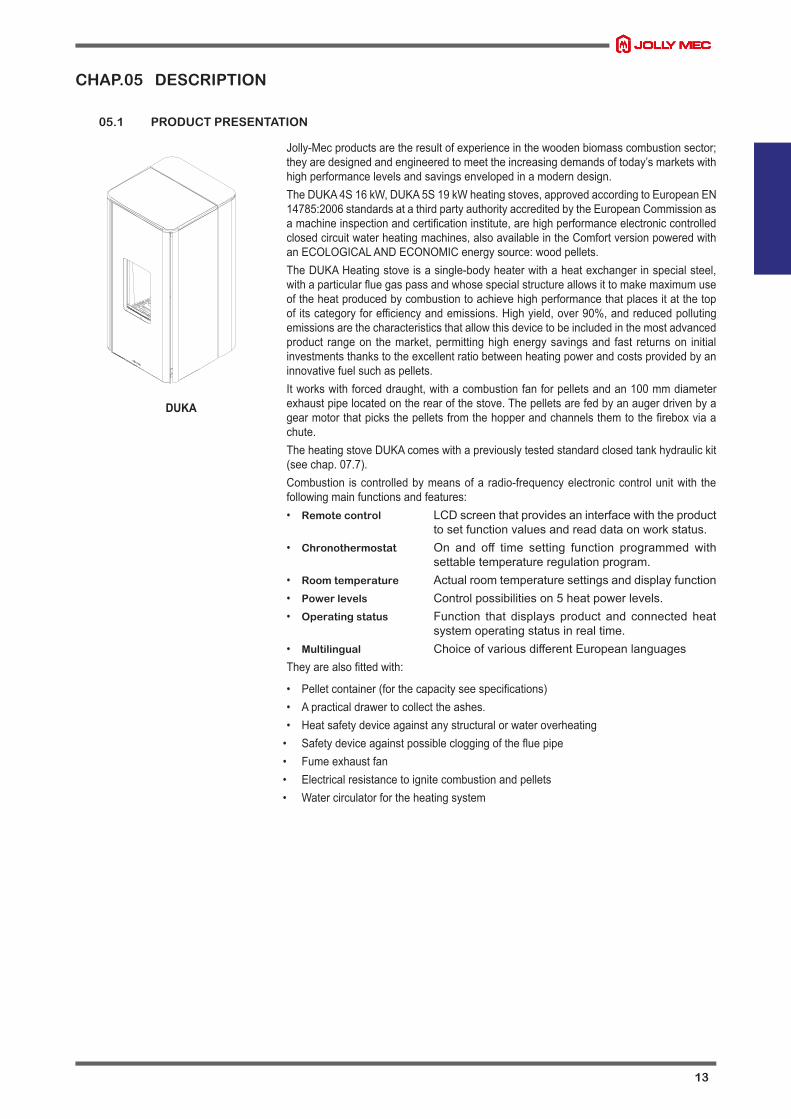
Jolly-Mec products are the result of experience in the wooden biomass combustion sector; they are designed and engineered to meet the increasing demands of today’s markets with high performance levels and savings enveloped in a modern design.The DUKA 4S 16 kW, DUKA 5S 19 kW heating stoves, approved according to European EN 14785:2006 standards at a third party authority accredited by the European Commission as a machine inspection and certification institute, are high performance electronic controlled closed circuit water heating machines, also available in the Comfort version powered with an ECOLOGICAL AND ECONOMIC energy source: wood pellets.The DUKA Heating stove is a single-body heater with a heat exchanger in special steel, with a particular flue gas pass and whose special structure allows it to make maximum use of the heat produced by combustion to achieve high performance that places it at the top of its category for efficiency and emissions. High yield, over 90%, and reduced polluting emissions are the characteristics that allow this device to be included in the most advanced product range on the market, permitting high energy savings and fast returns on initial investments thanks to the excellent ratio between heating power and costs provided by an innovative fuel such as pellets.It works with forced draught, with a combustion fan for pellets and an 100 mm diameter exhaust pipe located on the rear of the stove. The pellets are fed by an auger driven by a gear motor that picks the pellets from the hopper and channels them to the firebox via a chute.The heating stove DUKA comes with a previously tested standard closed tank hydraulic kit (see chap. 07.7).Combustion is controlled by means of a radio-frequency electronic control unit with the following main functions and features:• Remote control LCD screen that provides an interface with the product
to set function values and read data on work status.• Chronothermostat On and off time setting function programmed with
settable temperature regulation program.• Room temperature Actual room temperature settings and display function• Power levels Control possibilities on 5 heat power levels.• Operating status Function that displays product and connected heat
system operating status in real time.• Multilingual Choice of various different European languagesThey are also fitted with:
• Pellet container (for the capacity see specifications)• A practical drawer to collect the ashes.• Heat safety device against any structural or water overheating
• Safety device against possible clogging of the flue pipe• Fume exhaust fan• Electrical resistance to ignite combustion and pellets• Water circulator for the heating system
DUKA

14
05.2 PRODUCT IDENTIFICATION
It is COMPULSORY to indicate the product MODEL, the LOT number and SERIAL NUMBER in all communications with the Manufacturer.Identification numbers are printed on the adhesive plate located on the back of the device as illustrated on the right.Stove performance values measured during inspection tests according to the indicated reference and EC markings are also included on the plate.
The illustrated example plate may differ in graphics from the original affixed to the product.NOTE
1 Product model2 CE marking3 Year of commissioning and certification4 Reference standard5 Performance declaration No.*6 Product LOT N°7 Product code9 Product serial number
*Pursuant to European Regulation No. 305/2011, manufacturers are now required to have the DoP - Declaration of Performance for each product of own design concerned; Jolly-Mec did namely provide all of these documents in downloadable
electronic form that you can easily see on the website of the Company at the following address: http://www.jolly-mec.it/it/servizio-clienti/docman.html
WARNING
Via San Giuseppe, 2 - 24060 Telgate - BG - ITALYTel. +39.035.8359211 - fax +39.035.8359200
www.jolly-mec.it - [email protected]
Potenza elettrica nominaleRated electrical powerElektr. LeistungsaufnahmePuissance électrique nominalePotencia eléctrica nominal
Distanza minima materiali combustibili adiacentiMin. clearance from combustible materialsAbstand zu angrenzenden entzündlichen StoffenDistance aux matériaux combustiblesDistancia a materiales combustibles adyacentes
Utilizzare solo combustibili raccomandatiUse recommended fuels onlyVerwenden Sie nur die empfohlenen BrennstoffsortenUtiliser seulement des combustibles recommandésUtilizar sólo los combustibles recomendados
CO emissioniCO emissionsCO emissionEmission de COEmisión de CO
Tensione/Frequenza nominaleRated voltage/frequencySpannung/NennfrequenzTension/Fréquence nominaleTensión/Frecuencia nominal
Temperatura dei fumiFlue gas temperatureAbgastemperaturTempérature des fuméesTemperatura de los humos
Leggere e seguire le istruzioni di funzionamentoRead and follow the operating instructions.Lesen und befolgen Sie die BetriebsanleitungenLire et suivre les instructions de fonctionnementLeer y seguir las instrucciones de funcionamiento
Potenza termica nominaleRated heat outputNenn-HeizleistungPuissance nominalePotencia térmica nominal
N° lotto:
230 V
Pellets - Granulé de bois
Cod: CULT/6KW/UP/N
Emissioni polveriDust emissionsEmission poussièresStaubemmissionenEmission de polbo
112,4 °C
CULT 6 kW UP
Matr: 000000
Pt
CO @ 13% O
Tf
18
50 Hz
325 W
6,3 kW Nominal
Nominal
Ignition
48 W
Dust @ 13% O
n° DOP JM00182the dop was drafted on the basis to the test report of accredited laboratory the accreditationnumber of the laboratory is 2456 TÜV Rheinland Energy GmbH
80,7 mg/m201,4 mg/m3
Apparecchio per il riscaldamento domestico alimentato a pellet di legno - Residential space heatingappliance fired by wood pellet - Mit Holzpellets befeuerte Wärmeerzeuger für den Wohnbereich -Appareil de chauffage domestique alimenté au pellet de bois - Aparato para calefacción domesticaalimentado con pellets de madera
Reduced2,9 kW
Qtot6,7 kW Nominal3,0 kW
Potenza bruciataBurned powerMax HeizleistungPuiss. max. disponiblePotencia quemada
93,5 %95,1 %
RendimentoEfficiencyWirkungsgradRendementRendimiento Reduced
Nominal
Working
3 2
2
73,5 °C
Reduced
Reduced
17,3 mg/m3 Nominal
NominalReduced
B=100 mmS=150 mm
L'apparecchio non può esser utilizzato in canna fumaria condivisa - The appliance can not be usedin flue shared - Das Gerät kann nicht im gemeinsamen schorustein verwendet werden - L'appareilne peut pas etre utilisè dans conduit partagè - El aparato no se puede utilisar en tubo de humoscompartido
F=900 mm
L000000
EN 14785:200
1
2
4
5
3
6
7
8
yy

15
All appliance tests, final inspection and fine-tuning was performed using the recommended certified pellets.. Jolly Mec Caminetti S.p.A. is not responsible for malfunctions, breakdowns or problems due to the use of pellets that are not recommended, as combustion parameters vary according to the quality of the pellets.To achieve best operational results, it may be necessary to change the default factory settings on the control unit during the “first start-up” commissioning phase. These operations must only be performed by the relative Technical Assistance Centre (CAT), being the only operators authorised to complete the first start-up activities
WARNING
CHAP.06 TECHNICAL DATA
06.1 HOMOLOGATION
Technical specifications resulting from laboratory tests conducted according to EN 14785:2006 test methods at the CERTIFICATION institute.
Description DUKA 4S 16 kW DUKA 5S 19 kW UM
Nominal burning output 17,4 20,5 kWNominal heat output 16,2 19,0 kWReduced heat output 6,1 6,1 kWFluid power efficiency 14,8 17,1 kWSpace heating output 1,4 1,9 kWNominal output consumption 3,620 4,280 kg/hReduced output consumption 1,340 1,340 kg/hNominal output efficiency 93,7 92,6 %Rated voltage 230 230 VRated frequency 50 50 HzElectrical absorption(Switching on - nominal power - reduced power - stand-by) 310 - 42 - 32 - 3,4 310 - 45 - 32 - 3,4 W
Device mass 239 239 kgStandard hopper capacity 30 30 kgFlue draught 8,0 8,0 PaFume exhaust diam. 100 100 mmAverage fume Temperature at nominal output 118,0 135,9 °CAverage fume Temperature at reduced output 71,0 71,0 °CCO (13% O2) at nominal output 171 156 mg/Nm3
CO (13% O2) at reduced output 671 671 mg/Nm3
CO2 at nominal output 12,2 12,4 %CO2 at reduced output 6,7 6,7 %NOX (13% O2) at nominal output 98 95 mg/Nm3
OGC (13% O2) at nominal output 3 3 mg/Nm3
Dust (13% O2) at nominal output 19,8 14 mg/Nm3
Nominal fume mass output 10,02 11,72 g/sReduced fume mass output 6,53 6,53 g/sAverage heated area* 109 - 171 128 - 201 m2
Minimum air distance from inflammable side wall 200 200 mmMinimum air distance from inflammable rear wall 100 100 mmFrontal air distance from inflammable material 800 800 mmTesting pressure 6 6 barMaximum water working pressure 2,5 2,5 barWater content 33 33 lHeat pump head (@ 1m3/h) 7,6 7,6 mComburent air pipe diameter 50 50 mmEnergy efficiency class A++ A++ -
*According to the typology of building and insulation (Referred to the need of 55 W/m3 and 35 W/m3; room height 2,7 m).The declared output may vary according to fuel type.The above technical data are obtained with PELLET with the following features: Class A1 (EN ISO 17225-2: 2014) - Humidity: 5,62% - Ashes: <0.1% - Hydrogen: 6.29% - Carbon : 46.4% - Sulfur: 0.0080% - Nitrogen: 0.0500%.
Use the type of fuel as recommended in CHAP.06.2 - RECOMMENDED FUELS.

16
06.2 RECOMMENDED FUELS
A pellet product’s performance is significantly linked and highly influenced by the type and quality of wooden pellets that is burned. It is important to choose pellets that have no debris or impurities. The Association of Pellet Manufacturers with the Italian Thermotechnical Committee have established standards for identifying pellets in terms of energy*. As the efficiencies of different wooden PELLETS qualities differ, likewise the efficiency and heat capacity emitted by the product running on pellets will vary. Similarly, unburned residue left in the combustion chamber is inversely proportionate to pellet quality: the lower the pellet purity, the faster dirt accumulates in the machine.Jolly Mec Caminetti S.p.A strongly recommends the use of the same type of pellets used during first start-up, i.e. when the settings and calibrations were made to suit the loaded combustible materials. Continuous switching of types and qualities of combustible materials will require continuous adjustments to settings by the Technical Assistance Centre, which can not be endorsed by the Manufacturer.
The main quality certifications for PELLETS on the European market are DIN Plus, Ö-Norm M7135 and UNI EN14961-2(class A1), which guarantee the following quality standards:
Store pellets at least 1 m from the appliance, in a dry place and not outdoors, not even under porches or roofings.Do not use pellets that are very hard and with different dimensions; the mechanical parts are sized and tested for use with pellets with the above-mentioned characteristics.
Nobreakdownormalfunctiondependingonthequalityofthepelletsusedand/orbythedosageofthequantitywillbecoveredbythewarranty.
PELLET QUALITY IS VERY IMPORTANT; PLEASE READ THIS SECTION CAREFULLY WARNING
*CERTIFIED PELLET CHARACTERISTICS
Powder 1% maximum through a 3.2 mm screen
Apparent density 680 Kg/m3 minimum
Dimensions 6 mm diameter from 25 to 30 mm of maximum length
Ash content 1% maximum
Humidity 8% maximum
Heating power 4,9 kWh/Kg
Packaging in eco-compatible or biodegradable material sacks
WHAT YOU SHOULD KNOW ABOUT PELLETS:pellets are obtained by a drawing process using sawdust discarded by virgin wood processing systems and therefore have no chemical additives. The consistency, compactness and strength with which the pieces remain intact is due to a substance contained in wood called lignin; this acts as a binder during the compression phase. The various qualities of combustible materials can also depend on the sawdust mix used to produce the pellets, which generally have a standard length of between 5 and 30 mm, a diameter of between 5 and 6 mm, a weight of from 600 to 700 Kg/m3 and a humidity of no more than 8% of its weight.One advantage over wood is its greater heating power; in fact, when using good quality wood, it is possible to achieve about 4.3kWh/Kg with a humidity rate of up to 15%, whilst with pellets this can climb to 4.9kWh/Kg and a water content of a maximum of 8%.The sacks of pellets must be stored in a clean, dry place.
NOTE

17
06.3 COMPONENTS
The device is supplied with the following components:• Installation, use and maintenance manual.• Power cord to connect the stove to the mains.• Cladding.• Remote control.
Part List:1. Tube bundle scraper2. Firebox3. Combustion chamber grid4. Ash pan5. Combustion chamber door6. Handle for opening the door7. Aesthetic cladding glass8. Pellet loading lid9. Emergency console10. Pellet hopper11. Expansion tank12. Electronic control unit13. Thermal hydrometer14. Circulation pump15. 3 bar safety valve16. Hydraulic connections17. Safety thermostat with manual reset18. Room temperature probe19. Electrical socket with fuses and Main electric switch20. Comburent air intake tube Ø50 mm (M)21. Combustion and fume exhaust fan Ø100 mm (M)22. Pellet loading auger gear motor23. Pellet loading auger24. Heating fan (for Idro+Comfort and Idro)25. Heat exchanger (for Idro+Comfort and Idro)26. Hot air outlet (for Idro+Comfort and Idro)
1
2345
6
8
10
11
14
17
20
1819
15
21
7
9
16
25
24
26
12
13
24
2322
18
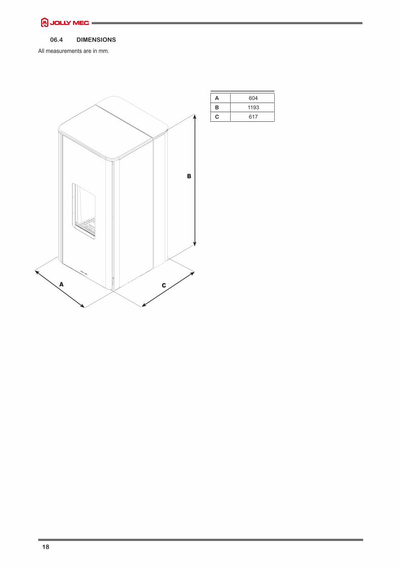
06.4 DIMENSIONS
All measurements are in mm.
C
B
A
A 604
B 1193
C 617

19
CHAP.07 POSITIONING AND CONNECTIONS FOR THE INSTALLER
07.1 HYDRAULIC CONNECTION AND EXTERNAL AIR INTAKE SETTINGS
The device must only be installed indoors and on surfaces that can support the load. If the existing construction does not meet thisrequirement, it will be necessary to take appropriate measures (e.g. installing a load distribution plate). The appliance must be installedin an area where the appliance itself, gas exhaust pipes and flue can be easily accessed for maintenance.
The device must be installed near walls made of non-flammable material. The installation of the device near flammable walls is allowed if observing the clearances specified below, or if a proper protection is installed (surfaces such as floor, ceiling and walls of the house near the device should be protected against overheating).The hydraulic connections between the wall and the appliance must be made using flexible pipes.Fig. 1 illustrates minimum distances that must be observed, all measures must be in mm.The lateral distance from the adjacent wall, according to installation, is to be maintained on both sides.1. Electrical socket2. External air inlet (see chap. 07.4)3. Rear panel4. Side panel
The hydraulic kit does not include cut-off valves. Therefore, we recommend these valves are installed on each stove hydraulic connection during installation. Use outlet type valves leaving the pulley towards the stove (see CHAP.07.6 - HYDRAULIC KIT).
FOR THE SYSTEM FEED THE COLD WATER MUST BE CONNECTED TO THE APPLIANCE.
NOTE
At the end of installation, accurately clean the heating system to eliminate all work residue. Dirt deposits can cause hydraulic components installed on the device such as the water circulator, anti-condensation valve, automatic air breather valve and safety valve to malfunction.Maintenance for problems due to these faults is not covered by the Jolly Mec warranty.
WARNING
The external air intakes must be made so that they cannot get accidentally covered and if they have an insect protection mesh they must be cleaned periodically to prevent clogging with dust and dirt, especially in periods with intense pollen concentrations.
NOTE
Bear in mind that the minimum distances frominflammable materials are:
Minimum air distance from inflammable side wale: 200 mmMinimum air distance from inflammable rear wall: 100 mmFrontal air distance from inflammable material: 800 mm
as indicated in CHAP.06.1 - HOMOLOGATION
NOTE
As indicated in the national reference standard UNI 10683:2012, the product can not be installed in rooms with a volume of under 15 m3.
NOTE
max 1250
100
200
800
1
32
4
Front view
View fromabove

20
- View from the back (main dimensions for the installation of the flue and air intakes. For parts of the hydraulic kit see chapter 07.7)
Rear flue gas exhaust Side flue gas exhaust
Detail R
R
268
404,
5
549
n 100
268
392
74
144
n50
n 100
107
153
192
300
600
45
95
140
210
Detail R
R
268
404,
5
549
n 100
268
392
74
144
n50
n 100
107
153
192
300
600
45
95
140
210
21
07.2 FLUE OR FUME EXHAUST SYSTEM
The flue or fume exhaust system is a fundamental element for the proper functioning of the stove and must comply with the following general standards:EN1856-1 Chimneys. Requirements for metal chimneys - Part 1: System chimney productsEN1856-2 Chimneys. Requirements for metal chimneys - Part 2: Metal flue liners and connecting flue pipesUNI 10683 Heat generators operating with wood or other solid bio fuels - Installation requirementsThe diameter of the flue must be sized according to the technical specifications of the appliance and type and place of installation. Eachappliance must have its own chimney flue without any inlets from other appliances.The exhaust duct of the combustion products generated by the forced draught equipment must respond to the following requirements:
• it is necessary to use union joints and pipes with pressure resistant seals, as the union of the flue could be slightly pressurised while the appliance running
• all changes in direction must be open to inspection to facilitate maintenance• correct draught to maintain depression in the combustion chamber, as per the technical specifications, must be guaranteed• it must be watertight, waterproof and suitably isolated and insulated• must be made of suitable materials that resist normal mechanical stress, heat, the action of the combustion products and acid
condensations• must be prevailingly vertical structures with deviations from the axis not greater that 45°• must be adequately distanced from combustible or inflammable materials via an air space or suitable insulation• must have an internal section which is preferably circular: square or rectangular sections must have rounded corners with a
radius of no less than 20 mm• must have an internal section that is constant, free and independent
If the flue is installed externally it must be insulated to prevent the cooling of fumes and formation of condensation. The same is valid for the tract from the roof to the chimney cap (Torrino). For the union between the stove and the flue, or if there are deviations or curves, for easier, quicker and safer installation, we recommend using double-walled stainless steel pipes. The use of pipes in fibre cement for connecting the equipment to the flue is forbidden.Exhaust pipes must not run through rooms where the installation of combustion equipment is forbidden. The union must be connected to the flue in such a way as to ensure they remain airtight when the appliance is operating in pressurised conditions and to avoid the formation of condensation and its conveyance to the appliance.
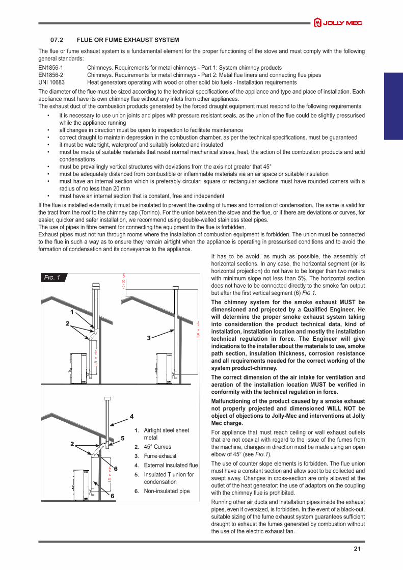
It has to be avoid, as much as possible, the assembly of horizontal sections. In any case, the horizontal segment (or its horizontal projection) do not have to be longer than two meters with minimum slope not less than 5%. The horizontal section does not have to be connected directly to the smoke fan output but after the first vertical segment (6) Fig.1.The chimney system for the smoke exhaust MUST bedimensioned and projected by a Qualified Engineer. Hewill determine the proper smoke exhaust system takinginto consideration the product technical data, kind ofinstallation,installationlocationandmostlytheinstallationtechnical regulation in force. The Engineer will giveindicationstotheinstalleraboutthematerialstouse,smokepath section, insulation thickness, corrosion resistanceandallrequirementsneededforthecorrectworkingofthesystemproduct-chimney.Thecorrectdimensionoftheairintakeforventilationandaeration of the installation locationMUST be verified inconformitywiththetechnicalregulationinforce.Malfunctioningoftheproductcausedbyasmokeexhaustnot properly projected and dimensioned WILL NOT beobjectofobjectionstoJolly-MecandinterventionsatJollyMec charge.For appliance that must reach ceiling or wall exhaust outlets that are not coaxial with regard to the issue of the fumes from the machine, changes in direction must be made using an open elbow of 45° (see Fig.1).The use of counter slope elements is forbidden. The flue union must have a constant section and allow soot to be collected and swept away. Changes in cross-section are only allowed at the outlet of the heat generator: the use of adaptors on the coupling with the chimney flue is prohibited.Running other air ducts and installation pipes inside the exhaust pipes, even if oversized, is forbidden. In the event of a black-out, suitable sizing of the fume exhaust system guarantees sufficient draught to exhaust the fumes generated by combustion without the use of the electric exhaust fan.
1
3
2
2
4
5
6
6
Fig.1
1. Airtight steel sheet metal
2. 45° Curves3. Fume exhaust4. External insulated flue5. Insulated T union for
condensation6. Non-insulated pipe

22
It is not allowed to install coaxial systems for the smoke output.WARNING
If the performance of the fume exhaust system is not excellent, it is possible to adjust the operating settings of the stove to overcome draught defects by a maximum of 15% of the fume exhaust device; this adjustment is however the exclusive competence of the specialised Technical Service Center.One airtight reading point is recommended on the flue to check emissions after installation and measure draught.Supporting the weight of the flue with the appliance union is strictly forbidden. Use specific stands or independent supports for this purpose.To install other combustion devices in the same room where the pellet appliance is installed, refer to UNI 10683 and UNI 7129 installation regulations.The minimum flue height must be over 3,0 m.Blocking of wall exhaust terminals at any height and any distance from openings, doors and/or windows is not permitted and a very important rule to follow.Installation of external fireplaces must be performed using insulated double-walled pipes, to prevent the formation of condensate; it must also be possible to inspect the base of the fireplace for routine maintenance which must be done at least once a year.A windproof chimney cap must be installed; in the presence of adverse weather conditions, especially high winds, this accessory allows the stove flue draught system to operate much easier.A minimum flue draught between 10 and 14 Pa must be guaranteed. This value must be measured using specific and controlled instruments each time the appliance and flue undergo maintenance. With strong winds and the chimney cap installed in the reflux area (see Fig.2, zone bordered by the dotted line A for roofs with ß>10° slant)
of the roof or without complying with the distances foreseen by UNI 10683 situations may arise where the stove does not work which will trigger the no depression alarm.It is not possible to make corrections or reset the stove operating values to override the alarm.
07.3 INSTALLATION ROOM VENTILATION
According to reference regulation UNI10683, 4 Pa depression must be verified between the installation room interior and exterior. Prepare adequate ventilation openings in the room where the product is installed to permit at least 50 m³/h clean comburent air flow not taken from polluted rooms. The ventilation openings, if fitted with insect-proof mesh, must be easily removable and undergo periodic cleaning to ensure clear air flow passage.If the comburent air inlet is directly connected to the stove, it may be necessary to make adjustments to the control unit, especially duringthe start-up phase, as the temperature and humidity of outdoor air not only varies during the period of use of the product, but also comeinto direct contact with the pellets and the ignition element, generating different fuel burning times.Jolly Mec allows the ducting system at the input of the combustion air within and not over the following limits: the length can’t be longerthat 1000 mm, the diameter has to have at least the same section of the stove/boiler connection, it is possible only one 90° change ofdirection, the center-to-center distance of the combustion air input pipe can be ± 300 mm.
As per the fuel product exhaust system, air vents are also extremely important and must be given the appropriateconsideration and respect.
The installer is directly liable for all electrical system parts, generation hook-up to the system, ventilation and the fume exhaust system and MUST, at the end of installation work, issue a declaration of conformity as per Ministerial Decree 37/08.On the other hand, the purchaser MUST assign all work to a qualified professional technician.The device must be installed and used in accordance with all local and national laws and EC Regulations.
WARNING
.
130
cm
.
50 c
m
ß>10°
A
90°
Fig.2

23
07.4 ASSEMBLY SEQUENCE
1. Unpack the stove by removing the cardboard. Take the stove off the pallet and handle it carefully until it gets off the pallet. 2. Mounting the cladding. For assembling the cladding please see the specific annexes (see AD219). For assembling the cladding
please see the specific annexes (see AD183). In case of rear flue gas exhaust, follow the specifications at point a) before mounting the cladding.
3. The stove may function by taking the comburent air directly from the outside (with direct connection to the stove comburent air inlet) or by the inside of the installation room. In case the comburent air is taken from the inside of the installation room, it is mandatory to make an opening in the room of at least Ø100 mm, communicating with the outside environment. In case the comburent air is taken directly from the outside, it is necessary to connect the Ø50 mm extensible pipe to the comburent air inlet of the appliance communicating directly with the outside environment (see chap. 07.3 for the characteristics of the comburent air canalisation).
4. Perform the electric and hydraulic connections.5. Place the stove in the location where you want to install it. When choosing the place to install it, remember that installation must
guarantee easy access to clean the stove, the fume pipes and the flue, and that the safety distances must be complied with as provided for in CHAP.06.1 – HOMOLOGATION. For the construction of fume pipes please comply with the specifications in CHAP. 07.2.
a)Sidefluegasexhaust1 - Remove the left upright (1) (Fig.1-2);2 - Remove the cap (2) from the side of the smoke exhaust (Fig.2-3)-PAY ATTENTION to the gasket;3 - Place the cap (2) on the back of the smoke exhaust (Fig.4-5);4 -Remove the precut (3) from the left upright (1) (Fig.6-7);5 - Position the left upright (1) in place (Fig.8);
Fig.1
1
Detail Y
Y
Fig.2
2
Detail AA
AA
Fig.3
Detail AC
AC
Fig.4
2
Detail AD
AD
Fig.5 Fig.6
2
2
Fig.7
3
1
Fig.8
1
Detail AA
AA
24
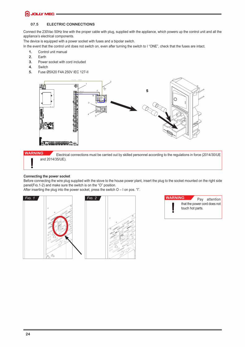
07.5 ELECTRIC CONNECTIONS
Connect the 230Vac 50Hz line with the proper cable with plug, supplied with the appliance, which powers up the control unit and all the appliance’s electrical components.The device is equipped with a power socket with fuses and a bipolar switch. In the event that the control unit does not switch on, even after turning the switch to I “ONE”, check that the fuses are intact.
1. Control unit manual2. Earth3. Power socket with cord included4. Switch5. Fuse Ø5X20 F4A 250V IEC 127-II
Electrical connections must be carried out by skilled personnel according to the regulations in force (2014/30/UE and 2014/35/UE).
WARNING
ConnectingthepowersocketBefore connecting the wire plug supplied with the stove to the house power plant, insert the plug to the socket mounted on the right side panel(Fig.1-2) and make sure the switch is on the “O” position.After inserting the plug into the power socket, press the switch O – I on pos. “I”.
Pay attention that the power cord does not touch hot parts.
WARNING
5
13
N
F
N F
12
3
45
Fig.1 Fig.2

25
07.6 CONTROL UNIT ELECTRICAL WIRING DIAGRAM
I Electrical connections must be carried out by skilled personnel according to the regulations in force (2014/30/UE and 2014/35/UE).
WARNING
a)WiringdiagramwithKIT1(IDROversion)
Number Description1 Radio control2 Emergency control console / radio antenna for
radio remote control3 Electronic card4 Bipolar switch5 Electric power cord with schuko socket6 Electrical heating element7 Circulation pump8 Pellets loader gear motor9 Encoder Screw
10 Smoke fan
Number Description11 Fume temperature sensor12 Flue Gas Encoder13 Bulb type safety thermostat14 Fume pressure switch15 Environment Probe / Puffer Probe / Thermostat16 Boiler Water Probe17 Pressure sensor18 External contact20 RC filter21 Parallel heating source contact
The representation of the components is approximate, but they can change in terms of shape.NOTE
1
2
3
4
5
6
7
8
9
10
11
12
13
14
15
16
17
18
19
20
21

26
b)WiringdiagramwithKIT2(IDRO+COMFORTversion)
Number Description1 Radio control2 Emergency control console / radio antenna for
radio remote control3 Electronic card4 Bipolar switch5 Electric power cord with schuko socket6 Electrical heating element7 Circulation pump8 Pellets loader gear motor9 Encoder Screw
10 Smoke fan11 Fume temperature sensor12 Flue Gas Encoder
Number Description13 Bulb type safety thermostat14 Fume pressure switch15 Environment Probe / Puffer Probe / Thermostat16 Boiler Water Probe17 Pressure sensor18 External contact20 RC filter21 Parallel heating source contact22 Fan output for Air / Comfort23 Integrated three-way valve for Comfort mode24 Additional board
The representation of the components is approximate, but they can change in terms of shape.NOTE
10
4
3
2
1
5
6
7
8
9
10
11
12
13
14
16
15
17
18
19
20
21
22
24
23

27
Use the CN6 (N V2 / PO) fitting to connect a parallel heat source (e.g. a gas boiler) when the appliance is operating in pellet mode: with the pellet stove OFF, ALARM ON and ALARM MEMORY, a parallel source can be enabled. In all other conditions, stove operations takes precedence.To connect the parallel source it is necessary to connect a relay (230 V) and an RC filter (100 Ω - 0.25 μF)
NOTE
The representation of the components is approximate, but they can change in terms of shape.NOTE
f)Parallelheatingsourcecontact
Relays230 V
RCfilter100Ω-0,25µF

28
07.7 HYDRAULIC KIT
1. Safety valve discharge Ø18mm M2. System discharge3. System feed ½”M4. System flow ¾”M5. System return ¾”M6. System load valve
1)KIT1Hydraulic kit for heating only (IDRO version, IDRO);
1. Safety valve discharge Ø18mm M2. System discharge3. System feed ½”M4. System flow ¾”M5. System return ¾”M6. System load valve
2)KIT2Hydraulic kit for heating only (IDRO+COMFORT version)
Detail R
R
268
404,
5
549
n 100
268
392
74
144
n50
n 100
107
153
192
300
600
45
95
140
210
1
2
3
45
6
Detail R
R
268
404,
5
549
n 100
268
392
74
144
n50
n 100
107
153
192
300
600
45
95
140
210
1
4
5
2
63

29
1÷1,2 bar cold pressurised water must always be in the stove. Topping up pressure is manual. After topping up, make sure the valve is closed.
WARNING
The installation operator is obliged to check that the closed expansion tank, supplied with the stove, has a capacity which is suitable for the system it will be connected to. For medium/large systems, a heat technician should inspect and calculate the needs of the rooms to be heated according to current regulations.
WARNING
•SafetycomponentsThe safety components are valid for all types of hydraulic kit.A. Air breather valveB. Stove water temperature probe and water safety thermostat probe wellC. Safety valve 3 bar
In the event of overpressure, the 3 bar safety valve (C) is triggered and intervenes inside the heating circuit. It is advisable to connect the valve to a drain to avoid, in case of intervention, that it discharges openly into the installation room.
WARNING
Fig.1
B
A
Fig.3
CFig.2
B
A

30
07.8 SYSTEM CONFIGURATIONS
Different hydraulic system configurations are possible with the device to allow for better operations based on the system solution adopted in the installation phase. This setting must be made by the installer or by the the specialised Technical Service Centre.The available system diagrams are listed below:
CONFIGURATION 1 – Heating - Device configuration for direct heating only.Summer operating mode cannot be set. Instead, the CRONO timer function or STAND-BY.The appliance, once the ROOM TEMPERATURE and BOILER WATER are set, runs at the set power until one of the two temperatures is reached, then switching to ECONOMY. When the appliance is in ECONOMY mode, the water circulation pump continues to operate to achieve AMBIENT TEMPERATURE and maintain the desired ambient temperature. It must be checked whether there are hydraulic interceptions between the device and system that could slow water flow and thus cause stove water overtemperature alarms.The ambient temperature can be measured by the ambient probe on the appliance, by the remote control or by an external thermostat connected to the TERM input on the board.To use the thermostat, which must have a CLEAN CONTACT, or the probe on-board the appliance, it is necessary to set the required value in the relative user menu.
CONFIGURATION5–Puffer–The appliance is connected to a Puffer (inert heat tank) and not directly to the heating system. PUFFER TEMPERATURE must be set.The ambient probe connected on-board the appliance must be inserted inside the puffer to become the puffer probe (a thermostat that must have a CLEAN CONTACT can also be used. To select the probe/thermostat, the relative value must be set in the technical menu). Control of the ambient temperature is not envisaged (read only) and is measured by the remote control of the appliance.In DIAGRAM LAYOUT 5, the appliance only ensures that the puffer temperature probe meets the set temperature settings.When the puffer temperature is met, the appliance switches to ECONOMY mode, with pump still running.In this configuration, the STAND-BY function is automatically activated and turns the appliance off when in ECONOMY mode for a period of time longer than that set in SET STAND-BY, at the DELAY OFF value.When the appliance is in Stand-by mode, thus waiting to turn back on, the circulation pump is off and the only input that can turn the appliance on is the puffer probe value which, when the puffer set temperature is -5°C, allows the restart. The differential restart value can be set in the technical menu used by the service technician.

31
CONFIGURATION 6 – Boiler –The boiler is connected to the heating system and in parallel with an accumulation tank for DHW production. In this configuration, the heating part is identical to the functions described in CONFIGURATION 1 while the boiler takes precedence over the heating system request. The boiler probe, to be connected to the PELLET input of the control unit (a thermostat that must have a CLEAN CONTACT can also be used. When choosing the probe/thermostat, it is necessary to set the the value in the technical menu), works with a 5°C temperature differential from the set BOILER TEMPERATURE, to activate the three-way deviator valve. When the set boiler temperature set is met, the deviator valve deviates towards the system (in the event that the boiler temperature drops 5°C below the set boiler temperature, the deviator valve deviates towards the boiler itself).Depending on its type, the deviator valve must be connected to terminals 28 (Fig.1) available in the electronic circuit board wiring.The STAND-BY function can also be set in this configuration and, if all utility requirements are met, the boiler will await restart.If SUMMER mode is set, the three-way valve will be set towards the boiler and the STAND-BY function is automatically activated. When boiler temperature is met, the appliance switches to stand-by and, when shutting down, if heat dissipation is required, heat is dissipated to the heating system.
Number Description20 RC filter28 Connection terminals Three-way valve
CONFIGURATION7–Puffer+Boiler–CONFIGURATION 7 is a mix between CONFIGURATION 5 and CONFIGURATION 6, Puffer and Boiler are connected in parallel to the boiler. The functions described in the relevant configurations also apply to CONFIGURATION 7, with the domestic hot water boiler taking precedence.
20
28
Fig.1
N
F - 230 VValve control

32
07.9 VERSIONS
IDRO VersionDepending on the set system type, it is possible to: - heat the system water;- product domestic hot water with boiler
IDRO+COMFORTversionDepending on the set system type, it is possible to:- heat the system water;- produce domestic hot water with a boiler, activate as desired the ambient fan (with adjustable power) to heat air and water at the same time;- activate the heating fan for the Comfort function only (adjustable speed of fan).

33
CHAP.08 USE AND MAINTENANCE FOR THE USER
08.1 APPLIANCE FUNCTIONS
The appliance electronically controls pellet combustion and water distribution to utilities.Pellets are taken from the storage tank by the gear motor driven auger and transported directly to the burn pot. The tank is filled through the lid, at the top of the cladding to permit access to the container chute. Pellets must be placed in the tank with a shovel and not directly poured from the bag (see vedi CHAP.08.6 - ORDINARY MAINTENANCE (bythecostumer)).
Ignition is through air aspirated into the burn pot by the centrifuge fan and brought to high temperature by heating an electrical resistance.The fireplace is made up of a special steel heat exchanger, closed at the front by a ceramic glass door. The exchanger has a gas pass that allows it to be defined as a flue stove, whose constructions fully exploits the heat produced by combustion.The quantity of fuel, the feeding of comburent air and the extraction of fumes are regulated with an electronic card in order to obtain a highly efficient combustion.All the operations for managing machine functions are handled by the supplied control unit installed on the device (see manual SM130 attached).
08.2 CONTROL UNIT
The electronic control unit, connected by radio frequency to the radio remote control, manages all the device functions and the LCD display screen on the handheld console can be used to monitor all the stove operating phases.The electronic control unit features a timer function with customisable programmes and a user-friendly operating settings.Depending on the type of system, the operational functions are controlled by the AMBIENT PROBE placed in the remote control or with standard installation in the rear section of the appliance. It can be used as an ambient thermostat, paying GREAT ATTENTION that the electrical connection to the stove motherboard is CLEAN The electric/electronic elements also include certain safety systems such as:FUME TEMPERATURE PROBE Fitted inside the fume exhaust fanPRESSURE SWITCH Connected in the appliance flue-gas boxSAFETY THERMOSTAT Triggers when water temperature is above the maximum permissible value
The radio remote control lets you use the following main functions:• Device start and stop• Heat output level control• Regulate the desired ambient temperature.• Optimise combustion.• Manually load pellets into the basket.• Manage the timed thermostat with several daily start ups, weekly start ups
and for week-ends.• Report any function irregularities.• Indicate the heating appliance’s operating mode.
In the event of radio remote control fault, main appliance functions can be controlled from the emergency console.
For a full and detailed description of the content in this section, see the enclosed manual SM130.NOTE

34
08.3 APPLIANCE START AND USE
After professionally installing the room ventilation system, the fume exhaust system, the hydraulic system and electrical system according to the relevant regulations, the specialised Technical Service Center can do the optional Commissioning Service.After the installation of the appliance for the first starting, in order to use the device, fill the tank with high quality pellets as recommended and perform the pellet pre-loading from LOAD PELLET menu (see manual SM116), set the desired temperature values and the output set value (we recommend to select level 3) and to start the device with the power key (see manual SM130), set the desired temperature values and the output set value (we recommend to select level 3) and to start the device with the power key (see manual SM130). The stove will run until the room probe, thermostat or accumulation tank probe temperature values are reached, according to the set configuration. When the set temperatures are reached, the stove switches to ECONOMY mode until a new request is sent by the probes.During the operating period in ECONOMY the water circulation pump remains active.Activate STAND-BY mode to turn off the appliance when all probe temperatures are reached for a time over that entered in the settings. The appliance is not actually switched off but is waiting to turn back on at a new probe/thermostat request.STAND-BY in system configurations 5 and 7, and in configuration 6, summer mode, is automatically enabled.Set SET CHRONO – MENU 2 to time operation start and stop. The crono can be quickly started by pressing Button 1 and 2 on the main display screen. The CHRONO function should be considered as a timer function, while STAND-BY is a temperature function. It is possible to set the desired temperature level for each time band.The message ORDINARY SERVICE is periodically displayed, every 100 hours of operation, to remind the user to clean the stove thoroughly CHAP.08.6-ROUTINEMAINTENANCE(BytheCustomer). Press the On button in the main screen to cancel the message.In the event of alarms and/or manual pellet load from MENU LOAD PELLET, the message CLEAN BASKET is a warning to be sure not to turn on the stove with previous operation combustion products and/or not burnt pellets in the firebox. To cancel the message, clean the brazier and press and hold down Button ON/OFF for three seconds. Pellet loading from the LOAD PELLET menu must be used only if the loading must be performed only if the auger is empty (before turning the device on), after a NO PELLET alarm, or after maintenance or cleaning of the container, with its consequent emptying. Every time the manual pellet load mode is enabled from the LOAD PELLET menu, the firebox MUST be emptied to create the correct conditions for the stove start-up phase.The appliance also has ANTIFREEZE functions that are activated when the boiler water temperature is equal to 5°C, activating the water circulator until it increases by 1°C. The device can be switched off while operating with manual intervention by the user or by setting a SET CHRONO or can switch off if an alarm is triggered following a device malfunction.In the third case follow the indications provided in CHAP. 09 - FAULT DIAGNOSIS AND TROUBLESHOOTING.
The installation technician must attend the optional Commissioning service since system components may require adjustments not pertinent to the specialised Technical Service Center at this time.Any additional work or intervention of the specialised Technicat Service Center due to the failure to complete the above adjustments during the optional Commitioning service are at the user’s expense.
WARNING
We recommend activating STAND-BY mode when permitted by factory and/or use conditions. Frequent starts and stops may cause appliance malfunctions, possible no start alarms and waste energy and fuel.
NOTE
The device must only be used with the combustion chamber door closed.The pellet hatch must be closed while the machine is running.The stove starting MUST ALWAYS be performed with clean and empty firebox.
WARNING

35
08.4 SAFETY THERMOSTAT WITH MANUAL RESET
A safety thermostat is installed on the appliance to read the temperature of the water circulating in the boiler, and cause the appliance to switch off if the temperature sensor reaches limit values which correspond to the thermostat trigger setting.To restore normal appliance operations following forced shutdown by a thermostat, proceed as follows:
1. Wait until the appliance is completely cold (on average 20 minutes);
2. Unscrew the thermostat reset button lid on the back of the appliance (see Fig. 1, positions B);
3. Press the button until you hear a CLICK;4. Refit the hood;5. Reset the alarm from the radio remote control by pressing
the ON/OFF button and waiting for the OFF message;6. Start up again the appliance.
If the alarm persists, contact the specialised Technical Service Center.
Socket unit (Fig.1):A. Main electrical socket with bipolar switchB. Water safety thermostat with manual resetC. Room temperature probe
Fig.1
A
B
C

36
08.5 TIPS FOR THE USER
• Use only original spare parts recommended by the manufacturer. Original spare parts are available through retailers, specialised Tecnical Service Centers, or directly at the head office of Jolly Mec Caminetti S.p.A.
• If condensation appears inside the stove, the causes could be: - The heat pump is set too low (recommended minimum threshold 60°- 65°)
- Poor draught by the flue (clean the flue)
- Insufficient comburent air (check comburent air conduit)
• If the glass becomes very dirty (with visible blackening) while operating, the possible causes could be: - Low draught by the flue (clean the flue or check its characteristics) - Insufficient comburent air (add more air with the combustion fan, clean the air intake)
• When pellets are not used for a long time (spring-summer period), the hopper, the auger and the basket must be completely emptied using a vacuum cleaner; clean carefully to prevent that pellet residue deposits there and damages components during the next start up.
• Only use recommended fuels under penalty of cancellation of the warranty.• Generally with a good quality product, every 500-1000 kg of pellet loaded in the hopper, check that there are no deposits of
sawdust on the bottom, and remove any sawdust there (sawdust reduces the auger’s capacity and creates functional problems for the stove). With low quality or non-certified pellets the frequency with which the bottom of the hopper needs cleaning to remove sawdust could become more frequent.
• The pellets must be fed into the hopper using a scoop. Do not empty the sack directly into the hopper.• Check for obstructions in the flue and in the external air intake before starting the machine after a prolonged period of disuse.• The stove must not be used as an incinerator. Do not use fuels that are not recommended.• The stove must not be modified; any unauthorised modification will automatically invalidate the warranty and release the
manufacture from all liability.• The stove must not be placed in direct contact with combustible materials (see CHAP 06 - TECHNICAL DATA)• Prompt and systematic maintenance is a fundamental component for perfect operating performance and continuous maximum
heat efficiency.
• Annually it is necessary to perform extraordinary cleaning unit by specialized Technical Service Centre, see CHAP.08.7 - SCHEDULED PREVENTIVE MAINTENANCE).
MORE CLEANING = HIGHER PERFORMANCE
Pellet combustion products must only be used with the combustion chamber door closed. NEVER open it during operations.Never run the fireplace without electrical current and with fuels other than wood pellets. DO NOT TOUCH the parts of the fireplace without cladding, excluding the handles and the regulating controls, as they are subject to high temperatures.
The room where the fireplace is installed must not directly adjoin multi-floored stairwells; there must not be other boilers, stoves or air extractors in the same room (except for “C” type appliances).
WARNING
Call the Fire Brigade if a fire occurs in the flue.WARNING

37
08.6 ORDINARY MAINTENANCE (by the costumer)
Before starting any type of cleaning, switch off the main switch and make sure that the appliance is cold. Never restart the stove before completing these operations and correctly reassembling all components.
WARNING
1. Stove door openingTo open the combustion chamber door, open the glass front door carefully (Fig. 1-2).Then bring the combustion chamber door handle to unhook the closure; at this point, pull the door to open it completely (Fig. 3-4). Close the door making sure it is correctly locked. Periodically check hinge integrity inside the door (Fig. 4).
• ORDINARY CLEANINGTHE INSTRUCTIONS BELOW REGARDING THE TIMING AND METHODS USED FOR THE VARIOUS PARTS TO BE CLEANED MUST BE CAREFULLY FOLLOWED.
Fig.1
Fig.2
Fig.3
Fig.4

38
2. ScrapingthetubebundleTo scrape the tube bundle it is necessary to open the door and move the dedicated lever 4 or 5 times to encourage the soot to fall inside the combustion chamber (Fig.5).Thisoperationmustbecarriedoutwithacoldandswitchedoffstove.
3. StovebodycleaningRemove the firebox (as described in point 3.Removethefireboxtocleanit)Use a brush to clean the internal walls of the combustion chamber in the FIRE FLECTOR allowing the soot to fall into the pan (Fig. 6). Remove the ash pan, empty it and accurately clean (as described in point 4.Ashpanremovalandcleaning). Eventually use a vacuum cleaner, with cold residual ashes, to suction any soot and ash left inside the ash pan compartment.
4. RemovethefireboxtocleanitLeave the combustion chamber door open, remove the grid and take the firebox away, by lifting it in vertical position (Fig.7-8-9) It is compulsory to clean the firebox thoroughly, making sure no holes are clogged.Eliminate the wastes on the firebox by overturning them and use a pointed object to remove any scales, by hitting the firebox internal walls and shaking it eventually.Before replacing the firebox, check there is no ash or dirt in the firebox housing. Vacuum this area thoroughly too (make sure residual ashes are cold) (Fig.9).Make sure that the area where the firebox rests is cleaned well (if the firebox does not sit well on it and air passes, the stove will not start up and operates poorly).After cleaning the firebox, make sure it is repositioned correctly in its housing as indicated (Fig.10).The electric igniter element must be centred correctly in its seat in the firebox and the seat must be perfectly in line with the housing.
Fig.6
Fig.7 Fig.8
Fig.9 Fig.9
Fig.10
Fig.5

39
5. AshpanremovalandcleaningWith the combustion chamber door open, extract the drawer positioned inside the stove at the bottom (Fig. 11-12-13). After removing and emptying the drawer it is recommended to vacuum the drawer housing to remove any ash residue (make sure residual ashes are cold) (Fig.14).Use a “drum type” vacuum cleaner equipped with a fine mesh filter, which will simplify cleaning as it prevents the vacuumed ash from returning to the environment. When finished, make sure the pan is correctly positioned.
6. PellettankopeningforcleaningandloadingApply light pressure to lift the pellet hopper cover, pulling upwards, to release the magnet closure (Fig.15-16).Empty the pellet container every 500-1000 Kg of pellet burnt, and check that no sawdust has accumulated on the bottom.Clean the bottom of the container carefully.After a long period of inactivity, empty the container and auger completely.Located on the rear part of the device, the hopper is filled through an openable lid. The hopper must be filled with pellets using a shove (not supplied) (Fig. 17-18) and not poured in directly from the bag.
Fig.11 Fig.12
Fig.13 Fig.14
Fig.16Fig.15
Fig.18Fig.17

40
7. Glass cleaningClean the glass daily with a damp sponge or paper hand towels (Fig.19-20).If the glass becomes dirty with black smoke, the brazier is probably dirty or the combustion air must be increased.Be careful not to use overly aggressive products to avoid ruining the paint. Never spray detergents directly onto the parts to be cleaned (Fig.21-22).If the stove requires more frequent and deeper cleaning, check the flue draught performance and the chimney cap. A windproof chimney cap is strongly recommended.Also clean the outside window where necessary (Fig.23).
8. Cladding cleaningFor cleaning the cladding (only for glass and steel parts) only use neutral water-based detergents that must be used to wet a cloth and pass it on it (Fig.24-25). Never spray detergents directly on cladding parts (Fig.26). Use of abrasive and/or corrosive chemical products can damage the painted parts and are reason for invalidation of the warranty on these parts.The chromatic variations of the painted surfaces, especially those in different materials and finishes and subject to different temperatures, cannot be deemed reason for dispute as they depend upon the natural characteristics of the materials and the use of the product.
Fig.20Fig.19
Fig.22
Fig.26
Fig.25Fig.24
Fig.21Fig.23

41
08.7 SCHEDULED PREVENTIVE MAINTENANCE (To be done by a specialised Technical Service Center)
We wish to remind you that the Extraordinary Maintenance to be carried out on this type of product must be done obligatorily every yearby qualified maintenance personnel, in order to maintain its functionality, efficiency and comfort.For any further queries you may have, we invite you to contact the specialised Technical Service Center through your retailer. Scheduled maintenance must include:
• Cleaning of the flue (with special focus on horizontal segments)• Stove fume pass cleaning• Cleaning of the flue-gas pipe inside the stove• Cleaning of fans• Check safety valves• Checking good water circulator operations• Check air breather valves• Check expansion tank pressure• Check good ignition resistance operations• Check electric/electronic system integrity• Check safety device, thermostat and pressure switch status and efficiency• Check the condition of the sealing gaskets, paying special attention to the one on the closure of the combustion chamber
door.• Check real water pressure measurements using the gauge and electronic pressure transmitter• Check the condition of the ceramic glass.• Check the pellet loading gear motor is working properly.• Clean the bottom of the pellet hopper.
To carry out these operations, the appliance must be disconnected from the mains; wait until the appliance is cold and comply rigorously with the safety regulations in force.
WARNING

42
Devicecleaningandmaintenanceschedulechart.
KEY: U: routine maintenance by the customer user T: extraordinary maintenance by a specialised Technical Service Center
Time between one cleaning and the next is strictly tied to fuel quality and also the device’s operating time. The most suitable cleaning frequency can only be established a few days after use according to the actual amount of deposited residue and may vary from the intervals imposed by Jolly Mec.
NOTE
Description Daily Weekly Monthly Annually Asnecessary
Scraping the tube bundle UStove body cleaning URemove the firebox to clean it UAsh pan removal and cleaning UPellet tank cleaning UGlass cleaning UCladding cleaning UCleaning of the flue TStove fume pass cleaning TCleaning of any deposits in thestove
TCleaning of fans TCheck safety valves TChecking good water circulator operations
TCheck air breather valves TCheck expansion tank pressure TCheck good ignition resistance operations
TCheck electric/electronic system integrity
TCheck safety device, thermostat and pressure switch status and efficiency
TCheck the condition of the sealing gaskets, paying special attention to the one on the closure of the combustion chamber door.
T
Check real water pressure measurements using the gauge and electronic pressure transmitter
T
Check the condition of the ceramicglass.
TCheck the pellet loading gear motor is working properly.
TClean the bottom of the pellet hopper. T

43
CHAP.09 FAULT DIAGNOSIS AND TROUBLESHOOTING
09.1 PROBLEMS
PROBLEM MAIN CHECKS TO BE PERFORMED
The pellets are not moving to the firebox
• The pellets have run out, refill the hopper.• The gear motor is not running, check the reason:
- Not connected to the mains. - Mechanically disconnected from the auger. - Gear motor broken.
• The auger is blocked by a foreign body which has fallen into the hopper.• The auger is blocked by very hard pellets; use the recommended pellet types (see CHAP.06.2 -
RECOMMENDED FUELS).
The appliance does not start automatically
• The basket is dirty. Clean carefully and reposition it correctly.• The basket is positioned incorrectly, replace it.• The resistance is faulty, replace it.• Stove started with correct pellet pre-load.
The pel lets burn incorrectly and unburnt elements gather in the basket, the door glass quickly dirties
• The amount of pellets loaded in the basket for the various output modes does not correspond to the amounts indicated in the Technical Specifications (see CHAP.06 - TECHNICAL DATA), check and correct the parameters.
• Low flue draught, do not use the fireplace, it could be dangerous; carefully clean the flue, the appliance and the fume extractor.
• Firebox is very dirty. Switch off the appliance and clean it.• Humid pellets. Replace the fuel.• The comburent air is scarce; make sure that the pellet drawer is well closed, that it is not full of ash.• Insufficient comburent air settings, change the comburent air flow value.• Check air inlet in the burner.
The appliance switches off when running at minimum power.
• The combustion fan speed is very high and the pellets are burning too quickly.• The pellet supply is running out.• The flue draught rate is too high.• The pellet load is too high, it does not all burn within the set time and fresh pellets accumulate inside the
firebox. Adjust the load level, or correct the combustion fan speed.• Pellet size is very small, adjust loading time
The flame is very inconsistent
• Check the bottom of the pellet container; there may be large deposits of sawdust.• The gear motor may have broken gearings, running empty.
A lot of condensation is created in the stove
• The pump start temperature limit is too low. Raise temperature to minimum 65°C.• The anti-condensation valve may require replacement.
The electric components are running when the appliance is switched off
• The electronic circuit board is broken. Replace it.
The circuit breaker trips • At first start up or after prolonged disuse, condensation may form on resistances. Repeat start up until the resistance expels all humidity.
The radiators do not get hot even if the water in the boiler is hot and the pump is running
• Air in the system: Vent all radiators, pump and boiler.• Check whether any intercepts (zone vales) are closed.
In accordance with the laws in force on safety for electrical appliances, a Jolly Mec Technical Assistance Centre or qualified personnel must obligatorily be contacted for all installation, maintenance or interventions that require access to electrical parts.
WARNING
For a detailed list of alarm messages, see the enclosed manual SM130.NOTE

44
EC111 EN 2022_01 REV02
Information requirements for solid fuel local space heaters
ACCORDING TO COMMISSION REGULATION (EU) 2015/1185
Manufacturer JOLLY-MEC CAMINETTI SPA Trademark JOLLY MEC
Model identifier(s) DUKA 4S 16 kW Indirect heating functionality yes
Direct heat output 1,4 kW Indirect heat output 14,8 kW Reference standard EN14785
Notified Body TÜV Rheinland Energy GmBH - NB 2456 - Am Grauen Stein, D-51105, Köln
Fuel Preferred
fuel (only one):
Other suitable fuel(s)
ηs
[%]
Space heating emissions at nominal
heat output (*)
Space heating emissions at minimum
heat output (*) (**) PM OGC CO NOx PM OGC CO NOx
[mg/Nm3 – 13%O2 ] [mg/Nm3 – 13%O2 ] Wood logs with moisture content ≤ 25 % no no
Compressed wood with moisture content ≤ 12 % yes no 83 20 3 171 98
Other woody biomass no no
Non-woody biomass no no
Anthracite and dry steam coal no no
Hard coke no no
Low temperature coke no no
Bituminous coal no no
Lignite briquettes no no
Peat briquettes no no
Blended fossil fuel briquettes no no
Other fossil fuel no no
Blended biomass and fossil fuel briquettes no no
Other blend of biomass and solid fuel no no
(*) PM = particulate matter, OGC = organic gaseous compounds, CO = carbon monoxide, NOx = nitrogen oxides (**) Only required if correction factors F(2) or F(3) are applied.
Please comply with the specific installation, assembly, use and maintenance precautions indicated in the manual supplied with the product.
Characteristics when operating with the preferred fuel
Heat output
Useful efficiency (NCV as received)
Item Symbol Value Unit
Item Symbol Value Unit
Nominal heat output Pnom 16,2 kW
Useful efficiency at nominal heat output ηth,nom 93,7 %
Minimum heat output (indicative) Pmin 6,1 kW
Useful efficiency at minimum heat ouput
(indicative) ηth,min 94,2 %
CHAP.10 ANNEXES 10.1 COMMISSION REGULATION (EU) 2015/1185

45
EC111 EN 2022_01 REV02
Auxiliary electricity consumption Type of heat output/room temperature
control (select one)
Item Symbol Value Unit Item Value
At nominal heat output elmax 0,042 kW Single stage heat output, no room temperature control
no
At minimum heat output elmin
0,032 kW
Two or more manual stages, no room temperature control
no
In standby mode elSB 0,003
kW With mechanic thermostat room
temperature control no
With electronic room temperature
control no
F(4) 0,6%
With electronic room temperature
control plus day timer no
With electronic room temperature
control plus week timer yes
F(2) 0,0%
Permanent pilot flame power requirement
Other control options (multiple selections possible)
Item Symbol Value Unit Item Value
Pilot flame power requirement (if
applicable) Ppilot N.A. kW
Room temperature control, with presence detection
no
Room temperature control, with
open window detection no
F(5) 0,0%
With distance control option yes
F(3) 0,0%
Contact details
Contact details JOLLY-MEC CAMINETTI SPA
Via San Giuseppe 2, Telgate (BG), 24060, IT [email protected] - +39 0358359211

46
EC112 EN 2022_01_REV02
Information requirements for solid fuel local space heaters
ACCORDING TO COMMISSION REGULATION (EU) 2015/1185
Manufacturer JOLLY-MEC CAMINETTI SPA Trademark JOLLY MEC
Model identifier(s) DUKA 5S 19 kW Indirect heating functionality yes
Direct heat output 1,9 kW Indirect heat output 17,1 kW Reference standard EN14785
Notified Body TÜV Rheinland Energy GmBH - NB 2456 - Am Grauen Stein, D-51105, Köln
Fuel Preferred
fuel (only one):
Other suitable fuel(s)
ηs
[%]
Space heating emissions at nominal
heat output (*)
Space heating emissions at minimum
heat output (*) (**) PM OGC CO NOx PM OGC CO NOx
[mg/Nm3 – 13%O2 ] [mg/Nm3 – 13%O2 ] Wood logs with moisture content ≤ 25 % no no
Compressed wood with moisture content ≤ 12 % yes no 82 14 3 156 95
Other woody biomass no no
Non-woody biomass no no
Anthracite and dry steam coal no no
Hard coke no no
Low temperature coke no no
Bituminous coal no no
Lignite briquettes no no
Peat briquettes no no
Blended fossil fuel briquettes no no
Other fossil fuel no no
Blended biomass and fossil fuel briquettes no no
Other blend of biomass and solid fuel no no
(*) PM = particulate matter, OGC = organic gaseous compounds, CO = carbon monoxide, NOx = nitrogen oxides (**) Only required if correction factors F(2) or F(3) are applied.
Please comply with the specific installation, assembly, use and maintenance precautions indicated in the manual supplied with the product.
Characteristics when operating with the preferred fuel
Heat output
Useful efficiency (NCV as received)
Item Symbol Value Unit
Item Symbol Value Unit
Nominal heat output Pnom 19,0 kW
Useful efficiency at nominal heat output ηth,nom 92,6 %
Minimum heat output (indicative) Pmin 6,1 kW
Useful efficiency at minimum heat ouput
(indicative) ηth,min 94,2 %

47
EC112 EN 2022_01_REV02
Auxiliary electricity consumption Type of heat output/room temperature
control (select one)
Item Symbol Value Unit Item Value
At nominal heat output elmax 0,045 kW Single stage heat output, no room temperature control
no
At minimum heat output elmin
0,032 kW
Two or more manual stages, no room temperature control
no
In standby mode elSB 0,003
kW With mechanic thermostat room
temperature control no
With electronic room temperature
control no
F(4) 0,5%
With electronic room temperature
control plus day timer no
With electronic room temperature
control plus week timer yes
F(2) 0,0%
Permanent pilot flame power requirement
Other control options (multiple selections possible)
Item Symbol Value Unit Item Value
Pilot flame power requirement (if
applicable) Ppilot N.A. kW
Room temperature control, with presence detection
no
Room temperature control, with
open window detection no
F(5) 0,0%
With distance control option yes
F(3) 0,0%
Contact details
Contact details JOLLY-MEC CAMINETTI SPA
Via San Giuseppe 2, Telgate (BG), 24060, IT [email protected] - +39 0358359211

SM
16
0 E
N R
EV
02
20
22
_03
Via S.Giuseppe 2 - 24060 Telgate (Bg) ItalyTel. +39 035.83.59.211 Fax +39 035.83.59.203
www.jolly-mec.it - [email protected]


