Embed Size (px)
Citation preview

[1] Oracle® Communications Services GatekeeperCommunication Service Reference Guide
Release 6.0
E50761-02
November 2015

Oracle Communications Services Gatekeeper Communication Service Reference Guide, Release 6.0
E50761-02
Copyright © 2015, Oracle and/or its affiliates. All rights reserved.
This software and related documentation are provided under a license agreement containing restrictions on use and disclosure and are protected by intellectual property laws. Except as expressly permitted in your license agreement or allowed by law, you may not use, copy, reproduce, translate, broadcast, modify, license, transmit, distribute, exhibit, perform, publish, or display any part, in any form, or by any means. Reverse engineering, disassembly, or decompilation of this software, unless required by law for interoperability, is prohibited.
The information contained herein is subject to change without notice and is not warranted to be error-free. If you find any errors, please report them to us in writing.
If this is software or related documentation that is delivered to the U.S. Government or anyone licensing it on behalf of the U.S. Government, then the following notice is applicable:
U.S. GOVERNMENT END USERS: Oracle programs, including any operating system, integrated software, any programs installed on the hardware, and/or documentation, delivered to U.S. Government end users are "commercial computer software" pursuant to the applicable Federal Acquisition Regulation and agency-specific supplemental regulations. As such, use, duplication, disclosure, modification, and adaptation of the programs, including any operating system, integrated software, any programs installed on the hardware, and/or documentation, shall be subject to license terms and license restrictions applicable to the programs. No other rights are granted to the U.S. Government.
This software or hardware is developed for general use in a variety of information management applications. It is not developed or intended for use in any inherently dangerous applications, including applications that may create a risk of personal injury. If you use this software or hardware in dangerous applications, then you shall be responsible to take all appropriate fail-safe, backup, redundancy, and other measures to ensure its safe use. Oracle Corporation and its affiliates disclaim any liability for any damages caused by use of this software or hardware in dangerous applications.
Oracle and Java are registered trademarks of Oracle and/or its affiliates. Other names may be trademarks of their respective owners.
Intel and Intel Xeon are trademarks or registered trademarks of Intel Corporation. All SPARC trademarks are used under license and are trademarks or registered trademarks of SPARC International, Inc. AMD, Opteron, the AMD logo, and the AMD Opteron logo are trademarks or registered trademarks of Advanced Micro Devices. UNIX is a registered trademark of The Open Group.
This software or hardware and documentation may provide access to or information about content, products, and services from third parties. Oracle Corporation and its affiliates are not responsible for and expressly disclaim all warranties of any kind with respect to third-party content, products, and services unless otherwise set forth in an applicable agreement between you and Oracle. Oracle Corporation and its affiliates will not be responsible for any loss, costs, or damages incurred due to your access to or use of third-party content, products, or services, except as set forth in an applicable agreement between you and Oracle.

iii
Contents
Preface ............................................................................................................................................................... xix
Audience..................................................................................................................................................... xixDocumentation Accessibility ................................................................................................................... xixRelated Documents ................................................................................................................................... xix
1 Understanding Communication Services
About the Software Architecture .......................................................................................................... 1-1Communication Services ........................................................................................................................ 1-1Container Services.................................................................................................................................... 1-2Communication Service Deployment Model ..................................................................................... 1-4
2 Understanding the Communication Service Architecture
Understanding How Communication Services Work....................................................................... 2-1Typical Application-Initiated Traffic Flow......................................................................................... 2-2Typical Network-Triggered Traffic Flow ............................................................................................ 2-3Common Features..................................................................................................................................... 2-3Connecting to SIP Networks Using Converged Application Server ............................................. 2-4
3 Services Gatekeeper OAuth 2.0 Authorization and Resource Servers
Using OAuth 2.0 with Services Gatekeeper........................................................................................ 3-1
4 Application Subscription Management
Overview of the Application Subscription Management Service.................................................. 4-1Application Interfaces ............................................................................................................................. 4-1Support for OAuth Authentication ...................................................................................................... 4-1Events and Statistics ................................................................................................................................ 4-2
Event Data Records............................................................................................................................ 4-2Managing Application Subscription Management ........................................................................... 4-2
Properties for Application Subscription Management................................................................. 4-3Configuration Workflow for Application Subscription Management....................................... 4-3
Deploying Application Subscription Management Packages.............................................. 4-4Creating an Application Subscription Management plug-in Instance ............................... 4-4Editing Application Subscription Management Attributes.................................................. 4-5Loading Application Subscription Configuration Files ........................................................ 4-5

iv
Loading Trusted Applications .................................................................................................. 4-8Cleaning Up Pending Requests and Expired Subscriptions................................................. 4-8Retrieving Application Subscription Configuration Files .................................................... 4-9Retrieving Application Subscription Lists .............................................................................. 4-9Configure Application OAuth Scope....................................................................................... 4-9Connecting to an SMSC .......................................................................................................... 4-10
Handling Traffic from Applications without Subscriptions..................................................... 4-11
5 Parlay X 2.1 Audio Call/SIP
Overview of the Parlay X 2.1 Audio Call / SIP Communication Service ...................................... 5-1Audio Call/SIP Plug-in Application Requests .............................................................................. 5-1Audio Call/SIP Plug-in Call Flow................................................................................................... 5-2
Application Interfaces ............................................................................................................................. 5-2Events and Statistics ................................................................................................................................ 5-2
Event Data Records ........................................................................................................................... 5-2Charging Data Records .................................................................................................................... 5-2Statistics ............................................................................................................................................... 5-3Alarms.................................................................................................................................................. 5-3
Managing Parlay X 2.1 Audio Call / SIP .............................................................................................. 5-3Properties for Parlay X 2.1 Audio Call/SIP.................................................................................... 5-3Configuration Workflow for Parlay X 2.1 Audio Call/SIP.......................................................... 5-4
6 Parlay X 2.1 Call Notification/SIP
Overview of the Parlay X 2.1 Call Notification/SIP Communication Service .............................. 6-1Simple monitoring ............................................................................................................................. 6-2Monitoring and rerouting ................................................................................................................. 6-2
Application Interfaces ............................................................................................................................. 6-2Events and Statistics ................................................................................................................................ 6-3
Event Data Records............................................................................................................................ 6-3Charging Data Records ..................................................................................................................... 6-3Statistics ............................................................................................................................................... 6-3
Managing Parlay X 2.1 Call Notification/SIP...................................................................................... 6-4Properties for Parlay X 2.1 Call Notification/SIP.......................................................................... 6-4Configuration Workflow for Parlay X 2.1 Call Notification/SIP................................................ 6-5
7 Parlay X 2.1 Multimedia Messaging/MM7
Overview of the Parlay X 2.1 Multimedia Messaging/MM7 Communication Service .............. 7-1Processing Application-initiated Requests..................................................................................... 7-2
Send Receipts............................................................................................................................... 7-2Delivery Receipts ....................................................................................................................... 7-2
Processing Network-triggered Requests ........................................................................................ 7-2Retrieving Offline MMS Messages .......................................................................................... 7-4
Polling Functionality ......................................................................................................................... 7-6Short Code Translation...................................................................................................................... 7-6
Application Interfaces ............................................................................................................................. 7-6Events and Statistics ................................................................................................................................ 7-6

v
Event Data Records............................................................................................................................ 7-7Charging Data Records ..................................................................................................................... 7-7Statistics ............................................................................................................................................... 7-7Alarms.................................................................................................................................................. 7-7
Tunneled Parameters for Parlay X 2.1 MM7 Rel 6.8.0 ....................................................................... 7-7ChargedParty...................................................................................................................................... 7-7ChargedPartyCD................................................................................................................................ 7-8timeStamp ........................................................................................................................................... 7-8expiryDate ........................................................................................................................................... 7-8allowAdaptation................................................................................................................................. 7-8DeliveryCondition ............................................................................................................................. 7-8UAProf ................................................................................................................................................. 7-9StatusText ............................................................................................................................................ 7-9
Managing Parlay X 2.1 Multimedia Messaging/MM7 ...................................................................... 7-9Properties for Parlay X 2.1 Multimedia Messaging/MM7 .......................................................... 7-9Configuration Workflow for Parlay X 2.1 MultiMedia Messaging/MM7 ............................. 7-10Provisioning Parlay X 2.1 MultiMedia Messaging/MM7 Communication Service ............. 7-11
8 Parlay X 2.1 Multimedia Messaging/SMTP, POP3, and IMAP
Overview of the Parlay X 2.1 Multimedia Messaging/SMTP, POP3, and IMAP Communication Service......................................................................................................................................................... 8-1
Processing Application-Initiated Requests..................................................................................... 8-2Send Requests.............................................................................................................................. 8-2Send Receipts............................................................................................................................... 8-2Delivery Receipts ....................................................................................................................... 8-3Retry Requests ............................................................................................................................. 8-3
Processing Network-Triggered Requests ....................................................................................... 8-4Retrieving Offline Messages...................................................................................................... 8-5
Application Interfaces ............................................................................................................................. 8-5Events and Statistics ................................................................................................................................ 8-5
Event Data Records ........................................................................................................................... 8-5Charging Data Records .................................................................................................................... 8-6Alarms.................................................................................................................................................. 8-6
Managing Parlay X 2.1 MultiMedia Messaging/SMTP, POP3, and IMAP ................................... 8-6Properties for Parlay X 2.1 MultiMedia Messaging/SMTP, POP3, and IMAP......................... 8-6Configuration Workflow for Parlay X 2.1 MultiMedia Messaging/SMTP, POP3, and IMAP....... 8-7Provisioning Workflow for Parlay X 2.1 MultiMedia Messaging/SMTP, POP3, and IMAP . 8-8
9 Parlay X 2.1 Presence/SIP
Overview of the Parlay X 2.1 Presence/SIP Communication Service............................................. 9-1Client as Presence Consumer ........................................................................................................... 9-1Client as Presence Supplier............................................................................................................... 9-2
Application Interfaces ............................................................................................................................. 9-2Events and Statistics ................................................................................................................................ 9-3
Event Data Records............................................................................................................................ 9-3

vi
Charging Data Records ..................................................................................................................... 9-3Statistics ............................................................................................................................................... 9-3Alarms.................................................................................................................................................. 9-4
Tunneled Parameters for Parlay X 2.1 Presence / SIP........................................................................ 9-4expireskey............................................................................................................................................ 9-4passidkey............................................................................................................................................. 9-4
Managing Parlay X 2.1 Presence/SIP .................................................................................................... 9-4URI Cache............................................................................................................................................ 9-5Subscriptions Cache........................................................................................................................... 9-5Notifications Cache............................................................................................................................ 9-5Properties for Parlay X 2.1 Presence/SIP........................................................................................ 9-5Configuration Workflow for Parlay X 2.1 Presence/SIP.............................................................. 9-6Provisioning Workflow for Parlay X 2.1 Presence/SIP ................................................................ 9-7Management Methods for Parlay X 2.1 Presence/SIP.................................................................. 9-7
10 Parlay X 2.1 Short Messaging/SMPP
Overview of the Parlay X 2.1 Short Messaging/SMPP Communication Service ..................... 10-1Split and Submit Messaging .......................................................................................................... 10-2Processing Application-Initiated Requests.................................................................................. 10-2
Send Receipts............................................................................................................................ 10-2Delivery Receipts .................................................................................................................... 10-2
Processing Network-Triggered Requests .................................................................................... 10-3Connection Handling and Provisioning...................................................................................... 10-4Multiple Connections and Multiple Plug-in Instances.............................................................. 10-5Windowing....................................................................................................................................... 10-5Segments........................................................................................................................................... 10-6Short Code Translation................................................................................................................... 10-6Load Balancing, High Availability, and Failover ....................................................................... 10-6Character Set Encoding .................................................................................................................. 10-7
Standard and Extended GSM Alphabets.............................................................................. 10-7Other Alphabets ....................................................................................................................... 10-7Overriding the DefaultDataCoding Attribute ..................................................................... 10-8
Application Interfaces .......................................................................................................................... 10-8Events and Statistics ............................................................................................................................. 10-9
Event Data ........................................................................................................................................ 10-9Charging Data Records .................................................................................................................. 10-9Statistics ............................................................................................................................................ 10-9Alarms............................................................................................................................................. 10-10
Tunneled Parameters for Parlay X 2.1 Short Messaging / SMPP ............................................... 10-10submit_date.................................................................................................................................... 10-10done_date ....................................................................................................................................... 10-10sms.protocol.id .............................................................................................................................. 10-11source_port..................................................................................................................................... 10-11destination_port ............................................................................................................................ 10-11data_coding.................................................................................................................................... 10-12esm_class ........................................................................................................................................ 10-12sms.service.type............................................................................................................................. 10-12

vii
sms.replace.if.present ................................................................................................................... 10-13com.bea.wlcp.wlng.plugin.sms.OriginatingAddressType ..................................................... 10-13com.bea.wlcp.wlng.plugin.sms.DestinationAddressType.n .................................................. 10-13com.bea.wlcp.wlng.plugin.sms.RequestDeliveryReportFlag................................................. 10-14com.bea.wlcp.wlng.plugin.sms.DataCoding ............................................................................ 10-14com.bea.wlcp.wlng.plugin.sms.Priority .................................................................................... 10-14originating_address ...................................................................................................................... 10-15smpp_billing_id............................................................................................................................. 10-15dest_addr_subunit ........................................................................................................................ 10-16dest_bearer_type ........................................................................................................................... 10-16service_type.................................................................................................................................... 10-17ussd_service_operation ................................................................................................................ 10-17its_session_info.............................................................................................................................. 10-18smpp_optional_int_tlv_param_tags........................................................................................... 10-18smpp_optional_int_tlv_param_values ...................................................................................... 10-19smpp_optional_octet_tlv_param_tags ....................................................................................... 10-19smpp_optional_octet_tlv_param_values................................................................................... 10-20com.bea.wlcp.wlng.plugin.sms.smpp.schedule_delivery_time ............................................ 10-20sms.validity.period ....................................................................................................................... 10-21
Managing Parlay X 2.1 Short Messaging/SMPP and Extended Web Services Binary SMS/SMPP.. 10-21
Properties for Parlay X 2.1 Short Messaging/SMPP and Extended Web Services Binary SMS/SMPP 10-22Configuration Workflow for Parlay X 2.1 Short Messaging/SMPP and Extended Web Services Binary SMS/SMPP 10-22Management Operations in the SMPP Server Service............................................................. 10-23
11 Parlay X 2.1 Terminal Location/MLP
Overview of the Parlay X 2.1 Terminal Location/MLP Communication Service ..................... 11-1Processing Direct Queries/Application-initiated Requests...................................................... 11-2Processing Notifications/Network-triggered Requests ............................................................ 11-2Understanding Terminal Location Precision .............................................................................. 11-2
Application Interfaces .......................................................................................................................... 11-2Events and Statistics ............................................................................................................................. 11-3
Event Data Records......................................................................................................................... 11-3Charging Data Records .................................................................................................................. 11-3Statistics ............................................................................................................................................ 11-3Alarms............................................................................................................................................... 11-3
Tunneled Parameters for Parlay X 2.1 Terminal Location /MLP.................................................. 11-4terminal_location.name_area ........................................................................................................ 11-4com.wlcp.wlng.terminal_location.start_time / com.wlcp.wlng.terminal_location.stop_time ...... 11-4terminal_location.polygon.point.n ............................................................................................... 11-5
Managing Parlay X 2.1 Terminal Location/MLP ............................................................................. 11-5Properties for Parlay X 2.1 Terminal Location/MLP................................................................. 11-5Configuration Workflow for Parlay X 2.1 Terminal Location/MLP....................................... 11-6

viii
12 Parlay X 2.1 Third Party Call/SIP
Overview of the Parlay X 2.1 Third Party Call/SIP Communication Service ............................ 12-1How It Works .................................................................................................................................. 12-1
Call Setup .................................................................................................................................. 12-1Call Duration ............................................................................................................................ 12-2
Application Interfaces .......................................................................................................................... 12-2Events and Statistics ............................................................................................................................. 12-2
Event Data Records......................................................................................................................... 12-2Charging Data Records .................................................................................................................. 12-3Statistics ............................................................................................................................................ 12-3Alarms............................................................................................................................................... 12-3
Managing Parlay X 2.1 Third Party Call/SIP .................................................................................... 12-3Properties for Parlay X 2.1 Third Party Call/SIP ....................................................................... 12-3Configuration Workflow for Parlay X 2.1 Third Party Call/SIP.............................................. 12-4
13 Parlay X 2.1 Terminal Status/SIP
Overview of the Parlay X 2.1 Terminal Status/SIP Communication Service ............................ 13-1Status Request for a Single Terminal............................................................................................ 13-2Status Request for Multiple Terminals ........................................................................................ 13-2Terminal Status Change Request: Plug-in-Triggered ................................................................ 13-3
Application Interfaces .......................................................................................................................... 13-3Events and Statistics ............................................................................................................................. 13-3
Event Data Records......................................................................................................................... 13-4Charging Data Records .................................................................................................................. 13-4Statistics ............................................................................................................................................ 13-4Alarms............................................................................................................................................... 13-4
Error Handling ....................................................................................................................................... 13-5Parlay X Exceptions ........................................................................................................................ 13-5Policy Exceptions ............................................................................................................................ 13-5Internal Error Codes ....................................................................................................................... 13-5
Tunneled Parameters for Parlay X 2.1 Terminal Status/SIP ......................................................... 13-7FromAddress ................................................................................................................................... 13-7
Managing Parlay X 2.1 Terminal Status/SIP .................................................................................... 13-7Properties for Parlay X 2.1 Terminal Status/SIP ........................................................................ 13-7Configuration Workflow for Parlay X 2.1 Terminal Status/SIP .............................................. 13-8
Reference: SLA Usage Restrictions.................................................................................................... 13-9SLA Usage Restriction: BusyAvailable ........................................................................................ 13-9SLA Usage Restriction: MaximumCount .................................................................................... 13-9SLA Usage Restriction: MaximumNotificationAddresses........................................................ 13-9SLA Usage Restriction: MaximumNotificationDuration ........................................................ 13-10SLA Usage Restriction: MaximumNotificationFrequency...................................................... 13-10SLA Usage Restriction: UnlimitedCountAllowed ................................................................... 13-10
14 Parlay X 3.0 Device Capabilities/LDAPv3
Overview of the Parlay X 3.0 Device Capabilities/LDAPv3 Communication Service............. 14-1Application Interfaces .......................................................................................................................... 14-1

ix
Events and Statistics ............................................................................................................................. 14-2Event Data Records......................................................................................................................... 14-2Charging Data Records .................................................................................................................. 14-2Statistics ............................................................................................................................................ 14-2
Managing Parlay X 3.0 Device Capabilities/LDAPv3 ................................................................... 14-2Properties for Parlay X 3.0 Device Capabilities/LDAPv3 Plug-in .......................................... 14-2Configuration Workflow for Device Capabilities/LDAPv3 Plug-in....................................... 14-3Creating an LDAP-to-XML Mapping File ................................................................................... 14-4
Reference: Attributes and Operations for Device Capabilities/LDAPv3................................... 14-6Attribute: AuthDN.......................................................................................................................... 14-7Attribute: AuthPassword .............................................................................................................. 14-7Attribute: BaseDN........................................................................................................................... 14-7Attribute: ConnTimeout................................................................................................................. 14-7Attribute: DeviceIdAttributeName .............................................................................................. 14-8Attribute: DeviceNameAttributeName ....................................................................................... 14-8Attribute: DeviceProfileURLAttributeName .............................................................................. 14-8Attribute: Host................................................................................................................................. 14-8Attribute: LDAPConnectionStatus ............................................................................................... 14-8Attribute: MaxConnections ........................................................................................................... 14-9Attribute: MinConnections ............................................................................................................ 14-9Attribute: Port .................................................................................................................................. 14-9Attribute: recoverTimerInterval.................................................................................................... 14-9Attribute: Schema.......................................................................................................................... 14-10Operation: apply ........................................................................................................................... 14-10Operation: updateSchemaURL ................................................................................................... 14-10
15 Parlay X 3.0 Payment/Diameter
Overview of the Parlay X 3.0 Payment Communication Service ................................................. 15-1Amount Charging ........................................................................................................................... 15-1Volume Based Charging ................................................................................................................ 15-2Processing Direct Queries/Application-initiated Requests...................................................... 15-2Processing Notifications/Network-triggered Requests ............................................................ 15-2Validating Reservation Requests .................................................................................................. 15-2
Application Interfaces .......................................................................................................................... 15-3Changing the List of Diameter AVPs for Your Implementation ................................................. 15-3
About the AVP Template Files...................................................................................................... 15-4Adding New AVPs for Diameter Payment in Template Files.................................................. 15-4Adding Diameter AVPs to a Template File During Runtime................................................... 15-5
Events and Statistics ............................................................................................................................. 15-6Event Data Records......................................................................................................................... 15-6Statistics ............................................................................................................................................ 15-6
Tunneled Parameters for Parlay X 3.0 Payment / Diameter .......................................................... 15-7session-id .......................................................................................................................................... 15-7
Managing Parlay X 3.0 Payment /Diameter...................................................................................... 15-8Properties for Parlay X 3.0 Payment/Diameter.......................................................................... 15-8Configuration Workflow for Parlay X 3.0 Payment/Diameter................................................ 15-9Provisioning Workflow for Parlay X 3.0 Payment/Diameter .................................................. 15-9

x
16 Parlay X 3.0 Address List Management Interface
Overview of the Parlay X 3.0 Address List Management Interface ............................................. 16-1Address List Management Architecture...................................................................................... 16-1Group URI Format .......................................................................................................................... 16-2Managing Groups ........................................................................................................................... 16-2Controlling Group Access.............................................................................................................. 16-2Managing and Querying Group Members.................................................................................. 16-2Managing and Querying Group Attributes ................................................................................ 16-2Managing and Querying Group Member Attributes ................................................................ 16-3
Application Interfaces .......................................................................................................................... 16-3Events and Statistics ............................................................................................................................. 16-3
Event Data Records......................................................................................................................... 16-3Alarms............................................................................................................................................... 16-4
Managing Parlay X 3.0 Address List Management Architecture ................................................. 16-4Properties for Parlay X 3.0 Address List Management Architecture ...................................... 16-4Configuration Workflow for Parlay X 3.0 Address List Management Architecture ............ 16-5
Reference: Attributes and Operations for Parlay X 3.0 Address List Management Architecture .... 16-5
Attribute: GroupNameMaxLength............................................................................................... 16-6Attribute: GroupSize....................................................................................................................... 16-6Operation: createGroup.................................................................................................................. 16-6Operation: queryGroups ................................................................................................................ 16-6Operation: deleteGroup ................................................................................................................. 16-7Operation: setAccess....................................................................................................................... 16-7Operation: queryAccess ................................................................................................................. 16-7Operation: addMember.................................................................................................................. 16-8Operation: addMembers ................................................................................................................ 16-8Operation: queryMembers............................................................................................................. 16-8Operation: deleteMember .............................................................................................................. 16-9Operation: deleteMembers ............................................................................................................ 16-9Operation: addGroupAttribute..................................................................................................... 16-9Operation: queryGroupAttribute ............................................................................................... 16-10Operation: deleteGroupAttribute ............................................................................................... 16-10Operation: addGroupMemberAttribute.................................................................................... 16-10Operation: queryGroupMemberAttributes............................................................................... 16-11Operation: deleteGroupMemberAttribute ................................................................................ 16-11Operation: addMemberAttribute................................................................................................ 16-11Operation: queryMemberAttributes .......................................................................................... 16-12Operation: deleteMemberAttribute............................................................................................ 16-12
17 Parlay X 4.0 Application-Driven Quality of Service/Diameter
Overview of the Parlay X 4.0 Application-Driven Quality of Service (QoS)/Diameter Communication Service ....................................................................................................................... 17-1
How it Works................................................................................................................................... 17-2Adding SOAP-Based QoS Support to an Application................................................................... 17-3Managing Parlay X 4.0 Application-Driven Quality of Service (QoS)/Diameter ..................... 17-3
Properties for Parlay X 4.0 Application-Driven QoS/Diameter .............................................. 17-3

xi
Configuration Workflow for Parlay X 4.0 Application-Driven QoS/Diameter .................... 17-4Events and Statistics ............................................................................................................................. 17-5
Event Data Records......................................................................................................................... 17-5Charging Data Records .................................................................................................................. 17-5
Reference: Attributes and Operations for Parlay X 4.0 Application-Driven Quality of Service (QoS)/Diameter ..................................................................................................................................... 17-5
Attribute: DestinationHost ........................................................................................................... 17-6Attribute: DestinationPort ............................................................................................................. 17-6Attribute: DestinationRealm.......................................................................................................... 17-6Attribute: OriginHost ..................................................................................................................... 17-6Attribute: OriginPort ...................................................................................................................... 17-7Attribute: OriginRealm .................................................................................................................. 17-7Attribute: Connected ...................................................................................................................... 17-7Attribute: RecordHistory ............................................................................................................... 17-7Operation: connect .......................................................................................................................... 17-7Operation: disconnect..................................................................................................................... 17-8Operation: loadQoSRequestTemplate.......................................................................................... 17-8Operation: retrieveQoSRequestTemplate.................................................................................... 17-8Operation: listQoSRequestTemplateMatchRule......................................................................... 17-9Operation: deleteQoSRequestTemplate....................................................................................... 17-9
18 REST Services
Overview of REST Services ................................................................................................................ 18-1
19 OneAPI Multimedia Messaging/MM7
About the OneAPI Multimedia Messaging Interface .................................................................... 19-1REST Service Descriptions Available at Run-time ..................................................................... 19-1
Sending MMS Messages...................................................................................................................... 19-2Query Delivery Status of MMS Message ......................................................................................... 19-5Subscribe to MMS Delivery Notification ........................................................................................ 19-8Stop Subscription to Delivery Notifications ................................................................................. 19-12Retrieve Messages Sent to Web Application ................................................................................. 19-14
Retrieving Full Messages ............................................................................................................. 19-16Subscribe to Notifications of Messages Sent to Application ..................................................... 19-19Stop Subscription to Application Message Notifications ........................................................... 19-23
20 OneAPI Payment/Diameter
About the Payment Interface .............................................................................................................. 20-1REST Service Descriptions Available at Run-time ..................................................................... 20-1
Charge Amount...................................................................................................................................... 20-2Query Transaction Status .................................................................................................................... 20-5List Transactions for Application User ............................................................................................. 20-7Refund Amount ................................................................................................................................... 20-10Reserve Amount .................................................................................................................................. 20-13Charge Reservation ............................................................................................................................. 20-18Release Reservation ............................................................................................................................ 20-21

xii
Resource States .................................................................................................................................... 20-24Payment Exceptions ............................................................................................................................ 20-25
21 OneAPI Short Messaging/SMPP
About the OneAPI Short Messaging Interface................................................................................ 21-1REST Service Descriptions Available at Run-time ..................................................................... 21-1
Sending SMS Messages ....................................................................................................................... 21-2Query Delivery Status of SMS Message........................................................................................... 21-5Subscribe to SMS Delivery Notification .......................................................................................... 21-8Stop Subscription to Delivery Notifications ................................................................................. 21-12Retrieve Messages Sent to Web Application ................................................................................. 21-14Subscribe to Notifications of Messages Sent to Application ..................................................... 21-17Stop Subscription to Application Message Notifications ........................................................... 21-20
22 OneAPI Terminal Location/MLP
About the Terminal Location Interface ............................................................................................ 22-1REST Service Descriptions Available at Run-time ..................................................................... 22-1
Query Mobile Terminal Location ...................................................................................................... 22-2
23 Extended Web Services Binary SMS/SMPP
Overview of the EWS Binary SMS/SMPP ........................................................................................ 23-1Send Receipts ................................................................................................................................... 23-2Delivery Receipts............................................................................................................................. 23-2Connection Handling and Provisioning...................................................................................... 23-2
Application Interfaces .......................................................................................................................... 23-3Events and Statistics ............................................................................................................................. 23-3
Event Data ........................................................................................................................................ 23-3Charging Data Records .................................................................................................................. 23-3Statistics ............................................................................................................................................ 23-3Alarms............................................................................................................................................... 23-4
Managing EWS Binary SMS/SMPP................................................................................................... 23-4
24 Extended Web Services Quality of Service /Diameter
Understanding the EWS Quality of Service/Diameter Communication Service ..................... 24-1Using Degraded Mode ................................................................................................................... 24-2An Example End to End QoS Solution......................................................................................... 24-2
Application Interfaces .......................................................................................................................... 24-2Events and Statistics ............................................................................................................................. 24-3
Event Data Records......................................................................................................................... 24-3Alarms............................................................................................................................................... 24-3
Specifications for the EWS Quality of Service/Diameter Communication Service ................. 24-4Managing the EWS Quality of Service/Diameter Communication Service .............................. 24-4
General Configuration Workflow................................................................................................. 24-4Configuring Coherence to Use Degraded Mode........................................................................ 24-5Managing Extended Web Services Quality of Service Templates ........................................... 24-8
Load a QoS Template .............................................................................................................. 24-8

xiii
Retrieve an Existing QoS Template ....................................................................................... 24-9List Match Rules for a QoS Template.................................................................................... 24-9Delete a QoS Template ............................................................................................................ 24-9
Reference: Attributes and Operations for EWS Quality of Service/ Diameter ....................... 24-10Attribute: DestinationHost .......................................................................................................... 24-10Attribute: DestinationPort ........................................................................................................... 24-10Attribute: DestinationRealm........................................................................................................ 24-10Attribute: OriginHost ................................................................................................................... 24-11Attribute: OriginPort .................................................................................................................... 24-11Attribute: OriginRealm ................................................................................................................ 24-11Attribute: Connected .................................................................................................................... 24-11Operation: connect ........................................................................................................................ 24-11Operation: disconnect................................................................................................................... 24-12Operation: loadQoSRequestTemplate........................................................................................ 24-12Operation: retrieveQoSRequestTemplate.................................................................................. 24-12Operation: listQoSRequestTemplateMatchRule....................................................................... 24-13Operation: deleteQoSRequestTemplate..................................................................................... 24-13
25 Extended Web Services Subscriber Profile/LDAPv3
Overview of the EWS Subscriber Profile/LDAPv3 Communication Service ........................... 25-1Application Interfaces .......................................................................................................................... 25-1Events and Statistics ............................................................................................................................. 25-2
Event Data Records......................................................................................................................... 25-2Charging Data Records .................................................................................................................. 25-2Statistics ............................................................................................................................................ 25-2Alarms............................................................................................................................................... 25-2
Managing EWS Subscriber Profile/LDAPv3 .................................................................................. 25-2Properties for EWS Subscriber Profile/LDAPv3........................................................................ 25-3LDAP Server Schema...................................................................................................................... 25-3Configuration Workflow for EWS Subscriber Profile/LDAPv3.............................................. 25-6Management Operations for EWS Subscriber Profile/LDAPv3.............................................. 25-7Provisioning for EWS Subscriber Profile/LDAPv3 ................................................................... 25-7
26 Extended Web Services WAP Push/PAP
Overview of the EWS WAP Push/PAP Communication Service................................................. 26-1Push Access Protocol (PAP) 2.0 .................................................................................................... 26-2
Application Interfaces .......................................................................................................................... 26-2Events and Statistics ............................................................................................................................. 26-3
Charging Data Records .................................................................................................................. 26-3Event Data Records......................................................................................................................... 26-3Statistics ............................................................................................................................................ 26-3Alarms............................................................................................................................................... 26-3
Managing the EWS WAP Push/PAP Communication Service..................................................... 26-3Properties for EWS WAP Push/PAP ........................................................................................... 26-3WAP User Address Scheme .......................................................................................................... 26-4Configuration Workflow for EWS WAP Push/PAP ................................................................. 26-5

xiv
27 Native MM7
Overview of the Native MM7 Communication Service ................................................................ 27-1Status Reports .................................................................................................................................. 27-1
Delivery Reports ...................................................................................................................... 27-2Read-Reply Report................................................................................................................... 27-2
Network-triggered Multimedia Messages .................................................................................. 27-2Application Interfaces .......................................................................................................................... 27-2Events and Statistics ............................................................................................................................. 27-2
Event Data Records......................................................................................................................... 27-2Charging Data Records .................................................................................................................. 27-3Statistics ............................................................................................................................................ 27-3Alarms............................................................................................................................................... 27-3
Managing Native MM7 ........................................................................................................................ 27-3Properties for Native MM7............................................................................................................ 27-3Configuration Workflow for Native MM7 .................................................................................. 27-4Provisioning Workflow for Native MM7 .................................................................................... 27-5
28 Native SMPP
Overview of the Native SMPP Communication Service ............................................................... 28-1SMPP Server Service....................................................................................................................... 28-1Connection Handling and Provisioning ..................................................................................... 28-2
About Creating and Resetting Connections......................................................................... 28-2About Session Handling ......................................................................................................... 28-3
Authentication ................................................................................................................................. 28-4Connection Pooling......................................................................................................................... 28-4
Server Connection Pools ......................................................................................................... 28-4Client Connection Pools.......................................................................................................... 28-4
Timeouts ........................................................................................................................................... 28-4SMPP Server Service Timers .................................................................................................. 28-4Plug-in Instance Timers .......................................................................................................... 28-5
Windowing....................................................................................................................................... 28-5Connection-Based Routing ............................................................................................................ 28-6
Enable Connection-Based Routing........................................................................................ 28-6Limitations ................................................................................................................................ 28-6
Short Code Translation................................................................................................................... 28-7USSD Support.................................................................................................................................. 28-7
its_session_info......................................................................................................................... 28-7service_type .............................................................................................................................. 28-7ussd_service_operation........................................................................................................... 28-8
Billing Identification ....................................................................................................................... 28-8smpp_billing_id ....................................................................................................................... 28-9
Load Balancing, High Availability and Fail-Over...................................................................... 28-9Application Interfaces ........................................................................................................................ 28-11Events and Statistics ........................................................................................................................... 28-11
Event Data Records....................................................................................................................... 28-11Charging Data Records ................................................................................................................ 28-12Statistics .......................................................................................................................................... 28-13

xv
Alarms............................................................................................................................................. 28-13Managing Native SMPP..................................................................................................................... 28-13Properties for SMPP Server Service ................................................................................................ 28-13Properties for Native SMPP Plug-in................................................................................................ 28-13Configuration Workflow for Native SMPP Communication Service ...................................... 28-14Provisioning Workflow for Native SMPP Communication Service ......................................... 28-15System Properties for SMPP Server Service .................................................................................. 28-15
System Property: oracle.ocsg.protocol.smpp.serverservice.max_threads............................ 28-15System Property: oracle.ocsg.protocol.smpp.serverservice.min_threads ............................ 28-15System Property: wlng.legacy.smpp.PDUManipulationAllowed......................................... 28-15System Property: wlng.smpp.max_payload_size .................................................................... 28-16
Reference: Attributes and Operations for SMPP Server Service ............................................... 28-16Attribute: ConnectionBasedRouting .......................................................................................... 28-17Attribute: EnquireLinkMaxFailureTimes .................................................................................. 28-17Attribute: EnquireLinkTimerValue ........................................................................................... 28-17Attribute: InactivityTimerValue ................................................................................................ 28-17Attribute: InitiationTimerValue ................................................................................................. 28-18Attribute: LooseBinding............................................................................................................... 28-18Attribute: OfflineMO .................................................................................................................... 28-18Attribute: RequestTimerValue .................................................................................................... 28-19Attribute: ServerAddress ............................................................................................................. 28-19Attribute: ServerPort..................................................................................................................... 28-19Attribute: skipAddressrangeCheckInBindRequest ................................................................. 28-20Attribute: SmscSystemId ............................................................................................................. 28-20Operation: addApplicationSpecificSettings .............................................................................. 28-20Operation: closeClientConnection.............................................................................................. 28-21Operation: closeServerConnection ............................................................................................. 28-22Operation: closeServerPort .......................................................................................................... 28-22Operation: deleteApplicationSpecificSettings .......................................................................... 28-22Operation: listApplicationSpecificSettings................................................................................ 28-23Operation: listClientConnections................................................................................................ 28-23Operation: listClusterServerConnectionsForMOJumping...................................................... 28-23Operation: listPluginInstances .................................................................................................... 28-23Operation: listServerConnections............................................................................................... 28-23Operation: listServerPorts............................................................................................................ 28-24Operation: resetClientConnection .............................................................................................. 28-24Operation: resetServerPort .......................................................................................................... 28-24Operation: updateAllServerPorts ............................................................................................... 28-25
Reference: Attributes and Operations for Native SMPP Plug-in .............................................. 28-25Attribute: BindType ...................................................................................................................... 28-26Attribute: DeliverSmRespCommandStatus .............................................................................. 28-26Attribute: EnableDeleteAfterCancel........................................................................................... 28-26Attribute: EnableDeleteAfterNotify ........................................................................................... 28-27Attribute: EnableDeleteAfterQuery ........................................................................................... 28-27Attribute: EnquireLinkTimerValue ............................................................................................ 28-27Attribute: EsmeAddressRange.................................................................................................... 28-27Attribute: EsmeNpi....................................................................................................................... 28-28

xvi
Attribute: EsmePassword ........................................................................................................... 28-28Attribute: EsmeSystemId ............................................................................................................. 28-28Attribute: EsmeSystemType ........................................................................................................ 28-28Attribute: EsmeTon....................................................................................................................... 28-29Attribute: LocalAddress ............................................................................................................... 28-29Attribute: LocalPort ...................................................................................................................... 28-29Attribute: MessageIdInHexFormat............................................................................................. 28-30Attribute: NumberReceiverConnections ................................................................................... 28-30Attribute: NumberTransceiverConnections.............................................................................. 28-30Attribute: NumberTransmitterConnections ............................................................................. 28-30Attribute: RequestTimerValue .................................................................................................... 28-31Attribute: RetryTimesBeforeGiveUp.......................................................................................... 28-31Attribute: RetryTimesBeforeReconnect ..................................................................................... 28-31Attribute: SmscAddress ............................................................................................................... 28-31Attribute: SmppVersion ............................................................................................................... 28-32Attribute: SmscPort ...................................................................................................................... 28-32Attribute: WindowingMaxQueueSize ....................................................................................... 28-32Attribute: WindowingMaxWaitTime......................................................................................... 28-33Attribute: WindowingSize ........................................................................................................... 28-33
29 Native UCP
Overview of the Native UCP Communication Service.................................................................. 29-1Connection and Credential Handling.......................................................................................... 29-2
Credentials ................................................................................................................................ 29-2Multiple Connections .............................................................................................................. 29-3Connection Pooling ................................................................................................................. 29-4
Windowing and Transaction Numbers ...................................................................................... 29-4Behavior When the Window is Exceeded ............................................................................ 29-4Behavior When TRNs Are Not Released.............................................................................. 29-4
Authentication ................................................................................................................................. 29-5Availability and Retry .................................................................................................................... 29-5
Application-Initiated traffic.................................................................................................... 29-5Network-Initiated traffic......................................................................................................... 29-5Client-Side Retry Handling .................................................................................................... 29-6
Heartbeat Support........................................................................................................................... 29-6Server-Side Heartbeat Support .............................................................................................. 29-6Client-Side Heartbeat Support............................................................................................... 29-7
Storage Provider.............................................................................................................................. 29-7Application Interfaces .......................................................................................................................... 29-7Events and Statistics ............................................................................................................................. 29-7
Event Data Records......................................................................................................................... 29-7About UCP_trn/UCP_mappedTrn....................................................................................... 29-8About UCP_oadc ..................................................................................................................... 29-9
Charging Data Records .................................................................................................................. 29-9Statistics ............................................................................................................................................ 29-9Alarms............................................................................................................................................... 29-9
Managing Native UCP.......................................................................................................................... 29-9

xvii
Properties for Native UCP Protocol Server Service ...................................................................... 29-10Properties for Native UCP Managed Plug-in................................................................................. 29-10Properties for Native UCP Plug-in Instance .................................................................................. 29-10Configuration Workflow for Native UCP Communication Service ......................................... 29-11Provisioning Workflow for Native UCP Communication Service............................................ 29-12Reconfiguring Native UCP Listen Ports ......................................................................................... 29-13Reference: Attributes and Operations for Native UCP Protocol Server Service .................... 29-13
Attribute: MaxReconnectAttempts............................................................................................. 29-14Attribute: TimeBetweenReconnectAttempts ............................................................................ 29-14Attribute: UCPProtocol (read-only) ........................................................................................... 29-14Operation: closeClientSideConnection ...................................................................................... 29-15Operation: closeServerSideConnection...................................................................................... 29-15Operation: dumpClientSideConnectionsInfo ........................................................................... 29-16Operation: dumpOngoingClientConnectionsRetryInfo.......................................................... 29-16Operation: dumpServerSideConnectionsInfo........................................................................... 29-16Operation: listUCPServersString ................................................................................................ 29-16Operation: restartPorts ................................................................................................................. 29-16Operation: stopOngoingClientConnectionRetry...................................................................... 29-17
A Events, Alarms, and Charging
Events......................................................................................................................................................... A-1Event handling in the Access Tier .................................................................................................. A-1Event handling in the Network Tier .............................................................................................. A-1
Alarms........................................................................................................................................................ A-3Management integration.................................................................................................................. A-4
OSS ............................................................................................................................................... A-4SNMP........................................................................................................................................... A-4
Charging Data Records .......................................................................................................................... A-4

xviii

xix
Preface
This book is a detailed reference for the communications services used in Oracle Communications Services Gatekeeper.
AudienceThis document is for system administrators who implement communication services on Services Gatekeeper.
Documentation AccessibilityFor information about Oracle's commitment to accessibility, visit the Oracle Accessibility Program website at http://www.oracle.com/pls/topic/lookup?ctx=acc&id=docacc.
Access to Oracle SupportOracle customers that have purchased support have access to electronic support through My Oracle Support. For information, visit http://www.oracle.com/pls/topic/lookup?ctx=acc&id=info or visit http://www.oracle.com/pls/topic/lookup?ctx=acc&id=trs if you are hearing impaired.
Related DocumentsFor more information, see the following documents in the Oracle Communications Services Gatekeeper documentation set:
■ Oracle Communications Services Gatekeeper Alarms Handling Guide
■ Oracle Communications Services Gatekeeper Application Developer's Guide
■ Oracle Communications Services Gatekeeper Concepts
■ Oracle Communications Services Gatekeeper Portal Developer's Guide
■ Oracle Communications Services Gatekeeper Extension Developer's Guide
■ Oracle Communications Services Gatekeeper Platform Test Environment User's Guide
■ Oracle Communications Services Gatekeeper Statement of Compliance
■ Oracle Communications Services Gatekeeper System Administrator's Guide

xx

1
Understanding Communication Services 1-1
1Understanding Communication Services
This chapter explains the Oracle Communications Services Gatekeeper software architecture for running communication services on networks that require traditional telephony protocol.
About the Software ArchitectureServices Gatekeeper is built on the Oracle WebLogic Server 12c product, is closely aligned with JEE standards, and tightly integrated with Oracle Communications Converged Application Server (Converged Application Server). Services Gatekeeper communication services provide access to network capabilities such as messaging, audio call, call control, terminal location, terminal status, presence information, and device capabilities. You can easily extend these communication services or create new ones by using the Platform Development Studio. Services Gatekeeper provides a secure container for running communication services.
Communication ServicesWhen used with traditional telephony networks, all traffic in Services Gatekeeper is processed through communication services. As shown in Figure 1–1, each communication service consists of:
■ A service facade layer that includes an application-facing interface used to communicate with the application, a security layer for authentication, and the XML Serialization to convert the data into a form that can be readily transported.
■ A service enabler layer that includes a processing layer and a protocol translation layer. Transactions begin in the processing layer, where requests are validated according to service level agreements (SLAs) and are then routed to a protocol translation layer, which communicates with the underlying network element.
For details on the communication services that Services Gatekeeper includes, see Services Gatekeeper Communication Service Reference Guide.
For details on administering and deploying communication services see Services Gatekeeper System Administrator's Guide.
For details on the service plug-ins available for you to use in custom communication services see Services Gatekeeper Application Developer's Guide.
For information on creating your own custom communication services see Services Gatekeeper Extension Developer's Guide.

Container Services
1-2 Services Gatekeeper Communication Service Reference Guide
Figure 1–1 Communication Service Components
Container ServicesWhen used with traditional telephony networks, Services Gatekeeper provides a container in which communication services are run. The container leverages the standard container services that Oracle WebLogic Server provides, and adds services specific to communication services and Services Gatekeeper generally. Container services include:
■ Budget
Manages cross-cluster bandwidth allocation, and supports geographically redundant installations. In the context of quota and rate SLAs, it also maintains historical data on usage patterns.
■ Event Data Record (EDR)
Broadcasts events and manages their translation into charging data and alarms, as necessary.
■ Storage
Provides access to data storage using distributed caching and the database.
■ Core
Performs initial setup tasks.
■ Event Channel
Broadcasts events among modules and servers in the cluster.
■ Configuration
Stores mostly read-only data, such as configuration information.
■ Statistics
Generates system statistics.

Container Services
Understanding Communication Services 1-3
■ Geographic Redundancy
Provides support for geographically redundant installations.
■ Plug-in Manager
Manages the service enabler processing layer.
■ SNMP
Provides SNMP service for alarms.
■ Account
Manages SLAs and sessions.
Figure 1–2 and Figure 1–3 show the interactions between the Parlay X 2.1 Short Messaging/SMPP communication service and selected container services as traffic flows through the service enabler layer of the communication service. Figure 1–2 shows this interaction for application-initiated traffic and Figure 1–3 shows this interaction for network-triggered traffic.
Figure 1–2 Interaction with Container Services for Typical Application-Initiated Traffic

Communication Service Deployment Model
1-4 Services Gatekeeper Communication Service Reference Guide
Figure 1–3 Interaction with Container Services for Typical Network-Triggered Traffic
Communication Service Deployment ModelWhen used with traditional telephony networks, communication services are typically deployed in two clustered tiers, an Access Tier and a Network Tier, typically separated by a firewall. In a single physical site installation, this corresponds to a single WebLogic Server administration domain. Each communication service is deployed in its own EAR file, one per tier.
Some EAR files may contain either multiple application-facing interfaces (such as the Parlay X 2.1 Short Messaging and Binary SMS/SMPP communication services) or multiple network plug-ins (such as the Parlay X 2.1 Third Party Call/SIP communication service) that support the same basic service capability.
A communication service can be installed or removed without impacting other communication services. If no interfaces are changed, existing communication services can be upgraded while traffic is running. This process is called a hitless upgrade and tracks traffic so that in-flight requests can be completed before the older version of the communication service is undeployed. Communication services may be deployed selectively, as needed.

2
Understanding the Communication Service Architecture 2-1
2Understanding the Communication ServiceArchitecture
This chapter is a high level introduction to Oracle Communications Services Gatekeeper communication services. For more detailed information on communication service components, see “Understanding Communication Service Components” in Services Gatekeeper Extension Developer's Guide.
Understanding How Communication Services WorkA communication service consists of a service type, such as Multimedia Messaging, Terminal Location, and so on, an application-facing interface (also called a "north" interface), and a network-facing interface (also called "south" interface).
Communication services are separated into two functional layers: the service facade and the service enabler. The service facade contains the application-facing interfaces and manages interactions with applications. The service enabler contains the mechanisms necessary for communicating with the underlying network nodes.
Application-initiated requests (also called mobile terminated, or MT requests) enter through the service facade. A facade comprises a set of application-facing interfaces of a particular type. Services Gatekeeper supplies facades for traditional SOAP Web Services interfaces, RESTful interfaces, OneAPI RESTful interfaces, and native telephony interfaces. There is also a facade specifically designed to work with the Oracle Service Bus, for SOA-style installations.
After the requests have been processed by the service facade, they are sent to the service enabler by using Remote Method Invocation (RMI). The service enabler layer manages service authorization and policy enforcement, charging, and traffic throttling and shaping. The enabler translates the request into a form appropriate for the underlying network node.
Although the operator may choose instead to run in a sessionless mode, by default Services Gatekeeper requires that applications (except those using native telephony interfaces) acquire a WebLogic session before sending request traffic. Applications do this using the Session Manager interface appropriate for their facade type. The Session Manager returns a session ID, which the application adds to the header of all its requests. Services Gatekeeper can use the session ID to keep track of all the traffic that an application sends for the duration of the session. Sessions allow correlation among sequences of operations. They are not used for authentication
Network-triggered (also called mobile originated, or MO) traffic enables applications to receive data from the telecom network. To do so, the application must first send a request to Services Gatekeeper, or have the operator perform the equivalent task using operations and management (OAM) operations, to register a description of the types

Typical Application-Initiated Traffic Flow
2-2 Services Gatekeeper Communication Service Reference Guide
of data it is interested in such as delivery notifications, incoming messages, and any criteria that the data must be meet to be acceptable. For example, an application might specify that it is only interested in receiving incoming SMS messages that are addressed to the 12345 short code and that begin with the string blue.
Typical Application-Initiated Traffic FlowThe following steps describe the application-initiated traffic flow. Steps 1-3 are optional.
1. An application establishes an HTTP session using the WebLogic Session Management Web Service in the facade layer. For details on creating a session see “Using Sessions and Session Persistence” in Fusion Middleware Developing Web Applications, Servlets, and JSPs, for WebLogic Server.
2. A session is established, and the session ID is returned to the application. After the application has been established, it may access multiple communication services across the cluster transparently.
3. The session is valid until the application terminates it or an operator-established time period has elapsed.
4. A request for a particular operation, usually transported over Secure Sockets Layer (SSL), enters at the application-facing interface in the facade layer, either directly from the application, or, if the particular installation uses an Oracle Service Bus, from the Oracle Service Bus. The application-facing interface is implemented as a SOAP-based Web Service or a RESTful Web Service. Requests using the RESTful requests are authenticated with HTTP basic or OAuth 2.0 authentication using a user name and password. SOAP-based Web Service requests are authenticated using WebLogic Server WS-Security, which supports plain text or digest passwords, X.509 certificates, or SAML tokens.
All requests are authenticated in this manner, whether the application uses the session mode.
In addition, SOAP-based requests may be further secured through encryption using the W3C’s standard XML encryption and through digital signatures using the W3C XML digital signature standard. The particular security requirements of the installation are specified in the WS-Policy section of the operator-published WSDL file.
For information about W3C’s standard XML encryption, see
http://www.w3.org/TR/xmlenc-core/
For information about W3C XML digital signature standard, see
http://www.w3.org/TR/2002/REC-xmldsig-core-20020212/
It is possible to use the appropriate standard Parlay X 2.1 or 3.0 WSDL to create SOAP-based requests, but the developer would then be required to ascertain the appropriate security type from the operator and insert the information manually.
5. The request is serialized and passed on to the service enabler over RMI.
From this point on, requests that enter the communication service using the SOAP Service Facade and those using the RESTful Service Facade use the same service enablers. SLA construction, CDRs, EDRs, alarms, and so forth are same for the SOAP-based requests as they are for the RESTful requests of the same type.
The entrance point for the service enabler marks the beginning of the application-initiated transaction.

Common Features
Understanding the Communication Service Architecture 2-3
6. The request is sent to the Plug-in Manager.
7. The Plug-in Manager invokes the Interceptor Stack to evaluate the request. The Interceptor Stack is a flexible set of chained evaluation steps that:
■ Validates the request
■ Enforces a range of policy decisions based on SLAs and possibly additional rules
■ Performs any necessary data manipulation
■ Routes the request to an appropriate protocol translation module (a network plug-in): Routing can be done on a wide variety of parameters.
If a request fails because of an unavailable module, an interceptor retries the request using one of the remaining eligible modules.
8. The request is sent to the network plug-in to be translated into the protocol suitable for the underlying network node. All state information required by the underlying network node is stored within the network plug-in.
9. The request is passed to the network.
10. When the network node acknowledges the request, charging data about the completed request is recorded.
11. The transaction commits.
Typical Network-Triggered Traffic FlowTo receive network-triggered traffic, an application must indicate to Services Gatekeeper that it is interested in receiving traffic from the network. It does this by registering for (or subscribing to) notifications, either by sending a request to Services Gatekeeper or by having the operator set up the notification using OAM operations.
For example, the application could send Services Gatekeeper a request to begin receiving SMS messages from the network, indicating that it is only interested in messages that are sent to the address 12345 and that begin with the string blue. SOAP-based requests indicate the URL of the Web Service that the application has implemented to receive these notifications back from Services Gatekeeper. RESTful requests indicate the channel to which the notifications should be published.
The registration for notifications is stored in the appropriate network plug-in, which in most cases passes it on to the underlying network node. In certain cases the Services Gatekeeper operator must do this manually. When a matching SMS message reaches the plug-in from the network, the plug-in sends the message to the Plug-in Manager, which invokes the Interceptor Stack for evaluation. Then, using RMI, the final interceptor passes the notification, along with the appropriate location from the registration, to the facade layer, which sends it on either to the application, the channel, or to the Oracle Service Bus.
Installations that include multiple facade layers (for example, both RESTful and SOA) can be set up to use the same service enabler layer. Special configuration is required in such installations to route network-triggered traffic to the appropriate facade layer. See the discussion on "Managing and Configuring the Tier Routing Manager" in Services Gatekeeper System Administrator's Guide for more information.
Common FeaturesThe following functionality is common to all communication services:

Connecting to SIP Networks Using Converged Application Server
2-4 Services Gatekeeper Communication Service Reference Guide
■ Service level agreements related to policy enforcement
■ Service level agreements related to network protection
■ Traffic security
■ Events, alarms, and charging
■ Statistics and transaction units
For information about service level agreements, see Services Gatekeeper Accounts and SLAs Guide.
For information about traffic security for SOAP-based interfaces to the communication services, see Overview of Exception Handling Using SOAP Faults and other SOAP-related chapters in Oracle WebLogic Server Understanding Security for WebLogic Server.
RESTFul Web Services to the communications services use either HTTP basic or OAuth 2.0 authentication with a user name and password. SSL is required. For information about basic HTTP authentication, see HTTP Authentication: Basic and Digest Access Authentication at:
http://www.ietf.org/rfc/rfc2617.txt
OAuth 2.0 is a draft open source Web authorization protocol developed by the Internet Engineering Task Force (IETF). For detailed specifications and more information see the IETF web site:
http://tools.ietf.org/wg/oauth/
For information about Services Gatekeeper support for OAuth 2.0 authentication, see "Services Gatekeeper OAuth 2.0 Authorization and Resource Servers".
For general information about events, alarms, and charging, see "Events, Alarms, and Charging".
For information about statistics, see the "Statistics" sections in the individual chapters in this guide.
Connecting to SIP Networks Using Converged Application ServerFor communication services that access Session Initiation Protocol (SIP) networks, Services Gatekeeper connects applications to SIP-based functionality by using the Oracle Communications Converged Application Server product, which is included with Services Gatekeeper. Converged Application Server is collocated with Services Gatekeeper in the network tier.

3
Services Gatekeeper OAuth 2.0 Authorization and Resource Servers 3-1
3Services Gatekeeper OAuth 2.0 Authorizationand Resource Servers
This chapter provides an overview of the OAuth 2.0 specification and explains where to find information on how to use it with Oracle Communications Services Gatekeeper communication services to protect third-party resources.
Using OAuth 2.0 with Services GatekeeperServices Gatekeeper provides OAuth 2.0 Authorization and Token endpoints allowing third-party applications secure access to subscriber resources (communications services). For example, your subscribers may want to share photos on an online auction Web site, but not expose their own security credentials to do so. In cases like this, you configure OAuth 2.0 to allow them access.
Authorized applications possessing valid tokens can interact with Services Gatekeeper communication services to perform various functions, including sending messages, charging and terminal location queries. For more information on the Authorization and Token endpoints, see the discussion about OAuth endpoints in the Services Gatekeeper OAuth Guide.
OAuth 2.0 modules are deployed by default during installation. A basic Authentication server is also provided in Services Gatekeeper for use with OAuth 2.0.
For complete details on how to use OAuth 2.0 to secure resources, see Services Gatekeeper OAuth Guide.

Using OAuth 2.0 with Services Gatekeeper
3-2 Services Gatekeeper Communication Service Reference Guide

4
Application Subscription Management 4-1
4Application Subscription Management
This chapter describes the use of Application Subscription Management in Oracle Communications Services Gatekeeper.
Overview of the Application Subscription Management ServiceServices Gatekeeper supports Open Mobile Alliance (OMA) General Service Subscription Management (GSSM) functionality including subscription management, subscription profile access and subscription validation with Application Subscription Management.
Application Subscription Management includes both a communication service and a RESTful interface for managing and querying service subscription status. Application Subscription Management grants or restricts application access to a subscriber’s communication service(s) depending on subscription status.
For information on the Open Mobile Alliance GSSM specification see the OMA web site:
http://technical.openmobilealliance.org/Technical/technical-information/release-program/current-releases
Application InterfacesServices Gatekeeper provides a RESTful interface for Application Subscription Management in addition to the Mbean interface accessible from the Administration Console or Platform Test Environment (PTE).
For more information on using the RESTful interface, see “Adding RESTful Application Subscription Management Support” in Services Gatekeeper Application Developer's Guide.
Support for OAuth AuthenticationServices Gatekeeper supports OAuth authentication in Application Subscription Management. Services Gatekeeper generates and stores an OAuth token for subscription requests using OAuth. Subsequent application access requests for subscriber services usage require a valid OAuth accessToken. The Services Gatekeeper OAuth Interceptor uses the provided accessToken to confirm a subscriber’s identity before permitting subscriber services usage.
See "Configure Application OAuth Scope" for information on enabling OAuth accessTokens in Application Subscription Management.

Events and Statistics
4-2 Services Gatekeeper Communication Service Reference Guide
For information about Services Gatekeeper OAuth support, see Services Gatekeeper OAuth Guide.
Events and StatisticsThe Application Subscription Management communication service generates event data records (EDRs) to assist system administrators and developers in monitoring the service.
Event Data RecordsTable 4–1 lists the EDRs generated by Application Subscription Management operations.
Managing Application Subscription ManagementThis section describes the properties and workflow for setting up the Application Subscription Management plug-in instance.
The Application Subscription Management plug-in supports loading an XML configuration file that includes subscription management settings for managed
Table 4–1 Application Subscription Management Class EDRs
EDR ID Description
409001 An application created a subscription using createSubscription.
409002 An application deleted a subscription using deleteSubscription.
409003 An application confirmed a subscription using confirmSubscription.
409004 A subscriber list of application subscriptions was generated using listSubscriptionsBySubscriberAddress.
409005 An application subscription list was generated using listSubscriptionsByApplicationName.
409006 An application subscription was retrieved using getSubscriptionById.
409007 An application subscription response was sent.
409008 An application subscription request was created using createSubscription from SMPP.
409009 An application subscription was suspended.
409010 An application subscription was unsuspended.
409101 createSubscription was called in the Access Tier.
409102 deleteSubscription was called in the Access Tier.
409103 confirmSubscription was called in the Access Tier.
409104 listSubscriptionsBySubscriberAddress was called in the Access Tier.
409105 listSubscriptionsByApplicationName was called in the Access Tier.
409106 getSubscriptionById was called in the Access Tier.
409107 notifySubscription callback in the Access Tier.
409110 suspend was called in the Access Tier.
409111 unsuspend was called in the Access Tier.

Managing Application Subscription Management
Application Subscription Management 4-3
applications. Additional operations are provided for retrieving configuration, listing subscriptions and connecting to a short message service center (SMSC).
Properties for Application Subscription ManagementTable 4–2 lists the technical specifications for the communication service.
Configuration Workflow for Application Subscription ManagementThe Services Gatekeeper installation includes two optional packages used with Application Subscription Management. By default, these packages are not installed. You must install and deploy the following packages before configuring Application Subscription Management:
■ wlng_at_app_subscription_rest.ear
■ wlng_nt_app_subscription.ear
You must create and configure a plug-in instance after installing the packages. The following lists the steps for configuring the plug-in:
1. Deploy the Application Subscription Management plug-in ear packages. See "Deploying Application Subscription Management Packages" for more information.
2. Create an Application Subscription Management plug-in instance. See "Creating an Application Subscription Management plug-in Instance" for more information.
3. Configure the Application Subscription Management plug-in attributes. See "Editing Application Subscription Management Attributes" for more information.
4. Load and retrieve application subscription configurations. See "Loading Application Subscription Configuration Files" and "Retrieving Application Subscription Configuration Files" for more information.
Table 4–2 Properties for Application Subscription Management
Property Description
Managed object in Administration Console
To access the managed object, select Domain Structure , then OCSG, server_name, Communication Services, and Plugin_app_subscription in that order.
MBean Domain=com.bea.wlcp.wlng
Name=wlng_nt _app_subscription
InstanceName=Plugin_app_subscription
Type=oracle.ocsg.plug-in.subscription.management.SubscriptionPluginMbean
Documentation: See the “All Classes” section of Services Gatekeeper OAM Java API Reference.
Network protocol plug-in service ID
Plugin_app_subscription
Network protocol plug-in instance ID
The ID is assigned when the plug-in instance is created. See the discussion about configuring and managing the plug-in manager in Services Gatekeeper System Administrator's Guide.
Service type AppSubscription
Interfaces with the network nodes using
SMPP Esme System Type and Version
Deployment artifacts wlng_nt_app_subscription.ear and wlng_at_app_subscription_rest.ear

Managing Application Subscription Management
4-4 Services Gatekeeper Communication Service Reference Guide
5. Load a list of trusted applications. See "Loading Trusted Applications" for more information.
6. Retrieve application subscription lists. See "Retrieving Application Subscription Lists" for more information.
7. Configure application OAuth scope if necessary. See "Configure Application OAuth Scope" for more information.
8. Connect to an SMSC. See "Connecting to an SMSC" for more information.
Deploying Application Subscription Management PackagesTo deploy the necessary packages:
1. Log into the Administration Console.
2. Click Deployments under Domain Structure.
3. If needed, enter the path to the applications directory in Path.
The default location for the applications directory is Oracle_home/ocsg_release_level/applications.
4. Click Install.
5. Select wlng_at_app_subscription_rest.ear.
6. Click Next.
7. Select Install this deployment as an application.
8. Click Next.
9. Select any optional settings that are needed in your environment. For more information on deployment settings, see the overview of deployment types in Services Gatekeeper System Administrator's Guide.
10. Click Next.
11. Review your deployment choices and click Finish.
12. Repeat steps 1 through 11 for the wlng_nt_app_subscription.ear application file.
Creating an Application Subscription Management plug-in InstanceYou must create one or more instances of the Application Subscription Management plug-in to manage subscription requests. Create an instance of the Application Subscription Management plug-in as follows:
1. Log into the Administration Console.
2. Expand OCSG in the Domain Structure pane.
3. click the name of the administration or managed server you want to create the Application Subscription Management plug-in instance on.
4. Expand the Container Services node in the Oracle Communications Services Gatekeeper pane.
5. Select PluginManager.
6. Click the Operations tab.
7. In the Select An wlngOption pull down menu, select createPluginInstance.
8. Enter Plugin_app_subscription in the PluginServiceId field.
9. Enter a unique name in the PluginInstanceId field.

Managing Application Subscription Management
Application Subscription Management 4-5
10. Click Invoke.
11. Add a route to the ASM plug-in using the pluginManager Mbean.
The Platform Test Environment MBean interface can also be used to create and manage Application Subscription Management plugins. For information on using the Platform Test Environment, see Services Gatekeeper Platform Test Environment User's Guide.
Editing Application Subscription Management AttributesEach instance of the Application Subscription Management plug-in can be configured with its own attributes.
For example, you can configure an instance of the plug-in for each type of SMSC used in your environment. To do so, set field values and use the methods from the Administration Console SubscriptionPluginMBean or a Java application. For information on the methods and fields of the MBean, see the "All Classes" section of Services Gatekeeper OAM Java API Reference.
To configure the Application Subscription Management plug-in attributes:
1. Log into the Administration Console.
2. Expand the OCSG node in Domain Structure.
3. Select the administration or managed server where you created the Application Subscription Management plug-in.
4. Expand Communication Services in Oracle Communications Services Gatekeeper.
5. Select the Application Subscription Management plug-in instance to configure.
6. Click Attributes.
7. Select the checkboxes of the attributes you wish to change.
8. Enter the new values for the attribute(s).
9. Click Update Attributes.
Loading Application Subscription Configuration FilesCreate and manage subscription configurations for application services using the loadAppSubscriptionsXml method of SubscriptionPluginMBean. For more information on the fields and methods of this MBean, see the "All Classes" section of Services Gatekeeper OAM Java API Reference.
Table 4–3 lists the configuration file elements available for use with loadAppSubscriptionsXml the operation configuration file.
Table 4–3 Subscription Management Configuration File Elements
Element Name Unique Description Required
serviceNumber Y The target telephone number if subscribed by SMS. The number can be a service provider number, or an application number.When using a service provider number, multiple application registrations share the same number, but must use different subscription short message text.
Y
appInstanceId Y The application’s instance ID. Y
applicationName Y The application’s name. Y

Managing Application Subscription Management
4-6 Services Gatekeeper Communication Service Reference Guide
Example 4–1 shows a sample subscription management XML configuration file used to load application subscription data into Services Gatekeeper.
Example 4–1 Sample Subscription Management XML Configuration File
<?xml version="1.0" encoding="UTF-8"?><subscriptions xmlns="http://oracle/ocsg/appSubscription/types" xmlns:xsi="http://www.w3.org/2001/XMLSchema-instance"> <!-- SP code --> <subscription serviceNumber="tel:1234"> <application appInstanceId="domain_user" applicationName="Oracle News" endpoint="http://www.oracle.com" expirePeriod="36000000" subscriptionChannel="ALL"> <metaInfo key="key1" value="value1"/> <metaInfo key="key2" value="value2"/> <subscribeInfo text="Subscribe 123" notification="You have subscribed Oracle News successfully"/> <unsubscribeInfo text="Un-Subscribe 123" notification="You have unsubscribed Oracle News successfully"/> <suspendInfo text="Suspend 123" notification="You have suspended Oracle News successfully"/> <unsuspendInfo text="Un-Suspend 123" notification="You have unsuspended Oracle News successfully"/> <resourceId>createoutboundMessage</resourceId> </application>
endpoint N The application’s endpoint where Services Gatekeeper sends subscription notifications.
Y
reqLimit N The maximum request time limit. N
expirePeriod N The number of seconds a subscription is valid. Y
subscriptionChannel N The subscription channel. Supported values are ALL, WEB_RESTFUL or SMS.
N
metaInfo.key N The new added EDR attribute key. N
metaInfo.value N The new added EDR attribute value. N
subscribeInfo.text N A regular expression describing accepted SMS subscribe request format.
Y
subscribeInfo.notification N The notification SMS text after subscription confirmation. Y
unsubscribeInfo.text N A regular expression describing accepted SMS unsubscribe request format.
Y
unsubscribeInfo.notification N The notification SMS text after unsubscription confirmation. Y
suspendInfo.text N A regular expression describing accepted SMS suspendInfo request format.
Y
suspendInfo.notification N The notification SMS text after a subscription suspension. Y
unsespendInfo.text N A regular expression describing accepted SMS unsuspendInfo request format.
Y
unsuspendInfo.notification N The notification SMS text after a subscription unsuspension. Y
resourceId N The value mapped to the OAuth scopeId. N
Table 4–3 (Cont.) Subscription Management Configuration File Elements
Element Name Unique Description Required

Managing Application Subscription Management
Application Subscription Management 4-7
<application appInstanceId="domain_user_1" applicationName="Oracle Jokes" endpoint="http://www.oracle.com" expirePeriod="36000000" subscriptionChannel="WEB_RESTFUL"> <subscribeInfo text="Subscribe 456" notification="You have subscribed Oracle Jokes successfully"/> <unsubscribeInfo text="Un-Subscribe 456" notification="You have unsubscribed Oracle Jokes successfully"/> <suspendInfo text="Suspend 456" notification="You have suspended Oracle Jokes successfully"/> <unsuspendInfo text="Un-Suspend 456" notification="You have unsuspended Oracle Jokes successfully"/> <resourceId>createoutboundMessage</resourceId> </application> </subscription> <!--App code--> <subscription serviceNumber="tel:5678"> <application appInstanceId="domain_user_2" applicationName="Google Weather" endpoint="http://www.google.com" expirePeriod="36000000" subscriptionChannel="SMS"> <subscribeInfo text="Subscribe" notification="You have subscribed Google Weather successfully"/> <unsubscribeInfo text="Un-Subscribe" notification="You have unsubscribed Google Weather successfully"/> <suspendInfo text="Suspend" notification="You have suspended Oracle Jokes successfully"/> <unsuspendInfo text="Un-Suspend" notification="You have unsuspended Oracle Jokes successfully"/> <resourceId>createoutboundMessage</resourceId> </application> </subscription> </subscriptions>
Load the new or update an existing application subscription configuration using the following procedure:
1. Log into the Administration Console.
2. Expand OCSG under Domain Structure.
3. Click the name of the administration or managed server you want to create the application subscription configuration on.
4. Expand Communication Services.
5. Select the Application Subscription Management plug-in instance you want to configure.
6. Click Operations.
7. In the Select An Operation pull down menu select loadAppSubscriptionsXml.
8. Copy and paste your XML configuration file contents in the xml field.
9. Click Invoke.
For more information on the fields and methods of the SubscriptionPluginMBean MBean, see the "All Classes" section of Services Gatekeeper OAM Java API Reference.

Managing Application Subscription Management
4-8 Services Gatekeeper Communication Service Reference Guide
Loading Trusted ApplicationsEnter a comma-separated list of trusted applications to the TrustedApplicationInstances attribute. The list takes effect when you restart the domain servers. An application can not create a subscription for itself.
Trusted applications are applications that you allow to perform these operations using only basic authorization:
■ createSubscription
■ deleteSubscriptionById
■ suspendSubscription
■ unsuspendSubscription
Applications not on the trusted list must provide OAuth tokens to invoke these operations.
1. Log into the Administration Console.
2. In the Change Center, click Lock & Edit.
3. Expand OCSG under Domain Structure.
4. Click the name of the administration or managed server from where you want to retrieve the subscription configuration.
5. Expand Communication Services.
6. Select an Application Subscription Management plug-in instance.
7. Click Attributes
8. Check the box next to the TrustedApplicationsInstances field.
9. Enter a comma-separated list of trusted applications.
10. Click Update Attributes.
11. In the Change Center, click Release Configuration.
Cleaning Up Pending Requests and Expired SubscriptionsYou use the ExpiryPeriod attribute to specify how often Services Gatekeeper searches for and cleans up pending requests for subscriptions.
You set a value in minutes, that specifies how often Services Gatekeeper searches for:
■ Application request for subscriptions a pending state (waiting to be created or deleted). If the time limit in the appendingexpiry column has been exceeded, the request is removed.
■ Whether the expiry timer has expired. This timer applies to the subscription regardless of state.
If either the appendinexpiry or expiry time limits are exceeded, Services Gatekeeper removes the request.
1. Log into the Administration Console.
2. In the Change Center, click Lock & Edit.
3. Expand OCSG under Domain Structure.
4. Click the name of the administration or managed server from where you want to retrieve the subscription configuration.
Managing Application Subscription Management
Application Subscription Management 4-9
5. Expand Communication Services.
6. Select an Application Subscription Management plug-in instance.
7. Click Attributes
8. Check the box next to the ExpiryPeriod field.
9. Enter a timer value in minutes.
10. Click Update Attributes.
11. In the Change Center, click Release Configuration.
Retrieving Application Subscription Configuration FilesRetrieve the current application subscription configuration in a plug-in instance using the following procedure:
1. Log into the Administration Console.
2. Expand OCSG under Domain Structure.
3. Click the name of the administration or managed server from where you want to retrieve the subscription configuration.
4. Expand Communication Services.
5. Select the Application Subscription Management plug-in instance you want to retrieve the subscription configuration from.
6. Click Operations.
7. In the Select An Operation pull down menu select retrieveAppSubscriptionsXml.
8. Click Invoke.
Retrieving Application Subscription ListsRetrieve a list of application subscriptions in Services Gatekeeper using the following procedure:
1. Log into the Administration Console.
2. Expand OCSG under Domain Structure.
3. Click the name of the administration or managed server from where you want to retrieve the subscription list.
4. Expand Communication Services.
5. Select the Application Subscription Management plug-in instance you want to retrieve the subscription list from.
6. Click Operations.
7. In the Select An Option pull down menu, select retrieveAppSubscriptionsList.
8. Click Invoke.
Configure Application OAuth ScopeYou must configure application scope when using OAuth authentication with Application Subscription Management.
Configure the application’s resourceId as an OAuth scopeId in Services Gatekeeper using the loadAppSubscriptionResourceXml method in the OAuthResourceMbean.

Managing Application Subscription Management
4-10 Services Gatekeeper Communication Service Reference Guide
For more information on the fields and methods of this MBean, see the "All Classes" section of Services Gatekeeper OAM Java API Reference.
To configure application OAuth scope:
1. Log into the Administration Console.
2. Expand OCSG under Domain Structure.
3. Click the name of the administration or managed server where the OAuth container service is hosted.
4. Expand Container Services.
5. Expand OAuthService.
6. Select OAuthResourceMBean.
7. Click Operations.
8. In the Select an Option pull down menu, select loadAppSubscriptionResourceXml.
9. Enter the XML string as shown in Example 4–2. Set the resource id to the same value used when loading the application subscription configuration. See "Loading Application Subscription Configuration Files" for more information. Set the interfaceName, methodName and tokenExpirePeriod as required.
Example 4–2 loadAppSubscriptionResourceXml Sample XML Configuration File
<?xml version="1.0" encoding="UTF-8"?><resources xmlns="http://oracle/ocsg/oauth2/management/xml" xmlns:xsi="http://www.w3.org/2001/XMLSchema-instance"> <!-- amountTransaction --> <resource id="OneAPIMMS" name="mms" interfaceName="oracle.ocsg.parlayrest.plugin.MmsPlugin" methodName="sendMessage" tokenExpirePeriod="3600"> </resource></resources>
Connecting to an SMSCApplication Subscription Management plug-in instances must connect to an SMSC to accept and confirm subscription requests by SMS. Connect each plug-in instance to its SMSC using the following procedure:
1. Log into the Administration Console.
2. Expand OCSG under Domain Structure.
3. Click the name of the administration or managed server where the Application Subscription Management plug-in to connect to an SMSC is hosted.
4. Expand Communication Services.
5. Select the Application Subscription Management plug-in instance you want to connect to an SMSC. The plug-in Attributes tab contains the SMSC connection information. See "Editing Application Subscription Management Attributes" for more information on configuring SMSC connection attributes.
6. Click Operations.
7. In the Select An Operation pull down menu select connect.
8. Click Invoke.

Managing Application Subscription Management
Application Subscription Management 4-11
9. Click Attributes and check the ActiveStatus value. A true value indicates successful connection to the configured SMSC.
Handling Traffic from Applications without SubscriptionsApplication Subscription Management checks for a valid subscription before allowing an application to use a subscriber communication service. However, some applications may not use subscriptions to manage message delivery. For example, a service provider may use an application in Services Gatekeeper to send a subscriber a text message about an emergency or pending service outage.
Services Gatekeeper only validates subscription status for applications configured in the Application Subscription Management XML file. Messages originating from applications not configured in the XML file bypass subscription validation and are sent through the normal delivery pathway. See "Loading Application Subscription Configuration Files" for information on the Application Subscription Management configuration file.
For a description of the attributes and operations of the SubscriptionPluginMBean MBean, see the “All Classes” section of Services Gatekeeper OAM Java API Reference.

Managing Application Subscription Management
4-12 Services Gatekeeper Communication Service Reference Guide

5
Parlay X 2.1 Audio Call/SIP 5-1
5Parlay X 2.1 Audio Call/SIP
This chapter describes the Oracle Communications Services Gatekeeper Parlay X 2.1 Audio Call/Session Initiation Protocol (SIP) communication service in detail.
Overview of the Parlay X 2.1 Audio Call / SIP Communication ServiceThe Parlay X 2.1 Audio Call/SIP communication service exposes the Parlay X 2.1 Audio Call 2.1 application interfaces.
The communication service connects to a SIP-IMS network using Oracle Converged Application Server. Converged Application Server is collocated with Services Gatekeeper in the network tier.
For the exact version of the standards that the Parley X 2.1 Audio Call communication service supports for the application-facing interfaces and the network protocols, see Services Gatekeeper Statement of Compliance.
Using this communication service, an application can:
■ Set up a Parlay X 2.1 call between a terminal device and a media server to play an audio file (such as WAV).
■ Get the status for a Parlay X 2.1 Audio call (played, playing, pending, or error).
■ Explicitly end any of these audio calls.
The Audio Call communication service can be used by applications to start an audio call using the Parlay X 2.1 Part 11 protocol.
The audio message content to be played must be defined in an audio file format stored at a URL available to the network. Services Gatekeeper does not actually render the message. This is the responsibility of equipment that must be present on the target telecom network.
Audio Call/SIP Plug-in Application RequestsThe Audio Call/SIP plug-in uses these requests that applications send to play or manage audio calls:
■ PlayAudioMessage: The application sends the URI of an audio file and the address of the terminal to the network. This request then returns a call correlator to the application and plays the audio file to the terminal.
■ EndMessage: The application send in the correlator of a PlayAudioMessage request to end that call immediately.

Application Interfaces
5-2 Services Gatekeeper Communication Service Reference Guide
■ GetMessageStatus: The application sends in the correlator of a PlayAudioMessage request to get the status of that call. This method returns the status of the call (played, playing, pending, or error).
Audio Call/SIP Plug-in Call FlowThis is a sample Audio Call/SIP call flow:
1. The application sends a Parlay X 2.1 PlayAudioCall request to the terminal address with a SIP INVITE message.
This message does not contain a Session Description Protocol (SDP).
2. The terminal returns a SIP 200 OK message to the application containing a valid SDP.
3. The application’s media server controller then processes the SDP and sends an ACK message back to the terminal address.
Application InterfacesFor information about the SOAP-based interface for the Parlay X 2.1 Audio Call/SIP communication service, see the discussion about Parlay X 2.1 Audio Call Interfaces in Services Gatekeeper Application Developer's Guide.
For information about the RESTful Audio Call interface, see the discussion about RESTful Audio Call in Services Gatekeeper Application Developer's Guide.
The RESTful Service Short Messaging interfaces provide RESTful access to the same functionality as the SOAP-based interfaces. The internal representations are identical, and for the purposes of creating SLAs, reading CDRs, and so on, they are the same.
Events and StatisticsThe Parlay X 2.1 Audio Call/SIP communication service generates event data records (EDRs), charging data records (CDRs), alarms, and statistics to assist system administrators and developers in monitoring the service.
See "Events, Alarms, and Charging" for more information.
Event Data Records Table 5–1 lists the IDs of the EDRs created by the Parlay X 2.1 Audio Call/SIP communication service. This does not include EDRs created when exceptions are thrown.
Charging Data Records Audio Call/SIP-specific CDRs are generated under the following conditions:
Table 5–1 EDRs Generated by Parlay X 2.1 Audio Call/SIP
EDR ID Method Called
1000 PlayTextMessage
1003 GetMessageStatus
1004 EndMessage

Managing Parlay X 2.1 Audio Call / SIP
Parlay X 2.1 Audio Call/SIP 5-3
■ When callConnected is sent from the network to Services Gatekeeper, indicating that the audio message has connected to the terminal. The CDR number is 405001; the class is oracle.ocsg.plugin.audio_call.sip.south.call.AudioCallCdrContext.
■ When callReleased is sent from the network to Services Gatekeeper, indicating that the audio message has completed playing. The CDR number is 405002; the class is oracle.ocsg.plugin.audio_call.sip.south.call.AudioCallCdrContext.
StatisticsTable 5–2 maps methods invoked from either the application or the network to the transaction types collected by the Services Gatekeeper statistics counters.
AlarmsFor the list of alarms, see Services Gatekeeper Alarms Handling Guide.
Managing Parlay X 2.1 Audio Call / SIPThis section describes the properties and workflow for setting up the Parlay X 2.1 Audio Call/SIP plug-in instance.
The Parlay 2.1 Audio Call/SIP plug-in supports sending an audio file to a single terminal.
The Audio Call/SIP plug-in is usable with high availability systems only if your media server supports clustering. See your media server documentation for details.
This plug-in service does not support multiple instantiation using the Plug-in Manager. You can create only one instance by using the Plug-in Manager. The plug-in instance is not automatically created when the plug-in service is started.
Properties for Parlay X 2.1 Audio Call/SIPTable 5–3 lists the technical specifications for the communication service.
Table 5–2 Methods and Transaction Types for Parlay X 2.1 Audio CalI/SIP
Method Transaction Type
PlayAudioMessage TRANSACTION_TYPE_CALL_CONTROL_SERVICE_INITIATED
Table 5–3 Properties for Parlay X 2.1 Audio CalI/SIP
Property Description
Managed object in Administration Console
To access this object, select domain_name, then OCSG, server_name, Communication Services, and then the plugin_instance_id, in that order.
MBean Domain=wlng_nt_audio_call_px21#6.0
Name=wlng_nt
InstanceName=Audio_Call_sip
Type=Plugin_px21_audio_call_sip.AudioCallMBean
Documentation: See the description of AudioCallMBean in the “All Classes” section of Services Gatekeeper OAM Java API Reference.
Network protocol plug-in service ID
Plugin_px21_audio_call_sip

Managing Parlay X 2.1 Audio Call / SIP
5-4 Services Gatekeeper Communication Service Reference Guide
Configuration Workflow for Parlay X 2.1 Audio Call/SIPFollowing is an outline for configuring the plug-in using the Administration Console or an MBean browser.
1. Using the Administration Console or an MBean browser, find AudioCallMBean listed in the Table 5–3.
2. Configure the behavior of the plug-in instance using AudioCallMBean. For information on the AudioCallMBean methods and fields, see the "All Classes" section of Services Gatekeeper OAM Java API Reference.
3. If required, create and load a node SLA. For details see the discussions on defining global node and service provider group mode SLAs and managing SLAs in Services Gatekeeper Portal Developer's Guide.
It is not necessary to set up routing rules to the plug-in instance.
Network protocol plug-in instance ID
The ID is assigned when the plug-in instance is created. See the discussion about configuring and managing the plug-in manager in Services Gatekeeper System Administrator's Guide.
Supported Address Schemes
tel, sip
Application-facing interfaces
com.bea.wlcp.wlng.px21.plugin.AudioCallPlugin
Service type AudioCall
Exposes to the service communication layer a Java representation of:
Parlay X 2.1 Part 11: Audio Call
Interfaces with the network nodes using:
RFC 3261.
http://www.ietf.org/rfc/rfc3261.txt
Deployment artifacts Application-facing: wlng_at_audio_call_px21.ear
Network-facing: wlng_nt_audio_call_px21.ear
Table 5–3 (Cont.) Properties for Parlay X 2.1 Audio CalI/SIP
Property Description

6
Parlay X 2.1 Call Notification/SIP 6-1
6Parlay X 2.1 Call Notification/SIP
This chapter describes the Oracle Communications Services Gatekeeper Parlay X 2.1 Call Notification/Session Initiation Protocol (SIP) communication service in detail.
Overview of the Parlay X 2.1 Call Notification/SIP Communication ServiceThe Parlay X 2.1 Call Notification/SIP communication service exposes the Parlay X 2.1 Call Notification application interfaces.
The communication service connects to a SIP-IMS network using Oracle Converged Application Server. Converged Application Server is collocated with Services Gatekeeper in the network tier. The SIP servlet running on Converged Application Serve acts as both as a SIP User Agent and a SIP Proxy. Depending on which Parlay X operation and state of the call, the SIP servlet acts either as a proxy or as the calling party.
For the exact version of the standards that the Parlay X 2.1 Call Notification communication service supports for the application-facing interfaces and the network protocols, see Services Gatekeeper Statement of Compliance.
Using this communication service, an application can:
■ Set up and tear down notifications on call events for a specified combination of caller and callee.
■ Receive additional notifications on call events related to the notification in question.
■ Affect a call during call setup.
This communication service is not used to set up new calls. It is used only to reroute or terminate calls that are already in progress.
For an application to receive notifications about call setup attempts from the network, it must register its interest in these notifications by setting up a subscription in Services Gatekeeper. A subscription, or a notification, is defined by a set of addresses and a set of criteria. The criteria define the events in which the application is interested. The addresses may be translated by some mechanism in the telecom network prior to reaching Services Gatekeeper.
Two types of notifications exist:
■ Simple monitoring
■ Monitoring and rerouting

Application Interfaces
6-2 Services Gatekeeper Communication Service Reference Guide
Simple monitoringAn application can register to be notified about the following events as the call between the caller and the callee is set up:
■ Callee is busy.
■ Callee is not reachable.
■ Callee does not answer.
■ Call is in progress.
■ Call setup in progress.
Monitoring and reroutingIn addition to monitoring the state of call setup, an application can also choose to make certain changes to the call under certain conditions. An application can:
■ Intercept a call setup attempt between the caller and the callee and reroute the call (to a C-party) without making an attempt to connect with the callee (B-party). An example might be a general technical support number that is routed to the appropriate call center based on time of day.
In addition, if one of the monitored events occurs (busy, not reachable, does not answer), an application can:
■ Let further processing of the call be handled by the network.
■ End the call.
■ Reroute the call to another callee (C-party).
Requests (registration for notifications) using the Call Notification communication service flow only in one direction: from the application to Services Gatekeeper.
The communication service manages only the signalling aspect of a call. The media or audio channel is managed by the underlying telecom network. Only parties residing on the same network can be controlled unless:
■ The network plug-in connects to a media gateway controller.
■ One of the participants is connected to a signalling gateway so that, from a signalling point of view, all parties reside on the same network.
Application InterfacesInformation about the SOAP-based interface for the Parlay X 2.1 Call Notification communication service is located in Services Gatekeeper Application Developer's Guide.
The RESTful Service Call Notification interfaces provide RESTful access to the same functionality as the SOAP-based interfaces. The internal representations are identical, and for the purposes of creating service level agreements (SLAs), reading charging detail records (CDRs), and so on, they are the same.
For information about the RESTful Call Notification interface, see the discussion about the Call Notification interface in Services Gatekeeper Application Developer's Guide.

Events and Statistics
Parlay X 2.1 Call Notification/SIP 6-3
Events and StatisticsThe Parlay X 2.1 Call Notification/SIP communication service generates event data records (EDRs), CDRs, alarms, and statistics to assist system administrators and developers in monitoring the service.
See "Events, Alarms, and Charging" for general information.
Event Data RecordsTable 6–1 lists IDs of the EDRs created by the Parlay X 2.1 Call Notification/SIP communication service. This list does not include EDRs created when exceptions are thrown.
Charging Data RecordsCall Notification/SIP - specific CDRs are generated under the following conditions:
■ After a notifyBusy, notifyCalledNumber, notifyNoAnswer, notifyAnswer, or notifyNotReachable is sent from the network.
■ After a handleBusy, handleCalledNumber, handleNoAnswer, or handleNotReachable is called.
StatisticsTable 6–2 maps methods invoked from either the application or the network to the transaction types collected by the Services Gatekeeper statistics counters.
Table 6–1 EDRs Generated by Parlay X 2.1 Call Notification/SIP
EDR ID Method Called
3000 startCallNotification
3001 stopCallNotification
3002 startCallDirectionNotification
3003 stopCallDirectionNotification
8014 notifyBusy
8015 notifyCalledNumber
8016 notifyNoAnswer
8017 notifyNotReachable
8018 handleBusy
8019 handleCalledNumber
8020 handleNoAnswer
8021 handleNotReachable
Table 6–2 Methods and Transaction Types for Parlay X 2.1 Call Notification/SIP
Method Transaction Type
notifyBusy TRANSACTION_TYPE_CALL_CONTROL_NETWORK_INITIATED
notifyNotReachable TRANSACTION_TYPE_CALL_CONTROL_NETWORK_INITIATED
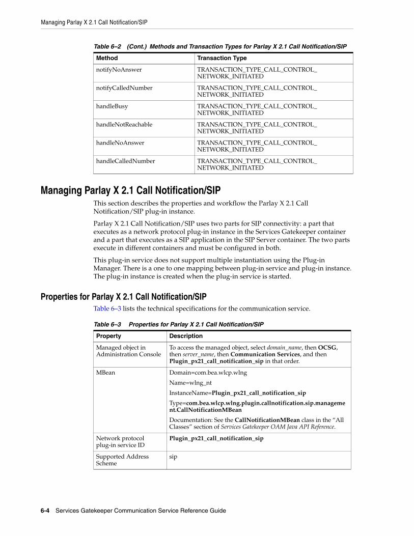
Managing Parlay X 2.1 Call Notification/SIP
6-4 Services Gatekeeper Communication Service Reference Guide
Managing Parlay X 2.1 Call Notification/SIPThis section describes the properties and workflow the Parlay X 2.1 Call Notification/SIP plug-in instance.
Parlay X 2.1 Call Notification/SIP uses two parts for SIP connectivity: a part that executes as a network protocol plug-in instance in the Services Gatekeeper container and a part that executes as a SIP application in the SIP Server container. The two parts execute in different containers and must be configured in both.
This plug-in service does not support multiple instantiation using the Plug-in Manager. There is a one to one mapping between plug-in service and plug-in instance. The plug-in instance is created when the plug-in service is started.
Properties for Parlay X 2.1 Call Notification/SIPTable 6–3 lists the technical specifications for the communication service.
notifyNoAnswer TRANSACTION_TYPE_CALL_CONTROL_NETWORK_INITIATED
notifyCalledNumber TRANSACTION_TYPE_CALL_CONTROL_NETWORK_INITIATED
handleBusy TRANSACTION_TYPE_CALL_CONTROL_NETWORK_INITIATED
handleNotReachable TRANSACTION_TYPE_CALL_CONTROL_NETWORK_INITIATED
handleNoAnswer TRANSACTION_TYPE_CALL_CONTROL_NETWORK_INITIATED
handleCalledNumber TRANSACTION_TYPE_CALL_CONTROL_NETWORK_INITIATED
Table 6–3 Properties for Parlay X 2.1 Call Notification/SIP
Property Description
Managed object in Administration Console
To access the managed object, select domain_name, then OCSG, then server_name, then Communication Services, and then Plugin_px21_call_notification_sip in that order.
MBean Domain=com.bea.wlcp.wlng
Name=wlng_nt
InstanceName=Plugin_px21_call_notification_sip
Type=com.bea.wlcp.wlng.plugin.callnotification.sip.management.CallNotificationMBean
Documentation: See the CallNotificationMBean class in the “All Classes” section of Services Gatekeeper OAM Java API Reference.
Network protocol plug-in service ID
Plugin_px21_call_notification_sip
Supported Address Scheme
sip
Table 6–2 (Cont.) Methods and Transaction Types for Parlay X 2.1 Call Notification/SIP
Method Transaction Type

Managing Parlay X 2.1 Call Notification/SIP
Parlay X 2.1 Call Notification/SIP 6-5
Configuration Workflow for Parlay X 2.1 Call Notification/SIPFollowing is an outline for configuring the plug-in using the Administration Console or an MBean browser.
1. Set up the routing rules to the plug-in instance. See the discussion about configuring and managing the plug-in manager in Services Gatekeeper System Administrator's Guide. Use the plug-in instance ID and address schemes listed in the "Properties for Parlay X 2.1 Call Notification/SIP" section.
2. If desired, create and load a node SLA. For details see the discussion on defining global node and service provider group node SLAs and managing SLAs in Services Gatekeeper Accounts and SLAs Guide.
3. Provision the service provider accounts and application accounts. For information, see Services Gatekeeper Portal Developer's Guide.
For a description of the fields and methods of the CallNotificationMBean class, see the “All Classes” section of Services Gatekeeper OAM Java API Reference.
Application-facing interfaces
com.bea.wlcp.wlng.px21.plugin.CallNotificationManagerPlugin
com.bea.wlcp.wlng.px21.plugin.CallDirectionManagerPlugin
com.bea.wlcp.wlng.px21.callback.CallNotificationCallback
Service type CallNotification
Exposes to the service communication layer a Java representation of:
Parlay X 2.1 Part 3: Call Notification
Interfaces with the network nodes using:
SIP: Session Initiation Protocol, RFC 3261
Deployment artifacts:
NT EAR
wlng_nt_call_notification_px21.ear
px21_call_notification_service.jar, plugin_px21_call_notification_sip.jar, and px21_call_notification_sip.war
Deployment artifacts:
AT EAR: Normal
wlng_at_call_notification_px21.ear
px21_call_notification.war, px21_call_notification_callback.jar, and rest_call_notification.war
Deployment artifacts:
AT EAR: SOAP Only
wlng_at_call_notification_px21_soap.ear
px21_call_notification.war and px21_call_notification_callback.jar
Table 6–3 (Cont.) Properties for Parlay X 2.1 Call Notification/SIP
Property Description

Managing Parlay X 2.1 Call Notification/SIP
6-6 Services Gatekeeper Communication Service Reference Guide

7
Parlay X 2.1 Multimedia Messaging/MM7 7-1
7Parlay X 2.1 Multimedia Messaging/MM7
This chapter describes the Oracle Communications Services Gatekeeper Parlay X 2.1 Multimedia Messaging/MM7 communication service in detail.
Overview of the Parlay X 2.1 Multimedia Messaging/MM7 Communication Service
The Parlay X 2.1 Multimedia Messaging/MM7 communication service exposes the Parlay X 2.1 Multimedia Messaging set of application interfaces.
The communication service acts as a Value Added Service (VAS) application connecting to an MMS relay server using the MM7 protocol.
For the exact version of the standards that the Parlay X 2.1 Multimedia Messaging/MM7communication service supports for the application-facing interfaces and the network protocols, see Services Gatekeeper Statement of Compliance.
Using a Multimedia Messaging communication service, an application can:
■ Send multimedia messages to one or many destination addresses. The payload in these multimedia messages can be any type that can be specified using MIME, including multipart messages.
■ Sign up to be notified that delivery receipts for sent multimedia messages have been received from the network.
■ Receive delivery receipts on sent multimedia messages that have arrived from the network.
■ Explicitly query Services Gatekeeper for delivery receipts on sent multimedia messages.
■ Sign up to be notified if specified multimedia messages for the application have been received from the network.
■ Receive notifications that specified multimedia messages for the application have arrived from the network. These notifications do not include the message payload, but they do provide a message ID.
■ Explicitly poll Services Gatekeeper for multimedia messages sent to the application that have arrived from the network and been stored in Services Gatekeeper.
Requests can flow in two directions. They can be application-initiated or network-triggered,

Overview of the Parlay X 2.1 Multimedia Messaging/MM7 Communication Service
7-2 Services Gatekeeper Communication Service Reference Guide
Processing Application-initiated RequestsAfter an application has sent a multimedia message to one or more destination addresses, two different types of response can be returned:
■ Send Receipts
■ Delivery Receipts
Send ReceiptsSend receipts are acknowledgements that the network node has received the multimedia message from the application by means of Services Gatekeeper. Although a single multimedia message may be sent to multiple destination addresses, normally only one send receipt is returned to the application. The receipt is returned synchronously in the response message to the sendMessage operation.
Delivery Receipts Delivery receipts contain the delivery status of the multimedia message. They report whether the multimedia message has actually been delivered to the mobile terminal by the network. There is one delivery receipt per destination address, with one of three possible outcomes:
■ Successful.
■ Unsuccessful: The multimedia message could not be delivered before it expired.
■ Unsupported: Delivery notification for this address is not supported. This can occur if the originating network supports delivery receipts but is unable to acquire the appropriate information for one or more destination addresses. This status is reported for each address for which this is the case.
Because actual delivery of the multimedia message may take several hours, or even days (if, for example, the mobile terminal is turned off at the time the multimedia message is sent), delivery receipts are returned asynchronously. Applications can either choose to have delivery receipts delivered to them automatically by supplying Services Gatekeeper with a callback interface or they can chose to poll Services Gatekeeper.
If the application supplies a callback interface, there are two possible outcomes:
■ Services Gatekeeper sends the delivery receipt and the application receives and acknowledges it.
■ Services Gatekeeper sends the delivery receipt but the application does not acknowledge reception. In this case, Services Gatekeeper stores the delivery receipt in temporary in-memory storage. The application can poll Services Gatekeeper for these receipts. Each stored delivery receipt is time stamped and, after a configurable time period, is removed.
If the application chooses not to supply a callback interface, Services Gatekeeper stores the delivery receipt in temporary in-memory storage. The application can poll Services Gatekeeper for these receipts. Each stored delivery receipt is time stamped and, after a configurable time period, removed.
Processing Network-triggered RequestsTwo types of traffic destined for an application can arrive at Services Gatekeeper from the network:

Overview of the Parlay X 2.1 Multimedia Messaging/MM7 Communication Service
Parlay X 2.1 Multimedia Messaging/MM7 7-3
■ Delivery receipts for application-initiated sent multimedia messages. See “Delivery Receipts” for more information.
■ Mobile-originated multimedia messages destined for the application
For an application to receive multimedia messages from the network, it must indicate its interest in these messages by registering for online notification in Services Gatekeeper. A notification is defined by a service activation number, which is the destination address of the multimedia message. The service activation number may be translated by some mechanism, such as short codes, in the telecom network. Use the StartMessageNotification method of the MessagingManagementMBean to register for online notification of network-triggered MMS messages from the Administration console. See the "All Classes" section of Services Gatekeeper OAM Java API Reference for details on the MessagingManagementMBean.
An application can also use the following operations to register for online notifications:
■ ParlayX 2.1 StartMessageNotification. See the 3GPP TS 29.199-05 Parlay X Web Services Part 5: Multimedia Messaging specification
■ REST Start Message Notification. See Services Gatekeeper Application Developer's Guide.
■ OneAPI Subscribe to MMS Delivery Notification. See Services Gatekeeper Application Developer's Guide.
An application can also register to receive multimedia messages offline. Services Gatekeeper stores the messages and delivers them when the application requests them. Use the enableReceiveMms method of MessagingManagementMBean to provision offline notification of network-triggered MMS messages.
Additional criteria can be tied to the service activation number, such as the start of the first plain/text part in the multimedia message payload or the subject of the multimedia message. For the message to be accepted by Services Gatekeeper, both the service activation number and any additional criteria must match the notification.
Mobile-originated messages to applications are routed based on the criteria that are specified when the notifications are created. The behavior for matching criteria is as follows:
■ If the subject of the message is not null, the subject is used for criteria matching the specified criteria.
■ If the subject of the message is null, the first word of first text attachment is used for matching the criteria.
■ If the criteria is not null, messages with no subject and no text attachment are not delivered to the application.
■ If the criteria is null, all messages are considered a match and delivered to the application.
Each registered notification must be unique, and notification attempts with overlapping criteria are rejected. The application can either retrieve received multimedia messages from Services Gatekeeper or include a callback interface when setting up the original notification.
Following are the possible scenarios for receipt and handling of multimedia messages.
1. The application has registered for online notification. Services Gatekeeper sends the message to the application, and the application receives the message and acknowledges receiving it.

Overview of the Parlay X 2.1 Multimedia Messaging/MM7 Communication Service
7-4 Services Gatekeeper Communication Service Reference Guide
If the MMS message is pure text, the text is included in the notification sent to the application.
If the MMS message is not pure text, the notification sent to the application includes a reference to the multimedia attachments. The application uses that reference to retrieve the attachments.
2. The application has registered for online notification. Services Gatekeeper sends the multimedia message to the application, but the application does not acknowledge receiving it.
Offline notification has been provisioned.
Services Gatekeeper stores the multimedia message. The application retrieves the message as described in "Retrieving Offline MMS Messages".
3. The application has registered for online notification. Offline notification has not been provisioned.
Services Gatekeeper sends the multimedia message to the application, but the application does not acknowledge receiving it. Services Gatekeeper returns an error to the network. It is the responsibility of the network to handle any further processing of the multimedia message.
4. The application has not registered for online notification. Offline notification has been provisioned. Services Gatekeeper stores the multimedia message.
The application retrieves the message as described in "Retrieving Offline MMS Messages".
5. The application has not registered an online subscription, and offline notification has not been provisioned.
Services Gatekeeper returns an error to the network. It is the responsibility of the network to handle any further processing of the multimedia message.
Retrieving Offline MMS Messages A ParlayX application fetches newly-arrived MMS messages with the getReceivedMessages operation. The response from this method is an array of MessageReference objects, one for each newly-arrived MMS message.
If an MMS message is pure text, the text message is included in the MessageReference object. If an MMS message is not pure text, the MessageReference object includes the reference to the multimedia attachments. The application then uses the reference to retrieve the attachment using the getMessage operation. See the 3GPP TS 29.199-05 Parlay X Web Services Part 5: Multimedia Messaging specification for a description of this operation.
The process is similar for REST applications. For information about getting MMS messages from a REST application, see the descriptions of the Get Received Messages and Get Message operations in the multimedia messaging chapter of Services Gatekeeper Application Developer's Guide.
For information about getting MMS messages from a OneAPI application, see the description about "Retrieve Messages Sent to Web Application".
Table 7–1 shows the MessageReference structure defined by the 3GPP TS 29.199-05 Parlay X Web Services Part 5: Multimedia Messaging specification. Elements related to this discussion are shown in boldface in Table 7–1.

Overview of the Parlay X 2.1 Multimedia Messaging/MM7 Communication Service
Parlay X 2.1 Multimedia Messaging/MM7 7-5
Example 7–1 shows the message and messageIdentifer in the REST Notification Data Object.
Example 7–1 REST Notification Data Object
{"notifyMessageReception": { "correlator": "String", "message": { "messageServiceActivationNumber": "String", "priority": "Default|Low|Normal|High", "senderAddress": "URI", "dateTime": "Calendar", "message": "String" --> if message is pure text it can be found here "messageIdentifier": "String", --> if not pure text the reference is found here "subject": "String" }}}
Each stored multimedia message is time stamped and, after a configurable time period, removed.
The OneAPI response to a request for the full MMS message including attachments is a multipart/form-data response in which the JSON message text and metadata are separated from the multimedia attachments by a separator that has the form
====12345====
The resourceURL in the response is the link to the message. The application uses this value to retrieve the entire message, including the attachments. Example 7–2 shows the structure of a response.
Table 7–1 ParlayX Message Reference Structure
Element name Element type Optional Description
messageIdentifier
xsd:string Yes If present, contains a reference to a message stored in the ParlayX gateway. If the message is pure text, this parameter is not present.
messageService
ActivationNumber
xsd:string No Number associated with the invoked Message service, i.e. the destination address used by the terminal to send the message.
senderAddress xsd:anyURI No Indicates message sender address.
subject xsd:string Yes If present, indicates the subject of the received message. This parameter will not be used for SMS services.
priority MessagePriority No The priority of the message: default is Normal.
message xsd:string Yes If present, then the messageIdentifier is not present and this parameter contains the whole message. The type of the message is always pure ASCII text in this case. The message will not be stored in the Parlay X gateway.
dateTime xsd:dateTime Yes Time when message was received by operator

Application Interfaces
7-6 Services Gatekeeper Communication Service Reference Guide
Example 7–2 OneAPI Response Body for Retrieving Full MMS messages
"inboundMessage": [{ "dateTime": "dateTime","destinationAddress": "String","messageId": "String", --> server-geenerated message identifier"inboundMMSMessage": "String", --> subject of the message"resourceURL": "URL", --> link to the full message and attachments"senderAddress": "String"},
====Content Divider====
Attachment(s)
Polling FunctionalityThe polling capability for retrieving offline notifications must be provisioned in advance.
To configure the polling capability:
■ Set the RequestDeliveryReportFlag attribute to non-zero. See this attribute of the M for information about valid values.
■ Use the enableReceiveMms operation to allow applications to poll for mobile-originated messages. See the description of the enableReceiveMms method of MessagingManagementMBean in Services Gatekeeper OAM Java API Reference for more information.
Short Code TranslationMessaging-capable networks use short codes and message prefixes to help route traffic and to make access to certain features easier for the end user. Instead of having to use the entire address, users can enter a short code that is mapped to the full address in the network. The Parlay X 2.1 Multimedia Messaging/MM7 communication service supports short codes and message prefixes, which allow the same short code to be mapped to multiple addresses based on the prefix to the enclosed message.
Application InterfacesThe SOAP-based interface for the Parlay X 2.1 MultiMedia Messaging/MM7 communication service are described in the discussion of Parlay X 2.1 Part 5: Multimedia Messaging in Services Gatekeeper Application Developer's Guide.
For information about the RESTful Call Notification interface, see the discussion of Multimedia Messaging in Services Gatekeeper Application Developer's Guide.
The RESTful Service Multimedia Messaging interfaces provide RESTful access to the same functionality as the SOAP-based interfaces. The internal representations are identical, and for the purposes of creating service level agreements (SLAs), reading (charging data records) CDRs, and so on, they are the same.
Events and StatisticsThe Parlay X 2.1 Multimedia Messaging/MM7 communication service generates event data records (EDRs), CDRs, alarms, and statistics to assist system administrators and developers in monitoring the service.
See "Events, Alarms, and Charging" for general information.

Tunneled Parameters for Parlay X 2.1 MM7 Rel 6.8.0
Parlay X 2.1 Multimedia Messaging/MM7 7-7
Event Data RecordsTable 7–2 lists the IDs of the EDRs created by the Parlay X 2.1 Multimedia Messaging/MM7 communication service.
Charging Data RecordsMultimedia Messaging/MM7-specific CDRs are generated under the following conditions:
■ After Services Gatekeeper successfully sends a sendMessage request to the network.
■ After Services Gatekeeper successfully receives and processes a delivery report sent from the network.
■ After Services Gatekeeper successfully receives and processes a mobile-originated message sent from the network.
StatisticsTable 7–3 maps methods invoked from either the application or the network to the transaction types collected by the Services Gatekeeper statistics counters.
AlarmsFor the list of alarms, see Services Gatekeeper Alarms Handling Guide.
Tunneled Parameters for Parlay X 2.1 MM7 Rel 6.8.0This section lists, by parameter key, the parameters that can be tunneled or defined in the <requestContext> element of an SLA.
ChargedParty
DescriptionSpecifies the party to be charged for a multimedia message submitted by the Value-Added Service Provider (VASP).
Table 7–2 EDRs Generated by Parlay X 2.1 Multimedia Messaging/MM7
EDR ID Description
8100 A (mobile-originated) MO message has arrived from the network.
8101 An MO delivery receipt has arrived from the network.
8102 The application has requested that a notification be started.
8103 The application has requested that a notification be stopped.
8104 The application has polled for a list of received messages.
8106 The application has polled for actual messages, returned as attachments.
Table 7–3 Methods and Transaction Types for Parlay X 2.1 Multimedia Messaging/MM7
Method Transaction Type
sendMessage TRANSACTION_TYPE_MESSAGING_MMS_SEND
deliver TRANSACTION_TYPE_MESSAGING_MMS_RECEIVE

Tunneled Parameters for Parlay X 2.1 MM7 Rel 6.8.0
7-8 Services Gatekeeper Communication Service Reference Guide
If defined, the ChargedParty xparameter is forwarded in the SOAP header in the north-bound interface.
Validated by the plug-in.
FormatString
ValueValid values: Sender, Recipient, Both, Neither
ChargedPartyCD
DescriptionSpecifies the address of the third party expected to pay for the multimedia message.
If defined, the ChargedPartyID xparameter is forwarded in the SOAP header in the north-bound interface.
FormatString
timeStamp
DescriptionSpecifies date and time that the multimedia message was submitted.
FormatDate/Time
expiryDate
DescriptionSpecifies the desired time for the expiration of the multimedia message.
FormatDate/Time
allowAdaptation
DescriptionSpecifies if VASP allows adaptation of the content.
Set to true to allow adaptation, false to prohibit it.
FormatBoolean
DeliveryCondition
DescriptionIn the event of a single Delivery Condition, if the condition is met, the multimedia message is delivered to the recipient MMS User Agent. Otherwise the message is discarded.

Managing Parlay X 2.1 Multimedia Messaging/MM7
Parlay X 2.1 Multimedia Messaging/MM7 7-9
Validated by the plug-in.
FormatPositive Integer
UAProf
DescriptionSpecifies the UserAgent Name or URL to the UAProfile (resource description framework) RDF.
Used for transferring user agent capabilities from R/S to value-added service provider (VASP).
If not null, this parameter is forwarded to the application.
FormatString
StatusText
DescriptionHuman-readable description of the numerical code that indicates the general type of an error.
If not null, this parameter is forwarded to the application.
FormatString
Managing Parlay X 2.1 Multimedia Messaging/MM7This section describes the properties and workflow for Parlay X 2.1 Multimedia Messaging/MM7 plug-in instances.
Properties for Parlay X 2.1 Multimedia Messaging/MM7Table 7–4 lists the technical specifications for the communication service.
Table 7–4 Properties for Multimedia Messaging/MM7
Property Description
Managed object in Administration Console
To access the object, select domain_name, then OCSG, server_name, Communication Services, and then the plug-in_instance_id, in that order.
MBean Domain=com.bea.wlcp.wlng
Name=wlng_nt
InstanceName=same as the network protocol instance_id assigned when the plug-in instance is created
Type=com.bea.wlcp.wlng.plugin.multimediamessaging.mm7.management.MessagingManagementMBean
Documentation: For information on MessagingManagementMBean, see the “All Classes” section of Services Gatekeeper OAM Java API Reference.

Managing Parlay X 2.1 Multimedia Messaging/MM7
7-10 Services Gatekeeper Communication Service Reference Guide
Configuration Workflow for Parlay X 2.1 MultiMedia Messaging/MM7Following is an outline for configuring the plug-in using the Administration Console or an MBean browser.
1. Create one or more instances of the plug-in service. See the discussion about configuring and managing the plug-in manager in Services Gatekeeper System Administrator's Guide. Use the plug-in service ID listed in "Properties for Parlay X 2.1 Multimedia Messaging/MM7".
2. Select the MBean for the plug-in instance. The MBean display name is the same as the plug-in instance ID given when the plug-in instance was created.
3. Configure the behavior of the plug-in instance using the following attributes in MessagingManagementMBean:
■ HTTPBasicAuthentication
Network protocol plug-in service ID
Plugin_px21_multimedia_messaging_mm7
Network protocol plug-in instance ID
The ID is assigned when the plug-in instance is created. See the discussion on configuring and managing the plug-in manager in Services Gatekeeper System Administrator's Guide.
Supported Address Scheme
tel, mailto, short
Application-facing interfaces
com.bea.wlcp.wlng.px21.plugin.MessageNotificationManagerPlugin
com.bea.wlcp.wlng.px21.plugin.ReceiveMessagePlugin
com.bea.wlcp.wlng.px21.plugin.SendMessagePlugin
com.bea.wlcp.wlng.px21.callback.MessageNotificationCallback
Service type MultimediaMessaging
Exposes to the service communication layer a Java representation of:
Parlay X 3.0 Part 5: Multimedia Messaging
Interfaces with the network nodes using:
MM7
Deployment artifact:
NT EAR
wlng_nt_multimedia_messaging_px21.ear
plugin_px21_multimedia_messaging_mm7.jar, px21_multimedia_messaging_service.jar, multimedia_messaging_mm7_rel5mm712.war, and multimedia_messaging_mm7_rel5mm715.war
Deployment artifact:
AT EAR: Normal
wlng_at_multimedia_messaging_px21.ear
px21_multimedia_messaging_callback.jar, px21_multimedia_messaging.war, and rest_multimedia_messaging.war
Deployment artifact:
AT EAR: SOAP Only
wlng_at_multimedia_messaging_px21_soap.ear
px21_multimedia_messaging_callback.jar and px21_multimedia_messaging.war
Table 7–4 (Cont.) Properties for Multimedia Messaging/MM7
Property Description

Managing Parlay X 2.1 Multimedia Messaging/MM7
Parlay X 2.1 Multimedia Messaging/MM7 7-11
If you are using HTTP basic authentication, also define:
– HTTPBasicAuthenticationUsername
– HTTPBasicAuthenticationPassword
■ DefaultPriority
■ MM7Version
■ Mm7relayserverAddress
■ VaspId
■ VasId
■ RequestDeliveryReportFlag
■ XSDVersion
For more information on the fields and methods of MessagingManagementMBean, see the "All Classes" section of Services Gatekeeper OAM Java API Reference.
4. Specify heartbeat behavior. See the discussion about configuring heartbeats in Services Gatekeeper System Administrator's Guide.
5. Set up the routing rules to the plug-in instance. See the discussion about configuring and managing the plug-in manager in Services Gatekeeper System Administrator's Guide. Use the plug-in instance ID and address schemes listed in "Properties for Parlay X 2.1 Multimedia Messaging/MM7".
6. Provide the administrator of the MM7 server with the URL to which the MM7 server should deliver mobile originated messages and delivery reports. The default URL is:
http://IP_Address_of_NT_server:port/context-root/plug-in_instance_IDIf you are using the REL-5-MM7-1-2 XSD, the default context-root is mmm-mm7.
If you are using the REL-5-MM7-1-5 XSD, the default context-root is mmm-mm7-rel5mm7-1-5.
If you are using the REL-6-MM7-1-4 XSDm the default context-root is mmm-mm7-rel6mm7-1-4.
7. If required, create and load a node SLA. For details see the discussion about defining global node and service provider group node SLAs and managing SLAs in Services Gatekeeper Accounts and SLAs Guide.
8. Provision the service provider accounts and application accounts. For information, see Services Gatekeeper Portal Developer's Guide.
Provisioning Parlay X 2.1 MultiMedia Messaging/MM7 Communication ServiceTo provision the Parlay X 2.1 MultiMedia Messaging/MM7 communication service, do the following:
■ Enable mobile-oriented messages to be stored in Services Gatekeeper for polling by applications, by using the enableReceiveMms method of MessagingManagementMBean.
■ Set up for notifications about mobile-originated messages on behalf of an application, by using the startMessageNotification method of MessagingManagementMBean.
Managing Parlay X 2.1 Multimedia Messaging/MM7
7-12 Services Gatekeeper Communication Service Reference Guide
■ Manage offline notifications, by using the following methods of MM7NotificationMBean:
– listOfflineNotificationInfo
– getOfflineNotificationInfo
– removeOfflineNotificationInfo
■ Manage offline notifications, by using the following methods of MM7NotificationMBean:
– listOnlineNotificationInfo
– getOnlineNotificationInfo
– removeOnlineNotificationInfo
For a description of the attributes and operations of the MessagingManagementMBean and MM7NotificationMBean MBeans, see the "All Classes" section of Services Gatekeeper OAM Java API Reference.

8
Parlay X 2.1 Multimedia Messaging/SMTP, POP3, and IMAP 8-1
8Parlay X 2.1 Multimedia Messaging/SMTP,POP3, and IMAP
This chapter describes the Oracle Communications Services Gatekeeper Parlay X 2.1 Multimedia Messaging/SMTP, POP3, and IMAP protocols.
Overview of the Parlay X 2.1 Multimedia Messaging/SMTP, POP3, and IMAP Communication Service
The Parlay X 2.1 Multimedia Messaging/SMTP, POP3, and IMAP communication service exposes the Parlay X 2.1 Multimedia Messaging set of application interfaces.
The communication service acts as a Value Added Service (VAS) application connecting to an email server using the SMTP, POP3, and IMAP protocols. It provides the capability of applying policy such as throttling and black listing to manage and regulate the flow of email.
For the exact version of the standards that the Parlay X 2.1 Multimedia Messaging/SMTP, POP3, and IMAP communication service supports for the application-facing interfaces and the network protocols, see the Services Gatekeeper Statement of Compliance.
Using this communication service, an application can:
■ Send email messages to one or more destination addresses. The attachments in these email messages can be of any type that can be specified using MIME.
■ Sign up to be notified that delivery receipts for sent email messages have been delivered to the email server.
■ Receive delivery receipts on sent or retrying email messages.
■ Explicitly query Services Gatekeeper for delivery receipts on sent email messages.
■ Sign up to be notified when specified email messages for the application have been received from the email server.
■ Receive notifications that specified email messages for the application have been received from the email server. These notifications provide a message ID, but do not include the message payload.
■ Explicitly poll Services Gatekeeper for email messages sent to the application that have arrived from the email server and been stored in Services Gatekeeper.
Requests can flow in two directions. They can be application-initiated or network-triggered.

Overview of the Parlay X 2.1 Multimedia Messaging/SMTP, POP3, and IMAP Communication Service
8-2 Services Gatekeeper Communication Service Reference Guide
Processing Application-Initiated RequestsApplication-initiated requests can be:
■ Send Requests
■ Send Receipts
■ Delivery Receipts
■ Retry Requests
Send RequestsWhen an application sends a request using Parlay X 2.1 Multimedia Messaging protocol to Services Gatekeeper, if the sender address and destination addresses start with the schema email:, Services Gatekeeper transforms the request to an email and uses SMTP protocol to send the request to an email server.
■ Routing mechanism
For this communication service, each plug-in instance connects to an email server by SMTP. Routing should be based on sender address but not destination address. In PluginManager MBean, when adding a route for the email plug-in instance, the value should use ^.* to match all addresses, for example, ^.*@oracle.com$. This means that the plug-in instance connects to oracle email server and all the requests with a sender address that matches the regular expression should be routed to this plug-in instance.
■ SMTP connections management
Each email plug-in instance creates an SMTP connection pool. The connections in the pool connect to SMTP server separately. Each connection can be in IDLE, BUSY, or DISCONNECT status and should send heartbeat to maintain itself. If disconnected, it should reconnect to SMTP server. When a plug-in instance receives a new request, it should select a connection in IDLE status from the pool, and set it to BUSY status. If the connection fails, enlarge the pool until it reaches the maximum connection number. If it still fails, the plug-in instance sends the request to the retry manager.
■ Email subject, body and attachments
When transforming the Parlay X 2.1 Multimedia Messaging request to an email message, set subject in email with the subject value in the original request. For email body and attachments, since there are only attachments in the original request, add an X-Parameter ContentInFirstAttachment to indicate whether there is an email body or not. If this X-Parameter is set to true, or is absent, then the first attachment contains the email body and other attachments are handled as regular attachments. If this X-Parameter is set to false, then all attachments are handled as regular attachments and the email body is blank.
■ Multiple destination addresses
For a request with multiple destination addresses, since Services Gatekeeper cannot use the common routing mechanism as mentioned above, the plug-in instance should be responsible for splitting single email into multiple email messages and sending it to each address.
Send ReceiptsFor this communication service, send receipts are acknowledgements that Services Gatekeeper has received the request from the application by means. The result values in the send receipts are UUIDs (universally unique identifiers) created by Services

Overview of the Parlay X 2.1 Multimedia Messaging/SMTP, POP3, and IMAP Communication Service
Parlay X 2.1 Multimedia Messaging/SMTP, POP3, and IMAP 8-3
Gatekeeper used to correlate subsequent delivery receipts at a later time. Although a single email message may be sent to multiple destination addresses, only one send receipt is returned to the application. The receipt is returned synchronously in the response message to the sendMessage operation.
Delivery Receipts Delivery receipts contain the final delivery status of the email message. They report whether the email message has actually been delivered to the delivery recipient by the network. There is one delivery receipt per destination address, with one of four possible outcomes:
■ DeliveryUncertain (the initial status)
■ DeliveredToNetwork
■ MessageWaiting (retry status)
■ DeliveryImpossible (message could not be delivered since the retry limit was exceeded)
Applications can either choose to have delivery receipts delivered to them automatically by supplying Services Gatekeeper with a callback interface or they can choose to poll Services Gatekeeper.
When Services Gatekeeper receives a request from an application, it creates an UUID and returns that UUID in the send receipts to application. It stores the delivery receipt for each destination address with initial status in temporary in-memory storage with the UUID and callback interface (if any).
After Services Gatekeeper sends an email successfully or fails to do so, it updates the delivery receipt in the in-memory store, if a callback interface exists, and sends the delivery receipt to notify the application.
If the application does not supply a callback interface, the application can poll Services Gatekeeper with the UUID for these stored delivery receipts.
DeliveredToNetwork and DeliveryImpossible are final delivery statuses. The stored delivery receipt should be removed if the status for all the destination addresses belonging to one UUID is a final status and are delivered to application callback interface or have been polled by application.
Each stored delivery receipt is time stamped. After a configurable time period, the stored delivery receipt is removed.
Retry RequestsWhen Services Gatekeeper sends an email which temporarily fails for any reason (such as no connection), it stores the request in storage, updates the status to MessageWaiting for this request, and sends a delivery receipt to the application (if a callback interface was provided).
After a configurable time interval, Services Gatekeeper retrieves the failed request from the store and attempts to resend the request. The number of retry attempts are also configurable.
If retry attempt for the send request succeeds, Services Gatekeeper updates the status to DeliveredToNetwork for this request and sends a delivery receipt.
If the number of retry attempts are exhausted and the send request has not succeeded, Services Gatekeeper updates the status to DeliveryImpossible for this request and creates a delivery receipt indicating the failure.

Overview of the Parlay X 2.1 Multimedia Messaging/SMTP, POP3, and IMAP Communication Service
8-4 Services Gatekeeper Communication Service Reference Guide
Processing Network-Triggered RequestsFor an application to receive email messages from the network, it must indicate its interest in these messages by registering for online notification in Services Gatekeeper. A notification is defined by a service activation number, which is the destination address of the email. An application can use the following operations to register for online notification:
■ ParlayX 2.1 StartMessageNotification. See the Parlay X Web Services Part 5: Multimedia Messaging specification listed in Services Gatekeeper Statement of Compliance.
■ Use the startMessageNotification operation of EmailManagementMBean to register for online notification from the Administration console.
An application can also register to receive email messages offline. Services Gatekeeper stores the messages and delivers them when the application requests them. Use the enableReceiveEmail operation of EmailManagementMBean from the Administration console to provision offline notification of network-triggered email messages. See the "All Classes" section of Services Gatekeeper OAM Java API Reference for details on EmailManagementMBean.
Extensions to ParlayX 2.1 interface include:
■ X-Parameter Password to indicate the credential of the email service activation number. The value should be encrypted by AES (Advanced Encryption Standard) or 3DES (Triple Data Encryption Standard) algorithm.
■ X-Parameter SizeLimit to indicate the maximum total size (in kilobyte) of an email message attachment accepted by Services Gatekeeper.
■ Each registered notification must be unique, and notification attempts with overlapping service activation number are rejected.
When Services Gatekeeper receives an online/offline notification request, it starts a POP3 or IMAP process according to the configuration. When using POP3, Services Gatekeeper uses the polling mechanism and retrieves email messages from email server using a configurable interval. When using IMAP, Services Gatekeeper attempts to utilize IDLE mechanism (whereby when new email messages arrive it is notified by the email server and retrieves the email). If the email server does not support the IDLE mechanism, then Services Gatekeeper falls back to the polling solution.
When using POP3 or IMAP3 protocols, Services Gatekeeper handles email messages it receives in the following ways:
■ The application has registered for online notification. Services Gatekeeper sends the message to the application, and the application receives the message and acknowledges receiving it.
If the email only has pure text body without attachments, the text is included in the notification sent to the application.
If the email message is not pure text, the notification sent to the application includes a reference to the attachments stored in storage. The application uses that reference to retrieve the attachments.
■ Offline notification has been provisioned. Services Gatekeeper stores the email. The application retrieves the message as described in "Retrieving Offline Messages".

Events and Statistics
Parlay X 2.1 Multimedia Messaging/SMTP, POP3, and IMAP 8-5
Retrieving Offline MessagesA ParlayX application fetches newly-arrived email messages with the getReceivedMessages operation. The response from this method is an array of MessageReference objects, one for each newly-arrived email message.
If an email message is pure text, the text message is included in the MessageReference object. If an email message is not pure text, the MessageReference object includes the reference to the attachments. The application then uses the reference to retrieve the attachment using the getMessage operation. See the Parlay X Web Services Part 5: Multimedia Messaging specification listed in theServices Gatekeeper Statement of Compliance for descriptions of this operation.
Application InterfacesFor information about the SOAP-based interface for the Parlay X 2.1 MultiMedia Messaging/MM7 communication service, see the discussion about Parlay X 2.1 Part 5: Multimedia Messaging in Services Gatekeeper Application Developer's Guide.
For information about the RESTful interface, see the discussion about the multimedia messaging interface in Services Gatekeeper Application Developer's Guide.
The RESTful Service interfaces provide RESTful access to the same functionality as the SOAP-based interfaces. The internal representations are identical, and for the purposes of creating service level agreements (SLAs), reading charging data records (CDR), and so on, they are the same.
This communication service uses a plug-in which enables applications to send email using Simple Mail Transfer Protocol (SMTP) and receive email using Post Office Protocol (POP) version 3 and Internet Message Access Protocol (IMAP).
See Services Gatekeeper Statement of Compliance for details on the SMTP, POP and IMAP interfaces supported.
Events and StatisticsThe Parlay X 2.1 MultiMedia Messaging/SMTP, POP3, and IMAP communication service generates event data records (EDRs), CDRs, and alarms to assist system administrators and developers in monitoring the service.
See "Events, Alarms, and Charging" for general information.
Event Data Records Table 8–1 lists the IDs of the EDRs created by the Parlay X 2.1 MultiMedia Messaging/SMTP, POP3, and IMAP communication service. It does not include EDRs created when exceptions are thrown.
Table 8–1 EDRs Generated by Email Communication Service
EDR ID Method Called
8107 SendMessage
8108 getMessageDeliveryStatus
8102 startMessageNotification
8103 stopMessageNotification
8104 getReceivedMessages

Managing Parlay X 2.1 MultiMedia Messaging/SMTP, POP3, and IMAP
8-6 Services Gatekeeper Communication Service Reference Guide
Charging Data Records MultiMedia Messaging/SMTP, POP3, and IMAP CDRs are generated under the following conditions:
■ When an email has been sent from Services Gatekeeper to the email server
■ When an email received from the email server.
AlarmsFor the list of alarms, see Services Gatekeeper Alarms Handling Guide.
Managing Parlay X 2.1 MultiMedia Messaging/SMTP, POP3, and IMAPThis section describes the properties and workflow for Parlay X 2.1 Multimedia Messaging/SMTP, POP3, and IMAP plug-in instances.
Properties for Parlay X 2.1 MultiMedia Messaging/SMTP, POP3, and IMAPTable 8–2 lists the technical specifications for the communication service.
8106 getMessage
8110 notifyMessageDeliveryReceipt
8111 notifyMessageReception
8120 submit email to email server
8121 delivery receipt for email
8122 receive email from email server
Table 8–2 Properties for MultiMedia Messaging/SMTP, POP3, and IMAP
Property Description
Managed object in Administration Console
sendMessagedomain_name > OCSG > server_name > Communication Services > plug-in_instance_id
MBean Domain=com.bea.wlcp.wlng
Name=wlng_nt
InstanceName=same as the network protocol instance_id assigned when the plug-in instance is created
Type=oracle.ocsg.plugin.multimediamessaging.email.management.EmailManagementMBean
Network protocol plug-in service ID
Plugin_px21_multimedia_messaging_email
Network protocol plug-in instance ID
The ID is assigned when the plug-in instance is created. See the description for SGADM456
Supported Address Scheme email
Table 8–1 (Cont.) EDRs Generated by Email Communication Service
EDR ID Method Called

Managing Parlay X 2.1 MultiMedia Messaging/SMTP, POP3, and IMAP
Parlay X 2.1 Multimedia Messaging/SMTP, POP3, and IMAP 8-7
Configuration Workflow for Parlay X 2.1 MultiMedia Messaging/SMTP, POP3, and IMAPUse the following procedure to configure the plug-in instance using the Administration Console or an MBean browser:
1. Create one or more instances of the plug-in service. See the section on configuring and managing the plug-in manager in Services Gatekeeper System Administrator's Guide.
Use the plug-in service ID listed in "Properties for Parlay X 2.1 MultiMedia Messaging/SMTP, POP3, and IMAP".
2. Select the MBean for the plug-in instance. The MBean display name is the same as the plug-in instance ID given when the plug-in instance was created.
3. Configure the behavior of the plug-in instance using attributes related to the SMTP/POP3/IMAP protocols according to email server information.
4. Set up the routing rules to the plug-in instance.
See the section on configuring and managing the plug-in manager in Services Gatekeeper System Administrator's Guide.
Use the plug-in instance ID and address schemes listed in "Properties for Parlay X 2.1 MultiMedia Messaging/SMTP, POP3, and IMAP".
5. If required, create and load a node SLA. For details see the discussion on defining global node and service provider group node SLAs and managing SLAs in Services Gatekeeper Accounts and SLAs Guide.
6. Provision the service provider accounts and application accounts.
Application-facing interfaces
com.bea.wlcp.wlng.px21.plugin.MessageNotificationManagerPlugin
com.bea.wlcp.wlng.px21.plugin.ReceiveMessagePlugin
com.bea.wlcp.wlng.px21.plugin.SendMessagePlugin
com.bea.wlcp.wlng.px21.callback.MessageNotificationCallback
Service type MultimediaMessaging-ParlayRestMms
Exposes to the service communication layer a java representation of:
Parlay X 2.1 Part 5: Multimedia Messaging
Protocols used for interfaces with the network nodes
SMTP, POP3, and SMTP
Deployment artifact:
NT.EAR
wlng_nt_multimedia_messaging_px21.ear
Plugin_px21_multimedia_messaging_mm7.jar
Plugin_px21_multimedia_messaging_email.jar
px21_multimedia_messaging_service.jar
multimedia_messaging_mm7_rel5mm712.war
multimedia_messaging_mm7_rel5mm715.war
Deployment artifact:
AT EAR: Normal
wlng_at_multimedia_messaging_px21.ear
px21_multimedia_messaging_callback.jar
px21_multimedia_messaging.war
rest_multimedia_messaging.war
Table 8–2 (Cont.) Properties for MultiMedia Messaging/SMTP, POP3, and IMAP
Property Description

Managing Parlay X 2.1 MultiMedia Messaging/SMTP, POP3, and IMAP
8-8 Services Gatekeeper Communication Service Reference Guide
Provisioning Workflow for Parlay X 2.1 MultiMedia Messaging/SMTP, POP3, and IMAPYou can provision the Parlay X 2.1 MultiMedia Messaging communication service for the supported protocols (SMTP, POP3, or IMAP) in the following way:
1. Configure the connections to the email server for the required protocol.
Use the attributes of EmailManagementMBean appropriate for the protocol.
2. Enable the connection for SMPTP and IMAP3 protocols, by calling the appropriate method of EmailManagementMBean. For the POP3 protocol, the configuration takes effect immediately. It does not require such explicit connection activation.
3. Enable mobile-oriented messages to be stored in Services Gatekeeper for polling by applications, by using the enableReceiveEmail method of EmailManagementMBean.
4. Manage offline notifications by using the following methods of EmailManagementMBean:
■ listOfflineNotificationInfo
■ getOfflineNotificationInfo
■ removeOfflineNotificationInfo
5. Manage online notifications by using the following methods of EmailManagementMBean:
■ listOnlineNotificationInfo
■ getOnlineNotificationInfo
■ removeOnlineNotificationInfo
For a description of the fields and methods of the EmailManagementMBean MBean, see the "All Classes" section of Services Gatekeeper OAM Java API Reference.
Tip: To monitor the status of each connection in the connection pool use, call the appropriate method of the MBean (listSMTPConnection, listPOP3Process, or listImap3Process).

9
Parlay X 2.1 Presence/SIP 9-1
9Parlay X 2.1 Presence/SIP
This chapter describes the Oracle Communications Services Gatekeeper Parlay X 2.1 Presence/SIP communication service in detail.
Overview of the Parlay X 2.1 Presence/SIP Communication ServiceThe Parlay X 2.1 Presence/SIP communication service exposes both the watcher aspect and the presentity aspect of the Parlay X 2.1 Presence set of application interfaces.
The communication service connects to a SIP-IMS network using Oracle Converged Application Server. Converged Application Server is collocated with Services Gatekeeper in the network tier.
For the exact version of the standards that the Parlay X 2.1 Presence/SIP communication service supports for the application-facing interfaces and the network protocols, see Services Gatekeeper Statement of Compliance.
The Parlay X 2.1 Presence/SIP communication service supports the Rich Presence Information Data (RPID) parser with the Open Mobile Alliance (OMA) extensions.
Presence information is a collection of data on an end user’s status, such as current activity, environment, available communication means, and contact addressees. Using the presence functionality, an application can function as a client in two modes: as a watcher or as a presentity. A watcher is a client that is interested in consuming presence information. A presentity is a client that allows its presence information to be delivered to watchers.
Client as Presence ConsumerAn application acting as a watcher can:
■ Subscribe to obtain presence data.
Each subscription requires authorization by the presentity. The authorization is returned asynchronously via the notification interface.
■ Choose to acquire presence information when a subscription has been established using:
– Direct synchronous polling. This is only effective for a single presentity. Groups are not supported.
– Specific notifications. These can be used for a single presentity. The watcher sets a notification trigger based on certain user presence attribute changes.
Possible attribute types include:
* Activity (User’s status: Available, Busy, At Lunch, and so on.)

Application Interfaces
9-2 Services Gatekeeper Communication Service Reference Guide
* Place (User’s current location: Home, In a Public Place, and so on.)
* Privacy (Degree of privacy the user has: Surrounded by Others, Alone and Can Talk Openly, and so on.)
* Sphere (User’s personal status: In his Work Capacity; In his Personal Capacity)
* Communication means (Type of communication client preferred: Phone, Email, SMS, and so on.)
* Other (name-value pair for arbitrary information)
Non-attribute notification parameters can include:
* Maximum frequency of notifications
* Duration of time during which notifications should occur
* Maximum number of notifications
* Whether status should be checked immediately after notification setup
■ End notifications. In this case, the subscription to the presentity is retained, but the specific notification is ended.
■ Receive information that:
– The initial conditions of the notification setup have been met (count or duration) and this specific setup has been ended.
– The subscription itself has ended.
Client as Presence SupplierAn application acting as a presentity can:
■ Publish present information.
■ Get a list of new watchers who have asked to subscribe to the client’s presence information.
■ Approve new watchers and update the subscriptions of current watchers.
■ Get a list of currently subscribed watchers.
■ Block the subscription of a currently subscribed watcher.
The presentity functionality requires a presence server in the underlying network. To approve new watchers and update the subscriptions of current watchers, there must also be a data manipulation server (DMS) in the underlying network. The block functionality is supported in two modes, one using a DMS and one not.
Application InterfacesFor information about the SOAP-based interface for the Parlay X 2.1 Presence communication service, the discussion about Parlay X 2.1 Part 14: Presence Interfaces in Services Gatekeeper Application Developer's Guide.
Information on the RESTful Presence interface is provided in the discussion about the interface in Services Gatekeeper Application Developer's Guide.
The RESTful Service Call Notification interfaces provide RESTful access to the same functionality as the SOAP-based interfaces. The internal representations are identical,

Events and Statistics
Parlay X 2.1 Presence/SIP 9-3
and for the purposes of creating service level agreements (SLAs), reading charging data records (CDRs), and so on, they are the same.
Events and StatisticsThe Parlay X 2.1 Presence/SIP communication service generates event data records (EDRs), CDRs), alarms, and statistics to assist system administrators and developers in monitoring the service.
See "Events, Alarms, and Charging" for more information.
Event Data RecordsTable 9–1 lists IDs of the EDRs created by the Presence/SIP communication service. This list does not include EDRs created when exceptions are thrown.
Charging Data RecordsPresence/SIP-specific CDRs are generated under the following conditions:
■ After the result of a poll for presence is successfully returned to the application.
■ After a notification for presence information is successfully sent to the application.
A Presence CDR contains an additional_info field for a notification call. This field contains the endpoint.
StatisticsTable 9–2 maps methods invoked from either the application or the network to the transaction types collected by the Services Gatekeeper statistics counters.
Table 9–1 EDRs Generated by Parlay X 2.1 Presence/SIP
EDR ID Method Called
2000 notifyReceived
2001 makeNotifySubscriptionCallback (includes Endpoint, string)
2002 makeSubscriptionEndedCallback (includes Endpoint, string)
2003 makeStatusChangedCallback (includes Endpoint, string)
2004 makeStatusEndCallback (includes Endpoint, string)
2005 subscribePresence (processes from application)
2006 getUserPresence
2007 startPresenceNotification
2008 endPresenceNotification
2009 publish
2010 blockSubscription
2011 getMyWatchers
2012 getOpenSubscriptions
2013 updateSubscriptionAuthorization
2015 onRequest (Watcher Info Notify)

Tunneled Parameters for Parlay X 2.1 Presence / SIP
9-4 Services Gatekeeper Communication Service Reference Guide
AlarmsFor the list of alarms, see Services Gatekeeper Alarms Handling Guide.
Tunneled Parameters for Parlay X 2.1 Presence / SIPThis section lists the parameters that can be tunneled.
expireskey
DescriptionThis value is used to cancel a subscription to a user presence. The parameter is configured in the SIP plug-in.
If set, this value replaces the default SubscribeExpiryValue configured in the PresenceMBean.
Can be set using parameter tunneling.
FormatString
Example<xparams> <param key="expireskey" value="1210"/> </xparams>
passidkey
DescriptionThis value is used among trusted intermediaries to assert the identity of a user sending a SIP message as it was identified by authentication.
Can be set using parameter tunneling.
FormatString
Example<xparams> <param key="passidkey" value="sip:[email protected]"/> </xparams>
Managing Parlay X 2.1 Presence/SIPThis section describes the properties and workflow for the Parlay X 2.1 Presence/SIP plug-in instance. It also describes the caches used by the plug-in instance.
Parlay X 2.1 Presence/SIP uses two parts for SIP connectivity: a part that executes as a network protocol plug-in instance in the Services Gatekeeper container and a part that executes as a SIP application in the SIP Server container.
Table 9–2 Methods and Transaction Types for Parlay X 2.1 Presence/SIP
Method Transaction Type
getUserPresence TRANSACTION_TYPE_PRESENCE_SERVICE_INITIATED
makeStatusChangedCallback TRANSACTION_TYPE_PRESENCE_NETWORK_INITIATED

Managing Parlay X 2.1 Presence/SIP
Parlay X 2.1 Presence/SIP 9-5
This plug-in service does not support multiple instantiation using the Plug-in Manager. There is a one to one mapping between plug-in service and plug-in instance. The plug-in instance is created when the plug-in service is started.
URI CacheIn Parlay X 2.1 Presence, the SIP URI of the user (the presentity in Presence Supplier cases, the watcher in Presence Consumer cases) is not passed as an argument. Instead, Services Gatekeeper maps the user URI to the application instance ID of the user application. The URI mapping is configured as a part of the service provider and application provisioning workflow and is then stored in the URI cache.
For requests that originate from an application, the URI is fetched from this cache before being put into the from header in the SIP requests. For application-terminating requests, the to header URI passed in the SIP NOTIFY requests is used to look up the account user name and application instance ID.
In the case of the Presence Supplier interface, the application can override the default mapping by including a tunneled parameter in the header of its request.
Subscriptions CacheEvery subscription, pending or not, is stored in the subscriptions cache during the subscription’s lifetime. It is added when an application invokes the subscribePresence method on the application-facing interface. It is removed when the subscription is terminated.
Notifications CacheAll registered notifications are cached. The entries are created when an application calls the startPresenceNotification on the application-facing interface. They are removed when endPresenceNotification is called, the end criteria are reached, or the subscription is ended.
Properties for Parlay X 2.1 Presence/SIPTable 9–3 lists the technical specifications for the communication service.
Table 9–3 Properties for Parlay X 2.1 Presence/SIP
Property Description
Managed object in Administration Console
To access the managed object, select domain_name, then OCSG, server_name, Communication Services, and then Plugin_px21_presence_sip in that order.
MBean Domain=com.bea.wlcp.wlng
Name=wlng_nt
InstanceName=Plugin_px21_presence_sip
Type=com.bea.wlcp.wlng.plugin.presence.sip.management.PresenceMBean
Documentation: See the “All Classes” section of Services Gatekeeper OAM Java API Reference.
Network protocol plug-in service ID
Plugin_px21_presence_sip
Network protocol plug-in instance ID
Plugin_px21_presence_sip

Managing Parlay X 2.1 Presence/SIP
9-6 Services Gatekeeper Communication Service Reference Guide
Configuration Workflow for Parlay X 2.1 Presence/SIPFollowing is an outline for configuring the plug-in using the PresenceMBean in the Administration Console or an MBean browser.
1. Select the MBean described in "Properties for Parlay X 2.1 Presence/SIP".
2. Configure these fields of the network protocol plug-in instance:
■ DefaultNotificationCount
■ DefaultNotificationDuration
■ NotificationCleanupTimerValue
■ NotificationCleanupTimerValue
3. Configure connection information to the SIP server using the SubscriptionCleanupTimerValue attribute.
4. Set up the routing rules to the plug-in instance. See the discussion about configuring and managing the plug-in manager in Services Gatekeeper System Administrator's Guide. Use the plug-in instance ID and address schemes listed in the "Properties for Parlay X 2.1 Presence/SIP" section.
5. If required, create and load a node SLA. For details see the discussion about "Defining Gobal Node and Service Provider Group Node SLAs and Managing SLAs in the Services Gatekeeper Accounts and SLAs Guide.
Supported Address Scheme
sip
Application-facing interfaces
com.bea.wlcp.wlng.px21.plugin.PresenceConsumerPlugin
com.bea.wlcp.wlng.px21.plugin.PresenceSupplierPlugin
com.bea.wlcp.wlng.px21.callback.PresenceNotificationCallback
Service type Presence
Exposes to the service communication layer a Java representation of:
Parlay X 2.1 Part 14: Presence
Interfaces with the network nodes using:
SIP: Session Initiation Protocol, RFC 3261.
Deployment artifact:
NT EAR
wlng_nt_presence_px21.ear
Plugin_px21_presence_sip.jar, px21_presence_service.jar, and px21_presence_sip.jar
Deployment artifact:
AT EAR: Normal
wlng_at_presence_px21.ear
px21_presence.war, px21_presence_callback.jar, and rest_presence.war
Deployment artifact:
AT EAR: SOAP Only
wlng_at_presence_px21_soap.ear
px21_presence.war and px21_presence_callback.jar
Table 9–3 (Cont.) Properties for Parlay X 2.1 Presence/SIP
Property Description

Managing Parlay X 2.1 Presence/SIP
Parlay X 2.1 Presence/SIP 9-7
6. Provision the service provider accounts and application accounts. For information, see Services Gatekeeper Portal Developer's Guide.
Provisioning Workflow for Parlay X 2.1 Presence/SIPFor every application, use the setApplicationInstanceSIPURI method of PresenceMBean to define a mapping between a SIP URI and application instance ID.
Use the getApplicationInstanceSIPURI method to display the mapping.
If an application is deleted, use the removeApplicationInstanceFromCache method to remove the data for the application.
Management Methods for Parlay X 2.1 Presence/SIPYou use these methods to the PresenceMBean to manage Parlay X 2.1 Presence/SIP:
■ clearCache
■ listNotificationsCache
■ istSubscriptionsCache
■ listURImappingCache
■ updateSubscriptionToBeconfirmed
For a description of the attributes and operations of PresenceMBean, see the "All Classes" section of Services Gatekeeper OAM Java API Reference.

Managing Parlay X 2.1 Presence/SIP
9-8 Services Gatekeeper Communication Service Reference Guide

10
Parlay X 2.1 Short Messaging/SMPP 10-1
10Parlay X 2.1 Short Messaging/SMPP
This chapter describes the Oracle Communications Services Gatekeeper Parlay X 2.1 Short Messaging/Short Message Peer to Peer (SMPP) communication service in detail.
Overview of the Parlay X 2.1 Short Messaging/SMPP Communication Service
The Parlay X 2.1 Short Messaging/SMPP communication service exposes the Parlay X 2.1 Short Messaging set of application interfaces.
The communication service acts as an External Short Message Entity (ESME) that connects to a Short Messaging Service Center (SMSC) over TCP/IP.
For the exact version of the standards that the Parlay X 2.1 Short Messaging/SMPP communication service supports for the application-facing interfaces and the network protocols, see Services Gatekeeper Statement of Compliance.
Services Gatekeeper provides support for the billing identification identifier, smpp_billing_id, defined in the SMPP Specification, through the use of a tunneled parameter. It also supports the ussd_service_operation, which was added as an optional parameter to the DELIVER_SM operation as a tunneled parameter in the SMPP Specification. See "smpp_billing_id" and "ussd_service_operation" for information about these parameters.
Using a Short Messaging communication service, an application can:
■ Send short messages to one or many destination addresses. The payload in these short messages can be text, logos, or ringtones. With Split and Submit messaging, short messages addressed to many recipients can be split into multiple individually-addressed messages.
Logos must be in either Smart Messaging or Enhanced Messaging Service (EMS) format. The image is not scaled. Ringtones must be in either Smart Messaging or EMS (iMelody) format.
■ Request to be notified that delivery receipts for sent short messages have been received from the network.
■ Receive delivery receipts on sent short messages that have arrived from the network.
■ Explicitly query Services Gatekeeper for delivery receipts on sent short messages.
■ Subscribe to be notified if specified short messages for the application have been received from the network.

Overview of the Parlay X 2.1 Short Messaging/SMPP Communication Service
10-2 Services Gatekeeper Communication Service Reference Guide
■ Receive notifications that specified short messages for the application have arrived from the network. These notifications include the short message payload.
■ Explicitly poll Services Gatekeeper for short messages sent to the application that have arrived from the network and been stored in Services Gatekeeper.
Requests can flow in two directions: from the application to the network (called application-initiated or mobile-terminated) and from the network to the application (called network-triggered or mobile-originated). Both of these scenarios are covered in the following sections.
Split and Submit MessagingBulk SMS messages addressed to multiple recipients can be split into a number of individually addressed SMS messages with Split and Submit Messaging regardless of the capabilities of the SMSC.
Split and Submit Messaging:
■ Works with SMSCs that do not support the SUBMIT_MULTI PDU
■ Supports sending to more than 254 addresses (the limit of SUBMIT_MULTI)
■ Frees applications from splitting messages, improving their performance.
Delivery receipts are returned on a per-message basis, one for each individual recipient.
Processing Application-Initiated RequestsAfter an application has sent a short message to one or more destination addresses, two different types of responses can be returned:
■ Send Receipts
■ Delivery Receipts
Send ReceiptsSend receipts are acknowledgements that the network node has received the short message from the application by means of Services Gatekeeper. Although a single short message may be sent to multiple destination addresses, Services Gatekeeper normally returns only one send receipt to the application. The receipt is returned synchronously in the response message to the sendSms operation.
Delivery Receipts Delivery receipts contain the delivery status of the short message; that is, whether the short message has actually been delivered by the network to the mobile terminal. There is one delivery receipt per destination address, with one of three possible outcomes:
■ Successful: In the case of concatenated short messages, this is returned only when all the parts have been successfully delivered.
■ Unsuccessful: The short message could not be delivered before it expired.
■ Unsupported: Delivery notification for this address is not supported. This can occur if the originating network supports delivery receipts but is unable to acquire the appropriate information for one or more destination addresses. This status is reported for each address for which this is the case.

Overview of the Parlay X 2.1 Short Messaging/SMPP Communication Service
Parlay X 2.1 Short Messaging/SMPP 10-3
Because actual delivery of the short message may take several hours, or even days (if, for example, the mobile terminal is turned off at the time the short message is sent), delivery receipts are returned asynchronously. Applications can choose either to have delivery receipts delivered to them automatically by supplying Services Gatekeeper with a callback interface or they can poll Services Gatekeeper.
If the application supplies a callback interface, there are two possible outcomes:
■ Services Gatekeeper sends the delivery receipt and the application receives and acknowledges it.
■ Services Gatekeeper sends the delivery receipt but the application does not acknowledge reception. In this case, Services Gatekeeper stores the delivery receipt. The application can poll Services Gatekeeper for these receipts. Each stored delivery receipt is time stamped and, after a configurable time period, is removed.
If the application chooses not to supply a callback interface, Services Gatekeeper stores the delivery receipt. The application can poll Services Gatekeeper for these receipts. Each stored delivery receipt is time stamped and, after a configurable time period, is removed.
To correlate a sent message with a delivery receipt from the network node, Services Gatekeeper stores the information about the message for a period of time. This information has a life span. If the delivery receipt does not arrive prior to the expiration of the message, a cancel request for the message is sent to the SMSC.
Processing Network-Triggered RequestsTwo types of traffic destined for an application can arrive at Services Gatekeeper from the network. They are:
■ Delivery receipts for application-initiated sent short messages
■ Mobile-originated short messages destined for the application
For an application to receive online notification of short messages from the network, it must indicate its interest in these messages by registering for online notification in Services Gatekeeper. A notification is defined by a service activation number, which is the destination address to which the mobile sender directs the short message. This is usually a short code. Use the startSmsNotification method to SmsMBean to register for online notification of network-triggered SMS messages from the Administration console. An application can also use the following operations to register for online notifications:
■ ParlayX 2.1 StartSmsNotification; see Parlay X 2.1 Web Services Part 4: Short Messaging specification
■ REST Start Sms Notification; see Services Gatekeeper Application Developer's Guide.
■ OneAPI Subscribe to SMS Delivery Notification; see Services Gatekeeper Application Developer's Guide.
An application can also be registered to receive short messages offline. Services Gatekeeper stores the messages and delivers them when the application requests them. Use the enableRecieveSms method to SmsMBean to provision offline notification of network-triggered SMS messages.
Additional criteria can be tied to the service activation number, such as the first word of the text in the short message payload. For Services Gatekeeper to accept a message, both the service activation number and the additional criteria must match the details in the notification. Each registered notification must be unique, and notification

Overview of the Parlay X 2.1 Short Messaging/SMPP Communication Service
10-4 Services Gatekeeper Communication Service Reference Guide
attempts with overlapping criteria are rejected. The application can either request received short messages from Services Gatekeeper or include a callback interface when setting up the original notification.
Following are the possible scenarios for receipt and handling of short messages.
1. The application has registered for online notification. Services Gatekeeper sends the short message to the application, and the application receives and acknowledges it.
In this case Services Gatekeeper acknowledges receiving the short message to the network
2. The application has registered for online notification. Services Gatekeeper sends the short message to the application, but the application does not acknowledge receiving it.
Offline notification has been provisioned and a registration identifier has been established, so Services Gatekeeper stores the short message and acknowledges receiving the short message to the network.
3. The application has registered for online notification. Services Gatekeeper sends the short message to the application, but the application does not acknowledge receiving it.
Offline notification has not been provisioned. Services Gatekeeper returns an error to the network. It is the responsibility of the network to handle any further processing of the short message
4. The application has not registered for online notification.
Offline notification has been provisioned. Services Gatekeeper stores the short message and acknowledges receiving the short message to the network.
5. The application has not registered for online notification.
Offline notification has not been provisioned. Services Gatekeeper acknowledges receiving the short message to the network with an error. It is the responsibility of the network to handle any further processing of the short message.
Each stored short message is time stamped and, after a configurable time period, removed from storage.
A SOAP application retrieves stored messages with the getReceivedSms operation; see the Parlay X 2.1 Web Services Part 4: Short Messaging specification for more information about this operation. A REST application retrieves them with the Get Received Sms operation; see the Services Gatekeeper Application Developer's Guide for information about this operation.
Connection Handling and ProvisioningThe Parlay X 2.1 Short Messaging/SMPP communication service uses the Services Gatekeeper SMPP Server Service to establish and manage southbound (client) connections between Services Gatekeeper and SMSCs. The SMPP Server Service is deployed as an Oracle WebLogic Server service.
See "System Properties for SMPP Server Service" and "Reference: Attributes and Operations for SMPP Server Service" for information about configuring connections between the Services Gatekeeper SMPP server service and an SMSC.
A client connection is created when this plug-in successfully binds with an SMSC. A successful rebind changes the connection ID.

Overview of the Parlay X 2.1 Short Messaging/SMPP Communication Service
Parlay X 2.1 Short Messaging/SMPP 10-5
When a client connection is successfully established, the connection is verified periodically by using ENQUIRE_LINK requests (heartbeats). If the ENQUIRE_LINK requests fail a configurable number of times, Services Gatekeeper attempts to reconnect with the SMSC. If the reconnect attempts fail a configurable number of times, the client connection is closed and removed.
The plug-in instance MBean provides the following configurable timers for southbound connections between Services Gatekeeper and SMSCs:
■ Connection timer: This timer sets the heartbeat interval that Services Gatekeeper uses to request the connection status on the client connection. If the ENQUIRE_LINK requests fail, Services Gatekeeper closes the connection and attempts to reconnect. See the EnquireLinkTimerValue field to SmsMBean for more information.
■ Transaction timer: This timer establishes the interval between an SMPP request to the SMSC and the corresponding SMPP response. If the interval is reached, Services Gatekeeper does not resend the request. In this case, Services Gatekeeper removes the transaction information and discards the PDU response. See the RequestTimerValue field to SmsMBean for more information.
Multiple Connections and Multiple Plug-in InstancesA Parlay X 2.1 Short Messaging/SMPP plug-in can bind to an SMSC as an ESME transmitter/receiver or transceiver. If more than one account in the SMSC is used, create one plug-in instance for each account. If more than one SMSC is used, create a plug-in instance for each account in each of the SMSCs.
If plug-in instances have the same bind type, they can share a connection to the SMSC. If they have different bind types, each must have its own client connection.
Each plug-in instance executes on all network tier servers. Shared storage is used, so network-triggered messages and delivery notifications can be accepted by all network tier servers and match them with all application subscriptions, thus creating a configuration with high availability.
WindowingTo maximize throughput, the Parlay X 2.1 Short Messaging/SMPP communication service supports windowing on the network-facing interfaces. Windowing provides a way to specify the amount of data that can be transmitted without receiving an acknowledgment.
Windowing for requests to the SMSC is configured in the plug-in.
The windowSize attribute sets the number of unacknowledged requests that can be sent simultaneously.
A request moves from the windowing queue to the window. From the window it is submitted for processing. A submitted request remains in the window until its response is received. When the response is received, the request is released and another request can be moved from the windowing queue to the window.
If any one of these windowing parameters is set to a value less than zero, windowing is turned off. If all of these three parameters are greater than zero, windowing is turned on.
For descriptions of these attributes to SmsMbean see the “All Classes” section of Services Gatekeeper OAM Java API Reference:
■ windowSize

Overview of the Parlay X 2.1 Short Messaging/SMPP Communication Service
10-6 Services Gatekeeper Communication Service Reference Guide
■ windowWaitTimeout
If the windowing request queue is full or the timer has expired, the request is not sent and an error code is returned to the plug-in instance.
SegmentsIf an SMS message is larger than the maximum payload size, the message content is concatenated into segments before it is delivered to the application.
The maximum payload size defaults to the standard set by the Parlay X 2.1 Short Messaging specification. You can set the maximum payload size using the wlng.smpp.max_payload_size system property on the command line when starting Services Gatekeeper.
For configuration attributes regarding segments, to SmsMbean see the "All Classes"” section of Services Gatekeeper OAM Java API Reference:
■ ReceiveSegmentsWaitTime
■ ReceiveSmsIgnoreMissingSegments
Short Code TranslationMessaging-capable networks use short codes and message prefixes to help route traffic and to make access to certain features easier for the end user. Instead of having to use the entire address, users can enter a short code that is mapped to the full address in the network. The Parlay X 2.1 Short Messaging/ SMPP communication service supports short codes and message prefixes, which allow the same short code to be mapped to different applications based on the prefix to the enclosed message.
Load Balancing, High Availability, and FailoverTo optimize system utilization, applications should load-balance application-triggered requests among all application tier servers.
When there are multiple connections to the SMSC within a single plug-in instance, the SMPP Server Service selects one of the connections to the SMSC.
A prerequisite for high-availability for the Parlay X 2.1 Short Messaging/SMPP communication service is redundant network tier servers, redundant network interface cards in each network tier server, and a redundant set of SMPP servers to connect to. High availability between Services Gatekeeper and the network is achieved by using at least two different plug-in instances per network tier server and having the plug-in instances connect to different SMPP servers.
High availability behavior is as follows:
■ The SMPP server runs in every network node. If one network node is unavailable, mobile-terminated requests are automatically routed to a healthy node. Related delivery reports are routed from the healthy network node that handled the request to the application.
■ If the application tier is unavailable, mobile-originated messages are routed to a healthy application tier node.
■ In a Services Gatekeeper cluster, if the server becomes unavailable after sending a SUBMIT_SM request to and receiving the SUBMIT_SM_RESP from the SMSC, the SMSC routes the subsequent delivery receipt to another server. This other server retrieves the message information from cluster-level storage and processes it.

Overview of the Parlay X 2.1 Short Messaging/SMPP Communication Service
Parlay X 2.1 Short Messaging/SMPP 10-7
■ In a Services Gatekeeper cluster, if a server becomes unavailable after sending a SUBMIT_SM request to and receiving the SUBMIT_SM_RESP from an application, the application routes the subsequent cancel, query, or replace request to another server. This other server retrieves the message information from cluster-level storage and processes it.
Character Set EncodingThe SMPP protocol expects the sender name value in ASCII characters. The use of non-ASCII characters can cause the request to become garbled or even to be removed at the SMSC.
The maximum size of an SMS message is 140 bytes, regardless of the type of data coding used. If the content exceeds 140 bytes, Service Gatekeeper sends it as multiple SMS messages.
Standard and Extended GSM AlphabetsThe standard GSM 03.38 alphabet uses 7 bits per character, allowing for 128 different characters with hexadecimal values 0x00 to 0x7F.
If all the characters in an SMS message are from the standard GSM alphabet, it is possible to send 160 of these 7-bit encoded characters in one SMS message of 140 bytes. This is because 140 bytes equals 1120 bits and if each character uses 7-bits, 160 (1120/7) characters fit into the message.
See the DefaultDatCoding field to SmsMBean for the default alphabet settings and payload size that Oracle recommends.
There is also an extended GSM alphabet that defines an additional 10 characters along with the original 128. These characters are sent as two 7-bit encoded characters, starting with the 7-bit encoded escape character (0x1B) from the standard alphabet. For example, if a message contains the character { from the extended alphabet, this character is encoded as 1B 28 where 1B is the escape character and 28 is the { extended character.
Each extended character requires two 7-bit encoded characters (escape character + extended character). Therefore, an SMS message containing a combination of characters from the standard GSM alphabet and characters from the extended GSM alphabet will hold fewer than 160 characters. The exact number depends on the particular mix of standard and extended characters.
For a list of the characters defined in the GSM standard and extended alphabets see the GSM web site:
http://www.csoft.co.uk/sms/character_sets/gsm.htm
To indicate that only SMS messages in which all the characters are from the standard or extended GSM alphabet, the DefaultDataCoding attribute should be set to 0. This is the default. setting. If the DefaultDataCoding attribute is set to 0 and the SMS message contains characters that are not in the standard or extended GSM alphabets, Services Gatekeeper rejects the message and throws an exception. If your SMSC sends 8-bit SMSs, set the DefaultDataCoding attribute to 1, which allows a maximum of 140 characters in an SMS.
Other AlphabetsIt is possible to send characters that are not in the standard or extended GSM alphabets if the DefaultDataCoding attribute is configured appropriately.
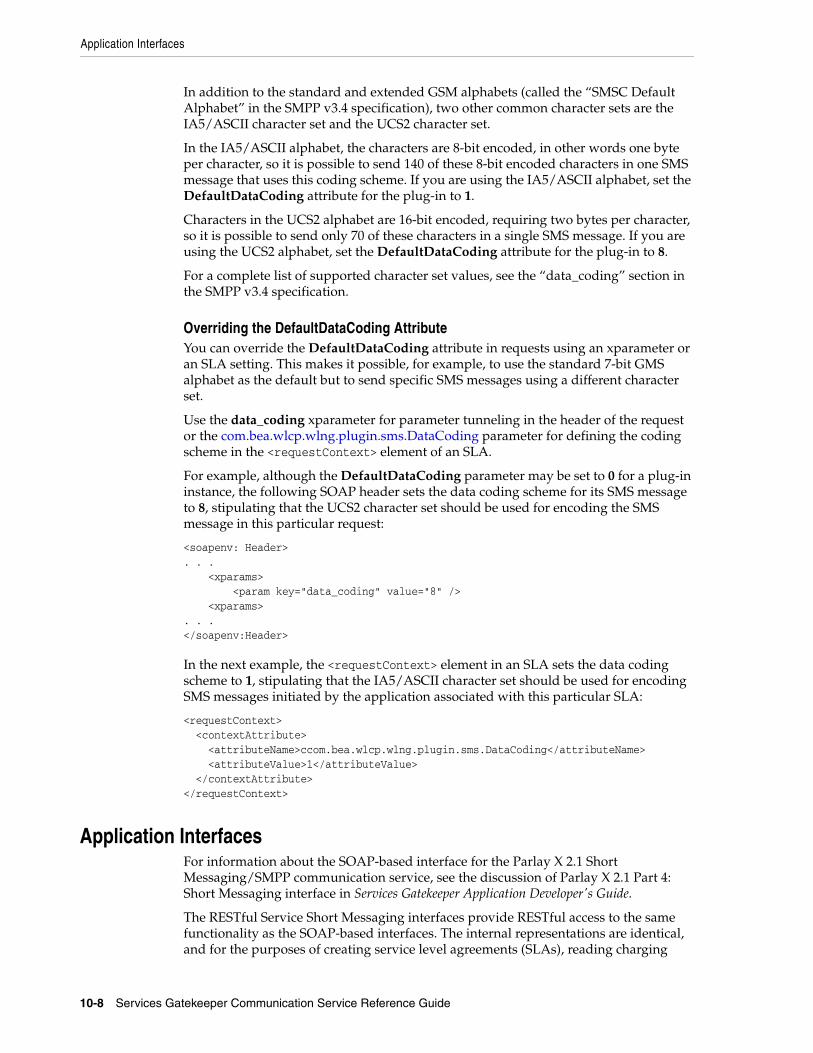
Application Interfaces
10-8 Services Gatekeeper Communication Service Reference Guide
In addition to the standard and extended GSM alphabets (called the “SMSC Default Alphabet” in the SMPP v3.4 specification), two other common character sets are the IA5/ASCII character set and the UCS2 character set.
In the IA5/ASCII alphabet, the characters are 8-bit encoded, in other words one byte per character, so it is possible to send 140 of these 8-bit encoded characters in one SMS message that uses this coding scheme. If you are using the IA5/ASCII alphabet, set the DefaultDataCoding attribute for the plug-in to 1.
Characters in the UCS2 alphabet are 16-bit encoded, requiring two bytes per character, so it is possible to send only 70 of these characters in a single SMS message. If you are using the UCS2 alphabet, set the DefaultDataCoding attribute for the plug-in to 8.
For a complete list of supported character set values, see the “data_coding” section in the SMPP v3.4 specification.
Overriding the DefaultDataCoding AttributeYou can override the DefaultDataCoding attribute in requests using an xparameter or an SLA setting. This makes it possible, for example, to use the standard 7-bit GMS alphabet as the default but to send specific SMS messages using a different character set.
Use the data_coding xparameter for parameter tunneling in the header of the request or the com.bea.wlcp.wlng.plugin.sms.DataCoding parameter for defining the coding scheme in the <requestContext> element of an SLA.
For example, although the DefaultDataCoding parameter may be set to 0 for a plug-in instance, the following SOAP header sets the data coding scheme for its SMS message to 8, stipulating that the UCS2 character set should be used for encoding the SMS message in this particular request:
<soapenv: Header>. . . <xparams> <param key="data_coding" value="8" /> <xparams>. . . </soapenv:Header>
In the next example, the <requestContext> element in an SLA sets the data coding scheme to 1, stipulating that the IA5/ASCII character set should be used for encoding SMS messages initiated by the application associated with this particular SLA:
<requestContext> <contextAttribute> <attributeName>ccom.bea.wlcp.wlng.plugin.sms.DataCoding</attributeName> <attributeValue>1</attributeValue> </contextAttribute></requestContext>
Application InterfacesFor information about the SOAP-based interface for the Parlay X 2.1 Short Messaging/SMPP communication service, see the discussion of Parlay X 2.1 Part 4: Short Messaging interface in Services Gatekeeper Application Developer's Guide.
The RESTful Service Short Messaging interfaces provide RESTful access to the same functionality as the SOAP-based interfaces. The internal representations are identical, and for the purposes of creating service level agreements (SLAs), reading charging

Events and Statistics
Parlay X 2.1 Short Messaging/SMPP 10-9
data records (CDRs), and so on, they are the same. For information about the RESTful Short Messaging interface, see the discussion about the short messaging interface in Services Gatekeeper Application Developer's Guide.
Events and StatisticsThe Parlay X 2.1 Short Messaging/SMPP communication service generates event data records (EDRs), CDRs, alarms, and statistics to assist system administrators and developers in monitoring the service.
See "Events, Alarms, and Charging" for more information.
Event DataTable 10–1 lists the IDs of the EDRs created by the Parlay X 2.1 Short Messaging/SMPP communication service. This list does not include EDRs created when exceptions are thrown.
See "Events and Statistics""Events and Statistics"for the list of EDRs generated by the SMPP Server Service.
Charging Data RecordsShort Messaging/SMPP-specific generates CDRs under the following conditions:
■ After Services Gatekeeper has successfully received and processed an application-originated message, and successfully sent all segments of the message to the network.
■ After Services Gatekeeper receives and processes a delivery report sent from the network.
■ After Services Gatekeeper successfully receives and processes a mobile-originated message sent from the network.
StatisticsTable 10–2 maps methods invoked from either the application or the network to the transaction types collected by the Services Gatekeeper statistics counters.
Table 10–1 EDRs Generated by Parlay X 2.1 Short Messaging/SMPP
EDR ID Method Called
6000 notifySmsDeliveryReceipt
6001 notifiySmsReception
7000 sendSms
7001 sendSmsLogo
7002 sendSmsRingtone
7003 startSmsNotification
7004 stopSmsNotification
7011 getSmsDeliveryStatus
7012 getReceivedSms

Tunneled Parameters for Parlay X 2.1 Short Messaging / SMPP
10-10 Services Gatekeeper Communication Service Reference Guide
AlarmsFor the list of alarms, see Services Gatekeeper Alarms Handling Guide.
Tunneled Parameters for Parlay X 2.1 Short Messaging / SMPPThis section lists the parameters that can be tunneled or defined in the <requestContext> element of an SLA.
The dest_bearer_type, service_type, ussd_service_operation, its_session_info parameters are used to support unstructured supplementary service data (USSD).
submit_dateYou can include submit_date as xparam in delivery report notifications sent from Services Gatekeeper to application listeners. You must set the ForwardXParams MBeam attribute to true in order to include submit_date.
You can only include "submit date" when the delivery report from SMSC has the informational content inserted into the short_message parameter of the DeliverSm PDU as shown in the SMPP specification v 3.4, appendix B.
In ParlayX SOAP callbacks, the xparam is set in the SOAP header, for example:
<xparams xmlns="http://schemas.xmlsoap.org/soap/envelope/"env:mustUnderstand="0"> <param xmlns="" key="submit date" value="1411251321"/> <param xmlns="" key="originating_address" value="12345"> </xparams>
For SMS OneAPI callbacks it is set in HTTP header, for example:
X-Plugin-Param-Keys: submit_date,originating_address X-Plugin-Param-Values: 1411251324,12345
done_date
DescriptionThis parameter returns the date and time a message was delivered to a terminal for OneAPI facade communication. Your implementation must support the SMPP v 3.3 style communication that makes this information available. Also xparams must be configured by setting the Services Gatekeeper SmsMBean attribute ForwardXParams to true.
This example shows an SMS OneAPI callback set in the HTTP header:
X-Plugin-Param-Keys: done_date,originating_addressX-Plugin-Param-Values: 1411251324,12345
Table 10–2 Methods and Transaction Types for Parlay X 2.1 Short Messaging/SMPP
Method Transaction Type
sendSms TRANSACTION_TYPE_MESSAGING_SEND
sendSmsLogo TRANSACTION_TYPE_MESSAGING_SEND
sendSmsRingtone TRANSACTION_TYPE_MESSAGING_SEND
receivedMobileOriginatedSMS TRANSACTION_TYPE_MESSAGING_RECEIVE

Tunneled Parameters for Parlay X 2.1 Short Messaging / SMPP
Parlay X 2.1 Short Messaging/SMPP 10-11
This example shows a SOAP callback with the xparam set in the header:
<xparams xmlns="http://schemas.xmlsoap.org/soap/envelope/"env:mustUnderstand="0"> <param xmlns="" key="done_date" value="1411251321"/> <param xmlns="" key="originating_address" value="12345"></xparams>
FormatString
sms.protocol.id
DescriptionThis parameter defines the mandatory SMPP protocol_id parameter.
It is valid for application-initiated requests only.
This parameter can be set using SLAs or parameter tunneling. An SLA setting overrides a tunneled parameter.
This parameter key name can be configured in the wlng.sms.protocol.id system property. The default is sms.protocol.id.
FormatInteger
ValueValue range is 0–65535.
source_port
DescriptionThis parameter defines the optional SMPP source_port parameter.
It is valid for application-initiated requests.
It is valid for network-triggered requests if the forwarding parameter is enabled. See the ForwardXParams field to SmsMBean for more information.
This parameter can be set using parameter tunneling.
FormatInteger
ValueValue range is 0–65535.
destination_port
DescriptionThis parameter defines the optional SMPP destination_port parameter.
It is valid for application-initiated requests.
It is valid for network-triggered requests if the forwarding parameter is enabled. See the ForwardXParams field to SmsMBean for more information.
This parameter can be set using parameter tunneling.

Tunneled Parameters for Parlay X 2.1 Short Messaging / SMPP
10-12 Services Gatekeeper Communication Service Reference Guide
FormatInteger
ValueValue range is 0–65535.
data_coding
DescriptionThis parameter defines the mandatory SMPP data_coding parameter.
Overrides the DefaultDataCoding configuration attribute. See the DefaultDataCoding field in SmsMBean for more information.
It is valid for application-initiated requests.
It is valid for network-triggered requests if the forwarding parameter is enabled. See the ForwardXParams field in SmsMBean for more information.
This parameter can be set using parameter tunneling.
FormatSigned Decimal
ValueValue range is -128 – +127. Some values are restricted. See the SMPP specification for details.
esm_class
DescriptionThis parameter defines the mandatory SMPP esm_class parameter.
It is valid for application-initiated requests only.
This parameter can be set using parameter tunneling.
FormatSigned Decimal
ValueValue range is -128 – +127. Some values are restricted. See the SMPP specification for details.
sms.service.type
DescriptionThis parameter defines the mandatory SMPP service_type parameter.
It is valid for application-initiated requests only.
This parameter can be set using SLAs or parameter tunneling. An SLA setting overrides a tunneled parameter.
This parameter name can be configured in the wlng.sms.service.type system property. The default is sms.service.type.
FormatString enumeration

Tunneled Parameters for Parlay X 2.1 Short Messaging / SMPP
Parlay X 2.1 Short Messaging/SMPP 10-13
ValueValid values are CMT, CPT, VMN, VMA, WAP, USSD, and an empty string (""). See the SMPP specification for details.
sms.replace.if.present
DescriptionThis parameter defines the mandatory SMPP replace_if_present_flag parameter.
It is valid for application-initiated requests only.
This parameter can be set using SLAs or parameter tunneling. An SLA setting overrides a tunneled parameter.
This parameter key name can be configured in the wlng.sms.replace.if.present system property. The default is sms.replace.if.present.
FormatInteger
ValueValue values are 0 and 1. See the SMPP specification for details.
com.bea.wlcp.wlng.plugin.sms.OriginatingAddressType
DescriptionThis parameter defines a mapping ID.
The ID is used for looking up an SMPP ESME Type Of Number (TON) and an SMPP ESME Numbering Plan Indicator (NPI). The TON and NPI are configured using OAM.
This parameter is valid for application-initiated requests only.
This parameter can be set using SLAs or parameter tunneling. An SLA setting overrides a tunneled parameter.
FormatString
com.bea.wlcp.wlng.plugin.sms.DestinationAddressType.n
DescriptionThis parameter defines a mapping ID.
The ID is used for looking up an SMPP ESME Type Of Number (TON) and an SMPP ESME Numbering Plan Indicator (NPI). The TON and NPI are configured using Oracle Access Manager (OAM).
The n is the number of the destination address. Valid values are 0 to one less than the number of destination addresses. An example of this parameter name would be:
com.bea.wlcp.wlng.plugin.sms.DestinationAddressType.2
This parameter is valid for application-initiated requests only.
This parameter can be set using SLAs or parameter tunneling. An SLA setting overrides a tunneled parameter.
FormatString

Tunneled Parameters for Parlay X 2.1 Short Messaging / SMPP
10-14 Services Gatekeeper Communication Service Reference Guide
com.bea.wlcp.wlng.plugin.sms.RequestDeliveryReportFlag
DescriptionThis parameter defines the mandatory SMPP registered_delivery parameter.
It specifies whether delivery reports are requested for application-initiated requests.
It is valid for application-initiated requests only.
This parameter can be set using SLAs or parameter tunneling. An SLA setting overrides a tunneled parameter.
FormatBoolean
Value■ 0 - Delivery receipt is never requested (was the old false option).
■ 1 - Delivery receipt is always requested (was the old true option).
■ 2 - Delivery receipt is requested if the application requests a delivery report. It either provides a callback URL when sending the message, or by having subscribed for delivery report notifications (new option).
com.bea.wlcp.wlng.plugin.sms.DataCoding
DescriptionThis parameter defines the mandatory SMPP data_coding parameter.
The plug-in uses it for encoding the message string.
It is valid for application-initiated requests only.
This parameter can be set using SLAs.
FormatInteger
ValueValue range is 0–255. Some values are restricted. See the SMPP specification for details.
com.bea.wlcp.wlng.plugin.sms.Priority
DescriptionThis parameter defines the mandatory SMPP priority_flag parameter.
It is valid for application-initiated requests only.
This parameter can be set using SLAs.
FormatString
ValueValid values are:
■ HIGH; Sets priority_flag to 3.
■ LOW; Sets priority_flag to 0.
■ DEFAULT; Sets priority_flag to 0.

Tunneled Parameters for Parlay X 2.1 Short Messaging / SMPP
Parlay X 2.1 Short Messaging/SMPP 10-15
■ UNDEFINED; Sets priority_flag to 0.
originating_address
DescriptionThis parameter defines the originating address of the SMS in the delivery receipt.
When this parameter is used, the SmsMBean's Boolean forwardXParam attribute must be set to true to make the parameter appear in the SOAP header. By default, forwardXParam is false. See the ForwardXParams field to SmsMBean for more information.
This parameter can be set using parameter tunneling.
FormatString
smpp_billing_id
DescriptionThis parameter defines the billing information according to the format in the SMPP Specification 5.1, section 4.8.4.3 titled "billing_identification".
The parameter works with SMPP 5.1 SMSCs, but with not with SMPP 3.4 SMSCs.
The parameter is intended for use with Parlay X 2.1 SMPP.
FormatHexadecimal String
Table 10–3 describes the format.
If the value is not sent as a hexadecimal string, it is ignored and a warning is logged.
Here is sample code for encoding the string.
private String getHexEncodedString(String normalString) { byte[] bHexStr = normalString.getBytes(); String retVal = ""; ..String sOctet = null; for (int i = 0; i < bHexStr.length; i++) { sOctet = Integer.toHexString((int) (bHexStr[i] & 0xFF)); if (sOctet.length() == 1) { sOctet = "0" + sOctet; }
Table 10–3 Format for smpp_bliing_id Value
FieldSize (octets) Type Description
parameter tag 2 Integer 0x060B
length 2 Integer Length of value part in octets
value 1 - 1024 Octet String
Bits 7......0
0XXXXXXX (Reserved)1XXXXXXX (Vendor Specific)
The first octet represents the Billing Format tag and indicates the format of the billing information contained in the remaining octets.

Tunneled Parameters for Parlay X 2.1 Short Messaging / SMPP
10-16 Services Gatekeeper Communication Service Reference Guide
retVal = retVal.concat(sOctet); } return retVal.toUpperCase(); }
dest_addr_subunit
DescriptionThis parameter defines the dest_addr_subunit field in the following SMPP operations:
■ SUBMIT_SM
■ SUBMIT_MULTI
■ DATA_SM
It can be set using parameter tunneling.
FormatSigned Decimal
The decimal value is automatically converted to a hexadecimal string before it is passed to the SMPP dest_addr_subunit field.
ValueValue range is -128 – +127.
Example<xparams> <param key="dest_addr_subunit" value="1"/> </xparams>
dest_bearer_type
DescriptionThis parameter is used to request the desired bearer for delivery of the message to the destination address.
If the receiving system (the SMSC) does not support the indicated bearer type, it may return a response PDU reporting a failure.
For the formal definition of the parameter and section 4.7.1 for its specification as an optional parameter for the DATA_SM operation, see section 5.3.2.5 of the Short Message Peer to Peer Protocol Specification v3.4 at:
http://docs.nimta.com/SMPP_v3_4_Issue1_2.pdf
This parameter can be set using parameter tunneling.
FormatUnsigned Byte [0–255]
ValueValid values are:
■ 0x00 = Unknown
■ 0x01 = SMS
■ 0x02 = Circuit Switched Data (CSD)
■ 0x03 = Packet Data
■ 0x04 = USSD
■ 0x05 = CDPD

Tunneled Parameters for Parlay X 2.1 Short Messaging / SMPP
Parlay X 2.1 Short Messaging/SMPP 10-17
■ 0x06 = DataTAC
■ 0x07 = FLEX/ReFLEX
■ 0x08 = Cell Broadcast (cellcast)
■ 9 to 255 Reserved
service_type
DescriptionThis parameter indicates the SMS application service associated with the message. Allows the ESME to use enhanced messaging services such as replace_if_present and to control the teleservice used on the air interface (for example, ANSI-136/TDMA and IS-95/CDMA).
It is used to support tunneling USSD (3G TS 23.090 version 3.0.0) messages through the SMPP protocol.
For the formal definition of the parameter and the appropriate subsections of section 4 for its specification as a mandatory parameter for SUBMIT_SM, SUBMIT_MULTI, DELIVER_SM, DATA_SM, and CANCEL_SM, see section 5.2.11 of the Short Message Peer to Peer Protocol Specification v3.4 at
http://docs.nimta.com/SMPP_v3_4_Issue1_2.pdf.
This parameter can be set using parameter tunneling.
FormatOctet string
ValueThe predefined generic service type value for USSD is USSD.
ussd_service_operation
DescriptionThis parameter defines the USSD service operation that is required when SMPP is used as an interface to a (GSM) USSD system.
It is used to support tunneling USSD (3G TS 23.090 version 3.0.0) messages through the SMPP protocol.
It is used as an optional parameter to the SMPP SUBMIT_SM operation.
This parameter is defined in section 5.3.2.44 of the Short Message Peer to Peer Protocol Specification v3.4.
It was added to the DELIVER_SM operation in the SMPP 5.1 specification. See Short Message Peer to Peer Protocol Specification Version 5.1.
This parameter can be set using parameter tunneling.
FormatUnsigned byte [0–255]
ValueValid values are:
■ 0 = PSSD indication
■ 1 = PSSR indication

Tunneled Parameters for Parlay X 2.1 Short Messaging / SMPP
10-18 Services Gatekeeper Communication Service Reference Guide
■ 2 = USSR request
■ 3 = USSN request
■ 4 to 15 Reserved
■ 16 = PSSD response
■ 17 = PSSR response
■ 18 = USSR confirm
■ 19 = USSN confirm
■ 20 to 31 Reserved
■ 32 to 255 Reserved for vendor-specific USSD operations
its_session_info
DescriptionThis is a required parameter for the CDMA Interactive Teleservice as defined by the Korean PCS carriers [KORITS]. Contains control information for the interactive session between an MS and an ESME.
See section 5.3.2.43 of the Short Message Peer to Peer Protocol Specification v3.4 for the formal definition of the parameter and the appropriate subsections of section 4 for its specification as an optional parameter for SUBMIT_SM, DELIVER_SM, and DATA_SM.
This parameter is also supported for native SMPP.
This parameter can be set using parameter tunneling.
FormatUnsigned Short (2 bytes) [0–65535] as an octet string
Following is a description of the octet string.
Bits 7...............0
SSSS SSSS (octet 1)
NNNN NNNE (octet 2)
Octet 1 contains the session number (0–255) encoded in binary. The session number remains constant for each session.
Octet 2 encodes the sequence number of the dialog unit (as assigned by the ESME) within the session in bits [7. . . 1].
Bit 0 of octet 2 is the End of Session Indicator, indicating that the message is the end of the conversation session. Valid values for the End of Session Indicator are:
■ 0 = End of Session Indicator inactive
■ 1 = End of Session Indicator active
smpp_optional_int_tlv_param_tags
DescriptionAn application or interceptor uses this parameter to pass integer data to a plug-in in TagLengthValue (TLV) data units. A TLV data unit consists of a tag/value pair. This

Tunneled Parameters for Parlay X 2.1 Short Messaging / SMPP
Parlay X 2.1 Short Messaging/SMPP 10-19
parameter passes a list of comma-separated items that are the tag parts of the data units.
See "smpp_optional_octet_tlv_param_tags" for sending data that is not of type integer.
The smpp_optional_int_tlv_param_tags list must have the same number of entries as its corresponding smpp_optional_int_tlv_param_values list. See "smpp_optional_int_tlv_param_values".
Within a TLV data unit, the sizes of the tag and length fields are each 2 bytes. The value of length field is always "0x00, 0x04", because integer data is always encoded in 4 bytes.
An example of code to tunnel TLV integer data is:
injectXParam(TLV_OPTIONAL_INT_PARAM_TAGS, "5121,5124"); injectXParam(TLV_OPTIONAL_INT_PARAM_VALUES, "999,1234");
This parameter can be set using parameter tunneling.
FormatThe tag identifiers must be in decimal format. For example, set a tag with the hexadecimal value 0x1401 as 5121.
smpp_optional_int_tlv_param_values
DescriptionAn application or interceptor uses this parameter to pass integer data to a plug-in in TagLengthValue (TLV) data units. A TLV data unit consists of a tag/value pair. This parameter passes a list of comma-separated items that are the value parts of the data units.
See "smpp_optional_octet_tlv_param_values" for sending data that is not of type integer.
The smpp_optional_int_tlv_param_values list must have the same number of entries as its corresponding smpp_optional_int_tlv_param_tags list. See "smpp_optional_int_tlv_param_tags".
Within a TLV data unit, the sizes of the tag and length fields are each 2 bytes. The value of length field is always "0x00, 0x04", because integer data is always encoded in 4 bytes.
An example of code that tunnels TLV integer data is:
injectXParam(TLV_OPTIONAL_INT_PARAM_TAGS, "5121,5124"); injectXParam(TLV_OPTIONAL_INT_PARAM_VALUES, "999,1234");
This parameter can be set using parameter tunneling.
smpp_optional_octet_tlv_param_tags
DescriptionAn application or interceptor uses this general-purpose parameter to pass any type of data to a plug-in in TagLengthValue (TLV) data units. A TLV data unit consists of a tag/value pair. This parameter passes a list of comma-separated items that are the tag parts of the data units.
See "smpp_optional_int_tlv_param_tags" for sending integer data.
Tunneled Parameters for Parlay X 2.1 Short Messaging / SMPP
10-20 Services Gatekeeper Communication Service Reference Guide
The smpp_optional_octet_tlv_param_tags list must have the same number of entries as its corresponding smpp_optional_octet_tlv_param_values list. See "smpp_optional_octet_tlv_param_values".
Within a TLV data unit, the sizes of the tag and length fields are each 2 bytes. The value of length field is the size of the actual data in the value field in the corresponding smpp_optional_octet_tlv_param_values parameter.
An example of code that tunnels TLV octet data is:
injectXParam(TLV_OPTIONAL_OCTET_PARAM_TAGS, "5121,5124", rctx); injectXParam(TLV_OPTIONAL_OCTET_PARAM_VALUES, "03e7,04d2", rctx); private void injectXParam(String name, String value, RequestContext rctx){ rctx.putXParam(name, value);
This parameter can be set using parameter tunneling.
FormatThe tag identifiers must be in decimal format. For example, set a tag with the hexadecimal value 0x1401 as 5121.
smpp_optional_octet_tlv_param_values
DescriptionAn application or interceptor uses this general-purpose parameter to pass any type of data to a plug-in in TagLengthValue (TLV) data units. A TLV data unit consists of a tag/value pair. This parameter passes a list of comma-separated items that are the value parts of the data units.
See "smpp_optional_int_tlv_param_values" for sending integer data.
The smpp_optional_octet_tlv_param_values list must have the same number of entries as its corresponding smpp_optional_octet_tlv_param_tags list. See "smpp_optional_octet_tlv_param_tags".
Within a TLV data unit, the sizes of the tag and length fields are each 2 bytes. The value of length field is the size of the actual data in the value field.
An example of code that tunnels TLV octet data is:
injectXParam(TLV_OPTIONAL_OCTET_PARAM_TAGS, "5121,5124", rctx); injectXParam(TLV_OPTIONAL_OCTET_PARAM_VALUES, "03e7,04d2", rctx); private void injectXParam(String name, String value, RequestContext rctx){ rctx.putXParam(name, value);
This parameter can be set using parameter tunneling.
FormatThe tag identifiers must be in decimal format. For example, set a tag with the hexadecimal value 0x1401 as 5121.
com.bea.wlcp.wlng.plugin.sms.smpp.schedule_delivery_time
DescriptionThis parameter specifies the scheduled time at which the message delivery should be first attempted. It defines either the absolute date and time or relative time from the current SMSC time at which delivery of this message will be attempted by the SMSC.
The PDU parameter is schedule_delivery_time.

Managing Parlay X 2.1 Short Messaging/SMPP and Extended Web Services Binary SMS/SMPP
Parlay X 2.1 Short Messaging/SMPP 10-21
FormatASCII string specified as YYMMDDhhmmsstnnp where:
■ YY: last two digits of the year, from 00 to 99.
■ MM: month from 1 to 12.
■ DD: day from 01 to 31.
■ hh: hour from 00 to 23.
■ ss: second from 00 to 59.
■ t: tenths of a second from 0 to 9.
■ nn: time differential in 15 minute increments between the local time (as expressed in the first 13 octets) and Universal Time Coordinated (UTC) from 00 to 48.
■ p +: local time is in 15 minute increments advanced in relation to UTC.
■ p -: local time is in 15 minute increments retarded in relation to UTC.
■ p R: local time is relative to the current SMSC time.
sms.validity.period
DescriptionThe validity_period parameter indicates the SMSC expiration time, after which the message should be discarded if not delivered to the destination. It can be defined in absolute time format or relative time format.
The PDU parameter is validity_period.
FormatASCII string specified as YYMMDDhhmmsstnnp where:
■ YY: last two digits of the year, from 00 to 99.
■ MM: month from 1 to 12.
■ DD: day from 01 to 31.
■ hh: hour from 00 to 23.
■ ss: second from 00 to 59.
■ t: tenths of a second from 0 to 9.
■ nn: time differential in 15 minute increments between the local time (as expressed in the first 13 octets) and Universal Time Coordinated (UTC) from 00 to 48.
■ p +: local time is in 15 minute increments advanced in relation to UTC.
■ p -: local time is in 15 minute increments retarded in relation to UTC.
■ p R: local time is relative to the current SMSC time.
Managing Parlay X 2.1 Short Messaging/SMPP and Extended Web Services Binary SMS/SMPP
This section describes the properties and workflow for setting up Parlay X 2.1 Short Messaging/SMPP and Extended Web Services Binary SMS/SMPP network protocol plug-in instances. These plug-in instances share the same configuration options.

Managing Parlay X 2.1 Short Messaging/SMPP and Extended Web Services Binary SMS/SMPP
10-22 Services Gatekeeper Communication Service Reference Guide
The Parlay X 2.1 Short Messaging/SMPP and Extended Web Services Binary SMS/SMPP communication services rely on an SMPP Server Service for connecting to the Small Message Service Center (SMSC).
The SMPP Server Service is also used by the Native SMPP Communication Service. See "Native SMPP" for information on managing client connections using SMPP Server Service.Configuration facilities for the SMPP Server Service are described in detail in the following sections of "Native SMPP":
■ Properties for SMPP Server Service
■ Reference: Attributes and Operations for SMPP Server Service
Properties for Parlay X 2.1 Short Messaging/SMPP and Extended Web Services Binary SMS/SMPP
Table 10–4 lists the technical specifications for the communication service.
Configuration Workflow for Parlay X 2.1 Short Messaging/SMPP and Extended Web Services Binary SMS/SMPP
Following is an outline for configuring the plug-in using the Administration Console or an MBean browser.
Table 10–4 Properties for Parlay X 2.1 Short Messaging/SMPP and EWS Binary SMS/SMPP
Property Description
Managed object in Administration Console
To manage the object, select domain_name, then OCSG, then server_name. then Communication Services, then plugin_instance_id in that order.
MBean Domain=com.bea.wlcp.wlng
Name=wlng_nt
InstanceName=same as the network protocol instance_id assigned when the plug-in instance is created
Type=oracle.ocsg.sms.smpp.management.SmsMBean
Documentation: See the “All Classes” section of Services Gatekeeper OAM Java API Reference
Network protocol plug-in service ID
Plugin_px21_short_messaging_smpp
Network protocol plug-in instance ID
The ID is assigned when the plug-in instance is created. See "Managing and Configuring the Plug-in Manager" in Services Gatekeeper System Administrator's Guide.
Supported Address Scheme
tel
Service type Sms
Exposes to the service communication layer a Java representation of:
Parlay X 2.1 Short Messaging/SMPP:
■ Parlay X 2.1 Part 4: Short Messaging
Extended Web Services Binary SMS/SMPP:
■ Extended Web Services Binary SMS
Interfaces with the network nodes using:
SMPP 3.4
Deployment artifacts wlng_nt_sms_px21.ear and wlng_at_sms_px21.ear

Managing Parlay X 2.1 Short Messaging/SMPP and Extended Web Services Binary SMS/SMPP
Parlay X 2.1 Short Messaging/SMPP 10-23
1. Create one or more instances of the plug-in service. See the discussion about configuring and managing the plug-in manager in Services Gatekeeper System Administrator's Guide. Use the plug-in service ID as listed in the "Properties for Parlay X 2.1 Short Messaging/SMPP and Extended Web Services Binary SMS/SMPP" section.
2. Using the Administration Console or an MBean browser, select the MBean for the plug-in instance. The MBean display name is the same as the plug-in instance ID given when the plug-in instance was created.
3. Configure the behavior of the plug-in instance. Seethe description about SmsMBean in the "All Classes" section of the Services Gatekeeper Java API Reference for the list of fields and methods.
4. If desired, configure the supportBulkRequest attribute to manage Split and Submit Messaging. See the discussion on attribute: supportBulkRequest in Services Gatekeeper System Administrator's Guide.
5. If the plug-in uses short code mappings, configure the Short Code Mapper. See the discussion on managing and configuring shortcode mappings in Services Gatekeeper System Administrator's Guide.
6. Set up the routing rules to the plug-in instance. See the discussion about configuring and managing the plug-in manager in Services Gatekeeper System Administrator's Guide. Use the plug-in instance ID and address schemes listed in the "Properties for Parlay X 2.1 Short Messaging/SMPP and Extended Web Services Binary SMS/SMPP" section.
7. If required, create and load a node SLA. For details see "Defining Global Node and Service Provider Group Node SLAs and Managing SLAs in Services Gatekeeper Portal Developer's Guide.
8. Provision the service provider accounts and application accounts. For information, see Services Gatekeeper Portal Developer's Guide.
Management Operations in the SMPP Server ServiceThe Parlay X 2.1 Short Messaging/SMPP and Extended Web Services Binary SMS/SMPP communication services use the SMPP Server Service to establish and manage client connections with the SMSC.
The SMPP Server Service establishes a client connection to the SMSC when the plug-in instance is activated or when the administrator resets the client connection by using the resetClientConnection SMPP Server Service operation.
The following Server Service methods to the SMPPServiceMBean, described in "Native SMPP" manage client connections:
■ closeClientConnection
■ listClientConnections
■ listPluginInstances
■ resetClientConnection
For a description of the attributes and operations of the SmsMBean and SMPPServiceMBean, see the "All Classes" section of Services Gatekeeper OAM Java API Reference.

Managing Parlay X 2.1 Short Messaging/SMPP and Extended Web Services Binary SMS/SMPP
10-24 Services Gatekeeper Communication Service Reference Guide

11
Parlay X 2.1 Terminal Location/MLP 11-1
11Parlay X 2.1 Terminal Location/MLP
This chapter describes the Oracle Communications Services Gatekeeper Parlay X 2.1 Terminal Location/Mobile Location Protocol (MLP) communication service in detail.
Overview of the Parlay X 2.1 Terminal Location/MLP Communication Service
The Parlay X 2.1 Terminal Location/MLP communication service exposes the Parlay X 2.1 Terminal Location application interfaces.
The communication service acts as an LCS -MLS client to a location server using MLP over HTTP.
For the exact version of the standards that the Parlay X 2.1 Terminal Location/MLP communication service supports for the application-facing interfaces and the network protocols, see Services Gatekeeper Statement of Compliance.
Services Gatekeeper connects to the location server using HTTP. It always acts as a single LCS/MLS client to the location server. It can be configured to act in Standard Location or Emergency Location Immediate mode on the node level.
Using the Terminal Location communication service, an application can:
■ Ask for the location of one or many terminals by polling.
■ Ask for the distance between a specified terminal and a specified position.
■ Sign up to be notified when a terminal enters or leaves a specified geographical area.
■ Receive notifications when the terminal enters or leaves the specified geographical area.
■ Sign up to be notified periodically about the location of a terminal.
■ Receive periodic location notifications about the location of a terminal.
The application can specify a number of parameters concerning the nature of the notification. These include:
■ Requested accuracy
Note: By default this communication service supports the Point and EllipticalArea data shapes from the MLP specification. Contact your Oracle Support representative for information on using more of the MLP data shapes.

Application Interfaces
11-2 Services Gatekeeper Communication Service Reference Guide
■ Accepted accuracy
■ Accepted response time
■ Maximum age of location data
■ Tolerance, which expresses the priority of response time versus accuracy
■ Minimum frequency of notifications
■ Duration of notifications
■ Maximum number of notifications
The nature of the information available as well as the accuracy of the location provided, the response times, and the frequency of notification are all dependent on the specifics of the protocol and network node used. Not all networks or protocols support all operations.
Processing Direct Queries/Application-initiated RequestsIf an application directly queries Services Gatekeeper for the location of a terminal or group of terminals, Services Gatekeeper sends the request to the network node. The location information is sent back synchronously in the response to the request.
Processing Notifications/Network-triggered RequestsIf an application registers for periodic or geographically-defined notifications, information for the application (which may or may not include the location data for one or more terminals) arrives at Services Gatekeeper from the network. The notification is passed on to the application. If the application acknowledges the reception of the notification, Services Gatekeeper acknowledges the reception of the notification to the network. If the application does not acknowledge the reception of the notification, Services Gatekeeper does not acknowledge the reception of the notification to the network.
Understanding Terminal Location PrecisionSee the discussion about understanding Parlay X 2.1 terminal location precision in Services Gatekeeper Application Developer's Guide for information on terminal location precision.
Application InterfacesFor information about the SOAP-based interface for the Parlay X 2.1 Terminal Location/MLP communication service, see the discussion about Parlay X 2.1 Part 9: Terminal Location interfaces in Services Gatekeeper Application Developer's Guide.
For information about the RESTful Audio Call interface, see the discussion of Terminal Location in Services Gatekeeper System Administrator's Guide.
The RESTful Service Short Messaging interfaces provide RESTful access to the same functionality as the SOAP-based interfaces. The internal representations are identical, and for the purposes of creating SLAs, reading CDRs, and so on, they are the same.

Events and Statistics
Parlay X 2.1 Terminal Location/MLP 11-3
Events and StatisticsThe Parlay X 2.1 Terminal Location/MLP communication service generates event data records (EDRs), charging data records (CDRs), alarms, and statistics to assist system administrators and developers in monitoring the service.
See "Events, Alarms, and Charging" for more information.
Event Data RecordsTable 11–1 lists IDs of the EDRs created by the Parlay X 2.1 Terminal Location/MLP communication service.
Charging Data RecordsTerminal Location/MLP - specific CDRs occur under the following conditions:
■ When the response to a polling request (of whatever type) is successfully delivered to the application.
■ When a notification is received from the network.
StatisticsTable 11–2 maps methods invoked from either the application or the network to the transaction types collected by the Services Gatekeeper statistics counters.
Method names for network-initiated requests are specified by the internal Services Gatekeeper name, which is not necessarily the same as the message from the network.
AlarmsFor the list of alarms, see Services Gatekeeper Alarms Handling Guide.
Table 11–1 EDRs Generated by Parlay X 2.1 Terminal Location/MLP
EDR ID Method Called
9001 getLocation
9002 getTerminalDistance
9003 getLocationForGroup
9004 sendLocationRequest
9011 LocationEnd
9012 LocationError
9013 LocationNotification
Table 11–2 Transaction Types for Parlay X 2.1 Terminal Location/MLP
Method Transaction type
getLocation TRANSACTION_TYPE_USER_LOCATION
getLocationForGroup TRANSACTION_TYPE_USER_LOCATION
getLocationDistance TRANSACTION_TYPE_USER_LOCATION
locationNotification TRANSACTION_TYPE_USER_LOCATION

Tunneled Parameters for Parlay X 2.1 Terminal Location /MLP
11-4 Services Gatekeeper Communication Service Reference Guide
Tunneled Parameters for Parlay X 2.1 Terminal Location /MLPThis section lists the parameters that can be tunneled.
terminal_location.name_area
DescriptionDefines the MLP <name_area> element.
Complements the existing Parlay X 2.1 functionality for startGeographicalNotification with support for named areas. The startGeographicalNotification operation is defined in theTerminalLocationNotificationManager interface.
Valid for application-initiated requests only.
When this parameter key is used to define the area, the latitude, longitude, and radius parameters provided by an application are not used.
Can be set using parameter tunneling
FormatString
Example<param key="terminal_location.name_area" value="Sausalito" />
com.wlcp.wlng.terminal_location.start_time / com.wlcp.wlng.terminal_location.stop_time
DescriptionDefines the <start_time> and <stop_time> MLP elements.
Complements the existing Parlay X 2.1 functionality for startGeographicalNotification with support for explicit start and stop times.
Valid for application-initiated requests only.
The utc_off attribute is used in both elements.
FormatString
The time is expressed in UTC format: yyyy-MM-ddThh:mm:ss[+|-]HH:MM using the definitions in Table 11–3.
Table 11–3 Format for terminal_location.start_time and stop_time Values
Element Meaning
yyyy year
MM month
dd day
T a constant
hh hours
mm minutes
ss seconds

Managing Parlay X 2.1 Terminal Location/MLP
Parlay X 2.1 Terminal Location/MLP 11-5
Example<param key="terminal_location.start_time" value="2008-09-26T16:15:00+08:00"/><param key="terminal_location.stop_time" value="2008-09-26T19:15:00+08:00"/>
terminal_location.polygon.point.n
DescriptionThis parameter represents a set of keys in which the prefix is terminal_location.polygon.point. and the suffix n is a number in the range of 1–15.
Defines the MLP <x> and <y> elements within the <coord> element. The <coord> elements are contained by the <LinearRing>. The <LinearRing> element is contained by the <outerBoundaryIs> and <polygon> elements.
Can be set using parameter tunneling.
FormatEach terminal_location.polygon.point key value is expressed in the format x:y where:
■ x corresponds to the <x> element
■ y corresponds to the <y> element
x and y are expressed as decimal degrees.
Example<xparams> <param key="terminal_location.polygon.point.1" value="6.999:43.564" /> <param key="terminal_location.polygon.point.2" value="7.027:43.564" /> <param key="terminal_location.polygon.point.3" value="7.027:43.564" /> <param key="terminal_location.polygon.point.4" value="6.999:43.564" /></xparams>
Managing Parlay X 2.1 Terminal Location/MLPThis section describes the properties and workflow for the Parlay X 2.1 Terminal Location/MLP plug-in instance.
Properties for Parlay X 2.1 Terminal Location/MLPTable 11–4 lists the technical specifications for the communication service.
[+|-] Positive or negative GMT offset. Use either + or -.
HH GMT offset in hours
MM GMT offset in minutes
Table 11–4 Properties for Parlay X 2.1 Terminal Location/MLP
Property Description
Managed object in Administration Console
To access the managed object, select domain_name, then OCSG, then server_name, then Communication Services, then plugin_instance_id, in that order.
Table 11–3 (Cont.) Format for terminal_location.start_time and stop_time Values
Element Meaning

Managing Parlay X 2.1 Terminal Location/MLP
11-6 Services Gatekeeper Communication Service Reference Guide
Configuration Workflow for Parlay X 2.1 Terminal Location/MLPFollowing is an outline for configuring the plug-in using the Administration Console or an MBean browser.
1. Create one or more instances of the plug-in service. See the discussion about configuring and managing the plug-in manager in Services Gatekeeper System Administrator's Guide. Use the plug-in service ID listed in the "Properties for Parlay X 2.1 Terminal Location/MLP"section.
MBean Domain=com.bea.wlcp.wlng
Name=wlng_nt
InstanceName=same as the network protocol instance_id assigned when the plug-in instance is created
Type=com.bea.wlcp.wlng.plugin.terminallocation.mlp.management.TerminalLocationMLPMBean
Network protocol plug-in service ID
Plugin_px21_terminal_location_mlp
Network protocol plug-in instance ID
The ID is assigned when the plug-in instance is created. See the discussion about configuring and managing the plug-in manager in Services Gatekeeper System Administrator's Guide.
Supported Address Scheme
tel
Application-facing interfaces
com.bea.wlcp.wlng.px21.plugin.TerminalLocationPlugin
com.bea.wlcp.wlng.px21.plugin.TerminalLocationNotificationManagerPlugin
com.bea.wlcp.wlng.px21.callback.TerminalLocationNotificationCallback
Service type TerminalLocation
Exposes to the service communication layer a Java representation of:
Parlay X 2.1 Part 9: Terminal Location
Interfaces with the network nodes using:
MLP 3.0/3.2
Deployment artifact:
NT EAR
wlng_nt_terminal_location_px21.ear
Plugin_px21_terminal_location_mlp.jar, px21_terminal_location_service.jar, and terminal_location_mlp.war
Deployment artifact:
AT EAR: Normal
wlng_at_terminal_location_px21.ear
px21_terminal_location.war, px21_terminal_location_callback.jar and rest_terminal_location.war
Deployment artifact:
AT EAR: SOAP Only
wlng_at_terminal_location_px21_soap.ear
px21_terminal_location.war and px21_terminal_location_callback.jar
Table 11–4 (Cont.) Properties for Parlay X 2.1 Terminal Location/MLP
Property Description

Managing Parlay X 2.1 Terminal Location/MLP
Parlay X 2.1 Terminal Location/MLP 11-7
2. Using the Administration Console or an MBean browser, select the MBean for the plug-in instance. The MBean display name is the same as the plug-in instance ID given when the plug-in instance was created.
3. Configure the fields of the TerminalLocationMLPMBean:
■ characterEncoding
■ cleanupInterval
■ decimalDegreesToDMSH
■ maxDuration
■ mlpVersionSupported
■ mlpLocationEstimates
■ mlpPushAddr
■ mlpRequestType
■ mlpServerUrl
■ mlpSrsName
■ mlpVersionSupported
■ msidType
■ password
■ requestor
■ requestTimeout
■ serviceId
■ username
■ xmlDoctypeTagUsage
4. Specify heartbeat behavior. See the discussion on configuring heartbeats in Services Gatekeeper System Administrator's Guide.
5. Set up the routing rules to the plug-in instance. See the discussion about configuring and managing the plug-in manager in Services Gatekeeper System Administrator's Guide. Use the plug-in instance ID and address schemes listed in the "Properties for Parlay X 2.1 Terminal Location/MLP"section.
6. If required, create and load a node SLA. For details see defining global node and service provider group node SLAs and managing SLAs in Services Gatekeeper Portal Developer's Guide.
7. Provision the service provider accounts and application accounts. For information, see Services Gatekeeper Portal Developer's Guide.
For a description of the attributes and operations of the TerminalLocationMLPMBean MBean, see the "All Classes" section of Services Gatekeeper OAM Java API Reference.

Managing Parlay X 2.1 Terminal Location/MLP
11-8 Services Gatekeeper Communication Service Reference Guide

12
Parlay X 2.1 Third Party Call/SIP 12-1
12Parlay X 2.1 Third Party Call/SIP
This chapter describes the Oracle Communications Services Gatekeeper Parlay X 2.1 Third Party Call/Session Initiation Protocol (SIP) communication service in detail.
Overview of the Parlay X 2.1 Third Party Call/SIP Communication ServiceThe Parlay X 2.1 Third Party Call/SIP communication service exposes the Parlay X 2.1 Third Party Call application interfaces.
The communication service connects to a SIP-IMS network using Oracle Converged Application Server. Converged Application Server is collocated with Services Gatekeeper in the network tier. In this relationship, Services Gatekeeper acts as a Back-to-Back User Agent for all calls.
For the exact version of the standards that the Parlay X 2.1 Third Party Call/SIP communication service supports for the application-facing interfaces and the network protocols, see Services Gatekeeper Statement of Compliance.
Using a Third Party Call Parlay X 2.1 communication service, an application can:
■ Set up a call between two parties.
For example, an application could set up a call between an investor and a broker if a particular stock reaches a predetermined price. Or a computer user could set up a call between himself and someone in the address book with a mouse click.
■ Query Services Gatekeeper for the status of a previously set up call.
■ Cancel a call as it is about to be set up.
■ Terminate an ongoing call it created.
How It WorksIn the Parlay X 2.1 Third Party Call model, a call has two distinct stages:
■ Call Setup
■ Call Duration
Call SetupThere are two parties involved in Third Party Call calls: the A-party (the caller) and the B-party (the callee). When a call is set up using a Third Party Call communication service, Services Gatekeeper attempts to set up a call leg to the A-party. When the caller goes off-hook (answers), Services Gatekeeper attempts to set up a call leg to the B-party. When the callee goes off-hook, the two call legs are connected using the underlying telecom network. This ends the call setup phase.

Application Interfaces
12-2 Services Gatekeeper Communication Service Reference Guide
The application can cancel the call during this phase.
Call DurationWhile the call is underway, the audio channel that connects the caller and the callee is completely managed by the telecom network. During this phase of the call, the application can only query for the status of the call. A call can be terminated in two ways, either using the application-facing interface, or having the caller or callee hang up.
Requests using a Parlay X 2.1 Third Party Call communication service flow only in one direction, from the application to the network. Therefore this communication service supports only application-initiated functionality.
The Parlay X 2.1 Third Party Call /SIP communication service manages only the signalling, or controlling, aspect of a call. The media or audio channel is managed by the telecom network. Only parties residing on the same network can be controlled, unless:
■ The network plug-in connects to a media gateway controller.
■ One of the participants is connected to a signalling gateway so that, from a signalling point of view, all parties reside on the same network.
Application InterfacesFor information about the SOAP-based interface for the Parlay X 2.1 Third Party Call communication service, see the discussion about Parlay X 2.1 Part2: Third Party Call in Services Gatekeeper Application Developer's Guide.
For information about the RESTful Third Party Call interface, see the discussion about RESTful Third Party Call interfaces in Services Gatekeeper Application Developer's Guide.
The RESTful Service Call Notification interfaces provide RESTful access to the same functionality as the SOAP-based interfaces. The internal representations are identical, and for the purposes of creating SLAs and reading charging data records (CDRs), and so on, they are the same.
Events and StatisticsThe Parlay X 2.1 Third Party Call/SIP communication service generates Event Data Records (EDRs), CDRs, alarms, and statistics to assist system administrators and developers in monitoring the service.
See "Events, Alarms, and Charging" for more information.
Event Data RecordsTable 12–1 lists the IDs of the EDRs created by the Parlay X 2.1 Third Party Call/ SIP communication service. This does not include EDRs created when exceptions are thrown.
Table 12–1 EDRs Generated by Parlay X 2.1 Third Party Call/SIP
EDR ID Method Called
8022 makeCall
8023 getCallInformation
8024 endCall
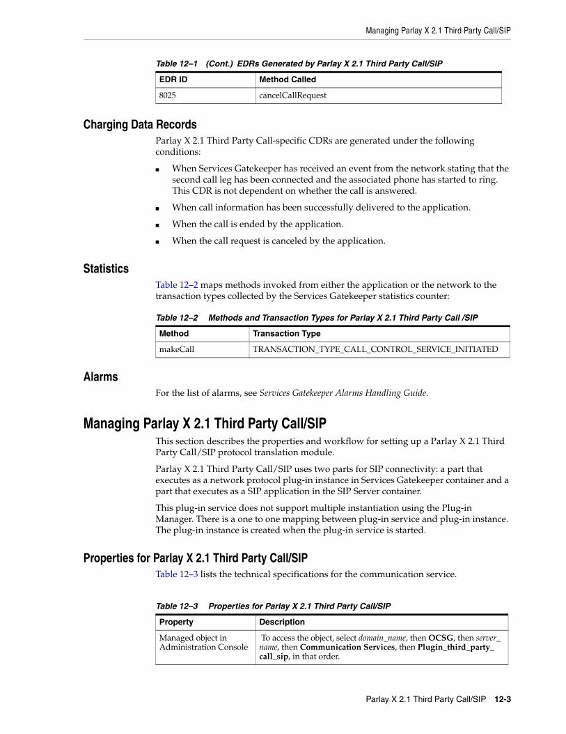
Managing Parlay X 2.1 Third Party Call/SIP
Parlay X 2.1 Third Party Call/SIP 12-3
Charging Data RecordsParlay X 2.1 Third Party Call-specific CDRs are generated under the following conditions:
■ When Services Gatekeeper has received an event from the network stating that the second call leg has been connected and the associated phone has started to ring. This CDR is not dependent on whether the call is answered.
■ When call information has been successfully delivered to the application.
■ When the call is ended by the application.
■ When the call request is canceled by the application.
StatisticsTable 12–2 maps methods invoked from either the application or the network to the transaction types collected by the Services Gatekeeper statistics counter:
AlarmsFor the list of alarms, see Services Gatekeeper Alarms Handling Guide.
Managing Parlay X 2.1 Third Party Call/SIPThis section describes the properties and workflow for setting up a Parlay X 2.1 Third Party Call/SIP protocol translation module.
Parlay X 2.1 Third Party Call/SIP uses two parts for SIP connectivity: a part that executes as a network protocol plug-in instance in Services Gatekeeper container and a part that executes as a SIP application in the SIP Server container.
This plug-in service does not support multiple instantiation using the Plug-in Manager. There is a one to one mapping between plug-in service and plug-in instance. The plug-in instance is created when the plug-in service is started.
Properties for Parlay X 2.1 Third Party Call/SIPTable 12–3 lists the technical specifications for the communication service.
8025 cancelCallRequest
Table 12–2 Methods and Transaction Types for Parlay X 2.1 Third Party Call /SIP
Method Transaction Type
makeCall TRANSACTION_TYPE_CALL_CONTROL_SERVICE_INITIATED
Table 12–3 Properties for Parlay X 2.1 Third Party Call/SIP
Property Description
Managed object in Administration Console
To access the object, select domain_name, then OCSG, then server_name, then Communication Services, then Plugin_third_party_call_sip, in that order.
Table 12–1 (Cont.) EDRs Generated by Parlay X 2.1 Third Party Call/SIP
EDR ID Method Called

Managing Parlay X 2.1 Third Party Call/SIP
12-4 Services Gatekeeper Communication Service Reference Guide
This Plug-in service does not support multiple instantiation using the Plug-in Manager. There is a one-to-one mapping between plug-in service and plug-in instance. The plug-in instance is created when the plug-in service is started.
Configuration Workflow for Parlay X 2.1 Third Party Call/SIPFollowing is an outline for configuring the plug-in using the Administration Console or an MBean browser.
1. Select the TPCMBean MBean.
See the "All Classes" section of Services Gatekeeper OAM Java API Reference for details on this MBean.
2. Configure behavior of the network protocol plug-in instance using these fields to the TCPMBean:
■ ChargingAllowed
■ ControllerURI
■ ISCRouteURI
■ MaximumCallLength
■ StatusRetentionTime
MBean Domain=com.bea.wlcp.wlng
Name=wlng_nt
InstanceName=Plugin_px21_third_party_call_sip
Type=com.bea.wlcp.wlng.plugin.tpc.sip.management.TPCMBean
Documentation: See the "All Classes" section of Services Gatekeeper OAM Java API Reference.
Network protocol plug-in service ID
Plugin_px21_third_party_call_sip
Network protocol plug-in instance ID
Plugin_px21_third_party_call_sip
Supported Address Scheme
sip, tel
Application-facing interface
com.bea.wlcp.wlng.px21.plugin.ThirdPartyCallPlugin
Service type ThirdPartyCall
Exposes to the service communication layer a Java representation of:
Parlay X 2.1 Part 2: Third Party Call
Interfaces with the network nodes using:
SIP: Session Initiation Protocol, RFC 3261
Deployment artifacts px21_third_party_call_service.jar, Plugin_px21_third_party_call_sip.jar, and Plugin_px21_third_party_call_sip.war, packaged in wlng_nt_third_party_call_px21.ear
px21_third_party_call.war, packaged in wlng_at_third_party_call_px21.ear
Table 12–3 (Cont.) Properties for Parlay X 2.1 Third Party Call/SIP
Property Description

Managing Parlay X 2.1 Third Party Call/SIP
Parlay X 2.1 Third Party Call/SIP 12-5
3. Set up the routing rules to the plug-in instance. See the discussion about configuring and managing the plug-in manager in Services Gatekeeper System Administrator's Guide. Use the plug-in instance ID and address schemes listed in the "Properties for Parlay X 2.1 Third Party Call/SIP" section.
4. If required, create and load a node SLA. For details see the discussion on defining global node and service provider group node SLAs and managing SLAs in Services Gatekeeper Portal Developer's Guide.
5. Provision the service provider accounts and application accounts. For information, see Services Gatekeeper Portal Developer's Guide.
For a description of the attributes and operations of the TPCMBean MBean, see the "All Classes" section of Services Gatekeeper OAM Java API Reference.

Managing Parlay X 2.1 Third Party Call/SIP
12-6 Services Gatekeeper Communication Service Reference Guide

13
Parlay X 2.1 Terminal Status/SIP 13-1
13Parlay X 2.1 Terminal Status/SIP
This chapter describes the Oracle Communications Services Gatekeeper Parlay X 2.1 Terminal Status/SIP communication service in detail.
Overview of the Parlay X 2.1 Terminal Status/SIP Communication ServiceThe Parlay X 2.1 Terminal Status/SIP communication service exposes the Parlay X 2.1 Terminal Status set of application interfaces.
This communication service uses the SIP protocol to connect to the Oracle Communications Converged Application Server (Converged Application Server), Service Controller product, using the IM-PSX GSM MAP interworking module. For details on configuring the IM-PSX GSM MAP module to work with this communication service, see “Configuring IM-PSX GSM MAP” in Oracle Communications Service Broker Processing Domain Configuration Guide.
For the exact version of the standards that the Parlay X 2.1 Terminal Status/SIP communication service supports for the application-facing interfaces and the network protocols, see Services Gatekeeper Statement of Compliance.
Using the Parlay X 2.1 Terminal Status/SIP communication service, an application can:
■ Obtain the status (reachable, unreachable, or busy) of a single terminal or group of terminals as often as you specify, within a time period you specify.
■ Return the status of a terminal or group of terminals only if the status changes. The terminal statuses are checked as frequently as you specify, for a time period you specify.
This communication service receives requests from applications, opens a transaction, translates the requests into the SIP protocol, and queries the network. The network then returns the status to the plug-in, which passes the status back to the application inside the same transaction.
To receive current terminal statuses for multiple terminals in the same transaction, an application sends the addresses of the terminals to the communication service. The communication service then opens a transaction and sends a separate query to the network for each terminal address. The plug-in collects replies as they come in and returns them to the application inside a transaction.
Note: This communication service is preintegrated with the Oracle Communications Converged Application Server, Service Controller product, and you must purchase that product separately.

Overview of the Parlay X 2.1 Terminal Status/SIP Communication Service
13-2 Services Gatekeeper Communication Service Reference Guide
To receive notification if a terminal status changes, an application sends the address of the terminal to the plug-in. The plug-in checks the status of the terminal periodically during the configured time period on a schedule defined by the frequency, duration, and count timer metrics to startNotification. For details on the timers scheduling see the Parlay X 2.1 Part 8 web site:
http://www.etsi.org/deliver/etsi_es/202300_202399/20239108/01.02.01_60/es_20239108v010201p.pdf
Also, see the discussion about the RESTful terminal status interface in Services Gatekeeper Application Developer's Guide for information on terminal status interface of the RESTful web service.
The Terminal Status/SIP plug-in accepts these parameters as input:
■ The terminal address or addresses.
■ The request frequency (number of seconds, minutes, or hours).
■ The total number of requests.
■ A true/false value for the checkImmediate parameter.
If checkImmediate=true the plug-in checks the status of the terminal or terminals immediately, and then thereafter as often as you specified. If checkImmediate=false the plug-in checks for status at the end of the first time period.
Status Request for a Single TerminalAn application queries Services Gatekeeper for the status of a terminal by sending the terminal’s address in a getStatus SOAP request. This communication service translates the request into a SIP SUBSCRIBE operation and forwards it to Converged Application Server, Service Controller. Converged Application Server, Service Conroller converts the SUBSCRIBE operation to an anyTimeInterrogationReq operation and passes it to the network node. The network node returns the status (reachable, unreachable, or busy) to Converged Application Sever, Service Controller. Converged Application Server, Service Controller then sends a SIP NOTIFY operation to this communication service, which then responds to the application with a getStatusResult SOAP message.
Status Request for Multiple TerminalsAn application queries Services Gatekeeper for the status of a group of terminals by sending the terminal addresses in a getStatusForGroup SOAP operation. This communication service translates the request into a series of SIP SUBSCRIBE operations, one for each terminal, and forwards them to Converged Application Server, Service Controller. Converged Application Server, Service Controller then converts these messages to SIP NOTIFY operations and send them to this communication services. This communication service collects the results and returns them to the requesting application in a single getStatusResultForGroup message. Unreachable terminals are given a status of NotRetrieved.
Oracle recommends that you increase the default Transaction Timeout settings for both your Services Gatekeeper domain and deployment before you use the getStatusResultForGroup operation. You do this to avoid error messages such as: Value exceeds maximum column length (150) for column destination_party. To change the Transaction Timeout settings:
Domain:
1. Open the Administration Console

Events and Statistics
Parlay X 2.1 Terminal Status/SIP 13-3
2. Navigate to Domain, then Services, then JTA.
3. Change the Timeout Seconds setting to 300 from 30.
4. Save your changes.
Deployment:
1. Open the Administration Console
2. Navigate to Deployments, then wlng_nt_terminal_status_px21(6.0.0.0), then TerminalStatus , then Configuration.
3. Change the Transaction Timeout setting to 300 from 0.
4. Save your changes.
Terminal Status Change Request: Plug-in-TriggeredAn application sends a terminal status change request and timer metrics to this communication service using startNotification operation. The communication service creates a transaction and starts querying the Converged Application Server, Service Controller for the terminal status with SIP SUBSCRIBE as directed by the timer metrics. Converged Application Server, Service Controller then converts the SIP SUBSCRIBE operation into anyTimeInterrogationReq operation and forwards it to the network node. The network node returns the status (reachable, unreachable, or busy) to Converged Application Server, Service Controller. Converged Application Server, Service Controller then sends a SIP NOTIFY operation to this communication service.
If the terminal status changes during the time period, this communication service returns that information to the application using statusNotification message. If the status does not change during the time period, it sends a statusEnd message back to the application and closes the transaction. The application can also end the transaction itself by sending an endNotification message.
Application InterfacesFor information about the SOAP-based interface for the Parlay X 2.1 Terminal Status communication service, see the discussion about Parlay X 2.1 Part 8: Terminal Status Interfaces in Services Gatekeeper Application Developer's Guide.
For information about the RESTful Call Notification interface, see the discussion about RESTful Terminal Status in Services Gatekeeper Application Developer's Guide.
The Representational State Transfer (RESTful) Service Call Notification interfaces provide RESTful access to the same functionality as the SOAP-based interfaces. The internal representations are identical, and for the purposes of creating Service Level Agreements (SLAs) and reading charging data records (CDRs), and so on, they are the same.
Events and StatisticsThe Parlay X 2.1 Terminal Status/SIP communication service generates Event Data Records (EDRs), CDRs, alarms, and statistics to assist system administrators and developers in monitoring the service.
See "Events, Alarms, and Charging" for more information.

Events and Statistics
13-4 Services Gatekeeper Communication Service Reference Guide
Event Data RecordsTable 13–1 lists the IDs of the EDRs created by the Parlay X 2.1 Terminal Status/SIP communication service.
Charging Data RecordsTerminal Status/SIP-specific CDRs are generated under the following conditions:
■ With the results of a getStatus or getStatusForGroup operation.
■ When statusNotification is called.
StatisticsTable 13–2 maps methods invoked from either the application or the network to the transaction types collected by the Services Gatekeeper statistics counters
AlarmsFor the list of alarms, see Services Gatekeeper Alarms Handling Guide.
Table 13–1 EDRs Generated by Parlay X 2.1Terminal Status/SIP
EDR ID Method Called
4000 getStatusForGroup
4001 getStatus
4002 startNotification
4003 endNotification
4015 statusNotification
4016 statusError
4017 statusEnd
4018 getStatusForGroup (network)
4019 getStatus (network)
4020 startNotification (network)
4021 endNotification (network)
91631 getStatus/getStatusForGroup (application)
91632 startNotification/endNotification (application)
91633 statusNotification (application)
91634 statusEnd (application)
Table 13–2 Methods and Transaction Types for Parlay X 2.1 Terminal Status/SIP
Method Transaction Type
getStatus TRANSACTION_TYPE_USER_STATUS
getStatusForGroup TRANSACTION_TYPE_USER_STATUS
startNotification TRANSACTION_TYPE_USER_STATUS
endNotification TRANSACTION_TYPE_USER_STATUS
statusNotification TRANSACTION_TYPE_USER_STATUS

Error Handling
Parlay X 2.1 Terminal Status/SIP 13-5
Error HandlingThe following section list the Terminal Status/SIP errors.
Parlay X ExceptionsTable 13–3 lists the application-facing service exceptions.
Policy ExceptionsTable 13–4 lists the Terminal Status/SIP policy exceptions.
Internal Error CodesTable 13–5 lists the Terminal Status/SIP internal error propagated to Parlay X SVC0001 messages.
Table 13–3 Terminal Status/SIP Parlay X Exceptions
Message ID Description Origin
SVC0001 Service error All operations
SVC0002 Invalid input value All operations
SVC0004 No valid addresses getStatus, getStatusForGroup, startNotification
SVC0005 Duplicate correlator startNotification
SVC0006 Invalid group getStatusForGroup
Table 13–4 Terminal Status/SIP Policy Exceptions
Message ID Description Origin
POL0001 Policy error All operations
POL0002 Privacy error All operations
POL0003 To many addresses getStatusForGroup, startNotification
POL0004 Unlimited notifications not supported
startNotification
POL0005 Too many notifications requested
startNotification
POL0006 Groups not allowed getStatusForGroup
POL0007 Nested groups not allowed getStatusForGroup
POL0009 Invalid frequency requested startNotification
POL0200 Busy criteria not supported startNotification
Table 13–5 Terminal Status/SIP Internal Error Codes
Error Code Cause Suggested Action
TS-000001 The SIP fromAddress in the MBean is an invalid URI.
Replace the value for fromAddress with a valid URI.
TS-000002 The IM-PSX server address in the MBean is invalid.
Replace the PsxServerAddress with a valid URI.
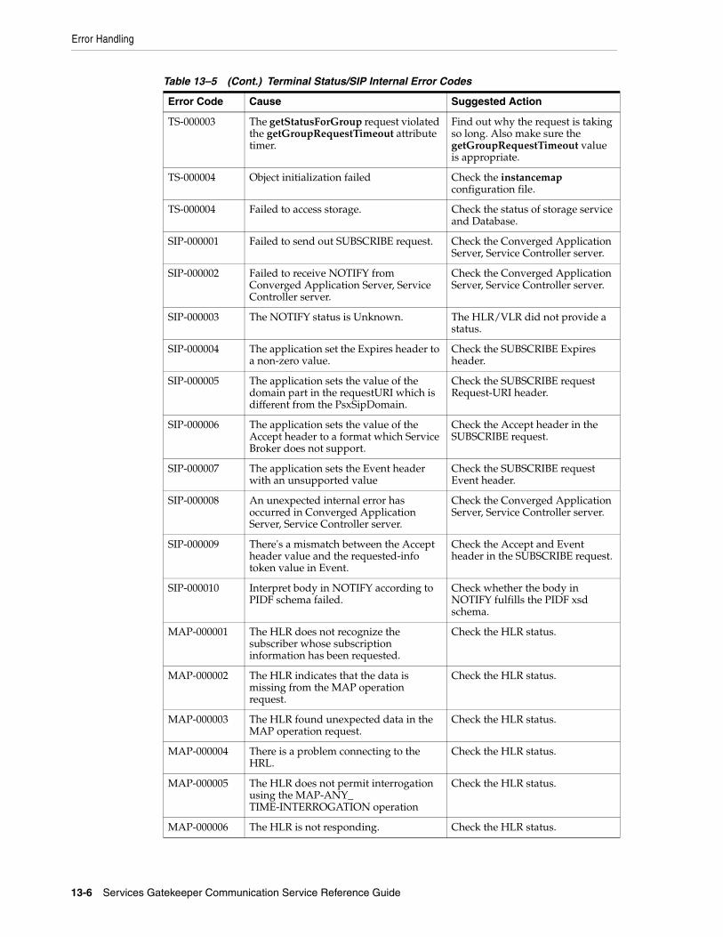
Error Handling
13-6 Services Gatekeeper Communication Service Reference Guide
TS-000003 The getStatusForGroup request violated the getGroupRequestTimeout attribute timer.
Find out why the request is taking so long. Also make sure the getGroupRequestTimeout value is appropriate.
TS-000004 Object initialization failed Check the instancemap configuration file.
TS-000004 Failed to access storage. Check the status of storage service and Database.
SIP-000001 Failed to send out SUBSCRIBE request. Check the Converged Application Server, Service Controller server.
SIP-000002 Failed to receive NOTIFY from Converged Application Server, Service Controller server.
Check the Converged Application Server, Service Controller server.
SIP-000003 The NOTIFY status is Unknown. The HLR/VLR did not provide a status.
SIP-000004 The application set the Expires header to a non-zero value.
Check the SUBSCRIBE Expires header.
SIP-000005 The application sets the value of the domain part in the requestURI which is different from the PsxSipDomain.
Check the SUBSCRIBE request Request-URI header.
SIP-000006 The application sets the value of the Accept header to a format which Service Broker does not support.
Check the Accept header in the SUBSCRIBE request.
SIP-000007 The application sets the Event header with an unsupported value
Check the SUBSCRIBE request Event header.
SIP-000008 An unexpected internal error has occurred in Converged Application Server, Service Controller server.
Check the Converged Application Server, Service Controller server.
SIP-000009 There's a mismatch between the Accept header value and the requested-info token value in Event.
Check the Accept and Event header in the SUBSCRIBE request.
SIP-000010 Interpret body in NOTIFY according to PIDF schema failed.
Check whether the body in NOTIFY fulfills the PIDF xsd schema.
MAP-000001 The HLR does not recognize the subscriber whose subscription information has been requested.
Check the HLR status.
MAP-000002 The HLR indicates that the data is missing from the MAP operation request.
Check the HLR status.
MAP-000003 The HLR found unexpected data in the MAP operation request.
Check the HLR status.
MAP-000004 There is a problem connecting to the HRL.
Check the HLR status.
MAP-000005 The HLR does not permit interrogation using the MAP-ANY_TIME-INTERROGATION operation
Check the HLR status.
MAP-000006 The HLR is not responding. Check the HLR status.
Table 13–5 (Cont.) Terminal Status/SIP Internal Error Codes
Error Code Cause Suggested Action

Managing Parlay X 2.1 Terminal Status/SIP
Parlay X 2.1 Terminal Status/SIP 13-7
Tunneled Parameters for Parlay X 2.1 Terminal Status/SIPThis section lists, by parameter key, the parameters that can be tunneled or defined in the <requestContext> element of an SLA.
FromAddress
DescriptionSet "From" in SUBSCRIBE request for specific getStatus messages in a getSgroupStatus request.
FormatString
Example<param key="FromAddress" value="sip:[email protected]" />
or
<param key="FromAddress" value="tel:1239658" />
Managing Parlay X 2.1 Terminal Status/SIPThis section describes the properties and workflow for the Parlay X 2.1 Terminal Status plug-in instance.
The plug-in instance is not automatically created when the plug-in service is started.
Properties for Parlay X 2.1 Terminal Status/SIPTable 13–6 lists the technical specifications for this communication service.
Table 13–6 Properties for Parlay X 2.1 Terminal Status/SIP
Property Description
Managed object in Administration Console
To access the object, select domain_name, then OCSG, then server_name, then Communication Services, then plugin_instance_id, in that order.
MBean Domain=com.bea.wlcp.wlngName=wlng_ntInstanceName=Plugin_px21_terminal_status_sipType=oracle.ocsg.plugin.terminal_status.sip.management.TerminalStatusMBean
Documentation: See the "All Classes" section of Services Gatekeeper OAM Java API Reference
Network protocol plug-in instance ID
The ID assigned when the plug-in instance is created. See the discussion about configuring and managing the plug-in manager in Services Gatekeeper System Administrator's Guide.
Network protocol plug-in service ID
Plugin_px21_terminal_status_sip
Supported Address Scheme tel
Application-facing Interfaces
com.bea.wlcp.wlng.px21.plugin.TerminalStatusPlugin
com.bea.wlcp.wlng.px21.plugin.TerminalStatusNotificationManagerPlugin
com.bea.wlcp.wlng.px21.callback.TerminalStatusNotificationCallback

Managing Parlay X 2.1 Terminal Status/SIP
13-8 Services Gatekeeper Communication Service Reference Guide
Configuration Workflow for Parlay X 2.1 Terminal Status/SIPFollowing is an outline for configuring the plug-in using the Administration Console or an MBean browser.
1. Create one or more instances of the plug-in service. See the discussion about configuring and managing the plug-in manager in Services Gatekeeper System Administrator's Guide. Use the plug-in service ID listed in the "Properties for Parlay X 2.1 Terminal Status/SIP".
2. Select the MBean for the plug-in instance. The MBean display name is the same as the plug-in instance ID assigned when the plug-in instance was created.
3. Configure the fields of the plug-in instance. See the TerminalStatusMBean:
■ SipNotifyTimeout
■ GroupRequestTimeout
■ GroupRequestInterval
■ PsxSipDomain
■ PsxServerAddress
■ FromAddress
■ ToParameters
4. Set up the routing rules to the plug-in instance. See the discussion about configuring and managing the plug-in manager in Services Gatekeeper System Administrator's Guide. Use the plug-in instance ID and address schemes listed in the "Properties for Parlay X 2.1 Terminal Status/SIP" section.
5. (Optional) Create and load a node SLA with Terminal Status usage restrictions. These usage restrictions are supported:
■ SLA Usage Restriction: BusyAvailable
Service Type TerminalStatus
Exposes to the service communication layer a Java representation of:
Parlay X 2.1 Par 8: Terminal Status/SIP
Interfaces with the network nodes using
RFC 3265
Deployment artifacts:
NT EARwlng_nt_terminal_status_px21.ear
Plugin_px21_terminal_status_sip.jar
px21_terminal_status_service.jar
terminal_status_sip.war
px21_terminal_status_callback_client.jar
AT EAR: Normalwlng_at_terminal_status_px21.ear
px21_terminal_status.war
px21_terminal_status_callback.jar
rest_terminal_status.war
At EARP: SOAP Only
wlng_at_terminal_status_px21_soap.earr
px21_terminal_status.war
px21_terminal_status_callback.jar
Table 13–6 (Cont.) Properties for Parlay X 2.1 Terminal Status/SIP
Property Description
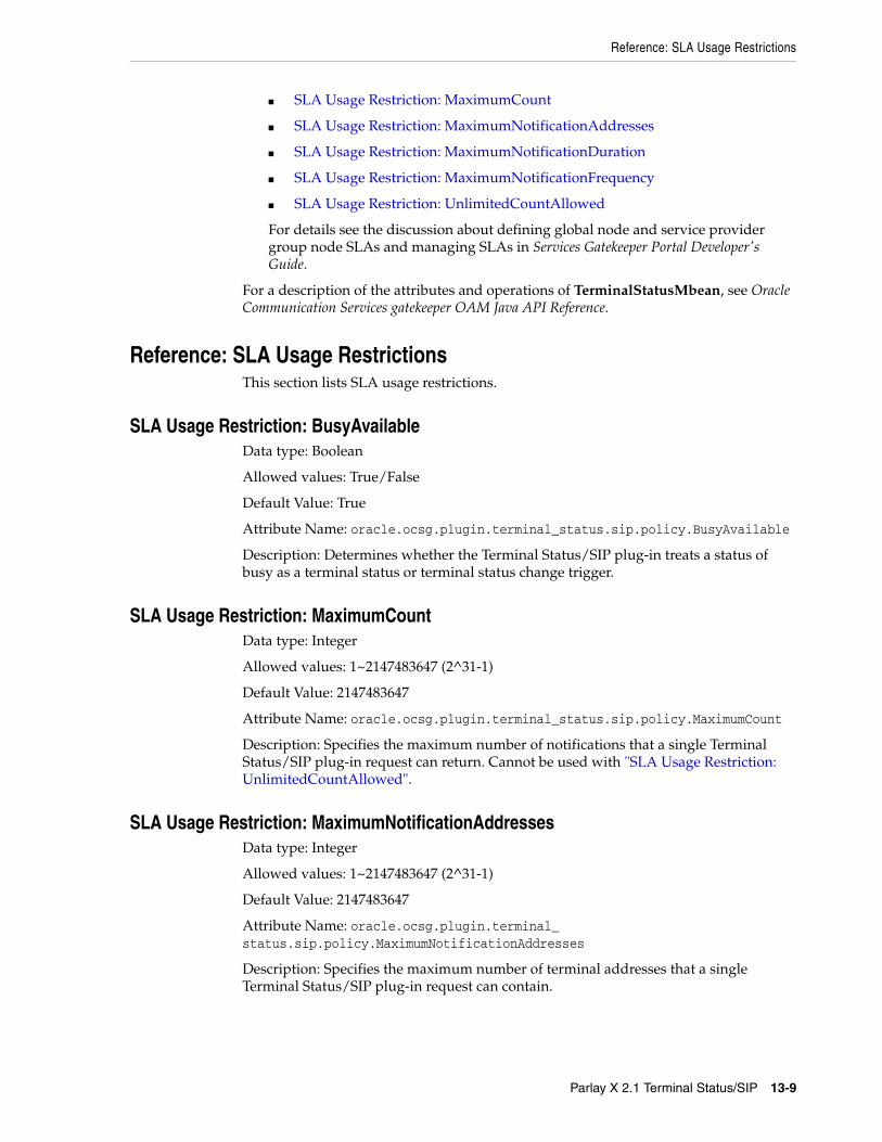
Reference: SLA Usage Restrictions
Parlay X 2.1 Terminal Status/SIP 13-9
■ SLA Usage Restriction: MaximumCount
■ SLA Usage Restriction: MaximumNotificationAddresses
■ SLA Usage Restriction: MaximumNotificationDuration
■ SLA Usage Restriction: MaximumNotificationFrequency
■ SLA Usage Restriction: UnlimitedCountAllowed
For details see the discussion about defining global node and service provider group node SLAs and managing SLAs in Services Gatekeeper Portal Developer's Guide.
For a description of the attributes and operations of TerminalStatusMbean, see Oracle Communication Services gatekeeper OAM Java API Reference.
Reference: SLA Usage RestrictionsThis section lists SLA usage restrictions.
SLA Usage Restriction: BusyAvailableData type: Boolean
Allowed values: True/False
Default Value: True
Attribute Name: oracle.ocsg.plugin.terminal_status.sip.policy.BusyAvailable
Description: Determines whether the Terminal Status/SIP plug-in treats a status of busy as a terminal status or terminal status change trigger.
SLA Usage Restriction: MaximumCountData type: Integer
Allowed values: 1~2147483647 (2^31-1)
Default Value: 2147483647
Attribute Name: oracle.ocsg.plugin.terminal_status.sip.policy.MaximumCount
Description: Specifies the maximum number of notifications that a single Terminal Status/SIP plug-in request can return. Cannot be used with "SLA Usage Restriction: UnlimitedCountAllowed".
SLA Usage Restriction: MaximumNotificationAddressesData type: Integer
Allowed values: 1~2147483647 (2^31-1)
Default Value: 2147483647
Attribute Name: oracle.ocsg.plugin.terminal_status.sip.policy.MaximumNotificationAddresses
Description: Specifies the maximum number of terminal addresses that a single Terminal Status/SIP plug-in request can contain.

Reference: SLA Usage Restrictions
13-10 Services Gatekeeper Communication Service Reference Guide
SLA Usage Restriction: MaximumNotificationDurationData type: Integer
Unit: Seconds
Allowed values: <TBA>
Default Value: 600
Attribute Name: oracle.ocsg.plugin.terminal_status.sip.policy.MaximumNotificationDuration
Description: Sets the maximum time limit that a Terminal Status/SIP plug-in request can last. Cannot be used with "SLA Usage Restriction: UnlimitedCountAllowed".
SLA Usage Restriction: MaximumNotificationFrequencyData type: Integer
Unit: Seconds
Allowed values: 1~2147483647 (2^31-1)
Default Value: 2147483647
Attribute Name: oracle.ocsg.plugin.terminal_status.sip.policy.MaximumNotificationFrequency
Description: Sets the maximum number of seconds allowed between Terminal Status/SIP plug-in requests.
SLA Usage Restriction: UnlimitedCountAllowedData type: Boolean
Allowed values: True/False
Default Value: False
Attribute Name: oracle.ocsg.plugin.terminal_status.sip.policy.UnlimitedCountAllowed
Description: Directs the Terminal Server/SIP plug-in to allow an unlimited number of notifications for each request. If this attribute is set to true, neither "SLA Usage Restriction: MaximumNotificationDuration" nor "SLA Usage Restriction: MaximumCount" can be specified

14
Parlay X 3.0 Device Capabilities/LDAPv3 14-1
14Parlay X 3.0 Device Capabilities/LDAPv3
This chapter describes the Oracle Communications Services Gatekeeper Parlay X 3.0 Device Capabilities/Lightweight Directory Access Protocol version 3 (LDAPv3) communication service in detail.
Overview of the Parlay X 3.0 Device Capabilities/LDAPv3 Communication Service
The Device Capabilities/LDAPv3 communication service exposes the Parlay X 3.0 Device Capabilities and Configuration set of application interfaces.
The communication service acts as an LDAP client to a directory service, connecting to the directory service using the LDAPv3.
For the exact version of the standards that the Device Capabilities/LDAPv3 communication service supports for the application-facing interfaces and the network protocols, see Services Gatekeeper Statement of Compliance.
The Parlay X 3.0 Device Capabilities/LDAPv3 communication service sends requests to any LDAPv3-compliant directory server with a device’s address (usually a phone number), and in return receives one of the following device identifiers:
■ The device’s unique device ID, device or model name, and a link to the User Agent Profile XML file.
■ The device’s equipment identifier (for example, its IMEI)
Application InterfacesFor information about the SOAP-based interface for the Parlay X 3.0 Device Capabilities communication service, see the discussion about Parlay X 3.0 Part 18 Device capabilities in Services Gatekeeper Application Developer's Guide.
For information about the RESTful Call Notification interface, see the discussion about RESTful device capabilities in Services Gatekeeper Application Developer's Guide.
The RESTful Service Call Notification interfaces provide RESTful access to the same functionality as the SOAP-based interfaces. The internal representations are identical, and for the purposes of creating service level agreements (SLAs) and reading charging data records (CDRs), and so on, they are the same.

Events and Statistics
14-2 Services Gatekeeper Communication Service Reference Guide
Events and StatisticsThe Parlay X 3.0 Device Capabilities/LDAPv3 communication service generates event data records (EDRs), alarms, and statistics to assist system administrators and developers in monitoring the service.
See "Events, Alarms, and Charging" for more information.
Event Data RecordsTable 14–1 lists the IDs of the EDRs created by the Device Capabilities/LDAPv3 communication service. This list does not include EDRs created when exceptions are thrown.
Charging Data RecordsThe Device Capabilities/LDAPv3 communication service does not generate any CDRs by default.
StatisticsTable 14–2 maps methods invoked from either the application or the network to the transaction types collected by the Services Gatekeeper statistics counters.
Managing Parlay X 3.0 Device Capabilities/LDAPv3 This section describes the properties and workflow for the Parlay X 3.0 Device Capabilities/LDAPv3 plug-in instance.
It also includes a description of how to create an LDAP-to-XML mapping file.
Properties for Parlay X 3.0 Device Capabilities/LDAPv3 Plug-inTable 14–3 lists the technical specifications for the communication service.
Table 14–1 EDRs Generated by Parlay X 3.0 Device Capabilities/LDAPv3
EDR ID Method Called
403001 getCapabilities
403002 getDeviceId
Table 14–2 Methods and Transaction Types for Parlay X 3.0 Device Capabilities/LDAPv3
Method Transaction Type
getCapabilities TRANSACTION_TYPE_OTHER
getDeviceId TRANSACTION_TYPE_OTHER
Table 14–3 Properties for Parlay X 3.0 Device Capabilities/LDAPv3
Property Description
Managed object in Administration Console
To access the object, select domain_name, then OCSG, then server_name, then Communication Services, then plug-in_instance_id, in that order.

Managing Parlay X 3.0 Device Capabilities/LDAPv3
Parlay X 3.0 Device Capabilities/LDAPv3 14-3
Configuration Workflow for Device Capabilities/LDAPv3 Plug-inFollowing is an outline for configuring the plug-in using the Administration Console or an MBean browser.
1. Create one or more instances of the plug-in service. See the discussion about configuring and managing the plug-in manager in Services Gatekeeper System Administrator's Guide. Use the plug-in service ID as listed in the "Properties for Parlay X 3.0 Device Capabilities/LDAPv3 Plug-in" section.
2. Using the Administration Console or an MBean browser, select the MBean for the plug-in instance. The MBean display name is the same as the plug-in instance ID given when the plug-in instance was created.
3. Define the characteristics of the LDAP server to connect to using these attributes:
MBean Domain=oracle.ocsg.plugin.dc.ldap.management
Name=wlng_nt_device_capabilities_px30
InstanceName=Device_cap
Type=oracle.ocsg.plugin.dc.ldap.management.DeviceCapabilitiesLdapMBean
Network protocol plug-in service ID
Plugin_px30_decvice_capabilities_ldap
Network protocol plug-in instance ID
The ID is assigned when the plug-in instance is created. See the discussion about configuring and managing the plug-in manager in Services Gatekeeper System Administrator's Guide.
Supported Address Formats
tel, id, imsi, ipv4/ipv6
Application-facing interface
com.bea.wlcp.wlng.px30.plugin.DeviceCapabilitiesPlugin
Service type DeviceCapabilities
Exposes to the service communication layer a Java representation of:
Device Capabilities/LDAP
Interfaces with the network nodes using:
LDAP
Deployment artifact
NT EAR
wlng_nt_device_capabilities_px30.ear
px30_device_capabilities.jar and Plugin_px30_device_capabilities_ldap.jar.
Deployment artifact
AT EAR: SOAP Only wlng_at_device_capabilities_px30_soap.ear
Ipx30_device_capabilities.war
Deployment artifact
AT EAR:
wlng_at_device_capabilities_px30.ear
px30_device_capabilities.jar and Plugin_px30_device_capabilities_ldap.jar
Table 14–3 (Cont.) Properties for Parlay X 3.0 Device Capabilities/LDAPv3
Property Description

Managing Parlay X 3.0 Device Capabilities/LDAPv3
14-4 Services Gatekeeper Communication Service Reference Guide
■ Attribute: Port
■ Attribute: BaseDN
■ Attribute: AuthDN
■ Attribute: AuthPassword
4. Using "Attribute: Schema", define the XML schema.
See "Creating an LDAP-to-XML Mapping File" for a description of the schema and "Configuration Workflow for Device Capabilities/LDAPv3 Plug-in" for a description of the mappings.
5. Define the connection pool characteristics for the connection:
■ Attribute: MinConnections
■ Attribute: MaxConnections
■ Attribute: ConnTimeout
6. Set up the routing rules to the plug-in instance. See the discussion about configuring and managing the plug-in manager in Services Gatekeeper System Administrator's Guide. Use the plug-in instance ID and address schemes listed in the "Properties for Parlay X 3.0 Device Capabilities/LDAPv3 Plug-in" section.
7. If required, create and load a node SLA. For details see the discussion about defining global node and service provider group node SLAs and managing SLAs in Services Gatekeeper Accounts and SLAs Guide.
8. Provision the service provider and application accounts. For information, see Services Gatekeeper Portal Developer's Guide.
Creating an LDAP-to-XML Mapping FileYou can create multiple Device Capabilities/LDAPv3 plug-in instances, each with a different LDAP configuration. Each plug-in instance could point to a different LDAP tree or even a different LDAP server.
Each Device Capabilities/LDAPv3 plug-in instance routes requests to an LDAP stack (LDAPJDK 4.1). The LDAP library (physical connection) is specified using the instanceId field. The LDAP stack is included as a library in the network tier EAR package.
The LDAP library must have the device capabilities (Name, agentProfileRef, and deviceId (IMEI)) stored as attributes in a single LDAP entry indexed by address. You can redirect a plug-in to a different LDAPv3 library by specifying a new Distinguished Name (DN) and schema as long as the device capabilities are all available from a single LDAP entry.
An XSD schema that you create maps the URI format (for example, tel: or imsi:) to an associated query string; this file does not affect the LDAP database.
You need to map the Device Capabilities communication service SOAP request data to an LDAP query string that matches the subscriber information in your LDAP directory. You do this by defining an XML file to map the data and an XSD schema to validate the XML.
Example 14–1 shows a sample LDAP query XSD schema for the sample XML data shown in Example 14–2. This XML file maps the tel:1234 address to msisdn=1234,domainName=msisdnD. The resulting LDAP query for this example is:
(&(msisdn=1234)(objectClass=*))

Managing Parlay X 3.0 Device Capabilities/LDAPv3
Parlay X 3.0 Device Capabilities/LDAPv3 14-5
in
domainName=msisdnD,%Base DN%.
The Base DN is configured using Attribute: BaseDN.
Example 14–1 LDAP Query XSD
<?xml version="1.0" encoding="UTF-8"?><xs:schema xmlns:xs="http://www.w3.org/2001/XMLSchema"><xs:element name="LdapConfig"><xs:complexType><xs:sequence><xs:element name="Keys" type="KeySet" minOccurs="1" maxOccurs="unbounded"/><xs:element name="LdapObject" type="LdapObject" minOccurs="1" maxOccurs="unbounded"/></xs:sequence></xs:complexType></xs:element>
<xs:complexType name="KeyObject"><xs:sequence><xs:element name="uriScheme" type="xs:string" minOccurs="1" maxOccurs="1"/><xs:element name="addressKeyName" type="xs:string" minOccurs="1" maxOccurs="1"/><xs:element name="objectKeyName" type="xs:string" minOccurs="0" maxOccurs="1"/><xs:element name="objectKeyValue" type="xs:string" minOccurs="0" maxOccurs="1"/></xs:sequence><xs:attribute name="id" type="xs:string" use="optional"/></xs:complexType>
<xs:complexType name="KeySet"><xs:sequence><xs:element name="Key" type="KeyObject" minOccurs="1" maxOccurs="unbounded"/></xs:sequence><xs:attribute name="id" type="xs:string" use="required"/></xs:complexType><xs:complexType name="LdapObject"><xs:sequence><xs:element name="ObjectKeySet" type="xs:string" minOccurs="0" maxOccurs="1"/></xs:sequence><xs:attribute name="id" type="xs:string" use="required"/><xs:attribute name="keyName" type="xs:string" use="required"/><xs:attribute name="keyValue" type="xs:string" use="required"/></xs:complexType></xs:schema>
Example 14–2 shows sample XML data that matches the LDAP query XSD file in Example 14–1.
Example 14–2 Sample XML Data
<?xml version="1.0" encoding="UTF-8"?><LdapConfig xmlns:xsi="http://www.w3.org/2001/XMLSchema-instance"xsi:noNamespaceSchemaLocation='sp_config.xsd'> <Keys id="sample"> <Key> <uriScheme>tel</uriScheme> <addressKeyName>msisdn</addressKeyName> <objectKeyName>domainName</objectKeyName> <objectKeyValue>msisdnD</objectKeyValue> </Key>

Reference: Attributes and Operations for Device Capabilities/LDAPv3
14-6 Services Gatekeeper Communication Service Reference Guide
</Keys> </LdapConfig>
You need to create your own LDAP query XSD file to map your LDAP SOAP request elements to your LDAP database elements. The LDAP query XSD file must define the following objects based on their elements, listed in Table 14–4:
■ LdapObject: A KeySet holder.
■ KeySet: A collection of KeyObjects. Sets of keys are used because there may be several ways to reach a certain node in the tree. One LDAP plug-in instance can be configured with several KeySets and can provide the link between the search key in the Extended Web Services interface and the LDAP tree.
■ KeyObject: An entry point to the LDAP tree that provides the link between the search key in the Extended Web Services interface and the LDAP tree.
Reference: Attributes and Operations for Device Capabilities/LDAPv3This section describes the attributes and operations for configuration and maintenance:
■ Attribute: AuthDN
■ Attribute: AuthPassword
■ Attribute: BaseDN
Table 14–4 LDAP Server Schema
Object Element Description
LdapObject ObjectKeySet Defines the KeySet through which it can be reached. Refers to the ID attribute of a defined KeySet.
LdapObject id The identity of the LdapObject. Can be referenced from other LdapObjects through the ParentObjectId field.
LdapObject keyName The name of the key through which the LdapObject can be reached.
LdapObject keyValue The value of the key through which the LdapObject can be reached.
KeyObject uriScheme Defines the URI scheme of the address for which this key applies.
KeyObject addressKeyName Defines the key name with which the address value is associated.
KeyObject objectKeyName Provides the possibility of defining the addressing key of a possible tree node above the node that is reached by the address key (that is, like the domain object in the 3DS directory information tree).
KeyObject objectKeyValue See objectKeyName. Defines the value of the key.
KeyObject id The identity of the key. Used only for descriptive purposes.
KeySet Key All keys in the KeySet
KeySet id The identity of the KeySet. Used when associating an LdapObject with a KeySet.
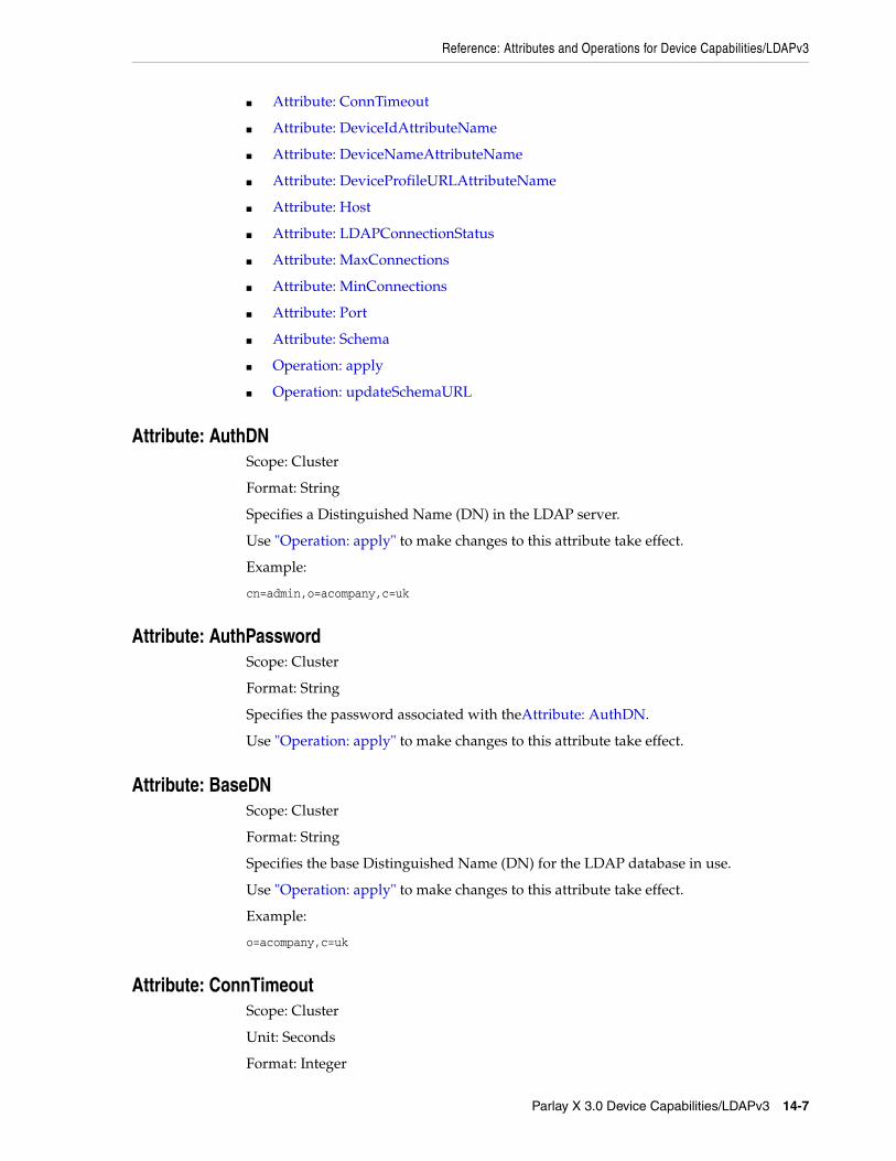
Reference: Attributes and Operations for Device Capabilities/LDAPv3
Parlay X 3.0 Device Capabilities/LDAPv3 14-7
■ Attribute: ConnTimeout
■ Attribute: DeviceIdAttributeName
■ Attribute: DeviceNameAttributeName
■ Attribute: DeviceProfileURLAttributeName
■ Attribute: Host
■ Attribute: LDAPConnectionStatus
■ Attribute: MaxConnections
■ Attribute: MinConnections
■ Attribute: Port
■ Attribute: Schema
■ Operation: apply
■ Operation: updateSchemaURL
Attribute: AuthDNScope: Cluster
Format: String
Specifies a Distinguished Name (DN) in the LDAP server.
Use "Operation: apply" to make changes to this attribute take effect.
Example:
cn=admin,o=acompany,c=uk
Attribute: AuthPassword Scope: Cluster
Format: String
Specifies the password associated with theAttribute: AuthDN.
Use "Operation: apply" to make changes to this attribute take effect.
Attribute: BaseDNScope: Cluster
Format: String
Specifies the base Distinguished Name (DN) for the LDAP database in use.
Use "Operation: apply" to make changes to this attribute take effect.
Example:
o=acompany,c=uk
Attribute: ConnTimeoutScope: Cluster
Unit: Seconds
Format: Integer

Reference: Attributes and Operations for Device Capabilities/LDAPv3
14-8 Services Gatekeeper Communication Service Reference Guide
Specifies the maximum time to wait for an LDAP connection to be established. If the related timer expires, a retry is performed. See "Attribute: recoverTimerInterval" for more information.
Use "Operation: apply" to make changes to this attribute take effect.
Attribute: DeviceIdAttributeNameScope: Cluster
Format: String
Specifies the DeviceId of the target LDAP entry.
Use "Operation: apply" to make changes to this attribute take effect.
Attribute: DeviceNameAttributeNameScope: Cluster
Format: String
Specifies the DeviceName of the target LDAP entry.
Use "Operation: apply" to make changes to this attribute take effect.
Attribute: DeviceProfileURLAttributeNameScope: Cluster
Format: String
Specifies the DeviceProfileURL of the target LDAP entry.
Use "Operation: apply" to make changes to this attribute take effect.
Attribute: HostScope: Cluster
Format: String
Specifies the host name or IP address of the LDAP server to connect to.
Use "Operation: apply" to make changes to this attribute take effect.
Examples:
myldapserver.mycompany.org192.168.0.14
Attribute: LDAPConnectionStatusRead-only.
Scope: Local
Unit: Not applicable
Values: active, update_pending, or deactive. Table 14–5 describes each of these values and their implications.
Format: String

Reference: Attributes and Operations for Device Capabilities/LDAPv3
Parlay X 3.0 Device Capabilities/LDAPv3 14-9
Use "Operation: apply" to make changes to this attribute take effect.
Attribute: MaxConnectionsScope: Cluster
Unit: Not applicable
Format: Integer
Specifies the maximum number of connections in the LDAP connection pool.
Use "Operation: apply" to make changes to this attribute take effect.
Attribute: MinConnectionsScope: Cluster
Unit: Not applicable
Format: Integer
Specifies the minimum number of connections to establish using connections from the LDAP connection pool.
Use "Operation: apply" to make changes to this attribute take effect.
Attribute: PortScope: Cluster
Unit: Not applicable
Format: Integer
Specifies the port number of the LDAP server to connect to.
Use "Operation: apply" to make changes to this attribute take effect.
Attribute: recoverTimerIntervalScope: Cluster
Format: Integer
Unit: Seconds
Table 14–5 LDAP Server Connection Status
Status Description
active The connection is active. The plug-in instance accepts requests.
update_pending The connection is temporarily unavailable due to an update of the configuration settings. The plug-in instance does not accept requests.
deactive The connection is inactive. The plug-in instance does not accept requests.
Reasons for this entering this state include:
■ Missing or incorrect configuration
■ LDAP server is unreachable
■ Internal errors

Reference: Attributes and Operations for Device Capabilities/LDAPv3
14-10 Services Gatekeeper Communication Service Reference Guide
Default Value: 300
Specifies the time to wait before performing an LDAP connection retry after an LDAP connection error. Should be at least twice the time defined in the ConnTimeout attribute. See "Attribute: ConnTimeout" for more information.
Use "Operation: apply" to make changes to this attribute take effect.
Attribute: SchemaScope: Cluster
Unit: Not applicable
Format: String
The LDAP schema to use.
Use "Operation: apply" to make changes to this attribute take effect.
Operation: applyScope: Cluster
Applies attribute changes.
Signature:
apply()
Operation: updateSchemaURLScope: Cluster
Format: String
Updates the schema URL to use when performing lookups in the LDAP database.
During the update, the LDAP connection is temporarily unavailable and the connection status is update_pending. See Table 14–5 for more information.
Signature:
pdateSchemaURL(SchemaURL:String)
Table 14–6 explains that the schemaURL parameter is the LDAP database schema URL to use.
Table 14–6 updateSchemaURL Parameters
Parameter Description
SchemaURL The LDAP database schema URL.
Examples:
Windows: file:///d:/ldap/schema.xml
UNIX: file://ldap/schema.xml

15
Parlay X 3.0 Payment/Diameter 15-1
15Parlay X 3.0 Payment/Diameter
This chapter describes the Oracle Communications Services Gatekeeper Parlay X 3.0 Payment/Diameter communication service in detail.
Overview of the Parlay X 3.0 Payment Communication ServiceThe Parlay X 3.0 Payment/Diameter communication service exposes the Parlay X 3.0 Payment set of application interfaces.
The communication service acts as a credit control client to a credit control server using the Diameter protocol.
For the exact version of the standards that the Parlay X 3.0 Payment/Diameter communication service supports for the application-facing interfaces and the network protocols, see Services Gatekeeper Statement of Compliance.
Using a Payment communication service, an application can:
■ Charge and refund accounts directly.
■ Operate on reservations, which includes:
– Make reservations.
– Charge reservations.
– Release reservations.
■ Charge multiple accounts concurrently.
This communication service uses templates that you use to change the list of Diameter AVPs that Services Gatekeeper sends to a Diameter server. See "Changing the List of Diameter AVPs for Your Implementation" for details on creating templates.
All charging is done on accounts. Accounts can be charged using units of charge (specified as a given currency or a charging code) or by volume of (specified by time or data). See "Amount Charging" and "Volume Based Charging" for details.
Amount ChargingA reservation expires after a given time. An expiration mechanism provided by the Storage Service is used. If the store entry expires, the reservation is cancelled.
Some Diameter servers, for example Oracle Billing and Revenue Management, mandate that a refund operation be correlated with a previous charge operation. The Payment interface does not provide any correlation between charge operations and refund operations. The session-id tunneled parameter has been added in order to correlate these requests. When an application calls chargeAmount, the tunneled

Overview of the Parlay X 3.0 Payment Communication Service
15-2 Services Gatekeeper Communication Service Reference Guide
parameter session-id is returned in the SOAP header. An application should use this session-id in subsequent refundAmount requests to correlate the two requests. If the application does not provided the tunneled parameter, it is the responsibility of the Diameter server to either accept or deny the request. If the request is denied, the application receives a ServiceException. See "session-id" for more information.
Volume Based ChargingVolume-based charging is similar to amount charging. However volume base charging maps to these Diameter AVPs instead of CC-Money:
■ CC-Time (in seconds)
■ CC-Total-Octets (in bytes)
■ CC-Input-Octets (in bytes)
■ CC-Output-Octets (in bytes)
■ CC-Service-Specific-Units
These AVPs all accept either bytes or seconds (as integers) as input. If your AVPs use something different, you also need to convert the data.
The rating parameters to use are unit, contract, service, or operation and they all map to the Service-Parameter-Info AVP.
Diameter servers frequently require a specific list of AVPs, or custom AVPs to process correctly, so you will probably have to modify the list of AVPs that Services Gatekeeper sends. You do this using a template file. See "Changing the List of Diameter AVPs for Your Implementation" for instructions.
Credit-control clients may need to request the price (or an estimate) of the service event in advance, and these clients should be able to handle situations where this amount may not be known.
Clients requesting cost information must:
■ Set the CC-Request-Type AVP to EVENT_REQUEST
■ Include a Requested-Action AVP set to PRICE_ENQUIRY, and
■ Include the requested service event information in the Service-Identifier AVP in the CCR message
Processing Direct Queries/Application-initiated RequestsIf an application makes a request to interact directly with an account, Services Gatekeeper sends the request to the network node capable of handling the request. The request does not return until the targeted account has been updated.
Processing Notifications/Network-triggered RequestsThere are no notifications or other network-triggered requests for this communications service.
Validating Reservation RequestsThe communication service supports the Granted-Service-Unit Diameter AVP that Services Gatekeeper sends to the network.

Changing the List of Diameter AVPs for Your Implementation
Parlay X 3.0 Payment/Diameter 15-3
This support enables the plug-in to validate whether the number of units granted is equal to the number of reserved units requested.
After the Credit Control Answer (CCA) has been received, the plug-in checks the CCA for the Granted-Service-Unit AVP. If this AVP exists, the plug-in compares the number of granted units to the number of reserved units that were requested in the RSU of the Credit Control Request (CCR).
If the Granted-Service-Unit AVP does not exist, the plug-in assumes that the full reservation was granted.
If the Granted-Service-Unit value is less than the number of requested units, the plug-in performs the following actions:
■ Raises the RESERVATION_NOT_GRANTED_ERROR exception (error id="000005") to notify the client that the reservation failed.
■ Releases the reservation by sending a termination Credit Control Request (CCR). This CCR may or may not contain the Used-Service-Unit (USU) field, depending on whether the client has called chargeReservation since the last reservation.
Application InterfacesFor information about the SOAP-based interface for the Parlay X 3.0 Payment communication service, see the discussion of Parlay X 3.0 Interfaces in Services Gatekeeper Application Developer's Guide.
For information about the RESTful Call Notification interface, see the discussion about RESTful payment interface in Services Gatekeeper Application Developer's Guide.
The RESTful Service Call Notification interfaces provide RESTful access to the same functionality as the SOAP-based interfaces. The internal representations are identical, and for the purposes of creating service level agreements (SLAs) and reading charging data records (CDRs), and so on, they are the same.
Changing the List of Diameter AVPs for Your ImplementationDiameter servers vary quite a bit in their messaging requirements. You probably need to change the list of AVPs that Services Gatekeeper sends to a Diameter server to make it acceptable to that server.
There are three ways to add AVPs to your implementation:
■ By adding new AVP definitions to AVP template files that you create, than loading the template files into Services Gatekeeper. This is the best method for major changes to your AVP list, and is probably most appropriate for the changes you make for the initial configuration of Services Gatekeeper. You must stop and restart Gatekeeper to make the changes take effect. See "About the AVP Template Files" for information on creating template files, and "Adding New AVPs for Diameter Payment in Template Files" for details on loading new AVPs into Services Gatekeeper.
■ By adding new AVP definitions to the default AVP template file. You add AVPs to the default template file and restart Services Gatekeeper. This is probably the best method for initial testing of Services Gatekeeper. You only alter one file, but you still need to restart Services Gatekeeper. Follow the instructions in "Adding New AVPs for Diameter Payment in Template Files" but instead of creating template files just make changes to defaultavptemplate.xml file provided.

Changing the List of Diameter AVPs for Your Implementation
15-4 Services Gatekeeper Communication Service Reference Guide
■ By using JMX operations to add new AVP definitions during runtime. This allows you to make changes to existing AVP template files without interrupting traffic or having to stop and restart Services Gatekeeper. This is most appropriate for changes to a running implementation. See "Adding Diameter AVPs to a Template File During Runtime" for details.
Changes to template files also require XSD changes.
About the AVP Template FilesYou can create separate templates for each of these operations:
■ com.bea.wlcp.wlng.px30.plugin.VolumeChargingPlugin. chargeVolume
■ com.bea.wlcp.wlng.px30.plugin.VolumeChargingPlugin. chargeSplitVolume
■ com.bea.wlcp.wlng.px30.plugin.VolumeChargingPlugin. getAmount
■ com.bea.wlcp.wlng.px30.plugin.VolumeChargingPlugin. refundVolume
■ com.bea.wlcp.wlng.px30.plugin.ReserveVolumeChargingPlugin. getAmount
■ com.bea.wlcp.wlng.px30.plugin.ReserveVolumeChargingPlugin. reserveVolume
■ com.bea.wlcp.wlng.px30.plugin.ReserveVolumeChargingPlugin. reserveAdditionalVolume
■ com.bea.wlcp.wlng.px30.plugin.ReserveVolumeChargingPlugin. releaseReservation
Each template can have three separate variations, one each for each of the time or octet data format, and a third if you use a custom data format. For example, the chargeVolume operation can have these templates:
■ com.bea.wlcp.wlng.px30.plugin.VolumeChargingPlugin.chargeVolumeTime
■ com.bea.wlcp.wlng.px30.plugin.VolumeChargingPlugin.chargeVolumeTime
■ com.bea.wlcp.wlng.px30.plugin.VolumeChargingPlugin.chargeVolumeCustom
Adding New AVPs for Diameter Payment in Template FilesIf your implementation requires multiple template files, follow the steps in this section to add them.
You must know the name, code number, and data type of each AVP to add before starting this procedure.
To add new AVPs to your Services Gatekeeper implementation:
1. Navigate to OCSB_home\ocsg_6.0\applications.
2. Unpackage the Plugin_px30_payment_diameter.ear file.
3. Unpackage the Plugin_px30_payment_diameter.jar file.
4. Navigate to the /xml directory you just unpacked.
5. Add an avpAttributeDefinitions element for each new AVP to the avp-attribute.xml file.
Tip: For testing or for minor AVP additions you can simply edit and use the example template file (defaultavptemplate.xml) instead of creating new template files.

Changing the List of Diameter AVPs for Your Implementation
Parlay X 3.0 Payment/Diameter 15-5
6. Make a copy of the defaultavptemplate.xml template file to work on. See "About the AVP Template Files" for details on what to name template files.
7. Create a new avpTemplate element in your new template file for each new AVP.
8. Repeat step 6 and 7 for each template file you are creating.
9. Navigate to the xsd directory (../xsd).
10. Add an element for each new AVP to the diameterAvp.xsd file.
An example XSD file paymentConfig.xsd is provided.
11. Update the Plugin_px30_payment_diameter.jar file to save your changes.
12. Update the wlng_nt_payment_px30.ear file to make your changes take effect.
13. Restart Services Gatekeeper.
Adding Diameter AVPs to a Template File During RuntimeThe instructions in this section allow you to add AVPs to existing template files. Before you follow the instructions in this section you must decide on a template file to change. See "About the AVP Template Files" for details on the template files.
To add AVPs without interrupting traffic or having to restart Services Gatekeeper using JMX operations:
1. Navigate to OCSB_home\ocsg_6.0\applications.
2. Unpackage the Plugin_px30_payment_diameter.ear file.
3. Unpackage the Plugin_px30_payment_diameter.jar file.
4. Navigate to the /xml directory you just unpacked.
5. Add your AVP changes to the defaultavpTemplate.xml file.
6. Open Service Gatekeeper in the Platform Test Environment (PTE) or anther MBean browser.
7. Navigate to navigate to wlng, then AccountService then ServiceLevelAgreementMBean, then to the setupCustomSlaXSDDefinition operation.
8. In the SlaType: field enter payment_diameter_avp.
9. In the FileContent: field select the Load the contents of a file icon.
Select the xml/paymentConfig.xsd file to add.
10. Click Record to make your changes take effect.
11. Navigate to wlng, AccountService, then ServiceLevelAgreementMBean.
12. Select one of these operations:
■ loadGlobalSlaByType
■ loadServiceProviderGroupSlaByType
■ loadApplicationGroupSlaByType
13. In the SlaType: field enter payment_diameter_avp.
14. In the FileContent: field, enter defaultavptemplate.xml.
15. Click Record to make your changes take effect.

Events and Statistics
15-6 Services Gatekeeper Communication Service Reference Guide
Events and StatisticsThe Parlay X 3.0 Payment/Diameter communication service generates event data records (EDRs), charging data records (CDRs), alarms, and statistics to assist system administrators and developers in monitoring the service.
See "Events, Alarms, and Charging" for more information.
Event Data RecordsTable 15–1 lists EDR IDs created by the Payment/Diameter communication service.
StatisticsTable 15–2 maps methods invoked from either the application or the network to the transaction types collected by the Services Gatekeeper statistics counter.
Table 15–1 EDRs Generated by Parlay X 3.0 Payment/Diameter
EDR ID Interface Method Called
15001 com.bea.wlcp.wlng.plugin.payment.diameter.north.AmountChargingPluginNorth
chargeAmount
15002 com.bea.wlcp.wlng.plugin.payment.diameter.north.AmountChargingPluginNorth
refundAmount
15003 com.bea.wlcp.wlng.plugin.payment.diameter.north.AmountChargingPluginNorth
chargeSplitAmount
15004 com.bea.wlcp.wlng.plugin.payment.diameter.north.ReserveAmountChargingPluginNorth
reserveAmount
15005 com.bea.wlcp.wlng.plugin.payment.diameter.north.ReserveAmountChargingPluginNorth
reserveAdditionalAmount
15006 com.bea.wlcp.wlng.plugin.payment.diameter.north.ReserveAmountChargingPluginNorth
chargeReservation
15007 com.bea.wlcp.wlng.plugin.payment.diameter.north.ReserveAmountChargingPluginNorth
releaseReservation
15013 oracle.ocsg.plugin.payment.north.VolumeChargingPluginNorth
chargeVolume
15014 oracle.ocsg.plugin.payment.north.VolumeChargingPluginNorth
chargeSplitVolume
15015 oracle.ocsg.plugin.payment.north.VolumeChargingPluginNorth
getAmount
15016 oracle.ocsg.plugin.payment.north.VolumeChargingPluginNorth
refundVolume
15017 oracle.ocsg.plugin.payment.north.ReserveVolumeChargingPluginNorth
getAmount
15018 oracle.ocsg.plugin.payment.north.ReserveVolumeChargingPluginNorth
reserveVolume
15019 oracle.ocsg.plugin.payment.north.ReserveVolumeChargingPluginNorth
reserveAdditionalVolume
15020 oracle.ocsg.plugin.payment.north.ReserveVolumeChargingPluginNorth
chargeReservation
15021 oracle.ocsg.plugin.payment.north.ReserveVolumeChargingPluginNorth
releaseReservation

Tunneled Parameters for Parlay X 3.0 Payment / Diameter
Parlay X 3.0 Payment/Diameter 15-7
Tunneled Parameters for Parlay X 3.0 Payment / DiameterThis section lists the parameters that can be tunneled.
session-id
DescriptionCorrelates a refundAmount operation with a chargeAmount operation.
Some billing systems, including Oracle Billing and Revenue Management, allow refund operations only on previously charged amounts. Parlay X does not have the ability to correlate charge and refund operations. This parameter provides that functionality.
The key and the value are available in the return message from a chargeAmount operation. It is the responsibility of the application to provide the key and the value in subsequent refundAmount operations to correlate the two.
If no session-id is provided in the request to the Diameter node, the Diameter node can either accept or deny the request. If the node denies the request, a ServiceException is sent back to the application.
Table 15–2 Methods and Transaction Types for Parlay X 3.0 Payment/Diameter
Method Interface Transaction type
chargeAmount com.bea.wlcp.wlng.px30.plugin.AmountChargingPlugin
TRANSACTION_TYPE_CHARGING_DIRECT
chargeSplitAmount com.bea.wlcp.wlng.px30.plugin.AmountChargingPlugin
TRANSACTION_TYPE_CHARGING_DIRECT
refundAmount com.bea.wlcp.wlng.px30.plugin.AmountChargingPlugin
TRANSACTION_TYPE_CHARGING_DIRECT
reserveAmount com.bea.wlcp.wlng.px30.plugin.ReserveAmountChargingPlugin
TRANSACTION_TYPE_CHARGING_RESERVED
reserveAdditionalAmount
com.bea.wlcp.wlng.px30.plugin.ReserveAmountChargingPlugin
TRANSACTION_TYPE_CHARGING_RESERVED
chargeReservation com.bea.wlcp.wlng.px30.plugin.ReserveAmountChargingPlugin
TRANSACTION_TYPE_CHARGING_RESERVED
chargeVolume com.bea.wlcp.wlng.px30.plugin.VolumeChargingPlugin
TRANSACTION_TYPE_CHARGING_DIRECT
chargeSplitVolume com.bea.wlcp.wlng.px30.plugin.VolumeChargingPlugin
TRANSACTION_TYPE_CHARGING_DIRECT
refundVolume com.bea.wlcp.wlng.px30.plugin.VolumeChargingPlugin
TRANSACTION_TYPE_CHARGING_DIRECT
reserveVolume com.bea.wlcp.wlng.px30.plugin.ReserveVolumeChargingPlugin
TRANSACTION_TYPE_CHARGING_RESERVED_STRING
reserveAdditionalVolume
com.bea.wlcp.wlng.px30.plugin.ReserveVolumeChargingPlugin
TRANSACTION_TYPE_CHARGING_RESERVED_STRING
chargeReservation com.bea.wlcp.wlng.px30.plugin.ReserveVolumeChargingPlugin
TRANSACTION_TYPE_CHARGING_RESERVED_STRING

Managing Parlay X 3.0 Payment /Diameter
15-8 Services Gatekeeper Communication Service Reference Guide
FormatString
ExampleThis is an example in a SOAP header:
<xparams> <param key=" session-id value="12233187769"/> </xparams>
Managing Parlay X 3.0 Payment /DiameterThis section describes the properties and workflow for the Parlay X 3.0 Payment/Diameter plug-in instance.
Properties for Parlay X 3.0 Payment/DiameterTable 15–3 lists the technical specifications for the communication service.
Table 15–3 Properties for Parlay X 3.0 Payment/Diameter
Property Description
Managed object in Administration Console
To access the object, select domain_name, then OCSG, then server_name, then Communication Services, then plugin_instance_id, in that order.
MBean Domain=com.bea.wlcp.wlng
Name=wlng_nt
InstanceName=same as the network protocol instance_id assigned when the plug-in instance is created
Type=com.bea.wlcp.wlng.plugin.payment.diameter.management.PaymentMBean
Documentation: See the "All Classes" section of Services Gatekeeper OAM Java API Reference
Network protocol plug-in service ID
Plugin_px30_payment_diameter
Network protocol plug-in instance ID
The ID is assigned when the plug-in instance is created. See "Managing and Configuring the Plug-in Manager" in Services Gatekeeper System Administrator's Guide.
Supported Address Scheme
tel
Application-facing interfaces
com.bea.wlcp.wlng.px30.plugin.AmountChargingPlugin
com.bea.wlcp.wlng.px30.plugin.ReserveAmountChargingPlugin
Service type Payment
Exposes to the service communication layer a Java representation of:
Parlay X 3.0 Part 6: Payment
Interfaces with the network nodes using:
Diameter
RFC3588 and RFC 4006
Deployment artifact
NT EAR
wlng_nt_payment_px30.ear
Plugin_px30_payment_diameter.jar and px30_payment_service.jar

Managing Parlay X 3.0 Payment /Diameter
Parlay X 3.0 Payment/Diameter 15-9
Configuration Workflow for Parlay X 3.0 Payment/DiameterFollowing is an outline for configuring the plug-in using the Administration Console or an MBean browser.
1. Create one or more instances of the plug-in service. See the discussion about configuring and managing the plug-in manager in Services Gatekeeper System Administrator's Guide. Use the plug-in service ID as listed in the "Properties for Parlay X 3.0 Payment/Diameter" section.
2. Add any additional or custom AVPs that your Diameter server requires. See "Changing the List of Diameter AVPs for Your Implementation" for instructions.
3. Using the Administration Console or an MBean browser, select the MBean for the plug-in instance. The MBean display name is the same as the plug-in instance ID given when the plug-in instance was created.
4. Configure the behavior of the plug-in instance using the PaymentMBean fields
5. Use the connect method to connect to the Diameter server.
6. Set up the routing rules to the plug-in instance. See the discussion about configuring and managing the plug-in manager in Services Gatekeeper System Administrator's Guide. Use the plug-in instance ID and address schemes listed in the "Properties for Parlay X 3.0 Payment/Diameter" section.
7. If required, create and load a node SLA. For details see the discussion on defining global node and service provider group node SLAs and managing SLAs in Services Gatekeeper Accounts and SLAs Guide.
8. Provision the service provider accounts and application accounts. For information, see Services Gatekeeper Portal Developer's Guide.
Provisioning Workflow for Parlay X 3.0 Payment/DiameterThe Parlay X 3.0 Payment/Diameter plug-in instance can be explicitly connected to the Diameter server. It does not connect to the server by default. The service has a connection status that will be preserved after service redeployment and server restart.
Use the connect and disconnect operations to PaymentMBean.
Use the SplitChargeEnabled field to PaymentMBean after any changes to the configuration attributes. Changes does not take affect until this operation is invoked.
For a description of the attributes and operations of the PaymentMbean MBean, see the "All Classes" section of Services Gatekeeper OAM Java API Reference.
Deployment artifact
AT EAR: Normal
wlng_at_payment_px30.ear
rest_payment.war and px30_payment.war
Deployment artifact
AT EAR: SOAP Only
wlng_at_payment_px30_soap.ear
px30_payment.war
Table 15–3 (Cont.) Properties for Parlay X 3.0 Payment/Diameter
Property Description

Managing Parlay X 3.0 Payment /Diameter
15-10 Services Gatekeeper Communication Service Reference Guide

16
Parlay X 3.0 Address List Management Interface 16-1
16Parlay X 3.0 Address List ManagementInterface
This chapter describes the Oracle Communications Services Gatekeeper Parlay X 3.0 Address List Management interface in detail.
Overview of the Parlay X 3.0 Address List Management InterfaceUse the Services Gatekeeper Address List Management plug-in interface to create and manage groups of resource owners and to associate them with group Uniform Resource Identifiers (URIs). Group URIs can be used to authenticate requests on behalf of group members.
The Address List Management plug-in is exposed northbound through SOAP or REST using the using the Parlay X 3.0 Part 13 Address List Management interface. It allows applications to create, read, update, and delete group URIs, and to manage group URI membership. The plug-in also exposes an internal API which allows other communication services to identify and expand group URIs using the Parlay X 3.0 SOAP interface. Group URIs can be used in place of individual URIs by the both OneAPI and ParlayX MMS, SMS and Terminal Location communication services.
Group URIs are required by the SMS, MMS, and Location APIs that require authorization from multiple resource owners. For example, a parent, who is the primary subscriber in a family plan, would like to track family members using a location-based application which makes use of the Address List Management plug-in. The parent authorizes location tracking on behalf of family members. The application creates a group owner which issues an authorization grant on behalf of the resource owner members that are part of the group URI. It passes multiple resource owner addresses to the getGroupLocation method of the Location API to retrieve location information.
Address List Management ArchitectureAddress List Management interface SOAP requests are received at the Services Gatekeeper Access tier and passed to the Network tier. They are translated into EJB requests and passed to the Address List plug-in. The plug-in uses store services to access the Services Gatekeeper database when handling requests.
The Address List Management interface is grouped into the following functions:
■ GroupManagement
■ Group
■ Member

Overview of the Parlay X 3.0 Address List Management Interface
16-2 Services Gatekeeper Communication Service Reference Guide
Group URI FormatGroup URIs are consistent with the style defined in RFC 2396 and are in the following format:
scheme:[email protected]
Here are some examples:
mailto:[email protected]
group:[email protected]
Managing GroupsCreate, query and delete address list groups using the following GroupManagement API calls:
■ Operation: createGroup
■ Operation: queryGroups
■ "Operation: deleteGroup"
Controlling Group AccessSet and query group access attributes, which assign group management permissions to group members, using the following GroupManagement API calls:
■ Operation: setAccess
■ Operation: queryAccess
Managing and Querying Group MembersManage group members using the following Group API calls:
■ Operation: addMember
■ Operation: addMembers
■ Operation: queryMembers
■ Operation: deleteMember
■ Operation: queryMembers
Manage individual group member attributes using the following Member API calls:
■ Operation: addMemberAttribute
■ Operation: queryMemberAttributes
■ Operation: deleteMemberAttribute
Managing and Querying Group AttributesGroup attributes apply to the address list group itself. Add, query, and delete group attributes using the following Group API calls:
■ Operation: addGroupAttribute
■ Operation: queryGroupAttribute
■ Operation: deleteGroupAttribute

Events and Statistics
Parlay X 3.0 Address List Management Interface 16-3
Managing and Querying Group Member AttributesGroup member attributes apply to individual members of a group. Add, query, and delete group member attributes using the following Group API calls:
■ Operation: addGroupMemberAttribute
■ Operation: queryGroupMemberAttributes
■ Operation: deleteGroupMemberAttribute
Application InterfacesFor information about the SOAP-based interface for the Parlay X 3.0 Address List Management communication service, see the discussion about Parlay X 3.0 Part 13: Address List Management in Services Gatekeeper Application Developer's Guide.
Events and StatisticsThe Parlay X 3.0 Address List Management Architecture generates event data records (EDRs), charging data records (CDRs), alarms, and statistics to assist system administrators and developers in monitoring the service.
See "Events, Alarms, and Charging" for more information.
Event Data RecordsTable 16–1 lists IDs of the EDRs created by the Parlay X 3.0 Address List Management Architecture. This does not include EDRs created when exceptions are thrown.
Table 16–1 EDRs Generated by Parlay X 3.0 Address List Management Architecture
EDR ID Method Called
28001 createGroup
28002 deleteGroup
28003 queryGroups
28004 setAccess
28005 queryAccess
28006 addGroupAttribute
28007 addGroupMemberAttribute
28008 addMember
28009 addMembers
28010 deleteGroupAttribute
28011 deleteGroupMemberAttribute
28012 deleteMember
28013 deleteMembers
28014 queryGroupAttributes
28015 queryGroupMemberAttributes
28016 queryMembers
28017 addMemberAttribute

Managing Parlay X 3.0 Address List Management Architecture
16-4 Services Gatekeeper Communication Service Reference Guide
AlarmsFor the list of alarms, see Services Gatekeeper Alarms Handling Guide.
Managing Parlay X 3.0 Address List Management ArchitectureThis section describes properties and workflows for the Parlay X 3.0Address List Management Architecture plug-in instance.
Properties for Parlay X 3.0 Address List Management ArchitectureTable 16–2 lists the technical specifications for the communication service.
28018 deleteMemberAttribute
28019 queryMemberAttributes
Table 16–2 Properties for Parlay X 3.0 Address List Management Architecture
Property Description
Managed object in Administration Console
To access the object, select domain_name, then OCSG, server_name, Communication Services, then Plugin_px30_address_list#6.0, in that order.
MBean Domain=com.bea.wlcp.wlng
Name=wlng_nt
InstanceName=Plugin_px30_address_list
Type=oracle.ocsg.plugin.al.px30.management.GroupMBeanImpl
Network protocol plug-in service ID
Plugin_px30_address_list
Network protocol plug-in instance ID
Plugin_px30_address_list
Supported Address Scheme
tel
Application-facing interface
com.bea.wlcp.wlng.px30.plugin.ThirdPartyCallPlugin
Service type AddressList
Exposes to the service communication layer a Java representation of:
Parlay X 3.0 Part 13: Address List
Interfaces with the network nodes using:
Open Service Access (OSA); Application Programming Interface (API); Part 4: Call Control SCF; Subpart 7: MultiParty Call Control Service
Deployment artifacts Plugin_px30_address_list.jar packaged in wlng_at_address_list_px30.ear
Plugin_px30_address_list.jar packaged in wlng_nt_address_list_px30.ear
Table 16–1 (Cont.) EDRs Generated by Parlay X 3.0 Address List Management
EDR ID Method Called

Reference: Attributes and Operations for Parlay X 3.0 Address List Management Architecture
Parlay X 3.0 Address List Management Interface 16-5
This plug-in service does not support multiple instantiation using the Plug-in Manager. There is a one-to-one mapping between the plug-in service and the plug-in instance. The plug-in instance is created when the plug-in service is started.
Configuration Workflow for Parlay X 3.0 Address List Management ArchitectureThe following procedure provides an outline to configure the Address List Management plug-in using the Administration Console or an MBean browser.
1. Select the MBean detailed in "Properties for Parlay X 3.0 Address List Management Architecture".
2. Configure the plug-in instance attributes:
■ Attribute: GroupNameMaxLength
■ Attribute: GroupSize
3. Set up the routing rules to the plug-in instance. See the discussion about configuring and managing the plug-in manager in Services Gatekeeper System Administrator's Guide. Use the plug-in instance ID and address schemes detailed in the "Properties for Parlay X 3.0 Address List Management Architecture" section.
4. If required, create and load a node SLA. For details see the discussion on defining global node and service provider group node SLAs and managing SLAs in Services Gatekeeper Accounts and SLAs Guide.
5. Provision the service provider accounts and application accounts. For information, see Services Gatekeeper Portal Developer's Guide.
Reference: Attributes and Operations for Parlay X 3.0 Address List Management Architecture
This section describes the attributes and operations for configuration and maintenance:
■ Attribute: GroupNameMaxLength
■ Attribute: GroupSize
■ Operation: createGroup
■ Operation: queryGroups
■ Operation: deleteGroup
■ Operation: setAccess
■ Operation: queryAccess
■ Operation: addMember
■ Operation: addMembers
■ Operation: queryMembers
■ Operation: deleteMember
■ Operation: deleteMembers
■ Operation: addGroupAttribute
■ Operation: queryGroupAttribute
■ Operation: deleteGroupAttribute

Reference: Attributes and Operations for Parlay X 3.0 Address List Management Architecture
16-6 Services Gatekeeper Communication Service Reference Guide
■ Operation: addGroupMemberAttribute
■ Operation: queryGroupMemberAttributes
■ Operation: deleteGroupMemberAttribute
■ Operation: addMemberAttribute
■ Operation: queryMemberAttributes
■ Operation: deleteMemberAttribute
Attribute: GroupNameMaxLengthScope: Cluster
Unit: Not applicable
Format: Integer
Indicates the maximum length of an address list group name.
Valid values are 0–255. The default value is 100.
Attribute: GroupSizeScope: Cluster
Unit: Not applicable
Format: Integer
Indicates the maximum number of members in an address list group.
Valid values are 0–65535. The default value is 50.
Operation: createGroupScope: Cluster
Creates an Address List Management group.
Signature:
createGroup(name: String, domain: String)
Operation: queryGroupsScope: Cluster
Queries an Address List Management group to return details about a particular group attribute, which is specified by attributeName.
Signature:
queryGroups(group: String, member: String, attributeName, String)
Table 16–3 createGroup Parameters
Parameter Description
name Name of the Address List Management group to create.
domain Domain the group should be created under.

Reference: Attributes and Operations for Parlay X 3.0 Address List Management Architecture
Parlay X 3.0 Address List Management Interface 16-7
Operation: deleteGroupScope: Cluster
Deletes the specified Address List Management group.
Signature:
deleteGroup(group: String)
Operation: setAccessScope: Cluster
Sets access permissions for a member of an Address List Management group. The access permissions control which group management functions the specified member is allowed to perform on the specified group.
Signature:
setAccess(group: String, requester: String, addPermission: Boolean, adminPermission: Boolean, deletePermission: Boolean, queryPermissions: Boolean)
Operation: queryAccessScope: Cluster
Queries the access permissions set for the group member passed in the requester parameter.
Return:
Table 16–4 queryGroups Parameters
Parameter Description
group Name of the Address List Management group.
member Member of the Address List Management group.
attributeName Attribute for which details will be returned.
Table 16–5 deleteGroup Parameters
Parameter Description
group Name of the Address List Management group to be deleted.
Table 16–6 setAccess Parameters
Parameter Description
group Name of the Address List Management group.
requester Member of the Address List Management group for which you want to set permissions.
addPermission If true, sets the permission for the requester to be able to add members to the group.
adminPermission If true, sets the permission for the requester to be able to modify the access permissions of members to the group.
deletePermission If true, sets the permission for the requester to be able to delete members from the group.
queryPermission If true, sets the permission for the requester to be able to query the group and member attributes.

Reference: Attributes and Operations for Parlay X 3.0 Address List Management Architecture
16-8 Services Gatekeeper Communication Service Reference Guide
Returns the list of access permissions for the group member passed in the requester parameter.
Signature:
Function(correlator: String)
Operation: addMemberScope: Cluster
Adds a single member to an Address List Management group.
Signature:
addMember(group: String, member: String)
Operation: addMembersScope: Cluster
Adds multiple members to an Address List Management group.
Signature:
addMember(group: String, member1: String, [member2: String,...memberN: String])
Operation: queryMembersScope: Cluster
Queries an Address List Management group to obtain a list of its members.
Signature:
queryMembers(group: String)
Table 16–7 queryAccess Parameters
Parameter Description
group Name of the Address List Management group.
requester Member of the Address List Management group.
Table 16–8 addMember Parameters
Parameter Description
group Name of the Address List Management group to which to add the member.
member Member to add to the group.
Table 16–9 addMembers Parameters
Parameter Description
group Name of the Address List Management group to which to add the members.
member[1...unbounded] Member(s) to add to the group.

Reference: Attributes and Operations for Parlay X 3.0 Address List Management Architecture
Parlay X 3.0 Address List Management Interface 16-9
Operation: deleteMemberScope: Cluster
Deletes a single member from an Address List Management group.
Signature:
deleteMember(group: String, member: String)
Operation: deleteMembersScope: Cluster
Deletes multiple members from an Address List Management group.
Signature:
addMember(group: String, member1: String, [member2: String, memberN: String])
Operation: addGroupAttributeScope: Cluster
Adds an attribute to an Address List Management group.
Signature:
addGroupAttribute(group: String, name: String, type: String, value: String, status: Enum)
Table 16–10 queryMembers Parameters
Parameter Description
group Name of the Address List Management group from which to retrieve a list of members.
Table 16–11 deleteMember Parameters
Parameter Description
group Name of the Address List Management group from which to delete the member.
member Member to delete from the group.
Table 16–12 deleteMembers Parameters
Parameter Description
group Name of the Address List Management group from which to delete member
members[1...unbounded]
Member(s) to remove from the group.
Table 16–13 addGroupAttribute Parameters
Parameter Description
group Name of the Address List Management group.
name Name of the attribute to be added.
type Data type of the attribute to be added.
value Value of the attribute.

Reference: Attributes and Operations for Parlay X 3.0 Address List Management Architecture
16-10 Services Gatekeeper Communication Service Reference Guide
Operation: queryGroupAttributeScope: Cluster
Queries an Address List Management group for the value associated with the passed attribute name. The attribute’s value and status are returned.
Signature:
queryGroupAttribute(group: String,attributeName: String))
Operation: deleteGroupAttributeScope: Cluster
Deletes an attribute from an Address List Management group.
Signature:
deleteGroupAttribute(group: String, attributeName: String))
Operation: addGroupMemberAttributeScope: Cluster
Adds an attribute to a member of a particular Address List Management group.
Signature:
addGroupMemberAttribute(group: String, member: String, name: String, type: String, value: String, status: Enum)
status Attribute status: Valid, Unknown, or Denied.
Table 16–14 queryGroupAttribute Parameters
Parameter Description
group Name of the Address List Management group.
attributeName Name of the attribute to be queried.
Table 16–15 deleteGroupAttribute Parameters
Parameter Description
group Name of the Address List Management group.
attributeName Name of the attribute to be deleted.
Table 16–16 addGroupMemberAttribute Parameters
Parameter Description
group Name of the Address List Management group.
member Name of the member to which the attribute is to be added.
name Name of the attribute to be added.
type Data type of the attribute to be added.
value Value of the attribute.
status Attribute status: Valid, Unknown, or Denied.
Table 16–13 (Cont.) addGroupAttribute Parameters
Parameter Description

Reference: Attributes and Operations for Parlay X 3.0 Address List Management Architecture
Parlay X 3.0 Address List Management Interface 16-11
Operation: queryGroupMemberAttributesScope: Cluster
Queries a member of an Address List Management group for list of attributes attached to the member. To retrieve the value of a particular attribute, use queryMemberAttribute.
Signature:
queryGroupMemberAttributes(group: String, member: String))
Operation: deleteGroupMemberAttributeScope: Cluster
Deletes an attribute from a member of a particular Address List Management group.
Signature:
deleteGroupMemberAttribute(group: String, member: String, attributeName: String))
Operation: addMemberAttributeScope: Cluster
Adds an attribute to a member outside of the context of a particular Address List Management group.
Signature:
addMemberAttribute(group: String, member: String, name: String, type: String, value: String, status: Enum)
Table 16–17 queryGroupMemberAttributes Parameters
Parameter Description
group Name of the Address List Management group.
member Name of the member from which to retrieve attributes.
Table 16–18 deleteGroupMemberAttribute Parameters
Parameter Description
group Name of the Address List Management group.
member Name of the member from which to delete an attribute.
attributeName Name of the attribute to be deleted.
Table 16–19 addMemberAttribute Parameters
Parameter Description
member Name of the member to which the attribute is to be added.
name Name of the attribute to be added.
type Data type of the attribute to be added.
value Value of the attribute.
status Attribute status: Valid, Unknown, or Denied.

Reference: Attributes and Operations for Parlay X 3.0 Address List Management Architecture
16-12 Services Gatekeeper Communication Service Reference Guide
Operation: queryMemberAttributesScope: Cluster
Queries a list of attributes for a member and retrieves their values.
Signature:
queryMemberAttributes(member: String, attributeName1: String, [attributeName2: String, attributeNameN: String]))
Operation: deleteMemberAttributeScope: Cluster
Deletes an attribute from a member.
Signature:
deleteMemberAttribute(member: String, attributeName: String))
Table 16–20 queryMemberAttributes Parameters
Parameter Description
member Name of the member from which to retrieve attributes.
attributeNames[1...unbounded]
Names of the attributes to be retrieved.
Table 16–21 deleteMemberAttribute Parameters
Parameter Description
member Name of the member from which to delete an attribute.
attributeName Name of the attribute to be deleted.

17
Parlay X 4.0 Application-Driven Quality of Service/Diameter 17-1
17Parlay X 4.0 Application-Driven Quality ofService/Diameter
This chapter describes the Oracle Communications Services Gatekeeper Parlay X 4.0 Application-Driven Quality of Service (QoS)/Diameter communication service, used by SOAP-based applications to request QoS changes to subscriber connections. See Services Gatekeeper Application Developer's Guide for information about the SOAP interface.
See "Extended Web Services Quality of Service /Diameter" for information on the REST-based QoS communication service.
Overview of the Parlay X 4.0 Application-Driven Quality of Service (QoS)/Diameter Communication Service
This communication service enables applications to dynamically change the quality of service available to subscriber network connections. It does this by requesting that predefined QoS feature profiles be applied to the connection.
The Parlay X 4.0 Application-Driven Quality of Service (QoS)/Diameter communication service provides SOAP-based applications with the ability to request QoS level changes for a subscriber connection. This communication service exposes the Parlay X 4.0 set of interfaces for application-driven QoS (Part 17). It uses the standard SOAP interfaces to communicate with web applications, and translates the SOAP traffic to Diameter Rx messages to communicate with a Policy and Charging Rules Function (PCRF).
This communication service enables an application to control QoS, however, applying QoS policy and applying quality changes to a subscriber connection require a separate PCRF working in conjunction with a Policy and Charging Enforcement Function (PCEF), which are provided by various third parties.
This communication service acts as a client to a Diameter server by using the Diameter protocol.
Using this communication service, an application can:
■ Apply a QoS feature profile
■ Modify an existing QoS feature profile
■ Remove an existing QoS feature profile
■ Retrieve the status for a subscriber’s QoS feature profile
■ Register and unregister for QoS-related events
■ Query for the QoS feature profile change history

Overview of the Parlay X 4.0 Application-Driven Quality of Service (QoS)/Diameter Communication Service
17-2 Services Gatekeeper Communication Service Reference Guide
■ Notify the application of how certain events impacted QoS feature profiles that were active on the subscriber connection when the events occurred
■ Delete the QoS feature profile
This communication service does not however, support the concept of default QoS feature profiles listed in the specification, because the Diameter Rx specification does not share this concept. Instead, use your PCRF/PCEF product tools to set default QoS feature profiles for subscribers, and then use this communication service to change, or request information about the QoS feature profile.
This document refers to the QoS feature profiles that this communication service manages as temporary QoS feature profiles to distinguish them from the default QoS feature profiles that you have already created and applied.
For additional information about adding QoS support to an application, see the discussion about adding SOAP-based quality of service support, and supported SOAP Parlay X 4.0 facades in Services Gatekeeper Application Developer's Guide.
See "Parlay X 4.0 Application-Driven Quality of Service/Diameter" in Services Gatekeeper Statement of Compliance for the exact version of the standards this communication service supports, and the list of supported Diameter Rx AVPs.
How it WorksFigure 17–1 shows the interaction between Services Gatekeeper and your other network nodes when this communication service is used.
Figure 17–1 Example Application-Driven QoS Implementation
In Figure 17–1:
1. A subscriber’s mobile device is registered with the Gateway GPRS Support Node (GGSN) or the PCEF.
2. The GGSN or PCEF requests a default QoS plan from the PCRF.
3. Once the QoS plan is returned from the PCRF, the GGSN or PCEF executes that plan and connects the subscriber’s device to the Internet.
4. A subscriber application sends a RESTful request to Services Gatekeeper for a change in QoS.
5. Services Gatekeeper sends the QoS request to the PCRF using the Rx specification.
6. The PCRF pushes the new QoS plan to the PCEF using the Gx specification, and the PCEF executes that plan.
7. The PCRF interfaces with BRM or another billing management system to charge the subscriber appropriately.

Managing Parlay X 4.0 Application-Driven Quality of Service (QoS)/Diameter
Parlay X 4.0 Application-Driven Quality of Service/Diameter 17-3
Adding SOAP-Based QoS Support to an ApplicationSee the discussion about adding SOAP-based quality of service support in Services Gatekeeper Application Developer's Guide.
Managing Parlay X 4.0 Application-Driven Quality of Service (QoS)/Diameter
This section describes the properties and workflow for setting up the Parlay X 4.0 Application-Driven Quality of Service (QoS)/Diameter plug-in instance.
Your network connections and performance requirements determine how you set up this communication service. Multiple Parlay X 4.0 Application-Driven Quality of Service (QoS)/Diameter communication service implementations generally connect to a smaller number of PCRFs.
This communication service is usable with high-availability implementations. However if the PCRF-Services Gatekeeper connection is broken on a high-availability implementation, the application session is torn down and no further requests are processed. The application must open a new session if further communication with the PCRF is required.
The plug-in instance is not automatically created when the plug-in service is started, you must create is using the Plug-in Manager.
Properties for Parlay X 4.0 Application-Driven QoS/DiameterTable 17–1 lists the technical specifications for this communication service.
Table 17–1 Properties for Parlay X 4.0 Application-Driven QoS/Diameter
Property Description
Managed object in Administration Console
To access the object, select domain_name, then OCSG, then server_name, then Communication Services, then plug-in_instance_id, in that order.
MBean interfaces Domain=oracle.ocsgName=wlng_ntInstanceName=Plugin_qos_diameterType=oracle.ocsg.plugin.qos.diameter.management.QoSMBean
Network protocol plug-in service ID
Plugin_qos_diameter
Supported address scheme tel, email, ipv4, ipv6, sip, and private
Application-facing interfaces
com.bea.wlcp.wlng.px40.plugin.ApplicationQoSPlugin
com.bea.wlcp.wlng.px40.plugin.ApplicationQoSNotificationManagerPlugIn
com.bea.wlcp.wlng.px40.callback.ApplicationQoSNotificationCallback
Service type Application-Driven QoS
Exposes to the service communication layer a Java representation of
SOAP
Interfaces with the network nodes using:
Diameter Rx

Managing Parlay X 4.0 Application-Driven Quality of Service (QoS)/Diameter
17-4 Services Gatekeeper Communication Service Reference Guide
Configuration Workflow for Parlay X 4.0 Application-Driven QoS/DiameterThe following is an outline for configuring this plug-in using the Administration console or an MBean browser. These instructions assume that you have already created the SLAs to manage services.
1. Select wlng, then PluginManager, and then createPluginInstance.
2. Set the following parameters:
■ Set PluginServiceId to Plugin_qos_diameter.
■ Set PluginInstanceId to Plugin_qos_diametern where n is an integer that is not already in use by an existing QoS plug-in instance.
3. Select wlng then PluginManager then addRoute.
4. Set the following parameters:
■ Set PluginInstanceId to the ID you configured in step 2.
■ Set an appropriate value for AddressExpression depending upon your Services Gatekeeper configuration.
5. Select the MBean wlng_nt_qos#version. Where version is the Services Gatekeeper version.
6. Select the plug-in instance you created in step 2. Expand QoSMBean and configure the plug-in instance attributes:
■ Attribute: DestinationHost
■ Attribute: DestinationPort
■ Attribute: DestinationRealm
■ Attribute: OriginHost
■ Attribute: OriginPort
■ Attribute: OriginRealm
■ Attribute: Connected
■ Attribute: RecordHistory
7. Ensure that your PCRF is listening on the destination port configured for this plug-in the DestinationPort attribute.
Deployment artifacts: NT EAR
wlng_nt_qos.ear
Plugin_qos_diameter.jar px40_qos_service.jar
Deployment artifacts: AT EAR:
wlng_at_qos_px40.ear
px40_qos.war px40_qos_callback.jar
Note: DestinationHost and DestinationPort should be the correct values for your PCRF.
Table 17–1 (Cont.) Properties for Parlay X 4.0 Application-Driven QoS/Diameter
Property Description

Reference: Attributes and Operations for Parlay X 4.0 Application-Driven Quality of Service (QoS)/Diameter
Parlay X 4.0 Application-Driven Quality of Service/Diameter 17-5
8. Use "Operation: loadQoSRequestTemplate" to load a QoS template for this communication service to use.
Events and StatisticsThe Parlay X 4.0 Application-Driven QoS/Diameter communication service generates event data records (EDRs), charging data records (CDRs), alarms, and statistics to assist system administrators and developers in monitoring the service.
See "Event Data Records" for the list of EDRs and "Events, Alarms, and Charging" for general information.
Event Data RecordsTable 17–2 lists the IDs of the EDRs created by the Parlay X 4.0 Application-Driven QoS communication service. This does not include EDRs created when exceptions are thrown.
Charging Data RecordsThis communication service does not generate any CDRs.
Reference: Attributes and Operations for Parlay X 4.0 Application-Driven Quality of Service (QoS)/Diameter
This section describes the attributes and operations for configuration and maintenance:
■ Attribute: DestinationHost
■ Attribute: DestinationPort
■ Attribute: DestinationRealm
Table 17–2 EDRs Generated by Parlay X 4.0 Application-Driven QoS
EDR ID Operation Called
91851 applyQoSFeatureResponse, applyQoSFeature
91852 getQoSStatusResponse, getQoSStatu
91853 modifyQoSFeatureResponse, modifyQoSFeature
91854 removeQoSFeatureResponse, removeQoSFeature
91855 getQoSHistoryResponse, getQoSHistory
91856 startQoSNotificationResponse, startQoSNotification
91857 stopQoSNotificationResponse, stopQoSNotification
91808 sendInitAAR
91809 RxAAA, sendModifyAAR
91810 RxSTA, sendSTR
91811 handleRxRAR
91862 notifyQoSEventResponse, notifyQoSEvent
91863 QoSRequestReached
91864 QoSNotificationReached

Reference: Attributes and Operations for Parlay X 4.0 Application-Driven Quality of Service (QoS)/Diameter
17-6 Services Gatekeeper Communication Service Reference Guide
■ Attribute: OriginHost
■ Attribute: OriginPort
■ Attribute: OriginRealm
■ Attribute: Connected
■ Attribute: RecordHistory
■ Operation: connect
■ Operation: disconnect
■ Operation: loadQoSRequestTemplate
■ Operation: retrieveQoSRequestTemplate
■ Operation: listQoSRequestTemplateMatchRule
■ Operation: deleteQoSRequestTemplate
Attribute: DestinationHost Scope: Cluster
Unit: Not applicable
Format: String
The host name of the PCRF Diameter server.
Valid values are either a host name or a regular expression matching a host name. The default value is host.destination.com.
Attribute: DestinationPortScope: Cluster
Unit: Not applicable
Format: Integer
Port number of the PCRF Diameter server.
Valid values are 0–65535. The default value is 3588.
Attribute: DestinationRealmScope: Cluster
Unit: Not applicable
Format: String
Diameter destination realm used for requests.
Valid values are either a realm or a regular expression matching a realm. The default value is destination.com.
Attribute: OriginHostScope: Local
Unit: Not applicable
Format: String

Reference: Attributes and Operations for Parlay X 4.0 Application-Driven Quality of Service (QoS)/Diameter
Parlay X 4.0 Application-Driven Quality of Service/Diameter 17-7
Host name of the machine running this communication service.
Valid values are either a host name or a regular expression matching a host name. The default value is host.origin.com.
Attribute: OriginPortScope: Local
Unit: Not applicable
Format: Integer
Port number of the machine running this communication service.
Valid values are 0–65535. A value of 0 indicates a random port and should be used when upgrading the plug-in. The default value is 0.
Attribute: OriginRealmScope: Cluster
Unit: Not applicable
Format: String
The Diameter originating realm used for requests.
Valid values are either a realm or a regular expression matching a realm. The default value is origin.com.
Attribute: ConnectedScope: Local
Unit: Not applicable
Format: Boolean
Checks the connection status. Confirms that the "Operation: connect" operation was successful.
Valid values are true or false. The default value false.
Attribute: RecordHistoryScope: Cluster
Unit: Not applicable
Format: Boolean
Indicates whether to record a transaction history for this communication service. A value of true records the history; the default value is false.
Operation: connectScope: Local
Connects this communication service to the PCRF Diameter server. If the plug-in is already connected to a Diameter server, it disconnects that server, and then reconnects using the specified parameters. The destination host, port, and realm, and origin host and port attributes must be set before using this operation.
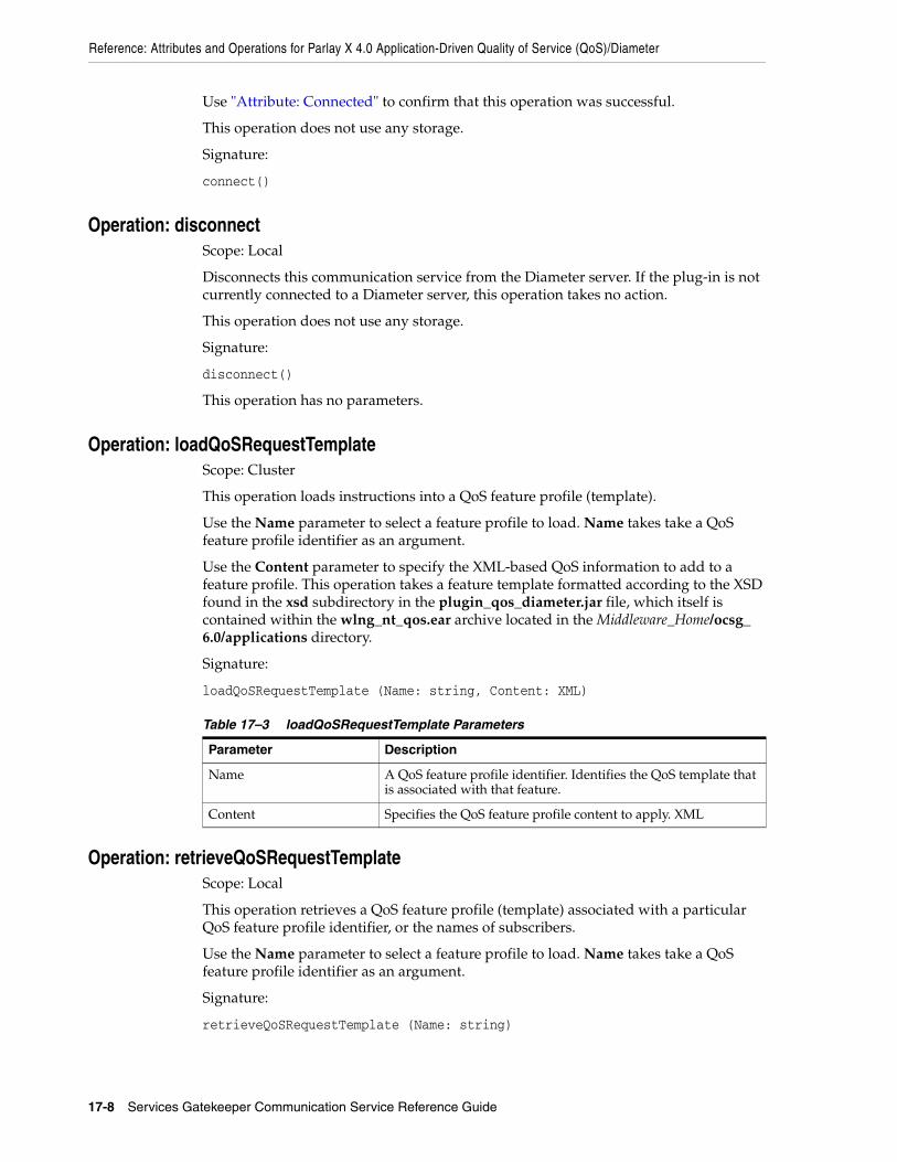
Reference: Attributes and Operations for Parlay X 4.0 Application-Driven Quality of Service (QoS)/Diameter
17-8 Services Gatekeeper Communication Service Reference Guide
Use "Attribute: Connected" to confirm that this operation was successful.
This operation does not use any storage.
Signature:
connect()
Operation: disconnectScope: Local
Disconnects this communication service from the Diameter server. If the plug-in is not currently connected to a Diameter server, this operation takes no action.
This operation does not use any storage.
Signature:
disconnect()
This operation has no parameters.
Operation: loadQoSRequestTemplateScope: Cluster
This operation loads instructions into a QoS feature profile (template).
Use the Name parameter to select a feature profile to load. Name takes take a QoS feature profile identifier as an argument.
Use the Content parameter to specify the XML-based QoS information to add to a feature profile. This operation takes a feature template formatted according to the XSD found in the xsd subdirectory in the plugin_qos_diameter.jar file, which itself is contained within the wlng_nt_qos.ear archive located in the Middleware_Home/ocsg_6.0/applications directory.
Signature:
loadQoSRequestTemplate (Name: string, Content: XML)
Operation: retrieveQoSRequestTemplateScope: Local
This operation retrieves a QoS feature profile (template) associated with a particular QoS feature profile identifier, or the names of subscribers.
Use the Name parameter to select a feature profile to load. Name takes take a QoS feature profile identifier as an argument.
Signature:
retrieveQoSRequestTemplate (Name: string)
Table 17–3 loadQoSRequestTemplate Parameters
Parameter Description
Name A QoS feature profile identifier. Identifies the QoS template that is associated with that feature.
Content Specifies the QoS feature profile content to apply. XML

Reference: Attributes and Operations for Parlay X 4.0 Application-Driven Quality of Service (QoS)/Diameter
Parlay X 4.0 Application-Driven Quality of Service/Diameter 17-9
Operation: listQoSRequestTemplateMatchRuleScope: Local
This operations returns a list of subscribers with a specific QoS feature profile (template).
Use the Name parameter to select a feature profile to load. Name takes take a QoS feature profile identifier as an argument.
Signature:
listQoSRequestTemplateMatchRule (Name: string)
Operation: deleteQoSRequestTemplateScope: Cluster
This operation deletes a QoS feature profile (template) for a subscriber, or set of subscribers.
The Name parameter specifies a the QoS feature profile and it take a QoS feature profile identifier as an argument.
Signature:
deleteQoSRequestTemplate (Name: string)
Table 17–4 retrieveQoSRequestTemplate Parameters
Parameter Description
Name A QoS feature profile identifier. Identifies the QoS template that is associated with that QoS feature profile.
Table 17–5 listQoSRequestTemplateMatchRule Parameters
Parameter Description
Name A QoS feature profile identifier. Identifies the QoS template that is associated with that QoS feature profile.
Table 17–6 deleteQoSRequestTemplate Parameters
Parameter Descripton
Name A QoS feature identifier. Identifies the QoS template that is associated with that feature.

Reference: Attributes and Operations for Parlay X 4.0 Application-Driven Quality of Service (QoS)/Diameter
17-10 Services Gatekeeper Communication Service Reference Guide

18
REST Services 18-1
18REST Services
This chapter describes how Oracle Communications Services Gatekeeper can be used with existing RESTFul Application Services.
Overview of REST Services Service providers may have existing third-party or proprietary applications or platforms that communicate using REST web services. Services Gatekeeper functionality can be integrated with existing applications that support REST interfaces by creating a RESTFul communication service.
Services Gatekeeper supports two types of RESTFul communication services. A REST2REST service exposes an existing REST API allowing communication between RESTFul interfaces. A REST Exposure or empty service is an application bound, network-facing service used when RESTFul requests are sent to a custom network implementation for translation and processing.
Services Gatekeeper mediates traffic between users and existing REST infrastructure allowing the application of service level agreements, policy enforcement, security, alarms and statistics for more control over communication services.
For more information on using REST services, see "Using the OneAPI RESTful Services" in Services Gatekeeper Application Developer's Guide, and these chapters in this book:
■ OneAPI Multimedia Messaging/MM7
■ OneAPI Payment/Diameter
■ OneAPI Short Messaging/SMPP
■ OneAPI Terminal Location/MLP
You can also use the Platform Development Wizard to generate REST2REST and REST Exposure Communication Services. For more information, see "Creating Extensions with Platform Development Wizard" in Services Gatekeeper Extension Developer's Guide.

Overview of REST Services
18-2 Services Gatekeeper Communication Service Reference Guide

19
OneAPI Multimedia Messaging/MM7 19-1
19OneAPI Multimedia Messaging/MM7
This chapter describes the Oracle Communications Services Gatekeeper OneAPI Multimedia Messaging/MM7 communication service in detail.
About the OneAPI Multimedia Messaging InterfaceApplications use the RESTful OneAPI MMS interface to send multimedia messages (MMS messages), to retrieve MMS messages and delivery status reports, and to start and stop notifications.
When the request body for an MMS operation contains a request for a delivery receipt, the application provides a notifyURL correlator for the message being sent and includes an endpoint address for returning the delivery notification.
The Services Gatekeeper OneAPI MMS interface complies with Open Mobile Alliance (OMA) specifications. See the discussion about OneAPI multimedia messaging compliance in Services Gatekeeper Statement of Compliance for a reference to the supported specification and RESTful bindings schema.
See "Using the OneAPI RESTful Interface" in Services Gatekeeper Application Developer's Guide for general information on creating applications using the OneAPI RESTful interface.
The information provided in this document is based on the OneAPI specification and is provided here for convenience.
REST Service Descriptions Available at Run-timeWhen the Administration Server for your Services Gatekeeper domain is in the running state, the REST service descriptions of these operations are located in:
http://host:port/oneapi/1/messaging/application.wadl
Where host and port are the host name and port of the machine on which the Services Services Gatekeeper Application Developer's GuideGatekeeper Access Tier (AT) is installed.

Sending MMS Messages
19-2 Services Gatekeeper Communication Service Reference Guide
Sending MMS Messages
To send an MMS message, provide the OneAPI-formatted URI of the addresses which must receive the message in the request body. If the sender requires a delivery receipt, specify the required parameters for the receipt.
If the Send MMS operation is successful, the response will contain the request identifier in the response body for this operation).
If the application requires a receipt for delivery of the message, the application can provide the notifyURL in the message body, to which notifications are to be sent.
19AuthorizationBasic or OAuth 2.0
19HTTP MethodPOST
19URIhttp://host:port/oneapi/1/messaging/outbound/senderAddress/requests
Where:
■ host and port are the host name and port of the machine on which the Services Gatekeeper Access Tier is installed.
■ The senderAddress is the subscriber for which the message is being sent.
19Request HeaderThe MIME-type for the Content-Type header field is multipart/form-data.
19Request BodyThe request body for the OneAPI Send MMS operation accepts the following parameters:
■ address: String. At least one address is the (optionally) URL-escaped enduser ID; in this case the MSISDN including the ’tel:’ protocol identifier and the country code optionally preceded by ‘+’. For example, tel:+15415550100.
■ message: String. Must be URL-escaped as per RFC 1738.
■ senderAddress: String. The address to whom a responding MMS may be sent.
senderName: String. The URL-escaped name of the sender to appear on the terminal. This is the address to whom a responding MMS may be sent.
■ clientCorrelator: String. Optional. Uniquely identifies this create MMS request. If there is a communication failure during the request, using the same client correlator when retrying the request allows the operator to avoid sending the same MMS twice.
■ notifyURL: anyURL. The URL-escaped URL to which you want a notification of delivery sent. The format of this notification is shown in Example 19–1.

Sending MMS Messages
OneAPI Multimedia Messaging/MM7 19-3
callbackData: String. will be passed back in this notification, so you can use it to identify the message the receipt relates to or any other useful data, such as a function name.
19Response HeaderThe Location header field contains the URI:
http://host:port/oneapi/1/messaging/outbound/senderAddress/requests/requestID
where requestID is the string identifier returned in the response body.
If the request fails, the Status-Line header field will contain the status code and the reason for the failure. For more information, see "Errors and Exceptions" in the discussion about One API Multimedia messaging in Services Gatekeeper Application Developer's Guide.
19Response BodyThe body of the response contains the request identifier as the string value for the resourceReference attribute. It is the request identifier returned in the Location header field of the response message. The application uses this request identifier to retrieve the delivery status for the sent message.
The response body for this operation is represented by the following JSON structure, where the value part of the name/value pair indicates its data type:
{"resourceReference": {"resourceURL": "URL"}}
19ExamplesExample 19–1 shows a sample of a OneAPI Send MMS request.
Example 19–1 OneAPI Send MMS Request
POST http://example.com/oneapi/1/messaging/outbound/tel%3A%2B5550102/requestsHTTP/1.1Content-Length: 12345Content-Type: multipart/form-data; boundary="===============123456=="; MIME-Version: 1.0Host: www.example.comDate: Thu, 04 Jun 2009 02:51:59 GMT --===============123456==Content-Disposition: form-data; name=”root-fields”Content-Type: application/x-www-form-urlencoded;address=tel%3A%2B15415550100&address=tel%3A%2B15415550101&senderAddress=tel:%2B5550102&&senderName=ExampleCompanySubject=My%20message¬ifyURL=http://example-application.com/notifications/DeliveryInfoNotification/54311&callbackData=&clientCorrelator=123456--===============123456==Content-Disposition: form-data; name=”attachments”; filename=”picture.jpg”Content-Type: image/gif

Sending MMS Messages
19-4 Services Gatekeeper Communication Service Reference Guide
GIF89a...binary image data...--===============123456==
Example 19–2 shows a sample of a OneAPI Send MMS response.
Example 19–2 OneAPI Send MMS Response
HTTP/1.1 201 CreatedContent-Type: application/jsonLocation: http://example.com/oneapi/1/messaging/outbound/ tel%3A%2B5550102/requests/abc123Content-Length: 12345Date: Thu, 04 Jun 2009 02:51:59 GMT {"resourceReference": {"resourceURL": " http://example.com/1/messaging/outbound/ tel%3A%2B5550102/requests/abc123"}}

Query Delivery Status of MMS Message
OneAPI Multimedia Messaging/MM7 19-5
Query Delivery Status of MMS Message
The Query Delivery Status operation retrieves the delivery status of a message that was previously sent using the system-generated requestID returned when the message was created.
If the Query Delivery Status is successful, the response body contains the delivery status for each of the addresses contained in the original send MMS request.
19AuthorizationBasic or OAuth 2.0
19HTTP MethodGET
19URIhttp://host:port/oneapi/1/messaging/outbound/senderAddress/requests/requestID/deliveryInfos
Where:
■ host and port are the host name and port of the machine on which the Services Gatekeeper Access Tier is installed.
■ senderAddress is the address to which a responding message may be sent.
■ requestID is the identifier returned in the result object of the corresponding Send operation.
19Request BodyThere is no request body.
19Response HeaderStandard header fields. If the request fails, the Status-Line header field will contain the status code and the reason for the failure. For more information, see "Errors and Exceptions" in the discussion about Using the OneAPI RESTful Interfaces.
19Response BodyThe response body contains an array of structures as the value for deliveryInfo. Each element in the array contains values for the following parameters.
■ address: String. The telephone number to which the initial message was sent.
■ deliveryStatus: Enumeration value. Table 19–1 lists the possible statuses:
Table 19–1 Enumeration Values for Delivery Status
Value Description
DeliveredToNetwork Successful delivery to the network. For concatenated messages, returned only when all the MMS-parts have been successfully delivered to the network.

Query Delivery Status of MMS Message
19-6 Services Gatekeeper Communication Service Reference Guide
■ resourceURL: A reference to the response.
The response body for this operation is represented by the following JSON data structure, where the value part of each name/value pair indicates its data type:
{"deliveryInfoList": { "deliveryInfo": [ { "address": "String", "deliveryStatus": "String"}, { "address": "String", "deliveryStatus": "String"}], "resourceURL": " http://example.com/oneapi/1/messaging/outbound/senderAddress/requests/requestID/deliveryInfos"}}
19ExamplesExample 19–3 shows a sample of a OneAPI Query Delivery Status request.
Example 19–3 OneAPI Query Delivery Status Request
GET http://example.com/oneapi/1/messaging/outbound/tel%3A%2B5550100/requests/abc123/deliveryInfos HTTP/1.1Accept: application/jsonHost: example.com:80
Example 19–4 shows a sample of a OneAPI Query Delivery Status response.
Example 19–4 OneAPI Query Delivery Status Response
HTTP/1.1 200 OKContent-Type: application/jsonDate: Thu, 04 Jun 2009 02:51:59 GMT {"deliveryInfoList": { "deliveryInfo": [ { "address": "tel:15415550101", "deliveryStatus": "MessageWaiting" }, { "address": "tel:15415550102",
DeliveryUncertain Delivery status unknown, for example, if it was handed off to another network.
DeliveryImpossible Unsuccessful delivery; the message could not be delivered before it expired.
DeliveredToTerminal Successful delivery to the terminal. For concatenated messages, returned only when all the MMS-parts have been successfully delivered to the terminal.
MessageWaiting The message is still queued for delivery. This is a temporary state, pending transition to one of the preceding states.
Table 19–1 (Cont.) Enumeration Values for Delivery Status
Value Description

Query Delivery Status of MMS Message
OneAPI Multimedia Messaging/MM7 19-7
"deliveryStatus": "MessageWaiting" } ], "resourceURL": " http://example.com/oneapi/1/messaging/outbound/tel%3A%2B5550100/requests/abc123/deliveryInfos"}}

Subscribe to MMS Delivery Notification
19-8 Services Gatekeeper Communication Service Reference Guide
Subscribe to MMS Delivery Notification
The Subscribe to MMS Delivery Notification operation creates a subscription to delivery notifications for an application.
To set up an MMS notification, provide a notifyURL for the delivery of the notifications. The request body contains the correlator for the notification, the notifyURL to which the call direction notifications must be sent and, optionally, the callbackData (a string to identify the notification).
If the subscription request is successful:
■ The response header contains the URI of the publish/subscribe server.
■ A data object associated with the result of the multimedia message operation is sent to the notifyURL address specified in the request body. This data object contains the appropriate notification (that the message was received or a delivery receipt for the call).
In addition, the delivery report notification sent to the application contains the callback data that the application provided when it sent the message.
19AuthorizationBasic or OAuth 2.0
19HTTP MethodPOST
19URIhttp://host:port/oneapi/1/messaging/outbound/senderAddress/subscriptions
Where:
■ host and port are the host name and port of the machine on which the Services Gatekeeper Access Tier is installed.
■ senderAddress is the address to whom a responding MMS may be sent.
19Request HeaderThe MIME-type for the Content-Type header field is application/x-www-form-urlencoded or application/json.
19Request BodyThe request body for the subscription operation accepts the following parameters:
■ notifyURL: URL. This will be used by the server to POST the notifications to you, so include the URL of your own listener application.
■ clientCorrelator: String. Optional. Uniquely identifies this create subscription request. If there is a communication failure during the request, using the same client correlator when retrying the request allows the operator to avoid creating a duplicate subscription.
■ callbackData: String. Optional. A function name or other data that you would like included when the POST is received.

Subscribe to MMS Delivery Notification
OneAPI Multimedia Messaging/MM7 19-9
19Response HeaderThe Location header field contains the URI of the publish/subscribe server:
http://host:port/oneapi/1/messaging/outbound/subscriptions/subscriptionID
Where:
■ host and port are the host name and port of the machine on which the Services Gatekeeper AT is installed.
■ subscriptionID is the reference to the created subscription.
If the request fails, the Status-Line header field contains the status code and the reason for the failure. For more information, see "Errors and Exceptions" in Using the OneAPI RESTful Interfaces.
19Response BodyThe response body contains a confirmation deliveryReceiptSubscription JSON data structure consisting of the parameters supplied in the subscription request.
{"deliveryReceiptSubscription": { "callbackReference": { "callbackData": "String", "notifyURL": " www.yourURL.here ", }, "resourceURL": " URL "}} A resourceURL is included as a reference to the response.
19Notification Data Object for MMS Delivery Receipt Sent to notifyURLAfter a OneAPI MMS subscription is made, Services Gatekeeper delivers a message receipt notification to the notifyURL specified in the subscription request.
This nested JSON object contains the following as the value of the attribute name deliveryInfoNotification:
■ deliveryInfo: Array. Contains the following two parameters:
– address: String. The message recipient’s subscriber ID.
– deliveryStatus: Enumeration value. Table 19–2 lists the possible statuses:
Table 19–2 Enumeration Values for Delivery Status
Value Description
DeliveredToNetwork Successful delivery to the network. For concatenated messages, returned only when all the MMS-parts have been successfully delivered to the network.
DeliveryUncertain Delivery status unknown; for example, if it was handed off to another network.
DeliveryImpossible Unsuccessful delivery; the message could not be delivered before it expired.
DeliveredToTerminal Successful delivery to the terminal. For concatenated messages, returned only when all the MMS-parts have been successfully delivered to the terminal.

Subscribe to MMS Delivery Notification
19-10 Services Gatekeeper Communication Service Reference Guide
■ link: Refers to the message URL (that was returned when the message was originally created).
The notification data object delivered to the notifyURL address is represented by the following JSON data structure, where the value part of each name/value pair indicates its data type:
{"deliveryInfoNotification": { "deliveryInfo": [ { "address": "String" "deliveryStatus": "String"}, ], "link": { "href": "URL", "rel": "String" }, "resourceURL":"URL" }}
19ExamplesExample 19–5 shows a sample of a OneAPI Subscribe to MMS Delivery Notifications request.
Example 19–5 OneAPI Subscribe to MMS Delivery Notifications Request
POST http://example.com/oneapi/1/messaging/outbound/tel%3A%2B5550100/subscriptions HTTP/1.1Accept: application/jsonContent-Type: application/json; charset=UTF-8Host: example.com:80 {"deliveryReceiptSubscription": { "callbackReference": { "callbackData": " doSomething()", "notifyURL": "http://www.oracle.com" }}}
Example 19–6 shows a sample of a OneAPI Subscribe to MMS Delivery Notifications response.
Example 19–6 OneAPI Subscribe to MMS Delivery Notifications Response
HTTP/1.1 201 CreatedContent-Type: application/jsonLocation: http://example.com/oneapi/1/messaging/outbound/subscriptions/sub789Date: Thu, 04 Jun 2009 02:51:59 GMT {"deliveryReceiptSubscription": { "callbackReference": { "callbackData": "doSomething()", "notifyURL": " www.oracle.com " }, "resourceURL": " http://example.com/oneapi/1/messaging/outbound/subscriptions/sub789"}}
Example 19–7 shows a sample of a OneAPI MMS Delivery Notification Message.

Subscribe to MMS Delivery Notification
OneAPI Multimedia Messaging/MM7 19-11
Example 19–7 OneAPI MMS Delivery Notification Message
{"deliveryInfoNotification": { "deliveryInfo": [ { "address": "tel:15415550101", "deliveryStatus": "DeliveredToTerminal"}, { "address": "tel:15415550102", "deliveryStatus": "DeliveredToTerminal"} ], "link": { "href": "http://example.com/oneapi/1/messaging/outbound/tel%3A%2B5550100/requests/{requestId}", "rel": "OutboundMessageRequest" }, "resourceURL": http://example.com/oneapi/1/messaging/outbound/tel%3A%2B5550100/requests/req123/DeliveryInfos }

Stop Subscription to Delivery Notifications
19-12 Services Gatekeeper Communication Service Reference Guide
Stop Subscription to Delivery Notifications
The Stop Subscription to Delivery Notification operation terminates a previously set up MMS notification for the application.
To stop a previously set up MMS notification, provide the correlator for the notification passed earlier in the Subscribe to MMS Delivery Notification request.
There is no request or response body for the Stop Subscription to Delivery Notification operation. If the request fails, the body of the error response contains the identifier for the notification and the type of exception.
19AuthorizationBasic or OAuth 2.0
19HTTP MethodDELETE
19URIhttp://host:port/oneapi/1/messaging/outbound/subscriptions/subscriptionID
Where:
■ host and port are the host name and port of the machine on which the Services Gatekeeper Access Tier is installed.
■ subscriptionID is the reference to the created subscription.
19Request BodyThere is no request body.
19Response HeaderStandard header fields. If the request fails, the Status-Line header field contains the status code and the reason for the failure. For more information, see "Errors and Exceptions" in Using the OneAPI RESTful Interfaces.
19Response BodyThere is no response body.
19ExamplesExample 19–8 shows a sample of a OneAPI Stop Subscription to Delivery Notification request.
Example 19–8 OneAPI Stop Subscription to Deliver Notification Request
DELETE http://example.com/oneapi/1/messaging/outbound/subscriptions/sub789 HTTP/1.1Accept: application/jsonHost: example.com:80

Stop Subscription to Delivery Notifications
OneAPI Multimedia Messaging/MM7 19-13
Example 19–9 shows a sample of a OneAPI Stop Subscription to Delivery Notification response.
Example 19–9 OneAPI Stop Subscription to Deliver Notification Response
HTTP/1.1 204 No Content Date: Thu, 04 Jun 2009 02:51:59 GMT
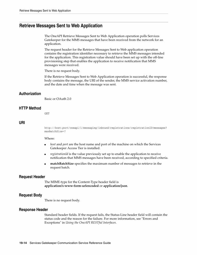
Retrieve Messages Sent to Web Application
19-14 Services Gatekeeper Communication Service Reference Guide
Retrieve Messages Sent to Web Application
The OneAPI Retrieve Messages Sent to Web Application operation polls Services Gatekeeper for the MMS messages that have been received from the network for an application.
The request header for the Retrieve Messages Sent to Web application operation contains the registration identifier necessary to retrieve the MMS messages intended for the application. This registration value should have been set up with the off-line provisioning step that enables the application to receive notification that MMS messages were received.
There is no request body.
If the Retrieve Messages Sent to Web Application operation is successful, the response body contains the message, the URI of the sender, the MMS service activation number, and the date and time when the message was sent.
19AuthorizationBasic or OAuth 2.0
19HTTP MethodGET
19URIhttp://host:port/oneapi/1/messaging/inbound/registrations/registrationID/messages?maxBatchSize=?
Where:
■ host and port are the host name and port of the machine on which the Services Gatekeeper Access Tier is installed.
■ registrationId is the value previously set up to enable the application to receive notification that MMS messages have been received, according to specified criteria.
■ matchBatchSize specifies the maximum number of messages to retrieve in the request batch.
19Request HeaderThe MIME-type for the Content-Type header field is application/x-www-form-urlencoded or application/json.
19Request BodyThere is no request body.
19Response HeaderStandard header fields. If the request fails, the Status-Line header field will contain the status code and the reason for the failure. For more information, see "Errors and Exceptions" in Using the OneAPI RESTful Interfaces.

Retrieve Messages Sent to Web Application
OneAPI Multimedia Messaging/MM7 19-15
19Response BodyThe response body is an inboundMessageList containing an array of structures as the value for inboundMessage. The response body also contains the following parameters:
■ inboundMessage: Array. Contains the following parameters:
– dateTime: dateTime. The date and time when the message was received.
– destinationAddress: String. The registration ID of the application.
– messageID: String. A server generated message identifier.
– inboundMMSMessage: String. Contains the subject of the message, which may determine whether you want to retrieve the entire MMS message.
– resourceURL: URL. Link to the message.
– senderAddress: String. The MSISDN of the sender.
■ numberOfMessagesInThisBatch: Integer. The total number of messages in the batch.
■ resourceURL: URL Self-referring resource URL.
The response body for this operation is represented by the following JSON data structure, where the value part of each name/value pair indicates its data type:
"inboundMessage": [ "dateTime": "dateTime", "destinationAddress": "String", "messageId": "String", "inboundMMSMessage": "String", "resourceURL": "URL", "senderAddress": "String"},]
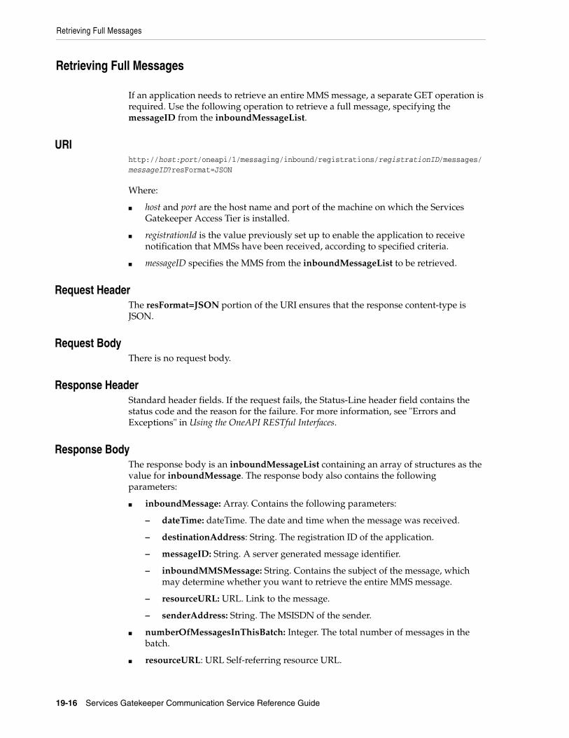
Retrieving Full Messages
19-16 Services Gatekeeper Communication Service Reference Guide
Retrieving Full Messages
If an application needs to retrieve an entire MMS message, a separate GET operation is required. Use the following operation to retrieve a full message, specifying the messageID from the inboundMessageList.
19URIhttp://host:port/oneapi/1/messaging/inbound/registrations/registrationID/messages/messageID?resFormat=JSON
Where:
■ host and port are the host name and port of the machine on which the Services Gatekeeper Access Tier is installed.
■ registrationId is the value previously set up to enable the application to receive notification that MMSs have been received, according to specified criteria.
■ messageID specifies the MMS from the inboundMessageList to be retrieved.
19Request HeaderThe resFormat=JSON portion of the URI ensures that the response content-type is JSON.
19Request BodyThere is no request body.
19Response HeaderStandard header fields. If the request fails, the Status-Line header field contains the status code and the reason for the failure. For more information, see "Errors and Exceptions" in Using the OneAPI RESTful Interfaces.
19Response BodyThe response body is an inboundMessageList containing an array of structures as the value for inboundMessage. The response body also contains the following parameters:
■ inboundMessage: Array. Contains the following parameters:
– dateTime: dateTime. The date and time when the message was received.
– destinationAddress: String. The registration ID of the application.
– messageID: String. A server generated message identifier.
– inboundMMSMessage: String. Contains the subject of the message, which may determine whether you want to retrieve the entire MMS message.
– resourceURL: URL. Link to the message.
– senderAddress: String. The MSISDN of the sender.
■ numberOfMessagesInThisBatch: Integer. The total number of messages in the batch.
■ resourceURL: URL Self-referring resource URL.

Retrieve Messages Sent to Web Application
OneAPI Multimedia Messaging/MM7 19-17
The response body for this operation is represented by the following JSON data structure, where the value part of each name/value pair indicates its data type:
"inboundMessage": [ { "dateTime": "dateTime", "destinationAddress": "String", "messageId": "String", "inboundMMSMessage": "String", "resourceURL": "URL", "senderAddress": "String"},
====Content Divider====
One or more attachments
19ExamplesExample 19–10 shows a sample of a OneAPI Retrieve Messages request.
Example 19–10 OneAPI Retrieve Messages Request
GET http://example.com/oneapi/1/messaging/inbound/registrations/3456/messages?maxBatchSize=2 HTTP/1.1Host: example.com:80Accept: application/json
Example 19–11 shows a sample of a OneAPI Retrieve Messages response.
Example 19–11 OneAPI Retrieve Messages Response
HTTP/1.1 200 OKContent-Type: application/jsonContent-Length: 12345Date: Thu, 04 Jun 2009 02:51:59 GMT {"inboundMessageList": { "inboundMessage": [ { "dateTime": "2010-11-19T12:00:00", "destinationAddress": "6789", "inboundMMSMessage": {"subject": "Rock Festival 2010"}, "messageId": "msg1", "resourceURL": "http://example.com/oneapi/1/messaging/inbound/registrations/3456/messages/msg1", "senderAddress": "tel:+5550100" }, { "dateTime": "2010-11-19T12:15:00", "destinationAddress": "6789", "inboundMMSMessage": {"subject": "London Marathon"}, "messageId": "msg2”, "resourceURL": " http://example.com/oneapi/1/messaging/inbound/registrations/sub789/messages/msg2", "senderAddress": "tel:+5550101" } ], "numberOfMessagesInThisBatch": "2", "resourceURL": " http://example.com/1/messaging/inbound/registrations/3456/messages?maxBatchSize=2 ", "totalNumberOfPendingMessages": "20"}

Retrieving Full Messages
19-18 Services Gatekeeper Communication Service Reference Guide
Example 19–12 shows a sample of a OneAPI Retrieve Full Message request.
Example 19–12 OneAPI Retrieve Full Message Request
GET http://example.com/oneapi/1/messaging/inbound/registrations/3456/messages/msg1?resFormat=JSON HTTP/1.1Host: example.com:80
Example 19–13 shows a sample of a OneAPI Retrieve Full Messages response.
Example 19–13 OneAPI Retrieve Full Message Response
HTTP/1.1 200 OKContent-Type: multipart/form-data; boundary=”=====12345====”Content-Length: 12345Date: Thu, 04 Jun 2009 02:51:59 GMT ====12345====Content-Disposition=multipart/form-data; name=”root-fields”Content-Type=application/jsonContent-Length: nnnn{"inboundMessage": { "dateTime": "2010-11-19T12:00:00", "destinationAddress": "6789", "messageId": "msg1", "inboundMMSMessage": {"subject": Rock Festival 2010"}, "resourceURL": " http://example.com/oneapi/1/messaging/inbound/registrations/3456/messages/msg1", "senderAddress": " tel:+5550100"}} ====12345==== Content-Disposition: form-data; name=”attachments”Content-Type: multipart/mixed; boundary=”====aaabbb”====aaabbbContent-Disposition:attachments;filename=”textBody.txt”;Content-Type: text/plain; charset=UTF-8Content-Transfer-Encoding: 8 bit Look at the attached picture====aaabbbContent-Disposition:attachments;filename=”image1.gif”;Content-Type: image/gifMIME-Version: 1.0Content-ID: <[email protected]> GIF89a...binary image data...====12345====

Subscribe to Notifications of Messages Sent to Application
OneAPI Multimedia Messaging/MM7 19-19
Subscribe to Notifications of Messages Sent to Application
The Subscribe to Notifications Sent to Application operation creates a subscription to delivery notifications for when an application receives a message.
To set up an application notification, provide the destinationAddress which triggers notifications and a notifyURL for the delivery of the notifications. The destinationAddress is the MSISDN, or code set up in Services Gatekeeper, to which subscribers may send an MMS to your application.
If the subscription request is successful:
■ The response header contains the URI of the publish/subscribe server.
■ The response body contains a resourceURL indicating the URI of the newly created subscription.
19AuthorizationBasic or OAuth 2.0
19HTTP MethodPOST
19URIhttp://host:port/oneapi/1/messaging/inbound/subscriptions
Where:
■ host and port are the host name and port of the machine on which the Services Gatekeeper Access Tier is installed.
19Request HeaderThe MIME-type for the Content-Type header field is application/json or application/x-www-form-urlencoded.
19Request BodyThe request body for the subscription operation accepts the following parameters:
■ destinationAddress: String. The MSISDN, or code agreed upon by the operator, to which people may send an MMS to your application.
■ notifyURL: URL. This is used by the server to POST the notifications to you, so include the URL of your own listener application.
■ criteria: String. Optional. Case-insensitive text to match against the first word of the message, ignoring any leading whitespace. This allows you to reuse a short code among various applications, each of which can register its own subscription with different criteria.
■ notificationFormat: Content Type. Optional. The content type that notifications will be sent; for OneAPI, only JSON is supported.
■ clientCorrelator: String. Optional. Uniquely identifies this create subscription request. If there is a communication failure during the request, using the same

Subscribe to Notifications of Messages Sent to Application
19-20 Services Gatekeeper Communication Service Reference Guide
client correlator when retrying the request allows the operator to avoid creating a duplicate subscription.
■ callbackData: String. Optional. A function name or other data that you would like included when the POST is received.
19Response HeaderThe Location header field contains the URI of the publish/subscribe server:
http://host:port/oneapi/1/messaging/inbound/subscriptions/subscriptionID
Where:
■ host and port are the host name and port of the machine on which the Services Gatekeeper Access Tier is installed.
■ subscriptionID is the reference to the created subscription.
If the request fails, the Status-Line header field will contain the status code and the reason for the failure. For more information, see "Errors and Exceptions" in Using the OneAPI RESTful Interfaces.
19Response BodyThe response body contains a confirmation resourceReference JSON data structure consisting of the parameters supplied in the subscription request.
{"resourceReference": {"resourceURL": "URL"}}
The resourceURL indicates the URI of the newly created subscription.
19Notification Data Object for Application Notification Message Sent to notifyURLAfter a OneAPI Application Notification subscription is made, Services Gatekeeper will deliver a message receipt notification to the specified notifyURL in the subscription request for every MMS received. If callbackData was provided in the subscription request, the notification contains this information.
This nested JSON object contains the following parameters as the value of the attribute name inboundMMSMessageNotification:
■ callbackData: String. The correlator used to identify the notification.
■ inboundMessage: Array. Contains the following parameters:
– destinationAddress: String. The number or shortcode for the application.
– messageID: String. A server-generated message identifier.
– inboundMMSMessage: String. Message subject or text.
– link: URL. The URL of the subscription that received this message.
– resourceURL: URL. Link to the message.
– senderAddress: String. The MSISDN of the sender.
The notification data object delivered to the notifyURL address is represented by the following JSON data structure, where the value part of each name/value pair indicates its data type:
{"inboundMessageNotification": { "callbackData": "String", "inboundMMSMessage": {
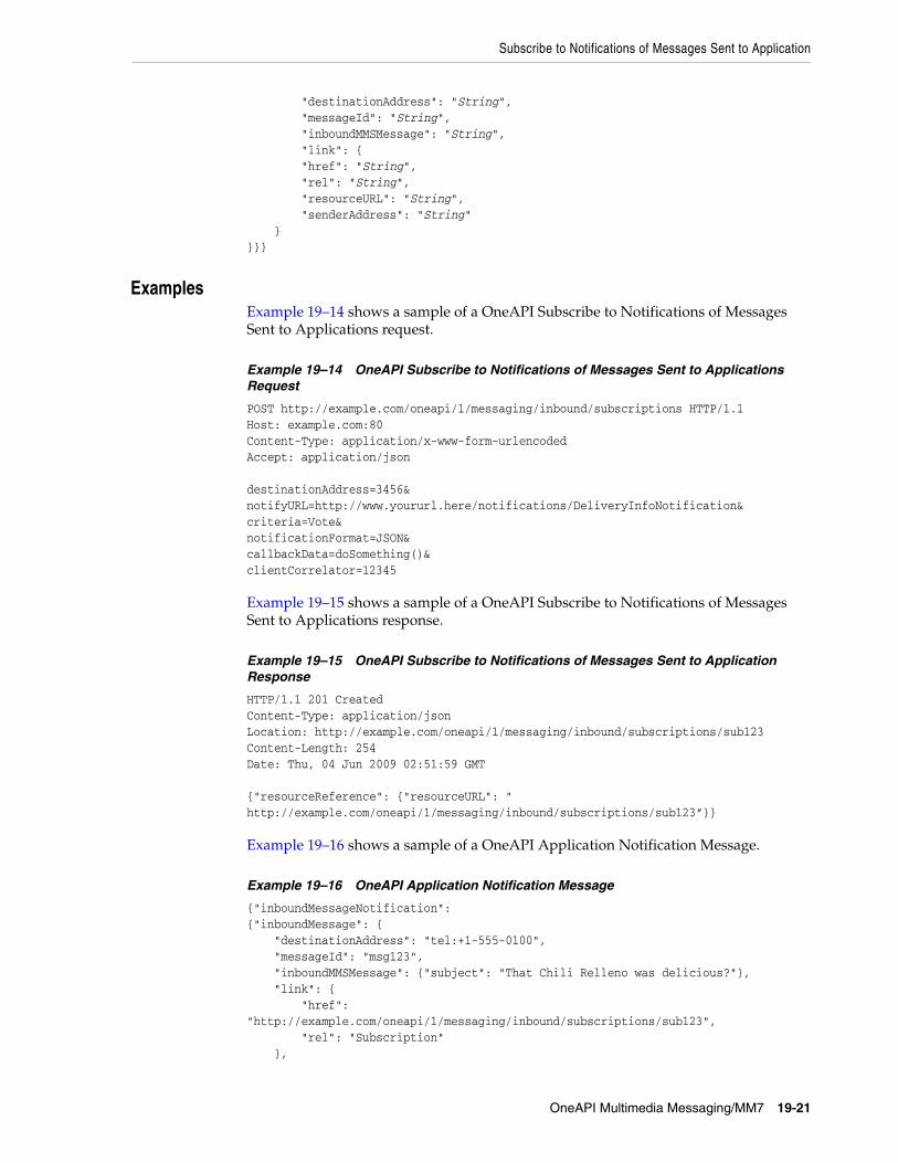
Subscribe to Notifications of Messages Sent to Application
OneAPI Multimedia Messaging/MM7 19-21
"destinationAddress": "String", "messageId": "String", "inboundMMSMessage": "String", "link": { "href": "String", "rel": "String", "resourceURL": "String", "senderAddress": "String" }}}}
19ExamplesExample 19–14 shows a sample of a OneAPI Subscribe to Notifications of Messages Sent to Applications request.
Example 19–14 OneAPI Subscribe to Notifications of Messages Sent to Applications Request
POST http://example.com/oneapi/1/messaging/inbound/subscriptions HTTP/1.1Host: example.com:80Content-Type: application/x-www-form-urlencodedAccept: application/json destinationAddress=3456¬ifyURL=http://www.yoururl.here/notifications/DeliveryInfoNotification&criteria=Vote¬ificationFormat=JSON&callbackData=doSomething()&clientCorrelator=12345
Example 19–15 shows a sample of a OneAPI Subscribe to Notifications of Messages Sent to Applications response.
Example 19–15 OneAPI Subscribe to Notifications of Messages Sent to Application Response
HTTP/1.1 201 CreatedContent-Type: application/jsonLocation: http://example.com/oneapi/1/messaging/inbound/subscriptions/sub123Content-Length: 254Date: Thu, 04 Jun 2009 02:51:59 GMT {"resourceReference": {"resourceURL": " http://example.com/oneapi/1/messaging/inbound/subscriptions/sub123”}}
Example 19–16 shows a sample of a OneAPI Application Notification Message.
Example 19–16 OneAPI Application Notification Message
{"inboundMessageNotification":{"inboundMessage": { "destinationAddress": "tel:+1-555-0100", "messageId": "msg123", "inboundMMSMessage": {"subject": "That Chili Relleno was delicious?"}, "link": { "href": "http://example.com/oneapi/1/messaging/inbound/subscriptions/sub123", "rel": "Subscription" },

Subscribe to Notifications of Messages Sent to Application
19-22 Services Gatekeeper Communication Service Reference Guide
"resourceURL": "http://example.com/oneapi/1/messaging/inbound/registrations/reg123/messages/msg123", "senderAddress": "tel:+5550101"}}}

Stop Subscription to Application Message Notifications
OneAPI Multimedia Messaging/MM7 19-23
Stop Subscription to Application Message Notifications
The Stop Subscription to Application Message Notification operation terminates a previously set up subscription to an application message notification.
To stop a previously set up subscription, provide the correlator for the notification passed earlier in the Subscribe to Notifications of Messages Sent to Application request.
There is no request or response body for the Stop Subscription to Notifications of Messages Sent to Application operation. If the request fails, the body of the error response will contain the identifier for the notification and the type of exception.
19AuthorizationBasic or OAuth 2.0
19HTTP MethodDELETE
19URIhttp://host:port/oneapi/1/messaging/inbound/subscriptions/subscriptionID
Where:
■ host and port are the host name and port of the machine on which the Services Gatekeeper Access Tier is installed.
■ subscriptionID is the reference to the created subscription.
19Request BodyThere is no request body.
19Response HeaderStandard header fields. If the request fails, the Status-Line header field contains the status code and the reason for the failure. See "Errors and Exceptions" in Using the OneAPI RESTful Interfaces for more information.
19Response BodyThere is no response body.
19ExamplesExample 19–17 shows a sample of a OneAPI Stop Subscription to Notifications of Messages Sent to Application request.
Example 19–17 OneAPI Stop Subscription to Notifications of Messages Sent to Application Request
DELETE http://example.com/oneapi/1/messaging/inbound/subscriptions/sub123 HTTP/1.1Accept: application/jsonHost: example.com:80

Stop Subscription to Application Message Notifications
19-24 Services Gatekeeper Communication Service Reference Guide
Example 19–18 shows a sample of a OneAPI Stop Subscription to Notifications of Messages Sent to Application response.
Example 19–18 OneAPI Stop Subscription to Notifications of Messages Sent to Application Response
HTTP/1.1 204 No contentAccept: application/jsonDate: Thu, 04 Jun 2009 02:51:59 GMT

20
OneAPI Payment/Diameter 20-1
20OneAPI Payment/Diameter
This chapter describes the Oracle Communications Services Gatekeeper OneAPI Payment/Diameter communication service in detail.
About the Payment InterfaceApplications use the RESTful Payment interface to charge an amount to an end-user’s account using Diameter and to refund amounts to that account. Applications can also reserve amounts, reserve additional amounts, charge against the reservation or release the reservation.
The Services Gatekeeper OneAPI Payment interface complies with Open Mobile Alliance (OMA) specifications. See "OneAPI Payment Interface" in Services Gatekeeper Statement of Compliance for a reference to the supported specification and RESTful bindings schema. Note that this interface does not support volume charging.
See "Using the OneAPI RESTful Interfaces" in Services Gatekeeper Application Developer's Guide for general information on creating applications using the OneAPI RESTful interface.
The information provided in this document is based on the OneAPI specification and provided here for convenience.
REST Service Descriptions Available at Run-timeWhen the Administration Server for your Services Gatekeeper domain is in the running state, the REST service descriptions of these operations can be found at
http://host:port/oneapi/1/payment/application.wadl
Where host and port are the host name and port of the machine on which the Services Gatekeeper Access Tier (AT) services are running.

Charge Amount
20-2 Services Gatekeeper Communication Service Reference Guide
Charge Amount
The Charge Amount operation charges an amount directly to an end-user’s application using the Diameter protocol.
To charge an amount for a call, provide the telephone address of the end-user (endUserId), a reference code (code) in case there is any dispute regarding the charges, and the billing information to charge for the call.
20AuthorizationBasic or OAuth 2.0
20HTTP MethodPOST
20URIhttp://host:port/oneapi/1/payment/endUserId/transactions/amount
Where:
host and port are the host name and port of the machine on which the Services Gatekeeper Access Tier (AT) services are running.
endUserId is the address of the subscriber to charge (MSISDN).
20Request HeaderThe MIME-type for the Content-Type header field can be either application/x-www-form-urlencoded or application/json.
20Request BodyThe request body for the Charge Amount operation accepts the following parameters:
■ endUserId: String. The URL-escaped end user ID. For example, a MSISDN including the ‘tel:’ protocol identifier and the country code preceded by ‘+’.For example, tel:+15415550100.
■ transactionOperationStatus: Enumeration. This indicates the desired resource state, in this case ‘charged’. See "Resource States" for more information.
■ description: String. The human-readable text to appear on the bill provided so the subscriber can easily see what was purchased.
■ currency: String. The 3-figure currency code defined in ISO4217.
■ amount: Decimal. The amount to be charged.
■ code: String. The charging code, from an existing contractual description that references an operator price point.
■ clientCorrelator: String. Optional. This uniquely identifies the create charge request. If there is a communication failure during the charge request, using the same client correlator when retrying the request allows the operator to avoid applying the same charge twice.
■ onBehalfOf: String. Optional. Allows aggregators or partners to specify the actual payee.

Charge Amount
OneAPI Payment/Diameter 20-3
■ purchaseCategoryCode: String. Optional. An indication of the content type. Values meaningful to the billing system would be published by a OneAPI implementation.
■ channel: String. Optional. Can be Wap, Web, MMS, or SMS, depending on the source of user interaction.
■ taxAmount: Decimal. Optional. Indicates a tax amount already charged by the merchant or application.
■ serviceID: String. Optional. The ID of the partner or merchant service.
■ productID: String. Optional. Combines with the serviceID to uniquely identify the product being purchased.
20Response HeaderThe Location header field contains the URI:
http://host:port/oneapi/1/payment/endUserId/transactions/amount/transactionID
Where transactionID is the string identifier returned in the response body.
The Status-Line header field returned indicates if the charge has been created or accepted. An accepted response indicates that additional processing is required before the transaction is complete. If the request fails, the Status-Line header field will contain the status code and the reason for the failure. See "Errors and Exceptions" in Services Gatekeeper Application Developer's Guide for more information.
20Response BodyThe response body contains a confirmation amountTransaction JSON data structure consisting of the parameters supplied in the payment request.
{"amountTransaction": { "clientCorrelator": "String", "endUserId": "String", "paymentAmount": { "chargingInformation": { "amount": "Decimal", "currency": "String", "description": " String" }, "totalAmountCharged": "Decimal" }, "code": "String", "resourceURL": "URL" "transactionOperationStatus": "String"}} A resourceURL is included as a reference to the response. The transactionOperationStatus provides the resource state. See, "Resource States" for more information.
20ExamplesExample 20–1 shows a sample of a OneAPI Charge Payment request.
Example 20–1 OneAPI Charge Payment Request
POST http://example.com/oneapi/1/payment/tel%3A%2B15415550100/transactions/amountHTTP/1.1

Charge Amount
20-4 Services Gatekeeper Communication Service Reference Guide
Accept: application/jsonHost: example.com:80Content-Type: application/x-www-form-urlencodedContent-Length: 12345 Date: Thu, 04 Jun 2009 02:51:59 GMT endUserId= tel%3A%2B15415550100&transactionOperationStatus=charged&description= Alien%20%20Game¤cy=USD&amount=10&code=REF-12345&clientCorrelator=54321&onBehalfOf=Example%20Games%20Inc&purchaseCategoryCode=Game&channel=WAP&taxAmount=0
Example 20–2 shows a sample of a OneAPI Charge Payment response.
Example 20–2 OneAPI Charge Payment Response
HTTP/1.1 201 CreatedContent-Type: application/jsonContent-Length: 12345Date: Thu, 04 Jun 2009 02:51:59 GMTLocation: http://example.com/1/payment/tel%3A%2B15415550100/transactions/amount/abc123 {"amountTransaction": { "clientCorrelator": "54321", "endUserId": "tel:+15415550100", "paymentAmount": { "chargingInformation": { "amount": "10", "currency": "USD", "description": " Alien Game" }, "totalAmountCharged": "10" }, "code": "REF-12345", "resourceURL": " http://example.com/oneapi/1/payment/tel%3A%2B15415550100/transactions/amount/abc123 "transactionOperationStatus": "Charged"}}
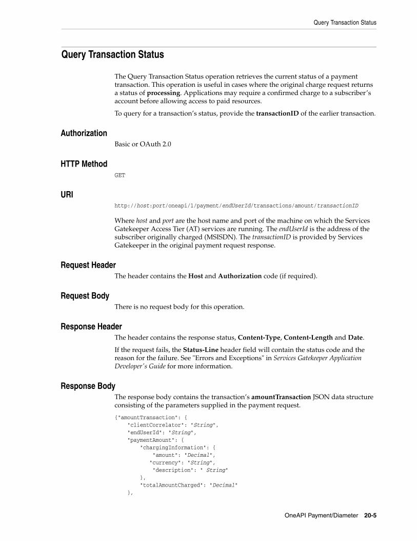
Query Transaction Status
OneAPI Payment/Diameter 20-5
Query Transaction Status
The Query Transaction Status operation retrieves the current status of a payment transaction. This operation is useful in cases where the original charge request returns a status of processing. Applications may require a confirmed charge to a subscriber’s account before allowing access to paid resources.
To query for a transaction’s status, provide the transactionID of the earlier transaction.
20AuthorizationBasic or OAuth 2.0
20HTTP MethodGET
20URIhttp://host:port/oneapi/1/payment/endUserId/transactions/amount/transactionID
Where host and port are the host name and port of the machine on which the Services Gatekeeper Access Tier (AT) services are running. The endUserId is the address of the subscriber originally charged (MSISDN). The transactionID is provided by Services Gatekeeper in the original payment request response.
20Request HeaderThe header contains the Host and Authorization code (if required).
20Request BodyThere is no request body for this operation.
20Response HeaderThe header contains the response status, Content-Type, Content-Length and Date.
If the request fails, the Status-Line header field will contain the status code and the reason for the failure. See "Errors and Exceptions" in Services Gatekeeper Application Developer's Guide for more information.
20Response BodyThe response body contains the transaction’s amountTransaction JSON data structure consisting of the parameters supplied in the payment request.
{"amountTransaction": { "clientCorrelator": "String", "endUserId": "String", "paymentAmount": { "chargingInformation": { "amount": "Decimal", "currency": "String", "description": " String" }, "totalAmountCharged": "Decimal" },
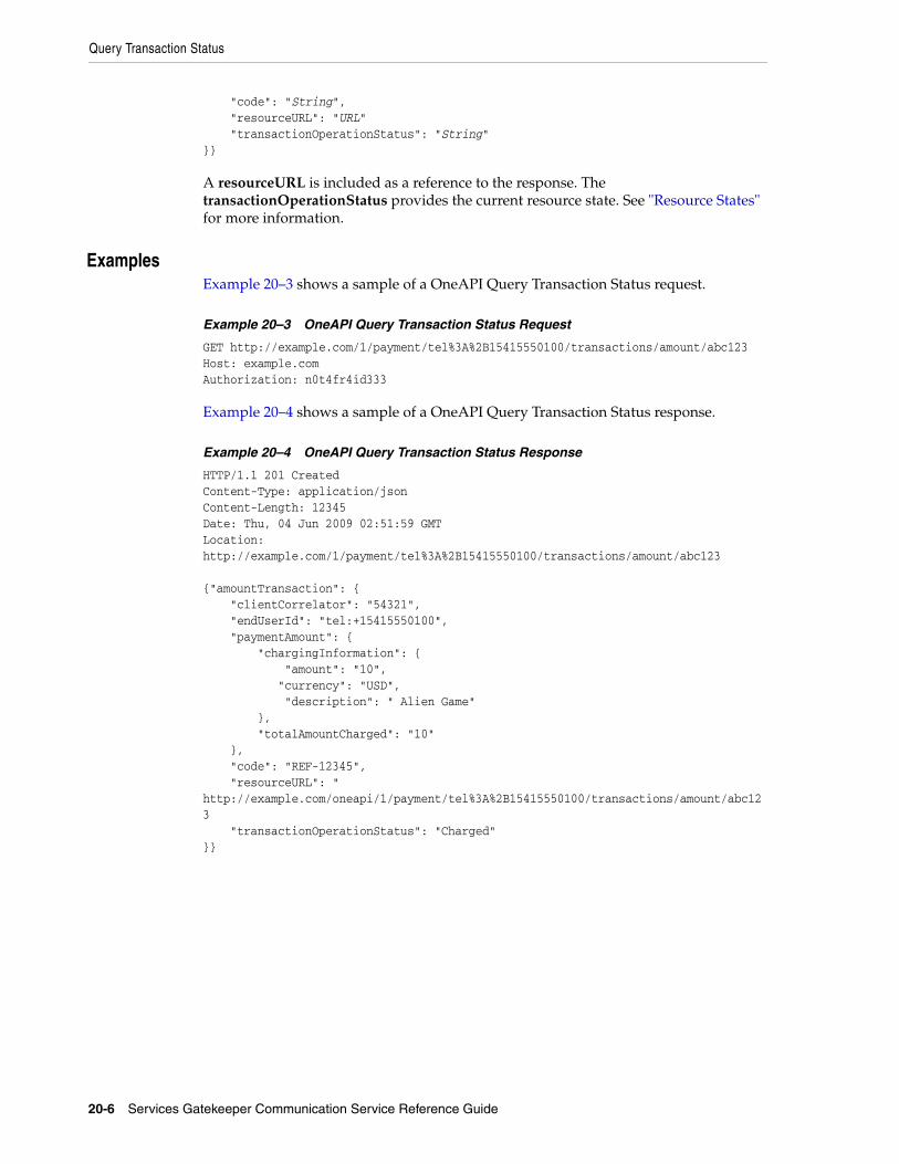
Query Transaction Status
20-6 Services Gatekeeper Communication Service Reference Guide
"code": "String", "resourceURL": "URL" "transactionOperationStatus": "String"}} A resourceURL is included as a reference to the response. The transactionOperationStatus provides the current resource state. See "Resource States" for more information.
20ExamplesExample 20–3 shows a sample of a OneAPI Query Transaction Status request.
Example 20–3 OneAPI Query Transaction Status Request
GET http://example.com/1/payment/tel%3A%2B15415550100/transactions/amount/abc123Host: example.comAuthorization: n0t4fr4id333
Example 20–4 shows a sample of a OneAPI Query Transaction Status response.
Example 20–4 OneAPI Query Transaction Status Response
HTTP/1.1 201 CreatedContent-Type: application/jsonContent-Length: 12345Date: Thu, 04 Jun 2009 02:51:59 GMTLocation: http://example.com/1/payment/tel%3A%2B15415550100/transactions/amount/abc123 {"amountTransaction": { "clientCorrelator": "54321", "endUserId": "tel:+15415550100", "paymentAmount": { "chargingInformation": { "amount": "10", "currency": "USD", "description": " Alien Game" }, "totalAmountCharged": "10" }, "code": "REF-12345", "resourceURL": " http://example.com/oneapi/1/payment/tel%3A%2B15415550100/transactions/amount/abc123 "transactionOperationStatus": "Charged"}}
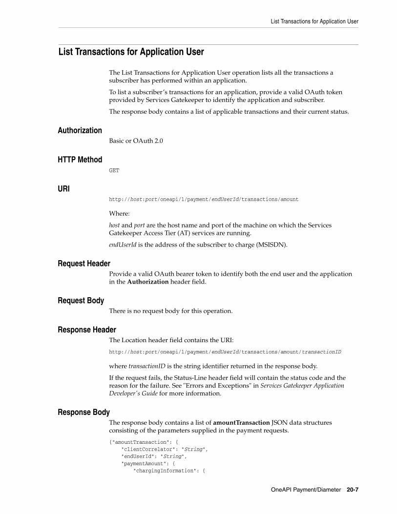
List Transactions for Application User
OneAPI Payment/Diameter 20-7
List Transactions for Application User
The List Transactions for Application User operation lists all the transactions a subscriber has performed within an application.
To list a subscriber’s transactions for an application, provide a valid OAuth token provided by Services Gatekeeper to identify the application and subscriber.
The response body contains a list of applicable transactions and their current status.
20AuthorizationBasic or OAuth 2.0
20HTTP MethodGET
20URIhttp://host:port/oneapi/1/payment/endUserId/transactions/amount
Where:
host and port are the host name and port of the machine on which the Services Gatekeeper Access Tier (AT) services are running.
endUserId is the address of the subscriber to charge (MSISDN).
20Request HeaderProvide a valid OAuth bearer token to identify both the end user and the application in the Authorization header field.
20Request BodyThere is no request body for this operation.
20Response HeaderThe Location header field contains the URI:
http://host:port/oneapi/1/payment/endUserId/transactions/amount/transactionID
where transactionID is the string identifier returned in the response body.
If the request fails, the Status-Line header field will contain the status code and the reason for the failure. See "Errors and Exceptions" in Services Gatekeeper Application Developer's Guide for more information.
20Response BodyThe response body contains a list of amountTransaction JSON data structures consisting of the parameters supplied in the payment requests.
{"amountTransaction": { "clientCorrelator": "String", "endUserId": "String", "paymentAmount": { "chargingInformation": {

List Transactions for Application User
20-8 Services Gatekeeper Communication Service Reference Guide
"amount": "Decimal", "currency": "String", "description": " String" }, "totalAmountCharged": "Decimal" }, "code": "String", "resourceURL": "URL" "transactionOperationStatus": "String"}} A resourceURL is included as a reference to the response for each transaction. The transactionOperationStatus provides the resource state. See "Resource States" for more information.
20ExamplesExample 20–5 shows a sample of a OneAPI List Transactions for Application User request.
Example 20–5 OneAPI List Transactions for Application User Request
GET http://example.com/1/payment/tel%3A%2B15415550100/transactions/amount HTTP/1.1Accept: application/jsonAuthorization: n0t4fr4id333Date: Thu, 06 Feb 1976 02:51:59 GMT
Example 20–6 shows a sample of a OneAPI List Transactions for Application User response.
Example 20–6 OneAPI List Transactions for Application User Response
HTTP/1.1 200 OKContent-Type: application/jsonContent-Length: 12345Date: Thu, 04 Jun 2009 02:51:59 GMT{"paymentTransactionList": {"amountTransaction": [ { "endUserId": "tel:+15415550100", "paymentAmount": { "chargingInformation": { "amount": "9", "currency": "USD", "code": "abc123", "description": "Alien%20Invaders" }, }, "code": "REF-ASM600-239238", "resourceURL": "https://example.com/1/payment/tel%3A%2B15415550100/transactions/amount/tx-a3c0e4e006da40a8a5b5-045972478cc3", "transactionOperationStatus": "Charged" }, { "endUserId": "tel:+15415550100", "paymentAmount": { "chargingInformation": { "amount": "9",

List Transactions for Application User
OneAPI Payment/Diameter 20-9
"currency": "USD", "code": "def456", "description": "Snakes%20Alive" }, }, "code": "REF-ASM600-239568", "resourceURL": "https://example.com/1/payment/tel%3A%2B15415550100/transactions/amount/tx-134sf3e6e6405gfd904e62d8ed84343u", "transactionOperationStatus": "Charged" }, { "endUserId": "tel:+15415550100", "paymentAmount": { "chargingInformation": { "amount": "9", "currency": "USD", "code": "wac-c116480e-316a-44e7-be76-5fde978b2f59", "description": "Monkey%20Tennis." }, }, "code": "REF-ASM600-239211", "resourceURL": "https://example.com/1/payment/tel%3A%2B15415550100/transactions/amount/tx-391sff4e6401gf3f404d82d9fe954545v", "transactionOperationStatus": "Charged" },],"resourceURL": "https://example.com/1/payment/tel%3A%2B15415550100/transactions/amount" }}

Refund Amount
20-10 Services Gatekeeper Communication Service Reference Guide
Refund Amount
The Refund Amount operation refunds a currency amount directly to a subscriber’s application using the Diameter protocol.
To refund an amount to a subscriber, submit a POST operation request in the same format as the Charge Amount operation.
20AuthorizationBasic or OAuth 2.0
20HTTP MethodPOST
20URIhttp://host:port/oneapi/1/payment/endUserId/transactions/amount
Where:
host and port are the host name and port of the machine on which the Services Gatekeeper Access Tier (AT) services are running.
endUserId is the address of the subscriber to refund (MSISDN).
20Request HeaderThe MIME-type for the Content-Type header field can be either application/x-www-form-urlencoded or application/json.
20Request BodyThe request body for the Refund Amount operation accepts the following parameters:
■ endUserId: String. The URL-escaped end user ID. For example, a MSISDN including the ‘tel:’ protocol identifier and the country code preceded by ‘+’. For example, tel:+15415550100.
■ transactionOperationStatus: Enumeration.This indicates the desired resource state, in this case ‘refunded’. See "Resource States" for more information.
■ description: String. The human-readable text to appear on the bill, so the subscriber can easily see what was refunded.
■ currency: String. The 3-figure currency code defined in ISO4217.
■ amount: Decimal. The amount to be refunded.
■ code: String. The charging code, from an existing contractual description that references an operator price point.
■ clientCorrelator: String. Uniquely identifies this refund request. If there is a communication failure during the refund request, using the same client correlator when retrying the request allows the operator to avoid applying the same refund twice.
■ onBehalfOf: String. Optional. Allows aggregators or partners to specify the actual payee.

Refund Amount
OneAPI Payment/Diameter 20-11
■ purchaseCategoryCode: String. Optional. An indication of the content type. Values meaningful to the billing system would be published by a OneAPI implementation.
■ channel: String. Optional. Can be “Wap”, “Web”, “MMS”, or “SMS”, depending on the source of user interaction.
■ taxAmount: Decimal. Optional. Indicates a tax amount already charged by the merchant or application.
■ serviceID: String. Optional. The ID of the partner or merchant service.
■ productID: String. Optional. Combines with the serviceID to uniquely identify the product being refunded.
20Response HeaderThe Location header field contains the URI:
http://host:port/oneapi/1/payment/endUserId/transactions/amount/transactionID
where, transactionID is the string identifier returned in the response body.
If the request fails, the Status-Line header field will contain the status code and the reason for the failure. See “Errors and Exceptions” in Using the OneAPI RESTful Interfaces for more information.
20Response BodyThe response body contains a confirmation amountTransaction JSON data structure consisting of the parameters supplied in the refund request.
{"amountTransaction": { "clientCorrelator": "String", "endUserId": "String", "paymentAmount": { "chargingInformation": { "amount": "Decimal", "currency": "String", "description": " String" }, "totalAmountRefunded": "Decimal" }, "code": "String", "resourceURL": "URL" "transactionOperationStatus": "String"}} A resourceURL is included as a reference to the response. The transactionOperationStatus provides the resource state. See "Resource States" for more information.
20ExamplesExample 20–7 shows a sample of a OneAPI Refund request.
Example 20–7 OneAPI Refund Request
POST http://example.com/oneapi/1/payment/tel%3A%2B15415550100/transactions/amount HTTP/1.1Accept: application/jsonHost: example.com:80

Refund Amount
20-12 Services Gatekeeper Communication Service Reference Guide
Content-Type: application/x-www-form-urlencodedContent-Length: 12345Date: Thu, 04 Jun 2009 02:51:59 GMT endUserId=tel%3A%2B15415550100&transactionOperationStatus=refunded&description= Alien%20Game¤cy=USD&amount=10&code=REF-12345&clientCorrelator=54321&onBehalfOf=Example%20Games%20Inc&purchaseCategoryCode=Game&channel=WAP&taxAmount=0
Example 20–8 shows a sample of a OneAPI Refund response.
Example 20–8 OneAPI Refund Response
HTTP/1.1 201 CreatedContent-Type: application/jsonContent-Length: 12345Date: Thu, 04 Jun 2009 02:51:59 GMTLocation: http://example.com/oneapi/1/payment/tel%3A%2B15415550100/transactions/amount/efg789 {"amountTransaction": { "clientCorrelator": "54321", "endUserId": "tel:+15415550100", "paymentAmount": { "chargingInformation": { "amount": "10", "currency": "USD", "description": "Alien Invaders" }, "totalAmountRefunded": "10" }, "code": "REF-12345", "resourceURL": "http://example.com/oneapi/1/payment/tel%3A%2B15415550100/transactions/amount/efg789", "transactionOperationStatus": "Refunded"}}

Reserve Amount
OneAPI Payment/Diameter 20-13
Reserve Amount
The Reserve Amount operation reserves a currency amount for a subscriber account to use as future payment.
To reserve an amount for future payment, provide the address of the enduser and the billing information for the transaction.
If the Reserve Amount operation is successful, the response body contains the string identifier for the reservation.
The default expiration or timeout of reserved amounts in Services Gatekeeper is 86400 seconds. To change the timeout duration to another value:
1. Locate and unpack the following .jar file:
OCSG_Domain\config\store_schema\com.bea.wlcp.wlng.plugin.payment.px30.diameter.store_5.1.0.0.jar
2. Open the wlng-cachestore-config-extensions.xml file for editing.
3. Locate the <expiry expiry_age="86400"/> parameter.
4. Edit the value by entering the number of seconds before a reservation expires.
5. Save the file.
6. Repackage the .jar file in the original location.
7. Restart the instance of Services Gatekeeper.
Changing the default expiration setting also changes the Parlay X payment reservation timeout in Services Gatekeeper.
20AuthorizationBasic or OAuth 2.0
20HTTP MethodPOST
20URIhttp://host:port/oneapi/1/payment/endUserId/transactions/amountReservation
Where host and port are the host name and port of the machine on which the Services Gatekeeper Access Tier (AT) services are running.
endUserId is the address of the subscriber to charge the reservation to (MSISDN).
20Request HeaderThe MIME-type for the Content-Type header field can be either application/x-www-form-urlencoded or application/json.
20Request BodyThe request body for the Reserve Amount operation accepts the following parameters:
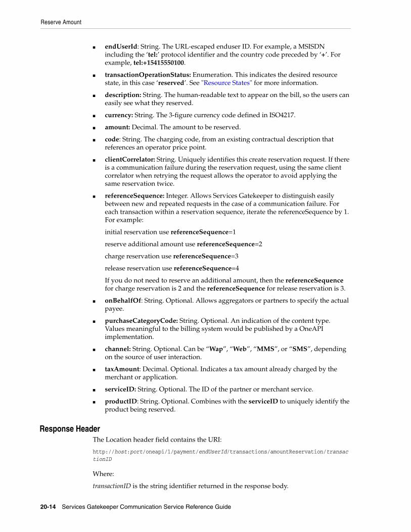
Reserve Amount
20-14 Services Gatekeeper Communication Service Reference Guide
■ endUserId: String. The URL-escaped enduser ID. For example, a MSISDN including the ‘tel:’ protocol identifier and the country code preceded by ‘+’. For example, tel:+15415550100.
■ transactionOperationStatus: Enumeration. This indicates the desired resource state, in this case ‘reserved’. See "Resource States" for more information.
■ description: String. The human-readable text to appear on the bill, so the users can easily see what they reserved.
■ currency: String. The 3-figure currency code defined in ISO4217.
■ amount: Decimal. The amount to be reserved.
■ code: String. The charging code, from an existing contractual description that references an operator price point.
■ clientCorrelator: String. Uniquely identifies this create reservation request. If there is a communication failure during the reservation request, using the same client correlator when retrying the request allows the operator to avoid applying the same reservation twice.
■ referenceSequence: Integer. Allows Services Gatekeeper to distinguish easily between new and repeated requests in the case of a communication failure. For each transaction within a reservation sequence, iterate the referenceSequence by 1. For example:
initial reservation use referenceSequence=1
reserve additional amount use referenceSequence=2
charge reservation use referenceSequence=3
release reservation use referenceSequence=4
If you do not need to reserve an additional amount, then the referenceSequence for charge reservation is 2 and the referenceSequence for release reservation is 3.
■ onBehalfOf: String. Optional. Allows aggregators or partners to specify the actual payee.
■ purchaseCategoryCode: String. Optional. An indication of the content type. Values meaningful to the billing system would be published by a OneAPI implementation.
■ channel: String. Optional. Can be “Wap”, “Web”, “MMS”, or “SMS”, depending on the source of user interaction.
■ taxAmount: Decimal. Optional. Indicates a tax amount already charged by the merchant or application.
■ serviceID: String. Optional. The ID of the partner or merchant service.
■ productID: String. Optional. Combines with the serviceID to uniquely identify the product being reserved.
20Response HeaderThe Location header field contains the URI:
http://host:port/oneapi/1/payment/endUserId/transactions/amountReservation/transactionID
Where:
transactionID is the string identifier returned in the response body.

Reserve Amount
OneAPI Payment/Diameter 20-15
If the request fails, the Status-Line header field contains the status code and the reason for the failure. See “Errors and Exceptions” in Using the OneAPI RESTful Interfaces for more information.
20Response BodyThe response body contains a confirmation amountReservationTransaction JSON data structure consisting of the parameters supplied in the reservation request.
{"amountReservationTransaction": { "clientCorrelator": "String", "endUserId": "String", "paymentAmount": { "chargingInformation": { "amount": "Decimal", "currency": "String", "description": " String" }, }, "code": "String", "resourceURL": "URL" "transactionOperationStatus": "String"}} A resourceURL is included as a reference to the response. The transactionOperationStatus provides the resource state. See "Resource States" for more information.
20Reserving Additional AmountThe Reserve Amount operation is used to update an existing reservation to request additional funds or resources. See "Charge Amount" for more information. Change the following parameters in the request for additional funds:
■ transactionOperationStatus=reserved: Indicates that we are not changing the resource state, just the value being reserved. See "Resource States" for more information.
■ amount: The additional reserved amount for this request (not the total amount reserved so far).
■ referenceSequence: Each time you reserve an additional amount against an existing reservation, make sure to iterate the referenceSequence each time. This ensures Services Gatekeeper can distinguish between new requests for additional amounts, and those that are being repeated due to a communication failure.
20ExamplesExample 20–9 shows a sample of a OneAPI Reserve Amount request.
Example 20–9 OneAPI Reserve Amount Request
POST http://example.com/oneapi/1/payment/tel%3A%2B15415550100/transactions/amountReservation HTTP/1.1Accept: application/jsonHost: example.com:80Content-Type: application/x-www-form-urlencodedContent-Length: 12345Date: Thu, 04 Jun 2009 02:51:59 GMT

Reserve Amount
20-16 Services Gatekeeper Communication Service Reference Guide
endUserId= tel%3A%2B15415550100&transactionOperationStatus=reserved&description= Streaming%20video%20of%20the%Big%20Fight¤cy=USD&amount=10&referenceCode=Video-abc123&clientCorrelator=54321&referenceSequence=1&onBehalfOf=Example%20Video%20Inc&purchaseCategoryCode=Video&channel=WAP&taxAmount=0
Example 20–10 shows a sample of a OneAPI Reserve Amount response.
Example 20–10 OneAPI Reserve Amount Response
HTTP/1.1 201 CreatedContent-Type: application/jsonContent-Length: 12345Date: Thu, 04 Jun 2009 02:51:59 GMTLocation: http://example.com/oneapi/1/payment/tel%3A%2B15415550100/transactions/amountReservation/abc123 {"amountReservationTransaction": { "clientCorrelator": "54321", "endUserId": "tel:+15415550100", "paymentAmount": {"chargingInformation": { "amount": "10", "currency": "USD", "description": "Streaming video of the Big Fight" }}, "code": "REF-12345", "referenceSequence": "1", "transactionOperationStatus": "Reserved"}}
Example 20–11 shows a sample of a OneAPI Reserve Additional Amount request.
Example 20–11 OneAPI Reserve Additional Amount Request
POST http://example.com/oneapi/1/payment/tel%3A%2B15415550100/transactions/amountReservation/abc123 HTTP/1.1Accept: application/jsonHost: example.com:80Content-Type: application/x-www-form-urlencodedContent-Length: 12345Date: Thu, 04 Jun 2009 02:51:59 GMT transactionOperationStatus=reserved&amount=5&code=REF-12346&referenceSequence=2&
Example 20–12 shows a sample of a OneAPI Reserve Additional Amount response.

Reserve Amount
OneAPI Payment/Diameter 20-17
Example 20–12 OneAPI Reserve Additional Amount Response
HTTP/1.1 200 OKContent-Type: application/jsonContent-Length: 12345Date: Thu, 04 Jun 2009 02:51:59 GMT {"amountReservationTransaction": { "endUserId": "tel:+15415550100", "paymentAmount": { "amountReserved": "15", "chargingInformation": { "amount": "10", "currency": "USD", "description": "Streaming Video of the Big Fight" }, "totalAmountCharged": "0" }, "code": "REF-12346", "referenceSequence": "2", "resourceURL": " http://example.com/oneapi/1/payment/tel%3A%2B15415550100/transactions/amountReservation/abc123", "transactionOperationStatus": "Reserved"}}

Charge Reservation
20-18 Services Gatekeeper Communication Service Reference Guide
Charge Reservation
The Charge Reservation operation charges a previously reserved amount against a subscriber’s account.
To charge a previously reserved amount to a subscriber’s account, provide the information for billing, the reservation identifier obtained from the initial request to reserve funds, and the reference code for any possible disputes.
20AuthorizationBasic or OAuth 2.0
20HTTP MethodPOST
20URIhttp://host:port/oneapi/1/payment/endUserId/transactions/amountReservation/transactionID
Where:
host and port are the host name and port of the machine on which the Services Gatekeeper Access Tier (AT) services are running.
endUserId is the address of the subscriber to charge (MSISDN).
transactionID is the unique value generated by Services Gatekeeper from the original reservation request.
20Request Change the following parameters in the reservation request to charge against a reservation:
■ transactionOperationStatus=charged: Indicates a change in the resource state to charge against the reservation. See "Resource States" for more information.
■ amount: The total amount to charge against the reservation.
■ referenceSequence: Iterate the referenceSequence with the charge request. This ensures the OneAPI server can distinguish between new requests for charging against a reservation, and those that are being repeated due to a communication failure.
■ description: Update the description to reflect the completed transaction.
The clientCorrelator parameter is not used as the resource has already been created.
20Response HeaderIf the request fails, the Status-Line header field contains the status code and the reason for the failure. See “Errors and Exceptions” in Using the OneAPI RESTful Interfaces for more information

Charge Reservation
OneAPI Payment/Diameter 20-19
20Response BodyThe response body contains a confirmation amountReservationTransaction JSON data structure consisting of the parameters supplied in the charge request.
{"amountReservationTransaction": "endUserId": "String", "paymentAmount": { "amountReserved":"Decimal", "chargingInformation": { "amount": "Decimal", "currency": "String", "description": " String" }, "totalAmountCharged": "Decimal" }, "code": "String", "resourceURL": "URL" "transactionOperationStatus": "String"}
Once the charge has been applied, the amountReserved parameter should have a value of zero. The totalAmountCharged parameter contains the final amount to charge against the reservation.
A resourceURL is included as a reference to the response. The transactionOperationStatus provides the resource state. See "Resource States" for more information.
20ExamplesExample 20–13 shows a sample of a OneAPI Charge Amount Against Reservation request.
Example 20–13 OneAPI Charge Amount Against Reservation Request
POST http://example.com/1/payment/tel%3A%2B15415550100/transactions/amountReservation/abc123 HTTP/1.1Accept: application/jsonHost: example.com:80Content-Type: application/x-www-form-urlencodedContent-Length: 12345Date: Thu, 04 Jun 2009 02:51:59 GMT transactionStatus=charged&description= Three%20rounds%20of%20the%Big%20Fight&amount=15&code=REF-123457&referenceSequence=3&
Example 20–14 shows a sample of a OneAPI Charge Amount Against Reservation response.
Example 20–14 OneAPI Charge Amount Against Reservation Response
HTTP/1.1 200 OKContent-Type: application/jsonContent-Length: 12345Date: Thu, 04 Jun 2009 02:51:59 GMT
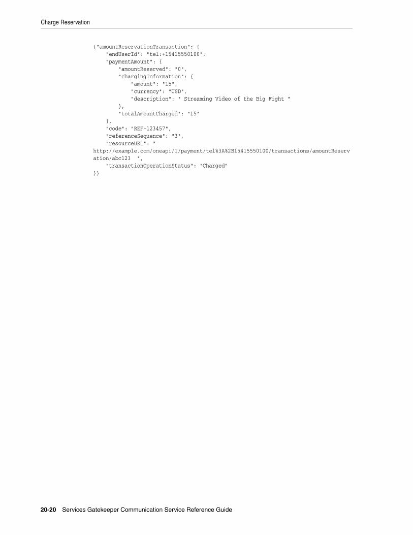
Charge Reservation
20-20 Services Gatekeeper Communication Service Reference Guide
{"amountReservationTransaction": { "endUserId": "tel:+15415550100", "paymentAmount": { "amountReserved": "0", "chargingInformation": { "amount": "15", "currency": "USD", "description": " Streaming Video of the Big Fight " }, "totalAmountCharged": "15" }, "code": "REF-123457", "referenceSequence": "3", "resourceURL": " http://example.com/oneapi/1/payment/tel%3A%2B15415550100/transactions/amountReservation/abc123 ", "transactionOperationStatus": "Charged"}}

Release Reservation
OneAPI Payment/Diameter 20-21
Release Reservation
The Release Reservation operation returns funds left in a reservation to the subscriber account against which the reservation was made.
To return funds left in a reservation to an account, provide the transactionID identifier obtained from the initial reservation request.
20AuthorizationBasic or OAuth 2.0
20HTTP MethodPOST
20URIhttp://host:port/oneapi/1/payment/endUserId/transactions/amountReservation/transactionID
Where:
host and port are the host name and port of the machine on which the Services Gatekeeper Access Tier (AT) services are running
endUserId is the address of the subscriber to charge (MSISDN).
transactionID is the unique value generated by Services Gatekeeper from the original reservation request.
20Request Change the following parameters in the reservation request to release a reservation:
■ transactionOperationStatus=released: Indicates a change in the resource state to release the reservation. See "Resource States" for more information.
■ referenceSequence: Iterate the referenceSequence when releasing a reservation. This ensures the OneAPI server can distinguish between new requests for reservation release, and those that are being repeated due to a communication failure.
20Response HeaderIf the request fails, the Status-Line header field contains the status code and the reason for the failure. See “Errors and Exceptions” in Using the OneAPI RESTful Interfaces for more information.
20Response BodyThe response body contains a confirmation amountReservationTransaction JSON data structure consisting of the parameters supplied in the release reservation request.
{"amountReservationTransaction": { "endUserId": "String", "paymentAmount": { "amountReserved":"Decimal", "chargingInformation": {
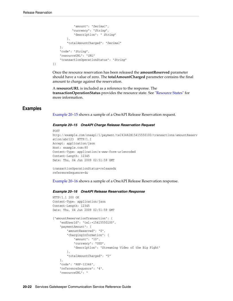
Release Reservation
20-22 Services Gatekeeper Communication Service Reference Guide
"amount": "Decimal", "currency": "String", "description": " String" }, "totalAmountCharged": "Decimal" }, "code": "String", "resourceURL": "URL" "transactionOperationStatus": "String"}}
Once the resource reservation has been released the amountReserved parameter should have a value of zero. The totalAmountCharged parameter contains the final amount to charge against the reservation.
A resourceURL is included as a reference to the response. The transactionOperationStatus provides the resource state. See "Resource States" for more information.
20ExamplesExample 20–15 shows a sample of a OneAPI Release Reservation request.
Example 20–15 OneAPI Charge Release Reservation Request
POST http://example.com/oneapi/1/payment/tel%3A%2B15415550100/transactions/amountReservation/abc123 HTTP/1.1Accept: application/jsonHost: example.com:80Content-Type: application/x-www-form-urlencodedContent-Length: 12345Date: Thu, 04 Jun 2009 02:51:59 GMT transactionOperationStatus=released&referenceSequence=4&
Example 20–16 shows a sample of a OneAPI Release Reservation response.
Example 20–16 OneAPI Release Reservation Response
HTTP/1.1 200 OKContent-Type: application/jsonContent-Length: 12345Date: Thu, 04 Jun 2009 02:51:59 GMT {"amountReservationTransaction": { "endUserId": "tel:+15415550100", "paymentAmount": { "amountReserved": "0", "chargingInformation": { "amount": "10", "currency": "USD", "description": "Streaming Video of the Big Fight" }, "totalAmountCharged": "5" }, "code": "REF-12346", "referenceSequence": "4", "resourceURL": "

Release Reservation
OneAPI Payment/Diameter 20-23
http://example.com/oneapi/1/payment/tel%3A%2B15415550100/transactions/amountReservation/abc123 ", "transactionOperationStatus": "Released"}}

Resource States
20-24 Services Gatekeeper Communication Service Reference Guide
Resource States
The client application passes the transactionOperationStatus in the request body so that the resource can be placed into a desired state. Services Gatekeeper either confirms this desired state in the transactionStatus response field, or instead shows a failure state as shown in Table 20–1 and Table 20–2.
Table 20–1 Resource States for Charges and Refunds
Value Description
Charged A successful charge was made.
Refunded A successful refund was made.
Denied The policy exception in the response will explain the reason. For example, insufficient balance, security issue, etc.
Refused The charge or refund was refused, or not explicitly accepted.
Table 20–2 Resource States for Reservations
Value Description
Reserved A successful reservation was created.
Denied The policy exception in the response will explain the reason. For example, insufficient balance, security issue, etc.
Refused The reservation was refused, or not explicitly accepted.
Charged A reservation has been charged against.
Released The reservation has ended.

Payment Exceptions
OneAPI Payment/Diameter 20-25
Payment Exceptions
For an overview of exceptions in the Services Gatekeeper RESTful interface, see “Errors and Exceptions” in Using the OneAPI RESTful Interfaces for more information. A list of service and policy exceptions specific to the payment interface is provided in Table 20–3.
Table 20–3 Service Exceptions for Payment
ID Exception Text Variables
SVC0270 Charging operation failed, the charge was not applied
None
SVC0271 Refunds not supported Guidance from the implementation on what to do instead should be provided
SVC0273 Refund failed The reason the refund failed. Valid reasons include:
■ The user did not accept the refund
■ The refund request is for an amount greater than the original charge

Payment Exceptions
20-26 Services Gatekeeper Communication Service Reference Guide

21
OneAPI Short Messaging/SMPP 21-1
21OneAPI Short Messaging/SMPP
This chapter describes the Oracle Communications Services Gatekeeper OneAPI Short messaging/SMPP communication service in detail.
About the OneAPI Short Messaging InterfaceApplications use the RESTful OneAPI SMS interface to send and fetch SMS messages, deliver status reports, and start and stop notifications.
When the request body for an SMS operation contains a request for a delivery receipt, the application provides a notifyURL correlator for the message being sent and includes an endpoint address for returning the delivery notification.
The Services Gatekeeper OneAPI SMS interface complies with Open Mobile Alliance (OMA) specifications. See the discussion on OneAPI short messaging in Services Gatekeeper Statement of Compliance for a reference to the supported specification and RESTful bindings schema.
See "Using the OneAPI RESTful Interfaces" in Services Gatekeeper Application Developer's Guide for information on using the Services Gatekeeper OneAPI interfaces.
The information provided in this chapter is based on the OneAPI specification and is provided here for convenience.
REST Service Descriptions Available at Run-timeWhen the Administration Server for your Services Gatekeeper domain is in the running state, the OneAPI REST service descriptions of these operations are located here:
http://host:port/oneapi/1/smsmessaging/application.wadl
where host and port are the host name and port of the machine on which Services Gatekeeper is installed.

Sending SMS Messages
21-2 Services Gatekeeper Communication Service Reference Guide
Sending SMS Messages
To send an SMS message, provide the OneAPI-formatted URI of the addresses that must receive the message in the request body. If the sender requires a delivery receipt, specify the required parameters for the receipt.
If the Send SMS operation is successful, the Location header field in the response contains the request identifier (which is also provided in the response body for this operation).
If the application requires a receipt for delivery of the message, the application must provide the notifyURL to which notifications are to be sent in the message body.
21AuthorizationBasic or OAuth 2.0
21HTTP MethodPOST
21URIhttp://host:port/oneapi/1/smsmessaging/outbound/senderAddress/requests
Where:
host and port are the host name and port of the machine on which Services Gatekeeper is installed.
senderAddress is the subscriber for which the message is being sent.
21Request HeaderThe MIME-type for the Content-Type header field can be application/x-www-form-urlencoded, application/json or application/xml.
21Request BodyThe request body for the OneAPI send SMS operation accepts the following parameters:
■ address: String. At least one address is the URL-escaped end user ID; in this case the MSISDN including the ’tel:’ protocol identifier and the country code preceded by ‘+’. i.e., tel:+15415550100.
■ message: String. Must be URL-escaped as per RFC 1738. Messages over 160 characters may be sent as two or more messages by the operator.
■ senderAddress: String. The address to whom a responding SMS may be sent.
■ clientCorrelator: String. Optional. Uniquely identifies this create SMS request. If there is a communication failure during the request, using the same client correlator when retrying the request allows the operator to avoid sending the same SMS twice.
■ senderName: String. Optional. The URL-escaped name of the sender to appear on the terminal. This is the address to whom a responding SMS may be sent.

Sending SMS Messages
OneAPI Short Messaging/SMPP 21-3
If the senderName parameter is present, Services Gatekeeper displays the senderName value as the sender entry in the SMS message delivered to the mobile subscriber.
If the senderName parameter is not present, Services Gatekeeper displays the value in the senderAddress parameter as the sender entry in the SMS message delivered to the mobile subscriber.
■ notifyURL: anyURL. The URL-escaped URL to which a notification of delivery sent. The notifyURL will be ignored if a notification subscription already exists for the senderAddress. The format of this notification is shown in Example 21–1.
callbackData: String. Will be passed back in this notification, so you can use it to identify the message the receipt relates to or any other useful data, such as a function name.
21Response HeaderThe Location header field contains the URI:
http://host:port/oneapi/1/smsmessaging/outbound/address/requests/requestID
Where requestID is the string identifier returned in the response body.
If the request fails, the Status-Line header field will contain the status code and the reason for the failure. For more information, see "Errors and Exceptions" in Services Gatekeeper Application Developer's Guide.
21Response BodyThe body of the response contains the request identifier as the string value for the resourceReference attribute. It is the request identifier returned in the Location header field of the response message and is also included in the resourceReference body. The application uses this request identifier to retrieve the delivery status for the sent message.
The response body for this operation is represented by the following JSON structure, where the value part of the name/value pair indicates its data type:
{"resourceReference": {"resourceURL": "String"}}
21ExamplesExample 21–1 shows a sample OneAPI Send SMS request.
Example 21–1 OneAPI Send SMS Request
POST http://example.com/oneapi/1/smsmessaging/outbound/tel%3A%2B5550100/requests HTTP/1.1Host: example.com:80Content-Type: application/x-www-form-urlencodedAccept: application/json address=tel%3A%2B15415550100&address=tel%3A %2B15415550101&senderAddress=tel:%2B5550100&message=Hello%20World&clientCorrelator=123456¬ifyURL=http://application.example.com/notifications/DeliveryInfoNotification&callbackData=some-data-useful-to-the-requester&senderName=ACME%20Inc.

Sending SMS Messages
21-4 Services Gatekeeper Communication Service Reference Guide
Example 21–2 shows a sample Send SMS response.
Example 21–2 OneAPI Send SMS Response
HTTP/1.1 201 CreatedContent-Type: application/jsonLocation: http://example.com/1/smsmessaging/outbound/ tel%3A%2B5550100/requests/abc123Content-Length: 12345Date: Thu, 04 Jun 2009 02:51:59 GMT {"resourceReference": {"resourceURL": " http://example.com/oneapi/1/smsmessaging/outbound/ tel%3A%2B5550100/requests/abc123"}}

Query Delivery Status of SMS Message
OneAPI Short Messaging/SMPP 21-5
Query Delivery Status of SMS Message
The Query Delivery Status operation retrieves the delivery status of a previously-sent message by using the system-generated requestID returned when the message was created.
If the Query Delivery Status is successful, the response body contains the delivery status for each of the addresses contained in the original send SMS request.
21AuthorizationBasic or OAuth 2.0
21HTTP MethodGET
21URIhttp://host:port/oneapi/1/smsmessaging/outbound/senderAddress/requests/requestID/deliveryInfos
Where:
■ host and port are the host name and port of the machine on which Services Gatekeeper is installed.
■ senderAddress is the address to which a responding SMS may be sent.
■ requestID is the identifier returned in the result object of the corresponding Send operation.
21Request BodyThere is no request body.
21Response HeaderStandard header fields. If the request fails, the Status-Line header field will contain the status code and the reason for the failure. See “Errors and Exceptions” in Using the OneAPI RESTful Interfaces for more information.
21Response BodyThe response body contains an array of structures as the value for deliveryInfo. Each element in the array contains values for the following parameters.
■ address: String. The telephone number to which the initial message was sent.
■ deliveryStatus: Enumeration value. Table 21–1 lists the possible statuses:
Table 21–1 Enumeration Values for Delivery Status
Value Description
DeliveredToNetwork Successful delivery to the network. For concatenated messages, returned only when all the SMS-parts have been successfully delivered to the network.

Query Delivery Status of SMS Message
21-6 Services Gatekeeper Communication Service Reference Guide
■ resourceURL: A reference to the response.
The response body for this operation is represented by the following JSON data structure, where the value part of each name/value pair indicates its data type:
{"deliveryInfoList": { "deliveryInfo": [ { "address": "String", "deliveryStatus": "String"}, { "address": "String", "deliveryStatus": "String"}], "resourceURL": " http://example.com/oneapi/1/smsmessaging/outbound/senderAddress/requests/requestID/deliveryInfos"}}
21ExamplesExample 21–3 shows a sample OneAPI Query Delivery Status request.
Example 21–3 OneAPI Query Delivery Status Request
GET http://example.com/oneapi/1/smsmessaging/outbound/tel%3A%2B5550100/requests/abc123/deliveryInfos HTTP/1.1Accept: application/json
Example 21–4 shows a sample OneAPI Query Delivery Status response.
Example 21–4 OneAPI Query Delivery Status Response
HTTP/1.1 200 OKContent-Type: application/jsonDate: Thu, 04 Jun 2009 02:51:59 GMT {"deliveryInfoList": { "deliveryInfo": [ { "address": "tel:+15415550100", "deliveryStatus": "MessageWaiting"}, { "address": "tel:+15415550101", "deliveryStatus": "MessageWaiting"}], "resourceURL": " http://example.com/oneapi/1/smsmessaging/outbound/tel%3A%2B5550100/requests/abc123/deliveryInfos "
DeliveryUncertain Delivery status unknown, for example, if it was handed off to another network.
DeliveryImpossible Unsuccessful delivery; the message could not be delivered before it expired.
DeliveredToTerminal Successful delivery to the terminal. For concatenated messages, returned only when all the SMS-parts have been successfully delivered to the terminal.
MessageWaiting The message is still queued for delivery. This is a temporary state, pending transition to one of the preceding states.
Table 21–1 (Cont.) Enumeration Values for Delivery Status
Value Description

Query Delivery Status of SMS Message
OneAPI Short Messaging/SMPP 21-7
}}

Subscribe to SMS Delivery Notification
21-8 Services Gatekeeper Communication Service Reference Guide
Subscribe to SMS Delivery Notification
The Subscribe to SMS Delivery Notification operation creates a subscription to delivery notifications for an application.
To set up an SMS notification, provide the criteria which will trigger notifications and a notifyURL for the delivery of the notifications. The criteria can be a string which, when matched, could be the notification of an SMS received or of a delivery receipt.
The request body contains the correlator for the notification, the notifyURL to which the call direction notifications must be sent and, optionally, the callbackData (a string to identify the notification).
If the subscription request is successful:
■ The response header will contain the URI of the publish/subscribe server.
■ A data object associated with the result of the short message operation will be sent to the notifyURL address specified in the request body. This data object will contain the appropriate notification (that the message was received or a delivery receipt for the call).
21AuthorizationBasic or OAuth 2.0
21HTTP MethodPOST
21URIhttp://host:port/oneapi/1/smsmessaging/outbound/senderAddress/subscriptions
where:
■ host and port are the host name and port of the machine on which Services Gatekeeper is installed.
■ senderAddress is the address to whom a responding SMS may be sent.
21Request HeaderThe MIME-type for the Content-Type header field can be application/json, application/xml, or application/x-www-form-urlencoded.
21Request BodyThe request body for the subscription operation accepts the following parameters:
■ notifyURL: URL. This will be used by the server to POST the notifications to you, so include the URL of your own listener application
■ clientCorrelator: String. Optional. Uniquely identifies this create subscription request. If there is a communication failure during the request, using the same client correlator when retrying the request allows the operator to avoid creating a duplicate subscription.
■ callbackData: String. Optional. A function name or other data that you would like included when the POST is received.

Subscribe to SMS Delivery Notification
OneAPI Short Messaging/SMPP 21-9
21Response HeaderThe Location header field contains the URI of the notification server:
http://host:port/oneapi/1/smsmessaging/outbound/subscriptions/subscriptionID
Where:
■ host and port are the host name and port of the machine on which Services Gatekeeper is installed.
■ subscriptionID is the reference to the created subscription.
If the request fails, the Status-Line header field will contain the status code and the reason for the failure. For more information, see "Errors and Exceptions" in Services Gatekeeper Application Developer's Guide.
21Response BodyThe response body contains a confirmation deliveryReceiptSubscription JSON data structure consisting of the parameters supplied in the subscription request.
{"deliveryReceiptSubscription": { "callbackReference": { "callbackData": "String", "notifyURL": " www.yourURL.here ", "criteria":"String" }, "resourceURL": " URL "}}
A resourceURL is included as a reference to the response.
21Notification Data Object for SMS Delivery Receipt Sent to notifyURLAfter a OneAPI SMS subscription is made, Services Gatekeeper delivers a message receipt notification to the notifyURL specified in the subscription request.
This nested JSON object contains the following as the value of the attribute name deliveryInfoNotification:
■ callbackData: String. The correlator used to identify the notification.
■ deliveryInfo: JSON Object. Contains the following two parameters:
– address: String. The message recipient’s subscriber ID.
– deliveryStatus: Enumeration value. Table 21–2 lists the possible statuses:
Table 21–2 Enumeration Values for Delivery Status
Value Description
DeliveredToNetwork Successful delivery to the network. For concatenated messages, returned only when all the SMS-parts have been successfully delivered to the network.
DeliveryUncertain Delivery status unknown, for example, if it was handed off to another network.
DeliveryImpossible Unsuccessful delivery; the message could not be delivered before it expired.

Subscribe to SMS Delivery Notification
21-10 Services Gatekeeper Communication Service Reference Guide
The notification data object delivered to the notifyURL address is represented by the following JSON data structure, where the value part of each name/value pair indicates its data type:
{"deliveryInfoNotification": { "callbackData": "String", "deliveryInfo": { "address": "String", "deliveryStatus": "Enumeration Value"}, }}
21ExamplesExample 21–5 shows a sample OneAPI Subscribe to SMS Delivery Notifications request.
Example 21–5 OneAPI Subscribe to SMS Delivery Notifications Request
POST http://example.com/oneapi/1/smsmessaging/outbound/ tel%3A%2B5550100/subscriptions HTTP/1.1Host: example.com:80Content-Type: application/x-www-form-urlencodedAccept: application/json notifyURL=http://www.oracle.com&criteria="GIGPICS"&callbackData=doSomething()
Example 21–6 shows a sample OneAPI Subscribe to SMS Delivery Notifications response.
Example 21–6 OneAPI Subscribe to SMS Delivery Notifications Response
HTTP/1.1 201 Created Content-Type: application/jsonLocation: http://example.com/oneapip/1/smsmessaging/outbound/subscriptions/sub789Date: Thu, 04 Jun 2009 02:51:59 GMT {"deliveryReceiptSubscription": { "callbackReference": { "callbackData": "doSomething()", "notifyURL": " www.oracle.com ", "criteria":"Urgent" }, "resourceURL": " http://example.com/oneapi/1/smsmessaging/outbound/subscriptions/sub789 "}}
Example 21–7 shows a sample OneAPI SMS Delivery Notification message.
DeliveredToTerminal Successful delivery to the terminal. For concatenated messages, returned only when all the SMS-parts have been successfully delivered to the terminal.
Table 21–2 (Cont.) Enumeration Values for Delivery Status
Value Description

Subscribe to SMS Delivery Notification
OneAPI Short Messaging/SMPP 21-11
Example 21–7 OneAPI SMS Delivery Notification Message
{"deliveryInfoNotification": { "callbackData": "12345", "deliveryInfo": { "address": "tel:+15415550100", "deliveryStatus": "DeliveredToNetwork"}, }}

Stop Subscription to Delivery Notifications
21-12 Services Gatekeeper Communication Service Reference Guide
Stop Subscription to Delivery Notifications
The Stop Subscription to Delivery Notification operation terminates a previously set up SMS notification for the application.
To stop a previously set up SMS notification, provide the correlator for the notification passed earlier in the Subscribe to SMS Delivery Notification request.
There is no request or response body for the Stop Subscription to Delivery Notification operation. If the request fails, the body of the error response will contain the identifier for the notification and the type of exception.
21AuthorizationBasic or OAuth 2.0
21HTTP MethodDELETE
21URIhttp://host:port/oneapi/1/smsmessaging/outbound/subscriptions/subscriptionID
Where:
■ host and port are the host name and port of the machine on which Services Gatekeeper is installed.
■ subscriptionID is the reference to the created subscription.
21Request BodyThere is no request body.
21Response HeaderStandard header fields. If the request fails, the Status-Line header field will contain the status code and the reason for the failure. For more information, see "Errors and Exceptions" in Services Gatekeeper Application Developer's Guide.
21Response BodyThere is no response body.
21ExamplesExample 21–8 shows a sample OneAPI Stop Subscription to SMS Delivery Notifications request.
Example 21–8 OneAPI Stop Subscription to Deliver Notification Request
DELETE http://example.com/oneapi/1/smsmessaging/outbound/subscriptions/sub789 HTTP/1.1Accept: application/jsonHost: example.com:80

Stop Subscription to Delivery Notifications
OneAPI Short Messaging/SMPP 21-13
Example 21–9 shows a sample OneAPI Stop Subscription to SMS Delivery Notifications response.
Example 21–9 OneAPI Stop Subscription to Deliver Notification Response
HTTP/1.1 204 No Content Date: Thu, 04 Jun 2009 02:51:59 GMT
Retrieve Messages Sent to Web Application
21-14 Services Gatekeeper Communication Service Reference Guide
Retrieve Messages Sent to Web Application
The OneAPI Retrieve Messages Sent to Web Application operation polls Services Gatekeeper for the SMS messages that have been received from the network for an application.
The request header for the Retrieve Messages SMS operation contains the registration identifier necessary to retrieve the SMS messages intended for the application. This registration value should have been set up with the off-line provisioning step that enables the application to receive notification that SMS messages have been received.
There is no request body.
If the Retrieve Messages Sent to Web Application operation is successful, the response body will contain the message, the URI of the sender, the SMS service activation number, and the date and time when the message was sent.
21AuthorizationBasic or OAuth 2.0
21HTTP MethodGET
21URIhttp://host:port/oneapi/1/smsmessaging/inbound/registrations/registrationID/messages?maxBatchSize=X
where:
■ host and port are the host name and port of the machine on which Services Gatekeeper is installed.
■ registrationId is the value previously set up to enable the application to receive notification that SMS messages have been received according to specified criteria.
■ The value of maxBatchSize is the maximum number of message to return.
21Request HeaderThe MIME-type for the accept header field is application/json.
21Request BodyThere is no request body.
21Response HeaderStandard header fields. If the request fails, the Status-Line header field will contain the status code and the reason for the failure. For more information, see "Errors and Exceptions" in Services Gatekeeper Application Developer's Guide.
21Response BodyThe response body is an inboundSMSMessageList containing an array of structures as the value for inboundSMSMessage. The response body also contains the following parameters:

Retrieve Messages Sent to Web Application
OneAPI Short Messaging/SMPP 21-15
■ inboundSMSMessage: Array. Contains the following parameters:
– dateTime: dateTime. The date and time when the message was received.
– destinationAddress: String. The number or shortcode for the application.
– messageID: String. A server generated message identifier.
– message: String. The SMS message.
– resourceURL: URL. Link to the message.
– senderAddress: String. The MSISDN of the sender.
■ numberOfMessagesInThisBatch: Integer. The total number of messages in the batch.
■ resourceURL: URL Self-referring resource URL.
The response body for this operation is represented by the following JSON data structure, where the value part of each name/value pair indicates its data type:
"inboundSMSMessage": [ { "dateTime": "dateTime", "destinationAddress": "String", "messageId": "String", "message": "String", "resourceURL": "URL", "senderAddress": "String"},
21ExamplesExample 21–10 shows a sample OneAPI Retrieve Messages request.
Example 21–10 OneAPI Retrieve Messages Request
GET http://example.com/oneapi/1/smsmessaging/inbound/registrations/3456/messages?maxBatchSize=2 HTTP/1.1Host: example.com:80Accept: application/json
Example 21–11 shows a sample OneAPI Retrieve Messages response.
Example 21–11 OneAPI Retrieve Messages Response
HTTP/1.1 200 OKContent-Type: application/jsonContent-Length: 12345Date: Thu, 04 Jun 2009 02:51:59 GMT {"inboundSMSMessageList": { "inboundSMSMessage": [ { "dateTime": "2009-11-19T12:00:00", "destinationAddress": "3456", "messageId": "msg1", "message": "Let’s Go Sharks!!", "resourceURL": "http://example.com/oneapi/1/smsmessaging/inbound/registrations/3456/messages/msg1", "senderAddress": "+15415550100"}, { "dateTime": "2009-11-19T12:00:00", "destinationAddress": "3456",

Retrieve Messages Sent to Web Application
21-16 Services Gatekeeper Communication Service Reference Guide
"messageId": "msg2", "message": "Thorton Shoots! He Scores! Goal!", "resourceURL": " http://example.com/oneapi/1/smsmessaging/inbound/registrations/3456/messages/msg2", "senderAddress": "+15415550100"} ], "numberOfMessagesInThisBatch": "2", "resourceURL": "http://example.com/oneapi/1/smsmessaging/inbound/registrations/3456/messages", "totalNumberOfPendingMessages": "20"}}

Subscribe to Notifications of Messages Sent to Application
OneAPI Short Messaging/SMPP 21-17
Subscribe to Notifications of Messages Sent to Application
The Subscribe to Notifications Sent to Application operation creates a subscription to delivery notifications for when an application receives a message.
To set up an application notification, provide the destinationAddress that will trigger notifications and a notifyURL for the delivery of the notifications. The destinationAddress is the MSISDN, or code set up in Services Gatekeeper, to which subscribers may send an SMS to your application.
If the subscription request is successful:
■ The response header contains the URI of the publish/subscribe server.
■ The response contains a resourceURL indicating the URI of the newly created subscription.
21AuthorizationBasic or OAuth 2.0
21HTTP MethodPOST
21URIhttp://host:port/oneapi/1/smsmessaging/inbound/subscriptions
where:
■ host and port are the host name and port of the machine on which Services Gatekeeper is installed.
21Request HeaderThe MIME-type for the Content-Type header field is application/x-www-form-urlencoded.
21Request BodyThe request body for the subscription operation accepts the following parameters:
■ destinationAddress: String. The MSISDN, or code agreed upon by the operator, to which subscribers may send an SMS to your application.
■ notifyURL: URL. Is used by the server to POST the notifications to you, so include the URL of your own listener application.
■ criteria: String. Optional. Case-insensitive text to match against the first word of the message, ignoring any leading whitespace. This allows you to reuse a short code among various applications, each of which can register its own subscription with different criteria.
■ notificationFormat: Content Type. Optional. The content type in which notifications will be sent; for OneAPI only JSON is supported.
■ clientCorrelator: String. Optional. Uniquely identifies this create subscription request. If there is a communication failure during the request, using the same

Subscribe to Notifications of Messages Sent to Application
21-18 Services Gatekeeper Communication Service Reference Guide
client correlator when retrying the request allows the operator to avoid creating a duplicate subscription.
■ callbackData: String. Optional. A function name or other data that you would like included when the POST is received.
21Response HeaderThe Location header field contains the URI of the publish/subscribe server:
http://host:port/oneapi/1/smsmessaging/inbound/subscriptions/subscriptionID
where:
■ host and port are the host name and port of the machine on which Services Gatekeeper is installed.
■ subscriptionID is the reference to the created subscription.
If the request fails, the Status-Line header field will contain the status code and the reason for the failure. For more information, see "Errors and Exceptions" in Services Gatekeeper Application Developer's Guide.
21Response BodyThe response body contains a confirmation resourceReference JSON data structure consisting of the parameters supplied in the subscription request.
{"resourceReference": {"resourceURL": "URL"}}
The resourceURL indicates the URI of the newly created subscription.
21Notification Data Object for Application Notification Message Sent to notifyURLAfter a OneAPI Application Notification subscription is made, Services Gatekeeper delivers a message receipt notification to the specified notifyURL in the subscription request.
This nested JSON object contains the following parameters as the value of the attribute name inboundSMSMessageNotification:
■ callbackData: String. The correlator used to identify the notification.
■ inboundSMSMessage: Array. Contains the following parameters:
– dateTime: dateTime. The date and time when the message was received.
– destinationAddress: String. The number or shortcode for the application.
– messageID: String. A server-generated message identifier.
– message: String. The SMS message.
– resourceURL: URL. A link to the message.
– senderAddress: String. The MSISDN of the sender.
The notification data object delivered to the notifyURL address is represented by the following JSON data structure, where the value part of each name/value pair indicates its data type:
{"inboundSMSMessageNotification": { "callbackData": "String", "inboundSMSMessage": { "dateTime": "dateTime",

Subscribe to Notifications of Messages Sent to Application
OneAPI Short Messaging/SMPP 21-19
"destinationAddress": "String", "messageId": "String", "message": "String", "senderAddress": "String" }}}
21ExamplesExample 21–12 shows a sample OneAPI Subscribe to Notifications of Messages Sent to Applications request.
Example 21–12 OneAPI Subscribe to Notifications of Messages Sent to Applications Request
POST http://example.com/oneapi/1/smsmessaging/inbound/subscriptions HTTP/1.1Host: example.com:80Content-Type: application/x-www-form-urlencodedAccept: application/json destinationAddress=3456¬ifyURL=http://www.yoururl.here/notifications/DeliveryInfoNotification&criteria=Vote¬ificationFormat=JSON&callbackData=doSomething()&clientCorrelator=12345
Example 21–13 shows a sample OneAPI Subscribe to Notifications of Messages Sent to Applications response.
Example 21–13 OneAPI Subscribe to Notifications of Messages Sent to Application Response
HTTP/1.1 201 CreatedContent-Type: application/jsonLocation: http://example.com/oneapi/1/smsmessaging/inbound/subscriptions/sub678Content-Length: 254Date: Thu, 04 Jun 2009 02:51:59 GMT {"resourceReference": {"resourceURL": "http://example.com/oneapi/1/smsmessaging/inbound/subscriptions/sub678"}}
Example 21–14 shows a sample OneAPI Application Notification Message.
Example 21–14 OneAPI Application Notification Message
{"inboundSMSMessageNotification": { "callbackData": "12345", "inboundSMSMessage": { "dateTime": "2009-11-19T12:00:00", "destinationAddress": "3456", "messageId": "mes1234", "message": "Vote for Mega Boy Band", "senderAddress": "+15415550100" }}}

Stop Subscription to Application Message Notifications
21-20 Services Gatekeeper Communication Service Reference Guide
Stop Subscription to Application Message Notifications
The Stop Subscription to Application Message Notification operation terminates a previously set up application message notification subscription.
To stop a previously set up subscription, provide the correlator for the notification passed earlier in the Subscribe to Notifications of Messages Sent to Application request.
There is no request or response body for the Stop Subscription to Notifications of Messages Sent to Application operation. If the request fails, the body of the error response will contain the identifier for the notification and the type of exception.
21AuthorizationBasic or OAuth 2.0
21HTTP MethodDELETE
21URIhttp://host:port/oneapi/1/smsmessaging/inbound/subscriptions/subscriptionID
where:
■ host and port are the host name and port of the machine on which Services Gatekeeper is installed.
■ subscriptionID is the reference to the created subscription.
21Request BodyThere is no request body.
21Response HeaderStandard header fields. If the request fails, the Status-Line header field will contain the status code and the reason for the failure. For more information, see "Errors and Exceptions" in Services Gatekeeper Application Developer's Guide.
21Response BodyThere is no response body.
21ExamplesExample 21–15 shows a sample OneAPI Stop Subscription to Notifications of Messages Sent to Application request.
Example 21–15 OneAPI Stop Subscription to Notifications of Messages Sent to Application Request
DELETE http://example.com/oneapi/1/smsmessaging/inbound/subscriptions/sub123 HTTP/1.1Accept: application/jsonHost: example.com:80

Stop Subscription to Application Message Notifications
OneAPI Short Messaging/SMPP 21-21
Example 21–16 shows a sample OneAPI Stop Subscription to Notifications of Messages Sent to Application response.
Example 21–16 OneAPI Stop Subscription to Notifications of Messages Sent to Application Response
HTTP/1.1 204 No contentAccept: application/jsonDate: Thu, 04 Jun 2009 02:51:59 GMT

Stop Subscription to Application Message Notifications
21-22 Services Gatekeeper Communication Service Reference Guide

22
OneAPI Terminal Location/MLP 22-1
22OneAPI Terminal Location/MLP
This chapter describes the Oracle Communications Services Gatekeeper OneAPI Terminal Location/MLP communication service in detail.
About the Terminal Location Interface Applications use the RESTful OneAPI Terminal Location interface to get a location for an individual terminal or a group of terminals.
The Services Gatekeeper OneAPI Location interface complies with Open Mobile Alliance (OMA) specifications. See the discussion about OneAPI terminal location in Services Gatekeeper Statement of Compliance for a reference to the supported specification and RESTful bindings schema.
See “Using the OneAPI RESTful Interfaces” in Services Gatekeeper Application Developer's Guide for general information on using the OneAPI RESTful interfaces.
The information provided in this document is based on the OneAPI specification and is provided here for convenience.
REST Service Descriptions Available at Run-timeWhen the Administration Server for your Services Gatekeeper domain is in the running state, the REST service descriptions of these operations are located here:
http://host:port/oneapi/1/terminallocation/application.wadl
Where host and port are the host name and port of the machine on which the Services Gatekeeper Access Tier (AT) services are running.

Query Mobile Terminal Location
22-2 Services Gatekeeper Communication Service Reference Guide
Query Mobile Terminal Location
The Query Terminal Location operation retrieves the location of one or more terminals.
To retrieve the location of a specific terminal, provide its URI as the address value of the query object in the Request-URI of the GET method. Repeat the address parameter in the request for multiple terminals.
If the Query Terminal Location operation is successful, the response body contains a nested JSON data object containing the physical coordinates of each specific terminal and the date and time for when such data was last collected.
A locationRetrievalStatus is also provided for each terminal in the response body.
22AuthorizationBasic or OAuth 2.0
22HTTP MethodGET
22URIhttp://host:port/oneapi/1/terminallocation/queries/location?${query}
Where:
■ host and port are the host name and port of the machine on which the Services Gatekeeper Access Tier (AT) services are running.
■ ${query} contains the following parameters:
– address: String. The MSISDN of the mobile device to locate. Repeat the address parameter for multiple devices. The protocol and ‘+’ identifier must be used for MSISDN, and must be URL-escaped. %3A represents ‘:’ and %2B represents ‘+’.
– requestedAccuracy: Integer. The preferred accuracy of the result, in meters. Typically, when you request an accurate location, it will take longer to retrieve than a coarse location. For example, requestedAccuracy=10 will take longer than requestedAccuracy=100.
22Request HeaderThe MIME-type for the Content-Type header field is application/json.
22Request BodyThere is no request body.
22Response HeaderStandard header fields. If the request fails, the Status-Line header field contains the status code and the reason for the failure. For more information, see the discussion about "Errors and Exceptions" in Services Gatekeeper Application Developer's Guide.

Query Mobile Terminal Location
OneAPI Terminal Location/MLP 22-3
22Response BodyThe location of the specific terminal is returned in the body of the response as the value of the terminalLocation JSON object. For more than one terminal, a terminalLocationList consisting of multiple terminalLocation objects are returned.
The parameters in this object are:
■ address: String. Denotes the terminal located (local and international numbers are supported).
■ currentLocation: JSON Object. Contains the following parameters:
– accuracy: Integer
– altitude: Integer
– latitude: Number (floating point)
– longitude: Number (floating point)
– timestamp: String. The date and time when the terminal’s geographical coordinates were collected, given in ISO 8601 extended format, yyyy-mm-ddThh-mm-ss.
■ locationRetrievalStatus: String. Contains one of the possible values:
– Retrieved: Successful retrieval of the terminal location for the address
– Not Retrieved: Services Gatekeeper was unable to locate the terminal location for the address
– Error: A service policy or exception has occurred. For more information, see the discussion about "Errors and Exceptions" in Services Gatekeeper Application Developer's Guide.
The response body for this operation is represented by the following JSON data structure, where the value part of the name/value pair indicates its data type. A response containing multiple terminal locations are contained in a terminalLocationList structure, as in Example 22–4, "Query Multiple Mobile Terminals Location Response".
{"terminalLocation": { "address": "String", "currentLocation": { "accuracy": "Integer", "altitude": "Float", "latitude": "Float", "longitude": "Float", "timestamp": "Calendar" },
22ExamplesExample 22–1 shows a sample of a OneAPI Single Mobile Terminal Location request.
Example 22–1 Query Single Mobile Terminal Location Request
GET http://example.com/oneapi/1/terminallocation/queries/location?&address=tel&3A%2B15415550100&requestedAccuracy=1000 HTTP/1.1Host: example.com:80Accept: application/json
Example 22–2 shows a sample of a OneAPI Single Mobile Terminal response.

Query Mobile Terminal Location
22-4 Services Gatekeeper Communication Service Reference Guide
Example 22–2 Query Single Mobile Terminal Location Response
HTTP/1.1 200 OKContent-Type: application/jsonContent-Length: 1234Date: Thu, 04 Jun 2009 02:51:59 GMT
{"terminalLocationList": {"terminalLocation": { "address": "tel:15415550100", "currentLocation": { "accuracy": "100", "altitude": "1001.0", "latitude": "-80.86302", "longitude": "41.277306", "timestamp": "2009-06-03T00:27:23.000Z" }, "locationRetrievalStatus": "Retrieved"}}}
Example 22–3 shows a sample of a OneAPI Multiple Mobile Terminals Location request.
Example 22–3 Query Multiple Mobile Terminals Location Request
GET http://example.com/oneapi/1/terminallocation/queries/location?&address=tel%3A%2B15415550100&address=tel%3A%2B15415550101&requestedAccuracy=1000 HTTP/1.1Host: example.com:80Accept: application/json
Example 22–4 shows a sample of a OneAPI Multiple Mobile Terminals Location request.
Example 22–4 Query Multiple Mobile Terminals Location Response
HTTP/1.1 200 OKX-Powered-By: Servlet/2.5Server: Example/v3Content-Type: application/jsonContent-Length: 1234Date: Thu, 04 Jun 2009 02:51:59 GMT {"terminalLocationList": {"terminalLocation": [ { "address": "tel:15415550100", "currentLocation": { "accuracy": "100", "altitude": "1001.0", "latitude": "-80.86302", "longitude": "41.277306", "timestamp": "2009-06-03T00:27:23.000Z"}, "locationRetrievalStatus": "Retrieved"}, { "address": "tel:15415550101", "errorInformation": { "messageId": "SVC0001", "text": "A service error occurred. %1 %2", "variables": ["Location information is not available for", "tel:15415550101"] }, "locationRetrievalStatus": "Error" }]}}

23
Extended Web Services Binary SMS/SMPP 23-1
23Extended Web Services Binary SMS/SMPP
This chapter describes the Oracle Communications Services Gatekeeper Extended Web Services (EWS) Binary SMS/Short Message Peer to Peer (SMPP) Communication Service in detail.
Overview of the EWS Binary SMS/SMPPThe EWS Binary SMS/SMPP communication service allows applications to send and receive generic binary object attachment, such as vCards. It exposes the Oracle Extended Web Services Binary SMS interface.
The communication service acts as an External Short Message Entity (ESME) that connects to a Short Messaging Service Center (SMSC) over TCP/IP.
For the exact version of the standards that the EWS Binary SMS/SMPP communication service supports for the application-facing interfaces and the network protocols, see Services Gatekeeper Statement of Compliance.
Using the EWS Binary SMS/SMPP communication service an application can:
■ Send short messages with binary attachments to one or more destination addresses.
■ Subscribe and unsubscribe for network-triggered binary short messages with binary attachments.
■ Receive network-triggered short messages with binary attachments.
The actual message element is made up of an array of UDH and message parts, encoded in Base64. See "3rd Generation Partnership Project; Technical Specification Group Terminals; Technical realization of the short message service (SMS); (Release 6) 3GPP 23.040 Version 6.5.0" at:
http://www.3gpp.org/ftp/Specs/html-info/23040.htm
The send message operation gives an application the flexibility to manipulate the SMPP UDH and message data. The UDH and message data elements are each optional, but both cannot be null at the same time; otherwise no data would be sent at all. The overall binaryMessage element is required. The contents of the UDH and the message can be of any binary data, although any byte array should be less than 140 bytes due to SMPP limitations, and the number of BinaryMessage arrays should be less than the SegmentsLimit specified in OAM. The default value is 1024. See the segmentsLimit attribute to SmsMBean for details.
This communication service supports automatic chunking of oversized binary SMS messages to handle messages that exceed the maximum size limits that switches enforce for a single SMS request. Oversized unsegmented messages are automatically

Overview of the EWS Binary SMS/SMPP
23-2 Services Gatekeeper Communication Service Reference Guide
divided into size-conforming individual messages. This feature is supported for SMSs using user data header (UDH) and Sar headers, and you must select the header your implementation uses. The default is UDH. See Configuring Automatic Chunking of Binary SMSs for in Services Gatekeeper Application Developer’s Guide for details.
The notification operation gives the application access to an array of SMPP UDHs, the SMPP DCS, the protocol identifier according to 3GPP 23.040 Version 6.5.0, and other data such as sender address, destination address and timestamp of the message.
SMPP expects the sender name value to be in ASCII characters. The use of non-ASCII characters may cause the request to become garbled or even be removed at the SMSCS
Services Gatekeeper provides support for the billing identification identifier, smpp_billing_id, defined in SMPP Specification 5.1, through the use of a tunneled parameter. It also supports the ussd_service_operation, which was added as an optional parameter to the deliverSM operation as a tunneled parameter in SMPP v 5.1. See the descriptions of the smpp_billing_id and ussd_service_operation tunneled parameters in "Parlay X 2.1 Short Messaging/SMPP" for more information.
Send ReceiptsSend receipts are acknowledgements that the network node has received the short message from the application by Services Gatekeeper. Although a single short message may be sent to multiple destination addresses, normally only one send receipt is returned to the application by Services Gatekeeper. The receipt is returned synchronously in the response message to the sendBinarySms operation.
Delivery ReceiptsDelivery receipt notifications can be set up using the sendBinarySms operation, but the actual asynchronous delivery of receipts is accomplished using the Parlay X 2.1 Short Messaging interface. See "Delivery Receipts" in "Parlay X 2.1 Short Messaging/SMPP" for information on delivery receipts.
Connection Handling and ProvisioningThe EWS Binary SMS/SMPP communication service uses the Services Gatekeeper SMPP Server Service to establish and manage southbound connections between Services Gatekeeper and Short Message Service Centers (SMSCs). The SMPP Server Service is deployed as an Oracle WebLogic Server Service.
The SMPP Server Service provides these services for the Parlay X 2.1 Short Messaging and Native SMPP plug-ins as well as for EWS Binary SMS/SMPP.
For information about configuration options pertaining to these client connections, see the "System Properties for SMPP Server Service" and "Reference: Attributes and Operations for SMPP Server Service" sections.
The client connection ID is created on the plug-in’s successful bind with the SMSC. The connection ID changes on a successful rebind.
For information about connection handling and provisioning, multiple connections and multiple plug-in instances, windowing, and load balancing/high availability, see the applicable sections in "Parlay X 2.1 Short Messaging/SMPP".

Events and Statistics
Extended Web Services Binary SMS/SMPP 23-3
Application InterfacesFor information on the application interface for the EWS Binary SMS/SMPP communication service, see the discussion about extended web services binary SMS in Services Gatekeeper Application Developer's Guide.
For information about the RESTful Call Notification interface, see the discussion on binary short messaging in Services Gatekeeper Application Developer's Guide.
The RESTful Service Call Notification interfaces provide RESTful access to the same functionality as the application interfaces. The internal representations are identical, and for the purposes of creating SLAs and reading CDRs, and so on, they are the same.
Events and StatisticsFor general information, see "Events, Alarms, and Charging".
The Extended Web Services Binary SMS/SMPP communication service generates event data records (EDRs), charging data records (CDRs), alarms, and statistics to assist system administrators and developers in monitoring the service.
Event DataTable 23–1 lists the IDs of the EDRs created by the EWS Binary SMS/SMPP communication service. This list does not include EDRs created when exceptions are thrown.
See "Events and Statistics" for the list of EDRs generated by the SMPP Server Service.
Charging Data RecordsEWS Binary SMS/SMPP-specific CDRs are generated under the following conditions:
■ After a mobile-terminated sendBinarySms request is sent from Services Gatekeeper to the network.
■ After a a network-triggered binary SMS message has been successfully delivered to the application.
StatisticsTable 23–2 maps methods invoked from either the application or the network to the transaction types collected by the Services Gatekeeper statistics counters.
Table 23–1 EDRs Generated by EWS Binary SMS /SMPP
EDRID Method Called
7101 sendBinarySms
7201 startBinarySmsNotification
7202 stopBinarySmsNotification
7204 notifyBinarySmsDeliveryReceipt
7205 notifyBinarySmsReception
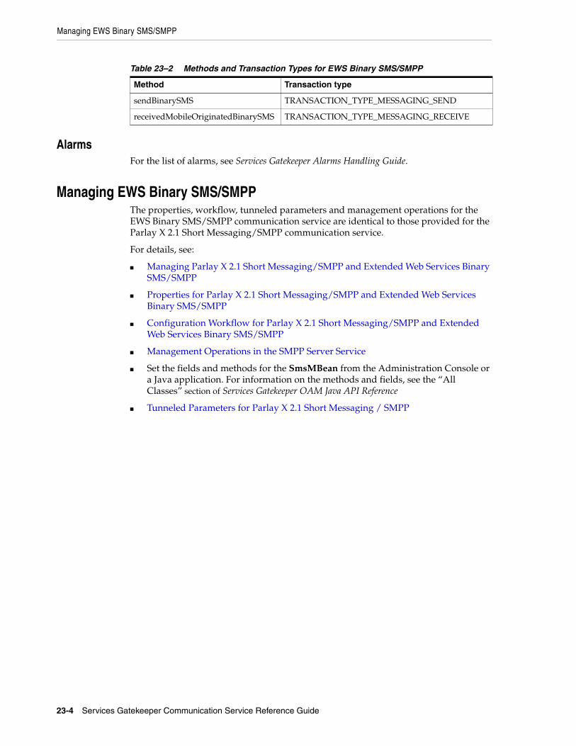
Managing EWS Binary SMS/SMPP
23-4 Services Gatekeeper Communication Service Reference Guide
AlarmsFor the list of alarms, see Services Gatekeeper Alarms Handling Guide.
Managing EWS Binary SMS/SMPPThe properties, workflow, tunneled parameters and management operations for the EWS Binary SMS/SMPP communication service are identical to those provided for the Parlay X 2.1 Short Messaging/SMPP communication service.
For details, see:
■ Managing Parlay X 2.1 Short Messaging/SMPP and Extended Web Services Binary SMS/SMPP
■ Properties for Parlay X 2.1 Short Messaging/SMPP and Extended Web Services Binary SMS/SMPP
■ Configuration Workflow for Parlay X 2.1 Short Messaging/SMPP and Extended Web Services Binary SMS/SMPP
■ Management Operations in the SMPP Server Service
■ Set the fields and methods for the SmsMBean from the Administration Console or a Java application. For information on the methods and fields, see the “All Classes” section of Services Gatekeeper OAM Java API Reference
■ Tunneled Parameters for Parlay X 2.1 Short Messaging / SMPP
Table 23–2 Methods and Transaction Types for EWS Binary SMS/SMPP
Method Transaction type
sendBinarySMS TRANSACTION_TYPE_MESSAGING_SEND
receivedMobileOriginatedBinarySMS TRANSACTION_TYPE_MESSAGING_RECEIVE

24
Extended Web Services Quality of Service /Diameter 24-1
24Extended Web Services Quality of Service/Diameter
This chapter describes the Oracle Communications Services Gatekeeper Extended Web Services Quality of Service (QoS)/Diameter communication service in detail.
See Services Gatekeeper Application Developer's Guide for information on the QoS RESTful interface.
Understanding the EWS Quality of Service/Diameter Communication Service
The Services Gatekeeper Extended Web Services Quality of Service (QoS)/Diameter communication service provides applications with a RESTful interface that allows them to control the quality of a subscriber connection. Among the connection quality aspects that the QoS feature can control include limiting and boosting subscriber connection bandwidth, as well as tuning connection latency. The QoS RESTful interface allows the application to initiate the following operations:
■ Apply a QoS policy
■ Apply a QoS policy based upon a pre-defined template
■ Modify an existing QoS policy
■ Remove an existing QoS policy
■ Register and unregister for QoS-related events
■ Query a QoS policy
While the Services Gatekeeper QoS feature enables an application to control QoS, actually executing the applied QoS policy and applying quality changes to a subscriber connection requires a separate Policy and Charging Rule Function (PCRF), such as Oracle Communications Policy Controller, working in conjunction with a Policy and Charging Enforcement Function (PCEF), solutions which are provided by various third parties.
Note: Services Gatekeeper applies a QoS plan to a subscriber ID and a framed IP address. Applying QoS plans to individual data streams for a particular subscriber ID is not supported.

Application Interfaces
24-2 Services Gatekeeper Communication Service Reference Guide
Using Degraded ModeThis communication service offers a degraded mode feature to multi-tier Services Gatekeeper implementations that use databases on standalone systems. Degraded mode allows your implementation to continue processing traffic using Oracle coherence storage in the event that the database becomes unavailable for any reason. Processing time is not degraded, however this is intended as a short-term solution. Your coherence memory is limited and can fill up depending on your request rate and the size of your coherence memory. Once the coherence memory is full, your implementation will no longer process requests.
To use this feature you must configure your Oracle Coherence settings; see "Configuring Coherence to Use Degraded Mode" for details.
An Example End to End QoS SolutionWhile Services Gatekeeper can apply and remove QoS plans, it provides no capability for actually enforcing QoS changes; instead it works in conjunction with PCRF and PCEF servers. Figure 24–1 illustrates a typical end to end QoS solution:
Figure 24–1 An Example End to End QoS Solution
In Figure 24–1:
1. A subscriber’s mobile device is registered with the Gateway GPRS Support Node (GGSN) or the PCEF.
2. The GGSN or PCEF requests a default QoS plan from the PCRF.
3. Once the QoS plan is returned from the PCRF, the GGSN or PCEF executes that plan and connects the subscriber’s device to the Internet.
4. A subscriber application sends a RESTful request to Services Gatekeeper for a change in QoS.
5. Services Gatekeeper sends the QoS request to the PCRF using the Rx protocol.
6. The PCRF pushes the new QoS plan to the PCEF using the Gx protocol, and the PCEF executes that plan.
7. The PCRF interfaces with BRM or another billing management system to charge the subscriber appropriately.
Application InterfacesFor information about the RESTful-based interface for the Extended Web Services Quality of Service (QoS)/Diameter communication service, see the discussion of QoS interfaces in the Services Gatekeeper Application Developer's Guide, another document in this set.

Events and Statistics
Extended Web Services Quality of Service /Diameter 24-3
Events and StatisticsThe Extended Web Services Quality of Service (QoS)/Diameter communication service generates Event Data Records (EDRs) and alarms, to assist system administrators and developers in monitoring the service.
For general information, see "Events, Alarms, and Charging".
Event Data RecordsTable 24–1 lists IDs of the EDRs created by the Extended Web Services Quality of Service (QoS)/Diameter communication service.
AlarmsFor the list of QoS-related alarms, see Services Gatekeeper Alarms Handling Guide.
Table 24–1 EDRs Generated Quality of Service/Diameter Communication Service
EDR ID Method Called
91801 ApplyQoSFeatureResponse and applyQoSFeature
91802 QoSStatus and getQoSStatus
91803 ActualProperties and modifyQoSFeature
91804 removeQoSFeature
91805 QoSFeatureExpiration
91806 startQoSNotification
91807 stopQoSNotification
91808 sendInitAAR
91809 sendModifyAAR
91810 sendSTR
91811 handleRxRAR
91812 applicationQoSNotification_NotifyQoSEvent
91813 Application Tier: ApplyQoSFeatureResponse and applyQoSFeature
91814 Application Tier: QoSStatus and getQoSStatus
91815 Application Tier: ActualProperties and modifyQoSFeature
91816 Application Tier: removeQoSFeature
91817 Application Tier: startQoSNotification
91818 Application Tier: stopQoSNotification
91819 applyTemplateBasedQoS
91820 modifyTemplateBasedQoS
91821 Application Tier: applyTemplateBasedQos

Specifications for the EWS Quality of Service/Diameter Communication Service
24-4 Services Gatekeeper Communication Service Reference Guide
Specifications for the EWS Quality of Service/Diameter Communication Service
Table 24–2 lists the technical specifications for the Extended Web Services Quality of Service (QoS)/Diameter communication service.
Managing the EWS Quality of Service/Diameter Communication ServiceThis section describes properties and workflows for the Extended Web Services Quality of Service (QoS)/Diameter communication service plug-in instance.
General Configuration WorkflowThe following procedure provides an outline to configure the Extended Web Services Quality of Service (QoS)/Diameter plug-in using the Administration Console or an MBean browser.
1. Select wlng, then PluginManager, and then createPluginInstance.
2. Set PluginServiceId to Plugin_qos_diameter and PluginInstanceId to Plugin_qos_diametern where n is an integer that is not already in use by an existing QoS plug-in instance.
3. Select wlng then PluginManager then addRoute.
Table 24–2 Elements of the Extended Web Services Quality of Service/ Diameter Communication Service
Element Description
Managed object in Administration Console
To access this object, select domain_name, then OCSG, AdminServer, Communication Services, and then Plugin_qos_diametern in that oder. Here, n is the number of the particular plug-in instance.
MBean Domain=com.bea.wlcp.wlng
Deployment Name=wlng_nt_qos#6.0.0.0
InstanceName=Plugin_qos_diametern where n is the number of the particular plug-in instance
Type=oracle.ocsg.plugin.qos.diameter.management.QoSMBean
Network protocol plug-in service ID
Plugin_qos_diameter
Network protocol plug-in instance ID
Plugin_qos_diamtern where n is the number of the particular plug-in instance
Supported address scheme
tel
Application-facing interface
RESTful
Network-facing interface Diameter Rx
Service type QoS RESTful management interface
Deployment artifacts wlng_at_qos_rest.ear, wlng_nt_qos_rest.ear, com.bea.wlcp.wlng.plugin.qos.diameter.store_6.0.0.0.jar, and RestfulQoSClient.jar (PTE)

Managing the EWS Quality of Service/Diameter Communication Service
Extended Web Services Quality of Service /Diameter 24-5
4. Set PluginInstanceId to the id you configured in step 2 and enter an appropriate value for AddressExpression depending upon your Services Gatekeeper configuration.
5. Select the MBean wlng_nt_qos#6.0.0.0 and select the plug-in instance you created in step 2.
6. Select wlng_nt_qos#6.0.0.0 then select the plug-in you created in step 2. Expand QoSMBean and configure the plug-in instance attributes:
■ Attribute: DestinationHost
■ Attribute: DestinationPort
■ Attribute: DestinationRealm
■ Attribute: OriginHost
■ Attribute: OriginPort
■ Attribute: OriginRealm
7. Ensure that your PCRF is listening on the DestinationPort configured for the QoS plug-in.
Configuring Coherence to Use Degraded ModeDegraded mode uses coherence storage for processing in the even that an external database is unavailable. You need to configure the coherence storage cache settings from write-through to use both write-behind and refresh-ahead, and specify the database tables to use for processing.
See "Using Degraded Mode" for a discussion on when to use this option.
See "Caching Data Sources" in Developing Applications with Oracle Coherence for a discussion of the write-through, write-behind, and refresh-ahead options. See “Managing and Configuring the Storage Service” in Services Gatekeeper System Administrator's Guide for instructions on how to change this setting in Services Gatekeeper.
To configure degraded mode:
1. Open the Gatekeeper_home/modules/com.bea.wlcp.wlng.storage.tc_6.0.0.0.jar/gk-coherence-cache-config.xml file for editing.
2. Configure the coherence cache to use write-behind and refresh-ahead as shown in the example below. This example sets up a write-behind cache with a write-requeue-threshold of 10, a refresh-ahead factor of 0.5, and an expiry-delay of 20 seconds.
<distributed-scheme> <scheme-name>default-wlng-write-behind</scheme-name> <service-name>DistributedCache</service-name> <backing-map-scheme> <read-write-backing-map-scheme> <internal-cache-scheme> <local-scheme> <scheme-ref>default-rw-local-scheme</scheme-ref> </local-scheme>
Note: DestinationHost and DestinationPort should be the correct values for your PCRF.

Managing the EWS Quality of Service/Diameter Communication Service
24-6 Services Gatekeeper Communication Service Reference Guide
</internal-cache-scheme> <cachestore-scheme> <class-scheme> <scheme-ref>default-db-class-scheme</scheme-ref> </class-scheme> </cachestore-scheme> <read-only>false</read-only> <write-delay>20s</write-delay> <write-batch-factor>0.2</write-batch-factor>
<write-requeue-threshold>10</write-requeue-threshold> <refresh-ahead-factor>0.5</refresh-ahead-factor> <expiry-delay>20s</expiry-delay>
</read-write-backing-map-scheme> </backing-map-scheme> <autostart>true</autostart> </distributed-scheme>
3. Save and close the file.
4. Open the domain_home/config/stora_schema/com.bea.wlcp.wlng.plugin.qos.diameter.store_5.1.0.0.jar/wlng-cachestore-config-extensions.xml file for writing.
5. Change the table type names for these database tables in the wlng-cachestore-config-extensions.xml file:
■ rest_qos_session_data
■ rest_qos_notification_corres
■ rest_qos_notification_register
■ rest_qos_template
You need to change the type_id of these tables from wlng.db.wt to wlng.db.wb. For example, change wlng.db.wt.plugin.qos.diameter.session_data to wlng.db.wb.plugin.qos.diameter.session_data.
Example 24–1 shows these tables with the correct table names:
Example 24–1 Changing the rest_qos tables in wlng-cachestore-config-extensions.xml
- <store type_id="wlng.db.wb.plugin.qos.diameter.session_data" db_table_name="rest_qos_session_data">- <identifier> <classes key-class="java.lang.String" value-class="oracle.ocsg.plugin.qos.diameter.store.AFSessionData" /> </identifier> </store>- <query name="com.bea.wlcp.wlng.plugin.qos.diameter.SessionDataQuery">- <sql>- <![CDATA[ SELECT * FROM rest_qos_session_data WHERE sessionId = ? ]]> </sql> <filter-class>oracle.ocsg.plugin.qos.diameter.store.FilterImpl</filter-class> </query>- <query name="com.bea.wlcp.wlng.plugin.qos.diameter.SessionDataQueryByNodeId">- <sql>- <![CDATA[ SELECT * FROM rest_qos_session_data WHERE nodeid = ? ]]> </sql>

Managing the EWS Quality of Service/Diameter Communication Service
Extended Web Services Quality of Service /Diameter 24-7
<filter-class>oracle.ocsg.plugin.qos.diameter.store.FilterImpl</filter-class> </query>- <db_table name="rest_qos_notification_corres" desc="qos notification correlator"> <key_column name="correlator" data_type="VARCHAR(255)" desc="correlator" /> <bucket_column name="correlatorData" desc="correlator data" /> </db_table>- <store type_id="wlng.db.wb.plugin.qos.diameter.notification.correlator" db_table_name="rest_qos_notification_corres">- <identifier> <classes key-class="java.lang.String" value-class="oracle.ocsg.plugin.qos.diameter.store.CorrelatorData" /> </identifier> </store>- <query name="com.bea.wlcp.wlng.plugin.qos.diameter.CorrelatorQuery">- <sql>- <![CDATA[ SELECT * FROM rest_qos_notification_corres ]]> </sql> <filter-class>oracle.ocsg.plugin.qos.diameter.store.FilterImpl</filter-class> </query>- <db_table name="rest_qos_notification_register" desc="">- <multi_key_column name="endUserId" data_type="VARCHAR(255)" desc="">- <methods> <get_method name="getEndUserId" /> <set_method name="setEndUserId" /> </methods> </multi_key_column>- <multi_key_column name="eventCriteria" data_type="INT" desc="">- <methods> <get_method name="getEvent" /> <set_method name="setEvent" /> </methods> </multi_key_column> <bucket_column name="qoSRegisterData" desc="The register data of the qos notification" /> - <value_column name="correlator" data_type="VARCHAR(255)" desc="correlator from client(parlayRest)">- <methods> <get_method name="getCorrelator" /> <set_method name="setCorrelator" /> </methods> </value_column>- <value_column name="endpoint" data_type="VARCHAR(255)" desc="end point">- <methods> <get_method name="getEndPoint" /> <set_method name="setEndPoint" /> </methods> </value_column> </db_table>- <store type_id="wlng.db.wb.plugin.qos.diameter.qos_register_data" db_table_name="rest_qos_notification_register">- <identifier> <classes key-class="oracle.ocsg.plugin.qos.diameter.store.QoSEventRegistrationKey" value-class="oracle.ocsg.plugin.qos.diameter.store.QoSEventRegistration" /> </identifier> </store>- <query name="com.bea.wlcp.wlng.plugin.qos.diameter.NotificationRegisterQueryByCorrelator"

Managing the EWS Quality of Service/Diameter Communication Service
24-8 Services Gatekeeper Communication Service Reference Guide
>- <sql>- <![CDATA[ SELECT * FROM rest_qos_notification_register WHERE correlator = ? ]]> </sql> <filter-class>oracle.ocsg.plugin.qos.diameter.store.FilterImpl</filter-class> </query>- <db_table name="rest_qos_template" desc="">- <multi_key_column name="pluginInstanceId" data_type="VARCHAR(255)" desc="">- <methods> <get_method name="getPluginId" /> <set_method name="setPluginId" /> </methods> </multi_key_column>- <multi_key_column name="matchRule" data_type="VARCHAR(255)" desc="">- <methods> <get_method name="getMatchRule" /> <set_method name="setMatchRule" /> </methods> </multi_key_column> <bucket_column name="qoSTemplateData" desc="The template data of the apply qos request" /> - <value_column name="content" data_type="BLOB" desc="template configuration in xml style">- <methods> <get_method name="getContent" /> <set_method name="setContent" /> </methods> </value_column> </db_table>
6. Save and close the file.
7. If the domain is running, stop and restart it.
Managing Extended Web Services Quality of Service TemplatesUsing the Administration Console or an MBean browser such as the Platform Test Environment, you can perform the following operations on QoS templates:
■ Load a QoS Template
■ Retrieve an Existing QoS Template
■ List Match Rules for a QoS Template
■ Delete a QoS Template
The creation of QoS templates and the usage of the QoS RESTful interface is covered in detail in the Services Gatekeeper Application Developer's Guidee, another document in this document set.
Load a QoS TemplateFor more information creating QoS templates, see the discussion on template-based apply QoS in Services Gatekeeper Application Developer's Guide, another document in this document set. Once you have created a QoS template, to load it, do the following.
1. Select the MBean wlng_nt_qos#6.0.0.0 and select the plug-in instance you wish to configure.
2. Expand QoSMBean and select loadQoSRequestTemplate.

Managing the EWS Quality of Service/Diameter Communication Service
Extended Web Services Quality of Service /Diameter 24-9
3. In the MatchRule text box, enter a regular expression that matches the subscriber identifiers you want associated with the QoS template.
4. In the Content text box, paste in the contents of a valid QoS template.
5. Execute the MBean operation.
The QoS template is loaded and available for use. See "Operation: loadQoSRequestTemplate" for more details.
Retrieve an Existing QoS TemplateTo retrieve an existing QoS template, do the following.
1. Select the MBean wlng_nt_qos#6.0.0.0 and select the plug-in instance you wish to configure.
2. Expand QoSMBean and select retrieveQoSRequestTemplate.
3. In the MatchRule text box, enter a regular expression that matches the subscriber identifiers you have associated with a QoS template. If you are not sure which MatchRules are defined, you can use the listQoSRequestTemplateMatchRules operation.
4. Execute the MBean operation.
The QoS template is returned in the Output text box. See "Operation: retrieveQoSRequestTemplate" for more details.
List Match Rules for a QoS TemplateTo list match rules for a QoS template, do the following.
1. Select the MBean wlng_nt_qos#6.0.0.0 and select the plug-in instance you wish to configure.
2. Expand QoSMBean and select listQoSRequestTemplateMatchRules.
3. Execute the MBean operation.
The MatchRules configured for the plug-in are returned in the Output text box. See "Operation: listQoSRequestTemplateMatchRule" for more details.
Delete a QoS TemplateTo delete a QoS template, do the following.
1. Select the MBean wlng_nt_qos#6.0.0.0 and select the plug-in instance you wish to configure using the Administration Console or an MBean browser.
2. Expand QoSMBean and select deleteQoSRequestTemplate.
3. In the MatchRule text box, enter a regular expression that matches the subscriber identifiers associated with the QoS template you want to delete.
4. Execute the MBean operation.
The QoS template is deleted. See "Operation: deleteQoSRequestTemplate" for more details.

Reference: Attributes and Operations for EWS Quality of Service/ Diameter
24-10 Services Gatekeeper Communication Service Reference Guide
Reference: Attributes and Operations for EWS Quality of Service/ Diameter
This section describes the attributes and operations for the configuration and maintenance of the Extended Web Services Quality of Service (QoS)/Diameter communication service:
■ Attribute: DestinationHost
■ Attribute: DestinationPort
■ Attribute: DestinationRealm
■ Attribute: OriginHost
■ Attribute: OriginPort
■ Attribute: OriginRealm
■ Attribute: Connected
■ Operation: connect
■ Operation: disconnect
■ Operation: loadQoSRequestTemplate
■ Operation: retrieveQoSRequestTemplate
■ Operation: listQoSRequestTemplateMatchRule
■ Operation: deleteQoSRequestTemplate
Attribute: DestinationHostScope: Shared
Unit: Not applicable
Format: String
The host name of the PCRF diameter server.
Valid values are either a host name or a regular expression matching a host name. The default value is host.destination.com.
Attribute: DestinationPortScope: Shared
Unit: Not applicable
Format: Integer
Port number of the PCRF diameter server.
Valid values are 0–65535. The default value is 3588.
Attribute: DestinationRealmScope: Shared
Unit: Not applicable
Format: String
Diameter destination realm used for requests.

Reference: Attributes and Operations for EWS Quality of Service/ Diameter
Extended Web Services Quality of Service /Diameter 24-11
Valid values are either a realm or a regular expression matching a realm. The default value is destination.com.
Attribute: OriginHostScope: Local
Unit: Not applicable
Format: String
Host name of the machine running the QoS plug-in.
Valid values are either a host name or a regular expression matching a host name. The default value is host.origin.com.
Attribute: OriginPortScope: Local
Unit: Not applicable
Format: Integer
Port number of the machine running the QoS plug-in.
Valid values are 0–65535. A value of 0 indicates a random port and should be used when upgrading the plug-in. The default value is 0.
Attribute: OriginRealmScope: Local
Unit: Not applicable
Format: String
Diameter originating realm used for requests.
Valid values are either a realm or a regular expression matching a realm. The default value is origin.com.
Attribute: ConnectedScope: Local
Unit: Not applicable
Format: Boolean
Boolean value indicating whether the plug-in is connected.
Valid values are true or false. The default value false.
Operation: connectScope: Local
Connects the QoS plug-in to the PCRF diameter server. If the plug-in is already connected, it will first be disconnected and then reconnected using the current parameters.
Signature:
connect()

Reference: Attributes and Operations for EWS Quality of Service/ Diameter
24-12 Services Gatekeeper Communication Service Reference Guide
Operation: disconnectScope: Local
Disconnects the QoS plug-in from the PCRF diameter server. If the plug-in is not currently connected, no action is taken.
Signature:
disconnect()
Operation: loadQoSRequestTemplateScope: Shared
This operation loads a QoS template for use with the template-based QoS interfaces.
The MatchRule parameter is a regular expression that determines to which subscriber IDs the QoS template will apply. For example a MatchRule value of tel:1234* will match any subscriber whose ID begins with tel:1234.
The Content parameter takes a template formatted according to the XSD found in the xsd subdirectory in the plugin_qos_diameter.jar file which itself is contained within the wlng_nt_qos.ear archive located in Middleware_Home/ocsg_6.0/applications directory.
For more information on QoS templates, see the discussion on template-based apply QoS in Services Gatekeeper Application Developer's Guide.
Signature:
loadQoSRequestTemplate(MatchRule: String, Content: XML)
Table 24–3 lists the parameters that the loadQoSRequestTemplate operation accepts.
Operation: retrieveQoSRequestTemplateScope: Local
This operation retrieves a QoS template associated with a particular subscriber ID or a range of subscriber IDs defined by the MatchRule parameter.
The MatchRule parameter is a regular expression that determines to which subscriber IDs the QoS template is applied. For example a MatchRule value of tel:1234* will match any subscriber whose ID begins with tel:1234.
Signature:
retrieveQoSRequestTemplate(MatchRule: String)
Table 24–4 lists the parameters that the retrieveQoSRequestTemplate operation accepts.
Table 24–3 loadQoSRequestTemplate Parameters
Parameter Description
MatchRule Literal or regular expression matching one or more subscriber IDs.
Content A valid QoS template.

Reference: Attributes and Operations for EWS Quality of Service/ Diameter
Extended Web Services Quality of Service /Diameter 24-13
Operation: listQoSRequestTemplateMatchRuleScope: Local
This operation lists all of the match rules that have been defined for the plug-in.
Signature:
listQoSRequestTemplateMatchRule()
Operation: deleteQoSRequestTemplateScope: Shared
This operation deletes a QoS template associated with a particular subscriber ID or a range of subscriber IDs defined by the MatchRule parameter.
The MatchRule parameter is a regular expression that determines to which subscriber IDs the QoS template is applied. For example a MatchRule value of tel:1234* will match any subscriber whose ID begins with tel:1234.
Signature:
deleteQoSRequestTemplate(MatchRule: String)
Table 24–5 lists the operations that the deleteQoSRequestTemplate operation accepts.
Table 24–4 retrieveQoSRequestTemplate Parameters
Parameter Description
MatchRule Literal or regular expression matching one or more subscriber IDs.
Table 24–5 retrieveQoSRequestTemplate Parameters
Parameter Description
MatchRule Literal or regular expression matching one or more subscriber IDs.

Reference: Attributes and Operations for EWS Quality of Service/ Diameter
24-14 Services Gatekeeper Communication Service Reference Guide

25
Extended Web Services Subscriber Profile/LDAPv3 25-1
25Extended Web Services SubscriberProfile/LDAPv3
This chapter describes the Oracle Communications Services Gatekeeper Extended Web Services (EWS) Subscriber Profile/Lightweight Directory Access Protocol (LDAPv3) communication service in detail.
Overview of the EWS Subscriber Profile/LDAPv3 Communication Service The EWS Subscriber Profile/LDAPv3 communication service exposes Oracle’s Extended Web Services Subscriber Profile application interface.
The communication service acts as an LDAP client to a directory service, connecting to the directory service using LDAPv3.
For the exact version of the standards that the communication service supports for the application-facing interfaces and the network protocols, see Services Gatekeeper Statement of Compliance.
Using the EWS Subscriber Profile/LDAPv3 communication service, an application can:
■ Retrieve the specific value for a particular property belonging to a subscriber profile stored in an LDAP data source.
■ Retrieve an entire subscriber profile from an LDAP data source, subject to SLA filtering.
Application InterfacesFor information about the application interface for the Extended Web Services Subscriber Profile communication service, see the discussion on extended web services subscriber profile in Services Gatekeeper Application Developer's Guide.
For information about the RESTful Call Notification interface, see the discussion on subscriber profile in Services Gatekeeper Application Developer's Guide.
The RESTful Service Call Notification interfaces provide RESTful access to the same functionality as the SOAP-based interfaces. The internal representations are identical, and for the purposes of creating SLAs and reading CDRs, and so on, they are the same.

Events and Statistics
25-2 Services Gatekeeper Communication Service Reference Guide
Events and StatisticsThe EWS Subscriber Profile/LDAPv3 communication service generates Event Data Records (EDRs), Charging Data Records (CDRs), alarms, and statistics to assist system administrators and developers in monitoring the service
See "Events, Alarms, and Charging" for more information.
Event Data RecordsTable 25–1 lists IDs of the EDRS created by the EWS Subscriber Profile/LDAPv3 communication service. This list does not include EDRs created when exceptions are thrown
Charging Data RecordsEWS Subscriber Profile/LDAPv3-specific CDRs are generated under the following conditions:
■ After Services Gatekeeper has returned a full or partial subscriber profile to an application based on one or more attributes requested by that application.
■ After Services Gatekeeper has returned a subscriber profile to an application based on the ID of the profile.
StatisticsTable 25–2 maps methods invoked from either the application or the network to the transaction types collected by the Services Gatekeeper statistics counters.
AlarmsFor the list of alarms, see Services Gatekeeper Alarms Handling Guide.
Managing EWS Subscriber Profile/LDAPv3 This section describes the properties and workflow for the EWS Subscriber Profile/LDAPv3 plug-in instance.
It includes an LDAP server schema to use in constructing LDAP queries.
A connection pool is used for connections to the LDAP server. The connection pool is shared among all plug-in instances, and any configuration settings related to this pool or schema updates are broadcast to all plug-in instances in the cluster.
Use the updateLDAPSettings method to force configuration changes to take effect.
Table 25–1 EDRs Generated by EWS Subscriber Profile/LDAPv3
EDR ID Method Called
13001 get
13002 getProfile
Table 25–2 Methods and Transaction Types for EWS Subscriber Profile/LDAPv3
Method Transaction Type
get TRANSACTION_TYPE_SUBSCRIBER_PROFILE
getProfile TRANSACTION_TYPE_SUBSCRIBER_PROFILE
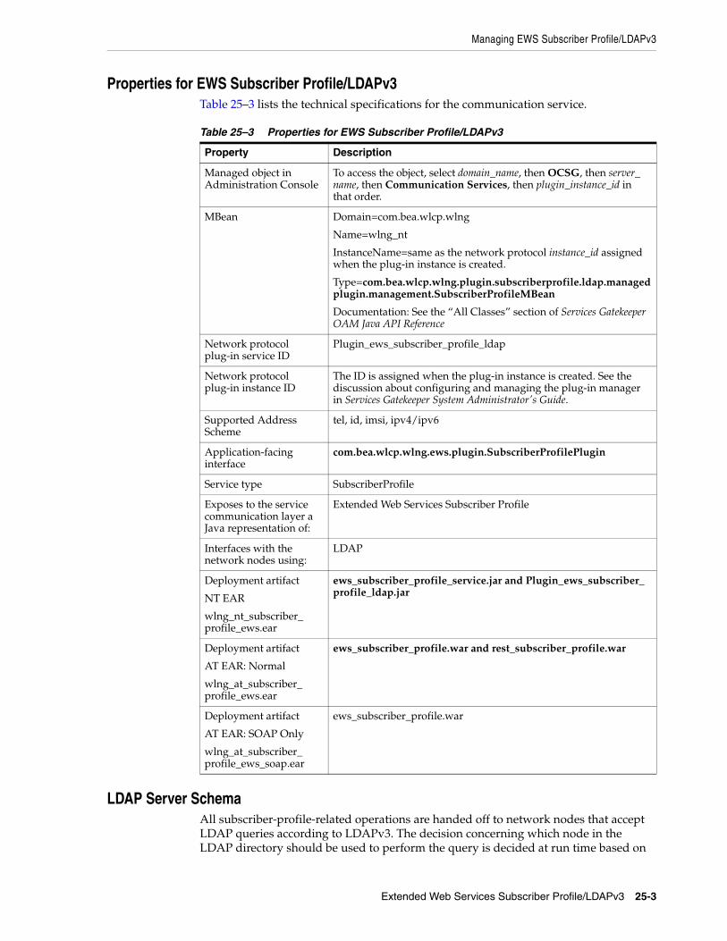
Managing EWS Subscriber Profile/LDAPv3
Extended Web Services Subscriber Profile/LDAPv3 25-3
Properties for EWS Subscriber Profile/LDAPv3Table 25–3 lists the technical specifications for the communication service.
LDAP Server SchemaAll subscriber-profile-related operations are handed off to network nodes that accept LDAP queries according to LDAPv3. The decision concerning which node in the LDAP directory should be used to perform the query is decided at run time based on
Table 25–3 Properties for EWS Subscriber Profile/LDAPv3
Property Description
Managed object in Administration Console
To access the object, select domain_name, then OCSG, then server_name, then Communication Services, then plugin_instance_id in that order.
MBean Domain=com.bea.wlcp.wlng
Name=wlng_nt
InstanceName=same as the network protocol instance_id assigned when the plug-in instance is created.
Type=com.bea.wlcp.wlng.plugin.subscriberprofile.ldap.managedplugin.management.SubscriberProfileMBean
Documentation: See the “All Classes” section of Services Gatekeeper OAM Java API Reference
Network protocol plug-in service ID
Plugin_ews_subscriber_profile_ldap
Network protocol plug-in instance ID
The ID is assigned when the plug-in instance is created. See the discussion about configuring and managing the plug-in manager in Services Gatekeeper System Administrator's Guide.
Supported Address Scheme
tel, id, imsi, ipv4/ipv6
Application-facing interface
com.bea.wlcp.wlng.ews.plugin.SubscriberProfilePlugin
Service type SubscriberProfile
Exposes to the service communication layer a Java representation of:
Extended Web Services Subscriber Profile
Interfaces with the network nodes using:
LDAP
Deployment artifact
NT EAR
wlng_nt_subscriber_profile_ews.ear
ews_subscriber_profile_service.jar and Plugin_ews_subscriber_profile_ldap.jar
Deployment artifact
AT EAR: Normal
wlng_at_subscriber_profile_ews.ear
ews_subscriber_profile.war and rest_subscriber_profile.war
Deployment artifact
AT EAR: SOAP Only
wlng_at_subscriber_profile_ews_soap.ear
ews_subscriber_profile.war

Managing EWS Subscriber Profile/LDAPv3
25-4 Services Gatekeeper Communication Service Reference Guide
configuration settings. The data that is handed back to the application that initiated the Subscriber Profile query is filtered using the result filter mechanism in the service provider group and application group SLAs. For more information, see the discussion about <resultRestrictions> in the defining service provider group and application group SLAs desction of the Services Gatekeeper Accounts and SLAs Guide.
A schema is used for constructing queries. See Example 25–1.
Example 25–1 LDAP Query schema XSD
<?xml version="1.0" encoding="UTF-8"?><xs:schema xmlns:xs="http://www.w3.org/2001/XMLSchema"><xs:element name="LdapConfig"><xs:complexType><xs:sequence><xs:element name="Keys" type="KeySet" minOccurs="1" maxOccurs="unbounded"/><xs:element name="LdapObject" type="LdapObject" minOccurs="1" maxOccurs="unbounded"/></xs:sequence></xs:complexType></xs:element>
<xs:complexType name="KeyObject"><xs:sequence><xs:element name="uriScheme" type="xs:string" minOccurs="1" maxOccurs="1"/><xs:element name="addressKeyName" type="xs:string" minOccurs="1" maxOccurs="1"/><xs:element name="objectKeyName" type="xs:string" minOccurs="0" maxOccurs="1"/><xs:element name="objectKeyValue" type="xs:string" minOccurs="0" maxOccurs="1"/></xs:sequence><xs:attribute name="id" type="xs:string" use="optional"/></xs:complexType>
<xs:complexType name="KeySet"><xs:sequence><xs:element name="Key" type="KeyObject" minOccurs="1" maxOccurs="unbounded"/></xs:sequence><xs:attribute name="id" type="xs:string" use="required"/></xs:complexType><xs:complexType name="LdapObject"><xs:sequence><xs:element name="ObjectKeySet" type="xs:string" minOccurs="0" maxOccurs="1"/></xs:sequence><xs:attribute name="id" type="xs:string" use="required"/><xs:attribute name="keyName" type="xs:string" use="required"/><xs:attribute name="keyValue" type="xs:string" use="required"/></xs:complexType></xs:schema>
The LDAP server schema describes the following elements:
■ LdapObject: Holder of a KeySet
■ KeySet: Defines a collection of KeyObjects. Sets of keys are used because there may be several ways to reach a certain node in the tree. One LDAP plug-in instance can be configured with several KeySets and can provide the link between the search key in the Extended Web Services interface and the LDAP tree.
■ KeyObject: Defines an entry point to the LDAP tree and provides the link between the search key in the Extended Web Services interface and the LDAP tree.
Table 25–4 describes the schema objects in detail.

Managing EWS Subscriber Profile/LDAPv3
Extended Web Services Subscriber Profile/LDAPv3 25-5
Example 25–2 shows a directory information tree built using the schema described in Table 25–4.
Example 25–2 Example of LDAP server schema
<?xml version="1.0" encoding="UTF-8"?><LdapConfig xmlns:xsi=http://www.w3.org/2001/XMLSchema-instancexsi:noNamespaceSchemaLocation='sp_config.xsd'><Keys id="myKeys"><Key id="misidnKey"><uriScheme>tel</uriScheme><addressKeyName>msisdn</addressKeyName><objectKeyName>domainName</objectKeyName><objectKeyValue>msisdnD</objectKeyValue></Key><Key id="imsiKey"><uriScheme>imsi</uriScheme><addressKeyName>imsi</addressKeyName><objectKeyName>domainName</objectKeyName><objectKeyValue>imsiD</objectKeyValue></Key><Key id="subscriberIdKey"><uriScheme>id</uriScheme><addressKeyName>id</addressKeyName><objectKeyName>domainName</objectKeyName>
Table 25–4 LDAP Server Schema
Object Element Description
LdapObject ObjectKeySet Defines the KeySet through which it can be reached. Refers to theID attribute of a defined KeySet.
LdapObject id The identity of the LdapObject. Can be referenced from other LdapObjects through the ParentObjectId field.
LdapObject keyName The name of the key through which the LdapObject can be reached.
LdapObject keyValue The value of the key through which the LdapObject can be reached.
KeyObject uriScheme Defines the URI scheme of the address for which this key applies.
KeyObject addressKeyName Defines the key name with which the address value is associated.
KeyObject objectKeyName Provides the possibility of defining the addressing key of a possible tree node above the node that is reached by the address key (that is, like the domain object in the 3DS directory information tree).
KeyObject objectKeyValue See objectKeyName. Defines the value of the key.
KeyObject id The identity of the key. Used only for descriptive purposes.
KeySet Key All keys in the KeySet
KeySet id The identity of the KeySet. Used when associating an LdapObject with a KeySet.

Managing EWS Subscriber Profile/LDAPv3
25-6 Services Gatekeeper Communication Service Reference Guide
<objectKeyValue>subsD</objectKeyValue></Key><Key id="ipv4Key"><uriScheme>ipv4</uriScheme><addressKeyName>ipv4Addr</addressKeyName><objectKeyName>domainName</objectKeyName><objectKeyValue>ipv4D</objectKeyValue></Key></Keys><LdapObject id="mySchema" keyName="serviceName" keyValue="mySchema"><ObjectKeySet>myKeys</ObjectKeySet></LdapObject></LdapConfig>
Configuration Workflow for EWS Subscriber Profile/LDAPv3Following is an outline for configuring the plug-in using the Administration Console or an MBean browser.
1. Create one or more instances of the plug-in service. See the discussion about configuring and managing the plug-in manager in Services Gatekeeper System Administrator's Guide. Use the plug-in service ID as listed in the "Properties for EWS Subscriber Profile/LDAPv3" section.
2. Select the MBean for the plug-in instance. The MBean display name is the same as the plug-in instance ID given when the plug-in instance was created.
3. Define the characteristics of the LDAP server to connect to using these fields:
■ Port
■ AuthDN
■ BaseDN
■ AuthPassword
4. Define the schema using either the Schema field or the updateSchemaURL operation.
See "LDAP Server Schema" for a description of the schema and "Configuration Workflow for EWS Subscriber Profile/LDAPv3" for a description of the mappings.
5. Define the connection pool characteristics for the connection using these fields:
■ MinConnections
■ MaxConnections
■ ConnTimeout
■ RecoverTimerInterval
6. Set up the routing rules to the plug-in instance. See the discussion about configuring and managing the plug-in manager in Services Gatekeeper System Administrator's Guide. Use the plug-in instance ID and address schemes listed in the "Properties for EWS Subscriber Profile/LDAPv3" section.
7. If required, create and load a node SLA. For details see the discussion about defining global node and service provider group node SLAs and managing SLAs in Services Gatekeeper Accounts and SLAs Guide.
8. Provision the service provider accounts and application accounts. For information, see Services Gatekeeper Portal Developer's Guide.

Managing EWS Subscriber Profile/LDAPv3
Extended Web Services Subscriber Profile/LDAPv3 25-7
Management Operations for EWS Subscriber Profile/LDAPv3There are no specific management operations, except for the updateLDAPSettings method, used to update the LDAP connection pool after changing any of these fields:
■ MinConnections
■ MaxConnections
■ ConnTimeout
■ RecoverTimerInterval
Provisioning for EWS Subscriber Profile/LDAPv3If the results from the LDAP query should be filtered, use the service provider group and application group SLAs. See the discussion about <resultRestrictions> in the defining service provider group and application group SLAs desction of the Services Gatekeeper Accounts and SLAs Guide.
For a description of the attributes and operations of the SubscriberProfileMBean MBean, see the “All Classes” section of Services Gatekeeper OAM Java API Reference.

Managing EWS Subscriber Profile/LDAPv3
25-8 Services Gatekeeper Communication Service Reference Guide

26
Extended Web Services WAP Push/PAP 26-1
26Extended Web Services WAP Push/PAP
This chapter describes the Oracle Communications Services Gatekeeper Extended Web Services (EWS) WAP Push/Push Access Protocol (PAP) communication service in detail.
Overview of the EWS WAP Push/PAP Communication ServiceThe EWS WAP Push/PAP communication service exposes the Oracle Extended Web Services WAP Push interface.
The communication service connects to a Push Proxy Gateway (PPG) using Push Access Protocol (PAP) 2.0. See "Push Access Protocol (PAP) 2.0" for information about this network protocol.
For the exact version of the standards that the communication service supports for the application-facing interfaces and the network protocols, see Services Gatekeeper Statement of Compliance.
Using the EWS WAP Push/PAP communication service, an application can:
■ Send a WAP Push message to a single or multiple (bulk) destinations.
■ Send a replacement WAP Push message.
■ Ask to be notified asynchronously of the status of WAP Push messages that have been sent. The possible values returned include:
– Rejected: The message was not accepted.
– Pending: The message is in process.
– Delivered: The message was successfully delivered to the end-user.
– Undeliverable: The message could not be delivered because of a problem.
– Expired: The message reached the maximum age allowed by server policy or could not be delivered by the time specified in the push submission.
– Aborted: The mobile device aborted the message.
– Timeout: The delivery process timed out.
– Cancelled: The message was cancelled through the cancel operation.
– Unknown: The server does not know the state of the message.
■ Send a result notification message. This occurs only if the initial push submission was accepted for processing. One result notification message is sent per destination address.

Application Interfaces
26-2 Services Gatekeeper Communication Service Reference Guide
Push Access Protocol (PAP) 2.0EWS WAP Push/PAP supports a subset of the PAP 2.0 operations. These include:
■ push-message: Submits a message to be delivered. This operation is also used to send a replacement message.
■ push-response: The response to the push-message operation. This response includes a code specifying the immediate status of the message submission, of the following general types:
– 1xxx Success: The action was successfully received, understood, and accepted
– 2xxx Client Error: The request contains bad syntax or cannot be fulfilled
– 3xxx Server Error: The server failed to fulfil an apparently valid request
– 4xxx: Service Failure: The service could not be performed. The operation may be retried
■ resultnotification-message: Specifies the final outcome of a specific message for a specific recipient. Sent only if the initial request includes the URL to which this notification is to be delivered. Includes both textual indication of state and a status code including the following general types:
– 1xxx Success: The action was successfully received, understood, and accepted
– 2xxx Client Error: The request contains bad syntax or cannot be fulfilled
– 3xxx Server Error: The telecom network node failed to fulfil an apparently valid request
– 4xxx: Service Failure: The service could not be performed. The operation may be retried
– 5xxx: Mobile Device Abort: The mobile device aborted the operation.
■ resultnotification-response: The response to the result notification. This response includes a code specifying the status of the notification
– 1xxx Success: The action was successfully received, understood, and accepted
– 2xxx Client Error: The request contains bad syntax or cannot be fulfilled
■ badmessage-response: A response indicating that request is unrecognizable or is of a protocol version that is not supported. This response contains either a 3002 code (Version not supported) or a 2000 code (Bad Request). In the case of Bad Request, a fragment of the unrecognizable message is included in the response
See Services Gatekeeper Statement of Compliance for the exact version of the protocol standard Services Gatekeeper supports.
Application InterfacesFor information about the application interface for the Extended Web Services WAP Push communication service, see the discussion on Extended Web Services WAP Push in Services Gatekeeper Application Developer's Guide.
For information about the RESTful Call Notification interface, see the discussion on WAP Push in Services Gatekeeper Application Developer's Guide.
The RESTful Service Call Notification interfaces provide RESTful access to the same functionality as the SOAP-based interfaces. The internal representations are identical, and for the purposes of creating SLAs and reading CDRs, and so on, they are the same.

Managing the EWS WAP Push/PAP Communication Service
Extended Web Services WAP Push/PAP 26-3
Events and StatisticsThe EWS WAP Push/PAP communication service generates Event Data Records (EDRs), charging data records (CDRs), alarms, and statistics to assist system administrators and developers in monitoring the service
See "Events, Alarms, and Charging" for more information.
Charging Data RecordsEWS WAP Push/PAP-specific CDRs are generated under the following conditions:
■ When the sendPushMessage response returns from the network.
■ When a sendResultNotificationMessage response returns from the application.
Event Data RecordsTable 26–1 lists the IDs of the EDRs created by the EWS WAP Push communication service.
StatisticsTable 26–2 maps methods invoked from either the application or the network to the transaction types collected by the Services Gatekeeper statistics counters.
AlarmsFor the list of alarms, see Services Gatekeeper Alarms Handling Guide.
Managing the EWS WAP Push/PAP Communication ServiceThis section describes the properties and workflow for the EWS WAP Push/PAP plug-in instance.
Properties for EWS WAP Push/PAPTable 26–3 lists the technical specifications for the communication service.
Table 26–1 EDRs Generated by EWS WAP Push/PAP
EDRID Method Called
14001 sendPushMessage
14002 sendResultNotificationMessage
Table 26–2 Methods and Transaction Types for EWS WAP Push/PAP
Method Transaction type
sendPushMessage TRANSACTION_TYPE_MESSAGE_SENDER_SEND
sendResultNotificationMessage TRANSACTION_TYPE_MESSAGE_SENDER_NOTIFY
Table 26–3 Properties for EWS WAP Push/PAP
Property Description
Managed object in Administration Console
To access the managed object, select domain_name, then OCSG, then server_name, then Communication Services, then plugin_instance_id in that order.

Managing the EWS WAP Push/PAP Communication Service
26-4 Services Gatekeeper Communication Service Reference Guide
WAP User Address SchemeThe wapuser address scheme supports the client address formats defined in the Wireless Application Protocol Push Proxy Gateway Service Specification.
To use the wapuser address scheme, the application should set the WAPPUSH and TYPE values in the destinationAddress. For example, given the address:
WAPPUSH=+155519990730
MBean Domain=com.bea.wlcp.wlng
Name=wlng_nt
InstanceName=same as the network protocol instance_id assigned when the plug-in instance is created
Type=com.bea.wlcp.wlng.plugin.pushmessage.pap.management.PushMessagePAPMBean
Documentation: See the “All Classes” section of Services Gatekeeper OAM Java API Reference
Network protocol plug-in service ID
Plugin_ews_push_message_pap
Network protocol plug-in instance ID
The ID is assigned when the plug-in instance is created. See the discussion about configuring and managing the plug-in manager in Services Gatekeeper System Administrator's Guide.
Supported Address Scheme
tel, wapuser
See "WAP User Address Scheme" for information on the wapuser address scheme.
Application-facing interface
com.bea.wlcp.wlng.ews.plugin.PushMessagePlugin
com.bea.wlcp.wlng.ews.callback.PushMessageNotificationCallback
Service type PushMessage
Exposes to the service communication layer a Java representation of:
Extended Web Services WAP Push
Interfaces with the network nodes using:
Push Access Protocol (PAP), 2.0. WAP-247-PAP-20010429-a
Deployment artifact:
NT EAR
wlng_nt_push_message_ews.ear
ews_push_message_service.jar, Plugin_ews_push_message_pap.jar, and ews_push_message_pap.war
Deployment artifact:
AT EAR: Normal
wlng_at_push_message_ews.ear
ews_push_message.war, ews_push_message_callback.jar, and rest_push_message.war
Deployment artifact:
AT EAR: SOAP Only
wlng_at_push_message_ews_soap.ear
ews_push_message.war and ews_push_message_callback.jar
Table 26–3 (Cont.) Properties for EWS WAP Push/PAP
Property Description

Managing the EWS WAP Push/PAP Communication Service
Extended Web Services WAP Push/PAP 26-5
set the destinationAddress to:
WAPPUSH=+155519990730/[email protected]
Given the address:
WAPPUSH=john.doe%40wapforum.org
set the destinationAddress to:
WAPPUSH=john.doe%40wapforum.org/ [email protected]
Configuration Workflow for EWS WAP Push/PAPFollowing is an outline for configuring the plug-in using the Administration Console.
1. Create one or more instances of the plug-in service. See the discussion about configuring and managing the plug-in manager in Services Gatekeeper System Administrator's Guide. Use the plug-in service ID as listed in the "Properties for EWS WAP Push/PAP" section.
2. Using the Administration Console or an MBean browser, select the MBean for the plug-in instance. The MBean display name is the same as the plug-in instance ID assigned when the plug-in instance was created.
3. Define the characteristics of the PPG server to connect to using the PPGNotificationURL and PPGURL fields.
4. Specify heartbeat behavior. See the discussion on configuring heartbeats in Services Gatekeeper System Administrator's Guide.
5. Set up the routing rules to the plug-in instance. See the discussion about configuring and managing the plug-in manager in Services Gatekeeper System Administrator's Guide. Use the plug-in instance ID and address schemes listed in the "Properties for EWS WAP Push/PAP" section.
6. If required, create and load a node SLA. For details see the discussion on defining global node and service provider group node SLAs and managing SLAs in Services Gatekeeper Accounts and SLAs Guide.
7. Provision the service provider accounts and application accounts. For information, see Services Gatekeeper Portal Developer's Guide.
For a description of the attributes and operations of the PushMessagePAPMBean MBean, see the “All Classes” section of Services Gatekeeper OAM Java API Reference.

Managing the EWS WAP Push/PAP Communication Service
26-6 Services Gatekeeper Communication Service Reference Guide

27
Native MM7 27-1
27Native MM7
This chapter describes the Oracle Communications Services Gatekeeper Native MM7 communication service in detail.
Overview of the Native MM7 Communication ServiceThe Native MM7 communication service exposes the 3GPP MM7 standard interfaces.
From the point of view of an application, the communication service acts as an MMS relay server. From the point of view of the network, it acts as an MMS VAS application.
For the exact version of the standards that the Native MM7 communication service supports for the application-facing interfaces and the network protocols, see Services Gatekeeper Statement of Compliance.
Using the Native MM7 communication service, an application can:
■ Send a multimedia message to one or many destination addresses.
The payload in these multimedia messages can be any type that can be specified using Multipurpose Internet Mail Extensions (MIME), including multipart messages. If a subscription for notifications has been previously set up, the request can also specify that a delivery report or a read report should be returned later in relation to this message.
■ Receive delivery reports on sent multimedia messages that have arrived from the network.
■ Receive read-reply reports on sent multimedia messages that have arrived from the network.
■ Receive multimedia messages from the network.
Requests can flow in two directions using the Native MM7 communication service: from the application to the network and from the network to the application.
Status ReportsThere are two types of status reports that can be returned to the application from the network via Services Gatekeeper. Both are returned asynchronously, using callback information provided when the notification is set up. If the network sends a report but no notification has been set up, Services Gatekeeper sends the network an error code indicating permanent failure.
■ Delivery Reports
■ Read-Reply Report

Application Interfaces
27-2 Services Gatekeeper Communication Service Reference Guide
Delivery ReportsDelivery reports are acknowledgements that the network node has handled the message from the application that was submitted. The report indicates the status of the message: for example, Forwarded, Expired, or Rejected. There is one delivery report per destination address. If a connection error occurs within Services Gatekeeper or between Services Gatekeeper and the application, an error code is returned to the network, which resends the message.
Read-Reply ReportRead-reply reports contain the final delivery status of the multimedia message. The final delivery status reports whether the message has actually been delivered by the network to the mobile terminal. It also includes the status of the message at that terminal; for example, Read or Deleted without being read.
Because a recipient can request that read-reply reports not be generated, lack of a read-reply report does not necessarily mean that the message has not been rendered on the recipient’s terminal.
There is one read-reply report per destination address. If a connection error occurs within Services Gatekeeper or between Services Gatekeeper and the application, an error code is returned to the network, which resends the message.
Network-triggered Multimedia MessagesFor an application to receive multimedia messages from the network, it must register its interest in these messages by setting up a subscription. A subscription, or notification, is defined by a destination address. For the message to be accepted by Services Gatekeeper, the destination address must match the subscription. Each registered subscription must be unique, and subscription attempts with overlapping criteria are rejected. If a message with several destination addresses arrives, Services Gatekeeper iterates through the list until it reaches a match or until the list is exhausted.
Application InterfacesFor information on the application interface for the Native MM7 communication service, see the discussion about the Native Interfaces in Services Gatekeeper Application Developer's Guide.
Events and StatisticsThe Native MM7 communication service generates Event Data Records (EDRs), Charging Data Records (CDRs), alarms, and statistics to assist system administrators and developers in monitoring the service
For general information, see Appendix A, "Events, Alarms, and Charging."
Event Data RecordsTable 27–1 lists the IDs of the EDRs created by the Native MM7 communication service.

Managing Native MM7
Native MM7 27-3
Charging Data RecordsNative MM7 -specific CDRs are generated under the following conditions:
■ After an MMS message has been successfully sent from the application to the network.
■ After an MMS message has been successfully sent from the network to the application.
■ After a delivery report has been successfully delivered to the application.
■ After a read-reply report has been successfully delivered to the application.
StatisticsTable 27–2 maps methods invoked from either the application or the network to the transaction types collected by the Services Gatekeeper statistics counters.
AlarmsFor the list of alarms, see Services Gatekeeper Alarms Handling Guide.
Managing Native MM7This section describes the properties and workflow for the Native MM7 communication service.
Properties for Native MM7Table 27–3 lists the technical specifications for the communication service.
Table 27–1 EDRs Generated by Native MM7
EDR ID Description
401000 An application-initiated message has entered the plug-in.
401001 An application-initiated message has exited the plug-in.
401002 A network-triggered message sent via v.1.0 has entered the plug-in.
401003 A network-triggered message has exited the plug-in. It is formatted according to v. 1.2.
401004 A delivery report using v. 1.0 has entered the plug-in.
401005 A delivery report has exited the plug-in. It is formatted according to v 1.2
401006 A read-reply report using v. 1.0 has entered the plug-in.
401007 A read-reply report has exited the plug-in. It is formatted according to v. 1.2
Table 27–2 Methods and Transaction Types for Native MM7
Method Transaction type
submit TRANSACTION_TYPE_MESSAGING_MMS_SEND
deliver TRANSACTION_TYPE_MESSAGING_MMS_RECEIVE

Managing Native MM7
27-4 Services Gatekeeper Communication Service Reference Guide
Configuration Workflow for Native MM7Following is an outline for configuring the plug-in using the Administration Console or an MBean browser.
1. Create one or more instances of the plug-in service. See the discussion about configuring and managing the plug-in manager in Services Gatekeeper System Administrator's Guide. Use the plug-in service ID as listed in the "Properties for Native MM7" section.
2. Using the Administration Console or an MBean browser, select the MBean for the plug-in instance. The MBean display name is the same as the plug-in instance ID assigned when the plug-in instance was created.
3. Configure the behavior of the plug-in instance with these fields
■ Mm7RelayServerAddress
■ HTTPBasicAuthentication. If using HTTP basic authentication also define: these fields
– HTTPBasicAuthenticationUsername
– HTTPBasicAuthenticationPassword
Table 27–3 Properties for Native MM7
Property Description
Managed object in Administration Console
To access the managed object, select domain_name, then OCSG, then server_name, then Communication Services, and then plugin_instance_id in that order.
MBean Domain=com.bea.wlcp.wlng
Name=wlng_nt
InstanceName=same as the network protocol instance_id assigned when the plug-in instance is created
Type=com.bea.wlcp.wlng.plugin.mm7.management.Mm7MBean
Network protocol plug-in service ID
Plugin_multimedia_messaging_mm7
Network protocol plug-in instance ID
The ID is assigned when the plug-in instance is created. See the discussion about configuring and managing the plug-in manager in Services Gatekeeper System Administrator's Guide.
Supported Address Scheme tel, mailto, short
Application-facing interfaces
com.bea.wlcp.wlng.mm7.plugin.MmsPlugin
com.bea.wlcp.wlng.mm7.callback.MmsVaspCallback
Service type Mm7
Exposes to the service communication layer a Java representation of:
3GPP TS 23.140 V5.3.0 (REL-5-MM7-1-2.xsd)
Interfaces with the network nodes using:
MM7 (REL-5-MM7-1-0 or REL-5-MM7-1-2)
Deployment artifacts Plugin_multimedia_messaging_mm7.jar, mm7_service.jar, 1_0_mm7_vasp.war, 1_2_mm7_vasp.war packaged in wlng_nt_multimedia_messaging_mm7.ear
mm7.war, mm7_callback_client.jar packaged in wlng_at_multimedia_messaging_mm7.ear

Managing Native MM7
Native MM7 27-5
■ XSDVersion
4. Specify heartbeat behavior. See the discussion on configuring heartbeats in Services Gatekeeper System Administrator's Guide.
5. Set up the routing rules to the plug-in instance. See the discussion about configuring and managing the plug-in manager in Services Gatekeeper System Administrator's Guide. Use the plug-in instance ID and address schemes listed in the "Properties for Native MM7" section.
6. Provide the administrator of the MM7 server with the URL to which the MM7 server should deliver mobile-originated messages and delivery reports:
■ For REL-5-MM7-1-0 the default URL is:
http://IP_Address_of_NT_ Server:port/1_0_mm7_vasp/mms_vasp
■ For REL-5-MM7-1-2 the default URL is:
http://IP_Address_of_NT Server:port/1_2_mm7_vasp/mms_vasp
7. If required, create and load a node SLA. For details, see the discussion about defining global node and service provider group node SLAs and managing SLAs in Services Gatekeeper Accounts and SLAs Guide
8. Provision the service provider accounts and application accounts. For information, see Services Gatekeeper Portal Developer's Guide.
Provisioning Workflow for Native MM7Following is an outline for provisioning Native MM7.
1. Register offline notifications. This means that mobile-originated messages should not result in notifications to an application, but instead be stored in Services Gatekeeper for polling. Use the addVASPIDMapping method to register offline notifications. Use the following operations to manage the offline registrations:
■ listAllVASIDMapping
■ addVASPIDMapping
■ removeReceiveMmsNotification
2. Register online notifications. This means that registrations for mobile-originated messages are managed on behalf of an application. Use the addVASPIDMapping method to register online notifications. Use the following methods to manage the online registrations:
■ listAllVASPIDMapping
■ enableReceiveMmsNotification
■ removeStatusReporting
For a description of the attributes and operations of the Mm7MBean MBean, see the “All Classes” section of Services Gatekeeper OAM Java API Reference.

Managing Native MM7
27-6 Services Gatekeeper Communication Service Reference Guide
28
Native SMPP 28-1
28Native SMPP
This chapter describes the Oracle Communications Services Gatekeeper Native SMPP communication service in detail.
Overview of the Native SMPP Communication ServiceThe Native SMPP communication service exposes the SMPP v. 3.4 standard interfaces.
The communication service acts as an External Short Message Entity (ESME) that connects to a Short Messaging Service Center (SMSC) over TCP/IP.
For the exact version of the standards that the Native SMPP communication service supports for the application-facing interfaces and the network protocols, see Services Gatekeeper Statement of Compliance.
The Native SMPP communication service access the network using the following network protocols:
■ SMPP v 3.4
■ SMPP v 5.1
SMPP v 5.1 supports the billing identification parameter and ussd service_operation as optional parameters to Deliver_SM. See "smpp_billing_id" and "ussd_service_operation" for more information.
Using the Native SMPP communication service, an application can:
■ Send a short message to one or many destination addresses.
■ Cancel a previously sent message that has not yet been delivered.
■ Replace a previously sent message that has not yet been delivered.
■ Query the delivery status of a previously sent message.
■ Receive short messages arrived from the network.
■ Receive the delivery status of a previously sent message.
Requests flow in two directions: from the application to the network and from the network to the application.
All Native SMPP components are deployed in the network tier.
SMPP Server ServiceThe core module of the Native SMPP communication service is an SMPP Server Service deployed as an Oracle WebLogic Server Service. It provides connection

Overview of the Native SMPP Communication Service
28-2 Services Gatekeeper Communication Service Reference Guide
services for the Native SMPP and Parlay X 2.1 Short Messaging plug-ins. The SMPP Server Service:
■ Receives SMPP data from the socket.
■ Constructs the SMPP protocol data unit (PDU).
■ Associates the current PDU with the correct application instance.
■ Invokes the plug-in.
■ Manages connections between Services Gatekeeper and applications.
■ Manages connections between Services Gatekeeper and Short Message Service Centers (SMSCs).
Because the SMPP Server Service is deployed in the network tier, applications using the Native SMPP Native communication service must be able to connect directly to the network tier. Firewalls must be configured to allow connection to the ports defined for the SMPP Server Service.
Connection Handling and Provisioning The Native SMPP communication service uses the Services Gatekeeper SMPP Server Service to establish and manage southbound (client) connections between Services Gatekeeper and SMSCs. The SMPP Server Service is deployed as an Oracle WebLogic Server service.
See "System Properties for SMPP Server Service" and "Reference: Attributes and Operations for SMPP Server Service" for information about configuring connections between the Services Gatekeeper SMPP server service and an SMSC.
A client connection is created when this plug-in successfully binds with an SMSC. A successful rebind changes the connection ID.
About Creating and Resetting ConnectionsThe connections between an application and Services Gatekeeper are called server connections and the connections between Services Gatekeeper and an SMSC are called client connections. Most applications require both connections to successfully operate.
■ If at least one plug-in instance successfully binds with Services Gatekeeper:
– A server connection is established between the application and Services Gatekeeper.
– A client connection is established between Services Gatekeeper and the SMSC.
– Services Gatekeeper sends a successful bind response to the application.
■ All plug-ins that fail to bind try to reconnect periodically.
■ If the client connection is not successfully established, Services Gatekeeper attempts to reconnect with the SMSC, and its corresponding server connection continues to receive requests from the application. However, the plug-in can not process these requests, and instead it sends an error response to the application. through the server connection. The application requests are not stored and not re-sent to the SMSC.
■ If all plug-in instances fail to bind, Services Gatekeeper sends a failure bind response to the application, and closes and removes the server connection.
■ If a client connection is successfully established with the SMSC, the connection is verified periodically using ENQUIRE_LINK requests (heartbeats). If the

Overview of the Native SMPP Communication Service
Native SMPP 28-3
ENQUIRE_LINK requests fail a configurable number of times, Services Gatekeeper attempts to reconnect with the SMSC. If the client connection reconnect attempts fail a configurable number of times, the connection is closed and removed. See "Attribute: EnquireLinkMaxFailureTimes" and "Attribute: RetryTimesBeforeGiveUp" for details.
You use the connectionId and plugininstanceId parameters to the "Operation: resetClientConnection" to establish or reestablish connections between Services Gatekeeper and SMSCs. The connection-related operations for this plug-in accept values for these parameters according to these rules:
■ You reset all connections for a plug-in using plugininstanceId. Any configuration changes you send in takes effect. This is the most common resetting strategy because it generally does not make sense to reset a single SMCC connection and leave the rest connecting to another SMSC.
■ You reset a single connection for a plug-in using connectionId, and only that connection is reset. Any connection configuration settings you include are ignored to avoid resetting the connection with new, conflicting settings. You will probably only reset a single connection rarely, for example in cases where a single connection is misbehaving and you are reluctant to reset all of the others.
■ If a value for the connectionId parameter is provided, this communication service ignores any value provided for the pluginInstanceId parameter. That is, only if connectionId has no value then a parameter value for plugininstanceId is used.
■ If connectionId has no value or no value that matches the fields sent, and the value for plugininstanceid does match, then all connections for plugininstanceId are reset.
■ Use "Operation: listClientConnections" to list client connections.
About Session HandlingApplications can bind to Services Gatekeeper as a transmitter, a receiver, or a transceiver. An application can establish several parallel sessions by issuing multiple bind operations.
The number of concurrent connections is provisioned for each Native SMPP plug-in, if connection-based routing is not enabled. See "Attribute: BindType", "Attribute: NumberReceiverConnections", "Attribute: NumberTransceiverConnections", and "Attribute: NumberTransmitterConnections".
The SMPP Server Service should be provisioned with the following data about the application instance:
■ The port number to bind to.
■ The maximum number of concurrent sessions allowed.
■ Whether subsequent operations should be allowed to target a previously sent short message.
■ Whether network-triggered short messages and delivery reports should be forwarded to the application.
■ The address range that, when matched with the destination address of a network-triggered short message, forwards the message to the application.
See "Operation: addApplicationSpecificSettings" for details about configuring these settings.

Overview of the Native SMPP Communication Service
28-4 Services Gatekeeper Communication Service Reference Guide
AuthenticationAuthentication credentials are configured in the Native SMPP plug-in instance MBean. See "Reference: Attributes and Operations for Native SMPP Plug-in" for more information.
Applications use an application instance ID as the ESME system_id and the related password when binding to Services Gatekeeper.
Connection PoolingThe SMPP Server Service maintains server and client connection pools.
Server Connection PoolsThe SMPP Server Service maintains a server connection pool for application-facing (northbound) connections. The pool is created when the SMPP Server Service is started.
The plug-in obtains connections from this pool to send messages to the application.
The server connections are used to:
■ Invoke the plug-in.
■ Send messages to and receive messages from the application.
■ Manage the application-facing SMPP timers.
■ Manage windowing toward the application.
■ Cache transaction mapping information for transactions between Services Gatekeeper and the application.
Client Connection PoolsThe SMPP Server Service maintains a client connection pool for network-facing (southbound) connections.
The plug-in sends BIND and UNBIND requests to the client pool and obtains a client connection ID from the pool to perform SMPP transactions.
The client connections are used to:
■ Invoke the plug-in.
■ Send messages to and receive messages from the SMSC.
■ Manage the network-facing SMPP timers.
■ Manage windowing toward the SMSC.
■ Cache transaction mapping information between Services Gatekeeper and the SMSC.
TimeoutsYou can configure timers for both application-facing and network-facing connections. Some of the timers for application-facing and network-facing connections have the same names, but they are configured in different MBeans.
SMPP Server Service TimersThe SMPP Server Service provides the following configurable timers for connections between Services Gatekeeper and applications:

Overview of the Native SMPP Communication Service
Native SMPP 28-5
■ Initiation timer: This timer ensures that when an application initiates a connection, the BIND occurs within a specified period after the connection is established to Services Gatekeeper. See "Attribute: InitiationTimerValue" for more information.
■ Inactivity timer: This timer establishes a period of inactivity after which, if no SMPP messages are exchanged with the application, Services Gatekeeper closes the connection. See "Attribute: InactivityTimerValue" for more information.
■ Connection timer: This timer sets the heartbeat interval that Services Gatekeeper uses to request the connection status on the server connection. If the ENQUIRE_LINK requests fail, Services Gatekeeper closes the connection and attempts to reconnect. See "Attribute: EnquireLinkTimerValue" in "Reference: Attributes and Operations for SMPP Server Service" for more information.
■ Transaction timer: This timer establishes the interval between an SMPP request to the application and the corresponding SMPP response. If the interval is reached, Services Gatekeeper does not re-send the request. In this case, Services Gatekeeper removes the transaction information and discards the PDU response. See "Attribute: RequestTimerValue" in "Reference: Attributes and Operations for SMPP Server Service" for more information.
You can disable any of these timers by setting their values to 0.
Plug-in Instance TimersThe plug-in instance MBean provides the following configurable timers for connections between Services Gatekeeper and SMSCs:
■ Connection timer: This timer sets the heartbeat interval that Services Gatekeeper uses to request the connection status on the client connection. If the ENQUIRE_LINK requests fail, Services Gatekeeper closes the connection and attempts to reconnect. See "Attribute: EnquireLinkTimerValue" in "Reference: Attributes and Operations for Native SMPP Plug-in" for more information.
■ Transaction timer: This timer establishes the interval between an SMPP request to the SMSC and the corresponding SMPP response. If the interval is reached, Services Gatekeeper does not re-send the request. In this case, Services Gatekeeper removes the transaction information and discards the PDU response. See the "Attribute: RequestTimerValue" in "Reference: Attributes and Operations for Native SMPP Plug-in" for more information.
WindowingTo maximize throughput, Native SMPP supports windowing on both the application-facing and network-facing interfaces. Windowing provides a way to specify the amount of data that can be transmitted without receiving an acknowledgment.
Requests wait in a windowing queue until they can be submitted. Two values apply to the windowing queue. The windowing maximum queue size is the size of the queue, specifying the maximum number of requests that can wait in the queue at one time. The windowing maximum wait time value specifies the maximum amount of time that a single request can wait in the windowing queue.
The windowing size value is the number of unacknowledged requests that can be sent simultaneously.
Windowing for mobile-originated requests toward the application is configured in the following parameters in the SMPP Server Service’s addApplicationSpecificSettings operation:

Overview of the Native SMPP Communication Service
28-6 Services Gatekeeper Communication Service Reference Guide
■ windowingSize
■ windowingMaxQueueSize
■ windowingMaxWaitTime
See "Operation: addApplicationSpecificSettings" for more information.
Windowing for mobile-terminated requests toward the SMSC is configured in the following plug-in instance MBean attributes:
■ Attribute: WindowingSize
■ Attribute: WindowingMaxQueueSize
■ Attribute: WindowingMaxWaitTime
A request moves from the windowing queue to the window. From the window it is submitted for processing. A submitted request remains in the window until its response is received. When the response is received, the request is released and another request can be moved from the windowing queue to the window.
If any one of these three windowing parameters is set to a value less than zero, windowing is turned off. If all of these three parameters are greater than zero, windowing is turned on.
In both directions, if the windowing request queue is full or the timer has expired, the request is not sent and an error code is returned to the plug-in instance.
Connection-Based RoutingConnection-based routing lets network operators configure geo-redundant sites to allow applications to send mobile-originated (MO), mobile-terminated (MT,) and delivery receipt (DR) traffic to and from any of the redundant sites. For example, a DR can be sent to a site other than the one through which the original message was submitted.
Enable Connection-Based RoutingTo use this feature, set the ConnectionBaseRouting attribute in the SMPP Server Service to true. By default this attribute is false. See "Attribute: ConnectionBasedRouting" for more information.
When connection-based routing is enabled, messages from the network are routed to the application that caused or that could have caused the connection in the plug-in to be established to the SMSC. This works both for delivering a short message with a new message and delivering a short message containing a delivery receipt. This means that DELIVER_SM with a new message is not routed based on the destination address, and DELIVER_SM containing a delivery receipt is not routed based on the message identifier.
LimitationsThe following are some limitations and issues pertaining to connection-based routing:
■ If an application is configured to support subsequent operations (CANCEL_SM, QUERY_SM and REPLACE_SM), those requests must be sent to the same geographic site as the original submit requests. They will not be accepted if sent to the other site. When Services Gatekeeper checks the subsequent operations, it returns an error response if it cannot find the original SUBMIT_SM request in the store.

Overview of the Native SMPP Communication Service
Native SMPP 28-7
■ If subsequent operations are enabled and a submit request is sent through site 1 but delivery receipt arrives on site 2, the data stored about the message in the database on site 1 is not deleted until the information is considered to be too old. The consequence is that an application can continue sending subsequent operations related to the message through site 1 even after the message was delivered.
■ If connection-based routing is enabled, the NumberReceiverConnections, NumberTransceiverConnections, and NumberTransmitterConnections attributes in the plug-in instance are ignored, because connections to the SMSC cannot be shared among different application instances.
Short Code TranslationThe Native SMPP communication service does not offer short code translations.
USSD SupportNative SMPP provides Unstructured Supplementary Services Data (USSD) through the its_session_info, service_type, and ussd_service_operation optional parameters.
its_session_infoRequired parameter for the CDMA Interactive Teleservice as defined by the Korean PCS carriers [KORITS]. Contains control information for the interactive session between an MS and an ESME.
See Section 5.3.2.43 of the Short Message Peer to Peer Protocol Specification v3.4 for the formal definition of the parameter and the appropriate subsections of Section 4 for its specification as an optional parameter for SUBMIT_SM, DELIVER_SM, and DATA_SM.
FormatOctet String
Following is a description of the octet string.
Bits 7...............0
SSSS SSSS (octet 1)
NNNN NNNE (octet 2)
Octet 1 contains the session number (0 -255) encoded in binary. The session number remains constant for each session.
The sequence number of the dialog unit (as assigned by the ESME) within the session is encoded in bits [7. . . 1] of octet 2.
The End of Session Indicator indicates the message is the end of the conversation session and is encoded in bit 0 of octet 2 as follows:
■ 0 = End of Session Indicator inactive
■ 1 = End of Session Indicator active
service_typeIndicates the SMS application service associated with the message. Allows the ESME to use enhanced messaging services such as “replace_if_present” (generic) and to control the teleservice used on the air interface (for example, ANSI-136/TDMA, IS-95/CDMA).

Overview of the Native SMPP Communication Service
28-8 Services Gatekeeper Communication Service Reference Guide
Used to support USSD (Unstructured Supplementary Service Data 3G TS 23.090 version 3.0.0) messages through the SMPP protocol.
See Section 5.2.11 of the Short Message Peer to Peer Protocol Specification v3.4. for the formal definition of the parameter and the appropriate subsections of Section 4 for its specification as a mandatory parameter for SUBMIT_SM, SUBMIT_MULTI, DELIVER_SM, DATA_SM, and CANCEL_SM.
FormatOctet String
ValueThe pre-defined generic service type value for USSD is USSD.
ussd_service_operationDefines the USSD service operation that is required when SMPP is used as an interface to a (GSM) USSD system.
Used to support tunneling USSD (Unstructured Supplementary Service Data 3G TS 23.090 version 3.0.0) messages through the SMPP protocol.
Used as an optional parameter to SMPP SUBMIT_SM.
Defined in section Section 5.3.2.44 of the Short Message Peer to Peer Protocol Specification v3.4.
Added to DELIVER_SM in the SMPP 5.1 specification. See Short Message Peer to Peer Protocol Specification Version 5.1.
FormatOctet String
ValueValid values are:
■ 0 = PSSD indication
■ 1 = PSSR indication
■ 2 = USSR request
■ 3 = USSN request
■ 4 to 15 Reserved
■ 16 = PSSD response
■ 17 = PSSR response
■ 18 = USSR confirm
■ 19 = USSN confirm
■ 20 to 31 Reserved
■ 32 to 255 Reserved for vendor-specific USSD operations
Billing IdentificationThe native SMPP communication service supports the billing_identification parameter in the format in the SMPP Specification 5.1 through an optional parameter named smpp_billing_id.
The parameter works with SMPP 5.1 SMSCs, but with not with SMPP 3.4 SMSCs.

Overview of the Native SMPP Communication Service
Native SMPP 28-9
smpp_billing_idDefines the billing information according to the format in the SMPP Specification 5.1, section 4.8.4.3 titled "billing_identification".
FormatHexadecimal string
Table 28–1 describes the format.
If the value is not sent as a hexadecimal string, it is ignored and a warning is logged.
Here is sample code for encoding the string.
private String getHexEncodedString(String normalString) { byte[] bHexStr = normalString.getBytes(); String retVal = ""; ..String sOctet = null; for (int i = 0; i < bHexStr.length; i++) { sOctet = Integer.toHexString((int) (bHexStr[i] & 0xFF)); if (sOctet.length() == 1) { sOctet = "0" + sOctet; } retVal = retVal.concat(sOctet); } return retVal.toUpperCase(); }
Load Balancing, High Availability and Fail-OverTo optimize system utilization, applications should load-balance application-triggered requests among all network tier servers.
The SMSC should load-balance network-triggered requests among all network tier servers.
Load balancing is supported only among plug-in instances that are located in same network tier server and share same large account. When a request is sent to a plug-in instance, the plug-in instances use the SMPP Server Service in the same server to forward the request to the applications. When a request is sent to the SMPP Server Service, the SMPP Server Service uses a plug-in instance in the same server to process the request.
High availability and fail-over is supported between Services Gatekeeper and the SMSC. High availability between the application and Services Gatekeeper must be handled by each application.
Table 28–1 Format for smpp_bliing_id Value
FieldSize (octets) Type Description
parameter tag
2 Integer 0x060B
length 2 Integer Length of value part in octets
value 1 - 1024 Octet String
Bits 7......0
0XXXXXXX (Reserved)1XXXXXXX (Vendor Specific)
The first octet represents the Billing Format tag and indicates the format of the billing information contained in the remaining octets.

Overview of the Native SMPP Communication Service
28-10 Services Gatekeeper Communication Service Reference Guide
A prerequisite for high-availability for the Native SMPP communication service is redundant network tier servers, redundant network interface cards in each network tier server, and a redundant set of SMPP servers to connect to. High availability between Services Gatekeeper and the network is achieved by using at least two different plug-in instances per network tier server and having the plug-in instances connect to different SMPP servers.
Between SMPP applications and Services Gatekeeper, the applications handle high availability and fail-over for application-initiated requests by binding to two or more network tier servers. For network-triggered requests, the same requirement that the applications bind to two or more network tier servers applies.
High availability behavior is as follows:
■ In a Services Gatekeeper cluster, if the server becomes unavailable after sending a Submit SM request to and receiving the SUBMIT_SM_RESP from the SMSC, the SMSC routes the subsequent delivery receipt to another server. This other server retrieves the message information from cluster-level storage and processes it.
■ In a Services Gatekeeper cluster, if a server becomes unavailable after sending a SUBMIT_ SM request to and receiving the SUBMIT_SM_RESP from an application, the application routes the subsequent CANCEL_SM, QUERY_SM or REPLACE_SM request to another server. This other server retrieves the message information from cluster-level storage and processes it.
■ In a geo-redundant configuration, all sites are connected to the SMSC. If a site becomes unavailable after sending a SUBMIT_ SM request to and receiving the SUBMIT_SM_RESP from the SMSC, the SMSC routes the subsequent delivery receipt to another site. This other site uses connection-based routing to process the delivery receipt.
■ In a geo-redundant configuration, if an application is configured to support subsequent operations (CANCEL_SM, QUERY_SM, and REPLACE_SM) through the subsequentOperationsAllowed parameter to the addApplicationSpecificSettings operation, those requests must be sent to the same geographic site from which the original submit requests were sent. They will not be accepted if they are sent to another site.
■ In a geo-redundant configuration, if an application is configured to support subsequent operations and a submit request is sent through site 1 but delivery receipt arrives on site 2, the data stored about the message in the database on site 1 is not deleted until the information is considered to be too old. The consequence is that an application can continue sending subsequent operations related to the message through site 1 even after the message was delivered.
The Native SMPP communication service can be provisioned for applications to share the same large account in the SMPP server, so that they share the same bind. However, his configuration is not recommended since it impacts high availability for network-triggered requests. When there is only one bind between Services Gatekeeper and the SMPP server, and more than one application is listening for network-triggered messages, the Native SMPP communication service must listen to incoming messages on behalf of all the applications. The bind between the plug-in and the network node is performed on all network tier servers, so network-triggered messages can be sent to any of these servers. If the network-triggered request ends up in a server that the application has not bound to, the communication service does not try to look up a server that the application has bound to. Instead, it does not see an active bind and treats the request as undeliverable to the application. Because it is common for SMPP servers to load-balance between binds, it is very likely that 50% or more of the requests

Events and Statistics
Native SMPP 28-11
will fail in this setup. The only way to ensure high availability in this scenario is to mandate that all applications bind to all network tier servers.
Application InterfacesFor information on the application interface for the Native SMPP communication service, see the discussion about Native SMPP Interfaces in Services Gatekeeper Application Developer's Guide.
Events and StatisticsThe Native SMPP communication service generates event data records (EDRs), charging data records (CDRs), alarms, and statistics to assist system administrators and developers in monitoring the service
For general information, see "Events, Alarms, and Charging".
Event Data RecordsTable 28–2 lists IDs of the EDRs created by the SMPP Server Service.
Table 28–2 EDRs Generated by the SMPP Server Service
EDR ID Description
400000 Entering the NorthChannelProcessor recvBind method.
400001 Entering the NorthChannelProcessor recvUnbind method.
400002 Entering the NorthChannelProcessor recvSubmitSM method.
400003 Leaving the NorthChannelProcessor sendSubmitSMResp method.
400004 Entering the NorthChannelProcessor recvSubmitMulti method.
400005 Leaving the NorthChannelProcessor sendSubmitMultiResp method.
400006 Entering the NorthChannelProcessor recvQuerySM method.
400007 Leaving the NorthChannelProcessor sendQuerySMResp method.
400008 Entering the NorthChannelProcessor recvCancelSM method.
400009 Leaving the NorthChannelProcessor sendCancelSMResp method.
400010 Entering the NorthChannelProcessor recvReplaceSM method.
400011 Leaving the NorthChannelProcessor sendReplaceSMResp method.
400020 Leaving the SouthChannelProcessor sendBind method.
400021 Leaving the SouthChannelProcessor sendUnbind method.
400022 Leaving the SouthChannelProcessor sendSubmitSM method.
400023 Entering the SouthChannelProcessor recvSubmitSMResp method.
400024 Leaving the SouthChannelProcessor sendSubmitMulti method.
400025 Entering the SouthChannelProcessor recvSubmitMultiResp method.

Events and Statistics
28-12 Services Gatekeeper Communication Service Reference Guide
The Native SMPP plug-in instance does not exchange events directly with the application or the SMSC, so it does not generate any EDRs.
Charging Data RecordsNative SMPP plug-in-specific CDRs are generated under the following conditions:
■ After a successful MT SUBMIT_SM_RESP operation from the application to the network.
■ After a successful MT SUBMIT_MULTI_RESP operation from the application to the network.
■ After a successful MO DELIVER_SM_RESPONSE operation from the network to the application.
400026 Leaving the SouthChannelProcessor sendQuerySM method.
400027 Entering the SouthChannelProcessor recvQuerySMResp method.
400028 Leaving the SouthChannelProcessor sendCancelSM method.
400029 Entering the SouthChannelProcessor recvCancelSMResp method.
400030 Leaving the SouthChannelProcessor sendReplaceSM method.
400031 Entering the SouthChannelProcessor recvReplaceSMResp method.
400051 Entering the NorthChannelProcessor recvUnbindResp method.
400054 Entering the NorthChannelProcessor recvGenericNack method.
400055 Entering the NorthChannelProcessor sendBindResp method.
400056 Leaving the NorthChannelProcessor sendUnbind method.
400057 Leaving the NorthChannelProcessor sendUnbindResp method.
400060 Leaving the NorthChannelProcessor sendGenericNack method.
400061 Entering the SouthChannelProcessor recvBindResp method.
400062 Entering the SouthChannelProcessor recvUnbind method.
400063 Entering the SouthChannelProcessor recvUnbindResp method.
400066 Entering the SouthChannelProcessor recvGenericNack method.
400067 Leaving the SouthChannelProcessor sendUnbindResp method.
400070 Leaving the SouthChannelProcessor sendGenericNack method.
400100 Leaving the NorthChannelProcessor sendDeliverSM method.
400101 Entering the NorthChannelProcessor recvDeliverSMResp method.
400108 Entering the SouthChannelProcessor recvDeliverSM method.
400109 Leaving the SouthChannelProcessor sendDeliverSMResp method.
Table 28–2 (Cont.) EDRs Generated by the SMPP Server Service
EDR ID Description

Properties for Native SMPP Plug-in
Native SMPP 28-13
StatisticsTable 28–3 maps methods invoked from either the application or the network to the transaction types collected by the Services Gatekeeper statistics counters.
AlarmsFor the list of alarms, see Services Gatekeeper Alarms Handling Guide.
Managing Native SMPPThis section describes the properties and workflow for the Native SMPP communication service.
Properties for SMPP Server ServiceTable 28–4 lists the technical specifications for the SMPP Server Service.
Properties for Native SMPP Plug-inTable 28–5 lists the technical specifications for the Native SMPP plug-in.
Table 28–3 Methods and Transaction Types for Native SMPP
Method Transaction type
submitSm TRANSACTION_TYPE_MESSAGING_SEND
submitSmMulti TRANSACTION_TYPE_MESSAGING_SEND
receiveMoReq TRANSACTION_TYPE_MESSAGING_RECEIVE
Table 28–4 SMPP Server Service Properties
Property Description
Managed object in Administration Console
To access the managed object, select domain_name, then OCSG, then server_name, then Container Services, then SMPPService.
MBean Domain=com.bea.wlcp.wlng
Name=wlng
InstanceName=SMPPService
Type=oracle.ocsg.protocol.smpp.management.SMPPServiceMBean
Exposes this interface to applications
Short Message Peer to Peer, Protocol Specification v3.4
Deployment artifacts oracle.ocsg.protocol.smpp_api_5.0.0.0.jar, oracle.ocsg.protocol.smpp_5.0.0.0.jar
Table 28–5 Native SMPP Plug-in Properties
Property Description
Managed object in Administration Console
To access the managed object, select domain_name, then OCSG, then server_name, then Communication Services, and then Plugin_sms_smpp#5.0 in that order.

Configuration Workflow for Native SMPP Communication Service
28-14 Services Gatekeeper Communication Service Reference Guide
Configuration Workflow for Native SMPP Communication ServiceFollowing is an outline for configuring the plug-in using the Administration Console or an MBean browser.
1. Navigate to Container Services and then SMPPService.
2. Configure the behavior of the SMPP Server Service.
See "Reference: Attributes and Operations for SMPP Server Service" for descriptions of the configuration options.
3. Using "Operation: updateAllServerPorts", apply the configuration settings for the Native SMPP Service.
4. Create one or more instances of the plug-in service. See the discussion about configuring and managing the plug-in manager in Services Gatekeeper System Administrator's Guide. Use the network protocol plug-in service ID as described in the "Properties for Native SMPP Plug-in" section.
5. Using the console or an MBean browser, select the MBean for the plug-in instance that you want to configure. The MBean display name is the same as the plug-in instance ID assigned when the plug-in instance was created.
6. Configure the behavior of the plug-in instance. See "Reference: Attributes and Operations for Native SMPP Plug-in" for the list of attributes that you can set.
MBean Domain=com.bea.wlcp.wlng
Name=wlng_nt
InstanceName=same as the network protocol instance_id assigned when the plug-in instance is created
Type=oracle.ocsg.plugin.nativesmpp.management.NativeSMPPPluginMBean
Deployment name wlng_nt_native_smpp_sms#5.0
Network protocol plug-in service ID
Plugin_sms_smpp
Network protocol plug-in instance ID
The ID is assigned when the plug-in instance is created. See the discussion about configuring and managing the plug-in manager in Services Gatekeeper System Administrator's Guide.
Exposes to the service communication layer a Java representation of:
SMPP v3.4, depends on common SMPP server service
Short Message Peer to Peer Protocol Specification v3.4
Interfaces with the network nodes using:
SMPP v3.4, depends on common SMPP server service4
Short Message Peer to Peer Protocol Specification v3.4
Service Type SMPP
Application-facing interfaces
oracle.ocsg.protocol.smpp.plugin.SMPPPluginNorth
oracle.ocsg.protocol.smpp.service.SMPPServiceNorth
Network-facing interfaces oracle.ocsg.protocol.smpp.plugin.SMPPPluginSouth
oracle.ocsg.protocol.smpp.service.SMPPServiceSouth
Supported Address Scheme tel
Deployment artifact wlng_nt_native_smpp_sms.ear
Table 28–5 (Cont.) Native SMPP Plug-in Properties
Property Description

System Properties for SMPP Server Service
Native SMPP 28-15
7. Apply the configuration settings for the Native SMPP plug-in instance by restarting the plug-in or using "Operation: resetClientConnection".
8. Set up the routing rules to the plug-in instance. See the discussion about configuring and managing the plug-in manager in Services Gatekeeper System Administrator's Guide. Use the plug-in instance ID and address schemes listed in the "Properties for Native SMPP Plug-in" section.
9. If required, create and load a node SLA. For details see the discussion on defining global node and service provider group node SLAs and managing SLAs in Services Gatekeeper Accounts and SLAs Guide.
10. Provision the service provider accounts and application accounts. For information, see Services Gatekeeper Portal Developer's Guide.
Provisioning Workflow for Native SMPP Communication ServiceFollowing is an outline of tasks for provisioning the communication service.
1. To register application instances to use the Native SMPP communication service, use "Operation: addApplicationSpecificSettings" in the MBean for the SMPP Server Service. Use the following operations to manage the account settings:
■ Operation: addApplicationSpecificSettings
■ Operation: deleteApplicationSpecificSettings
2. Using "Operation: updateAllServerPorts", apply the provisioning settings.
System Properties for SMPP Server ServiceThe SMPP Server Service has some system properties that cannot be modified at runtime. Set these properties on the Java command line when you start Services Gatekeeper.
These system properties are applicable to both Native SMPP and Parlay X SMS/SMPP plug-ins.
System Property: oracle.ocsg.protocol.smpp.serverservice.max_threadsFormat: Integer
Maximum number of threads available to server connections.
The default is 32.
System Property: oracle.ocsg.protocol.smpp.serverservice.min_threadsFormat: Integer
Minimum number of threads available to client and server connections. Each client connection uses one thread. Each server port uses one thread.
The default is 2.
System Property: wlng.legacy.smpp.PDUManipulationAllowedFormat: Boolean
Specifies whether an interceptor can modify a parameter passed between the SMPP Server Service and a plug-in.

Reference: Attributes and Operations for SMPP Server Service
28-16 Services Gatekeeper Communication Service Reference Guide
Set to true to allow parameter modification, false to prohibit it.
The default is true.
System Property: wlng.smpp.max_payload_sizeFormat: Integer
Specifies the maximum number of characters in an SMS message.
The default is the maximum defined by the Parlay X 2.1 SMS specification: 160 GSM 7-bit characters or 70 Unicode characters.
Reference: Attributes and Operations for SMPP Server ServiceThe attributes listed in this section are used only by the Native SMPP communication service.
All of the operations are used by the Native SMPP communication service, but only the following four are used by the Parlay X 2.1 Short Messaging/SMPP and Extended Web Services Binary SMS/SMPP communication services:
■ Operation: closeClientConnection
■ Operation: listClientConnections
■ Operation: listPluginInstances
■ Operation: resetClientConnection
This section describes the attributes and operations for configuration and maintenance.
■ Attribute: ConnectionBasedRouting
■ Attribute: EnquireLinkMaxFailureTimes
■ Attribute: EnquireLinkTimerValue
■ Attribute: InactivityTimerValue
■ Attribute: InitiationTimerValue
■ Attribute: LooseBinding
■ Attribute: OfflineMO
■ Attribute: RequestTimerValue
■ Attribute: ServerAddress
■ Attribute: ServerPort
■ Attribute: SmscSystemId
■ Operation: addApplicationSpecificSettings
■ Operation: closeClientConnection
■ Operation: closeServerConnection
■ Operation: closeServerPort
■ Operation: deleteApplicationSpecificSettings
■ Operation: listApplicationSpecificSettings
■ Operation: listClientConnections

Reference: Attributes and Operations for SMPP Server Service
Native SMPP 28-17
■ Operation: listClusterServerConnectionsForMOJumping
■ Operation: listPluginInstances
■ Operation: listServerConnections
■ Operation: listServerPorts
■ Operation: resetClientConnection
■ Operation: resetServerPort
■ Operation: updateAllServerPorts
Attribute: ConnectionBasedRoutingScope: Cluster
Unit: Not applicable
Format: Boolean
Enables and disables connection-based routing for Native SMPP plug-ins.
Connection-based routing lets operators configure geo-redundant sites to allow applications to send MO, MT, and DR traffic to and from either of the sites.
Set to true to enable, false to disable. The default is false.
For more information, see "Connection-Based Routing".
This attribute can be modified only when there are no active connections between SMPP applications and the SMPP Server Service.
Attribute: EnquireLinkMaxFailureTimesScope: Cluster
Unit: Not applicable
Format: Integer
Maximum number of failed ENQUIRE_LINK requests to the application before the connection with the application is closed.
Attribute: EnquireLinkTimerValue Scope: Cluster
Unit: Seconds
Format: Integer
Minimum interval between the submission of ENQUIRE_LINK requests (heartbeats) to an application.
To disable the sending of ENQUIRE_LINK requests, set this value to 0 (zero).
Attribute: InactivityTimerValue Scope: Cluster
Unit: Seconds
Format: Integer

Reference: Attributes and Operations for SMPP Server Service
28-18 Services Gatekeeper Communication Service Reference Guide
Maximum period of inactivity for an application before the connection with the application is closed.
Use 0 (zero) for no timeout.
Attribute: InitiationTimerValue Scope: Cluster
Unit: Seconds
Format: Integer
Maximum time between establishment a connection to the application and the BIND request.
If the timeout value is reached, the server connection is closed.
Use 0 (zero) for no timeout.
Attribute: LooseBindingScope: Server
Unit: Not applicable
Format: Boolean
Controls behavior on application BIND and UNBIND.
If true, the following applies:
■ As long as there are transmitting-capable connections (TX, TRX) from applications, TX and TRX connections will be kept open to SMSCs.
■ As long as there are receiving-capable connections (RX, TRX) from applications, RX and TRX connections will be kept open to SMSCs.
If false, the binding rules are more restrictive:
■ As long as there are TX connections from applications, TX connections will be kept open to SMSCs.
■ As long as there are RX connections from applications, RX connections will be kept open to SMSCs.
■ As long as there are TRX connections from applications, TRX connections will be kept open to SMSCs.
This attribute value cannot be changed while there is an active connection with an application.
The default is true.
Attribute: OfflineMOScope: Cluster
Unit: Not applicable
Format: Boolean
Specifies whether the JMS-based routing functionality for network-triggered messages is enabled. If true, a message from the network to an NT server that does not have an active bind to the appropriate application can be placed in a JMS queue from which another server that does have an active bind can fetch it and send it to the application.

Reference: Attributes and Operations for SMPP Server Service
Native SMPP 28-19
The default is false.
The time that the message stays alive in the JMS queue is configurable. The default value is 3600000 milliseconds. To change this value, in the administrative console:
1. Select Services ->Messaging->JMS Modules.
2. Click WLNGJMSResource. The Settings page opens.
3. On the Configuration tab, click LegacySMSConnectionFactory. The Settings for LegacySMSConnectionFactory page opens
4. On the Configuration tab, select the Default Delivery sub-tab.
5. Make your changes to the Default Time-to-Live attribute.
6. Click Save.
7. Click the Activate Changes button in the Change Center.
This attribute is not applicable if ConnectionBasedRouting is true.
Attribute: RequestTimerValueScope: Cluster
Unit: Seconds
Format: Integer
Maximum time between the submission of a request to an application and the receipt of the corresponding response, before the connection is closed.
Set to 0 (zero) for no timeout.
Attribute: ServerAddressScope: Server
Unit: Not applicable
Format: String
Default host name or IP address that applications use to connect to the SMPP Server Service.
Multiple addresses are supported as a comma-separated list of IP addresses.
Attribute: ServerPortScope: Server
Unit: Not applicable
Format: Integer [1024–65535]
Default port that applications use to connect to the SMPP Server Service.
Updating this attribute takes effect immediately if the old port and the new port are not in use. In this case, the SMPP Server Service closes the old port and opens the new port.
If the old port is in use when this attribute is set, it is closed after the last application instance that used it is removed by the deleteApplicationSpecificSettings operation. See "Operation: deleteApplicationSpecificSettings" for more information.

Reference: Attributes and Operations for SMPP Server Service
28-20 Services Gatekeeper Communication Service Reference Guide
When a new application instance is added with the addApplicationSpecificSettings operation, if the acceptPort parameter to that operation is a negative value, all traffic from the application uses the new port. See "Operation: addApplicationSpecificSettings" for more information.
Attribute: skipAddressrangeCheckInBindRequest Scope: Cluster
Unit: NA
Format: Boolean
Default Value: False
If set to false, Services Gatekeeper confirms that the address range provided in the bind request from a Native SMPP application exactly matches what is provisioned in the application-specific setting. The address range must exactly match.
You can remove this checking by setting this attribute to true.
Attribute: SmscSystemId Scope: Cluster
Unit: Not applicable
Format: String; maximum 16 characters
SMSC system ID. Sent to an ESME client upon a successful BIND.
Operation: addApplicationSpecificSettingsScope: Cluster
Specifies connection details for an application with the specified applicationInstanceId.
Required for an application instance to access the SMPP Server Service.
This operation takes effect immediately after it is invoked. The SMPP Server Service closes the old port, if it is not in use, and opens the new port, if it is not in use.
See "Windowing" for more information about the windowingSize, windowingMaxQueueSize, and windowingMaxWaitTime parameters.
Signature:
addApplicationSpecificSettings(applicationInstanceId: int, acceptPort: int, maxSession: int, subsequentOperationsAllowed: boolean, notificationEnabled: boolean, addressRange: String, windowingSize: int, windowingMaxQueueSize: int, windowingMaxWaitTime: int)
Table 28–6 addApplicationSpecificSettings Parameters
Parameter Description
applicationInstanceId ID of the application instance for which the settings are valid.
acceptPort Port to which the application is allowed to bind. A negative value allows binding to the port specified as the ServerPort. See "Attribute: ServerPort" for more information.

Reference: Attributes and Operations for SMPP Server Service
Native SMPP 28-21
Operation: closeClientConnectionScope: Server
Closes the specified client connection between the communication service and the SMSC.
maxSession Maximum number of concurrent sessions the application is allowed to establish.
A negative value allows an unlimited number of concurrent sessions.
subsequentOperationsAllowed
Specifies if the application is allowed to perform the following operations on a previously-sent short message:
■ QUERY_SM
■ REPLACE_SM
■ CANCEL_SM
Enter:
■ true to allow
■ false to deny
Setting this attribute to false reduces the resource utilization by the SMPP Server Service since it does not need to track each request in its store.
See "Connection-Based Routing" for details about how subsequent operations are handled in geo-redundant configurations.
notificationEnabled Specifies if the application is allowed to receive network-triggered messages. If allowed, the application can send the BIND_TRANSCEIVER and BIND_RECEIVER operations.
Enter:
■ true to allow
■ false to deny
addressRange If the notificationEnabled parameter is true, specifies the address range for listening for network-triggered short messages. Only messages that are sent to this address range are forwarded to the application.
The address range is expressed as a regular expression. When used for binding a receiver or transceiver, the address range in the bind operation must be in the specified range. Otherwise the bind is rejected. See Appendix A in SMPP Protocol Specification v3.4.
This setting is valid only if the application is allowed to receive network-triggered messages.
Example:
^1234
windowingSize Maximum number of concurrent mobile-originated requests.
windowingMaxQueueSize Maximum number of mobile-originated requests allowed to wait in the windowing queue.
windowingMaxWaitTime Maximum time in seconds that each mobile-originated request is allowed to wait in the windowing queue.
Table 28–6 (Cont.) addApplicationSpecificSettings Parameters
Parameter Description
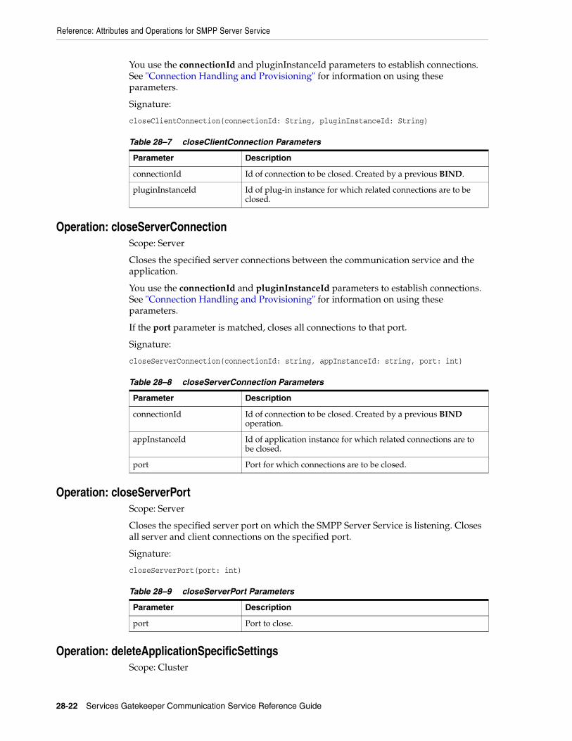
Reference: Attributes and Operations for SMPP Server Service
28-22 Services Gatekeeper Communication Service Reference Guide
You use the connectionId and pluginInstanceId parameters to establish connections. See "Connection Handling and Provisioning" for information on using these parameters.
Signature:
closeClientConnection(connectionId: String, pluginInstanceId: String)
Operation: closeServerConnectionScope: Server
Closes the specified server connections between the communication service and the application.
You use the connectionId and pluginInstanceId parameters to establish connections. See "Connection Handling and Provisioning" for information on using these parameters.
If the port parameter is matched, closes all connections to that port.
Signature:
closeServerConnection(connectionId: string, appInstanceId: string, port: int)
Operation: closeServerPortScope: Server
Closes the specified server port on which the SMPP Server Service is listening. Closes all server and client connections on the specified port.
Signature:
closeServerPort(port: int)
Operation: deleteApplicationSpecificSettingsScope: Cluster
Table 28–7 closeClientConnection Parameters
Parameter Description
connectionId Id of connection to be closed. Created by a previous BIND.
pluginInstanceId Id of plug-in instance for which related connections are to be closed.
Table 28–8 closeServerConnection Parameters
Parameter Description
connectionId Id of connection to be closed. Created by a previous BIND operation.
appInstanceId Id of application instance for which related connections are to be closed.
port Port for which connections are to be closed.
Table 28–9 closeServerPort Parameters
Parameter Description
port Port to close.

Reference: Attributes and Operations for SMPP Server Service
Native SMPP 28-23
Deletes application-specific settings for an application with the specified applicationInstanceId.
The application will no longer be able to access the SMPP Server Service.
Signature:
deleteApplicationSpecificSettings(applicationInstanceId: String)
Operation: listApplicationSpecificSettingsScope: Cluster
Displays all application-specific settings.
Signature:
listApplicationSpecificSettings()
Operation: listClientConnectionsScope: Server
Displays description and status of all client connections. These are connections between the communication service and the SMSC.
Signature:
listClientConnections()
Operation: listClusterServerConnectionsForMOJumpingScope: Cluster
Displays the description and status for cluster server connections for which the MO jumping is enabled.
For information about MO jumping, see "Attribute: OfflineMO" for more information.
Signature:
listClusterServerConnectionsForMOJumping()
Operation: listPluginInstancesScope: Server
Displays description and status for all registered plug-in instances.
listPluginInstances()
Operation: listServerConnectionsScope: Server
Displays description and status of each server connection.
Signature:
listServerConnections()
Table 28–10 deleteApplicationSpecificSettings Parameters
Parameter Description
applicationInstanceId ID of the application instance for which to delete settings

Reference: Attributes and Operations for SMPP Server Service
28-24 Services Gatekeeper Communication Service Reference Guide
Operation: listServerPortsScope: Server
Displays description and status of each server port.
Signature:
listServerPorts()
Operation: resetClientConnectionScope: Server
Closes and restarts the specified client connection between the communication service and the SMSC. See "About Creating and Resetting Connections" for information on using the connectionId and pluginstanceId parameters to create connections.
connectionId Syntax for the Native SMPP plug-in:
plugin_instance_id#plugin_version
For example:
Plugin_px21_short_messaging_smpp_myinstance#6.0.0.0
connectionId Syntax for the Parlay X 2.1 Short Messaging/SMPP plug-in:
Plugin_px21_short_messaging_smpp_myinstance
For example:
plugin_instance_id
Signature:
resetClientConnection(connectionId: String, pluginInstanceId: String)
Operation: resetServerPortScope: Server
Closes and restarts the specified application-facing server port on which the SMPP Server Service is listening. This operation resets all server and client connections on the specified port.
Signature:
resetServerPort(port: int)
Table 28–11 resetClientConnection Parameters
Parameter Description
connectionId Id of the connection to be reset. Created by a previous BIND operation.
pluginInstanceId Id of the plug-in instance for which related connections are to be reset.
Table 28–12 resetServerPort Parameters
Parameter Description
port Port to reset.

Reference: Attributes and Operations for Native SMPP Plug-in
Native SMPP 28-25
Operation: updateAllServerPortsScope: Server
Closes and restarts all server ports all local server ports in the current configuration.
Signature:
updateAllServerPorts()
Reference: Attributes and Operations for Native SMPP Plug-inThis section describes the attributes and operations for configuration and maintenance:
■ Attribute: BindType
■ Attribute: DeliverSmRespCommandStatus
■ Attribute: EnableDeleteAfterCancel
■ Attribute: EnableDeleteAfterNotify
■ Attribute: EnableDeleteAfterQuery
■ Attribute: EnquireLinkTimerValue
■ Attribute: EsmeAddressRange
■ Attribute: EsmeNpi
■ Attribute: EsmePassword
■ Attribute: EsmeSystemId
■ Attribute: EsmeSystemType
■ Attribute: EsmeTon
■ Attribute: LocalAddress
■ Attribute: LocalPort
■ Attribute: MessageIdInHexFormat
■ Attribute: NumberReceiverConnections
■ Attribute: NumberTransceiverConnections
■ Attribute: NumberTransmitterConnections
■ Attribute: RequestTimerValue
■ Attribute: RetryTimesBeforeGiveUp
■ Attribute: RetryTimesBeforeReconnect
■ Attribute: SmscAddress
■ Attribute: SmppVersion
■ Attribute: SmscPort
■ Attribute: WindowingMaxQueueSize
■ Attribute: WindowingMaxWaitTime
■ Attribute: WindowingSize

Reference: Attributes and Operations for Native SMPP Plug-in
28-26 Services Gatekeeper Communication Service Reference Guide
Attribute: BindTypeScope: Server
Unit: Not applicable
Format: Integer
Specifies how the plug-in binds to the SMSC.
Use:
■ 1 to bind as Transceiver
■ 2 to bind as Transmitter
■ 3 to bind as Receiver
The setting is not applied until the plug-in is restarted or the SMPP Server Service "Operation: resetClientConnection" is performed.
Attribute: DeliverSmRespCommandStatusScope: Cluster
Unit: Not applicable
Format: Integer
Error code to used in the command_status field when the application is unavailable. See section 5.1.3 command_status in SMPP Protocol Specification v3.4.
Specifies how the plug-in responds to an SMSC if a network-triggered short message cannot be delivered to an application that subscribed for notifications on incoming short messages.
The default is ESME_RINVDSTADR.
The setting is not applied until the plug-in is restarted or the SMPP Server Service "Operation: resetClientConnection" is performed.
Table 28–13 lists the possible values for DeliverSmRespCommandStatus.
Attribute: EnableDeleteAfterCancelScope: Cluster
Table 28–13 DeliverSmRespCommandStatus Response Codes
Error Code Definition Possible Scenario
1 Invalid Message Length Failed to decode the short message in deliverSm (MOAT).
6 Invalid priority flag The priority flag is less than 0 or greater than 3.
8 System Error An internal Services Gatekeeper error has occurred, for example, a storage exception.
10 Invalid Source Address An invalid source address in deliverSm, for example, an empty address.
11 Invalid Address Services Gatekeeper received a delivery receipt with an unknown address or a MOAT from an address without any registration.
12 Invalid Message ID The messageId in deliverSm is null or unknown.
67 Invalid esm_class field data
Invalid esm_class field data in deliverSm, for example, -1.
Reference: Attributes and Operations for Native SMPP Plug-in
Native SMPP 28-27
Unit: Not applicable
Format: Boolean
Specifies whether to delete SMPP session information from storage after receipt of a CANCEL_SM_RESP.
The default is true.
Attribute: EnableDeleteAfterNotifyScope: Cluster
Unit: Not applicable
Format: Boolean
Specifies whether to delete SMPP session information from storage after receipt of the delivery report with the final message state.
The default is true.
Attribute: EnableDeleteAfterQueryScope: Cluster
Unit: Not applicable
Format: Boolean
Specifies whether to delete SMPP session information from storage after the receipt of the query response with the final message state.
The default is false.
Attribute: EnquireLinkTimerValueScope: Cluster
Unit: Seconds
Format: Integer
Minimum interval between ENQUIRE_LINK requests to the SMSC.
The default is 60.
To disable the sending of ENQUIRE_LINK requests, set this value to 0 (zero).
Attribute: EsmeAddressRangeScope: Server
Unit: Not applicable
Format: String formatted as a regular expression.
ESME address range. This is the address range of the SMS messages to be sent to the plug-in instance by the SMSC.
The default is ^.*$.
The setting is not applied until the plug-in is restarted or the SMPP Server Service "Operation: resetClientConnection" is performed.

Reference: Attributes and Operations for Native SMPP Plug-in
28-28 Services Gatekeeper Communication Service Reference Guide
Attribute: EsmeNpiScope: Server
Unit: Not applicable
Format: Integer
The ESME Numbering Plan Indicator (NPI) used in a BIND request.
Used for destination address and as a default for originating address. Also used for both destination address and originating address during bind operation. Use:
■ 0 for Unknown
■ 1 for ISDN (E163/E164)
■ 3 for Data (X.121)
■ 4 for Telex (F.69)
■ 6 for Land Mobile (E.212)
■ 8 for National
■ 9 for Private
■ 10 for ERMES
■ 14 for Internet (IP)
■ 18 for WAP Client ID
The default is 0.
The setting is not applied until the plug-in is restarted or the SMPP Server Service "Operation: resetClientConnection" is performed.
Attribute: EsmePassword Scope: Cluster
Unit: Not applicable
Format: String
Password used by the plug-in instance for connecting to the SMSC as an ESME.
Attribute: EsmeSystemIdScope: Cluster
Unit: Not applicable
Format: String
System ID used by the plug-in instance when connecting to the SMSC as an ESME.
The default is OCSG.
The setting is not applied until the plug-in is restarted or the SMPP Server Service "Operation: resetClientConnection" is performed.
Attribute: EsmeSystemTypeScope: Cluster
Unit: Not applicable

Reference: Attributes and Operations for Native SMPP Plug-in
Native SMPP 28-29
Format: String
System type used by the plug-in instance for connecting to the SMSC as an ESME.
The default is mess_gateway.
The setting is not applied until the plug-in is restarted or the SMPP Server Service "Operation: resetClientConnection" is performed.
Attribute: EsmeTonScope: Cluster
Unit: Not applicable
Format: Integer
ESME Type Of Number (TON).
Used for destination address and as a default for originating address. Also used for both destination address and originating address in a BIND request. Use:
■ 0 for Unknown
■ 1 for International
■ 2 for National
■ 3 for Network
■ 4 for Subscriber
■ 5 for Alphanumeric
■ 6 for Abbreviated
■ 7 Reserved
The default is 0.
The setting is not applied until the plug-in is restarted or the SMPP Server Service "Operation: resetClientConnection" is performed.
Attribute: LocalAddressScope: Server
Unit: Not applicable
Format: String
Local server address used by the plug-in to connect to the SMSC. The address can be expressed as an IP address or host name. The address or host name must resolve to a local address.
Enter "" to use the default address of the server.
The setting is not applied until the plug-in is restarted or the SMPP Server Service "Operation: resetClientConnection" is performed.
Attribute: LocalPortScope: Server
Unit: Not applicable
Format: Integer [1 - (65535 - number of connections)]

Reference: Attributes and Operations for Native SMPP Plug-in
28-30 Services Gatekeeper Communication Service Reference Guide
Local port used by the plug-in to connect to the SMSC.
The default is 3000.
The setting is not applied until the plug-in is restarted or the SMPP Server Service "Operation: resetClientConnection" is performed.
Attribute: MessageIdInHexFormatScope: Cluster
Unit: Not applicable
Format: Boolean
Specifies the message_id format used in SUBMIT_SM_RESP, SUBMIT_MULTI_RESP, DATA_SM_RESP operations.
If true, the format is hexadecimal; if false, it is decimal.
The default is false.
Attribute: NumberReceiverConnectionsScope: Cluster
Unit: Not applicable
Format: Integer
Number of connections used to connect to the SMSC if the bind type is 3.
The default is 1.
See "Attribute: BindType" for more information.
The connections are established with the first successful BIND between the application and Services Gatekeeper, if connection-based routing is disabled.
If connection-based routing is enabled, connections to the SMSC cannot be shared among different application instances, so this attribute is ignored.
Attribute: NumberTransceiverConnectionsScope: Cluster
Unit: Not applicable
Format: Integer
Number of connections used to connect to the SMSC if the bind type is 1.
The default is 1.
See "Attribute: BindType" for more information.
The connections are established with the first successful BIND between the application and Services Gatekeeper, if connection-based routing is disabled.
If connection-based routing is enabled, connections to the SMSC cannot be shared among different application instances, so this attribute is ignored.
Attribute: NumberTransmitterConnectionsScope: Cluster
Reference: Attributes and Operations for Native SMPP Plug-in
Native SMPP 28-31
Unit: Not applicable
Format: Integer
Number of connections used to connect to the SMSC if the bind type is or 2.
The default is 1.
See "Attribute: BindType" for more information.
The connections are established with the first successful BIND between the application and Services Gatekeeper, if connection-based routing is disabled.
If connection-based routing is enabled, connections to the SMSC cannot be shared among different application instances, so this attribute is ignored.
Attribute: RequestTimerValueScope: Cluster
Unit: Seconds
Format: Integer
Maximum time between the submission of a request to the SMSC and the receipt of the corresponding response before the connection is terminated.
The default is 20.
Set to 0 (zero) for no timeout.
Attribute: RetryTimesBeforeGiveUpScope: Cluster
Unit: Not applicable
Format: Integer
Maximum number of times for the plug-in to try to reconnect to the server service.
The default is 30.
The setting is not applied until the plug-in is restarted or the SMPP Server Service "Operation: resetClientConnection" is performed.
Attribute: RetryTimesBeforeReconnectScope: Cluster
Unit: Not applicable
Format: Integer
Maximum number of times for the plug-in to try to connect to the server service before attempting to reconnect.
The default is 3.
The setting is not applied until the plug-in is restarted or the SMPP Server Service "Operation: resetClientConnection" is performed.
Attribute: SmscAddressScope: Cluster

Reference: Attributes and Operations for Native SMPP Plug-in
28-32 Services Gatekeeper Communication Service Reference Guide
Unit: Not applicable
Format: String
SMSC address as an IP address or host name.
The setting is not applied until the plug-in is restarted or the SMPP Server Service "Operation: resetClientConnection" is performed.
Attribute: SmppVersionScope: Cluster
Unit: Not applicable
Format: String
SMPP version of the communication service used between Services Gatekeeper and the SMSC.
Valid values are 3.4 and 5.1.
3.4 is the fully-supported version.
5.1 is provided to support the billing identification parameter and the ussd_service_operation parameter for the DELIVER_SM operation. See "USSD Support" and "Billing Identification" for information about these parameters
The default is 3.4.
Attribute: SmscPort Scope: Cluster
Unit: Not applicable
Format: Integer
Listening port used by the SMSC
The default is 5016.
The setting is not applied until the plug-in is restarted or the SMPP Server Service "Operation: resetClientConnection" is performed.
Attribute: WindowingMaxQueueSizeScope: Cluster
Unit: Not applicable
Format: Integer
Maximum number of mobile-terminated requests to the SMSC allowed in the windowing queue.
The default is 100.
If any one of the three windowing attributes (WindowingMaxQueueSize, WindowingMaxWaitTime, or WindowingSize) is set to a value less than zero, windowing is turned off. If all of these three attributes have values greater than zero, windowing is turned on.
See "Windowing" for general information about windowing.

Reference: Attributes and Operations for Native SMPP Plug-in
Native SMPP 28-33
Attribute: WindowingMaxWaitTimeScope: Cluster
Unit: Seconds
Format: Integer
Maximum time that a mobile-terminated request to the SMSC is allowed to wait in the windowing queue.
The default is 15.
If any one of the three windowing attributes (WindowingMaxQueueSize, WindowingMaxWaitTime, or WindowingSize) is set to a value less than zero, windowing is turned off. If all of these three attributes have values greater than zero, windowing is turned on.
See "Windowing" for general information about windowing.
Attribute: WindowingSizeScope: Cluster
Unit: Not applicable
Format: Integer
Maximum number of simultaneous unacknowledged mobile-terminated requests to the SMSC enforced for each connection.
The default is 5.
If any one of the three windowing attributes (WindowingMaxQueueSize, WindowingMaxWaitTime, or WindowingSize) is set to a value less than zero, windowing is turned off. If all of these three attributes have values greater than zero, windowing is turned on.
See "Windowing" for general information about windowing.

Reference: Attributes and Operations for Native SMPP Plug-in
28-34 Services Gatekeeper Communication Service Reference Guide

29
Native UCP 29-1
29Native UCP
This chapter describes the Oracle Communications Services Gatekeeper Native UCP communication service.
Overview of the Native UCP Communication ServiceThe Native UCP communication service exposes the UCP Short Message Service Center EMI-UCP standard interfaces.
The communication service acts as a Short Message Terminal (SMT) that connects to a Short Messaging Service Center (SMSC) over TCP/IP.
For the exact version of the standards that the UCP communication service supports for the application-facing interfaces and the network protocols, see Services Gatekeeper Statement of Compliance.
The Native UCP service can:
■ Connect to a specified SMSC address.
■ Open a session with the SMSC.
■ Send acknowledgments to the SMSC.
■ Send acknowledgments to the application.
■ Send a mobile-terminated SMS message to destination addresses.
■ Deliver a mobile-originated SMS message.
■ Deliver a delivery notification associated with a previously sent mobile-terminated SMS message.
All Native UCP components are deployed in the network tier.
The core module of the Native UCP communication service is a Native UCP Protocol Server Service deployed as an Oracle WebLogic Server Service. The Native UCP Protocol Server Service:
■ Receives UCP data from the socket.
■ Constructs the UCP protocol data unit (PDU).
■ Associates the current PDU with the correct application instance.
■ Invokes the plug-in.
There is also a Native UCP managed plug-in module, as well as the Native UCP plug-in instances.

Overview of the Native UCP Communication Service
29-2 Services Gatekeeper Communication Service Reference Guide
In addition, Native UCP uses the Connection Information Manager service to create and manage a credential map to support each plug-in instance. For information about the Connection Information Manager, see the discussion about managing and configuring native UCP connection information in Services Gatekeeper System Administrator's Guide.
The entire Native UCP Service is deployed in the network tier, so applications using it must connect directly to the network tier. The network and any firewall should be configured to allow connection to the ports defined for the Native UCP Service.
There is no failover between network tier servers. Redundant SMSCs and redundant network cards are required to support high-availability features.
To optimize system utilization, the application and the SMSC should load balance the requests among all network tier servers.
Hitless upgrade is not supported for the Native UCP communication service. To upgrade you must restart the server.
Connection and Credential HandlingPlug-in instances establish connections to Services Gatekeeper using facilities provided by the Protocol Server Service. They also use the Protocol Server Service to open a session and to send requests to the SMSC. The Protocol Server Service creates a new socket connection for each session management operation of subtype "open session" that is sent.
The Native UCP Protocol Server Service uses the Connection Information Manager´s getConnectInfo operation to get the connection information for a particular plug-in instance. When a plug-in instance sends a Native UCP PDU to the Protocol Server Service passing its plug-in instance ID, a connection ID is returned. This connection ID identifies the SMSC connection on which the request was sent.
A server-side connection connects an application to Services Gatekeeper, which is the server in this context.
A client-side connection connects an SMSC to Services Gatekeeper, which is a client in this context.
Native UCP has no unbind operation. There are no receiver, transceiver, or transmitter connection types. If a connection is lost, the Protocol Server Service automatically closes one connection to the SMSC for the current application instance. See "Multiple Connections" for more information.
CredentialsThe Protocol Server Service performs network credential mappings based on a credential map set up in the Connection Information Manager.
A user/password combination is associated with a credential ID that is stored in the Connection Information Manager. See the Connection Information Manager´s createOrUpdateUserPasswordCredentialEntry operation. The credential ID is associated with a plug-in instance and an application instance in an entry in the Connection Information Manager's credential map. See the Connection Information Manager’s createOrUpdateCredentialMap operation.
For detailed information on how to configure the connection information and the credential map, see the discussion about managing and configuring native UCP connection information in Services Gatekeeper System Administrator's Guide.

Overview of the Native UCP Communication Service
Native UCP 29-3
Windowing and Transaction NumbersTo maximize throughput, Native UCP supports windowing on both the application-facing and network-facing interfaces. This provides a way to specify the amount of data that can be transmitted to and from the network without receiving an acknowledgment.
On the server side, Native UCP creates a transaction number (TRN) allocation table using default values. These are used by server-side connections sending deliver_short_message and deliver_notification requests to an application.
On the client side, Native UCP creates a transaction number allocation table using values configured in the Connection Information Manager. Configure the client-side windowing behavior by setting the parameters listed in Table 29–1 using the Connection Information Manager´s addXParamToCredentialEntry operation. For information about this operation, see the discussion on managing and configuring connection information in Services Gatekeeper System Administrator's Guide.
Behavior When the Window is ExceededIf Services Gatekeeper tries to allocate a TRN when all the TRNs have been allocated and none is old enough to be cleaned up and maxWaitAcquireTimeout has expired, an exception is thrown causing Services Gatekeeper to respond with a NACK.
Behavior When TRNs Are Not ReleasedWhen a TRN is allocated, values that have already been allocated are checked to see whether they have expired. Entries older than allocationTimeout are cleaned and automatically released. An error is logged, but no alarm is generated. No NACK is triggered for a request that was originally associated with the expired TRN.
Multiple ConnectionsAn application instance can establish multiple TCP connections to Services Gatekeeper. Multiple application instances, those with different application instance names, cannot share a connection to the SMSC.
If one connection between an application instance and an SMSC is dropped, Services Gatekeeper does not automatically close associated application instance connections as long as there are other SMSC connections available for that same application instance. If all connections to the SMSC for a particular application instance are dropped, Services Gatekeeper terminates all of that application instance’s connections.
Table 29–1 UCP Windowing Parameters in ConnectionInfoManager
Parameter Description Default
windowSize Maximum number of unacknowledged transactions allowed between a plug-in instance and an SMSC
100
maxWaitAcquireTimeout Maximum time in milliseconds that a request can wait while trying to allocate a transaction number
3000
allocationTimeout Maximum time in milliseconds that an allocated transaction number can be held while the plug-in or the SMSC is waiting for an acknowledgment
5000
maxQueueSize Maximum number of threads that can wait for a transaction number to be allocated
5

Overview of the Native UCP Communication Service
29-4 Services Gatekeeper Communication Service Reference Guide
Connection PoolingWhen an application instance sends an open session operation on a new connection, the Protocol Server Service tries to establish a connection to the underlying SMSCs and then to open the session. It does not automatically establish connection pools to the underlying SMSCs. It establishes additional connections only when an application instance establishes multiple connections with Services Gatekeeper.
Because an application may establish multiple connections, a request sent from the Protocol Server Service to a plug-in includes a server-side connection identifier. This identifier is then included when the plug-in uses the Protocol Server Service to send acknowledgments back to the application. Acknowledgments must be sent on the same connection as the corresponding request. Delivery reports can be sent on a different connection.
Windowing and Transaction Numbers To maximize throughput, Native UCP supports windowing on both the application-facing and network-facing interfaces. This provides a way to specify the amount of data that can be transmitted to and from the network without receiving an acknowledgment.
On the server side, Native UCP creates a transaction number (TRN) allocation table using default values. These are used by server-side connections sending deliver_short_message and deliver_notification requests to an application.
On the client side, Native UCP creates a transaction number allocation table using values configured in the Connection Information Manager. Configure the client-side windowing behavior by setting the parameters listed in Table 29–2 using the Connection Information Manager´s addXParamToCredentialEntry operation. For information about this operation, see the discussion about managing and configuring native UCP connection information in Services Gatekeeper System Administrator's Guide.
Behavior When the Window is ExceededIf Services Gatekeeper tries to allocate a TRN when all the TRNs have been allocated and none is old enough to be cleaned up and maxWaitAcquireTimeout has expired, an exception is thrown causing Services Gatekeeper to respond with a NACK.
Behavior When TRNs Are Not ReleasedWhen a TRN is allocated, values that have already been allocated are checked to see whether they have expired. Entries older than allocationTimeout are cleaned and automatically released. An error is logged, but no alarm is generated. No NACK is triggered for a request that was originally associated with the expired TRN.
Table 29–2 UCP Windowing Parameters in ConnectionInfoManager
Parameter Description Default
windowSize Maximum number of unacknowledged transactions allowed between a plug-in instance and an SMSC
100
maxWaitAcquireTimeout Maximum time in milliseconds that a request can wait while trying to allocate a transaction number
3000
allocationTimeout Maximum time in milliseconds that an allocated transaction number can be held while the plug-in or the SMSC is waiting for an acknowledgment
5000
maxQueueSize Maximum number of threads that can wait for a transaction number to be allocated
5

Overview of the Native UCP Communication Service
Native UCP 29-5
AuthenticationApplications are authenticated on receipt of the openSession PDU, after which the connection is associated with the authenticated identity.
Subsequent requests on the connection trigger an identity assertion associating the request with the identity that was authenticated with the receipt of the open session PDU. A consequence of this behavior is that an application can continue to send messages after the password has been changed. To force a new authentication, close the connection.
Table 29–3 describes the mapping between the Native UCP authentication parameters and the Services Gatekeeper parameters.
The password is stored in the Connection Information Manager. No password information is stored by the Protocol Server Service or by the plug-in.
Availability and RetryThe availability and retry behavior of the Protocol Server Service is as follows.
Application-Initiated trafficIf there is no acknowledgment from the network, the UCP Protocol Server Service does not start any timers per request, does not perform any retries, and does not report an acknowledgment back to the application.
The only exception to this behavior is when the wait on an openSession request exceeds the configured Native UCP OpenSessionTimeout maximum. See the OpenSessionTimeout field for more information.
If the Protocol Server Service receives an exception when calling the submit_short_message operation, it sends a NACK to the application.
Network-Initiated trafficIf the underlying SMSC does not receive an acknowledgment from Services Gatekeeper, the SMSC should resend the request.
If a message is sent to an application but no acknowledgment is returned from the application, the UCP Protocol Server Service does not start any per request timers, does not perform any retries, and does not send back an acknowledgment to the application.
If the Protocol Server Service receives an exception when calling the deliver_short_message or deliver_notification operation, it sends a NACK to the SMSC.
Delivery reports do not have to be sent on the same server that sent the original delivery request, even in a geo-redundant setup. In a clustered configuration, if the server that submits an SMS fails, another server can handle the delivery report for that SMS.
Table 29–3 Authentication Parameters
Native UCP ParameterServices Gatekeeper ConnectionInfoManager Credential Parameter
originating address (OAdC) application instance name
password password

Overview of the Native UCP Communication Service
29-6 Services Gatekeeper Communication Service Reference Guide
Client-Side Retry HandlingNative UCP automatically tries to re-establish a dropped connection when an initial openSession attempt or an established session fails. The number of retries attempted is configured by the maxReconnectAttempts attribute and the number of milliseconds between retries by the timeBetweenReconnectAttempts attribute.
The retry behavior is as follows:
■ Initial openSession failure: When an application sends the initial open session request, Services Gatekeeper sends one open session request to each SMSC that matches the current configuration in terms of plug-ins, routes, SLAs, and so on. If one of the SMSCs responds with an ACK, Services Gatekeeper returns an ACK to the application.
For all SMSCs that Services Gatekeeper cannot connect to or receive an acknowledgment from, it tries to re-establish a connection. Specifically, retry is triggered in the following cases:
– Services Gatekeeper receives a NACK in response to the open session request.
– The socket to the SMSC cannot be set up.
– The socket is closed before the acknowledgment is received.
– The timeout period, configured by the OpenSessionTimeout attribute, expires before an acknowledgment is received.
■ Established session failure: If the client-side connection is dropped and the Services Gatekeeper application instance associated with the dropped connection still has other working connections, Services Gatekeeper sends an open session request to each SMSC that matches the current configuration, following the same procedure as described above for an initial openSession failure.
Use the dumpOngoingClientConnectionsRetryInfo and stopOngoingClientConnectionRetry operations to manage connections that are in the retry state.
Heartbeat SupportNative UCP provides heartbeat support by sending UCP operation "31" (SMT alert) requests at regular intervals. This prevents firewalls and the SMSC from closing an idle connection.
Server-Side Heartbeat SupportHeartbeat support for Native UCP server-side connections has the following characteristics:
■ In response to a UCP operation type "31"(SMT Alert), the corresponding acknowledgment is sent.
■ There are no timeouts associated with heartbeats.
■ Services Gatekeeper does not close any connections because of missing heartbeat requests.
■ Heartbeats received on server-side connections are not forwarded to client-side connections.
■ There are no configuration attributes associated with server-side heartbeat functions.

Events and Statistics
Native UCP 29-7
Client-Side Heartbeat SupportHeartbeat support for Native UCP client-side connections has the following characteristics:
■ Heartbeats are not enabled by default for a client-side connection.
■ Heartbeats are enabled by setting the heartbeatInterval parameter in the Connection Information Manager. This parameter defines the interval, in milliseconds, between UCP operation type 31 requests. The value is configured with the addXParamToCredentialEntry method of the ConnectionInfoManager MBean.
For information about this operation, see discussion on managing and configuring connection information in Services Gatekeeper System Administrator's Guide.
■ Services Gatekeeper does not close any client-side connections because of missing acknowledgments on heartbeat requests.
■ Received client-side heartbeat acknowledgments are not forwarded to server-side connections.
Storage ProviderThe Native UCP Protocol Server Service and the Native UCP plug-in use the default Services Gatekeeper store.
Application InterfacesFor information about the application interface for the Native UCP communication service, see the discussion about Native UCP Interfaces in Services Gatekeeper Application Developer's Guide.
Events and StatisticsThe Native UCP communication service generates event data records (EDRs), charging data records (CDRs), alarms, and statistics to assist system administrators and developers in monitoring the service
For general information, see Appendix A, "Events, Alarms, and Charging."
Event Data RecordsTable 29–4 lists IDs of the EDRs created by the Native UCP communication service.
When there are multiple SMSCs, it is possible that EDR data generated for open session requests may contain the wrong data for some of the EDRs because EDR data is stored in the current context.
Table 29–4 EDRs Generated by Native UCP
EDR ID Description
402001 application-initiated openSession to the SMSC
402002 application-initiated submitSM to the SMSC
402003 application-initiated ACK to the SMSC
402004 application-initiated NACK to the SMSC
402010 network-triggered deliverSM to the application

Events and Statistics
29-8 Services Gatekeeper Communication Service Reference Guide
Table 29–5 describes Native UCP-specific fields included in the Native UCP EDRs.
About UCP_trn/UCP_mappedTrnTransaction numbers must be mapped in the following cases:
■ When sending a submit_short_message operation (51) to the SMSC and receiving the corresponding acknowledgment
■ When sending a deliver_notification operation (53) to the application and receiving the corresponding acknowledgment
■ When sending a deliver_short_message operation (52) to the application and receiving the corresponding acknowledgment
A UCP_mappedTrn is required in the following circumstances because pooled connections create the possibility of sending conflicting or overlapping transaction numbers were they not mapped:
■ When a submit_short_message request is sent:
– UCP_trn holds the original transaction number as received by the application.
– UCP_mappedTrn holds the transaction number that was used in the request to the SMSC.
■ When the acknowledgment for the submit_short_message request is received:
– UCP_trn holds the original transaction number, which is then used to forward the acknowledgment to the application.
– UCP_mappedTrn holds the transaction number that was included in the acknowledgment from the SMSC.
402011 network-triggered deliveryNotification to the application
402012 network-triggered ACK to the application
402013 network-triggered NACK to the application
Table 29–5 Native UCP-Specific EDR Fields
EDR Parameter Description
UCP_isOperation true if EDR is for an operation, false if for an acknowledgment
UCP_opType UCP operation type; for example, 51 for a submit_short_message request
UCP_trn UCP transaction number; see "About UCP_trn/UCP_mappedTrn"
UCP_mappedTrn mapped transaction number; see "About UCP_trn/UCP_mappedTrn"
UCP_sourceConnID source connection ID; for the connection that received the PDU
UCP_outgoingConnID
outgoing connection ID for the connection on which the PDU was sent
UCP_adc AdC parameter in the UCP PDU
UCP_oadc OAdC parameter in the UCP PDU; see "About UCP_oadc"
UCP_scts Service Center Timestamp (SCTS) parameter in the UCP PDU
Table 29–4 (Cont.) EDRs Generated by Native UCP
EDR ID Description

Managing Native UCP
Native UCP 29-9
About UCP_oadcThe UCP_oadc parameter used in a deliver_notification operation (53) identifies the recipient of a message that was previously sent by the submit_short_message operation (51).
The UCP_oadc parameter normally contains the large account/originator number.
Charging Data RecordsThe Native UCP communication service generates charging data records (CDRs) under the following conditions:
■ After a mobile-originated SMS UCP PDU has been processed by the plug-in.
■ After a mobile-terminated SMS UCP PDU has been processed by the plug-in.
■ When an ACK is received.
The CDR includes the service center timestamp (SCTS). The ACK is correlated with submit_short_message using the connection identifiers and the transaction number (TRN).
■ When a delivery report for a mobile-terminated SMS message is received.
The CDR includes the SCTS for correlation with submit (and submit ACK) using SCTS and AdC and OAdC parameters.
StatisticsTable 29–6 maps methods invoked from either the application or the network to the transaction types collected by the Services Gatekeeper statistics counter.
AlarmsFor the list of alarms, see Services Gatekeeper Alarms Handling Guide.
Managing Native UCPThis section describes the properties and workflow for the Native UCP communication service.
Native UCP relies upon facilities in Services Gatekeeper Connection Information Manager to create and store connection and credential information for a UCP plug-in instance. For information about this manager, see discussion on managing and configuring connection information in Services Gatekeeper System Administrator's Guidee.
Plug-in instances are associated with application instances and authentication credentials through the createOrUpdateCredentialMap operation in the Connection Information Manager.
There can be only one application instance per large account.
The work manager is registered when the managed plug-in is started. Settings in the Native UCP managed plug-in provide the IP address and port where the plug-in
Table 29–6 Methods and Transaction Types for Native UCP
Method Transaction Type
submit_short_message TRANSACTION_TYPE_MESSAGING_SEND
deliver_short_message TRANSACTION_TYPE_MESSAGING_RECEIVE

Properties for Native UCP Protocol Server Service
29-10 Services Gatekeeper Communication Service Reference Guide
registers its work manager. These settings apply to all the Native UCP plug-in instances. If these settings are changed, a restart is required.
Properties for Native UCP Protocol Server ServiceTable 29–7 lists the technical specifications for the UCP protocol server service.
Properties for Native UCP Managed Plug-inTable 29–8 lists the technical specifications for the Native UCP managed plug-in.
Properties for Native UCP Plug-in InstanceTable 29–9 lists the technical specifications for the plug-in instance.
Table 29–7 Native UCP Protocol Server Service Properties
Property Description
Managed object in Administration Console
To manage the object, select domain_name , then OCSG, then server_name, then Container Services, and then UCPService.
MBean Domain=com.bea.wlcp.wlng
Name=wlng
InstanceName=UCPService
Type=oracle.ocsg.protocol.ucp.management.UCPServerMBean
Documentation: See the “All Classes” section of Services Gatekeeper OAM Java API Reference
Exposes this interface to applications
EMI-UCP 5.1
Deployment artifacts oracle.ocsg.protocol.ucp_6.0.0.0.jar, oracle.ocsg.protocol.ucp_api_6.0.0.0.jar
Table 29–8 Native UCP Managed Plug-in Properties
Property Description
Managed object in Administration Console
To manage the object, select domain_name, then OCSG, then server_name, then Communication Services, and then oracle.ocsg.native_ucp_sms
MBean Domain=com.bea.wlcp.wlng
AppName=native_ucp_sms#6.0.0
InstanceName = oracle.ocsg.native_ucp_sms
Type = oracle.ocsg.plugin.nativefacade.ucp.management.NativeUCPManagedPluginMBean
Documentation: See the “All Classes” section of Services Gatekeeper OAM Java API Reference
Supported Network Interface
UCP v5.1
Supported Application Interface
UCP v5.1
Deployment artifact wlng_nt_native_ucp_sms.ear

Configuration Workflow for Native UCP Communication Service
Native UCP 29-11
Configuration Workflow for Native UCP Communication ServiceFollowing is an outline for configuring the plug-in using the Administration Console or an MBean browser.
1. Configure the listen address and the listen port in the Native UCP managed plug-in MBean, NativeUCPManagedPluginMBean. All the Native UCP plug-in instances use these fields.
■ listenAddress
■ listenPort
See "Reconfiguring Native UCP Listen Ports" if you need to change these values.
2. [Optional] Configure the Native UCP address routing interceptor if there is a possibility of multiple SMSCs owning the same address. This ensures that messages sent to the same address are sent to the same SMSC. It also ensures that all message segments for a concatenated SMS message are sent to the same SMSC.
This interceptor is not enabled by default.
To enable it, edit the interceptor chain to include the NativeUCPAddressRouting class:
a. Open the config.xml file that is bundled in the interceptors.ear file in the Services Gatekeeper installation.
This is the file in which the interceptor chain is defined.
b. Locate the RoundRobinPluginList routing interceptor in the file. The line looks like this:
<interceptor class="com.bea.wlcp.wlng.interceptor.RoundRobinPluginList" index="1000"/>
Table 29–9 Native UCP Plug-in Instance Properties
Property Description
Managed object in Administration Console
To manage the object, select domain_name, then OCSG, then server_name, then Communication Services, then plugin_instance_id in that order.
MBean Domain=com.bea.wlcp.wlng
AppName=native_ucp_sms#5.1.0
Instance Name=same as the network protocol instance_id assigned when the plug-in instance is created
Type=oracle.ocsg.plugin.nativefacade.ucp.management.NativeUCPPluginMBean
Documentation: See the “All Classes” section of Services Gatekeeper OAM Java API Reference
Supported network interface
UCP v5.1
Supported application interface
UCP v5.1
Supported character sets 7-bit GSM charset + Unicode (16-bit UCS2)
Supported address scheme tel
Deployment artifact wlng_nt_native_ucp_sms.ear

Provisioning Workflow for Native UCP Communication Service
29-12 Services Gatekeeper Communication Service Reference Guide
c. Add the NativeUCPAddressRouting class interceptor immediately before the RoundRobinPluginList routing interceptor. The line for the NativeUCPAddressRouting interceptor looks like this:
<interceptor class="com.bea.wlcp.wlng.interceptor.NativeUCPAddressRouting" index="950"/>
The resulting interceptor chain should look like this:
... <interceptor class="com.bea.wlcp.wlng.interceptor.FilterPluginListUsingCustomMatch" index="800"/> <interceptor class="com.bea.wlcp.wlng.interceptor.RemoveOptional" index="900"/> <interceptor class="com.bea.wlcp.wlng.interceptor.NativeUCPAddressRouting" index="950"/> <interceptor class="com.bea.wlcp.wlng.interceptor.RoundRobinPluginList" index="1000"/> <interceptor class="com.bea.wlcp.wlng.interceptor.InvokeServiceCorrelation" index="1100"/> ...
The interceptor verifies that the request it is intercepting is a Native UCP request before it modifies the plug-in list. If it is not a Native UCP request, the list is not modified.
Provisioning Workflow for Native UCP Communication ServicePerform steps 1 through 5 in the Connection Information Manager. The operations and attributes used in these steps are described in the discussion about managing and configuring connection information in Services Gatekeeper System Administrator's Guide.
1. Create one or more Native UCP plug-in instances. See the discussion about configuring and managing the plug-in manager in Services Gatekeeper System Administrator's Guide. Use the plug-in service ID described in the "Properties for Native UCP Plug-in Instance" section.
2. Set up the network connection mapping for the plug-in instance using the Connection Information Manager.
■ createOrUpdateLocalHostAddress
■ createOrUpdateRemoteHostAddress
■ createOrUpdateListenAddress
3. Set up the network credential mapping. This associates a user and password with a credential ID. Use the following operation:
■ createOrUpdateUserPasswordCredentialEntry
4. Create or update the credential map for the plug-in instance. This entry associates the credential ID with the application instance ID and the plug-in instance ID. Use the following operation:
■ createOrUpdateCredentialMap
5. Add any connection-specific parameters needed to support windowing and heartbeats. See "Windowing and Transaction Numbers" and "Heartbeat Support" for more information. Use the addXParamToCredentialEntry method.

Reference: Attributes and Operations for Native UCP Protocol Server Service
Native UCP 29-13
6. Configure the retry behavior for the Native UCP Protocol Server Service with the MaxReconnectAttempts and TimeBetweenReconnectAttempts fields.
7. Configure the timeout limit for the plug-in instance with the OpenSessionTimeout field.
8. If required, create and load a node SLA. For details see the discussion on defining global node and service provider group node SLAs and managing SLAs in Services Gatekeeper Accounts and SLAs Guide.
9. Provision the service provider accounts and application accounts. For information, see Services Gatekeeper Portal Developer's Guide.
Reconfiguring Native UCP Listen PortsThe listen port and address is used by the Native UCP plug-in upon startup to register a work manager in the UCP Protocol Server Service.
To reconfigure the listen port and listen address:
1. In the Connection Information Manager, create the new listen address and port using the createOrUpdateListenAddress operation.
2. Remove the old listen address and port using the Connection Information Manager’s removeListenAddress operation.
3. View the new listen address configuration using the Connection Information Manager’s getAllListenAddress operation.
4. In the Native UCP Managed Plug-in, change the listenAddress and listenPort attributes to match the new values that you just configured in the Connection Information Manager. See the listenAddress and listenPort fields for more information.
5. Register the work manager at the new port using the reRegisterWorkManager operation. See the reRegisterWorkManager method for more information.
Services Gatekeeper cannot accept new server-side connections on the new ports until you restart the ports using the restartPorts operation. See the restartPorts method for more information.
6. Using thelistUCPServersString method in the Native UCP Protocol Server Service, view the currently running listen ports.
7. Using the restartports method, close and restart all current listening ports. This closes all server-side and client-side connections.
8. Using the listUCPServersString, verify that Native UCP is listening on the new ports.
9. Using thedumpServerSideconnectionsInfo method, verify that applications are reconnecting on the new listen ports.
10. Using the dumpClientSideConnectionsInfo method, verify that connections to the SMSCs have been re-established.
Reference: Attributes and Operations for Native UCP Protocol Server Service
This section describes the attributes and operations for configuration and maintenance:

Reference: Attributes and Operations for Native UCP Protocol Server Service
29-14 Services Gatekeeper Communication Service Reference Guide
■ Attribute: MaxReconnectAttempts
■ Attribute: TimeBetweenReconnectAttempts
■ Attribute: UCPProtocol (read-only)
■ Operation: closeClientSideConnection
■ Operation: closeServerSideConnection
■ Operation: dumpClientSideConnectionsInfo
■ Operation: dumpOngoingClientConnectionsRetryInfo
■ Operation: dumpServerSideConnectionsInfo
■ Operation: listUCPServersString
■ Operation: restartPorts
■ Operation: stopOngoingClientConnectionRetry
Attribute: MaxReconnectAttemptsScope: Cluster
Unit: Not applicable
Format: Integer
Specifies the maximum number of reconnect retries permitted.
See "Attribute: TimeBetweenReconnectAttempts" and "Client-Side Retry Handling" for information about how dropped connections are handled.
Attribute: TimeBetweenReconnectAttemptsScope: Cluster
Unit: Milliseconds
Format: Integer
Specifies the time, in milliseconds, between reconnect attempts.
See "Attribute: TimeBetweenReconnectAttempts" and "Client-Side Retry Handling" for information about how dropped connections are handled.
Attribute: UCPProtocol (read-only)Scope: Cluster
Unit: Not applicable
Format: String
Table 29–10 MaxReconnectAttempts Values
Value Meaning
-1 retry forever; no maximum
0 no retries
< 0 maximum number of retries
-1 retry forever; no maximum

Reference: Attributes and Operations for Native UCP Protocol Server Service
Native UCP 29-15
Specifies the UCP protocol string.
This value must match a protocol string defined for a listen address in the Connection Information Manager.
Operation: closeClientSideConnectionScope: Server
Closes a client-side connection between Services Gatekeeper (the client in this relationship) and an SMSC.
After this method is used to close a client-side connection, no retries are attempted on the closed connection.
Does not implicitly close any server-side connections.
Use "Operation: dumpClientSideConnectionsInfo" to see information about the open client-side connections
Signature:
closeClientSideConnection(pluginInstanceID: String, ocsgUser: String, connectionID: String)
Operation: closeServerSideConnectionScope: Server
Closes a server-side connection between an application and Services Gatekeeper (the server in this relationship).
Does not implicitly close any client-side connections
Use "Operation: dumpServerSideConnectionsInfo" to see information about the open server-side connections.
Signature:
closeServerSideConnection(pluginInstanceID: String, ocsgUser: String, connectionID: String)
Table 29–11 closeClientSideConnection Parameters
Parameter Description
pluginInstanceID Instance ID of the connected plug-in instance
ocsgUser User name used to connect
connectionID Connection ID the request was sent on
pluginInstanceID Instance ID of the connected plug-in instance
Table 29–12 closeServerSideConnection Parameters
Parameter Description
pluginInstanceID Instance ID of the connected plug-in instance
ocsgUser User name used to connect
connectionID Connection ID the request was sent on
pluginInstanceID Instance ID of the connected plug-in instance

Reference: Attributes and Operations for Native UCP Protocol Server Service
29-16 Services Gatekeeper Communication Service Reference Guide
Operation: dumpClientSideConnectionsInfoScope: Server
Lists information for all the current client-side connections. These are the connections between Services Gatekeeper and SMSCs.
Dumped information includes pluginInstanceID, ocsgUser, and connectionID for all current connections.
Signature:
dumpClientSideConnectionInfo()
Operation: dumpOngoingClientConnectionsRetryInfoScope: Server
Lists current client-side connections that are experiencing periodic retry attempts.
The following sample output shows a dump for a connection that has already performed seven retries and is configured to perform an infinite number of retries ("Attribute: MaxReconnectAttempts" = -1), with 60 seconds between retry attempts ("Attribute: TimeBetweenReconnectAttempts"= 60000):
<pluginInstance id="native_ucp_sms_plugin_2"><user name="1234567"><connection max_retries="-1" current_retries="7" retry_interval="60000" id="c_localhost:9887_tmp_8237645"/></user></pluginInstance>
Signature:
dumpOngoingClientConnectionsRetryInfo()
Operation: dumpServerSideConnectionsInfoScope: Server
Lists information for all the current server-side connections. These are the connections between Services Gatekeeper and applications.
Dumped information includes pluginInstanceID, ocsgUser, and connectionID for all current connections.
Signature:
dumpServerSideConnectionInfo()
Operation: listUCPServersStringScope: Server
Lists the currently running UCP servers as a comma-separated list of strings in the format host:port.
Signature:
listUCPServersString()
Operation: restartPortsScope: Server

Reference: Attributes and Operations for Native UCP Protocol Server Service
Native UCP 29-17
Restarts the Native UCP listen ports.
This operation must be performed if users of the Native UCP Protocol Server Service have reregistered their work managers at new ports. See the reRegisterWorkManager method for more information.
The new ports must have been configured in the Connection Information Manager MBean for the UCP protocol. See the createOrUpdateListenAddress and removeListenAddress operations in managing and configuring connection information in Services Gatekeeper System Administrator's Guide.
This operation abruptly terminates all ongoing traffic and closes all server-side and client-side connections.
Signature:
restartPorts()
Operation: stopOngoingClientConnectionRetryScope: Server
Stops ongoing retry attempts for the specified connection.
Use "Operation: dumpOngoingClientConnectionsRetryInfo" to see information about the current client-side connections that are in the retry state.
See "Client-Side Retry Handling" for more information.
Signature:
stopOngoingClientConnectionRetry(pluginInstanceID: String, ocsgUser: String, connectionID: String)
For descriptions of the attributes and operations of the NativeUCPManagedPluginMBean and NativeUCPPluginMBean MBeans, see the “All Classes” section of Services Gatekeeper OAM Java API Reference.
Table 29–13 stopOngoingClientConnectionRetry Parameters
Parameter Description
pluginInstanceID Instance ID of the plug-in instance that is trying to reconnect
ocsgUser User name used to connect
connectionID Connection ID the request was sent on
pluginInstanceID Instance ID of the plug-in instance that is trying to reconnect

Reference: Attributes and Operations for Native UCP Protocol Server Service
29-18 Services Gatekeeper Communication Service Reference Guide

A
Events, Alarms, and Charging A-1
AEvents, Alarms, and Charging
This appendix describes the features common to the handling of events, alarms, and charging in Oracle Communications Services Gatekeeper.
EventsEvents are handled differently in the access tier and the network tier.
Event handling in the Access TierThe access tier runs in the WebLogic Server’s Web Services Container, so events or alarms that are raised there can be monitored through standard JMX mechanisms or by using the WebLogic Diagnostics Framework.
For more information on how this works, see:
■ Designing Manageable Applications in Oracle Fusion Middleware Developing Manageable Applications With JMX for Oracle WebLogic Server
■ Oracle Fusion Middleware Developing Manageable Applications With JMX for Oracle WebLogic Server
Event handling in the Network TierIn the network tier, much of the functionality comes from the interaction between communication services and the Services Gatekeeper Container Services. To capture this specialized level of information, and other pertinent information about the status of the tier, Services Gatekeeper has developed specific mechanisms to record the data.
In standard communication services, all status information generated by the network tier - events, alarms, charging data, and usage statistics - begins as an event, which is fired whenever designated methods are called or exceptions are thrown. These events are then sent to the EDR Service.
In the EDR Service, events are processed through XML-based filters, which provide the criteria by which the events are classified into types. The filters can also be used to transform the data in the original event, including adding other useful information. When the information has been processed by the filters, it is delivered to type-specific listeners. There are three types of filters that are all found in the wlng-edr.xml file. They produce three distinct types of data: Event Data Records (EDRs), Charging Data Records (CDRs), and Alarms. All three of these filters can be customized as desired, using the Administrative Console. These filters can also deliver desired event-based information to external JMS-based listeners. Such listeners are set up as standard JMS topic subscribers and can be anywhere on the network. See Services Gatekeeper System Administrator's Guide for more information on setting up these filters.

Events
A-2 Services Gatekeeper Communication Service Reference Guide
Each EDR always includes the data in Table A–1.
In addition, most events include the data in Table A–2.
Table A–1 EDR Data
Element Represents
ServiceName The service type (SMS, Call Handling, etc.) that produced the event
ServerName The name of the WLS host
Timestamp The time at which the event was triggered (in milliseconds from midnight 1 January 1970)
ContainerTransactionID The transaction ID from WebLogic Server, if available. This identifies the thread on which the request is executed
Class The name of the class that logged the event
Method The name of the method that logged the event
Source The kind of event. There are two possible values for this field:
■ Method: the event was fired in relation to a method call
■ Exception: the event was fired in relation to an exception being thrown
Table A–2 Event Data
Element Represents
Direction The direction in which the request is traveling. There are two possible values for this field:
■ South: traveling toward the network node
■ North: traveling toward the application
Position The position of the EDR relative to the method that logged the EDR. There are two possible values for this field:
■ Before: the event occurred before the method
■ After: the event occurred after the method
Interface The interface at which the EDR is logged. There are three possible values for this field:
■ North: the event was logged at the north plug-in interface
■ South: the event was logged at the south plug-in interface
■ Other: the event was logged someplace other than the north or south interfaces
State Indicates where the EDR was dispatched:
■ ENTER_AT: upon entering the AT layer, southbound
■ ENTER_NT: upon entering the NT layer, southbound
■ ENTER_NET: upon entering the network layer, southbound
■ EXIT_AT: upon exiting the AT layer, northbound
■ EXIT_NT: upon exiting the NT layer, northbound
■ EXIT_NET: upon exiting the network layer, northbound
Exception The name of the exception that triggered the EDR
SessionId The application’s session identifier
ServiceProviderId The service provider account identifier

Alarms
Events, Alarms, and Charging A-3
AlarmsNetwork tier alarms are those events that are of immediate interest to the operator. They are EDRs that are defined via filters created in the internal configuration file. While each alarm begins as an EDR, not all the information available in the EDR is stored when the alarm is written to the database (although that information can be retrieved using an external listener). Each alarm entry in the database includes the information described in Table A–3.
ApplicationId The application account identifier
AppInstanceId Current application instance ID. If current traffic is Oauth enabled and the EDR is triggered by AT, the value is "OAuth_User".
TransactionId Transaction Id. Correlates completed traffic among all three EDR states
Facade The facade, either "REST" or "SOAP"
OrigAddress The originating address with scheme. For example: tel:12123334444
DestAddress The destination address. If this is a send list, the first address will be listed here. Additional addresses are stored in the AdditionalInfo field.
AdditionalInfo Variable information depending on the communication service. Stored as “key=value\n” pairs.
PluginID The unique ID of the plug-in instance
URL The URL of the current web service
WebAppName Name of the current web application
HttpMethod HTTP request method. For example "POST", or "GET".
RequestContext Attributes in the request context map. (Name/Value pairs)
InterceptorChain List of all of the interceptors that are triggered
SubscriberId Subscriber identifier (using route address)
Table A–3 Alarm Data
Element Represents
alarm_id A unique sequential identifier
source The name of the software module that raised the alarm and the IP address of the server in which the module runs. This is not the same as the Source field in the event
timestamp The time at which the event was triggered (in milliseconds from midnight 1 January 1970)
severity The importance of the alarm. There are four possible values for this field:
■ 4 for warning
■ 3 for minor
■ 2 for major
■ 1 for critical
Table A–2 (Cont.) Event Data
Element Represents

Charging Data Records
A-4 Services Gatekeeper Communication Service Reference Guide
Management integrationServices Gatekeeper supports integration of its alarm and event mechanisms with external management tools.
OSSAn Operation Support System (OSS) can integrate with Services Gatekeeper alarm and event services through the creation of external JMS listeners. Integration can be managed by OAM scripts through the use of JMX-based tools.
SNMPServices Gatekeeper supports the sending of alarms as SNMP traps to SNMP managers. The alarms sent to the SNMP managers can be filtered on alarm severity.
Charging Data RecordsCDRs originate as filtered EDRs. While each CDR begins as an EDR, not all the information available in the EDR is stored when the CDR is written to the database, although that information can be retrieved using an external listener. Table A–4 lists information that each CDR in the database contains.
identifier The alarm type
alarm_info Information provided by the module that raised the alarm
additional_info This field includes:
■ Service Provider ID
■ Application ID
■ Application Instance ID
■ Plug-in instance ID
■ Other information depending on context
Table A–4 CDR Data
Element Represents
transaction_id The Services Gatekeeper transaction sequence number
service_name The communication service whose use is being tracked
service_provider The Service Provider ID
application_id The Application ID
application_instance_id The user name of the Application Account. This is a string that is equivalent to the 2.2 value: Application Instance Group ID
container_transaction_id The transaction ID from WebLogic Server, if available. This identifies the thread on which the request is executed
server_name The name of the server in which the CDR was generated
timestamp The time at which the event was triggered (in milliseconds from midnight 1 January 1970)
service_correlation_ID An identifier that allows the usage of multiple service types to be correlated into a single charging unit
Table A–3 (Cont.) Alarm Data
Element Represents

Charging Data Records
Events, Alarms, and Charging A-5
charging_session_id An ID correlating related transactions within a service capability module that belong to one charging session. For example, a call containing three call legs will produce three separate transactions within the same session
In installations where sessions are not used, this field contains only a placeholder value.
start_of_usage The date and time the request began to use the services of the underlying network
connect_time The date and time the destination party responded. Used for Call Control traffic only
end_of_usage The date and time the request stopped using the services of the underlying network
duration_of_usage The total time the request used the services of the underlying network
amount_of_usage The used amount. Used when charging is not time dependent, as in, for example, flat rate services
originating_party The originating party’s address
destination_party The destination party's address. This is the first address in the case of send lists, with all additional addresses placed in the additional_info field.
charging_info A service code added by the application or by policy service
additional_info If the communication service supports send lists, all destination addresses other than the first, under the destinationParty key. In addition any other information provided by the communication service
Table A–4 (Cont.) CDR Data
Element Represents

Charging Data Records
A-6 Services Gatekeeper Communication Service Reference Guide


