Embed Size (px)
Citation preview

Eaton® 93PM UPS
20–100 kW (480V Four Wire) – 100 kW FrameInstallation and Operation Manual


Eaton® 93PM UPS
20–100 kW (480V Four Wire) – 100 kW FrameInstallation and Operation Manual
IMPORTANT SAFETY INSTRUCTIONS SAVE THESE INSTRUCTIONSThis manual contains important instructions that you should follow during installation and maintenance of the UPS and batteries. Please read all instructions before operating the equipment and save this manual for future reference.
CONSIGNES DE SÉCURITÉ IMPORTANTES CONSERVER CES INSTRUCTIONSCe manuel comporte des instructions importantes que vous êtes invité à suivre lors de toute procédure d'installation et de maintenance des batteries et de l'onduleur. Veuillez consulter entièrement ces instructions avant de faire fonctionner l'équipement et conserver ce manuel afin de pouvoir vous y reporter ultérieurement.
Eaton, Powerware, and Mini-Slot are registered trademarks and ConnectUPS is a trademark of Eaton or its subsidiaries and affiliates. Modbus is a registered trademark of Schneider Electric. National Electrical Code and NEC are registered trademarks of National Fire Protection Association, Inc. All other trademarks are property of their respective companies.
©Copyright 2016 Eaton, Raleigh, NC, USA. All rights reserved. No part of this document may be reproduced in any way without the express written approval of Eaton.
Table of Contents
1 INTRODUCTION . . . . . . . . . . . . . . . . . . . . . . . . . . . . . . . . . . . . . . . . . . . . . . . . . . . . . . . . . . . . . . . . . . . . . . . . . . . . . . . . . . . . . . 1-11.1 UPS Standard Features . . . . . . . . . . . . . . . . . . . . . . . . . . . . . . . . . . . . . . . . . . . . . . . . . . . . . . . . . . . . . . . . . 1-1
1.1.1 Installation Features. . . . . . . . . . . . . . . . . . . . . . . . . . . . . . . . . . . . . . . . . . . . . . . . . . . . . . . . . . . . . . . 1-11.1.2 Control Panel . . . . . . . . . . . . . . . . . . . . . . . . . . . . . . . . . . . . . . . . . . . . . . . . . . . . . . . . . . . . . . . . . . . . 1-31.1.3 Customer Interface . . . . . . . . . . . . . . . . . . . . . . . . . . . . . . . . . . . . . . . . . . . . . . . . . . . . . . . . . . . . . . . 1-31.1.4 Energy Saver System Mode . . . . . . . . . . . . . . . . . . . . . . . . . . . . . . . . . . . . . . . . . . . . . . . . . . . . . . . . 1-31.1.5 Internal Redundancy . . . . . . . . . . . . . . . . . . . . . . . . . . . . . . . . . . . . . . . . . . . . . . . . . . . . . . . . . . . . . . 1-31.1.6 UL 924 Auxiliary Lighting and Power Equipment Certification . . . . . . . . . . . . . . . . . . . . . . . . . . . . . . 1-31.1.7 ENERGY STAR. . . . . . . . . . . . . . . . . . . . . . . . . . . . . . . . . . . . . . . . . . . . . . . . . . . . . . . . . . . . . . . . . . . 1-31.1.8 Advanced Battery Management . . . . . . . . . . . . . . . . . . . . . . . . . . . . . . . . . . . . . . . . . . . . . . . . . . . . . 1-4
1.2 Options and Accessories. . . . . . . . . . . . . . . . . . . . . . . . . . . . . . . . . . . . . . . . . . . . . . . . . . . . . . . . . . . . . . . . 1-41.2.1 Integrated Battery Cabinet. . . . . . . . . . . . . . . . . . . . . . . . . . . . . . . . . . . . . . . . . . . . . . . . . . . . . . . . . . 1-41.2.2 Sidecar Integrated Accessory Cabinet-Bypass . . . . . . . . . . . . . . . . . . . . . . . . . . . . . . . . . . . . . . . . . . 1-51.2.3 Top Entry Wiring Sidecar . . . . . . . . . . . . . . . . . . . . . . . . . . . . . . . . . . . . . . . . . . . . . . . . . . . . . . . . . . . 1-51.2.4 Parallel System . . . . . . . . . . . . . . . . . . . . . . . . . . . . . . . . . . . . . . . . . . . . . . . . . . . . . . . . . . . . . . . . . . 1-51.2.5 Monitoring and Communication . . . . . . . . . . . . . . . . . . . . . . . . . . . . . . . . . . . . . . . . . . . . . . . . . . . . . 1-51.2.6 Additional Output Surge Protection . . . . . . . . . . . . . . . . . . . . . . . . . . . . . . . . . . . . . . . . . . . . . . . . . . . 1-6
1.3 Battery System . . . . . . . . . . . . . . . . . . . . . . . . . . . . . . . . . . . . . . . . . . . . . . . . . . . . . . . . . . . . . . . . . . . . . . . 1-61.4 Basic System Configurations. . . . . . . . . . . . . . . . . . . . . . . . . . . . . . . . . . . . . . . . . . . . . . . . . . . . . . . . . . . . . 1-61.5 Using This Manual . . . . . . . . . . . . . . . . . . . . . . . . . . . . . . . . . . . . . . . . . . . . . . . . . . . . . . . . . . . . . . . . . . . . . 1-61.6 Conventions Used in This Manual . . . . . . . . . . . . . . . . . . . . . . . . . . . . . . . . . . . . . . . . . . . . . . . . . . . . . . . . . 1-71.7 Symbols, Controls, and Indicators. . . . . . . . . . . . . . . . . . . . . . . . . . . . . . . . . . . . . . . . . . . . . . . . . . . . . . . . . 1-71.8 For More Information . . . . . . . . . . . . . . . . . . . . . . . . . . . . . . . . . . . . . . . . . . . . . . . . . . . . . . . . . . . . . . . . . . 1-81.9 Getting Help . . . . . . . . . . . . . . . . . . . . . . . . . . . . . . . . . . . . . . . . . . . . . . . . . . . . . . . . . . . . . . . . . . . . . . . . . 1-8
2 SAFETY WARNINGS . . . . . . . . . . . . . . . . . . . . . . . . . . . . . . . . . . . . . . . . . . . . . . . . . . . . . . . . . . . . . . . . . . . . . . . . . . . . . . . . . . 2-1
SECTION 1 — INSTALLATION
3 UPS INSTALLATION PLAN AND UNPACKING . . . . . . . . . . . . . . . . . . . . . . . . . . . . . . . . . . . . . . . . . . . . . . . . . . . . . . . . . . . . 3-13.1 Creating an Installation Plan . . . . . . . . . . . . . . . . . . . . . . . . . . . . . . . . . . . . . . . . . . . . . . . . . . . . . . . . . . . . . 3-13.2 Preparing the Site . . . . . . . . . . . . . . . . . . . . . . . . . . . . . . . . . . . . . . . . . . . . . . . . . . . . . . . . . . . . . . . . . . . . . 3-1
3.2.1 Environmental and Installation Considerations . . . . . . . . . . . . . . . . . . . . . . . . . . . . . . . . . . . . . . . . . . 3-13.2.2 UPS System Power Wiring Preparation. . . . . . . . . . . . . . . . . . . . . . . . . . . . . . . . . . . . . . . . . . . . . . . . 3-123.2.3 External Parallel UPS System Power Wiring Preparation . . . . . . . . . . . . . . . . . . . . . . . . . . . . . . . . . . 3-133.2.4 UPS System Interface Wiring Preparation . . . . . . . . . . . . . . . . . . . . . . . . . . . . . . . . . . . . . . . . . . . . . . 3-23
3.3 Inspecting and Unpacking the UPS Cabinets . . . . . . . . . . . . . . . . . . . . . . . . . . . . . . . . . . . . . . . . . . . . . . . . 3-24
4 UPS SYSTEM INSTALLATION . . . . . . . . . . . . . . . . . . . . . . . . . . . . . . . . . . . . . . . . . . . . . . . . . . . . . . . . . . . . . . . . . . . . . . . . . . 4-14.1 Preliminary Installation Information . . . . . . . . . . . . . . . . . . . . . . . . . . . . . . . . . . . . . . . . . . . . . . . . . . . . . . . . 4-14.2 Unloading the UPS Cabinet from the Pallet. . . . . . . . . . . . . . . . . . . . . . . . . . . . . . . . . . . . . . . . . . . . . . . . . . 4-14.3 Integrated Battery Cabinet Installation . . . . . . . . . . . . . . . . . . . . . . . . . . . . . . . . . . . . . . . . . . . . . . . . . . . . . 4-54.4 Sidecar Integrated Accessory Cabinet-Bypass Wiring Installation . . . . . . . . . . . . . . . . . . . . . . . . . . . . . . . . 4-54.5 External AC Power Wiring Installation. . . . . . . . . . . . . . . . . . . . . . . . . . . . . . . . . . . . . . . . . . . . . . . . . . . . . . 4-64.6 Battery Power Wiring . . . . . . . . . . . . . . . . . . . . . . . . . . . . . . . . . . . . . . . . . . . . . . . . . . . . . . . . . . . . . . . . . . 4-114.7 Installing Interface Connections . . . . . . . . . . . . . . . . . . . . . . . . . . . . . . . . . . . . . . . . . . . . . . . . . . . . . . . . . . 4-12
Eaton 93PM UPS (20–100 kW, 480V Four Wire – 100 kW Frame) Installation and Operation Manual P-164000566—Rev 2 www.eaton.com/powerquality i
Table of Contents
4.7.1 Installing Building Alarm and Relay Contact Connections . . . . . . . . . . . . . . . . . . . . . . . . . . . . . . . . . . . 4-124.7.2 Installing Battery Detect Interface Connections . . . . . . . . . . . . . . . . . . . . . . . . . . . . . . . . . . . . . . . . . . 4-164.7.3 Installing Battery Shunt Trip Interface Connections . . . . . . . . . . . . . . . . . . . . . . . . . . . . . . . . . . . . . . . 4-174.7.4 Generator Interface Connections . . . . . . . . . . . . . . . . . . . . . . . . . . . . . . . . . . . . . . . . . . . . . . . . . . . . . 4-214.7.5 Installing External Parallel CAN Control Wiring and Connections . . . . . . . . . . . . . . . . . . . . . . . . . . . . . 4-224.7.6 Installing External Parallel Pull Chain Control Wiring and Connections . . . . . . . . . . . . . . . . . . . . . . . . . 4-254.7.7 Installing Minislot Interface Connections . . . . . . . . . . . . . . . . . . . . . . . . . . . . . . . . . . . . . . . . . . . . . . . 4-26
4.8 Installing a REPO Switch. . . . . . . . . . . . . . . . . . . . . . . . . . . . . . . . . . . . . . . . . . . . . . . . . . . . . . . . . . . . . . . . . 4-284.9 Initial Startup . . . . . . . . . . . . . . . . . . . . . . . . . . . . . . . . . . . . . . . . . . . . . . . . . . . . . . . . . . . . . . . . . . . . . . . . . . 4-314.10 Completing the Installation Checklist . . . . . . . . . . . . . . . . . . . . . . . . . . . . . . . . . . . . . . . . . . . . . . . . . . . . . . . 4-31
SECTION 2 — OPERATION
5 UNDERSTANDING UPS OPERATION . . . . . . . . . . . . . . . . . . . . . . . . . . . . . . . . . . . . . . . . . . . . . . . . . . . . . . . . . . . . . . . . . . . . 5-15.1 UPS System Overview . . . . . . . . . . . . . . . . . . . . . . . . . . . . . . . . . . . . . . . . . . . . . . . . . . . . . . . . . . . . . . . . . . 5-15.2 Single UPS . . . . . . . . . . . . . . . . . . . . . . . . . . . . . . . . . . . . . . . . . . . . . . . . . . . . . . . . . . . . . . . . . . . . . . . . . . . 5-2
5.2.1 Modes . . . . . . . . . . . . . . . . . . . . . . . . . . . . . . . . . . . . . . . . . . . . . . . . . . . . . . . . . . . . . . . . . . . . . . . . . . 5-25.2.2 Energy Saver System Mode . . . . . . . . . . . . . . . . . . . . . . . . . . . . . . . . . . . . . . . . . . . . . . . . . . . . . . . . . 5-25.2.3 Normal Mode . . . . . . . . . . . . . . . . . . . . . . . . . . . . . . . . . . . . . . . . . . . . . . . . . . . . . . . . . . . . . . . . . . . . 5-35.2.4 Bypass Mode . . . . . . . . . . . . . . . . . . . . . . . . . . . . . . . . . . . . . . . . . . . . . . . . . . . . . . . . . . . . . . . . . . . . 5-45.2.5 Battery Mode . . . . . . . . . . . . . . . . . . . . . . . . . . . . . . . . . . . . . . . . . . . . . . . . . . . . . . . . . . . . . . . . . . . . 5-5
5.3 Single UPS Unit System Oneline Configurations . . . . . . . . . . . . . . . . . . . . . . . . . . . . . . . . . . . . . . . . . . . . . . 5-6
6 UPS OPERATING INSTRUCTIONS . . . . . . . . . . . . . . . . . . . . . . . . . . . . . . . . . . . . . . . . . . . . . . . . . . . . . . . . . . . . . . . . . . . . . . . 6-16.1 UPS Controls and Indicators . . . . . . . . . . . . . . . . . . . . . . . . . . . . . . . . . . . . . . . . . . . . . . . . . . . . . . . . . . . . . . 6-16.2 Using the Control Panel . . . . . . . . . . . . . . . . . . . . . . . . . . . . . . . . . . . . . . . . . . . . . . . . . . . . . . . . . . . . . . . . . 6-2
6.2.1 Status Indicators . . . . . . . . . . . . . . . . . . . . . . . . . . . . . . . . . . . . . . . . . . . . . . . . . . . . . . . . . . . . . . . . . . 6-36.2.2 System Events . . . . . . . . . . . . . . . . . . . . . . . . . . . . . . . . . . . . . . . . . . . . . . . . . . . . . . . . . . . . . . . . . . . 6-36.2.3 Using the LCD Touch Screen . . . . . . . . . . . . . . . . . . . . . . . . . . . . . . . . . . . . . . . . . . . . . . . . . . . . . . . . 6-46.2.4 Using the Menu. . . . . . . . . . . . . . . . . . . . . . . . . . . . . . . . . . . . . . . . . . . . . . . . . . . . . . . . . . . . . . . . . . . 6-56.2.5 Mimic Screen . . . . . . . . . . . . . . . . . . . . . . . . . . . . . . . . . . . . . . . . . . . . . . . . . . . . . . . . . . . . . . . . . . . . 6-56.2.6 Display Menu Operation . . . . . . . . . . . . . . . . . . . . . . . . . . . . . . . . . . . . . . . . . . . . . . . . . . . . . . . . . . . . 6-66.2.7 Sign In . . . . . . . . . . . . . . . . . . . . . . . . . . . . . . . . . . . . . . . . . . . . . . . . . . . . . . . . . . . . . . . . . . . . . . . . . . 6-116.2.8 System Controls . . . . . . . . . . . . . . . . . . . . . . . . . . . . . . . . . . . . . . . . . . . . . . . . . . . . . . . . . . . . . . . . . . 6-13
6.3 Single UPS Operation . . . . . . . . . . . . . . . . . . . . . . . . . . . . . . . . . . . . . . . . . . . . . . . . . . . . . . . . . . . . . . . . . . . 6-166.3.1 Starting the UPS in Double Conversion Mode . . . . . . . . . . . . . . . . . . . . . . . . . . . . . . . . . . . . . . . . . . . 6-166.3.2 Starting the UPS in Bypass Mode . . . . . . . . . . . . . . . . . . . . . . . . . . . . . . . . . . . . . . . . . . . . . . . . . . . . . 6-166.3.3 Starting the UPMs. . . . . . . . . . . . . . . . . . . . . . . . . . . . . . . . . . . . . . . . . . . . . . . . . . . . . . . . . . . . . . . . . 6-176.3.4 Starting a Single UPM . . . . . . . . . . . . . . . . . . . . . . . . . . . . . . . . . . . . . . . . . . . . . . . . . . . . . . . . . . . . . . 6-176.3.5 Transfer from Double Conversion to Bypass Mode . . . . . . . . . . . . . . . . . . . . . . . . . . . . . . . . . . . . . . . 6-186.3.6 Transfer from Bypass to Double Conversion Mode . . . . . . . . . . . . . . . . . . . . . . . . . . . . . . . . . . . . . . . 6-186.3.7 Transfer from ESS Mode to Double Conversion Mode. . . . . . . . . . . . . . . . . . . . . . . . . . . . . . . . . . . . . 6-186.3.8 Transfer from Double Conversion Mode to ESS Mode. . . . . . . . . . . . . . . . . . . . . . . . . . . . . . . . . . . . . 6-196.3.9 Transfer from Double Conversion to Bypass Mode and Shut Down UPMs . . . . . . . . . . . . . . . . . . . . . 6-196.3.10 Single UPM Shutdown . . . . . . . . . . . . . . . . . . . . . . . . . . . . . . . . . . . . . . . . . . . . . . . . . . . . . . . . . . . . . 6-196.3.11 Single UPM Restart . . . . . . . . . . . . . . . . . . . . . . . . . . . . . . . . . . . . . . . . . . . . . . . . . . . . . . . . . . . . . . . . 6-206.3.12 UPS and Critical Load Shutdown. . . . . . . . . . . . . . . . . . . . . . . . . . . . . . . . . . . . . . . . . . . . . . . . . . . . . . 6-206.3.13 Charger Control . . . . . . . . . . . . . . . . . . . . . . . . . . . . . . . . . . . . . . . . . . . . . . . . . . . . . . . . . . . . . . . . . . . 6-206.3.14 Battery Test . . . . . . . . . . . . . . . . . . . . . . . . . . . . . . . . . . . . . . . . . . . . . . . . . . . . . . . . . . . . . . . . . . . . . . 6-21
ii Eaton 93PM UPS (20–100 kW, 480V Four Wire – 100 kW Frame) Installation and Operation Manual P-164000566—Rev 2 www.eaton.com/powerquality
Table of Contents
6.3.15 Using the UPS LOAD OFF Command . . . . . . . . . . . . . . . . . . . . . . . . . . . . . . . . . . . . . . . . . . . . . . . . . 6-216.3.16 Using the Remote Emergency Power-off Switch . . . . . . . . . . . . . . . . . . . . . . . . . . . . . . . . . . . . . . . . 6-22
6.4 Multiple External Parallel System Operation . . . . . . . . . . . . . . . . . . . . . . . . . . . . . . . . . . . . . . . . . . . . . . . . . 6-236.4.1 Starting the Parallel System in Double Conversion Mode . . . . . . . . . . . . . . . . . . . . . . . . . . . . . . . . . . 6-236.4.2 Starting the Parallel System in Bypass Mode . . . . . . . . . . . . . . . . . . . . . . . . . . . . . . . . . . . . . . . . . . . 6-246.4.3 Starting the Parallel System UPMs . . . . . . . . . . . . . . . . . . . . . . . . . . . . . . . . . . . . . . . . . . . . . . . . . . . 6-246.4.4 Starting a Single UPM . . . . . . . . . . . . . . . . . . . . . . . . . . . . . . . . . . . . . . . . . . . . . . . . . . . . . . . . . . . . . 6-256.4.5 Transfer from Double Conversion to Bypass Mode. . . . . . . . . . . . . . . . . . . . . . . . . . . . . . . . . . . . . . . 6-256.4.6 Transfer from Bypass to Double Conversion Mode. . . . . . . . . . . . . . . . . . . . . . . . . . . . . . . . . . . . . . . 6-256.4.7 Transfer from ESS Mode to Double Conversion Mode . . . . . . . . . . . . . . . . . . . . . . . . . . . . . . . . . . . . 6-266.4.8 Transfer from Double Conversion Mode to ESS Mode . . . . . . . . . . . . . . . . . . . . . . . . . . . . . . . . . . . . 6-266.4.9 Transfer from Double Conversion to Bypass Mode and Shut Down all UPMs . . . . . . . . . . . . . . . . . . 6-266.4.10 Single UPM Shutdown . . . . . . . . . . . . . . . . . . . . . . . . . . . . . . . . . . . . . . . . . . . . . . . . . . . . . . . . . . . . 6-276.4.11 Single UPM Restart . . . . . . . . . . . . . . . . . . . . . . . . . . . . . . . . . . . . . . . . . . . . . . . . . . . . . . . . . . . . . . . 6-276.4.12 Single UPS Shutdown . . . . . . . . . . . . . . . . . . . . . . . . . . . . . . . . . . . . . . . . . . . . . . . . . . . . . . . . . . . . . 6-276.4.13 Single UPS Restart . . . . . . . . . . . . . . . . . . . . . . . . . . . . . . . . . . . . . . . . . . . . . . . . . . . . . . . . . . . . . . . 6-286.4.14 Parallel System and Critical Load Shutdown . . . . . . . . . . . . . . . . . . . . . . . . . . . . . . . . . . . . . . . . . . . . 6-296.4.15 Charger Control . . . . . . . . . . . . . . . . . . . . . . . . . . . . . . . . . . . . . . . . . . . . . . . . . . . . . . . . . . . . . . . . . . 6-296.4.16 Battery Test . . . . . . . . . . . . . . . . . . . . . . . . . . . . . . . . . . . . . . . . . . . . . . . . . . . . . . . . . . . . . . . . . . . . . 6-296.4.17 Using the LOAD OFF Command . . . . . . . . . . . . . . . . . . . . . . . . . . . . . . . . . . . . . . . . . . . . . . . . . . . . . 6-306.4.18 Using the Remote Emergency Power-off Switch . . . . . . . . . . . . . . . . . . . . . . . . . . . . . . . . . . . . . . . . 6-31
7 COMMUNICATION . . . . . . . . . . . . . . . . . . . . . . . . . . . . . . . . . . . . . . . . . . . . . . . . . . . . . . . . . . . . . . . . . . . . . . . . . . . . . . . . . . . 7-17.1 Minislot Cards . . . . . . . . . . . . . . . . . . . . . . . . . . . . . . . . . . . . . . . . . . . . . . . . . . . . . . . . . . . . . . . . . . . . . . . . 7-17.2 Building Alarm Monitoring. . . . . . . . . . . . . . . . . . . . . . . . . . . . . . . . . . . . . . . . . . . . . . . . . . . . . . . . . . . . . . . 7-27.3 General Purpose Relay Contact. . . . . . . . . . . . . . . . . . . . . . . . . . . . . . . . . . . . . . . . . . . . . . . . . . . . . . . . . . . 7-27.4 Predict Pulse Remote Monitoring and Management Service . . . . . . . . . . . . . . . . . . . . . . . . . . . . . . . . . . . . 7-2
7.4.1 PredictPulse Service Features . . . . . . . . . . . . . . . . . . . . . . . . . . . . . . . . . . . . . . . . . . . . . . . . . . . . . . . 7-27.4.2 Installing PredictPulse . . . . . . . . . . . . . . . . . . . . . . . . . . . . . . . . . . . . . . . . . . . . . . . . . . . . . . . . . . . . . 7-3
8 UPS MAINTENANCE . . . . . . . . . . . . . . . . . . . . . . . . . . . . . . . . . . . . . . . . . . . . . . . . . . . . . . . . . . . . . . . . . . . . . . . . . . . . . . . . . . 8-18.1 Important Safety Instructions . . . . . . . . . . . . . . . . . . . . . . . . . . . . . . . . . . . . . . . . . . . . . . . . . . . . . . . . . . . . 8-18.2 Performing Preventive Maintenance. . . . . . . . . . . . . . . . . . . . . . . . . . . . . . . . . . . . . . . . . . . . . . . . . . . . . . . 8-2
8.2.1 DAILY Maintenance. . . . . . . . . . . . . . . . . . . . . . . . . . . . . . . . . . . . . . . . . . . . . . . . . . . . . . . . . . . . . . . 8-28.2.2 MONTHLY Maintenance . . . . . . . . . . . . . . . . . . . . . . . . . . . . . . . . . . . . . . . . . . . . . . . . . . . . . . . . . . . 8-28.2.3 ANNUAL Maintenance . . . . . . . . . . . . . . . . . . . . . . . . . . . . . . . . . . . . . . . . . . . . . . . . . . . . . . . . . . . . 8-38.2.4 BATTERY Maintenance . . . . . . . . . . . . . . . . . . . . . . . . . . . . . . . . . . . . . . . . . . . . . . . . . . . . . . . . . . . . 8-3
8.3 Installing Batteries. . . . . . . . . . . . . . . . . . . . . . . . . . . . . . . . . . . . . . . . . . . . . . . . . . . . . . . . . . . . . . . . . . . . . 8-48.4 Recycling the Used Battery or UPS. . . . . . . . . . . . . . . . . . . . . . . . . . . . . . . . . . . . . . . . . . . . . . . . . . . . . . . . 8-48.5 Maintenance Training . . . . . . . . . . . . . . . . . . . . . . . . . . . . . . . . . . . . . . . . . . . . . . . . . . . . . . . . . . . . . . . . . . 8-4
9 PRODUCT SPECIFICATIONS . . . . . . . . . . . . . . . . . . . . . . . . . . . . . . . . . . . . . . . . . . . . . . . . . . . . . . . . . . . . . . . . . . . . . . . . . . . 9-19.1 Model Numbers . . . . . . . . . . . . . . . . . . . . . . . . . . . . . . . . . . . . . . . . . . . . . . . . . . . . . . . . . . . . . . . . . . . . . . 9-19.2 Specifications . . . . . . . . . . . . . . . . . . . . . . . . . . . . . . . . . . . . . . . . . . . . . . . . . . . . . . . . . . . . . . . . . . . . . . . . 9-1
9.2.1 UPS Input. . . . . . . . . . . . . . . . . . . . . . . . . . . . . . . . . . . . . . . . . . . . . . . . . . . . . . . . . . . . . . . . . . . . . . . 9-19.2.2 UPS Output . . . . . . . . . . . . . . . . . . . . . . . . . . . . . . . . . . . . . . . . . . . . . . . . . . . . . . . . . . . . . . . . . . . . . 9-29.2.3 UPS Environmental . . . . . . . . . . . . . . . . . . . . . . . . . . . . . . . . . . . . . . . . . . . . . . . . . . . . . . . . . . . . . . . 9-2
WARRANTY. . . . . . . . . . . . . . . . . . . . . . . . . . . . . . . . . . . . . . . . . . . . . . . . . . . . . . . . . . . . . . . . . . . . . . . . . . . . . . . . . . . . . . . . . . . . . . . . W-1
Eaton 93PM UPS (20–100 kW, 480V Four Wire – 100 kW Frame) Installation and Operation Manual P-164000566—Rev 2 www.eaton.com/powerquality iii

Table of Contents
This page intentionally left blank.
iv Eaton 93PM UPS (20–100 kW, 480V Four Wire – 100 kW Frame) Installation and Operation Manual P-164000566—Rev 2 www.eaton.com/powerquality

List of Figures
Figure 1-1. Eaton 93PM Capacity Frame UPS (20–100 kW, Four Wire) . . . . . . . . . . . . . . . . . . . . . . . . . . . . . . . . . . . . . 1-2Figure 1-2. Eaton 93PM Capacity Frame UPS (20–100 kW, Four Wire) with
Left or Right Mounted Top Entry Wiring Sidecar . . . . . . . . . . . . . . . . . . . . . . . . . . . . . . . . . . . . . . . . . . . . . 1-2Figure 3-1. UPS Cabinet Dimensions (Front and Right Side Views) . . . . . . . . . . . . . . . . . . . . . . . . . . . . . . . . . . . . . . . . 3-4Figure 3-2. UPS Cabinet Dimensions (Top and Bottom Views). . . . . . . . . . . . . . . . . . . . . . . . . . . . . . . . . . . . . . . . . . . . 3-5Figure 3-3. UPS Cabinet Front and Back Floor Mounting Bracket Mounting Dimensions (Back Views). . . . . . . . . . . . . 3-6Figure 3-4. UPS Cabinet with Left-Mounted or Right-Mounted Sidecar Dimensions (Front and Right Side Views) . . . . 3-7Figure 3-5. UPS Cabinet with Left-Mounted or Right-Mounted Sidecar Dimensions (Top and Bottom Views) . . . . . . . 3-8Figure 3-6. UPS Cabinet Center of Gravity . . . . . . . . . . . . . . . . . . . . . . . . . . . . . . . . . . . . . . . . . . . . . . . . . . . . . . . . . . . 3-9Figure 3-7. UPS Cabinet with Left-Mounted or Right-Mounted Top Entry Wiring Sidecar Center of Gravity . . . . . . . . . 3-10Figure 3-8. Remote EPO Switch Dimensions . . . . . . . . . . . . . . . . . . . . . . . . . . . . . . . . . . . . . . . . . . . . . . . . . . . . . . . . . 3-11Figure 3-9. 93PM External Parallel Wire Length . . . . . . . . . . . . . . . . . . . . . . . . . . . . . . . . . . . . . . . . . . . . . . . . . . . . . . . 3-14Figure 3-10. UPS Cabinet as Shipped on Pallet . . . . . . . . . . . . . . . . . . . . . . . . . . . . . . . . . . . . . . . . . . . . . . . . . . . . . . . . . 3-25Figure 3-11. UPS Cabinet with Left-Mounted or Right-Mounted Top Entry Wiring Sidecar as Shipped on Pallet . . . . . . 3-26Figure 4-1. Removing the Pallet Skids and Supports – Eaton 93PM UPS. . . . . . . . . . . . . . . . . . . . . . . . . . . . . . . . . . . . 4-2Figure 4-2. Removing the Sidecar Pallet Skids and Supports – Eaton 93PM UPS . . . . . . . . . . . . . . . . . . . . . . . . . . . . . 4-3Figure 4-3. Removing the Sidecar Rear Shipping Bracket – Eaton 93PM UPS . . . . . . . . . . . . . . . . . . . . . . . . . . . . . . . . 4-5Figure 4-4. UPS Conduit and Wire Entry Locations. . . . . . . . . . . . . . . . . . . . . . . . . . . . . . . . . . . . . . . . . . . . . . . . . . . . . 4-7Figure 4-5. Sidecar Conduit and Wire Entry Locations . . . . . . . . . . . . . . . . . . . . . . . . . . . . . . . . . . . . . . . . . . . . . . . . . . 4-8Figure 4-6. UPS Inter-Cabinet Wiring Access Location . . . . . . . . . . . . . . . . . . . . . . . . . . . . . . . . . . . . . . . . . . . . . . . . . . 4-9Figure 4-7. Power Terminal Locations. . . . . . . . . . . . . . . . . . . . . . . . . . . . . . . . . . . . . . . . . . . . . . . . . . . . . . . . . . . . . . . 4-10Figure 4-8. Power Terminal Detail . . . . . . . . . . . . . . . . . . . . . . . . . . . . . . . . . . . . . . . . . . . . . . . . . . . . . . . . . . . . . . . . . . 4-11Figure 4-9. Interface Terminal Locations . . . . . . . . . . . . . . . . . . . . . . . . . . . . . . . . . . . . . . . . . . . . . . . . . . . . . . . . . . . . . 4-13Figure 4-10. Interface Terminal Detail . . . . . . . . . . . . . . . . . . . . . . . . . . . . . . . . . . . . . . . . . . . . . . . . . . . . . . . . . . . . . . . . 4-14Figure 4-11. Bottom Access Interface Wiring Location. . . . . . . . . . . . . . . . . . . . . . . . . . . . . . . . . . . . . . . . . . . . . . . . . . . 4-14Figure 4-12. Wire Tie Anchors. . . . . . . . . . . . . . . . . . . . . . . . . . . . . . . . . . . . . . . . . . . . . . . . . . . . . . . . . . . . . . . . . . . . . . 4-15Figure 4-13. Building Alarm Terminal Block Connector Assignments . . . . . . . . . . . . . . . . . . . . . . . . . . . . . . . . . . . . . . . . 4-15Figure 4-14. Relay Contact Terminal Block Connector Assignments . . . . . . . . . . . . . . . . . . . . . . . . . . . . . . . . . . . . . . . . 4-16Figure 4-15. Battery Shunt Trip Locations . . . . . . . . . . . . . . . . . . . . . . . . . . . . . . . . . . . . . . . . . . . . . . . . . . . . . . . . . . . . . 4-19Figure 4-16. Battery Shunt Trip Terminal Detail. . . . . . . . . . . . . . . . . . . . . . . . . . . . . . . . . . . . . . . . . . . . . . . . . . . . . . . . . 4-20Figure 4-17. Battery Shunt Trip Terminal Assignments. . . . . . . . . . . . . . . . . . . . . . . . . . . . . . . . . . . . . . . . . . . . . . . . . . . 4-20Figure 4-18. External Parallel CAN Wiring . . . . . . . . . . . . . . . . . . . . . . . . . . . . . . . . . . . . . . . . . . . . . . . . . . . . . . . . . . . . . 4-24Figure 4-19. External Parallel Terminal Block. . . . . . . . . . . . . . . . . . . . . . . . . . . . . . . . . . . . . . . . . . . . . . . . . . . . . . . . . . . 4-24Figure 4-20. External Parallel Pull Chain Wiring. . . . . . . . . . . . . . . . . . . . . . . . . . . . . . . . . . . . . . . . . . . . . . . . . . . . . . . . . 4-27Figure 4-21. REPO Switch. . . . . . . . . . . . . . . . . . . . . . . . . . . . . . . . . . . . . . . . . . . . . . . . . . . . . . . . . . . . . . . . . . . . . . . . . 4-29Figure 4-22. REPO Terminal Block Connector Assignments. . . . . . . . . . . . . . . . . . . . . . . . . . . . . . . . . . . . . . . . . . . . . . . 4-29Figure 4-23. Normally-Open REPO Switch Wiring. . . . . . . . . . . . . . . . . . . . . . . . . . . . . . . . . . . . . . . . . . . . . . . . . . . . . . . 4-30Figure 4-24. Normally-Closed REPO Switch Wiring . . . . . . . . . . . . . . . . . . . . . . . . . . . . . . . . . . . . . . . . . . . . . . . . . . . . . 4-30Figure 5-1. Main Elements of the UPS System. . . . . . . . . . . . . . . . . . . . . . . . . . . . . . . . . . . . . . . . . . . . . . . . . . . . . . . . 5-1Figure 5-2. Path of Current Through the UPS in Energy Saver System Mode . . . . . . . . . . . . . . . . . . . . . . . . . . . . . . . . 5-3Figure 5-3. Path of Current Through the UPS in Normal Mode. . . . . . . . . . . . . . . . . . . . . . . . . . . . . . . . . . . . . . . . . . . . 5-4Figure 5-4. Path of Current Through the UPS in Bypass Mode. . . . . . . . . . . . . . . . . . . . . . . . . . . . . . . . . . . . . . . . . . . . 5-5Figure 5-5. Path of Current Through the UPS in Battery Mode. . . . . . . . . . . . . . . . . . . . . . . . . . . . . . . . . . . . . . . . . . . . 5-6Figure 5-6. Eaton 93PM-100-1 UPS System Oneline . . . . . . . . . . . . . . . . . . . . . . . . . . . . . . . . . . . . . . . . . . . . . . . . . . . 5-7Figure 5-7. Eaton 93PM-100-2 UPS System Oneline . . . . . . . . . . . . . . . . . . . . . . . . . . . . . . . . . . . . . . . . . . . . . . . . . . . 5-8Figure 5-8. Eaton 93PM-100-3 UPS System Oneline . . . . . . . . . . . . . . . . . . . . . . . . . . . . . . . . . . . . . . . . . . . . . . . . . . . 5-9
Eaton 93PM UPS (20–100 kW, 480V Four Wire – 100 kW Frame) Installation and Operation Manual P-164000566—Rev 2 www.eaton.com/powerquality v
List of Figures
Figure 6-1. UPS Controls and Indicators . . . . . . . . . . . . . . . . . . . . . . . . . . . . . . . . . . . . . . . . . . . . . . . . . . . . . . . . . . . . . . 6-1Figure 6-2. UPS Control Panel. . . . . . . . . . . . . . . . . . . . . . . . . . . . . . . . . . . . . . . . . . . . . . . . . . . . . . . . . . . . . . . . . . . . . . 6-2Figure 6-3. Parts of the LCD . . . . . . . . . . . . . . . . . . . . . . . . . . . . . . . . . . . . . . . . . . . . . . . . . . . . . . . . . . . . . . . . . . . . . . . 6-4Figure 6-4. Main Menu and Mimic Screen . . . . . . . . . . . . . . . . . . . . . . . . . . . . . . . . . . . . . . . . . . . . . . . . . . . . . . . . . . . . 6-5Figure 6-5. Typical Meters Summary Screen . . . . . . . . . . . . . . . . . . . . . . . . . . . . . . . . . . . . . . . . . . . . . . . . . . . . . . . . . . 6-7Figure 6-6. Typical Active Events Screen . . . . . . . . . . . . . . . . . . . . . . . . . . . . . . . . . . . . . . . . . . . . . . . . . . . . . . . . . . . . . 6-7Figure 6-7. Typical System Log Screen. . . . . . . . . . . . . . . . . . . . . . . . . . . . . . . . . . . . . . . . . . . . . . . . . . . . . . . . . . . . . . . 6-8Figure 6-8. Typical Settings User Screen . . . . . . . . . . . . . . . . . . . . . . . . . . . . . . . . . . . . . . . . . . . . . . . . . . . . . . . . . . . . . 6-8Figure 6-9. Typical Information Screen . . . . . . . . . . . . . . . . . . . . . . . . . . . . . . . . . . . . . . . . . . . . . . . . . . . . . . . . . . . . . . . 6-9Figure 6-10. Typical About Screen . . . . . . . . . . . . . . . . . . . . . . . . . . . . . . . . . . . . . . . . . . . . . . . . . . . . . . . . . . . . . . . . . . . 6-9Figure 6-11. Typical Settings Configuration 1 Screen . . . . . . . . . . . . . . . . . . . . . . . . . . . . . . . . . . . . . . . . . . . . . . . . . . . . . 6-10Figure 6-12. Typical Settings Configuration 2 Screen . . . . . . . . . . . . . . . . . . . . . . . . . . . . . . . . . . . . . . . . . . . . . . . . . . . . . 6-10Figure 6-13. Typical Statistics Screen . . . . . . . . . . . . . . . . . . . . . . . . . . . . . . . . . . . . . . . . . . . . . . . . . . . . . . . . . . . . . . . . . 6-11Figure 6-14. Sign In Password Screen . . . . . . . . . . . . . . . . . . . . . . . . . . . . . . . . . . . . . . . . . . . . . . . . . . . . . . . . . . . . . . . . 6-12Figure 6-15. Sign In Keypad . . . . . . . . . . . . . . . . . . . . . . . . . . . . . . . . . . . . . . . . . . . . . . . . . . . . . . . . . . . . . . . . . . . . . . . . 6-12Figure 6-16. Typical System Control Screen . . . . . . . . . . . . . . . . . . . . . . . . . . . . . . . . . . . . . . . . . . . . . . . . . . . . . . . . . . . . 6-13Figure 6-17. Typical UPS Control Screen . . . . . . . . . . . . . . . . . . . . . . . . . . . . . . . . . . . . . . . . . . . . . . . . . . . . . . . . . . . . . . 6-14Figure 6-18. Typical UPM Select Screen. . . . . . . . . . . . . . . . . . . . . . . . . . . . . . . . . . . . . . . . . . . . . . . . . . . . . . . . . . . . . . . 6-14Figure 6-19. Typical UPM Control Screen . . . . . . . . . . . . . . . . . . . . . . . . . . . . . . . . . . . . . . . . . . . . . . . . . . . . . . . . . . . . . . 6-15Figure 6-20. Typical EAA Control Screen . . . . . . . . . . . . . . . . . . . . . . . . . . . . . . . . . . . . . . . . . . . . . . . . . . . . . . . . . . . . . . 6-15Figure 6-21. REPO Operation . . . . . . . . . . . . . . . . . . . . . . . . . . . . . . . . . . . . . . . . . . . . . . . . . . . . . . . . . . . . . . . . . . . . . . . 6-23Figure 7-1. Optional Minislot Cards. . . . . . . . . . . . . . . . . . . . . . . . . . . . . . . . . . . . . . . . . . . . . . . . . . . . . . . . . . . . . . . . . . 7-1Figure 8-1. Air Filter Location . . . . . . . . . . . . . . . . . . . . . . . . . . . . . . . . . . . . . . . . . . . . . . . . . . . . . . . . . . . . . . . . . . . . . . 8-3
vi Eaton 93PM UPS (20–100 kW, 480V Four Wire – 100 kW Frame) Installation and Operation Manual P-164000566—Rev 2 www.eaton.com/powerquality
List of Tables
Table 3-1. Air Conditioning or Ventilation Requirements During Full Load Operation . . . . . . . . . . . . . . . . . . . . . . . . . . 3-2Table 3-2. UPS Cabinet Weights . . . . . . . . . . . . . . . . . . . . . . . . . . . . . . . . . . . . . . . . . . . . . . . . . . . . . . . . . . . . . . . . . . 3-3Table 3-3. UPS Cabinet Clearances . . . . . . . . . . . . . . . . . . . . . . . . . . . . . . . . . . . . . . . . . . . . . . . . . . . . . . . . . . . . . . . . 3-3Table 3-4. Input/Output Ratings and External Wiring Requirements for the
Eaton 93PM-100-1 and 93PM-100-2 (N+1) . . . . . . . . . . . . . . . . . . . . . . . . . . . . . . . . . . . . . . . . . . . . . . . . . . 3-15Table 3-5. Input/Output Ratings and External Wiring Requirements for the
Eaton 93PM-100-2 and 93PM-100-3 (N+1) . . . . . . . . . . . . . . . . . . . . . . . . . . . . . . . . . . . . . . . . . . . . . . . . . . 3-16Table 3-6. UPS External Power Cable Terminations for the Eaton 93PM-100-1, 93PM-100-2, and 93PM-100-3 . . . . . 3-17Table 3-7. Power Cable Conduit Requirements . . . . . . . . . . . . . . . . . . . . . . . . . . . . . . . . . . . . . . . . . . . . . . . . . . . . . . . 3-18Table 3-8. Recommended Input and Bypass Circuit Breaker Ratings . . . . . . . . . . . . . . . . . . . . . . . . . . . . . . . . . . . . . . 3-20Table 3-9. Recommended Output Circuit Breaker Ratings . . . . . . . . . . . . . . . . . . . . . . . . . . . . . . . . . . . . . . . . . . . . . . 3-21Table 3-10. Recommended DC Input Battery Disconnect Circuit Breaker Ratings . . . . . . . . . . . . . . . . . . . . . . . . . . . . . 3-22Table 4-1. Building Alarm Connections and Wire Terminations . . . . . . . . . . . . . . . . . . . . . . . . . . . . . . . . . . . . . . . . . . . 4-15Table 4-2. Relay Contact Connections and Wire Terminations . . . . . . . . . . . . . . . . . . . . . . . . . . . . . . . . . . . . . . . . . . . 4-16Table 4-3. Battery Shunt Trip Connections and Wire Terminations . . . . . . . . . . . . . . . . . . . . . . . . . . . . . . . . . . . . . . . . 4-20Table 4-4. External Parallel CAN and Pull Chain Connections . . . . . . . . . . . . . . . . . . . . . . . . . . . . . . . . . . . . . . . . . . . . 4-23Table 4-5. External Parallel CAN and Pull Chain Terminal Block Terminations. . . . . . . . . . . . . . . . . . . . . . . . . . . . . . . . 4-23Table 4-6. Normally-Open REPO Connections and Wire Terminations . . . . . . . . . . . . . . . . . . . . . . . . . . . . . . . . . . . . . 4-30Table 4-7. Normally-Closed REPO Connections and Wire Terminations . . . . . . . . . . . . . . . . . . . . . . . . . . . . . . . . . . . . 4-30Table 6-1. Status Indicators . . . . . . . . . . . . . . . . . . . . . . . . . . . . . . . . . . . . . . . . . . . . . . . . . . . . . . . . . . . . . . . . . . . . . . 6-3Table 6-2. Display Function Menu Map . . . . . . . . . . . . . . . . . . . . . . . . . . . . . . . . . . . . . . . . . . . . . . . . . . . . . . . . . . . . . 6-5Table 6-3. Display Menu Operation . . . . . . . . . . . . . . . . . . . . . . . . . . . . . . . . . . . . . . . . . . . . . . . . . . . . . . . . . . . . . . . . 6-6Table 6-4. Controls Menu Operation . . . . . . . . . . . . . . . . . . . . . . . . . . . . . . . . . . . . . . . . . . . . . . . . . . . . . . . . . . . . . . . 6-13Table 6-5. Typical System Status Messages . . . . . . . . . . . . . . . . . . . . . . . . . . . . . . . . . . . . . . . . . . . . . . . . . . . . . . . . . 6-13Table 7-1. IRC-MS Default Triggers . . . . . . . . . . . . . . . . . . . . . . . . . . . . . . . . . . . . . . . . . . . . . . . . . . . . . . . . . . . . . . . . 7-1
Eaton 93PM UPS (20–100 kW, 480V Four Wire – 100 kW Frame) Installation and Operation Manual P-164000566—Rev 2 www.eaton.com/powerquality vii

List of Tables
This page intentionally left blank.
viii Eaton 93PM UPS (20–100 kW, 480V Four Wire – 100 kW Frame) Installation and Operation Manual P-164000566—Rev 2 www.eaton.com/powerquality
Chapter 1 Introduction
The Eaton® 93PM 20–100 kW, Four Wire uninterruptible power supply (UPS) is a true online, continuous-duty, transformerless, double-conversion, solid-state, three-phase system, providing conditioned and uninterruptible AC power to protect the customer's load from power failures.
The Eaton 93PM 20–100 kW, Four Wire UPS online power protection system is used to prevent loss of valuable electronic information, minimize equipment downtime, and minimize the adverse effect on production equipment due to unexpected power problems.
The Eaton 93PM 20–100 kW, Four Wire UPS continually monitors incoming electrical power and removes the surges, spikes, sags, and other irregularities that are inherent in commercial utility power. Working with a building's electrical system, the UPS system supplies clean, consistent power that sensitive electronic equipment requires for reliable operation. During brownouts, blackouts, and other power interruptions, batteries provide emergency power to safeguard operation.
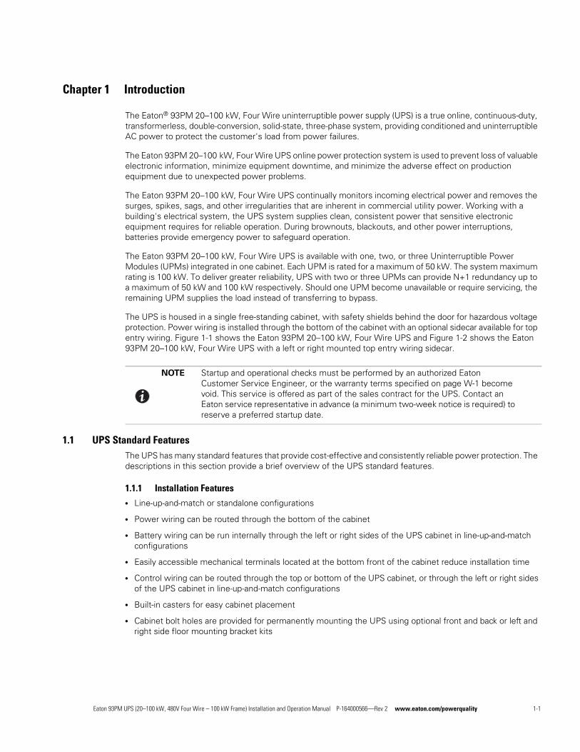
The Eaton 93PM 20–100 kW, Four Wire UPS is available with one, two, or three Uninterruptible Power Modules (UPMs) integrated in one cabinet. Each UPM is rated for a maximum of 50 kW. The system maximum rating is 100 kW. To deliver greater reliability, UPS with two or three UPMs can provide N+1 redundancy up to a maximum of 50 kW and 100 kW respectively. Should one UPM become unavailable or require servicing, the remaining UPM supplies the load instead of transferring to bypass.
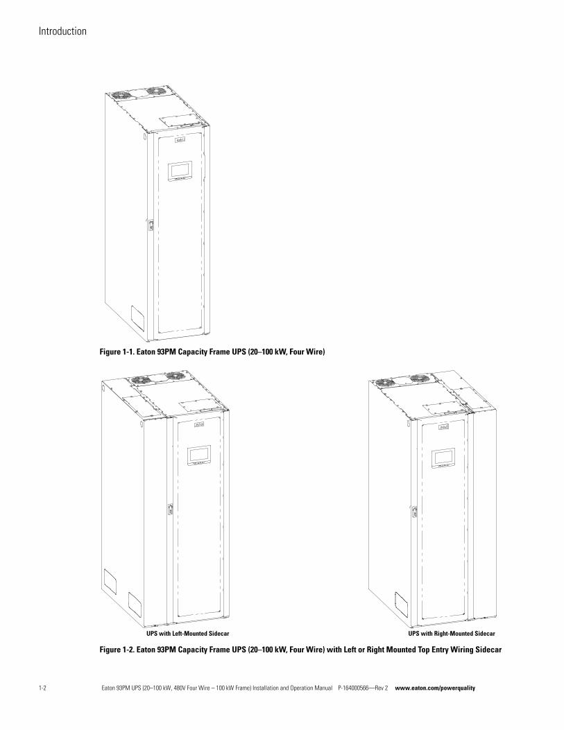
The UPS is housed in a single free-standing cabinet, with safety shields behind the door for hazardous voltage protection. Power wiring is installed through the bottom of the cabinet with an optional sidecar available for top entry wiring. Figure 1-1 shows the Eaton 93PM 20–100 kW, Four Wire UPS and Figure 1-2 shows the Eaton 93PM 20–100 kW, Four Wire UPS with a left or right mounted top entry wiring sidecar.
1.1 UPS Standard FeaturesThe UPS has many standard features that provide cost-effective and consistently reliable power protection. The descriptions in this section provide a brief overview of the UPS standard features.
1.1.1 Installation Featuresl Line-up-and-match or standalone configurations
l Power wiring can be routed through the bottom of the cabinet
l Battery wiring can be run internally through the left or right sides of the UPS cabinet in line-up-and-match configurations
l Easily accessible mechanical terminals located at the bottom front of the cabinet reduce installation time
l Control wiring can be routed through the top or bottom of the UPS cabinet, or through the left or right sides of the UPS cabinet in line-up-and-match configurations
l Built-in casters for easy cabinet placement
l Cabinet bolt holes are provided for permanently mounting the UPS using optional front and back or left and right side floor mounting bracket kits
NOTE Startup and operational checks must be performed by an authorized Eaton Customer Service Engineer, or the warranty terms specified on page W-1 become void. This service is offered as part of the sales contract for the UPS. Contact an Eaton service representative in advance (a minimum two-week notice is required) to reserve a preferred startup date.
Eaton 93PM UPS (20–100 kW, 480V Four Wire – 100 kW Frame) Installation and Operation Manual P-164000566—Rev 2 www.eaton.com/powerquality 1-1
Introduction
Figure 1-1. Eaton 93PM Capacity Frame UPS (20–100 kW, Four Wire)
Figure 1-2. Eaton 93PM Capacity Frame UPS (20–100 kW, Four Wire) with Left or Right Mounted Top Entry Wiring Sidecar
UPS with Left-Mounted Sidecar UPS with Right-Mounted Sidecar
1-2 Eaton 93PM UPS (20–100 kW, 480V Four Wire – 100 kW Frame) Installation and Operation Manual P-164000566—Rev 2 www.eaton.com/powerquality
Introduction
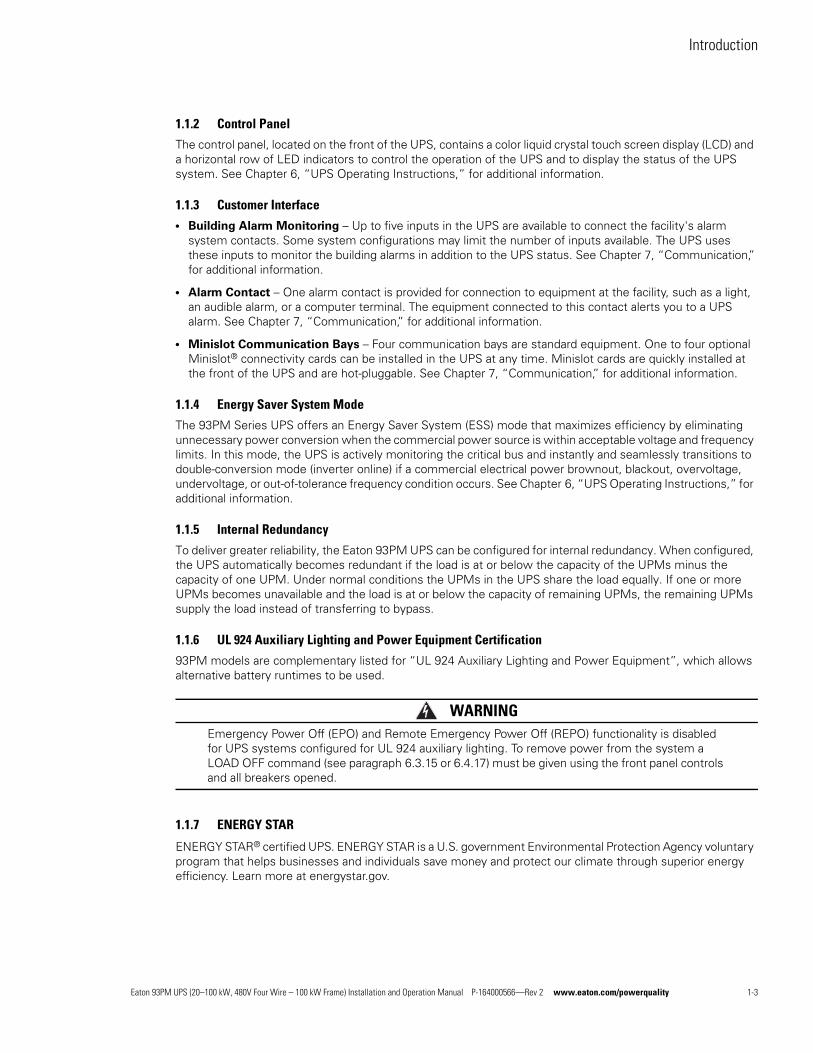
1.1.2 Control Panel
The control panel, located on the front of the UPS, contains a color liquid crystal touch screen display (LCD) and a horizontal row of LED indicators to control the operation of the UPS and to display the status of the UPS system. See Chapter 6, “UPS Operating Instructions,” for additional information.
1.1.3 Customer Interfacel Building Alarm Monitoring – Up to five inputs in the UPS are available to connect the facility's alarm
system contacts. Some system configurations may limit the number of inputs available. The UPS uses these inputs to monitor the building alarms in addition to the UPS status. See Chapter 7, “Communication,” for additional information.
l Alarm Contact – One alarm contact is provided for connection to equipment at the facility, such as a light, an audible alarm, or a computer terminal. The equipment connected to this contact alerts you to a UPS alarm. See Chapter 7, “Communication,” for additional information.
l Minislot Communication Bays – Four communication bays are standard equipment. One to four optional Minislot® connectivity cards can be installed in the UPS at any time. Minislot cards are quickly installed at the front of the UPS and are hot-pluggable. See Chapter 7, “Communication,” for additional information.
1.1.4 Energy Saver System Mode
The 93PM Series UPS offers an Energy Saver System (ESS) mode that maximizes efficiency by eliminating unnecessary power conversion when the commercial power source is within acceptable voltage and frequency limits. In this mode, the UPS is actively monitoring the critical bus and instantly and seamlessly transitions to double-conversion mode (inverter online) if a commercial electrical power brownout, blackout, overvoltage, undervoltage, or out-of-tolerance frequency condition occurs. See Chapter 6, “UPS Operating Instructions,” for additional information.
1.1.5 Internal Redundancy
To deliver greater reliability, the Eaton 93PM UPS can be configured for internal redundancy. When configured, the UPS automatically becomes redundant if the load is at or below the capacity of the UPMs minus the capacity of one UPM. Under normal conditions the UPMs in the UPS share the load equally. If one or more UPMs becomes unavailable and the load is at or below the capacity of remaining UPMs, the remaining UPMs supply the load instead of transferring to bypass.
1.1.6 UL 924 Auxiliary Lighting and Power Equipment Certification
93PM models are complementary listed for “UL 924 Auxiliary Lighting and Power Equipment”, which allows alternative battery runtimes to be used.
WARNINGEmergency Power Off (EPO) and Remote Emergency Power Off (REPO) functionality is disabled for UPS systems configured for UL 924 auxiliary lighting. To remove power from the system a LOAD OFF command (see paragraph 6.3.15 or 6.4.17) must be given using the front panel controls and all breakers opened.
1.1.7 ENERGY STAR
ENERGY STAR® certified UPS. ENERGY STAR is a U.S. government Environmental Protection Agency voluntary program that helps businesses and individuals save money and protect our climate through superior energy efficiency. Learn more at energystar.gov.
Eaton 93PM UPS (20–100 kW, 480V Four Wire – 100 kW Frame) Installation and Operation Manual P-164000566—Rev 2 www.eaton.com/powerquality 1-3
Introduction
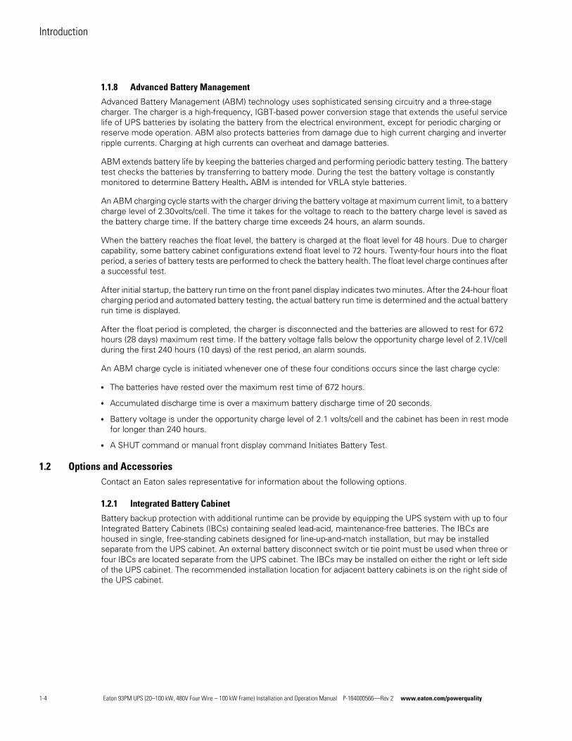
1.1.8 Advanced Battery Management
Advanced Battery Management (ABM) technology uses sophisticated sensing circuitry and a three-stage charger. The charger is a high-frequency, IGBT-based power conversion stage that extends the useful service life of UPS batteries by isolating the battery from the electrical environment, except for periodic charging or reserve mode operation. ABM also protects batteries from damage due to high current charging and inverter ripple currents. Charging at high currents can overheat and damage batteries.
ABM extends battery life by keeping the batteries charged and performing periodic battery testing. The battery test checks the batteries by transferring to battery mode. During the test the battery voltage is constantly monitored to determine Battery Health. ABM is intended for VRLA style batteries.
An ABM charging cycle starts with the charger driving the battery voltage at maximum current limit, to a battery charge level of 2.30volts/cell. The time it takes for the voltage to reach to the battery charge level is saved as the battery charge time. If the battery charge time exceeds 24 hours, an alarm sounds.
When the battery reaches the float level, the battery is charged at the float level for 48 hours. Due to charger capability, some battery cabinet configurations extend float level to 72 hours. Twenty-four hours into the float period, a series of battery tests are performed to check the battery health. The float level charge continues after a successful test.
After initial startup, the battery run time on the front panel display indicates two minutes. After the 24-hour float charging period and automated battery testing, the actual battery run time is determined and the actual battery run time is displayed.
After the float period is completed, the charger is disconnected and the batteries are allowed to rest for 672 hours (28 days) maximum rest time. If the battery voltage falls below the opportunity charge level of 2.1V/cell during the first 240 hours (10 days) of the rest period, an alarm sounds.
An ABM charge cycle is initiated whenever one of these four conditions occurs since the last charge cycle:
l The batteries have rested over the maximum rest time of 672 hours.
l Accumulated discharge time is over a maximum battery discharge time of 20 seconds.
l Battery voltage is under the opportunity charge level of 2.1 volts/cell and the cabinet has been in rest mode for longer than 240 hours.
l A SHUT command or manual front display command Initiates Battery Test.
1.2 Options and AccessoriesContact an Eaton sales representative for information about the following options.
1.2.1 Integrated Battery Cabinet
Battery backup protection with additional runtime can be provide by equipping the UPS system with up to four Integrated Battery Cabinets (IBCs) containing sealed lead-acid, maintenance-free batteries. The IBCs are housed in single, free-standing cabinets designed for line-up-and-match installation, but may be installed separate from the UPS cabinet. An external battery disconnect switch or tie point must be used when three or four IBCs are located separate from the UPS cabinet. The IBCs may be installed on either the right or left side of the UPS cabinet. The recommended installation location for adjacent battery cabinets is on the right side of the UPS cabinet.
1-4 Eaton 93PM UPS (20–100 kW, 480V Four Wire – 100 kW Frame) Installation and Operation Manual P-164000566—Rev 2 www.eaton.com/powerquality
Introduction
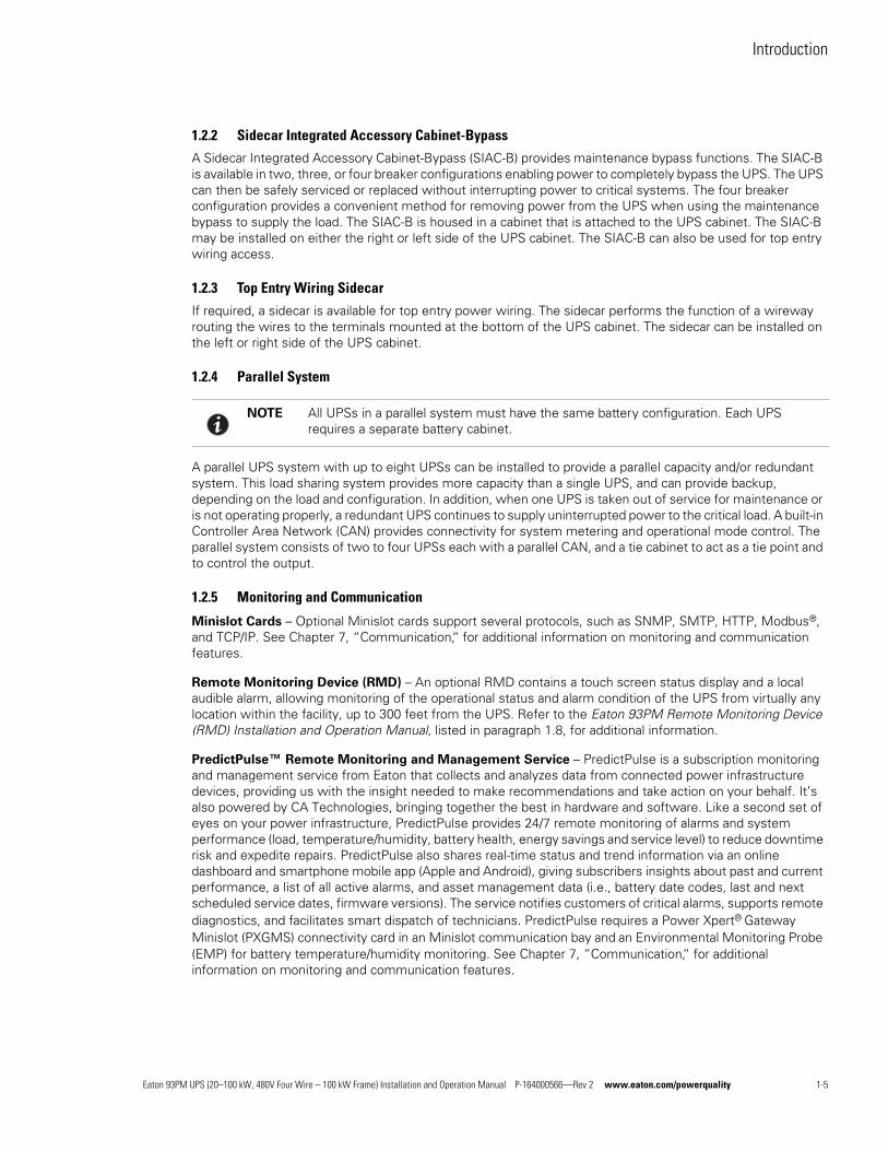
1.2.2 Sidecar Integrated Accessory Cabinet-Bypass
A Sidecar Integrated Accessory Cabinet-Bypass (SIAC-B) provides maintenance bypass functions. The SIAC-B is available in two, three, or four breaker configurations enabling power to completely bypass the UPS. The UPS can then be safely serviced or replaced without interrupting power to critical systems. The four breaker configuration provides a convenient method for removing power from the UPS when using the maintenance bypass to supply the load. The SIAC-B is housed in a cabinet that is attached to the UPS cabinet. The SIAC-B may be installed on either the right or left side of the UPS cabinet. The SIAC-B can also be used for top entry wiring access.
1.2.3 Top Entry Wiring Sidecar
If required, a sidecar is available for top entry power wiring. The sidecar performs the function of a wireway routing the wires to the terminals mounted at the bottom of the UPS cabinet. The sidecar can be installed on the left or right side of the UPS cabinet.
1.2.4 Parallel System
A parallel UPS system with up to eight UPSs can be installed to provide a parallel capacity and/or redundant system. This load sharing system provides more capacity than a single UPS, and can provide backup, depending on the load and configuration. In addition, when one UPS is taken out of service for maintenance or is not operating properly, a redundant UPS continues to supply uninterrupted power to the critical load. A built-in Controller Area Network (CAN) provides connectivity for system metering and operational mode control. The parallel system consists of two to four UPSs each with a parallel CAN, and a tie cabinet to act as a tie point and to control the output.
1.2.5 Monitoring and Communication
Minislot Cards – Optional Minislot cards support several protocols, such as SNMP, SMTP, HTTP, Modbus®, and TCP/IP. See Chapter 7, “Communication,“ for additional information on monitoring and communication features.
Remote Monitoring Device (RMD) – An optional RMD contains a touch screen status display and a local audible alarm, allowing monitoring of the operational status and alarm condition of the UPS from virtually any location within the facility, up to 300 feet from the UPS. Refer to the Eaton 93PM Remote Monitoring Device (RMD) Installation and Operation Manual, listed in paragraph 1.8, for additional information.
PredictPulse™ Remote Monitoring and Management Service – PredictPulse is a subscription monitoring and management service from Eaton that collects and analyzes data from connected power infrastructure devices, providing us with the insight needed to make recommendations and take action on your behalf. It’s also powered by CA Technologies, bringing together the best in hardware and software. Like a second set of eyes on your power infrastructure, PredictPulse provides 24/7 remote monitoring of alarms and system performance (load, temperature/humidity, battery health, energy savings and service level) to reduce downtime risk and expedite repairs. PredictPulse also shares real-time status and trend information via an online dashboard and smartphone mobile app (Apple and Android), giving subscribers insights about past and current performance, a list of all active alarms, and asset management data (i.e., battery date codes, last and next scheduled service dates, firmware versions). The service notifies customers of critical alarms, supports remote diagnostics, and facilitates smart dispatch of technicians. PredictPulse requires a Power Xpert® Gateway Minislot (PXGMS) connectivity card in an Minislot communication bay and an Environmental Monitoring Probe (EMP) for battery temperature/humidity monitoring. See Chapter 7, “Communication,“ for additional information on monitoring and communication features.
NOTE All UPSs in a parallel system must have the same battery configuration. Each UPS requires a separate battery cabinet.
Eaton 93PM UPS (20–100 kW, 480V Four Wire – 100 kW Frame) Installation and Operation Manual P-164000566—Rev 2 www.eaton.com/powerquality 1-5
Introduction
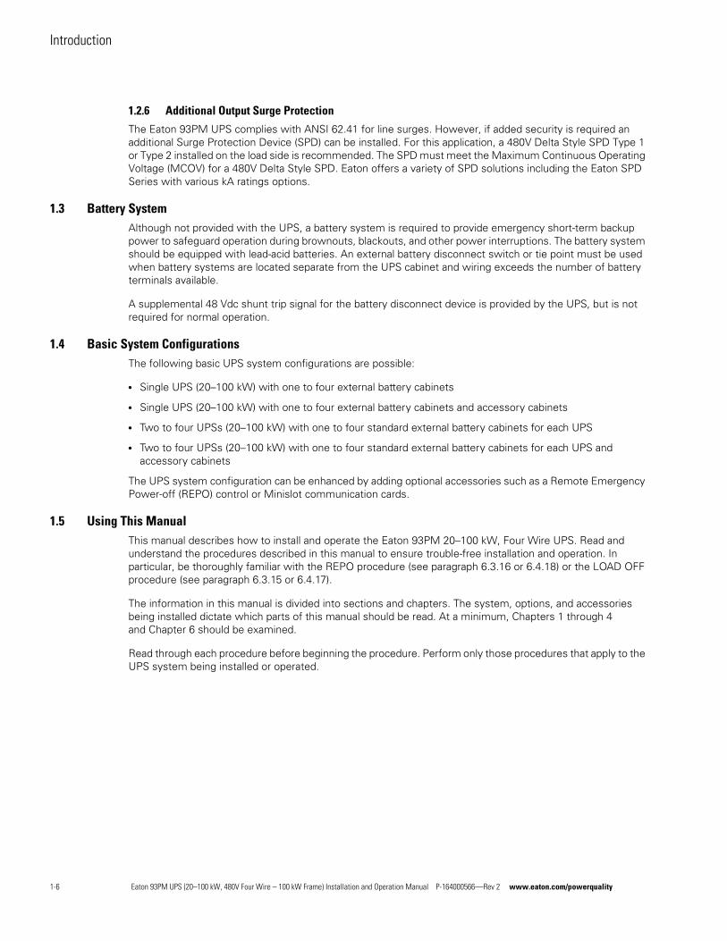
1.2.6 Additional Output Surge Protection
The Eaton 93PM UPS complies with ANSI 62.41 for line surges. However, if added security is required an additional Surge Protection Device (SPD) can be installed. For this application, a 480V Delta Style SPD Type 1 or Type 2 installed on the load side is recommended. The SPD must meet the Maximum Continuous Operating Voltage (MCOV) for a 480V Delta Style SPD. Eaton offers a variety of SPD solutions including the Eaton SPD Series with various kA ratings options.
1.3 Battery SystemAlthough not provided with the UPS, a battery system is required to provide emergency short-term backup power to safeguard operation during brownouts, blackouts, and other power interruptions. The battery system should be equipped with lead-acid batteries. An external battery disconnect switch or tie point must be used when battery systems are located separate from the UPS cabinet and wiring exceeds the number of battery terminals available.
A supplemental 48 Vdc shunt trip signal for the battery disconnect device is provided by the UPS, but is not required for normal operation.
1.4 Basic System ConfigurationsThe following basic UPS system configurations are possible:
l Single UPS (20–100 kW) with one to four external battery cabinets
l Single UPS (20–100 kW) with one to four external battery cabinets and accessory cabinets
l Two to four UPSs (20–100 kW) with one to four standard external battery cabinets for each UPS
l Two to four UPSs (20–100 kW) with one to four standard external battery cabinets for each UPS and accessory cabinets
The UPS system configuration can be enhanced by adding optional accessories such as a Remote Emergency Power-off (REPO) control or Minislot communication cards.
1.5 Using This ManualThis manual describes how to install and operate the Eaton 93PM 20–100 kW, Four Wire UPS. Read and understand the procedures described in this manual to ensure trouble-free installation and operation. In particular, be thoroughly familiar with the REPO procedure (see paragraph 6.3.16 or 6.4.18) or the LOAD OFF procedure (see paragraph 6.3.15 or 6.4.17).
The information in this manual is divided into sections and chapters. The system, options, and accessories being installed dictate which parts of this manual should be read. At a minimum, Chapters 1 through 4 and Chapter 6 should be examined.
Read through each procedure before beginning the procedure. Perform only those procedures that apply to the UPS system being installed or operated.
1-6 Eaton 93PM UPS (20–100 kW, 480V Four Wire – 100 kW Frame) Installation and Operation Manual P-164000566—Rev 2 www.eaton.com/powerquality
Introduction
1.6 Conventions Used in This ManualThis manual uses these type conventions:
l Bold type highlights important concepts in discussions, key terms in procedures, and menu options, or represents a command or option that you type or enter at a prompt.
l Italic type highlights notes and new terms where they are defined.
l Screen type represents information that appears on the screen or LCD.
In this manual, the term UPS refers only to the UPS cabinet and its internal elements. The term UPS system refers to the entire power protection system – the UPS cabinet, an external battery system, and options or accessories installed.
The term line-up-and-match refers to accessory cabinets that are physically located adjacent to the UPS. The term standalone refers to accessory cabinets that are located separate from the UPS.
Left and right side notations are referenced standing in front of the cabinet.
1.7 Symbols, Controls, and IndicatorsThe following are examples of symbols used on the UPS or accessories to alert you to important information:
Icon Description
Note Information notes call attention to important features or instructions.
[Keys] Brackets are used when referring to a specific key, such as [Enter] or [Ctrl].
RISK OF ELECTRIC SHOCK - Observe the warning associated with the risk of electric shock symbol.
CAUTION: REFER TO OPERATOR'S MANUAL - Refer to your operator's manual for additional information, such as important operating and maintenance instructions.
This symbol indicates that you should not discard the UPS or the UPS batteries in the trash. This product contains sealed, lead-acid batteries and must be disposed of properly. For more information, contact your local recycling/reuse or hazardous waste center.
This symbol indicates that you should not discard waste electrical or electronic equipment (WEEE) in the trash. For proper disposal, contact your local recycling/reuse or hazardous waste center.
Eaton 93PM UPS (20–100 kW, 480V Four Wire – 100 kW Frame) Installation and Operation Manual P-164000566—Rev 2 www.eaton.com/powerquality 1-7
Introduction
1.8 For More InformationRefer to the Eaton 93PM Integrated Battery Cabinet Installation Manual-Large and Large High Rate or the Eaton 93PM Universal Integrated Battery Cabinet Installation Manual-Large and Large High Rate for the following additional information:
l Installation instructions, including site preparation, planning for installation, wiring and safety information, and detailed illustrations of cabinets with dimensional and connection point drawings
Refer to the Eaton 93PM Sidecar Integrated Accessory Cabinet-Bypass Installation and Operation (50 kW and 100 kW SIAC-B) Manual for the following additional information:
l Installation instructions, including site preparation, planning for installation, wiring and safety information, and detailed illustrations of cabinets with dimensional and connection point drawings
l Operation, including breakers, standard features and optional accessories, procedures for using the bypass functions, and information about maintenance
Refer to the Eaton 93PM Remote Monitoring Device (RMD) Installation and Operation Manual for additional installation and operating instructions.
Visit www.eaton.com/powerquality or contact an Eaton service representative for information on how to obtain copies of these manuals.
1.9 Getting HelpIf help is needed with any of the following:
l Scheduling initial startup
l Regional locations and telephone numbers
l A question about any of the information in this manual
l A question this manual does not answer
Please call the Customer Reliability Center at:
United States: 1-800-843-9433
Canada: 1-800-461-9166 ext 260
All other countries: Call your local service representative
Please use the following e-mail address for manual comments, suggestions, or to report an error in this manual:
1-8 Eaton 93PM UPS (20–100 kW, 480V Four Wire – 100 kW Frame) Installation and Operation Manual P-164000566—Rev 2 www.eaton.com/powerquality
Chapter 2 Safety Warnings
IMPORTANT SAFETY INSTRUCTIONS SAVE THESE INSTRUCTIONSThis manual contains important instructions that should be followed during installation and maintenance of the UPS and batteries. Read all instructions before operating the equipment and save this manual for future reference.
The UPS is designed for industrial or computer room applications, and contains safety shieldsbehind the door and front panels. However, the UPS is a sophisticated power system and shouldbe handled with appropriate care.
DANGERThis UPS contains LETHAL VOLTAGES. All repairs and service should be performed by AUTHORIZED SERVICE PERSONNEL ONLY. There are NO USER SERVICEABLE PARTS inside the UPS.
WARNINGl The UPS is powered by its own energy source (batteries). The output terminals may carry live
voltage even when the UPS is disconnected from an AC source.
l To reduce the risk of fire or electric shock, install this UPS in a temperature and humidity controlled, indoor environment, free of conductive contaminants. Ambient temperature must not exceed 40C (104F). Do not operate near water or excessive humidity (95% maximum). The system is not intended for outdoor use.
l As a result of the connected loads high leakage current is possible. Connection to earth ground is required for safety and proper product operation. Do not check UPS operation by any action that includes removal of the earth (ground) connection with loads attached.
l Emergency Power Off (EPO) and Remote Emergency Power Off (REPO) functionality is disabled for UPS systems configured for UL 924 auxiliary lighting. To remove power from the system a LOAD OFF command (see paragraph 6.3.15 or 6.4.17) must be given using the front panel controls and all breakers opened.
l Ensure all power is disconnected before performing installation or service.
l Batteries can present a risk of electrical shock or burn from high short-circuit current. The following precautions should be observed: 1) Remove watches, rings, or other metal objects; 2) Use tools with insulated handles; 3) Do not lay tools or metal parts on top of batteries; 4) Wear rubber gloves and boots.
l ELECTRIC ENERGY HAZARD. Do not attempt to alter any UPS or battery wiring or connectors. Attempting to alter wiring can cause injury.
l Do not open or mutilate batteries. Released electrolyte is harmful to the skin and eyes. It may be toxic.
Eaton 93PM UPS (20–100 kW, 480V Four Wire – 100 kW Frame) Installation and Operation Manual P-164000566—Rev 2 www.eaton.com/powerquality 2-1
Safety Warnings
CAUTIONl Installation or servicing should be performed by qualified service personnel knowledgeable of
UPS and battery systems, and required precautions. Keep unauthorized personnel away from equipment. Consider all warnings, cautions, and notes before installing or servicing equipment. DO NOT DISCONNECT the batteries while the UPS is in Battery mode.
l Replace batteries with the same number and type of batteries as originally installed with the UPS.
l Disconnect the charging source prior to connecting or disconnecting terminals.
l Determine if the battery is inadvertently grounded. If it is, remove the source of the ground. Contacting any part of a grounded battery can cause a risk of electric shock. An electric shock is less likely if you disconnect the grounding connection before you work on the batteries.
l Proper disposal of batteries is required. Refer to local codes for disposal requirements.
l Do not dispose of batteries in a fire. Batteries may explode when exposed to flame.
l Keep the UPS door closed and front panels installed to ensure proper cooling airflow and to protect personnel from dangerous voltages inside the unit.
l Do not install or operate the UPS system close to gas or electric heat sources.
l Lead-acid batteries can present a risk of fire because they generate hydrogen gas. Do not smoke when near batteries. Do not cause flame or spark in battery area. Discharge static electricity from body before touching batteries by first touching a grounded metal surface.
l The operating environment should be maintained within the parameters stated in this manual.
l Keep surroundings uncluttered, clean, and free from excess moisture.
l Observe all DANGER, CAUTION, and WARNING notices affixed to the inside and outside of the equipment.
AVERTISSEMENT!l Les batteries peuvent présenter un risque de décharge électrique ou de brûlure par des
courts–circuits de haute intensité. Prendre les précautions nécessaires.
l Pour le replacement, utiliser le même nombre et modéle des batteries.
ATTENTION!l Une mise au rebut réglementaire des batteries est obligatoire. Consulter les règlements en
vigueur dans votre localité.
l Ne jamais jeter les batteries au feu. L'exposition aux flammes risque de les faire exploser.
l Les accumulateurs au plomb-acide peuvent représenter un risque d’incendie, car ils génèrent de l’hydrogène gazeux. Ne pas fumer près des accumulateurs. Ne pas produire de flamme ou d’étincelle dans la zone de l’accumulateur. Dissiper l'électricité statique de votre corps en touchant une surface reliée à la terre avant de toucher les accumulateurs.
2-2 Eaton 93PM UPS (20–100 kW, 480V Four Wire – 100 kW Frame) Installation and Operation Manual P-164000566—Rev 2 www.eaton.com/powerquality

Section 1Installation

Chapter 3 UPS Installation Plan and Unpacking
Use the following basic sequence of steps to install the UPS:1. Create an installation plan for the UPS system (Chapter 3).
2. Prepare your site for the UPS system (Chapter 3).
3. Inspect and unpack the UPS cabinet (Chapter 3).
4. Unload and install the UPS cabinet, and wire the system (Chapter 4).
5. Install features, accessories, or options, as applicable (Chapter 4).
6. Complete the Installation Checklist (Chapter 4).
7. Have authorized service personnel perform preliminary operational checks and start up the system.
3.1 Creating an Installation PlanBefore installing the UPS system, read and understand how this manual applies to the system being installed. Use the procedures and illustrations in paragraph 3.2 and Chapter 4 to create a logical plan for installing the system.
3.2 Preparing the SiteFor the UPS system to operate at peak efficiency, the installation site should meet the environmental parameters outlined in this manual. The operating environment must meet the weight, clearance, and environmental requirements specified.
3.2.1 Environmental and Installation Considerations
The UPS system installation must meet the following guidelines:
l The system must be installed on a level floor suitable for computer or electronic equipment.
l The system must be operated at an altitude no higher than 1500m (5000 ft) without derating. For additional assistance with high altitude operation, contact an Eaton service representative (see paragraph 1.9).
l The system must be installed in a temperature and humidity controlled indoor area free of conductive contaminants.
Failure to follow guidelines may void your warranty.
The basic environmental requirements for operation of the UPS are:
l Ambient Temperature Range: 5–40C (41–104F)
l Recommended Operating Range: 5–40C (41–104F)
l Maximum Relative Humidity: 95%, noncondensing
NOTE Startup and operational checks must be performed by an authorized Eaton Customer Service Engineer, or the warranty terms specified on page W-1 become void. This service is offered as part of the sales contract for the UPS. Contact an Eaton service representative in advance (a minimum two-week notice is required) to reserve a preferred startup date.
Eaton 93PM UPS (20–100 kW, 480V Four Wire – 100 kW Frame) Installation and Operation Manual P-164000566—Rev 2 www.eaton.com/powerquality 3-1
UPS Installation Plan and Unpacking
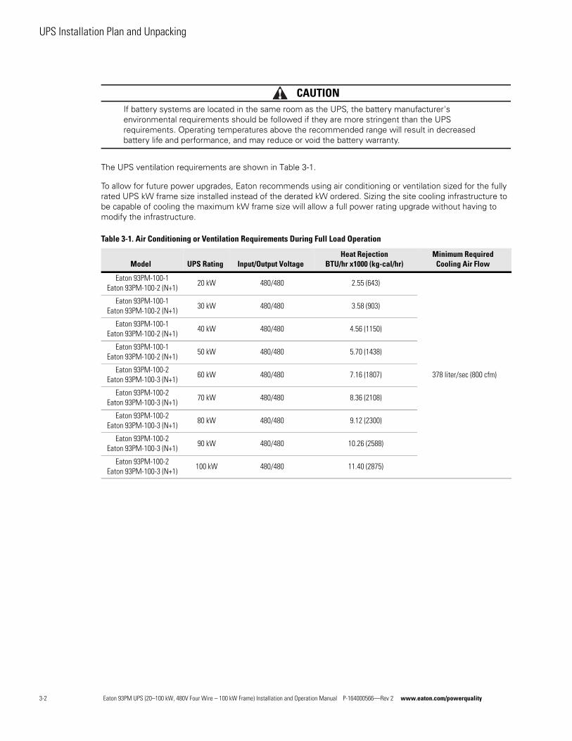
CAUTIONIf battery systems are located in the same room as the UPS, the battery manufacturer's environmental requirements should be followed if they are more stringent than the UPS requirements. Operating temperatures above the recommended range will result in decreased battery life and performance, and may reduce or void the battery warranty.
The UPS ventilation requirements are shown in Table 3-1.
To allow for future power upgrades, Eaton recommends using air conditioning or ventilation sized for the fully rated UPS kW frame size installed instead of the derated kW ordered. Sizing the site cooling infrastructure to be capable of cooling the maximum kW frame size will allow a full power rating upgrade without having to modify the infrastructure.
Table 3-1. Air Conditioning or Ventilation Requirements During Full Load Operation
Model UPS Rating Input/Output VoltageHeat Rejection
BTU/hr x1000 (kg-cal/hr)Minimum Required
Cooling Air Flow
Eaton 93PM-100-1Eaton 93PM-100-2 (N+1)
20 kW 480/480 2.55 (643)
378 liter/sec (800 cfm)
Eaton 93PM-100-1Eaton 93PM-100-2 (N+1)
30 kW 480/480 3.58 (903)
Eaton 93PM-100-1Eaton 93PM-100-2 (N+1)
40 kW 480/480 4.56 (1150)
Eaton 93PM-100-1Eaton 93PM-100-2 (N+1)
50 kW 480/480 5.70 (1438)
Eaton 93PM-100-2Eaton 93PM-100-3 (N+1)
60 kW 480/480 7.16 (1807)
Eaton 93PM-100-2Eaton 93PM-100-3 (N+1)
70 kW 480/480 8.36 (2108)
Eaton 93PM-100-2Eaton 93PM-100-3 (N+1)
80 kW 480/480 9.12 (2300)
Eaton 93PM-100-2Eaton 93PM-100-3 (N+1)
90 kW 480/480 10.26 (2588)
Eaton 93PM-100-2Eaton 93PM-100-3 (N+1)
100 kW 480/480 11.40 (2875)
3-2 Eaton 93PM UPS (20–100 kW, 480V Four Wire – 100 kW Frame) Installation and Operation Manual P-164000566—Rev 2 www.eaton.com/powerquality
UPS Installation Plan and Unpacking
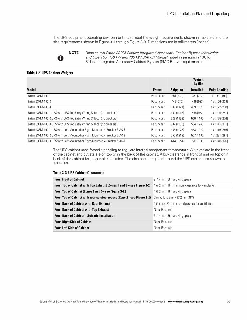
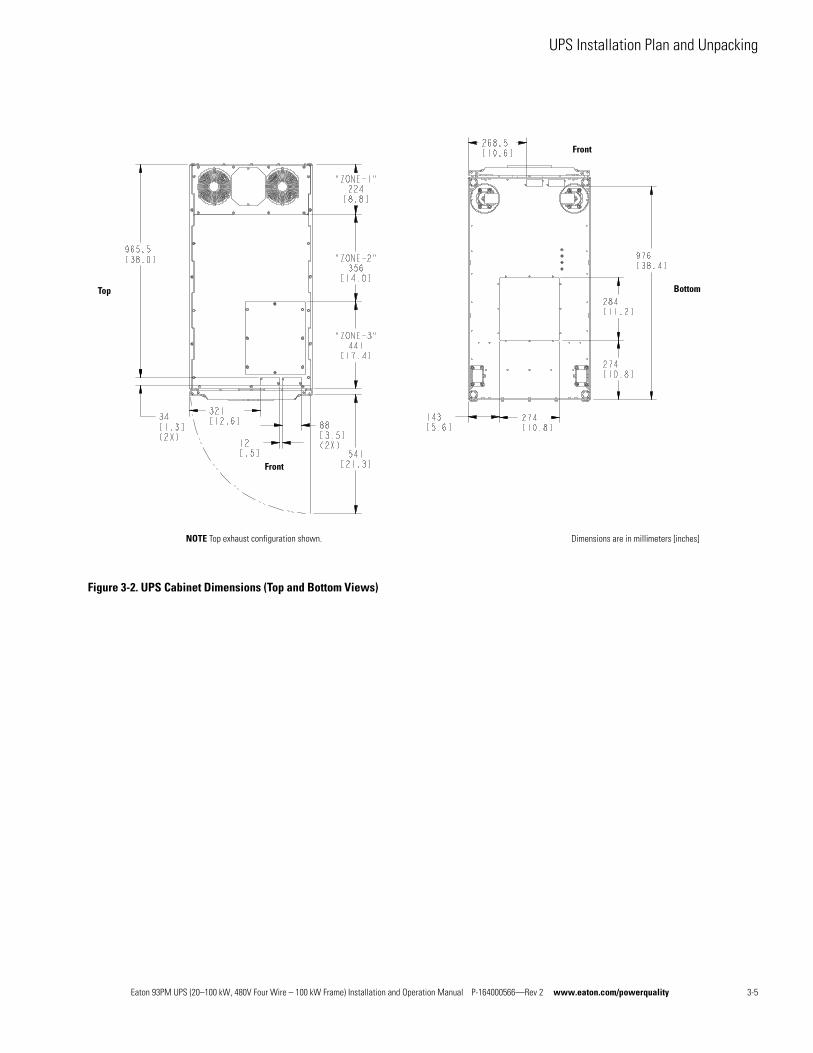
The UPS equipment operating environment must meet the weight requirements shown in Table 3-2 and the size requirements shown in Figure 3-1 through Figure 3-8. Dimensions are in millimeters (inches).
The UPS cabinet uses forced air cooling to regulate internal component temperature. Air inlets are in the front of the cabinet and outlets are on top or in the back of the cabinet. Allow clearance in front of and on top or in back of the cabinet for proper air circulation. The clearances required around the UPS cabinet are shown in Table 3-3.
NOTE Refer to the Eaton 93PM Sidecar Integrated Accessory Cabinet-Bypass Installation and Operation (50 kW and 100 kW SIAC-B) Manual, listed in paragraph 1.8, for Sidecar Integrated Accessory Cabinet-Bypass (SIAC-B) size requirements.
Table 3-2. UPS Cabinet Weights
Model
Weight kg (lb)
Frame Shipping Installed Point Loading
Eaton 93PM-100-1 Redundant 381 (840) 361 (797) 4 at 90 (199)
Eaton 93PM-100-2 Redundant 445 (980) 425 (937) 4 at 106 (234)
Eaton 93PM-100-3 Redundant 509 (1121) 489 (1078) 4 at 122 (270)
Eaton 93PM-100-1 UPS with UPS Top Entry Wiring Sidecar (no breakers) Redundant 459 (1012) 436 (962) 4 at 109 (241)
Eaton 93PM-100-2 UPS with UPS Top Entry Wiring Sidecar (no breakers) Redundant 523 (1152) 500 (1102) 4 at 125 (276)
Eaton 93PM-100-3 UPS with UPS Top Entry Wiring Sidecar (no breakers) Redundant 587 (1293) 564 (1243) 4 at 141 (311)
Eaton 93PM-100-1 UPS with Left-Mounted or Right-Mounted 4-Breaker SIAC-B Redundant 486 (1073) 463 (1022) 4 at 116 (256)
Eaton 93PM-100-2 UPS with Left-Mounted or Right-Mounted 4-Breaker SIAC-B Redundant 550 (1213) 527 (1162) 4 at 291 (291)
Eaton 93PM-100-3 UPS with Left-Mounted or Right-Mounted 4-Breaker SIAC-B Redundant 614 (1354) 591(1303) 4 at 148 (326)
Table 3-3. UPS Cabinet Clearances
From Front of Cabinet 914.4 mm (36") working space
From Top of Cabinet with Top Exhaust (Zones 1 and 3 – see Figure 3-2 ) 457.2 mm (18") minimum clearance for ventilation
From Top of Cabinet (Zones 2 and 3– see Figure 3-2 ) 457.2 mm (18") working space
From Top of Cabinet with rear service access (Zone 2– see Figure 3-2) Can be less than 457.2 mm (18")
From Back of Cabinet with Rear Exhaust 254 mm (18") minimum clearance for ventilation
From Back of Cabinet with Top Exhaust None Required
From Back of Cabinet – Seismic Installation 914.4 mm (36") working space
From Right Side of Cabinet None Required
From Left Side of Cabinet None Required
Eaton 93PM UPS (20–100 kW, 480V Four Wire – 100 kW Frame) Installation and Operation Manual P-164000566—Rev 2 www.eaton.com/powerquality 3-3
UPS Installation Plan and Unpacking
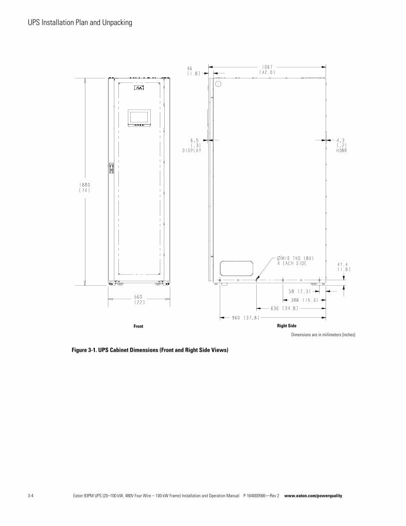
Figure 3-1. UPS Cabinet Dimensions (Front and Right Side Views)
Dimensions are in millimeters [inches]
Front Right Side
3-4 Eaton 93PM UPS (20–100 kW, 480V Four Wire – 100 kW Frame) Installation and Operation Manual P-164000566—Rev 2 www.eaton.com/powerquality
UPS Installation Plan and Unpacking
Figure 3-2. UPS Cabinet Dimensions (Top and Bottom Views)
Bottom
Dimensions are in millimeters [inches]
Top
NOTE Top exhaust configuration shown.
Front
Front
Eaton 93PM UPS (20–100 kW, 480V Four Wire – 100 kW Frame) Installation and Operation Manual P-164000566—Rev 2 www.eaton.com/powerquality 3-5
UPS Installation Plan and Unpacking
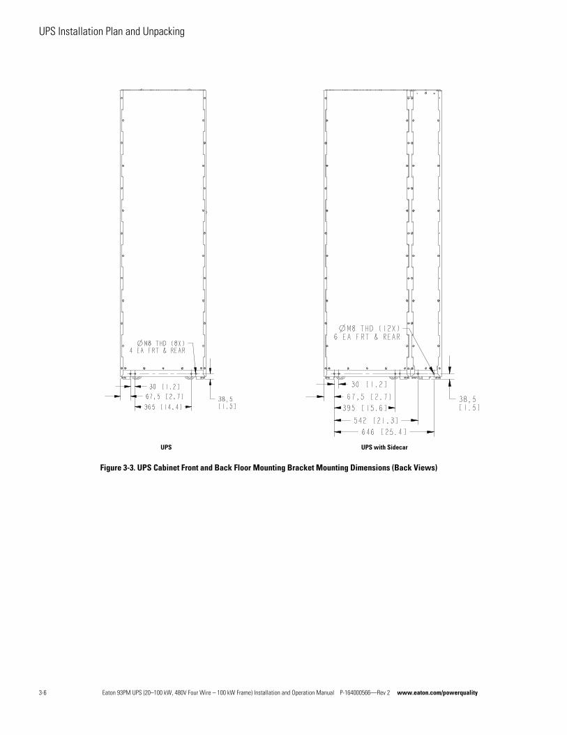
Figure 3-3. UPS Cabinet Front and Back Floor Mounting Bracket Mounting Dimensions (Back Views)
UPS with SidecarUPS
3-6 Eaton 93PM UPS (20–100 kW, 480V Four Wire – 100 kW Frame) Installation and Operation Manual P-164000566—Rev 2 www.eaton.com/powerquality
UPS Installation Plan and Unpacking
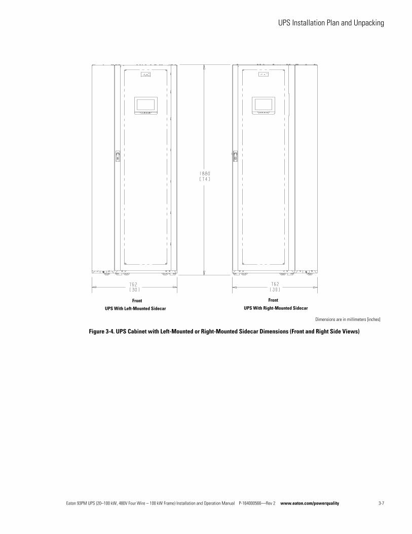
Figure 3-4. UPS Cabinet with Left-Mounted or Right-Mounted Sidecar Dimensions (Front and Right Side Views)
Dimensions are in millimeters [inches]
Front Front
UPS With Left-Mounted Sidecar UPS With Right-Mounted Sidecar
Eaton 93PM UPS (20–100 kW, 480V Four Wire – 100 kW Frame) Installation and Operation Manual P-164000566—Rev 2 www.eaton.com/powerquality 3-7
UPS Installation Plan and Unpacking
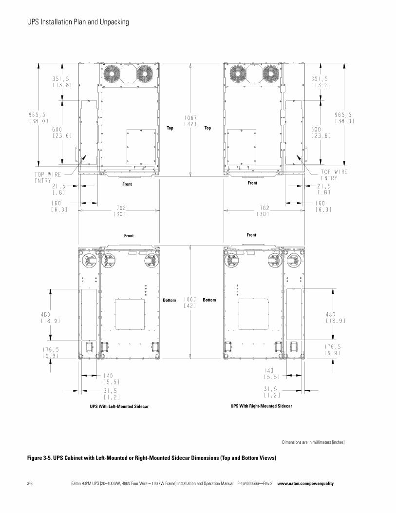
Figure 3-5. UPS Cabinet with Left-Mounted or Right-Mounted Sidecar Dimensions (Top and Bottom Views)
Dimensions are in millimeters [inches]
UPS With Left-Mounted Sidecar UPS With Right-Mounted Sidecar
Front
Front Front
Front
Bottom Bottom
Top Top
3-8 Eaton 93PM UPS (20–100 kW, 480V Four Wire – 100 kW Frame) Installation and Operation Manual P-164000566—Rev 2 www.eaton.com/powerquality
UPS Installation Plan and Unpacking
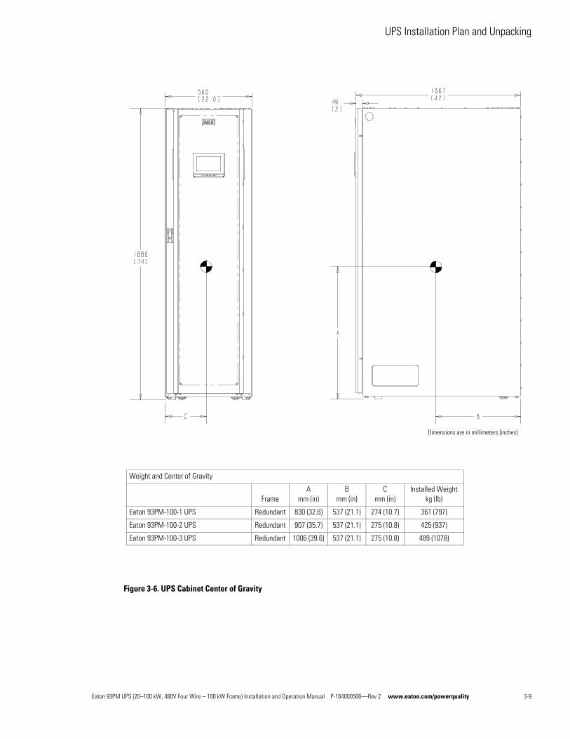
Figure 3-6. UPS Cabinet Center of Gravity
Dimensions are in millimeters [inches]
Weight and Center of Gravity
FrameA
mm (in)B
mm (in)C
mm (in)Installed Weight
kg (lb)
Eaton 93PM-100-1 UPS Redundant 830 (32.6) 537 (21.1) 274 (10.7) 361 (797)
Eaton 93PM-100-2 UPS Redundant 907 (35.7) 537 (21.1) 275 (10.8) 425 (937)
Eaton 93PM-100-3 UPS Redundant 1006 (39.6) 537 (21.1) 275 (10.8) 489 (1078)
Eaton 93PM UPS (20–100 kW, 480V Four Wire – 100 kW Frame) Installation and Operation Manual P-164000566—Rev 2 www.eaton.com/powerquality 3-9
UPS Installation Plan and Unpacking
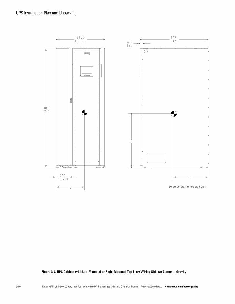
Figure 3-7. UPS Cabinet with Left-Mounted or Right-Mounted Top Entry Wiring Sidecar Center of Gravity
Dimensions are in millimeters [inches]
3-10 Eaton 93PM UPS (20–100 kW, 480V Four Wire – 100 kW Frame) Installation and Operation Manual P-164000566—Rev 2 www.eaton.com/powerquality
UPS Installation Plan and Unpacking
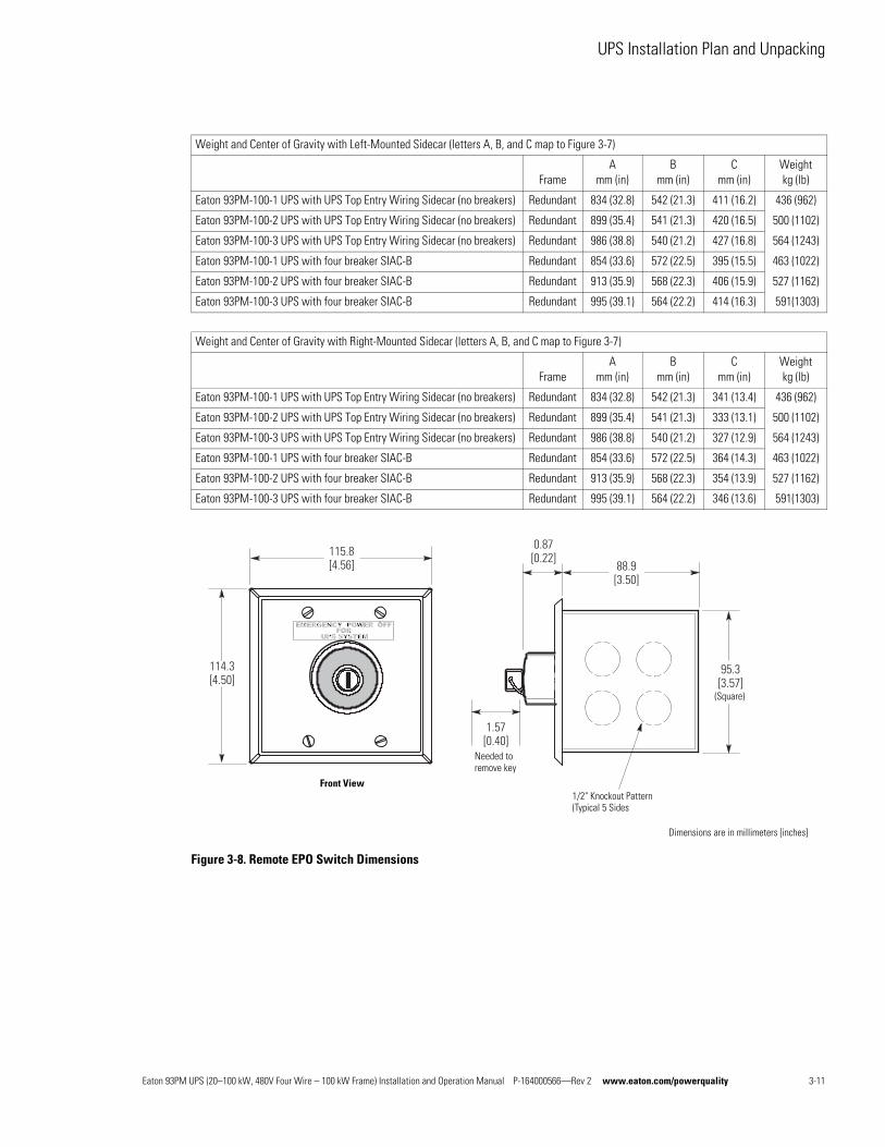
Figure 3-8. Remote EPO Switch Dimensions
Weight and Center of Gravity with Left-Mounted Sidecar (letters A, B, and C map to Figure 3-7)
FrameA
mm (in)B
mm (in)C
mm (in)Weightkg (lb)
Eaton 93PM-100-1 UPS with UPS Top Entry Wiring Sidecar (no breakers) Redundant 834 (32.8) 542 (21.3) 411 (16.2) 436 (962)
Eaton 93PM-100-2 UPS with UPS Top Entry Wiring Sidecar (no breakers) Redundant 899 (35.4) 541 (21.3) 420 (16.5) 500 (1102)
Eaton 93PM-100-3 UPS with UPS Top Entry Wiring Sidecar (no breakers) Redundant 986 (38.8) 540 (21.2) 427 (16.8) 564 (1243)
Eaton 93PM-100-1 UPS with four breaker SIAC-B Redundant 854 (33.6) 572 (22.5) 395 (15.5) 463 (1022)
Eaton 93PM-100-2 UPS with four breaker SIAC-B Redundant 913 (35.9) 568 (22.3) 406 (15.9) 527 (1162)
Eaton 93PM-100-3 UPS with four breaker SIAC-B Redundant 995 (39.1) 564 (22.2) 414 (16.3) 591(1303)
Weight and Center of Gravity with Right-Mounted Sidecar (letters A, B, and C map to Figure 3-7)
FrameA
mm (in)B
mm (in)C
mm (in)Weightkg (lb)
Eaton 93PM-100-1 UPS with UPS Top Entry Wiring Sidecar (no breakers) Redundant 834 (32.8) 542 (21.3) 341 (13.4) 436 (962)
Eaton 93PM-100-2 UPS with UPS Top Entry Wiring Sidecar (no breakers) Redundant 899 (35.4) 541 (21.3) 333 (13.1) 500 (1102)
Eaton 93PM-100-3 UPS with UPS Top Entry Wiring Sidecar (no breakers) Redundant 986 (38.8) 540 (21.2) 327 (12.9) 564 (1243)
Eaton 93PM-100-1 UPS with four breaker SIAC-B Redundant 854 (33.6) 572 (22.5) 364 (14.3) 463 (1022)
Eaton 93PM-100-2 UPS with four breaker SIAC-B Redundant 913 (35.9) 568 (22.3) 354 (13.9) 527 (1162)
Eaton 93PM-100-3 UPS with four breaker SIAC-B Redundant 995 (39.1) 564 (22.2) 346 (13.6) 591(1303)
115.8[4.56]
114.3[4.50]
0.87[0.22]
88.9[3.50]
1.57[0.40]
95.3[3.57]
Front View1/2" Knockout Pattern(Typical 5 Sides
Needed to remove key
(Square)
Dimensions are in millimeters [inches]
Eaton 93PM UPS (20–100 kW, 480V Four Wire – 100 kW Frame) Installation and Operation Manual P-164000566—Rev 2 www.eaton.com/powerquality 3-11
UPS Installation Plan and Unpacking
3.2.2 UPS System Power Wiring Preparation
Read and understand the following notes while planning and performing the installation:
WARNINGAs a result of the connected loads high leakage current is possible. Connection to earth ground is required for safety and proper product operation. Do not check UPS operation by any action that includes removal of the earth (ground) connection with loads attached.
l Refer to national and local electrical codes for acceptable external wiring practices.
l To allow for future power upgrades, Eaton recommends installing the UPS using wiring and external overcurrent protection breakers sized for the fully rated UPS kW frame size installed instead of the derated kW ordered. Wiring for the maximum kW frame size will allow a full power rating upgrade without having to modify the site wiring infrastructure.
l For external wiring, use 75°C copper wire. Wire sizes listed in Table 3-4 or Table 3-5 are for copper wiring only. If wire is run in an ambient temperature greater than 40°C, larger size wire may be necessary. Wire sizes are based on using the specified breakers.
l The AC output and output ground wiring to the critical load should be sized the same as the UPS rectifier, bypass, and rectifier and bypass ground wiring if the recommended output breaker listed in Table 3-9 is not installed in the system.
l Recommended wire sizes are based on NFPA National Electrical Code® (NEC®)70 Table 310.15(B)(16) 75°C ampacity with 40°C ambient correction factors.
l The neutral conductor is sized the same as the phase conductor for balanced and resistive loads. Non-linear loads, up to the maximum of 1.5x the load current, require a larger neutral conductor and should be sized in accordance with NFPA NEC 70 Article 310.15(B)(5).
l Connect rectifier input to a 3 wire, grounded Wye source or in single source applications, a 3-wire High Resistance Ground (HRG) source. A neutral conductor is not used from the rectifier source.
l Supported single source, single or dual feed power sources:
- 3-wire grounded Wye (TN,TT) – Rectifier Input
- 4-wire grounded Wye (TN,TT) – Bypass Input
- 3-wire High Resistance Ground (IT) – Rectifier Input
- 4-wire High Resistance Ground (IT) – Bypass Input
l Supported dual source, dual feed power sources:
- 3-wire grounded Wye (TN, TT) – Rectifier Input
- 4-wire grounded Wye (TN, TT) – Bypass Input
CAUTIONSINGLE HIGH IMPEDANCE GROUND SOURCE – In North American installations, the neutral conductor from the high impedance ground source of supply CANNOT be used.
NOTE Refer to the Eaton 93PM Sidecar Integrated Accessory Cabinet-Bypass Installation and Operation (50 kW and 100 kW SIAC-B) Manual, listed in paragraph 1.8, for SIAC-B power wiring preparation and requirements.
3-12 Eaton 93PM UPS (20–100 kW, 480V Four Wire – 100 kW Frame) Installation and Operation Manual P-164000566—Rev 2 www.eaton.com/powerquality
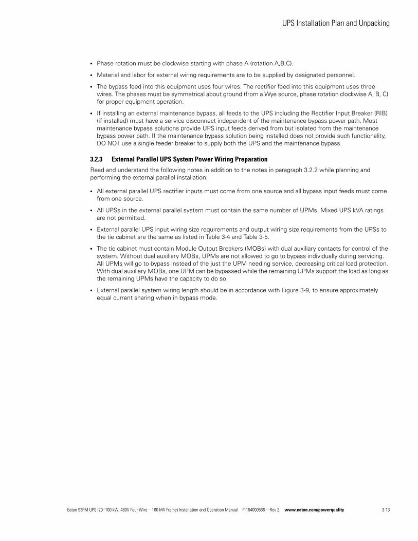
UPS Installation Plan and Unpacking
l Phase rotation must be clockwise starting with phase A (rotation A,B,C).
l Material and labor for external wiring requirements are to be supplied by designated personnel.
l The bypass feed into this equipment uses four wires. The rectifier feed into this equipment uses three wires. The phases must be symmetrical about ground (from a Wye source, phase rotation clockwise A, B, C) for proper equipment operation.
l If installing an external maintenance bypass, all feeds to the UPS including the Rectifier Input Breaker (RIB) (if installed) must have a service disconnect independent of the maintenance bypass power path. Most maintenance bypass solutions provide UPS input feeds derived from but isolated from the maintenance bypass power path. If the maintenance bypass solution being installed does not provide such functionality, DO NOT use a single feeder breaker to supply both the UPS and the maintenance bypass.
3.2.3 External Parallel UPS System Power Wiring Preparation
Read and understand the following notes in addition to the notes in paragraph 3.2.2 while planning and performing the external parallel installation:
l All external parallel UPS rectifier inputs must come from one source and all bypass input feeds must come from one source.
l All UPSs in the external parallel system must contain the same number of UPMs. Mixed UPS kVA ratings are not permitted.
l External parallel UPS input wiring size requirements and output wiring size requirements from the UPSs to the tie cabinet are the same as listed in Table 3-4 and Table 3-5.
l The tie cabinet must contain Module Output Breakers (MOBs) with dual auxiliary contacts for control of the system. Without dual auxiliary MOBs, UPMs are not allowed to go to bypass individually during servicing. All UPMs will go to bypass instead of the just the UPM needing service, decreasing critical load protection. With dual auxiliary MOBs, one UPM can be bypassed while the remaining UPMs support the load as long as the remaining UPMs have the capacity to do so.
l External parallel system wiring length should be in accordance with Figure 3-9, to ensure approximately equal current sharing when in bypass mode.
Eaton 93PM UPS (20–100 kW, 480V Four Wire – 100 kW Frame) Installation and Operation Manual P-164000566—Rev 2 www.eaton.com/powerquality 3-13
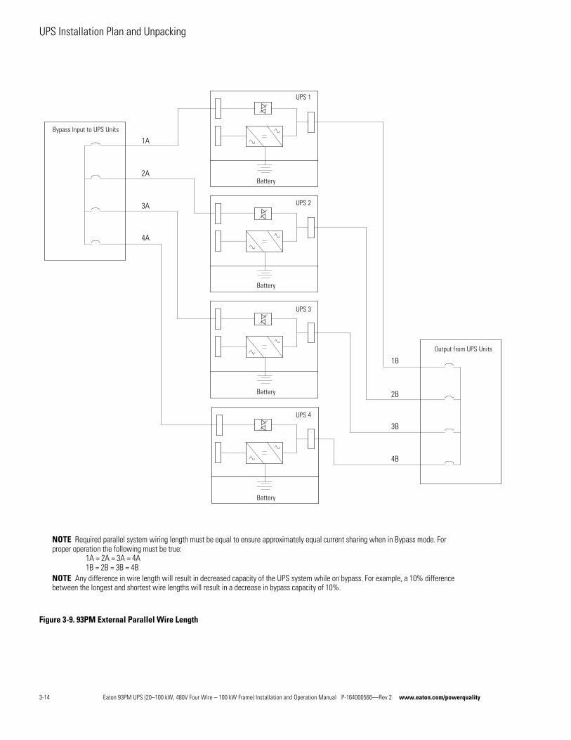
UPS Installation Plan and Unpacking
Figure 3-9. 93PM External Parallel Wire Length
NOTE Required parallel system wiring length must be equal to ensure approximately equal current sharing when in Bypass mode. Forproper operation the following must be true:
1A = 2A = 3A = 4A1B = 2B = 3B = 4B
NOTE Any difference in wire length will result in decreased capacity of the UPS system while on bypass. For example, a 10% differencebetween the longest and shortest wire lengths will result in a decrease in bypass capacity of 10%.
Bypass Input to UPS Units
UPS 1
Battery
UPS 2
UPS 3
UPS 4
Output from UPS Units
Battery
Battery
Battery
1A
2A
3A
4A
1B
2B
3B
4B
3-14 Eaton 93PM UPS (20–100 kW, 480V Four Wire – 100 kW Frame) Installation and Operation Manual P-164000566—Rev 2 www.eaton.com/powerquality
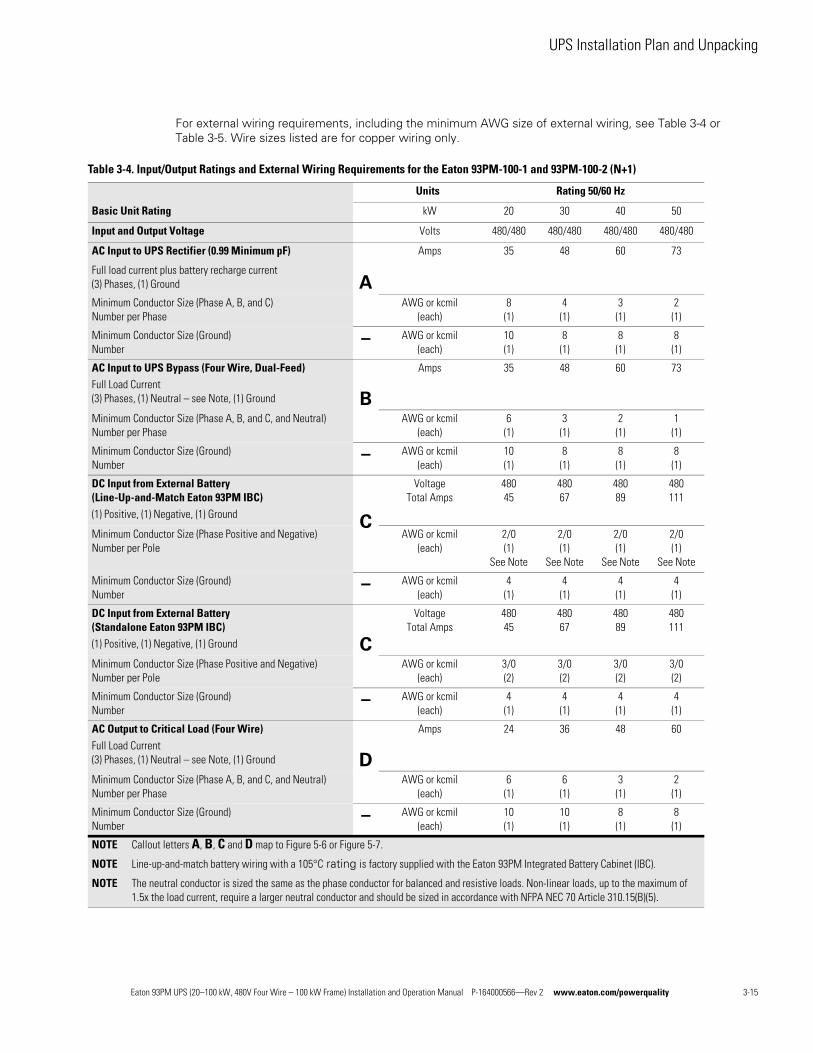
UPS Installation Plan and Unpacking
For external wiring requirements, including the minimum AWG size of external wiring, see Table 3-4 or Table 3-5. Wire sizes listed are for copper wiring only.
Table 3-4. Input/Output Ratings and External Wiring Requirements for the Eaton 93PM-100-1 and 93PM-100-2 (N+1)
Basic Unit Rating
Units Rating 50/60 Hz
kW 20 30 40 50
Input and Output Voltage Volts 480/480 480/480 480/480 480/480
AC Input to UPS Rectifier (0.99 Minimum pF)
Full load current plus battery recharge current(3) Phases, (1) Ground A
Amps 35 48 60 73
Minimum Conductor Size (Phase A, B, and C)Number per Phase
AWG or kcmil(each)
8(1)
4(1)
3(1)
2(1)
Minimum Conductor Size (Ground)Number
– AWG or kcmil(each)
10(1)
8(1)
8(1)
8(1)
AC Input to UPS Bypass (Four Wire, Dual-Feed)Full Load Current(3) Phases, (1) Neutral – see Note, (1) Ground B
Amps 35 48 60 73
Minimum Conductor Size (Phase A, B, and C, and Neutral)Number per Phase
AWG or kcmil(each)
6(1)
3(1)
2(1)
1(1)
Minimum Conductor Size (Ground)Number
– AWG or kcmil(each)
10(1)
8(1)
8(1)
8(1)
DC Input from External Battery(Line-Up-and-Match Eaton 93PM IBC)(1) Positive, (1) Negative, (1) Ground
C
VoltageTotal Amps
48045
48067
48089
480111
Minimum Conductor Size (Phase Positive and Negative)Number per Pole
AWG or kcmil(each)
2/0(1)
See Note
2/0(1)
See Note
2/0(1)
See Note
2/0(1)
See Note
Minimum Conductor Size (Ground)Number
– AWG or kcmil(each)
4(1)
4(1)
4(1)
4(1)
DC Input from External Battery (Standalone Eaton 93PM IBC)(1) Positive, (1) Negative, (1) Ground C
VoltageTotal Amps
48045
48067
48089
480111
Minimum Conductor Size (Phase Positive and Negative)Number per Pole
AWG or kcmil(each)
3/0(2)
3/0(2)
3/0(2)
3/0(2)
Minimum Conductor Size (Ground)Number
– AWG or kcmil(each)
4(1)
4(1)
4(1)
4(1)
AC Output to Critical Load (Four Wire)Full Load Current(3) Phases, (1) Neutral – see Note, (1) Ground D
Amps 24 36 48 60
Minimum Conductor Size (Phase A, B, and C, and Neutral)Number per Phase
AWG or kcmil(each)
6(1)
6(1)
3(1)
2(1)
Minimum Conductor Size (Ground)Number
– AWG or kcmil(each)
10(1)
10(1)
8(1)
8(1)
NOTE Callout letters A, B, C and D map to Figure 5-6 or Figure 5-7.
NOTE Line-up-and-match battery wiring with a 105°C rating is factory supplied with the Eaton 93PM Integrated Battery Cabinet (IBC).
NOTE The neutral conductor is sized the same as the phase conductor for balanced and resistive loads. Non-linear loads, up to the maximum of 1.5x the load current, require a larger neutral conductor and should be sized in accordance with NFPA NEC 70 Article 310.15(B)(5).
Eaton 93PM UPS (20–100 kW, 480V Four Wire – 100 kW Frame) Installation and Operation Manual P-164000566—Rev 2 www.eaton.com/powerquality 3-15
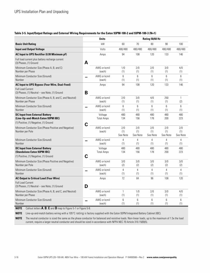
UPS Installation Plan and Unpacking
Table 3-5. Input/Output Ratings and External Wiring Requirements for the Eaton 93PM-100-2 and 93PM-100-3 (N+1)
Basic Unit Rating
Units Rating 50/60 Hz
kW 60 70 80 90 100
Input and Output Voltage Volts 480/480 480/480 480/480 480/480 480/480
AC Input to UPS Rectifier (0.99 Minimum pF)
Full load current plus battery recharge current(3) Phases, (1) Ground A
Amps 94 108 120 133 146
Minimum Conductor Size (Phase A, B, and C)Number per Phase
AWG or kcmil(each)
1/0(1)
2/0(1)
2/0(1)
3/0(1)
4/0(1)
Minimum Conductor Size (Ground)Number
– AWG or kcmil(each)
6(1)
6(1)
6(1)
6(1)
6(1)
AC Input to UPS Bypass (Four Wire, Dual-Feed)Full Load Current(3) Phases, (1) Neutral – see Note, (1) Ground B
Amps 94 108 120 133 146
Minimum Conductor Size (Phase A, B, and C, and Neutral)Number per Phase
AWG or kcmil(each)
2/0(1)
3/0(1)
4/0(1)
250(1)
1(2)
Minimum Conductor Size (Ground)Number
– AWG or kcmil(each)
6(1)
6(1)
6(1)
6(1)
6(1)
DC Input from External Battery (Line-Up-and-Match Eaton 93PM IBC)(1) Positive, (1) Negative, (1) Ground
C
VoltageTotal Amps
480134
480156
480178
480200
480223
Minimum Conductor Size (Phase Positive and Negative)Number per Pole
AWG or kcmil(each)
2/0(1)
See Note
2/0(1)
See Note
2/0(1)
See Note
2/0(1)
See Note
2/0(1)
See Note
Minimum Conductor Size (Ground)Number
– AWG or kcmil(each)
4(1)
4(1)
4(1)
4(1)
4(1)
DC Input from External Battery (Standalone Eaton 93PM IBC)(1) Positive, (1) Negative, (1) Ground C
VoltageTotal Amps
480134
480156
480178
480200
480223
Minimum Conductor Size (Phase Positive and Negative)Number per Pole
AWG or kcmil(each)
3/0(2)
3/0(2)
3/0(2)
3/0(2)
3/0(2)
Minimum Conductor Size (Ground)Number
– AWG or kcmil(each)
4(1)
4(1)
4(1)
4(1)
4(1)
AC Output to Critical Load (Four Wire)Full Load Current(3) Phases, (1) Neutral – see Note, (1) Ground D
Amps 72 84 96 108 120
Minimum Conductor Size (Phase A, B, and C, and Neutral)Number per Phase
AWG or kcmil(each)
1(1)
1/0(1)
2/0(1)
3/0(1)
4/0(1)
Minimum Conductor Size (Ground)Number
– AWG or kcmil(each)
6(1)
6(1)
6(1)
6(1)
6(1)
NOTE Callout letters A, B, C and D map to Figure 5-7 or Figure 5-8.
NOTE Line-up-and-match battery wiring with a 105°C rating is factory supplied with the Eaton 93PM Integrated Battery Cabinet (IBC).
NOTE The neutral conductor is sized the same as the phase conductor for balanced and resistive loads. Non-linear loads, up to the maximum of 1.5x the load current, require a larger neutral conductor and should be sized in accordance with NFPA NEC 70 Article 310.15(B)(5).
3-16 Eaton 93PM UPS (20–100 kW, 480V Four Wire – 100 kW Frame) Installation and Operation Manual P-164000566—Rev 2 www.eaton.com/powerquality
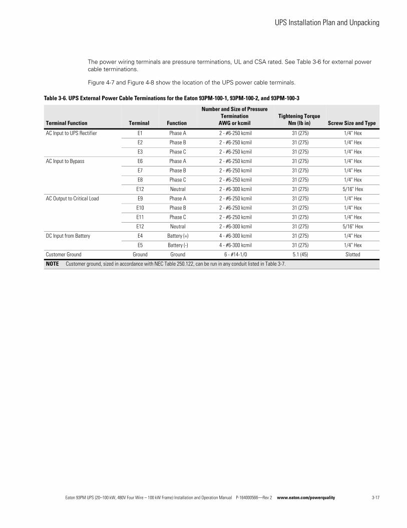
UPS Installation Plan and Unpacking
The power wiring terminals are pressure terminations, UL and CSA rated. See Table 3-6 for external power cable terminations.
Figure 4-7 and Figure 4-8 show the location of the UPS power cable terminals.
Table 3-6. UPS External Power Cable Terminations for the Eaton 93PM-100-1, 93PM-100-2, and 93PM-100-3
Terminal Function Terminal Function
Number and Size of Pressure Termination
AWG or kcmilTightening Torque
Nm (lb in) Screw Size and Type
AC Input to UPS Rectifier E1 Phase A 2 - #6-250 kcmil 31 (275) 1/4" Hex
E2 Phase B 2 - #6-250 kcmil 31 (275) 1/4" Hex
E3 Phase C 2 - #6-250 kcmil 31 (275) 1/4" Hex
AC Input to Bypass E6 Phase A 2 - #6-250 kcmil 31 (275) 1/4" Hex
E7 Phase B 2 - #6-250 kcmil 31 (275) 1/4" Hex
E8 Phase C 2 - #6-250 kcmil 31 (275) 1/4" Hex
E12 Neutral 2 - #6-300 kcmil 31 (275) 5/16" Hex
AC Output to Critical Load E9 Phase A 2 - #6-250 kcmil 31 (275) 1/4" Hex
E10 Phase B 2 - #6-250 kcmil 31 (275) 1/4" Hex
E11 Phase C 2 - #6-250 kcmil 31 (275) 1/4" Hex
E12 Neutral 2 - #6-300 kcmil 31 (275) 5/16" Hex
DC Input from Battery E4 Battery (+) 4 - #6-300 kcmil 31 (275) 1/4" Hex
E5 Battery (-) 4 - #6-300 kcmil 31 (275) 1/4" Hex
Customer Ground Ground Ground 6 - #14-1/0 5.1 (45) Slotted
NOTE Customer ground, sized in accordance with NEC Table 250.122, can be run in any conduit listed in Table 3-7.
Eaton 93PM UPS (20–100 kW, 480V Four Wire – 100 kW Frame) Installation and Operation Manual P-164000566—Rev 2 www.eaton.com/powerquality 3-17
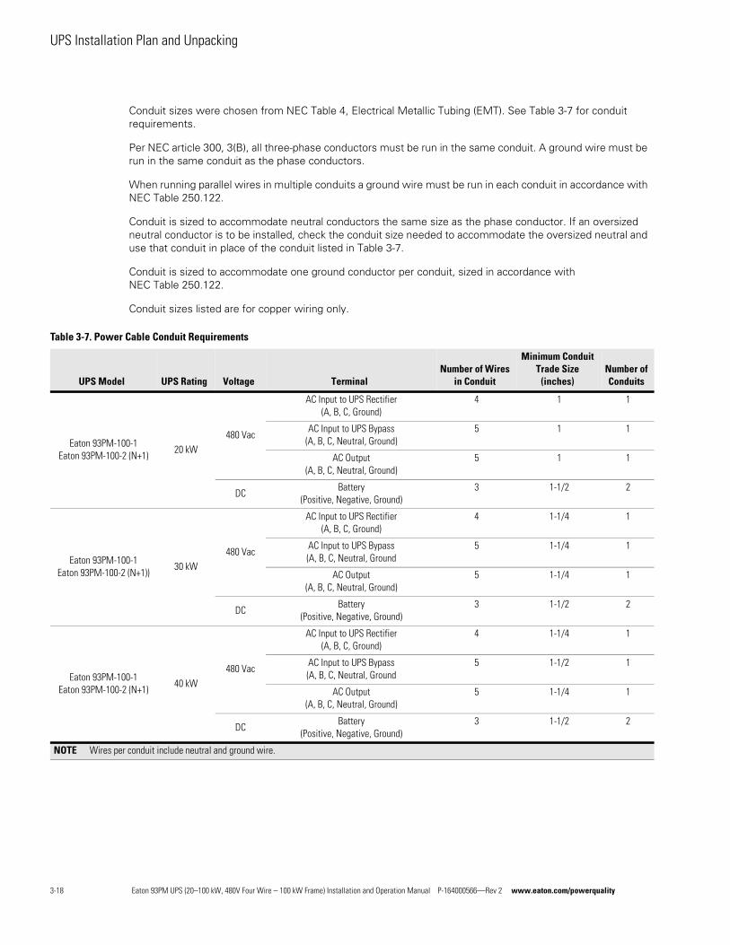
UPS Installation Plan and Unpacking
Conduit sizes were chosen from NEC Table 4, Electrical Metallic Tubing (EMT). See Table 3-7 for conduit requirements.
Per NEC article 300, 3(B), all three-phase conductors must be run in the same conduit. A ground wire must be run in the same conduit as the phase conductors.
When running parallel wires in multiple conduits a ground wire must be run in each conduit in accordance with NEC Table 250.122.
Conduit is sized to accommodate neutral conductors the same size as the phase conductor. If an oversized neutral conductor is to be installed, check the conduit size needed to accommodate the oversized neutral and use that conduit in place of the conduit listed in Table 3-7.
Conduit is sized to accommodate one ground conductor per conduit, sized in accordance with NEC Table 250.122.
Conduit sizes listed are for copper wiring only.
Table 3-7. Power Cable Conduit Requirements
UPS Model UPS Rating Voltage TerminalNumber of Wires
in Conduit
Minimum Conduit Trade Size
(inches)Number of Conduits
Eaton 93PM-100-1Eaton 93PM-100-2 (N+1)
20 kW480 Vac
AC Input to UPS Rectifier (A, B, C, Ground)
4 1 1
AC Input to UPS Bypass(A, B, C, Neutral, Ground)
5 1 1
AC Output(A, B, C, Neutral, Ground)
5 1 1
DCBattery
(Positive, Negative, Ground)3 1-1/2 2
Eaton 93PM-100-1Eaton 93PM-100-2 (N+1))
30 kW480 Vac
AC Input to UPS Rectifier (A, B, C, Ground)
4 1-1/4 1
AC Input to UPS Bypass(A, B, C, Neutral, Ground
5 1-1/4 1
AC Output(A, B, C, Neutral, Ground)
5 1-1/4 1
DCBattery
(Positive, Negative, Ground)3 1-1/2 2
Eaton 93PM-100-1Eaton 93PM-100-2 (N+1)
40 kW480 Vac
AC Input to UPS Rectifier (A, B, C, Ground)
4 1-1/4 1
AC Input to UPS Bypass(A, B, C, Neutral, Ground
5 1-1/2 1
AC Output(A, B, C, Neutral, Ground)
5 1-1/4 1
DCBattery
(Positive, Negative, Ground)3 1-1/2 2
NOTE Wires per conduit include neutral and ground wire.
3-18 Eaton 93PM UPS (20–100 kW, 480V Four Wire – 100 kW Frame) Installation and Operation Manual P-164000566—Rev 2 www.eaton.com/powerquality
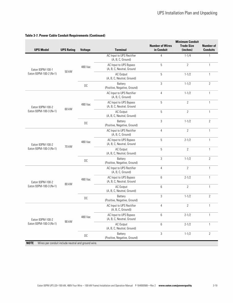
UPS Installation Plan and Unpacking
Eaton 93PM-100-1Eaton 93PM-100-2 (N+1)
50 kW480 Vac
AC Input to UPS Rectifier (A, B, C, Ground)
4 1-1/4 1
AC Input to UPS Bypass(A, B, C, Neutral, Ground
5 2 1
AC Output(A, B, C, Neutral, Ground)
5 1-1/2 1
DCBattery
(Positive, Negative, Ground)3 1-1/2 2
Eaton 93PM-100-2Eaton 93PM-100-3 (N+1)
60 kW480 Vac
AC Input to UPS Rectifier (A, B, C, Ground)
4 1-1/2 1
AC Input to UPS Bypass(A, B, C, Neutral, Ground
5 2 1
AC Output(A, B, C, Neutral, Ground)
5 2 1
DCBattery
(Positive, Negative, Ground)3 1-1/2 2
Eaton 93PM-100-2Eaton 93PM-100-3 (N+1)
70 kW480 Vac
AC Input to UPS Rectifier (A, B, C, Ground)
4 2 1
AC Input to UPS Bypass(A, B, C, Neutral, Ground
5 2-1/2 1
AC Output(A, B, C, Neutral, Ground)
5 2 1
DCBattery
(Positive, Negative, Ground)3 1-1/2 2
Eaton 93PM-100-2Eaton 93PM-100-3 (N+1)
80 kW480 Vac
AC Input to UPS Rectifier (A, B, C, Ground)
4 2 1
AC Input to UPS Bypass(A, B, C, Neutral, Ground
6 2-1/2 1
AC Output(A, B, C, Neutral, Ground)
6 2 1
DCBattery
(Positive, Negative, Ground)3 1-1/2 2
Eaton 93PM-100-2Eaton 93PM-100-3 (N+1)
90 kW480 Vac
AC Input to UPS Rectifier (A, B, C, Ground))
4 2 1
AC Input to UPS Bypass(A, B, C, Neutral, Ground
6 2-1/2 1
AC Output(A, B, C, Neutral, Ground)
6 2-1/2 1
DCBattery
(Positive, Negative, Ground)3 1-1/2 2
Table 3-7. Power Cable Conduit Requirements (Continued)
UPS Model UPS Rating Voltage TerminalNumber of Wires
in Conduit
Minimum Conduit Trade Size
(inches)Number of Conduits
NOTE Wires per conduit include neutral and ground wire.
Eaton 93PM UPS (20–100 kW, 480V Four Wire – 100 kW Frame) Installation and Operation Manual P-164000566—Rev 2 www.eaton.com/powerquality 3-19
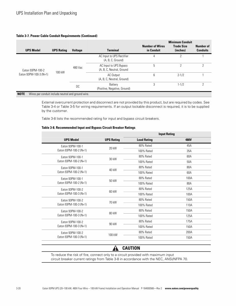
UPS Installation Plan and Unpacking
External overcurrent protection and disconnect are not provided by this product, but are required by codes. See Table 3-4 or Table 3-5 for wiring requirements. If an output lockable disconnect is required, it is to be supplied by the customer.
Table 3-8 lists the recommended rating for input and bypass circuit breakers.
CAUTIONTo reduce the risk of fire, connect only to a circuit provided with maximum input circuit breaker current ratings from Table 3-8 in accordance with the NEC, ANSI/NFPA 70.
Eaton 93PM-100-2Eaton 93PM-100-3 (N+1)
100 kW480 Vac
AC Input to UPS Rectifier (A, B, C, Ground)
4 2 1
AC Input to UPS Bypass(A, B, C, Neutral, Ground
5 2 2
AC Output(A, B, C, Neutral, Ground)
6 2-1/2 1
DCBattery
(Positive, Negative, Ground)3 1-1/2 2
Table 3-7. Power Cable Conduit Requirements (Continued)
UPS Model UPS Rating Voltage TerminalNumber of Wires
in Conduit
Minimum Conduit Trade Size
(inches)Number of Conduits
NOTE Wires per conduit include neutral and ground wire.
Table 3-8. Recommended Input and Bypass Circuit Breaker Ratings
Input Rating
UPS Model UPS Rating Load Rating 480V
Eaton 93PM-100-1Eaton 93PM-100-2 (N+1)
20 kW80% Rated 45A
100% Rated 35A
Eaton 93PM-100-1Eaton 93PM-100-2 (N+1)
30 kW80% Rated 60A
100% Rated 50A
Eaton 93PM-100-1Eaton 93PM-100-2 (N+1)
40 kW80% Rated 80A
100% Rated 60A
Eaton 93PM-100-1Eaton 93PM-100-2 (N+1)
50 kW80% Rated 100A
100% Rated 80A
Eaton 93PM-100-2Eaton 93PM-100-3 (N+1)
60 kW80% Rated 125A
100% Rated 100A
Eaton 93PM-100-2Eaton 93PM-100-3 (N+1)
70 kW80% Rated 150A
100% Rated 110A
Eaton 93PM-100-2Eaton 93PM-100-3 (N+1)
80 kW80% Rated 150A
100% Rated 125A
Eaton 93PM-100-2Eaton 93PM-100-3 (N+1)
90 kW80% Rated 175A
100% Rated 150A
Eaton 93PM-100-2Eaton 93PM-100-3 (N+1)
100 kW80% Rated 200A
100% Rated 150A
3-20 Eaton 93PM UPS (20–100 kW, 480V Four Wire – 100 kW Frame) Installation and Operation Manual P-164000566—Rev 2 www.eaton.com/powerquality
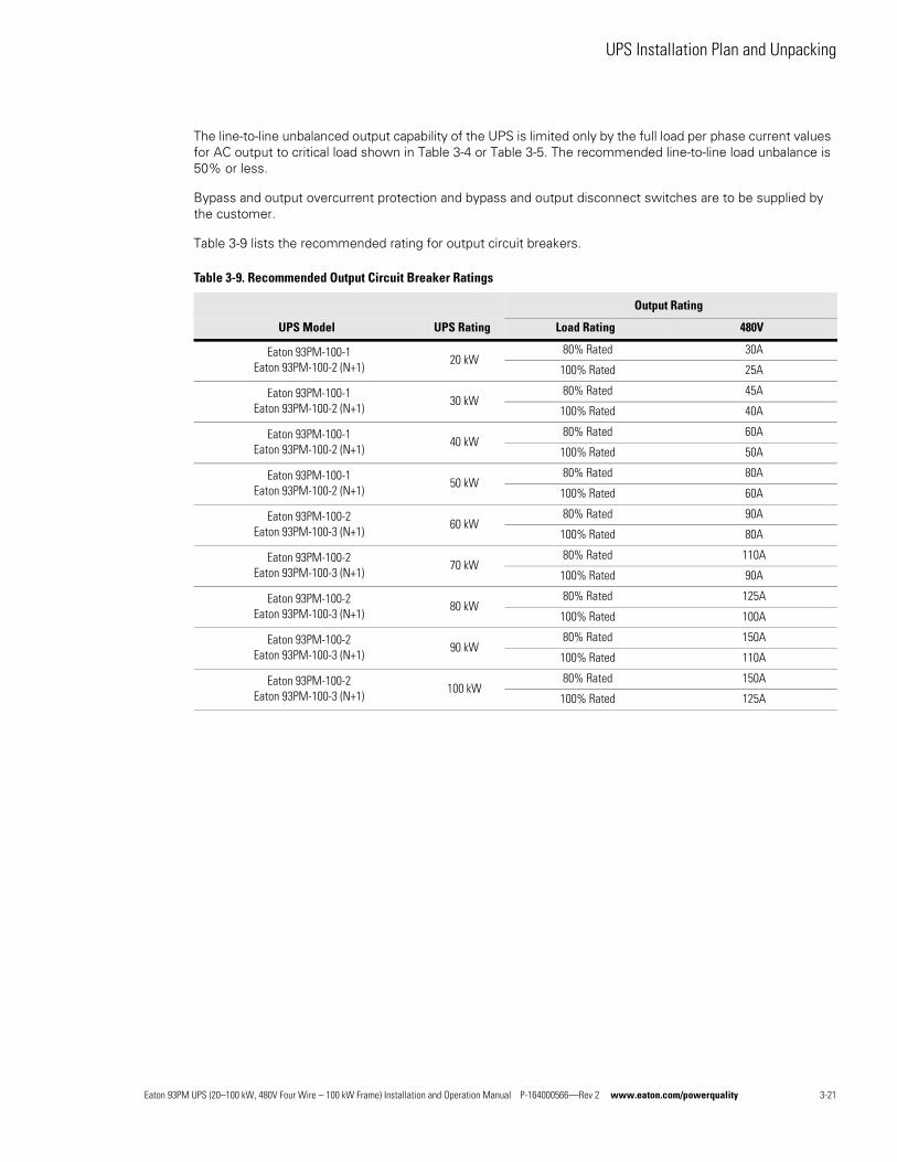
UPS Installation Plan and Unpacking
The line-to-line unbalanced output capability of the UPS is limited only by the full load per phase current values for AC output to critical load shown in Table 3-4 or Table 3-5. The recommended line-to-line load unbalance is 50% or less.
Bypass and output overcurrent protection and bypass and output disconnect switches are to be supplied by the customer.
Table 3-9 lists the recommended rating for output circuit breakers.
Table 3-9. Recommended Output Circuit Breaker Ratings
Output Rating
UPS Model UPS Rating Load Rating 480V
Eaton 93PM-100-1Eaton 93PM-100-2 (N+1)
20 kW80% Rated 30A
100% Rated 25A
Eaton 93PM-100-1Eaton 93PM-100-2 (N+1)
30 kW80% Rated 45A
100% Rated 40A
Eaton 93PM-100-1Eaton 93PM-100-2 (N+1)
40 kW80% Rated 60A
100% Rated 50A
Eaton 93PM-100-1Eaton 93PM-100-2 (N+1)
50 kW80% Rated 80A
100% Rated 60A
Eaton 93PM-100-2Eaton 93PM-100-3 (N+1)
60 kW80% Rated 90A
100% Rated 80A
Eaton 93PM-100-2Eaton 93PM-100-3 (N+1)
70 kW80% Rated 110A
100% Rated 90A
Eaton 93PM-100-2Eaton 93PM-100-3 (N+1)
80 kW80% Rated 125A
100% Rated 100A
Eaton 93PM-100-2Eaton 93PM-100-3 (N+1)
90 kW80% Rated 150A
100% Rated 110A
Eaton 93PM-100-2Eaton 93PM-100-3 (N+1)
100 kW80% Rated 150A
100% Rated 125A
Eaton 93PM UPS (20–100 kW, 480V Four Wire – 100 kW Frame) Installation and Operation Manual P-164000566—Rev 2 www.eaton.com/powerquality 3-21
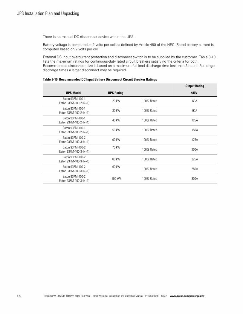
UPS Installation Plan and Unpacking
There is no manual DC disconnect device within the UPS.
Battery voltage is computed at 2 volts per cell as defined by Article 480 of the NEC. Rated battery current is computed based on 2 volts per cell.
External DC input overcurrent protection and disconnect switch is to be supplied by the customer. Table 3-10 lists the maximum ratings for continuous-duty rated circuit breakers satisfying the criteria for both. Recommended disconnect size is based on a maximum full load discharge time less than 3 hours. For longer discharge times a larger disconnect may be required.
Table 3-10. Recommended DC Input Battery Disconnect Circuit Breaker Ratings
Output Rating
UPS Model UPS Rating 480V
Eaton 93PM-100-1Eaton 93PM-100-2 (N+1)
20 kW 100% Rated 60A
Eaton 93PM-100-1Eaton 93PM-100-2 (N+1)
30 kW 100% Rated 90A
Eaton 93PM-100-1Eaton 93PM-100-2 (N+1)
40 kW 100% Rated 125A
Eaton 93PM-100-1Eaton 93PM-100-2 (N+1)
50 kW 100% Rated 150A
Eaton 93PM-100-2Eaton 93PM-100-3 (N+1)
60 kW 100% Rated 175A
Eaton 93PM-100-2Eaton 93PM-100-3 (N+1)
70 kW100% Rated 200A
Eaton 93PM-100-2Eaton 93PM-100-3 (N+1)
80 kW 100% Rated 225A
Eaton 93PM-100-2Eaton 93PM-100-3 (N+1)
90 kW100% Rated 250A
Eaton 93PM-100-2Eaton 93PM-100-3 (N+1)
100 kW 100% Rated 300A
3-22 Eaton 93PM UPS (20–100 kW, 480V Four Wire – 100 kW Frame) Installation and Operation Manual P-164000566—Rev 2 www.eaton.com/powerquality
UPS Installation Plan and Unpacking
3.2.4 UPS System Interface Wiring Preparation
Control wiring for features and options should be connected at the customer interface terminal blocks located inside the UPS.
WARNINGDo not directly connect relay contacts to the mains related circuits. Reinforced insulation to the mains is required.
Read and understand the following notes while planning and performing the installation:
l Use Class 1 wiring methods (as defined by the NEC) for interface wiring from 30V to 600V. The wire should be rated for 600V, 1A minimum. 12 AWG maximum wire size.
l Use Class 2 wiring methods (as defined by the NEC) for interface wiring up to 30V. The wire should be rated for 24V, 1A minimum.
l Because of the battery shunt trip wiring route in the UPS cabinet, the wire should be rated for a minimum of 600V.
l Use twisted-pair wires for each input and return or common.
l All interface wiring and conduit is to be supplied by the customer.
l When installing external interface wiring between a building alarm, relay output, battery breaker trip, or Minislot and the UPS interface terminals, conduit must be installed between each device and the UPS cabinet.
l If using conduit, install the interface wiring in separate conduit from the power wiring.
l All building alarm inputs require an isolated normally-open contact or switch (rated at 24 Vdc, 20 mA minimum) connected between the alarm input and common terminal. All control wiring and switch contacts are customer-supplied.
l LAN and telephone drops for use with Minislot connectivity cards must be supplied by the customer.
l The UPS battery detect signal wiring from an UPS building alarm must be connected to the battery disconnect device.
l Program the battery detect building alarm to read battery open and for normally open contacts.
l A supplemental 48 Vdc shunt trip signal for the battery disconnect device is provided, but is not required for normal operation.
l Battery detect and 48 Vdc shunt trip wiring should be a minimum of 18 AWG.
l The REPO feature opens all switchgear in the UPS cabinet and isolates power from your critical load. Local electrical codes may also require tripping upstream protective devices to the UPS.
l The REPO switch must be a latching-type switch not tied to any other circuits.
l A jumper wire must be connected between pins 3 and 4 on the REPO terminal block if using a normally-closed REPO switch.
l REPO wiring should be a minimum of 18 AWG and a maximum of 16 AWG.
l The REPO switch wiring must be in accordance with NEC Article 725 Class 2 requirements.
NOTE Refer to the Eaton 93PM Sidecar Integrated Accessory Cabinet-Bypass Installation and Operation (50 kW and 100 kW SIAC-B) Manual, listed in paragraph 1.8, for SIAC-B interface wiring preparation and requirements.
Eaton 93PM UPS (20–100 kW, 480V Four Wire – 100 kW Frame) Installation and Operation Manual P-164000566—Rev 2 www.eaton.com/powerquality 3-23
UPS Installation Plan and Unpacking
l The maximum distance between the REPO and the UPS cannot exceed 150m (500 ft).
l Alarm relay contacts have a maximum current rating of 5A and a switched voltage rating of 30 Vac.
l Alarm relay wiring should be a minimum of 18 AWG (recommended 18 AWG).
3.3 Inspecting and Unpacking the UPS CabinetsThe cabinet is shipped bolted to a metal and wood pallet (see Figure 3-10 or Figure 3-11) with outer protective packaging material covering the cabinet.
WARNINGThe UPS cabinet is heavy (see Table 3-2). If unpacking and unloading instructions are not closely followed, the cabinet may tip and cause serious injury.
1. Carefully inspect the outer packaging for evidence of damage during transit.
CAUTIONDo not install a damaged cabinet. Report any damage to the carrier and contact an Eaton service representative immediately.
2. Use a forklift or pallet jack to move the packaged cabinet to the installation site, or as close as possible, before unpacking. If possible, move the cabinet using the pallet. Insert the forklift or pallet jack forks between the supports on the bottom of the pallet (see Figure 3-6 or Figure 3-7 for the UPS cabinet center of gravity measurements).
CAUTIONDo not tilt the UPS cabinet more than 10° from vertical or the cabinet may tip over.
3. Set the pallet on a firm, level surface, allowing a minimum clearance of 3m (10 ft) on each side for removing the cabinet from the pallet.
4. Remove the protective packaging material from the cabinet and recycle in a responsible manner. Retain any parts kits packaged with the cabinet.
5. Inspect the contents for any evidence of physical damage, and compare each item with the Bill of Lading. If damage has occurred or shortages are evident, contact an Eaton service representative immediately to determine the extent of the damage and its impact on further installation.
NOTE Startup and operational checks must be performed by an authorized Eaton Customer Service Engineer, or the warranty terms specified on page W-1 become void. This service is offered as part of the sales contract for the UPS. Contact an Eaton service representative in advance (a minimum two-week notice is required) to reserve a preferred startup date.
NOTE For the following step, verify that the forklift or pallet jack is rated to handle the weight of the cabinet (see Table 3-2 for cabinet weight).
NOTE While waiting for installation, protect the unpacked cabinet from moisture, dust, and other harmful contaminants. Failure to store and protect the UPS properly may void the warranty.
3-24 Eaton 93PM UPS (20–100 kW, 480V Four Wire – 100 kW Frame) Installation and Operation Manual P-164000566—Rev 2 www.eaton.com/powerquality
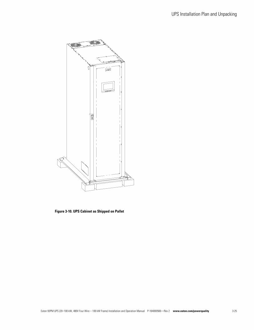
UPS Installation Plan and Unpacking
Figure 3-10. UPS Cabinet as Shipped on Pallet
Eaton 93PM UPS (20–100 kW, 480V Four Wire – 100 kW Frame) Installation and Operation Manual P-164000566—Rev 2 www.eaton.com/powerquality 3-25
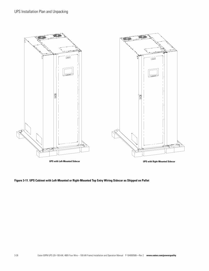
UPS Installation Plan and Unpacking
Figure 3-11. UPS Cabinet with Left-Mounted or Right-Mounted Top Entry Wiring Sidecar as Shipped on Pallet
UPS with Left-Mounted Sidecar UPS with Right-Mounted Sidecar
3-26 Eaton 93PM UPS (20–100 kW, 480V Four Wire – 100 kW Frame) Installation and Operation Manual P-164000566—Rev 2 www.eaton.com/powerquality
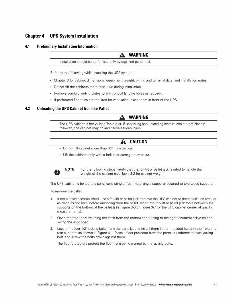
Chapter 4 UPS System Installation
4.1 Preliminary Installation Information
WARNINGInstallation should be performed only by qualified personnel.
Refer to the following while installing the UPS system:
l Chapter 3 for cabinet dimensions, equipment weight, wiring and terminal data, and installation notes.
l Do not tilt the cabinets more than ±10 during installation.
l Remove conduit landing plates to add conduit landing holes as required.
l If perforated floor tiles are required for ventilation, place them in front of the UPS.
4.2 Unloading the UPS Cabinet from the Pallet
WARNINGThe UPS cabinet is heavy (see Table 3-2). If unpacking and unloading instructions are not closely followed, the cabinet may tip and cause serious injury.
CAUTIONl Do not tilt cabinet more than 10° from vertical.
l Lift the cabinets only with a forklift or damage may occur.
The UPS cabinet is bolted to a pallet consisting of four metal angle supports secured to two wood supports.
To remove the pallet:
1. If not already accomplished, use a forklift or pallet jack to move the UPS cabinet to the installation area, or as close as possible, before unloading from the pallet. Insert the forklift or pallet jack forks between the supports on the bottom of the pallet (see Figure 3-6 or Figure 3-7 for the UPS cabinet center of gravity measurements).
2. Open the front door by lifting the latch from the bottom and turning to the right (counterclockwise) and swing the door open.
3. Locate the four 1/2" jacking bolts from the parts kit and install them in the threaded holes in the front and rear supports as shown in Figure 4-1. Place a floor protector from the parts kit underneath each jacking bolt, and screw the bolts down against them.
The floor protectors protect the floor from being marred by the jacking bolts.
NOTE For the following steps, verify that the forklift or pallet jack is rated to handle the weight of the cabinet (see Table 3-2 for cabinet weight).
Eaton 93PM UPS (20–100 kW, 480V Four Wire – 100 kW Frame) Installation and Operation Manual P-164000566—Rev 2 www.eaton.com/powerquality 4-1
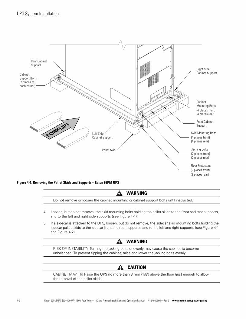
UPS System Installation
Figure 4-1. Removing the Pallet Skids and Supports – Eaton 93PM UPS
WARNINGDo not remove or loosen the cabinet mounting or cabinet support bolts until instructed.
4. Loosen, but do not remove, the skid mounting bolts holding the pallet skids to the front and rear supports, and to the left and right side supports (see Figure 4-1).
5. If a sidecar is attached to the UPS, loosen, but do not remove, the sidecar skid mounting bolts holding the sidecar pallet skids to the sidecar front and rear supports, and to the left and right supports (see Figure 4-1 and Figure 4-2).
WARNINGRISK OF INSTABILITY. Turning the jacking bolts unevenly may cause the cabinet to become unbalanced. To prevent tipping the cabinet, raise and lower the jacking bolts evenly.
CAUTIONCABINET MAY TIP. Raise the UPS no more than 3 mm (1/8") above the floor (just enough to allow the removal of the pallet skids).
CabinetMounting Bolts(4 places front)(4 places rear)
Pallet Skid
Skid Mounting Bolts(4 places front)(4 places rear)
Floor Protectors(2 places front)(2 places rear)
Right SideCabinet Support
Rear CabinetSupport
Jacking Bolts(2 places front)(2 places rear)
Front CabinetSupport
CabinetSupport Bolts(2 places ateach corner)
Left SideCabinet Support
4-2 Eaton 93PM UPS (20–100 kW, 480V Four Wire – 100 kW Frame) Installation and Operation Manual P-164000566—Rev 2 www.eaton.com/powerquality
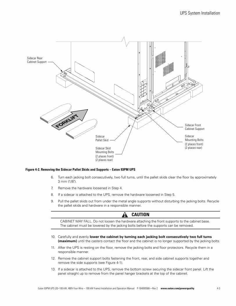
UPS System Installation
Figure 4-2. Removing the Sidecar Pallet Skids and Supports – Eaton 93PM UPS
6. Turn each jacking bolt consecutively, two full turns, until the pallet skids clear the floor by approximately 3 mm (1/8").
7. Remove the hardware loosened in Step 4.
8. If a sidecar is attached to the UPS, remove the hardware loosened in Step 5.
9. Pull the pallet skids out from under the metal angle supports without disturbing the jacking bolts. Recycle the pallet skids and hardware in a responsible manner.
CAUTIONCABINET MAY FALL. Do not loosen the hardware attaching the front supports to the cabinet base. The cabinet must be lowered by the jacking bolts before the supports can be removed.
10. Carefully and evenly lower the cabinet by turning each jacking bolt consecutively two full turns
(maximum) until the casters contact the floor and the cabinet is no longer supported by the jacking bolts.
11. After the UPS is resting on the floor, remove the jacking bolts and floor protectors. Recycle them in a responsible manner.
12. Remove the cabinet support bolts fastening the front, rear, and side cabinet supports together and remove the side supports (see Figure 4-1).
13. If a sidecar is attached to the UPS, remove the bottom screw securing the sidecar front panel. Lift the panel straight up to remove from the panel hanger brackets at the top of the cabinet.
SidecarMounting Bolts(2 places front)(2 places rear)
SidecarPallet Skid
Sidecar SkidMounting Bolts(2 places front)(2 places rear)
Sidecar RearCabinet Support
Sidecar FrontCabinet Support
Eaton 93PM UPS (20–100 kW, 480V Four Wire – 100 kW Frame) Installation and Operation Manual P-164000566—Rev 2 www.eaton.com/powerquality 4-3
UPS System Installation
14. If a sidecar is attached to the UPS, remove the sidecar mounting bolts holding the front and rear sidecar supports to the cabinet base (see Figure 4-2).
15. Remove the cabinet mounting bolts holding the front and rear supports to the cabinet base (see Figure 4-1).
16. If installing the cabinet permanently, retain the cabinet mounting bolts; otherwise, recycle the bolts along with the support brackets in a responsible manner.
17. Close the door and secure the latch.
18. If a sidecar is attached to the UPS, remove the screws securing sidecar rear shipping bracket. Remove the bracket and reinstall the screws (see Figure 4-3).
19. If the leveling feet are not retracted, turn all four leveling feet until they are retracted as far into the cabinet as possible.
CAUTIONTo prevent tipping when rolling the cabinet, push the cabinet from the rear whenever possible.
20. Roll the cabinet to the final installation location.
21. Secure the UPS in position by lowering the leveling feet until the cabinet is level and locked in place.
22. Locate the top splice bracket shipped with the IBC.
23. Remove the screws along each adjacent cabinet top panel securing the top panels. Retain the hardware for later use.
24. Install the top splice bracket between the adjacent cabinet and secure the tie strap with retained hardware.
25. If permanently mounting the UPS using the left and right side floor mounting brackets, proceed to Step 26; if using the front and rear floor mounting brackets, proceed to Step 30; otherwise, proceed to Step 33.
26. Locate the left and right side floor mounting brackets from the floor mounting kit.
27. Using the retained cabinet mounting bolts, install the floor mounting brackets to the left and right side of the UPS with the angle facing outward.
28. Secure the cabinet to the floor with customer-supplied hardware.
29. Proceed to paragraph 4.3.
30. Locate the front and back floor mounting brackets from the floor mounting kit.
31. Using the retained cabinet mounting bolts, install the floor mounting brackets to the front and rear of the UPS with the angle facing outward.
32. Secure the cabinet to the floor with customer-supplied hardware.
NOTE Use the leveling feet to level and lock the cabinet in place.
NOTE Either front and back floor mounting brackets or left and right side floor mounting brackets are available for permanently mounting the UPS.
4-4 Eaton 93PM UPS (20–100 kW, 480V Four Wire – 100 kW Frame) Installation and Operation Manual P-164000566—Rev 2 www.eaton.com/powerquality
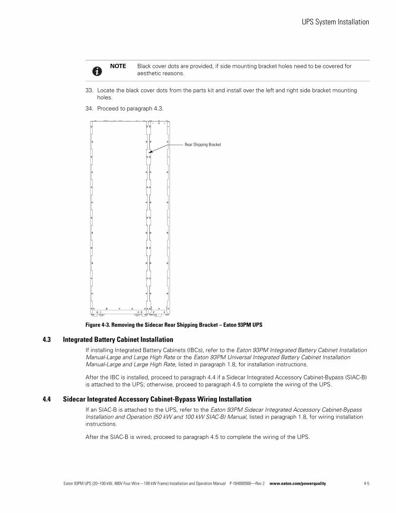
UPS System Installation
33. Locate the black cover dots from the parts kit and install over the left and right side bracket mounting holes.
34. Proceed to paragraph 4.3.
Figure 4-3. Removing the Sidecar Rear Shipping Bracket – Eaton 93PM UPS
4.3 Integrated Battery Cabinet InstallationIf installing Integrated Battery Cabinets (IBCs), refer to the Eaton 93PM Integrated Battery Cabinet Installation Manual-Large and Large High Rate or the Eaton 93PM Universal Integrated Battery Cabinet Installation Manual-Large and Large High Rate, listed in paragraph 1.8, for installation instructions.
After the IBC is installed, proceed to paragraph 4.4 if a Sidecar Integrated Accessory Cabinet-Bypass (SIAC-B) is attached to the UPS; otherwise, proceed to paragraph 4.5 to complete the wiring of the UPS.
4.4 Sidecar Integrated Accessory Cabinet-Bypass Wiring InstallationIf an SIAC-B is attached to the UPS, refer to the Eaton 93PM Sidecar Integrated Accessory Cabinet-Bypass Installation and Operation (50 kW and 100 kW SIAC-B) Manual, listed in paragraph 1.8, for wiring installation instructions.
After the SIAC-B is wired, proceed to paragraph 4.5 to complete the wiring of the UPS.
NOTE Black cover dots are provided, if side mounting bracket holes need to be covered for aesthetic reasons.
Rear Shipping Bracket
Eaton 93PM UPS (20–100 kW, 480V Four Wire – 100 kW Frame) Installation and Operation Manual P-164000566—Rev 2 www.eaton.com/powerquality 4-5
UPS System Installation
4.5 External AC Power Wiring InstallationTo install wiring:
1. Open the front door by lifting the latch from the bottom and turning to the right (counterclockwise) and swing the door open.
2. Remove the screws securing the bottom internal safety shield panel and remove the panel to gain access to the input, output, and battery power wiring terminals. Retain the hardware for later use.
3. If wiring the UPS using the top entry sidecar, proceed to Step 7; otherwise proceed to Step 4.
4. Bottom Entry Wiring. Remove the bottom conduit plate (see Figure 4-4) from the inside bottom of the UPS. Identify all conduit requirements and mark their location. Drill and punch all conduit holes in the bottom conduit plate prior to mounting on the UPS. Install the conduit plate and install all conduit runs into the plate. Pull the wiring through conduit into the wiring area.
5. Route the input and output cables through the bottom of the cabinet to the UPS terminals. See Figure 4-4 for wiring access information, and Figure 4-7 for terminal locations.
6. Proceed to Step 11.
7. If not already accomplished, remove the bottom screw securing the sidecar front panel. Lift the panel straight up to remove from the panel hanger brackets at the top of the cabinet.
8. Remove the screws securing the sidecar internal safety shield panel and remove the panel to gain access to the interior of the sidecar and the UPS inter-cabinet wiring access pass-through. Retain the hardware for later use.
9. Top Entry Wiring. Remove the top conduit plate (see Figure 4-5) from the top of the sidecar. Identify all conduit requirements and mark their location. Drill and punch all conduit holes in the top conduit plate prior to mounting on the sidecar. Install the conduit plate and install all conduit runs into the plate. Pull the wiring through the conduit into the wiring area.
10. Route the input and output cables through the top of the UPS sidecar and the UPS inter-cabinet wiring access pass-through to the UPS terminals. See Figure 4-5 and Figure 4-6 for wiring access information, and Figure 4-7 for terminal locations.
11. Connect phase A, B, and C rectifier input power wiring from the utility source to the rectifier input terminals. See paragraph 3.2.2 for wiring and termination requirements.
For a detailed view of the UPS terminal blocks, see Figure 4-8.
12. Connect phase A, B, and C, and Neutral bypass input power wiring from the utility source to the bypass input terminals. See paragraph 3.2.2 for wiring and termination requirements.
For a detailed view of the UPS terminal blocks, see Figure 4-8.
13. If wiring an external parallel system, proceed to Step 14; otherwise, proceed to Step 16.
CAUTIONExternal parallel system wiring length should be in accordance with Figure 3-9, to ensure approximately equal current sharing when in Bypass mode.
14. Connect phase A, B, and C power wiring from the output terminals of each UPS to the tie cabinet.
For a detailed view of the UPS terminal blocks, see Figure 4-8.
15. Proceed to Step 17.
4-6 Eaton 93PM UPS (20–100 kW, 480V Four Wire – 100 kW Frame) Installation and Operation Manual P-164000566—Rev 2 www.eaton.com/powerquality
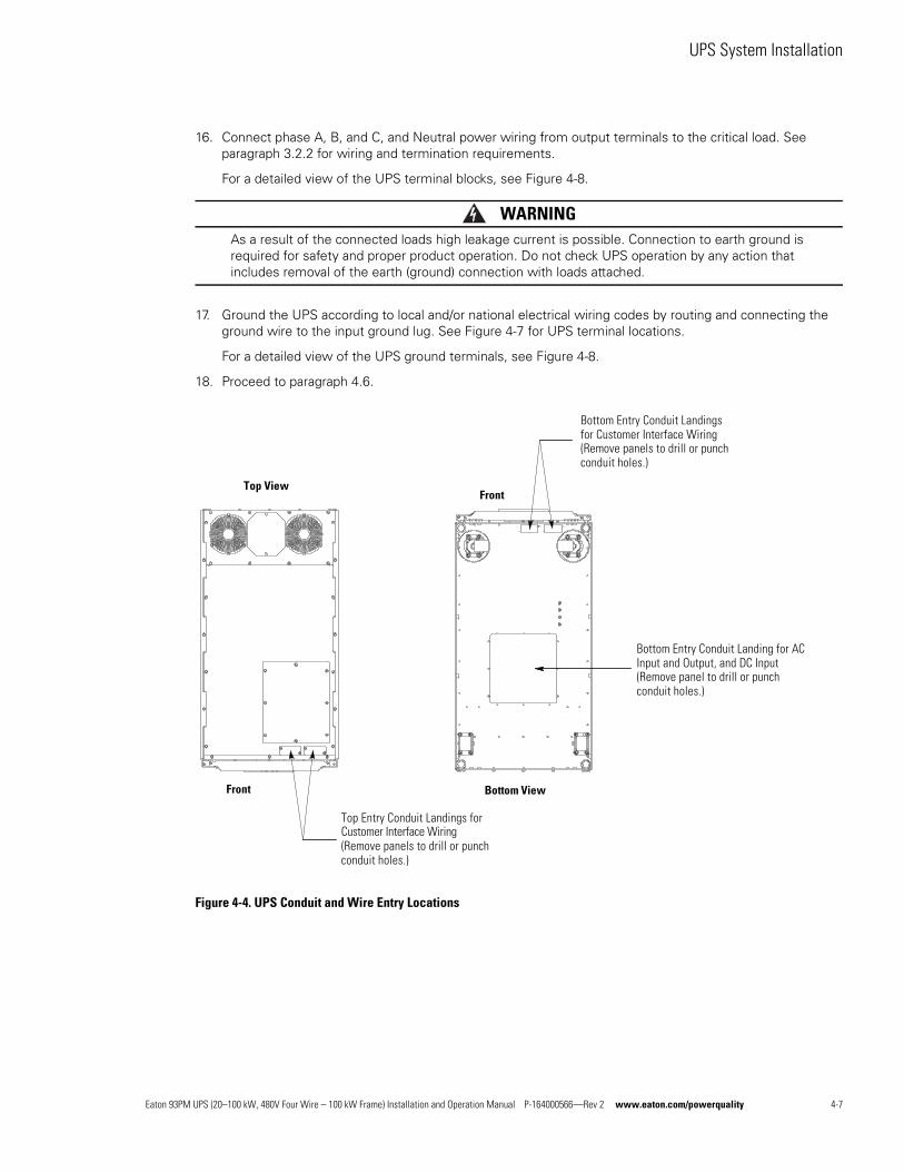
UPS System Installation
16. Connect phase A, B, and C, and Neutral power wiring from output terminals to the critical load. See paragraph 3.2.2 for wiring and termination requirements.
For a detailed view of the UPS terminal blocks, see Figure 4-8.
WARNINGAs a result of the connected loads high leakage current is possible. Connection to earth ground is required for safety and proper product operation. Do not check UPS operation by any action that includes removal of the earth (ground) connection with loads attached.
17. Ground the UPS according to local and/or national electrical wiring codes by routing and connecting the ground wire to the input ground lug. See Figure 4-7 for UPS terminal locations.
For a detailed view of the UPS ground terminals, see Figure 4-8.
18. Proceed to paragraph 4.6.
Figure 4-4. UPS Conduit and Wire Entry Locations
Bottom Entry Conduit Landing for ACInput and Output, and DC Input(Remove panel to drill or punchconduit holes.)
Front
Top View
Top Entry Conduit Landings forCustomer Interface Wiring(Remove panels to drill or punchconduit holes.)
Bottom Entry Conduit Landingsfor Customer Interface Wiring(Remove panels to drill or punchconduit holes.)
Front
Bottom View
Eaton 93PM UPS (20–100 kW, 480V Four Wire – 100 kW Frame) Installation and Operation Manual P-164000566—Rev 2 www.eaton.com/powerquality 4-7
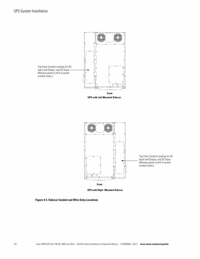
UPS System Installation
Figure 4-5. Sidecar Conduit and Wire Entry Locations
Top Entry Conduit Landing for ACInput and Output, and DC Input(Remove panel to drill or punchconduit holes.)
Front
UPS with Right -Mounted Sidecar
Top Entry Conduit Landing for ACInput and Output, and DC Input(Remove panel to drill or punchconduit holes.)
UPSwith Left-Mounted Sidecar
Front
4-8 Eaton 93PM UPS (20–100 kW, 480V Four Wire – 100 kW Frame) Installation and Operation Manual P-164000566—Rev 2 www.eaton.com/powerquality
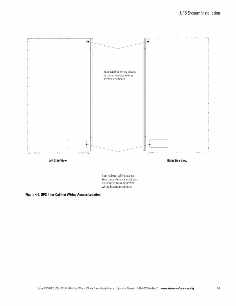
UPS System Installation
Figure 4-6. UPS Inter-Cabinet Wiring Access Location
Inter-cabinet wiring accessto route interface wiringbetween cabinets.
Inter-cabinet wiring accessknockouts. Remove knockoutsas required to route powerwiring between cabinets.
Left Side View Right Side View
Eaton 93PM UPS (20–100 kW, 480V Four Wire – 100 kW Frame) Installation and Operation Manual P-164000566—Rev 2 www.eaton.com/powerquality 4-9
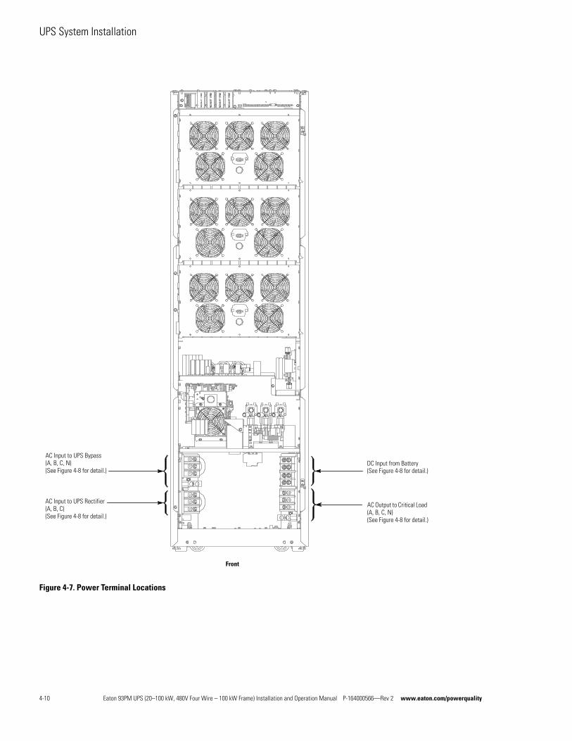
UPS System Installation
Figure 4-7. Power Terminal Locations
DC Input from Battery(See Figure 4-8 for detail.)
AC Input to UPS Rectifier (A, B, C)(See Figure 4-8 for detail.)
Front
AC Output to Critical Load (A, B, C, N)(See Figure 4-8 for detail.)
AC Input to UPS Bypass (A, B, C, N)(See Figure 4-8 for detail.)
4-10 Eaton 93PM UPS (20–100 kW, 480V Four Wire – 100 kW Frame) Installation and Operation Manual P-164000566—Rev 2 www.eaton.com/powerquality
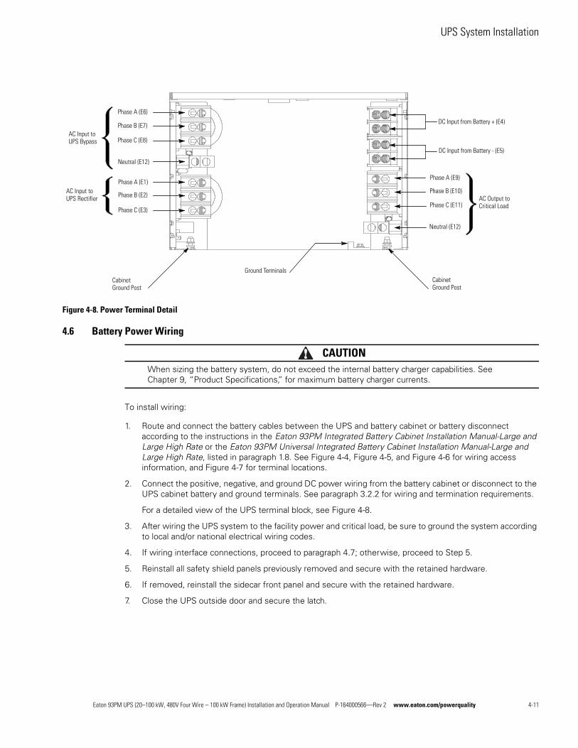
UPS System Installation
Figure 4-8. Power Terminal Detail
4.6 Battery Power Wiring
CAUTIONWhen sizing the battery system, do not exceed the internal battery charger capabilities. See Chapter 9, “Product Specifications,” for maximum battery charger currents.
To install wiring:
1. Route and connect the battery cables between the UPS and battery cabinet or battery disconnect according to the instructions in the Eaton 93PM Integrated Battery Cabinet Installation Manual-Large and Large High Rate or the Eaton 93PM Universal Integrated Battery Cabinet Installation Manual-Large and Large High Rate, listed in paragraph 1.8. See Figure 4-4, Figure 4-5, and Figure 4-6 for wiring access information, and Figure 4-7 for terminal locations.
2. Connect the positive, negative, and ground DC power wiring from the battery cabinet or disconnect to the UPS cabinet battery and ground terminals. See paragraph 3.2.2 for wiring and termination requirements.
For a detailed view of the UPS terminal block, see Figure 4-8.
3. After wiring the UPS system to the facility power and critical load, be sure to ground the system according to local and/or national electrical wiring codes.
4. If wiring interface connections, proceed to paragraph 4.7; otherwise, proceed to Step 5.
5. Reinstall all safety shield panels previously removed and secure with the retained hardware.
6. If removed, reinstall the sidecar front panel and secure with the retained hardware.
7. Close the UPS outside door and secure the latch.
DC Input from Battery - (E5)
DC Input from Battery + (E4)
AC Input to UPS Bypass
AC Input to UPS Rectifier
Phase A (E6)
Phase B (E7)
Phase C (E8)
Phase C (E3)
Phase B (E2)
Phase A (E1)
Neutral (E12)
Cabinet Ground Post
AC Output to Critical LoadPhase C (E11)
Phase B (E10)
Phase A (E9)
Neutral (E12)
Cabinet Ground Post
Ground Terminals
Eaton 93PM UPS (20–100 kW, 480V Four Wire – 100 kW Frame) Installation and Operation Manual P-164000566—Rev 2 www.eaton.com/powerquality 4-11
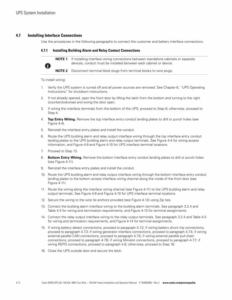
UPS System Installation
4.7 Installing Interface ConnectionsUse the procedures in the following paragraphs to connect the customer and battery interface connections.
4.7.1 Installing Building Alarm and Relay Contact Connections
To install wiring:
1. Verify the UPS system is turned off and all power sources are removed. See Chapter 6, “UPS Operating Instructions,“ for shutdown instructions.
2. If not already opened, open the front door by lifting the latch from the bottom and turning to the right (counterclockwise) and swing the door open.
3. If wiring the interface terminals from the bottom of the UPS, proceed to Step 8; otherwise, proceed to Step 4.
4. Top Entry Wiring. Remove the top interface entry conduit landing plates to drill or punch holes (see Figure 4-4).
5. Reinstall the interface entry plates and install the conduit.
6. Route the UPS building alarm and relay output interface wiring through the top interface entry conduit landing plates to the UPS building alarm and relay output terminals. See Figure 4-4 for wiring access information, and Figure 4-9 and Figure 4-10 for UPS interface terminal locations.
7. Proceed to Step 13.
8. Bottom Entry Wiring. Remove the bottom interface entry conduit landing plates to drill or punch holes (see Figure 4-11).
9. Reinstall the interface entry plates and install the conduit.
10. Route the UPS building alarm and relay output interface wiring through the bottom interface entry conduit landing plates to the bottom access interface wiring channel along the inside of the front door (see Figure 4-11).
11. Route the wiring along the interface wiring channel (see Figure 4-11) to the UPS building alarm and relay output terminals. See Figure 4-9 and Figure 4-10 for UPS interface terminal locations.
12. Secure the wiring to the wire tie anchors provided (see Figure 4-12) using Zip ties.
13. Connect the building alarm interface wiring to the building alarm terminals. See paragraph 3.2.4 and Table 4-3 for wiring and termination requirements, and Figure 4-13 for terminal assignments.
14. Connect the relay output interface wiring to the relay output terminals. See paragraph 3.2.4 and Table 4-3 for wiring and termination requirements, and Figure 4-14 for terminal assignments.
15. If wiring battery detect connections, proceed to paragraph 4.7.2; if wiring battery shunt trip connections, proceed to paragraph 4.7.3; if wiring generator interface connections, proceed to paragraph 4.7.4; if wiring external parallel CAN connections, proceed to paragraph 4.7.5; if wiring external parallel pull chain connections, proceed to paragraph 4.7.6; if wiring Minislot connections, proceed to paragraph 4.7.7; if wiring REPO connections, proceed to paragraph 4.8; otherwise, proceed to Step 16.
16. Close the UPS outside door and secure the latch.
NOTE 1 If installing interface wiring connections between standalone cabinets or separate devices, conduit must be installed between each cabinet or device.
NOTE 2 Disconnect terminal block plugs from terminal blocks to wire plugs.
4-12 Eaton 93PM UPS (20–100 kW, 480V Four Wire – 100 kW Frame) Installation and Operation Manual P-164000566—Rev 2 www.eaton.com/powerquality
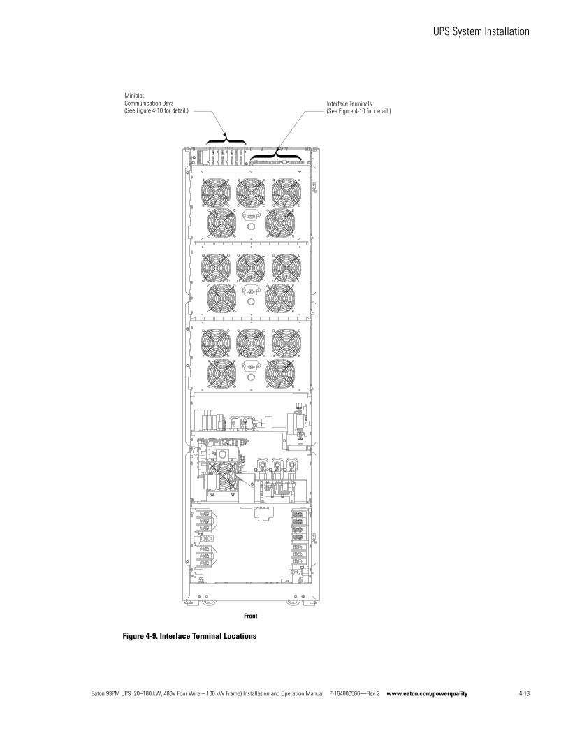
UPS System Installation
Figure 4-9. Interface Terminal Locations
Front
Interface Terminals(See Figure 4-10 for detail.)
Minislot Communication Bays(See Figure 4-10 for detail.)
Eaton 93PM UPS (20–100 kW, 480V Four Wire – 100 kW Frame) Installation and Operation Manual P-164000566—Rev 2 www.eaton.com/powerquality 4-13
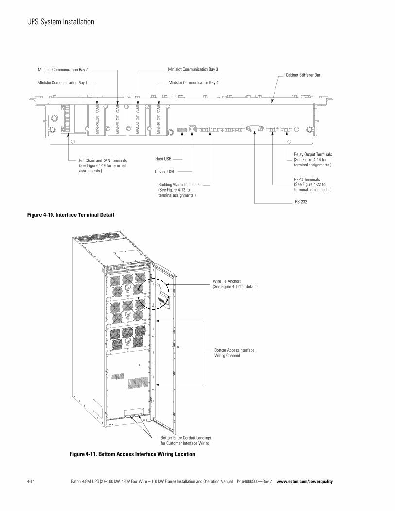
UPS System Installation
Figure 4-10. Interface Terminal Detail
Figure 4-11. Bottom Access Interface Wiring Location
Pull Chain Terminals
Minislot Communication Bay 2
Minislot Communication Bay 1
Minislot Communication Bay 3
Minislot Communication Bay 4
Building Alarm Terminals (See Figure 4-13 for terminal assignments.)
Device USB
RS-232
Host USB
REPO Terminals (See Figure 4-22 for terminal assignments.)
Relay Output Terminals (See Figure 4-14 for terminal assignments.)
Cabinet Stiffener Bar
Pull Chain and CAN Terminals (See Figure 4-19 for terminal assignments.)
Wire Tie Anchors (See Figure 4-12 for detail.)
Bottom Access Interface Wiring Channel
Bottom Entry Conduit Landings for Customer Interface Wiring
4-14 Eaton 93PM UPS (20–100 kW, 480V Four Wire – 100 kW Frame) Installation and Operation Manual P-164000566—Rev 2 www.eaton.com/powerquality
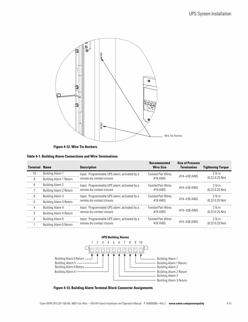
UPS System Installation
Figure 4-12. Wire Tie Anchors
Figure 4-13. Building Alarm Terminal Block Connector Assignments
Wire Tie Anchors
Table 4-1. Building Alarm Connections and Wire Terminations
Terminal Name DescriptionRecommended
Wire SizeSize of Pressure
Termination Tightening Torque
10 Building Alarm 1 Input: Programmable UPS alarm, activated by a remote dry contact closure
Twisted Pair Wires #18 AWG
#1430 AWG2 lb in
(0.22-0.25 Nm)9 Building Alarm 1 Return
8 Building Alarm 2 Input: Programmable UPS alarm, activated by a remote dry contact closure
Twisted Pair Wires #18 AWG
#1430 AWG2 lb in
(0.22-0.25 Nm)7 Building Alarm 2 Return
6 Building Alarm 3 Input: Programmable UPS alarm, activated by a remote dry contact closure
Twisted Pair Wires #18 AWG #1430 AWG
2 lb in(0.22-0.25 Nm)5 Building Alarm 3 Return
4 Building Alarm 4 Input: Programmable UPS alarm, activated by a remote dry contact closure
Twisted Pair Wires #18 AWG #1430 AWG
2 lb in(0.22-0.25 Nm)3 Building Alarm 4 Return
2 Building Alarm 5 Input: Programmable UPS alarm, activated by a remote dry contact closure
Twisted Pair Wires #18 AWG #1430 AWG
2 lb in(0.22-0.25 Nm)1 Building Alarm 5 Return
UPS Building Alarms
1 2 3 4 5 6 7 8 9 10
Building Alarm 5Building Alarm 5 Return
Building Alarm 4Building Alarm 4 Return
Building Alarm 1 ReturnBuilding Alarm 1
Building Alarm 2 ReturnBuilding Alarm 2
Building Alarm 3 ReturnBuilding Alarm 3
Eaton 93PM UPS (20–100 kW, 480V Four Wire – 100 kW Frame) Installation and Operation Manual P-164000566—Rev 2 www.eaton.com/powerquality 4-15
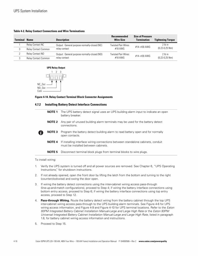
UPS System Installation
Figure 4-14. Relay Contact Terminal Block Connector Assignments
4.7.2 Installing Battery Detect Interface Connections
To install wiring:
1. Verify the UPS system is turned off and all power sources are removed. See Chapter 6, “UPS Operating Instructions,“ for shutdown instructions.
2. If not already opened, open the front door by lifting the latch from the bottom and turning to the right (counterclockwise) and swing the door open.
3. If wiring the battery detect connections using the inter-cabinet wiring access pass-through (line-up-and-match configurations), proceed to Step 4; if wiring the battery interface connections using bottom entry access, proceed to Step 6; if wiring the battery interface connections using top entry access, proceed to Step 12.
4. Pass-through Wiring. Route the battery detect wiring from the battery cabinet through the top UPS inter-cabinet wiring access pass-through to the UPS building alarm terminals. See Figure 4-6 for UPS wiring access information, and Figure 4-9 and Figure 4-10 for UPS terminal locations. Refer to the Eaton 93PM Integrated Battery Cabinet Installation Manual-Large and Large High Rate or the Eaton 93PM Universal Integrated Battery Cabinet Installation Manual-Large and Large High Rate, listed in paragraph 1.8, for battery cabinet wiring access information and instructions.
5. Proceed to Step 15.
Table 4-2. Relay Contact Connections and Wire Terminations
Terminal Name DescriptionRecommended
Wire SizeSize of Pressure
Termination Tightening Torque
1 Relay Contact NC Output: General purpose normally-closed (NC) relay contact
Twisted Pair Wires #18 AWG
#1430 AWG2 lb in
(0.22-0.25 Nm)3 Relay Contact Common
2 Relay Contact NO Output: General purpose normally-closed (NO) relay contact
Twisted Pair Wires #18 AWG
#1430 AWG2 lb in
(0.22-0.25 Nm)3 Relay Contact Common
NOTE 1 The UPS battery detect signal uses an UPS building alarm input to indicate an open battery breaker.
NOTE 2 Any pair of unused building alarm terminals may be used for the battery detect connections.
NOTE 3 Program the battery detect building alarm to read battery open and for normally open contacts.
NOTE 4 If installing interface wiring connections between standalone cabinets, conduit must be installed between cabinets.
NOTE 5 Disconnect terminal block plugs from terminal blocks to wire plugs.
UPS Relay Output
1 2 3
NO_OutNC_Out
Com
4-16 Eaton 93PM UPS (20–100 kW, 480V Four Wire – 100 kW Frame) Installation and Operation Manual P-164000566—Rev 2 www.eaton.com/powerquality
UPS System Installation
6. Bottom Entry Wiring. Remove the bottom interface entry conduit landing plate to drill or punch holes (see Figure 4-11).
7. Reinstall the interface entry plate and install the conduit.
8. Route the battery detect wiring from the battery cabinet through the bottom interface entry conduit landing plate to the bottom access interface wiring channel along the inside of the front door (see Figure 4-11). Refer to the Eaton 93PM Integrated Battery Cabinet Installation Manual-Large and Large High Rate or the Eaton 93PM Universal Integrated Battery Cabinet Installation Manual-Large and Large High Rate, listed in paragraph 1.8, for battery cabinet wiring access information and instructions.
9. Route the wiring along the interface wiring channel (see Figure 4-11) to the UPS building alarm terminals. See Figure 4-9 and Figure 4-10 for UPS interface terminal locations.
10. Secure the wiring to the wire tie anchors provided (see Figure 4-12) using Zip ties.
11. Proceed to Step 15.
12. Top Entry Wiring. Remove the top interface entry conduit landing plate to drill or punch holes (see Figure 4-4).
13. Reinstall the interface entry plate and install the conduit.
14. Route the battery detect wiring from the battery cabinet through the top interface entry conduit landing plate to the UPS building alarm terminals. See Figure 4-4 for wiring access information, and Figure 4-9 and Figure 4-10 for UPS interface terminal locations. Refer to the Eaton 93PM Integrated Battery Cabinet Installation Manual-Large and Large High Rate or the Eaton 93PM Universal Integrated Battery Cabinet Installation Manual-Large and Large High Rate, listed in paragraph 1.8, for battery cabinet wiring access information and instructions.
15. Connect the battery detect wiring to one pair of building alarm terminals. See paragraph 3.2.4 and Table 4-1 for wiring and termination requirements, and Figure 4-13 for terminal assignments.
16. If wiring battery shunt trip connections, proceed to paragraph 4.7.3; if wiring generator interface connections, proceed to paragraph 4.7.4; if wiring external parallel CAN connections, proceed to paragraph 4.7.5; if wiring external parallel pull chain connections, proceed to paragraph 4.7.6; if wiring Minislot connections, proceed to paragraph 4.7.7; if wiring REPO connections, proceed to paragraph 4.8; otherwise, proceed to Step 17.
17. Close the UPS outside door and secure the latch.
4.7.3 Installing Battery Shunt Trip Interface Connections
To install wiring:
1. Verify the UPS system is turned off and all power sources are removed. See Chapter 6, “UPS Operating Instructions,“ for shutdown instructions.
2. If not already opened, open the front door by lifting the latch from the bottom and turning to the right (counterclockwise) and swing the door open.
3. If not already removed, remove the screws securing the bottom internal safety shield panel and remove the panel. Retain the hardware for later use.
4. Remove the screws securing the internal safety shield panel above the bottom safety panel and remove the panel to gain access to the battery shunt trip wiring terminals. Retain the hardware for later use.
NOTE 1 If installing interface wiring connections between standalone cabinets, conduit must be installed between cabinets.
NOTE 2 Disconnect terminal block plugs from terminal blocks to wire plugs.
Eaton 93PM UPS (20–100 kW, 480V Four Wire – 100 kW Frame) Installation and Operation Manual P-164000566—Rev 2 www.eaton.com/powerquality 4-17
UPS System Installation
5. If wiring the battery shunt trip connections using the inter-cabinet wiring access pass-through (line-up-and-match configurations), proceed to Step 6; if wiring the battery shunt trip connections using bottom entry access, proceed to Step 8; if wiring the battery shunt trip connections using top entry access, proceed to Step 10.
6. Pass-through Wiring. Route the battery shunt trip wiring from the battery cabinet through the bottom UPS inter-cabinet wiring access pass-through and static switch shelf bushing to the UPS battery shunt trip terminals. See Figure 4-6 for UPS wiring access information, and Figure 4-15 and Figure 4-16 for UPS terminal locations. Refer to the Eaton 93PM Integrated Battery Cabinet Installation Manual-Large and Large High Rate or the Eaton 93PM Universal Integrated Battery Cabinet Installation Manual-Large and Large High Rate, listed in paragraph 1.8, for battery cabinet wiring access information and instructions.
7. Proceed to Step 11.
8. Bottom Entry Wiring. Route the battery shunt trip wiring from the battery cabinet or battery disconnect through the bottom of the UPS and static switch shelf bushing to the UPS battery shunt trip terminals. See Figure 4-4 for UPS wiring access information, and Figure 4-15 and Figure 4-16 for UPS terminal locations. Refer to the Eaton 93PM Integrated Battery Cabinet Installation Manual-Large and Large High Rate or the Eaton 93PM Universal Integrated Battery Cabinet Installation Manual-Large and Large High Rate, listed in paragraph 1.8, for battery cabinet wiring access information and instructions.
9. Proceed to Step 11.
10. Top Entry Wiring. Route the battery shunt trip wiring from the battery cabinet or battery disconnect through the top of the UPS sidecar and the bottom UPS inter-cabinet wiring access pass-through and static switch shelf bushing to the UPS battery shunt trip terminals. See Figure 4-5 and Figure 4-6 for UPS wiring access information, and Figure 4-15 and Figure 4-16 for UPS terminal locations. Refer to the Eaton 93PM Integrated Battery Cabinet Installation Manual-Large and Large High Rate or the Eaton 93PM Universal Integrated Battery Cabinet Installation Manual-Large and Large High Rate, listed in paragraph 1.8, for battery cabinet wiring access information and instructions.
11. Connect the wiring to the battery shunt trip terminals. See paragraph 3.2.4 and Table 4-3 for wiring and termination requirements, and Figure 4-17 for terminal assignments.
12. If wiring generator interface connections, proceed to paragraph 4.7.4; if wiring external parallel CAN connections, proceed to paragraph 4.7.5; if wiring external parallel pull chain connections, proceed to paragraph 4.7.6; if wiring Minislot connections, proceed to paragraph 4.7.7; if wiring REPO connections, proceed to paragraph 4.8; otherwise, proceed to Step 13.
13. Reinstall all safety shield panels previously removed and secure with the retained hardware.
14. If removed, reinstall the sidecar front panel and secure with the retained hardware.
15. Close the UPS outside door and secure the latch.
4-18 Eaton 93PM UPS (20–100 kW, 480V Four Wire – 100 kW Frame) Installation and Operation Manual P-164000566—Rev 2 www.eaton.com/powerquality
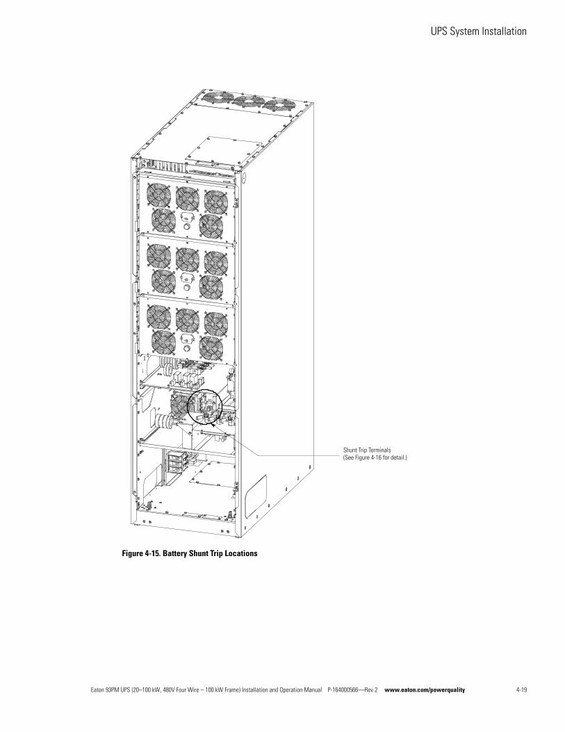
UPS System Installation
Figure 4-15. Battery Shunt Trip Locations
Shunt Trip Terminals (See Figure 4-16 for detail.)
Eaton 93PM UPS (20–100 kW, 480V Four Wire – 100 kW Frame) Installation and Operation Manual P-164000566—Rev 2 www.eaton.com/powerquality 4-19
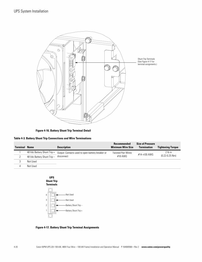
UPS System Installation
Figure 4-16. Battery Shunt Trip Terminal Detail
Figure 4-17. Battery Shunt Trip Terminal Assignments
Shunt Trip Terminals(See Figure 4-17 for terminal assignments.)
Table 4-3. Battery Shunt Trip Connections and Wire Terminations
Terminal Name DescriptionRecommended
Minimum Wire SizeSize of Pressure
Termination Tightening Torque
1 48 Vdc Battery Shunt Trip + Output: Contacts used to open battery breaker or disconnect
Twisted Pair Wires #18 AWG
#1430 AWG2 lb in
(0.22-0.25 Nm)2 48 Vdc Battery Shunt Trip –
3 Not Used
4 Not Used
Battery Shunt Trip +
Battery Shunt Trip –
Not Used
Not Used
UPSShunt Trip Terminals
1
2
3
4
4-20 Eaton 93PM UPS (20–100 kW, 480V Four Wire – 100 kW Frame) Installation and Operation Manual P-164000566—Rev 2 www.eaton.com/powerquality
UPS System Installation
4.7.4 Generator Interface Connections
If ESS is enabled and the UPS will be fed by a site generator at any time, the On Generator building alarm must be wired and configured to a Building Alarm Input. Wiring the On Generator sensing circuit to a building alarm allows the UPS to optimize its operation with the generator by transferring the UPS from ESS mode to Normal (double conversion) mode.
To Install wiring:
1. Verify the UPS system is turned off and all power sources are removed. See Chapter 6, “UPS Operating Instructions,“ for shutdown instructions.
2. If not already opened, open the front door by lifting the latch from the bottom and turning to the right (counterclockwise) and swing the door open.
3. If wiring the interface terminals from the bottom of the UPS, proceed to Step 8; otherwise, proceed to Step 4.
4. Top Entry Wiring. Remove the top interface entry conduit landing plates to drill or punch holes (see Figure 4-4).
5. Reinstall the interface entry plates and install the conduit.
6. Route the UPS building alarm interface wiring through the top interface entry conduit landing plates to the UPS building alarm terminals. See Figure 4-4 for wiring access information, and Figure 4-9 and Figure 4-10 for UPS interface terminal locations.
7. Proceed to Step 13.
8. Bottom Entry Wiring. Remove the bottom interface entry conduit landing plates to drill or punch holes (see Figure 4-11).
9. Reinstall the interface entry plates and install the conduit.
10. Route the UPS building alarm interface wiring through the bottom interface entry conduit landing plates to the bottom access interface wiring channel along the inside of the front door (see Figure 4-11).
11. Route the wiring along the interface wiring channel (see Figure 4-11) to the UPS building alarm terminals. See Figure 4-9 and Figure 4-10 for UPS interface terminal locations.
12. Secure the wiring to the wire tie anchors provided (see Figure 4-12) using Zip ties.
13. Connect the building alarm interface wiring to the building alarm terminals. See paragraph 3.2.4 and Table 4-1 for wiring and termination requirements, and Figure 4-13 for terminal assignments.
14. If wiring external parallel CAN connections, proceed to paragraph 4.7.5; if wiring external parallel pull chain connections, proceed to paragraph 4.7.6; if wiring Minislot connections, proceed to paragraph 4.7.7; if wiring REPO connections, proceed to paragraph 4.8; otherwise, proceed to Step 15.
15. Close the UPS outside door and secure the latch.
NOTE 1 An UPS building alarm input is used to indicate On Generator.
NOTE 2 Any pair of unused building alarm terminals may be used for On Generator connections.
NOTE 3 Program the building alarm to read On Generator and for either Normally Open (default) or Normally Closed as required by the generator sensing output.
NOTE 4 If installing interface wiring connections between standalone cabinets, conduit must be installed between cabinets.
NOTE 5 Disconnect terminal block plugs from terminal blocks to wire plugs.
Eaton 93PM UPS (20–100 kW, 480V Four Wire – 100 kW Frame) Installation and Operation Manual P-164000566—Rev 2 www.eaton.com/powerquality 4-21
UPS System Installation
4.7.5 Installing External Parallel CAN Control Wiring and Connections
To install wiring:
1. Verify the UPS system is turned off and all power sources are removed. See Chapter 6, “UPS Operating Instructions,“ for shutdown instructions.
2. If not already opened, open the front door by lifting the latch from the bottom and turning to the right (counterclockwise) and swing the door open.
3. If wiring the external parallel CAN connections using the inter-cabinet wiring access pass-through (line-up-and-match configurations), proceed to Step 4; if wiring the external parallel CAN connections using bottom entry access, proceed to Step 6; if wiring the external parallel CAN connections using top entry access, proceed to Step 12.
4. Pass-through Wiring. Route the external parallel CAN control wiring between UPS cabinets through the top UPS inter-cabinet wiring access pass-through to the UPS external parallel terminals. See Figure 4-6 for UPS wiring access information, and Figure 4-9 and Figure 4-10 for UPS interface terminal locations.
5. Proceed to Step 15.
6. Bottom Entry Wiring. Remove the bottom interface entry conduit landing plate to drill or punch holes (see Figure 4-11).
7. Reinstall the interface entry plate and install the conduit.
8. Route the external parallel CAN control wiring through the bottom interface entry conduit landing plate to the bottom access interface wiring channel along the inside of the front door (see Figure 4-11).
9. Route the wiring along the interface wiring channel (see Figure 4-11) to the UPS external parallel terminals. See Figure 4-9 and Figure 4-10 for UPS interface terminal locations.
10. Secure the wiring to the wire tie anchors provided (see Figure 4-12) using Zip ties.
11. Proceed to Step 15.
12. Top Entry Wiring. Remove the top interface entry conduit landing plate to drill or punch holes (see Figure 4-4).
13. Reinstall the interface entry plate and install the conduit.
14. Route the external parallel CAN control wiring through the top interface entry conduit landing plate to the UPS external parallel terminals. See Figure 4-4 for wiring access information and Figure 4-9 and Figure 4-10 for UPS interface terminal locations.
15. Connect the external parallel CAN wiring to the CAN terminals. See paragraph 3.2.4, Table 4-4, and Table 4-5 for wiring and termination requirements, and Figure 4-18 and Figure 4-19 for wiring information and terminal assignments.
16. If wiring external parallel pull chain connections, proceed to paragraph 4.7.6; if wiring Minislot connections, proceed to paragraph 4.7.7; if wiring REPO connections, proceed to paragraph 4.8; otherwise, proceed to Step 17.
17. Close the UPS outside door and secure the latch.
NOTE 1 If installing interface wiring connections between standalone cabinets, conduit must be installed between each cabinet.
NOTE 2 Disconnect terminal block plugs from terminal blocks to wire plugs.
4-22 Eaton 93PM UPS (20–100 kW, 480V Four Wire – 100 kW Frame) Installation and Operation Manual P-164000566—Rev 2 www.eaton.com/powerquality
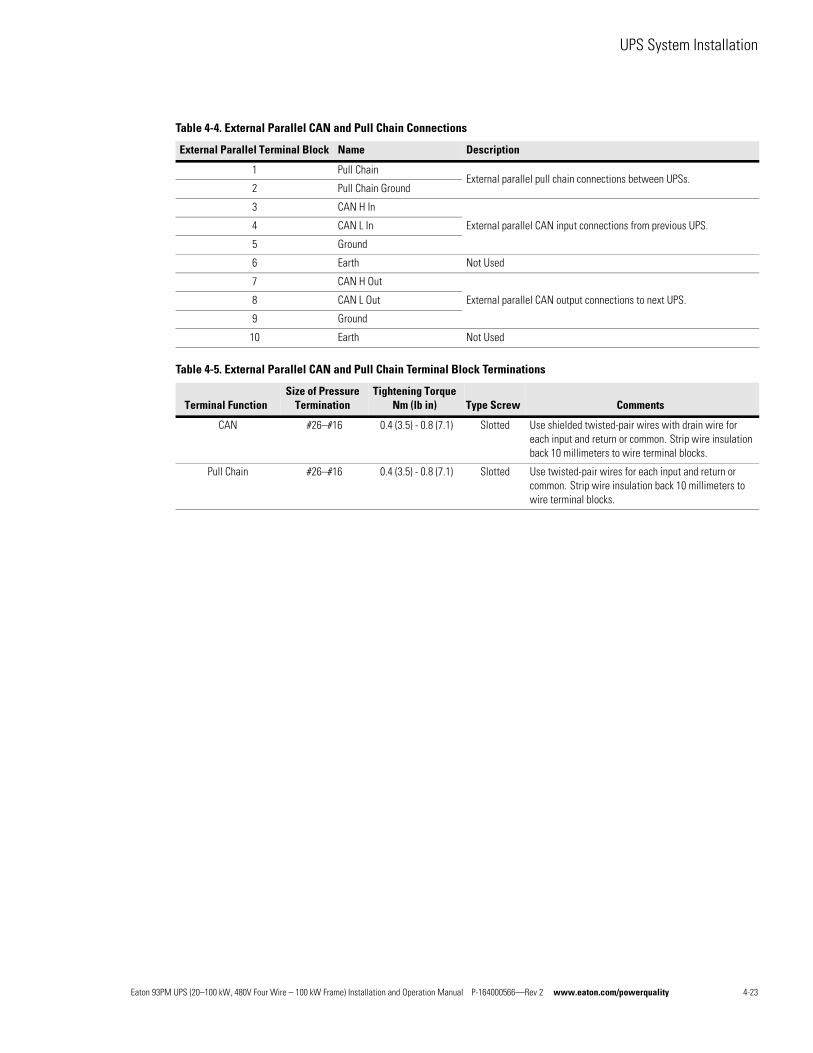
UPS System Installation
Table 4-4. External Parallel CAN and Pull Chain Connections
External Parallel Terminal Block Name Description
1 Pull ChainExternal parallel pull chain connections between UPSs.
2 Pull Chain Ground
3 CAN H In
External parallel CAN input connections from previous UPS.4 CAN L In
5 Ground
6 Earth Not Used
7 CAN H Out
External parallel CAN output connections to next UPS.8 CAN L Out
9 Ground
10 Earth Not Used
Table 4-5. External Parallel CAN and Pull Chain Terminal Block Terminations
Terminal FunctionSize of Pressure
TerminationTightening Torque
Nm (lb in) Type Screw Comments
CAN #26–#16 0.4 (3.5) - 0.8 (7.1) Slotted Use shielded twisted-pair wires with drain wire for each input and return or common. Strip wire insulation back 10 millimeters to wire terminal blocks.
Pull Chain #26–#16 0.4 (3.5) - 0.8 (7.1) Slotted Use twisted-pair wires for each input and return or common. Strip wire insulation back 10 millimeters to wire terminal blocks.
Eaton 93PM UPS (20–100 kW, 480V Four Wire – 100 kW Frame) Installation and Operation Manual P-164000566—Rev 2 www.eaton.com/powerquality 4-23
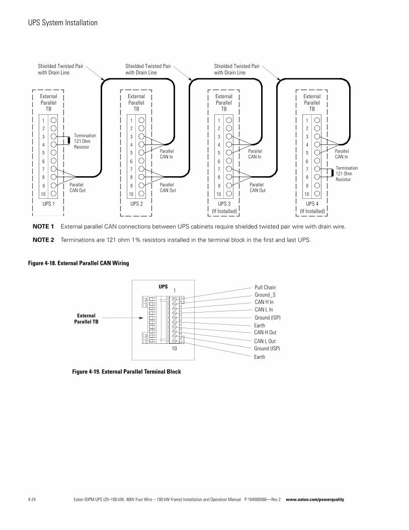
UPS System Installation
Figure 4-18. External Parallel CAN Wiring
Figure 4-19. External Parallel Terminal Block
1
2
3
4
5
6
7
8
9
10
UPS 1
ExternalParallel
TB
1
2
3
4
5
6
7
8
9
10
UPS 4(If Installed)
ExternalParallel
TB
1
2
3
4
5
6
7
8
9
10
UPS 2
ExternalParallel
TB
1
2
3
4
5
6
7
8
9
10
UPS 3(If Installed)
ExternalParallel
TB
Shielded Twisted Pairwith Drain Line
Shielded Twisted Pairwith Drain Line
Shielded Twisted Pairwith Drain Line
ParallelCAN Out
ParallelCAN Out
ParallelCAN Out
ParallelCAN In
ParallelCAN In
ParallelCAN In
Termination121 OhmResistor
Termination121 OhmResistor
NOTE 1 External parallel CAN connections between UPS cabinets require shielded twisted pair wire with drain wire.
NOTE 2 Terminations are 121 ohm 1% resistors installed in the terminal block in the first and last UPS.
UPS
ExternalParallel TB
Ground_SPull Chain
CAN L InCAN H In
CAN L Out
CAN H Out
Earth
Ground (ISP)
EarthGround (ISP)
10
1
4-24 Eaton 93PM UPS (20–100 kW, 480V Four Wire – 100 kW Frame) Installation and Operation Manual P-164000566—Rev 2 www.eaton.com/powerquality
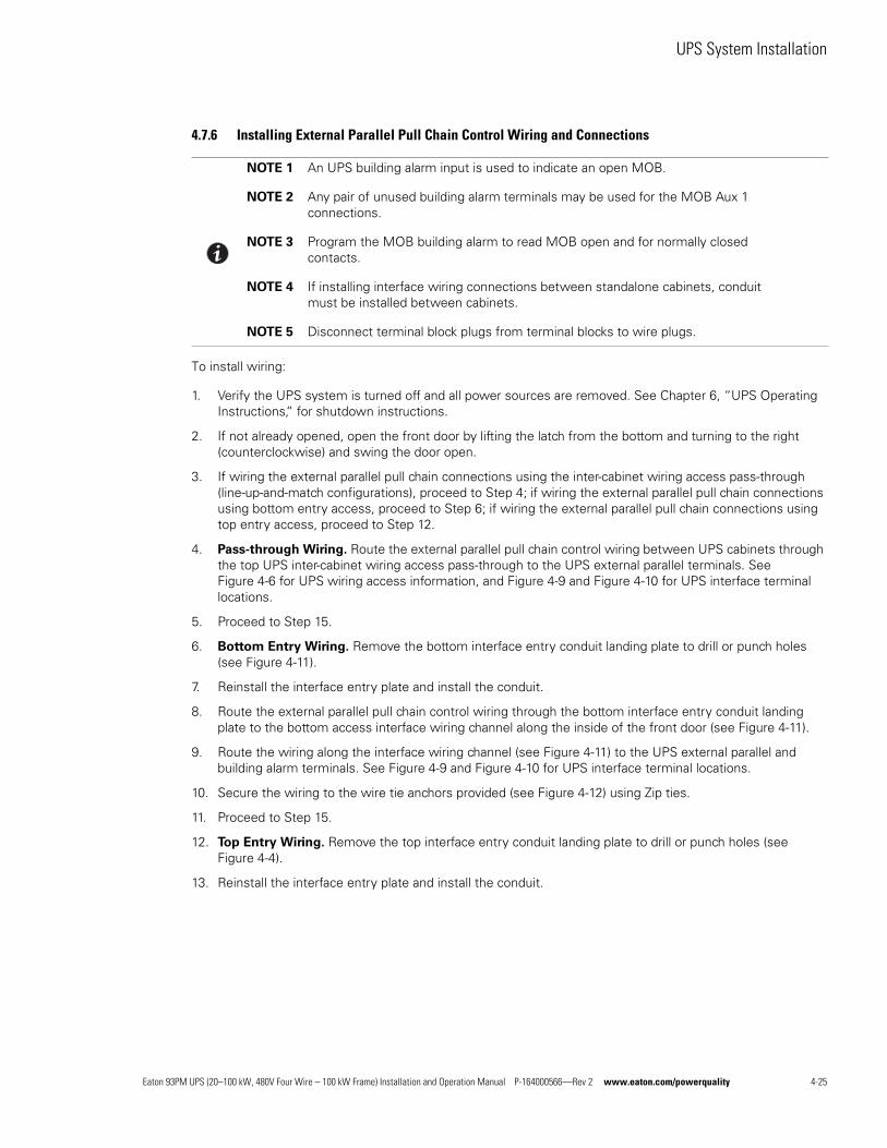
UPS System Installation
4.7.6 Installing External Parallel Pull Chain Control Wiring and Connections
To install wiring:
1. Verify the UPS system is turned off and all power sources are removed. See Chapter 6, “UPS Operating Instructions,“ for shutdown instructions.
2. If not already opened, open the front door by lifting the latch from the bottom and turning to the right (counterclockwise) and swing the door open.
3. If wiring the external parallel pull chain connections using the inter-cabinet wiring access pass-through (line-up-and-match configurations), proceed to Step 4; if wiring the external parallel pull chain connections using bottom entry access, proceed to Step 6; if wiring the external parallel pull chain connections using top entry access, proceed to Step 12.
4. Pass-through Wiring. Route the external parallel pull chain control wiring between UPS cabinets through the top UPS inter-cabinet wiring access pass-through to the UPS external parallel terminals. See Figure 4-6 for UPS wiring access information, and Figure 4-9 and Figure 4-10 for UPS interface terminal locations.
5. Proceed to Step 15.
6. Bottom Entry Wiring. Remove the bottom interface entry conduit landing plate to drill or punch holes (see Figure 4-11).
7. Reinstall the interface entry plate and install the conduit.
8. Route the external parallel pull chain control wiring through the bottom interface entry conduit landing plate to the bottom access interface wiring channel along the inside of the front door (see Figure 4-11).
9. Route the wiring along the interface wiring channel (see Figure 4-11) to the UPS external parallel and building alarm terminals. See Figure 4-9 and Figure 4-10 for UPS interface terminal locations.
10. Secure the wiring to the wire tie anchors provided (see Figure 4-12) using Zip ties.
11. Proceed to Step 15.
12. Top Entry Wiring. Remove the top interface entry conduit landing plate to drill or punch holes (see Figure 4-4).
13. Reinstall the interface entry plate and install the conduit.
NOTE 1 An UPS building alarm input is used to indicate an open MOB.
NOTE 2 Any pair of unused building alarm terminals may be used for the MOB Aux 1 connections.
NOTE 3 Program the MOB building alarm to read MOB open and for normally closed contacts.
NOTE 4 If installing interface wiring connections between standalone cabinets, conduit must be installed between cabinets.
NOTE 5 Disconnect terminal block plugs from terminal blocks to wire plugs.
Eaton 93PM UPS (20–100 kW, 480V Four Wire – 100 kW Frame) Installation and Operation Manual P-164000566—Rev 2 www.eaton.com/powerquality 4-25
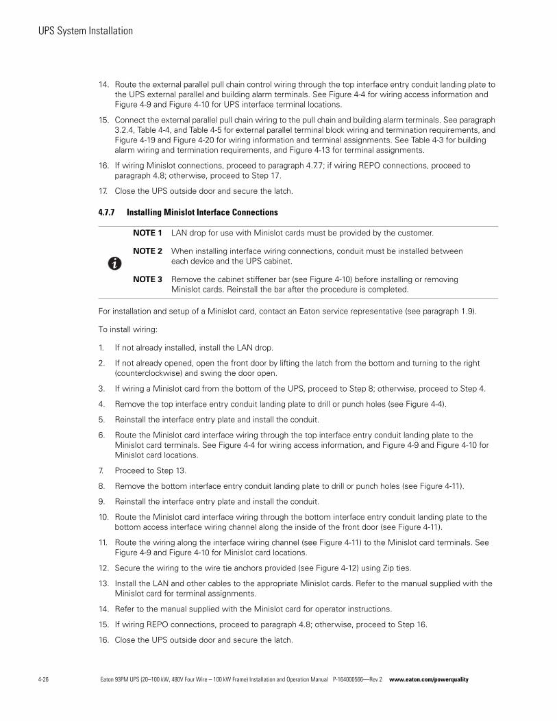
UPS System Installation
14. Route the external parallel pull chain control wiring through the top interface entry conduit landing plate to the UPS external parallel and building alarm terminals. See Figure 4-4 for wiring access information and Figure 4-9 and Figure 4-10 for UPS interface terminal locations.
15. Connect the external parallel pull chain wiring to the pull chain and building alarm terminals. See paragraph 3.2.4, Table 4-4, and Table 4-5 for external parallel terminal block wiring and termination requirements, and Figure 4-19 and Figure 4-20 for wiring information and terminal assignments. See Table 4-3 for building alarm wiring and termination requirements, and Figure 4-13 for terminal assignments.
16. If wiring Minislot connections, proceed to paragraph 4.7.7; if wiring REPO connections, proceed to paragraph 4.8; otherwise, proceed to Step 17.
17. Close the UPS outside door and secure the latch.
4.7.7 Installing Minislot Interface Connections
For installation and setup of a Minislot card, contact an Eaton service representative (see paragraph 1.9).
To install wiring:
1. If not already installed, install the LAN drop.
2. If not already opened, open the front door by lifting the latch from the bottom and turning to the right (counterclockwise) and swing the door open.
3. If wiring a Minislot card from the bottom of the UPS, proceed to Step 8; otherwise, proceed to Step 4.
4. Remove the top interface entry conduit landing plate to drill or punch holes (see Figure 4-4).
5. Reinstall the interface entry plate and install the conduit.
6. Route the Minislot card interface wiring through the top interface entry conduit landing plate to the Minislot card terminals. See Figure 4-4 for wiring access information, and Figure 4-9 and Figure 4-10 for Minislot card locations.
7. Proceed to Step 13.
8. Remove the bottom interface entry conduit landing plate to drill or punch holes (see Figure 4-11).
9. Reinstall the interface entry plate and install the conduit.
10. Route the Minislot card interface wiring through the bottom interface entry conduit landing plate to the bottom access interface wiring channel along the inside of the front door (see Figure 4-11).
11. Route the wiring along the interface wiring channel (see Figure 4-11) to the Minislot card terminals. See Figure 4-9 and Figure 4-10 for Minislot card locations.
12. Secure the wiring to the wire tie anchors provided (see Figure 4-12) using Zip ties.
13. Install the LAN and other cables to the appropriate Minislot cards. Refer to the manual supplied with the Minislot card for terminal assignments.
14. Refer to the manual supplied with the Minislot card for operator instructions.
15. If wiring REPO connections, proceed to paragraph 4.8; otherwise, proceed to Step 16.
16. Close the UPS outside door and secure the latch.
NOTE 1 LAN drop for use with Minislot cards must be provided by the customer.
NOTE 2 When installing interface wiring connections, conduit must be installed between each device and the UPS cabinet.
NOTE 3 Remove the cabinet stiffener bar (see Figure 4-10) before installing or removing Minislot cards. Reinstall the bar after the procedure is completed.
4-26 Eaton 93PM UPS (20–100 kW, 480V Four Wire – 100 kW Frame) Installation and Operation Manual P-164000566—Rev 2 www.eaton.com/powerquality
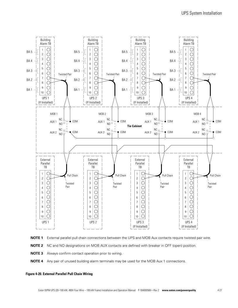
UPS System Installation
Figure 4-20. External Parallel Pull Chain Wiring
NOTE 1 External parallel pull chain connections between the UPS and MOB Aux contacts require twisted pair wire.
NOTE 2 NC and NO designations on MOB AUX contacts are defined with breaker in OFF (open) position.
NOTE 3 Always confirm contact operation prior to wiring.
NOTE 4 Any pair of unused building alarm terminals may be used for the MOB Aux 1 connections.
1
2
3
4
5
6
7
8
9
10
UPS 1
ExternalParallel
TB
1
2
3
4
5
6
7
8
9
10
UPS 4(If Installed)
ExternalParallel
TB
1
2
3
4
5
6
7
8
9
10
UPS 2
ExternalParallel
TB
1
2
3
4
5
6
7
8
9
10
UPS 3(If Installed)
ExternalParallel
TB
Pull Chain
1
2
3
4
5
6
7
8
9
10
UPS 3(If Installed)
BuildingAlarm TB
AUX 1
AUX 2
Tie Cabinet
MOB 1 MOB 2 MOB 3 MOB 4
COM
COM
COM
COM
COM
COM
COM
COM
Twisted Pair Twisted Pair Twisted Pair Twisted Pair
NC
NO
NC
NO
NC
NO
NC
NO
NC
NO
NC
NO
NC
NO
NC
NO
AUX 1
AUX 2
AUX 1
AUX 2
AUX 1
AUX 2
1
2
3
4
5
6
7
8
9
10
UPS 1(If Installed)
BuildingAlarm TB
1
2
3
4
5
6
7
8
9
10
UPS 2(If Installed)
BuildingAlarm TB
1
2
3
4
5
6
7
8
9
10
UPS 4(If Installed)
BuildingAlarm TB
Pull Chain Pull Chain Pull Chain
TwistedPair
TwistedPair
TwistedPair
TwistedPair
BA 1
BA 2
BA 3
BA 4
BA 5
BA 1
BA 2
BA 3
BA 4
BA 5
BA 1
BA 2
BA 3
BA 4
BA 5
BA 1
BA 2
BA 3
BA 4
BA 5
Eaton 93PM UPS (20–100 kW, 480V Four Wire – 100 kW Frame) Installation and Operation Manual P-164000566—Rev 2 www.eaton.com/powerquality 4-27
UPS System Installation
4.8 Installing a REPO SwitchA latching-type Remote Emergency Power-off (REPO) switch can be used in an emergency to shut down the UPS and remove power to the critical load from a location away from where the UPS is installed. Figure 4-21 shows a REPO switch.
To Install a REPO switch:
1. Verify the UPS system is turned off and all power sources are removed. See Chapter 6, “UPS Operating Instructions,“ for shutdown instructions.
2. Securely mount the REPO switch. Recommended locations include operator's consoles or near exit doors. See Figure 3-8 for enclosure dimensions and wiring knockouts.
3. If not already opened, open the front door by lifting the latch from the bottom and turning to the right (counterclockwise) and swing the door open.
4. If wiring the REPO terminals from the bottom of the UPS, proceed to Step 9; otherwise, proceed to Step 5.
5. Remove the top interface entry conduit landing plate to drill or punch holes (see Figure 4-4).
6. Reinstall the interface entry plate and install the conduit.
7. Route the REPO wiring through the top interface entry conduit landing plate to the REPO terminals. See Figure 4-4 for wiring access information, and Figure 4-9 and Figure 4-10 for UPS interface terminal locations.
8. Proceed to Step 14.
9. Remove the bottom interface entry conduit landing plate to drill or punch holes (see Figure 4-11).
10. Reinstall the interface entry plate and install the conduit.
NOTE 1 Before installing a REPO switch, verify that the UPS was installed according to the instructions in paragraphs 4.2 through 4.6.
NOTE 2 When installing the REPO switch, you must install conduit between the device and the UPS cabinet for wiring the switch.
NOTE 3 The REPO switch must be a Normally-open or Normally-closed latching-type switch not tied into any other circuits.
NOTE 4 This procedure is intended for installing the Eaton-supplied REPO switch. If installing another manufacturer's switch, use this procedure, and Figure 4-23 and Figure 4-24 as a guide.
NOTE 5 The REPO switch wiring must be in accordance with NEC Article 725 Class 2 requirements.
NOTE 6 Disconnect terminal block plugs from terminal blocks to wire plugs.
4-28 Eaton 93PM UPS (20–100 kW, 480V Four Wire – 100 kW Frame) Installation and Operation Manual P-164000566—Rev 2 www.eaton.com/powerquality
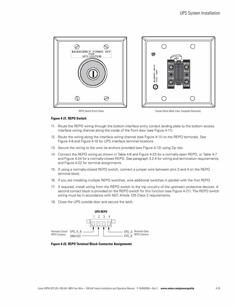
UPS System Installation
Figure 4-21. REPO Switch
11. Route the REPO wiring through the bottom interface entry conduit landing plate to the bottom access interface wiring channel along the inside of the front door (see Figure 4-11).
12. Route the wiring along the interface wiring channel (see Figure 4-11) to the REPO terminals. See Figure 4-9 and Figure 4-10 for UPS interface terminal locations.
13. Secure the wiring to the wire tie anchors provided (see Figure 4-12) using Zip ties.
14. Connect the REPO wiring as shown in Table 4-6 and Figure 4-23 for a normally-open REPO, or Table 4-7 and Figure 4-24 for a normally-closed REPO. See paragraph 3.2.4 for wiring and termination requirements, and Figure 4-22 for terminal assignments.
15. If using a normally-closed REPO switch, connect a jumper wire between pins 3 and 4 on the REPO terminal block.
16. If you are installing multiple REPO switches, wire additional switches in parallel with the first REPO.
17. If required, install wiring from the REPO switch to the trip circuitry of the upstream protective devices. A second contact block is provided on the REPO switch for this function (see Figure 4-21). The REPO switch wiring must be in accordance with NEC Article 725 Class 2 requirements.
18. Close the UPS outside door and secure the latch.
Figure 4-22. REPO Terminal Block Connector Assignments
REPO Switch (Front View) Contact Block (Back View, Faceplate Removed)
Normally Closed REPO Contacts
Normally Open REPO Contacts
UPS REPO
1 2 3 4
GND-ISOEPO_A_B
EPO_BEPO_A
Eaton 93PM UPS (20–100 kW, 480V Four Wire – 100 kW Frame) Installation and Operation Manual P-164000566—Rev 2 www.eaton.com/powerquality 4-29
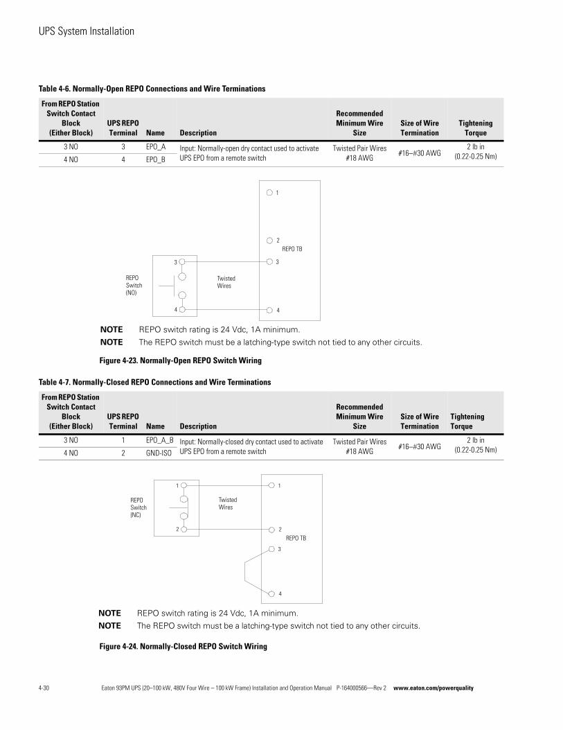
UPS System Installation
Figure 4-23. Normally-Open REPO Switch Wiring
Figure 4-24. Normally-Closed REPO Switch Wiring
Table 4-6. Normally-Open REPO Connections and Wire Terminations
From REPO Station Switch Contact
Block(Either Block)
UPS REPO Terminal Name Description
Recommended Minimum Wire
SizeSize of Wire Termination
Tightening Torque
3 NO 3 EPO_A Input: Normally-open dry contact used to activate UPS EPO from a remote switch
Twisted Pair Wires #18 AWG
#1630 AWG2 lb in
(0.22-0.25 Nm)4 NO 4 EPO_B
3
1
2
4
3
4
REPO Switch (NO)
Twisted Wires
REPO TB
NOTE REPO switch rating is 24 Vdc, 1A minimum.
NOTE The REPO switch must be a latching-type switch not tied to any other circuits.
Table 4-7. Normally-Closed REPO Connections and Wire Terminations
From REPO Station Switch Contact
Block(Either Block)
UPS REPO Terminal Name Description
Recommended Minimum Wire
SizeSize of Wire Termination
Tightening Torque
3 NO 1 EPO_A_B Input: Normally-closed dry contact used to activate UPS EPO from a remote switch
Twisted Pair Wires #18 AWG
#1630 AWG2 lb in
(0.22-0.25 Nm)4 NO 2 GND-ISO
3
1
2
4
1
2
REPO Switch (NC)
Twisted Wires
REPO TB
NOTE REPO switch rating is 24 Vdc, 1A minimum.
NOTE The REPO switch must be a latching-type switch not tied to any other circuits.
4-30 Eaton 93PM UPS (20–100 kW, 480V Four Wire – 100 kW Frame) Installation and Operation Manual P-164000566—Rev 2 www.eaton.com/powerquality
UPS System Installation
4.9 Initial StartupStartup may be performed by the customer’s battery qualified electrical contractor for single (not parallel) UPS installations without any accessory cabinets such as an External Battery Cabinet.
Startup and operational checks for parallel systems or installations with accessory cabinets must be performed by an authorized Eaton Customer Service Engineer, or the warranty terms specified on page W-1 become void. This service is offered as part of the sales contract for the UPS. Contact an Eaton service representative in advance (usually a two-week notice is required) to reserve a preferred startup date.
4.10 Completing the Installation ChecklistThe final step in installing the UPS system is completing the following Installation Checklist. This checklist ensures that you have completely installed all hardware, cables, and other equipment. Complete all items listed on the checklist to ensure a smooth installation. Make a copy of the Installation Checklist before filling it out, and retain the original.
After the installation is complete, an Eaton Customer Service Engineer must verify the operation of the UPS system and commission it to support the critical load. The service representative cannot perform any installation tasks other than verifying software and operating setup parameters. Service personnel may request a copy of the completed Installation Checklist to verify all applicable equipment installations have been completed.
NOTE The Installation Checklist MUST be completed prior to starting the UPS system for the first time.
Eaton 93PM UPS (20–100 kW, 480V Four Wire – 100 kW Frame) Installation and Operation Manual P-164000566—Rev 2 www.eaton.com/powerquality 4-31
UPS System Installation
Installation Checklisto All packing materials and restraints have been removed from each cabinet.
o The UPS cabinet is placed in its installed location.
o All conduits and cables are properly routed to the UPS and any ancillary cabinets.
o All power cables are properly sized and terminated.
o Battery cables are terminated on E4 (+) and E5 (–).
o Battery shunt trip signal wiring is connected from the UPS to the battery disconnect.
o Battery detect signal wiring is connected from the UPS to the battery disconnect.
o A ground conductor is properly installed.
o Building alarms and alarm relays are wired appropriately. (Optional)
o LAN drops are installed. (Optional)
o LAN connections have been completed. (Optional)
o The REPO device is mounted in its installed location and its wiring is terminated inside the UPS cabinet. (Optional)
o A jumper wire is connected between pins 3 and 4 on the REPO terminal block if using a normally-closed REPO switch. (Optional)
o All internal safety shields are installed.
o Accessories are mounted in installed locations and wiring is terminated inside the UPS cabinet. (Optional)
o Air conditioning equipment is installed and operating correctly.
o The area around the installed UPS system is clean and dust-free. (Eaton recommends that the UPS be installed on a level floor suitable for computer or electronic equipment.)
o Adequate workspace exists around the UPS and other cabinets.
o Adequate lighting is provided around all UPS equipment.
o A 120 Vac service outlet is located within 7.5m (25 ft) of the UPS equipment.
o Startup and operational checks are performed by an authorized Eaton Customer Service Engineer for parallel systems or installations with accessory cabinets.
4-32 Eaton 93PM UPS (20–100 kW, 480V Four Wire – 100 kW Frame) Installation and Operation Manual P-164000566—Rev 2 www.eaton.com/powerquality

UPS System Installation
Notes
________________________________________________________________________
________________________________________________________________________
________________________________________________________________________
________________________________________________________________________
________________________________________________________________________
________________________________________________________________________
________________________________________________________________________
________________________________________________________________________
________________________________________________________________________
________________________________________________________________________
________________________________________________________________________
________________________________________________________________________
________________________________________________________________________
________________________________________________________________________
Eaton 93PM UPS (20–100 kW, 480V Four Wire – 100 kW Frame) Installation and Operation Manual P-164000566—Rev 2 www.eaton.com/powerquality 4-33

UPS System Installation
This page intentionally left blank.
4-34 Eaton 93PM UPS (20–100 kW, 480V Four Wire – 100 kW Frame) Installation and Operation Manual P-164000566—Rev 2 www.eaton.com/powerquality

Section 2Operation

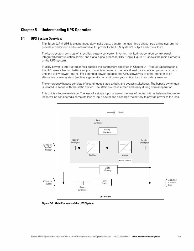
Chapter 5 Understanding UPS Operation
5.1 UPS System OverviewThe Eaton 93PM UPS is a continuous-duty, solid-state, transformerless, three-phase, true online system that provides conditioned and uninterruptible AC power to the UPS system's output and critical load.
The basic system consists of a rectifier, battery converter, inverter, monitoring/operation control panel, integrated communication server, and digital signal processor (DSP) logic. Figure 5-1 shows the main elements of the UPS system.
If utility power is interrupted or falls outside the parameters specified in Chapter 9, “Product Specifications,” the UPS uses a backup battery supply to maintain power to the critical load for a specified period of time or until the utility power returns. For extended power outages, the UPS allows you to either transfer to an alternative power system (such as a generator) or shut down your critical load in an orderly manner.
The emergency bypass consists of a continuous static switch, and bypass switchgear. The bypass switchgear is located in series with the static switch. The static switch is armed and ready during normal operation.
This unit is a four-wire device. The loss of a single input phase or the loss of neutral with unbalanced four-wire loads will be considered a complete loss of input power and discharge the battery to provide power to the load.
Figure 5-1. Main Elements of the UPS System
AC Input toRectifier/
Charger
AC Output to Critical Load
Rectifier Switchgear
Battery Switchgear
Battery Converter
Battery
Inverter Switchgear
UPS Cabinet
Bypass Switchgear
Static Switch
Digital Metering
InverterRectifier
Power Module
AC Input toBypass
Eaton 93PM UPS (20–100 kW, 480V Four Wire – 100 kW Frame) Installation and Operation Manual P-164000566—Rev 2 www.eaton.com/powerquality 5-1
Understanding UPS Operation
5.2 Single UPSA single UPS operates independently to support an applied load from the inverter, providing conditioned and uninterruptible AC power to the critical load from the output of the module. During an outage, the inverter continues to operate, supporting power to the load from the battery supply. If the unit requires service, applied loads are transferred to the internal bypass either automatically or manually. With the exception of an optional external battery cabinet, no other cabinets or equipment are required for the single UPS to successfully support its applied loads.
5.2.1 Modes
The Eaton 93PMUPS supports a critical load in four different modes of operation:
l In Energy Saver System (ESS) mode, commercial AC power is supplied directly to the critical load through the internal bypass and transfers automatically to Normal mode (double-conversion on demand) if an abnormal condition is detected. The battery charger also provides charging current for the battery, if needed.
l In Normal (double-conversion) mode, the critical load is supplied by the inverter, which derives its power from rectified utility AC power. In this mode, the battery charger also provides charging current for the battery, if needed.
l In Bypass mode, the critical load is directly supported by utility power. The battery charger also provides charging current for the battery, if needed.
l In Battery mode, the battery provides DC power, which maintains inverter operation. The battery supports the critical load.
The following paragraphs describe the differences in the UPS operating modes, using block diagrams to show the power flow during each mode of operation.
5.2.2 Energy Saver System Mode
When the UPS is operating in ESS mode, commercial AC power is supplied directly to the critical load through the internal bypass with the power module in a standby state. Surge protection and some filtering is also provided, ensuring that clean power is delivered to the load equipment. If a commercial power brownout, blackout, overvoltage, undervoltage, out-of-tolerance frequency condition occurs, or any other disturbance is detected in the incoming power, the system forward transfers to normal mode (double-conversion on demand). In case of a complete utility outage or if input power is outside the tolerances of the system, the UPS transfers to battery mode and continues to supply conditioned, clean power to the critical load. When the input line returns to normal operating range, the UPS returns to ESS operation. For charging batteries, the UPS will not enter ESS mode until charger is 25% or less of maximum charger current.
When operating in ESS, the UPS superior detection and control algorithms continuously monitor incoming power quality and allow the fast engagement of power converters. Typical transition time to double conversion is less than two milliseconds, which is practically seamless. If the UPS detects a fault condition while operating in ESS, it is also able to detect and determine whether the fault is caused by the load or if it is upstream from the UPS. A fault at the bypass source results in an immediate switch over to the inverter; a fault in the load keeps the UPS in Energy Saver System (ESS) mode.
When power conditions are within acceptable limits, the UPS operates as a high-efficiency, energy-saving system — providing surge protection for IT equipment and ensuring clean power is delivered to the facility. Energy saver system increases system efficiency to 99% at 100% linear load and nominal Vin.
Figure 5-2 shows the path of electrical power through the UPS system when the UPS is operating in Normal mode.
ESS mode is a normal operating mode, and not an alarm condition. While the UPS is in this mode, the NORMAL light on the front display will illuminate.
5-2 Eaton 93PM UPS (20–100 kW, 480V Four Wire – 100 kW Frame) Installation and Operation Manual P-164000566—Rev 2 www.eaton.com/powerquality
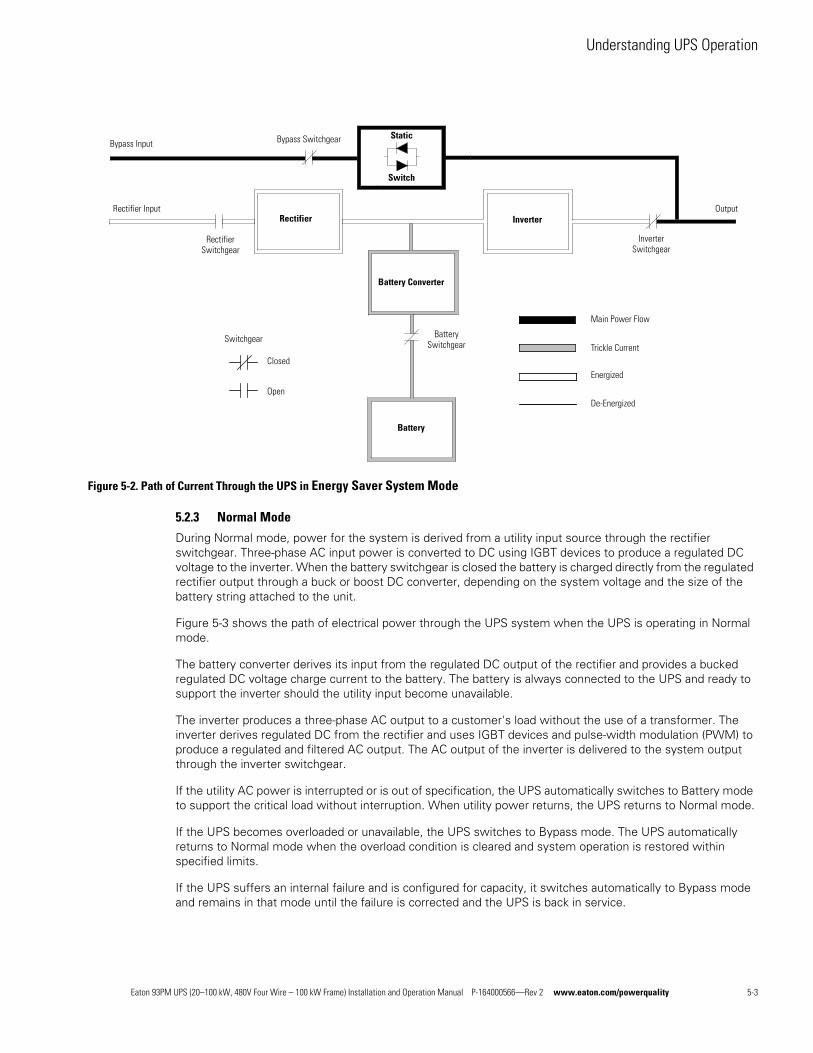
Understanding UPS Operation
Figure 5-2. Path of Current Through the UPS in Energy Saver System Mode
5.2.3 Normal Mode
During Normal mode, power for the system is derived from a utility input source through the rectifier switchgear. Three-phase AC input power is converted to DC using IGBT devices to produce a regulated DC voltage to the inverter. When the battery switchgear is closed the battery is charged directly from the regulated rectifier output through a buck or boost DC converter, depending on the system voltage and the size of the battery string attached to the unit.
Figure 5-3 shows the path of electrical power through the UPS system when the UPS is operating in Normal mode.
The battery converter derives its input from the regulated DC output of the rectifier and provides a bucked regulated DC voltage charge current to the battery. The battery is always connected to the UPS and ready to support the inverter should the utility input become unavailable.
The inverter produces a three-phase AC output to a customer's load without the use of a transformer. The inverter derives regulated DC from the rectifier and uses IGBT devices and pulse-width modulation (PWM) to produce a regulated and filtered AC output. The AC output of the inverter is delivered to the system output through the inverter switchgear.
If the utility AC power is interrupted or is out of specification, the UPS automatically switches to Battery mode to support the critical load without interruption. When utility power returns, the UPS returns to Normal mode.
If the UPS becomes overloaded or unavailable, the UPS switches to Bypass mode. The UPS automatically returns to Normal mode when the overload condition is cleared and system operation is restored within specified limits.
If the UPS suffers an internal failure and is configured for capacity, it switches automatically to Bypass mode and remains in that mode until the failure is corrected and the UPS is back in service.
Static
Switch
Bypass InputStatic
Switch
Bypass Switchgear
Rectifier Inverter
Inverter Switchgear
Rectifier Switchgear
Rectifier Input Output
Battery Converter
Battery Switchgear
Main Power Flow
Switchgear
Closed
Open
Battery
Trickle Current
De-Energized
Energized
Eaton 93PM UPS (20–100 kW, 480V Four Wire – 100 kW Frame) Installation and Operation Manual P-164000566—Rev 2 www.eaton.com/powerquality 5-3
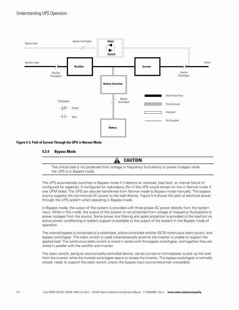
Understanding UPS Operation
Figure 5-3. Path of Current Through the UPS in Normal Mode
5.2.4 Bypass Mode
CAUTIONThe critical load is not protected from voltage or frequency fluctuations or power outages while the UPS is in Bypass mode.
The UPS automatically switches to Bypass mode if it detects an overload, load fault, or internal failure (if configured for capacity). If configured for redundancy (N+1) the UPS would remain on line in Normal mode if one UPM failed. The UPS can also be transferred from Normal mode to Bypass mode manually. The bypass source supplies the commercial AC power to the load directly. Figure 5-4 shows the path of electrical power through the UPS system when operating in Bypass mode.
In Bypass mode, the output of the system is provided with three-phase AC power directly from the system input. While in this mode, the output of the system is not protected from voltage or frequency fluctuations or power outages from the source. Some power line filtering and spike protection is provided to the load but no active power conditioning or battery support is available to the output of the system in the Bypass mode of operation.
The internal bypass is comprised of a solid-state, silicon-controlled rectifier (SCR) continuous static switch, and bypass switchgear. The static switch is used instantaneously anytime the inverter is unable to support the applied load. The continuous static switch is wired in series with the bypass switchgear, and together they are wired in parallel with the rectifier and inverter.
The static switch, being an electronically-controlled device, can be turned on immediately to pick up the load from the inverter while the inverter switchgear opens to isolate the inverter. The bypass switchgear is normally closed, ready to support the static switch unless the bypass input source becomes unavailable.
Rectifier Inverter
Battery Converter
Battery Switchgear
Main Power Flow
Output
Inverter Switchgear
Bypass Input
Rectifier Switchgear
Rectifier Input
Switchgear
Closed
Open
Battery
Trickle Current
De-Energized
Energized
Static
Switch
Bypass Switchgear
5-4 Eaton 93PM UPS (20–100 kW, 480V Four Wire – 100 kW Frame) Installation and Operation Manual P-164000566—Rev 2 www.eaton.com/powerquality
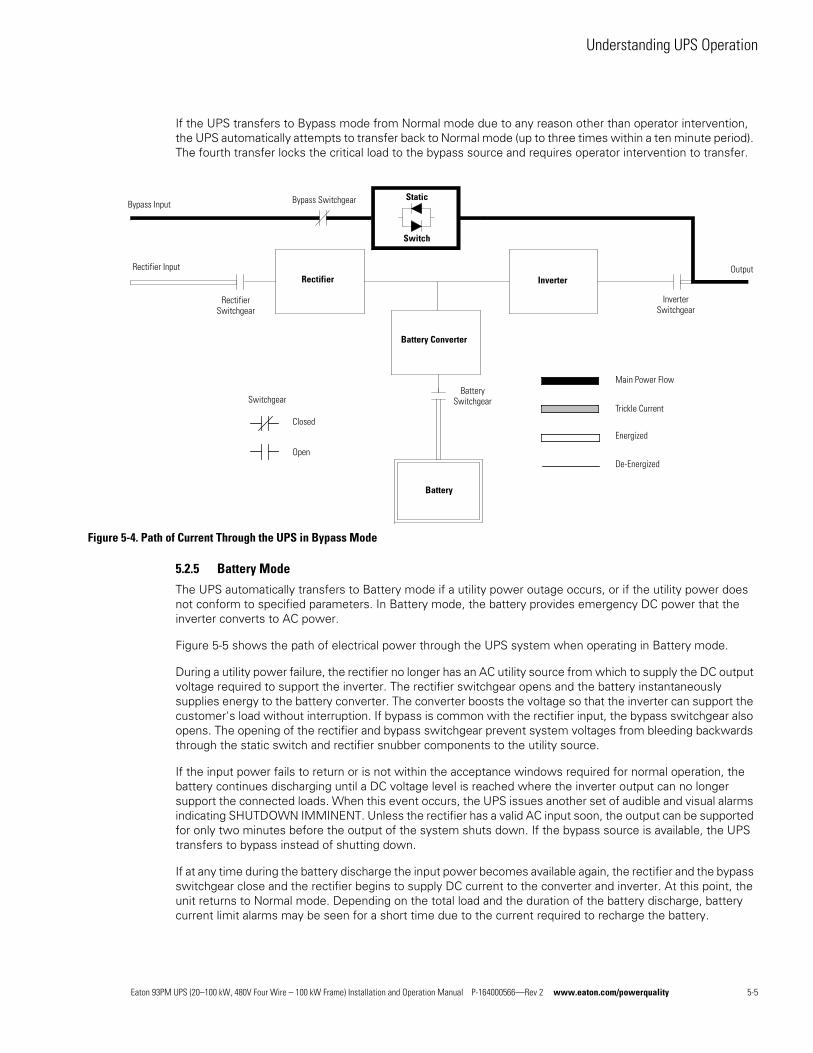
Understanding UPS Operation
If the UPS transfers to Bypass mode from Normal mode due to any reason other than operator intervention, the UPS automatically attempts to transfer back to Normal mode (up to three times within a ten minute period). The fourth transfer locks the critical load to the bypass source and requires operator intervention to transfer.
Figure 5-4. Path of Current Through the UPS in Bypass Mode
5.2.5 Battery Mode
The UPS automatically transfers to Battery mode if a utility power outage occurs, or if the utility power does not conform to specified parameters. In Battery mode, the battery provides emergency DC power that the inverter converts to AC power.
Figure 5-5 shows the path of electrical power through the UPS system when operating in Battery mode.
During a utility power failure, the rectifier no longer has an AC utility source from which to supply the DC output voltage required to support the inverter. The rectifier switchgear opens and the battery instantaneously supplies energy to the battery converter. The converter boosts the voltage so that the inverter can support the customer's load without interruption. If bypass is common with the rectifier input, the bypass switchgear also opens. The opening of the rectifier and bypass switchgear prevent system voltages from bleeding backwards through the static switch and rectifier snubber components to the utility source.
If the input power fails to return or is not within the acceptance windows required for normal operation, the battery continues discharging until a DC voltage level is reached where the inverter output can no longer support the connected loads. When this event occurs, the UPS issues another set of audible and visual alarms indicating SHUTDOWN IMMINENT. Unless the rectifier has a valid AC input soon, the output can be supported for only two minutes before the output of the system shuts down. If the bypass source is available, the UPS transfers to bypass instead of shutting down.
If at any time during the battery discharge the input power becomes available again, the rectifier and the bypass switchgear close and the rectifier begins to supply DC current to the converter and inverter. At this point, the unit returns to Normal mode. Depending on the total load and the duration of the battery discharge, battery current limit alarms may be seen for a short time due to the current required to recharge the battery.
Bypass InputStatic
Switch
Bypass Switchgear
Rectifier Inverter
Inverter Switchgear
Rectifier Switchgear
Rectifier Input Output
Battery Converter
Battery Switchgear
Main Power Flow
Switchgear
Closed
Open
Battery
Trickle Current
De-Energized
Energized
Eaton 93PM UPS (20–100 kW, 480V Four Wire – 100 kW Frame) Installation and Operation Manual P-164000566—Rev 2 www.eaton.com/powerquality 5-5
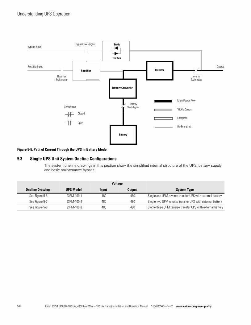
Understanding UPS Operation
Figure 5-5. Path of Current Through the UPS in Battery Mode
5.3 Single UPS Unit System Oneline ConfigurationsThe system oneline drawings in this section show the simplified internal structure of the UPS, battery supply, and basic maintenance bypass.
Bypass InputStatic
Switch
Bypass Switchgear
Rectifier Inverter
Inverter Switchgear
Rectifier Switchgear
Rectifier Input Output
Battery Converter
Battery Switchgear
Main Power Flow
Switchgear
Closed
Open
Battery
Trickle Current
De-Energized
Energized
Oneline Drawing UPS Model
Voltage
System TypeInput Output
See Figure 5-6 93PM-100-1 480 480 Single one UPM reverse transfer UPS with external battery
See Figure 5-7 93PM-100-2 480 480 Single two UPM reverse transfer UPS with external battery
See Figure 5-8 93PM-100-3 480 480 Single three UPM reverse transfer UPS with external battery
5-6 Eaton 93PM UPS (20–100 kW, 480V Four Wire – 100 kW Frame) Installation and Operation Manual P-164000566—Rev 2 www.eaton.com/powerquality
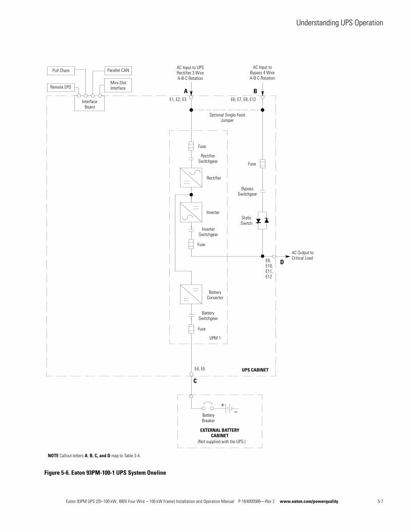
Understanding UPS Operation
Figure 5-6. Eaton 93PM-100-1 UPS System Oneline
Optional Single-Feed Jumper
Battery Breaker
EXTERNAL BATTERYCABINET
(Not supplied with the UPS.)
C
E4, E5
E1, E2, E3 E6, E7, E8, E12
Parallel CAN
Mini-Slot Interface
Interface Board
Pull Chain
Remote EPO
AC Input to Bypass 4 Wire A-B-C Rotation
AC Input to UPS Rectifier 3 Wire A-B-C Rotation
A B
AC Output to Critical Load
D
UPS CABINET
E9, E10, E11,E12
Bypass Switchgear
Static Switch
Fuse
UPM 1
Battery Switchgear
Battery Converter
Fuse
Rectifier
Fuse
Rectifier Switchgear
Fuse
Inverter
Inverter Switchgear
NOTE Callout letters A, B, C, and D map to Table 3-4.
Eaton 93PM UPS (20–100 kW, 480V Four Wire – 100 kW Frame) Installation and Operation Manual P-164000566—Rev 2 www.eaton.com/powerquality 5-7
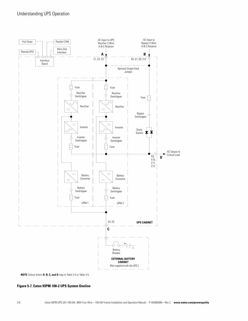
Understanding UPS Operation
Figure 5-7. Eaton 93PM-100-2 UPS System Oneline
Optional Single-Feed Jumper
Battery Breaker
EXTERNAL BATTERYCABINET
(Not supplied with the UPS.)
C
E4, E5
E1, E2, E3 E6, E7, E8, E12
Parallel CAN
Mini-Slot Interface
Interface Board
Pull Chain
Remote EPO
AC Input to Bypass 4 Wire A-B-C Rotation
AC Input to UPS Rectifier 3 Wire A-B-C Rotation
A B
AC Output to Critical Load
D
UPS CABINET
E9, E10, E11,E12
Bypass Switchgear
Fuse
UPM 1
Battery Switchgear
Battery Converter
Fuse
Rectifier
Fuse
Rectifier Switchgear
Fuse
Inverter
Inverter Switchgear
UPM 2
Battery Switchgear
Battery Converter
Fuse
Rectifier
Fuse
Rectifier Switchgear
Fuse
Inverter
Inverter Switchgear
Static Switch
NOTE Callout letters A, B, C, and D map to Table 3-4 or Table 3-5.
5-8 Eaton 93PM UPS (20–100 kW, 480V Four Wire – 100 kW Frame) Installation and Operation Manual P-164000566—Rev 2 www.eaton.com/powerquality
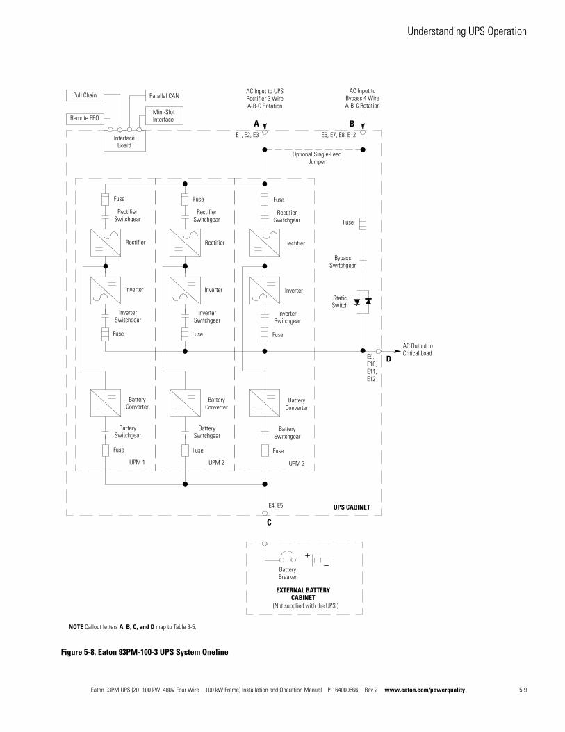
Understanding UPS Operation
Figure 5-8. Eaton 93PM-100-3 UPS System Oneline
Optional Single-Feed Jumper
Battery Breaker
EXTERNAL BATTERYCABINET
(Not supplied with the UPS.)
C
E4, E5
E1, E2, E3 E6, E7, E8, E12
Parallel CAN
Mini-Slot Interface
Interface Board
Pull Chain
Remote EPO
AC Input to Bypass 4 Wire A-B-C Rotation
AC Input to UPS Rectifier 3 Wire A-B-C Rotation
A B
AC Output to Critical Load
D
UPS CABINET
E9, E10, E11,E12
Bypass Switchgear
Static Switch
Fuse
UPM 1
Battery Switchgear
Battery Converter
Fuse
Rectifier
Fuse
Rectifier Switchgear
Fuse
Inverter
Inverter Switchgear
UPM 2
Battery Switchgear
Battery Converter
Fuse
Rectifier
Fuse
Rectifier Switchgear
Fuse
Inverter
Inverter Switchgear
UPM 3
Battery Switchgear
Battery Converter
Fuse
Rectifier
Fuse
Rectifier Switchgear
Fuse
Inverter
Inverter Switchgear
NOTE Callout letters A, B, C, and D map to Table 3-5.
Eaton 93PM UPS (20–100 kW, 480V Four Wire – 100 kW Frame) Installation and Operation Manual P-164000566—Rev 2 www.eaton.com/powerquality 5-9

Understanding UPS Operation
This page intentionally left blank.
5-10 Eaton 93PM UPS (20–100 kW, 480V Four Wire – 100 kW Frame) Installation and Operation Manual P-164000566—Rev 2 www.eaton.com/powerquality
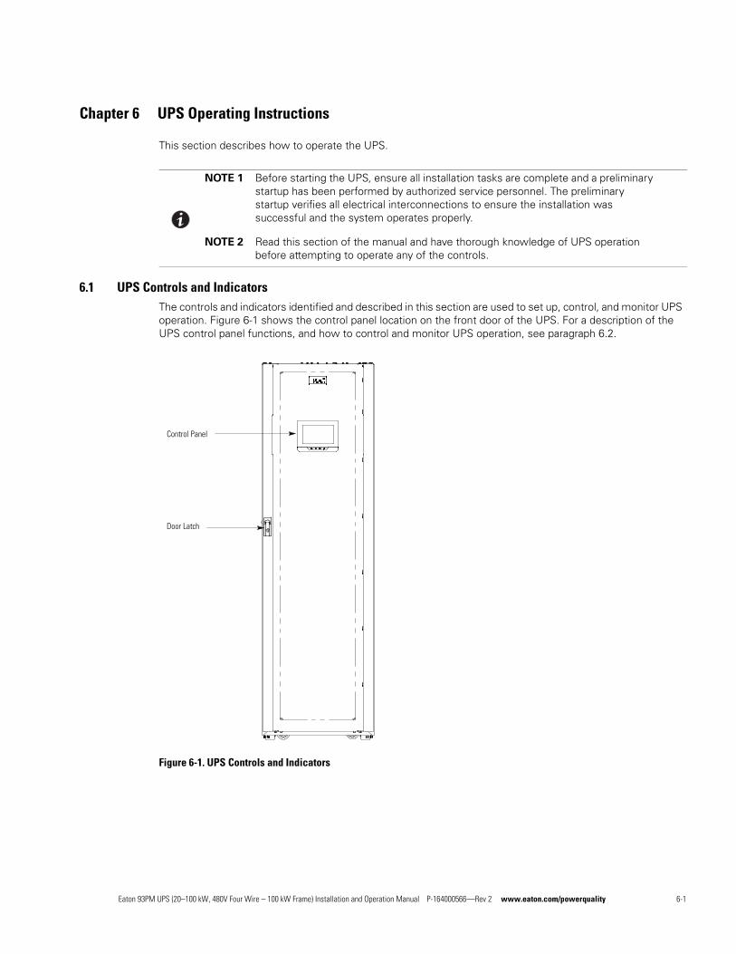
Chapter 6 UPS Operating Instructions
This section describes how to operate the UPS.
6.1 UPS Controls and IndicatorsThe controls and indicators identified and described in this section are used to set up, control, and monitor UPS operation. Figure 6-1 shows the control panel location on the front door of the UPS. For a description of the UPS control panel functions, and how to control and monitor UPS operation, see paragraph 6.2.
Figure 6-1. UPS Controls and Indicators
NOTE 1 Before starting the UPS, ensure all installation tasks are complete and a preliminary startup has been performed by authorized service personnel. The preliminary startup verifies all electrical interconnections to ensure the installation was successful and the system operates properly.
NOTE 2 Read this section of the manual and have thorough knowledge of UPS operation before attempting to operate any of the controls.
Door Latch
Control Panel
Eaton 93PM UPS (20–100 kW, 480V Four Wire – 100 kW Frame) Installation and Operation Manual P-164000566—Rev 2 www.eaton.com/powerquality 6-1
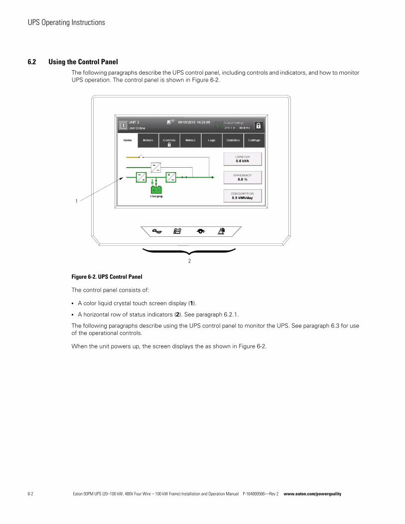
UPS Operating Instructions
6.2 Using the Control PanelThe following paragraphs describe the UPS control panel, including controls and indicators, and how to monitor UPS operation. The control panel is shown in Figure 6-2.
Figure 6-2. UPS Control Panel
The control panel consists of:
l A color liquid crystal touch screen display (1).
l A horizontal row of status indicators (2). See paragraph 6.2.1.
The following paragraphs describe using the UPS control panel to monitor the UPS. See paragraph 6.3 for use of the operational controls.
When the unit powers up, the screen displays the as shown in Figure 6-2.
1
2
6-2 Eaton 93PM UPS (20–100 kW, 480V Four Wire – 100 kW Frame) Installation and Operation Manual P-164000566—Rev 2 www.eaton.com/powerquality
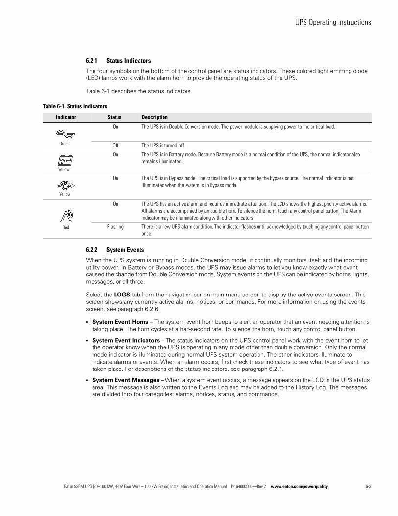
UPS Operating Instructions
6.2.1 Status Indicators
The four symbols on the bottom of the control panel are status indicators. These colored light emitting diode (LED) lamps work with the alarm horn to provide the operating status of the UPS.
Table 6-1 describes the status indicators.
6.2.2 System Events
When the UPS system is running in Double Conversion mode, it continually monitors itself and the incoming utility power. In Battery or Bypass modes, the UPS may issue alarms to let you know exactly what event caused the change from Double Conversion mode. System events on the UPS can be indicated by horns, lights, messages, or all three.
Select the LOGS tab from the navigation bar on main menu screen to display the active events screen. This screen shows any currently active alarms, notices, or commands. For more information on using the events screen, see paragraph 6.2.6.
l System Event Horns – The system event horn beeps to alert an operator that an event needing attention is taking place. The horn cycles at a half-second rate. To silence the horn, touch any control panel button.
l System Event Indicators – The status indicators on the UPS control panel work with the event horn to let the operator know when the UPS is operating in any mode other than double conversion. Only the normal mode indicator is illuminated during normal UPS system operation. The other indicators illuminate to indicate alarms or events. When an alarm occurs, first check these indicators to see what type of event has taken place. For descriptions of the status indicators, see paragraph 6.2.1.
l System Event Messages – When a system event occurs, a message appears on the LCD in the UPS status area. This message is also written to the Events Log and may be added to the History Log. The messages are divided into four categories: alarms, notices, status, and commands.
Table 6-1. Status Indicators
Indicator Status Description
On The UPS is in Double Conversion mode. The power module is supplying power to the critical load.
Off The UPS is turned off.
On The UPS is in Battery mode. Because Battery mode is a normal condition of the UPS, the normal indicator also remains illuminated.
On The UPS is in Bypass mode. The critical load is supported by the bypass source. The normal indicator is not illuminated when the system is in Bypass mode.
On The UPS has an active alarm and requires immediate attention. The LCD shows the highest priority active alarms. All alarms are accompanied by an audible horn. To silence the horn, touch any control panel button. The Alarm indicator may be illuminated along with other indicators.
Flashing There is a new UPS alarm condition. The indicator flashes until acknowledged by touching any control panel button once.
Green
Yellow
Yellow
Red
Eaton 93PM UPS (20–100 kW, 480V Four Wire – 100 kW Frame) Installation and Operation Manual P-164000566—Rev 2 www.eaton.com/powerquality 6-3
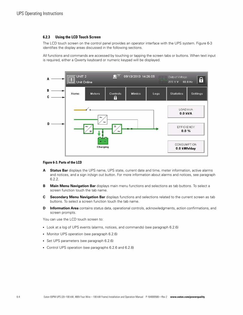
UPS Operating Instructions
6.2.3 Using the LCD Touch Screen
The LCD touch screen on the control panel provides an operator interface with the UPS system. Figure 6-3 identifies the display areas discussed in the following sections.
All functions and commands are accessed by touching or tapping the screen tabs or buttons. When text input is required, either a Qwerty keyboard or numeric keypad will be displayed.
Figure 6-3. Parts of the LCD
A Status Bar displays the UPS name, UPS state, current date and time, meter information, active alarms and notices, and a sign in/sign out button. For more information about alarms and notices, see paragraph 6.2.2.
B Main Menu Navigation Bar displays main menu functions and selections as tab buttons. To select a screen function touch the tab name.
C Secondary Menu Navigation Bar displays functions and selections related to the current screen as tab buttons. To select a screen function touch the tab name.
D Information Area contains status data, operational controls, acknowledgments, action confirmations, and screen prompts.
You can use the LCD touch screen to:
l Look at a log of UPS events (alarms, notices, and commands) (see paragraph 6.2.6)
l Monitor UPS operation (see paragraph 6.2.6)
l Set UPS parameters (see paragraph 6.2.6)
l Control UPS operation (see paragraphs 6.2.6 and 6.2.8)
A
B
C
D
6-4 Eaton 93PM UPS (20–100 kW, 480V Four Wire – 100 kW Frame) Installation and Operation Manual P-164000566—Rev 2 www.eaton.com/powerquality
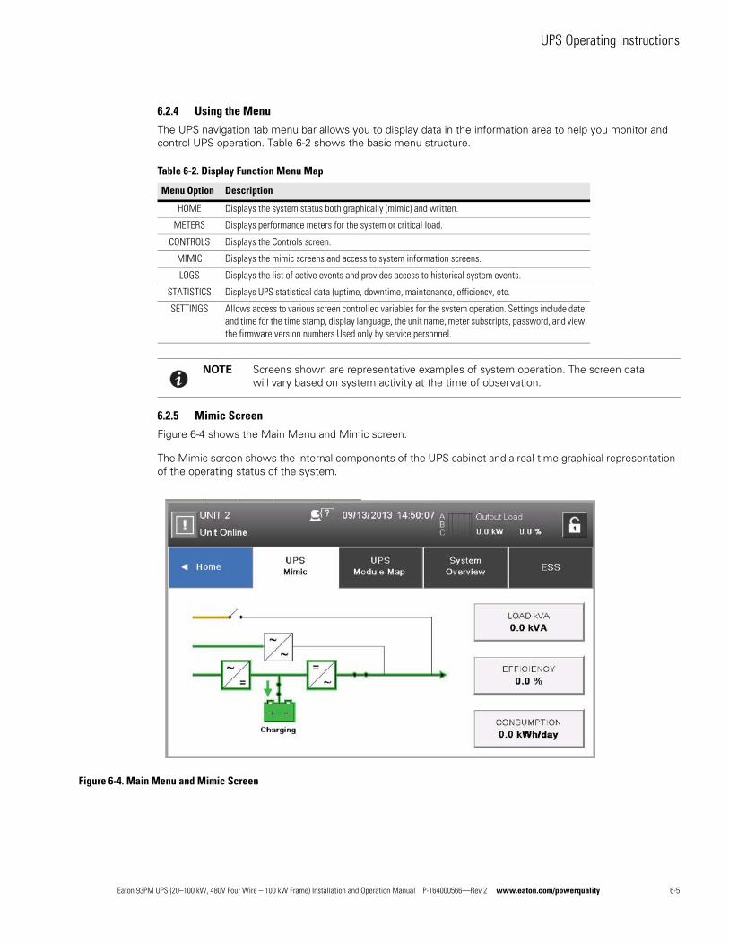
UPS Operating Instructions
6.2.4 Using the Menu
The UPS navigation tab menu bar allows you to display data in the information area to help you monitor and control UPS operation. Table 6-2 shows the basic menu structure.
6.2.5 Mimic Screen
Figure 6-4 shows the Main Menu and Mimic screen.
The Mimic screen shows the internal components of the UPS cabinet and a real-time graphical representation of the operating status of the system.
Figure 6-4. Main Menu and Mimic Screen
Table 6-2. Display Function Menu Map
Menu Option Description
HOME Displays the system status both graphically (mimic) and written.
METERS Displays performance meters for the system or critical load.
CONTROLS Displays the Controls screen.
MIMIC Displays the mimic screens and access to system information screens.
LOGS Displays the list of active events and provides access to historical system events.
STATISTICS Displays UPS statistical data (uptime, downtime, maintenance, efficiency, etc.
SETTINGS Allows access to various screen controlled variables for the system operation. Settings include date and time for the time stamp, display language, the unit name, meter subscripts, password, and view the firmware version numbers Used only by service personnel.
NOTE Screens shown are representative examples of system operation. The screen data will vary based on system activity at the time of observation.
Eaton 93PM UPS (20–100 kW, 480V Four Wire – 100 kW Frame) Installation and Operation Manual P-164000566—Rev 2 www.eaton.com/powerquality 6-5
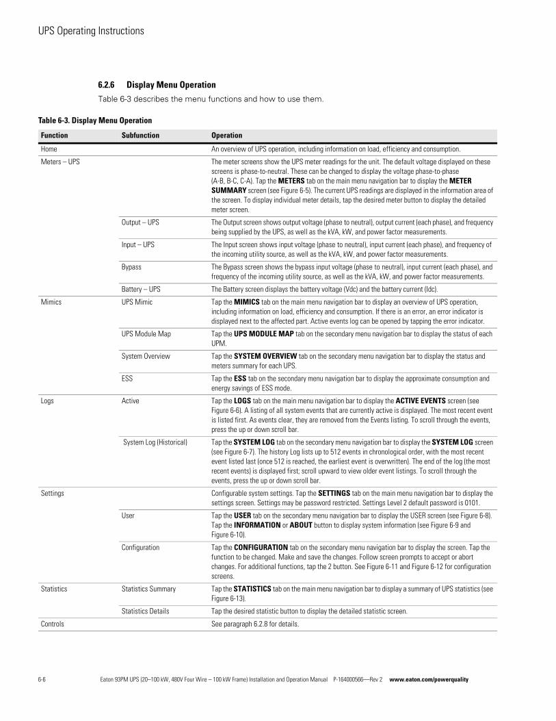
UPS Operating Instructions
6.2.6 Display Menu Operation
Table 6-3 describes the menu functions and how to use them.
Table 6-3. Display Menu Operation
Function Subfunction Operation
Home An overview of UPS operation, including information on load, efficiency and consumption.
Meters – UPS The meter screens show the UPS meter readings for the unit. The default voltage displayed on these screens is phase-to-neutral. These can be changed to display the voltage phase-to-phase (A-B, B-C, C-A). Tap the METERS tab on the main menu navigation bar to display the METER SUMMARY screen (see Figure 6-5). The current UPS readings are displayed in the information area of the screen. To display individual meter details, tap the desired meter button to display the detailed meter screen.
Output – UPS The Output screen shows output voltage (phasetoneutral), output current (each phase), and frequency being supplied by the UPS, as well as the kVA, kW, and power factor measurements.
Input – UPS The Input screen shows input voltage (phasetoneutral), input current (each phase), and frequency of the incoming utility source, as well as the kVA, kW, and power factor measurements.
Bypass The Bypass screen shows the bypass input voltage (phasetoneutral), input current (each phase), and frequency of the incoming utility source, as well as the kVA, kW, and power factor measurements.
Battery – UPS The Battery screen displays the battery voltage (Vdc) and the battery current (Idc).
Mimics UPS Mimic Tap the MIMICS tab on the main menu navigation bar to display an overview of UPS operation, including information on load, efficiency and consumption. If there is an error, an error indicator is displayed next to the affected part. Active events log can be opened by tapping the error indicator.
UPS Module Map Tap the UPS MODULE MAP tab on the secondary menu navigation bar to display the status of each UPM.
System Overview Tap the SYSTEM OVERVIEW tab on the secondary menu navigation bar to display the status and meters summary for each UPS.
ESS Tap the ESS tab on the secondary menu navigation bar to display the approximate consumption and energy savings of ESS mode.
Logs Active Tap the LOGS tab on the main menu navigation bar to display the ACTIVE EVENTS screen (see Figure 6-6). A listing of all system events that are currently active is displayed. The most recent event is listed first. As events clear, they are removed from the Events listing. To scroll through the events, press the up or down scroll bar.
System Log (Historical) Tap the SYSTEM LOG tab on the secondary menu navigation bar to display the SYSTEM LOG screen (see Figure 6-7). The history Log lists up to 512 events in chronological order, with the most recent event listed last (once 512 is reached, the earliest event is overwritten). The end of the log (the most recent events) is displayed first; scroll upward to view older event listings. To scroll through the events, press the up or down scroll bar.
Settings Configurable system settings. Tap the SETTINGS tab on the main menu navigation bar to display the settings screen. Settings may be password restricted. Settings Level 2 default password is 0101.
User Tap the USER tab on the secondary menu navigation bar to display the USER screen (see Figure 6-8). Tap the INFORMATION or ABOUT button to display system information (see Figure 6-9 and Figure 6-10).
Configuration Tap the CONFIGURATION tab on the secondary menu navigation bar to display the screen. Tap the function to be changed. Make and save the changes. Follow screen prompts to accept or abort changes. For additional functions, tap the 2 button. See Figure 6-11 and Figure 6-12 for configuration screens.
Statistics Statistics Summary Tap the STATISTICS tab on the main menu navigation bar to display a summary of UPS statistics (see Figure 6-13).
Statistics Details Tap the desired statistic button to display the detailed statistic screen.
Controls See paragraph 6.2.8 for details.
6-6 Eaton 93PM UPS (20–100 kW, 480V Four Wire – 100 kW Frame) Installation and Operation Manual P-164000566—Rev 2 www.eaton.com/powerquality
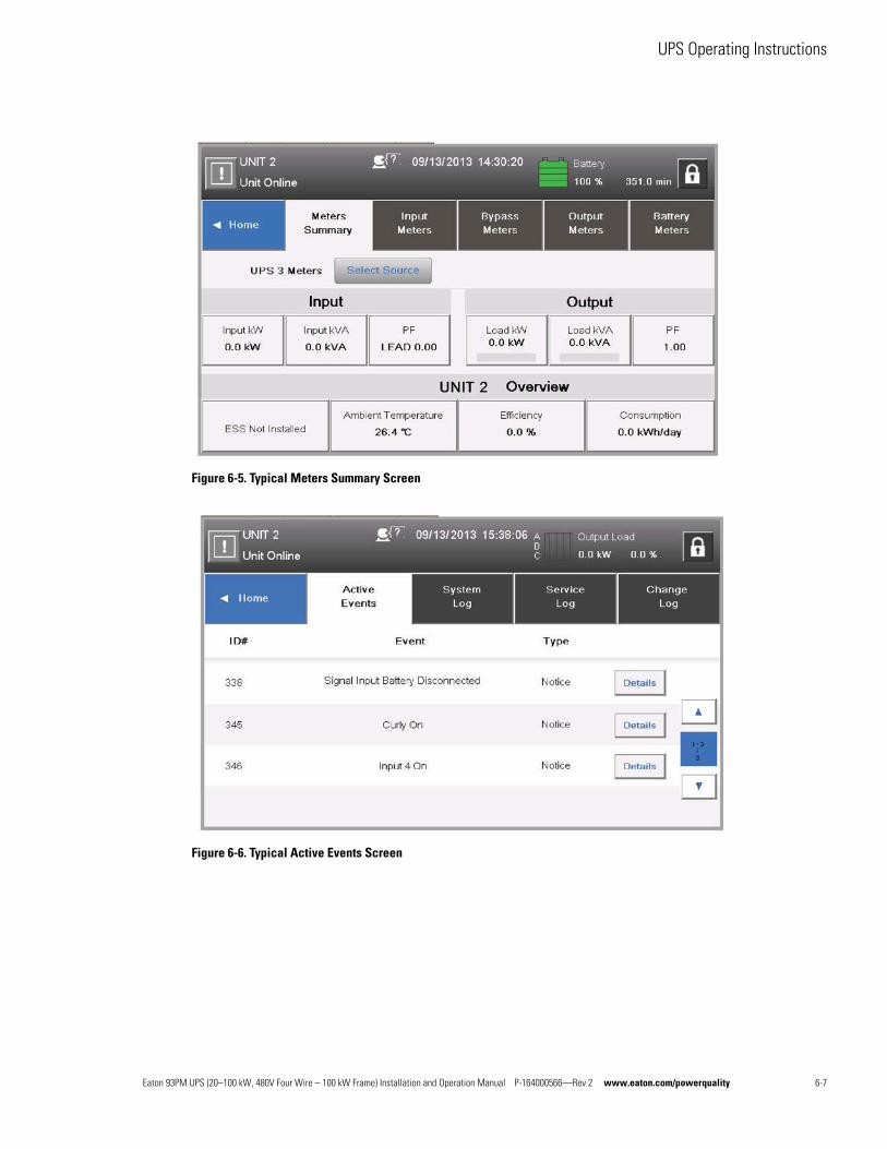
UPS Operating Instructions
Figure 6-5. Typical Meters Summary Screen
Figure 6-6. Typical Active Events Screen
Eaton 93PM UPS (20–100 kW, 480V Four Wire – 100 kW Frame) Installation and Operation Manual P-164000566—Rev 2 www.eaton.com/powerquality 6-7
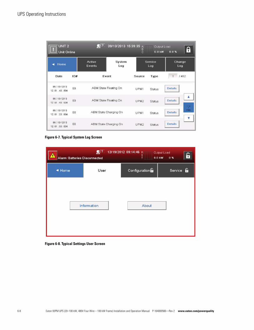
UPS Operating Instructions
Figure 6-7. Typical System Log Screen
Figure 6-8. Typical Settings User Screen
6-8 Eaton 93PM UPS (20–100 kW, 480V Four Wire – 100 kW Frame) Installation and Operation Manual P-164000566—Rev 2 www.eaton.com/powerquality
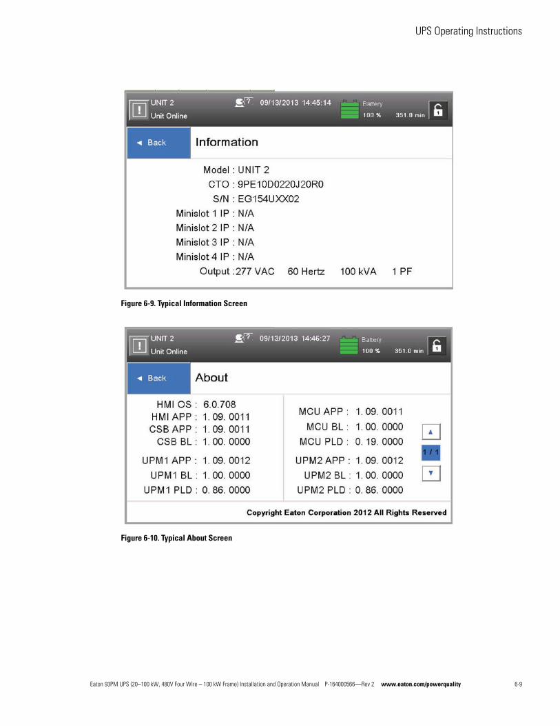
UPS Operating Instructions
Figure 6-9. Typical Information Screen
Figure 6-10. Typical About Screen
Eaton 93PM UPS (20–100 kW, 480V Four Wire – 100 kW Frame) Installation and Operation Manual P-164000566—Rev 2 www.eaton.com/powerquality 6-9
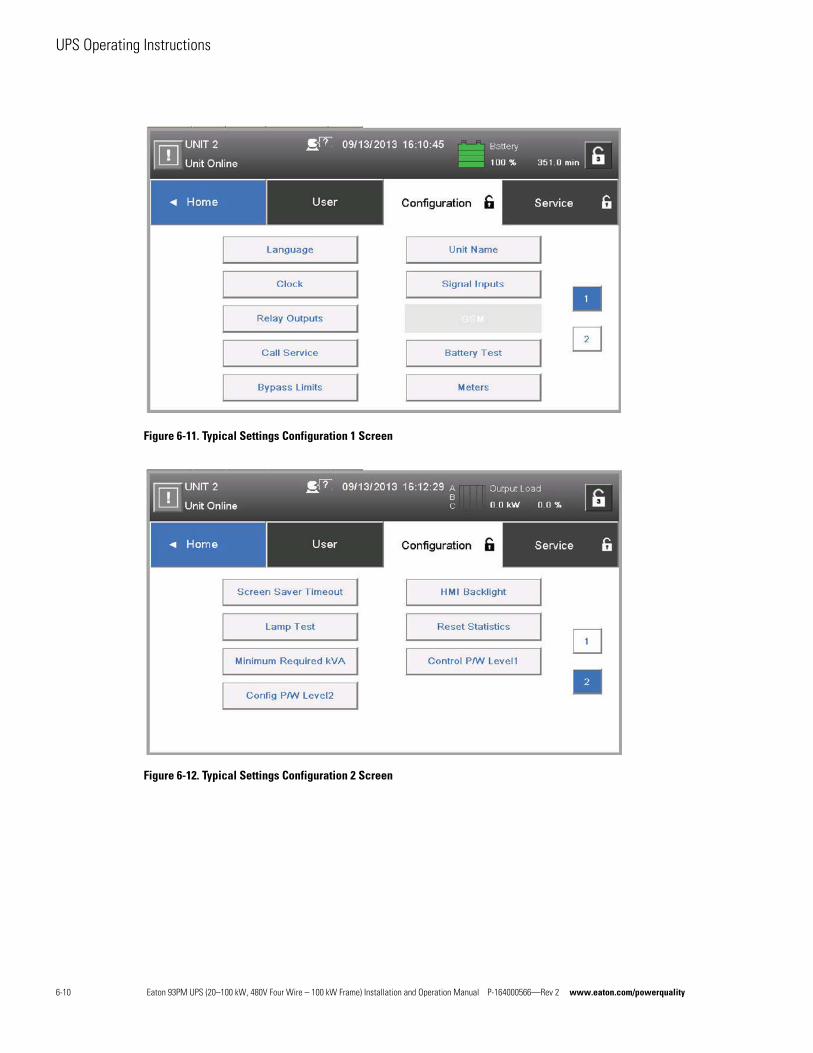
UPS Operating Instructions
Figure 6-11. Typical Settings Configuration 1 Screen
Figure 6-12. Typical Settings Configuration 2 Screen
6-10 Eaton 93PM UPS (20–100 kW, 480V Four Wire – 100 kW Frame) Installation and Operation Manual P-164000566—Rev 2 www.eaton.com/powerquality
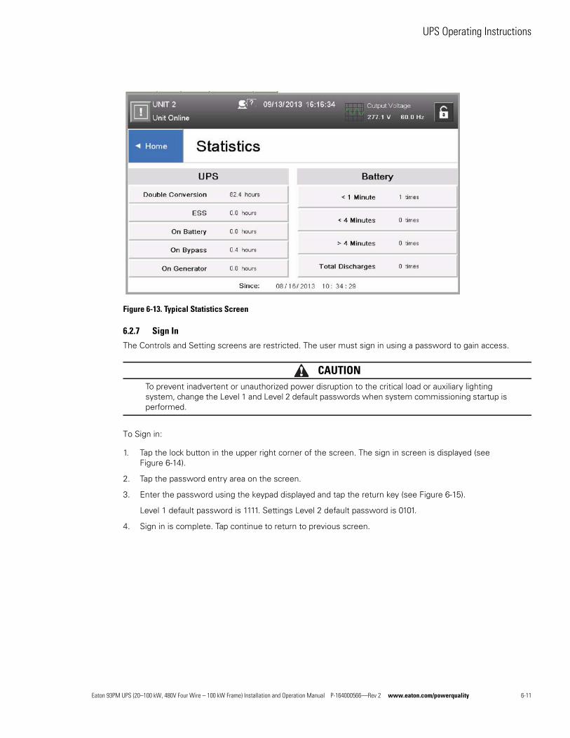
UPS Operating Instructions
Figure 6-13. Typical Statistics Screen
6.2.7 Sign In
The Controls and Setting screens are restricted. The user must sign in using a password to gain access.
CAUTIONTo prevent inadvertent or unauthorized power disruption to the critical load or auxiliary lighting system, change the Level 1 and Level 2 default passwords when system commissioning startup is performed.
To Sign in:
1. Tap the lock button in the upper right corner of the screen. The sign in screen is displayed (see Figure 6-14).
2. Tap the password entry area on the screen.
3. Enter the password using the keypad displayed and tap the return key (see Figure 6-15).
Level 1 default password is 1111. Settings Level 2 default password is 0101.
4. Sign in is complete. Tap continue to return to previous screen.
Eaton 93PM UPS (20–100 kW, 480V Four Wire – 100 kW Frame) Installation and Operation Manual P-164000566—Rev 2 www.eaton.com/powerquality 6-11
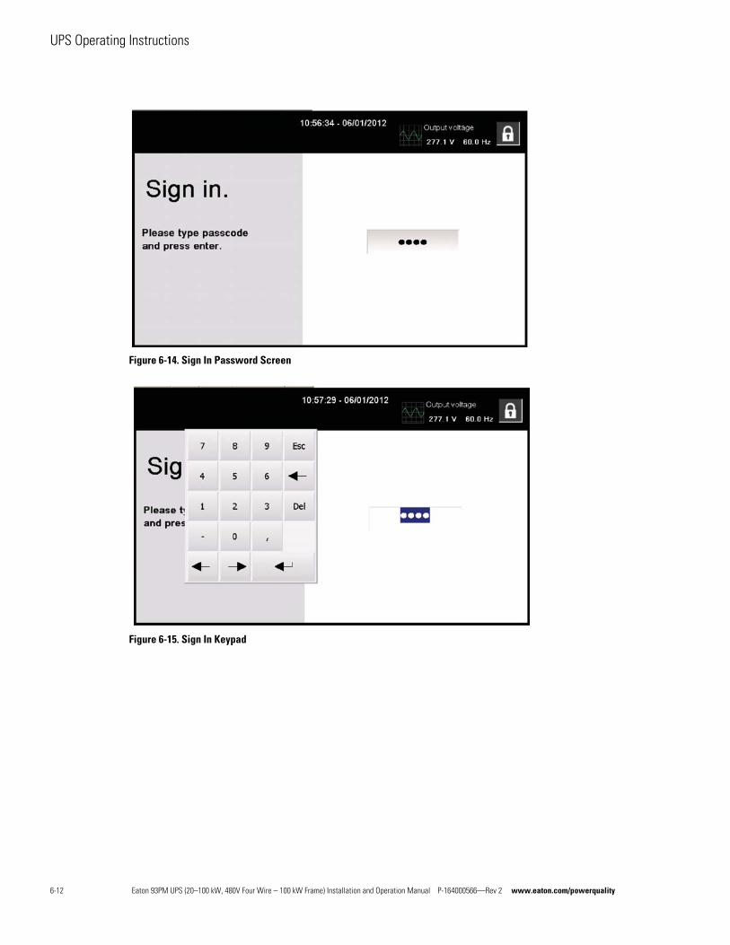
UPS Operating Instructions
Figure 6-14. Sign In Password Screen
Figure 6-15. Sign In Keypad
6-12 Eaton 93PM UPS (20–100 kW, 480V Four Wire – 100 kW Frame) Installation and Operation Manual P-164000566—Rev 2 www.eaton.com/powerquality
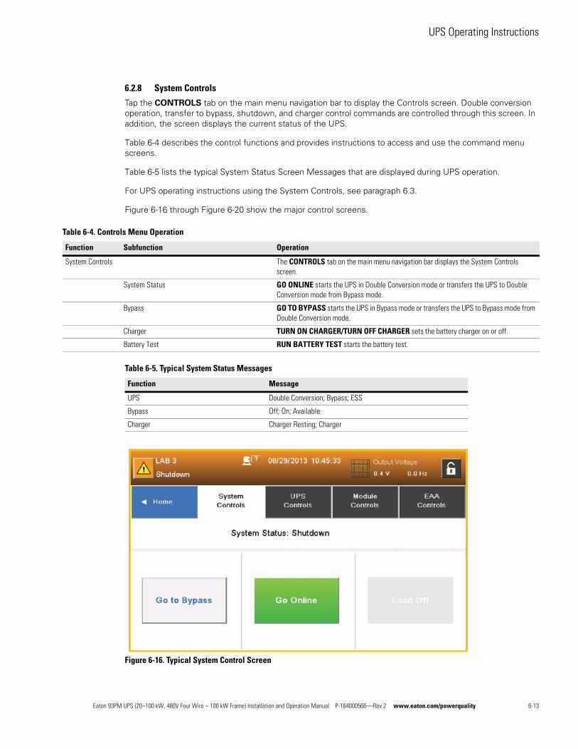
UPS Operating Instructions
6.2.8 System Controls
Tap the CONTROLS tab on the main menu navigation bar to display the Controls screen. Double conversion operation, transfer to bypass, shutdown, and charger control commands are controlled through this screen. In addition, the screen displays the current status of the UPS.
Table 6-4 describes the control functions and provides instructions to access and use the command menu screens.
Table 6-5 lists the typical System Status Screen Messages that are displayed during UPS operation.
For UPS operating instructions using the System Controls, see paragraph 6.3.
Figure 6-16 through Figure 6-20 show the major control screens.
Figure 6-16. Typical System Control Screen
Table 6-4. Controls Menu Operation
Function Subfunction Operation
System Controls The CONTROLS tab on the main menu navigation bar displays the System Controls screen.
System Status GO ONLINE starts the UPS in Double Conversion mode or transfers the UPS to Double Conversion mode from Bypass mode.
Bypass GO TO BYPASS starts the UPS in Bypass mode or transfers the UPS to Bypass mode from Double Conversion mode.
Charger TURN ON CHARGER/TURN OFF CHARGER sets the battery charger on or off.
Battery Test RUN BATTERY TEST starts the battery test.
Table 6-5. Typical System Status Messages
Function Message
UPS Double Conversion; Bypass; ESS
Bypass Off; On; Available
Charger Charger Resting; Charger
Eaton 93PM UPS (20–100 kW, 480V Four Wire – 100 kW Frame) Installation and Operation Manual P-164000566—Rev 2 www.eaton.com/powerquality 6-13
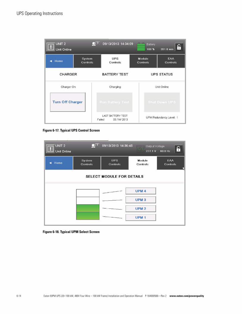
UPS Operating Instructions
Figure 6-17. Typical UPS Control Screen
Figure 6-18. Typical UPM Select Screen
6-14 Eaton 93PM UPS (20–100 kW, 480V Four Wire – 100 kW Frame) Installation and Operation Manual P-164000566—Rev 2 www.eaton.com/powerquality
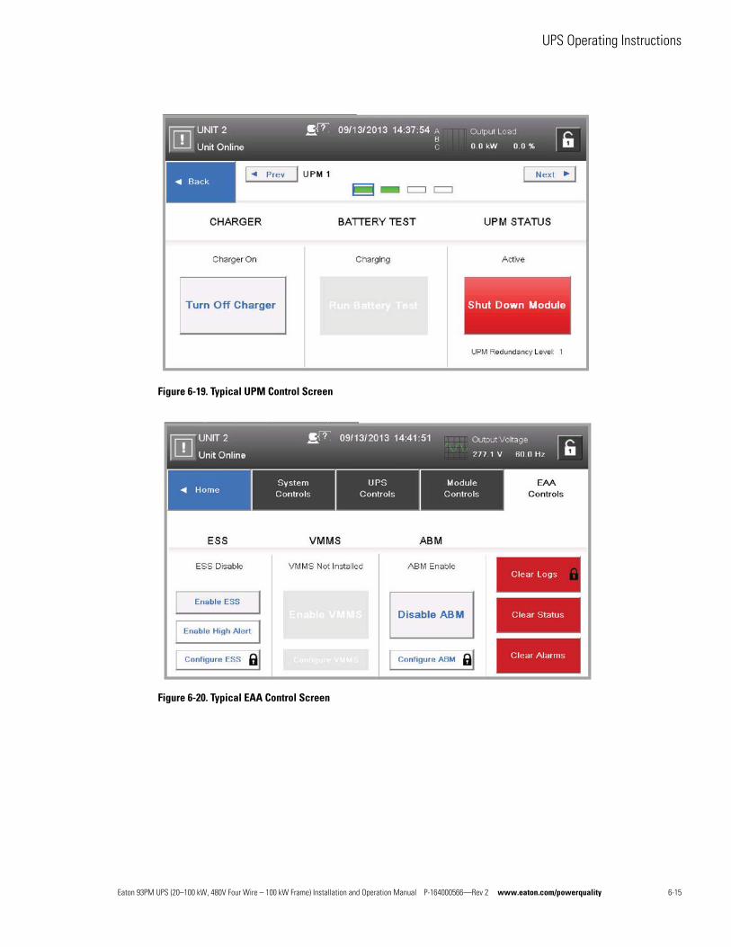
UPS Operating Instructions
Figure 6-19. Typical UPM Control Screen
Figure 6-20. Typical EAA Control Screen
Eaton 93PM UPS (20–100 kW, 480V Four Wire – 100 kW Frame) Installation and Operation Manual P-164000566—Rev 2 www.eaton.com/powerquality 6-15
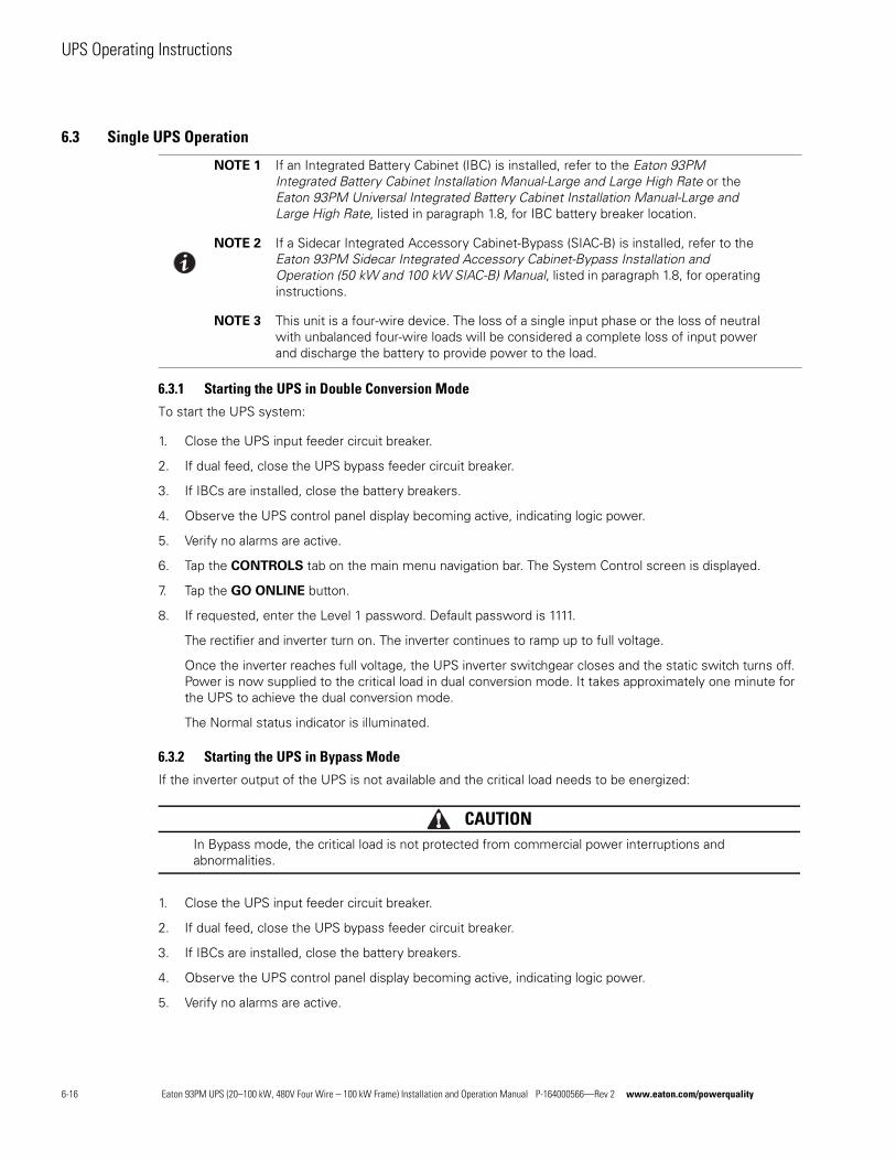
UPS Operating Instructions
6.3 Single UPS Operation
6.3.1 Starting the UPS in Double Conversion Mode
To start the UPS system:
1. Close the UPS input feeder circuit breaker.
2. If dual feed, close the UPS bypass feeder circuit breaker.
3. If IBCs are installed, close the battery breakers.
4. Observe the UPS control panel display becoming active, indicating logic power.
5. Verify no alarms are active.
6. Tap the CONTROLS tab on the main menu navigation bar. The System Control screen is displayed.
7. Tap the GO ONLINE button.
8. If requested, enter the Level 1 password. Default password is 1111.
The rectifier and inverter turn on. The inverter continues to ramp up to full voltage.
Once the inverter reaches full voltage, the UPS inverter switchgear closes and the static switch turns off. Power is now supplied to the critical load in dual conversion mode. It takes approximately one minute for the UPS to achieve the dual conversion mode.
The Normal status indicator is illuminated.
6.3.2 Starting the UPS in Bypass Mode
If the inverter output of the UPS is not available and the critical load needs to be energized:
CAUTIONIn Bypass mode, the critical load is not protected from commercial power interruptions and abnormalities.
1. Close the UPS input feeder circuit breaker.
2. If dual feed, close the UPS bypass feeder circuit breaker.
3. If IBCs are installed, close the battery breakers.
4. Observe the UPS control panel display becoming active, indicating logic power.
5. Verify no alarms are active.
NOTE 1 If an Integrated Battery Cabinet (IBC) is installed, refer to the Eaton 93PM Integrated Battery Cabinet Installation Manual-Large and Large High Rate or the Eaton 93PM Universal Integrated Battery Cabinet Installation Manual-Large and Large High Rate, listed in paragraph 1.8, for IBC battery breaker location.
NOTE 2 If a Sidecar Integrated Accessory Cabinet-Bypass (SIAC-B) is installed, refer to the Eaton 93PM Sidecar Integrated Accessory Cabinet-Bypass Installation and Operation (50 kW and 100 kW SIAC-B) Manual, listed in paragraph 1.8, for operating instructions.
NOTE 3 This unit is a four-wire device. The loss of a single input phase or the loss of neutral with unbalanced four-wire loads will be considered a complete loss of input power and discharge the battery to provide power to the load.
6-16 Eaton 93PM UPS (20–100 kW, 480V Four Wire – 100 kW Frame) Installation and Operation Manual P-164000566—Rev 2 www.eaton.com/powerquality
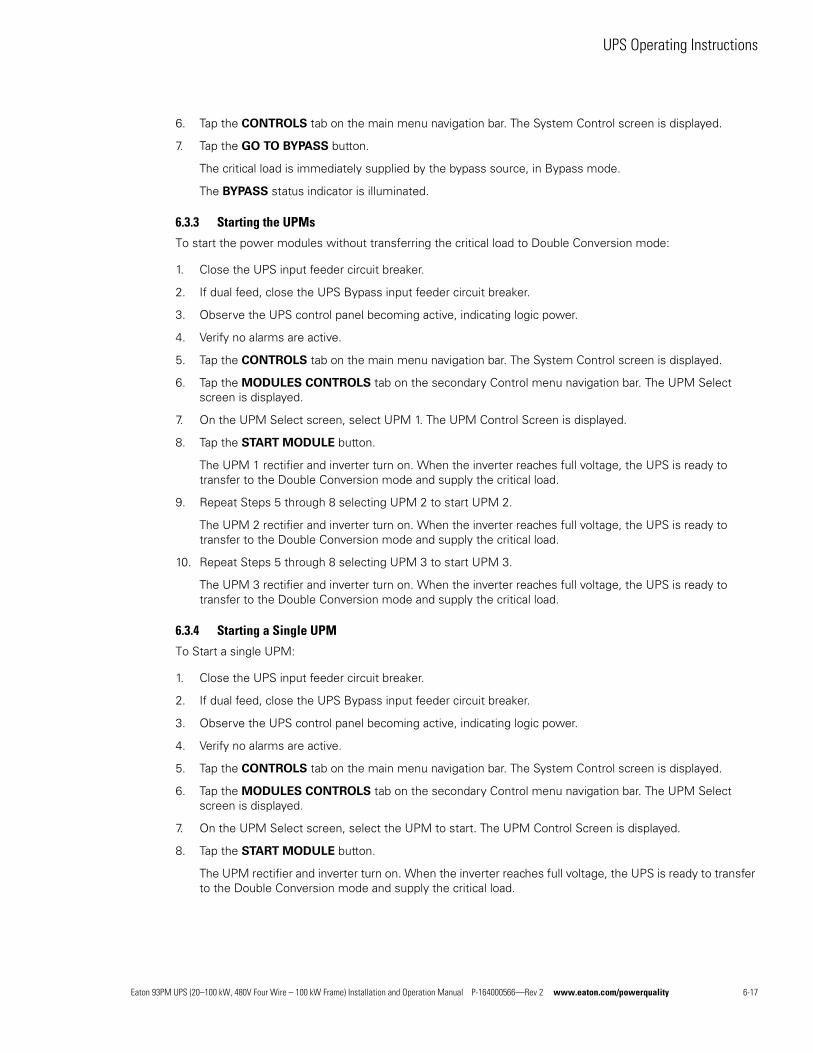
UPS Operating Instructions
6. Tap the CONTROLS tab on the main menu navigation bar. The System Control screen is displayed.
7. Tap the GO TO BYPASS button.
The critical load is immediately supplied by the bypass source, in Bypass mode.
The BYPASS status indicator is illuminated.
6.3.3 Starting the UPMs
To start the power modules without transferring the critical load to Double Conversion mode:
1. Close the UPS input feeder circuit breaker.
2. If dual feed, close the UPS Bypass input feeder circuit breaker.
3. Observe the UPS control panel becoming active, indicating logic power.
4. Verify no alarms are active.
5. Tap the CONTROLS tab on the main menu navigation bar. The System Control screen is displayed.
6. Tap the MODULES CONTROLS tab on the secondary Control menu navigation bar. The UPM Select screen is displayed.
7. On the UPM Select screen, select UPM 1. The UPM Control Screen is displayed.
8. Tap the START MODULE button.
The UPM 1 rectifier and inverter turn on. When the inverter reaches full voltage, the UPS is ready to transfer to the Double Conversion mode and supply the critical load.
9. Repeat Steps 5 through 8 selecting UPM 2 to start UPM 2.
The UPM 2 rectifier and inverter turn on. When the inverter reaches full voltage, the UPS is ready to transfer to the Double Conversion mode and supply the critical load.
10. Repeat Steps 5 through 8 selecting UPM 3 to start UPM 3.
The UPM 3 rectifier and inverter turn on. When the inverter reaches full voltage, the UPS is ready to transfer to the Double Conversion mode and supply the critical load.
6.3.4 Starting a Single UPM
To Start a single UPM:
1. Close the UPS input feeder circuit breaker.
2. If dual feed, close the UPS Bypass input feeder circuit breaker.
3. Observe the UPS control panel becoming active, indicating logic power.
4. Verify no alarms are active.
5. Tap the CONTROLS tab on the main menu navigation bar. The System Control screen is displayed.
6. Tap the MODULES CONTROLS tab on the secondary Control menu navigation bar. The UPM Select screen is displayed.
7. On the UPM Select screen, select the UPM to start. The UPM Control Screen is displayed.
8. Tap the START MODULE button.
The UPM rectifier and inverter turn on. When the inverter reaches full voltage, the UPS is ready to transfer to the Double Conversion mode and supply the critical load.
Eaton 93PM UPS (20–100 kW, 480V Four Wire – 100 kW Frame) Installation and Operation Manual P-164000566—Rev 2 www.eaton.com/powerquality 6-17
UPS Operating Instructions
6.3.5 Transfer from Double Conversion to Bypass Mode
To transfer the critical load to Bypass mode:
CAUTIONIn Bypass mode, the critical load is not protected from commercial power interruptions and abnormalities.
1. Tap the CONTROLS tab on the main menu navigation bar. The System Control screen is displayed.
2. Tap the GO TO BYPASS button.
The UPS transfers to Bypass mode. and the critical load is immediately supplied by the bypass source. If the bypass source is not available, the power module remains on and an alarm sounds.
The BYPASS status indicator is illuminated. The power module remains on.
WARNINGPower is present inside the UPS cabinet.
6.3.6 Transfer from Bypass to Double Conversion Mode
To transfer the critical load to Normal mode:
1. Tap the CONTROLS tab on the main menu navigation bar. The System Control screen is displayed.
2. Tap the GO ONLINE button.
The UPS transfers to Double Conversion mode. If the power module is not available, the system remains on bypass and an alarm sounds.
The NORMAL status indicator is illuminated.
6.3.7 Transfer from ESS Mode to Double Conversion Mode
To transfer the load to Standard Normal mode:
1. Tap the CONTROLS tab on the main menu navigation bar. The Control screen is displayed.
2. Tap the EAA CONTROLS tab on the secondary Control menu navigation bar. The EAA CONTROLS
screen is displayed.
3. Tap the DISABLE ESS button.
The UPS transfers to Double Conversion mode.
The NORMAL status indicator is illuminated.
6-18 Eaton 93PM UPS (20–100 kW, 480V Four Wire – 100 kW Frame) Installation and Operation Manual P-164000566—Rev 2 www.eaton.com/powerquality
UPS Operating Instructions
6.3.8 Transfer from Double Conversion Mode to ESS Mode
To transfer the load to HE Normal mode:
1. Tap the CONTROLS tab on the main menu navigation bar. The Control screen is displayed.
2. Tap the EAA CONTROLS tab on the secondary Control menu navigation bar. The EAA CONTROLS
screen is displayed.
3. Tap the ENABLE ESS button.
The UPS transfers to ESS mode if no abnormal power conditions are detected. If abnormal power conditions are detected, the UPS will wait and transfer to ESS mode when conditions are cleared.
The NORMAL status indicator is illuminated.
6.3.9 Transfer from Double Conversion to Bypass Mode and Shut Down UPMs
To transfer the critical load to Bypass mode and shut down the UPMs:
1. Transfer the critical load to bypass by performing the procedure in paragraph 6.3.5.
2. Tap the CONTROLS tab on the main menu navigation bar. The System Control screen is displayed.
3. Tap the MODULES CONTROLS tab on the secondary Control menu navigation bar. The UPM Select screen is displayed.
4. On the UPM Select screen, select UPM 1. The UPM Control Screen is displayed.
5. Tap the SHUT DOWN MODULE button.
The UPM status indicates SHUTDOWN. The power module is turned off.
Logic power remains on.
6. Repeat Steps 2 through 5 selecting UPM 2 to shut down UPM 2.
The UPM status indicates SHUTDOWN. The power module is turned off.
Logic power remains on.
7. Repeat Steps 2 through 5 selecting UPM 3 to shut down UPM 3.
The UPM status indicates SHUTDOWN. The power module is turned off.
Logic power remains on.
6.3.10 Single UPM Shutdown
To shut down a single UPM:
1. Tap the CONTROLS tab on the main menu navigation bar. The System Control screen is displayed.
2. Tap the MODULES CONTROLS tab on the secondary Control menu navigation bar. The UPM Select screen is displayed.
3. On the UPM Select screen, select the UPM to shutdown. The UPM Control Screen is displayed.
4. Tap the SHUT DOWN MODULE button.
The UPM status indicates SHUTDOWN. The power module is turned off. The remaining UPMs continue to supply the critical load.
Logic power remains on.
Eaton 93PM UPS (20–100 kW, 480V Four Wire – 100 kW Frame) Installation and Operation Manual P-164000566—Rev 2 www.eaton.com/powerquality 6-19
UPS Operating Instructions
6.3.11 Single UPM Restart
To restart a single UPM from a shutdown state:
1. Tap the CONTROLS tab on the main menu navigation bar. The System Control screen is displayed.
2. Tap the MODULES CONTROLS tab on the secondary Control menu navigation bar. The UPM Select screen is displayed.
3. On the UPM Select screen, select the UPM to start. The UPM Control Screen is displayed.
4. Tap the START MODULE button.
The UPM rectifier and inverter turn on. When the inverter reaches full voltage, the UPS is ready to transfer to the Double Conversion mode and supply the critical load.
6.3.12 UPS and Critical Load Shutdown
To perform maintenance or service on the critical load, shut down power to the load:
1. Turn off all equipment that is being powered by the UPS.
2. Perform the Load Off procedure in paragraph 6.3.15.
The inverter and bypass switchgear open, and the power module is turned off.
3. Perform the battery charger off procedure in paragraph 6.3.13.
The rectifier and battery switchgear open.
WARNINGPower is present inside the UPS cabinet until the upstream input feeder circuit breakers and battery breakers are opened.
4. Open the UPS input feeder circuit breaker.
5. If dual feed, open the UPS bypass feeder circuit breaker.
6. If IBCs are installed, open all battery breakers.
6.3.13 Charger Control
To turn the battery charger on:
1. Tap the CONTROLS tab on the main menu navigation bar. The Control screen is displayed.
2. Tap the UPS CONTROLS tab on the secondary navigation bar. The UPS Control screen is displayed.
3. Tap the TURN ON CHARGER button.
To turn the battery charger off:
1. Tap the CONTROLS tab on the main menu navigation bar. The Control screen is displayed.
2. Tap the UPS CONTROLS tab on the secondary navigation bar. The UPS Control screen is displayed.
3. Tap the TURN OFF CHARGER button.
6-20 Eaton 93PM UPS (20–100 kW, 480V Four Wire – 100 kW Frame) Installation and Operation Manual P-164000566—Rev 2 www.eaton.com/powerquality
UPS Operating Instructions
6.3.14 Battery Test
To start the battery test:
1. Tap the CONTROLS tab on the main menu navigation bar. The System Control screen is displayed.
2. Tap the UPS CONTROLS tab on the secondary navigation bar. The UPS Control screen is displayed.
3. Tap the RUN BATTERY TEST button.
6.3.15 Using the UPS LOAD OFF Command
An UPS shutdown is initiated by the LOAD OFF command on the UPS Control screen. The UPS LOAD OFF
controls the UPS output by powering down the UPS and de-energizing the critical load.
The UPS (including Bypass) remains off until restarted.
To use the LOAD OFF command:
1. Tap the CONTROLS tab on the main menu navigation bar. The System Control screen is displayed.
CAUTIONAll power to the critical load is lost when LOAD OFF is selected in the following step. You should use this feature only when you want to de-energize the critical load.
2. Tap the LOAD OFF button.
An action confirmation screen is displayed. Follow the on screen prompts to shut down the UPS or to cancel the shutdown. Selecting YES will immediately shut down the UPS and de-energize the critical load. Selecting NO will abort the shutdown.
CAUTIONDo not attempt to restart the system after Load Off until the cause of the shutdown has been identified and cleared.
3. To restart the UPS after using the LOAD OFF follow the procedure in paragraph 6.3.1 or 6.3.2.
WARNINGPower is present inside the UPS cabinet until the upstream input feeder circuit breakers and battery breakers are opened.
NOTE 1 The UPS has a user initiated battery test intended to determine if the batteries are able to support the load.
NOTE 2 The battery test is only able to be initiated when the battery is fully charged. This normally occurs within 72 hours of the start of a charging cycle. The command will not be shown if the test is not able to be run.
Eaton 93PM UPS (20–100 kW, 480V Four Wire – 100 kW Frame) Installation and Operation Manual P-164000566—Rev 2 www.eaton.com/powerquality 6-21
UPS Operating Instructions
6.3.16 Using the Remote Emergency Power-off Switch
WARNINGEmergency Power Off (EPO) and Remote Emergency Power Off (REPO) functionality is disabled for UPS systems configured for UL 924 auxiliary lighting. To remove power from the system a LOAD OFF command (see paragraph 6.3.15) must be given using the front panel controls and all breakers opened.
A UPS emergency power-off is initiated by the REPO pushbutton switch. In an emergency, you can use this switch to control the UPS output. The REPO switch de-energizes the critical load and powers down the UPS immediately, without asking for verification.
The UPS, including Bypass, remains off until restarted.
CAUTIONAll power to the critical load is lost when the REPO switch is activated in the following step. You should use this feature only when you want to de-energize the critical load.
To use the REPO switch:
1. Firmly push the red pushbutton until it locks into place. The switch latches into the activated state (see Figure 6-21).
The rectifier, inverter, battery, and bypass switchgear open, and the power module is turned off immediately, without asking for verification.
CAUTIONDo not attempt to restart the system after the REPO until the cause of the shutdown has been identified and cleared.
2. To deactivate the REPO switch in preparation for restarting the UPS, insert the supplied key and rotate clockwise until the red pushbutton releases (see Figure 6-21). To remove the key, rotate the key back to the vertical position.
3. Restart the UPS by following the procedure in paragraph 6.3.1 or 6.3.2.
WARNINGPower is present inside the UPS cabinet until the upstream input feeder circuit breakers and battery breakers are opened.
NOTE The following instructions are for the Eaton-supplied REPO switch. If a customer-supplied REPO switch is used, it may not activate in the same manner; refer to the operating instructions provided with the switch.
6-22 Eaton 93PM UPS (20–100 kW, 480V Four Wire – 100 kW Frame) Installation and Operation Manual P-164000566—Rev 2 www.eaton.com/powerquality
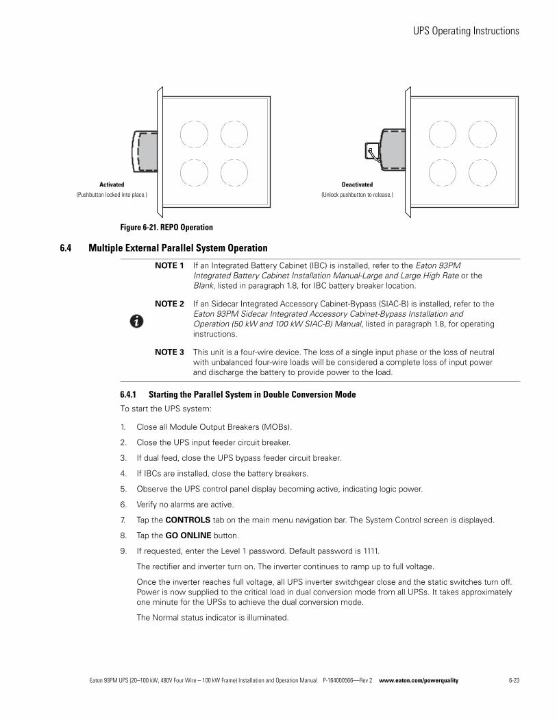
UPS Operating Instructions
Figure 6-21. REPO Operation
6.4 Multiple External Parallel System Operation
6.4.1 Starting the Parallel System in Double Conversion Mode
To start the UPS system:
1. Close all Module Output Breakers (MOBs).
2. Close the UPS input feeder circuit breaker.
3. If dual feed, close the UPS bypass feeder circuit breaker.
4. If IBCs are installed, close the battery breakers.
5. Observe the UPS control panel display becoming active, indicating logic power.
6. Verify no alarms are active.
7. Tap the CONTROLS tab on the main menu navigation bar. The System Control screen is displayed.
8. Tap the GO ONLINE button.
9. If requested, enter the Level 1 password. Default password is 1111.
The rectifier and inverter turn on. The inverter continues to ramp up to full voltage.
Once the inverter reaches full voltage, all UPS inverter switchgear close and the static switches turn off. Power is now supplied to the critical load in dual conversion mode from all UPSs. It takes approximately one minute for the UPSs to achieve the dual conversion mode.
The Normal status indicator is illuminated.
Activated
(Pushbutton locked into place.)
Deactivated
(Unlock pushbutton to release.)
NOTE 1 If an Integrated Battery Cabinet (IBC) is installed, refer to the Eaton 93PM Integrated Battery Cabinet Installation Manual-Large and Large High Rate or the Blank, listed in paragraph 1.8, for IBC battery breaker location.
NOTE 2 If an Sidecar Integrated Accessory Cabinet-Bypass (SIAC-B) is installed, refer to the Eaton 93PM Sidecar Integrated Accessory Cabinet-Bypass Installation and Operation (50 kW and 100 kW SIAC-B) Manual, listed in paragraph 1.8, for operating instructions.
NOTE 3 This unit is a four-wire device. The loss of a single input phase or the loss of neutral with unbalanced four-wire loads will be considered a complete loss of input power and discharge the battery to provide power to the load.
Eaton 93PM UPS (20–100 kW, 480V Four Wire – 100 kW Frame) Installation and Operation Manual P-164000566—Rev 2 www.eaton.com/powerquality 6-23
UPS Operating Instructions
6.4.2 Starting the Parallel System in Bypass Mode
If the inverter output of the UPS is not available and the critical load needs to be energized:
CAUTIONIn Bypass mode, the critical load is not protected from commercial power interruptions and abnormalities.
1. Close all Module Output Breakers (MOBs).
2. Close the UPS input feeder circuit breaker.
3. If dual feed, close the UPS bypass feeder circuit breaker.
4. If IBCs are installed, close the battery breakers.
5. Observe the UPS control panel display becoming active, indicating logic power.
6. Verify no alarms are active.
7. Tap the CONTROLS tab on the main menu navigation bar. The System Control screen is displayed.
8. Tap the GO TO BYPASS button.
The critical load is immediately supplied by the bypass source, in Bypass mode from all UPSs.
The BYPASS status indicator is illuminated.
6.4.3 Starting the Parallel System UPMs
To start the power modules without transferring the critical load to Double Conversion mode:
1. Close the UPS input feeder circuit breaker.
2. If dual feed, close the UPS Bypass input feeder circuit breaker.
3. Observe the UPS control panel becoming active, indicating logic power.
4. Verify no alarms are active.
5. Tap the CONTROLS tab on the main menu navigation bar. The System Control screen is displayed.
6. Tap the MODULES CONTROLS tab on the secondary Control menu navigation bar. The UPM Select screen is displayed.
7. On the UPM Select screen, select UPM 1. The UPM Control Screen is displayed.
8. Tap the START MODULE button.
The UPM 1 rectifier and inverter turn on. When the inverter reaches full voltage, the UPS is ready to transfer to the Double Conversion mode and supply the critical load.
9. Repeat Steps 5 through 8 selecting UPM 2 to start UPM 2.
The UPM 2 rectifier and inverter turn on. When the inverter reaches full voltage, the UPS is ready to transfer to the Double Conversion mode and supply the critical load.
10. Repeat Steps 5 through 8 selecting UPM 3 to start UPM 3.
The UPM 3 rectifier and inverter turn on. When the inverter reaches full voltage, the UPS is ready to transfer to the Double Conversion mode and supply the critical load.
11. Repeat Steps 1 through 10 for each UPS in the parallel system.
6-24 Eaton 93PM UPS (20–100 kW, 480V Four Wire – 100 kW Frame) Installation and Operation Manual P-164000566—Rev 2 www.eaton.com/powerquality
UPS Operating Instructions
6.4.4 Starting a Single UPM
To Start a single UPM:
1. Close the UPS input feeder circuit breaker.
2. If dual feed, close the UPS Bypass input feeder circuit breaker.
3. Observe the UPS control panel becoming active, indicating logic power.
4. Verify no alarms are active.
5. Tap the CONTROLS tab on the main menu navigation bar. The System Control screen is displayed.
6. Tap the MODULES CONTROLS tab on the secondary Control menu navigation bar. The UPM Select screen is displayed.
7. On the UPM Select screen, select the UPM to start. The UPM Control Screen is displayed.
8. Tap the START MODULE button.
The UPM rectifier and inverter turn on. When the inverter reaches full voltage, the UPS is ready to transfer to the Double Conversion mode and supply the critical load.
6.4.5 Transfer from Double Conversion to Bypass Mode
To transfer the critical load to Bypass mode:
CAUTIONIn Bypass mode, the critical load is not protected from commercial power interruptions and abnormalities.
1. Tap the CONTROLS tab on the main menu navigation bar. The System Control screen is displayed.
2. Tap the GO TO BYPASS button.
All of the UPSs transfer to Bypass mode. and the critical load is immediately supplied by the bypass source. If the bypass source is not available, the power module remains on and an alarm sounds.
The BYPASS status indicator is illuminated. The power module remains on.
WARNINGPower is present inside the UPS cabinet.
6.4.6 Transfer from Bypass to Double Conversion Mode
To transfer the critical load to Normal mode:
1. Tap the CONTROLS tab on the main menu navigation bar. The System Control screen is displayed.
2. Tap the GO ONLINE button.
All of the UPSs transfer to Double Conversion mode. If the power module is not available, the system remains on bypass and an alarm sounds.
The NORMAL status indicator is illuminated.
Eaton 93PM UPS (20–100 kW, 480V Four Wire – 100 kW Frame) Installation and Operation Manual P-164000566—Rev 2 www.eaton.com/powerquality 6-25
UPS Operating Instructions
6.4.7 Transfer from ESS Mode to Double Conversion Mode
To transfer the load to Standard Normal mode:
1. Tap the CONTROLS tab on the main menu navigation bar. The Control screen is displayed.
2. Tap the EAA CONTROLS tab on the secondary Control menu navigation bar. The EAA CONTROLS
screen is displayed.
3. Tap the DISABLE ESS button.
All of the UPSs transfer to Double Conversion mode.
The NORMAL status indicator is illuminated.
6.4.8 Transfer from Double Conversion Mode to ESS Mode
To transfer the load to HE Normal mode:
1. Tap the CONTROLS tab on the main menu navigation bar. The Control screen is displayed.
2. Tap the EAA CONTROLS tab on the secondary Control menu navigation bar. The EAA CONTROLS
screen is displayed..
3. Tap the ENABLE ESS button.
All of the UPSs transfer to ESS mode if no abnormal power conditions are detected. If abnormal power conditions are detected, the UPSs will wait and transfer to ESS mode when conditions are cleared.
The NORMAL status indicator is illuminated.
6.4.9 Transfer from Double Conversion to Bypass Mode and Shut Down all UPMs
To transfer the critical load to Bypass mode and shut down the UPMs:
1. Transfer the critical load to bypass by performing the procedure in paragraph 6.4.5.
2. Tap the CONTROLS tab on the main menu navigation bar. The System Control screen is displayed.
3. Tap the MODULES CONTROLS tab on the secondary Control menu navigation bar. The UPM Select screen is displayed.
4. On the UPM Select screen, select UPM 1. The UPM Control Screen is displayed.
5. Tap the SHUT DOWN MODULE button.
The UPM status indicates SHUTDOWN. The power module is turned off.
Logic power remains on.
6. Repeat Steps 2 through 5 selecting UPM 2 to shut down UPM 2.
The UPM status indicates SHUTDOWN. The power module is turned off.
Logic power remains on.
7. Repeat Steps 2 through 5 selecting UPM 3 to shut down UPM 3.
The UPM status indicates SHUTDOWN. The power module is turned off.
Logic power remains on.
8. Repeat Steps 2 through 7 for each UPS in the parallel system.
6-26 Eaton 93PM UPS (20–100 kW, 480V Four Wire – 100 kW Frame) Installation and Operation Manual P-164000566—Rev 2 www.eaton.com/powerquality
UPS Operating Instructions
6.4.10 Single UPM Shutdown
To shut down a single UPM:
1. Tap the CONTROLS tab on the main menu navigation bar. The System Control screen is displayed.
2. Tap the MODULES CONTROLS tab on the secondary Control menu navigation bar. The UPM Select screen is displayed.
3. On the UPM Select screen, select the UPM to shutdown. The UPM Control Screen is displayed.
4. Tap the SHUT DOWN MODULE button.
The UPM status indicates SHUTDOWN. The power module is turned off. The remaining UPMs continue to supply the critical load.
Logic power remains on.
6.4.11 Single UPM Restart
To restart a single UPM from a shutdown state:
1. Tap the CONTROLS tab on the main menu navigation bar. The System Control screen is displayed.
2. Tap the MODULES CONTROLS tab on the secondary Control menu navigation bar. The UPM Select screen is displayed.
3. On the UPM Select screen, select the UPM to start. The UPM Control Screen is displayed.
4. Tap the START MODULE button.
The UPM rectifier and inverter turn on. When the inverter reaches full voltage, the UPS is ready to transfer to the Double Conversion mode and supply the critical load.
6.4.12 Single UPS Shutdown
To Shutdown a single UPS:
To shut down a single UPS:
1. Open the MOB for the UPS being shut down.
2. On the UPS being shut down, tap the CONTROLS tab on the main menu navigation bar. The System Control screen is displayed.
3. Tap the GO TO BYPASS button.
The UPS being shut down transfers to Bypass mode. The BYPASS status indicator is illuminated. The power module remains on.
4. Tap the CONTROLS tab on the main menu navigation bar. The System Control screen is displayed.
5. Tap the MODULES CONTROLS tab on the secondary Control menu navigation bar. The UPM Select screen is displayed.
6. On the UPM Select screen, select UPM 1. The UPM Control Screen is displayed.
7. Tap the SHUT DOWN MODULE button.
The UPM status indicates SHUTDOWN. The input, output, and battery switchgear open, and the power module is turned off.
Logic power remains on.
NOTE To shut down a single UPS, MOBs with dual auxiliary contacts must be installed and connected according to the procedure in paragraph 4.7.6.
Eaton 93PM UPS (20–100 kW, 480V Four Wire – 100 kW Frame) Installation and Operation Manual P-164000566—Rev 2 www.eaton.com/powerquality 6-27
UPS Operating Instructions
8. Repeat Steps 4 through 7 selecting UPM 2 to shut down UPM 2.
The UPM status indicates SHUTDOWN. The input, output, and battery switchgear open, and the power module is turned off.
Logic power remains on.
9. Repeat Steps 4 through 7 selecting UPM 3 to shut down UPM 3.
The UPM status indicates SHUTDOWN. The input, output, and battery switchgear open, and the power module is turned off.
Logic power remains on.
WARNINGPower is present inside the UPS cabinet until the upstream input feeder circuit breakers and battery breakers are opened.
10. Open the all of the UPSs input feeder circuit breaker.
11. If dual feed, open all of the UPSs bypass feeder circuit breaker.
12. If IBCs are installed, open all battery breakers.
The UPS is now completely shut down.
6.4.13 Single UPS Restart
To restart a single UPS from a shutdown state:
1. Close the MOB for the UPS being restarted.
2. Close the UPS input feeder circuit breaker for the UPS being restarted.
3. If dual feed, close the UPS bypass feeder circuit breaker for the UPS being restarted.
4. If IBCs are installed, close the battery breakers for the UPS being restarted.
5. On the UPS being restarted, observe the UPS control panel display becoming active, indicating logic power.
6. Verify no alarms are active.
7. On the UPS being restarted, tap the CONTROLS tab on the main menu navigation bar. The System Control screen is displayed.
8. Tap the GO ONLINE button.
9. If requested, enter the Level 1 password. Default password is 1111.
The rectifier and inverter turn on. The inverter continues to ramp up to full voltage.
Once the inverter reaches full voltage, all UPS inverter switchgear close and the static switches turn off. Power is now supplied to the critical load in dual conversion mode from all UPSs. It takes approximately one minute for the UPSs to achieve the dual conversion mode.
The Normal status indicator is illuminated.
NOTE If the UPS is starting on a bus with other online paralleled UPSs, the UPS will not go to bypass during startup. The UPS will start, sync to the other UPSs online, and go online.
6-28 Eaton 93PM UPS (20–100 kW, 480V Four Wire – 100 kW Frame) Installation and Operation Manual P-164000566—Rev 2 www.eaton.com/powerquality
UPS Operating Instructions
6.4.14 Parallel System and Critical Load Shutdown
To perform maintenance or service on the critical load, shut down power to the load:
1. Turn off all equipment that is being powered by the UPS parallel system.
2. Transfer the UPSs to bypass by performing the procedure in paragraph 6.4.9.
3. Perform the Load Off procedure in paragraph 6.4.17.
The inverter and bypass switchgear open, and the power module is turned off on all UPSs.
4. Perform the battery charger off procedure in paragraph 6.4.15.
The rectifier and battery switchgear open.
WARNINGPower is present inside the UPS cabinet until the upstream input feeder circuit breakers and battery breakers are opened.
5. Open the all of the UPSs input feeder circuit breaker.
6. If dual feed, open all of the UPSs bypass feeder circuit breaker.
7. If IBCs are installed, open all battery breakers.
6.4.15 Charger Control
To turn the battery charger on:
1. Tap the CONTROLS tab on the main menu navigation bar. The Control screen is displayed.
2. Tap the UPS CONTROLS tab on the secondary navigation bar. The UPS Control screen is displayed.
3. Tap the TURN ON CHARGER button.
To turn the battery charger off:
1. Tap the CONTROLS tab on the main menu navigation bar. The Control screen is displayed.
2. Tap the UPS CONTROLS tab on the secondary navigation bar. The UPS Control screen is displayed.
3. Tap the TURN OFF CHARGER button.
6.4.16 Battery Test
To start the battery test:
1. Tap the CONTROLS tab on the main menu navigation bar. The System Control screen is displayed.
2. Tap the UPS CONTROLS tab on the secondary navigation bar. The UPS Control screen is displayed.
3. Tap the RUN BATTERY TEST button.
NOTE 1 This UPS has a user initiated battery test intended to determine if the batteries are able to support the load.
NOTE 2 The battery test is only able to be initiated when the battery is fully charged. This normally occurs within 72 hours of the start of a charging cycle. The command will not be shown if the test is not able to be run.
Eaton 93PM UPS (20–100 kW, 480V Four Wire – 100 kW Frame) Installation and Operation Manual P-164000566—Rev 2 www.eaton.com/powerquality 6-29
UPS Operating Instructions
6.4.17 Using the LOAD OFF Command
An UPS shutdown is initiated by the LOAD OFF command on the UPS Control screen. The UPS LOAD OFF
controls the UPSs output by powering down all of the UPSs and de-energizing the critical load.
The UPSs (including Bypass) remains off until restarted.
To use the LOAD OFF command:
1. Tap the CONTROLS tab on the main menu navigation bar. The System Control screen is displayed.
CAUTIONAll power to the critical load is lost when LOAD OFF is selected in the following step. You should use this feature only when you want to de-energize the critical load.
2. Tap the LOAD OFF button.
An action confirmation screen is displayed. Follow the on screen prompts to shut down the UPS or to cancel the shutdown. Selecting YES will immediately shut down the UPS and de-energize the critical load. Selecting NO will abort the shutdown
CAUTIONDo not attempt to restart the system after Load Off until the cause of the shutdown has been identified and cleared.
3. To restart the UPS after using the LOAD OFF follow the procedure in paragraph 6.4.1 or 6.4.2.
WARNINGPower is present inside the UPS cabinet until the upstream input feeder circuit breakers and battery breakers are opened.
6-30 Eaton 93PM UPS (20–100 kW, 480V Four Wire – 100 kW Frame) Installation and Operation Manual P-164000566—Rev 2 www.eaton.com/powerquality
UPS Operating Instructions
6.4.18 Using the Remote Emergency Power-off Switch
WARNINGEmergency Power Off (EPO) and Remote Emergency Power Off (REPO) functionality is disabled for UPS systems configured for UL 924 auxiliary lighting. To remove power from the system a LOAD OFF command (see paragraph 6.4.17) must be given using the front panel controls and all breakers opened.
A UPS emergency power-off is initiated by the REPO pushbutton switch. In an emergency, you can use this switch to control the UPS output. The REPO switch de-energizes the critical load and powers down the UPSs immediately, without asking for verification.
The UPSs, including Bypass, remains off until restarted.
CAUTIONAll power to the critical load is lost when the REPO switch is activated in the following step. You should use this feature only when you want to de-energize the critical load.
To use the REPO switch:
1. Firmly push the red pushbutton until it locks into place. The switch latches into the activated state (see Figure 6-21).
The rectifier, inverter, battery, and bypass switchgear open, and the power module is turned off immediately on all UPSs, without asking for verification.
CAUTIONDo not attempt to restart the system after the REPO until the cause of the shutdown has been identified and cleared.
2. To deactivate the REPO switch in preparation for restarting the UPS, insert the supplied key and rotate clockwise until the red pushbutton releases (see Figure 6-21). To remove the key, rotate the key back to the vertical position.
3. Restart the UPS by following the procedure in paragraph 6.4.1 or 6.4.2.
WARNINGPower is present inside the UPS cabinet until the upstream input feeder circuit breakers and battery breakers are opened.
NOTE The following instructions are for the Eaton-supplied REPO switch. If a customer-supplied REPO switch is used, it may not activate in the same manner; refer to the operating instructions provided with the switch.
Eaton 93PM UPS (20–100 kW, 480V Four Wire – 100 kW Frame) Installation and Operation Manual P-164000566—Rev 2 www.eaton.com/powerquality 6-31

UPS Operating Instructions
This page intentionally left blank.
6-32 Eaton 93PM UPS (20–100 kW, 480V Four Wire – 100 kW Frame) Installation and Operation Manual P-164000566—Rev 2 www.eaton.com/powerquality
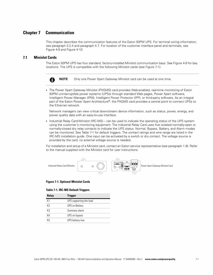
Chapter 7 Communication
This chapter describes the communication features of the Eaton 93PM UPS. For terminal wiring information, see paragraph 3.2.4 and paragraph 4.7. For location of the customer interface panel and terminals, see Figure 4-9 and Figure 4-10.
7.1 Minislot CardsThe Eaton 93PM UPS has four standard, factory-installed Minislot communication bays. See Figure 4-9 for bay locations. The UPS is compatible with the following Minislot cards (see Figure 7-1):
l The Power Xpert Gateway Minislot (PXGMS) card provides Web-enabled, real-time monitoring of Eaton 93PM uninterruptible power systems (UPSs) through standard Web pages, Power Xpert software, Intelligent Power Manager (IPM), Intelligent Power Protector (IPP), or third-party software. As an integral part of the Eaton Power Xpert Architecture®, the PXGMS card provides a central point to connect UPSs to the Ethernet network.
Network managers can view critical downstream device information, such as status, power, energy, and power quality data with an easy-to-use interface.
l Industrial Relay Card-Minislot (IRC-MS) – can be used to indicate the operating status of the UPS system using the customer's monitoring equipment. The Industrial Relay Card uses five isolated normally-open or normally-closed dry relay contacts to indicate the UPS status. Normal, Bypass, Battery, and Alarm modes can be monitored. See Table 7-1 for default triggers. The contact ratings and wire range are listed in the IRC-MS installation guide. One input can be activated by a switch or dry contact. The voltage source is provided by the card, no external voltage source is needed.
For installation and setup of a Minislot card, contact an Eaton service representative (see paragraph 1.8). Refer to the manual supplied with the Minislot card for user instructions.
Figure 7-1. Optional Minislot Cards
NOTE Only one Power Xpert Gateway Minislot card can be used at one time.
Table 7-1. IRC-MS Default Triggers
Relay Trigger
K1 UPS supporting the load
K2 UPS on Battery
K3 Summary alarm
K4 UPS on bypass
K5 UPS battery low
IdentPower
Act100
PXGMS UPS
RestartTX RX
Setup
CMNStatusDHCP
EMPEthernet 10/100+ -
Industrial Relay Card-Minislot Power Xpert Gateway Minislot Card
Eaton 93PM UPS (20–100 kW, 480V Four Wire – 100 kW Frame) Installation and Operation Manual P-164000566—Rev 2 www.eaton.com/powerquality 7-1
Communication
7.2 Building Alarm MonitoringThis standard feature lets you connect the UPS to your building alarms, such as smoke detectors or overtemperature alarms. The building alarm customer interface terminals for external are located inside the UPS. Use twisted-pair wires for each alarm input and common.
The building alarms can be programmed to display the alarm functional name.
7.3 General Purpose Relay ContactOne general purpose relay contact is provided as a standard feature on the UPS. The relay contact customer interface terminals are located inside the UPS. Use twisted-pair wires for the normally-closed or normally-open and common connections.
Normally-closed or normally-open contacts can be used. If the state of the contact changes from the state specified as normal, a signal is issued. This contact can be connected to equipment at the facility (such as a light or an alarm bell) to notify the operator when an alarm is active on the UPS. This feature is useful if the UPS is located in a remote area where the UPS horn may not be heard immediately.
CAUTIONContacts should not be operated in excess of 30 Vac @ 5A maximum.
7.4 Predict Pulse Remote Monitoring and Management ServiceThe Eaton 93PM UPS supports Eaton's PredictPulse remote monitoring and management service. PredictPulse is a subscription monitoring and management service that collects and analyzes data from connected power infrastructure devices, providing us with the insight needed to make recommendations and take action on your behalf. It’s also powered by CA Technologies, bringing together the best in hardware and software. PredictPulse Service is included at no charge during the first year of Eaton 93PM UPS operation (warranty period) along with the required connectivity parts. Beyond that, it may be purchased with Eaton Support Agreements or as a standalone subscription after the initial warranty expires. PredictPulse may also be subscribed to for free as part of a 90-day trial period. PredictPulse availability and first year bundled offers may vary by market. For more information, visit www.eaton.com/predictpulse.
7.4.1 PredictPulse Service Features
PredictPulse provides proactive monitoring, an online dashboard, mobile app with alarm status information and a monthly report detailing the ongoing health of your Eaton 93PM UPS. Features include:
l Proactive monitoring that automatically analyzes the status of the Eaton 93PM UPS 96 times every day (every 15 minutes). All health data gathered from the unit, current and historical, is analyzed at the Customer Reliability Center (CRC). Algorithms and sophisticated analytics software is constantly scanning your UPS's data for potential failures. Anomalies are escalated to a Software and Monitoring analyst or Technical Support specialist. Critical events are remotely diagnosed to expedite repairs, including smart dispatch of field technicians with probable cause and likely parts (avoiding return visits due to lack of required parts). Through this service, the CRC can take pre-emptive, corrective action to ensure the highest level of availability of your Eaton 93PM UPS.
l Easy self-installation in minutes from a wizard installer or directly from the PXGMS card. PredictPulse uses standard Eaton connectivity hardware, requiring no special software (devices only need to be connected to a network).
NOTE If contact ratings are required that can be operated above the rated voltage and current available with the UPS general purpose relay contacts, an IRC-MS card should be used.
7-2 Eaton 93PM UPS (20–100 kW, 480V Four Wire – 100 kW Frame) Installation and Operation Manual P-164000566—Rev 2 www.eaton.com/powerquality

Communication
l Ability to give an unlimited number of coworkers access to the real-time data and reports found in PredictPulse’s online dashboard and mobile app. This allows you to collaborate and Eaton to notify the most appropriate person responsible for a specific site or device.
l Real-time access to key performance information, alarms and trended health data about your Eaton 93PM UPS via the PredictPulse online dashboard. Depending on the model, the dashboard aggregates all subscribed devices and provides detailed information about voltages, loads, energy savings, service levels, external factors such as temperature and humidity, attached batteries, and system availability. All of these factors contribute to the Relative Performance Index (RPI) score that allows you to compare your unit's health relative to Eaton's optimum UPS operating levels.
l Real-time alarm events for all subscribed devices via the PredictPulse mobile app (Apple and Android). You can track all alarms by device. As critical alarms occur, Eaton will acknowledge them so you know when Eaton has diagnosed the alarm (and pending notification of resolution).
l A monthly summary report that delivers key performance information, alarms and trended health data about your Eaton 93PM UPS, based on the prior month’s data.
l A foundation based on CA Technologies’ leading Data Center Infrastructure Management (DCIM) software application. This enables powerful reporting, analytics, security, and compatibility with hundreds of power infrastructure devices.
7.4.2 Installing PredictPulse
A quick start guide and self-installation wizard tool are available at www.eaton.com/predictpulse. The latest updates, installation tips and information on connecting PredictPulse are also available at that link. For installation support or questions about PredictPulse, contact [email protected].
PredictPulse relies on a PXGMS card installed with the UPS to send one-way outbound SMTP e-mails to Eaton, as well as an Environmental Monitoring Probe (EMP) for battery temperature/humidity monitoring. PredictPulse is secure as Eaton never communicates through your firewall—it only listens for health data and alarm data—and uses industry-standard security protocols. By using a common e-mail transport mechanism, you do not have to open your network to proprietary or potentially unsecure protocols and transports. The PXGMS Connectivity Card gathers information directly from the UPS and any external sensors that are attached, and transmits that data every 15 minutes (or 96 times per day), enabling real-time monitoring and advanced virtual preventive maintenance.
Eaton 93PM UPS (20–100 kW, 480V Four Wire – 100 kW Frame) Installation and Operation Manual P-164000566—Rev 2 www.eaton.com/powerquality 7-3

Communication
This page intentionally left blank.
7-4 Eaton 93PM UPS (20–100 kW, 480V Four Wire – 100 kW Frame) Installation and Operation Manual P-164000566—Rev 2 www.eaton.com/powerquality
Chapter 8 UPS Maintenance
The components inside the UPS cabinet are secured to a sturdy metal frame. All repairable parts and assemblies are located for easy removal, with very little disassembly. This design allows authorized service personnel to perform routine maintenance and servicing quickly.
You must schedule periodic performance checks of your UPS system to keep it running properly. Regular routine checks of operation and system parameters enable your system to function efficiently for many trouble-free years.
8.1 Important Safety InstructionsRemember that your UPS system is designed to supply power EVEN WHEN DISCONNECTED FROM THE
UTILITY POWER. The UPS module interiors are unsafe until the DC power source is disconnected and the electrolytic capacitors are discharged. After disconnecting the utility power and the DC power, authorized service personnel should wait at least five minutes for capacitor bleedoff before attempting internal access to the UPS module.
WARNINGl Servicing and maintenance should be performed by qualified service personnel only.
l LETHAL VOLTAGE PRESENT. This unit should not be operated with the cabinet doors open or protective panels removed. Do not make any assumptions about the electrical state of any cabinet in the UPS system.
Each battery string is an energy source in itself. DO NOT ATTEMPT TO ACCESS ANY INTERNAL AREA OF
THE BATTERY STRING YOURSELF. VOLTAGES ARE ALWAYS PRESENT IN THE BATTERY STRING. If you suspect that a battery string needs service, contact an Eaton service representative.
If the string requires service contact an Eaton service representative.
Observe these precautions when working on or around batteries:
l Remove watches, rings, or other metal objects.
l Use tools with insulated handles.
l Wear rubber gloves and boots.
l Do not lay tools or metal parts on top of batteries.
l Disconnect the charging source prior to connecting or disconnecting terminals.
l Determine if the battery is inadvertently grounded. If it is, remove the source of the ground. Contact with any part of a grounded battery can result in electrical shock. The likelihood of such shock is reduced if such grounds are removed during installation and maintenance.
l When replacing batteries, use the same number of sealed, lead-acid batteries.
l Proper disposal of batteries is required. Refer to your local codes for disposal requirements.
l Do not dispose of batteries in a fire. Batteries may explode when exposed to flame.
l Do not open or mutilate batteries. Released electrolyte is harmful to the skin and eyes. It may be toxic.
Eaton 93PM UPS (20–100 kW, 480V Four Wire – 100 kW Frame) Installation and Operation Manual P-164000566—Rev 2 www.eaton.com/powerquality 8-1
UPS Maintenance
8.2 Performing Preventive MaintenanceThe UPS system requires very little preventive maintenance. However, the system should be inspected periodically to verify that the units are operating normally and that the batteries are in good condition.
8.2.1 DAILY Maintenance
Perform the following steps daily:
1. Check the area surrounding the UPS system. Ensure the area is not cluttered, allowing free access to the unit.
2. Ensure the air intakes (vents on the front door of the UPS cabinet and the exhaust openings (on the rear of the UPS cabinet) are not blocked.
3. Ensure the operating environment is within the parameters specified in paragraph 3.2.1 and Chapter 9, “Product Specifications.”
4. Ensure the UPS is in Normal mode (Normal status indicator is illuminated). If an alarm lamp is illuminated or the Normal status indicator is not illuminated, contact an Eaton service representative.
8.2.2 MONTHLY Maintenance
Perform the following steps monthly:
1. Monitor system parameters as described in paragraph 6.2, “Using the Control Panel”.
2. Check the UPS air filter (located behind the front door) and wash or replace as necessary. See Figure 8-1 for filter location. Contact an Eaton service representative for replacement filters.
CAUTIONVerify washed filter is thoroughly dry before reinstalling.
To remove the filters:
a. Unfasten the front door by lifting the latch from the bottom and turning to the right (counterclockwise) and swing the door open (see Figure 6-1).
b. Remove the foam filters from the frame on the front door.
c. Replace the washed or new foam filters into the frame on the front door.
d. Close the front door and secure the latch.
3. Record maintenance results and any corrective actions in a suitable log.
8-2 Eaton 93PM UPS (20–100 kW, 480V Four Wire – 100 kW Frame) Installation and Operation Manual P-164000566—Rev 2 www.eaton.com/powerquality
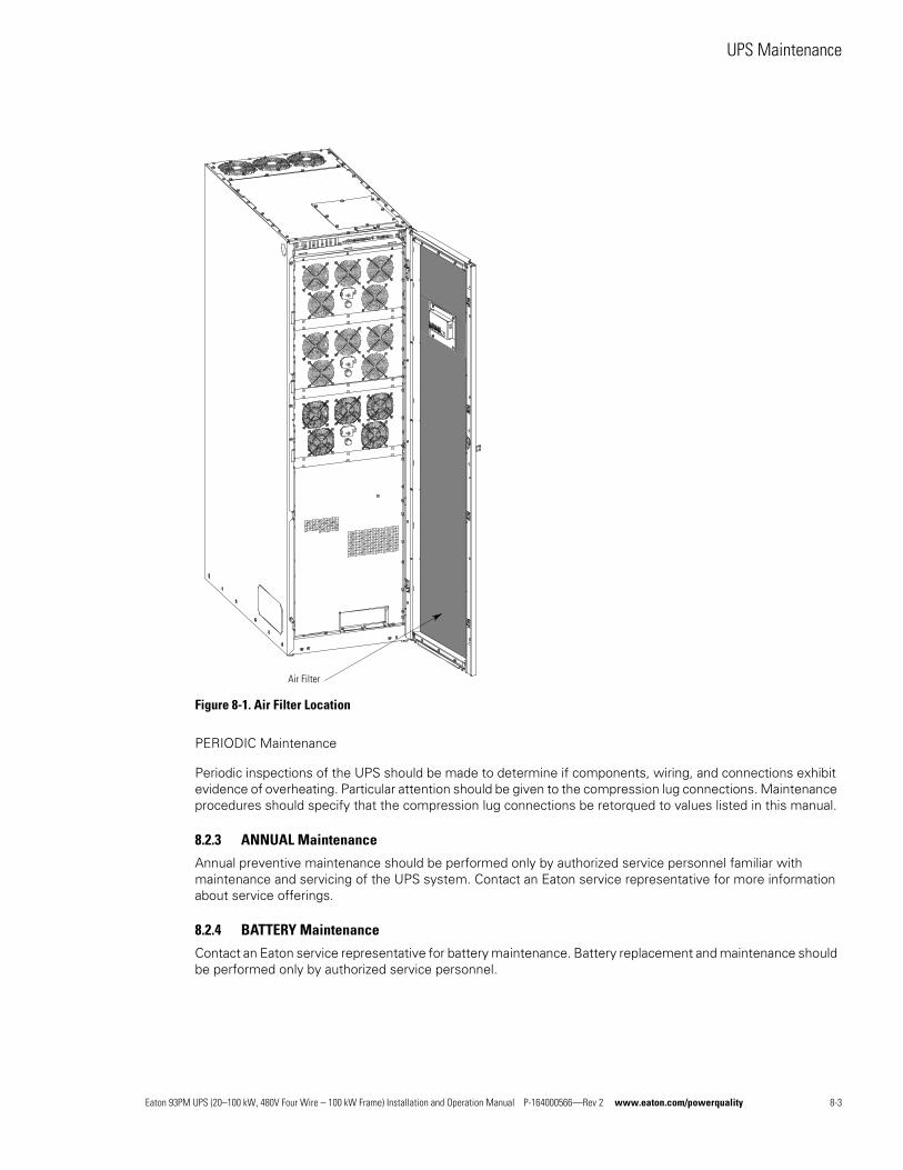
UPS Maintenance
Figure 8-1. Air Filter Location
PERIODIC Maintenance
Periodic inspections of the UPS should be made to determine if components, wiring, and connections exhibit evidence of overheating. Particular attention should be given to the compression lug connections. Maintenance procedures should specify that the compression lug connections be retorqued to values listed in this manual.
8.2.3 ANNUAL Maintenance
Annual preventive maintenance should be performed only by authorized service personnel familiar with maintenance and servicing of the UPS system. Contact an Eaton service representative for more information about service offerings.
8.2.4 BATTERY Maintenance
Contact an Eaton service representative for battery maintenance. Battery replacement and maintenance should be performed only by authorized service personnel.
Air Filter
Eaton 93PM UPS (20–100 kW, 480V Four Wire – 100 kW Frame) Installation and Operation Manual P-164000566—Rev 2 www.eaton.com/powerquality 8-3
UPS Maintenance
8.3 Installing Batteries
Install batteries in accordance with the battery and battery system manufacturer's instructions.
8.4 Recycling the Used Battery or UPSContact your local recycling or hazardous waste center for information on proper disposal of the used battery or UPS.
WARNINGl Do not dispose of the battery or batteries in a fire. Batteries may explode. Proper disposal of
batteries is required. Refer to your local codes for disposal requirements.
l Do not open or mutilate the battery or batteries. Released electrolyte is harmful to the skin and eyes. It may be toxic.
l A battery can cause electrical shock, burn from high short-circuit current, or fire. Observe proper precautions.
ATTENTION!l Une batterie peut prêsenter un risque de choc êlectrique, de brulure, ou d'incendie. Suivre les
précautions qui s'imposent.
l Pour le remplacement, utiliser le même nombre et modéle des batteries.
l L'élimination des batteries est règlementée. Consulter les codes locaux à cet effet.
CAUTIONDo not discard the UPS or the UPS batteries in the trash. This product contains sealed, lead-acid batteries and must be disposed of properly. For more information, contact your local recycling/reuse or hazardous waste center.
CAUTIONDo not discard waste electrical or electronic equipment (WEEE) in the trash. For proper disposal, contact your local recycling/reuse or hazardous waste center.
8.5 Maintenance TrainingA basic training course, available from Eaton, gives you a competent working knowledge of the UPS system operation and teaches you how to perform first level corrective maintenance. For more information about training and other services, contact the Customer Reliability Center (see paragraph 1.8).
NOTE There is no manual DC disconnect device within the UPS.
8-4 Eaton 93PM UPS (20–100 kW, 480V Four Wire – 100 kW Frame) Installation and Operation Manual P-164000566—Rev 2 www.eaton.com/powerquality
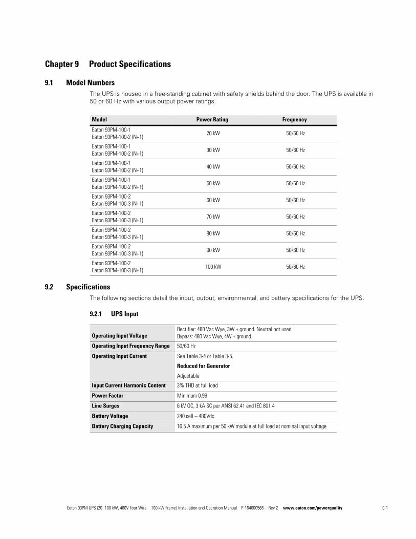
Chapter 9 Product Specifications
9.1 Model NumbersThe UPS is housed in a free-standing cabinet with safety shields behind the door. The UPS is available in 50 or 60 Hz with various output power ratings.
9.2 SpecificationsThe following sections detail the input, output, environmental, and battery specifications for the UPS.
9.2.1 UPS Input
Model Power Rating Frequency
Eaton 93PM-100-1Eaton 93PM-100-2 (N+1)
20 kW 50/60 Hz
Eaton 93PM-100-1Eaton 93PM-100-2 (N+1)
30 kW 50/60 Hz
Eaton 93PM-100-1Eaton 93PM-100-2 (N+1)
40 kW 50/60 Hz
Eaton 93PM-100-1Eaton 93PM-100-2 (N+1)
50 kW 50/60 Hz
Eaton 93PM-100-2Eaton 93PM-100-3 (N+1)
60 kW 50/60 Hz
Eaton 93PM-100-2Eaton 93PM-100-3 (N+1)
70 kW 50/60 Hz
Eaton 93PM-100-2Eaton 93PM-100-3 (N+1)
80 kW 50/60 Hz
Eaton 93PM-100-2Eaton 93PM-100-3 (N+1)
90 kW 50/60 Hz
Eaton 93PM-100-2Eaton 93PM-100-3 (N+1)
100 kW 50/60 Hz
Operating Input VoltageRectifier: 480 Vac Wye, 3W + ground. Neutral not used.Bypass: 480 Vac Wye, 4W + ground.
Operating Input Frequency Range 50/60 Hz
Operating Input Current See Table 3-4 or Table 3-5.
Reduced for Generator
Adjustable
Input Current Harmonic Content 3% THD at full load
Power Factor Minimum 0.99
Line Surges 6 kV OC, 3 kA SC per ANSI 62.41 and IEC 8014
Battery Voltage 240 cell – 480Vdc
Battery Charging Capacity 16.5 A maximum per 50 kW module at full load at nominal input voltage
Eaton 93PM UPS (20–100 kW, 480V Four Wire – 100 kW Frame) Installation and Operation Manual P-164000566—Rev 2 www.eaton.com/powerquality 9-1
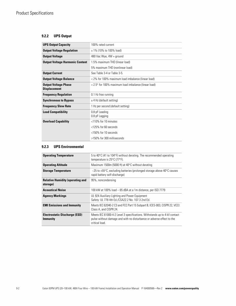
Product Specifications
9.2.2 UPS Output
9.2.3 UPS Environmental
UPS Output Capacity 100% rated current
Output Voltage Regulation ± 1% (10% to 100% load)
Output Voltage 480 Vac Wye, 4W + ground
Output Voltage Harmonic Content 1.5% maximum THD (linear load)
5% maximum THD (nonlinear load)
Output Current See Table 3-4 or Table 3-5.
Output Voltage Balance < 2% for 100% maximum load imbalance (linear load)
Output Voltage Phase Displacement
< 2.5 for 100% maximum load imbalance (linear load)
Frequency Regulation 0.1 Hz free running
Synchronous to Bypass ± 4 Hz (default setting)
Frequency Slew Rate 1 Hz per second (default setting)
Load Compatibility 0.8 pF Leading0.8 pF Lagging
Overload Capability <110% for 10 minutes
<125% for 60 seconds
<150% for 10 seconds
>150% for 300 milliseconds
Operating Temperature 5 to 40C (41 to 104F) without derating. The recommended operating temperature is 25C (77F).
Operating Altitude Maximum 1500m (5000 ft) at 40C without derating
Storage Temperature 25 to +55C, excluding batteries (prolonged storage above 40C causes rapid battery self-discharge)
Relative Humidity (operating and storage)
95%, noncondensing
Acoustical Noise 100 kW at 100% load – 65 dBA at a 1m distance, per ISO 7779
Agency Markings UL 924 Auxiliary Lighting and Power EquipmentSafety: UL 778 4th Ed./CSA22.2 No. 107.3 2nd Ed.
EMI Emissions and Immunity Meets IEC 62040-2 C3 and FCC Part 15 Subpart B, ICES-003, CISPR 22, VCCI: Class A, and CISPR 24.
Electrostatic Discharge (ESD) Immunity
Meets IEC 61000-4-2 Level 3 specifications. Withstands up to 4 kV contact pulse without damage and with no disturbance or adverse effect to the critical load.
9-2 Eaton 93PM UPS (20–100 kW, 480V Four Wire – 100 kW Frame) Installation and Operation Manual P-164000566—Rev 2 www.eaton.com/powerquality
Warranty
Limited Factory Warranty for Three-Phase Eaton 93PM UPS and 93PM UPS Accessory ProductsWARRANTOR: The warrantor for the limited warranties set forth herein is Eaton (”Eaton”).
LIMITED WARRANTY: This limited warranty (this ”Warranty”) applies only to the original end-user (the ”End-User”) of the Eaton Three-Phase 93PM UPS and 93PM UPS Accessory Products (the ”Product”) and cannot be transferred. This restriction applies even in the event that the Product is initially sold by Eaton for resale to an EndUser. This Warranty gives you specific legal rights, and you may also have other rights which vary from State to State (or jurisdiction to jurisdiction).
WHAT THIS LIMITED WARRANTY COVERS: The warrantor warrants, with the terms of this Warranty, that the Eaton three-phase UPS electronics, Eaton-built accessories, and Eaton-built battery cabinets (individually and collectively, the ”Warranted Items”) are free from defects in material and workmanship.
For Product installed (and currently located) in the fifty (50) United States and the District of Columbia, if, in the opinion of Eaton, a Warranted Item is defective, Eaton's sole obligation, at the option of Eaton, will be to refurbish or replace such defective Warranted Item (including the costs of providing diagnosis, service, and labor [“labor coverage”]). The defective Warranted Item will be refurbished or replaced onsite at the End-User's location or such other location as determined by Eaton. Any parts that are replaced may be new or reconditioned. All parts replaced by Eaton shall become the property of Eaton.
For Product installed (and currently located) outside the fifty (50) United States and the District of Columbia, if, in the opinion of Eaton, a Warranted Item is defective, Eaton's sole obligation, at the option of Eaton, will be to refurbish or replace such defective Warranted Item (not including the costs of labor coverage). The defective Warranted Item will be refurbished or replaced onsite at the End-User's location or such other location as determined by Eaton. Any parts that are replaced may be new or reconditioned. All parts replaced by Eaton shall become the property of Eaton.
LIMITED WARRANTY PERIOD: The period covered by this Warranty for Product installed (and currently located) in the fifty (50) United States and the District of Columbia is six (6) months from the date of Product purchase for labor coverage when no startup is performed by an authorized Eaton Customer Service Engineer or Agent or twelve (12) months from the date of Product purchase with startup performed by an authorized Eaton Customer Service Engineer or Agent and twelve (12) months from the date of Product purchase or eighteen (18) months from date of Product shipment, whichever occurs first, for the refurbishment/replacement of parts.
The period covered by this Warranty for Product installed (and currently located) outside the fifty (50) United States and the District of Columbia is twelve (12) months from the date of Product purchase or eighteen (18) months from the date of Product shipment, whichever occurs first, for the refurbishment/replacement of parts.
WHAT THIS LIMITED WARRANTY DOES NOT COVER: This Warranty does not cover any defects or damages caused by: (a) failure to properly store the Product before installation, including the ”trickle charge” of batteries no later than the date indicated on the packaging; (b) shipping and delivery of the Product if shipping is FOB Factory; (c) neglect, accident, fire, flood, lightning, vandalism, acts of God, Customer's neglect, abuse, misuse, misapplication, incorrect installation; (d) repair or alteration not authorized in writing by Eaton personnel or performed by an authorized Eaton Customer Service Engineer or Agent; or (e) improper testing, operation, maintenance, adjustment, or any modification of any kind not authorized in writing by Eaton personnel or performed by an authorized Eaton Customer Service Engineer or Agent.
This Warranty is not valid: if the Product's serial numbers have been removed or are illegible. Any Warranted Items repaired or replaced pursuant to this Warranty will be warranted for the remaining portion of the original Warranty subject to all the terms thereof. Eaton does not provide a labor warranty for Product located outside of the fifty (50) United States or the District of Columbia. Any equipment, parts, or materials included in the
Product and not manufactured by Eaton are warranted solely by the manufacturer of such equipment,
parts, or materials and are not included as part of this Warranty. Batteries are not warranted by Eaton.
Eaton 93PM UPS (20–100 kW, 480V Four Wire – 100 kW Frame) Installation and Operation Manual P-164000566—Rev 2 www.eaton.com/powerquality W-1
Warranty
THIS WARRANTY IS THE ENDUSER'S SOLE REMEDY AND IS EXPRESSLY IN LIEU OF, AND THERE ARE
NO OTHER, EXPRESSED OR IMPLIED GUARANTEES OR WARRANTIES (INCLUDING ANY IMPLIED
WARRANTY OF MERCHANTABILITY OR FITNESS FOR ANY PURPOSE, WHICH ARE EXPRESSLY
DISCLAIMED). SOME STATES OR JURISDICTIONS DO NOT ALLOW THE EXCLUSION OF EXPRESS OR
IMPLIED WARRANTIES, SO THE ABOVE EXCLUSION MAY NOT APPLY TO YOU. IN THAT EVENT, SUCH
WARRANTIES ARE LIMITED IN DURATION TO THE LIMITED WARRANTY PERIOD. SOME STATES OR
JURISDICTIONS DO NOT ALLOW LIMITATIONS ON HOW LONG AN IMPLIED WARRANTY LASTS OR
THE EXCLUSION OR LIMITATION OF INCIDENTAL OR CONSEQUENTIAL DAMAGES, SO THE ABOVE
LIMITATIONS AND/OR EXCLUSIONS MAY NOT APPLY TO YOU.
LIMITATION OF LIABILITY: In no event shall Eaton be liable for any indirect, incidental, special or consequential damages of any kind or type whatsoever, resulting from or in connection with any claim or cause of action, whether brought in contract or in tort (including negligence and strict liability). Some States or jurisdictions do not allow the exclusion of limitation of incidental or consequential damages, so the above limitation or exclusion may not apply to you. Eaton shall not be responsible for failure to provide service or parts due to causes beyond Eaton's reasonable control. In no case will Eaton's liability under this Warranty exceed the replacement value of the Warranted Items.
END-USER'S OBLIGATIONS: In order to receive the benefits of this Warranty, the End-User must register the product warranty (via mail or online at www.powerquality.eaton.com/ProductRegistration “product registration”); use the Product in a normal way; follow the Product's user's guide; and protect against further damage to the Product if there is a covered defect.
OTHER LIMITATIONS: Eaton's obligations under this Warranty are expressly conditioned upon receipt
by Eaton of all payments due to it (including interest charges, if any). During such time as Eaton has not
received payment of any amount due to it for the Product, in accordance with the contract terms under
which the Product is sold, Eaton shall have no obligation under this Warranty. Also during such time,
the period of this Warranty shall continue to run and the expiration of this Warranty shall not be
extended upon payment of any overdue or unpaid amounts.
COSTS NOT RELATED TO WARRANTY: The End-User shall be invoiced for, and shall pay for, all services not expressly provided for by the terms of this Warranty, including without limitation site calls involving an inspection that determines no corrective maintenance is required. Any costs for replacement equipment, installation, materials, freight charges, travel expenses, or labor of Eaton representatives outside the terms of this Warranty will be borne by the End-User.
OBTAINING WARRANTY SERVICE: In the USA, call the Eaton Customer Reliability Center 7x24 at 800-843-9433. Outside of the USA, call your local Eaton sales or service representative, or call the Eaton Customer Reliability Center in the United States at 919845-3633. For comments or questions about this Limited Factory Warranty, write to the Customer Quality Representative, 8609 Six Forks Road, Raleigh, North Carolina 27615 USA.
W-2 Eaton 93PM UPS (20–100 kW, 480V Four Wire – 100 kW Frame) Installation and Operation Manual P-164000566—Rev 2 www.eaton.com/powerquality


*P-164000566 2*P-164000566 2


