Embed Size (px)
Citation preview
Copyright© 2017 by Turbomachinery Laboratory, Texas A&M Engineering Experiment Station
Effect of Gas Presence on Erosive Wear of Split-Vane Electrical Submersible Pump Gerald Morrison, Yi Chen, Daniel Steck, Yiming Chen, Changrui Bai, Abhay Patil
Texas A&M University, College Station, TX
Gerald L. Morrison is a Professor of Mechanical Engineering at Texas A&M University. He has been a member of the
Turbomachinery Laboratory for over 35 years investigating aircraft jet noise, space shuttle turbopump and standard
pump seals, and single and multiphase flow meters and pumps.
Yi Chen has been a Ph.D. candidate in Mechanical Engineering from Texas A&M University since 2012. His research
interests include multi-phase flow testing and simulation, erosion analysis and prediction, turbomachinery and head
transfer.
Daniel Steck has a MS in Mechanical Engineering from Texas A&M University. His Master's research focused on
experimental fluid mechanics. He is currently pursuing a PhD in computational solid mechanics.
Yiming Chen has been enrolled in the Doctoral Program in Mechanical Engineering Department, Texas A&M
University since 2013. He received his M.S. degree in Engineering Mechanics from Tsinghua University in 2013
and his B.S. degree in Aircraft Design from Beijing University of Aeronautics and Astronautics in 2006. His research
interests include computation fluid dynamics, flow field analysis in turbo machinery, multiphase flow simulation,
pump design and performance prediction and erosion prediction.
Changrui Bai received his Ph.D. degree in Mechanical Engineering from Texas A&M University in 2017, his M.S.
degree in Instrumentation Science and Technology from Beihang University in 2013, and his B.S. degree in Automation
from Shandong University in 2010. His research interests include rotor-bearing system modeling, machinery fault
diagnosis, condition monitoring, and vibration analysis.
Abhay Patil is a Research Engineer working for Dr. Morrison at Turbomachinery Laboratory, TAMU. His research
includes numerical and experimental investigations of performance and reliability of artificial lifting methods for
multiphase flows. Dr. Abhay Patil holds a PhD degree in Mechanical Engineering from Texas A&M University,
College Station.
46TH TURBOMACHINERY & 33RD PUMP SYMPOSIA
HOUSTON, TEXAS I DECEMBER 11-14, 2017
GEORGE R. BROWN CONVENTION CENTER
Copyright© 2017 by Turbomachinery Laboratory, Texas A&M Engineering Experiment Station
ABSTRACT
Most well productions are characterized by the presence of some amount of gas which may alter the mechanisms of pump wear. The
current investigation is focused on the effect of gas entrainment on the wear mechanism in a split vane pump which is often included
in the lower tandem of an ESP pump subsystem. Split vane pumps are designed to improve the gas handling capability in gaseous
wells by inducing large levels of turbulence using split impeller vanes. This may adversely affect the pump life if abrasives are present
in the wellfluid. To quantify the effect of gas presence, slurry testing was carried out at 0%, 10%, and 20% GVF (Gas Volume
Fraction) for 66 hours. Two gram/liter of 140 mesh frac sand was continuously supplied while the pump was run at the best efficiency
point. Performance data was recorded at 0, 22, 44 and 66 hours. The presence of gas had a profound effect on the overall wear of the
pump stages, reducing their performance by more than 50% during the 20% GVF test. The hydraulic path as well as the secondary
flow path was severely eroded showing how sand and gas both contribute to the performance degradation. CFD simulations were
employed to characterize the erosion across the hydraulic path for single phase flow. An erosion model developed in the
Turbomachinery laboratory was utilized to predict the erosion. The study concludes with validation of prediction results using
experimental data.
INTRODUCTION
Artificial lift is required when the natural flow of mature oil or gas fields drops below economic production rates after a period of
production. The Electrical Submersible Pump was introduced to the petroleum industry by the pump inventor Armais Artunoff in
1927. Currently, about 60% of the world’s oil is produced by ESPs. Today’s challenges and requirements of ESP systems continue to
push ESP research to have longer life spans, handle multiphase flows, resist abrasive erosion and maximize operating efficiency.
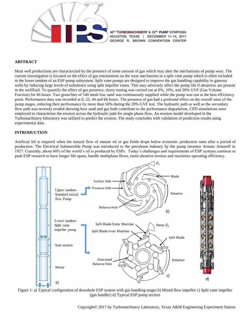
Figure 1: a) Typical configuration of downhole ESP system with gas handling stages b) Mixed flow impeller c) Split vane impeller
(gas handler) d) Typical ESP pump section
46TH TURBOMACHINERY & 33RD PUMP SYMPOSIA
HOUSTON, TEXAS I DECEMBER 11-14, 2017
GEORGE R. BROWN CONVENTION CENTER
Copyright© 2017 by Turbomachinery Laboratory, Texas A&M Engineering Experiment Station
An electrical submersible pumping (ESP) system is shown in Fig. 1 a). Pump section is configured into different tandems, with each
tandem encasing multiple pump stages depending on head requirement. Usually, the upper tandem is equipped with standard mixed
flow impeller pump stages as shown in figure 1 b) while lower tandem is equipped with gas handling stages with uniquely designed
impellers used to homogenize the flow by inducing turbulent mixing to enable better gas handling. Impellers as shown in the figure
1c) have split vanes and oversized balance holes to alter the pressure distribution and induce turbulence to break up the gas bubbles
and vanes with steep exit angle to increase the total head. However, reliability of such an impeller while subjected to frac sand in
gassy wells is still unknown.
Due to the high cost of subsea installations and recurring failures in specific geographic regions, significant effort has been spent on
increasing the run life of ESPs to at least five years, and to locate, predict and mitigate any and all causes of pump failure. One of the
critical factors affecting the pump reliability is complex production fluid properties varying with time. Oil wells typically produce a
mixture of gas, oil, water and frac sand particles, the composition of which changes throughout the life of the well. So far research on
ESP wear was mainly focused on two phase testing with water and sand. ESP wear due to presence of sand in gassy wells was not
addressed before. Inclusion of gas may reduce pump reliability further and deviate the failure modes predicted without gas. Initial in-
house testing of a mixed flow pump in presence of gas indicated that presence of gas accelerates the wear, especially along the
bearings (Zheng 2013). Based on those findings, further testing of split vane impeller pumps which are basically designed to handle
the gas was proposed to quantify the effect of gas presence on erosion of pump stages.
Three different tests have been conducted for conditions as shown in the table 1. New stages were utilized for each test condition.
Stage configuration was chosen based on space constraint and capacity of a regular 250 HP induction motor. Temperature at the inlet
is monitored for maintaining a constant inlet GVF. The stages of the pump are installed inside a special casing built for the sole
purpose of the laboratory experiment. A typical cross section of a mixed flow pump with flow from the bottom to top is shown in the
figure 1 d). The pump was operated at its best efficiency point during the erosion study. Framo Engineering tested centrifugal pumps
passing 300 tons of sand through pumps at concentrations of 0.02, 0.2 and 2 grams of sand per liter of water. The results showed that
the higher concentration is required to obtain significant erosion in a reasonable time period. This is the basis for the 2 grams/liter
concentration used for this study.
Table 1: Operating Conditions for erosion testing of the split-vane pump for 66 hours
Inlet Gas Volume
Fraction
0% 10% 20%
Number of Stages 2 2 3
Liquid Flowrate-BEP
(gallon/min)
1050 940 950
Inlet Pressure(Psig) 45 45 40
Net Erosion Hours 66 66 66
Inlet Volume Flow Rate
(gallon/min)
1050 1044 1187
Rotor Speed(RPM) 3600 3600 3600
For a new pump, radial clearance of the front and back seals varies from 8 to 12 mils and the average radial clearance between bearing
and journal is 6 mils. The impeller and diffuser are made of Ni-Resist 1b cast iron, and the bearings are made of cemented carbide.
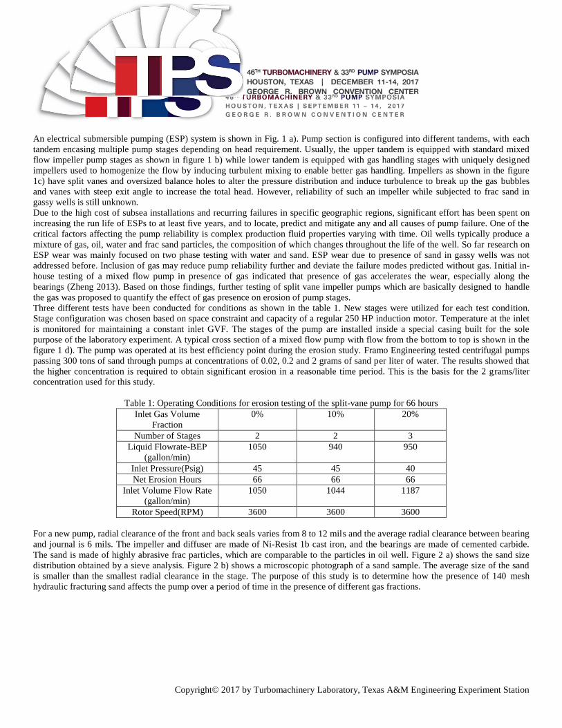
The sand is made of highly abrasive frac particles, which are comparable to the particles in oil well. Figure 2 a) shows the sand size
distribution obtained by a sieve analysis. Figure 2 b) shows a microscopic photograph of a sand sample. The average size of the sand
is smaller than the smallest radial clearance in the stage. The purpose of this study is to determine how the presence of 140 mesh
hydraulic fracturing sand affects the pump over a period of time in the presence of different gas fractions.
46TH TURBOMACHINERY & 33RD PUMP SYMPOSIA
HOUSTON, TEXAS I DECEMBER 11-14, 2017
GEORGE R. BROWN CONVENTION CENTER
Copyright© 2017 by Turbomachinery Laboratory, Texas A&M Engineering Experiment Station
Figure 2: a) Sand sieve analysis b) Microscopic photograph
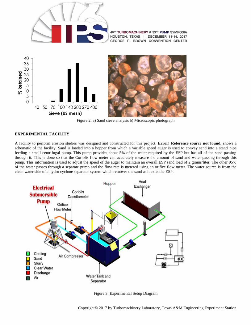
EXPERIMENTAL FACILITY
A facility to perform erosion studies was designed and constructed for this project. Error! Reference source not found. shows a
schematic of the facility. Sand is loaded into a hopper from which a variable speed auger is used to convey sand into a stand pipe
feeding a small centrifugal pump. This pump provides about 5% of the water required by the ESP but has all of the sand passing
through it. This is done so that the Coriolis flow meter can accurately measure the amount of sand and water passing through this
pump. This information is used to adjust the speed of the auger to maintain an overall ESP sand load of 2 grams/liter. The other 95%
of the water passes through a separate pump and the flow rate is metered using an orifice flow meter. The water source is from the
clean water side of a hydro cyclone separator system which removes the sand as it exits the ESP.
Figure 3: Experimental Setup Diagram
46TH TURBOMACHINERY & 33RD PUMP SYMPOSIA
HOUSTON, TEXAS I DECEMBER 11-14, 2017
GEORGE R. BROWN CONVENTION CENTER
Copyright© 2017 by Turbomachinery Laboratory, Texas A&M Engineering Experiment Station
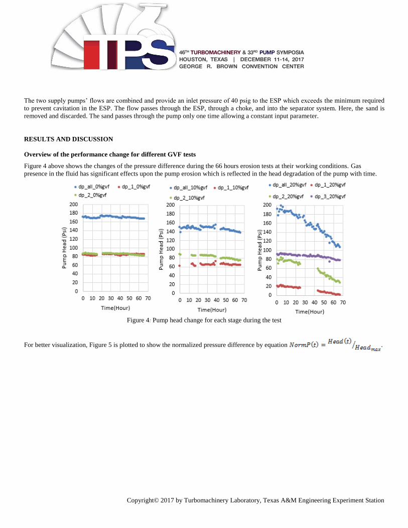
The two supply pumps’ flows are combined and provide an inlet pressure of 40 psig to the ESP which exceeds the minimum required
to prevent cavitation in the ESP. The flow passes through the ESP, through a choke, and into the separator system. Here, the sand is
removed and discarded. The sand passes through the pump only one time allowing a constant input parameter.
RESULTS AND DISCUSSION
Overview of the performance change for different GVF tests
Figure 4 above shows the changes of the pressure difference during the 66 hours erosion tests at their working conditions. Gas
presence in the fluid has significant effects upon the pump erosion which is reflected in the head degradation of the pump with time.
Figure 4: Pump head change for each stage during the test
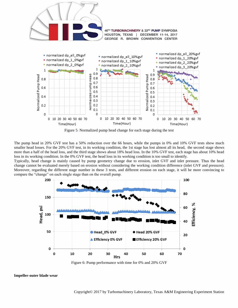
For better visualization, Figure 5 is plotted to show the normalized pressure difference by equation .
46TH TURBOMACHINERY & 33RD PUMP SYMPOSIA
HOUSTON, TEXAS I DECEMBER 11-14, 2017
GEORGE R. BROWN CONVENTION CENTER
Copyright© 2017 by Turbomachinery Laboratory, Texas A&M Engineering Experiment Station
Figure 5: Normalized pump head change for each stage during the test
The pump head in 20% GVF test has a 50% reduction over the 66 hours, while the pumps in 0% and 10% GVF tests show much
smaller head losses. For the 20% GVF test, in its working condition, the 1st stage has lost almost all its head, the second stage shows
more than a half of the head loss, and the third stage shows about 18% head loss. In the 10% GVF test, each stage has about 10% head
loss in its working condition. In the 0% GVF test, the head loss in its working condition is too small to identify.
Typically, head change is mainly caused by pump geometry change due to erosion, inlet GVF and inlet pressure. Thus the head
change cannot be evaluated merely based on erosion without considering the working condition difference (inlet GVF and pressure).
Moreover, regarding the different stage number in these 3 tests, and different erosion on each stage, it will be more convincing to
compare the “change” on each single stage than on the overall pump.
Figure 6: Pump performance with time for 0% and 20% GVF
Impeller-outer blade wear
46TH TURBOMACHINERY & 33RD PUMP SYMPOSIA
HOUSTON, TEXAS I DECEMBER 11-14, 2017
GEORGE R. BROWN CONVENTION CENTER
Copyright© 2017 by Turbomachinery Laboratory, Texas A&M Engineering Experiment Station
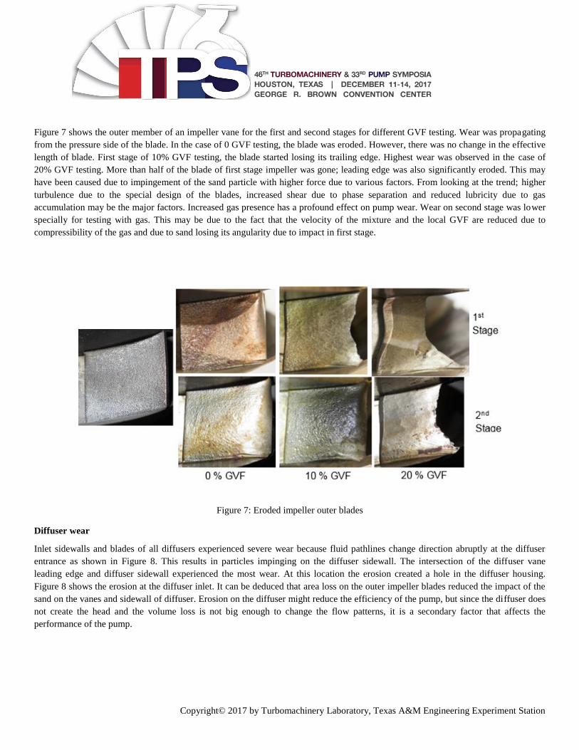
Figure 7 shows the outer member of an impeller vane for the first and second stages for different GVF testing. Wear was propagating
from the pressure side of the blade. In the case of 0 GVF testing, the blade was eroded. However, there was no change in the effective
length of blade. First stage of 10% GVF testing, the blade started losing its trailing edge. Highest wear was observed in the case of
20% GVF testing. More than half of the blade of first stage impeller was gone; leading edge was also significantly eroded. This may
have been caused due to impingement of the sand particle with higher force due to various factors. From looking at the trend; higher
turbulence due to the special design of the blades, increased shear due to phase separation and reduced lubricity due to gas
accumulation may be the major factors. Increased gas presence has a profound effect on pump wear. Wear on second stage was lower
specially for testing with gas. This may be due to the fact that the velocity of the mixture and the local GVF are reduced due to
compressibility of the gas and due to sand losing its angularity due to impact in first stage.
Figure 7: Eroded impeller outer blades
Diffuser wear
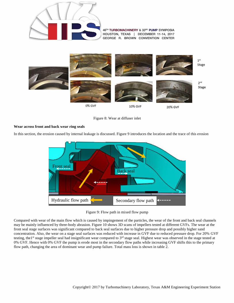
Inlet sidewalls and blades of all diffusers experienced severe wear because fluid pathlines change direction abruptly at the diffuser
entrance as shown in Figure 8. This results in particles impinging on the diffuser sidewall. The intersection of the diffuser vane
leading edge and diffuser sidewall experienced the most wear. At this location the erosion created a hole in the diffuser housing.
Figure 8 shows the erosion at the diffuser inlet. It can be deduced that area loss on the outer impeller blades reduced the impact of the
sand on the vanes and sidewall of diffuser. Erosion on the diffuser might reduce the efficiency of the pump, but since the diffuser does
not create the head and the volume loss is not big enough to change the flow patterns, it is a secondary factor that affects the
performance of the pump.
46TH TURBOMACHINERY & 33RD PUMP SYMPOSIA
HOUSTON, TEXAS I DECEMBER 11-14, 2017
GEORGE R. BROWN CONVENTION CENTER
Copyright© 2017 by Turbomachinery Laboratory, Texas A&M Engineering Experiment Station
Figure 8: Wear at diffuser inlet
Wear across front and back wear ring seals
In this section, the erosion caused by internal leakage is discussed. Figure 9 introduces the location and the trace of this erosion
Figure 9: Flow path in mixed flow pump
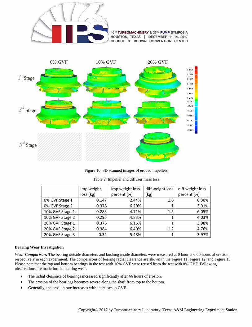
Compared with wear of the main flow which is caused by impingement of the particles, the wear of the front and back seal channels
may be mainly influenced by three-body abrasion. Figure 10 shows 3D scans of impellers tested at different GVFs. The wear at the
front seal stage surfaces was significant compared to back seal surfaces due to higher pressure drop and possibly higher sand
concentration. Also, the wear on a stage seal surfaces was reduced with increase in GVF due to reduced pressure drop. For 20% GVF
testing, the1st stage impeller seal had insignificant wear compared to 3rd stage seal. Highest wear was observed in the stage tested at
0% GVF. Hence with 0% GVF the pump is erode most in the secondary flow paths while increasing GVF shifts this to the primary
flow path, changing the area of dominant wear and pump failure. Total mass loss is shown in table 2.
Front seal Back seal
Hydraulic flow path Secondary flow path
46TH TURBOMACHINERY & 33RD PUMP SYMPOSIA
HOUSTON, TEXAS I DECEMBER 11-14, 2017
GEORGE R. BROWN CONVENTION CENTER
Copyright© 2017 by Turbomachinery Laboratory, Texas A&M Engineering Experiment Station
Figure 10: 3D scanned images of eroded impellers
Table 2: Impeller and diffuser mass loss
imp weight loss (kg)
imp weight loss percent (%)
diff weight loss (kg)
diff weight loss percent (%)
0% GVF Stage 1 0.147 2.44% 1.6 6.30%
0% GVF Stage 2 0.378 6.20% 1 3.91%
10% GVF Stage 1 0.283 4.71% 1.5 6.05%
10% GVF Stage 2 0.295 4.83% 1 4.03%
20% GVF Stage 1 0.376 6.16% 1 3.98%
20% GVF Stage 2 0.384 6.40% 1.2 4.76%
20% GVF Stage 3 0.34 5.48% 1 3.97%
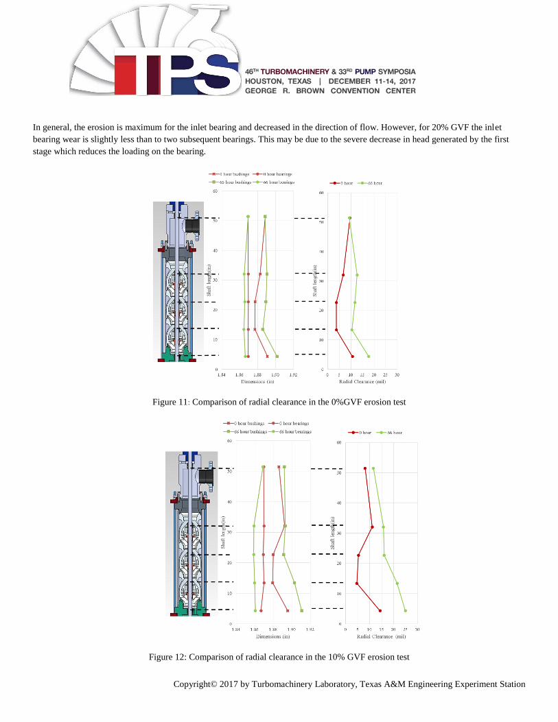
Bearing Wear Investigation
Wear Comparison: The bearing outside diameters and bushing inside diameters were measured at 0 hour and 66 hours of erosion
respectively in each experiment. The comparisons of bearing radial clearance are shown in the Figure 11, Figure 12, and Figure 13.
Please note that the top and bottom bearings in the test with 10% GVF were reused from the test with 0% GVF. Following
observations are made for the bearing wear.
The radial clearance of bearings increased significantly after 66 hours of erosion.
The erosion of the bearings becomes severe along the shaft from top to the bottom.
Generally, the erosion rate increases with increases in GVF.
1st Stage
2nd
Stage
3rd
Stage
0% GVF 10% GVF 20% GVF
46TH TURBOMACHINERY & 33RD PUMP SYMPOSIA
HOUSTON, TEXAS I DECEMBER 11-14, 2017
GEORGE R. BROWN CONVENTION CENTER
Copyright© 2017 by Turbomachinery Laboratory, Texas A&M Engineering Experiment Station
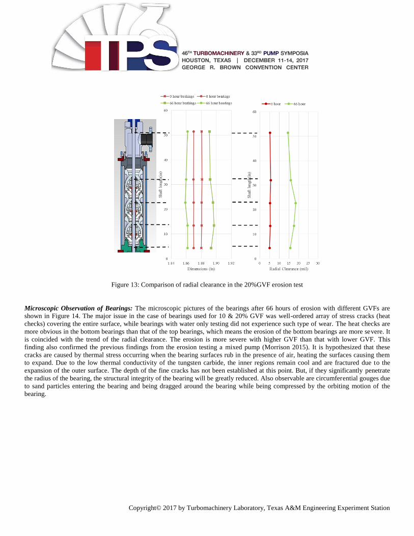
In general, the erosion is maximum for the inlet bearing and decreased in the direction of flow. However, for 20% GVF the inlet
bearing wear is slightly less than to two subsequent bearings. This may be due to the severe decrease in head generated by the first
stage which reduces the loading on the bearing.
Figure 11: Comparison of radial clearance in the 0%GVF erosion test
Figure 12: Comparison of radial clearance in the 10% GVF erosion test
46TH TURBOMACHINERY & 33RD PUMP SYMPOSIA
HOUSTON, TEXAS I DECEMBER 11-14, 2017
GEORGE R. BROWN CONVENTION CENTER
Copyright© 2017 by Turbomachinery Laboratory, Texas A&M Engineering Experiment Station
Figure 13: Comparison of radial clearance in the 20%GVF erosion test
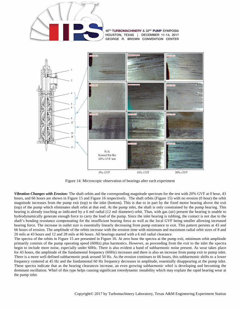
Microscopic Observation of Bearings: The microscopic pictures of the bearings after 66 hours of erosion with different GVFs are
shown in Figure 14. The major issue in the case of bearings used for 10 & 20% GVF was well-ordered array of stress cracks (heat
checks) covering the entire surface, while bearings with water only testing did not experience such type of wear. The heat checks are
more obvious in the bottom bearings than that of the top bearings, which means the erosion of the bottom bearings are more severe. It
is coincided with the trend of the radial clearance. The erosion is more severe with higher GVF than that with lower GVF. This
finding also confirmed the previous findings from the erosion testing a mixed pump (Morrison 2015). It is hypothesized that these
cracks are caused by thermal stress occurring when the bearing surfaces rub in the presence of air, heating the surfaces causing them
to expand. Due to the low thermal conductivity of the tungsten carbide, the inner regions remain cool and are fractured due to the
expansion of the outer surface. The depth of the fine cracks has not been established at this point. But, if they significantly penetrate
the radius of the bearing, the structural integrity of the bearing will be greatly reduced. Also observable are circumferential gouges due
to sand particles entering the bearing and being dragged around the bearing while being compressed by the orbiting motion of the
bearing.
46TH TURBOMACHINERY & 33RD PUMP SYMPOSIA
HOUSTON, TEXAS I DECEMBER 11-14, 2017
GEORGE R. BROWN CONVENTION CENTER
Copyright© 2017 by Turbomachinery Laboratory, Texas A&M Engineering Experiment Station
Figure 14: Microscopic observation of bearings after each experiment
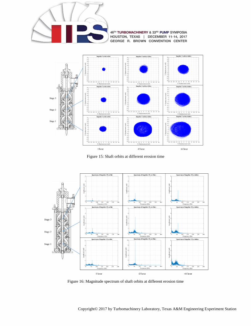
Vibration Changes with Erosion: The shaft orbits and the corresponding magnitude spectrum for the test with 20% GVF at 0 hour, 43
hours, and 66 hours are shown in Figure 15 and Figure 16 respectively. The shaft orbits (Figure 15) with no erosion (0 hour) the orbit
magnitude increases from the pump exit (top) to the inlet (bottom). This is due to in part by the fixed motor bearing above the exit
(top) of the pump which eliminates shaft orbit at that end. At the pump inlet, the shaft is only constrained by the pump bearing. This
bearing is already touching as indicated by a 6 mil radial (12 mil diameter) orbit. Thus, with gas (air) present the bearing is unable to
hydrodynamically generate enough force to carry the load of the pump. Since the inlet bearing is rubbing, the contact is not due to the
shaft’s bending resistance compensating for the insufficient bearing force as well as the local GVF being smaller allowing increased
bearing force. The increase in outlet size is essentially linearly decreasing from pump entrance to exit. This pattern persists at 43 and
66 hours of erosion. The amplitude of the orbits increase with the erosion time with minimum and maximum radial orbit sizes of 8 and
20 mils at 43 hours and 12 and 28 mils at 66 hours. All bearings started with a 6 mil radial clearance.
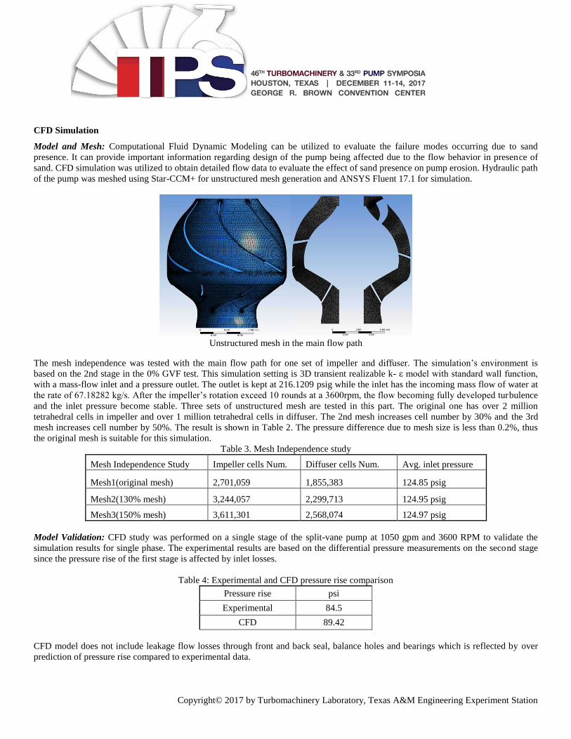
The spectra of the orbits in Figure 15 are presented in Figure 16. At zero hour the spectra at the pump exit, minimum orbit amplitude
primarily consists of the pump operating speed (60Hz) plus harmonics. However, as proceeding from the exit to the inlet the spectra
begin to include more noise, especially under 60Hz. There is also evident a band of subharmonic noise present. As wear takes place
for 43 hours, the amplitude of the fundamental frequency (60Hz) increases and there is also an increase from pump exit to pump inlet.
There is a more well defined subharmonic peak around 50 Hz. As the erosion continues to 66 hours, this subharmonic shifts to a lower
frequency centered at 45 Hz and the fundamental 60 Hz frequency decreases in amplitude, essentially disappearing at the pump inlet.
These spectra indicate that as the bearing clearances increase, an even growing subharmonic whirl is developing and becoming the
dominant oscillation. Whirl of this type helps causing significant rotordynamic instability which may explain the rapid bearing wear at
the pump inlet.
46TH TURBOMACHINERY & 33RD PUMP SYMPOSIA
HOUSTON, TEXAS I DECEMBER 11-14, 2017
GEORGE R. BROWN CONVENTION CENTER
Copyright© 2017 by Turbomachinery Laboratory, Texas A&M Engineering Experiment Station
Figure 15: Shaft orbits at different erosion time
Figure 16: Magnitude spectrum of shaft orbits at different erosion time
46TH TURBOMACHINERY & 33RD PUMP SYMPOSIA
HOUSTON, TEXAS I DECEMBER 11-14, 2017
GEORGE R. BROWN CONVENTION CENTER
Copyright© 2017 by Turbomachinery Laboratory, Texas A&M Engineering Experiment Station
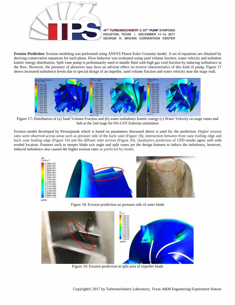
CFD Simulation
Model and Mesh: Computational Fluid Dynamic Modeling can be utilized to evaluate the failure modes occurring due to sand
presence. It can provide important information regarding design of the pump being affected due to the flow behavior in presence of
sand. CFD simulation was utilized to obtain detailed flow data to evaluate the effect of sand presence on pump erosion. Hydraulic path
of the pump was meshed using Star-CCM+ for unstructured mesh generation and ANSYS Fluent 17.1 for simulation.
Unstructured mesh in the main flow path
The mesh independence was tested with the main flow path for one set of impeller and diffuser. The simulation’s environment is
based on the 2nd stage in the 0% GVF test. This simulation setting is 3D transient realizable k- ε model with standard wall function,
with a mass-flow inlet and a pressure outlet. The outlet is kept at 216.1209 psig while the inlet has the incoming mass flow of water at
the rate of 67.18282 kg/s. After the impeller’s rotation exceed 10 rounds at a 3600rpm, the flow becoming fully developed turbulence
and the inlet pressure become stable. Three sets of unstructured mesh are tested in this part. The original one has over 2 million
tetrahedral cells in impeller and over 1 million tetrahedral cells in diffuser. The 2nd mesh increases cell number by 30% and the 3rd
mesh increases cell number by 50%. The result is shown in Table 2. The pressure difference due to mesh size is less than 0.2%, thus
the original mesh is suitable for this simulation.
Table 3. Mesh Independence study
Mesh Independence Study Impeller cells Num. Diffuser cells Num. Avg. inlet pressure
Mesh1(original mesh) 2,701,059 1,855,383 124.85 psig
Mesh2(130% mesh) 3,244,057 2,299,713 124.95 psig
Mesh3(150% mesh) 3,611,301 2,568,074 124.97 psig
Model Validation: CFD study was performed on a single stage of the split-vane pump at 1050 gpm and 3600 RPM to validate the
simulation results for single phase. The experimental results are based on the differential pressure measurements on the second stage
since the pressure rise of the first stage is affected by inlet losses.
Table 4: Experimental and CFD pressure rise comparison
Pressure rise psi
Experimental 84.5
CFD 89.42
CFD model does not include leakage flow losses through front and back seal, balance holes and bearings which is reflected by over
prediction of pressure rise compared to experimental data.
46TH TURBOMACHINERY & 33RD PUMP SYMPOSIA
HOUSTON, TEXAS I DECEMBER 11-14, 2017
GEORGE R. BROWN CONVENTION CENTER
Copyright© 2017 by Turbomachinery Laboratory, Texas A&M Engineering Experiment Station
Erosion Prediction: Erosion modeling was performed using ANSYS Fluent Euler-Granular model. A set of equations are obtained by
deriving conservation equations for each phase. Flow behavior was evaluated using sand volume fraction, water velocity and turbulent
kinetic energy distribution. Split vane pump is preliminarily used to handle fluid with high gas void fraction by inducing turbulence in
the flow. However, the presence of abrasives may have an adverse effect on erosive characteristics of this kind of pump. Figure 17
shows increased turbulence levels due to special design of an impeller, sand volume fraction and water velocity near the stage wall.
Figure 17: Distribution of (a) Sand Volume Fraction and (b) water turbulence kinetic energy (c) Water Velocity on stage vanes and
hub at the 2nd stage for 0% GVF Eulerian simulation
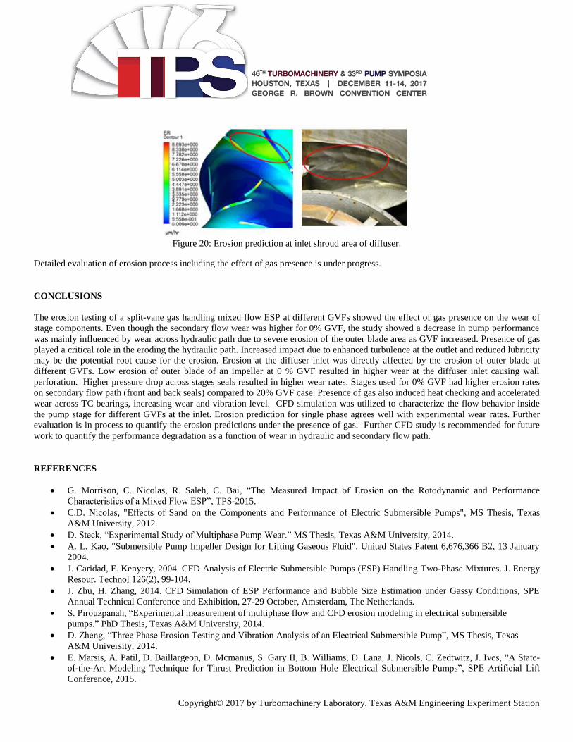
Erosion model developed by Pirouzpanah which is based on parameters discussed above is used for the prediction. Higher erosion
rates were observed across areas such as pressure side of the back vane (Figure 18), intersection between front vane trailing edge and
back vane leading edge (Figure 19) and the diffuser inlet section (Figure 20). Qualitative prediction of CFD results agree well with
eroded location. Features such as steeper blade exit angle and split vanes are the design features to induce the turbulence, however,
induced turbulence also caused the higher erosion rates as predicted by model.
Figure 18: Erosion prediction on pressure side of outer blade
Figure 19: Erosion prediction at split area of impeller blade
46TH TURBOMACHINERY & 33RD PUMP SYMPOSIA
HOUSTON, TEXAS I DECEMBER 11-14, 2017
GEORGE R. BROWN CONVENTION CENTER
Copyright© 2017 by Turbomachinery Laboratory, Texas A&M Engineering Experiment Station
Figure 20: Erosion prediction at inlet shroud area of diffuser.
Detailed evaluation of erosion process including the effect of gas presence is under progress.
CONCLUSIONS
The erosion testing of a split-vane gas handling mixed flow ESP at different GVFs showed the effect of gas presence on the wear of
stage components. Even though the secondary flow wear was higher for 0% GVF, the study showed a decrease in pump performance
was mainly influenced by wear across hydraulic path due to severe erosion of the outer blade area as GVF increased. Presence of gas
played a critical role in the eroding the hydraulic path. Increased impact due to enhanced turbulence at the outlet and reduced lubricity
may be the potential root cause for the erosion. Erosion at the diffuser inlet was directly affected by the erosion of outer blade at
different GVFs. Low erosion of outer blade of an impeller at 0 % GVF resulted in higher wear at the diffuser inlet causing wall
perforation. Higher pressure drop across stages seals resulted in higher wear rates. Stages used for 0% GVF had higher erosion rates
on secondary flow path (front and back seals) compared to 20% GVF case. Presence of gas also induced heat checking and accelerated
wear across TC bearings, increasing wear and vibration level. CFD simulation was utilized to characterize the flow behavior inside
the pump stage for different GVFs at the inlet. Erosion prediction for single phase agrees well with experimental wear rates. Further
evaluation is in process to quantify the erosion predictions under the presence of gas. Further CFD study is recommended for future
work to quantify the performance degradation as a function of wear in hydraulic and secondary flow path.
REFERENCES
G. Morrison, C. Nicolas, R. Saleh, C. Bai, “The Measured Impact of Erosion on the Rotodynamic and Performance
Characteristics of a Mixed Flow ESP”, TPS-2015.
C.D. Nicolas, "Effects of Sand on the Components and Performance of Electric Submersible Pumps", MS Thesis, Texas
A&M University, 2012.
D. Steck, “Experimental Study of Multiphase Pump Wear.” MS Thesis, Texas A&M University, 2014.
A. L. Kao, "Submersible Pump Impeller Design for Lifting Gaseous Fluid". United States Patent 6,676,366 B2, 13 January
2004.
J. Caridad, F. Kenyery, 2004. CFD Analysis of Electric Submersible Pumps (ESP) Handling Two-Phase Mixtures. J. Energy
Resour. Technol 126(2), 99-104.
J. Zhu, H. Zhang, 2014. CFD Simulation of ESP Performance and Bubble Size Estimation under Gassy Conditions, SPE
Annual Technical Conference and Exhibition, 27-29 October, Amsterdam, The Netherlands.
S. Pirouzpanah, “Experimental measurement of multiphase flow and CFD erosion modeling in electrical submersible
pumps.” PhD Thesis, Texas A&M University, 2014.
D. Zheng, “Three Phase Erosion Testing and Vibration Analysis of an Electrical Submersible Pump”, MS Thesis, Texas
A&M University, 2014.
E. Marsis, A. Patil, D. Baillargeon, D. Mcmanus, S. Gary II, B. Williams, D. Lana, J. Nicols, C. Zedtwitz, J. Ives, “A State-
of-the-Art Modeling Technique for Thrust Prediction in Bottom Hole Electrical Submersible Pumps”, SPE Artificial Lift
Conference, 2015.
46TH TURBOMACHINERY & 33RD PUMP SYMPOSIA
HOUSTON, TEXAS I DECEMBER 11-14, 2017
GEORGE R. BROWN CONVENTION CENTER
Copyright© 2017 by Turbomachinery Laboratory, Texas A&M Engineering Experiment Station
S. Pirouzpanah, SR Gudigopuram, G. Morrison, “Two-phase flow characterization in a split vane impeller Electrical
Submersible Pump”, Journal of Petroleum Science and Engineering 148, 82-93
S. Pirouzpanah, G. Morrison, “Predictive Erosion Modeling in an ESP Pump”, ASME 2014 4th Joint US-European Fluids
Engineering Division Summer Meeting.
G. Morrison, S Pirouspanah, K Kirland, SL Scott, LJ Barrios, “Performance Evaluation of a Multiphase Electric Submersible
Pump”, Offshore Technology Conference, 2014.
ACKNOWLEDGEMENTS
Authors would like to thank Royal Dutch Shell for their financial and technical support.
46TH TURBOMACHINERY & 33RD PUMP SYMPOSIA
HOUSTON, TEXAS I DECEMBER 11-14, 2017
GEORGE R. BROWN CONVENTION CENTER


![[Sonography of synovial and erosive inflammatory changes]](https://img.pdfslide.net/doc/110x75/6356be6d5108319c870372a1/sonography-of-synovial-and-erosive-inflammatory-changes.jpg)


