Embed Size (px)
Citation preview

December 23, 2003 17:11 WSPC/123-JCSC 00105
Journal of Circuits, Systems, and ComputersVol. 12, No. 5 (2003) 1–12c© World Scientific Publishing Company
EFFICIENT DESIGN OF NARROWBAND COSINE-MODULATED
FILTER BANKS USING A TWO-STAGE FREQUENCY-RESPONSE
MASKING APPROACH
SERGIO L. NETTO∗, LUIZ C. R. de BARCELLOS†, and PAULO S. R. DINIZ‡
Programa de Engenharia Eletrica-COPPE/EE,Federal University of Rio de Janeiro,
P. O. Box 68504, Rio de Janeiro, RJ, 21945-970, Brazil∗[email protected]†[email protected]
A new cosine-modulated filter bank (CMFB) structure is proposed based on thefrequency-response masking (FRM) approach using masking filter decomposition. Theresulting structure, the so-called FRM2-CMFB, presents reasonable computational com-plexity (number of arithmetic operations per output sample) and allows one to designfilter banks with extremely large number of bands. The examples include the use ofM = 1024 bands, where the standard minimax method cannot be employed. These ex-amples indicate that the reduction in computational complexity can be as high as 60%of the original FRM-CMFB structure, which does not use masking filter decomposition.
Keywords:
1. Introduction
The frequency-response masking (FRM) approach is an efficient method for de-
signing linear-phase FIR digital filters with general passbands and sharp transition
bands. With such method, by allowing a small increase in the overall filter order, it
is possible to reduce the number of coefficients to about 30% of the number required
by a minimax FIR direct-form filter.1
The cosine-modulated filter banks (CMFBs) are very popular in applications
requiring large number of subbands due to their easy design (based solely on a
single prototype filter) and computationally efficient implementation.2–6
In this paper, we analyze the use of the FRM approach to design the proto-
type filter of a CMFB. The narrowband-CMFB case is considered where standard
minimax method fails to converge and even the FRM-CMFB7 structure presents
high computational complexity. A new structure is then introduced, the so-called
FRM2-CMFB, where the original FRM masking filter is decomposed as a cascade
of two filters, namely a second stage interpolated base filter followed by the corre-
sponding masking filters. The result is the further reduction in the computational
1

December 23, 2003 17:11 WSPC/123-JCSC 00105
2 S. L. Netto, L. C. R. de Barcellos & P. S. R. Diniz
complexity of the CMFB implementation, when compared to the FRM-CMFB, and
the possibility of designing filter banks with large number of bands.
The organization of this paper is as follows: In Secs. 2 and 3, we describe the
basic concepts behind the FRM and CMFB methods, respectively. In Sec. 4, the
FRM-CMFB structure presented in Ref. 7 is revised. A narrowband CMFB design
is then reviewed as a motivation to introduce the FRM2-CMFB structure in Sec. 5.
The examples are included to illustrate the results achieved with the proposed
method.
2. The FRM Method
In the FRM technique, a lowpass base filter is interpolated by a factor of L, Hb1(zL),
what generates a repetitive frequency spectrum whose output signal is processed
by the so-called positive masking filter, G1(z). Similarly, the complement of this
repetitive frequency response, Hb2(zL), is cascaded by the negative masking fil-
ter, G2(z). In such scheme, both masking filters must keep the desired spectrum
repetitions within the overall passband, while eliminating the undesired spectrum
repetitions. The output of both masking filters are then added together to form the
desired overall response. This entire procedure is represented by
H(z) = Hb1(zL)G1(z) + Hb2(z
L)G2(z) (1)
and is illustrated in Fig. 1, where one can clearly see the sharp transition nature of
the resulting filter.
� � � ��
� ������ ������
�
�
(a) Base filter.
0
� ����������� ���"!�� #%$ � �������'& �(�
)*
+
,
(b) Positive masking filtering.
-
. /103254�6�7�8(."9. :�; 0 254�6�7'<=8(.
>-
?
@
(c) Negative masking filtering.
0
A B�C�D�E�F�G H�A"I�A J%K C D�E�F�G'L H(A
MN
O
P
(d) Overall FRM response.
Fig. 1. FRM operation: The combination of the frequency responses in the direct and comple-mentary branches generates the FRM filter with general passband and narrow transition band.

December 23, 2003 17:11 WSPC/123-JCSC 00105
Efficient Design of Narrowband CMFBs Using a Two-Stage FRM 3
If the base filter has linear phase and an even order, Nb, its complementary
version can be obtained by subtracting the output signal of Hb1(zL) from a delayed
version of the input signal obtained at its central node, that is
Hb2(zL) = z−Nb/2 − Hb1(z
L) = z−Nb/2 −
Nb∑
i=0
hb(i)z−Li , (2)
where hb(n) is the impulse response of the base filter. Hence, under such conditions,
no additional complexity is required to implement the complementary filter Hb2(zL)
in the FRM scheme. If the passband is narrow enough when compared to the desired
transition band, it is possible to eliminate the FRM complementary branch and
further reducing the number of coefficients in the resulting filter.1 Such case of
CMFBs with large number of bands is addressed in this paper.
3. The CMFB Structure
CMFBs are a commonly used tool in signal processing applications.2,3,8,9 The main
advantages of CMFBs include its simple design, as only one prototype filter is
required, since the analysis and synthesis filter banks are obtained by modulating
this filter with a proper set of cosine functions, and its computationally efficient
implementation. The CMFB prototype filter is characterized by a 3-dB attenuation
point and the stopband edge frequency given by
ω3dB ≈π
2M; ωs =
(1 + ρ)π
2M, (3)
where ρ is the so-called roll-off factor that controls the amount of overlapping
between adjacent bands. If the prototype filter has order Np and transfer function
Hp(z) =
Np∑
n=0
hp(n)z−n , (4)
then the impulse responses of the analysis and the synthesis filters are given by
hm(n) = 2hp(n) cos
[
(2m + 1)(n − Np/2)π
2M+ (−1)m π
4
]
, (5)
fm(n) = 2hp(n) cos
[
(2m + 1)(n − Np/2)π
2M− (−1)m π
4
]
, (6)
respectively, for m = 0, 1, . . . , (M − 1), and n = 0, 1, . . . , Np.
If the CMFB prototype filter has (Np + 1) = 2KM coefficients, then we can
perform a polyphase decomposition on Hp(z), with 2M components, as follows
Hp(z) =2M−1∑
j=0
[
cm,jz−j
K−1∑
k=0
(−1)khp(2kM + j)z−2kM
]
=
2M−1∑
j=0
z−jEj(z2M ) (7)

December 23, 2003 17:11 WSPC/123-JCSC 00105
4 S. L. Netto, L. C. R. de Barcellos & P. S. R. Diniz
������� ��� � � - �� �
�-(-� ����� �
DCT-IV
� � � ���� �� � - �� �
� � � � � �...
��� ��-� � - �� �
� � �-� � � �
��� �� � - � �
-(-� ��� � - ���� ������ � - �� �
.
.
.��� � -
� � - �� �
�
.
.
....
.
.
....
.
.
....
� -1
� -1
� -1
� -1
� -1
Fig. 2. Efficient CMFB structure.
with
Ej(z) =K−1∑
k=0
hp(2kM + j)z−k , (8)
for j = 1, . . . , 2M .
Therefore, after some standard algebraic manipulations,2 the analysis filters can
then be written asa
Hm(z) =
2M−1∑
j=0
[
cm,jz−j
K−1∑
k=0
(−1)khp(2kM + j)z−2kM
]
=
2M−1∑
j=0
cm,jz−jEj(−z2M ) , (9)
for m = 0, 1, . . . , (M − 1). Based on such description, the analysis filter bank can
be efficiently implemented as given in Fig. 2, where I is the identity matrix, J is
the reverse identity matrix, and each element of the DCT-IV matrix is given by
[CIV]m,n =
√
2
Mcos
[
2m + 1
2M
(
n +1
2
)
π
]
. (10)
4. The FRM-CMFB Structure
Let us consider the FRM-CMFB structure where the FRM approach is used to
design the prototype filter of a CMFB. Assume also that we are mainly interested
on the narrowband filter case, where the complementary branch is absent from the
aA similar decomposition can be performed to the synthesis filters.

December 23, 2003 17:11 WSPC/123-JCSC 00105
Efficient Design of Narrowband CMFBs Using a Two-Stage FRM 5
FRM structure.b In such case, the transfer functions for the analysis filters are given
by
Hm(z) =N
∑
n=0
cm,n(hIb1 ∗ g1)(n)z−n , (11)
where the term (hIb1 ∗ g1)(n) denotes the convolution between the interpolated base
filter and the positive masking filter responses, and N is the overall order of the
FRM filter. The key point in the FRM-CMFB structure is to find out how to obtain
a computationally efficient polyphase decomposition of this convolution operation.
Assuming that Hb1(z) and G1(z) have orders Nb and Nm, respectively, and
using the definition of convolution, Eq. (11) can be rewritten as
Hm(z) =
Nb∑
i=0
[
hb(i)z−Li
Nm∑
n=0
cm,(n+Li)g1(n)z−n
]
. (12)
It can then be shown that if the interpolation factor can be written as7
L = 2KaM +M
Kb, (13)
where Ka ≥ 0 and Kb > 0 are integer numbers, then the analysis filters can be
expressed as
Hm(z) =
Q−1∑
q=0
[
z−LqH ′
b1q(−zLQ)
2M−1∑
j=0
cm,(n+ MKb
q)z−jE′
j(−z2M )
]
, (14)
where
H ′
b1q(z) =
Kc−1∑
k=0
(−1)Kaqhb(kQ + q)z−k , (15)
for q = 0, 1, . . . , (Q − 1), where Q = 2Kb and (Nb + 1) = QKc. Then, an efficient
FRM-CMFB structure results, where the total number of coefficients is equal to
M = Nb + Nm + 1 (16)
without taking into account the lower branch of the FRM structure.
Example 1. In this example, we design a CMFB with M = 1024 channels, using
a roll-off factor of ρ = 0.1, a maximum bandpass ripple of Ap = 0.2 dB, and
a minimum stopband attenuation of Ar = 50 dB. The standard minimax design
would require a prototype filter of order N = 88 865, which is an impractical option.
bThe general case is addressed, for instance, in Ref. 7.

December 23, 2003 17:11 WSPC/123-JCSC 00105
6 S. L. Netto, L. C. R. de Barcellos & P. S. R. Diniz
For this design, by selecting Ka = 0 and Kb = 4, such that L = 256 (which cor-
responds to Q = 8 polyphase components for the base filter) we obtain a prototype
filter described in Table 1. This design results on a total of M = 1147 coefficients,
corresponding to Md = 574 distinct coefficients. As we noted, the masking filter will
have less than 2M coefficients, therefore several lines of the FRM-CMFB structure
can be removed, simplifying the resulting filter even further.
Table 1. FRM-CMFB characteristics in Example 1.
L Nb N+ N− M Ap Ar
256 344 801 0 1147 0.08 dB 62 dB
0 0.002 0.004 0.006 0.008 0.01 0.012 0.014 0.016−160
−140
−120
−100
−80
−60
−40
−20
0
20
Normalized Frequency
Gain
, dB
(a)
0 0.002 0.004 0.006 0.008 0.01 0.012 0.014 0.016−140
−120
−100
−80
−60
−40
−20
0
20
Normalized Frequency
Ga
in,
dB
(b)
Fig. 3. Magnitude responses of Example 1: (a) Prototype filter; (b) Filter bank (bands 0 to 15).

December 23, 2003 17:11 WSPC/123-JCSC 00105
Efficient Design of Narrowband CMFBs Using a Two-Stage FRM 7
The partial magnitude response for the prototype filter can be seen in Fig. 3(a),
and the 16 first channels of the corresponding filter bank are depicted in Fig. 3(b).
5. The FRM2-CMFB Structure
As discussed above, the FRM method can be an efficient way to design CMFB
prototype filters, particularly in cases where the number of bands tends to be very
large, and the prototype-filter order reaches impractical levels. In fact, there are
cases, as the one illustrated in Example 1 that even the FRM-CMFB tends to
present reasonably high computational complexity. The structure can then be fur-
ther simplified by designing the prototype filter with another stage of the FRM
method to form the original masking filter. This technique is referred to as a two-
stage FRM method, if only the upper branch is present in the original FRM filter
(as in the case addressed in this paper), or masking filter factorization,10 if the two
FRM branches are present in the original design.
Thus, by using the two-stage FRM method to design the CMFB prototype filter,
the resulting structure, the so-called (FRM2-CMFB), is characterized by the block
diagram depicted in Fig. 4. In the FRM2-CMFB structure, we can then write
Hm(z) =
N∑
n=0
cm,n((hIb1 ∗ hI
b
′
) ∗ g1)(n)z−n , (17)
where (hIb1 ∗ hI
b′
)(n) denotes the convolution of the two interpolated base filters.
Notice, however, that this convolution must present an overall interpolation factor
that satisfies Eq. (13). For instance, if L is a multiple of L′, we can write
Hm(z) =
NB∑
i=0
[
(hI2b1 ∗ h′
b)(i)z−L′i
Nm∑
n=0
cm,(n+L′i)g1(n)z−n
]
, (18)
where NB is the order of the convolution (hIb1 ∗ hI
b
′
)(n), and hI2b1 represents the
original base filter interpolated by a factor of L/L′. From Eq. (18), the values
of cm,(n+L′i) depend only on L′, and therefore the two base filters together will
not misalign the DCT-IV terms in the masking filter decomposition. We can then
rewrite Hm(z) as
Hm(z) =
Q′−1
∑
q=0
[
z−L′qHb1q(−zL′Q′
)
2M−1∑
j=0
cm,(n+ M
K′
b
q)z−jE′
j(−z2M )
]
, (19)
Interpolatedfilter by �
Interpolated
filter by ���Maskingfilter (+)
������ �� ����� ��� ���� � ����
Fig. 4. CMFB prototype filter using the two-stage FRM method.

December 23, 2003 17:11 WSPC/123-JCSC 00105
8 S. L. Netto, L. C. R. de Barcellos & P. S. R. Diniz
where Q′, L′, and K ′
b are the respective counterparts of Q, L, and Kb, in
the polyphase decomposition of the second base filter, H ′
b(z), and Hb1q(−zL′Q′
)
represents the z-transform of the convolutions between hI2b1 and each polyphase
component of H ′
b(z), the second base filter. It is possible, however, in the z do-
main to treat each of these convolutions as the cascade of two filters, turning
Eq. (19) into
Hm(z) = Hb1(−zL)
Q′−1
∑
q=0
z−L′qH ′
bq(−zL′Q′
)2M−1∑
j=0
cm,(n+ M
K′
b
q)z−jE′
j(−z2M )
, (20)
where H ′
bq(z) is the qth polyphase component of H ′
b(z), for q = 0, 1, ..., (Q′ − 1).
From this equation, we notice that by using the two-stage FRM method to design
prototype filter for a CMFB, it is necessary to decompose the second-stage base
filter by a factor of Q′ = 2M/L′, and to introduce a slightly changed version of the
interpolated base filter, Hb1(−zL), at the input of the FRM-CMFB. This leads to
the so-called FRM2-CMFB structure depicted in Fig. 5.
������� ��� � �������
���� � � - ������� ��� ��� � � �-����! � � � � �
I-(-1� "
J
#$#�#� ��% � - � ��� � ��� ��� �
��� ��� � �-����! � � � � �
��� ��� �...
��� ��� � � -1�-����! � � � � �.
.
.
��� ��� ���� ��� � � �
-� ��! � � � � �
-(-1� "
I-J
#�#$#��� ��� ���� ��� � � +1
�-����! � � � � �
��� ��� �...
��� ��� � �&� -1�-����! � � � � �.
.
.
��� ��� �
')( +*�, " �.-�/ �
� -1� -1
� -1� -1
� -1� -1
� -1� -1
� -1� -1
� -1
� -1
� -1
� -1
� -1
� -1
.
.
....
.
.
.
.
.
.
.
.
.
� -2
� -1
Fig. 5. Block diagram of the FRM2-CMFB using the two-stage FRM method to design theCMFB prototype filter (the DCT-IV block is not shown).

December 23, 2003 17:11 WSPC/123-JCSC 00105
Efficient Design of Narrowband CMFBs Using a Two-Stage FRM 9
Table 2. FRM2-CMFB characteristics in Example 2.
L′
N′b
N′+ N
′− M Ap Ar
16 66 49 0 462 0.02 dB 60 dB
0 0.002 0.004 0.006 0.008 0.01 0.012 0.014 0.016−200
−150
−100
−50
0
50
Normalized Frequency
Gain
, dB
(a)
0 0.002 0.004 0.006 0.008 0.01 0.012 0.014 0.016−200
−150
−100
−50
0
50
Normalized Frequency
Ga
in,
dB
(b)
Fig. 6. Magnitude responses of Example 2: (a) Prototype filter; (b) Filter bank (bands 0 to 15).
Example 2. In this second example, we design the filter bank described in Exam-
ple 1 using the FRM2-CMFB method. In this case, the original base filter remains
unchanged while the masking filter is decomposed into two new filters. For the
second-stage base filter the interpolation factor was chosen to be L′ = 16, corre-
sponding to Q′ = 128, yielding the filter characteristics shown in Table 2 and the
magnitude responses seen in Fig. 6. Thus, in this case, for the complete FRM2-
December 23, 2003 17:11 WSPC/123-JCSC 00105
10 S. L. Netto, L. C. R. de Barcellos & P. S. R. Diniz
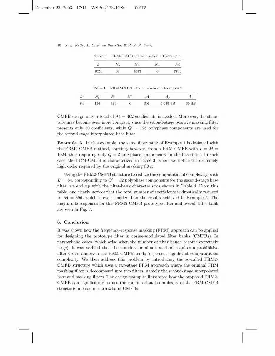
Table 3. FRM-CMFB characteristics in Example 3.
L Nb N+ N− M
1024 88 7613 0 7703
Table 4. FRM2-CMFB characteristics in Example 3.
L′ N ′b
N ′+ N ′
− M Ap Ar
64 116 189 0 396 0.045 dB 60 dB
CMFB design only a total of M = 462 coefficients is needed. Moreover, the struc-
ture may become even more compact, since the second-stage positive masking filter
presents only 50 coefficients, while Q′ = 128 polyphase components are used for
the second-stage interpolated base filter.
Example 3. In this example, the same filter bank of Example 1 is designed with
the FRM2-CMFB method, starting, however, from a FRM-CMFB with L = M =
1024, thus requiring only Q = 2 polyphase components for the base filter. In such
case, the FRM-CMFB is characterized in Table 3, where we notice the extremely
high order required by the original masking filter.
Using the FRM2-CMFB structure to reduce the computational complexity, with
L′ = 64, corresponding to Q′ = 32 polyphase components for the second-stage base
filter, we end up with the filter-bank characteristics shown in Table 4. From this
table, one clearly notices that the total number of coefficients is drastically reduced
to M = 396, which is even smaller than the results achieved in Example 2. The
magnitude responses for this FRM2-CMFB prototype filter and overall filter bank
are seen in Fig. 7.
6. Conclusion
It was shown how the frequency-response masking (FRM) approach can be applied
for designing the prototype filter in cosine-modulated filter banks (CMFBs). In
narrowband cases (which arise when the number of filter bands become extremely
large), it was verified that the standard minimax method requires a prohibitive
filter order, and even the FRM-CMFB tends to present significant computational
complexity. We then address this problem by introducing the so-called FRM2-
CMFB structure which uses a two-stage FRM approach where the original FRM
masking filter is decomposed into two filters, namely the second-stage interpolated
base and masking filters. The design examples illustrated how the proposed FRM2-
CMFB can significantly reduce the computational complexity of the FRM-CMFB
structure in cases of narrowband CMFBs.

December 23, 2003 17:11 WSPC/123-JCSC 00105
Efficient Design of Narrowband CMFBs Using a Two-Stage FRM 11
0 0.002 0.004 0.006 0.008 0.01 0.012 0.014 0.016−200
−150
−100
−50
0
50
Normalized Frequency
Ga
in,
dB
(a)
0 0.002 0.004 0.006 0.008 0.01 0.012 0.014 0.016−160
−140
−120
−100
−80
−60
−40
−20
0
20
Normalized Frequency
Ga
in,
dB
(b)
Fig. 7. Magnitude responses of Example 3: (a) Prototype filter; (b) Filter bank (bands 0 to 15).
References
1. Y. C. Lim, “Frequency-response masking approach for the synthesis of sharp linearphase digital filters”, IEEE Trans. Circuits Syst. CAS-33 (1986) 357–364.
2. P. P. Vaidyanathan, Multirate Systems and Filter Banks, Prentice-Hall, EnglewoodCliffs, NJ, 1993.
3. T. Saramaki, “A generalized class of cosine-modulated filter banks”, Proc. TICSP
Workshop Transforms and Filter Banks, Tampere, Finland, June 1998, pp. 336–365.4. A. Viholainen, T. Saramaki, and M. Renfors, “Cosine-modulated filter bank design for
VDSL modems”, Proc. IEEE Int. Workshop Intelligent Signal Processing and Com-
munication Systems, Melbourne, Australia, November 1998, pp. 143–147.5. J. Alhava and A. Viholainen, “Implementation of nearly perfect-reconstruction cosine-
modulated filter banks”, Proc. FinSig, Oulu, Finland, 1999, pp. 222–226.

December 23, 2003 17:11 WSPC/123-JCSC 00105
12 S. L. Netto, L. C. R. de Barcellos & P. S. R. Diniz
6. A. Viholainen, T. Saramaki, and M. Renfors, “Nearly-perfect reconstruction cosine-modulated filter bank design for VDSL modems”, Proc. IEEE Int. Conf. Electronics,
Circuits Systems, Paphos, Greece, September 1999, pp. 373–376.7. P. S. R. Diniz, L. C. R. de Barcellos, and S. L. Netto, “Design of cosine-modulated filter
bank prototype filters using the frequency-response masking approach”, Proc. IEEE
Int. Conf. Acoustics, Speech, and Signal Processing, Vol. VI, Salt Lake City, UT, May2001, pp. SPTM-P4.6 1–4.
8. H. S. Malvar, Signal Processing with Lapped Transforms, Artech House, Boston, MA,1991.
9. P. S. R. Diniz, E. A. B. da Silva, and S. L. Netto, Digital Signal Processing: System
Analysis and Design, Cambridge University Press, Cambridge, UK, 2002.10. Y. C. Lim and Y. Lian, “Frequency-response masking approach for digital filter design:
Complexity reduction via masking filter factorization”, IEEE Trans. Circuits Syst. II,
Analog and Digital Signal Processing 41 (1994) 518–525.


