Embed Size (px)
Citation preview

Hyderabad|Delhi|Bhopal|Pune|Bhubaneswar| Lucknow|Patna|Bengaluru|Chennai|Vijayawada|Vizag |Tirupati | Kukatpally | Kolkata ACE Engineering Publications
1. ErrorAnalysis,Units&Standards
ElectricalMeasurements(SolutionsforVolume‐1ClassRoomPracticeQuestions)
01. Ans: (a)
Sol: For 10V total input resistance
Rv = fsdm
fsd
I
V= 10/100A = 105
Sensitivity = Rv/Vfsd = 105/10
= 10k/V
For 100V Rv = 100/100A = 106
Sensitivity = Rv/Vfsd = 106/100
= 10 k/V
(or)
Sensitivity = 6
fsd 10100
1
I
1
= 10 k/V
02. Ans: (d)
Sol: Variables are measured with accuracy
x 0.5% of reading 80 (limiting error)
Y 1% of full scale value 100
(Guaranteed error)
Z 1.5 % reading 50 (limiting error)
The limiting error for Y is obtained as
Guaranteed
Error = 100( 1/100) 1
Then % L.E in Y meter
1100
x20
x = 5%
Given zxyw , Add all %L.E s
Therefore =± (0.5% + 5% + 1.5%)
= ± 7%
03. Ans: (i) 41.97 (ii) 0.224 (iii) 0.1513
( Update key )
Sol: Mean ( X ) = n
x
10
8.419.41425.429.411.42428.41427.41
= 41.97
SD = 1n
d2n
for n < 20 dn = nXX
110
17.013.003.053.007.0
)13.0(03.017.003.027.022222
22222
= 0.224
Probable error = 0.6745 × SD
= 0.1513
04. Ans: 150 V (Update key )
Sol:
:V:V 21
Vk20SVk10S21 dcdc
Ifsd = 2dc
fsd
1dc S
1I
S
1
= 0.1mA = 0.05 mA
The maximum allowable current in this
combination is 0.05mA, since both are
connected in series.
Maximum D.C voltage can be measured as
= 0.05 mA (10 k /V100+20 k/V 100)
= 3000 0.05 = 150 V
V1 V2
100V 100V
0.05mA
:3: PostalCoachingSolutions
Hyderabad|Delhi|Bhopal|Pune|Bhubaneswar| Lucknow|Patna|Bengaluru|Chennai|Vijayawada|Vizag |Tirupati | Kukatpally | Kolkata ACE Engineering Publications
05.
Sol: Internal impedance of 1st voltmeter
mA5
V100 = 20 k
Internal impedance of 2nd voltmeter
= 100 × 250 /V = 25 k
Internal impedance of 3rd voltmeters,
= 5 k
Total impedance across 120 V
= 20 + 25 + 5 = 50 k
Sensitivity = V/6.416V120
k50
Reading of 1st voltmeter
= V/6.416
k20
= 48 V
Reading of 2nd voltmeter
= V/6.416
k25
= 60 V
Reading of 3rd voltmeter
V/4166
k5
= 12 V
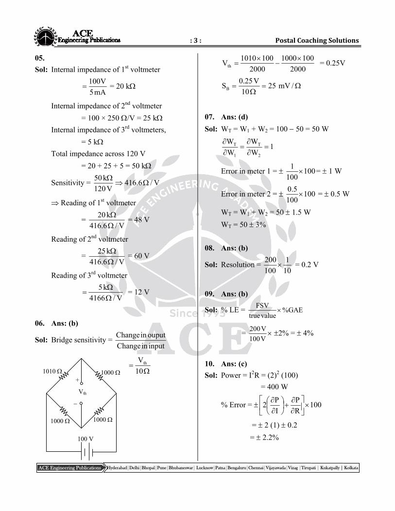
06. Ans: (b)
Sol: Bridge sensitivity = inputinChange
ouputinChange
10
Vth
2000
1001000
2000
1001010Vth
= 0.25V
/mV2510
V25.0SB
07. Ans: (d)
Sol: WT = W1 + W2 = 100 50 = 50 W
1W
W
W
W
2
T
1
T
Error in meter 1 = 100100
1 = 1 W
Error in meter 2 = 100100
5.0 = 0.5 W
WT = W1 + W2 = 50 1.5 W
WT = 50 3%
08. Ans: (b)
Sol: Resolution = 10
1
100
200 = 0.2 V
09. Ans: (b)
Sol: % LE = FSV
%GAEtrue value
= 200V
100V 2% = 4%
10. Ans: (c) Sol: Power = I2R = (2)2 (100)
= 400 W
% Error = 100R
P
I
P2
= 2 (1) 0.2
= 2.2%
1010 1000
1000 1000
100 V
+
Vth
:4: Electrical&ElectronicMeasurements
Hyderabad|Delhi|Bhopal|Pune|Bhubaneswar| Lucknow|Patna|Bengaluru|Chennai|Vijayawada|Vizag |Tirupati | Kukatpally | Kolkata ACE Engineering Publications
3.ElectromechanicalIndicatingInstruments
Error = 400100
2.2
= 8.8 W
11. Ans: (c)
Sol: RT = R1 + R2 = 36 + 75 = 111
72
100
536
100
5R T
= 5.55
RT = 111 5.55
12. Ans: (a)
Sol: I
VR
100I
I100
V
V100
R
R
100R
R
= 2% + 1%
= 3%
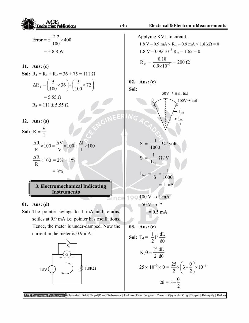
01. Ans: (d)
Sol: The pointer swings to 1 mA and returns,
settles at 0.9 mA i.e, pointer has oscillations.
Hence, the meter is under-damped. Now the
current in the meter is 0.9 mA.
Applying KVL to circuit,
1.8 V – 0.9 mA Rm – 0.9 mA 1.8 k = 0
1.8 V – 0.9103 Rm – 1.62 = 0
200109.0
18.0R
3m
02. Ans: (c)
Sol:
volt/1000
1S
V/I
1S
fsd
1000
1
S
1Ifsd
mA1
100 V 1 mA
50 V ?
= 0.5 mA
03. Ans: (c)
Sol: Td = d
dLI
2
1 2
d
dL
2
IK
2
c
25 10–6 = 6102
32
25
2 = 2
3
50V Half fsd
100V fsd
Ifsd
2
Ifsd
0
+ 1.8V 1.8K
G +
S1
:5: PostalCoachingSolutions
Hyderabad|Delhi|Bhopal|Pune|Bhubaneswar| Lucknow|Patna|Bengaluru|Chennai|Vijayawada|Vizag |Tirupati | Kukatpally | Kolkata ACE Engineering Publications
2
5= 3
= 1.2 rad
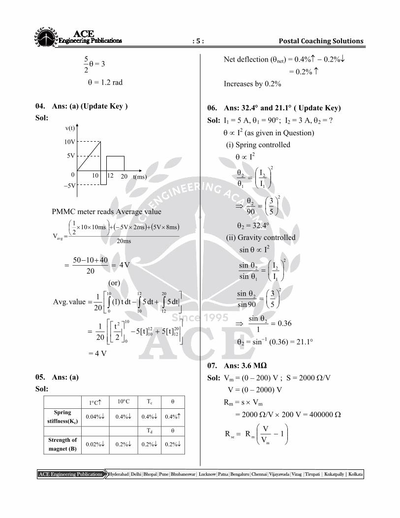
04. Ans: (a) (Update Key )
Sol:
PMMC meter reads Average value
ms20
ms8V5ms2V5ms10102
1
Vavg
V420
401050
(or)
10 12 20
0 10 12
1Avg.value (1) t dt 5dt 5dt
20
20
121210
10
0
2
]t[5]t[52
t
20
1
= 4 V
05. Ans: (a)
Sol:
1C 10C Tc
Spring
stiffness(Kc) 0.04% 0.4% 0.4% 0.4%
Td
Strength of
magnet (B) 0.02% 0.2% 0.2% 0.2%
Net deflection (net) = 0.4% 0.2%
= 0.2%
Increases by 0.2%
06. Ans: 32.4 and 21.1 ( Update Key)
Sol: I1 = 5 A, 1 = 90; I2 = 3 A, 2 = ?
I2 (as given in Question)
(i) Spring controlled
I2
2
1
2
1
2
I
I
θ
θ
2
2
5
3
90
θ
2 = 32.4 (ii) Gravity controlled
sin I2
2
2 2
1 1
sin I
sin I
2
2sin 3
sin 90 5
2sin0.36
1
2 = sin1 (0.36) = 21.1
07. Ans: 3.6 MΩ
Sol: Vm = (0 – 200) V ; S = 2000 /V
V = (0 – 2000) V
Rm = s Vm
= 2000 /V 200 V = 400000
1
V
VRR
m
mse
10 12 20 t(ms) 0
10V
5V
5V
v(t)
:6: Electrical&ElectronicMeasurements
Hyderabad|Delhi|Bhopal|Pune|Bhubaneswar| Lucknow|Patna|Bengaluru|Chennai|Vijayawada|Vizag |Tirupati | Kukatpally | Kolkata ACE Engineering Publications
1
200
2000400000 = 3.6 M
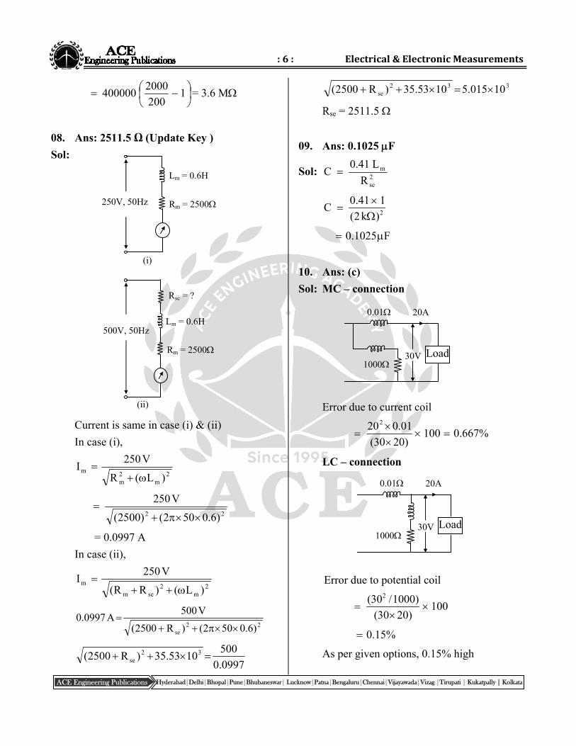
08. Ans: 2511.5 Ω (Update Key )
Sol:
Current is same in case (i) & (ii)
In case (i),
2
m2m
m)L(R
V250I
22 )6.0502()2500(
V250
= 0.0997 A
In case (ii),
2
m2
sem
m)L()RR(
V250I
22
se )6.0502()R2500(
V500A0997.0
0997.0
5001053.35)R2500( 32
se
332se 10015.51053.35)R2500(
Rse = 2511.5
09. Ans: 0.1025 F
Sol: 2se
m
R
L41.0C
2
0.41 1C
(2k )
0.1025 F
10. Ans: (c)
Sol: MC – connection
Error due to current coil
%667.0100)2030(
01.0202
LC – connection
Error due to potential coil
2(30 /1000)
100(30 20)
0.15%
As per given options, 0.15% high
Load
20A 0.01
1000 30V
Load
20A 0.01
1000 30V
Lm = 0.6H
Rm = 2500 250V, 50Hz
(i)
Lm = 0.6H
Rm = 2500
500V, 50Hz
Rsc = ?
(ii)
:7: PostalCoachingSolutions
Hyderabad|Delhi|Bhopal|Pune|Bhubaneswar| Lucknow|Patna|Bengaluru|Chennai|Vijayawada|Vizag |Tirupati | Kukatpally | Kolkata ACE Engineering Publications
11. Ans: (b)
Sol:
21
211
WW
WW3tan
Power factor = cos
= 0.917 lag (since load is inductive)
12. Ans: (c)
Sol: I
VR load
1020
200
For same error VCL RRR
C3 R1010100
RC = 0.01
13. Ans: (a)
Sol: i(t) = 3 + 4 2 sin314t
PMMC reads average value.
Average value = 3A
14. Ans: (b)
Sol: Hot wire ammeter reads RMS value
2
2
rms2
42I
A46.3
15. Ans: (d) ( Update Key )
Sol: Moving Iron Ammeter, I2
For 1 A dc 20
I1 = 1 A, 1 = 20
For 3 sin 314 t ?
MI Ammeter measures the rms value of AC
current
2
3
2
II m
2 , 2
3I2 , 2 = ?
21
22
1
2
I
I
θ
θ
2
22
)1(
)2/3(
20
902
16. Ans: (a)
Sol: Vdc = Idc 10
102
512
V85
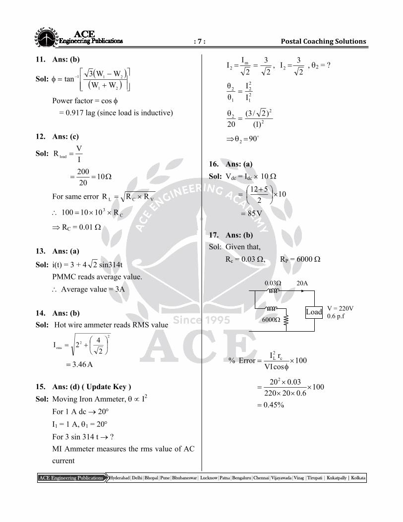
17. Ans: (b)
Sol: Given that,
Rc = 0.03 , RP = 6000
100cosVI
rIError% c
2L
1006.020220
03.0202
%45.0
Load
20A 0.03
6000
V = 220V 0.6 p.f
:8: Electrical&ElectronicMeasurements
Hyderabad|Delhi|Bhopal|Pune|Bhubaneswar| Lucknow|Patna|Bengaluru|Chennai|Vijayawada|Vizag |Tirupati | Kukatpally | Kolkata ACE Engineering Publications
4.MeasurementofPowerandEnergy
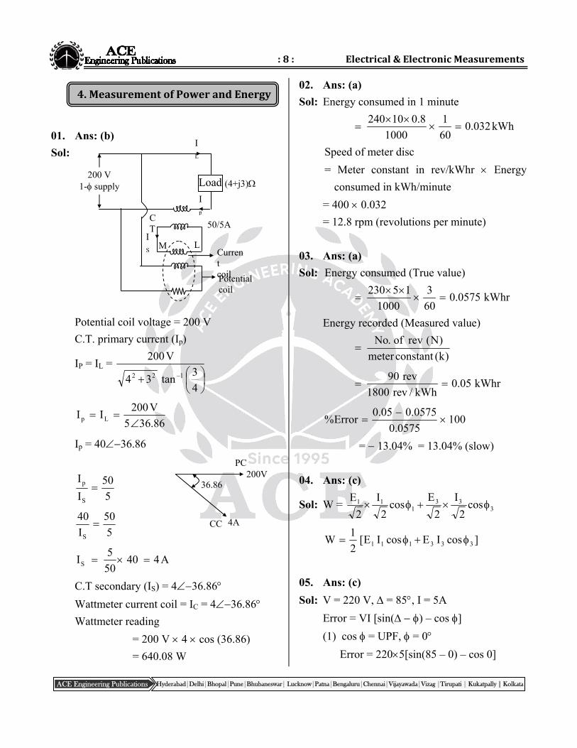
01. Ans: (b)
Sol:
Potential coil voltage = 200 V
C.T. primary current (Ip)
IP = IL =
4
3tan34
V200
122
86.365
V200II Lp
Ip = 4036.86
5
50
I
I
S
p
5
50
I
40
S
A44050
5IS
C.T secondary (IS) = 436.86
Wattmeter current coil = IC = 436.86 Wattmeter reading
= 200 V 4 cos (36.86)
= 640.08 W
02. Ans: (a)
Sol: Energy consumed in 1 minute
240 10 0.8 1
0.032kWh1000 60
Speed of meter disc
= Meter constant in rev/kWhr Energy
consumed in kWh/minute
= 400 0.032
= 12.8 rpm (revolutions per minute)
03. Ans: (a)
Sol: Energy consumed (True value)
230 5 1 3
0.0575 kWhr1000 60
Energy recorded (Measured value)
)k(constantmeter
)N(revof.No
90 rev
0.05 kWhr1800 rev / kWh
1000575.0
0575.005.0Error%
= 13.04% = 13.04% (slow)
04. Ans: (c)
Sol: W = 333
111 cos
2
I
2
Ecos
2
I
2
E
]cosIEcosIE[2
1W 333111
05. Ans: (c)
Sol: V = 220 V, = 85, I = 5A
Error = VI [sin( ) – cos ]
(1) cos = UPF, = 0
Error = 2205[sin(85 – 0) – cos 0]
200V
4A
PC
CC
36.86
Load
50/5A
200 V 1- supply
Ip
IL
L M IS
CT
Current coil Potential coil
(4+j3)
:9: PostalCoachingSolutions
Hyderabad|Delhi|Bhopal|Pune|Bhubaneswar| Lucknow|Patna|Bengaluru|Chennai|Vijayawada|Vizag |Tirupati | Kukatpally | Kolkata ACE Engineering Publications
= 4.185 W ≃ 4.12 W
(2) cos = 0.5 lag, = 60
Error = 2205 [sin(85 – 60) – cos 60]
= 85.12 W
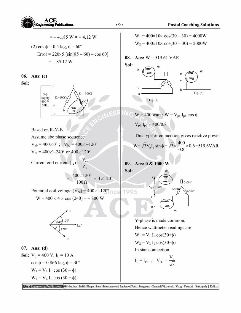
06. Ans: (c)
Sol:
Based on R-Y-B
Assume abc phase sequence
Vab = 4000 ; Vbc = 400120
Vca = 400240 or 400120
Current coil current (Ic) = 2
ca
Z
V
1204100
120400
Potential coil voltage (Vbc) = 400–120
W = 400 4 cos (240) = 800 W
07. Ans: (d)
Sol: VL = 400 V, IL = 10 A
cos = 0.866 lag, = 30
W1 = VL IL cos (30 )
W2 = VL IL cos (30 + )
W1 = 40010 cos(30 – 30) = 4000W
W2 = 40010 cos(30 + 30) = 2000W
08. Ans: W = 519.61 VAR
Sol:
W = 400 watt ; W = Vph Iph cos
Vph Iph = 400/0.8
This type of connection gives reactive power
W= p p3V I sin =400
3 0.60.8
=519.6VAR
09. Ans: 0 & 1000 W
Sol:
Y-phase is made common.
Hence wattmeter readings are
W1 = VL IL cos(30+)
W2 = VL IL cos(30)
In star-connection
IL = Iph ; 3
VV L
ph
R
W1
560
W2
560
560 VL= 100V
Y
B
PC
CC
c b
a
Z1=100 Z2 = 100 3-
supply 400 V 50Hz
R
Y
B
240
IC
IC
Ref
120
120
R
Y
B
W
Fig. (b)
R
Y
B
W
Fig. (a)
:10: Electrical&ElectronicMeasurements
Hyderabad|Delhi|Bhopal|Pune|Bhubaneswar| Lucknow|Patna|Bengaluru|Chennai|Vijayawada|Vizag |Tirupati | Kukatpally | Kolkata ACE Engineering Publications
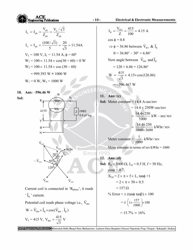
R
W
100
N
Z 0.8 pf lag
415V
Y
B
IR
ph
L
ph
phphL Z
3/V
Z
VII
A54.113
20
5
)3/100(II phL
VL = 100 V, IL = 11.54 A, = 60
W1 = 100 11.54 cos(30 + 60) = 0 W
W2 = 100 11.54 cos (30 60)
= 999.393 W ≃ 1000 W
W1 = 0 W, W2 = 1000 W
10. Ans: –596.46 W
Sol:
Current coil is connected in ‘Rphase’, it reads
‘ RI
’ current.
Potential coil reads phase voltage i.e., BNV
)I.V(cosIVW RBNRBN
VL = 415 V, V3
415VBN
A15.4100
415
Z
VI RY
R
cos = 0.8
= 36.86 between RRY I&V
= 36.86 – 30 = 6.86
Now angle between RBN IandV
= 120 + 6.86 = 126.86
)86.126(cos15.43
415W
= 596.467 W
11. Ans: (c)
Sol: Meter constant = 14.4 A-sec/rev
= 14.4 250W-sec/rev
revsec/kW1000
2504.14
rev/kWhr36001000
2504.14
Meter constant = rev/kWhr1000
1
Meter constant in terms of rev/kWhr = 1000
12. Ans: (d)
Sol: Rp = 1000 , Lp = 0.5 H, f = 50 Hz,
cos = 0.7,
XLp = 2 f L, tan =1
= 2 50 0.5
= 157
% Error = (tan tan) 100
= 157
1 1001000
= 15.7% ≃ 16%
30
60
BNV
YNV
RI
RNVRYV
YNV
120
36.86
:11: PostalCoachingSolutions
Hyderabad|Delhi|Bhopal|Pune|Bhubaneswar| Lucknow|Patna|Bengaluru|Chennai|Vijayawada|Vizag |Tirupati | Kukatpally | Kolkata ACE Engineering Publications
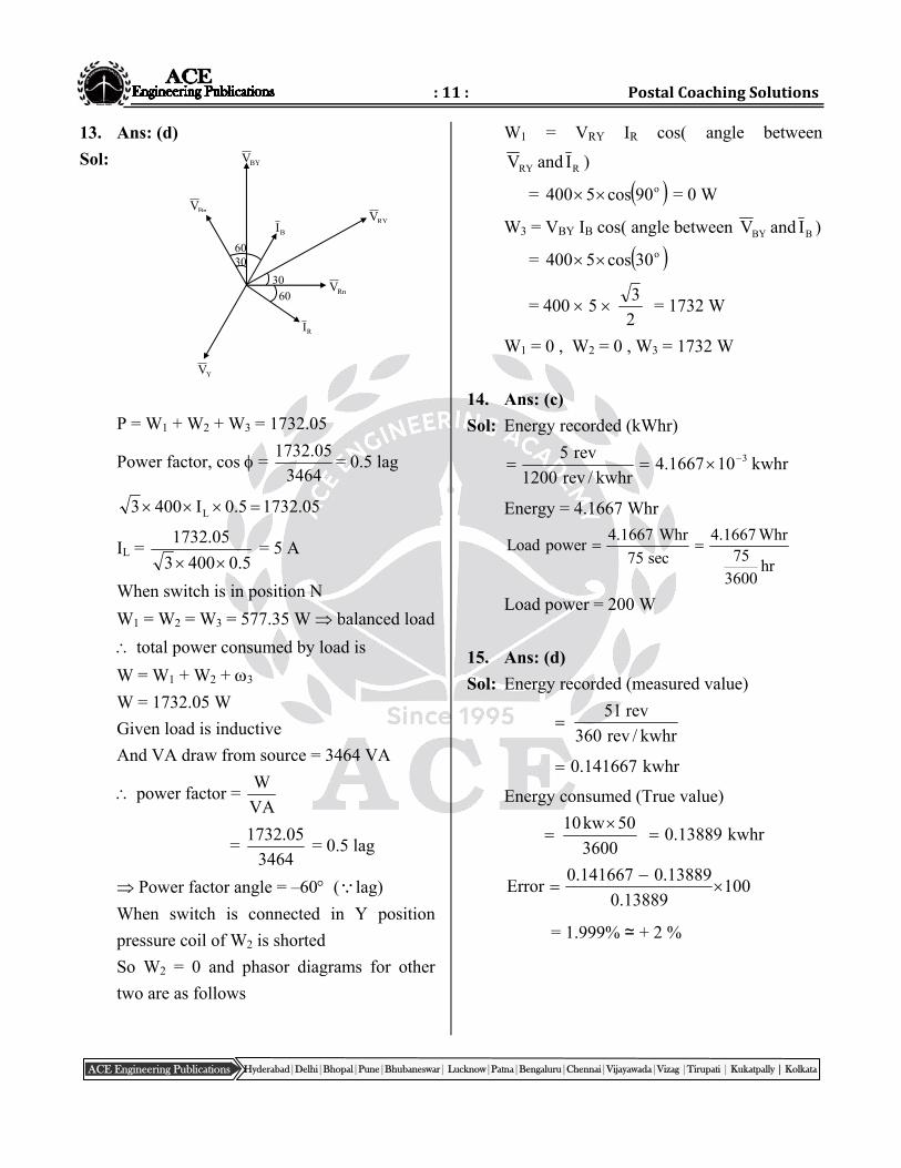
13. Ans: (d)
Sol:
P = W1 + W2 + W3 = 1732.05
Power factor, cos = 3464
05.1732= 0.5 lag
05.17325.0I4003 L
IL = 5.04003
05.1732
= 5 A
When switch is in position N
W1 = W2 = W3 = 577.35 W balanced load
total power consumed by load is
W = W1 + W2 + 3
W = 1732.05 W
Given load is inductive
And VA draw from source = 3464 VA
power factor = VA
W
= 3464
05.1732 = 0.5 lag
Power factor angle = –60 (lag)
When switch is connected in Y position
pressure coil of W2 is shorted
So W2 = 0 and phasor diagrams for other
two are as follows
W1 = VRY IR cos( angle between
RRY IandV )
= o90cos5400 = 0 W
W3 = VBY IB cos( angle between BBY IandV )
= o30cos5400
= 400 5 2
3 = 1732 W
W1 = 0 , W2 = 0 , W3 = 1732 W
14. Ans: (c)
Sol: Energy recorded (kWhr)
kwhr101667.4kwhr/rev1200
rev5 3
Energy = 4.1667 Whr
4.1667 Whr 4.1667 WhrLoad power
7575 sec hr3600
Load power = 200 W
15. Ans: (d)
Sol: Energy recorded (measured value)
kwhr/rev360
rev51
kwhr141667.0
Energy consumed (True value)
3600
50kw10 kwhr13889.0
10013889.0
13889.0141667.0Error
= 1.999% ≃ + 2 %
RnV
BI
YnV
BnVRYV
BYV
3060
3060
RI
:12: Electrical&ElectronicMeasurements
Hyderabad|Delhi|Bhopal|Pune|Bhubaneswar| Lucknow|Patna|Bengaluru|Chennai|Vijayawada|Vizag |Tirupati | Kukatpally | Kolkata ACE Engineering Publications
5.BridgeMeasurementofR,L&C
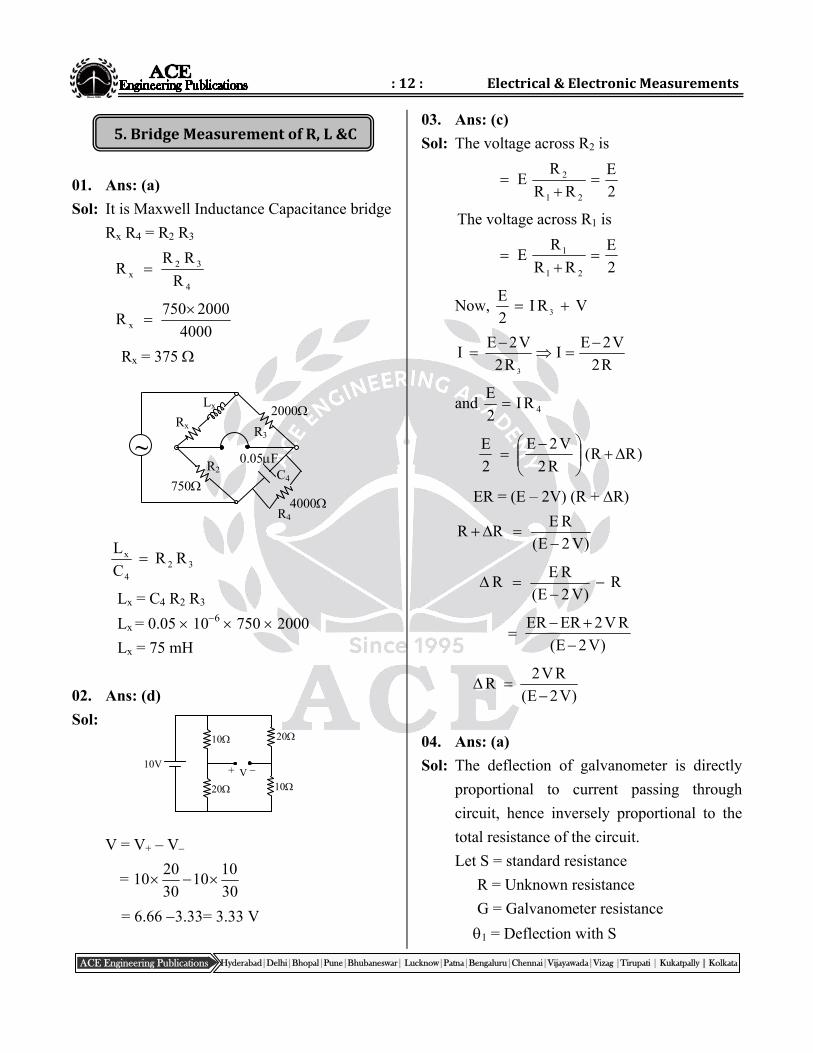
01. Ans: (a)
Sol: It is Maxwell Inductance Capacitance bridge
Rx R4 = R2 R3
4
32x R
RRR
4000
2000750R x
Rx = 375
324
x RRC
L
Lx = C4 R2 R3
Lx = 0.05 106 750 2000
Lx = 75 mH
02. Ans: (d)
Sol:
V = V+ – V–
= 30
1010
30
2010
= 6.66 3.33= 3.33 V
03. Ans: (c)
Sol: The voltage across R2 is
2
E
RR
RE
21
2
The voltage across R1 is
2
E
RR
RE
21
1
Now, VRI2
E3
R2
V2EI
R2
V2EI
3
and 4RI2
E
)RR(R2
V2E
2
E
ER = (E – 2V) (R + R)
)V2E(
RERR
R)V2E(
RER
)V2E(
RV2ERER
)V2E(
RV2R
04. Ans: (a)
Sol: The deflection of galvanometer is directly
proportional to current passing through
circuit, hence inversely proportional to the
total resistance of the circuit.
Let S = standard resistance
R = Unknown resistance
G = Galvanometer resistance
1 = Deflection with S
Rx
2000
C4
R4
Lx
R3
R2
~
750 4000
0.05F
10V
10
20
20
10
+ V
:13: PostalCoachingSolutions
Hyderabad|Delhi|Bhopal|Pune|Bhubaneswar| Lucknow|Patna|Bengaluru|Chennai|Vijayawada|Vizag |Tirupati | Kukatpally | Kolkata ACE Engineering Publications
2 = Deflection with R
GS
GR
2
1
GGSR2
1
336 101051
411010105.0
= 0.4 106
= 0.4 M
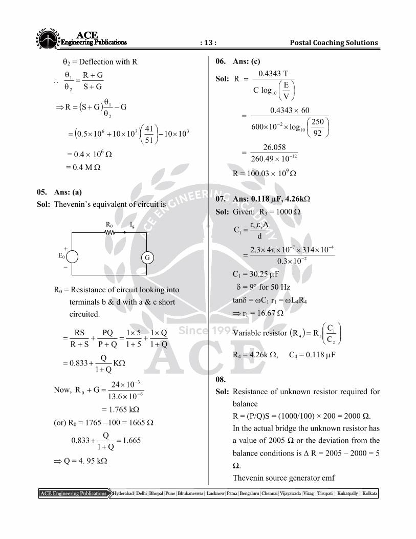
05. Ans: (a)
Sol: Thevenin’s equivalent of circuit is
R0 = Resistance of circuit looking into
terminals b & d with a & c short
circuited.
Q1
Q1
51
51
QP
PQ
SR
RS
KQ1
Q833.0
Now, 6
3
0106.13
1024GR
= 1.765 k
(or) R0 = 1765 100 = 1665
665.1Q1
Q833.0
Q = 4. 95 k
06. Ans: (c)
Sol:
V
ElogC
T4343.0R
10
92
250log10600
604343.0
102
121049.260
058.26
R = 100.03 109
07. Ans: 0.118 F, 4.26k
Sol: Given: R3 = 1000
0 r1
AC
d
2
47
103.0
103141043.2
C1 = 30.25 F
= 9 for 50 Hz
tan = C1 r1 = L4R4
r1 = 16.67
Variable resistor
2
134 C
CRR
R4 = 4.26k , C4 = 0.118 F
08.
Sol: Resistance of unknown resistor required for
balance
R = (P/Q)S = (1000/100) × 200 = 2000 Ω.
In the actual bridge the unknown resistor has
a value of 2005 Ω or the deviation from the
balance conditions is R = 2005 – 2000 = 5
Ω.
Thevenin source generator emf
E0 G
Ig R0
+
:14: Electrical&ElectronicMeasurements
Hyderabad|Delhi|Bhopal|Pune|Bhubaneswar| Lucknow|Patna|Bengaluru|Chennai|Vijayawada|Vizag |Tirupati | Kukatpally | Kolkata ACE Engineering Publications
QP
P
SR
REE0
=
1001000
1000
2002005
20055
= 1.0307 × 10⁻³V.
Internal resistance of bridge looking into
terminals b and d.
QP
PQ
SR
RSR 0
= 1001000
1001000
2002005
2002005
= 272.8 Ω
Hence the current through the galvanometer
0g
0
EI
R G
31.0307 10
A272.8 100
= 2.77 µA.
Deflection of the galvanometer
= SiIg = 10 × 2.77
= 27.7 mm/Ω.
Sensitivity of bridge
SB = R
27.7
5.54mm /5
09. Ans: (d)
Sol: R1R4 = R2 R3
1
324 R
RRR
%)3%5%2(10
1005
= 50 10%
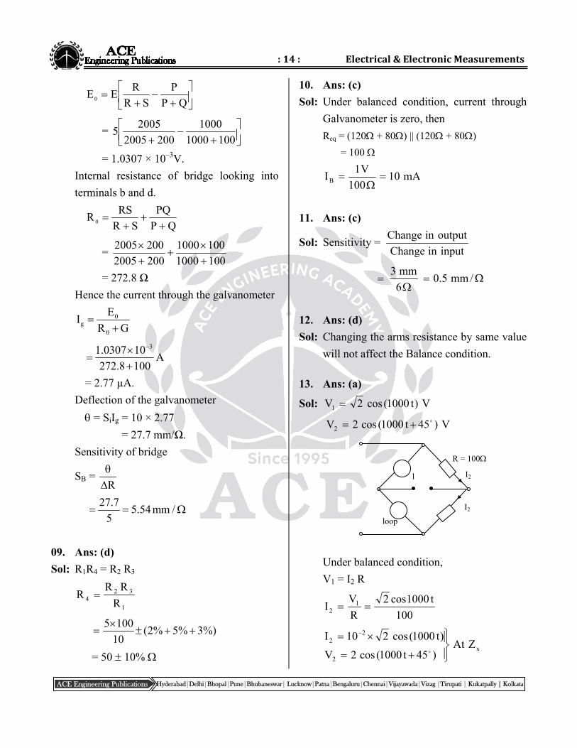
10. Ans: (c)
Sol: Under balanced condition, current through
Galvanometer is zero, then
Req = (120 + 80) || (120 + 80)
= 100
mA10100
V1IB
11. Ans: (c)
Sol: Sensitivity =inputinChange
outputinChange
/mm5.06
mm3
12. Ans: (d)
Sol: Changing the arms resistance by same value
will not affect the Balance condition.
13. Ans: (a)
Sol: V)t1000(cos2V1
V)45t1000(cos2V2
Under balanced condition,
V1 = I2 R
100
t1000cos2
R
VI 1
2
x
2
22 ZAt
)45t1000(cos2V
)t1000(cos210I
R = 100
1
loop
I2
I2
:15: PostalCoachingSolutions
Hyderabad|Delhi|Bhopal|Pune|Bhubaneswar| Lucknow|Patna|Bengaluru|Chennai|Vijayawada|Vizag |Tirupati | Kukatpally | Kolkata ACE Engineering Publications
7.Potentiometers&InstrumentTransformers
‘I2’ lags ‘V2’ by 45. So, Zx has ‘R’ and ‘L’
in series.
R = Z cos
10045cos210
22
XL = Z sin
10045sin102
22
XL = L
mH100H1.01000
100XL L
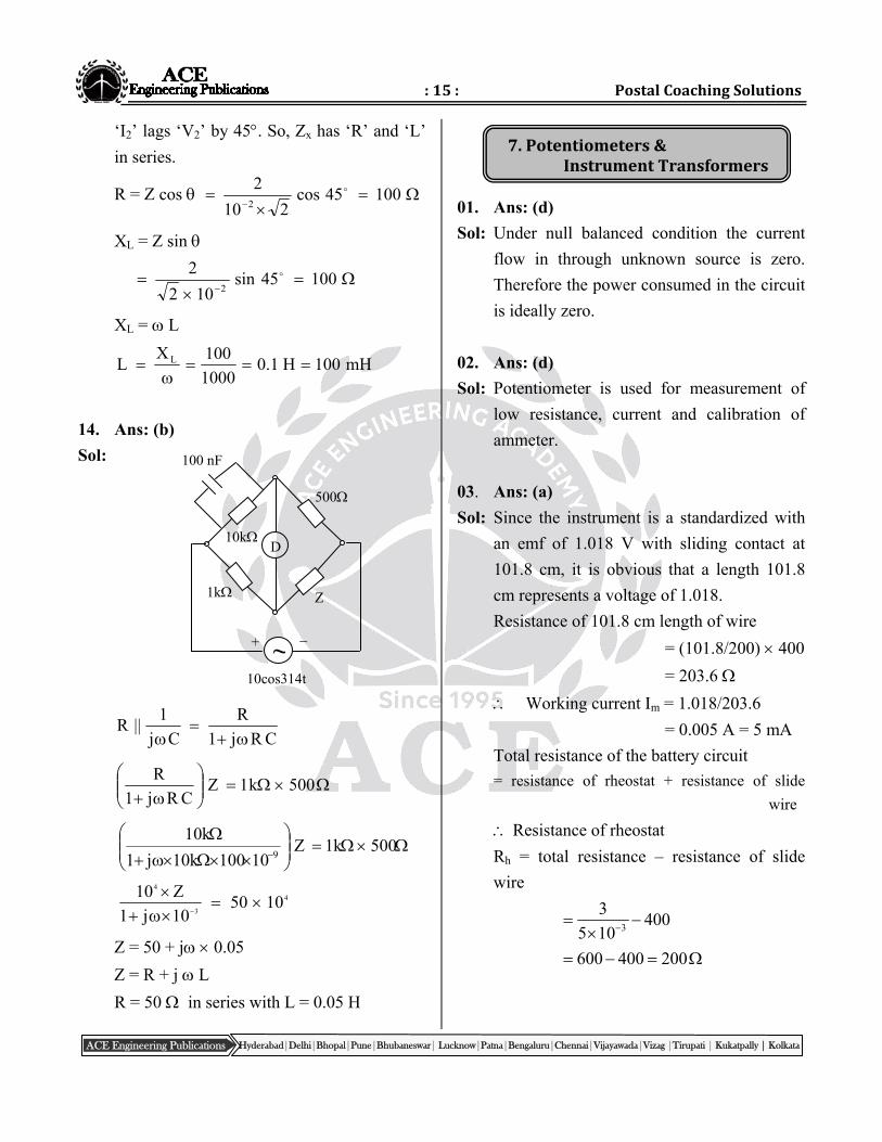
14. Ans: (b)
Sol:
CRj1
R
Cj
1||R
500k1ZCRj1
R
500k1Z
10100k10j1
k109
4
3
4
105010j1
Z10
Z = 50 + j 0.05
Z = R + j L
R = 50 in series with L = 0.05 H
01. Ans: (d)
Sol: Under null balanced condition the current
flow in through unknown source is zero.
Therefore the power consumed in the circuit
is ideally zero.
02. Ans: (d)
Sol: Potentiometer is used for measurement of
low resistance, current and calibration of
ammeter.
03. Ans: (a)
Sol: Since the instrument is a standardized with
an emf of 1.018 V with sliding contact at
101.8 cm, it is obvious that a length 101.8
cm represents a voltage of 1.018.
Resistance of 101.8 cm length of wire
= (101.8/200) 400
= 203.6
Working current Im = 1.018/203.6
= 0.005 A = 5 mA
Total resistance of the battery circuit
= resistance of rheostat + resistance of slide
wire
Resistance of rheostat
Rh = total resistance – resistance of slide
wire
3
3400
5 10
600 400 200
500
1k Z
+ ~
D
10k
100 nF
10cos314t
:16: Electrical&ElectronicMeasurements
Hyderabad|Delhi|Bhopal|Pune|Bhubaneswar| Lucknow|Patna|Bengaluru|Chennai|Vijayawada|Vizag |Tirupati | Kukatpally | Kolkata ACE Engineering Publications
04. Ans: (b)
Sol: Voltage drop per unit length
cm/V029.0cm50
V45.1
Voltage drop across 75 cm length
= 0.029 75 = 2.175 V
Current through resistor (I)
A75.211.0
V175.2
(or)
75 cm 0.1
50 cm ?
Slide wire resistance with standard cell
067.01.070
50
Then 0.067 Iw = 1.45 V
A75.21067.0
45.1Iw
05. Ans: (a)
Sol:
Under balanced, Ig = 0
x
200E 3.2V
(200 200 2800)
0.2V
Ex = 200 mV
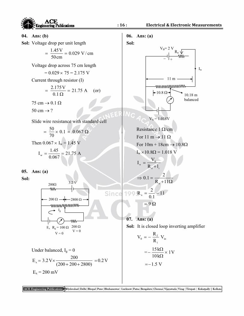
06. Ans: (a)
Sol:
Resistance 1 /cm
For 11 m 11
For 10m + 18cm 10.8
Iw 10.8 = 1.018 V
rn
Bw lR
VI
11R
21.0
n
111.0
2R n
9
07. Ans: (a)
Sol: It is closed loop inverting amplifier
ini
f0 V
R
RV
=15k
1V10k
V5.1
VB= 2 V
11 m
VS = 1.018V
+
Iw
Rn
10.8 10.18 m balanced
200
Rg = 100
3.2 V
2800 200
Ig
Ex 200
V = 0 V = 0
:17: PostalCoachingSolutions
Hyderabad|Delhi|Bhopal|Pune|Bhubaneswar| Lucknow|Patna|Bengaluru|Chennai|Vijayawada|Vizag |Tirupati | Kukatpally | Kolkata ACE Engineering Publications
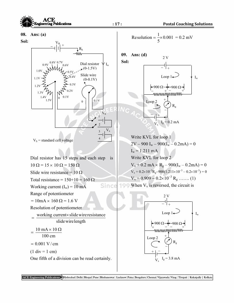
08. Ans: (a)
Sol:
Dial resistor has 15 steps and each step is
10 = 15 10 = 150
Slide wire resistance = 10
Total resistance = 150+10 = 160
Working current (Iw) = 10 mA
Range of potentiometer
= 10mA 160 = 1.6 V
Resolution of potentiometer
lengthwireslide
resistancewireslidecurrentworking
cm100
10mA10
cm/V001.0
(1 div = 1 cm)
One fifth of a division can be read certainly.
001.05
1solutionRe = 0.2 mV
09. Ans: (d)
Sol:
Write KVL for loop 1
2V – 900 Iw – 900(Iw – 0.2mA) = 0
Iw = 1.211 mA
Write KVL for loop 2
Vx + 0.2 mA Rg – 900(Iw – 0.2mA) = 0
Vx + 0.2103Rg900(1.211103 – 0.2103) = 0
Vx = 0.909 0.2103 Rg ……. (1)
When Vx is reversed, the circuit is
Rg
2 V
900 900
Vx Ig = 3.8 mA
+
+ +
Loop 1 Iw
Loop 2
+
+
Rg
2 V
900 900
Vx Ig = 0.2 mA
+
+ +
Loop 1 Iw
Loop 2
+
+
0 0.1V
0.2V
0.3V
0.4V
0.5V
0.6V 0.7V 0.8V
0.9V
1.0V
1.1V
1.2V
1.3V
1.4V 1.5V
+ VB
Rh
Iw
VS
Dial resistor (0-1.5V)
0 0.1V
Vx
1
2
3
4
Slide wire (0-0.1V)
VS = standard cell voltage
:18: Electrical&ElectronicMeasurements
Hyderabad|Delhi|Bhopal|Pune|Bhubaneswar| Lucknow|Patna|Bengaluru|Chennai|Vijayawada|Vizag |Tirupati | Kukatpally | Kolkata ACE Engineering Publications
Write KVL for loop (1)
2 – 900Iw – 900(Iw – 3.8mA) = 0
Iw = 3.011 mA
Write KVL for loop (2)
Vx – 900(3.8mA – Iw) – 3.8mARg = 0
Vx –900(3.8103–3.011103)– 3.8103 Rg = 0
Vx = 0.710 + 3.8103 Rg ………(2)
Substitute (2) in eqn (1)
0.710+3.8103Rg = 0.9090.2103Rg
Rg = 49.72 ≃ 50
Substitute ‘Rg’ value in eqn (2)
Vx = 0.710 + 3.8 103 50 = 0.9001V
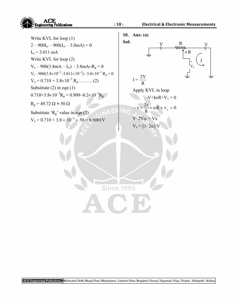
10. Ans: (a)
Sol:
I = R
V2
Apply KVL in loop
–V+IR+Vx = 0
0vRR
v2v x
V–2V = Vx
Vx = [1–2] V
+ Vx
–
V V
R
R
I
Hyderabad|Delhi|Bhopal|Pune|Bhubaneswar| Lucknow|Patna|Bengaluru|Chennai|Vijayawada|Vizag |Tirupati | Kukatpally | Kolkata ACE Engineering Publications
8.CathodeRayOscilloscope
ElectronicMeasurements
01. Ans: (b)
Sol: Time period of one cycle = 5.02
8.8
= 2.2 msec
Therefore frequency = 3102.2
1
T
1
= 454.5 Hz
The peak to peak Voltage = 4.6100
= 460 mV
Therefore the peak voltage Vm = 230 mV
R.M.S voltage = 2
230= 162.6 mV
02. Ans: (c)
Sol: In channel 1
The peak to peak voltage is 5V and peak to
peak divisions of upper trace voltage = 2
Therefore for one division voltage is 2.5V
In channel 2, the no. of divisions for
unknown voltage = 3
Divisions = 3, voltage/division = 2.5
voltage = 2.5 3 = 7.5 V
Similarly frequency of upper trace is 1kHz
So the time period T
(for four divisions) = f
1
T = 3101 1 msec
i.e for four divisions time
period = 1m sec
In channel 2, for eight divisions of unknown
waveform time period = 2m sec.
03. Ans: (c)
Sol: No. of cycles of signal displayed
= fsignal Tsweep
= 200Hz
cm
ms5.0cm10 = 1
i.e, one cycle of sine wave will be displayed.
We know Vrms =22
V pp
Vrms = 22
div/VoltNv
Nv = div/Volt
V22 rms
Nv = 2 2 300mV
100mv / cm
Nv = 8.485cm
i.e 8.485cm required to display peak to peak
of signal. But screen has only 8cm (vertical)
As such, peak points will be clipped.
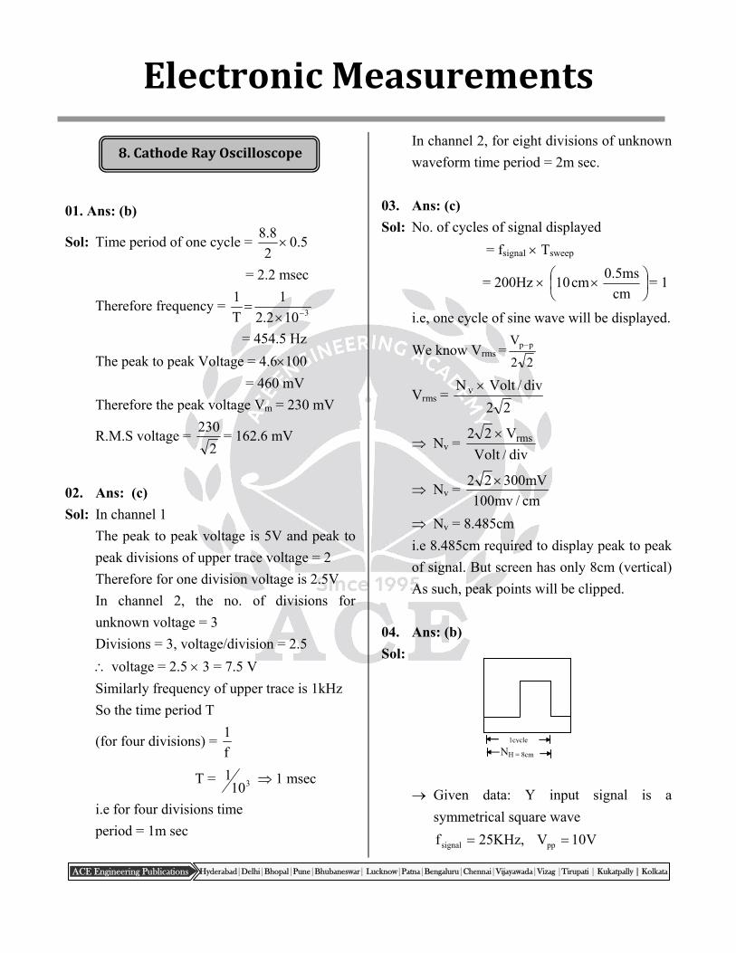
04. Ans: (b)
Sol:
Given data: Y input signal is a
symmetrical square wave
V10V,KHz25f ppsignal
1cycle
NH = 8cm
:20: Electrical&ElectronicMeasurements
Hyderabad|Delhi|Bhopal|Pune|Bhubaneswar| Lucknow|Patna|Bengaluru|Chennai|Vijayawada|Vizag |Tirupati | Kukatpally | Kolkata ACE Engineering Publications
0 1 2 3 4
1
1
(2,2)
(0,0)
(2,2)
0 1 2 3 4
1
1
180 0 (or) 360
270
90
+
+
–
–
1:1
Screen has 10 Horizontal divisions & 8
vertical divisions
which displays 1.25 cycles of Y-input
signal.
div
VOLTNV VPP
PP
V
VVOLT
div N =
cm5
V10= 2 Volt/ c.m
div
TIMEcycleperNT Hsignal
cycleperN
T
div
TIME
H
signal
1
25kHz 8cm
cm
s5
05. Ans: (a)
Sol: Frequency ratio is 2
Two cycles of sine wave displayed on
vertical time base
06. Ans: (a)
Sol:
07. Ans: (a)
Sol: Since the coupling mode is set to DC the
capacitance effect at the input side is zero.
Therefore the waveform displayed on the
screen is both DC and AC components.
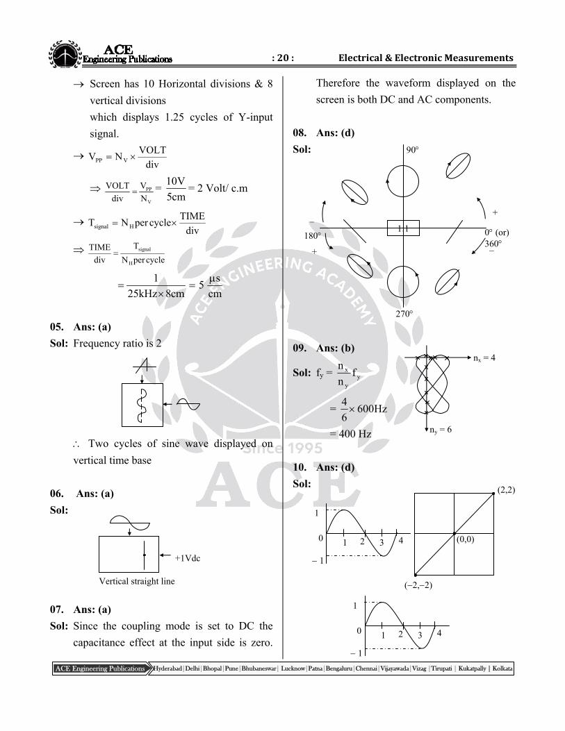
08. Ans: (d)
Sol:
09. Ans: (b)
Sol: fy = yy
x fn
n
= Hz6006
4
= 400 Hz
10. Ans: (d)
Sol:
+1Vdc
Vertical straight line
nx = 4
ny = 6
:21: PostalCoachingSolutions
Hyderabad|Delhi|Bhopal|Pune|Bhubaneswar| Lucknow|Patna|Bengaluru|Chennai|Vijayawada|Vizag |Tirupati | Kukatpally | Kolkata ACE Engineering Publications
9.DigitalVoltmeters
= 900 00 < < 900
900 < < 1800
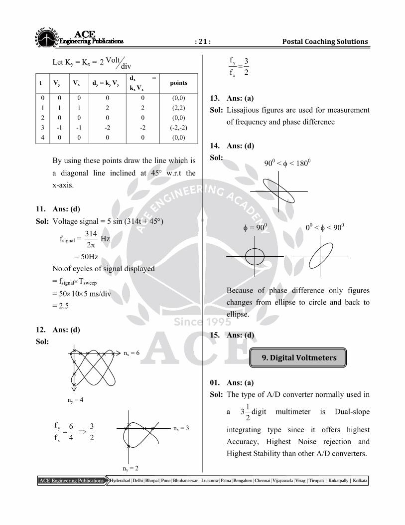
Let Ky = Kx = divVolt2
t Vy Vx dy = ky Vy dx =
kx Vx points
0
1
2
3
4
0
1
0
-1
0
0
1
0
-1
0
0
2
0
-2
0
0
2
0
-2
0
(0,0)
(2,2)
(0,0)
(-2,-2)
(0,0)
By using these points draw the line which is
a diagonal line inclined at 45 w.r.t the
x-axis.
11. Ans: (d)
Sol: Voltage signal = 5 sin (314t + 45)
fsignal = 2
314 Hz
= 50Hz
No.of cycles of signal displayed
= fsignalTsweep
= 50105 ms/div
= 2.5
12. Ans: (d)
Sol:
4
6
f
f
x
y 2
3
2
3
f
f
x
y
13. Ans: (a)
Sol: Lissajious figures are used for measurement
of frequency and phase difference
14. Ans: (d)
Sol:
Because of phase difference only figures
changes from ellipse to circle and back to
ellipse.
15. Ans: (d)
01. Ans: (a)
Sol: The type of A/D converter normally used in
a 2
13 digit multimeter is Dual-slope
integrating type since it offers highest
Accuracy, Highest Noise rejection and
Highest Stability than other A/D converters.
nx = 6
ny = 4
nx = 3
ny = 2
:22: Electrical&ElectronicMeasurements
Hyderabad|Delhi|Bhopal|Pune|Bhubaneswar| Lucknow|Patna|Bengaluru|Chennai|Vijayawada|Vizag |Tirupati | Kukatpally | Kolkata ACE Engineering Publications
02. Ans: (d)
Sol: DVM measures the average value of the
input signal which is 1 V.
DVM indicates as 1.000 V
03. Ans: (c)
Sol: 0.2% of reading +10 counts (1)
= 0.2 )rangeysensitivit(10100
100
= 0.2
200
102
110
100
1004
= 0.2 + 0.1 = ± 0.3 V
%error = 100100
3.0 = 0.3%
04. Ans: (d)
Sol: When 2
1 digit is present voltage range
becomes double. Therefore 1V can read
upto 1.9999 V.
05. Ans: (d)
Sol: Resolution=countimummax
readingscalefull=
9999
V999.9
= 1mV
06. Ans: (b)
Sol: Sensitivity = resolution lowest voltage range
= 10010
14 mV
= 0.01 mV
07. Ans: (c)
Sol: The DVM has 2
13 digit display
Therefore, the count range is from 0 to 1999
i.e., 2000 counts.
Resolution = countMaximum
rangevoltagegiven
mV2.02000
mV200
08. Ans: (a)
Sol: Resolution = max.voltage
max. count
3.999
1mV3999
09. Ans: (b)
Sol: A and R are true, but R is not correct
explanation for A.
10. Ans: (c)
Sol: When 2
1digit switched ON, then DVM will
be able to read more than the selected range.
11. Ans: (b)
Sol: Given , 2
13 digit, FSD value of 200 mV
Resolution = mV1.02000
mV200
mV1.05mV100100
5.0Error
= 1 mV
The value lies between 99.0 mV &
101.0 mV
12. Ans: (d)
Sol: The DVM has 2
13 digit display.
Therefore, its scale resolution is 0.001
:23: PostalCoachingSolutions
Hyderabad|Delhi|Bhopal|Pune|Bhubaneswar| Lucknow|Patna|Bengaluru|Chennai|Vijayawada|Vizag |Tirupati | Kukatpally | Kolkata ACE Engineering Publications
10.AnalogElectronicVoltmeters
Its resolution in 200mV range is 100mV
The maximum voltage that can be
measured in this 200mV lowest Range:
199.9mV
13. Ans: (b)
Sol: For N-decade counter
Pulse width (max) = clk
N
f
10
Resolution 1count 1.Tclk
Resolution = f
1
Range of pulse width
f
1 to
F
110N
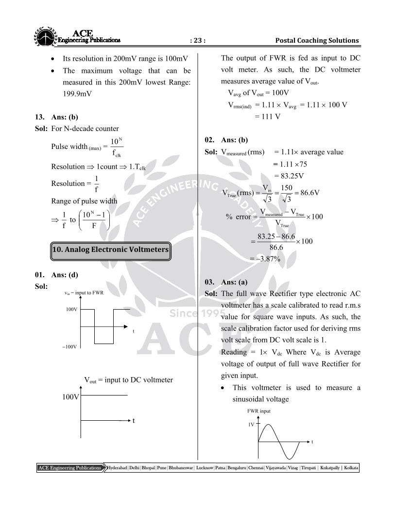
01. Ans: (d)
Sol:
The output of FWR is fed as input to DC
volt meter. As such, the DC voltmeter
measures average value of Vout.
Vavg of Vout = 100V
Vrms(ind) = 1.11 Vavg = 1.11 100 V
= 111 V
02. Ans: (b)
Sol: Vmeasured (rms) = 1.11 average value
= 1.11 75
= 83.25V
V6.863
150
3
V)rms(V m
True
100V
VVerror%
True
Truemeasured
1006.86
6.8625.83
= –3.87%
03. Ans: (a)
Sol: The full wave Rectifier type electronic AC
voltmeter has a scale calibrated to read r.m.s
value for square wave inputs. As such, the
scale calibration factor used for deriving rms
volt scale from DC volt scale is 1.
Reading = 1 Vdc Where Vdc is Average
voltage of output of full wave Rectifier for
given input.
This voltmeter is used to measure a
sinusoidal voltage
t
1V
FWR input
100V
100V
t
vin = input to FWR
Vout = input to DC voltmeter
100V
t
:24: Electrical&ElectronicMeasurements
Hyderabad|Delhi|Bhopal|Pune|Bhubaneswar| Lucknow|Patna|Bengaluru|Chennai|Vijayawada|Vizag |Tirupati | Kukatpally | Kolkata ACE Engineering Publications
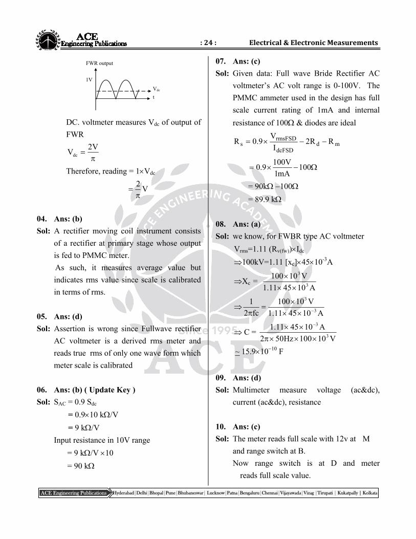
DC. voltmeter measures Vdc of output of
FWR
V2
Vdc
Therefore, reading = 1Vdc
V2
04. Ans: (b)
Sol: A rectifier moving coil instrument consists
of a rectifier at primary stage whose output
is fed to PMMC meter.
As such, it measures average value but
indicates rms value since scale is calibrated
in terms of rms.
05. Ans: (d)
Sol: Assertion is wrong since Fullwave rectifier
AC voltmeter is a derived rms meter and
reads true rms of only one wave form which
meter scale is calibrated
06. Ans: (b) ( Update Key )
Sol: SAC = 0.9 Sdc
= 0.910 k/V
= 9 k/V
Input resistance in 10V range
= 9 k/V 10
= 90 k
07. Ans: (c)
Sol: Given data: Full wave Bride Rectifier AC
voltmeter’s AC volt range is 0-100V. The
PMMC ammeter used in the design has full
scale current rating of 1mA and internal
resistance of 100 & diodes are ideal
mddcFSD
rmsFSDs RR2
I
V9.0R
100mA1
V1009.0
= 90k 100
= 89.9 k
08. Ans: (a)
Sol: we know, for FWBR type AC voltmeter
Vrms=1.11 (Rv(fw))Idc
100kV=1.11 [xc]4510-3A
Xc = A104511.1
V101003
3
A104511.1
V10100
fc2
13
3
C = V10100Hz502
A104511.13
3
~ 15.91010 F
09. Ans: (d)
Sol: Multimeter measure voltage (ac&dc),
current (ac&dc), resistance
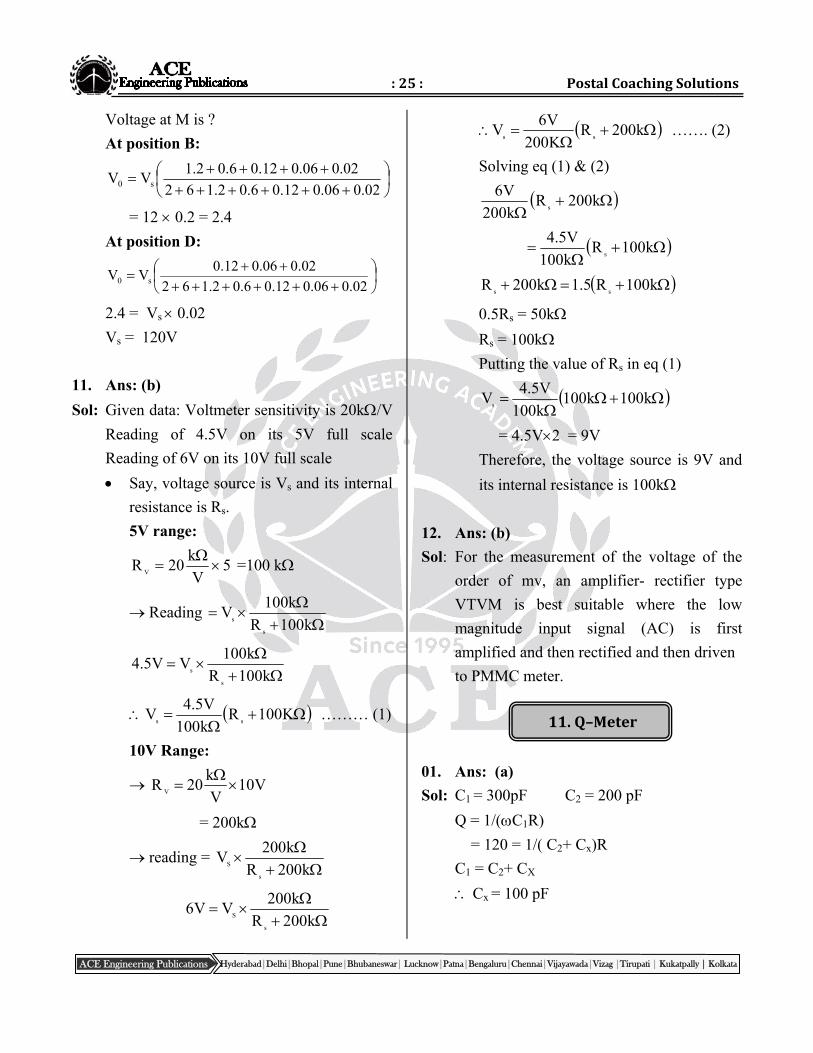
10. Ans: (c)
Sol: The meter reads full scale with 12v at M
and range switch at B.
Now range switch is at D and meter
reads full scale value.
FWR output
Vdc
t
1V
:25: PostalCoachingSolutions
Hyderabad|Delhi|Bhopal|Pune|Bhubaneswar| Lucknow|Patna|Bengaluru|Chennai|Vijayawada|Vizag |Tirupati | Kukatpally | Kolkata ACE Engineering Publications
11.Q–Meter
Voltage at M is ?
At position B:
02.006.012.06.02.162
02.006.012.06.02.1VV s0
= 12 0.2 = 2.4
At position D:
02.006.012.06.02.162
02.006.012.0VV s0
2.4 = Vs 0.02
Vs = 120V
11. Ans: (b)
Sol: Given data: Voltmeter sensitivity is 20k/V
Reading of 4.5V on its 5V full scale
Reading of 6V on its 10V full scale
Say, voltage source is Vs and its internal
resistance is Rs.
5V range:
5V
k20R
V
=100 k
Reading
k100R
k100V
s
s
k100R
k100VV5.4
s
s
K100Rk100
V5.4V
ss ……… (1)
10V Range:
V10V
k20R
V
= 200k
reading =
k200R
k200V
s
S
k200R
k200VV6
s
S
k200RK200
V6V
ss ……. (2)
Solving eq (1) & (2)
k200Rk200
V6s
k100Rk100
V5.4s
k100R5.1k200Rss
0.5Rs = 50k
Rs = 100k
Putting the value of Rs in eq (1)
k100k100k100
V5.4V
s
= 4.5V2 = 9V
Therefore, the voltage source is 9V and
its internal resistance is 100k
12. Ans: (b)
Sol: For the measurement of the voltage of the
order of mv, an amplifier- rectifier type
VTVM is best suitable where the low
magnitude input signal (AC) is first
amplified and then rectified and then driven
to PMMC meter.
01. Ans: (a)
Sol: C1 = 300pF C2 = 200 pF
Q = 1/(C1R)
= 120 = 1/( C2+ Cx)R
C1 = C2+ CX
Cx = 100 pF
:26: Electrical&ElectronicMeasurements
Hyderabad|Delhi|Bhopal|Pune|Bhubaneswar| Lucknow|Patna|Bengaluru|Chennai|Vijayawada|Vizag |Tirupati | Kukatpally | Kolkata ACE Engineering Publications
02. Ans: (b)
Sol: %error = 100Rr
r
1001002.0
02.0
= –0.2%
03. Ans: (c)
Sol: Q-meter consists of R, L, C connected in
series.
Q-meter works on the principle of series
resonance.
04. Ans: (b)
Sol: Given data: Cd = 820 pF,
= 106rad/sec & C = 9.18nF
We know, d2 CC
1L
pF820nF18.910
126
= 100H
The inductance of coil tested with a Q-meter
is 100H.
05. Ans: (b)
Sol: A series RLC circuit exhibits voltage
magnification property at resonance. i.e., the
voltage across the capacitor will be equal to
Q-times of applied voltage.
Given that V = applied voltage and
V0 = Voltage across capacitor
There fore, in
maxc
V
VQ
V
VQ 0
06. Ans: (b)
Sol: f1 = 500 kHz ; f2 = 250kHz
C1 = 36 pF ; C2 = 160 pF
n = 250kHz
500kHz
n = 0.5
Cd = 1)5.0(
pF160)5.0(pF362
2
= 5.33pF
07. Ans: (c)
Sol: Q = voltageInput
readingvoltmetercapactor
= 310500
10
= 20
08. Ans: i (c), ii (a)
Sol: (i) 1n
CnCC
22
21
d
3
288360
= 24 pF
(ii) L = d121 CC
1
23 6
1264 H
2 500 10 24 360 10
09. Ans: (b)
Sol: Qtrue = Qmeas
coilR
r1
Qactual = Qobserved
sR
R1
:27: PostalCoachingSolutions
Hyderabad|Delhi|Bhopal|Pune|Bhubaneswar| Lucknow|Patna|Bengaluru|Chennai|Vijayawada|Vizag |Tirupati | Kukatpally | Kolkata ACE Engineering Publications
10. Ans: (c)
Sol: measured
trued
Q
Q
C
C1
15.244
245
C
Cd
= 2.044×10⁻³
489C
C
d
11. Ans: (b)
Sol: Q-meter works on the principle of series
resonance
inc VQV
Both A & R are individually true but R is
not the correct explanation of A.
Hyderabad|Delhi|Bhopal|Pune|Bhubaneswar| Lucknow|Patna|Bengaluru|Chennai|Vijayawada|Vizag |Tirupati | Kukatpally | Kolkata ACE Engineering Publications
12.BasicsofTransducers
Transducers
01. Ans: (d)
Sol: piezo electric transducer is an active
transducer
02. Ans: (c)
Sol: Active transducers do not require an
auxiliary power source to produce their
output. From given options thermocouple &
solar cell pair transducers are active
transducers as they produce output with no
auxiliary power source.
03. Ans: (d)
Sol: Pressure Piezoelectric crystal
Temperature Thermistor
Displacement Capacitive transducer
Stress Resistance strain gauge
04. Ans: (d)
Sol: Thermocuple Cold junction
compensation
Strain gauge DC bridge
Piezoelectric crystal Charge amplifier
LVDT Phase sensitive detector
05. Ans: (b)
Sol: Usually from transducers we get small
output which is not sufficient for further
processing, so in order to amplify that output
we require signal conditioning circuit.
finally to read the output we require
recorder.
06. Ans: (d)
Sol: Bolometer measurement of power at 500
MHz
Hot wire anemometer measurement of
flow of air around an aeroplane.
C-type bourdon tube measurement of
high pressure
Optical pyrometer measurement of
temperature of furnace.
07. Ans: (d)
Sol: Charge amplifier with very low bias current
and high input impedance piezoelectric
sensor for measurement of static force
Voltage amplifier with low bias current and
very high input impedance Glass
electrode PH sensor
Voltage amplifier with very high CMRR
sensing applications strain gauge in
unipolar DC wheatstone bridge.
08. Ans: (b)
Sol: Mcleod gauge Pressure
Turbine meter Flow
Pyrometer Temperature
Synchros Displacement
:29: PostalCoachingSolutions
Hyderabad|Delhi|Bhopal|Pune|Bhubaneswar| Lucknow|Patna|Bengaluru|Chennai|Vijayawada|Vizag |Tirupati | Kukatpally | Kolkata ACE Engineering Publications
13.Resistive,Capacitive,InductiveTransducers
09. Ans: (a)
Sol: Variable capacitance device Pressure
transducer
Orifice meter Flow measurement
Thermistors Temperature measurement
10. Ans: (b)
Sol: From given options diaphragm and pivot
torque are employed for displacement
measurement while thermistor and
thermocouple not related to displacement
measurement.
11. Ans: (a)
Sol: Instrumentation amplifier is used to amplify
signals from transducer
12. Ans: (a)
Sol: LVDT gives linear output & also very
accurate compare to any other transducer
given in options.
13. Ans: (b) ( Update Key )
Sol: The lower limit of useful working range of a
transducer is determined by transducer error
and noise.
14. Ans: (d)
Sol: From given options, thermocouple and
thermopile, piezoelectric pick-up,
photovoltaic cellare a self generating type
transducers.
01. Ans: (b)
Sol: For resistive potentiometer
output E0 = K Ei
Where E0 = output of the potentiometer
Ei = input of the potentiometer
02. Ans: (b)
Sol: In a resistance potentiometer, non linearity
decreases with increase of load to
potentiometer resistance because the output
equation for potentiometer under loading
condition is
m
p0
R
RK1K1
KE
Rp = resistance of the potentiometer
Rm = resistance of the meter
03. Ans: (a)
Sol: In a resistance potentiometer high value of
resistance lease to high value of sensitivity
04. Ans: (c)
Sol: Total temperature of POT = Tambient + Tpot
PW
C30Tpot
W1100
10
R
VP
22
W1W
C30Tpot
= 30 C
:30: Electrical&ElectronicMeasurements
Hyderabad|Delhi|Bhopal|Pune|Bhubaneswar| Lucknow|Patna|Bengaluru|Chennai|Vijayawada|Vizag |Tirupati | Kukatpally | Kolkata ACE Engineering Publications
Total temperature of POT = 40 +30
= 70C
05. Ans: (a)
Sol: Semiconductor strain gauge has a much
higher gauge factor then that of a metal wire
strain gauge because of piezo resistive
effect.
06. Ans: (b)
Sol: We for quarter bridge strain measuring
circuit the output Fi
0 G4
VV
Here, V0 = 1 mV
Strain () = 500 10–6
Vi = 4 V
Now GF = 2
07. Ans: (a)
Sol: For the given bending force we can say that
configuration P is subjected to more tension
compare to other two configurations.
08. Ans: (d)
Sol: Gf = 1+20.35
= 1.70
09. Ans: (c)
Sol: for sinusoidal input output should have to be
sinusoidal
10. Ans: (c)
Sol: Gauge factor 4105.1
250/150.04
11. Ans: (b)
Sol: A gauge factor is a ratio of per unit change
in resistance to per unit change in length
L/L
R/RF.G
12. Ans: (b)
Sol: To receive the optimum output signal for
shear strain, all the gauges should be placed
at a position that is 45 in with respect to the
longitudinal axis.
13. Ans: (c)
Sol: A strain gauge bridge sometimes excited
with ac to avoid the power frequency pick-
up.
14. Ans: (b)
Sol: GF = 2
=1 10–6
R = 120
We know =
GFR
R
R = GF R
= 2 1 10–6 120
R = 240 10–6
15. Ans: (c)
Sol: The piezoresistive effect is a change in the
electrical resistivity of a semi conductor or
metal when mechanical strain is applied.
Semiconductor strain gauges have higher
piezoresistive coefficient so higher gauge
factor.
:31: PostalCoachingSolutions
Hyderabad|Delhi|Bhopal|Pune|Bhubaneswar| Lucknow|Patna|Bengaluru|Chennai|Vijayawada|Vizag |Tirupati | Kukatpally | Kolkata ACE Engineering Publications
E
R
L+L L–L
R
Co
16. Ans: (a)
Sol: In given diagram of LVDT, two secondary
coils are so connected that output will
always be added. So output is constant
voltage graph.
17. Ans: (d)
Sol: LVDT has one primary coil and two
secondary coils are connected in opposition ,
so that output must difference between two
secondary output voltage.
18. Ans: (a)
Sol: LVDT is an inductive transducer which
translates the linear motion into electrical
signals.
19. Ans: (b)
Sol: Air cored inductive transducers are suitable
to use at higher frequencies
20. Ans: (d)
Sol: Inductive transducer in differential
configuration of output is unaffected by
External magnetic field temperature
changes, variation of supply voltage &
frequency.
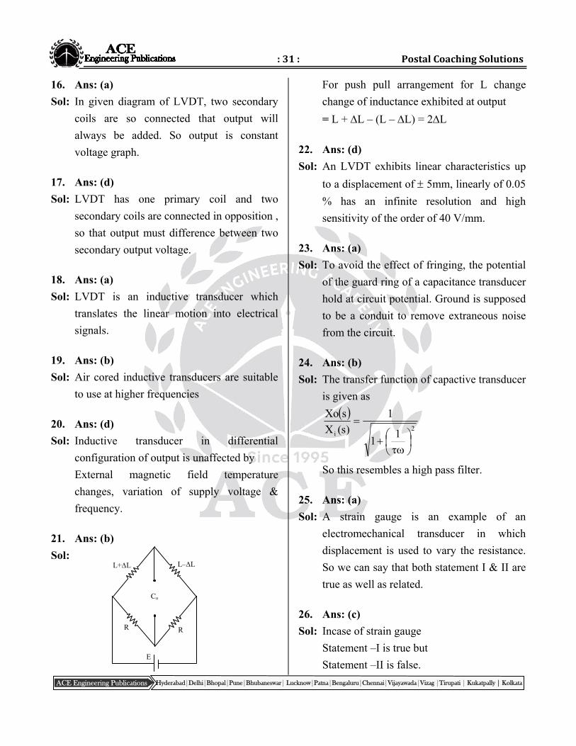
21. Ans: (b)
Sol:
For push pull arrangement for L change
change of inductance exhibited at output
= L + L – (L – L) = 2L
22. Ans: (d)
Sol: An LVDT exhibits linear characteristics up
to a displacement of 5mm, linearly of 0.05
% has an infinite resolution and high
sensitivity of the order of 40 V/mm.
23. Ans: (a)
Sol: To avoid the effect of fringing, the potential
of the guard ring of a capacitance transducer
hold at circuit potential. Ground is supposed
to be a conduit to remove extraneous noise
from the circuit.
24. Ans: (b)
Sol: The transfer function of capactive transducer
is given as
2i 1
1
1
)s(X
sXo
So this resembles a high pass filter.
25. Ans: (a)
Sol: A strain gauge is an example of an
electromechanical transducer in which
displacement is used to vary the resistance.
So we can say that both statement I & II are
true as well as related.
26. Ans: (c)
Sol: Incase of strain gauge
Statement –I is true but
Statement –II is false.
:32: Electrical&ElectronicMeasurements
Hyderabad|Delhi|Bhopal|Pune|Bhubaneswar| Lucknow|Patna|Bengaluru|Chennai|Vijayawada|Vizag |Tirupati | Kukatpally | Kolkata ACE Engineering Publications
14.PiezoElectricTransducers
15.MeasurementofTemperature
01. Ans: (b) (Update Key )
Sol: For piezo electric transducer
frequency 1
cable length
fnew Hz10002
2000
2
fold
02. Ans: (a)
Sol: The output piezo electric transducer is a zero
for static pressure.
03. Ans: (a)
Sol: For signal conditioning of piezo electric type
transducer we require a charge amplifier
04. Ans: (d)
Sol: Piezoelectric transducers is used to measure
dynamic pressure measurement while for
static its output is zero millivolts.
05. Ans: (a)
Sol: t = 2.5mm
G = N
V05.0 m
P = 1.6 105 N/m2
We know = gtp
= 0.05 2.5 10–3 1.6 106
e0 = 200 V
06. Ans: (c) ( Update Key )
Sol: The piezoelectric transducers vibrate at
ultrasonic frequencies. Piezoelectric material
is a type of electro acoustic transducer that
converts electrical energy into mechanical
and vice versa.
07. Ans: (a)
Sol: Piezoelectric crystal can be shown as
electrical equivalent circuit in interms L and
C. Quartz, Rochelle salt, tour maline are
piezoelectric crystal. Also piezoelectric
crystal exhibits the reverse effect of
electrostriction.
08. Ans: (c)
Sol: Piezoelectric transducer used for dynamic
displacement only and it is useless for static
displacement. Piezoelectric materials have
low dielectric constant.
Quartz dielectric constant is 4.2
09. Ans: (a)
Sol: BaTiO3 used in record player. Mechanical
stress in piezoelectric material producer on
electric polarization and application of
electric field produces a mechanical strain.
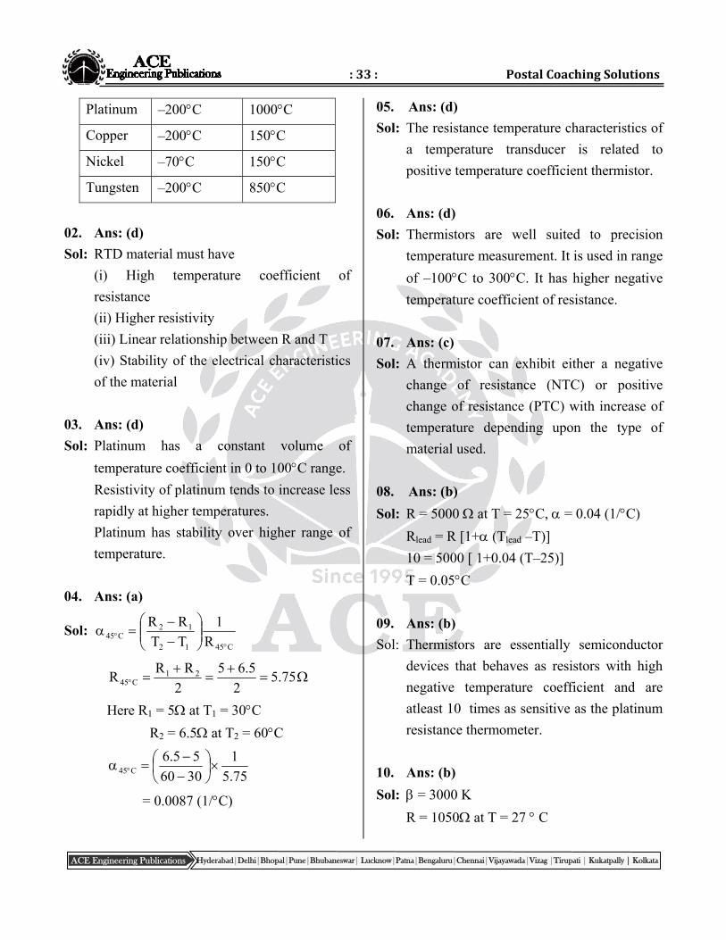
01. Ans: (a)
Sol: Platinum resistance thermometer used to
measure temperature in the range –200 C to
1000C
Material Minimum
temperature
Maximum
temperature
:33: PostalCoachingSolutions
Hyderabad|Delhi|Bhopal|Pune|Bhubaneswar| Lucknow|Patna|Bengaluru|Chennai|Vijayawada|Vizag |Tirupati | Kukatpally | Kolkata ACE Engineering Publications
Platinum –200C 1000C
Copper –200C 150C
Nickel –70C 150C
Tungsten –200C 850C
02. Ans: (d)
Sol: RTD material must have
(i) High temperature coefficient of
resistance
(ii) Higher resistivity
(iii) Linear relationship between R and T
(iv) Stability of the electrical characteristics
of the material
03. Ans: (d)
Sol: Platinum has a constant volume of
temperature coefficient in 0 to 100C range.
Resistivity of platinum tends to increase less
rapidly at higher temperatures.
Platinum has stability over higher range of
temperature.
04. Ans: (a)
Sol: C4512
12C45 R
1
TT
RR
75.52
5.65
2
RRR 21
C45
Here R1 = 5 at T1 = 30C
R2 = 6.5 at T2 = 60C
75.5
1
3060
55.6C45
= 0.0087 (1/C)
05. Ans: (d)
Sol: The resistance temperature characteristics of
a temperature transducer is related to
positive temperature coefficient thermistor.
06. Ans: (d)
Sol: Thermistors are well suited to precision
temperature measurement. It is used in range
of –100C to 300C. It has higher negative
temperature coefficient of resistance.
07. Ans: (c)
Sol: A thermistor can exhibit either a negative
change of resistance (NTC) or positive
change of resistance (PTC) with increase of
temperature depending upon the type of
material used.
08. Ans: (b)
Sol: R = 5000 at T = 25C, = 0.04 (1/C)
Rlead = R [1+ (Tlead –T)]
10 = 5000 [ 1+0.04 (T–25)]
T = 0.05C
09. Ans: (b)
Sol: Thermistors are essentially semiconductor
devices that behaves as resistors with high
negative temperature coefficient and are
atleast 10 times as sensitive as the platinum
resistance thermometer.
10. Ans: (b)
Sol: = 3000 K
R = 1050 at T = 27 C
:34: Electrical&ElectronicMeasurements
Hyderabad|Delhi|Bhopal|Pune|Bhubaneswar| Lucknow|Patna|Bengaluru|Chennai|Vijayawada|Vizag |Tirupati | Kukatpally | Kolkata ACE Engineering Publications
16.MeasurementofFlow,Viscosity,Humidity
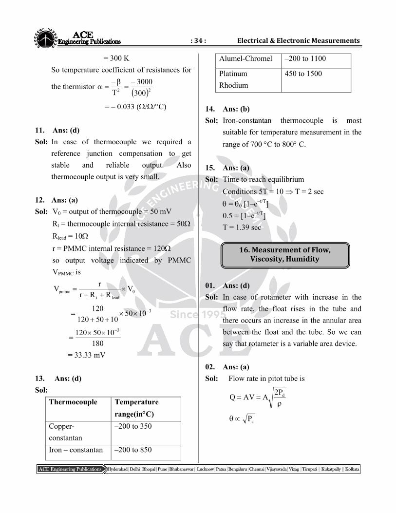
= 300 K
So temperature coefficient of resistances for
the thermistor 2T
2300
3000
= – 0.033 (//C)
11. Ans: (d)
Sol: In case of thermocouple we required a
reference junction compensation to get
stable and reliable output. Also
thermocouple output is very small.
12. Ans: (a)
Sol: V0 = output of thermocouple = 50 mV
Rt = thermocouple internal resistance = 50
Rlead = 10
r = PMMC internal resistance = 120
so output voltage indicated by PMMC
VPMMC is
0leadt
pmmc VRRr
rV
310501050120
120
180
1050120 3
= 33.33 mV
13. Ans: (d)
Sol:
Thermocouple Temperature
range(inC)
Copper-
constantan
–200 to 350
Iron – constantan –200 to 850
Alumel-Chromel –200 to 1100
Platinum
Rhodium
450 to 1500
14. Ans: (b)
Sol: Iron-constantan thermocouple is most
suitable for temperature measurement in the
range of 700 C to 800 C.
15. Ans: (a)
Sol: Time to reach equilibrium
Conditions 5T = 10 T = 2 sec
= 0 [1–e–t/T]
0.5 = [1–e–t/T]
T = 1.39 sec
01. Ans: (d)
Sol: In case of rotameter with increase in the
flow rate, the float rises in the tube and
there occurs an increase in the annular area
between the float and the tube. So we can
say that rotameter is a variable area device.
02. Ans: (a)
Sol: Flow rate in pitot tube is
dP2AAVQ
dP
:35: PostalCoachingSolutions
Hyderabad|Delhi|Bhopal|Pune|Bhubaneswar| Lucknow|Patna|Bengaluru|Chennai|Vijayawada|Vizag |Tirupati | Kukatpally | Kolkata ACE Engineering Publications
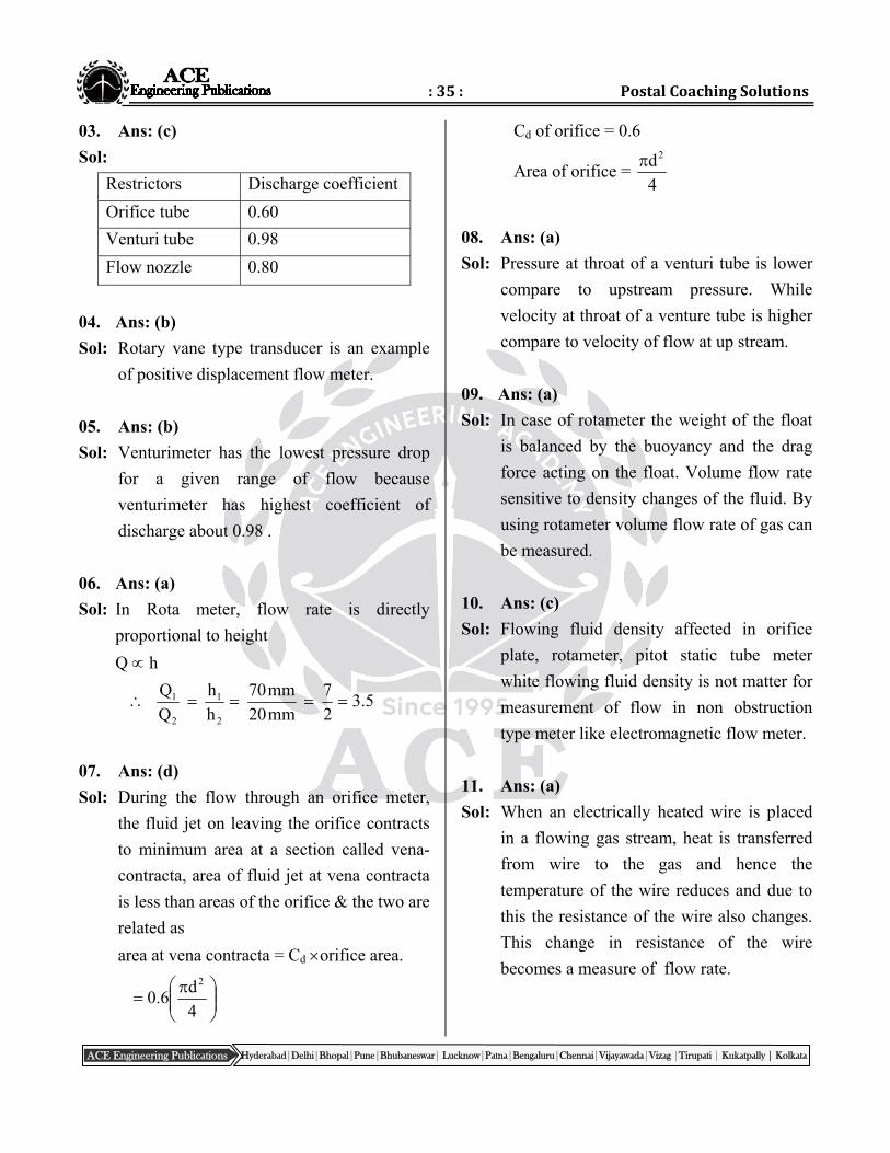
03. Ans: (c)
Sol:
Restrictors Discharge coefficient
Orifice tube 0.60
Venturi tube 0.98
Flow nozzle 0.80
04. Ans: (b)
Sol: Rotary vane type transducer is an example
of positive displacement flow meter.
05. Ans: (b)
Sol: Venturimeter has the lowest pressure drop
for a given range of flow because
venturimeter has highest coefficient of
discharge about 0.98 .
06. Ans: (a)
Sol: In Rota meter, flow rate is directly
proportional to height
Q h
5.32
7
mm20
mm70
h
h
Q
Q
2
1
2
1
07. Ans: (d)
Sol: During the flow through an orifice meter,
the fluid jet on leaving the orifice contracts
to minimum area at a section called vena-
contracta, area of fluid jet at vena contracta
is less than areas of the orifice & the two are
related as
area at vena contracta = Cd orifice area.
4
d6.0
2
Cd of orifice = 0.6
Area of orifice = 4
d2
08. Ans: (a)
Sol: Pressure at throat of a venturi tube is lower
compare to upstream pressure. While
velocity at throat of a venture tube is higher
compare to velocity of flow at up stream.
09. Ans: (a)
Sol: In case of rotameter the weight of the float
is balanced by the buoyancy and the drag
force acting on the float. Volume flow rate
sensitive to density changes of the fluid. By
using rotameter volume flow rate of gas can
be measured.
10. Ans: (c)
Sol: Flowing fluid density affected in orifice
plate, rotameter, pitot static tube meter
white flowing fluid density is not matter for
measurement of flow in non obstruction
type meter like electromagnetic flow meter.
11. Ans: (a)
Sol: When an electrically heated wire is placed
in a flowing gas stream, heat is transferred
from wire to the gas and hence the
temperature of the wire reduces and due to
this the resistance of the wire also changes.
This change in resistance of the wire
becomes a measure of flow rate.
:36: Electrical&ElectronicMeasurements
Hyderabad|Delhi|Bhopal|Pune|Bhubaneswar| Lucknow|Patna|Bengaluru|Chennai|Vijayawada|Vizag |Tirupati | Kukatpally | Kolkata ACE Engineering Publications
17.IntermediateQuantityMeasurements
12. Ans: (a)
Sol: Hot wire anemometer gives good result
when the flowing fluid is exceptionally
clean.
13. Ans: (c)
Sol: The turbine type flow meter used to
measure totalisation of flow.
14. Ans: (b)
Sol: In case of electromagnectic flow meter the
induced voltage is proportional to flow rate
as A
QB
A
VABe
e Q
01. Ans: (d)
Sol: In seismic vibration sensor for measuring
amplitude of vibration n << & slightly
less than 1.
02. Ans: (d)
Sol: M
Kn
Decreasing the mass in case of a seismic
acceleration sensor while keeping all other
parameters constant will increase the natural
frequency, without affecting steady state
sensitivity.
03. Ans: (a)
Sol: M = 100 gm
Fn = 1kHz
04. Ans: (a)
Sol: f = 100 Hz
X = 10 mm
Peak acceleration of the seismicmass = 2x
= (2f)2x
= (2 100)210 10-3
= 3947.84 (m/sec2)
05. Ans: (a)
Sol: accelerometer input range
= 0 m/sec2 to 98.1 (m/sec2)
F = 30 Hz
M = 0.01 kg
We know acceleration = 2 x
2
onacceleratix
221302
1.98xtomm0x
= 2.76 mm
06. Ans: (b)
Sol: In dc tachogenerators used for measurement
of speed of a shaft, frequent calibration has
to be done because the strength of
permanent magnet decreases with age.
07. Ans: (c)
Sol: In a drag up type ac tachogenerator, the
output voltage is modulated waveform.
08. Ans: (b) (Update Key )
Sol: nteeth = 60
N = speed of shaft
N = 25 rps
We know
:37: PostalCoachingSolutions
Hyderabad|Delhi|Bhopal|Pune|Bhubaneswar| Lucknow|Patna|Bengaluru|Chennai|Vijayawada|Vizag |Tirupati | Kukatpally | Kolkata ACE Engineering Publications
Speed of shaft in rps = teethn
ratepulse
50
ondsecperpulses25
Pulses per second = 25 60
= 1500
09. Ans: (b)
Sol: fr = rotating frequency of motor
)rps(5.2460
1470
Ff = stroboscope flashing frequency
= 12.5 (fps)
Fr –nff = 24.5 – nff
n = 2 fr – nff = –30 rpm
So star mark moves at a speed of 30 rpm
against the direction of rotation.
10. Ans: (c)
Sol: 60teethofnumber
ondsecperpulsesrpm
teethofnumber
uteminperflashrpm
n
FN