Embed Size (px)
Citation preview
ACE Engineering Publications Hyderabad|Delhi|Bhopal|Pune|Bhubaneswar| Lucknow|Patna|Bengaluru|Chennai|Vijayawada|Vizag |Tirupati | Kukatpally| Kolkata
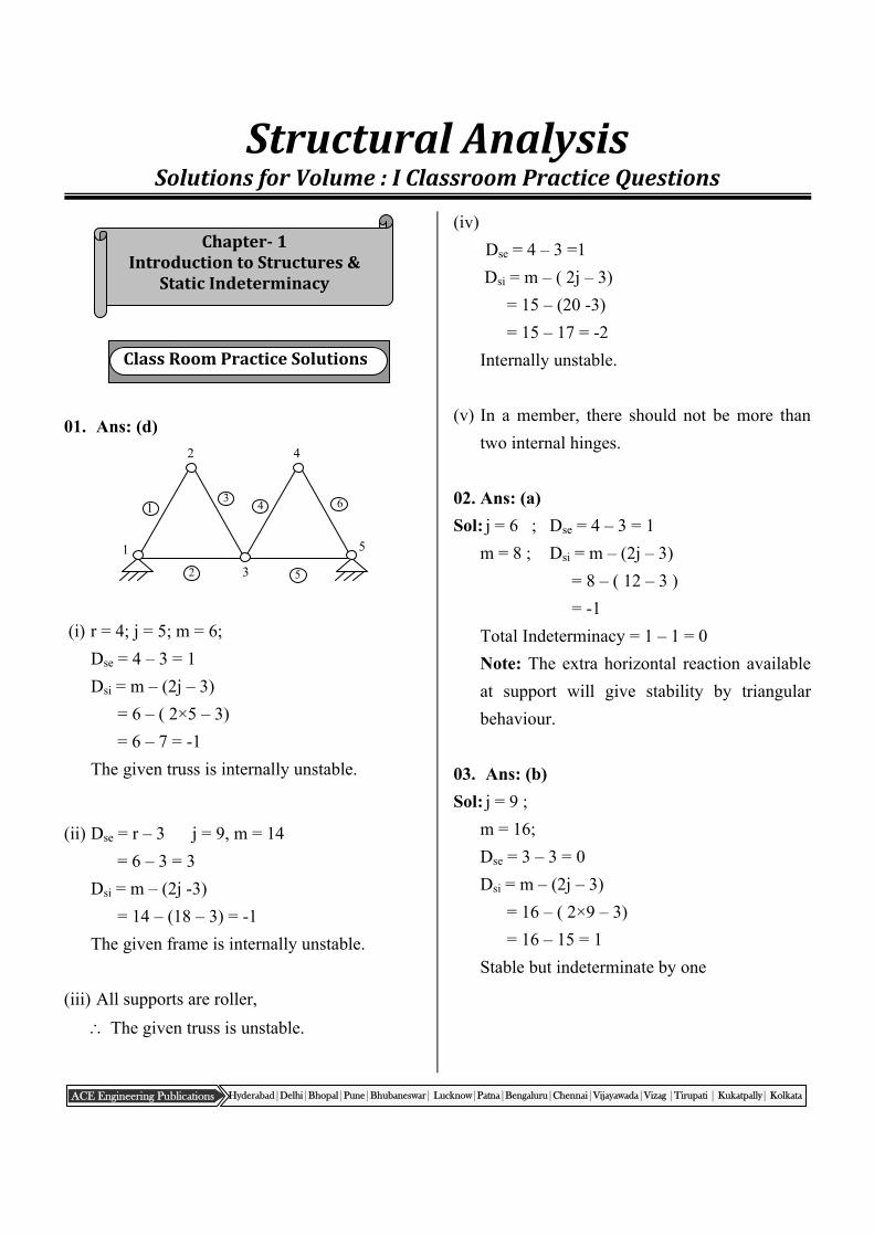
Chapter‐1IntroductiontoStructures&
StaticIndeterminacy
StructuralAnalysisSolutionsforVolume:IClassroomPracticeQuestions
01. Ans: (d)
(i) r = 4; j = 5; m = 6;
Dse = 4 – 3 = 1
Dsi = m – (2j – 3)
= 6 – ( 2×5 – 3)
= 6 – 7 = -1
The given truss is internally unstable.
(ii) Dse = r – 3 j = 9, m = 14
= 6 – 3 = 3
Dsi = m – (2j -3)
= 14 – (18 – 3) = -1
The given frame is internally unstable.
(iii) All supports are roller,
The given truss is unstable.
(iv)
Dse = 4 – 3 =1
Dsi = m – ( 2j – 3)
= 15 – (20 -3)
= 15 – 17 = -2
Internally unstable.
(v) In a member, there should not be more than
two internal hinges.
02. Ans: (a)
Sol: j = 6 ; Dse = 4 – 3 = 1
m = 8 ; Dsi = m – (2j – 3)
= 8 – ( 12 – 3 )
= -1
Total Indeterminacy = 1 – 1 = 0
Note: The extra horizontal reaction available
at support will give stability by triangular
behaviour.
03. Ans: (b)
Sol: j = 9 ;
m = 16;
Dse = 3 – 3 = 0
Dsi = m – (2j – 3)
= 16 – ( 2×9 – 3)
= 16 – 15 = 1
Stable but indeterminate by one
ClassRoomPracticeSolutions
1
2
3 4
5
6
1
2
3
4
5
: 2 : CIVIL - Postal Coaching Solutions
ACE Engineering Publications Hyderabad|Delhi|Bhopal|Pune|Bhubaneswar| Lucknow|Patna|Bengaluru|Chennai|Vijayawada|Vizag |Tirupati | Kukatpally| Kolkata
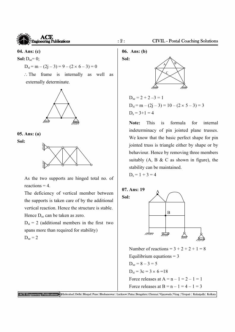
04. Ans: (c)
Sol: Dse= 0;
Dsi = m – (2j – 3) = 9 – (2 6 – 3) = 0
The frame is internally as well as
externally determinate.
05. Ans: (a)
Sol:
As the two supports are hinged total no. of
reactions = 4.
The deficiency of vertical member between
the supports is taken care of by the additional
vertical reaction. Hence the structure is stable.
Hence Dse can be taken as zero.
Dsi = 2 (additional members in the first two
spans more than required for stability)
Dse = 2
06. Ans: (b)
Sol:
Dse = 2 + 2 –3 = 1
Dsi = m – (2j – 3) = 10 – (2 5 – 3) = 3
Ds = 3+1 = 4
Note: This is formula for internal
indeterminacy of pin jointed plane trusses.
We know that the basic perfect shape for pin
jointed truss is triangle either by shape or by
behaviour. Hence by removing three members
suitably (A, B & C as shown in figure), the
stability can be maintained.
Ds = 1 + 3 = 4
07. Ans: 19
Sol:
Number of reactions = 3 + 2 + 2 + 1 = 8
Equilibrium equations = 3
Dse = 8 – 3 = 5
Dsi = 3c = 3 6 =18
Force releases at A = n – 1 = 2 – 1 = 1
Force releases at B = n – 1 = 4 – 1 = 3
A B
C
A
B
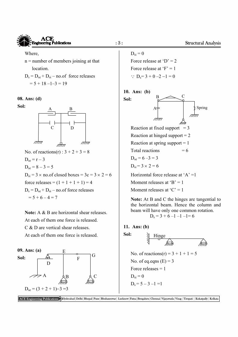
: 3 : Structural Analysis
ACE Engineering Publications Hyderabad|Delhi|Bhopal|Pune|Bhubaneswar| Lucknow|Patna|Bengaluru|Chennai|Vijayawada|Vizag |Tirupati | Kukatpally| Kolkata
Where,
n = number of members joining at that
location.
Ds = Dse + Dsi – no.of force releases
= 5 + 18 –1–3 = 19
08. Ans: (d)
Sol:
No. of reactions(r) : 3 + 2 + 3 = 8
Dse = r – 3
Dse = 8 – 3 = 5
Dsi = 3 no.of closed boxes = 3c = 3 2 = 6
force releases = (1 + 1 + 1 + 1) = 4
Ds = Dse + Dsi – no.of force releases
= 5 + 6 – 4 = 7
Note: A & B are horizontal shear releases.
At each of them one force is released.
C & D are vertical shear releases.
At each of them one force is released.
09. Ans: (a)
Sol:
Dse = (3 + 2 + 1)3 =3
Dsi = 0
Force release at ‘D’ = 2
Force release at ‘F’ = 1
Ds= 3 + 0 –2 1 = 0
10. Ans: (b)
Sol:
Reaction at fixed support = 3
Reaction at hinged support = 2
Reaction at spring support = 1
Total reactions = 6
Dse = 6 –3 = 3
Dsi = 3 2 = 6
Horizontal force release at ‘A’ =1
Moment releases at ‘B’ = 1
Moment releases at ‘C’ = 1
Note: At B and C the hinges are tangential to the horizontal beam. Hence the column and beam will have only one common rotation.
Ds = 3 + 6 –1 –1 –1= 6
11. Ans: (b)
Sol:
No. of reactions(r) = 3 + 1 + 1 = 5
No. of eq.eqns (E) = 3
Force releases = 1
Dsi = 0
Ds = 5 – 3 –1 =1
A B
C D
Hinge
Spring A
B C
A B C
D
G E
F
: 4 : CIVIL - Postal Coaching Solutions
ACE Engineering Publications Hyderabad|Delhi|Bhopal|Pune|Bhubaneswar| Lucknow|Patna|Bengaluru|Chennai|Vijayawada|Vizag |Tirupati | Kukatpally| Kolkata
Chapter‐2KinematicIndeterminacy
12. Ans: Zero
Sol: The given truss is statically determinate. Determinate structures are not subjected to stresses by lack of fit, temperature change, sinking of supports etc.
.
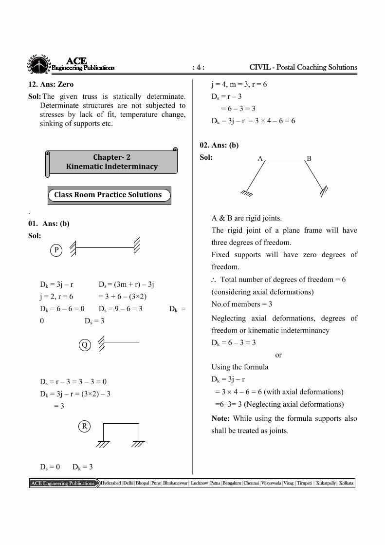
01. Ans: (b)
Sol:
Dk = 3j – r Ds = (3m + r) – 3j
j = 2, r = 6 = 3 + 6 – (3×2)
Dk = 6 – 6 = 0 Ds = 9 – 6 = 3 Dk =
0 Ds = 3
Ds = r – 3 = 3 – 3 = 0
Dk = 3j – r = (3×2) – 3
= 3
Ds = 0 Dk = 3
j = 4, m = 3, r = 6
Ds = r – 3
= 6 – 3 = 3
Dk = 3j – r = 3 × 4 – 6 = 6
02. Ans: (b)
Sol:
A & B are rigid joints.
The rigid joint of a plane frame will have
three degrees of freedom.
Fixed supports will have zero degrees of
freedom.
Total number of degrees of freedom = 6
(considering axial deformations)
No.of members = 3
Neglecting axial deformations, degrees of
freedom or kinematic indeterminancy
Dk = 6 – 3 = 3
or
Using the formula
Dk = 3j – r
= 3 4 – 6 = 6 (with axial deformations)
=6–3= 3 (Neglecting axial deformations)
Note: While using the formula supports also
shall be treated as joints.
A B
ClassRoomPracticeSolutions
P
Q
R
: 5 : Structural Analysis
ACE Engineering Publications Hyderabad|Delhi|Bhopal|Pune|Bhubaneswar| Lucknow|Patna|Bengaluru|Chennai|Vijayawada|Vizag |Tirupati | Kukatpally| Kolkata
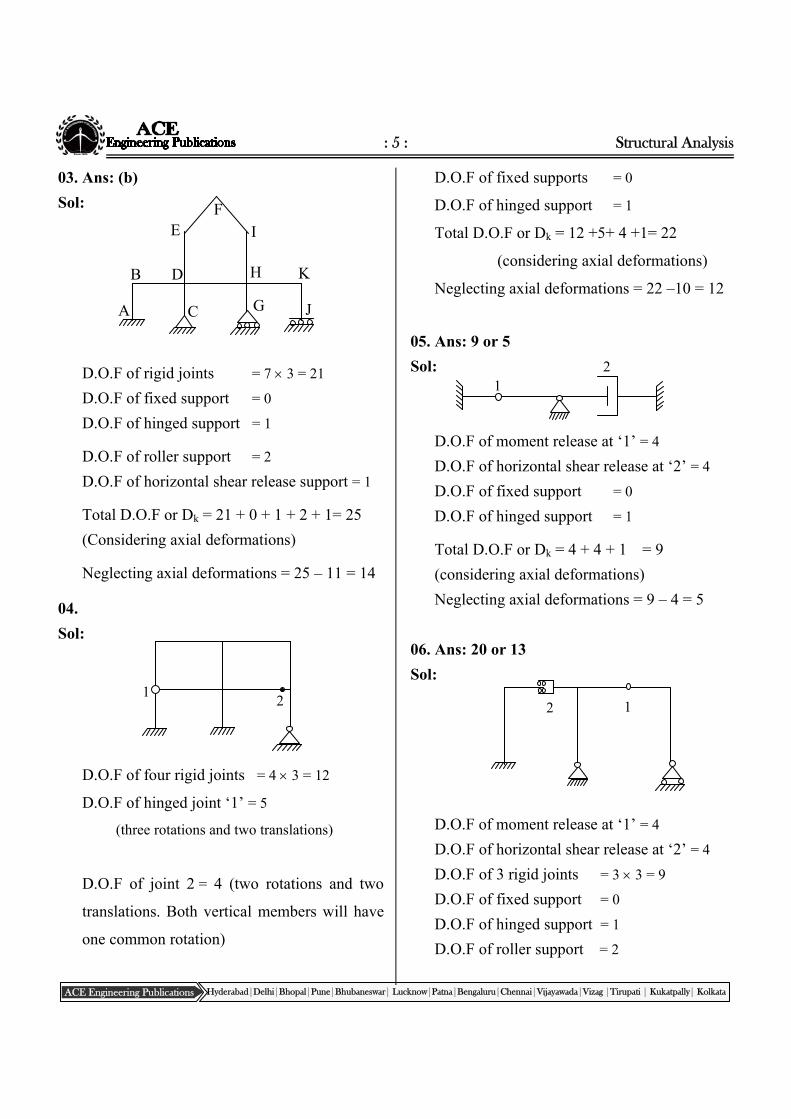
03. Ans: (b)
Sol:
D.O.F of rigid joints = 7 3 = 21
D.O.F of fixed support = 0
D.O.F of hinged support = 1
D.O.F of roller support = 2
D.O.F of horizontal shear release support = 1
Total D.O.F or Dk = 21 + 0 + 1 + 2 + 1= 25
(Considering axial deformations)
Neglecting axial deformations = 25 – 11 = 14
04.
Sol:
D.O.F of four rigid joints = 4 3 = 12
D.O.F of hinged joint ‘1’ = 5
(three rotations and two translations)
D.O.F of joint 2 = 4 (two rotations and two
translations. Both vertical members will have
one common rotation)
D.O.F of fixed supports = 0
D.O.F of hinged support = 1
Total D.O.F or Dk = 12 +5+ 4 +1= 22
(considering axial deformations)
Neglecting axial deformations = 22 –10 = 12
05. Ans: 9 or 5
Sol:
D.O.F of moment release at ‘1’ = 4
D.O.F of horizontal shear release at ‘2’ = 4
D.O.F of fixed support = 0
D.O.F of hinged support = 1
Total D.O.F or Dk = 4 + 4 + 1 = 9
(considering axial deformations)
Neglecting axial deformations = 9 – 4 = 5
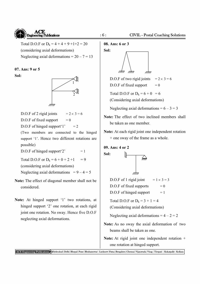
06. Ans: 20 or 13
Sol:
D.O.F of moment release at ‘1’ = 4
D.O.F of horizontal shear release at ‘2’ = 4
D.O.F of 3 rigid joints = 3 3 = 9
D.O.F of fixed support = 0
D.O.F of hinged support = 1
D.O.F of roller support = 2
1 2
1 2
1 2
A
B
C
D
E F
G
H
I
J
K
: 6 : CIVIL - Postal Coaching Solutions
ACE Engineering Publications Hyderabad|Delhi|Bhopal|Pune|Bhubaneswar| Lucknow|Patna|Bengaluru|Chennai|Vijayawada|Vizag |Tirupati | Kukatpally| Kolkata
Total D.O.F or Dk = 4 + 4 + 9 +1+2 = 20
(considering axial deformations)
Neglecting axial deformations = 20 – 7 = 13
07. Ans: 9 or 5
Sol:
D.O.F of 2 rigid joints = 2 3 = 6
D.O.F of fixed support = 0
D.O.F of hinged support‘1’ = 2
(Two members are connected to the hinged
support ‘1’. Hence two different rotations are
possible)
D.O.F of hinged support‘2’ = 1
Total D.O.F or Dk = 6 + 0 + 2 +1 = 9
(considering axial deformations)
Neglecting axial deformations = 9 – 4 = 5
Note: The effect of diagonal member shall not be
considered.
Note: At hinged support ‘1’ two rotations, at
hinged support ‘2’ one rotation, at each rigid
joint one rotation. No sway. Hence five D.O.F
neglecting axial deformations.
08. Ans: 6 or 3
Sol:
D.O.F of two rigid joints = 2 3 = 6
D.O.F of fixed support = 0
Total D.O.F or Dk = 6 + 0 = 6
(Considering axial deformations)
Neglecting axial deformations = 6 – 3 = 3
Note: The effect of two inclined members shall
be taken as one member.
Note: At each rigid joint one independent rotation
+ one sway of the frame as a whole.
09. Ans: 4 or 2
Sol:
D.O.F of 1 rigid joint = 1 3 = 3
D.O.F of fixed supports = 0
D.O.F of hinged support = 1
Total D.O.F or Dk = 3 + 1 = 4
(Considering axial deformations)
Neglecting axial deformations = 4 – 2 = 2
Note: As no sway the axial deformation of two
beams shall be taken as one.
Note: At rigid joint one independent rotation +
one rotation at hinged support.
2
1
: 7 : Structural Analysis
ACE Engineering Publications Hyderabad|Delhi|Bhopal|Pune|Bhubaneswar| Lucknow|Patna|Bengaluru|Chennai|Vijayawada|Vizag |Tirupati | Kukatpally| Kolkata
Chapter‐3StaticallyDeterminateFrames
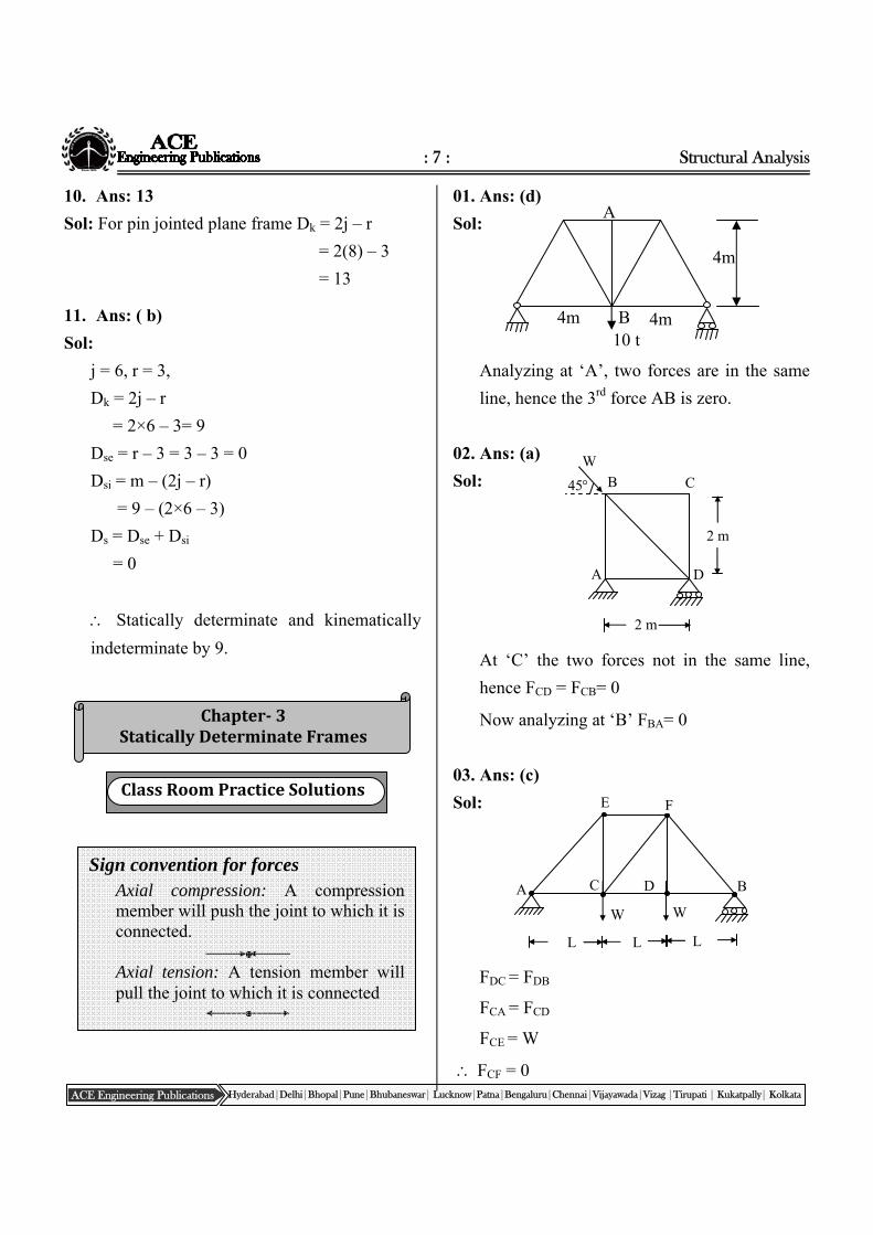
10. Ans: 13
Sol: For pin jointed plane frame Dk = 2j – r
= 2(8) – 3
= 13
11. Ans: ( b)
Sol:
j = 6, r = 3,
Dk = 2j – r
= 2×6 – 3= 9
Dse = r – 3 = 3 – 3 = 0
Dsi = m – (2j – r)
= 9 – (2×6 – 3)
Ds = Dse + Dsi
= 0
Statically determinate and kinematically
indeterminate by 9.
01. Ans: (d)
Sol:
Analyzing at ‘A’, two forces are in the same
line, hence the 3rd force AB is zero.
02. Ans: (a)
Sol:
At ‘C’ the two forces not in the same line,
hence FCD = FCB= 0
Now analyzing at ‘B’ FBA= 0
03. Ans: (c)
Sol:
FDC = FDB
FCA = FCD
FCE = W
FCF = 0
Sign convention for forces Axial compression: A compression
member will push the joint to which it is connected.
Axial tension: A tension member will
pull the joint to which it is connected
ClassRoomPracticeSolutions
B 10 t
4m 4m
4m
A
2 m
45
A
B C
D
W
2 m
W
L L L
A
E F
B C D
W
: 8 : CIVIL - Postal Coaching Solutions
ACE Engineering Publications Hyderabad|Delhi|Bhopal|Pune|Bhubaneswar| Lucknow|Patna|Bengaluru|Chennai|Vijayawada|Vizag |Tirupati | Kukatpally| Kolkata
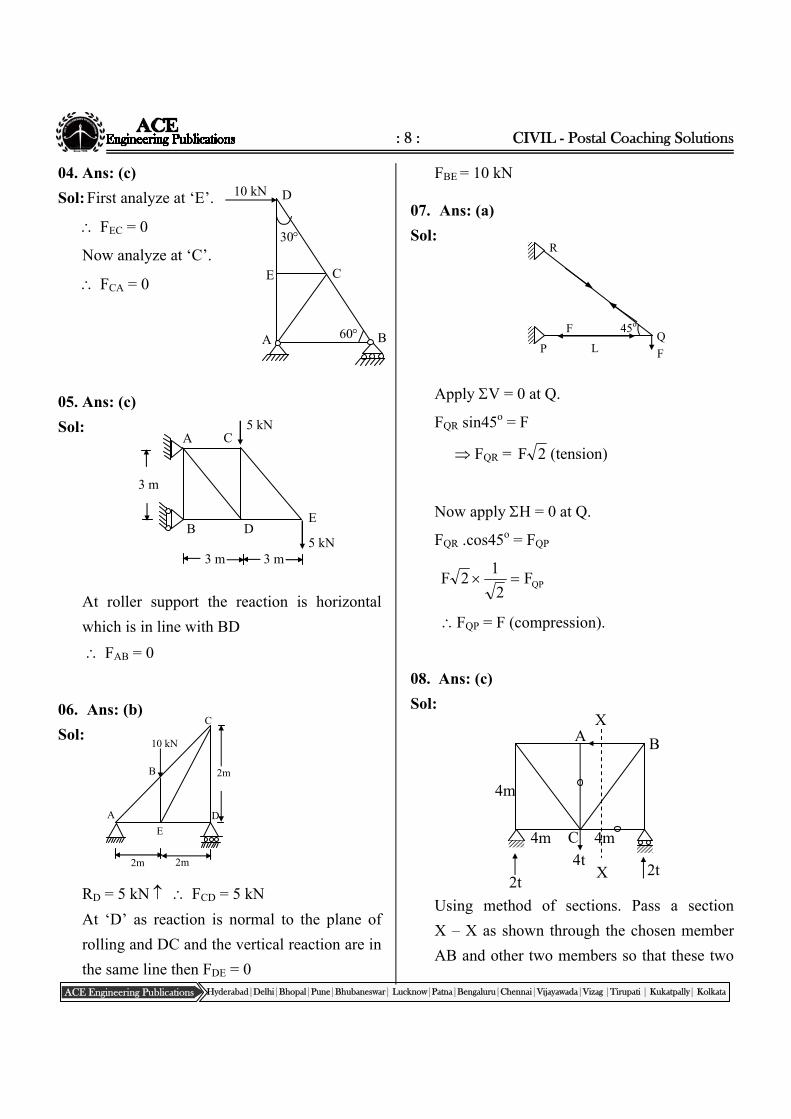
04. Ans: (c)
Sol: First analyze at ‘E’.
FEC = 0
Now analyze at ‘C’.
FCA = 0
05. Ans: (c)
Sol:
At roller support the reaction is horizontal
which is in line with BD
FAB = 0
06. Ans: (b)
Sol:
RD = 5 kN FCD = 5 kN
At ‘D’ as reaction is normal to the plane of
rolling and DC and the vertical reaction are in
the same line then FDE = 0
FBE = 10 kN
07. Ans: (a)
Sol:
Apply V = 0 at Q.
FQR sin45o = F
FQR = 2F (tension)
Now apply H = 0 at Q.
FQR .cos45o = FQP
QPF2
12F
FQP = F (compression).
08. Ans: (c)
Sol:
Using method of sections. Pass a section
X – X as shown through the chosen member
AB and other two members so that these two
Q
R
P F
45o F
L
A B
4m
2t
4t 2t
4m 4m
X
X
C
A
E
B
C
D
30
60
10 kN
A C
E D B
3 m 3 m
3 m
5 kN
5 kN
E
A D
C
B
10 kN
2m
2m 2m
: 9 : Structural Analysis
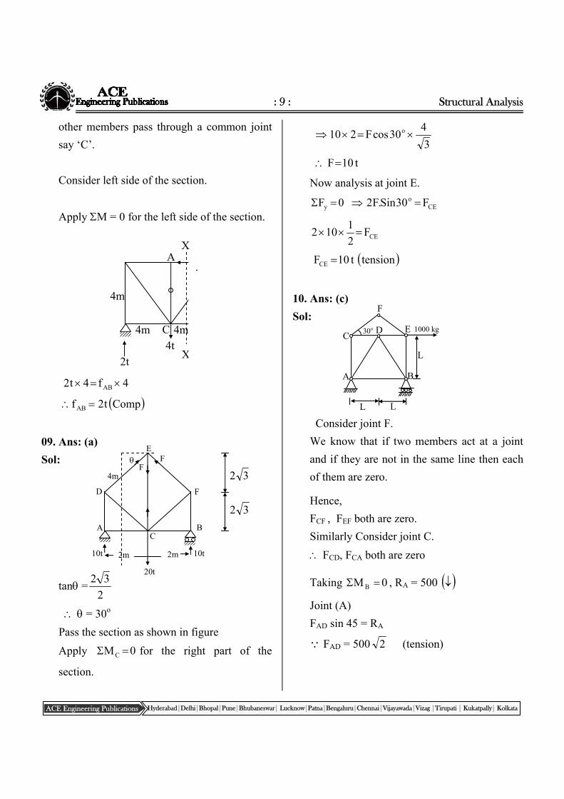
ACE Engineering Publications Hyderabad|Delhi|Bhopal|Pune|Bhubaneswar| Lucknow|Patna|Bengaluru|Chennai|Vijayawada|Vizag |Tirupati | Kukatpally| Kolkata
other members pass through a common joint
say ‘C’.
Consider left side of the section.
Apply M = 0 for the left side of the section.
4f4t2 AB
Compt2fAB
09. Ans: (a)
Sol:
tan =2
32
= 30o
Pass the section as shown in figure
Apply 0MC for the right part of the
section.
3
430cosF210 o
t10F
Now analysis at joint E.
CEo
y F30Sin.F20F
CEF2
1102
tensiont10FCE
10. Ans: (c)
Sol:
Consider joint F.
We know that if two members act at a joint
and if they are not in the same line then each
of them are zero.
Hence,
FCF , FEF both are zero.
Similarly Consider joint C.
FCD, FCA both are zero
Taking 0M B , RA = 500
Joint (A)
FAD sin 45 = RA
FAD = 500 2 (tension)
A B
4m
2t
4t 2t
4m 4m
X
X
C
.
L
L L
A B
C D E
F
1000 kg 30o
F D
A B
E
F F
4m
2m 2m 10t 10t
20t
C
32
32
: 10 : CIVIL - Postal Coaching Solutions
ACE Engineering Publications Hyderabad|Delhi|Bhopal|Pune|Bhubaneswar| Lucknow|Patna|Bengaluru|Chennai|Vijayawada|Vizag |Tirupati | Kukatpally| Kolkata
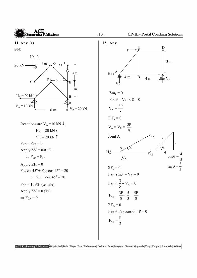
11. Ans: (c)
Sol:
Reactions are VA =10 kN ,
HA = 20 kN
VB = 20 kN
FHG = FHE = 0
Apply V = 0 at ‘G’
AEAC FF
Apply H = 0
FGE cos45o + FCG cos 45o = 20
2FGC cos 45o = 20
FGC = 210 (tensile)
Apply V = 0 @C
FCA = 0
12. Ans:
mc = 0
P 3 – VA 8 = 0
8
P3VA
Fy = 0
VA = VC = 8
P3
Joint A
Fy = 0
FAE sin – VA = 0
FAE 0V5
3A
8
P5
3
5
8
P3FAE
FX = 0
FAB + FAE .cos – P = 0
2
PFAB
3 m
3 m
A B
C D
E
G F
H
6 m
3 m
10 kN
20 kN
3m
HA = 20 kN
VA = 10 kNVB = 20 kN
E
B C Vc
3 m
D P
A HA
VA
4 m 4 m
FAE
FAB
VA
HA
A
3
4
5
5
4cos
5
3sin
: 11 : Structural Analysis
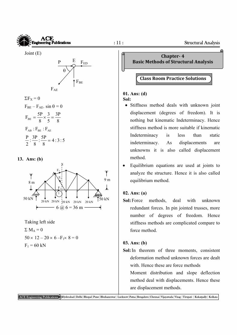
ACE Engineering Publications Hyderabad|Delhi|Bhopal|Pune|Bhubaneswar| Lucknow|Patna|Bengaluru|Chennai|Vijayawada|Vizag |Tirupati | Kukatpally| Kolkata
Chapter‐4BasicMethodsofStructuralAnalysis
Joint (E)
FX = 0
FBE – FAE. sin = 0
8
P3
5
3
8
P5FBE
AEBEAB F:F:F
5:3:48
P5:
8
P3:
2
P
13. Ans: (b)
Taking left side
MA = 0
50 12 – 20 6 –F1 8 = 0
F1 = 60 kN
01. Ans: (d) Sol: Stiffness method deals with unknown joint
displacement (degrees of freedom). It is
nothing but kinematic Indeterminacy. Hence
stiffness method is more suitable if kinematic
Indeterminacy is less than static
indeterminacy. As displacements are
unknowns it is also called displacement
method.
Equilibrium equations are used at joints to
analyze the structure. Hence it is also called
equilibrium method.
02. Ans: (a)
Sol: Force methods, deal with unknown
redundant forces. In pin jointed trusses, more
number of degrees of freedom. Hence
stiffness methods are complicated compare to
force method.
03. Ans: (b)
Sol: In theorem of three moments, consistent
deformation method unknown forces are dealt
with. Hence these are force methods
Moment distribution and slope deflection
method deal with displacements. Hence these
are displacement methods.
ClassRoomPracticeSolutions
E P FED
FBE
FAE
20 kN 20 kN 20 kN 20 kN 20 kN
9 m 8 m
6 @ 6 = 36 m
1
X
F3
F2
F1
50 kN 50 kN
A
: 12 : CIVIL - Postal Coaching Solutions
ACE Engineering Publications Hyderabad|Delhi|Bhopal|Pune|Bhubaneswar| Lucknow|Patna|Bengaluru|Chennai|Vijayawada|Vizag |Tirupati | Kukatpally| Kolkata
Chapter‐5EnergyPrinciples
04. Ans: (c)
Sol:
In Force methods, forces are kept unknowns
and unknown forces are found by using
geometric compatability conditions.
In displacement methods, joint displacements
are kept as unknowns and joint equilibrium
conditions are enforced to find unknown
displacements.
05. Ans: (b)
Sol:
Description Option
Kani’s method is very much
suitable for multistorey
frames
A-4
Force method suitable if static
indeterminacy is less.
B-3
Column analogy method suitable
for box frames with varying
sections and inclined
members
C-1
Displacement method suitable if
Kinematic Indeterminacy is
less
D-2
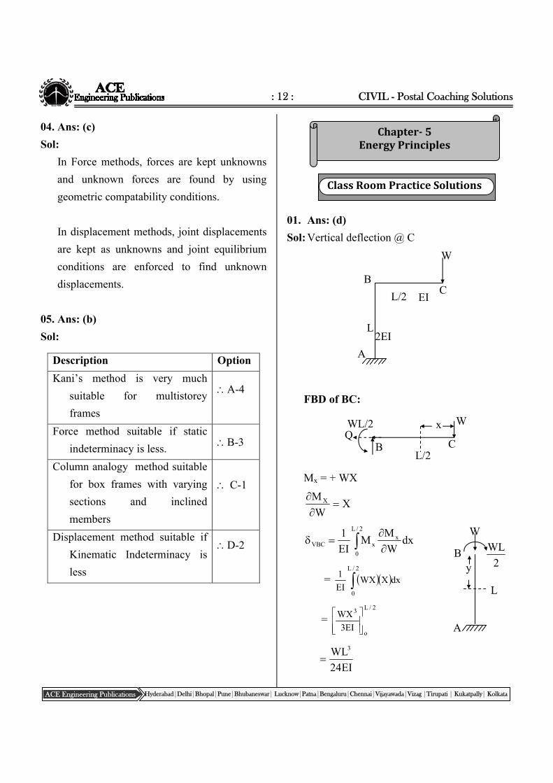
01. Ans: (d)
Sol: Vertical deflection @ C
FBD of BC:
Mx = + WX
XW
M X
dxW
MM
EI
1 x2/L
0
xVBC
= 2/L
0
dxXWXEI
1
= 2/L
o
3
EI3
WX
EI24
WL3
ClassRoomPracticeSolutions
L/2 C
W
2EI L
A
B
EI
y
L
W
B 2
WL
A
WL/2 Q
x W
C L/2
B
: 13 : Structural Analysis
ACE Engineering Publications Hyderabad|Delhi|Bhopal|Pune|Bhubaneswar| Lucknow|Patna|Bengaluru|Chennai|Vijayawada|Vizag |Tirupati | Kukatpally| Kolkata
FBD of AB:
2
WLM y
2
L
W
M y
dy2
1
2
WL
EI2
1 L
0
VAB
L
0
2
y4
WL
EI2
1
EI8
WL3
Total vertical deflection at
c = EI8
WL
EI24
WL 33
EI6
WL3
02. Ans: (b)
Sol: Horizontal deflection at C
FBD of BC:
Mx = + WX
0Q
M x
hBC = 0dx0WXEI
1 2/L
0
FBD of AB:
My = Qy2
WL
yQ
M y
hAB =
L
0
y dyyQ2
WL
EI2
1
dyy2
WL
EI2
1 L
0
(Q= 0 as it is imaginary force)
=L
0
2
2
y
2
WL
EI2
1
EI8
WL3
Total horizontal deflection = EI8
WL3
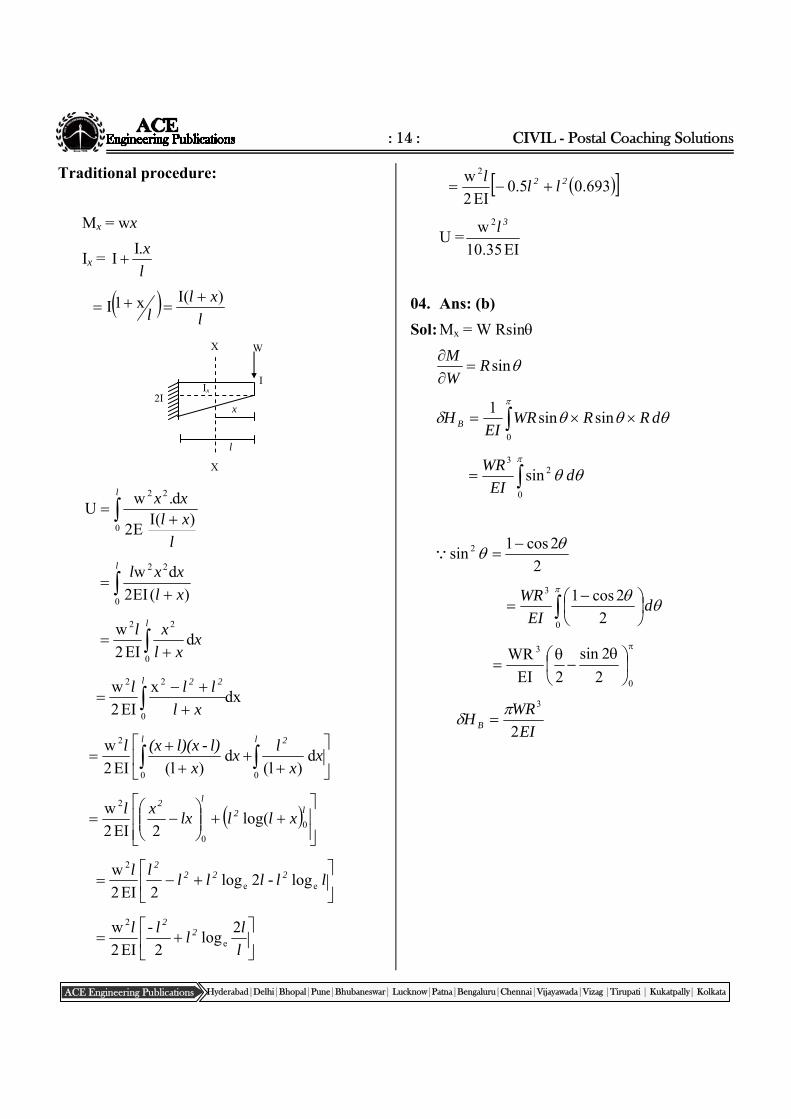
03. Ans: (c)
Sol:
Shortcut: Strain energy is inversely
proportional to I.
With uniform I, U =EI6
w 2 3l.
With uniform 2I, U = EI12
w 2 3l
As given has I varying from I to 2I,
denominator shall be in between 6 and 12.
L
W
EI 2EI
L/2 C
W
Q
2EI L
A
B EI
WL/2 Q
W x
Q B L/2
C
y
L
W
Q 2
WL
A
B
: 14 : CIVIL - Postal Coaching Solutions
ACE Engineering Publications Hyderabad|Delhi|Bhopal|Pune|Bhubaneswar| Lucknow|Patna|Bengaluru|Chennai|Vijayawada|Vizag |Tirupati | Kukatpally| Kolkata
Traditional procedure:
Mx = wx
Ix = l
x.II
l
xll
)(Ix1I
l
l
xlxx
0
22
)(IE2
d.wU
l
xl
xxl
0
22
)(EI2
dw
l
xxl
xl
0
22
dEI2
w
dxx
EI2
w
0
22
l 22
xl
lll
l 2l
xx
lx
x
l)-l)(x(xl
00
2
d)l(
d)l(EI2
w
l2
l2
xlllxxl
0
0
2
log(2EI2
w
ll-lll
ll 2222
ee
2
log2log2EI2
w
l
ll
l-l 22 2
log2EI2
we
2
693.05.0EI2
w 222 ll
l
U =EI35.10
w 2 3l
04. Ans: (b)
Sol: Mx = W Rsin
sinRW
M
0
sinsin1
dRRWREI
H B
0
23
sin dEI
WR
2
2cos1sin 2
0
3
2
2cos1d
EI
WR
0
3
2
2sin
2EI
WR
EI
WRH B 2
3
Ix I
2I
x
l
X
X W
: 15 : Structural Analysis
ACE Engineering Publications Hyderabad|Delhi|Bhopal|Pune|Bhubaneswar| Lucknow|Patna|Bengaluru|Chennai|Vijayawada|Vizag |Tirupati | Kukatpally| Kolkata
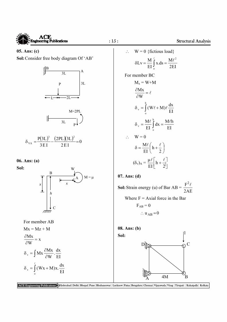
05. Ans: (c)
Sol: Consider free body diagram Of ‘AB’
0IE2
L3PL2
IE3
L3P 23
VA
06. Ans: (a)
Sol:
For member AB
Mx = Mz + M
xW
Mx
EI
dx.
W
MxMxv
o
v EI
dx.x)MWx(
W = 0 {fictious load}
EI2
Mds.x
EI
MLv
2
o
For member BC
Mx = W+M
W
Mx
h
o
v EI
dx)MW(
EI
hMdx
EI
M h
o
v
W = 0
2h
EI
M
(v)A =
2
hEI
07. Ans: (d)
Sol: Strain energy (u) of Bar AB = AE2
F2
Where F = Axial force in the Bar
FAB = 0
0u AB
08. Ans: (b)
Sol:
A
D
B
C
4M
1
3L P
B
L
A 3L
2L
M=2PL
3L P
h
C
A B
W
x x
M =
: 16 : CIVIL - Postal Coaching Solutions
ACE Engineering Publications Hyderabad|Delhi|Bhopal|Pune|Bhubaneswar| Lucknow|Patna|Bengaluru|Chennai|Vijayawada|Vizag |Tirupati | Kukatpally| Kolkata
Apply unit load in the vertical direction at
‘C’. Due to this unit load FCB = 1
Change in length of member BC due
temperature change = tl
= 10 106 4000 25 = 1mm
VC = k = 1 1 = 1mm
09. Ans: (a)
Sol:
Apply unit horizontal load at ‘C’.
Due to this the force in the member BC zero.
Horizontal deflection @ C =k= 0
10. Ans: (d)
Sol:
Apply unit vertical load at ‘C’. to get the
values of k.
Members Force P k AE
Pkl/AE
AC 2
W
2
1
AE
AE2
W
AB 2
W
2
1
AE2
l
AE4
W
AE
Pkcv
l=
AE4
W
AE2
W ll
AE4
W3 l
11. Ans: (d)
Sol: Apply unit horizontal load at ‘C’. to get the
values of k
Members
P
k AE
AE
l'Pk
AC
2
W
2
1
AE
AE2
W
AB
2
W
2
1
AE2
l
AE4
W
AE4
W
AE2
W
AE
'PkCH
lll
AE4
Wl
12. Ans: 1.5 10–3
Sol: As the structure is determinate extra forces
will not be generated due to lack of fit.
3104
6tan Inclination of member BC
is mainly due to 6 mm extension in BD
= 1.5 10–3 Radians.
W
A B
AE, l
C 45 45
2AE,l 2
w
2
w
1
A B
AE, l
C 45 45
2AE,l 2
1
2
1
A
D
B
C
4M
1
: 17 : Structural Analysis
ACE Engineering Publications Hyderabad|Delhi|Bhopal|Pune|Bhubaneswar| Lucknow|Patna|Bengaluru|Chennai|Vijayawada|Vizag |Tirupati | Kukatpally| Kolkata
W2
1
W1
X y
2
Maxwell’s law of Reciprocal deflections:
jiij where
ij = deflection @ ‘i’ due to unit load at ‘j’
ji = deflection @ j due to unit load at i
Further Maxwell’s law is valid for both prismatic and non prismatic becomes.
Chapter‐6MomentDistributionMethod
13. Ans: (c)
Sol:
Maxwell’s theorem independent of EI.
Hence option ‘C’.
14. Ans: (c)
Sol:
Using Bettie’s Theorem:
Virtual work done by
W1 = virtual work done by W2
w22 = w11
1
2
2
1
w
w
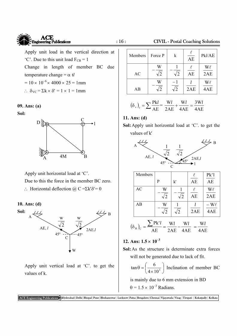
01. Ans: (a)
Sol:
L3
I
4
3
L4
I
L4
I
L4
IL4
I)F.D( BE
4
1
02. Ans: (c)
Sol:
Joint Member Relative
stiffness ‘k’
Distribution
factor
D.F= k / k
BA 1.5I/6 0.5 B
BC I/4 0.5
CB 4
I 0.4
C
CD
4
I2
4
3 0.6
A B
P
L/4, 4 EI 3L/4, EI
ClassRoomPracticeSolutions
A
B
C
D
4L
4L
4L
3L
E
EI = constant
6m 4m 4m 1m
B A
C D
1.5I I 2I I
: 18 : CIVIL - Postal Coaching Solutions
ACE Engineering Publications Hyderabad|Delhi|Bhopal|Pune|Bhubaneswar| Lucknow|Patna|Bengaluru|Chennai|Vijayawada|Vizag |Tirupati | Kukatpally| Kolkata
Note: Oover hang present beyond ‘D’ does
not give fixity. Hence ‘D’ will act like simple
support. ‘B’ and ‘C’ have other supports
beyond them. Hence they act like fixed
supports to calculate stiffness
03. Ans: (a)
Sol:
Rotational stiffness of a joint is the sum of
stiffness of all members meeting at that joint
KO = KOA + KOB + KOC + KOD
0L
EI4
L
EI3
L
EI4 =
L
EI11
04. Ans: (b)
Sol:
Rotational stiffness of joint ‘B’
L
EI11
L
EI11M
, =
EI11
ML
= Rotation of joint ‘B’.
05. Ans: (b)
Sol:
Member D.F
DB 31
DA 31
DC 31
Moment at ‘D’ transferred from over hang,
MD = P.L
A C B
M
EI, L EI, L
EI, L
D
A
P
B
EI
EI EI
EI
C
D
Rigid joint
L
L
L
L
A
B
PL
C
D
MD= P.L
A
B
D
L
O EI = constant
L L L/2
: 19 : Structural Analysis
ACE Engineering Publications Hyderabad|Delhi|Bhopal|Pune|Bhubaneswar| Lucknow|Patna|Bengaluru|Chennai|Vijayawada|Vizag |Tirupati | Kukatpally| Kolkata
Distribution factors are 31 , 3
1 , 31 to DA,
DB, DC respectively.
MDA = 3
PL
MA = 6
PL
3
PL
2
1
(Far end ‘A’ is fixed, hence the carry over
moment is half of that of moment of near end
‘D’ of beam ‘AD’)
06. Ans: (d)
Sol:
Consider free body diagram of ‘BC’
Consider free body diagram of ‘AC’
Moment at ‘A’ = M2
M2
l
l
07. Ans: (c)
Sol:
Load is acting at center of the beam.
RA = RB = 2
p ( )
As center ‘C’ has an internal moment hinge
MC = 0
MA = RB 2
L
= 2
L
2
p
MA = 4
pl (anticlockwise)
08. Ans: (d)
Sol: Carry over factor
endnearatappliedMoment
endfaratdevelopedMomentCAB
Let us apply moment ‘M’ at A
For RA ; take moment @ C = 0
A D 6
PL 3
PL
A C
M l/2 l/2
B
M
l
M2
2l
l
M2
C B
2l
l
M2
C
A B
P
P/2 P/2 l/2 l/2
MA
C
A B C
L L
M
RB= M/L RA=M/L
MB
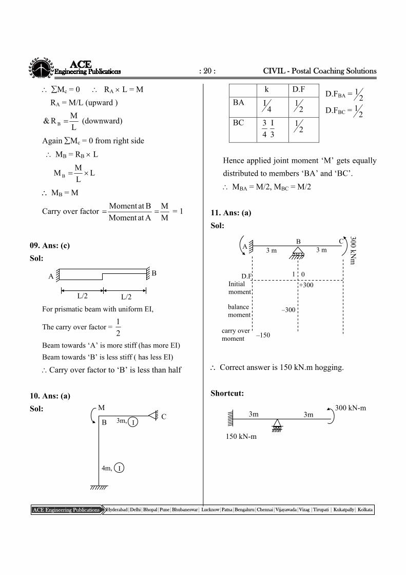
: 20 : CIVIL - Postal Coaching Solutions
ACE Engineering Publications Hyderabad|Delhi|Bhopal|Pune|Bhubaneswar| Lucknow|Patna|Bengaluru|Chennai|Vijayawada|Vizag |Tirupati | Kukatpally| Kolkata
L/2 L/2
A B
D.FBA = 21
D.FBC = 21
3 m A B C
300 kNm
3 m
0 1 D.F +300 Initial
moment
balance moment
–300
carry over moment –150
Mc = 0 RA L = M
RA = M/L (upward )
L
MR& B (downward)
Again Mc = 0 from right side
MB = RB L
LL
MM B
MB = M
Carry over factor AatMoment
BatMoment
M
M = 1
09. Ans: (c)
Sol:
For prismatic beam with uniform EI,
The carry over factor = 2
1
Beam towards ‘A’ is more stiff (has more EI)
Beam towards ‘B’ is less stiff ( has less EI)
Carry over factor to ‘B’ is less than half
10. Ans: (a)
Sol:
k D.F
BA 4
I 21
BC
3
I
4
3 2
1
Hence applied joint moment ‘M’ gets equally
distributed to members ‘BA’ and ‘BC’.
MBA = M/2, MBC = M/2
11. Ans: (a)
Sol:
Correct answer is 150 kN.m hogging.
Shortcut:
M
B 3m, C
4m,
I
I
300 kN-m
150 kN-m
3m 3m
: 21 : Structural Analysis
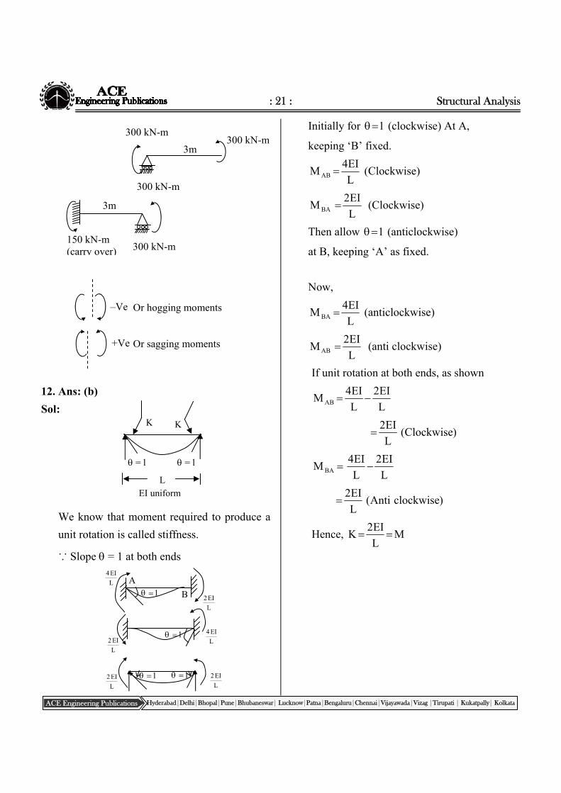
ACE Engineering Publications Hyderabad|Delhi|Bhopal|Pune|Bhubaneswar| Lucknow|Patna|Bengaluru|Chennai|Vijayawada|Vizag |Tirupati | Kukatpally| Kolkata
K
L
K
= l = l
EI uniform
12. Ans: (b)
Sol:
We know that moment required to produce a
unit rotation is called stiffness.
∵ Slope = 1 at both ends
Initially for 1 (clockwise) At A,
keeping ‘B’ fixed.
L
EI4M AB (Clockwise)
L
EI2M BA (Clockwise)
Then allow 1 (anticlockwise)
at B, keeping ‘A’ as fixed.
Now,
L
EI4M BA (anticlockwise)
L
EI2MAB (anti clockwise)
If unit rotation at both ends, as shown
L
EI2
L
EI4M AB
)Clockwise(L
EI2
L
EI2
L
EI4M BA
)clockwiseAnti(L
EI2
Hence, ML
EI2K
300 kN-m 300 kN-m
300 kN-m
3m
150 kN-m (carry over) 300 kN-m
3m
–Ve
+Ve
Or hogging moments
Or sagging moments
L
EI2 L
EI2 1 1
L
EI2 L
EI4
1
L
EI4
L
EI2
A
B
1
: 22 : CIVIL - Postal Coaching Solutions
ACE Engineering Publications Hyderabad|Delhi|Bhopal|Pune|Bhubaneswar| Lucknow|Patna|Bengaluru|Chennai|Vijayawada|Vizag |Tirupati | Kukatpally| Kolkata
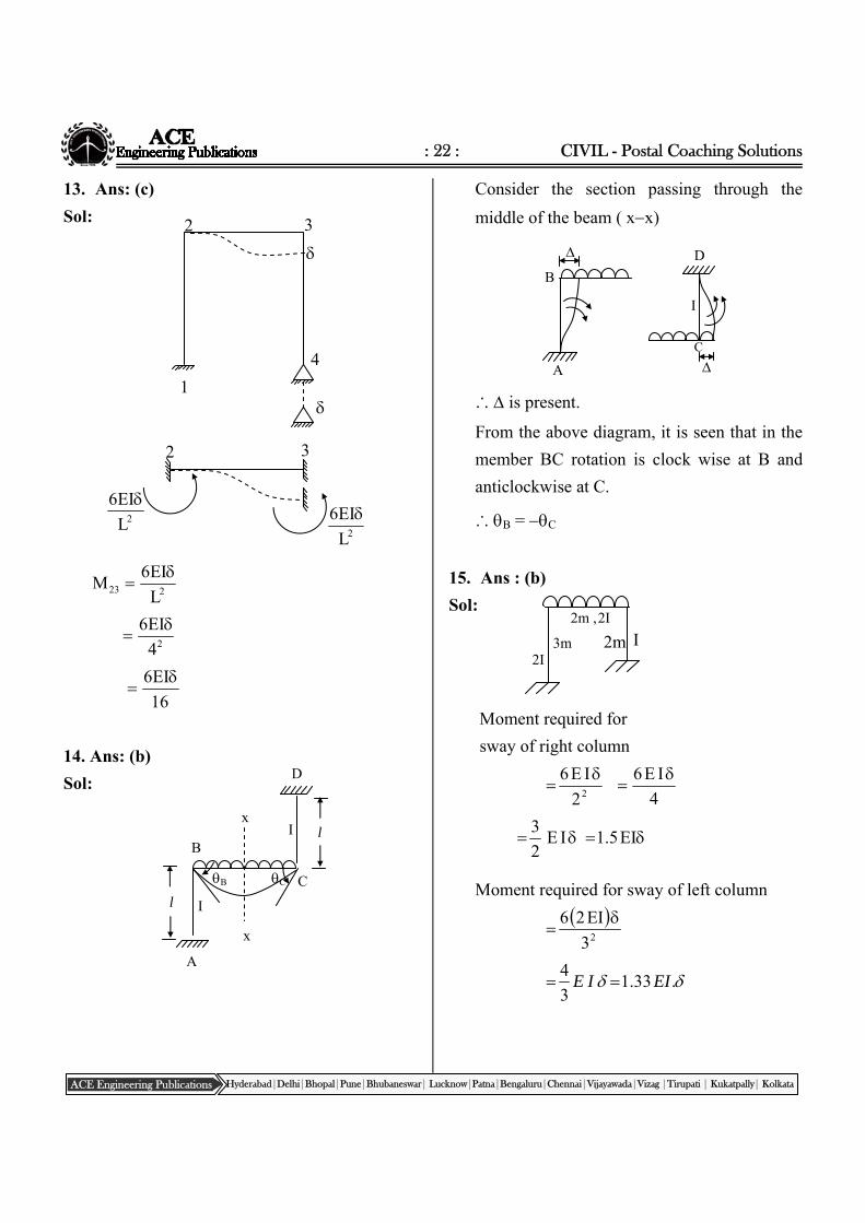
13. Ans: (c)
Sol:
223 L
EI6M
24
EI6
16
EI6
14. Ans: (b)
Sol:
Consider the section passing through the
middle of the beam ( xx)
∴ is present.
From the above diagram, it is seen that in the
member BC rotation is clock wise at B and
anticlockwise at C.
∴ B = C
15. Ans : (b)
Sol:
Moment required for
sway of right column
4
IE6
2
IE62
EI5.1IE2
3
Moment required for sway of left column
23
EI26
.33.13
4EIIE
l
l B
D
A
C
I
I
B C
x
x
B
A
D
I
C
I 2m ,
2I 3m 2m
2I
3
4
1
2
2 3
2L
EI6
2L
EI6
: 23 : Structural Analysis
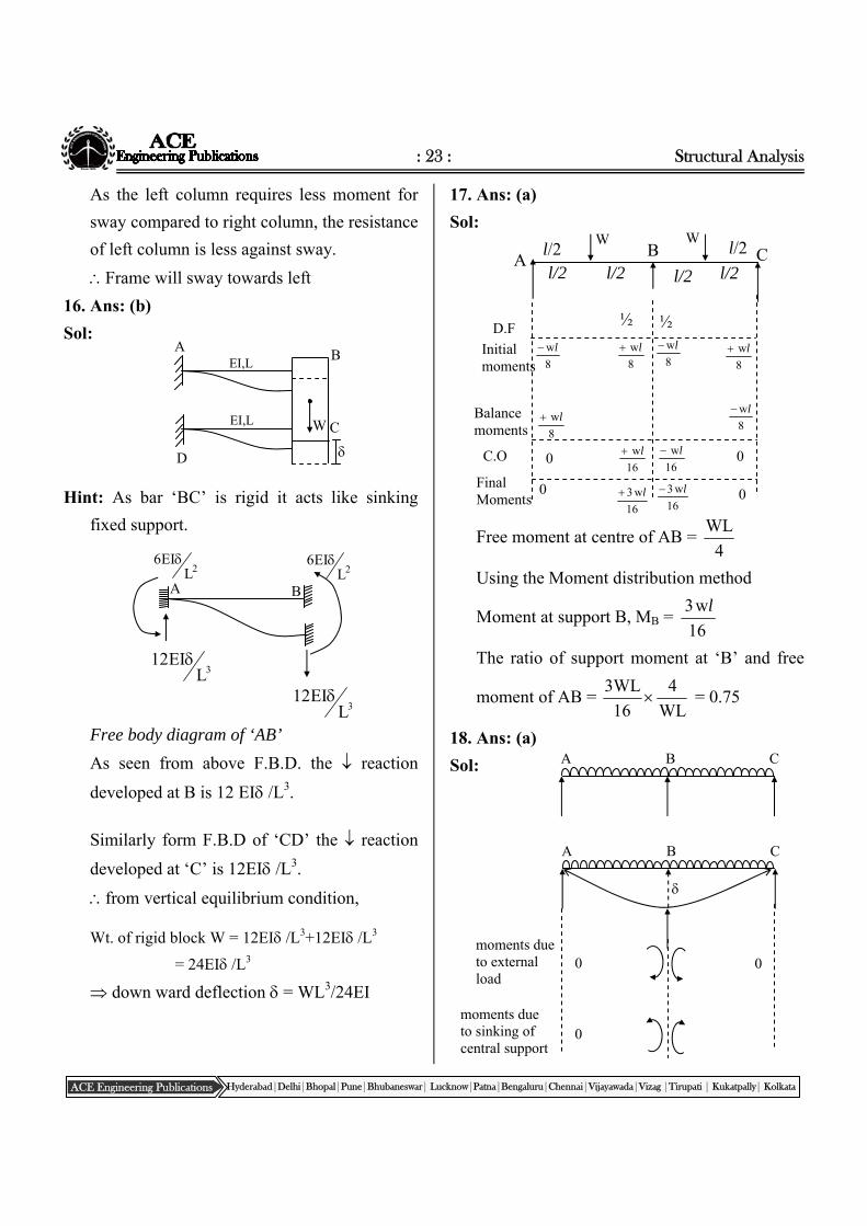
ACE Engineering Publications Hyderabad|Delhi|Bhopal|Pune|Bhubaneswar| Lucknow|Patna|Bengaluru|Chennai|Vijayawada|Vizag |Tirupati | Kukatpally| Kolkata
As the left column requires less moment for
sway compared to right column, the resistance
of left column is less against sway.
Frame will sway towards left
16. Ans: (b)
Sol:
Hint: As bar ‘BC’ is rigid it acts like sinking
fixed support.
Free body diagram of ‘AB’
As seen from above F.B.D. the reaction
developed at B is 12 EI /L3.
Similarly form F.B.D of ‘CD’ the reaction
developed at ‘C’ is 12EI /L3.
from vertical equilibrium condition,
Wt. of rigid block W = 12EI /L3+12EI /L3
= 24EI /L3 down ward deflection = WL3/24EI
17. Ans: (a)
Sol:
Free moment at centre of AB = 4
WL
Using the Moment distribution method
Moment at support B, MB = 16
w3 l
The ratio of support moment at ‘B’ and free
moment of AB = WL
4
16
WL3 = 0.75
18. Ans: (a)
Sol:
A
D
C WEI,L
EI,L B
2LEI6 2L
EI6
3LEI12
3LEI12
A B
A B C
W W l/2
l/2
l/2 l/2 l/2 l/2
8
wl 8
wl
8
wl
8
wl
8
wl
8
wl
16
wl 16
wl
16
w3 l 16
w3 l
0 0
D.F
Initial moments
Balance moments
C.O
Final Moments
½ ½
0 0
C B A
C B A
moments due to external load
0 0
moments due to sinking of central support
0
: 24 : CIVIL - Postal Coaching Solutions
ACE Engineering Publications Hyderabad|Delhi|Bhopal|Pune|Bhubaneswar| Lucknow|Patna|Bengaluru|Chennai|Vijayawada|Vizag |Tirupati | Kukatpally| Kolkata
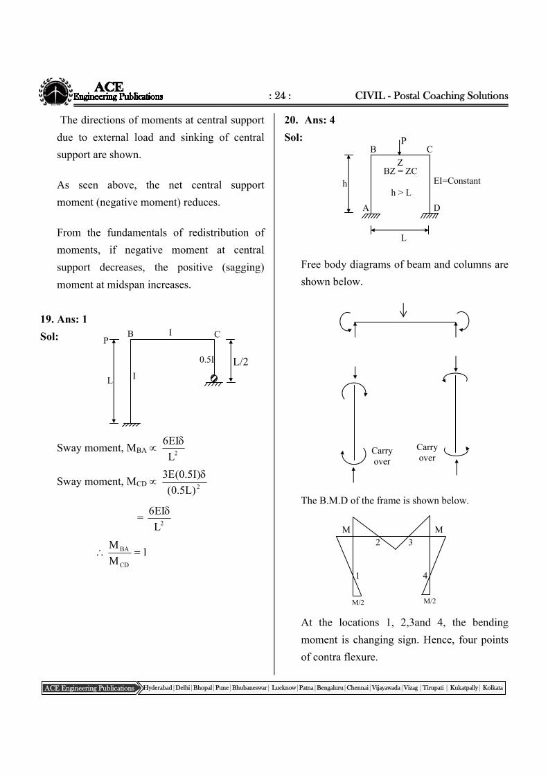
P
h BZ = ZC
A
B C
D
EI=Constant h > L
Z
L
The directions of moments at central support
due to external load and sinking of central
support are shown.
As seen above, the net central support
moment (negative moment) reduces.
From the fundamentals of redistribution of
moments, if negative moment at central
support decreases, the positive (sagging)
moment at midspan increases.
19. Ans: 1
Sol:
Sway moment, MBA 2L
EI6
Sway moment, MCD 2)L5.0(
)I5.0(E3
= 2L
EI6
1M
M
CD
BA
20. Ans: 4
Sol:
Free body diagrams of beam and columns are
shown below.
The B.M.D of the frame is shown below.
At the locations 1, 2,3and 4, the bending
moment is changing sign. Hence, four points
of contra flexure.
Carry over
Carry over
M/2 M/2
M M
1
2 3
4
I P
B C
I L
0.5I L/2
: 25 : Structural Analysis
ACE Engineering Publications Hyderabad|Delhi|Bhopal|Pune|Bhubaneswar| Lucknow|Patna|Bengaluru|Chennai|Vijayawada|Vizag |Tirupati | Kukatpally| Kolkata
A
B C
D 2.5 m
5 m 10 kN
10 m
Chapter‐7SlopeDeflectionMethod
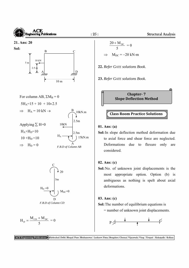
21. Ans: 20
Sol:
For column AB, MB = 0
5HA=15 + 10 + 102.5
HA = 10 kN
Applying H=0
HA+HD=10
10 +HD =10
HD = 0
5
MMH DCCD
D
= 0
5
M20 DC = 0
MDC = 20 kN-m
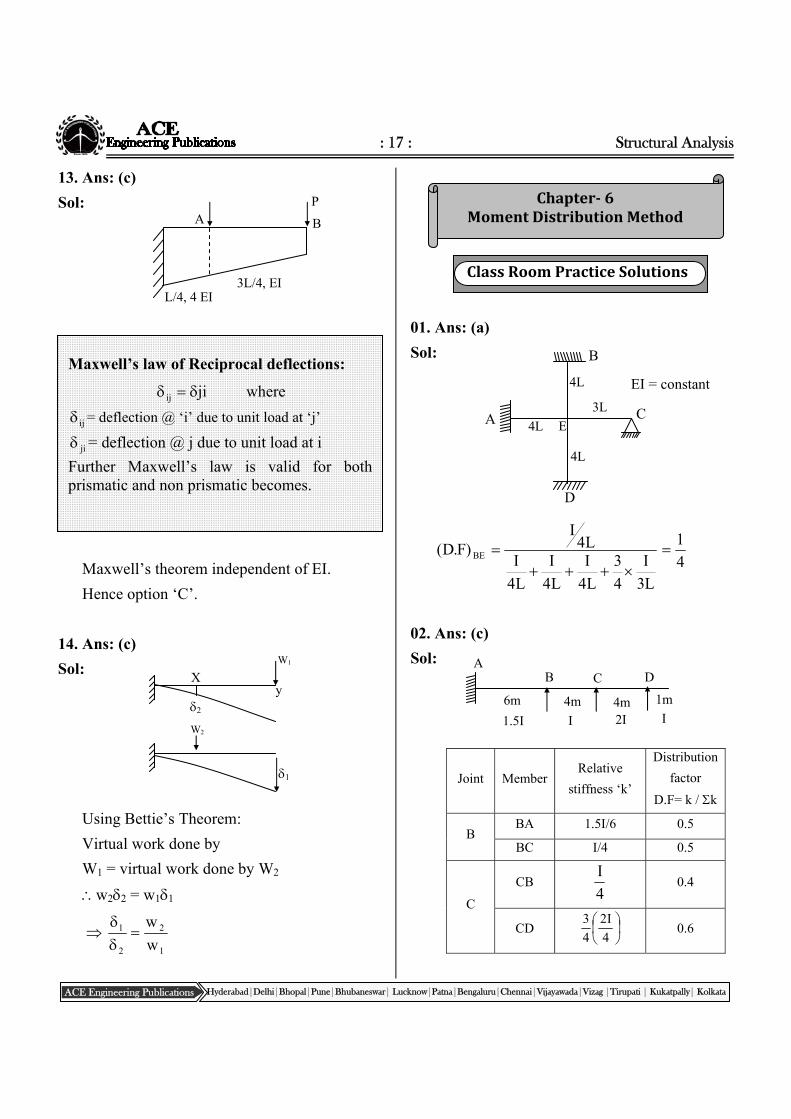
22. Refer GATE solutions Book.
23. Refer GATE solutions Book.
01. Ans: (a)
Sol: In slope deflection method deformation due
to axial force and shear force are neglected.
Deformations due to flexure only are
considered.
02. Ans: (c)
Sol: No. of unknown joint displacements is the
most appropriate option. Option (b) is
ambiguous as nothing is spelt about axial
deformations.
03. Ans: (c)
Sol: The number of equilibrium equations is
= number of unknown joint displacements.
A
15kN.m
B 10kN.m
2.5m
2.5m 10kN
HA
F.B.D of Column AB
F.B.D of Column CD
HD =0
20
MDC=0
C
D
5m
P
ClassRoomPracticeSolutions
: 26 : CIVIL - Postal Coaching Solutions
ACE Engineering Publications Hyderabad|Delhi|Bhopal|Pune|Bhubaneswar| Lucknow|Patna|Bengaluru|Chennai|Vijayawada|Vizag |Tirupati | Kukatpally| Kolkata
R X Y
For the above beam unknown displacement is
the rotation at central support only.
For the above beam unknown displacements
are the rotations at central support and right
end support.
For the above frame unknown displacements
are the rotation at rigid joint X and sway
deflection at right support Y.
04. Ans: (a)
Sol: MBA=
L
32
L
EI2AB
Note:
Clock wise rotations are taken as +Ve.
Anti clock wise rotations are –Ve.
= relative sinking of right support with
respect to left support. In the standard
equation right support is assumed to sink
more than left support and is taken as +Ve.
In the given problem A is clock wise hence
taken as positive. B is anti clock wise hence
taken as negative. Further right support sinks
less than that of left support.
2L
3
2.2
L
EI2M BA
2L
EI3
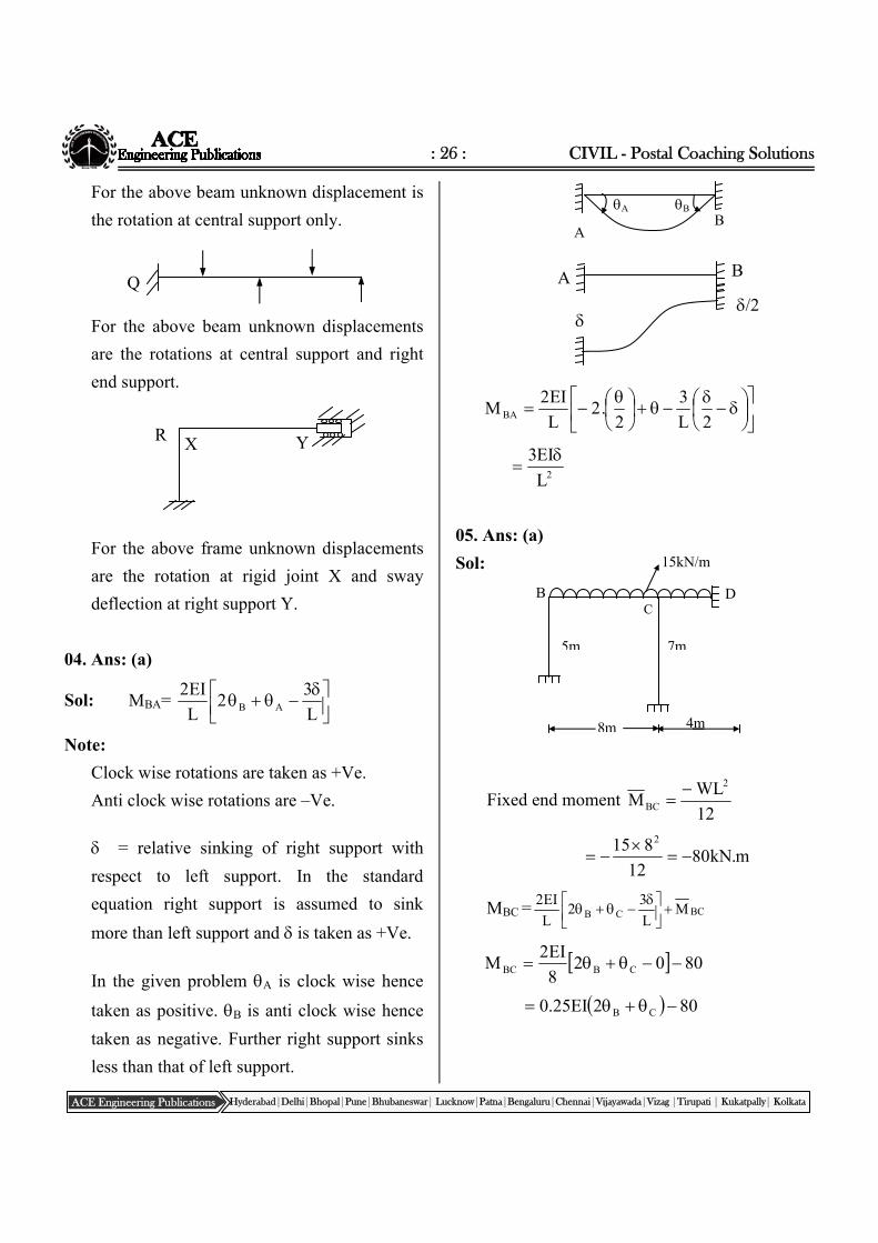
05. Ans: (a)
Sol:
Fixed end moment 12
WLM
2
BC
m.kN8012
815 2
MBC = BCCB ML
32
L
EI2
80028
EI2M CBBC
802EI25.0 CB
Q
A B
A B
/2
A B
B D
7m5m
8m 4m
15kN/m
C
: 27 : Structural Analysis
ACE Engineering Publications Hyderabad|Delhi|Bhopal|Pune|Bhubaneswar| Lucknow|Patna|Bengaluru|Chennai|Vijayawada|Vizag |Tirupati | Kukatpally| Kolkata
Chapter- 8 Plastic Theory
06. Ans: (c)
Sol:
Free body diagrams of columns shown below.
The joint moments are assumed clock wise
For horizontal equilibrium H = 0
HA+HD+P=0
4
M M H BAAB
A
4
M
4
0M
4
M M H CDCDDCCD
D
0P4
M
4
MM CDABBA
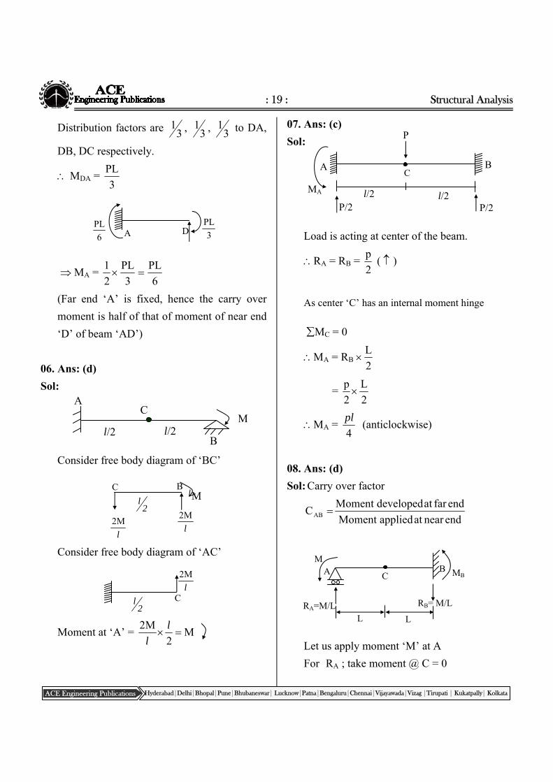
07. Ans: (b)
Sol:
At joint ‘Q’ relative stiffness
= EI24
EI4
3
EI330M
EI
15Q
08. Ans (a)
Sol: Slope at ‘R’
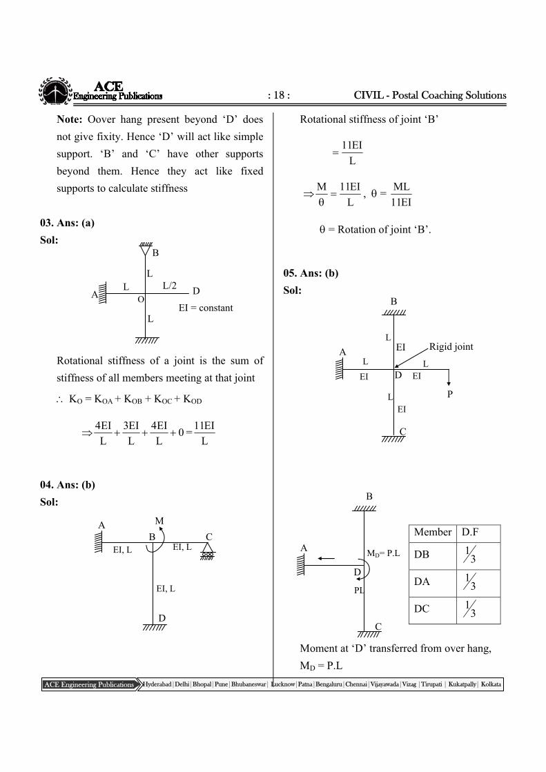
MR = 0 = )2(3
EI2QR
RQ Q2
EI
5.7
2Q
R
(Sign neglected)
01. Ans: (d)
Sol: Ductile materials like mild steel are used for
design using plastic theory. For ductile
materials plastic deformation before Fracture
is much larger than elastic deformation.
02. Ans: (c)
Sol: Shape factor is the ratio of plastic moment
and yield (elastic) moment.
Z
Z
Z.f
Z.f
M
MS P
y
Py
e
P
3m
4m
Q
EI
30 kN/m
R
P
MBA
MAB MDC=0
MCD
HD HA
4m 4m
A
B C
D
A D
C B P
4 m 4 m EI=Constant
4 m
hinge
ClassRoomPracticeSolutions
: 28 : CIVIL - Postal Coaching Solutions
ACE Engineering Publications Hyderabad|Delhi|Bhopal|Pune|Bhubaneswar| Lucknow|Patna|Bengaluru|Chennai|Vijayawada|Vizag |Tirupati | Kukatpally| Kolkata
We know that section modulus represents the
strength of a section both in plastic and elastic
theory.
As ZP > ZY for all sections, shape factor
indicates the increase of strengths of a section
due to plastic action over elastic strength.
Hence statements 1 and 2 are correct.
Shape factor is more if area near neutral axis
is more (bulk area).
For example :
i) Consider a square section and circular
section of same area.
Scircle = 1.7 Ssquare = 1.5
ii) Refer solution of Problem 3: for I section
along Y axis area is more near neutral axis
compared to area near X axis. Hence shape
factor SYY > SXX
statement 3 is wrong.
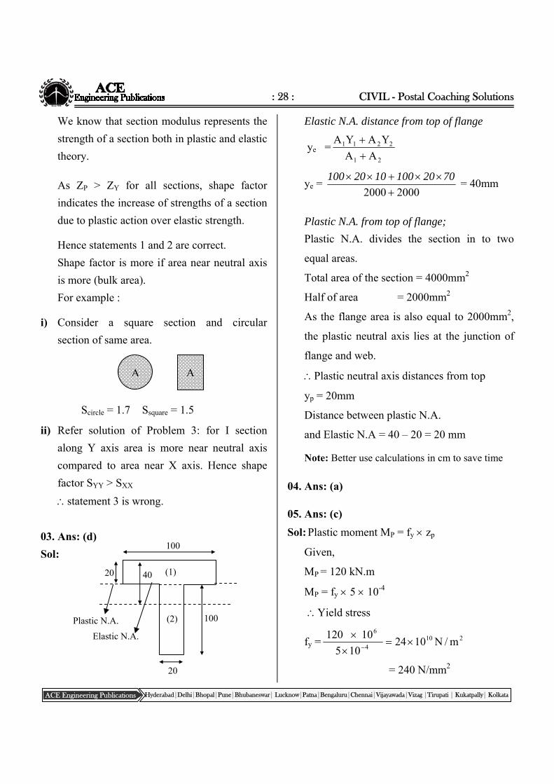
03. Ans: (d)
Sol:
Elastic N.A. distance from top of flange
ye =21
2211
AA
YAYA
ye = 20002000
70201001020 100 = 40mm
Plastic N.A. from top of flange;
Plastic N.A. divides the section in to two
equal areas.
Total area of the section = 4000mm2
Half of area = 2000mm2
As the flange area is also equal to 2000mm2,
the plastic neutral axis lies at the junction of
flange and web.
Plastic neutral axis distances from top
yp = 20mm
Distance between plastic N.A.
and Elastic N.A = 40 – 20 = 20 mm
Note: Better use calculations in cm to save time
04. Ans: (a)
05. Ans: (c)
Sol: Plastic moment MP = fy zp
Given,
MP = 120 kN.m
MP = fy 5 10-4
Yield stress
fy =210
4
6
m/N1024105
10 120
= 240 N/mm2
A A
20
100
40
100
Elastic N.A.
Plastic N.A.
20
(1)
(2)
: 29 : Structural Analysis
ACE Engineering Publications Hyderabad|Delhi|Bhopal|Pune|Bhubaneswar| Lucknow|Patna|Bengaluru|Chennai|Vijayawada|Vizag |Tirupati | Kukatpally| Kolkata
06. Ans: (a)
Sol:
From similar triangles,
pep
p
M)MM(
p
epp M
)MM(
S
11p
(Shape factor of I section 1.12
12.1
11
8p
07. Ans: (c)
Sol:
Mep = M. R of elasto plastic section
= M.R. of elastic part + M.R.of Plastic part
= fy.Z + fy.Zp
Zelastic part = 6
b.
24
bh
2
h 22
Zplastic part =
8
h.
4
h
4
hb2
16
bh3 2
Mep = fy.Z + fy.Zp
= fi
16
bh3
24
bh 22
= 2y bhf
48
11
Shortcut :
M.R of fully plastic section = f.bh2/4
M.R of fully elastic section = f.bh2/6
M.R of partly plastifyed section lies between
the above two values.
(f.bh2/6) < Mep < f.bh2/4
The denominator of the above value will be
between 4 and 6. Hence by elimination
technique option c.
l
Me
Mp
lp
W
X X
lp
h
h/4
b
h/4
fy
fy
: 30 : CIVIL - Postal Coaching Solutions
ACE Engineering Publications Hyderabad|Delhi|Bhopal|Pune|Bhubaneswar| Lucknow|Patna|Bengaluru|Chennai|Vijayawada|Vizag |Tirupati | Kukatpally| Kolkata
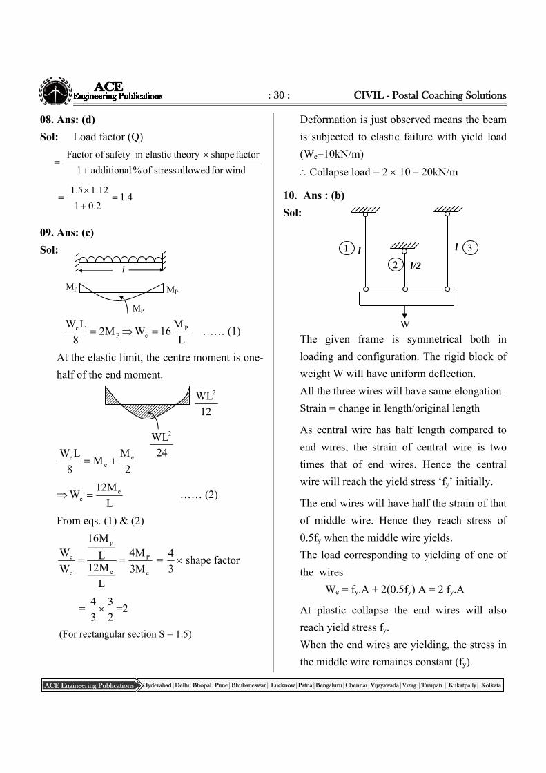
08. Ans: (d)
Sol: Load factor (Q)
windforallowedstressof%additional1
factorshapetheory n elastic safety i Factor of
4.12.01
12.15.1
09. Ans: (c)
Sol:
Pc M28
LW
L
M16W P
c …… (1)
At the elastic limit, the centre moment is one-
half of the end moment.
2
MM
8
LW ee
e
L
M12W e
e …… (2)
From eqs. (1) & (2)
e
P
e
p
e
c
M3
M4
L
M12L
M16
W
W =
3
4 shape factor
= 3
4
2
3=2
(For rectangular section S = 1.5)
Deformation is just observed means the beam
is subjected to elastic failure with yield load
(We=10kN/m)
Collapse load = 2 10 = 20kN/m
10. Ans : (b)
Sol:
The given frame is symmetrical both in
loading and configuration. The rigid block of
weight W will have uniform deflection.
All the three wires will have same elongation.
Strain = change in length/original length
As central wire has half length compared to
end wires, the strain of central wire is two
times that of end wires. Hence the central
wire will reach the yield stress ‘fy’ initially.
The end wires will have half the strain of that
of middle wire. Hence they reach stress of
0.5fy when the middle wire yields.
The load corresponding to yielding of one of
the wires
We = fy.A + 2(0.5fy) A = 2 fy.A
At plastic collapse the end wires will also
reach yield stress fy.
When the end wires are yielding, the stress in
the middle wire remaines constant (fy).
12
WL2
24
WL2
l
MP MP
MP
l l
l/2
W
2
1 3
: 31 : Structural Analysis
ACE Engineering Publications Hyderabad|Delhi|Bhopal|Pune|Bhubaneswar| Lucknow|Patna|Bengaluru|Chennai|Vijayawada|Vizag |Tirupati | Kukatpally| Kolkata
L/2 L/2 2L/3 L/3
W W
MP MP
A B C
2 Mp Mp
P
L/2 L/2
collapse load = 3fy.A
ratio of collapse load and yield load = 3:2
11. Ans: (a)
Sol: In all theories, viz. elastic theory, plastic
theory and limit state theory, Bernouli’s
assumption is valid according to which
“Plane transverse sections which are plane
and normal to the longitudinal axis before
bending remain plane and normal after
bending”.
It means
Strain variation
is linear as shown
aside
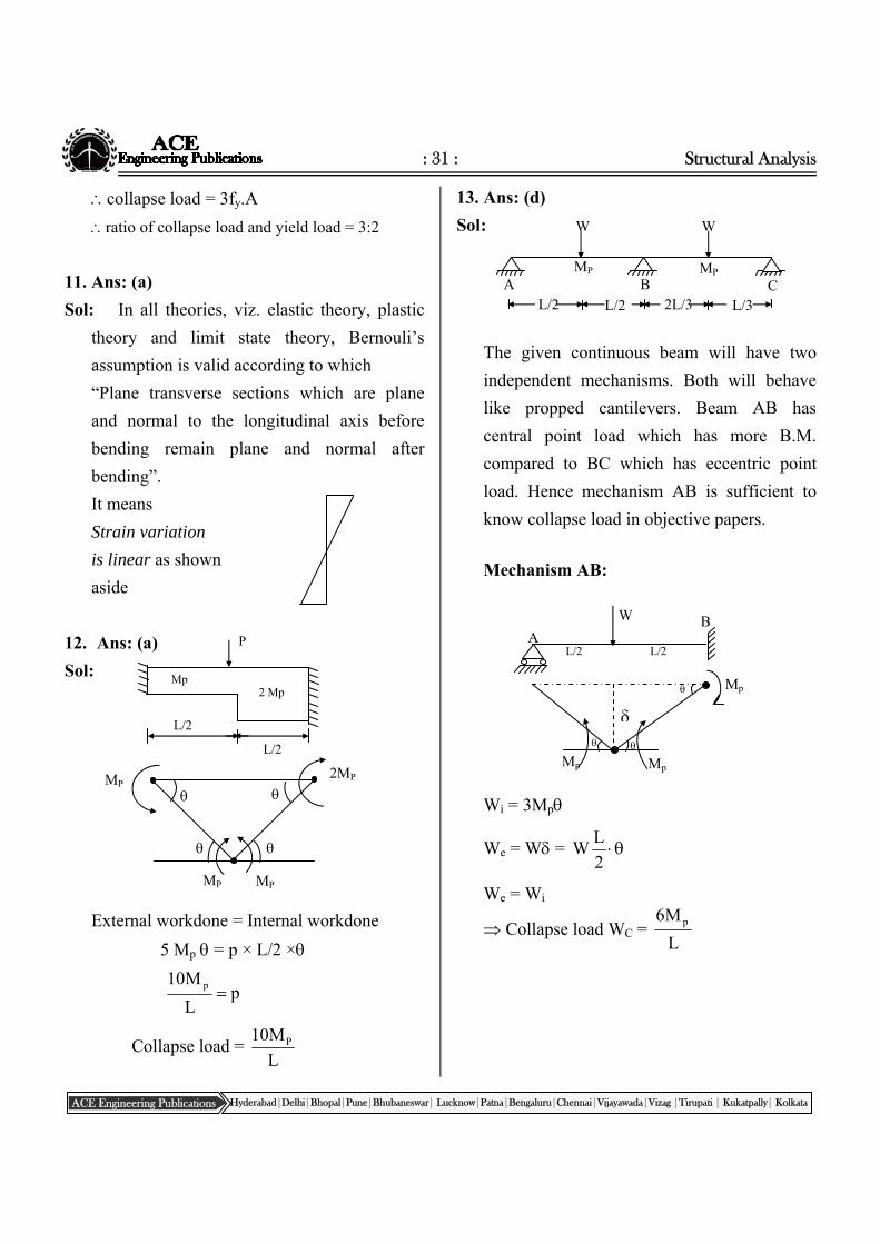
12. Ans: (a)
Sol:
External workdone = Internal workdone
5 Mp = p × L/2 ×
pL
M10 p
Collapse load = L
M10 P
13. Ans: (d)
Sol:
The given continuous beam will have two
independent mechanisms. Both will behave
like propped cantilevers. Beam AB has
central point load which has more B.M.
compared to BC which has eccentric point
load. Hence mechanism AB is sufficient to
know collapse load in objective papers.
Mechanism AB:
Wi = 3Mp
We = W = 2
LW
We = Wi
Collapse load WC = L
M6 p
Mp Mp
Mp
L/2 L/2
W
A B
MP 2MP
MP MP
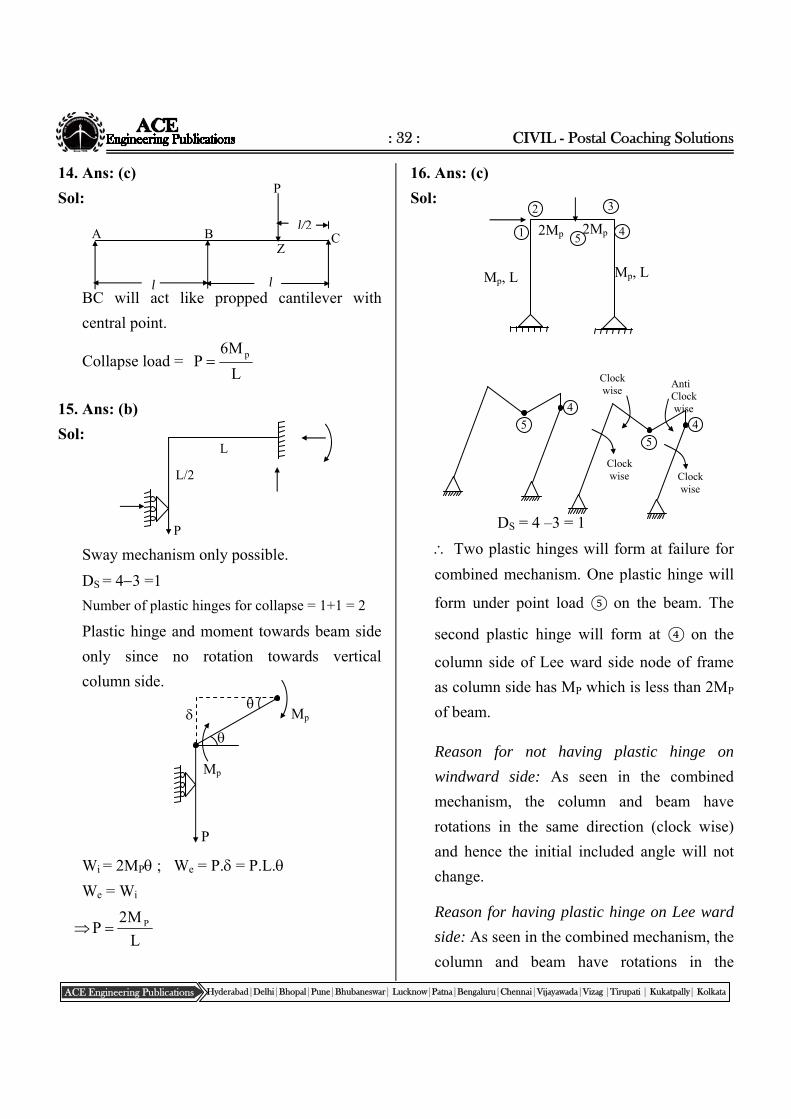
: 32 : CIVIL - Postal Coaching Solutions
ACE Engineering Publications Hyderabad|Delhi|Bhopal|Pune|Bhubaneswar| Lucknow|Patna|Bengaluru|Chennai|Vijayawada|Vizag |Tirupati | Kukatpally| Kolkata
A B
P
Z
l l
l/2C
14. Ans: (c)
Sol:
BC will act like propped cantilever with
central point.
Collapse load = L
M6P p
15. Ans: (b)
Sol:
Sway mechanism only possible.
DS = 43 =1
Number of plastic hinges for collapse = 1+1 = 2
Plastic hinge and moment towards beam side
only since no rotation towards vertical
column side.
Wi = 2MP ; We = P. = P.L.
We = Wi
L
M2P P
16. Ans: (c)
Sol:
DS = 4 –3 = 1
Two plastic hinges will form at failure for
combined mechanism. One plastic hinge will
form under point load ⑤ on the beam. The
second plastic hinge will form at ④ on the
column side of Lee ward side node of frame
as column side has MP which is less than 2MP
of beam.
Reason for not having plastic hinge on
windward side: As seen in the combined
mechanism, the column and beam have
rotations in the same direction (clock wise)
and hence the initial included angle will not
change.
Reason for having plastic hinge on Lee ward
side: As seen in the combined mechanism, the
column and beam have rotations in the
P
L
L/2
Mp
Mp
P
5
4
2Mp 2Mp
2
Mp, L Mp, L
1 5
3
4
5
4
Clock wise
Clock wise
Clock wise
Anti Clock wise
: 33 : Structural Analysis
ACE Engineering Publications Hyderabad|Delhi|Bhopal|Pune|Bhubaneswar| Lucknow|Patna|Bengaluru|Chennai|Vijayawada|Vizag |Tirupati | Kukatpally| Kolkata
opposite (column clock wise and beam anti
clock wise) and hence the initial included
angle changes leading to plastic hinge on
weaker side.
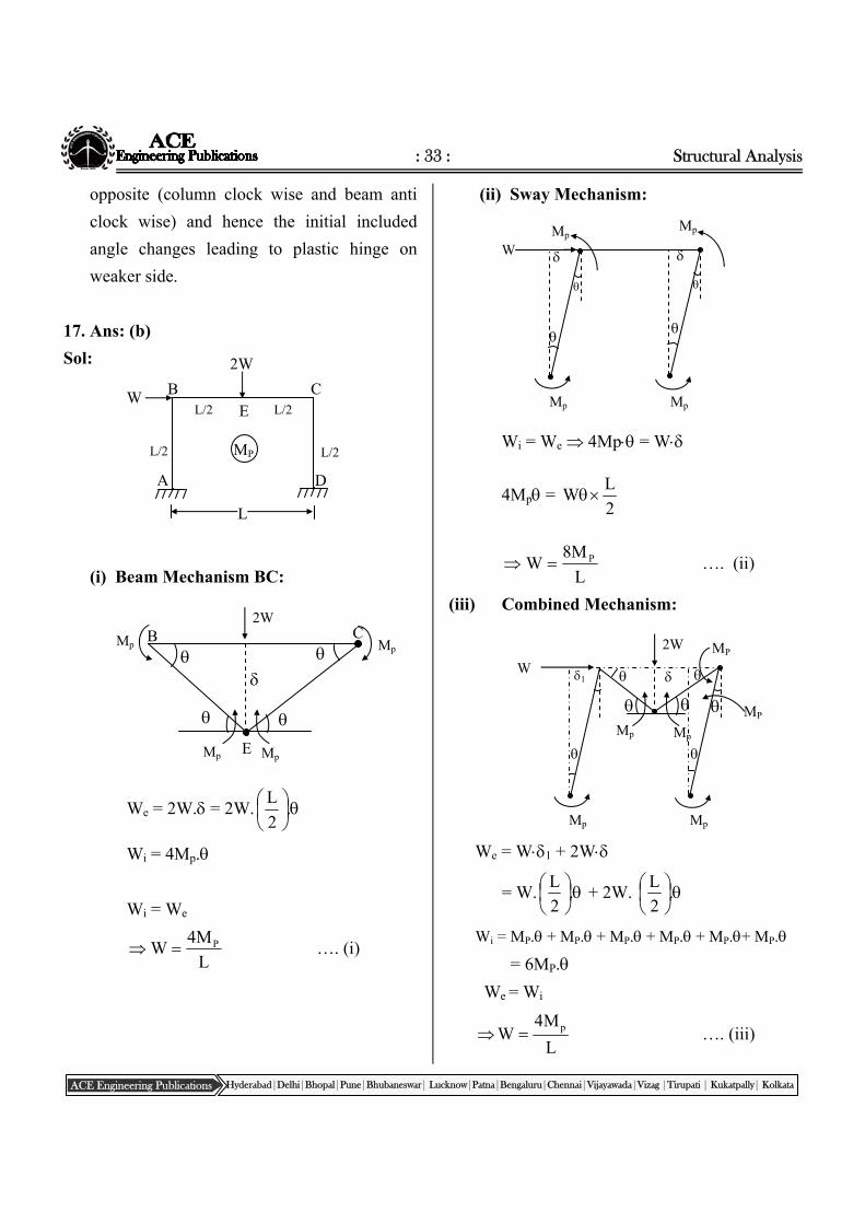
17. Ans: (b)
Sol:
(i) Beam Mechanism BC:
We = 2W. = 2W.
.2
L
Wi = 4Mp.
Wi = We
L
M4W P …. (i)
(ii) Sway Mechanism:
Wi = We 4Mp = W
4Mp = 2
LW
L
M8W P …. (ii)
(iii) Combined Mechanism:
We = W1 + 2W
= W.
.
2
L + 2W.
.
2
L
Wi = MP. + MP. + MP. + MP. + MP.+ MP.
= 6MP.
We = Wi
L
M4W p …. (iii)
L
W
2W
L/2 L/2
L/2 L/2
A
B C
D
E
MP
Mp
Mp
Mp
Mp
2W C B
E
Mp W
Mp
Mp Mp
Mp
W
Mp
Mp Mp
1
2W
MP
MP
: 34 : CIVIL - Postal Coaching Solutions
ACE Engineering Publications Hyderabad|Delhi|Bhopal|Pune|Bhubaneswar| Lucknow|Patna|Bengaluru|Chennai|Vijayawada|Vizag |Tirupati | Kukatpally| Kolkata
Chapter‐9RollingLoads&InfluenceLines
∴Collapse load is the minimum of above three
cases
L
M4W p
C
Short cut:
Compared to the columns, the beam has
double the length and double the load. Hence
practically the beam mechanism will govern
the collapse.
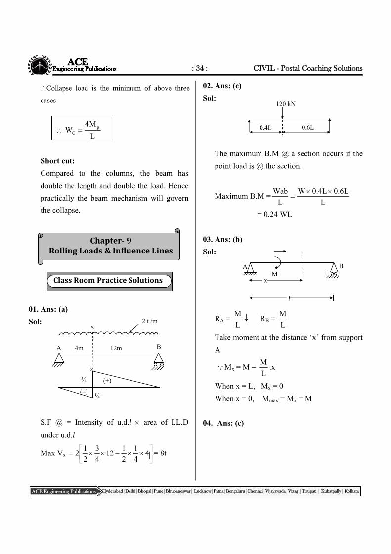
01. Ans: (a)
Sol:
S.F @ = Intensity of u.d.l area of I.L.D
under u.d.l
Max Vx
4
4
1
2
112
4
3
2
12 = 8t
02. Ans: (c)
Sol:
The maximum B.M @ a section occurs if the
point load is @ the section.
Maximum B.M =L
L6.0L4.0W
L
Wab
= 0.24 WL
03. Ans: (b)
Sol:
RA = L
M RB =
L
M
Take moment at the distance ‘x’ from support
A
Mx = M L
M.x
When x = L, Mx = 0
When x = 0, Mmax = Mx = M
04. Ans: (c)
0.4L 0.6L
120 kN
¾
¼
(+)
(–)
12m 4m A B
2 t /m
A B
x
l
M ClassRoomPracticeSolutions
: 35 : Structural Analysis
ACE Engineering Publications Hyderabad|Delhi|Bhopal|Pune|Bhubaneswar| Lucknow|Patna|Bengaluru|Chennai|Vijayawada|Vizag |Tirupati | Kukatpally| Kolkata
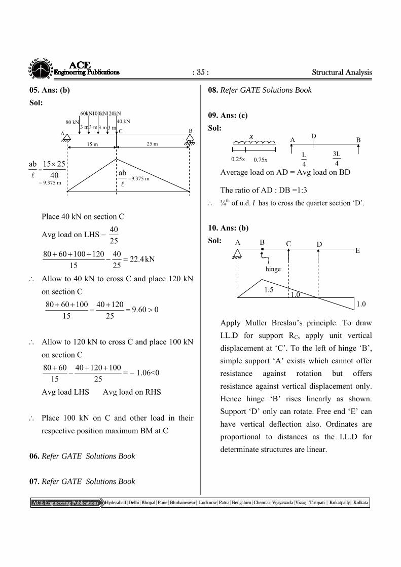
05. Ans: (b)
Sol:
Place 40 kN on section C
Avg load on LHS 25
40
kN4.2225
40
15
1201006080
Allow to 40 kN to cross C and place 120 kN
on section C
060.925
12040
15
1006080
Allow to 120 kN to cross C and place 100 kN
on section C
25
10012040
15
6080
= 1.06<0
Avg load LHS Avg load on RHS
Place 100 kN on C and other load in their
respective position maximum BM at C
06. Refer GATE Solutions Book
07. Refer GATE Solutions Book
08. Refer GATE Solutions Book
09. Ans: (c)
Sol:
Average load on AD = Avg load on BD
The ratio of AD : DB =1:3
¾th of u.d. l has to cross the quarter section ‘D’.
10. Ans: (b)
Sol:
Apply Muller Breslau’s principle. To draw
I.L.D for support RC, apply unit vertical
displacement at ‘C’. To the left of hinge ‘B’,
simple support ‘A’ exists which cannot offer
resistance against rotation but offers
resistance against vertical displacement only.
Hence hinge ‘B’ rises linearly as shown.
Support ‘D’ only can rotate. Free end ‘E’ can
have vertical deflection also. Ordinates are
proportional to distances as the I.L.D for
determinate structures are linear.
A B C DE
1.0 1.0
1.5
hinge
0.75x
x
4
L 4
L3
A B D
0.25x
A
80 kN 3 m 3 m 3 m 3 m
60kN 100kN 120kN
40 kN
C
15 m 25 m
B
ab=9.375 m
ab=
40
2515
= 9.375 m
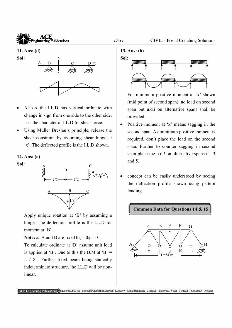
: 36 : CIVIL - Postal Coaching Solutions
ACE Engineering Publications Hyderabad|Delhi|Bhopal|Pune|Bhubaneswar| Lucknow|Patna|Bengaluru|Chennai|Vijayawada|Vizag |Tirupati | Kukatpally| Kolkata
B
1/2
A C
1/2 +
A B C
+ 1/8
Common Data for Questions 14 & 15
x
D
x
A B C E
11. Ans: (d)
Sol:
At x-x the I.L.D has vertical ordinate with
change in sign from one side to the other side.
It is the character of I.L.D for shear force.
Using Muller Breslau’s principle, release the
shear constraint by assuming shear hinge at
‘x’. The deflected profile is the I.L.D shown.
12. Ans: (a)
Sol:
Apply unique rotation at ‘B’ by assuming a
hinge. The deflection profile is the I.L.D for
moment at ‘B’.
Note: as A and B are fixed A = B = 0
To calculate ordinate at ‘B’ assume unit load
is applied at ‘B’. Due to this the B.M at ‘B’ =
L / 8. Further fixed beam being statically
indeterminate structure, the I.L.D will be non-
linear.
13. Ans: (b)
Sol:
For minimum positive moment at ‘x’ shown
(mid point of second span), no load on second
span but u.d.l on alternative spans shall be
provided.
Positive moment at ‘x’ means sagging in the
second span. As minimum positive moment is
required, don’t place the load on the second
span. Further to counter sagging in second
span place the u.d.l on alternative spans (1, 3
and 5)
concept can be easily understood by seeing
the deflection profile shown using pattern
loading.
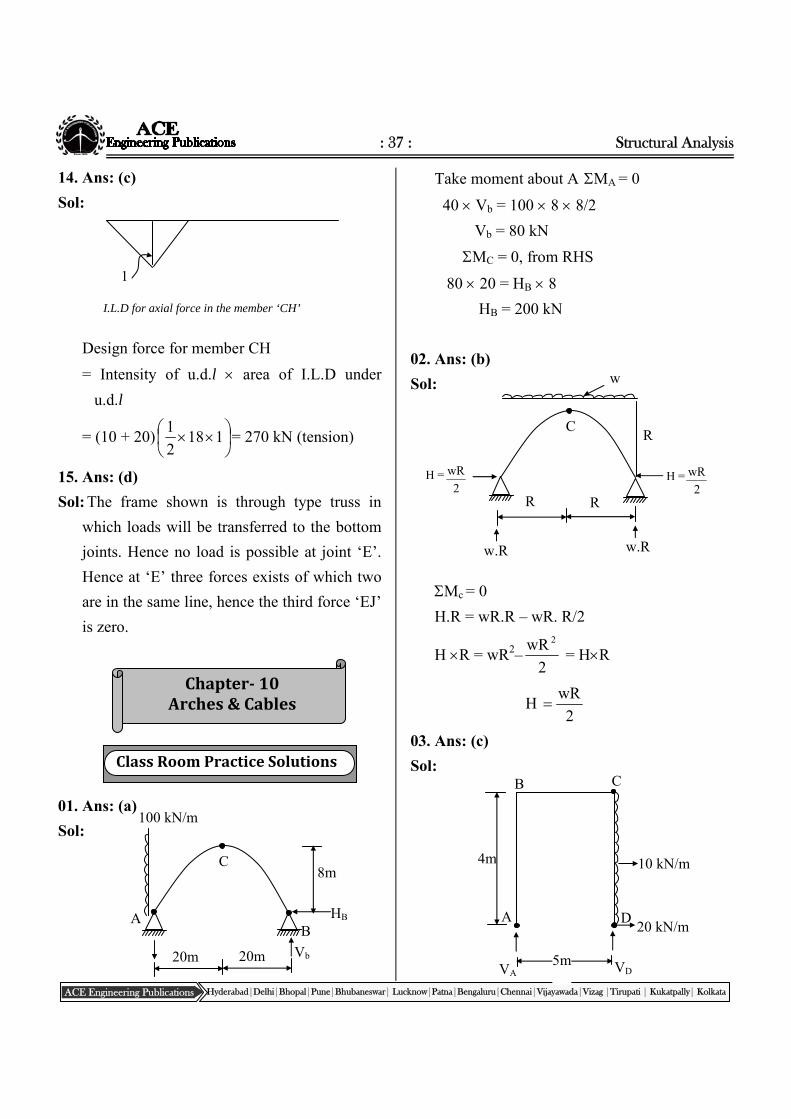
L=54 m
A B
C D E F G
L K J I H
: 37 : Structural Analysis
ACE Engineering Publications Hyderabad|Delhi|Bhopal|Pune|Bhubaneswar| Lucknow|Patna|Bengaluru|Chennai|Vijayawada|Vizag |Tirupati | Kukatpally| Kolkata
Chapter‐10Arches&Cables
14. Ans: (c)
Sol:
I.L.D for axial force in the member ‘CH’
Design force for member CH
= Intensity of u.d.l area of I.L.D under
u.d.l
= (10 + 20)
118
2
1= 270 kN (tension)
15. Ans: (d)
Sol: The frame shown is through type truss in
which loads will be transferred to the bottom
joints. Hence no load is possible at joint ‘E’.
Hence at ‘E’ three forces exists of which two
are in the same line, hence the third force ‘EJ’
is zero.
01. Ans: (a)
Sol:
Take moment about A MA = 0
40 Vb = 100 8 8/2
Vb = 80 kN
MC = 0, from RHS
80 20 = HB 8
HB = 200 kN
02. Ans: (b)
Sol:
Mc = 0
H.R = wR.R – wR. R/2
H R = wR2–2
wR 2
= HR
H 2
wR
03. Ans: (c)
Sol:
1
R R
R
w.R w.R
C
w
H =2
wR H =2
wR
ClassRoomPracticeSolutions
20m 20m
8m C
100 kN/m
HB AB
Vb
4m
C B
A D
10 kN/m
20 kN/m
5m VD VA
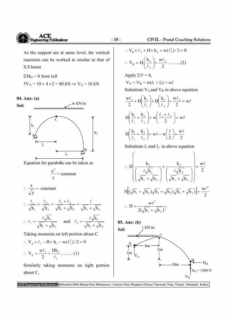
: 38 : CIVIL - Postal Coaching Solutions
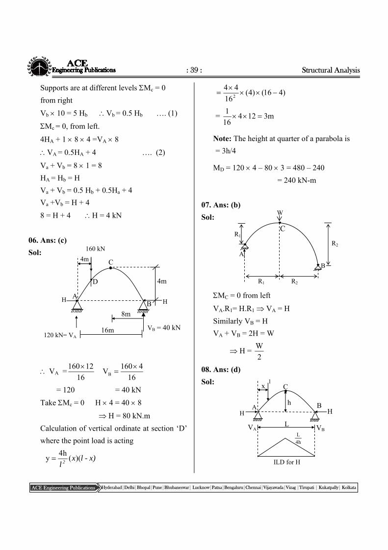
ACE Engineering Publications Hyderabad|Delhi|Bhopal|Pune|Bhubaneswar| Lucknow|Patna|Bengaluru|Chennai|Vijayawada|Vizag |Tirupati | Kukatpally| Kolkata
As the support are at same level, the vertical
reactions can be worked to similar to that of
S.S beam
MD = 0 from left
5VA = 10 4 2 = 80 kN VA = 16 kN
04. Ans: (a)
Sol:
Equation for parabola can be taken as
y
x2
= constant
y
x constant
2121
21
2
2
1
1
hhhhhh
21
22
21
11
hh
hand
hh
h
Taking moments on left portion about C
02/)(whHV 2111A
1
11A
Hh
2
wV
…….. (1)
Similarly taking moments on right portion
about C,
02/)(whHV 2222B
2
wh.HV 2
2
2B
…….. (2)
Apply V = 0,
VA + VB = w(l1 + l2) = wl
Substitute VA and VB in above equation
w
2
whH
hH
2
w 2
2
2
1
11
w
2w
hhH 21
2
2
1
1
2
w
2ww
hhH
2
2
1
1
Substitute l1 and l2 in above equation
2
w
hh
h
h
hh
h
hH
21
2
2
21
1
1
2
w)hh(hh)hh(H
2
212121
2
21
2
)hh(2
wH
05. Ans: (b)
Sol:
C
B
A
5m
10m
8m
1 kN/m
1m VA
HB = 1500 N
HB
VB
h1
h2 A
w kN/m
B
C
l2
l1
l
: 39 : Structural Analysis
ACE Engineering Publications Hyderabad|Delhi|Bhopal|Pune|Bhubaneswar| Lucknow|Patna|Bengaluru|Chennai|Vijayawada|Vizag |Tirupati | Kukatpally| Kolkata
A
W
R2
R1
C
R1 R2
B
Supports are at different levels Mc = 0
from right
Vb 10 = 5 Hb Vb = 0.5 Hb …. (1)
Mc = 0, from left.
4HA + 1 8 4 =VA 8
VA = 0.5HA + 4 …. (2)
Va + Vb = 8 1 = 8
HA = Hb = H
Va + Vb = 0.5 Hb + 0.5Ha + 4
Va +Vb = H + 4
8 = H + 4 H = 4 kN
06. Ans: (c)
Sol:
VA =16
12160
16
4160VB
= 120 = 40 kN
Take Mc = 0 H 4 = 40 8
H = 80 kN.m
Calculation of vertical ordinate at section ‘D’
where the point load is acting
x)-lxl 2
)((h4
y
)416()4(16
442
= m312416
1
Note: The height at quarter of a parabola is
= 3h/4
MD = 120 4 – 80 3 = 480 – 240
= 240 kN-m
07. Ans: (b)
Sol:
MC = 0 from left
VA.R1= H.R1 VA = H
Similarly VB = H
VA + VB = 2H = W
H = 2
W
08. Ans: (d)
Sol:
16m
4m
C 4m
D
8m
A B
VB = 40 kN 120 kN= VA
160 kN
H H
C
A HH
B
x 1
h
L VA VB
h4
L
ILD for H
: 40 : CIVIL - Postal Coaching Solutions
ACE Engineering Publications Hyderabad|Delhi|Bhopal|Pune|Bhubaneswar| Lucknow|Patna|Bengaluru|Chennai|Vijayawada|Vizag |Tirupati | Kukatpally| Kolkata
Assume a unit load rolls on the span from left
to right. The horizontal and vertical reactions
will change at the supports as the load moves
on the span.
Assume the unit load be at a distance x from A.
Then
VA = L
xL and VB =
L
x
Assume H=The horizontal thrust at supports.
Apply MC = 0 from right
H.h = 2
L.
L
x
H = h2
x
For horizontal thrust to be maximum
x =2
L i.e., at the crown.
Maximum horizontal reaction of h4
Lis
possible if the load is at the crown.
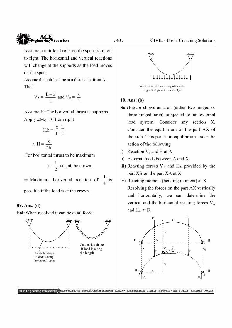
09. Ans: (d)
Sol: When resolved it can be axial force
Load transferred from cross girders to the
longitudinal girder in cable bridges.
10. Ans: (b)
Sol: Figure shows an arch (either two-hinged or
three-hinged arch) subjected to an external
load system. Consider any section X.
Consider the equilibrium of the part AX of
the arch. This part is in equilibrium under the
action of the following
i) Reaction Va and H at A
ii) External loads between A and X
iii) Reacting forces VX and HX provided by the
part XB on the part XA at X
iv) Reacting moment (bending moment) at X.
Resolving the forces on the part AX vertically
and horizontally, we can determine the
vertical and the horizontal reacting forces VX
and HX at D.
Parabolic shape If load is along horizontal span
Catenaries shape If load is along the length
B A
H
C X P1 P2
H
H A
Va
Va
x
y
P2 VX
P1
x
y
H B
Vb
Vb C
: 41 : Structural Analysis
ACE Engineering Publications Hyderabad|Delhi|Bhopal|Pune|Bhubaneswar| Lucknow|Patna|Bengaluru|Chennai|Vijayawada|Vizag |Tirupati | Kukatpally| Kolkata
S M Pn
Arch section subjected to normal thrust Pn radial shear S, bending moment M.
Let the tangent to the centre line of the arch at
X be inclined at to the horizontal.
The component of the reacting forces at X
perpendicular to the tangent at X is called the
Shear Force (or) Radical Shear at X.
Shear at X= S
= HX sin –VX sin (or) VX cos –HX sin
The component of reacting forces at X along
the tangent X is called the Normal thrust at X.
Normal thrust at X = Pn = HXcos +VXsin
(HX = H) from F.B.D
(Neglecting sign)
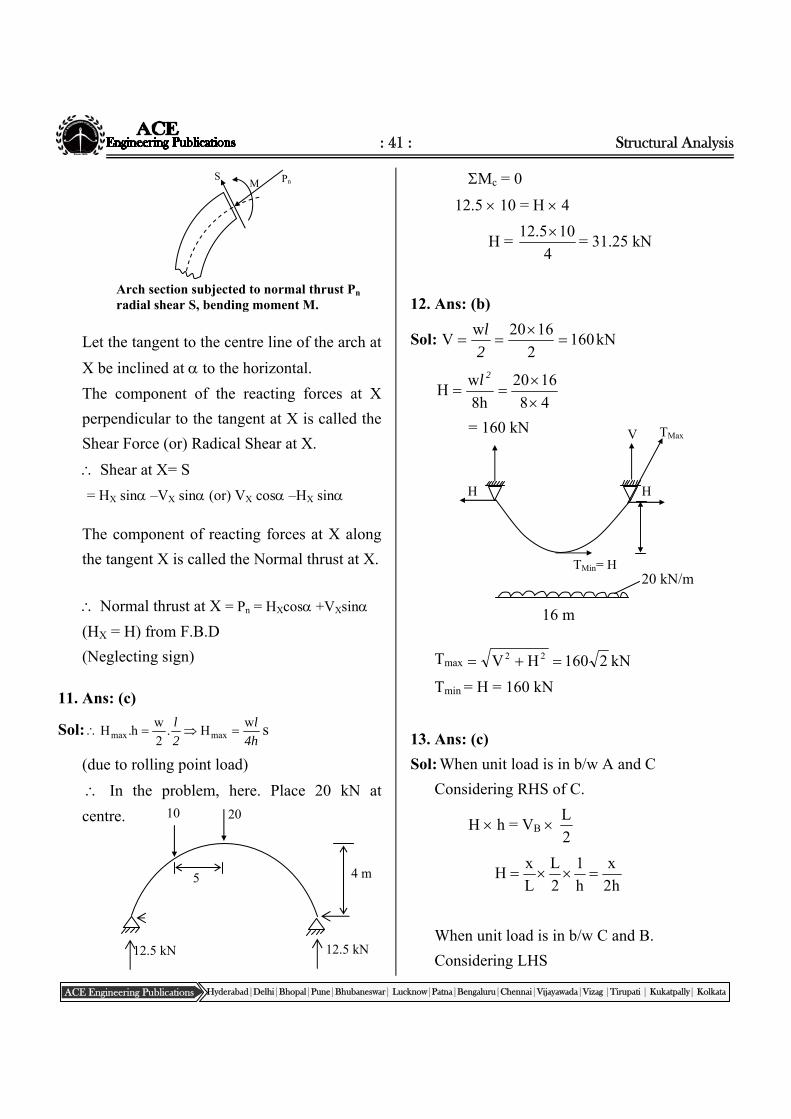
11. Ans: (c)
Sol: 4h
l
2
l wH.
2
wh.H maxmax s
(due to rolling point load)
In the problem, here. Place 20 kN at
centre.
Mc = 0
12.5 10 = H 4
H = 4
105.12 = 31.25 kN
12. Ans: (b)
Sol: kN1602
1620wV
2
l
48
1620
h8
wH
2l
= 160 kN
Tmax kN2160HV 22
Tmin = H = 160 kN
13. Ans: (c)
Sol: When unit load is in b/w A and C
Considering RHS of C.
H h = VB 2
L
h2
x
h
1
2
L
L
xH
When unit load is in b/w C and B.
Considering LHS 12.5 kN
10
4 m
20
5
12.5 kN
16 m
H
20 kN/m
H
TMax
TMin= H
V
: 42 : CIVIL - Postal Coaching Solutions
ACE Engineering Publications Hyderabad|Delhi|Bhopal|Pune|Bhubaneswar| Lucknow|Patna|Bengaluru|Chennai|Vijayawada|Vizag |Tirupati | Kukatpally| Kolkata
Chapter- 11 Matrix Methods &
Miscellaneous Topics
Assume restrained structure at 1 & 2
hH2
LVA
h2
xL
h2
L
L
)xL(H
14. Ans: (b)
Sol:
Mc = 0, from left
VA 8 = H 2 + 10 8 4
VA = 0.25 H + 40 …. (1)
Mc = 0 from right
12Vb = 3H + 10 12 6
Vb = 0.25H + 60 …. (2)
Va+ Vb = 200 kN
400 = 0.25H + 40 + 0.25 H +60
400 = 0.5 H + 100
H = 200 kN
15. Ans: (c)
Sol: H = 200 kN
Vb = 0.25 200 + 60
= 110 kN
Maximum tension occurs at highest support
(B)
Tmax. = 2222 200110VbH
01. Ans: (b)
Sol: EI
1d
(EI) = 2EI
half (b)
02. Ans: (d)
Sol:
H
3m
12m 8m
H
A
2m C
VA
VB
B
10 kN/m
4m 4m 8m
I 2I 2I A
B C D
ClassRoomPracticeSolutions
C
HB AB
VB
HA
L/4h
VA
: 43 : Structural Analysis
ACE Engineering Publications Hyderabad|Delhi|Bhopal|Pune|Bhubaneswar| Lucknow|Patna|Bengaluru|Chennai|Vijayawada|Vizag |Tirupati | Kukatpally| Kolkata
Restrain at ‘C’. Apply unit rotation at B
Consider BC
k21 = force developed at 1 due to unit rotation
at
k21 = k12 = 0.5 EI
k
EI2EI5.0
EI5.0EI3
03. Ans: (d)
Sol:
For portion AC () RB
= 3
22 EI12EI6EI6
llll
For portion BC( ) RB = 33
EI3EI3
ll
K11 = 333
EI15EI3EI12
lll
K21 = 2
EI3
l
K22 = lll
EI7EI3EI4
K12 = 22 ll
EI3EI6
=
2l
EI3
K =
ll
llEI7EI3
EI3EI15
KK
KK
2
23
22`21
1211
A B C D
A B C D
4m 4m
B
C
0.5 EI
EI4
EI4
L
1
A C
B L
2
2
EI6
l
2
EI6
l
2
EI6
l
222
EI3EI3EI6
lll
0EI6EI622
ll
2
EI6
l
2
EI6
l
2
EI3
l
l
EI4
l
EI3
: 44 : CIVIL - Postal Coaching Solutions
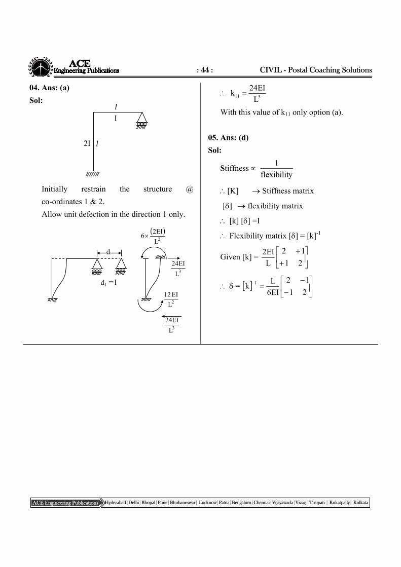
ACE Engineering Publications Hyderabad|Delhi|Bhopal|Pune|Bhubaneswar| Lucknow|Patna|Bengaluru|Chennai|Vijayawada|Vizag |Tirupati | Kukatpally| Kolkata
04. Ans: (a)
Sol:
Initially restrain the structure @
co-ordinates 1 & 2.
Allow unit defection in the direction 1 only.
311 L
EI24k
With this value of k11 only option (a).
05. Ans: (d)
Sol:
Stiffness yflexibilit
1
[K] Stiffness matrix
[] flexibility matrix
[k] [] =I
Flexibility matrix [] = [k]-1
Given [k] =
21
12
L
EI2
=
21
12
EI6
Lk 1
l
l
I
2I
d
d1 =1
3L
EI24
2L
EI12
3L
EI24
2L
EI26


