Embed Size (px)
Citation preview

Dublin Institute of TechnologyARROW@DIT
Articles Centre for Industrial and Engineering Optics
2010-01-01
Electronic Speckle Pattern Interferometer usingHolographic Optical Elements for VibrationMeasurementsViswanath BavigaddaDublin Institute of Technology, [email protected]
Raghavendra JallapuramDublin Institute of Technology, [email protected]
Emilia MihaylovaDublin Institute of Technology, [email protected]
Vincent ToalDublin Institute of Technology, [email protected]
This Article is brought to you for free and open access by the Centre forIndustrial and Engineering Optics at ARROW@DIT. It has been acceptedfor inclusion in Articles by an authorized administrator of [email protected] more information, please contact [email protected],[email protected].
Recommended CitationBavigadda, V., Jallapuram, J.,Mihaylova, E., Toal, V.:Electronic speckle pattern interferometer using holographic optical elements forvibration measurements.Optics Letters, Vol. 35, No. 19, October 1, 2010, pp.3273-3275

1
Electronic speckle pattern interferometer using holographic
optical elements for vibration measurements
Viswanath Bavigadda∗, Raghavendra Jallapuram, Emilia Mihaylova and Vincent Toal
Centre for Industrial and Engineering Optics, Dublin Institute of Technology, Kevin Street,
Dublin 08, Ireland
*Corresponding author: [email protected]
Abstract: A simple and compact electronic speckle pattern interferometry (ESPI) built
with holographic optical elements (HOEs) used for the study of out-of-plane vibration is
reported. Carefully fabricated reflection and transmission HOEs provide reference and
object beams in the interferometer. All the alignment difficulties in conventional ESPI
systems are minimized using HOEs. The time average ESPI subtraction method is used to
generate correlation fringes. The background speckle noise is removed by introducing a
phase shift between sequential images. The amplitude and phase maps are obtained using
path difference modulation in an unbalanced ESPI.
Electronic speckle pattern interferometry is a popular non-destructive testing tool for quantitative
measurement of dynamic displacements of an object1, 2
. Conventional ESPI systems consist of
expensive bulk optical elements whose alignment is a critical and time consuming task.
Alternative ESPI systems were designed using diode lasers and single mode optical fibres3, 4
.
ESPI systems can be further simplified by using holographic optical elements. in place of bulk
optics. A HOE based ESPI system was reported by Petrov and Lau5. In-plane and out-of-plane

2
sensitive ESPI systems using diffraction gratings6 and HOEs providing purely out of plane
sensitivity in interferometric systems7,8,9
have also been reported. Time average ESPI with phase
stepping is a widely used technique for vibration measurement1. Vibration may also be measured
using the reference beam modulation technique10,11
. In this letter, we report a HOE based ESPI
system for out-of-plane vibration measurement. A reflection holographic optical element
(RHOE) provides the reference beam in the interferometer12
and a transmission holographic
optical element (THOE) is used to provide normal illumination of the test object ly, making the
ESPI system sensitive only to out-of-plane displacement. The laser diode wavelength is
modulated to provide path length modulation in the interferometer.
Speckle correlation fringes in ESPI are normally obtained by subtraction of two images
corresponding to the displaced and undisplaced positions of the test object. When the test object
is vibrating harmonically at an angular frequencyω , amplitude 0a and phase 0ϕ , the brightness at
any point of the correlogram can be described as11
( )0 0 0
44 cosrB I I J a
πψ
λ =
(1)
where the background intensity term 0 rI I+ due to object and reference beam intensities
0 and r
I I has been removed as explained later.
To obtain contours of constant amplitude and phase, the reference beam is modulated at the same
angular frequency as that of the test objectω but with an amplitude ra and phase rϕ , the
brightness of the correlogram at any point is modified to become
( ){ } ( )1
2 2 2
0 0 0 0 0
44 2 cos cosr r rr
B I I J a a a aπ
ϕ ϕ ψλ
′ = + − −
(2)

3
The brightness usually modulates over only a few gray levels, making it difficult hard to detect
fringes visually so we simply square the brightness B′ and display the result as
( ){ } ( )2
12 2 2
0 0 0 0 0
416 2 cos cosr r r rB I I J a a a a
πϕ ϕ ψ
λ ′′ = + − −
(3)
As we vary the amplitude of the reference beam path modulation in the interferometer by
varying the laser drive current, i, the regions where 0ra a= and 0r
ϕ ϕ= are displayed with
maximum brightness10,11
.
A plot of wavelength versus drive current enables us to identify mode hop free regions of
operation of a diode laser for both recording of HOEs and stable reference beam path modulation
in the ESPI system. A temperature controlled diode laser (ONDAX) was used. Its nominal
wavelength was 658 nm and the wavelength change and its associated power change per mA
drive current were 5.1pm and 0.8mW respectively.
The setup for recording the HOEs is shown in Fig. 1. A polarizing beam splitter (PBS) and two
half wave plates (HWP1 & 2) were used to split the laser beam into two parts with the same
polarization state but variable beam ratio. The RHOE was recorded by the Denisyuk method
(using beam 1 with the intensity of beam 2 set at zero), with a diffuser between the mirror and
the emulsion to provide a speckled object beam. To record a THOE mirror 1 and the diffuser
were removed, then the intensities of beams 1 and 2 were equalized. The two HOEs were
recorded in this way to enable them to be used in contact with one another. Thus on
reconstruction by beam 1, a speckled reference beam is provided for the ESPI system by the
RHOE and a beam diffracted by the THOE in the direction of beam 2 illuminates the test object.
For RHOE recording PFG-03C silver halide emulsion on glass substrate (6.3cm×6.3cm), the
laser beam intensity and exposure time was 500µW/cm2 and 6s respectively using the diode laser

4
(Fig.1). SM-612
processing was used. The diffraction efficiency of the RHOE was 12%. The
THOE was recorded in HP-P13
silver halide holographic emulsion on glass substrate
(6.3cm×6.3cm). The angle between the recording beams was 30o. The intensity and exposure
time was 600µW/cm2 and 5s respectively; SM-6
12 processing was used. The diffraction
efficiency of the THOE was 20%.
Fig. 1 Recording set up for HOEs: reflection hologram of a diffuser and transmission grating
The ESPI system is shown in Fig. 2. The laser beam was spatially filtered (SF) and collimated
(L2) to illuminate the RHOE at an angle of approximately 250 to generate the speckled reference
beam for the interferometer. The beam transmitted through the RHOE illuminates the THOE
which diffracts the light to illuminate the test object. An unwanted secondary reflection grating
is usually recoreded along with the THOE. To ensure that light diffracted by this grating does
not enter the camera, the angle of illumination was altered slightly from the recording angle..
The object and reference beams were allowed to interfere on the focal plane of the CMOS
camera (AVT Guppy F-036B) . The optical path difference between the object and reference
beam is 2l (26cm). A National Instruments digital to analog converter (D/A) (NI USB-6229)
Photosensitive Plate
Diffuser
Laser
diode HWP1 HWP2 SF L1
PBS
Mirror 1
1
SF
L2
2
Mirror 2

5
was used to provide two sinusoidal waveforms of same frequency but with different amplitude
and phase, one to drive a PZT attached to the test object and the other to modulate the diode laser
drive current. A rectangular pulse (25Hz) triggers image acquisition by the camera. A
rectangular waveform generated synchronously with the image acquisition pulse, causes the laser
drive current to change, producing a phase change of π in the interferometer at the beginning of
each frame. Subtraction of the successive π phase shifted speckle interferograms removes the
background speckle noise3 and the resulting high contrast Bessel fringes are displayed on a
monitor.
Fig. 2 Out-of-plane sensitive HOE based ESPI system
Simultaneously the optical path difference in the interferometer is modulated at the vibration
frequency and at an amplitude which effectively freezes the motion of the object in certain
regions for which the argument of the Bessel function in Eq. (3) is zero, and which therefore
appear brightest in the display.
SF
CL
RHOE
Test object
Waveform
for laser
D/A
Object waveform
Digital pulse
for camera
CMOS
camera
THOE
Diode laser
l
Reconstructed image
from RHOE
6
The phase difference between the object and reference beams in an unbalanced interferometer
with a path length difference 2l is
( )22l
πλ
Φ = (4)
When the laser is modulated the relative phase difference changes by
2
4 l di
di
π λλ
∆Φ = − ∆
(5)
From Eq. 5 the amplitude of vibration on iso-amplitude contours3 is, ,
2r
l da i
di
λλ = ∆
(6)
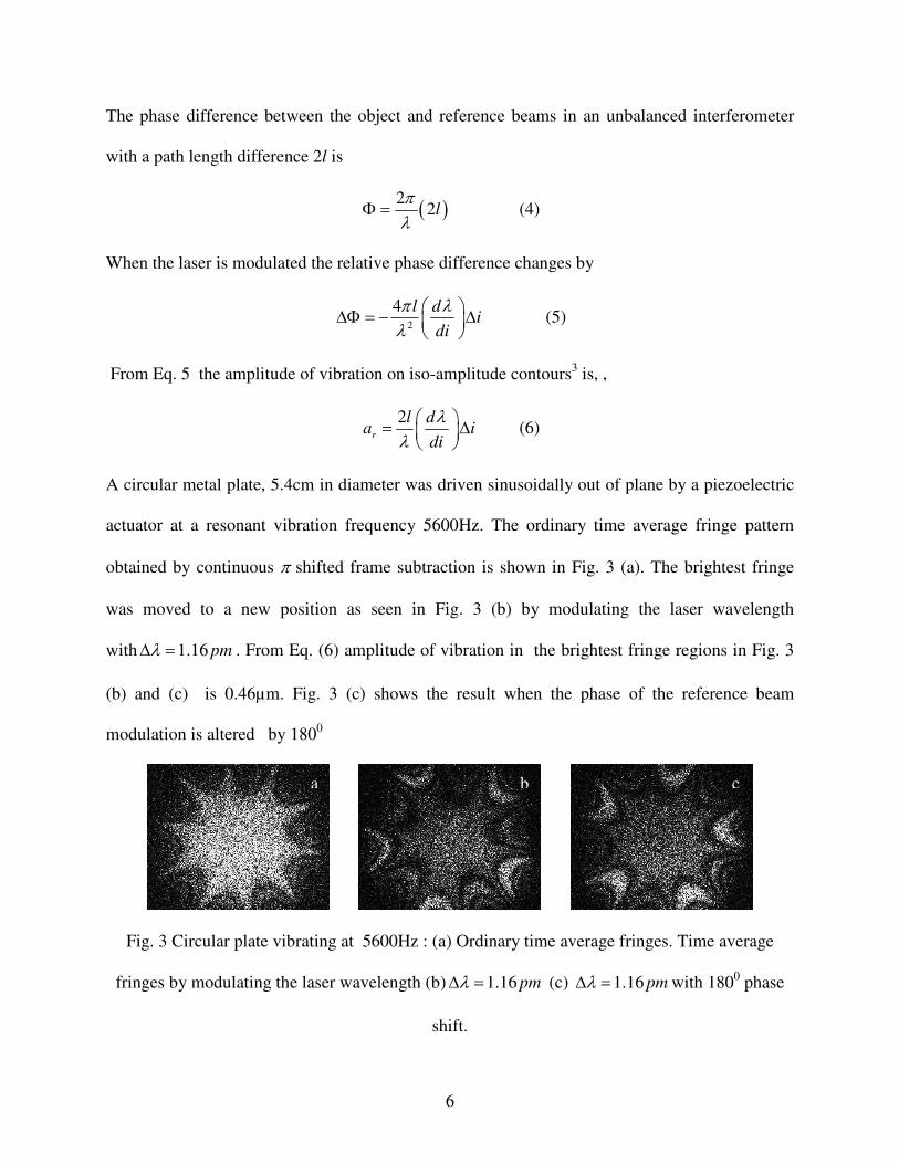
A circular metal plate, 5.4cm in diameter was driven sinusoidally out of plane by a piezoelectric
actuator at a resonant vibration frequency 5600Hz. The ordinary time average fringe pattern
obtained by continuous π shifted frame subtraction is shown in Fig. 3 (a). The brightest fringe
was moved to a new position as seen in Fig. 3 (b) by modulating the laser wavelength
with 1.16 pmλ∆ = . From Eq. (6) amplitude of vibration in the brightest fringe regions in Fig. 3
(b) and (c) is 0.46µm. Fig. 3 (c) shows the result when the phase of the reference beam
modulation is altered by 1800
Fig. 3 Circular plate vibrating at 5600Hz : (a) Ordinary time average fringes. Time average
fringes by modulating the laser wavelength (b) 1.16 pmλ∆ = (c) 1.16 pmλ∆ = with 1800 phase
shift.
a b c

7
In conclusion a simple ESPI system using holographic optical elements to obtain vibrational
amplitude and phase measurements was implemented. Use of HOEs reduces the number of
optical elements drastically, leading to a compact ESPI system providing correlation fringes of
good contrast.These ESPI systems can facilitate optical non-destructive testing at low cost for
industrial use.
The authors would like to acknowledge Irish Technological Research Sector STRAND I and
Enterprise Ireland Commercialisation Fund for financial support. We thank the School of
Physics at the Dublin Institute of Technology. for laboratory facilities
References
1. C. Joenathan, Appl. Opt. 30, 4658 (1991)
2. F. M. Santoyo, M. C. Shellabear and J. R. Tyrer, Appl. Opt. 30, 717 (1991)
3. H. Atcha and R. P. Tatam, Meas. Sci. Technol. 5, 704 (1994)
4. A. Olszak, K. Patorski, Opt. Comms., 138, 265 (1997)
5. V. Petrov and B. Lau, Opt. Eng. 35, 2363 (1996)
6. M.P. Whelan, C. Forno, Proceedings of Interferometry '99, SPIE Vol. 3144, September
(1999).
7. Toal V., Whelan W., Connelly M., Martin S., Reddy G. T. S. patent WO2009/044387 A2
(2009)
8. V Bavigadda, V Toal, R. Jallapuram and E. Mihaylova, Proc. SPIE, 7389 (2009)
9. S. R. Guntaka, V. Sainov, V.Toal, S. Martin, T. Petrova and J. Harizanova, J. Opt. A: Pure
Appl. Opt. 8, 182 (2006)

8
10. O. J. Lokberg and K. Hogmoen, J. Phys. E: Sci. Instr. 9, 847 (1976)
11. O. J. Lokberg and K.Hogmoen, Appl. Opt. 15, 2701 (1976)
12. S. R Guntaka, V. Toal and S. Martin, Appl. Opt. Appl. Opt. 41, 7475 (2002)
13. P. K. Rastogi, Editor, Digital speckle pattern interferometry and related techniques, pp. 231,
John Wiley and Sons Ltd. (2001)
14. http://www.geola.lt/lt/holography_materials/chemistry/
15. http://www.optics.bas.bg/index.php?lang=en&page=11


