Embed Size (px)
Citation preview
Speckle Reduction Using Multiple Tones of Illumination
Nicholas George and Atul Jain
The occurrence and smoothing of speckle are studied as a function of the line width for a highly collimat-ed illuminating source. A general theory is presented for speckling in the image of a partially diffuse,phase type of object, which has a variable number of random scattering centers per resolution element.Then, an expression is derived for the wavelength spacing required to decouple the speckle patternsarising from two monochromatic tones in an imaging system, thereby establishing that it is feasible tosmooth speckle using multicolor illumination. This theory is verified in a series of experiments using bothlaser illumination and band-limited light from a carbon arc. With highly collimated sources, we showthat speckle appears laserlike for an imaged diffuser even up to line widths of 5 A. Then, smoothing of
speckle is demonstrated in the imaging of a diffuser and for a section of an optic nerve when the illuminationis provided by six narrow lines spread over 1500 A. Since with color-blind, panchromatic viewing thespeckle smooths, a direct extension of this method to holographic microscopy, using a multitone laser,should permit one to record and reconstruct holograms of diffraction-limited resolution that are essentiallyspeckle-free.
IntroductionUnder monochromatic illumination, objects with a
scale of roughness grossly on the order of the wave-length are hard to discern in feature detail, owing tothe rapid spatial variations that occur in the scat-tered radiation. This characteristic of laser illumi-nation to speckle has been studied by many investi-gators; however, owing to space limitations, we citeonly a few of the publications.'- 2 2 It is difficult toquote a specific numerical value for this resolutionloss since it varies widely with the roughness of theobject being studied. However, in the application oflaser holography to microscopy, this speckle effecthas been a severe obstacle,10"12"17 20 limiting theworking resolution to from a few to several times theclassical optics limit. As examples, Young et al. re-port that "the usual resolution criterion should bedivided by five or more whenever diffused laser lightis used"'12 ; Close reports resolutions of a few micronson test samples17; and Cox et al. have obtained simi-lar resolutions with biological specimens.10
Gabor14 has classified speckle into two categories:The objective speckle that arises owing to uneven il-lumination falling on the subject. The subjectivespeckle that arises from the roughness of the subjectin conjunction with the convolving effect of a finiteaperture. The objective type can occur when oneholographically records a smooth transparency but
The authors are with the California Institute of Technology,
Pasadena, California 91109.Received 25 September 1972.
with a diffuser placed in the beam illuminating thetransparency. While the diffuser creates a helpfulredundancy in the recording, it also leads to the del-eterious speckle. Most prior studies of speckle elim-ination have considered only this objective type, andgood results have been reported, although thesubject is far from closed.5-9,14' 22
In this paper we consider the smoothing of subjec-tive speckle. This is a somewhat neglected topic,since it has been generally argued that the only ef-fective means for smoothing this type is to increasethe aperture.' 4 However, if one draws this conclu-sion, it is implicitly assumed that operation is at asingle wavelength or that separate, independentlooks are not being made in the over-all process. Inthe method we are to describe, separate wavelengthsare used to provide independent looks.20 '21 In thisway, we will show that one can smooth subjectivespeckle at a fixed value of aperture. Probably, too, amethod that smooths subjective speckle also smoothsthe objective type (but not conversely). Hence, inthis instance, the need for making the distinction isnot great.
An analysis for the wavelength variation of specklein an imaging system has not been found in the lit-erature; however, Goodman has treated the relatedproblem of the wavelength sensitivity of speckle inthe far-field region of a coherently illuminated groupof scatterers.2 Recent experiments have been re-ported in confirmation of the thesis that speckle pat-terns vary spatially in a marked way with change inwavelength.' 9-2 '
We feel that an interesting possibility for dramati-
1202 APPLIED OPTICS / Vol. 12, No. 6 / June 1973
cally reducing the speckle effect in holographicmicroscopy is to use a multicolor recording processwith several widely spaced laser tones spanning thevisible optical region. The hologram-volume effectspermit one to record and play back these images in anoninteracting way, provided that adequate spatialseparation and wavelength intervals have been cho-sen between each reference beam.23 In viewing, thesame multitone spectra are used for the referencebeams so that no spatial distortions occur, but acolor-blind monitor with uniform response over thevisible spectrum must be provided, e.g., by a vidiconapparatus, in order to average the multitone speckle.
Within this context, we report the first study of thespatial variations of speckle in the imaging system ofa microscope as the wavelength of a monochromaticsource is scanned through the visible. First, we ana-lyze the imaging of a diffuser in which there is avariable number of random phase heights per resolu-tion cell. This is a good model for the objects ofpractical interest covering the smooth case, throughthe troublesome case where five to ten random scat-ters per resolution element are limiting the resolu-tion, and the case where the number of random con-tributors per resolution cell is very high. We showthat the multicolor speckle will decorrelate when
- X1 _ (Xo2/ 2wn 3ho){I[1 - e(Ph) 2 /[1
+ (N - 1)(pho)2e(Phof]11/2
where the n3 is the difference in the refractive indexof the air and the diffuse object, N is the number ofscatterers per resolution cell, and the heights hr ofthe scatterers have been assumed to have a normaldistribution with an expected value of zero and astandard deviation ho, p = -2irn3/Xo, and Xo = (Xi+ 2)/2. As an alternative interpretation, specklewill appear laserlike as a given line width increasesfrom the few hertz band up to a small fraction of theabove A2 - X1 (this fraction is typically a few ang-stroms). We note too that wavelength diversity mayalso prove useful in electron microscopy where themonoenergetic electrons typically have a monochro-maticity dX/ X < 10-5, where X is the de Broglie wave-
'length of the electron. This is easily small enough tocause speckle, however a further consideration ofspeckle in matter waves is beyond the scope of thispaper.
Analysis of Diffuser Imaging
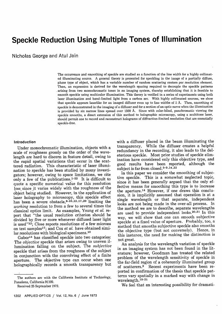
An imaging system for a microscope is idealized bya lens of focal length F and aperture D, an inputplane (Qn) at a distance s' = F + from the lens(Fig. 1), and thus with the image plane at a distances given by 1/s + 1/s' = 1/F. For monochromatic il-lumination, eiot, of an arbitrary object Do, we de-scribe the transverse scalar component of the inputelectric field by f(Q,n)eiwt. In the image plane, thiscorresponding field amplitude is found by two appli-cations of the usual Fresnel-zone approximation ofSommerfeld's formula2 4; i.e., the output field ampli-tude E(x,y)eiwt is given by
E(x, y) = -exp [-(i2r/1o)(s + s')]
XO2sS'
X ffff' dSddudvf(Q,i7)T(u,v)
X exp {-s[(u- )2 + ( - )2]
-A s [(x-u)2 + (y-v)2], (1)
in which (u, v) are Cartesian coordinates in the planeof the lens, X = 27rc/w, and c = 3 108 m/sec.The transmission function for the lens T(u,v) willbe taken with the spherical convergence factor exp[+(i7r/XoF)(u 2 + v2)] and a pupil function that isGaussian, i.e., it is given by
T(u, v) = exp[-(i/X,)(U2+ V2)/pI, (2a)
where
1/ p = -(1/F) - (i4Xo/IrD2), (2b)
and D is the diameter of the lens of focal length F.25
Substitution of Eq. (2) into Eq. (1) and integrationover the (u,v) plane, defining the magnification fac-tor M = s/s' and the up-scaled variables x' = -M(,y' = -M7a, give the result:
E(x, y) =
exp{-(i2w/X0)(M + 1)s' - (i/Xo)[(x2 + y2)/Ms']}X
2S'
2 M3
x 4 ffdx'dy'f (_M - )
exp{_ir, (xI 2 +2 )]2) [(D2x - x)2{XOS MI AXTs
+ (y - yl)2], Y(3)
In the basic imaging equation, Eq. (3), the con-volving effect of a finite aperture, D, is readily seen.As is well known, subjective speckle arises from thisaveraging or smearing of the input function f (-x'/M, -y'/M), i.e., for a finite aperture E(x,y) will notbe a perfectly resolved scaled replica of f (-x'/M,-y'/M). The departures here from the usual imag-
Fig. 1. Single lens magnification with object plane (tii) andimage plane (x,y).
June 1973 / Vol. 12, No. 6 / APPLIED OPTICS 1203
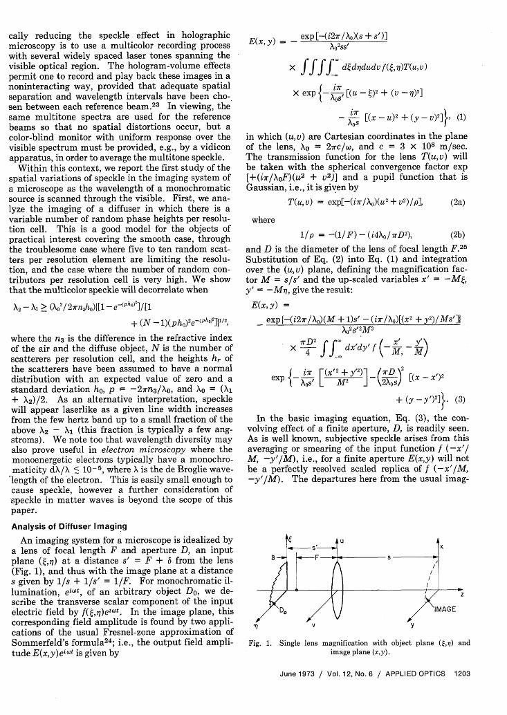
A semitransparent object of complex-valued am-plitude transmission factor Do(Q,7) is placed in theinput plane and illuminated by a mtonochromaticplane wave incident at the polar angle Oo in the (Q,,)plane (Fig. 2). Thus, the input amplitude functionf(Q,,) is given by
fQ,,) = Do(t,7)) exp[-i(27r/Xo)nof sinG0], (5)
where no and n1 are the relative indices of refractionin the two media and nosingo = nsinO,. For a gen-eral object consisting of an amplitude transmittance,denoted by real-valued function D1(,-q) and thephase delay 4(Q,77), we write
DQ,71) = D1(Q,7) exp[-0Q(t,n)1.] (6)
Fig. 2. The idealized diffuser object (Do) in the (,77) planeshowing a magnified inset between S1S2 for the computation ofthe transmission function, Eq. (10). The diffuser has steps of
width wr and random height hr.
ing formula are that phase terms have been retainedand the Gaussian transmission function of Eq. (2) isused. Hence, it is instructive to find the radius ofthe resolution cell for comparison to the conventionalcircular pupil function. By integration of Eq. (3)with a delta function impulse as input, i.e., f =5(x',y'), we find that the output spot size is given by
E(x, y) exp[-(rD/ 2XOS)2 (X
2+ y2)].
Thus, in the output plane (x,y), the intensity falls toa 1/e2 fraction of its peak at a radius of 0.637Xos/D.From this impulse interpretation, we define the radi-us of the resolution cell referenced to the (x,y) planeor the Q,-q) plane, respectively, as
Aw = (2XSs/ 7rD) or Awo = (2kts' /7rD). (4)
If we would have used the usual circ [(U2 +V2)1/2/(D/2)] as the pupil function portion of Eq.(2a), the resulting Airy disk would have the functionvalue [2J,(z)/z] 2 . This would result in a radius forthe 1/e2 power down locus of 0.82 Xos/D, which isclose enough for our purposes to the correspondingvalue of 0.637 Xos/D, obtained for a Gaussian pupilfunction.26
Model for the Phase-Type Diffuser
There have been various ways, in the past, of de-scribing the electric field transmitted by a roughobject. Hopkins and Tiziani,16 for instance, idealizethe diffuser as a series of closely packed lenslets ofvarying sizes and focal length. Enloe4 and Good-man,2 on the other hand, idealize the diffuser as arandomly spaced array of inifinitesimal radiators,each radiating with a random phase.
For the surface contour h(Q,7) of the diffuserbetween planes I and II spaced by Z0 + ZI inwe use a ray optics approximation to V/Qn).we write the phase delay
(shownFig. 2),
Thus,
4~,Qa) = (27rn/Xo)(Zo-h)/cos60
+ (2wrn,/A)(Z1 + h)/cosO,;
and suppressing the nonessential constant phase de-lays, we can rewrite Eq. (5) as follows:
f(t, 7) = D1(Q, i)
exp[-(i27r/Xo)not sin0o] exp [_ ir n3hQt, q) (7
in which n3 = (ni/cos~i - no/cos0o).Now, consider the simplified one-dimensional case
with a pure phase object, i.e., DI = 1, consisting ofrandomly positioned steps of height hr and width wrcentered at t = Or, i.e.,
h(x, y) = hr rect[(r)/w r].
Then, the one-dimensional idealization of Eq. (7) be-comes
fGQ) = exp[-(i2wr/ Xo)nt sin 0] exp d
n3E hr rect[( -r)/ Wr]} (8)
where the function rect(x) = 1 when Ix < I 2 and iszero otherwise. If nonoverlapping steps are assumedin the expression
£ hr rect (t - r)/Wrl
one can prove the following identity:
exp J-(i27r / A,)n 3 5 hr rect [( -r)/Wr]} = 1r
+ 5 rect [(Q - r)/ Wr1t exp[-(i27r/Xo)n 3hrl - 11.
Substituting this into Eq. (8) we obtain
1204 APPLIED OPTICS / Vol. 12, No. 6 / June 1973
Ez
nono I j
Do
() = exp[-i(2r/AO)n04 sinG0]
(1 + rect[(4- 4r)/ wr]{ exp[-i(27r/Xo)n 3hr] - }) (9)
Equation (9) for a pure phase type of diffusercould equally well have been postulated directly, asfollows. The multiplicative term exp[-i(27r/Xo)notsin 00], with the linear phase taper in (), occursfor a plane wave incident at an angle G0 , as shown inFig. 2. With nonoverlapping steps assumed in the
E rect [( w,]r)/r,
the term within the square brackets, [ , is either 1 orexp[-i(27r/Xo)n3hr]. This holds for an arbitraryvalue of , hence If() 1 as it must for a pure phaseobject.
We could adapt this transmitted field to fit a vari-ety of models for the diffuser. Thus we can considerthe height of a step given by hr(4) to be roughly con-stant over the width wr. On the other hand, if oneprefers the randomly positioned lenslets of Hopkinsand Tiziani, then hr becomes the quadratic phasetransmission for each lens, i.e., hr(4) = [( - r) 2/frl,where fr is the focal length of the lenslet centered at4r.
If we make the assumption that the width of eachrandom step is much less than the resolution cellsize, i.e., Wr < Awo, then insofar as integrations ofthe form of Eq. (3), we can replace the rect [( -4r)/wr] by the Dirac delta function, i.e., by wr6( -4r). Thus, combining Eqs. (8) and (9), we find aconvenient approximation for the one-dimensionalinput transmittance
f() = exp [-( i2r) not sin 0 ]
( + E Wr6 ( - r) {exP[-(i27r/)n 3hr1 }). (10)
To facilitate the consideration of our diffuser, wearbitrarily define the one-dimensional lens process,reducing Eq. (3), as follows:
El(x) = exp[-(iwno /Xo)(x2/Ms')] f) dx'f (M)
exp{ ino(x')2 [(X - X)]2}
Substitution of Eq. (10) into Eq. (11) and integrat-ing give
El(x) = Aw(wrj 2 exp[ bro (x 2o2x sin )
4rn02x2 sin2 0l + exp i7rnO 2\12M2 +\ L o (Ms'/J
X exp[ (X-Xr') + Mono (2Xr'sino (Xr ')jr . - (E °w) A M M2S'/
X Mwr [exp(-! inahr-l) -1] (12)
Now define the intensity or energy density factor byI(x) = EE,*, and from Eq. (12) we find
I(x) = 7r(Aw) 2e-2a + 2(7r)1/2Awe-' ZMWr
exp [ (Xw )] t cos(X - 0Ir + 02r)- COS(X - ¢r0A
+ 25 exp[-2(x - Xr')2 /(AW)2](MWr) 2{1 - cos02r)
+ 55 exp[ -(x-Xm')2/(AW)2 - (x -Xr') 2/(AW) 2 ]m r
X expE i(0lm - 0r)1]
X M2wmwr(e02m - 1)(e+i1t2r_-1), (13)
in which a = 4-x(nox sinG0 )2/(\OM)2,
X = (2r / XoXnox sing0 / M),
kir = (rnO / Xo2Xr sin0o / M - (Xr') 2/(M2S')}, and
¢k2r = (27r/IO)%3hr.
Equation (13) is a convenient starting point for thestatistical analysis of decorrelation based on combin-ing intensity patterns taken at separate wave-lengths.2' Equation (12) is the more useful startingpoint in the simpler amplitude decoupling criterionpresented in Eq. (21) of the following section.
Expected Value and Variance for the Electric FieldTo calculate the wavelength spacing required to
decouple the speckle pattern described by Eqs. (12)and (13), first we analyze the simpler case when o isconstant, e.g., when = 0. Later separate com-ment is included for the important case when a dis-tributed angular spectrum is used for the illumina-tion.
We assume the response of a panchromatic view-ing system is given by I = EEl* + E2 E2 * +when there are multiple tones of monochromatic il-lumination, i.e., beat terms are negligible with longexposure times. Hence, we must compare the intensi-ties in the image plane at two different wavelengthsand find when these two intensity patterns aredecorrelated. Since in computing EE,*, commonphase terms will cancel, we factor Eq. (12) extract-ing and suppressing the term exp (i7rno/Xo)[(2xsin00/M) - (x 2 /Ms')]1. The remainder of the electric fieldwe denote by E, and rewriting Eq. (12) gives
El(x) = Aw(w) 1/2 + E exp[_(xxr)
i7rn,(Xr' )2 ( _/ i27r foM2S' MWr {exp ( O n3h) - 1- (14)
Additionally, comparing Eqs. (12) and (14), one willnote that we have dropped the quadratic multiplierexp[-4rno 2x 2 sin0o/(X0
2 M2 )] from the first term inEq. (14); and the small phase term expi(i7rno/AO) [2(xr' - x)sindo/M]I from the summation.
June 1973 / Vol. 12, No. 6 / APPUED OPTICS 1205
To study the speckle in the image plane, we con-sider an arbitrary position x. In Eq. (14), the rapidfalloff of the Gaussian term, exp {-[(x - X,')1AWj2},limits the number of scatterers from among the en-tire set xr' that contribute effectively to El at x.Thus, if there are N scatterers remaining from thisset that are positioned (in image plane coordinates)with values of xr' in the range x - Aw < Xr' < +Aw, then we can approximate Eq. (14) by
N
El(x)= A - BN + B E exp(+iphr). (15)r=1
We have defined A = AW(T)l/2,
B = Mw, exp[-(irnOx2)/(XOM 2s')] and p as
p = -(2wn 3 / o). (16)
To simplify the analysis, we assume that the stepwidths wr are constant for all scatterers and equal tow,. Also, with negligible error, the Gaussian per-mits us to approximate the phase term exp-[i-rno(xr') 2/XoM 2s'] in Eq. (14) by the term exp- [i7rnox2 /XoM 2 s'] in Eq. (15).
If we assume that the real random variable hr isdistributed according to some known density func-tion, f(hr), and the corresponding characteristicfunction for this distribution is given by F(p) =f exp(+iph) f(h)dh, then we also obtain the fol-lowing results for the expectation and variance ofeiPh (Ref. 27):
(eiPl) = F(p), (17)
U2(eiPh) = 1- F(p)F*(p). (18)
If we also assume that the random variables hrrepresented by different scattering points are inde-pendent, then we can calculate the expected yalueand variance of our amplitude defined by Eq. (15).Thus, we obtain the following expression for the ex-pected value of the electric field at a point in theimage plane
(E1(x)) = A - NB + BNF(p). (19)
Also, the variance in this electric field, defined byU2[El(x)] = ((E, - (El)) (El - (El))*), is readilycomputed by substitution of Eq (15) into this formand simplification using Eqs. (17)-(19). The result-ing expression for the variance in the electrical fieldis
a2[E,(x)] = N(1 - FF*)BB*, (20)
where BB* = (Mw,) 2 and the characteristic functionF is given by Eq. (17).
Wavelength Spacing for Speckle Decorrelation
We note that our expected value is some complexnumber, while the variance is a real number since it
is defined by 2 = (E, - (El)12 ). Thus, Eq. (20).gives us the square of the radius of a circle centeredaround the expected value within which roughly halfof our values of E, lie. The intensity at some fixed:point x can thus be considered to have changed sig-nificantly when the magnitude of the change inEl(x) with wavelength is of the order of the standarddeviation. Thus, we adopt the criterion that thespeckle is decoupled when the wavelength changecauses the average of the magnitude squared changein EI(x) to be equal to the variance for a particularwavelength Xo, i.e., decorrelation occurs whenever
(AE,(x)AE,(x)*) > 2[E(X )]. (21)
The change in the electric field E(x) with wave-length interval AX is given by
AEl(x) = [El(x)/aX]AX.
Thus differentiating Eq. (15) with respect to andnoting that dp/dX = (+27rn3/X 2o), we obtain
N h2
Wfl
AE,(x) = (-ABN + B ihreiPh, r2
+ AR E e iPhr) AX, (22)
where
AB = i7rnox2Mw, /( Xo2M 2s') exp[i7rnox2/( XM 2s')1.
We now consider the speckle near the axis, i.e.,when AB is negligible (worst case). In this case Eq.(22) reduces to
N 2wn,AE,(x) = B E ihr A 23 eiPhr AX. (23)
If we now compute (El(x)AE,(x)*), we obtain thefollowing result, assuming that the expected value ofhr is zero and that the standard deviation is ho,
(AEj(x)AE,(x)*) = (2rn3AX/X 2 )'Iho2N
+ (N 2 - N)[(d/dp)F(p)XT(ddp)F(p)]*IBB*. (24)
Substituting Eqs. (20) and (24) into the criterion,Eq. (21), we obtain a value for the wavelength spac-ing X2 - Xl required to decorrelate the speckle:
A2 - A1
_ Ao 4 1-F(p)F*(p) lV2
2wn3 ho2 + (N - 1)[(d/dp)F(p)][(d/dp)F(p)]* I
.[decoupled case]. (25)
The speckle pattern will therefore be laserlikewhen the spectral line width of a single tone is muchless than is given by Eq. (25), i.e., when the linewidth AX is given by
1206 APPLIED OPTICS / Vol. 12, No. 6 / June 1973
10A < 0 (X2 - X1).
< X { 1 - F(p)F*(p) 2207rn3 h 2 + (N- 1)[(dldp)F(p)][(d/dp)F(p)]*
[laserlike case]. (26)
To illustrate the above results with an example,assume that the heights of the scatterers are distrib-uted normally, where our expected value and stan-dard deviation for the heights have already been takento be zero and ho, respectively. Thus, we write thedensity function for hr as
f(hr) = exp[-hr2 /(2h02 )]/ho(27r)112 (27a)
and the corresponding characteristic function as
F(p) = exp(-'/ 2p2h 02). (27b)
Substituting Eq. (27) into Eq. (25) we obtain thewavelength spacing required to decorrelate the spec-kle pattern as
X2 -~, = X,2 [ I- eplhh2 %/A2 - =2wn~h 1 (N-1)(h p)2e-'!ho2]* (28)
We note that for the case of a very rough diffuser,where (pho) is greater than 1, Eq. (28) can beapproximated by
-A -\1 0 /(27rn3h 0 ), when (pho)' » 1. (29)
In the case of a relatively smooth diffuser, Eq. (28)can be reduced to
- ' =I[1 + (N- 1)(pho)'j'' ,when (ph0 )2 < 1. (30)
Now assuming monochromatic illumination, westudy the condition under which we can expect aparticular diffuser to give a large amount of speckle.If we take the ratio of the standard deviation to theamplitude of the expected value, i.e., by Eqs. (19)and (20), we obtain the average fractional change inamplitude among different resolution cells of width2Aw. When this ratio is very small, we have thecase when most cells have the same intensity; andthere is practically no speckle. In the case wherethis ratio approaches 1, we have a badly speckledcase. Thus, for the normal distribution, as definedby Eq. (27), this ratio is given by
R (N)12(1 -e-Plho)1/2B1 (31)A - NB + NBe-Pho/ 2 (3
By Eq. (31), we note that R goes to zero, i.e., nospeckle, when the roughness as characterized by phodecreases. Alternatively, taking A to be of the sameorder of magnitude as NB, we note that the ratio Ris proportional to 1/(N)1/2. Thus, the badly speck-led case occurs with small numbers of scatterers per
resolution element. And as N gets very large, sayexceeding 100, the amount of speckle is drasticallyreduced.
If we assume operation at a single wavelength, it isstill possible to obtain averaging of speckle by super-imposing image intensities formed when the diffuseris illuminated successively by plane waves at differ-ent angles of incidence. We can calculate the angu-lar difference AG0 between successive plane waves in-cident at angles O1 and 002 , which will decouplethese respective image intensities. Since we areconsidering the sequential recording of intensities,the phase term containing 0, which was suppressedin writing Eq. (14), still does not enter: and Eqs.(15) and (16) form a convenient starting point.From n3 = (n,/cosG - no/cos0o) and nsinGi =nosinG0, we compute the angular variation of n3 :
dn3/dG0 = (1/2)(no2/nXsin2Go /cosG10)
-(nosinO/cos2G0). (32)
The variation of p, at fixed wavelength, is found bydifferentiation of Eq. (16), i.e.,
dp/do = (-27r/ko)(dn3/ddO). (33)
Following the same mathematical procedure as wedid in deriving Eq. (25) except that now AE,(x) =[dEi(x)/aOo]Ao, one can readily show that the an-gular spacing A0 = 002 - 0 , is given by
AG0/~~~~ F(p)F*(p) /2
= (o {h0 2 + (N - )[(d/dp)F(p)][(d/ dp)F(p)]* T)
{rno[2sinSo / cos2'0 - nsin200/(ncosS30)]I- (34)
For the case when the heights are distributed nor-mally, by substitution of Eq. (27) into (34), we findthe angular separation required to decouple thespeckle patterns reduces to
AGO = (Xo(1-e-p2 ho2 )/[ + (N - 1)(hop)2e~P2 ho2
]}1/2)/
Fn h f2sin0o nosin200y] (35)[rn0h 0 0 nICOS301G, 35We will use Eq. (35) in the following section to es-tablish a numerical value for the degree of collima-tion required to assure that our speckle averaging isdue to wavelength variation and not to multiangularilluminating beams.
Experiments with Laser SourcesThree different experiments were conducted using
a laser. In the first, a single mode argon laser wasused to illuminate a ground glass diffuser and thespeckle positions were charted as the wavelength wasset to the various principal lines (4579 A, 4727 A,4765 A, 4880 A, 4965 A, 5017 A, and 5145 A). Inthis experiment, the statistical problem is differentin the details from the analysis presented herein
June 1973 / Vol. 12, No. 6 / APPLIED OPTICS 1207
(e.g., see Goodman's treatment2 ) in that the numberof scatterers that contribute at each point in the out-put plane is essentially that of the entire illuminateddiffuser; and this is usually a very large number.Since, in this experiment, the diffuser is not beingimaged, one should not be thinking in terms of thenumber of scatterers per resolution cell, i.e., the N ofthe previous section. Nevertheless, speckle reposi-tioning is readily seen; the bright spots in the imagevary quite noticeably for the wavelength shifts of 100A or so.
In this first experiment it is also interesting tovary the size of that portion of the diffuser that isbeing illuminated. The equation for the speckle sizein the nonimaged case indicates a speckle size in-versely proportional to the entire object dimension.' 6
Thus, one can greatly enlarge the mean speckle sizeby placing a small aperture at the diffuser. It is anexperimental convenience to work with these largerspeckles. An effective nonmechanical means forproviding this variable aperture is to pass the colli-mated output of the laser directly through a micro-scope objective. Then, of course, the spot size of theexit beam converges to a small diameter in the rearfocal plane of the objective, and thereafter it rapidlyexpands. The diffuser is placed in this exit beam;axial translation of the diffuser in this region nearand beyond the rear focal plane provides a handymethod for varying the effective aperture over a widerange. The diffuser is fixed at a specific position thatgives large, easily monitored speckles on a screen at1-2-m distance; and then the wavelength is varied.Again, no imaging is involved; and the speckle posi-tions are readily charted by directly exposing a pieceof sheet film placed at the screen. While specklerepositioning is definitely observed at the differentwavelengths, we were not satisfied that we had theamount of control necessary to corroborate the theo-ry, e.g., the wavelength spacing and total intervalavailable were limited.
A more persuasive experimental observation ofspeckle averaging with multiple tones of monochro-matic illumination was obtained in the following sec-ond experiment using an argon laser source. Theprism line selector, not the single mode etalon, is re-moved so that oscillation is obtained simultaneouslyon several of the transitions listed in the precedingparagraph. The speckle averages pretty well forthese wavelength spacings; photographing an objectilluminated first by a single tone and then by themultitone clearly shows this effect. In this imagingexperiment, the aperture of the camera is used tocontrol the amount of subjective speckle that is in-troduced by the camera lens.
Unfortunately, the spread of wavelengths and thesingle collimated beam of the argon laser are not ad-equate for the recording and reconstruction of spec-kle-free holograms as a simple, single exposure pro-cess. Both spatial and spectral separation of themultitone reference beams are probably going to berequired.2 3
A third experiment was performed using a singlemode helium-neon laser at 6328 A. This laser iscontinuously tunable over the Doppler-broadenedtransition (about 1200 MHz) by a piezoelectric con-trol of the cavity length. Using the 3-M Company'sMagic Transparent Tape as a standard diffuser,since it is both readily available and reproducible,we carefully measured bright spot positons in specklepatterns as the wavelength was scanned over 1200MHz. By this experiment, we concluded that themotion is below the threshold of detection for suchsmall shifts in frequency. This null result is inagreement with the prediction of our theory, e.g.,Eq. (26). Care was taken to control the angulardrift of the laser beam in all of these experiments[see Go in Eq. (12)]. This is particularly importantfor the argon laser since the wavelength selectionconsists of angularly positioning a prism in the cavi-ty. Both this and the large temperature changesduring warmup cause easily measurable drifts in Go.For our experiments, angular control is obtained bypassing the laser beam through two high-quality mi-croscope objectives separated by twice their focallength (20 mm) with a 5-gm diam pinhole located attheir common focus. The output beam from thisunity beam expander-spatial filter device is used asthe source. Thus, the angular deviation in Go ismaintained at some small portion of 2 X 10⁻⁴ rad.
Multicolor Speckle Experiments
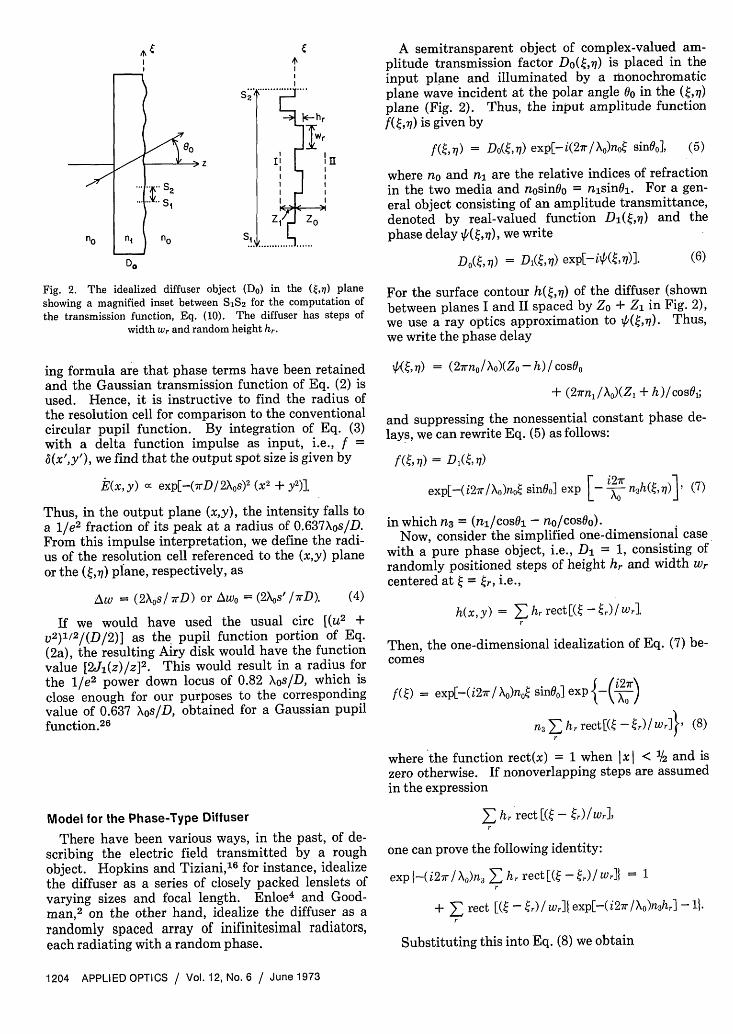
A series of experiments was also performed usingboth the Scotch Magic Tape diffuser and a biologicalspecimen as objects with band-limited light beingused to simulate a continuously tunable laser (seeFig. 3). A carbon arc or high-pressure mercury arc
VA---
I s I
I xIIRSOES____
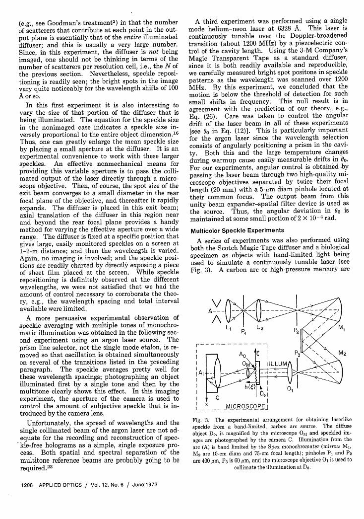
Fig. 3. The experimental arrangement for obtaining laserlikespeckle from a band-limited, carbon arc source. The diffuseobject Do, is magnified by the microscope OM and speckled im-ages are photographed by the camera C. Illumination from thearc (A) is band limited by the Spex monochromater (mirrors MI,M2 are 10-cm diam and 75-cm focal length); pinholes PI and P2are 400 jm, P3 is 60 gm, and the microscope objective O1 is used to
collimate the illumination at Do.
1208 APPLIED OPTICS / Vol. 12, No. 6 / June 1973
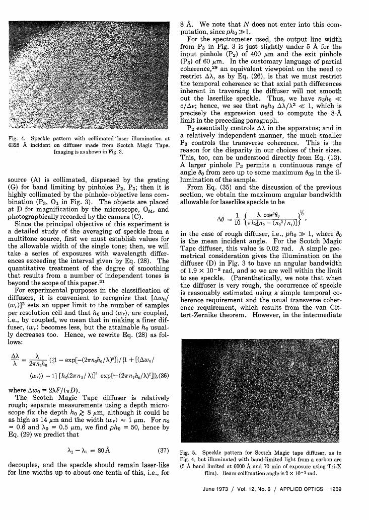
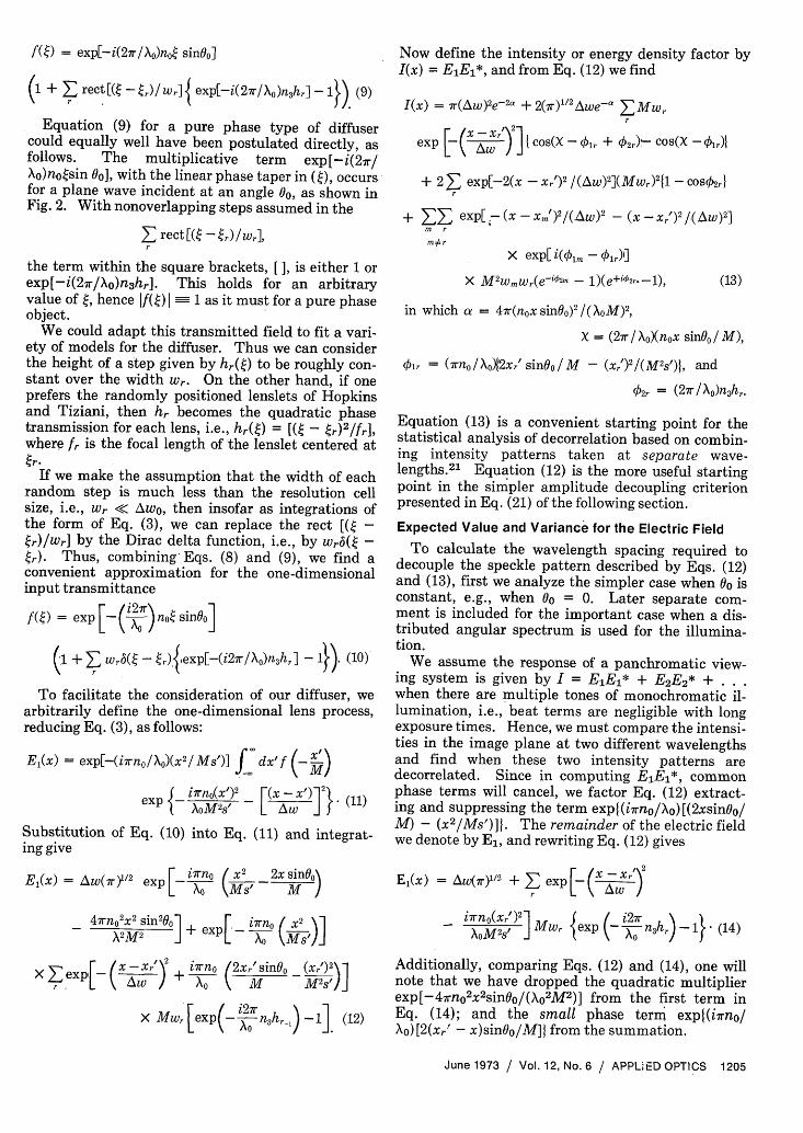
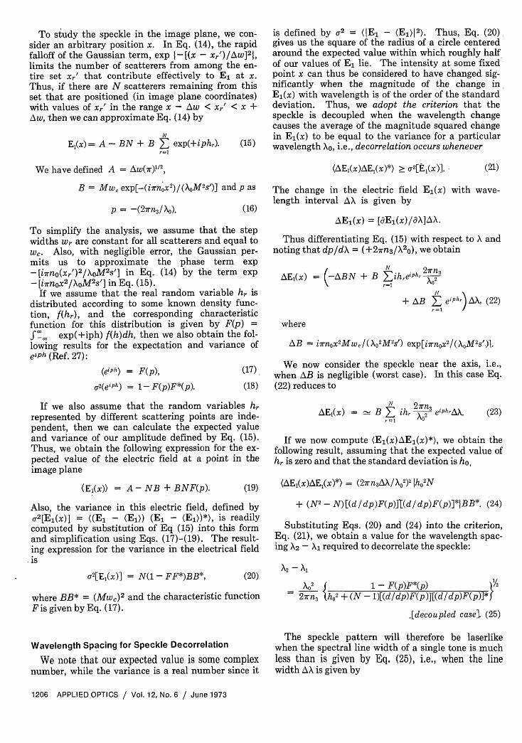
Fig. 4. Speckle pattern with collimated-laser illumination at6328 A incident on diffuser made from Scotch Magic Tape.
Imaging is as shown in Fig. 3.
source (A) is collimated, dispersed by the grating(G) for band limiting by pinholes P 2, P 3; then it ishighly collimated by the pinhole-objective lens com-bination (P3, 01 in Fig. 3). The objects are placedat D for magnification by the microscope, OM, andphotographically recorded by the camera (C).
Since the principal objective of this experiment isa detailed study of the averaging of speckle from amultitone source, first we must establish values forthe allowable width of the single tone; then, we willtake a series of exposures with wavelength differ-ences exceeding the interval given by Eq. (28). Thequantitative treatment of the degree of smoothingthat results from a number of independent tones isbeyond the scope of this paper.21
For experimental purposes in the classification ofdiffusers, it is convenient to recognize that [Awo/(W,)] 2 sets an upper limit to the number of samplesper resolution cell and that ho and (r), are coupled,i.e., by coupled, we mean that in making a finer dif-fuser, (wr) becomes less, but the attainable ho usual-ly decreases too. Hence, we rewrite Eq. (28) as fol-lows:
AX= 2wnh, (11 - exp[-(27rn3ho/X)2]} / {1 + [(Aw 0 /
(wr)) - 1] [ho(2rn,/ X)]2 exp[-(2wrn3h0/X)2]1), (36)
where Awo = 2XF/(rD).The Scotch Magic Tape diffuser is relatively
rough; separate measurements using a depth micro-scope fix the depth ho > 8 gm, although it could beas high as 14 gm and the width (wr) 1 gim. For n3= 0.6 and 0 = 0.5 gm, we find pho = 50, hence byEq. (29) we predict that
X,-X = 8oA (37)
decouples, and the speckle should remain laser-likefor line widths up to about one tenth of this, i.e., for
8 A. We note that N does not enter into this com-putation, since pho >>1.
For the spectrometer used, the output line widthfrom P 3 in Fig. 3 is just slightly under 5 A for theinput pinhole (P2) of 400 m and the exit pinhole(P3) of 60 gim. In the customary language of partialcoherence,29 an equivalent viewpoint on the need torestrict AX, as by Eq. (26), is that we must restrictthe temporal coherence so that axial path differencesinherent in traversing the diffuser will not smoothout the laserlike speckle. Thus, we have n3ho <c/Ay; hence, we see that n3ho AX/X 2 < 1, which isprecisely the expression used to compute the 8-Alimit in the preceding paragraph.
P 2 essentially controls AX in the apparatus; and ina relatively independent manner, the much smallerP 3 controls the transverse coherence. This is thereason for the disparity in our choices of their sizes.This, too, can be understood directly from Eq. (13).A larger pinhole P 3 permits a continuous range ofangle 00 from zero up to some maximum 002 in the il-lumination of the sample.
From Eq. (35) and the discussion of the previoussection, we obtain the maximum angular bandwidthallowable for laserlike speckle to be
1 A Co~;200 /AG = 10 rh[no-(no2/n)]
in the case of rough diffuser, i.e., pho >> 1, where 00is the mean incident angle. For the Scotch MagicTape diffuser, this value is 0.02 rad. A simple geo-metrical consideration gives the illumination on thediffuser (D) in Fig. 3 to have an angular bandwidthof 1.9 x 10⁻³ rad, and so we are well within the limitto see speckle. (Parenthetically, we note that whenthe diffuser is very rough, the occurrence of speckleis reasonably estimated using a simple temporal co-herence requirement and the usual transverse coher-ence requirement, which results from the van Cit-tert-Zernike theorem. However, in the intermediate
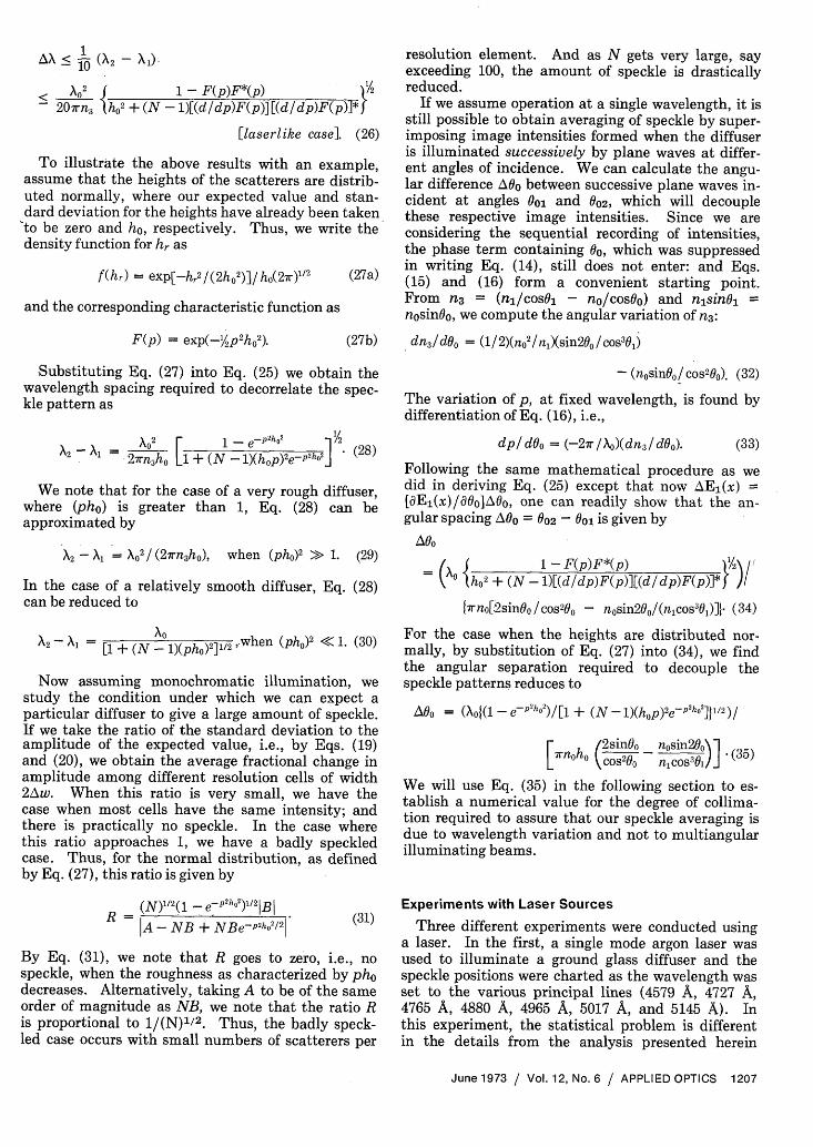
Fig. 5. Speckle pattern for Scotch Magic tape diffuser, as inFig. 4, but illuminated with band-limited light from a carbon arc(5 A band limited at 6000 A and 70 min of exposure using Tri-X
film). Beam collimation angle is 2 x 10⁻³ rad.
June 1973 / Vol. 12, No. 6 / APPLIED OPTICS 1209
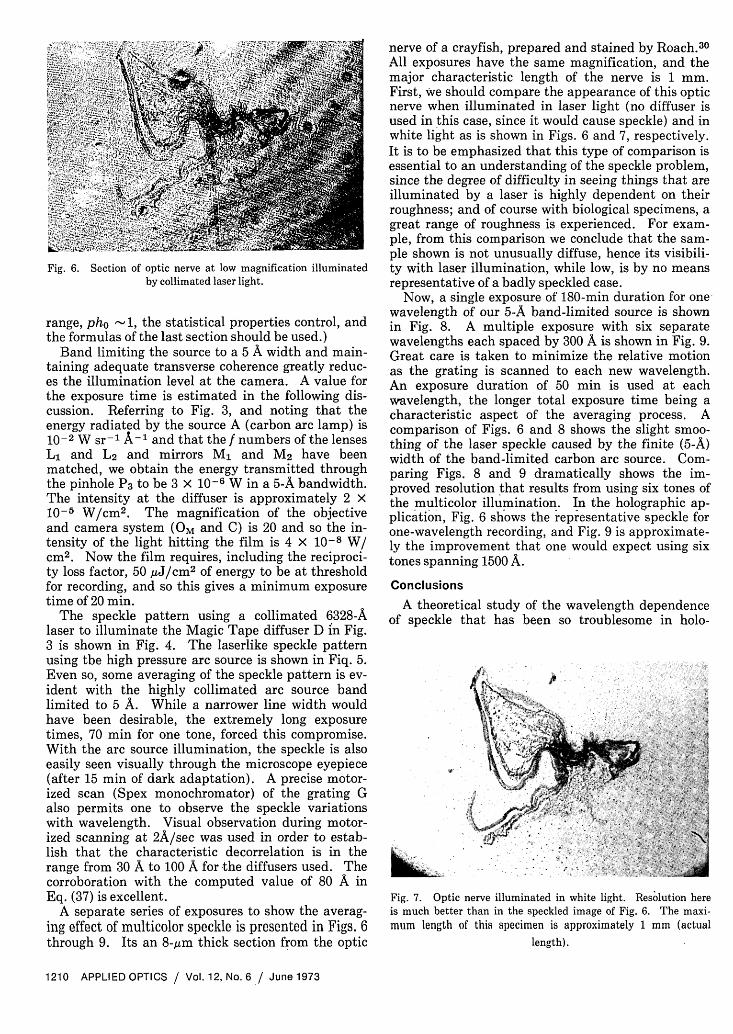
Fig. 6. Section of optic nerve at low magnification illuminatedby collimated laser light.
range, pho 1, the statistical properties control, andthe formulas of the last section should be used.)
Band limiting the source to a 5 A width and main-taining adequate transverse coherence greatly reduc-es the illumination level at the camera. A value forthe exposure time is estimated in the following dis-cussion. Referring to Fig. 3, and noting that theenergy radiated by the source A (carbon arc lamp) is10-2 W sr-1 A-1 and that the f numbers of the lensesL1 and L2 and mirrors M1 and M2 have beenmatched, we obtain the energy transmitted throughthe pinhole P3 to be 3 X 10⁻⁶ W in a 5-A bandwidth.The intensity at the diffuser is approximately 2 10-5 W/cm 2 . The magnification of the objectiveand camera system (OM and C) is 20 and so the in-tensity of the light hitting the film is 4 10-8 W/cm2. Now the film requires, including the reciproci-ty loss factor, 50 ,j/cm 2 of energy to be at thresholdfor recording, and so this gives a minimum exposuretime of 20 min.
The speckle pattern using a collimated 6328-Alaser to illuminate the Magic Tape diffuser D in Fig.3 is shown in Fig. 4. The laserlike speckle patternusing tbe high pressure arc source is shown in Fiq. 5.Even so, some averaging of the speckle pattern is ev-ident with the highly collimated arc source bandlimited to 5 A. While a narrower line width wouldhave been desirable, the extremely long exposuretimes, 70 min for one tone, forced this compromise.With the arc source illumination, the speckle is alsoeasily seen visually through the microscope eyepiece(after 15 min of dark adaptation). A precise motor-ized scan (Spex monochromator) of the grating Galso permits one to observe the speckle variationswith wavelength. Visual observation during motor-ized scanning at 2A/sec was used in order to estab-lish that the characteristic decorrelation is in therange from 30 A to 100 A for the diffusers used. Thecorroboration with the computed value of 80 A inEq. (37) is excellent.
A separate series of exposures to show the averag-ing effect of multicolor speckle is presented in Figs. 6through 9. Its an 8-,gm thick section from the optic
nerve of a crayfish, prepared and stained by Roach.30
All exposures have the same magnification, and themajor characteristic length of the nerve is 1 mm.First, we should compare the appearance of this opticnerve when illuminated in laser light (no diffuser isused in this case, since it would cause speckle) and inwhite light as is shown in Figs. 6 and 7, respectively.It is to be emphasized that this type of comparison isessential to an understanding of the speckle problem,since the degree of difficulty in seeing things that areilluminated by a laser is highly dependent on theirroughness; and of course with biological specimens, agreat range of roughness is experienced. For exam-ple, from this comparison we conclude that the sam-ple shown is not unusually diffuse, hence its visibili-ty with laser illumination, while low, is by no meansrepresentative of a badly speckled case.
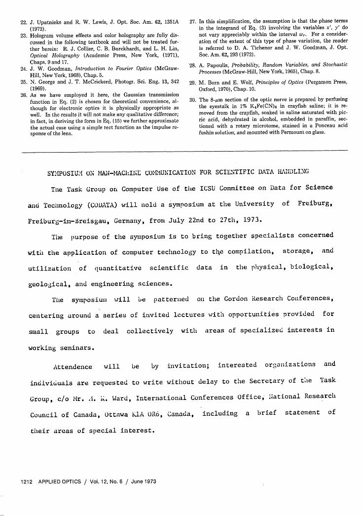
Now, a single exposure of 180-min duration for onewavelength of our 5-A band-limited source is shownin Fig. 8. A multiple exposure with six separatewavelengths each spaced by 300 A is shown in Fig. 9.Great care is taken to minimize the relative motionas the grating is scanned to each new wavelength.An exposure duration of 50 min is used at eachwavelength, the longer total exposure time being acharacteristic aspect of the averaging process. Acomparison of Figs. 6 and 8 shows the slight smoo-thing of the laser speckle caused by the finite (5-A)width of the band-limited carbon arc source. Com-paring Figs. 8 and 9 dramatically shows the im-proved resolution that results from using six tones ofthe multicolor illumination. In the holographic ap-plication, Fig. 6 shows the representative speckle forone-wavelength recording, and Fig. 9 is approximate-ly the improvement that one would expect using sixtones spanning 1500 A.
Conclusions
A theoretical study of the wavelength dependenceof speckle that has been so troublesome in holo-
NK
Fig. 7. Optic nerve illuminated in white light. Resolution hereis much better than in the speckled image of Fig. 6. The maxi-mum length of this specimen is approximately 1 mm (actual
length).
1210 APPLIED OPTICS / Vol. 12, No. 6 / June 1973
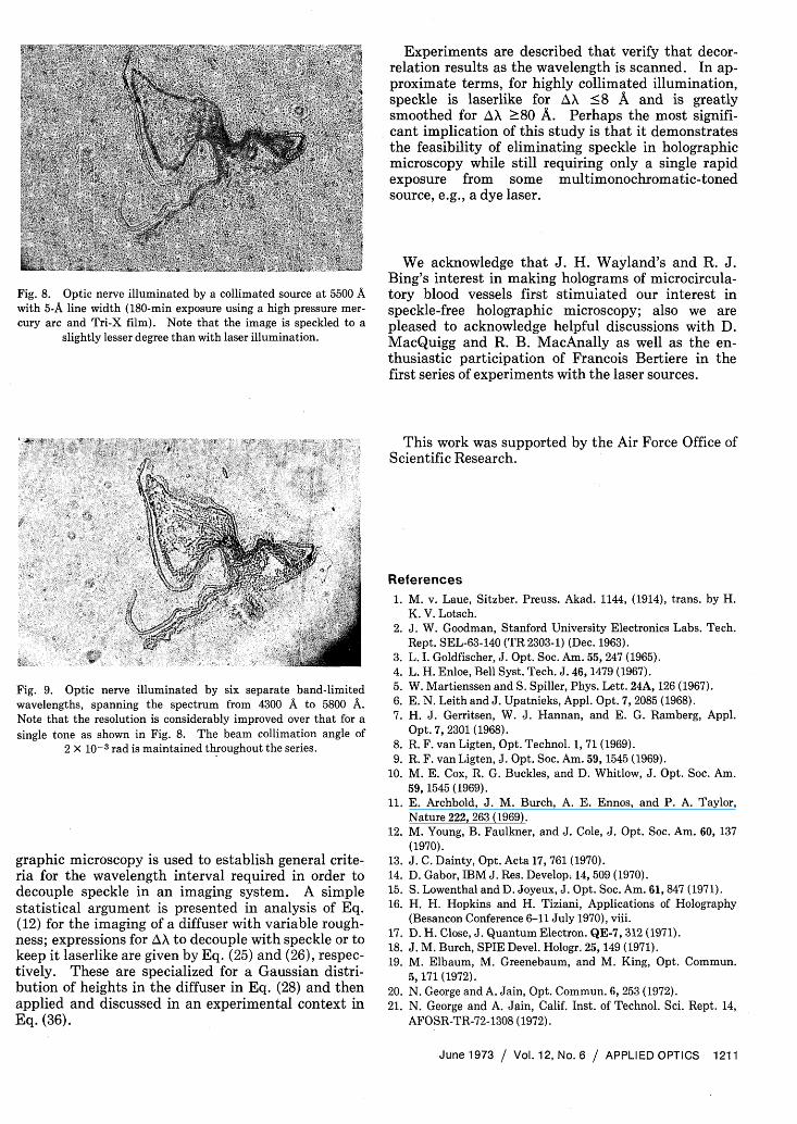
Fig. 8. Optic nerve illuminated by a collimated source at 5500 Awith 5-A line width (180-min exposure using a high pressure mer-cury arc and Tri-X film). Note that the image is speckled to a
slightly lesser degree than with laser illumination.
Fig. 9. Optic nerve illuminated by six separate band-limitedwavelengths, spanning the spectrum from 4300 A to 5800 A.Note that the resolution is considerably improved over that for asingle tone as shown in Fig. 8. The beam collimation angle of
2 x 10⁻³ rad is maintained throughout the series.
graphic microscopy is used to establish general crite-ria for the wavelength interval required in order todecouple speckle in an imaging system. A simplestatistical argument is presented in analysis of Eq.(12) for the imaging of a diffuser with variable rough-ness; expressions for AX to decouple with speckle or tokeep it laserlike are given by Eq. (25) and (26), respec-tively. These are specialized for a Gaussian distri-bution of heights in the diffuser in Eq. (28) and thenapplied and discussed in an experimental context inEq. (36).
Experiments are described that verify that decor-relation results as the wavelength is scanned. In ap-proximate terms, for highly collimated illumination,speckle is laserlike for AX <8 A and is greatlysmoothed for AX 80 A. Perhaps the most signifi-cant implication of this study is that it demonstratesthe feasibility of eliminating speckle in holographicmicroscopy while still requiring only a single rapidexposure from some multimonochromatic-tonedsource, e.g., a dye laser.
We acknowledge that J. H. Wayland's and R. J.Bing's interest in making holograms of microcircula-tory blood vessels first stimulated our interest inspeckle-free holographic microscopy; also we arepleased to acknowledge helpful discussions with D.MacQuigg and R. B. MacAnally as well as the en-thusiastic participation of Francois Bertiere in thefirst series of experiments with the laser sources.
This work was supported by the Air Force Office ofScientific Research.
References1. M. v. Laue, Sitzber. Preuss. Akad. 1144, (1914), trans. by H.
K. V. Lotsch.2. J. W. Goodman, Stanford University Electronics Labs. Tech.
Rept. SEL-63-140 (TR 2303-1) (Dec. 1963).3. L. I. Goldfischer, J. Opt. Soc. Am. 55, 247 (1965).4. L. H. Enloe, Bell Syst. Tech. J. 46, 1479 (1967).5. W. Martienssen and S. Spiller, Phys. Lett. 24A, 126 (1967).6. E. N. Leith and J. Upatnieks, Appl. Opt. 7, 2085 (1968).7. H. J. Gerritsen, W. J. Hannan, and E. G. Ramberg, Appl.
Opt. 7, 2301 (1968).8. R. F. van Ligten, Opt. Technol. 1, 71 (1969).9. R. F. van Ligten, J. Opt. Soc. Am. 59, 1545 (1969).
10. M. E. Cox, R. G. Buckles, and D. Whitlow, J. Opt. Soc. Am.59, 1545 (1969).
11. E. Archbold, J. M. Burch, A. E. Ennos, and P. A. Taylor,Nature 222, 263 (1969).
12. M. Young, B. Faulkner, and J. Cole, J. Opt. Soc. Am. 60, 137(1970).
13. J. C. Dainty, Opt. Acta 17, 761 (1970).14. D. Gabor, IBM J. Res. Develop; 14, 509 (1970).15. S. Lowenthal and D. Joyeux, J. Opt. Soc. Am. 61, 847 (1971).16. H. H. Hopkins and H. Tiziani, Applications of Holography
(Besancon Conference 6-11 July 1970), viii.17. D. H. Close, J. Quantum Electron. QE-7, 312 (1971).18. J. M. Burch, SPIE Devel. Hologr. 25, 149 (1971).19. M. Elbaum, M. Greenebaum, and M. King, Opt. Commun.
5, 171 (1972).20. N. George and A. Jain, Opt. Commun. 6, 253 (1972).21. N. George and A. Jain, Calif. Inst. of Technol. Sci. Rept. 14,
AFOSR-TR-72-1308 (1972).
June 1973 / Vol. 12, No. 6 / APPLIED OPTICS 1211
22. J. Upatnieks and R. W. Lewis, J. Opt. Soc. Am. 62, 1351A(1972).
23. Hologram volume effects and color holography are fully dis-cussed in the following textbook and will not be treated fur-ther herein: R. J. Collier, C. B. Burckhardt, and L. H. Lin,Optical Holography (Academic Press, New York, (1971),Chaps. 9 and 17.
24. J. W. Goodman, Introduction to Fourier Optics (McGraw-Hill, New York, 1968), Chap. 5.
25. N. George and J. T. McCrickerd, Photogr. Sci. Eng. 13, 342(1969).
26. As we have employed it here, the Gaussian transmissionfunction in Eq. (2) is chosen for theoretical convenience, al-though for electronic optics it is physically appropriate aswell. In the results it will not make any qualitative difference;in fact, in deriving the form in Eq. (15) we further approximatethe actual case using a simple rect function as the impulse re-sponse of the lens.
27. In this simplification, the assumption is that the phase termsin the integrand of Eq. (3) involving the variables x', y' donot vary appreciably within the interval wr. For a consider-ation of the extent of this type of phase variation, the readeris referred to D. A. Tichenor and J. W. Goodman, J. Opt.Soc. Am. 62, 293 (1972).
28. A. Papoulis, Probability, Random Variables, and Stochastic
Processes (McGraw-Hill, New York, 1965), Chap. 8.
29. M. Born and E. Wolf, Principles of Optics (Pergamon Press,Oxford, 1970), Chap. 10.
30. The 8-Mm section of the optic nerve is prepared by perfusingthe eyestalk in 1% K4Fe(CN)6 in crayfish saline; it is re-moved from the crayfish, soaked in saline saturated with pic-ric acid, dehydrated in alcohol, embedded in paraffin, sec-tioned with a rotary microtome, stained in a Ponceau acidfushin solution, and mounted with Permount on glass.
SYMPOSIUI ON MA4-1-MACINE COMMUNICATION FOR SCIENTIFIC DATA HINDLING'
The Task Group on Computer Use of the ISU Committee on Data for Science
and Technology (CODATA) will old a symposium at te University of Freiburg,
Freiburg-im-Breisgau, Germany, from July 22nd to 27th, 1973.
The purpose of the symposium is to bring together specialists concerned
with te application of computer technology to the compilation, storage, and
utilization of quantitative scientific data in the physical, biological,
geological, and engineering sciences.
The symposium will e patterlied on the Gordon Research Conferences,
centering around a series of invited lectures with opportunities provided for
small groups to deal collectively with areas of specialized interests in
working seminars.
Attendence will be by invitation; interested organizations and
individuals are requested to write without delay to the Secretary of tie Task
Group, c/o Mir. A. is. Ward, International Conferences Office, Inational Research
Council of Canada, Ottawa KlA OR6, Canada, including a brief statement of
their areas of special interest.
1212 APPLIED OPTICS / Vol. 12, No. 6 / June 1973


