Embed Size (px)
Citation preview
ENGINE
C
D
E
SECTION EC A
EC
ENGINE CONTROL SYSTEM
F
G
H
I
J
K
L
M
N
O
P
CONTENTS
MRA8DE
PRECAUTION ............................................... 9
PRECAUTIONS ................................................... 9Precaution for Supplemental Restraint System (SRS) "AIR BAG" and "SEAT BELT PRE-TEN-SIONER" ...................................................................9Precaution for Procedure without Cowl Top Cover ......9On Board Diagnostic (OBD) System of Engine and CVT ....................................................................9General Precautions ...............................................10
PREPARATION ...........................................13
PREPARATION ..................................................13Special Service Tools ..............................................13Commercial Service Tools ......................................13
SYSTEM DESCRIPTION .............................15
COMPONENT PARTS .......................................15
ENGINE CONTROL SYSTEM ...................................15ENGINE CONTROL SYSTEM : Component Parts Location ....................................15Accelerator Pedal Position Sensor ..........................19Air Fuel Ratio (A/F) Sensor 1 ..................................19ASCD Steering Switch ............................................20Battery Current Sensor (with Battery Temperature Sensor) ....................................................................20Camshaft Position Sensor (PHASE) .......................21Clutch Pedal Position Switch ..................................21Crankshaft Position Sensor (POS) ..........................21Cooling Fan .............................................................21ECM ........................................................................22Electric Throttle Control Actuator ............................22Engine Coolant Temperature Sensor ......................23Engine Oil Pressure Sensor ....................................23Engine Oil Temperature Sensor ..............................24EVAP Canister Purge Volume Control Solenoid Valve .......................................................................24
EVAP Canister Vent Control Valve ..........................24EVAP Control System Pressure Sensor ..................25Exhaust Valve Timing Control Position Sensor .......25Exhaust Valve Timing Control Solenoid Valve ........25Fuel Injector .............................................................25Fuel Level Sensor Unit, Fuel Filter and Fuel Pump Assembly .................................................................26Heated Oxygen Sensor 2 ........................................26Ignition Coil with Power Transistor ..........................27Intake Valve Timing Control Solenoid Valve ...........27Intake Manifold Runner Control Valve .....................27Intake Manifold Tuning Valve ..................................28Knock Sensor ..........................................................28Mass Air Flow Sensor (with Intake Air Tempera-ture Sensor) .............................................................28Park/Neutral Position Switch ...................................29Refrigerant Pressure Sensor ...................................29Stop Lamp Switch & Brake Pedal Position Switch ....29Transmission Range Switch ....................................29
STRUCTURE AND OPERATION .....................30Positive Crankcase Ventilation ................................30On Board Refueling Vapor Recovery (ORVR) ........31
SYSTEM ............................................................32
ENGINE CONTROL SYSTEM ...................................32ENGINE CONTROL SYSTEM : System Descrip-tion ...........................................................................32ENGINE CONTROL SYSTEM : Fail Safe ..............33
MULTIPORT FUEL INJECTION SYSTEM ................35MULTIPORT FUEL INJECTION SYSTEM : Sys-tem Description ........................................................35
ELECTRIC IGNITION SYSTEM .................................38ELECTRIC IGNITION SYSTEM : System De-scription ...................................................................38
INTAKE VALVE TIMING CONTROL .........................39INTAKE VALVE TIMING CONTROL : System De-scription ...................................................................39
EC-1Revision: October 2013 2014 Sentra NAM
EXHAUST VALVE TIMING CONTROL .................... 41EXHAUST VALVE TIMING CONTROL : System Description .............................................................. 41
INTAKE MANIFOLD RUNNER CONTROL .............. 43INTAKE MANIFOLD RUNNER CONTROL : Sys-tem Description ....................................................... 43
INTAKE MANIFOLD TUNING SYSTEM ................... 43INTAKE MANIFOLD TUNING SYSTEM : System Description .............................................................. 43
ENGINE PROTECTION CONTROL AT LOW EN-GINE OIL PRESSURE .............................................. 44
ENGINE PROTECTION CONTROL AT LOW EN-GINE OIL PRESSURE : System Description ......... 44
FUEL FILLER CAP WARNING SYSTEM ................. 45FUEL FILLER CAP WARNING SYSTEM : System Description .............................................................. 45
AIR CONDITIONING CUT CONTROL ...................... 46AIR CONDITIONING CUT CONTROL : System Description .............................................................. 46
COOLING FAN CONTROL ....................................... 47COOLING FAN CONTROL : System Description ... 47
STARTER MOTOR DRIVE CONTROL ..................... 48STARTER MOTOR DRIVE CONTROL : System Description .............................................................. 48
EVAPORATIVE EMISSION SYSTEM ....................... 49EVAPORATIVE EMISSION SYSTEM : System Description .............................................................. 49
AUTOMATIC SPEED CONTROL DEVICE (ASCD) ... 51AUTOMATIC SPEED CONTROL DEVICE (AS-CD) : System Description ....................................... 51
CAN COMMUNICATION ........................................... 52CAN COMMUNICATION : System Description ...... 52
ECO MODE CONTROL ............................................ 52ECO MODE CONTROL : System Description ........ 52
SPORT MODE CONTROL ........................................ 52SPORT MODE CONTROL : System Description ... 53
OPERATION ...................................................... 54
AUTOMATIC SPEED CONTROL DEVICE (ASCD) ... 54AUTOMATIC SPEED CONTROL DEVICE (AS-CD) : Switch Name and Function ........................... 54
ON BOARD DIAGNOSTIC (OBD) SYSTEM ..... 55Diagnosis Description ............................................. 55GST (Generic Scan Tool) ....................................... 55
DIAGNOSIS SYSTEM (ECM) ............................ 56
DIAGNOSIS DESCRIPTION ..................................... 56DIAGNOSIS DESCRIPTION : 1st Trip Detection Logic and Two Trip Detection Logic ....................... 56
DIAGNOSIS DESCRIPTION : DTC and Freeze Frame Data ............................................................. 56DIAGNOSIS DESCRIPTION : Counter System ...... 57DIAGNOSIS DESCRIPTION : Driving Pattern ........ 60DIAGNOSIS DESCRIPTION : System Readiness Test (SRT) Code ..................................................... 61DIAGNOSIS DESCRIPTION : Permanent Diag-nostic Trouble Code (Permanent DTC) .................. 62DIAGNOSIS DESCRIPTION : Malfunction Indica-tor Lamp (MIL) ........................................................ 63On Board Diagnosis Function ................................. 63CONSULT Function ................................................ 66
ECU DIAGNOSIS INFORMATION ............. 77
ECM ................................................................... 77Reference Value ..................................................... 77Fail Safe ................................................................. 90DTC Inspection Priority Chart ............................... 93DTC Index .............................................................. 94Test Value and Test Limit ....................................... 97
WIRING DIAGRAM ...................................105
ENGINE CONTROL SYSTEM ..........................105Wiring Diagram ..................................................... 105
BASIC INSPECTION .................................126
DIAGNOSIS AND REPAIR WORKFLOW ........126Work Flow ............................................................. 126Diagnostic Work Sheet ......................................... 129
BASIC INSPECTION ........................................131Work Procedure .................................................... 131
ADDITIONAL SERVICE WHEN REPLACING ECM ..................................................................135
Description ............................................................ 135Work Procedure .................................................... 135
VIN REGISTRATION ........................................137Description ............................................................ 137Work Procedure .................................................... 137
ACCELERATOR PEDAL RELEASED POSI-TION LEARNING ..............................................138
Description ............................................................ 138Work Procedure .................................................... 138
THROTTLE VALVE CLOSED POSITION LEARNING .......................................................139
Description ............................................................ 139Work Procedure .................................................... 139
IDLE AIR VOLUME LEARNING .......................140Description ............................................................ 140Work Procedure .................................................... 140
MIXTURE RATIO SELF-LEARNING VALUE CLEAR ..............................................................142
EC-2Revision: October 2013 2014 Sentra NAM
C
D
E
F
G
H
I
J
K
L
M
C
A
N
O
P
E
Description ............................................................ 142Work Procedure .................................................... 142
FUEL PRESSURE ............................................ 143Work Procedure .................................................... 143
HOW TO SET SRT CODE ................................ 145Description ............................................................ 145SRT Set Driving Pattern ........................................ 146Work Procedure .................................................... 148
HOW TO ERASE PERMANENT DTC .............. 151Description ............................................................ 151Work Procedure (Group A) ................................... 152Work Procedure (Group B) ................................... 154
DTC/CIRCUIT DIAGNOSIS ....................... 157
TROUBLE DIAGNOSIS - SPECIFICATION VALUE .............................................................. 157
Description ............................................................ 157Component Function Check .................................. 157Diagnosis Procedure ............................................. 158
POWER SUPPLY AND GROUND CIRCUIT .... 164Diagnosis Procedure ............................................. 164
U0101 CAN COMM CIRCUIT ........................... 168Description ............................................................ 168DTC Logic ............................................................. 168Diagnosis Procedure ............................................. 168
U1001 CAN COMM CIRCUIT ........................... 169Description ............................................................ 169DTC Logic ............................................................. 169Diagnosis Procedure ............................................. 169
P0011 IVT CONTROL ...................................... 170DTC Logic ............................................................. 170Diagnosis Procedure ............................................. 171Component Inspection .......................................... 172
P0014 EVT CONTROL ..................................... 173DTC Logic ............................................................. 173Diagnosis Procedure ............................................. 174Component Inspection .......................................... 175
P0031, P0032 A/F SENSOR 1 HEATER ......... 176DTC Logic ............................................................. 176Diagnosis Procedure ............................................. 176Component Inspection (A/F Sensor 1 Heater) ...... 177
P0037, P0038 HO2S2 HEATER ....................... 178DTC Logic ............................................................. 178Diagnosis Procedure ............................................. 178Component Inspection (HO2S Heater) ................. 179
P0075 IVT CONTROL SOLENOID VALVE ..... 180DTC Logic ............................................................. 180Diagnosis Procedure ............................................. 180Component Inspection (IVT Control Solenoid Valve) .................................................................... 181
P0078 EVT CONTROL SOLENOID VALVE ... 183DTC Logic ..............................................................183Diagnosis Procedure .............................................183Component Inspection (EVT Control Solenoid Valve) ....................................................................184
P0101, P0102, P0103 MAF SENSOR ............. 186DTC Logic ..............................................................186Diagnosis Procedure .............................................187Component Inspection (MAF Sensor) ...................188
P0111 IAT SENSOR ....................................... 192DTC Logic ..............................................................192Component Function Check ..................................193Diagnosis Procedure .............................................193Component Inspection ...........................................193
P0112, P0113 IAT SENSOR ........................... 194DTC Logic ..............................................................194Diagnosis Procedure .............................................194Component Inspection (IAT Sensor) .....................195
P0116 ECT SENSOR ...................................... 196DTC Logic ..............................................................196Component Function Check ..................................197Diagnosis Procedure .............................................197Component Inspection ...........................................197
P0117, P0118 ECT SENSOR .......................... 198DTC Logic ..............................................................198Diagnosis Procedure .............................................198Component Inspection (ECT Sensor) ....................199
P0122, P0123 TP SENSOR ............................ 200DTC Logic ..............................................................200Diagnosis Procedure .............................................200Component Inspection (TP Sensor) ......................202
P0125 ECT SENSOR ...................................... 203DTC Logic ..............................................................203Diagnosis Procedure .............................................203Component Inspection ...........................................204
P0127 IAT SENSOR ....................................... 205DTC Logic ..............................................................205Diagnosis Procedure .............................................205Component Inspection ...........................................206
P0128 THERMOSTAT FUNCTION ................. 207DTC Logic ..............................................................207Diagnosis Procedure .............................................208Component Inspection ...........................................208
P0130 A/F SENSOR 1 .................................... 210DTC Logic ..............................................................210Component Function Check ..................................211Diagnosis Procedure .............................................211
P0131 A/F SENSOR 1 .................................... 214DTC Logic ..............................................................214Diagnosis Procedure .............................................215
EC-3Revision: October 2013 2014 Sentra NAM
P0132 A/F SENSOR 1 ..................................... 217DTC Logic ..............................................................217Diagnosis Procedure .............................................218
P0137 HO2S2 .................................................. 220DTC Logic ..............................................................220Component Function Check ..................................221Diagnosis Procedure .............................................222Component Inspection (HO2S2) ...........................223
P0138 HO2S2 .................................................. 225DTC Logic ..............................................................225Component Function Check ..................................226Diagnosis Procedure .............................................227Component Inspection (HO2S2) ...........................229
P0139 HO2S2 .................................................. 232DTC Logic ..............................................................232Component Function Check ..................................233Diagnosis Procedure .............................................234Component Inspection (HO2S2) ...........................235
P014C, P014D, P015A, P015B A/F SENSOR 1 ....................................................................... 238
DTC Logic ..............................................................238Diagnosis Procedure .............................................240Component Inspection (A/F Sensor 1 Heater) ......242Component Inspection (MAF Sensor) ...................242
P0171 FUEL INJECTION SYSTEM FUNC-TION ................................................................. 246
DTC Logic ..............................................................246Diagnosis Procedure .............................................247
P0172 FUEL INJECTION SYSTEM FUNC-TION ................................................................. 250
DTC Logic ..............................................................250Diagnosis Procedure .............................................251
P0181 FTT SENSOR ....................................... 254DTC Logic ..............................................................254Component Function Check ..................................255Diagnosis Procedure .............................................256Component Inspection ...........................................257
P0182, P0183 FTT SENSOR ........................... 258DTC Logic ..............................................................258Diagnosis Procedure .............................................258Component Inspection ...........................................259
P0196 EOT SENSOR ...................................... 261DTC Logic ..............................................................261Component Function Check ..................................263Diagnosis Procedure .............................................263Component Inspection ...........................................263
P0197, P0198 EOT SENSOR .......................... 264DTC Logic ..............................................................264Diagnosis Procedure .............................................264Component Inspection (EOT Sensor) ...................265
P0222, P0223 TP SENSOR ..............................266DTC Logic ............................................................. 266Diagnosis Procedure ............................................. 266Component Inspection (TP Sensor) ...................... 268
P0300, P0301, P0302, P0303, P0304 MIS-FIRE ..................................................................269
DTC Logic ............................................................. 269Diagnosis Procedure ............................................. 270
P0327, P0328 KS .............................................275DTC Logic ............................................................. 275Diagnosis Procedure ............................................. 275Component Inspection (KS) .................................. 276
P0335 CKP SENSOR (POS) ............................277DTC Logic ............................................................. 277Diagnosis Procedure ............................................. 277Component Inspection [CKP Sensor (POS)] ........ 279
P0340 CMP SENSOR (PHASE) .......................280DTC Logic ............................................................. 280Diagnosis Procedure ............................................. 280Component Inspection [CMP Sensor (PHASE)] ... 282
P0420 THREE WAY CATALYST FUNCTION ..283DTC Logic ............................................................. 283Component Function Check ................................. 284Diagnosis Procedure ............................................. 285
P0441 EVAP CONTROL SYSTEM ..................288DTC Logic ............................................................. 288Component Function Check ................................. 289Diagnosis Procedure ............................................. 290
P0443 EVAP CANISTER PURGE VOLUME CONTROL SOLENOID VALVE ........................293
DTC Logic ............................................................. 293Diagnosis Procedure ............................................. 294Component Inspection .......................................... 296
P0444, P0445 EVAP CANISTER PURGE VOLUME CONTROL SOLENOID VALVE .......298
DTC Logic ............................................................. 298Diagnosis Procedure ............................................. 298Component Inspection (EVAP Canister Purge Volume Control Solenoid Valve) ........................... 300
P0447 EVAP CANISTER VENT CONTROL VALVE ..............................................................301
DTC Logic ............................................................. 301Diagnosis Procedure ............................................. 301Component Inspection .......................................... 303
P0448 EVAP CANISTER VENT CONTROL VALVE ..............................................................305
DTC Logic ............................................................. 305Diagnosis Procedure ............................................. 306Component Inspection .......................................... 307
EC-4Revision: October 2013 2014 Sentra NAM

C
D
E
F
G
H
I
J
K
L
M
C
A
N
O
P
E
P0451 EVAP CONTROL SYSTEM PRES-SURE SENSOR ................................................ 309
DTC Logic ............................................................. 309Diagnosis Procedure ............................................. 310Component Inspection .......................................... 311
P0452 EVAP CONTROL SYSTEM PRES-SURE SENSOR ................................................ 313
DTC Logic ............................................................. 313Diagnosis Procedure ............................................. 313Component Inspection .......................................... 315
P0453 EVAP CONTROL SYSTEM PRES-SURE SENSOR ................................................ 316
DTC Logic ............................................................. 316Diagnosis Procedure ............................................. 316Component Inspection .......................................... 319
P0456 EVAP CONTROL SYSTEM .................. 320DTC Logic ............................................................. 320Diagnosis Procedure ............................................. 321Component Inspection .......................................... 325
P0460 FUEL LEVEL SENSOR ........................ 326DTC Logic ............................................................. 326Diagnosis Procedure ............................................. 326
P0461 FUEL LEVEL SENSOR ........................ 327DTC Logic ............................................................. 327Component Function Check .................................. 327Diagnosis Procedure ............................................. 328
P0462, P0463 FUEL LEVEL SENSOR ............ 329DTC Logic ............................................................. 329Diagnosis Procedure ............................................. 329
P0500 VSS ....................................................... 330
EXCEPT FOR M/T MODELS ................................... 330EXCEPT FOR M/T MODELS : Description ........... 330EXCEPT FOR M/T MODELS : DTC Logic ............ 330EXCEPT FOR M/T MODELS : Diagnosis Proce-dure ....................................................................... 330
M/T MODELS ........................................................... 331M/T MODELS : Description ................................... 331M/T MODELS : DTC Logic .................................... 331M/T MODELS : Component Function Check ........ 332M/T MODELS : Diagnosis Procedure ................... 333
P0506 ISC SYSTEM ......................................... 334Description ............................................................ 334DTC Logic ............................................................. 334Diagnosis Procedure ............................................. 334
P0507 ISC SYSTEM ......................................... 336Description ............................................................ 336DTC Logic ............................................................. 336Diagnosis Procedure ............................................. 336
P050A, P050B, P050E COLD START CON-TROL ............................................................... 338
Description .............................................................338DTC Logic ..............................................................338Diagnosis Procedure .............................................339
P0520 EOP SENSOR ...................................... 340DTC Logic ..............................................................340Diagnosis Procedure .............................................340Component Inspection (EOP Sensor) ...................342
P0524 ENGINE OIL PRESSURE .................... 343DTC Logic ..............................................................343Diagnosis Procedure .............................................344Component Inspection (EOP Sensor) ...................345
P0603 ECM ..................................................... 346DTC Logic ..............................................................346Diagnosis Procedure .............................................346
P0604 ECM ..................................................... 347DTC Logic ..............................................................347Diagnosis Procedure .............................................347
P0605 ECM ..................................................... 348DTC Logic ..............................................................348Diagnosis Procedure .............................................348
P0606 ECM ..................................................... 349DTC Logic ..............................................................349Diagnosis Procedure .............................................349
P0607 ECM ..................................................... 350DTC Logic ..............................................................350Diagnosis Procedure .............................................350
P060A ECM ..................................................... 351DTC Logic ..............................................................351Diagnosis Procedure .............................................351
P060B ECM ..................................................... 352DTC Logic ..............................................................352Diagnosis Procedure .............................................352
P0643 SENSOR POWER SUPPLY ................ 353Description .............................................................353DTC Logic ..............................................................353Diagnosis Procedure .............................................354
P0850 PNP SWITCH ....................................... 355Description .............................................................355DTC Logic ..............................................................355Component Function Check ..................................356Diagnosis Procedure .............................................356
P1078 EVT CONTROL POSITION SENSOR . 359DTC Logic ..............................................................359Diagnosis Procedure .............................................359Component Inspection (EVT Control Position Sensor) ..................................................................360
P1148 CLOSED LOOP CONTROL ................ 362
EC-5Revision: October 2013 2014 Sentra NAM
DTC Logic ..............................................................362Diagnosis Procedure .............................................362
P117A AIR FUEL RATIO ................................. 363DTC Logic ..............................................................363Diagnosis Procedure .............................................364
P1212 TCS COMMUNICATION LINE ............. 368Description .............................................................368DTC Logic ..............................................................368Diagnosis Procedure .............................................368
P1217 ENGINE OVER TEMPERATURE ......... 369DTC Logic ..............................................................369Component Function Check ..................................369Diagnosis Procedure .............................................370
P1225 TP SENSOR ......................................... 372DTC Logic ..............................................................372Diagnosis Procedure .............................................372
P1226 TP SENSOR ......................................... 373DTC Logic ..............................................................373Diagnosis Procedure .............................................373
P1550 BATTERY CURRENT SENSOR .......... 374DTC Logic ..............................................................374Diagnosis Procedure .............................................374Component Inspection (Battery Current Sensor) ..375
P1551, P1552 BATTERY CURRENT SEN-SOR .................................................................. 377
DTC Logic ..............................................................377Diagnosis Procedure .............................................377Component Inspection (Battery Current Sensor) ..378
P1553 BATTERY CURRENT SENSOR .......... 380DTC Logic ..............................................................380Diagnosis Procedure .............................................380Component Inspection (Battery Current Sensor) ..381
P1554 BATTERY CURRENT SENSOR .......... 383DTC Logic ..............................................................383Component Function Check ..................................383Diagnosis Procedure .............................................384Component Inspection (Battery Current Sensor) ..385
P1556, P1557 BATTERY TEMPERATURE SENSOR .......................................................... 386
DTC Logic ..............................................................386Diagnosis Procedure .............................................386Component Inspection ...........................................387
P1564 ASCD STEERING SWITCH ................. 388DTC Logic ..............................................................388Diagnosis Procedure .............................................388Component Inspection ...........................................390
P1572 ASCD BRAKE SWITCH ....................... 391DTC Logic ..............................................................391Diagnosis Procedure .............................................392
Component Inspection (Brake Pedal Position Switch) .................................................................. 394Component Inspection (Stop Lamp Switch) .......... 395
P1574 ASCD VEHICLE SPEED SENSOR .......397Description ............................................................ 397DTC Logic ............................................................. 397Diagnosis Procedure ............................................. 397
P1650 STARTER MOTOR RELAY 2 ...............399Description ............................................................ 399DTC Logic ............................................................. 399Diagnosis Procedure ............................................. 400
P1651 STARTER MOTOR RELAY ..................402Description ............................................................ 402DTC Logic ............................................................. 402Diagnosis Procedure ............................................. 402
P1652 STARTER MOTOR SYSTEM COMM ...404Description ............................................................ 404DTC Logic ............................................................. 404Diagnosis Procedure ............................................. 404
P1715 INPUT SPEED SENSOR .......................406Description ............................................................ 406DTC Logic ............................................................. 406Diagnosis Procedure ............................................. 406
P1800 INTAKE MANIFOLD TUNING VALVE ..408DTC Logic ............................................................. 408Diagnosis Procedure ............................................. 408Component Inspection (Intake Manifold Tuning Valve) .................................................................... 409
P1805 BRAKE SWITCH ...................................410DTC Logic ............................................................. 410Component Function Check ................................. 410Diagnosis Procedure ............................................. 410Component Inspection (Stop Lamp Switch) .......... 412
P2004 INTAKE MANIFOLD RUNNER CON-TROL VALVE ...................................................413
DTC Logic ............................................................. 413Diagnosis Procedure ............................................. 413Component Inspection .......................................... 414
P2014, P2016, P2017, P2018 INTAKE MANI-FOLD RUNNER CONTROL VALVE POSI-TION SENSOR .................................................416
DTC Logic ............................................................. 416Diagnosis Procedure ............................................. 416
P2096, P2097 A/F SENSOR 1 .........................419DTC Logic ............................................................. 419Diagnosis Procedure ............................................. 419
P2100, P2103 THROTTLE CONTROL MO-TOR RELAY .....................................................423
DTC Logic ............................................................. 423Diagnosis Procedure ............................................. 423
EC-6Revision: October 2013 2014 Sentra NAM
C
D
E
F
G
H
I
J
K
L
M
C
A
N
O
P
E
P2101 ELECTRIC THROTTLE CONTROL FUNCTION ....................................................... 425
DTC Logic ............................................................. 425Diagnosis Procedure ............................................. 425Component Inspection (Throttle Control Motor) .... 427
P2118 THROTTLE CONTROL MOTOR .......... 428DTC Logic ............................................................. 428Diagnosis Procedure ............................................. 428Component Inspection (Throttle Control Motor) .... 429
P2119 ELECTRIC THROTTLE CONTROL ACTUATOR ...................................................... 430
DTC Logic ............................................................. 430Diagnosis Procedure ............................................. 430
P2122, P2123 APP SENSOR ........................... 432DTC Logic ............................................................. 432Diagnosis Procedure ............................................. 432Component Inspection (APP Sensor) ................... 433
P2127, P2128 APP SENSOR ........................... 435DTC Logic ............................................................. 435Diagnosis Procedure ............................................. 435Component Inspection (APP Sensor) ................... 436
P2135 TP SENSOR .......................................... 438DTC Logic ............................................................. 438Diagnosis Procedure ............................................. 438Component Inspection (TP Sensor) ...................... 439
P2138 APP SENSOR ....................................... 441DTC Logic ............................................................. 441Diagnosis Procedure ............................................. 441Component Inspection (APP Sensor) ................... 443
SENSOR POWER SUPPLY 2 CIRCUIT .......... 444Description ............................................................ 444Diagnosis Procedure ............................................. 444
BRAKE PEDAL POSITION SWITCH ............... 446Component Function Check .................................. 446Diagnosis Procedure ............................................. 446Component Inspection (Brake Pedal Position Switch) .................................................................. 447
ASCD INDICATOR ........................................... 449Component Function Check .................................. 449Diagnosis Procedure ............................................. 449
FUEL INJECTOR ............................................. 450Component Function Check .................................. 450Diagnosis Procedure ............................................. 450Component Inspection (Fuel Injector) ................... 451
FUEL PUMP ..................................................... 453Component Function Check .................................. 453Diagnosis Procedure ............................................. 453Component Inspection (Fuel Pump) ..................... 455
IGNITION SIGNAL .......................................... 456Component Function Check ..................................456Diagnosis Procedure .............................................456Component Inspection (Condenser) ......................459Component Inspection (Ignition Coil with Power Transistor) .............................................................459
ELECTRICAL LOAD SIGNAL ........................ 461Description .............................................................461Component Function Check ..................................461Diagnosis Procedure .............................................461
COOLING FAN ................................................ 463Component Function Check ..................................463Diagnosis Procedure .............................................463Component Inspection (Cooling Fan Motor) ..........464
REFRIGERANT PRESSURE SENSOR .......... 465Component Function Check ..................................465Diagnosis Procedure .............................................465
MALFUNCTION INDICATOR LAMP .............. 467Component Function Check ..................................467Diagnosis Procedure .............................................467
ON BOARD REFUELING VAPOR RECOV-ERY (ORVR) .................................................... 468
Component Function Check ..................................468Diagnosis Procedure .............................................468Component Inspection ...........................................470
SYMPTOM DIAGNOSIS ............................ 473
ENGINE CONTROL SYSTEM ........................ 473Symptom Table .....................................................473
NORMAL OPERATING CONDITION ............. 478Description .............................................................478
PERIODIC MAINTENANCE ...................... 479
IDLE SPEED ................................................... 479Inspection ..............................................................479
IGNITION TIMING ........................................... 480Inspection ..............................................................480
EVAPORATIVE EMISSION SYSTEM ............. 481Inspection ..............................................................481
EVAP LEAK CHECK ...................................... 482Inspection ..............................................................482
POSITIVE CRANKCASE VENTILATION ....... 484Inspection ..............................................................484
REMOVAL AND INSTALLATION ............. 485
ECM ................................................................. 485Exploded View .......................................................485Removal and Installation .......................................485
EC-7Revision: October 2013 2014 Sentra NAM
SERVICE DATA AND SPECIFICATIONS (SDS) ..........................................................486
SERVICE DATA AND SPECIFICATIONS (SDS) ................................................................ 486
Idle Speed ............................................................. 486Ignition Timing ....................................................... 486Calculated Load Value .......................................... 486Mass Air Flow Sensor ........................................... 486
EC-8Revision: October 2013 2014 Sentra NAM
PRECAUTIONS[MRA8DE]
C
D
E
F
G
H
I
J
K
L
M
A
C
N
P
O
< PRECAUTION >
E
PRECAUTIONPRECAUTIONSPrecaution for Supplemental Restraint System (SRS) "AIR BAG" and "SEAT BELT PRE-TENSIONER" INFOID:0000000010290434
The Supplemental Restraint System such as “AIR BAG” and “SEAT BELT PRE-TENSIONER”, used alongwith a front seat belt, helps to reduce the risk or severity of injury to the driver and front passenger for certaintypes of collision. Information necessary to service the system safely is included in the SR and SB section ofthis Service Manual.WARNING:• To avoid rendering the SRS inoperative, which could increase the risk of personal injury or death in
the event of a collision which would result in air bag inflation, all maintenance must be performed byan authorized NISSAN/INFINITI dealer.
• Improper maintenance, including incorrect removal and installation of the SRS, can lead to personalinjury caused by unintentional activation of the system. For removal of Spiral Cable and Air BagModule, see the SR section.
• Do not use electrical test equipment on any circuit related to the SRS unless instructed to in thisService Manual. SRS wiring harnesses can be identified by yellow and/or orange harnesses or har-ness connectors.
PRECAUTIONS WHEN USING POWER TOOLS (AIR OR ELECTRIC) AND HAMMERSWARNING:• When working near the Airbag Diagnosis Sensor Unit or other Airbag System sensors with the Igni-
tion ON or engine running, DO NOT use air or electric power tools or strike near the sensor(s) with ahammer. Heavy vibration could activate the sensor(s) and deploy the air bag(s), possibly causingserious injury.
• When using air or electric power tools or hammers, always switch the Ignition OFF, disconnect thebattery and wait at least three minutes before performing any service.
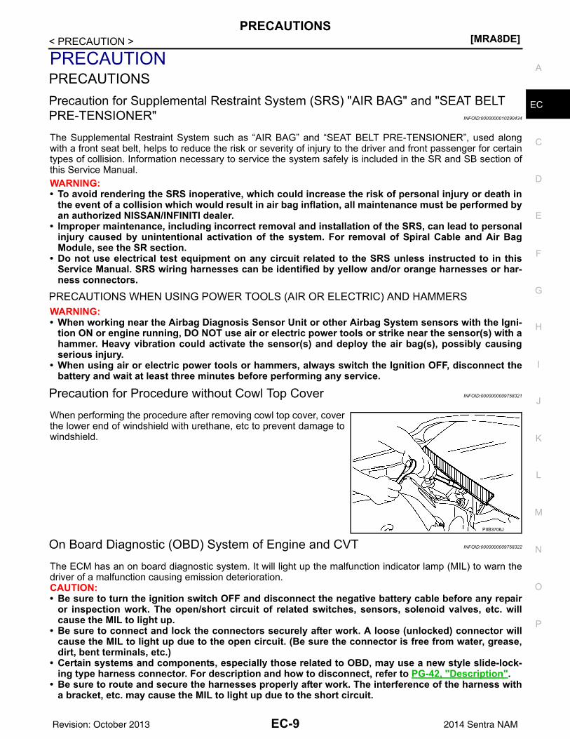
Precaution for Procedure without Cowl Top Cover INFOID:0000000009758321
When performing the procedure after removing cowl top cover, coverthe lower end of windshield with urethane, etc to prevent damage towindshield.
On Board Diagnostic (OBD) System of Engine and CVT INFOID:0000000009758322
The ECM has an on board diagnostic system. It will light up the malfunction indicator lamp (MIL) to warn thedriver of a malfunction causing emission deterioration.CAUTION:• Be sure to turn the ignition switch OFF and disconnect the negative battery cable before any repair
or inspection work. The open/short circuit of related switches, sensors, solenoid valves, etc. willcause the MIL to light up.
• Be sure to connect and lock the connectors securely after work. A loose (unlocked) connector willcause the MIL to light up due to the open circuit. (Be sure the connector is free from water, grease,dirt, bent terminals, etc.)
• Certain systems and components, especially those related to OBD, may use a new style slide-lock-ing type harness connector. For description and how to disconnect, refer to PG-42, "Description".
• Be sure to route and secure the harnesses properly after work. The interference of the harness witha bracket, etc. may cause the MIL to light up due to the short circuit.
PIIB3706J
EC-9Revision: October 2013 2014 Sentra NAM
[MRA8DE]PRECAUTIONS
< PRECAUTION >• Be sure to connect rubber tubes properly after work. A misconnected or disconnected rubber tube
may cause the MIL to light up due to the malfunction of the EVAP system or fuel injection system,etc.
• Be sure to erase the unnecessary malfunction information (repairs completed) from the ECM andTCM (Transmission control module) before returning the vehicle to the customer.
General Precautions INFOID:0000000009758323
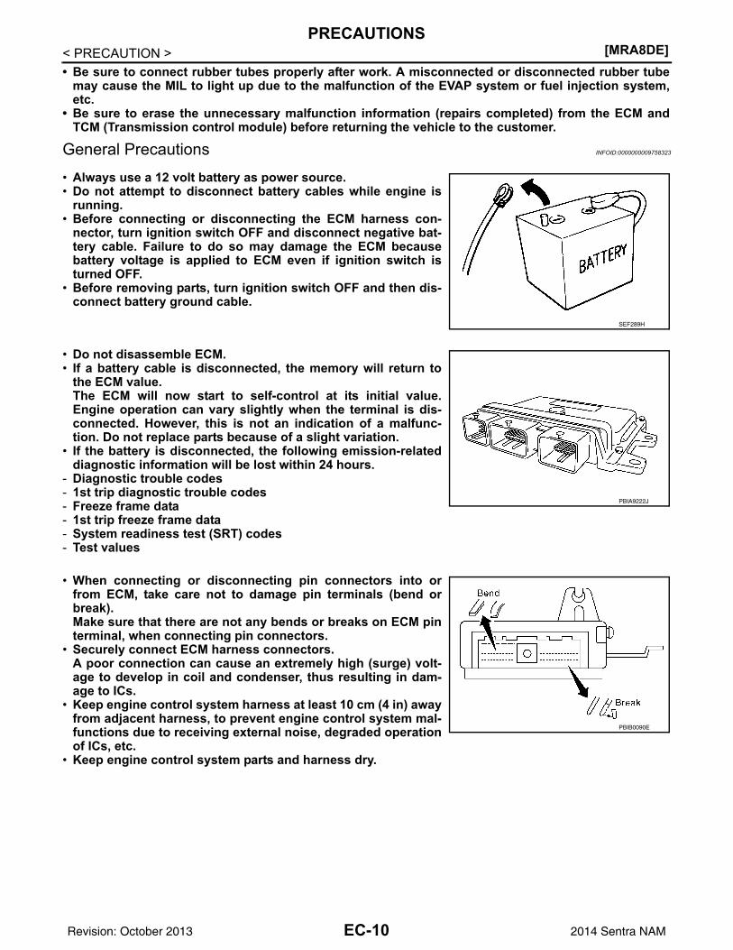
• Always use a 12 volt battery as power source.• Do not attempt to disconnect battery cables while engine is
running.• Before connecting or disconnecting the ECM harness con-
nector, turn ignition switch OFF and disconnect negative bat-tery cable. Failure to do so may damage the ECM becausebattery voltage is applied to ECM even if ignition switch isturned OFF.
• Before removing parts, turn ignition switch OFF and then dis-connect battery ground cable.
• Do not disassemble ECM.• If a battery cable is disconnected, the memory will return to
the ECM value.The ECM will now start to self-control at its initial value.Engine operation can vary slightly when the terminal is dis-connected. However, this is not an indication of a malfunc-tion. Do not replace parts because of a slight variation.
• If the battery is disconnected, the following emission-relateddiagnostic information will be lost within 24 hours.
- Diagnostic trouble codes- 1st trip diagnostic trouble codes- Freeze frame data- 1st trip freeze frame data- System readiness test (SRT) codes- Test values
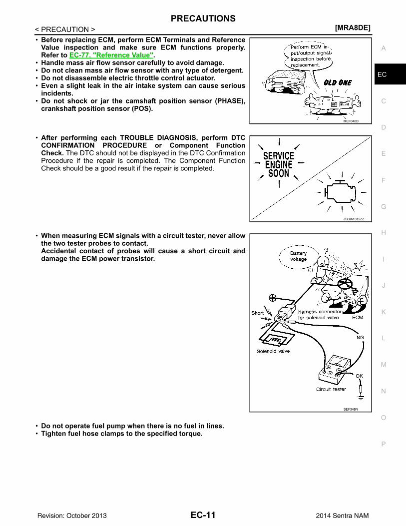
• When connecting or disconnecting pin connectors into orfrom ECM, take care not to damage pin terminals (bend orbreak).Make sure that there are not any bends or breaks on ECM pinterminal, when connecting pin connectors.
• Securely connect ECM harness connectors.A poor connection can cause an extremely high (surge) volt-age to develop in coil and condenser, thus resulting in dam-age to ICs.
• Keep engine control system harness at least 10 cm (4 in) awayfrom adjacent harness, to prevent engine control system mal-functions due to receiving external noise, degraded operationof ICs, etc.
• Keep engine control system parts and harness dry.
SEF289H
PBIA9222J
PBIB0090E
EC-10Revision: October 2013 2014 Sentra NAM
PRECAUTIONS[MRA8DE]
C
D
E
F
G
H
I
J
K
L
M
A
C
N
P
O
< PRECAUTION >
E
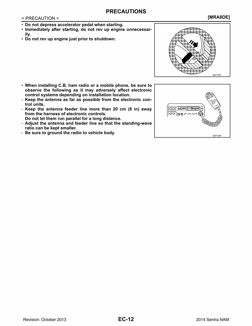
• Before replacing ECM, perform ECM Terminals and ReferenceValue inspection and make sure ECM functions properly.Refer to EC-77, "Reference Value".
• Handle mass air flow sensor carefully to avoid damage.• Do not clean mass air flow sensor with any type of detergent.• Do not disassemble electric throttle control actuator.• Even a slight leak in the air intake system can cause serious
incidents.• Do not shock or jar the camshaft position sensor (PHASE),
crankshaft position sensor (POS).
• After performing each TROUBLE DIAGNOSIS, perform DTCCONFIRMATION PROCEDURE or Component FunctionCheck. The DTC should not be displayed in the DTC ConfirmationProcedure if the repair is completed. The Component FunctionCheck should be a good result if the repair is completed.
• When measuring ECM signals with a circuit tester, never allowthe two tester probes to contact.Accidental contact of probes will cause a short circuit anddamage the ECM power transistor.
• Do not operate fuel pump when there is no fuel in lines.• Tighten fuel hose clamps to the specified torque.
MEF040D
JSBIA1315ZZ
SEF348N
EC-11Revision: October 2013 2014 Sentra NAM
[MRA8DE]PRECAUTIONS
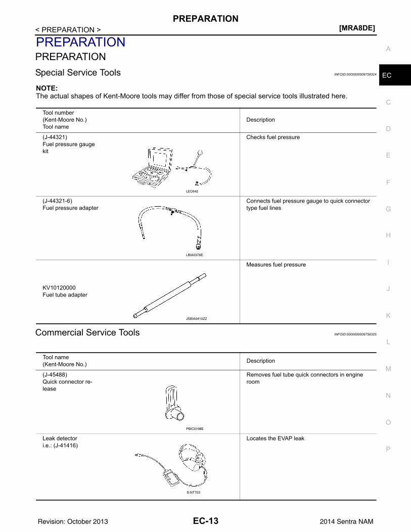
< PRECAUTION >• Do not depress accelerator pedal when starting.• Immediately after starting, do not rev up engine unnecessar-
ily.• Do not rev up engine just prior to shutdown.
• When installing C.B. ham radio or a mobile phone, be sure toobserve the following as it may adversely affect electroniccontrol systems depending on installation location.
- Keep the antenna as far as possible from the electronic con-trol units.
- Keep the antenna feeder line more than 20 cm (8 in) awayfrom the harness of electronic controls.Do not let them run parallel for a long distance.
- Adjust the antenna and feeder line so that the standing-waveratio can be kept smaller.
- Be sure to ground the radio to vehicle body.
SEF709Y
SEF708Y
EC-12Revision: October 2013 2014 Sentra NAM
PREPARATION[MRA8DE]
C
D
E
F
G
H
I
J
K
L
M
A
C
N
P
O
< PREPARATION >
E
PREPARATIONPREPARATIONSpecial Service Tools INFOID:0000000009758324
NOTE:The actual shapes of Kent-Moore tools may differ from those of special service tools illustrated here.
Commercial Service Tools INFOID:0000000009758325
Tool number(Kent-Moore No.)Tool name
Description
(J-44321)Fuel pressure gauge kit
Checks fuel pressure
(J-44321-6)Fuel pressure adapter
Connects fuel pressure gauge to quick connector type fuel lines
KV10120000Fuel tube adapter
Measures fuel pressure
LEC642
LBIA0376E
JSBIA0410ZZ
Tool name(Kent-Moore No.) Description
(J-45488)Quick connector re-lease
Removes fuel tube quick connectors in engine room
Leak detector i.e.: (J-41416)
Locates the EVAP leak
PBIC0198E
S-NT703
EC-13Revision: October 2013 2014 Sentra NAM
[MRA8DE]PREPARATION
< PREPARATION >
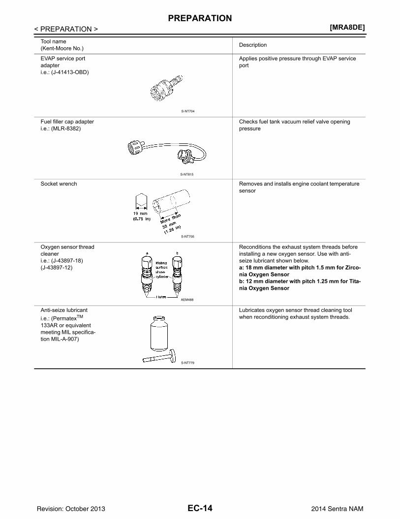
EVAP service port adapteri.e.: (J-41413-OBD)
Applies positive pressure through EVAP service port
Fuel filler cap adapteri.e.: (MLR-8382)
Checks fuel tank vacuum relief valve opening pressure
Socket wrench Removes and installs engine coolant temperature sensor
Oxygen sensor thread cleaneri.e.: (J-43897-18)(J-43897-12)
Reconditions the exhaust system threads before installing a new oxygen sensor. Use with anti-seize lubricant shown below.a: 18 mm diameter with pitch 1.5 mm for Zirco-nia Oxygen Sensorb: 12 mm diameter with pitch 1.25 mm for Tita-nia Oxygen Sensor
Anti-seize lubricant i.e.: (PermatexTM 133AR or equivalent meeting MIL specifica-tion MIL-A-907)
Lubricates oxygen sensor thread cleaning tool when reconditioning exhaust system threads.
Tool name(Kent-Moore No.) Description
S-NT704
S-NT815
S-NT705
AEM488
S-NT779
EC-14Revision: October 2013 2014 Sentra NAM
COMPONENT PARTS[MRA8DE]
C
D
E
F
G
H
I
J
K
L
M
A
C
N
P
O
< SYSTEM DESCRIPTION >
E
SYSTEM DESCRIPTIONCOMPONENT PARTSENGINE CONTROL SYSTEMENGINE CONTROL SYSTEM : Component Parts Location INFOID:0000000009758326
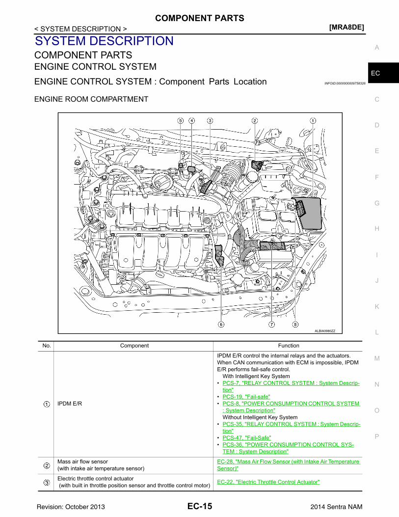
ENGINE ROOM COMPARTMENT
No. Component Function
IPDM E/R
IPDM E/R control the internal relays and the actuators.When CAN communication with ECM is impossible, IPDM E/R performs fail-safe control.
With Intelligent Key System• PCS-7, "RELAY CONTROL SYSTEM : System Descrip-
tion"• PCS-19, "Fail-safe"• PCS-8, "POWER CONSUMPTION CONTROL SYSTEM
: System Description"Without Intelligent Key System
• PCS-35, "RELAY CONTROL SYSTEM : System Descrip-tion"
• PCS-47, "Fail-Safe"• PCS-36, "POWER CONSUMPTION CONTROL SYS-
TEM : System Description"
Mass air flow sensor(with intake air temperature sensor)
EC-28, "Mass Air Flow Sensor (with Intake Air Temperature Sensor)"
Electric throttle control actuator (with built in throttle position sensor and throttle control motor) EC-22, "Electric Throttle Control Actuator"
ALBIA0980ZZ
EC-15Revision: October 2013 2014 Sentra NAM
[MRA8DE]COMPONENT PARTS
< SYSTEM DESCRIPTION >
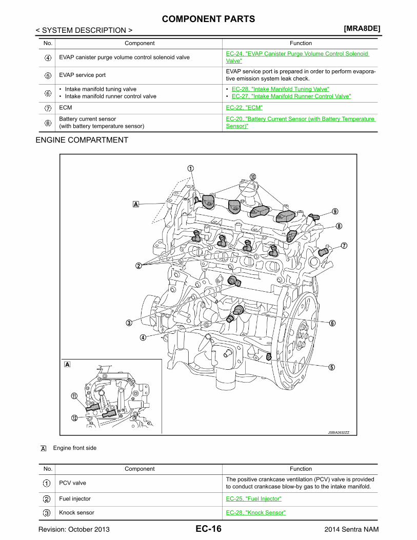
ENGINE COMPARTMENT
EVAP canister purge volume control solenoid valve EC-24, "EVAP Canister Purge Volume Control Solenoid Valve"
EVAP service port EVAP service port is prepared in order to perform evapora-tive emission system leak check.
• Intake manifold tuning valve• Intake manifold runner control valve
• EC-28, "Intake Manifold Tuning Valve"• EC-27, "Intake Manifold Runner Control Valve"
ECM EC-22, "ECM"
Battery current sensor(with battery temperature sensor)
EC-20, "Battery Current Sensor (with Battery Temperature Sensor)"
No. Component Function
Engine front side
No. Component Function
PCV valve The positive crankcase ventilation (PCV) valve is provided to conduct crankcase blow-by gas to the intake manifold.
Fuel injector EC-25, "Fuel Injector"
Knock sensor EC-28, "Knock Sensor"
JSBIA2632ZZ
EC-16Revision: October 2013 2014 Sentra NAM
COMPONENT PARTS[MRA8DE]
C
D
E
F
G
H
I
J
K
L
M
A
C
N
P
O
< SYSTEM DESCRIPTION >
E
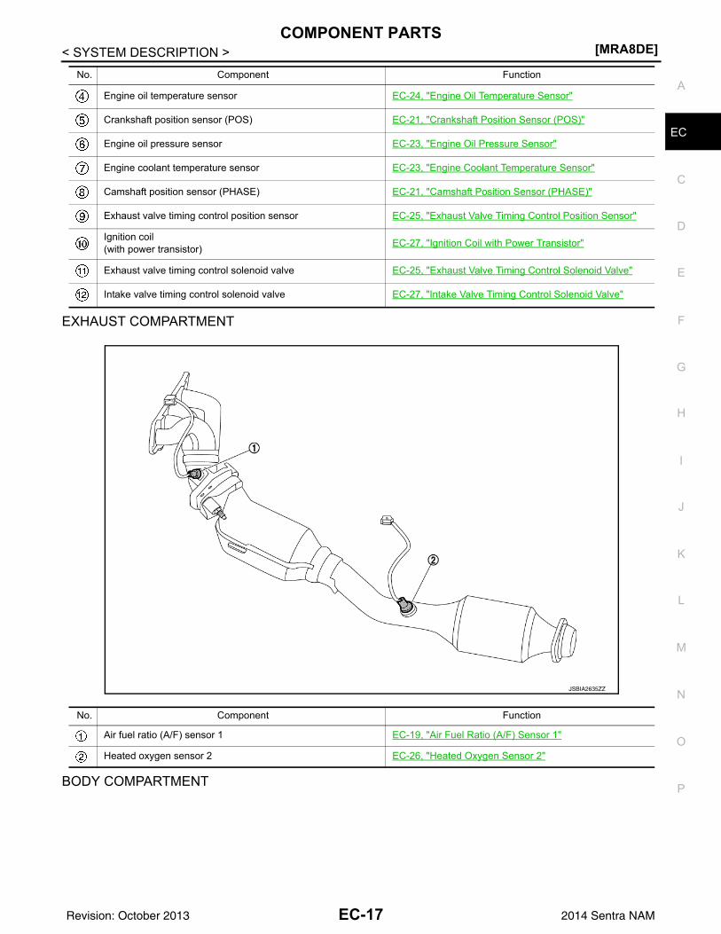
EXHAUST COMPARTMENT
BODY COMPARTMENT
Engine oil temperature sensor EC-24, "Engine Oil Temperature Sensor"
Crankshaft position sensor (POS) EC-21, "Crankshaft Position Sensor (POS)"
Engine oil pressure sensor EC-23, "Engine Oil Pressure Sensor"
Engine coolant temperature sensor EC-23, "Engine Coolant Temperature Sensor"
Camshaft position sensor (PHASE) EC-21, "Camshaft Position Sensor (PHASE)"
Exhaust valve timing control position sensor EC-25, "Exhaust Valve Timing Control Position Sensor"
Ignition coil(with power transistor) EC-27, "Ignition Coil with Power Transistor"
Exhaust valve timing control solenoid valve EC-25, "Exhaust Valve Timing Control Solenoid Valve"
Intake valve timing control solenoid valve EC-27, "Intake Valve Timing Control Solenoid Valve"
No. Component Function
No. Component Function
Air fuel ratio (A/F) sensor 1 EC-19, "Air Fuel Ratio (A/F) Sensor 1"
Heated oxygen sensor 2 EC-26, "Heated Oxygen Sensor 2"
JSBIA2635ZZ
EC-17Revision: October 2013 2014 Sentra NAM
[MRA8DE]COMPONENT PARTS
< SYSTEM DESCRIPTION >
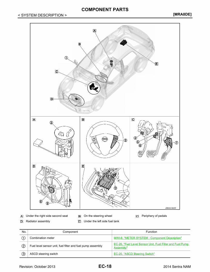
Under the right side second seat On the steering wheel Periphery of pedals
Radiator assembly Under the left side fuel tank
No. Component Function
Combination meter MWI-6, "METER SYSTEM : Component Description"
Fuel level sensor unit, fuel filter and fuel pump assembly EC-26, "Fuel Level Sensor Unit, Fuel Filter and Fuel Pump Assembly"
ASCD steering switch EC-20, "ASCD Steering Switch"
JSBIA3185ZZ
EC-18Revision: October 2013 2014 Sentra NAM
COMPONENT PARTS[MRA8DE]
C
D
E
F
G
H
I
J
K
L
M
A
C
N
P
O
< SYSTEM DESCRIPTION >
E
Accelerator Pedal Position Sensor INFOID:0000000009758327
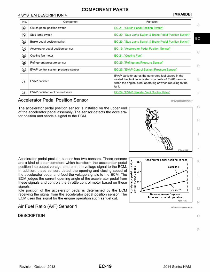
The accelerator pedal position sensor is installed on the upper endof the accelerator pedal assembly. The sensor detects the accelera-tor position and sends a signal to the ECM.
Accelerator pedal position sensor has two sensors. These sensorsare a kind of potentiometers which transform the accelerator pedalposition into output voltage, and emit the voltage signal to the ECM.In addition, these sensors detect the opening and closing speed ofthe accelerator pedal and feed the voltage signals to the ECM. TheECM judges the current opening angle of the accelerator pedal fromthese signals and controls the throttle control motor based on thesesignals.Idle position of the accelerator pedal is determined by the ECMreceiving the signal from the accelerator pedal position sensor. TheECM uses this signal for the engine operation such as fuel cut.
Air Fuel Ratio (A/F) Sensor 1 INFOID:0000000009758328
DESCRIPTION
Clutch pedal position switch EC-21, "Clutch Pedal Position Switch"
Stop lamp switch EC-29, "Stop Lamp Switch & Brake Pedal Position Switch"
Brake pedal position switch EC-29, "Stop Lamp Switch & Brake Pedal Position Switch"
Accelerator pedal position sensor EC-19, "Accelerator Pedal Position Sensor"
Cooling fan motor EC-21, "Cooling Fan"
Refrigerant pressure sensor EC-29, "Refrigerant Pressure Sensor"
EVAP control system pressure sensor EC-25, "EVAP Control System Pressure Sensor"
EVAP canister
EVAP canister stores the generated fuel vapors in the sealed fuel tank to activated charcoals of EVAP canister when the engine is not operating or when refueling to the tank.
EVAP canister vent control valve EC-24, "EVAP Canister Vent Control Valve"
No. Component Function
JPBIA4615ZZ
PBIB1741E
EC-19Revision: October 2013 2014 Sentra NAM
[MRA8DE]COMPONENT PARTS
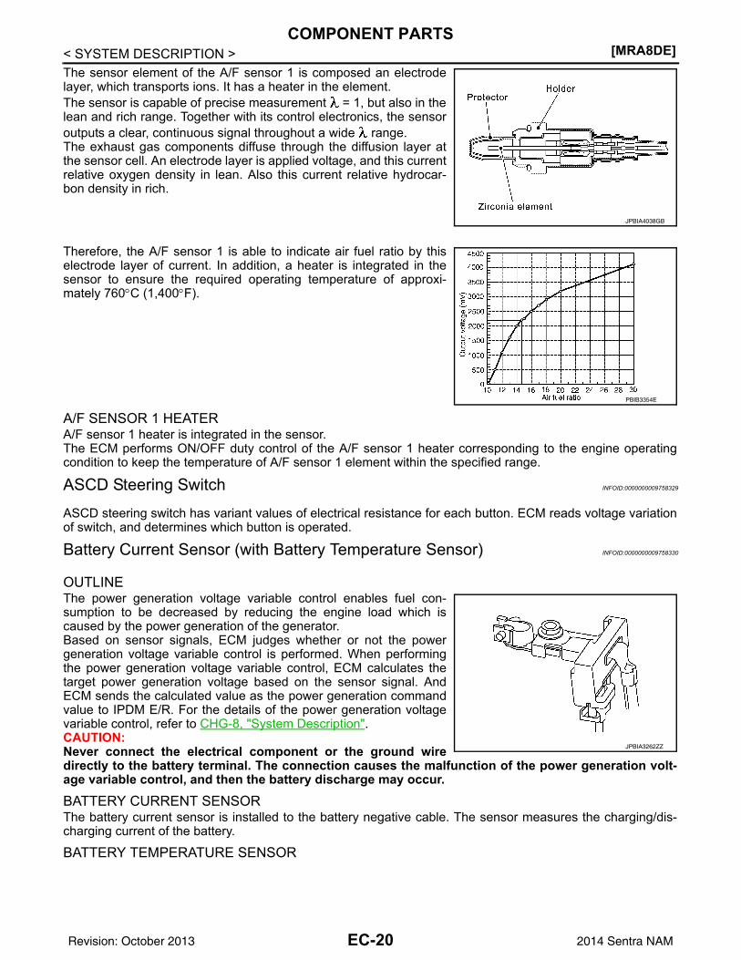
< SYSTEM DESCRIPTION >The sensor element of the A/F sensor 1 is composed an electrodelayer, which transports ions. It has a heater in the element.The sensor is capable of precise measurement = 1, but also in thelean and rich range. Together with its control electronics, the sensoroutputs a clear, continuous signal throughout a wide range.The exhaust gas components diffuse through the diffusion layer atthe sensor cell. An electrode layer is applied voltage, and this currentrelative oxygen density in lean. Also this current relative hydrocar-bon density in rich.
Therefore, the A/F sensor 1 is able to indicate air fuel ratio by thiselectrode layer of current. In addition, a heater is integrated in thesensor to ensure the required operating temperature of approxi-mately 760°C (1,400°F).
A/F SENSOR 1 HEATERA/F sensor 1 heater is integrated in the sensor.The ECM performs ON/OFF duty control of the A/F sensor 1 heater corresponding to the engine operatingcondition to keep the temperature of A/F sensor 1 element within the specified range.
ASCD Steering Switch INFOID:0000000009758329
ASCD steering switch has variant values of electrical resistance for each button. ECM reads voltage variationof switch, and determines which button is operated.
Battery Current Sensor (with Battery Temperature Sensor) INFOID:0000000009758330
OUTLINEThe power generation voltage variable control enables fuel con-sumption to be decreased by reducing the engine load which iscaused by the power generation of the generator.Based on sensor signals, ECM judges whether or not the powergeneration voltage variable control is performed. When performingthe power generation voltage variable control, ECM calculates thetarget power generation voltage based on the sensor signal. AndECM sends the calculated value as the power generation commandvalue to IPDM E/R. For the details of the power generation voltagevariable control, refer to CHG-8, "System Description".CAUTION:Never connect the electrical component or the ground wiredirectly to the battery terminal. The connection causes the malfunction of the power generation volt-age variable control, and then the battery discharge may occur.
BATTERY CURRENT SENSORThe battery current sensor is installed to the battery negative cable. The sensor measures the charging/dis-charging current of the battery.
BATTERY TEMPERATURE SENSOR
JPBIA4038GB
PBIB3354E
JPBIA3262ZZ
EC-20Revision: October 2013 2014 Sentra NAM
COMPONENT PARTS[MRA8DE]
C
D
E
F
G
H
I
J
K
L
M
A
C
N
P
O
< SYSTEM DESCRIPTION >
E
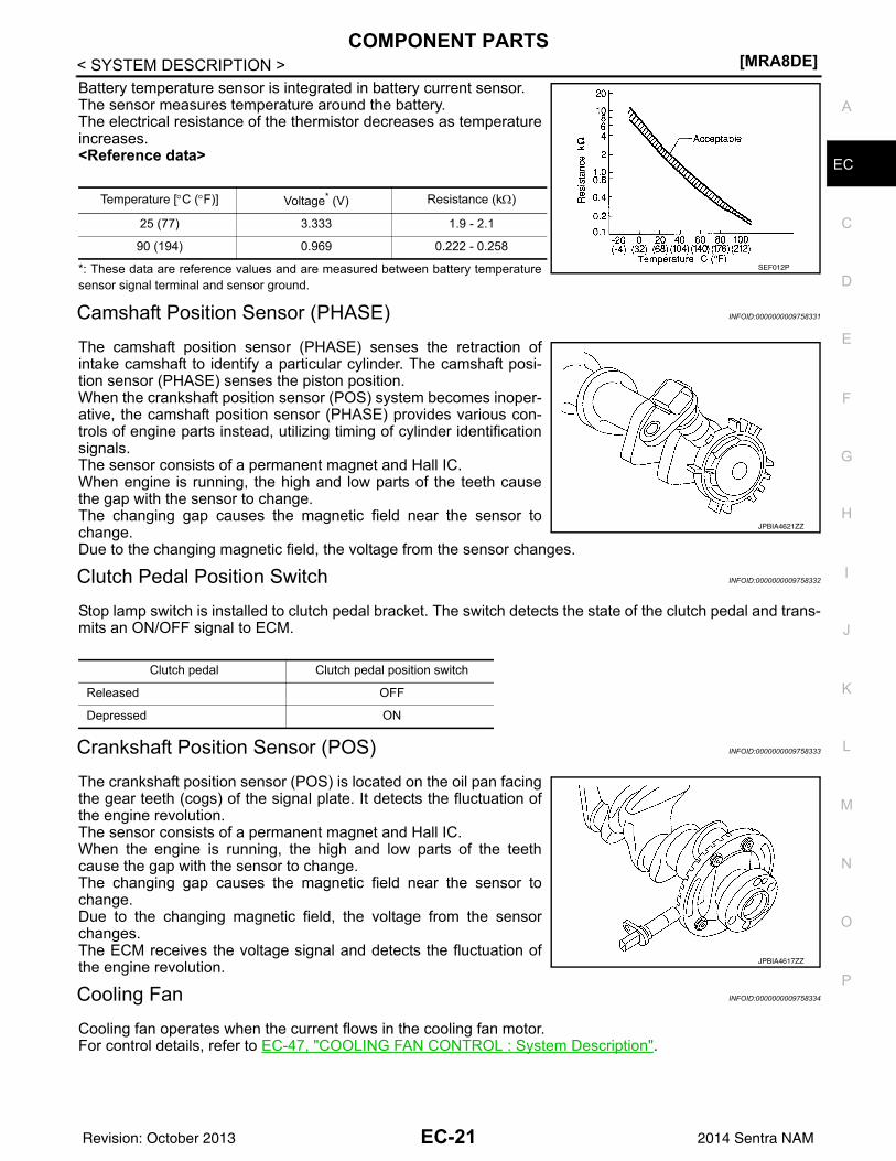
Battery temperature sensor is integrated in battery current sensor.The sensor measures temperature around the battery.The electrical resistance of the thermistor decreases as temperatureincreases.<Reference data>
*: These data are reference values and are measured between battery temperaturesensor signal terminal and sensor ground.
Camshaft Position Sensor (PHASE) INFOID:0000000009758331
The camshaft position sensor (PHASE) senses the retraction ofintake camshaft to identify a particular cylinder. The camshaft posi-tion sensor (PHASE) senses the piston position.When the crankshaft position sensor (POS) system becomes inoper-ative, the camshaft position sensor (PHASE) provides various con-trols of engine parts instead, utilizing timing of cylinder identificationsignals.The sensor consists of a permanent magnet and Hall IC.When engine is running, the high and low parts of the teeth causethe gap with the sensor to change.The changing gap causes the magnetic field near the sensor tochange.Due to the changing magnetic field, the voltage from the sensor changes.
Clutch Pedal Position Switch INFOID:0000000009758332
Stop lamp switch is installed to clutch pedal bracket. The switch detects the state of the clutch pedal and trans-mits an ON/OFF signal to ECM.
Crankshaft Position Sensor (POS) INFOID:0000000009758333
The crankshaft position sensor (POS) is located on the oil pan facingthe gear teeth (cogs) of the signal plate. It detects the fluctuation ofthe engine revolution.The sensor consists of a permanent magnet and Hall IC.When the engine is running, the high and low parts of the teethcause the gap with the sensor to change.The changing gap causes the magnetic field near the sensor tochange.Due to the changing magnetic field, the voltage from the sensorchanges.The ECM receives the voltage signal and detects the fluctuation ofthe engine revolution.
Cooling Fan INFOID:0000000009758334
Cooling fan operates when the current flows in the cooling fan motor.For control details, refer to EC-47, "COOLING FAN CONTROL : System Description".
Temperature [°C (°F)] Voltage* (V) Resistance (kΩ)
25 (77) 3.333 1.9 - 2.1
90 (194) 0.969 0.222 - 0.258SEF012P
JPBIA4621ZZ
Clutch pedal Clutch pedal position switch
Released OFF
Depressed ON
JPBIA4617ZZ
EC-21Revision: October 2013 2014 Sentra NAM
[MRA8DE]COMPONENT PARTS
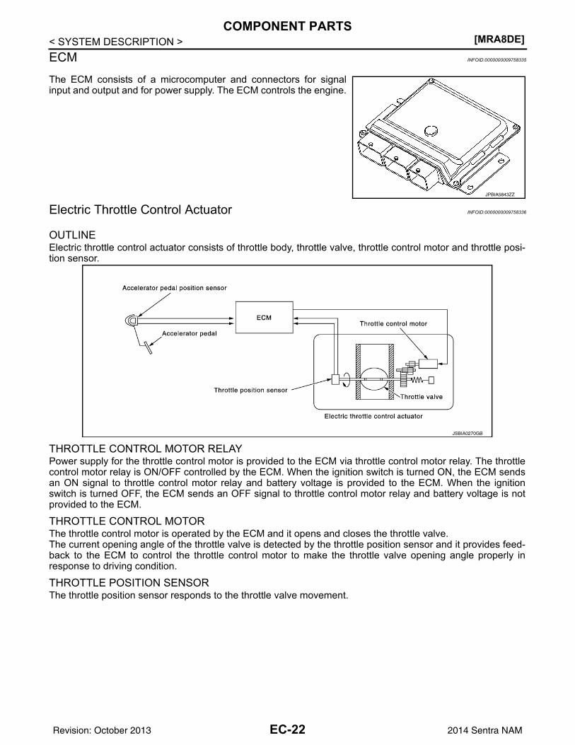
< SYSTEM DESCRIPTION >ECM INFOID:0000000009758335
The ECM consists of a microcomputer and connectors for signalinput and output and for power supply. The ECM controls the engine.
Electric Throttle Control Actuator INFOID:0000000009758336
OUTLINEElectric throttle control actuator consists of throttle body, throttle valve, throttle control motor and throttle posi-tion sensor.
THROTTLE CONTROL MOTOR RELAYPower supply for the throttle control motor is provided to the ECM via throttle control motor relay. The throttlecontrol motor relay is ON/OFF controlled by the ECM. When the ignition switch is turned ON, the ECM sendsan ON signal to throttle control motor relay and battery voltage is provided to the ECM. When the ignitionswitch is turned OFF, the ECM sends an OFF signal to throttle control motor relay and battery voltage is notprovided to the ECM.
THROTTLE CONTROL MOTORThe throttle control motor is operated by the ECM and it opens and closes the throttle valve.The current opening angle of the throttle valve is detected by the throttle position sensor and it provides feed-back to the ECM to control the throttle control motor to make the throttle valve opening angle properly inresponse to driving condition.
THROTTLE POSITION SENSORThe throttle position sensor responds to the throttle valve movement.
JPBIA5843ZZ
JSBIA0270GB
EC-22Revision: October 2013 2014 Sentra NAM
COMPONENT PARTS[MRA8DE]
C
D
E
F
G
H
I
J
K
L
M
A
C
N
P
O
< SYSTEM DESCRIPTION >
E
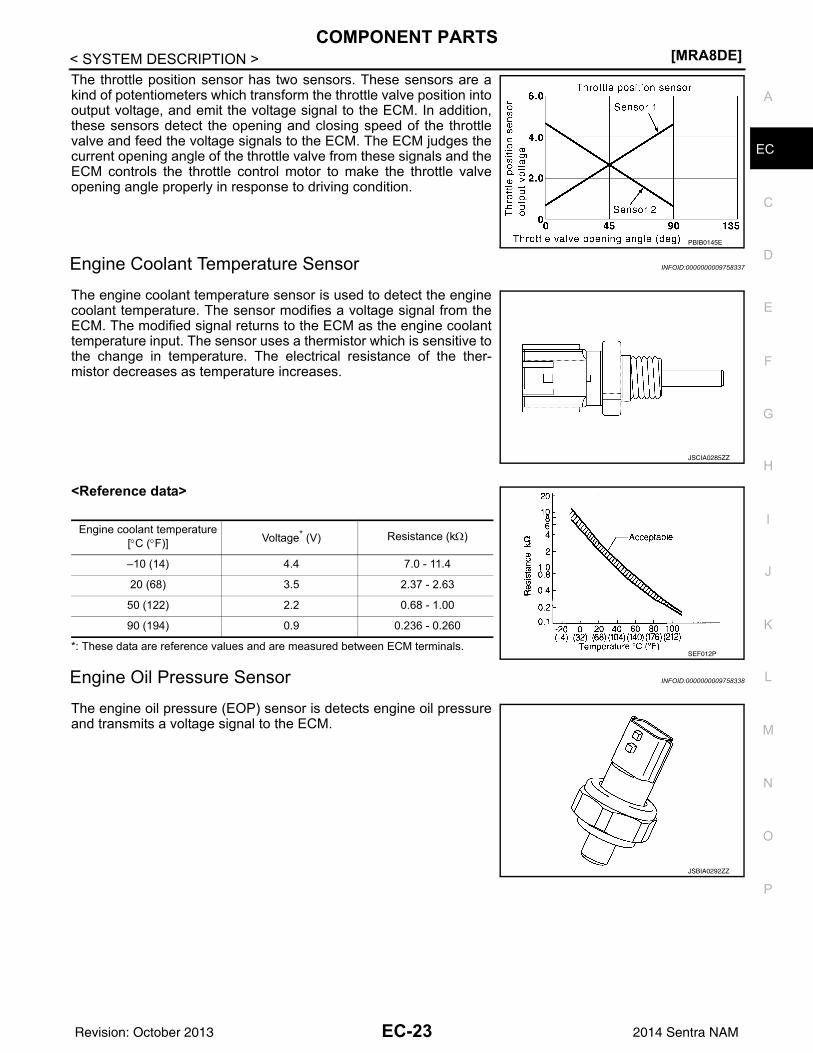
The throttle position sensor has two sensors. These sensors are akind of potentiometers which transform the throttle valve position intooutput voltage, and emit the voltage signal to the ECM. In addition,these sensors detect the opening and closing speed of the throttlevalve and feed the voltage signals to the ECM. The ECM judges thecurrent opening angle of the throttle valve from these signals and theECM controls the throttle control motor to make the throttle valveopening angle properly in response to driving condition.
Engine Coolant Temperature Sensor INFOID:0000000009758337
The engine coolant temperature sensor is used to detect the enginecoolant temperature. The sensor modifies a voltage signal from theECM. The modified signal returns to the ECM as the engine coolanttemperature input. The sensor uses a thermistor which is sensitive tothe change in temperature. The electrical resistance of the ther-mistor decreases as temperature increases.
<Reference data>
*: These data are reference values and are measured between ECM terminals.
Engine Oil Pressure Sensor INFOID:0000000009758338
The engine oil pressure (EOP) sensor is detects engine oil pressureand transmits a voltage signal to the ECM.
PBIB0145E
JSCIA0285ZZ
Engine coolant temperature[°C (°F)] Voltage* (V) Resistance (kΩ)
–10 (14) 4.4 7.0 - 11.4
20 (68) 3.5 2.37 - 2.63
50 (122) 2.2 0.68 - 1.00
90 (194) 0.9 0.236 - 0.260
SEF012P
JSBIA0292ZZ
EC-23Revision: October 2013 2014 Sentra NAM

[MRA8DE]COMPONENT PARTS
< SYSTEM DESCRIPTION >Engine Oil Temperature Sensor INFOID:0000000009758339
The engine oil temperature sensor is used to detect the engine oiltemperature. The sensor modifies a voltage signal from the ECM.The modified signal returns to the ECM as the engine oil tempera-ture input. The sensor uses a thermistor which is sensitive to thechange in temperature. The electrical resistance of the thermistordecreases as temperature increases.
<Reference data>
*: These data are reference values and are measured between ECM terminals.
EVAP Canister Purge Volume Control Solenoid Valve INFOID:0000000009758340
The EVAP canister purge volume control solenoid valve uses a ON/OFF duty to control the flow rate of fuel vapor from the EVAP canis-ter. The EVAP canister purge volume control solenoid valve ismoved by ON/OFF pulses from the ECM. The longer the ON pulse,the greater the amount of fuel vapor that will flow through the valve.
EVAP Canister Vent Control Valve INFOID:0000000009758341
The EVAP canister vent control valve is located on the EVAP canis-ter and is used to seal the canister vent.This solenoid valve responds to signals from the ECM. When theECM sends an ON signal, the coil in the solenoid valve is energized.A plunger will then move to seal the canister vent. The ability to sealthe vent is necessary for the on board diagnosis of other evaporativeemission control system components.This solenoid valve is used only for diagnosis, and usually remainsopened.When the vent is closed, under normal purge conditions, the evapo-rative emission control system is depressurized and allows “EVAPControl System” diagnosis.
JPBIA5280ZZ
Engine oil temperature[°C (°F)] Voltage* (V) Resistance (kΩ)
–10 (14) 4.4 7.0 - 11.4
20 (68) 3.5 2.37 - 2.63
50 (122) 2.2 0.68 - 1.00
90 (194) 0.9 0.236 - 0.260
110 (230) 0.6 0.143 - 0.153SEF012P
JSBIA0651ZZ
PBIB1263E
EC-24Revision: October 2013 2014 Sentra NAM
COMPONENT PARTS[MRA8DE]
C
D
E
F
G
H
I
J
K
L
M
A
C
N
P
O
< SYSTEM DESCRIPTION >
E
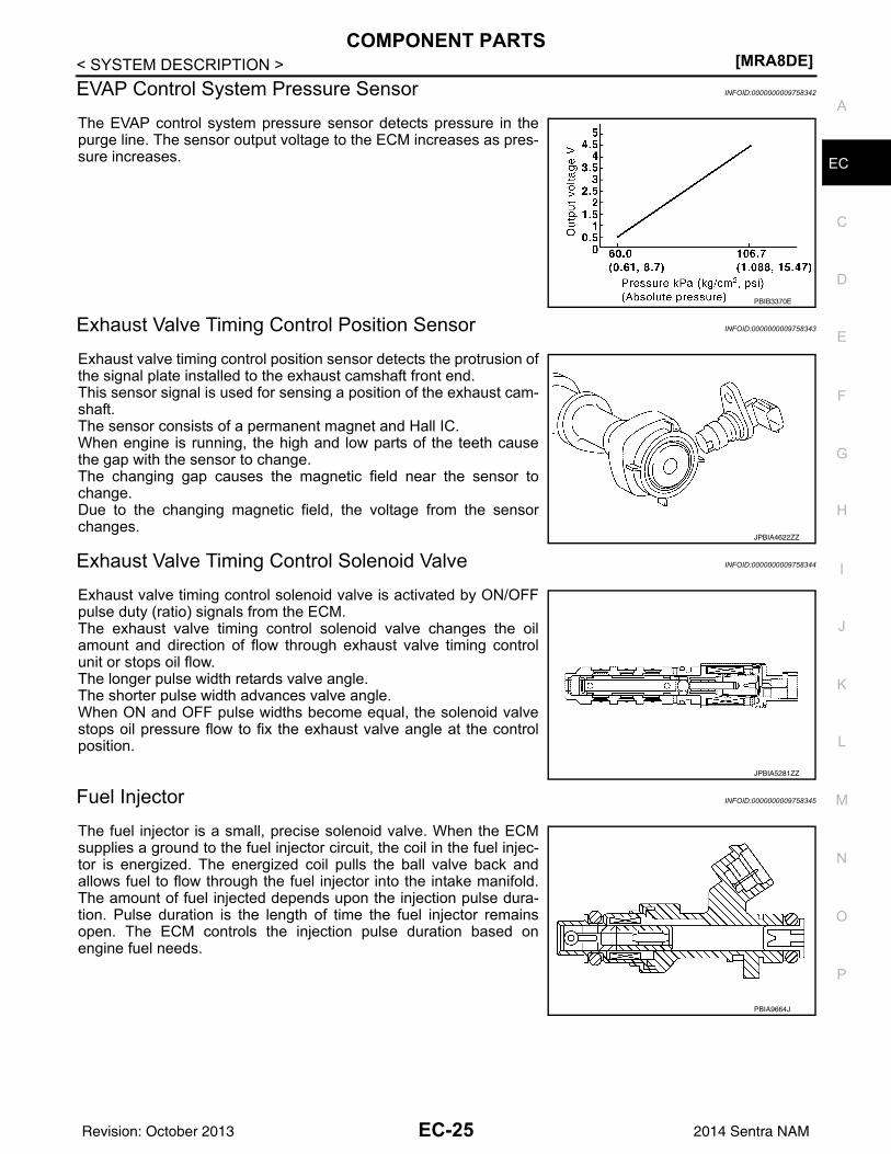
EVAP Control System Pressure Sensor INFOID:0000000009758342
The EVAP control system pressure sensor detects pressure in thepurge line. The sensor output voltage to the ECM increases as pres-sure increases.
Exhaust Valve Timing Control Position Sensor INFOID:0000000009758343
Exhaust valve timing control position sensor detects the protrusion ofthe signal plate installed to the exhaust camshaft front end. This sensor signal is used for sensing a position of the exhaust cam-shaft.The sensor consists of a permanent magnet and Hall IC.When engine is running, the high and low parts of the teeth causethe gap with the sensor to change.The changing gap causes the magnetic field near the sensor tochange.Due to the changing magnetic field, the voltage from the sensorchanges.
Exhaust Valve Timing Control Solenoid Valve INFOID:0000000009758344
Exhaust valve timing control solenoid valve is activated by ON/OFFpulse duty (ratio) signals from the ECM.The exhaust valve timing control solenoid valve changes the oilamount and direction of flow through exhaust valve timing controlunit or stops oil flow.The longer pulse width retards valve angle.The shorter pulse width advances valve angle.When ON and OFF pulse widths become equal, the solenoid valvestops oil pressure flow to fix the exhaust valve angle at the controlposition.
Fuel Injector INFOID:0000000009758345
The fuel injector is a small, precise solenoid valve. When the ECMsupplies a ground to the fuel injector circuit, the coil in the fuel injec-tor is energized. The energized coil pulls the ball valve back andallows fuel to flow through the fuel injector into the intake manifold.The amount of fuel injected depends upon the injection pulse dura-tion. Pulse duration is the length of time the fuel injector remainsopen. The ECM controls the injection pulse duration based onengine fuel needs.
PBIB3370E
JPBIA4622ZZ
JPBIA5281ZZ
PBIA9664J
EC-25Revision: October 2013 2014 Sentra NAM
[MRA8DE]COMPONENT PARTS
< SYSTEM DESCRIPTION >Fuel Level Sensor Unit, Fuel Filter and Fuel Pump Assembly INFOID:0000000009758346
*: ECM determines the start signal status by the signals of engine speed and battery voltage.The ECM activates the fuel pump for a few seconds after the ignition switch is turned ON to improve enginestart ability. If the ECM receives a engine speed signal from the crankshaft position sensor (POS) and cam-shaft position sensor (PHASE), it knows that the engine is rotating, and causes the pump to operate. If theengine speed signal is not received when the ignition switch is ON, the engine stalls. The ECM stops pumpoperation and prevents battery discharging, thereby improving safety. The ECM does not directly drive the fuelpump. It controls the ON/OFF fuel pump relay, which in turn controls the fuel pump.
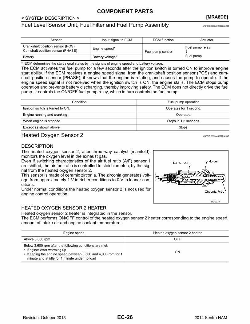
Heated Oxygen Sensor 2 INFOID:0000000009758347
DESCRIPTIONThe heated oxygen sensor 2, after three way catalyst (manifold),monitors the oxygen level in the exhaust gas.Even if switching characteristics of the air fuel ratio (A/F) sensor 1are shifted, the air fuel ratio is controlled to stoichiometric, by the sig-nal from the heated oxygen sensor 2.This sensor is made of ceramic zirconia. The zirconia generates volt-age from approximately 1 V in richer conditions to 0 V in leaner con-ditions.Under normal conditions the heated oxygen sensor 2 is not used forengine control operation.
HEATED OXYGEN SENSOR 2 HEATERHeated oxygen sensor 2 heater is integrated in the sensor.The ECM performs ON/OFF control of the heated oxygen sensor 2 heater corresponding to the engine speed,amount of intake air and engine coolant temperature.
Sensor Input signal to ECM ECM function Actuator
Crankshaft position sensor (POS)Camshaft position sensor (PHASE) Engine speed*
Fuel pump controlFuel pump relay↓Fuel pumpBattery Battery voltage*
Condition Fuel pump operation
Ignition switch is turned to ON. Operates for 1 second.
Engine running and cranking Operates.
When engine is stopped Stops in 1.5 seconds.
Except as shown above Stops.
SEF327R
Engine speed Heated oxygen sensor 2 heater
Above 3,600 rpm OFF
Below 3,600 rpm after the following conditions are met.• Engine: After warming up• Keeping the engine speed between 3,500 and 4,000 rpm for 1
minute and at idle for 1 minute under no load
ON
EC-26Revision: October 2013 2014 Sentra NAM
COMPONENT PARTS[MRA8DE]
C
D
E
F
G
H
I
J
K
L
M
A
C
N
P
O
< SYSTEM DESCRIPTION >
E
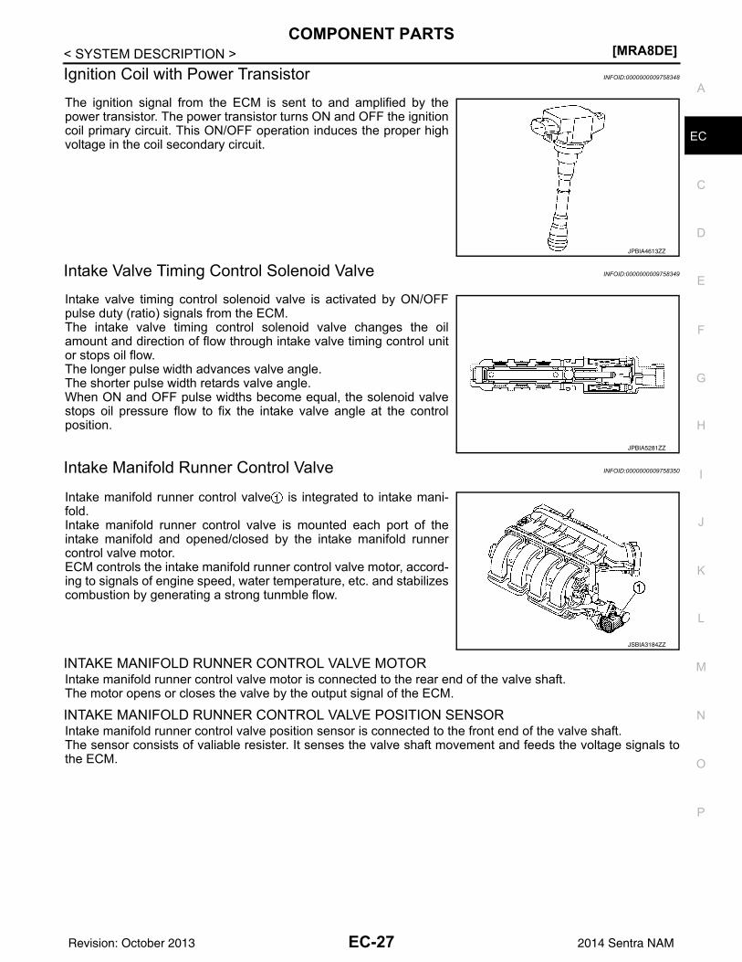
Ignition Coil with Power Transistor INFOID:0000000009758348
The ignition signal from the ECM is sent to and amplified by thepower transistor. The power transistor turns ON and OFF the ignitioncoil primary circuit. This ON/OFF operation induces the proper highvoltage in the coil secondary circuit.
Intake Valve Timing Control Solenoid Valve INFOID:0000000009758349
Intake valve timing control solenoid valve is activated by ON/OFFpulse duty (ratio) signals from the ECM.The intake valve timing control solenoid valve changes the oilamount and direction of flow through intake valve timing control unitor stops oil flow.The longer pulse width advances valve angle.The shorter pulse width retards valve angle.When ON and OFF pulse widths become equal, the solenoid valvestops oil pressure flow to fix the intake valve angle at the controlposition.
Intake Manifold Runner Control Valve INFOID:0000000009758350
Intake manifold runner control valve is integrated to intake mani-fold.Intake manifold runner control valve is mounted each port of theintake manifold and opened/closed by the intake manifold runnercontrol valve motor.ECM controls the intake manifold runner control valve motor, accord-ing to signals of engine speed, water temperature, etc. and stabilizescombustion by generating a strong tunmble flow.
INTAKE MANIFOLD RUNNER CONTROL VALVE MOTORIntake manifold runner control valve motor is connected to the rear end of the valve shaft.The motor opens or closes the valve by the output signal of the ECM.
INTAKE MANIFOLD RUNNER CONTROL VALVE POSITION SENSORIntake manifold runner control valve position sensor is connected to the front end of the valve shaft.The sensor consists of valiable resister. It senses the valve shaft movement and feeds the voltage signals tothe ECM.
JPBIA4613ZZ
JPBIA5281ZZ
JSBIA3184ZZ
EC-27Revision: October 2013 2014 Sentra NAM
[MRA8DE]COMPONENT PARTS
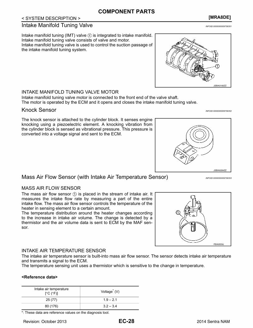
< SYSTEM DESCRIPTION >Intake Manifold Tuning Valve INFOID:0000000009758351
Intake manifold tuning (IMT) valve is integrated to intake manifold.Intake manifold tuning valve consists of valve and motor.Intake manifold tuning valve is used to control the suction passage ofthe intake manifold tuning system.
INTAKE MANIFOLD TUNING VALVE MOTORIntake manifold tuning valve motor is connected to the front end of the valve shaft.The motor is operated by the ECM and it opens and closes the intake manifold tuning valve.
Knock Sensor INFOID:0000000009758352
The knock sensor is attached to the cylinder block. It senses engineknocking using a piezoelectric element. A knocking vibration fromthe cylinder block is sensed as vibrational pressure. This pressure isconverted into a voltage signal and sent to the ECM.
Mass Air Flow Sensor (with Intake Air Temperature Sensor) INFOID:0000000009758353
MASS AIR FLOW SENSORThe mass air flow sensor is placed in the stream of intake air. Itmeasures the intake flow rate by measuring a part of the entireintake flow. The mass air flow sensor controls the temperature of theheater in sensing element to a certain amount.The temperature distribution around the heater changes accordingto the increase in intake air volume. The change is detected by athermistor and the air volume data is sent to ECM by the MAF sen-sor.
INTAKE AIR TEMPERATURE SENSORThe intake air temperature sensor is built-into mass air flow sensor. The sensor detects intake air temperatureand transmits a signal to the ECM.The temperature sensing unit uses a thermistor which is sensitive to the change in temperature.
<Reference data>
*: These data are reference values on the diagnosis tool.
JSBIA3183ZZ
JSBIA0284ZZ
PBIA9559J
Intake air temperature[°C (°F)] Voltage* (V)
25 (77) 1.9 – 2.1
80 (176) 3.2 – 3.4
EC-28Revision: October 2013 2014 Sentra NAM
COMPONENT PARTS[MRA8DE]
C
D
E
F
G
H
I
J
K
L
M
A
C
N
P
O
< SYSTEM DESCRIPTION >
E
Park/Neutral Position Switch INFOID:0000000009758354
Park/Neutral Position Switch is installed to manual transaxle. The switch detects the neutral position andtransmits a voltage signal.
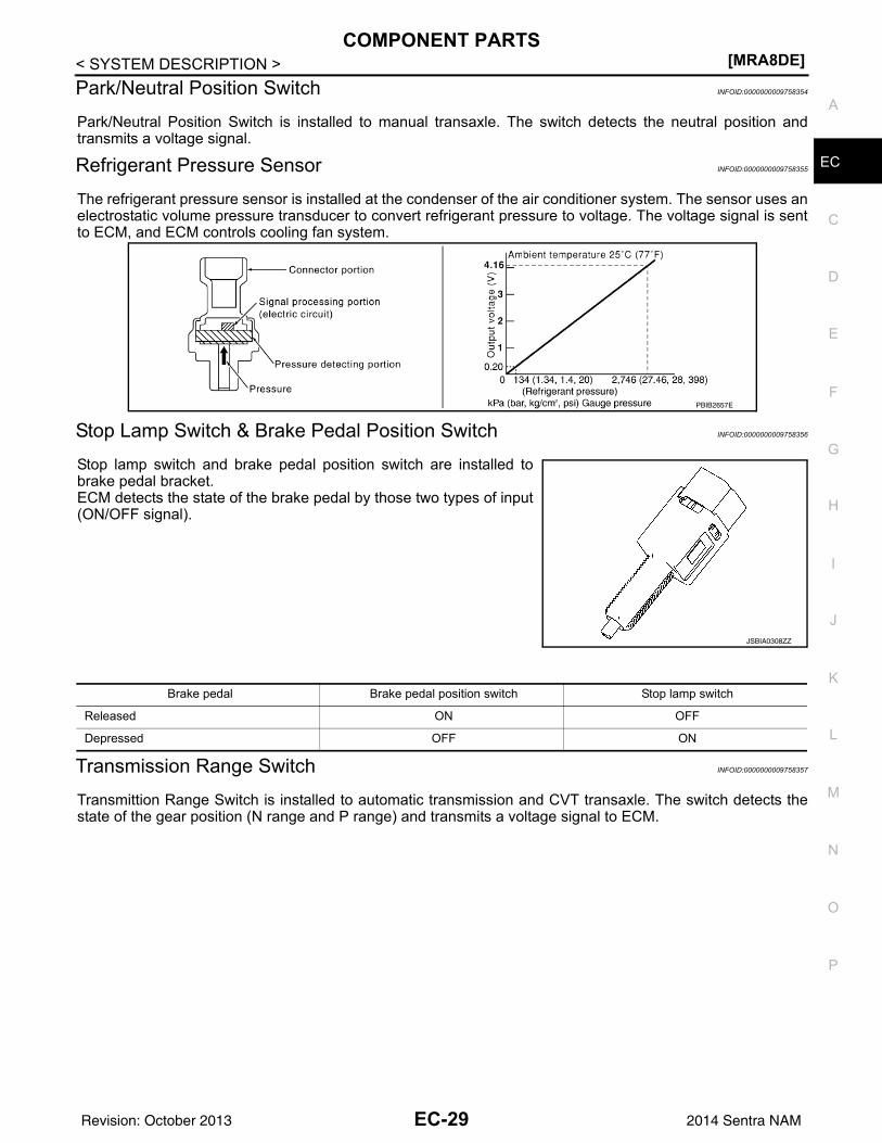
Refrigerant Pressure Sensor INFOID:0000000009758355
The refrigerant pressure sensor is installed at the condenser of the air conditioner system. The sensor uses anelectrostatic volume pressure transducer to convert refrigerant pressure to voltage. The voltage signal is sentto ECM, and ECM controls cooling fan system.
Stop Lamp Switch & Brake Pedal Position Switch INFOID:0000000009758356
Stop lamp switch and brake pedal position switch are installed tobrake pedal bracket.ECM detects the state of the brake pedal by those two types of input(ON/OFF signal).
Transmission Range Switch INFOID:0000000009758357
Transmittion Range Switch is installed to automatic transmission and CVT transaxle. The switch detects thestate of the gear position (N range and P range) and transmits a voltage signal to ECM.
PBIB2657E
JSBIA0308ZZ
Brake pedal Brake pedal position switch Stop lamp switch
Released ON OFF
Depressed OFF ON
EC-29Revision: October 2013 2014 Sentra NAM
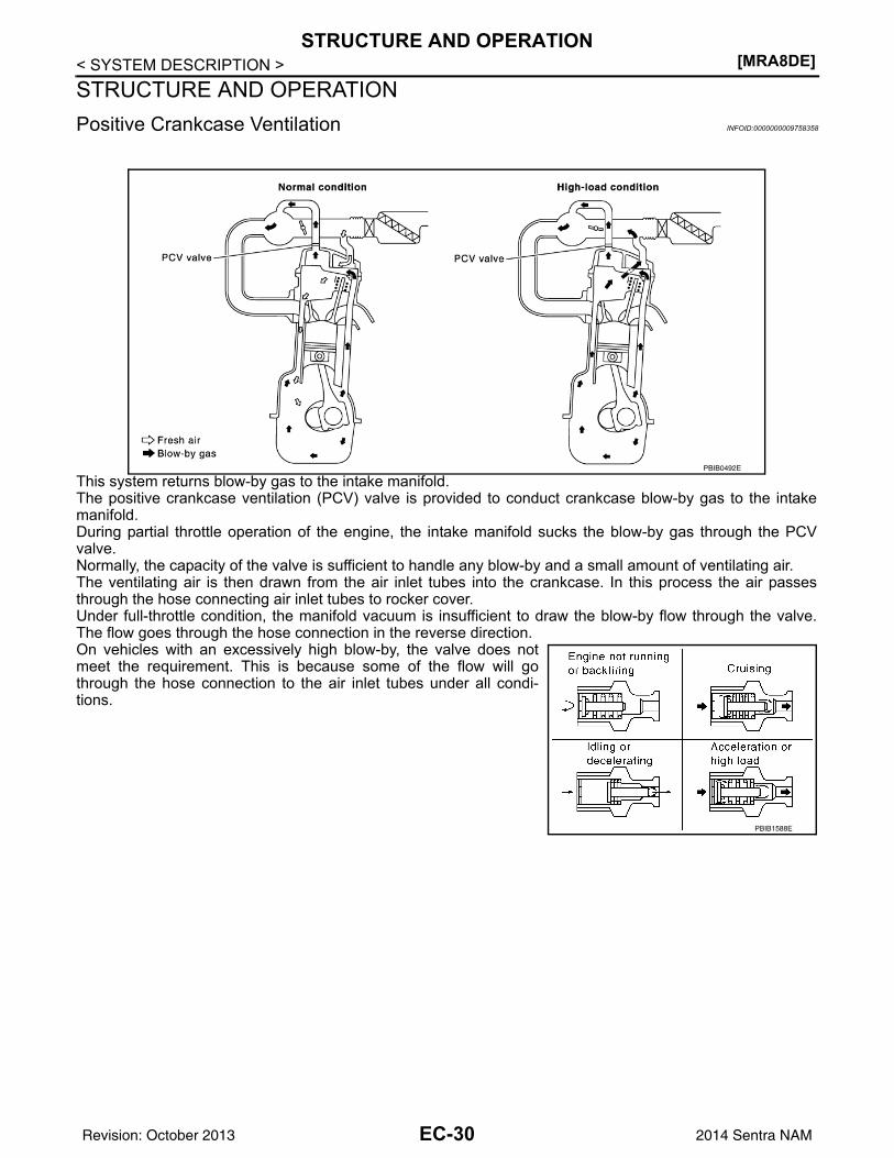
[MRA8DE]STRUCTURE AND OPERATION
< SYSTEM DESCRIPTION >STRUCTURE AND OPERATIONPositive Crankcase Ventilation INFOID:0000000009758358
This system returns blow-by gas to the intake manifold.The positive crankcase ventilation (PCV) valve is provided to conduct crankcase blow-by gas to the intakemanifold.During partial throttle operation of the engine, the intake manifold sucks the blow-by gas through the PCVvalve.Normally, the capacity of the valve is sufficient to handle any blow-by and a small amount of ventilating air.The ventilating air is then drawn from the air inlet tubes into the crankcase. In this process the air passesthrough the hose connecting air inlet tubes to rocker cover.Under full-throttle condition, the manifold vacuum is insufficient to draw the blow-by flow through the valve.The flow goes through the hose connection in the reverse direction.On vehicles with an excessively high blow-by, the valve does notmeet the requirement. This is because some of the flow will gothrough the hose connection to the air inlet tubes under all condi-tions.
PBIB0492E
PBIB1588E
EC-30Revision: October 2013 2014 Sentra NAM
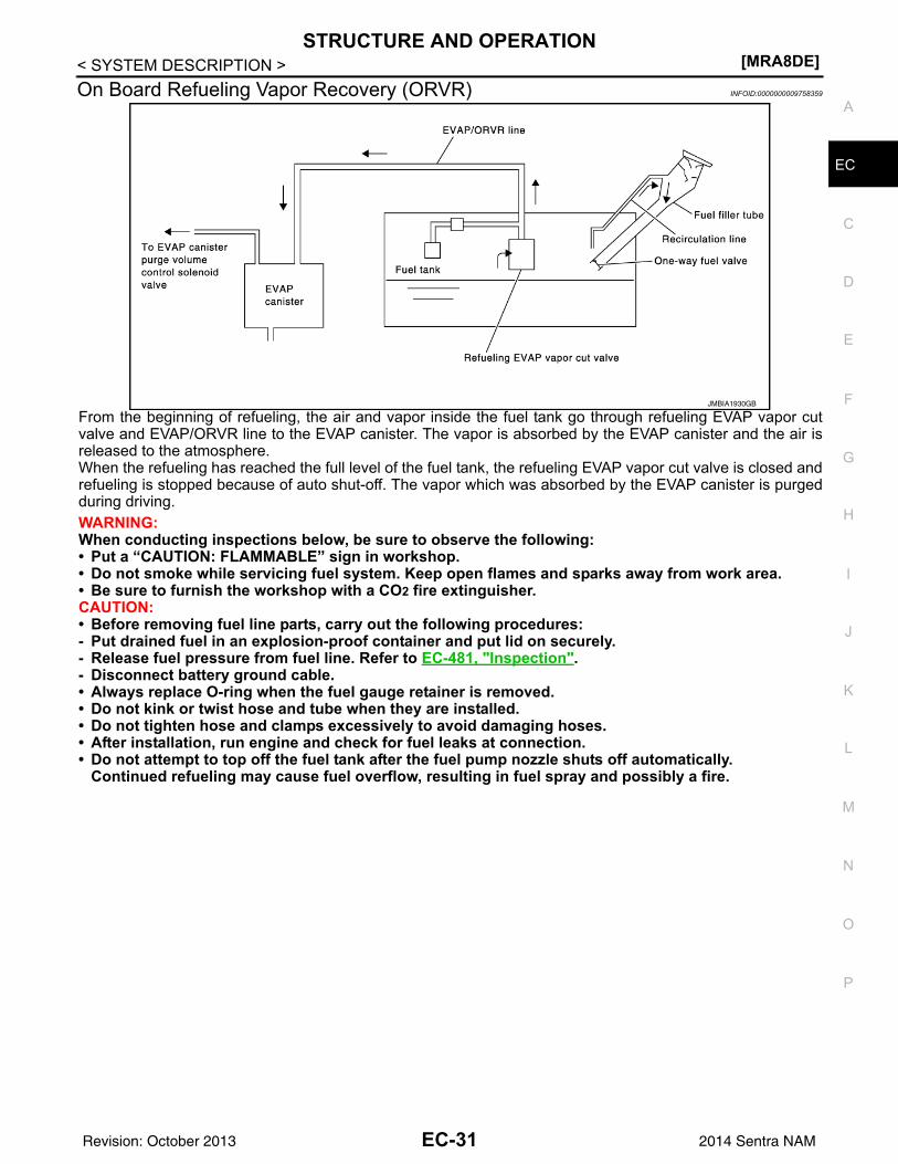
STRUCTURE AND OPERATION[MRA8DE]
C
D
E
F
G
H
I
J
K
L
M
A
C
N
P
O
< SYSTEM DESCRIPTION >
E
On Board Refueling Vapor Recovery (ORVR) INFOID:0000000009758359
From the beginning of refueling, the air and vapor inside the fuel tank go through refueling EVAP vapor cutvalve and EVAP/ORVR line to the EVAP canister. The vapor is absorbed by the EVAP canister and the air isreleased to the atmosphere.When the refueling has reached the full level of the fuel tank, the refueling EVAP vapor cut valve is closed andrefueling is stopped because of auto shut-off. The vapor which was absorbed by the EVAP canister is purgedduring driving.WARNING:When conducting inspections below, be sure to observe the following:• Put a “CAUTION: FLAMMABLE” sign in workshop.• Do not smoke while servicing fuel system. Keep open flames and sparks away from work area.• Be sure to furnish the workshop with a CO2 fire extinguisher.CAUTION:• Before removing fuel line parts, carry out the following procedures:- Put drained fuel in an explosion-proof container and put lid on securely.- Release fuel pressure from fuel line. Refer to EC-481, "Inspection".- Disconnect battery ground cable.• Always replace O-ring when the fuel gauge retainer is removed.• Do not kink or twist hose and tube when they are installed.• Do not tighten hose and clamps excessively to avoid damaging hoses.• After installation, run engine and check for fuel leaks at connection.• Do not attempt to top off the fuel tank after the fuel pump nozzle shuts off automatically.
Continued refueling may cause fuel overflow, resulting in fuel spray and possibly a fire.
JMBIA1930GB
EC-31Revision: October 2013 2014 Sentra NAM
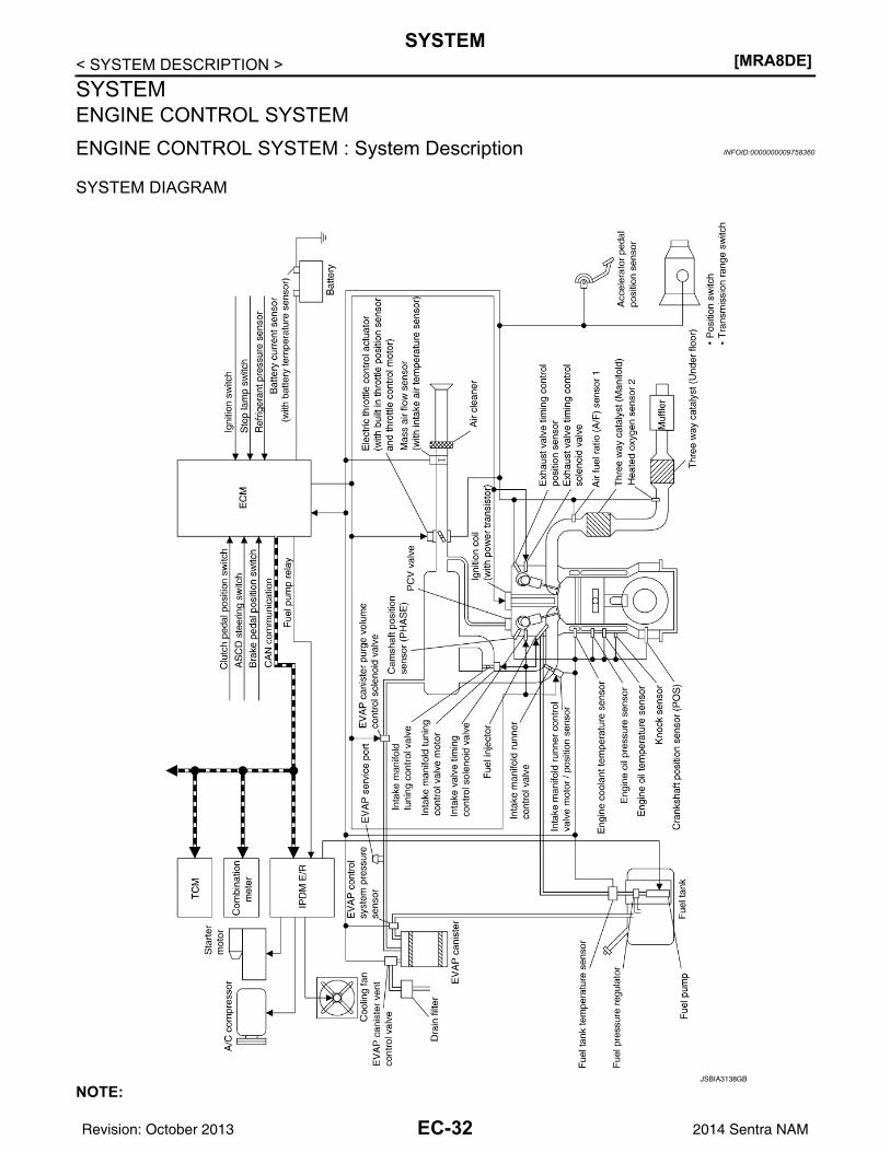
[MRA8DE]SYSTEM
< SYSTEM DESCRIPTION >SYSTEMENGINE CONTROL SYSTEMENGINE CONTROL SYSTEM : System Description INFOID:0000000009758360
SYSTEM DIAGRAM
NOTE:JSBIA3138GB
EC-32Revision: October 2013 2014 Sentra NAM
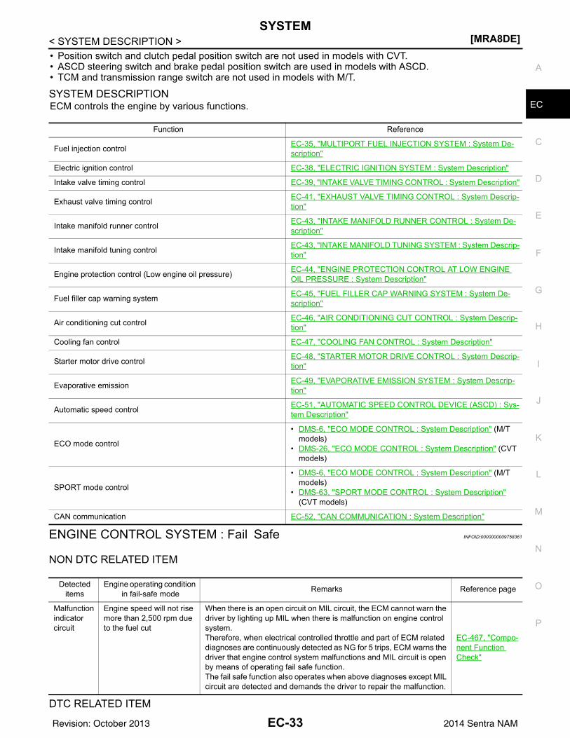
SYSTEM[MRA8DE]
C
D
E
F
G
H
I
J
K
L
M
A
C
N
P
O
< SYSTEM DESCRIPTION >
E
• Position switch and clutch pedal position switch are not used in models with CVT.• ASCD steering switch and brake pedal position switch are used in models with ASCD.• TCM and transmission range switch are not used in models with M/T.
SYSTEM DESCRIPTIONECM controls the engine by various functions.
ENGINE CONTROL SYSTEM : Fail Safe INFOID:0000000009758361
NON DTC RELATED ITEM
DTC RELATED ITEM
Function Reference
Fuel injection control EC-35, "MULTIPORT FUEL INJECTION SYSTEM : System De-scription"
Electric ignition control EC-38, "ELECTRIC IGNITION SYSTEM : System Description"
Intake valve timing control EC-39, "INTAKE VALVE TIMING CONTROL : System Description"
Exhaust valve timing control EC-41, "EXHAUST VALVE TIMING CONTROL : System Descrip-tion"
Intake manifold runner control EC-43, "INTAKE MANIFOLD RUNNER CONTROL : System De-scription"
Intake manifold tuning control EC-43, "INTAKE MANIFOLD TUNING SYSTEM : System Descrip-tion"
Engine protection control (Low engine oil pressure) EC-44, "ENGINE PROTECTION CONTROL AT LOW ENGINE OIL PRESSURE : System Description"
Fuel filler cap warning system EC-45, "FUEL FILLER CAP WARNING SYSTEM : System De-scription"
Air conditioning cut control EC-46, "AIR CONDITIONING CUT CONTROL : System Descrip-tion"
Cooling fan control EC-47, "COOLING FAN CONTROL : System Description"
Starter motor drive control EC-48, "STARTER MOTOR DRIVE CONTROL : System Descrip-tion"
Evaporative emission EC-49, "EVAPORATIVE EMISSION SYSTEM : System Descrip-tion"
Automatic speed control EC-51, "AUTOMATIC SPEED CONTROL DEVICE (ASCD) : Sys-tem Description"
ECO mode control
• DMS-6, "ECO MODE CONTROL : System Description" (M/T models)
• DMS-26, "ECO MODE CONTROL : System Description" (CVT models)
SPORT mode control
• DMS-6, "ECO MODE CONTROL : System Description" (M/T models)
• DMS-63, "SPORT MODE CONTROL : System Description" (CVT models)
CAN communication EC-52, "CAN COMMUNICATION : System Description"
Detected items
Engine operating condition in fail-safe mode Remarks Reference page
Malfunction indicator circuit
Engine speed will not rise more than 2,500 rpm due to the fuel cut
When there is an open circuit on MIL circuit, the ECM cannot warn the driver by lighting up MIL when there is malfunction on engine control system.Therefore, when electrical controlled throttle and part of ECM related diagnoses are continuously detected as NG for 5 trips, ECM warns the driver that engine control system malfunctions and MIL circuit is open by means of operating fail safe function.The fail safe function also operates when above diagnoses except MIL circuit are detected and demands the driver to repair the malfunction.
EC-467, "Compo-nent Function Check"
EC-33Revision: October 2013 2014 Sentra NAM
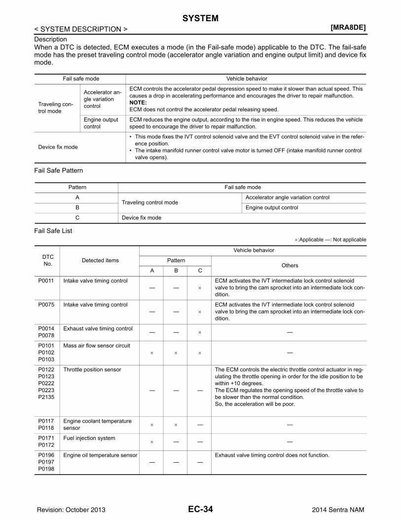
[MRA8DE]SYSTEM
< SYSTEM DESCRIPTION >DescriptionWhen a DTC is detected, ECM executes a mode (in the Fail-safe mode) applicable to the DTC. The fail-safemode has the preset traveling control mode (accelerator angle variation and engine output limit) and device fixmode.
Fail Safe Pattern
Fail Safe List×:Applicable —: Not applicable
Fail safe mode Vehicle behavior
Traveling con-trol mode
Accelerator an-gle variation control
ECM controls the accelerator pedal depression speed to make it slower than actual speed. This causes a drop in accelerating performance and encourages the driver to repair malfunction.NOTE:ECM does not control the accelerator pedal releasing speed.
Engine output control
ECM reduces the engine output, according to the rise in engine speed. This reduces the vehicle speed to encourage the driver to repair malfunction.
Device fix mode
• This mode fixes the IVT control solenoid valve and the EVT control solenoid valve in the refer-ence position.
• The intake manifold runner control valve motor is turned OFF (intake manifold runner control valve opens).
Pattern Fail safe mode
ATraveling control mode
Accelerator angle variation control
B Engine output control
C Device fix mode
DTC No. Detected items
Vehicle behavior
PatternOthers
A B C
P0011 Intake valve timing control— — ×
ECM activates the IVT intermediate lock control solenoid valve to bring the cam sprocket into an intermediate lock con-dition.
P0075 Intake valve timing control— — ×
ECM activates the IVT intermediate lock control solenoid valve to bring the cam sprocket into an intermediate lock con-dition.
P0014P0078
Exhaust valve timing control — — × —
P0101P0102P0103
Mass air flow sensor circuit× × × —
P0122P0123P0222P0223P2135
Throttle position sensor
— — —
The ECM controls the electric throttle control actuator in reg-ulating the throttle opening in order for the idle position to be within +10 degrees.The ECM regulates the opening speed of the throttle valve to be slower than the normal condition.So, the acceleration will be poor.
P0117P0118
Engine coolant temperature sensor × × — —
P0171P0172
Fuel injection system× — — —
P0196P0197P0198
Engine oil temperature sensor— — —
Exhaust valve timing control does not function.
EC-34Revision: October 2013 2014 Sentra NAM
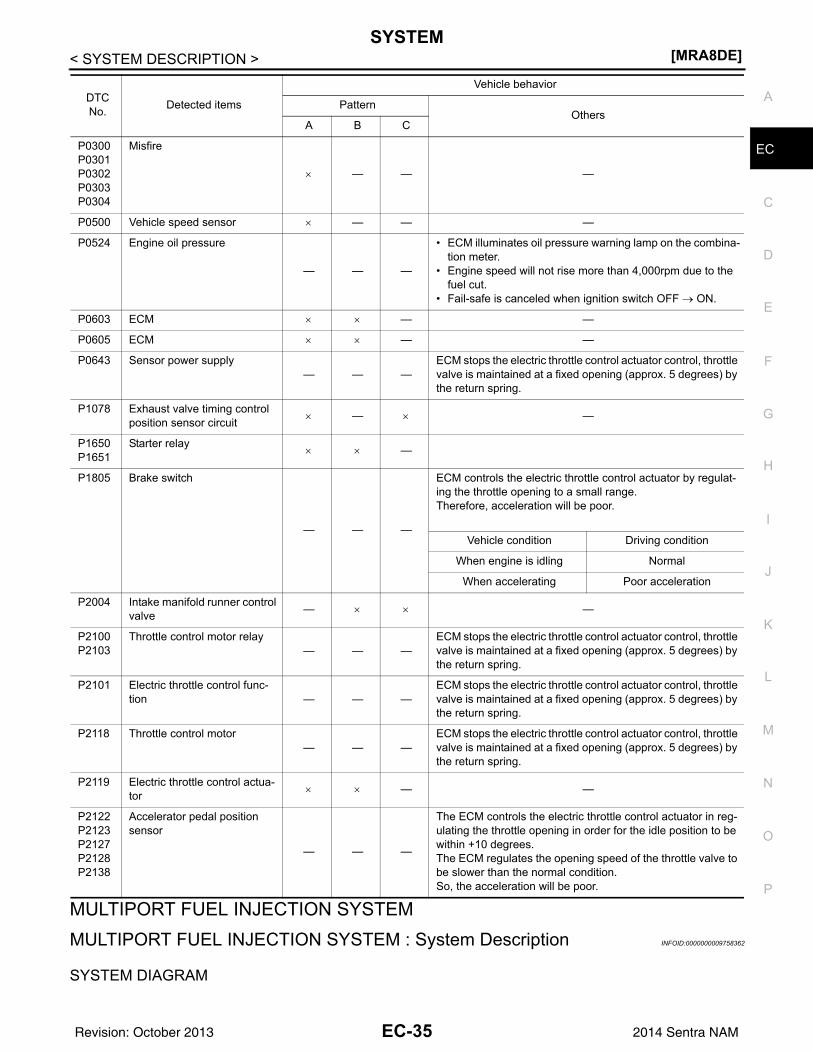
SYSTEM[MRA8DE]
C
D
E
F
G
H
I
J
K
L
M
A
C
N
P
O
< SYSTEM DESCRIPTION >
E
MULTIPORT FUEL INJECTION SYSTEMMULTIPORT FUEL INJECTION SYSTEM : System Description INFOID:0000000009758362
SYSTEM DIAGRAM
P0300P0301P0302P0303P0304
Misfire
× — — —
P0500 Vehicle speed sensor × — — —
P0524 Engine oil pressure
— — —
• ECM illuminates oil pressure warning lamp on the combina-tion meter.
• Engine speed will not rise more than 4,000rpm due to the fuel cut.
• Fail-safe is canceled when ignition switch OFF → ON.
P0603 ECM × × — —
P0605 ECM × × — —
P0643 Sensor power supply— — —
ECM stops the electric throttle control actuator control, throttle valve is maintained at a fixed opening (approx. 5 degrees) by the return spring.
P1078 Exhaust valve timing control position sensor circuit × — × —
P1650P1651
Starter relay× × —
P1805 Brake switch
— — —
ECM controls the electric throttle control actuator by regulat-ing the throttle opening to a small range.Therefore, acceleration will be poor.
Vehicle condition Driving condition
When engine is idling Normal
When accelerating Poor acceleration
P2004 Intake manifold runner control valve — × × —
P2100P2103
Throttle control motor relay— — —
ECM stops the electric throttle control actuator control, throttle valve is maintained at a fixed opening (approx. 5 degrees) by the return spring.
P2101 Electric throttle control func-tion — — —
ECM stops the electric throttle control actuator control, throttle valve is maintained at a fixed opening (approx. 5 degrees) by the return spring.
P2118 Throttle control motor— — —
ECM stops the electric throttle control actuator control, throttle valve is maintained at a fixed opening (approx. 5 degrees) by the return spring.
P2119 Electric throttle control actua-tor × × — —
P2122P2123P2127P2128P2138
Accelerator pedal position sensor
— — —
The ECM controls the electric throttle control actuator in reg-ulating the throttle opening in order for the idle position to be within +10 degrees.The ECM regulates the opening speed of the throttle valve to be slower than the normal condition.So, the acceleration will be poor.
DTC No. Detected items
Vehicle behavior
PatternOthers
A B C
EC-35Revision: October 2013 2014 Sentra NAM
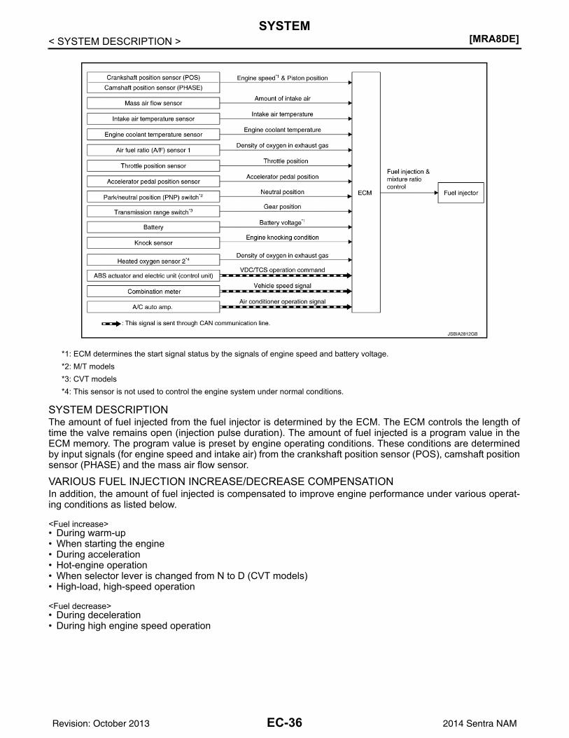
[MRA8DE]SYSTEM
< SYSTEM DESCRIPTION >
SYSTEM DESCRIPTIONThe amount of fuel injected from the fuel injector is determined by the ECM. The ECM controls the length oftime the valve remains open (injection pulse duration). The amount of fuel injected is a program value in theECM memory. The program value is preset by engine operating conditions. These conditions are determinedby input signals (for engine speed and intake air) from the crankshaft position sensor (POS), camshaft positionsensor (PHASE) and the mass air flow sensor.
VARIOUS FUEL INJECTION INCREASE/DECREASE COMPENSATIONIn addition, the amount of fuel injected is compensated to improve engine performance under various operat-ing conditions as listed below.
<Fuel increase>• During warm-up• When starting the engine• During acceleration• Hot-engine operation• When selector lever is changed from N to D (CVT models)• High-load, high-speed operation
<Fuel decrease>• During deceleration• During high engine speed operation
*1: ECM determines the start signal status by the signals of engine speed and battery voltage.*2: M/T models*3: CVT models*4: This sensor is not used to control the engine system under normal conditions.
JSBIA2812GB
EC-36Revision: October 2013 2014 Sentra NAM
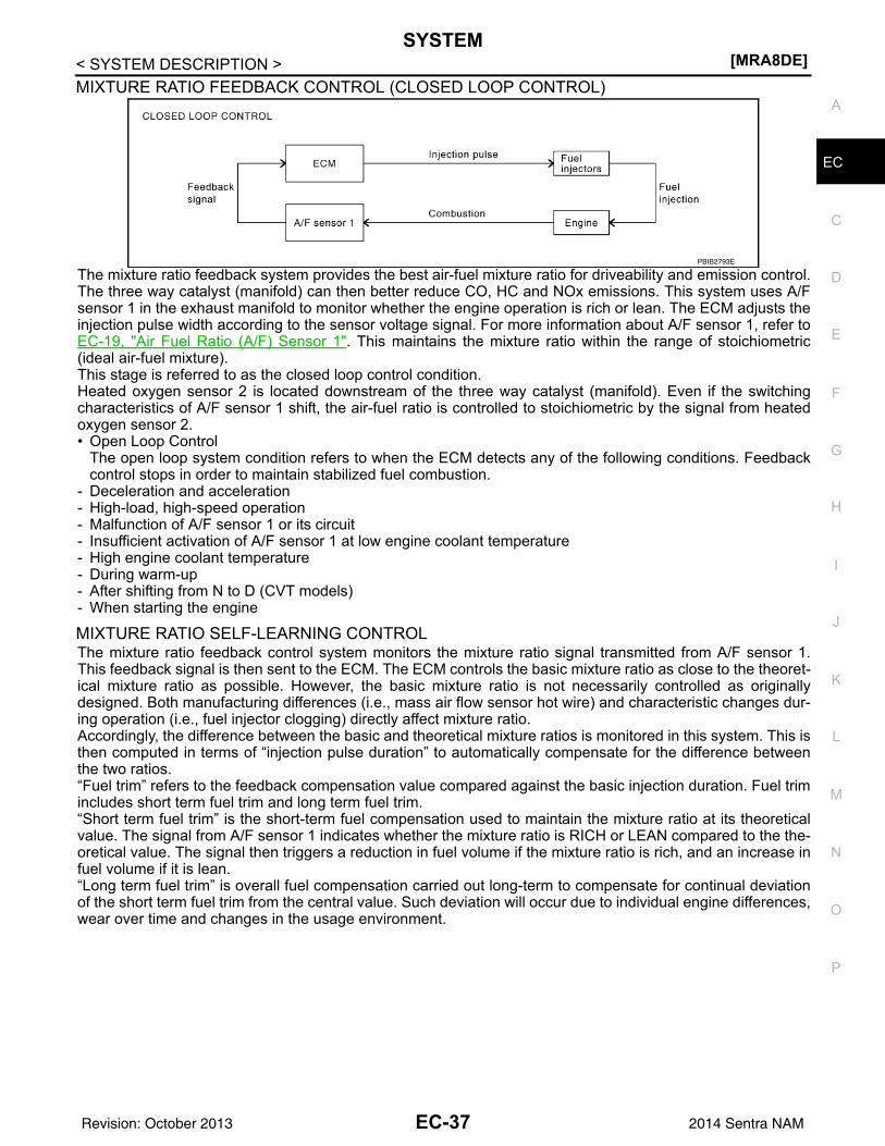
SYSTEM[MRA8DE]
C
D
E
F
G
H
I
J
K
L
M
A
C
N
P
O
< SYSTEM DESCRIPTION >
E
MIXTURE RATIO FEEDBACK CONTROL (CLOSED LOOP CONTROL)
The mixture ratio feedback system provides the best air-fuel mixture ratio for driveability and emission control.The three way catalyst (manifold) can then better reduce CO, HC and NOx emissions. This system uses A/Fsensor 1 in the exhaust manifold to monitor whether the engine operation is rich or lean. The ECM adjusts theinjection pulse width according to the sensor voltage signal. For more information about A/F sensor 1, refer toEC-19, "Air Fuel Ratio (A/F) Sensor 1". This maintains the mixture ratio within the range of stoichiometric(ideal air-fuel mixture).This stage is referred to as the closed loop control condition.Heated oxygen sensor 2 is located downstream of the three way catalyst (manifold). Even if the switchingcharacteristics of A/F sensor 1 shift, the air-fuel ratio is controlled to stoichiometric by the signal from heatedoxygen sensor 2.• Open Loop Control
The open loop system condition refers to when the ECM detects any of the following conditions. Feedbackcontrol stops in order to maintain stabilized fuel combustion.
- Deceleration and acceleration- High-load, high-speed operation- Malfunction of A/F sensor 1 or its circuit- Insufficient activation of A/F sensor 1 at low engine coolant temperature- High engine coolant temperature- During warm-up- After shifting from N to D (CVT models)- When starting the engine
MIXTURE RATIO SELF-LEARNING CONTROLThe mixture ratio feedback control system monitors the mixture ratio signal transmitted from A/F sensor 1.This feedback signal is then sent to the ECM. The ECM controls the basic mixture ratio as close to the theoret-ical mixture ratio as possible. However, the basic mixture ratio is not necessarily controlled as originallydesigned. Both manufacturing differences (i.e., mass air flow sensor hot wire) and characteristic changes dur-ing operation (i.e., fuel injector clogging) directly affect mixture ratio.Accordingly, the difference between the basic and theoretical mixture ratios is monitored in this system. This isthen computed in terms of “injection pulse duration” to automatically compensate for the difference betweenthe two ratios.“Fuel trim” refers to the feedback compensation value compared against the basic injection duration. Fuel trimincludes short term fuel trim and long term fuel trim.“Short term fuel trim” is the short-term fuel compensation used to maintain the mixture ratio at its theoreticalvalue. The signal from A/F sensor 1 indicates whether the mixture ratio is RICH or LEAN compared to the the-oretical value. The signal then triggers a reduction in fuel volume if the mixture ratio is rich, and an increase infuel volume if it is lean.“Long term fuel trim” is overall fuel compensation carried out long-term to compensate for continual deviationof the short term fuel trim from the central value. Such deviation will occur due to individual engine differences,wear over time and changes in the usage environment.
PBIB2793E
EC-37Revision: October 2013 2014 Sentra NAM
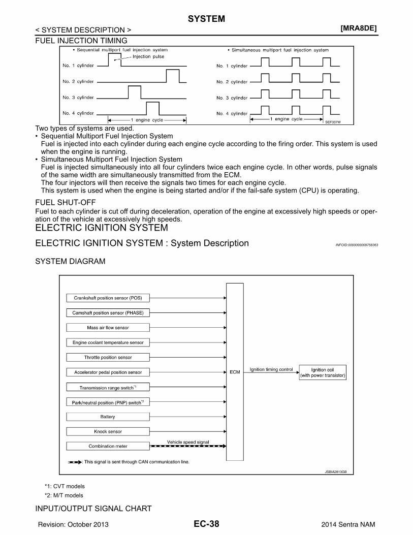
[MRA8DE]SYSTEM
< SYSTEM DESCRIPTION >FUEL INJECTION TIMING
Two types of systems are used.• Sequential Multiport Fuel Injection System
Fuel is injected into each cylinder during each engine cycle according to the firing order. This system is usedwhen the engine is running.
• Simultaneous Multiport Fuel Injection SystemFuel is injected simultaneously into all four cylinders twice each engine cycle. In other words, pulse signalsof the same width are simultaneously transmitted from the ECM.The four injectors will then receive the signals two times for each engine cycle.This system is used when the engine is being started and/or if the fail-safe system (CPU) is operating.
FUEL SHUT-OFFFuel to each cylinder is cut off during deceleration, operation of the engine at excessively high speeds or oper-ation of the vehicle at excessively high speeds.ELECTRIC IGNITION SYSTEMELECTRIC IGNITION SYSTEM : System Description INFOID:0000000009758363
SYSTEM DIAGRAM
INPUT/OUTPUT SIGNAL CHART
SEF337W
*1: CVT models*2: M/T models
JSBIA2813GB
EC-38Revision: October 2013 2014 Sentra NAM
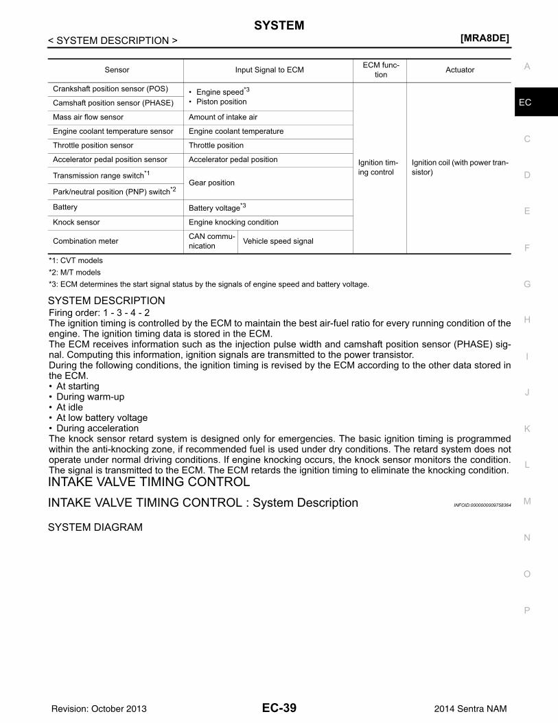
SYSTEM[MRA8DE]
C
D
E
F
G
H
I
J
K
L
M
A
C
N
P
O
< SYSTEM DESCRIPTION >
E
*1: CVT models*2: M/T models*3: ECM determines the start signal status by the signals of engine speed and battery voltage.
SYSTEM DESCRIPTIONFiring order: 1 - 3 - 4 - 2 The ignition timing is controlled by the ECM to maintain the best air-fuel ratio for every running condition of theengine. The ignition timing data is stored in the ECM.The ECM receives information such as the injection pulse width and camshaft position sensor (PHASE) sig-nal. Computing this information, ignition signals are transmitted to the power transistor.During the following conditions, the ignition timing is revised by the ECM according to the other data stored inthe ECM.• At starting• During warm-up• At idle• At low battery voltage• During accelerationThe knock sensor retard system is designed only for emergencies. The basic ignition timing is programmedwithin the anti-knocking zone, if recommended fuel is used under dry conditions. The retard system does notoperate under normal driving conditions. If engine knocking occurs, the knock sensor monitors the condition.The signal is transmitted to the ECM. The ECM retards the ignition timing to eliminate the knocking condition.INTAKE VALVE TIMING CONTROLINTAKE VALVE TIMING CONTROL : System Description INFOID:0000000009758364
SYSTEM DIAGRAM
Sensor Input Signal to ECM ECM func-tion Actuator
Crankshaft position sensor (POS) • Engine speed*3
• Piston position
Ignition tim-ing control
Ignition coil (with power tran-sistor)
Camshaft position sensor (PHASE)
Mass air flow sensor Amount of intake air
Engine coolant temperature sensor Engine coolant temperature
Throttle position sensor Throttle position
Accelerator pedal position sensor Accelerator pedal position
Transmission range switch*1Gear position
Park/neutral position (PNP) switch*2
Battery Battery voltage*3
Knock sensor Engine knocking condition
Combination meter CAN commu-nication Vehicle speed signal
EC-39Revision: October 2013 2014 Sentra NAM
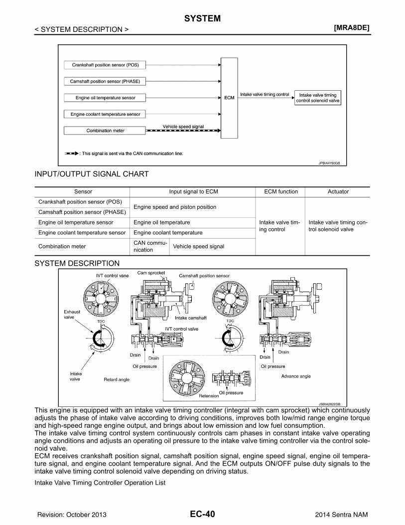
[MRA8DE]SYSTEM
< SYSTEM DESCRIPTION >
INPUT/OUTPUT SIGNAL CHART
SYSTEM DESCRIPTION
This engine is equipped with an intake valve timing controller (integral with cam sprocket) which continuouslyadjusts the phase of intake valve according to driving conditions, improves both low/mid range engine torqueand high-speed range engine output, and brings about low emission and low fuel consumption.The intake valve timing control system continuously controls cam phases in constant intake valve operatingangle conditions and adjusts an operating oil pressure to the intake valve timing controller via the control sole-noid valve.ECM receives crankshaft position signal, camshaft position signal, engine speed signal, engine oil tempera-ture signal, and engine coolant temperature signal. And the ECM outputs ON/OFF pulse duty signals to theintake valve timing control solenoid valve depending on driving status.Intake Valve Timing Controller Operation List
JPBIA4760GB
Sensor Input signal to ECM ECM function Actuator
Crankshaft position sensor (POS)Engine speed and piston position
Intake valve tim-ing control
Intake valve timing con-trol solenoid valve
Camshaft position sensor (PHASE)
Engine oil temperature sensor Engine oil temperature
Engine coolant temperature sensor Engine coolant temperature
Combination meter CAN commu-nication Vehicle speed signal
JSBIA2822GB
EC-40Revision: October 2013 2014 Sentra NAM
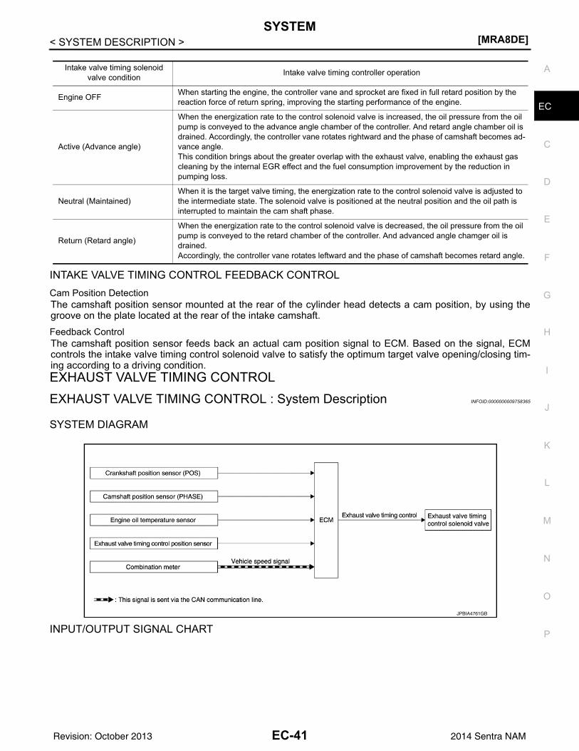
SYSTEM[MRA8DE]
C
D
E
F
G
H
I
J
K
L
M
A
C
N
P
O
< SYSTEM DESCRIPTION >
E
INTAKE VALVE TIMING CONTROL FEEDBACK CONTROLCam Position DetectionThe camshaft position sensor mounted at the rear of the cylinder head detects a cam position, by using thegroove on the plate located at the rear of the intake camshaft.Feedback ControlThe camshaft position sensor feeds back an actual cam position signal to ECM. Based on the signal, ECMcontrols the intake valve timing control solenoid valve to satisfy the optimum target valve opening/closing tim-ing according to a driving condition.EXHAUST VALVE TIMING CONTROLEXHAUST VALVE TIMING CONTROL : System Description INFOID:0000000009758365
SYSTEM DIAGRAM
INPUT/OUTPUT SIGNAL CHART
Intake valve timing solenoid valve condition Intake valve timing controller operation
Engine OFF When starting the engine, the controller vane and sprocket are fixed in full retard position by the reaction force of return spring, improving the starting performance of the engine.
Active (Advance angle)
When the energization rate to the control solenoid valve is increased, the oil pressure from the oil pump is conveyed to the advance angle chamber of the controller. And retard angle chamber oil is drained. Accordingly, the controller vane rotates rightward and the phase of camshaft becomes ad-vance angle.This condition brings about the greater overlap with the exhaust valve, enabling the exhaust gas cleaning by the internal EGR effect and the fuel consumption improvement by the reduction in pumping loss.
Neutral (Maintained)When it is the target valve timing, the energization rate to the control solenoid valve is adjusted to the intermediate state. The solenoid valve is positioned at the neutral position and the oil path is interrupted to maintain the cam shaft phase.
Return (Retard angle)
When the energization rate to the control solenoid valve is decreased, the oil pressure from the oil pump is conveyed to the retard chamber of the controller. And advanced angle chamger oil is drained.Accordingly, the controller vane rotates leftward and the phase of camshaft becomes retard angle.
JPBIA4761GB
EC-41Revision: October 2013 2014 Sentra NAM
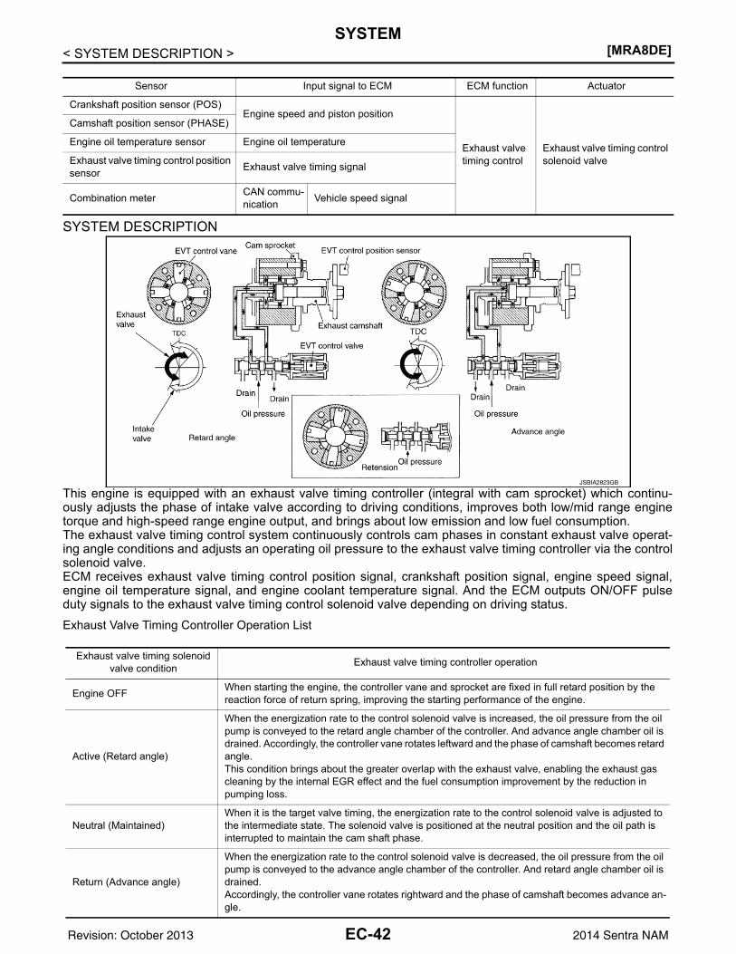
[MRA8DE]SYSTEM
< SYSTEM DESCRIPTION >
SYSTEM DESCRIPTION
This engine is equipped with an exhaust valve timing controller (integral with cam sprocket) which continu-ously adjusts the phase of intake valve according to driving conditions, improves both low/mid range enginetorque and high-speed range engine output, and brings about low emission and low fuel consumption.The exhaust valve timing control system continuously controls cam phases in constant exhaust valve operat-ing angle conditions and adjusts an operating oil pressure to the exhaust valve timing controller via the controlsolenoid valve.ECM receives exhaust valve timing control position signal, crankshaft position signal, engine speed signal,engine oil temperature signal, and engine coolant temperature signal. And the ECM outputs ON/OFF pulseduty signals to the exhaust valve timing control solenoid valve depending on driving status.Exhaust Valve Timing Controller Operation List
Sensor Input signal to ECM ECM function Actuator
Crankshaft position sensor (POS)Engine speed and piston position
Exhaust valve timing control
Exhaust valve timing control solenoid valve
Camshaft position sensor (PHASE)
Engine oil temperature sensor Engine oil temperature
Exhaust valve timing control position sensor Exhaust valve timing signal
Combination meter CAN commu-nication Vehicle speed signal
JSBIA2823GB
Exhaust valve timing solenoid valve condition Exhaust valve timing controller operation
Engine OFF When starting the engine, the controller vane and sprocket are fixed in full retard position by the reaction force of return spring, improving the starting performance of the engine.
Active (Retard angle)
When the energization rate to the control solenoid valve is increased, the oil pressure from the oil pump is conveyed to the retard angle chamber of the controller. And advance angle chamber oil is drained. Accordingly, the controller vane rotates leftward and the phase of camshaft becomes retard angle.This condition brings about the greater overlap with the exhaust valve, enabling the exhaust gas cleaning by the internal EGR effect and the fuel consumption improvement by the reduction in pumping loss.
Neutral (Maintained)When it is the target valve timing, the energization rate to the control solenoid valve is adjusted to the intermediate state. The solenoid valve is positioned at the neutral position and the oil path is interrupted to maintain the cam shaft phase.
Return (Advance angle)
When the energization rate to the control solenoid valve is decreased, the oil pressure from the oil pump is conveyed to the advance angle chamber of the controller. And retard angle chamber oil is drained.Accordingly, the controller vane rotates rightward and the phase of camshaft becomes advance an-gle.
EC-42Revision: October 2013 2014 Sentra NAM
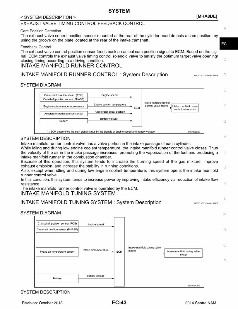
SYSTEM[MRA8DE]
C
D
E
F
G
H
I
J
K
L
M
A
C
N
P
O
< SYSTEM DESCRIPTION >
E
EXHAUST VALVE TIMING CONTROL FEEDBACK CONTROLCam Position DetectionThe exhaust valve control position sensor mounted at the rear of the cylinder head detects a cam position, byusing the groove on the plate located at the rear of the intake camshaft.Feedback ControlThe exhaust valve control position sensor feeds back an actual cam position signal to ECM. Based on the sig-nal, ECM controls the exhaust valve timing control solenoid valve to satisfy the optimum target valve opening/closing timing according to a driving condition.INTAKE MANIFOLD RUNNER CONTROLINTAKE MANIFOLD RUNNER CONTROL : System Description INFOID:0000000009758366
SYSTEM DIAGRAM
SYSTEM DESCRIPTIONIntake manifold runner control valve has a valve portion in the intake passage of each cylinder.While idling and during low engine coolant temperature, the intake manifold runner control valve closes. Thusthe velocity of the air in the intake passage increases, promoting the vaporization of the fuel and producing aintake manifold runner in the combustion chamber.Because of this operation, this system tends to increase the burning speed of the gas mixture, improveexhaust emission, and increase the stability in running conditions.Also, except when idling and during low engine coolant temperature, this system opens the intake manifoldrunner control valve.In this condition, this system tends to increase power by improving intake efficiency via reduction of intake flowresistance.The intake manifold runner control valve is operated by the ECM.INTAKE MANIFOLD TUNING SYSTEMINTAKE MANIFOLD TUNING SYSTEM : System Description INFOID:0000000009758367
SYSTEM DIAGRAM
SYSTEM DESCRIPTION
JPBIA6226GB
JSBIA2817GB
EC-43Revision: October 2013 2014 Sentra NAM
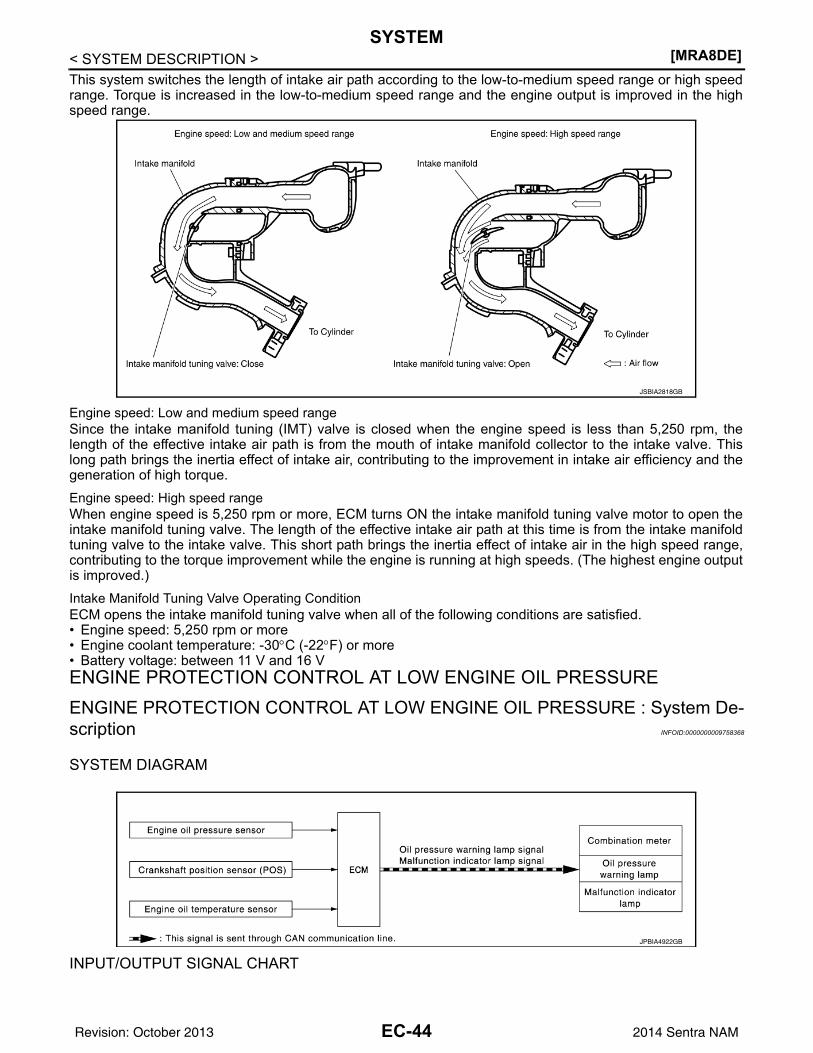
[MRA8DE]SYSTEM
< SYSTEM DESCRIPTION >This system switches the length of intake air path according to the low-to-medium speed range or high speedrange. Torque is increased in the low-to-medium speed range and the engine output is improved in the highspeed range.
Engine speed: Low and medium speed rangeSince the intake manifold tuning (IMT) valve is closed when the engine speed is less than 5,250 rpm, thelength of the effective intake air path is from the mouth of intake manifold collector to the intake valve. Thislong path brings the inertia effect of intake air, contributing to the improvement in intake air efficiency and thegeneration of high torque.Engine speed: High speed rangeWhen engine speed is 5,250 rpm or more, ECM turns ON the intake manifold tuning valve motor to open theintake manifold tuning valve. The length of the effective intake air path at this time is from the intake manifoldtuning valve to the intake valve. This short path brings the inertia effect of intake air in the high speed range,contributing to the torque improvement while the engine is running at high speeds. (The highest engine outputis improved.)Intake Manifold Tuning Valve Operating Condition ECM opens the intake manifold tuning valve when all of the following conditions are satisfied.• Engine speed: 5,250 rpm or more• Engine coolant temperature: -30°C (-22°F) or more• Battery voltage: between 11 V and 16 VENGINE PROTECTION CONTROL AT LOW ENGINE OIL PRESSUREENGINE PROTECTION CONTROL AT LOW ENGINE OIL PRESSURE : System De-scription INFOID:0000000009758368
SYSTEM DIAGRAM
INPUT/OUTPUT SIGNAL CHART
JSBIA2818GB
JPBIA4922GB
EC-44Revision: October 2013 2014 Sentra NAM
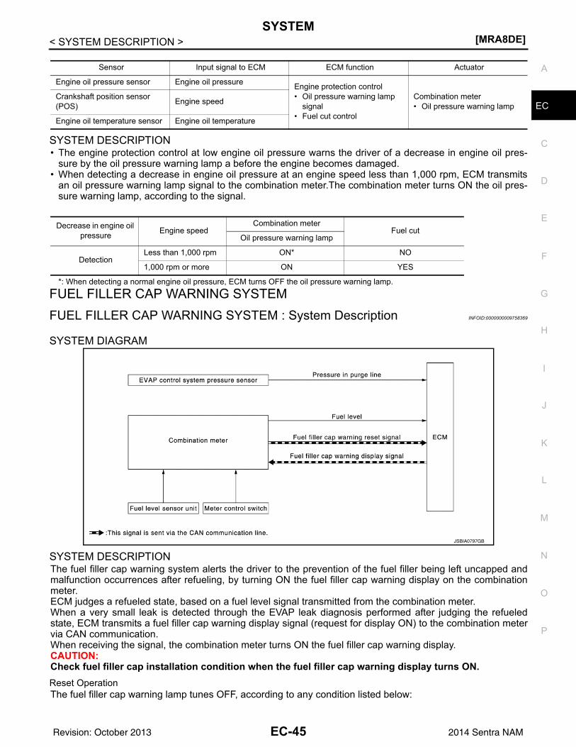
SYSTEM[MRA8DE]
C
D
E
F
G
H
I
J
K
L
M
A
C
N
P
O
< SYSTEM DESCRIPTION >
E
SYSTEM DESCRIPTION• The engine protection control at low engine oil pressure warns the driver of a decrease in engine oil pres-
sure by the oil pressure warning lamp a before the engine becomes damaged.• When detecting a decrease in engine oil pressure at an engine speed less than 1,000 rpm, ECM transmits
an oil pressure warning lamp signal to the combination meter.The combination meter turns ON the oil pres-sure warning lamp, according to the signal.
*: When detecting a normal engine oil pressure, ECM turns OFF the oil pressure warning lamp.
FUEL FILLER CAP WARNING SYSTEMFUEL FILLER CAP WARNING SYSTEM : System Description INFOID:0000000009758369
SYSTEM DIAGRAM
SYSTEM DESCRIPTIONThe fuel filler cap warning system alerts the driver to the prevention of the fuel filler being left uncapped andmalfunction occurrences after refueling, by turning ON the fuel filler cap warning display on the combinationmeter.ECM judges a refueled state, based on a fuel level signal transmitted from the combination meter.When a very small leak is detected through the EVAP leak diagnosis performed after judging the refueledstate, ECM transmits a fuel filler cap warning display signal (request for display ON) to the combination metervia CAN communication. When receiving the signal, the combination meter turns ON the fuel filler cap warning display.CAUTION:Check fuel filler cap installation condition when the fuel filler cap warning display turns ON.Reset OperationThe fuel filler cap warning lamp tunes OFF, according to any condition listed below:
Sensor Input signal to ECM ECM function Actuator
Engine oil pressure sensor Engine oil pressure Engine protection control• Oil pressure warning lamp
signal• Fuel cut control
Combination meter• Oil pressure warning lamp
Crankshaft position sensor (POS) Engine speed
Engine oil temperature sensor Engine oil temperature
Decrease in engine oil pressure Engine speed
Combination meterFuel cut
Oil pressure warning lamp
DetectionLess than 1,000 rpm ON* NO
1,000 rpm or more ON YES
JSBIA0797GB
EC-45Revision: October 2013 2014 Sentra NAM
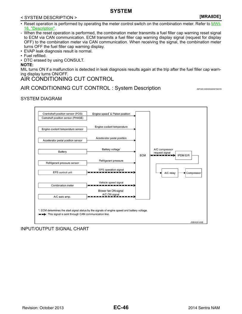
[MRA8DE]SYSTEM
< SYSTEM DESCRIPTION >• Reset operation is performed by operating the meter control switch on the combination meter. Refer to MWI-
16, "Description".- When the reset operation is performed, the combination meter transmits a fuel filler cap warning reset signal
to ECM via CAN communication. ECM transmits a fuel filler cap warning display signal (request for displayOFF) to the combination meter via CAN communication. When receiving the signal, the combination meterturns OFF the fuel filler cap warning display.
• EVAP leak diagnosis result is normal.• Fuel refilled.• DTC erased by using CONSULT.NOTE:MIL turns ON if a malfunction is detected in leak diagnosis results again at the trip after the fuel filler cap warn-ing display turns ON/OFF.AIR CONDITIONING CUT CONTROLAIR CONDITIONING CUT CONTROL : System Description INFOID:0000000009758370
SYSTEM DIAGRAM
INPUT/OUTPUT SIGNAL CHARTJSBIA2814GB
EC-46Revision: October 2013 2014 Sentra NAM
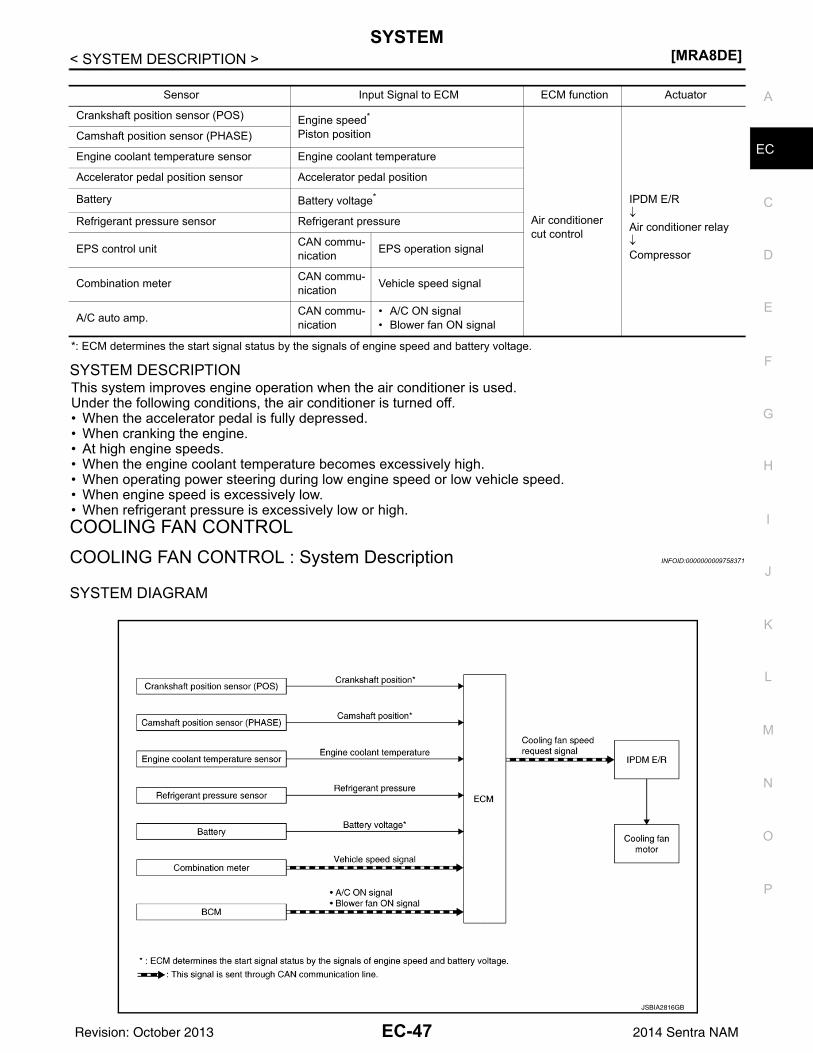
SYSTEM[MRA8DE]
C
D
E
F
G
H
I
J
K
L
M
A
C
N
P
O
< SYSTEM DESCRIPTION >
E
*: ECM determines the start signal status by the signals of engine speed and battery voltage.
SYSTEM DESCRIPTIONThis system improves engine operation when the air conditioner is used.Under the following conditions, the air conditioner is turned off.• When the accelerator pedal is fully depressed.• When cranking the engine.• At high engine speeds.• When the engine coolant temperature becomes excessively high.• When operating power steering during low engine speed or low vehicle speed.• When engine speed is excessively low.• When refrigerant pressure is excessively low or high.COOLING FAN CONTROLCOOLING FAN CONTROL : System Description INFOID:0000000009758371
SYSTEM DIAGRAM
Sensor Input Signal to ECM ECM function Actuator
Crankshaft position sensor (POS) Engine speed*
Piston position
Air conditioner cut control
IPDM E/R↓Air conditioner relay↓Compressor
Camshaft position sensor (PHASE)
Engine coolant temperature sensor Engine coolant temperature
Accelerator pedal position sensor Accelerator pedal position
Battery Battery voltage*
Refrigerant pressure sensor Refrigerant pressure
EPS control unit CAN commu-nication EPS operation signal
Combination meter CAN commu-nication Vehicle speed signal
A/C auto amp. CAN commu-nication
• A/C ON signal• Blower fan ON signal
JSBIA2816GB
EC-47Revision: October 2013 2014 Sentra NAM
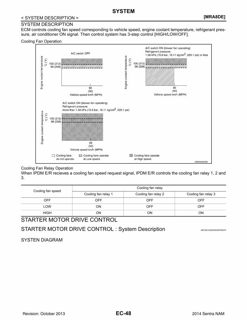
[MRA8DE]SYSTEM
< SYSTEM DESCRIPTION >SYSTEM DESCRIPTIONECM controls cooling fan speed corresponding to vehicle speed, engine coolant temperature, refrigerant pres-sure, air conditioner ON signal. Then control system has 3-step control [HIGH/LOW/OFF].Cooling Fan Operation
Cooling Fan Relay OperationWhen IPDM E/R recieves a cooling fan speed request signal, IPDM E/R controls the cooling fan ralay 1, 2 and3.
STARTER MOTOR DRIVE CONTROLSTARTER MOTOR DRIVE CONTROL : System Description INFOID:0000000009758372
SYSTEN DIAGRAM
JSBIA2662GB
Cooling fan speedCooling fan relay
Cooling fan relay 1 Cooling fan relay 2 Cooling fan relay 3
OFF OFF OFF OFF
LOW ON OFF OFF
HIGH ON ON ON
EC-48Revision: October 2013 2014 Sentra NAM
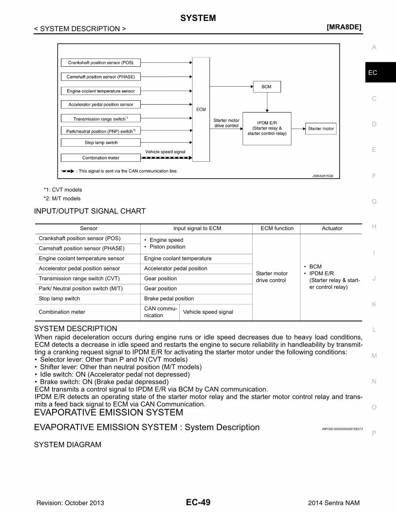
SYSTEM[MRA8DE]
C
D
E
F
G
H
I
J
K
L
M
A
C
N
P
O
< SYSTEM DESCRIPTION >
E
INPUT/OUTPUT SIGNAL CHART
SYSTEM DESCRIPTIONWhen rapid deceleration occurs during engine runs or idle speed decreases due to heavy load conditions,ECM detects a decrease in idle speed and restarts the engine to secure reliability in handleability by transmit-ting a cranking request signal to IPDM E/R for activating the starter motor under the following conditions:• Selector lever: Other than P and N (CVT models)• Shifter lever: Other than neutral position (M/T models)• Idle switch: ON (Accelerator pedal not depressed)• Brake switch: ON (Brake pedal depressed)ECM transmits a control signal to IPDM E/R via BCM by CAN communication.IPDM E/R detects an operating state of the starter motor relay and the starter motor control relay and trans-mits a feed back signal to ECM via CAN Communication.EVAPORATIVE EMISSION SYSTEMEVAPORATIVE EMISSION SYSTEM : System Description INFOID:0000000009758373
SYSTEM DIAGRAM
*1: CVT models*2: M/T models
JSBIA2815GB
Sensor Input signal to ECM ECM function Actuator
Crankshaft position sensor (POS) • Engine speed• Piston position
Starter motor drive control
• BCM• IPDM E/R
(Starter relay & start-er control relay)
Camshaft position sensor (PHASE)
Engine coolant temperature sensor Engine coolant temperature
Accelerator pedal position sensor Accelerator pedal position
Transmission range switch (CVT) Gear position
Park/ Neutral position switch (M/T) Gear position
Stop lamp switch Brake pedal position
Combination meter CAN commu-nication Vehicle speed signal
EC-49Revision: October 2013 2014 Sentra NAM
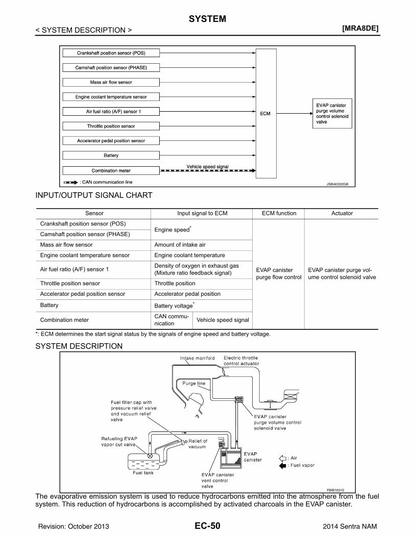
[MRA8DE]SYSTEM
< SYSTEM DESCRIPTION >
INPUT/OUTPUT SIGNAL CHART
*: ECM determines the start signal status by the signals of engine speed and battery voltage.
SYSTEM DESCRIPTION
The evaporative emission system is used to reduce hydrocarbons emitted into the atmosphere from the fuelsystem. This reduction of hydrocarbons is accomplished by activated charcoals in the EVAP canister.
JSBIA0322GB
Sensor Input signal to ECM ECM function Actuator
Crankshaft position sensor (POS)Engine speed*
EVAP canister purge flow control
EVAP canister purge vol-ume control solenoid valve
Camshaft position sensor (PHASE)
Mass air flow sensor Amount of intake air
Engine coolant temperature sensor Engine coolant temperature
Air fuel ratio (A/F) sensor 1 Density of oxygen in exhaust gas(Mixture ratio feedback signal)
Throttle position sensor Throttle position
Accelerator pedal position sensor Accelerator pedal position
Battery Battery voltage*
Combination meter CAN commu-nication Vehicle speed signal
PBIB1631E
EC-50Revision: October 2013 2014 Sentra NAM
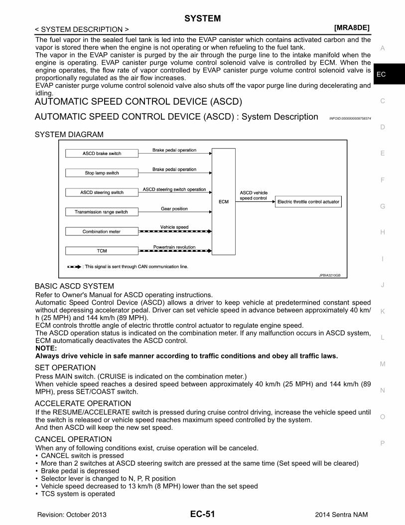
SYSTEM[MRA8DE]
C
D
E
F
G
H
I
J
K
L
M
A
C
N
P
O
< SYSTEM DESCRIPTION >
E
The fuel vapor in the sealed fuel tank is led into the EVAP canister which contains activated carbon and thevapor is stored there when the engine is not operating or when refueling to the fuel tank.The vapor in the EVAP canister is purged by the air through the purge line to the intake manifold when theengine is operating. EVAP canister purge volume control solenoid valve is controlled by ECM. When theengine operates, the flow rate of vapor controlled by EVAP canister purge volume control solenoid valve isproportionally regulated as the air flow increases.EVAP canister purge volume control solenoid valve also shuts off the vapor purge line during decelerating andidling.AUTOMATIC SPEED CONTROL DEVICE (ASCD)AUTOMATIC SPEED CONTROL DEVICE (ASCD) : System Description INFOID:0000000009758374
SYSTEM DIAGRAM
BASIC ASCD SYSTEMRefer to Owner's Manual for ASCD operating instructions.Automatic Speed Control Device (ASCD) allows a driver to keep vehicle at predetermined constant speedwithout depressing accelerator pedal. Driver can set vehicle speed in advance between approximately 40 km/h (25 MPH) and 144 km/h (89 MPH).ECM controls throttle angle of electric throttle control actuator to regulate engine speed.The ASCD operation status is indicated on the combination meter. If any malfunction occurs in ASCD system,ECM automatically deactivates the ASCD control.NOTE:Always drive vehicle in safe manner according to traffic conditions and obey all traffic laws.
SET OPERATIONPress MAIN switch. (CRUISE is indicated on the combination meter.)When vehicle speed reaches a desired speed between approximately 40 km/h (25 MPH) and 144 km/h (89MPH), press SET/COAST switch.
ACCELERATE OPERATIONIf the RESUME/ACCELERATE switch is pressed during cruise control driving, increase the vehicle speed untilthe switch is released or vehicle speed reaches maximum speed controlled by the system.And then ASCD will keep the new set speed.
CANCEL OPERATIONWhen any of following conditions exist, cruise operation will be canceled.• CANCEL switch is pressed• More than 2 switches at ASCD steering switch are pressed at the same time (Set speed will be cleared)• Brake pedal is depressed• Selector lever is changed to N, P, R position• Vehicle speed decreased to 13 km/h (8 MPH) lower than the set speed• TCS system is operated
JPBIA3210GB
EC-51Revision: October 2013 2014 Sentra NAM
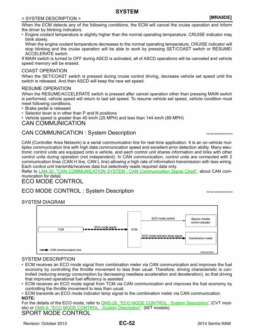
[MRA8DE]SYSTEM
< SYSTEM DESCRIPTION >When the ECM detects any of the following conditions, the ECM will cancel the cruise operation and informthe driver by blinking indicators.• Engine coolant temperature is slightly higher than the normal operating temperature, CRUISE indicator may
blink slowly.When the engine coolant temperature decreases to the normal operating temperature, CRUISE indicator willstop blinking and the cruise operation will be able to work by pressing SET/COAST switch or RESUME/ACCELERATE switch.
If MAIN switch is turned to OFF during ASCD is activated, all of ASCD operations will be canceled and vehiclespeed memory will be erased.
COAST OPERATIONWhen the SET/COAST switch is pressed during cruise control driving, decrease vehicle set speed until theswitch is released. And then ASCD will keep the new set speed.
RESUME OPERATIONWhen the RESUME/ACCELERATE switch is pressed after cancel operation other than pressing MAIN switchis performed, vehicle speed will return to last set speed. To resume vehicle set speed, vehicle condition mustmeet following conditions.• Brake pedal is released• Selector lever is in other than P and N positions• Vehicle speed is greater than 40 km/h (25 MPH) and less than 144 km/h (89 MPH)CAN COMMUNICATIONCAN COMMUNICATION : System Description INFOID:0000000009758375
CAN (Controller Area Network) is a serial communication line for real time application. It is an on-vehicle mul-tiplex communication line with high data communication speed and excellent error detection ability. Many elec-tronic control units are equipped onto a vehicle, and each control unit shares information and links with othercontrol units during operation (not independent). In CAN communication, control units are connected with 2communication lines (CAN H line, CAN L line) allowing a high rate of information transmission with less wiring.Each control unit transmits/receives data but selectively reads required data only.Refer to LAN-30, "CAN COMMUNICATION SYSTEM : CAN Communication Signal Chart", about CAN com-munication for detail.ECO MODE CONTROLECO MODE CONTROL : System Description INFOID:0000000009758376
SYSTEM DIAGRAM
SYSTEM DESCRIPTION• ECM receives an ECO mode signal from combination meter via CAN communication and improves the fuel
economy by controlling the throttle movement to less than usual. Therefore, driving characteristic is con-trolled (reducing energy consumption by decreasing needless acceleration and deceleration), so that drivingthat improved operational fuel efficiency is assisted.
• ECM receives an ECO mode signal from TCM via CAN communication and improves the fuel economy bycontrolling the throttle movement to less than usual.
• ECM transmits an ECO mode indicator lamp signal to the combination meter via CAN communication.NOTE:For the details of the ECO mode, refer to DMS-26, "ECO MODE CONTROL : System Description" (CVT mod-els) or DMS-6, "ECO MODE CONTROL : System Description" (M/T models).SPORT MODE CONTROL
JPBIA5876GB
EC-52Revision: October 2013 2014 Sentra NAM
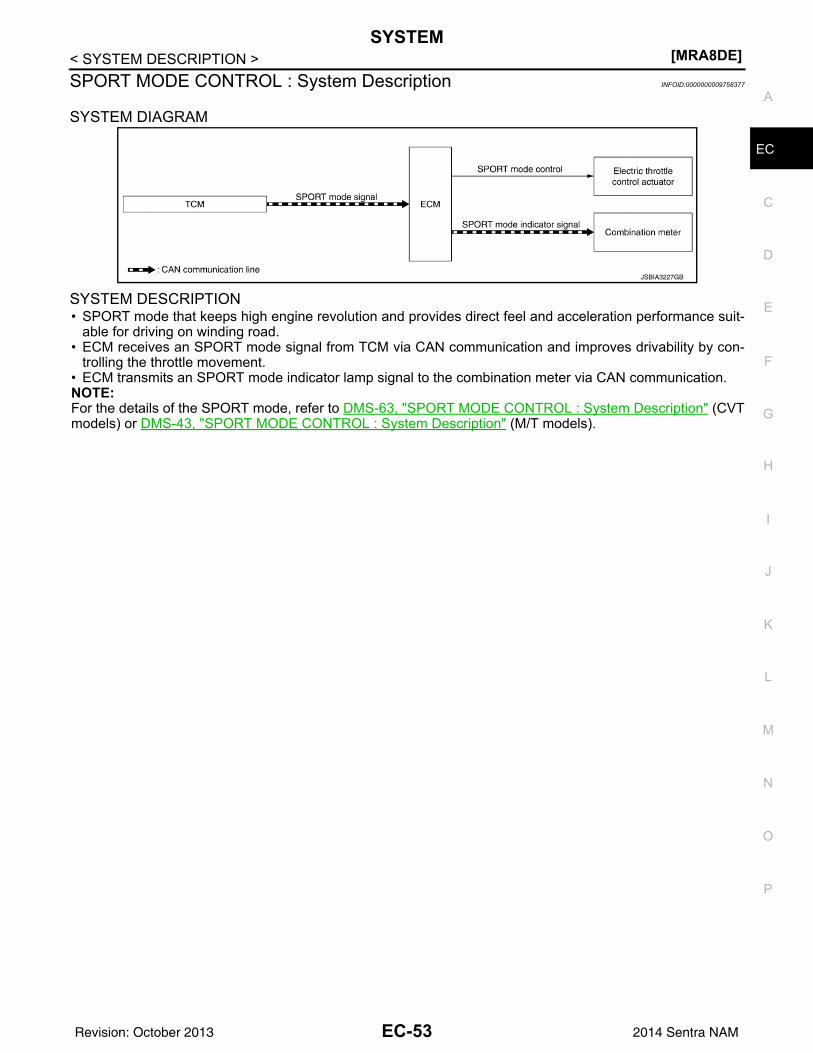
SYSTEM[MRA8DE]
C
D
E
F
G
H
I
J
K
L
M
A
C
N
P
O
< SYSTEM DESCRIPTION >
E
SPORT MODE CONTROL : System Description INFOID:0000000009758377
SYSTEM DIAGRAM
SYSTEM DESCRIPTION• SPORT mode that keeps high engine revolution and provides direct feel and acceleration performance suit-
able for driving on winding road.• ECM receives an SPORT mode signal from TCM via CAN communication and improves drivability by con-
trolling the throttle movement.• ECM transmits an SPORT mode indicator lamp signal to the combination meter via CAN communication.NOTE:For the details of the SPORT mode, refer to DMS-63, "SPORT MODE CONTROL : System Description" (CVTmodels) or DMS-43, "SPORT MODE CONTROL : System Description" (M/T models).
JSBIA3227GB
EC-53Revision: October 2013 2014 Sentra NAM
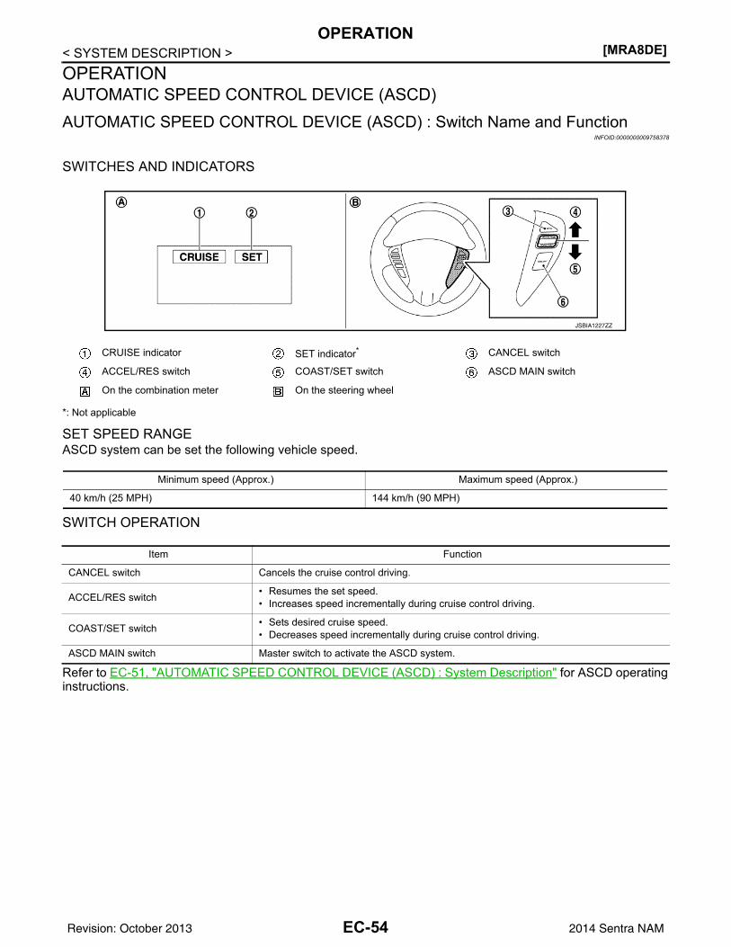
[MRA8DE]OPERATION
< SYSTEM DESCRIPTION >OPERATIONAUTOMATIC SPEED CONTROL DEVICE (ASCD)AUTOMATIC SPEED CONTROL DEVICE (ASCD) : Switch Name and Function
INFOID:0000000009758378
SWITCHES AND INDICATORS
*: Not applicable
SET SPEED RANGEASCD system can be set the following vehicle speed.
SWITCH OPERATION
Refer to EC-51, "AUTOMATIC SPEED CONTROL DEVICE (ASCD) : System Description" for ASCD operatinginstructions.
CRUISE indicator SET indicator* CANCEL switch
ACCEL/RES switch COAST/SET switch ASCD MAIN switch
On the combination meter On the steering wheel
JSBIA1227ZZ
Minimum speed (Approx.) Maximum speed (Approx.)
40 km/h (25 MPH) 144 km/h (90 MPH)
Item Function
CANCEL switch Cancels the cruise control driving.
ACCEL/RES switch • Resumes the set speed.• Increases speed incrementally during cruise control driving.
COAST/SET switch • Sets desired cruise speed.• Decreases speed incrementally during cruise control driving.
ASCD MAIN switch Master switch to activate the ASCD system.
EC-54Revision: October 2013 2014 Sentra NAM
ON BOARD DIAGNOSTIC (OBD) SYSTEM[MRA8DE]
C
D
E
F
G
H
I
J
K
L
M
A
C
N
P
O
< SYSTEM DESCRIPTION >
E
ON BOARD DIAGNOSTIC (OBD) SYSTEMDiagnosis Description INFOID:0000000009758379
This system is an on board diagnostic system that records exhaust emission-related diagnostic informationand detects a sensors/actuator-related malfunction. A malfunction is indicated by the malfunction indicatorlamp (MIL) and stored in ECU memory as a DTC. The diagnostic information can be obtained with the diag-nostic tool (GST: Generic Scan Tool).
GST (Generic Scan Tool) INFOID:0000000009758380
When GST is connected with a data link connector equipped on the vehicle side, it will communicate with thecontrol unit equipped in the vehicle and then enable various kinds of diagnostic tests. Refer to GI-47, "Descrip-tion".NOTE:Service $0A is not applied for regions where it is not mandated.
EC-55Revision: October 2013 2014 Sentra NAM
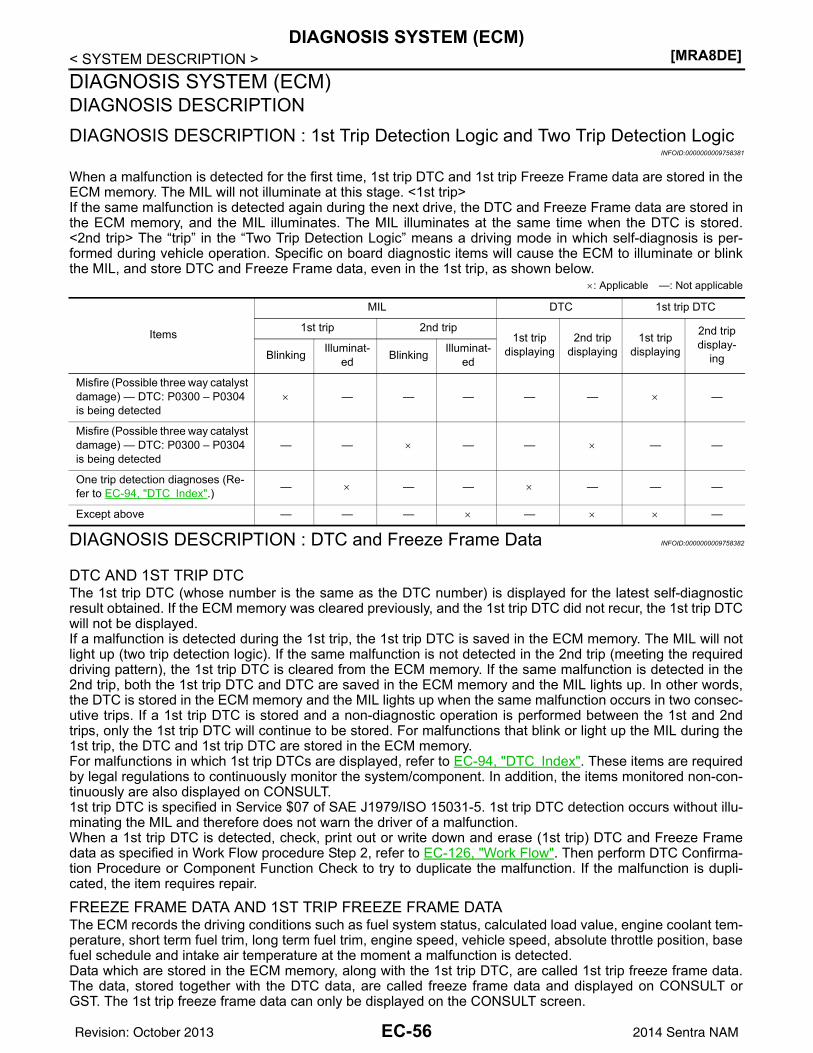
[MRA8DE]DIAGNOSIS SYSTEM (ECM)
< SYSTEM DESCRIPTION >DIAGNOSIS SYSTEM (ECM)DIAGNOSIS DESCRIPTIONDIAGNOSIS DESCRIPTION : 1st Trip Detection Logic and Two Trip Detection Logic
INFOID:0000000009758381
When a malfunction is detected for the first time, 1st trip DTC and 1st trip Freeze Frame data are stored in theECM memory. The MIL will not illuminate at this stage. <1st trip>If the same malfunction is detected again during the next drive, the DTC and Freeze Frame data are stored inthe ECM memory, and the MIL illuminates. The MIL illuminates at the same time when the DTC is stored.<2nd trip> The “trip” in the “Two Trip Detection Logic” means a driving mode in which self-diagnosis is per-formed during vehicle operation. Specific on board diagnostic items will cause the ECM to illuminate or blinkthe MIL, and store DTC and Freeze Frame data, even in the 1st trip, as shown below.
×: Applicable —: Not applicable
DIAGNOSIS DESCRIPTION : DTC and Freeze Frame Data INFOID:0000000009758382
DTC AND 1ST TRIP DTCThe 1st trip DTC (whose number is the same as the DTC number) is displayed for the latest self-diagnosticresult obtained. If the ECM memory was cleared previously, and the 1st trip DTC did not recur, the 1st trip DTCwill not be displayed.If a malfunction is detected during the 1st trip, the 1st trip DTC is saved in the ECM memory. The MIL will notlight up (two trip detection logic). If the same malfunction is not detected in the 2nd trip (meeting the requireddriving pattern), the 1st trip DTC is cleared from the ECM memory. If the same malfunction is detected in the2nd trip, both the 1st trip DTC and DTC are saved in the ECM memory and the MIL lights up. In other words,the DTC is stored in the ECM memory and the MIL lights up when the same malfunction occurs in two consec-utive trips. If a 1st trip DTC is stored and a non-diagnostic operation is performed between the 1st and 2ndtrips, only the 1st trip DTC will continue to be stored. For malfunctions that blink or light up the MIL during the1st trip, the DTC and 1st trip DTC are stored in the ECM memory.For malfunctions in which 1st trip DTCs are displayed, refer to EC-94, "DTC Index". These items are requiredby legal regulations to continuously monitor the system/component. In addition, the items monitored non-con-tinuously are also displayed on CONSULT.1st trip DTC is specified in Service $07 of SAE J1979/ISO 15031-5. 1st trip DTC detection occurs without illu-minating the MIL and therefore does not warn the driver of a malfunction.When a 1st trip DTC is detected, check, print out or write down and erase (1st trip) DTC and Freeze Framedata as specified in Work Flow procedure Step 2, refer to EC-126, "Work Flow". Then perform DTC Confirma-tion Procedure or Component Function Check to try to duplicate the malfunction. If the malfunction is dupli-cated, the item requires repair.
FREEZE FRAME DATA AND 1ST TRIP FREEZE FRAME DATAThe ECM records the driving conditions such as fuel system status, calculated load value, engine coolant tem-perature, short term fuel trim, long term fuel trim, engine speed, vehicle speed, absolute throttle position, basefuel schedule and intake air temperature at the moment a malfunction is detected.Data which are stored in the ECM memory, along with the 1st trip DTC, are called 1st trip freeze frame data.The data, stored together with the DTC data, are called freeze frame data and displayed on CONSULT orGST. The 1st trip freeze frame data can only be displayed on the CONSULT screen.
Items
MIL DTC 1st trip DTC
1st trip 2nd trip 1st trip
displaying2nd trip
displaying1st trip
displaying
2nd trip display-
ingBlinking Illuminat-ed Blinking Illuminat-
ed
Misfire (Possible three way catalyst damage) — DTC: P0300 – P0304 is being detected
× — — — — — × —
Misfire (Possible three way catalyst damage) — DTC: P0300 – P0304 is being detected
— — × — — × — —
One trip detection diagnoses (Re-fer to EC-94, "DTC Index".) — × — — × — — —
Except above — — — × — × × —
EC-56Revision: October 2013 2014 Sentra NAM
DIAGNOSIS SYSTEM (ECM)[MRA8DE]
C
D
E
F
G
H
I
J
K
L
M
A
C
N
P
O
< SYSTEM DESCRIPTION >
E
Only one set of freeze frame data (either 1st trip freeze frame data or freeze frame data) can be stored in theECM. 1st trip freeze frame data is stored in the ECM memory along with the 1st trip DTC. There is no priorityfor 1st trip freeze frame data and it is updated each time a different 1st trip DTC is detected. However, oncefreeze frame data (2nd trip detection/MIL on) is stored in the ECM memory, 1st trip freeze frame data is nolonger stored. Remember, only one set of freeze frame data can be stored in the ECM. The ECM has the fol-lowing priorities to update the data.
For example, the EGR malfunction (Priority: 2) was detected and the freeze frame data was saved in the 2ndtrip. After that when the misfire (Priority: 1) is detected in another trip, the freeze frame data will be updatedfrom the EGR malfunction to the misfire. The 1st trip freeze frame data is updated each time a different mal-function is detected. There is no priority for 1st trip freeze frame data. However, once freeze frame data isstored in the ECM memory, 1st trip freeze data is no longer stored (because only one freeze frame data or 1sttrip freeze frame data can be stored in the ECM). If freeze frame data is stored in the ECM memory and freezeframe data with the same priority occurs later, the first (original) freeze frame data remains unchanged in theECM memory.Both 1st trip freeze frame data and freeze frame data (along with the DTCs) are cleared when the ECM mem-ory is erased.
DIAGNOSIS DESCRIPTION : Counter System INFOID:0000000009758383
RELATIONSHIP BETWEEN MIL, 1ST TRIP DTC, DTC, AND DETECTABLE ITEMS• When a malfunction is detected for the first time, the 1st trip DTC and the 1st trip freeze frame data are
stored in the ECM memory.• When the same malfunction is detected in two consecutive trips, the DTC and the freeze frame data are
stored in the ECM memory, and the MIL will come on.• The MIL will turn OFF after the vehicle is driven 3 times (driving pattern B) with no malfunction. The drive is
counted only when the recorded driving pattern is met (as stored in the ECM). If another malfunction occurswhile counting, the counter will reset.
• The DTC and the freeze frame data will be stored until the vehicle is driven 40 times (driving pattern A) with-out the same malfunction recurring (except for Misfire and Fuel Injection System). For Misfire and Fuel Injec-tion System, the DTC and freeze frame data will be stored until the vehicle is driven 80 times (driving patternC) without the same malfunction recurring. The “TIME” in “SELF-DIAGNOSTIC RESULTS” mode of CON-SULT will count the number of times the vehicle is driven.
• The 1st trip DTC is not displayed when the self-diagnosis results in OK for the 2nd trip.
COUNTER SYSTEM CHART
For details about patterns B and C under “Fuel Injection System” and “Misfire”, see “EXPLANATION FORDRIVING PATTERNS FOR “MISFIRE <EXHAUST QUALITY DETERIORATION>”, “FUEL INJECTION SYS-TEM”.For details about patterns A and B under Other, see “EXPLANATION FOR DRIVING PATTERNS FOR “MIS-FIRE <EXHAUST QUALITY DETERIORATION>”, “FUEL INJECTION SYSTEM”.• *1: Clear timing is at the moment OK is detected.• *2: Clear timing is when the same malfunction is detected in the 2nd trip.
Relationship Between MIL, DTC, 1st Trip DTC and Driving Patterns for “Misfire <Exhaust Quality De-terioration>”, “Fuel Injection System”
Priority Items
1 Freeze frame data Misfire — DTC: P0300 – P0304Fuel Injection System Function — DTC: P0171, P0172
2 Except the above items
3 1st trip freeze frame data
Items Fuel Injection System Misfire Other
MIL (turns OFF) 3 (pattern B) 3 (pattern B) 3 (pattern B)
DTC, Freeze Frame Data (no display) 80 (pattern C) 80 (pattern C) 40 (pattern A)
1st Trip DTC (clear) 1 (pattern C), *1 1 (pattern C), *1 1 (pattern B)
1st Trip Freeze Frame Data (clear) *1, *2 *1, *2 1 (pattern B)
EC-57Revision: October 2013 2014 Sentra NAM
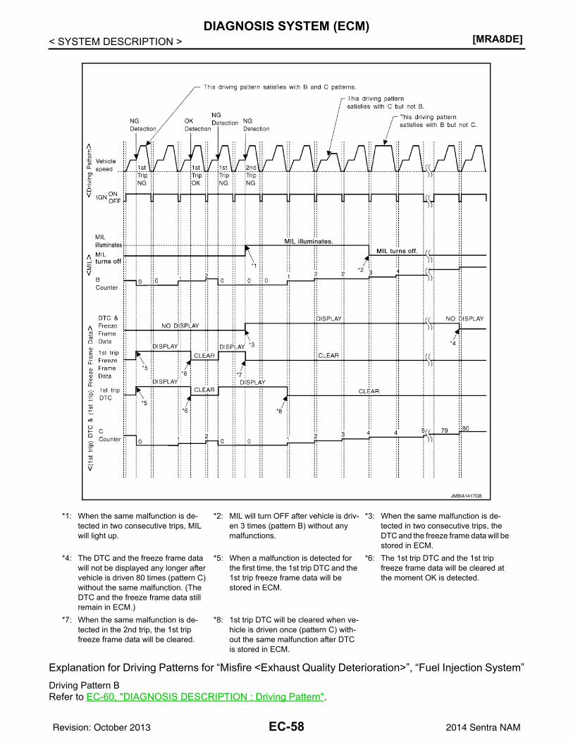
[MRA8DE]DIAGNOSIS SYSTEM (ECM)
< SYSTEM DESCRIPTION >
Explanation for Driving Patterns for “Misfire <Exhaust Quality Deterioration>”, “Fuel Injection System”Driving Pattern BRefer to EC-60, "DIAGNOSIS DESCRIPTION : Driving Pattern".
*1: When the same malfunction is de-tected in two consecutive trips, MIL will light up.
*2: MIL will turn OFF after vehicle is driv-en 3 times (pattern B) without any malfunctions.
*3: When the same malfunction is de-tected in two consecutive trips, the DTC and the freeze frame data will be stored in ECM.
*4: The DTC and the freeze frame data will not be displayed any longer after vehicle is driven 80 times (pattern C) without the same malfunction. (The DTC and the freeze frame data still remain in ECM.)
*5: When a malfunction is detected for the first time, the 1st trip DTC and the 1st trip freeze frame data will be stored in ECM.
*6: The 1st trip DTC and the 1st trip freeze frame data will be cleared at the moment OK is detected.
*7: When the same malfunction is de-tected in the 2nd trip, the 1st trip freeze frame data will be cleared.
*8: 1st trip DTC will be cleared when ve-hicle is driven once (pattern C) with-out the same malfunction after DTC is stored in ECM.
JMBIA1417GB
EC-58Revision: October 2013 2014 Sentra NAM
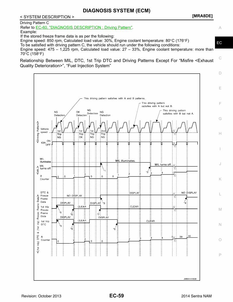
DIAGNOSIS SYSTEM (ECM)[MRA8DE]
C
D
E
F
G
H
I
J
K
L
M
A
C
N
P
O
< SYSTEM DESCRIPTION >
E
Driving Pattern CRefer to EC-60, "DIAGNOSIS DESCRIPTION : Driving Pattern".Example:If the stored freeze frame data is as per the following:Engine speed: 850 rpm, Calculated load value: 30%, Engine coolant temperature: 80°C (176°F)To be satisfied with driving pattern C, the vehicle should run under the following conditions:Engine speed: 475 – 1,225 rpm, Calculated load value: 27 – 33%, Engine coolant temperature: more than70°C (158°F)
Relationship Between MIL, DTC, 1st Trip DTC and Driving Patterns Except For “Misfire <ExhaustQuality Deterioration>”, “Fuel Injection System”
JMBIA1418GB
EC-59Revision: October 2013 2014 Sentra NAM
[MRA8DE]DIAGNOSIS SYSTEM (ECM)
< SYSTEM DESCRIPTION >
Explanation for Driving Patterns Except for “Misfire <Exhaust Quality Deterioration>”, “Fuel InjectionSystem”Driving Pattern ARefer to EC-60, "DIAGNOSIS DESCRIPTION : Driving Pattern".Driving Pattern BRefer to EC-60, "DIAGNOSIS DESCRIPTION : Driving Pattern".
DIAGNOSIS DESCRIPTION : Driving Pattern INFOID:0000000009758384
DRIVING PATTERN ADriving pattern A means a trip satisfying the following conditions.• Engine speed reaches 400 rpm or more.• Engine coolant temperature rises by 20°C (36°F) or more after starting the engine.• Engine coolant temperature reaches 70°C (158°F) or more.• The ignition switch is turned from ON to OFF.NOTE:• When the same malfunction is detected regardless of driving conditions, reset the counter of driving pattern
A.• When the above conditions are satisfied without detecting the same malfunction, reset the counter of driving
pattern A.
DRIVING PATTERN BDriving pattern B means a trip satisfying the following conditions.• Engine speed reaches 400 rpm or more.• Engine coolant temperature reaches 70°C (158°F) or more.• Vehicle speed of 70 – 120 km/h (44 – 75 MPH) is maintained for 60 seconds or more under the control of
closed loop.• Vehicle speed of 30 – 60 km/h (19 – 37 MPH) is maintained for 10 seconds or more under the control of
closed loop.• Under the closed loop control condition, the following state reaches 12 seconds or more in total: Vehicle
speed of 4 km/h (2 MPH) or less with idling condition.• The state of driving at 10 km/h (7 MPH) or more reaches 10 minutes or more in total.• A lapse of 22 minutes or more after engine start.NOTE:• Drive the vehicle at a constant velocity.• When the same malfunction is detected regardless of driving conditions, reset the counter of driving pattern
B.• When the above conditions are satisfied without detecting the same malfunction, reset the counter of driving
pattern B.
DRIVING PATTERN CDriving pattern C means operating vehicle as per the following:The following conditions should be satisfied at the same time:Engine speed: (Engine speed in the freeze frame data) ±375 rpmCalculated load value: (Calculated load value in the freeze frame data) x (1±0.1) [%]Engine coolant temperature condition:
*1: When the same malfunction is de-tected in two consecutive trips, MIL will light up.
*2: MIL will turn OFF after vehicle is driv-en 3 times (pattern B) without any malfunctions.
*3: When the same malfunction is de-tected in two consecutive trips, the DTC and the freeze frame data will be stored in ECM.
*4: The DTC and the freeze frame data will not be displayed any longer after vehicle is driven 40 times (pattern A) without the same malfunction.(The DTC and the freeze frame data still remain in ECM.)
*5: When a malfunction is detected for the first time, the 1st trip DTC and the 1st trip freeze frame data will be stored in ECM.
*6: 1st trip DTC will be cleared after vehi-cle is driven once (pattern B) without the same malfunction.
*7: When the same malfunction is de-tected in the 2nd trip, the 1st trip freeze frame data will be cleared.
EC-60Revision: October 2013 2014 Sentra NAM
DIAGNOSIS SYSTEM (ECM)[MRA8DE]
C
D
E
F
G
H
I
J
K
L
M
A
C
N
P
O
< SYSTEM DESCRIPTION >
E
• When the freeze frame data shows lower than 70°C (158°F), engine coolant temperature should be lowerthan 70°C (158°F).
• When the freeze frame data shows higher than or equal to 70°C (158°F), engine coolant temperature shouldbe higher than or equal to 70°C (158°F).
NOTE:• When the same malfunction is detected regardless of the above vehicle conditions, reset the counter of driv-
ing pattern C.• When the above conditions are satisfied without detecting the same malfunction, reset the counter of driving
pattern C.• The 1st trip DTC will be cleared when C counter is counted once without the same malfunction after DTC is
stored in ECM.
DRIVING PATTERN DDriving pattern D means a trip satisfying the following conditions.• The state of driving at 40 km/h (25 MPH) reaches 300 seconds or more in total.• Idle speed lasts 30 seconds or more.• A lapse of 600 seconds or more after engine start.NOTE:• When the same malfunction is detected regardless of driving conditions, reset the counter of driving pattern
D.• When the above conditions are satisfied without detecting the same malfunction, reset the counter of driving
pattern D.
DIAGNOSIS DESCRIPTION : System Readiness Test (SRT) Code INFOID:0000000009758385
System Readiness Test (SRT) code is specified in Service $01 of SAE J1979/ISO 15031-5.As part of an enhanced emissions test for Inspection & Maintenance (I/M), certain states require the status ofSRT be used to indicate whether the ECM has completed self-diagnosis of major emission systems and com-ponents. Completion must be verified in order for the emissions inspection to proceed.If a vehicle is rejected for a State emissions inspection due to one or more SRT items indicating “INCMP”, usethe information in this Service Manual to set the SRT to “CMPLT”.In most cases the ECM will automatically complete its self-diagnosis cycle during normal usage, and the SRTstatus will indicate “CMPLT” for each application system. Once set as “CMPLT”, the SRT status remains“CMPLT” until the self-diagnosis memory is erased.Occasionally, certain portions of the self-diagnostic test may not be completed as a result of the customer'snormal driving pattern; the SRT will indicate “INCMP” for these items.NOTE:The SRT will also indicate “INCMP” if the self-diagnosis memory is erased for any reason or if the ECM mem-ory power supply is interrupted for several hours.If, during the state emissions inspection, the SRT indicates “CMPLT” for all test items, the inspector will con-tinue with the emissions test. However, if the SRT indicates “INCMP” for one or more of the SRT items thevehicle is returned to the customer untested.NOTE:If permanent DTC is stored or MIL illuminates during the state emissions inspection, the vehicle is alsore-turned to the customer untested even though the SRT indicates “CMPLT” for all test items. Therefore, it isim-portant to check SRT (“CMPLT”), DTC (No DTCs) and permanent DTC (NO permanent DTCs) beforetheinspection.
SRT SET TIMINGSRT is set as “CMPLT” after self-diagnosis has been performed one or more times. Completion of SRT isdone regardless of whether the result is OK or NG. The set timing is different between OK and NG results andis shown in the table below.
EC-61Revision: October 2013 2014 Sentra NAM
[MRA8DE]DIAGNOSIS SYSTEM (ECM)
< SYSTEM DESCRIPTION >
OK: Self-diagnosis is carried out and the result is OK.NG: Self-diagnosis is carried out and the result is NG.—: Self-diagnosis is not carried out.When all SRT related self-diagnoses show OK results in a single cycle (Ignition OFF-ON-OFF), the SRT willindicate “CMPLT”. → Case 1 aboveWhen all SRT related self-diagnoses show OK results through several different cycles, the SRT will indicate“CMPLT” at the time the respective self-diagnoses have at least one OK result. → Case 2 aboveIf one or more SRT related self-diagnoses show NG results in 2 consecutive cycles, the SRT will also indicate“CMPLT”. → Case 3 aboveThe table above shows that the minimum number of cycles for setting SRT as “INCMP” is the number one (1)for each self-diagnosis (Case 1 & 2) or the number two (2) for one of self-diagnoses (Case 3). However, inpreparation for the state emissions inspection, it is unnecessary for each self-diagnosis to be executed twice(Case 3) for the following reasons:• The SRT will indicate “CMPLT” at the time the respective self-diagnoses have one (1) OK result.• The emissions inspection requires “CMPLT” of the SRT only with OK self-diagnosis results.• During SRT driving pattern, the 1st trip DTC (NG) is detected prior to “CMPLT” of SRT and the self-diagnosis
memory must be erased from the ECM after repair.• If the 1st trip DTC is erased, all the SRT will indicate “INCMP”.
NOTE:SRT can be set as “CMPLT” together with the DTC(s). Therefore, DTC check must always be carried outprior to the state emission inspection even though the SRT indicates “CMPLT”.
DIAGNOSIS DESCRIPTION : Permanent Diagnostic Trouble Code (Permanent DTC)INFOID:0000000009758386
Permanent DTC is defined in SAE J1979/ISO 15031-5 Service $0A.ECM stores a DTC issuing a command of turning on MIL as a permanent DTC and keeps storing the DTC asa permanent DTC until ECM judges that there is no presence of malfunction.Permanent DTCs cannot be erased by using the erase function of CONSULT or Generic Scan Tool (GST) andby disconnecting the battery to shut off power to ECM. This prevents a vehicle from passing the in-use inspec-tion without repairing a malfunctioning part.When not passing the in-use inspection due to more than one permanent DTC, permanent DTCs should beerased, referring to this manual.NOTE:• The important items in in-use inspection are that MIL is not ON, SRT test items are set, and permanent
DTCs are not included.• Permanent DTCs do not apply for regions that permanent DTCs are not regulated by law.
Self-diagnosis resultExample
Diagnosis Ignition cycle ← ON → OFF ← ON → OFF ← ON → OFF ← ON →
All OK Case 1 P0400 OK (1) — (1) OK (2) — (2)
P0402 OK (1) — (1) — (1) OK (2)
P1402 OK (1) OK (2) — (2) — (2)
SRT of EGR “CMPLT” “CMPLT” “CMPLT” “CMPLT”
Case 2 P0400 OK (1) — (1) — (1) — (1)
P0402 — (0) — (0) OK (1) — (1)
P1402 OK (1) OK (2) — (2) — (2)
SRT of EGR “INCMP” “INCMP” “CMPLT” “CMPLT”
NG exists Case 3 P0400 OK OK — —
P0402 — — — —
P1402 NG — NGNG
(Consecutive NG)
(1st trip)DTC 1st trip DTC — 1st trip DTC DTC
(= MIL ON)
SRT of EGR “INCMP” “INCMP” “INCMP” “CMPLT”
EC-62Revision: October 2013 2014 Sentra NAM
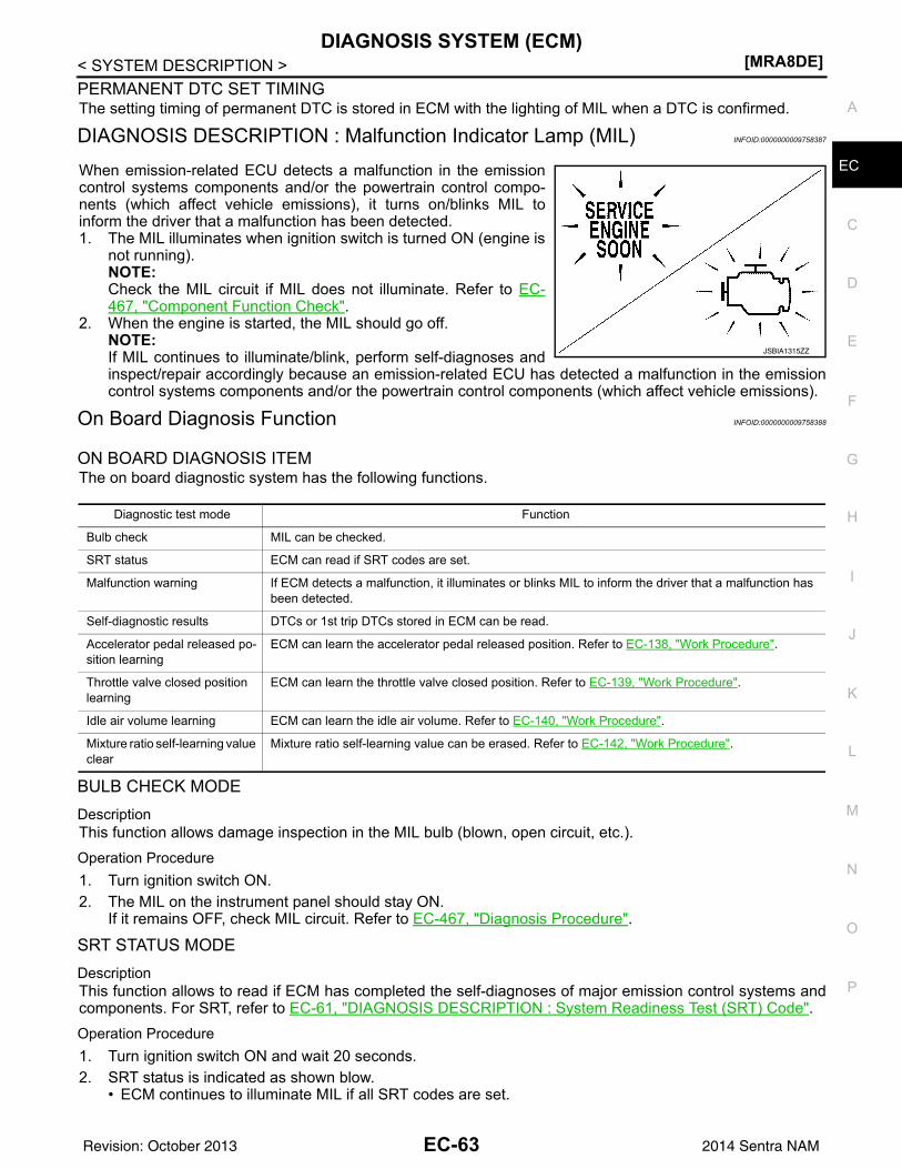
DIAGNOSIS SYSTEM (ECM)[MRA8DE]
C
D
E
F
G
H
I
J
K
L
M
A
C
N
P
O
< SYSTEM DESCRIPTION >
E
PERMANENT DTC SET TIMINGThe setting timing of permanent DTC is stored in ECM with the lighting of MIL when a DTC is confirmed.
DIAGNOSIS DESCRIPTION : Malfunction Indicator Lamp (MIL) INFOID:0000000009758387
When emission-related ECU detects a malfunction in the emissioncontrol systems components and/or the powertrain control compo-nents (which affect vehicle emissions), it turns on/blinks MIL toinform the driver that a malfunction has been detected.1. The MIL illuminates when ignition switch is turned ON (engine is
not running).NOTE:Check the MIL circuit if MIL does not illuminate. Refer to EC-467, "Component Function Check".
2. When the engine is started, the MIL should go off.NOTE:If MIL continues to illuminate/blink, perform self-diagnoses andinspect/repair accordingly because an emission-related ECU has detected a malfunction in the emissioncontrol systems components and/or the powertrain control components (which affect vehicle emissions).
On Board Diagnosis Function INFOID:0000000009758388
ON BOARD DIAGNOSIS ITEMThe on board diagnostic system has the following functions.
BULB CHECK MODEDescriptionThis function allows damage inspection in the MIL bulb (blown, open circuit, etc.).Operation Procedure1. Turn ignition switch ON.2. The MIL on the instrument panel should stay ON.
If it remains OFF, check MIL circuit. Refer to EC-467, "Diagnosis Procedure".
SRT STATUS MODEDescriptionThis function allows to read if ECM has completed the self-diagnoses of major emission control systems andcomponents. For SRT, refer to EC-61, "DIAGNOSIS DESCRIPTION : System Readiness Test (SRT) Code".Operation Procedure1. Turn ignition switch ON and wait 20 seconds.2. SRT status is indicated as shown blow.
• ECM continues to illuminate MIL if all SRT codes are set.
JSBIA1315ZZ
Diagnostic test mode Function
Bulb check MIL can be checked.
SRT status ECM can read if SRT codes are set.
Malfunction warning If ECM detects a malfunction, it illuminates or blinks MIL to inform the driver that a malfunction has been detected.
Self-diagnostic results DTCs or 1st trip DTCs stored in ECM can be read.
Accelerator pedal released po-sition learning
ECM can learn the accelerator pedal released position. Refer to EC-138, "Work Procedure".
Throttle valve closed position learning
ECM can learn the throttle valve closed position. Refer to EC-139, "Work Procedure".
Idle air volume learning ECM can learn the idle air volume. Refer to EC-140, "Work Procedure".
Mixture ratio self-learning value clear
Mixture ratio self-learning value can be erased. Refer to EC-142, "Work Procedure".
EC-63Revision: October 2013 2014 Sentra NAM
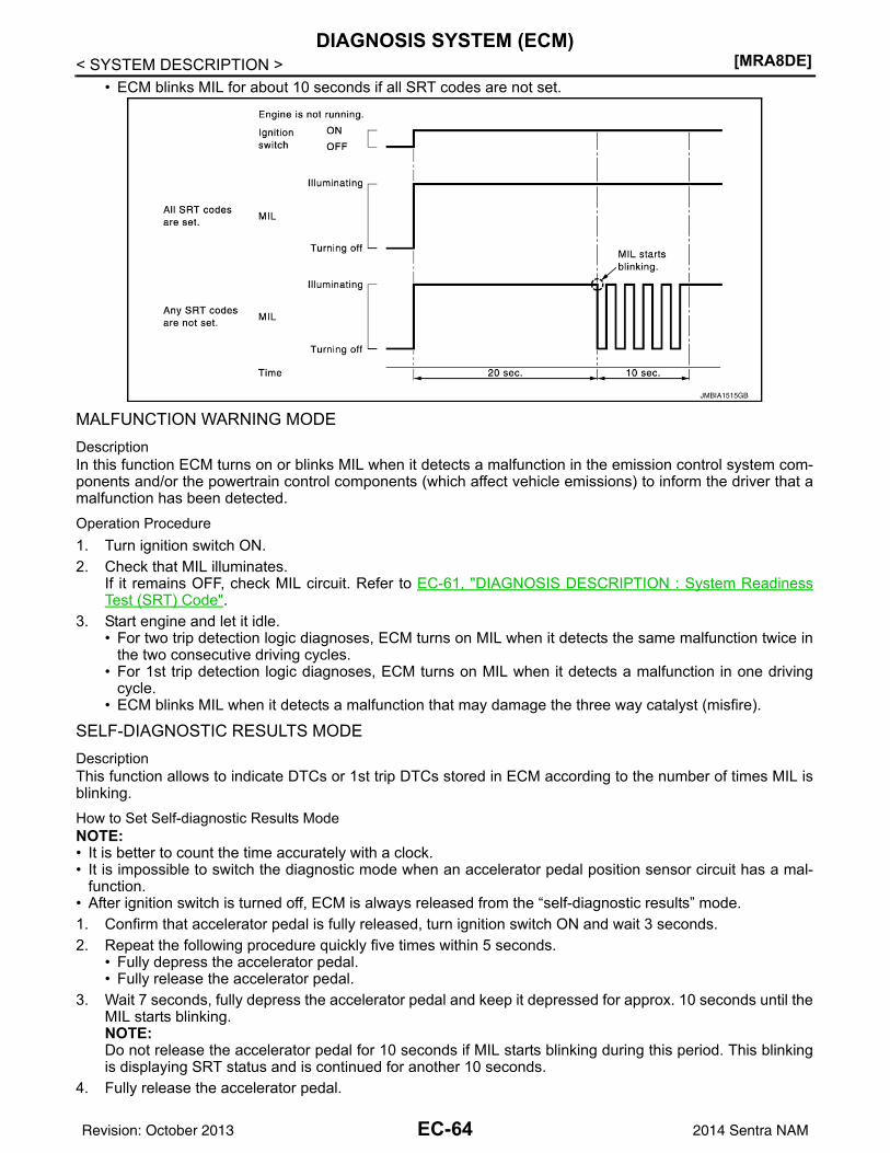
[MRA8DE]DIAGNOSIS SYSTEM (ECM)
< SYSTEM DESCRIPTION >• ECM blinks MIL for about 10 seconds if all SRT codes are not set.
MALFUNCTION WARNING MODEDescriptionIn this function ECM turns on or blinks MIL when it detects a malfunction in the emission control system com-ponents and/or the powertrain control components (which affect vehicle emissions) to inform the driver that amalfunction has been detected.Operation Procedure1. Turn ignition switch ON.2. Check that MIL illuminates.
If it remains OFF, check MIL circuit. Refer to EC-61, "DIAGNOSIS DESCRIPTION : System ReadinessTest (SRT) Code".
3. Start engine and let it idle.• For two trip detection logic diagnoses, ECM turns on MIL when it detects the same malfunction twice in
the two consecutive driving cycles.• For 1st trip detection logic diagnoses, ECM turns on MIL when it detects a malfunction in one driving
cycle.• ECM blinks MIL when it detects a malfunction that may damage the three way catalyst (misfire).
SELF-DIAGNOSTIC RESULTS MODEDescriptionThis function allows to indicate DTCs or 1st trip DTCs stored in ECM according to the number of times MIL isblinking.How to Set Self-diagnostic Results ModeNOTE:• It is better to count the time accurately with a clock.• It is impossible to switch the diagnostic mode when an accelerator pedal position sensor circuit has a mal-
function.• After ignition switch is turned off, ECM is always released from the “self-diagnostic results” mode.1. Confirm that accelerator pedal is fully released, turn ignition switch ON and wait 3 seconds.2. Repeat the following procedure quickly five times within 5 seconds.
• Fully depress the accelerator pedal.• Fully release the accelerator pedal.
3. Wait 7 seconds, fully depress the accelerator pedal and keep it depressed for approx. 10 seconds until theMIL starts blinking.NOTE:Do not release the accelerator pedal for 10 seconds if MIL starts blinking during this period. This blinkingis displaying SRT status and is continued for another 10 seconds.
4. Fully release the accelerator pedal.
JMBIA1515GB
EC-64Revision: October 2013 2014 Sentra NAM
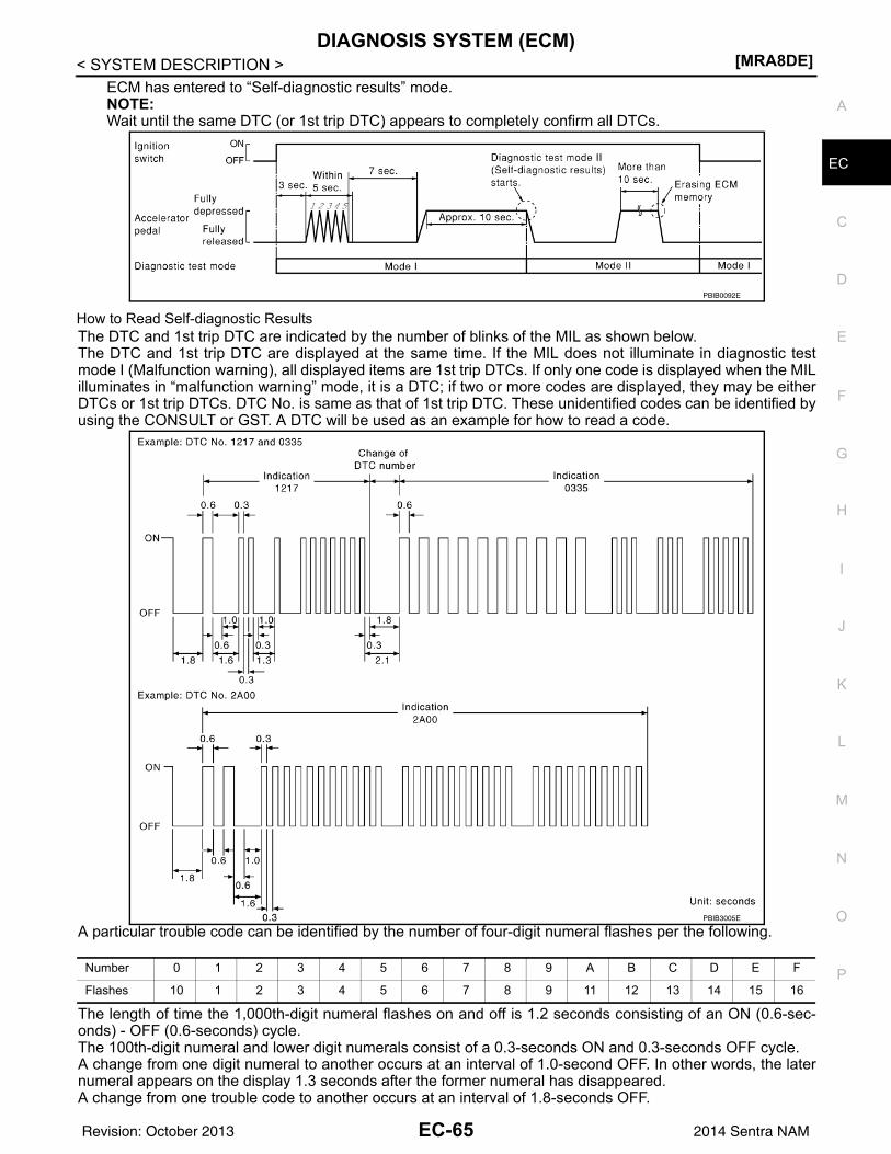
DIAGNOSIS SYSTEM (ECM)[MRA8DE]
C
D
E
F
G
H
I
J
K
L
M
A
C
N
P
O
< SYSTEM DESCRIPTION >
E
ECM has entered to “Self-diagnostic results” mode.NOTE:Wait until the same DTC (or 1st trip DTC) appears to completely confirm all DTCs.
How to Read Self-diagnostic ResultsThe DTC and 1st trip DTC are indicated by the number of blinks of the MIL as shown below.The DTC and 1st trip DTC are displayed at the same time. If the MIL does not illuminate in diagnostic testmode I (Malfunction warning), all displayed items are 1st trip DTCs. If only one code is displayed when the MILilluminates in “malfunction warning” mode, it is a DTC; if two or more codes are displayed, they may be eitherDTCs or 1st trip DTCs. DTC No. is same as that of 1st trip DTC. These unidentified codes can be identified byusing the CONSULT or GST. A DTC will be used as an example for how to read a code.
A particular trouble code can be identified by the number of four-digit numeral flashes per the following.
The length of time the 1,000th-digit numeral flashes on and off is 1.2 seconds consisting of an ON (0.6-sec-onds) - OFF (0.6-seconds) cycle.The 100th-digit numeral and lower digit numerals consist of a 0.3-seconds ON and 0.3-seconds OFF cycle.A change from one digit numeral to another occurs at an interval of 1.0-second OFF. In other words, the laternumeral appears on the display 1.3 seconds after the former numeral has disappeared.A change from one trouble code to another occurs at an interval of 1.8-seconds OFF.
PBIB0092E
PBIB3005E
Number 0 1 2 3 4 5 6 7 8 9 A B C D E F
Flashes 10 1 2 3 4 5 6 7 8 9 11 12 13 14 15 16
EC-65Revision: October 2013 2014 Sentra NAM
[MRA8DE]DIAGNOSIS SYSTEM (ECM)
< SYSTEM DESCRIPTION >In this way, all the detected malfunctions are classified by their DTC numbers. The DTC 0000 refers to no mal-function. Refer to EC-94, "DTC Index".How to Erase Self-diagnostic ResultsBy performing this procedure, ECM memory is erased and the following diagnostic information is erased aswell.• Diagnostic trouble codes• 1st trip diagnostic trouble codes• Freeze frame data• 1st trip freeze frame data• System readiness test (SRT) codes• Test valuesNOTE:Also, if a battery terminal is disconnected, ECM memory is erased and the diagnostic information as listedabove is erased. (The amount of time required for erasing may vary from a few seconds to several hours.)1. Turn ignition switch OFF and wait at least 10 seconds.2. Turn ignition switch ON.3. Turn ignition switch OFF and wait at least 10 seconds.4. Turn ignition switch ON.5. Set ECM in “self-diagnostic results” mode.6. The diagnostic information has been erased from the backup memory in the ECM.
Fully depress the accelerator pedal and keep it depressed for more than 10 seconds.7. Fully release the accelerator pedal, and confirm the DTC 0000 is displayed.
CONSULT Function INFOID:0000000009758389
FUNCTION
*: The following emission-related diagnostic information is cleared when the ECM memory is erased.• Diagnostic trouble codes• 1st trip diagnostic trouble codes• Freeze frame data• 1st trip freeze frame data• System readiness test (SRT) codes• Test values
SELF DIAGNOSTIC RESULTS MODESelf Diagnostic ItemRegarding items of DTC and 1st trip DTC, refer to EC-94, "DTC Index".How to Read DTC and 1st Trip DTCDTCs and 1st trip DTCs related to the malfunction are displayed in “Self-diag results”.• When ECM detects a 1st trip DTC, “1t” is displayed for “TIME”.• When ECM has detected a current DTC, “0” is displayed for “TIME”.• If “TIME” is neither “0” nor “1t”, the DTC occurred in the past and ECM shows the number of times the vehi-
cle has been driven since the last detection of the DTC.
Diagnostic test mode Function
Self Diagnostic Results Self-diagnostic results such as 1st trip DTC, DTCs and 1st trip freeze frame data or freeze frame data can be read and erased quickly.*
Data Monitor Input/Output data in the ECM can be read.
Work Support This mode enables a technician to adjust some devices faster and more accurately by following the in-dications on the CONSULT unit.
Active Test Diagnostic Test Mode in which CONSULT drives some actuators apart from the ECMs and also shifts some parameters in a specified range.
Ecu Identification ECM part number can be read.
DTC Work Support The use of this mode enables quick and accurate performance of Confirmation Procedure.
EC-66Revision: October 2013 2014 Sentra NAM
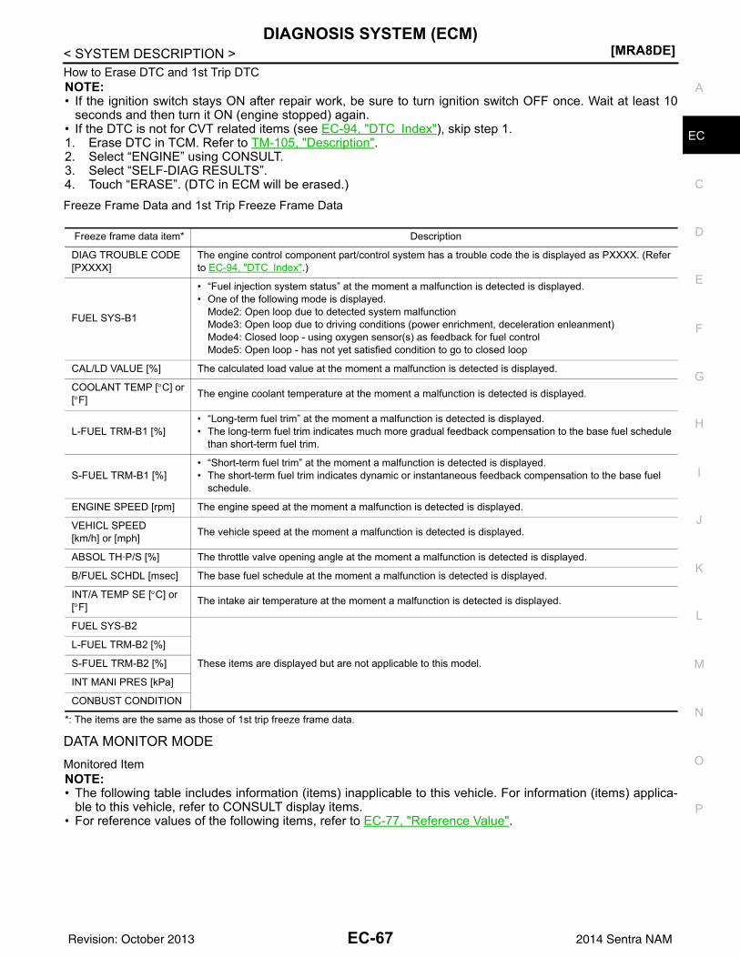
DIAGNOSIS SYSTEM (ECM)[MRA8DE]
C
D
E
F
G
H
I
J
K
L
M
A
C
N
P
O
< SYSTEM DESCRIPTION >
E
How to Erase DTC and 1st Trip DTCNOTE:• If the ignition switch stays ON after repair work, be sure to turn ignition switch OFF once. Wait at least 10
seconds and then turn it ON (engine stopped) again.• If the DTC is not for CVT related items (see EC-94, "DTC Index"), skip step 1.1. Erase DTC in TCM. Refer to TM-105, "Description".2. Select “ENGINE” using CONSULT.3. Select “SELF-DIAG RESULTS”.4. Touch “ERASE”. (DTC in ECM will be erased.)Freeze Frame Data and 1st Trip Freeze Frame Data
*: The items are the same as those of 1st trip freeze frame data.
DATA MONITOR MODEMonitored ItemNOTE:• The following table includes information (items) inapplicable to this vehicle. For information (items) applica-
ble to this vehicle, refer to CONSULT display items.• For reference values of the following items, refer to EC-77, "Reference Value".
Freeze frame data item* Description
DIAG TROUBLE CODE[PXXXX]
The engine control component part/control system has a trouble code the is displayed as PXXXX. (Refer to EC-94, "DTC Index".)
FUEL SYS-B1
• “Fuel injection system status” at the moment a malfunction is detected is displayed.• One of the following mode is displayed.
Mode2: Open loop due to detected system malfunctionMode3: Open loop due to driving conditions (power enrichment, deceleration enleanment)Mode4: Closed loop - using oxygen sensor(s) as feedback for fuel controlMode5: Open loop - has not yet satisfied condition to go to closed loop
CAL/LD VALUE [%] The calculated load value at the moment a malfunction is detected is displayed.
COOLANT TEMP [°C] or [°F] The engine coolant temperature at the moment a malfunction is detected is displayed.
L-FUEL TRM-B1 [%]• “Long-term fuel trim” at the moment a malfunction is detected is displayed.• The long-term fuel trim indicates much more gradual feedback compensation to the base fuel schedule
than short-term fuel trim.
S-FUEL TRM-B1 [%]• “Short-term fuel trim” at the moment a malfunction is detected is displayed.• The short-term fuel trim indicates dynamic or instantaneous feedback compensation to the base fuel
schedule.
ENGINE SPEED [rpm] The engine speed at the moment a malfunction is detected is displayed.
VEHICL SPEED[km/h] or [mph] The vehicle speed at the moment a malfunction is detected is displayed.
ABSOL TH·P/S [%] The throttle valve opening angle at the moment a malfunction is detected is displayed.
B/FUEL SCHDL [msec] The base fuel schedule at the moment a malfunction is detected is displayed.
INT/A TEMP SE [°C] or [°F] The intake air temperature at the moment a malfunction is detected is displayed.
FUEL SYS-B2
These items are displayed but are not applicable to this model.
L-FUEL TRM-B2 [%]
S-FUEL TRM-B2 [%]
INT MANI PRES [kPa]
CONBUST CONDITION
EC-67Revision: October 2013 2014 Sentra NAM
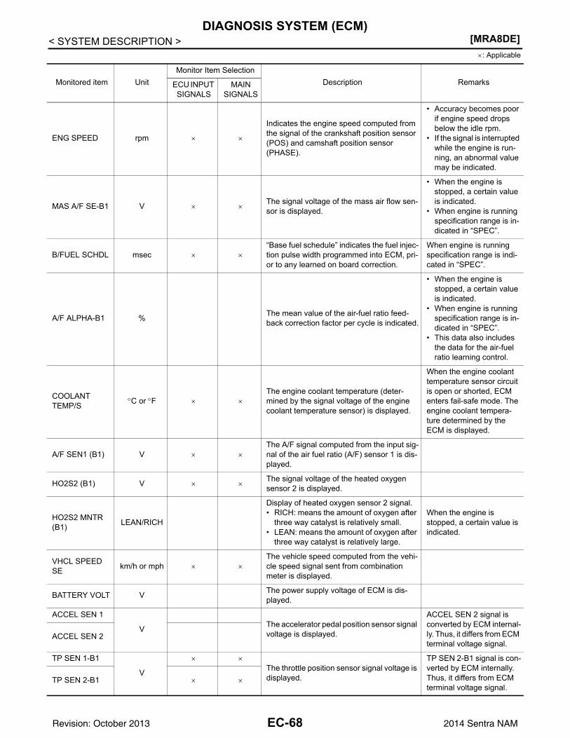
[MRA8DE]DIAGNOSIS SYSTEM (ECM)
< SYSTEM DESCRIPTION >×: Applicable
Monitored item UnitMonitor Item Selection
Description RemarksECU INPUT SIGNALS
MAIN SIGNALS
ENG SPEED rpm × ×
Indicates the engine speed computed from the signal of the crankshaft position sensor (POS) and camshaft position sensor (PHASE).
• Accuracy becomes poor if engine speed drops below the idle rpm.
• If the signal is interrupted while the engine is run-ning, an abnormal value may be indicated.
MAS A/F SE-B1 V × ×The signal voltage of the mass air flow sen-sor is displayed.
• When the engine is stopped, a certain value is indicated.
• When engine is running specification range is in-dicated in “SPEC”.
B/FUEL SCHDL msec × ×“Base fuel schedule” indicates the fuel injec-tion pulse width programmed into ECM, pri-or to any learned on board correction.
When engine is running specification range is indi-cated in “SPEC”.
A/F ALPHA-B1 % The mean value of the air-fuel ratio feed-back correction factor per cycle is indicated.
• When the engine is stopped, a certain value is indicated.
• When engine is running specification range is in-dicated in “SPEC”.
• This data also includes the data for the air-fuel ratio learning control.
COOLANT TEMP/S °C or °F × ×
The engine coolant temperature (deter-mined by the signal voltage of the engine coolant temperature sensor) is displayed.
When the engine coolant temperature sensor circuit is open or shorted, ECM enters fail-safe mode. The engine coolant tempera-ture determined by the ECM is displayed.
A/F SEN1 (B1) V × ×The A/F signal computed from the input sig-nal of the air fuel ratio (A/F) sensor 1 is dis-played.
HO2S2 (B1) V × ×The signal voltage of the heated oxygen sensor 2 is displayed.
HO2S2 MNTR (B1) LEAN/RICH
Display of heated oxygen sensor 2 signal.• RICH: means the amount of oxygen after
three way catalyst is relatively small.• LEAN: means the amount of oxygen after
three way catalyst is relatively large.
When the engine is stopped, a certain value is indicated.
VHCL SPEED SE km/h or mph × ×
The vehicle speed computed from the vehi-cle speed signal sent from combination meter is displayed.
BATTERY VOLT V The power supply voltage of ECM is dis-played.
ACCEL SEN 1
V The accelerator pedal position sensor signal voltage is displayed.
ACCEL SEN 2 signal is converted by ECM internal-ly. Thus, it differs from ECM terminal voltage signal.
ACCEL SEN 2
TP SEN 1-B1
V
× ×The throttle position sensor signal voltage is displayed.
TP SEN 2-B1 signal is con-verted by ECM internally. Thus, it differs from ECM terminal voltage signal.
TP SEN 2-B1 × ×
EC-68Revision: October 2013 2014 Sentra NAM
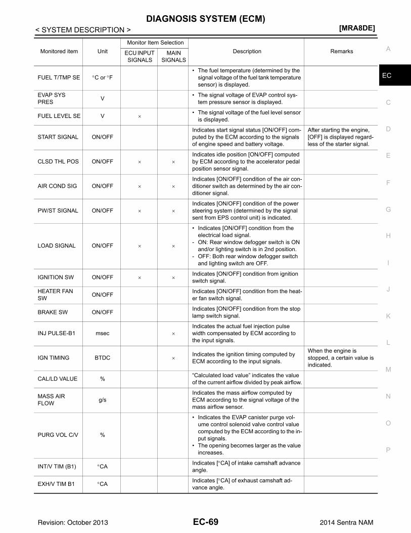
DIAGNOSIS SYSTEM (ECM)[MRA8DE]
C
D
E
F
G
H
I
J
K
L
M
A
C
N
P
O
< SYSTEM DESCRIPTION >
EFUEL T/TMP SE °C or °F• The fuel temperature (determined by the
signal voltage of the fuel tank temperature sensor) is displayed.
EVAP SYS PRES V • The signal voltage of EVAP control sys-
tem pressure sensor is displayed.
FUEL LEVEL SE V ו The signal voltage of the fuel level sensor
is displayed.
START SIGNAL ON/OFFIndicates start signal status [ON/OFF] com-puted by the ECM according to the signals of engine speed and battery voltage.
After starting the engine, [OFF] is displayed regard-less of the starter signal.
CLSD THL POS ON/OFF × ×Indicates idle position [ON/OFF] computed by ECM according to the accelerator pedal position sensor signal.
AIR COND SIG ON/OFF × ×Indicates [ON/OFF] condition of the air con-ditioner switch as determined by the air con-ditioner signal.
PW/ST SIGNAL ON/OFF × ×Indicates [ON/OFF] condition of the power steering system (determined by the signal sent from EPS control unit) is indicated.
LOAD SIGNAL ON/OFF × ×
• Indicates [ON/OFF] condition from the electrical load signal.
- ON: Rear window defogger switch is ON and/or lighting switch is in 2nd position.
- OFF: Both rear window defogger switch and lighting switch are OFF.
IGNITION SW ON/OFF × ×Indicates [ON/OFF] condition from ignition switch signal.
HEATER FAN SW ON/OFF Indicates [ON/OFF] condition from the heat-
er fan switch signal.
BRAKE SW ON/OFF Indicates [ON/OFF] condition from the stop lamp switch signal.
INJ PULSE-B1 msec ×Indicates the actual fuel injection pulse width compensated by ECM according to the input signals.
IGN TIMING BTDC ×Indicates the ignition timing computed by ECM according to the input signals.
When the engine is stopped, a certain value is indicated.
CAL/LD VALUE % “Calculated load value” indicates the value of the current airflow divided by peak airflow.
MASS AIR FLOW g/s
Indicates the mass airflow computed by ECM according to the signal voltage of the mass airflow sensor.
PURG VOL C/V %
• Indicates the EVAP canister purge vol-ume control solenoid valve control value computed by the ECM according to the in-put signals.
• The opening becomes larger as the value increases.
INT/V TIM (B1) °CA Indicates [°CA] of intake camshaft advance angle.
EXH/V TIM B1 °CA Indicates [°CA] of exhaust camshaft ad-vance angle.
Monitored item UnitMonitor Item Selection
Description RemarksECU INPUT SIGNALS
MAIN SIGNALS
EC-69Revision: October 2013 2014 Sentra NAM
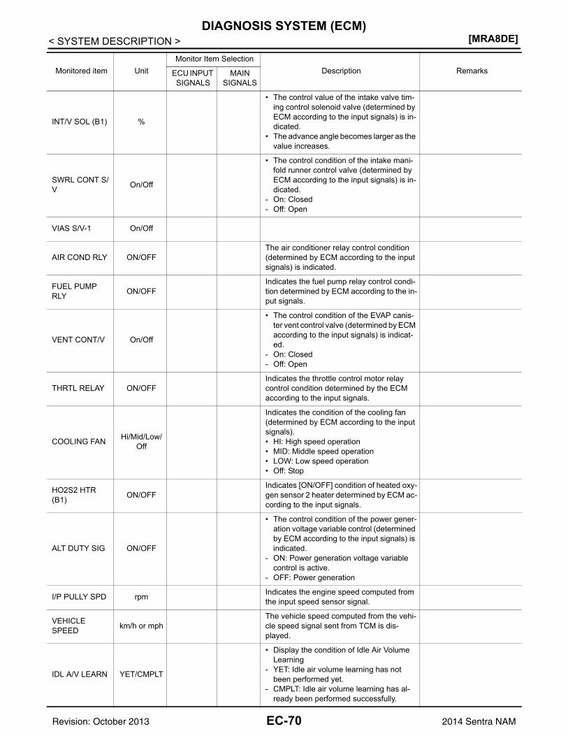
[MRA8DE]DIAGNOSIS SYSTEM (ECM)
< SYSTEM DESCRIPTION >
INT/V SOL (B1) %
• The control value of the intake valve tim-ing control solenoid valve (determined by ECM according to the input signals) is in-dicated.
• The advance angle becomes larger as the value increases.
SWRL CONT S/V On/Off
• The control condition of the intake mani-fold runner control valve (determined by ECM according to the input signals) is in-dicated.
- On: Closed- Off: Open
VIAS S/V-1 On/Off
AIR COND RLY ON/OFFThe air conditioner relay control condition (determined by ECM according to the input signals) is indicated.
FUEL PUMP RLY ON/OFF
Indicates the fuel pump relay control condi-tion determined by ECM according to the in-put signals.
VENT CONT/V On/Off
• The control condition of the EVAP canis-ter vent control valve (determined by ECM according to the input signals) is indicat-ed.
- On: Closed- Off: Open
THRTL RELAY ON/OFFIndicates the throttle control motor relay control condition determined by the ECM according to the input signals.
COOLING FAN Hi/Mid/Low/Off
Indicates the condition of the cooling fan (determined by ECM according to the input signals).• HI: High speed operation• MID: Middle speed operation• LOW: Low speed operation• Off: Stop
HO2S2 HTR (B1) ON/OFF
Indicates [ON/OFF] condition of heated oxy-gen sensor 2 heater determined by ECM ac-cording to the input signals.
ALT DUTY SIG ON/OFF
• The control condition of the power gener-ation voltage variable control (determined by ECM according to the input signals) is indicated.
- ON: Power generation voltage variable control is active.
- OFF: Power generation
I/P PULLY SPD rpm Indicates the engine speed computed from the input speed sensor signal.
VEHICLE SPEED km/h or mph
The vehicle speed computed from the vehi-cle speed signal sent from TCM is dis-played.
IDL A/V LEARN YET/CMPLT
• Display the condition of Idle Air Volume Learning
- YET: Idle air volume learning has not been performed yet.
- CMPLT: Idle air volume learning has al-ready been performed successfully.
Monitored item UnitMonitor Item Selection
Description RemarksECU INPUT SIGNALS
MAIN SIGNALS
EC-70Revision: October 2013 2014 Sentra NAM
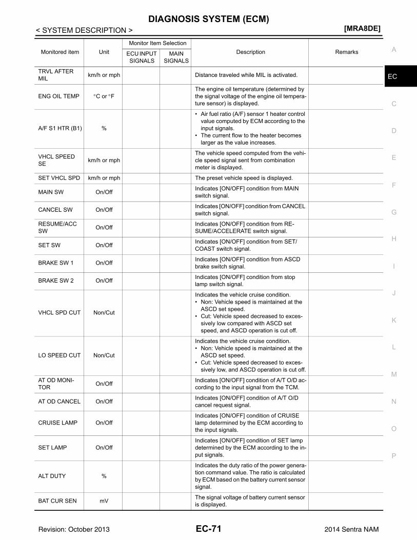
DIAGNOSIS SYSTEM (ECM)[MRA8DE]
C
D
E
F
G
H
I
J
K
L
M
A
C
N
P
O
< SYSTEM DESCRIPTION >
ETRVL AFTER MIL km/h or mph Distance traveled while MIL is activated.
ENG OIL TEMP °C or °FThe engine oil temperature (determined by the signal voltage of the engine oil tempera-ture sensor) is displayed.
A/F S1 HTR (B1) %
• Air fuel ratio (A/F) sensor 1 heater control value computed by ECM according to the input signals.
• The current flow to the heater becomes larger as the value increases.
VHCL SPEED SE km/h or mph
The vehicle speed computed from the vehi-cle speed signal sent from combination meter is displayed.
SET VHCL SPD km/h or mph The preset vehicle speed is displayed.
MAIN SW On/Off Indicates [ON/OFF] condition from MAIN switch signal.
CANCEL SW On/Off Indicates [ON/OFF] condition from CANCEL switch signal.
RESUME/ACC SW On/Off Indicates [ON/OFF] condition from RE-
SUME/ACCELERATE switch signal.
SET SW On/Off Indicates [ON/OFF] condition from SET/COAST switch signal.
BRAKE SW 1 On/Off Indicates [ON/OFF] condition from ASCD brake switch signal.
BRAKE SW 2 On/Off Indicates [ON/OFF] condition from stop lamp switch signal.
VHCL SPD CUT Non/Cut
Indicates the vehicle cruise condition.• Non: Vehicle speed is maintained at the
ASCD set speed.• Cut: Vehicle speed decreased to exces-
sively low compared with ASCD set speed, and ASCD operation is cut off.
LO SPEED CUT Non/Cut
Indicates the vehicle cruise condition.• Non: Vehicle speed is maintained at the
ASCD set speed.• Cut: Vehicle speed decreased to exces-
sively low, and ASCD operation is cut off.
AT OD MONI-TOR On/Off Indicates [ON/OFF] condition of A/T O/D ac-
cording to the input signal from the TCM.
AT OD CANCEL On/Off Indicates [ON/OFF] condition of A/T O/D cancel request signal.
CRUISE LAMP On/OffIndicates [ON/OFF] condition of CRUISE lamp determined by the ECM according to the input signals.
SET LAMP On/OffIndicates [ON/OFF] condition of SET lamp determined by the ECM according to the in-put signals.
ALT DUTY %
Indicates the duty ratio of the power genera-tion command value. The ratio is calculated by ECM based on the battery current sensor signal.
BAT CUR SEN mV The signal voltage of battery current sensor is displayed.
Monitored item UnitMonitor Item Selection
Description RemarksECU INPUT SIGNALS
MAIN SIGNALS
EC-71Revision: October 2013 2014 Sentra NAM
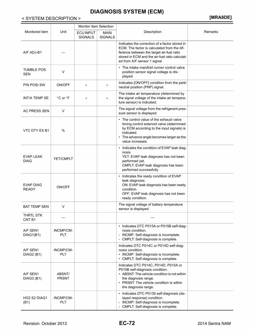
[MRA8DE]DIAGNOSIS SYSTEM (ECM)
< SYSTEM DESCRIPTION >
A/F ADJ-B1 —
Indicates the correction of a factor stored in ECM. The factor is calculated from the dif-ference between the target air-fuel ratio stored in ECM and the air-fuel ratio calculat-ed from A/F sensor 1 signal.
TUMBLE POS SEN V
• The intake manifold runner control valve position sensor signal voltage is dis-played.
P/N POSI SW ON/OFF × ×Indicates [ON/OFF] condition from the park/neutral position (PNP) signal.
INT/A TEMP SE °C or °F × ×The intake air temperature (determined by the signal voltage of the intake air tempera-ture sensor) is indicated.
AC PRESS SEN V The signal voltage from the refrigerant pres-sure sensor is displayed.
VTC DTY EX B1 %
• The control value of the exhaust valve timing control solenoid valve (determined by ECM according to the input signals) is indicated.
• The advance angle becomes larger as the value increases.
EVAP LEAK DIAG YET/CMPLT
• Indicates the condition of EVAP leak diag-nosis.YET: EVAP leak diagnosis has not been performed yet.CMPLT: EVAP leak diagnosis has been performed successfully.
EVAP DIAG READY ON/OFF
• Indicates the ready condition of EVAP leak diagnosis.ON: EVAP leak diagnosis has been ready condition.OFF: EVAP leak diagnosis has not been ready condition.
BAT TEMP SEN V The signal voltage of battery temperature sensor is displayed.
THRTL STK CNT B1 — —
A/F SEN1 DIAG1(B1)
INCMP/CM-PLT
• Indicates DTC P015A or P015B self-diag-nosis condition.
- INCMP: Self-diagnosis is incomplete.- CMPLT: Self-diagnosis is complete.
A/F SEN1 DIAG2 (B1)
INCMP/CM-PLT
Indicates DTC P014C or P014D self-diag-nosis condition.• INCMP: Self-diagnosis is incomplete.• CMPLT: Self-diagnosis is complete.
A/F SEN1 DIAG3 (B1)
ABSNT/PRSNT
Indicates DTC P014C, P014D, P015A or P015B self-diagnosis condition.• ABSNT: The vehicle condition is not within
the diagnosis range.• PRSNT: The vehicle condition is within
the diagnosis range.
HO2 S2 DIAG1 (B1)
INCMP/CM-PLT
• Indicates DTC P0139 self-diagnosis (de-layed response) condition.
- INCMP: Self-diagnosis is incomplete.- CMPLT: Self-diagnosis is complete.
Monitored item UnitMonitor Item Selection
Description RemarksECU INPUT SIGNALS
MAIN SIGNALS
EC-72Revision: October 2013 2014 Sentra NAM
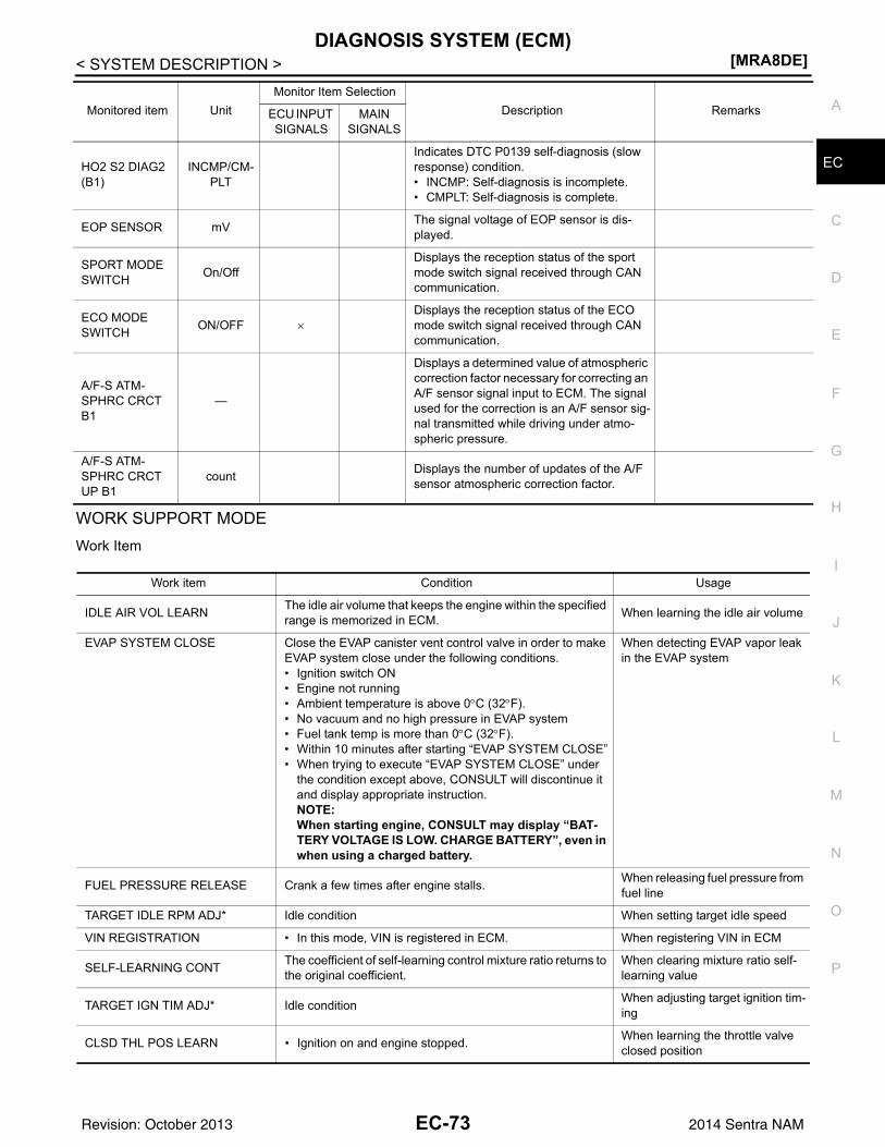
DIAGNOSIS SYSTEM (ECM)[MRA8DE]
C
D
E
F
G
H
I
J
K
L
M
A
C
N
P
O
< SYSTEM DESCRIPTION >
E
WORK SUPPORT MODEWork Item
HO2 S2 DIAG2 (B1)
INCMP/CM-PLT
Indicates DTC P0139 self-diagnosis (slow response) condition.• INCMP: Self-diagnosis is incomplete.• CMPLT: Self-diagnosis is complete.
EOP SENSOR mV The signal voltage of EOP sensor is dis-played.
SPORT MODE SWITCH On/Off
Displays the reception status of the sport mode switch signal received through CAN communication.
ECO MODE SWITCH ON/OFF ×
Displays the reception status of the ECO mode switch signal received through CAN communication.
A/F-S ATM-SPHRC CRCT B1
—
Displays a determined value of atmospheric correction factor necessary for correcting an A/F sensor signal input to ECM. The signal used for the correction is an A/F sensor sig-nal transmitted while driving under atmo-spheric pressure.
A/F-S ATM-SPHRC CRCT UP B1
count Displays the number of updates of the A/F sensor atmospheric correction factor.
Monitored item UnitMonitor Item Selection
Description RemarksECU INPUT SIGNALS
MAIN SIGNALS
Work item Condition Usage
IDLE AIR VOL LEARN The idle air volume that keeps the engine within the specified range is memorized in ECM. When learning the idle air volume
EVAP SYSTEM CLOSE Close the EVAP canister vent control valve in order to make EVAP system close under the following conditions.• Ignition switch ON• Engine not running• Ambient temperature is above 0°C (32°F).• No vacuum and no high pressure in EVAP system• Fuel tank temp is more than 0°C (32°F).• Within 10 minutes after starting “EVAP SYSTEM CLOSE”• When trying to execute “EVAP SYSTEM CLOSE” under
the condition except above, CONSULT will discontinue it and display appropriate instruction.NOTE:When starting engine, CONSULT may display “BAT-TERY VOLTAGE IS LOW. CHARGE BATTERY”, even in when using a charged battery.
When detecting EVAP vapor leak in the EVAP system
FUEL PRESSURE RELEASE Crank a few times after engine stalls. When releasing fuel pressure from fuel line
TARGET IDLE RPM ADJ* Idle condition When setting target idle speed
VIN REGISTRATION • In this mode, VIN is registered in ECM. When registering VIN in ECM
SELF-LEARNING CONT The coefficient of self-learning control mixture ratio returns to the original coefficient.
When clearing mixture ratio self-learning value
TARGET IGN TIM ADJ* Idle condition When adjusting target ignition tim-ing
CLSD THL POS LEARN • Ignition on and engine stopped. When learning the throttle valve closed position
EC-73Revision: October 2013 2014 Sentra NAM
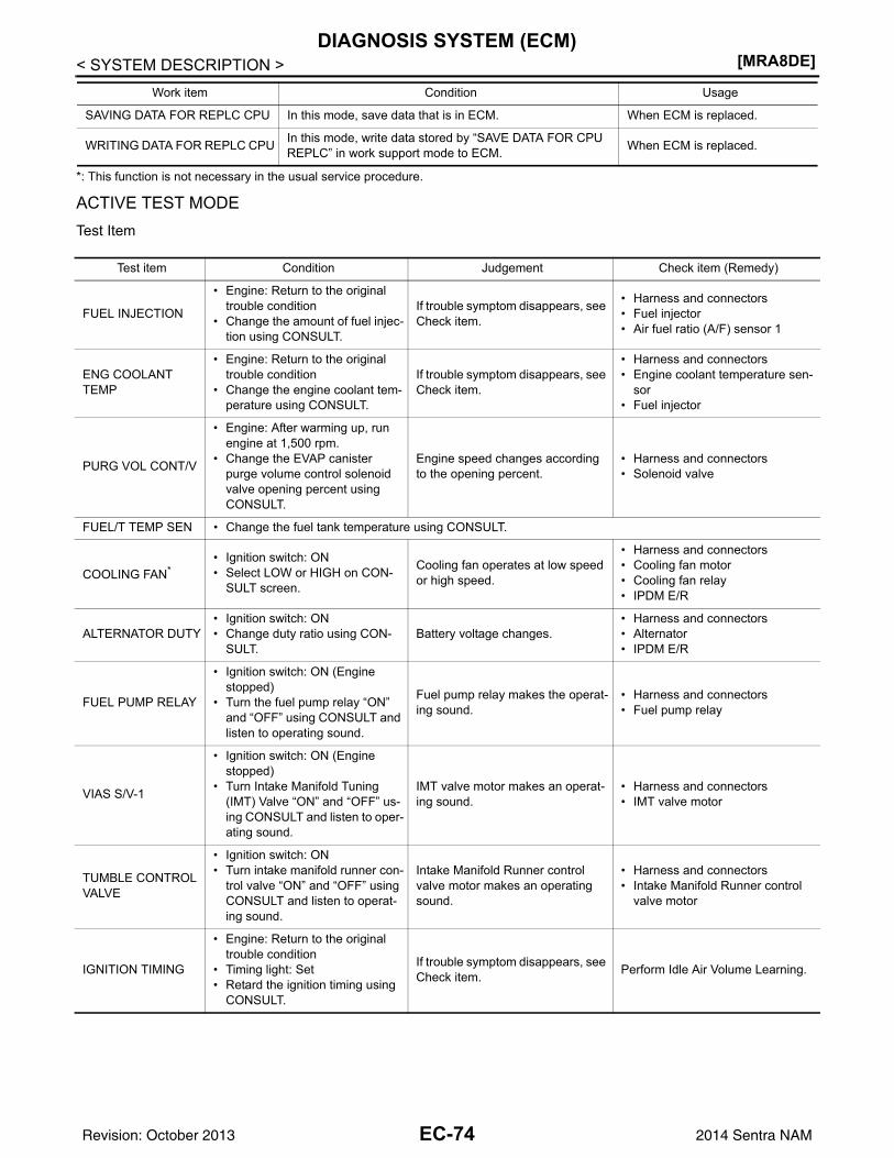
[MRA8DE]DIAGNOSIS SYSTEM (ECM)
< SYSTEM DESCRIPTION >
*: This function is not necessary in the usual service procedure.
ACTIVE TEST MODETest Item
SAVING DATA FOR REPLC CPU In this mode, save data that is in ECM. When ECM is replaced.
WRITING DATA FOR REPLC CPU In this mode, write data stored by “SAVE DATA FOR CPU REPLC” in work support mode to ECM. When ECM is replaced.
Work item Condition Usage
Test item Condition Judgement Check item (Remedy)
FUEL INJECTION
• Engine: Return to the original trouble condition
• Change the amount of fuel injec-tion using CONSULT.
If trouble symptom disappears, see Check item.
• Harness and connectors• Fuel injector• Air fuel ratio (A/F) sensor 1
ENG COOLANT TEMP
• Engine: Return to the original trouble condition
• Change the engine coolant tem-perature using CONSULT.
If trouble symptom disappears, see Check item.
• Harness and connectors• Engine coolant temperature sen-
sor• Fuel injector
PURG VOL CONT/V
• Engine: After warming up, run engine at 1,500 rpm.
• Change the EVAP canister purge volume control solenoid valve opening percent using CONSULT.
Engine speed changes according to the opening percent.
• Harness and connectors• Solenoid valve
FUEL/T TEMP SEN • Change the fuel tank temperature using CONSULT.
COOLING FAN*• Ignition switch: ON• Select LOW or HIGH on CON-
SULT screen.
Cooling fan operates at low speed or high speed.
• Harness and connectors• Cooling fan motor• Cooling fan relay• IPDM E/R
ALTERNATOR DUTY• Ignition switch: ON• Change duty ratio using CON-
SULT.Battery voltage changes.
• Harness and connectors• Alternator• IPDM E/R
FUEL PUMP RELAY
• Ignition switch: ON (Engine stopped)
• Turn the fuel pump relay “ON” and “OFF” using CONSULT and listen to operating sound.
Fuel pump relay makes the operat-ing sound.
• Harness and connectors• Fuel pump relay
VIAS S/V-1
• Ignition switch: ON (Engine stopped)
• Turn Intake Manifold Tuning (IMT) Valve “ON” and “OFF” us-ing CONSULT and listen to oper-ating sound.
IMT valve motor makes an operat-ing sound.
• Harness and connectors• IMT valve motor
TUMBLE CONTROL VALVE
• Ignition switch: ON• Turn intake manifold runner con-
trol valve “ON” and “OFF” using CONSULT and listen to operat-ing sound.
Intake Manifold Runner control valve motor makes an operating sound.
• Harness and connectors• Intake Manifold Runner control
valve motor
IGNITION TIMING
• Engine: Return to the original trouble condition
• Timing light: Set• Retard the ignition timing using
CONSULT.
If trouble symptom disappears, see Check item. Perform Idle Air Volume Learning.
EC-74Revision: October 2013 2014 Sentra NAM
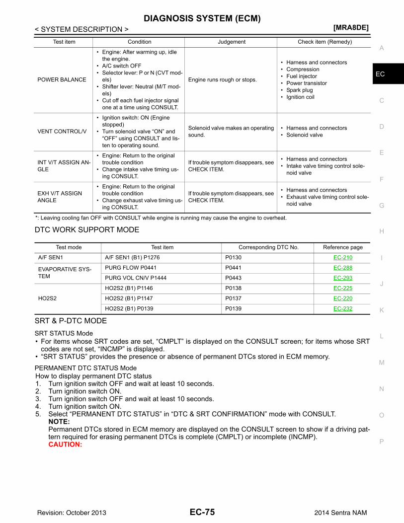
DIAGNOSIS SYSTEM (ECM)[MRA8DE]
C
D
E
F
G
H
I
J
K
L
M
A
C
N
P
O
< SYSTEM DESCRIPTION >
E
*: Leaving cooling fan OFF with CONSULT while engine is running may cause the engine to overheat.
DTC WORK SUPPORT MODE
SRT & P-DTC MODESRT STATUS Mode• For items whose SRT codes are set, “CMPLT” is displayed on the CONSULT screen; for items whose SRT
codes are not set, “INCMP” is displayed.• “SRT STATUS” provides the presence or absence of permanent DTCs stored in ECM memory.PERMANENT DTC STATUS ModeHow to display permanent DTC status1. Turn ignition switch OFF and wait at least 10 seconds.2. Turn ignition switch ON.3. Turn ignition switch OFF and wait at least 10 seconds.4. Turn ignition switch ON.5. Select “PERMANENT DTC STATUS” in “DTC & SRT CONFIRMATION” mode with CONSULT.
NOTE:Permanent DTCs stored in ECM memory are displayed on the CONSULT screen to show if a driving pat-tern required for erasing permanent DTCs is complete (CMPLT) or incomplete (INCMP).CAUTION:
POWER BALANCE
• Engine: After warming up, idle the engine.
• A/C switch OFF• Selector lever: P or N (CVT mod-
els)• Shifter lever: Neutral (M/T mod-
els)• Cut off each fuel injector signal
one at a time using CONSULT.
Engine runs rough or stops.
• Harness and connectors• Compression• Fuel injector• Power transistor• Spark plug• Ignition coil
VENT CONTROL/V
• Ignition switch: ON (Engine stopped)
• Turn solenoid valve “ON” and “OFF” using CONSULT and lis-ten to operating sound.
Solenoid valve makes an operating sound.
• Harness and connectors• Solenoid valve
INT V/T ASSIGN AN-GLE
• Engine: Return to the original trouble condition
• Change intake valve timing us-ing CONSULT.
If trouble symptom disappears, see CHECK ITEM.
• Harness and connectors• Intake valve timing control sole-
noid valve
EXH V/T ASSIGN ANGLE
• Engine: Return to the original trouble condition
• Change exhaust valve timing us-ing CONSULT.
If trouble symptom disappears, see CHECK ITEM.
• Harness and connectors• Exhaust valve timing control sole-
noid valve
Test item Condition Judgement Check item (Remedy)
Test mode Test item Corresponding DTC No. Reference page
A/F SEN1 A/F SEN1 (B1) P1276 P0130 EC-210
EVAPORATIVE SYS-TEM
PURG FLOW P0441 P0441 EC-288
PURG VOL CN/V P1444 P0443 EC-293
HO2S2
HO2S2 (B1) P1146 P0138 EC-225
HO2S2 (B1) P1147 P0137 EC-220
HO2S2 (B1) P0139 P0139 EC-232
EC-75Revision: October 2013 2014 Sentra NAM
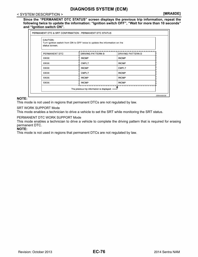
[MRA8DE]DIAGNOSIS SYSTEM (ECM)
< SYSTEM DESCRIPTION >Since the “PERMANENT DTC STATUS” screen displays the previous trip information, repeat thefollowing twice to update the information: “Ignition switch OFF”, “Wait for more than 10 seconds”and “Ignition switch ON”.
NOTE:This mode is not used in regions that permanent DTCs are not regulated by law.SRT WORK SUPPORT ModeThis mode enables a technician to drive a vehicle to set the SRT while monitoring the SRT status.PERMANENT DTC WORK SUPPORT ModeThis mode enables a technician to drive a vehicle to complete the driving pattern that is required for erasingpermanent DTC.NOTE:This mode is not used in regions that permanent DTCs are not regulated by law.
JSBIA0062GB
EC-76Revision: October 2013 2014 Sentra NAM
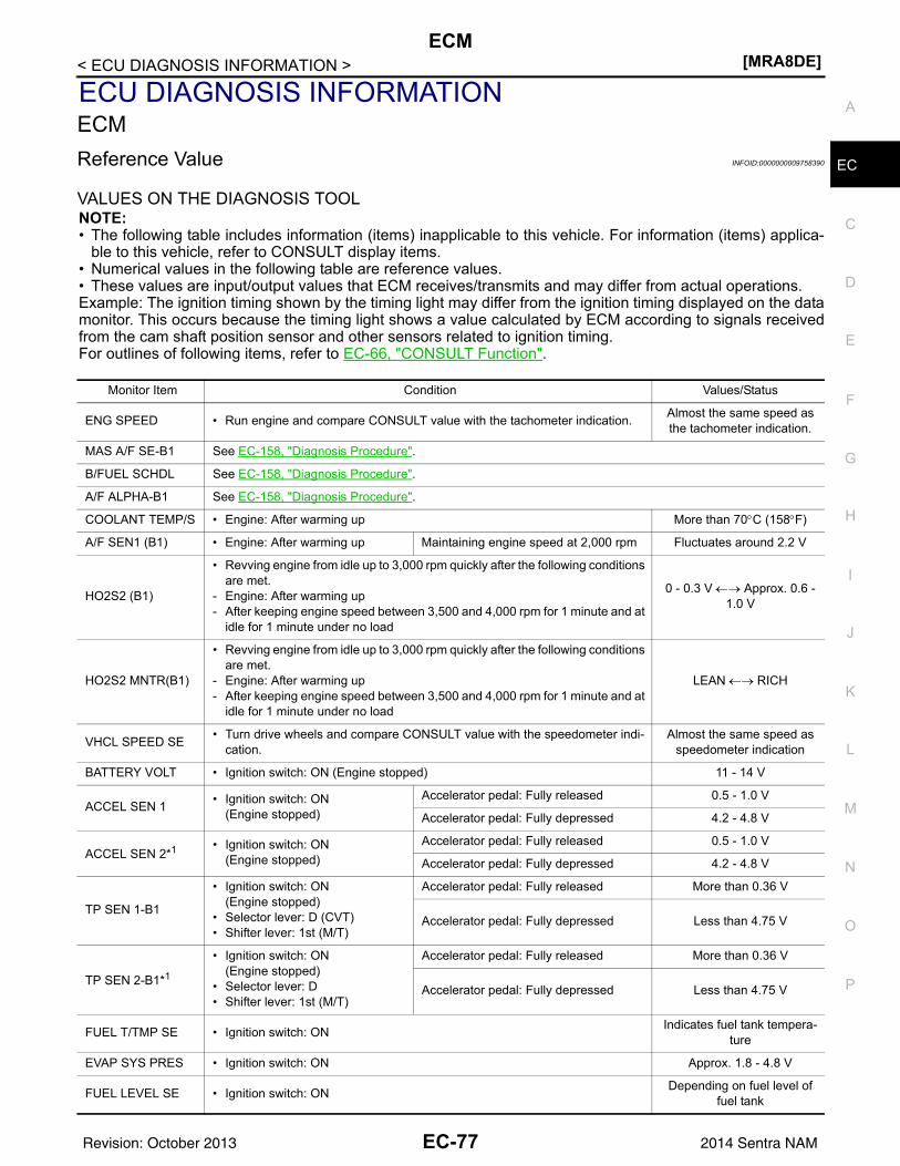
ECM[MRA8DE]
C
D
E
F
G
H
I
J
K
L
M
A
C
N
P
O
< ECU DIAGNOSIS INFORMATION >
E
ECU DIAGNOSIS INFORMATIONECMReference Value INFOID:0000000009758390
VALUES ON THE DIAGNOSIS TOOLNOTE:• The following table includes information (items) inapplicable to this vehicle. For information (items) applica-
ble to this vehicle, refer to CONSULT display items.• Numerical values in the following table are reference values.• These values are input/output values that ECM receives/transmits and may differ from actual operations.Example: The ignition timing shown by the timing light may differ from the ignition timing displayed on the datamonitor. This occurs because the timing light shows a value calculated by ECM according to signals receivedfrom the cam shaft position sensor and other sensors related to ignition timing.For outlines of following items, refer to EC-66, "CONSULT Function".
Monitor Item Condition Values/Status
ENG SPEED • Run engine and compare CONSULT value with the tachometer indication. Almost the same speed as the tachometer indication.
MAS A/F SE-B1 See EC-158, "Diagnosis Procedure".
B/FUEL SCHDL See EC-158, "Diagnosis Procedure".
A/F ALPHA-B1 See EC-158, "Diagnosis Procedure".
COOLANT TEMP/S • Engine: After warming up More than 70°C (158°F)
A/F SEN1 (B1) • Engine: After warming up Maintaining engine speed at 2,000 rpm Fluctuates around 2.2 V
HO2S2 (B1)
• Revving engine from idle up to 3,000 rpm quickly after the following conditions are met.
- Engine: After warming up- After keeping engine speed between 3,500 and 4,000 rpm for 1 minute and at
idle for 1 minute under no load
0 - 0.3 V ←→ Approx. 0.6 - 1.0 V
HO2S2 MNTR(B1)
• Revving engine from idle up to 3,000 rpm quickly after the following conditions are met.
- Engine: After warming up- After keeping engine speed between 3,500 and 4,000 rpm for 1 minute and at
idle for 1 minute under no load
LEAN ←→ RICH
VHCL SPEED SE • Turn drive wheels and compare CONSULT value with the speedometer indi-cation.
Almost the same speed as speedometer indication
BATTERY VOLT • Ignition switch: ON (Engine stopped) 11 - 14 V
ACCEL SEN 1 • Ignition switch: ON(Engine stopped)
Accelerator pedal: Fully released 0.5 - 1.0 V
Accelerator pedal: Fully depressed 4.2 - 4.8 V
ACCEL SEN 2*1 • Ignition switch: ON(Engine stopped)
Accelerator pedal: Fully released 0.5 - 1.0 V
Accelerator pedal: Fully depressed 4.2 - 4.8 V
TP SEN 1-B1
• Ignition switch: ON(Engine stopped)
• Selector lever: D (CVT)• Shifter lever: 1st (M/T)
Accelerator pedal: Fully released More than 0.36 V
Accelerator pedal: Fully depressed Less than 4.75 V
TP SEN 2-B1*1
• Ignition switch: ON(Engine stopped)
• Selector lever: D• Shifter lever: 1st (M/T)
Accelerator pedal: Fully released More than 0.36 V
Accelerator pedal: Fully depressed Less than 4.75 V
FUEL T/TMP SE • Ignition switch: ON Indicates fuel tank tempera-ture
EVAP SYS PRES • Ignition switch: ON Approx. 1.8 - 4.8 V
FUEL LEVEL SE • Ignition switch: ON Depending on fuel level of fuel tank
EC-77Revision: October 2013 2014 Sentra NAM
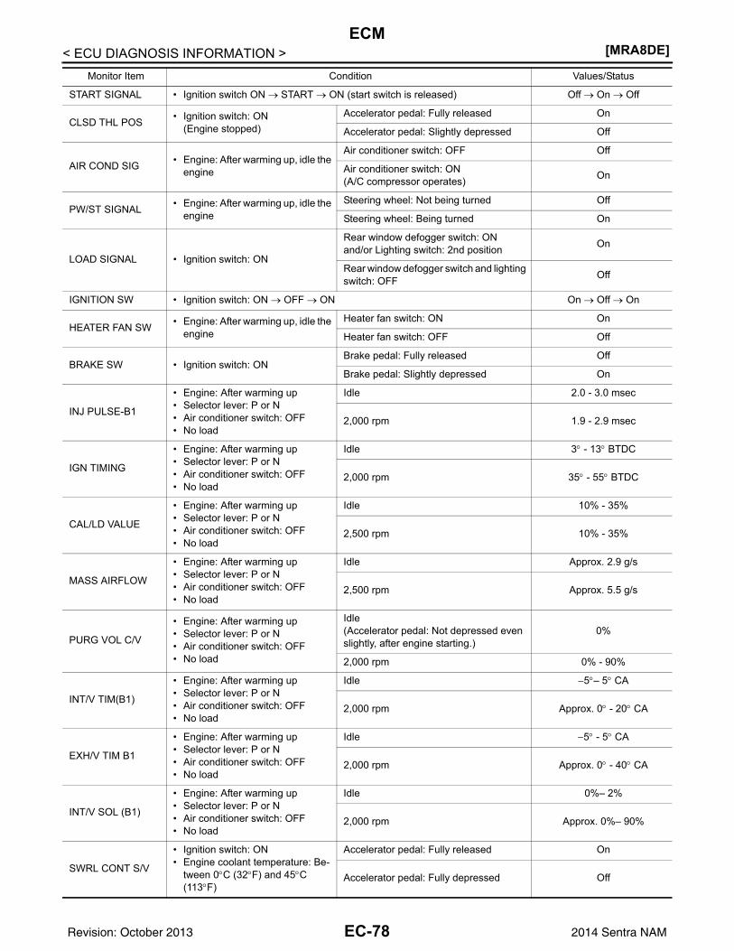
[MRA8DE]ECM
< ECU DIAGNOSIS INFORMATION >
START SIGNAL • Ignition switch ON → START → ON (start switch is released) Off → On → Off
CLSD THL POS • Ignition switch: ON(Engine stopped)
Accelerator pedal: Fully released On
Accelerator pedal: Slightly depressed Off
AIR COND SIG • Engine: After warming up, idle the engine
Air conditioner switch: OFF Off
Air conditioner switch: ON(A/C compressor operates) On
PW/ST SIGNAL • Engine: After warming up, idle the engine
Steering wheel: Not being turned Off
Steering wheel: Being turned On
LOAD SIGNAL • Ignition switch: ON
Rear window defogger switch: ONand/or Lighting switch: 2nd position On
Rear window defogger switch and lighting switch: OFF Off
IGNITION SW • Ignition switch: ON → OFF → ON On → Off → On
HEATER FAN SW • Engine: After warming up, idle the engine
Heater fan switch: ON On
Heater fan switch: OFF Off
BRAKE SW • Ignition switch: ONBrake pedal: Fully released Off
Brake pedal: Slightly depressed On
INJ PULSE-B1
• Engine: After warming up• Selector lever: P or N• Air conditioner switch: OFF• No load
Idle 2.0 - 3.0 msec
2,000 rpm 1.9 - 2.9 msec
IGN TIMING
• Engine: After warming up• Selector lever: P or N• Air conditioner switch: OFF• No load
Idle 3° - 13° BTDC
2,000 rpm 35° - 55° BTDC
CAL/LD VALUE
• Engine: After warming up• Selector lever: P or N• Air conditioner switch: OFF• No load
Idle 10% - 35%
2,500 rpm 10% - 35%
MASS AIRFLOW
• Engine: After warming up• Selector lever: P or N• Air conditioner switch: OFF• No load
Idle Approx. 2.9 g/s
2,500 rpm Approx. 5.5 g/s
PURG VOL C/V
• Engine: After warming up• Selector lever: P or N• Air conditioner switch: OFF• No load
Idle(Accelerator pedal: Not depressed even slightly, after engine starting.)
0%
2,000 rpm 0% - 90%
INT/V TIM(B1)
• Engine: After warming up• Selector lever: P or N• Air conditioner switch: OFF• No load
Idle −5°– 5° CA
2,000 rpm Approx. 0° - 20° CA
EXH/V TIM B1
• Engine: After warming up• Selector lever: P or N• Air conditioner switch: OFF• No load
Idle −5° - 5° CA
2,000 rpm Approx. 0° - 40° CA
INT/V SOL (B1)
• Engine: After warming up• Selector lever: P or N• Air conditioner switch: OFF• No load
Idle 0%– 2%
2,000 rpm Approx. 0%– 90%
SWRL CONT S/V
• Ignition switch: ON• Engine coolant temperature: Be-
tween 0°C (32°F) and 45°C (113°F)
Accelerator pedal: Fully released On
Accelerator pedal: Fully depressed Off
Monitor Item Condition Values/Status
EC-78Revision: October 2013 2014 Sentra NAM
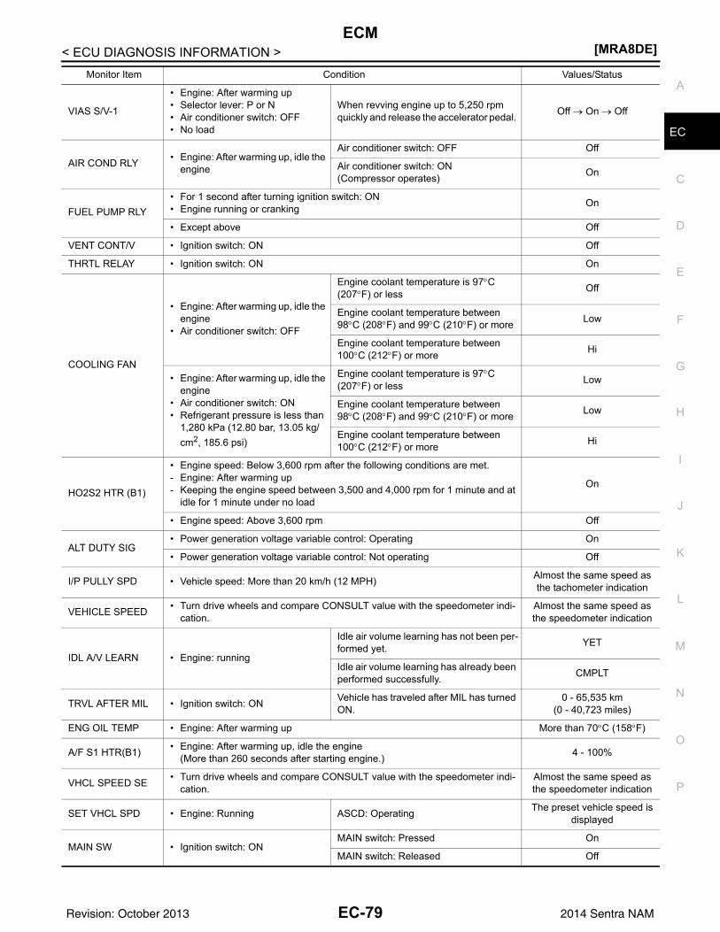
ECM[MRA8DE]
C
D
E
F
G
H
I
J
K
L
M
A
C
N
P
O
< ECU DIAGNOSIS INFORMATION >
E
VIAS S/V-1
• Engine: After warming up• Selector lever: P or N• Air conditioner switch: OFF• No load
When revving engine up to 5,250 rpm quickly and release the accelerator pedal. Off → On → Off
AIR COND RLY • Engine: After warming up, idle the engine
Air conditioner switch: OFF Off
Air conditioner switch: ON(Compressor operates) On
FUEL PUMP RLY• For 1 second after turning ignition switch: ON• Engine running or cranking On
• Except above Off
VENT CONT/V • Ignition switch: ON Off
THRTL RELAY • Ignition switch: ON On
COOLING FAN
• Engine: After warming up, idle the engine
• Air conditioner switch: OFF
Engine coolant temperature is 97°C (207°F) or less Off
Engine coolant temperature between 98°C (208°F) and 99°C (210°F) or more Low
Engine coolant temperature between 100°C (212°F) or more Hi
• Engine: After warming up, idle the engine
• Air conditioner switch: ON• Refrigerant pressure is less than
1,280 kPa (12.80 bar, 13.05 kg/cm2, 185.6 psi)
Engine coolant temperature is 97°C (207°F) or less Low
Engine coolant temperature between 98°C (208°F) and 99°C (210°F) or more Low
Engine coolant temperature between 100°C (212°F) or more Hi
HO2S2 HTR (B1)
• Engine speed: Below 3,600 rpm after the following conditions are met.- Engine: After warming up- Keeping the engine speed between 3,500 and 4,000 rpm for 1 minute and at
idle for 1 minute under no load
On
• Engine speed: Above 3,600 rpm Off
ALT DUTY SIG• Power generation voltage variable control: Operating On
• Power generation voltage variable control: Not operating Off
I/P PULLY SPD • Vehicle speed: More than 20 km/h (12 MPH) Almost the same speed as the tachometer indication
VEHICLE SPEED • Turn drive wheels and compare CONSULT value with the speedometer indi-cation.
Almost the same speed as the speedometer indication
IDL A/V LEARN • Engine: running
Idle air volume learning has not been per-formed yet. YET
Idle air volume learning has already been performed successfully. CMPLT
TRVL AFTER MIL • Ignition switch: ON Vehicle has traveled after MIL has turned ON.
0 - 65,535 km(0 - 40,723 miles)
ENG OIL TEMP • Engine: After warming up More than 70°C (158°F)
A/F S1 HTR(B1) • Engine: After warming up, idle the engine(More than 260 seconds after starting engine.) 4 - 100%
VHCL SPEED SE • Turn drive wheels and compare CONSULT value with the speedometer indi-cation.
Almost the same speed as the speedometer indication
SET VHCL SPD • Engine: Running ASCD: Operating The preset vehicle speed is displayed
MAIN SW • Ignition switch: ONMAIN switch: Pressed On
MAIN switch: Released Off
Monitor Item Condition Values/Status
EC-79Revision: October 2013 2014 Sentra NAM
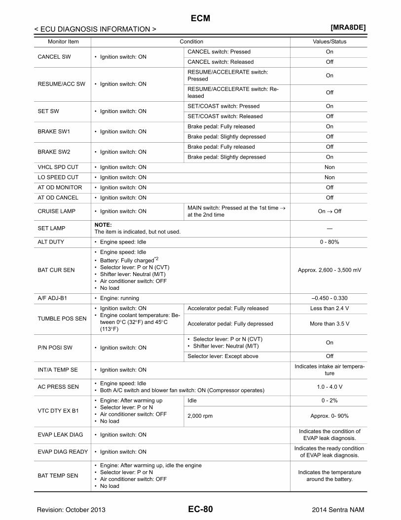
[MRA8DE]ECM
< ECU DIAGNOSIS INFORMATION >
CANCEL SW • Ignition switch: ONCANCEL switch: Pressed On
CANCEL switch: Released Off
RESUME/ACC SW • Ignition switch: ON
RESUME/ACCELERATE switch: Pressed On
RESUME/ACCELERATE switch: Re-leased Off
SET SW • Ignition switch: ONSET/COAST switch: Pressed On
SET/COAST switch: Released Off
BRAKE SW1 • Ignition switch: ONBrake pedal: Fully released On
Brake pedal: Slightly depressed Off
BRAKE SW2 • Ignition switch: ONBrake pedal: Fully released Off
Brake pedal: Slightly depressed On
VHCL SPD CUT • Ignition switch: ON Non
LO SPEED CUT • Ignition switch: ON Non
AT OD MONITOR • Ignition switch: ON Off
AT OD CANCEL • Ignition switch: ON Off
CRUISE LAMP • Ignition switch: ON MAIN switch: Pressed at the 1st time → at the 2nd time On → Off
SET LAMP NOTE:The item is indicated, but not used. —
ALT DUTY • Engine speed: Idle 0 - 80%
BAT CUR SEN
• Engine speed: Idle• Battery: Fully charged*2
• Selector lever: P or N (CVT)• Shifter lever: Neutral (M/T)• Air conditioner switch: OFF• No load
Approx. 2,600 - 3,500 mV
A/F ADJ-B1 • Engine: running –0.450 - 0.330
TUMBLE POS SEN
• Ignition switch: ON• Engine coolant temperature: Be-
tween 0°C (32°F) and 45°C (113°F)
Accelerator pedal: Fully released Less than 2.4 V
Accelerator pedal: Fully depressed More than 3.5 V
P/N POSI SW • Ignition switch: ON• Selector lever: P or N (CVT)• Shifter lever: Neutral (M/T) On
Selector lever: Except above Off
INT/A TEMP SE • Ignition switch: ON Indicates intake air tempera-ture
AC PRESS SEN • Engine speed: Idle• Both A/C switch and blower fan switch: ON (Compressor operates) 1.0 - 4.0 V
VTC DTY EX B1
• Engine: After warming up• Selector lever: P or N• Air conditioner switch: OFF• No load
Idle 0 - 2%
2,000 rpm Approx. 0- 90%
EVAP LEAK DIAG • Ignition switch: ON Indicates the condition of EVAP leak diagnosis.
EVAP DIAG READY • Ignition switch: ON Indicates the ready condition of EVAP leak diagnosis.
BAT TEMP SEN
• Engine: After warming up, idle the engine• Selector lever: P or N• Air conditioner switch: OFF• No load
Indicates the temperature around the battery.
Monitor Item Condition Values/Status
EC-80Revision: October 2013 2014 Sentra NAM
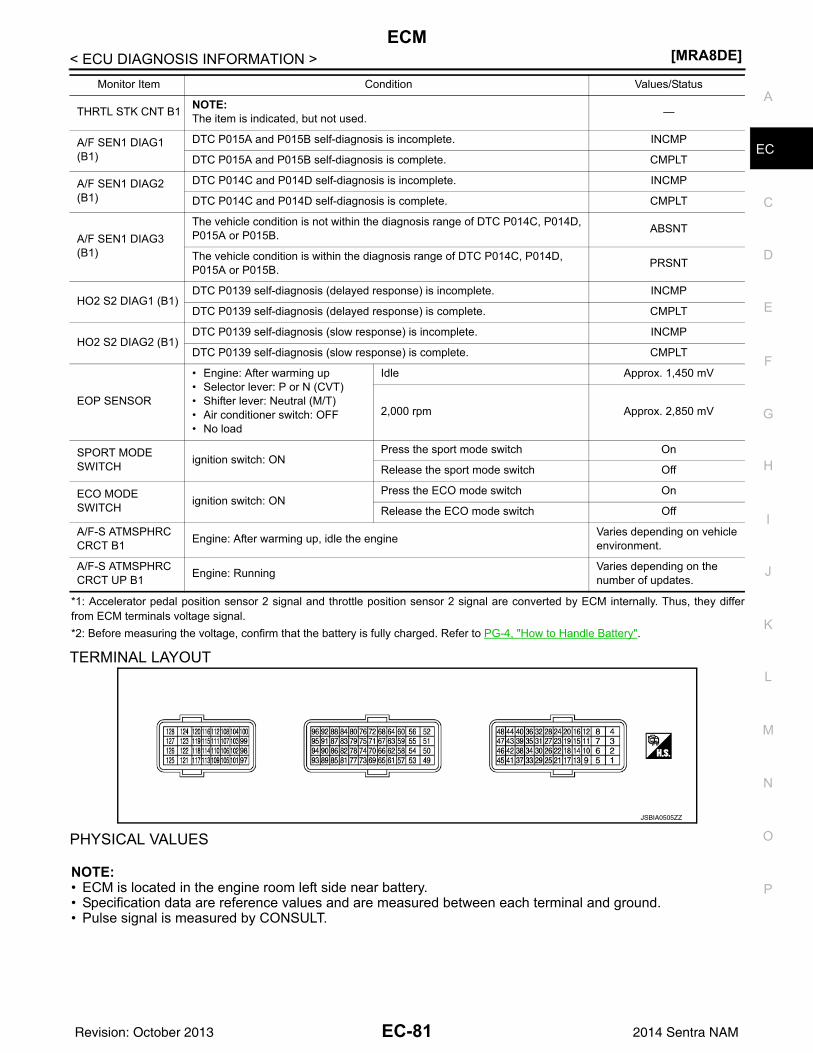
ECM[MRA8DE]
C
D
E
F
G
H
I
J
K
L
M
A
C
N
P
O
< ECU DIAGNOSIS INFORMATION >
E
*1: Accelerator pedal position sensor 2 signal and throttle position sensor 2 signal are converted by ECM internally. Thus, they differfrom ECM terminals voltage signal.*2: Before measuring the voltage, confirm that the battery is fully charged. Refer to PG-4, "How to Handle Battery".
TERMINAL LAYOUT
PHYSICAL VALUES
NOTE:• ECM is located in the engine room left side near battery.• Specification data are reference values and are measured between each terminal and ground.• Pulse signal is measured by CONSULT.
THRTL STK CNT B1 NOTE:The item is indicated, but not used. —
A/F SEN1 DIAG1 (B1)
DTC P015A and P015B self-diagnosis is incomplete. INCMP
DTC P015A and P015B self-diagnosis is complete. CMPLT
A/F SEN1 DIAG2 (B1)
DTC P014C and P014D self-diagnosis is incomplete. INCMP
DTC P014C and P014D self-diagnosis is complete. CMPLT
A/F SEN1 DIAG3 (B1)
The vehicle condition is not within the diagnosis range of DTC P014C, P014D, P015A or P015B. ABSNT
The vehicle condition is within the diagnosis range of DTC P014C, P014D, P015A or P015B. PRSNT
HO2 S2 DIAG1 (B1)DTC P0139 self-diagnosis (delayed response) is incomplete. INCMP
DTC P0139 self-diagnosis (delayed response) is complete. CMPLT
HO2 S2 DIAG2 (B1)DTC P0139 self-diagnosis (slow response) is incomplete. INCMP
DTC P0139 self-diagnosis (slow response) is complete. CMPLT
EOP SENSOR
• Engine: After warming up• Selector lever: P or N (CVT)• Shifter lever: Neutral (M/T)• Air conditioner switch: OFF• No load
Idle Approx. 1,450 mV
2,000 rpm Approx. 2,850 mV
SPORT MODE SWITCH ignition switch: ON
Press the sport mode switch On
Release the sport mode switch Off
ECO MODE SWITCH ignition switch: ON
Press the ECO mode switch On
Release the ECO mode switch Off
A/F-S ATMSPHRC CRCT B1 Engine: After warming up, idle the engine Varies depending on vehicle
environment.
A/F-S ATMSPHRC CRCT UP B1 Engine: Running Varies depending on the
number of updates.
Monitor Item Condition Values/Status
JSBIA0505ZZ
EC-81Revision: October 2013 2014 Sentra NAM
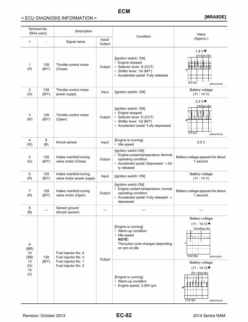
[MRA8DE]ECM
< ECU DIAGNOSIS INFORMATION >
Terminal No.(Wire color) Description
Condition Value(Approx.)
+ − Signal name Input/Output
1(P)
128(B/Y)
Throttle control motor (Close) Output
[Ignition switch: ON]• Engine stopped• Selector lever: D (CVT)• Shifter lever: 1st (M/T)• Accelerator pedal: Fully released
1.8 V
2(G)
128(B/Y)
Throttle control motor power supply Input [Ignition switch: ON] Battery voltage
(11 - 14 V)
3(W)
128(B/Y)
Throttle control motor (Open) Output
[Ignition switch: ON]• Engine stopped• Selector lever: D (CVT)• Shifter lever: 1st (M/T)• Accelerator pedal: Fully depressed
3.2 V
4(W)
8(B) Knock sensor Input [Engine is running]
• Idle speed 2.5 V
5(G)
128(B/Y)
Intake manifold tuning valve motor (Close) Output
[Ignition switch ON]• Engine coolant temperature: Normal
operating condition• Accelerator pedal: Depressed → ful-
ly released
Battery voltage appears for about 1 second.
6(R)
128(B/Y)
Intake manifold tuning valve motor power supply Input [Ignition switch: ON] Battery voltage
(11 - 14 V)
7(R)
128(B/Y)
Intake manifold tuning valve motor (Open) Output
[Ignition switch ON]• Engine coolant temperature: normal
operating condition• Accelerator pedal: Fully released →
depressed
Battery voltage appears for about 1 second.
8(B) — Sensor ground
(Knock sensor) — — —
9(BR)10
(SB)13(O)14(V)
128(B/Y)
Fuel injector No. 4Fuel injector No. 3Fuel injector No. 1Fuel injector No. 2
Output
[Engine is running]• Warm-up condition• Idle speed
NOTE:The pulse cycle changes depending on rpm at idle
Battery voltage(11 - 14 V)
[Engine is running]• Warm-up condition• Engine speed: 2,000 rpm
Battery voltage(11 - 14 V)
JMBIA0326GB
JMBIA0324GB
JSBIA3228ZZ
JMBIA0090GB
EC-82Revision: October 2013 2014 Sentra NAM
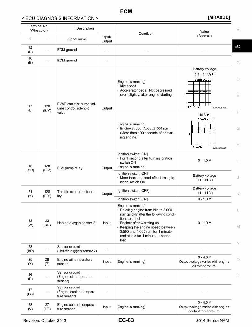
ECM[MRA8DE]
C
D
E
F
G
H
I
J
K
L
M
A
C
N
P
O
< ECU DIAGNOSIS INFORMATION >
E12(B) — ECM ground — — —
16(B) — ECM ground — — —
17(L)
128(B/Y)
EVAP canister purge vol-ume control solenoid valve
Output
[Engine is running]• Idle speed• Accelerator pedal: Not depressed
even slightly, after engine starting
Battery voltage(11 - 14 V)
[Engine is running]• Engine speed: About 2,000 rpm
(More than 100 seconds after start-ing engine.)
10 V
18(GR)
128(B/Y) Fuel pump relay Output
[Ignition switch: ON]• For 1 second after turning ignition
switch ON[Engine is running]
0 - 1.0 V
[Ignition switch: ON]• More than 1 second after turning ig-
nition switch ON
Battery voltage(11 - 14 V)
21(Y)
128(B/Y)
Throttle control motor re-lay Output
[Ignition switch: OFF] Battery voltage(11 - 14 V)
[Ignition switch: ON] 0 - 1.0 V
22(W)
23(BR) Heated oxygen sensor 2 Input
[Engine is running]• Revving engine from idle to 3,000
rpm quickly after the following condi-tions are met
- Engine: after warming up- Keeping the engine speed between
3,500 and 4,000 rpm for 1 minute and at idle for 1 minute under no load
0 - 1.0 V
23(BR) — Sensor ground
(Heated oxygen sensor 2) — — —
25(Y)
26(P)
Engine oil temperature sensor Input [Engine is running]
0 - 4.8 VOutput voltage varies with engine
oil temperature.
26(P) —
Sensor ground(Engine oil temperature sensor)
— — —
27(LG) —
Sensor ground(Engine coolant tempera-ture sensor)
— — —
28(V)
27(LG)
Engine coolant tempera-ture sensor Input [Engine is running]
0 - 4.8 VOutput voltage varies with engine
coolant temperature.
Terminal No.(Wire color) Description
Condition Value(Approx.)
+ − Signal name Input/Output
JMBIA0087GB
JMBIA0328GB
EC-83Revision: October 2013 2014 Sentra NAM
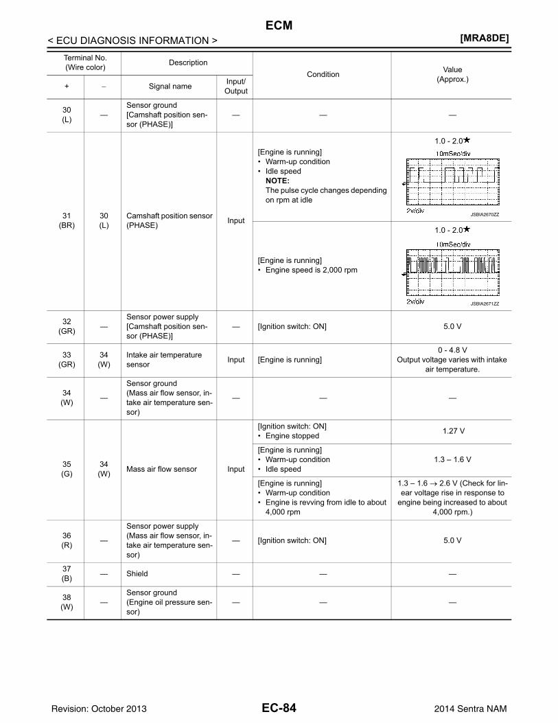
[MRA8DE]ECM
< ECU DIAGNOSIS INFORMATION >
30(L) —
Sensor ground[Camshaft position sen-sor (PHASE)]
— — —
31(BR)
30(L)
Camshaft position sensor (PHASE) Input
[Engine is running]• Warm-up condition• Idle speed
NOTE:The pulse cycle changes depending on rpm at idle
1.0 - 2.0
[Engine is running]• Engine speed is 2,000 rpm
1.0 - 2.0
32(GR) —
Sensor power supply[Camshaft position sen-sor (PHASE)]
— [Ignition switch: ON] 5.0 V
33(GR)
34(W)
Intake air temperature sensor Input [Engine is running]
0 - 4.8 VOutput voltage varies with intake
air temperature.
34(W) —
Sensor ground(Mass air flow sensor, in-take air temperature sen-sor)
— — —
35(G)
34(W) Mass air flow sensor Input
[Ignition switch: ON]• Engine stopped 1.27 V
[Engine is running]• Warm-up condition• Idle speed
1.3 – 1.6 V
[Engine is running]• Warm-up condition• Engine is revving from idle to about
4,000 rpm
1.3 – 1.6 → 2.6 V (Check for lin-ear voltage rise in response to
engine being increased to about 4,000 rpm.)
36(R) —
Sensor power supply(Mass air flow sensor, in-take air temperature sen-sor)
— [Ignition switch: ON] 5.0 V
37(B) — Shield — — —
38(W) —
Sensor ground(Engine oil pressure sen-sor)
— — —
Terminal No.(Wire color) Description
Condition Value(Approx.)
+ − Signal name Input/Output
JSBIA2670ZZ
JSBIA2671ZZ
EC-84Revision: October 2013 2014 Sentra NAM
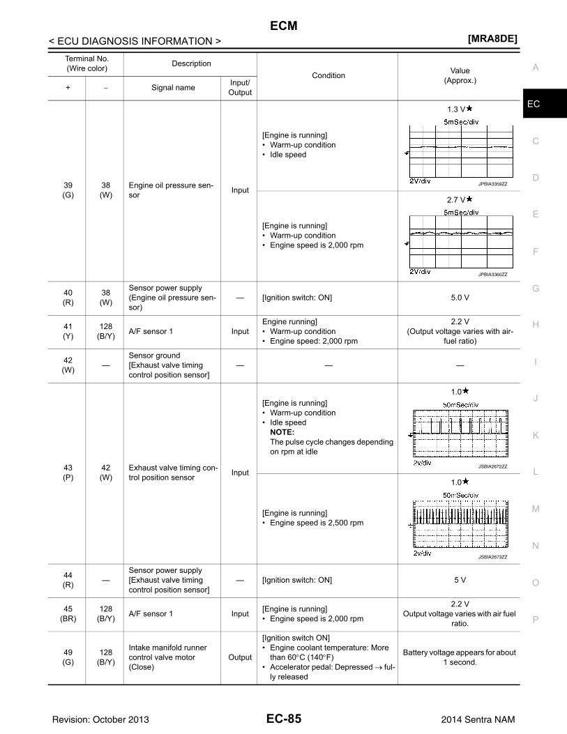
ECM[MRA8DE]
C
D
E
F
G
H
I
J
K
L
M
A
C
N
P
O
< ECU DIAGNOSIS INFORMATION >
E
39(G)
38(W)
Engine oil pressure sen-sor Input
[Engine is running]• Warm-up condition• Idle speed
1.3 V
[Engine is running]• Warm-up condition• Engine speed is 2,000 rpm
2.7 V
40(R)
38(W)
Sensor power supply(Engine oil pressure sen-sor)
— [Ignition switch: ON] 5.0 V
41(Y)
128(B/Y) A/F sensor 1 Input
Engine running]• Warm-up condition• Engine speed: 2,000 rpm
2.2 V(Output voltage varies with air-
fuel ratio)
42(W) —
Sensor ground[Exhaust valve timing control position sensor]
— — —
43(P)
42(W)
Exhaust valve timing con-trol position sensor Input
[Engine is running]• Warm-up condition• Idle speed
NOTE:The pulse cycle changes depending on rpm at idle
1.0
[Engine is running]• Engine speed is 2,500 rpm
1.0
44(R) —
Sensor power supply[Exhaust valve timing control position sensor]
— [Ignition switch: ON] 5 V
45(BR)
128(B/Y) A/F sensor 1 Input [Engine is running]
• Engine speed is 2,000 rpm
2.2 VOutput voltage varies with air fuel
ratio.
49(G)
128(B/Y)
Intake manifold runner control valve motor (Close)
Output
[Ignition switch ON]• Engine coolant temperature: More
than 60°C (140°F)• Accelerator pedal: Depressed → ful-
ly released
Battery voltage appears for about 1 second.
Terminal No.(Wire color) Description
Condition Value(Approx.)
+ − Signal name Input/Output
JPBIA3359ZZ
JPBIA3360ZZ
JSBIA2672ZZ
JSBIA2673ZZ
EC-85Revision: October 2013 2014 Sentra NAM
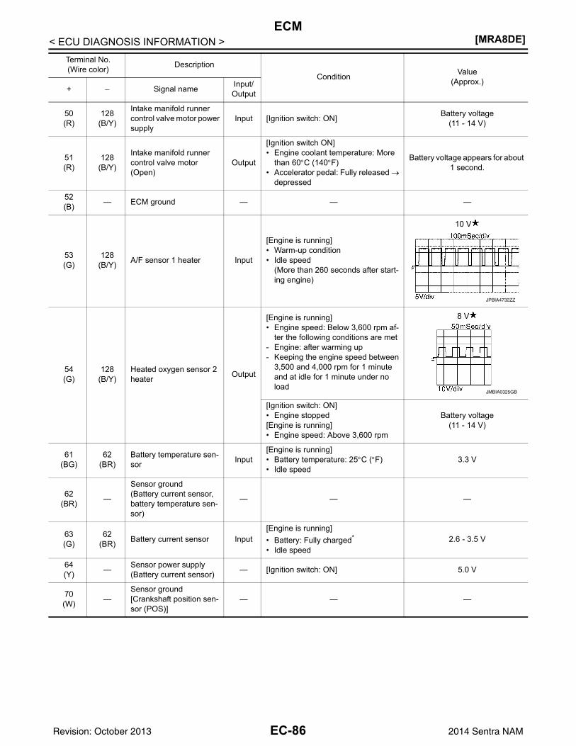
[MRA8DE]ECM
< ECU DIAGNOSIS INFORMATION >
50(R)
128(B/Y)
Intake manifold runner control valve motor power supply
Input [Ignition switch: ON] Battery voltage(11 - 14 V)
51(R)
128(B/Y)
Intake manifold runner control valve motor (Open)
Output
[Ignition switch ON]• Engine coolant temperature: More
than 60°C (140°F)• Accelerator pedal: Fully released →
depressed
Battery voltage appears for about 1 second.
52(B) — ECM ground — — —
53(G)
128(B/Y) A/F sensor 1 heater Input
[Engine is running]• Warm-up condition• Idle speed
(More than 260 seconds after start-ing engine)
10 V
54(G)
128(B/Y)
Heated oxygen sensor 2 heater Output
[Engine is running]• Engine speed: Below 3,600 rpm af-
ter the following conditions are met- Engine: after warming up- Keeping the engine speed between
3,500 and 4,000 rpm for 1 minute and at idle for 1 minute under no load
8 V
[Ignition switch: ON]• Engine stopped[Engine is running]• Engine speed: Above 3,600 rpm
Battery voltage(11 - 14 V)
61(BG)
62(BR)
Battery temperature sen-sor Input
[Engine is running]• Battery temperature: 25°C (°F)• Idle speed
3.3 V
62(BR) —
Sensor ground(Battery current sensor, battery temperature sen-sor)
— — —
63(G)
62(BR) Battery current sensor Input
[Engine is running]• Battery: Fully charged*
• Idle speed2.6 - 3.5 V
64(Y) — Sensor power supply
(Battery current sensor) — [Ignition switch: ON] 5.0 V
70(W) —
Sensor ground[Crankshaft position sen-sor (POS)]
— — —
Terminal No.(Wire color) Description
Condition Value(Approx.)
+ − Signal name Input/Output
JPBIA4732ZZ
JMBIA0325GB
EC-86Revision: October 2013 2014 Sentra NAM
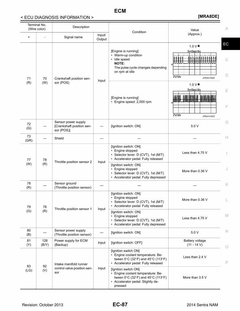
ECM[MRA8DE]
C
D
E
F
G
H
I
J
K
L
M
A
C
N
P
O
< ECU DIAGNOSIS INFORMATION >
E
71(R)
70(W)
Crankshaft position sen-sor (POS) Input
[Engine is running]• Warm-up condition• Idle speed
NOTE:The pulse cycle changes depending on rpm at idle
1.0 V
[Engine is running]• Engine speed: 2,000 rpm
1.0 V
72(G) —
Sensor power supply[Crankshaft position sen-sor (POS)]
— [Ignition switch: ON] 5.0 V
73(GR) — Shield — — —
77(W)
78(R) Throttle position sensor 2 Input
[Ignition switch: ON]• Engine stopped• Selector lever: D (CVT), 1st (M/T)• Accelerator pedal: Fully released
Less than 4.75 V
[Ignition switch: ON]• Engine stopped• Selector lever: D (CVT), 1st (M/T)• Accelerator pedal: Fully depressed
More than 0.36 V
78(R) — Sensor ground
(Throttle position sensor) — — —
79(G)
78(R) Throttle position sensor 1 Input
[Ignition switch: ON]• Engine stopped• Selector lever: D (CVT), 1st (M/T)• Accelerator pedal: Fully released
More than 0.36 V
[Ignition switch: ON]• Engine stopped• Selector lever: D (CVT), 1st (M/T)• Accelerator pedal: Fully depressed
Less than 4.75 V
80(B) — Sensor power supply
(Throttle position sensor) — [Ignition switch: ON] 5.0 V
81(Y)
128(B/Y)
Power supply for ECM (Backup) Input [Ignition switch: OFF] Battery voltage
(11 - 14 V)
83(LG)
92(V)
Intake manifold runner control valve position sen-sor
Input
[Ignition switch ON]• Engine coolant temperature: Be-
tween 0°C (32°F) and 45°C (113°F)• Accelerator pedal: Fully released
Less than 2.4 V
[Ignition switch ON]• Engine coolant temperature: Be-
tween 0°C (32°F) and 45°C (113°F)• Accelerator pedal: Slightly de-
pressed
More than 3.5 V
Terminal No.(Wire color) Description
Condition Value(Approx.)
+ − Signal name Input/Output
JPBIA4728ZZ
JPBIA4729ZZ
EC-87Revision: October 2013 2014 Sentra NAM
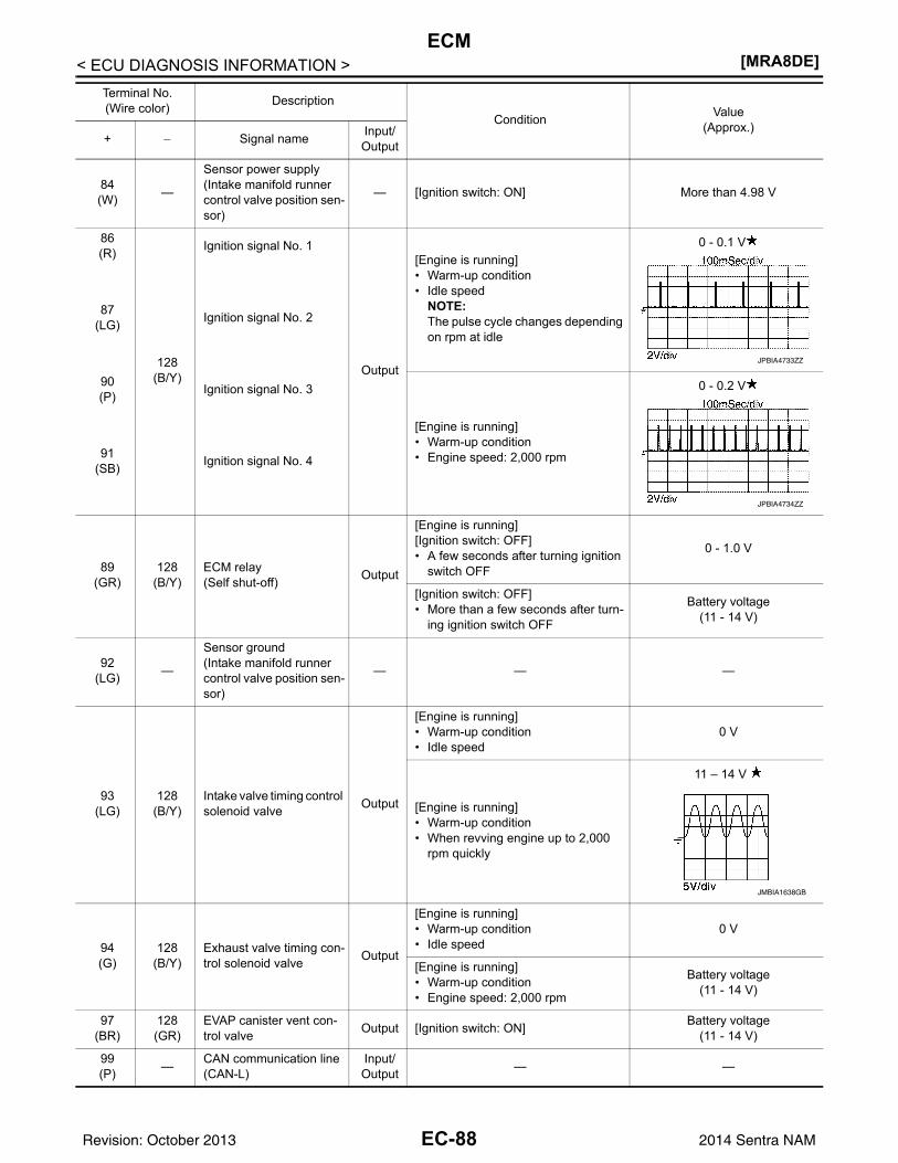
[MRA8DE]ECM
< ECU DIAGNOSIS INFORMATION >
84(W) —
Sensor power supply(Intake manifold runner control valve position sen-sor)
— [Ignition switch: ON] More than 4.98 V
86(R)
128(B/Y)
Ignition signal No. 1
Output
[Engine is running]• Warm-up condition• Idle speed
NOTE:The pulse cycle changes depending on rpm at idle
0 - 0.1 V
87(LG) Ignition signal No. 2
90(P) Ignition signal No. 3
[Engine is running]• Warm-up condition• Engine speed: 2,000 rpm
0 - 0.2 V
91(SB) Ignition signal No. 4
89(GR)
128(B/Y)
ECM relay(Self shut-off) Output
[Engine is running][Ignition switch: OFF]• A few seconds after turning ignition
switch OFF
0 - 1.0 V
[Ignition switch: OFF]• More than a few seconds after turn-
ing ignition switch OFF
Battery voltage(11 - 14 V)
92(LG) —
Sensor ground(Intake manifold runner control valve position sen-sor)
— — —
93(LG)
128(B/Y)
Intake valve timing control solenoid valve Output
[Engine is running]• Warm-up condition• Idle speed
0 V
[Engine is running]• Warm-up condition• When revving engine up to 2,000
rpm quickly
11 – 14 V
94(G)
128(B/Y)
Exhaust valve timing con-trol solenoid valve Output
[Engine is running]• Warm-up condition• Idle speed
0 V
[Engine is running]• Warm-up condition• Engine speed: 2,000 rpm
Battery voltage(11 - 14 V)
97(BR)
128(GR)
EVAP canister vent con-trol valve Output [Ignition switch: ON] Battery voltage
(11 - 14 V)
99(P) — CAN communication line
(CAN-L)Input/Output — —
Terminal No.(Wire color) Description
Condition Value(Approx.)
+ − Signal name Input/Output
JPBIA4733ZZ
JPBIA4734ZZ
JMBIA1638GB
EC-88Revision: October 2013 2014 Sentra NAM
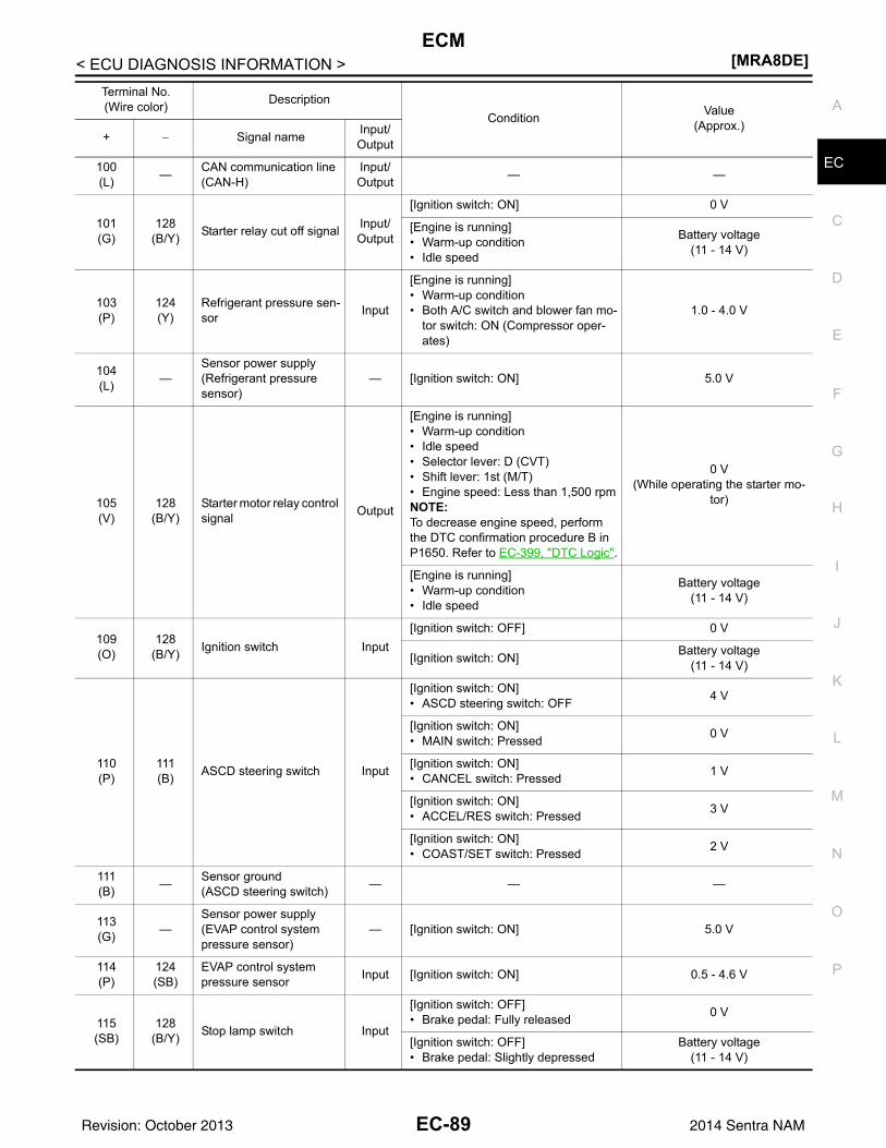
ECM[MRA8DE]
C
D
E
F
G
H
I
J
K
L
M
A
C
N
P
O
< ECU DIAGNOSIS INFORMATION >
E100(L) — CAN communication line
(CAN-H)Input/Output — —
101(G)
128(B/Y) Starter relay cut off signal Input/
Output
[Ignition switch: ON] 0 V
[Engine is running]• Warm-up condition• Idle speed
Battery voltage(11 - 14 V)
103(P)
124(Y)
Refrigerant pressure sen-sor Input
[Engine is running]• Warm-up condition• Both A/C switch and blower fan mo-
tor switch: ON (Compressor oper-ates)
1.0 - 4.0 V
104(L) —
Sensor power supply(Refrigerant pressure sensor)
— [Ignition switch: ON] 5.0 V
105(V)
128(B/Y)
Starter motor relay control signal Output
[Engine is running]• Warm-up condition• Idle speed• Selector lever: D (CVT)• Shift lever: 1st (M/T)• Engine speed: Less than 1,500 rpmNOTE:To decrease engine speed, perform the DTC confirmation procedure B in P1650. Refer to EC-399, "DTC Logic".
0 V(While operating the starter mo-
tor)
[Engine is running]• Warm-up condition• Idle speed
Battery voltage(11 - 14 V)
109(O)
128(B/Y) Ignition switch Input
[Ignition switch: OFF] 0 V
[Ignition switch: ON] Battery voltage(11 - 14 V)
110(P)
111(B) ASCD steering switch Input
[Ignition switch: ON]• ASCD steering switch: OFF 4 V
[Ignition switch: ON]• MAIN switch: Pressed 0 V
[Ignition switch: ON]• CANCEL switch: Pressed 1 V
[Ignition switch: ON]• ACCEL/RES switch: Pressed 3 V
[Ignition switch: ON]• COAST/SET switch: Pressed 2 V
111(B) — Sensor ground
(ASCD steering switch) — — —
113(G) —
Sensor power supply(EVAP control system pressure sensor)
— [Ignition switch: ON] 5.0 V
114(P)
124(SB)
EVAP control system pressure sensor Input [Ignition switch: ON] 0.5 - 4.6 V
115(SB)
128(B/Y) Stop lamp switch Input
[Ignition switch: OFF]• Brake pedal: Fully released 0 V
[Ignition switch: OFF]• Brake pedal: Slightly depressed
Battery voltage(11 - 14 V)
Terminal No.(Wire color) Description
Condition Value(Approx.)
+ − Signal name Input/Output
EC-89Revision: October 2013 2014 Sentra NAM
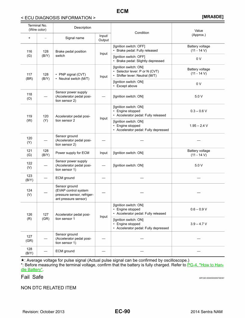
[MRA8DE]ECM
< ECU DIAGNOSIS INFORMATION >
: Average voltage for pulse signal (Actual pulse signal can be confirmed by oscilloscope.)*: Before measuring the terminal voltage, confirm that the battery is fully charged. Refer to PG-4, "How to Han-dle Battery".
Fail Safe INFOID:0000000009758391
NON DTC RELATED ITEM
116(G)
128(B/Y)
Brake pedal position switch Input
[Ignition switch: OFF]• Brake pedal: Fully released
Battery voltage(11 - 14 V)
[Ignition switch: OFF]• Brake pedal: Slightly depressed 0 V
117(BR)
128(B/Y)
• PNP signal (CVT)• Neutral switch (M/T) Input
[Ignition switch: ON]• Selector lever: P or N (CVT)• Shifter lever: Neutral (M/T)
Battery voltage(11 - 14 V)
[Ignition switch: ON]• Except above 0 V
118(O) —
Sensor power supply(Accelerator pedal posi-tion sensor 2)
— [Ignition switch: ON] 5.0 V
119(W)
120(Y)
Accelerator pedal posi-tion sensor 2 Input
[Ignition switch: ON]• Engine stopped• Accelerator pedal: Fully released
0.3 – 0.6 V
[Ignition switch: ON]• Engine stopped• Accelerator pedal: Fully depressed
1.95 – 2.4 V
120(Y) —
Sensor ground(Accelerator pedal posi-tion sensor 2)
— — —
121(G)
128(B/Y) Power supply for ECM Input [Ignition switch: ON] Battery voltage
(11 - 14 V)
122(V) —
Sensor power supply(Accelerator pedal posi-tion sensor 1)
— [Ignition switch: ON] 5.0 V
123(B/Y) — ECM ground — — —
124(V) —
Sensor ground(EVAP control system pressure sensor, refriger-ant pressure sensor)
— — —
126(R)
127(GR)
Accelerator pedal posi-tion sensor 1 Input
[Ignition switch: ON]• Engine stopped• Accelerator pedal: Fully released
0.6 – 0.9 V
[Ignition switch: ON]• Engine stopped• Accelerator pedal: Fully depressed
3.9 – 4.7 V
127(GR) —
Sensor ground(Accelerator pedal posi-tion sensor 1)
— — —
128(B/Y) — ECM ground — — —
Terminal No.(Wire color) Description
Condition Value(Approx.)
+ − Signal name Input/Output
EC-90Revision: October 2013 2014 Sentra NAM
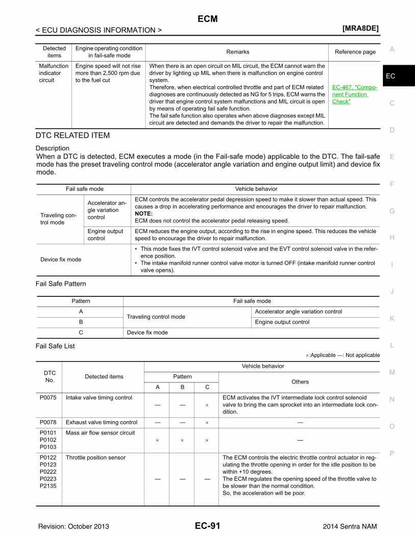
ECM[MRA8DE]
C
D
E
F
G
H
I
J
K
L
M
A
C
N
P
O
< ECU DIAGNOSIS INFORMATION >
E
DTC RELATED ITEMDescriptionWhen a DTC is detected, ECM executes a mode (in the Fail-safe mode) applicable to the DTC. The fail-safemode has the preset traveling control mode (accelerator angle variation and engine output limit) and device fixmode.
Fail Safe Pattern
Fail Safe List×:Applicable —: Not applicable
Detected items
Engine operating condition in fail-safe mode Remarks Reference page
Malfunction indicator circuit
Engine speed will not rise more than 2,500 rpm due to the fuel cut
When there is an open circuit on MIL circuit, the ECM cannot warn the driver by lighting up MIL when there is malfunction on engine control system.Therefore, when electrical controlled throttle and part of ECM related diagnoses are continuously detected as NG for 5 trips, ECM warns the driver that engine control system malfunctions and MIL circuit is open by means of operating fail safe function.The fail safe function also operates when above diagnoses except MIL circuit are detected and demands the driver to repair the malfunction.
EC-467, "Compo-nent Function Check"
Fail safe mode Vehicle behavior
Traveling con-trol mode
Accelerator an-gle variation control
ECM controls the accelerator pedal depression speed to make it slower than actual speed. This causes a drop in accelerating performance and encourages the driver to repair malfunction.NOTE:ECM does not control the accelerator pedal releasing speed.
Engine output control
ECM reduces the engine output, according to the rise in engine speed. This reduces the vehicle speed to encourage the driver to repair malfunction.
Device fix mode
• This mode fixes the IVT control solenoid valve and the EVT control solenoid valve in the refer-ence position.
• The intake manifold runner control valve motor is turned OFF (intake manifold runner control valve opens).
Pattern Fail safe mode
ATraveling control mode
Accelerator angle variation control
B Engine output control
C Device fix mode
DTC No. Detected items
Vehicle behavior
PatternOthers
A B C
P0075 Intake valve timing control— — ×
ECM activates the IVT intermediate lock control solenoid valve to bring the cam sprocket into an intermediate lock con-dition.
P0078 Exhaust valve timing control — — × —
P0101P0102P0103
Mass air flow sensor circuit× × × —
P0122P0123P0222P0223P2135
Throttle position sensor
— — —
The ECM controls the electric throttle control actuator in reg-ulating the throttle opening in order for the idle position to be within +10 degrees.The ECM regulates the opening speed of the throttle valve to be slower than the normal condition.So, the acceleration will be poor.
EC-91Revision: October 2013 2014 Sentra NAM
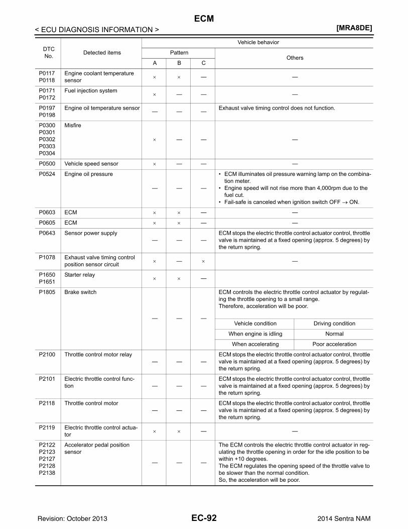
[MRA8DE]ECM
< ECU DIAGNOSIS INFORMATION >
P0117P0118
Engine coolant temperature sensor × × — —
P0171P0172
Fuel injection system× — — —
P0197P0198
Engine oil temperature sensor — — — Exhaust valve timing control does not function.
P0300P0301P0302P0303P0304
Misfire
× — — —
P0500 Vehicle speed sensor × — — —
P0524 Engine oil pressure
— — —
• ECM illuminates oil pressure warning lamp on the combina-tion meter.
• Engine speed will not rise more than 4,000rpm due to the fuel cut.
• Fail-safe is canceled when ignition switch OFF → ON.
P0603 ECM × × — —
P0605 ECM × × — —
P0643 Sensor power supply— — —
ECM stops the electric throttle control actuator control, throttle valve is maintained at a fixed opening (approx. 5 degrees) by the return spring.
P1078 Exhaust valve timing control position sensor circuit × — × —
P1650P1651
Starter relay× × —
P1805 Brake switch
— — —
ECM controls the electric throttle control actuator by regulat-ing the throttle opening to a small range.Therefore, acceleration will be poor.
Vehicle condition Driving condition
When engine is idling Normal
When accelerating Poor acceleration
P2100 Throttle control motor relay— — —
ECM stops the electric throttle control actuator control, throttle valve is maintained at a fixed opening (approx. 5 degrees) by the return spring.
P2101 Electric throttle control func-tion — — —
ECM stops the electric throttle control actuator control, throttle valve is maintained at a fixed opening (approx. 5 degrees) by the return spring.
P2118 Throttle control motor— — —
ECM stops the electric throttle control actuator control, throttle valve is maintained at a fixed opening (approx. 5 degrees) by the return spring.
P2119 Electric throttle control actua-tor × × — —
P2122P2123P2127P2128P2138
Accelerator pedal position sensor
— — —
The ECM controls the electric throttle control actuator in reg-ulating the throttle opening in order for the idle position to be within +10 degrees.The ECM regulates the opening speed of the throttle valve to be slower than the normal condition.So, the acceleration will be poor.
DTC No. Detected items
Vehicle behavior
PatternOthers
A B C
EC-92Revision: October 2013 2014 Sentra NAM
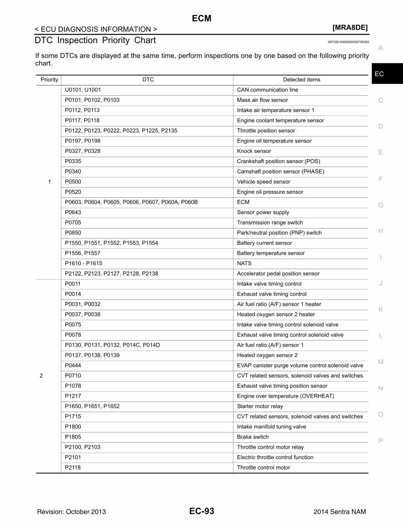
ECM[MRA8DE]
C
D
E
F
G
H
I
J
K
L
M
A
C
N
P
O
< ECU DIAGNOSIS INFORMATION >
E
DTC Inspection Priority Chart INFOID:0000000009758392
If some DTCs are displayed at the same time, perform inspections one by one based on the following prioritychart.
Priority DTC Detected items
1
U0101, U1001 CAN communication line
P0101, P0102, P0103 Mass air flow sensor
P0112, P0113 Intake air temperature sensor 1
P0117, P0118 Engine coolant temperature sensor
P0122, P0123, P0222, P0223, P1225, P2135 Throttle position sensor
P0197, P0198 Engine oil temperature sensor
P0327, P0328 Knock sensor
P0335 Crankshaft position sensor (POS)
P0340 Camshaft position sensor (PHASE)
P0500 Vehicle speed sensor
P0520 Engine oil pressure sensor
P0603, P0604, P0605, P0606, P0607, P060A, P060B ECM
P0643 Sensor power supply
P0705 Transmission range switch
P0850 Park/neutral position (PNP) switch
P1550, P1551, P1552, P1553, P1554 Battery current sensor
P1556, P1557 Battery temperature sensor
P1610 - P1615 NATS
P2122, P2123, P2127, P2128, P2138 Accelerator pedal position sensor
2
P0011 Intake valve timing control
P0014 Exhaust valve timing control
P0031, P0032 Air fuel ratio (A/F) sensor 1 heater
P0037, P0038 Heated oxygen sensor 2 heater
P0075 Intake valve timing control solenoid valve
P0078 Exhaust valve timing control solenoid valve
P0130, P0131, P0132, P014C, P014D Air fuel ratio (A/F) sensor 1
P0137, P0138, P0139 Heated oxygen sensor 2
P0444 EVAP canister purge volume control solenoid valve
P0710 CVT related sensors, solenoid valves and switches
P1078 Exhaust valve timing position sensor
P1217 Engine over temperature (OVERHEAT)
P1650, P1651, P1652 Starter motor relay
P1715 CVT related sensors, solenoid valves and switches
P1800 Intake manifold tuning valve
P1805 Brake switch
P2100, P2103 Throttle control motor relay
P2101 Electric throttle control function
P2118 Throttle control motor
EC-93Revision: October 2013 2014 Sentra NAM
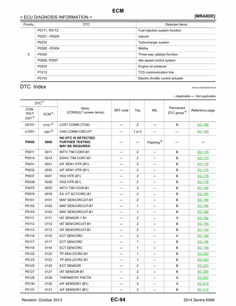
[MRA8DE]ECM
< ECU DIAGNOSIS INFORMATION >
DTC Index INFOID:0000000009758393
×:Applicable —: Not applicable
3
P0171, P0172 Fuel injection system function
P0201 - P0204 Injector
P0234 Turbocharger system
P0300 - P0304 Misfire
P0420 Three way catalyst function
P0506, P0507 Idle speed control system
P0524 Engine oil pressure
P1212 TCS communication line
P2119 Electric throttle control actuator
Priority DTC Detected items
DTC*1
Items (CONSULT screen terms) SRT code Trip MIL
Permanent DTC group*4 Reference pageCON-
SULTGST*2
ECM*3
U0101 0101*5 LOST COMM (TCM) — 2 — B EC-168
U1001 1001*5 CAN COMM CIRCUIT — 1 or 2 — — EC-169
P0000 0000NO DTC IS DETECTED. FURTHER TESTING MAY BE REQUIRED.
— — Flashing*6 — —
P0011 0011 INT/V TIM CONT-B1 × 2 × B EC-170
P0014 0014 EXH/V TIM CONT-B1 — 2 × B EC-173
P0031 0031 A/F SEN1 HTR (B1) — 2 × B EC-176
P0032 0032 A/F SEN1 HTR (B1) — 2 × B EC-176
P0037 0037 HO2 HTR (B1) — 2 × B EC-178
P0038 0038 HO2 HTR (B1) — 2 × B EC-178
P0075 0075 INT/V TIM V/CIR-B1 — 2 × B EC-180
P0078 0078 EX V/T ACT/CIRC-B1 — 2 × B EC-183
P0101 0101 MAF SEN/CIRCUIT-B1 — 2 × B EC-186
P0102 0102 MAF SEN/CIRCUIT-B1 — 1 × B EC-186
P0103 0103 MAF SEN/CIRCUIT-B1 — 1 × B EC-186
P0111 0111 IAT SENSOR 1 B1 — 2 × A EC-192
P0112 0112 IAT SEN/CIRCUIT-B1 — 2 × B EC-194
P0113 0113 IAT SEN/CIRCUIT-B1 — 2 × B EC-194
P0116 0116 ECT SEN/CIRC — 2 × A EC-196
P0117 0117 ECT SEN/CIRC — 1 × B EC-198
P0118 0118 ECT SEN/CIRC — 1 × B EC-198
P0122 0122 TP SEN 2/CIRC-B1 — 1 × B EC-200
P0123 0123 TP SEN 2/CIRC-B1 — 1 × B EC-200
P0125 0125 ECT SENSOR — 2 × B EC-203
P0127 0127 IAT SENSOR-B1 — 2 × B EC-205
P0128 0128 THERMSTAT FNCTN — 2 × A EC-207
P0130 0130 A/F SENSOR1 (B1) — 2 × A EC-210
P0131 0131 A/F SENSOR1 (B1) — 2 × B EC-214
EC-94Revision: October 2013 2014 Sentra NAM
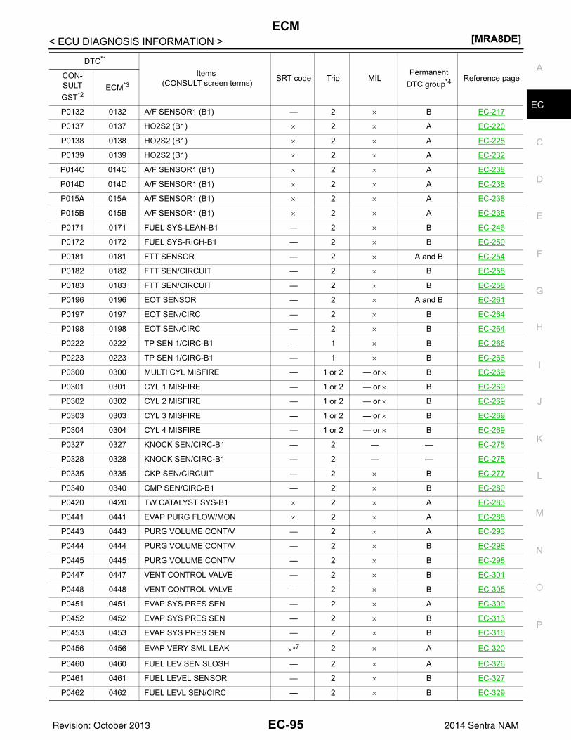
ECM[MRA8DE]
C
D
E
F
G
H
I
J
K
L
M
A
C
N
P
O
< ECU DIAGNOSIS INFORMATION >
EP0132 0132 A/F SENSOR1 (B1) — 2 × B EC-217
P0137 0137 HO2S2 (B1) × 2 × A EC-220
P0138 0138 HO2S2 (B1) × 2 × A EC-225
P0139 0139 HO2S2 (B1) × 2 × A EC-232
P014C 014C A/F SENSOR1 (B1) × 2 × A EC-238
P014D 014D A/F SENSOR1 (B1) × 2 × A EC-238
P015A 015A A/F SENSOR1 (B1) × 2 × A EC-238
P015B 015B A/F SENSOR1 (B1) × 2 × A EC-238
P0171 0171 FUEL SYS-LEAN-B1 — 2 × B EC-246
P0172 0172 FUEL SYS-RICH-B1 — 2 × B EC-250
P0181 0181 FTT SENSOR — 2 × A and B EC-254
P0182 0182 FTT SEN/CIRCUIT — 2 × B EC-258
P0183 0183 FTT SEN/CIRCUIT — 2 × B EC-258
P0196 0196 EOT SENSOR — 2 × A and B EC-261
P0197 0197 EOT SEN/CIRC — 2 × B EC-264
P0198 0198 EOT SEN/CIRC — 2 × B EC-264
P0222 0222 TP SEN 1/CIRC-B1 — 1 × B EC-266
P0223 0223 TP SEN 1/CIRC-B1 — 1 × B EC-266
P0300 0300 MULTI CYL MISFIRE — 1 or 2 — or × B EC-269
P0301 0301 CYL 1 MISFIRE — 1 or 2 — or × B EC-269
P0302 0302 CYL 2 MISFIRE — 1 or 2 — or × B EC-269
P0303 0303 CYL 3 MISFIRE — 1 or 2 — or × B EC-269
P0304 0304 CYL 4 MISFIRE — 1 or 2 — or × B EC-269
P0327 0327 KNOCK SEN/CIRC-B1 — 2 — — EC-275
P0328 0328 KNOCK SEN/CIRC-B1 — 2 — — EC-275
P0335 0335 CKP SEN/CIRCUIT — 2 × B EC-277
P0340 0340 CMP SEN/CIRC-B1 — 2 × B EC-280
P0420 0420 TW CATALYST SYS-B1 × 2 × A EC-283
P0441 0441 EVAP PURG FLOW/MON × 2 × A EC-288
P0443 0443 PURG VOLUME CONT/V — 2 × A EC-293
P0444 0444 PURG VOLUME CONT/V — 2 × B EC-298
P0445 0445 PURG VOLUME CONT/V — 2 × B EC-298
P0447 0447 VENT CONTROL VALVE — 2 × B EC-301
P0448 0448 VENT CONTROL VALVE — 2 × B EC-305
P0451 0451 EVAP SYS PRES SEN — 2 × A EC-309
P0452 0452 EVAP SYS PRES SEN — 2 × B EC-313
P0453 0453 EVAP SYS PRES SEN — 2 × B EC-316
P0456 0456 EVAP VERY SML LEAK ×*7 2 × A EC-320
P0460 0460 FUEL LEV SEN SLOSH — 2 × A EC-326
P0461 0461 FUEL LEVEL SENSOR — 2 × B EC-327
P0462 0462 FUEL LEVL SEN/CIRC — 2 × B EC-329
DTC*1
Items (CONSULT screen terms) SRT code Trip MIL
Permanent DTC group*4 Reference pageCON-
SULTGST*2
ECM*3
EC-95Revision: October 2013 2014 Sentra NAM
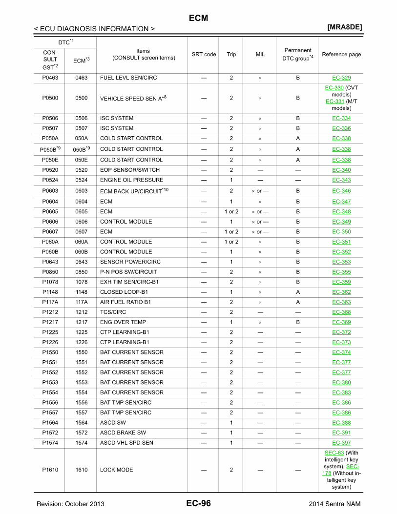
[MRA8DE]ECM
< ECU DIAGNOSIS INFORMATION >
P0463 0463 FUEL LEVL SEN/CIRC — 2 × B EC-329
P0500 0500 VEHICLE SPEED SEN A*8 — 2 × B
EC-330 (CVT models)
EC-331 (M/T models)
P0506 0506 ISC SYSTEM — 2 × B EC-334
P0507 0507 ISC SYSTEM — 2 × B EC-336
P050A 050A COLD START CONTROL — 2 × A EC-338
P050B*9 050B*9 COLD START CONTROL — 2 × A EC-338
P050E 050E COLD START CONTROL — 2 × A EC-338
P0520 0520 EOP SENSOR/SWITCH — 2 — — EC-340
P0524 0524 ENGINE OIL PRESSURE — 1 — — EC-343
P0603 0603 ECM BACK UP/CIRCUIT*10 — 2 × or — B EC-346
P0604 0604 ECM — 1 × B EC-347
P0605 0605 ECM — 1 or 2 × or — B EC-348
P0606 0606 CONTROL MODULE — 1 × or — B EC-349
P0607 0607 ECM — 1 or 2 × or — B EC-350
P060A 060A CONTROL MODULE — 1 or 2 × B EC-351
P060B 060B CONTROL MODULE — 1 × B EC-352
P0643 0643 SENSOR POWER/CIRC — 1 × B EC-353
P0850 0850 P-N POS SW/CIRCUIT — 2 × B EC-355
P1078 1078 EXH TIM SEN/CIRC-B1 — 2 × B EC-359
P1148 1148 CLOSED LOOP-B1 — 1 × A EC-362
P117A 117A AIR FUEL RATIO B1 — 2 × A EC-363
P1212 1212 TCS/CIRC — 2 — — EC-368
P1217 1217 ENG OVER TEMP — 1 × B EC-369
P1225 1225 CTP LEARNING-B1 — 2 — — EC-372
P1226 1226 CTP LEARNING-B1 — 2 — — EC-373
P1550 1550 BAT CURRENT SENSOR — 2 — — EC-374
P1551 1551 BAT CURRENT SENSOR — 2 — — EC-377
P1552 1552 BAT CURRENT SENSOR — 2 — — EC-377
P1553 1553 BAT CURRENT SENSOR — 2 — — EC-380
P1554 1554 BAT CURRENT SENSOR — 2 — — EC-383
P1556 1556 BAT TMP SEN/CIRC — 2 — — EC-386
P1557 1557 BAT TMP SEN/CIRC — 2 — — EC-386
P1564 1564 ASCD SW — 1 — — EC-388
P1572 1572 ASCD BRAKE SW — 1 — — EC-391
P1574 1574 ASCD VHL SPD SEN — 1 — — EC-397
P1610 1610 LOCK MODE — 2 — —
SEC-63 (With intelligent key system), SEC-
178 (Without in-telligent key
system)
DTC*1
Items (CONSULT screen terms) SRT code Trip MIL
Permanent DTC group*4 Reference pageCON-
SULTGST*2
ECM*3
EC-96Revision: October 2013 2014 Sentra NAM
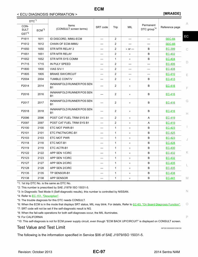
ECM[MRA8DE]
C
D
E
F
G
H
I
J
K
L
M
A
C
N
P
O
< ECU DIAGNOSIS INFORMATION >
E
*1: 1st trip DTC No. is the same as DTC No.*2: This number is prescribed by SAE J1979/ ISO 15031-5.*3: In Diagnostic Test Mode II (Self-diagnostic results), this number is controlled by NISSAN.*4: Refer to EC-151, "Description".*5: The trouble diagnosis for this DTC needs CONSULT.*6: When the ECM is in the mode that displays SRT status, MIL may blink. For details, Refer to EC-63, "On Board Diagnosis Function".*7: SRT code will not be set if the self-diagnostic result is NG.*8: When the fail-safe operations for both self-diagnoses occur, the MIL illuminates.*9: For CALIFORNIA*10: This self-diagnosis is not for ECM power supply circuit, even though “ECM BACK UP/CIRCUIT” is displayed on CONSULT screen.
Test Value and Test Limit INFOID:0000000010290195
The following is the information specified in Service $06 of SAE J1979/ISO 15031-5.
P1611 1611 ID DISCORD, IMMU-ECM — 2 — — SEC-64
P1612 1612 CHAIN OF ECM-IMMU — 2 — — SEC-65
P1650 1650 STR MTR RELAY 2 — 2 × or — B EC-399
P1651 1651 STR MTR RELAY — 2 × B EC-402
P1652 1652 STR MTR SYS COMM — 1 × B EC-404
P1715 1715 IN PULY SPEED — 2 — — EC-406
P1800 1800 VIAS S/V-1 — 2 — — EC-408
P1805 1805 BRAKE SW/CIRCUIT — 2 — — EC-410
P2004 2004 TUMBLE CONT/V — 2 × B EC-413
P2014 2014 IN/MANIFOLD RUNNER POS SEN B1 — 2 × B EC-416
P2016 2016 IN/MANIFOLD RUNNER POS SEN B1 — 2 × B EC-416
P2017 2017 IN/MANIFOLD RUNNER POS SEN B1 — 2 × B EC-416
P2018 2018 IN/MANIFOLD RUNNER POS SEN B1 — 2 × B EC-416
P2096 2096 POST CAT FUEL TRIM SYS B1 — 2 × A EC-419
P2097 2097 POST CAT FUEL TRIM SYS B1 — 2 × A EC-419
P2100 2100 ETC MOT PWR-B1 — 1 × B EC-423
P2101 2101 ETC FNCTN/CIRC-B1 — 1 × B EC-425
P2103 2103 ETC MOT PWR — 1 × B EC-423
P2118 2118 ETC MOT-B1 — 1 × B EC-428
P2119 2119 ETC ACTR-B1 — 1 × B EC-430
P2122 2122 APP SEN 1/CIRC — 1 × B EC-432
P2123 2123 APP SEN 1/CIRC — 1 × B EC-432
P2127 2127 APP SEN 2/CIRC — 1 × B EC-435
P2128 2128 APP SEN 2/CIRC — 1 × B EC-435
P2135 2135 TP SENSOR-B1 — 1 × B EC-438
P2138 2138 APP SENSOR — 1 × B EC-441
DTC*1
Items (CONSULT screen terms) SRT code Trip MIL
Permanent DTC group*4 Reference pageCON-
SULTGST*2
ECM*3
EC-97Revision: October 2013 2014 Sentra NAM
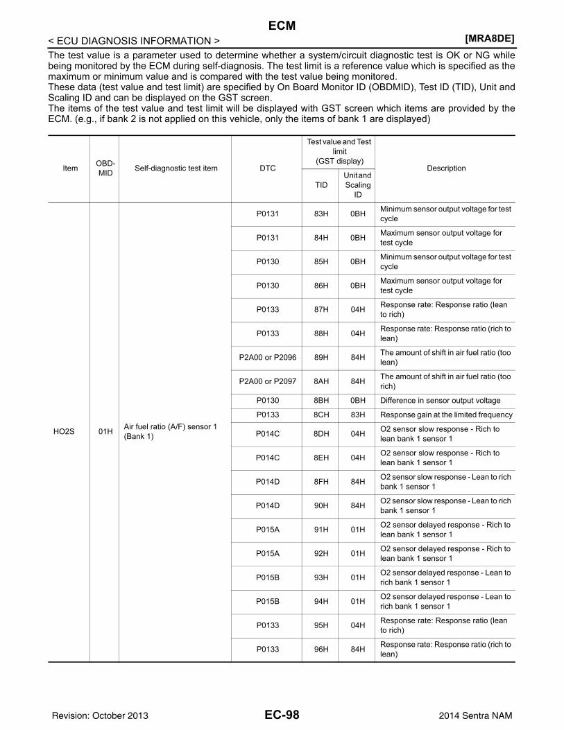
[MRA8DE]ECM
< ECU DIAGNOSIS INFORMATION >The test value is a parameter used to determine whether a system/circuit diagnostic test is OK or NG whilebeing monitored by the ECM during self-diagnosis. The test limit is a reference value which is specified as themaximum or minimum value and is compared with the test value being monitored.These data (test value and test limit) are specified by On Board Monitor ID (OBDMID), Test ID (TID), Unit andScaling ID and can be displayed on the GST screen.The items of the test value and test limit will be displayed with GST screen which items are provided by theECM. (e.g., if bank 2 is not applied on this vehicle, only the items of bank 1 are displayed)
Item OBD-MID Self-diagnostic test item DTC
Test value and Test limit
(GST display)Description
TIDUnit and Scaling
ID
HO2S 01H Air fuel ratio (A/F) sensor 1 (Bank 1)
P0131 83H 0BH Minimum sensor output voltage for test cycle
P0131 84H 0BH Maximum sensor output voltage for test cycle
P0130 85H 0BH Minimum sensor output voltage for test cycle
P0130 86H 0BH Maximum sensor output voltage for test cycle
P0133 87H 04H Response rate: Response ratio (lean to rich)
P0133 88H 04H Response rate: Response ratio (rich to lean)
P2A00 or P2096 89H 84H The amount of shift in air fuel ratio (too lean)
P2A00 or P2097 8AH 84H The amount of shift in air fuel ratio (too rich)
P0130 8BH 0BH Difference in sensor output voltage
P0133 8CH 83H Response gain at the limited frequency
P014C 8DH 04H O2 sensor slow response - Rich to lean bank 1 sensor 1
P014C 8EH 04H O2 sensor slow response - Rich to lean bank 1 sensor 1
P014D 8FH 84H O2 sensor slow response - Lean to rich bank 1 sensor 1
P014D 90H 84H O2 sensor slow response - Lean to rich bank 1 sensor 1
P015A 91H 01H O2 sensor delayed response - Rich to lean bank 1 sensor 1
P015A 92H 01H O2 sensor delayed response - Rich to lean bank 1 sensor 1
P015B 93H 01H O2 sensor delayed response - Lean to rich bank 1 sensor 1
P015B 94H 01H O2 sensor delayed response - Lean to rich bank 1 sensor 1
P0133 95H 04H Response rate: Response ratio (lean to rich)
P0133 96H 84H Response rate: Response ratio (rich to lean)
EC-98Revision: October 2013 2014 Sentra NAM
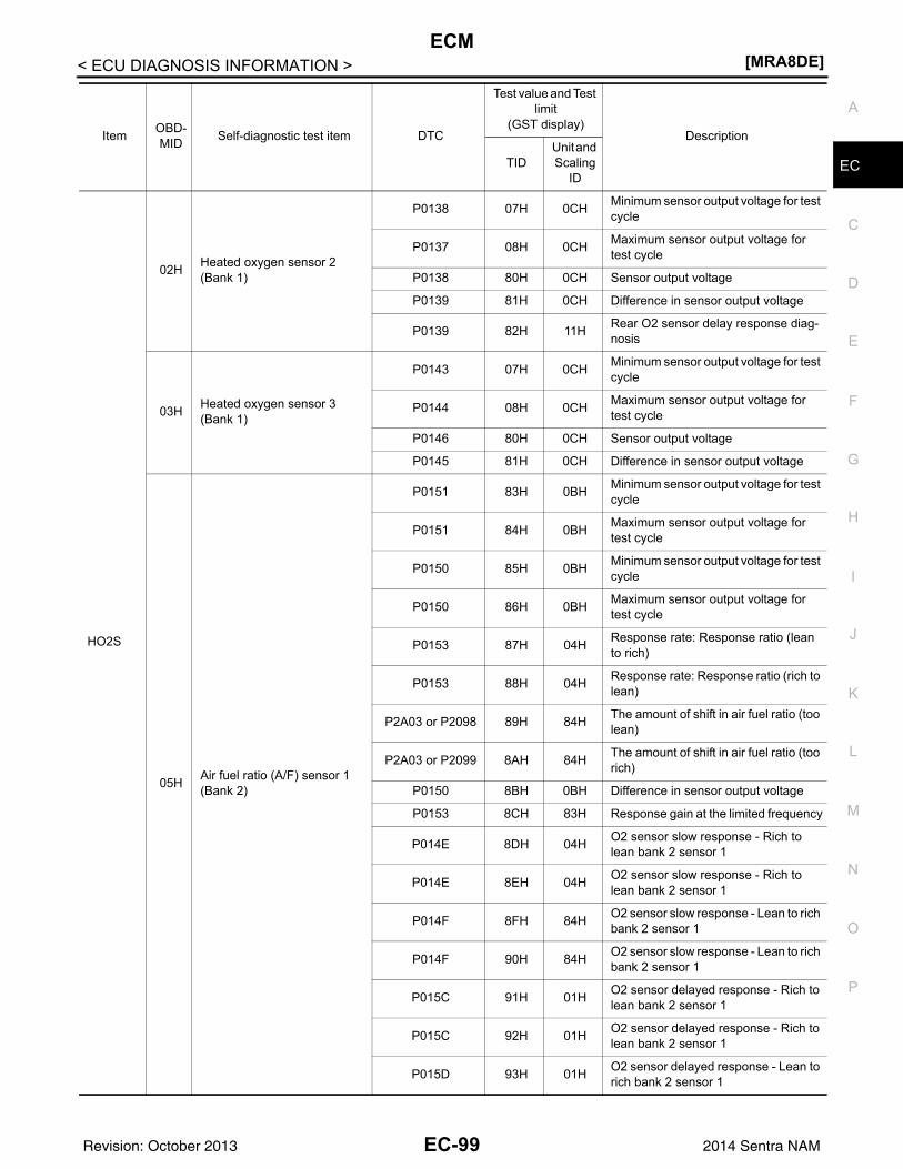
ECM[MRA8DE]
C
D
E
F
G
H
I
J
K
L
M
A
C
N
P
O
< ECU DIAGNOSIS INFORMATION >
E
HO2S
02H Heated oxygen sensor 2 (Bank 1)
P0138 07H 0CH Minimum sensor output voltage for test cycle
P0137 08H 0CH Maximum sensor output voltage for test cycle
P0138 80H 0CH Sensor output voltage
P0139 81H 0CH Difference in sensor output voltage
P0139 82H 11H Rear O2 sensor delay response diag-nosis
03H Heated oxygen sensor 3 (Bank 1)
P0143 07H 0CH Minimum sensor output voltage for test cycle
P0144 08H 0CH Maximum sensor output voltage for test cycle
P0146 80H 0CH Sensor output voltage
P0145 81H 0CH Difference in sensor output voltage
05H Air fuel ratio (A/F) sensor 1 (Bank 2)
P0151 83H 0BH Minimum sensor output voltage for test cycle
P0151 84H 0BH Maximum sensor output voltage for test cycle
P0150 85H 0BH Minimum sensor output voltage for test cycle
P0150 86H 0BH Maximum sensor output voltage for test cycle
P0153 87H 04H Response rate: Response ratio (lean to rich)
P0153 88H 04H Response rate: Response ratio (rich to lean)
P2A03 or P2098 89H 84H The amount of shift in air fuel ratio (too lean)
P2A03 or P2099 8AH 84H The amount of shift in air fuel ratio (too rich)
P0150 8BH 0BH Difference in sensor output voltage
P0153 8CH 83H Response gain at the limited frequency
P014E 8DH 04H O2 sensor slow response - Rich to lean bank 2 sensor 1
P014E 8EH 04H O2 sensor slow response - Rich to lean bank 2 sensor 1
P014F 8FH 84H O2 sensor slow response - Lean to rich bank 2 sensor 1
P014F 90H 84H O2 sensor slow response - Lean to rich bank 2 sensor 1
P015C 91H 01H O2 sensor delayed response - Rich to lean bank 2 sensor 1
P015C 92H 01H O2 sensor delayed response - Rich to lean bank 2 sensor 1
P015D 93H 01H O2 sensor delayed response - Lean to rich bank 2 sensor 1
Item OBD-MID Self-diagnostic test item DTC
Test value and Test limit
(GST display)Description
TIDUnit and Scaling
ID
EC-99Revision: October 2013 2014 Sentra NAM
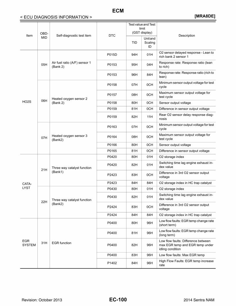
[MRA8DE]ECM
< ECU DIAGNOSIS INFORMATION >
HO2S
05H Air fuel ratio (A/F) sensor 1 (Bank 2)
P015D 94H 01H O2 sensor delayed response - Lean to rich bank 2 sensor 1
P0153 95H 04H Response rate: Response ratio (lean to rich)
P0153 96H 84H Response rate: Response ratio (rich to lean)
06H Heated oxygen sensor 2 (Bank 2)
P0158 07H 0CH Minimum sensor output voltage for test cycle
P0157 08H 0CH Maximum sensor output voltage for test cycle
P0158 80H 0CH Sensor output voltage
P0159 81H 0CH Difference in sensor output voltage
P0159 82H 11H Rear O2 sensor delay response diag-nosis
07H Heated oxygen sensor 3 (Bank2)
P0163 07H 0CH Minimum sensor output voltage for test cycle
P0164 08H 0CH Maximum sensor output voltage for test cycle
P0166 80H 0CH Sensor output voltage
P0165 81H 0CH Difference in sensor output voltage
CATA-LYST
21H Three way catalyst function (Bank1)
P0420 80H 01H O2 storage index
P0420 82H 01H Switching time lag engine exhaust in-dex value
P2423 83H 0CH Difference in 3rd O2 sensor output voltage
P2423 84H 84H O2 storage index in HC trap catalyst
22H Three way catalyst function (Bank2)
P0430 80H 01H O2 storage index
P0430 82H 01H Switching time lag engine exhaust in-dex value
P2424 83H 0CH Difference in 3rd O2 sensor output voltage
P2424 84H 84H O2 storage index in HC trap catalyst
EGR SYSTEM 31H EGR function
P0400 80H 96H Low flow faults: EGR temp change rate (short term)
P0400 81H 96H Low flow faults: EGR temp change rate (long term)
P0400 82H 96HLow flow faults: Difference between max EGR temp and EGR temp under idling condition
P0400 83H 96H Low flow faults: Max EGR temp
P1402 84H 96H High Flow Faults: EGR temp increase rate
Item OBD-MID Self-diagnostic test item DTC
Test value and Test limit
(GST display)Description
TIDUnit and Scaling
ID
EC-100Revision: October 2013 2014 Sentra NAM
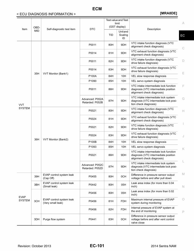
ECM[MRA8DE]
C
D
E
F
G
H
I
J
K
L
M
A
C
N
P
O
< ECU DIAGNOSIS INFORMATION >
E
VVT SYSTEM
35H VVT Monitor (Bank1)
P0011 80H 9DH VTC intake function diagnosis (VTC alignment check diagnosis)
P0014 81H 9DH VTC exhaust function diagnosis (VTC alignment check diagnosis)
P0011 82H 9DH VTC intake function diagnosis (VTC drive failure diagnosis)
P0014 83H 9DH VTC exhaust function diagnosis (VTC drive failure diagnosis)
P100A 84H 10H VEL slow response diagnosis
P1090 85H 10H VEL servo system diagnosis
P0011 86H 9DHVTC intake intermediate lock function diagnosis (VTC intermediate position alignment check diagnosis)
Advanced: P052ARetarded: P052B 87H 9DH
VTC intake intermediate lock system diagnosis (VTC intermediate lock posi-tion check diagnosis)
36H VVT Monitor (Bank2)
P0021 80H 9DH VTC intake function diagnosis (VTC alignment check diagnosis)
P0024 81H 9DH VTC exhaust function diagnosis (VTC alignment check diagnosis)
P0021 82H 9DH VTC intake function diagnosis (VTC drive failure diagnosis)
P0024 83H 9DH VTC exhaust function diagnosis (VTC drive failure diagnosis)
P100B 84H 10H VEL slow response diagnosis
P1093 85H 10H VEL servo system diagnosis
P0021 86H 9DHVTC intake intermediate lock function diagnosis (VTC intermediate position alignment check diagnosis)
Advanced: P052CRetarded: P052D 87H 9DH
VTC intake intermediate lock system diagnosis (VTC intermediate lock posi-tion check diagnosis)
EVAP SYSTEM
39H EVAP control system leak (Cap Off) P0455 80H 0CH Difference in pressure sensor output
voltage before and after pull down
3BH EVAP control system leak (Small leak) P0442 80H 05H Leak area index (for more than 0.04
inch)
3CH EVAP control system leak (Very small leak)
P0456 80H 05H Leak area index (for more than 0.02 inch)
P0456 81H FDH Maximum internal pressure of EVAP system during monitoring
P0456 82H FDH Internal pressure of EVAP system at the end of monitoring
3DH Purge flow system P0441 83H 0CHDifference in pressure sensor output voltage before and after vent control valve close
Item OBD-MID Self-diagnostic test item DTC
Test value and Test limit
(GST display)Description
TIDUnit and Scaling
ID
EC-101Revision: October 2013 2014 Sentra NAM
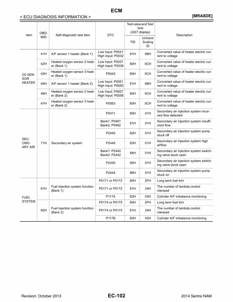
[MRA8DE]ECM
< ECU DIAGNOSIS INFORMATION >
O2 SEN-SOR HEATER
41H A/F sensor 1 heater (Bank 1) Low Input: P0031High Input: P0032 81H 0BH Converted value of heater electric cur-
rent to voltage
42H Heated oxygen sensor 2 heat-er (Bank 1)
Low Input: P0037High Input: P0038 80H 0CH Converted value of heater electric cur-
rent to voltage
43H Heated oxygen sensor 3 heat-er (Bank 1) P0043 80H 0CH Converted value of heater electric cur-
rent to voltage
45H A/F sensor 1 heater (Bank 2) Low Input: P0051High Input: P0052 81H 0BH Converted value of heater electric cur-
rent to voltage
46H Heated oxygen sensor 2 heat-er (Bank 2)
Low Input: P0057High Input: P0058 80H 0CH Converted value of heater electric cur-
rent to voltage
47H Heated oxygen sensor 3 heat-er (Bank 2) P0063 80H 0CH Converted value of heater electric cur-
rent to voltage
SEC-OND-ARY AIR
71H Secondary air system
P0411 80H 01H Secondary air injection system incor-rect flow detected
Bank1: P0491Bank2: P0492 81H 01H Secondary air injection system insuffi-
cient flow
P2445 82H 01H Secondary air injection system pump stuck off
P2448 83H 01H Secondary air injection system high airflow
Bank1: P2440Bank2: P2442 84H 01H Secondary air injection system switch-
ing valve stuck open
P2440 85H 01H Secondary air injection system switch-ing valve stuck open
P2444 86H 01H Secondary air injection system pump stuck on
FUEL SYSTEM
81H Fuel injection system function (Bank 1)
P0171 or P0172 80H 2FH Long term fuel trim
P0171 or P0172 81H 24H The number of lambda control clamped
P117A 82H 03H Cylinder A/F imbalance monitoring
82H Fuel injection system function (Bank 2)
P0174 or P0175 80H 2FH Long term fuel trim
P0174 or P0175 81H 24H The number of lambda control clamped
P117B 82H 03H Cylinder A/F imbalance monitoring
Item OBD-MID Self-diagnostic test item DTC
Test value and Test limit
(GST display)Description
TIDUnit and Scaling
ID
EC-102Revision: October 2013 2014 Sentra NAM
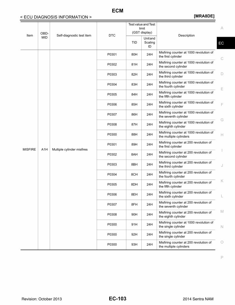
ECM[MRA8DE]
C
D
E
F
G
H
I
J
K
L
M
A
C
N
P
O
< ECU DIAGNOSIS INFORMATION >
E
MISFIRE A1H Multiple cylinder misfires
P0301 80H 24H Misfiring counter at 1000 revolution of the first cylinder
P0302 81H 24H Misfiring counter at 1000 revolution of the second cylinder
P0303 82H 24H Misfiring counter at 1000 revolution of the third cylinder
P0304 83H 24H Misfiring counter at 1000 revolution of the fourth cylinder
P0305 84H 24H Misfiring counter at 1000 revolution of the fifth cylinder
P0306 85H 24H Misfiring counter at 1000 revolution of the sixth cylinder
P0307 86H 24H Misfiring counter at 1000 revolution of the seventh cylinder
P0308 87H 24H Misfiring counter at 1000 revolution of the eighth cylinder
P0300 88H 24H Misfiring counter at 1000 revolution of the multiple cylinders
P0301 89H 24H Misfiring counter at 200 revolution of the first cylinder
P0302 8AH 24H Misfiring counter at 200 revolution of the second cylinder
P0303 8BH 24H Misfiring counter at 200 revolution of the third cylinder
P0304 8CH 24H Misfiring counter at 200 revolution of the fourth cylinder
P0305 8DH 24H Misfiring counter at 200 revolution of the fifth cylinder
P0306 8EH 24H Misfiring counter at 200 revolution of the sixth cylinder
P0307 8FH 24H Misfiring counter at 200 revolution of the seventh cylinder
P0308 90H 24H Misfiring counter at 200 revolution of the eighth cylinder
P0300 91H 24H Misfiring counter at 1000 revolution of the single cylinder
P0300 92H 24H Misfiring counter at 200 revolution of the single cylinder
P0300 93H 24H Misfiring counter at 200 revolution of the multiple cylinders
Item OBD-MID Self-diagnostic test item DTC
Test value and Test limit
(GST display)Description
TIDUnit and Scaling
ID
EC-103Revision: October 2013 2014 Sentra NAM
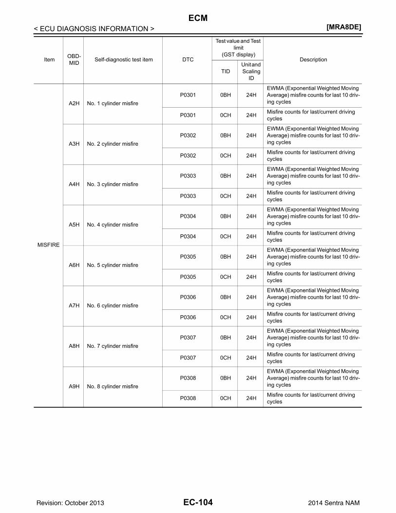
[MRA8DE]ECM
< ECU DIAGNOSIS INFORMATION >
MISFIRE
A2H No. 1 cylinder misfireP0301 0BH 24H
EWMA (Exponential Weighted Moving Average) misfire counts for last 10 driv-ing cycles
P0301 0CH 24H Misfire counts for last/current driving cycles
A3H No. 2 cylinder misfireP0302 0BH 24H
EWMA (Exponential Weighted Moving Average) misfire counts for last 10 driv-ing cycles
P0302 0CH 24H Misfire counts for last/current driving cycles
A4H No. 3 cylinder misfireP0303 0BH 24H
EWMA (Exponential Weighted Moving Average) misfire counts for last 10 driv-ing cycles
P0303 0CH 24H Misfire counts for last/current driving cycles
A5H No. 4 cylinder misfireP0304 0BH 24H
EWMA (Exponential Weighted Moving Average) misfire counts for last 10 driv-ing cycles
P0304 0CH 24H Misfire counts for last/current driving cycles
A6H No. 5 cylinder misfireP0305 0BH 24H
EWMA (Exponential Weighted Moving Average) misfire counts for last 10 driv-ing cycles
P0305 0CH 24H Misfire counts for last/current driving cycles
A7H No. 6 cylinder misfireP0306 0BH 24H
EWMA (Exponential Weighted Moving Average) misfire counts for last 10 driv-ing cycles
P0306 0CH 24H Misfire counts for last/current driving cycles
A8H No. 7 cylinder misfireP0307 0BH 24H
EWMA (Exponential Weighted Moving Average) misfire counts for last 10 driv-ing cycles
P0307 0CH 24H Misfire counts for last/current driving cycles
A9H No. 8 cylinder misfireP0308 0BH 24H
EWMA (Exponential Weighted Moving Average) misfire counts for last 10 driv-ing cycles
P0308 0CH 24H Misfire counts for last/current driving cycles
Item OBD-MID Self-diagnostic test item DTC
Test value and Test limit
(GST display)Description
TIDUnit and Scaling
ID
EC-104Revision: October 2013 2014 Sentra NAM
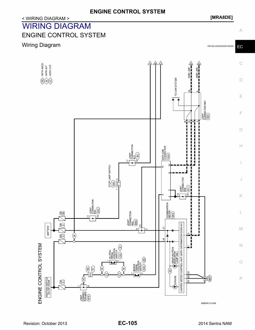
ENGINE CONTROL SYSTEM[MRA8DE]
C
D
E
F
G
H
I
J
K
L
M
A
C
N
P
O
< WIRING DIAGRAM >
E
WIRING DIAGRAMENGINE CONTROL SYSTEMWiring Diagram INFOID:0000000009758395
ABBWA1214GB
EC-105Revision: October 2013 2014 Sentra NAM
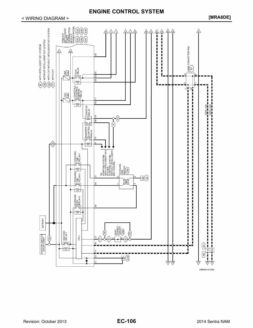
[MRA8DE]ENGINE CONTROL SYSTEM
< WIRING DIAGRAM >
ABBWA1215GB
EC-106Revision: October 2013 2014 Sentra NAM
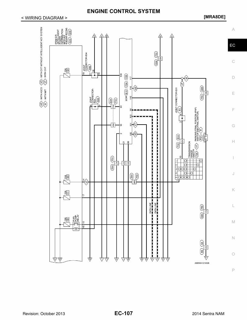
ENGINE CONTROL SYSTEM[MRA8DE]
C
D
E
F
G
H
I
J
K
L
M
A
C
N
P
O
< WIRING DIAGRAM >
E
ABBWA1216GB
EC-107Revision: October 2013 2014 Sentra NAM
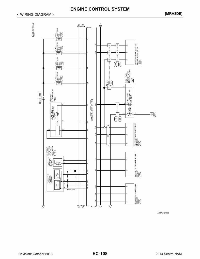
[MRA8DE]ENGINE CONTROL SYSTEM
< WIRING DIAGRAM >
ABBWA1217GB
EC-108Revision: October 2013 2014 Sentra NAM
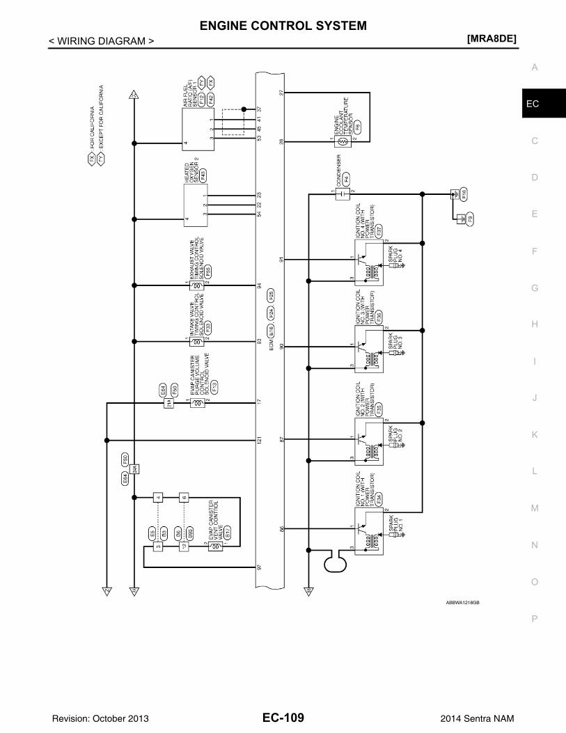
ENGINE CONTROL SYSTEM[MRA8DE]
C
D
E
F
G
H
I
J
K
L
M
A
C
N
P
O
< WIRING DIAGRAM >
E
ABBWA1218GB
EC-109Revision: October 2013 2014 Sentra NAM
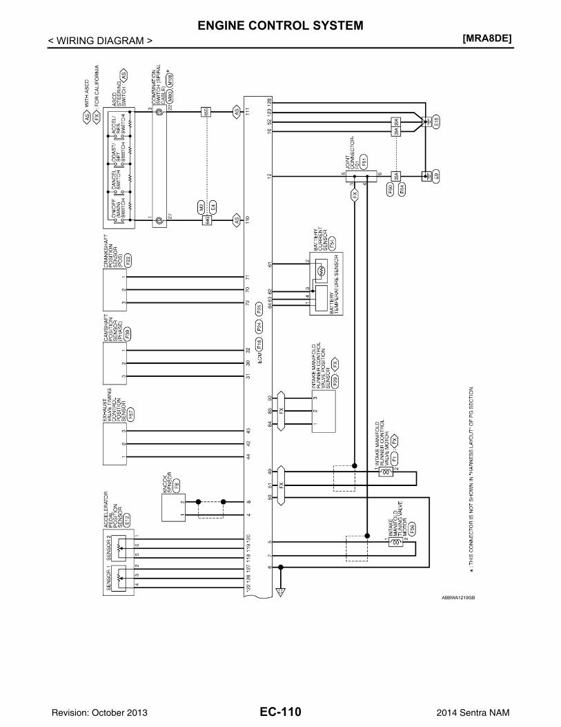
[MRA8DE]ENGINE CONTROL SYSTEM
< WIRING DIAGRAM >
ABBWA1219GB
EC-110Revision: October 2013 2014 Sentra NAM
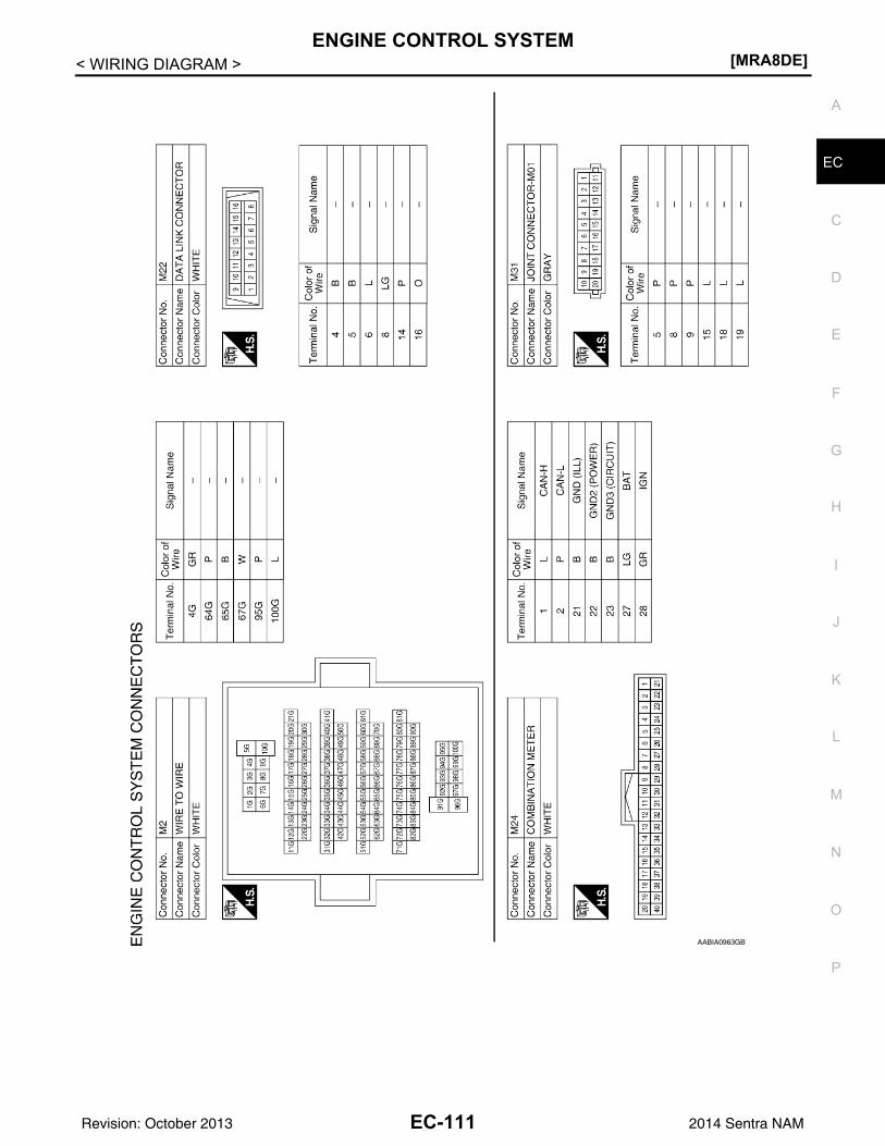
ENGINE CONTROL SYSTEM[MRA8DE]
C
D
E
F
G
H
I
J
K
L
M
A
C
N
P
O
< WIRING DIAGRAM >
E
AABIA0963GB
EC-111Revision: October 2013 2014 Sentra NAM
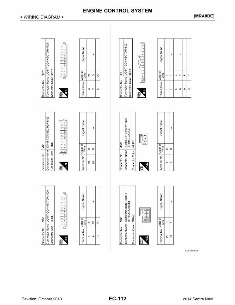
[MRA8DE]ENGINE CONTROL SYSTEM
< WIRING DIAGRAM >
AABIA0964GB
EC-112Revision: October 2013 2014 Sentra NAM
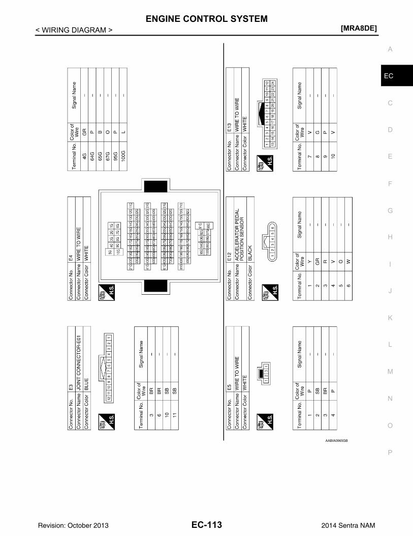
ENGINE CONTROL SYSTEM[MRA8DE]
C
D
E
F
G
H
I
J
K
L
M
A
C
N
P
O
< WIRING DIAGRAM >
E
AABIA0965GB
EC-113Revision: October 2013 2014 Sentra NAM
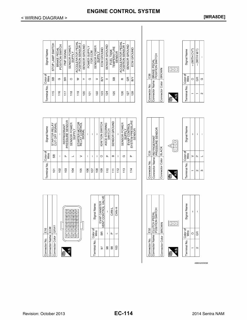
[MRA8DE]ENGINE CONTROL SYSTEM
< WIRING DIAGRAM >
ABBIA2059GB
EC-114Revision: October 2013 2014 Sentra NAM
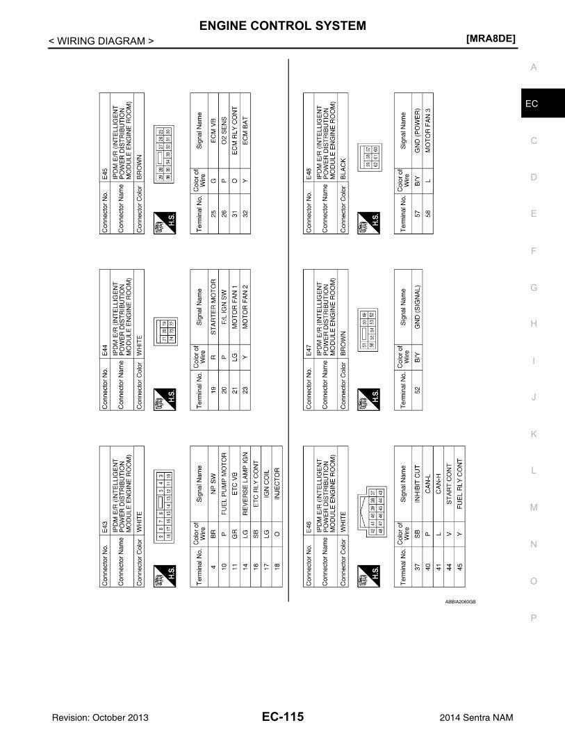
ENGINE CONTROL SYSTEM[MRA8DE]
C
D
E
F
G
H
I
J
K
L
M
A
C
N
P
O
< WIRING DIAGRAM >
E
ABBIA2060GB
EC-115Revision: October 2013 2014 Sentra NAM
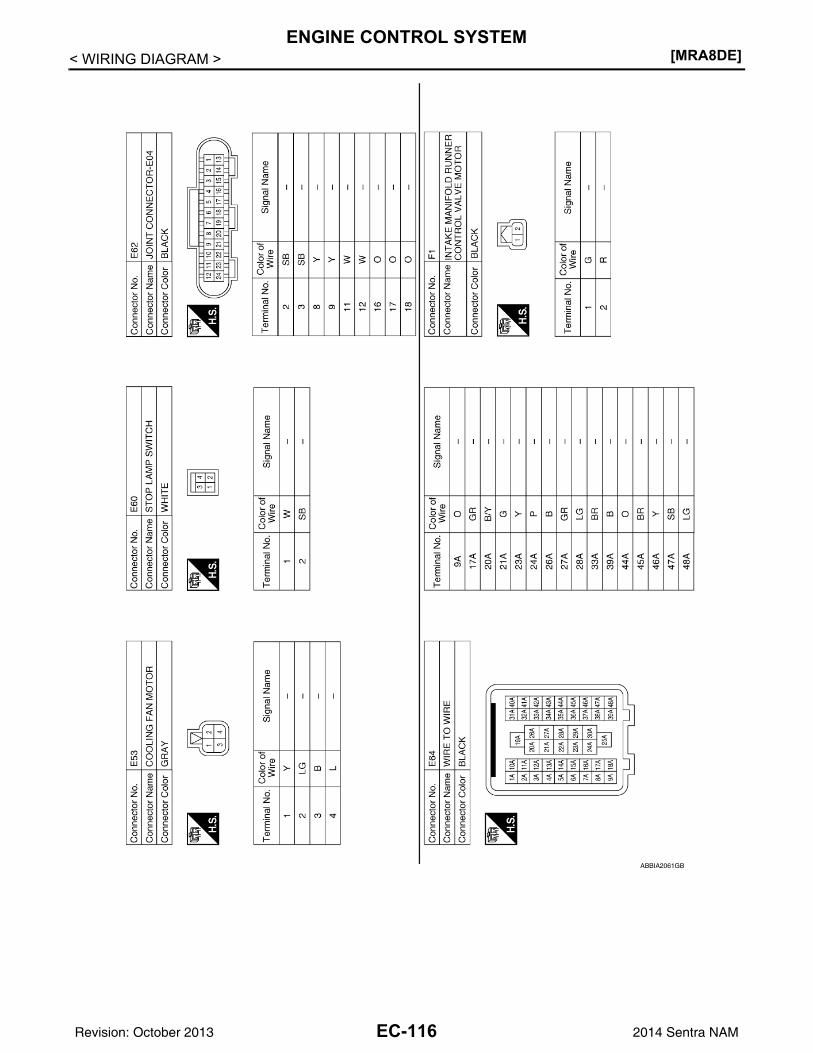
[MRA8DE]ENGINE CONTROL SYSTEM
< WIRING DIAGRAM >
ABBIA2061GB
EC-116Revision: October 2013 2014 Sentra NAM
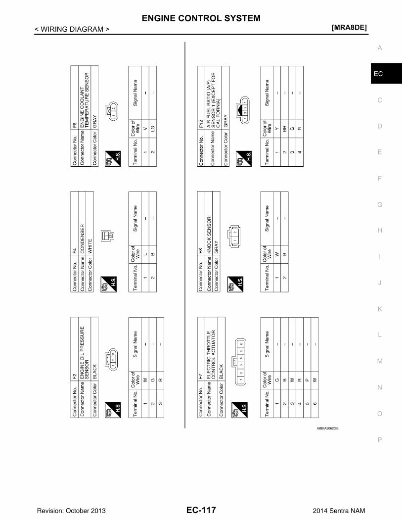
ENGINE CONTROL SYSTEM[MRA8DE]
C
D
E
F
G
H
I
J
K
L
M
A
C
N
P
O
< WIRING DIAGRAM >
E
ABBIA2062GB
EC-117Revision: October 2013 2014 Sentra NAM
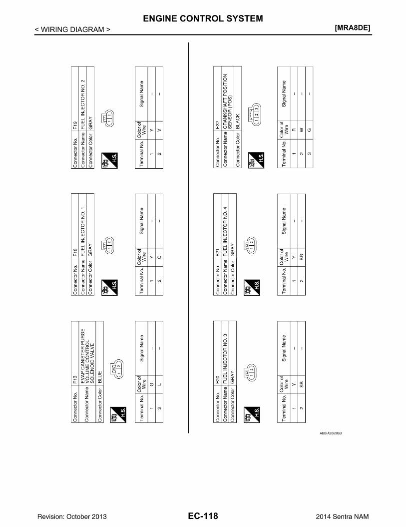
[MRA8DE]ENGINE CONTROL SYSTEM
< WIRING DIAGRAM >
ABBIA2063GB
EC-118Revision: October 2013 2014 Sentra NAM
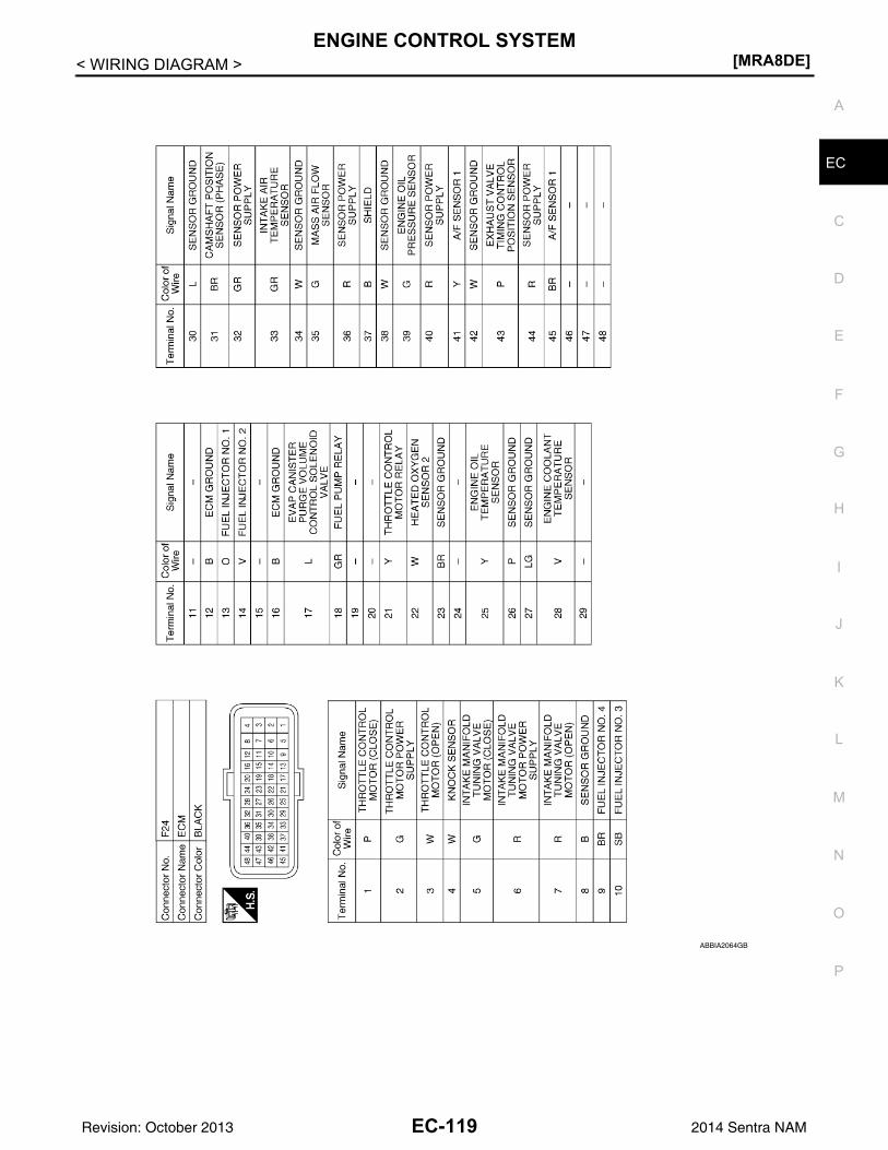
ENGINE CONTROL SYSTEM[MRA8DE]
C
D
E
F
G
H
I
J
K
L
M
A
C
N
P
O
< WIRING DIAGRAM >
E
ABBIA2064GB
EC-119Revision: October 2013 2014 Sentra NAM
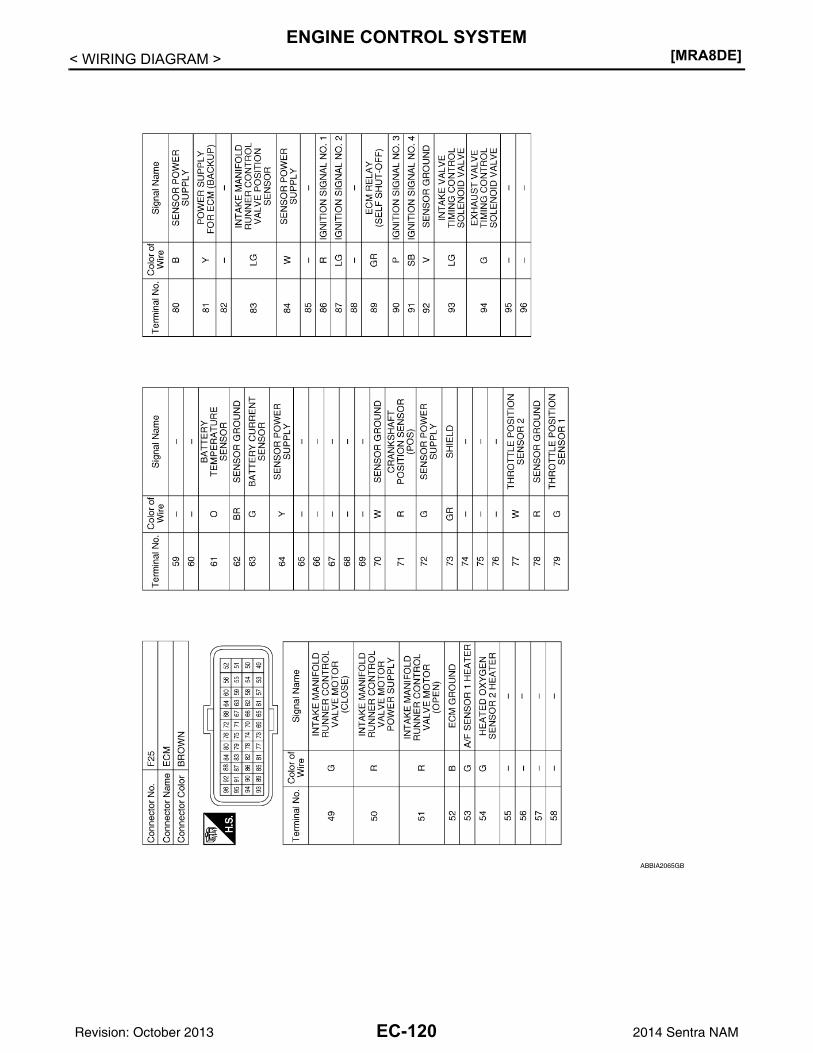
[MRA8DE]ENGINE CONTROL SYSTEM
< WIRING DIAGRAM >
ABBIA2065GB
EC-120Revision: October 2013 2014 Sentra NAM
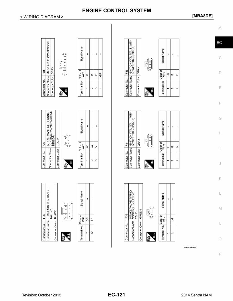
ENGINE CONTROL SYSTEM[MRA8DE]
C
D
E
F
G
H
I
J
K
L
M
A
C
N
P
O
< WIRING DIAGRAM >
E
ABBIA2066GB
EC-121Revision: October 2013 2014 Sentra NAM
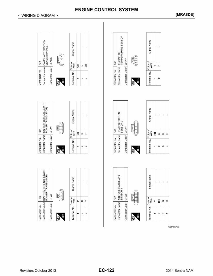
[MRA8DE]ENGINE CONTROL SYSTEM
< WIRING DIAGRAM >
ABBIA2067GB
EC-122Revision: October 2013 2014 Sentra NAM
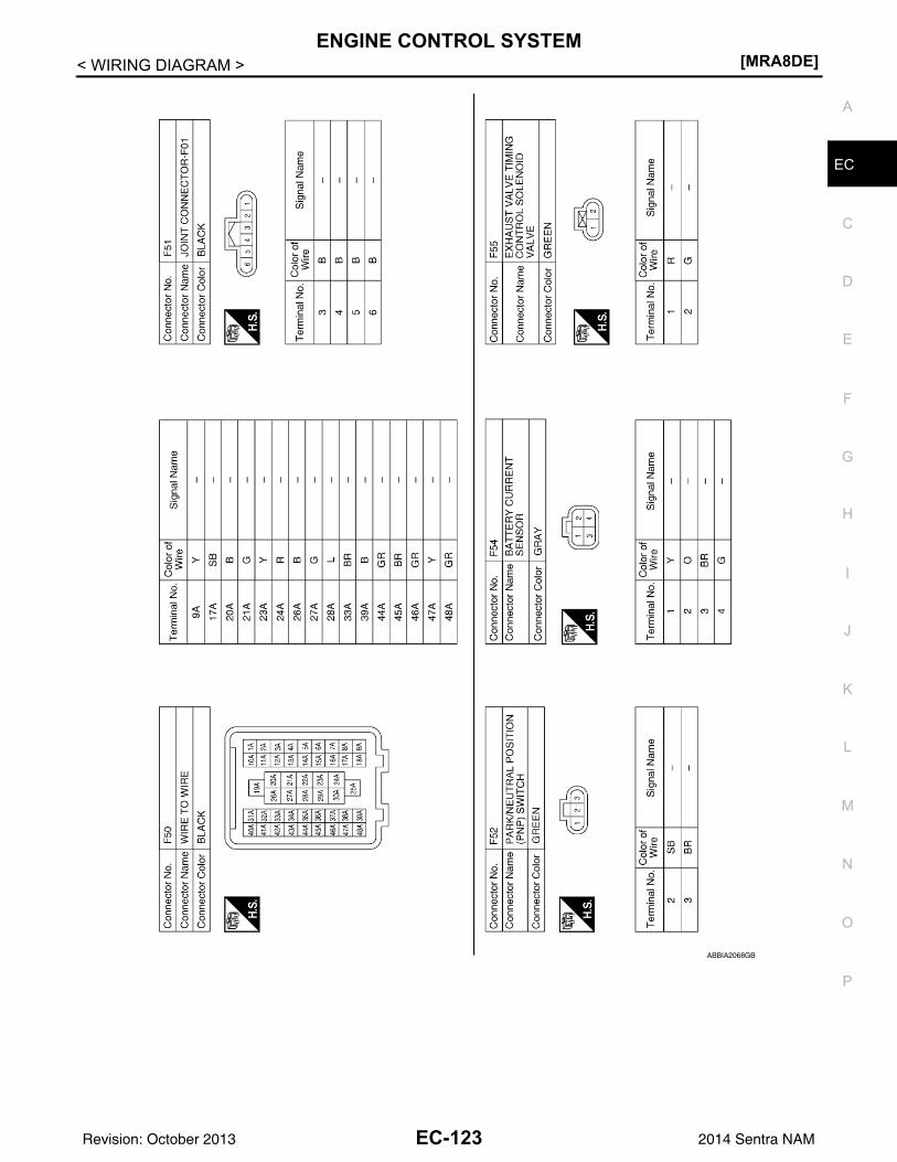
ENGINE CONTROL SYSTEM[MRA8DE]
C
D
E
F
G
H
I
J
K
L
M
A
C
N
P
O
< WIRING DIAGRAM >
E
ABBIA2068GB
EC-123Revision: October 2013 2014 Sentra NAM
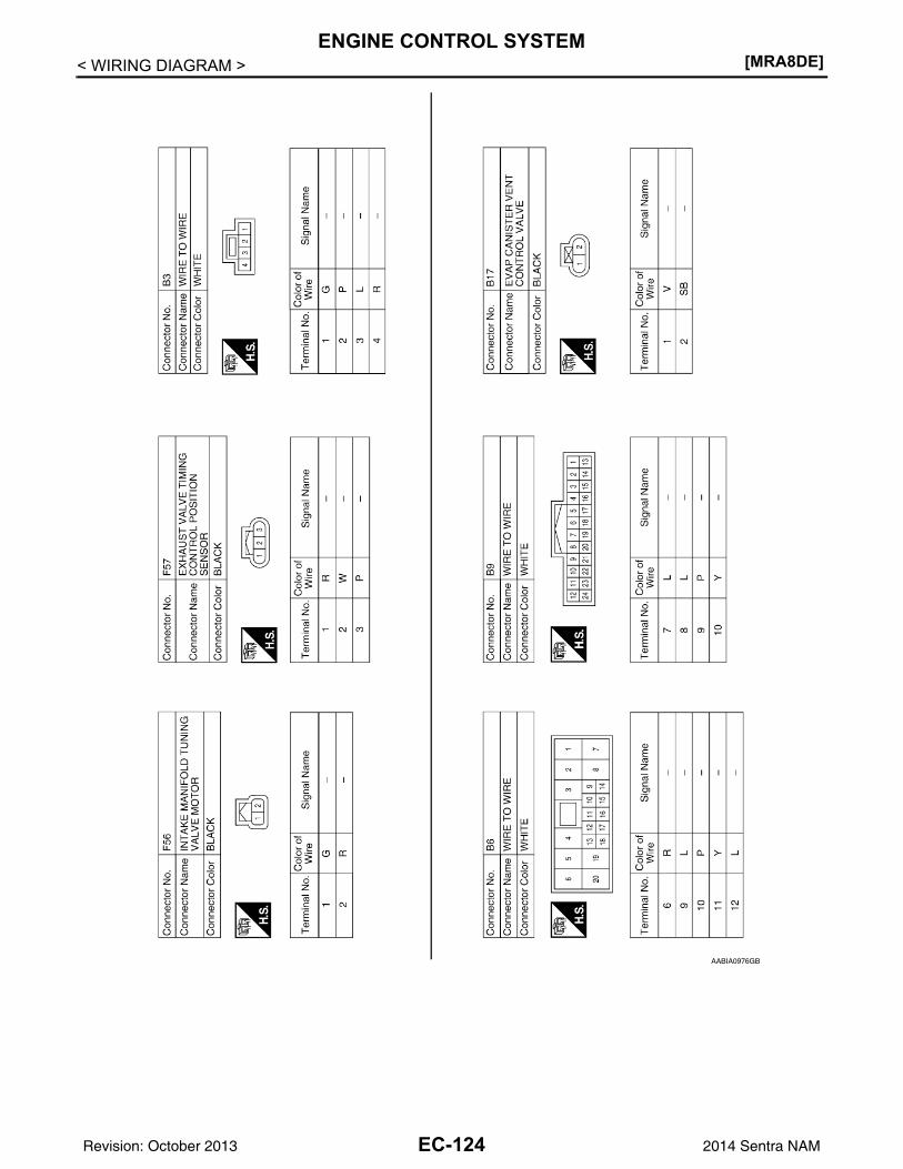
[MRA8DE]ENGINE CONTROL SYSTEM
< WIRING DIAGRAM >
AABIA0976GB
EC-124Revision: October 2013 2014 Sentra NAM
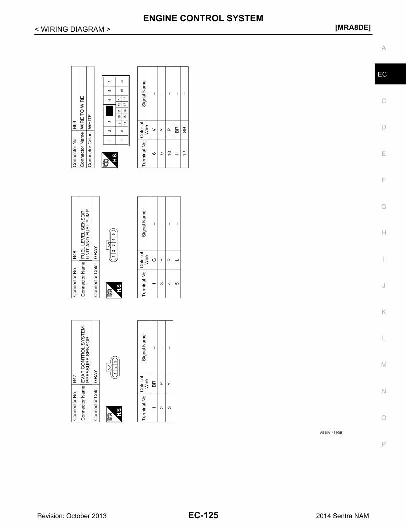
ENGINE CONTROL SYSTEM[MRA8DE]
C
D
E
F
G
H
I
J
K
L
M
A
C
N
P
O
< WIRING DIAGRAM >
E
ABBIA1454GB
EC-125Revision: October 2013 2014 Sentra NAM
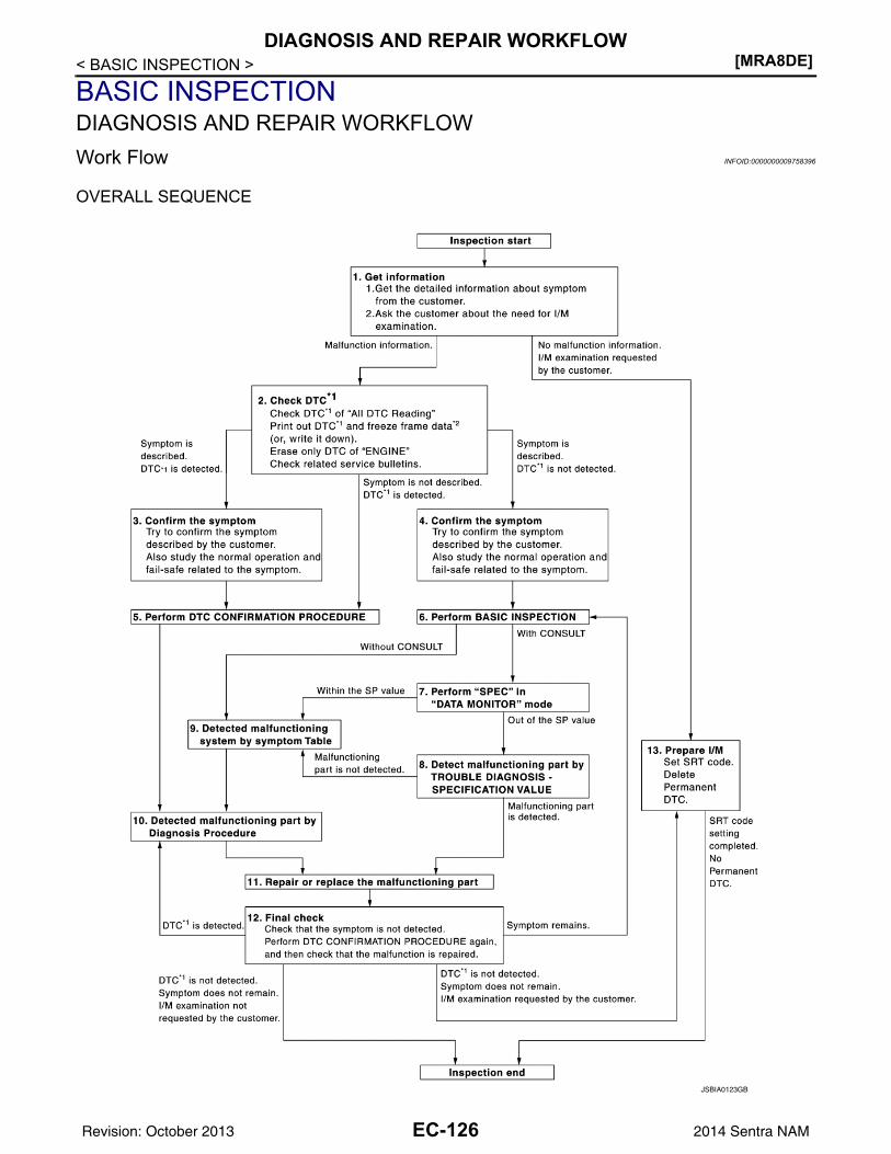
[MRA8DE]DIAGNOSIS AND REPAIR WORKFLOW
< BASIC INSPECTION >
BASIC INSPECTIONDIAGNOSIS AND REPAIR WORKFLOWWork Flow INFOID:0000000009758396
OVERALL SEQUENCE
JSBIA0123GB
EC-126Revision: October 2013 2014 Sentra NAM
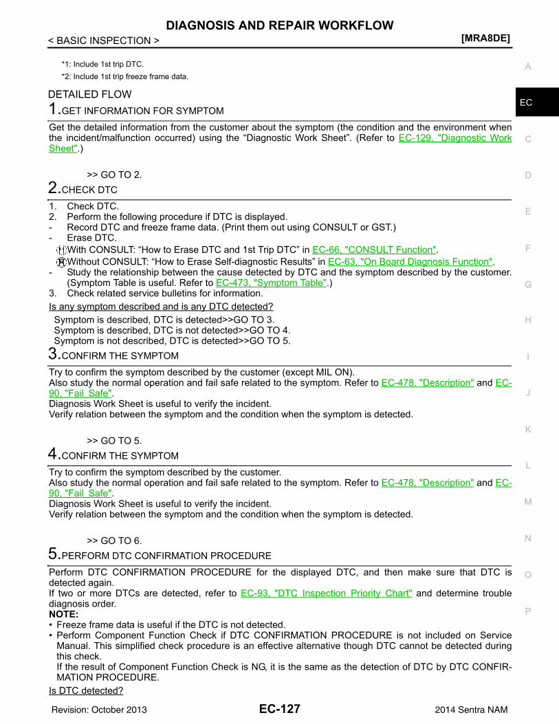
DIAGNOSIS AND REPAIR WORKFLOW[MRA8DE]
C
D
E
F
G
H
I
J
K
L
M
A
C
N
P
O
< BASIC INSPECTION >
EDETAILED FLOW1.GET INFORMATION FOR SYMPTOM
Get the detailed information from the customer about the symptom (the condition and the environment whenthe incident/malfunction occurred) using the “Diagnostic Work Sheet”. (Refer to EC-129, "Diagnostic WorkSheet".)
>> GO TO 2.2.CHECK DTC
1. Check DTC.2. Perform the following procedure if DTC is displayed.- Record DTC and freeze frame data. (Print them out using CONSULT or GST.)- Erase DTC.
With CONSULT: “How to Erase DTC and 1st Trip DTC” in EC-66, "CONSULT Function".Without CONSULT: “How to Erase Self-diagnostic Results” in EC-63, "On Board Diagnosis Function".
- Study the relationship between the cause detected by DTC and the symptom described by the customer.(Symptom Table is useful. Refer to EC-473, "Symptom Table".)
3. Check related service bulletins for information.Is any symptom described and is any DTC detected?Symptom is described, DTC is detected>>GO TO 3.Symptom is described, DTC is not detected>>GO TO 4.Symptom is not described, DTC is detected>>GO TO 5.
3.CONFIRM THE SYMPTOM
Try to confirm the symptom described by the customer (except MIL ON).Also study the normal operation and fail safe related to the symptom. Refer to EC-478, "Description" and EC-90, "Fail Safe".Diagnosis Work Sheet is useful to verify the incident.Verify relation between the symptom and the condition when the symptom is detected.
>> GO TO 5.4.CONFIRM THE SYMPTOM
Try to confirm the symptom described by the customer.Also study the normal operation and fail safe related to the symptom. Refer to EC-478, "Description" and EC-90, "Fail Safe".Diagnosis Work Sheet is useful to verify the incident.Verify relation between the symptom and the condition when the symptom is detected.
>> GO TO 6.5.PERFORM DTC CONFIRMATION PROCEDURE
Perform DTC CONFIRMATION PROCEDURE for the displayed DTC, and then make sure that DTC isdetected again.If two or more DTCs are detected, refer to EC-93, "DTC Inspection Priority Chart" and determine troublediagnosis order.NOTE:• Freeze frame data is useful if the DTC is not detected.• Perform Component Function Check if DTC CONFIRMATION PROCEDURE is not included on Service
Manual. This simplified check procedure is an effective alternative though DTC cannot be detected duringthis check.If the result of Component Function Check is NG, it is the same as the detection of DTC by DTC CONFIR-MATION PROCEDURE.
Is DTC detected?
*1: Include 1st trip DTC.*2: Include 1st trip freeze frame data.
EC-127Revision: October 2013 2014 Sentra NAM
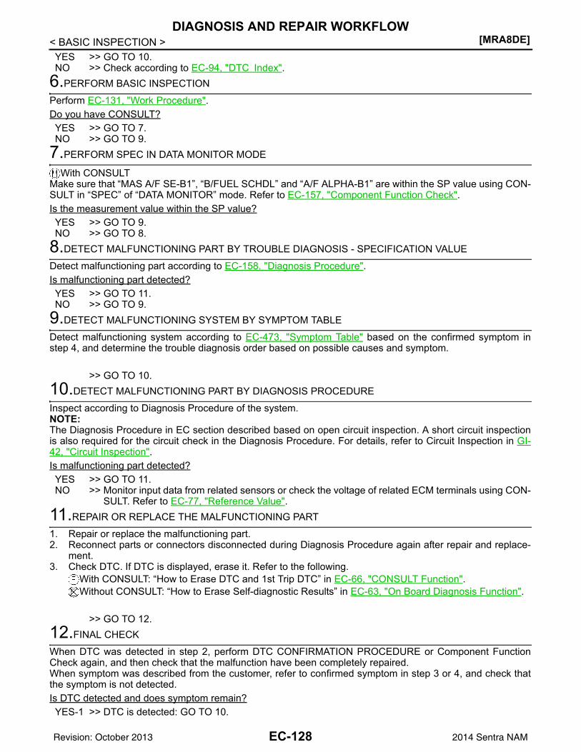
[MRA8DE]DIAGNOSIS AND REPAIR WORKFLOW
< BASIC INSPECTION >YES >> GO TO 10.NO >> Check according to EC-94, "DTC Index".
6.PERFORM BASIC INSPECTION
Perform EC-131, "Work Procedure".Do you have CONSULT?YES >> GO TO 7.NO >> GO TO 9.
7.PERFORM SPEC IN DATA MONITOR MODE
With CONSULTMake sure that “MAS A/F SE-B1”, “B/FUEL SCHDL” and “A/F ALPHA-B1” are within the SP value using CON-SULT in “SPEC” of “DATA MONITOR” mode. Refer to EC-157, "Component Function Check".Is the measurement value within the SP value?YES >> GO TO 9.NO >> GO TO 8.
8.DETECT MALFUNCTIONING PART BY TROUBLE DIAGNOSIS - SPECIFICATION VALUE
Detect malfunctioning part according to EC-158, "Diagnosis Procedure".Is malfunctioning part detected?YES >> GO TO 11.NO >> GO TO 9.
9.DETECT MALFUNCTIONING SYSTEM BY SYMPTOM TABLE
Detect malfunctioning system according to EC-473, "Symptom Table" based on the confirmed symptom instep 4, and determine the trouble diagnosis order based on possible causes and symptom.
>> GO TO 10.10.DETECT MALFUNCTIONING PART BY DIAGNOSIS PROCEDURE
Inspect according to Diagnosis Procedure of the system.NOTE:The Diagnosis Procedure in EC section described based on open circuit inspection. A short circuit inspectionis also required for the circuit check in the Diagnosis Procedure. For details, refer to Circuit Inspection in GI-42, "Circuit Inspection".Is malfunctioning part detected?YES >> GO TO 11.NO >> Monitor input data from related sensors or check the voltage of related ECM terminals using CON-
SULT. Refer to EC-77, "Reference Value".11.REPAIR OR REPLACE THE MALFUNCTIONING PART
1. Repair or replace the malfunctioning part.2. Reconnect parts or connectors disconnected during Diagnosis Procedure again after repair and replace-
ment.3. Check DTC. If DTC is displayed, erase it. Refer to the following.
With CONSULT: “How to Erase DTC and 1st Trip DTC” in EC-66, "CONSULT Function".Without CONSULT: “How to Erase Self-diagnostic Results” in EC-63, "On Board Diagnosis Function".
>> GO TO 12.12.FINAL CHECK
When DTC was detected in step 2, perform DTC CONFIRMATION PROCEDURE or Component FunctionCheck again, and then check that the malfunction have been completely repaired.When symptom was described from the customer, refer to confirmed symptom in step 3 or 4, and check thatthe symptom is not detected.Is DTC detected and does symptom remain?YES-1 >> DTC is detected: GO TO 10.
EC-128Revision: October 2013 2014 Sentra NAM
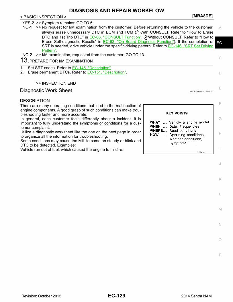
DIAGNOSIS AND REPAIR WORKFLOW[MRA8DE]
C
D
E
F
G
H
I
J
K
L
M
A
C
N
P
O
< BASIC INSPECTION >
E
YES-2 >> Symptom remains: GO TO 6.NO-1 >> No request for I/M examination from the customer: Before returning the vehicle to the customer,
always erase unnecessary DTC in ECM and TCM ( With CONSULT: Refer to “How to EraseDTC and 1st Trip DTC” in EC-66, "CONSULT Function", Without CONSULT: Refer to “How toErase Self-diagnostic Results” in EC-63, "On Board Diagnosis Function"). If the completion ofSRT is needed, drive vehicle under the specific driving pattern. Refer to EC-146, "SRT Set DrivingPattern".
NO-2 >> I/M examination, requested from the customer: GO TO 13.13.PREPARE FOR I/M EXAMINATION
1. Set SRT codes. Refer to EC-145, "Description".2. Erase permanent DTCs. Refer to EC-151, "Description".
>> INSPECTION END
Diagnostic Work Sheet INFOID:0000000009758397
DESCRIPTIONThere are many operating conditions that lead to the malfunction ofengine components. A good grasp of such conditions can make trou-bleshooting faster and more accurate.In general, each customer feels differently about a incident. It isimportant to fully understand the symptoms or conditions for a cus-tomer complaint.Utilize a diagnostic worksheet like the one on the next page in orderto organize all the information for troubleshooting.Some conditions may cause the MIL to come on steady or blink andDTC to be detected. Examples:Vehicle ran out of fuel, which caused the engine to misfire.
SEF907L
EC-129Revision: October 2013 2014 Sentra NAM
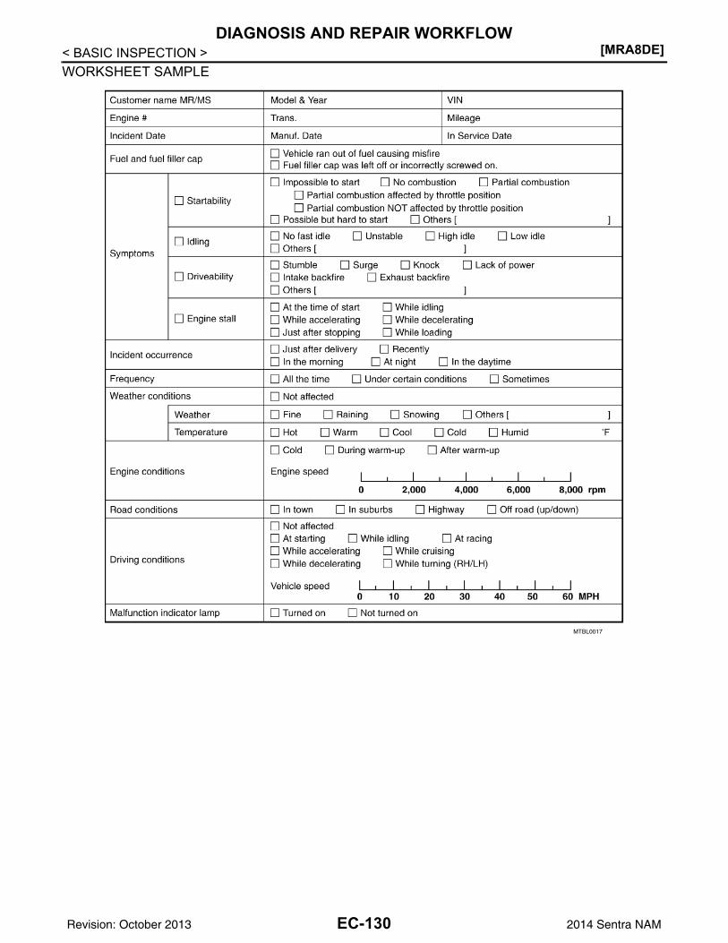
[MRA8DE]DIAGNOSIS AND REPAIR WORKFLOW
< BASIC INSPECTION >WORKSHEET SAMPLE
MTBL0017
EC-130Revision: October 2013 2014 Sentra NAM
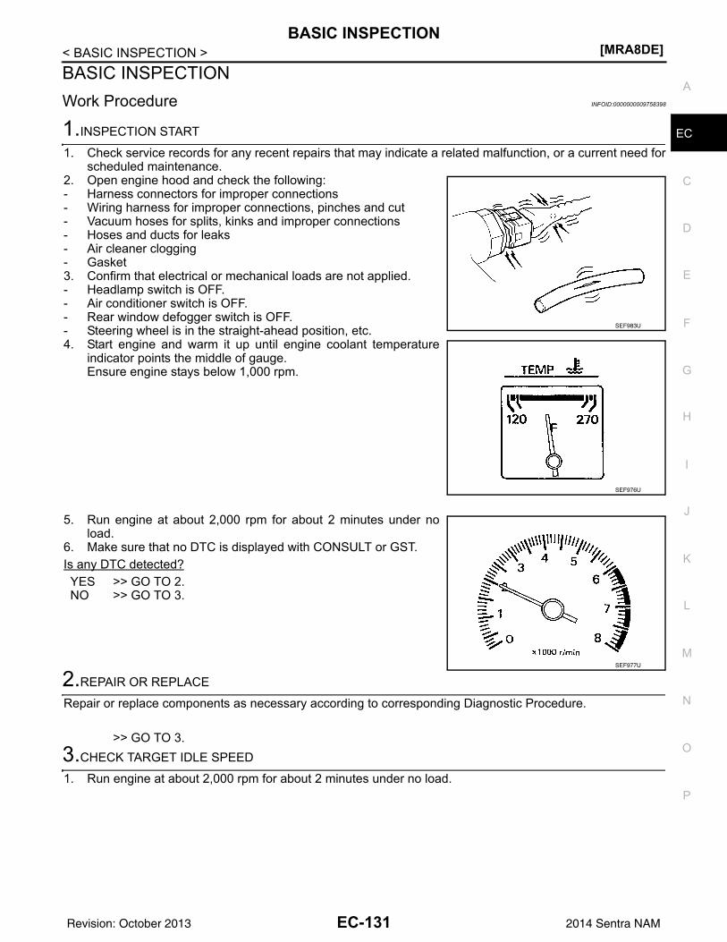
BASIC INSPECTION[MRA8DE]
C
D
E
F
G
H
I
J
K
L
M
A
C
N
P
O
< BASIC INSPECTION >
E
BASIC INSPECTIONWork Procedure INFOID:0000000009758398
1.INSPECTION START
1. Check service records for any recent repairs that may indicate a related malfunction, or a current need forscheduled maintenance.
2. Open engine hood and check the following:- Harness connectors for improper connections- Wiring harness for improper connections, pinches and cut- Vacuum hoses for splits, kinks and improper connections- Hoses and ducts for leaks- Air cleaner clogging- Gasket3. Confirm that electrical or mechanical loads are not applied.- Headlamp switch is OFF.- Air conditioner switch is OFF.- Rear window defogger switch is OFF.- Steering wheel is in the straight-ahead position, etc.4. Start engine and warm it up until engine coolant temperature
indicator points the middle of gauge.Ensure engine stays below 1,000 rpm.
5. Run engine at about 2,000 rpm for about 2 minutes under noload.
6. Make sure that no DTC is displayed with CONSULT or GST.Is any DTC detected?YES >> GO TO 2.NO >> GO TO 3.
2.REPAIR OR REPLACE
Repair or replace components as necessary according to corresponding Diagnostic Procedure.
>> GO TO 3.3.CHECK TARGET IDLE SPEED
1. Run engine at about 2,000 rpm for about 2 minutes under no load.
SEF983U
SEF976U
SEF977U
EC-131Revision: October 2013 2014 Sentra NAM
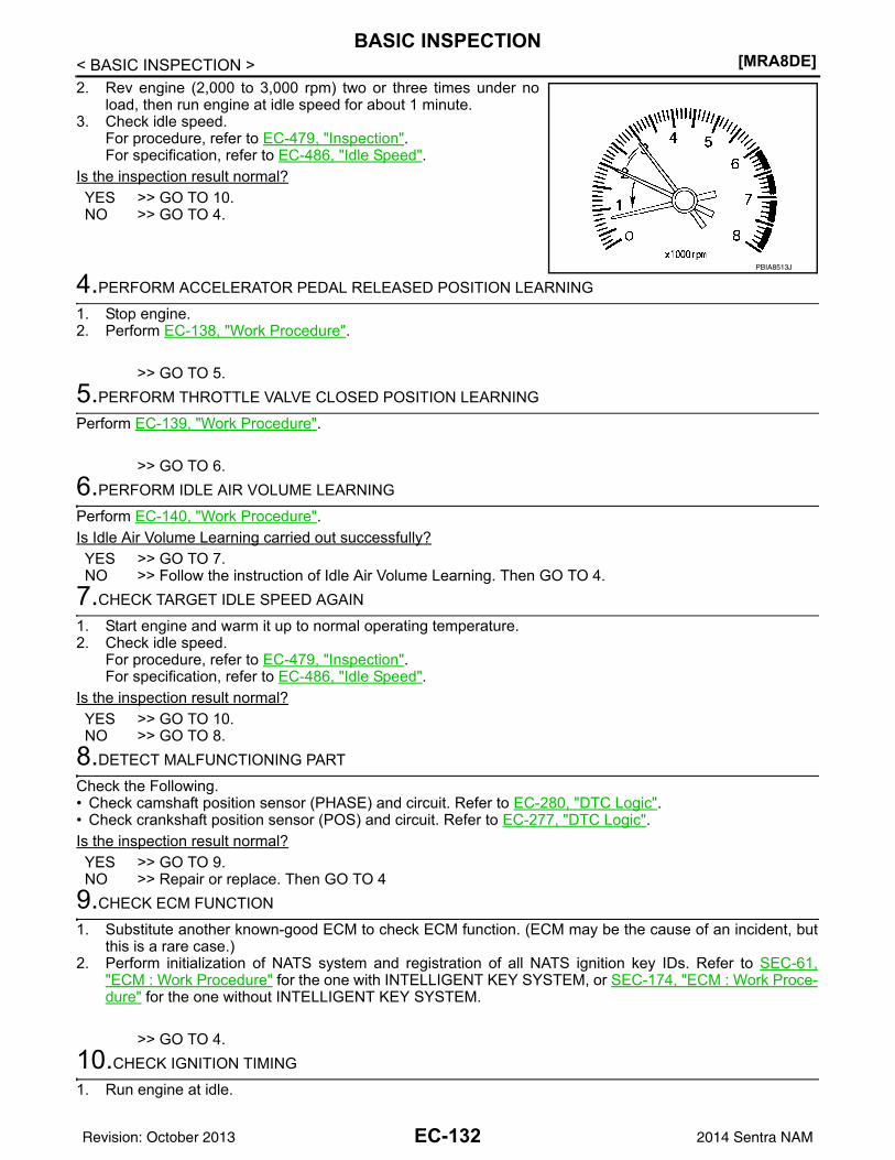
[MRA8DE]BASIC INSPECTION
< BASIC INSPECTION >2. Rev engine (2,000 to 3,000 rpm) two or three times under no
load, then run engine at idle speed for about 1 minute.3. Check idle speed.
For procedure, refer to EC-479, "Inspection".For specification, refer to EC-486, "Idle Speed".
Is the inspection result normal?YES >> GO TO 10.NO >> GO TO 4.
4.PERFORM ACCELERATOR PEDAL RELEASED POSITION LEARNING
1. Stop engine.2. Perform EC-138, "Work Procedure".
>> GO TO 5.5.PERFORM THROTTLE VALVE CLOSED POSITION LEARNING
Perform EC-139, "Work Procedure".
>> GO TO 6.6.PERFORM IDLE AIR VOLUME LEARNING
Perform EC-140, "Work Procedure".Is Idle Air Volume Learning carried out successfully?YES >> GO TO 7.NO >> Follow the instruction of Idle Air Volume Learning. Then GO TO 4.
7.CHECK TARGET IDLE SPEED AGAIN
1. Start engine and warm it up to normal operating temperature.2. Check idle speed.
For procedure, refer to EC-479, "Inspection".For specification, refer to EC-486, "Idle Speed".
Is the inspection result normal?YES >> GO TO 10.NO >> GO TO 8.
8.DETECT MALFUNCTIONING PART
Check the Following.• Check camshaft position sensor (PHASE) and circuit. Refer to EC-280, "DTC Logic".• Check crankshaft position sensor (POS) and circuit. Refer to EC-277, "DTC Logic".Is the inspection result normal?YES >> GO TO 9.NO >> Repair or replace. Then GO TO 4
9.CHECK ECM FUNCTION
1. Substitute another known-good ECM to check ECM function. (ECM may be the cause of an incident, butthis is a rare case.)
2. Perform initialization of NATS system and registration of all NATS ignition key IDs. Refer to SEC-61,"ECM : Work Procedure" for the one with INTELLIGENT KEY SYSTEM, or SEC-174, "ECM : Work Proce-dure" for the one without INTELLIGENT KEY SYSTEM.
>> GO TO 4.10.CHECK IGNITION TIMING
1. Run engine at idle.
PBIA8513J
EC-132Revision: October 2013 2014 Sentra NAM
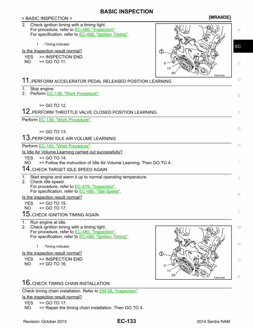
BASIC INSPECTION[MRA8DE]
C
D
E
F
G
H
I
J
K
L
M
A
C
N
P
O
< BASIC INSPECTION >
E
2. Check ignition timing with a timing light.For procedure, refer to EC-480, "Inspection"For specification, refer to EC-486, "Ignition Timing".
Is the inspection result normal?YES >> INSPECTION END.NO >> GO TO 11.
11.PERFORM ACCELERATOR PEDAL RELEASED POSITION LEARNING
1. Stop engine.2. Perform EC-138, "Work Procedure".
>> GO TO 12.12.PERFORM THROTTLE VALVE CLOSED POSITION LEARNING
Perform EC-139, "Work Procedure".
>> GO TO 13.13.PERFORM IDLE AIR VOLUME LEARNING
Perform EC-140, "Work Procedure".Is Idle Air Volume Learning carried out successfully?YES >> GO TO 14.NO >> Follow the instruction of Idle Air Volume Learning. Then GO TO 4.
14.CHECK TARGET IDLE SPEED AGAIN
1. Start engine and warm it up to normal operating temperature.2. Check idle speed.
For procedure, refer to EC-479, "Inspection".For specification, refer to EC-486, "Idle Speed".
Is the inspection result normal?YES >> GO TO 15.NO >> GO TO 17.
15.CHECK IGNITION TIMING AGAIN
1. Run engine at idle.2. Check ignition timing with a timing light.
For procedure, refer to EC-480, "Inspection".For specification, refer to EC-486, "Ignition Timing".
Is the inspection result normal?YES >> INSPECTION END.NO >> GO TO 16.
16.CHECK TIMING CHAIN INSTALLATION
Check timing chain installation. Refer to EM-58, "Inspection".Is the inspection result normal?YES >> GO TO 17.NO >> Repair the timing chain installation. Then GO TO 4.
1 : Timing indicator
PBIB3263E
1 : Timing indicator
PBIB3263E
EC-133Revision: October 2013 2014 Sentra NAM
[MRA8DE]BASIC INSPECTION
< BASIC INSPECTION >
17.DETECT MALFUNCTIONING PART
Check the following.• Check camshaft position sensor (PHASE) and circuit. Refer to EC-280, "DTC Logic".• Check crankshaft position sensor (POS) and circuit. Refer to EC-277, "DTC Logic".Is the inspection result normal?YES >> GO TO 18.NO >> Repair or replace. Then GO TO 4
18.CHECK ECM FUNCTION
1. Substitute another known-good ECM to check ECM function. (ECM may be the cause of an incident, butthis is a rare case.)
2. Perform initialization of NATS system and registration of all NATS ignition key IDs. Refer to SEC-61,"ECM : Work Procedure" for the one with INTELLIGENT KEY SYSTEM, or SEC-174, "ECM : Work Proce-dure" for the one without INTELLIGENT KEY SYSTEM.
>> GO TO 4.
EC-134Revision: October 2013 2014 Sentra NAM
ADDITIONAL SERVICE WHEN REPLACING ECM[MRA8DE]
C
D
E
F
G
H
I
J
K
L
M
A
C
N
P
O
< BASIC INSPECTION >
E
ADDITIONAL SERVICE WHEN REPLACING ECMDescription INFOID:0000000009758399
When replacing ECM, the following procedure must be performed. (For details, refer to EC-135, "Work Proce-dure".)
PROGRAMMING OPERATIONNOTE:After replacing with a blank ECM, programming is required to write ECM information. Be sure to follow the pro-cedure to perform the programming.
Work Procedure INFOID:0000000009758400
1.SAVE ECM DATA
With CONSULT1. Turn ignition switch OFF.2. Reconnect all harness connectors disconnected.3. Turn ignition switch ON.4. Select “SAVING DATA FOR REPLC CPU” in “WORK SUPPORT” mode of “ENGINE” using CONSULT.5. Follow the instruction of CONSULT display.NOTE:• Necessary data in ECM is copied and saved to CONSULT.• Go to Step 2 regardless of with or without success in saving data.
>> GO TO 2.2.CHECK ECM PART NUMBER
Check ECM part number to see whether it is blank ECM or not.NOTE:• Part number of blank ECM is 23703 - ×××××.• Check part number when ordering ECM or the one included in the label on the container box.Is the ECM a blank ECM?YES >> GO TO 3.NO >> GO TO 5.
3.SAVE ECM PART NUMBER
Read out the part number from the old ECM and save the number, following the programming instructions.Refer to CONSULT Operation Manual.NOTE:• The ECM part number is saved in CONSULT.• Even when ECM part number is not saved in CONSULT, go to 4.
>> GO TO 4.4.PERFORM ECM PROGRAMMING
After replacing ECM, perform the ECM programming. Refer to CONSULT Operation Manual.NOTE:• Refer to EC-485, "Removal and Installation" for replacement of ECM.• During programming, maintain the following conditions:- Ignition switch: ON- Electric load: OFF- Brake pedal: Not depressed- Battery voltage: 12 – 13.5 V (Be sure to check the value of battery voltage by selecting “BATTERY VOLT” in
“Data monitor” of CONSULT.)
>> GO TO 6.5.REPLACE ECM
EC-135Revision: October 2013 2014 Sentra NAM
[MRA8DE]ADDITIONAL SERVICE WHEN REPLACING ECM
< BASIC INSPECTION >Replace ECM. Refer to EC-485, "Removal and Installation".
>> GO TO 6.6.PERFORM INITIALIZATION OF IVIS (NATS) SYSTEM AND REGISTRATION OF ALL IVIS (NATS) IGNI-TION KEY IDSRefer to SEC-61, "ECM : Work Procedure" (With Intelligent Key System) or SEC-174, "ECM : Work Proce-dure" (Without Intelligent Key System).
>> GO TO 7.7.CHECK ECM DATA STATUS
Check if the data is successfully copied from the ECM at Step 1 (before replacement) and saved in CONSULT.Is the data saved successfully?YES >> GO TO 8.NO >> GO TO 9.
8.WRITE ECM DATA
With CONSULT1. Select “WRITING DATA FOR REPLC CPU” in “WORK SUPPORT” mode of “ENGINE” using CONSULT.2. Follow the instruction of CONSULT display.NOTE:The data saved by “SAVING DATA FOR REPLC CPU” is written to ECM.
>> GO TO 10.9.PERFORM VIN REGISTRATION
Refer to EC-137, "Work Procedure".
>> GO TO 10.10.PERFORM ACCELERATOR PEDAL RELEASED POSITION LEARNING
Perform Accelerator Pedal Released Position Learning. Refer to EC-138, "Work Procedure".
>> GO TO 11.11.PERFORM THROTTLE VALVE CLOSED POSITION LEARNING
Perform Throttle Valve Closed Position Learning. Refer to EC-139, "Work Procedure".
>> GO TO 12.12.PERFORM IDLE AIR VOLUME LEARNING
Perform Idle Air Volume Learning. Refer to EC-140, "Work Procedure".
>> END
EC-136Revision: October 2013 2014 Sentra NAM
VIN REGISTRATION[MRA8DE]
C
D
E
F
G
H
I
J
K
L
M
A
C
N
P
O
< BASIC INSPECTION >
E
VIN REGISTRATIONDescription INFOID:0000000009758401
VIN Registration is an operation to registering VIN in ECM. It must be performed each time ECM is replaced.NOTE:Accurate VIN which is registered in ECM may be required for Inspection & Maintenance (I/M).
Work Procedure INFOID:0000000009758402
1.CHECK VIN
Check the VIN of the vehicle and note it. Refer to GI-23, "Identification Number".
>> GO TO 2.2.PERFORM VIN REGISTRATION
With CONSULT1. Turn ignition switch ON and engine stopped.2. Select “VIN REGISTRATION” in “WORK SUPPORT” mode of “ENGINE” using CONSULT.3. Follow the instruction of CONSULT display.
>> END
EC-137Revision: October 2013 2014 Sentra NAM
[MRA8DE]ACCELERATOR PEDAL RELEASED POSITION LEARNING
< BASIC INSPECTION >ACCELERATOR PEDAL RELEASED POSITION LEARNINGDescription INFOID:0000000009758403
Accelerator Pedal Released Position Learning is a function of ECM to learn the fully released position of theaccelerator pedal by monitoring the accelerator pedal position sensor output signal. It must be performed eachtime harness connector of accelerator pedal position sensor or ECM is disconnected.
Work Procedure INFOID:0000000009758404
1.START
1. Make sure that accelerator pedal is fully released.2. Turn ignition switch ON and wait at least 2 seconds.3. Turn ignition switch OFF and wait at least 10 seconds.4. Turn ignition switch ON and wait at least 2 seconds.5. Turn ignition switch OFF and wait at least 10 seconds.
>> END
EC-138Revision: October 2013 2014 Sentra NAM
THROTTLE VALVE CLOSED POSITION LEARNING[MRA8DE]
C
D
E
F
G
H
I
J
K
L
M
A
C
N
P
O
< BASIC INSPECTION >
E
THROTTLE VALVE CLOSED POSITION LEARNINGDescription INFOID:0000000009758405
Throttle Valve Closed Position Learning is a function of ECM to learn the fully closed position of the throttlevalve by monitoring the throttle position sensor output signal. It must be performed each time the harness con-nector of the electric throttle control actuator or ECM is disconnected or electric throttle control actuator insideis cleaned.
Work Procedure INFOID:0000000009758406
1.START
With CONSULT1. Turn ignition switch ON.2. Select “CLSD THL POS LEARN” in “WORK SUPPORT” mode of “ENGINE” using CONSULT.3. Follow the instructions on the CONSULT display.4. Turn ignition switch OFF and wait at least 10 seconds.
Check that throttle valve moves during the above 10 seconds by confirming the operating sound.Without CONSULT
1. Start the engine.NOTE:Engine coolant temperature is 25°C (77°F) or less before engine starts.
2. Warm up the engine.NOTE:Raise engine coolant temperature until it reaches 65°C (149°F) or more.
3. Turn ignition switch OFF and wait at least 10 seconds.Check that throttle valve moves during the above 10 seconds by confirming the operating sound.
>> END
EC-139Revision: October 2013 2014 Sentra NAM
[MRA8DE]IDLE AIR VOLUME LEARNING
< BASIC INSPECTION >IDLE AIR VOLUME LEARNINGDescription INFOID:0000000009758407
Idle Air Volume Learning is a function of ECM to learn the idle air volume that keeps each engine idle speedwithin the specific range. It must be performed under any of the following conditions:• Each time electric throttle control actuator or ECM is replaced.• Idle speed or ignition timing is out of specification.
Work Procedure INFOID:0000000009758408
1.PRECONDITIONING
Make sure that all of the following conditions are satisfied.Learning will be cancelled if any of the following conditions are missed for even a moment.• Battery voltage: More than 11.6 V (At idle)• Engine coolant temperature: 70 - 100°C (158 - 212°F)• Selector lever: P or N (CVT), Neutral (M/T)• Electric load switch: OFF
(Air conditioner, headlamp, rear window defogger)On vehicles equipped with daytime running light systems, set lighting switch to the 1st position tolight only small lamps.
• Steering wheel: Neutral (Straight-ahead position)• Vehicle speed: Stopped• Transmission: Warmed-up- CVT models• With CONSULT: Drive vehicle until “ATF TENP SEN” in “DATA MONITOR” mode of “CVT” system indicates
less than 0.9 V.• Without CONSULT: Drive vehicle for 10 minutes.- M/T models• Drive vehicle for 10 minutes.Do you have CONSULT?YES >> GO TO 2.NO >> GO TO 3.
2.IDLE AIR VOLUME LEARNING
With CONSULT1. Perform Accelerator Pedal Released Position Learning. Refer to EC-138, "Work Procedure".2. Perform Throttle Valve Closed Position Learning. Refer to EC-139, "Work Procedure".3. Start engine and warm it up to normal operating temperature.4. Select “IDLE AIR VOL LEARN” in “WORK SUPPORT” mode of “ENGINE”.5. Touch “START” and wait 20 seconds.Is “CMPLT” displayed on CONSULT screen?YES >> GO TO 4.NO >> GO TO 5.
3.IDLE AIR VOLUME LEARNING
Without CONSULTNOTE:• It is better to count the time accurately with a clock.• It is impossible to switch the diagnostic mode when an accelerator pedal position sensor circuit has
a malfunction.1. Perform Accelerator Pedal Released Position Learning. Refer to EC-138, "Work Procedure".2. Perform Throttle Valve Closed Position Learning. Refer to EC-139, "Work Procedure".3. Start engine and warm it up to normal operating temperature.4. Turn ignition switch OFF and wait at least 10 seconds.5. Confirm that accelerator pedal is fully released, turn ignition switch ON and wait 3 seconds.6. Repeat the following procedure quickly five times within 5 seconds.- Fully depress the accelerator pedal.- Fully release the accelerator pedal.
EC-140Revision: October 2013 2014 Sentra NAM
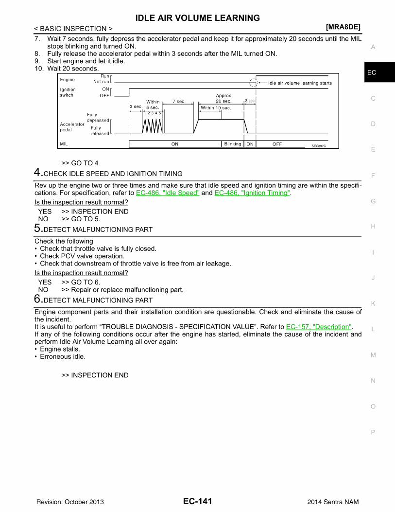
IDLE AIR VOLUME LEARNING[MRA8DE]
C
D
E
F
G
H
I
J
K
L
M
A
C
N
P
O
< BASIC INSPECTION >
E
7. Wait 7 seconds, fully depress the accelerator pedal and keep it for approximately 20 seconds until the MILstops blinking and turned ON.
8. Fully release the accelerator pedal within 3 seconds after the MIL turned ON.9. Start engine and let it idle.10. Wait 20 seconds.
>> GO TO 44.CHECK IDLE SPEED AND IGNITION TIMING
Rev up the engine two or three times and make sure that idle speed and ignition timing are within the specifi-cations. For specification, refer to EC-486, "Idle Speed" and EC-486, "Ignition Timing".Is the inspection result normal?YES >> INSPECTION ENDNO >> GO TO 5.
5.DETECT MALFUNCTIONING PART
Check the following• Check that throttle valve is fully closed.• Check PCV valve operation.• Check that downstream of throttle valve is free from air leakage.Is the inspection result normal?YES >> GO TO 6.NO >> Repair or replace malfunctioning part.
6.DETECT MALFUNCTIONING PART
Engine component parts and their installation condition are questionable. Check and eliminate the cause ofthe incident.It is useful to perform “TROUBLE DIAGNOSIS - SPECIFICATION VALUE”. Refer to EC-157, "Description".If any of the following conditions occur after the engine has started, eliminate the cause of the incident andperform Idle Air Volume Learning all over again:• Engine stalls.• Erroneous idle.
>> INSPECTION END
SEC897C
EC-141Revision: October 2013 2014 Sentra NAM
[MRA8DE]MIXTURE RATIO SELF-LEARNING VALUE CLEAR
< BASIC INSPECTION >MIXTURE RATIO SELF-LEARNING VALUE CLEARDescription INFOID:0000000009758409
This describes how to erase the mixture ratio self-learning value. For the actual procedure, follow the instruc-tions in “Diagnosis Procedure”.
Work Procedure INFOID:0000000009758410
1.START
With CONSULT1. Start engine and warm it up to normal operating temperature.2. Select “SELF-LEARNING CONT” in “WORK SUPPORT” mode of “ENGINE” using CONSULT.3. Clear mixture ratio self-learning value by touching “CLEAR”.
With GST1. Start engine and warm it up to normal operating temperature.2. Turn ignition switch OFF.3. Disconnect mass air flow sensor harness connector.4. Restart engine and let it idle for at least 5 seconds.5. Stop engine and reconnect mass air flow sensor harness connector.6. Select Service $03 with GST. Make sure DTC P0102 is detected.7. Select Service $04 with GST to erase the DTC P0102.
>> END
EC-142Revision: October 2013 2014 Sentra NAM
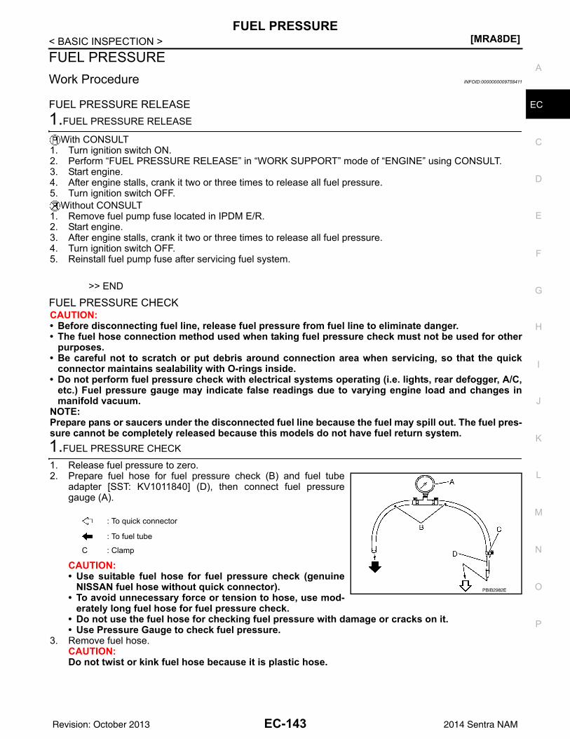
FUEL PRESSURE[MRA8DE]
C
D
E
F
G
H
I
J
K
L
M
A
C
N
P
O
< BASIC INSPECTION >
E
FUEL PRESSUREWork Procedure INFOID:0000000009758411
FUEL PRESSURE RELEASE1.FUEL PRESSURE RELEASE
With CONSULT1. Turn ignition switch ON.2. Perform “FUEL PRESSURE RELEASE” in “WORK SUPPORT” mode of “ENGINE” using CONSULT.3. Start engine.4. After engine stalls, crank it two or three times to release all fuel pressure.5. Turn ignition switch OFF.
Without CONSULT1. Remove fuel pump fuse located in IPDM E/R.2. Start engine.3. After engine stalls, crank it two or three times to release all fuel pressure.4. Turn ignition switch OFF.5. Reinstall fuel pump fuse after servicing fuel system.
>> END
FUEL PRESSURE CHECKCAUTION:• Before disconnecting fuel line, release fuel pressure from fuel line to eliminate danger.• The fuel hose connection method used when taking fuel pressure check must not be used for other
purposes.• Be careful not to scratch or put debris around connection area when servicing, so that the quick
connector maintains sealability with O-rings inside.• Do not perform fuel pressure check with electrical systems operating (i.e. lights, rear defogger, A/C,
etc.) Fuel pressure gauge may indicate false readings due to varying engine load and changes inmanifold vacuum.
NOTE:Prepare pans or saucers under the disconnected fuel line because the fuel may spill out. The fuel pres-sure cannot be completely released because this models do not have fuel return system.1.FUEL PRESSURE CHECK
1. Release fuel pressure to zero.2. Prepare fuel hose for fuel pressure check (B) and fuel tube
adapter [SST: KV1011840] (D), then connect fuel pressuregauge (A).
CAUTION:• Use suitable fuel hose for fuel pressure check (genuine
NISSAN fuel hose without quick connector).• To avoid unnecessary force or tension to hose, use mod-
erately long fuel hose for fuel pressure check.• Do not use the fuel hose for checking fuel pressure with damage or cracks on it.• Use Pressure Gauge to check fuel pressure.
3. Remove fuel hose.CAUTION:Do not twist or kink fuel hose because it is plastic hose.
: To quick connector
: To fuel tube
C : Clamp
PBIB2982E
EC-143Revision: October 2013 2014 Sentra NAM
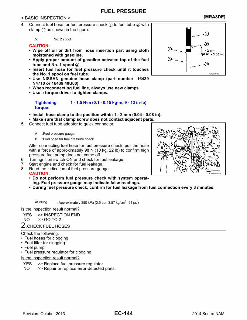
[MRA8DE]FUEL PRESSURE
< BASIC INSPECTION >4. Connect fuel hose for fuel pressure check to fuel tube with
clamp as shown in the figure.
CAUTION:• Wipe off oil or dirt from hose insertion part using cloth
moistened with gasoline.• Apply proper amount of gasoline between top of the fuel
tube and No. 1 spool .• Insert fuel hose for fuel pressure check until it touches
the No. 1 spool on fuel tube.• Use NISSAN genuine hose clamp (part number: 16439
N4710 or 16439 40U00).• When reconnecting fuel line, always use new clamps.• Use a torque driver to tighten clamps.
• Install hose clamp to the position within 1 - 2 mm (0.04 - 0.08 in).• Make sure that clamp screw does not contact adjacent parts.
5. Connect fuel tube adapter to quick connector.
After connecting fuel hose for fuel pressure check, pull the hosewith a force of approximately 98 N (10 kg, 22 lb) to confirm highpressure fuel pump does not come off.
6. Turn ignition switch ON and check for fuel leakage.7. Start engine and check for fuel leakage.8. Read the indication of fuel pressure gauge.
CAUTION:• Do not perform fuel pressure check with system operat-
ing. Fuel pressure gauge may indicate false readings.• During fuel pressure check, confirm for fuel leakage from fuel connection every 3 minutes.
Is the inspection result normal?YES >> INSPECTION ENDNO >> GO TO 2.
2.CHECK FUEL HOSES
Check the following.• Fuel hoses for clogging• Fuel filter for clogging• Fuel pump • Fuel pressure regulator for cloggingIs the inspection result normal?YES >> Replace fuel pressure regulator.NO >> Repair or replace error-detected parts.
5: No. 2 spool
Tightening torque:
1 - 1.5 N·m (0.1 - 0.15 kg-m, 9 - 13 in-lb)
A :Fuel pressure gaugeB :Fuel hose for fuel pressure check
At idling : Approximately 350 kPa (3.5 bar, 3.57 kg/cm2, 51 psi)
PBIB2983E
ALBIA0981ZZ
EC-144Revision: October 2013 2014 Sentra NAM
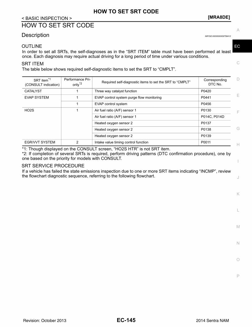
HOW TO SET SRT CODE[MRA8DE]
C
D
E
F
G
H
I
J
K
L
M
A
C
N
P
O
< BASIC INSPECTION >
E
HOW TO SET SRT CODEDescription INFOID:0000000009758412
OUTLINEIn order to set all SRTs, the self-diagnoses as in the “SRT ITEM” table must have been performed at leastonce. Each diagnosis may require actual driving for a long period of time under various conditions.
SRT ITEMThe table below shows required self-diagnostic items to set the SRT to “CMPLT”.
*1: Though displayed on the CONSULT screen, “HO2S HTR” is not SRT item.*2: If completion of several SRTs is required, perform driving patterns (DTC confirmation procedure), one byone based on the priority for models with CONSULT.
SRT SERVICE PROCEDUREIf a vehicle has failed the state emissions inspection due to one or more SRT items indicating “INCMP”, reviewthe flowchart diagnostic sequence, referring to the following flowchart.
SRT item*1
(CONSULT indication)Performance Pri-
ority*2 Required self-diagnostic items to set the SRT to “CMPLT” Corresponding DTC No.
CATALYST 1 Three way catalyst function P0420
EVAP SYSTEM 1 EVAP control system purge flow monitoring P0441
1 EVAP control system P0456
HO2S 1 Air fuel ratio (A/F) sensor 1 P0130
Air fuel ratio (A/F) sensor 1 P014C, P014D
Heated oxygen sensor 2 P0137
Heated oxygen sensor 2 P0138
Heated oxygen sensor 2 P0139
EGR/VVT SYSTEM 2 Intake value timing control function P0011
EC-145Revision: October 2013 2014 Sentra NAM
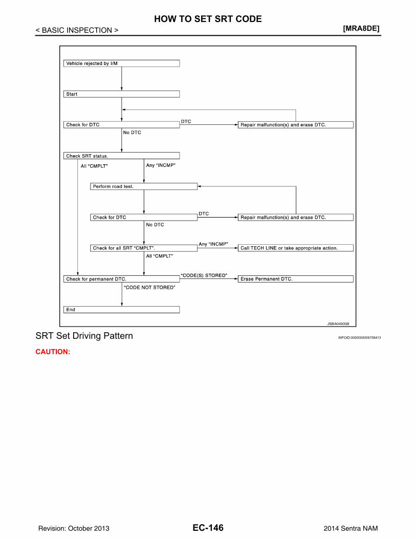
[MRA8DE]HOW TO SET SRT CODE
< BASIC INSPECTION >
SRT Set Driving Pattern INFOID:0000000009758413
CAUTION:
JSBIA0400GB
EC-146Revision: October 2013 2014 Sentra NAM
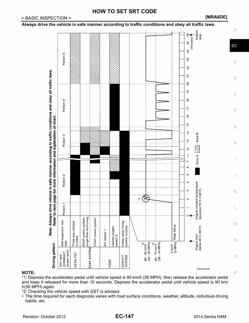
HOW TO SET SRT CODE[MRA8DE]
C
D
E
F
G
H
I
J
K
L
M
A
C
N
P
O
< BASIC INSPECTION >
E
Always drive the vehicle in safe manner according to traffic conditions and obey all traffic laws.
NOTE:*1: Depress the accelerator pedal until vehicle speed is 90 km/h (56 MPH), then release the accelerator pedaland keep it released for more than 10 seconds. Depress the accelerator pedal until vehicle speed is 90 km/h(56 MPH) again.*2: Checking the vehicle speed with GST is advised.• The time required for each diagnosis varies with road surface conditions, weather, altitude, individual driving
habits, etc.
JPBIA5322GB
EC-147Revision: October 2013 2014 Sentra NAM
[MRA8DE]HOW TO SET SRT CODE
< BASIC INSPECTION >Zone A refers to the range where the time, required for the diagnosis under normal conditions*, is the short-est.Zone B refers to the range where the diagnosis can still be performed if the diagnosis is not completed withinzone A.
*: Normal conditions refer to the following:• Sea level• Flat road• Ambient air temperature: 20 - 30°C (68 - 86°F)• Diagnosis is performed as quickly as possible under normal conditions.
Under different conditions [For example: ambient air temperature other than 20 - 30°C (68 - 86°F)], diagno-sis may also be performed.
• "EGR/VVT SYSTEM" written in the figure is not applicable to the vehicle.
Work Procedure INFOID:0000000009758414
1.CHECK DTC
Check DTC.Is any DTC detected?YES >> Repair malfunction(s) and erase DTC. Refer to EC-94, "DTC Index".NO >> GO TO 2.
2.CHECK SRT STATUS
With CONSULTSelect “SRT STATUS” in “DTC & SRT CONFIRMATION” using CONSULT.
Without CONSULTPerform “SRT status” mode with EC-63, "On Board Diagnosis Function".
With GSTSelect Service $01 with GST.Is SRT code(s) set?YES >> ENDNO-1 >> With CONSULT: GO TO 3.NO-2 >> Without CONSULT: GO TO 4.
3.DTC CONFIRMATION PROCEDURE
1. Select “SRT WORK SUPPORT” in “DTC & SRT CONFIRMATION” using CONSULT.2. For SRT(s) that is not set, perform the corresponding “DTC CONFIRMATION PROCEDURE” according to
the “Performance Priority” in the “SRT ITEM” table. Refer to EC-145, "Description".3. Check DTC.Is any DTC detected?YES >> Repair malfunction(s) and erase DTC. Refer to EC-94, "DTC Index".NO >> GO TO 9.
4.PERFORM ROAD TEST
• Check the “Performance Priority” in the “SRT ITEM” table. Refer to EC-145, "Description".• Perform the most efficient SRT set driving pattern to set the SRT properly. Refer to EC-146, "SRT Set Driv-
ing Pattern".In order to set all SRTs, the SRT set driving pattern must be performed at least once.
>> GO TO 5.5.PATTERN 1
1. Check the vehicle condition;- Engine coolant temperature is −10 to 35°C (14 to 95°F).- Fuel tank temperature is more than 0°C (32°F).2. Start the engine.3. Keep engine idling until the engine coolant temperature is greater than 70°C (158°F)NOTE:ECM terminal voltage is follows;
EC-148Revision: October 2013 2014 Sentra NAM
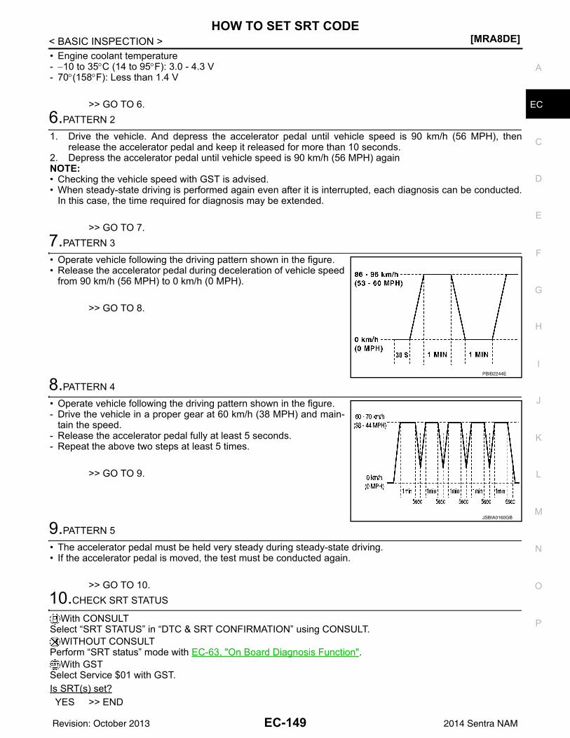
HOW TO SET SRT CODE[MRA8DE]
C
D
E
F
G
H
I
J
K
L
M
A
C
N
P
O
< BASIC INSPECTION >
E
• Engine coolant temperature- −10 to 35°C (14 to 95°F): 3.0 - 4.3 V- 70°(158°F): Less than 1.4 V
>> GO TO 6.6.PATTERN 2
1. Drive the vehicle. And depress the accelerator pedal until vehicle speed is 90 km/h (56 MPH), thenrelease the accelerator pedal and keep it released for more than 10 seconds.
2. Depress the accelerator pedal until vehicle speed is 90 km/h (56 MPH) againNOTE:• Checking the vehicle speed with GST is advised.• When steady-state driving is performed again even after it is interrupted, each diagnosis can be conducted.
In this case, the time required for diagnosis may be extended.
>> GO TO 7.7.PATTERN 3
• Operate vehicle following the driving pattern shown in the figure.• Release the accelerator pedal during deceleration of vehicle speed
from 90 km/h (56 MPH) to 0 km/h (0 MPH).
>> GO TO 8.
8.PATTERN 4
• Operate vehicle following the driving pattern shown in the figure.- Drive the vehicle in a proper gear at 60 km/h (38 MPH) and main-
tain the speed.- Release the accelerator pedal fully at least 5 seconds.- Repeat the above two steps at least 5 times.
>> GO TO 9.
9.PATTERN 5
• The accelerator pedal must be held very steady during steady-state driving.• If the accelerator pedal is moved, the test must be conducted again.
>> GO TO 10.10.CHECK SRT STATUS
With CONSULTSelect “SRT STATUS” in “DTC & SRT CONFIRMATION” using CONSULT.
WITHOUT CONSULTPerform “SRT status” mode with EC-63, "On Board Diagnosis Function".
With GSTSelect Service $01 with GST.Is SRT(s) set?YES >> END
PBIB2244E
JSBIA0160GB
EC-149Revision: October 2013 2014 Sentra NAM
[MRA8DE]HOW TO SET SRT CODE
< BASIC INSPECTION >NO >> Perform this procedure again.
EC-150Revision: October 2013 2014 Sentra NAM
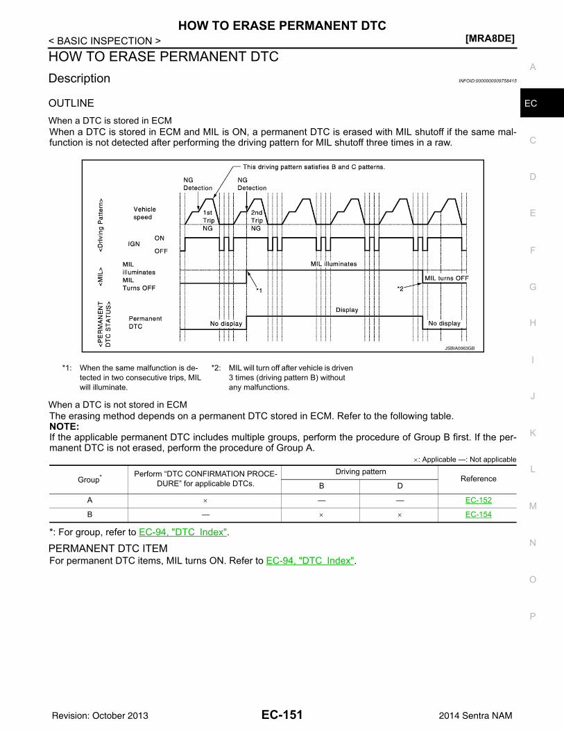
HOW TO ERASE PERMANENT DTC[MRA8DE]
C
D
E
F
G
H
I
J
K
L
M
A
C
N
P
O
< BASIC INSPECTION >
E
HOW TO ERASE PERMANENT DTCDescription INFOID:0000000009758415
OUTLINEWhen a DTC is stored in ECMWhen a DTC is stored in ECM and MIL is ON, a permanent DTC is erased with MIL shutoff if the same mal-function is not detected after performing the driving pattern for MIL shutoff three times in a raw.
When a DTC is not stored in ECMThe erasing method depends on a permanent DTC stored in ECM. Refer to the following table.NOTE:If the applicable permanent DTC includes multiple groups, perform the procedure of Group B first. If the per-manent DTC is not erased, perform the procedure of Group A.
×: Applicable —: Not applicable
*: For group, refer to EC-94, "DTC Index".
PERMANENT DTC ITEMFor permanent DTC items, MIL turns ON. Refer to EC-94, "DTC Index".
*1: When the same malfunction is de-tected in two consecutive trips, MIL will illuminate.
*2: MIL will turn off after vehicle is driven 3 times (driving pattern B) without any malfunctions.
JSBIA0063GB
Group* Perform “DTC CONFIRMATION PROCE-DURE” for applicable DTCs.
Driving patternReference
B D
A × — — EC-152
B — × × EC-154
EC-151Revision: October 2013 2014 Sentra NAM
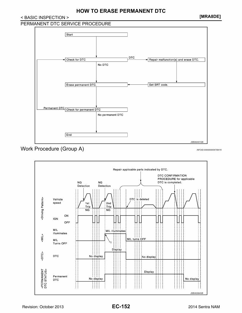
[MRA8DE]HOW TO ERASE PERMANENT DTC
< BASIC INSPECTION >PERMANENT DTC SERVICE PROCEDURE
Work Procedure (Group A) INFOID:0000000009758416
JSBIA0401GB
JSBIA0064GB
EC-152Revision: October 2013 2014 Sentra NAM
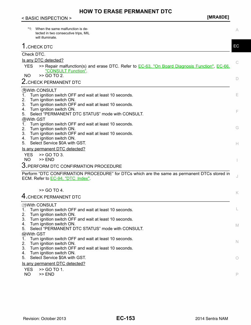
HOW TO ERASE PERMANENT DTC[MRA8DE]
C
D
E
F
G
H
I
J
K
L
M
A
C
N
P
O
< BASIC INSPECTION >
E1.CHECK DTC
Check DTC.Is any DTC detected?YES >> Repair malfunction(s) and erase DTC. Refer to EC-63, "On Board Diagnosis Function", EC-66,
"CONSULT Function".NO >> GO TO 2.
2.CHECK PERMANENT DTC
With CONSULT1. Turn ignition switch OFF and wait at least 10 seconds.2. Turn ignition switch ON.3. Turn ignition switch OFF and wait at least 10 seconds.4. Turn ignition switch ON.5. Select “PERMANENT DTC STATUS” mode with CONSULT.
With GST1. Turn ignition switch OFF and wait at least 10 seconds.2. Turn ignition switch ON.3. Turn ignition switch OFF and wait at least 10 seconds.4. Turn ignition switch ON.5. Select Service $0A with GST.Is any permanent DTC detected?YES >> GO TO 3.NO >> END
3.PERFORM DTC CONFIRMATION PROCEDURE
Perform “DTC CONFIRMATION PROCEDURE” for DTCs which are the same as permanent DTCs stored inECM. Refer to EC-94, "DTC Index".
>> GO TO 4.4.CHECK PERMANENT DTC
With CONSULT1. Turn ignition switch OFF and wait at least 10 seconds.2. Turn ignition switch ON.3. Turn ignition switch OFF and wait at least 10 seconds.4. Turn ignition switch ON.5. Select “PERMANENT DTC STATUS” mode with CONSULT.
With GST1. Turn ignition switch OFF and wait at least 10 seconds.2. Turn ignition switch ON.3. Turn ignition switch OFF and wait at least 10 seconds.4. Turn ignition switch ON.5. Select Service $0A with GST.Is any permanent DTC detected?YES >> GO TO 1.NO >> END
*1: When the same malfunction is de-tected in two consecutive trips, MIL will illuminate.
EC-153Revision: October 2013 2014 Sentra NAM
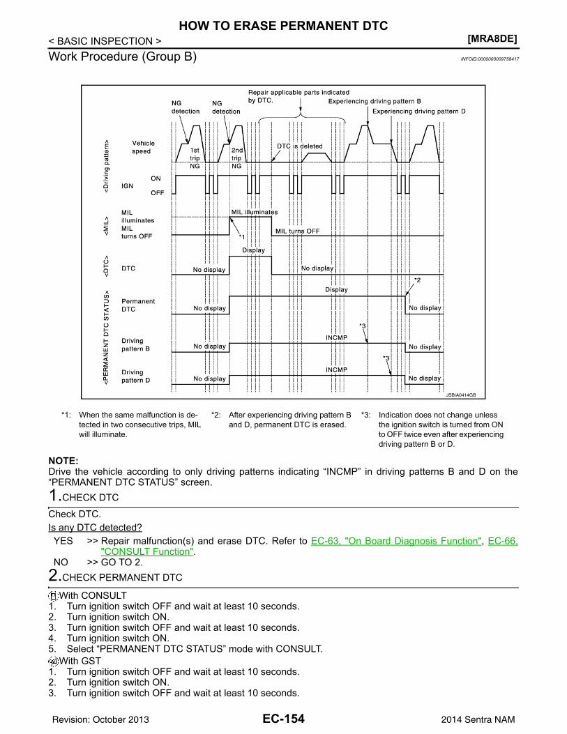
[MRA8DE]HOW TO ERASE PERMANENT DTC
< BASIC INSPECTION >Work Procedure (Group B) INFOID:0000000009758417
NOTE:Drive the vehicle according to only driving patterns indicating “INCMP” in driving patterns B and D on the“PERMANENT DTC STATUS” screen.1.CHECK DTC
Check DTC.Is any DTC detected?YES >> Repair malfunction(s) and erase DTC. Refer to EC-63, "On Board Diagnosis Function", EC-66,
"CONSULT Function".NO >> GO TO 2.
2.CHECK PERMANENT DTC
With CONSULT1. Turn ignition switch OFF and wait at least 10 seconds.2. Turn ignition switch ON.3. Turn ignition switch OFF and wait at least 10 seconds.4. Turn ignition switch ON.5. Select “PERMANENT DTC STATUS” mode with CONSULT.
With GST1. Turn ignition switch OFF and wait at least 10 seconds.2. Turn ignition switch ON.3. Turn ignition switch OFF and wait at least 10 seconds.
*1: When the same malfunction is de-tected in two consecutive trips, MIL will illuminate.
*2: After experiencing driving pattern B and D, permanent DTC is erased.
*3: Indication does not change unless the ignition switch is turned from ON to OFF twice even after experiencing driving pattern B or D.
JSBIA0414GB
EC-154Revision: October 2013 2014 Sentra NAM
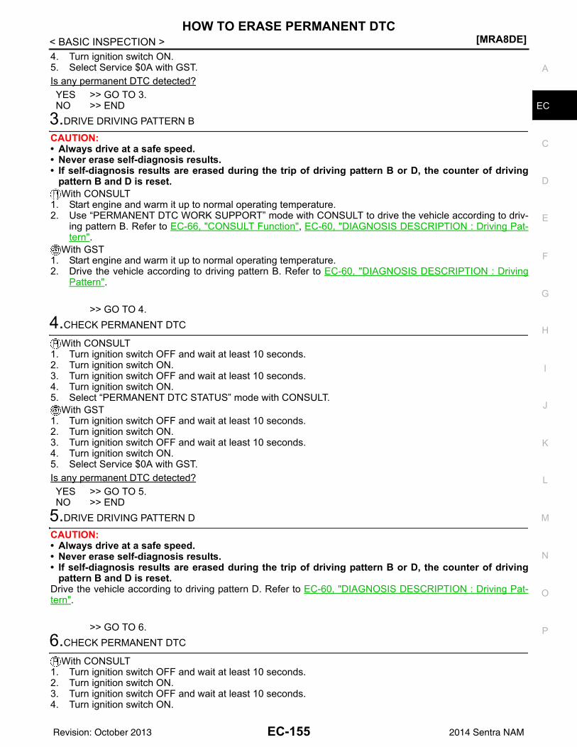
HOW TO ERASE PERMANENT DTC[MRA8DE]
C
D
E
F
G
H
I
J
K
L
M
A
C
N
P
O
< BASIC INSPECTION >
E
4. Turn ignition switch ON.5. Select Service $0A with GST.Is any permanent DTC detected?YES >> GO TO 3.NO >> END
3.DRIVE DRIVING PATTERN B
CAUTION:• Always drive at a safe speed.• Never erase self-diagnosis results.• If self-diagnosis results are erased during the trip of driving pattern B or D, the counter of driving
pattern B and D is reset.With CONSULT
1. Start engine and warm it up to normal operating temperature.2. Use “PERMANENT DTC WORK SUPPORT” mode with CONSULT to drive the vehicle according to driv-
ing pattern B. Refer to EC-66, "CONSULT Function", EC-60, "DIAGNOSIS DESCRIPTION : Driving Pat-tern".
With GST1. Start engine and warm it up to normal operating temperature.2. Drive the vehicle according to driving pattern B. Refer to EC-60, "DIAGNOSIS DESCRIPTION : Driving
Pattern".
>> GO TO 4.4.CHECK PERMANENT DTC
With CONSULT1. Turn ignition switch OFF and wait at least 10 seconds.2. Turn ignition switch ON.3. Turn ignition switch OFF and wait at least 10 seconds.4. Turn ignition switch ON.5. Select “PERMANENT DTC STATUS” mode with CONSULT.
With GST1. Turn ignition switch OFF and wait at least 10 seconds.2. Turn ignition switch ON.3. Turn ignition switch OFF and wait at least 10 seconds.4. Turn ignition switch ON.5. Select Service $0A with GST.Is any permanent DTC detected?YES >> GO TO 5.NO >> END
5.DRIVE DRIVING PATTERN D
CAUTION:• Always drive at a safe speed.• Never erase self-diagnosis results.• If self-diagnosis results are erased during the trip of driving pattern B or D, the counter of driving
pattern B and D is reset.Drive the vehicle according to driving pattern D. Refer to EC-60, "DIAGNOSIS DESCRIPTION : Driving Pat-tern".
>> GO TO 6.6.CHECK PERMANENT DTC
With CONSULT1. Turn ignition switch OFF and wait at least 10 seconds.2. Turn ignition switch ON.3. Turn ignition switch OFF and wait at least 10 seconds.4. Turn ignition switch ON.
EC-155Revision: October 2013 2014 Sentra NAM
[MRA8DE]HOW TO ERASE PERMANENT DTC
< BASIC INSPECTION >5. Select “PERMANENT DTC STATUS” mode with CONSULT.
With GST1. Turn ignition switch OFF and wait at least 10 seconds.2. Turn ignition switch ON.3. Turn ignition switch OFF and wait at least 10 seconds.4. Turn ignition switch ON.5. Select Service $0A with GST.Is any permanent DTC detected?YES >> GO TO 1.NO >> END
EC-156Revision: October 2013 2014 Sentra NAM
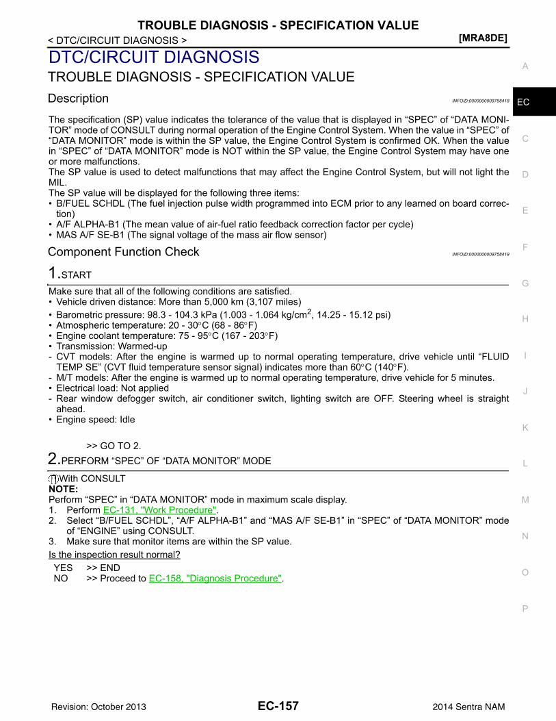
TROUBLE DIAGNOSIS - SPECIFICATION VALUE[MRA8DE]
C
D
E
F
G
H
I
J
K
L
M
A
C
N
P
O
< DTC/CIRCUIT DIAGNOSIS >
E
DTC/CIRCUIT DIAGNOSISTROUBLE DIAGNOSIS - SPECIFICATION VALUEDescription INFOID:0000000009758418
The specification (SP) value indicates the tolerance of the value that is displayed in “SPEC” of “DATA MONI-TOR” mode of CONSULT during normal operation of the Engine Control System. When the value in “SPEC” of“DATA MONITOR” mode is within the SP value, the Engine Control System is confirmed OK. When the valuein “SPEC” of “DATA MONITOR” mode is NOT within the SP value, the Engine Control System may have oneor more malfunctions.The SP value is used to detect malfunctions that may affect the Engine Control System, but will not light theMIL.The SP value will be displayed for the following three items:• B/FUEL SCHDL (The fuel injection pulse width programmed into ECM prior to any learned on board correc-
tion)• A/F ALPHA-B1 (The mean value of air-fuel ratio feedback correction factor per cycle)• MAS A/F SE-B1 (The signal voltage of the mass air flow sensor)
Component Function Check INFOID:0000000009758419
1.START
Make sure that all of the following conditions are satisfied.• Vehicle driven distance: More than 5,000 km (3,107 miles)• Barometric pressure: 98.3 - 104.3 kPa (1.003 - 1.064 kg/cm2, 14.25 - 15.12 psi)• Atmospheric temperature: 20 - 30°C (68 - 86°F)• Engine coolant temperature: 75 - 95°C (167 - 203°F)• Transmission: Warmed-up- CVT models: After the engine is warmed up to normal operating temperature, drive vehicle until “FLUID
TEMP SE” (CVT fluid temperature sensor signal) indicates more than 60°C (140°F).- M/T models: After the engine is warmed up to normal operating temperature, drive vehicle for 5 minutes.• Electrical load: Not applied- Rear window defogger switch, air conditioner switch, lighting switch are OFF. Steering wheel is straight
ahead.• Engine speed: Idle
>> GO TO 2.2.PERFORM “SPEC” OF “DATA MONITOR” MODE
With CONSULTNOTE:Perform “SPEC” in “DATA MONITOR” mode in maximum scale display.1. Perform EC-131, "Work Procedure".2. Select “B/FUEL SCHDL”, “A/F ALPHA-B1” and “MAS A/F SE-B1” in “SPEC” of “DATA MONITOR” mode
of “ENGINE” using CONSULT.3. Make sure that monitor items are within the SP value.Is the inspection result normal?YES >> ENDNO >> Proceed to EC-158, "Diagnosis Procedure".
EC-157Revision: October 2013 2014 Sentra NAM
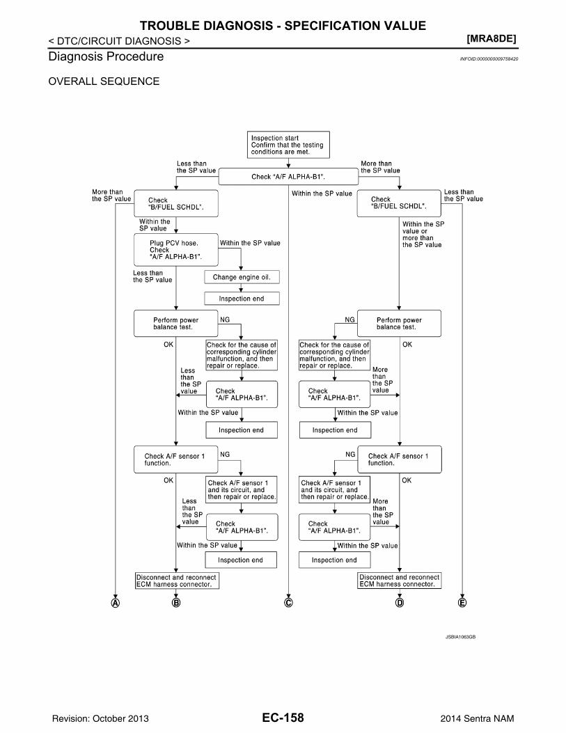
[MRA8DE]TROUBLE DIAGNOSIS - SPECIFICATION VALUE
< DTC/CIRCUIT DIAGNOSIS >Diagnosis Procedure INFOID:0000000009758420
OVERALL SEQUENCE
JSBIA1063GB
EC-158Revision: October 2013 2014 Sentra NAM
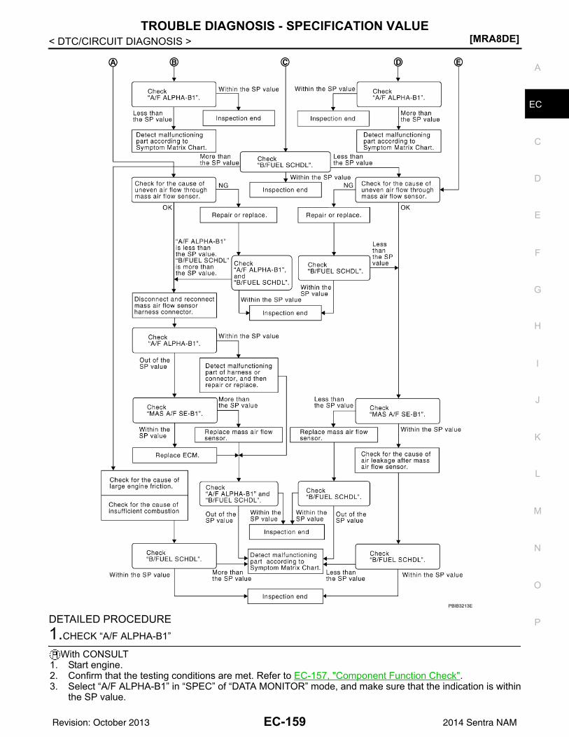
TROUBLE DIAGNOSIS - SPECIFICATION VALUE[MRA8DE]
C
D
E
F
G
H
I
J
K
L
M
A
C
N
P
O
< DTC/CIRCUIT DIAGNOSIS >
E
DETAILED PROCEDURE1.CHECK “A/F ALPHA-B1”
With CONSULT1. Start engine.2. Confirm that the testing conditions are met. Refer to EC-157, "Component Function Check".3. Select “A/F ALPHA-B1” in “SPEC” of “DATA MONITOR” mode, and make sure that the indication is within
the SP value.
PBIB3213E
EC-159Revision: October 2013 2014 Sentra NAM
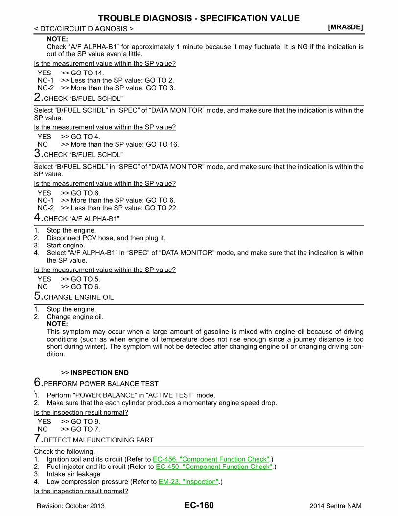
[MRA8DE]TROUBLE DIAGNOSIS - SPECIFICATION VALUE
< DTC/CIRCUIT DIAGNOSIS >NOTE:Check “A/F ALPHA-B1” for approximately 1 minute because it may fluctuate. It is NG if the indication isout of the SP value even a little.
Is the measurement value within the SP value?YES >> GO TO 14.NO-1 >> Less than the SP value: GO TO 2.NO-2 >> More than the SP value: GO TO 3.
2.CHECK “B/FUEL SCHDL”
Select “B/FUEL SCHDL” in “SPEC” of “DATA MONITOR” mode, and make sure that the indication is within theSP value.Is the measurement value within the SP value?YES >> GO TO 4.NO >> More than the SP value: GO TO 16.
3.CHECK “B/FUEL SCHDL”
Select “B/FUEL SCHDL” in “SPEC” of “DATA MONITOR” mode, and make sure that the indication is within theSP value.Is the measurement value within the SP value?YES >> GO TO 6.NO-1 >> More than the SP value: GO TO 6.NO-2 >> Less than the SP value: GO TO 22.
4.CHECK “A/F ALPHA-B1”
1. Stop the engine.2. Disconnect PCV hose, and then plug it.3. Start engine.4. Select “A/F ALPHA-B1” in “SPEC” of “DATA MONITOR” mode, and make sure that the indication is within
the SP value.Is the measurement value within the SP value?YES >> GO TO 5.NO >> GO TO 6.
5.CHANGE ENGINE OIL
1. Stop the engine.2. Change engine oil.
NOTE:This symptom may occur when a large amount of gasoline is mixed with engine oil because of drivingconditions (such as when engine oil temperature does not rise enough since a journey distance is tooshort during winter). The symptom will not be detected after changing engine oil or changing driving con-dition.
>> INSPECTION END6.PERFORM POWER BALANCE TEST
1. Perform “POWER BALANCE” in “ACTIVE TEST” mode.2. Make sure that the each cylinder produces a momentary engine speed drop.Is the inspection result normal?YES >> GO TO 9.NO >> GO TO 7.
7.DETECT MALFUNCTIONING PART
Check the following.1. Ignition coil and its circuit (Refer to EC-456, "Component Function Check".)2. Fuel injector and its circuit (Refer to EC-450, "Component Function Check".)3. Intake air leakage4. Low compression pressure (Refer to EM-23, "Inspection".)Is the inspection result normal?
EC-160Revision: October 2013 2014 Sentra NAM
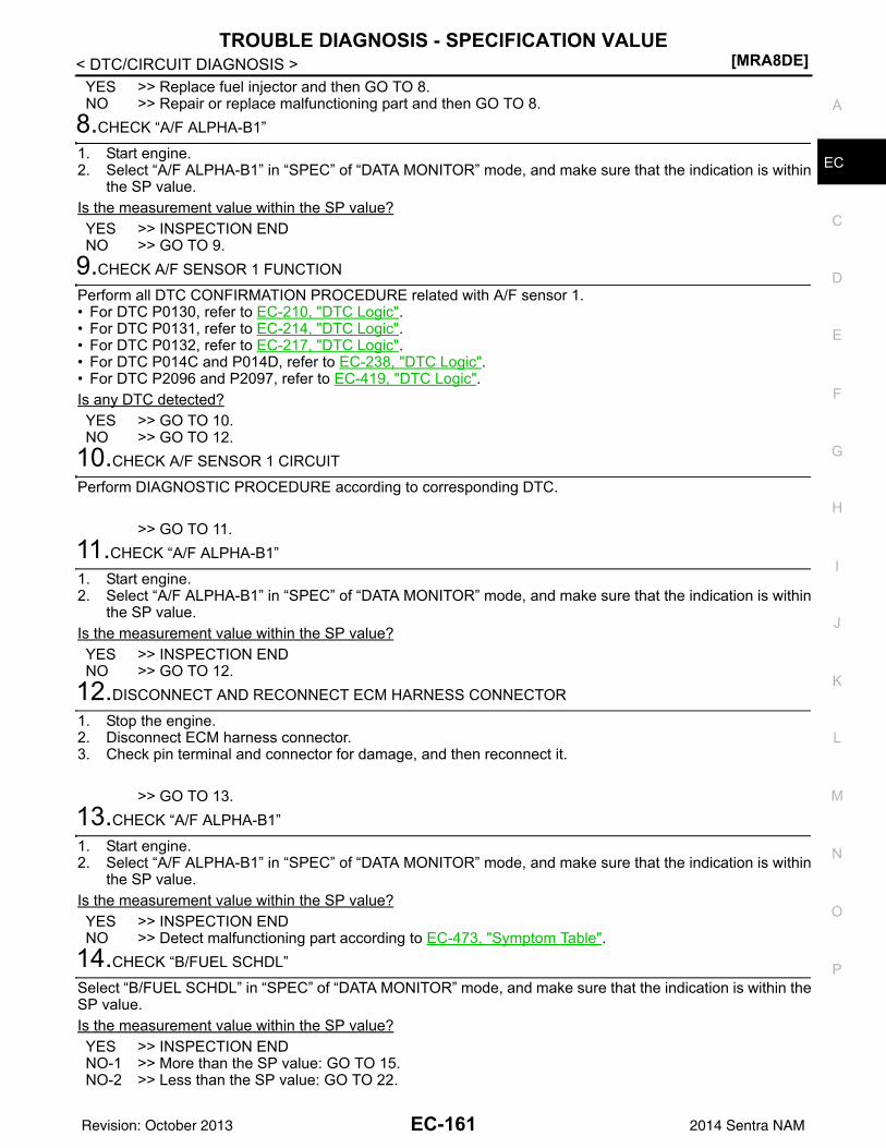
TROUBLE DIAGNOSIS - SPECIFICATION VALUE[MRA8DE]
C
D
E
F
G
H
I
J
K
L
M
A
C
N
P
O
< DTC/CIRCUIT DIAGNOSIS >
E
YES >> Replace fuel injector and then GO TO 8.NO >> Repair or replace malfunctioning part and then GO TO 8.
8.CHECK “A/F ALPHA-B1”
1. Start engine.2. Select “A/F ALPHA-B1” in “SPEC” of “DATA MONITOR” mode, and make sure that the indication is within
the SP value.Is the measurement value within the SP value?YES >> INSPECTION ENDNO >> GO TO 9.
9.CHECK A/F SENSOR 1 FUNCTION
Perform all DTC CONFIRMATION PROCEDURE related with A/F sensor 1.• For DTC P0130, refer to EC-210, "DTC Logic".• For DTC P0131, refer to EC-214, "DTC Logic".• For DTC P0132, refer to EC-217, "DTC Logic".• For DTC P014C and P014D, refer to EC-238, "DTC Logic".• For DTC P2096 and P2097, refer to EC-419, "DTC Logic".Is any DTC detected?YES >> GO TO 10.NO >> GO TO 12.
10.CHECK A/F SENSOR 1 CIRCUIT
Perform DIAGNOSTIC PROCEDURE according to corresponding DTC.
>> GO TO 11.11.CHECK “A/F ALPHA-B1”
1. Start engine.2. Select “A/F ALPHA-B1” in “SPEC” of “DATA MONITOR” mode, and make sure that the indication is within
the SP value.Is the measurement value within the SP value?YES >> INSPECTION ENDNO >> GO TO 12.
12.DISCONNECT AND RECONNECT ECM HARNESS CONNECTOR
1. Stop the engine.2. Disconnect ECM harness connector.3. Check pin terminal and connector for damage, and then reconnect it.
>> GO TO 13.13.CHECK “A/F ALPHA-B1”
1. Start engine.2. Select “A/F ALPHA-B1” in “SPEC” of “DATA MONITOR” mode, and make sure that the indication is within
the SP value.Is the measurement value within the SP value?YES >> INSPECTION ENDNO >> Detect malfunctioning part according to EC-473, "Symptom Table".
14.CHECK “B/FUEL SCHDL”
Select “B/FUEL SCHDL” in “SPEC” of “DATA MONITOR” mode, and make sure that the indication is within theSP value.Is the measurement value within the SP value?YES >> INSPECTION ENDNO-1 >> More than the SP value: GO TO 15.NO-2 >> Less than the SP value: GO TO 22.
EC-161Revision: October 2013 2014 Sentra NAM
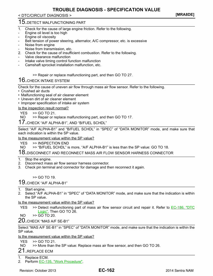
[MRA8DE]TROUBLE DIAGNOSIS - SPECIFICATION VALUE
< DTC/CIRCUIT DIAGNOSIS >
15.DETECT MALFUNCTIONING PART
1. Check for the cause of large engine friction. Refer to the following.- Engine oil level is too high- Engine oil viscosity- Belt tension of power steering, alternator, A/C compressor, etc. is excessive- Noise from engine- Noise from transmission, etc.2. Check for the cause of insufficient combustion. Refer to the following.- Valve clearance malfunction- Intake valve timing control function malfunction- Camshaft sprocket installation malfunction, etc.
>> Repair or replace malfunctioning part, and then GO TO 27.16.CHECK INTAKE SYSTEM
Check for the cause of uneven air flow through mass air flow sensor. Refer to the following.• Crushed air ducts• Malfunctioning seal of air cleaner element• Uneven dirt of air cleaner element• Improper specification of intake air systemIs the inspection result normal?YES >> GO TO 21.NO >> Repair or replace malfunctioning part, and then GO TO 17.
17.CHECK “A/F ALPHA-B1”, AND “B/FUEL SCHDL”
Select “A/F ALPHA-B1” and “B/FUEL SCHDL” in “SPEC” of “DATA MONITOR” mode, and make sure thateach indication is within the SP value.Is the measurement value within the SP value?YES >> INSPECTION ENDNO >> “B/FUEL SCHDL” is more, “A/F ALPHA-B1” is less than the SP value: GO TO 18.
18.DISCONNECT AND RECONNECT MASS AIR FLOW SENSOR HARNESS CONNECTOR
1. Stop the engine.2. Disconnect mass air flow sensor harness connector.3. Check pin terminal and connector for damage and then reconnect it again.
>> GO TO 19.19.CHECK “A/F ALPHA-B1”
1. Start engine.2. Select “A/F ALPHA-B1” in “SPEC” of “DATA MONITOR” mode, and make sure that the indication is within
the SP value.Is the measurement value within the SP value?YES >> Detect malfunctioning part of mass air flow sensor circuit and repair it. Refer to EC-186, "DTC
Logic". Then GO TO 26.NO >> GO TO 20.
20.CHECK “MAS A/F SE-B1”
Select “MAS A/F SE-B1” in “SPEC” of “DATA MONITOR” mode, and make sure that the indication is within theSP value.Is the measurement value within the SP value?YES >> GO TO 21.NO >> More than the SP value: Replace mass air flow sensor, and then GO TO 26.
21.REPLACE ECM
1. Replace ECM.2. Perform EC-135, "Work Procedure".
EC-162Revision: October 2013 2014 Sentra NAM
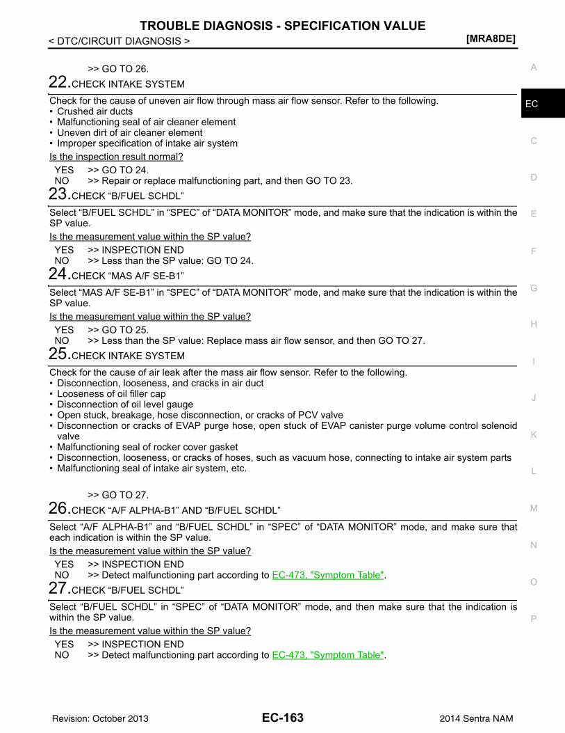
TROUBLE DIAGNOSIS - SPECIFICATION VALUE[MRA8DE]
C
D
E
F
G
H
I
J
K
L
M
A
C
N
P
O
< DTC/CIRCUIT DIAGNOSIS >
E
>> GO TO 26.22.CHECK INTAKE SYSTEM
Check for the cause of uneven air flow through mass air flow sensor. Refer to the following.• Crushed air ducts• Malfunctioning seal of air cleaner element• Uneven dirt of air cleaner element• Improper specification of intake air systemIs the inspection result normal?YES >> GO TO 24.NO >> Repair or replace malfunctioning part, and then GO TO 23.
23.CHECK “B/FUEL SCHDL”
Select “B/FUEL SCHDL” in “SPEC” of “DATA MONITOR” mode, and make sure that the indication is within theSP value.Is the measurement value within the SP value?YES >> INSPECTION ENDNO >> Less than the SP value: GO TO 24.
24.CHECK “MAS A/F SE-B1”
Select “MAS A/F SE-B1” in “SPEC” of “DATA MONITOR” mode, and make sure that the indication is within theSP value.Is the measurement value within the SP value?YES >> GO TO 25.NO >> Less than the SP value: Replace mass air flow sensor, and then GO TO 27.
25.CHECK INTAKE SYSTEM
Check for the cause of air leak after the mass air flow sensor. Refer to the following.• Disconnection, looseness, and cracks in air duct• Looseness of oil filler cap• Disconnection of oil level gauge• Open stuck, breakage, hose disconnection, or cracks of PCV valve• Disconnection or cracks of EVAP purge hose, open stuck of EVAP canister purge volume control solenoid
valve• Malfunctioning seal of rocker cover gasket• Disconnection, looseness, or cracks of hoses, such as vacuum hose, connecting to intake air system parts• Malfunctioning seal of intake air system, etc.
>> GO TO 27.26.CHECK “A/F ALPHA-B1” AND “B/FUEL SCHDL”
Select “A/F ALPHA-B1” and “B/FUEL SCHDL” in “SPEC” of “DATA MONITOR” mode, and make sure thateach indication is within the SP value. Is the measurement value within the SP value?YES >> INSPECTION ENDNO >> Detect malfunctioning part according to EC-473, "Symptom Table".
27.CHECK “B/FUEL SCHDL”
Select “B/FUEL SCHDL” in “SPEC” of “DATA MONITOR” mode, and then make sure that the indication iswithin the SP value.Is the measurement value within the SP value?YES >> INSPECTION ENDNO >> Detect malfunctioning part according to EC-473, "Symptom Table".
EC-163Revision: October 2013 2014 Sentra NAM
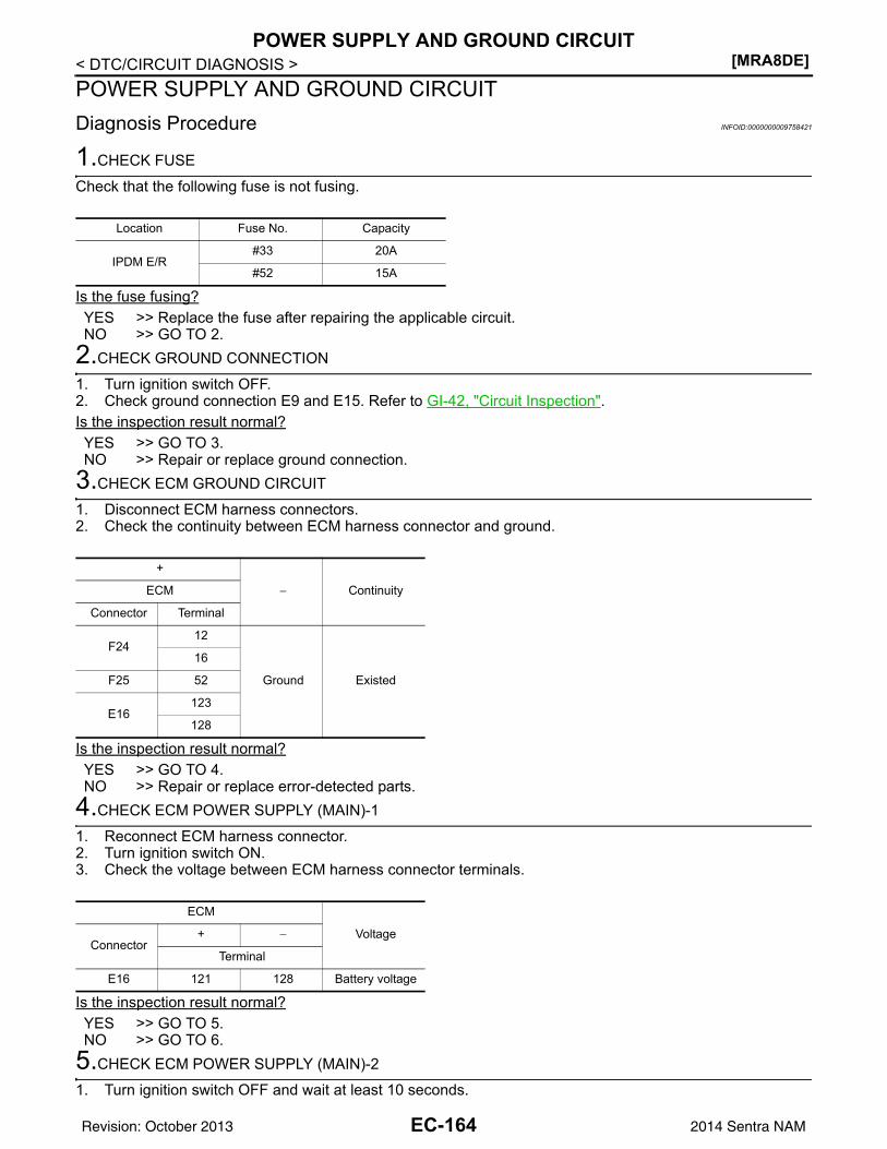
[MRA8DE]POWER SUPPLY AND GROUND CIRCUIT
< DTC/CIRCUIT DIAGNOSIS >POWER SUPPLY AND GROUND CIRCUITDiagnosis Procedure INFOID:0000000009758421
1.CHECK FUSE
Check that the following fuse is not fusing.
Is the fuse fusing?YES >> Replace the fuse after repairing the applicable circuit.NO >> GO TO 2.
2.CHECK GROUND CONNECTION
1. Turn ignition switch OFF.2. Check ground connection E9 and E15. Refer to GI-42, "Circuit Inspection".Is the inspection result normal?YES >> GO TO 3.NO >> Repair or replace ground connection.
3.CHECK ECM GROUND CIRCUIT
1. Disconnect ECM harness connectors.2. Check the continuity between ECM harness connector and ground.
Is the inspection result normal?YES >> GO TO 4.NO >> Repair or replace error-detected parts.
4.CHECK ECM POWER SUPPLY (MAIN)-1
1. Reconnect ECM harness connector.2. Turn ignition switch ON.3. Check the voltage between ECM harness connector terminals.
Is the inspection result normal?YES >> GO TO 5.NO >> GO TO 6.
5.CHECK ECM POWER SUPPLY (MAIN)-2
1. Turn ignition switch OFF and wait at least 10 seconds.
Location Fuse No. Capacity
IPDM E/R#33 20A
#52 15A
+
− ContinuityECM
Connector Terminal
F2412
Ground Existed
16
F25 52
E16123
128
ECM
VoltageConnector
+ −
Terminal
E16 121 128 Battery voltage
EC-164Revision: October 2013 2014 Sentra NAM
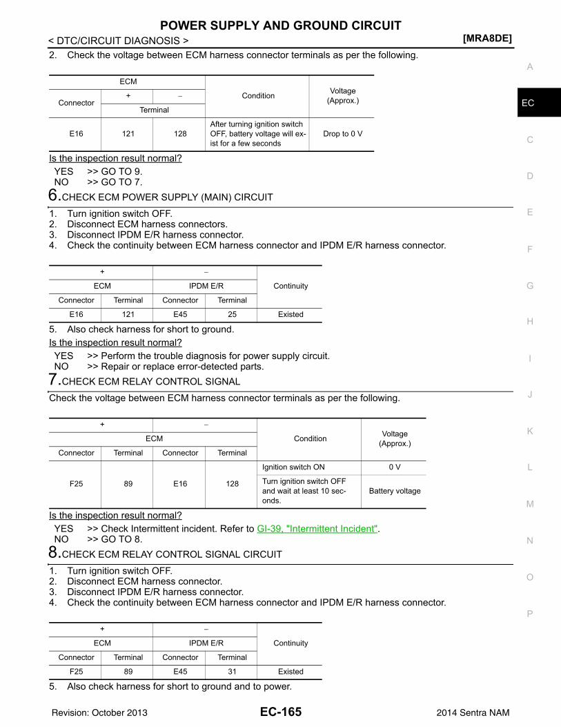
POWER SUPPLY AND GROUND CIRCUIT[MRA8DE]
C
D
E
F
G
H
I
J
K
L
M
A
C
N
P
O
< DTC/CIRCUIT DIAGNOSIS >
E
2. Check the voltage between ECM harness connector terminals as per the following.
Is the inspection result normal?YES >> GO TO 9.NO >> GO TO 7.
6.CHECK ECM POWER SUPPLY (MAIN) CIRCUIT
1. Turn ignition switch OFF.2. Disconnect ECM harness connectors.3. Disconnect IPDM E/R harness connector.4. Check the continuity between ECM harness connector and IPDM E/R harness connector.
5. Also check harness for short to ground.Is the inspection result normal?YES >> Perform the trouble diagnosis for power supply circuit.NO >> Repair or replace error-detected parts.
7.CHECK ECM RELAY CONTROL SIGNAL
Check the voltage between ECM harness connector terminals as per the following.
Is the inspection result normal?YES >> Check Intermittent incident. Refer to GI-39, "Intermittent Incident".NO >> GO TO 8.
8.CHECK ECM RELAY CONTROL SIGNAL CIRCUIT
1. Turn ignition switch OFF.2. Disconnect ECM harness connector.3. Disconnect IPDM E/R harness connector.4. Check the continuity between ECM harness connector and IPDM E/R harness connector.
5. Also check harness for short to ground and to power.
ECM
Condition Voltage(Approx.)Connector
+ −
Terminal
E16 121 128After turning ignition switch OFF, battery voltage will ex-ist for a few seconds
Drop to 0 V
+ −
ContinuityECM IPDM E/R
Connector Terminal Connector Terminal
E16 121 E45 25 Existed
+ −
Condition Voltage(Approx.)ECM
Connector Terminal Connector Terminal
F25 89 E16 128
Ignition switch ON 0 V
Turn ignition switch OFF and wait at least 10 sec-onds.
Battery voltage
+ −
ContinuityECM IPDM E/R
Connector Terminal Connector Terminal
F25 89 E45 31 Existed
EC-165Revision: October 2013 2014 Sentra NAM
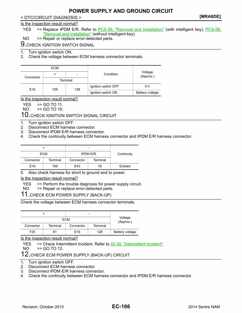
[MRA8DE]POWER SUPPLY AND GROUND CIRCUIT
< DTC/CIRCUIT DIAGNOSIS >Is the inspection result normal?YES >> Replace IPDM E/R. Refer to PCS-58, "Removal and Installation" (with intelligent key), PCS-58,
"Removal and Installation" (without intelligent key).NO >> Repair or replace error-detected parts.
9.CHECK IGNITION SWITCH SIGNAL
1. Turn ignition switch ON.2. Check the voltage between ECM harness connector terminals.
Is the inspection result normal?YES >> GO TO 11.NO >> GO TO 10.
10.CHECK IGNITION SWITCH SIGNAL CIRCUIT
1. Turn ignition switch OFF.2. Disconnect ECM harness connector.3. Disconnect IPDM E/R harness connector.4. Check the continuity between ECM harness connector and IPDM E/R harness connector.
5. Also check harness for short to ground and to power.Is the inspection result normal?YES >> Perform the trouble diagnosis for power supply circuit.NO >> Repair or replace error-detected parts.
11.CHECK ECM POWER SUPPLY (BACK-UP)
Check the voltage between ECM harness connector terminals.
Is the inspection result normal?YES >> Check Intermittent Incident. Refer to GI-39, "Intermittent Incident".NO >> GO TO 12.
12.CHECK ECM POWER SUPPLY (BACK-UP) CIRCUIT
1. Turn ignition switch OFF.2. Disconnect ECM harness connector.3. Disconnect IPDM E/R harness connector.4. Check the continuity between ECM harness connector and IPDM E/R harness connector.
ECM
Condition Voltage(Approx.)Connector
+ −
Terminal
E16 109 128Ignition switch OFF 0 V
Ignition switch ON Battery voltage
+ −
ContinuityECM IPDM E/R
Connector Terminal Connector Terminal
E16 109 E43 18 Existed
+ −Voltage
(Approx.)ECM
Connector Terminal Connector Terminal
F25 81 E16 128 Battery voltage
EC-166Revision: October 2013 2014 Sentra NAM
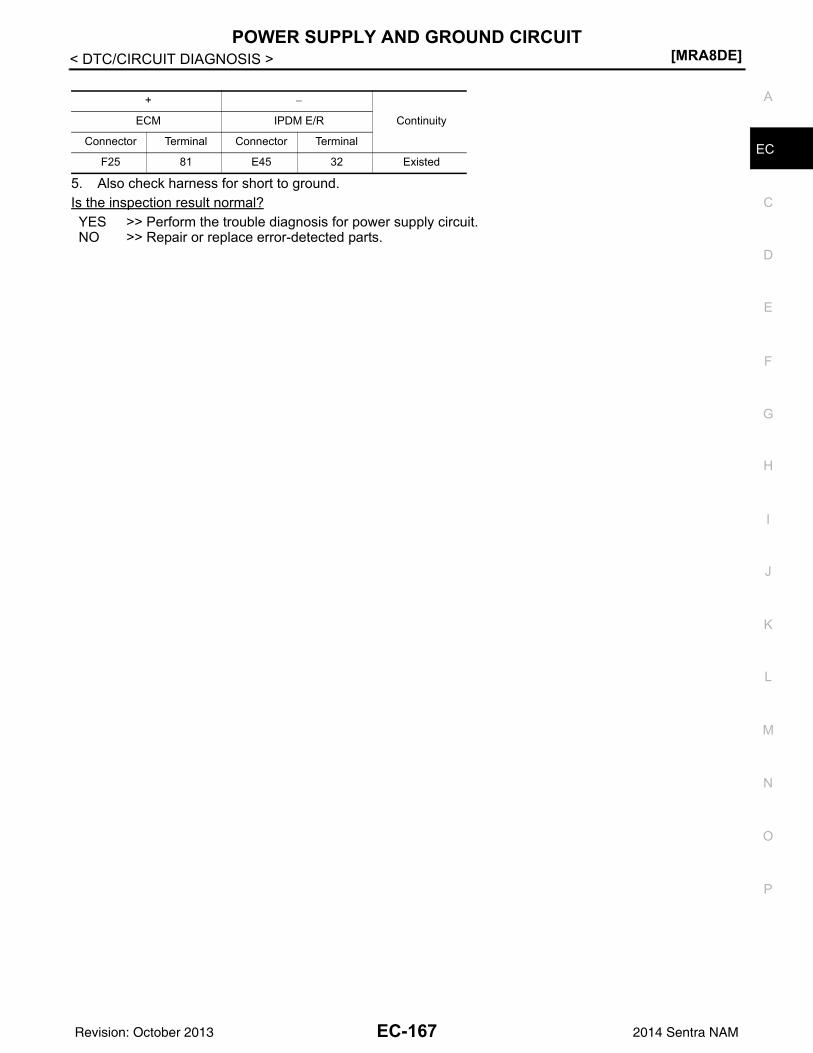
POWER SUPPLY AND GROUND CIRCUIT[MRA8DE]
C
D
E
F
G
H
I
J
K
L
M
A
C
N
P
O
< DTC/CIRCUIT DIAGNOSIS >
E
5. Also check harness for short to ground.Is the inspection result normal?YES >> Perform the trouble diagnosis for power supply circuit.NO >> Repair or replace error-detected parts.
+ −
ContinuityECM IPDM E/R
Connector Terminal Connector Terminal
F25 81 E45 32 Existed
EC-167Revision: October 2013 2014 Sentra NAM
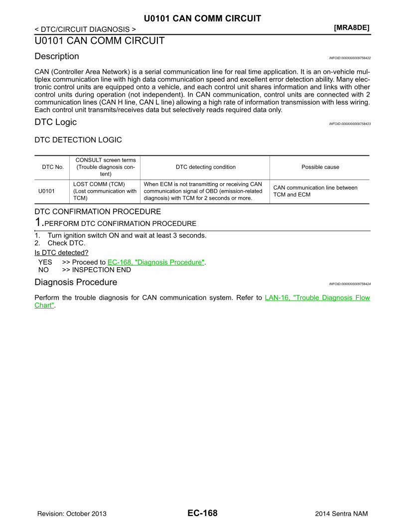
[MRA8DE]U0101 CAN COMM CIRCUIT
< DTC/CIRCUIT DIAGNOSIS >U0101 CAN COMM CIRCUITDescription INFOID:0000000009758422
CAN (Controller Area Network) is a serial communication line for real time application. It is an on-vehicle mul-tiplex communication line with high data communication speed and excellent error detection ability. Many elec-tronic control units are equipped onto a vehicle, and each control unit shares information and links with othercontrol units during operation (not independent). In CAN communication, control units are connected with 2communication lines (CAN H line, CAN L line) allowing a high rate of information transmission with less wiring.Each control unit transmits/receives data but selectively reads required data only.
DTC Logic INFOID:0000000009758423
DTC DETECTION LOGIC
DTC CONFIRMATION PROCEDURE1.PERFORM DTC CONFIRMATION PROCEDURE
1. Turn ignition switch ON and wait at least 3 seconds.2. Check DTC.Is DTC detected?YES >> Proceed to EC-168, "Diagnosis Procedure".NO >> INSPECTION END
Diagnosis Procedure INFOID:0000000009758424
Perform the trouble diagnosis for CAN communication system. Refer to LAN-16, "Trouble Diagnosis FlowChart".
DTC No.CONSULT screen terms(Trouble diagnosis con-
tent)DTC detecting condition Possible cause
U0101LOST COMM (TCM)(Lost communication with TCM)
When ECM is not transmitting or receiving CAN communication signal of OBD (emission-related diagnosis) with TCM for 2 seconds or more.
CAN communication line between TCM and ECM
EC-168Revision: October 2013 2014 Sentra NAM
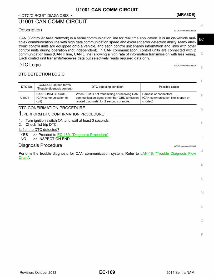
U1001 CAN COMM CIRCUIT[MRA8DE]
C
D
E
F
G
H
I
J
K
L
M
A
C
N
P
O
< DTC/CIRCUIT DIAGNOSIS >
E
U1001 CAN COMM CIRCUITDescription INFOID:0000000009758425
CAN (Controller Area Network) is a serial communication line for real time application. It is an on-vehicle mul-tiplex communication line with high data communication speed and excellent error detection ability. Many elec-tronic control units are equipped onto a vehicle, and each control unit shares information and links with othercontrol units during operation (not independent). In CAN communication, control units are connected with 2communication lines (CAN H line, CAN L line) allowing a high rate of information transmission with less wiring.Each control unit transmits/receives data but selectively reads required data only.
DTC Logic INFOID:0000000009758426
DTC DETECTION LOGIC
DTC CONFIRMATION PROCEDURE1.PERFORM DTC CONFIRMATION PROCEDURE
1. Turn ignition switch ON and wait at least 3 seconds.2. Check 1st trip DTC.Is 1st trip DTC detected?YES >> Proceed to EC-169, "Diagnosis Procedure".NO >> INSPECTION END
Diagnosis Procedure INFOID:0000000009758427
Perform the trouble diagnosis for CAN communication system. Refer to LAN-16, "Trouble Diagnosis FlowChart".
DTC No. CONSULT screen terms(Trouble diagnosis content) DTC detecting condition Possible cause
U1001CAN COMM CIRCUIT(CAN communication cir-cuit)
When ECM is not transmitting or receiving CAN communication signal other than OBD (emission related diagnosis) for 2 seconds or more.
Harness or connectors(CAN communication line is open or shorted)
EC-169Revision: October 2013 2014 Sentra NAM
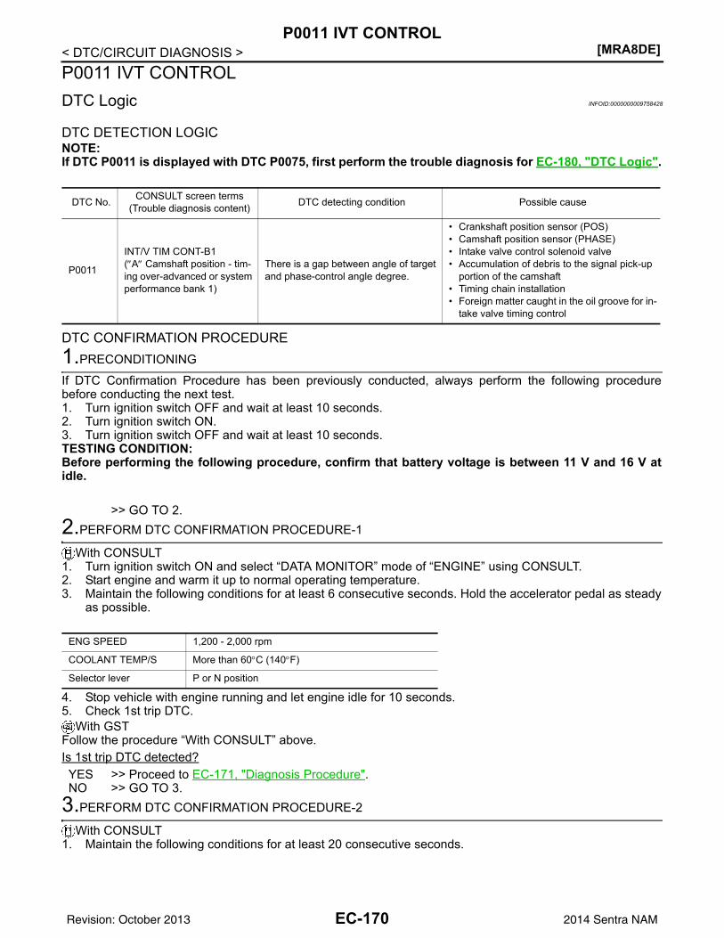
[MRA8DE]P0011 IVT CONTROL
< DTC/CIRCUIT DIAGNOSIS >P0011 IVT CONTROLDTC Logic INFOID:0000000009758428
DTC DETECTION LOGICNOTE:If DTC P0011 is displayed with DTC P0075, first perform the trouble diagnosis for EC-180, "DTC Logic".
DTC CONFIRMATION PROCEDURE1.PRECONDITIONING
If DTC Confirmation Procedure has been previously conducted, always perform the following procedurebefore conducting the next test.1. Turn ignition switch OFF and wait at least 10 seconds.2. Turn ignition switch ON.3. Turn ignition switch OFF and wait at least 10 seconds.TESTING CONDITION:Before performing the following procedure, confirm that battery voltage is between 11 V and 16 V atidle.
>> GO TO 2.2.PERFORM DTC CONFIRMATION PROCEDURE-1
With CONSULT1. Turn ignition switch ON and select “DATA MONITOR” mode of “ENGINE” using CONSULT.2. Start engine and warm it up to normal operating temperature.3. Maintain the following conditions for at least 6 consecutive seconds. Hold the accelerator pedal as steady
as possible.
4. Stop vehicle with engine running and let engine idle for 10 seconds.5. Check 1st trip DTC.
With GSTFollow the procedure “With CONSULT” above.Is 1st trip DTC detected?YES >> Proceed to EC-171, "Diagnosis Procedure".NO >> GO TO 3.
3.PERFORM DTC CONFIRMATION PROCEDURE-2
With CONSULT1. Maintain the following conditions for at least 20 consecutive seconds.
DTC No. CONSULT screen terms(Trouble diagnosis content) DTC detecting condition Possible cause
P0011
INT/V TIM CONT-B1(″A″ Camshaft position - tim-ing over-advanced or system performance bank 1)
There is a gap between angle of target and phase-control angle degree.
• Crankshaft position sensor (POS)• Camshaft position sensor (PHASE)• Intake valve control solenoid valve• Accumulation of debris to the signal pick-up
portion of the camshaft• Timing chain installation• Foreign matter caught in the oil groove for in-
take valve timing control
ENG SPEED 1,200 - 2,000 rpm
COOLANT TEMP/S More than 60°C (140°F)
Selector lever P or N position
EC-170Revision: October 2013 2014 Sentra NAM
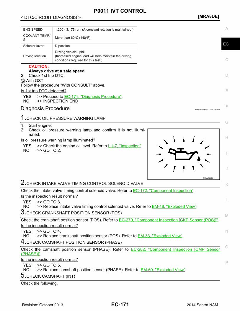
P0011 IVT CONTROL[MRA8DE]
C
D
E
F
G
H
I
J
K
L
M
A
C
N
P
O
< DTC/CIRCUIT DIAGNOSIS >
E
CAUTION:Always drive at a safe speed.
2. Check 1st trip DTC.With GST
Follow the procedure “With CONSULT” above.Is 1st trip DTC detected?YES >> Proceed to EC-171, "Diagnosis Procedure".NO >> INSPECTION END
Diagnosis Procedure INFOID:0000000009758429
1.CHECK OIL PRESSURE WARNING LAMP
1. Start engine.2. Check oil pressure warning lamp and confirm it is not illumi-
nated.Is oil pressure warning lamp illuminated?YES >> Check the engine oil level. Refer to LU-7, "Inspection".NO >> GO TO 2.
2.CHECK INTAKE VALVE TIMING CONTROL SOLENOID VALVE
Check the intake valve timing control solenoid valve. Refer to EC-172, "Component Inspection".Is the inspection result normal?YES >> GO TO 3.NO >> Replace intake valve timing control solenoid valve. Refer to EM-48, "Exploded View".
3.CHECK CRANKSHAFT POSITION SENSOR (POS)
Check the crankshaft position sensor (POS). Refer to EC-279, "Component Inspection [CKP Sensor (POS)]".Is the inspection result normal?YES >> GO TO 4.NO >> Replace crankshaft position sensor (POS). Refer to EM-33, "Exploded View".
4.CHECK CAMSHAFT POSITION SENSOR (PHASE)
Check the camshaft position sensor (PHASE). Refer to EC-282, "Component Inspection [CMP Sensor(PHASE)]".Is the inspection result normal?YES >> GO TO 5.NO >> Replace camshaft position sensor (PHASE). Refer to EM-60, "Exploded View".
5.CHECK CAMSHAFT (INT)
Check the following.
ENG SPEED 1,200 - 3,175 rpm (A constant rotation is maintained.)
COOLANT TEMP/S More than 60°C (140°F)
Selector lever D position
Driving locationDriving vehicle uphill(Increased engine load will help maintain the driving conditions required for this test.)
PBIA8559J
EC-171Revision: October 2013 2014 Sentra NAM
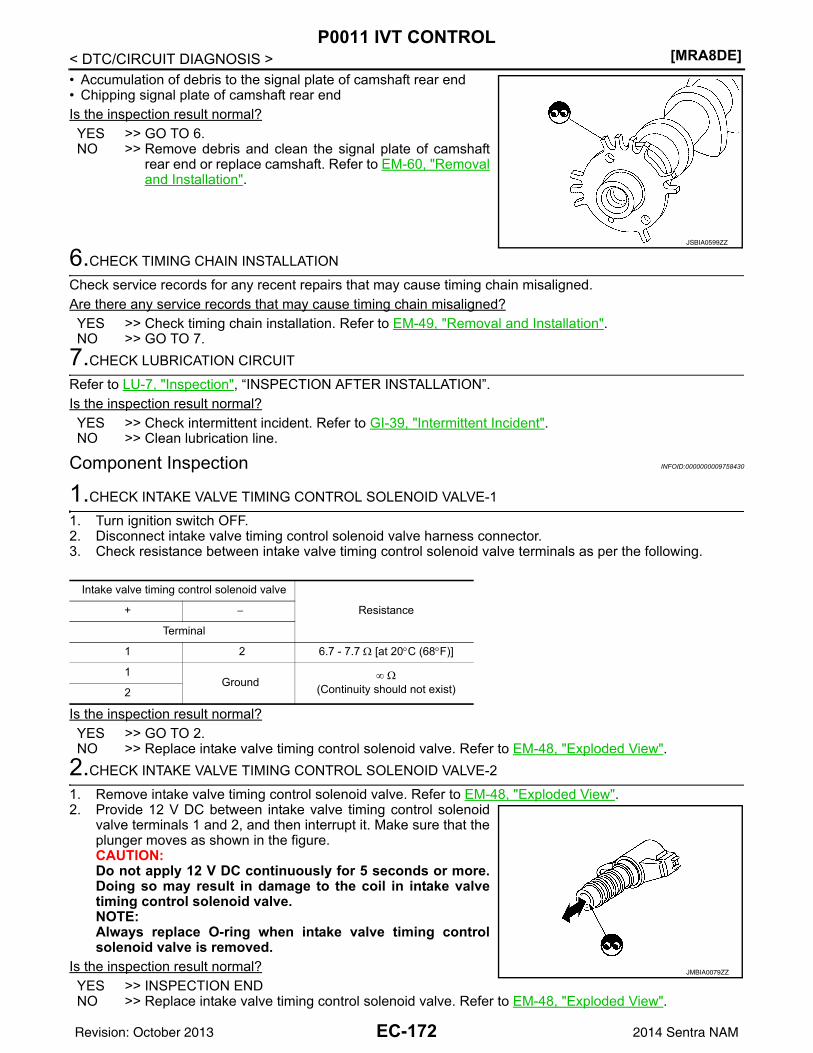
[MRA8DE]P0011 IVT CONTROL
< DTC/CIRCUIT DIAGNOSIS >• Accumulation of debris to the signal plate of camshaft rear end• Chipping signal plate of camshaft rear endIs the inspection result normal?YES >> GO TO 6.NO >> Remove debris and clean the signal plate of camshaft
rear end or replace camshaft. Refer to EM-60, "Removaland Installation".
6.CHECK TIMING CHAIN INSTALLATION
Check service records for any recent repairs that may cause timing chain misaligned.Are there any service records that may cause timing chain misaligned?YES >> Check timing chain installation. Refer to EM-49, "Removal and Installation".NO >> GO TO 7.
7.CHECK LUBRICATION CIRCUIT
Refer to LU-7, "Inspection", “INSPECTION AFTER INSTALLATION”.Is the inspection result normal?YES >> Check intermittent incident. Refer to GI-39, "Intermittent Incident".NO >> Clean lubrication line.
Component Inspection INFOID:0000000009758430
1.CHECK INTAKE VALVE TIMING CONTROL SOLENOID VALVE-1
1. Turn ignition switch OFF.2. Disconnect intake valve timing control solenoid valve harness connector.3. Check resistance between intake valve timing control solenoid valve terminals as per the following.
Is the inspection result normal?YES >> GO TO 2.NO >> Replace intake valve timing control solenoid valve. Refer to EM-48, "Exploded View".
2.CHECK INTAKE VALVE TIMING CONTROL SOLENOID VALVE-2
1. Remove intake valve timing control solenoid valve. Refer to EM-48, "Exploded View".2. Provide 12 V DC between intake valve timing control solenoid
valve terminals 1 and 2, and then interrupt it. Make sure that theplunger moves as shown in the figure.CAUTION:Do not apply 12 V DC continuously for 5 seconds or more.Doing so may result in damage to the coil in intake valvetiming control solenoid valve.NOTE:Always replace O-ring when intake valve timing controlsolenoid valve is removed.
Is the inspection result normal?YES >> INSPECTION ENDNO >> Replace intake valve timing control solenoid valve. Refer to EM-48, "Exploded View".
JSBIA0599ZZ
Intake valve timing control solenoid valve
Resistance+ −
Terminal
1 2 6.7 - 7.7 Ω [at 20°C (68°F)]
1Ground ∞ Ω
(Continuity should not exist)2
JMBIA0079ZZ
EC-172Revision: October 2013 2014 Sentra NAM
P0014 EVT CONTROL[MRA8DE]
C
D
E
F
G
H
I
J
K
L
M
A
C
N
P
O
< DTC/CIRCUIT DIAGNOSIS >
E
P0014 EVT CONTROLDTC Logic INFOID:0000000009758431
DTC DETECTION LOGICNOTE:• If DTC P0014 is displayed with DTC P0078, first perform trouble diagnosis for DTC P0078. Refer to
EC-183, "DTC Logic".• If DTC P0014 is displayed with P1078, first perform trouble diagnosis for P1078. Refer to EC-359,
"DTC Logic".
DTC CONFIRMATION PROCEDURE1.PRECONDITIONING
If DTC Confirmation Procedure has been previously conducted, always perform the following procedurebefore conducting the next test.1. Turn ignition switch OFF and wait at least 10 seconds.2. Turn ignition switch ON.3. Turn ignition switch OFF and wait at least 10 seconds.TESTING CONDITION: Before performing the following procedure, confirm that battery voltage is between 10 V and 16 V atidle.
>> GO TO 2.2.PERFORM DTC CONFIRMATION PROCEDURE-1
With CONSULT1. Turn ignition switch ON and select “DATA MONITOR” mode of “ENGINE” using CONSULT.2. Start engine and warm it up to the normal operating temperature.3. Maintain the following conditions for at least 6 consecutive seconds. Hold the accelerator pedal as steady
as possible.
4. Let engine idle for 10 seconds.5. Check 1st trip DTC.
With GSTFollow the procedure “With CONSULT” above.Is 1st trip DTC detected?YES >> Proceed to EC-174, "Diagnosis Procedure"NO >> GO TO 3.
3.PERFORM DTC CONFIRMATION PROCEDURE-2
With CONSULT
DTC No. CONSULT screen terms(Trouble diagnosis content) DTC detecting condition Possible cause
P0014
EXH/V TIM CONT-B1(″B″ Camshaft position - tim-ing over-advanced or system performance bank 1)
There is a gap between angle of target and phase-control angle degree.
• Crankshaft position sensor (POS)• Camshaft position sensor (PHASE)• Exhaust valve timing control position sen-
sor• Exhaust valve control solenoid valve• Accumulation of debris to the signal pick-
up portion of the camshaft• Timing chain installation• Foreign matter caught in the oil groove for
exhaust valve timing control
ENG SPEED 1,200 - 2,000 rpm (A constant rotation is maintained.)
COOLANT TEMP/S More than 60°C (140°F)
Selector lever P or N position
EC-173Revision: October 2013 2014 Sentra NAM
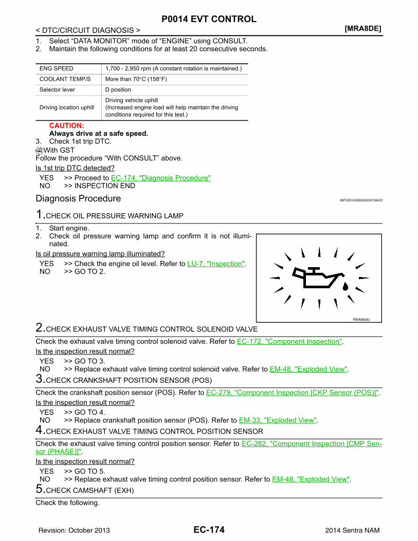
[MRA8DE]P0014 EVT CONTROL
< DTC/CIRCUIT DIAGNOSIS >1. Select “DATA MONITOR” mode of “ENGINE” using CONSULT.2. Maintain the following conditions for at least 20 consecutive seconds.
CAUTION:Always drive at a safe speed.
3. Check 1st trip DTC.With GST
Follow the procedure “With CONSULT” above.Is 1st trip DTC detected?YES >> Proceed to EC-174, "Diagnosis Procedure"NO >> INSPECTION END
Diagnosis Procedure INFOID:0000000009758432
1.CHECK OIL PRESSURE WARNING LAMP
1. Start engine.2. Check oil pressure warning lamp and confirm it is not illumi-
nated.Is oil pressure warning lamp illuminated?YES >> Check the engine oil level. Refer to LU-7, "Inspection".NO >> GO TO 2.
2.CHECK EXHAUST VALVE TIMING CONTROL SOLENOID VALVE
Check the exhaust valve timing control solenoid valve. Refer to EC-172, "Component Inspection".Is the inspection result normal?YES >> GO TO 3.NO >> Replace exhaust valve timing control solenoid valve. Refer to EM-48, "Exploded View".
3.CHECK CRANKSHAFT POSITION SENSOR (POS)
Check the crankshaft position sensor (POS). Refer to EC-279, "Component Inspection [CKP Sensor (POS)]".Is the inspection result normal?YES >> GO TO 4.NO >> Replace crankshaft position sensor (POS). Refer to EM-33, "Exploded View".
4.CHECK EXHAUST VALVE TIMING CONTROL POSITION SENSOR
Check the exhaust valve timing control position sensor. Refer to EC-282, "Component Inspection [CMP Sen-sor (PHASE)]".Is the inspection result normal?YES >> GO TO 5.NO >> Replace exhaust valve timing control position sensor. Refer to EM-48, "Exploded View".
5.CHECK CAMSHAFT (EXH)
Check the following.
ENG SPEED 1,700 - 2,950 rpm (A constant rotation is maintained.)
COOLANT TEMP/S More than 70°C (158°F)
Selector lever D position
Driving location uphillDriving vehicle uphill(Increased engine load will help maintain the driving conditions required for this test.)
PBIA8559J
EC-174Revision: October 2013 2014 Sentra NAM
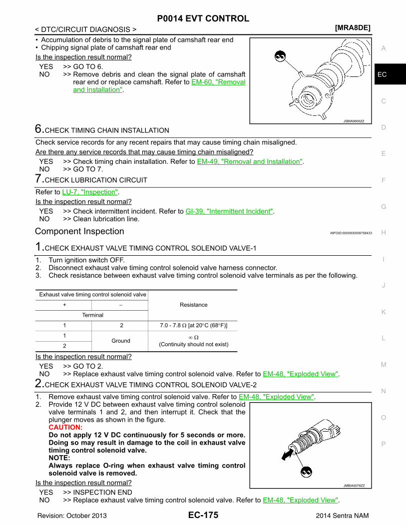
P0014 EVT CONTROL[MRA8DE]
C
D
E
F
G
H
I
J
K
L
M
A
C
N
P
O
< DTC/CIRCUIT DIAGNOSIS >
E
• Accumulation of debris to the signal plate of camshaft rear end• Chipping signal plate of camshaft rear endIs the inspection result normal?YES >> GO TO 6.NO >> Remove debris and clean the signal plate of camshaft
rear end or replace camshaft. Refer to EM-60, "Removaland Installation".
6.CHECK TIMING CHAIN INSTALLATION
Check service records for any recent repairs that may cause timing chain misaligned.Are there any service records that may cause timing chain misaligned?YES >> Check timing chain installation. Refer to EM-49, "Removal and Installation".NO >> GO TO 7.
7.CHECK LUBRICATION CIRCUIT
Refer to LU-7, "Inspection".Is the inspection result normal?YES >> Check intermittent incident. Refer to GI-39, "Intermittent Incident".NO >> Clean lubrication line.
Component Inspection INFOID:0000000009758433
1.CHECK EXHAUST VALVE TIMING CONTROL SOLENOID VALVE-1
1. Turn ignition switch OFF.2. Disconnect exhaust valve timing control solenoid valve harness connector.3. Check resistance between exhaust valve timing control solenoid valve terminals as per the following.
Is the inspection result normal?YES >> GO TO 2.NO >> Replace exhaust valve timing control solenoid valve. Refer to EM-48, "Exploded View".
2.CHECK EXHAUST VALVE TIMING CONTROL SOLENOID VALVE-2
1. Remove exhaust valve timing control solenoid valve. Refer to EM-48, "Exploded View".2. Provide 12 V DC between exhaust valve timing control solenoid
valve terminals 1 and 2, and then interrupt it. Check that theplunger moves as shown in the figure.CAUTION:Do not apply 12 V DC continuously for 5 seconds or more.Doing so may result in damage to the coil in exhaust valvetiming control solenoid valve.NOTE:Always replace O-ring when exhaust valve timing controlsolenoid valve is removed.
Is the inspection result normal?YES >> INSPECTION ENDNO >> Replace exhaust valve timing control solenoid valve. Refer to EM-48, "Exploded View".
JSBIA0600ZZ
Exhaust valve timing control solenoid valve
Resistance+ −
Terminal
1 2 7.0 - 7.8 Ω [at 20°C (68°F)]
1Ground ∞ Ω
(Continuity should not exist)2
JMBIA0079ZZ
EC-175Revision: October 2013 2014 Sentra NAM
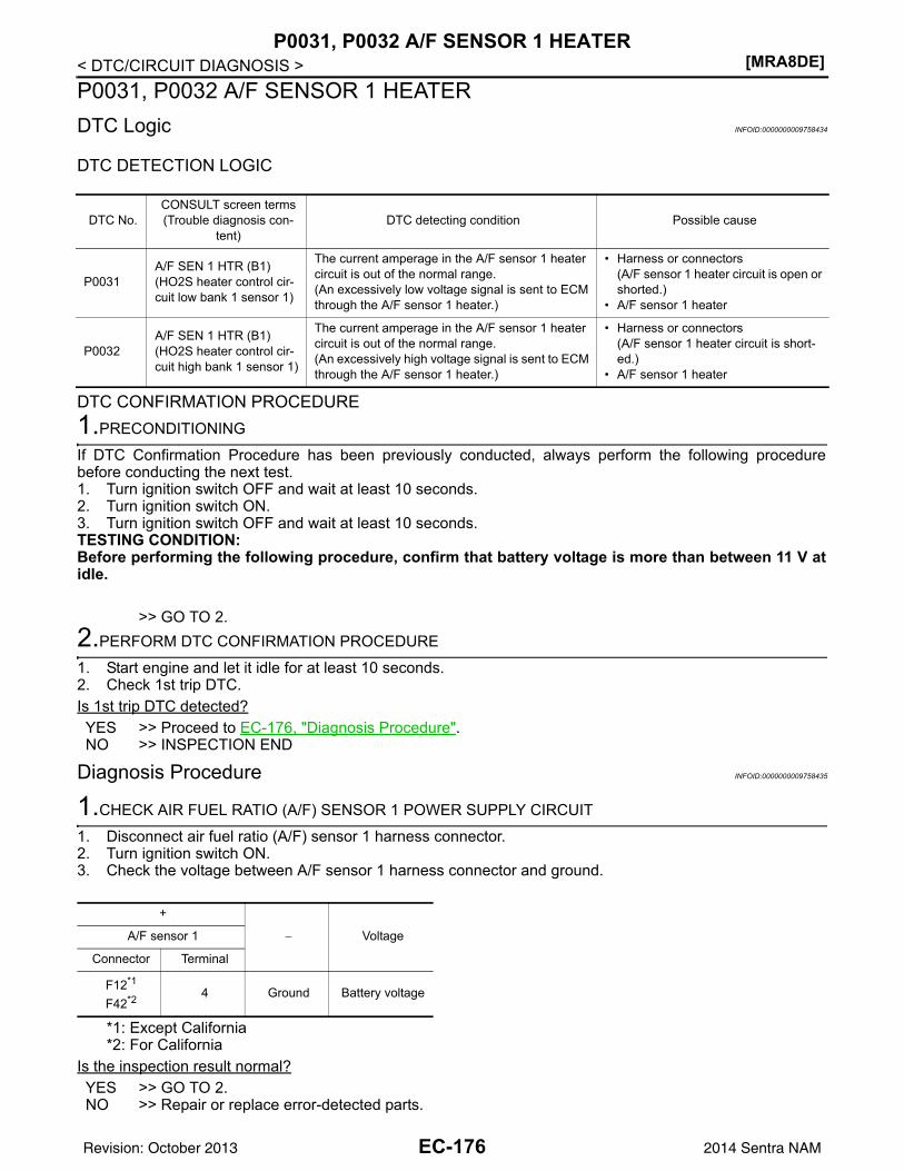
[MRA8DE]P0031, P0032 A/F SENSOR 1 HEATER
< DTC/CIRCUIT DIAGNOSIS >P0031, P0032 A/F SENSOR 1 HEATERDTC Logic INFOID:0000000009758434
DTC DETECTION LOGIC
DTC CONFIRMATION PROCEDURE1.PRECONDITIONING
If DTC Confirmation Procedure has been previously conducted, always perform the following procedurebefore conducting the next test.1. Turn ignition switch OFF and wait at least 10 seconds.2. Turn ignition switch ON.3. Turn ignition switch OFF and wait at least 10 seconds.TESTING CONDITION:Before performing the following procedure, confirm that battery voltage is more than between 11 V atidle.
>> GO TO 2.2.PERFORM DTC CONFIRMATION PROCEDURE
1. Start engine and let it idle for at least 10 seconds.2. Check 1st trip DTC.Is 1st trip DTC detected?YES >> Proceed to EC-176, "Diagnosis Procedure".NO >> INSPECTION END
Diagnosis Procedure INFOID:0000000009758435
1.CHECK AIR FUEL RATIO (A/F) SENSOR 1 POWER SUPPLY CIRCUIT
1. Disconnect air fuel ratio (A/F) sensor 1 harness connector.2. Turn ignition switch ON.3. Check the voltage between A/F sensor 1 harness connector and ground.
*1: Except California*2: For California
Is the inspection result normal?YES >> GO TO 2.NO >> Repair or replace error-detected parts.
DTC No.CONSULT screen terms(Trouble diagnosis con-
tent)DTC detecting condition Possible cause
P0031A/F SEN 1 HTR (B1)(HO2S heater control cir-cuit low bank 1 sensor 1)
The current amperage in the A/F sensor 1 heater circuit is out of the normal range.(An excessively low voltage signal is sent to ECM through the A/F sensor 1 heater.)
• Harness or connectors(A/F sensor 1 heater circuit is open or shorted.)
• A/F sensor 1 heater
P0032A/F SEN 1 HTR (B1)(HO2S heater control cir-cuit high bank 1 sensor 1)
The current amperage in the A/F sensor 1 heater circuit is out of the normal range.(An excessively high voltage signal is sent to ECM through the A/F sensor 1 heater.)
• Harness or connectors(A/F sensor 1 heater circuit is short-ed.)
• A/F sensor 1 heater
+
− VoltageA/F sensor 1
Connector Terminal
F12*1
F42*2 4 Ground Battery voltage
EC-176Revision: October 2013 2014 Sentra NAM
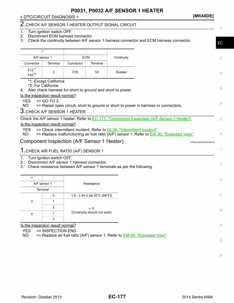
P0031, P0032 A/F SENSOR 1 HEATER[MRA8DE]
C
D
E
F
G
H
I
J
K
L
M
A
C
N
P
O
< DTC/CIRCUIT DIAGNOSIS >
E
2.CHECK A/F SENSOR 1 HEATER OUTPUT SIGNAL CIRCUIT
1. Turn ignition switch OFF.2. Disconnect ECM harness connector.3. Check the continuity between A/F sensor 1 harness connector and ECM harness connector.
*1: Except California*2: For California
4. Also check harness for short to ground and short to power.Is the inspection result normal?YES >> GO TO 3.NO >> Repair open circuit, short to ground or short to power in harness or connectors.
3.CHECK A/F SENSOR 1 HEATER
Check the A/F sensor 1 heater. Refer to EC-177, "Component Inspection (A/F Sensor 1 Heater)".Is the inspection result normal?YES >> Check intermittent incident. Refer to GI-39, "Intermittent Incident".NO >> Replace malfunctioning air fuel ratio (A/F) sensor 1. Refer to EM-30, "Exploded View".
Component Inspection (A/F Sensor 1 Heater) INFOID:0000000009758436
1.CHECK AIR FUEL RATIO (A/F) SENSOR 1
1. Turn ignition switch OFF.2. Disconnect A/F sensor 1 harness connector.3. Check resistance between A/F sensor 1 terminals as per the following.
Is the inspection result normal?YES >> INSPECTION ENDNO >> Replace air fuel ratio (A/F) sensor 1. Refer to EM-30, "Exploded View".
+ −
ContinuityA/F sensor 1 ECM
Connector Terminal Connector Terminal
F12*1
F42*2 3 F25 53 Existed
+ −
ResistanceA/F sensor 1
Terminal
3
4 1.8 - 2.44 Ω [at 20°C (68°F)]
1
∞ Ω(Continuity should not exist)
2
4 1
2
EC-177Revision: October 2013 2014 Sentra NAM
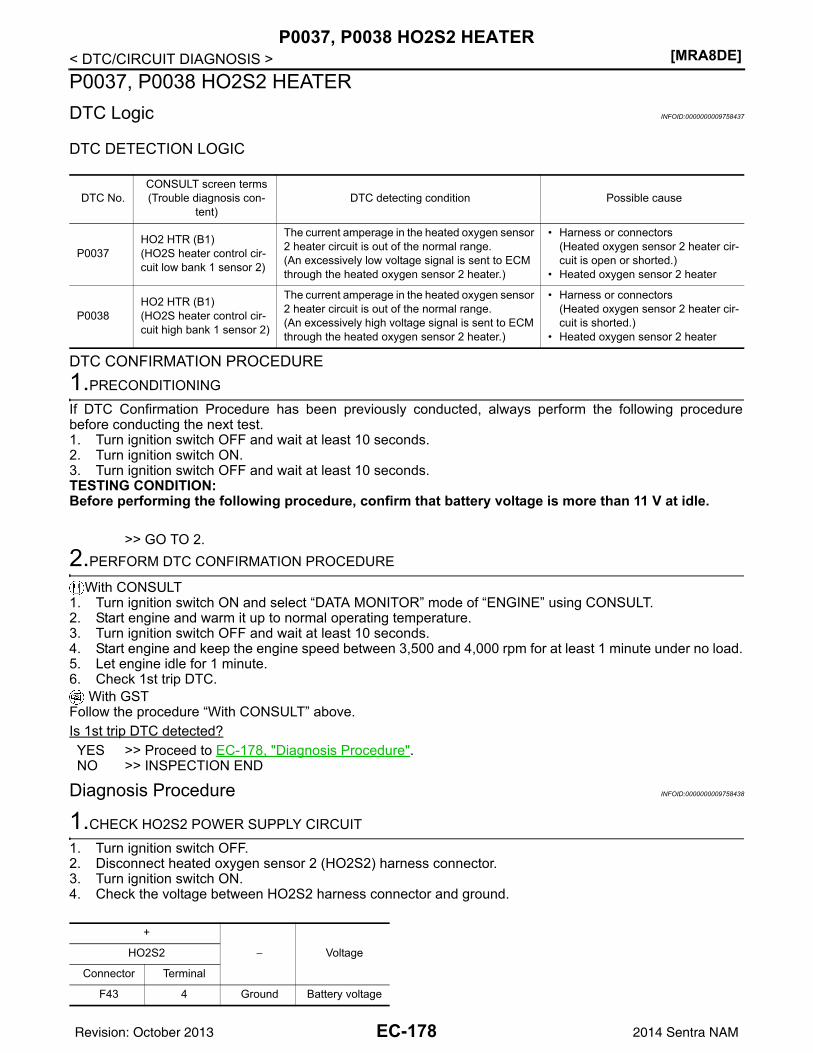
[MRA8DE]P0037, P0038 HO2S2 HEATER
< DTC/CIRCUIT DIAGNOSIS >P0037, P0038 HO2S2 HEATERDTC Logic INFOID:0000000009758437
DTC DETECTION LOGIC
DTC CONFIRMATION PROCEDURE1.PRECONDITIONING
If DTC Confirmation Procedure has been previously conducted, always perform the following procedurebefore conducting the next test.1. Turn ignition switch OFF and wait at least 10 seconds.2. Turn ignition switch ON.3. Turn ignition switch OFF and wait at least 10 seconds.TESTING CONDITION:Before performing the following procedure, confirm that battery voltage is more than 11 V at idle.
>> GO TO 2.2.PERFORM DTC CONFIRMATION PROCEDURE
With CONSULT1. Turn ignition switch ON and select “DATA MONITOR” mode of “ENGINE” using CONSULT.2. Start engine and warm it up to normal operating temperature.3. Turn ignition switch OFF and wait at least 10 seconds.4. Start engine and keep the engine speed between 3,500 and 4,000 rpm for at least 1 minute under no load.5. Let engine idle for 1 minute.6. Check 1st trip DTC.
With GSTFollow the procedure “With CONSULT” above.Is 1st trip DTC detected?YES >> Proceed to EC-178, "Diagnosis Procedure".NO >> INSPECTION END
Diagnosis Procedure INFOID:0000000009758438
1.CHECK HO2S2 POWER SUPPLY CIRCUIT
1. Turn ignition switch OFF.2. Disconnect heated oxygen sensor 2 (HO2S2) harness connector.3. Turn ignition switch ON.4. Check the voltage between HO2S2 harness connector and ground.
DTC No.CONSULT screen terms(Trouble diagnosis con-
tent)DTC detecting condition Possible cause
P0037HO2 HTR (B1)(HO2S heater control cir-cuit low bank 1 sensor 2)
The current amperage in the heated oxygen sensor 2 heater circuit is out of the normal range.(An excessively low voltage signal is sent to ECM through the heated oxygen sensor 2 heater.)
• Harness or connectors(Heated oxygen sensor 2 heater cir-cuit is open or shorted.)
• Heated oxygen sensor 2 heater
P0038HO2 HTR (B1)(HO2S heater control cir-cuit high bank 1 sensor 2)
The current amperage in the heated oxygen sensor 2 heater circuit is out of the normal range.(An excessively high voltage signal is sent to ECM through the heated oxygen sensor 2 heater.)
• Harness or connectors(Heated oxygen sensor 2 heater cir-cuit is shorted.)
• Heated oxygen sensor 2 heater
+
− VoltageHO2S2
Connector Terminal
F43 4 Ground Battery voltage
EC-178Revision: October 2013 2014 Sentra NAM
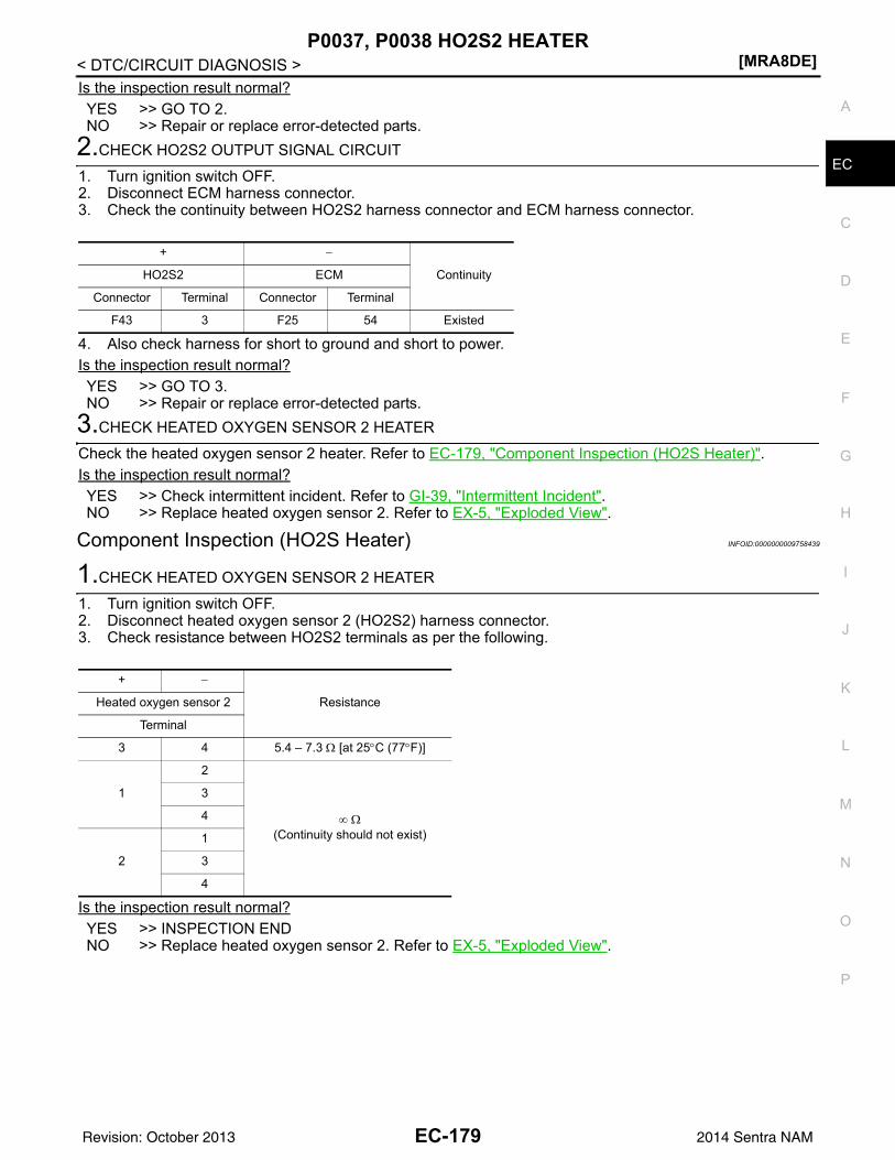
P0037, P0038 HO2S2 HEATER[MRA8DE]
C
D
E
F
G
H
I
J
K
L
M
A
C
N
P
O
< DTC/CIRCUIT DIAGNOSIS >
E
Is the inspection result normal?YES >> GO TO 2.NO >> Repair or replace error-detected parts.
2.CHECK HO2S2 OUTPUT SIGNAL CIRCUIT
1. Turn ignition switch OFF.2. Disconnect ECM harness connector.3. Check the continuity between HO2S2 harness connector and ECM harness connector.
4. Also check harness for short to ground and short to power.Is the inspection result normal?YES >> GO TO 3.NO >> Repair or replace error-detected parts.
3.CHECK HEATED OXYGEN SENSOR 2 HEATER
Check the heated oxygen sensor 2 heater. Refer to EC-179, "Component Inspection (HO2S Heater)".Is the inspection result normal?YES >> Check intermittent incident. Refer to GI-39, "Intermittent Incident".NO >> Replace heated oxygen sensor 2. Refer to EX-5, "Exploded View".
Component Inspection (HO2S Heater) INFOID:0000000009758439
1.CHECK HEATED OXYGEN SENSOR 2 HEATER
1. Turn ignition switch OFF.2. Disconnect heated oxygen sensor 2 (HO2S2) harness connector.3. Check resistance between HO2S2 terminals as per the following.
Is the inspection result normal?YES >> INSPECTION ENDNO >> Replace heated oxygen sensor 2. Refer to EX-5, "Exploded View".
+ −
ContinuityHO2S2 ECM
Connector Terminal Connector Terminal
F43 3 F25 54 Existed
+ −
ResistanceHeated oxygen sensor 2
Terminal
3 4 5.4 – 7.3 Ω [at 25°C (77°F)]
1
2
∞ Ω(Continuity should not exist)
3
4
2
1
3
4
EC-179Revision: October 2013 2014 Sentra NAM
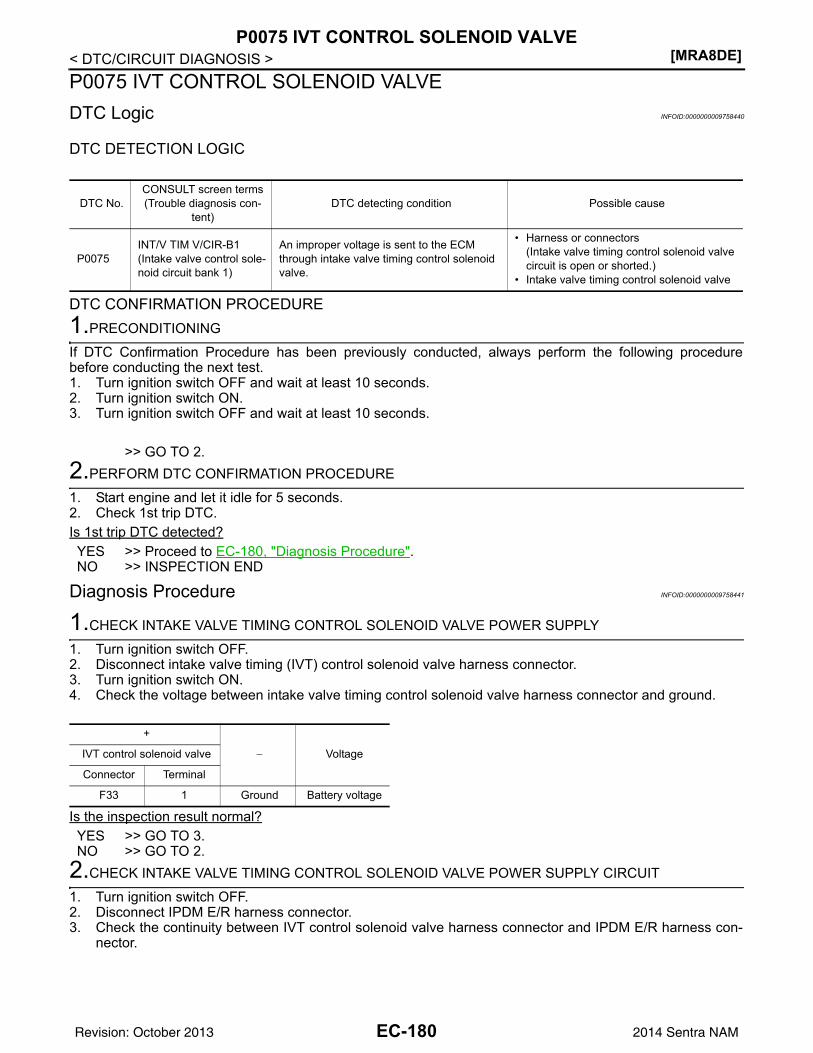
[MRA8DE]P0075 IVT CONTROL SOLENOID VALVE
< DTC/CIRCUIT DIAGNOSIS >P0075 IVT CONTROL SOLENOID VALVEDTC Logic INFOID:0000000009758440
DTC DETECTION LOGIC
DTC CONFIRMATION PROCEDURE1.PRECONDITIONING
If DTC Confirmation Procedure has been previously conducted, always perform the following procedurebefore conducting the next test.1. Turn ignition switch OFF and wait at least 10 seconds.2. Turn ignition switch ON.3. Turn ignition switch OFF and wait at least 10 seconds.
>> GO TO 2.2.PERFORM DTC CONFIRMATION PROCEDURE
1. Start engine and let it idle for 5 seconds.2. Check 1st trip DTC.Is 1st trip DTC detected?YES >> Proceed to EC-180, "Diagnosis Procedure".NO >> INSPECTION END
Diagnosis Procedure INFOID:0000000009758441
1.CHECK INTAKE VALVE TIMING CONTROL SOLENOID VALVE POWER SUPPLY
1. Turn ignition switch OFF.2. Disconnect intake valve timing (IVT) control solenoid valve harness connector.3. Turn ignition switch ON.4. Check the voltage between intake valve timing control solenoid valve harness connector and ground.
Is the inspection result normal?YES >> GO TO 3.NO >> GO TO 2.
2.CHECK INTAKE VALVE TIMING CONTROL SOLENOID VALVE POWER SUPPLY CIRCUIT
1. Turn ignition switch OFF.2. Disconnect IPDM E/R harness connector.3. Check the continuity between IVT control solenoid valve harness connector and IPDM E/R harness con-
nector.
DTC No.CONSULT screen terms(Trouble diagnosis con-
tent)DTC detecting condition Possible cause
P0075INT/V TIM V/CIR-B1(Intake valve control sole-noid circuit bank 1)
An improper voltage is sent to the ECM through intake valve timing control solenoid valve.
• Harness or connectors(Intake valve timing control solenoid valve circuit is open or shorted.)
• Intake valve timing control solenoid valve
+
− VoltageIVT control solenoid valve
Connector Terminal
F33 1 Ground Battery voltage
EC-180Revision: October 2013 2014 Sentra NAM
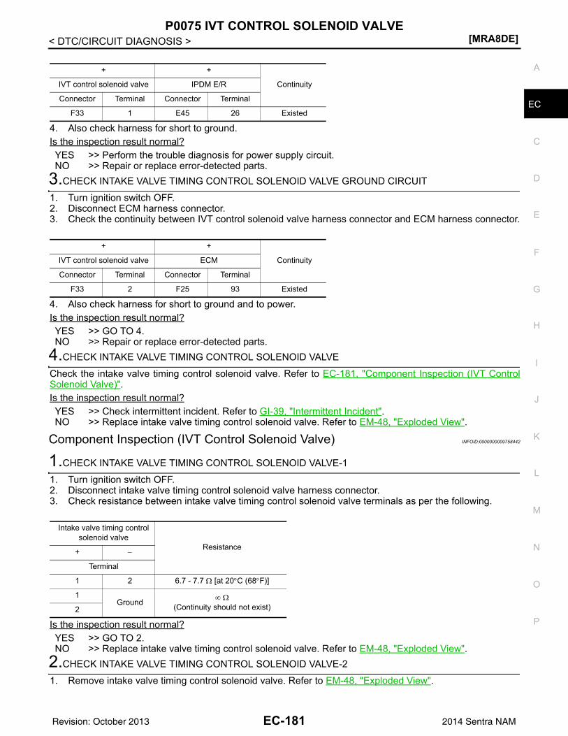
P0075 IVT CONTROL SOLENOID VALVE[MRA8DE]
C
D
E
F
G
H
I
J
K
L
M
A
C
N
P
O
< DTC/CIRCUIT DIAGNOSIS >
E
4. Also check harness for short to ground.Is the inspection result normal?YES >> Perform the trouble diagnosis for power supply circuit.NO >> Repair or replace error-detected parts.
3.CHECK INTAKE VALVE TIMING CONTROL SOLENOID VALVE GROUND CIRCUIT
1. Turn ignition switch OFF.2. Disconnect ECM harness connector.3. Check the continuity between IVT control solenoid valve harness connector and ECM harness connector.
4. Also check harness for short to ground and to power. Is the inspection result normal?YES >> GO TO 4.NO >> Repair or replace error-detected parts.
4.CHECK INTAKE VALVE TIMING CONTROL SOLENOID VALVE
Check the intake valve timing control solenoid valve. Refer to EC-181, "Component Inspection (IVT ControlSolenoid Valve)".Is the inspection result normal?YES >> Check intermittent incident. Refer to GI-39, "Intermittent Incident".NO >> Replace intake valve timing control solenoid valve. Refer to EM-48, "Exploded View".
Component Inspection (IVT Control Solenoid Valve) INFOID:0000000009758442
1.CHECK INTAKE VALVE TIMING CONTROL SOLENOID VALVE-1
1. Turn ignition switch OFF.2. Disconnect intake valve timing control solenoid valve harness connector.3. Check resistance between intake valve timing control solenoid valve terminals as per the following.
Is the inspection result normal?YES >> GO TO 2.NO >> Replace intake valve timing control solenoid valve. Refer to EM-48, "Exploded View".
2.CHECK INTAKE VALVE TIMING CONTROL SOLENOID VALVE-2
1. Remove intake valve timing control solenoid valve. Refer to EM-48, "Exploded View".
+ +
ContinuityIVT control solenoid valve IPDM E/R
Connector Terminal Connector Terminal
F33 1 E45 26 Existed
+ +
ContinuityIVT control solenoid valve ECM
Connector Terminal Connector Terminal
F33 2 F25 93 Existed
Intake valve timing control solenoid valve
Resistance+ −
Terminal
1 2 6.7 - 7.7 Ω [at 20°C (68°F)]
1Ground ∞ Ω
(Continuity should not exist)2
EC-181Revision: October 2013 2014 Sentra NAM
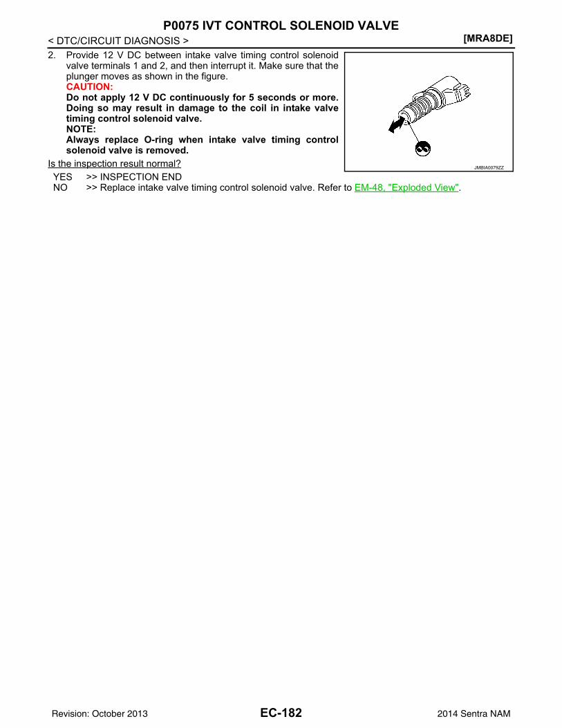
[MRA8DE]P0075 IVT CONTROL SOLENOID VALVE
< DTC/CIRCUIT DIAGNOSIS >2. Provide 12 V DC between intake valve timing control solenoid
valve terminals 1 and 2, and then interrupt it. Make sure that theplunger moves as shown in the figure.CAUTION:Do not apply 12 V DC continuously for 5 seconds or more.Doing so may result in damage to the coil in intake valvetiming control solenoid valve.NOTE:Always replace O-ring when intake valve timing controlsolenoid valve is removed.
Is the inspection result normal?YES >> INSPECTION ENDNO >> Replace intake valve timing control solenoid valve. Refer to EM-48, "Exploded View".
JMBIA0079ZZ
EC-182Revision: October 2013 2014 Sentra NAM
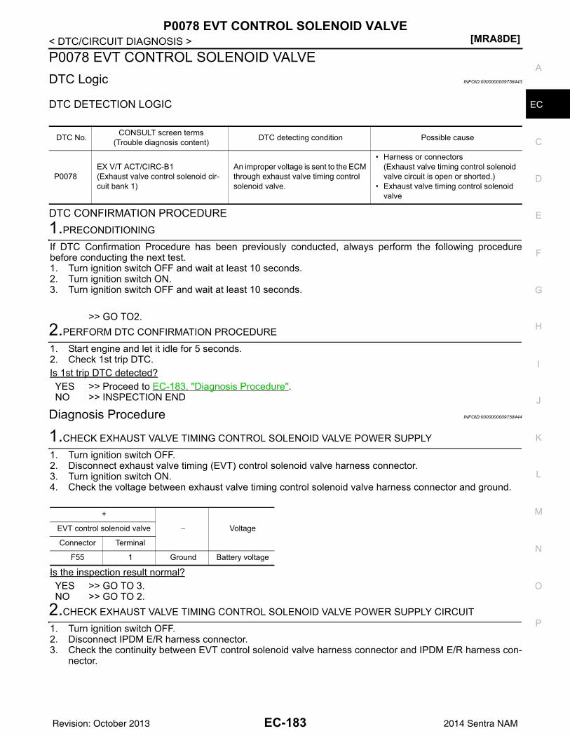
P0078 EVT CONTROL SOLENOID VALVE[MRA8DE]
C
D
E
F
G
H
I
J
K
L
M
A
C
N
P
O
< DTC/CIRCUIT DIAGNOSIS >
E
P0078 EVT CONTROL SOLENOID VALVEDTC Logic INFOID:0000000009758443
DTC DETECTION LOGIC
DTC CONFIRMATION PROCEDURE1.PRECONDITIONING
If DTC Confirmation Procedure has been previously conducted, always perform the following procedurebefore conducting the next test.1. Turn ignition switch OFF and wait at least 10 seconds.2. Turn ignition switch ON.3. Turn ignition switch OFF and wait at least 10 seconds.
>> GO TO2.2.PERFORM DTC CONFIRMATION PROCEDURE
1. Start engine and let it idle for 5 seconds.2. Check 1st trip DTC.Is 1st trip DTC detected?YES >> Proceed to EC-183, "Diagnosis Procedure".NO >> INSPECTION END
Diagnosis Procedure INFOID:0000000009758444
1.CHECK EXHAUST VALVE TIMING CONTROL SOLENOID VALVE POWER SUPPLY
1. Turn ignition switch OFF.2. Disconnect exhaust valve timing (EVT) control solenoid valve harness connector.3. Turn ignition switch ON.4. Check the voltage between exhaust valve timing control solenoid valve harness connector and ground.
Is the inspection result normal?YES >> GO TO 3.NO >> GO TO 2.
2.CHECK EXHAUST VALVE TIMING CONTROL SOLENOID VALVE POWER SUPPLY CIRCUIT
1. Turn ignition switch OFF.2. Disconnect IPDM E/R harness connector.3. Check the continuity between EVT control solenoid valve harness connector and IPDM E/R harness con-
nector.
DTC No. CONSULT screen terms(Trouble diagnosis content) DTC detecting condition Possible cause
P0078EX V/T ACT/CIRC-B1(Exhaust valve control solenoid cir-cuit bank 1)
An improper voltage is sent to the ECM through exhaust valve timing control solenoid valve.
• Harness or connectors(Exhaust valve timing control solenoid valve circuit is open or shorted.)
• Exhaust valve timing control solenoid valve
+
− VoltageEVT control solenoid valve
Connector Terminal
F55 1 Ground Battery voltage
EC-183Revision: October 2013 2014 Sentra NAM
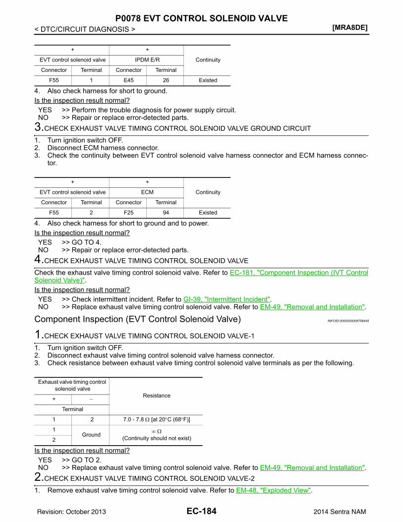
[MRA8DE]P0078 EVT CONTROL SOLENOID VALVE
< DTC/CIRCUIT DIAGNOSIS >
4. Also check harness for short to ground.Is the inspection result normal?YES >> Perform the trouble diagnosis for power supply circuit.NO >> Repair or replace error-detected parts.
3.CHECK EXHAUST VALVE TIMING CONTROL SOLENOID VALVE GROUND CIRCUIT
1. Turn ignition switch OFF.2. Disconnect ECM harness connector.3. Check the continuity between EVT control solenoid valve harness connector and ECM harness connec-
tor.
4. Also check harness for short to ground and to power. Is the inspection result normal?YES >> GO TO 4.NO >> Repair or replace error-detected parts.
4.CHECK EXHAUST VALVE TIMING CONTROL SOLENOID VALVE
Check the exhaust valve timing control solenoid valve. Refer to EC-181, "Component Inspection (IVT ControlSolenoid Valve)".Is the inspection result normal?YES >> Check intermittent incident. Refer to GI-39, "Intermittent Incident".NO >> Replace exhaust valve timing control solenoid valve. Refer to EM-49, "Removal and Installation".
Component Inspection (EVT Control Solenoid Valve) INFOID:0000000009758445
1.CHECK EXHAUST VALVE TIMING CONTROL SOLENOID VALVE-1
1. Turn ignition switch OFF.2. Disconnect exhaust valve timing control solenoid valve harness connector.3. Check resistance between exhaust valve timing control solenoid valve terminals as per the following.
Is the inspection result normal?YES >> GO TO 2.NO >> Replace exhaust valve timing control solenoid valve. Refer to EM-49, "Removal and Installation".
2.CHECK EXHAUST VALVE TIMING CONTROL SOLENOID VALVE-2
1. Remove exhaust valve timing control solenoid valve. Refer to EM-48, "Exploded View".
+ +
ContinuityEVT control solenoid valve IPDM E/R
Connector Terminal Connector Terminal
F55 1 E45 26 Existed
+ +
ContinuityEVT control solenoid valve ECM
Connector Terminal Connector Terminal
F55 2 F25 94 Existed
Exhaust valve timing control solenoid valve
Resistance+ −
Terminal
1 2 7.0 - 7.8 Ω [at 20°C (68°F)]
1Ground ∞ Ω
(Continuity should not exist)2
EC-184Revision: October 2013 2014 Sentra NAM
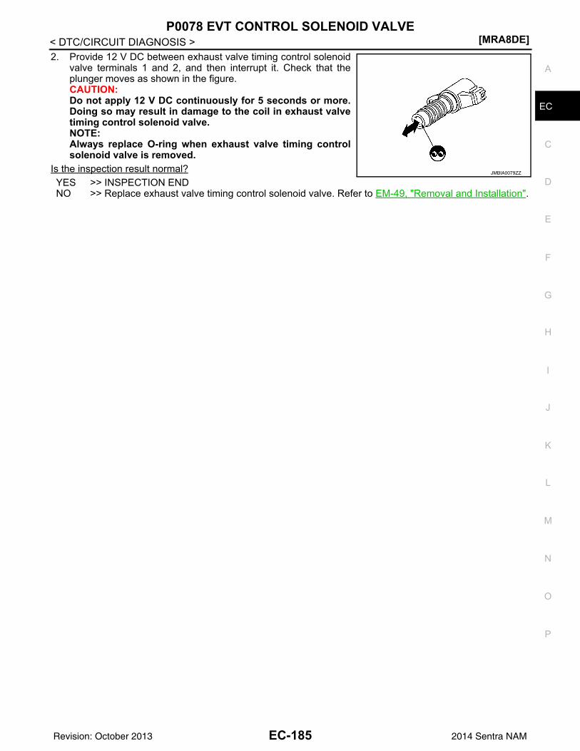
P0078 EVT CONTROL SOLENOID VALVE[MRA8DE]
C
D
E
F
G
H
I
J
K
L
M
A
C
N
P
O
< DTC/CIRCUIT DIAGNOSIS >
E
2. Provide 12 V DC between exhaust valve timing control solenoidvalve terminals 1 and 2, and then interrupt it. Check that theplunger moves as shown in the figure.CAUTION:Do not apply 12 V DC continuously for 5 seconds or more.Doing so may result in damage to the coil in exhaust valvetiming control solenoid valve.NOTE:Always replace O-ring when exhaust valve timing controlsolenoid valve is removed.
Is the inspection result normal?YES >> INSPECTION ENDNO >> Replace exhaust valve timing control solenoid valve. Refer to EM-49, "Removal and Installation".
JMBIA0079ZZ
EC-185Revision: October 2013 2014 Sentra NAM
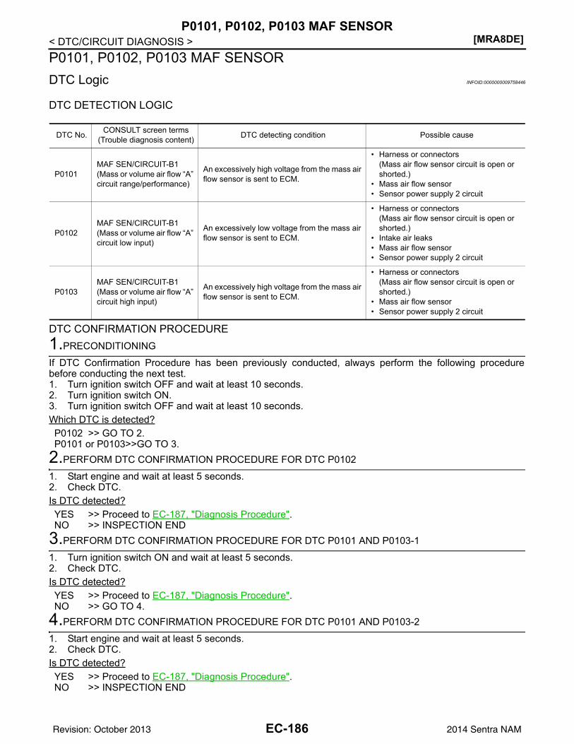
[MRA8DE]P0101, P0102, P0103 MAF SENSOR
< DTC/CIRCUIT DIAGNOSIS >P0101, P0102, P0103 MAF SENSORDTC Logic INFOID:0000000009758446
DTC DETECTION LOGIC
DTC CONFIRMATION PROCEDURE1.PRECONDITIONING
If DTC Confirmation Procedure has been previously conducted, always perform the following procedurebefore conducting the next test.1. Turn ignition switch OFF and wait at least 10 seconds.2. Turn ignition switch ON.3. Turn ignition switch OFF and wait at least 10 seconds.Which DTC is detected?P0102 >> GO TO 2.P0101 or P0103>>GO TO 3.
2.PERFORM DTC CONFIRMATION PROCEDURE FOR DTC P0102
1. Start engine and wait at least 5 seconds.2. Check DTC.Is DTC detected?YES >> Proceed to EC-187, "Diagnosis Procedure".NO >> INSPECTION END
3.PERFORM DTC CONFIRMATION PROCEDURE FOR DTC P0101 AND P0103-1
1. Turn ignition switch ON and wait at least 5 seconds.2. Check DTC.Is DTC detected?YES >> Proceed to EC-187, "Diagnosis Procedure".NO >> GO TO 4.
4.PERFORM DTC CONFIRMATION PROCEDURE FOR DTC P0101 AND P0103-2
1. Start engine and wait at least 5 seconds.2. Check DTC.Is DTC detected?YES >> Proceed to EC-187, "Diagnosis Procedure".NO >> INSPECTION END
DTC No. CONSULT screen terms(Trouble diagnosis content) DTC detecting condition Possible cause
P0101MAF SEN/CIRCUIT-B1(Mass or volume air flow “A” circuit range/performance)
An excessively high voltage from the mass air flow sensor is sent to ECM.
• Harness or connectors(Mass air flow sensor circuit is open or shorted.)
• Mass air flow sensor• Sensor power supply 2 circuit
P0102MAF SEN/CIRCUIT-B1(Mass or volume air flow “A” circuit low input)
An excessively low voltage from the mass air flow sensor is sent to ECM.
• Harness or connectors(Mass air flow sensor circuit is open or shorted.)
• Intake air leaks• Mass air flow sensor• Sensor power supply 2 circuit
P0103MAF SEN/CIRCUIT-B1(Mass or volume air flow “A” circuit high input)
An excessively high voltage from the mass air flow sensor is sent to ECM.
• Harness or connectors(Mass air flow sensor circuit is open or shorted.)
• Mass air flow sensor• Sensor power supply 2 circuit
EC-186Revision: October 2013 2014 Sentra NAM
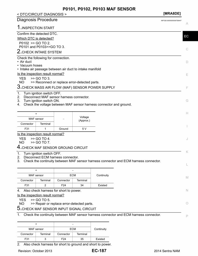
P0101, P0102, P0103 MAF SENSOR[MRA8DE]
C
D
E
F
G
H
I
J
K
L
M
A
C
N
P
O
< DTC/CIRCUIT DIAGNOSIS >
E
Diagnosis Procedure INFOID:0000000009758447
1.INSPECTION START
Confirm the detected DTC.Which DTC is detected?P0102 >> GO TO 2.P0101 and P0103>>GO TO 3.
2.CHECK INTAKE SYSTEM
Check the following for connection.• Air duct• Vacuum hoses• Intake air passage between air duct to intake manifoldIs the inspection result normal?YES >> GO TO 3.NO >> Reconnect or replace error-detected parts.
3.CHECK MASS AIR FLOW (MAF) SENSOR POWER SUPPLY
1. Turn ignition switch OFF.2. Disconnect MAF sensor harness connector.3. Turn ignition switch ON.4. Check the voltage between MAF sensor harness connector and ground.
Is the inspection result normal?YES >> GO TO 4.NO >> GO TO 7.
4.CHECK MAF SENSOR GROUND CIRCUIT
1. Turn ignition switch OFF.2. Disconnect ECM harness connector.3. Check the continuity between MAF sensor harness connector and ECM harness connector.
4. Also check harness for short to power.Is the inspection result normal?YES >> GO TO 5.NO >> Repair or replace error-detected parts.
5.CHECK MAF SENSOR INPUT SIGNAL CIRCUIT
1. Check the continuity between MAF sensor harness connector and ECM harness connector.
2. Also check harness for short to ground and short to power.
+
−Voltage
(Approx.)MAF sensor
Connector Terminal
F31 1 Ground 5 V
+ −
ContinuityMAF sensor ECM
Connector Terminal Connector Terminal
F31 2 F24 34 Existed
+ −
ContinuityMAF sensor ECM
Connector Terminal Connector Terminal
F31 3 F24 35 Existed
EC-187Revision: October 2013 2014 Sentra NAM
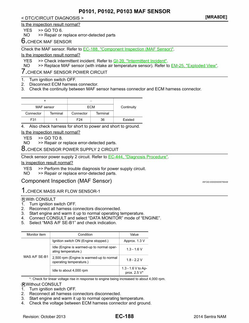
[MRA8DE]P0101, P0102, P0103 MAF SENSOR
< DTC/CIRCUIT DIAGNOSIS >Is the inspection result normal?YES >> GO TO 6.NO >> Repair or replace error-detected parts
6.CHECK MAF SENSOR
Check the MAF sensor. Refer to EC-188, "Component Inspection (MAF Sensor)".Is the inspection result normal?YES >> Check intermittent incident. Refer to GI-39, "Intermittent Incident".NO >> Replace MAF sensor (with intake air temperature sensor). Refer to EM-25, "Exploded View".
7.CHECK MAF SENSOR POWER CIRCUIT
1. Turn ignition switch OFF.2. Disconnect ECM harness connector.3. Check the continuity between MAF sensor harness connector and ECM harness connector.
4. Also check harness for short to power and short to ground.Is the inspection result normal?YES >> GO TO 8.NO >> Repair or replace error-detected parts.
8.CHECK SENSOR POWER SUPPLY 2 CIRCUIT
Check sensor power supply 2 circuit. Refer to EC-444, "Diagnosis Procedure".Is inspection result normal?YES >> Perform the trouble diagnosis for power supply circuit.NO >> Repair or replace error-detected parts.
Component Inspection (MAF Sensor) INFOID:0000000009758448
1.CHECK MASS AIR FLOW SENSOR-1
With CONSULT1. Turn ignition switch OFF.2. Reconnect all harness connectors disconnected.3. Start engine and warm it up to normal operating temperature.4. Connect CONSULT and select “DATA MONITOR” mode of “ENGINE”.5. Select “MAS A/F SE-B1” and check indication.
*: Check for linear voltage rise in response to engine being increased to about 4,000 rpm.Without CONSULT
1. Turn ignition switch OFF.2. Reconnect all harness connectors disconnected.3. Start engine and warm it up to normal operating temperature.4. Check the voltage between ECM harness connector and ground.
+ −
ContinuityMAF sensor ECM
Connector Terminal Connector Terminal
F31 1 F24 36 Existed
Monitor item Condition Value
MAS A/F SE-B1
Ignition switch ON (Engine stopped.) Approx. 1.3 V
Idle (Engine is warmed-up to normal oper-ating temperature.) 1.3 - 1.6 V
2,500 rpm (Engine is warmed-up to normal operating temperature.) 1.8 - 2.2 V
Idle to about 4,000 rpm 1.3 - 1.6 V to Ap-prox. 2.5 V*
EC-188Revision: October 2013 2014 Sentra NAM
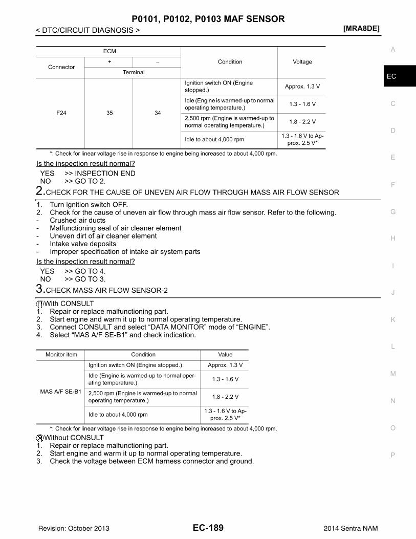
P0101, P0102, P0103 MAF SENSOR[MRA8DE]
C
D
E
F
G
H
I
J
K
L
M
A
C
N
P
O
< DTC/CIRCUIT DIAGNOSIS >
E
*: Check for linear voltage rise in response to engine being increased to about 4,000 rpm.
Is the inspection result normal?YES >> INSPECTION ENDNO >> GO TO 2.
2.CHECK FOR THE CAUSE OF UNEVEN AIR FLOW THROUGH MASS AIR FLOW SENSOR
1. Turn ignition switch OFF.2. Check for the cause of uneven air flow through mass air flow sensor. Refer to the following.- Crushed air ducts- Malfunctioning seal of air cleaner element- Uneven dirt of air cleaner element- Intake valve deposits- Improper specification of intake air system partsIs the inspection result normal?YES >> GO TO 4.NO >> GO TO 3.
3.CHECK MASS AIR FLOW SENSOR-2
With CONSULT1. Repair or replace malfunctioning part.2. Start engine and warm it up to normal operating temperature.3. Connect CONSULT and select “DATA MONITOR” mode of “ENGINE”.4. Select “MAS A/F SE-B1” and check indication.
*: Check for linear voltage rise in response to engine being increased to about 4,000 rpm.Without CONSULT
1. Repair or replace malfunctioning part.2. Start engine and warm it up to normal operating temperature.3. Check the voltage between ECM harness connector and ground.
ECM
Condition VoltageConnector
+ −
Terminal
F24 35 34
Ignition switch ON (Engine stopped.) Approx. 1.3 V
Idle (Engine is warmed-up to normal operating temperature.) 1.3 - 1.6 V
2,500 rpm (Engine is warmed-up to normal operating temperature.) 1.8 - 2.2 V
Idle to about 4,000 rpm 1.3 - 1.6 V to Ap-prox. 2.5 V*
Monitor item Condition Value
MAS A/F SE-B1
Ignition switch ON (Engine stopped.) Approx. 1.3 V
Idle (Engine is warmed-up to normal oper-ating temperature.) 1.3 - 1.6 V
2,500 rpm (Engine is warmed-up to normal operating temperature.) 1.8 - 2.2 V
Idle to about 4,000 rpm 1.3 - 1.6 V to Ap-prox. 2.5 V*
EC-189Revision: October 2013 2014 Sentra NAM
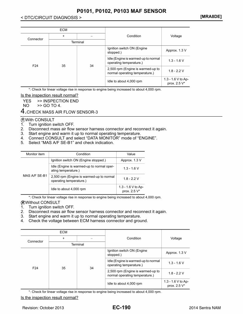
[MRA8DE]P0101, P0102, P0103 MAF SENSOR
< DTC/CIRCUIT DIAGNOSIS >
*: Check for linear voltage rise in response to engine being increased to about 4,000 rpm.
Is the inspection result normal?YES >> INSPECTION ENDNO >> GO TO 4.
4.CHECK MASS AIR FLOW SENSOR-3
With CONSULT1. Turn ignition switch OFF.2. Disconnect mass air flow sensor harness connector and reconnect it again.3. Start engine and warm it up to normal operating temperature.4. Connect CONSULT and select “DATA MONITOR” mode of “ENGINE”.5. Select “MAS A/F SE-B1” and check indication.
*: Check for linear voltage rise in response to engine being increased to about 4,000 rpm.Without CONSULT
1. Turn ignition switch OFF.2. Disconnect mass air flow sensor harness connector and reconnect it again.3. Start engine and warm it up to normal operating temperature.4. Check the voltage between ECM harness connector and ground.
*: Check for linear voltage rise in response to engine being increased to about 4,000 rpm.
Is the inspection result normal?
ECM
Condition VoltageConnector
+ −
Terminal
F24 35 34
Ignition switch ON (Engine stopped.) Approx. 1.3 V
Idle (Engine is warmed-up to normal operating temperature.) 1.3 - 1.6 V
2,500 rpm (Engine is warmed-up to normal operating temperature.) 1.8 - 2.2 V
Idle to about 4,000 rpm 1.3 - 1.6 V to Ap-prox. 2.5 V*
Monitor item Condition Value
MAS A/F SE-B1
Ignition switch ON (Engine stopped.) Approx. 1.3 V
Idle (Engine is warmed-up to normal oper-ating temperature.) 1.3 - 1.6 V
2,500 rpm (Engine is warmed-up to normal operating temperature.) 1.8 - 2.2 V
Idle to about 4,000 rpm 1.3 - 1.6 V to Ap-prox. 2.5 V*
ECM
Condition VoltageConnector
+ −
Terminal
F24 35 34
Ignition switch ON (Engine stopped.) Approx. 1.3 V
Idle (Engine is warmed-up to normal operating temperature.) 1.3 - 1.6 V
2,500 rpm (Engine is warmed-up to normal operating temperature.) 1.8 - 2.2 V
Idle to about 4,000 rpm 1.3 - 1.6 V to Ap-prox. 2.5 V*
EC-190Revision: October 2013 2014 Sentra NAM
P0101, P0102, P0103 MAF SENSOR[MRA8DE]
C
D
E
F
G
H
I
J
K
L
M
A
C
N
P
O
< DTC/CIRCUIT DIAGNOSIS >
E
YES >> INSPECTION ENDNO >> Clean or replace mass air flow sensor. Refer to EM-25, "Exploded View".
EC-191Revision: October 2013 2014 Sentra NAM
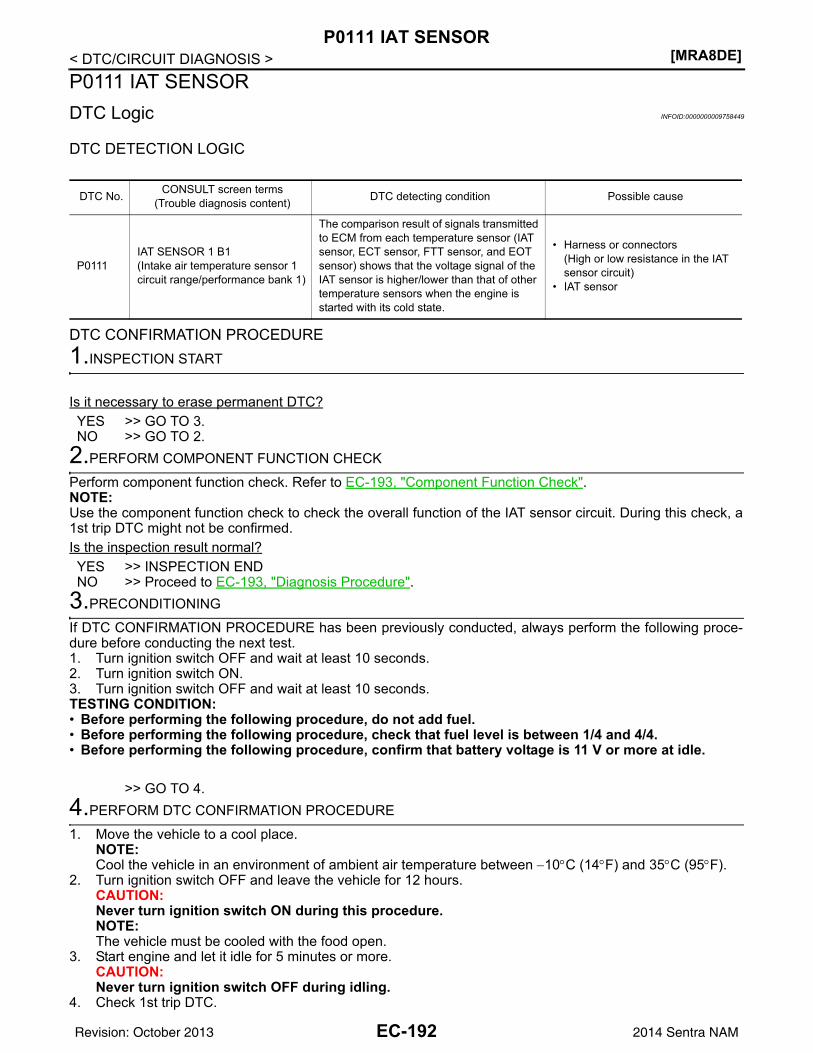
[MRA8DE]P0111 IAT SENSOR
< DTC/CIRCUIT DIAGNOSIS >P0111 IAT SENSORDTC Logic INFOID:0000000009758449
DTC DETECTION LOGIC
DTC CONFIRMATION PROCEDURE1.INSPECTION START
Is it necessary to erase permanent DTC?YES >> GO TO 3.NO >> GO TO 2.
2.PERFORM COMPONENT FUNCTION CHECK
Perform component function check. Refer to EC-193, "Component Function Check".NOTE:Use the component function check to check the overall function of the IAT sensor circuit. During this check, a1st trip DTC might not be confirmed.Is the inspection result normal?YES >> INSPECTION ENDNO >> Proceed to EC-193, "Diagnosis Procedure".
3.PRECONDITIONING
If DTC CONFIRMATION PROCEDURE has been previously conducted, always perform the following proce-dure before conducting the next test.1. Turn ignition switch OFF and wait at least 10 seconds.2. Turn ignition switch ON.3. Turn ignition switch OFF and wait at least 10 seconds.TESTING CONDITION:• Before performing the following procedure, do not add fuel.• Before performing the following procedure, check that fuel level is between 1/4 and 4/4.• Before performing the following procedure, confirm that battery voltage is 11 V or more at idle.
>> GO TO 4.4.PERFORM DTC CONFIRMATION PROCEDURE
1. Move the vehicle to a cool place.NOTE:Cool the vehicle in an environment of ambient air temperature between −10°C (14°F) and 35°C (95°F).
2. Turn ignition switch OFF and leave the vehicle for 12 hours.CAUTION:Never turn ignition switch ON during this procedure.NOTE:The vehicle must be cooled with the food open.
3. Start engine and let it idle for 5 minutes or more.CAUTION:Never turn ignition switch OFF during idling.
4. Check 1st trip DTC.
DTC No. CONSULT screen terms(Trouble diagnosis content) DTC detecting condition Possible cause
P0111IAT SENSOR 1 B1(Intake air temperature sensor 1 circuit range/performance bank 1)
The comparison result of signals transmitted to ECM from each temperature sensor (IAT sensor, ECT sensor, FTT sensor, and EOT sensor) shows that the voltage signal of the IAT sensor is higher/lower than that of other temperature sensors when the engine is started with its cold state.
• Harness or connectors(High or low resistance in the IAT sensor circuit)
• IAT sensor
EC-192Revision: October 2013 2014 Sentra NAM
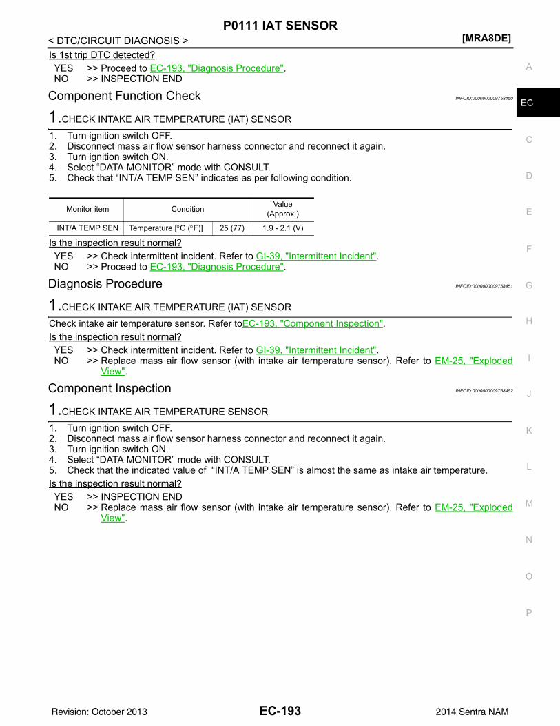
P0111 IAT SENSOR[MRA8DE]
C
D
E
F
G
H
I
J
K
L
M
A
C
N
P
O
< DTC/CIRCUIT DIAGNOSIS >
E
Is 1st trip DTC detected?YES >> Proceed to EC-193, "Diagnosis Procedure".NO >> INSPECTION END
Component Function Check INFOID:0000000009758450
1.CHECK INTAKE AIR TEMPERATURE (IAT) SENSOR
1. Turn ignition switch OFF.2. Disconnect mass air flow sensor harness connector and reconnect it again.3. Turn ignition switch ON.4. Select “DATA MONITOR” mode with CONSULT.5. Check that “INT/A TEMP SEN” indicates as per following condition.
Is the inspection result normal?YES >> Check intermittent incident. Refer to GI-39, "Intermittent Incident".NO >> Proceed to EC-193, "Diagnosis Procedure".
Diagnosis Procedure INFOID:0000000009758451
1.CHECK INTAKE AIR TEMPERATURE (IAT) SENSOR
Check intake air temperature sensor. Refer toEC-193, "Component Inspection".Is the inspection result normal?YES >> Check intermittent incident. Refer to GI-39, "Intermittent Incident".NO >> Replace mass air flow sensor (with intake air temperature sensor). Refer to EM-25, "Exploded
View".
Component Inspection INFOID:0000000009758452
1.CHECK INTAKE AIR TEMPERATURE SENSOR
1. Turn ignition switch OFF.2. Disconnect mass air flow sensor harness connector and reconnect it again.3. Turn ignition switch ON.4. Select “DATA MONITOR” mode with CONSULT.5. Check that the indicated value of “INT/A TEMP SEN” is almost the same as intake air temperature. Is the inspection result normal?YES >> INSPECTION ENDNO >> Replace mass air flow sensor (with intake air temperature sensor). Refer to EM-25, "Exploded
View".
Monitor item Condition Value(Approx.)
INT/A TEMP SEN Temperature [°C (°F)] 25 (77) 1.9 - 2.1 (V)
EC-193Revision: October 2013 2014 Sentra NAM
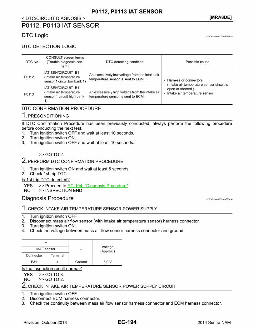
[MRA8DE]P0112, P0113 IAT SENSOR
< DTC/CIRCUIT DIAGNOSIS >P0112, P0113 IAT SENSORDTC Logic INFOID:0000000009758453
DTC DETECTION LOGIC
DTC CONFIRMATION PROCEDURE1.PRECONDITIONING
If DTC Confirmation Procedure has been previously conducted, always perform the following procedurebefore conducting the next test.1. Turn ignition switch OFF and wait at least 10 seconds.2. Turn ignition switch ON.3. Turn ignition switch OFF and wait at least 10 seconds.
>> GO TO 2.2.PERFORM DTC CONFIRMATION PROCEDURE
1. Turn ignition switch ON and wait at least 5 seconds.2. Check 1st trip DTC.Is 1st trip DTC detected?YES >> Proceed to EC-194, "Diagnosis Procedure".NO >> INSPECTION END
Diagnosis Procedure INFOID:0000000009758454
1.CHECK INTAKE AIR TEMPERATURE SENSOR POWER SUPPLY
1. Turn ignition switch OFF.2. Disconnect mass air flow sensor (with intake air temperature sensor) harness connector.3. Turn ignition switch ON.4. Check the voltage between mass air flow sensor harness connector and ground.
Is the inspection result normal?YES >> GO TO 3.NO >> GO TO 2.
2.CHECK INTAKE AIR TEMPERATURE SENSOR POWER SUPPLY CIRCUIT
1. Turn ignition switch OFF.2. Disconnect ECM harness connector.3. Check the continuity between mass air flow sensor harness connector and ECM harness connector.
DTC No.CONSULT screen terms(Trouble diagnosis con-
tent)DTC detecting condition Possible cause
P0112IAT SEN/CIRCUIT- B1(Intake air temperature sensor 1 circuit low bank 1)
An excessively low voltage from the intake air temperature sensor is sent to ECM. • Harness or connectors
(Intake air temperature sensor circuit is open or shorted.)
• Intake air temperature sensorP0113
IAT SEN/CIRCUIT- B1(Intake air temperature sensor 1 circuit high bank 1)
An excessively high voltage from the intake air temperature sensor is sent to ECM.
+
−Voltage
(Approx.)MAF sensor
Connector Terminal
F31 4 Ground 5.0 V
EC-194Revision: October 2013 2014 Sentra NAM
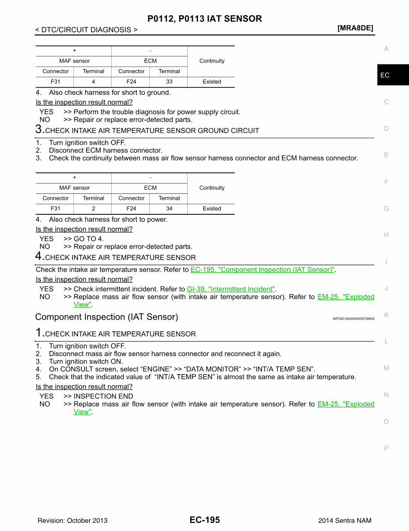
P0112, P0113 IAT SENSOR[MRA8DE]
C
D
E
F
G
H
I
J
K
L
M
A
C
N
P
O
< DTC/CIRCUIT DIAGNOSIS >
E
4. Also check harness for short to ground.Is the inspection result normal?YES >> Perform the trouble diagnosis for power supply circuit.NO >> Repair or replace error-detected parts.
3.CHECK INTAKE AIR TEMPERATURE SENSOR GROUND CIRCUIT
1. Turn ignition switch OFF.2. Disconnect ECM harness connector.3. Check the continuity between mass air flow sensor harness connector and ECM harness connector.
4. Also check harness for short to power.Is the inspection result normal?YES >> GO TO 4.NO >> Repair or replace error-detected parts.
4.CHECK INTAKE AIR TEMPERATURE SENSOR
Check the intake air temperature sensor. Refer to EC-195, "Component Inspection (IAT Sensor)".Is the inspection result normal?YES >> Check intermittent incident. Refer to GI-39, "Intermittent Incident".NO >> Replace mass air flow sensor (with intake air temperature sensor). Refer to EM-25, "Exploded
View".
Component Inspection (IAT Sensor) INFOID:0000000009758455
1.CHECK INTAKE AIR TEMPERATURE SENSOR
1. Turn ignition switch OFF.2. Disconnect mass air flow sensor harness connector and reconnect it again.3. Turn ignition switch ON.4. On CONSULT screen, select “ENGINE” >> “DATA MONITOR” >> “INT/A TEMP SEN”.5. Check that the indicated value of “INT/A TEMP SEN” is almost the same as intake air temperature. Is the inspection result normal?YES >> INSPECTION ENDNO >> Replace mass air flow sensor (with intake air temperature sensor). Refer to EM-25, "Exploded
View".
+ −
ContinuityMAF sensor ECM
Connector Terminal Connector Terminal
F31 4 F24 33 Existed
+ −
ContinuityMAF sensor ECM
Connector Terminal Connector Terminal
F31 2 F24 34 Existed
EC-195Revision: October 2013 2014 Sentra NAM
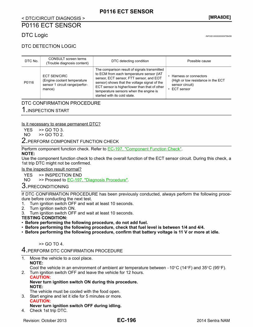
[MRA8DE]P0116 ECT SENSOR
< DTC/CIRCUIT DIAGNOSIS >P0116 ECT SENSORDTC Logic INFOID:0000000009758456
DTC DETECTION LOGIC
DTC CONFIRMATION PROCEDURE1.INSPECTION START
Is it necessary to erase permanent DTC?YES >> GO TO 3.NO >> GO TO 2.
2.PERFORM COMPONENT FUNCTION CHECK
Perform component function check. Refer to EC-197, "Component Function Check".NOTE:Use the component function check to check the overall function of the ECT sensor circuit. During this check, a1st trip DTC might not be confirmed.Is the inspection result normal?YES >> INSPECTION ENDNO >> Proceed to EC-197, "Diagnosis Procedure".
3.PRECONDITIONING
If DTC CONFIRMATION PROCEDURE has been previously conducted, always perform the following proce-dure before conducting the next test.1. Turn ignition switch OFF and wait at least 10 seconds.2. Turn ignition switch ON.3. Turn ignition switch OFF and wait at least 10 seconds.TESTING CONDITION:• Before performing the following procedure, do not add fuel.• Before performing the following procedure, check that fuel level is between 1/4 and 4/4.• Before performing the following procedure, confirm that battery voltage is 11 V or more at idle.
>> GO TO 4.4.PERFORM DTC CONFIRMATION PROCEDURE
1. Move the vehicle to a cool place.NOTE:Cool the vehicle in an environment of ambient air temperature between −10°C (14°F) and 35°C (95°F).
2. Turn ignition switch OFF and leave the vehicle for 12 hours.CAUTION:Never turn ignition switch ON during this procedure.NOTE:The vehicle must be cooled with the food open.
3. Start engine and let it idle for 5 minutes or more.CAUTION:Never turn ignition switch OFF during idling.
4. Check 1st trip DTC.
DTC No. CONSULT screen terms(Trouble diagnosis content) DTC detecting condition Possible cause
P0116
ECT SEN/CIRC(Engine coolant temperature sensor 1 circuit range/perfor-mance)
The comparison result of signals transmitted to ECM from each temperature sensor (IAT sensor, ECT sensor, FTT sensor, and EOT sensor) shows that the voltage signal of the ECT sensor is higher/lower than that of other temperature sensors when the engine is started with its cold state.
• Harness or connectors(High or low resistance in the ECT sensor circuit)
• ECT sensor
EC-196Revision: October 2013 2014 Sentra NAM
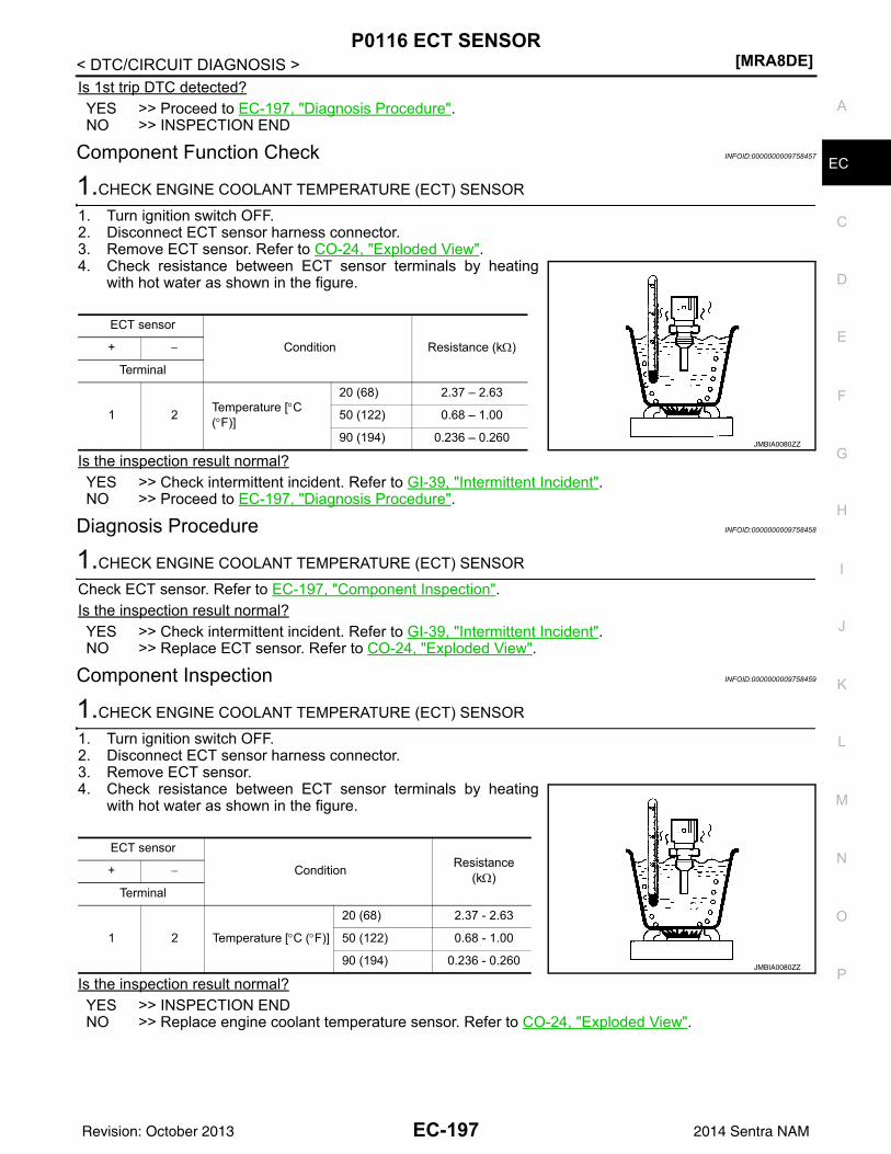
P0116 ECT SENSOR[MRA8DE]
C
D
E
F
G
H
I
J
K
L
M
A
C
N
P
O
< DTC/CIRCUIT DIAGNOSIS >
E
Is 1st trip DTC detected?YES >> Proceed to EC-197, "Diagnosis Procedure".NO >> INSPECTION END
Component Function Check INFOID:0000000009758457
1.CHECK ENGINE COOLANT TEMPERATURE (ECT) SENSOR
1. Turn ignition switch OFF.2. Disconnect ECT sensor harness connector.3. Remove ECT sensor. Refer to CO-24, "Exploded View".4. Check resistance between ECT sensor terminals by heating
with hot water as shown in the figure.
Is the inspection result normal?YES >> Check intermittent incident. Refer to GI-39, "Intermittent Incident".NO >> Proceed to EC-197, "Diagnosis Procedure".
Diagnosis Procedure INFOID:0000000009758458
1.CHECK ENGINE COOLANT TEMPERATURE (ECT) SENSOR
Check ECT sensor. Refer to EC-197, "Component Inspection".Is the inspection result normal?YES >> Check intermittent incident. Refer to GI-39, "Intermittent Incident".NO >> Replace ECT sensor. Refer to CO-24, "Exploded View".
Component Inspection INFOID:0000000009758459
1.CHECK ENGINE COOLANT TEMPERATURE (ECT) SENSOR
1. Turn ignition switch OFF.2. Disconnect ECT sensor harness connector.3. Remove ECT sensor.4. Check resistance between ECT sensor terminals by heating
with hot water as shown in the figure.
Is the inspection result normal?YES >> INSPECTION ENDNO >> Replace engine coolant temperature sensor. Refer to CO-24, "Exploded View".
ECT sensor
Condition Resistance (kΩ)+ −
Terminal
1 2 Temperature [°C (°F)]
20 (68) 2.37 – 2.63
50 (122) 0.68 – 1.00
90 (194) 0.236 – 0.260JMBIA0080ZZ
ECT sensor
Condition Resistance (kΩ)+ −
Terminal
1 2 Temperature [°C (°F)]
20 (68) 2.37 - 2.63
50 (122) 0.68 - 1.00
90 (194) 0.236 - 0.260JMBIA0080ZZ
EC-197Revision: October 2013 2014 Sentra NAM
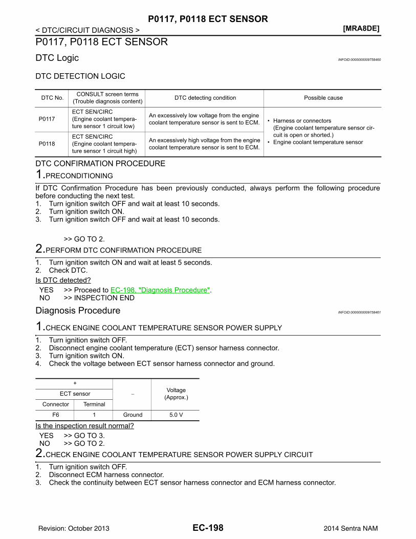
[MRA8DE]P0117, P0118 ECT SENSOR
< DTC/CIRCUIT DIAGNOSIS >P0117, P0118 ECT SENSORDTC Logic INFOID:0000000009758460
DTC DETECTION LOGIC
DTC CONFIRMATION PROCEDURE1.PRECONDITIONING
If DTC Confirmation Procedure has been previously conducted, always perform the following procedurebefore conducting the next test.1. Turn ignition switch OFF and wait at least 10 seconds.2. Turn ignition switch ON.3. Turn ignition switch OFF and wait at least 10 seconds.
>> GO TO 2.2.PERFORM DTC CONFIRMATION PROCEDURE
1. Turn ignition switch ON and wait at least 5 seconds.2. Check DTC.Is DTC detected?YES >> Proceed to EC-198, "Diagnosis Procedure".NO >> INSPECTION END
Diagnosis Procedure INFOID:0000000009758461
1.CHECK ENGINE COOLANT TEMPERATURE SENSOR POWER SUPPLY
1. Turn ignition switch OFF.2. Disconnect engine coolant temperature (ECT) sensor harness connector.3. Turn ignition switch ON.4. Check the voltage between ECT sensor harness connector and ground.
Is the inspection result normal?YES >> GO TO 3.NO >> GO TO 2.
2.CHECK ENGINE COOLANT TEMPERATURE SENSOR POWER SUPPLY CIRCUIT
1. Turn ignition switch OFF.2. Disconnect ECM harness connector.3. Check the continuity between ECT sensor harness connector and ECM harness connector.
DTC No. CONSULT screen terms(Trouble diagnosis content) DTC detecting condition Possible cause
P0117ECT SEN/CIRC(Engine coolant tempera-ture sensor 1 circuit low)
An excessively low voltage from the engine coolant temperature sensor is sent to ECM. • Harness or connectors
(Engine coolant temperature sensor cir-cuit is open or shorted.)
• Engine coolant temperature sensor P0118ECT SEN/CIRC(Engine coolant tempera-ture sensor 1 circuit high)
An excessively high voltage from the engine coolant temperature sensor is sent to ECM.
+
−Voltage
(Approx.)ECT sensor
Connector Terminal
F6 1 Ground 5.0 V
EC-198Revision: October 2013 2014 Sentra NAM
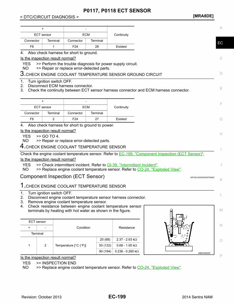
P0117, P0118 ECT SENSOR[MRA8DE]
C
D
E
F
G
H
I
J
K
L
M
A
C
N
P
O
< DTC/CIRCUIT DIAGNOSIS >
E
4. Also check harness for short to ground.Is the inspection result normal?YES >> Perform the trouble diagnosis for power supply circuit.NO >> Repair or replace error-detected parts.
3.CHECK ENGINE COOLANT TEMPERATURE SENSOR GROUND CIRCUIT
1. Turn ignition switch OFF.2. Disconnect ECM harness connector.3. Check the continuity between ECT sensor harness connector and ECM harness connector.
4. Also check harness for short to ground to power.Is the inspection result normal?YES >> GO TO 4.NO >> Repair or replace error-detected parts.
4.CHECK ENGINE COOLANT TEMPERATURE SENSOR
Check the engine coolant temperature sensor. Refer to EC-199, "Component Inspection (ECT Sensor)".Is the inspection result normal?YES >> Check intermittent incident. Refer to GI-39, "Intermittent Incident".NO >> Replace engine coolant temperature sensor. Refer to CO-24, "Exploded View".
Component Inspection (ECT Sensor) INFOID:0000000009758462
1.CHECK ENGINE COOLANT TEMPERATURE SENSOR
1. Turn ignition switch OFF.2. Disconnect engine coolant temperature sensor harness connector.3. Remove engine coolant temperature sensor.4. Check resistance between engine coolant temperature sensor
terminals by heating with hot water as shown in the figure.
Is the inspection result normal?YES >> INSPECTION ENDNO >> Replace engine coolant temperature sensor. Refer to CO-24, "Exploded View".
+ −
ContinuityECT sensor ECM
Connector Terminal Connector Terminal
F6 1 F24 28 Existed
+ −
ContinuityECT sensor ECM
Connector Terminal Connector Terminal
F6 2 F24 27 Existed
ECT sensor
Condition Resistance+ −
Terminal
1 2 Temperature [°C (°F)]
20 (68) 2.37 - 2.63 kΩ
50 (122) 0.68 - 1.00 kΩ
90 (194) 0.236 - 0.260 kΩJMBIA0080ZZ
EC-199Revision: October 2013 2014 Sentra NAM
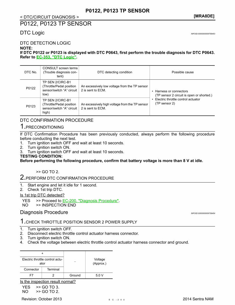
[MRA8DE]P0122, P0123 TP SENSOR
< DTC/CIRCUIT DIAGNOSIS >P0122, P0123 TP SENSORDTC Logic INFOID:0000000009758463
DTC DETECTION LOGICNOTE:If DTC P0122 or P0123 is displayed with DTC P0643, first perform the trouble diagnosis for DTC P0643.Refer to EC-353, "DTC Logic".
DTC CONFIRMATION PROCEDURE1.PRECONDITIONING
If DTC Confirmation Procedure has been previously conducted, always perform the following procedurebefore conducting the next test.1. Turn ignition switch OFF and wait at least 10 seconds.2. Turn ignition switch ON.3. Turn ignition switch OFF and wait at least 10 seconds.TESTING CONDITION:Before performing the following procedure, confirm that battery voltage is more than 8 V at idle.
>> GO TO 2.2.PERFORM DTC CONFIRMATION PROCEDURE
1. Start engine and let it idle for 1 second.2. Check 1st trip DTC.Is 1st trip DTC detected?YES >> Proceed to EC-200, "Diagnosis Procedure".NO >> INSPECTION END
Diagnosis Procedure INFOID:0000000009758464
1.CHECK THROTTLE POSITION SENSOR 2 POWER SUPPLY
1. Turn ignition switch OFF.2. Disconnect electric throttle control actuator harness connector.3. Turn ignition switch ON.4. Check the voltage between electric throttle control actuator harness connector and ground.
Is the inspection result normal?YES >> GO TO 3.NO >> GO TO 2.
DTC No.CONSULT screen terms(Trouble diagnosis con-
tent)DTC detecting condition Possible cause
P0122
TP SEN 2/CIRC-B1(Throttle/Pedal position sensor/switch “A” circuit low)
An excessively low voltage from the TP sensor 2 is sent to ECM. • Harness or connectors
(TP sensor 2 circuit is open or shorted.)• Electric throttle control actuator
(TP sensor 2)P0123
TP SEN 2/CIRC-B1(Throttle/Pedal position sensor/switch “A” circuit high)
An excessively high voltage from the TP sensor 2 is sent to ECM.
+
−Voltage
(Approx.)Electric throttle control actu-
ator
Connector Terminal
F7 2 Ground 5.0 V
E C - 2 0 0Revision: October 2013 2014 Sentra NAM

P0122, P0123 TP SENSOR[MRA8DE]
C
D
E
F
G
H
I
J
K
L
M
A
C
N
P
O
< DTC/CIRCUIT DIAGNOSIS >
E
2.CHECK THROTTLE POSITION SENSOR 2 POWER SUPPLY CIRCUIT
1. Turn ignition switch OFF.2. Disconnect ECM harness connector.3. Check the continuity between electric throttle control actuator harness connector and ECM harness con-
nector.
4. Also check harness for short to power.Is the inspection result normal?YES >> Perform the trouble diagnosis for power supply circuit.NO >> Repair or replace error-detected parts.
3.CHECK THROTTLE POSITION SENSOR 2 GROUND CIRCUIT
1. Turn ignition switch OFF.2. Disconnect ECM harness connector.3. Check the continuity between electric throttle control actuator harness connector and ECM harness con-
nector.
Is the inspection result normal?YES >> GO TO 4.NO >> Repair or replace error-detected parts.
4.CHECK THROTTLE POSITION SENSOR 2 INPUT SIGNAL CIRCUIT
1. Check the continuity between electric throttle control actuator harness connector and ECM harness con-nector.
2. Also check harness for short to ground and to power.Is the inspection result normal?YES >> GO TO 5.NO >> Repair or replace error-detected parts.
5.CHECK THROTTLE POSITION SENSOR
Check throttle position sensor. Refer to EC-202, "Component Inspection (TP Sensor)".Is the inspection result normal?YES >> Check intermittent incident. Refer to GI-39, "Intermittent Incident".NO >> Replace electric throttle control actuator. Refer to EM-27, "Removal and Installation".
+ −
ContinuityElectric throttle control actu-ator ECM
Connector Terminal Connector Terminal
F7 2 F25 80 Existed
+ −
ContinuityElectric throttle control actu-ator ECM
Connector Terminal Connector Terminal
F7 4 F25 78 Existed
+ −
ContinuityElectric throttle control actu-ator ECM
Connector Terminal Connector Terminal
F7 3 F25 77 Existed
EC-201Revision: October 2013 2014 Sentra NAM
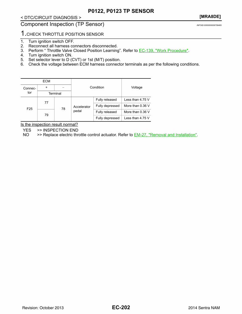
[MRA8DE]P0122, P0123 TP SENSOR
< DTC/CIRCUIT DIAGNOSIS >Component Inspection (TP Sensor) INFOID:0000000009758465
1.CHECK THROTTLE POSITION SENSOR
1. Turn ignition switch OFF.2. Reconnect all harness connectors disconnected.3. Perform “ Throttle Valve Closed Position Learning”. Refer to EC-139, "Work Procedure".4. Turn ignition switch ON.5. Set selector lever to D (CVT) or 1st (M/T) position.6. Check the voltage between ECM harness connector terminals as per the following conditions.
Is the inspection result normal?YES >> INSPECTION ENDNO >> Replace electric throttle control actuator. Refer to EM-27, "Removal and Installation".
ECM
Condition VoltageConnec-tor
+ −
Terminal
F25
77
78 Accelerator pedal
Fully released Less than 4.75 V
Fully depressed More than 0.36 V
79Fully released More than 0.36 V
Fully depressed Less than 4.75 V
EC-202Revision: October 2013 2014 Sentra NAM
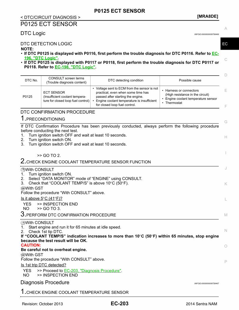
P0125 ECT SENSOR[MRA8DE]
C
D
E
F
G
H
I
J
K
L
M
A
C
N
P
O
< DTC/CIRCUIT DIAGNOSIS >
E
P0125 ECT SENSORDTC Logic INFOID:0000000009758466
DTC DETECTION LOGICNOTE:• If DTC P0125 is displayed with P0116, first perform the trouble diagnosis for DTC P0116. Refer to EC-
196, "DTC Logic".• If DTC P0125 is displayed with P0117 or P0118, first perform the trouble diagnosis for DTC P0117 or
P0118. Refer to EC-198, "DTC Logic".
DTC CONFIRMATION PROCEDURE1.PRECONDITIONING
If DTC Confirmation Procedure has been previously conducted, always perform the following procedurebefore conducting the next test.1. Turn ignition switch OFF and wait at least 10 seconds.2. Turn ignition switch ON.3. Turn ignition switch OFF and wait at least 10 seconds.
>> GO TO 2.2.CHECK ENGINE COOLANT TEMPERATURE SENSOR FUNCTION
With CONSULT1. Turn ignition switch ON.2. Select “DATA MONITOR” mode of “ENGINE” using CONSULT.3. Check that “COOLANT TEMP/S” is above 10°C (50°F).
With GSTFollow the procedure “With CONSULT” above.Is it above 5°C (41°F)?YES >> INSPECTION ENDNO >> GO TO 3.
3.PERFORM DTC CONFIRMATION PROCEDURE
With CONSULT1. Start engine and run it for 65 minutes at idle speed.2. Check 1st tip DTC.If “COOLANT TEMP/S” indication increases to more than 10°C (50°F) within 65 minutes, stop enginebecause the test result will be OK.CAUTION:Be careful not to overheat engine.
With GSTFollow the procedure “With CONSULT” above.Is 1st trip DTC detected?YES >> Proceed to EC-203, "Diagnosis Procedure".NO >> INSPECTION END
Diagnosis Procedure INFOID:0000000009758467
1.CHECK ENGINE COOLANT TEMPERATURE SENSOR
DTC No. CONSULT screen terms(Trouble diagnosis content) DTC detecting condition Possible cause
P0125ECT SENSOR(Insufficient coolant tempera-ture for closed loop fuel control)
• Voltage sent to ECM from the sensor is not practical, even when some time has passed after starting the engine.
• Engine coolant temperature is insufficient for closed loop fuel control.
• Harness or connectors(High resistance in the circuit)
• Engine coolant temperature sensor• Thermostat
EC-203Revision: October 2013 2014 Sentra NAM
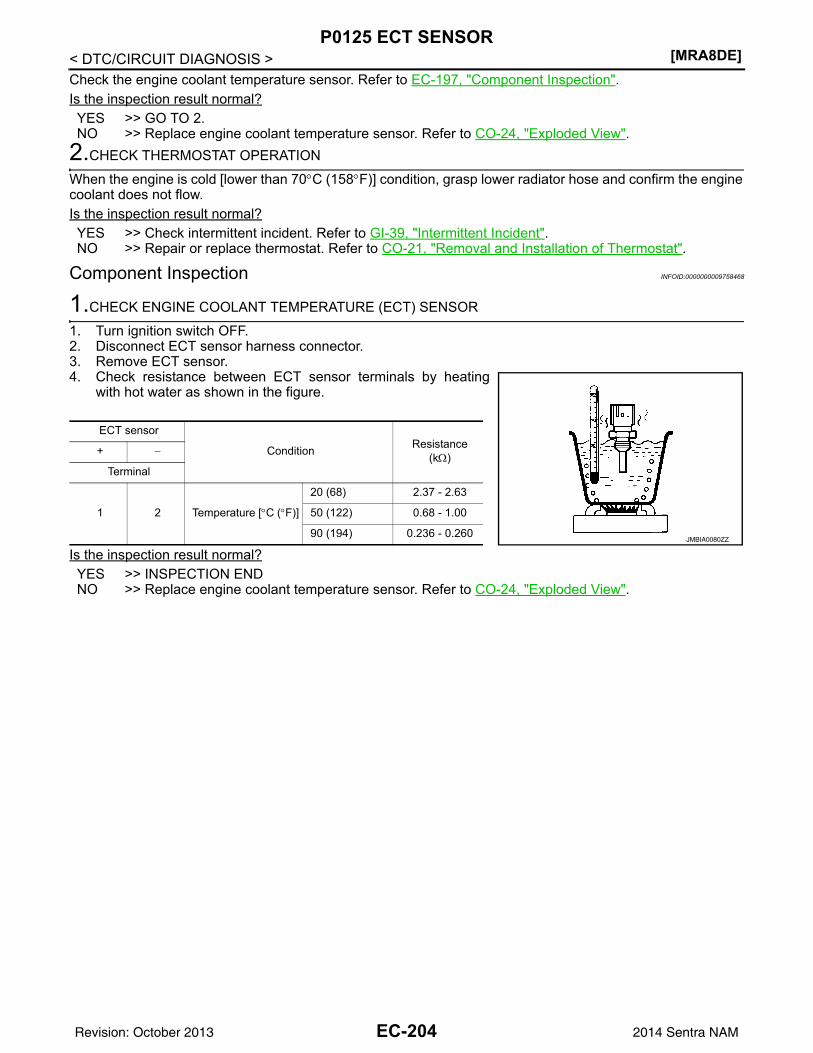
[MRA8DE]P0125 ECT SENSOR
< DTC/CIRCUIT DIAGNOSIS >Check the engine coolant temperature sensor. Refer to EC-197, "Component Inspection".Is the inspection result normal?YES >> GO TO 2.NO >> Replace engine coolant temperature sensor. Refer to CO-24, "Exploded View".
2.CHECK THERMOSTAT OPERATION
When the engine is cold [lower than 70°C (158°F)] condition, grasp lower radiator hose and confirm the enginecoolant does not flow.Is the inspection result normal?YES >> Check intermittent incident. Refer to GI-39, "Intermittent Incident".NO >> Repair or replace thermostat. Refer to CO-21, "Removal and Installation of Thermostat".
Component Inspection INFOID:0000000009758468
1.CHECK ENGINE COOLANT TEMPERATURE (ECT) SENSOR
1. Turn ignition switch OFF.2. Disconnect ECT sensor harness connector.3. Remove ECT sensor.4. Check resistance between ECT sensor terminals by heating
with hot water as shown in the figure.
Is the inspection result normal?YES >> INSPECTION ENDNO >> Replace engine coolant temperature sensor. Refer to CO-24, "Exploded View".
ECT sensor
Condition Resistance (kΩ)+ −
Terminal
1 2 Temperature [°C (°F)]
20 (68) 2.37 - 2.63
50 (122) 0.68 - 1.00
90 (194) 0.236 - 0.260JMBIA0080ZZ
EC-204Revision: October 2013 2014 Sentra NAM
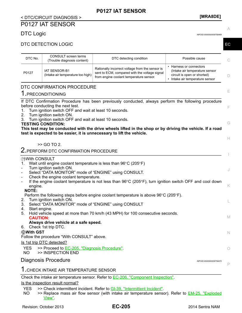
P0127 IAT SENSOR[MRA8DE]
C
D
E
F
G
H
I
J
K
L
M
A
C
N
P
O
< DTC/CIRCUIT DIAGNOSIS >
E
P0127 IAT SENSORDTC Logic INFOID:0000000009758469
DTC DETECTION LOGIC
DTC CONFIRMATION PROCEDURE1.PRECONDITIONING
If DTC Confirmation Procedure has been previously conducted, always perform the following procedurebefore conducting the next test.1. Turn ignition switch OFF and wait at least 10 seconds.2. Turn ignition switch ON.3. Turn ignition switch OFF and wait at least 10 seconds.TESTING CONDITION:This test may be conducted with the drive wheels lifted in the shop or by driving the vehicle. If a roadtest is expected to be easier, it is unnecessary to lift the vehicle.
>> GO TO 2.2.PERFORM DTC CONFIRMATION PROCEDURE
With CONSULT1. Wait until engine coolant temperature is less than 96°C (205°F)- Turn ignition switch ON.- Select “DATA MONITOR” mode of “ENGINE” using CONSULT.- Check the engine coolant temperature.- If the engine coolant temperature is not less than 96°C (205°F), turn ignition switch OFF and cool down
engine.NOTE:Perform the following steps before engine coolant temperature is above 96°C (205°F).
2. Turn ignition switch ON.3. Select “DATA MONITOR” mode of “ENGINE” using CONSULT4. Start engine.5. Hold vehicle speed at more than 70 km/h (43 MPH) for 100 consecutive seconds.
CAUTION:Always drive vehicle at a safe speed.
6. Check 1st trip DTC.With GST
Follow the procedure “With CONSULT” above.Is 1st trip DTC detected?YES >> Proceed to EC-205, "Diagnosis Procedure".NO >> INSPECTION END
Diagnosis Procedure INFOID:0000000009758470
1.CHECK INTAKE AIR TEMPERATURE SENSOR
Check the intake air temperature sensor. Refer to EC-206, "Component Inspection".Is the inspection result normal?YES >> Check intermittent incident. Refer to GI-39, "Intermittent Incident".NO >> Replace mass air flow sensor (with intake air temperature sensor). Refer to EM-25, "Exploded
View".
DTC No. CONSULT screen terms(Trouble diagnosis content) DTC detecting condition Possible cause
P0127 IAT SENSOR-B1(Intake air temperature too high)
Rationally incorrect voltage from the sensor is sent to ECM, compared with the voltage signal from engine coolant temperature sensor.
• Harness or connectors(Intake air temperature sensor circuit is open or shorted)
• Intake air temperature sensor
EC-205Revision: October 2013 2014 Sentra NAM
[MRA8DE]P0127 IAT SENSOR
< DTC/CIRCUIT DIAGNOSIS >Component Inspection INFOID:0000000009758471
1.CHECK INTAKE AIR TEMPERATURE SENSOR
1. Turn ignition switch OFF.2. Disconnect mass air flow sensor harness connector and reconnect it again.3. Turn ignition switch ON.4. Select “DATA MONITOR” mode with CONSULT.5. Check that the indicated value of “INT/A TEMP SEN” is almost the same as intake air temperature. Is the inspection result normal?YES >> INSPECTION ENDNO >> Replace mass air flow sensor (with intake air temperature sensor). Refer to EM-25, "Exploded
View".
EC-206Revision: October 2013 2014 Sentra NAM
P0128 THERMOSTAT FUNCTION[MRA8DE]
C
D
E
F
G
H
I
J
K
L
M
A
C
N
P
O
< DTC/CIRCUIT DIAGNOSIS >
E
P0128 THERMOSTAT FUNCTIONDTC Logic INFOID:0000000009758472
DTC DETECTION LOGICNOTE:If DTC P0128 is displayed with DTC P0300, P0301, P0302, P0303 or P0304, first perform the troublediagnosis for P0300, P0301, P0302, P0303 or P0304. Refer to EC-269, "DTC Logic".Engine coolant temperature has not risen enough to open the thermostat even though the engine has run longenough.This is due to a leak in the seal or the thermostat being stuck open.
DTC CONFIRMATION PROCEDURENOTE:Never refuel before and during the following procedure.1.PRECONDITIONING-1
If DTC Confirmation Procedure has been previously conducted, always perform the following procedurebefore conducting the next test.1. Turn ignition switch OFF and wait at least 10 seconds.2. Turn ignition switch ON.3. Turn ignition switch OFF and wait at least 10 seconds.
>> GO TO 2.2.PRECONDITIONING-2
With CONSULT1. Turn ignition switch ON.2. Check the following conditions:
3. Select “DATA MONITOR” mode of “ENGINE” using CONSULT.4. Check the following conditions:
Is the condition satisfied?YES >> GO TO 3.NO >> 1. Satisfy the condition.
2. GO TO 3.3.PERFORM DTC CONFIRMATION PROCEDURE-1
With CONSULT1. Start engine.2. Drive the vehicle until the following condition is satisfied.
CAUTION:Always drive vehicle at safe speed.
- STEP 1
DTC No. CONSULT screen terms(Trouble diagnosis content) DTC detecting condition Possible cause
P0128
THERMSTAT FNCTN[Coolant thermostat (coolant temperature below thermostat regulating temperature)]
The engine coolant temperature does not reach to specified temperature even though the engine has run long enough.
• Thermostat• Leakage from sealing portion of ther-
mostat• Engine coolant temperature sensor
Ambient temperature −10°C (14°F) or more
A/C switch OFF
Blower fan switch OFF
COOLANT TEMP/S −10°C – 58°C (14 – 136°F)
EC-207Revision: October 2013 2014 Sentra NAM
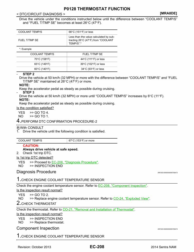
[MRA8DE]P0128 THERMOSTAT FUNCTION
< DTC/CIRCUIT DIAGNOSIS >Drive the vehicle under the conditions instructed below until the difference between “COOLANT TEMP/S”
and “FUEL T/TMP SE” becomes at least 26°C (47°F).
*: Example
- STEP 2Drive the vehicle at 50 km/h (32 MPH) or more with the difference between “COOLANT TEMP/S” and “FUEL
T/TMP SE” maintained at 26°C (47°F) or more.NOTE:Keep the accelerator pedal as steady as possible during cruising.
- STEP 3Drive the vehicle at 50 km/h (32 MPH) or more until “COOLANT TEMP/S” increases by 6°C (11°F).NOTE:Keep the accelerator pedal as steady as possible during cruising.
Is the condition satisfied?YES >> GO TO 4.NO >> GO TO 1.
4.PERFORM DTC CONFIRMATION PROCEDURE-2
With CONSULT1. Drive the vehicle until the following condition is satisfied.
CAUTION:Always drive vehicle at safe speed.
2. Check 1st trip DTC.Is 1st trip DTC detected?YES >> Proceed to EC-208, "Diagnosis Procedure".NO >> INSPECTION END
Diagnosis Procedure INFOID:0000000009758473
1.CHECK ENGINE COOLANT TEMPERATURE SENSOR
Check the engine coolant temperature sensor. Refer to EC-208, "Component Inspection".Is the inspection result normal?YES >> GO TO 2.NO >> Replace engine coolant temperature sensor. Refer to CO-24, "Exploded View".
2.CHECK THERMOSTAT
Check the thermostat. Refer to CO-21, "Removal and Installation of Thermostat".Is the inspection result normal?YES >> INSPECTION ENDNO >> Replace thermostat.
Component Inspection INFOID:0000000009758474
1.CHECK ENGINE COOLANT TEMPERATURE SENSOR
COOLANT TEMP/S 66°C (151°F) or less
FUEL T/TMP SELess than the value calculated by sub-tracting 26°C (47°F) from “COOLANT TEMP/S”.*
COOLANT TEMP/S FUEL T/TMP SE
70°C (158°F) 44°C (111°F) or less
65°C (149°F) 39°C (102°F) or less
60°C (140°F) 34°C (93°F) or less
COOLANT TEMP/S 67°C (153°F) or more
EC-208Revision: October 2013 2014 Sentra NAM
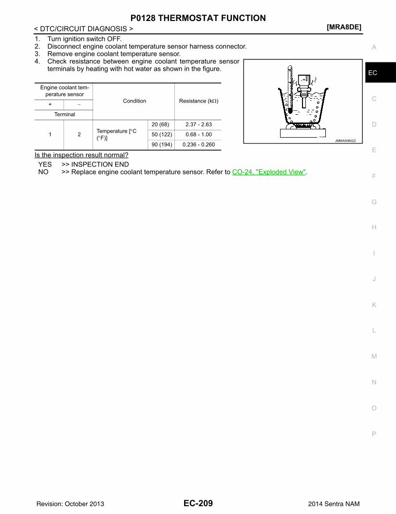
P0128 THERMOSTAT FUNCTION[MRA8DE]
C
D
E
F
G
H
I
J
K
L
M
A
C
N
P
O
< DTC/CIRCUIT DIAGNOSIS >
E
1. Turn ignition switch OFF.2. Disconnect engine coolant temperature sensor harness connector.3. Remove engine coolant temperature sensor.4. Check resistance between engine coolant temperature sensor
terminals by heating with hot water as shown in the figure.
Is the inspection result normal?YES >> INSPECTION ENDNO >> Replace engine coolant temperature sensor. Refer to CO-24, "Exploded View".
Engine coolant tem-perature sensor
Condition Resistance (kΩ)+ −
Terminal
1 2 Temperature [°C (°F)]
20 (68) 2.37 - 2.63
50 (122) 0.68 - 1.00
90 (194) 0.236 - 0.260JMBIA0080ZZ
EC-209Revision: October 2013 2014 Sentra NAM
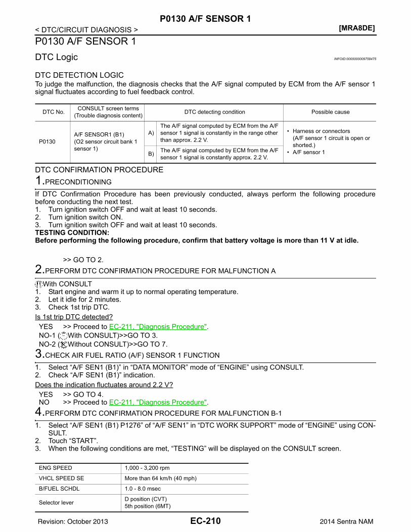
[MRA8DE]P0130 A/F SENSOR 1
< DTC/CIRCUIT DIAGNOSIS >P0130 A/F SENSOR 1DTC Logic INFOID:0000000009758475
DTC DETECTION LOGICTo judge the malfunction, the diagnosis checks that the A/F signal computed by ECM from the A/F sensor 1signal fluctuates according to fuel feedback control.
DTC CONFIRMATION PROCEDURE1.PRECONDITIONING
If DTC Confirmation Procedure has been previously conducted, always perform the following procedurebefore conducting the next test.1. Turn ignition switch OFF and wait at least 10 seconds.2. Turn ignition switch ON.3. Turn ignition switch OFF and wait at least 10 seconds.TESTING CONDITION:Before performing the following procedure, confirm that battery voltage is more than 11 V at idle.
>> GO TO 2.2.PERFORM DTC CONFIRMATION PROCEDURE FOR MALFUNCTION A
With CONSULT1. Start engine and warm it up to normal operating temperature.2. Let it idle for 2 minutes.3. Check 1st trip DTC.Is 1st trip DTC detected?YES >> Proceed to EC-211, "Diagnosis Procedure".NO-1 ( With CONSULT)>>GO TO 3.NO-2 ( Without CONSULT)>>GO TO 7.
3.CHECK AIR FUEL RATIO (A/F) SENSOR 1 FUNCTION
1. Select “A/F SEN1 (B1)” in “DATA MONITOR” mode of “ENGINE” using CONSULT.2. Check “A/F SEN1 (B1)” indication.Does the indication fluctuates around 2.2 V?YES >> GO TO 4.NO >> Proceed to EC-211, "Diagnosis Procedure".
4.PERFORM DTC CONFIRMATION PROCEDURE FOR MALFUNCTION B-1
1. Select “A/F SEN1 (B1) P1276” of “A/F SEN1” in “DTC WORK SUPPORT” mode of “ENGINE” using CON-SULT.
2. Touch “START”.3. When the following conditions are met, “TESTING” will be displayed on the CONSULT screen.
DTC No. CONSULT screen terms(Trouble diagnosis content) DTC detecting condition Possible cause
P0130A/F SENSOR1 (B1)(O2 sensor circuit bank 1 sensor 1)
A)The A/F signal computed by ECM from the A/F sensor 1 signal is constantly in the range other than approx. 2.2 V.
• Harness or connectors(A/F sensor 1 circuit is open or shorted.)
• A/F sensor 1B) The A/F signal computed by ECM from the A/F sensor 1 signal is constantly approx. 2.2 V.
ENG SPEED 1,000 - 3,200 rpm
VHCL SPEED SE More than 64 km/h (40 mph)
B/FUEL SCHDL 1.0 - 8.0 msec
Selector lever D position (CVT)5th position (6MT)
EC-210Revision: October 2013 2014 Sentra NAM
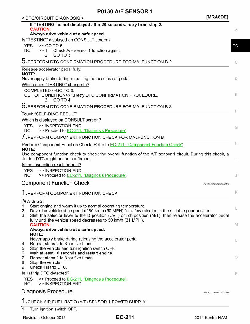
P0130 A/F SENSOR 1[MRA8DE]
C
D
E
F
G
H
I
J
K
L
M
A
C
N
P
O
< DTC/CIRCUIT DIAGNOSIS >
E
If “TESTING” is not displayed after 20 seconds, retry from step 2.CAUTION:Always drive vehicle at a safe speed.
Is “TESTING” displayed on CONSULT screen?YES >> GO TO 5.NO >> 1. Check A/F sensor 1 function again.
2. GO TO 3.5.PERFORM DTC CONFIRMATION PROCEDURE FOR MALFUNCTION B-2
Release accelerator pedal fully.NOTE:Never apply brake during releasing the accelerator pedal.Which does “TESTING” change to?COMPLETED>>GO TO 6.OUT OF CONDITION>>1.Retry DTC CONFIRMATION PROCEDURE.
2. GO TO 4.6.PERFORM DTC CONFIRMATION PROCEDURE FOR MALFUNCTION B-3
Touch “SELF-DIAG RESULT”Which is displayed on CONSULT screen?YES >> INSPECTION ENDNO >> Proceed to EC-211, "Diagnosis Procedure".
7.PERFORM COMPONENT FUNCTION CHECK FOR MALFUNCTION B
Perform Component Function Check. Refer to EC-211, "Component Function Check".NOTE:Use component function check to check the overall function of the A/F sensor 1 circuit. During this check, a1st trip DTC might not be confirmed.Is the inspection result normal?YES >> INSPECTION ENDNO >> Proceed to EC-211, "Diagnosis Procedure".
Component Function Check INFOID:0000000009758476
1.PERFORM COMPONENT FUNCTION CHECK
With GST1. Start engine and warm it up to normal operating temperature.2. Drive the vehicle at a speed of 80 km/h (50 MPH) for a few minutes in the suitable gear position.3. Shift the selector lever to the D position (CVT) or 5th position (M/T), then release the accelerator pedal
fully until the vehicle speed decreases to 50 km/h (31 MPH).CAUTION:Always drive vehicle at a safe speed.NOTE:Never apply brake during releasing the accelerator pedal.
4. Repeat steps 2 to 3 for five times.5. Stop the vehicle and turn ignition switch OFF.6. Wait at least 10 seconds and restart engine.7. Repeat steps 2 to 3 for five times.8. Stop the vehicle.9. Check 1st trip DTC.Is 1st trip DTC detected?YES >> Proceed to EC-211, "Diagnosis Procedure".NO >> INSPECTION END
Diagnosis Procedure INFOID:0000000009758477
1.CHECK AIR FUEL RATIO (A/F) SENSOR 1 POWER SUPPLY
1. Turn ignition switch OFF.
EC-211Revision: October 2013 2014 Sentra NAM
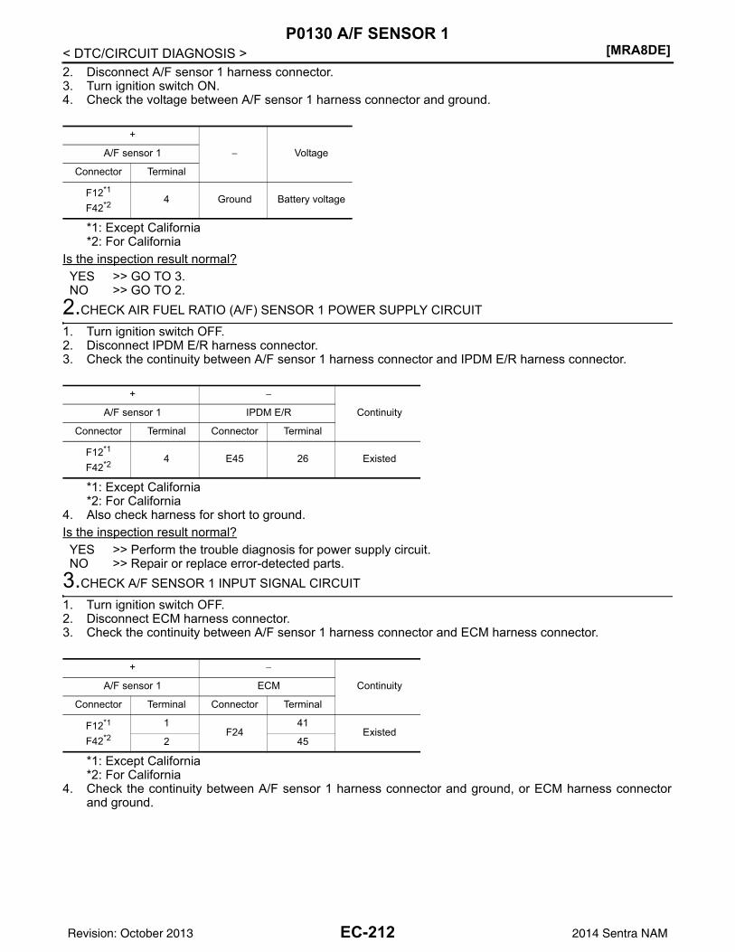
[MRA8DE]P0130 A/F SENSOR 1
< DTC/CIRCUIT DIAGNOSIS >2. Disconnect A/F sensor 1 harness connector.3. Turn ignition switch ON.4. Check the voltage between A/F sensor 1 harness connector and ground.
*1: Except California*2: For California
Is the inspection result normal?YES >> GO TO 3.NO >> GO TO 2.
2.CHECK AIR FUEL RATIO (A/F) SENSOR 1 POWER SUPPLY CIRCUIT
1. Turn ignition switch OFF.2. Disconnect IPDM E/R harness connector.3. Check the continuity between A/F sensor 1 harness connector and IPDM E/R harness connector.
*1: Except California*2: For California
4. Also check harness for short to ground.Is the inspection result normal?YES >> Perform the trouble diagnosis for power supply circuit.NO >> Repair or replace error-detected parts.
3.CHECK A/F SENSOR 1 INPUT SIGNAL CIRCUIT
1. Turn ignition switch OFF.2. Disconnect ECM harness connector.3. Check the continuity between A/F sensor 1 harness connector and ECM harness connector.
*1: Except California*2: For California
4. Check the continuity between A/F sensor 1 harness connector and ground, or ECM harness connectorand ground.
+
− VoltageA/F sensor 1
Connector Terminal
F12*1
F42*2 4 Ground Battery voltage
+ −
ContinuityA/F sensor 1 IPDM E/R
Connector Terminal Connector Terminal
F12*1
F42*2 4 E45 26 Existed
+ −
ContinuityA/F sensor 1 ECM
Connector Terminal Connector Terminal
F12*1
F42*2
1F24
41Existed
2 45
EC-212Revision: October 2013 2014 Sentra NAM
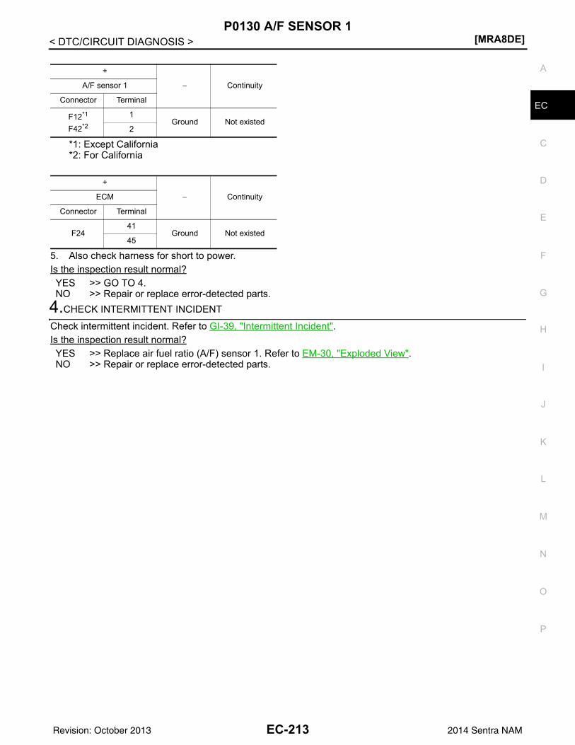
P0130 A/F SENSOR 1[MRA8DE]
C
D
E
F
G
H
I
J
K
L
M
A
C
N
P
O
< DTC/CIRCUIT DIAGNOSIS >
E
*1: Except California*2: For California
5. Also check harness for short to power.Is the inspection result normal?YES >> GO TO 4.NO >> Repair or replace error-detected parts.
4.CHECK INTERMITTENT INCIDENT
Check intermittent incident. Refer to GI-39, "Intermittent Incident".Is the inspection result normal?YES >> Replace air fuel ratio (A/F) sensor 1. Refer to EM-30, "Exploded View".NO >> Repair or replace error-detected parts.
+
− ContinuityA/F sensor 1
Connector Terminal
F12*1
F42*2
1Ground Not existed
2
+
− ContinuityECM
Connector Terminal
F2441
Ground Not existed45
EC-213Revision: October 2013 2014 Sentra NAM
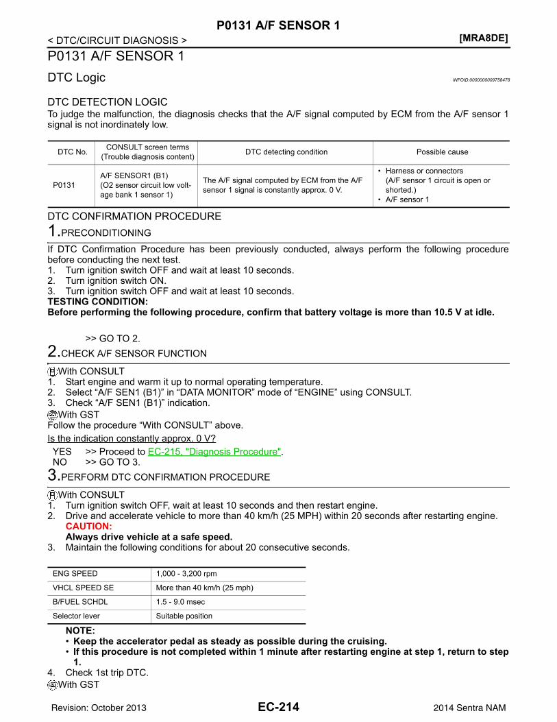
[MRA8DE]P0131 A/F SENSOR 1
< DTC/CIRCUIT DIAGNOSIS >P0131 A/F SENSOR 1DTC Logic INFOID:0000000009758478
DTC DETECTION LOGICTo judge the malfunction, the diagnosis checks that the A/F signal computed by ECM from the A/F sensor 1signal is not inordinately low.
DTC CONFIRMATION PROCEDURE1.PRECONDITIONING
If DTC Confirmation Procedure has been previously conducted, always perform the following procedurebefore conducting the next test.1. Turn ignition switch OFF and wait at least 10 seconds.2. Turn ignition switch ON.3. Turn ignition switch OFF and wait at least 10 seconds.TESTING CONDITION:Before performing the following procedure, confirm that battery voltage is more than 10.5 V at idle.
>> GO TO 2.2.CHECK A/F SENSOR FUNCTION
With CONSULT1. Start engine and warm it up to normal operating temperature.2. Select “A/F SEN1 (B1)” in “DATA MONITOR” mode of “ENGINE” using CONSULT.3. Check “A/F SEN1 (B1)” indication.
With GSTFollow the procedure “With CONSULT” above.Is the indication constantly approx. 0 V?YES >> Proceed to EC-215, "Diagnosis Procedure".NO >> GO TO 3.
3.PERFORM DTC CONFIRMATION PROCEDURE
With CONSULT1. Turn ignition switch OFF, wait at least 10 seconds and then restart engine.2. Drive and accelerate vehicle to more than 40 km/h (25 MPH) within 20 seconds after restarting engine.
CAUTION:Always drive vehicle at a safe speed.
3. Maintain the following conditions for about 20 consecutive seconds.
NOTE:• Keep the accelerator pedal as steady as possible during the cruising.• If this procedure is not completed within 1 minute after restarting engine at step 1, return to step
1.4. Check 1st trip DTC.
With GST
DTC No. CONSULT screen terms(Trouble diagnosis content) DTC detecting condition Possible cause
P0131A/F SENSOR1 (B1)(O2 sensor circuit low volt-age bank 1 sensor 1)
The A/F signal computed by ECM from the A/F sensor 1 signal is constantly approx. 0 V.
• Harness or connectors(A/F sensor 1 circuit is open or shorted.)
• A/F sensor 1
ENG SPEED 1,000 - 3,200 rpm
VHCL SPEED SE More than 40 km/h (25 mph)
B/FUEL SCHDL 1.5 - 9.0 msec
Selector lever Suitable position
EC-214Revision: October 2013 2014 Sentra NAM
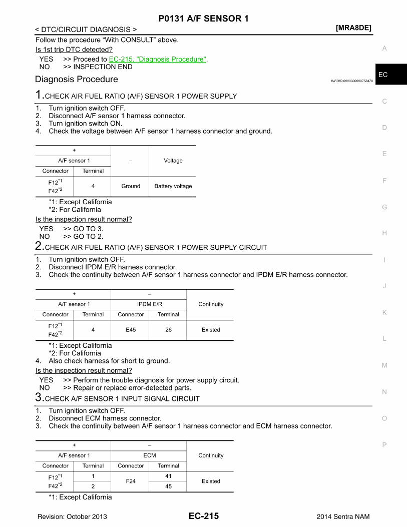
P0131 A/F SENSOR 1[MRA8DE]
C
D
E
F
G
H
I
J
K
L
M
A
C
N
P
O
< DTC/CIRCUIT DIAGNOSIS >
E
Follow the procedure “With CONSULT” above.Is 1st trip DTC detected?YES >> Proceed to EC-215, "Diagnosis Procedure".NO >> INSPECTION END
Diagnosis Procedure INFOID:0000000009758479
1.CHECK AIR FUEL RATIO (A/F) SENSOR 1 POWER SUPPLY
1. Turn ignition switch OFF.2. Disconnect A/F sensor 1 harness connector.3. Turn ignition switch ON.4. Check the voltage between A/F sensor 1 harness connector and ground.
*1: Except California*2: For California
Is the inspection result normal?YES >> GO TO 3.NO >> GO TO 2.
2.CHECK AIR FUEL RATIO (A/F) SENSOR 1 POWER SUPPLY CIRCUIT
1. Turn ignition switch OFF.2. Disconnect IPDM E/R harness connector.3. Check the continuity between A/F sensor 1 harness connector and IPDM E/R harness connector.
*1: Except California*2: For California
4. Also check harness for short to ground.Is the inspection result normal?YES >> Perform the trouble diagnosis for power supply circuit.NO >> Repair or replace error-detected parts.
3.CHECK A/F SENSOR 1 INPUT SIGNAL CIRCUIT
1. Turn ignition switch OFF.2. Disconnect ECM harness connector.3. Check the continuity between A/F sensor 1 harness connector and ECM harness connector.
*1: Except California
+
− VoltageA/F sensor 1
Connector Terminal
F12*1
F42*2 4 Ground Battery voltage
+ −
ContinuityA/F sensor 1 IPDM E/R
Connector Terminal Connector Terminal
F12*1
F42*2 4 E45 26 Existed
+ −
ContinuityA/F sensor 1 ECM
Connector Terminal Connector Terminal
F12*1
F42*2
1F24
41Existed
2 45
EC-215Revision: October 2013 2014 Sentra NAM
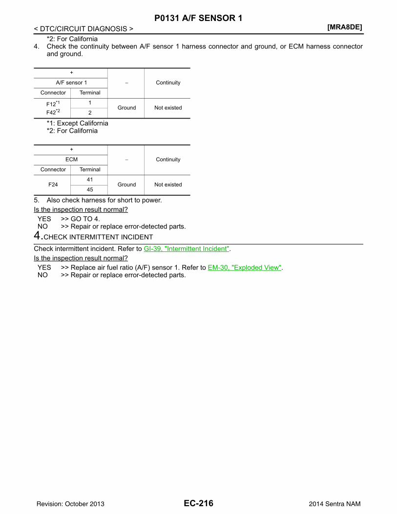
[MRA8DE]P0131 A/F SENSOR 1
< DTC/CIRCUIT DIAGNOSIS >*2: For California
4. Check the continuity between A/F sensor 1 harness connector and ground, or ECM harness connectorand ground.
*1: Except California*2: For California
5. Also check harness for short to power.Is the inspection result normal?YES >> GO TO 4.NO >> Repair or replace error-detected parts.
4.CHECK INTERMITTENT INCIDENT
Check intermittent incident. Refer to GI-39, "Intermittent Incident".Is the inspection result normal?YES >> Replace air fuel ratio (A/F) sensor 1. Refer to EM-30, "Exploded View".NO >> Repair or replace error-detected parts.
+
− ContinuityA/F sensor 1
Connector Terminal
F12*1
F42*2
1Ground Not existed
2
+
− ContinuityECM
Connector Terminal
F2441
Ground Not existed45
EC-216Revision: October 2013 2014 Sentra NAM
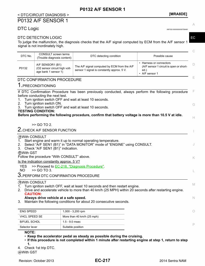
P0132 A/F SENSOR 1[MRA8DE]
C
D
E
F
G
H
I
J
K
L
M
A
C
N
P
O
< DTC/CIRCUIT DIAGNOSIS >
E
P0132 A/F SENSOR 1DTC Logic INFOID:0000000009758480
DTC DETECTION LOGICTo judge the malfunction, the diagnosis checks that the A/F signal computed by ECM from the A/F sensor 1signal is not inordinately high.
DTC CONFIRMATION PROCEDURE1.PRECONDITIONING
If DTC Confirmation Procedure has been previously conducted, always perform the following procedurebefore conducting the next test.1. Turn ignition switch OFF and wait at least 10 seconds.2. Turn ignition switch ON.3. Turn ignition switch OFF and wait at least 10 seconds.TESTING CONDITION:Before performing the following procedure, confirm that battery voltage is more than 10.5 V at idle.
>> GO TO 2.2.CHECK A/F SENSOR FUNCTION
With CONSULT1. Start engine and warm it up to normal operating temperature.2. Select “A/F SEN1 (B1)” in “DATA MONITOR” mode of “ENGINE” using CONSULT.3. Check “A/F SEN1 (B1)” indication.
With GSTFollow the procedure “With CONSULT” above.Is the indication constantly approx. 5 V?YES >> Proceed to EC-218, "Diagnosis Procedure".NO >> GO TO 3.
3.PERFORM DTC CONFIRMATION PROCEDURE
With CONSULT1. Turn ignition switch OFF, wait at least 10 seconds and then restart engine.2. Drive and accelerate vehicle to more than 40 km/h (25 MPH) within 20 seconds after restarting engine.
CAUTION:Always drive vehicle at a safe speed.
3. Maintain the following conditions for about 20 consecutive seconds.
NOTE:• Keep the accelerator pedal as steady as possible during the cruising.• If this procedure is not completed within 1 minute after restarting engine at step 1, return to step
1.4. Check 1st trip DTC.
With GST
DTC No. CONSULT screen terms(Trouble diagnosis content) DTC detecting condition Possible cause
P0132A/F SENSOR1 (B1)(O2 sensor circuit high volt-age bank 1 sensor 1)
The A/F signal computed by ECM from the A/F sensor 1 signal is constantly approx. 5 V.
• Harness or connectors(A/F sensor 1 circuit is open or short-ed.)
• A/F sensor 1
ENG SPEED 1,000 - 3,200 rpm
VHCL SPEED SE More than 40 km/h (25 mph)
B/FUEL SCHDL 1.5 - 9.0 msec
Selector lever Suitable position
EC-217Revision: October 2013 2014 Sentra NAM
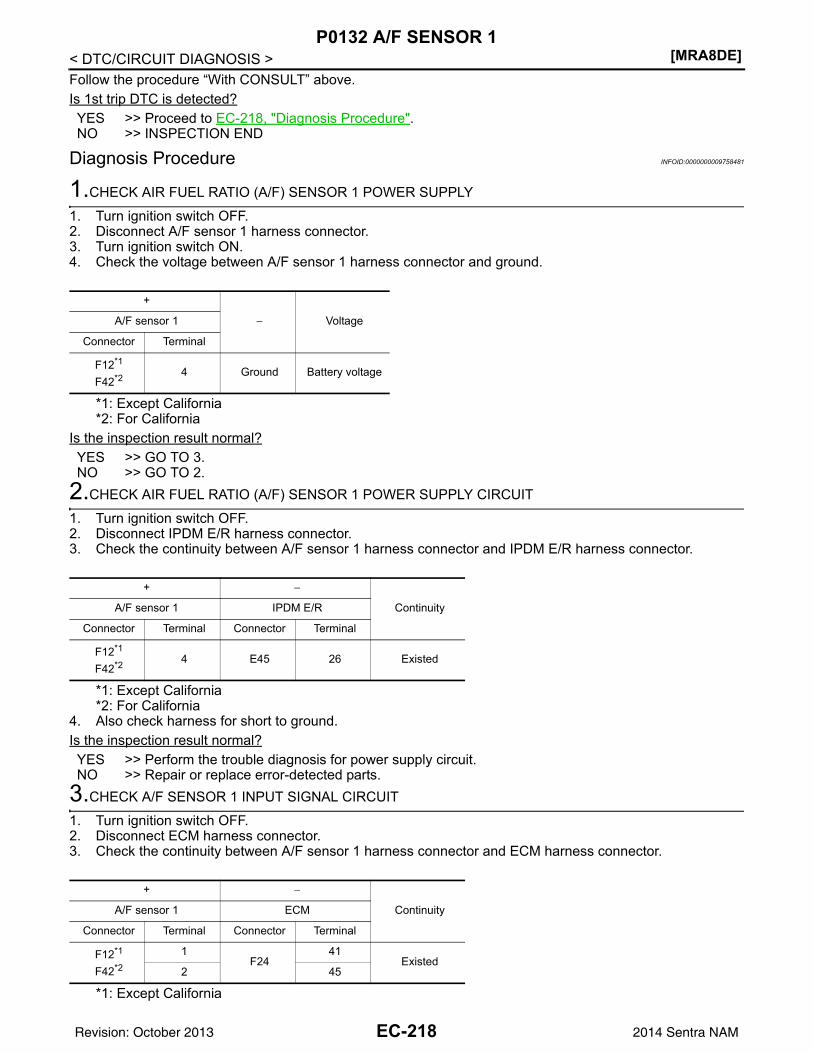
[MRA8DE]P0132 A/F SENSOR 1
< DTC/CIRCUIT DIAGNOSIS >Follow the procedure “With CONSULT” above.Is 1st trip DTC is detected?YES >> Proceed to EC-218, "Diagnosis Procedure".NO >> INSPECTION END
Diagnosis Procedure INFOID:0000000009758481
1.CHECK AIR FUEL RATIO (A/F) SENSOR 1 POWER SUPPLY
1. Turn ignition switch OFF.2. Disconnect A/F sensor 1 harness connector.3. Turn ignition switch ON.4. Check the voltage between A/F sensor 1 harness connector and ground.
*1: Except California*2: For California
Is the inspection result normal?YES >> GO TO 3.NO >> GO TO 2.
2.CHECK AIR FUEL RATIO (A/F) SENSOR 1 POWER SUPPLY CIRCUIT
1. Turn ignition switch OFF.2. Disconnect IPDM E/R harness connector.3. Check the continuity between A/F sensor 1 harness connector and IPDM E/R harness connector.
*1: Except California*2: For California
4. Also check harness for short to ground.Is the inspection result normal?YES >> Perform the trouble diagnosis for power supply circuit.NO >> Repair or replace error-detected parts.
3.CHECK A/F SENSOR 1 INPUT SIGNAL CIRCUIT
1. Turn ignition switch OFF.2. Disconnect ECM harness connector.3. Check the continuity between A/F sensor 1 harness connector and ECM harness connector.
*1: Except California
+
− VoltageA/F sensor 1
Connector Terminal
F12*1
F42*2 4 Ground Battery voltage
+ −
ContinuityA/F sensor 1 IPDM E/R
Connector Terminal Connector Terminal
F12*1
F42*2 4 E45 26 Existed
+ −
ContinuityA/F sensor 1 ECM
Connector Terminal Connector Terminal
F12*1
F42*2
1F24
41Existed
2 45
EC-218Revision: October 2013 2014 Sentra NAM
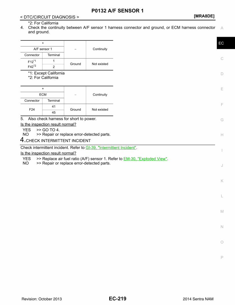
P0132 A/F SENSOR 1[MRA8DE]
C
D
E
F
G
H
I
J
K
L
M
A
C
N
P
O
< DTC/CIRCUIT DIAGNOSIS >
E
*2: For California4. Check the continuity between A/F sensor 1 harness connector and ground, or ECM harness connector
and ground.
*1: Except California*2: For California
5. Also check harness for short to power.Is the inspection result normal?YES >> GO TO 4.NO >> Repair or replace error-detected parts.
4.CHECK INTERMITTENT INCIDENT
Check intermittent incident. Refer to GI-39, "Intermittent Incident".Is the inspection result normal?YES >> Replace air fuel ratio (A/F) sensor 1. Refer to EM-30, "Exploded View".NO >> Repair or replace error-detected parts.
+
− ContinuityA/F sensor 1
Connector Terminal
F12*1
F42*2
1Ground Not existed
2
+
− ContinuityECM
Connector Terminal
F2441
Ground Not existed45
EC-219Revision: October 2013 2014 Sentra NAM
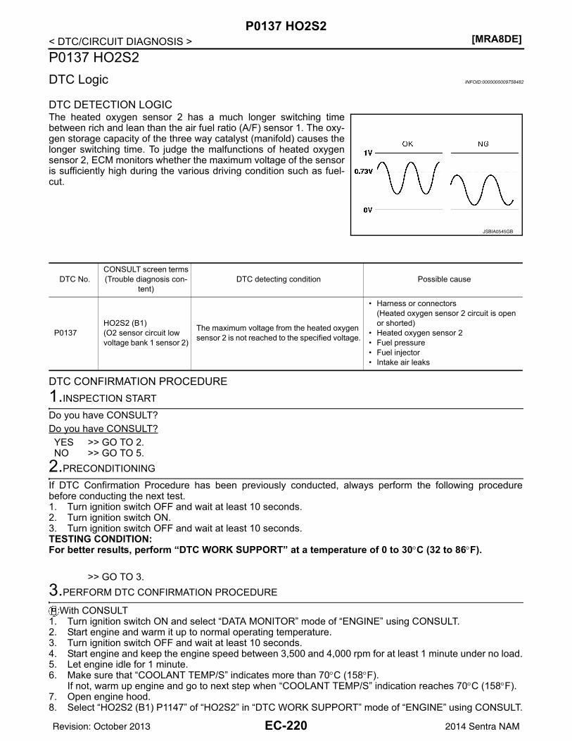
[MRA8DE]P0137 HO2S2
< DTC/CIRCUIT DIAGNOSIS >P0137 HO2S2DTC Logic INFOID:0000000009758482
DTC DETECTION LOGICThe heated oxygen sensor 2 has a much longer switching timebetween rich and lean than the air fuel ratio (A/F) sensor 1. The oxy-gen storage capacity of the three way catalyst (manifold) causes thelonger switching time. To judge the malfunctions of heated oxygensensor 2, ECM monitors whether the maximum voltage of the sensoris sufficiently high during the various driving condition such as fuel-cut.
DTC CONFIRMATION PROCEDURE1.INSPECTION START
Do you have CONSULT?Do you have CONSULT?YES >> GO TO 2.NO >> GO TO 5.
2.PRECONDITIONING
If DTC Confirmation Procedure has been previously conducted, always perform the following procedurebefore conducting the next test.1. Turn ignition switch OFF and wait at least 10 seconds.2. Turn ignition switch ON.3. Turn ignition switch OFF and wait at least 10 seconds.TESTING CONDITION:For better results, perform “DTC WORK SUPPORT” at a temperature of 0 to 30°C (32 to 86°F).
>> GO TO 3.3.PERFORM DTC CONFIRMATION PROCEDURE
With CONSULT1. Turn ignition switch ON and select “DATA MONITOR” mode of “ENGINE” using CONSULT.2. Start engine and warm it up to normal operating temperature.3. Turn ignition switch OFF and wait at least 10 seconds.4. Start engine and keep the engine speed between 3,500 and 4,000 rpm for at least 1 minute under no load.5. Let engine idle for 1 minute.6. Make sure that “COOLANT TEMP/S” indicates more than 70°C (158°F).
If not, warm up engine and go to next step when “COOLANT TEMP/S” indication reaches 70°C (158°F).7. Open engine hood.8. Select “HO2S2 (B1) P1147” of “HO2S2” in “DTC WORK SUPPORT” mode of “ENGINE” using CONSULT.
JSBIA0545GB
DTC No.CONSULT screen terms(Trouble diagnosis con-
tent)DTC detecting condition Possible cause
P0137HO2S2 (B1)(O2 sensor circuit low voltage bank 1 sensor 2)
The maximum voltage from the heated oxygen sensor 2 is not reached to the specified voltage.
• Harness or connectors(Heated oxygen sensor 2 circuit is open or shorted)
• Heated oxygen sensor 2• Fuel pressure• Fuel injector• Intake air leaks
EC-220Revision: October 2013 2014 Sentra NAM
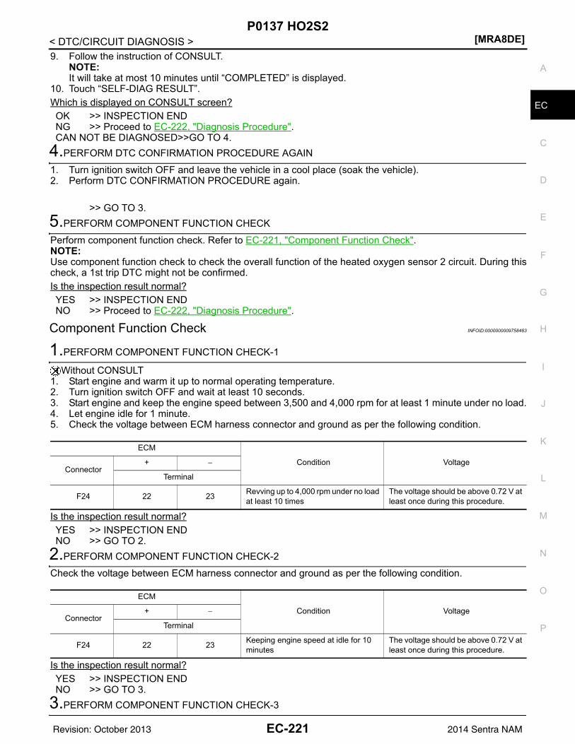
P0137 HO2S2[MRA8DE]
C
D
E
F
G
H
I
J
K
L
M
A
C
N
P
O
< DTC/CIRCUIT DIAGNOSIS >
E
9. Follow the instruction of CONSULT.NOTE:It will take at most 10 minutes until “COMPLETED” is displayed.
10. Touch “SELF-DIAG RESULT”.Which is displayed on CONSULT screen?OK >> INSPECTION ENDNG >> Proceed to EC-222, "Diagnosis Procedure".CAN NOT BE DIAGNOSED>>GO TO 4.
4.PERFORM DTC CONFIRMATION PROCEDURE AGAIN
1. Turn ignition switch OFF and leave the vehicle in a cool place (soak the vehicle).2. Perform DTC CONFIRMATION PROCEDURE again.
>> GO TO 3.5.PERFORM COMPONENT FUNCTION CHECK
Perform component function check. Refer to EC-221, "Component Function Check".NOTE:Use component function check to check the overall function of the heated oxygen sensor 2 circuit. During thischeck, a 1st trip DTC might not be confirmed.Is the inspection result normal?YES >> INSPECTION ENDNO >> Proceed to EC-222, "Diagnosis Procedure".
Component Function Check INFOID:0000000009758483
1.PERFORM COMPONENT FUNCTION CHECK-1
Without CONSULT1. Start engine and warm it up to normal operating temperature.2. Turn ignition switch OFF and wait at least 10 seconds.3. Start engine and keep the engine speed between 3,500 and 4,000 rpm for at least 1 minute under no load.4. Let engine idle for 1 minute.5. Check the voltage between ECM harness connector and ground as per the following condition.
Is the inspection result normal?YES >> INSPECTION ENDNO >> GO TO 2.
2.PERFORM COMPONENT FUNCTION CHECK-2
Check the voltage between ECM harness connector and ground as per the following condition.
Is the inspection result normal?YES >> INSPECTION ENDNO >> GO TO 3.
3.PERFORM COMPONENT FUNCTION CHECK-3
ECM
Condition VoltageConnector
+ −
Terminal
F24 22 23 Revving up to 4,000 rpm under no load at least 10 times
The voltage should be above 0.72 V at least once during this procedure.
ECM
Condition VoltageConnector
+ −
Terminal
F24 22 23 Keeping engine speed at idle for 10 minutes
The voltage should be above 0.72 V at least once during this procedure.
EC-221Revision: October 2013 2014 Sentra NAM
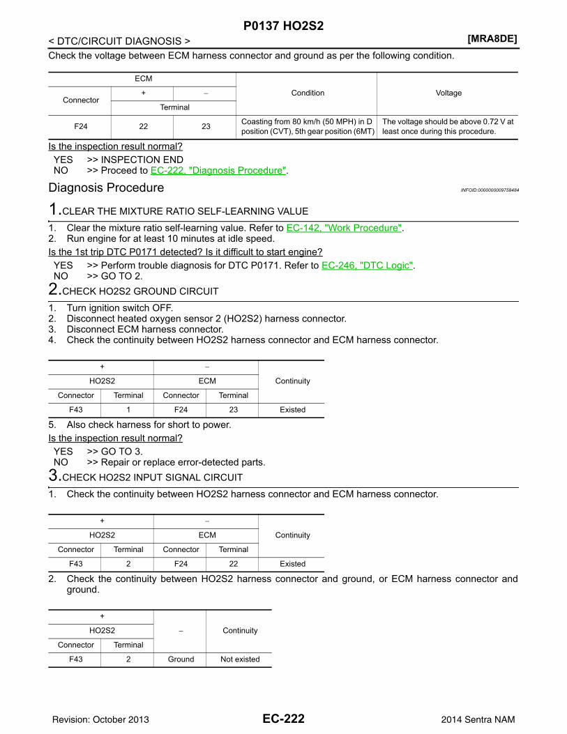
[MRA8DE]P0137 HO2S2
< DTC/CIRCUIT DIAGNOSIS >Check the voltage between ECM harness connector and ground as per the following condition.
Is the inspection result normal?YES >> INSPECTION ENDNO >> Proceed to EC-222, "Diagnosis Procedure".
Diagnosis Procedure INFOID:0000000009758484
1.CLEAR THE MIXTURE RATIO SELF-LEARNING VALUE
1. Clear the mixture ratio self-learning value. Refer to EC-142, "Work Procedure".2. Run engine for at least 10 minutes at idle speed.Is the 1st trip DTC P0171 detected? Is it difficult to start engine?YES >> Perform trouble diagnosis for DTC P0171. Refer to EC-246, "DTC Logic".NO >> GO TO 2.
2.CHECK HO2S2 GROUND CIRCUIT
1. Turn ignition switch OFF.2. Disconnect heated oxygen sensor 2 (HO2S2) harness connector.3. Disconnect ECM harness connector.4. Check the continuity between HO2S2 harness connector and ECM harness connector.
5. Also check harness for short to power.Is the inspection result normal?YES >> GO TO 3.NO >> Repair or replace error-detected parts.
3.CHECK HO2S2 INPUT SIGNAL CIRCUIT
1. Check the continuity between HO2S2 harness connector and ECM harness connector.
2. Check the continuity between HO2S2 harness connector and ground, or ECM harness connector andground.
ECM
Condition VoltageConnector
+ −
Terminal
F24 22 23 Coasting from 80 km/h (50 MPH) in D position (CVT), 5th gear position (6MT)
The voltage should be above 0.72 V at least once during this procedure.
+ −
ContinuityHO2S2 ECM
Connector Terminal Connector Terminal
F43 1 F24 23 Existed
+ −
ContinuityHO2S2 ECM
Connector Terminal Connector Terminal
F43 2 F24 22 Existed
+
− ContinuityHO2S2
Connector Terminal
F43 2 Ground Not existed
EC-222Revision: October 2013 2014 Sentra NAM
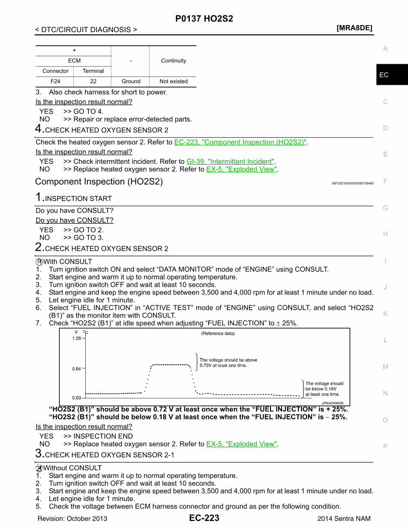
P0137 HO2S2[MRA8DE]
C
D
E
F
G
H
I
J
K
L
M
A
C
N
P
O
< DTC/CIRCUIT DIAGNOSIS >
E
3. Also check harness for short to power.Is the inspection result normal?YES >> GO TO 4.NO >> Repair or replace error-detected parts.
4.CHECK HEATED OXYGEN SENSOR 2
Check the heated oxygen sensor 2. Refer to EC-223, "Component Inspection (HO2S2)".Is the inspection result normal?YES >> Check intermittent incident. Refer to GI-39, "Intermittent Incident".NO >> Replace heated oxygen sensor 2. Refer to EX-5, "Exploded View".
Component Inspection (HO2S2) INFOID:0000000009758485
1.INSPECTION START
Do you have CONSULT?Do you have CONSULT?YES >> GO TO 2.NO >> GO TO 3.
2.CHECK HEATED OXYGEN SENSOR 2
With CONSULT1. Turn ignition switch ON and select “DATA MONITOR” mode of “ENGINE” using CONSULT.2. Start engine and warm it up to normal operating temperature.3. Turn ignition switch OFF and wait at least 10 seconds.4. Start engine and keep the engine speed between 3,500 and 4,000 rpm for at least 1 minute under no load.5. Let engine idle for 1 minute.6. Select “FUEL INJECTION” in “ACTIVE TEST” mode of “ENGINE” using CONSULT, and select “HO2S2
(B1)” as the monitor item with CONSULT.7. Check “HO2S2 (B1)” at idle speed when adjusting “FUEL INJECTION” to ± 25%.
“HO2S2 (B1)” should be above 0.72 V at least once when the “FUEL INJECTION” is + 25%.“HO2S2 (B1)” should be below 0.18 V at least once when the “FUEL INJECTION” is − 25%.
Is the inspection result normal?YES >> INSPECTION ENDNO >> Replace heated oxygen sensor 2. Refer to EX-5, "Exploded View".
3.CHECK HEATED OXYGEN SENSOR 2-1
Without CONSULT1. Start engine and warm it up to normal operating temperature.2. Turn ignition switch OFF and wait at least 10 seconds.3. Start engine and keep the engine speed between 3,500 and 4,000 rpm for at least 1 minute under no load.4. Let engine idle for 1 minute.5. Check the voltage between ECM harness connector and ground as per the following condition.
+
− ContinuityECM
Connector Terminal
F24 22 Ground Not existed
JPBIA5998GB
EC-223Revision: October 2013 2014 Sentra NAM
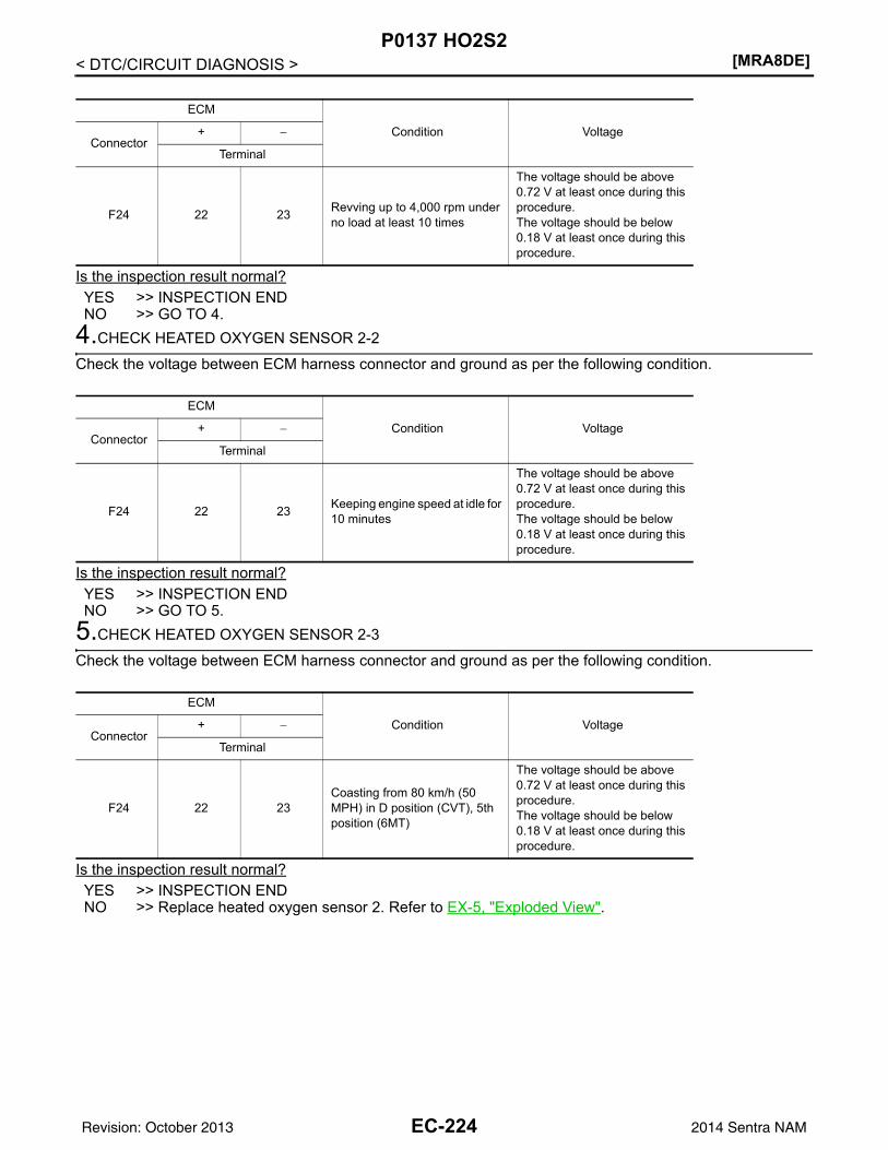
[MRA8DE]P0137 HO2S2
< DTC/CIRCUIT DIAGNOSIS >
Is the inspection result normal?YES >> INSPECTION ENDNO >> GO TO 4.
4.CHECK HEATED OXYGEN SENSOR 2-2
Check the voltage between ECM harness connector and ground as per the following condition.
Is the inspection result normal?YES >> INSPECTION ENDNO >> GO TO 5.
5.CHECK HEATED OXYGEN SENSOR 2-3
Check the voltage between ECM harness connector and ground as per the following condition.
Is the inspection result normal?YES >> INSPECTION ENDNO >> Replace heated oxygen sensor 2. Refer to EX-5, "Exploded View".
ECM
Condition VoltageConnector
+ −
Terminal
F24 22 23 Revving up to 4,000 rpm under no load at least 10 times
The voltage should be above 0.72 V at least once during this procedure.The voltage should be below 0.18 V at least once during this procedure.
ECM
Condition VoltageConnector
+ −
Terminal
F24 22 23 Keeping engine speed at idle for 10 minutes
The voltage should be above 0.72 V at least once during this procedure.The voltage should be below 0.18 V at least once during this procedure.
ECM
Condition VoltageConnector
+ −
Terminal
F24 22 23Coasting from 80 km/h (50 MPH) in D position (CVT), 5th position (6MT)
The voltage should be above 0.72 V at least once during this procedure.The voltage should be below 0.18 V at least once during this procedure.
EC-224Revision: October 2013 2014 Sentra NAM
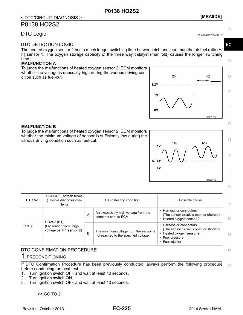
P0138 HO2S2[MRA8DE]
C
D
E
F
G
H
I
J
K
L
M
A
C
N
P
O
< DTC/CIRCUIT DIAGNOSIS >
E
P0138 HO2S2DTC Logic INFOID:0000000009758486
DTC DETECTION LOGICThe heated oxygen sensor 2 has a much longer switching time between rich and lean than the air fuel ratio (A/F) sensor 1. The oxygen storage capacity of the three way catalyst (manifold) causes the longer switchingtime.MALFUNCTION ATo judge the malfunctions of heated oxygen sensor 2, ECM monitorswhether the voltage is unusually high during the various driving con-dition such as fuel-cut.
MALFUNCTION BTo judge the malfunctions of heated oxygen sensor 2, ECM monitorswhether the minimum voltage of sensor is sufficiently low during thevarious driving condition such as fuel-cut.
DTC CONFIRMATION PROCEDURE1.PRECONDITIONING
If DTC Confirmation Procedure has been previously conducted, always perform the following procedurebefore conducting the next test.1. Turn ignition switch OFF and wait at least 10 seconds.2. Turn ignition switch ON.3. Turn ignition switch OFF and wait at least 10 seconds.
>> GO TO 2.
PBIB1848E
PBIB2376E
DTC No.CONSULT screen terms(Trouble diagnosis con-
tent)DTC detecting condition Possible cause
P0138HO2S2 (B1)(O2 sensor circuit high voltage bank 1 sensor 2)
A) An excessively high voltage from the sensor is sent to ECM.
• Harness or connectors(The sensor circuit is open or shorted)
• Heated oxygen sensor 2
B) The minimum voltage from the sensor is not reached to the specified voltage.
• Harness or connectors(The sensor circuit is open or shorted)
• Heated oxygen sensor 2• Fuel pressure• Fuel injector
EC-225Revision: October 2013 2014 Sentra NAM
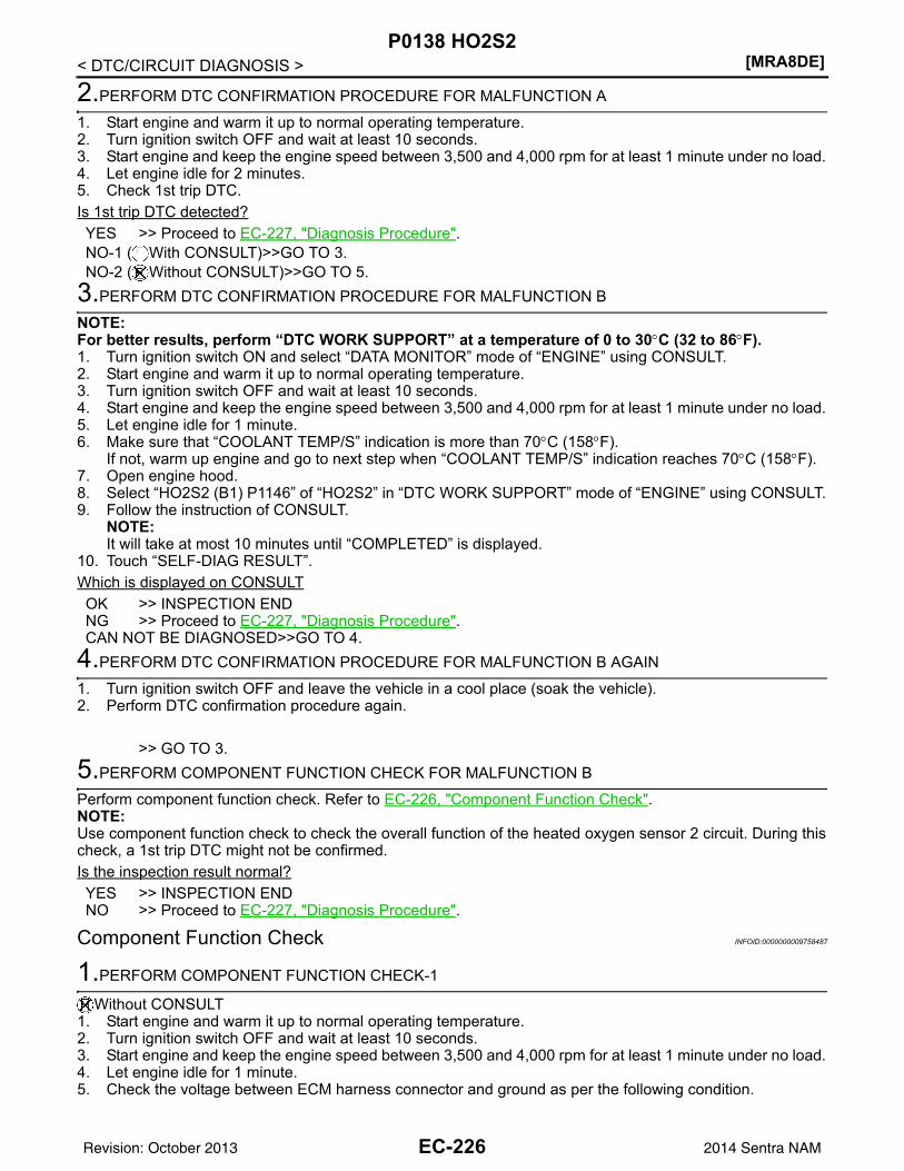
[MRA8DE]P0138 HO2S2
< DTC/CIRCUIT DIAGNOSIS >
2.PERFORM DTC CONFIRMATION PROCEDURE FOR MALFUNCTION A
1. Start engine and warm it up to normal operating temperature.2. Turn ignition switch OFF and wait at least 10 seconds.3. Start engine and keep the engine speed between 3,500 and 4,000 rpm for at least 1 minute under no load.4. Let engine idle for 2 minutes.5. Check 1st trip DTC.Is 1st trip DTC detected?YES >> Proceed to EC-227, "Diagnosis Procedure".NO-1 ( With CONSULT)>>GO TO 3.NO-2 ( Without CONSULT)>>GO TO 5.
3.PERFORM DTC CONFIRMATION PROCEDURE FOR MALFUNCTION B
NOTE:For better results, perform “DTC WORK SUPPORT” at a temperature of 0 to 30°C (32 to 86°F).1. Turn ignition switch ON and select “DATA MONITOR” mode of “ENGINE” using CONSULT.2. Start engine and warm it up to normal operating temperature.3. Turn ignition switch OFF and wait at least 10 seconds.4. Start engine and keep the engine speed between 3,500 and 4,000 rpm for at least 1 minute under no load.5. Let engine idle for 1 minute.6. Make sure that “COOLANT TEMP/S” indication is more than 70°C (158°F).
If not, warm up engine and go to next step when “COOLANT TEMP/S” indication reaches 70°C (158°F).7. Open engine hood.8. Select “HO2S2 (B1) P1146” of “HO2S2” in “DTC WORK SUPPORT” mode of “ENGINE” using CONSULT.9. Follow the instruction of CONSULT.
NOTE:It will take at most 10 minutes until “COMPLETED” is displayed.
10. Touch “SELF-DIAG RESULT”.Which is displayed on CONSULTOK >> INSPECTION ENDNG >> Proceed to EC-227, "Diagnosis Procedure".CAN NOT BE DIAGNOSED>>GO TO 4.
4.PERFORM DTC CONFIRMATION PROCEDURE FOR MALFUNCTION B AGAIN
1. Turn ignition switch OFF and leave the vehicle in a cool place (soak the vehicle).2. Perform DTC confirmation procedure again.
>> GO TO 3.5.PERFORM COMPONENT FUNCTION CHECK FOR MALFUNCTION B
Perform component function check. Refer to EC-226, "Component Function Check".NOTE:Use component function check to check the overall function of the heated oxygen sensor 2 circuit. During thischeck, a 1st trip DTC might not be confirmed.Is the inspection result normal?YES >> INSPECTION ENDNO >> Proceed to EC-227, "Diagnosis Procedure".
Component Function Check INFOID:0000000009758487
1.PERFORM COMPONENT FUNCTION CHECK-1
Without CONSULT1. Start engine and warm it up to normal operating temperature.2. Turn ignition switch OFF and wait at least 10 seconds.3. Start engine and keep the engine speed between 3,500 and 4,000 rpm for at least 1 minute under no load.4. Let engine idle for 1 minute.5. Check the voltage between ECM harness connector and ground as per the following condition.
EC-226Revision: October 2013 2014 Sentra NAM
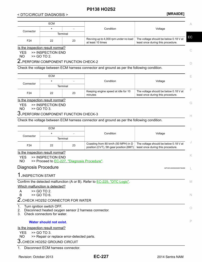
P0138 HO2S2[MRA8DE]
C
D
E
F
G
H
I
J
K
L
M
A
C
N
P
O
< DTC/CIRCUIT DIAGNOSIS >
E
Is the inspection result normal?YES >> INSPECTION ENDNO >> GO TO 2.
2.PERFORM COMPONENT FUNCTION CHECK-2
Check the voltage between ECM harness connector and ground as per the following condition.
Is the inspection result normal?YES >> INSPECTION ENDNO >> GO TO 3.
3.PERFORM COMPONENT FUNCTION CHECK-3
Check the voltage between ECM harness connector and ground as per the following condition.
Is the inspection result normal?YES >> INSPECTION ENDNO >> Proceed to EC-227, "Diagnosis Procedure".
Diagnosis Procedure INFOID:0000000009758488
1.INSPECTION START
Confirm the detected malfunction (A or B). Refer to EC-225, "DTC Logic".Which malfunction is detected?A >> GO TO 2.B >> GO TO 6.
2.CHECK HO2S2 CONNECTOR FOR WATER
1. Turn ignition switch OFF.2. Disconnect heated oxygen sensor 2 harness connector.3. Check connectors for water.
Is the inspection result normal?YES >> GO TO 3.NO >> Repair or replace error-detected parts.
3.CHECK HO2S2 GROUND CIRCUIT
1. Disconnect ECM harness connector.
ECM
Condition VoltageConnector
+ −
Terminal
F24 22 23 Revving up to 4,000 rpm under no load at least 10 times
The voltage should be below 0.18 V at least once during this procedure.
ECM
Condition VoltageConnector
+ −
Terminal
F24 22 23 Keeping engine speed at idle for 10 minutes
The voltage should be below 0.18 V at least once during this procedure.
ECM
Condition VoltageConnector
+ −
Terminal
F24 22 23 Coasting from 80 km/h (50 MPH) in D position (CVT), 5th gear position (6MT)
The voltage should be below 0.18 V at least once during this procedure.
Water should not exist.
EC-227Revision: October 2013 2014 Sentra NAM
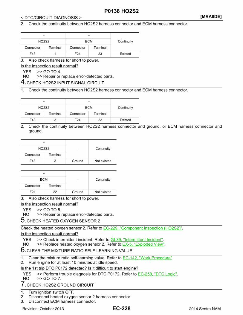
[MRA8DE]P0138 HO2S2
< DTC/CIRCUIT DIAGNOSIS >2. Check the continuity between HO2S2 harness connector and ECM harness connector.
3. Also check harness for short to power.Is the inspection result normal?YES >> GO TO 4.NO >> Repair or replace error-detected parts.
4.CHECK HO2S2 INPUT SIGNAL CIRCUIT
1. Check the continuity between HO2S2 harness connector and ECM harness connector.
2. Check the continuity between HO2S2 harness connector and ground, or ECM harness connector andground.
3. Also check harness for short to power.Is the inspection result normal?YES >> GO TO 5.NO >> Repair or replace error-detected parts.
5.CHECK HEATED OXYGEN SENSOR 2
Check the heated oxygen sensor 2. Refer to EC-229, "Component Inspection (HO2S2)".Is the inspection result normal?YES >> Check intermittent incident. Refer to GI-39, "Intermittent Incident".NO >> Replace heated oxygen sensor 2. Refer to EX-5, "Exploded View".
6.CLEAR THE MIXTURE RATIO SELF-LEARNING VALUE
1. Clear the mixture ratio self-learning value. Refer to EC-142, "Work Procedure".2. Run engine for at least 10 minutes at idle speed.Is the 1st trip DTC P0172 detected? Is it difficult to start engine?YES >> Perform trouble diagnosis for DTC P0172. Refer to EC-250, "DTC Logic".NO >> GO TO 7.
7.CHECK HO2S2 GROUND CIRCUIT
1. Turn ignition switch OFF.2. Disconnect heated oxygen sensor 2 harness connector.3. Disconnect ECM harness connector.
+ −
ContinuityHO2S2 ECM
Connector Terminal Connector Terminal
F43 1 F24 23 Existed
+ −
ContinuityHO2S2 ECM
Connector Terminal Connector Terminal
F43 2 F24 22 Existed
+
− ContinuityHO2S2
Connector Terminal
F43 2 Ground Not existed
+
− ContinuityECM
Connector Terminal
F24 22 Ground Not existed
EC-228Revision: October 2013 2014 Sentra NAM
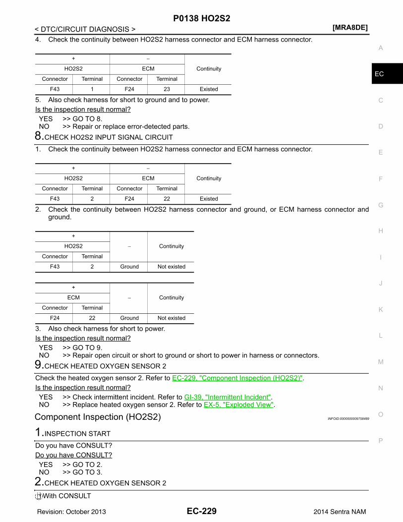
P0138 HO2S2[MRA8DE]
C
D
E
F
G
H
I
J
K
L
M
A
C
N
P
O
< DTC/CIRCUIT DIAGNOSIS >
E
4. Check the continuity between HO2S2 harness connector and ECM harness connector.
5. Also check harness for short to ground and to power.Is the inspection result normal?YES >> GO TO 8.NO >> Repair or replace error-detected parts.
8.CHECK HO2S2 INPUT SIGNAL CIRCUIT
1. Check the continuity between HO2S2 harness connector and ECM harness connector.
2. Check the continuity between HO2S2 harness connector and ground, or ECM harness connector andground.
3. Also check harness for short to power.Is the inspection result normal?YES >> GO TO 9.NO >> Repair open circuit or short to ground or short to power in harness or connectors.
9.CHECK HEATED OXYGEN SENSOR 2
Check the heated oxygen sensor 2. Refer to EC-229, "Component Inspection (HO2S2)".Is the inspection result normal?YES >> Check intermittent incident. Refer to GI-39, "Intermittent Incident".NO >> Replace heated oxygen sensor 2. Refer to EX-5, "Exploded View".
Component Inspection (HO2S2) INFOID:0000000009758489
1.INSPECTION START
Do you have CONSULT?Do you have CONSULT?YES >> GO TO 2.NO >> GO TO 3.
2.CHECK HEATED OXYGEN SENSOR 2
With CONSULT
+ −
ContinuityHO2S2 ECM
Connector Terminal Connector Terminal
F43 1 F24 23 Existed
+ −
ContinuityHO2S2 ECM
Connector Terminal Connector Terminal
F43 2 F24 22 Existed
+
− ContinuityHO2S2
Connector Terminal
F43 2 Ground Not existed
+
− ContinuityECM
Connector Terminal
F24 22 Ground Not existed
EC-229Revision: October 2013 2014 Sentra NAM
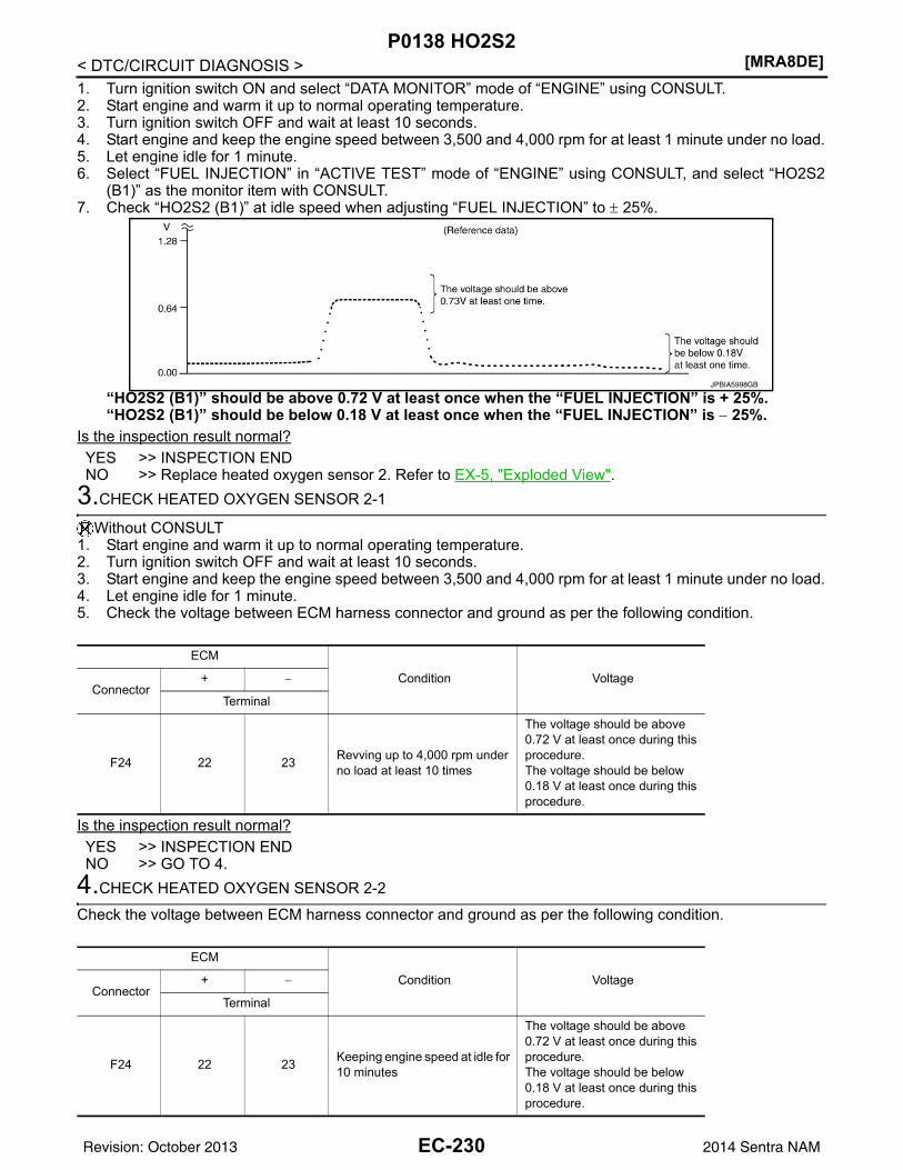
[MRA8DE]P0138 HO2S2
< DTC/CIRCUIT DIAGNOSIS >1. Turn ignition switch ON and select “DATA MONITOR” mode of “ENGINE” using CONSULT.2. Start engine and warm it up to normal operating temperature.3. Turn ignition switch OFF and wait at least 10 seconds.4. Start engine and keep the engine speed between 3,500 and 4,000 rpm for at least 1 minute under no load.5. Let engine idle for 1 minute.6. Select “FUEL INJECTION” in “ACTIVE TEST” mode of “ENGINE” using CONSULT, and select “HO2S2
(B1)” as the monitor item with CONSULT.7. Check “HO2S2 (B1)” at idle speed when adjusting “FUEL INJECTION” to ± 25%.
“HO2S2 (B1)” should be above 0.72 V at least once when the “FUEL INJECTION” is + 25%.“HO2S2 (B1)” should be below 0.18 V at least once when the “FUEL INJECTION” is − 25%.
Is the inspection result normal?YES >> INSPECTION ENDNO >> Replace heated oxygen sensor 2. Refer to EX-5, "Exploded View".
3.CHECK HEATED OXYGEN SENSOR 2-1
Without CONSULT1. Start engine and warm it up to normal operating temperature.2. Turn ignition switch OFF and wait at least 10 seconds.3. Start engine and keep the engine speed between 3,500 and 4,000 rpm for at least 1 minute under no load.4. Let engine idle for 1 minute.5. Check the voltage between ECM harness connector and ground as per the following condition.
Is the inspection result normal?YES >> INSPECTION ENDNO >> GO TO 4.
4.CHECK HEATED OXYGEN SENSOR 2-2
Check the voltage between ECM harness connector and ground as per the following condition.
JPBIA5998GB
ECM
Condition VoltageConnector
+ −
Terminal
F24 22 23 Revving up to 4,000 rpm under no load at least 10 times
The voltage should be above 0.72 V at least once during this procedure.The voltage should be below 0.18 V at least once during this procedure.
ECM
Condition VoltageConnector
+ −
Terminal
F24 22 23 Keeping engine speed at idle for 10 minutes
The voltage should be above 0.72 V at least once during this procedure.The voltage should be below 0.18 V at least once during this procedure.
EC-230Revision: October 2013 2014 Sentra NAM
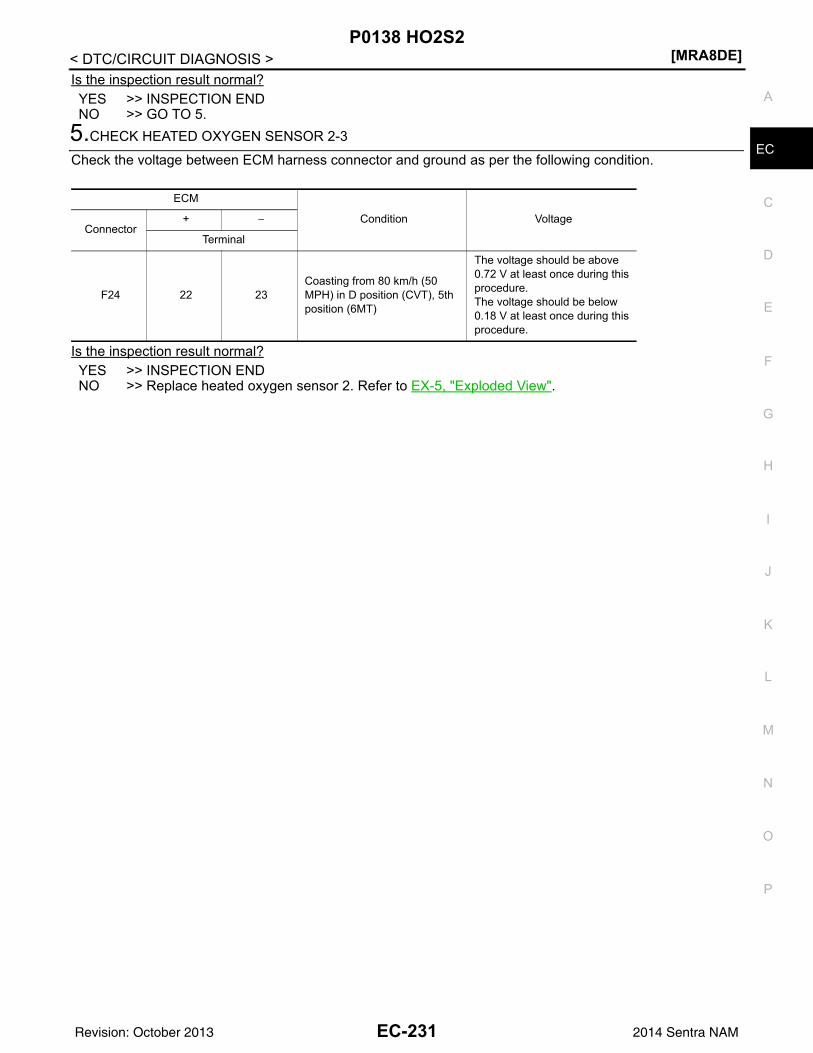
P0138 HO2S2[MRA8DE]
C
D
E
F
G
H
I
J
K
L
M
A
C
N
P
O
< DTC/CIRCUIT DIAGNOSIS >
E
Is the inspection result normal?YES >> INSPECTION ENDNO >> GO TO 5.
5.CHECK HEATED OXYGEN SENSOR 2-3
Check the voltage between ECM harness connector and ground as per the following condition.
Is the inspection result normal?YES >> INSPECTION ENDNO >> Replace heated oxygen sensor 2. Refer to EX-5, "Exploded View".
ECM
Condition VoltageConnector
+ −
Terminal
F24 22 23Coasting from 80 km/h (50 MPH) in D position (CVT), 5th position (6MT)
The voltage should be above 0.72 V at least once during this procedure.The voltage should be below 0.18 V at least once during this procedure.
EC-231Revision: October 2013 2014 Sentra NAM
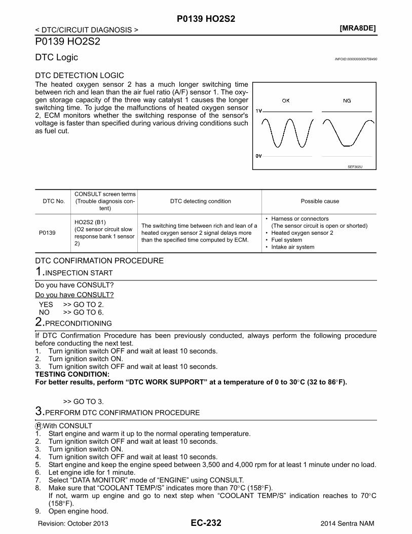
[MRA8DE]P0139 HO2S2
< DTC/CIRCUIT DIAGNOSIS >P0139 HO2S2DTC Logic INFOID:0000000009758490
DTC DETECTION LOGICThe heated oxygen sensor 2 has a much longer switching timebetween rich and lean than the air fuel ratio (A/F) sensor 1. The oxy-gen storage capacity of the three way catalyst 1 causes the longerswitching time. To judge the malfunctions of heated oxygen sensor2, ECM monitors whether the switching response of the sensor'svoltage is faster than specified during various driving conditions suchas fuel cut.
DTC CONFIRMATION PROCEDURE1.INSPECTION START
Do you have CONSULT?Do you have CONSULT?YES >> GO TO 2.NO >> GO TO 6.
2.PRECONDITIONING
If DTC Confirmation Procedure has been previously conducted, always perform the following procedurebefore conducting the next test.1. Turn ignition switch OFF and wait at least 10 seconds.2. Turn ignition switch ON.3. Turn ignition switch OFF and wait at least 10 seconds.TESTING CONDITION:For better results, perform “DTC WORK SUPPORT” at a temperature of 0 to 30°C (32 to 86°F).
>> GO TO 3.3.PERFORM DTC CONFIRMATION PROCEDURE
With CONSULT1. Start engine and warm it up to the normal operating temperature.2. Turn ignition switch OFF and wait at least 10 seconds.3. Turn ignition switch ON.4. Turn ignition switch OFF and wait at least 10 seconds.5. Start engine and keep the engine speed between 3,500 and 4,000 rpm for at least 1 minute under no load.6. Let engine idle for 1 minute.7. Select “DATA MONITOR” mode of “ENGINE” using CONSULT.8. Make sure that “COOLANT TEMP/S” indicates more than 70°C (158°F).
If not, warm up engine and go to next step when “COOLANT TEMP/S” indication reaches to 70°C(158°F).
9. Open engine hood.
SEF302U
DTC No.CONSULT screen terms(Trouble diagnosis con-
tent)DTC detecting condition Possible cause
P0139
HO2S2 (B1)(O2 sensor circuit slow response bank 1 sensor 2)
The switching time between rich and lean of a heated oxygen sensor 2 signal delays more than the specified time computed by ECM.
• Harness or connectors(The sensor circuit is open or shorted)
• Heated oxygen sensor 2• Fuel system• Intake air system
EC-232Revision: October 2013 2014 Sentra NAM
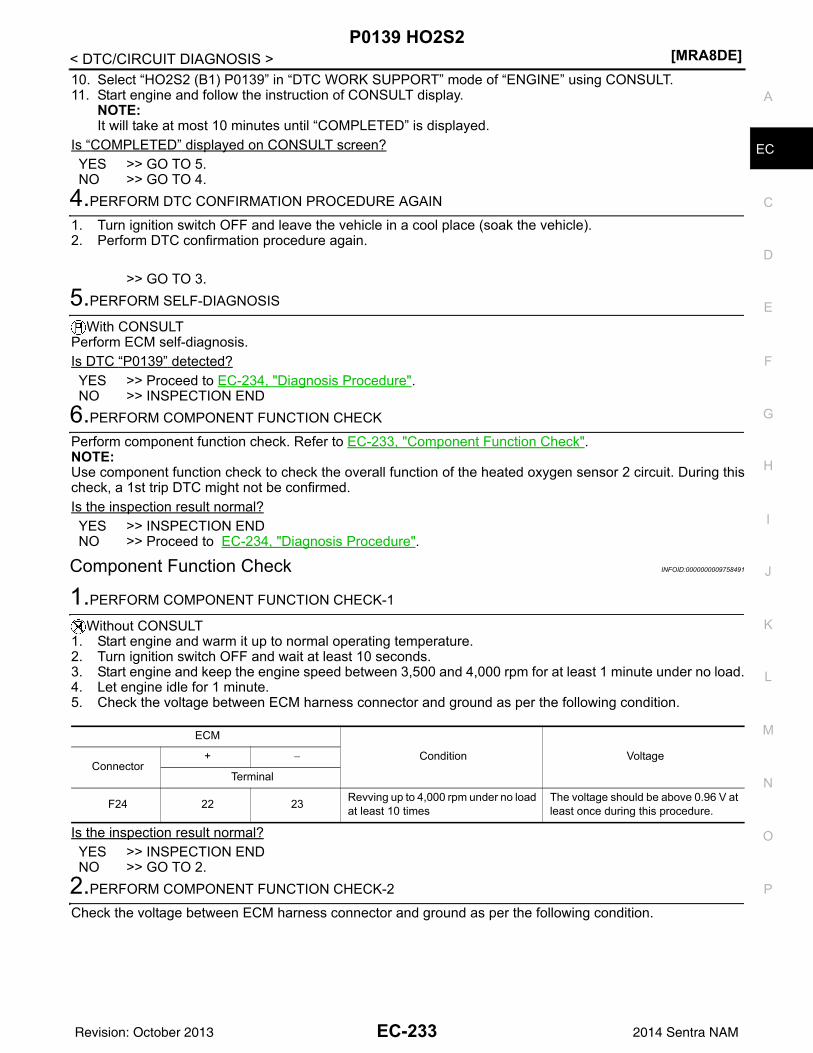
P0139 HO2S2[MRA8DE]
C
D
E
F
G
H
I
J
K
L
M
A
C
N
P
O
< DTC/CIRCUIT DIAGNOSIS >
E
10. Select “HO2S2 (B1) P0139” in “DTC WORK SUPPORT” mode of “ENGINE” using CONSULT.11. Start engine and follow the instruction of CONSULT display.
NOTE:It will take at most 10 minutes until “COMPLETED” is displayed.
Is “COMPLETED” displayed on CONSULT screen?YES >> GO TO 5.NO >> GO TO 4.
4.PERFORM DTC CONFIRMATION PROCEDURE AGAIN
1. Turn ignition switch OFF and leave the vehicle in a cool place (soak the vehicle).2. Perform DTC confirmation procedure again.
>> GO TO 3.5.PERFORM SELF-DIAGNOSIS
With CONSULTPerform ECM self-diagnosis.Is DTC “P0139” detected?YES >> Proceed to EC-234, "Diagnosis Procedure".NO >> INSPECTION END
6.PERFORM COMPONENT FUNCTION CHECK
Perform component function check. Refer to EC-233, "Component Function Check".NOTE:Use component function check to check the overall function of the heated oxygen sensor 2 circuit. During thischeck, a 1st trip DTC might not be confirmed.Is the inspection result normal?YES >> INSPECTION ENDNO >> Proceed to EC-234, "Diagnosis Procedure".
Component Function Check INFOID:0000000009758491
1.PERFORM COMPONENT FUNCTION CHECK-1
Without CONSULT1. Start engine and warm it up to normal operating temperature.2. Turn ignition switch OFF and wait at least 10 seconds.3. Start engine and keep the engine speed between 3,500 and 4,000 rpm for at least 1 minute under no load.4. Let engine idle for 1 minute.5. Check the voltage between ECM harness connector and ground as per the following condition.
Is the inspection result normal?YES >> INSPECTION ENDNO >> GO TO 2.
2.PERFORM COMPONENT FUNCTION CHECK-2
Check the voltage between ECM harness connector and ground as per the following condition.
ECM
Condition VoltageConnector
+ −
Terminal
F24 22 23 Revving up to 4,000 rpm under no load at least 10 times
The voltage should be above 0.96 V at least once during this procedure.
EC-233Revision: October 2013 2014 Sentra NAM
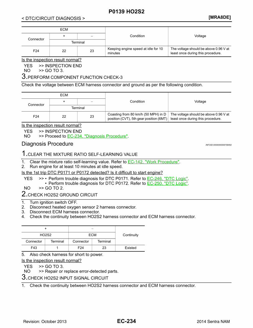
[MRA8DE]P0139 HO2S2
< DTC/CIRCUIT DIAGNOSIS >
Is the inspection result normal?YES >> INSPECTION ENDNO >> GO TO 3.
3.PERFORM COMPONENT FUNCTION CHECK-3
Check the voltage between ECM harness connector and ground as per the following condition.
Is the inspection result normal?YES >> INSPECTION ENDNO >> Proceed to EC-234, "Diagnosis Procedure".
Diagnosis Procedure INFOID:0000000009758492
1.CLEAR THE MIXTURE RATIO SELF-LEARNING VALUE
1. Clear the mixture ratio self-learning value. Refer to EC-142, "Work Procedure".2. Run engine for at least 10 minutes at idle speed.Is the 1st trip DTC P0171 or P0172 detected? Is it difficult to start engine?YES >> • Perform trouble diagnosis for DTC P0171. Refer to EC-246, "DTC Logic".
• Perform trouble diagnosis for DTC P0172. Refer to EC-250, "DTC Logic".NO >> GO TO 2.
2.CHECK HO2S2 GROUND CIRCUIT
1. Turn ignition switch OFF.2. Disconnect heated oxygen sensor 2 harness connector.3. Disconnect ECM harness connector.4. Check the continuity between HO2S2 harness connector and ECM harness connector.
5. Also check harness for short to power.Is the inspection result normal?YES >> GO TO 3.NO >> Repair or replace error-detected parts.
3.CHECK HO2S2 INPUT SIGNAL CIRCUIT
1. Check the continuity between HO2S2 harness connector and ECM harness connector.
ECM
Condition VoltageConnector
+ −
Terminal
F24 22 23 Keeping engine speed at idle for 10 minutes
The voltage should be above 0.96 V at least once during this procedure.
ECM
Condition VoltageConnector
+ −
Terminal
F24 22 23 Coasting from 80 km/h (50 MPH) in D position (CVT), 5th gear position (6MT)
The voltage should be above 0.96 V at least once during this procedure.
+ −
ContinuityHO2S2 ECM
Connector Terminal Connector Terminal
F43 1 F24 23 Existed
EC-234Revision: October 2013 2014 Sentra NAM
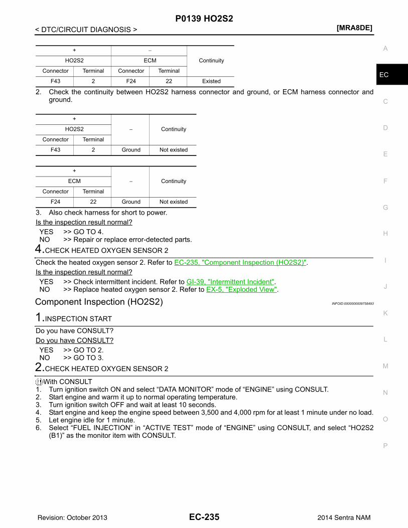
P0139 HO2S2[MRA8DE]
C
D
E
F
G
H
I
J
K
L
M
A
C
N
P
O
< DTC/CIRCUIT DIAGNOSIS >
E
2. Check the continuity between HO2S2 harness connector and ground, or ECM harness connector andground.
3. Also check harness for short to power.Is the inspection result normal?YES >> GO TO 4.NO >> Repair or replace error-detected parts.
4.CHECK HEATED OXYGEN SENSOR 2
Check the heated oxygen sensor 2. Refer to EC-235, "Component Inspection (HO2S2)".Is the inspection result normal?YES >> Check intermittent incident. Refer to GI-39, "Intermittent Incident".NO >> Replace heated oxygen sensor 2. Refer to EX-5, "Exploded View".
Component Inspection (HO2S2) INFOID:0000000009758493
1.INSPECTION START
Do you have CONSULT?Do you have CONSULT?YES >> GO TO 2.NO >> GO TO 3.
2.CHECK HEATED OXYGEN SENSOR 2
With CONSULT1. Turn ignition switch ON and select “DATA MONITOR” mode of “ENGINE” using CONSULT.2. Start engine and warm it up to normal operating temperature.3. Turn ignition switch OFF and wait at least 10 seconds.4. Start engine and keep the engine speed between 3,500 and 4,000 rpm for at least 1 minute under no load.5. Let engine idle for 1 minute.6. Select “FUEL INJECTION” in “ACTIVE TEST” mode of “ENGINE” using CONSULT, and select “HO2S2
(B1)” as the monitor item with CONSULT.
+ −
ContinuityHO2S2 ECM
Connector Terminal Connector Terminal
F43 2 F24 22 Existed
+
− ContinuityHO2S2
Connector Terminal
F43 2 Ground Not existed
+
− ContinuityECM
Connector Terminal
F24 22 Ground Not existed
EC-235Revision: October 2013 2014 Sentra NAM
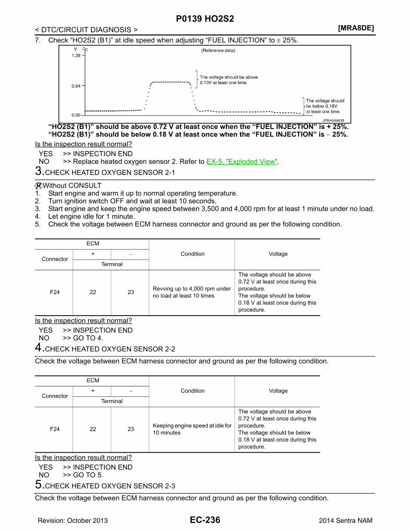
[MRA8DE]P0139 HO2S2
< DTC/CIRCUIT DIAGNOSIS >7. Check “HO2S2 (B1)” at idle speed when adjusting “FUEL INJECTION” to ± 25%.
“HO2S2 (B1)” should be above 0.72 V at least once when the “FUEL INJECTION” is + 25%.“HO2S2 (B1)” should be below 0.18 V at least once when the “FUEL INJECTION” is − 25%.
Is the inspection result normal?YES >> INSPECTION ENDNO >> Replace heated oxygen sensor 2. Refer to EX-5, "Exploded View".
3.CHECK HEATED OXYGEN SENSOR 2-1
Without CONSULT1. Start engine and warm it up to normal operating temperature.2. Turn ignition switch OFF and wait at least 10 seconds.3. Start engine and keep the engine speed between 3,500 and 4,000 rpm for at least 1 minute under no load.4. Let engine idle for 1 minute.5. Check the voltage between ECM harness connector and ground as per the following condition.
Is the inspection result normal?YES >> INSPECTION ENDNO >> GO TO 4.
4.CHECK HEATED OXYGEN SENSOR 2-2
Check the voltage between ECM harness connector and ground as per the following condition.
Is the inspection result normal?YES >> INSPECTION ENDNO >> GO TO 5.
5.CHECK HEATED OXYGEN SENSOR 2-3
Check the voltage between ECM harness connector and ground as per the following condition.
JPBIA5998GB
ECM
Condition VoltageConnector
+ −
Terminal
F24 22 23 Revving up to 4,000 rpm under no load at least 10 times
The voltage should be above 0.72 V at least once during this procedure.The voltage should be below 0.18 V at least once during this procedure.
ECM
Condition VoltageConnector
+ −
Terminal
F24 22 23 Keeping engine speed at idle for 10 minutes
The voltage should be above 0.72 V at least once during this procedure.The voltage should be below 0.18 V at least once during this procedure.
EC-236Revision: October 2013 2014 Sentra NAM
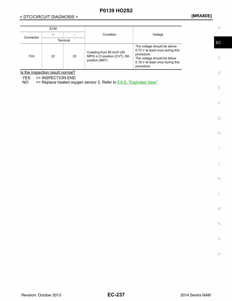
P0139 HO2S2[MRA8DE]
C
D
E
F
G
H
I
J
K
L
M
A
C
N
P
O
< DTC/CIRCUIT DIAGNOSIS >
E
Is the inspection result normal?YES >> INSPECTION ENDNO >> Replace heated oxygen sensor 2. Refer to EX-5, "Exploded View".
ECM
Condition VoltageConnector
+ −
Terminal
F24 22 23Coasting from 80 km/h (50 MPH) in D position (CVT), 5th position (6MT)
The voltage should be above 0.72 V at least once during this procedure.The voltage should be below 0.18 V at least once during this procedure.
EC-237Revision: October 2013 2014 Sentra NAM
[MRA8DE]P014C, P014D, P015A, P015B A/F SENSOR 1
< DTC/CIRCUIT DIAGNOSIS >P014C, P014D, P015A, P015B A/F SENSOR 1DTC Logic INFOID:0000000009758494
DTC DETECTION LOGICTo judge the malfunction of A/F sensor 1, this diagnosis measures response time of the A/F signal computedby ECM from the A/F sensor 1 signal. The time is compensated by engine operating (speed and load), fuelfeedback control constant, and the A/F sensor 1 temperature index. Judgment is based on whether the com-pensated time (the A/F signal cycling time index) is inordinately long or not.
DTC CONFIRMATION PROCEDURE1.PRECONDITIONING
If DTC Confirmation Procedure has been previously conducted, always perform the following procedurebefore conducting the next test.1. Turn ignition switch OFF and wait at least 10 seconds.2. Turn ignition switch ON.3. Turn ignition switch OFF and wait at least 10 seconds.TESTING CONDITION:Before performing the following procedure, confirm that battery voltage is more than 11 V at idle.Do you have CONSULT?YES >> GO TO 2.NO >> GO TO 6.
2.PERFORM DTC CONFIRMATION PROCEDURE-1
With CONSULT1. Start engine and warm it up to normal operating temperature.2. Turn ignition switch OFF and wait at least 10 seconds.3. Turn ignition switch ON.4. Turn ignition switch OFF and wait at least 10 seconds.5. Restart engine and keep the engine speed between 3,500 and 4,000 rpm for at least 1 minute under no
load.6. Let engine idle for 1 minute.7. Increase the engine speed up to about 3,600 rpm and keep it for 10 seconds.8. Fully release accelerator pedal and then let engine idle for about 1 minute.9. On CONSULT screen, select “ENGINE” >> “DATA MONITOR” >> “A/F SEN1 DIAG3 (B1)”.10. Check that the data monitor indicates “PRSNT”.
NOTE:If “PRSNT” changed to “ABSNT”, refer to EC-211, "Component Function Check".
Is “PRSNT” displayed on CONSULT screen?YES >> GO TO 4NO >> GO TO 3.
3.PERFORM DTC CONFIRMATION PROCEDURE-2
With CONSULTPerform DTC confirmation procedure-1 again.
DTC No. CONSULT screen terms(Trouble diagnosis content) DTC detecting condition Possible cause
P014C
A/F SENSOR1 (B1)(O2 sensor slow response - rich to lean bank 1 sensor 1)
The response time of a A/F sensor 1 signal delays more than the specified time computed by ECM.
• Harness or connectors(A/F sensor 1 circuit is open or shorted.)
• A/F sensor 1• A/F sensor 1 heater• Fuel pressure• Fuel injector• Intake air leaks• Exhaust gas leaks• PCV• Mass air flow sensor
P014D
A/F SENSOR1 (B1)(O2 sensor slow response - lean to rich bank 1 sensor 1)
EC-238Revision: October 2013 2014 Sentra NAM
P014C, P014D, P015A, P015B A/F SENSOR 1[MRA8DE]
C
D
E
F
G
H
I
J
K
L
M
A
C
N
P
O
< DTC/CIRCUIT DIAGNOSIS >
E
Is “PRSNT” displayed on CONSULT screen?YES >> GO TO 4.NO >> Proceed to EC-211, "Component Function Check".
4.PERFORM DTC CONFIRMATION PROCEDURE-3
With CONSULT1. Wait for about 20 seconds at idle.2. On CONSULT screen, select “ENGINE” >> “DATA MONITOR” >> “A/F SEN1 DIAG2 (B1)”.3. Check that the data monitor indicates “CMPLT”.
NOTE:If “CMPLT” changed to “INCMP”, refer to EC-211, "Component Function Check".
Is “CMPLT” displayed on CONSULT screen?YES >> GO TO 5.NO >> Refer to EC-211, "Component Function Check".
5.PERFORM SELF-DIAGNOSIS
With CONSULTCheck the “SELF-DIAG RESULT”.Is any DTC detected?YES >> Proceed to EC-240, "Diagnosis Procedure".NO >> INSPECTION END
6.CHECK AIR-FUEL RATIO SELF-LEARNING VALUE
With GST1. Start engine and warm it up to normal operating temperature.2. Select Service $01 with GST.3. Calculate the total value of “Short term fuel trim” and “Long term fuel trim” indications.Is the total percentage within ±15%?YES >> GO TO 8.NO >> GO TO 7.
7.DETECT MALFUNCTIONING PART
Check the following.• Intake air leaks• Exhaust gas leaks• Incorrect fuel pressure• Lack of fuel• Fuel injector• Incorrect PCV hose connection• PCV valve• Mass air flow sensor
>> Repair or replace malfunctioning part.8.PERFORM DTC CONFIRMATION PROCEDURE
1. Turn ignition switch OFF and wait at least 10 seconds.2. Turn ignition switch ON.3. Turn ignition switch OFF and wait at least 10 seconds.4. Start engine and keep the engine speed between 3,500 and 4,000 rpm for at least 1 minute under no load.5. Let engine idle for 1 minute.6. Increase the engine speed up to about 3,600 rpm and keep it for 10 seconds.7. Fully release accelerator pedal and then let engine idle for about 1 minute.8. Check 1st trip DTC.Is 1st trip DTC detected?YES >> Proceed to EC-240, "Diagnosis Procedure".NO >> INSPECTION END
EC-239Revision: October 2013 2014 Sentra NAM
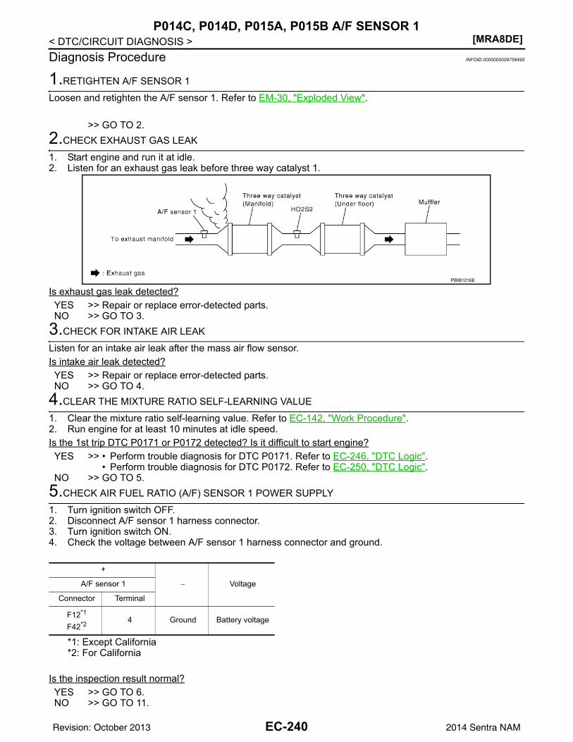
[MRA8DE]P014C, P014D, P015A, P015B A/F SENSOR 1
< DTC/CIRCUIT DIAGNOSIS >Diagnosis Procedure INFOID:0000000009758495
1.RETIGHTEN A/F SENSOR 1
Loosen and retighten the A/F sensor 1. Refer to EM-30, "Exploded View".
>> GO TO 2.2.CHECK EXHAUST GAS LEAK
1. Start engine and run it at idle.2. Listen for an exhaust gas leak before three way catalyst 1.
Is exhaust gas leak detected?YES >> Repair or replace error-detected parts.NO >> GO TO 3.
3.CHECK FOR INTAKE AIR LEAK
Listen for an intake air leak after the mass air flow sensor.Is intake air leak detected?YES >> Repair or replace error-detected parts.NO >> GO TO 4.
4.CLEAR THE MIXTURE RATIO SELF-LEARNING VALUE
1. Clear the mixture ratio self-learning value. Refer to EC-142, "Work Procedure".2. Run engine for at least 10 minutes at idle speed.Is the 1st trip DTC P0171 or P0172 detected? Is it difficult to start engine?YES >> • Perform trouble diagnosis for DTC P0171. Refer to EC-246, "DTC Logic".
• Perform trouble diagnosis for DTC P0172. Refer to EC-250, "DTC Logic".NO >> GO TO 5.
5.CHECK AIR FUEL RATIO (A/F) SENSOR 1 POWER SUPPLY
1. Turn ignition switch OFF.2. Disconnect A/F sensor 1 harness connector.3. Turn ignition switch ON.4. Check the voltage between A/F sensor 1 harness connector and ground.
*1: Except California*2: For California
Is the inspection result normal?YES >> GO TO 6.NO >> GO TO 11.
PBIB1216E
+
− VoltageA/F sensor 1
Connector Terminal
F12*1
F42*2 4 Ground Battery voltage
EC-240Revision: October 2013 2014 Sentra NAM
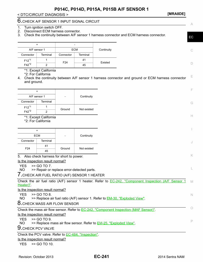
P014C, P014D, P015A, P015B A/F SENSOR 1[MRA8DE]
C
D
E
F
G
H
I
J
K
L
M
A
C
N
P
O
< DTC/CIRCUIT DIAGNOSIS >
E
6.CHECK A/F SENSOR 1 INPUT SIGNAL CIRCUIT
1. Turn ignition switch OFF.2. Disconnect ECM harness connector.3. Check the continuity between A/F sensor 1 harness connector and ECM harness connector.
*1: Except California*2: For California
4. Check the continuity between A/F sensor 1 harness connector and ground or ECM harness connectorand ground.
*1: Except California*2: For California
5. Also check harness for short to power.Is the inspection result normal?YES >> GO TO 7.NO >> Repair or replace error-detected parts.
7.CHECK AIR FUEL RATIO (A/F) SENSOR 1 HEATER
Check the air fuel ratio (A/F) sensor 1 heater. Refer to EC-242, "Component Inspection (A/F Sensor 1Heater)".Is the inspection result normal?YES >> GO TO 8.NO >> Replace air fuel ratio (A/F) sensor 1. Refer to EM-30, "Exploded View".
8.CHECK MASS AIR FLOW SENSOR
Check the mass air flow sensor. Refer to EC-242, "Component Inspection (MAF Sensor)".Is the inspection result normal?YES >> GO TO 9. NO >> Replace mass air flow sensor. Refer to EM-25, "Exploded View".
9.CHECK PCV VALVE
Check the PCV valve. Refer to EC-484, "Inspection".Is the inspection result normal?YES >> GO TO 10.
+ -
ContinuityA/F sensor 1 ECM
Connector Terminal Connector Terminal
F12*1
F42*2
1F24
41Existed
2 45
+
− ContinuityA/F sensor 1
Connector Terminal
F12*1
F42*2
1Ground Not existed
2
+
− ContinuityECM
Connector Terminal
F2441
Ground Not existed45
EC-241Revision: October 2013 2014 Sentra NAM
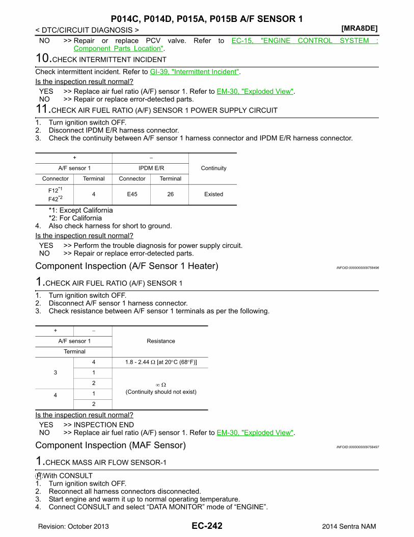
[MRA8DE]P014C, P014D, P015A, P015B A/F SENSOR 1
< DTC/CIRCUIT DIAGNOSIS >NO >> Repair or replace PCV valve. Refer to EC-15, "ENGINE CONTROL SYSTEM :
Component Parts Location".10.CHECK INTERMITTENT INCIDENT
Check intermittent incident. Refer to GI-39, "Intermittent Incident".Is the inspection result normal?YES >> Replace air fuel ratio (A/F) sensor 1. Refer to EM-30, "Exploded View".NO >> Repair or replace error-detected parts.
11.CHECK AIR FUEL RATIO (A/F) SENSOR 1 POWER SUPPLY CIRCUIT
1. Turn ignition switch OFF.2. Disconnect IPDM E/R harness connector.3. Check the continuity between A/F sensor 1 harness connector and IPDM E/R harness connector.
*1: Except California*2: For California
4. Also check harness for short to ground.Is the inspection result normal?YES >> Perform the trouble diagnosis for power supply circuit.NO >> Repair or replace error-detected parts.
Component Inspection (A/F Sensor 1 Heater) INFOID:0000000009758496
1.CHECK AIR FUEL RATIO (A/F) SENSOR 1
1. Turn ignition switch OFF.2. Disconnect A/F sensor 1 harness connector.3. Check resistance between A/F sensor 1 terminals as per the following.
Is the inspection result normal?YES >> INSPECTION ENDNO >> Replace air fuel ratio (A/F) sensor 1. Refer to EM-30, "Exploded View".
Component Inspection (MAF Sensor) INFOID:0000000009758497
1.CHECK MASS AIR FLOW SENSOR-1
With CONSULT1. Turn ignition switch OFF.2. Reconnect all harness connectors disconnected.3. Start engine and warm it up to normal operating temperature.4. Connect CONSULT and select “DATA MONITOR” mode of “ENGINE”.
+ −
ContinuityA/F sensor 1 IPDM E/R
Connector Terminal Connector Terminal
F12*1
F42*2 4 E45 26 Existed
+ −
ResistanceA/F sensor 1
Terminal
3
4 1.8 - 2.44 Ω [at 20°C (68°F)]
1
∞ Ω(Continuity should not exist)
2
4 1
2
EC-242Revision: October 2013 2014 Sentra NAM
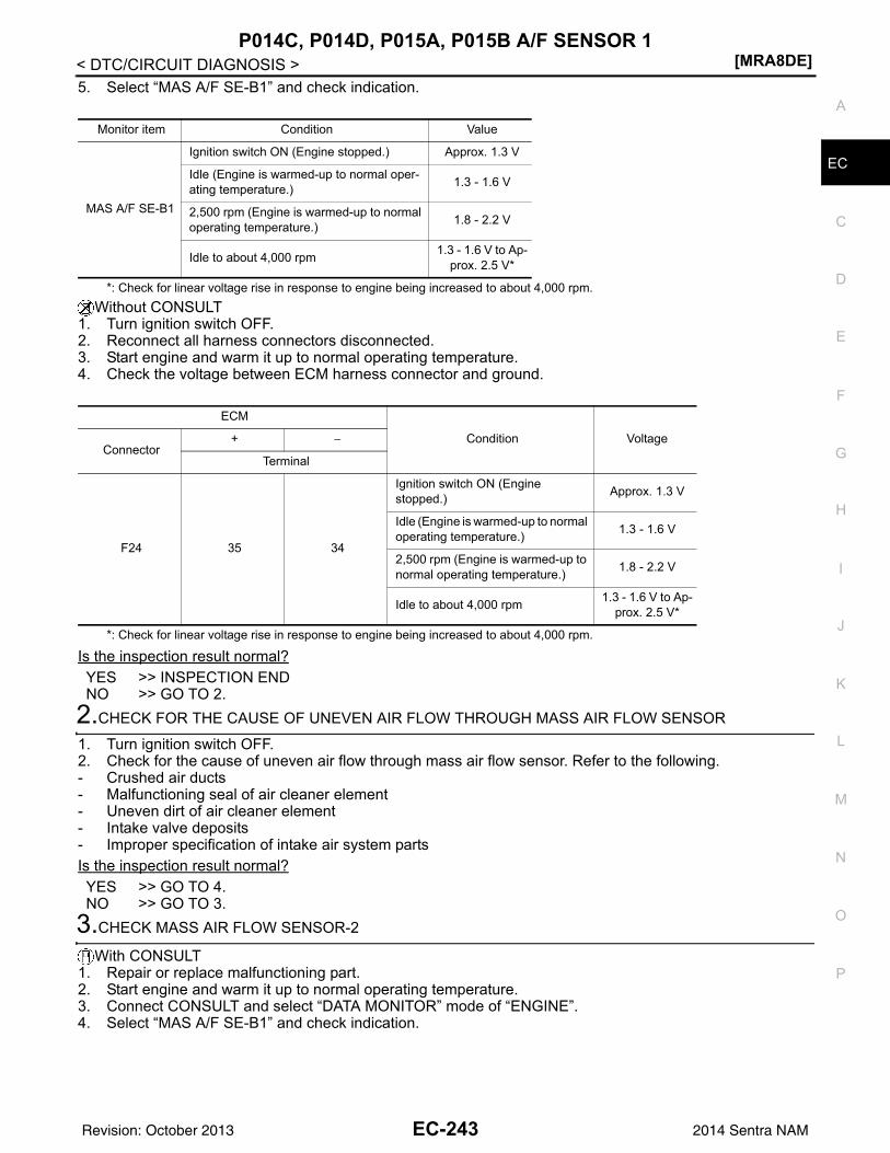
P014C, P014D, P015A, P015B A/F SENSOR 1[MRA8DE]
C
D
E
F
G
H
I
J
K
L
M
A
C
N
P
O
< DTC/CIRCUIT DIAGNOSIS >
E
5. Select “MAS A/F SE-B1” and check indication.
*: Check for linear voltage rise in response to engine being increased to about 4,000 rpm.Without CONSULT
1. Turn ignition switch OFF.2. Reconnect all harness connectors disconnected.3. Start engine and warm it up to normal operating temperature.4. Check the voltage between ECM harness connector and ground.
*: Check for linear voltage rise in response to engine being increased to about 4,000 rpm.
Is the inspection result normal?YES >> INSPECTION ENDNO >> GO TO 2.
2.CHECK FOR THE CAUSE OF UNEVEN AIR FLOW THROUGH MASS AIR FLOW SENSOR
1. Turn ignition switch OFF.2. Check for the cause of uneven air flow through mass air flow sensor. Refer to the following.- Crushed air ducts- Malfunctioning seal of air cleaner element- Uneven dirt of air cleaner element- Intake valve deposits- Improper specification of intake air system partsIs the inspection result normal?YES >> GO TO 4.NO >> GO TO 3.
3.CHECK MASS AIR FLOW SENSOR-2
With CONSULT1. Repair or replace malfunctioning part.2. Start engine and warm it up to normal operating temperature.3. Connect CONSULT and select “DATA MONITOR” mode of “ENGINE”.4. Select “MAS A/F SE-B1” and check indication.
Monitor item Condition Value
MAS A/F SE-B1
Ignition switch ON (Engine stopped.) Approx. 1.3 V
Idle (Engine is warmed-up to normal oper-ating temperature.) 1.3 - 1.6 V
2,500 rpm (Engine is warmed-up to normal operating temperature.) 1.8 - 2.2 V
Idle to about 4,000 rpm 1.3 - 1.6 V to Ap-prox. 2.5 V*
ECM
Condition VoltageConnector
+ −
Terminal
F24 35 34
Ignition switch ON (Engine stopped.) Approx. 1.3 V
Idle (Engine is warmed-up to normal operating temperature.) 1.3 - 1.6 V
2,500 rpm (Engine is warmed-up to normal operating temperature.) 1.8 - 2.2 V
Idle to about 4,000 rpm 1.3 - 1.6 V to Ap-prox. 2.5 V*
EC-243Revision: October 2013 2014 Sentra NAM
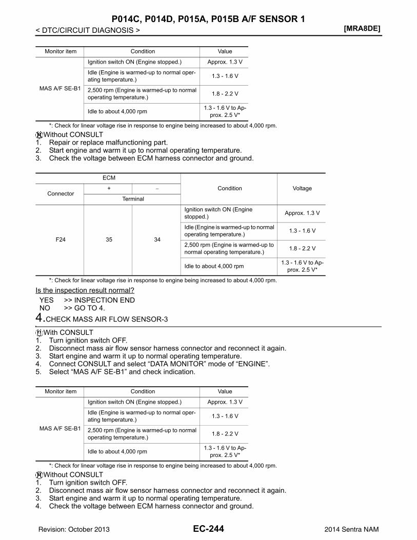
[MRA8DE]P014C, P014D, P015A, P015B A/F SENSOR 1
< DTC/CIRCUIT DIAGNOSIS >
*: Check for linear voltage rise in response to engine being increased to about 4,000 rpm.Without CONSULT
1. Repair or replace malfunctioning part.2. Start engine and warm it up to normal operating temperature.3. Check the voltage between ECM harness connector and ground.
*: Check for linear voltage rise in response to engine being increased to about 4,000 rpm.
Is the inspection result normal?YES >> INSPECTION ENDNO >> GO TO 4.
4.CHECK MASS AIR FLOW SENSOR-3
With CONSULT1. Turn ignition switch OFF.2. Disconnect mass air flow sensor harness connector and reconnect it again.3. Start engine and warm it up to normal operating temperature.4. Connect CONSULT and select “DATA MONITOR” mode of “ENGINE”.5. Select “MAS A/F SE-B1” and check indication.
*: Check for linear voltage rise in response to engine being increased to about 4,000 rpm.Without CONSULT
1. Turn ignition switch OFF.2. Disconnect mass air flow sensor harness connector and reconnect it again.3. Start engine and warm it up to normal operating temperature.4. Check the voltage between ECM harness connector and ground.
Monitor item Condition Value
MAS A/F SE-B1
Ignition switch ON (Engine stopped.) Approx. 1.3 V
Idle (Engine is warmed-up to normal oper-ating temperature.) 1.3 - 1.6 V
2,500 rpm (Engine is warmed-up to normal operating temperature.) 1.8 - 2.2 V
Idle to about 4,000 rpm 1.3 - 1.6 V to Ap-prox. 2.5 V*
ECM
Condition VoltageConnector
+ −
Terminal
F24 35 34
Ignition switch ON (Engine stopped.) Approx. 1.3 V
Idle (Engine is warmed-up to normal operating temperature.) 1.3 - 1.6 V
2,500 rpm (Engine is warmed-up to normal operating temperature.) 1.8 - 2.2 V
Idle to about 4,000 rpm 1.3 - 1.6 V to Ap-prox. 2.5 V*
Monitor item Condition Value
MAS A/F SE-B1
Ignition switch ON (Engine stopped.) Approx. 1.3 V
Idle (Engine is warmed-up to normal oper-ating temperature.) 1.3 - 1.6 V
2,500 rpm (Engine is warmed-up to normal operating temperature.) 1.8 - 2.2 V
Idle to about 4,000 rpm 1.3 - 1.6 V to Ap-prox. 2.5 V*
EC-244Revision: October 2013 2014 Sentra NAM
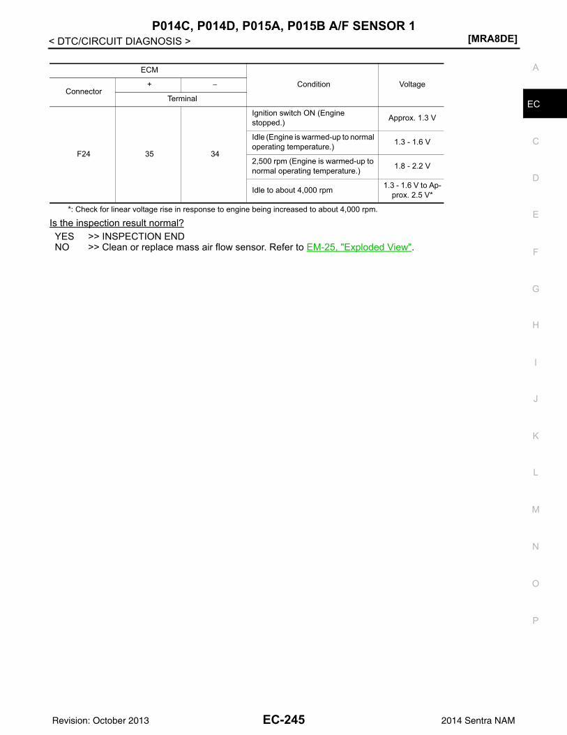
P014C, P014D, P015A, P015B A/F SENSOR 1[MRA8DE]
C
D
E
F
G
H
I
J
K
L
M
A
C
N
P
O
< DTC/CIRCUIT DIAGNOSIS >
E
*: Check for linear voltage rise in response to engine being increased to about 4,000 rpm.
Is the inspection result normal?YES >> INSPECTION ENDNO >> Clean or replace mass air flow sensor. Refer to EM-25, "Exploded View".
ECM
Condition VoltageConnector
+ −
Terminal
F24 35 34
Ignition switch ON (Engine stopped.) Approx. 1.3 V
Idle (Engine is warmed-up to normal operating temperature.) 1.3 - 1.6 V
2,500 rpm (Engine is warmed-up to normal operating temperature.) 1.8 - 2.2 V
Idle to about 4,000 rpm 1.3 - 1.6 V to Ap-prox. 2.5 V*
EC-245Revision: October 2013 2014 Sentra NAM
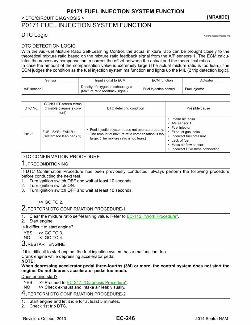
[MRA8DE]P0171 FUEL INJECTION SYSTEM FUNCTION
< DTC/CIRCUIT DIAGNOSIS >P0171 FUEL INJECTION SYSTEM FUNCTIONDTC Logic INFOID:0000000009758498
DTC DETECTION LOGICWith the Air/Fuel Mixture Ratio Self-Learning Control, the actual mixture ratio can be brought closely to thetheoretical mixture ratio based on the mixture ratio feedback signal from the A/F sensors 1. The ECM calcu-lates the necessary compensation to correct the offset between the actual and the theoretical ratios.In case the amount of the compensation value is extremely large (The actual mixture ratio is too lean.), theECM judges the condition as the fuel injection system malfunction and lights up the MIL (2 trip detection logic).
DTC CONFIRMATION PROCEDURE1.PRECONDITIONING
If DTC Confirmation Procedure has been previously conducted, always perform the following procedurebefore conducting the next test.1. Turn ignition switch OFF and wait at least 10 seconds.2. Turn ignition switch ON.3. Turn ignition switch OFF and wait at least 10 seconds.
>> GO TO 2.2.PERFORM DTC CONFIRMATION PROCEDURE-1
1. Clear the mixture ratio self-learning value. Refer to EC-142, "Work Procedure".2. Start engine.Is it difficult to start engine?YES >> GO TO 3.NO >> GO TO 4.
3.RESTART ENGINE
If it is difficult to start engine, the fuel injection system has a malfunction, too.Crank engine while depressing accelerator pedal.NOTE:When depressing accelerator pedal three-fourths (3/4) or more, the control system does not start theengine. Do not depress accelerator pedal too much.Does engine start?YES >> Proceed to EC-247, "Diagnosis Procedure".NO >> Check exhaust and intake air leak visually.
4.PERFORM DTC CONFIRMATION PROCEDURE-2
1. Start engine and let it idle for at least 5 minutes.2. Check 1st trip DTC.
Sensor Input signal to ECM ECM function Actuator
A/F sensor 1 Density of oxygen in exhaust gas(Mixture ratio feedback signal) Fuel injection control Fuel injector
DTC No.CONSULT screen terms(Trouble diagnosis con-
tent)DTC detecting condition Possible cause
P0171 FUEL SYS-LEAN-B1(System too lean bank 1)
• Fuel injection system does not operate properly.• The amount of mixture ratio compensation is too
large. (The mixture ratio is too lean.)
• Intake air leaks• A/F sensor 1• Fuel injector• Exhaust gas leaks• Incorrect fuel pressure• Lack of fuel• Mass air flow sensor• Incorrect PCV hose connection
EC-246Revision: October 2013 2014 Sentra NAM
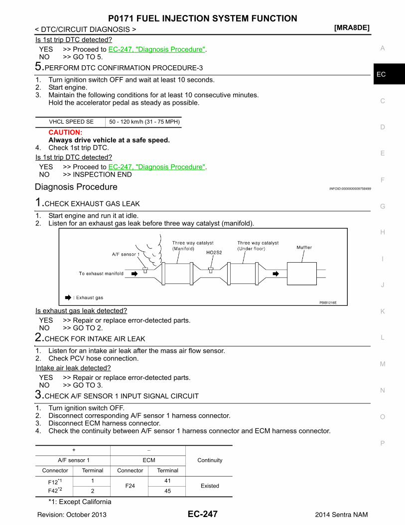
P0171 FUEL INJECTION SYSTEM FUNCTION[MRA8DE]
C
D
E
F
G
H
I
J
K
L
M
A
C
N
P
O
< DTC/CIRCUIT DIAGNOSIS >
E
Is 1st trip DTC detected?YES >> Proceed to EC-247, "Diagnosis Procedure".NO >> GO TO 5.
5.PERFORM DTC CONFIRMATION PROCEDURE-3
1. Turn ignition switch OFF and wait at least 10 seconds.2. Start engine.3. Maintain the following conditions for at least 10 consecutive minutes.
Hold the accelerator pedal as steady as possible.
CAUTION:Always drive vehicle at a safe speed.
4. Check 1st trip DTC.Is 1st trip DTC detected?YES >> Proceed to EC-247, "Diagnosis Procedure".NO >> INSPECTION END
Diagnosis Procedure INFOID:0000000009758499
1.CHECK EXHAUST GAS LEAK
1. Start engine and run it at idle.2. Listen for an exhaust gas leak before three way catalyst (manifold).
Is exhaust gas leak detected?YES >> Repair or replace error-detected parts.NO >> GO TO 2.
2.CHECK FOR INTAKE AIR LEAK
1. Listen for an intake air leak after the mass air flow sensor.2. Check PCV hose connection.Intake air leak detected?YES >> Repair or replace error-detected parts.NO >> GO TO 3.
3.CHECK A/F SENSOR 1 INPUT SIGNAL CIRCUIT
1. Turn ignition switch OFF.2. Disconnect corresponding A/F sensor 1 harness connector.3. Disconnect ECM harness connector.4. Check the continuity between A/F sensor 1 harness connector and ECM harness connector.
*1: Except California
VHCL SPEED SE 50 - 120 km/h (31 - 75 MPH)
PBIB1216E
+ −
ContinuityA/F sensor 1 ECM
Connector Terminal Connector Terminal
F12*1
F42*2
1F24
41Existed
2 45
EC-247Revision: October 2013 2014 Sentra NAM
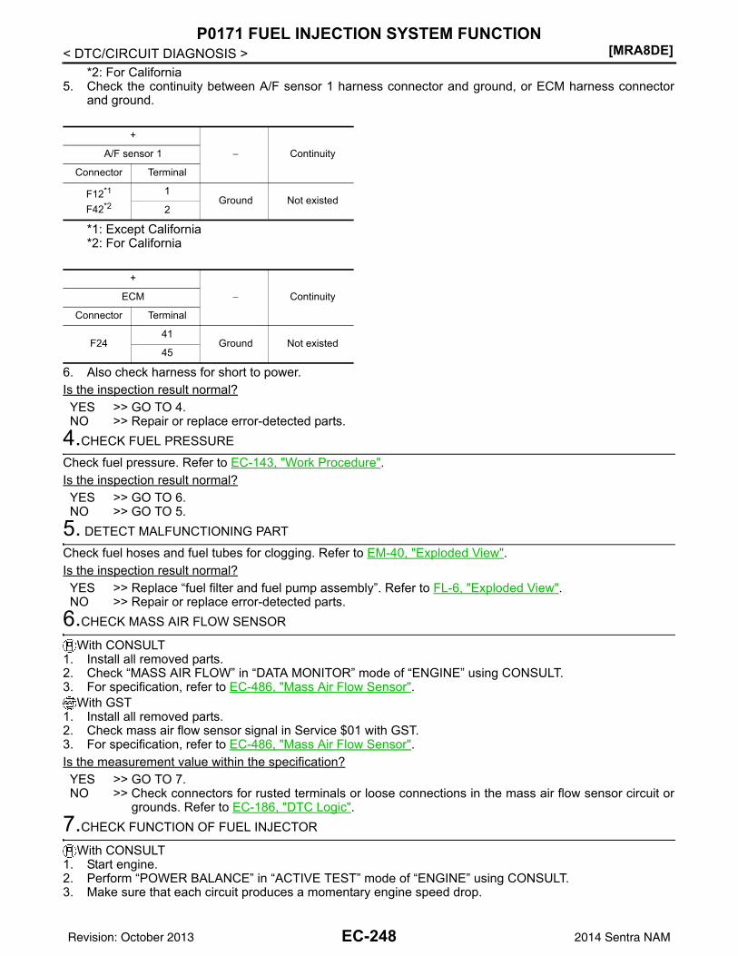
[MRA8DE]P0171 FUEL INJECTION SYSTEM FUNCTION
< DTC/CIRCUIT DIAGNOSIS >*2: For California
5. Check the continuity between A/F sensor 1 harness connector and ground, or ECM harness connectorand ground.
*1: Except California*2: For California
6. Also check harness for short to power.Is the inspection result normal?YES >> GO TO 4.NO >> Repair or replace error-detected parts.
4.CHECK FUEL PRESSURE
Check fuel pressure. Refer to EC-143, "Work Procedure".Is the inspection result normal?YES >> GO TO 6.NO >> GO TO 5.
5. DETECT MALFUNCTIONING PART
Check fuel hoses and fuel tubes for clogging. Refer to EM-40, "Exploded View".Is the inspection result normal?YES >> Replace “fuel filter and fuel pump assembly”. Refer to FL-6, "Exploded View".NO >> Repair or replace error-detected parts.
6.CHECK MASS AIR FLOW SENSOR
With CONSULT1. Install all removed parts.2. Check “MASS AIR FLOW” in “DATA MONITOR” mode of “ENGINE” using CONSULT.3. For specification, refer to EC-486, "Mass Air Flow Sensor".
With GST1. Install all removed parts.2. Check mass air flow sensor signal in Service $01 with GST.3. For specification, refer to EC-486, "Mass Air Flow Sensor".Is the measurement value within the specification?YES >> GO TO 7.NO >> Check connectors for rusted terminals or loose connections in the mass air flow sensor circuit or
grounds. Refer to EC-186, "DTC Logic".7.CHECK FUNCTION OF FUEL INJECTOR
With CONSULT1. Start engine.2. Perform “POWER BALANCE” in “ACTIVE TEST” mode of “ENGINE” using CONSULT.3. Make sure that each circuit produces a momentary engine speed drop.
+
− ContinuityA/F sensor 1
Connector Terminal
F12*1
F42*2
1Ground Not existed
2
+
− ContinuityECM
Connector Terminal
F2441
Ground Not existed45
EC-248Revision: October 2013 2014 Sentra NAM
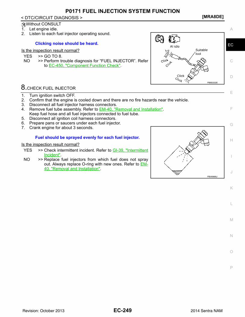
P0171 FUEL INJECTION SYSTEM FUNCTION[MRA8DE]
C
D
E
F
G
H
I
J
K
L
M
A
C
N
P
O
< DTC/CIRCUIT DIAGNOSIS >
E
Without CONSULT1. Let engine idle.2. Listen to each fuel injector operating sound.
Is the inspection result normal?YES >> GO TO 8.NO >> Perform trouble diagnosis for “FUEL INJECTOR”. Refer
to EC-450, "Component Function Check".
8.CHECK FUEL INJECTOR
1. Turn ignition switch OFF.2. Confirm that the engine is cooled down and there are no fire hazards near the vehicle.3. Disconnect all fuel injector harness connectors.4. Remove fuel tube assembly. Refer to EM-40, "Removal and Installation".
Keep fuel hose and all fuel injectors connected to fuel tube.5. Disconnect all ignition coil harness connectors.6. Prepare pans or saucers under each fuel injector.7. Crank engine for about 3 seconds.
Is the inspection result normal?YES >> Check intermittent incident. Refer to GI-39, "Intermittent
Incident".NO >> Replace fuel injectors from which fuel does not spray
out. Always replace O-ring with new ones. Refer to EM-40, "Removal and Installation".
Clicking noise should be heard.
PBIB3332E
Fuel should be sprayed evenly for each fuel injector.
PBIA9666J
EC-249Revision: October 2013 2014 Sentra NAM
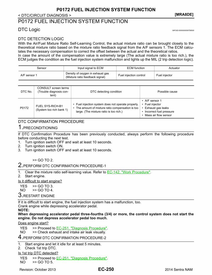
[MRA8DE]P0172 FUEL INJECTION SYSTEM FUNCTION
< DTC/CIRCUIT DIAGNOSIS >P0172 FUEL INJECTION SYSTEM FUNCTIONDTC Logic INFOID:0000000009758500
DTC DETECTION LOGICWith the Air/Fuel Mixture Ratio Self-Learning Control, the actual mixture ratio can be brought closely to thetheoretical mixture ratio based on the mixture ratio feedback signal from the A/F sensors 1. The ECM calcu-lates the necessary compensation to correct the offset between the actual and the theoretical ratios.In case the amount of the compensation value is extremely large (The actual mixture ratio is too rich.), theECM judges the condition as the fuel injection system malfunction and lights up the MIL (2 trip detection logic).
DTC CONFIRMATION PROCEDURE1.PRECONDITIONING
If DTC Confirmation Procedure has been previously conducted, always perform the following procedurebefore conducting the next test.1. Turn ignition switch OFF and wait at least 10 seconds.2. Turn ignition switch ON.3. Turn ignition switch OFF and wait at least 10 seconds.
>> GO TO 2.2.PERFORM DTC CONFIRMATION PROCEDURE-1
1. Clear the mixture ratio self-learning value. Refer to EC-142, "Work Procedure".2. Start engine.Is it difficult to start engine?YES >> GO TO 3.NO >> GO TO 4.
3.RESTART ENGINE
If it is difficult to start engine, the fuel injection system has a malfunction, too.Crank engine while depressing accelerator pedal.NOTE:When depressing accelerator pedal three-fourths (3/4) or more, the control system does not start theengine. Do not depress accelerator pedal too much.Does engine start?YES >> Proceed to EC-251, "Diagnosis Procedure".NO >> Check exhaust and intake air leak visually.
4.PERFORM DTC CONFIRMATION PROCEDURE-2
1. Start engine and let it idle for at least 5 minutes.2. Check 1st trip DTC.Is 1st trip DTC detected?YES >> Proceed to EC-251, "Diagnosis Procedure".NO >> GO TO 5.
Sensor Input signal to ECM ECM function Actuator
A/F sensor 1 Density of oxygen in exhaust gas(Mixture ratio feedback signal) Fuel injection control Fuel injector
DTC No.CONSULT screen terms(Trouble diagnosis con-
tent)DTC detecting condition Possible cause
P0172 FUEL SYS-RICH-B1(System too rich bank 1)
• Fuel injection system does not operate properly.• The amount of mixture ratio compensation is too
large. (The mixture ratio is too rich.)
• A/F sensor 1• Fuel injector• Exhaust gas leaks• Incorrect fuel pressure• Mass air flow sensor
EC-250Revision: October 2013 2014 Sentra NAM
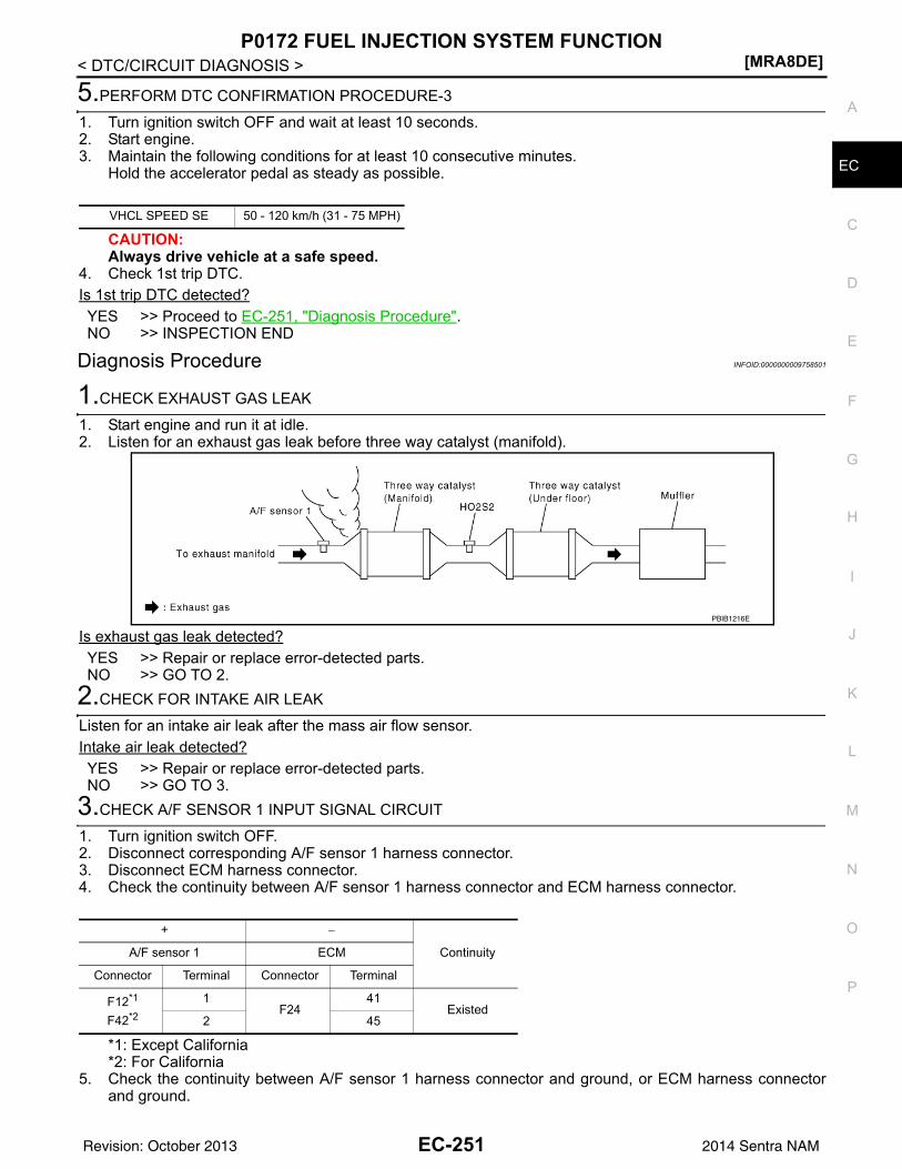
P0172 FUEL INJECTION SYSTEM FUNCTION[MRA8DE]
C
D
E
F
G
H
I
J
K
L
M
A
C
N
P
O
< DTC/CIRCUIT DIAGNOSIS >
E
5.PERFORM DTC CONFIRMATION PROCEDURE-3
1. Turn ignition switch OFF and wait at least 10 seconds.2. Start engine.3. Maintain the following conditions for at least 10 consecutive minutes.
Hold the accelerator pedal as steady as possible.
CAUTION:Always drive vehicle at a safe speed.
4. Check 1st trip DTC.Is 1st trip DTC detected?YES >> Proceed to EC-251, "Diagnosis Procedure".NO >> INSPECTION END
Diagnosis Procedure INFOID:0000000009758501
1.CHECK EXHAUST GAS LEAK
1. Start engine and run it at idle.2. Listen for an exhaust gas leak before three way catalyst (manifold).
Is exhaust gas leak detected?YES >> Repair or replace error-detected parts.NO >> GO TO 2.
2.CHECK FOR INTAKE AIR LEAK
Listen for an intake air leak after the mass air flow sensor.Intake air leak detected?YES >> Repair or replace error-detected parts.NO >> GO TO 3.
3.CHECK A/F SENSOR 1 INPUT SIGNAL CIRCUIT
1. Turn ignition switch OFF.2. Disconnect corresponding A/F sensor 1 harness connector.3. Disconnect ECM harness connector.4. Check the continuity between A/F sensor 1 harness connector and ECM harness connector.
*1: Except California*2: For California
5. Check the continuity between A/F sensor 1 harness connector and ground, or ECM harness connectorand ground.
VHCL SPEED SE 50 - 120 km/h (31 - 75 MPH)
PBIB1216E
+ −
ContinuityA/F sensor 1 ECM
Connector Terminal Connector Terminal
F12*1
F42*2
1F24
41Existed
2 45
EC-251Revision: October 2013 2014 Sentra NAM
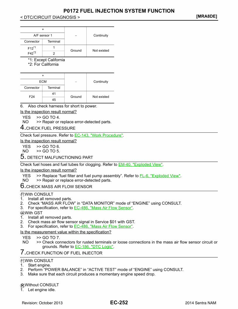
[MRA8DE]P0172 FUEL INJECTION SYSTEM FUNCTION
< DTC/CIRCUIT DIAGNOSIS >
*1: Except California*2: For California
6. Also check harness for short to power.Is the inspection result normal?YES >> GO TO 4.NO >> Repair or replace error-detected parts.
4.CHECK FUEL PRESSURE
Check fuel pressure. Refer to EC-143, "Work Procedure".Is the inspection result normal?YES >> GO TO 6.NO >> GO TO 5.
5. DETECT MALFUNCTIONING PART
Check fuel hoses and fuel tubes for clogging. Refer to EM-40, "Exploded View".Is the inspection result normal?YES >> Replace “fuel filter and fuel pump assembly”. Refer to FL-6, "Exploded View".NO >> Repair or replace error-detected parts.
6.CHECK MASS AIR FLOW SENSOR
With CONSULT1. Install all removed parts.2. Check “MASS AIR FLOW” in “DATA MONITOR” mode of “ENGINE” using CONSULT.3. For specification, refer to EC-486, "Mass Air Flow Sensor".
With GST1. Install all removed parts.2. Check mass air flow sensor signal in Service $01 with GST.3. For specification, refer to EC-486, "Mass Air Flow Sensor".Is the measurement value within the specification?YES >> GO TO 7.NO >> Check connectors for rusted terminals or loose connections in the mass air flow sensor circuit or
grounds. Refer to EC-186, "DTC Logic".7.CHECK FUNCTION OF FUEL INJECTOR
With CONSULT1. Start engine.2. Perform “POWER BALANCE” in “ACTIVE TEST” mode of “ENGINE” using CONSULT.3. Make sure that each circuit produces a momentary engine speed drop.
Without CONSULT1. Let engine idle.
+
− ContinuityA/F sensor 1
Connector Terminal
F12*1
F42*2
1Ground Not existed
2
+
− ContinuityECM
Connector Terminal
F2441
Ground Not existed45
EC-252Revision: October 2013 2014 Sentra NAM
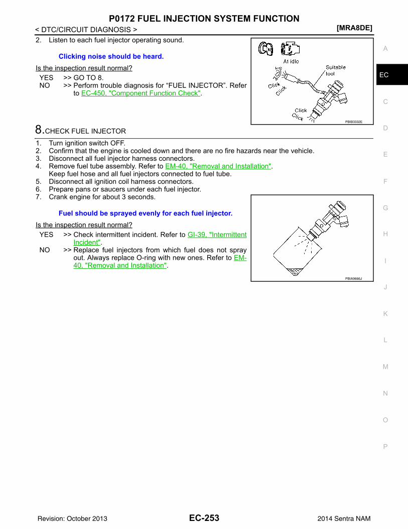
P0172 FUEL INJECTION SYSTEM FUNCTION[MRA8DE]
C
D
E
F
G
H
I
J
K
L
M
A
C
N
P
O
< DTC/CIRCUIT DIAGNOSIS >
E
2. Listen to each fuel injector operating sound.
Is the inspection result normal?YES >> GO TO 8.NO >> Perform trouble diagnosis for “FUEL INJECTOR”. Refer
to EC-450, "Component Function Check".
8.CHECK FUEL INJECTOR
1. Turn ignition switch OFF.2. Confirm that the engine is cooled down and there are no fire hazards near the vehicle.3. Disconnect all fuel injector harness connectors.4. Remove fuel tube assembly. Refer to EM-40, "Removal and Installation".
Keep fuel hose and all fuel injectors connected to fuel tube.5. Disconnect all ignition coil harness connectors.6. Prepare pans or saucers under each fuel injector.7. Crank engine for about 3 seconds.
Is the inspection result normal?YES >> Check intermittent incident. Refer to GI-39, "Intermittent
Incident".NO >> Replace fuel injectors from which fuel does not spray
out. Always replace O-ring with new ones. Refer to EM-40, "Removal and Installation".
Clicking noise should be heard.
PBIB3332E
Fuel should be sprayed evenly for each fuel injector.
PBIA9666J
EC-253Revision: October 2013 2014 Sentra NAM
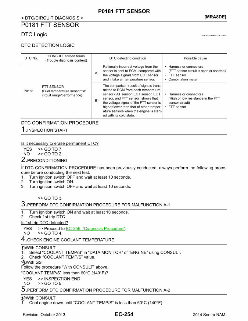
[MRA8DE]P0181 FTT SENSOR
< DTC/CIRCUIT DIAGNOSIS >P0181 FTT SENSORDTC Logic INFOID:0000000009758502
DTC DETECTION LOGIC
DTC CONFIRMATION PROCEDURE1.INSPECTION START
Is it necessary to erase permanent DTC?YES >> GO TO 7.NO >> GO TO 2.
2.PRECONDITIONING
If DTC CONFIRMATION PROCEDURE has been previously conducted, always perform the following proce-dure before conducting the next test.1. Turn ignition switch OFF and wait at least 10 seconds.2. Turn ignition switch ON.3. Turn ignition switch OFF and wait at least 10 seconds.
>> GO TO 3.3.PERFORM DTC CONFIRMATION PROCEDURE FOR MALFUNCTION A-1
1. Turn ignition switch ON and wait at least 10 seconds.2. Check 1st trip DTC.Is 1st trip DTC detected?YES >> Proceed to EC-256, "Diagnosis Procedure".NO >> GO TO 4.
4.CHECK ENGINE COOLANT TEMPERATURE
With CONSULT1. Select “COOLANT TEMP/S” in “DATA MONITOR” of “ENGINE” using CONSULT.2. Check “COOLANT TEMP/S” value.
With GSTFollow the procedure “With CONSULT” above.“COOLANT TEMP/S” less than 60°C (140°F)?YES >> INSPECTION ENDNO >> GO TO 5.
5.PERFORM DTC CONFIRMATION PROCEDURE FOR MALFUNCTION A-2
With CONSULT1. Cool engine down until “COOLANT TEMP/S” is less than 60°C (140°F).
DTC No. CONSULT screen terms(Trouble diagnosis content) DTC detecting condition Possible cause
P0181FTT SENSOR(Fuel temperature sensor ″A″ circuit range/performance)
A)
Rationally incorrect voltage from the sensor is sent to ECM, compared with the voltage signals from ECT sensor and intake air temperature sensor.
• Harness or connectors(FTT sensor circuit is open or shorted)
• FTT sensor• Combination meter
B)
The comparison result of signals trans-mitted to ECM from each temperature sensor (IAT sensor, ECT sensor, EOT sensor, and FTT sensor) shows that the voltage signal of the FTT sensor is higher/lower than that of other temper-ature sensors when the engine is start-ed with its cold state.
• Harness or connectors(High or low resistance in the FTT sensor circuit)
• FTT sensor
EC-254Revision: October 2013 2014 Sentra NAM
P0181 FTT SENSOR[MRA8DE]
C
D
E
F
G
H
I
J
K
L
M
A
C
N
P
O
< DTC/CIRCUIT DIAGNOSIS >
E
2. Wait at least 10 seconds.3. Check 1st trip DTC.
With GSTFollow the procedure “With CONSULT” above.Is 1st trip DTC detected?YES >> Proceed to EC-256, "Diagnosis Procedure".NO >> GO TO 6.
6.PERFORM COMPONENT FUNCTION CHECK (FOR MALFUNCTION B)
Perform component function check. Refer to EC-255, "Component Function Check".NOTE:Use the component function check to check the overall function of the FTT sensor circuit. During this check, a1st trip DTC might not be confirmed.Is the inspection result normal?YES >> INSPECTION ENDNO >> Proceed to EC-256, "Diagnosis Procedure".
7.PRECONDITIONING
If DTC CONFIRMATION PROCEDURE has been previously conducted, always perform the following proce-dure before conducting the next test.1. Turn ignition switch OFF and wait at least 10 seconds.2. Turn ignition switch ON.3. Turn ignition switch OFF and wait at least 10 seconds.TESTING CONDITION:• Before performing the following procedure, do not add fuel.• Before performing the following procedure, check that fuel level is between 1/4 and 4/4.• Before performing the following procedure, confirm that battery voltage is 11 V or more at idle.
>> GO TO 8.8.PERFORM DTC CONFIRMATION PROCEDURE B
1. Move the vehicle to a cool place.NOTE:Cool the vehicle in an environment of ambient air temperature between −10°C (14°F) and 35°C (95°F).
2. Turn ignition switch OFF and leave the vehicle for 12 hours.CAUTION:Never turn ignition switch ON during this procedure.NOTE:The vehicle must be cooled with the food open.
3. Start engine and let it idle for 5 minutes or more.CAUTION:Never turn ignition switch OFF during idling.
4. Check 1st trip DTC.Is 1st trip DTC detected?YES >> Proceed to EC-256, "Diagnosis Procedure".NO >> INSPECTION END
Component Function Check INFOID:0000000009758503
1.CHECK FUEL TANK TEMPERATURE (FTT) SENSOR
1. Turn ignition switch OFF.2. Disconnect fuel level sensor unit and fuel pump harness connector.3. Remove fuel level sensor unit. Refer to FL-6, "Removal and Installation".
EC-255Revision: October 2013 2014 Sentra NAM
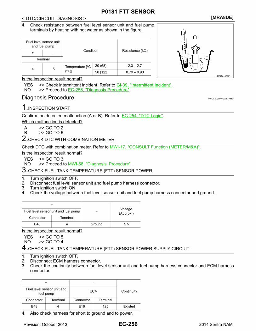
[MRA8DE]P0181 FTT SENSOR
< DTC/CIRCUIT DIAGNOSIS >4. Check resistance between fuel level sensor unit and fuel pump
terminals by heating with hot water as shown in the figure.
Is the inspection result normal?YES >> Check intermittent incident. Refer to GI-39, "Intermittent Incident".NO >> Proceed to EC-256, "Diagnosis Procedure".
Diagnosis Procedure INFOID:0000000009758504
1.INSPECTION START
Confirm the detected malfunction (A or B). Refer to EC-254, "DTC Logic".Which malfunction is detected?A >> GO TO 2.B >> GO TO 6.
2.CHECK DTC WITH COMBINATION METER
Check DTC with combination meter. Refer to MWI-17, "CONSULT Function (METER/M&A)".Is the inspection result normal?YES >> GO TO 3.NO >> Proceed to MWI-58, "Diagnosis Procedure".
3.CHECK FUEL TANK TEMPERATURE (FTT) SENSOR POWER
1. Turn ignition switch OFF.2. Disconnect fuel level sensor unit and fuel pump harness connector.3. Turn ignition switch ON.4. Check the voltage between fuel level sensor unit and fuel pump harness connector and ground.
Is the inspection result normal?YES >> GO TO 5.NO >> GO TO 4.
4.CHECK FUEL TANK TEMPERATURE (FTT) SENSOR POWER SUPPLY CIRCUIT
1. Turn ignition switch OFF.2. Disconnect ECM harness connector.3. Check the continuity between fuel level sensor unit and fuel pump harness connector and ECM harness
connector.
4. Also check harness for short to ground and to power.
Fuel level sensor unit and fuel pump
Condition Resistance (kΩ)+ −
Terminal
4 5 Temperature [°C (°F)]
20 (68) 2.3 – 2.7
50 (122) 0.79 – 0.90JMBIA0167ZZ
+
−Voltage
(Approx.)Fuel level sensor unit and fuel pump
Connector Terminal
B48 4 Ground 5 V
+ -
ContinuityFuel level sensor unit and fuel pump ECM
Connector Terminal Connector Terminal
B48 4 E16 125 Existed
EC-256Revision: October 2013 2014 Sentra NAM
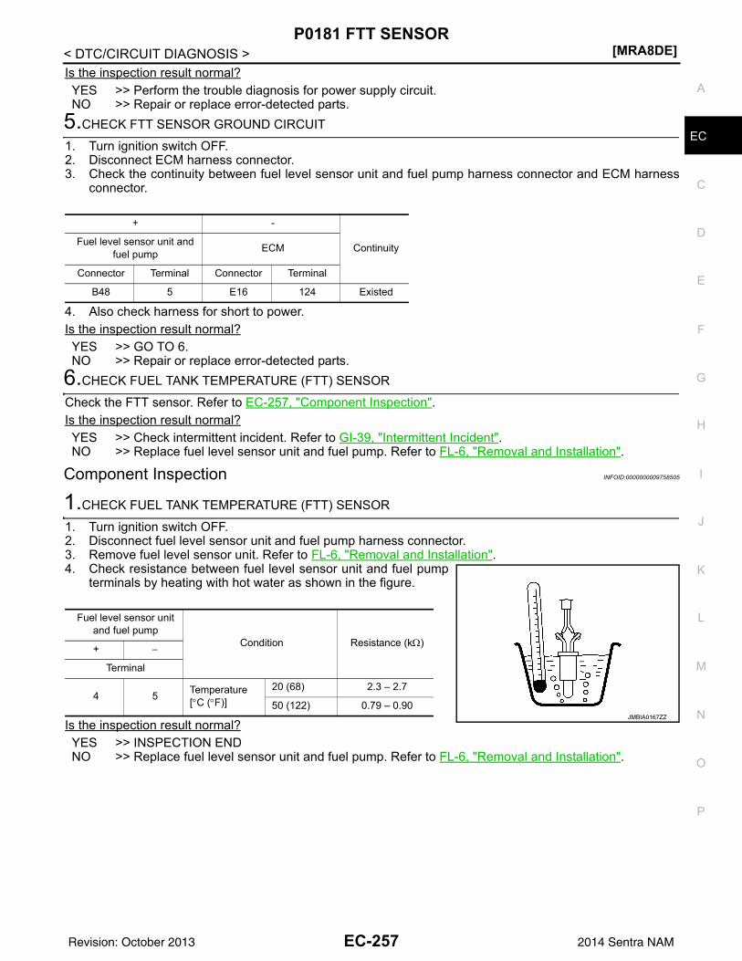
P0181 FTT SENSOR[MRA8DE]
C
D
E
F
G
H
I
J
K
L
M
A
C
N
P
O
< DTC/CIRCUIT DIAGNOSIS >
E
Is the inspection result normal?YES >> Perform the trouble diagnosis for power supply circuit.NO >> Repair or replace error-detected parts.
5.CHECK FTT SENSOR GROUND CIRCUIT
1. Turn ignition switch OFF.2. Disconnect ECM harness connector.3. Check the continuity between fuel level sensor unit and fuel pump harness connector and ECM harness
connector.
4. Also check harness for short to power.Is the inspection result normal?YES >> GO TO 6.NO >> Repair or replace error-detected parts.
6.CHECK FUEL TANK TEMPERATURE (FTT) SENSOR
Check the FTT sensor. Refer to EC-257, "Component Inspection".Is the inspection result normal?YES >> Check intermittent incident. Refer to GI-39, "Intermittent Incident".NO >> Replace fuel level sensor unit and fuel pump. Refer to FL-6, "Removal and Installation".
Component Inspection INFOID:0000000009758505
1.CHECK FUEL TANK TEMPERATURE (FTT) SENSOR
1. Turn ignition switch OFF.2. Disconnect fuel level sensor unit and fuel pump harness connector.3. Remove fuel level sensor unit. Refer to FL-6, "Removal and Installation".4. Check resistance between fuel level sensor unit and fuel pump
terminals by heating with hot water as shown in the figure.
Is the inspection result normal?YES >> INSPECTION ENDNO >> Replace fuel level sensor unit and fuel pump. Refer to FL-6, "Removal and Installation".
+ -
ContinuityFuel level sensor unit and fuel pump ECM
Connector Terminal Connector Terminal
B48 5 E16 124 Existed
Fuel level sensor unit and fuel pump
Condition Resistance (kΩ)+ −
Terminal
4 5 Temperature [°C (°F)]
20 (68) 2.3 – 2.7
50 (122) 0.79 – 0.90JMBIA0167ZZ
EC-257Revision: October 2013 2014 Sentra NAM
[MRA8DE]P0182, P0183 FTT SENSOR
< DTC/CIRCUIT DIAGNOSIS >P0182, P0183 FTT SENSORDTC Logic INFOID:0000000009758506
DTC DETECTION LOGIC
DTC CONFIRMATION PROCEDURE1.PRECONDITIONING
If DTC Confirmation Procedure has been previously conducted, always perform the following procedurebefore conducting the next test. 1. Turn ignition switch OFF and wait at least 10 seconds.2. Turn ignition switch ON.3. Turn ignition switch OFF and wait at least 10 seconds.
>> GO TO 2.2.PERFORM DTC CONFIRMATION PROCEDURE
1. Turn ignition switch ON and wait at least 5 seconds.2. Check 1st trip DTC.Is 1st trip DTC detected?YES >> Proceed to EC-258, "Diagnosis Procedure".NO >> INSPECTION END
Diagnosis Procedure INFOID:0000000009758507
1.CHECK DTC WITH COMBINATION METER
Refer to MWI-17, "CONSULT Function (METER/M&A)".Is the inspection result normal?YES >> GO TO 2.NO >> Proceed to MWI-58, "Diagnosis Procedure".
2.CHECK FUEL TANK TEMPERATURE (FTT) SENSOR POWER SUPPLY
1. Turn ignition switch OFF.2. Disconnect fuel level sensor unit and fuel pump harness connector.3. Turn ignition switch ON.4. Check the voltage between fuel level sensor unit and fuel pump harness connector and ground.
Is the inspection result normal?YES >> GO TO 4.NO >> GO TO 3.
DTC No. CONSULT screen terms(Trouble diagnosis content) DTC detecting condition Possible cause
P0182FTT SEN/CIRCUIT(Fuel temperature sensor ″A″ circuit low)
An excessively low voltage from the sensor is sent to ECM.
• Harness or connectors(The FTT sensor circuit is open or shorted.)
• Fuel tank temperature sensor• Combination meterP0183
FTT SEN/CIRCUIT(Fuel temperature sensor ″A″ circuit high)
An excessively high voltage from the sensor is sent to ECM.
+
−Voltage
(Approx.)Fuel level sensor unit and fuel
pump
Connector Terminal
B48 4 Ground 5 V
EC-258Revision: October 2013 2014 Sentra NAM
P0182, P0183 FTT SENSOR[MRA8DE]
C
D
E
F
G
H
I
J
K
L
M
A
C
N
P
O
< DTC/CIRCUIT DIAGNOSIS >
E
3.CHECK FUEL TANK TEMPERATURE (FTT) SENSOR POWER SUPPLY CIRCUIT
1. Turn ignition switch OFF.2. Disconnect ECM harness connector.3. Check the continuity between fuel level sensor unit and fuel pump harness connector and ECM harness
connector.
4. Also check harness for short to ground and to power.Is the inspection result normal?YES >> Perform the trouble diagnosis for power supply circuit.NO >> Repair or replace error-detected parts.
4.CHECK FUEL TANK TEMPERATURE (FTT) SENSOR GROUND CIRCUIT
1. Turn ignition switch OFF.2. Disconnect ECM connector.3. Check the continuity between fuel level sensor unit and fuel pump harness connector and ECM harness
connector.
4. Also check harness for short to power.Is the inspection result normal?YES >> GO TO 5.NO >> Repair or replace error-detected parts.
5.CHECK FUEL TANK TEMPERATURE (FTT) SENSOR
Check the FTT sensor. Refer to EC-259, "Component Inspection".Is the inspection result normal?YES >> Check intermittent incident. Refer to GI-39, "Intermittent Incident".NO >> Replace “fuel level sensor unit and fuel pump”. Refer to FL-6, "Removal and Installation".
Component Inspection INFOID:0000000009758508
1.CHECK FUEL TANK TEMPERATURE (FTT) SENSOR
1. Turn ignition switch OFF.2. Disconnect fuel level sensor unit and fuel pump harness connector.3. Remove fuel level sensor unit. Refer to FL-6, "Removal and Installation".
+ −
ContinuityFuel level sensor unit and fuel pump ECM
Connector Terminal Connector Terminal
B48 4 E16 125 Existed
+ −
ContinuityFuel level sensor unit and fuel pump ECM
Connector Terminal Connector Terminal
B48 5 E16 124 Existed
EC-259Revision: October 2013 2014 Sentra NAM
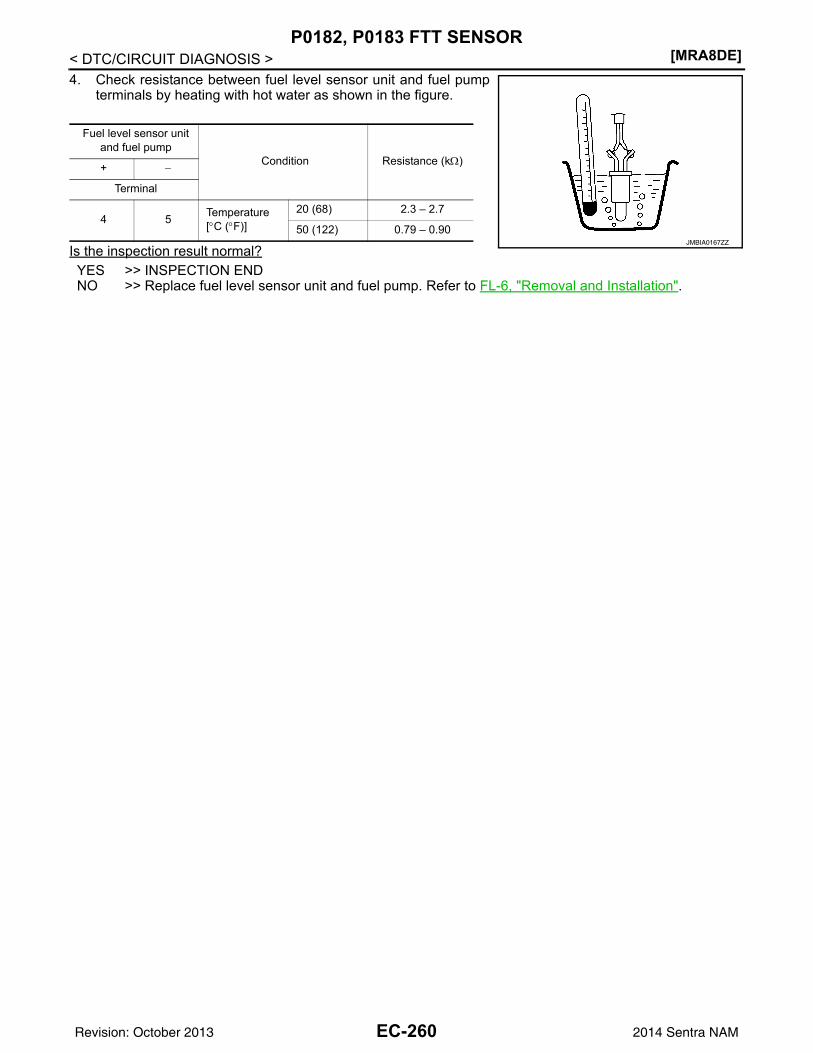
[MRA8DE]P0182, P0183 FTT SENSOR
< DTC/CIRCUIT DIAGNOSIS >4. Check resistance between fuel level sensor unit and fuel pump
terminals by heating with hot water as shown in the figure.
Is the inspection result normal?YES >> INSPECTION ENDNO >> Replace fuel level sensor unit and fuel pump. Refer to FL-6, "Removal and Installation".
Fuel level sensor unit and fuel pump
Condition Resistance (kΩ)+ −
Terminal
4 5 Temperature [°C (°F)]
20 (68) 2.3 – 2.7
50 (122) 0.79 – 0.90JMBIA0167ZZ
EC-260Revision: October 2013 2014 Sentra NAM
P0196 EOT SENSOR[MRA8DE]
C
D
E
F
G
H
I
J
K
L
M
A
C
N
P
O
< DTC/CIRCUIT DIAGNOSIS >
E
P0196 EOT SENSORDTC Logic INFOID:0000000009758509
DTC DETECTION LOGICNOTE:If DTC P0196 is displayed with DTC P0197 or P0198, first perform the trouble diagnosis for DTC P0197 orP0198. Refer to EC-264, "DTC Logic".
DTC CONFIRMATION PROCEDURE1.INSPECTION START
Is it necessary to erase permanent DTC?YES >> GO TO 6.NO >> GO TO 2.
2.PRECONDITIONING
If DTC CONFIRMATION PROCEDURE has been previously conducted, always perform the following proce-dure before conducting the next test.1. Turn ignition switch OFF and wait at least 10 seconds.2. Turn ignition switch ON.3. Turn ignition switch OFF and wait at least 10 seconds.TESTING CONDITION:Before performing the following procedure, confirm that battery voltage is 11 V or more at idle.
>> GO TO 3.3.PERFORM DTC CONFIRMATION PROCEDURE FOR MALFUNCTION A-1
1. Start engine and warm it up to normal operating temperature.2. Turn ignition switch OFF and wait at least 10 seconds.3. Turn ignition switch ON.4. Turn ignition switch OFF and wait at least 10 seconds.5. Start engine and let it idle for 5 minutes and 10 seconds.6. Check 1st trip DTC.Is 1st trip DTC detected?YES >> Proceed to EC-263, "Diagnosis Procedure".NO >> GO TO 4.
4.PERFORM DTC CONFIRMATION PROCEDURE FOR MALFUNCTION A-2
With CONSULT1. Select “DATA MONITOR” mode of “ENGINE” using CONSULT.2. Check that “COOLANT TEMP/S” indicates above 80°C (176°F).
If it is above 80°C (176°F), go to the following steps.
DTC No. CONSULT screen terms(Trouble diagnosis content) DTC detecting condition Possible cause
P0196EOT SENSOR(Engine oil temperature sensor range/performance)
A)
Rationally incorrect voltage from the sensor is sent to ECM, compared with the voltage signals from EOT sensor and intake air temperature sensor.
• Harness or connectors(EOT sensor circuit is open or short-ed)
• EOT sensor
B)
The comparison result of signals trans-mitted to ECM from each temperature sensor (IAT sensor, ECT sensor, FTT sensor, and EOT sensor) shows that the signal voltage of the EOT sensor is high-er/lower than that of other temperature sensors when the engine is started with its cold state.
• Harness or connectors(High or low resistance in the EOT sensor circuit)
• EOT sensor
EC-261Revision: October 2013 2014 Sentra NAM
[MRA8DE]P0196 EOT SENSOR
< DTC/CIRCUIT DIAGNOSIS >If it is below 80°C (176°F), warm engine up until “COOLANT TEMP/S” indicates more than 80°C (176°F).Then perform the following steps.
3. Turn ignition switch OFF and soak the vehicle in a cool place.4. Turn ignition switch ON.
NOTE:Do not turn ignition switch OFF until step 8.
5. Select “DATA MONITOR” mode of “ENGINE” using CONSULT.6. Check the following.
If they are within the specified range, perform the following steps.If they are out of the specified range, soak the vehicle to meet the above conditions. Then perform the fol-lowing steps.NOTE:• Do not turn ignition switch OFF.• If it is supposed to need a long period of time, do not deplete the battery.
7. Start engine and let it idle for 5 minutes.8. Check 1st trip DTC.
With GSTFollow the procedure “With CONSULT” above.Is 1st trip DTC detected?YES >> Proceed to EC-263, "Diagnosis Procedure".NO >> GO TO 5.
5.PERFORM COMPONENT FUNCTION CHECK (FOR MALFUNCTION B)
Perform component function check. Refer to EC-263, "Component Function Check".NOTE:Use the component function check to check the overall function of the EOT sensor circuit. During this check, a1st trip DTC might not be confirmed.Is the inspection result normal?YES >> INSPECTION ENDNO >> Proceed to EC-263, "Diagnosis Procedure".
6.PRECONDITIONING
If DTC CONFIRMATION PROCEDURE has been previously conducted, always perform the following proce-dure before conducting the next test.1. Turn ignition switch OFF and wait at least 10 seconds.2. Turn ignition switch ON.3. Turn ignition switch OFF and wait at least 10 seconds.TESTING CONDITION:• Before performing the following procedure, do not add fuel.• Before performing the following procedure, check that fuel level is between 1/4 and 4/4.• Before performing the following procedure, confirm that battery voltage is 11 V or more at idle.
>> GO TO 7.7.PERFORM DTC CONFIRMATION PROCEDURE B
1. Move the vehicle to a cool place.NOTE:Cool the vehicle in an environment of ambient air temperature between −10°C (14°F) and 35°C (95°F).
2. Turn ignition switch OFF and leave the vehicle for 12 hours.CAUTION:Never turn ignition switch ON during this procedure.NOTE:The vehicle must be cooled with the food open.
3. Start engine and let it idle for 5 minutes or more.
COOLANT TEMP/S Below 40°C (104°F)
INT/A TEMP SE Below 40°C (104°F)
Difference between “COOLANT TEMP/S” and “INT/A TEMP SE” Within 6°C (11°F)
EC-262Revision: October 2013 2014 Sentra NAM
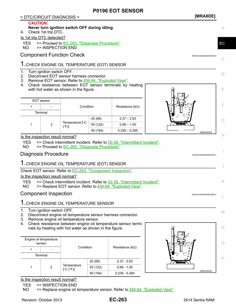
P0196 EOT SENSOR[MRA8DE]
C
D
E
F
G
H
I
J
K
L
M
A
C
N
P
O
< DTC/CIRCUIT DIAGNOSIS >
E
CAUTION:Never turn ignition switch OFF during idling.
4. Check 1st trip DTC.Is 1st trip DTC detected?YES >> Proceed to EC-263, "Diagnosis Procedure".NO >> INSPECTION END
Component Function Check INFOID:0000000009758510
1.CHECK ENGINE OIL TEMPERATURE (EOT) SENSOR
1. Turn ignition switch OFF.2. Disconnect EOT sensor harness connector.3. Remove EOT sensor. Refer to EM-94, "Exploded View".4. Check resistance between EOT sensor terminals by heating
with hot water as shown in the figure.
Is the inspection result normal?YES >> Check intermittent incident. Refer to GI-39, "Intermittent Incident".NO >> Proceed to EC-263, "Diagnosis Procedure".
Diagnosis Procedure INFOID:0000000009758511
1.CHECK ENGINE OIL TEMPERATURE (EOT) SENSOR
Check EOT sensor. Refer to EC-263, "Component Inspection".Is the inspection result normal?YES >> Check intermittent incident. Refer to GI-39, "Intermittent Incident".NO >> Replace EOT sensor. Refer to EM-94, "Exploded View".
Component Inspection INFOID:0000000009758512
1.CHECK ENGINE OIL TEMPERATURE SENSOR
1. Turn ignition switch OFF.2. Disconnect engine oil temperature sensor harness connector.3. Remove engine oil temperature sensor.4. Check resistance between engine oil temperature sensor termi-
nals by heating with hot water as shown in the figure.
Is the inspection result normal?YES >> INSPECTION ENDNO >> Replace engine oil temperature sensor. Refer to EM-94, "Exploded View".
EOT sensor
Condition Resistance (kΩ)+ −
Terminal
1 2 Temperature [°C (°F)]
20 (68) 2.37 – 2.63
50 (122) 0.68 – 1.00
90 (194) 0.236 – 0.260JMBIA0080ZZ
Engine oil temperature sensor
Condition Resistance (kΩ)+ −
Terminal
1 2 Temperature [°C (°F)]
20 (68) 2.37 - 2.63
50 (122) 0.68 - 1.00
90 (194) 0.236 - 0.260JMBIA0080ZZ
EC-263Revision: October 2013 2014 Sentra NAM
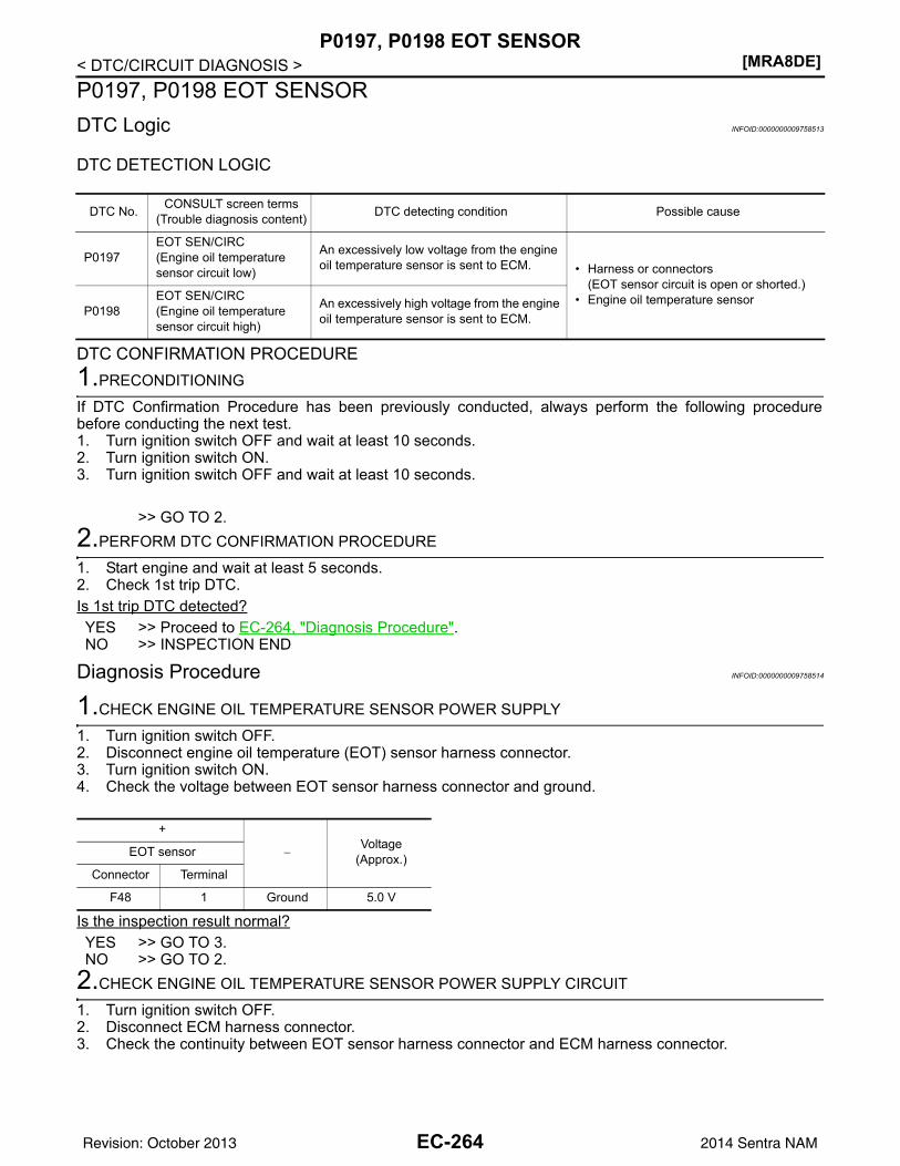
[MRA8DE]P0197, P0198 EOT SENSOR
< DTC/CIRCUIT DIAGNOSIS >P0197, P0198 EOT SENSORDTC Logic INFOID:0000000009758513
DTC DETECTION LOGIC
DTC CONFIRMATION PROCEDURE1.PRECONDITIONING
If DTC Confirmation Procedure has been previously conducted, always perform the following procedurebefore conducting the next test.1. Turn ignition switch OFF and wait at least 10 seconds.2. Turn ignition switch ON.3. Turn ignition switch OFF and wait at least 10 seconds.
>> GO TO 2.2.PERFORM DTC CONFIRMATION PROCEDURE
1. Start engine and wait at least 5 seconds.2. Check 1st trip DTC.Is 1st trip DTC detected?YES >> Proceed to EC-264, "Diagnosis Procedure".NO >> INSPECTION END
Diagnosis Procedure INFOID:0000000009758514
1.CHECK ENGINE OIL TEMPERATURE SENSOR POWER SUPPLY
1. Turn ignition switch OFF.2. Disconnect engine oil temperature (EOT) sensor harness connector.3. Turn ignition switch ON.4. Check the voltage between EOT sensor harness connector and ground.
Is the inspection result normal?YES >> GO TO 3.NO >> GO TO 2.
2.CHECK ENGINE OIL TEMPERATURE SENSOR POWER SUPPLY CIRCUIT
1. Turn ignition switch OFF.2. Disconnect ECM harness connector.3. Check the continuity between EOT sensor harness connector and ECM harness connector.
DTC No. CONSULT screen terms(Trouble diagnosis content) DTC detecting condition Possible cause
P0197EOT SEN/CIRC(Engine oil temperature sensor circuit low)
An excessively low voltage from the engine oil temperature sensor is sent to ECM. • Harness or connectors
(EOT sensor circuit is open or shorted.)• Engine oil temperature sensor
P0198EOT SEN/CIRC(Engine oil temperature sensor circuit high)
An excessively high voltage from the engine oil temperature sensor is sent to ECM.
+
−Voltage
(Approx.)EOT sensor
Connector Terminal
F48 1 Ground 5.0 V
EC-264Revision: October 2013 2014 Sentra NAM
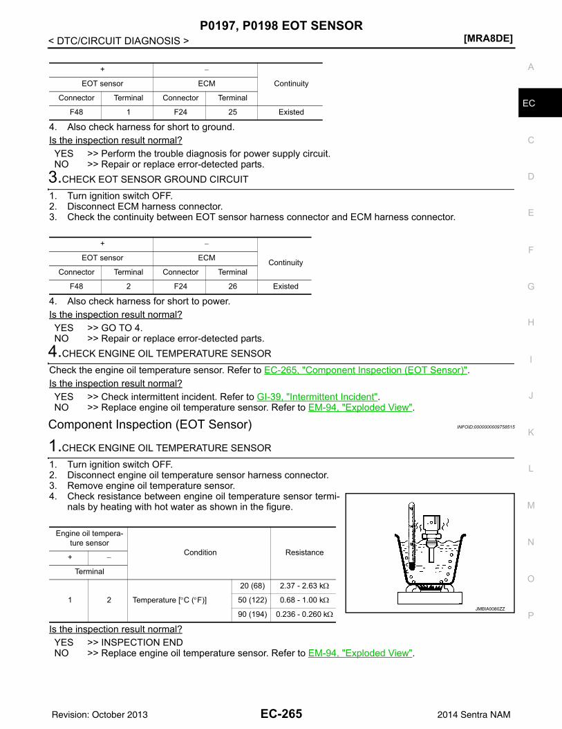
P0197, P0198 EOT SENSOR[MRA8DE]
C
D
E
F
G
H
I
J
K
L
M
A
C
N
P
O
< DTC/CIRCUIT DIAGNOSIS >
E
4. Also check harness for short to ground.Is the inspection result normal?YES >> Perform the trouble diagnosis for power supply circuit.NO >> Repair or replace error-detected parts.
3.CHECK EOT SENSOR GROUND CIRCUIT
1. Turn ignition switch OFF.2. Disconnect ECM harness connector.3. Check the continuity between EOT sensor harness connector and ECM harness connector.
4. Also check harness for short to power.Is the inspection result normal?YES >> GO TO 4.NO >> Repair or replace error-detected parts.
4.CHECK ENGINE OIL TEMPERATURE SENSOR
Check the engine oil temperature sensor. Refer to EC-265, "Component Inspection (EOT Sensor)".Is the inspection result normal?YES >> Check intermittent incident. Refer to GI-39, "Intermittent Incident".NO >> Replace engine oil temperature sensor. Refer to EM-94, "Exploded View".
Component Inspection (EOT Sensor) INFOID:0000000009758515
1.CHECK ENGINE OIL TEMPERATURE SENSOR
1. Turn ignition switch OFF.2. Disconnect engine oil temperature sensor harness connector.3. Remove engine oil temperature sensor.4. Check resistance between engine oil temperature sensor termi-
nals by heating with hot water as shown in the figure.
Is the inspection result normal?YES >> INSPECTION ENDNO >> Replace engine oil temperature sensor. Refer to EM-94, "Exploded View".
+ −
ContinuityEOT sensor ECM
Connector Terminal Connector Terminal
F48 1 F24 25 Existed
+ −
ContinuityEOT sensor ECM
Connector Terminal Connector Terminal
F48 2 F24 26 Existed
Engine oil tempera-ture sensor
Condition Resistance+ −
Terminal
1 2 Temperature [°C (°F)]
20 (68) 2.37 - 2.63 kΩ
50 (122) 0.68 - 1.00 kΩ
90 (194) 0.236 - 0.260 kΩJMBIA0080ZZ
EC-265Revision: October 2013 2014 Sentra NAM
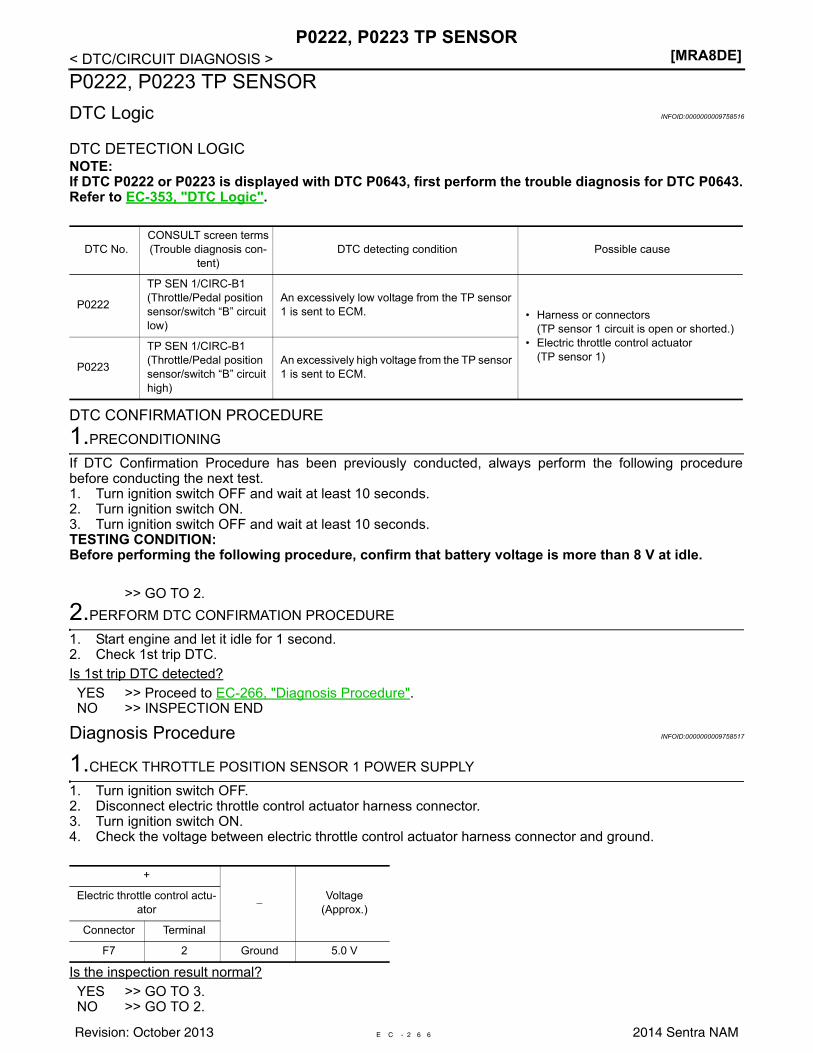
[MRA8DE]P0222, P0223 TP SENSOR
< DTC/CIRCUIT DIAGNOSIS >P0222, P0223 TP SENSORDTC Logic INFOID:0000000009758516
DTC DETECTION LOGICNOTE:If DTC P0222 or P0223 is displayed with DTC P0643, first perform the trouble diagnosis for DTC P0643.Refer to EC-353, "DTC Logic".
DTC CONFIRMATION PROCEDURE1.PRECONDITIONING
If DTC Confirmation Procedure has been previously conducted, always perform the following procedurebefore conducting the next test.1. Turn ignition switch OFF and wait at least 10 seconds.2. Turn ignition switch ON.3. Turn ignition switch OFF and wait at least 10 seconds.TESTING CONDITION:Before performing the following procedure, confirm that battery voltage is more than 8 V at idle.
>> GO TO 2.2.PERFORM DTC CONFIRMATION PROCEDURE
1. Start engine and let it idle for 1 second.2. Check 1st trip DTC.Is 1st trip DTC detected?YES >> Proceed to EC-266, "Diagnosis Procedure".NO >> INSPECTION END
Diagnosis Procedure INFOID:0000000009758517
1.CHECK THROTTLE POSITION SENSOR 1 POWER SUPPLY
1. Turn ignition switch OFF.2. Disconnect electric throttle control actuator harness connector.3. Turn ignition switch ON.4. Check the voltage between electric throttle control actuator harness connector and ground.
Is the inspection result normal?YES >> GO TO 3.NO >> GO TO 2.
DTC No.CONSULT screen terms(Trouble diagnosis con-
tent)DTC detecting condition Possible cause
P0222
TP SEN 1/CIRC-B1(Throttle/Pedal position sensor/switch “B” circuit low)
An excessively low voltage from the TP sensor 1 is sent to ECM. • Harness or connectors
(TP sensor 1 circuit is open or shorted.)• Electric throttle control actuator
(TP sensor 1)P0223
TP SEN 1/CIRC-B1(Throttle/Pedal position sensor/switch “B” circuit high)
An excessively high voltage from the TP sensor 1 is sent to ECM.
+
−Voltage
(Approx.)Electric throttle control actu-
ator
Connector Terminal
F7 2 Ground 5.0 V
E C - 2 6 6Revision: October 2013 2014 Sentra NAM
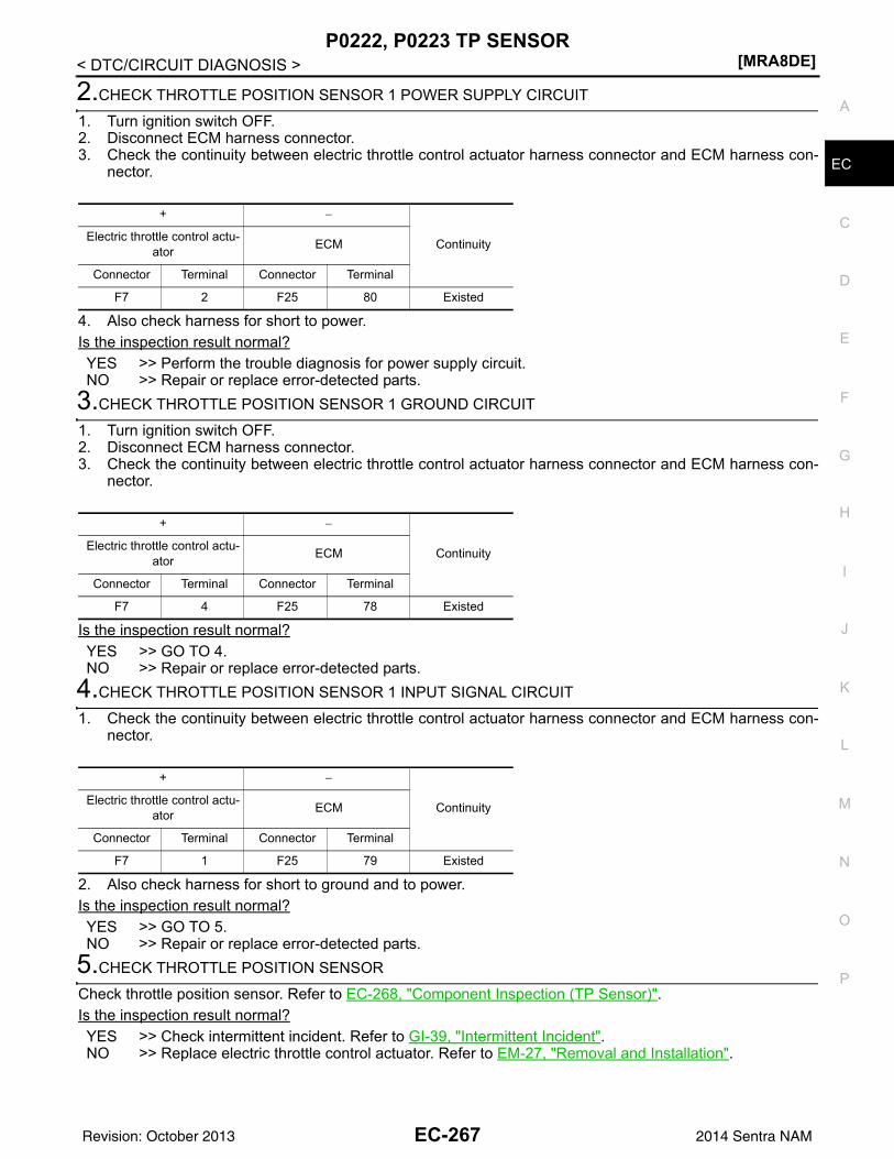
P0222, P0223 TP SENSOR[MRA8DE]
C
D
E
F
G
H
I
J
K
L
M
A
C
N
P
O
< DTC/CIRCUIT DIAGNOSIS >
E
2.CHECK THROTTLE POSITION SENSOR 1 POWER SUPPLY CIRCUIT
1. Turn ignition switch OFF.2. Disconnect ECM harness connector.3. Check the continuity between electric throttle control actuator harness connector and ECM harness con-
nector.
4. Also check harness for short to power.Is the inspection result normal?YES >> Perform the trouble diagnosis for power supply circuit.NO >> Repair or replace error-detected parts.
3.CHECK THROTTLE POSITION SENSOR 1 GROUND CIRCUIT
1. Turn ignition switch OFF.2. Disconnect ECM harness connector.3. Check the continuity between electric throttle control actuator harness connector and ECM harness con-
nector.
Is the inspection result normal?YES >> GO TO 4.NO >> Repair or replace error-detected parts.
4.CHECK THROTTLE POSITION SENSOR 1 INPUT SIGNAL CIRCUIT
1. Check the continuity between electric throttle control actuator harness connector and ECM harness con-nector.
2. Also check harness for short to ground and to power.Is the inspection result normal?YES >> GO TO 5.NO >> Repair or replace error-detected parts.
5.CHECK THROTTLE POSITION SENSOR
Check throttle position sensor. Refer to EC-268, "Component Inspection (TP Sensor)".Is the inspection result normal?YES >> Check intermittent incident. Refer to GI-39, "Intermittent Incident".NO >> Replace electric throttle control actuator. Refer to EM-27, "Removal and Installation".
+ −
ContinuityElectric throttle control actu-ator ECM
Connector Terminal Connector Terminal
F7 2 F25 80 Existed
+ −
ContinuityElectric throttle control actu-ator ECM
Connector Terminal Connector Terminal
F7 4 F25 78 Existed
+ −
ContinuityElectric throttle control actu-ator ECM
Connector Terminal Connector Terminal
F7 1 F25 79 Existed
EC-267Revision: October 2013 2014 Sentra NAM
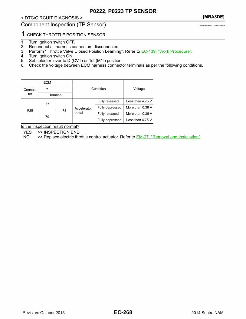
[MRA8DE]P0222, P0223 TP SENSOR
< DTC/CIRCUIT DIAGNOSIS >Component Inspection (TP Sensor) INFOID:0000000009758518
1.CHECK THROTTLE POSITION SENSOR
1. Turn ignition switch OFF.2. Reconnect all harness connectors disconnected.3. Perform “ Throttle Valve Closed Position Learning”. Refer to EC-139, "Work Procedure".4. Turn ignition switch ON.5. Set selector lever to D (CVT) or 1st (M/T) position.6. Check the voltage between ECM harness connector terminals as per the following conditions.
Is the inspection result normal?YES >> INSPECTION ENDNO >> Replace electric throttle control actuator. Refer to EM-27, "Removal and Installation".
ECM
Condition VoltageConnec-tor
+ −
Terminal
F25
77
78 Accelerator pedal
Fully released Less than 4.75 V
Fully depressed More than 0.36 V
79Fully released More than 0.36 V
Fully depressed Less than 4.75 V
EC-268Revision: October 2013 2014 Sentra NAM
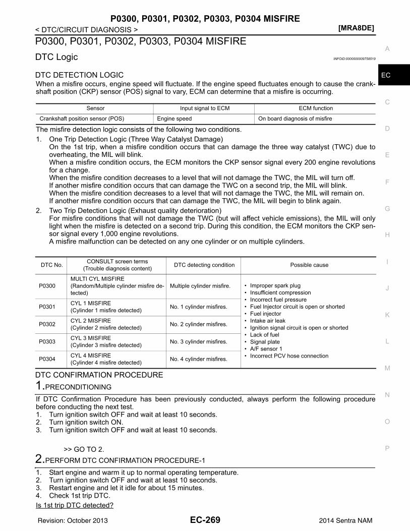
P0300, P0301, P0302, P0303, P0304 MISFIRE[MRA8DE]
C
D
E
F
G
H
I
J
K
L
M
A
C
N
P
O
< DTC/CIRCUIT DIAGNOSIS >
E
P0300, P0301, P0302, P0303, P0304 MISFIREDTC Logic INFOID:0000000009758519
DTC DETECTION LOGICWhen a misfire occurs, engine speed will fluctuate. If the engine speed fluctuates enough to cause the crank-shaft position (CKP) sensor (POS) signal to vary, ECM can determine that a misfire is occurring.
The misfire detection logic consists of the following two conditions.1. One Trip Detection Logic (Three Way Catalyst Damage)
On the 1st trip, when a misfire condition occurs that can damage the three way catalyst (TWC) due tooverheating, the MIL will blink.When a misfire condition occurs, the ECM monitors the CKP sensor signal every 200 engine revolutionsfor a change.When the misfire condition decreases to a level that will not damage the TWC, the MIL will turn off.If another misfire condition occurs that can damage the TWC on a second trip, the MIL will blink.When the misfire condition decreases to a level that will not damage the TWC, the MIL will remain on.If another misfire condition occurs that can damage the TWC, the MIL will begin to blink again.
2. Two Trip Detection Logic (Exhaust quality deterioration)For misfire conditions that will not damage the TWC (but will affect vehicle emissions), the MIL will onlylight when the misfire is detected on a second trip. During this condition, the ECM monitors the CKP sen-sor signal every 1,000 engine revolutions.A misfire malfunction can be detected on any one cylinder or on multiple cylinders.
DTC CONFIRMATION PROCEDURE1.PRECONDITIONING
If DTC Confirmation Procedure has been previously conducted, always perform the following procedurebefore conducting the next test.1. Turn ignition switch OFF and wait at least 10 seconds.2. Turn ignition switch ON.3. Turn ignition switch OFF and wait at least 10 seconds.
>> GO TO 2.2.PERFORM DTC CONFIRMATION PROCEDURE-1
1. Start engine and warm it up to normal operating temperature.2. Turn ignition switch OFF and wait at least 10 seconds.3. Restart engine and let it idle for about 15 minutes.4. Check 1st trip DTC.Is 1st trip DTC detected?
Sensor Input signal to ECM ECM function
Crankshaft position sensor (POS) Engine speed On board diagnosis of misfire
DTC No. CONSULT screen terms(Trouble diagnosis content) DTC detecting condition Possible cause
P0300MULTI CYL MISFIRE(Random/Multiple cylinder misfire de-tected)
Multiple cylinder misfire. • Improper spark plug• Insufficient compression• Incorrect fuel pressure• Fuel Injector circuit is open or shorted• Fuel injector• Intake air leak• Ignition signal circuit is open or shorted• Lack of fuel• Signal plate• A/F sensor 1• Incorrect PCV hose connection
P0301 CYL 1 MISFIRE(Cylinder 1 misfire detected) No. 1 cylinder misfires.
P0302 CYL 2 MISFIRE(Cylinder 2 misfire detected) No. 2 cylinder misfires.
P0303 CYL 3 MISFIRE(Cylinder 3 misfire detected) No. 3 cylinder misfires.
P0304 CYL 4 MISFIRE(Cylinder 4 misfire detected) No. 4 cylinder misfires.
EC-269Revision: October 2013 2014 Sentra NAM
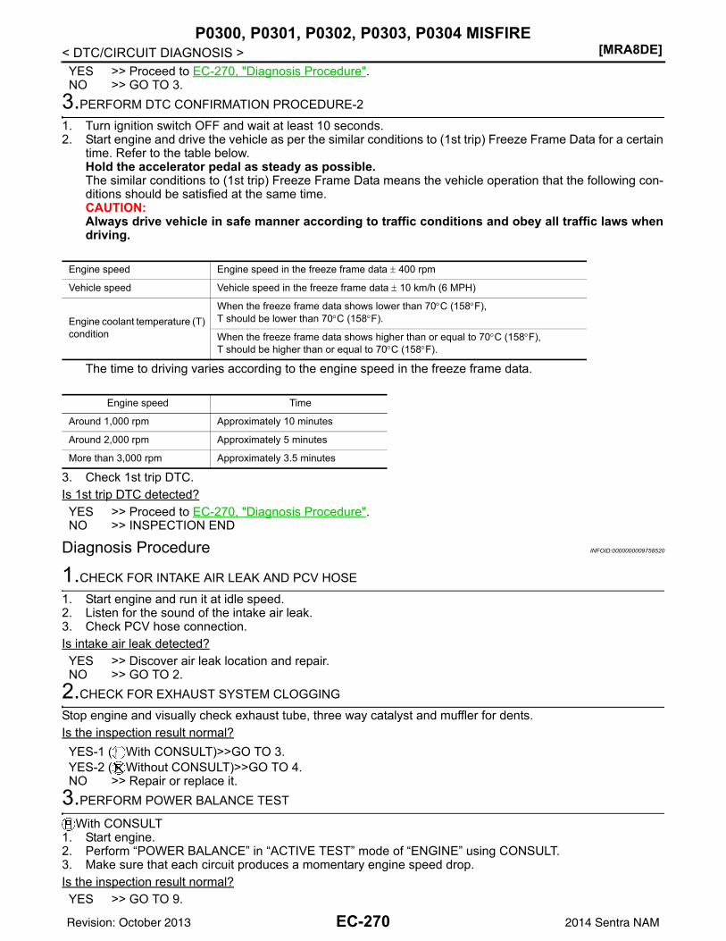
[MRA8DE]P0300, P0301, P0302, P0303, P0304 MISFIRE
< DTC/CIRCUIT DIAGNOSIS >YES >> Proceed to EC-270, "Diagnosis Procedure".NO >> GO TO 3.
3.PERFORM DTC CONFIRMATION PROCEDURE-2
1. Turn ignition switch OFF and wait at least 10 seconds.2. Start engine and drive the vehicle as per the similar conditions to (1st trip) Freeze Frame Data for a certain
time. Refer to the table below.Hold the accelerator pedal as steady as possible.The similar conditions to (1st trip) Freeze Frame Data means the vehicle operation that the following con-ditions should be satisfied at the same time.CAUTION:Always drive vehicle in safe manner according to traffic conditions and obey all traffic laws whendriving.
The time to driving varies according to the engine speed in the freeze frame data.
3. Check 1st trip DTC.Is 1st trip DTC detected?YES >> Proceed to EC-270, "Diagnosis Procedure".NO >> INSPECTION END
Diagnosis Procedure INFOID:0000000009758520
1.CHECK FOR INTAKE AIR LEAK AND PCV HOSE
1. Start engine and run it at idle speed.2. Listen for the sound of the intake air leak.3. Check PCV hose connection.Is intake air leak detected?YES >> Discover air leak location and repair.NO >> GO TO 2.
2.CHECK FOR EXHAUST SYSTEM CLOGGING
Stop engine and visually check exhaust tube, three way catalyst and muffler for dents.Is the inspection result normal?YES-1 ( With CONSULT)>>GO TO 3.YES-2 ( Without CONSULT)>>GO TO 4.NO >> Repair or replace it.
3.PERFORM POWER BALANCE TEST
With CONSULT1. Start engine.2. Perform “POWER BALANCE” in “ACTIVE TEST” mode of “ENGINE” using CONSULT.3. Make sure that each circuit produces a momentary engine speed drop.Is the inspection result normal?YES >> GO TO 9.
Engine speed Engine speed in the freeze frame data ± 400 rpm
Vehicle speed Vehicle speed in the freeze frame data ± 10 km/h (6 MPH)
Engine coolant temperature (T) condition
When the freeze frame data shows lower than 70°C (158°F),T should be lower than 70°C (158°F).
When the freeze frame data shows higher than or equal to 70°C (158°F),T should be higher than or equal to 70°C (158°F).
Engine speed Time
Around 1,000 rpm Approximately 10 minutes
Around 2,000 rpm Approximately 5 minutes
More than 3,000 rpm Approximately 3.5 minutes
EC-270Revision: October 2013 2014 Sentra NAM
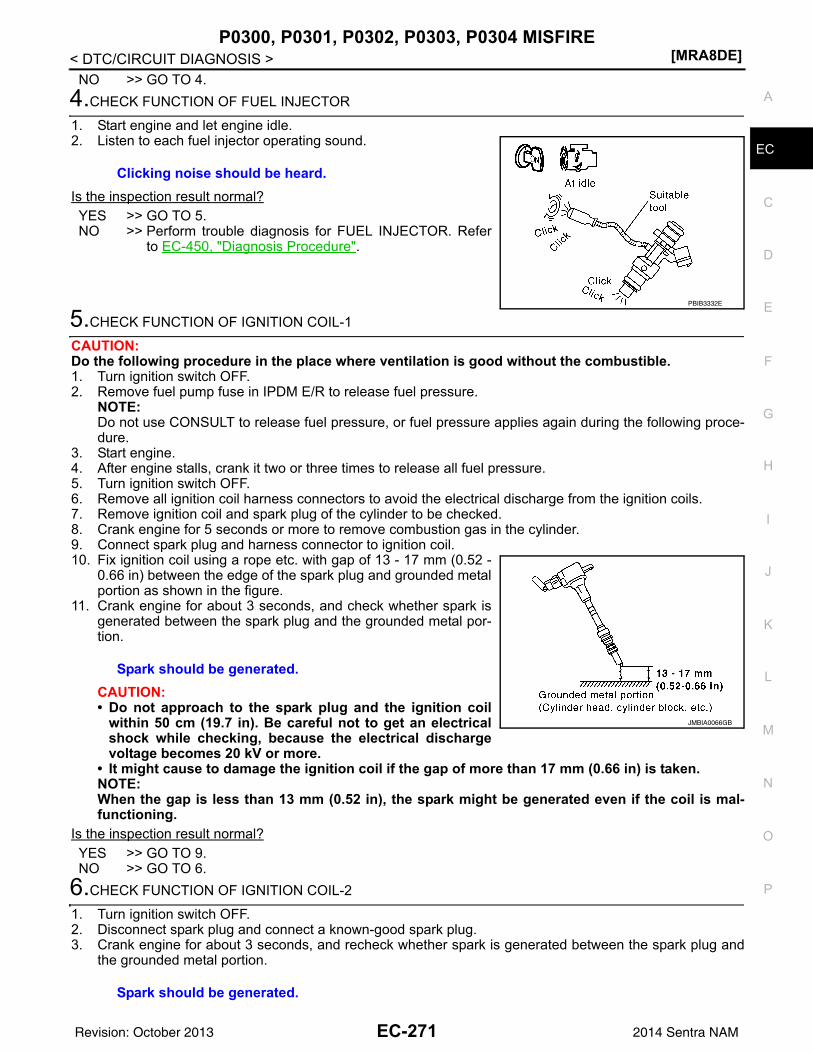
P0300, P0301, P0302, P0303, P0304 MISFIRE[MRA8DE]
C
D
E
F
G
H
I
J
K
L
M
A
C
N
P
O
< DTC/CIRCUIT DIAGNOSIS >
E
NO >> GO TO 4.4.CHECK FUNCTION OF FUEL INJECTOR
1. Start engine and let engine idle.2. Listen to each fuel injector operating sound.
Is the inspection result normal?YES >> GO TO 5.NO >> Perform trouble diagnosis for FUEL INJECTOR. Refer
to EC-450, "Diagnosis Procedure".
5.CHECK FUNCTION OF IGNITION COIL-1
CAUTION:Do the following procedure in the place where ventilation is good without the combustible.1. Turn ignition switch OFF.2. Remove fuel pump fuse in IPDM E/R to release fuel pressure.
NOTE:Do not use CONSULT to release fuel pressure, or fuel pressure applies again during the following proce-dure.
3. Start engine.4. After engine stalls, crank it two or three times to release all fuel pressure.5. Turn ignition switch OFF.6. Remove all ignition coil harness connectors to avoid the electrical discharge from the ignition coils.7. Remove ignition coil and spark plug of the cylinder to be checked.8. Crank engine for 5 seconds or more to remove combustion gas in the cylinder.9. Connect spark plug and harness connector to ignition coil.10. Fix ignition coil using a rope etc. with gap of 13 - 17 mm (0.52 -
0.66 in) between the edge of the spark plug and grounded metalportion as shown in the figure.
11. Crank engine for about 3 seconds, and check whether spark isgenerated between the spark plug and the grounded metal por-tion.
CAUTION:• Do not approach to the spark plug and the ignition coil
within 50 cm (19.7 in). Be careful not to get an electricalshock while checking, because the electrical dischargevoltage becomes 20 kV or more.
• It might cause to damage the ignition coil if the gap of more than 17 mm (0.66 in) is taken.NOTE:When the gap is less than 13 mm (0.52 in), the spark might be generated even if the coil is mal-functioning.
Is the inspection result normal?YES >> GO TO 9.NO >> GO TO 6.
6.CHECK FUNCTION OF IGNITION COIL-2
1. Turn ignition switch OFF.2. Disconnect spark plug and connect a known-good spark plug.3. Crank engine for about 3 seconds, and recheck whether spark is generated between the spark plug and
the grounded metal portion.
Clicking noise should be heard.
PBIB3332E
Spark should be generated.
JMBIA0066GB
Spark should be generated.
EC-271Revision: October 2013 2014 Sentra NAM
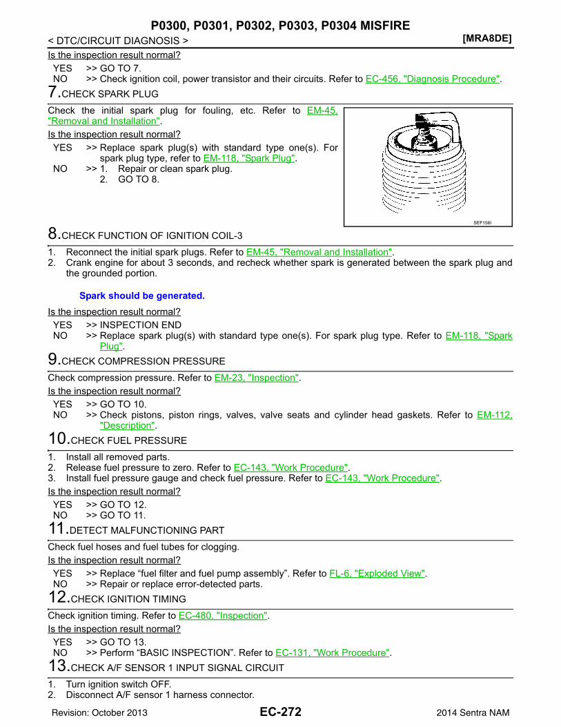
[MRA8DE]P0300, P0301, P0302, P0303, P0304 MISFIRE
< DTC/CIRCUIT DIAGNOSIS >Is the inspection result normal?YES >> GO TO 7.NO >> Check ignition coil, power transistor and their circuits. Refer to EC-456, "Diagnosis Procedure".
7.CHECK SPARK PLUG
Check the initial spark plug for fouling, etc. Refer to EM-45,"Removal and Installation".Is the inspection result normal?YES >> Replace spark plug(s) with standard type one(s). For
spark plug type, refer to EM-118, "Spark Plug".NO >> 1. Repair or clean spark plug.
2. GO TO 8.
8.CHECK FUNCTION OF IGNITION COIL-3
1. Reconnect the initial spark plugs. Refer to EM-45, "Removal and Installation".2. Crank engine for about 3 seconds, and recheck whether spark is generated between the spark plug and
the grounded portion.
Is the inspection result normal?YES >> INSPECTION ENDNO >> Replace spark plug(s) with standard type one(s). For spark plug type. Refer to EM-118, "Spark
Plug".9.CHECK COMPRESSION PRESSURE
Check compression pressure. Refer to EM-23, "Inspection".Is the inspection result normal?YES >> GO TO 10.NO >> Check pistons, piston rings, valves, valve seats and cylinder head gaskets. Refer to EM-112,
"Description".10.CHECK FUEL PRESSURE
1. Install all removed parts.2. Release fuel pressure to zero. Refer to EC-143, "Work Procedure".3. Install fuel pressure gauge and check fuel pressure. Refer to EC-143, "Work Procedure".Is the inspection result normal?YES >> GO TO 12.NO >> GO TO 11.
11.DETECT MALFUNCTIONING PART
Check fuel hoses and fuel tubes for clogging.Is the inspection result normal?YES >> Replace “fuel filter and fuel pump assembly”. Refer to FL-6, "Exploded View".NO >> Repair or replace error-detected parts.
12.CHECK IGNITION TIMING
Check ignition timing. Refer to EC-480, "Inspection".Is the inspection result normal?YES >> GO TO 13.NO >> Perform “BASIC INSPECTION”. Refer to EC-131, "Work Procedure".
13.CHECK A/F SENSOR 1 INPUT SIGNAL CIRCUIT
1. Turn ignition switch OFF.2. Disconnect A/F sensor 1 harness connector.
SEF156I
Spark should be generated.
EC-272Revision: October 2013 2014 Sentra NAM
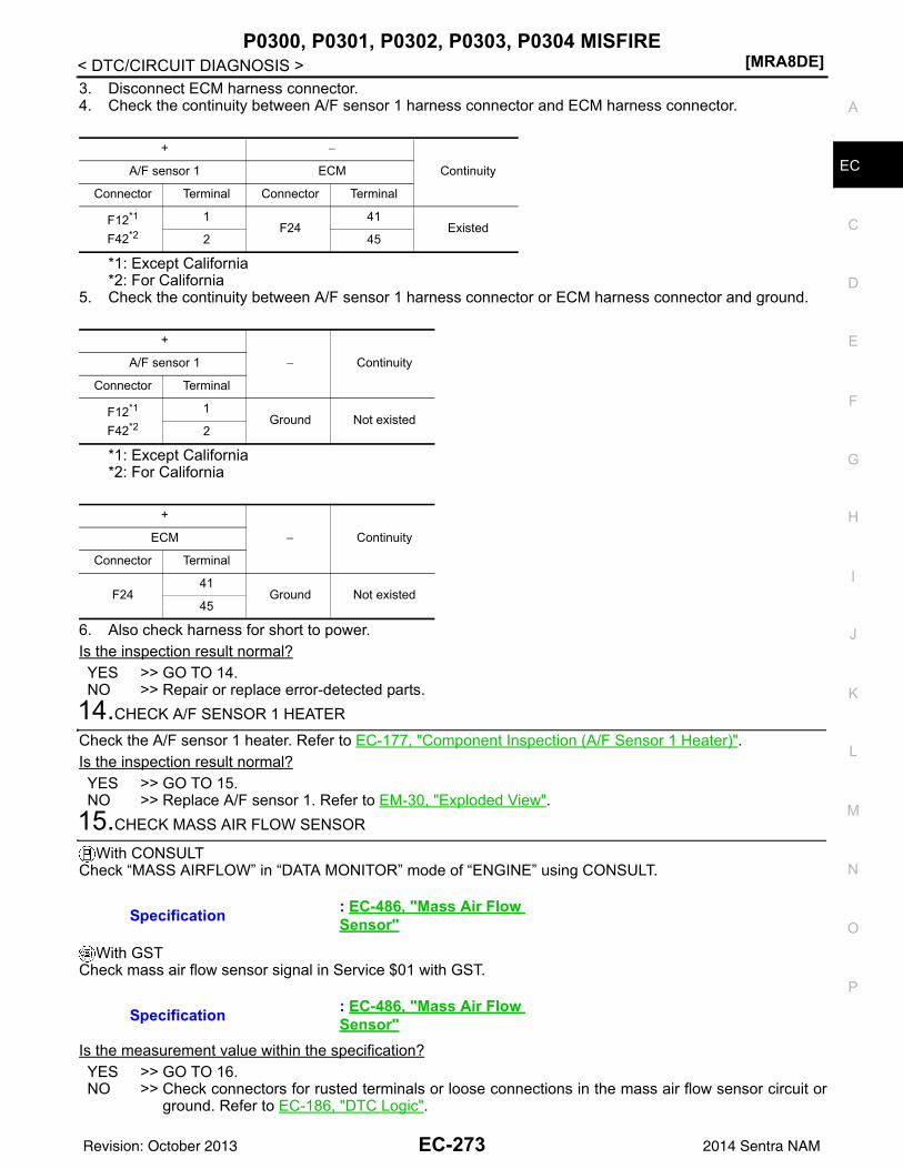
P0300, P0301, P0302, P0303, P0304 MISFIRE[MRA8DE]
C
D
E
F
G
H
I
J
K
L
M
A
C
N
P
O
< DTC/CIRCUIT DIAGNOSIS >
E
3. Disconnect ECM harness connector.4. Check the continuity between A/F sensor 1 harness connector and ECM harness connector.
*1: Except California*2: For California
5. Check the continuity between A/F sensor 1 harness connector or ECM harness connector and ground.
*1: Except California*2: For California
6. Also check harness for short to power.Is the inspection result normal?YES >> GO TO 14.NO >> Repair or replace error-detected parts.
14.CHECK A/F SENSOR 1 HEATER
Check the A/F sensor 1 heater. Refer to EC-177, "Component Inspection (A/F Sensor 1 Heater)".Is the inspection result normal?YES >> GO TO 15.NO >> Replace A/F sensor 1. Refer to EM-30, "Exploded View".
15.CHECK MASS AIR FLOW SENSOR
With CONSULTCheck “MASS AIRFLOW” in “DATA MONITOR” mode of “ENGINE” using CONSULT.
With GSTCheck mass air flow sensor signal in Service $01 with GST.
Is the measurement value within the specification?YES >> GO TO 16.NO >> Check connectors for rusted terminals or loose connections in the mass air flow sensor circuit or
ground. Refer to EC-186, "DTC Logic".
+ −
ContinuityA/F sensor 1 ECM
Connector Terminal Connector Terminal
F12*1
F42*2
1F24
41Existed
2 45
+
− ContinuityA/F sensor 1
Connector Terminal
F12*1
F42*2
1Ground Not existed
2
+
− ContinuityECM
Connector Terminal
F2441
Ground Not existed45
Specification : EC-486, "Mass Air Flow Sensor"
Specification : EC-486, "Mass Air Flow Sensor"
EC-273Revision: October 2013 2014 Sentra NAM
[MRA8DE]P0300, P0301, P0302, P0303, P0304 MISFIRE
< DTC/CIRCUIT DIAGNOSIS >
16.CHECK SYMPTOM TABLE
Check items on the rough idle symptom in EC-473, "Symptom Table".Is the inspection result normal?YES >> GO TO 17.NO >> Repair or replace error-detected parts.
17.ERASE THE 1ST TRIP DTC
Some tests may cause a 1st trip DTC to be set.Erase the 1st trip DTC from the ECM memory after performing the tests. Refer to EC-55, "Diagnosis Descrip-tion".
>> GO TO 18.18.CHECK INTERMITTENT INCIDENT
Perform GI-39, "Intermittent Incident".
>> INSPECTION END
EC-274Revision: October 2013 2014 Sentra NAM
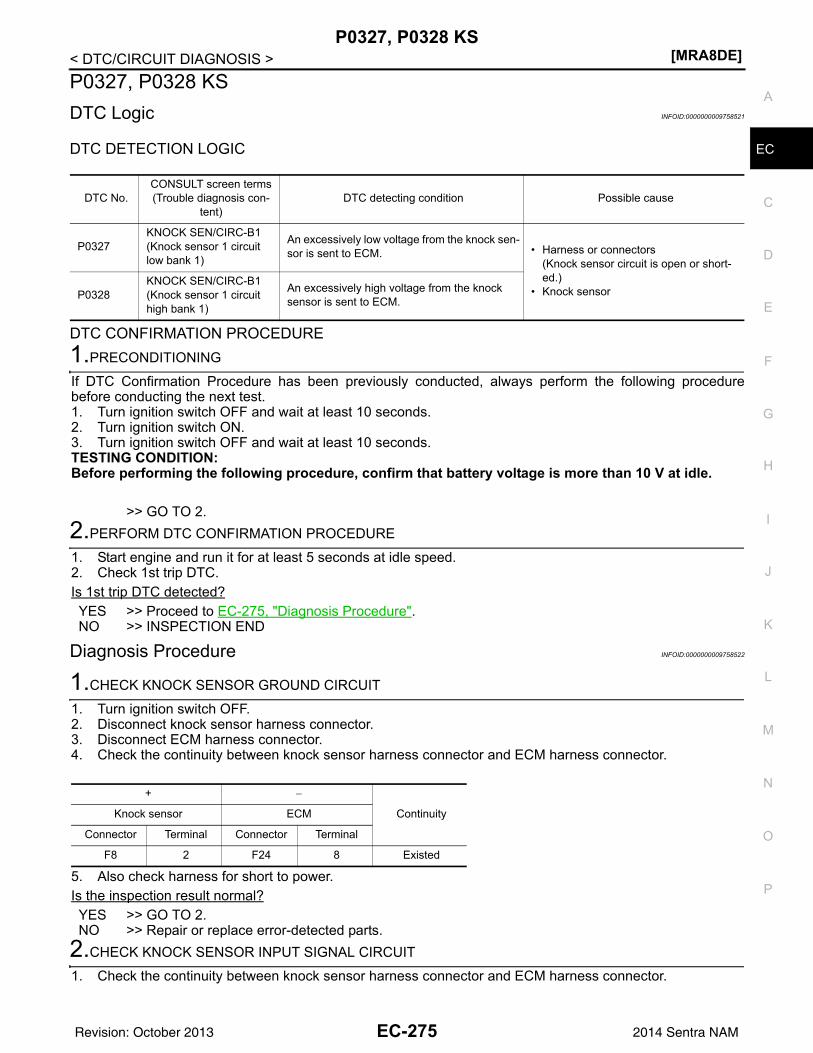
P0327, P0328 KS[MRA8DE]
C
D
E
F
G
H
I
J
K
L
M
A
C
N
P
O
< DTC/CIRCUIT DIAGNOSIS >
E
P0327, P0328 KSDTC Logic INFOID:0000000009758521
DTC DETECTION LOGIC
DTC CONFIRMATION PROCEDURE1.PRECONDITIONING
If DTC Confirmation Procedure has been previously conducted, always perform the following procedurebefore conducting the next test.1. Turn ignition switch OFF and wait at least 10 seconds.2. Turn ignition switch ON.3. Turn ignition switch OFF and wait at least 10 seconds.TESTING CONDITION:Before performing the following procedure, confirm that battery voltage is more than 10 V at idle.
>> GO TO 2.2.PERFORM DTC CONFIRMATION PROCEDURE
1. Start engine and run it for at least 5 seconds at idle speed.2. Check 1st trip DTC.Is 1st trip DTC detected?YES >> Proceed to EC-275, "Diagnosis Procedure".NO >> INSPECTION END
Diagnosis Procedure INFOID:0000000009758522
1.CHECK KNOCK SENSOR GROUND CIRCUIT
1. Turn ignition switch OFF.2. Disconnect knock sensor harness connector.3. Disconnect ECM harness connector.4. Check the continuity between knock sensor harness connector and ECM harness connector.
5. Also check harness for short to power.Is the inspection result normal?YES >> GO TO 2.NO >> Repair or replace error-detected parts.
2.CHECK KNOCK SENSOR INPUT SIGNAL CIRCUIT
1. Check the continuity between knock sensor harness connector and ECM harness connector.
DTC No.CONSULT screen terms(Trouble diagnosis con-
tent)DTC detecting condition Possible cause
P0327KNOCK SEN/CIRC-B1(Knock sensor 1 circuit low bank 1)
An excessively low voltage from the knock sen-sor is sent to ECM. • Harness or connectors
(Knock sensor circuit is open or short-ed.)
• Knock sensorP0328KNOCK SEN/CIRC-B1(Knock sensor 1 circuit high bank 1)
An excessively high voltage from the knock sensor is sent to ECM.
+ −
ContinuityKnock sensor ECM
Connector Terminal Connector Terminal
F8 2 F24 8 Existed
EC-275Revision: October 2013 2014 Sentra NAM
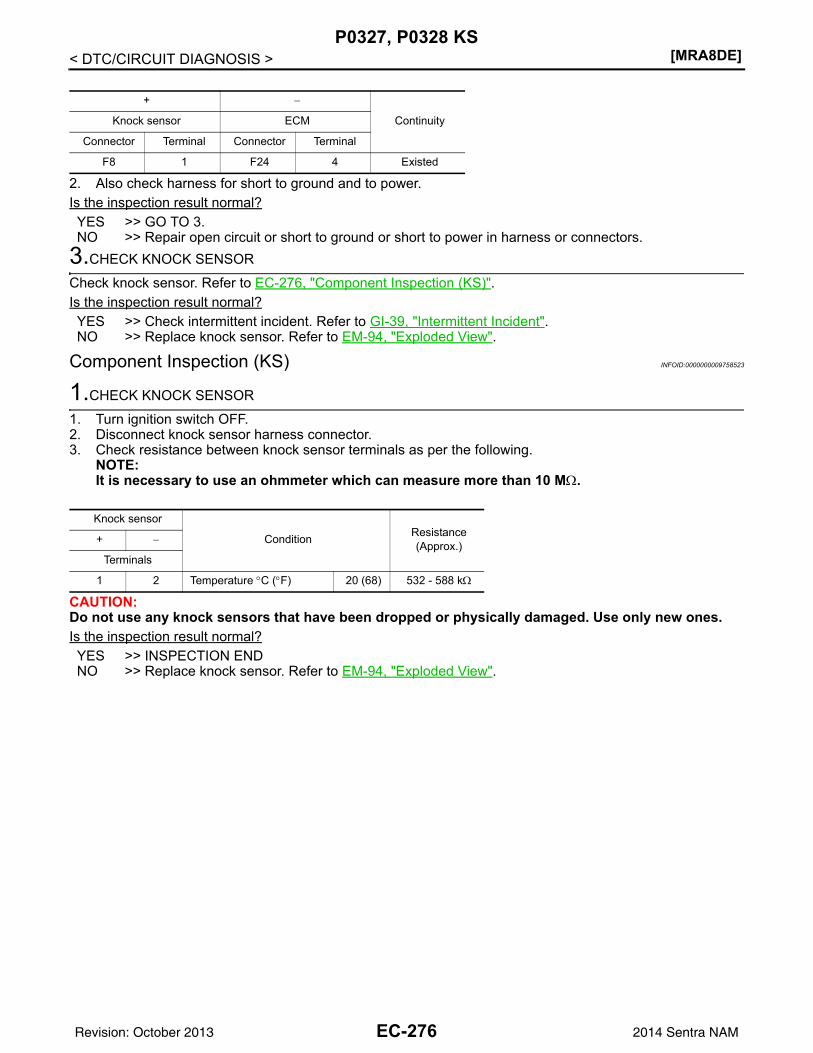
[MRA8DE]P0327, P0328 KS
< DTC/CIRCUIT DIAGNOSIS >
2. Also check harness for short to ground and to power.Is the inspection result normal?YES >> GO TO 3.NO >> Repair open circuit or short to ground or short to power in harness or connectors.
3.CHECK KNOCK SENSOR
Check knock sensor. Refer to EC-276, "Component Inspection (KS)".Is the inspection result normal?YES >> Check intermittent incident. Refer to GI-39, "Intermittent Incident".NO >> Replace knock sensor. Refer to EM-94, "Exploded View".
Component Inspection (KS) INFOID:0000000009758523
1.CHECK KNOCK SENSOR
1. Turn ignition switch OFF.2. Disconnect knock sensor harness connector.3. Check resistance between knock sensor terminals as per the following.
NOTE:It is necessary to use an ohmmeter which can measure more than 10 MΩ.
CAUTION:Do not use any knock sensors that have been dropped or physically damaged. Use only new ones.Is the inspection result normal?YES >> INSPECTION ENDNO >> Replace knock sensor. Refer to EM-94, "Exploded View".
+ −
ContinuityKnock sensor ECM
Connector Terminal Connector Terminal
F8 1 F24 4 Existed
Knock sensor
Condition Resistance(Approx.)+ −
Terminals
1 2 Temperature °C (°F) 20 (68) 532 - 588 kΩ
EC-276Revision: October 2013 2014 Sentra NAM
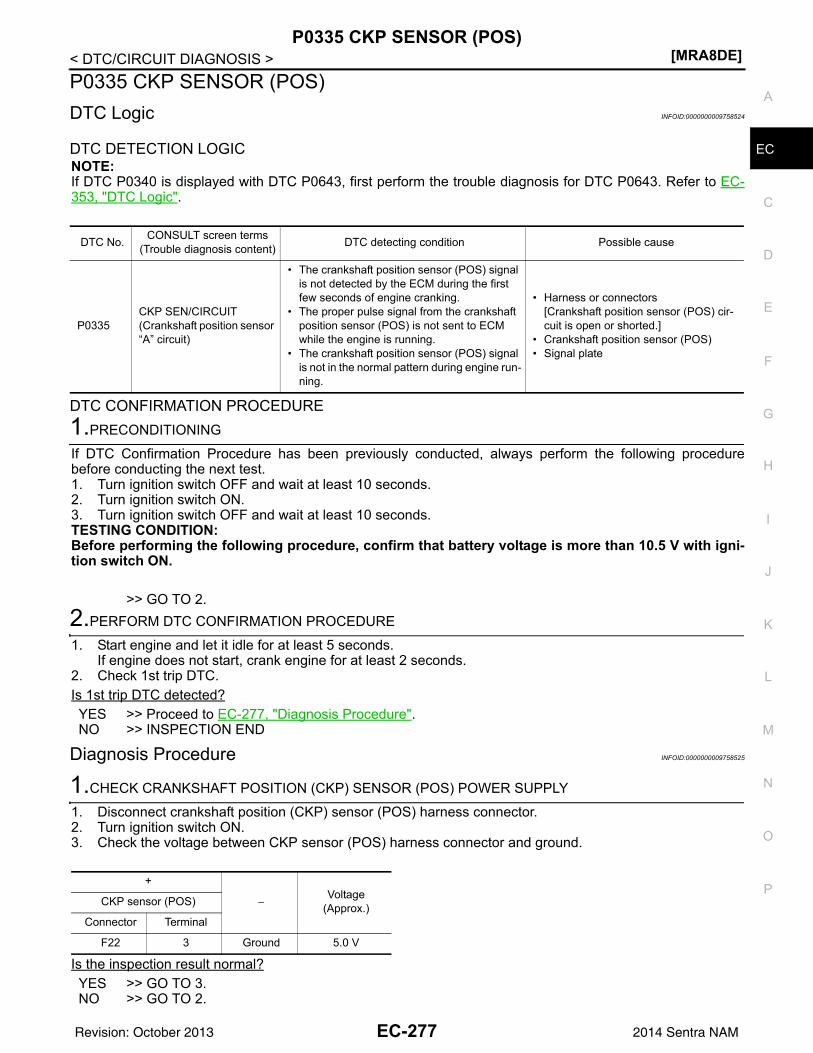
P0335 CKP SENSOR (POS)[MRA8DE]
C
D
E
F
G
H
I
J
K
L
M
A
C
N
P
O
< DTC/CIRCUIT DIAGNOSIS >
E
P0335 CKP SENSOR (POS)DTC Logic INFOID:0000000009758524
DTC DETECTION LOGICNOTE:If DTC P0340 is displayed with DTC P0643, first perform the trouble diagnosis for DTC P0643. Refer to EC-353, "DTC Logic".
DTC CONFIRMATION PROCEDURE1.PRECONDITIONING
If DTC Confirmation Procedure has been previously conducted, always perform the following procedurebefore conducting the next test.1. Turn ignition switch OFF and wait at least 10 seconds.2. Turn ignition switch ON.3. Turn ignition switch OFF and wait at least 10 seconds.TESTING CONDITION:Before performing the following procedure, confirm that battery voltage is more than 10.5 V with igni-tion switch ON.
>> GO TO 2.2.PERFORM DTC CONFIRMATION PROCEDURE
1. Start engine and let it idle for at least 5 seconds.If engine does not start, crank engine for at least 2 seconds.
2. Check 1st trip DTC.Is 1st trip DTC detected?YES >> Proceed to EC-277, "Diagnosis Procedure".NO >> INSPECTION END
Diagnosis Procedure INFOID:0000000009758525
1.CHECK CRANKSHAFT POSITION (CKP) SENSOR (POS) POWER SUPPLY
1. Disconnect crankshaft position (CKP) sensor (POS) harness connector.2. Turn ignition switch ON.3. Check the voltage between CKP sensor (POS) harness connector and ground.
Is the inspection result normal?YES >> GO TO 3.NO >> GO TO 2.
DTC No. CONSULT screen terms(Trouble diagnosis content) DTC detecting condition Possible cause
P0335CKP SEN/CIRCUIT(Crankshaft position sensor “A” circuit)
• The crankshaft position sensor (POS) signal is not detected by the ECM during the first few seconds of engine cranking.
• The proper pulse signal from the crankshaft position sensor (POS) is not sent to ECM while the engine is running.
• The crankshaft position sensor (POS) signal is not in the normal pattern during engine run-ning.
• Harness or connectors[Crankshaft position sensor (POS) cir-cuit is open or shorted.]
• Crankshaft position sensor (POS)• Signal plate
+
−Voltage
(Approx.)CKP sensor (POS)
Connector Terminal
F22 3 Ground 5.0 V
EC-277Revision: October 2013 2014 Sentra NAM
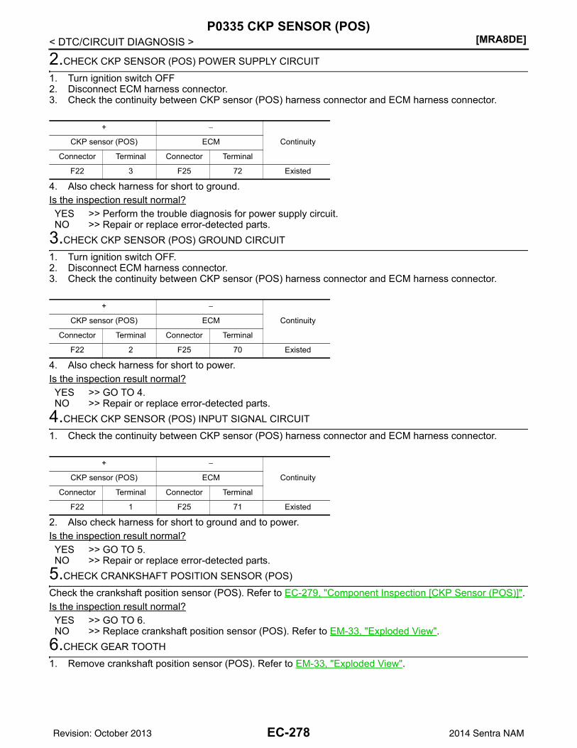
[MRA8DE]P0335 CKP SENSOR (POS)
< DTC/CIRCUIT DIAGNOSIS >
2.CHECK CKP SENSOR (POS) POWER SUPPLY CIRCUIT
1. Turn ignition switch OFF2. Disconnect ECM harness connector.3. Check the continuity between CKP sensor (POS) harness connector and ECM harness connector.
4. Also check harness for short to ground.Is the inspection result normal?YES >> Perform the trouble diagnosis for power supply circuit.NO >> Repair or replace error-detected parts.
3.CHECK CKP SENSOR (POS) GROUND CIRCUIT
1. Turn ignition switch OFF.2. Disconnect ECM harness connector.3. Check the continuity between CKP sensor (POS) harness connector and ECM harness connector.
4. Also check harness for short to power.Is the inspection result normal?YES >> GO TO 4.NO >> Repair or replace error-detected parts.
4.CHECK CKP SENSOR (POS) INPUT SIGNAL CIRCUIT
1. Check the continuity between CKP sensor (POS) harness connector and ECM harness connector.
2. Also check harness for short to ground and to power.Is the inspection result normal?YES >> GO TO 5.NO >> Repair or replace error-detected parts.
5.CHECK CRANKSHAFT POSITION SENSOR (POS)
Check the crankshaft position sensor (POS). Refer to EC-279, "Component Inspection [CKP Sensor (POS)]".Is the inspection result normal?YES >> GO TO 6.NO >> Replace crankshaft position sensor (POS). Refer to EM-33, "Exploded View".
6.CHECK GEAR TOOTH
1. Remove crankshaft position sensor (POS). Refer to EM-33, "Exploded View".
+ −
ContinuityCKP sensor (POS) ECM
Connector Terminal Connector Terminal
F22 3 F25 72 Existed
+ −
ContinuityCKP sensor (POS) ECM
Connector Terminal Connector Terminal
F22 2 F25 70 Existed
+ −
ContinuityCKP sensor (POS) ECM
Connector Terminal Connector Terminal
F22 1 F25 71 Existed
EC-278Revision: October 2013 2014 Sentra NAM
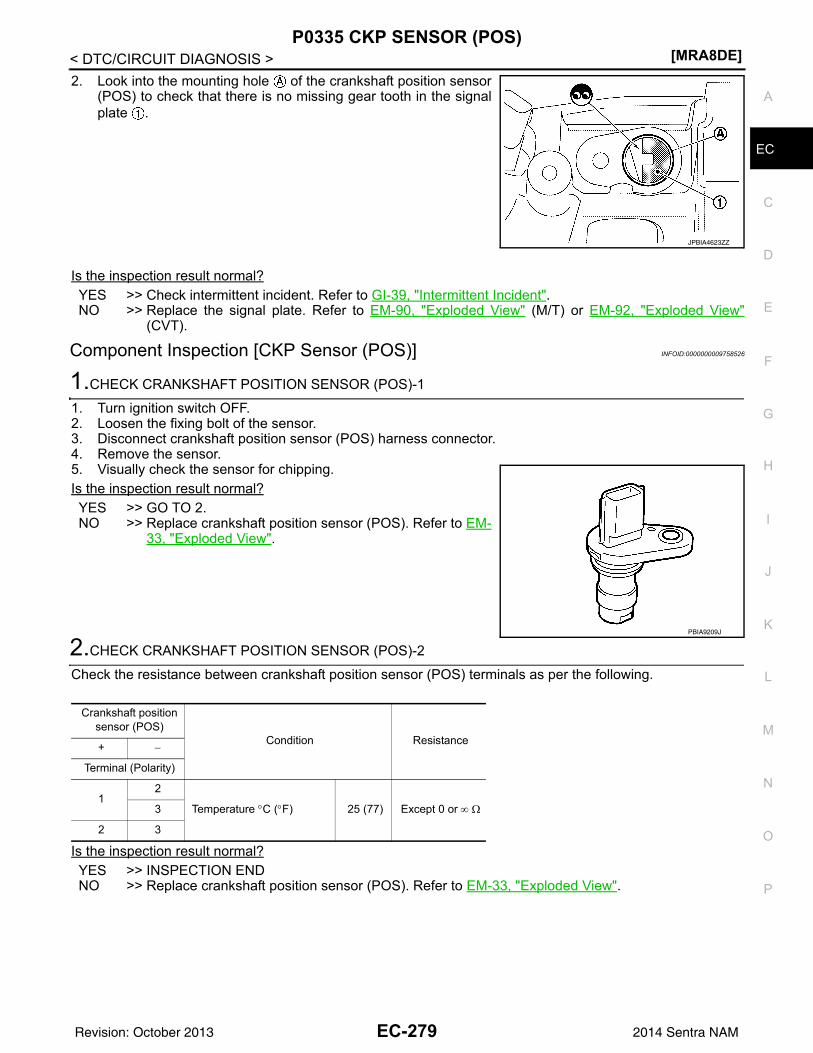
P0335 CKP SENSOR (POS)[MRA8DE]
C
D
E
F
G
H
I
J
K
L
M
A
C
N
P
O
< DTC/CIRCUIT DIAGNOSIS >
E
2. Look into the mounting hole of the crankshaft position sensor(POS) to check that there is no missing gear tooth in the signalplate .
Is the inspection result normal?YES >> Check intermittent incident. Refer to GI-39, "Intermittent Incident".NO >> Replace the signal plate. Refer to EM-90, "Exploded View" (M/T) or EM-92, "Exploded View"
(CVT).
Component Inspection [CKP Sensor (POS)] INFOID:0000000009758526
1.CHECK CRANKSHAFT POSITION SENSOR (POS)-1
1. Turn ignition switch OFF.2. Loosen the fixing bolt of the sensor.3. Disconnect crankshaft position sensor (POS) harness connector.4. Remove the sensor.5. Visually check the sensor for chipping.Is the inspection result normal?YES >> GO TO 2.NO >> Replace crankshaft position sensor (POS). Refer to EM-
33, "Exploded View".
2.CHECK CRANKSHAFT POSITION SENSOR (POS)-2
Check the resistance between crankshaft position sensor (POS) terminals as per the following.
Is the inspection result normal?YES >> INSPECTION ENDNO >> Replace crankshaft position sensor (POS). Refer to EM-33, "Exploded View".
JPBIA4623ZZ
PBIA9209J
Crankshaft position sensor (POS)
Condition Resistance+ −
Terminal (Polarity)
12
Temperature °C (°F) 25 (77) Except 0 or ∞ Ω3
2 3
EC-279Revision: October 2013 2014 Sentra NAM
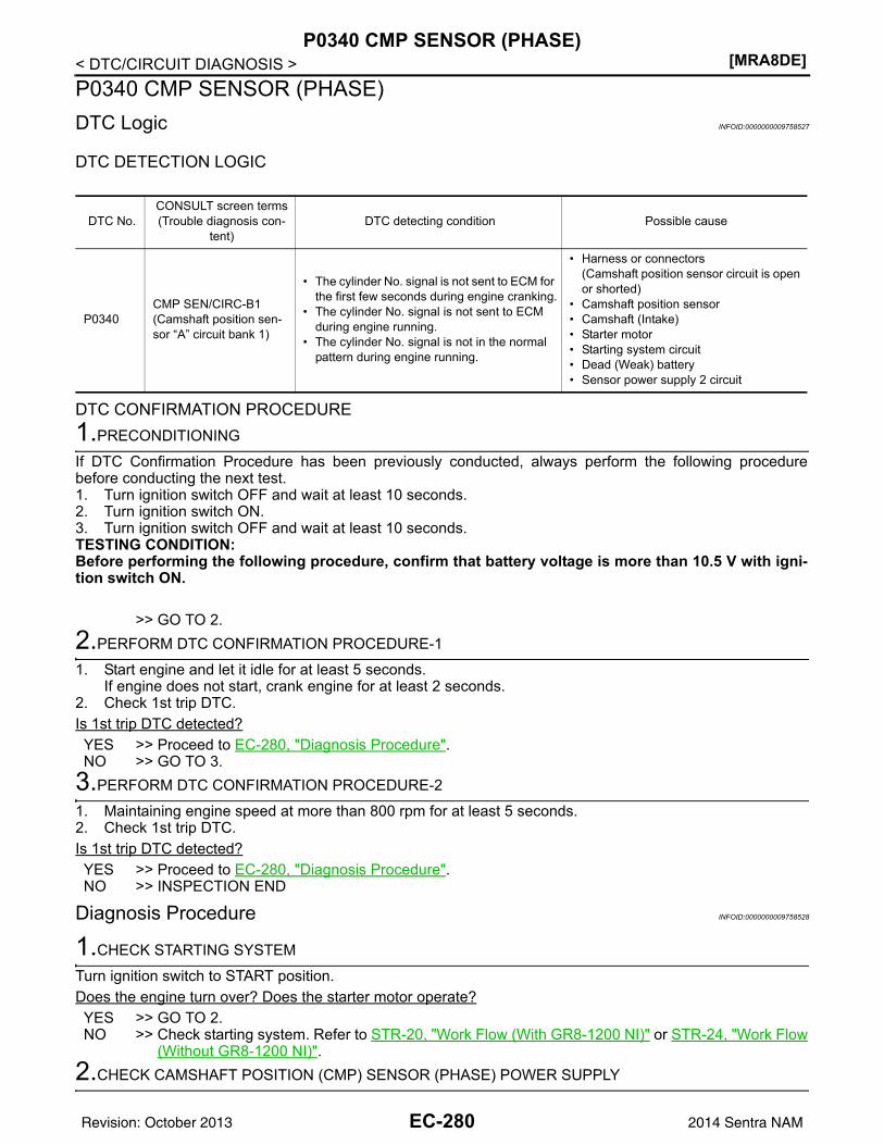
[MRA8DE]P0340 CMP SENSOR (PHASE)
< DTC/CIRCUIT DIAGNOSIS >P0340 CMP SENSOR (PHASE)DTC Logic INFOID:0000000009758527
DTC DETECTION LOGIC
DTC CONFIRMATION PROCEDURE1.PRECONDITIONING
If DTC Confirmation Procedure has been previously conducted, always perform the following procedurebefore conducting the next test.1. Turn ignition switch OFF and wait at least 10 seconds.2. Turn ignition switch ON.3. Turn ignition switch OFF and wait at least 10 seconds.TESTING CONDITION:Before performing the following procedure, confirm that battery voltage is more than 10.5 V with igni-tion switch ON.
>> GO TO 2.2.PERFORM DTC CONFIRMATION PROCEDURE-1
1. Start engine and let it idle for at least 5 seconds.If engine does not start, crank engine for at least 2 seconds.
2. Check 1st trip DTC.Is 1st trip DTC detected?YES >> Proceed to EC-280, "Diagnosis Procedure".NO >> GO TO 3.
3.PERFORM DTC CONFIRMATION PROCEDURE-2
1. Maintaining engine speed at more than 800 rpm for at least 5 seconds.2. Check 1st trip DTC.Is 1st trip DTC detected?YES >> Proceed to EC-280, "Diagnosis Procedure".NO >> INSPECTION END
Diagnosis Procedure INFOID:0000000009758528
1.CHECK STARTING SYSTEM
Turn ignition switch to START position.Does the engine turn over? Does the starter motor operate?YES >> GO TO 2.NO >> Check starting system. Refer to STR-20, "Work Flow (With GR8-1200 NI)" or STR-24, "Work Flow
(Without GR8-1200 NI)".2.CHECK CAMSHAFT POSITION (CMP) SENSOR (PHASE) POWER SUPPLY
DTC No.CONSULT screen terms(Trouble diagnosis con-
tent)DTC detecting condition Possible cause
P0340CMP SEN/CIRC-B1(Camshaft position sen-sor “A” circuit bank 1)
• The cylinder No. signal is not sent to ECM for the first few seconds during engine cranking.
• The cylinder No. signal is not sent to ECM during engine running.
• The cylinder No. signal is not in the normal pattern during engine running.
• Harness or connectors(Camshaft position sensor circuit is open or shorted)
• Camshaft position sensor• Camshaft (Intake)• Starter motor• Starting system circuit• Dead (Weak) battery• Sensor power supply 2 circuit
EC-280Revision: October 2013 2014 Sentra NAM
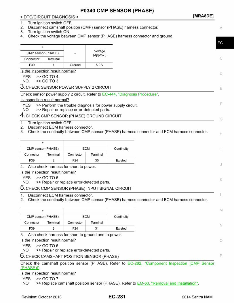
P0340 CMP SENSOR (PHASE)[MRA8DE]
C
D
E
F
G
H
I
J
K
L
M
A
C
N
P
O
< DTC/CIRCUIT DIAGNOSIS >
E
1. Turn ignition switch OFF.2. Disconnect camshaft position (CMP) sensor (PHASE) harness connector.3. Turn ignition switch ON.4. Check the voltage between CMP sensor (PHASE) harness connector and ground.
Is the inspection result normal?YES >> GO TO 4.NO >> GO TO 3.
3.CHECK SENSOR POWER SUPPLY 2 CIRCUIT
Check sensor power supply 2 circuit. Refer to EC-444, "Diagnosis Procedure".Is inspection result normal?YES >> Perform the trouble diagnosis for power supply circuit.NO >> Repair or replace error-detected parts.
4.CHECK CMP SENSOR (PHASE) GROUND CIRCUIT
1. Turn ignition switch OFF.2. Disconnect ECM harness connector.3. Check the continuity between CMP sensor (PHASE) harness connector and ECM harness connector.
4. Also check harness for short to power.Is the inspection result normal?YES >> GO TO 5.NO >> Repair or replace error-detected parts.
5.CHECK CMP SENSOR (PHASE) INPUT SIGNAL CIRCUIT
1. Disconnect ECM harness connector.2. Check the continuity between CMP sensor (PHASE) harness connector and ECM harness connector.
3. Also check harness for short to ground and to power.Is the inspection result normal?YES >> GO TO 6.NO >> Repair or replace error-detected parts.
6.CHECK CAMSHAFT POSITION SENSOR (PHASE)
Check the camshaft position sensor (PHASE). Refer to EC-282, "Component Inspection [CMP Sensor(PHASE)]".Is the inspection result normal?YES >> GO TO 7.NO >> Replace camshaft position sensor (PHASE). Refer to EM-60, "Removal and Installation".
+
−Voltage
(Approx.)CMP sensor (PHASE)
Connector Terminal
F39 1 Ground 5.0 V
+ −
ContinuityCMP sensor (PHASE) ECM
Connector Terminal Connector Terminal
F39 2 F24 30 Existed
+ −
ContinuityCMP sensor (PHASE) ECM
Connector Terminal Connector Terminal
F39 3 F24 31 Existed
EC-281Revision: October 2013 2014 Sentra NAM
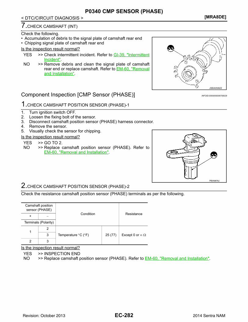
[MRA8DE]P0340 CMP SENSOR (PHASE)
< DTC/CIRCUIT DIAGNOSIS >
7.CHECK CAMSHAFT (INT)
Check the following.• Accumulation of debris to the signal plate of camshaft rear end• Chipping signal plate of camshaft rear endIs the inspection result normal?YES >> Check intermittent incident. Refer to GI-39, "Intermittent
Incident".NO >> Remove debris and clean the signal plate of camshaft
rear end or replace camshaft. Refer to EM-60, "Removaland Installation".
Component Inspection [CMP Sensor (PHASE)] INFOID:0000000009758529
1.CHECK CAMSHAFT POSITION SENSOR (PHASE)-1
1. Turn ignition switch OFF.2. Loosen the fixing bolt of the sensor.3. Disconnect camshaft position sensor (PHASE) harness connector.4. Remove the sensor.5. Visually check the sensor for chipping.Is the inspection result normal?YES >> GO TO 2.NO >> Replace camshaft position sensor (PHASE). Refer to
EM-60, "Removal and Installation".
2.CHECK CAMSHAFT POSITION SENSOR (PHASE)-2
Check the resistance camshaft position sensor (PHASE) terminals as per the following.
Is the inspection result normal?YES >> INSPECTION ENDNO >> Replace camshaft position sensor (PHASE). Refer to EM-60, "Removal and Installation".
JSBIA0599ZZ
PBIA9876J
Camshaft position sensor (PHASE)
Condition Resistance+ −
Terminals (Polarity)
12
Temperature °C (°F) 25 (77) Except 0 or ∞ Ω3
2 3
EC-282Revision: October 2013 2014 Sentra NAM
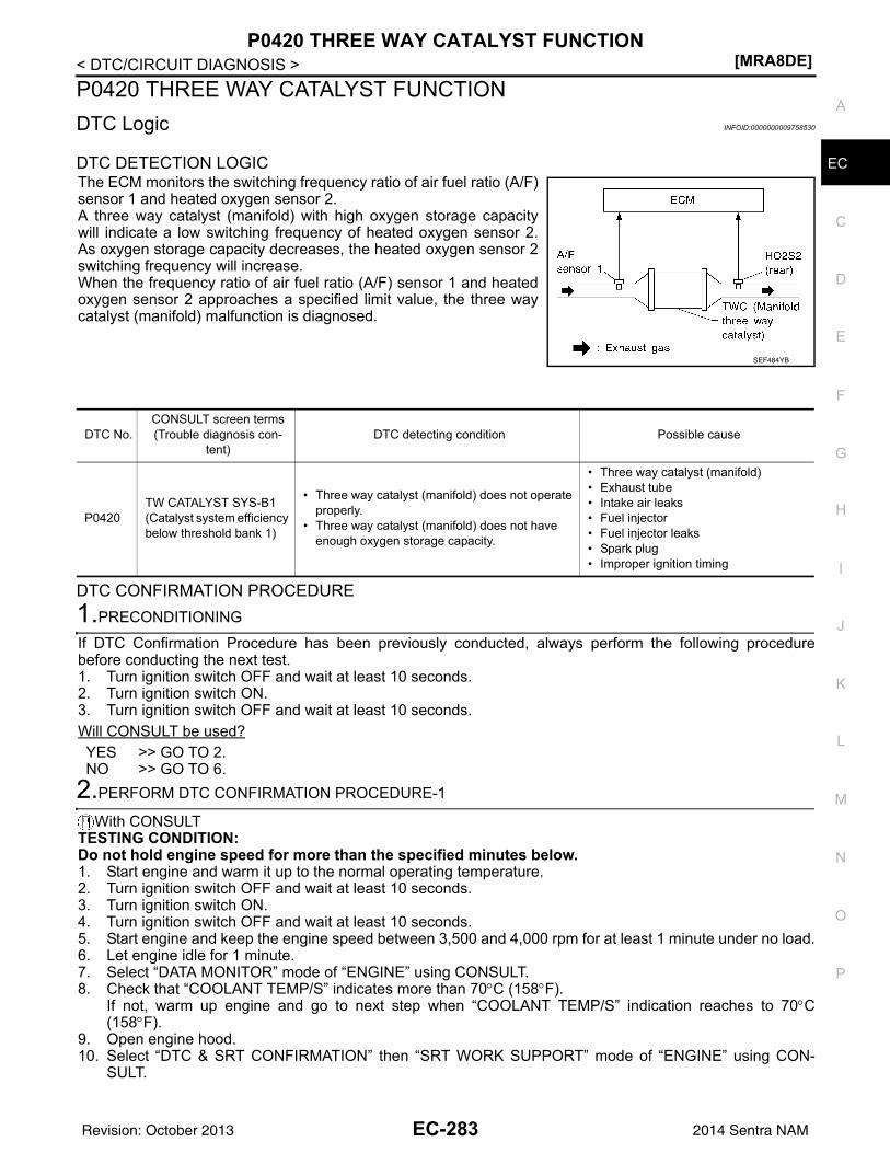
P0420 THREE WAY CATALYST FUNCTION[MRA8DE]
C
D
E
F
G
H
I
J
K
L
M
A
C
N
P
O
< DTC/CIRCUIT DIAGNOSIS >
E
P0420 THREE WAY CATALYST FUNCTIONDTC Logic INFOID:0000000009758530
DTC DETECTION LOGICThe ECM monitors the switching frequency ratio of air fuel ratio (A/F)sensor 1 and heated oxygen sensor 2.A three way catalyst (manifold) with high oxygen storage capacitywill indicate a low switching frequency of heated oxygen sensor 2.As oxygen storage capacity decreases, the heated oxygen sensor 2switching frequency will increase.When the frequency ratio of air fuel ratio (A/F) sensor 1 and heatedoxygen sensor 2 approaches a specified limit value, the three waycatalyst (manifold) malfunction is diagnosed.
DTC CONFIRMATION PROCEDURE1.PRECONDITIONING
If DTC Confirmation Procedure has been previously conducted, always perform the following procedurebefore conducting the next test.1. Turn ignition switch OFF and wait at least 10 seconds.2. Turn ignition switch ON.3. Turn ignition switch OFF and wait at least 10 seconds.Will CONSULT be used?YES >> GO TO 2.NO >> GO TO 6.
2.PERFORM DTC CONFIRMATION PROCEDURE-1
With CONSULTTESTING CONDITION:Do not hold engine speed for more than the specified minutes below.1. Start engine and warm it up to the normal operating temperature.2. Turn ignition switch OFF and wait at least 10 seconds.3. Turn ignition switch ON.4. Turn ignition switch OFF and wait at least 10 seconds.5. Start engine and keep the engine speed between 3,500 and 4,000 rpm for at least 1 minute under no load.6. Let engine idle for 1 minute.7. Select “DATA MONITOR” mode of “ENGINE” using CONSULT.8. Check that “COOLANT TEMP/S” indicates more than 70°C (158°F).
If not, warm up engine and go to next step when “COOLANT TEMP/S” indication reaches to 70°C(158°F).
9. Open engine hood.10. Select “DTC & SRT CONFIRMATION” then “SRT WORK SUPPORT” mode of “ENGINE” using CON-
SULT.
SEF484YB
DTC No.CONSULT screen terms(Trouble diagnosis con-
tent)DTC detecting condition Possible cause
P0420TW CATALYST SYS-B1(Catalyst system efficiency below threshold bank 1)
• Three way catalyst (manifold) does not operate properly.
• Three way catalyst (manifold) does not have enough oxygen storage capacity.
• Three way catalyst (manifold)• Exhaust tube• Intake air leaks• Fuel injector• Fuel injector leaks• Spark plug• Improper ignition timing
EC-283Revision: October 2013 2014 Sentra NAM
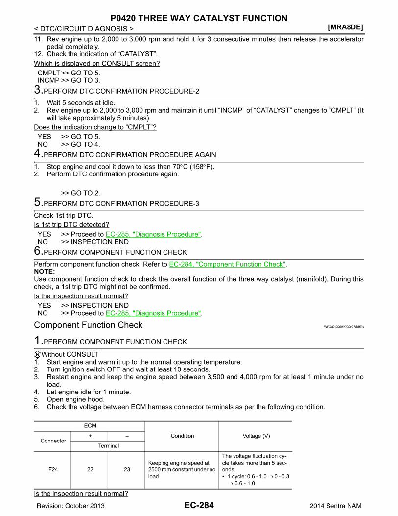
[MRA8DE]P0420 THREE WAY CATALYST FUNCTION
< DTC/CIRCUIT DIAGNOSIS >11. Rev engine up to 2,000 to 3,000 rpm and hold it for 3 consecutive minutes then release the accelerator
pedal completely.12. Check the indication of “CATALYST”.Which is displayed on CONSULT screen?CMPLT>> GO TO 5.INCMP >> GO TO 3.
3.PERFORM DTC CONFIRMATION PROCEDURE-2
1. Wait 5 seconds at idle.2. Rev engine up to 2,000 to 3,000 rpm and maintain it until “INCMP” of “CATALYST” changes to “CMPLT” (It
will take approximately 5 minutes).Does the indication change to “CMPLT”?YES >> GO TO 5.NO >> GO TO 4.
4.PERFORM DTC CONFIRMATION PROCEDURE AGAIN
1. Stop engine and cool it down to less than 70°C (158°F).2. Perform DTC confirmation procedure again.
>> GO TO 2.5.PERFORM DTC CONFIRMATION PROCEDURE-3
Check 1st trip DTC.Is 1st trip DTC detected?YES >> Proceed to EC-285, "Diagnosis Procedure".NO >> INSPECTION END
6.PERFORM COMPONENT FUNCTION CHECK
Perform component function check. Refer to EC-284, "Component Function Check".NOTE:Use component function check to check the overall function of the three way catalyst (manifold). During thischeck, a 1st trip DTC might not be confirmed.Is the inspection result normal?YES >> INSPECTION ENDNO >> Proceed to EC-285, "Diagnosis Procedure".
Component Function Check INFOID:0000000009758531
1.PERFORM COMPONENT FUNCTION CHECK
Without CONSULT1. Start engine and warm it up to the normal operating temperature.2. Turn ignition switch OFF and wait at least 10 seconds.3. Restart engine and keep the engine speed between 3,500 and 4,000 rpm for at least 1 minute under no
load.4. Let engine idle for 1 minute.5. Open engine hood.6. Check the voltage between ECM harness connector terminals as per the following condition.
Is the inspection result normal?
ECM
Condition Voltage (V)Connector
+ –
Terminal
F24 22 23Keeping engine speed at 2500 rpm constant under no load
The voltage fluctuation cy-cle takes more than 5 sec-onds.• 1 cycle: 0.6 - 1.0 → 0 - 0.3 → 0.6 - 1.0
EC-284Revision: October 2013 2014 Sentra NAM
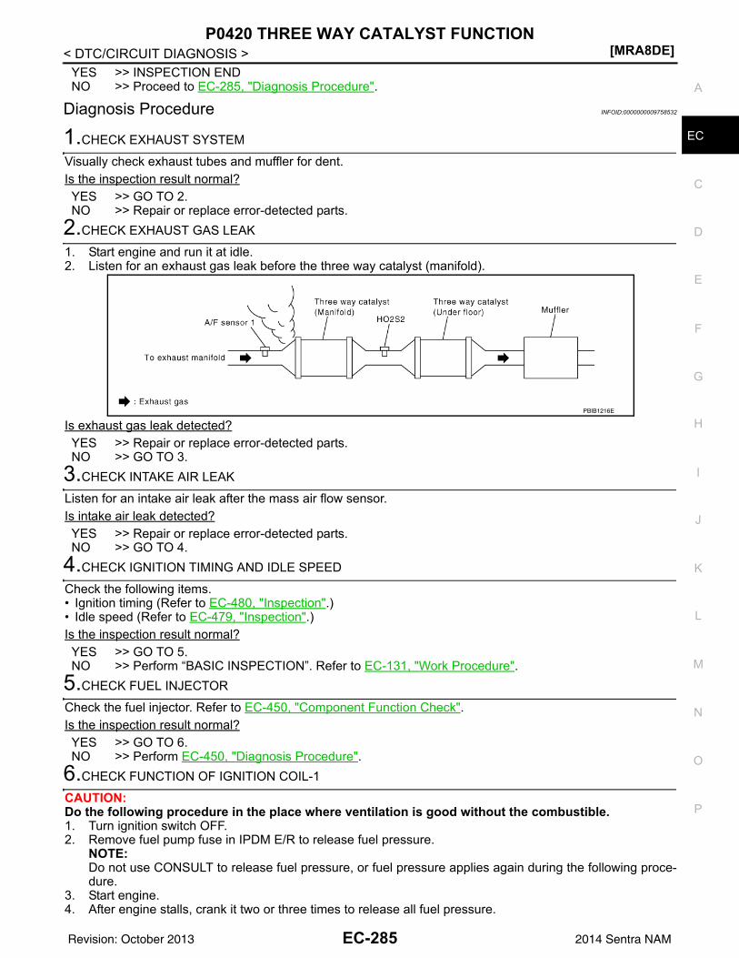
P0420 THREE WAY CATALYST FUNCTION[MRA8DE]
C
D
E
F
G
H
I
J
K
L
M
A
C
N
P
O
< DTC/CIRCUIT DIAGNOSIS >
E
YES >> INSPECTION ENDNO >> Proceed to EC-285, "Diagnosis Procedure".
Diagnosis Procedure INFOID:0000000009758532
1.CHECK EXHAUST SYSTEM
Visually check exhaust tubes and muffler for dent.Is the inspection result normal?YES >> GO TO 2.NO >> Repair or replace error-detected parts.
2.CHECK EXHAUST GAS LEAK
1. Start engine and run it at idle.2. Listen for an exhaust gas leak before the three way catalyst (manifold).
Is exhaust gas leak detected?YES >> Repair or replace error-detected parts.NO >> GO TO 3.
3.CHECK INTAKE AIR LEAK
Listen for an intake air leak after the mass air flow sensor.Is intake air leak detected?YES >> Repair or replace error-detected parts.NO >> GO TO 4.
4.CHECK IGNITION TIMING AND IDLE SPEED
Check the following items.• Ignition timing (Refer to EC-480, "Inspection".)• Idle speed (Refer to EC-479, "Inspection".)Is the inspection result normal?YES >> GO TO 5.NO >> Perform “BASIC INSPECTION”. Refer to EC-131, "Work Procedure".
5.CHECK FUEL INJECTOR
Check the fuel injector. Refer to EC-450, "Component Function Check".Is the inspection result normal?YES >> GO TO 6.NO >> Perform EC-450, "Diagnosis Procedure".
6.CHECK FUNCTION OF IGNITION COIL-1
CAUTION:Do the following procedure in the place where ventilation is good without the combustible.1. Turn ignition switch OFF.2. Remove fuel pump fuse in IPDM E/R to release fuel pressure.
NOTE:Do not use CONSULT to release fuel pressure, or fuel pressure applies again during the following proce-dure.
3. Start engine.4. After engine stalls, crank it two or three times to release all fuel pressure.
PBIB1216E
EC-285Revision: October 2013 2014 Sentra NAM
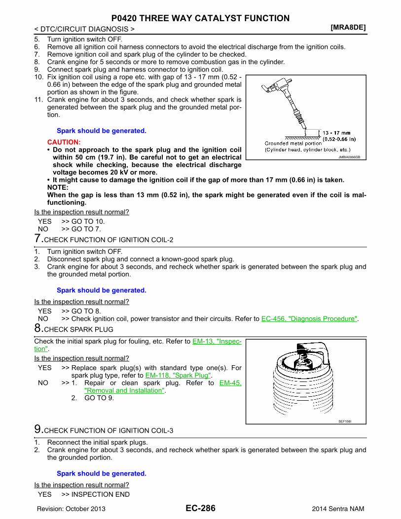
[MRA8DE]P0420 THREE WAY CATALYST FUNCTION
< DTC/CIRCUIT DIAGNOSIS >5. Turn ignition switch OFF.6. Remove all ignition coil harness connectors to avoid the electrical discharge from the ignition coils.7. Remove ignition coil and spark plug of the cylinder to be checked.8. Crank engine for 5 seconds or more to remove combustion gas in the cylinder.9. Connect spark plug and harness connector to ignition coil.10. Fix ignition coil using a rope etc. with gap of 13 - 17 mm (0.52 -
0.66 in) between the edge of the spark plug and grounded metalportion as shown in the figure.
11. Crank engine for about 3 seconds, and check whether spark isgenerated between the spark plug and the grounded metal por-tion.
CAUTION:• Do not approach to the spark plug and the ignition coil
within 50 cm (19.7 in). Be careful not to get an electricalshock while checking, because the electrical dischargevoltage becomes 20 kV or more.
• It might cause to damage the ignition coil if the gap of more than 17 mm (0.66 in) is taken.NOTE:When the gap is less than 13 mm (0.52 in), the spark might be generated even if the coil is mal-functioning.
Is the inspection result normal?YES >> GO TO 10.NO >> GO TO 7.
7.CHECK FUNCTION OF IGNITION COIL-2
1. Turn ignition switch OFF.2. Disconnect spark plug and connect a known-good spark plug.3. Crank engine for about 3 seconds, and recheck whether spark is generated between the spark plug and
the grounded metal portion.
Is the inspection result normal?YES >> GO TO 8.NO >> Check ignition coil, power transistor and their circuits. Refer to EC-456, "Diagnosis Procedure".
8.CHECK SPARK PLUG
Check the initial spark plug for fouling, etc. Refer to EM-13, "Inspec-tion".Is the inspection result normal?YES >> Replace spark plug(s) with standard type one(s). For
spark plug type, refer to EM-118, "Spark Plug".NO >> 1. Repair or clean spark plug. Refer to EM-45,
"Removal and Installation".2. GO TO 9.
9.CHECK FUNCTION OF IGNITION COIL-3
1. Reconnect the initial spark plugs.2. Crank engine for about 3 seconds, and recheck whether spark is generated between the spark plug and
the grounded portion.
Is the inspection result normal?YES >> INSPECTION END
Spark should be generated.
JMBIA0066GB
Spark should be generated.
SEF156I
Spark should be generated.
EC-286Revision: October 2013 2014 Sentra NAM
P0420 THREE WAY CATALYST FUNCTION[MRA8DE]
C
D
E
F
G
H
I
J
K
L
M
A
C
N
P
O
< DTC/CIRCUIT DIAGNOSIS >
E
NO >> Replace spark plug(s) with standard type one(s). For spark plug type, refer to EM-118, "SparkPlug".
10.CHECK FUEL INJECTOR
1. Turn ignition switch OFF.2. Remove fuel injector assembly. Refer to EM-40, "Removal and Installation".
Keep fuel hose and all fuel injectors connected to fuel tube.3. Disconnect all ignition coil harness connectors.4. Reconnect all fuel injector harness connectors disconnected.5. Turn ignition switch ON.Does fuel drip from fuel injector?YES >> GO TO 11.NO >> Replace the fuel injector(s) from which fuel is dripping. Refer to EM-40, "Removal and Installa-
tion".11.CHECK INTERMITTENT INCIDENT
Check intermittent incident. Refer to GI-39, "Intermittent Incident".Is the trouble fixed?YES >> INSPECTION ENDNO >> Replace three way catalyst assembly. Refer to EX-5, "Exploded View".
EC-287Revision: October 2013 2014 Sentra NAM
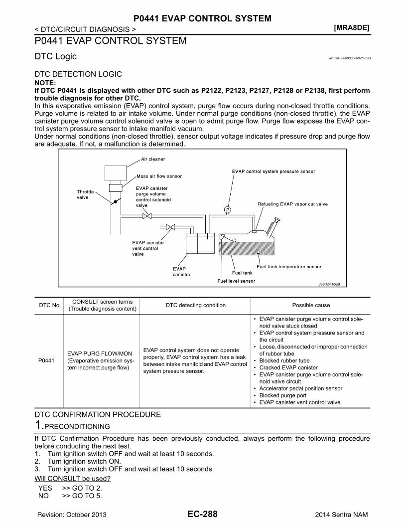
[MRA8DE]P0441 EVAP CONTROL SYSTEM
< DTC/CIRCUIT DIAGNOSIS >P0441 EVAP CONTROL SYSTEMDTC Logic INFOID:0000000009758533
DTC DETECTION LOGICNOTE:If DTC P0441 is displayed with other DTC such as P2122, P2123, P2127, P2128 or P2138, first performtrouble diagnosis for other DTC.In this evaporative emission (EVAP) control system, purge flow occurs during non-closed throttle conditions.Purge volume is related to air intake volume. Under normal purge conditions (non-closed throttle), the EVAPcanister purge volume control solenoid valve is open to admit purge flow. Purge flow exposes the EVAP con-trol system pressure sensor to intake manifold vacuum.Under normal conditions (non-closed throttle), sensor output voltage indicates if pressure drop and purge floware adequate. If not, a malfunction is determined.
DTC CONFIRMATION PROCEDURE1.PRECONDITIONING
If DTC Confirmation Procedure has been previously conducted, always perform the following procedurebefore conducting the next test. 1. Turn ignition switch OFF and wait at least 10 seconds.2. Turn ignition switch ON.3. Turn ignition switch OFF and wait at least 10 seconds.Will CONSULT be used?YES >> GO TO 2.NO >> GO TO 5.
JSBIA0416GB
DTC No. CONSULT screen terms(Trouble diagnosis content) DTC detecting condition Possible cause
P0441EVAP PURG FLOW/MON(Evaporative emission sys-tem incorrect purge flow)
EVAP control system does not operate properly, EVAP control system has a leak between intake manifold and EVAP control system pressure sensor.
• EVAP canister purge volume control sole-noid valve stuck closed
• EVAP control system pressure sensor and the circuit
• Loose, disconnected or improper connection of rubber tube
• Blocked rubber tube• Cracked EVAP canister• EVAP canister purge volume control sole-
noid valve circuit• Accelerator pedal position sensor• Blocked purge port• EVAP canister vent control valve
EC-288Revision: October 2013 2014 Sentra NAM
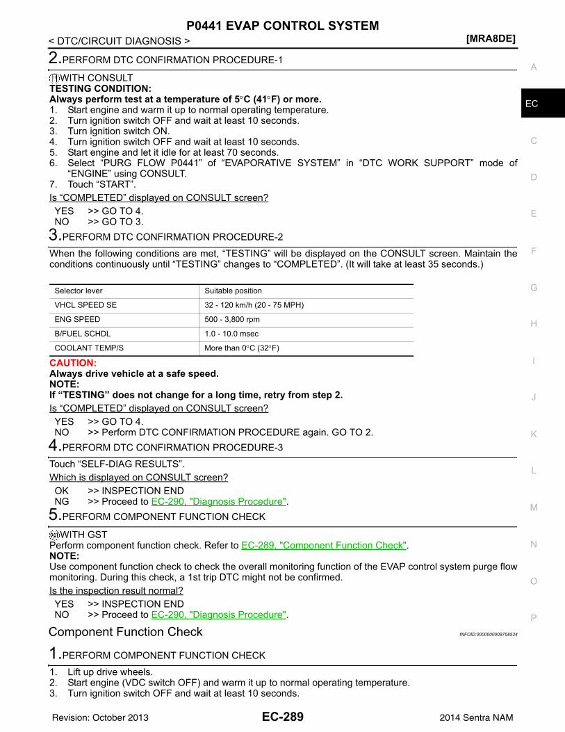
P0441 EVAP CONTROL SYSTEM[MRA8DE]
C
D
E
F
G
H
I
J
K
L
M
A
C
N
P
O
< DTC/CIRCUIT DIAGNOSIS >
E
2.PERFORM DTC CONFIRMATION PROCEDURE-1
WITH CONSULTTESTING CONDITION:Always perform test at a temperature of 5°C (41°F) or more.1. Start engine and warm it up to normal operating temperature.2. Turn ignition switch OFF and wait at least 10 seconds.3. Turn ignition switch ON.4. Turn ignition switch OFF and wait at least 10 seconds.5. Start engine and let it idle for at least 70 seconds.6. Select “PURG FLOW P0441” of “EVAPORATIVE SYSTEM” in “DTC WORK SUPPORT” mode of
“ENGINE” using CONSULT.7. Touch “START”.Is “COMPLETED” displayed on CONSULT screen?YES >> GO TO 4.NO >> GO TO 3.
3.PERFORM DTC CONFIRMATION PROCEDURE-2
When the following conditions are met, “TESTING” will be displayed on the CONSULT screen. Maintain theconditions continuously until “TESTING” changes to “COMPLETED”. (It will take at least 35 seconds.)
CAUTION:Always drive vehicle at a safe speed.NOTE:If “TESTING” does not change for a long time, retry from step 2.Is “COMPLETED” displayed on CONSULT screen?YES >> GO TO 4.NO >> Perform DTC CONFIRMATION PROCEDURE again. GO TO 2.
4.PERFORM DTC CONFIRMATION PROCEDURE-3
Touch “SELF-DIAG RESULTS”.Which is displayed on CONSULT screen?OK >> INSPECTION ENDNG >> Proceed to EC-290, "Diagnosis Procedure".
5.PERFORM COMPONENT FUNCTION CHECK
WITH GSTPerform component function check. Refer to EC-289, "Component Function Check".NOTE:Use component function check to check the overall monitoring function of the EVAP control system purge flowmonitoring. During this check, a 1st trip DTC might not be confirmed.Is the inspection result normal?YES >> INSPECTION ENDNO >> Proceed to EC-290, "Diagnosis Procedure".
Component Function Check INFOID:0000000009758534
1.PERFORM COMPONENT FUNCTION CHECK
1. Lift up drive wheels.2. Start engine (VDC switch OFF) and warm it up to normal operating temperature.3. Turn ignition switch OFF and wait at least 10 seconds.
Selector lever Suitable position
VHCL SPEED SE 32 - 120 km/h (20 - 75 MPH)
ENG SPEED 500 - 3,800 rpm
B/FUEL SCHDL 1.0 - 10.0 msec
COOLANT TEMP/S More than 0°C (32°F)
EC-289Revision: October 2013 2014 Sentra NAM
[MRA8DE]P0441 EVAP CONTROL SYSTEM
< DTC/CIRCUIT DIAGNOSIS >4. Start engine and wait at least 70 seconds.5. Set voltmeter probes to ECM harness connector terminals as per the following.
*1: Except for California*2: For California
6. Check EVAP control system pressure sensor value at idle speed and note it.7. Establish and maintain the following conditions for at least 1 minute.
8. Verify that EVAP control system pressure sensor value stays 0.1 V less than the value at idle speed (mea-sured at step 6) for at least 1 second.
Is the inspection result normal?YES >> INSPECTION ENDNO >> Proceed to EC-290, "Diagnosis Procedure".
Diagnosis Procedure INFOID:0000000009758535
1.CHECK EVAP CANISTER
1. Turn ignition switch OFF.2. Check EVAP canister for cracks.Is the inspection result normal?YES-1 >> With CONSULT: GO TO 2.YES-2 >> Without CONSULT: GO TO 3.NO >> Replace EVAP canister. Refer to FL-15, "Removal and Installation".
2.CHECK PURGE FLOW
WITH CONSULT1. Disconnect vacuum hose connected to EVAP canister purge volume control solenoid valve at EVAP ser-
vice port.2. Start engine and let it idle.3. Select “PURG VOL CONT/V” in “ACTIVE TEST” mode of “ENGINE” using CONSULT.4. Touch “Qd” and “Qu” on CONSULT screen to adjust “PURG VOL CONT/V” opening and check vacuum
existence.
Is the inspection result normal?YES >> GO TO 7.NO >> GO TO 4.
3.CHECK PURGE FLOW
WITHOUT CONSULT1. Start engine and warm it up to normal operating temperature.2. Stop engine.
ECM
Connector+ –
Terminal
E16 114 124
Air conditioner switch ON
Headlamp switch ON
Rear window defogger switch ON
Engine speed Approx. 3,000 rpm
Gear position Any position other than P, N or R
PURG VOL CONT/V Vacuum
100% Existed
0% Not existed
EC-290Revision: October 2013 2014 Sentra NAM
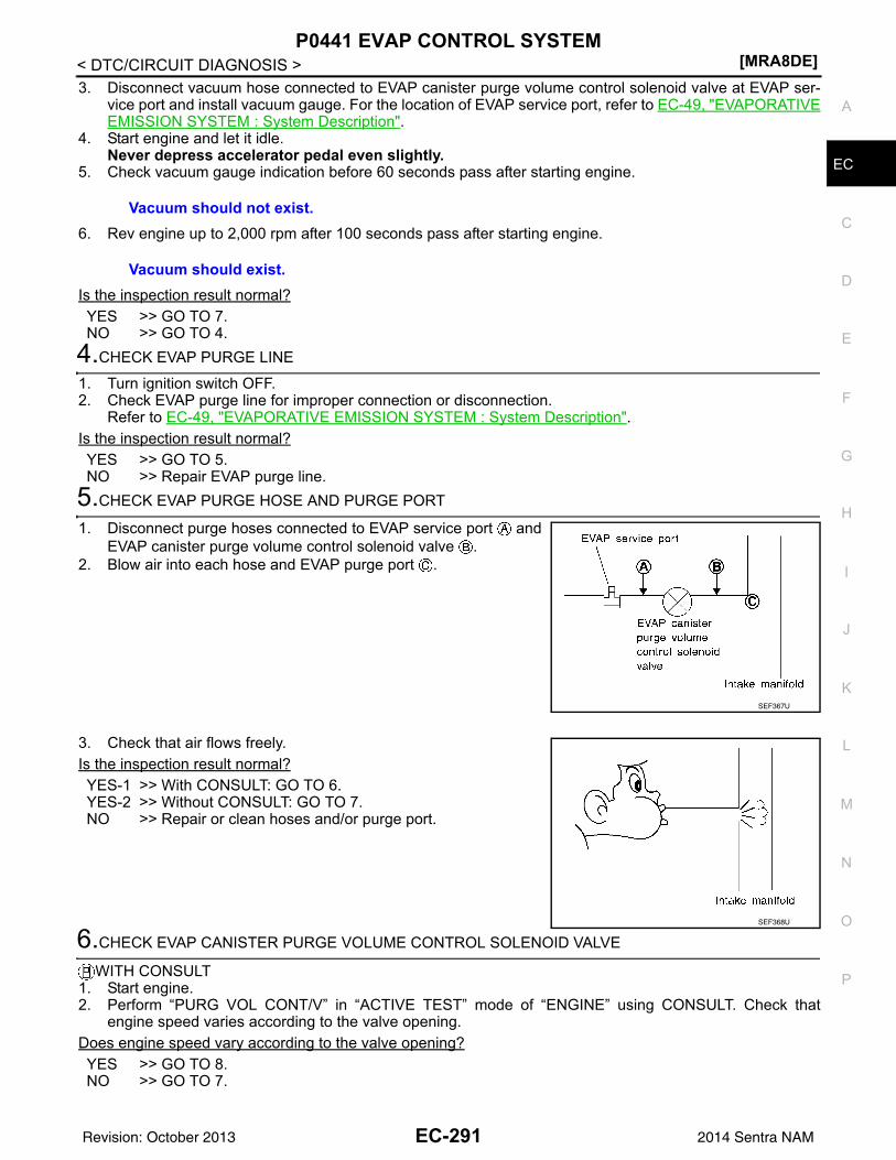
P0441 EVAP CONTROL SYSTEM[MRA8DE]
C
D
E
F
G
H
I
J
K
L
M
A
C
N
P
O
< DTC/CIRCUIT DIAGNOSIS >
E
3. Disconnect vacuum hose connected to EVAP canister purge volume control solenoid valve at EVAP ser-vice port and install vacuum gauge. For the location of EVAP service port, refer to EC-49, "EVAPORATIVEEMISSION SYSTEM : System Description".
4. Start engine and let it idle.Never depress accelerator pedal even slightly.
5. Check vacuum gauge indication before 60 seconds pass after starting engine.
6. Rev engine up to 2,000 rpm after 100 seconds pass after starting engine.
Is the inspection result normal?YES >> GO TO 7.NO >> GO TO 4.
4.CHECK EVAP PURGE LINE
1. Turn ignition switch OFF.2. Check EVAP purge line for improper connection or disconnection.
Refer to EC-49, "EVAPORATIVE EMISSION SYSTEM : System Description".Is the inspection result normal?YES >> GO TO 5.NO >> Repair EVAP purge line.
5.CHECK EVAP PURGE HOSE AND PURGE PORT
1. Disconnect purge hoses connected to EVAP service port andEVAP canister purge volume control solenoid valve .
2. Blow air into each hose and EVAP purge port .
3. Check that air flows freely.Is the inspection result normal?YES-1 >> With CONSULT: GO TO 6.YES-2 >> Without CONSULT: GO TO 7.NO >> Repair or clean hoses and/or purge port.
6.CHECK EVAP CANISTER PURGE VOLUME CONTROL SOLENOID VALVE
WITH CONSULT1. Start engine.2. Perform “PURG VOL CONT/V” in “ACTIVE TEST” mode of “ENGINE” using CONSULT. Check that
engine speed varies according to the valve opening.Does engine speed vary according to the valve opening?YES >> GO TO 8.NO >> GO TO 7.
Vacuum should not exist.
Vacuum should exist.
SEF367U
SEF368U
EC-291Revision: October 2013 2014 Sentra NAM
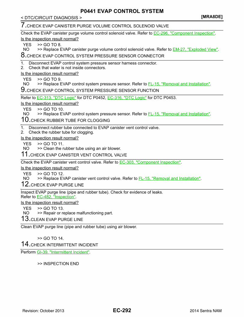
[MRA8DE]P0441 EVAP CONTROL SYSTEM
< DTC/CIRCUIT DIAGNOSIS >
7.CHECK EVAP CANISTER PURGE VOLUME CONTROL SOLENOID VALVE
Check the EVAP canister purge volume control solenoid valve. Refer to EC-296, "Component Inspection".Is the inspection result normal?YES >> GO TO 8.NO >> Replace EVAP canister purge volume control solenoid valve. Refer to EM-27, "Exploded View".
8.CHECK EVAP CONTROL SYSTEM PRESSURE SENSOR CONNECTOR
1. Disconnect EVAP control system pressure sensor harness connector.2. Check that water is not inside connectors.Is the inspection result normal?YES >> GO TO 9.NO >> Replace EVAP control system pressure sensor. Refer to FL-15, "Removal and Installation".
9.CHECK EVAP CONTROL SYSTEM PRESSURE SENSOR FUNCTION
Refer to EC-313, "DTC Logic" for DTC P0452, EC-316, "DTC Logic" for DTC P0453.Is the inspection result normal?YES >> GO TO 10.NO >> Replace EVAP control system pressure sensor. Refer to FL-15, "Removal and Installation".
10.CHECK RUBBER TUBE FOR CLOGGING
1. Disconnect rubber tube connected to EVAP canister vent control valve.2. Check the rubber tube for clogging.Is the inspection result normal?YES >> GO TO 11.NO >> Clean the rubber tube using an air blower.
11.CHECK EVAP CANISTER VENT CONTROL VALVE
Check the EVAP canister vent control valve. Refer to EC-303, "Component Inspection".Is the inspection result normal?YES >> GO TO 12.NO >> Replace EVAP canister vent control valve. Refer to FL-15, "Removal and Installation".
12.CHECK EVAP PURGE LINE
Inspect EVAP purge line (pipe and rubber tube). Check for evidence of leaks.Refer to EC-482, "Inspection".Is the inspection result normal?YES >> GO TO 13.NO >> Repair or replace malfunctioning part.
13.CLEAN EVAP PURGE LINE
Clean EVAP purge line (pipe and rubber tube) using air blower.
>> GO TO 14.14.CHECK INTERMITTENT INCIDENT
Perform GI-39, "Intermittent Incident".
>> INSPECTION END
EC-292Revision: October 2013 2014 Sentra NAM
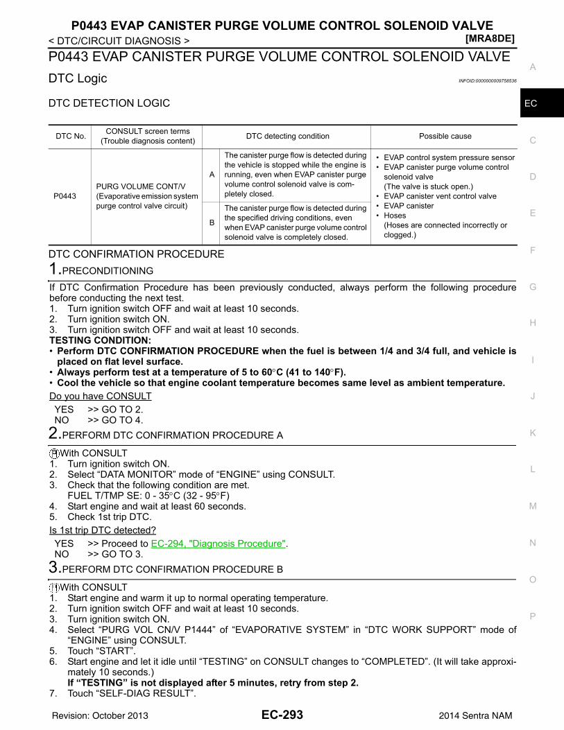
P0443 EVAP CANISTER PURGE VOLUME CONTROL SOLENOID VALVE[MRA8DE]
C
D
E
F
G
H
I
J
K
L
M
A
C
N
P
O
< DTC/CIRCUIT DIAGNOSIS >
E
P0443 EVAP CANISTER PURGE VOLUME CONTROL SOLENOID VALVEDTC Logic INFOID:0000000009758536
DTC DETECTION LOGIC
DTC CONFIRMATION PROCEDURE1.PRECONDITIONING
If DTC Confirmation Procedure has been previously conducted, always perform the following procedurebefore conducting the next test.1. Turn ignition switch OFF and wait at least 10 seconds.2. Turn ignition switch ON.3. Turn ignition switch OFF and wait at least 10 seconds.TESTING CONDITION:• Perform DTC CONFIRMATION PROCEDURE when the fuel is between 1/4 and 3/4 full, and vehicle is
placed on flat level surface.• Always perform test at a temperature of 5 to 60°C (41 to 140°F).• Cool the vehicle so that engine coolant temperature becomes same level as ambient temperature.Do you have CONSULTYES >> GO TO 2.NO >> GO TO 4.
2.PERFORM DTC CONFIRMATION PROCEDURE A
With CONSULT1. Turn ignition switch ON.2. Select “DATA MONITOR” mode of “ENGINE” using CONSULT.3. Check that the following condition are met.
FUEL T/TMP SE: 0 - 35°C (32 - 95°F)4. Start engine and wait at least 60 seconds.5. Check 1st trip DTC.Is 1st trip DTC detected?YES >> Proceed to EC-294, "Diagnosis Procedure".NO >> GO TO 3.
3.PERFORM DTC CONFIRMATION PROCEDURE B
With CONSULT1. Start engine and warm it up to normal operating temperature.2. Turn ignition switch OFF and wait at least 10 seconds.3. Turn ignition switch ON.4. Select “PURG VOL CN/V P1444” of “EVAPORATIVE SYSTEM” in “DTC WORK SUPPORT” mode of
“ENGINE” using CONSULT.5. Touch “START”.6. Start engine and let it idle until “TESTING” on CONSULT changes to “COMPLETED”. (It will take approxi-
mately 10 seconds.)If “TESTING” is not displayed after 5 minutes, retry from step 2.
7. Touch “SELF-DIAG RESULT”.
DTC No. CONSULT screen terms(Trouble diagnosis content) DTC detecting condition Possible cause
P0443PURG VOLUME CONT/V(Evaporative emission system purge control valve circuit)
A
The canister purge flow is detected during the vehicle is stopped while the engine is running, even when EVAP canister purge volume control solenoid valve is com-pletely closed.
• EVAP control system pressure sensor• EVAP canister purge volume control
solenoid valve(The valve is stuck open.)
• EVAP canister vent control valve• EVAP canister• Hoses
(Hoses are connected incorrectly or clogged.)
B
The canister purge flow is detected during the specified driving conditions, even when EVAP canister purge volume control solenoid valve is completely closed.
EC-293Revision: October 2013 2014 Sentra NAM
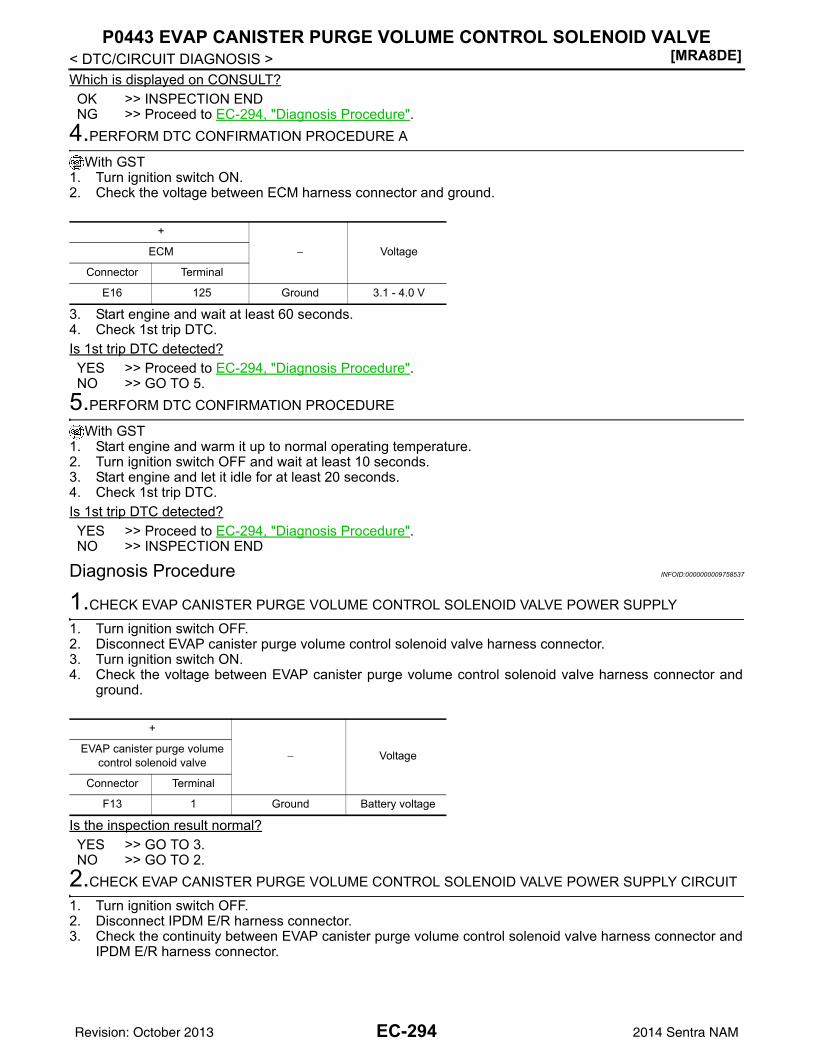
[MRA8DE]P0443 EVAP CANISTER PURGE VOLUME CONTROL SOLENOID VALVE
< DTC/CIRCUIT DIAGNOSIS >Which is displayed on CONSULT?OK >> INSPECTION ENDNG >> Proceed to EC-294, "Diagnosis Procedure".
4.PERFORM DTC CONFIRMATION PROCEDURE A
With GST1. Turn ignition switch ON.2. Check the voltage between ECM harness connector and ground.
3. Start engine and wait at least 60 seconds.4. Check 1st trip DTC.Is 1st trip DTC detected?YES >> Proceed to EC-294, "Diagnosis Procedure".NO >> GO TO 5.
5.PERFORM DTC CONFIRMATION PROCEDURE
With GST1. Start engine and warm it up to normal operating temperature.2. Turn ignition switch OFF and wait at least 10 seconds.3. Start engine and let it idle for at least 20 seconds.4. Check 1st trip DTC.Is 1st trip DTC detected?YES >> Proceed to EC-294, "Diagnosis Procedure".NO >> INSPECTION END
Diagnosis Procedure INFOID:0000000009758537
1.CHECK EVAP CANISTER PURGE VOLUME CONTROL SOLENOID VALVE POWER SUPPLY
1. Turn ignition switch OFF.2. Disconnect EVAP canister purge volume control solenoid valve harness connector.3. Turn ignition switch ON.4. Check the voltage between EVAP canister purge volume control solenoid valve harness connector and
ground.
Is the inspection result normal?YES >> GO TO 3.NO >> GO TO 2.
2.CHECK EVAP CANISTER PURGE VOLUME CONTROL SOLENOID VALVE POWER SUPPLY CIRCUIT
1. Turn ignition switch OFF.2. Disconnect IPDM E/R harness connector.3. Check the continuity between EVAP canister purge volume control solenoid valve harness connector and
IPDM E/R harness connector.
+
− VoltageECM
Connector Terminal
E16 125 Ground 3.1 - 4.0 V
+
− VoltageEVAP canister purge volume control solenoid valve
Connector Terminal
F13 1 Ground Battery voltage
EC-294Revision: October 2013 2014 Sentra NAM
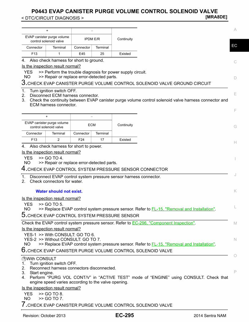
P0443 EVAP CANISTER PURGE VOLUME CONTROL SOLENOID VALVE[MRA8DE]
C
D
E
F
G
H
I
J
K
L
M
A
C
N
P
O
< DTC/CIRCUIT DIAGNOSIS >
E
4. Also check harness for short to ground.Is the inspection result normal?YES >> Perform the trouble diagnosis for power supply circuit.NO >> Repair or replace error-detected parts.
3.CHECK EVAP CANISTER PURGE VOLUME CONTROL SOLENOID VALVE GROUND CIRCUIT
1. Turn ignition switch OFF.2. Disconnect ECM harness connector.3. Check the continuity between EVAP canister purge volume control solenoid valve harness connector and
ECM harness connector.
4. Also check harness for short to power.Is the inspection result normal?YES >> GO TO 4.NO >> Repair or replace error-detected parts.
4.CHECK EVAP CONTROL SYSTEM PRESSURE SENSOR CONNECTOR
1. Disconnect EVAP control system pressure sensor harness connector.2. Check connectors for water.
Is the inspection result normal?YES >> GO TO 5.NO >> Replace EVAP control system pressure sensor. Refer to FL-15, "Removal and Installation".
5.CHECK EVAP CONTROL SYSTEM PRESSURE SENSOR
Check the EVAP control system pressure sensor. Refer to EC-296, "Component Inspection".Is the inspection result normal?YES-1 >> With CONSULT: GO TO 6.YES-2 >> Without CONSULT: GO TO 7.NO >> Replace EVAP control system pressure sensor. Refer to FL-15, "Removal and Installation".
6.CHECK EVAP CANISTER PURGE VOLUME CONTROL SOLENOID VALVE
With CONSULT1. Turn ignition switch OFF.2. Reconnect harness connectors disconnected.3. Start engine.4. Perform “PURG VOL CONT/V” in “ACTIVE TEST” mode of “ENGINE” using CONSULT. Check that
engine speed varies according to the valve opening.Is the inspection result normal?YES >> GO TO 8.NO >> GO TO 7.
7.CHECK EVAP CANISTER PURGE VOLUME CONTROL SOLENOID VALVE
+ −
ContinuityEVAP canister purge volume control solenoid valve IPDM E/R
Connector Terminal Connector Terminal
F13 1 E45 25 Existed
+ −
ContinuityEVAP canister purge volume control solenoid valve ECM
Connector Terminal Connector Terminal
F13 2 F24 17 Existed
Water should not exist.
EC-295Revision: October 2013 2014 Sentra NAM
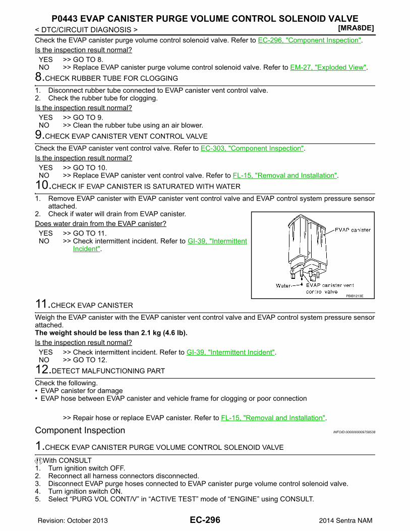
[MRA8DE]P0443 EVAP CANISTER PURGE VOLUME CONTROL SOLENOID VALVE
< DTC/CIRCUIT DIAGNOSIS >Check the EVAP canister purge volume control solenoid valve. Refer to EC-296, "Component Inspection".Is the inspection result normal?YES >> GO TO 8.NO >> Replace EVAP canister purge volume control solenoid valve. Refer to EM-27, "Exploded View".
8.CHECK RUBBER TUBE FOR CLOGGING
1. Disconnect rubber tube connected to EVAP canister vent control valve.2. Check the rubber tube for clogging.Is the inspection result normal?YES >> GO TO 9.NO >> Clean the rubber tube using an air blower.
9.CHECK EVAP CANISTER VENT CONTROL VALVE
Check the EVAP canister vent control valve. Refer to EC-303, "Component Inspection".Is the inspection result normal?YES >> GO TO 10.NO >> Replace EVAP canister vent control valve. Refer to FL-15, "Removal and Installation".
10.CHECK IF EVAP CANISTER IS SATURATED WITH WATER
1. Remove EVAP canister with EVAP canister vent control valve and EVAP control system pressure sensorattached.
2. Check if water will drain from EVAP canister.Does water drain from the EVAP canister?YES >> GO TO 11.NO >> Check intermittent incident. Refer to GI-39, "Intermittent
Incident".
11.CHECK EVAP CANISTER
Weigh the EVAP canister with the EVAP canister vent control valve and EVAP control system pressure sensorattached.The weight should be less than 2.1 kg (4.6 lb).Is the inspection result normal?YES >> Check intermittent incident. Refer to GI-39, "Intermittent Incident".NO >> GO TO 12.
12.DETECT MALFUNCTIONING PART
Check the following.• EVAP canister for damage• EVAP hose between EVAP canister and vehicle frame for clogging or poor connection
>> Repair hose or replace EVAP canister. Refer to FL-15, "Removal and Installation".
Component Inspection INFOID:0000000009758538
1.CHECK EVAP CANISTER PURGE VOLUME CONTROL SOLENOID VALVE
With CONSULT1. Turn ignition switch OFF.2. Reconnect all harness connectors disconnected.3. Disconnect EVAP purge hoses connected to EVAP canister purge volume control solenoid valve.4. Turn ignition switch ON.5. Select “PURG VOL CONT/V” in “ACTIVE TEST” mode of “ENGINE” using CONSULT.
PBIB1213E
EC-296Revision: October 2013 2014 Sentra NAM
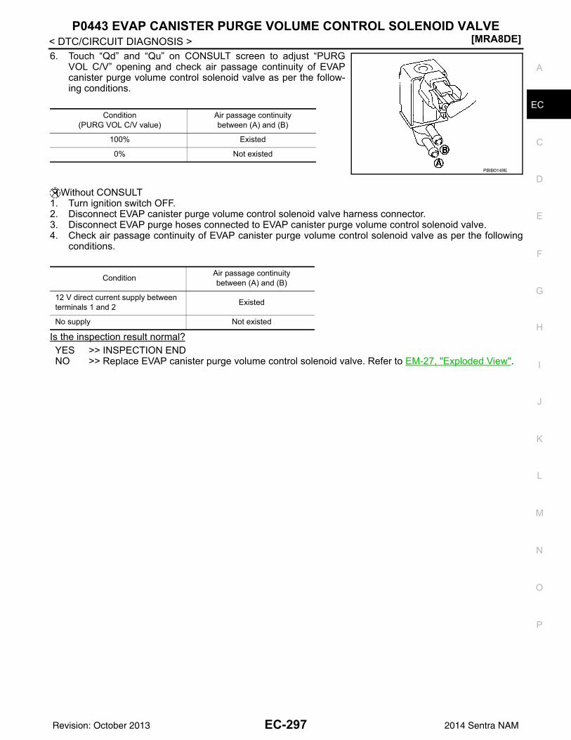
P0443 EVAP CANISTER PURGE VOLUME CONTROL SOLENOID VALVE[MRA8DE]
C
D
E
F
G
H
I
J
K
L
M
A
C
N
P
O
< DTC/CIRCUIT DIAGNOSIS >
E
6. Touch “Qd” and “Qu” on CONSULT screen to adjust “PURGVOL C/V” opening and check air passage continuity of EVAPcanister purge volume control solenoid valve as per the follow-ing conditions.
Without CONSULT1. Turn ignition switch OFF.2. Disconnect EVAP canister purge volume control solenoid valve harness connector.3. Disconnect EVAP purge hoses connected to EVAP canister purge volume control solenoid valve.4. Check air passage continuity of EVAP canister purge volume control solenoid valve as per the following
conditions.
Is the inspection result normal?YES >> INSPECTION ENDNO >> Replace EVAP canister purge volume control solenoid valve. Refer to EM-27, "Exploded View".
Condition(PURG VOL C/V value)
Air passage continuity between (A) and (B)
100% Existed
0% Not existed
PBIB0149E
Condition Air passage continuity between (A) and (B)
12 V direct current supply between terminals 1 and 2 Existed
No supply Not existed
EC-297Revision: October 2013 2014 Sentra NAM
[MRA8DE]
P0444, P0445 EVAP CANISTER PURGE VOLUME CONTROL SOLENOID VALVE
< DTC/CIRCUIT DIAGNOSIS >P0444, P0445 EVAP CANISTER PURGE VOLUME CONTROL SOLENOIDVALVEDTC Logic INFOID:0000000009758539
DTC DETECTION LOGIC
DTC CONFIRMATION PROCEDURE1.CONDITIONING
If DTC Confirmation Procedure has been previously conducted, always perform the following procedurebefore conducting the next test.1. Turn ignition switch OFF and wait at least 10 seconds.2. Turn ignition switch ON.3. Turn ignition switch OFF and wait at least 10 seconds.TESTING CONDITION:Before performing the following procedure, confirm battery voltage is more than 11 V at idle.
>> GO TO 2.2.PERFORM DTC CONFIRMATION PROCEDURE
1. Start engine and let it idle for at least 13 seconds.2. Check 1st trip DTC.Is 1st trip DTC detected?YES >> Proceed to EC-298, "Diagnosis Procedure".NO >> INSPECTION END
Diagnosis Procedure INFOID:0000000009758540
1.CHECK EVAP CANISTER PURGE VOLUME CONTROL SOLENOID VALVE POWER SUPPLY
1. Turn ignition switch OFF.2. Disconnect EVAP canister purge volume control solenoid valve harness connector.3. Turn ignition switch ON.4. Check the voltage between EVAP canister purge volume control solenoid valve harness connector and
ground.
Is the inspection result normal?YES >> GO TO 3.
DTC No. CONSULT screen terms(Trouble diagnosis content) DTC detecting condition Possible cause
P0444PURG VOLUME CONT/V(Evaporative emission system purge control valve circuit open)
An excessively low voltage signal is sent to ECM through the EVAP canister purge vol-ume control solenoid valve.
• Harness or connectors(EVAP canister purge volume control solenoid valve circuit is open or short-ed.)
• EVAP canister purge volume control solenoid valve
P0445
PURG VOLUME CONT/V(Evaporative emission system purge control valve circuit short-ed)
An excessively high voltage signal is sent to ECM through the valve
• Harness or connectors(EVAP canister purge volume control solenoid valve circuit is shorted.)
• EVAP canister purge volume control solenoid valve
+
− VoltageEVAP canister purge vol-ume control solenoid valve
Connector Terminal
F13 1 Ground Battery voltage
EC-298Revision: October 2013 2014 Sentra NAM
P0444, P0445 EVAP CANISTER PURGE VOLUME CONTROL SOLENOID VALVE
[MRA8DE]
C
D
E
F
G
H
I
J
K
L
M
A
C
N
P
O
< DTC/CIRCUIT DIAGNOSIS >
E
NO >> GO TO 2.2.CHECK EVAP CANISTER PURGE VOLUME CONTROL SOLENOID VALVE POWER SUPPLY CIRCUIT
1. Turn ignition switch OFF.2. Disconnect IPDM E/R harness connector.3. Check the continuity between EVAP canister purge volume control solenoid valve harness connector and
IPDM E/R harness connector.
4. Also check harness for short to ground.Is the inspection result normal?YES-1 ( With CONSULT)>>GO TO 4.YES-2 ( Without CONSULT)>>GO TO 5.NO >> Repair or replace error-detected parts.
3.CHECK EVAP CANISTER PURGE VOLUME CONTROL SOLENOID VALVE GROUND CIRCUIT
1. Turn ignition switch OFF.2. Disconnect ECM harness connector.3. Check the continuity between EVAP canister purge volume control solenoid valve harness connector and
ECM harness connector.
4. Also check harness for short to power.Is the inspection result normal?YES-1 ( With CONSULT)>>GO TO 4.YES-2 ( Without CONSULT)>>GO TO 5.NO >> Repair or replace error-detected parts.
4.CHECK EVAP CANISTER PURGE VOLUME CONTROL SOLENOID VALVE OPERATION
With CONSULT1. Reconnect all harness connectors disconnected.2. Start engine.3. Perform “PURG VOL CONT/V” in “ACTIVE TEST” mode of “ENGINE” using CONSULT.4. Check that engine speed varies according to the valve opening.Does engine speed vary according to the valve opening?YES >> Check intermittent incident. Refer to GI-39, "Intermittent Incident".NO >> GO TO 5.
5.CHECK EVAP CANISTER PURGE VOLUME CONTROL SOLENOID VALVE
Check the EVAP canister purge volume control solenoid valve. Refer to EC-300, "Component Inspection(EVAP Canister Purge Volume Control Solenoid Valve)". Is the inspection result normal?YES >> Check intermittent incident. Refer to GI-39, "Intermittent Incident".NO >> Replace EVAP canister purge volume control solenoid valve. Refer to EM-27, "Exploded View".
+ −
ContinuityEVAP canister purge vol-ume control solenoid valve IPDM E/R
Connector Terminal Connector Terminal
F13 1 E45 25 Existed
+ −
ContinuityEVAP canister purge vol-ume control solenoid valve ECM
Connector Terminal Connector Terminal
F13 2 F24 17 Existed
EC-299Revision: October 2013 2014 Sentra NAM
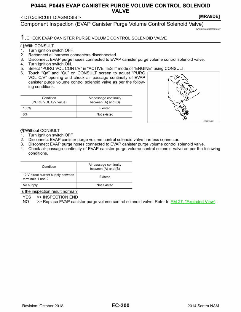
[MRA8DE]
P0444, P0445 EVAP CANISTER PURGE VOLUME CONTROL SOLENOID VALVE
< DTC/CIRCUIT DIAGNOSIS >Component Inspection (EVAP Canister Purge Volume Control Solenoid Valve)
INFOID:0000000009758541
1.CHECK EVAP CANISTER PURGE VOLUME CONTROL SOLENOID VALVE
With CONSULT1. Turn ignition switch OFF.2. Reconnect all harness connectors disconnected.3. Disconnect EVAP purge hoses connected to EVAP canister purge volume control solenoid valve.4. Turn ignition switch ON.5. Select “PURG VOL CONT/V” in “ACTIVE TEST” mode of “ENGINE” using CONSULT.6. Touch “Qd” and “Qu” on CONSULT screen to adjust “PURG
VOL C/V” opening and check air passage continuity of EVAPcanister purge volume control solenoid valve as per the follow-ing conditions.
Without CONSULT1. Turn ignition switch OFF.2. Disconnect EVAP canister purge volume control solenoid valve harness connector.3. Disconnect EVAP purge hoses connected to EVAP canister purge volume control solenoid valve.4. Check air passage continuity of EVAP canister purge volume control solenoid valve as per the following
conditions.
Is the inspection result normal?YES >> INSPECTION ENDNO >> Replace EVAP canister purge volume control solenoid valve. Refer to EM-27, "Exploded View".
Condition(PURG VOL C/V value)
Air passage continuity between (A) and (B)
100% Existed
0% Not existed
PBIB0149E
Condition Air passage continuity between (A) and (B)
12 V direct current supply between terminals 1 and 2 Existed
No supply Not existed
EC-300Revision: October 2013 2014 Sentra NAM
P0447 EVAP CANISTER VENT CONTROL VALVE[MRA8DE]
C
D
E
F
G
H
I
J
K
L
M
A
C
N
P
O
< DTC/CIRCUIT DIAGNOSIS >
E
P0447 EVAP CANISTER VENT CONTROL VALVEDTC Logic INFOID:0000000009758542
DTC DETECTION LOGIC
DTC CONFIRMATION PROCEDURE1.PRECONDITIONING
If DTC Confirmation Procedure has been previously conducted, always perform the following procedurebefore conducting the next test.1. Turn ignition switch OFF and wait at least 10 seconds.2. Turn ignition switch ON.3. Turn ignition switch OFF and wait at least 10 seconds.TESTING CONDITION:Before performing the following procedure, confirm battery voltage is more than 11 V at idle.
>> GO TO 2.2.PERFORM DTC CONFIRMATION PROCEDURE
1. Start engine and wait at least 8 seconds.2. Check 1st trip DTC.Is 1st trip DTC detected?YES >> Proceed to EC-301, "Diagnosis Procedure".NO >> INSPECTION END
Diagnosis Procedure INFOID:0000000009758543
1.INSPECTION START
Do you have CONSULT?Do you have CONSULT?YES >> GO TO 2.NO >> GO TO 3.
2.CHECK EVAP CANISTER VENT CONTROL VALVE CIRCUIT
With CONSULT1. Turn ignition switch OFF and then turn ON.2. Select “VENT CONTROL/V” in “ACTIVE TEST” mode of “ENGINE” using CONSULT.3. Touch “ON/OFF” on CONSULT screen.4. Check for operating sound of the valve.
Is the inspection result normal?YES >> GO TO 7.NO >> GO TO 3.
3.CHECK EVAP CANISTER VENT CONTROL VALVE POWER SUPPLY
1. Turn ignition switch OFF.2. Disconnect EVAP canister vent control valve harness connector.3. Turn ignition switch ON.
DTC No. CONSULT screen terms(Trouble diagnosis content) DTC detecting condition Possible cause
P0447VENT CONTROL VALVE(Evaporative emission system vent control circuit open)
An improper voltage signal is sent to ECM through EVAP canister vent control valve.
• Harness or connectors(EVAP canister vent control valve circuit is open or shorted.)
• EVAP canister vent control valve
Clicking sound should be heard.
EC-301Revision: October 2013 2014 Sentra NAM
[MRA8DE]P0447 EVAP CANISTER VENT CONTROL VALVE
< DTC/CIRCUIT DIAGNOSIS >4. Check the voltage between EVAP canister vent control valve harness connector and ground.
Is the inspection result normal?YES >> GO TO 5.NO >> GO TO 4.
4.CHECK EVAP CANISTER VENT CONTROL VALVE POWER SUPPLY CIRCUIT
1. Turn ignition switch OFF.2. Disconnect IPDM E/R harness connector.3. Check the continuity between EVAP canister vent control valve harness connector and IPDM E/R harness
connector.
4. Also check harness for short to ground.Is the inspection result normal?YES >> Perform the trouble diagnosis for power supply circuit.NO >> Repair or replace error-detected parts.
5.CHECK EVAP CANISTER VENT CONTROL VALVE OUTPUT SIGNAL CIRCUIT
1. Turn ignition switch OFF.2. Disconnect ECM harness connector.3. Check the continuity between EVAP canister vent control valve harness connector and ECM harness con-
nector.
4. Also check harness for short to power.Is the inspection result normal?YES >> GO TO 6.NO >> Repair or replace error-detected parts.
6.CHECK RUBBER TUBE FOR CLOGGING
1. Disconnect rubber tube connected to EVAP canister vent control valve.2. Check the rubber tube for clogging.Is the inspection result normal?YES >> GO TO 7.NO >> Clean the rubber tube using an air blower.
7.CHECK EVAP CANISTER VENT CONTROL VALVE
Check the EVAP canister vent control valve. Refer to EC-303, "Component Inspection".Is the inspection result normal?YES >> Check intermittent incident. Refer to GI-39, "Intermittent Incident".
+
− VoltageEVAP canister vent control valve
Connector Terminal
B17 1 Ground Battery voltage
+ −
ContinuityEVAP canister vent control valve IPDM E/R
Connector Terminal Connector Terminal
B17 1 E45 26 Existed
+ −
ContinuityEVAP canister vent control valve ECM
Connector Terminal Connector Terminal
B17 2 E16 97 Existed
EC-302Revision: October 2013 2014 Sentra NAM
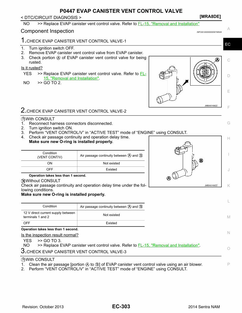
P0447 EVAP CANISTER VENT CONTROL VALVE[MRA8DE]
C
D
E
F
G
H
I
J
K
L
M
A
C
N
P
O
< DTC/CIRCUIT DIAGNOSIS >
E
NO >> Replace EVAP canister vent control valve. Refer to FL-15, "Removal and Installation"
Component Inspection INFOID:0000000009758544
1.CHECK EVAP CANISTER VENT CONTROL VALVE-1
1. Turn ignition switch OFF.2. Remove EVAP canister vent control valve from EVAP canister.3. Check portion of EVAP canister vent control valve for being
rusted.Is it rusted?YES >> Replace EVAP canister vent control valve. Refer to FL-
15, "Removal and Installation".NO >> GO TO 2.
2.CHECK EVAP CANISTER VENT CONTROL VALVE-2
With CONSULT1. Reconnect harness connectors disconnected.2. Turn ignition switch ON.3. Perform “VENT CONTROL/V” in “ACTIVE TEST” mode of “ENGINE” using CONSULT.4. Check air passage continuity and operation delay time.
Make sure new O-ring is installed properly.
Operation takes less than 1 second.Without CONSULT
Check air passage continuity and operation delay time under the fol-lowing conditions.Make sure new O-ring is installed properly.
Operation takes less than 1 second.
Is the inspection result normal?YES >> GO TO 3.NO >> Replace EVAP canister vent control valve. Refer to FL-15, "Removal and Installation".
3.CHECK EVAP CANISTER VENT CONTROL VALVE-3
With CONSULT1. Clean the air passage [portion to ] of EVAP canister vent control valve using an air blower.2. Perform “VENT CONTROL/V” in “ACTIVE TEST” mode of “ENGINE” using CONSULT.
JMBIA0168ZZ
Condition(VENT CONT/V) Air passage continuity between and
ON Not existed
OFF Existed
Condition Air passage continuity between and
12 V direct current supply between terminals 1 and 2 Not existed
OFF Existed
JMBIA0169ZZ
EC-303Revision: October 2013 2014 Sentra NAM

[MRA8DE]P0447 EVAP CANISTER VENT CONTROL VALVE
< DTC/CIRCUIT DIAGNOSIS >3. Check air passage continuity and operation delay time.
Make sure new O-ring is installed properly.
Operation takes less than 1 second.Without CONSULT
1. Clean the air passage [portion to ] of EVAP canister ventcontrol valve using an air blower.
2. Check air passage continuity and operation delay time under the following conditions.Make sure new O-ring is installed properly.
Operation takes less than 1 second.
Is the inspection result normal?YES >> INSPECTION ENDNO >> Replace EVAP canister vent control valve. Refer to FL-15, "Removal and Installation".
Condition(VENT CONT/V) Air passage continuity between and
ON Not existed
OFF Existed
Condition Air passage continuity between and
12 V direct current supply between terminals 1 and 2 Not existed
OFF Existed
JMBIA0169ZZ
EC-304Revision: October 2013 2014 Sentra NAM
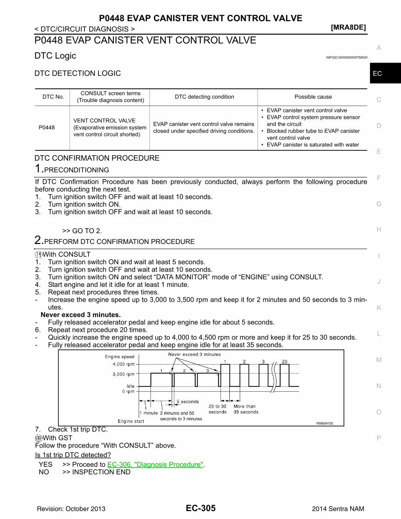
P0448 EVAP CANISTER VENT CONTROL VALVE[MRA8DE]
C
D
E
F
G
H
I
J
K
L
M
A
C
N
P
O
< DTC/CIRCUIT DIAGNOSIS >
E
P0448 EVAP CANISTER VENT CONTROL VALVEDTC Logic INFOID:0000000009758545
DTC DETECTION LOGIC
DTC CONFIRMATION PROCEDURE1.PRECONDITIONING
If DTC Confirmation Procedure has been previously conducted, always perform the following procedurebefore conducting the next test.1. Turn ignition switch OFF and wait at least 10 seconds.2. Turn ignition switch ON.3. Turn ignition switch OFF and wait at least 10 seconds.
>> GO TO 2.2.PERFORM DTC CONFIRMATION PROCEDURE
With CONSULT1. Turn ignition switch ON and wait at least 5 seconds.2. Turn ignition switch OFF and wait at least 10 seconds.3. Turn ignition switch ON and select “DATA MONITOR” mode of “ENGINE” using CONSULT.4. Start engine and let it idle for at least 1 minute. 5. Repeat next procedures three times.- Increase the engine speed up to 3,000 to 3,500 rpm and keep it for 2 minutes and 50 seconds to 3 min-
utes.Never exceed 3 minutes.
- Fully released accelerator pedal and keep engine idle for about 5 seconds.6. Repeat next procedure 20 times.- Quickly increase the engine speed up to 4,000 to 4,500 rpm or more and keep it for 25 to 30 seconds.- Fully released accelerator pedal and keep engine idle for at least 35 seconds.
7. Check 1st trip DTC.With GST
Follow the procedure “With CONSULT” above.Is 1st trip DTC detected?YES >> Proceed to EC-306, "Diagnosis Procedure".NO >> INSPECTION END
DTC No. CONSULT screen terms(Trouble diagnosis content) DTC detecting condition Possible cause
P0448VENT CONTROL VALVE(Evaporative emission system vent control circuit shorted)
EVAP canister vent control valve remains closed under specified driving conditions.
• EVAP canister vent control valve• EVAP control system pressure sensor
and the circuit• Blocked rubber tube to EVAP canister
vent control valve• EVAP canister is saturated with water
PBIB0972E
EC-305Revision: October 2013 2014 Sentra NAM
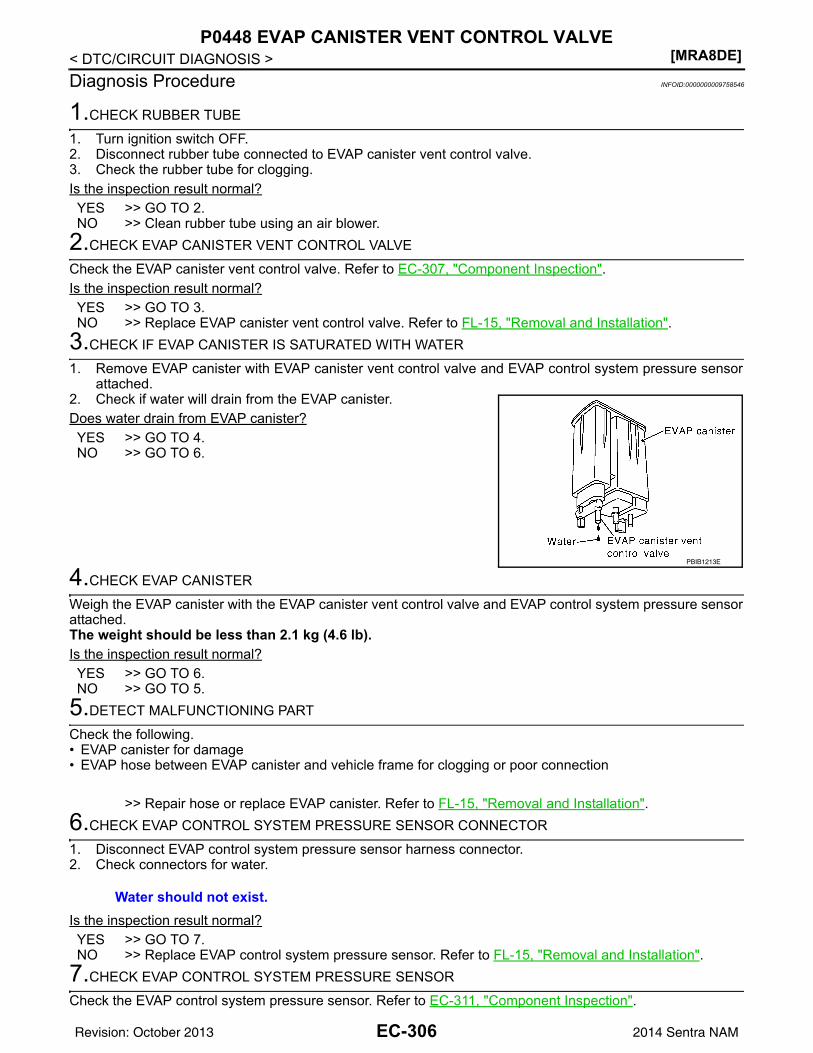
[MRA8DE]P0448 EVAP CANISTER VENT CONTROL VALVE
< DTC/CIRCUIT DIAGNOSIS >Diagnosis Procedure INFOID:0000000009758546
1.CHECK RUBBER TUBE
1. Turn ignition switch OFF.2. Disconnect rubber tube connected to EVAP canister vent control valve.3. Check the rubber tube for clogging.Is the inspection result normal?YES >> GO TO 2.NO >> Clean rubber tube using an air blower.
2.CHECK EVAP CANISTER VENT CONTROL VALVE
Check the EVAP canister vent control valve. Refer to EC-307, "Component Inspection".Is the inspection result normal?YES >> GO TO 3.NO >> Replace EVAP canister vent control valve. Refer to FL-15, "Removal and Installation".
3.CHECK IF EVAP CANISTER IS SATURATED WITH WATER
1. Remove EVAP canister with EVAP canister vent control valve and EVAP control system pressure sensorattached.
2. Check if water will drain from the EVAP canister.Does water drain from EVAP canister?YES >> GO TO 4.NO >> GO TO 6.
4.CHECK EVAP CANISTER
Weigh the EVAP canister with the EVAP canister vent control valve and EVAP control system pressure sensorattached.The weight should be less than 2.1 kg (4.6 lb).Is the inspection result normal?YES >> GO TO 6.NO >> GO TO 5.
5.DETECT MALFUNCTIONING PART
Check the following.• EVAP canister for damage• EVAP hose between EVAP canister and vehicle frame for clogging or poor connection
>> Repair hose or replace EVAP canister. Refer to FL-15, "Removal and Installation".6.CHECK EVAP CONTROL SYSTEM PRESSURE SENSOR CONNECTOR
1. Disconnect EVAP control system pressure sensor harness connector.2. Check connectors for water.
Is the inspection result normal?YES >> GO TO 7.NO >> Replace EVAP control system pressure sensor. Refer to FL-15, "Removal and Installation".
7.CHECK EVAP CONTROL SYSTEM PRESSURE SENSOR
Check the EVAP control system pressure sensor. Refer to EC-311, "Component Inspection".
PBIB1213E
Water should not exist.
EC-306Revision: October 2013 2014 Sentra NAM
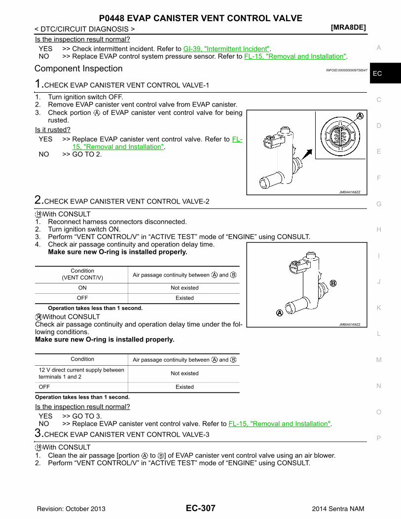
P0448 EVAP CANISTER VENT CONTROL VALVE[MRA8DE]
C
D
E
F
G
H
I
J
K
L
M
A
C
N
P
O
< DTC/CIRCUIT DIAGNOSIS >
E
Is the inspection result normal?YES >> Check intermittent incident. Refer to GI-39, "Intermittent Incident".NO >> Replace EVAP control system pressure sensor. Refer to FL-15, "Removal and Installation".
Component Inspection INFOID:0000000009758547
1.CHECK EVAP CANISTER VENT CONTROL VALVE-1
1. Turn ignition switch OFF.2. Remove EVAP canister vent control valve from EVAP canister.3. Check portion of EVAP canister vent control valve for being
rusted.Is it rusted?YES >> Replace EVAP canister vent control valve. Refer to FL-
15, "Removal and Installation".NO >> GO TO 2.
2.CHECK EVAP CANISTER VENT CONTROL VALVE-2
With CONSULT1. Reconnect harness connectors disconnected.2. Turn ignition switch ON.3. Perform “VENT CONTROL/V” in “ACTIVE TEST” mode of “ENGINE” using CONSULT.4. Check air passage continuity and operation delay time.
Make sure new O-ring is installed properly.
Operation takes less than 1 second.Without CONSULT
Check air passage continuity and operation delay time under the fol-lowing conditions.Make sure new O-ring is installed properly.
Operation takes less than 1 second.
Is the inspection result normal?YES >> GO TO 3.NO >> Replace EVAP canister vent control valve. Refer to FL-15, "Removal and Installation".
3.CHECK EVAP CANISTER VENT CONTROL VALVE-3
With CONSULT1. Clean the air passage [portion to ] of EVAP canister vent control valve using an air blower.2. Perform “VENT CONTROL/V” in “ACTIVE TEST” mode of “ENGINE” using CONSULT.
JMBIA0168ZZ
Condition(VENT CONT/V) Air passage continuity between and
ON Not existed
OFF Existed
Condition Air passage continuity between and
12 V direct current supply between terminals 1 and 2 Not existed
OFF Existed
JMBIA0169ZZ
EC-307Revision: October 2013 2014 Sentra NAM
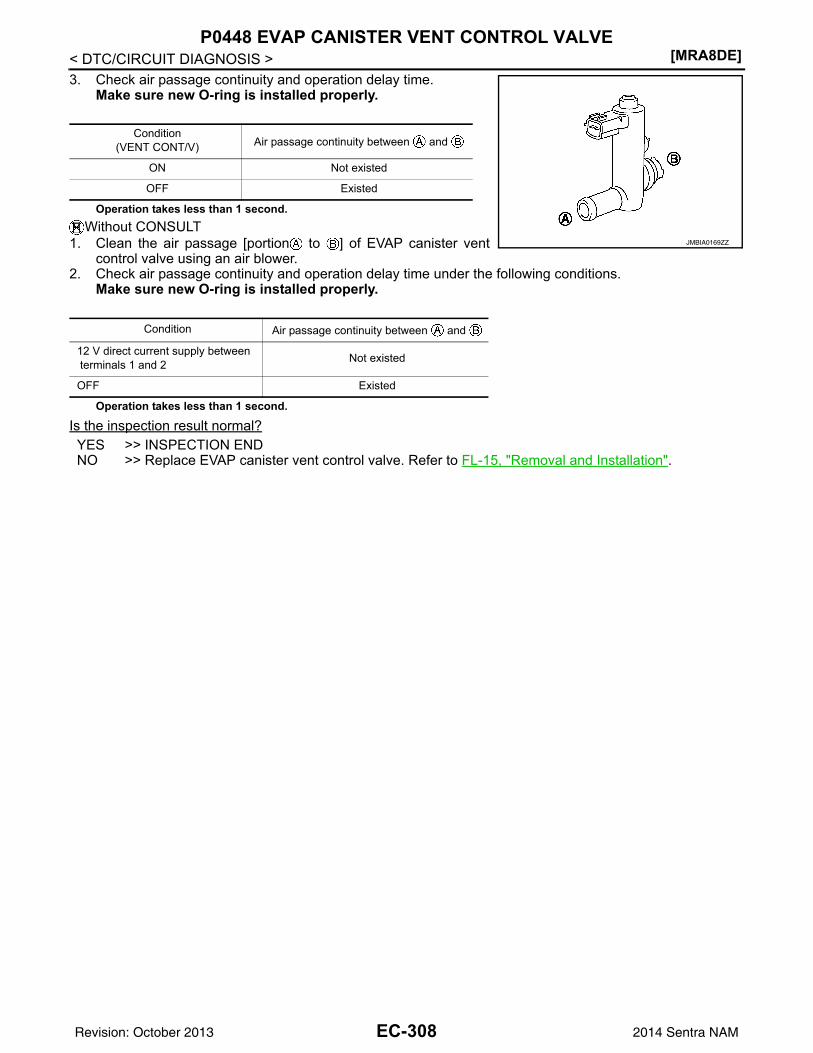
[MRA8DE]P0448 EVAP CANISTER VENT CONTROL VALVE
< DTC/CIRCUIT DIAGNOSIS >3. Check air passage continuity and operation delay time.
Make sure new O-ring is installed properly.
Operation takes less than 1 second.Without CONSULT
1. Clean the air passage [portion to ] of EVAP canister ventcontrol valve using an air blower.
2. Check air passage continuity and operation delay time under the following conditions.Make sure new O-ring is installed properly.
Operation takes less than 1 second.
Is the inspection result normal?YES >> INSPECTION ENDNO >> Replace EVAP canister vent control valve. Refer to FL-15, "Removal and Installation".
Condition(VENT CONT/V) Air passage continuity between and
ON Not existed
OFF Existed
Condition Air passage continuity between and
12 V direct current supply between terminals 1 and 2 Not existed
OFF Existed
JMBIA0169ZZ
EC-308Revision: October 2013 2014 Sentra NAM
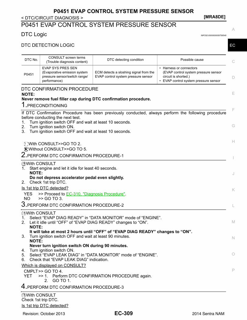
P0451 EVAP CONTROL SYSTEM PRESSURE SENSOR[MRA8DE]
C
D
E
F
G
H
I
J
K
L
M
A
C
N
P
O
< DTC/CIRCUIT DIAGNOSIS >
E
P0451 EVAP CONTROL SYSTEM PRESSURE SENSORDTC Logic INFOID:0000000009758548
DTC DETECTION LOGIC
DTC CONFIRMATION PROCEDURENOTE:Never remove fuel filler cap during DTC confirmation procedure.1.PRECONDITIONING
If DTC Confirmation Procedure has been previously conducted, always perform the following procedurebefore conducting the next test. 1. Turn ignition switch OFF and wait at least 10 seconds.2. Turn ignition switch ON.3. Turn ignition switch OFF and wait at least 10 seconds.
With CONSULT>>GO TO 2.Without CONSULT>>GO TO 5.
2.PERFORM DTC CONFIRMATION PROCEDURE-1
With CONSULT1. Start engine and let it idle for least 40 seconds.
NOTE:Do not depress accelerator pedal even slightly.
2. Check 1st trip DTC.Is 1st trip DTC detected?YES >> Proceed to EC-310, "Diagnosis Procedure".NO >> GO TO 3.
3.PERFORM DTC CONFIRMATION PROCEDURE-2
With CONSULT1. Select “EVAP DIAG READY” in “DATA MONITOR” mode of “ENGINE”.2. Let it idle until “OFF” of “EVAP DIAG READY” changes to “ON”.
NOTE:It will take at most 2 hours until “OFF” of “EVAP DIAG READY” changes to “ON”.
3. Turn ignition switch OFF and wait at least 90 minutes.NOTE:Never turn ignition switch ON during 90 minutes.
4. Turn ignition switch ON.5. Select “EVAP LEAK DIAG” in “DATA MONITOR” mode of “ENGINE”.6. Check that “EVAP LEAK DIAG” indication.Which is displayed on CONSULT?CMPLT>> GO TO 4.YET >> 1. Perform DTC CONFIRMATION PROCEDURE again.
2. GO TO 1.4.PERFORM DTC CONFIRMATION PROCEDURE-3
With CONSULTCheck 1st trip DTC.Is 1st trip DTC detected?
DTC No. CONSULT screen terms(Trouble diagnosis content) DTC detecting condition Possible cause
P0451
EVAP SYS PRES SEN(Evaporative emission system pressure sensor/switch range/performance)
ECM detects a sloshing signal from the EVAP control system pressure sensor
• Harness or connectors(EVAP control system pressure sensor circuit is shorted.)
• EVAP control system pressure sensor
EC-309Revision: October 2013 2014 Sentra NAM
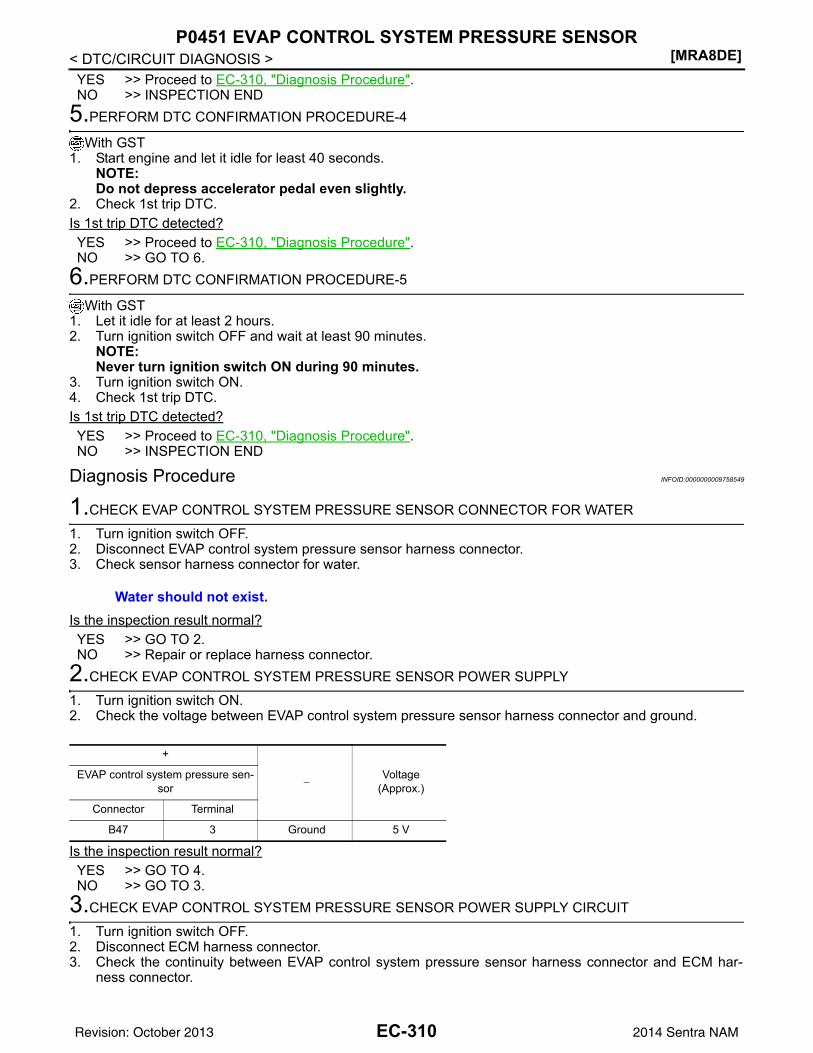
[MRA8DE]P0451 EVAP CONTROL SYSTEM PRESSURE SENSOR
< DTC/CIRCUIT DIAGNOSIS >YES >> Proceed to EC-310, "Diagnosis Procedure".NO >> INSPECTION END
5.PERFORM DTC CONFIRMATION PROCEDURE-4
With GST1. Start engine and let it idle for least 40 seconds.
NOTE:Do not depress accelerator pedal even slightly.
2. Check 1st trip DTC.Is 1st trip DTC detected?YES >> Proceed to EC-310, "Diagnosis Procedure".NO >> GO TO 6.
6.PERFORM DTC CONFIRMATION PROCEDURE-5
With GST1. Let it idle for at least 2 hours.2. Turn ignition switch OFF and wait at least 90 minutes.
NOTE:Never turn ignition switch ON during 90 minutes.
3. Turn ignition switch ON.4. Check 1st trip DTC.Is 1st trip DTC detected?YES >> Proceed to EC-310, "Diagnosis Procedure".NO >> INSPECTION END
Diagnosis Procedure INFOID:0000000009758549
1.CHECK EVAP CONTROL SYSTEM PRESSURE SENSOR CONNECTOR FOR WATER
1. Turn ignition switch OFF.2. Disconnect EVAP control system pressure sensor harness connector.3. Check sensor harness connector for water.
Is the inspection result normal?YES >> GO TO 2.NO >> Repair or replace harness connector.
2.CHECK EVAP CONTROL SYSTEM PRESSURE SENSOR POWER SUPPLY
1. Turn ignition switch ON.2. Check the voltage between EVAP control system pressure sensor harness connector and ground.
Is the inspection result normal?YES >> GO TO 4.NO >> GO TO 3.
3.CHECK EVAP CONTROL SYSTEM PRESSURE SENSOR POWER SUPPLY CIRCUIT
1. Turn ignition switch OFF.2. Disconnect ECM harness connector.3. Check the continuity between EVAP control system pressure sensor harness connector and ECM har-
ness connector.
Water should not exist.
+
−Voltage
(Approx.)EVAP control system pressure sen-
sor
Connector Terminal
B47 3 Ground 5 V
EC-310Revision: October 2013 2014 Sentra NAM
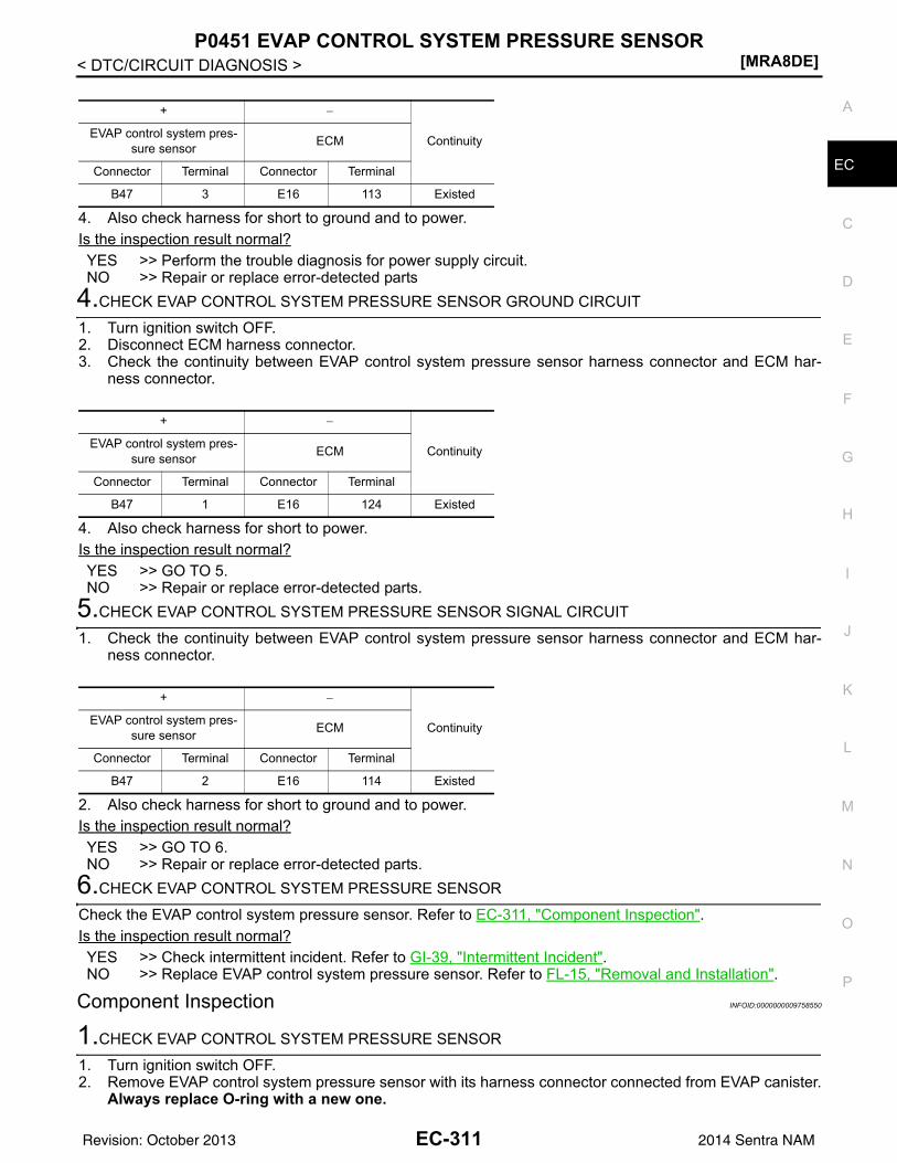
P0451 EVAP CONTROL SYSTEM PRESSURE SENSOR[MRA8DE]
C
D
E
F
G
H
I
J
K
L
M
A
C
N
P
O
< DTC/CIRCUIT DIAGNOSIS >
E
4. Also check harness for short to ground and to power.Is the inspection result normal?YES >> Perform the trouble diagnosis for power supply circuit.NO >> Repair or replace error-detected parts
4.CHECK EVAP CONTROL SYSTEM PRESSURE SENSOR GROUND CIRCUIT
1. Turn ignition switch OFF.2. Disconnect ECM harness connector.3. Check the continuity between EVAP control system pressure sensor harness connector and ECM har-
ness connector.
4. Also check harness for short to power.Is the inspection result normal?YES >> GO TO 5.NO >> Repair or replace error-detected parts.
5.CHECK EVAP CONTROL SYSTEM PRESSURE SENSOR SIGNAL CIRCUIT
1. Check the continuity between EVAP control system pressure sensor harness connector and ECM har-ness connector.
2. Also check harness for short to ground and to power.Is the inspection result normal?YES >> GO TO 6.NO >> Repair or replace error-detected parts.
6.CHECK EVAP CONTROL SYSTEM PRESSURE SENSOR
Check the EVAP control system pressure sensor. Refer to EC-311, "Component Inspection".Is the inspection result normal?YES >> Check intermittent incident. Refer to GI-39, "Intermittent Incident".NO >> Replace EVAP control system pressure sensor. Refer to FL-15, "Removal and Installation".
Component Inspection INFOID:0000000009758550
1.CHECK EVAP CONTROL SYSTEM PRESSURE SENSOR
1. Turn ignition switch OFF.2. Remove EVAP control system pressure sensor with its harness connector connected from EVAP canister.
Always replace O-ring with a new one.
+ −
ContinuityEVAP control system pres-sure sensor ECM
Connector Terminal Connector Terminal
B47 3 E16 113 Existed
+ −
ContinuityEVAP control system pres-sure sensor ECM
Connector Terminal Connector Terminal
B47 1 E16 124 Existed
+ −
ContinuityEVAP control system pres-sure sensor ECM
Connector Terminal Connector Terminal
B47 2 E16 114 Existed
EC-311Revision: October 2013 2014 Sentra NAM
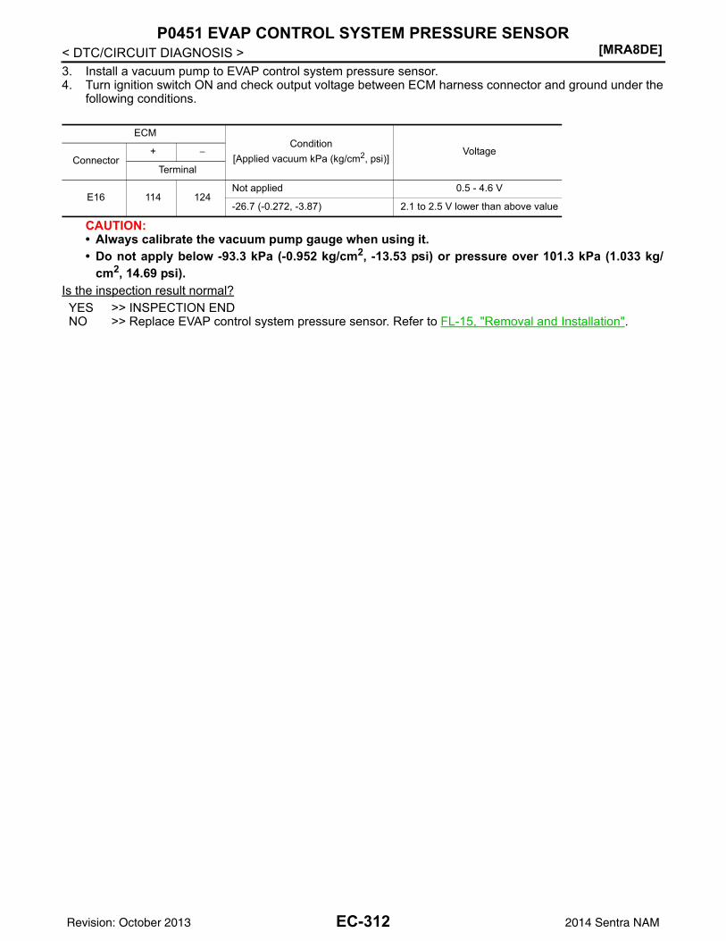
[MRA8DE]P0451 EVAP CONTROL SYSTEM PRESSURE SENSOR
< DTC/CIRCUIT DIAGNOSIS >3. Install a vacuum pump to EVAP control system pressure sensor.4. Turn ignition switch ON and check output voltage between ECM harness connector and ground under the
following conditions.
CAUTION:• Always calibrate the vacuum pump gauge when using it.• Do not apply below -93.3 kPa (-0.952 kg/cm2, -13.53 psi) or pressure over 101.3 kPa (1.033 kg/
cm2, 14.69 psi).Is the inspection result normal?YES >> INSPECTION ENDNO >> Replace EVAP control system pressure sensor. Refer to FL-15, "Removal and Installation".
ECMCondition
[Applied vacuum kPa (kg/cm2, psi)]Voltage
Connector+ −
Terminal
E16 114 124Not applied 0.5 - 4.6 V
-26.7 (-0.272, -3.87) 2.1 to 2.5 V lower than above value
EC-312Revision: October 2013 2014 Sentra NAM
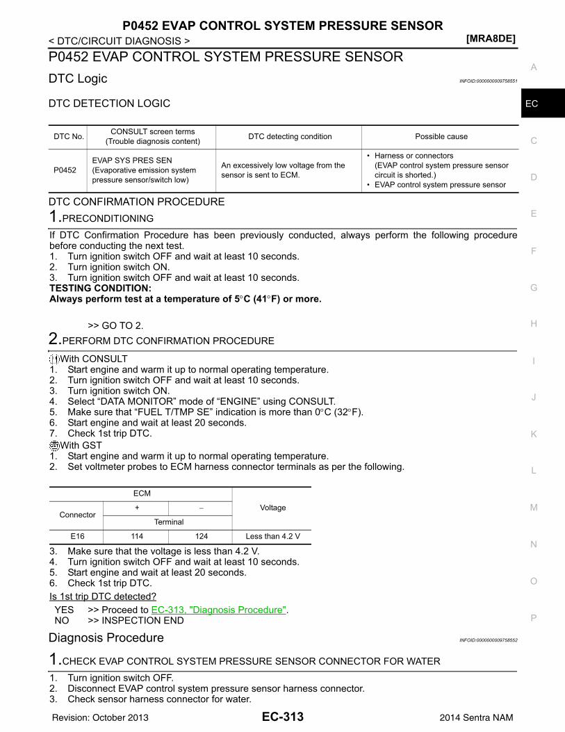
P0452 EVAP CONTROL SYSTEM PRESSURE SENSOR[MRA8DE]
C
D
E
F
G
H
I
J
K
L
M
A
C
N
P
O
< DTC/CIRCUIT DIAGNOSIS >
E
P0452 EVAP CONTROL SYSTEM PRESSURE SENSORDTC Logic INFOID:0000000009758551
DTC DETECTION LOGIC
DTC CONFIRMATION PROCEDURE1.PRECONDITIONING
If DTC Confirmation Procedure has been previously conducted, always perform the following procedurebefore conducting the next test.1. Turn ignition switch OFF and wait at least 10 seconds.2. Turn ignition switch ON.3. Turn ignition switch OFF and wait at least 10 seconds.TESTING CONDITION:Always perform test at a temperature of 5°C (41°F) or more.
>> GO TO 2.2.PERFORM DTC CONFIRMATION PROCEDURE
With CONSULT1. Start engine and warm it up to normal operating temperature.2. Turn ignition switch OFF and wait at least 10 seconds.3. Turn ignition switch ON.4. Select “DATA MONITOR” mode of “ENGINE” using CONSULT.5. Make sure that “FUEL T/TMP SE” indication is more than 0°C (32°F).6. Start engine and wait at least 20 seconds.7. Check 1st trip DTC.
With GST1. Start engine and warm it up to normal operating temperature.2. Set voltmeter probes to ECM harness connector terminals as per the following.
3. Make sure that the voltage is less than 4.2 V.4. Turn ignition switch OFF and wait at least 10 seconds.5. Start engine and wait at least 20 seconds.6. Check 1st trip DTC.Is 1st trip DTC detected?YES >> Proceed to EC-313, "Diagnosis Procedure".NO >> INSPECTION END
Diagnosis Procedure INFOID:0000000009758552
1.CHECK EVAP CONTROL SYSTEM PRESSURE SENSOR CONNECTOR FOR WATER
1. Turn ignition switch OFF.2. Disconnect EVAP control system pressure sensor harness connector.3. Check sensor harness connector for water.
DTC No. CONSULT screen terms(Trouble diagnosis content) DTC detecting condition Possible cause
P0452EVAP SYS PRES SEN(Evaporative emission system pressure sensor/switch low)
An excessively low voltage from the sensor is sent to ECM.
• Harness or connectors(EVAP control system pressure sensor circuit is shorted.)
• EVAP control system pressure sensor
ECM
VoltageConnector
+ −
Terminal
E16 114 124 Less than 4.2 V
EC-313Revision: October 2013 2014 Sentra NAM
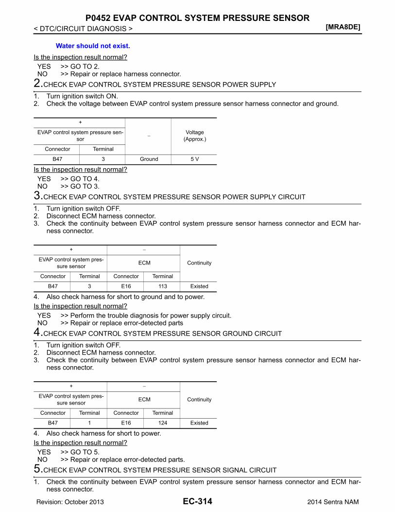
[MRA8DE]P0452 EVAP CONTROL SYSTEM PRESSURE SENSOR
< DTC/CIRCUIT DIAGNOSIS >
Is the inspection result normal?YES >> GO TO 2.NO >> Repair or replace harness connector.
2.CHECK EVAP CONTROL SYSTEM PRESSURE SENSOR POWER SUPPLY
1. Turn ignition switch ON.2. Check the voltage between EVAP control system pressure sensor harness connector and ground.
Is the inspection result normal?YES >> GO TO 4.NO >> GO TO 3.
3.CHECK EVAP CONTROL SYSTEM PRESSURE SENSOR POWER SUPPLY CIRCUIT
1. Turn ignition switch OFF.2. Disconnect ECM harness connector.3. Check the continuity between EVAP control system pressure sensor harness connector and ECM har-
ness connector.
4. Also check harness for short to ground and to power.Is the inspection result normal?YES >> Perform the trouble diagnosis for power supply circuit.NO >> Repair or replace error-detected parts
4.CHECK EVAP CONTROL SYSTEM PRESSURE SENSOR GROUND CIRCUIT
1. Turn ignition switch OFF.2. Disconnect ECM harness connector.3. Check the continuity between EVAP control system pressure sensor harness connector and ECM har-
ness connector.
4. Also check harness for short to power.Is the inspection result normal?YES >> GO TO 5.NO >> Repair or replace error-detected parts.
5.CHECK EVAP CONTROL SYSTEM PRESSURE SENSOR SIGNAL CIRCUIT
1. Check the continuity between EVAP control system pressure sensor harness connector and ECM har-ness connector.
Water should not exist.
+
−Voltage
(Approx.)EVAP control system pressure sen-
sor
Connector Terminal
B47 3 Ground 5 V
+ −
ContinuityEVAP control system pres-sure sensor ECM
Connector Terminal Connector Terminal
B47 3 E16 113 Existed
+ −
ContinuityEVAP control system pres-sure sensor ECM
Connector Terminal Connector Terminal
B47 1 E16 124 Existed
EC-314Revision: October 2013 2014 Sentra NAM
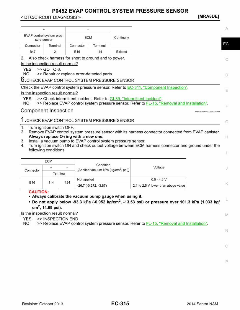
P0452 EVAP CONTROL SYSTEM PRESSURE SENSOR[MRA8DE]
C
D
E
F
G
H
I
J
K
L
M
A
C
N
P
O
< DTC/CIRCUIT DIAGNOSIS >
E
2. Also check harness for short to ground and to power.Is the inspection result normal?YES >> GO TO 6.NO >> Repair or replace error-detected parts.
6.CHECK EVAP CONTROL SYSTEM PRESSURE SENSOR
Check the EVAP control system pressure sensor. Refer to EC-311, "Component Inspection".Is the inspection result normal?YES >> Check intermittent incident. Refer to GI-39, "Intermittent Incident".NO >> Replace EVAP control system pressure sensor. Refer to FL-15, "Removal and Installation".
Component Inspection INFOID:0000000009758553
1.CHECK EVAP CONTROL SYSTEM PRESSURE SENSOR
1. Turn ignition switch OFF.2. Remove EVAP control system pressure sensor with its harness connector connected from EVAP canister.
Always replace O-ring with a new one.3. Install a vacuum pump to EVAP control system pressure sensor.4. Turn ignition switch ON and check output voltage between ECM harness connector and ground under the
following conditions.
CAUTION:• Always calibrate the vacuum pump gauge when using it.• Do not apply below -93.3 kPa (-0.952 kg/cm2, -13.53 psi) or pressure over 101.3 kPa (1.033 kg/
cm2, 14.69 psi).Is the inspection result normal?YES >> INSPECTION ENDNO >> Replace EVAP control system pressure sensor. Refer to FL-15, "Removal and Installation".
+ −
ContinuityEVAP control system pres-sure sensor ECM
Connector Terminal Connector Terminal
B47 2 E16 114 Existed
ECMCondition
[Applied vacuum kPa (kg/cm2, psi)]Voltage
Connector+ −
Terminal
E16 114 124Not applied 0.5 - 4.6 V
-26.7 (-0.272, -3.87) 2.1 to 2.5 V lower than above value
EC-315Revision: October 2013 2014 Sentra NAM
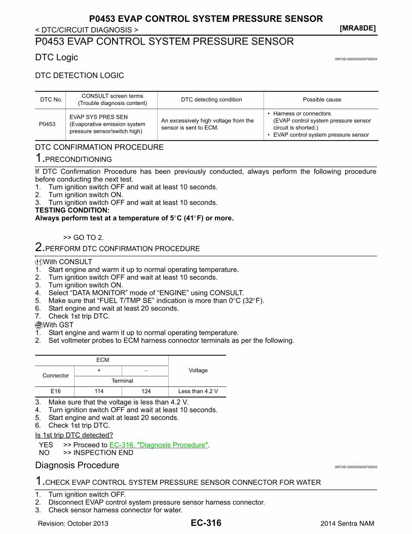
[MRA8DE]P0453 EVAP CONTROL SYSTEM PRESSURE SENSOR
< DTC/CIRCUIT DIAGNOSIS >P0453 EVAP CONTROL SYSTEM PRESSURE SENSORDTC Logic INFOID:0000000009758554
DTC DETECTION LOGIC
DTC CONFIRMATION PROCEDURE1.PRECONDITIONING
If DTC Confirmation Procedure has been previously conducted, always perform the following procedurebefore conducting the next test.1. Turn ignition switch OFF and wait at least 10 seconds.2. Turn ignition switch ON.3. Turn ignition switch OFF and wait at least 10 seconds.TESTING CONDITION:Always perform test at a temperature of 5°C (41°F) or more.
>> GO TO 2.2.PERFORM DTC CONFIRMATION PROCEDURE
With CONSULT1. Start engine and warm it up to normal operating temperature.2. Turn ignition switch OFF and wait at least 10 seconds.3. Turn ignition switch ON.4. Select “DATA MONITOR” mode of “ENGINE” using CONSULT.5. Make sure that “FUEL T/TMP SE” indication is more than 0°C (32°F).6. Start engine and wait at least 20 seconds.7. Check 1st trip DTC.
With GST1. Start engine and warm it up to normal operating temperature.2. Set voltmeter probes to ECM harness connector terminals as per the following.
3. Make sure that the voltage is less than 4.2 V.4. Turn ignition switch OFF and wait at least 10 seconds.5. Start engine and wait at least 20 seconds.6. Check 1st trip DTC.Is 1st trip DTC detected?YES >> Proceed to EC-316, "Diagnosis Procedure".NO >> INSPECTION END
Diagnosis Procedure INFOID:0000000009758555
1.CHECK EVAP CONTROL SYSTEM PRESSURE SENSOR CONNECTOR FOR WATER
1. Turn ignition switch OFF.2. Disconnect EVAP control system pressure sensor harness connector.3. Check sensor harness connector for water.
DTC No. CONSULT screen terms(Trouble diagnosis content) DTC detecting condition Possible cause
P0453EVAP SYS PRES SEN(Evaporative emission system pressure sensor/switch high)
An excessively high voltage from the sensor is sent to ECM.
• Harness or connectors(EVAP control system pressure sensor circuit is shorted.)
• EVAP control system pressure sensor
ECM
VoltageConnector
+ −
Terminal
E16 114 124 Less than 4.2 V
EC-316Revision: October 2013 2014 Sentra NAM
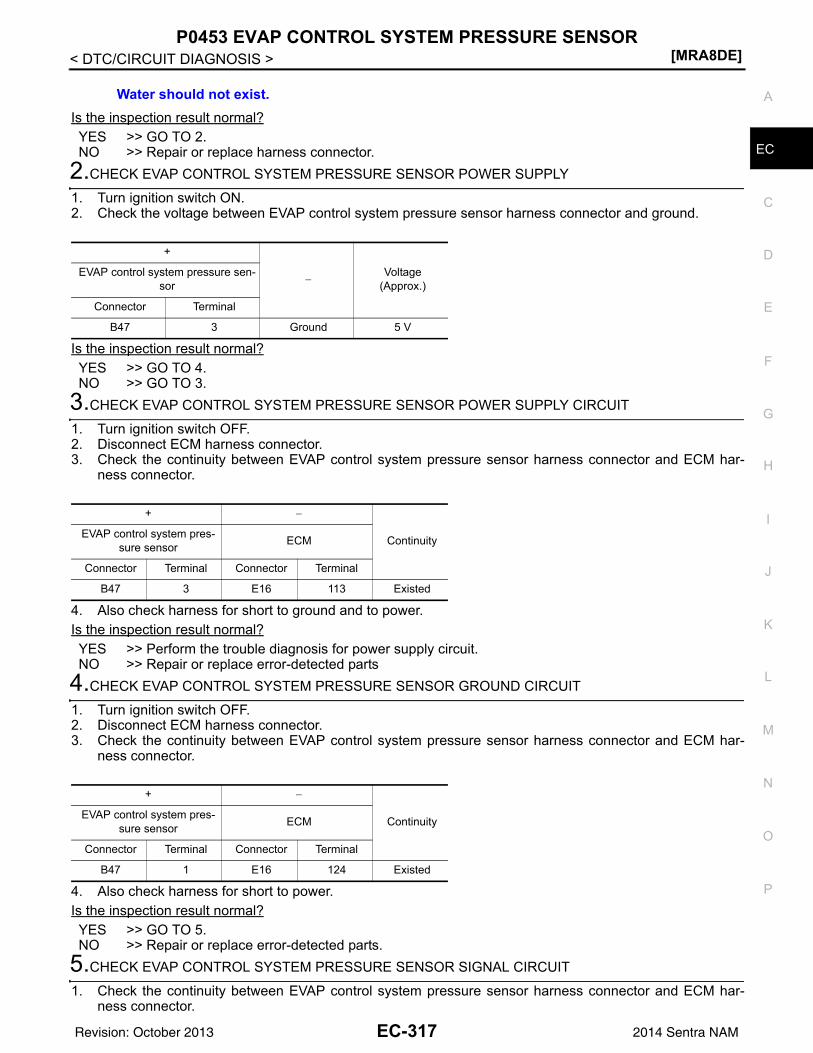
P0453 EVAP CONTROL SYSTEM PRESSURE SENSOR[MRA8DE]
C
D
E
F
G
H
I
J
K
L
M
A
C
N
P
O
< DTC/CIRCUIT DIAGNOSIS >
E
Is the inspection result normal?YES >> GO TO 2.NO >> Repair or replace harness connector.
2.CHECK EVAP CONTROL SYSTEM PRESSURE SENSOR POWER SUPPLY
1. Turn ignition switch ON.2. Check the voltage between EVAP control system pressure sensor harness connector and ground.
Is the inspection result normal?YES >> GO TO 4.NO >> GO TO 3.
3.CHECK EVAP CONTROL SYSTEM PRESSURE SENSOR POWER SUPPLY CIRCUIT
1. Turn ignition switch OFF.2. Disconnect ECM harness connector.3. Check the continuity between EVAP control system pressure sensor harness connector and ECM har-
ness connector.
4. Also check harness for short to ground and to power.Is the inspection result normal?YES >> Perform the trouble diagnosis for power supply circuit.NO >> Repair or replace error-detected parts
4.CHECK EVAP CONTROL SYSTEM PRESSURE SENSOR GROUND CIRCUIT
1. Turn ignition switch OFF.2. Disconnect ECM harness connector.3. Check the continuity between EVAP control system pressure sensor harness connector and ECM har-
ness connector.
4. Also check harness for short to power.Is the inspection result normal?YES >> GO TO 5.NO >> Repair or replace error-detected parts.
5.CHECK EVAP CONTROL SYSTEM PRESSURE SENSOR SIGNAL CIRCUIT
1. Check the continuity between EVAP control system pressure sensor harness connector and ECM har-ness connector.
Water should not exist.
+
−Voltage
(Approx.)EVAP control system pressure sen-
sor
Connector Terminal
B47 3 Ground 5 V
+ −
ContinuityEVAP control system pres-sure sensor ECM
Connector Terminal Connector Terminal
B47 3 E16 113 Existed
+ −
ContinuityEVAP control system pres-sure sensor ECM
Connector Terminal Connector Terminal
B47 1 E16 124 Existed
EC-317Revision: October 2013 2014 Sentra NAM
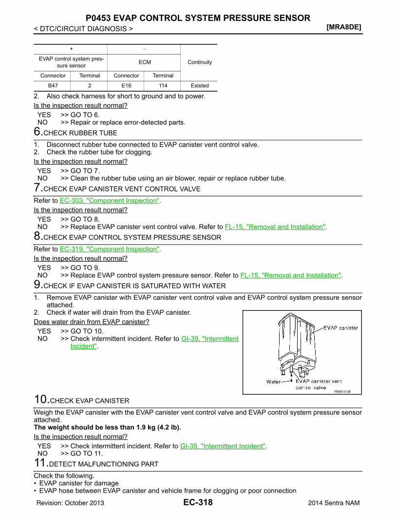
[MRA8DE]P0453 EVAP CONTROL SYSTEM PRESSURE SENSOR
< DTC/CIRCUIT DIAGNOSIS >
2. Also check harness for short to ground and to power.Is the inspection result normal?YES >> GO TO 6.NO >> Repair or replace error-detected parts.
6.CHECK RUBBER TUBE
1. Disconnect rubber tube connected to EVAP canister vent control valve.2. Check the rubber tube for clogging.Is the inspection result normal?YES >> GO TO 7.NO >> Clean the rubber tube using an air blower, repair or replace rubber tube.
7.CHECK EVAP CANISTER VENT CONTROL VALVE
Refer to EC-303, "Component Inspection".Is the inspection result normal?YES >> GO TO 8.NO >> Replace EVAP canister vent control valve. Refer to FL-15, "Removal and Installation".
8.CHECK EVAP CONTROL SYSTEM PRESSURE SENSOR
Refer to EC-319, "Component Inspection".Is the inspection result normal?YES >> GO TO 9.NO >> Replace EVAP control system pressure sensor. Refer to FL-15, "Removal and Installation".
9.CHECK IF EVAP CANISTER IS SATURATED WITH WATER
1. Remove EVAP canister with EVAP canister vent control valve and EVAP control system pressure sensorattached.
2. Check if water will drain from the EVAP canister.Does water drain from EVAP canister?YES >> GO TO 10.NO >> Check intermittent incident. Refer to GI-39, "Intermittent
Incident".
10.CHECK EVAP CANISTER
Weigh the EVAP canister with the EVAP canister vent control valve and EVAP control system pressure sensorattached.The weight should be less than 1.9 kg (4.2 lb).Is the inspection result normal?YES >> Check intermittent incident. Refer to GI-39, "Intermittent Incident".NO >> GO TO 11.
11.DETECT MALFUNCTIONING PART
Check the following.• EVAP canister for damage• EVAP hose between EVAP canister and vehicle frame for clogging or poor connection
+ −
ContinuityEVAP control system pres-sure sensor ECM
Connector Terminal Connector Terminal
B47 2 E16 114 Existed
PBIB1213E
EC-318Revision: October 2013 2014 Sentra NAM
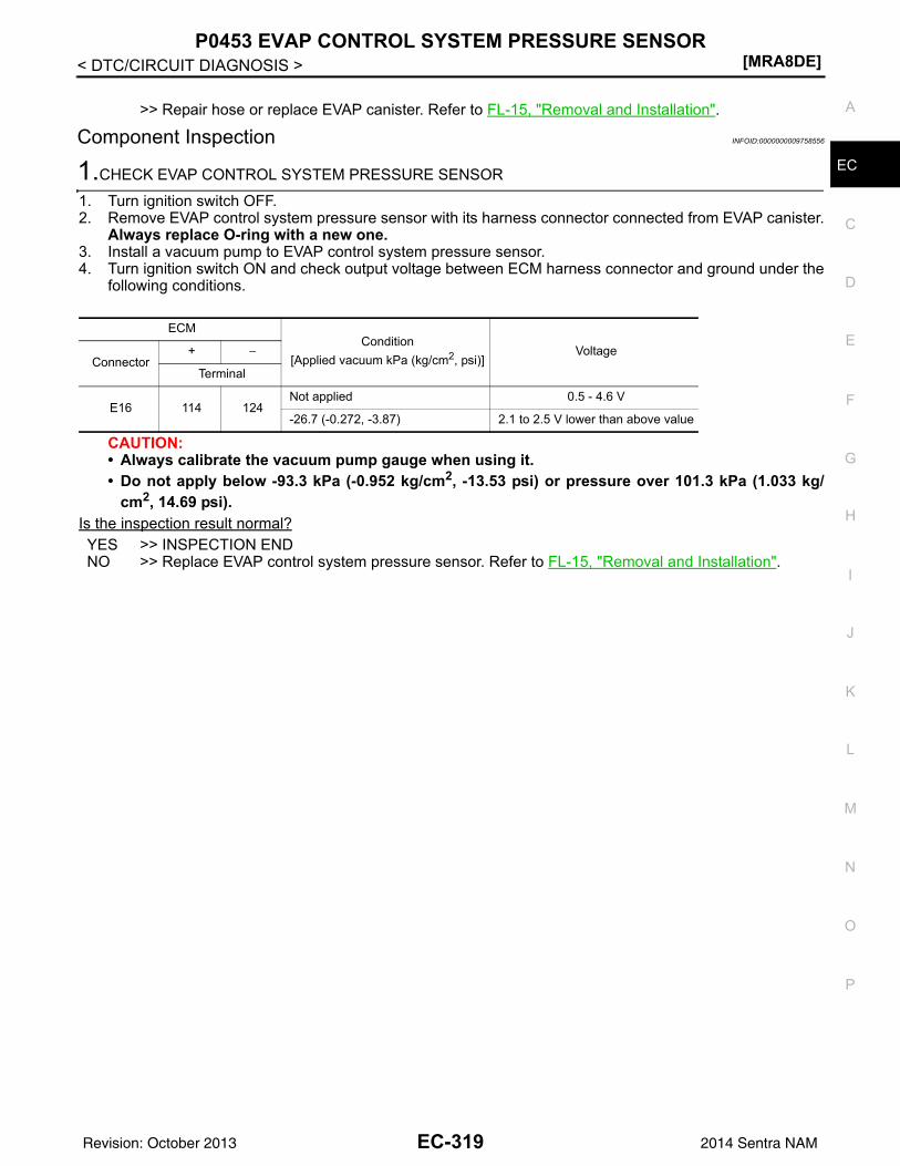
P0453 EVAP CONTROL SYSTEM PRESSURE SENSOR[MRA8DE]
C
D
E
F
G
H
I
J
K
L
M
A
C
N
P
O
< DTC/CIRCUIT DIAGNOSIS >
E
>> Repair hose or replace EVAP canister. Refer to FL-15, "Removal and Installation".
Component Inspection INFOID:0000000009758556
1.CHECK EVAP CONTROL SYSTEM PRESSURE SENSOR
1. Turn ignition switch OFF.2. Remove EVAP control system pressure sensor with its harness connector connected from EVAP canister.
Always replace O-ring with a new one.3. Install a vacuum pump to EVAP control system pressure sensor.4. Turn ignition switch ON and check output voltage between ECM harness connector and ground under the
following conditions.
CAUTION:• Always calibrate the vacuum pump gauge when using it.• Do not apply below -93.3 kPa (-0.952 kg/cm2, -13.53 psi) or pressure over 101.3 kPa (1.033 kg/
cm2, 14.69 psi).Is the inspection result normal?YES >> INSPECTION ENDNO >> Replace EVAP control system pressure sensor. Refer to FL-15, "Removal and Installation".
ECMCondition
[Applied vacuum kPa (kg/cm2, psi)]Voltage
Connector+ −
Terminal
E16 114 124Not applied 0.5 - 4.6 V
-26.7 (-0.272, -3.87) 2.1 to 2.5 V lower than above value
EC-319Revision: October 2013 2014 Sentra NAM
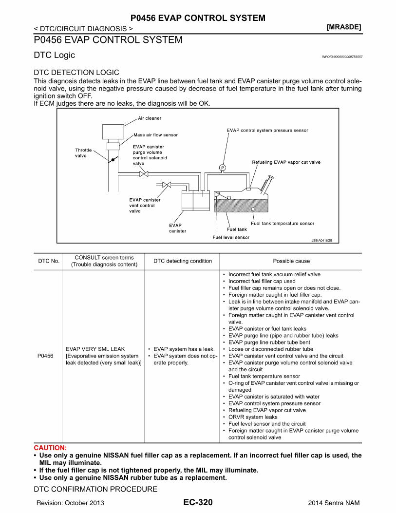
[MRA8DE]P0456 EVAP CONTROL SYSTEM
< DTC/CIRCUIT DIAGNOSIS >P0456 EVAP CONTROL SYSTEMDTC Logic INFOID:0000000009758557
DTC DETECTION LOGICThis diagnosis detects leaks in the EVAP line between fuel tank and EVAP canister purge volume control sole-noid valve, using the negative pressure caused by decrease of fuel temperature in the fuel tank after turningignition switch OFF.If ECM judges there are no leaks, the diagnosis will be OK.
CAUTION:• Use only a genuine NISSAN fuel filler cap as a replacement. If an incorrect fuel filler cap is used, the
MIL may illuminate.• If the fuel filler cap is not tightened properly, the MIL may illuminate.• Use only a genuine NISSAN rubber tube as a replacement.
DTC CONFIRMATION PROCEDURE
JSBIA0416GB
DTC No. CONSULT screen terms(Trouble diagnosis content) DTC detecting condition Possible cause
P0456EVAP VERY SML LEAK[Evaporative emission system leak detected (very small leak)]
• EVAP system has a leak.• EVAP system does not op-
erate properly.
• Incorrect fuel tank vacuum relief valve• Incorrect fuel filler cap used• Fuel filler cap remains open or does not close.• Foreign matter caught in fuel filler cap.• Leak is in line between intake manifold and EVAP can-
ister purge volume control solenoid valve.• Foreign matter caught in EVAP canister vent control
valve.• EVAP canister or fuel tank leaks• EVAP purge line (pipe and rubber tube) leaks• EVAP purge line rubber tube bent• Loose or disconnected rubber tube• EVAP canister vent control valve and the circuit• EVAP canister purge volume control solenoid valve
and the circuit• Fuel tank temperature sensor• O-ring of EVAP canister vent control valve is missing or
damaged• EVAP canister is saturated with water• EVAP control system pressure sensor• Refueling EVAP vapor cut valve• ORVR system leaks• Fuel level sensor and the circuit• Foreign matter caught in EVAP canister purge volume
control solenoid valve
EC-320Revision: October 2013 2014 Sentra NAM
P0456 EVAP CONTROL SYSTEM[MRA8DE]
C
D
E
F
G
H
I
J
K
L
M
A
C
N
P
O
< DTC/CIRCUIT DIAGNOSIS >
E
1.PRECONDITIONING
If DTC Confirmation Procedure has been previously conducted, always perform the following before conduct-ing the next test.1. Turn ignition switch OFF and wait at least 10 seconds.2. Turn ignition switch ON.3. Turn ignition switch OFF and wait at least 10 seconds.Do you have CONSULT?YES >> GO TO 2.NO >> GO TO 4.
2.PERFORM DTC CONFIRMATION PROCEDURE-1
WITH CONSULT1. Turn ignition switch ON and select “EVAP DIAG READY” in “DATA MONITOR” mode of “ENGINE” using
CONSULT.2. Start engine and wait at idle until “OFF” of “EVAP DIAG READY” changes to “ON”.
NOTE:It will take at most 2 hours until “OFF” of “EVAP DIAG READY” changes to “ON”.
3. Turn ignition switch OFF and wait at least 90 minutes.NOTE:Never turn ignition switch ON during 90 minutes.
4. Turn ignition switch ON and select “EVAP LEAK DIAG” in “DATA MONITOR” mode of “ENGINE” usingCONSULT.
5. Check that “EVAP LEAK DIAG” indication.Which is displayed on CONSULT?CMPLT>> GO TO 3.YET >> Perform DTC CONFIRMATION PROCEDURE again. GO TO 1.
3.PERFORM DTC CONFIRMATION PROCEDURE-2
Check 1st trip DTC.Is 1st trip DTC detected?YES >> Proceed toEC-321, "Diagnosis Procedure".NO >> INSPECTION END.
4.PERFORM DTC CONFIRMATION PROCEDURE
WITH GST1. Start engine and wait engine idle for at least 2 hours. 2. Turn ignition switch OFF and wait at least 90 minutes.
NOTE:Never turn ignition switch ON during 90 minutes.
3. Turn ignition switch ON.4. Check 1st trip DTC.Is 1st trip DTC detected?YES >> Proceed to EC-321, "Diagnosis Procedure".NO >> INSPECTION END.
Diagnosis Procedure INFOID:0000000009758558
1.CHECK FUEL FILLER CAP DESIGN
1. Turn ignition switch OFF.
EC-321Revision: October 2013 2014 Sentra NAM
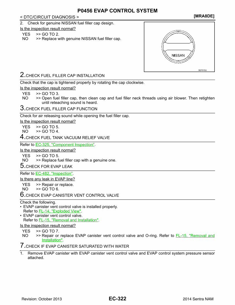
[MRA8DE]P0456 EVAP CONTROL SYSTEM
< DTC/CIRCUIT DIAGNOSIS >2. Check for genuine NISSAN fuel filler cap design.Is the inspection result normal?YES >> GO TO 2.NO >> Replace with genuine NISSAN fuel filler cap.
2.CHECK FUEL FILLER CAP INSTALLATION
Check that the cap is tightened properly by rotating the cap clockwise.Is the inspection result normal?YES >> GO TO 3.NO >> Open fuel filler cap, then clean cap and fuel filler neck threads using air blower. Then retighten
until reteaching sound is heard.3.CHECK FUEL FILLER CAP FUNCTION
Check for air releasing sound while opening the fuel filler cap.Is the inspection result normal?YES >> GO TO 5.NO >> GO TO 4.
4.CHECK FUEL TANK VACUUM RELIEF VALVE
Refer to EC-325, "Component Inspection".Is the inspection result normal?YES >> GO TO 5.NO >> Replace fuel filler cap with a genuine one.
5.CHECK FOR EVAP LEAK
Refer to EC-482, "Inspection".Is there any leak in EVAP line?YES >> Repair or replace.NO >> GO TO 6.
6.CHECK EVAP CANISTER VENT CONTROL VALVE
Check the following.• EVAP canister vent control valve is installed properly.
Refer to FL-14, "Exploded View".• EVAP canister vent control valve.
Refer to FL-15, "Removal and Installation".Is the inspection result normal?YES >> GO TO 7.NO >> Repair or replace EVAP canister vent control valve and O-ring. Refer to FL-15, "Removal and
Installation".7.CHECK IF EVAP CANISTER SATURATED WITH WATER
1. Remove EVAP canister with EVAP canister vent control valve and EVAP control system pressure sensorattached.
SEF915U
EC-322Revision: October 2013 2014 Sentra NAM
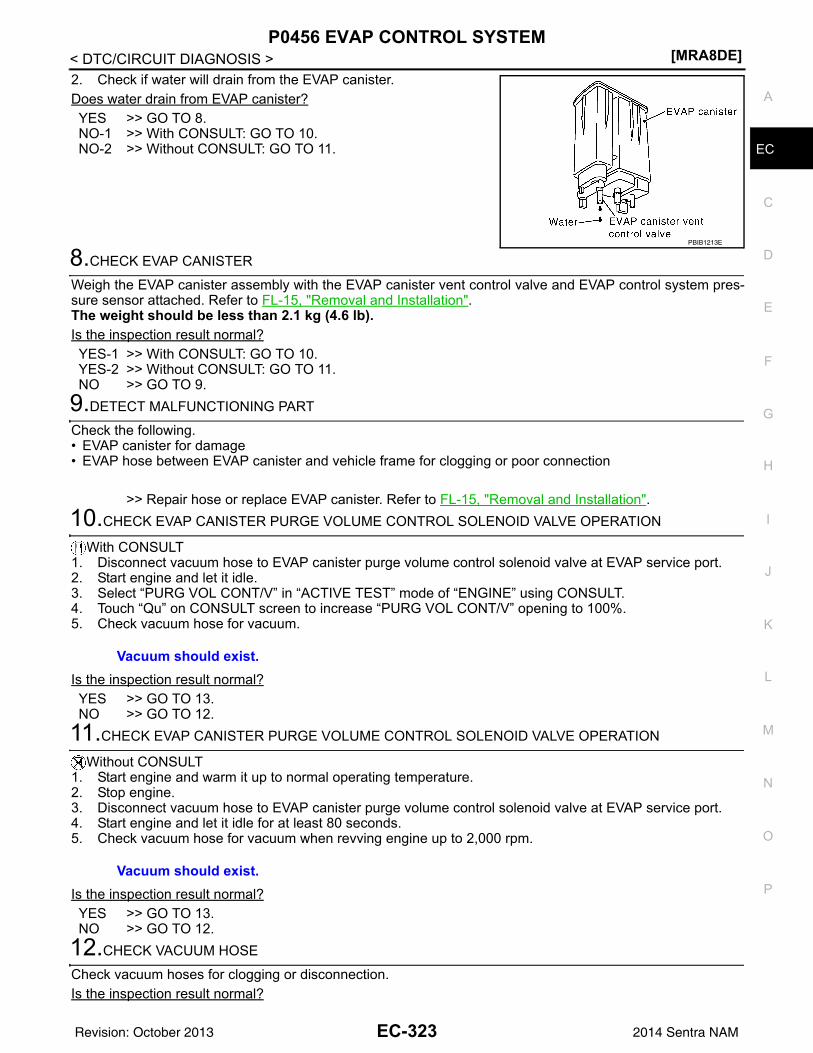
P0456 EVAP CONTROL SYSTEM[MRA8DE]
C
D
E
F
G
H
I
J
K
L
M
A
C
N
P
O
< DTC/CIRCUIT DIAGNOSIS >
E
2. Check if water will drain from the EVAP canister.Does water drain from EVAP canister?YES >> GO TO 8.NO-1 >> With CONSULT: GO TO 10.NO-2 >> Without CONSULT: GO TO 11.
8.CHECK EVAP CANISTER
Weigh the EVAP canister assembly with the EVAP canister vent control valve and EVAP control system pres-sure sensor attached. Refer to FL-15, "Removal and Installation".The weight should be less than 2.1 kg (4.6 lb).Is the inspection result normal?YES-1 >> With CONSULT: GO TO 10.YES-2 >> Without CONSULT: GO TO 11.NO >> GO TO 9.
9.DETECT MALFUNCTIONING PART
Check the following.• EVAP canister for damage• EVAP hose between EVAP canister and vehicle frame for clogging or poor connection
>> Repair hose or replace EVAP canister. Refer to FL-15, "Removal and Installation".10.CHECK EVAP CANISTER PURGE VOLUME CONTROL SOLENOID VALVE OPERATION
With CONSULT1. Disconnect vacuum hose to EVAP canister purge volume control solenoid valve at EVAP service port.2. Start engine and let it idle.3. Select “PURG VOL CONT/V” in “ACTIVE TEST” mode of “ENGINE” using CONSULT.4. Touch “Qu” on CONSULT screen to increase “PURG VOL CONT/V” opening to 100%.5. Check vacuum hose for vacuum.
Is the inspection result normal?YES >> GO TO 13.NO >> GO TO 12.
11.CHECK EVAP CANISTER PURGE VOLUME CONTROL SOLENOID VALVE OPERATION
Without CONSULT1. Start engine and warm it up to normal operating temperature.2. Stop engine.3. Disconnect vacuum hose to EVAP canister purge volume control solenoid valve at EVAP service port.4. Start engine and let it idle for at least 80 seconds.5. Check vacuum hose for vacuum when revving engine up to 2,000 rpm.
Is the inspection result normal?YES >> GO TO 13.NO >> GO TO 12.
12.CHECK VACUUM HOSE
Check vacuum hoses for clogging or disconnection.Is the inspection result normal?
PBIB1213E
Vacuum should exist.
Vacuum should exist.
EC-323Revision: October 2013 2014 Sentra NAM
[MRA8DE]P0456 EVAP CONTROL SYSTEM
< DTC/CIRCUIT DIAGNOSIS >YES >> GO TO 13.NO >> Repair or reconnect the hose.
13.CHECK EVAP CANISTER PURGE VOLUME CONTROL SOLENOID VALVE
Check the EVAP canister purge volume control solenoid valve. Refer to EC-296, "Component Inspection".Is the inspection result normal?YES >> GO TO 14.NO >> Replace EVAP canister purge volume control solenoid valve. Refer to EM-27, "Exploded View".
14.CHECK FUEL TANK TEMPERATURE SENSOR
Check the fuel tank temperature sensor. Refer to EC-257, "Component Inspection".Is the inspection result normal?YES >> GO TO 15.NO >> Replace fuel level sensor unit. Refer to FL-6, "Removal and Installation".
15.CHECK EVAP CONTROL SYSTEM PRESSURE SENSOR
Check the EVAP control system pressure sensor. Refer to FL-15, "Removal and Installation".Is the inspection result normal?YES >> GO TO 16.NO >> Replace EVAP control system pressure sensor. Refer to FL-15, "Removal and Installation".
16.CHECK EVAP PURGE LINE
Check EVAP purge line (pipe, rubber tube, fuel tank and EVAP canister) for cracks or improper connection.Refer to EC-49, "EVAPORATIVE EMISSION SYSTEM : System Description".Is the inspection result normal?YES >> GO TO 17.NO >> Repair or reconnect the hose.
17.CLEAN EVAP PURGE LINE
Clean EVAP purge line (pipe and rubber tube) using air blower.
>> GO TO 18.18.CHECK EVAP/ORVR LINE
Check EVAP/ORVR line between EVAP canister and fuel tank for clogging, kink, looseness and improper con-nection. For location, refer to EC-49, "EVAPORATIVE EMISSION SYSTEM : System Description".Is the inspection result normal?YES >> GO TO 19.NO >> Repair or replace hoses and tubes.
19.CHECK RECIRCULATION LINE
Check recirculation line between fuel filler tube and fuel tank for clogging, kink, cracks, looseness andimproper connection.Is the inspection result normal?YES >> GO TO 20.NO >> Repair or replace hose, tube or fuel filler tube. Refer to FL-10, "Exploded View".
20.CHECK REFUELING EVAP VAPOR CUT VALVE
Check the refueling EVAP vapor cut valve. Refer to FL-13, "Inspection".Is the inspection result normal?YES >> GO TO 21.NO >> Replace refueling EVAP vapor cut valve with fuel tank. Refer to FL-10, "Removal and Installation".
21.CHECK FUEL LEVEL SENSOR
Check the fuel level sensor. Refer to MWI-59, "Component Inspection".Is the inspection result normal?YES >> Check intermittent incident. Refer to GI-39, "Intermittent Incident".
EC-324Revision: October 2013 2014 Sentra NAM
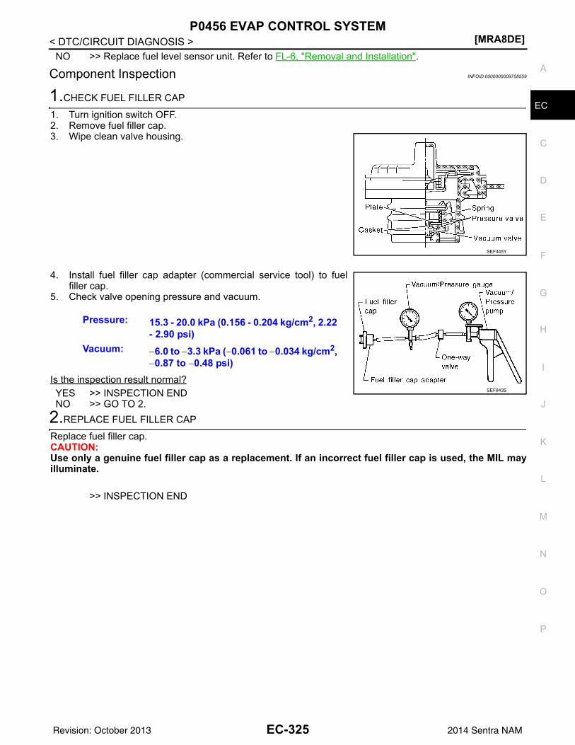
P0456 EVAP CONTROL SYSTEM[MRA8DE]
C
D
E
F
G
H
I
J
K
L
M
A
C
N
P
O
< DTC/CIRCUIT DIAGNOSIS >
E
NO >> Replace fuel level sensor unit. Refer to FL-6, "Removal and Installation".
Component Inspection INFOID:0000000009758559
1.CHECK FUEL FILLER CAP
1. Turn ignition switch OFF.2. Remove fuel filler cap.3. Wipe clean valve housing.
4. Install fuel filler cap adapter (commercial service tool) to fuelfiller cap.
5. Check valve opening pressure and vacuum.
Is the inspection result normal?YES >> INSPECTION ENDNO >> GO TO 2.
2.REPLACE FUEL FILLER CAP
Replace fuel filler cap.CAUTION:Use only a genuine fuel filler cap as a replacement. If an incorrect fuel filler cap is used, the MIL mayilluminate.
>> INSPECTION END
SEF445Y
Pressure: 15.3 - 20.0 kPa (0.156 - 0.204 kg/cm2, 2.22 - 2.90 psi)
Vacuum: −6.0 to −3.3 kPa (−0.061 to −0.034 kg/cm2, −0.87 to −0.48 psi)
SEF943S
EC-325Revision: October 2013 2014 Sentra NAM
[MRA8DE]P0460 FUEL LEVEL SENSOR
< DTC/CIRCUIT DIAGNOSIS >P0460 FUEL LEVEL SENSORDTC Logic INFOID:0000000009758560
DTC DETECTION LOGICNOTE:• If DTC P0460 is displayed with DTC UXXXX, first perform the trouble diagnosis for DTC UXXXX.• If DTC P0460 is displayed with DTC P0607, first perform the trouble diagnosis for DTC P0607. Refer
to EC-350, "DTC Logic".When the vehicle is parked, naturally the fuel level in the fuel tank is stable. It means that output signal of thefuel level sensor does not change. If ECM senses sloshing signal from the sensor, fuel level sensor malfunc-tion is detected.
DTC CONFIRMATION PROCEDURE1.PRECONDITIONING
If DTC Confirmation Procedure has been previously conducted, always perform the following procedurebefore conducting the next test.1. Turn ignition switch OFF and wait at least 10 seconds.2. Turn ignition switch ON.3. Turn ignition switch OFF and wait at least 10 seconds.
>> GO TO 2.2.PERFORM DTC CONFIRMATION PROCEDURE
1. Start engine and wait maximum of 2 consecutive minutes.2. Check 1st trip DTC.Is 1st trip DTC detected?YES >> Proceed to EC-326, "Diagnosis Procedure".NO >> INSPECTION END
Diagnosis Procedure INFOID:0000000009758561
1.CHECK COMBINATION METER FUNCTION
Refer to MWI-17, "CONSULT Function (METER/M&A)".Is the inspection result normal?YES >> Check intermittent incident. Refer to GI-39, "Intermittent Incident".NO >> Refer to MWI-58, "Diagnosis Procedure".
DTC No. CONSULT screen terms(Trouble diagnosis content) DTC detecting condition Possible cause
P0460 FUEL LEV SEN SLOSH(Fuel Level Sensor ″A″ Circuit)
Even though the vehicle is parked, a sig-nal being varied is sent from the fuel level sensor to ECM.
• Harness or connectors(The CAN communication line is open or shorted)
• Harness or connectors(The sensor circuit is open or shorted)
• Combination meter• Fuel level sensor
EC-326Revision: October 2013 2014 Sentra NAM
P0461 FUEL LEVEL SENSOR[MRA8DE]
C
D
E
F
G
H
I
J
K
L
M
A
C
N
P
O
< DTC/CIRCUIT DIAGNOSIS >
E
P0461 FUEL LEVEL SENSORDTC Logic INFOID:0000000009758562
DTC DETECTION LOGICNOTE:• If DTC P0461 is displayed with DTC UXXXX, first perform the trouble diagnosis for DTC UXXXX.• If DTC P0461 is displayed with DTC P0607, first perform the trouble diagnosis for DTC P0607. Refer
to EC-350, "DTC Logic".Driving long distances naturally affect fuel gauge level.This diagnosis detects the fuel gauge malfunction of the gauge not moving even after a long distance hasbeen driven.
DTC CONFIRMATION PROCEDURE
1.PERFORM COMPONENT FUNCTION CHECK
Perform component function check. Refer to EC-327, "Component Function Check".Use component function check to check the overall function of the fuel level sensor function. During thischeck, a 1st trip DTC might not be confirmed.Is the inspection result normal?YES >> INSPECTION ENDNO >> Proceed to EC-328, "Diagnosis Procedure".
Component Function Check INFOID:0000000009758563
1.PRECONDITIONING
WARNING:When performing following procedure, be sure to observe the handling of the fuel. Refer to EC-10,"General Precautions".TESTING CONDITION:Before starting component function check, preparation of draining fuel and refilling fuel is required.Do you have CONSULT?YES >> GO TO 2.NO >> GO TO 3.
2.PERFORM COMPONENT FUNCTION CHECK
With CONSULTNOTE:Start from step 10, if it is possible to confirm that the fuel cannot be drained by 30 (7-7/8 US gal, 6-5/8 Imp gal) in advance.1. Prepare a fuel container and a spare hose.2. Release fuel pressure from fuel line, refer to EC-143, "Work Procedure".3. Remove the fuel feed hose on the fuel level sensor unit.4. Connect a spare fuel hose where the fuel feed hose was removed.5. Turn ignition switch OFF and wait at least 10 seconds then turn ON.6. Select “FUEL LEVEL SE” in “DATA MONITOR” mode of “ENGINE” using CONSULT.7. Check “FUEL LEVEL SE” output voltage and note it.8. Select “FUEL PUMP RELAY” in “ACTIVE TEST” mode of “ENGINE” using CONSULT.
DTC No. CONSULT screen terms(Trouble diagnosis content) DTC detecting condition Possible cause
P0461FUEL LEVEL SENSOR(Fuel level sensor ″A″ circuit range/performance)
The output signal of the fuel level sensor does not change within the specified range even though the vehicle has been driven a long distance.
• Harness or connectors(The CAN communication line is open or shorted)
• Harness or connectors(The sensor circuit is open or shorted)
• Combination meter• Fuel level sensor
EC-327Revision: October 2013 2014 Sentra NAM
[MRA8DE]P0461 FUEL LEVEL SENSOR
< DTC/CIRCUIT DIAGNOSIS >9. Touch “ON” and drain fuel approximately 30 (7-7/8 US gal, 6-5/8 Imp gal) and stop it.10. Check “FUEL LEVEL SE” output voltage and note it.11. Fill fuel into the fuel tank for 30 (7-7/8 US gal, 6-5/8 Imp gal).12. Check “FUEL LEVEL SE” output voltage and note it.13. Confirm whether the voltage changes more than 0.03 V during step 7 to 10 and 10 to 12.Is the inspection result normal?YES >> INSPECTION ENDNO >> Proceed to EC-328, "Diagnosis Procedure".
3.PERFORM COMPONENT FUNCTION CHECK
Without CONSULTNOTE:Start from step 8, if it is possible to confirm that the fuel cannot be drained by 30 (7-7/8 US gal, 6-5/8Imp gal) in advance.1. Prepare a fuel container and a spare hose.2. Release fuel pressure from fuel line. Refer to EC-143, "Work Procedure".3. Remove the fuel feed hose on the fuel level sensor unit.4. Connect a spare fuel hose where the fuel feed hose was removed.5. Turn ignition switch ON.6. Drain fuel by 30 (7-7/8 US gal, 6-5/8 Imp gal) from the fuel tank using proper equipment.7. Confirm that the fuel gauge indication varies.8. Fill fuel into the fuel tank for 30 (7-7/8 US gal, 6-5/8 Imp gal).9. Confirm that the fuel gauge indication varies.Is the inspection result normal?YES >> INSPECTION ENDNO >> Proceed to EC-328, "Diagnosis Procedure".
Diagnosis Procedure INFOID:0000000009758564
1.CHECK COMBINATION METER FUNCTION
Refer to MWI-17, "CONSULT Function (METER/M&A)".Is the inspection result normal?YES >> Check intermittent incident. Refer to GI-39, "Intermittent Incident".NO >> Refer to MWI-58, "Diagnosis Procedure".
EC-328Revision: October 2013 2014 Sentra NAM
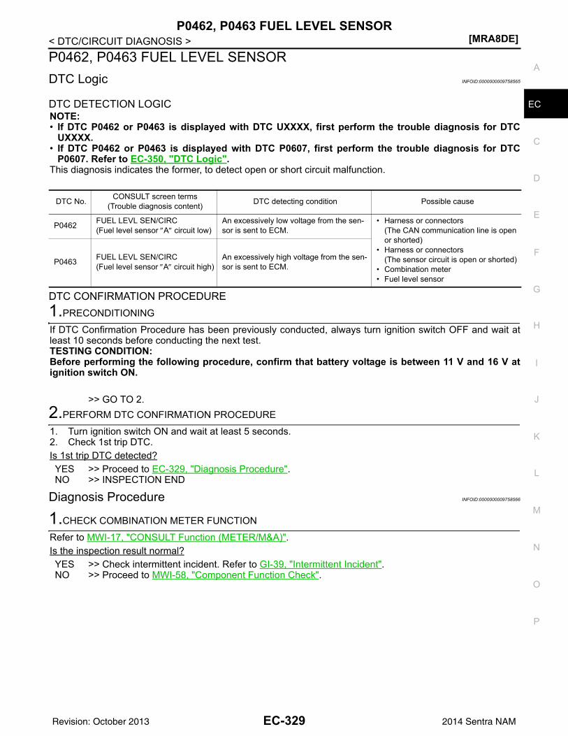
P0462, P0463 FUEL LEVEL SENSOR[MRA8DE]
C
D
E
F
G
H
I
J
K
L
M
A
C
N
P
O
< DTC/CIRCUIT DIAGNOSIS >
E
P0462, P0463 FUEL LEVEL SENSORDTC Logic INFOID:0000000009758565
DTC DETECTION LOGICNOTE:• If DTC P0462 or P0463 is displayed with DTC UXXXX, first perform the trouble diagnosis for DTC
UXXXX.• If DTC P0462 or P0463 is displayed with DTC P0607, first perform the trouble diagnosis for DTC
P0607. Refer to EC-350, "DTC Logic".This diagnosis indicates the former, to detect open or short circuit malfunction.
DTC CONFIRMATION PROCEDURE1.PRECONDITIONING
If DTC Confirmation Procedure has been previously conducted, always turn ignition switch OFF and wait atleast 10 seconds before conducting the next test.TESTING CONDITION:Before performing the following procedure, confirm that battery voltage is between 11 V and 16 V atignition switch ON.
>> GO TO 2.2.PERFORM DTC CONFIRMATION PROCEDURE
1. Turn ignition switch ON and wait at least 5 seconds.2. Check 1st trip DTC.Is 1st trip DTC detected?YES >> Proceed to EC-329, "Diagnosis Procedure".NO >> INSPECTION END
Diagnosis Procedure INFOID:0000000009758566
1.CHECK COMBINATION METER FUNCTION
Refer to MWI-17, "CONSULT Function (METER/M&A)".Is the inspection result normal?YES >> Check intermittent incident. Refer to GI-39, "Intermittent Incident".NO >> Proceed to MWI-58, "Component Function Check".
DTC No. CONSULT screen terms(Trouble diagnosis content) DTC detecting condition Possible cause
P0462 FUEL LEVL SEN/CIRC(Fuel level sensor ″A″ circuit low)
An excessively low voltage from the sen-sor is sent to ECM.
• Harness or connectors(The CAN communication line is open or shorted)
• Harness or connectors(The sensor circuit is open or shorted)
• Combination meter• Fuel level sensor
P0463 FUEL LEVL SEN/CIRC(Fuel level sensor ″A″ circuit high)
An excessively high voltage from the sen-sor is sent to ECM.
EC-329Revision: October 2013 2014 Sentra NAM
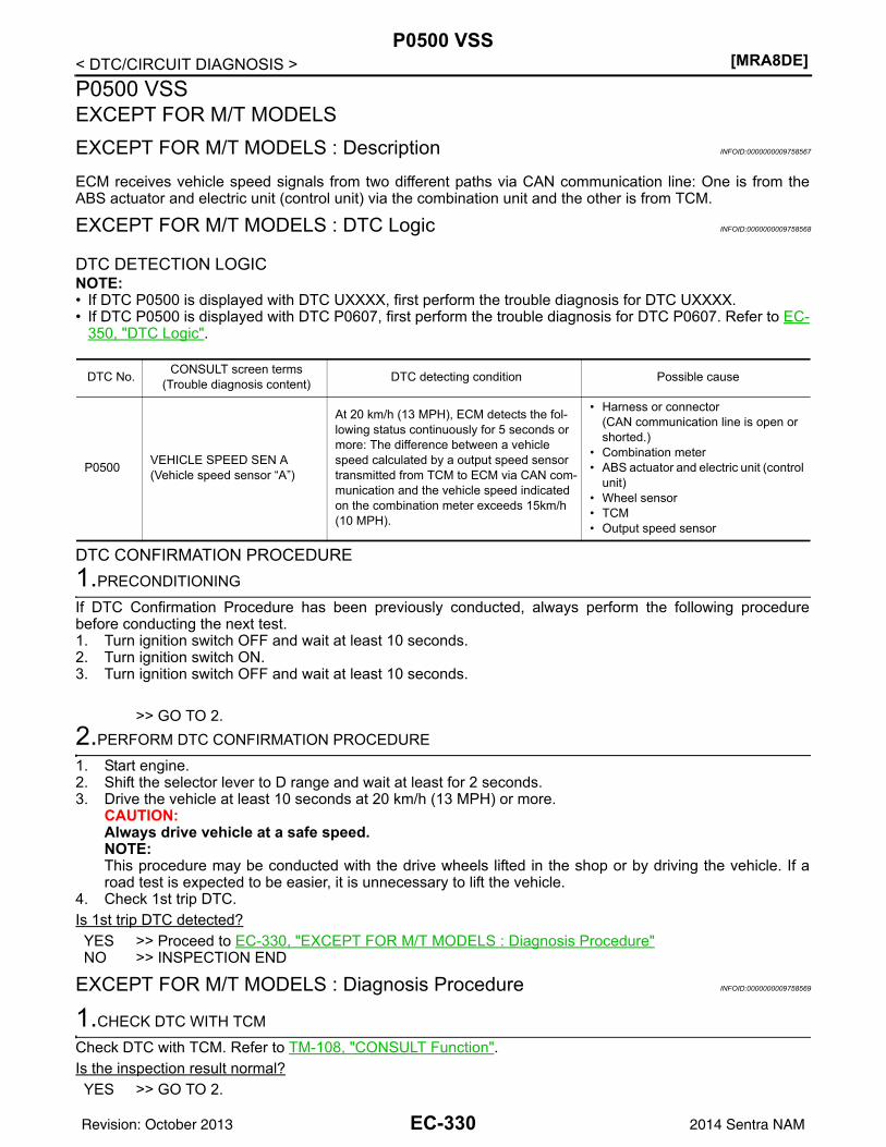
[MRA8DE]P0500 VSS
< DTC/CIRCUIT DIAGNOSIS >P0500 VSSEXCEPT FOR M/T MODELSEXCEPT FOR M/T MODELS : Description INFOID:0000000009758567
ECM receives vehicle speed signals from two different paths via CAN communication line: One is from theABS actuator and electric unit (control unit) via the combination unit and the other is from TCM.
EXCEPT FOR M/T MODELS : DTC Logic INFOID:0000000009758568
DTC DETECTION LOGICNOTE:• If DTC P0500 is displayed with DTC UXXXX, first perform the trouble diagnosis for DTC UXXXX.• If DTC P0500 is displayed with DTC P0607, first perform the trouble diagnosis for DTC P0607. Refer to EC-
350, "DTC Logic".
DTC CONFIRMATION PROCEDURE1.PRECONDITIONING
If DTC Confirmation Procedure has been previously conducted, always perform the following procedurebefore conducting the next test.1. Turn ignition switch OFF and wait at least 10 seconds.2. Turn ignition switch ON.3. Turn ignition switch OFF and wait at least 10 seconds.
>> GO TO 2.2.PERFORM DTC CONFIRMATION PROCEDURE
1. Start engine.2. Shift the selector lever to D range and wait at least for 2 seconds.3. Drive the vehicle at least 10 seconds at 20 km/h (13 MPH) or more.
CAUTION:Always drive vehicle at a safe speed.NOTE:This procedure may be conducted with the drive wheels lifted in the shop or by driving the vehicle. If aroad test is expected to be easier, it is unnecessary to lift the vehicle.
4. Check 1st trip DTC.Is 1st trip DTC detected?YES >> Proceed to EC-330, "EXCEPT FOR M/T MODELS : Diagnosis Procedure"NO >> INSPECTION END
EXCEPT FOR M/T MODELS : Diagnosis Procedure INFOID:0000000009758569
1.CHECK DTC WITH TCM
Check DTC with TCM. Refer to TM-108, "CONSULT Function".Is the inspection result normal?YES >> GO TO 2.
DTC No. CONSULT screen terms(Trouble diagnosis content) DTC detecting condition Possible cause
P0500 VEHICLE SPEED SEN A(Vehicle speed sensor “A”)
At 20 km/h (13 MPH), ECM detects the fol-lowing status continuously for 5 seconds or more: The difference between a vehicle speed calculated by a output speed sensor transmitted from TCM to ECM via CAN com-munication and the vehicle speed indicated on the combination meter exceeds 15km/h (10 MPH).
• Harness or connector(CAN communication line is open or shorted.)
• Combination meter• ABS actuator and electric unit (control
unit)• Wheel sensor• TCM• Output speed sensor
EC-330Revision: October 2013 2014 Sentra NAM

P0500 VSS[MRA8DE]
C
D
E
F
G
H
I
J
K
L
M
A
C
N
P
O
< DTC/CIRCUIT DIAGNOSIS >
E
NO >> Perform trouble shooting relevant to DTC indicated. Refer to TM-126, "DTC Index".2.CHECK DTC WITH ABS ACTUATOR AND ELECTRIC UNIT (CONTROL UNIT)
Check DTC with ABS actuator and electric unit (control unit). Refer to BRC-31, "CONSULT Function (ABS)".Is the inspection result normal?YES >> GO TO 3.NO >> Perform trouble shooting relevant to DTC indicated. Refer to BRC-43, "DTC Index".
3.CHECK DTC WITH COMBINATION METER
Check DTC with combination meter. Refer to MWI-17, "CONSULT Function (METER/M&A)".Is the inspection result normal?YES >> GO TO 4.NO >> Perform trouble shooting relevant to DTC indicated. Refer to MWI-26, "DTC Index".
4.CHECK OUTPUT SPEED SENSOR
Check output speed sensor. Refer to TM-178, "Diagnosis Procedure".Is the inspection result normal?YES >> GO TO 5.NO >> Replace or replace error-detected parts.
5.CHECK WHEEL SENSOR
Check wheel sensor. Refer to BRC-68, "Diagnosis Procedure".Is the inspection result normal?YES >> Check intermittent incident. Refer to GI-39, "Intermittent Incident".NO >> Replace or replace error-detected parts.
M/T MODELSM/T MODELS : Description INFOID:0000000009758570
The vehicle speed signal is sent to the combination meter from the “ABS actuator and electric unit (controlunit)” via the CAN communication line. The combination meter then sends a signal to the ECM via the CANcommunication line.
M/T MODELS : DTC Logic INFOID:0000000009758571
DTC DETECTION LOGICNOTE:• If DTC P0500 is displayed with DTC UXXXX, first perform the trouble diagnosis for DTC UXXXX.• If DTC P0500 is displayed with DTC P0607, first perform the trouble diagnosis for DTC P0607. Refer
to EC-350, "DTC Logic".
DTC CONFIRMATION PROCEDURE1.INSPECTION START
Do you have CONSULT?Do you have CONSULT?
DTC No. CONSULT screen terms(Trouble diagnosis content) DTC detecting condition Possible cause
P0500 VEHICLE SPEED SEN A(Vehicle speed sensor “A”)
The vehicle speed signal sent to ECM is al-most 0 km/h (0 MPH) even when vehicle is being driven.
• Harness or connectors(CAN communication line is open or shorted)
• Harness or connectors(Vehicle speed signal circuit is open or shorted)
• Wheel sensor• Combination meter• ABS actuator and electric unit (control
unit)
EC-331Revision: October 2013 2014 Sentra NAM
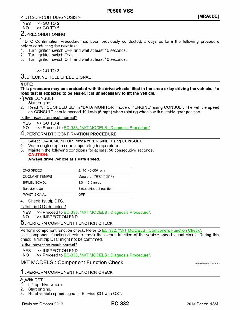
[MRA8DE]P0500 VSS
< DTC/CIRCUIT DIAGNOSIS >YES >> GO TO 2.NO >> GO TO 5.
2.PRECONDITIONING
If DTC Confirmation Procedure has been previously conducted, always perform the following procedurebefore conducting the next test.1. Turn ignition switch OFF and wait at least 10 seconds.2. Turn ignition switch ON.3. Turn ignition switch OFF and wait at least 10 seconds.
>> GO TO 3.3.CHECK VEHICLE SPEED SIGNAL
NOTE:This procedure may be conducted with the drive wheels lifted in the shop or by driving the vehicle. If aroad test is expected to be easier, it is unnecessary to lift the vehicle.
With CONSULT1. Start engine.2. Read “VHCL SPEED SE” in “DATA MONITOR” mode of “ENGINE” using CONSULT. The vehicle speed
on CONSULT should exceed 10 km/h (6 mph) when rotating wheels with suitable gear position.Is the inspection result normal?YES >> GO TO 4.NO >> Proceed to EC-333, "M/T MODELS : Diagnosis Procedure".
4.PERFORM DTC CONFIRMATION PROCEDURE
1. Select “DATA MONITOR” mode of “ENGINE” using CONSULT.2. Warm engine up to normal operating temperature.3. Maintain the following conditions for at least 50 consecutive seconds.
CAUTION:Always drive vehicle at a safe speed.
4. Check 1st trip DTC.Is 1st trip DTC detected?YES >> Proceed to EC-333, "M/T MODELS : Diagnosis Procedure".NO >> INSPECTION END
5.PERFORM COMPONENT FUNCTION CHECK
Perform component function check. Refer to EC-332, "M/T MODELS : Component Function Check".Use component function check to check the overall function of the vehicle speed signal circuit. During thischeck, a 1st trip DTC might not be confirmed.Is the inspection result normal?YES >> INSPECTION ENDNO >> Proceed to EC-333, "M/T MODELS : Diagnosis Procedure".
M/T MODELS : Component Function Check INFOID:0000000009758572
1.PERFORM COMPONENT FUNCTION CHECK
With GST1. Lift up drive wheels.2. Start engine.3. Read vehicle speed signal in Service $01 with GST.
ENG SPEED 2,100 - 6,000 rpm
COOLANT TEMP/S More than 70°C (158°F)
B/FUEL SCHDL 4.0 - 19.0 msec
Selector lever Except Neutral position
PW/ST SIGNAL OFF
EC-332Revision: October 2013 2014 Sentra NAM
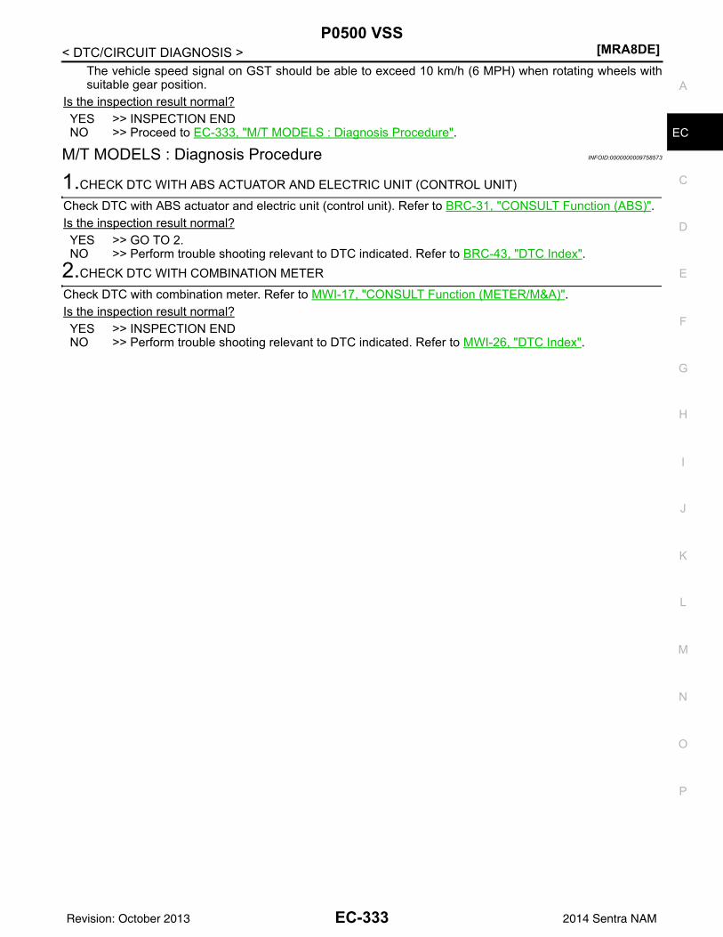
P0500 VSS[MRA8DE]
C
D
E
F
G
H
I
J
K
L
M
A
C
N
P
O
< DTC/CIRCUIT DIAGNOSIS >
E
The vehicle speed signal on GST should be able to exceed 10 km/h (6 MPH) when rotating wheels withsuitable gear position.
Is the inspection result normal?YES >> INSPECTION ENDNO >> Proceed to EC-333, "M/T MODELS : Diagnosis Procedure".
M/T MODELS : Diagnosis Procedure INFOID:0000000009758573
1.CHECK DTC WITH ABS ACTUATOR AND ELECTRIC UNIT (CONTROL UNIT)
Check DTC with ABS actuator and electric unit (control unit). Refer to BRC-31, "CONSULT Function (ABS)".Is the inspection result normal?YES >> GO TO 2.NO >> Perform trouble shooting relevant to DTC indicated. Refer to BRC-43, "DTC Index".
2.CHECK DTC WITH COMBINATION METER
Check DTC with combination meter. Refer to MWI-17, "CONSULT Function (METER/M&A)".Is the inspection result normal?YES >> INSPECTION ENDNO >> Perform trouble shooting relevant to DTC indicated. Refer to MWI-26, "DTC Index".
EC-333Revision: October 2013 2014 Sentra NAM
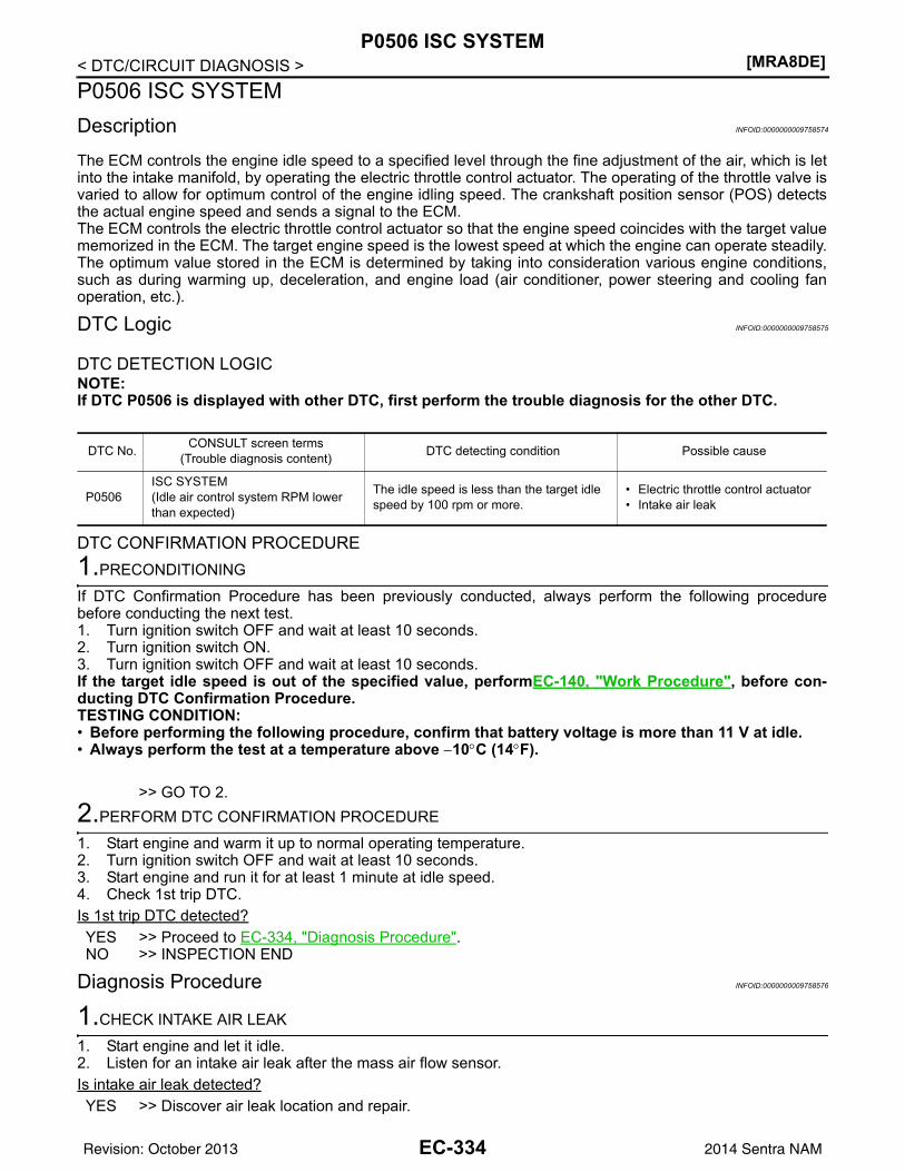
[MRA8DE]P0506 ISC SYSTEM
< DTC/CIRCUIT DIAGNOSIS >P0506 ISC SYSTEMDescription INFOID:0000000009758574
The ECM controls the engine idle speed to a specified level through the fine adjustment of the air, which is letinto the intake manifold, by operating the electric throttle control actuator. The operating of the throttle valve isvaried to allow for optimum control of the engine idling speed. The crankshaft position sensor (POS) detectsthe actual engine speed and sends a signal to the ECM.The ECM controls the electric throttle control actuator so that the engine speed coincides with the target valuememorized in the ECM. The target engine speed is the lowest speed at which the engine can operate steadily.The optimum value stored in the ECM is determined by taking into consideration various engine conditions,such as during warming up, deceleration, and engine load (air conditioner, power steering and cooling fanoperation, etc.).
DTC Logic INFOID:0000000009758575
DTC DETECTION LOGICNOTE:If DTC P0506 is displayed with other DTC, first perform the trouble diagnosis for the other DTC.
DTC CONFIRMATION PROCEDURE1.PRECONDITIONING
If DTC Confirmation Procedure has been previously conducted, always perform the following procedurebefore conducting the next test.1. Turn ignition switch OFF and wait at least 10 seconds.2. Turn ignition switch ON.3. Turn ignition switch OFF and wait at least 10 seconds.If the target idle speed is out of the specified value, performEC-140, "Work Procedure", before con-ducting DTC Confirmation Procedure.TESTING CONDITION:• Before performing the following procedure, confirm that battery voltage is more than 11 V at idle.• Always perform the test at a temperature above −10°C (14°F).
>> GO TO 2.2.PERFORM DTC CONFIRMATION PROCEDURE
1. Start engine and warm it up to normal operating temperature.2. Turn ignition switch OFF and wait at least 10 seconds.3. Start engine and run it for at least 1 minute at idle speed.4. Check 1st trip DTC.Is 1st trip DTC detected?YES >> Proceed to EC-334, "Diagnosis Procedure".NO >> INSPECTION END
Diagnosis Procedure INFOID:0000000009758576
1.CHECK INTAKE AIR LEAK
1. Start engine and let it idle.2. Listen for an intake air leak after the mass air flow sensor.Is intake air leak detected?YES >> Discover air leak location and repair.
DTC No. CONSULT screen terms(Trouble diagnosis content) DTC detecting condition Possible cause
P0506ISC SYSTEM(Idle air control system RPM lower than expected)
The idle speed is less than the target idle speed by 100 rpm or more.
• Electric throttle control actuator• Intake air leak
EC-334Revision: October 2013 2014 Sentra NAM
P0506 ISC SYSTEM[MRA8DE]
C
D
E
F
G
H
I
J
K
L
M
A
C
N
P
O
< DTC/CIRCUIT DIAGNOSIS >
E
NO >> Replace ECM. Refer to EC-485, "Removal and Installation".
EC-335Revision: October 2013 2014 Sentra NAM
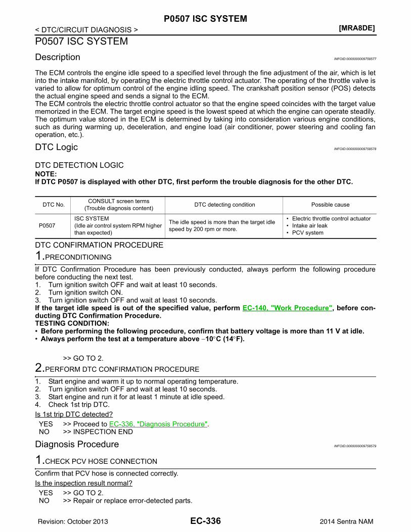
[MRA8DE]P0507 ISC SYSTEM
< DTC/CIRCUIT DIAGNOSIS >P0507 ISC SYSTEMDescription INFOID:0000000009758577
The ECM controls the engine idle speed to a specified level through the fine adjustment of the air, which is letinto the intake manifold, by operating the electric throttle control actuator. The operating of the throttle valve isvaried to allow for optimum control of the engine idling speed. The crankshaft position sensor (POS) detectsthe actual engine speed and sends a signal to the ECM.The ECM controls the electric throttle control actuator so that the engine speed coincides with the target valuememorized in the ECM. The target engine speed is the lowest speed at which the engine can operate steadily.The optimum value stored in the ECM is determined by taking into consideration various engine conditions,such as during warming up, deceleration, and engine load (air conditioner, power steering and cooling fanoperation, etc.).
DTC Logic INFOID:0000000009758578
DTC DETECTION LOGICNOTE:If DTC P0507 is displayed with other DTC, first perform the trouble diagnosis for the other DTC.
DTC CONFIRMATION PROCEDURE1.PRECONDITIONING
If DTC Confirmation Procedure has been previously conducted, always perform the following procedurebefore conducting the next test.1. Turn ignition switch OFF and wait at least 10 seconds.2. Turn ignition switch ON.3. Turn ignition switch OFF and wait at least 10 seconds.If the target idle speed is out of the specified value, perform EC-140, "Work Procedure", before con-ducting DTC Confirmation Procedure.TESTING CONDITION:• Before performing the following procedure, confirm that battery voltage is more than 11 V at idle.• Always perform the test at a temperature above −10°C (14°F).
>> GO TO 2.2.PERFORM DTC CONFIRMATION PROCEDURE
1. Start engine and warm it up to normal operating temperature.2. Turn ignition switch OFF and wait at least 10 seconds.3. Start engine and run it for at least 1 minute at idle speed.4. Check 1st trip DTC.Is 1st trip DTC detected?YES >> Proceed to EC-336, "Diagnosis Procedure".NO >> INSPECTION END
Diagnosis Procedure INFOID:0000000009758579
1.CHECK PCV HOSE CONNECTION
Confirm that PCV hose is connected correctly.Is the inspection result normal?YES >> GO TO 2.NO >> Repair or replace error-detected parts.
DTC No. CONSULT screen terms(Trouble diagnosis content) DTC detecting condition Possible cause
P0507ISC SYSTEM(Idle air control system RPM higher than expected)
The idle speed is more than the target idle speed by 200 rpm or more.
• Electric throttle control actuator• Intake air leak• PCV system
EC-336Revision: October 2013 2014 Sentra NAM
P0507 ISC SYSTEM[MRA8DE]
C
D
E
F
G
H
I
J
K
L
M
A
C
N
P
O
< DTC/CIRCUIT DIAGNOSIS >
E
2.CHECK INTAKE AIR LEAK
1. Start engine and let it idle.2. Listen for an intake air leak after the mass air flow sensor.Is intake air leak detected?YES >> Discover air leak location and repair.NO >> Replace ECM. Refer to EC-485, "Removal and Installation".
EC-337Revision: October 2013 2014 Sentra NAM
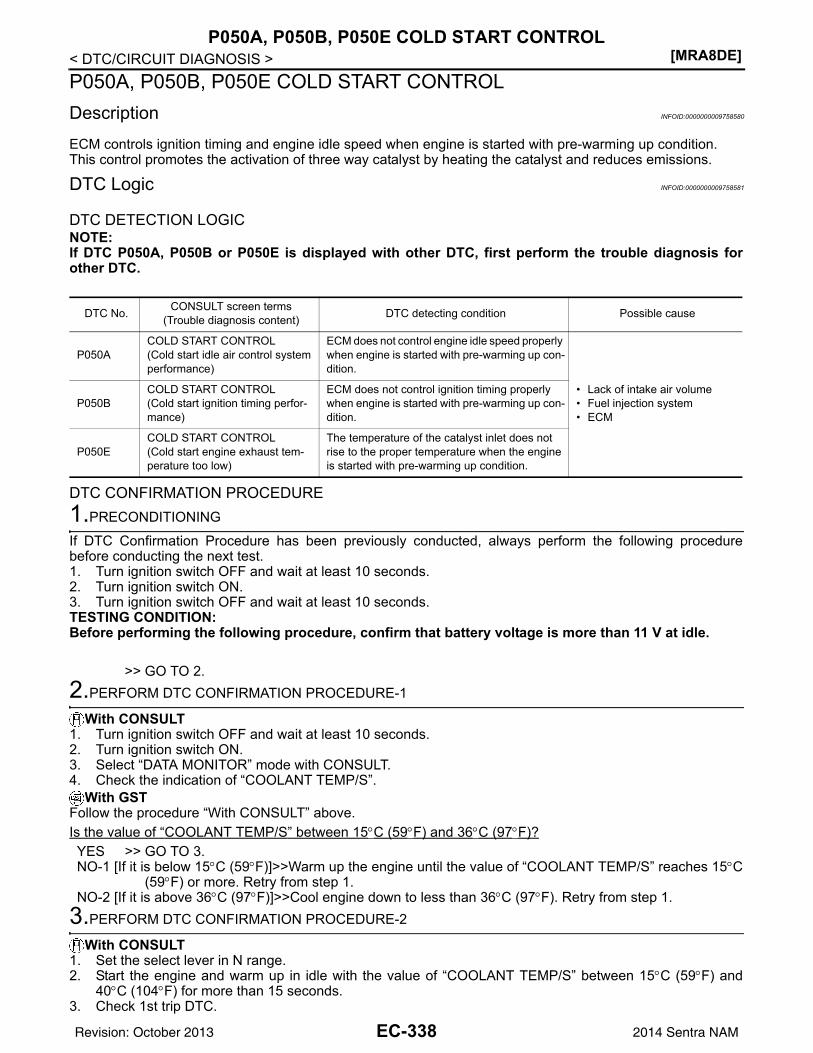
[MRA8DE]P050A, P050B, P050E COLD START CONTROL
< DTC/CIRCUIT DIAGNOSIS >P050A, P050B, P050E COLD START CONTROLDescription INFOID:0000000009758580
ECM controls ignition timing and engine idle speed when engine is started with pre-warming up condition.This control promotes the activation of three way catalyst by heating the catalyst and reduces emissions.
DTC Logic INFOID:0000000009758581
DTC DETECTION LOGICNOTE:If DTC P050A, P050B or P050E is displayed with other DTC, first perform the trouble diagnosis forother DTC.
DTC CONFIRMATION PROCEDURE1.PRECONDITIONING
If DTC Confirmation Procedure has been previously conducted, always perform the following procedurebefore conducting the next test.1. Turn ignition switch OFF and wait at least 10 seconds.2. Turn ignition switch ON.3. Turn ignition switch OFF and wait at least 10 seconds.TESTING CONDITION:Before performing the following procedure, confirm that battery voltage is more than 11 V at idle.
>> GO TO 2.2.PERFORM DTC CONFIRMATION PROCEDURE-1
With CONSULT1. Turn ignition switch OFF and wait at least 10 seconds.2. Turn ignition switch ON.3. Select “DATA MONITOR” mode with CONSULT.4. Check the indication of “COOLANT TEMP/S”.
With GSTFollow the procedure “With CONSULT” above.Is the value of “COOLANT TEMP/S” between 15°C (59°F) and 36°C (97°F)?YES >> GO TO 3.NO-1 [If it is below 15°C (59°F)]>>Warm up the engine until the value of “COOLANT TEMP/S” reaches 15°C
(59°F) or more. Retry from step 1.NO-2 [If it is above 36°C (97°F)]>>Cool engine down to less than 36°C (97°F). Retry from step 1.
3.PERFORM DTC CONFIRMATION PROCEDURE-2
With CONSULT1. Set the select lever in N range.2. Start the engine and warm up in idle with the value of “COOLANT TEMP/S” between 15°C (59°F) and
40°C (104°F) for more than 15 seconds.3. Check 1st trip DTC.
DTC No. CONSULT screen terms(Trouble diagnosis content) DTC detecting condition Possible cause
P050ACOLD START CONTROL(Cold start idle air control system performance)
ECM does not control engine idle speed properly when engine is started with pre-warming up con-dition.
• Lack of intake air volume• Fuel injection system• ECM
P050BCOLD START CONTROL(Cold start ignition timing perfor-mance)
ECM does not control ignition timing properly when engine is started with pre-warming up con-dition.
P050ECOLD START CONTROL(Cold start engine exhaust tem-perature too low)
The temperature of the catalyst inlet does not rise to the proper temperature when the engine is started with pre-warming up condition.
EC-338Revision: October 2013 2014 Sentra NAM
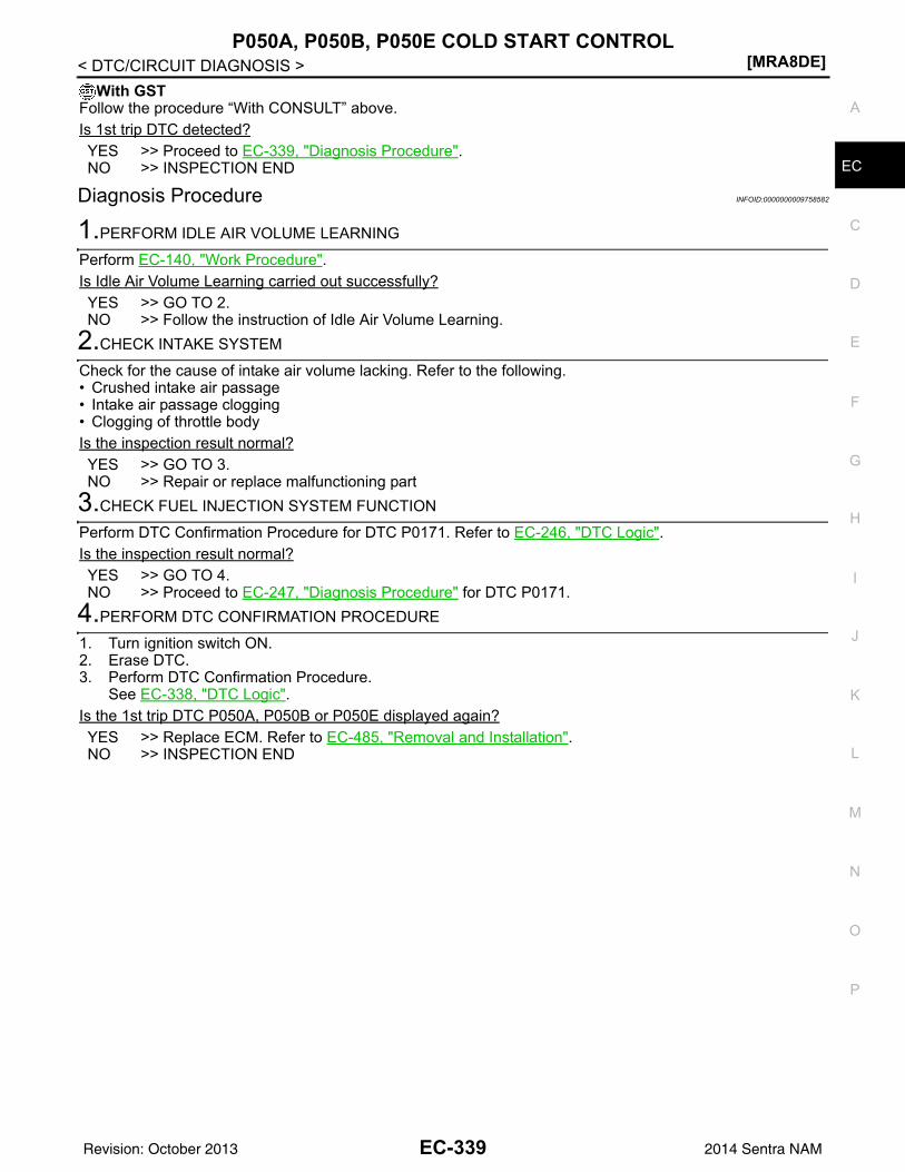
P050A, P050B, P050E COLD START CONTROL[MRA8DE]
C
D
E
F
G
H
I
J
K
L
M
A
C
N
P
O
< DTC/CIRCUIT DIAGNOSIS >
E
With GSTFollow the procedure “With CONSULT” above.Is 1st trip DTC detected?YES >> Proceed to EC-339, "Diagnosis Procedure".NO >> INSPECTION END
Diagnosis Procedure INFOID:0000000009758582
1.PERFORM IDLE AIR VOLUME LEARNING
Perform EC-140, "Work Procedure".Is Idle Air Volume Learning carried out successfully?YES >> GO TO 2.NO >> Follow the instruction of Idle Air Volume Learning.
2.CHECK INTAKE SYSTEM
Check for the cause of intake air volume lacking. Refer to the following.• Crushed intake air passage• Intake air passage clogging• Clogging of throttle bodyIs the inspection result normal?YES >> GO TO 3.NO >> Repair or replace malfunctioning part
3.CHECK FUEL INJECTION SYSTEM FUNCTION
Perform DTC Confirmation Procedure for DTC P0171. Refer to EC-246, "DTC Logic".Is the inspection result normal?YES >> GO TO 4.NO >> Proceed to EC-247, "Diagnosis Procedure" for DTC P0171.
4.PERFORM DTC CONFIRMATION PROCEDURE
1. Turn ignition switch ON.2. Erase DTC.3. Perform DTC Confirmation Procedure.
See EC-338, "DTC Logic".Is the 1st trip DTC P050A, P050B or P050E displayed again?YES >> Replace ECM. Refer to EC-485, "Removal and Installation".NO >> INSPECTION END
EC-339Revision: October 2013 2014 Sentra NAM
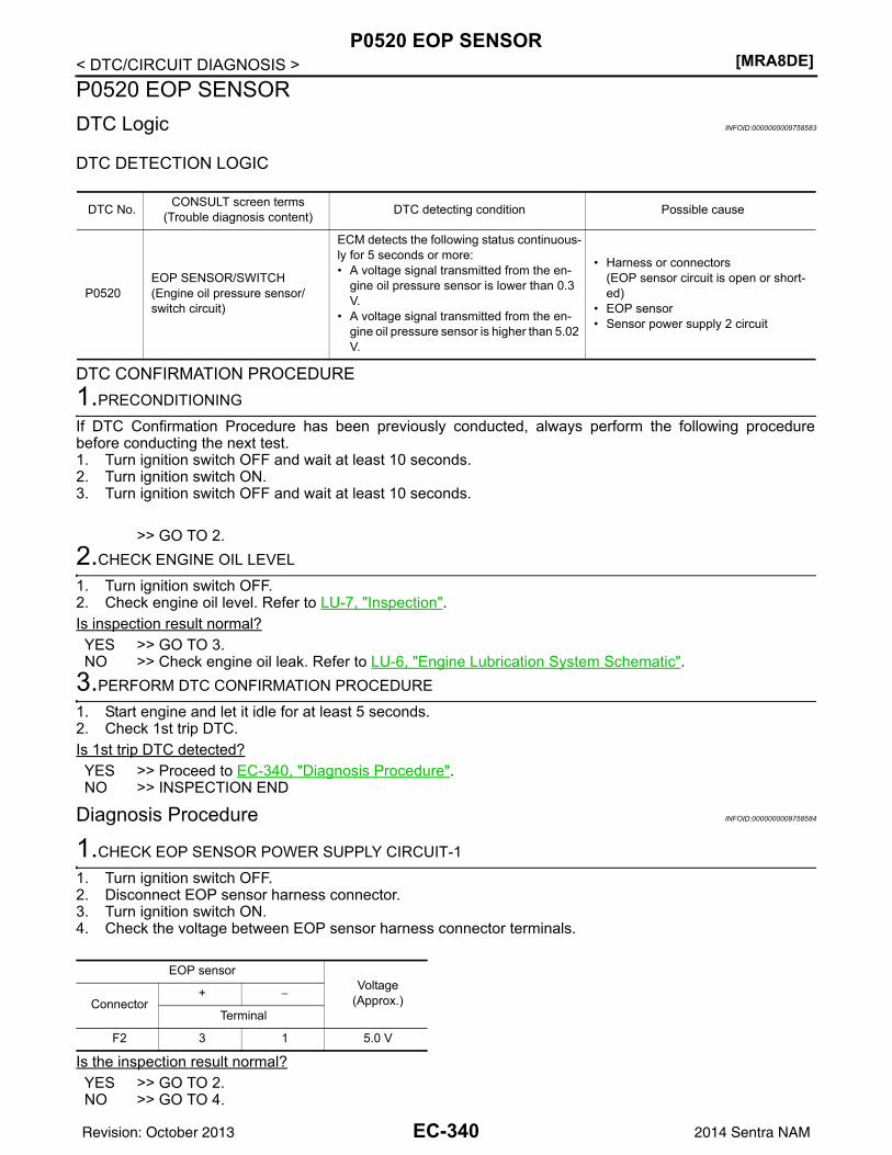
[MRA8DE]P0520 EOP SENSOR
< DTC/CIRCUIT DIAGNOSIS >P0520 EOP SENSORDTC Logic INFOID:0000000009758583
DTC DETECTION LOGIC
DTC CONFIRMATION PROCEDURE1.PRECONDITIONING
If DTC Confirmation Procedure has been previously conducted, always perform the following procedurebefore conducting the next test.1. Turn ignition switch OFF and wait at least 10 seconds.2. Turn ignition switch ON.3. Turn ignition switch OFF and wait at least 10 seconds.
>> GO TO 2.2.CHECK ENGINE OIL LEVEL
1. Turn ignition switch OFF.2. Check engine oil level. Refer to LU-7, "Inspection".Is inspection result normal?YES >> GO TO 3.NO >> Check engine oil leak. Refer to LU-6, "Engine Lubrication System Schematic".
3.PERFORM DTC CONFIRMATION PROCEDURE
1. Start engine and let it idle for at least 5 seconds.2. Check 1st trip DTC.Is 1st trip DTC detected?YES >> Proceed to EC-340, "Diagnosis Procedure".NO >> INSPECTION END
Diagnosis Procedure INFOID:0000000009758584
1.CHECK EOP SENSOR POWER SUPPLY CIRCUIT-1
1. Turn ignition switch OFF.2. Disconnect EOP sensor harness connector.3. Turn ignition switch ON.4. Check the voltage between EOP sensor harness connector terminals.
Is the inspection result normal?YES >> GO TO 2.NO >> GO TO 4.
DTC No. CONSULT screen terms(Trouble diagnosis content) DTC detecting condition Possible cause
P0520EOP SENSOR/SWITCH(Engine oil pressure sensor/switch circuit)
ECM detects the following status continuous-ly for 5 seconds or more:• A voltage signal transmitted from the en-
gine oil pressure sensor is lower than 0.3 V.
• A voltage signal transmitted from the en-gine oil pressure sensor is higher than 5.02 V.
• Harness or connectors(EOP sensor circuit is open or short-ed)
• EOP sensor• Sensor power supply 2 circuit
EOP sensorVoltage
(Approx.)Connector+ −
Terminal
F2 3 1 5.0 V
EC-340Revision: October 2013 2014 Sentra NAM
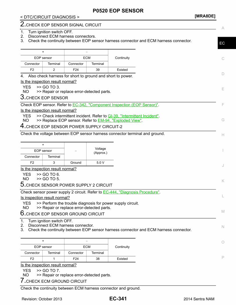
P0520 EOP SENSOR[MRA8DE]
C
D
E
F
G
H
I
J
K
L
M
A
C
N
P
O
< DTC/CIRCUIT DIAGNOSIS >
E
2.CHECK EOP SENSOR SIGNAL CIRCUIT
1. Turn ignition switch OFF.2. Disconnect ECM harness connectors.3. Check the continuity between EOP sensor harness connector and ECM harness connector.
4. Also check harness for short to ground and short to power.Is the inspection result normal?YES >> GO TO 3.NO >> Repair or replace error-detected parts.
3.CHECK EOP SENSOR
Check EOP sensor. Refer to EC-342, "Component Inspection (EOP Sensor)".Is the inspection result normal?YES >> Check intermittent incident. Refer to GI-39, "Intermittent Incident".NO >> Replace EOP sensor. Refer to EM-94, "Exploded View".
4.CHECK EOP SENSOR POWER SUPPLY CIRCUIT-2
Check the voltage between EOP sensor harness connector terminal and ground.
Is the inspection result normal?YES >> GO TO 6.NO >> GO TO 5.
5.CHECK SENSOR POWER SUPPLY 2 CIRCUIT
Check sensor power supply 2 circuit. Refer to EC-444, "Diagnosis Procedure".Is inspection result normal?YES >> Perform the trouble diagnosis for power supply circuit.NO >> Repair or replace error-detected parts.
6.CHECK EOP SENSOR GROUND CIRCUIT
1. Turn ignition switch OFF.2. Disconnect ECM harness connector.3. Check the continuity between EOP sensor harness connector and ECM harness connector.
Is the inspection result normal?YES >> GO TO 7.NO >> Repair or replace error-detected parts.
7.CHECK ECM GROUND CIRCUIT
Check the continuity between ECM harness connector and ground.
+ −
ContinuityEOP sensor ECM
Connector Terminal Connector Terminal
F2 2 F24 39 Existed
+
−Voltage
(Approx.)EOP sensor
Connector Terminal
F2 3 Ground 5.0 V
+ −
ContinuityEOP sensor ECM
Connector Terminal Connector Terminal
F2 1 F24 38 Existed
EC-341Revision: October 2013 2014 Sentra NAM
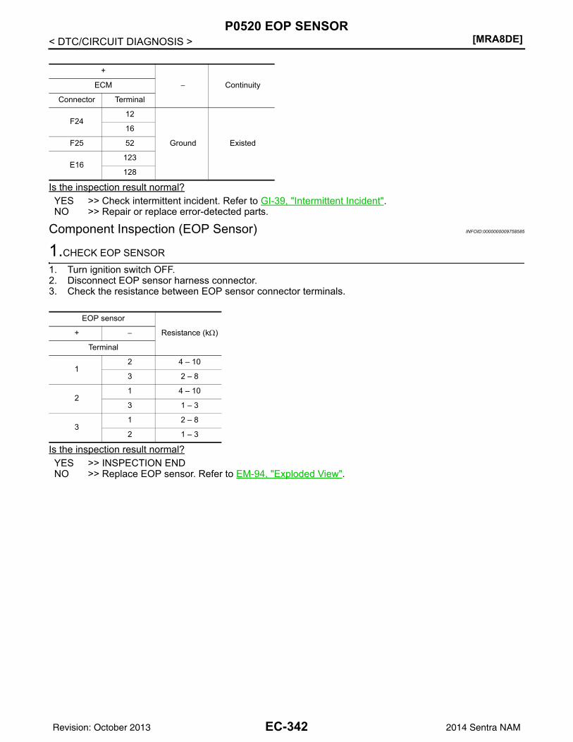
[MRA8DE]P0520 EOP SENSOR
< DTC/CIRCUIT DIAGNOSIS >
Is the inspection result normal?YES >> Check intermittent incident. Refer to GI-39, "Intermittent Incident".NO >> Repair or replace error-detected parts.
Component Inspection (EOP Sensor) INFOID:0000000009758585
1.CHECK EOP SENSOR
1. Turn ignition switch OFF.2. Disconnect EOP sensor harness connector.3. Check the resistance between EOP sensor connector terminals.
Is the inspection result normal?YES >> INSPECTION ENDNO >> Replace EOP sensor. Refer to EM-94, "Exploded View".
+
− ContinuityECM
Connector Terminal
F2412
Ground Existed
16
F25 52
E16123
128
EOP sensor
Resistance (kΩ)+ −
Terminal
12 4 – 10
3 2 – 8
21 4 – 10
3 1 – 3
31 2 – 8
2 1 – 3
EC-342Revision: October 2013 2014 Sentra NAM
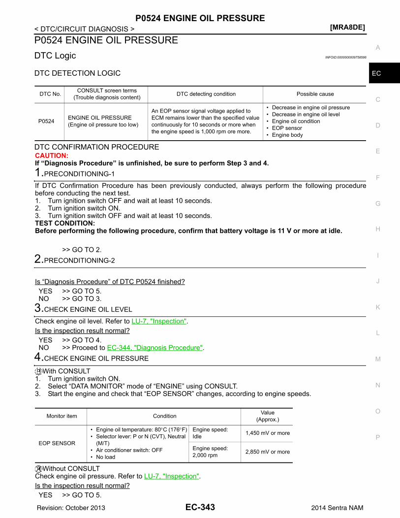
P0524 ENGINE OIL PRESSURE[MRA8DE]
C
D
E
F
G
H
I
J
K
L
M
A
C
N
P
O
< DTC/CIRCUIT DIAGNOSIS >
E
P0524 ENGINE OIL PRESSUREDTC Logic INFOID:0000000009758586
DTC DETECTION LOGIC
DTC CONFIRMATION PROCEDURECAUTION:If “Diagnosis Procedure” is unfinished, be sure to perform Step 3 and 4.1.PRECONDITIONING-1
If DTC Confirmation Procedure has been previously conducted, always perform the following procedurebefore conducting the next test.1. Turn ignition switch OFF and wait at least 10 seconds.2. Turn ignition switch ON.3. Turn ignition switch OFF and wait at least 10 seconds.TEST CONDITION:Before performing the following procedure, confirm that battery voltage is 11 V or more at idle.
>> GO TO 2.2.PRECONDITIONING-2
Is “Diagnosis Procedure” of DTC P0524 finished?YES >> GO TO 5.NO >> GO TO 3.
3.CHECK ENGINE OIL LEVEL
Check engine oil level. Refer to LU-7, "Inspection".Is the inspection result normal?YES >> GO TO 4.NO >> Proceed to EC-344, "Diagnosis Procedure".
4.CHECK ENGINE OIL PRESSURE
With CONSULT1. Turn ignition switch ON.2. Select “DATA MONITOR” mode of “ENGINE” using CONSULT.3. Start the engine and check that “EOP SENSOR” changes, according to engine speeds.
Without CONSULTCheck engine oil pressure. Refer to LU-7, "Inspection".Is the inspection result normal?YES >> GO TO 5.
DTC No. CONSULT screen terms(Trouble diagnosis content) DTC detecting condition Possible cause
P0524 ENGINE OIL PRESSURE(Engine oil pressure too low)
An EOP sensor signal voltage applied to ECM remains lower than the specified value continuously for 10 seconds or more when the engine speed is 1,000 rpm ore more.
• Decrease in engine oil pressure• Decrease in engine oil level• Engine oil condition• EOP sensor• Engine body
Monitor item Condition Value(Approx.)
EOP SENSOR
• Engine oil temperature: 80°C (176°F)• Selector lever: P or N (CVT), Neutral
(M/T)• Air conditioner switch: OFF• No load
Engine speed:Idle 1,450 mV or more
Engine speed:2,000 rpm 2,850 mV or more
EC-343Revision: October 2013 2014 Sentra NAM
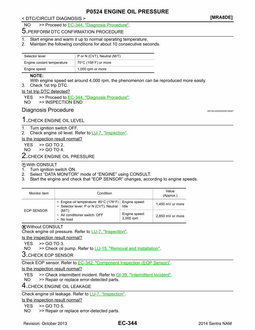
[MRA8DE]P0524 ENGINE OIL PRESSURE
< DTC/CIRCUIT DIAGNOSIS >NO >> Proceed to EC-344, "Diagnosis Procedure".
5.PERFORM DTC CONFIRMATION PROCEDURE
1. Start engine and warm it up to normal operating temperature.2. Maintain the following conditions for about 10 consecutive seconds.
NOTE:With engine speed set around 4,000 rpm, the phenomenon can be reproduced more easily.
3. Check 1st trip DTC.Is 1st trip DTC detected?YES >> Proceed to EC-344, "Diagnosis Procedure".NO >> INSPECTION END
Diagnosis Procedure INFOID:0000000009758587
1.CHECK ENGINE OIL LEVEL
1. Turn ignition switch OFF.2. Check engine oil level. Refer to LU-7, "Inspection".Is the inspection result normal?YES >> GO TO 2.NO >> GO TO 4.
2.CHECK ENGINE OIL PRESSURE
With CONSULT1. Turn ignition switch ON.2. Select “DATA MONITOR” mode of “ENGINE” using CONSULT.3. Start the engine and check that “EOP SENSOR” changes, according to engine speeds.
Without CONSULTCheck engine oil pressure. Refer to LU-7, "Inspection".Is the inspection result normal?YES >> GO TO 3.NO >> Check oil pump. Refer to LU-15, "Removal and Installation".
3.CHECK EOP SENSOR
Check EOP sensor. Refer to EC-342, "Component Inspection (EOP Sensor)".Is the inspection result normal?YES >> Check intermittent incident. Refer to GI-39, "Intermittent Incident".NO >> Repair or replace error-detected parts.
4.CHECK ENGINE OIL LEAKAGE
Check engine oil leakage. Refer to LU-7, "Inspection".Is the inspection result normal?YES >> GO TO 5.NO >> Repair or replace error-detected parts.
Selector lever P or N (CVT), Neutral (M/T)
Engine coolant temperature 70°C (158°F) or more
Engine speed 1,000 rpm or more
Monitor item Condition Value(Approx.)
EOP SENSOR
• Engine oil temperature: 80°C (176°F)• Selector lever: P or N (CVT), Neutral
(M/T)• Air conditioner switch: OFF• No load
Engine speed:Idle 1,450 mV or more
Engine speed:2,000 rpm 2,850 mV or more
EC-344Revision: October 2013 2014 Sentra NAM
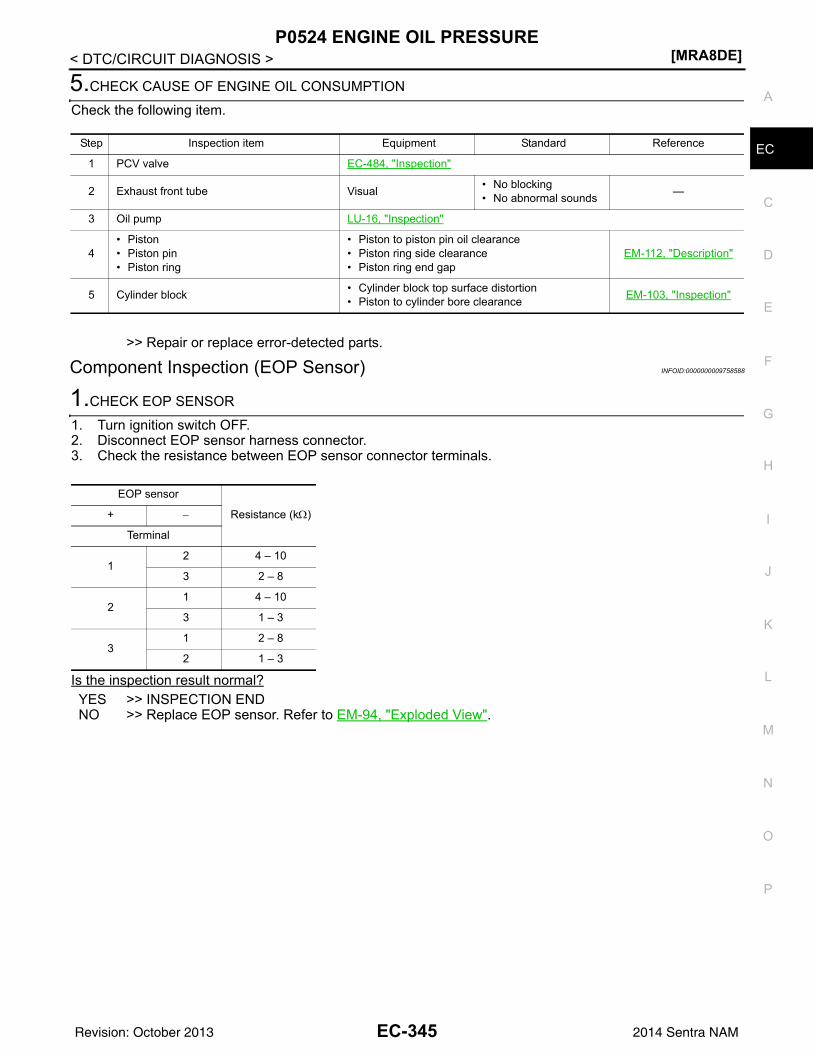
P0524 ENGINE OIL PRESSURE[MRA8DE]
C
D
E
F
G
H
I
J
K
L
M
A
C
N
P
O
< DTC/CIRCUIT DIAGNOSIS >
E
5.CHECK CAUSE OF ENGINE OIL CONSUMPTION
Check the following item.
>> Repair or replace error-detected parts.
Component Inspection (EOP Sensor) INFOID:0000000009758588
1.CHECK EOP SENSOR
1. Turn ignition switch OFF.2. Disconnect EOP sensor harness connector.3. Check the resistance between EOP sensor connector terminals.
Is the inspection result normal?YES >> INSPECTION ENDNO >> Replace EOP sensor. Refer to EM-94, "Exploded View".
Step Inspection item Equipment Standard Reference
1 PCV valve EC-484, "Inspection"
2 Exhaust front tube Visual • No blocking• No abnormal sounds —
3 Oil pump LU-16, "Inspection"
4• Piston• Piston pin• Piston ring
• Piston to piston pin oil clearance• Piston ring side clearance• Piston ring end gap
EM-112, "Description"
5 Cylinder block • Cylinder block top surface distortion• Piston to cylinder bore clearance EM-103, "Inspection"
EOP sensor
Resistance (kΩ)+ −
Terminal
12 4 – 10
3 2 – 8
21 4 – 10
3 1 – 3
31 2 – 8
2 1 – 3
EC-345Revision: October 2013 2014 Sentra NAM
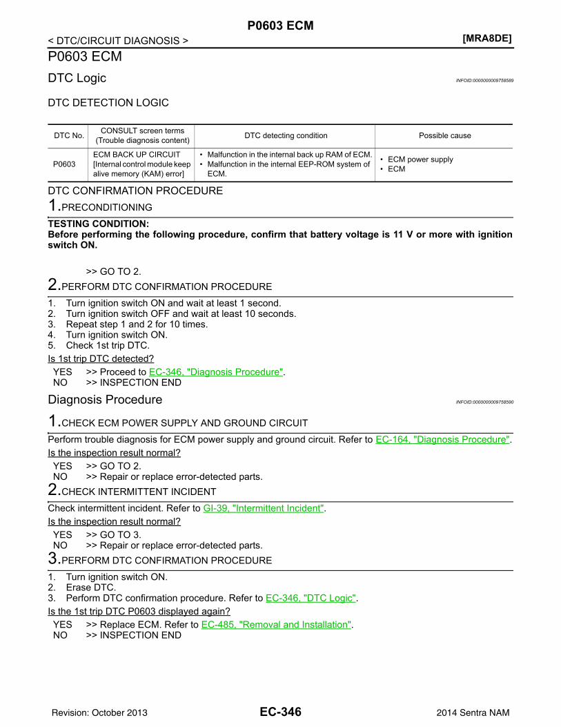
[MRA8DE]P0603 ECM
< DTC/CIRCUIT DIAGNOSIS >P0603 ECMDTC Logic INFOID:0000000009758589
DTC DETECTION LOGIC
DTC CONFIRMATION PROCEDURE1.PRECONDITIONING
TESTING CONDITION:Before performing the following procedure, confirm that battery voltage is 11 V or more with ignitionswitch ON.
>> GO TO 2.2.PERFORM DTC CONFIRMATION PROCEDURE
1. Turn ignition switch ON and wait at least 1 second.2. Turn ignition switch OFF and wait at least 10 seconds.3. Repeat step 1 and 2 for 10 times.4. Turn ignition switch ON.5. Check 1st trip DTC.Is 1st trip DTC detected?YES >> Proceed to EC-346, "Diagnosis Procedure".NO >> INSPECTION END
Diagnosis Procedure INFOID:0000000009758590
1.CHECK ECM POWER SUPPLY AND GROUND CIRCUIT
Perform trouble diagnosis for ECM power supply and ground circuit. Refer to EC-164, "Diagnosis Procedure".Is the inspection result normal?YES >> GO TO 2.NO >> Repair or replace error-detected parts.
2.CHECK INTERMITTENT INCIDENT
Check intermittent incident. Refer to GI-39, "Intermittent Incident".Is the inspection result normal?YES >> GO TO 3.NO >> Repair or replace error-detected parts.
3.PERFORM DTC CONFIRMATION PROCEDURE
1. Turn ignition switch ON.2. Erase DTC.3. Perform DTC confirmation procedure. Refer to EC-346, "DTC Logic".Is the 1st trip DTC P0603 displayed again?YES >> Replace ECM. Refer to EC-485, "Removal and Installation".NO >> INSPECTION END
DTC No. CONSULT screen terms(Trouble diagnosis content) DTC detecting condition Possible cause
P0603ECM BACK UP CIRCUIT[Internal control module keep alive memory (KAM) error]
• Malfunction in the internal back up RAM of ECM.• Malfunction in the internal EEP-ROM system of
ECM.
• ECM power supply• ECM
EC-346Revision: October 2013 2014 Sentra NAM
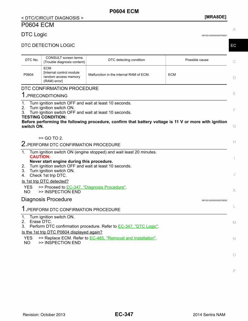
P0604 ECM[MRA8DE]
C
D
E
F
G
H
I
J
K
L
M
A
C
N
P
O
< DTC/CIRCUIT DIAGNOSIS >
E
P0604 ECMDTC Logic INFOID:0000000009758591
DTC DETECTION LOGIC
DTC CONFIRMATION PROCEDURE1.PRECONDITIONING
1. Turn ignition switch OFF and wait at least 10 seconds.2. Turn ignition switch ON.3. Turn ignition switch OFF and wait at least 10 seconds.TESTING CONDITION:Before performing the following procedure, confirm that battery voltage is 11 V or more with ignitionswitch ON.
>> GO TO 2.2.PERFORM DTC CONFIRMATION PROCEDURE
1. Turn ignition switch ON (engine stopped) and wait least 20 minutes.CAUTION:Never start engine during this procedure.
2. Turn ignition switch OFF and wait at least 10 seconds.3. Turn ignition switch ON.4. Check 1st trip DTC.Is 1st trip DTC detected?YES >> Proceed to EC-347, "Diagnosis Procedure".NO >> INSPECTION END
Diagnosis Procedure INFOID:0000000009758592
1.PERFORM DTC CONFIRMATION PROCEDURE
1. Turn ignition switch ON.2. Erase DTC.3. Perform DTC confirmation procedure. Refer to EC-347, "DTC Logic".Is the 1st trip DTC P0604 displayed again?YES >> Replace ECM. Refer to EC-485, "Removal and Installation".NO >> INSPECTION END
DTC No. CONSULT screen terms(Trouble diagnosis content) DTC detecting condition Possible cause
P0604
ECM[Internal control module random access memory (RAM) error]
Malfunction in the internal RAM of ECM. ECM
EC-347Revision: October 2013 2014 Sentra NAM
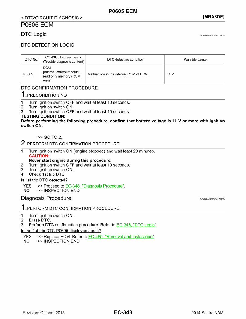
[MRA8DE]P0605 ECM
< DTC/CIRCUIT DIAGNOSIS >P0605 ECMDTC Logic INFOID:0000000009758593
DTC DETECTION LOGIC
DTC CONFIRMATION PROCEDURE1.PRECONDITIONING
1. Turn ignition switch OFF and wait at least 10 seconds.2. Turn ignition switch ON.3. Turn ignition switch OFF and wait at least 10 seconds.TESTING CONDITION:Before performing the following procedure, confirm that battery voltage is 11 V or more with ignitionswitch ON.
>> GO TO 2.2.PERFORM DTC CONFIRMATION PROCEDURE
1. Turn ignition switch ON (engine stopped) and wait least 20 minutes.CAUTION:Never start engine during this procedure.
2. Turn ignition switch OFF and wait at least 10 seconds.3. Turn ignition switch ON.4. Check 1st trip DTC.Is 1st trip DTC detected?YES >> Proceed to EC-348, "Diagnosis Procedure".NO >> INSPECTION END
Diagnosis Procedure INFOID:0000000009758594
1.PERFORM DTC CONFIRMATION PROCEDURE
1. Turn ignition switch ON.2. Erase DTC.3. Perform DTC confirmation procedure. Refer to EC-348, "DTC Logic".Is the 1st trip DTC P0605 displayed again?YES >> Replace ECM. Refer to EC-485, "Removal and Installation".NO >> INSPECTION END
DTC No. CONSULT screen terms(Trouble diagnosis content) DTC detecting condition Possible cause
P0605
ECM[Internal control module read only memory (ROM) error]
Malfunction in the internal ROM of ECM. ECM
EC-348Revision: October 2013 2014 Sentra NAM
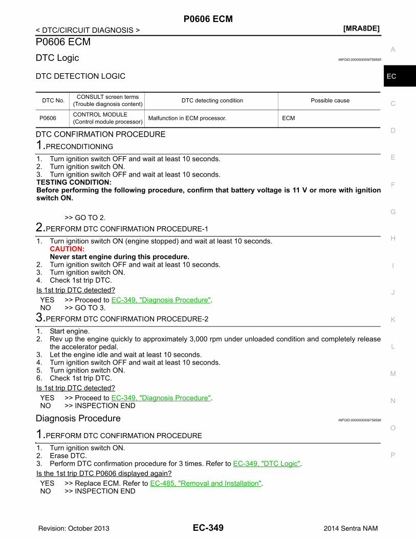
P0606 ECM[MRA8DE]
C
D
E
F
G
H
I
J
K
L
M
A
C
N
P
O
< DTC/CIRCUIT DIAGNOSIS >
E
P0606 ECMDTC Logic INFOID:0000000009758595
DTC DETECTION LOGIC
DTC CONFIRMATION PROCEDURE1.PRECONDITIONING
1. Turn ignition switch OFF and wait at least 10 seconds.2. Turn ignition switch ON.3. Turn ignition switch OFF and wait at least 10 seconds.TESTING CONDITION:Before performing the following procedure, confirm that battery voltage is 11 V or more with ignitionswitch ON.
>> GO TO 2.2.PERFORM DTC CONFIRMATION PROCEDURE-1
1. Turn ignition switch ON (engine stopped) and wait at least 10 seconds.CAUTION:Never start engine during this procedure.
2. Turn ignition switch OFF and wait at least 10 seconds.3. Turn ignition switch ON.4. Check 1st trip DTC.Is 1st trip DTC detected?YES >> Proceed to EC-349, "Diagnosis Procedure".NO >> GO TO 3.
3.PERFORM DTC CONFIRMATION PROCEDURE-2
1. Start engine.2. Rev up the engine quickly to approximately 3,000 rpm under unloaded condition and completely release
the accelerator pedal.3. Let the engine idle and wait at least 10 seconds.4. Turn ignition switch OFF and wait at least 10 seconds.5. Turn ignition switch ON.6. Check 1st trip DTC.Is 1st trip DTC detected?YES >> Proceed to EC-349, "Diagnosis Procedure".NO >> INSPECTION END
Diagnosis Procedure INFOID:0000000009758596
1.PERFORM DTC CONFIRMATION PROCEDURE
1. Turn ignition switch ON.2. Erase DTC.3. Perform DTC confirmation procedure for 3 times. Refer to EC-349, "DTC Logic".Is the 1st trip DTC P0606 displayed again?YES >> Replace ECM. Refer to EC-485, "Removal and Installation".NO >> INSPECTION END
DTC No. CONSULT screen terms(Trouble diagnosis content) DTC detecting condition Possible cause
P0606 CONTROL MODULE(Control module processor) Malfunction in ECM processor. ECM
EC-349Revision: October 2013 2014 Sentra NAM
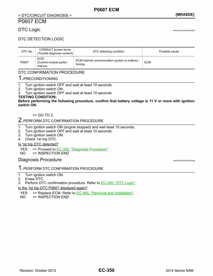
[MRA8DE]P0607 ECM
< DTC/CIRCUIT DIAGNOSIS >P0607 ECMDTC Logic INFOID:0000000009758597
DTC DETECTION LOGIC
DTC CONFIRMATION PROCEDURE1.PRECONDITIONING
1. Turn ignition switch OFF and wait at least 10 seconds.2. Turn ignition switch ON.3. Turn ignition switch OFF and wait at least 10 seconds.TESTING CONDITION:Before performing the following procedure, confirm that battery voltage is 11 V or more with ignitionswitch ON.
>> GO TO 2.2.PERFORM DTC CONFIRMATION PROCEDURE
1. Turn ignition switch ON (engine stopped) and wait least 10 seconds.2. Turn ignition switch OFF and wait at least 10 seconds.3. Turn ignition switch ON.4. Check 1st trip DTC.Is 1st trip DTC detected?YES >> Proceed to EC-350, "Diagnosis Procedure".NO >> INSPECTION END
Diagnosis Procedure INFOID:0000000009758598
1.PERFORM DTC CONFIRMATION PROCEDURE
1. Turn ignition switch ON.2. Erase DTC.3. Perform DTC confirmation procedure. Refer to EC-350, "DTC Logic".Is the 1st trip DTC P0607 displayed again?YES >> Replace ECM. Refer to EC-485, "Removal and Installation".NO >> INSPECTION END
DTC No. CONSULT screen terms(Trouble diagnosis content) DTC detecting condition Possible cause
P0607ECM(Control module perfor-mance)
ECM internal communication system is malfunc-tioning. ECM
EC-350Revision: October 2013 2014 Sentra NAM
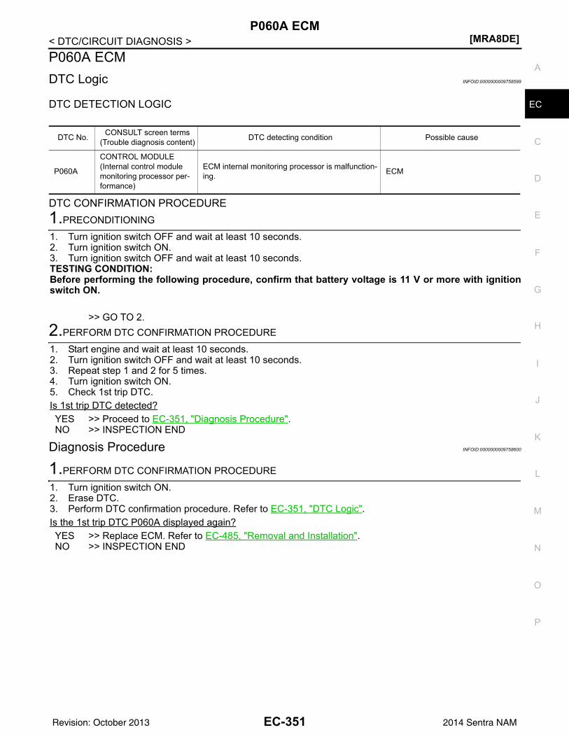
P060A ECM[MRA8DE]
C
D
E
F
G
H
I
J
K
L
M
A
C
N
P
O
< DTC/CIRCUIT DIAGNOSIS >
E
P060A ECMDTC Logic INFOID:0000000009758599
DTC DETECTION LOGIC
DTC CONFIRMATION PROCEDURE1.PRECONDITIONING
1. Turn ignition switch OFF and wait at least 10 seconds.2. Turn ignition switch ON.3. Turn ignition switch OFF and wait at least 10 seconds.TESTING CONDITION:Before performing the following procedure, confirm that battery voltage is 11 V or more with ignitionswitch ON.
>> GO TO 2.2.PERFORM DTC CONFIRMATION PROCEDURE
1. Start engine and wait at least 10 seconds.2. Turn ignition switch OFF and wait at least 10 seconds.3. Repeat step 1 and 2 for 5 times.4. Turn ignition switch ON.5. Check 1st trip DTC.Is 1st trip DTC detected?YES >> Proceed to EC-351, "Diagnosis Procedure".NO >> INSPECTION END
Diagnosis Procedure INFOID:0000000009758600
1.PERFORM DTC CONFIRMATION PROCEDURE
1. Turn ignition switch ON.2. Erase DTC.3. Perform DTC confirmation procedure. Refer to EC-351, "DTC Logic".Is the 1st trip DTC P060A displayed again?YES >> Replace ECM. Refer to EC-485, "Removal and Installation".NO >> INSPECTION END
DTC No. CONSULT screen terms(Trouble diagnosis content) DTC detecting condition Possible cause
P060A
CONTROL MODULE(Internal control module monitoring processor per-formance)
ECM internal monitoring processor is malfunction-ing. ECM
EC-351Revision: October 2013 2014 Sentra NAM
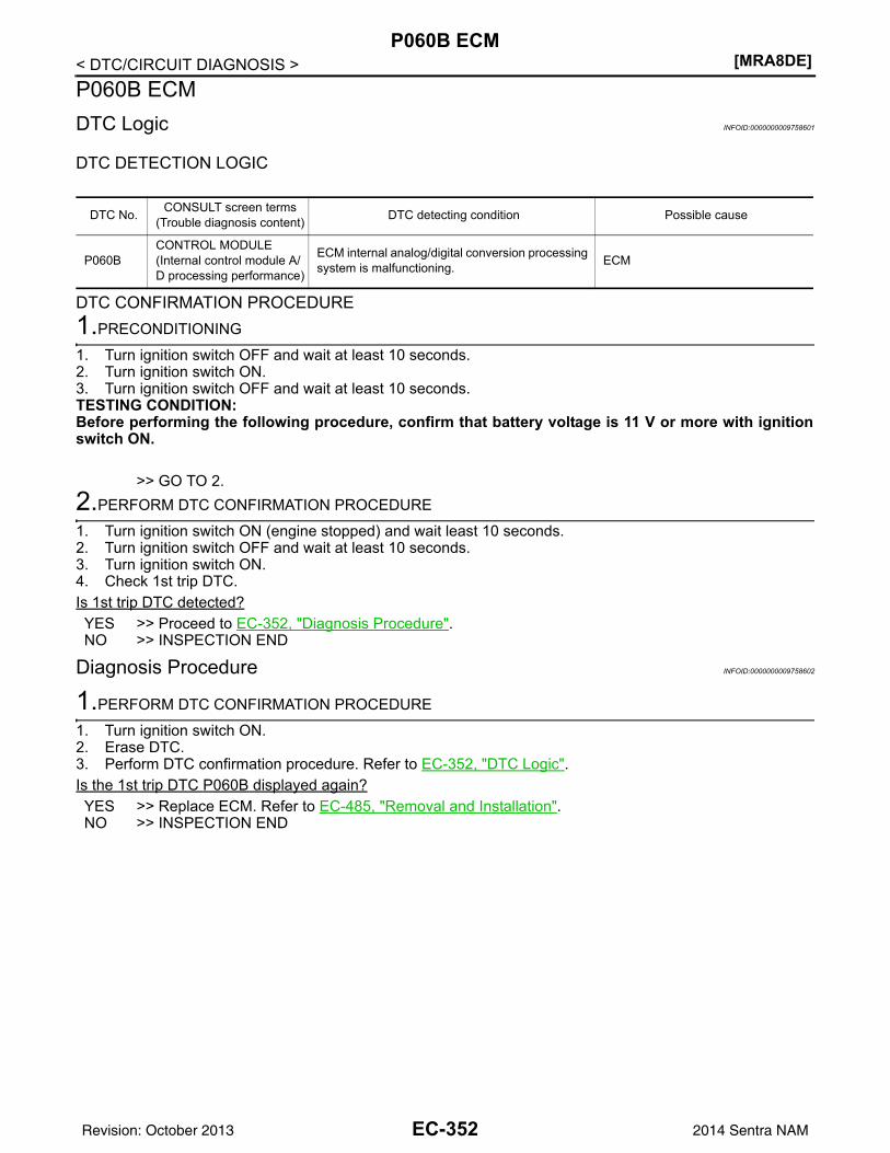
[MRA8DE]P060B ECM
< DTC/CIRCUIT DIAGNOSIS >P060B ECMDTC Logic INFOID:0000000009758601
DTC DETECTION LOGIC
DTC CONFIRMATION PROCEDURE1.PRECONDITIONING
1. Turn ignition switch OFF and wait at least 10 seconds.2. Turn ignition switch ON.3. Turn ignition switch OFF and wait at least 10 seconds.TESTING CONDITION:Before performing the following procedure, confirm that battery voltage is 11 V or more with ignitionswitch ON.
>> GO TO 2.2.PERFORM DTC CONFIRMATION PROCEDURE
1. Turn ignition switch ON (engine stopped) and wait least 10 seconds.2. Turn ignition switch OFF and wait at least 10 seconds.3. Turn ignition switch ON.4. Check 1st trip DTC.Is 1st trip DTC detected?YES >> Proceed to EC-352, "Diagnosis Procedure".NO >> INSPECTION END
Diagnosis Procedure INFOID:0000000009758602
1.PERFORM DTC CONFIRMATION PROCEDURE
1. Turn ignition switch ON.2. Erase DTC.3. Perform DTC confirmation procedure. Refer to EC-352, "DTC Logic".Is the 1st trip DTC P060B displayed again?YES >> Replace ECM. Refer to EC-485, "Removal and Installation".NO >> INSPECTION END
DTC No. CONSULT screen terms(Trouble diagnosis content) DTC detecting condition Possible cause
P060BCONTROL MODULE(Internal control module A/D processing performance)
ECM internal analog/digital conversion processing system is malfunctioning. ECM
EC-352Revision: October 2013 2014 Sentra NAM
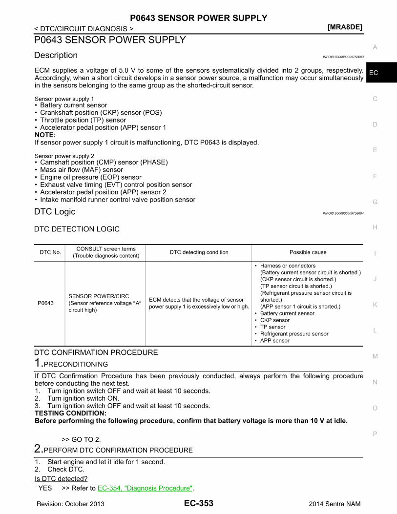
P0643 SENSOR POWER SUPPLY[MRA8DE]
C
D
E
F
G
H
I
J
K
L
M
A
C
N
P
O
< DTC/CIRCUIT DIAGNOSIS >
E
P0643 SENSOR POWER SUPPLYDescription INFOID:0000000009758603
ECM supplies a voltage of 5.0 V to some of the sensors systematically divided into 2 groups, respectively.Accordingly, when a short circuit develops in a sensor power source, a malfunction may occur simultaneouslyin the sensors belonging to the same group as the shorted-circuit sensor.
Sensor power supply 1• Battery current sensor• Crankshaft position (CKP) sensor (POS)• Throttle position (TP) sensor• Accelerator pedal position (APP) sensor 1NOTE:If sensor power supply 1 circuit is malfunctioning, DTC P0643 is displayed.
Sensor power supply 2• Camshaft position (CMP) sensor (PHASE)• Mass air flow (MAF) sensor• Engine oil pressure (EOP) sensor• Exhaust valve timing (EVT) control position sensor• Accelerator pedal position (APP) sensor 2• Intake manifold runner control valve position sensor
DTC Logic INFOID:0000000009758604
DTC DETECTION LOGIC
DTC CONFIRMATION PROCEDURE1.PRECONDITIONING
If DTC Confirmation Procedure has been previously conducted, always perform the following procedurebefore conducting the next test.1. Turn ignition switch OFF and wait at least 10 seconds.2. Turn ignition switch ON.3. Turn ignition switch OFF and wait at least 10 seconds.TESTING CONDITION:Before performing the following procedure, confirm that battery voltage is more than 10 V at idle.
>> GO TO 2.2.PERFORM DTC CONFIRMATION PROCEDURE
1. Start engine and let it idle for 1 second.2. Check DTC.Is DTC detected?YES >> Refer to EC-354, "Diagnosis Procedure".
DTC No. CONSULT screen terms(Trouble diagnosis content) DTC detecting condition Possible cause
P0643SENSOR POWER/CIRC(Sensor reference voltage ″A″ circuit high)
ECM detects that the voltage of sensor power supply 1 is excessively low or high.
• Harness or connectors(Battery current sensor circuit is shorted.)(CKP sensor circuit is shorted.)(TP sensor circuit is shorted.)(Refrigerant pressure sensor circuit is shorted.)(APP sensor 1 circuit is shorted.)
• Battery current sensor• CKP sensor• TP sensor• Refrigerant pressure sensor• APP sensor
EC-353Revision: October 2013 2014 Sentra NAM
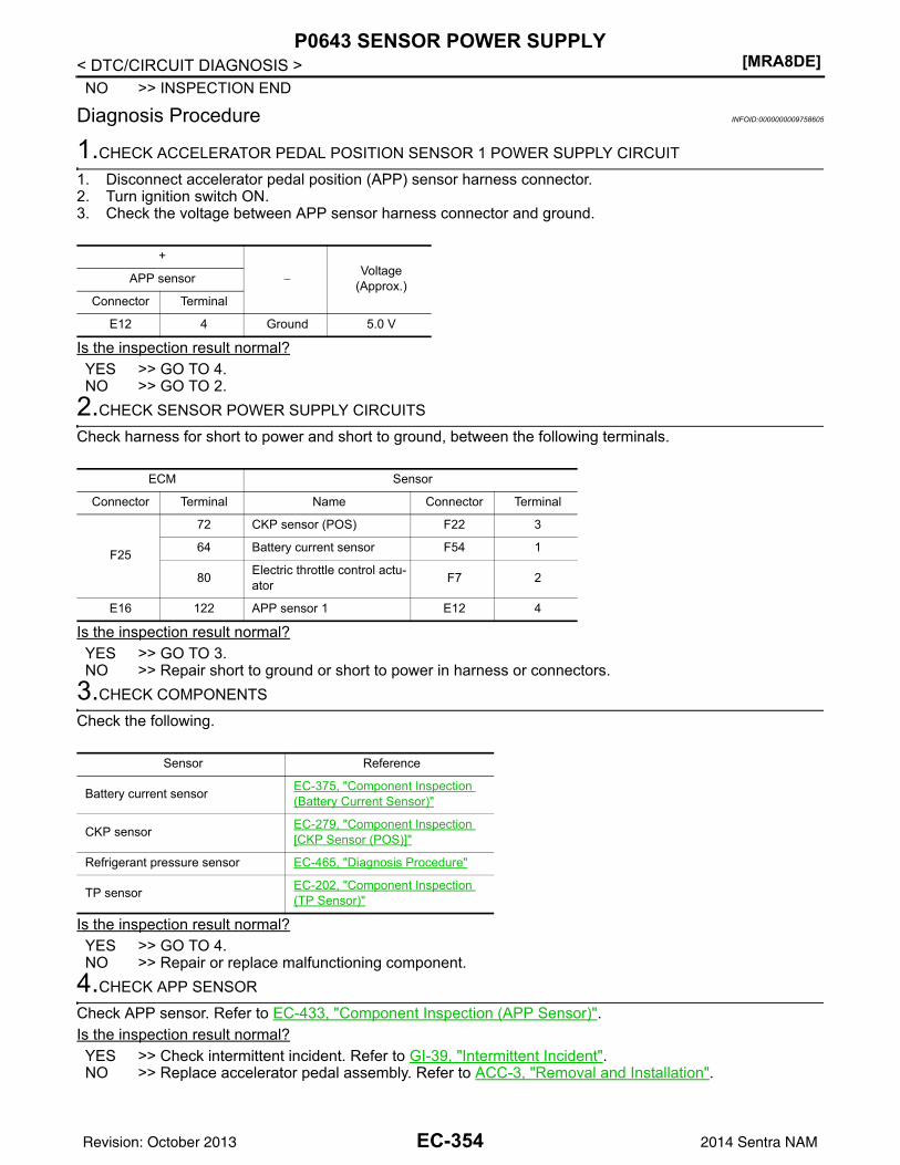
[MRA8DE]P0643 SENSOR POWER SUPPLY
< DTC/CIRCUIT DIAGNOSIS >NO >> INSPECTION END
Diagnosis Procedure INFOID:0000000009758605
1.CHECK ACCELERATOR PEDAL POSITION SENSOR 1 POWER SUPPLY CIRCUIT
1. Disconnect accelerator pedal position (APP) sensor harness connector.2. Turn ignition switch ON.3. Check the voltage between APP sensor harness connector and ground.
Is the inspection result normal?YES >> GO TO 4.NO >> GO TO 2.
2.CHECK SENSOR POWER SUPPLY CIRCUITS
Check harness for short to power and short to ground, between the following terminals.
Is the inspection result normal?YES >> GO TO 3.NO >> Repair short to ground or short to power in harness or connectors.
3.CHECK COMPONENTS
Check the following.
Is the inspection result normal?YES >> GO TO 4.NO >> Repair or replace malfunctioning component.
4.CHECK APP SENSOR
Check APP sensor. Refer to EC-433, "Component Inspection (APP Sensor)".Is the inspection result normal?YES >> Check intermittent incident. Refer to GI-39, "Intermittent Incident".NO >> Replace accelerator pedal assembly. Refer to ACC-3, "Removal and Installation".
+
−Voltage
(Approx.)APP sensor
Connector Terminal
E12 4 Ground 5.0 V
ECM Sensor
Connector Terminal Name Connector Terminal
F25
72 CKP sensor (POS) F22 3
64 Battery current sensor F54 1
80 Electric throttle control actu-ator F7 2
E16 122 APP sensor 1 E12 4
Sensor Reference
Battery current sensor EC-375, "Component Inspection (Battery Current Sensor)"
CKP sensor EC-279, "Component Inspection [CKP Sensor (POS)]"
Refrigerant pressure sensor EC-465, "Diagnosis Procedure"
TP sensor EC-202, "Component Inspection (TP Sensor)"
EC-354Revision: October 2013 2014 Sentra NAM
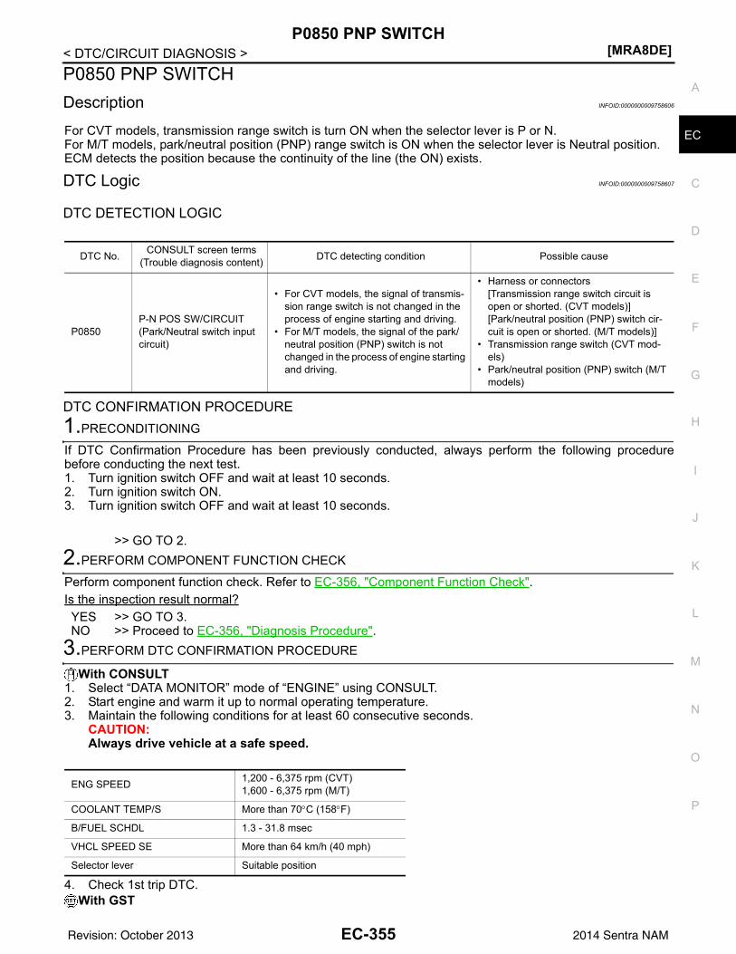
P0850 PNP SWITCH[MRA8DE]
C
D
E
F
G
H
I
J
K
L
M
A
C
N
P
O
< DTC/CIRCUIT DIAGNOSIS >
E
P0850 PNP SWITCHDescription INFOID:0000000009758606
For CVT models, transmission range switch is turn ON when the selector lever is P or N.For M/T models, park/neutral position (PNP) range switch is ON when the selector lever is Neutral position.ECM detects the position because the continuity of the line (the ON) exists.
DTC Logic INFOID:0000000009758607
DTC DETECTION LOGIC
DTC CONFIRMATION PROCEDURE1.PRECONDITIONING
If DTC Confirmation Procedure has been previously conducted, always perform the following procedurebefore conducting the next test. 1. Turn ignition switch OFF and wait at least 10 seconds.2. Turn ignition switch ON.3. Turn ignition switch OFF and wait at least 10 seconds.
>> GO TO 2.2.PERFORM COMPONENT FUNCTION CHECK
Perform component function check. Refer to EC-356, "Component Function Check".Is the inspection result normal?YES >> GO TO 3.NO >> Proceed to EC-356, "Diagnosis Procedure".
3.PERFORM DTC CONFIRMATION PROCEDURE
With CONSULT1. Select “DATA MONITOR” mode of “ENGINE” using CONSULT.2. Start engine and warm it up to normal operating temperature.3. Maintain the following conditions for at least 60 consecutive seconds.
CAUTION:Always drive vehicle at a safe speed.
4. Check 1st trip DTC.With GST
DTC No. CONSULT screen terms(Trouble diagnosis content) DTC detecting condition Possible cause
P0850P-N POS SW/CIRCUIT(Park/Neutral switch input circuit)
• For CVT models, the signal of transmis-sion range switch is not changed in the process of engine starting and driving.
• For M/T models, the signal of the park/neutral position (PNP) switch is not changed in the process of engine starting and driving.
• Harness or connectors[Transmission range switch circuit is open or shorted. (CVT models)][Park/neutral position (PNP) switch cir-cuit is open or shorted. (M/T models)]
• Transmission range switch (CVT mod-els)
• Park/neutral position (PNP) switch (M/T models)
ENG SPEED 1,200 - 6,375 rpm (CVT)1,600 - 6,375 rpm (M/T)
COOLANT TEMP/S More than 70°C (158°F)
B/FUEL SCHDL 1.3 - 31.8 msec
VHCL SPEED SE More than 64 km/h (40 mph)
Selector lever Suitable position
EC-355Revision: October 2013 2014 Sentra NAM
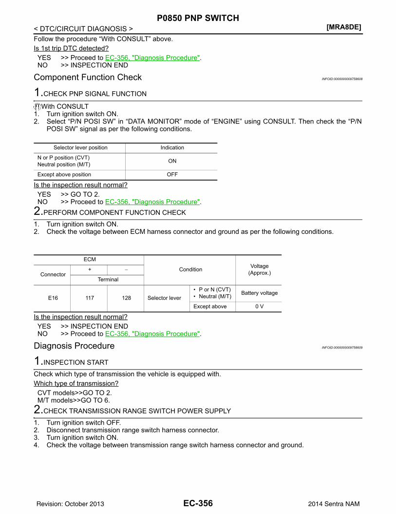
[MRA8DE]P0850 PNP SWITCH
< DTC/CIRCUIT DIAGNOSIS >Follow the procedure “With CONSULT” above.Is 1st trip DTC detected?YES >> Proceed to EC-356, "Diagnosis Procedure".NO >> INSPECTION END
Component Function Check INFOID:0000000009758608
1.CHECK PNP SIGNAL FUNCTION
With CONSULT1. Turn ignition switch ON.2. Select “P/N POSI SW” in “DATA MONITOR” mode of “ENGINE” using CONSULT. Then check the “P/N
POSI SW” signal as per the following conditions.
Is the inspection result normal?YES >> GO TO 2.NO >> Proceed to EC-356, "Diagnosis Procedure".
2.PERFORM COMPONENT FUNCTION CHECK
1. Turn ignition switch ON.2. Check the voltage between ECM harness connector and ground as per the following conditions.
Is the inspection result normal?YES >> INSPECTION ENDNO >> Proceed to EC-356, "Diagnosis Procedure".
Diagnosis Procedure INFOID:0000000009758609
1.INSPECTION START
Check which type of transmission the vehicle is equipped with.Which type of transmission?CVT models>>GO TO 2.M/T models>>GO TO 6.
2.CHECK TRANSMISSION RANGE SWITCH POWER SUPPLY
1. Turn ignition switch OFF.2. Disconnect transmission range switch harness connector.3. Turn ignition switch ON.4. Check the voltage between transmission range switch harness connector and ground.
Selector lever position Indication
N or P position (CVT)Neutral position (M/T) ON
Except above position OFF
ECM
Condition Voltage(Approx.)Connector
+ −
Terminal
E16 117 128 Selector lever• P or N (CVT)• Neutral (M/T) Battery voltage
Except above 0 V
EC-356Revision: October 2013 2014 Sentra NAM
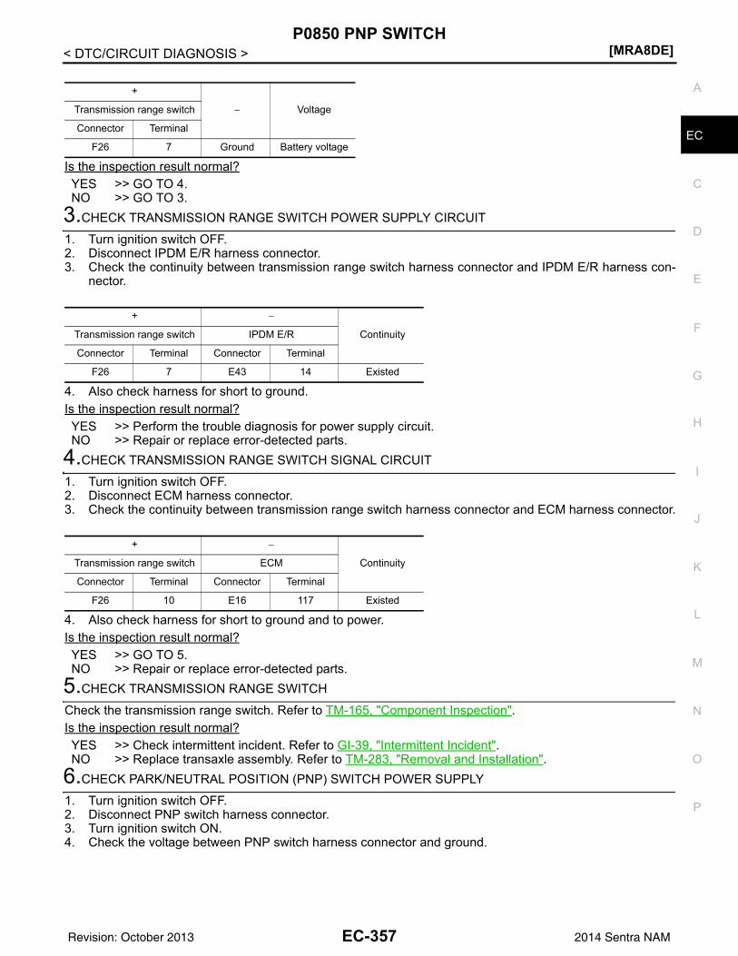
P0850 PNP SWITCH[MRA8DE]
C
D
E
F
G
H
I
J
K
L
M
A
C
N
P
O
< DTC/CIRCUIT DIAGNOSIS >
E
Is the inspection result normal?YES >> GO TO 4.NO >> GO TO 3.
3.CHECK TRANSMISSION RANGE SWITCH POWER SUPPLY CIRCUIT
1. Turn ignition switch OFF.2. Disconnect IPDM E/R harness connector.3. Check the continuity between transmission range switch harness connector and IPDM E/R harness con-
nector.
4. Also check harness for short to ground.Is the inspection result normal?YES >> Perform the trouble diagnosis for power supply circuit.NO >> Repair or replace error-detected parts.
4.CHECK TRANSMISSION RANGE SWITCH SIGNAL CIRCUIT
1. Turn ignition switch OFF.2. Disconnect ECM harness connector.3. Check the continuity between transmission range switch harness connector and ECM harness connector.
4. Also check harness for short to ground and to power.Is the inspection result normal?YES >> GO TO 5.NO >> Repair or replace error-detected parts.
5.CHECK TRANSMISSION RANGE SWITCH
Check the transmission range switch. Refer to TM-165, "Component Inspection".Is the inspection result normal?YES >> Check intermittent incident. Refer to GI-39, "Intermittent Incident".NO >> Replace transaxle assembly. Refer to TM-283, "Removal and Installation".
6.CHECK PARK/NEUTRAL POSITION (PNP) SWITCH POWER SUPPLY
1. Turn ignition switch OFF.2. Disconnect PNP switch harness connector.3. Turn ignition switch ON.4. Check the voltage between PNP switch harness connector and ground.
+
− VoltageTransmission range switch
Connector Terminal
F26 7 Ground Battery voltage
+ −
ContinuityTransmission range switch IPDM E/R
Connector Terminal Connector Terminal
F26 7 E43 14 Existed
+ −
ContinuityTransmission range switch ECM
Connector Terminal Connector Terminal
F26 10 E16 117 Existed
EC-357Revision: October 2013 2014 Sentra NAM
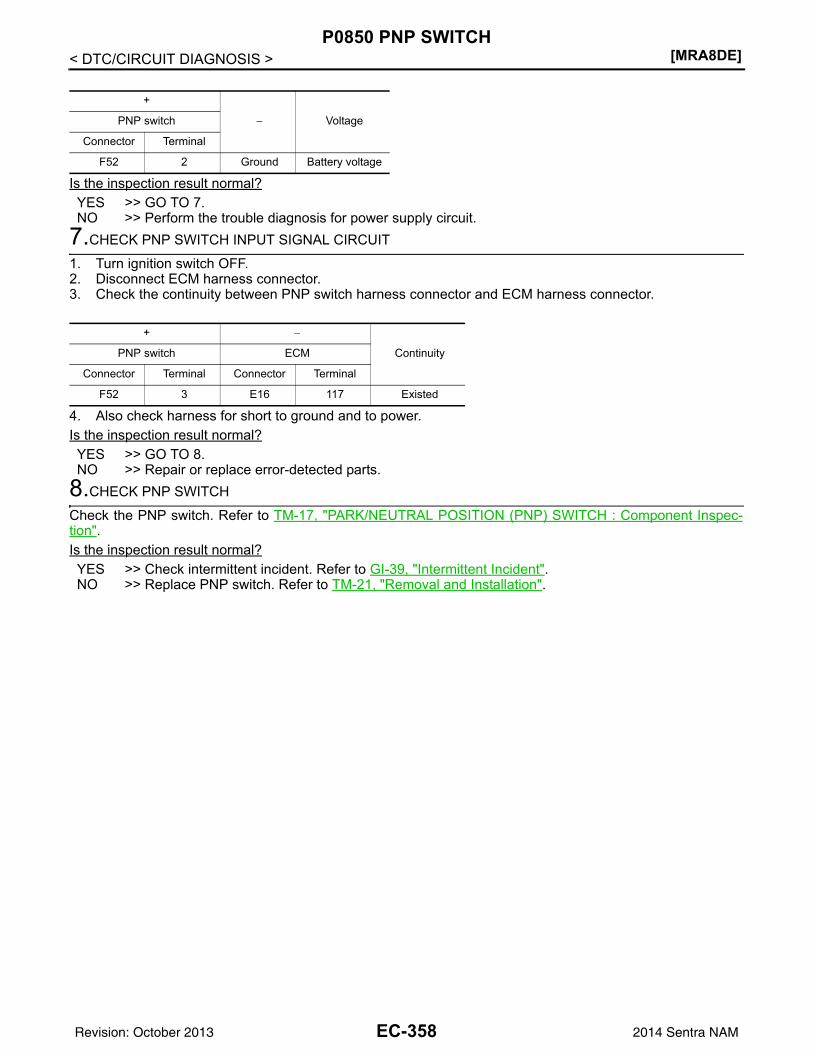
[MRA8DE]P0850 PNP SWITCH
< DTC/CIRCUIT DIAGNOSIS >
Is the inspection result normal?YES >> GO TO 7.NO >> Perform the trouble diagnosis for power supply circuit.
7.CHECK PNP SWITCH INPUT SIGNAL CIRCUIT
1. Turn ignition switch OFF.2. Disconnect ECM harness connector.3. Check the continuity between PNP switch harness connector and ECM harness connector.
4. Also check harness for short to ground and to power.Is the inspection result normal?YES >> GO TO 8.NO >> Repair or replace error-detected parts.
8.CHECK PNP SWITCH
Check the PNP switch. Refer to TM-17, "PARK/NEUTRAL POSITION (PNP) SWITCH : Component Inspec-tion".Is the inspection result normal?YES >> Check intermittent incident. Refer to GI-39, "Intermittent Incident".NO >> Replace PNP switch. Refer to TM-21, "Removal and Installation".
+
− VoltagePNP switch
Connector Terminal
F52 2 Ground Battery voltage
+ −
ContinuityPNP switch ECM
Connector Terminal Connector Terminal
F52 3 E16 117 Existed
EC-358Revision: October 2013 2014 Sentra NAM
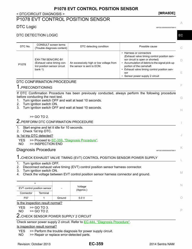
P1078 EVT CONTROL POSITION SENSOR[MRA8DE]
C
D
E
F
G
H
I
J
K
L
M
A
C
N
P
O
< DTC/CIRCUIT DIAGNOSIS >
E
P1078 EVT CONTROL POSITION SENSORDTC Logic INFOID:0000000009758610
DTC DETECTION LOGIC
DTC CONFIRMATION PROCEDURE1.PRECONDITIONING
If DTC Confirmation Procedure has been previously conducted, always perform the following procedurebefore conducting the next test. 1. Turn ignition switch OFF and wait at least 10 seconds.2. Turn ignition switch ON.3. Turn ignition switch OFF and wait at least 10 seconds.
>> GO TO 2.2.PERFORM DTC CONFIRMATION PROCEDURE
1. Start engine and let it idle for 10 seconds.2. Check 1st trip DTC.Is 1st trip DTC detected?YES >> Proceed to EC-359, "Diagnosis Procedure".NO >> INSPECTION END
Diagnosis Procedure INFOID:0000000009758611
1.CHECK EXHAUST VALVE TIMING (EVT) CONTROL POSITION SENSOR POWER SUPPLY
1. Turn ignition switch OFF.2. Disconnect exhaust valve timing (EVT) control position sensor harness connector.3. Turn ignition switch ON.4. Check the voltage between EVT control position sensor harness connector and ground.
Is the inspection result normal?YES >> GO TO 3.NO >> GO TO 2.
2.CHECK SENSOR POWER SUPPLY 2 CIRCUIT
Check sensor power supply 2 circuit. Refer to EC-444, "Diagnosis Procedure".Is inspection result normal?YES >> Perform the trouble diagnosis for power supply circuit.NO >> Repair or replace error-detected parts.
DTC No. CONSULT screen terms(Trouble diagnosis content) DTC detecting condition Possible cause
P1078
EXH TIM SEN/CIRC-B1(Exhaust valve timing con-trol position sensor circuit bank 1)
An excessively high or low voltage from the sensor is sent to ECM.
• Harness or connectors(Exhaust valve timing control position sen-sor circuit is open or shorted)
• Accumulation of debris to the signal pick-up portion of the camshaft
• Exhaust valve timing control position sen-sor
• Sensor power supply 2 circuit
+
−Voltage
(Approx.)EVT control position sensor
Connector Terminal
F57 1 Ground 5.0 V
EC-359Revision: October 2013 2014 Sentra NAM
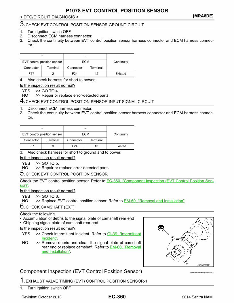
[MRA8DE]P1078 EVT CONTROL POSITION SENSOR
< DTC/CIRCUIT DIAGNOSIS >
3.CHECK EVT CONTROL POSITION SENSOR GROUND CIRCUIT
1. Turn ignition switch OFF.2. Disconnect ECM harness connector.3. Check the continuity between EVT control position sensor harness connector and ECM harness connec-
tor.
4. Also check harness for short to power.Is the inspection result normal?YES >> GO TO 4.NO >> Repair or replace error-detected parts.
4.CHECK EVT CONTROL POSITION SENSOR INPUT SIGNAL CIRCUIT
1. Disconnect ECM harness connector.2. Check the continuity between EVT control position sensor harness connector and ECM harness connec-
tor.
3. Also check harness for short to ground and to power.Is the inspection result normal?YES >> GO TO 5.NO >> Repair or replace error-detected parts.
5.CHECK EVT CONTROL POSITION SENSOR
Check the EVT control position sensor. Refer to EC-360, "Component Inspection (EVT Control Position Sen-sor)".Is the inspection result normal?YES >> GO TO 6.NO >> Replace EVT control position sensor. Refer to EM-60, "Removal and Installation".
6.CHECK CAMSHAFT (EXT)
Check the following.• Accumulation of debris to the signal plate of camshaft rear end• Chipping signal plate of camshaft rear endIs the inspection result normal?YES >> Check intermittent incident. Refer to GI-39, "Intermittent
Incident".NO >> Remove debris and clean the signal plate of camshaft
rear end or replace camshaft. Refer to EM-60, "Removaland Installation".
Component Inspection (EVT Control Position Sensor) INFOID:0000000009758612
1.EXHAUST VALVE TIMING (EVT) CONTROL POSITION SENSOR-1
1. Turn ignition switch OFF.
+ −
ContinuityEVT control position sensor ECM
Connector Terminal Connector Terminal
F57 2 F24 42 Existed
+ −
ContinuityEVT control position sensor ECM
Connector Terminal Connector Terminal
F57 3 F24 43 Existed
JSBIA0600ZZ
EC-360Revision: October 2013 2014 Sentra NAM
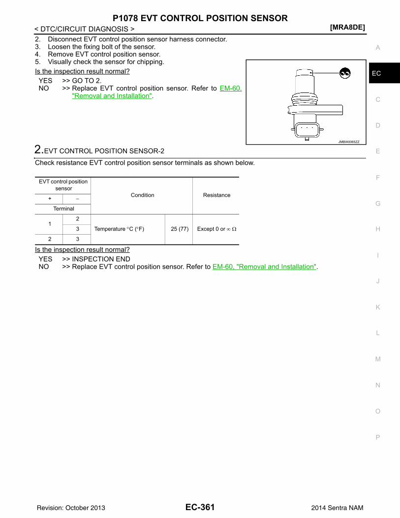
P1078 EVT CONTROL POSITION SENSOR[MRA8DE]
C
D
E
F
G
H
I
J
K
L
M
A
C
N
P
O
< DTC/CIRCUIT DIAGNOSIS >
E
2. Disconnect EVT control position sensor harness connector.3. Loosen the fixing bolt of the sensor.4. Remove EVT control position sensor.5. Visually check the sensor for chipping.Is the inspection result normal?YES >> GO TO 2.NO >> Replace EVT control position sensor. Refer to EM-60,
"Removal and Installation".
2.EVT CONTROL POSITION SENSOR-2
Check resistance EVT control position sensor terminals as shown below.
Is the inspection result normal?YES >> INSPECTION ENDNO >> Replace EVT control position sensor. Refer to EM-60, "Removal and Installation".
JMBIA0065ZZ
EVT control position sensor
Condition Resistance+ −
Terminal
12
Temperature °C (°F) 25 (77) Except 0 or ∞ Ω3
2 3
EC-361Revision: October 2013 2014 Sentra NAM
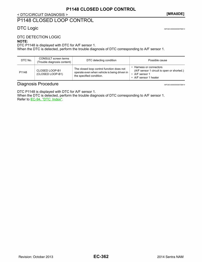
[MRA8DE]P1148 CLOSED LOOP CONTROL
< DTC/CIRCUIT DIAGNOSIS >P1148 CLOSED LOOP CONTROLDTC Logic INFOID:0000000009758613
DTC DETECTION LOGICNOTE:DTC P1148 is displayed with DTC for A/F sensor 1.When the DTC is detected, perform the trouble diagnosis of DTC corresponding to A/F sensor 1.
Diagnosis Procedure INFOID:0000000009758614
DTC P1148 is displayed with DTC for A/F sensor 1. When the DTC is detected, perform the trouble diagnosis of DTC corresponding to A/F sensor 1.Refer to EC-94, "DTC Index".
DTC No. CONSULT screen terms(Trouble diagnosis content) DTC detecting condition Possible cause
P1148 CLOSED LOOP-B1(CLOSED LOOP-B1)
The closed loop control function does not operate even when vehicle is being driven in the specified condition.
• Harness or connectors(A/F sensor 1 circuit is open or shorted.)
• A/F sensor 1• A/F sensor 1 heater
EC-362Revision: October 2013 2014 Sentra NAM
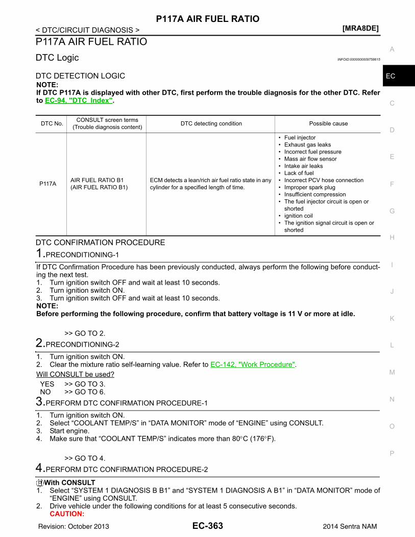
P117A AIR FUEL RATIO[MRA8DE]
C
D
E
F
G
H
I
J
K
L
M
A
C
N
P
O
< DTC/CIRCUIT DIAGNOSIS >
E
P117A AIR FUEL RATIODTC Logic INFOID:0000000009758615
DTC DETECTION LOGICNOTE:If DTC P117A is displayed with other DTC, first perform the trouble diagnosis for the other DTC. Referto EC-94, "DTC Index".
DTC CONFIRMATION PROCEDURE1.PRECONDITIONING-1
If DTC Confirmation Procedure has been previously conducted, always perform the following before conduct-ing the next test. 1. Turn ignition switch OFF and wait at least 10 seconds.2. Turn ignition switch ON.3. Turn ignition switch OFF and wait at least 10 seconds.NOTE:Before performing the following procedure, confirm that battery voltage is 11 V or more at idle.
>> GO TO 2.2.PRECONDITIONING-2
1. Turn ignition switch ON.2. Clear the mixture ratio self-learning value. Refer to EC-142, "Work Procedure".Will CONSULT be used?YES >> GO TO 3.NO >> GO TO 6.
3.PERFORM DTC CONFIRMATION PROCEDURE-1
1. Turn ignition switch ON.2. Select “COOLANT TEMP/S” in “DATA MONITOR” mode of “ENGINE” using CONSULT.3. Start engine.4. Make sure that “COOLANT TEMP/S” indicates more than 80°C (176°F).
>> GO TO 4.4.PERFORM DTC CONFIRMATION PROCEDURE-2
With CONSULT1. Select “SYSTEM 1 DIAGNOSIS B B1” and “SYSTEM 1 DIAGNOSIS A B1” in “DATA MONITOR” mode of
“ENGINE” using CONSULT.2. Drive vehicle under the following conditions for at least 5 consecutive seconds.
CAUTION:
DTC No. CONSULT screen terms(Trouble diagnosis content) DTC detecting condition Possible cause
P117A AIR FUEL RATIO B1(AIR FUEL RATIO B1)
ECM detects a lean/rich air fuel ratio state in any cylinder for a specified length of time.
• Fuel injector• Exhaust gas leaks• Incorrect fuel pressure• Mass air flow sensor• Intake air leaks• Lack of fuel• Incorrect PCV hose connection• Improper spark plug• Insufficient compression• The fuel injector circuit is open or
shorted• ignition coil• The ignition signal circuit is open or
shorted
EC-363Revision: October 2013 2014 Sentra NAM
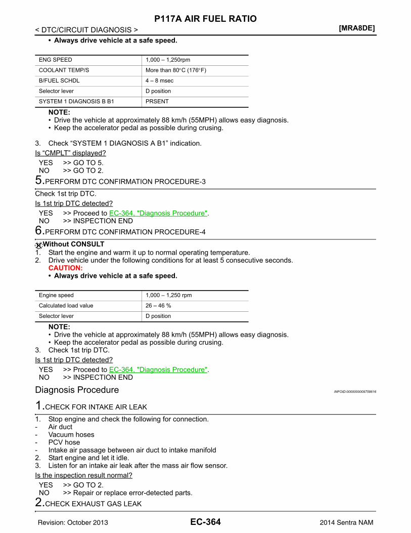
[MRA8DE]P117A AIR FUEL RATIO
< DTC/CIRCUIT DIAGNOSIS >• Always drive vehicle at a safe speed.
NOTE:• Drive the vehicle at approximately 88 km/h (55MPH) allows easy diagnosis.• Keep the accelerator pedal as possible during crusing.
3. Check “SYSTEM 1 DIAGNOSIS A B1” indication.Is “CMPLT” displayed?YES >> GO TO 5.NO >> GO TO 2.
5.PERFORM DTC CONFIRMATION PROCEDURE-3
Check 1st trip DTC.Is 1st trip DTC detected?YES >> Proceed to EC-364, "Diagnosis Procedure".NO >> INSPECTION END
6.PERFORM DTC CONFIRMATION PROCEDURE-4
Without CONSULT1. Start the engine and warm it up to normal operating temperature.2. Drive vehicle under the following conditions for at least 5 consecutive seconds.
CAUTION:• Always drive vehicle at a safe speed.
NOTE:• Drive the vehicle at approximately 88 km/h (55MPH) allows easy diagnosis.• Keep the accelerator pedal as possible during crusing.
3. Check 1st trip DTC.Is 1st trip DTC detected?YES >> Proceed to EC-364, "Diagnosis Procedure".NO >> INSPECTION END
Diagnosis Procedure INFOID:0000000009758616
1.CHECK FOR INTAKE AIR LEAK
1. Stop engine and check the following for connection.- Air duct- Vacuum hoses- PCV hose- Intake air passage between air duct to intake manifold2. Start engine and let it idle.3. Listen for an intake air leak after the mass air flow sensor.Is the inspection result normal?YES >> GO TO 2.NO >> Repair or replace error-detected parts.
2.CHECK EXHAUST GAS LEAK
ENG SPEED 1,000 – 1,250rpm
COOLANT TEMP/S More than 80°C (176°F)
B/FUEL SCHDL 4 – 8 msec
Selector lever D position
SYSTEM 1 DIAGNOSIS B B1 PRSENT
Engine speed 1,000 – 1,250 rpm
Calculated load value 26 – 46 %
Selector lever D position
EC-364Revision: October 2013 2014 Sentra NAM
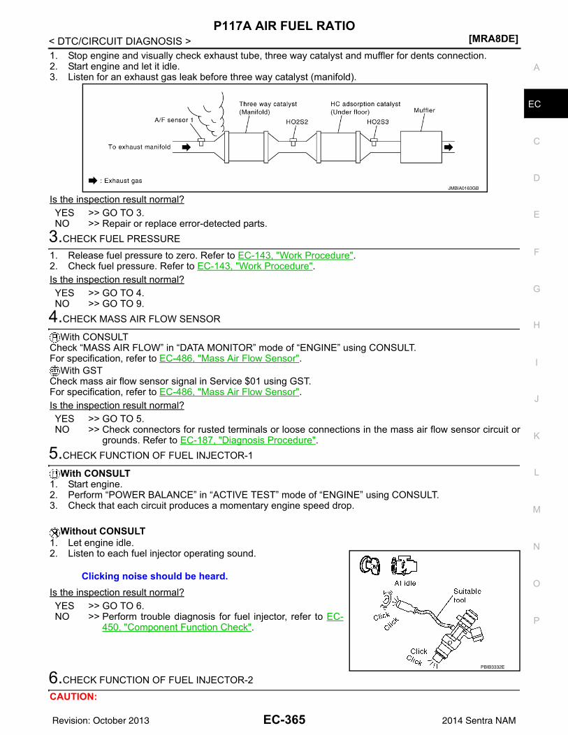
P117A AIR FUEL RATIO[MRA8DE]
C
D
E
F
G
H
I
J
K
L
M
A
C
N
P
O
< DTC/CIRCUIT DIAGNOSIS >
E
1. Stop engine and visually check exhaust tube, three way catalyst and muffler for dents connection.2. Start engine and let it idle.3. Listen for an exhaust gas leak before three way catalyst (manifold).
Is the inspection result normal?YES >> GO TO 3.NO >> Repair or replace error-detected parts.
3.CHECK FUEL PRESSURE
1. Release fuel pressure to zero. Refer to EC-143, "Work Procedure".2. Check fuel pressure. Refer to EC-143, "Work Procedure".Is the inspection result normal?YES >> GO TO 4.NO >> GO TO 9.
4.CHECK MASS AIR FLOW SENSOR
With CONSULTCheck “MASS AIR FLOW” in “DATA MONITOR” mode of “ENGINE” using CONSULT.For specification, refer to EC-486, "Mass Air Flow Sensor".
With GSTCheck mass air flow sensor signal in Service $01 using GST.For specification, refer to EC-486, "Mass Air Flow Sensor".Is the inspection result normal?YES >> GO TO 5.NO >> Check connectors for rusted terminals or loose connections in the mass air flow sensor circuit or
grounds. Refer to EC-187, "Diagnosis Procedure".5.CHECK FUNCTION OF FUEL INJECTOR-1
With CONSULT1. Start engine.2. Perform “POWER BALANCE” in “ACTIVE TEST” mode of “ENGINE” using CONSULT.3. Check that each circuit produces a momentary engine speed drop.
Without CONSULT1. Let engine idle.2. Listen to each fuel injector operating sound.
Is the inspection result normal?YES >> GO TO 6.NO >> Perform trouble diagnosis for fuel injector, refer to EC-
450, "Component Function Check".
6.CHECK FUNCTION OF FUEL INJECTOR-2
CAUTION:
JMBIA0163GB
Clicking noise should be heard.
PBIB3332E
EC-365Revision: October 2013 2014 Sentra NAM
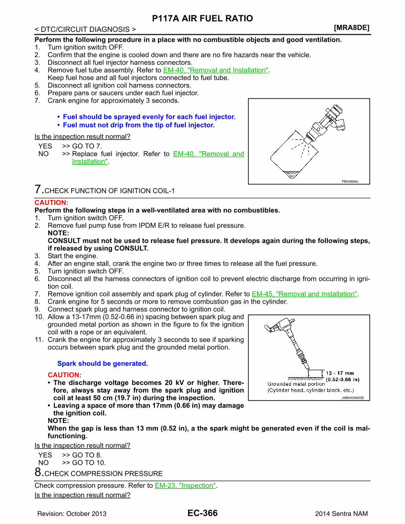
[MRA8DE]P117A AIR FUEL RATIO
< DTC/CIRCUIT DIAGNOSIS >Perform the following procedure in a place with no combustible objects and good ventilation.1. Turn ignition switch OFF.2. Confirm that the engine is cooled down and there are no fire hazards near the vehicle.3. Disconnect all fuel injector harness connectors.4. Remove fuel tube assembly. Refer to EM-40, "Removal and Installation".
Keep fuel hose and all fuel injectors connected to fuel tube.5. Disconnect all ignition coil harness connectors.6. Prepare pans or saucers under each fuel injector.7. Crank engine for approximately 3 seconds.
Is the inspection result normal?YES >> GO TO 7.NO >> Replace fuel injector. Refer to EM-40, "Removal and
Installation".
7.CHECK FUNCTION OF IGNITION COIL-1
CAUTION:Perform the following steps in a well-ventilated area with no combustibles.1. Turn ignition switch OFF.2. Remove fuel pump fuse from IPDM E/R to release fuel pressure.
NOTE:CONSULT must not be used to release fuel pressure. It develops again during the following steps,if released by using CONSULT.
3. Start the engine.4. After an engine stall, crank the engine two or three times to release all the fuel pressure. 5. Turn ignition switch OFF.6. Disconnect all the harness connectors of ignition coil to prevent electric discharge from occurring in igni-
tion coil.7. Remove ignition coil assembly and spark plug of cylinder. Refer to EM-45, "Removal and Installation".8. Crank engine for 5 seconds or more to remove combustion gas in the cylinder.9. Connect spark plug and harness connector to ignition coil.10. Allow a 13-17mm (0.52-0.66 in) spacing between spark plug and
grounded metal portion as shown in the figure to fix the ignitioncoil with a rope or an equivalent.
11. Crank the engine for approximately 3 seconds to see if sparkingoccurs between spark plug and the grounded metal portion.
CAUTION:• The discharge voltage becomes 20 kV or higher. There-
fore, always stay away from the spark plug and ignitioncoil at least 50 cm (19.7 in) during the inspection.
• Leaving a space of more than 17mm (0.66 in) may damagethe ignition coil.
NOTE:When the gap is less than 13 mm (0.52 in), a the spark might be generated even if the coil is mal-functioning.
Is the inspection result normal?YES >> GO TO 8.NO >> GO TO 10.
8.CHECK COMPRESSION PRESSURE
Check compression pressure. Refer to EM-23, "Inspection".Is the inspection result normal?
• Fuel should be sprayed evenly for each fuel injector.• Fuel must not drip from the tip of fuel injector.
PBIA9666J
Spark should be generated.
JMBIA0066GB
EC-366Revision: October 2013 2014 Sentra NAM
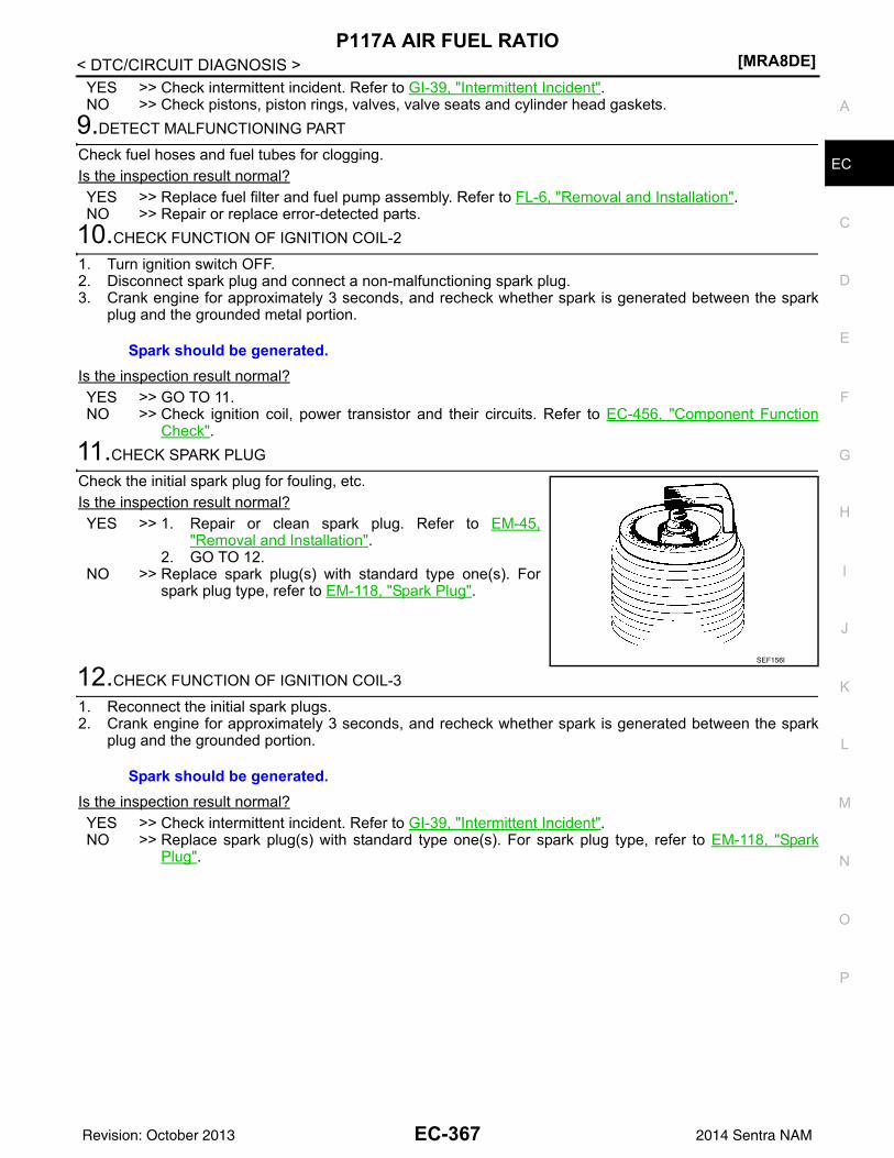
P117A AIR FUEL RATIO[MRA8DE]
C
D
E
F
G
H
I
J
K
L
M
A
C
N
P
O
< DTC/CIRCUIT DIAGNOSIS >
E
YES >> Check intermittent incident. Refer to GI-39, "Intermittent Incident".NO >> Check pistons, piston rings, valves, valve seats and cylinder head gaskets.
9.DETECT MALFUNCTIONING PART
Check fuel hoses and fuel tubes for clogging.Is the inspection result normal?YES >> Replace fuel filter and fuel pump assembly. Refer to FL-6, "Removal and Installation".NO >> Repair or replace error-detected parts.
10.CHECK FUNCTION OF IGNITION COIL-2
1. Turn ignition switch OFF.2. Disconnect spark plug and connect a non-malfunctioning spark plug.3. Crank engine for approximately 3 seconds, and recheck whether spark is generated between the spark
plug and the grounded metal portion.
Is the inspection result normal?YES >> GO TO 11.NO >> Check ignition coil, power transistor and their circuits. Refer to EC-456, "Component Function
Check".11.CHECK SPARK PLUG
Check the initial spark plug for fouling, etc.Is the inspection result normal?YES >> 1. Repair or clean spark plug. Refer to EM-45,
"Removal and Installation".2. GO TO 12.
NO >> Replace spark plug(s) with standard type one(s). Forspark plug type, refer to EM-118, "Spark Plug".
12.CHECK FUNCTION OF IGNITION COIL-3
1. Reconnect the initial spark plugs.2. Crank engine for approximately 3 seconds, and recheck whether spark is generated between the spark
plug and the grounded portion.
Is the inspection result normal?YES >> Check intermittent incident. Refer to GI-39, "Intermittent Incident".NO >> Replace spark plug(s) with standard type one(s). For spark plug type, refer to EM-118, "Spark
Plug".
Spark should be generated.
SEF156I
Spark should be generated.
EC-367Revision: October 2013 2014 Sentra NAM
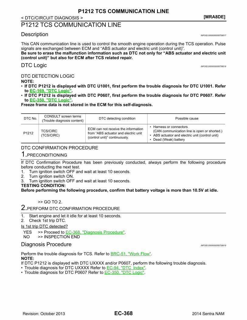
[MRA8DE]P1212 TCS COMMUNICATION LINE
< DTC/CIRCUIT DIAGNOSIS >P1212 TCS COMMUNICATION LINEDescription INFOID:0000000009758617
This CAN communication line is used to control the smooth engine operation during the TCS operation. Pulsesignals are exchanged between ECM and “ABS actuator and electric unit (control unit)”.Be sure to erase the malfunction information such as DTC not only for “ABS actuator and electric unit(control unit)” but also for ECM after TCS related repair.
DTC Logic INFOID:0000000009758618
DTC DETECTION LOGICNOTE:• If DTC P1212 is displayed with DTC U1001, first perform the trouble diagnosis for DTC U1001. Refer
to EC-169, "DTC Logic".• If DTC P1212 is displayed with DTC P0607, first perform the trouble diagnosis for DTC P0607. Refer
to EC-350, "DTC Logic".Freeze frame data is not stored in the ECM for this self-diagnosis.
DTC CONFIRMATION PROCEDURE1.PRECONDITIONING
If DTC Confirmation Procedure has been previously conducted, always perform the following procedurebefore conducting the next test.1. Turn ignition switch OFF and wait at least 10 seconds.2. Turn ignition switch ON.3. Turn ignition switch OFF and wait at least 10 seconds.TESTING CONDITION:Before performing the following procedure, confirm that battery voltage is more than 10.5V at idle.
>> GO TO 2.2.PERFORM DTC CONFIRMATION PROCEDURE
1. Start engine and let it idle for at least 10 seconds.2. Check 1st trip DTC.Is 1st trip DTC detected?YES >> Proceed to EC-368, "Diagnosis Procedure".NO >> INSPECTION END
Diagnosis Procedure INFOID:0000000009758619
Perform the trouble diagnosis for TCS. Refer to BRC-51, "Work Flow".NOTE:If DTC P1212 is displayed with DTC UXXXX and/or P0607, perform the following trouble diagnosis.• Trouble diagnosis for DTC UXXXX Refer to EC-94, "DTC Index".• Trouble diagnosis for DTC P0607 Refer to EC-350, "DTC Logic".
DTC No. CONSULT screen terms(Trouble diagnosis content) DTC detecting condition Possible cause
P1212 TCS/CIRC(TCS/CIRC)
ECM can not receive the information from “ABS actuator and electric unit (control unit)” continuously.
• Harness or connectors(CAN communication line is open or shorted.)
• ABS actuator and electric unit (control unit)• Dead (Weak) battery
EC-368Revision: October 2013 2014 Sentra NAM
P1217 ENGINE OVER TEMPERATURE[MRA8DE]
C
D
E
F
G
H
I
J
K
L
M
A
C
N
P
O
< DTC/CIRCUIT DIAGNOSIS >
E
P1217 ENGINE OVER TEMPERATUREDTC Logic INFOID:0000000009758620
DTC DETECTION LOGICNOTE:• If DTC P1217 is displayed with DTC UXXXX, first perform the trouble diagnosis for DTC UXXXX.• If DTC P1217 is displayed with DTC P0607, first perform the trouble diagnosis for DTC P0607. Refer
to EC-350, "DTC Logic".If the cooling fan or another component in the cooling system malfunctions, engine coolant temperature willrise.When the engine coolant temperature reaches an abnormally high temperature condition, a malfunction isindicated.
CAUTION:When a malfunction is indicated, be sure to replace the coolant. Refer to CO-12, "Changing EngineCoolant". Also, replace the engine oil. Refer to LU-9, "Refilling".1. Fill radiator with coolant up to specified level with a filling speed of 2 liters per minute. Be sure to
use coolant with the proper mixture ratio. Refer to MA-12, "Engine Coolant Mixture Ratio".2. After refilling coolant, run engine to ensure that no water-flow noise is emitted.
DTC CONFIRMATION PROCEDURE1.PERFORM COMPONENT FUNCTION CHECK
Perform component function check. Refer to EC-369, "Component Function Check".NOTE:Use component function check to check the overall function of the cooling fan. During this check, a DTC mightnot be confirmed.Is the inspection result normal?YES >> INSPECTION ENDNO >> Proceed to EC-370, "Diagnosis Procedure".
Component Function Check INFOID:0000000009758621
1.PERFORM COMPONENT FUNCTION CHECK-1
WARNING:Never remove the radiator cap when the engine is hot. Serious burns could be caused by high pres-sure fluid escaping from the radiator.Wrap a thick cloth around cap. Carefully remove the cap by turning it a quarter turn to allow built-uppressure to escape. Then turn the cap all the way off.
DTC No.CONSULT screen terms(Trouble diagnosis con-
tent)DTC detecting condition Possible cause
P1217ENG OVER TEMP(Engine over tempera-ture)
• Cooling fan does not operate properly (Over-heat).
• Cooling fan system does not operate properly (Overheat).
• Engine coolant was not added to the system using the proper filling method.
• Engine coolant is not within the specified range.
• Harness or connectors(Cooling fan circuit is open or shorted.)
• IPDM E/R• Cooling fan motor• Radiator hose• Radiator• Radiator cap• Reservoir tank• Water pump• Thermostat
EC-369Revision: October 2013 2014 Sentra NAM
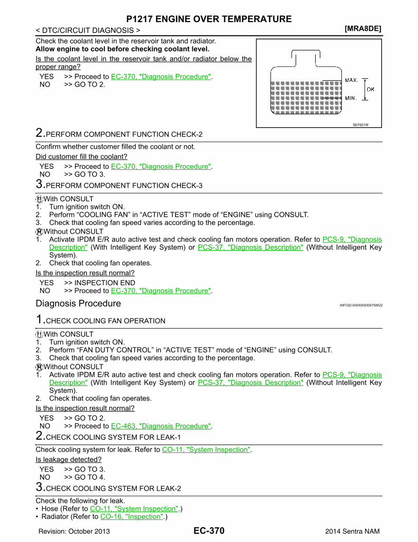
[MRA8DE]P1217 ENGINE OVER TEMPERATURE
< DTC/CIRCUIT DIAGNOSIS >Check the coolant level in the reservoir tank and radiator.Allow engine to cool before checking coolant level.Is the coolant level in the reservoir tank and/or radiator below theproper range?YES >> Proceed to EC-370, "Diagnosis Procedure".NO >> GO TO 2.
2.PERFORM COMPONENT FUNCTION CHECK-2
Confirm whether customer filled the coolant or not.Did customer fill the coolant?YES >> Proceed to EC-370, "Diagnosis Procedure".NO >> GO TO 3.
3.PERFORM COMPONENT FUNCTION CHECK-3
With CONSULT1. Turn ignition switch ON.2. Perform “COOLING FAN” in “ACTIVE TEST” mode of “ENGINE” using CONSULT.3. Check that cooling fan speed varies according to the percentage.
Without CONSULT1. Activate IPDM E/R auto active test and check cooling fan motors operation. Refer to PCS-9, "Diagnosis
Description" (With Intelligent Key System) or PCS-37, "Diagnosis Description" (Without Intelligent KeySystem).
2. Check that cooling fan operates.Is the inspection result normal?YES >> INSPECTION ENDNO >> Proceed to EC-370, "Diagnosis Procedure".
Diagnosis Procedure INFOID:0000000009758622
1.CHECK COOLING FAN OPERATION
With CONSULT1. Turn ignition switch ON.2. Perform “FAN DUTY CONTROL” in “ACTIVE TEST” mode of “ENGINE” using CONSULT.3. Check that cooling fan speed varies according to the percentage.
Without CONSULT1. Activate IPDM E/R auto active test and check cooling fan motors operation. Refer to PCS-9, "Diagnosis
Description" (With Intelligent Key System) or PCS-37, "Diagnosis Description" (Without Intelligent KeySystem).
2. Check that cooling fan operates.Is the inspection result normal?YES >> GO TO 2.NO >> Proceed to EC-463, "Diagnosis Procedure".
2.CHECK COOLING SYSTEM FOR LEAK-1
Check cooling system for leak. Refer to CO-11, "System Inspection".Is leakage detected?YES >> GO TO 3.NO >> GO TO 4.
3.CHECK COOLING SYSTEM FOR LEAK-2
Check the following for leak.• Hose (Refer to CO-11, "System Inspection".)• Radiator (Refer to CO-16, "Inspection".)
SEF621W
EC-370Revision: October 2013 2014 Sentra NAM
P1217 ENGINE OVER TEMPERATURE[MRA8DE]
C
D
E
F
G
H
I
J
K
L
M
A
C
N
P
O
< DTC/CIRCUIT DIAGNOSIS >
E
• Water pump (Refer to CO-19, "Removal and Installation".)
>> Repair or replace malfunctioning part.4.CHECK RADIATOR CAP
Check radiator cap. Refer to CO-11, "System Inspection".Is the inspection result normal?YES >> GO TO 5.NO >> Replace radiator cap. Refer to CO-15, "Exploded View".
5.CHECK THERMOSTAT
Check thermostat. Refer to CO-23, "Inspection".Is the inspection result normal?YES >> GO TO 6.NO >> Replace thermostat. Refer to CO-21, "Removal and Installation of Thermostat".
6.CHECK WATER CONTROL VALVE
Check water control valve. Refer to CO-25, "Removal and Installation".Is the inspection result normal?YES >> GO TO 7.NO >> Replace water control valve. Refer to CO-25, "Removal and Installation".
7.CHECK ENGINE COOLANT TEMPERATURE SENSOR
Refer to EC-199, "Component Inspection (ECT Sensor)".Is the inspection result normal?YES >> GO TO 8.NO >> Replace engine coolant temperature sensor. Refer to CO-24, "Exploded View".
8.OVERHEATING CAUSE ANALYSIS
If the cause cannot be isolated, check the CO-9, "Troubleshooting Chart".
>> INSPECTION END
EC-371Revision: October 2013 2014 Sentra NAM
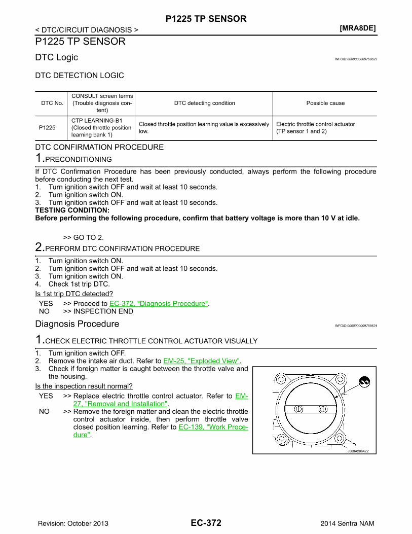
[MRA8DE]P1225 TP SENSOR
< DTC/CIRCUIT DIAGNOSIS >P1225 TP SENSORDTC Logic INFOID:0000000009758623
DTC DETECTION LOGIC
DTC CONFIRMATION PROCEDURE1.PRECONDITIONING
If DTC Confirmation Procedure has been previously conducted, always perform the following procedurebefore conducting the next test.1. Turn ignition switch OFF and wait at least 10 seconds.2. Turn ignition switch ON.3. Turn ignition switch OFF and wait at least 10 seconds.TESTING CONDITION:Before performing the following procedure, confirm that battery voltage is more than 10 V at idle.
>> GO TO 2.2.PERFORM DTC CONFIRMATION PROCEDURE
1. Turn ignition switch ON.2. Turn ignition switch OFF and wait at least 10 seconds.3. Turn ignition switch ON.4. Check 1st trip DTC.Is 1st trip DTC detected?YES >> Proceed to EC-372, "Diagnosis Procedure".NO >> INSPECTION END
Diagnosis Procedure INFOID:0000000009758624
1.CHECK ELECTRIC THROTTLE CONTROL ACTUATOR VISUALLY
1. Turn ignition switch OFF.2. Remove the intake air duct. Refer to EM-25, "Exploded View".3. Check if foreign matter is caught between the throttle valve and
the housing.Is the inspection result normal?YES >> Replace electric throttle control actuator. Refer to EM-
27, "Removal and Installation".NO >> Remove the foreign matter and clean the electric throttle
control actuator inside, then perform throttle valveclosed position learning. Refer to EC-139, "Work Proce-dure".
DTC No.CONSULT screen terms(Trouble diagnosis con-
tent)DTC detecting condition Possible cause
P1225CTP LEARNING-B1(Closed throttle position learning bank 1)
Closed throttle position learning value is excessively low.
Electric throttle control actuator(TP sensor 1 and 2)
JSBIA2864ZZ
EC-372Revision: October 2013 2014 Sentra NAM
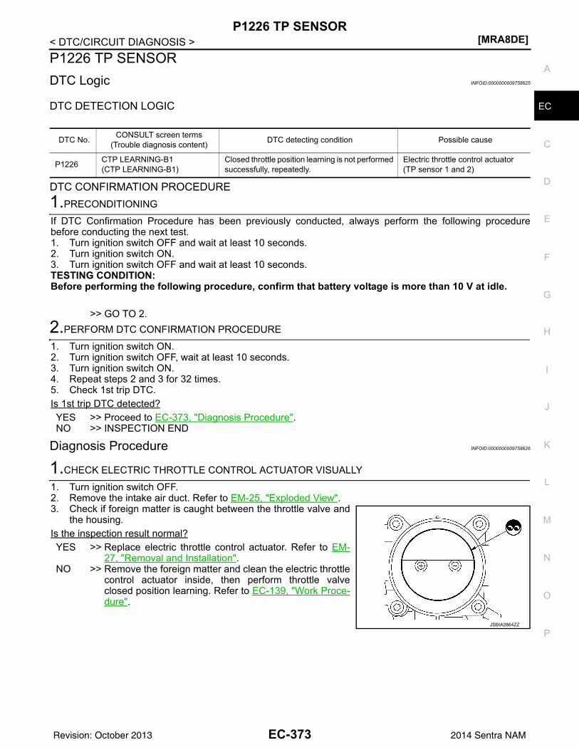
P1226 TP SENSOR[MRA8DE]
C
D
E
F
G
H
I
J
K
L
M
A
C
N
P
O
< DTC/CIRCUIT DIAGNOSIS >
E
P1226 TP SENSORDTC Logic INFOID:0000000009758625
DTC DETECTION LOGIC
DTC CONFIRMATION PROCEDURE1.PRECONDITIONING
If DTC Confirmation Procedure has been previously conducted, always perform the following procedurebefore conducting the next test.1. Turn ignition switch OFF and wait at least 10 seconds.2. Turn ignition switch ON.3. Turn ignition switch OFF and wait at least 10 seconds.TESTING CONDITION:Before performing the following procedure, confirm that battery voltage is more than 10 V at idle.
>> GO TO 2.2.PERFORM DTC CONFIRMATION PROCEDURE
1. Turn ignition switch ON.2. Turn ignition switch OFF, wait at least 10 seconds.3. Turn ignition switch ON.4. Repeat steps 2 and 3 for 32 times.5. Check 1st trip DTC.Is 1st trip DTC detected?YES >> Proceed to EC-373, "Diagnosis Procedure".NO >> INSPECTION END
Diagnosis Procedure INFOID:0000000009758626
1.CHECK ELECTRIC THROTTLE CONTROL ACTUATOR VISUALLY
1. Turn ignition switch OFF.2. Remove the intake air duct. Refer to EM-25, "Exploded View".3. Check if foreign matter is caught between the throttle valve and
the housing.Is the inspection result normal?YES >> Replace electric throttle control actuator. Refer to EM-
27, "Removal and Installation".NO >> Remove the foreign matter and clean the electric throttle
control actuator inside, then perform throttle valveclosed position learning. Refer to EC-139, "Work Proce-dure".
DTC No. CONSULT screen terms(Trouble diagnosis content) DTC detecting condition Possible cause
P1226 CTP LEARNING-B1(CTP LEARNING-B1)
Closed throttle position learning is not performed successfully, repeatedly.
Electric throttle control actuator(TP sensor 1 and 2)
JSBIA2864ZZ
EC-373Revision: October 2013 2014 Sentra NAM
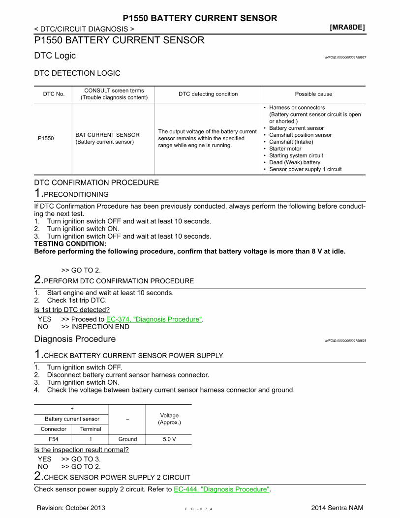
[MRA8DE]P1550 BATTERY CURRENT SENSOR
< DTC/CIRCUIT DIAGNOSIS >P1550 BATTERY CURRENT SENSORDTC Logic INFOID:0000000009758627
DTC DETECTION LOGIC
DTC CONFIRMATION PROCEDURE1.PRECONDITIONING
If DTC Confirmation Procedure has been previously conducted, always perform the following before conduct-ing the next test. 1. Turn ignition switch OFF and wait at least 10 seconds.2. Turn ignition switch ON.3. Turn ignition switch OFF and wait at least 10 seconds.TESTING CONDITION:Before performing the following procedure, confirm that battery voltage is more than 8 V at idle.
>> GO TO 2.2.PERFORM DTC CONFIRMATION PROCEDURE
1. Start engine and wait at least 10 seconds.2. Check 1st trip DTC.Is 1st trip DTC detected?YES >> Proceed to EC-374, "Diagnosis Procedure".NO >> INSPECTION END
Diagnosis Procedure INFOID:0000000009758628
1.CHECK BATTERY CURRENT SENSOR POWER SUPPLY
1. Turn ignition switch OFF.2. Disconnect battery current sensor harness connector.3. Turn ignition switch ON.4. Check the voltage between battery current sensor harness connector and ground.
Is the inspection result normal?YES >> GO TO 3.NO >> GO TO 2.
2.CHECK SENSOR POWER SUPPLY 2 CIRCUIT
Check sensor power supply 2 circuit. Refer to EC-444, "Diagnosis Procedure".
DTC No. CONSULT screen terms(Trouble diagnosis content) DTC detecting condition Possible cause
P1550 BAT CURRENT SENSOR(Battery current sensor)
The output voltage of the battery current sensor remains within the specified range while engine is running.
• Harness or connectors(Battery current sensor circuit is open or shorted.)
• Battery current sensor• Camshaft position sensor• Camshaft (Intake)• Starter motor• Starting system circuit• Dead (Weak) battery• Sensor power supply 1 circuit
+
−Voltage
(Approx.)Battery current sensor
Connector Terminal
F54 1 Ground 5.0 V
E C - 3 7 4Revision: October 2013 2014 Sentra NAM
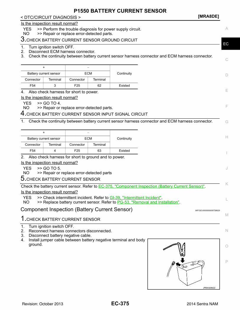
P1550 BATTERY CURRENT SENSOR[MRA8DE]
C
D
E
F
G
H
I
J
K
L
M
A
C
N
P
O
< DTC/CIRCUIT DIAGNOSIS >
E
Is the inspection result normal?YES >> Perform the trouble diagnosis for power supply circuit.NO >> Repair or replace error-detected parts.
3.CHECK BATTERY CURRENT SENSOR GROUND CIRCUIT
1. Turn ignition switch OFF.2. Disconnect ECM harness connector.3. Check the continuity between battery current sensor harness connector and ECM harness connector.
4. Also check harness for short to power.Is the inspection result normal?YES >> GO TO 4.NO >> Repair or replace error-detected parts.
4.CHECK BATTERY CURRENT SENSOR INPUT SIGNAL CIRCUIT
1. Check the continuity between battery current sensor harness connector and ECM harness connector.
2. Also check harness for short to ground and to power.Is the inspection result normal?YES >> GO TO 5.NO >> Repair or replace error-detected parts
5.CHECK BATTERY CURRENT SENSOR
Check the battery current sensor. Refer to EC-375, "Component Inspection (Battery Current Sensor)".Is the inspection result normal?YES >> Check intermittent incident. Refer to GI-39, "Intermittent Incident".NO >> Replace battery current sensor. Refer to PG-53, "Removal and Installation".
Component Inspection (Battery Current Sensor) INFOID:0000000009758629
1.CHECK BATTERY CURRENT SENSOR
1. Turn ignition switch OFF.2. Reconnect harness connectors disconnected.3. Disconnect battery negative cable.4. Install jumper cable between battery negative terminal and body
ground.
+ −
ContinuityBattery current sensor ECM
Connector Terminal Connector Terminal
F54 3 F25 62 Existed
+ −
ContinuityBattery current sensor ECM
Connector Terminal Connector Terminal
F54 4 F25 63 Existed
JPBIA3286ZZ
EC-375Revision: October 2013 2014 Sentra NAM
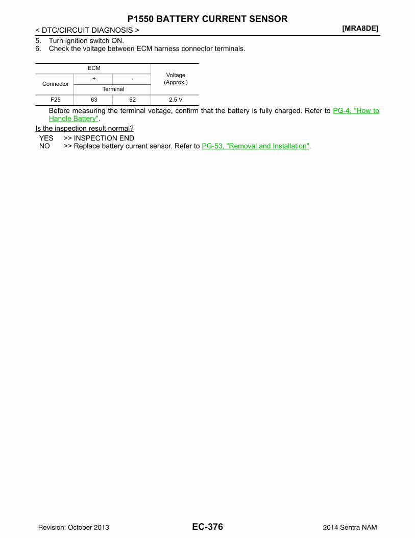
[MRA8DE]P1550 BATTERY CURRENT SENSOR
< DTC/CIRCUIT DIAGNOSIS >5. Turn ignition switch ON.6. Check the voltage between ECM harness connector terminals.
Before measuring the terminal voltage, confirm that the battery is fully charged. Refer to PG-4, "How toHandle Battery".
Is the inspection result normal?YES >> INSPECTION ENDNO >> Replace battery current sensor. Refer to PG-53, "Removal and Installation".
ECMVoltage
(Approx.)Connector+ -
Terminal
F25 63 62 2.5 V
EC-376Revision: October 2013 2014 Sentra NAM
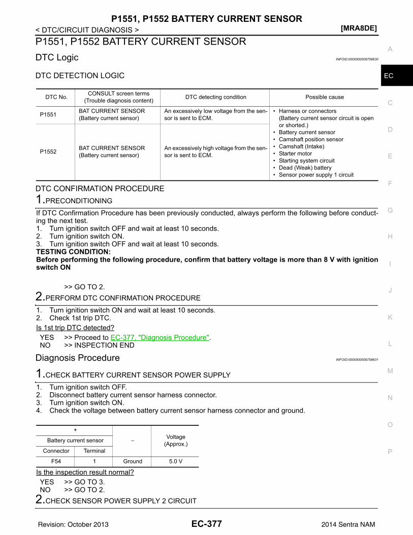
P1551, P1552 BATTERY CURRENT SENSOR[MRA8DE]
C
D
E
F
G
H
I
J
K
L
M
A
C
N
P
O
< DTC/CIRCUIT DIAGNOSIS >
E
P1551, P1552 BATTERY CURRENT SENSORDTC Logic INFOID:0000000009758630
DTC DETECTION LOGIC
DTC CONFIRMATION PROCEDURE1.PRECONDITIONING
If DTC Confirmation Procedure has been previously conducted, always perform the following before conduct-ing the next test. 1. Turn ignition switch OFF and wait at least 10 seconds.2. Turn ignition switch ON.3. Turn ignition switch OFF and wait at least 10 seconds.TESTING CONDITION:Before performing the following procedure, confirm that battery voltage is more than 8 V with ignitionswitch ON
>> GO TO 2.2.PERFORM DTC CONFIRMATION PROCEDURE
1. Turn ignition switch ON and wait at least 10 seconds.2. Check 1st trip DTC.Is 1st trip DTC detected?YES >> Proceed to EC-377, "Diagnosis Procedure".NO >> INSPECTION END
Diagnosis Procedure INFOID:0000000009758631
1.CHECK BATTERY CURRENT SENSOR POWER SUPPLY
1. Turn ignition switch OFF.2. Disconnect battery current sensor harness connector.3. Turn ignition switch ON.4. Check the voltage between battery current sensor harness connector and ground.
Is the inspection result normal?YES >> GO TO 3.NO >> GO TO 2.
2.CHECK SENSOR POWER SUPPLY 2 CIRCUIT
DTC No. CONSULT screen terms(Trouble diagnosis content) DTC detecting condition Possible cause
P1551 BAT CURRENT SENSOR(Battery current sensor)
An excessively low voltage from the sen-sor is sent to ECM.
• Harness or connectors(Battery current sensor circuit is open or shorted.)
• Battery current sensor• Camshaft position sensor• Camshaft (Intake)• Starter motor• Starting system circuit• Dead (Weak) battery• Sensor power supply 1 circuit
P1552 BAT CURRENT SENSOR(Battery current sensor)
An excessively high voltage from the sen-sor is sent to ECM.
+
−Voltage
(Approx.)Battery current sensor
Connector Terminal
F54 1 Ground 5.0 V
EC-377Revision: October 2013 2014 Sentra NAM
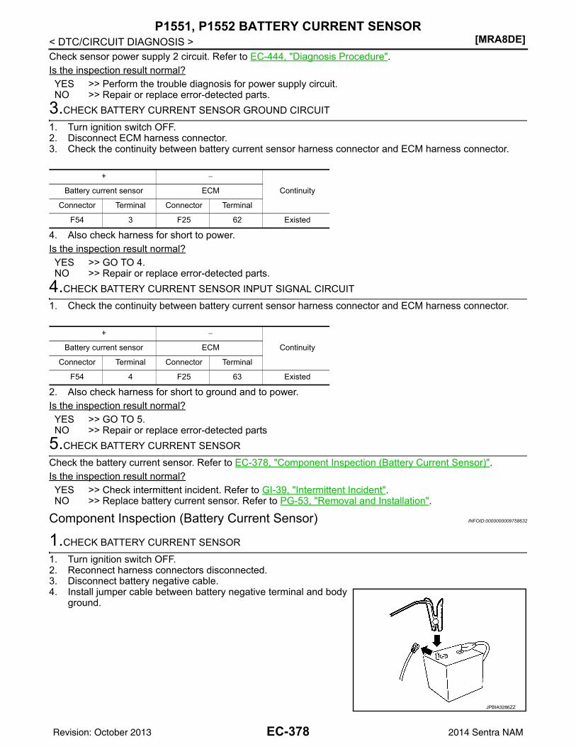
[MRA8DE]P1551, P1552 BATTERY CURRENT SENSOR
< DTC/CIRCUIT DIAGNOSIS >Check sensor power supply 2 circuit. Refer to EC-444, "Diagnosis Procedure".Is the inspection result normal?YES >> Perform the trouble diagnosis for power supply circuit.NO >> Repair or replace error-detected parts.
3.CHECK BATTERY CURRENT SENSOR GROUND CIRCUIT
1. Turn ignition switch OFF.2. Disconnect ECM harness connector.3. Check the continuity between battery current sensor harness connector and ECM harness connector.
4. Also check harness for short to power.Is the inspection result normal?YES >> GO TO 4.NO >> Repair or replace error-detected parts.
4.CHECK BATTERY CURRENT SENSOR INPUT SIGNAL CIRCUIT
1. Check the continuity between battery current sensor harness connector and ECM harness connector.
2. Also check harness for short to ground and to power.Is the inspection result normal?YES >> GO TO 5.NO >> Repair or replace error-detected parts
5.CHECK BATTERY CURRENT SENSOR
Check the battery current sensor. Refer to EC-378, "Component Inspection (Battery Current Sensor)".Is the inspection result normal?YES >> Check intermittent incident. Refer to GI-39, "Intermittent Incident".NO >> Replace battery current sensor. Refer to PG-53, "Removal and Installation".
Component Inspection (Battery Current Sensor) INFOID:0000000009758632
1.CHECK BATTERY CURRENT SENSOR
1. Turn ignition switch OFF.2. Reconnect harness connectors disconnected.3. Disconnect battery negative cable.4. Install jumper cable between battery negative terminal and body
ground.
+ −
ContinuityBattery current sensor ECM
Connector Terminal Connector Terminal
F54 3 F25 62 Existed
+ −
ContinuityBattery current sensor ECM
Connector Terminal Connector Terminal
F54 4 F25 63 Existed
JPBIA3286ZZ
EC-378Revision: October 2013 2014 Sentra NAM
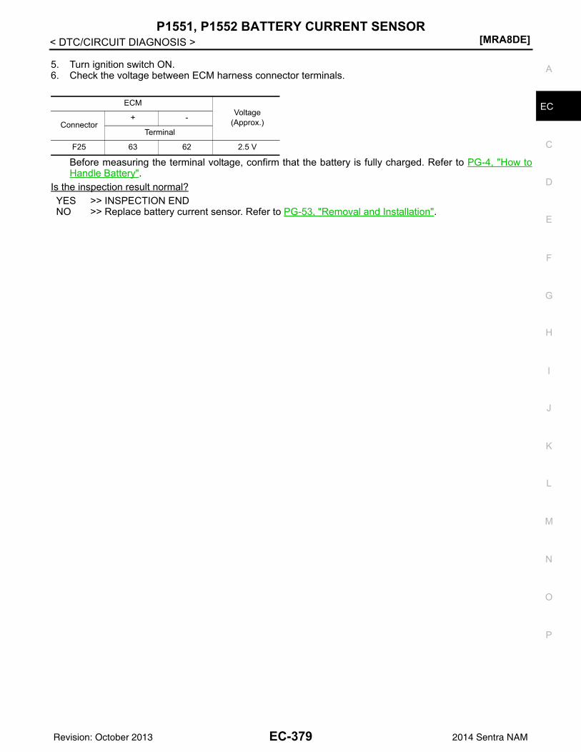
P1551, P1552 BATTERY CURRENT SENSOR[MRA8DE]
C
D
E
F
G
H
I
J
K
L
M
A
C
N
P
O
< DTC/CIRCUIT DIAGNOSIS >
E
5. Turn ignition switch ON.6. Check the voltage between ECM harness connector terminals.
Before measuring the terminal voltage, confirm that the battery is fully charged. Refer to PG-4, "How toHandle Battery".
Is the inspection result normal?YES >> INSPECTION ENDNO >> Replace battery current sensor. Refer to PG-53, "Removal and Installation".
ECMVoltage
(Approx.)Connector+ -
Terminal
F25 63 62 2.5 V
EC-379Revision: October 2013 2014 Sentra NAM
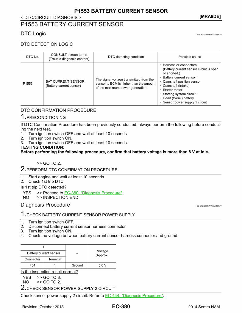
[MRA8DE]P1553 BATTERY CURRENT SENSOR
< DTC/CIRCUIT DIAGNOSIS >P1553 BATTERY CURRENT SENSORDTC Logic INFOID:0000000009758633
DTC DETECTION LOGIC
DTC CONFIRMATION PROCEDURE1.PRECONDITIONING
If DTC Confirmation Procedure has been previously conducted, always perform the following before conduct-ing the next test. 1. Turn ignition switch OFF and wait at least 10 seconds.2. Turn ignition switch ON.3. Turn ignition switch OFF and wait at least 10 seconds.TESTING CONDITION:Before performing the following procedure, confirm that battery voltage is more than 8 V at idle.
>> GO TO 2.2.PERFORM DTC CONFIRMATION PROCEDURE
1. Start engine and wait at least 10 seconds.2. Check 1st trip DTC.Is 1st trip DTC detected?YES >> Proceed to EC-380, "Diagnosis Procedure".NO >> INSPECTION END
Diagnosis Procedure INFOID:0000000009758634
1.CHECK BATTERY CURRENT SENSOR POWER SUPPLY
1. Turn ignition switch OFF.2. Disconnect battery current sensor harness connector.3. Turn ignition switch ON.4. Check the voltage between battery current sensor harness connector and ground.
Is the inspection result normal?YES >> GO TO 3.NO >> GO TO 2.
2.CHECK SENSOR POWER SUPPLY 2 CIRCUIT
Check sensor power supply 2 circuit. Refer to EC-444, "Diagnosis Procedure".
DTC No. CONSULT screen terms(Trouble diagnosis content) DTC detecting condition Possible cause
P1553 BAT CURRENT SENSOR(Battery current sensor)
The signal voltage transmitted from the sensor to ECM is higher than the amount of the maximum power generation.
• Harness or connectors(Battery current sensor circuit is open or shorted.)
• Battery current sensor• Camshaft position sensor• Camshaft (Intake)• Starter motor• Starting system circuit• Dead (Weak) battery• Sensor power supply 1 circuit
+
−Voltage
(Approx.)Battery current sensor
Connector Terminal
F54 1 Ground 5.0 V
EC-380Revision: October 2013 2014 Sentra NAM

P1553 BATTERY CURRENT SENSOR[MRA8DE]
C
D
E
F
G
H
I
J
K
L
M
A
C
N
P
O
< DTC/CIRCUIT DIAGNOSIS >
E
Is the inspection result normal?YES >> Perform the trouble diagnosis for power supply circuit.NO >> Repair or replace error-detected parts.
3.CHECK BATTERY CURRENT SENSOR GROUND CIRCUIT
1. Turn ignition switch OFF.2. Disconnect ECM harness connector.3. Check the continuity between battery current sensor harness connector and ECM harness connector.
4. Also check harness for short to power.Is the inspection result normal?YES >> GO TO 4.NO >> Repair or replace error-detected parts.
4.CHECK BATTERY CURRENT SENSOR INPUT SIGNAL CIRCUIT
1. Check the continuity between battery current sensor harness connector and ECM harness connector.
2. Also check harness for short to ground and to power.Is the inspection result normal?YES >> GO TO 5.NO >> Repair or replace error-detected parts
5.CHECK BATTERY CURRENT SENSOR
Check the battery current sensor. Refer to EC-381, "Component Inspection (Battery Current Sensor)".Is the inspection result normal?YES >> Check intermittent incident. Refer to GI-39, "Intermittent Incident".NO >> Replace battery current sensor. Refer to PG-53, "Removal and Installation".
Component Inspection (Battery Current Sensor) INFOID:0000000009758635
1.CHECK BATTERY CURRENT SENSOR
1. Turn ignition switch OFF.2. Reconnect harness connectors disconnected.3. Disconnect battery negative cable.4. Install jumper cable between battery negative terminal and body
ground.
+ −
ContinuityBattery current sensor ECM
Connector Terminal Connector Terminal
F54 3 F25 62 Existed
+ −
ContinuityBattery current sensor ECM
Connector Terminal Connector Terminal
F54 4 F25 63 Existed
JPBIA3286ZZ
EC-381Revision: October 2013 2014 Sentra NAM

[MRA8DE]P1553 BATTERY CURRENT SENSOR
< DTC/CIRCUIT DIAGNOSIS >5. Turn ignition switch ON.6. Check the voltage between ECM harness connector terminals.
Before measuring the terminal voltage, confirm that the battery is fully charged. Refer to PG-4, "How toHandle Battery".
Is the inspection result normal?YES >> INSPECTION ENDNO >> Replace battery current sensor. Refer to PG-53, "Removal and Installation".
ECMVoltage
(Approx.)Connector+ -
Terminal
F25 63 62 2.5 V
EC-382Revision: October 2013 2014 Sentra NAM
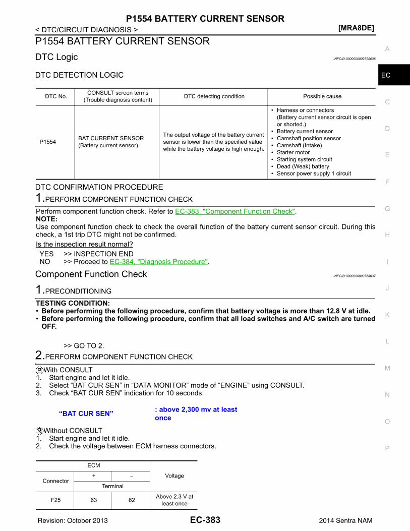
P1554 BATTERY CURRENT SENSOR[MRA8DE]
C
D
E
F
G
H
I
J
K
L
M
A
C
N
P
O
< DTC/CIRCUIT DIAGNOSIS >
E
P1554 BATTERY CURRENT SENSORDTC Logic INFOID:0000000009758636
DTC DETECTION LOGIC
DTC CONFIRMATION PROCEDURE1.PERFORM COMPONENT FUNCTION CHECK
Perform component function check. Refer to EC-383, "Component Function Check".NOTE:Use component function check to check the overall function of the battery current sensor circuit. During thischeck, a 1st trip DTC might not be confirmed.Is the inspection result normal?YES >> INSPECTION ENDNO >> Proceed to EC-384, "Diagnosis Procedure".
Component Function Check INFOID:0000000009758637
1.PRECONDITIONING
TESTING CONDITION:• Before performing the following procedure, confirm that battery voltage is more than 12.8 V at idle.• Before performing the following procedure, confirm that all load switches and A/C switch are turned
OFF.
>> GO TO 2.2.PERFORM COMPONENT FUNCTION CHECK
With CONSULT1. Start engine and let it idle.2. Select “BAT CUR SEN” in “DATA MONITOR” mode of “ENGINE” using CONSULT.3. Check “BAT CUR SEN” indication for 10 seconds.
Without CONSULT1. Start engine and let it idle.2. Check the voltage between ECM harness connectors.
DTC No. CONSULT screen terms(Trouble diagnosis content) DTC detecting condition Possible cause
P1554 BAT CURRENT SENSOR(Battery current sensor)
The output voltage of the battery current sensor is lower than the specified value while the battery voltage is high enough.
• Harness or connectors(Battery current sensor circuit is open or shorted.)
• Battery current sensor• Camshaft position sensor• Camshaft (Intake)• Starter motor• Starting system circuit• Dead (Weak) battery• Sensor power supply 1 circuit
“BAT CUR SEN” : above 2,300 mv at least once
ECM
VoltageConnector
+ −
Terminal
F25 63 62 Above 2.3 V at least once
EC-383Revision: October 2013 2014 Sentra NAM
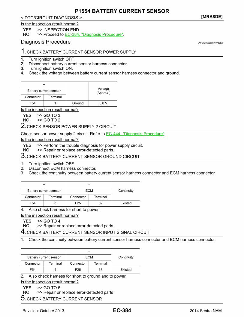
[MRA8DE]P1554 BATTERY CURRENT SENSOR
< DTC/CIRCUIT DIAGNOSIS >Is the inspection result normal?YES >> INSPECTION ENDNO >> Proceed to EC-384, "Diagnosis Procedure".
Diagnosis Procedure INFOID:0000000009758638
1.CHECK BATTERY CURRENT SENSOR POWER SUPPLY
1. Turn ignition switch OFF.2. Disconnect battery current sensor harness connector.3. Turn ignition switch ON.4. Check the voltage between battery current sensor harness connector and ground.
Is the inspection result normal?YES >> GO TO 3.NO >> GO TO 2.
2.CHECK SENSOR POWER SUPPLY 2 CIRCUIT
Check sensor power supply 2 circuit. Refer to EC-444, "Diagnosis Procedure".Is the inspection result normal?YES >> Perform the trouble diagnosis for power supply circuit.NO >> Repair or replace error-detected parts.
3.CHECK BATTERY CURRENT SENSOR GROUND CIRCUIT
1. Turn ignition switch OFF.2. Disconnect ECM harness connector.3. Check the continuity between battery current sensor harness connector and ECM harness connector.
4. Also check harness for short to power.Is the inspection result normal?YES >> GO TO 4.NO >> Repair or replace error-detected parts.
4.CHECK BATTERY CURRENT SENSOR INPUT SIGNAL CIRCUIT
1. Check the continuity between battery current sensor harness connector and ECM harness connector.
2. Also check harness for short to ground and to power.Is the inspection result normal?YES >> GO TO 5.NO >> Repair or replace error-detected parts
5.CHECK BATTERY CURRENT SENSOR
+
−Voltage
(Approx.)Battery current sensor
Connector Terminal
F54 1 Ground 5.0 V
+ −
ContinuityBattery current sensor ECM
Connector Terminal Connector Terminal
F54 3 F25 62 Existed
+ −
ContinuityBattery current sensor ECM
Connector Terminal Connector Terminal
F54 4 F25 63 Existed
EC-384Revision: October 2013 2014 Sentra NAM
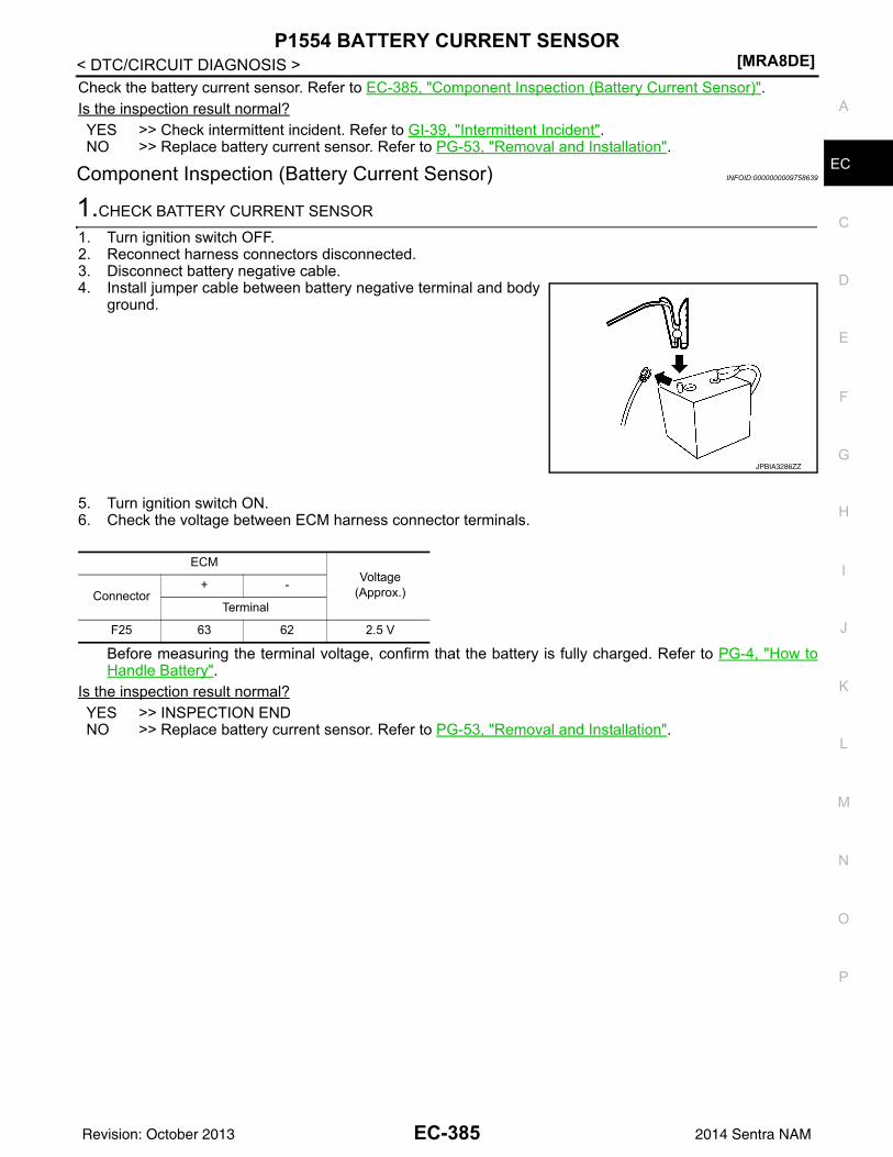
P1554 BATTERY CURRENT SENSOR[MRA8DE]
C
D
E
F
G
H
I
J
K
L
M
A
C
N
P
O
< DTC/CIRCUIT DIAGNOSIS >
E
Check the battery current sensor. Refer to EC-385, "Component Inspection (Battery Current Sensor)".Is the inspection result normal?YES >> Check intermittent incident. Refer to GI-39, "Intermittent Incident".NO >> Replace battery current sensor. Refer to PG-53, "Removal and Installation".
Component Inspection (Battery Current Sensor) INFOID:0000000009758639
1.CHECK BATTERY CURRENT SENSOR
1. Turn ignition switch OFF.2. Reconnect harness connectors disconnected.3. Disconnect battery negative cable.4. Install jumper cable between battery negative terminal and body
ground.
5. Turn ignition switch ON.6. Check the voltage between ECM harness connector terminals.
Before measuring the terminal voltage, confirm that the battery is fully charged. Refer to PG-4, "How toHandle Battery".
Is the inspection result normal?YES >> INSPECTION ENDNO >> Replace battery current sensor. Refer to PG-53, "Removal and Installation".
JPBIA3286ZZ
ECMVoltage
(Approx.)Connector+ -
Terminal
F25 63 62 2.5 V
EC-385Revision: October 2013 2014 Sentra NAM
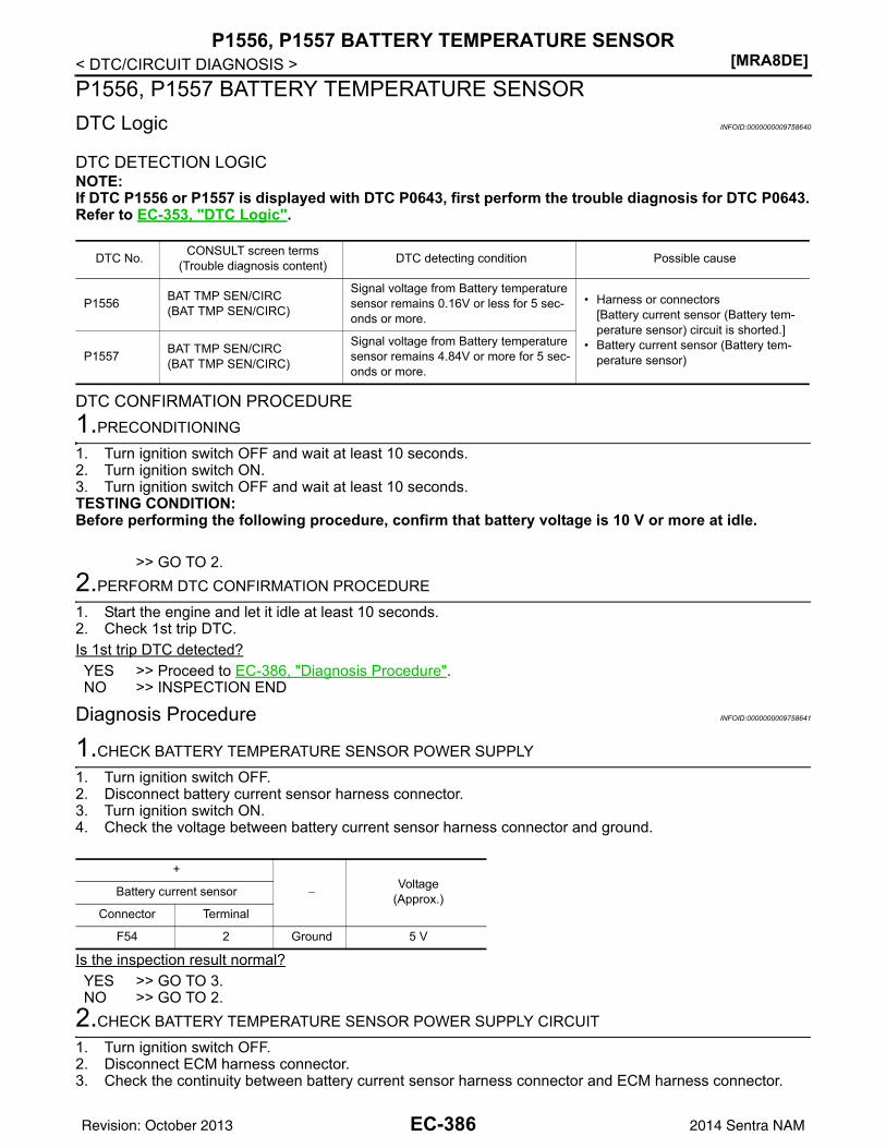
[MRA8DE]P1556, P1557 BATTERY TEMPERATURE SENSOR
< DTC/CIRCUIT DIAGNOSIS >P1556, P1557 BATTERY TEMPERATURE SENSORDTC Logic INFOID:0000000009758640
DTC DETECTION LOGICNOTE:If DTC P1556 or P1557 is displayed with DTC P0643, first perform the trouble diagnosis for DTC P0643.Refer to EC-353, "DTC Logic".
DTC CONFIRMATION PROCEDURE1.PRECONDITIONING
1. Turn ignition switch OFF and wait at least 10 seconds.2. Turn ignition switch ON.3. Turn ignition switch OFF and wait at least 10 seconds.TESTING CONDITION:Before performing the following procedure, confirm that battery voltage is 10 V or more at idle.
>> GO TO 2.2.PERFORM DTC CONFIRMATION PROCEDURE
1. Start the engine and let it idle at least 10 seconds.2. Check 1st trip DTC.Is 1st trip DTC detected?YES >> Proceed to EC-386, "Diagnosis Procedure".NO >> INSPECTION END
Diagnosis Procedure INFOID:0000000009758641
1.CHECK BATTERY TEMPERATURE SENSOR POWER SUPPLY
1. Turn ignition switch OFF.2. Disconnect battery current sensor harness connector.3. Turn ignition switch ON.4. Check the voltage between battery current sensor harness connector and ground.
Is the inspection result normal?YES >> GO TO 3.NO >> GO TO 2.
2.CHECK BATTERY TEMPERATURE SENSOR POWER SUPPLY CIRCUIT
1. Turn ignition switch OFF.2. Disconnect ECM harness connector.3. Check the continuity between battery current sensor harness connector and ECM harness connector.
DTC No. CONSULT screen terms(Trouble diagnosis content) DTC detecting condition Possible cause
P1556 BAT TMP SEN/CIRC(BAT TMP SEN/CIRC)
Signal voltage from Battery temperature sensor remains 0.16V or less for 5 sec-onds or more.
• Harness or connectors[Battery current sensor (Battery tem-perature sensor) circuit is shorted.]
• Battery current sensor (Battery tem-perature sensor)P1557 BAT TMP SEN/CIRC
(BAT TMP SEN/CIRC)
Signal voltage from Battery temperature sensor remains 4.84V or more for 5 sec-onds or more.
+
−Voltage
(Approx.)Battery current sensor
Connector Terminal
F54 2 Ground 5 V
EC-386Revision: October 2013 2014 Sentra NAM
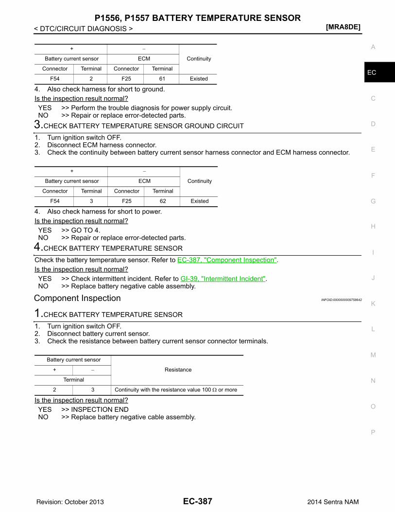
P1556, P1557 BATTERY TEMPERATURE SENSOR[MRA8DE]
C
D
E
F
G
H
I
J
K
L
M
A
C
N
P
O
< DTC/CIRCUIT DIAGNOSIS >
E
4. Also check harness for short to ground.Is the inspection result normal?YES >> Perform the trouble diagnosis for power supply circuit.NO >> Repair or replace error-detected parts.
3.CHECK BATTERY TEMPERATURE SENSOR GROUND CIRCUIT
1. Turn ignition switch OFF.2. Disconnect ECM harness connector.3. Check the continuity between battery current sensor harness connector and ECM harness connector.
4. Also check harness for short to power.Is the inspection result normal?YES >> GO TO 4.NO >> Repair or replace error-detected parts.
4.CHECK BATTERY TEMPERATURE SENSOR
Check the battery temperature sensor. Refer to EC-387, "Component Inspection".Is the inspection result normal?YES >> Check intermittent incident. Refer to GI-39, "Intermittent Incident".NO >> Replace battery negative cable assembly.
Component Inspection INFOID:0000000009758642
1.CHECK BATTERY TEMPERATURE SENSOR
1. Turn ignition switch OFF.2. Disconnect battery current sensor.3. Check the resistance between battery current sensor connector terminals.
Is the inspection result normal?YES >> INSPECTION ENDNO >> Replace battery negative cable assembly.
+ −
ContinuityBattery current sensor ECM
Connector Terminal Connector Terminal
F54 2 F25 61 Existed
+ −
ContinuityBattery current sensor ECM
Connector Terminal Connector Terminal
F54 3 F25 62 Existed
Battery current sensor
Resistance+ −
Terminal
2 3 Continuity with the resistance value 100 Ω or more
EC-387Revision: October 2013 2014 Sentra NAM
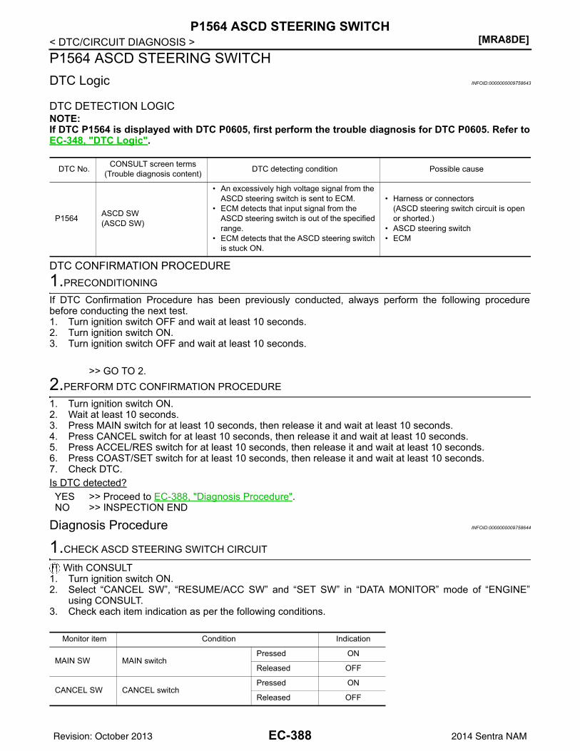
[MRA8DE]P1564 ASCD STEERING SWITCH
< DTC/CIRCUIT DIAGNOSIS >P1564 ASCD STEERING SWITCHDTC Logic INFOID:0000000009758643
DTC DETECTION LOGICNOTE:If DTC P1564 is displayed with DTC P0605, first perform the trouble diagnosis for DTC P0605. Refer toEC-348, "DTC Logic".
DTC CONFIRMATION PROCEDURE1.PRECONDITIONING
If DTC Confirmation Procedure has been previously conducted, always perform the following procedurebefore conducting the next test.1. Turn ignition switch OFF and wait at least 10 seconds.2. Turn ignition switch ON.3. Turn ignition switch OFF and wait at least 10 seconds.
>> GO TO 2.2.PERFORM DTC CONFIRMATION PROCEDURE
1. Turn ignition switch ON.2. Wait at least 10 seconds.3. Press MAIN switch for at least 10 seconds, then release it and wait at least 10 seconds.4. Press CANCEL switch for at least 10 seconds, then release it and wait at least 10 seconds.5. Press ACCEL/RES switch for at least 10 seconds, then release it and wait at least 10 seconds.6. Press COAST/SET switch for at least 10 seconds, then release it and wait at least 10 seconds.7. Check DTC.Is DTC detected?YES >> Proceed to EC-388, "Diagnosis Procedure".NO >> INSPECTION END
Diagnosis Procedure INFOID:0000000009758644
1.CHECK ASCD STEERING SWITCH CIRCUIT
With CONSULT1. Turn ignition switch ON.2. Select “CANCEL SW”, “RESUME/ACC SW” and “SET SW” in “DATA MONITOR” mode of “ENGINE”
using CONSULT.3. Check each item indication as per the following conditions.
DTC No. CONSULT screen terms(Trouble diagnosis content) DTC detecting condition Possible cause
P1564 ASCD SW(ASCD SW)
• An excessively high voltage signal from the ASCD steering switch is sent to ECM.
• ECM detects that input signal from the ASCD steering switch is out of the specified range.
• ECM detects that the ASCD steering switch is stuck ON.
• Harness or connectors(ASCD steering switch circuit is open or shorted.)
• ASCD steering switch• ECM
Monitor item Condition Indication
MAIN SW MAIN switchPressed ON
Released OFF
CANCEL SW CANCEL switchPressed ON
Released OFF
EC-388Revision: October 2013 2014 Sentra NAM
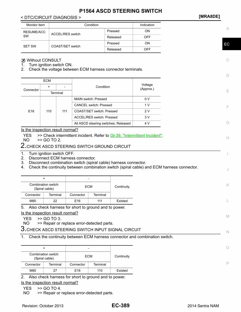
P1564 ASCD STEERING SWITCH[MRA8DE]
C
D
E
F
G
H
I
J
K
L
M
A
C
N
P
O
< DTC/CIRCUIT DIAGNOSIS >
E
Without CONSULT1. Turn ignition switch ON.2. Check the voltage between ECM harness connector terminals.
Is the inspection result normal?YES >> Check intermittent incident. Refer to GI-39, "Intermittent Incident".NO >> GO TO 2.
2.CHECK ASCD STEERING SWITCH GROUND CIRCUIT
1. Turn ignition switch OFF.2. Disconnect ECM harness connector.3. Disconnect combination switch (spiral cable) harness connector.4. Check the continuity between combination switch (spiral cable) and ECM harness connector.
5. Also check harness for short to ground and to power.Is the inspection result normal?YES >> GO TO 3.NO >> Repair or replace error-detected parts.
3.CHECK ASCD STEERING SWITCH INPUT SIGNAL CIRCUIT
1. Check the continuity between ECM harness connector and combination switch.
2. Also check harness for short to ground and to power.Is the inspection result normal?YES >> GO TO 4.NO >> Repair or replace error-detected parts.
RESUME/ACC SW ACCEL/RES switch
Pressed ON
Released OFF
SET SW COAST/SET switchPressed ON
Released OFF
Monitor item Condition Indication
ECM
Condition Voltage(Approx.)Connector
+ -
Terminal
E16 110 111
MAIN switch: Pressed 0 V
CANCEL switch: Pressed 1 V
COAST/SET switch: Pressed 2 V
ACCEL/RES switch: Pressed 3 V
All ASCD steering switches: Released 4 V
+ −
ContinuityCombination switch(Spiral cable) ECM
Connector Terminal Connector Terminal
M80 22 E16 111 Existed
+ −
ContinuityCombination switch(Spiral cable) ECM
Connector Terminal Connector Terminal
M80 27 E16 110 Existed
EC-389Revision: October 2013 2014 Sentra NAM
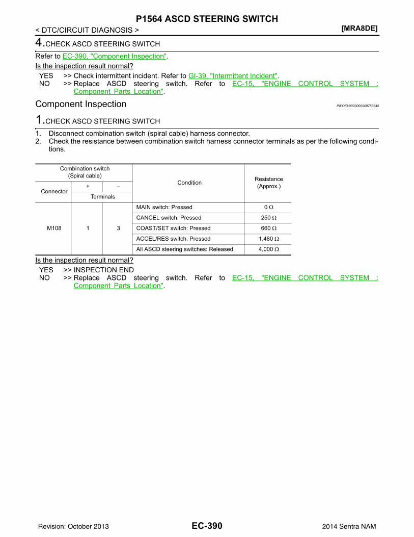
[MRA8DE]P1564 ASCD STEERING SWITCH
< DTC/CIRCUIT DIAGNOSIS >
4.CHECK ASCD STEERING SWITCH
Refer to EC-390, "Component Inspection".Is the inspection result normal?YES >> Check intermittent incident. Refer to GI-39, "Intermittent Incident".NO >> Replace ASCD steering switch. Refer to EC-15, "ENGINE CONTROL SYSTEM :
Component Parts Location".
Component Inspection INFOID:0000000009758645
1.CHECK ASCD STEERING SWITCH
1. Disconnect combination switch (spiral cable) harness connector.2. Check the resistance between combination switch harness connector terminals as per the following condi-
tions.
Is the inspection result normal?YES >> INSPECTION ENDNO >> Replace ASCD steering switch. Refer to EC-15, "ENGINE CONTROL SYSTEM :
Component Parts Location".
Combination switch(Spiral cable)
Condition Resistance(Approx.)
Connector+ −
Terminals
M108 1 3
MAIN switch: Pressed 0 Ω
CANCEL switch: Pressed 250 Ω
COAST/SET switch: Pressed 660 Ω
ACCEL/RES switch: Pressed 1,480 Ω
All ASCD steering switches: Released 4,000 Ω
EC-390Revision: October 2013 2014 Sentra NAM
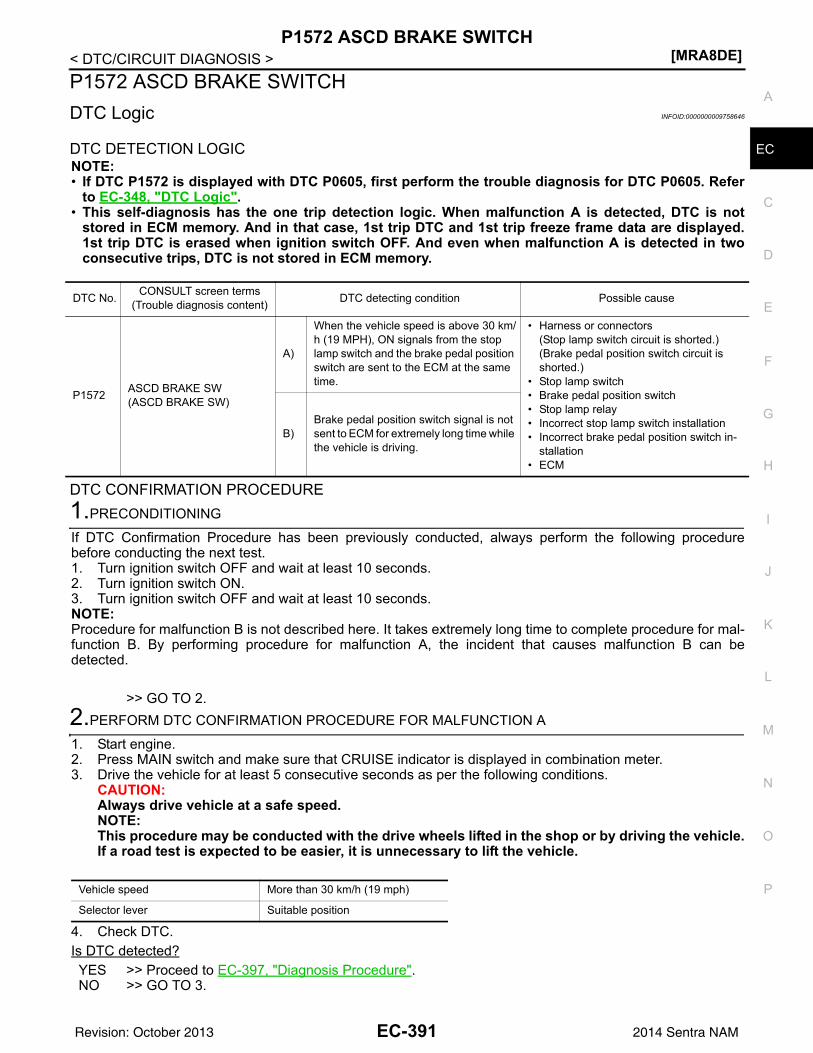
P1572 ASCD BRAKE SWITCH[MRA8DE]
C
D
E
F
G
H
I
J
K
L
M
A
C
N
P
O
< DTC/CIRCUIT DIAGNOSIS >
E
P1572 ASCD BRAKE SWITCHDTC Logic INFOID:0000000009758646
DTC DETECTION LOGICNOTE:• If DTC P1572 is displayed with DTC P0605, first perform the trouble diagnosis for DTC P0605. Refer
to EC-348, "DTC Logic".• This self-diagnosis has the one trip detection logic. When malfunction A is detected, DTC is not
stored in ECM memory. And in that case, 1st trip DTC and 1st trip freeze frame data are displayed.1st trip DTC is erased when ignition switch OFF. And even when malfunction A is detected in twoconsecutive trips, DTC is not stored in ECM memory.
DTC CONFIRMATION PROCEDURE1.PRECONDITIONING
If DTC Confirmation Procedure has been previously conducted, always perform the following procedurebefore conducting the next test.1. Turn ignition switch OFF and wait at least 10 seconds.2. Turn ignition switch ON.3. Turn ignition switch OFF and wait at least 10 seconds.NOTE:Procedure for malfunction B is not described here. It takes extremely long time to complete procedure for mal-function B. By performing procedure for malfunction A, the incident that causes malfunction B can bedetected.
>> GO TO 2.2.PERFORM DTC CONFIRMATION PROCEDURE FOR MALFUNCTION A
1. Start engine.2. Press MAIN switch and make sure that CRUISE indicator is displayed in combination meter.3. Drive the vehicle for at least 5 consecutive seconds as per the following conditions.
CAUTION:Always drive vehicle at a safe speed.NOTE:This procedure may be conducted with the drive wheels lifted in the shop or by driving the vehicle.If a road test is expected to be easier, it is unnecessary to lift the vehicle.
4. Check DTC.Is DTC detected?YES >> Proceed to EC-397, "Diagnosis Procedure".NO >> GO TO 3.
DTC No. CONSULT screen terms(Trouble diagnosis content) DTC detecting condition Possible cause
P1572 ASCD BRAKE SW(ASCD BRAKE SW)
A)
When the vehicle speed is above 30 km/h (19 MPH), ON signals from the stop lamp switch and the brake pedal position switch are sent to the ECM at the same time.
• Harness or connectors(Stop lamp switch circuit is shorted.)(Brake pedal position switch circuit is shorted.)
• Stop lamp switch• Brake pedal position switch• Stop lamp relay• Incorrect stop lamp switch installation• Incorrect brake pedal position switch in-
stallation• ECM
B)Brake pedal position switch signal is not sent to ECM for extremely long time while the vehicle is driving.
Vehicle speed More than 30 km/h (19 mph)
Selector lever Suitable position
EC-391Revision: October 2013 2014 Sentra NAM
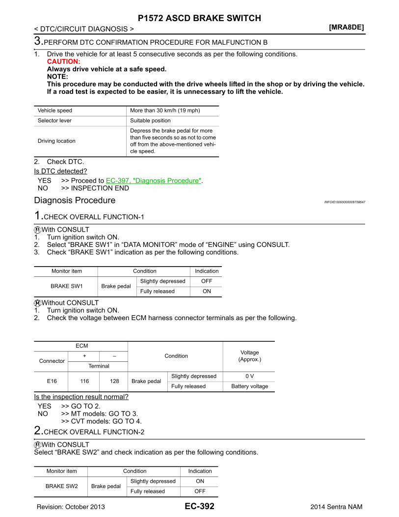
[MRA8DE]P1572 ASCD BRAKE SWITCH
< DTC/CIRCUIT DIAGNOSIS >
3.PERFORM DTC CONFIRMATION PROCEDURE FOR MALFUNCTION B
1. Drive the vehicle for at least 5 consecutive seconds as per the following conditions.CAUTION:Always drive vehicle at a safe speed.NOTE:This procedure may be conducted with the drive wheels lifted in the shop or by driving the vehicle.If a road test is expected to be easier, it is unnecessary to lift the vehicle.
2. Check DTC.Is DTC detected?YES >> Proceed to EC-397, "Diagnosis Procedure".NO >> INSPECTION END
Diagnosis Procedure INFOID:0000000009758647
1.CHECK OVERALL FUNCTION-1
With CONSULT1. Turn ignition switch ON.2. Select “BRAKE SW1” in “DATA MONITOR” mode of “ENGINE” using CONSULT.3. Check “BRAKE SW1” indication as per the following conditions.
Without CONSULT1. Turn ignition switch ON.2. Check the voltage between ECM harness connector terminals as per the following.
Is the inspection result normal?YES >> GO TO 2.NO >> MT models: GO TO 3.
>> CVT models: GO TO 4.2.CHECK OVERALL FUNCTION-2
With CONSULTSelect “BRAKE SW2” and check indication as per the following conditions.
Vehicle speed More than 30 km/h (19 mph)
Selector lever Suitable position
Driving location
Depress the brake pedal for more than five seconds so as not to come off from the above-mentioned vehi-cle speed.
Monitor item Condition Indication
BRAKE SW1 Brake pedalSlightly depressed OFF
Fully released ON
ECM
Condition Voltage(Approx.)Connector
+ –
Terminal
E16 116 128 Brake pedalSlightly depressed 0 V
Fully released Battery voltage
Monitor item Condition Indication
BRAKE SW2 Brake pedalSlightly depressed ON
Fully released OFF
EC-392Revision: October 2013 2014 Sentra NAM
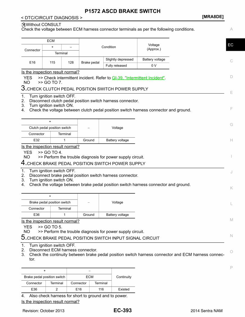
P1572 ASCD BRAKE SWITCH[MRA8DE]
C
D
E
F
G
H
I
J
K
L
M
A
C
N
P
O
< DTC/CIRCUIT DIAGNOSIS >
E
Without CONSULTCheck the voltage between ECM harness connector terminals as per the following conditions.
Is the inspection result normal?YES >> Check intermittent incident. Refer to GI-39, "Intermittent Incident".NO >> GO TO 7.
3.CHECK CLUTCH PEDAL POSITION SWITCH POWER SUPPLY
1. Turn ignition switch OFF.2. Disconnect clutch pedal position switch harness connector.3. Turn ignition switch ON.4. Check the voltage between clutch pedal position switch harness connector and ground.
Is the inspection result normal?YES >> GO TO 4.NO >> Perform the trouble diagnosis for power supply circuit.
4.CHECK BRAKE PEDAL POSITION SWITCH POWER SUPPLY
1. Turn ignition switch OFF.2. Disconnect brake pedal position switch harness connector.3. Turn ignition switch ON.4. Check the voltage between brake pedal position switch harness connector and ground.
Is the inspection result normal?YES >> GO TO 5.NO >> Perform the trouble diagnosis for power supply circuit.
5.CHECK BRAKE PEDAL POSITION SWITCH INPUT SIGNAL CIRCUIT
1. Turn ignition switch OFF.2. Disconnect ECM harness connector.3. Check the continuity between brake pedal position switch harness connector and ECM harness connec-
tor.
4. Also check harness for short to ground and to power.Is the inspection result normal?
ECM
Condition Voltage(Approx.)Connector
+ –
Terminal
E16 115 128 Brake pedalSlightly depressed Battery voltage
Fully released 0 V
+
− VoltageClutch pedal position switch
Connector Terminal
E32 1 Ground Battery voltage
+
− VoltageBrake pedal position switch
Connector Terminal
E36 1 Ground Battery voltage
+ −
ContinuityBrake pedal position switch ECM
Connector Terminal Connector Terminal
E36 2 E16 116 Existed
EC-393Revision: October 2013 2014 Sentra NAM
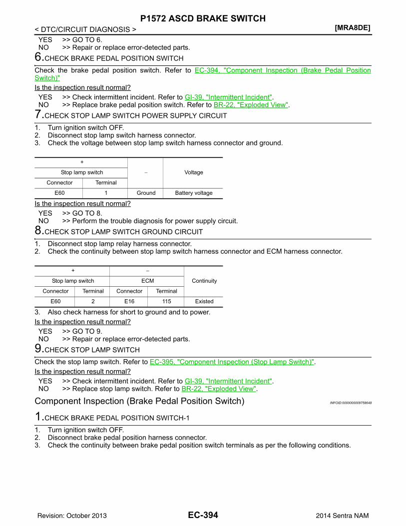
[MRA8DE]P1572 ASCD BRAKE SWITCH
< DTC/CIRCUIT DIAGNOSIS >YES >> GO TO 6.NO >> Repair or replace error-detected parts.
6.CHECK BRAKE PEDAL POSITION SWITCH
Check the brake pedal position switch. Refer to EC-394, "Component Inspection (Brake Pedal PositionSwitch)"Is the inspection result normal?YES >> Check intermittent incident. Refer to GI-39, "Intermittent Incident".NO >> Replace brake pedal position switch. Refer to BR-22, "Exploded View".
7.CHECK STOP LAMP SWITCH POWER SUPPLY CIRCUIT
1. Turn ignition switch OFF.2. Disconnect stop lamp switch harness connector.3. Check the voltage between stop lamp switch harness connector and ground.
Is the inspection result normal?YES >> GO TO 8.NO >> Perform the trouble diagnosis for power supply circuit.
8.CHECK STOP LAMP SWITCH GROUND CIRCUIT
1. Disconnect stop lamp relay harness connector.2. Check the continuity between stop lamp switch harness connector and ECM harness connector.
3. Also check harness for short to ground and to power.Is the inspection result normal?YES >> GO TO 9.NO >> Repair or replace error-detected parts.
9.CHECK STOP LAMP SWITCH
Check the stop lamp switch. Refer to EC-395, "Component Inspection (Stop Lamp Switch)".Is the inspection result normal?YES >> Check intermittent incident. Refer to GI-39, "Intermittent Incident".NO >> Replace stop lamp switch. Refer to BR-22, "Exploded View".
Component Inspection (Brake Pedal Position Switch) INFOID:0000000009758648
1.CHECK BRAKE PEDAL POSITION SWITCH-1
1. Turn ignition switch OFF.2. Disconnect brake pedal position harness connector.3. Check the continuity between brake pedal position switch terminals as per the following conditions.
+
− VoltageStop lamp switch
Connector Terminal
E60 1 Ground Battery voltage
+ −
ContinuityStop lamp switch ECM
Connector Terminal Connector Terminal
E60 2 E16 115 Existed
EC-394Revision: October 2013 2014 Sentra NAM

P1572 ASCD BRAKE SWITCH[MRA8DE]
C
D
E
F
G
H
I
J
K
L
M
A
C
N
P
O
< DTC/CIRCUIT DIAGNOSIS >
E
Is the inspection result normal?YES >> INSPECTION ENDNO >> GO TO 2.
2.CHECK BRAKE PEDAL POSITION SWITCH-2
1. Adjust brake pedal position switch installation. Refer to BR-15, "Adjustment".2. Check the continuity between brake pedal position switch terminals as per the following conditions.
Is the inspection result normal?YES >> INSPECTION ENDNO >> Replace brake pedal position switch. Refer to BR-22, "Exploded View".
Component Inspection (Stop Lamp Switch) INFOID:0000000009758649
1.CHECK STOP LAMP SWITCH-1
1. Turn ignition switch OFF.2. Disconnect stop lamp switch harness connector.3. Check the continuity between stop lamp switch terminals as per the following conditions.
Is the inspection result normal?YES >> INSPECTION ENDNO >> GO TO 2.
2.CHECK STOP LAMP SWITCH-2
1. Adjust stop lamp switch installation. Refer to BR-15, "Adjustment".2. Check the continuity between stop lamp switch terminals as per the following conditions.
Brake pedal position switch
Condition Continuity+ −
Terminals
1 2 Brake pedalFully released Existed
Slightly de-pressed Not existed
Brake pedal position switch
Condition Continuity+ −
Terminals
1 2 Brake pedalFully released Existed
Slightly de-pressed Not existed
Stop lamp switch
Condition Continuity+ −
Terminals
1 2 Brake pedalFully released Not existed
Slightly de-pressed Existed
Stop lamp switch
Condition Continuity+ −
Terminals
1 2 Brake pedalFully released Not existed
Slightly de-pressed Existed
EC-395Revision: October 2013 2014 Sentra NAM
[MRA8DE]P1572 ASCD BRAKE SWITCH
< DTC/CIRCUIT DIAGNOSIS >Is the inspection result normal?YES >> INSPECTION ENDNO >> Replace stop lamp switch. Refer to BR-22, "Exploded View".
EC-396Revision: October 2013 2014 Sentra NAM
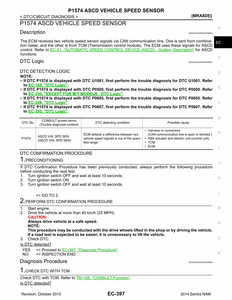
P1574 ASCD VEHICLE SPEED SENSOR[MRA8DE]
C
D
E
F
G
H
I
J
K
L
M
A
C
N
P
O
< DTC/CIRCUIT DIAGNOSIS >
E
P1574 ASCD VEHICLE SPEED SENSORDescription INFOID:0000000009758650
The ECM receives two vehicle speed sensor signals via CAN communication line. One is sent from combina-tion meter, and the other is from TCM (Transmission control module). The ECM uses these signals for ASCDcontrol. Refer to EC-51, "AUTOMATIC SPEED CONTROL DEVICE (ASCD) : System Description" for ASCDfunctions.
DTC Logic INFOID:0000000009758651
DTC DETECTION LOGICNOTE:• If DTC P1574 is displayed with DTC U1001, first perform the trouble diagnosis for DTC U1001. Refer
to EC-168, "DTC Logic".• If DTC P1574 is displayed with DTC P0500, first perform the trouble diagnosis for DTC P0500. Refer
to EC-330, "EXCEPT FOR M/T MODELS : DTC Logic".• If DTC P1574 is displayed with DTC P0605, first perform the trouble diagnosis for DTC P0605. Refer
to EC-348, "DTC Logic".• If DTC P1574 is displayed with DTC P0607, first perform the trouble diagnosis for DTC P0607. Refer
to EC-350, "DTC Logic".
DTC CONFIRMATION PROCEDURE1.PRECONDITIONING
If DTC Confirmation Procedure has been previously conducted, always perform the following procedurebefore conducting the next test.1. Turn ignition switch OFF and wait at least 10 seconds.2. Turn ignition switch ON.3. Turn ignition switch OFF and wait at least 10 seconds.
>> GO TO 2.2.PERFORM DTC CONFIRMATION PROCEDURE
1. Start engine.2. Drive the vehicle at more than 40 km/h (25 MPH).
CAUTION:Always drive vehicle at a safe speed.NOTE:This procedure may be conducted with the drive wheels lifted in the shop or by driving the vehicle.If a road test is expected to be easier, it is unnecessary to lift the vehicle.
3. Check DTC.Is DTC detected?YES >> Proceed to EC-397, "Diagnosis Procedure".NO >> INSPECTION END
Diagnosis Procedure INFOID:0000000009758652
1.CHECK DTC WITH TCM
Check DTC with TCM. Refer to TM-108, "CONSULT Function".Is DTC detected?
DTC No. CONSULT screen terms(Trouble diagnosis content) DTC detecting condition Possible cause
P1574 ASCD VHL SPD SEN(ASCD VHL SPD SEN)
ECM detects a difference between two vehicle speed signals is out of the speci-fied range.
• Harness or connectors(CAN communication line is open or shorted.)
• ABS actuator and electric unit (control unit)• TCM• ECM
EC-397Revision: October 2013 2014 Sentra NAM
[MRA8DE]P1574 ASCD VEHICLE SPEED SENSOR
< DTC/CIRCUIT DIAGNOSIS >NO >> GO TO 2.YES >> Perform trouble shooting relevant to DTC indicated.
2.CHECK DTC WITH “ABS ACTUATOR AND ELECTRIC UNIT (CONTROL UNIT)”
Check DTC with ABS actuator and electric unit (control unit). Refer to BRC-31, "CONSULT Function (ABS)".Is DTC detected?NO >> INSPECTION ENDYES >> Perform trouble shooting relevant to DTC indicated.
EC-398Revision: October 2013 2014 Sentra NAM
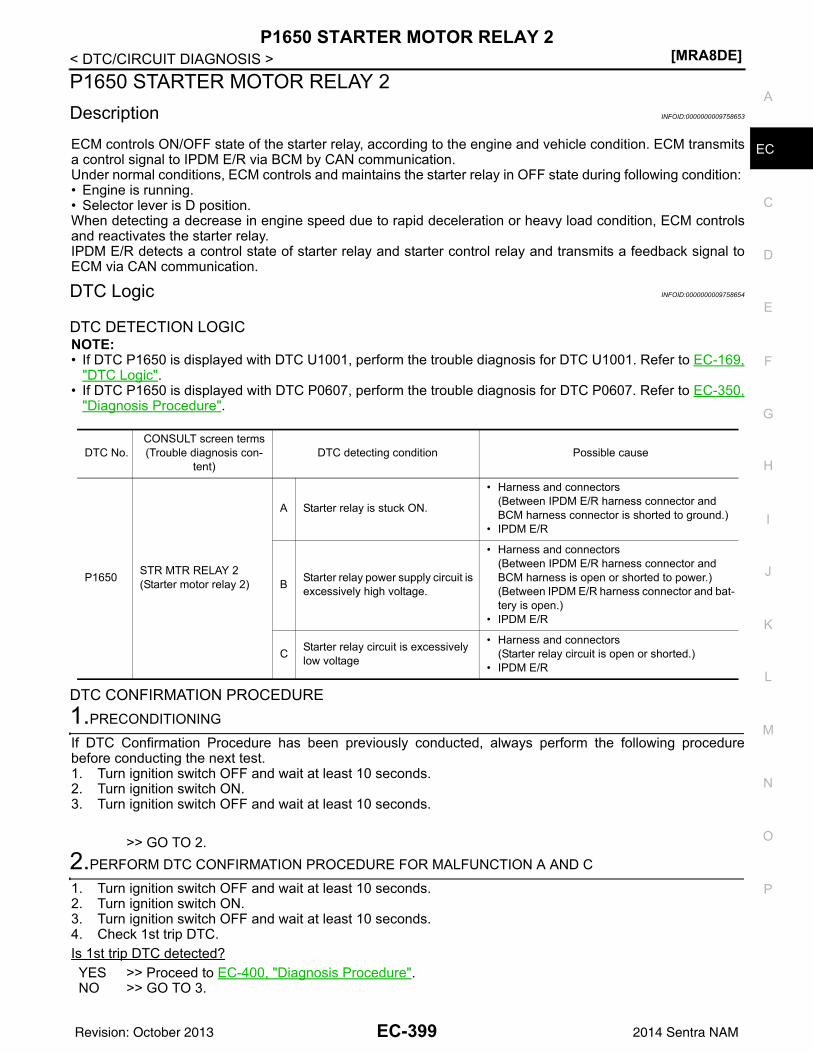
P1650 STARTER MOTOR RELAY 2[MRA8DE]
C
D
E
F
G
H
I
J
K
L
M
A
C
N
P
O
< DTC/CIRCUIT DIAGNOSIS >
E
P1650 STARTER MOTOR RELAY 2Description INFOID:0000000009758653
ECM controls ON/OFF state of the starter relay, according to the engine and vehicle condition. ECM transmitsa control signal to IPDM E/R via BCM by CAN communication.Under normal conditions, ECM controls and maintains the starter relay in OFF state during following condition: • Engine is running.• Selector lever is D position.When detecting a decrease in engine speed due to rapid deceleration or heavy load condition, ECM controlsand reactivates the starter relay.IPDM E/R detects a control state of starter relay and starter control relay and transmits a feedback signal toECM via CAN communication.
DTC Logic INFOID:0000000009758654
DTC DETECTION LOGICNOTE:• If DTC P1650 is displayed with DTC U1001, perform the trouble diagnosis for DTC U1001. Refer to EC-169,
"DTC Logic".• If DTC P1650 is displayed with DTC P0607, perform the trouble diagnosis for DTC P0607. Refer to EC-350,
"Diagnosis Procedure".
DTC CONFIRMATION PROCEDURE1.PRECONDITIONING
If DTC Confirmation Procedure has been previously conducted, always perform the following procedurebefore conducting the next test.1. Turn ignition switch OFF and wait at least 10 seconds.2. Turn ignition switch ON.3. Turn ignition switch OFF and wait at least 10 seconds.
>> GO TO 2.2.PERFORM DTC CONFIRMATION PROCEDURE FOR MALFUNCTION A AND C
1. Turn ignition switch OFF and wait at least 10 seconds.2. Turn ignition switch ON.3. Turn ignition switch OFF and wait at least 10 seconds.4. Check 1st trip DTC.Is 1st trip DTC detected?YES >> Proceed to EC-400, "Diagnosis Procedure".NO >> GO TO 3.
DTC No.CONSULT screen terms(Trouble diagnosis con-
tent)DTC detecting condition Possible cause
P1650 STR MTR RELAY 2(Starter motor relay 2)
A Starter relay is stuck ON.
• Harness and connectors(Between IPDM E/R harness connector and BCM harness connector is shorted to ground.)
• IPDM E/R
B Starter relay power supply circuit is excessively high voltage.
• Harness and connectors(Between IPDM E/R harness connector and BCM harness is open or shorted to power.)(Between IPDM E/R harness connector and bat-tery is open.)
• IPDM E/R
C Starter relay circuit is excessively low voltage
• Harness and connectors(Starter relay circuit is open or shorted.)
• IPDM E/R
EC-399Revision: October 2013 2014 Sentra NAM
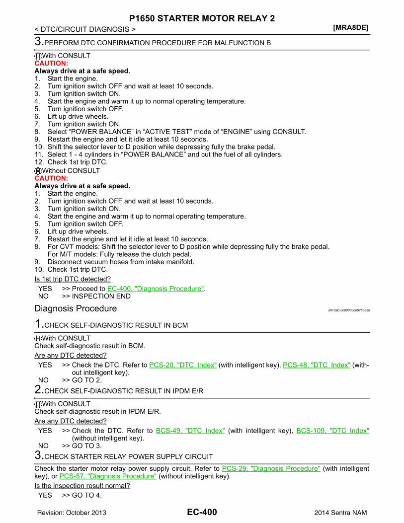
[MRA8DE]P1650 STARTER MOTOR RELAY 2
< DTC/CIRCUIT DIAGNOSIS >
3.PERFORM DTC CONFIRMATION PROCEDURE FOR MALFUNCTION B
With CONSULTCAUTION:Always drive at a safe speed.1. Start the engine.2. Turn ignition switch OFF and wait at least 10 seconds.3. Turn ignition switch ON.4. Start the engine and warm it up to normal operating temperature.5. Turn ignition switch OFF.6. Lift up drive wheels.7. Turn ignition switch ON.8. Select “POWER BALANCE” in “ACTIVE TEST” mode of “ENGINE” using CONSULT.9. Restart the engine and let it idle at least 10 seconds.10. Shift the selector lever to D position while depressing fully the brake pedal.11. Select 1 - 4 cylinders in “POWER BALANCE” and cut the fuel of all cylinders.12. Check 1st trip DTC.
Without CONSULTCAUTION:Always drive at a safe speed.1. Start the engine.2. Turn ignition switch OFF and wait at least 10 seconds.3. Turn ignition switch ON.4. Start the engine and warm it up to normal operating temperature.5. Turn ignition switch OFF.6. Lift up drive wheels.7. Restart the engine and let it idle at least 10 seconds.8. For CVT models: Shift the selector lever to D position while depressing fully the brake pedal.
For M/T models: Fully release the clutch pedal.9. Disconnect vacuum hoses from intake manifold.10. Check 1st trip DTC.Is 1st trip DTC detected?YES >> Proceed to EC-400, "Diagnosis Procedure".NO >> INSPECTION END
Diagnosis Procedure INFOID:0000000009758655
1.CHECK SELF-DIAGNOSTIC RESULT IN BCM
With CONSULTCheck self-diagnostic result in BCM.Are any DTC detected?YES >> Check the DTC. Refer to PCS-20, "DTC Index" (with intelligent key), PCS-48, "DTC Index" (with-
out intelligent key).NO >> GO TO 2.
2.CHECK SELF-DIAGNOSTIC RESULT IN IPDM E/R
With CONSULTCheck self-diagnostic result in IPDM E/R.Are any DTC detected?YES >> Check the DTC. Refer to BCS-49, "DTC Index" (with intelligent key), BCS-109, "DTC Index"
(without intelligent key).NO >> GO TO 3.
3.CHECK STARTER RELAY POWER SUPPLY CIRCUIT
Check the starter motor relay power supply circuit. Refer to PCS-29, "Diagnosis Procedure" (with intelligentkey), or PCS-57, "Diagnosis Procedure" (without intelligent key).Is the inspection result normal?YES >> GO TO 4.
EC-400Revision: October 2013 2014 Sentra NAM
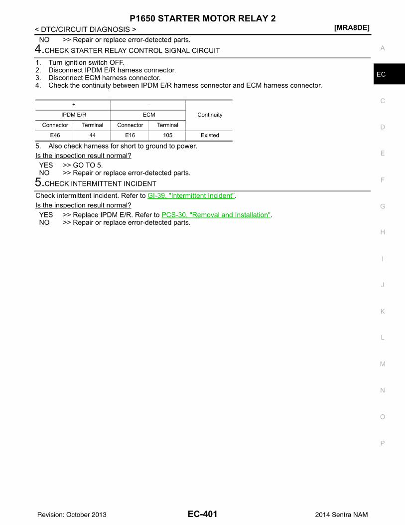
P1650 STARTER MOTOR RELAY 2[MRA8DE]
C
D
E
F
G
H
I
J
K
L
M
A
C
N
P
O
< DTC/CIRCUIT DIAGNOSIS >
E
NO >> Repair or replace error-detected parts.4.CHECK STARTER RELAY CONTROL SIGNAL CIRCUIT
1. Turn ignition switch OFF.2. Disconnect IPDM E/R harness connector.3. Disconnect ECM harness connector.4. Check the continuity between IPDM E/R harness connector and ECM harness connector.
5. Also check harness for short to ground to power.Is the inspection result normal?YES >> GO TO 5.NO >> Repair or replace error-detected parts.
5.CHECK INTERMITTENT INCIDENT
Check intermittent incident. Refer to GI-39, "Intermittent Incident".Is the inspection result normal?YES >> Replace IPDM E/R. Refer to PCS-30, "Removal and Installation".NO >> Repair or replace error-detected parts.
+ −
ContinuityIPDM E/R ECM
Connector Terminal Connector Terminal
E46 44 E16 105 Existed
EC-401Revision: October 2013 2014 Sentra NAM
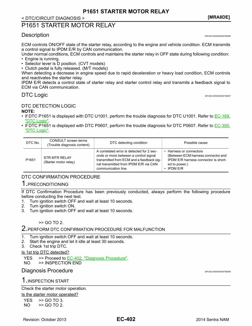
[MRA8DE]P1651 STARTER MOTOR RELAY
< DTC/CIRCUIT DIAGNOSIS >P1651 STARTER MOTOR RELAYDescription INFOID:0000000009758656
ECM controls ON/OFF state of the starter relay, according to the engine and vehicle condition. ECM transmitsa control signal to IPDM E/R by CAN communication.Under normal conditions, ECM controls and maintains the starter relay in OFF state during following condition: • Engine is running.• Selector lever is D position. (CVT models)• Clutch pedal is fully released. (M/T models)When detecting a decrease in engine speed due to rapid deceleration or heavy load condition, ECM controlsand reactivates the starter relay.IPDM E/R detects a control state of starter relay and starter control relay and transmits a feedback signal toECM via CAN communication.
DTC Logic INFOID:0000000009758657
DTC DETECTION LOGICNOTE:• If DTC P1651 is displayed with DTC U1001, perform the trouble diagnosis for DTC U1001. Refer to EC-169,
"DTC Logic".• If DTC P1651 is displayed with DTC P0607, perform the trouble diagnosis for DTC P0607. Refer to EC-350,
"DTC Logic".
DTC CONFIRMATION PROCEDURE1.PRECONDITIONING
If DTC Confirmation Procedure has been previously conducted, always perform the following procedurebefore conducting the next test.1. Turn ignition switch OFF and wait at least 10 seconds.2. Turn ignition switch ON.3. Turn ignition switch OFF and wait at least 10 seconds.
>> GO TO 2.2.PERFORM DTC CONFIRMATION PROCEDURE FOR MALFUNCTION
1. Turn ignition switch OFF and wait at least 10 seconds.2. Start the engine and let it idle at least 30 seconds.3. Check 1st trip DTC.Is 1st trip DTC detected?YES >> Proceed to EC-402, "Diagnosis Procedure".NO >> INSPECTION END
Diagnosis Procedure INFOID:0000000009758658
1.INSPECTION START
Check the starter motor operation.Is the starter motor operated?YES >> GO TO 3.NO >> GO TO 2.
DTC No. CONSULT screen terms(Trouble diagnosis content) DTC detecting condition Possible cause
P1651 STR MTR RELAY(Starter motor relay)
A correlated error is detected for 2 sec-onds or more between a control signal transmitted from ECM and a feedback sig-nal transmitted from IPDM E/R via CAN communication line.
• Harness or connectors(Between ECM harness connector and IPDM E/R harness connector is short-ed to power.)
• IPDM E/R
EC-402Revision: October 2013 2014 Sentra NAM
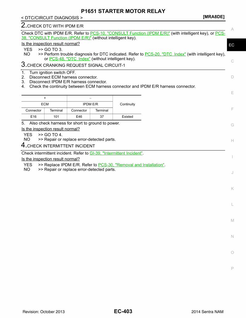
P1651 STARTER MOTOR RELAY[MRA8DE]
C
D
E
F
G
H
I
J
K
L
M
A
C
N
P
O
< DTC/CIRCUIT DIAGNOSIS >
E
2.CHECK DTC WITH IPDM E/R
Check DTC with IPDM E/R. Refer to PCS-10, "CONSULT Function (IPDM E/R)" (with intelligent key), or PCS-38, "CONSULT Function (IPDM E/R)" (without intelligent key).Is the inspection result normal?YES >> GO TO 3.NO >> Perform trouble diagnosis for DTC indicated. Refer to PCS-20, "DTC Index" (with intelligent key),
or PCS-48, "DTC Index" (without intelligent key).3.CHECK CRANKING REQUEST SIGNAL CIRCUIT-1
1. Turn ignition switch OFF.2. Disconnect ECM harness connector.3. Disconnect IPDM E/R harness connector.4. Check the continuity between ECM harness connector and IPDM E/R harness connector.
5. Also check harness for short to ground to power.Is the inspection result normal?YES >> GO TO 4.NO >> Repair or replace error-detected parts.
4.CHECK INTERMITTENT INCIDENT
Check intermittent incident. Refer to GI-39, "Intermittent Incident".Is the inspection result normal?YES >> Replace IPDM E/R. Refer to PCS-30, "Removal and Installation".NO >> Repair or replace error-detected parts.
+ −
ContinuityECM IPDM E/R
Connector Terminal Connector Terminal
E16 101 E46 37 Existed
EC-403Revision: October 2013 2014 Sentra NAM
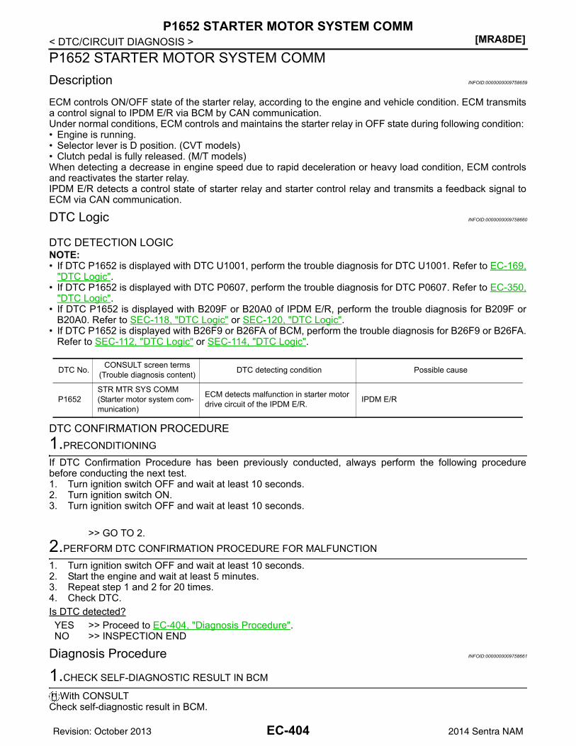
[MRA8DE]P1652 STARTER MOTOR SYSTEM COMM
< DTC/CIRCUIT DIAGNOSIS >P1652 STARTER MOTOR SYSTEM COMMDescription INFOID:0000000009758659
ECM controls ON/OFF state of the starter relay, according to the engine and vehicle condition. ECM transmitsa control signal to IPDM E/R via BCM by CAN communication.Under normal conditions, ECM controls and maintains the starter relay in OFF state during following condition: • Engine is running.• Selector lever is D position. (CVT models)• Clutch pedal is fully released. (M/T models)When detecting a decrease in engine speed due to rapid deceleration or heavy load condition, ECM controlsand reactivates the starter relay.IPDM E/R detects a control state of starter relay and starter control relay and transmits a feedback signal toECM via CAN communication.
DTC Logic INFOID:0000000009758660
DTC DETECTION LOGICNOTE:• If DTC P1652 is displayed with DTC U1001, perform the trouble diagnosis for DTC U1001. Refer to EC-169,
"DTC Logic".• If DTC P1652 is displayed with DTC P0607, perform the trouble diagnosis for DTC P0607. Refer to EC-350,
"DTC Logic".• If DTC P1652 is displayed with B209F or B20A0 of IPDM E/R, perform the trouble diagnosis for B209F or
B20A0. Refer to SEC-118, "DTC Logic" or SEC-120, "DTC Logic".• If DTC P1652 is displayed with B26F9 or B26FA of BCM, perform the trouble diagnosis for B26F9 or B26FA.
Refer to SEC-112, "DTC Logic" or SEC-114, "DTC Logic".
DTC CONFIRMATION PROCEDURE1.PRECONDITIONING
If DTC Confirmation Procedure has been previously conducted, always perform the following procedurebefore conducting the next test.1. Turn ignition switch OFF and wait at least 10 seconds.2. Turn ignition switch ON.3. Turn ignition switch OFF and wait at least 10 seconds.
>> GO TO 2.2.PERFORM DTC CONFIRMATION PROCEDURE FOR MALFUNCTION
1. Turn ignition switch OFF and wait at least 10 seconds.2. Start the engine and wait at least 5 minutes.3. Repeat step 1 and 2 for 20 times.4. Check DTC.Is DTC detected?YES >> Proceed to EC-404, "Diagnosis Procedure".NO >> INSPECTION END
Diagnosis Procedure INFOID:0000000009758661
1.CHECK SELF-DIAGNOSTIC RESULT IN BCM
With CONSULTCheck self-diagnostic result in BCM.
DTC No. CONSULT screen terms(Trouble diagnosis content) DTC detecting condition Possible cause
P1652STR MTR SYS COMM(Starter motor system com-munication)
ECM detects malfunction in starter motor drive circuit of the IPDM E/R. IPDM E/R
EC-404Revision: October 2013 2014 Sentra NAM
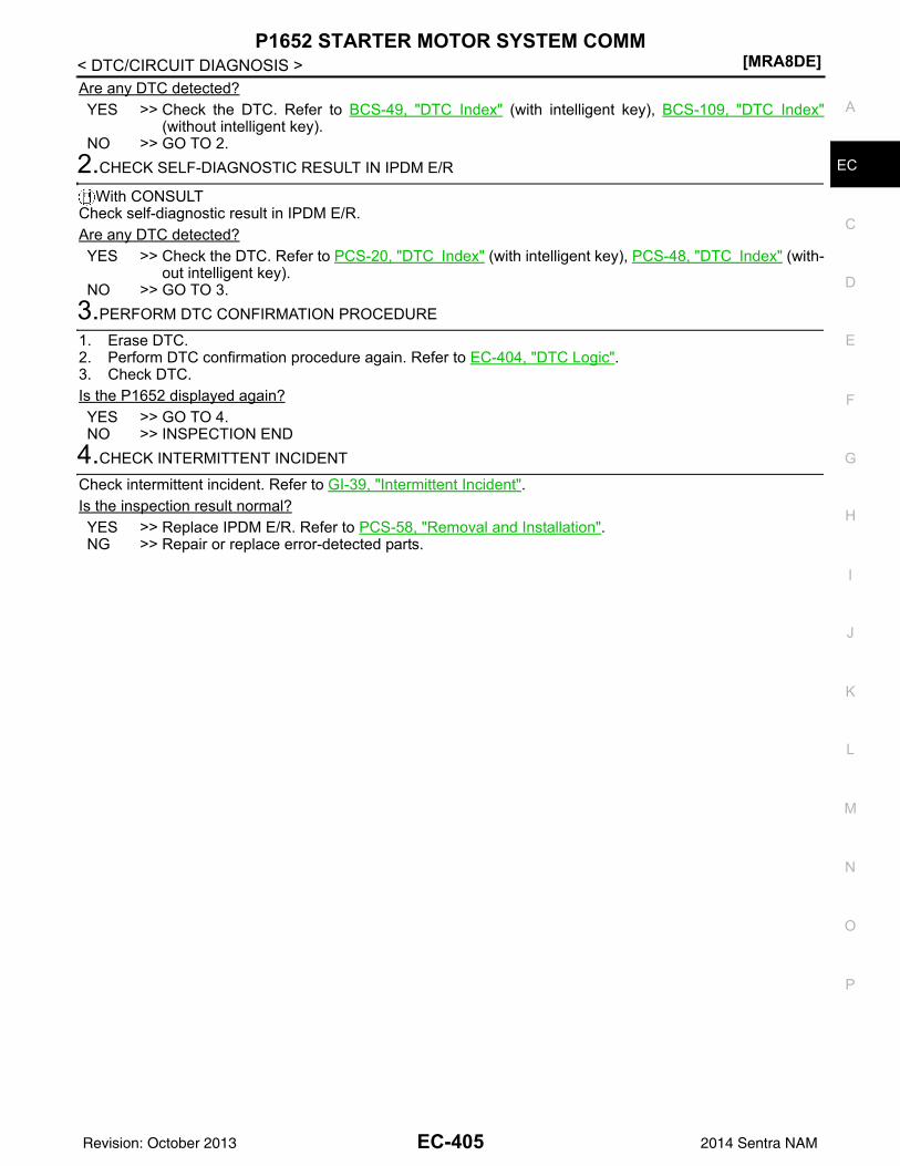
P1652 STARTER MOTOR SYSTEM COMM[MRA8DE]
C
D
E
F
G
H
I
J
K
L
M
A
C
N
P
O
< DTC/CIRCUIT DIAGNOSIS >
E
Are any DTC detected?YES >> Check the DTC. Refer to BCS-49, "DTC Index" (with intelligent key), BCS-109, "DTC Index"
(without intelligent key).NO >> GO TO 2.
2.CHECK SELF-DIAGNOSTIC RESULT IN IPDM E/R
With CONSULTCheck self-diagnostic result in IPDM E/R.Are any DTC detected?YES >> Check the DTC. Refer to PCS-20, "DTC Index" (with intelligent key), PCS-48, "DTC Index" (with-
out intelligent key).NO >> GO TO 3.
3.PERFORM DTC CONFIRMATION PROCEDURE
1. Erase DTC.2. Perform DTC confirmation procedure again. Refer to EC-404, "DTC Logic".3. Check DTC.Is the P1652 displayed again?YES >> GO TO 4.NO >> INSPECTION END
4.CHECK INTERMITTENT INCIDENT
Check intermittent incident. Refer to GI-39, "Intermittent Incident".Is the inspection result normal?YES >> Replace IPDM E/R. Refer to PCS-58, "Removal and Installation".NG >> Repair or replace error-detected parts.
EC-405Revision: October 2013 2014 Sentra NAM
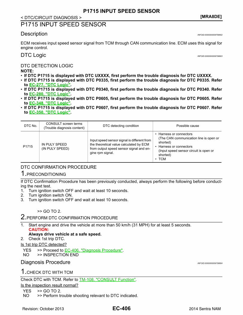
[MRA8DE]P1715 INPUT SPEED SENSOR
< DTC/CIRCUIT DIAGNOSIS >P1715 INPUT SPEED SENSORDescription INFOID:0000000009758662
ECM receives input speed sensor signal from TCM through CAN communication line. ECM uses this signal forengine control.
DTC Logic INFOID:0000000009758663
DTC DETECTION LOGICNOTE:• If DTC P1715 is displayed with DTC UXXXX, first perform the trouble diagnosis for DTC UXXXX.• If DTC P1715 is displayed with DTC P0335, first perform the trouble diagnosis for DTC P0335. Refer
to EC-277, "DTC Logic".• If DTC P1715 is displayed with DTC P0340, first perform the trouble diagnosis for DTC P0340. Refer
to EC-280, "DTC Logic".• If DTC P1715 is displayed with DTC P0605, first perform the trouble diagnosis for DTC P0605. Refer
to EC-348, "DTC Logic".• If DTC P1715 is displayed with DTC P0607, first perform the trouble diagnosis for DTC P0607. Refer
to EC-350, "DTC Logic".
DTC CONFIRMATION PROCEDURE1.PRECONDITIONING
If DTC Confirmation Procedure has been previously conducted, always perform the following before conduct-ing the next test. 1. Turn ignition switch OFF and wait at least 10 seconds.2. Turn ignition switch ON.3. Turn ignition switch OFF and wait at least 10 seconds.
>> GO TO 2.2.PERFORM DTC CONFIRMATION PROCEDURE
1. Start engine and drive the vehicle at more than 50 km/h (31 MPH) for at least 5 seconds.CAUTION:Always drive vehicle at a safe speed.
2. Check 1st trip DTC.Is 1st trip DTC detected?YES >> Proceed to EC-406, "Diagnosis Procedure".NO >> INSPECTION END
Diagnosis Procedure INFOID:0000000009758664
1.CHECK DTC WITH TCM
Check DTC with TCM. Refer to TM-108, "CONSULT Function".Is the inspection result normal?YES >> GO TO 2.NO >> Perform trouble shooting relevant to DTC indicated.
DTC No. CONSULT screen terms(Trouble diagnosis content) DTC detecting condition Possible cause
P1715 IN PULY SPEED(IN PULY SPEED)
Input speed sensor signal is different from the theoretical value calculated by ECM from output speed sensor signal and en-gine rpm signal.
• Harness or connectors(The CAN communication line is open or shorted)
• Harness or connectors(Input speed sensor circuit is open or shorted)
• TCM
EC-406Revision: October 2013 2014 Sentra NAM
P1715 INPUT SPEED SENSOR[MRA8DE]
C
D
E
F
G
H
I
J
K
L
M
A
C
N
P
O
< DTC/CIRCUIT DIAGNOSIS >
E
2.REPLACE TCM
Replace TCM. Refer to TM-263, "Removal and Installation".
>> INSPECTION END
EC-407Revision: October 2013 2014 Sentra NAM
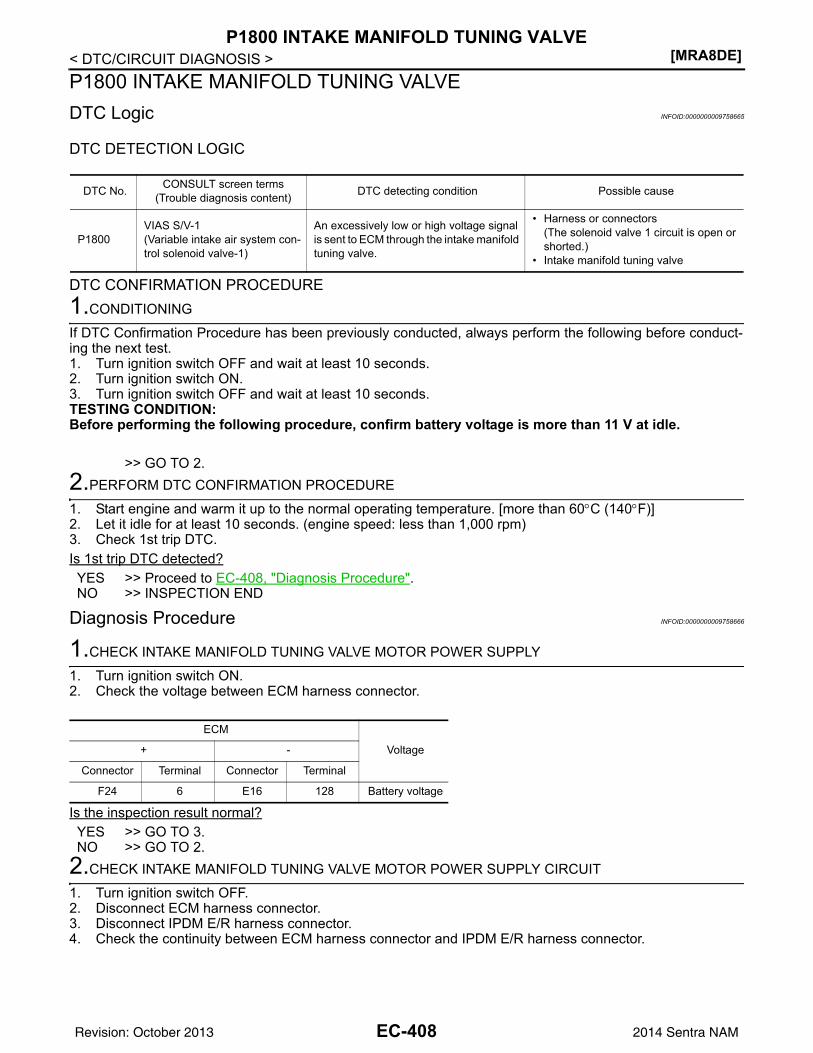
[MRA8DE]P1800 INTAKE MANIFOLD TUNING VALVE
< DTC/CIRCUIT DIAGNOSIS >P1800 INTAKE MANIFOLD TUNING VALVE DTC Logic INFOID:0000000009758665
DTC DETECTION LOGIC
DTC CONFIRMATION PROCEDURE1.CONDITIONING
If DTC Confirmation Procedure has been previously conducted, always perform the following before conduct-ing the next test.1. Turn ignition switch OFF and wait at least 10 seconds.2. Turn ignition switch ON.3. Turn ignition switch OFF and wait at least 10 seconds.TESTING CONDITION:Before performing the following procedure, confirm battery voltage is more than 11 V at idle.
>> GO TO 2.2.PERFORM DTC CONFIRMATION PROCEDURE
1. Start engine and warm it up to the normal operating temperature. [more than 60°C (140°F)]2. Let it idle for at least 10 seconds. (engine speed: less than 1,000 rpm)3. Check 1st trip DTC.Is 1st trip DTC detected?YES >> Proceed to EC-408, "Diagnosis Procedure".NO >> INSPECTION END
Diagnosis Procedure INFOID:0000000009758666
1.CHECK INTAKE MANIFOLD TUNING VALVE MOTOR POWER SUPPLY
1. Turn ignition switch ON.2. Check the voltage between ECM harness connector.
Is the inspection result normal?YES >> GO TO 3.NO >> GO TO 2.
2.CHECK INTAKE MANIFOLD TUNING VALVE MOTOR POWER SUPPLY CIRCUIT
1. Turn ignition switch OFF.2. Disconnect ECM harness connector.3. Disconnect IPDM E/R harness connector.4. Check the continuity between ECM harness connector and IPDM E/R harness connector.
DTC No. CONSULT screen terms(Trouble diagnosis content) DTC detecting condition Possible cause
P1800VIAS S/V-1(Variable intake air system con-trol solenoid valve-1)
An excessively low or high voltage signal is sent to ECM through the intake manifold tuning valve.
• Harness or connectors(The solenoid valve 1 circuit is open or shorted.)
• Intake manifold tuning valve
ECM
Voltage+ -
Connector Terminal Connector Terminal
F24 6 E16 128 Battery voltage
EC-408Revision: October 2013 2014 Sentra NAM
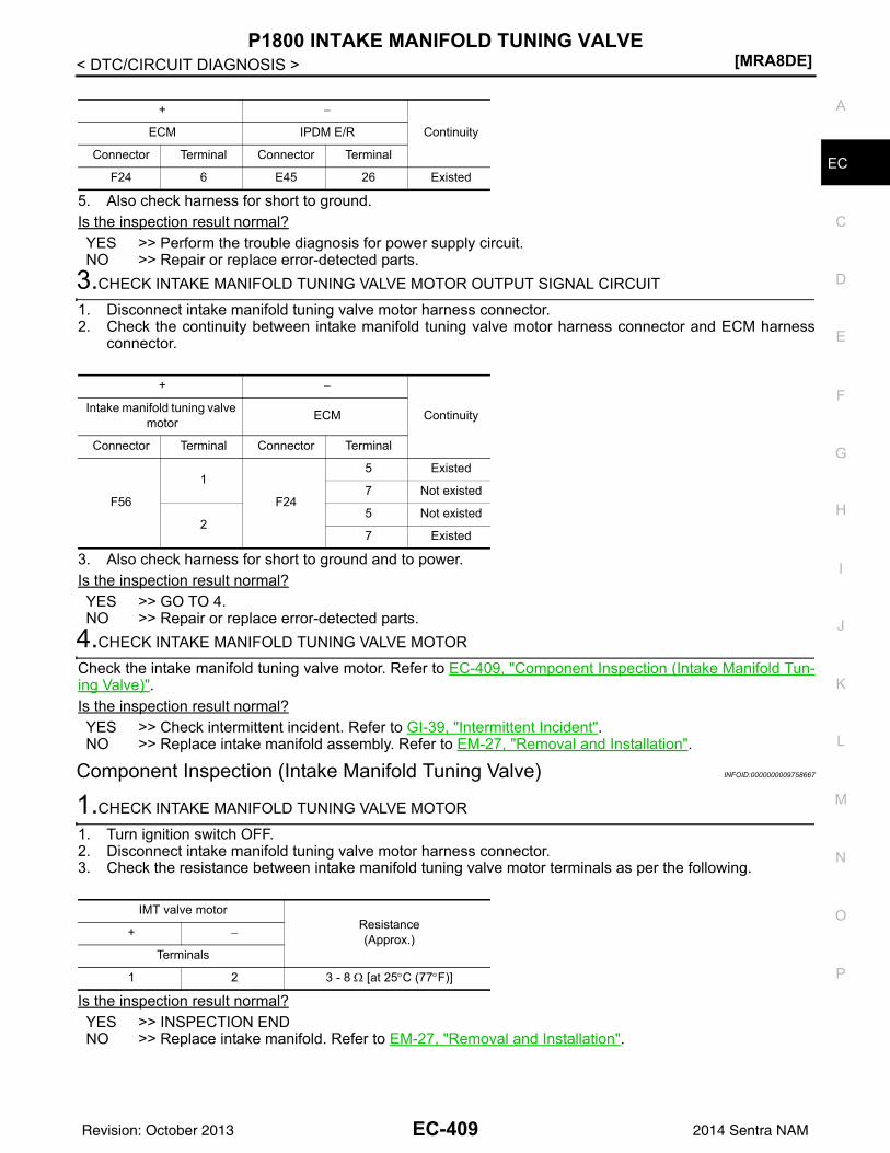
P1800 INTAKE MANIFOLD TUNING VALVE[MRA8DE]
C
D
E
F
G
H
I
J
K
L
M
A
C
N
P
O
< DTC/CIRCUIT DIAGNOSIS >
E
5. Also check harness for short to ground.Is the inspection result normal?YES >> Perform the trouble diagnosis for power supply circuit.NO >> Repair or replace error-detected parts.
3.CHECK INTAKE MANIFOLD TUNING VALVE MOTOR OUTPUT SIGNAL CIRCUIT
1. Disconnect intake manifold tuning valve motor harness connector.2. Check the continuity between intake manifold tuning valve motor harness connector and ECM harness
connector.
3. Also check harness for short to ground and to power.Is the inspection result normal?YES >> GO TO 4.NO >> Repair or replace error-detected parts.
4.CHECK INTAKE MANIFOLD TUNING VALVE MOTOR
Check the intake manifold tuning valve motor. Refer to EC-409, "Component Inspection (Intake Manifold Tun-ing Valve)".Is the inspection result normal?YES >> Check intermittent incident. Refer to GI-39, "Intermittent Incident".NO >> Replace intake manifold assembly. Refer to EM-27, "Removal and Installation".
Component Inspection (Intake Manifold Tuning Valve) INFOID:0000000009758667
1.CHECK INTAKE MANIFOLD TUNING VALVE MOTOR
1. Turn ignition switch OFF.2. Disconnect intake manifold tuning valve motor harness connector.3. Check the resistance between intake manifold tuning valve motor terminals as per the following.
Is the inspection result normal?YES >> INSPECTION ENDNO >> Replace intake manifold. Refer to EM-27, "Removal and Installation".
+ −
ContinuityECM IPDM E/R
Connector Terminal Connector Terminal
F24 6 E45 26 Existed
+ −
ContinuityIntake manifold tuning valve motor ECM
Connector Terminal Connector Terminal
F56
1
F24
5 Existed
7 Not existed
25 Not existed
7 Existed
IMT valve motorResistance(Approx.)+ −
Terminals
1 2 3 - 8 Ω [at 25°C (77°F)]
EC-409Revision: October 2013 2014 Sentra NAM
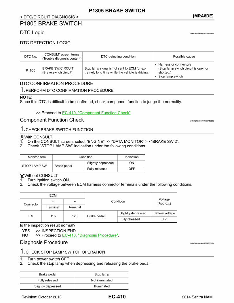
[MRA8DE]P1805 BRAKE SWITCH
< DTC/CIRCUIT DIAGNOSIS >P1805 BRAKE SWITCHDTC Logic INFOID:0000000009758668
DTC DETECTION LOGIC
DTC CONFIRMATION PROCEDURE1.PERFORM DTC CONFIRMATION PROCEDURE
NOTE:Since this DTC is difficult to be confirmed, check component function to judge the normality.
>> Proceed to EC-410, "Component Function Check".
Component Function Check INFOID:0000000009758669
1.CHECK BRAKE SWITCH FUNCTION
With CONSULT1. On the CONSULT screen, select “ENGINE” >> “DATA MONITOR” >> “BRAKE SW 2”.2. Check “STOP LAMP SW” indication under the following conditions.
Without CONSULT1. Turn ignition switch ON.2. Check the voltage between ECM harness connector terminals under the following conditions.
Is the inspection result normal?YES >> INSPECTION ENDNO >> Proceed to EC-410, "Diagnosis Procedure".
Diagnosis Procedure INFOID:0000000009758670
1.CHECK STOP LAMP SWITCH OPERATION
1. Turn power switch OFF.2. Check the stop lamp when depressing and releasing the brake pedal.
DTC No. CONSULT screen terms(Trouble diagnosis content) DTC detecting condition Possible cause
P1805 BRAKE SW/CIRCUIT(Brake switch circuit)
Stop lamp signal is not sent to ECM for ex-tremely long time while the vehicle is driving.
• Harness or connectors(Stop lamp switch circuit is open or shorted.)
• Stop lamp switch
Monitor item Condition Indication
STOP LAMP SW Brake pedalSlightly depressed ON
Fully released OFF
ECM
Condition Voltage(Approx.)Connector
+ –
Terminal Terminal
E16 115 128 Brake pedalSlightly depressed Battery voltage
Fully released 0 V
Brake pedal Stop lamp
Fully released Not illuminated
Slightly depressed Illuminated
EC-410Revision: October 2013 2014 Sentra NAM
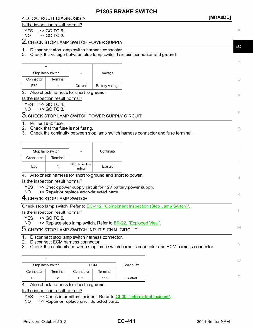
P1805 BRAKE SWITCH[MRA8DE]
C
D
E
F
G
H
I
J
K
L
M
A
C
N
P
O
< DTC/CIRCUIT DIAGNOSIS >
E
Is the inspection result normal?YES >> GO TO 5. NO >> GO TO 2.
2.CHECK STOP LAMP SWITCH POWER SUPPLY
1. Disconnect stop lamp switch harness connector.2. Check the voltage between stop lamp switch harness connector and ground.
3. Also check harness for short to ground.Is the inspection result normal?YES >> GO TO 4.NO >> GO TO 3.
3.CHECK STOP LAMP SWITCH POWER SUPPLY CIRCUIT
1. Pull out #30 fuse.2. Check that the fuse is not fusing.3. Check the continuity between stop lamp switch harness connector and fuse terminal.
4. Also check harness for short to ground and short to power.Is the inspection result normal?YES >> Check power supply circuit for 12V battery power supply.NO >> Repair or replace error-detected parts.
4.CHECK STOP LAMP SWITCH
Check stop lamp switch. Refer to EC-412, "Component Inspection (Stop Lamp Switch)".Is the inspection result normal?YES >> GO TO 5.NO >> Replace stop lamp switch. Refer to BR-22, "Exploded View".
5.CHECK STOP LAMP SWITCH INPUT SIGNAL CIRCUIT
1. Disconnect stop lamp switch harness connector.2. Disconnect ECM harness connector.3. Check the continuity between stop lamp switch harness connector and ECM harness connector.
4. Also check harness for short to ground.Is the inspection result normal?YES >> Check intermittent incident. Refer to GI-39, "Intermittent Incident".NO >> Repair or replace error-detected parts.
+
− VoltageStop lamp switch
Connector Terminal
E60 1 Ground Battery voltage
+
− ContinuityStop lamp switch
Connector Terminal
E60 1 #30 fuse ter-minal Existed
+ −
ContinuityStop lamp switch ECM
Connector Terminal Connector Terminal
E60 2 E16 115 Existed
EC-411Revision: October 2013 2014 Sentra NAM
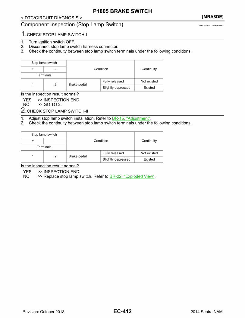
[MRA8DE]P1805 BRAKE SWITCH
< DTC/CIRCUIT DIAGNOSIS >Component Inspection (Stop Lamp Switch) INFOID:0000000009758671
1.CHECK STOP LAMP SWITCH-I
1. Turn ignition switch OFF.2. Disconnect stop lamp switch harness connector.3. Check the continuity between stop lamp switch terminals under the following conditions.
Is the inspection result normal?YES >> INSPECTION ENDNO >> GO TO 2.
2.CHECK STOP LAMP SWITCH-II
1. Adjust stop lamp switch installation. Refer to BR-15, "Adjustment".2. Check the continuity between stop lamp switch terminals under the following conditions.
Is the inspection result normal?YES >> INSPECTION ENDNO >> Replace stop lamp switch. Refer to BR-22, "Exploded View".
Stop lamp switch
Condition Continuity+ −
Terminals
1 2 Brake pedalFully released Not existed
Slightly depressed Existed
Stop lamp switch
Condition Continuity+ −
Terminals
1 2 Brake pedalFully released Not existed
Slightly depressed Existed
EC-412Revision: October 2013 2014 Sentra NAM
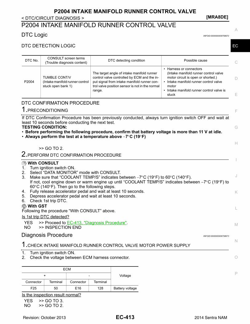
P2004 INTAKE MANIFOLD RUNNER CONTROL VALVE[MRA8DE]
C
D
E
F
G
H
I
J
K
L
M
A
C
N
P
O
< DTC/CIRCUIT DIAGNOSIS >
E
P2004 INTAKE MANIFOLD RUNNER CONTROL VALVEDTC Logic INFOID:0000000009758672
DTC DETECTION LOGIC
DTC CONFIRMATION PROCEDURE1.PRECONDITIONING
If DTC Confirmation Procedure has been previously conducted, always turn ignition switch OFF and wait atleast 10 seconds before conducting the next test.TESTING CONDITION:• Before performing the following procedure, confirm that battery voltage is more than 11 V at idle.• Always perform the test at a temperature above −7°C (19°F)
>> GO TO 2.2.PERFORM DTC CONFIRMATION PROCEDURE
With CONSULT1. Turn ignition switch ON.2. Select “DATA MONITOR” mode with CONSULT.3. Make sure that “COOLANT TEMP/S” indicates between −7°C (19°F) to 60°C (140°F).
If not, cool engine down or warm engine up until “COOLANT TEMP/S” indicates between −7°C (19°F) to60°C (140°F). Then go to the following steps.
4. Fully release accelerator pedal and wait at least 10 seconds.5. Depress accelerator pedal and wait at least 10 seconds.6. Check 1st trip DTC.
With GSTFollowing the procedure “With CONSULT” above.Is 1st trip DTC detected?YES >> Proceed to EC-413, "Diagnosis Procedure".NO >> INSPECTION END
Diagnosis Procedure INFOID:0000000009758673
1.CHECK INTAKE MANIFOLD RUNNER CONTROL VALVE MOTOR POWER SUPPLY
1. Turn ignition switch ON.2. Check the voltage between ECM harness connector.
Is the inspection result normal?YES >> GO TO 3.NO >> GO TO 2.
DTC No. CONSULT screen terms(Trouble diagnosis content) DTC detecting condition Possible cause
P2004TUMBLE CONT/V(Intake manifold runner control stuck open bank 1)
The target angle of intake manifold runner control valve controlled by ECM and the in-put signal from intake manifold runner con-trol valve position sensor is not in the normal range.
• Harness or connectors(Intake manifold runner control valve motor circuit is open or shorted.)
• Intake manifold runner control valve motor
• Intake manifold runner control valve is stuck
ECM
Voltage+ -
Connector Terminal Connector Terminal
F25 50 E16 128 Battery voltage
EC-413Revision: October 2013 2014 Sentra NAM
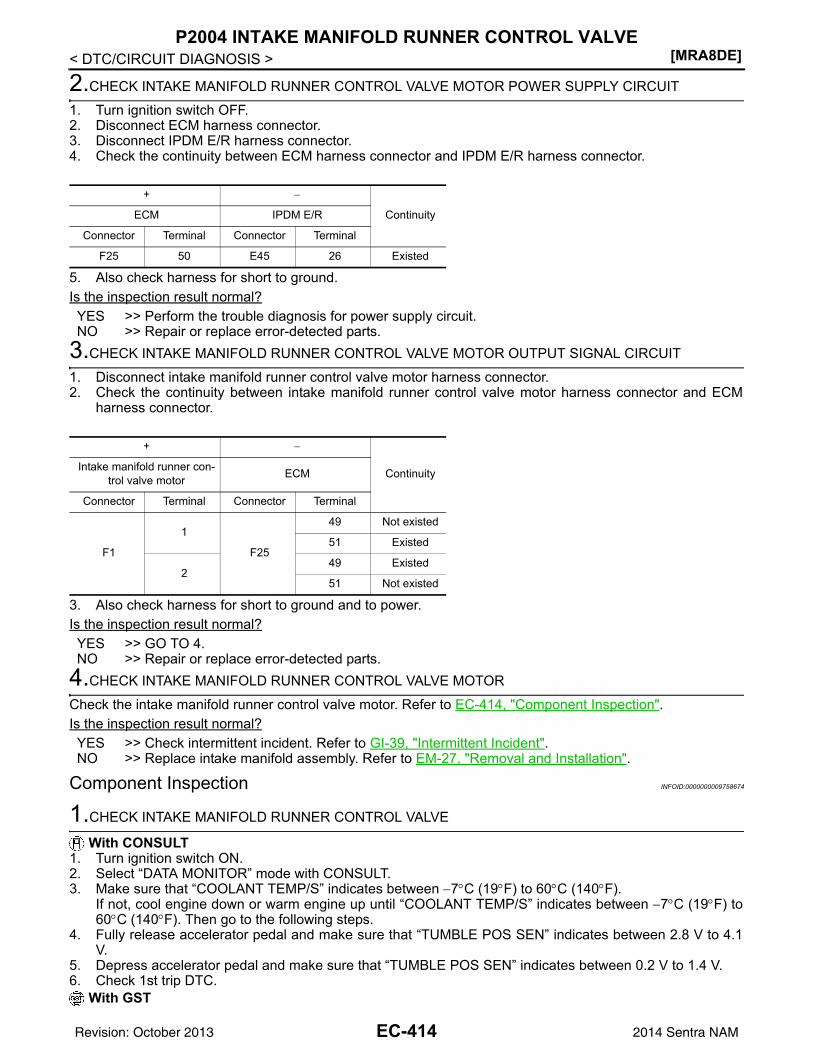
[MRA8DE]P2004 INTAKE MANIFOLD RUNNER CONTROL VALVE
< DTC/CIRCUIT DIAGNOSIS >
2.CHECK INTAKE MANIFOLD RUNNER CONTROL VALVE MOTOR POWER SUPPLY CIRCUIT
1. Turn ignition switch OFF.2. Disconnect ECM harness connector.3. Disconnect IPDM E/R harness connector.4. Check the continuity between ECM harness connector and IPDM E/R harness connector.
5. Also check harness for short to ground.Is the inspection result normal?YES >> Perform the trouble diagnosis for power supply circuit.NO >> Repair or replace error-detected parts.
3.CHECK INTAKE MANIFOLD RUNNER CONTROL VALVE MOTOR OUTPUT SIGNAL CIRCUIT
1. Disconnect intake manifold runner control valve motor harness connector.2. Check the continuity between intake manifold runner control valve motor harness connector and ECM
harness connector.
3. Also check harness for short to ground and to power.Is the inspection result normal?YES >> GO TO 4.NO >> Repair or replace error-detected parts.
4.CHECK INTAKE MANIFOLD RUNNER CONTROL VALVE MOTOR
Check the intake manifold runner control valve motor. Refer to EC-414, "Component Inspection".Is the inspection result normal?YES >> Check intermittent incident. Refer to GI-39, "Intermittent Incident".NO >> Replace intake manifold assembly. Refer to EM-27, "Removal and Installation".
Component Inspection INFOID:0000000009758674
1.CHECK INTAKE MANIFOLD RUNNER CONTROL VALVE
With CONSULT1. Turn ignition switch ON.2. Select “DATA MONITOR” mode with CONSULT.3. Make sure that “COOLANT TEMP/S” indicates between −7°C (19°F) to 60°C (140°F).
If not, cool engine down or warm engine up until “COOLANT TEMP/S” indicates between −7°C (19°F) to60°C (140°F). Then go to the following steps.
4. Fully release accelerator pedal and make sure that “TUMBLE POS SEN” indicates between 2.8 V to 4.1V.
5. Depress accelerator pedal and make sure that “TUMBLE POS SEN” indicates between 0.2 V to 1.4 V.6. Check 1st trip DTC.
With GST
+ −
ContinuityECM IPDM E/R
Connector Terminal Connector Terminal
F25 50 E45 26 Existed
+ −
ContinuityIntake manifold runner con-trol valve motor ECM
Connector Terminal Connector Terminal
F1
1
F25
49 Not existed
51 Existed
249 Existed
51 Not existed
EC-414Revision: October 2013 2014 Sentra NAM
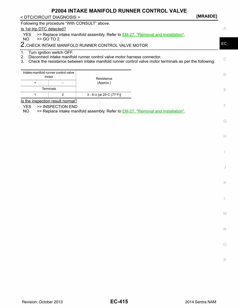
P2004 INTAKE MANIFOLD RUNNER CONTROL VALVE[MRA8DE]
C
D
E
F
G
H
I
J
K
L
M
A
C
N
P
O
< DTC/CIRCUIT DIAGNOSIS >
E
Following the procedure “With CONSULT” above.Is 1st trip DTC detected?YES >> Replace intake manifold assembly. Refer to EM-27, "Removal and Installation".NO >> GO TO 2.
2.CHECK INTAKE MANIFOLD RUNNER CONTROL VALVE MOTOR
1. Turn ignition switch OFF.2. Disconnect intake manifold runner control valve motor harness connector.3. Check the resistance between intake manifold runner control valve motor terminals as per the following.
Is the inspection result normal?YES >> INSPECTION ENDNO >> Replace intake manifold assembly. Refer to EM-27, "Removal and Installation".
Intake manifold runner control valve motor Resistance
(Approx.)+ −
Terminals
1 2 3 - 8 Ω [at 25°C (77°F)]
EC-415Revision: October 2013 2014 Sentra NAM
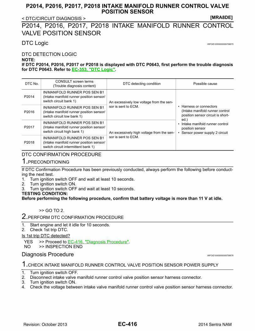
[MRA8DE]
P2014, P2016, P2017, P2018 INTAKE MANIFOLD RUNNER CONTROL VALVE POSITION SENSOR
< DTC/CIRCUIT DIAGNOSIS >P2014, P2016, P2017, P2018 INTAKE MANIFOLD RUNNER CONTROLVALVE POSITION SENSORDTC Logic INFOID:0000000009758675
DTC DETECTION LOGICNOTE:If DTC P2014, P2016, P2017 or P2018 is displayed with DTC P0643, first perform the trouble diagnosisfor DTC P0643. Refer to EC-353, "DTC Logic".
DTC CONFIRMATION PROCEDURE1.PRECONDITIONING
If DTC Confirmation Procedure has been previously conducted, always perform the following before conduct-ing the next test. 1. Turn ignition switch OFF and wait at least 10 seconds.2. Turn ignition switch ON.3. Turn ignition switch OFF and wait at least 10 seconds.TESTING CONDITION:Before performing the following procedure, confirm that battery voltage is more than 11 V at idle.
>> GO TO 2.2.PERFORM DTC CONFIRMATION PROCEDURE
1. Start engine and let it idle for 10 seconds.2. Check 1st trip DTC.Is 1st trip DTC detected?YES >> Proceed to EC-416, "Diagnosis Procedure".NO >> INSPECTION END
Diagnosis Procedure INFOID:0000000009758676
1.CHECK INTAKE MANIFOLD RUNNER CONTROL VALVE POSITION SENSOR POWER SUPPLY
1. Turn ignition switch OFF.2. Disconnect intake valve manifold runner control valve position sensor harness connector.3. Turn ignition switch ON.4. Check the voltage between intake valve manifold runner control valve position sensor harness connector.
DTC No. CONSULT screen terms(Trouble diagnosis content) DTC detecting condition Possible cause
P2014IN/MANIFOLD RUNNER POS SEN B1(Intake manifold runner position sensor/switch circuit bank 1) An excessively low voltage from the sen-
sor is sent to ECM. • Harness or connectors(Intake manifold runner control position sensor circuit is short-ed.)
• Intake manifold runner control position sensor
• Sensor power supply 2 circuit
P2016IN/MANIFOLD RUNNER POS SEN B1(Intake manifold runner position sensor/switch circuit low bank 1)
P2017IN/MANIFOLD RUNNER POS SEN B1(Intake manifold runner position sensor/switch circuit high bank 1) An excessively high voltage from the sen-
sor is sent to ECM.P2018
IN/MANIFOLD RUNNER POS SEN B1(Intake manifold runner position sensor/switch circuit intermittent bank 1)
EC-416Revision: October 2013 2014 Sentra NAM
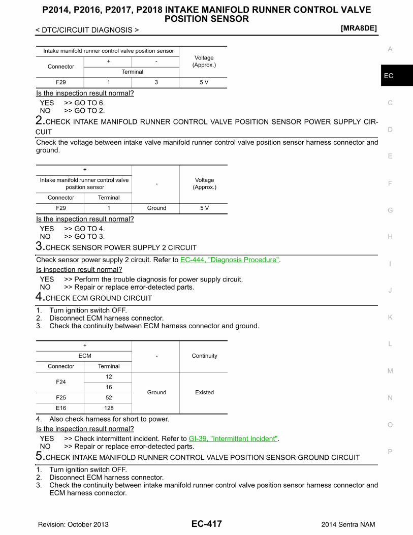
P2014, P2016, P2017, P2018 INTAKE MANIFOLD RUNNER CONTROL VALVE POSITION SENSOR
[MRA8DE]
C
D
E
F
G
H
I
J
K
L
M
A
C
N
P
O
< DTC/CIRCUIT DIAGNOSIS >
E
Is the inspection result normal?YES >> GO TO 6.NO >> GO TO 2.
2.CHECK INTAKE MANIFOLD RUNNER CONTROL VALVE POSITION SENSOR POWER SUPPLY CIR-CUITCheck the voltage between intake valve manifold runner control valve position sensor harness connector andground.
Is the inspection result normal?YES >> GO TO 4.NO >> GO TO 3.
3.CHECK SENSOR POWER SUPPLY 2 CIRCUIT
Check sensor power supply 2 circuit. Refer to EC-444, "Diagnosis Procedure".Is inspection result normal?YES >> Perform the trouble diagnosis for power supply circuit.NO >> Repair or replace error-detected parts.
4.CHECK ECM GROUND CIRCUIT
1. Turn ignition switch OFF.2. Disconnect ECM harness connector.3. Check the continuity between ECM harness connector and ground.
4. Also check harness for short to power.Is the inspection result normal?YES >> Check intermittent incident. Refer to GI-39, "Intermittent Incident".NO >> Repair or replace error-detected parts.
5.CHECK INTAKE MANIFOLD RUNNER CONTROL VALVE POSITION SENSOR GROUND CIRCUIT
1. Turn ignition switch OFF.2. Disconnect ECM harness connector.3. Check the continuity between intake manifold runner control valve position sensor harness connector and
ECM harness connector.
Intake manifold runner control valve position sensorVoltage
(Approx.)Connector+ -
Terminal
F29 1 3 5 V
+
- Voltage(Approx.)
Intake manifold runner control valve position sensor
Connector Terminal
F29 1 Ground 5 V
+
- ContinuityECM
Connector Terminal
F2412
Ground Existed16
F25 52
E16 128
EC-417Revision: October 2013 2014 Sentra NAM
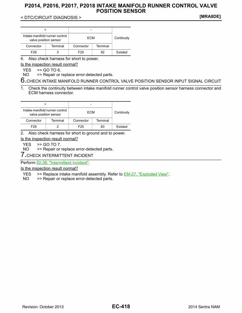
[MRA8DE]
P2014, P2016, P2017, P2018 INTAKE MANIFOLD RUNNER CONTROL VALVE POSITION SENSOR
< DTC/CIRCUIT DIAGNOSIS >
4. Also check harness for short to power.Is the inspection result normal?YES >> GO TO 6.NO >> Repair or replace error-detected parts.
6.CHECK INTAKE MANIFOLD RUNNER CONTROL VALVE POSITION SENSOR INPUT SIGNAL CIRCUIT
1. Check the continuity between intake manifold runner control valve position sensor harness connector andECM harness connector.
2. Also check harness for short to ground and to power.Is the inspection result normal?YES >> GO TO 7.NO >> Repair or replace error-detected parts.
7.CHECK INTERMITTENT INCIDENT
Perform GI-39, "Intermittent Incident".Is the inspection result normal?YES >> Replace intake manifold assembly. Refer to EM-27, "Exploded View".NO >> Repair or replace error-detected parts.
+ -
ContinuityIntake manifold runner control valve position sensor ECM
Connector Terminal Connector Terminal
F29 3 F25 92 Existed
+ -
ContinuityIntake manifold runner control valve position sensor ECM
Connector Terminal Connector Terminal
F29 2 F25 83 Existed
EC-418Revision: October 2013 2014 Sentra NAM
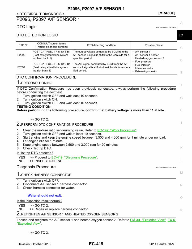
P2096, P2097 A/F SENSOR 1[MRA8DE]
C
D
E
F
G
H
I
J
K
L
M
A
C
N
P
O
< DTC/CIRCUIT DIAGNOSIS >
E
P2096, P2097 A/F SENSOR 1DTC Logic INFOID:0000000009758677
DTC DETECTION LOGIC
DTC CONFIRMATION PROCEDURE1.PRECONDITIONING
If DTC Confirmation Procedure has been previously conducted, always perform the following procedurebefore conducting the next test.1. Turn ignition switch OFF and wait least 10 seconds.2. Turn ignition switch ON.3. Turn ignition switch OFF and wait least 10 seconds.TESTING CONDITION:Before performing the following procedure, confirm that battery voltage is more than 11 at idle.
>> GO TO 2.2.PERFORM DTC CONFIRMATION PROCEDURE
1. Clear the mixture ratio self-learning value. Refer to EC-142, "Work Procedure".2. Turn ignition switch OFF and wait at least 10 seconds.3. Start engine and keep the engine speed between 3,500 and 4,000 rpm for 1 minute under no load.4. Let engine idle for 1 minute.5. Keep engine speed between 2,500 and 3,000 rpm for 20 minutes.6. Check 1st trip DTC.Is 1st trip DTC detected?YES >> Proceed to EC-419, "Diagnosis Procedure".NO >> INSPECTION END
Diagnosis Procedure INFOID:0000000009758678
1.CHECK HARNESS CONNECTOR
1. Turn ignition switch OFF.2. Disconnect A/F sensor 1 harness connector.3. Check harness connector for water.
Is the inspection result normal?YES >> GO TO 2.NO >> Repair or replace harness connector.
2.RETIGHTEN A/F SENSOR 1 AND HEATED OXYGEN SENSOR 2
Loosen and retighten the A/F sensor 1 and heated oxygen sensor 2. Refer to EM-30, "Exploded View", EX-5,"Exploded View".
>> GO TO 3.
DTC No. CONSULT screen terms(Trouble diagnosis content) DTC detecting condition Possible Cause
P2096POST CAT FUEL TRIM SYS B1(Post catalyst fuel trim system too lean bank 1)
The output voltage computed by ECM from the A/F sensor 1 signal is shifts to the lean side for a specified period.
• A/F sensor 1• A/F sensor 1 heater• Heated oxygen sensor 2• Fuel pressure• Fuel injector• Intake air leaks• Exhaust gas leaks
P2097POST CAT FUEL TRIM SYS B1(Post catalyst fuel trim system too rich bank 1)
The A/F signal computed by ECM from the A/F sensor 1 signal is shifts to the rich side for a spec-ified period.
Water should not exit.
EC-419Revision: October 2013 2014 Sentra NAM
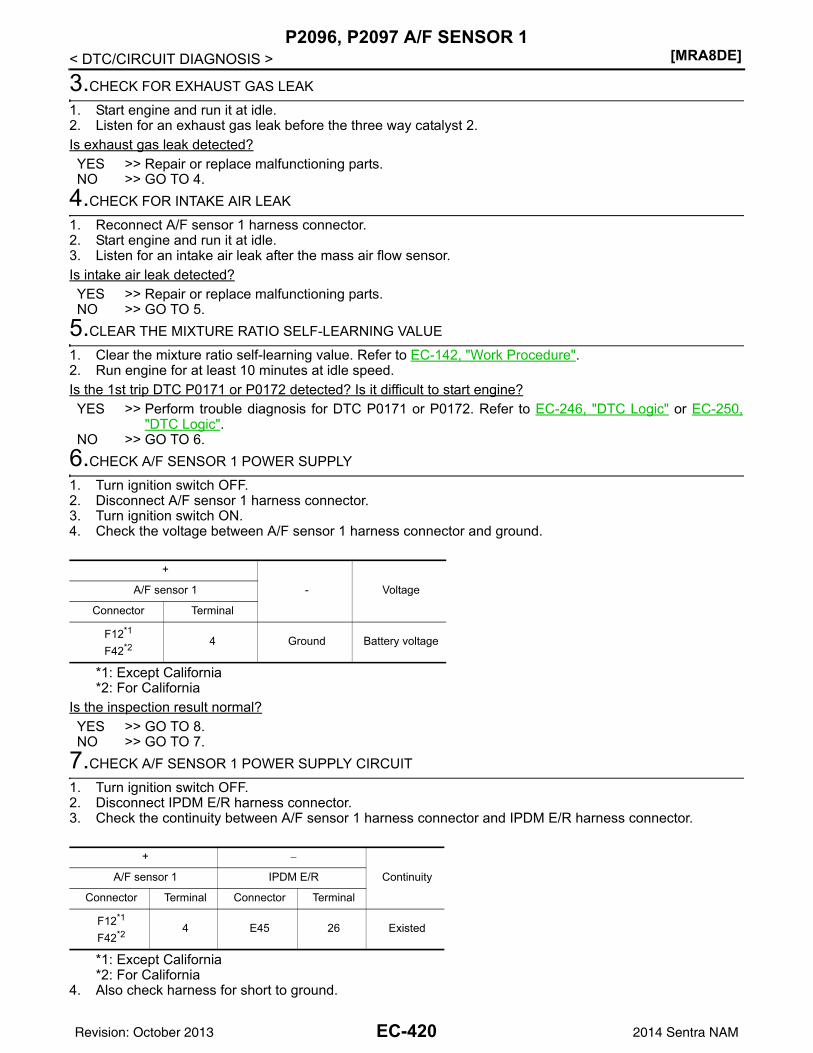
[MRA8DE]P2096, P2097 A/F SENSOR 1
< DTC/CIRCUIT DIAGNOSIS >
3.CHECK FOR EXHAUST GAS LEAK
1. Start engine and run it at idle.2. Listen for an exhaust gas leak before the three way catalyst 2.Is exhaust gas leak detected?YES >> Repair or replace malfunctioning parts.NO >> GO TO 4.
4.CHECK FOR INTAKE AIR LEAK
1. Reconnect A/F sensor 1 harness connector.2. Start engine and run it at idle.3. Listen for an intake air leak after the mass air flow sensor.Is intake air leak detected?YES >> Repair or replace malfunctioning parts.NO >> GO TO 5.
5.CLEAR THE MIXTURE RATIO SELF-LEARNING VALUE
1. Clear the mixture ratio self-learning value. Refer to EC-142, "Work Procedure".2. Run engine for at least 10 minutes at idle speed.Is the 1st trip DTC P0171 or P0172 detected? Is it difficult to start engine?YES >> Perform trouble diagnosis for DTC P0171 or P0172. Refer to EC-246, "DTC Logic" or EC-250,
"DTC Logic".NO >> GO TO 6.
6.CHECK A/F SENSOR 1 POWER SUPPLY
1. Turn ignition switch OFF.2. Disconnect A/F sensor 1 harness connector.3. Turn ignition switch ON.4. Check the voltage between A/F sensor 1 harness connector and ground.
*1: Except California*2: For California
Is the inspection result normal?YES >> GO TO 8.NO >> GO TO 7.
7.CHECK A/F SENSOR 1 POWER SUPPLY CIRCUIT
1. Turn ignition switch OFF.2. Disconnect IPDM E/R harness connector.3. Check the continuity between A/F sensor 1 harness connector and IPDM E/R harness connector.
*1: Except California*2: For California
4. Also check harness for short to ground.
+
- VoltageA/F sensor 1
Connector Terminal
F12*1
F42*2 4 Ground Battery voltage
+ −
ContinuityA/F sensor 1 IPDM E/R
Connector Terminal Connector Terminal
F12*1
F42*2 4 E45 26 Existed
EC-420Revision: October 2013 2014 Sentra NAM
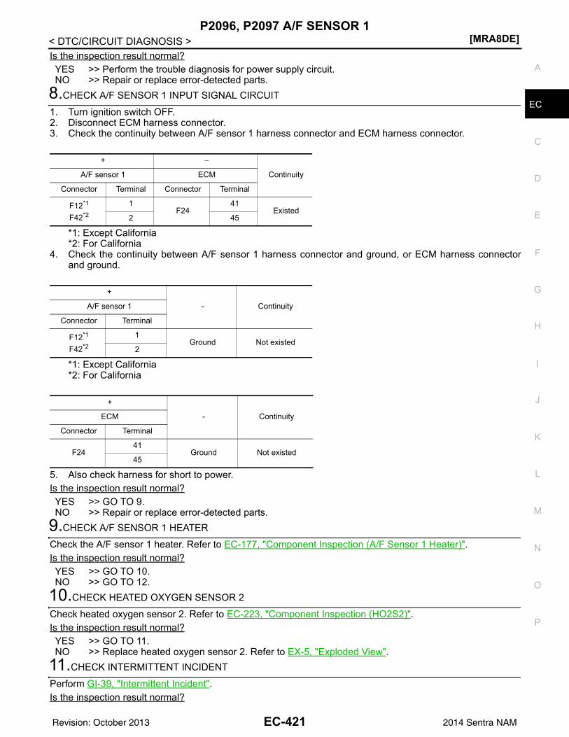
P2096, P2097 A/F SENSOR 1[MRA8DE]
C
D
E
F
G
H
I
J
K
L
M
A
C
N
P
O
< DTC/CIRCUIT DIAGNOSIS >
E
Is the inspection result normal?YES >> Perform the trouble diagnosis for power supply circuit.NO >> Repair or replace error-detected parts.
8.CHECK A/F SENSOR 1 INPUT SIGNAL CIRCUIT
1. Turn ignition switch OFF.2. Disconnect ECM harness connector.3. Check the continuity between A/F sensor 1 harness connector and ECM harness connector.
*1: Except California*2: For California
4. Check the continuity between A/F sensor 1 harness connector and ground, or ECM harness connectorand ground.
*1: Except California*2: For California
5. Also check harness for short to power.Is the inspection result normal?YES >> GO TO 9.NO >> Repair or replace error-detected parts.
9.CHECK A/F SENSOR 1 HEATER
Check the A/F sensor 1 heater. Refer to EC-177, "Component Inspection (A/F Sensor 1 Heater)".Is the inspection result normal?YES >> GO TO 10.NO >> GO TO 12.
10.CHECK HEATED OXYGEN SENSOR 2
Check heated oxygen sensor 2. Refer to EC-223, "Component Inspection (HO2S2)".Is the inspection result normal?YES >> GO TO 11.NO >> Replace heated oxygen sensor 2. Refer to EX-5, "Exploded View".
11.CHECK INTERMITTENT INCIDENT
Perform GI-39, "Intermittent Incident".Is the inspection result normal?
+ −
ContinuityA/F sensor 1 ECM
Connector Terminal Connector Terminal
F12*1
F42*2
1F24
41Existed
2 45
+
- ContinuityA/F sensor 1
Connector Terminal
F12*1
F42*2
1Ground Not existed
2
+
- ContinuityECM
Connector Terminal
F2441
Ground Not existed45
EC-421Revision: October 2013 2014 Sentra NAM
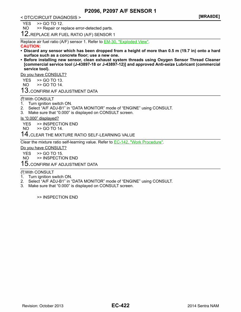
[MRA8DE]P2096, P2097 A/F SENSOR 1
< DTC/CIRCUIT DIAGNOSIS >YES >> GO TO 12.NO >> Repair or replace error-detected parts.
12.REPLACE AIR FUEL RATIO (A/F) SENSOR 1
Replace air fuel ratio (A/F) sensor 1. Refer to EM-30, "Exploded View".CAUTION:• Discard any sensor which has been dropped from a height of more than 0.5 m (19.7 in) onto a hard
surface such as a concrete floor; use a new one.• Before installing new sensor, clean exhaust system threads using Oxygen Sensor Thread Cleaner
[commercial service tool (J-43897-18 or J-43897-12)] and approved Anti-seize Lubricant (commercialservice tool).
Do you have CONSULT?YES >> GO TO 13.NO >> GO TO 14.
13.CONFIRM A/F ADJUSTMENT DATA
With CONSULT1. Turn ignition switch ON.2. Select “A/F ADJ-B1” in “DATA MONITOR” mode of “ENGINE” using CONSULT.3. Make sure that “0.000” is displayed on CONSULT screen.Is “0.000” displayed?YES >> INSPECTION ENDNO >> GO TO 14.
14.CLEAR THE MIXTURE RATIO SELF-LEARNING VALUE
Clear the mixture ratio self-learning value. Refer to EC-142, "Work Procedure".Do you have CONSULT?YES >> GO TO 15.NO >> INSPECTION END
15.CONFIRM A/F ADJUSTMENT DATA
With CONSULT1. Turn ignition switch ON.2. Select “A/F ADJ-B1” in “DATA MONITOR” mode of “ENGINE” using CONSULT.3. Make sure that “0.000” is displayed on CONSULT screen.
>> INSPECTION END
EC-422Revision: October 2013 2014 Sentra NAM
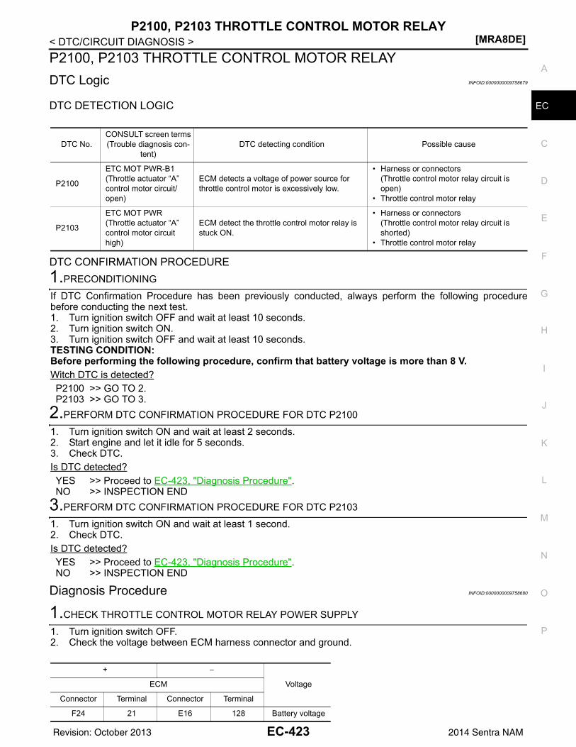
P2100, P2103 THROTTLE CONTROL MOTOR RELAY[MRA8DE]
C
D
E
F
G
H
I
J
K
L
M
A
C
N
P
O
< DTC/CIRCUIT DIAGNOSIS >
E
P2100, P2103 THROTTLE CONTROL MOTOR RELAYDTC Logic INFOID:0000000009758679
DTC DETECTION LOGIC
DTC CONFIRMATION PROCEDURE1.PRECONDITIONING
If DTC Confirmation Procedure has been previously conducted, always perform the following procedurebefore conducting the next test.1. Turn ignition switch OFF and wait at least 10 seconds.2. Turn ignition switch ON.3. Turn ignition switch OFF and wait at least 10 seconds.TESTING CONDITION:Before performing the following procedure, confirm that battery voltage is more than 8 V.Witch DTC is detected?P2100 >> GO TO 2.P2103 >> GO TO 3.
2.PERFORM DTC CONFIRMATION PROCEDURE FOR DTC P2100
1. Turn ignition switch ON and wait at least 2 seconds.2. Start engine and let it idle for 5 seconds.3. Check DTC.Is DTC detected?YES >> Proceed to EC-423, "Diagnosis Procedure".NO >> INSPECTION END
3.PERFORM DTC CONFIRMATION PROCEDURE FOR DTC P2103
1. Turn ignition switch ON and wait at least 1 second.2. Check DTC.Is DTC detected?YES >> Proceed to EC-423, "Diagnosis Procedure".NO >> INSPECTION END
Diagnosis Procedure INFOID:0000000009758680
1.CHECK THROTTLE CONTROL MOTOR RELAY POWER SUPPLY
1. Turn ignition switch OFF.2. Check the voltage between ECM harness connector and ground.
DTC No.CONSULT screen terms(Trouble diagnosis con-
tent)DTC detecting condition Possible cause
P2100
ETC MOT PWR-B1(Throttle actuator “A” control motor circuit/open)
ECM detects a voltage of power source for throttle control motor is excessively low.
• Harness or connectors(Throttle control motor relay circuit is open)
• Throttle control motor relay
P2103
ETC MOT PWR(Throttle actuator “A” control motor circuit high)
ECM detect the throttle control motor relay is stuck ON.
• Harness or connectors(Throttle control motor relay circuit is shorted)
• Throttle control motor relay
+ −
VoltageECM
Connector Terminal Connector Terminal
F24 21 E16 128 Battery voltage
EC-423Revision: October 2013 2014 Sentra NAM
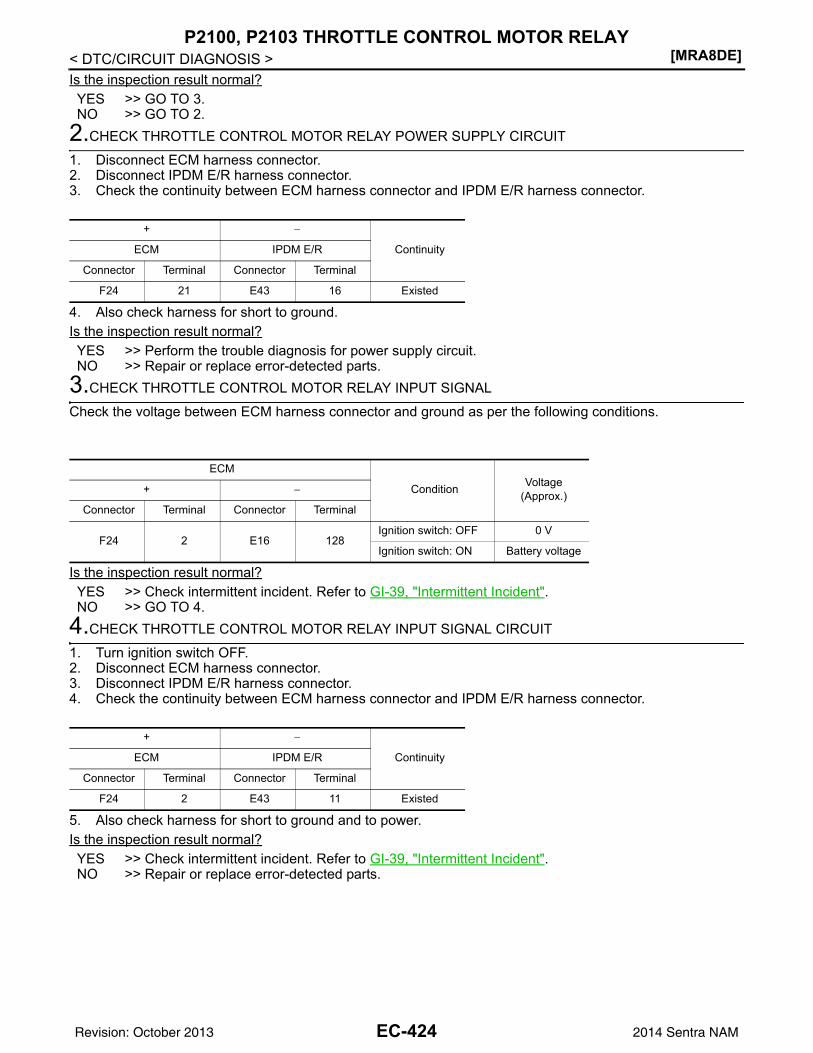
[MRA8DE]P2100, P2103 THROTTLE CONTROL MOTOR RELAY
< DTC/CIRCUIT DIAGNOSIS >Is the inspection result normal?YES >> GO TO 3.NO >> GO TO 2.
2.CHECK THROTTLE CONTROL MOTOR RELAY POWER SUPPLY CIRCUIT
1. Disconnect ECM harness connector.2. Disconnect IPDM E/R harness connector.3. Check the continuity between ECM harness connector and IPDM E/R harness connector.
4. Also check harness for short to ground.Is the inspection result normal?YES >> Perform the trouble diagnosis for power supply circuit.NO >> Repair or replace error-detected parts.
3.CHECK THROTTLE CONTROL MOTOR RELAY INPUT SIGNAL
Check the voltage between ECM harness connector and ground as per the following conditions.
Is the inspection result normal?YES >> Check intermittent incident. Refer to GI-39, "Intermittent Incident".NO >> GO TO 4.
4.CHECK THROTTLE CONTROL MOTOR RELAY INPUT SIGNAL CIRCUIT
1. Turn ignition switch OFF.2. Disconnect ECM harness connector.3. Disconnect IPDM E/R harness connector.4. Check the continuity between ECM harness connector and IPDM E/R harness connector.
5. Also check harness for short to ground and to power.Is the inspection result normal?YES >> Check intermittent incident. Refer to GI-39, "Intermittent Incident".NO >> Repair or replace error-detected parts.
+ −
ContinuityECM IPDM E/R
Connector Terminal Connector Terminal
F24 21 E43 16 Existed
ECM
Condition Voltage(Approx.)+ −
Connector Terminal Connector Terminal
F24 2 E16 128Ignition switch: OFF 0 V
Ignition switch: ON Battery voltage
+ −
ContinuityECM IPDM E/R
Connector Terminal Connector Terminal
F24 2 E43 11 Existed
EC-424Revision: October 2013 2014 Sentra NAM
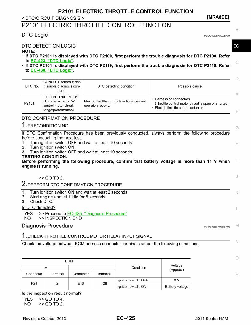
P2101 ELECTRIC THROTTLE CONTROL FUNCTION[MRA8DE]
C
D
E
F
G
H
I
J
K
L
M
A
C
N
P
O
< DTC/CIRCUIT DIAGNOSIS >
E
P2101 ELECTRIC THROTTLE CONTROL FUNCTIONDTC Logic INFOID:0000000009758681
DTC DETECTION LOGICNOTE:• If DTC P2101 is displayed with DTC P2100, first perform the trouble diagnosis for DTC P2100. Refer
to EC-423, "DTC Logic".• If DTC P2101 is displayed with DTC P2119, first perform the trouble diagnosis for DTC P2119. Refer
to EC-430, "DTC Logic".
DTC CONFIRMATION PROCEDURE1.PRECONDITIONING
If DTC Confirmation Procedure has been previously conducted, always perform the following procedurebefore conducting the next test.1. Turn ignition switch OFF and wait at least 10 seconds.2. Turn ignition switch ON.3. Turn ignition switch OFF and wait at least 10 seconds.TESTING CONDITION:Before performing the following procedure, confirm that battery voltage is more than 11 V whenengine is running.
>> GO TO 2.2.PERFORM DTC CONFIRMATION PROCEDURE
1. Turn ignition switch ON and wait at least 2 seconds.2. Start engine and let it idle for 5 seconds.3. Check DTC.Is DTC detected?YES >> Proceed to EC-425, "Diagnosis Procedure".NO >> INSPECTION END
Diagnosis Procedure INFOID:0000000009758682
1.CHECK THROTTLE CONTROL MOTOR RELAY INPUT SIGNAL
Check the voltage between ECM harness connector terminals as per the following conditions.
Is the inspection result normal?YES >> GO TO 4.NO >> GO TO 2.
DTC No.CONSULT screen terms(Trouble diagnosis con-
tent)DTC detecting condition Possible cause
P2101
ETC FNCTN/CIRC-B1(Throttle actuator “A” control motor circuit range/performance)
Electric throttle control function does not operate properly.
• Harness or connectors(Throttle control motor circuit is open or shorted)
• Electric throttle control actuator
ECM
Condition Voltage(Approx.)+ −
Connector Terminal Connector Terminal
F24 2 E16 128Ignition switch: OFF 0 V
Ignition switch: ON Battery voltage
EC-425Revision: October 2013 2014 Sentra NAM
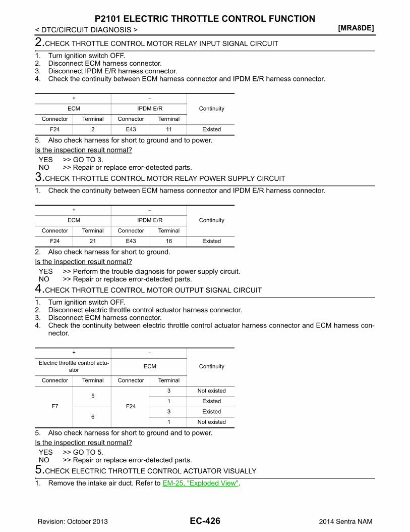
[MRA8DE]P2101 ELECTRIC THROTTLE CONTROL FUNCTION
< DTC/CIRCUIT DIAGNOSIS >
2.CHECK THROTTLE CONTROL MOTOR RELAY INPUT SIGNAL CIRCUIT
1. Turn ignition switch OFF.2. Disconnect ECM harness connector.3. Disconnect IPDM E/R harness connector.4. Check the continuity between ECM harness connector and IPDM E/R harness connector.
5. Also check harness for short to ground and to power.Is the inspection result normal?YES >> GO TO 3.NO >> Repair or replace error-detected parts.
3.CHECK THROTTLE CONTROL MOTOR RELAY POWER SUPPLY CIRCUIT
1. Check the continuity between ECM harness connector and IPDM E/R harness connector.
2. Also check harness for short to ground.Is the inspection result normal?YES >> Perform the trouble diagnosis for power supply circuit.NO >> Repair or replace error-detected parts.
4.CHECK THROTTLE CONTROL MOTOR OUTPUT SIGNAL CIRCUIT
1. Turn ignition switch OFF.2. Disconnect electric throttle control actuator harness connector.3. Disconnect ECM harness connector.4. Check the continuity between electric throttle control actuator harness connector and ECM harness con-
nector.
5. Also check harness for short to ground and to power.Is the inspection result normal?YES >> GO TO 5.NO >> Repair or replace error-detected parts.
5.CHECK ELECTRIC THROTTLE CONTROL ACTUATOR VISUALLY
1. Remove the intake air duct. Refer to EM-25, "Exploded View".
+ −
ContinuityECM IPDM E/R
Connector Terminal Connector Terminal
F24 2 E43 11 Existed
+ −
ContinuityECM IPDM E/R
Connector Terminal Connector Terminal
F24 21 E43 16 Existed
+ −
ContinuityElectric throttle control actu-ator ECM
Connector Terminal Connector Terminal
F7
5
F24
3 Not existed
1 Existed
63 Existed
1 Not existed
EC-426Revision: October 2013 2014 Sentra NAM
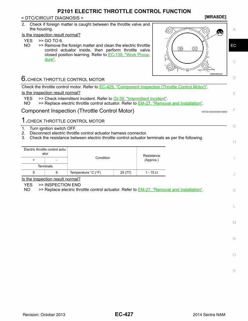
P2101 ELECTRIC THROTTLE CONTROL FUNCTION[MRA8DE]
C
D
E
F
G
H
I
J
K
L
M
A
C
N
P
O
< DTC/CIRCUIT DIAGNOSIS >
E
2. Check if foreign matter is caught between the throttle valve andthe housing.
Is the inspection result normal?YES >> GO TO 6.NO >> Remove the foreign matter and clean the electric throttle
control actuator inside, then perform throttle valveclosed position learning. Refer to EC-139, "Work Proce-dure".
6.CHECK THROTTLE CONTROL MOTOR
Check the throttle control motor. Refer to EC-429, "Component Inspection (Throttle Control Motor)".Is the inspection result normal?YES >> Check intermittent incident. Refer to GI-39, "Intermittent Incident".NO >> Replace electric throttle control actuator. Refer to EM-27, "Removal and Installation".
Component Inspection (Throttle Control Motor) INFOID:0000000009758683
1.CHECK THROTTLE CONTROL MOTOR
1. Turn ignition switch OFF.2. Disconnect electric throttle control actuator harness connector.3. Check the resistance between electric throttle control actuator terminals as per the following.
Is the inspection result normal?YES >> INSPECTION ENDNO >> Replace electric throttle control actuator. Refer to EM-27, "Removal and Installation".
JSBIA2864ZZ
Electric throttle control actu-ator
Condition Resistance(Approx.)+ −
Terminals
5 6 Temperature °C (°F) 25 (77) 1 - 15 Ω
EC-427Revision: October 2013 2014 Sentra NAM
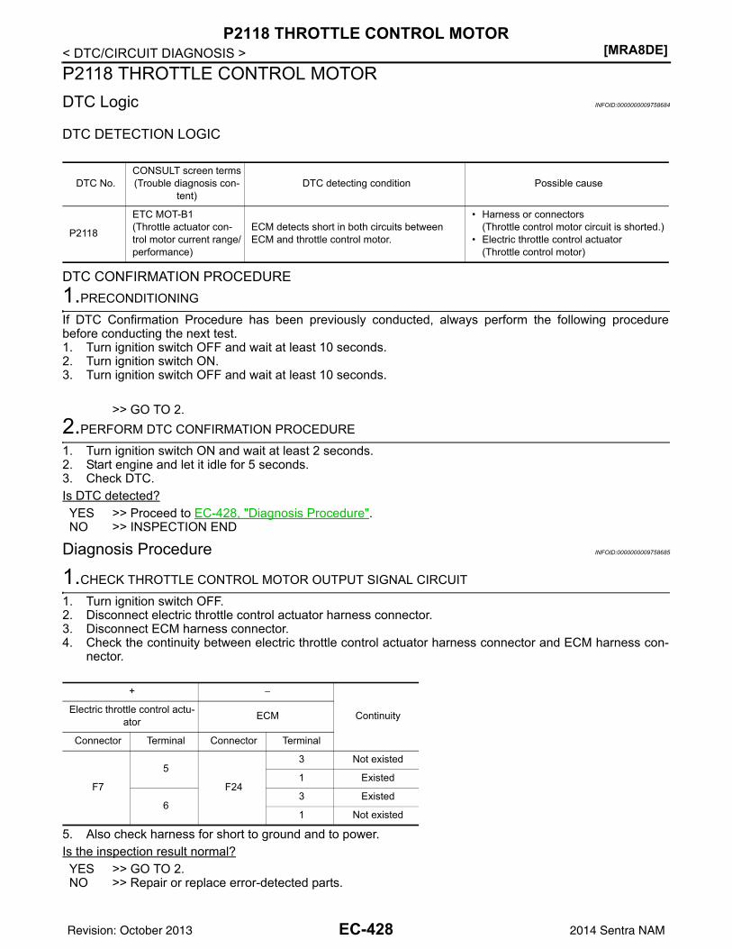
[MRA8DE]P2118 THROTTLE CONTROL MOTOR
< DTC/CIRCUIT DIAGNOSIS >P2118 THROTTLE CONTROL MOTORDTC Logic INFOID:0000000009758684
DTC DETECTION LOGIC
DTC CONFIRMATION PROCEDURE1.PRECONDITIONING
If DTC Confirmation Procedure has been previously conducted, always perform the following procedurebefore conducting the next test.1. Turn ignition switch OFF and wait at least 10 seconds.2. Turn ignition switch ON.3. Turn ignition switch OFF and wait at least 10 seconds.
>> GO TO 2.2.PERFORM DTC CONFIRMATION PROCEDURE
1. Turn ignition switch ON and wait at least 2 seconds.2. Start engine and let it idle for 5 seconds.3. Check DTC.Is DTC detected?YES >> Proceed to EC-428, "Diagnosis Procedure".NO >> INSPECTION END
Diagnosis Procedure INFOID:0000000009758685
1.CHECK THROTTLE CONTROL MOTOR OUTPUT SIGNAL CIRCUIT
1. Turn ignition switch OFF.2. Disconnect electric throttle control actuator harness connector.3. Disconnect ECM harness connector.4. Check the continuity between electric throttle control actuator harness connector and ECM harness con-
nector.
5. Also check harness for short to ground and to power.Is the inspection result normal?YES >> GO TO 2.NO >> Repair or replace error-detected parts.
DTC No.CONSULT screen terms(Trouble diagnosis con-
tent)DTC detecting condition Possible cause
P2118
ETC MOT-B1(Throttle actuator con-trol motor current range/performance)
ECM detects short in both circuits between ECM and throttle control motor.
• Harness or connectors(Throttle control motor circuit is shorted.)
• Electric throttle control actuator(Throttle control motor)
+ −
ContinuityElectric throttle control actu-ator ECM
Connector Terminal Connector Terminal
F7
5
F24
3 Not existed
1 Existed
63 Existed
1 Not existed
EC-428Revision: October 2013 2014 Sentra NAM
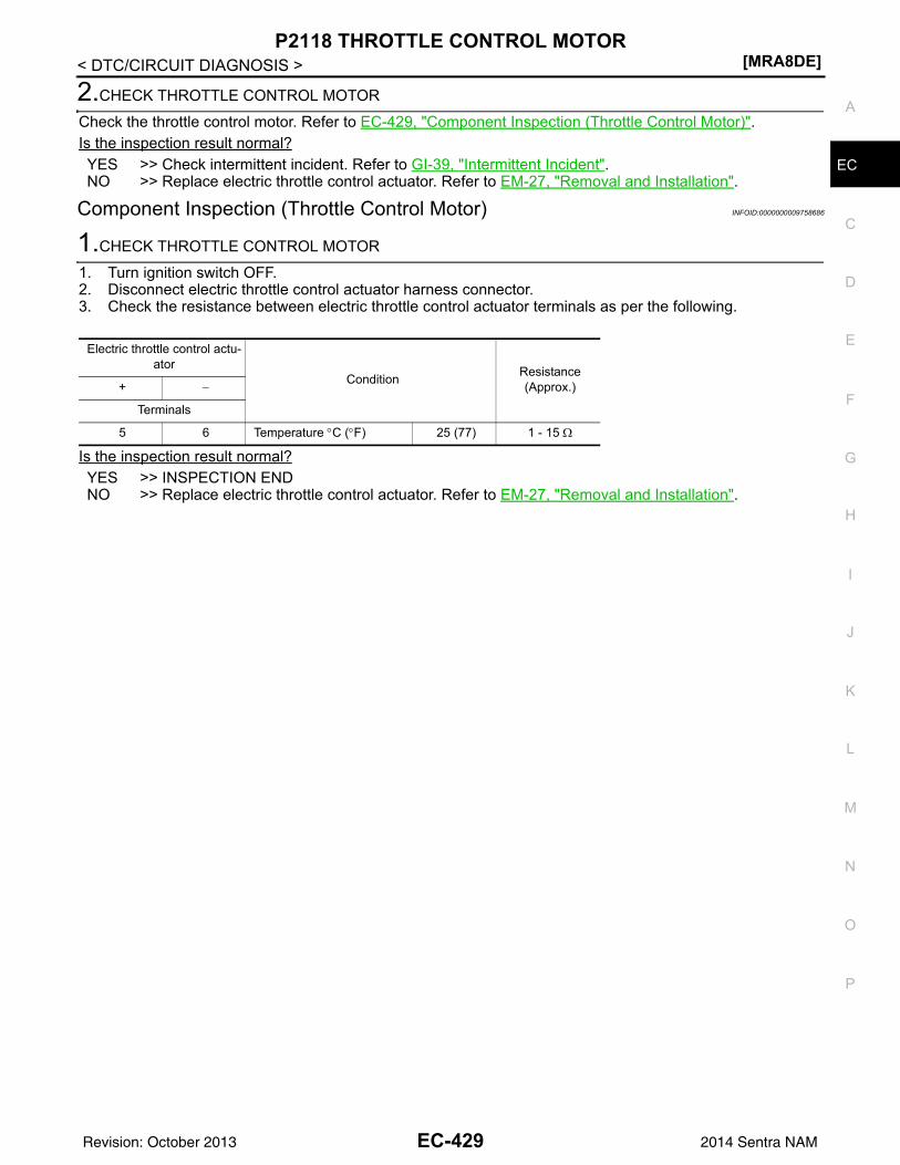
P2118 THROTTLE CONTROL MOTOR[MRA8DE]
C
D
E
F
G
H
I
J
K
L
M
A
C
N
P
O
< DTC/CIRCUIT DIAGNOSIS >
E
2.CHECK THROTTLE CONTROL MOTOR
Check the throttle control motor. Refer to EC-429, "Component Inspection (Throttle Control Motor)".Is the inspection result normal?YES >> Check intermittent incident. Refer to GI-39, "Intermittent Incident".NO >> Replace electric throttle control actuator. Refer to EM-27, "Removal and Installation".
Component Inspection (Throttle Control Motor) INFOID:0000000009758686
1.CHECK THROTTLE CONTROL MOTOR
1. Turn ignition switch OFF.2. Disconnect electric throttle control actuator harness connector.3. Check the resistance between electric throttle control actuator terminals as per the following.
Is the inspection result normal?YES >> INSPECTION ENDNO >> Replace electric throttle control actuator. Refer to EM-27, "Removal and Installation".
Electric throttle control actu-ator
Condition Resistance(Approx.)+ −
Terminals
5 6 Temperature °C (°F) 25 (77) 1 - 15 Ω
EC-429Revision: October 2013 2014 Sentra NAM
[MRA8DE]P2119 ELECTRIC THROTTLE CONTROL ACTUATOR
< DTC/CIRCUIT DIAGNOSIS >P2119 ELECTRIC THROTTLE CONTROL ACTUATORDTC Logic INFOID:0000000009758687
DTC DETECTION LOGIC
DTC CONFIRMATION PROCEDURE1.PRECONDITIONING
If DTC Confirmation Procedure has been previously conducted, always perform the following procedurebefore conducting the next test.1. Turn ignition switch OFF and wait at least 10 seconds.2. Turn ignition switch ON.3. Turn ignition switch OFF and wait at least 10 seconds.
>> GO TO 2.2.PERFORM DTC CONFIRMATION PROCEDURE FOR MALFUNCTION A AND B
1. Turn ignition switch ON and wait at least 1 second.2. Set selector lever to D (CVT) or 1st (M/T) position and wait at least 3 seconds.3. Set selector lever to P (CVT) or Neutral (M/T) position.4. Turn ignition switch OFF and wait at least 10 seconds.5. Turn ignition switch ON and wait at least 1 second.6. Set selector lever to D (CVT) or 1st (M/T) position and wait at least 3 seconds.7. Set selector lever to P (CVT) or Neutral (M/T) position.8. Turn ignition switch OFF, wait at least 10 seconds and then turn ON.9. Check DTC.Is DTC detected?YES >> Proceed to EC-430, "Diagnosis Procedure".NO >> GO TO 3.
3.PERFORM DTC CONFIRMATION PROCEDURE FOR MALFUNCTION C
1. Turn ignition switch ON and wait at least 1 second.2. Set selector lever to D (CVT) or 1st (M/T) position and wait at least 3 seconds.3. Set selector lever to P (CVT) or Neutral (M/T) position.4. Start engine and let it idle for 3 seconds.5. Check DTC.Is DTC detected?YES >> Proceed to EC-430, "Diagnosis Procedure".NO >> INSPECTION END
Diagnosis Procedure INFOID:0000000009758688
1.CHECK ELECTRIC THROTTLE CONTROL ACTUATOR VISUALLY
1. Remove the intake air duct. Refer to EM-25, "Exploded View".
DTC No.CONSULT screen terms(Trouble diagnosis con-
tent)DTC detecting condition Possible cause
P2119
ETC ACTR-B1(Throttle actuator con-trol throttle body range/performance)
A Electric throttle control actuator does not function properly due to the return spring malfunction.
Electric throttle control actuatorB Throttle valve opening angle in fail-safe mode is not in specified range.
C ECM detect the throttle valve is stuck open.
EC-430Revision: October 2013 2014 Sentra NAM
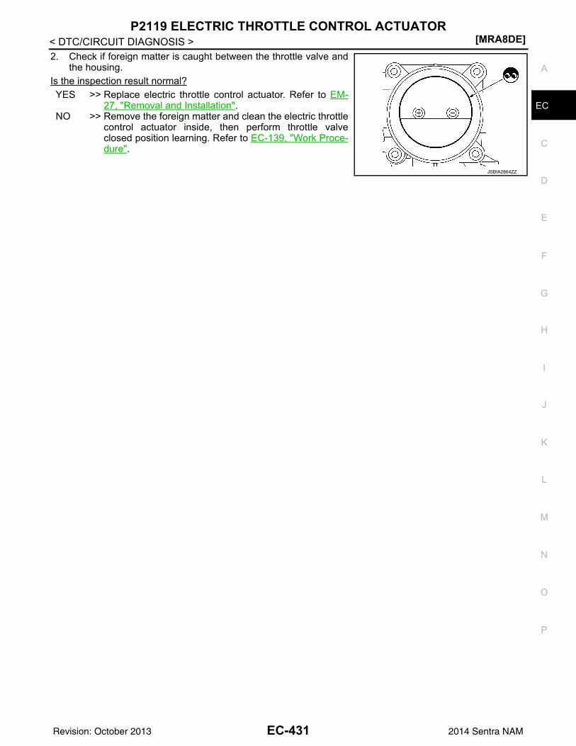
P2119 ELECTRIC THROTTLE CONTROL ACTUATOR[MRA8DE]
C
D
E
F
G
H
I
J
K
L
M
A
C
N
P
O
< DTC/CIRCUIT DIAGNOSIS >
E
2. Check if foreign matter is caught between the throttle valve andthe housing.
Is the inspection result normal?YES >> Replace electric throttle control actuator. Refer to EM-
27, "Removal and Installation".NO >> Remove the foreign matter and clean the electric throttle
control actuator inside, then perform throttle valveclosed position learning. Refer to EC-139, "Work Proce-dure".
JSBIA2864ZZ
EC-431Revision: October 2013 2014 Sentra NAM
[MRA8DE]P2122, P2123 APP SENSOR
< DTC/CIRCUIT DIAGNOSIS >P2122, P2123 APP SENSORDTC Logic INFOID:0000000009758689
DTC DETECTION LOGICNOTE:If DTC P2122 or P2123 is displayed with DTC P0643, first perform the trouble diagnosis for DTC P0643.Refer to EC-353, "DTC Logic".
DTC CONFIRMATION PROCEDURE1.PRECONDITIONING
If DTC Confirmation Procedure has been previously conducted, always perform the following procedurebefore conducting the next test.1. Turn ignition switch OFF and wait at least 10 seconds.2. Turn ignition switch ON.3. Turn ignition switch OFF and wait at least 10 seconds.TESTING CONDITION:Before performing the following procedure, confirm that battery voltage is more than 8 V at idle.
>> GO TO 2.2.PERFORM DTC CONFIRMATION PROCEDURE
1. Start engine and let it idle for 1 second.2. Check DTC.Is DTC detected?YES >> Proceed to EC-432, "Diagnosis Procedure".NO >> INSPECTION END
Diagnosis Procedure INFOID:0000000009758690
1.CHECK APP SENSOR 1 POWER SUPPLY
1. Turn ignition switch OFF.2. Disconnect accelerator pedal position (APP) sensor harness connector.3. Turn ignition switch ON.4. Check the voltage between APP sensor harness connector and ground.
Is the inspection result normal?YES >> GO TO 3.NO >> GO TO 2.
DTC No.CONSULT screen terms(Trouble diagnosis con-
tent)DTC detecting condition Possible cause
P2122
APP SEN 1/CIRC(Throttle/Pedal position sensor/switch “D” circuit low)
An excessively low voltage from the APP sensor 1 is sent to ECM. • Harness or connectors
(APP sensor 1 circuit is open or shorted.)• Accelerator pedal position sensor (APP
sensor 1)P2123
APP SEN 1/CIRC(Throttle/Pedal position sensor/switch “D” circuit high)
An excessively high voltage from the APP sensor 1 is sent to ECM.
+
−Voltage
(Approx.)APP sensor
Connector Terminal
E12 4 Ground 5.0 V
EC-432Revision: October 2013 2014 Sentra NAM
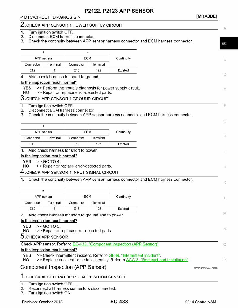
P2122, P2123 APP SENSOR[MRA8DE]
C
D
E
F
G
H
I
J
K
L
M
A
C
N
P
O
< DTC/CIRCUIT DIAGNOSIS >
E
2.CHECK APP SENSOR 1 POWER SUPPLY CIRCUIT
1. Turn ignition switch OFF.2. Disconnect ECM harness connector.3. Check the continuity between APP sensor harness connector and ECM harness connector.
4. Also check harness for short to ground.Is the inspection result normal?YES >> Perform the trouble diagnosis for power supply circuit.NO >> Repair or replace error-detected parts.
3.CHECK APP SENSOR 1 GROUND CIRCUIT
1. Turn ignition switch OFF.2. Disconnect ECM harness connector.3. Check the continuity between APP sensor harness connector and ECM harness connector.
4. Also check harness for short to power.Is the inspection result normal?YES >> GO TO 4.NO >> Repair or replace error-detected parts.
4.CHECK APP SENSOR 1 INPUT SIGNAL CIRCUIT
1. Check the continuity between APP sensor harness connector and ECM harness connector.
2. Also check harness for short to ground and to power.Is the inspection result normal?YES >> GO TO 5.NO >> Repair or replace error-detected parts.
5.CHECK APP SENSOR
Check APP sensor. Refer to EC-433, "Component Inspection (APP Sensor)".Is the inspection result normal?YES >> Check intermittent incident. Refer to GI-39, "Intermittent Incident".NO >> Replace accelerator pedal assembly. Refer to ACC-3, "Removal and Installation".
Component Inspection (APP Sensor) INFOID:0000000009758691
1.CHECK ACCELERATOR PEDAL POSITION SENSOR
1. Turn ignition switch OFF.2. Reconnect all harness connectors disconnected.3. Turn ignition switch ON.
+ −
ContinuityAPP sensor ECM
Connector Terminal Connector Terminal
E12 4 E16 122 Existed
+ −
ContinuityAPP sensor ECM
Connector Terminal Connector Terminal
E12 2 E16 127 Existed
+ −
ContinuityAPP sensor ECM
Connector Terminal Connector Terminal
E12 3 E16 126 Existed
EC-433Revision: October 2013 2014 Sentra NAM
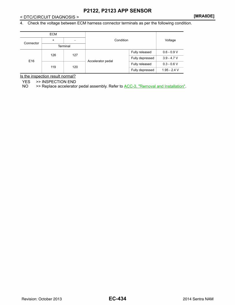
[MRA8DE]P2122, P2123 APP SENSOR
< DTC/CIRCUIT DIAGNOSIS >4. Check the voltage between ECM harness connector terminals as per the following condition.
Is the inspection result normal?YES >> INSPECTION ENDNO >> Replace accelerator pedal assembly. Refer to ACC-3, "Removal and Installation".
ECM
Condition VoltageConnector
+ −
Terminal
E16
126 127
Accelerator pedal
Fully released 0.6 - 0.9 V
Fully depressed 3.9 - 4.7 V
119 120Fully released 0.3 - 0.6 V
Fully depressed 1.95 - 2.4 V
EC-434Revision: October 2013 2014 Sentra NAM
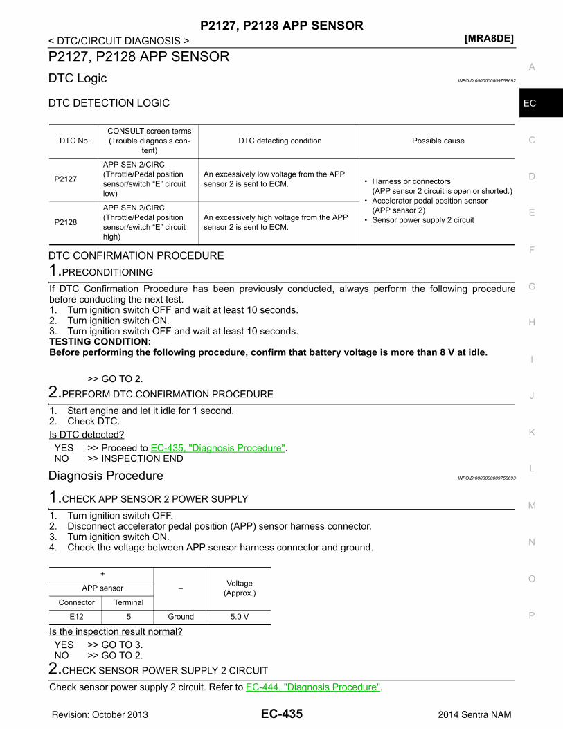
P2127, P2128 APP SENSOR[MRA8DE]
C
D
E
F
G
H
I
J
K
L
M
A
C
N
P
O
< DTC/CIRCUIT DIAGNOSIS >
E
P2127, P2128 APP SENSORDTC Logic INFOID:0000000009758692
DTC DETECTION LOGIC
DTC CONFIRMATION PROCEDURE1.PRECONDITIONING
If DTC Confirmation Procedure has been previously conducted, always perform the following procedurebefore conducting the next test.1. Turn ignition switch OFF and wait at least 10 seconds.2. Turn ignition switch ON.3. Turn ignition switch OFF and wait at least 10 seconds.TESTING CONDITION:Before performing the following procedure, confirm that battery voltage is more than 8 V at idle.
>> GO TO 2.2.PERFORM DTC CONFIRMATION PROCEDURE
1. Start engine and let it idle for 1 second.2. Check DTC.Is DTC detected?YES >> Proceed to EC-435, "Diagnosis Procedure".NO >> INSPECTION END
Diagnosis Procedure INFOID:0000000009758693
1.CHECK APP SENSOR 2 POWER SUPPLY
1. Turn ignition switch OFF.2. Disconnect accelerator pedal position (APP) sensor harness connector.3. Turn ignition switch ON.4. Check the voltage between APP sensor harness connector and ground.
Is the inspection result normal?YES >> GO TO 3.NO >> GO TO 2.
2.CHECK SENSOR POWER SUPPLY 2 CIRCUIT
Check sensor power supply 2 circuit. Refer to EC-444, "Diagnosis Procedure".
DTC No.CONSULT screen terms(Trouble diagnosis con-
tent)DTC detecting condition Possible cause
P2127
APP SEN 2/CIRC(Throttle/Pedal position sensor/switch “E” circuit low)
An excessively low voltage from the APP sensor 2 is sent to ECM. • Harness or connectors
(APP sensor 2 circuit is open or shorted.)• Accelerator pedal position sensor
(APP sensor 2)• Sensor power supply 2 circuitP2128
APP SEN 2/CIRC(Throttle/Pedal position sensor/switch “E” circuit high)
An excessively high voltage from the APP sensor 2 is sent to ECM.
+
−Voltage
(Approx.)APP sensor
Connector Terminal
E12 5 Ground 5.0 V
EC-435Revision: October 2013 2014 Sentra NAM
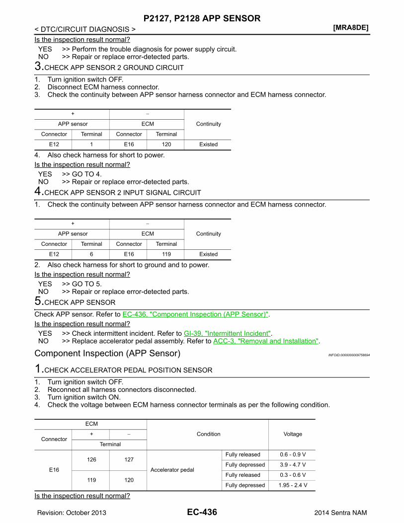
[MRA8DE]P2127, P2128 APP SENSOR
< DTC/CIRCUIT DIAGNOSIS >Is the inspection result normal?YES >> Perform the trouble diagnosis for power supply circuit.NO >> Repair or replace error-detected parts.
3.CHECK APP SENSOR 2 GROUND CIRCUIT
1. Turn ignition switch OFF.2. Disconnect ECM harness connector.3. Check the continuity between APP sensor harness connector and ECM harness connector.
4. Also check harness for short to power.Is the inspection result normal?YES >> GO TO 4.NO >> Repair or replace error-detected parts.
4.CHECK APP SENSOR 2 INPUT SIGNAL CIRCUIT
1. Check the continuity between APP sensor harness connector and ECM harness connector.
2. Also check harness for short to ground and to power.Is the inspection result normal?YES >> GO TO 5.NO >> Repair or replace error-detected parts.
5.CHECK APP SENSOR
Check APP sensor. Refer to EC-436, "Component Inspection (APP Sensor)".Is the inspection result normal?YES >> Check intermittent incident. Refer to GI-39, "Intermittent Incident".NO >> Replace accelerator pedal assembly. Refer to ACC-3, "Removal and Installation".
Component Inspection (APP Sensor) INFOID:0000000009758694
1.CHECK ACCELERATOR PEDAL POSITION SENSOR
1. Turn ignition switch OFF.2. Reconnect all harness connectors disconnected.3. Turn ignition switch ON.4. Check the voltage between ECM harness connector terminals as per the following condition.
Is the inspection result normal?
+ −
ContinuityAPP sensor ECM
Connector Terminal Connector Terminal
E12 1 E16 120 Existed
+ −
ContinuityAPP sensor ECM
Connector Terminal Connector Terminal
E12 6 E16 119 Existed
ECM
Condition VoltageConnector
+ −
Terminal
E16
126 127
Accelerator pedal
Fully released 0.6 - 0.9 V
Fully depressed 3.9 - 4.7 V
119 120Fully released 0.3 - 0.6 V
Fully depressed 1.95 - 2.4 V
EC-436Revision: October 2013 2014 Sentra NAM
P2127, P2128 APP SENSOR[MRA8DE]
C
D
E
F
G
H
I
J
K
L
M
A
C
N
P
O
< DTC/CIRCUIT DIAGNOSIS >
E
YES >> INSPECTION ENDNO >> Replace accelerator pedal assembly. Refer to ACC-3, "Removal and Installation".
EC-437Revision: October 2013 2014 Sentra NAM
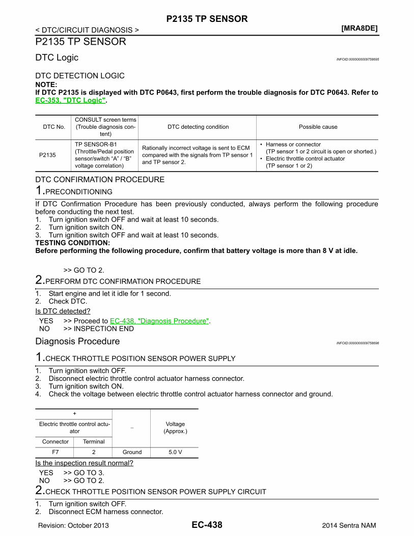
[MRA8DE]P2135 TP SENSOR
< DTC/CIRCUIT DIAGNOSIS >P2135 TP SENSORDTC Logic INFOID:0000000009758695
DTC DETECTION LOGICNOTE:If DTC P2135 is displayed with DTC P0643, first perform the trouble diagnosis for DTC P0643. Refer toEC-353, "DTC Logic".
DTC CONFIRMATION PROCEDURE1.PRECONDITIONING
If DTC Confirmation Procedure has been previously conducted, always perform the following procedurebefore conducting the next test.1. Turn ignition switch OFF and wait at least 10 seconds.2. Turn ignition switch ON.3. Turn ignition switch OFF and wait at least 10 seconds.TESTING CONDITION:Before performing the following procedure, confirm that battery voltage is more than 8 V at idle.
>> GO TO 2.2.PERFORM DTC CONFIRMATION PROCEDURE
1. Start engine and let it idle for 1 second.2. Check DTC.Is DTC detected?YES >> Proceed to EC-438, "Diagnosis Procedure".NO >> INSPECTION END
Diagnosis Procedure INFOID:0000000009758696
1.CHECK THROTTLE POSITION SENSOR POWER SUPPLY
1. Turn ignition switch OFF.2. Disconnect electric throttle control actuator harness connector.3. Turn ignition switch ON.4. Check the voltage between electric throttle control actuator harness connector and ground.
Is the inspection result normal?YES >> GO TO 3.NO >> GO TO 2.
2.CHECK THROTTLE POSITION SENSOR POWER SUPPLY CIRCUIT
1. Turn ignition switch OFF.2. Disconnect ECM harness connector.
DTC No.CONSULT screen terms(Trouble diagnosis con-
tent)DTC detecting condition Possible cause
P2135
TP SENSOR-B1(Throttle/Pedal position sensor/switch “A” / “B” voltage correlation)
Rationally incorrect voltage is sent to ECM compared with the signals from TP sensor 1 and TP sensor 2.
• Harness or connector(TP sensor 1 or 2 circuit is open or shorted.)
• Electric throttle control actuator(TP sensor 1 or 2)
+
−Voltage
(Approx.)Electric throttle control actu-
ator
Connector Terminal
F7 2 Ground 5.0 V
EC-438Revision: October 2013 2014 Sentra NAM
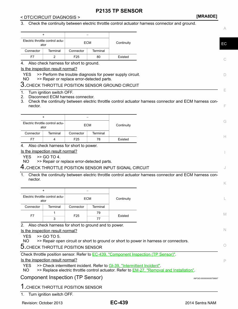
P2135 TP SENSOR[MRA8DE]
C
D
E
F
G
H
I
J
K
L
M
A
C
N
P
O
< DTC/CIRCUIT DIAGNOSIS >
E
3. Check the continuity between electric throttle control actuator harness connector and ground.
4. Also check harness for short to ground.Is the inspection result normal?YES >> Perform the trouble diagnosis for power supply circuit.NO >> Repair or replace error-detected parts.
3.CHECK THROTTLE POSITION SENSOR GROUND CIRCUIT
1. Turn ignition switch OFF.2. Disconnect ECM harness connector.3. Check the continuity between electric throttle control actuator harness connector and ECM harness con-
nector.
4. Also check harness for short to power.Is the inspection result normal?YES >> GO TO 4.NO >> Repair or replace error-detected parts.
4.CHECK THROTTLE POSITION SENSOR INPUT SIGNAL CIRCUIT
1. Check the continuity between electric throttle control actuator harness connector and ECM harness con-nector.
2. Also check harness for short to ground and to power.Is the inspection result normal?YES >> GO TO 5.NO >> Repair open circuit or short to ground or short to power in harness or connectors.
5.CHECK THROTTLE POSITION SENSOR
Check throttle position sensor. Refer to EC-439, "Component Inspection (TP Sensor)".Is the inspection result normal?YES >> Check intermittent incident. Refer to GI-39, "Intermittent Incident".NO >> Replace electric throttle control actuator. Refer to EM-27, "Removal and Installation".
Component Inspection (TP Sensor) INFOID:0000000009758697
1.CHECK THROTTLE POSITION SENSOR
1. Turn ignition switch OFF.
+ −
ContinuityElectric throttle control actu-ator ECM
Connector Terminal Connector Terminal
F7 2 F25 80 Existed
+ −
ContinuityElectric throttle control actu-ator ECM
Connector Terminal Connector Terminal
F7 4 F25 78 Existed
+ −
ContinuityElectric throttle control actu-ator ECM
Connector Terminal Connector Terminal
F71
F2579
Existed3 77
EC-439Revision: October 2013 2014 Sentra NAM
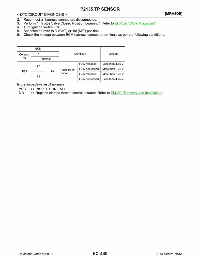
[MRA8DE]P2135 TP SENSOR
< DTC/CIRCUIT DIAGNOSIS >2. Reconnect all harness connectors disconnected.3. Perform “ Throttle Valve Closed Position Learning”. Refer to EC-139, "Work Procedure".4. Turn ignition switch ON.5. Set selector lever to D (CVT) or 1st (M/T) position.6. Check the voltage between ECM harness connector terminals as per the following conditions.
Is the inspection result normal?YES >> INSPECTION ENDNO >> Replace electric throttle control actuator. Refer to EM-27, "Removal and Installation".
ECM
Condition VoltageConnec-tor
+ −
Terminal
F25
77
78 Accelerator pedal
Fully released Less than 4.75 V
Fully depressed More than 0.36 V
79Fully released More than 0.36 V
Fully depressed Less than 4.75 V
EC-440Revision: October 2013 2014 Sentra NAM
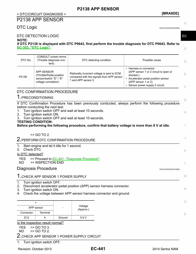
P2138 APP SENSOR[MRA8DE]
C
D
E
F
G
H
I
J
K
L
M
A
C
N
P
O
< DTC/CIRCUIT DIAGNOSIS >
E
P2138 APP SENSORDTC Logic INFOID:0000000009758698
DTC DETECTION LOGICNOTE:If DTC P2138 is displayed with DTC P0643, first perform the trouble diagnosis for DTC P0643. Refer toEC-353, "DTC Logic".
DTC CONFIRMATION PROCEDURE1.PRECONDITIONING
If DTC Confirmation Procedure has been previously conducted, always perform the following procedurebefore conducting the next test.1. Turn ignition switch OFF and wait at least 10 seconds.2. Turn ignition switch ON.3. Turn ignition switch OFF and wait at least 10 seconds.TESTING CONDITION:Before performing the following procedure, confirm that battery voltage is more than 8 V at idle.
>> GO TO 2.2.PERFORM DTC CONFIRMATION PROCEDURE
1. Start engine and let it idle for 1 second.2. Check DTC.Is DTC detected?YES >> Proceed to EC-441, "Diagnosis Procedure".NO >> INSPECTION END
Diagnosis Procedure INFOID:0000000009758699
1.CHECK APP SENSOR 1 POWER SUPPLY
1. Turn ignition switch OFF.2. Disconnect accelerator pedal position (APP) sensor harness connector.3. Turn ignition switch ON.4. Check the voltage between APP sensor harness connector and ground.
Is the inspection result normal?YES >> GO TO 3.NO >> GO TO 2.
2.CHECK APP SENSOR 1 POWER SUPPLY CIRCUIT
1. Turn ignition switch OFF.
DTC No.CONSULT screen terms(Trouble diagnosis con-
tent)DTC detecting condition Possible cause
P2138
APP SENSOR(Throttle/Pedal position sensor/switch “D” / “E” voltage correlation)
Rationally incorrect voltage is sent to ECM compared with the signals from APP sensor 1 and APP sensor 2.
• Harness or connector(APP sensor 1 or 2 circuit is open or shorted.)
• Accelerator pedal position sensor(APP sensor 1 or 2)
• Sensor power supply 2 circuit
+
−Voltage
(Approx.)APP sensor
Connector Terminal
E12 4 Ground 5.0 V
EC-441Revision: October 2013 2014 Sentra NAM
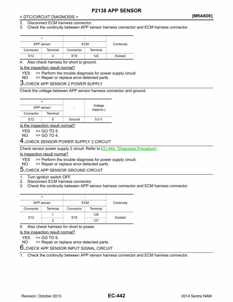
[MRA8DE]P2138 APP SENSOR
< DTC/CIRCUIT DIAGNOSIS >2. Disconnect ECM harness connector.3. Check the continuity between APP sensor harness connector and ECM harness connector.
4. Also check harness for short to ground.Is the inspection result normal?YES >> Perform the trouble diagnosis for power supply circuit.NO >> Repair or replace error-detected parts.
3.CHECK APP SENSOR 2 POWER SUPPLY
Check the voltage between APP sensor harness connector and ground.
Is the inspection result normal?YES >> GO TO 5.NO >> GO TO 4.
4.CHECK SENSOR POWER SUPPLY 2 CIRCUIT
Check sensor power supply 2 circuit. Refer to EC-444, "Diagnosis Procedure".Is inspection result normal?YES >> Perform the trouble diagnosis for power supply circuit.NO >> Repair or replace error-detected parts.
5.CHECK APP SENSOR GROUND CIRCUIT
1. Turn ignition switch OFF.2. Disconnect ECM harness connector.3. Check the continuity between APP sensor harness connector and ECM harness connector.
4. Also check harness for short to power.Is the inspection result normal?YES >> GO TO 6.NO >> Repair or replace error-detected parts.
6.CHECK APP SENSOR INPUT SIGNAL CIRCUIT
1. Check the continuity between APP sensor harness connector and ECM harness connector.
+ −
ContinuityAPP sensor ECM
Connector Terminal Connector Terminal
E12 4 E16 122 Existed
+
−Voltage
(Approx.)APP sensor
Connector Terminal
E12 5 Ground 5.0 V
+ −
ContinuityAPP sensor ECM
Connector Terminal Connector Terminal
E121
E16120
Existed2 127
EC-442Revision: October 2013 2014 Sentra NAM
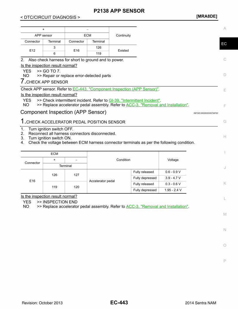
P2138 APP SENSOR[MRA8DE]
C
D
E
F
G
H
I
J
K
L
M
A
C
N
P
O
< DTC/CIRCUIT DIAGNOSIS >
E
2. Also check harness for short to ground and to power.Is the inspection result normal?YES >> GO TO 7.NO >> Repair or replace error-detected parts
7.CHECK APP SENSOR
Check APP sensor. Refer to EC-443, "Component Inspection (APP Sensor)".Is the inspection result normal?YES >> Check intermittent incident. Refer to GI-39, "Intermittent Incident".NO >> Replace accelerator pedal assembly. Refer to ACC-3, "Removal and Installation".
Component Inspection (APP Sensor) INFOID:0000000009758700
1.CHECK ACCELERATOR PEDAL POSITION SENSOR
1. Turn ignition switch OFF.2. Reconnect all harness connectors disconnected.3. Turn ignition switch ON.4. Check the voltage between ECM harness connector terminals as per the following condition.
Is the inspection result normal?YES >> INSPECTION ENDNO >> Replace accelerator pedal assembly. Refer to ACC-3, "Removal and Installation".
+ −
ContinuityAPP sensor ECM
Connector Terminal Connector Terminal
E123
E16126
Existed6 119
ECM
Condition VoltageConnector
+ −
Terminal
E16
126 127
Accelerator pedal
Fully released 0.6 - 0.9 V
Fully depressed 3.9 - 4.7 V
119 120Fully released 0.3 - 0.6 V
Fully depressed 1.95 - 2.4 V
EC-443Revision: October 2013 2014 Sentra NAM
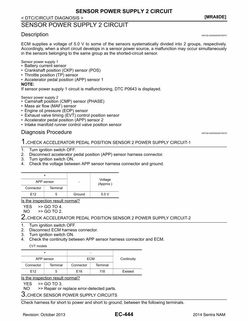
[MRA8DE]SENSOR POWER SUPPLY 2 CIRCUIT
< DTC/CIRCUIT DIAGNOSIS >SENSOR POWER SUPPLY 2 CIRCUITDescription INFOID:0000000009758701
ECM supplies a voltage of 5.0 V to some of the sensors systematically divided into 2 groups, respectively.Accordingly, when a short circuit develops in a sensor power source, a malfunction may occur simultaneouslyin the sensors belonging to the same group as the shorted-circuit sensor.
Sensor power supply 1• Battery current sensor• Crankshaft position (CKP) sensor (POS)• Throttle position (TP) sensor• Accelerator pedal position (APP) sensor 1NOTE:If sensor power supply 1 circuit is malfunctioning, DTC P0643 is displayed.
Sensor power supply 2• Camshaft position (CMP) sensor (PHASE)• Mass air flow (MAF) sensor• Engine oil pressure (EOP) sensor• Exhaust valve timing (EVT) control position sensor• Accelerator pedal position (APP) sensor 2• Intake manifold runner control valve position sensor
Diagnosis Procedure INFOID:0000000009758702
1.CHECK ACCELERATOR PEDAL POSITION SENSOR 2 POWER SUPPLY CIRCUIT-1
1. Turn ignition switch OFF.2. Disconnect accelerator pedal position (APP) sensor harness connector.3. Turn ignition switch ON.4. Check the voltage between APP sensor harness connector and ground.
Is the inspection result normal?YES >> GO TO 4.NO >> GO TO 2.
2.CHECK ACCELERATOR PEDAL POSITION SENSOR 2 POWER SUPPLY CIRCUIT-2
1. Turn ignition switch OFF.2. Disconnect ECM harness connector.3. Turn ignition switch ON.4. Check the continuity between APP sensor harness connector and ECM.
CVT models
Is the inspection result normal?YES >> GO TO 3.NO >> Repair or replace error-detected parts.
3.CHECK SENSOR POWER SUPPLY CIRCUITS
Check harness for short to power and short to ground, between the following terminals.
+
−Voltage
(Approx.)APP sensor
Connector Terminal
E12 5 Ground 5.0 V
+ −
ContinuityAPP sensor ECM
Connector Terminal Connector Terminal
E12 5 E16 118 Existed
EC-444Revision: October 2013 2014 Sentra NAM
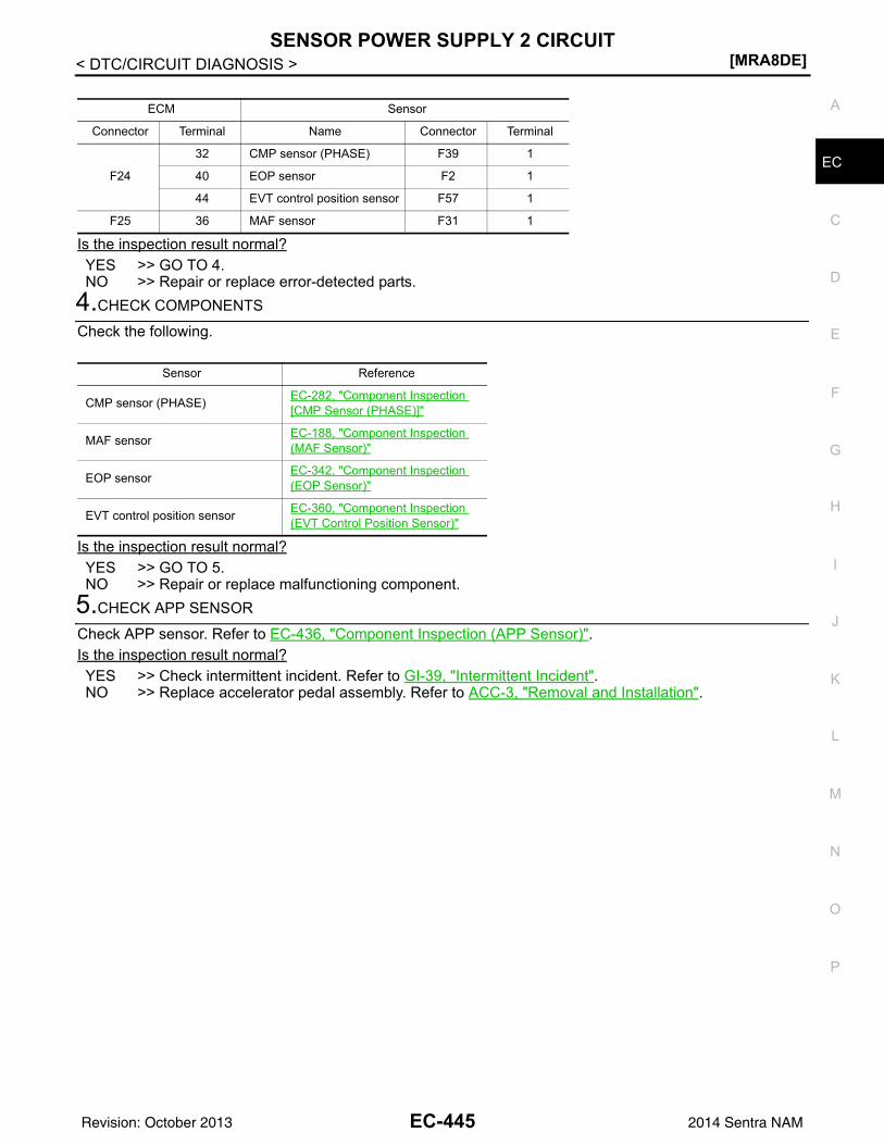
SENSOR POWER SUPPLY 2 CIRCUIT[MRA8DE]
C
D
E
F
G
H
I
J
K
L
M
A
C
N
P
O
< DTC/CIRCUIT DIAGNOSIS >
E
Is the inspection result normal?YES >> GO TO 4.NO >> Repair or replace error-detected parts.
4.CHECK COMPONENTS
Check the following.
Is the inspection result normal?YES >> GO TO 5.NO >> Repair or replace malfunctioning component.
5.CHECK APP SENSOR
Check APP sensor. Refer to EC-436, "Component Inspection (APP Sensor)".Is the inspection result normal?YES >> Check intermittent incident. Refer to GI-39, "Intermittent Incident".NO >> Replace accelerator pedal assembly. Refer to ACC-3, "Removal and Installation".
ECM Sensor
Connector Terminal Name Connector Terminal
F24
32 CMP sensor (PHASE) F39 1
40 EOP sensor F2 1
44 EVT control position sensor F57 1
F25 36 MAF sensor F31 1
Sensor Reference
CMP sensor (PHASE) EC-282, "Component Inspection [CMP Sensor (PHASE)]"
MAF sensor EC-188, "Component Inspection (MAF Sensor)"
EOP sensor EC-342, "Component Inspection (EOP Sensor)"
EVT control position sensor EC-360, "Component Inspection (EVT Control Position Sensor)"
EC-445Revision: October 2013 2014 Sentra NAM
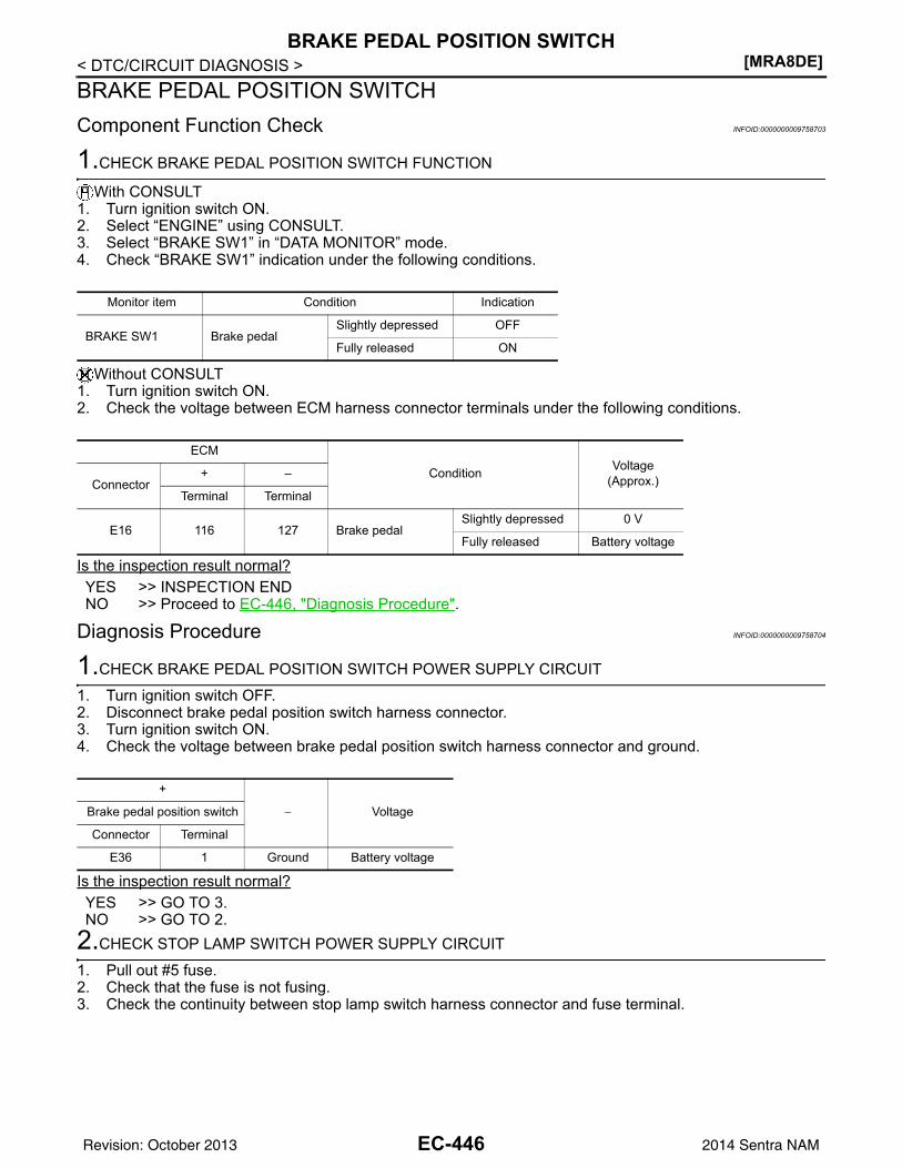
[MRA8DE]BRAKE PEDAL POSITION SWITCH
< DTC/CIRCUIT DIAGNOSIS >BRAKE PEDAL POSITION SWITCHComponent Function Check INFOID:0000000009758703
1.CHECK BRAKE PEDAL POSITION SWITCH FUNCTION
With CONSULT1. Turn ignition switch ON.2. Select “ENGINE” using CONSULT.3. Select “BRAKE SW1” in “DATA MONITOR” mode.4. Check “BRAKE SW1” indication under the following conditions.
Without CONSULT1. Turn ignition switch ON.2. Check the voltage between ECM harness connector terminals under the following conditions.
Is the inspection result normal?YES >> INSPECTION ENDNO >> Proceed to EC-446, "Diagnosis Procedure".
Diagnosis Procedure INFOID:0000000009758704
1.CHECK BRAKE PEDAL POSITION SWITCH POWER SUPPLY CIRCUIT
1. Turn ignition switch OFF.2. Disconnect brake pedal position switch harness connector.3. Turn ignition switch ON.4. Check the voltage between brake pedal position switch harness connector and ground.
Is the inspection result normal?YES >> GO TO 3.NO >> GO TO 2.
2.CHECK STOP LAMP SWITCH POWER SUPPLY CIRCUIT
1. Pull out #5 fuse.2. Check that the fuse is not fusing.3. Check the continuity between stop lamp switch harness connector and fuse terminal.
Monitor item Condition Indication
BRAKE SW1 Brake pedalSlightly depressed OFF
Fully released ON
ECM
Condition Voltage(Approx.)Connector
+ –
Terminal Terminal
E16 116 127 Brake pedalSlightly depressed 0 V
Fully released Battery voltage
+
− VoltageBrake pedal position switch
Connector Terminal
E36 1 Ground Battery voltage
EC-446Revision: October 2013 2014 Sentra NAM
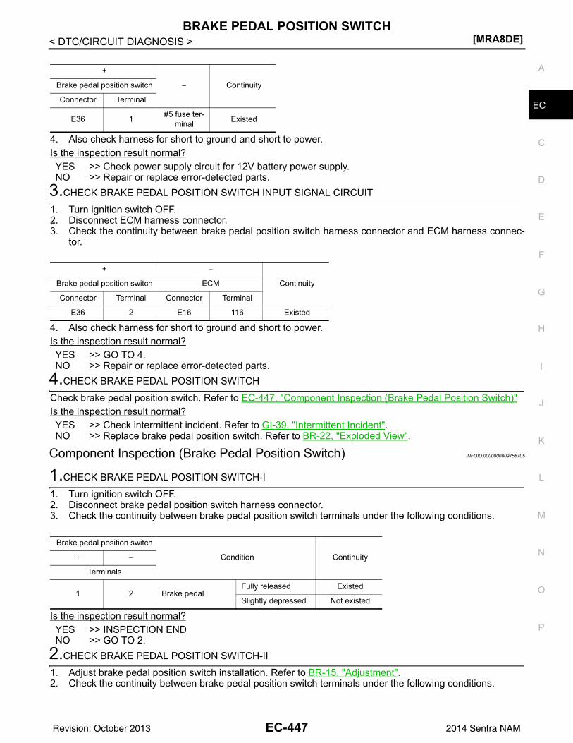
BRAKE PEDAL POSITION SWITCH[MRA8DE]
C
D
E
F
G
H
I
J
K
L
M
A
C
N
P
O
< DTC/CIRCUIT DIAGNOSIS >
E
4. Also check harness for short to ground and short to power.Is the inspection result normal?YES >> Check power supply circuit for 12V battery power supply.NO >> Repair or replace error-detected parts.
3.CHECK BRAKE PEDAL POSITION SWITCH INPUT SIGNAL CIRCUIT
1. Turn ignition switch OFF.2. Disconnect ECM harness connector.3. Check the continuity between brake pedal position switch harness connector and ECM harness connec-
tor.
4. Also check harness for short to ground and short to power.Is the inspection result normal?YES >> GO TO 4.NO >> Repair or replace error-detected parts.
4.CHECK BRAKE PEDAL POSITION SWITCH
Check brake pedal position switch. Refer to EC-447, "Component Inspection (Brake Pedal Position Switch)"Is the inspection result normal?YES >> Check intermittent incident. Refer to GI-39, "Intermittent Incident".NO >> Replace brake pedal position switch. Refer to BR-22, "Exploded View".
Component Inspection (Brake Pedal Position Switch) INFOID:0000000009758705
1.CHECK BRAKE PEDAL POSITION SWITCH-I
1. Turn ignition switch OFF.2. Disconnect brake pedal position switch harness connector.3. Check the continuity between brake pedal position switch terminals under the following conditions.
Is the inspection result normal?YES >> INSPECTION ENDNO >> GO TO 2.
2.CHECK BRAKE PEDAL POSITION SWITCH-II
1. Adjust brake pedal position switch installation. Refer to BR-15, "Adjustment".2. Check the continuity between brake pedal position switch terminals under the following conditions.
+
− ContinuityBrake pedal position switch
Connector Terminal
E36 1 #5 fuse ter-minal Existed
+ −
ContinuityBrake pedal position switch ECM
Connector Terminal Connector Terminal
E36 2 E16 116 Existed
Brake pedal position switch
Condition Continuity+ −
Terminals
1 2 Brake pedalFully released Existed
Slightly depressed Not existed
EC-447Revision: October 2013 2014 Sentra NAM
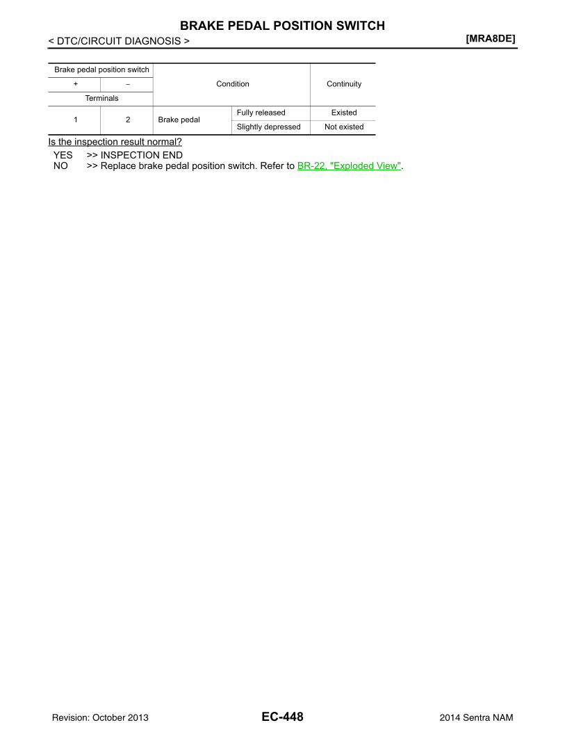
[MRA8DE]BRAKE PEDAL POSITION SWITCH
< DTC/CIRCUIT DIAGNOSIS >
Is the inspection result normal?YES >> INSPECTION ENDNO >> Replace brake pedal position switch. Refer to BR-22, "Exploded View".
Brake pedal position switch
Condition Continuity+ −
Terminals
1 2 Brake pedalFully released Existed
Slightly depressed Not existed
EC-448Revision: October 2013 2014 Sentra NAM
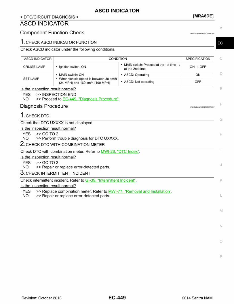
ASCD INDICATOR[MRA8DE]
C
D
E
F
G
H
I
J
K
L
M
A
C
N
P
O
< DTC/CIRCUIT DIAGNOSIS >
E
ASCD INDICATORComponent Function Check INFOID:0000000009758706
1.CHECK ASCD INDICATOR FUNCTION
Check ASCD indicator under the following conditions.
Is the inspection result normal?YES >> INSPECTION ENDNO >> Proceed to EC-449, "Diagnosis Procedure".
Diagnosis Procedure INFOID:0000000009758707
1.CHECK DTC
Check that DTC UXXXX is not displayed.Is the inspection result normal?YES >> GO TO 2.NO >> Perform trouble diagnosis for DTC UXXXX.
2.CHECK DTC WITH COMBINATION METER
Check DTC with combination meter. Refer to MWI-26, "DTC Index".Is the inspection result normal?YES >> GO TO 3.NO >> Repair or replace error-detected parts.
3.CHECK INTERMITTENT INCIDENT
Check intermittent incident. Refer to GI-39, "Intermittent Incident".Is the inspection result normal?YES >> Replace combination meter. Refer to MWI-77, "Removal and Installation".NO >> Repair or replace error-detected parts.
ASCD INDICATOR CONDITION SPECIFICATION
CRUISE LAMP • Ignition switch: ON • MAIN switch: Pressed at the 1st time →at the 2nd time ON → OFF
SET LAMP• MAIN switch: ON• When vehicle speed is between 38 km/h
(24 MPH) and 160 km/h (100 MPH)
• ASCD: Operating ON
• ASCD: Not operating OFF
EC-449Revision: October 2013 2014 Sentra NAM
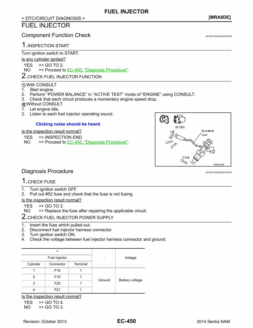
[MRA8DE]FUEL INJECTOR
< DTC/CIRCUIT DIAGNOSIS >FUEL INJECTORComponent Function Check INFOID:0000000009758708
1.INSPECTION START
Turn ignition switch to START.Is any cylinder ignited?YES >> GO TO 2.NO >> Proceed to EC-450, "Diagnosis Procedure".
2.CHECK FUEL INJECTOR FUNCTION
With CONSULT1. Start engine.2. Perform “POWER BALANCE” in “ACTIVE TEST” mode of “ENGINE” using CONSULT.3. Check that each circuit produces a momentary engine speed drop.
Without CONSULT1. Let engine idle.2. Listen to each fuel injector operating sound.
Is the inspection result normal?YES >> INSPECTION ENDNO >> Proceed to EC-450, "Diagnosis Procedure".
Diagnosis Procedure INFOID:0000000009758709
1.CHECK FUSE
1. Turn ignition switch OFF.2. Pull out #52 fuse and check that the fuse is not fusing.Is the inspection result normal?YES >> GO TO 2.NO >> Replace the fuse after repairing the applicable circuit.
2.CHECK FUEL INJECTOR POWER SUPPLY
1. Insert the fuse which pulled out.2. Disconnect fuel injector harness connector.3. Turn ignition switch ON.4. Check the voltage between fuel injector harness connector and ground.
Is the inspection result normal?YES >> GO TO 4.NO >> GO TO 3.
Clicking noise should be heard.
PBIB3332E
+
− VoltageFuel injector
Cylinder Connector Terminal
1 F18 1
Ground Battery voltage2 F19 1
3 F20 1
4 F21 1
EC-450Revision: October 2013 2014 Sentra NAM
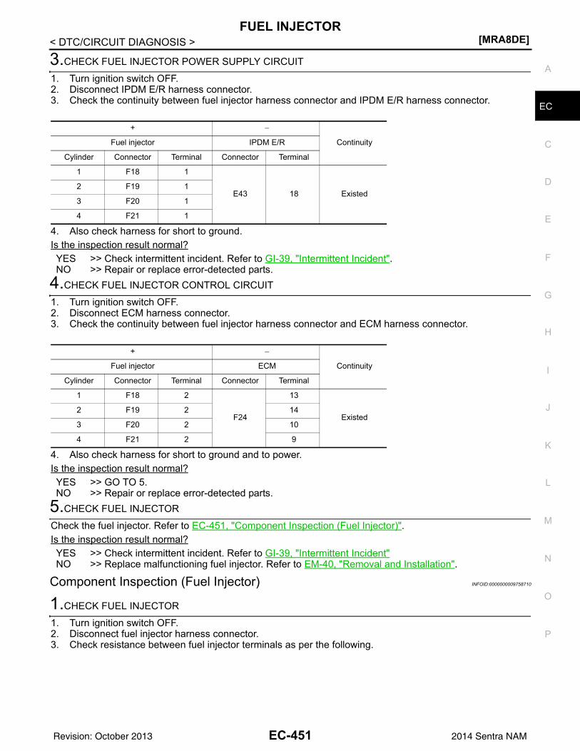
FUEL INJECTOR[MRA8DE]
C
D
E
F
G
H
I
J
K
L
M
A
C
N
P
O
< DTC/CIRCUIT DIAGNOSIS >
E
3.CHECK FUEL INJECTOR POWER SUPPLY CIRCUIT
1. Turn ignition switch OFF.2. Disconnect IPDM E/R harness connector.3. Check the continuity between fuel injector harness connector and IPDM E/R harness connector.
4. Also check harness for short to ground.Is the inspection result normal?YES >> Check intermittent incident. Refer to GI-39, "Intermittent Incident". NO >> Repair or replace error-detected parts.
4.CHECK FUEL INJECTOR CONTROL CIRCUIT
1. Turn ignition switch OFF.2. Disconnect ECM harness connector.3. Check the continuity between fuel injector harness connector and ECM harness connector.
4. Also check harness for short to ground and to power.Is the inspection result normal?YES >> GO TO 5.NO >> Repair or replace error-detected parts.
5.CHECK FUEL INJECTOR
Check the fuel injector. Refer to EC-451, "Component Inspection (Fuel Injector)".Is the inspection result normal?YES >> Check intermittent incident. Refer to GI-39, "Intermittent Incident"NO >> Replace malfunctioning fuel injector. Refer to EM-40, "Removal and Installation".
Component Inspection (Fuel Injector) INFOID:0000000009758710
1.CHECK FUEL INJECTOR
1. Turn ignition switch OFF.2. Disconnect fuel injector harness connector.3. Check resistance between fuel injector terminals as per the following.
+ −
ContinuityFuel injector IPDM E/R
Cylinder Connector Terminal Connector Terminal
1 F18 1
E43 18 Existed2 F19 1
3 F20 1
4 F21 1
+ −
ContinuityFuel injector ECM
Cylinder Connector Terminal Connector Terminal
1 F18 2
F24
13
Existed2 F19 2 14
3 F20 2 10
4 F21 2 9
EC-451Revision: October 2013 2014 Sentra NAM
[MRA8DE]FUEL INJECTOR
< DTC/CIRCUIT DIAGNOSIS >
Is the inspection result normal?YES >> INSPECTION ENDNO >> Replace malfunctioning fuel injector. Refer to EM-40, "Removal and Installation"
Fuel injector
Condition Resistance+ −
Terminals
1 2 Temperature °C (°F) 10 – 60 (50 – 140) 11.1 – 14.5 Ω
EC-452Revision: October 2013 2014 Sentra NAM
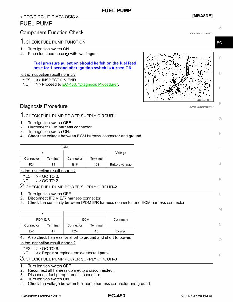
FUEL PUMP[MRA8DE]
C
D
E
F
G
H
I
J
K
L
M
A
C
N
P
O
< DTC/CIRCUIT DIAGNOSIS >
E
FUEL PUMPComponent Function Check INFOID:0000000009758711
1.CHECK FUEL PUMP FUNCTION
1. Turn ignition switch ON.2. Pinch fuel feed hose with two fingers.
Is the inspection result normal?YES >> INSPECTION ENDNO >> Proceed to EC-453, "Diagnosis Procedure".
Diagnosis Procedure INFOID:0000000009758712
1.CHECK FUEL PUMP POWER SUPPLY CIRCUIT-1
1. Turn ignition switch OFF.2. Disconnect ECM harness connector.3. Turn ignition switch ON.4. Check the voltage between ECM harness connector and ground.
Is the inspection result normal?YES >> GO TO 3.NO >> GO TO 2.
2.CHECK FUEL PUMP POWER SUPPLY CIRCUIT-2
1. Turn ignition switch OFF.2. Disconnect IPDM E/R harness connector.3. Check the continuity between IPDM E/R harness connector and ECM harness connector.
4. Also check harness for short to ground and short to power.Is the inspection result normal?YES >> GO TO 8.NO >> Repair or replace error-detected parts.
3.CHECK FUEL PUMP POWER SUPPLY CIRCUIT-3
1. Turn ignition switch OFF.2. Reconnect all harness connectors disconnected.3. Disconnect fuel pump harness connector.4. Turn ignition switch ON.5. Check the voltage between fuel pump harness connector and ground.
Fuel pressure pulsation should be felt on the fuel feed hose for 1 second after ignition switch is turned ON.
JSBIA0601ZZ
ECM
Voltage+ −
Connector Terminal Connector Terminal
F24 18 E16 128 Battery voltage
+ −
ContinuityIPDM E/R ECM
Connector Terminal Connector Terminal
E46 45 F24 18 Existed
EC-453Revision: October 2013 2014 Sentra NAM
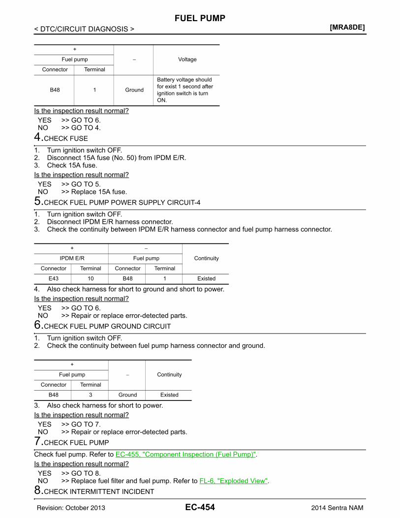
[MRA8DE]FUEL PUMP
< DTC/CIRCUIT DIAGNOSIS >
Is the inspection result normal?YES >> GO TO 6.NO >> GO TO 4.
4.CHECK FUSE
1. Turn ignition switch OFF.2. Disconnect 15A fuse (No. 50) from IPDM E/R.3. Check 15A fuse.Is the inspection result normal?YES >> GO TO 5.NO >> Replace 15A fuse.
5.CHECK FUEL PUMP POWER SUPPLY CIRCUIT-4
1. Turn ignition switch OFF.2. Disconnect IPDM E/R harness connector.3. Check the continuity between IPDM E/R harness connector and fuel pump harness connector.
4. Also check harness for short to ground and short to power.Is the inspection result normal?YES >> GO TO 6.NO >> Repair or replace error-detected parts.
6.CHECK FUEL PUMP GROUND CIRCUIT
1. Turn ignition switch OFF.2. Check the continuity between fuel pump harness connector and ground.
3. Also check harness for short to power. Is the inspection result normal?YES >> GO TO 7.NO >> Repair or replace error-detected parts.
7.CHECK FUEL PUMP
Check fuel pump. Refer to EC-455, "Component Inspection (Fuel Pump)".Is the inspection result normal?YES >> GO TO 8.NO >> Replace fuel filter and fuel pump. Refer to FL-6, "Exploded View".
8.CHECK INTERMITTENT INCIDENT
+
− VoltageFuel pump
Connector Terminal
B48 1 Ground
Battery voltage should for exist 1 second after ignition switch is turn ON.
+ −
ContinuityIPDM E/R Fuel pump
Connector Terminal Connector Terminal
E43 10 B48 1 Existed
+
− ContinuityFuel pump
Connector Terminal
B48 3 Ground Existed
EC-454Revision: October 2013 2014 Sentra NAM
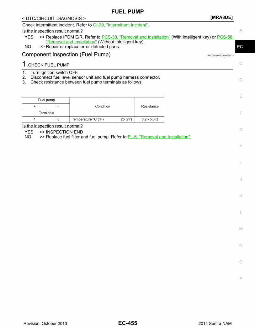
FUEL PUMP[MRA8DE]
C
D
E
F
G
H
I
J
K
L
M
A
C
N
P
O
< DTC/CIRCUIT DIAGNOSIS >
E
Check intermittent incident. Refer to GI-39, "Intermittent Incident".Is the inspection result normal?YES >> Replace IPDM E/R. Refer to PCS-30, "Removal and Installation" (With intelligent key) or PCS-58,
"Removal and Installation" (Without intelligent key).NO >> Repair or replace error-detected parts.
Component Inspection (Fuel Pump) INFOID:0000000009758713
1.CHECK FUEL PUMP
1. Turn ignition switch OFF.2. Disconnect fuel level sensor unit and fuel pump harness connector.3. Check resistance between fuel pump terminals as follows.
Is the inspection result normal?YES >> INSPECTION ENDNO >> Replace fuel filter and fuel pump. Refer to FL-6, "Removal and Installation".
Fuel pump
Condition Resistance+ −
Terminals
1 3 Temperature °C (°F) 25 (77) 0.2 - 5.0 Ω
EC-455Revision: October 2013 2014 Sentra NAM
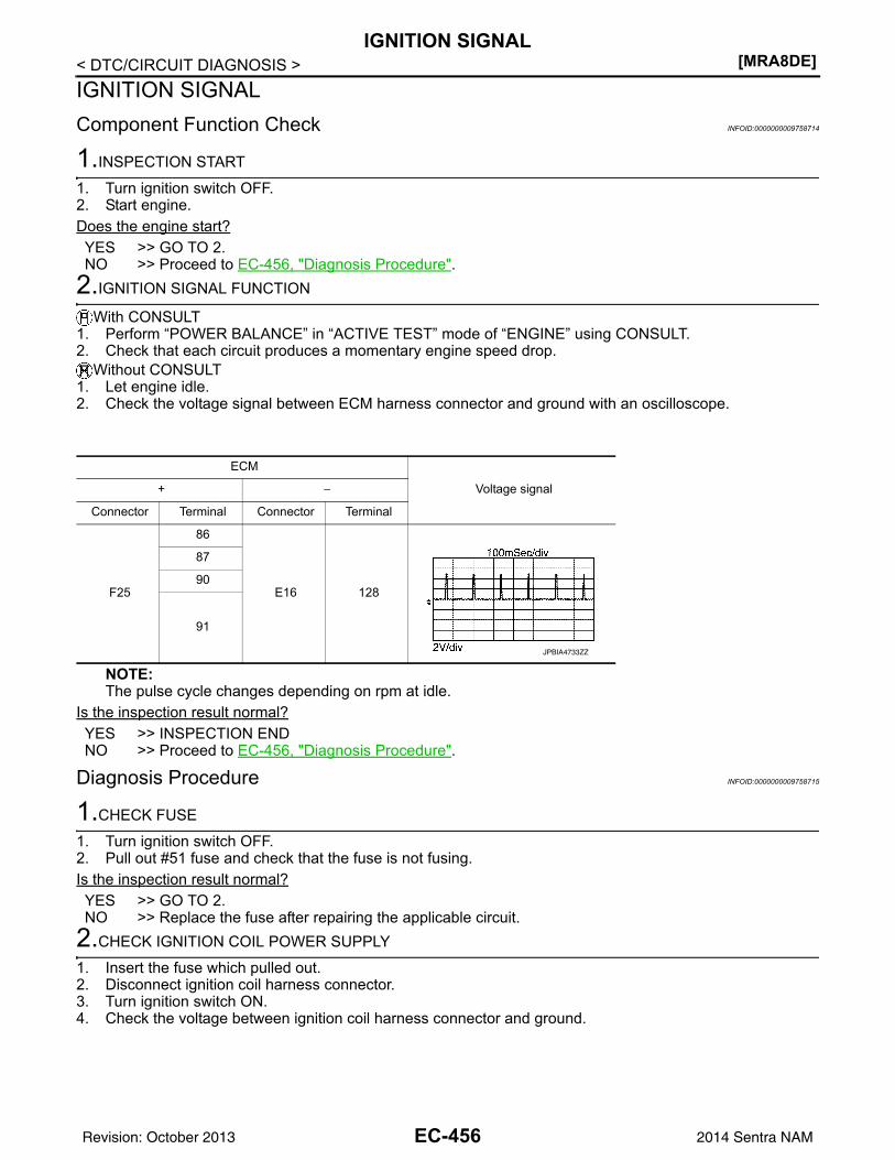
[MRA8DE]IGNITION SIGNAL
< DTC/CIRCUIT DIAGNOSIS >IGNITION SIGNALComponent Function Check INFOID:0000000009758714
1.INSPECTION START
1. Turn ignition switch OFF.2. Start engine.Does the engine start?YES >> GO TO 2.NO >> Proceed to EC-456, "Diagnosis Procedure".
2.IGNITION SIGNAL FUNCTION
With CONSULT1. Perform “POWER BALANCE” in “ACTIVE TEST” mode of “ENGINE” using CONSULT.2. Check that each circuit produces a momentary engine speed drop.
Without CONSULT1. Let engine idle.2. Check the voltage signal between ECM harness connector and ground with an oscilloscope.
NOTE:The pulse cycle changes depending on rpm at idle.
Is the inspection result normal?YES >> INSPECTION ENDNO >> Proceed to EC-456, "Diagnosis Procedure".
Diagnosis Procedure INFOID:0000000009758715
1.CHECK FUSE
1. Turn ignition switch OFF.2. Pull out #51 fuse and check that the fuse is not fusing.Is the inspection result normal?YES >> GO TO 2.NO >> Replace the fuse after repairing the applicable circuit.
2.CHECK IGNITION COIL POWER SUPPLY
1. Insert the fuse which pulled out.2. Disconnect ignition coil harness connector.3. Turn ignition switch ON.4. Check the voltage between ignition coil harness connector and ground.
ECM
Voltage signal+ −
Connector Terminal Connector Terminal
F25
86
E16 128
87
90
91
JPBIA4733ZZ
EC-456Revision: October 2013 2014 Sentra NAM
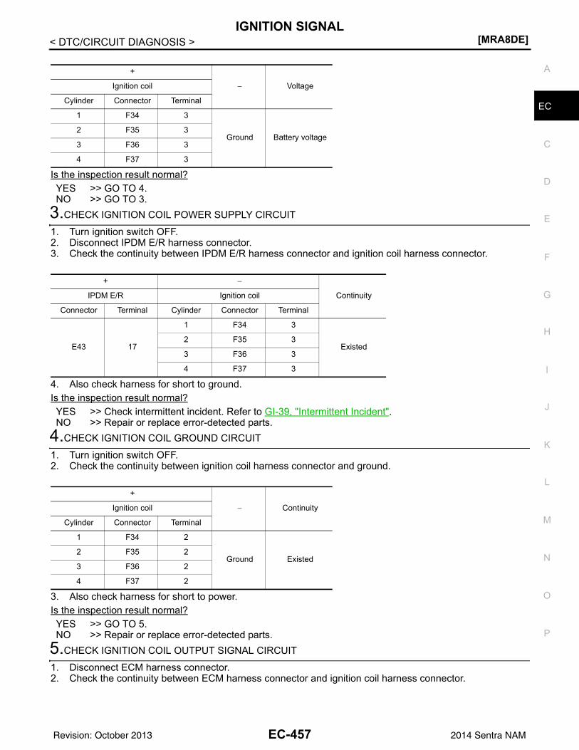
IGNITION SIGNAL[MRA8DE]
C
D
E
F
G
H
I
J
K
L
M
A
C
N
P
O
< DTC/CIRCUIT DIAGNOSIS >
E
Is the inspection result normal?YES >> GO TO 4.NO >> GO TO 3.
3.CHECK IGNITION COIL POWER SUPPLY CIRCUIT
1. Turn ignition switch OFF.2. Disconnect IPDM E/R harness connector.3. Check the continuity between IPDM E/R harness connector and ignition coil harness connector.
4. Also check harness for short to ground.Is the inspection result normal?YES >> Check intermittent incident. Refer to GI-39, "Intermittent Incident".NO >> Repair or replace error-detected parts.
4.CHECK IGNITION COIL GROUND CIRCUIT
1. Turn ignition switch OFF.2. Check the continuity between ignition coil harness connector and ground.
3. Also check harness for short to power.Is the inspection result normal?YES >> GO TO 5.NO >> Repair or replace error-detected parts.
5.CHECK IGNITION COIL OUTPUT SIGNAL CIRCUIT
1. Disconnect ECM harness connector.2. Check the continuity between ECM harness connector and ignition coil harness connector.
+
− VoltageIgnition coil
Cylinder Connector Terminal
1 F34 3
Ground Battery voltage2 F35 3
3 F36 3
4 F37 3
+ −
ContinuityIPDM E/R Ignition coil
Connector Terminal Cylinder Connector Terminal
E43 17
1 F34 3
Existed2 F35 3
3 F36 3
4 F37 3
+
− ContinuityIgnition coil
Cylinder Connector Terminal
1 F34 2
Ground Existed2 F35 2
3 F36 2
4 F37 2
EC-457Revision: October 2013 2014 Sentra NAM
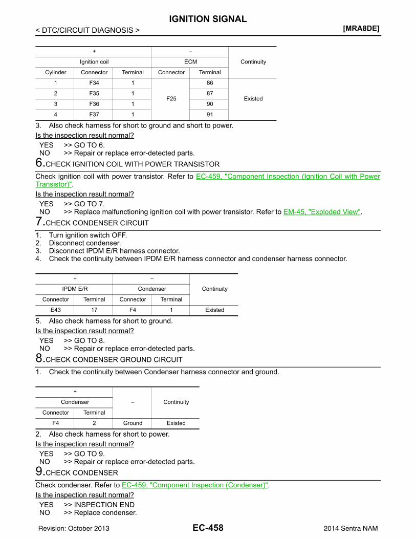
[MRA8DE]IGNITION SIGNAL
< DTC/CIRCUIT DIAGNOSIS >
3. Also check harness for short to ground and short to power.Is the inspection result normal?YES >> GO TO 6.NO >> Repair or replace error-detected parts.
6.CHECK IGNITION COIL WITH POWER TRANSISTOR
Check ignition coil with power transistor. Refer to EC-459, "Component Inspection (Ignition Coil with PowerTransistor)".Is the inspection result normal?YES >> GO TO 7.NO >> Replace malfunctioning ignition coil with power transistor. Refer to EM-45, "Exploded View".
7.CHECK CONDENSER CIRCUIT
1. Turn ignition switch OFF.2. Disconnect condenser.3. Disconnect IPDM E/R harness connector.4. Check the continuity between IPDM E/R harness connector and condenser harness connector.
5. Also check harness for short to ground.Is the inspection result normal?YES >> GO TO 8.NO >> Repair or replace error-detected parts.
8.CHECK CONDENSER GROUND CIRCUIT
1. Check the continuity between Condenser harness connector and ground.
2. Also check harness for short to power.Is the inspection result normal?YES >> GO TO 9.NO >> Repair or replace error-detected parts.
9.CHECK CONDENSER
Check condenser. Refer to EC-459, "Component Inspection (Condenser)".Is the inspection result normal?YES >> INSPECTION ENDNO >> Replace condenser.
+ −
ContinuityIgnition coil ECM
Cylinder Connector Terminal Connector Terminal
1 F34 1
F25
86
Existed2 F35 1 87
3 F36 1 90
4 F37 1 91
+ −
ContinuityIPDM E/R Condenser
Connector Terminal Connector Terminal
E43 17 F4 1 Existed
+
− ContinuityCondenser
Connector Terminal
F4 2 Ground Existed
EC-458Revision: October 2013 2014 Sentra NAM
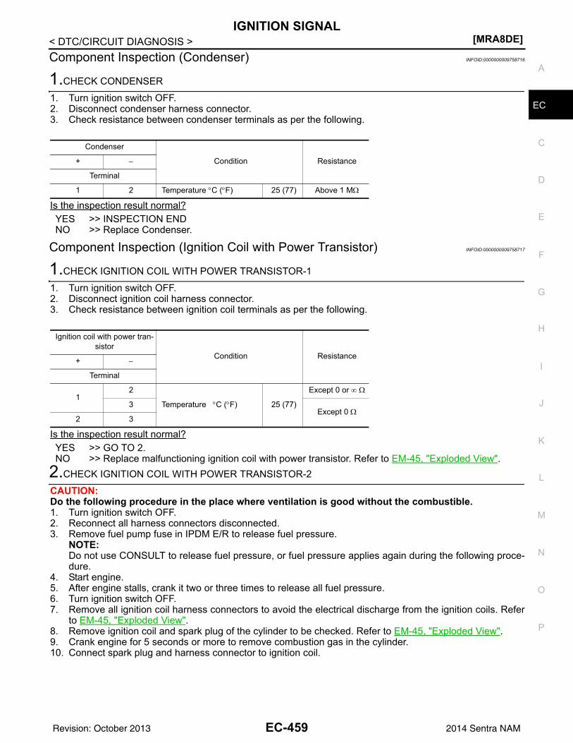
IGNITION SIGNAL[MRA8DE]
C
D
E
F
G
H
I
J
K
L
M
A
C
N
P
O
< DTC/CIRCUIT DIAGNOSIS >
E
Component Inspection (Condenser) INFOID:0000000009758716
1.CHECK CONDENSER
1. Turn ignition switch OFF.2. Disconnect condenser harness connector.3. Check resistance between condenser terminals as per the following.
Is the inspection result normal?YES >> INSPECTION ENDNO >> Replace Condenser.
Component Inspection (Ignition Coil with Power Transistor) INFOID:0000000009758717
1.CHECK IGNITION COIL WITH POWER TRANSISTOR-1
1. Turn ignition switch OFF.2. Disconnect ignition coil harness connector.3. Check resistance between ignition coil terminals as per the following.
Is the inspection result normal?YES >> GO TO 2.NO >> Replace malfunctioning ignition coil with power transistor. Refer to EM-45, "Exploded View".
2.CHECK IGNITION COIL WITH POWER TRANSISTOR-2
CAUTION:Do the following procedure in the place where ventilation is good without the combustible.1. Turn ignition switch OFF.2. Reconnect all harness connectors disconnected.3. Remove fuel pump fuse in IPDM E/R to release fuel pressure.
NOTE:Do not use CONSULT to release fuel pressure, or fuel pressure applies again during the following proce-dure.
4. Start engine.5. After engine stalls, crank it two or three times to release all fuel pressure.6. Turn ignition switch OFF.7. Remove all ignition coil harness connectors to avoid the electrical discharge from the ignition coils. Refer
to EM-45, "Exploded View".8. Remove ignition coil and spark plug of the cylinder to be checked. Refer to EM-45, "Exploded View".9. Crank engine for 5 seconds or more to remove combustion gas in the cylinder.10. Connect spark plug and harness connector to ignition coil.
Condenser
Condition Resistance+ −
Terminal
1 2 Temperature °C (°F) 25 (77) Above 1 MΩ
Ignition coil with power tran-sistor
Condition Resistance+ −
Terminal
12
Temperature °C (°F) 25 (77)
Except 0 or ∞ Ω
3Except 0 Ω
2 3
EC-459Revision: October 2013 2014 Sentra NAM
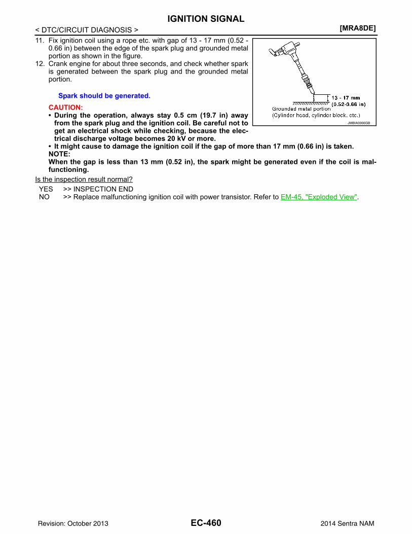
[MRA8DE]IGNITION SIGNAL
< DTC/CIRCUIT DIAGNOSIS >11. Fix ignition coil using a rope etc. with gap of 13 - 17 mm (0.52 -
0.66 in) between the edge of the spark plug and grounded metalportion as shown in the figure.
12. Crank engine for about three seconds, and check whether sparkis generated between the spark plug and the grounded metalportion.
CAUTION:• During the operation, always stay 0.5 cm (19.7 in) away
from the spark plug and the ignition coil. Be careful not toget an electrical shock while checking, because the elec-trical discharge voltage becomes 20 kV or more.
• It might cause to damage the ignition coil if the gap of more than 17 mm (0.66 in) is taken.NOTE:When the gap is less than 13 mm (0.52 in), the spark might be generated even if the coil is mal-functioning.
Is the inspection result normal?YES >> INSPECTION ENDNO >> Replace malfunctioning ignition coil with power transistor. Refer to EM-45, "Exploded View".
Spark should be generated.
JMBIA0066GB
EC-460Revision: October 2013 2014 Sentra NAM
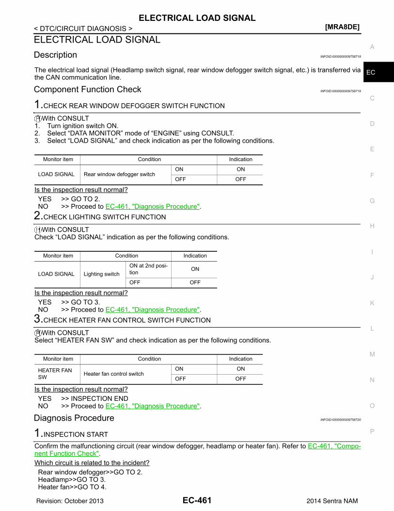
ELECTRICAL LOAD SIGNAL[MRA8DE]
C
D
E
F
G
H
I
J
K
L
M
A
C
N
P
O
< DTC/CIRCUIT DIAGNOSIS >
E
ELECTRICAL LOAD SIGNALDescription INFOID:0000000009758718
The electrical load signal (Headlamp switch signal, rear window defogger switch signal, etc.) is transferred viathe CAN communication line.
Component Function Check INFOID:0000000009758719
1.CHECK REAR WINDOW DEFOGGER SWITCH FUNCTION
With CONSULT1. Turn ignition switch ON.2. Select “DATA MONITOR” mode of “ENGINE” using CONSULT.3. Select “LOAD SIGNAL” and check indication as per the following conditions.
Is the inspection result normal?YES >> GO TO 2.NO >> Proceed to EC-461, "Diagnosis Procedure".
2.CHECK LIGHTING SWITCH FUNCTION
With CONSULTCheck “LOAD SIGNAL” indication as per the following conditions.
Is the inspection result normal?YES >> GO TO 3.NO >> Proceed to EC-461, "Diagnosis Procedure".
3.CHECK HEATER FAN CONTROL SWITCH FUNCTION
With CONSULTSelect “HEATER FAN SW” and check indication as per the following conditions.
Is the inspection result normal?YES >> INSPECTION ENDNO >> Proceed to EC-461, "Diagnosis Procedure".
Diagnosis Procedure INFOID:0000000009758720
1.INSPECTION START
Confirm the malfunctioning circuit (rear window defogger, headlamp or heater fan). Refer to EC-461, "Compo-nent Function Check".Which circuit is related to the incident?Rear window defogger>>GO TO 2.Headlamp>>GO TO 3.Heater fan>>GO TO 4.
Monitor item Condition Indication
LOAD SIGNAL Rear window defogger switchON ON
OFF OFF
Monitor item Condition Indication
LOAD SIGNAL Lighting switchON at 2nd posi-tion ON
OFF OFF
Monitor item Condition Indication
HEATER FAN SW Heater fan control switch
ON ON
OFF OFF
EC-461Revision: October 2013 2014 Sentra NAM
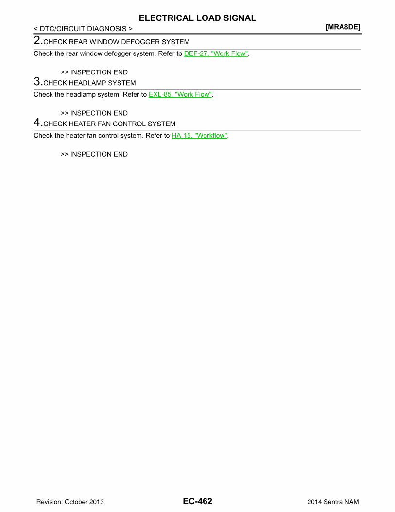
[MRA8DE]ELECTRICAL LOAD SIGNAL
< DTC/CIRCUIT DIAGNOSIS >
2.CHECK REAR WINDOW DEFOGGER SYSTEM
Check the rear window defogger system. Refer to DEF-27, "Work Flow".
>> INSPECTION END3.CHECK HEADLAMP SYSTEM
Check the headlamp system. Refer to EXL-85, "Work Flow".
>> INSPECTION END4.CHECK HEATER FAN CONTROL SYSTEM
Check the heater fan control system. Refer to HA-15, "Workflow".
>> INSPECTION END
EC-462Revision: October 2013 2014 Sentra NAM
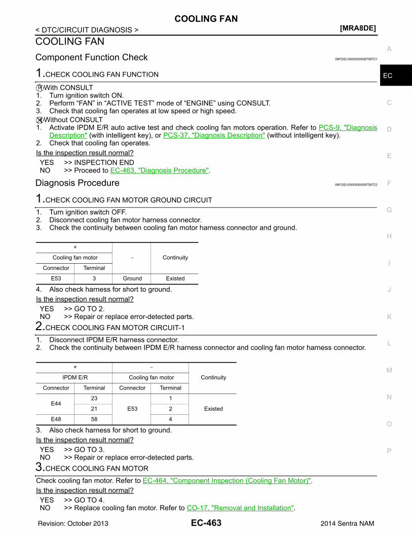
COOLING FAN[MRA8DE]
C
D
E
F
G
H
I
J
K
L
M
A
C
N
P
O
< DTC/CIRCUIT DIAGNOSIS >
E
COOLING FANComponent Function Check INFOID:0000000009758721
1.CHECK COOLING FAN FUNCTION
With CONSULT1. Turn ignition switch ON.2. Perform “FAN” in “ACTIVE TEST” mode of “ENGINE” using CONSULT.3. Check that cooling fan operates at low speed or high speed.
Without CONSULT1. Activate IPDM E/R auto active test and check cooling fan motors operation. Refer to PCS-9, "Diagnosis
Description" (with intelligent key), or PCS-37, "Diagnosis Description" (without intelligent key).2. Check that cooling fan operates.Is the inspection result normal?YES >> INSPECTION ENDNO >> Proceed to EC-463, "Diagnosis Procedure".
Diagnosis Procedure INFOID:0000000009758722
1.CHECK COOLING FAN MOTOR GROUND CIRCUIT
1. Turn ignition switch OFF.2. Disconnect cooling fan motor harness connector.3. Check the continuity between cooling fan motor harness connector and ground.
4. Also check harness for short to ground.Is the inspection result normal?YES >> GO TO 2.NO >> Repair or replace error-detected parts.
2.CHECK COOLING FAN MOTOR CIRCUIT-1
1. Disconnect IPDM E/R harness connector.2. Check the continuity between IPDM E/R harness connector and cooling fan motor harness connector.
3. Also check harness for short to ground.Is the inspection result normal?YES >> GO TO 3.NO >> Repair or replace error-detected parts.
3.CHECK COOLING FAN MOTOR
Check cooling fan motor. Refer to EC-464, "Component Inspection (Cooling Fan Motor)".Is the inspection result normal?YES >> GO TO 4.NO >> Replace cooling fan motor. Refer to CO-17, "Removal and Installation".
+
− ContinuityCooling fan motor
Connector Terminal
E53 3 Ground Existed
+ −
ContinuityIPDM E/R Cooling fan motor
Connector Terminal Connector Terminal
E4423
E53
1
Existed21 2
E48 58 4
EC-463Revision: October 2013 2014 Sentra NAM
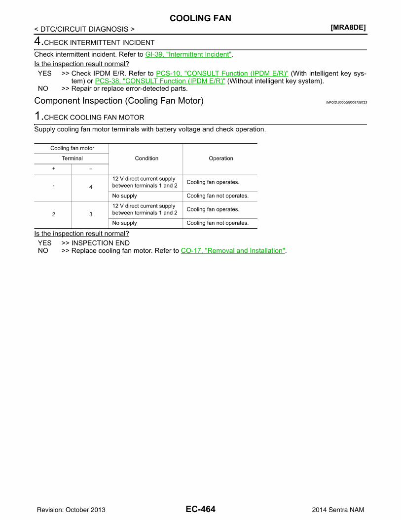
[MRA8DE]COOLING FAN
< DTC/CIRCUIT DIAGNOSIS >
4.CHECK INTERMITTENT INCIDENT
Check intermittent incident. Refer to GI-39, "Intermittent Incident".Is the inspection result normal?YES >> Check IPDM E/R. Refer to PCS-10, "CONSULT Function (IPDM E/R)" (With intelligent key sys-
tem) or PCS-38, "CONSULT Function (IPDM E/R)" (Without intelligent key system).NO >> Repair or replace error-detected parts.
Component Inspection (Cooling Fan Motor) INFOID:0000000009758723
1.CHECK COOLING FAN MOTOR
Supply cooling fan motor terminals with battery voltage and check operation.
Is the inspection result normal?YES >> INSPECTION ENDNO >> Replace cooling fan motor. Refer to CO-17, "Removal and Installation".
Cooling fan motor
Condition OperationTerminal
+ −
1 412 V direct current supply between terminals 1 and 2 Cooling fan operates.
No supply Cooling fan not operates.
2 312 V direct current supply between terminals 1 and 2 Cooling fan operates.
No supply Cooling fan not operates.
EC-464Revision: October 2013 2014 Sentra NAM
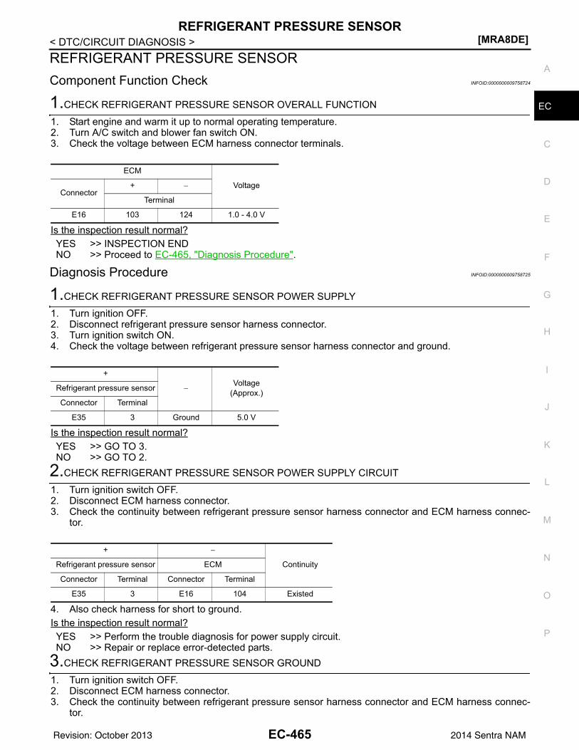
REFRIGERANT PRESSURE SENSOR[MRA8DE]
C
D
E
F
G
H
I
J
K
L
M
A
C
N
P
O
< DTC/CIRCUIT DIAGNOSIS >
E
REFRIGERANT PRESSURE SENSORComponent Function Check INFOID:0000000009758724
1.CHECK REFRIGERANT PRESSURE SENSOR OVERALL FUNCTION
1. Start engine and warm it up to normal operating temperature.2. Turn A/C switch and blower fan switch ON.3. Check the voltage between ECM harness connector terminals.
Is the inspection result normal?YES >> INSPECTION ENDNO >> Proceed to EC-465, "Diagnosis Procedure".
Diagnosis Procedure INFOID:0000000009758725
1.CHECK REFRIGERANT PRESSURE SENSOR POWER SUPPLY
1. Turn ignition OFF.2. Disconnect refrigerant pressure sensor harness connector.3. Turn ignition switch ON.4. Check the voltage between refrigerant pressure sensor harness connector and ground.
Is the inspection result normal?YES >> GO TO 3.NO >> GO TO 2.
2.CHECK REFRIGERANT PRESSURE SENSOR POWER SUPPLY CIRCUIT
1. Turn ignition switch OFF.2. Disconnect ECM harness connector.3. Check the continuity between refrigerant pressure sensor harness connector and ECM harness connec-
tor.
4. Also check harness for short to ground.Is the inspection result normal?YES >> Perform the trouble diagnosis for power supply circuit.NO >> Repair or replace error-detected parts.
3.CHECK REFRIGERANT PRESSURE SENSOR GROUND
1. Turn ignition switch OFF.2. Disconnect ECM harness connector.3. Check the continuity between refrigerant pressure sensor harness connector and ECM harness connec-
tor.
ECM
VoltageConnector
+ −
Terminal
E16 103 124 1.0 - 4.0 V
+
−Voltage
(Approx.)Refrigerant pressure sensor
Connector Terminal
E35 3 Ground 5.0 V
+ −
ContinuityRefrigerant pressure sensor ECM
Connector Terminal Connector Terminal
E35 3 E16 104 Existed
EC-465Revision: October 2013 2014 Sentra NAM
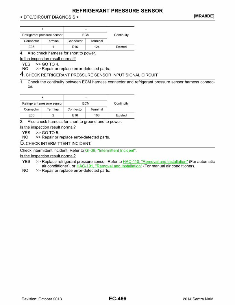
[MRA8DE]REFRIGERANT PRESSURE SENSOR
< DTC/CIRCUIT DIAGNOSIS >
4. Also check harness for short to power.Is the inspection result normal?YES >> GO TO 4.NO >> Repair or replace error-detected parts.
4.CHECK REFRIGERANT PRESSURE SENSOR INPUT SIGNAL CIRCUIT
1. Check the continuity between ECM harness connector and refrigerant pressure sensor harness connec-tor.
2. Also check harness for short to ground and to power.Is the inspection result normal?YES >> GO TO 5.NO >> Repair or replace error-detected parts.
5.CHECK INTERMITTENT INCIDENT.
Check intermittent incident. Refer to GI-39, "Intermittent Incident".Is the inspection result normal?YES >> Replace refrigerant pressure sensor. Refer to HAC-110, "Removal and Installation" (For automatic
air condittioner), or HAC-191, "Removal and Installation" (For manual air condittioner).NO >> Repair or replace error-detected parts.
+ −
ContinuityRefrigerant pressure sensor ECM
Connector Terminal Connector Terminal
E35 1 E16 124 Existed
+ −
ContinuityRefrigerant pressure sensor ECM
Connector Terminal Connector Terminal
E35 2 E16 103 Existed
EC-466Revision: October 2013 2014 Sentra NAM
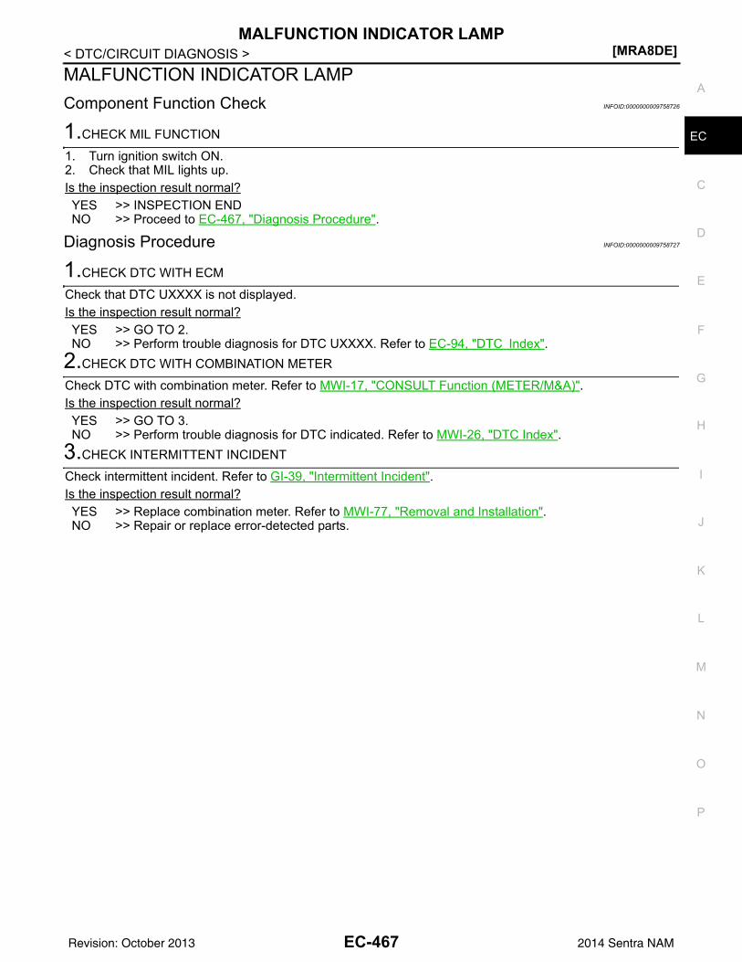
MALFUNCTION INDICATOR LAMP[MRA8DE]
C
D
E
F
G
H
I
J
K
L
M
A
C
N
P
O
< DTC/CIRCUIT DIAGNOSIS >
E
MALFUNCTION INDICATOR LAMPComponent Function Check INFOID:0000000009758726
1.CHECK MIL FUNCTION
1. Turn ignition switch ON.2. Check that MIL lights up.Is the inspection result normal?YES >> INSPECTION ENDNO >> Proceed to EC-467, "Diagnosis Procedure".
Diagnosis Procedure INFOID:0000000009758727
1.CHECK DTC WITH ECM
Check that DTC UXXXX is not displayed.Is the inspection result normal?YES >> GO TO 2.NO >> Perform trouble diagnosis for DTC UXXXX. Refer to EC-94, "DTC Index".
2.CHECK DTC WITH COMBINATION METER
Check DTC with combination meter. Refer to MWI-17, "CONSULT Function (METER/M&A)".Is the inspection result normal?YES >> GO TO 3.NO >> Perform trouble diagnosis for DTC indicated. Refer to MWI-26, "DTC Index".
3.CHECK INTERMITTENT INCIDENT
Check intermittent incident. Refer to GI-39, "Intermittent Incident".Is the inspection result normal?YES >> Replace combination meter. Refer to MWI-77, "Removal and Installation".NO >> Repair or replace error-detected parts.
EC-467Revision: October 2013 2014 Sentra NAM
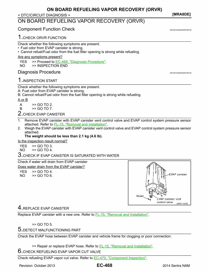
[MRA8DE]ON BOARD REFUELING VAPOR RECOVERY (ORVR)
< DTC/CIRCUIT DIAGNOSIS >ON BOARD REFUELING VAPOR RECOVERY (ORVR)Component Function Check INFOID:0000000009758728
1.CHECK ORVR FUNCTION
Check whether the following symptoms are present.• Fuel odor from EVAP canister is strong.• Cannot refuel/Fuel odor from the fuel filler opening is strong while refueling.Are any symptoms present?YES >> Proceed to EC-468, "Diagnosis Procedure".NO >> INSPECTION END
Diagnosis Procedure INFOID:0000000009758729
1.INSPECTION START
Check whether the following symptoms are present.A: Fuel odor from EVAP canister is strong.B: Cannot refuel/Fuel odor from the fuel filler opening is strong while refueling.A or BA >> GO TO 2.B >> GO TO 7.
2.CHECK EVAP CANISTER
1. Remove EVAP canister with EVAP canister vent control valve and EVAP control system pressure sensorattached. Refer to FL-15, "Removal and Installation".
2. Weigh the EVAP canister with EVAP canister vent control valve and EVAP control system pressure sensorattached.The weight should be less than 2.1 kg (4.6 lb).
Is the inspection result normal?YES >> GO TO 3.NO >> GO TO 4.
3.CHECK IF EVAP CANISTER IS SATURATED WITH WATER
Check if water will drain from EVAP canisterDoes water drain from the EVAP canister?YES >> GO TO 4.NO >> GO TO 6.
4.REPLACE EVAP CANISTER
Replace EVAP canister with a new one. Refer to FL-15, "Removal and Installation".
>> GO TO 5.5.DETECT MALFUNCTIONING PART
Check the EVAP hose between EVAP canister and vehicle frame for clogging or poor connection.
>> Repair or replace EVAP hose. Refer to FL-15, "Removal and Installation".6.CHECK REFUELING EVAP VAPOR CUT VALVE
Check refueling EVAP vapor cut valve. Refer to EC-470, "Component Inspection".
JMBIA1134GB
EC-468Revision: October 2013 2014 Sentra NAM
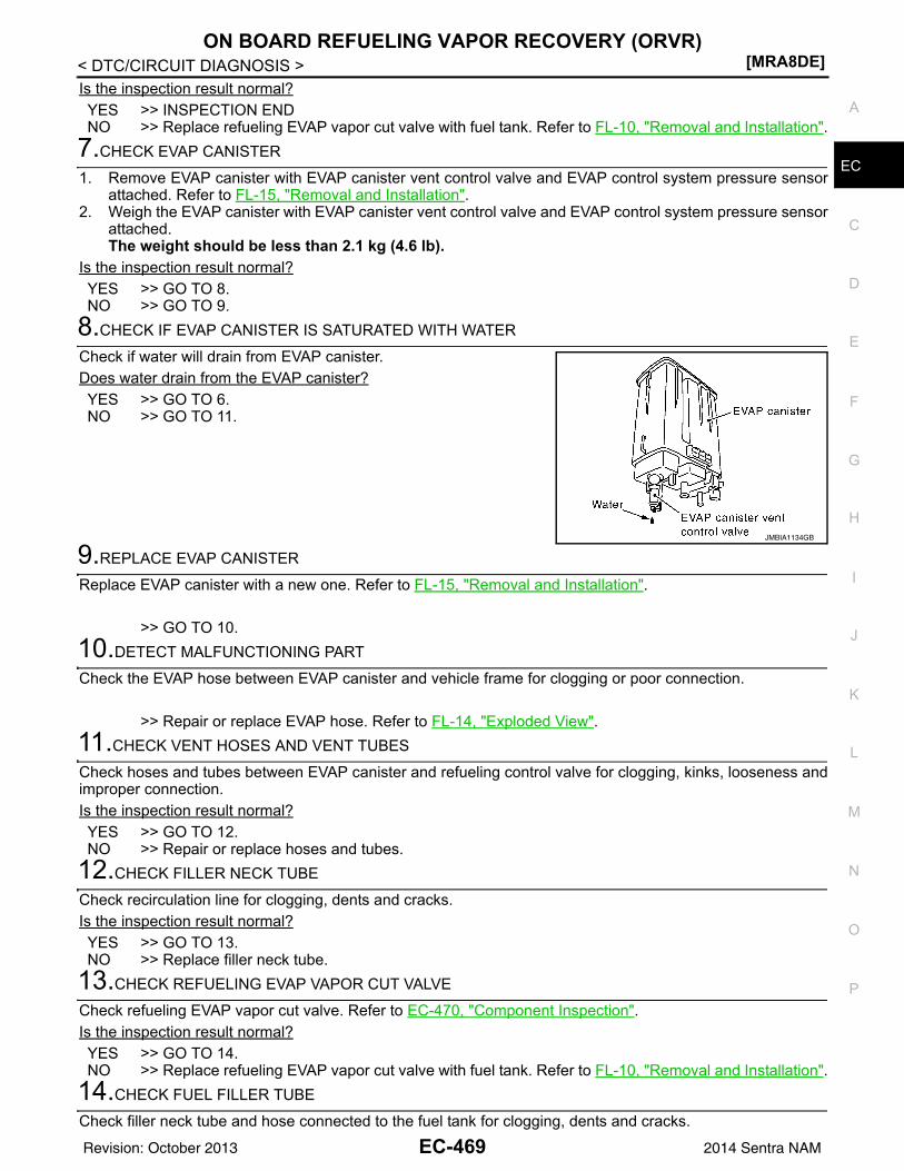
ON BOARD REFUELING VAPOR RECOVERY (ORVR)[MRA8DE]
C
D
E
F
G
H
I
J
K
L
M
A
C
N
P
O
< DTC/CIRCUIT DIAGNOSIS >
E
Is the inspection result normal?YES >> INSPECTION ENDNO >> Replace refueling EVAP vapor cut valve with fuel tank. Refer to FL-10, "Removal and Installation".
7.CHECK EVAP CANISTER
1. Remove EVAP canister with EVAP canister vent control valve and EVAP control system pressure sensorattached. Refer to FL-15, "Removal and Installation".
2. Weigh the EVAP canister with EVAP canister vent control valve and EVAP control system pressure sensorattached.The weight should be less than 2.1 kg (4.6 lb).
Is the inspection result normal?YES >> GO TO 8.NO >> GO TO 9.
8.CHECK IF EVAP CANISTER IS SATURATED WITH WATER
Check if water will drain from EVAP canister.Does water drain from the EVAP canister?YES >> GO TO 6.NO >> GO TO 11.
9.REPLACE EVAP CANISTER
Replace EVAP canister with a new one. Refer to FL-15, "Removal and Installation".
>> GO TO 10.10.DETECT MALFUNCTIONING PART
Check the EVAP hose between EVAP canister and vehicle frame for clogging or poor connection.
>> Repair or replace EVAP hose. Refer to FL-14, "Exploded View".11.CHECK VENT HOSES AND VENT TUBES
Check hoses and tubes between EVAP canister and refueling control valve for clogging, kinks, looseness andimproper connection.Is the inspection result normal?YES >> GO TO 12.NO >> Repair or replace hoses and tubes.
12.CHECK FILLER NECK TUBE
Check recirculation line for clogging, dents and cracks. Is the inspection result normal?YES >> GO TO 13.NO >> Replace filler neck tube.
13.CHECK REFUELING EVAP VAPOR CUT VALVE
Check refueling EVAP vapor cut valve. Refer to EC-470, "Component Inspection".Is the inspection result normal?YES >> GO TO 14.NO >> Replace refueling EVAP vapor cut valve with fuel tank. Refer to FL-10, "Removal and Installation".
14.CHECK FUEL FILLER TUBE
Check filler neck tube and hose connected to the fuel tank for clogging, dents and cracks.
JMBIA1134GB
EC-469Revision: October 2013 2014 Sentra NAM
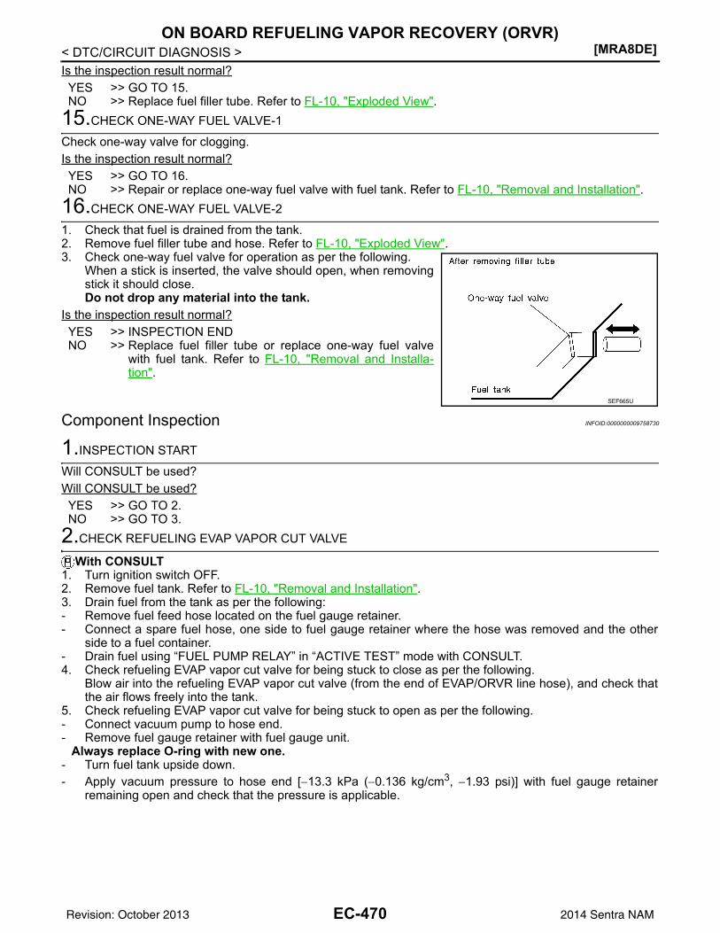
[MRA8DE]ON BOARD REFUELING VAPOR RECOVERY (ORVR)
< DTC/CIRCUIT DIAGNOSIS >Is the inspection result normal?YES >> GO TO 15.NO >> Replace fuel filler tube. Refer to FL-10, "Exploded View".
15.CHECK ONE-WAY FUEL VALVE-1
Check one-way valve for clogging.Is the inspection result normal?YES >> GO TO 16.NO >> Repair or replace one-way fuel valve with fuel tank. Refer to FL-10, "Removal and Installation".
16.CHECK ONE-WAY FUEL VALVE-2
1. Check that fuel is drained from the tank.2. Remove fuel filler tube and hose. Refer to FL-10, "Exploded View".3. Check one-way fuel valve for operation as per the following.
When a stick is inserted, the valve should open, when removingstick it should close.Do not drop any material into the tank.
Is the inspection result normal?YES >> INSPECTION ENDNO >> Replace fuel filler tube or replace one-way fuel valve
with fuel tank. Refer to FL-10, "Removal and Installa-tion".
Component Inspection INFOID:0000000009758730
1.INSPECTION START
Will CONSULT be used?Will CONSULT be used?YES >> GO TO 2.NO >> GO TO 3.
2.CHECK REFUELING EVAP VAPOR CUT VALVE
With CONSULT1. Turn ignition switch OFF.2. Remove fuel tank. Refer to FL-10, "Removal and Installation".3. Drain fuel from the tank as per the following:- Remove fuel feed hose located on the fuel gauge retainer.- Connect a spare fuel hose, one side to fuel gauge retainer where the hose was removed and the other
side to a fuel container.- Drain fuel using “FUEL PUMP RELAY” in “ACTIVE TEST” mode with CONSULT.4. Check refueling EVAP vapor cut valve for being stuck to close as per the following.
Blow air into the refueling EVAP vapor cut valve (from the end of EVAP/ORVR line hose), and check thatthe air flows freely into the tank.
5. Check refueling EVAP vapor cut valve for being stuck to open as per the following.- Connect vacuum pump to hose end.- Remove fuel gauge retainer with fuel gauge unit.
Always replace O-ring with new one.- Turn fuel tank upside down.- Apply vacuum pressure to hose end [−13.3 kPa (−0.136 kg/cm3, −1.93 psi)] with fuel gauge retainer
remaining open and check that the pressure is applicable.
SEF665U
EC-470Revision: October 2013 2014 Sentra NAM
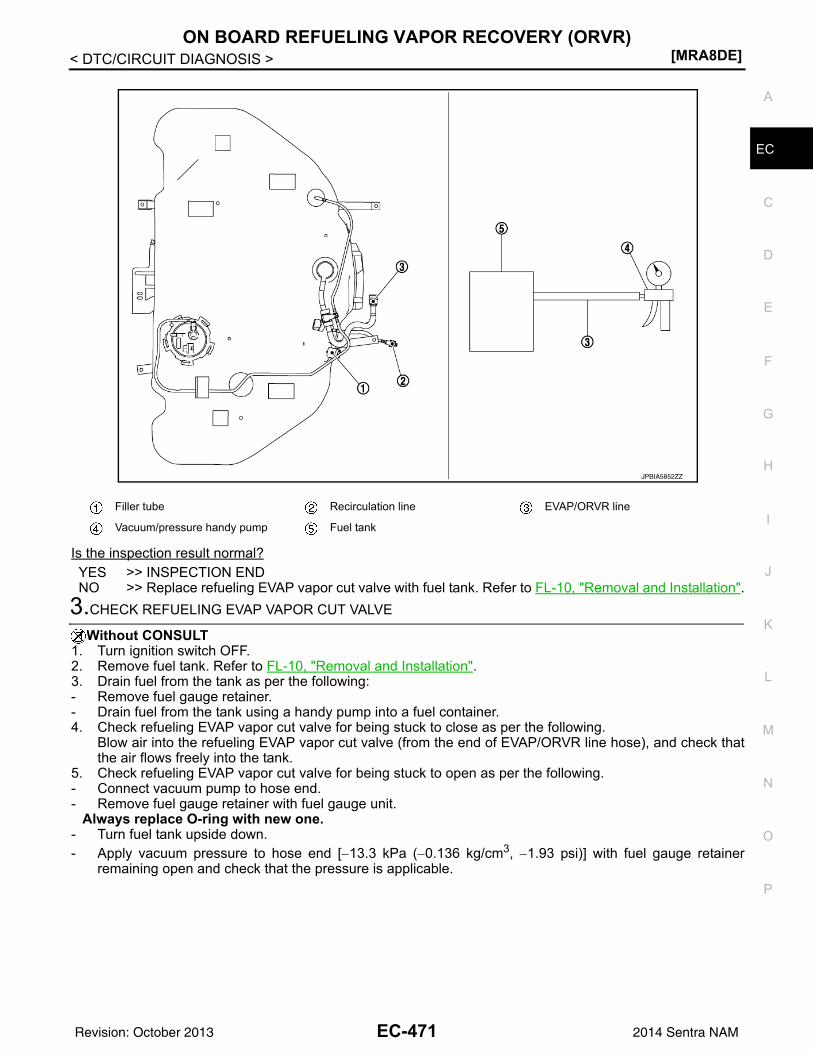
ON BOARD REFUELING VAPOR RECOVERY (ORVR)[MRA8DE]
C
D
E
F
G
H
I
J
K
L
M
A
C
N
P
O
< DTC/CIRCUIT DIAGNOSIS >
E
Is the inspection result normal?YES >> INSPECTION ENDNO >> Replace refueling EVAP vapor cut valve with fuel tank. Refer to FL-10, "Removal and Installation".
3.CHECK REFUELING EVAP VAPOR CUT VALVE
Without CONSULT1. Turn ignition switch OFF.2. Remove fuel tank. Refer to FL-10, "Removal and Installation".3. Drain fuel from the tank as per the following:- Remove fuel gauge retainer.- Drain fuel from the tank using a handy pump into a fuel container.4. Check refueling EVAP vapor cut valve for being stuck to close as per the following.
Blow air into the refueling EVAP vapor cut valve (from the end of EVAP/ORVR line hose), and check thatthe air flows freely into the tank.
5. Check refueling EVAP vapor cut valve for being stuck to open as per the following.- Connect vacuum pump to hose end.- Remove fuel gauge retainer with fuel gauge unit.
Always replace O-ring with new one.- Turn fuel tank upside down.- Apply vacuum pressure to hose end [−13.3 kPa (−0.136 kg/cm3, −1.93 psi)] with fuel gauge retainer
remaining open and check that the pressure is applicable.
Filler tube Recirculation line EVAP/ORVR line
Vacuum/pressure handy pump Fuel tank
JPBIA5852ZZ
EC-471Revision: October 2013 2014 Sentra NAM
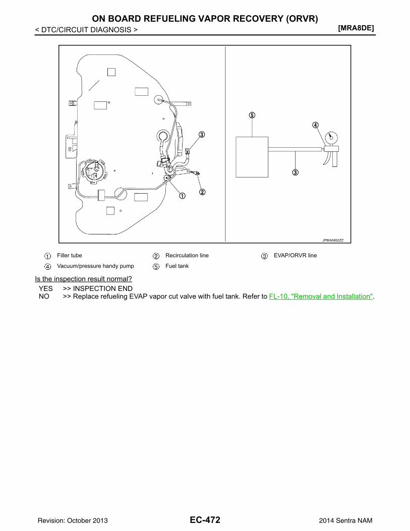
[MRA8DE]ON BOARD REFUELING VAPOR RECOVERY (ORVR)
< DTC/CIRCUIT DIAGNOSIS >
Is the inspection result normal?YES >> INSPECTION ENDNO >> Replace refueling EVAP vapor cut valve with fuel tank. Refer to FL-10, "Removal and Installation".
Filler tube Recirculation line EVAP/ORVR line
Vacuum/pressure handy pump Fuel tank
JPBIA5852ZZ
EC-472Revision: October 2013 2014 Sentra NAM
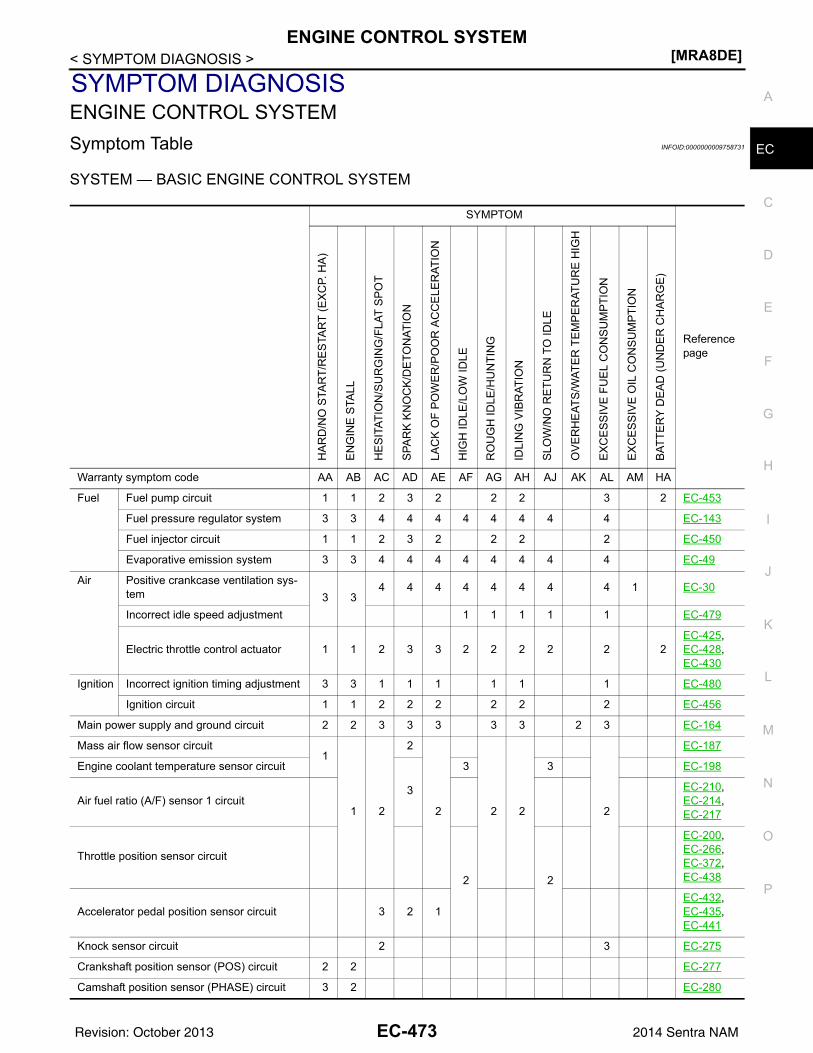
ENGINE CONTROL SYSTEM[MRA8DE]
C
D
E
F
G
H
I
J
K
L
M
A
C
N
P
O
< SYMPTOM DIAGNOSIS >
E
SYMPTOM DIAGNOSISENGINE CONTROL SYSTEMSymptom Table INFOID:0000000009758731
SYSTEM — BASIC ENGINE CONTROL SYSTEM
SYMPTOM
Reference page
HA
RD
/NO
STA
RT/
RE
STA
RT
(EX
CP.
HA
)
EN
GIN
E S
TALL
HE
SIT
ATIO
N/S
UR
GIN
G/F
LAT
SP
OT
SPA
RK
KN
OC
K/D
ETO
NAT
ION
LAC
K O
F P
OW
ER
/PO
OR
AC
CE
LER
ATIO
N
HIG
H ID
LE/L
OW
IDLE
RO
UG
H ID
LE/H
UN
TIN
G
IDLI
NG
VIB
RAT
ION
SLO
W/N
O R
ETU
RN
TO
IDLE
OV
ER
HE
ATS
/WAT
ER
TE
MP
ER
ATU
RE
HIG
H
EX
CE
SS
IVE
FU
EL
CO
NS
UM
PTIO
N
EX
CE
SS
IVE
OIL
CO
NS
UM
PTIO
N
BAT
TER
Y D
EA
D (U
ND
ER
CH
AR
GE
)
Warranty symptom code AA AB AC AD AE AF AG AH AJ AK AL AM HA
Fuel Fuel pump circuit 1 1 2 3 2 2 2 3 2 EC-453
Fuel pressure regulator system 3 3 4 4 4 4 4 4 4 4 EC-143
Fuel injector circuit 1 1 2 3 2 2 2 2 EC-450
Evaporative emission system 3 3 4 4 4 4 4 4 4 4 EC-49
Air Positive crankcase ventilation sys-tem 3 3
4 4 4 4 4 4 4 4 1 EC-30
Incorrect idle speed adjustment 1 1 1 1 1 EC-479
Electric throttle control actuator 1 1 2 3 3 2 2 2 2 2 2EC-425, EC-428, EC-430
Ignition Incorrect ignition timing adjustment 3 3 1 1 1 1 1 1 EC-480
Ignition circuit 1 1 2 2 2 2 2 2 EC-456
Main power supply and ground circuit 2 2 3 3 3 3 3 2 3 EC-164
Mass air flow sensor circuit1
1 2
2
2 2 2 2
EC-187
Engine coolant temperature sensor circuit
3
3 3 EC-198
Air fuel ratio (A/F) sensor 1 circuitEC-210, EC-214, EC-217
Throttle position sensor circuit
2 2
EC-200, EC-266, EC-372, EC-438
Accelerator pedal position sensor circuit 3 2 1EC-432, EC-435, EC-441
Knock sensor circuit 2 3 EC-275
Crankshaft position sensor (POS) circuit 2 2 EC-277
Camshaft position sensor (PHASE) circuit 3 2 EC-280
EC-473Revision: October 2013 2014 Sentra NAM
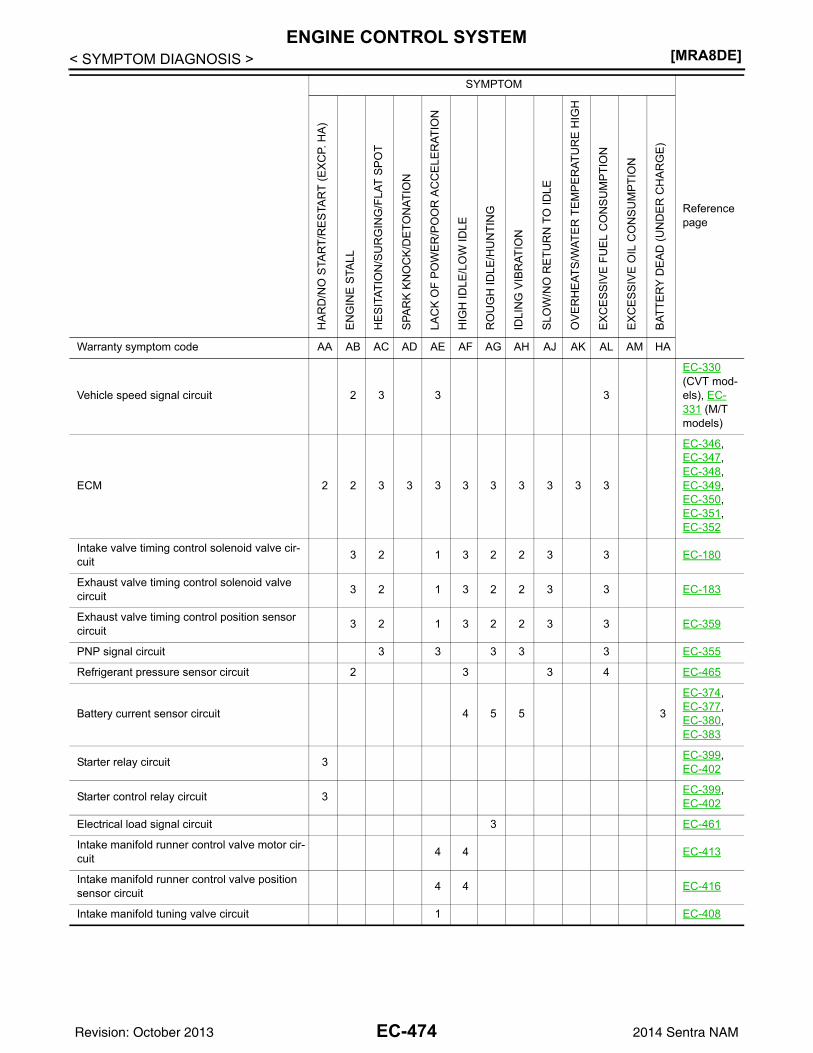
[MRA8DE]ENGINE CONTROL SYSTEM
< SYMPTOM DIAGNOSIS >
Vehicle speed signal circuit 2 3 3 3
EC-330 (CVT mod-els), EC-331 (M/T models)
ECM 2 2 3 3 3 3 3 3 3 3 3
EC-346, EC-347, EC-348, EC-349, EC-350, EC-351, EC-352
Intake valve timing control solenoid valve cir-cuit 3 2 1 3 2 2 3 3 EC-180
Exhaust valve timing control solenoid valve circuit 3 2 1 3 2 2 3 3 EC-183
Exhaust valve timing control position sensor circuit 3 2 1 3 2 2 3 3 EC-359
PNP signal circuit 3 3 3 3 3 EC-355
Refrigerant pressure sensor circuit 2 3 3 4 EC-465
Battery current sensor circuit 4 5 5 3
EC-374, EC-377, EC-380, EC-383
Starter relay circuit 3 EC-399, EC-402
Starter control relay circuit 3 EC-399, EC-402
Electrical load signal circuit 3 EC-461
Intake manifold runner control valve motor cir-cuit 4 4 EC-413
Intake manifold runner control valve position sensor circuit 4 4 EC-416
Intake manifold tuning valve circuit 1 EC-408
SYMPTOM
Reference page
HA
RD
/NO
STA
RT/
RE
STA
RT
(EX
CP.
HA
)
EN
GIN
E S
TALL
HE
SIT
ATIO
N/S
UR
GIN
G/F
LAT
SP
OT
SPA
RK
KN
OC
K/D
ETO
NAT
ION
LAC
K O
F P
OW
ER
/PO
OR
AC
CE
LER
ATIO
N
HIG
H ID
LE/L
OW
IDLE
RO
UG
H ID
LE/H
UN
TIN
G
IDLI
NG
VIB
RAT
ION
SLO
W/N
O R
ETU
RN
TO
IDLE
OV
ER
HE
ATS
/WAT
ER
TE
MP
ER
ATU
RE
HIG
H
EX
CE
SS
IVE
FU
EL
CO
NS
UM
PTIO
N
EX
CE
SS
IVE
OIL
CO
NS
UM
PTIO
N
BAT
TER
Y D
EA
D (U
ND
ER
CH
AR
GE
)
Warranty symptom code AA AB AC AD AE AF AG AH AJ AK AL AM HA
EC-474Revision: October 2013 2014 Sentra NAM
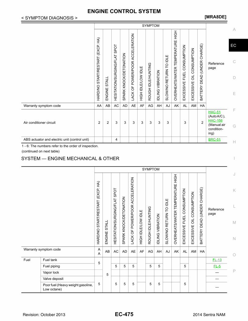
ENGINE CONTROL SYSTEM[MRA8DE]
C
D
E
F
G
H
I
J
K
L
M
A
C
N
P
O
< SYMPTOM DIAGNOSIS >
E
1 - 6: The numbers refer to the order of inspection.(continued on next table)
SYSTEM — ENGINE MECHANICAL & OTHER
Air conditioner circuit 2 2 3 3 3 3 3 3 3 3 2
HAC-51 (Auto A/C ), HAC-156 (Manual air condition-ing)
ABS actuator and electric unit (control unit) 4 BRC-51
SYMPTOM
Reference page
HA
RD
/NO
STA
RT/
RE
STA
RT
(EX
CP.
HA
)
EN
GIN
E S
TALL
HE
SIT
ATIO
N/S
UR
GIN
G/F
LAT
SP
OT
SPA
RK
KN
OC
K/D
ETO
NAT
ION
LAC
K O
F P
OW
ER
/PO
OR
AC
CE
LER
ATIO
N
HIG
H ID
LE/L
OW
IDLE
RO
UG
H ID
LE/H
UN
TIN
G
IDLI
NG
VIB
RAT
ION
SLO
W/N
O R
ETU
RN
TO
IDLE
OV
ER
HE
ATS
/WAT
ER
TE
MP
ER
ATU
RE
HIG
H
EX
CE
SS
IVE
FU
EL
CO
NS
UM
PTIO
N
EX
CE
SS
IVE
OIL
CO
NS
UM
PTIO
N
BAT
TER
Y D
EA
D (U
ND
ER
CH
AR
GE
)
Warranty symptom code AA AB AC AD AE AF AG AH AJ AK AL AM HA
Fuel Fuel tank5
5
FL-13
Fuel piping 5 5 5 5 5 5 FL-5
Vapor lock —
Valve deposit5 5 5 5 5 5 5
—
Poor fuel (Heavy weight gasoline, Low octane) —
EC-475Revision: October 2013 2014 Sentra NAM
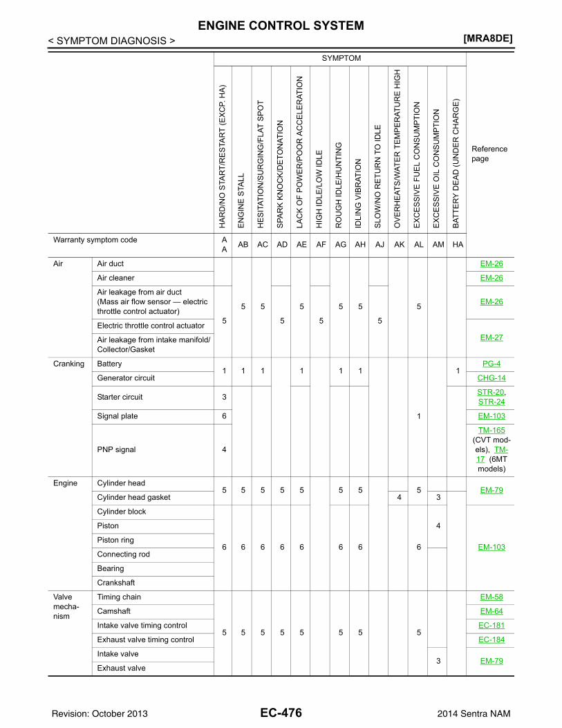
[MRA8DE]ENGINE CONTROL SYSTEM
< SYMPTOM DIAGNOSIS >
Air Air duct
5 5 5 5 5 5
EM-26
Air cleaner EM-26
Air leakage from air duct(Mass air flow sensor — electric throttle control actuator)
5 5 5 5
EM-26
Electric throttle control actuatorEM-27Air leakage from intake manifold/
Collector/Gasket
Cranking Battery1 1 1 1 1 1
1
1PG-4
Generator circuit CHG-14
Starter circuit 3 STR-20, STR-24
Signal plate 6 EM-103
PNP signal 4
TM-165 (CVT mod-els), TM-17 (6MT models)
Engine Cylinder head5 5 5 5 5 5 5 5 EM-79
Cylinder head gasket 4 3
Cylinder block
6 6 6 6 6 6 6 6
4
EM-103
Piston
Piston ring
Connecting rod
Bearing
Crankshaft
Valve mecha-nism
Timing chain
5 5 5 5 5 5 5 5
EM-58
Camshaft EM-64
Intake valve timing control EC-181
Exhaust valve timing control EC-184
Intake valve3 EM-79
Exhaust valve
SYMPTOM
Reference page
HA
RD
/NO
STA
RT/
RE
STA
RT
(EX
CP.
HA
)
EN
GIN
E S
TALL
HE
SIT
ATIO
N/S
UR
GIN
G/F
LAT
SP
OT
SPA
RK
KN
OC
K/D
ETO
NAT
ION
LAC
K O
F P
OW
ER
/PO
OR
AC
CE
LER
ATIO
N
HIG
H ID
LE/L
OW
IDLE
RO
UG
H ID
LE/H
UN
TIN
G
IDLI
NG
VIB
RAT
ION
SLO
W/N
O R
ETU
RN
TO
IDLE
OV
ER
HE
ATS
/WAT
ER
TE
MP
ER
ATU
RE
HIG
H
EX
CE
SS
IVE
FU
EL
CO
NS
UM
PTIO
N
EX
CE
SS
IVE
OIL
CO
NS
UM
PTIO
N
BAT
TER
Y D
EA
D (U
ND
ER
CH
AR
GE
)
Warranty symptom code AA AB AC AD AE AF AG AH AJ AK AL AM HA
EC-476Revision: October 2013 2014 Sentra NAM
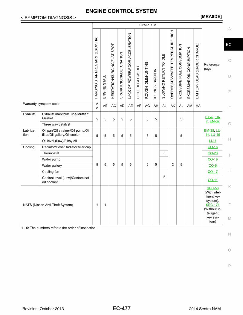
ENGINE CONTROL SYSTEM[MRA8DE]
C
D
E
F
G
H
I
J
K
L
M
A
C
N
P
O
< SYMPTOM DIAGNOSIS >
E
1 - 6: The numbers refer to the order of inspection.
Exhaust Exhaust manifold/Tube/Muffler/Gasket 5 5 5 5 5 5 5 5 EX-4, EX-
7, EM-32Three way catalyst
Lubrica-tion
Oil pan/Oil strainer/Oil pump/Oil filter/Oil gallery/Oil cooler 5 5 5 5 5 5 5 5
EM-35, LU-11, LU-16
Oil level (Low)/Filthy oil LU-7
Cooling Radiator/Hose/Radiator filler cap
5 5 5 5 5 5 5 2 5
CO-16
Thermostat 5 CO-23
Water pump CO-19
Water gallery CO-6
Cooling fan5
CO-17
Coolant level (Low)/Contaminat-ed coolant CO-11
NATS (Nissan Anti-Theft System) 1 1
SEC-58 (With intel-ligent key system), SEC-171
(Without in-telligent key sys-
tem)
SYMPTOM
Reference page
HA
RD
/NO
STA
RT/
RE
STA
RT
(EX
CP.
HA
)
EN
GIN
E S
TALL
HE
SIT
ATIO
N/S
UR
GIN
G/F
LAT
SP
OT
SPA
RK
KN
OC
K/D
ETO
NAT
ION
LAC
K O
F P
OW
ER
/PO
OR
AC
CE
LER
ATIO
N
HIG
H ID
LE/L
OW
IDLE
RO
UG
H ID
LE/H
UN
TIN
G
IDLI
NG
VIB
RAT
ION
SLO
W/N
O R
ETU
RN
TO
IDLE
OV
ER
HE
ATS
/WAT
ER
TE
MP
ER
ATU
RE
HIG
H
EX
CE
SS
IVE
FU
EL
CO
NS
UM
PTIO
N
EX
CE
SS
IVE
OIL
CO
NS
UM
PTIO
N
BAT
TER
Y D
EA
D (U
ND
ER
CH
AR
GE
)
Warranty symptom code AA AB AC AD AE AF AG AH AJ AK AL AM HA
EC-477Revision: October 2013 2014 Sentra NAM
[MRA8DE]NORMAL OPERATING CONDITION
< SYMPTOM DIAGNOSIS >NORMAL OPERATING CONDITIONDescription INFOID:0000000009758732
FUEL CUT CONTROL (AT NO LOAD AND HIGH ENGINE SPEED)If the engine speed is above 2,500 rpm under no load (for example, the selector lever position is neutral andengine speed is over 2,500 rpm) fuel will be cut off after some time. The exact time when the fuel is cut off var-ies based on engine speed.Fuel cut will be operated until the engine speed reaches 2,000 rpm, then fuel cut will be cancelled.NOTE:This function is different from deceleration control listed under Multiport Fuel Injection System, EC-35, "MUL-TIPORT FUEL INJECTION SYSTEM : System Description".
EC-478Revision: October 2013 2014 Sentra NAM
IDLE SPEED[MRA8DE]
C
D
E
F
G
H
I
J
K
L
M
A
C
N
P
O
< PERIODIC MAINTENANCE >
E
PERIODIC MAINTENANCEIDLE SPEEDInspection INFOID:0000000009758733
1.CHECK IDLE SPEED
With CONSULTCheck idle speed in “DATA MONITOR” mode of “ENGINE” using CONSULT.
With GSTCheck idle speed with Service $01 of GST.
>> INSPECTION END
Specification : EC-486, "Idle Speed"
Specification : EC-486, "Idle Speed"
EC-479Revision: October 2013 2014 Sentra NAM
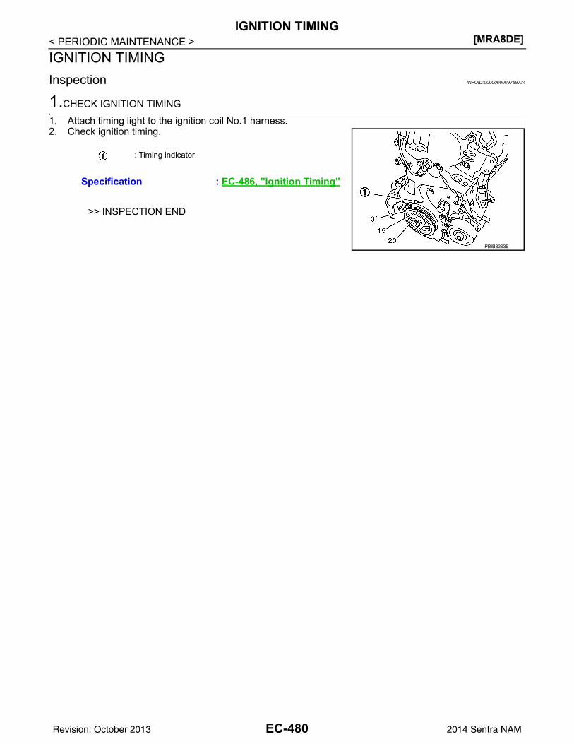
[MRA8DE]IGNITION TIMING
< PERIODIC MAINTENANCE >IGNITION TIMINGInspection INFOID:0000000009758734
1.CHECK IGNITION TIMING
1. Attach timing light to the ignition coil No.1 harness.2. Check ignition timing.
>> INSPECTION END
: Timing indicator
Specification : EC-486, "Ignition Timing"
PBIB3263E
EC-480Revision: October 2013 2014 Sentra NAM
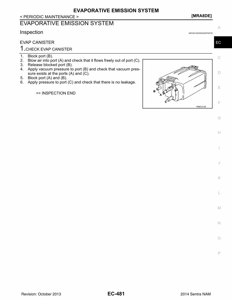
EVAPORATIVE EMISSION SYSTEM[MRA8DE]
C
D
E
F
G
H
I
J
K
L
M
A
C
N
P
O
< PERIODIC MAINTENANCE >
E
EVAPORATIVE EMISSION SYSTEMInspection INFOID:0000000009758735
EVAP CANISTER1.CHECK EVAP CANISTER
1. Block port (B).2. Blow air into port (A) and check that it flows freely out of port (C).3. Release blocked port (B).4. Apply vacuum pressure to port (B) and check that vacuum pres-
sure exists at the ports (A) and (C). 5. Block port (A) and (B).6. Apply pressure to port (C) and check that there is no leakage.
>> INSPECTION END
PBIB1212E
EC-481Revision: October 2013 2014 Sentra NAM
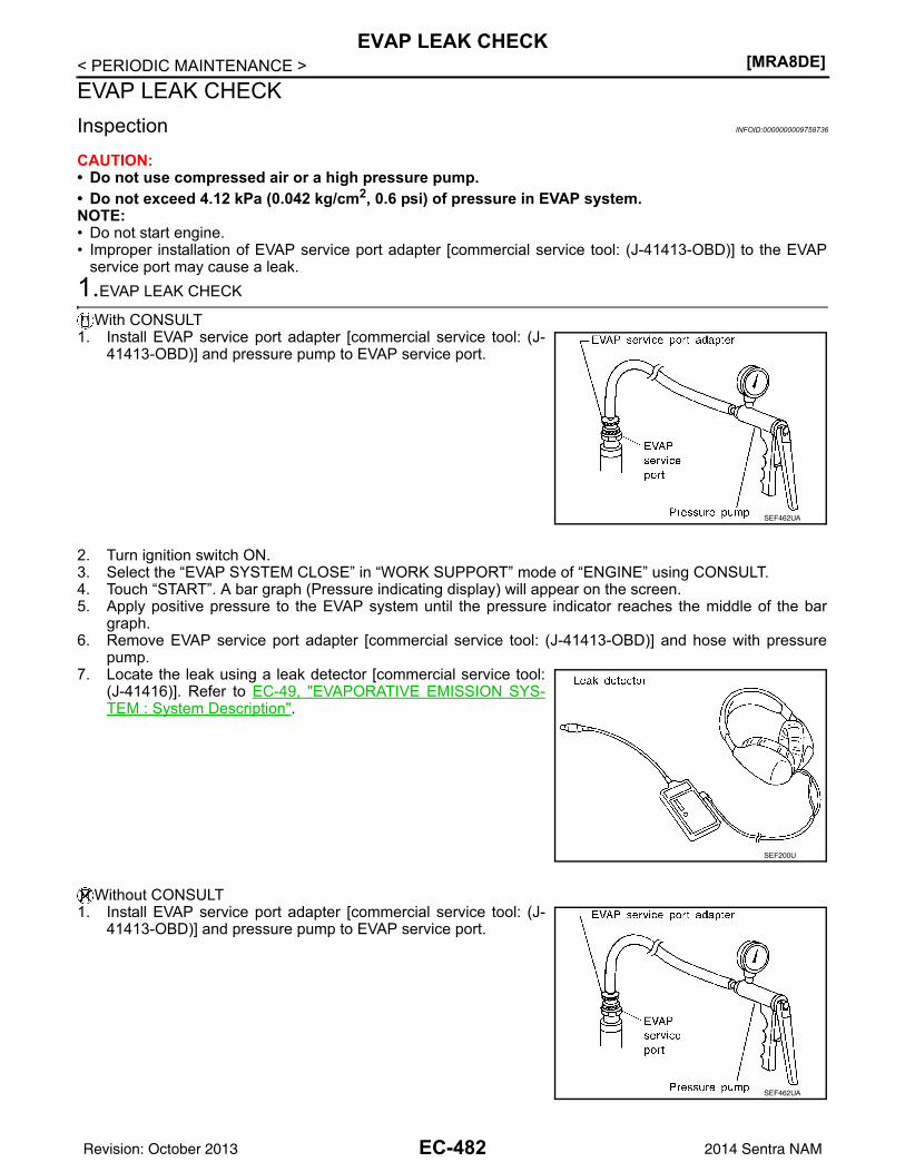
[MRA8DE]EVAP LEAK CHECK
< PERIODIC MAINTENANCE >EVAP LEAK CHECKInspection INFOID:0000000009758736
CAUTION:• Do not use compressed air or a high pressure pump.• Do not exceed 4.12 kPa (0.042 kg/cm2, 0.6 psi) of pressure in EVAP system.NOTE:• Do not start engine.• Improper installation of EVAP service port adapter [commercial service tool: (J-41413-OBD)] to the EVAP
service port may cause a leak.1.EVAP LEAK CHECK
With CONSULT1. Install EVAP service port adapter [commercial service tool: (J-
41413-OBD)] and pressure pump to EVAP service port.
2. Turn ignition switch ON.3. Select the “EVAP SYSTEM CLOSE” in “WORK SUPPORT” mode of “ENGINE” using CONSULT.4. Touch “START”. A bar graph (Pressure indicating display) will appear on the screen.5. Apply positive pressure to the EVAP system until the pressure indicator reaches the middle of the bar
graph.6. Remove EVAP service port adapter [commercial service tool: (J-41413-OBD)] and hose with pressure
pump.7. Locate the leak using a leak detector [commercial service tool:
(J-41416)]. Refer to EC-49, "EVAPORATIVE EMISSION SYS-TEM : System Description".
Without CONSULT1. Install EVAP service port adapter [commercial service tool: (J-
41413-OBD)] and pressure pump to EVAP service port.
SEF462UA
SEF200U
SEF462UA
EC-482Revision: October 2013 2014 Sentra NAM
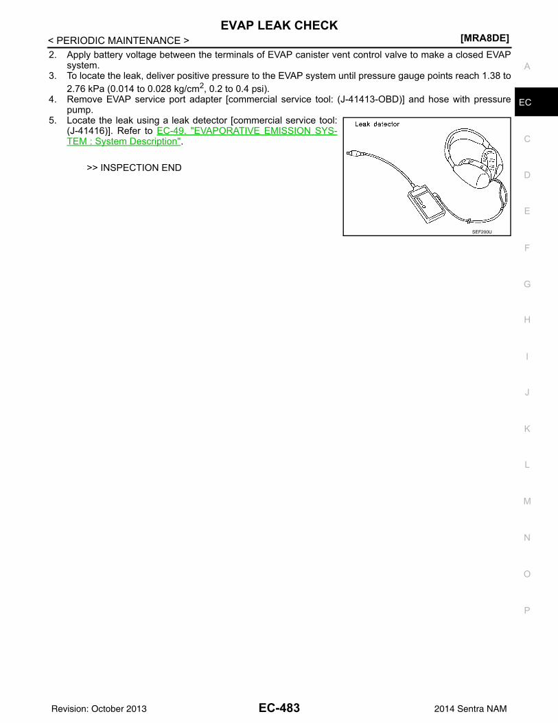
EVAP LEAK CHECK[MRA8DE]
C
D
E
F
G
H
I
J
K
L
M
A
C
N
P
O
< PERIODIC MAINTENANCE >
E
2. Apply battery voltage between the terminals of EVAP canister vent control valve to make a closed EVAPsystem.
3. To locate the leak, deliver positive pressure to the EVAP system until pressure gauge points reach 1.38 to2.76 kPa (0.014 to 0.028 kg/cm2, 0.2 to 0.4 psi).
4. Remove EVAP service port adapter [commercial service tool: (J-41413-OBD)] and hose with pressurepump.
5. Locate the leak using a leak detector [commercial service tool:(J-41416)]. Refer to EC-49, "EVAPORATIVE EMISSION SYS-TEM : System Description".
>> INSPECTION END
SEF200U
EC-483Revision: October 2013 2014 Sentra NAM
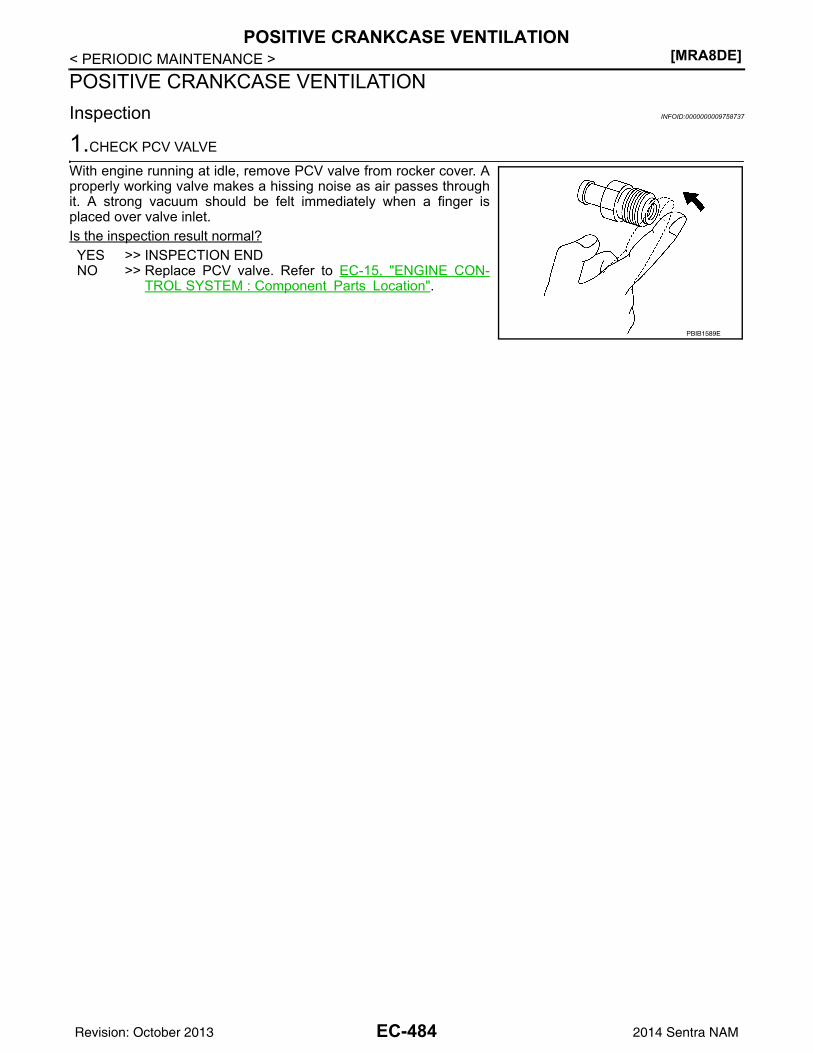
[MRA8DE]POSITIVE CRANKCASE VENTILATION
< PERIODIC MAINTENANCE >POSITIVE CRANKCASE VENTILATIONInspection INFOID:0000000009758737
1.CHECK PCV VALVE
With engine running at idle, remove PCV valve from rocker cover. Aproperly working valve makes a hissing noise as air passes throughit. A strong vacuum should be felt immediately when a finger isplaced over valve inlet.Is the inspection result normal?YES >> INSPECTION ENDNO >> Replace PCV valve. Refer to EC-15, "ENGINE CON-
TROL SYSTEM : Component Parts Location".
PBIB1589E
EC-484Revision: October 2013 2014 Sentra NAM
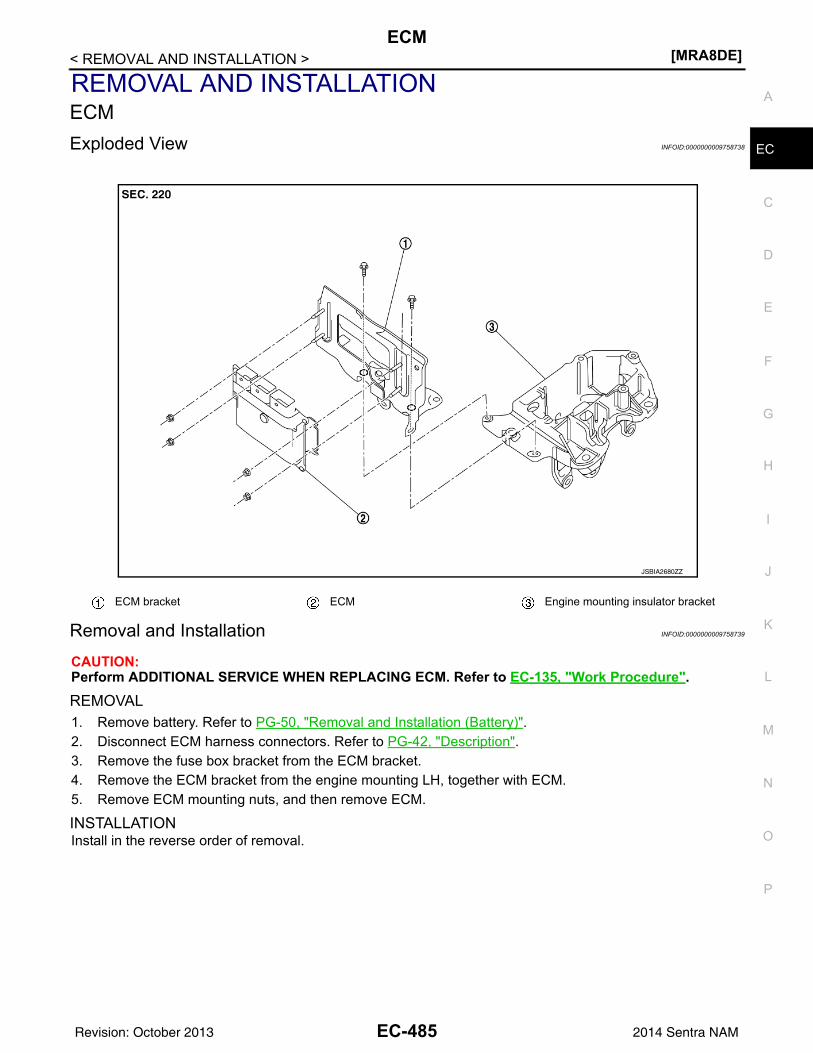
ECM[MRA8DE]
C
D
E
F
G
H
I
J
K
L
M
A
C
N
P
O
< REMOVAL AND INSTALLATION >
E
REMOVAL AND INSTALLATIONECMExploded View INFOID:0000000009758738
Removal and Installation INFOID:0000000009758739
CAUTION:Perform ADDITIONAL SERVICE WHEN REPLACING ECM. Refer to EC-135, "Work Procedure".
REMOVAL1. Remove battery. Refer to PG-50, "Removal and Installation (Battery)".2. Disconnect ECM harness connectors. Refer to PG-42, "Description".3. Remove the fuse box bracket from the ECM bracket.4. Remove the ECM bracket from the engine mounting LH, together with ECM.5. Remove ECM mounting nuts, and then remove ECM.
INSTALLATIONInstall in the reverse order of removal.
ECM bracket ECM Engine mounting insulator bracket
JSBIA2680ZZ
EC-485Revision: October 2013 2014 Sentra NAM
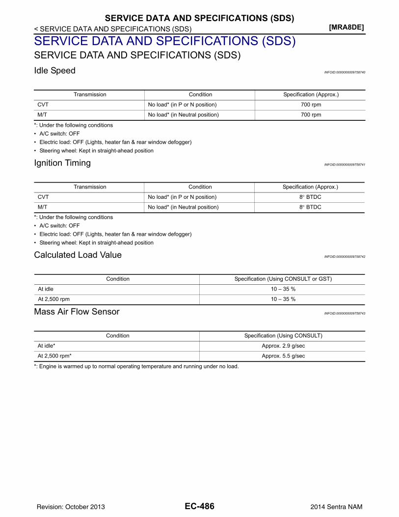
[MRA8DE]SERVICE DATA AND SPECIFICATIONS (SDS)
< SERVICE DATA AND SPECIFICATIONS (SDS)
SERVICE DATA AND SPECIFICATIONS (SDS)SERVICE DATA AND SPECIFICATIONS (SDS)Idle Speed INFOID:0000000009758740
*: Under the following conditions• A/C switch: OFF• Electric load: OFF (Lights, heater fan & rear window defogger)• Steering wheel: Kept in straight-ahead position
Ignition Timing INFOID:0000000009758741
*: Under the following conditions• A/C switch: OFF• Electric load: OFF (Lights, heater fan & rear window defogger)• Steering wheel: Kept in straight-ahead position
Calculated Load Value INFOID:0000000009758742
Mass Air Flow Sensor INFOID:0000000009758743
*: Engine is warmed up to normal operating temperature and running under no load.
Transmission Condition Specification (Approx.)
CVT No load* (in P or N position) 700 rpm
M/T No load* (in Neutral position) 700 rpm
Transmission Condition Specification (Approx.)
CVT No load* (in P or N position) 8° BTDC
M/T No load* (in Neutral position) 8° BTDC
Condition Specification (Using CONSULT or GST)
At idle 10 – 35 %
At 2,500 rpm 10 – 35 %
Condition Specification (Using CONSULT)
At idle* Approx. 2.9 g/sec
At 2,500 rpm* Approx. 5.5 g/sec
EC-486Revision: October 2013 2014 Sentra NAM


