Embed Size (px)
Citation preview

ENGLISH Document No. CSD-SMESAR3 Revision 01
CopyrightⓒSAMSUNG MEDISON Co., LTD.


SSaaffeettyy RReeqquuiirreemmeennttss
Classifications: - Type of protection against electrical shock: Class I - Degree of protection against electrical shock (Patient connection):Type BF equipment - Degree of protection against harmful ingress of water: Ordinary equipment - Degree of safety of application in the presence of a flammable anesthetic material with air or with oxygen or nitrous oxide: Equipment not suitable for use in the presence of a flammable anesthetic mixture with air or with oxygen or nitrous oxide.
- Mode of operation: Continuous operation
Electromechanical safety standards met: - IEC/EN 60601-1 Medical Electrical Equipment, Part 1General Requirements for Safety. - IEC/EN 60601-1-1 Safety requirements for medical electrical systems. - IEC/EN 60601-1-2 Electromagnetic compatibility -Requirements and tests. - IEC/EN 60601-2-37 Particular requirements for the safety of ultrasonic medical
diagnostic and monitoring equipment. - IEC 61157 Declaration of acoustic output parameters. - ISO 10993-1 Biological evaluation of medical devices. - UL 60601-1 Medical Electrical Equipment, Part 1 General Requirements for Safety. - CSA 22.2, 601.1 Medical Electrical Equipment, Part 1 General Requirements for Safety.

Declarations:
This is CSA symbol for Canada and United States of America
0123
This is manufacturer’s declaration of product compliance with applicable EEC directive(s) and the European notified body.
This is manufacturer’s declaration of product compliance with applicable EEC directive(s).
This is GMP symbol for Good Manufacturing Practice of Korea quality system regulation.
RREEAADD TTHHIISS FFIIRRSSTT
Before asking for the product to be repaired, read this service manual thoroughly, learn how to troubleshoot, and make sure you understand the precautions fully. The repair of the system and the replacement of parts must be carried out by an authorized dealer or the customer service department of SAMSUNG MEDISON Co., Ltd. The company is shall not be held liable for any injury and damage caused by not following this warning. For safe use of this product, you should read ‘Chapter 2. Safety’ in this manual, prior to starting to useing this system.
DDAANNGGEERR˙ ˙ ˙ ˙ ˙ ˙ Describes precautions necessary to prevent user hazards of great urgency. Ignoring a DANGER warning will risk life-threatening injury.
WWAARRNNIINNGG˙ ˙ ˙ ˙ ˙ ˙ ˙ Used to indicate the presence of a hazard that can cause serious personal injury, or substantial property damage.
CCAAUUTTIIOONN˙ ˙ ˙ ˙ ˙ ˙ ˙ Indicates the presence of a hazard that can cause equipment damage.
NNOOTTEE˙ ˙ ˙ ˙ A piece of information useful for installing, operating and maintaining a system. Not related to any hazard.
목차
Contents
Chapter 1. General Information
1.1 Overview ....................................................................................................... 1-1 1.2 Features and Advantages of SonoAce R3 .................................................. 1-2 1.3 Product Configuration .................................................................................... 1-3 1.3.1 Console ......................................................................................... 1-3 1.3.2 LCD Monitor ................................................................................. 1-4 1.3.3 Control Panel ................................................................................ 1-5 1.3.4 Probe ............................................................................................ 1-5 1.4 Specifications .................................................................................................. 1-6
Chapter 2. Safety
2.1 Overview ....................................................................................................... 2-1 2.2 Safety-Related Information ............................................................................ 2-2 2.2.1 Safety Symbols ............................................................................ 2-2 2.2.2 LABEL ........................................................................................... 2-3 2.3 Electrical Safety .............................................................................................. 2-4 2.3.1 Prevention Electric Shock ........................................................... 2-4 2.3.2 ESD ............................................................................................... 2-4 2.3.3 EMI ................................................................................................ 2-5 2.3.4 EMC .............................................................................................. 2-5 2.4 Mechanical Safety .......................................................................................... 2-11 2.4.1 Moving Equipment ....................................................................... 2-11 2.4.2 Safety Note ................................................................................... 2-11 2.5 Biological Safety ............................................................................................. 2-12 2.5.1 ALARA Principle .......................................................................... 2-12 2.6 Environmental Protection .............................................................................. 2-24
목차
Contents
Chapter 3. Installing the Product
3.1 Overview ....................................................................................................... 3-1 3.2 Transportation ................................................................................................ 3-3 3.2.1 Precautions for Transportation .................................................... 3-3 3.2.2 Temperature and Humidity ......................................................... 3-3 3.3 Unpacking ....................................................................................................... 3-4 3.3.1 Unpacking the Box ....................................................................... 3-4 3.3.2 Checking Package contents ....................................................... 3-5 3.4 Precautions for Installation ............................................................................ 3-6 3.4.1 Precautions ................................................................................... 3-6 3.5 Installations Procedure .................................................................................. 3-7 3.5.1 Installation Safety ......................................................................... 3-7 3.5.2 Connecting the Power Cord ........................................................ 3-8 3.5.3 Connecting the Network Cable ................................................... 3-9 3.5.4 Connecting the Probe .................................................................. 3-9 3.6 Starting the Product ....................................................................................... 3-10 3.7 Shutting down the Product ............................................................................ 3-11 3.8 Connecting the Peripherals ........................................................................... 3-12 3.8.1 External Peripherals .................................................................... 3-12 3.9 System Setting ............................................................................................... 3-14 3.9.1 General System Setup ................................................................ 3-14 3.9.2 Display Setup ............................................................................... 3-16 3.9.3 Misc ............................................................................................... 3-18 3.10 Measure Setting ............................................................................................. 3-19 3.10.1 General ......................................................................................... 3-19 3.10.2 Doppler ......................................................................................... 3-20 3.10.3 Report ........................................................................................... 3-21 3.10.4 OB ................................................................................................. 3-22 3.10.5 Fetal Echo .................................................................................... 3-25 3.10.6 Cardiac.......................................................................................... 3-26 3.10.7 Urology.......................................................................................... 3-26 3.10.8 Vascular ........................................................................................ 3-27 3.11 Setting DICOM ( Optional ) ............................................................................ 3-28 3.11.1 Setting DICOM Information ......................................................... 3-28 3.11.2 Network Setup .............................................................................. 3-29 3.11.3 Adding or Changing the DICOM Server .................................... 3-29 3.11.4 Editing the DICOM Server ........................................................... 3-32 3.11.5 Deleting DICOM Server ............................................................... 3-32
목차
3.11.6 Testing DICOM Server ................................................................ 3-32 3.11.7 DICOM Log .................................................................................. 3-32 3.12 Setting Option ................................................................................................. 3-34 3.13 Setting Peripheral Devices ............................................................................ 3-35 3.13.1 Video Out Type ............................................................................ 3-35 3.13.2 Foot Switch ................................................................................... 3-35 3.13.3 Printer 1 ........................................................................................ 3-35 3.13.4 Printer 2 ........................................................................................ 3-35 3.14 Information ...................................................................................................... 3-36
목차
Contents
Chapter 4. Checking the Product
4.1 Overview ..................................................................................................... 4-1 4.2 Starting the Product ....................................................................................... 4-2 4.3 Monitor ....................................................................................................... 4-3 4.3.1 Monitor Display ............................................................................ 4-3 4.4 Control Panel .................................................................................................. 4-5 4.4.1 Detail Control Panel ..................................................................... 4-6 4.4.2 Soft Menu ..................................................................................... 4-8 4.4.3 Keyboards .................................................................................... 4-9 4.5 Checking the Performance .......................................................................... 4-11 4.5.1 Basic Check ................................................................................. 4-11 4.5.2 Detail Check ................................................................................. 4-12
목차
Contents
제5장 제품 구조
5.1 개요 5-1 5.2 System Block Diagram .................................................................................. 5-3 5.3 EKO7의 기본 구조 ........................................................................................ 5-4 5.3.1 개요 ............................................................................................... 5-4 5.3.2 Ultrasound System Part .............................................................. 5-4 5.3.3 PC Part ......................................................................................... 5-5 5.3.4 User Interface Part ....................................................................... 5-5 5.3.5 AC to DC Power Module ............................................................. 5-5 5.4 PSA 5-6 5.5 Beamformer Board ......................................................................................... 5-8 5.6 CW Board 5-11 5.7 Back End Board ............................................................................................. 5-14 5.8 PCI Board 5-18 5.9 DVI Board 5-19 5.10 VGA Card 5-21 5.11 VCRIN Board .................................................................................................. 5-22 5.12 PC Mother Board ........................................................................................... 5-23 5.13 Software DSC ................................................................................................. 5-24 5.14 LCD IF Board .................................................................................................. 5-26 5.15 Rear Board ..................................................................................................... 5-27 5.16 Control Panel .................................................................................................. 5-28 5.17 Power Supply ................................................................................................. 5-30
목차
Contents
Chapter 6. Basic Maintenance
6.1 Overview ....................................................................................................... 6-1 6.2 System Information ........................................................................................ 6-2 6.3 Admin Mode ................................................................................................... 6-3 6.3.1 Entering Admin Mode .................................................................. 6-3 6.3.2 Admin Mode Functions................................................................ 6-4 6.4 Upgrade . .................................................................................................... 6-6 6.4.1 Software Upgrade ........................................................................ 6-6 6.4.2 Hardware Upgrade ...................................................................... 6-9 6.5 Backup & Restore .......................................................................................... 6-10 6.5.1 Backup User Setting .................................................................... 6-10 6.5.2 Restore User Setting ................................................................... 6-12 6.6 Adding and Deleting Options......................................................................... 6-14 6.6.1 Option type ................................................................................... 6-14 6.6.2 Registering Option ....................................................................... 6-14 6.7 Control Panel .................................................................................................. 6-16
목차
Contents
Chapter 7. Troubleshooting
7.1 Overview ....................................................................................................... 7-1 7.2 Power ....................................................................................................... 7-2 7.2.1 Power Failure ............................................................................... 7-2 7.2.2 Power cannot turned off .............................................................. 7-2 7.2.3 Power is automatically turned off ................................................ 7-2 7.3 Monitro ....................................................................................................... 7-3 7.3.1 Blank Screen ................................................................................ 7-3 7.3.2 Screen Color Abnomal ................................................................ 7-3 7.4 Error Messages .............................................................................................. 7-4 7.4.1 System hangs after an error during booting............................... 7-4 7.4.2 System works even if error occurred .......................................... 7-4 7.5 Image ....................................................................................................... 7-5 7.5.1 No BW Image Echo & No BW Mode Image Format ......................... 7-5 7.5.2 Noise Link Rain over the BW Mode Image (Noise) ........................... 7-5 7.5.3 PW & Color Doppler Mode Trouble ................................................... 7-5
목차
Contents
Chapter 8. Disassembly and Reassembly
8.1 Overview ....................................................................................................... 8-1 8.2 Disassembly and Reassembly of the Body Cover ...................................... 8-3 8.2.1 Preparations ................................................................................. 8-3 8.2.2 Body Rear & Middle Cover ......................................................... 8-3 8.2.3 Disassembly of the Main Part and LCD/Control Panel ............. 8-4 8.3 Disassembly and Reassembly of the Main System Part ............................ 8-5 8.3.1 Preparations ................................................................................. 8-5 8.3.2 Power & HDD & Side Fan ........................................................... 8-5 8.3.3 PSA & Rear & Rear Fan & Handle ............................................. 8-6 8.3.4 LCD & Inverter & USB Board ...................................................... 8-7 8.4 Disassembly and Reassembly of the Control Panel ................................... 8-8 8.4.1 Preparations ................................................................................. 8-8 8.4.2 Disassembly Control Panel and LCD ......................................... 8-8 8.4.3 Control Panel ................................................................................ 8-9
목차
Contents
Chapter 9. Probe
9.1 Overview ....................................................................................................... 9-1 9.2 Probe List ....................................................................................................... 9-2 9.3 Thermal Index (TI Table) ............................................................................... 9-5 9.4 Ultrasound Transmission Gel ........................................................................ 9-6 9.5 Sheaths ....................................................................................................... 9-7 9.6 Probe Precautions .......................................................................................... 9-9
Chapter 10. User Maintenance
10.1 Overview ....................................................................................................... 10-1 10.2 System Maintenance ..................................................................................... 10-2 10.2.1 Installation Maintenance .............................................................. 10-2 10.2.2 Cleaning and Disinfections .......................................................... 10-2 10.2.3 Fuse Replacement ...................................................................... 10-3 10.2.4 Accuracy Check ........................................................................... 10-4 10.3 Administration of Information ......................................................................... 10-5 10.3.1 User Setting Back-up ................................................................... 10-5 10.3.2 Patient Information Back-up ........................................................ 10-5 10.3.3 Software ........................................................................................ 10-5
Chapter 11. Service Part List
11.1 Overview ....................................................................................................... 11-1 11.2 Body Cover ..................................................................................................... 11-2 11.3 Ultrasound System Part ............................................................................... 11-4 11.4 LCD Part ....................................................................................................... 11-5 11.5 PC Part ....................................................................................................... 11-6 11.6 Power Part ...................................................................................................... 11-8 11.7 User Interface Part ......................................................................................... 11-9 11.8 ETC Part ................................................................................................. 11-10 11.9 Options ................................................................................................... 11-11 11.10 Probes ................................................................................................... 11-12
Chapter 1. General Information 1-1
CChhaapptteerr 11.. GGeenneerraall IInnffoorrmmaattiioonn
1.1 Overview
Chapter 1 contains the information necessary to plan the Troubleshooting of SonoAceR3. The SonoAceR3 is a high-resolution color ultrasound scanner with high penetration and a variety of measurement functions.
Contents
1.1 Overview ....................................................................................................1-1 1.2 Features and Advantages of SonoAceR3 ...............................................1-2 1.3 Product Configuration ...............................................................................1-3 1.3.1 Console ....................................................................................1-3 1.3.2 LCD Monitor ............................................................................1-4 1.3.3 Control Panel ...........................................................................1-5 1.3.4 Probes......................................................................................1-5 1.4 Specifications .............................................................................................1-6
Chapter 1. General Information 1-2
1.2 Features and Advantages of SonoAceR3
High-end Digital Beamforming : The SonoAceR3 utilizes the newly
developed Digital Beam forming technology. A variety of applications : The SonoAceR3 is optimized for use in a variety
of ultrasound departments, cardiac, vascular, abdomen, Obsterics, Urology, Gynecology.
Various diagnostic Modes : 2D Mode, M Mode, Color Doppler Mode, Power Doppler Mode, PW Spectral Doppler Mode, etc.
Measurement and Report Functions : Besides the basic distance, area, circumference and volume measurement functions, the SonoAceR3 also provides application-specific measurement functions. The report function collates measurement data.
Review of Scanned Images : The SonoAceR3 displays Cine images of 512 frames and loop images of 4096 lines.
SonoViewTM : This is a total ultrasound image management system, which allows a user to archive, view and exchange documents.
Digital Imaging and Communication in Medicine (DICOM) Function : This is used to archive, transmit and print DICOM images through a network.
Peripheral/Accessory Connection : A variety of peripheral devices including VCRs and printers can be easily connected to the SonoAceR3.
Chapter 1. General Information 1-3
1.3 Product Configuration
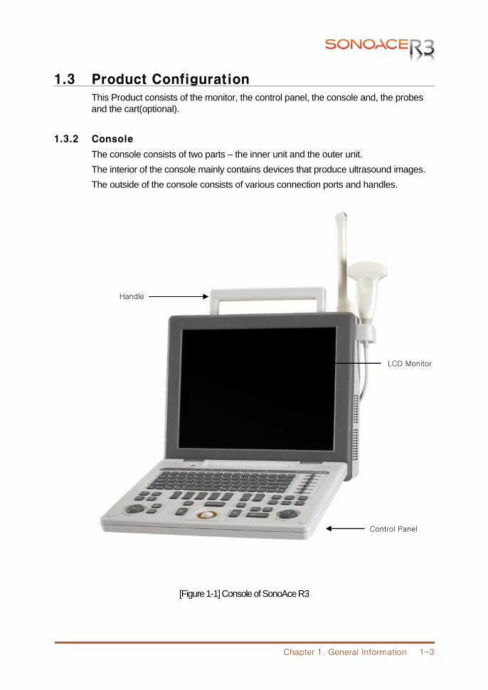
This Product consists of the monitor, the control panel, the console and, the probes and the cart(optional).
1.3.2 Console
The console consists of two parts – the inner unit and the outer unit. The interior of the console mainly contains devices that produce ultrasound images. The outside of the console consists of various connection ports and handles.
[Figure 1-1] Console of SonoAce R3
Handle
LCD Monitor
Control Panel
Chapter 1. General Information 1-4
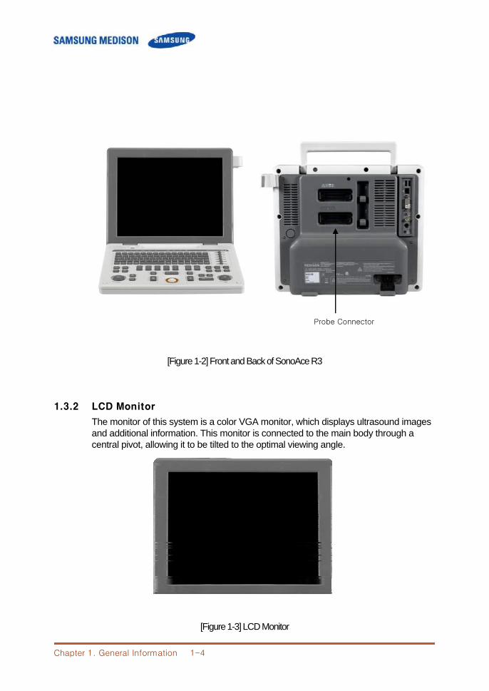
[Figure 1-2] Front and Back of SonoAce R3
1.3.2 LCD Monitor
The monitor of this system is a color VGA monitor, which displays ultrasound images and additional information. This monitor is connected to the main body through a central pivot, allowing it to be tilted to the optimal viewing angle.
[Figure 1-3] LCD Monitor
Probe Connector
Chapter 1. General Information 1-5
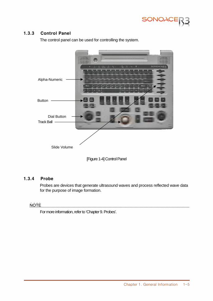
1.3.3 Control Panel
The control panel can be used for controlling the system.
[Figure 1-4] Control Panel
1.3.4 Probe
Probes are devices that generate ultrasound waves and process reflected wave data for the purpose of image formation.
NNOOTTEE˙ ˙ ˙ ˙ For more information, refer to ‘Chapter 9. Probes’.
Track Ball
Alpha-Numeric
Dial Button
Slide Volume
Button
Chapter 1. General Information 1-6
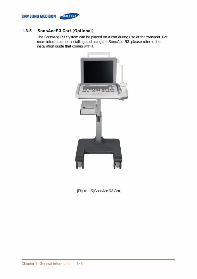
1.3.5 SonoAceR3 Cart (Optional)
The SonoAce R3 System can be placed on a cart during use or for transport. For more information on installing and using the SonoAce R3, please refer to the installation guide that comes with it.
[Figure 1-5] SonoAce R3 Cart
Chapter 1. General Information 1-7
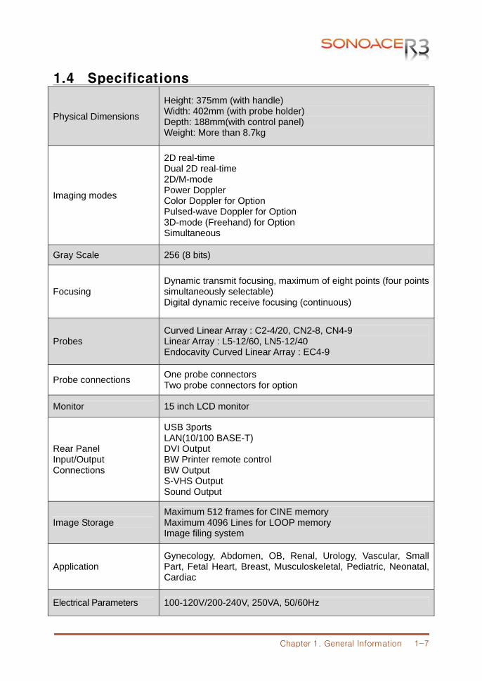
1.4 Specifications
Physical Dimensions
Height: 375mm (with handle) Width: 402mm (with probe holder) Depth: 188mm(with control panel) Weight: More than 8.7kg
Imaging modes
2D real-time Dual 2D real-time 2D/M-mode Power Doppler Color Doppler for Option Pulsed-wave Doppler for Option 3D-mode (Freehand) for Option Simultaneous
Gray Scale 256 (8 bits)
Focusing Dynamic transmit focusing, maximum of eight points (four points simultaneously selectable) Digital dynamic receive focusing (continuous)
Probes Curved Linear Array : C2-4/20, CN2-8, CN4-9 Linear Array : L5-12/60, LN5-12/40 Endocavity Curved Linear Array : EC4-9
Probe connections One probe connectors Two probe connectors for option
Monitor 15 inch LCD monitor
Rear Panel Input/Output Connections
USB 3ports LAN(10/100 BASE-T) DVI Output BW Printer remote control BW Output S-VHS Output Sound Output
Image Storage Maximum 512 frames for CINE memory Maximum 4096 Lines for LOOP memory Image filing system
Application Gynecology, Abdomen, OB, Renal, Urology, Vascular, Small Part, Fetal Heart, Breast, Musculoskeletal, Pediatric, Neonatal, Cardiac
Electrical Parameters 100-120V/200-240V, 250VA, 50/60Hz
Chapter 1. General Information 1-8
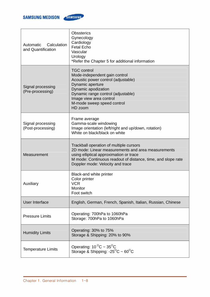
Automatic Calculation and Quantification
Obssterics Gynecology Cardiology Fetal Echo Vascular Urology *Refer the Chapter 5 for additional information
Signal processing (Pre-processing)
TGC control Mode-independent gain control Acoustic power control (adjustable) Dynamic aperture Dynamic apodization Dynamic range control (adjustable) Image view area control M-mode sweep speed control HD zoom
Signal processing (Post-processing)
Frame average Gamma-scale windowing Image orientation (left/right and up/down, rotation) White on black/black on white
Measurement
Trackball operation of multiple cursors 2D mode: Linear measurements and area measurements using elliptical approximation or trace M mode: Continuous readout of distance, time, and slope rate Doppler mode: Velocity and trace
Auxiliary
Black-and white printer Color printer VCR Monitor Foot switch
User Interface English, German, French, Spanish, Italian, Russian, Chinese
Pressure Limits Operating: 700hPa to 1060hPa Storage: 700hPa to 1060hPa
Humidity Limits Operating: 30% to 75% Storage & Shipping: 20% to 90%
Temperature Limits Operating: 10 OC ~ 35OC Storage & Shipping: -25OC ~ 60OC
Chapter 2. Safety 2-1
CChhaapptteerr 22.. SSaaffeettyy
2.1 Overview
Chapter 2 contains the information necessary to Safety Please read this chapter before using the SAMSUNG MEDISON ultrasound system. It is relevant to the ultrasound system, the probes, the recording devices, and any of the optional equipment. SonoAce R3 is intended for use by, or by the order of, and under the supervision of, a licensed physician who is qualified for direct use of the medical device.
Contents
2.1 Overview ....................................................................................................2-1 2.2 Safety – Related Information ....................................................................2-2 2.2.1 Safety Symbols .......................................................................2-2 2.2.2 LABEL ......................................................................................2-3 2.3 Electrical Safety .........................................................................................2-4 2.3.1 Prevention Electric Shock ......................................................2-4 2.3.2 ESD ..........................................................................................2-4 2.3.3 EMI ...........................................................................................2-5 2.3.4 EMC .........................................................................................2-5 2.4 Mechanical Safety ................................................................................... 2-11 2.4.1 Moving Equipment ................................................................ 2-11 2.4.2 Safety Note ............................................................................ 2-11 2.5 Biological Safety ..................................................................................... 2-12 2.5.1 ALARA Principle ................................................................... 2-12 2.6 Environmental Protection....................................................................... 2-24
Chapter 2. Safety 2-2
2.2 Safety – Related Information
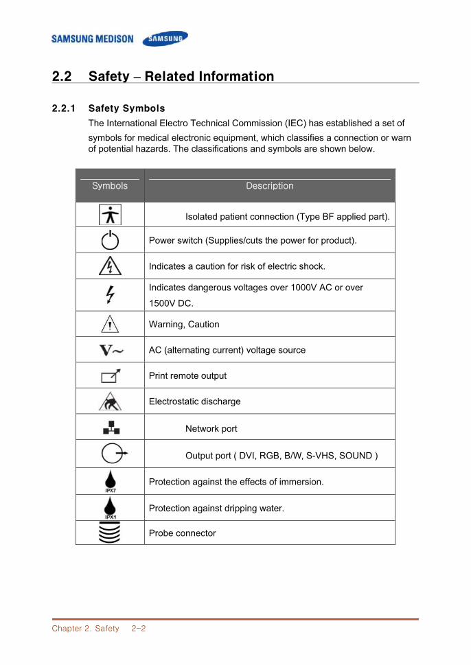
2.2.1 Safety Symbols
The International Electro Technical Commission (IEC) has established a set of symbols for medical electronic equipment, which classifies a connection or warn of potential hazards. The classifications and symbols are shown below.
Symbols Description
Isolated patient connection (Type BF applied part).
Power switch (Supplies/cuts the power for product).
Indicates a caution for risk of electric shock.
Indicates dangerous voltages over 1000V AC or over 1500V DC.
Warning, Caution
AC (alternating current) voltage source
Print remote output
Electrostatic discharge
Network port
Output port ( DVI, RGB, B/W, S-VHS, SOUND )
Protection against the effects of immersion.
Protection against dripping water.
Probe connector
Chapter 2. Safety 2-3
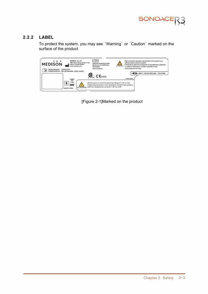
2.2.2 LABEL
To protect the system, you may see ‘Warning’ or ‘Caution’ marked on the surface of the product
[Figure 2-1]Marked on the product
Chapter 2. Safety 2-4
2.3 Electrical Safety
This equipment has been verified as a Class I device with Type BF applied parts.
2.3.1 Prevention of Electric Shock
Additional equipment connected to medical electrical equipment must comply with the respective IEC or ISO standards (e.g. IEC 60950 for data processing equipment). Furthermore all configurations shall comply with the requirements for medical electrical systems (see IEC 60601-1-1 or clause 16 of the 3 Ed. of IEC 60601-1, respectively). Anybody connecting additional equipment to medical electrical equipment configures a medical system and is therefore responsible that the system complies with the requirements for medical electrical systems. Attention is drawn to the fact that local laws take priority over the abovementioned requirements. If in doubt, consult your local representative or the technical service department.
WWAARRNNIINNGG˙ ˙ ˙ ˙ ˙ ˙ ˙ Electric shock may exist result if this system, including and all of its externally mounted
recording and monitoring devices, is not properly grounded. Do not remove the covers on the system; hazardous voltages are present inside. Cabinet
panels must be in place while the system is in use. All internal adjustments and replacements must be made by a qualified SAMSUNG MEDISON Customer Service Department.
Check the face, housing, and cable before use. Do not use, if the face is cracked, chipped, or torn, the housing is damaged, or if the cable is abraded.
Always disconnect the system from the wall outlet prior to cleaning the system. All patient contact devices, such as probes and ECG leads, must be removed from the patient
prior to application of a high voltage defibrillation pulse. The use of flammable anesthetic gas or oxidizing gases (N20) should be avoided.
CCAAUUTTIIOONN˙ ˙ ˙ ˙ ˙ ˙ ˙ The system has been designed for 100-120VAC and 200-240VAC; you should select the
inputOutlet voltage of monitor, printer and VCR. Prior to connecting an OEM power cord, verify that the voltage indicated on the power cord matches the voltage rating of the OEM device.
An isolation transformer protects the system from power surges. The isolation transformer continues to operate when the system is in standby.
Do not immerse the cable in liquids. Cables are not waterproof. The operator does not contact the parts (SIP/SOP) and the patient simultaneously.
Chapter 2. Safety 2-5
2.3.2 ESD
Electrostatic discharge (ESD), commonly referred to as a static shock, is a naturally occurring phenomenon. ESD is most prevalent during conditions of low humidity, which can be caused by heating or air conditioning. During low humidity conditions, electrical charges naturally build up on individuals, creating static electricity. An ESD occurs when an individual with an electrical energy build-up comes in contact with conductive objects such as metal doorknobs, file cabinets, computer equipment, and even other individuals. The static shock or ESD is a discharge of the electrical energy build-up from a charged individual to a lesser or non-charged individual or object.
CCAAUUTTIIOONN ˙ ˙ ˙ ˙ ˙ ˙ ˙
The level of electrical energy discharged from a system user or patient to an ultrasound system can be significant enough to cause damage to the system or probes.
Always perform the pre-ESD preventive procedures before using connectors marked with the ESD warning label.
- Apply anti-static spray on carpets or linoleum. - Use anti-static mats. - Ground the product to the patient table or bed.
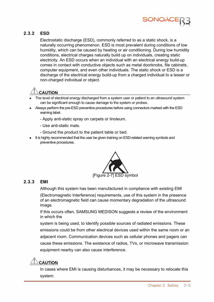
It is highly recommended that the user be given training on ESD-related warning symbols and preventive procedures.
[Figure 2-7] ESD symbol 2.3.3 EMI
Although this system has been manufactured in compliance with existing EMI (Electromagnetic Interference) requirements, use of this system in the presence of an electromagnetic field can cause momentary degradation of the ultrasound image. If this occurs often, SAMSUNG MEDISON suggests a review of the environment in which the system is being used, to identify possible sources of radiated emissions. These emissions could be from other electrical devices used within the same room or an adjacent room. Communication devices such as cellular phones and pagers can cause these emissions. The existence of radios, TVs, or microwave transmission equipment nearby can also cause interference.
CCAAUUTTIIOONN˙ ˙ ˙ ˙ ˙ ˙ ˙ In cases where EMI is causing disturbances, it may be necessary to relocate this system.
Chapter 2. Safety 2-6
2.3.4 EMC
The testing for EMC(Electromagnetic Compatibility) of this system has been performed according to the international standard for EMC with medical devices (IEC60601-1-2). This IEC standard was adopted in Europe as the European norm (EN60601-1-2).
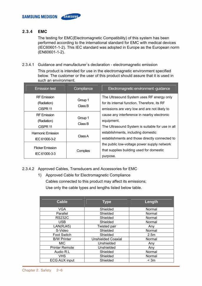
2.3.4.1 Guidance and manufacturer’s declaration - electromagnetic emission This product is intended for use in the electromagnetic environment specified below. The customer or the user of this product should assure that it is used in such an environment.
Emission test Compliance Electromagnetic environment -guidance
RF Emission
(Radiation)
CISPR 11
Group 1
Class B
The Ultrasound System uses RF energy only
for its internal function. Therefore, its RF
emissions are very low and are not likely to
cause any interference in nearby electronic
equipment.
The Ultrasound System is suitable for use in all
establishments, including domestic
establishments and those directly connected to
the public low-voltage power supply network
that supplies building used for domestic
purpose.
RF Emission
(Radiation)
CISPR 11
Group 1
Class B
Harmonic Emission
IEC 61000-3-2 Class A
Flicker Emission
IEC 61000-3-3 Complies
2.3.4.2 Approved Cables, Transducers and Accessories for EMC 1) Approved Cable for Electromagnetic Compliance
Cables connected to this product may affect its emissions; Use only the cable types and lengths listed below table.
Cable Type Length
VGA Shielded Normal Parallel Shielded Normal RS232C Shielded Normal
USB Shielded Normal LAN(RJ45) Twisted pair Any
S-Video Shielded Normal Foot Switch Shielded 2.5m B/W Printer Unshielded Coaxial Normal
MIC Unshielded Any Printer Remote Unshielded Any
Audio R.L Shielded Normal VHS Shielded Normal
ECG AUX input Shielded < 3m
Chapter 2. Safety 2-7
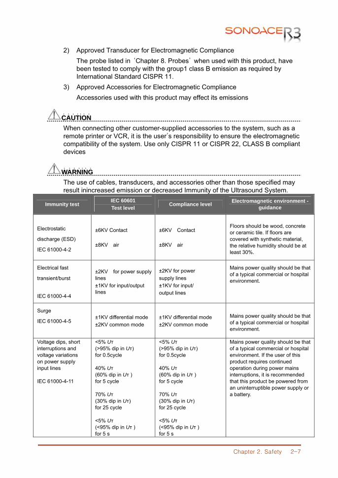
2) Approved Transducer for Electromagnetic Compliance The probe listed in ‘Chapter 8. Probes’ when used with this product, have been tested to comply with the group1 class B emission as required by International Standard CISPR 11.
3) Approved Accessories for Electromagnetic Compliance Accessories used with this product may effect its emissions
CCAAUUTTIIOONN˙ ˙ ˙ ˙ ˙ ˙ ˙ When connecting other customer-supplied accessories to the system, such as a remote printer or VCR, it is the user’s responsibility to ensure the electromagnetic compatibility of the system. Use only CISPR 11 or CISPR 22, CLASS B compliant devices
WWAARRNNIINNGG˙ ˙ ˙ ˙ ˙ ˙ ˙ The use of cables, transducers, and accessories other than those specified may result inincreased emission or decreased Immunity of the Ultrasound System.
Immunity test IEC 60601 Test level
Compliance level Electromagnetic environment -guidance
Electrostatic
discharge (ESD)
IEC 61000-4-2
±6KV Contact ±8KV air
±6KV Contact ±8KV air
Floors should be wood, concrete or ceramic tile. If floors are covered with synthetic material, the relative humidity should be at least 30%.
Electrical fast
transient/burst
IEC 61000-4-4
±2KV for power supply lines ±1KV for input/output lines
±2KV for power supply lines ±1KV for input/ output lines
Mains power quality should be that of a typical commercial or hospital environment.
Surge
IEC 61000-4-5 ±1KV differential mode ±2KV common mode
±1KV differential mode ±2KV common mode
Mains power quality should be that of a typical commercial or hospital environment.
Voltage dips, short interruptions and voltage variations on power supply input lines IEC 61000-4-11
<5% Uт (>95% dip in Uт) for 0.5cycle 40% Uт (60% dip in Uт ) for 5 cycle 70% Uт (30% dip in Uт) for 25 cycle <5% Uт (<95% dip in Uт ) for 5 s
<5% Uт (>95% dip in Uт) for 0.5cycle 40% Uт (60% dip in Uт ) for 5 cycle 70% Uт (30% dip in Uт) for 25 cycle <5% Uт (<95% dip in Uт ) for 5 s
Mains power quality should be that of a typical commercial or hospital environment. If the user of this product requires continued operation during power mains interruptions, it is recommended that this product be powered from an uninterruptible power supply or a battery.
Chapter 2. Safety 2-8
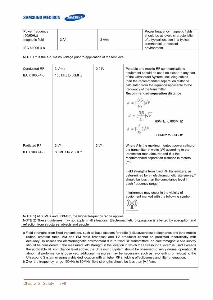
Power frequency (50/60Hz) magnetic field IEC 61000-4-8
3 A/m 3 A/m
Power frequency magnetic fields should be at levels characteristic of a typical location in a typical commercial or hospital environment.
NOTE Uт is the a.c. mains voltage prior to application of the test level.
Conducted RF
IEC 61000-4-6
3 Vrms
150 kHz to 80MHz
0.01V Portable and mobile RF communications equipment should be used no closer to any part of the Ultrasound System, including cables, than the recommended separation distance calculated from the equation applicable to the frequency of the transmitter. Recommended separation distance
80MHz to 800MHZ
800MHz to 2.5GHz
Radiated RF
IEC 61000-4-3
3 V/m
80 MHz to 2.5GHz
3 V/m
Where P is the maximum output power rating of the transmitter in watts (W) according to the transmitter manufacturer and d is the recommended separation distance in meters (m). Field strengths from fixed RF transmitters, as deter-mined by an electromagnetic site survey, a should be less than the compliance level in each frequency range. b Interference may occur in the vicinity of equipment marked with the following symbol :
NOTE 1) At 80MHz and 800MHz, the higher frequency range applies. NOTE 2) These guidelines may not apply in all situations. Electromagnetic propagation is affected by absorption and reflection from structures, objects and people.
a Field strengths from fixed transmitters, such as base stations for radio (cellular/cordless) telephones and land mobile radios, amateur radio, AM and FM radio broadcast and TV broadcast cannot be predicted theoretically with accuracy. To assess the electromagnetic environment due to fixed RF transmitters, an electromagnetic site survey should be considered. If the measured field strength in the location in which the Ultrasound System is used exceeds the applicable RF compliance level above, the Ultrasound System should be observed to verify normal operation. If abnormal performance is observed, additional measures may be necessary, such as re-orienting or relocating the Ultrasound System or using a shielded location with a higher RF shielding effectiveness and filter attenuation.
b Over the frequency range 150kHz to 80MHz, field strengths should be less than [V1] V/m.
Chapter 2. Safety 2-9
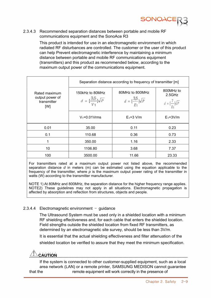
2.3.4.3 Recommended separation distances between portable and mobile RF communications equipment and the SonoAce R3
This product is intended for use in an electromagnetic environment in which radiated RF disturbances are controlled. The customer or the user of this product can help Prevent electromagnetic interference by maintaining a minimum distance between portable and mobile RF communications equipment (transmitters) and this product as recommended below, according to the maximum output power of the communications equipment.
Rated maximum output power of
transmitter [W]
Separation distance according to frequency of transmitter [m]
150kHz to 80MHz
80MHz to 800MHz
800MHz to 2.5GHz
V1=0.01Vrms E1=3 V/m E1=3V/m
0.01 35.00 0.11 0.23
0.1 110.68 0.36 0.73
1 350.00 1.16 2.33
10 1106.80 3.68 7.37
100 3500.00 11.66 23.33
For transmitters rated at a maximum output power not listed above, the recommended separation distance d in meters (m) can be estimated using the equation applicable to the frequency of the transmitter, where p is the maximum output power rating of the transmitter in watts (W) according to the transmitter manufacturer. NOTE 1) At 80MHz and 800MHz, the separation distance for the higher frequency range applies. NOTE2) These guidelines may not apply in all situations. Electromagnetic propagation is affected by absorption and reflection from structures, objects and people.
2.3.4.4 Electromagnetic environment – guidance
The Ultrasound System must be used only in a shielded location with a minimum RF shielding effectiveness and, for each cable that enters the shielded location. Field strengths outside the shielded location from fixed RF transmitters, as determined by an electromagnetic site survey, should be less than 3V/m. It is essential that the actual shielding effectiveness and filter attenuation of the shielded location be verified to assure that they meet the minimum specification.
CCAAUUTTIIOONN˙ ˙ ˙ ˙ ˙ ˙ ˙ If the system is connected to other customer-supplied equipment, such as a local area network (LAN) or a remote printer, SAMSUNG MEDISON cannot guarantee that the remote equipment will work correctly in the presence of

Chapter 2. Safety 2-10
electromagnetic phenomena.
Chapter 2. Safety 2-11
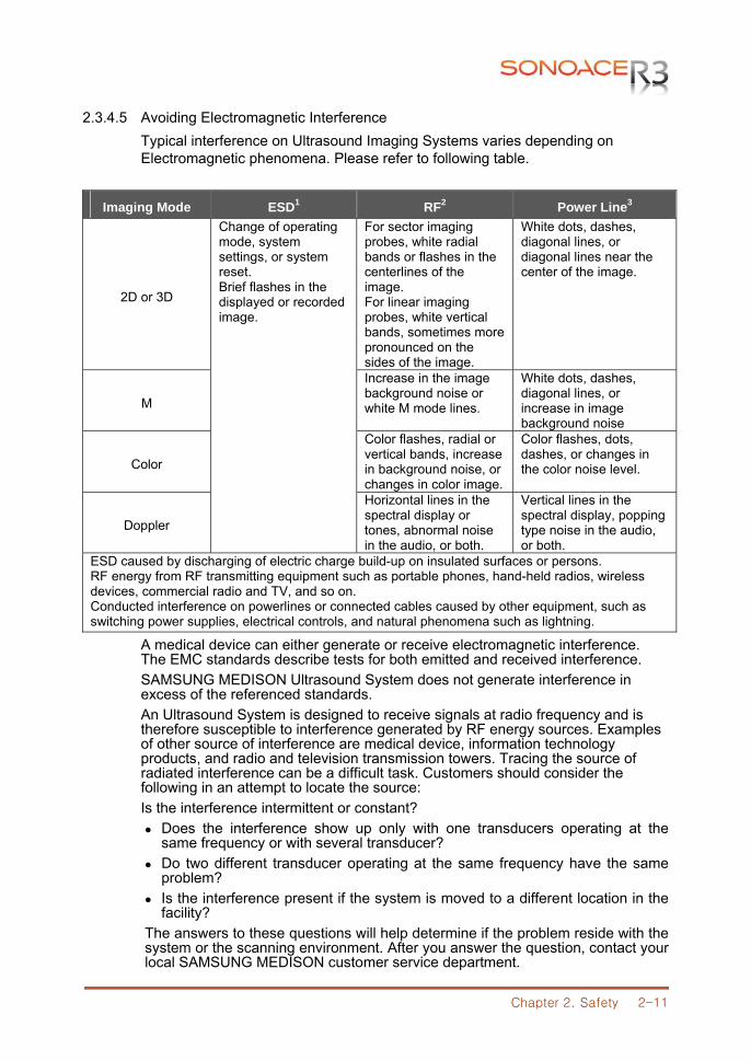
2.3.4.5 Avoiding Electromagnetic Interference Typical interference on Ultrasound Imaging Systems varies depending on Electromagnetic phenomena. Please refer to following table.
Imaging Mode ESD1 RF2 Power Line3
2D or 3D
Change of operating mode, system settings, or system reset. Brief flashes in the displayed or recorded image.
For sector imaging probes, white radial bands or flashes in the centerlines of the image. For linear imaging probes, white vertical bands, sometimes more pronounced on the sides of the image.
White dots, dashes, diagonal lines, or diagonal lines near the center of the image.
M
Increase in the image background noise or white M mode lines.
White dots, dashes, diagonal lines, or increase in image background noise
Color
Color flashes, radial or vertical bands, increase in background noise, or changes in color image.
Color flashes, dots, dashes, or changes in the color noise level.
Doppler
Horizontal lines in the spectral display or tones, abnormal noise in the audio, or both.
Vertical lines in the spectral display, popping type noise in the audio, or both.
ESD caused by discharging of electric charge build-up on insulated surfaces or persons. RF energy from RF transmitting equipment such as portable phones, hand-held radios, wireless devices, commercial radio and TV, and so on. Conducted interference on powerlines or connected cables caused by other equipment, such as switching power supplies, electrical controls, and natural phenomena such as lightning.
A medical device can either generate or receive electromagnetic interference. The EMC standards describe tests for both emitted and received interference. SAMSUNG MEDISON Ultrasound System does not generate interference in excess of the referenced standards. An Ultrasound System is designed to receive signals at radio frequency and is therefore susceptible to interference generated by RF energy sources. Examples of other source of interference are medical device, information technology products, and radio and television transmission towers. Tracing the source of radiated interference can be a difficult task. Customers should consider the following in an attempt to locate the source: Is the interference intermittent or constant?
Does the interference show up only with one transducers operating at the same frequency or with several transducer?
Do two different transducer operating at the same frequency have the same problem?
Is the interference present if the system is moved to a different location in the facility?
The answers to these questions will help determine if the problem reside with the system or the scanning environment. After you answer the question, contact your local SAMSUNG MEDISON customer service department.

Chapter 2. Safety 2-12
2.4 Mechanical Safety
2.4.1 Moving the Equipment
CCAAUUTTIIOONN ˙ ˙ ˙ ˙ ˙ ˙ ˙ Always turn the power off and disconnect the cables before moving the product.
NNOOTTEE ˙ ˙ ˙ ˙ Use the handle on the product, and move the product slowly. You can also move
the product by using the SonoAce R3 Cart (Optional).
2.4.2 Safety Note
CCAAUUTTIIOONN˙ ˙ ˙ ˙ ˙ ˙ ˙ Do not press the control panel excessively. Never attempt to modify the product in any way. Check the operational safety when using the product after a prolonged break in service. Make sure that other objects, such as metal pieces, do not enter the system. Do not block the ventilation slots. To prevent damage to the power cord, be sure to grip the plug head – not the cord –when
unplugging. Excessive bending or twisting of cables on patient-applied parts may cause failure or
intermittent operation of the system. Incorrect cleaning or sterilization of a patient-applied part may cause permanent damage.
Please refer to “Chapter 8. Maintenance” for detailed information on protecting, cleaning and disinfecting the equipment.
Chapter 2. Safety 2-13
2.5 Biological Safety
Verify the alignment of the Probe before use. See the “Chapter 9. Probes” section of this manual.
WWAARRNNIINNGG˙ ˙ ˙ ˙ ˙ ˙ ˙ Ultrasound waves may have damaging effects on cells and, therefore, may be
harmful to the patient. If there is no medical benefit, minimize the exposure time and maintain the ultrasound wave output level at low. Please refer to the ALARA principle.
Do not use the system if an error message appears on the video display indicating that a hazardous condition exists. Note the error code, turn off the power to the system, and call your local SAMSUNG MEDISON Customer Service Department.
Do not use a system that exhibits erratic or inconsistent updating. Discontinuities in the scanning sequence are indicative of a hardware failure that should be corrected before use.
The system limits the maximum contact temperature to 43 degree Celsius, and the ultrasonic waves output observes American FDA regulations.
2.5.1 ALARA Principle
Guidance for the use of diagnostic ultrasound is defined by the “as low as reasonably achievable” (ALARA) principle. The decision as to what is reasonable has been left to the judgment and insight of qualified personnel. No set of rules can be formulated that would be sufficiently complete to dictate the correct response for every circumstance. By keeping ultrasound exposure as low as possible, while obtaining diagnostic images, users can minimize ultrasonic bio effects. Since the threshold for diagnostic ultrasound bio effects is undetermined, it is the sonographer’s responsibility to control the total energy transmitted into the patient. The sonographer must reconcile exposure time with diagnostic image quality. To ensure diagnostic image quality and limit exposure time, the ultrasound system provides controls that can be manipulated during the exam to optimize the results of the exam. The ability of the user to abide by the ALARA principle is important. Advances in diagnostic ultrasound not only in the technology but also in the applications of the technology, have resulted in the need for more and better information to guide the user. The output indices are designed to provide that important information There are a number of variables, which affect the way in which the output display indices can be used to implement the ALARA principle. These variables include mass, body size, location of the bone relative to the focal point, attenuation in the body, and ultrasound exposure time. Exposure time is an especially useful variable, because the user controls it. The ability to limit the index values over time support the ALARA principle..
Chapter 2. Safety 2-14
2.5.1.1 Applying ALARA The system-imaging mode used depends upon the information needed. 2D-mode and M-mode imaging provide anatomical information, while Doppler, Power, and Color imaging provide information about blood flow. Scanned modes, like 2D-mode, Power, or Color, disperse or scatter the ultrasonic energy over an area, while an unscanned mode, like M-mode or Doppler, concentrates ultrasonic energy. Understanding the nature of the imaging mode being used allows the sonographer to apply the ALARA principle with informed judgment. The probe frequency, system set-up values, scanning techniques, and operator experience aid the sonographer in meeting the definition of the ALARA principle. The decision as to the amount of acoustic output is, in the final analysis, up to the system operator. This decision must be based on the following factors: type of patient, type of exam, patient history, ease or difficulty of obtaining diagnostically useful information, and the potential localized heating of the patient due to probe surface temperatures. Prudent use of the system occurs when patient exposure is limited to the lowest index reading for the shortest amount of time necessary to achieve acceptable diagnostic results. Although a high index reading does not mean that a bioeffect is actually occurring, a high index reading should be taken seriously. Every effort should be made to reduce the possible effects of a high index reading. Limiting exposure time is an effective way to accomplish this goal. There are several system controls that the operator can use to adjust the image quality and limit the acoustic intensity. These controls are related to the techniques that an operator might use to implement ALARA. These controls can be divided into three categories: direct, indirect, and receiver control.
2.5.1.2 Direct Controls Application selection and the output intensity control directly affect acoustic intensity. There are different ranges of allowable intensity or output based on your selection. Selecting the correct range of acoustic intensity for the application is one of the first things required during any exam. For example, peripheral vascular intensity levels are not recommended for fetal exams. Some systems automatically select the proper range for a particular procedure, while others require manual selection. Ultimately, the user bears the responsibility for proper clinical use. The SAMSUNG MEDISON system provides both automatic and user-definable settings. Output has direct impact on acoustic intensity. Once the application has been established, the output control can be used to increase or decrease the intensity output. The output control allows you to select intensity levels less than the defined maximum. Prudent use dictates that you select the lowest output intensity consistent with good image quality.
Chapter 2. Safety 2-15
2.5.1.3 Indirect Controls The indirect controls are those that have an indirect effect on acoustic intensity. These controls affect imaging mode, pulse repetition frequency, focus depth, pulse length, and probe selection. The choice of imaging mode determines the nature of the ultrasound beam. 2D-mode is a scanning mode, Doppler is a stationary or unscanned mode. A stationary ultrasound beam concentrates energy on a single location. A moving or scanned ultrasound beam disperses the energy over a wide area and the beam is only concentrated on a given area for a fraction of the time necessary in unscanned mode. Pulse repetition frequency or rate refers to the number of ultrasound bursts of energy over a specific period of time. The higher the pulse repetition frequency, the more pulses of energy in a given period of time. Several controls affect pulse repetition frequency: focal depth, display depth, sample volume depth, color sensitivity, number of focal zones, and sector width controls. Focus of the ultrasound beam affects the image resolution. To maintain or increase resolution at a different focus requires a variation in output over the focal zone. This variation of output is a function of system optimization. Different exams require different focal depths. Setting the focus to the proper depth improves the resolution of the structure of interest. Pulse length is the time during which the ultrasonic burst is turned on. The longer the pulse, the greater the time-average intensity value. The greater the time-average intensity, the greater the likelihood of temperature increase and cavitations. Pulse length or burst length or pulse duration is the output pulse duration in pulsed Doppler. Increasing the Doppler sample volume increases the pulse length. Probe selection affects intensity indirectly. Tissue attenuation changes with frequency. The higher the probe operating frequency, the greater the attenuation of the ultrasonic energy. Higher probe operating frequencies require higher output intensity to scan at a deeper depth. To scan deeper at the same output intensity, a lower probe frequency is required. Using more gain and output beyond a point, without corresponding increases in image quality, can mean that a lower frequency probe is needed.
2.5.1.4 Receiver Controls Receiver controls are used by the operator to improve image quality. These controls have no effect on output. Receiver controls only affect how the ultrasound echo is received. These controls include gain, TGC, dynamic range, and image processing. The important thing to remember, relative to output, is that receiver controls should be optimized before increasing output. For example; before increasing output, optimize gain to improve image quality.
Chapter 2. Safety 2-16
2.5.1.5 Additional Considerations Ensure that scanning time is kept to a minimum, and ensure that only medically required scanning is performed. Never compromise quality by rushing through an exam. A poor exam will require a follow-up, which ultimately increases the time. Diagnostic ultrasound is an important tool in medicine, and, like any tool, should be used efficiently and effectively.
2.5.1.6 Output Display Features The system output display comprises two basic indices: a mechanical index and a thermal index. The thermal index consists of the following indices: soft tissue (TIs) and bone (TIb). One of these three thermal indices will be displayed at all times. Which one depends upon the system preset or user choice, depending upon the application at hand. The mechanical index is continuously displayed over the range of 0.0 to 1.9, in increments of 0.1. The thermal index consists of the three indices, and only one of these is displayed at any one time. Each probe application has a default selection that is appropriate for that combination. The TIb or TIs is continuously displayed over the range of 0.0 to maximum output, based on the probe and application, in increments of 0.1. The application-specific nature of the default setting is also an important factor of index behavior. A default setting is a system control state which is preset by the manufacturer or the operator. The system has default index settings for the probe application. The default settings are invoked automatically by the ultrasound system when power is turned on, new patient data is entered into the system database, or a change in application takes place. The decision as to which of the three thermal indices to display should be based on the following criteria: Appropriate index for the application: TIs is used for imaging soft tissue; and TIb for a focus at or near bone. Some factors might create artificially high or low thermal index readings e.g. presence of fluid or bone, or the flow of blood. A highly attenuating tissue path, for example, will cause the potential for local zone heating to be less than the thermal index displays. Scanned modes versus unscanned modes of operation affect the thermal index. For scanned modes, heating tends to be near the surface; for unscanned modes, the potential for heating tends to be deeper in the focal zone. Always limit ultrasound exposure time. Do not rush the exam. Ensure that the indices are kept to a minimum and that exposure time is limited without compromising diagnostic sensitivity.

Chapter 2. Safety 2-17
1) Mechanical Index (MI) Display Mechanical bio effects are threshold phenomena that occur when a certain level of output is exceeded. The threshold level varies, however, with the type of tissue. The potential for mechanical bio effects varies with peak pressure and ultrasound frequency. The MI accounts for these two factors. The higher the MI value, the greater the likelihood of mechanical bio effects occurring but there is no specific MI value that means that a mechanical effect will actually occur. The MI should be used as a guide for implementing the ALARA principle.
2) Thermal Index (TI) Display The TI informs the user about the potential for temperature increase occuring at the body surface, within body tissue, or at the point of focus of the ultrasound beam on bone. The TI is an estimate of the temperature increase in specific body tissues. The actual amount of any temperature rise is influenced by factors such as tissue type, vascularity, and mode of operation etc. The TI should be used as a guide for implementing the ALARA principle. The bone thermal index (TIb) informs the user about potential heating at or near the focus after the ultrasound beam has passed through soft tissue or fluid, for example, at or near second or third trimester fetal bone. The cranial bone thermal index (TIc) informs the user about the potential heating of bone at or near the surface, for example, cranial bone. The soft tissue thermal index (TIs) informs the user about the potential for heating within soft homogeneous tissue. You can select either TIs or TIb using the TIs/TIb selection on the Miscellaneous system setups. TIc is displayed when you select a trans-cranial application.
3) Mechanical and Thermal indices Display Precision and Accuracy The Mechanical and Thermal Indices on the system are precise to 0.1 units. The MI and TI display accuracy estimates for the system are given in the Acoustic Output Tables manual. These accuracy estimates are based on the variability range of probes and systems, inherent acoustic output modeling errors and measurement variability, as described below. The displayed values should be interpreted as relative information to help the system operator achieve the ALARA principle through prudent use of the system. The values should not be interpreted as actual physical values investigated tissue or organs. The initial data that is used to support the output display is derived from laboratory measurements based on the AIUM measurement standard. The measurements are then put into algorithms for calculating the displayed output values. Many of the assumptions used in the process of measurement and calculation are conservative in nature. Over-estimation of actual in situ exposure, for the vast majority of tissue paths, is built into the measurement and calculation process. For example:
Chapter 2. Safety 2-18
The measured water tank values are de-rated using a conservative, industry standard, attenuation coefficient of 0.3dB/cm-MHz. Conservative values for tissue characteristics were selected for use in the TI models. Conservative values for tissue or bone absorption rates, blood perfusion rates, blood heat capacity, and tissue thermal conductivity were selected. Steady state temperature rise is assumed in the industry standard TI models, and the assumption is made that the ultrasound probe is held steady in one position long enough for steady state to be reached. A number of factors are considered when estimating the accuracy of display values: hardware variations, algorithm accuracy estimation and measurement variability. Variability among probes and systems is a significant factor. Probe variability results from piezoelectric crystal efficiencies, process-related impedance differences, and sensitive lens focusing parameter variations. Differences in the system pulse voltage control and efficiencies are also a contributor to variability. There are inherent uncertainties in the algorithms used for estimating acoustic output values over the range of possible system operating conditions and pulse voltages. Inaccuracies in laboratory measurements are related to differences in hydrophone calibration and performance, positioning, alignment and digitization tolerances, and variability among test operators. The conservative assumptions of the output estimation algorithms of linear propagation, at all depths, through a 0.3dB/cm-MHz attenuated medium are not taken into account in calculation of the accuracy estimate displayed. Neither linear propagation, nor uniform attenuation at the 0.3dB/ cm-MHz rate, occur in water tank measurements or in most tissue paths in the body. In the body, different tissues and organs have dissimilar attenuation characteristics. In water, there is almost no attenuation. In the body, and particularly in water tank measurements, non-linear propagation and saturation losses occur as pulse voltages increase. The display accuracy estimates take into account the variability ranges of probes and systems, inherent acoustic output modeling errors, and measurement variability. Display accuracy estimates are not based on errors in, or caused by measuring according to, the AIUM measurement standards. They are also independent of the effects of non-linear loss on the measured values.
2.5.1.7 Control Affecting the indices
As various system controls are adjusted, the TI and MI values may change. This will be most apparent as the POWER control is adjusted; however, other system controls will affect the onscreen output values.
1) POWER
Power controls the system acoustic output. Two real-time output values are on the screen: a TI and a MI. They change as the system responds to POWER adjustments.
Chapter 2. Safety 2-19
In combined modes, such as simultaneous Color, 2D-mode and pulsed Doppler, the individual modes each add to the total TI. One mode will be the dominant contributor to this total. The displayed MI will be from the mode with the largest peak pressure.
2.5.1.8 2D mode Controls 1) 2D mode size
Narrowing the sector angle may increase the frame rate. This action will increase the TI. Pulse voltage may be automatically adjusted down with software controls to keep the TI below the system maximums. A decrease in pulse voltage will decrease MI.
2) ZOOM Increasing the zoom magnification may increase frame rate. This action will increase the TI. The number of focal zones may also increase automatically to improve resolution. This action may change MI since the peak intensity can occur at a different depth.
3) Persistence A lower persistence will decrease the TI. Pulse voltage may be automatically increased. An increase in pulse voltage will increase MI.
4) Focal no. More focal zones may change both the TI and MI by changing frame rate or focal depth automatically. Lower frame rates decrease the TI. MI displayed will correspond to the zone with the largest peak intensity.
5) FOCUS Changing the focal depth will change the MI. Generally, higher MI values will occur when the focal depth is near the natural focus of the transducer.
2.5.1.9 Color and Power Controls 1) Color Sensitivity
Increasing the color sensitivity may increase the TI. More time is spent scanning for color images. Color pulses are the dominant pulse type in this mode.
2) Color Sector Width
Narrower color sector width will increase color frame rate and the TI will increase. The system may automatically decrease pulse voltage to stay below the system maximum. A decrease in pulse voltage will decrease the MI. If pulsed Doppler is also enabled then pulsed Doppler will remain the dominant mode and the TI change will be small.
Chapter 2. Safety 2-20
3) Color Sector Depth Deeper color sector depth may automatically decrease color frame rate or select a new color focal zone or color pulse length. The TI will change due to the combination of these effects. Generally, the TI will decrease with increased color sector depth. MI will correspond to the peak intensity of the dominant pulse type, which is a color pulse. However, if pulsed Doppler is also enabled then pulsed Doppler will remain the dominant mode and the TI change will be small.
4) SCALE Using the SCALE control to increase the color velocity range may increase the TI. The system will automatically adjust pulse voltage to stay below the system maximums. A decrease in pulse voltage will also decrease MI
5) SEC WIDTH
A narrower 2D-mode sector width in Color imaging will increase color frame rate. The TI will increase. MI will not change. If pulsed Doppler is also enabled, then pulsed Doppler will remain as the primary mode and the TI change will be small.
2.5.1.10 M mode and Doppler Controls 1) Speed
M-mode and Doppler sweep speed adjustments will not affect the MI. When M-mode sweep speed changes, TI changes
2) Simultaneous and Update Methods
Use of combination modes affects both the TI and MI through the combination of pulse types. During simultaneous mode, the TI is additive. During auto-update and duplex, the TI will display the dominant pulse type. The displayed MI will be from the mode with the largest peak pressure.
3) Sample Volume Depth When Doppler sample volume depth is increased the Doppler PRF may automatically decrease. A decrease in PRF will decrease the TI. The system may also automatically decrease the pulse voltage to remain below the system maximum. A decrease in pulse voltage will decrease MI.
2.5.1.11 Doppler, CW, M-mode, and Color Imaging Controls When a new imaging mode is selected, both the TI and the MI will change to default settings. Each mode has a corresponding pulse repetition frequency and maximum intensity point. In combined or simultaneous modes, the TI is the sum of the contribution from the modes enabled and MI is the MI for the focal zone and mode with the largest derated intensity. If a mode is turned off and then reselected, the system will return to the previously selected settings.

Chapter 2. Safety 2-21
1) Probe Each probe model available has unique specifications for contact area, beam shape, and center frequency. Defaults are initialized when you select a probe. SAMSUNG MEDISON factory defaults vary with probe, application, and selected mode. Defaults have been chosen below the FDA limits for intended use.
2) DEPTH
An increase in 2D-mode depth will automatically decrease the 2D-mode frame rate. This would decrease the TI. The system may also automatically choose a deeper 2D-mode focal depth. A change of focal depth may change the MI. The MI displayed is that of the zone with the largest peak intensity.
3) Application
Acoustic output defaults are set when you select an application. SAMSUNG MEDISON factory defaults vary with probe, application, and mode. Defaults have been chosen below the FDA limits for intended use.
2.5.1.12 Related Guidance Documents For more information about ultrasonic bio effects and related topics refer to the following; AIUM Report, January 28, 1993, “Bio effects and Safety of Diagnostic Ultrasound” Bio effects Considerations for the Safety of Diagnostic Ultrasound, J Ultrasound Med., Sept. 1998: Vol. 7, No. 9 Supplement Acoustic Output Measurement Standard for Diagnostic Ultrasound Equipment. (AIUM, NEMA. 1998) Acoustic Output Labeling Standard for Diagnostic Ultrasound Equipment (AIUM, 1998) Second Edition of the AIUM Output Display Standard Brochure, Dated March 10, 1994. (A copy of this document is shipped with each system.) Information for Manufacturer Seeking Marketing Clearance of Diagnostic Ultrasound Systems and Transducers. FDA. September 1997. FDA. Standard for Real-Time Display of Thermal and Mechanical Acoustic Output Indices on Diagnostic Ultrasound Equipment. (Revision 1, AIUM, NEMA. 1998) WFUMB. Symposium on Safety of Ultrasound in Medicine: Conclusions and Recommendations on Thermal and Non-Thermal Mechanisms for Biological Effects of Ultrasound, Ultrasound in Medicine and Biology, 1998: Vol. 24, Supplement1.
2.5.1.13 Acoustic Output and Measurement Since the first usage of diagnostic ultrasound, the possible human biological effects (bio effects) of ultrasound exposure have been studied by various scientific and medical institutions. In October 1987, the American Institute of Ultrasound in Medicine(AIUM)은 Bio effects Committee (Bio effects
Chapter 2. Safety 2-22
Considerations for the Safety of Diagnostic Ultrasound, J Ultrasound Med., Sept. 1988: Vol.7, No.9 Supplement) sometimes referred to as the Stowe Report, which reviewed available data on possible effects of ultrasound exposure. Another report“Bio effects and Safety of Diagnostic Ultrasound,” dated January 28, 1993 provides more up to date information. The acoustic output for this system has been measured and calculated in accordance with the December 1985 “510(K) Guide for Measuring and Reporting Acoustic Output of Diagnostic Ultrasound Medical Devices,” except that the hydrophone meets the requirements of “Acoustic Output Measurement Standard for Diagnostic Ultrasound Equipment” (NEMA UD 2-1992)
2.5.1.14 In Situ, Derated, and Water Value Intensities All intensity parameters are measured in water. Since water does not absorb acoustic energy, these water measurements represent a worst case value. Biological tissue does absorb acoustic energy. The true value of the intensity at any point depends on the amount and type of tissue and the frequency of the ultrasound that passes through the tissue. The intensity value in the tissue, In Situ, has been estimated using the following formula:
In Situ = Water [ )23.0( alfe− ]
where: In Situ = In Situ Intensity Value Water = Water Value Intensity e = 2.7183 a = Attenuation Factor Tissue a(dB/cm-MHz) Brain .53 Heart .66 Kidney .79 Liver .43 Muscle .55 l = skin line to measurement depth (cm) f = Center frequency of the transducer/system/mode combination (MHz) Since the ultrasonic path during an examination is likely to pass through varying lengths and types of tissue, it is difficult to estimate the true In Situ intensity. An attenuation factor of 0.3 is used for general reporting purpose; therefore, the In Situ value which is commonly reported uses the formula: In Situ (derated) = Water [
)069.0( lfe−]
Since this value is not the true In Situ intensity, the term “derated” is used. The maximum derated and the maximum water values do not always occur at the same operating condition; therefore, the reported maximum water and derated values may not be related to the In Situ (derated) formula. Take for example a multi-zone array transducer that has maximum water value intensities in its deepest zone: the same transducer may have its largest derated intensity in one if its shallowest focal zones.
Chapter 2. Safety 2-23
2.5.1.15 Acoustic Output and Measurement The terms and symbols used in the acoustic output tables are defined in the following paragraphs. ISPTA.3 The derated spatial-peak temporal-average intensity (milliwatts per
square centimeter). ISPPA.3 The derated spatial-peak pulse-average intensity (watts per square
centimeter). The value of IPA.3 at the position of global maximum MI (IPA.3@MI) may be reported instead of ISPPA.3 if the global maximum MI is reported.
MI The Mechanical Index. The value of MI at the position of ISPPA.3, ([email protected]) may be reported instead of MI (global maximum value) if ISPPA.3 is 190W/cm2.
Pr.3 The derated peak rarefactional pressure (megapascals) associated with the transmit pattern giving rise to the reported MI value.
WO The ultrasonic power (milliwatts). For the operating condition giving rise to ISPTA.3, WO is the total time-average power;. For operating conditions subject to reporting under ISPPA.3, WO is the ultrasonic power associated with the transmit pattern giving rise to the value reported under ISPPA.3
Fc The center frequency (MHz). For MI and ISPPA.3, Fc is the center frequency associated with the transmit pattern giving rise to the global maximum value of the respective parameter. For ISPTA.3, for combined modes involving beam types of unequal center frequency, Fc is defined as the overall range of center frequencies of the respective transmit patterns.
ZSP The axial distance at which the reported parameter is measured (centimeters).
x-6,y-6 are respectively the in-plane (azimuth) and out-of-plane (elevation) -6 dimensions in the x-y plane where ZSP is found (centimeters).
PD The pulse duration (microseconds) associated with the transmit pattern giving rise to the reported value of the respective parameter.
PRF The pulse repetition frequency (Hz) associated with the transmit pattern giving rise to the reported value of the respective parameter.
EBD The entrance beam dimensions for the azimuth and elevation planes (centimeters).
EDS The entrance dimensions of the scan for the azimuth and elevation planes (centimeters).
Chapter 2. Safety 2-24
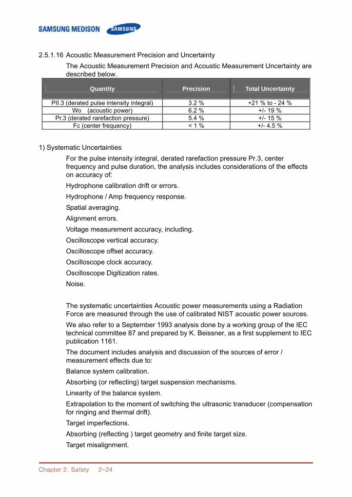
2.5.1.16 Acoustic Measurement Precision and Uncertainty The Acoustic Measurement Precision and Acoustic Measurement Uncertainty are described below.
Quantity Precision Total Uncertainty
PII.3 (derated pulse intensity integral) 3.2 % +21 % to - 24 % Wo (acoustic power) 6.2 % +/- 19 %
Pr.3 (derated rarefaction pressure) 5.4 % +/- 15 % Fc (center frequency) < 1 % +/- 4.5 %
1) Systematic Uncertainties
For the pulse intensity integral, derated rarefaction pressure Pr.3, center frequency and pulse duration, the analysis includes considerations of the effects on accuracy of: Hydrophone calibration drift or errors. Hydrophone / Amp frequency response. Spatial averaging. Alignment errors. Voltage measurement accuracy, including. Oscilloscope vertical accuracy. Oscilloscope offset accuracy. Oscilloscope clock accuracy. Oscilloscope Digitization rates. Noise. The systematic uncertainties Acoustic power measurements using a Radiation Force are measured through the use of calibrated NIST acoustic power sources. We also refer to a September 1993 analysis done by a working group of the IEC technical committee 87 and prepared by K. Beissner, as a first supplement to IEC publication 1161. The document includes analysis and discussion of the sources of error / measurement effects due to: Balance system calibration. Absorbing (or reflecting) target suspension mechanisms. Linearity of the balance system. Extrapolation to the moment of switching the ultrasonic transducer (compensation for ringing and thermal drift). Target imperfections. Absorbing (reflecting ) target geometry and finite target size. Target misalignment.
Chapter 2. Safety 2-25
Ultrasonic transducer misalignment. Water temperature. Ultrasonic attenuation and acoustic streaming. Coupling or shielding foil properties. Plane-wave assumption. Environmental influences. Excitation voltage measurement. Ultrasonic transducer temperature. Effects due to nonlinear propagation and saturation loss. The overall findings of the analysis give a rough Acoustic Power accuracy figure of +/- 10% for the frequency range of 1 - 10 MHz.
Chapter 2. Safety 2-26
2.6 Environmental Protection
CCAAUUTTIIOONN˙ ˙ ˙ ˙ ˙ ˙ ˙ The console and peripherals could be sent back to manufacturers for recycling or
proper disposal after their useful lives. Disposal of waste shall be disposed in accordance with national laws. The waste sheaths are to be disposed of safely and national regulations must be
observed.
Waste Electrical and Electronic Equipment
Chapter 3. Installing the Product 3-1
CChhaapptteerr33.. IInnssttaalllliinngg tthhee PPrroodduucctt
3.1 Overview Chapter 3 contains the information necessary to plan the installation of SonoAce R3 and install it. This chapter describes the requirements for the transportation and installation environment for the product, so that the product is installed in the best condition. Also included are product installation and set up procedures and electrical security check procedures. In addition, procedures for connecting probes and external equipment are included. Contents
3.1 Overview ....................................................................................................3-1 3.2 Transportation ...........................................................................................3-3 3.2.1 Precautions for Transportation ...............................................3-3 3.2.2 Temperature and Humidity ....................................................3-3 3.3 Unpacking ..................................................................................................3-4 3.3.1 Unpacking the Box ..................................................................3-4 3.3.2 Checking Package contents ..................................................3-5 3.4 Precautions for Installation .......................................................................3-6 3.4.1 Precautions ..............................................................................3-6 3.5 Installation Procedure ...............................................................................3-7 3.5.1 Installation Safety ....................................................................3-7 3.5.2 Connecting the Power Cord ...................................................3-8 3.5.3 Connecting the Network Cable ..............................................3-9 3.5.4 Connecting the Probe .............................................................3-9 3.6 Starting the Product ............................................................................... 3-10 3.7 Shutting down the Product .................................................................... 3-11 3.8 Connecting the Peripherals ................................................................... 3-12 3.8.1 External Peripherals ............................................................ 3-12 3.9 System Setting ....................................................................................... 3-14 3.9.1 General System Setup ........................................................ 3-14 3.9.2 Display Setup ....................................................................... 3-16 3.9.3 Misc ....................................................................................... 3-18 3.10 Measure Setting ..................................................................................... 3-19 3.10.1 General ................................................................................. 3-19 3.10.2 Doppler ................................................................................. 3-20 3.10.3 Report ................................................................................... 3-21 3.10.4 OB ......................................................................................... 3-22
Chapter 3. Installing the Product 3-2
3.10.5 Fetal Echo ............................................................................ 3-25 3.10.6 Cardiac.................................................................................. 3-26 3.10.7 Urology.................................................................................. 3-26 3.10.8 Vascular ................................................................................ 3-27 3.11 Setting DICOM ( Optional ) .................................................................... 3-28 3.11.1 Setting DICOM Information ................................................. 3-28 3.11.2 Network Setup ...................................................................... 3-29 3.11.3 Adding or Changing the DICOM Server ............................ 3-29 3.11.4 Editing the DICOM Server Information ............................... 3-32 3.11.5 Deleting DICOM Server ....................................................... 3-32 3.11.6 Testing DICOM Server ........................................................ 3-32 3.11.7 DICOM Log .......................................................................... 3-32 3.12 Setting Option ......................................................................................... 3-34 3.13 Setting Peripheral Devices .................................................................... 3-35 3.13.1 Video Out Type .................................................................... 3-35 3.13.2 Foot Switch ........................................................................... 3-35 3.13.3 Printer 1 ................................................................................ 3-35 3.13.4 Printer 2 ................................................................................ 3-35 3.14 Information .............................................................................................. 3-36
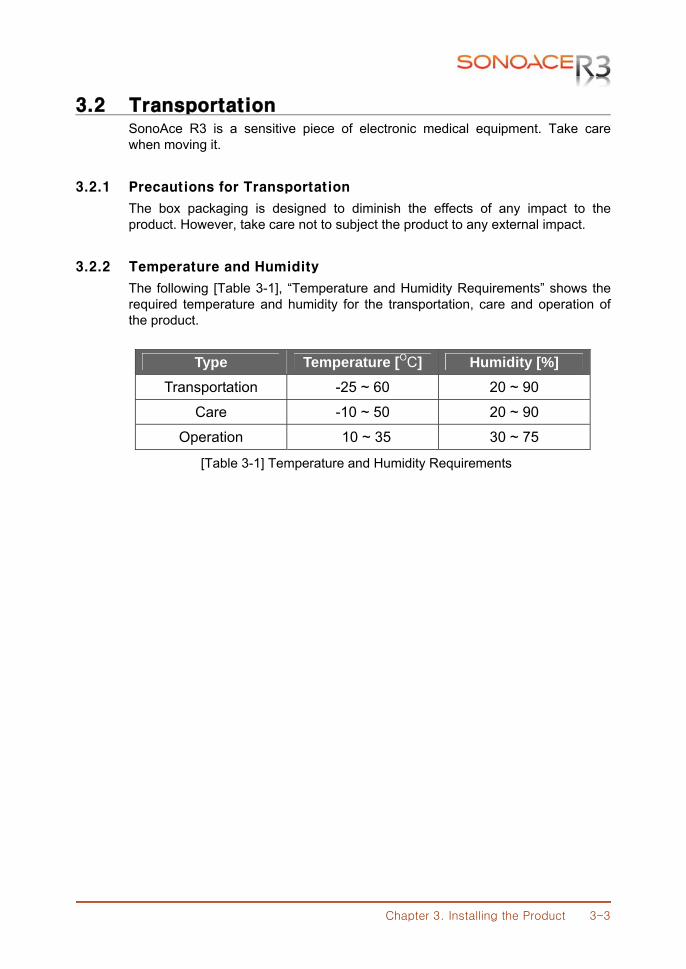
Chapter 3. Installing the Product 3-3
3.2 Transportation SonoAce R3 is a sensitive piece of electronic medical equipment. Take care when moving it.
3.2.1 Precautions for Transportation
The box packaging is designed to diminish the effects of any impact to the product. However, take care not to subject the product to any external impact.
3.2.2 Temperature and Humidity
The following [Table 3-1], “Temperature and Humidity Requirements” shows the required temperature and humidity for the transportation, care and operation of the product.
Type Temperature [OC] Humidity [%]
Transportation -25 ~ 60 20 ~ 90
Care -10 ~ 50 20 ~ 90
Operation 10 ~ 35 30 ~ 75
[Table 3-1] Temperature and Humidity Requirements
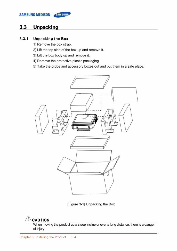
Chapter 3. Installing the Product 3-4
3.3 Unpacking
3.3.1 Unpacking the Box
1) Remove the box strap. 2) Lift the top side of the box up and remove it. 3) Lift the box body up and remove it. 4) Remove the protective plastic packaging. 5) Take the probe and accessory boxes out and put them in a safe place.
[Figure 3-1] Unpacking the Box
CCAAUUTTIIOONN˙ ˙ ˙ ˙ ˙ ˙ ˙ When moving the product up a steep incline or over a long distance, there is a danger of injury.
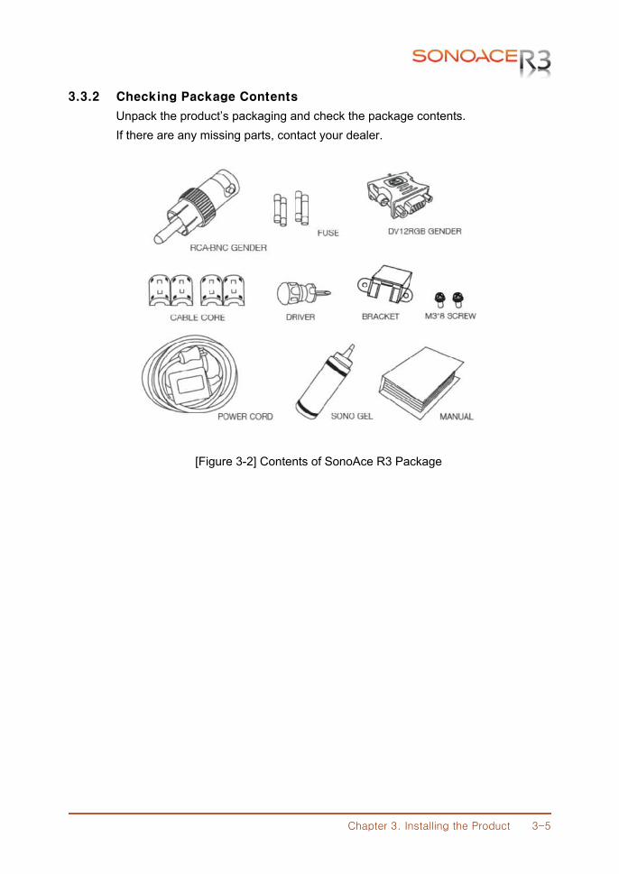
Chapter 3. Installing the Product 3-5
3.3.2 Checking Package Contents
Unpack the product’s packaging and check the package contents. If there are any missing parts, contact your dealer.
[Figure 3-2] Contents of SonoAce R3 Package
Chapter 3. Installing the Product 3-6
3.4 Precautions for Installation
3.4.1 Precautions
Please follow the precautions below. 1) Avoid installing the product where water may get into it. 2) Avoid installing the product in direct sunlight. 3) Avoid installing the product in places where there are high temperature fluctuations. 4) Temperatures of 10OC ~ 35 OC and a humidity of 30% ~ 75% are required
for normal operation.. 5) Avoid installing the product near a heater. 6) Avoid installing the product in a dusty location, or where there is a lack of
ventilation. 7) Avoid installing the product in a location subject to vibration. 8) Avoid installing the product where there are chemicals or gas.
CCAAUUTTIIOONN˙ ˙ ˙ ˙ ˙ ˙ ˙
If you use the product near a generator, X-Ray equipment, or a broadcasting transmission cable, the screen may not work normally due to interference.
In addition, sharing the same wall outlet with other electric equipment may cause noise.
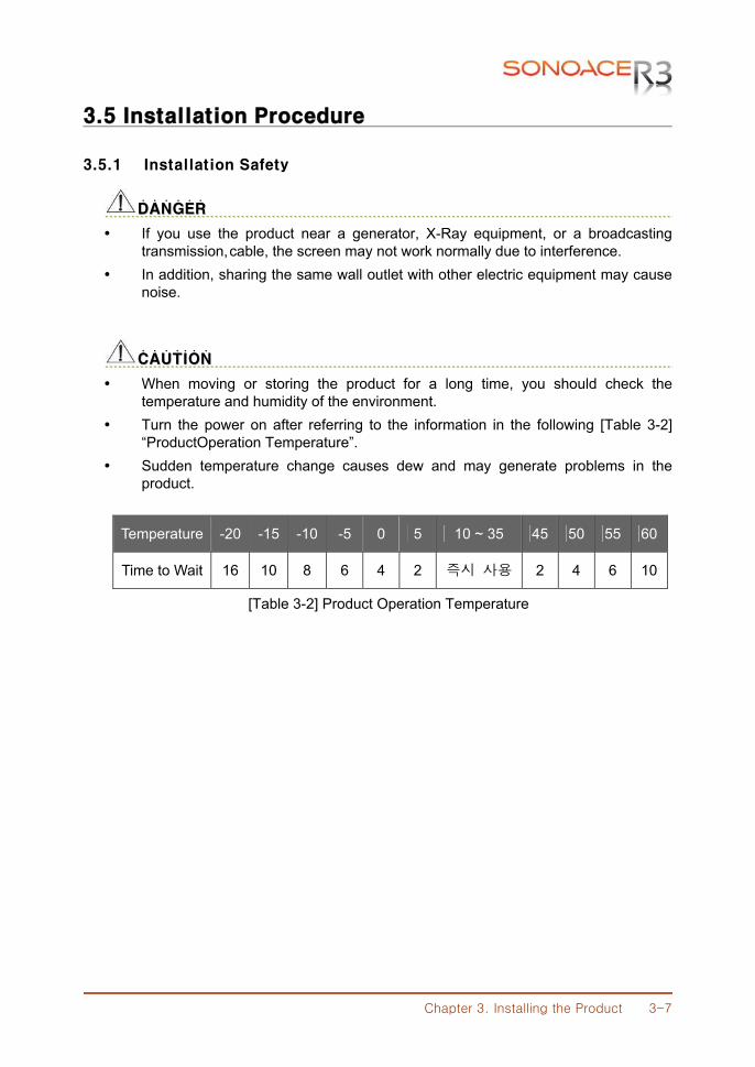
Chapter 3. Installing the Product 3-7
3.5 Installation Procedure
3.5.1 Installation Safety
DDAANNGGEERR˙ ˙ ˙ ˙ ˙ ˙
If you use the product near a generator, X-Ray equipment, or a broadcasting transmission, cable, the screen may not work normally due to interference.
In addition, sharing the same wall outlet with other electric equipment may cause noise.
CCAAUUTTIIOONN˙ ˙ ˙ ˙ ˙ ˙ ˙
When moving or storing the product for a long time, you should check the temperature and humidity of the environment.
Turn the power on after referring to the information in the following [Table 3-2] “ProductOperation Temperature”.
Sudden temperature change causes dew and may generate problems in the product.
Temperature -20 -15 -10 -5 0 5 10 ~ 35 45 50 55 60
Time to Wait 16 10 8 6 4 2 즉시 사용 2 4 6 10
[Table 3-2] Product Operation Temperature
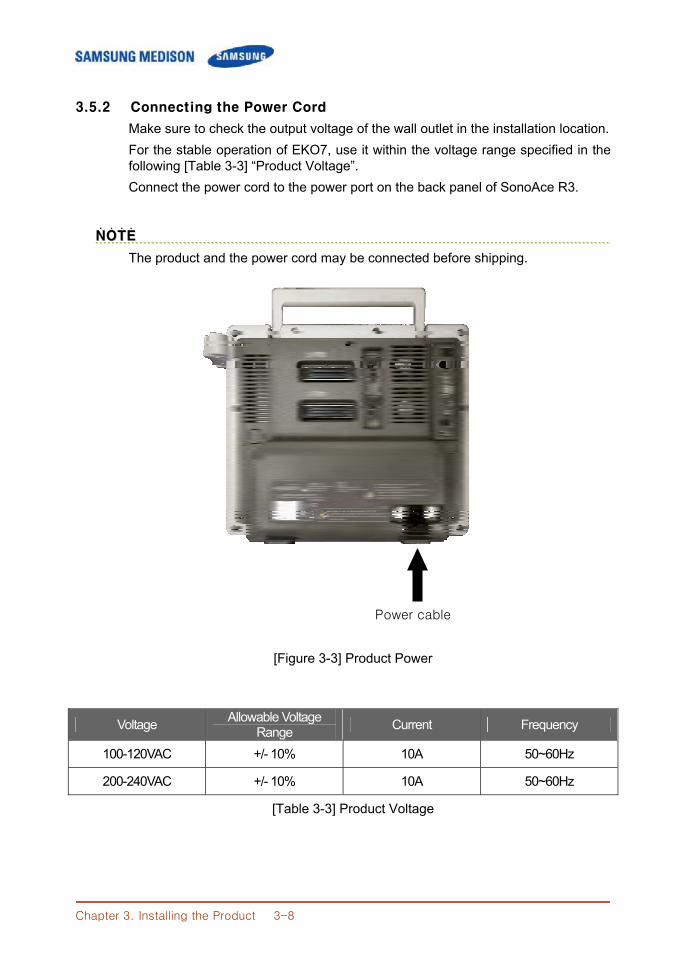
Chapter 3. Installing the Product 3-8
3.5.2 Connecting the Power Cord
Make sure to check the output voltage of the wall outlet in the installation location. For the stable operation of EKO7, use it within the voltage range specified in the following [Table 3-3] “Product Voltage”. Connect the power cord to the power port on the back panel of SonoAce R3.
NNOOTTEE˙ ˙ ˙ ˙
The product and the power cord may be connected before shipping.
[Figure 3-3] Product Power
Voltage Allowable Voltage Range Current Frequency
100-120VAC +/- 10% 10A 50~60Hz
200-240VAC +/- 10% 10A 50~60Hz
[Table 3-3] Product Voltage
Power cable
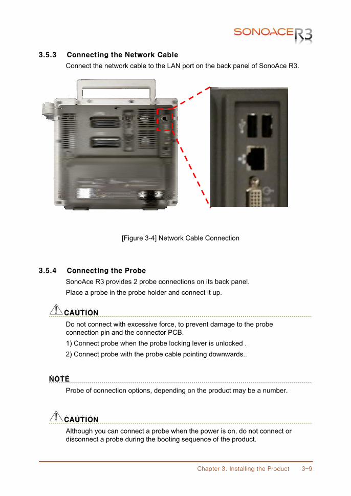
Chapter 3. Installing the Product 3-9
3.5.3 Connecting the Network Cable
Connect the network cable to the LAN port on the back panel of SonoAce R3.
[Figure 3-4] Network Cable Connection
3.5.4 Connecting the Probe
SonoAce R3 provides 2 probe connections on its back panel. Place a probe in the probe holder and connect it up.
CCAAUUTTIIOONN˙ ˙ ˙ ˙ ˙ ˙ ˙
Do not connect with excessive force, to prevent damage to the probe connection pin and the connector PCB.
1) Connect probe when the probe locking lever is unlocked . 2) Connect probe with the probe cable pointing downwards..
NNOOTTEE˙ ˙ ˙ ˙
Probe of connection options, depending on the product may be a number.
CCAAUUTTIIOONN˙ ˙ ˙ ˙ ˙ ˙ ˙
Although you can connect a probe when the power is on, do not connect or disconnect a probe during the booting sequence of the product.
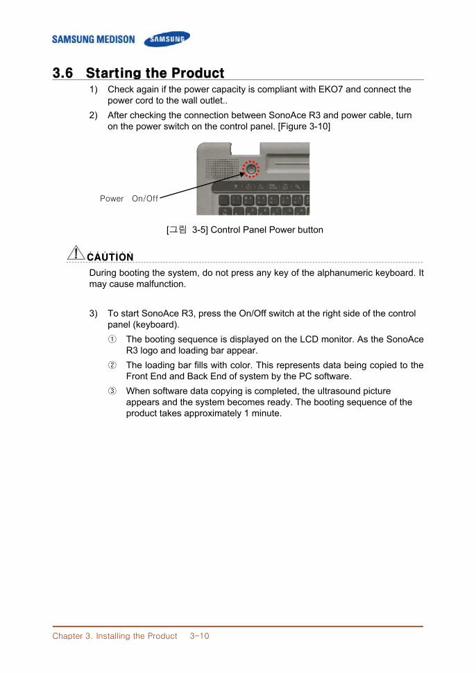
Chapter 3. Installing the Product 3-10
3.6 Starting the Product 1) Check again if the power capacity is compliant with EKO7 and connect the
power cord to the wall outlet.. 2) After checking the connection between SonoAce R3 and power cable, turn
on the power switch on the control panel. [Figure 3-10]
[그림 3-5] Control Panel Power button
CCAAUUTTIIOONN˙ ˙ ˙ ˙ ˙ ˙ ˙
During booting the system, do not press any key of the alphanumeric keyboard. It may cause malfunction.
3) To start SonoAce R3, press the On/Off switch at the right side of the control
panel (keyboard). ① The booting sequence is displayed on the LCD monitor. As the SonoAce
R3 logo and loading bar appear. ② The loading bar fills with color. This represents data being copied to the
Front End and Back End of system by the PC software. ③ When software data copying is completed, the ultrasound picture
appears and the system becomes ready. The booting sequence of the product takes approximately 1 minute.
Power On/Off
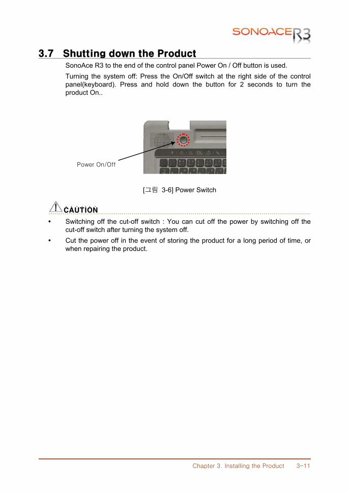
Chapter 3. Installing the Product 3-11
3.7 Shutting down the Product SonoAce R3 to the end of the control panel Power On / Off button is used. Turning the system off: Press the On/Off switch at the right side of the control panel(keyboard). Press and hold down the button for 2 seconds to turn the product On..
[그림 3-6] Power Switch
CCAAUUTTIIOONN˙ ˙ ˙ ˙ ˙ ˙ ˙
Switching off the cut-off switch : You can cut off the power by switching off the cut-off switch after turning the system off.
Cut the power off in the event of storing the product for a long period of time, or when repairing the product.
Power On/Off
Chapter 3. Installing the Product 3-12
3.8 Connecting the Peripherals SonoAce R3 provides various connectors so that various external devices can be connected. Peripherals can include a mono printer, color printer, line printer, USB storage device, and VCR. These are peripheral devices that can be connected for use when needed and are connected via the USB port located at the rear panel.
NNOOTTEE˙ ˙ ˙ ˙
Refer to the operation manual of peripheral device about its operating.
CCAAUUTTIIOONN˙ ˙ ˙ ˙ ˙ ˙ ˙ When using a peripheral device from a USB port, always turn the power off before connecting/disconnecting the device. Connection / disconnection of USB devices during power-on may lead to malfunction of the system and USB devices.
NNOOTTEE˙ ˙ ˙ ˙
When remove the removable disk, use Utility > Storage manager. We recommend that you connect USB storage devices (MO drive, flash memory
media,etc.) to the ports on the front panel and other USB peripheral devices to the rear panel for added convenience..
3.8.1 External Peripherals
3.8.1.1 Video Page Printer Color : SONY UP-20, SONY UP-21MD Black and White : SONY UP-897MD, MITSUBISHI P-91, MITSUBISHI P-93W
3.8.1.2 USB Video Printer Color : SONY UP-D23MD Black and Whiite : SONY UP-D897
3.8.1.3 InkJet Printer HP DeskJet 5650, HP DeskJet 5940, HP DeskJet 6540, HP DeskJet 6970, HP DeskJet 6980
3.8.1.4 LaserJet Printer HP LaserJet 1320, HP LaserJet 2420, HP LaserJet P2015, HP Color LaserJet 3600, HP OfficeJet J5780, HP OfficeJetPro K550
3.8.1.5 USB MO Disk Drive Fujitsu DynaMO1300U2B
3.8.2.6 Flash Memory media Imation iFLASH USB2.0 1GB, Imation USB Swing Blue 1G
Chapter 3. Installing the Product 3-13
3.8.2.7 CD-RW MyBox(External USB Case)+ LG CDRW 52x, LiteON LTR-52327SX CD-RW LiteON CD-RW/DVD-ROM(SOHC-5232KX), LiteON CD-RW(SOHR-5239SX)
CCAAUUTTIIOONN˙ ˙ ˙ ˙ ˙ ˙ ˙
You must install Linux or above (English) compatible printer and driver Contact SAMSUNG MEDISON customer service Team for inquiries about printer driver installation.
When connecting the printer, ensure that the printer is configured under Linux or system setup and has been chosen as the default printer .
Please check the port used in printer before connecting. Printers should be connected to the Printer port while the USB printer connected to the USB port.
NNOOTTEE˙ ˙ ˙ ˙
If you use the USB 1.1 flash memory, the system cannot recognize it. In the case of this,delete the flash memory from the console and quip again.
Regarding file formats that are not ordinarily saved: Please check first to see if it is possibleto save the file format on a desktop PC before trying to save the file on a Flash Memory.
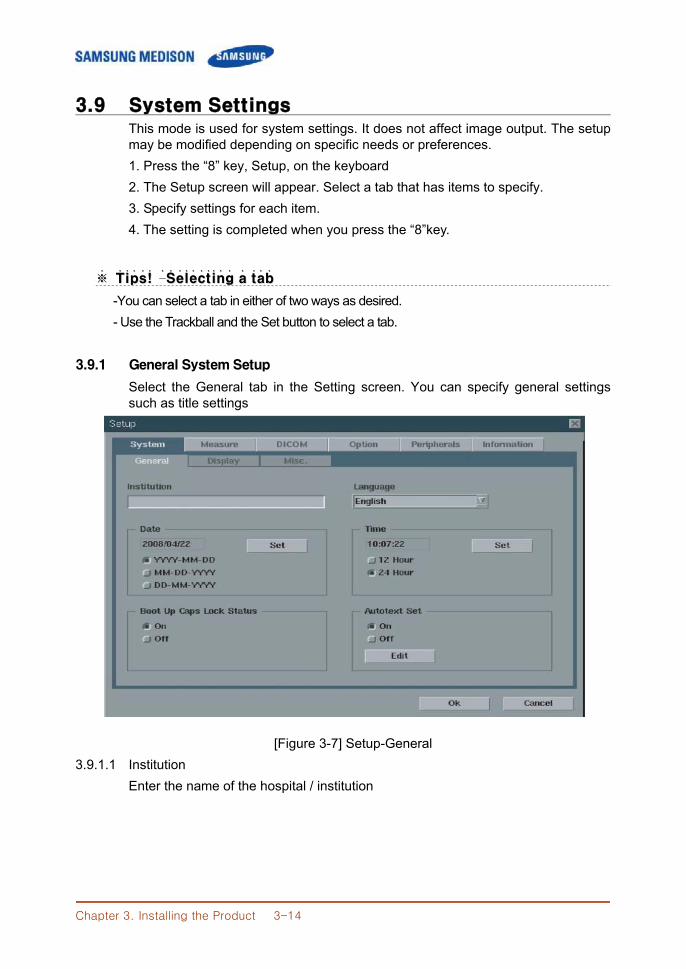
Chapter 3. Installing the Product 3-14
3.9 System Settings This mode is used for system settings. It does not affect image output. The setup may be modified depending on specific needs or preferences. 1. Press the “8” key, Setup, on the keyboard 2. The Setup screen will appear. Select a tab that has items to specify. 3. Specify settings for each item. 4. The setting is completed when you press the “8”key.
※※ TTiippss!! ˙ ˙ ˙ ˙ ˙ ––SSeelleeccttiinngg aa ttaabb˙ ˙ ˙ ˙ ˙ ˙ ˙ ˙ ˙ ˙ ˙ ˙ ˙
-You can select a tab in either of two ways as desired. - Use the Trackball and the Set button to select a tab.
3.9.1 General System Setup
Select the General tab in the Setting screen. You can specify general settings such as title settings
[Figure 3-7] Setup-General
3.9.1.1 Institution Enter the name of the hospital / institution
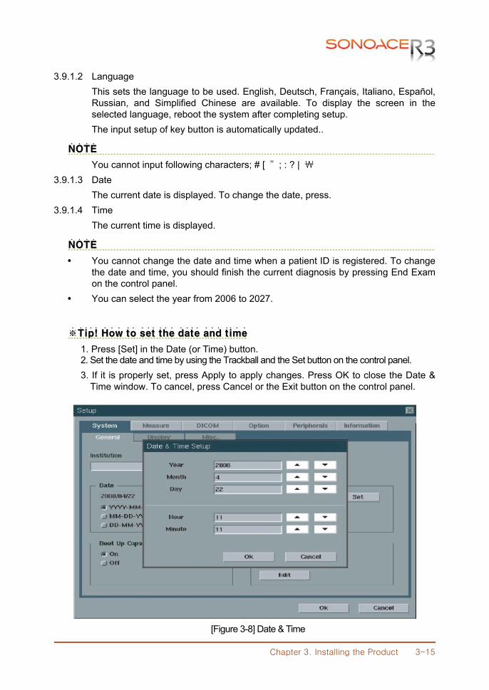
Chapter 3. Installing the Product 3-15
3.9.1.2 Language This sets the language to be used. English, Deutsch, Français, Italiano, Español, Russian, and Simplified Chinese are available. To display the screen in the selected language, reboot the system after completing setup. The input setup of key button is automatically updated..
NNOOTTEE˙ ˙ ˙ ˙
You cannot input following characters; # [ “ ; : ? | ₩ 3.9.1.3 Date
The current date is displayed. To change the date, press. 3.9.1.4 Time
The current time is displayed.
NNOOTTEE˙ ˙ ˙ ˙
You cannot change the date and time when a patient ID is registered. To change the date and time, you should finish the current diagnosis by pressing End Exam on the control panel.
You can select the year from 2006 to 2027.
※※TTiipp!! ˙ ˙ ˙ ˙ HHooww ttoo sseett tthhee ddaattee aanndd ttiimmee˙ ˙ ˙ ˙ ˙ ˙ ˙ ˙ ˙ ˙ ˙ ˙ ˙ ˙ ˙ ˙ ˙ ˙ ˙ ˙ ˙ ˙
1. Press [Set] in the Date (or Time) button. 2. Set the date and time by using the Trackball and the Set button on the control panel. 3. If it is properly set, press Apply to apply changes. Press OK to close the Date &
Time window. To cancel, press Cancel or the Exit button on the control panel.
[Figure 3-8] Date & Time
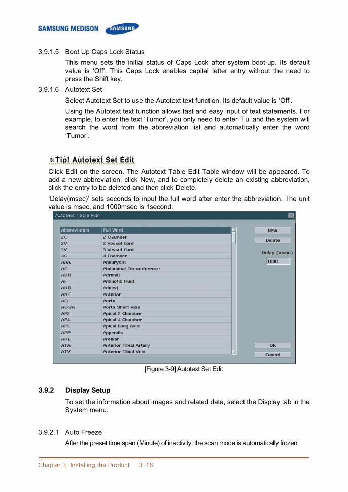
Chapter 3. Installing the Product 3-16
3.9.1.5 Boot Up Caps Lock Status This menu sets the initial status of Caps Lock after system boot-up. Its default value is ‘Off’. This Caps Lock enables capital letter entry without the need to press the Shift key.
3.9.1.6 Autotext Set Select Autotext Set to use the Autotext text function. Its default value is ‘Off’. Using the Autotext text function allows fast and easy input of text statements. For example, to enter the text ‘Tumor’, you only need to enter ‘Tu’ and the system will search the word from the abbreviation list and automatically enter the word ‘Tumor’.
※※TTiipp!! ˙ ˙ ˙ ˙ AAuuttootteexxtt SSeett EEddiitt˙ ˙ ˙ ˙ ˙ ˙ ˙ ˙ ˙ ˙ ˙ ˙ ˙ ˙ ˙
Click Edit on the screen. The Autotext Table Edit Table window will be appeared. To add a new abbreviation, click New, and to completely delete an existing abbreviation, click the entry to be deleted and then click Delete. ‘Delay(msec)’ sets seconds to input the full word after enter the abbreviation. The unit value is msec, and 1000msec is 1second.
[Figure 3-9] Autotext Set Edit
3.9.2 Display Setup
To set the information about images and related data, select the Display tab in the System menu.
3.9.2.1 Auto Freeze After the preset time span (Minute) of inactivity, the scan mode is automatically frozen
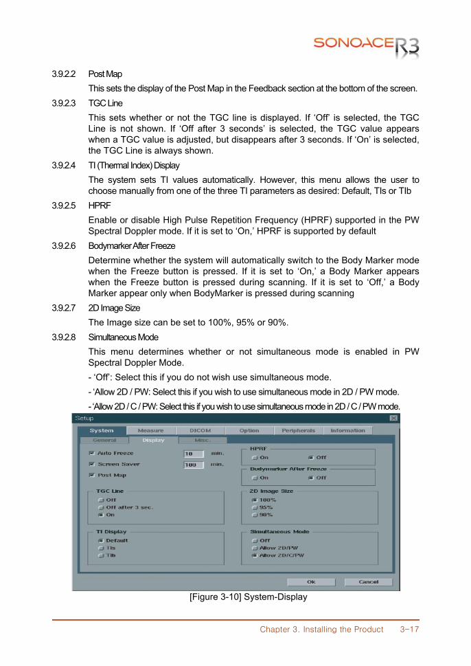
Chapter 3. Installing the Product 3-17
3.9.2.2 Post Map This sets the display of the Post Map in the Feedback section at the bottom of the screen.
3.9.2.3 TGC Line This sets whether or not the TGC line is displayed. If ‘Off’ is selected, the TGC Line is not shown. If ‘Off after 3 seconds’ is selected, the TGC value appears when a TGC value is adjusted, but disappears after 3 seconds. If ‘On’ is selected, the TGC Line is always shown.
3.9.2.4 TI (Thermal Index) Display The system sets TI values automatically. However, this menu allows the user to choose manually from one of the three TI parameters as desired: Default, TIs or TIb
3.9.2.5 HPRF Enable or disable High Pulse Repetition Frequency (HPRF) supported in the PW Spectral Doppler mode. If it is set to ‘On,’ HPRF is supported by default
3.9.2.6 Bodymarker After Freeze Determine whether the system will automatically switch to the Body Marker mode when the Freeze button is pressed. If it is set to ‘On,’ a Body Marker appears when the Freeze button is pressed during scanning. If it is set to ‘Off,’ a Body Marker appear only when BodyMarker is pressed during scanning
3.9.2.7 2D Image Size The Image size can be set to 100%, 95% or 90%.
3.9.2.8 Simultaneous Mode This menu determines whether or not simultaneous mode is enabled in PW Spectral Doppler Mode. - ‘Off’: Select this if you do not wish use simultaneous mode. - ‘Allow 2D / PW: Select this if you wish to use simultaneous mode in 2D / PW mode. - ‘Allow 2D / C / PW: Select this if you wish to use simultaneous mode in 2D / C / PW mode.
[Figure 3-10] System-Display
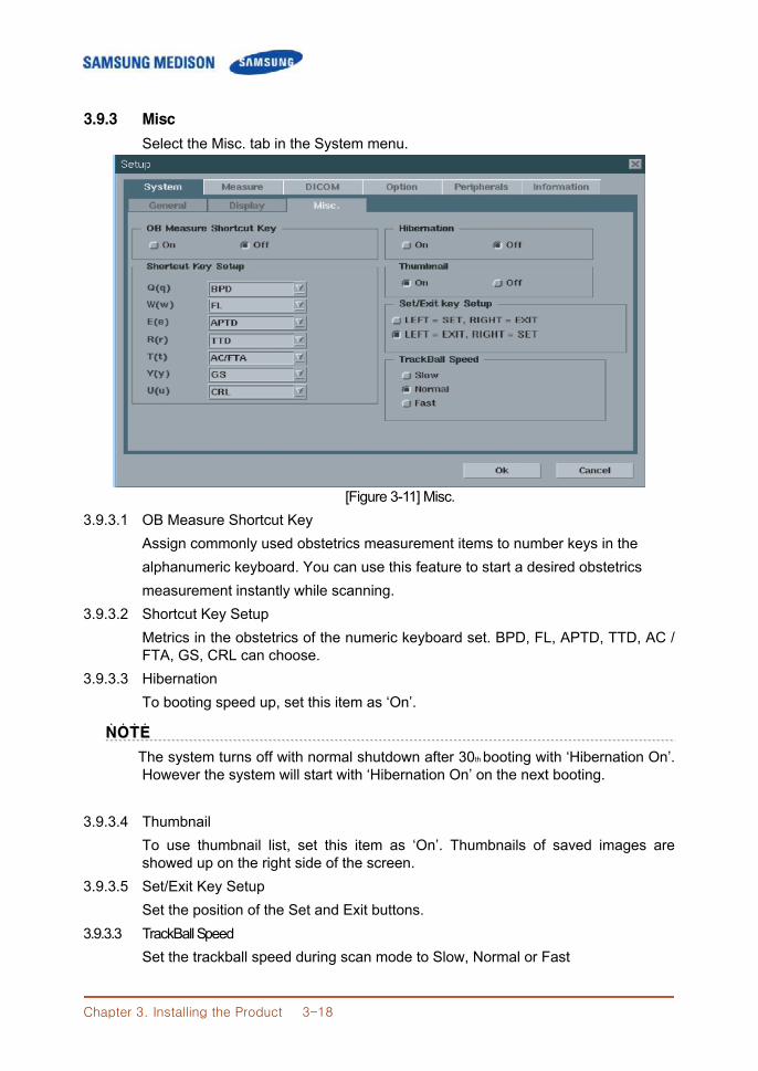
Chapter 3. Installing the Product 3-18
3.9.3 Misc
Select the Misc. tab in the System menu.
[Figure 3-11] Misc. 3.9.3.1 OB Measure Shortcut Key
Assign commonly used obstetrics measurement items to number keys in the alphanumeric keyboard. You can use this feature to start a desired obstetrics measurement instantly while scanning.
3.9.3.2 Shortcut Key Setup Metrics in the obstetrics of the numeric keyboard set. BPD, FL, APTD, TTD, AC / FTA, GS, CRL can choose.
3.9.3.3 Hibernation To booting speed up, set this item as ‘On’.
NNOOTTEE˙ ˙ ˙ ˙
The system turns off with normal shutdown after 30th booting with ‘Hibernation On’. However the system will start with ‘Hibernation On’ on the next booting.
3.9.3.4 Thumbnail To use thumbnail list, set this item as ‘On’. Thumbnails of saved images are showed up on the right side of the screen.
3.9.3.5 Set/Exit Key Setup Set the position of the Set and Exit buttons.
3.9.3.3 TrackBall Speed Set the trackball speed during scan mode to Slow, Normal or Fast
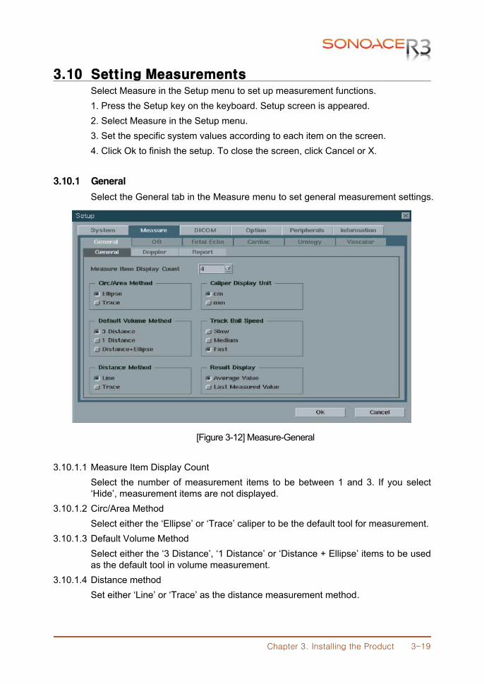
Chapter 3. Installing the Product 3-19
3.10 Setting Measurements Select Measure in the Setup menu to set up measurement functions. 1. Press the Setup key on the keyboard. Setup screen is appeared. 2. Select Measure in the Setup menu. 3. Set the specific system values according to each item on the screen. 4. Click Ok to finish the setup. To close the screen, click Cancel or X.
3.10.1 General
Select the General tab in the Measure menu to set general measurement settings.
[Figure 3-12] Measure-General 3.10.1.1 Measure Item Display Count
Select the number of measurement items to be between 1 and 3. If you select ‘Hide’, measurement items are not displayed.
3.10.1.2 Circ/Area Method Select either the ‘Ellipse’ or ‘Trace’ caliper to be the default tool for measurement.
3.10.1.3 Default Volume Method Select either the ‘3 Distance’, ‘1 Distance’ or ‘Distance + Ellipse’ items to be used as the default tool in volume measurement.
3.10.1.4 Distance method Set either ‘Line’ or ‘Trace’ as the distance measurement method.
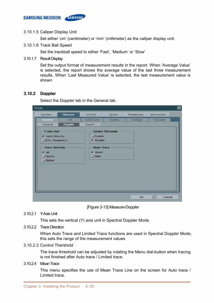
Chapter 3. Installing the Product 3-20
3.10.1.5 Caliper Display Unit Set either ‘cm’ (centimeter) or ‘mm’ (millimeter) as the caliper display unit.
3.10.1.6 Track Ball Speed Set the trackball speed to either ‘Fast’, ‘Medium’ or ‘Slow’
3.10.1.7 Result Display Set the output format of measurement results in the report. When ‘Average Value’ is selected, the report shows the average value of the last three measurement results. When ‘Last Measured Value’ is selected, the last measurement value is shown
3.10.2 Doppler
Select the Doppler tab in the General tab.
[Figure 3-13] Measure-Doppler 3.10.2.1 Y-Axis Unit
This sets the vertical (Y) axis unit in Spectral Doppler Mode. 3.10.2.2 Trace Direction
When Auto Trace and Limited Trace functions are used in Spectral Doppler Mode, this sets the range of the measurement values
3.10.2.3 Control Thershold The trace threshold can be adjusted by rotating the Menu dial-button when tracing is not finished after Auto trace / Limited trace.
3.10.2.4 Mean Trace This menu specifies the use of Mean Trace Line on the screen for Auto trace / Limited trace.
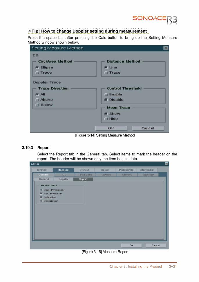
Chapter 3. Installing the Product 3-21
※※TTiipp!! ˙ ˙ ˙ ˙ HHooww ttoo cchhaannggee DDoopppplleerr sseettttiinngg dduurriinngg mmeeaassuurreemmeenntt˙ ˙ ˙ ˙ ˙ ˙ ˙ ˙ ˙ ˙ ˙ ˙ ˙ ˙ ˙ ˙ ˙ ˙ ˙ ˙ ˙˙˙ ˙ ˙ ˙ ˙ ˙˙ ˙ ˙ ˙ ˙ ˙ ˙ ˙ ˙ ˙ ˙ ˙ ˙ ˙
Press the space bar after pressing the Calc button to bring up the Setting Measure Method window shown below.
[Figure 3-14] Setting Measure Method
3.10.3 Report
Select the Report tab in the General tab. Select items to mark the header on the report. The header will be shown only the item has its data.
[Figure 3-15] Measure-Report
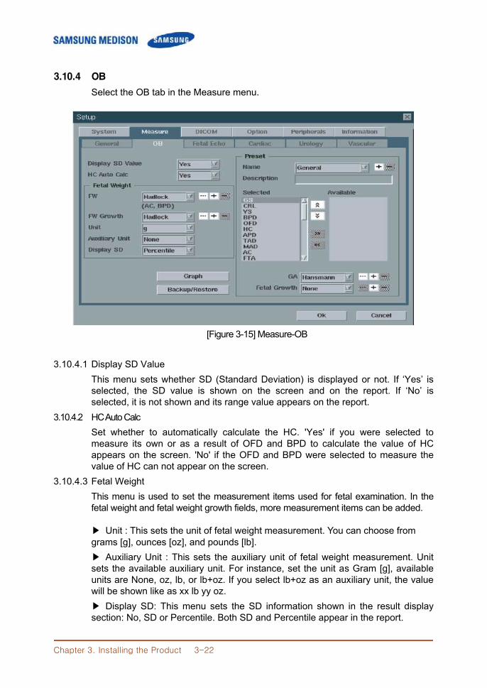
Chapter 3. Installing the Product 3-22
3.10.4 OB
Select the OB tab in the Measure menu.
[Figure 3-15] Measure-OB 3.10.4.1 Display SD Value
This menu sets whether SD (Standard Deviation) is displayed or not. If ‘Yes’ is selected, the SD value is shown on the screen and on the report. If ‘No’ is selected, it is not shown and its range value appears on the report.
3.10.4.2 HC Auto Calc Set whether to automatically calculate the HC. 'Yes' if you were selected to measure its own or as a result of OFD and BPD to calculate the value of HC appears on the screen. 'No' if the OFD and BPD were selected to measure the value of HC can not appear on the screen.
3.10.4.3 Fetal Weight This menu is used to set the measurement items used for fetal examination. In the fetal weight and fetal weight growth fields, more measurement items can be added.
▶ Unit : This sets the unit of fetal weight measurement. You can choose from grams [g], ounces [oz], and pounds [lb]. ▶ Auxiliary Unit : This sets the auxiliary unit of fetal weight measurement. Unit sets the available auxiliary unit. For instance, set the unit as Gram [g], available units are None, oz, lb, or lb+oz. If you select lb+oz as an auxiliary unit, the value will be shown like as xx lb yy oz. ▶ Display SD: This menu sets the SD information shown in the result display section: No, SD or Percentile. Both SD and Percentile appear in the report.
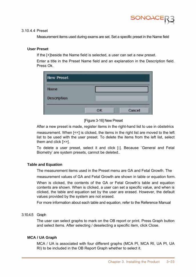
Chapter 3. Installing the Product 3-23
3.10.4.4 Preset Measurement items used during exams are set. Set a specific preset in the Name field
User Preset
If the [+]beside the Name field is selected, a user can set a new preset. Enter a title in the Preset Name field and an explanation in the Description field. Press Ok.
[Figure 3-16] New Preset After a new preset is made, register items in the right-hand list to use in obstetrics measurement. When [<<] is clicked, the items in the right list are moved to the left list to be used with the user preset. To delete the items from the left list, select them and click [>>]. To delete a user preset, select it and click [-]. Because `General and Fetal Biometry’ are system presets, cannot be deleted..
Table and Equation
The measurement items used in the Preset menu are GA and Fetal Growth. The measurement values of GA and Fetal Growth are shown in table or equation form. When is clicked, the contents of the GA or Fetal Growth’s table and equation contents are shown. When is clicked, a user can set a specific value, and when is clicked, the table and equation set by the user are erased. However, the default values provided by the system are not erased. For more information about each table and equation, refer to the Reference Manual
3.10.4.5 Graph
The user can select graphs to mark on the OB report or print. Press Graph button and select items. After selecting / deselecting a specific item, click Close.
MCA / UA Graph
MCA / UA is associated with four different graphs (MCA PI, MCA RI, UA PI, UA RI) to be included in the OB Report Graph whether to select it.
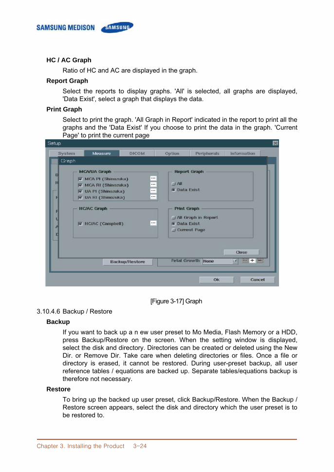
Chapter 3. Installing the Product 3-24
HC / AC Graph
Ratio of HC and AC are displayed in the graph. Report Graph
Select the reports to display graphs. 'All' is selected, all graphs are displayed, 'Data Exist', select a graph that displays the data.
Print Graph Select to print the graph. 'All Graph in Report' indicated in the report to print all the graphs and the 'Data Exist' If you choose to print the data in the graph. 'Current Page' to print the current page
[Figure 3-17] Graph 3.10.4.6 Backup / Restore
Backup If you want to back up a n ew user preset to Mo Media, Flash Memory or a HDD, press Backup/Restore on the screen. When the setting window is displayed, select the disk and directory. Directories can be created or deleted using the New Dir. or Remove Dir. Take care when deleting directories or files. Once a file or directory is erased, it cannot be restored. During user-preset backup, all user reference tables / equations are backed up. Separate tables/equations backup is therefore not necessary.
Restore To bring up the backed up user preset, click Backup/Restore. When the Backup / Restore screen appears, select the disk and directory which the user preset is to be restored to.
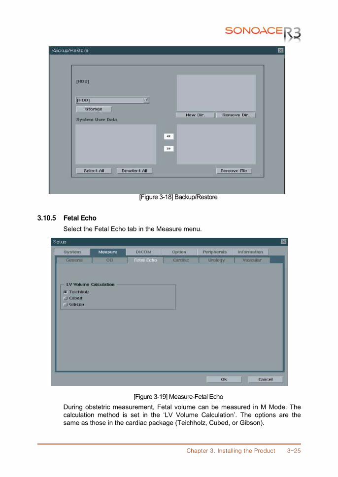
Chapter 3. Installing the Product 3-25
[Figure 3-18] Backup/Restore
3.10.5 Fetal Echo
Select the Fetal Echo tab in the Measure menu.
[Figure 3-19] Measure-Fetal Echo During obstetric measurement, Fetal volume can be measured in M Mode. The calculation method is set in the ‘LV Volume Calculation’. The options are the same as those in the cardiac package (Teichholz, Cubed, or Gibson).
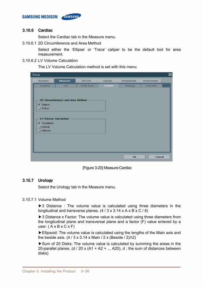
Chapter 3. Installing the Product 3-26
3.10.6 Cardiac
Select the Cardiac tab in the Measure menu. 3.10.6.1 2D Circumference and Area Method
Select either the ‘Ellipse’ or ‘Trace’ caliper to be the default tool for area measurement.
3.10.6.2 LV Volume Calculation The LV Volume Calculation method is set with this menu.
[Figure 3-20] Measure-Cardiac
3.10.7 Urology
Select the Urology tab in the Measure menu.
3.10.7.1 Volume Method ▶3 Distance : The volume value is calculated using three diameters in the longitudinal and transverse planes. (4 / 3 x 3.14 x A x B x C / 8) ▶3 Distance x Factor: The volume value is calculated using three diameters from the longitudinal plane and transversal plane and a factor (F) value entered by a user. ( A x B x C x F) ▶Ellipsoid: The volume value is calculated using the lengths of the Main axis and the beside axis. (4 / 3 x 3.14 x Main / 2 x (Beside / 2)Λ2) ▶Sum of 20 Disks: The volume value is calculated by summing the areas in the 20-parallel planes. (d / 20 x (A1 + A2 + ... A20), d : the sum of distances between disks)
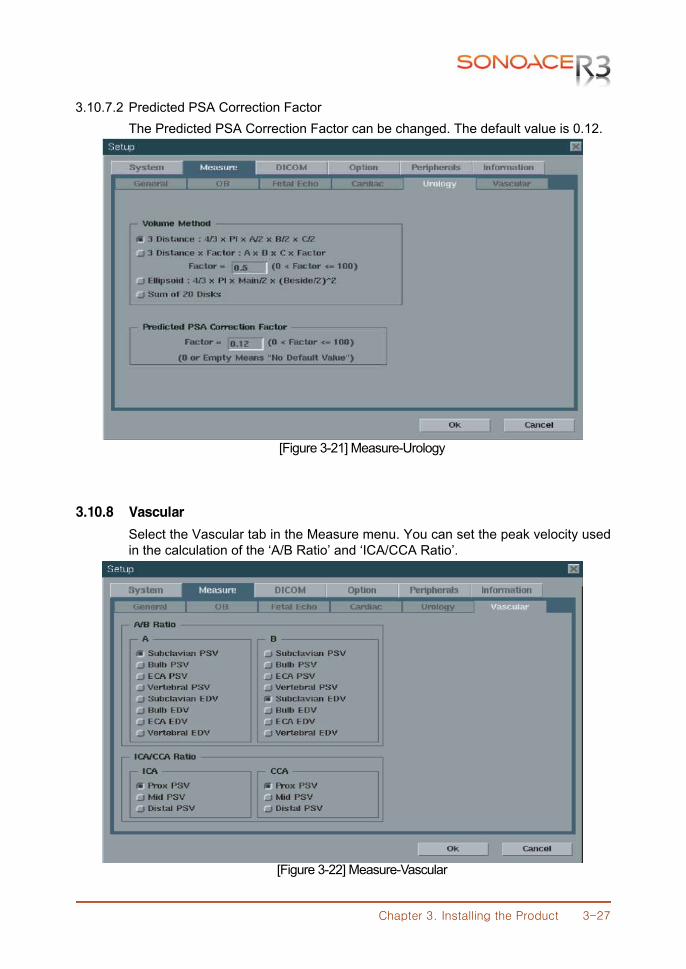
Chapter 3. Installing the Product 3-27
3.10.7.2 Predicted PSA Correction Factor The Predicted PSA Correction Factor can be changed. The default value is 0.12.
[Figure 3-21] Measure-Urology
3.10.8 Vascular
Select the Vascular tab in the Measure menu. You can set the peak velocity used in the calculation of the ‘A/B Ratio’ and ‘ICA/CCA Ratio’.
[Figure 3-22] Measure-Vascular
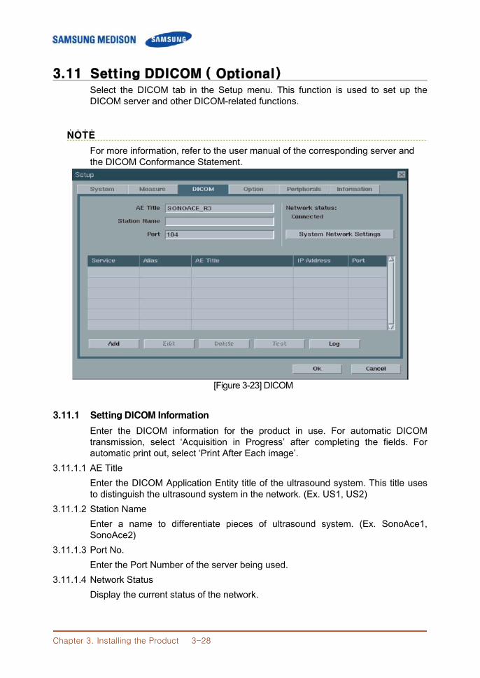
Chapter 3. Installing the Product 3-28
3.11 Setting DDICOM ( Optional) Select the DICOM tab in the Setup menu. This function is used to set up the DICOM server and other DICOM-related functions.
NNOOTTEE˙ ˙ ˙ ˙
For more information, refer to the user manual of the corresponding server and the DICOM Conformance Statement.
[Figure 3-23] DICOM
3.11.1 Setting DICOM Information
Enter the DICOM information for the product in use. For automatic DICOM transmission, select ‘Acquisition in Progress’ after completing the fields. For automatic print out, select ‘Print After Each image’.
3.11.1.1 AE Title Enter the DICOM Application Entity title of the ultrasound system. This title uses to distinguish the ultrasound system in the network. (Ex. US1, US2)
3.11.1.2 Station Name Enter a name to differentiate pieces of ultrasound system. (Ex. SonoAce1, SonoAce2)
3.11.1.3 Port No. Enter the Port Number of the server being used.
3.11.1.4 Network Status Display the current status of the network.
Chapter 3. Installing the Product 3-29
3.11.2 Network Setup
To set the network like IP address, press System Network Settings. To set the IP value automatically, press ‘Using Dynamic IP Configuration’. If you enter the wrong IP address, the network will not run. To finish the network setup, click Apply. To cancel setup, click Close.
3.11.3 Adding or Changing the DICOM Server
Click Add to enter the information related to the DICOM Server. Store Server Information Select STORE under Services. Configure the Image Storage Service using DICOM.
3.11.3.1 Service Select the kind of server to use. The supported DICOM servers are Store, Print, and Worklist.
3.11.3.2 Alias Enter the name of the server being used.
3.11.3.3 Transfer Mode Select any one of the three image transfer methods. ▶Batch: send all images when you click the End Exam. ▶Send As You Go: send the image whenever you press the Save button. ▶Manual: send the image manually only in the SonoView.
3.11.3.4 Connect Timeout Set how many seconds the system will wait until get response.
3.11.3.5 IP Address Enter the IP address of the server being used.
3.11.3.6 Port Enter the Port Number of the server being used.
3.11.3.7 Retry Interval Set how many seconds the system will wait if the transmission fails.
3.11.3.8 Maximum Retries Set how many times the system will retry.
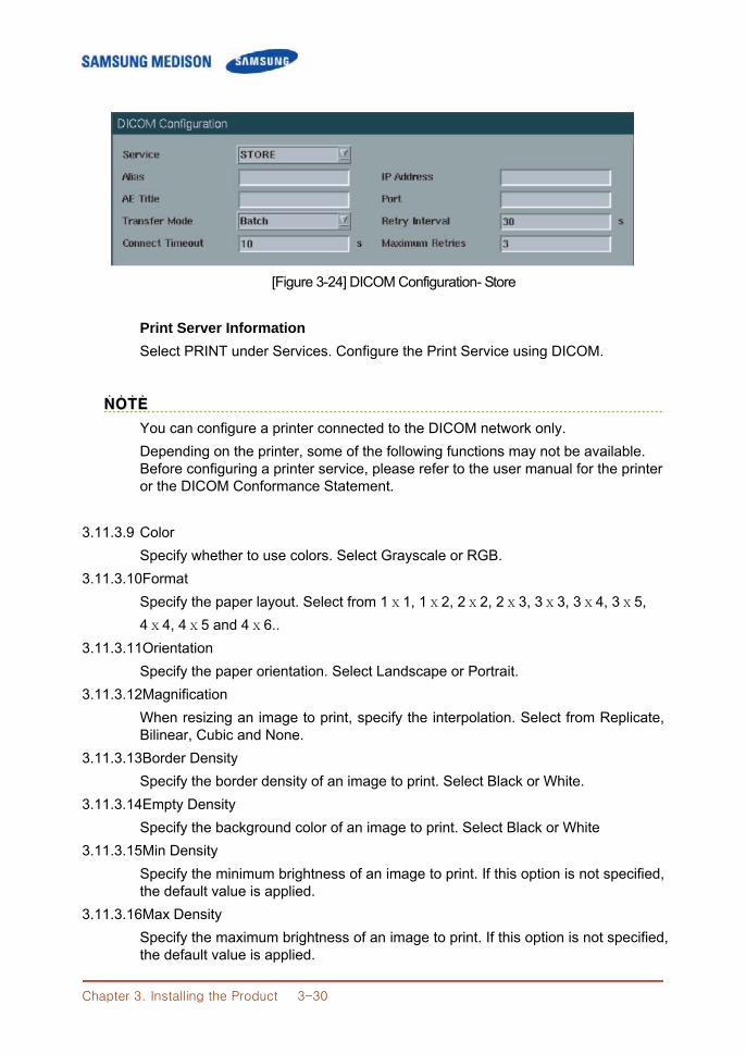
Chapter 3. Installing the Product 3-30
[Figure 3-24] DICOM Configuration- Store
Print Server Information Select PRINT under Services. Configure the Print Service using DICOM.
NNOOTTEE˙ ˙ ˙ ˙
You can configure a printer connected to the DICOM network only. Depending on the printer, some of the following functions may not be available. Before configuring a printer service, please refer to the user manual for the printer or the DICOM Conformance Statement.
3.11.3.9 Color
Specify whether to use colors. Select Grayscale or RGB. 3.11.3.10Format
Specify the paper layout. Select from 1ⅹ1, 1ⅹ2, 2ⅹ2, 2ⅹ3, 3ⅹ3, 3ⅹ4, 3ⅹ5, 4ⅹ4, 4ⅹ5 and 4ⅹ6..
3.11.3.11Orientation Specify the paper orientation. Select Landscape or Portrait.
3.11.3.12Magnification When resizing an image to print, specify the interpolation. Select from Replicate, Bilinear, Cubic and None.
3.11.3.13Border Density Specify the border density of an image to print. Select Black or White.
3.11.3.14Empty Density Specify the background color of an image to print. Select Black or White
3.11.3.15Min Density Specify the minimum brightness of an image to print. If this option is not specified, the default value is applied.
3.11.3.16Max Density Specify the maximum brightness of an image to print. If this option is not specified, the default value is applied.
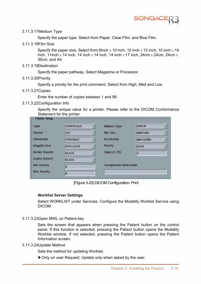
Chapter 3. Installing the Product 3-31
3.11.3.17Medium Type Specify the paper type. Select from Paper, Clear Film, and Blue Film.
3.11.3.18Film Size Specify the paper size. Select from 8inchⅹ10 inch, 10 inchⅹ12 inch, 10 inchⅹ14 inch, 11inchⅹ14 inch, 14 inchⅹ14 inch, 14 inchⅹ17 inch, 24cmⅹ24cm, 24cmⅹ30cm, and A4
3.11.3.19Destination Specify the paper pathway. Select Magazine or Processor.
3.11.3.20Priority Specify a priority for the print command. Select from High, Med and Low.
3.11.3.21Copies Enter the number of copies between 1 and 99.
3.11.3.22Configuration Info Specify the unique value for a printer. Please refer to the DICOM Conformance Statement for the printer.
[Figure 3-25] DICOM Configuration- Print Worklist Server Settings Select WORKLIST under Services. Configure the Modality Worklist Service using DICOM.
3.11.3.23Open MWL on Patient key Sets the screen that appears when pressing the Patient button on the control panel. If this function is selected, pressing the Patient button opens the Modality Worklist window. If not selected, pressing the Patient button opens the Patient Information screen.
3.11.3.24Update Method Sets the method for updating Worklist. ▶Only on user Request: Update only when asked by the user.
Chapter 3. Installing the Product 3-32
※※TTiipp!! ˙ ˙ ˙ ˙ WWoorrkkLLiisstt TTiippss..˙ ˙ ˙ ˙ ˙ ˙ ˙ ˙ ˙ ˙ ˙ ˙ ˙ To update a worklist, in the Search tab on the Patient Information screen, select Worklist for Search Source and press Search. ▶On Startup and Every: Worklist is updated at the system boot-up and then updated continually at a set interval. Note that Worklist is not updated while the Modality Worklist window is open.
3.11.3.25Scheduled Station AE Title Sets the range of AE Title to fetch from the hospital’s Worklist server. ▶All: Obtains the list of patients saved under all AE Titles within the server. ▶This System: Obtains the list of patients for the AE Titles set under the DICOM tab. ▶Another: Obtains the list of patients for the AE Title directly entered by the user.
NNOOTTEE˙ ˙ ˙ ˙
This function is available only if when the Worklist server is configured.
3.11.3.26Start Date Set the range of dates to search. ▶Today: Obtains the list of patients for the current date. ▶Prior_days, Next_days: Obtains the list of patients for dates between n days
prior to the current date and n days after the current date. ▶Period From Date: Enter a date and the system obtains the list of patients starting from the date entered up until the current date. To Date: Enter a date and the system obtains the list of patients starting from the current date up until the date entered. From Date To Date: Enter two separate dates and the system obtains the list of patients between the two dates entered..
3.11.4 Editing the DICOM Server Information
Click Edit in the setting DICOM window to edit the server information already entered.
3.11.5 Deleting DICOM Server
Click Delete in the setting DICOM window to erase the current server information.
Chapter 3. Installing the Product 3-33
3.11.6 Testing DICOM Server
Select a service and click Test on the screen. The connection with the selected service is tested and the results are shown under the Ping and Verify items. If the result is Normal, it indicates that the connection is normal.
3.11.7 DICOM Log
Click Log in the setting DICOM window, and the screen will be changed. Set or copy the current DICOM log file. DICOM log file is the history of all DICOM services performed so far on the product. Click Close to finish the DICOM log.
3.11.7.1 Log Settings
Set the DICOM Log.. ▶Delete archived log file after: set the number of days to wait before deleting the archived history. After that period, the log file will be deleted. However there is only one log file, it will not be deleted. ▶Log File Maximum Size: set the maximum size of each history file archived. Set the unit as Kbytes
3.11.7.2 Explanation View the log setting.
3.11.7.3 DICOM Log View, copy, or delete the DICOM log files. ▶View Selected File: Select the log file from ‘Select log files to copy’ and click View selected file. ▶Copy Selected Files:
1. Select the log files and set the storage file format on the ‘Copy to’. 2. Set the ‘Delete files after copy’ whether to delete the log files saved in the hard disk of the system. 3. Click Copy selected files.
▶Delete Selected Files: Select the log file and click Delete Selected Files.
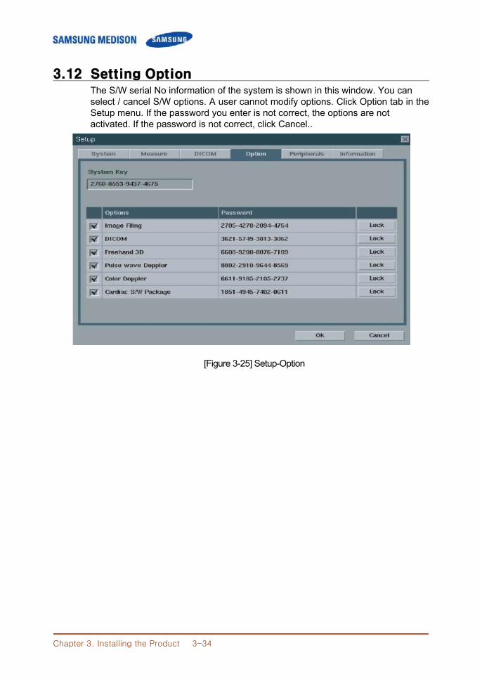
Chapter 3. Installing the Product 3-34
3.12 Setting Option The S/W serial No information of the system is shown in this window. You can
select / cancel S/W options. A user cannot modify options. Click Option tab in the Setup menu. If the password you enter is not correct, the options are not activated. If the password is not correct, click Cancel..
[Figure 3-25] Setup-Option
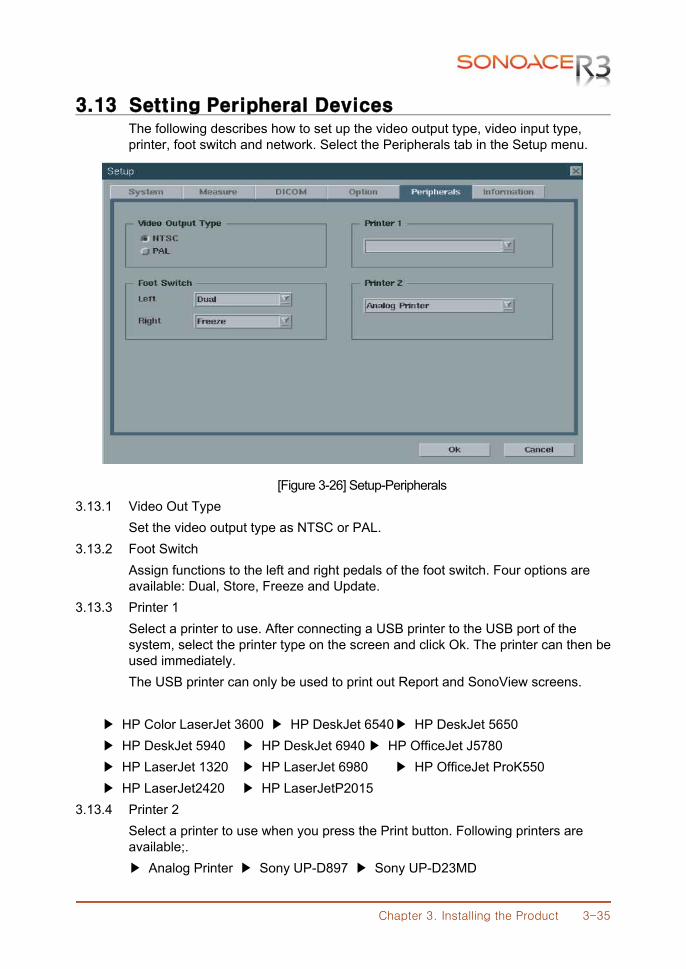
Chapter 3. Installing the Product 3-35
3.13 Setting Peripheral Devices The following describes how to set up the video output type, video input type,
printer, foot switch and network. Select the Peripherals tab in the Setup menu.
[Figure 3-26] Setup-Peripherals 3.13.1 Video Out Type
Set the video output type as NTSC or PAL. 3.13.2 Foot Switch
Assign functions to the left and right pedals of the foot switch. Four options are available: Dual, Store, Freeze and Update. 3.13.3 Printer 1
Select a printer to use. After connecting a USB printer to the USB port of the system, select the printer type on the screen and click Ok. The printer can then be used immediately.
The USB printer can only be used to print out Report and SonoView screens. ▶ HP Color LaserJet 3600 ▶ HP DeskJet 6540 ▶ HP DeskJet 5650 ▶ HP DeskJet 5940 ▶ HP DeskJet 6940 ▶ HP OfficeJet J5780 ▶ HP LaserJet 1320 ▶ HP LaserJet 6980 ▶ HP OfficeJet ProK550 ▶ HP LaserJet2420 ▶ HP LaserJetP2015 3.13.4 Printer 2
Select a printer to use when you press the Print button. Following printers are available;.
▶ Analog Printer ▶ Sony UP-D897 ▶ Sony UP-D23MD
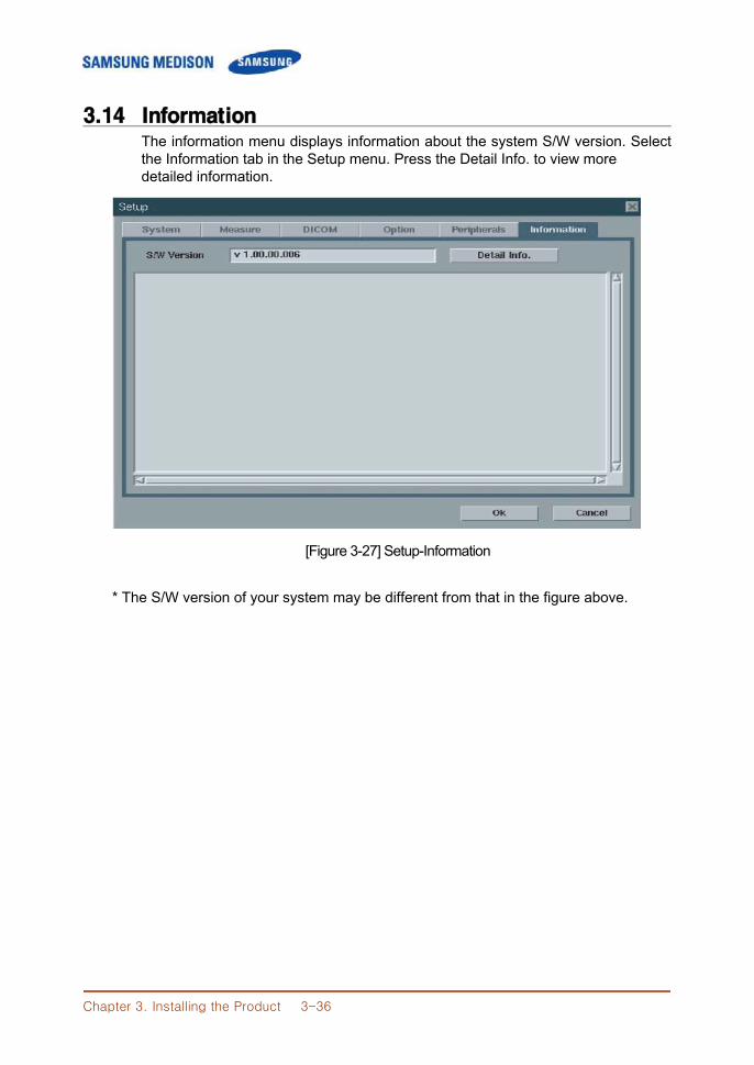
Chapter 3. Installing the Product 3-36
3.14 Information The information menu displays information about the system S/W version. Select
the Information tab in the Setup menu. Press the Detail Info. to view more detailed information.
[Figure 3-27] Setup-Information * The S/W version of your system may be different from that in the figure above.
Chapter 4. Checking the Product 4-1
CChhaapptteerr 44.. CChheecckkiinngg tthhee PPrroodduucctt
4.1 Overview
Chapter 4 describes how to check SonoAce R3 and how to check if its major functions and the power supply are working properly.
Contents
4.1 Overview ....................................................................................... 4-1 4.2 Starting the Product ...................................................................... 4-2 4.3 Monitor .......................................................................................... 4-3 4.3.1 Monitor Display ............................................................. 4-3 4.4 Control Panel ................................................................................ 4-5 4.4.1 Detail Control Panel ..................................................... 4-6 4.4.2 Soft Menu ..................................................................... 4-8 4.4.3 Keyboards .................................................................... 4-9 4.5 Checking the Performance ....................................................... 4-11 4.5.1 Basic Check ................................................................ 4-11 4.5.2 Detail Check ............................................................... 4-12
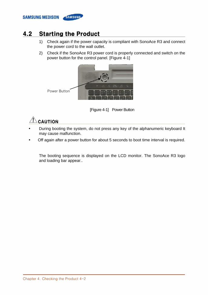
Chapter 4. Checking the Product 4-2
4.2 Starting the Product
1) Check again if the power capacity is compliant with SonoAce R3 and connect the power cord to the wall outlet. 2) Check if the SonoAce R3 power cord is properly connected and switch on the power button for the control panel. [Figure 4-1]
[Figure 4-1] Power Button
CCAAUUTTIIOONN˙ ˙ ˙ ˙ ˙ ˙ ˙
During booting the system, do not press any key of the alphanumeric keyboard It may cause malfunction.
Off again after a power button for about 5 seconds to boot time interval is required. The booting sequence is displayed on the LCD monitor. The SonoAce R3 logo and loading bar appear..
Power Button
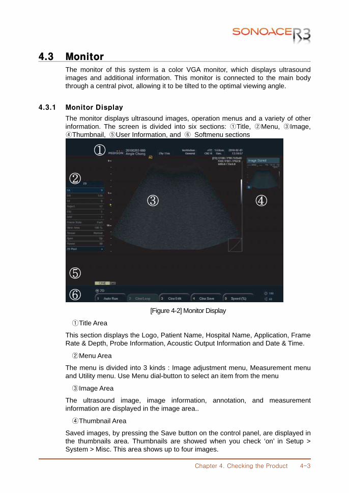
Chapter 4. Checking the Product 4-3
4.3 Monitor
The monitor of this system is a color VGA monitor, which displays ultrasound images and additional information. This monitor is connected to the main body through a central pivot, allowing it to be tilted to the optimal viewing angle.
4.3.1 Monitor Display
The monitor displays ultrasound images, operation menus and a variety of other information. The screen is divided into six sections: ①Title, ②Menu, ③Image, ④Thumbnail, ⑤User Information, and ⑥ Softmenu sections
[Figure 4-2] Monitor Display
① Title Area
This section displays the Logo, Patient Name, Hospital Name, Application, Frame Rate & Depth, Probe Information, Acoustic Output Information and Date & Time.
② Menu Area
The menu is divided into 3 kinds : Image adjustment menu, Measurement menu and Utility menu. Use Menu dial-button to select an item from the menu
③ Image Area
The ultrasound image, image information, annotation, and measurement information are displayed in the image area..
④ Thumbnail Area
Saved images, by pressing the Save button on the control panel, are displayed in the thumbnails area. Thumbnails are showed when you check ‘on’ in Setup > System > Misc. This area shows up to four images.
②
③
①
④
⑤
⑥
Chapter 4. Checking the Product 4-4
⑤ User Information Area
A variety of information necessary for system use e.g. current system status and Body Markers.
⑥ Softmenu
Available menu items may vary depending on the current system state. To set or change a Soft Menu item, use the corresponding dial-button on the control panel.
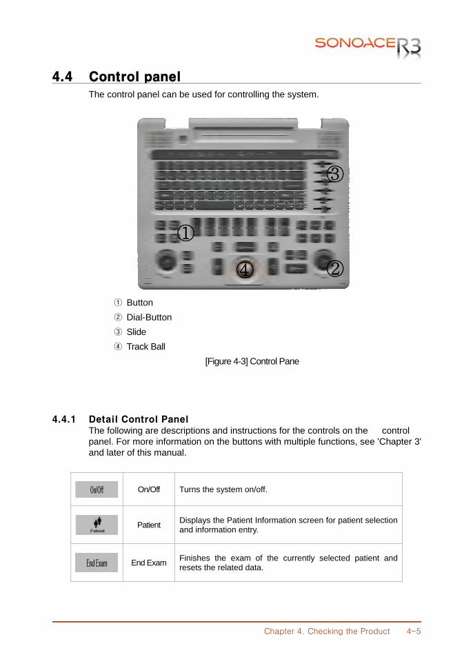
Chapter 4. Checking the Product 4-5
4.4 Control panel
The control panel can be used for controlling the system.
① Button ② Dial-Button ③ Slide ④ Track Ball
[Figure 4-3] Control Pane
4.4.1 Detail Control Panel The following are descriptions and instructions for the controls on the control panel. For more information on the buttons with multiple functions, see 'Chapter 3' and later of this manual.
On/Off Turns the system on/off.
Patient Displays the Patient Information screen for patient selection
and information entry.
End Exam Finishes the exam of the currently selected patient and
resets the related data.
①
②
③
④
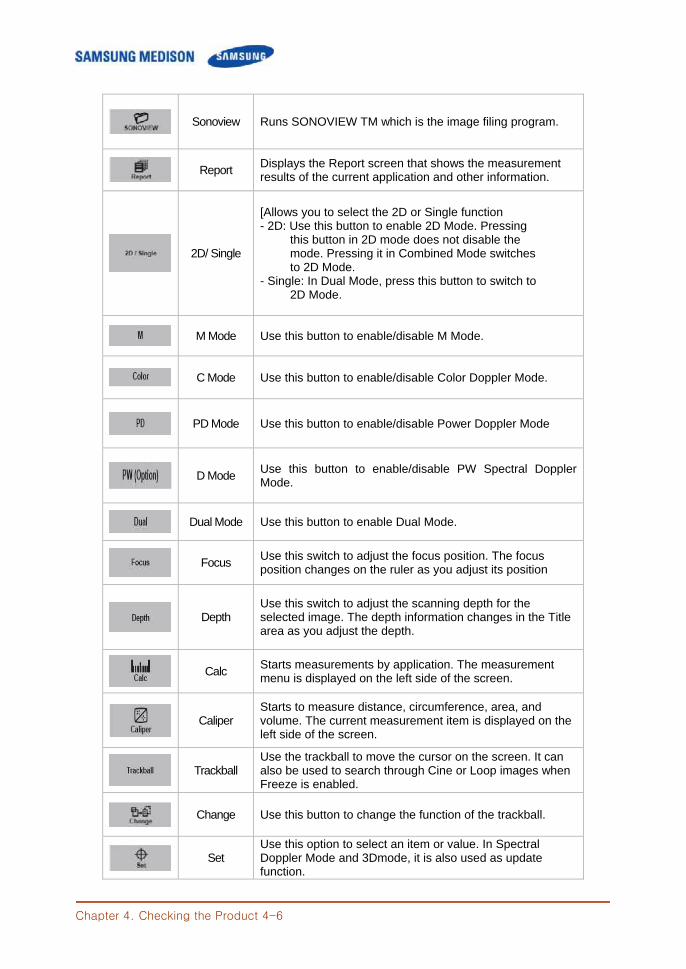
Chapter 4. Checking the Product 4-6
Sonoview Runs SONOVIEW TM which is the image filing program.
Report Displays the Report screen that shows the measurement
results of the current application and other information.
2D/ Single
[Allows you to select the 2D or Single function - 2D: Use this button to enable 2D Mode. Pressing this button in 2D mode does not disable the mode. Pressing it in Combined Mode switches to 2D Mode. - Single: In Dual Mode, press this button to switch to 2D Mode.
M Mode Use this button to enable/disable M Mode.
C Mode Use this button to enable/disable Color Doppler Mode.
PD Mode Use this button to enable/disable Power Doppler Mode
D Mode Use this button to enable/disable PW Spectral Doppler
Mode.
Dual Mode Use this button to enable Dual Mode.
Focus Use this switch to adjust the focus position. The focus
position changes on the ruler as you adjust its position
Depth
Use this switch to adjust the scanning depth for the selected image. The depth information changes in the Title area as you adjust the depth.
Calc Starts measurements by application. The measurement
menu is displayed on the left side of the screen.
Caliper
Starts to measure distance, circumference, area, and volume. The current measurement item is displayed on the left side of the screen.
Trackball
Use the trackball to move the cursor on the screen. It can also be used to search through Cine or Loop images when Freeze is enabled.
Change Use this button to change the function of the trackball.
Set
Use this option to select an item or value. In Spectral Doppler Mode and 3Dmode, it is also used as update function.
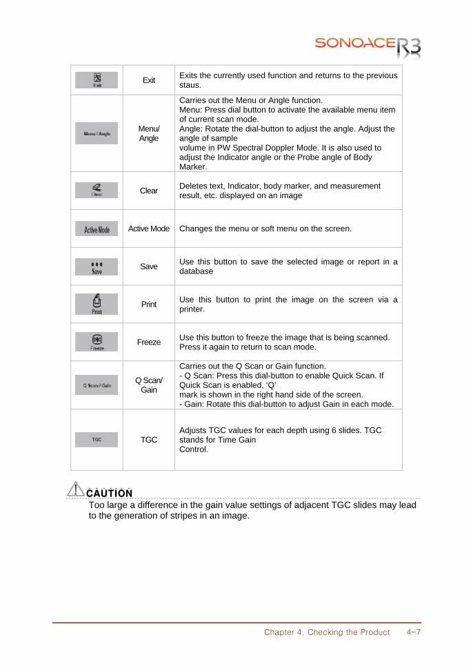
Chapter 4. Checking the Product 4-7
Exit Exits the currently used function and returns to the previous
staus.
Menu/ Angle
Carries out the Menu or Angle function. Menu: Press dial button to activate the available menu item of current scan mode. Angle: Rotate the dial-button to adjust the angle. Adjust the angle of sample volume in PW Spectral Doppler Mode. It is also used to adjust the Indicator angle or the Probe angle of Body Marker.
Clear Deletes text, Indicator, body marker, and measurement
result, etc. displayed on an image
Active Mode Changes the menu or soft menu on the screen.
Save Use this button to save the selected image or report in a
database
Print Use this button to print the image on the screen via a
printer.
Freeze Use this button to freeze the image that is being scanned.
Press it again to return to scan mode.
Q Scan/
Gain
Carries out the Q Scan or Gain function. - Q Scan: Press this dial-button to enable Quick Scan. If Quick Scan is enabled, ‘Q’ mark is shown in the right hand side of the screen. - Gain: Rotate this dial-button to adjust Gain in each mode.
TGC Adjusts TGC values for each depth using 6 slides. TGC stands for Time Gain Control.
CCAAUUTTIIOONN ˙ ˙ ˙ ˙ ˙ ˙ ˙
Too large a difference in the gain value settings of adjacent TGC slides may lead to the generation of stripes in an image.
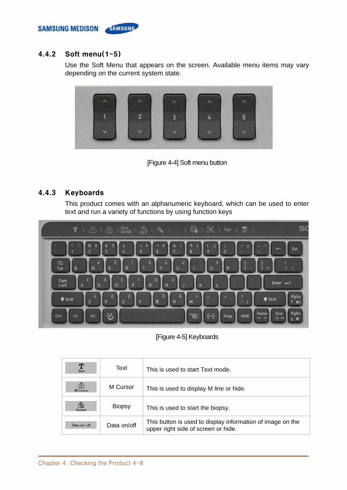
Chapter 4. Checking the Product 4-8
4.4.2 Soft menu(1~5)
Use the Soft Menu that appears on the screen. Available menu items may vary depending on the current system state.
[Figure 4-4] Soft menu button
4.4.3 Keyboards
This product comes with an alphanumeric keyboard, which can be used to enter text and run a variety of functions by using function keys
[Figure 4-5] Keyboards
Text This is used to start Text mode.
M Cursor This is used to display M line or hide.
Biopsy This is used to start the biopsy.
Data on/off This button is used to display information of image on the upper right side of screen or hide.
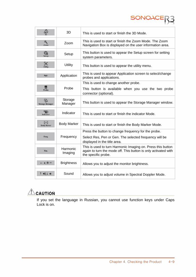
Chapter 4. Checking the Product 4-9
3D This is used to start or finish the 3D Mode.
Zoom This is used to start or finish the Zoom Mode. The Zoom Navigation Box is displayed on the user information area.
Setup This button is used to appear the Setup screen for setting system parameters.
Utility This button is used to appear the utility menu.
Application This is used to appear Application screen to select/change probes and applications.
Probe This is used to change another probe.
This button is available when you use the two probe connector (optional).
Storage Manager This button is used to appear the Storage Manager window.
Indicator This is used to start or finish the indicator Mode.
Body Marker This is used to start or finish the Body Marker Mode.
Frequency Press the button to change frequency for the probe.
Select Res, Pen or Gen. The selected frequency will be displayed in the title area.
Harmonic Imaging
This is used to turn Harmonic Imaging on. Press this button again to turn the mode off. This button is only activated with the specific probe.
Brightness Allows you to adjust the monitor brightness.
Sound Allows you to adjust volume in Spectral Doppler Mode.
CCAAUUTTIIOONN ˙ ˙ ˙ ˙ ˙ ˙ ˙
If you set the language in Russian, you cannot use function keys under Caps Lock is on.
Chapter 4. Checking the Product 4-10
4.5 Checking the Performance
4.5.1 Basic Check
1) Monitor Check the screen color, focus, dots, residual image, spot, blurring, etc.. Check the screen status when a shock is applied to the monitor and check the signal when you shake the cable. 2) Control Panel and LED Status
Press on control panel key and check if the corresponding character is displayed on the screen.
Check if the Key board LED is turned on. 3) Body Mark Key
Check if the Body Mark [Body Mark Key] is properly displayed and if the key works properly.
4) Indicator Key Check if the trackball works properly by moving it up, down, left and right.
5) Clear Key Check if TEXT and measurement data is erased properly when this key is pressed.
6) Zoom Operation Examination Check that the Zoom works properly.
7) Sonoview Examination Save an IMAGE and CINE INAGE in each mode. Check if the images are properly saved. Check if Backup & Restore works properly.
8) Measure Check if DISTANCE, CALIPER and CALC works properly.
9) Patient Enter information in PATIENT and check if the entered contents appear in the report or SonoView.
10) End Exam Measure for a New Patient and check if the measured data is cleared when End Exam is selected.
11) Probe Key Check if it works properly when the probe is changed.
Chapter 4. Checking the Product 4-11
4.5.1 Detail Check
1) B Mode ① Check if there is any missing line in an image by doing a Knife Test. ② Check if the image is displayed properly through Phantom. ③ Check if Freeze Cine ( Broken Image, Auto run, Auto run Speed and Track
ball Cine) and its related functions work properly. ④ Check if there is an image brightness change when the Gain is adjusted. ⑤ Check if there is an image brightness change when the TGC Gain is adjusted.
⑥ Check if the image is flipped horizontally or vertically and left or right when the Left/Right Flip, Up/Down Direction and Rotation keys are pressed.
⑦ Check if the image select menus (EE, DR, View Area, Tissue, Frame Rate) work properly.
⑧ Check if the frequency (Phantom, Res, Pen, Gen) is normal.
⑨ Check if the image changes according to Depth change.
⑩ Check if the image changes according to Depth change when the focus is changed.
⑪ Check if the image compensation modes (FSI, Harmonic, DMR, SRF, Quick Scan, Spatial Compound Imaging) work properly.
2) Dual Mode ① Check if the image is displayed properly through Phantom. ② Check if the image is flipped horizontally or vertically and left or right when
the Left/Right Flip, Up/Down Direction and Rotation keys are pressed. ③ Check if the image select menus (EE, DR, View Area, Tissue, Frame Rate,
Sane angle, Power) work properly. ④ Check if the frequency (Phantom, Res, Pen, Gen) is normal. ⑤ Check if the image changes according to Depth change.
⑥ Check if the image changes according to Depth change when the focus is changed.
⑦ Check if the left or right image Cine (number of pages, Auto run, Auto run Speed and Track ball Cine) and its related functions work properly.
3) M Mode ① Check if the image is displayed properly through Phantom. ② Check if theinformation on M Line is displayed in the Image area. ③ Check if there is an image brightness change when the GAIN is adjusted.. ④ Check if image select menus (EE, DR, View Area, Tissue, Frame Rate, Sane
angle, Power ) work properly.
Chapter 4. Checking the Product 4-12
⑤ Check if image changes according to Depth change.
⑥ Check if the image changes according to Depth change when the focus is changed
⑦ Check if the speed change and information is correct according to the SPEED conversion step.
⑧ Check if an image is reversed when Negative operates.
⑨ Check if the Top Down Format and Side by Sede Format Image are correct when Loop Format is selected.
⑩ Check if the Freeze Cine (Broken Image, Auto run, Auto run Speed and Track ball Cine) and its related functions work properly.
. 4) C Mode & PD Mode ① Check if the image is displayed properly through Phantom. ② Check if the image select menus (Balance, Sensitivity, Color Mode, Display)
work properly. ③ Check if the image changes according to Depth change. ④ Check if Freeze Cine ( Broken Image, Auto run, Auto run Speed and Track
ball Cine) and its related functions work properly. ⑤ Check if there is image brightness change when the Color Gain is adjusted.
⑥ Check if an image is broken or if there is noise (B or C Mode Noise) When ROI Box is moved.
⑦ Adjust the Scale up and down and check if the frequency is converted and blood flow speed range is controlled. (Check with directly scan)
⑧ Operate the filter and check if small signals are removed by step.
⑨ Check if the Color Bar is reserved when the Invert key is pressed.
⑩ Move the Baseline up and down and check if the blood flow range moves to + or - part.
5) D Mode ① Check if the image is displayed properly through Phantom. ② Check if the Doppler PRF value changes as the Simultaneous is turned on or off. ③ Check if the Doppler spectrum works properly. ④ Change the Scale and check the speed range change. ⑤ Move the Baseline up and down and check if the blood flow range moves to
+ or – part.
⑥ Operate the filter and check if small signals in the spectrum are removed.
⑦ Operate the Invert and check if the Doppler waveform is reversed.
⑧ Operate the Angle.
Chapter 4. Checking the Product 4-13
⑨ Move the SV or Size and check if it works properly.
⑩ Change the Spectrum Type and check if the spectrum video changes.
⑪ Check if Sound Volume works properly.
⑫ Check if the line when appears when Auto Calc runs is continuous and if the subsequent calculations are automatically done correctly.
⑬ Check if the Top Down Format and Side by Side Format Image are correct when LOOP FORMAT is selected.
⑭ Check if the CINE/LOOP (Broken Image, Auto run, Auto run Speed and Track ball Cine) and its related functions work properly.
Chapter 5. Product structure 5-1
CChhaapptteerr 55.. PPrroodduucctt SSttrruuccttuurree
5.1 Overview
Chapter 5 describes the internal structure and operation mechanism of SonoAce R3. This chapter must be read for the product maintenance and upgrade. SonoAce R3 is high technology ultrasound system. It not only adopted 15 inch LCD monitor and provides high resolution ultrasound Image, but also provides the premium grade system functions. To improve the processing speed, SAMSUNG MEDISON Co., Ltd. developed new interface to connect a latest PC and the ultrasound system with its proprietary technology. The enhancement of processor speed makes the system operations faster and reduces diagnosis time. SonoAce R3 can use up to 96 Element probes and adopted Digital Beamforming of TX 32 Channels. Ultrasound image is displayed on the LCD through the Front End Part and Back End Part (including PC Part). The resolution of the LCD monitor is 1024 X 768 pixels and various image formats are provided. The wide view angle of the LCD panel provides convenient work environment for diagnosis. The USB port are placed on the front panel of the system for easier image backup and software service. Since this system supports various external storage devices such as USB MO, USB Flash Memory and external-type USB HDD, upgrade becomes more easier. SonoAce R3 consists of the following major components.
Ultrasound System Part : PSA, Main Board, Rear Board, PC Module Monitor Part Control Panel Part : Control Panel Board, Track Ball, Power Part
Chapter 5. Product structure 5-2
Contents
5.1 Overview ..................................................................................................5-1
5.2 System Block Diagram .............................................................................5-3
5.3 Basic Structure of SonoAce R3 ................................................................5-4
5.4 PSA (2 Port Option) ...................................................................................5-5
5.5 Beamformer Part .......................................................................................5-7
5.6 Back End Part .......................................................................................... 5-11
5.7 Rear Board ............................................................................................. 5-17
5.8 Control Panel .......................................................................................... 5-18
5.9 Power Supply ......................................................................................... 5-19
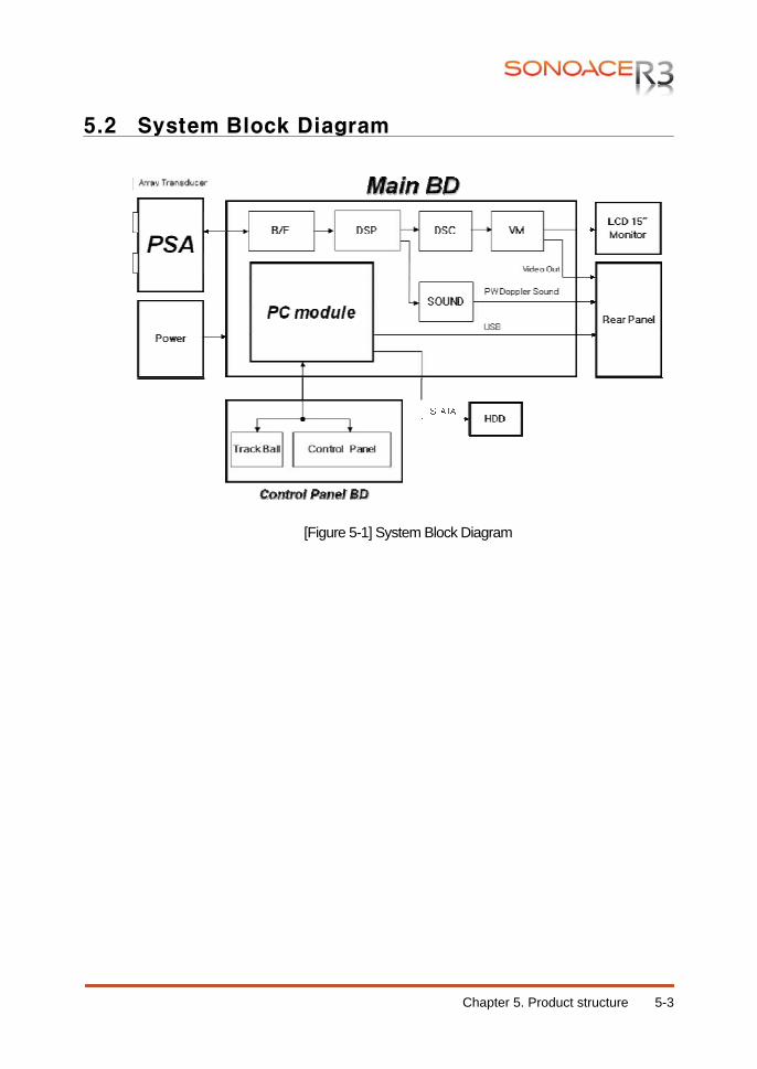
Chapter 5. Product structure 5-3
5.2 System Block Diagram
[Figure 5-1] System Block Diagram
Chapter 5. Product structure 5-4
5.3 Basic Structure of SonoAce R3
5.3.1 Overview
SonoAce R3 consists of Ultrasound System Part, PC Part, User Interface Part and Power Part. However, it consists of Front End Part, Back End Part, User Interface Part, and Power Part from the electronical view point. The following is the description of electronical structure of SonoAce R3. Front End Part refers to PSA (Probe Select Assembly), and BF (Beamformer) Part of the Ultrasound System Part. The Front End Part delivers High Voltage Pulser to the probe so that ultrasound is generated, amplifies the returned echo signal and processes Digital Beamforming. The RF signal generated here is delivered to the Back End Part. Back End Part refers to the BE(Back End) Board and PC of the Ultrasound System Part. The RF signal generated in the FE(Front End) Board is processed to diagnosis image such as BW, Color Doppler, PW Doppler, and Power Doppler and displayed on the monitor so that users can see it. User Interface Part refers to the LCD monitor and control panel.
5.3.2 Ultrasound System Part
It recognizes probes and delivers system and application information depending on the user environment to each board. Based on the information, TX Focusing and RX Focusing are done. When high-voltage Pulser is delivered to probe along through the TX Focusing, ultrasound is generated and the echo signal returned from human body is amplified by the amplifier circuit and then is processed by Digital Beamforming. The RF signal generated here is delivered to the PC Part to process it to provide diagnosis image such as BW, Color Doppler, PW Doppler, and Power Doppler and display it on the monitor.
5.3.3 User Interface Part
User Interface Part enables users to view ultrasound image on the LCD monitor and control SonoAce R3 through the control panel The image output from the Back End Board is transferred to the LCD monitor and external device. Image output interface includes VHS, S-VHS, Composite, and DVI In addition, the control panel enables users to easily operate the system through various interfaces.
5.3.4 AC to DC Power Module
It converts 110/230V AC voltage from external into DC voltage and supplies power to the Ultrasound System Part and It provides power cut-off switch and fuse to prevent problem due to over-voltage.
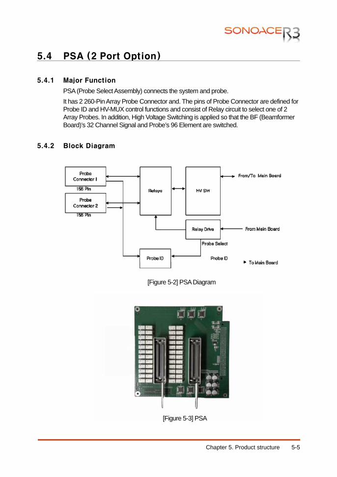
Chapter 5. Product structure 5-5
5.4 PSA (2 Port Option)
5.4.1 Major Function
PSA (Probe Select Assembly) connects the system and probe. It has 2 260-Pin Array Probe Connector and. The pins of Probe Connector are defined for Probe ID and HV-MUX control functions and consist of Relay circuit to select one of 2 Array Probes. In addition, High Voltage Switching is applied so that the BF (Beamformer Board)’s 32 Channel Signal and Probe’s 96 Element are switched.
5.4.2 Block Diagram
[Figure 5-2] PSA Diagram
[Figure 5-3] PSA
Chapter 5. Product structure 5-6
5.4.3 Specification
32 Channel BF Board Support 260 Pin Array Probe Connector 2ea(Option) High Voltage Switching (32 Channel : 80 Element) Probe Switching Probe ID Reader
5.4.4 Operation Mechanism
5.4.4.1 High Voltage Switching Process SonoAce R3 supports 32 Channels and 192 Elements Probes. Since the BF(Beamformer part)’s Pulser and Receiver circuit consists of 32 Channels only, additional Element Selection is necessary. Element Selection uses High Voltage Switches and switches based on the Control Signal output from the DSP FPGA Control Signal is connected through the Mother Board Connector. High Voltage Switch consists of the Shift Register and High Voltage FET.
5.4.4.2 Probe Switching It consists of circuit to select one of 2 probes. It can select a probe selected by the user by using Latched type relay. It drives the Relay with the Probe Select signal transmitted from the DSP FPGA. The Probe Select signal is connected through Mother Board Connector.
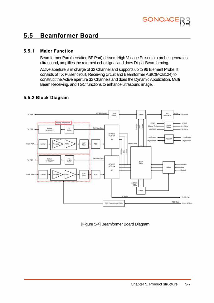
Chapter 5. Product structure 5-7
5.5 Beamformer Board
5.5.1 Major Function
Beamformer Part (hereafter, BF Part) delivers High Voltage Pulser to a probe, generates ultrasound, amplifies the returned echo signal and does Digital Beamforming. Active aperture is in charge of 32 Channel and supports up to 96 Element Probe. It consists of TX Pulser circuit, Receiving circuit and Beamformer ASIC(MCB124) to construct the Active aperture 32 Channels and does the Dynamic Apodization, Multi Beam Receiving, and TGC functions to enhance ultrasound image.
5.5.2 Block Diagram
[Figure 5-4] Beamformer Board Diagram
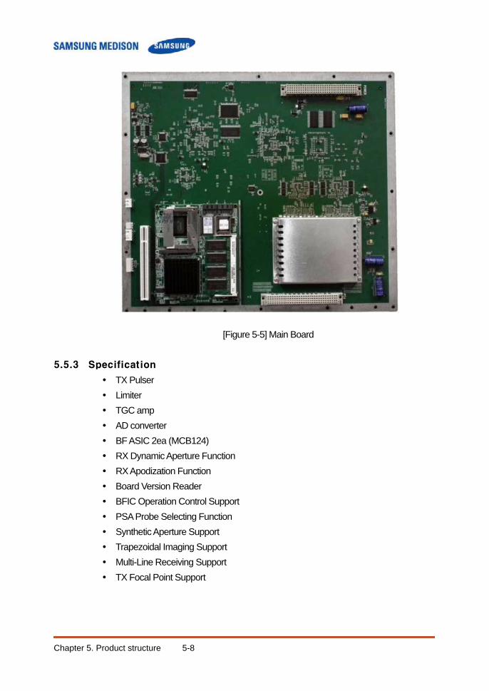
Chapter 5. Product structure 5-8
[Figure 5-5] Main Board
5.5.3 Specification
TX Pulser Limiter TGC amp AD converter BF ASIC 2ea (MCB124) RX Dynamic Aperture Function RX Apodization Function Board Version Reader BFIC Operation Control Support PSA Probe Selecting Function Synthetic Aperture Support Trapezoidal Imaging Support Multi-Line Receiving Support TX Focal Point Support
Chapter 5. Product structure 5-9
5.5.4 Operation Mechanism
5.5.4.1 TX Pulser
The Exciting pulse data provided by BF ASIC(MCB124) is applied to TX Pulser via TX Pulse Buffer. TX Pulser(MHIC2022) generates Bipolar Pulser using the Exciting pulse data and the High Voltage. Bipolar Pulser is sent to the Probe element by using the PSA (Probe Select Assembly) to generate ultrasound. Since Active aperture 132 Channels provide up to 96 Elements, additional Element Selection is necessary. For this purpose, High Voltage Switch is used. High Voltage Switch is constructed in PSA (Probe Select Assembly).
5.5.4.2 Receive Channel Receive Channel amplifies echo that is penetrated through the medium of human body and the reflected, and does the role of Analog Digital Converter so that Beamforming can be conducted. It consists of Limiter and Pre-Amp, TGC-Amp, Low-Pass Filter and A/D Converter.
1) Limiter
It removes unnecessary signal from the Echo returned through the PSA (Probe Select Assembly)’s High Voltage Switch. Up to 180 Vpp Tx Pulses and a few mV Echo signals are mixed. Since actually necessary RX data is the echo signal of a few mV, Tx Pulse should be removed before the signal to the Pre-Amp. Limiter removes signal of higher than approximately 0.6V and transfers the echo signal to the Pre-Amp.
2) Pre-Amp
Pre-Amp amplifies echo signal of a few mV that is not processed.
3) TGC-Amp Each TGC(Time Gain Compensation) Amp consists of 4 channels. Since the echo signal that is penetrated and reflected by medium diminishes as it traverses, it compensates the attenuation of the signal.
4) Low Pass Filter(Anti-aliasing) Low-Pass Filter filters noise in Stop Band that is out of ultrasound band. In addition, it does the role of Anti-aliasing Filter that minimizes the Aliasing Effect that may appear in a high frequency probe such as 7.5MHz probe. The Aliasing of high frequency probe occurs due to the limitation of the Sampling Clock in the BF ASIC.
5) A/D Converter It converts the digital signal to be used in the Digital Beamforming into analog.
Chapter 5. Product structure 5-10
5.5.4.3 Digital Beamforming The ultrasound generated by a probe takes channel mode that uses a number of elements for TX Focusing. The ultrasound generated by channel is penetrated through medium and reflected as echo signal. However, since echo signals do not return to Probe Element simultaneously, but they return with delay variation. Therefore, a countermeasure against the delays is necessary for RX Focusing and it is very important to construct ultrasound image. Digital Beamforming samples the echo signal returned to Probe Element and save the sampled data into the memory. The data saved in the memory when the sampling is complete means that time compensation is complete. The time compensation is done by the Sampling Clock itself. RX Focusing becomes complete, just by reading the data saved in memory and adding the data. Since this method requires different Sampling Clock for each element, VSCG(Variable Sampling Clock Generator) is necessary. VSCG(Variable Sampling Clock Generator) uses 61.6Mhz that is the same as A/D Sampling Clock and generates data necessary for BF ASIC(MCB024A).
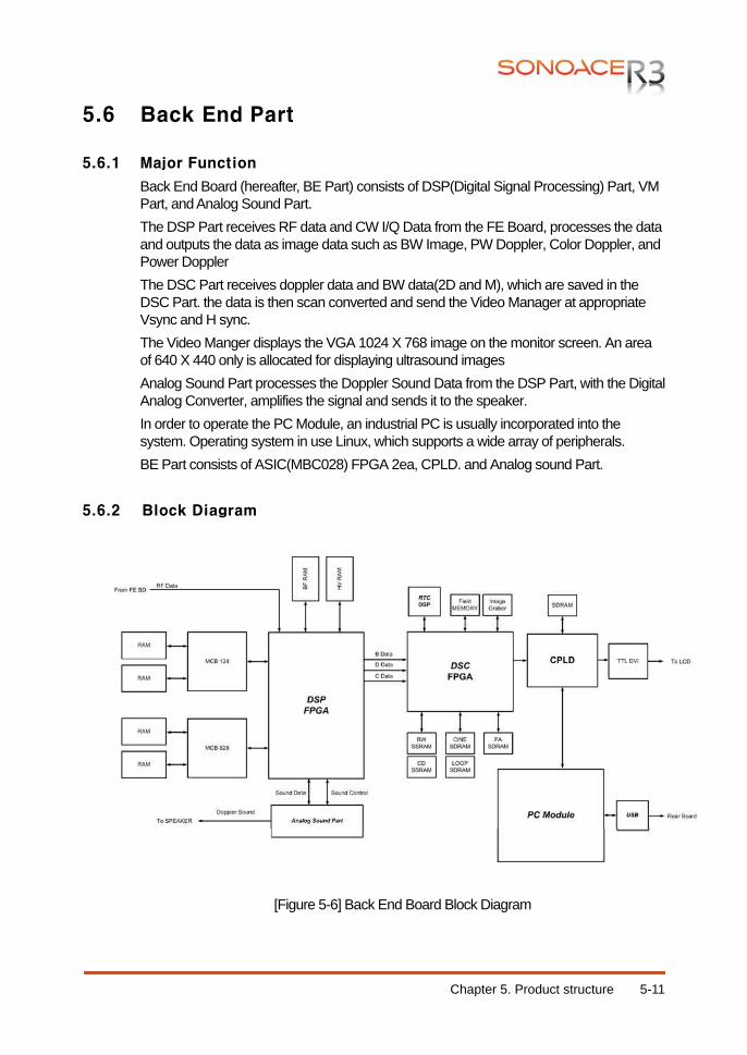
Chapter 5. Product structure 5-11
5.6 Back End Part
5.6.1 Major Function
Back End Board (hereafter, BE Part) consists of DSP(Digital Signal Processing) Part, VM Part, and Analog Sound Part. The DSP Part receives RF data and CW I/Q Data from the FE Board, processes the data and outputs the data as image data such as BW Image, PW Doppler, Color Doppler, and Power Doppler The DSC Part receives doppler data and BW data(2D and M), which are saved in the DSC Part. the data is then scan converted and send the Video Manager at appropriate Vsync and H sync. The Video Manger displays the VGA 1024 X 768 image on the monitor screen. An area of 640 X 440 only is allocated for displaying ultrasound images Analog Sound Part processes the Doppler Sound Data from the DSP Part, with the Digital Analog Converter, amplifies the signal and sends it to the speaker. In order to operate the PC Module, an industrial PC is usually incorporated into the system. Operating system in use Linux, which supports a wide array of peripherals. BE Part consists of ASIC(MBC028) FPGA 2ea, CPLD. and Analog sound Part.
5.6.2 Block Diagram
[Figure 5-6] Back End Board Block Diagram
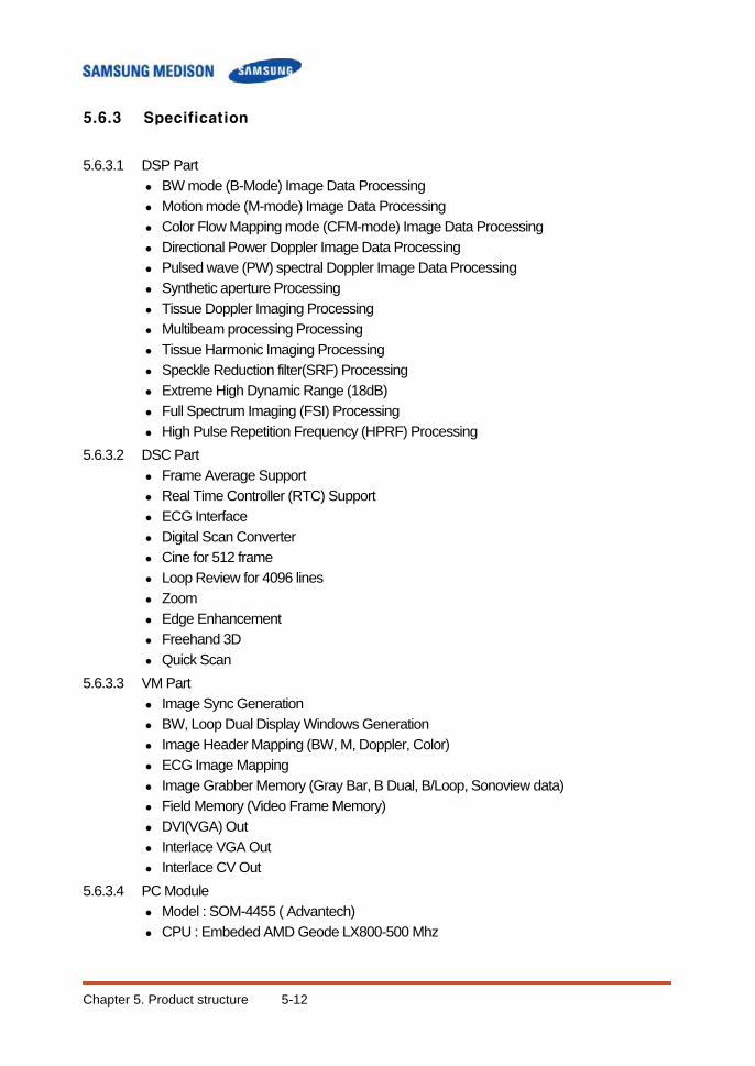
Chapter 5. Product structure 5-12
5.6.3 Specification
5.6.3.1 DSP Part
BW mode (B-Mode) Image Data Processing Motion mode (M-mode) Image Data Processing Color Flow Mapping mode (CFM-mode) Image Data Processing Directional Power Doppler Image Data Processing Pulsed wave (PW) spectral Doppler Image Data Processing Synthetic aperture Processing Tissue Doppler Imaging Processing Multibeam processing Processing Tissue Harmonic Imaging Processing Speckle Reduction filter(SRF) Processing Extreme High Dynamic Range (18dB) Full Spectrum Imaging (FSI) Processing High Pulse Repetition Frequency (HPRF) Processing
5.6.3.2 DSC Part Frame Average Support Real Time Controller (RTC) Support ECG Interface Digital Scan Converter Cine for 512 frame Loop Review for 4096 lines Zoom Edge Enhancement Freehand 3D Quick Scan
5.6.3.3 VM Part Image Sync Generation BW, Loop Dual Display Windows Generation Image Header Mapping (BW, M, Doppler, Color) ECG Image Mapping Image Grabber Memory (Gray Bar, B Dual, B/Loop, Sonoview data) Field Memory (Video Frame Memory) DVI(VGA) Out Interlace VGA Out Interlace CV Out
5.6.3.4 PC Module Model : SOM-4455 ( Advantech) CPU : Embeded AMD Geode LX800-500 Mhz
Chapter 5. Product structure 5-13
5.6.4 DSP Part Operation Mechanism
5.7.4.1 BW Mode and M Mode Image Data Processing
RF data generated in the BF Board in Input to the FPGA. The input RF data in converted into RF data, which can be processed by the FPGA, and Input to the ASIC (MCB028A). The ASIC (MCB028A) generate BW mode image data (hereafter, BW Data) and send the data to the DSP FPGA. ASIC(MCB028) not only generate BW data but also do the functions of FSI(Full Spectrum Image), Spatial Compound Imaging (SCI), Trapezoidal Imaging, and Synthetic Aperture. Especially, BW data is generated using the received RF data and through the DTGC(Digital Time Gain Compensation), Decimation, Quadrature mixer, Envelope detection, Log compression and various filters. The BW data generated by ASIC(MCB028A) as described above are input to the DSP FPGA again. The data are processed by FSI(Full Spectrum Image) and Lateral filter, which is used to remove Multibeam artifact, and sent to the DSC Part. For your reference, BW data can also be used as Motion Mode Image Data.
5.7.4.2 Doppler Image Data Processing The RF data generated in the BF Board is input to the FPGA. The input RF data is converted into RF data that can be processed by the FPGA and input to the ASIC (MCB028A). ASIC (MCB028A) receives RF data and does the DTGC (Digital Time Gain Compensation), Decimation, and Quadrature mixer processing for the RF data . The RF data becomes I/Q data (In-phase & Quadrature Data). I/Q data are input to the DSP FPGA again. I/Q data are processed by the FPGA and Doppler DSP and become Doppler Data and are sent to the DSC Part. Detailed descriptions are given below. The DSP FPGA that received the I/Q Data, sends the data to the Doppler DSP via filtering. I/Q Data passes through the Clutter Filter. After that, the Doppler Sound is generated through the Hilbert transform that separates sound directions. The data are input to the DSP FPGA again and is sent to the Analog Sound Part of the DSC Part. In addition, I/Q Data are sent to the FFT (Fast Fourier Transform) circuit to generate the Doppler Spectrum, after passing through the Clutter Filter. By extracting the basic Doppler components of Power, Velocity, and Variance components, the Doppler Data are generated. The data are input to the DSP FPGA again and is sent to the DSC Part
5.7.4.3 Color Image Data Processing The RF data generated in the BF Board is input to the FPGA. The input RF data is converted into RF data that can be processed by the FPGA and input to the ASIC (MCB028A).
Chapter 5. Product structure 5-14
ASIC (MCB028A) receives RF data and does the DTGC (Digital Time Gain Compensation), Decimation, and Quadrature mixer processing for the RF data . The RF data becomes I/Q data (In-phase & Quadrature Data). I/Q data are input to the DSP FPGA again. I/Q data are processed by the FPGA and Doppler DSP and become Doppler Data and are sent to the DSC Part. Detailed descriptions are given below. The DSP FPGA receives the I/Q Data, sends the data to the ASIC (MCB028A) to extract color components. However, since the color component include Wall (blood vessel wall) Noise, the data are sent to the DSP FPGA again and passes through the Rejection, Smooth Filter, and Post Filter. Color Data are completed in the process and sent to the DSC Part
5.6.5 Analog Sound Part Operation Mechanism
Processes the Doppler Sound and outputs to the speaker. Doppler Sound is generated in the Doppler Part and is sent to the Analog Sound Part. Doppler Sound passes through Audio Digital Analog Converter because the speaker requires analog signal.
5.6.6 DSC Part Operation Mechanism
The DSC Part is an image filter circuit that improves image quality. It consists of the screen conversion part which writes the received scan line data reads the monitor by the H-sync cycle, frame memory part, and zoom and freehand 3D path parts. The DSC Part sums data from 2D mode and spectral Doppler mode produced by different paths together as one set of common data. If facilitates various functions such as Digital Scan Conversion and Frame Average, 3D(DMA), Cine, RTC, Read Zoom, and Edge Enhance along with Memory.DMA (Direct Memory Access) consists of FA(Frame Average), DMA and ECG In/Out Part. Since DMA processes data using the DMA path with the PC Module, it plays key role to improve the product performance. RTC(Real Time Controller) generates base signal necessary for entire system operation in real-time and controls the system operations. It generates and controls the PRF (Pulse Repeat Frequency), OF(One Frame), RP(Rate Pulse), Line Type, and Scan Line signals necessary.
5.6.7 VM Part Operation Mechanism
The Video Manger Part converts the image data received from the DSC Part into Video image for displaying on the monitor and key it in with PC’s VGA data. The keyed data id turmed into interlace and non-interlace signals for displaying the final output through a VGA monitor, interlace monitor, echo printer, etc.
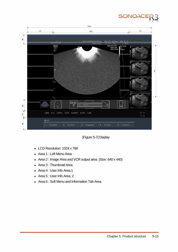
Chapter 5. Product structure 5-15
[Figure 5-7] Display
LCD Resolution: 1024 x 768 Area 1 : Left Menu Area Area 2 : Image Area and VCR output area. (Size: 640 x 440) Area 3 : Thumbnail Area. Area 4 : User Info Area.1 Area 5 : User Info Area. 2 Area 6 : Soft Menu and Information Tab Area.
640
1024
192192
Chapter 5. Product structure 5-16
5.6.8 PC Module Operation Mechanism
5.6.8.1 PCI/Local Bus Interface PCI/Local Bus Interface connects to the PCI bus of the CPU, converting it into a Local Bus so that various devices in the Local bus can be allocated in absolute address ranges fir their direct use.
5.6.8.2 Peripheral Port Interface CPU : Embedded AMD Geode LX800-500MHz Main Memory : 512MB DDR SDRAM Operating System : Linux Kernel 2.6.17.14 Compiler : g++ v3.2.2 USB 2.0
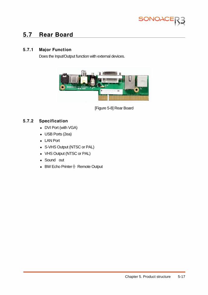
Chapter 5. Product structure 5-17
5.7 Rear Board
5.7.1 Major Function
Does the Input/Output function with external devices.
[Figure 5-8] Rear Board
5.7.2 Specification
DVI Port (with VGA) USB Ports (2ea) LAN Port S-VHS Output (NTSC or PAL) VHS Output (NTSC or PAL) Sound out BW Echo Printer용 Remote Output
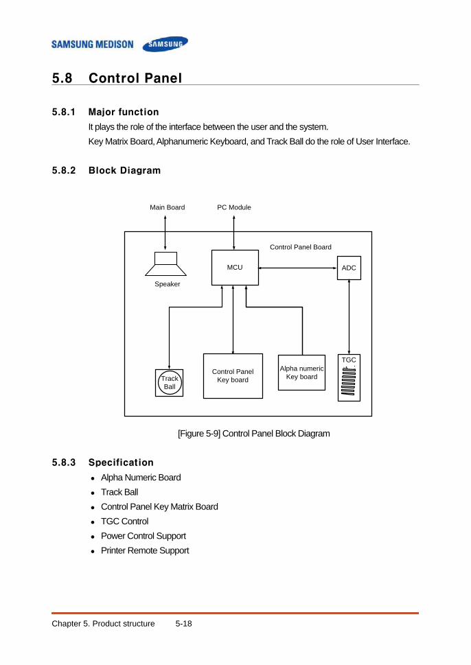
Chapter 5. Product structure 5-18
5.8 Control Panel
5.8.1 Major function
It plays the role of the interface between the user and the system. Key Matrix Board, Alphanumeric Keyboard, and Track Ball do the role of User Interface.
5.8.2 Block Diagram
[Figure 5-9] Control Panel Block Diagram
5.8.3 Specification
Alpha Numeric Board Track Ball Control Panel Key Matrix Board TGC Control Power Control Support Printer Remote Support
TGC
TrackBall
MCU
Alpha numeric Key board
PC Module
ADC
Control Panel Board
Control PanelKey board
Main Board
Speaker
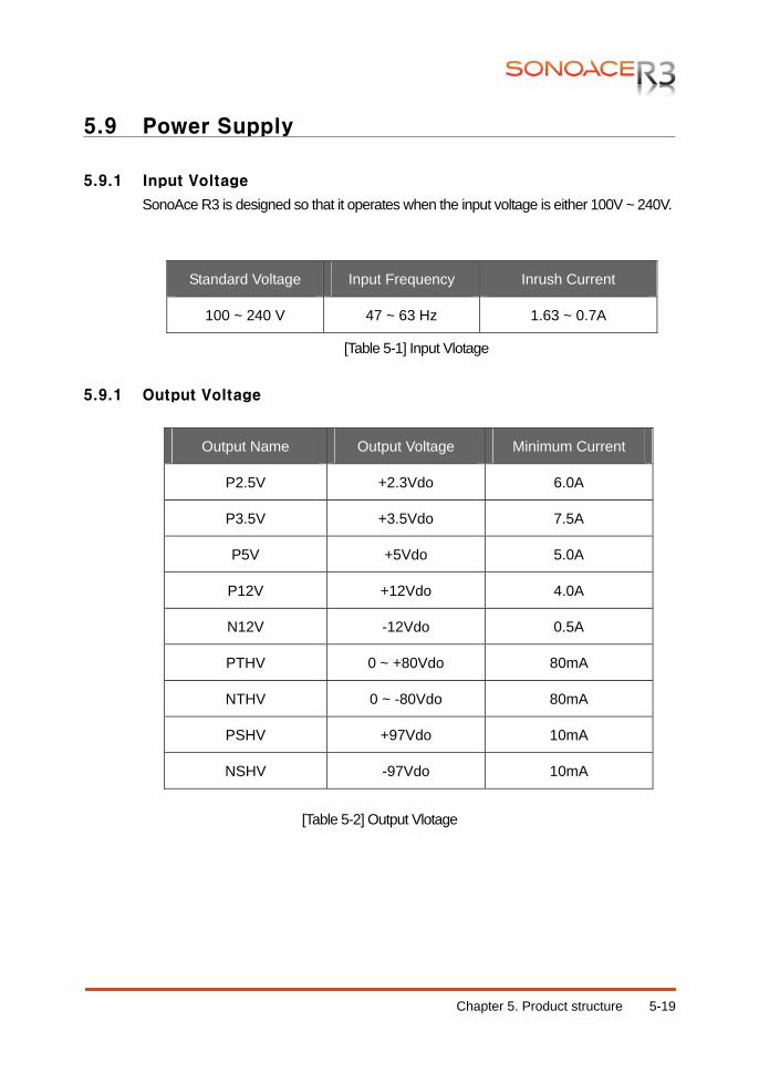
Chapter 5. Product structure 5-19
5.9 Power Supply
5.9.1 Input Voltage
SonoAce R3 is designed so that it operates when the input voltage is either 100V ~ 240V.
Standard Voltage Input Frequency Inrush Current
100 ~ 240 V 47 ~ 63 Hz 1.63 ~ 0.7A
[Table 5-1] Input Vlotage 5.9.1 Output Voltage
[Table 5-2] Output Vlotage
Output Name Output Voltage Minimum Current
P2.5V +2.3Vdo 6.0A
P3.5V +3.5Vdo 7.5A
P5V +5Vdo 5.0A
P12V +12Vdo 4.0A
N12V -12Vdo 0.5A
PTHV 0 ~ +80Vdo 80mA
NTHV 0 ~ -80Vdo 80mA
PSHV +97Vdo 10mA
NSHV -97Vdo 10mA
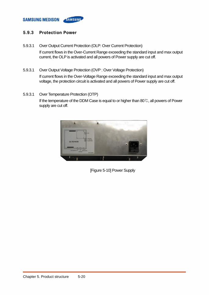
Chapter 5. Product structure 5-20
5.9.3 Protection Power
5.9.3.1 Over Output Current Protection (OLP: Over Current Protection) If current flows in the Over-Current Range exceeding the standard input and max output current, the OLP is activated and all powers of Power supply are cut off.
5.9.3.1 Over Output Voltage Protection (OVP : Over Voltage Protection)
If current flows in the Over-Voltage Range exceeding the standard input and max output voltage, the protection circuit is activated and all powers of Power supply are cut off.
5.9.3.1 Over Temperature Protection (OTP)
If the temperature of the DDM Case is equal to or higher than 80℃, all powers of Power supply are cut off.
[Figure 5-10] Power Supply
Chapter 6. Basic Maintenance 6-1
Chapter 6. Basic Maintenance
6.1 Overview Chapter 6 describes basic EKO7maintenance procedures. How to upgrade and how to use Admin Mode (Service Mode) are described. Contents 6.1 Overview ..................................................................................................6-1 6.2 System Information ...................................................................................6-2 6.3 Admin Mode ..............................................................................................6-3 6.3.1 Entering Admin Mode .............................................................6-3 6.3.2 Admin Mode Functions...........................................................6-4 6.4 Upgrade . .............................................................................................6-6 6.4.1 Software Upgrade ...................................................................6-6 6.4.2 Hardware Upgrade .................................................................6-9 6.5 Backup & Restore .................................................................................. 6-10 6.5.1 Backup User Setting ............................................................ 6-10 6.5.2 Restore User Setting ........................................................... 6-12 6.6 Adding and Deleting Options................................................................. 6-14 6.6.1 Option type ........................................................................... 6-14 6.6.2 Registering Option ............................................................... 6-14 6.7 Control Panel .......................................................................................... 6-16
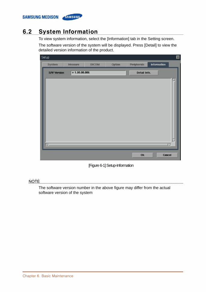
Chapter 6. Basic Maintenance
6.2 System Information To view system information, select the [Information] tab in the Setting screen. The software version of the system will be displayed. Press [Detail] to view the detailed version information of the product.
[Figure 6-1] Setup-Information
NNOOTTEE˙ ˙ ˙ ˙ The software version number in the above figure may differ from the actual software version of the system
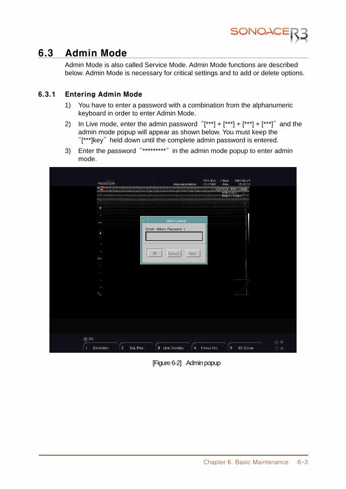
Chapter 6. Basic Maintenance 6-3
6.3 Admin Mode Admin Mode is also called Service Mode. Admin Mode functions are described below. Admin Mode is necessary for critical settings and to add or delete options.
6.3.1 Entering Admin Mode
1) You have to enter a password with a combination from the alphanumeric keyboard in order to enter Admin Mode. 2) In Live mode, enter the admin password “[***] + [***] + [***] + [***]” and the admin mode popup will appear as shown below. You must keep the “[***]key” held down until the complete admin password is entered. 3) Enter the password “*********” in the admin mode popup to enter admin mode.
[Figure 6-2] Admin popup

Chapter 6. Basic Maintenance
6.3.2 Admin Mode Functions
This section describes admin mode.
[Figure 6-3] Admin Mode 6.3.2.1 System Serial#
Enter the System Serial No. in system serial #.
6.3.2.2 Save Configurations Saves all settings in the system.
6.3.2.3 Init System Initializes the system back to the factory default settings.
6.3.2.4 Export Settings ( All Probes/Apps) R&D only.
6.3.2.5 Logo Supported logo is Product Logo, SAMSUNG MEDISON Logo and SONOACE Logo
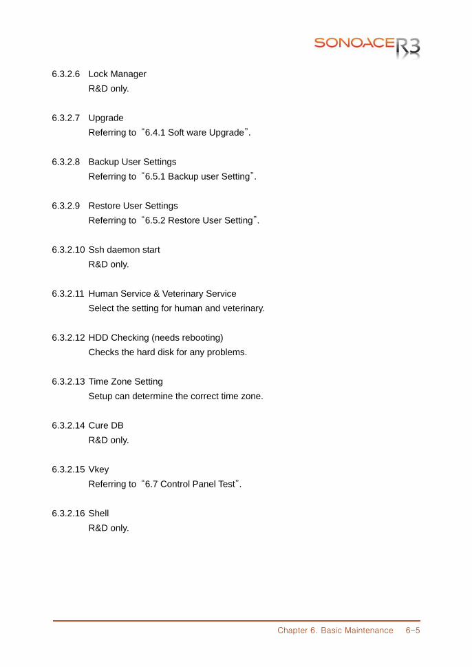
Chapter 6. Basic Maintenance 6-5
6.3.2.6 Lock Manager R&D only.
6.3.2.7 Upgrade Referring to “6.4.1 Soft ware Upgrade”.
6.3.2.8 Backup User Settings Referring to “6.5.1 Backup user Setting”.
6.3.2.9 Restore User Settings Referring to “6.5.2 Restore User Setting”.
6.3.2.10 Ssh daemon start R&D only.
6.3.2.11 Human Service & Veterinary Service Select the setting for human and veterinary.
6.3.2.12 HDD Checking (needs rebooting) Checks the hard disk for any problems.
6.3.2.13 Time Zone Setting Setup can determine the correct time zone.
6.3.2.14 Cure DB R&D only.
6.3.2.15 Vkey Referring to “6.7 Control Panel Test”.
6.3.2.16 Shell R&D only.
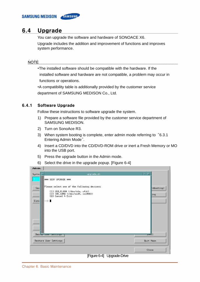
Chapter 6. Basic Maintenance
6.4 Upgrade You can upgrade the software and hardware of SONOACE X6. Upgrade includes the addition and improvement of functions and improves system performance.
NNOOTTEE˙ ˙ ˙ ˙ •The installed software should be compatible with the hardware. If the installed software and hardware are not compatible, a problem may occur in functions or operations. •A compatibility table is additionally provided by the customer service department of SAMSUNG MEDISON Co., Ltd.
6.4.1 Software Upgrade
Follow these instructions to software upgrade the system. 1) Prepare a software file provided by the customer service department of
SAMSUNG MEDISON. 2) Turn on SonoAce R3. 3) When system booting is complete, enter admin mode referring to “6.3.1
Entering Admin Mode”. 4) Insert a CD/DVD into the CD/DVD-ROM drive or inert a Fresh Memory or MO
into the USB port. 5) Press the upgrade button in the Admin mode. 6) Select the drive in the upgrade popup. [Figure 6-4]
[Figure 6-4] Upgrade-Drive
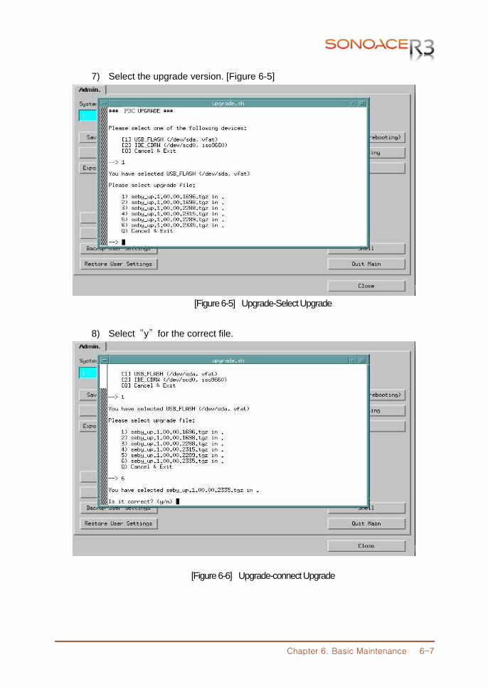
Chapter 6. Basic Maintenance 6-7
7) Select the upgrade version. [Figure 6-5]
[Figure 6-5] Upgrade-Select Upgrade
8) Select “y” for the correct file.
[Figure 6-6] Upgrade-connect Upgrade
P3C
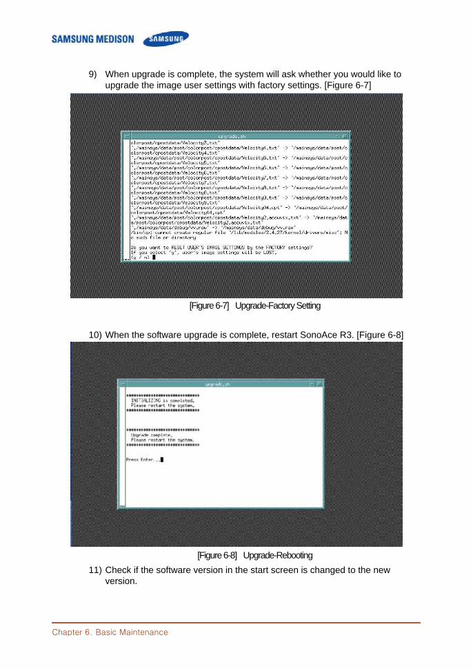
Chapter 6. Basic Maintenance
9) When upgrade is complete, the system will ask whether you would like to upgrade the image user settings with factory settings. [Figure 6-7]
[Figure 6-7] Upgrade-Factory Setting 10) When the software upgrade is complete, restart SonoAce R3. [Figure 6-8]
[Figure 6-8] Upgrade-Rebooting 11) Check if the software version in the start screen is changed to the new
version.
Chapter 6. Basic Maintenance 6-9
6.4.2 Hardware Upgrade
This means the replacement or addition of hardware.
NNOOTTEE˙ ˙ ˙ ˙ For information on hardware upgrade, refer to the “Chapter 8 Disassembly and Reassembly” of the Service Manual.
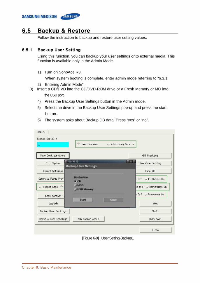
Chapter 6. Basic Maintenance
6.5 Backup & Restore Follow the instruction to backup and restore user setting values.
6.5.1 Backup User Setting
Using this function, you can backup your user settings onto external media. This function is available only in the Admin Mode. 1) Turn on SonoAce R3. When system booting is complete, enter admin mode referring to “6.3.1 2) Entering Admin Mode”.
3) Insert a CD/DVD into the CD/DVD-ROM drive or a Fresh Memory or MO into the USB port. 4) Press the Backup User Settings button in the Admin mode. 5) Select the drive in the Backup User Settings pop-up and press the start button.. 6) The system asks about Backup DB data. Press “yes” or “no”.
[Figure 6-9] User Setting-Backup1
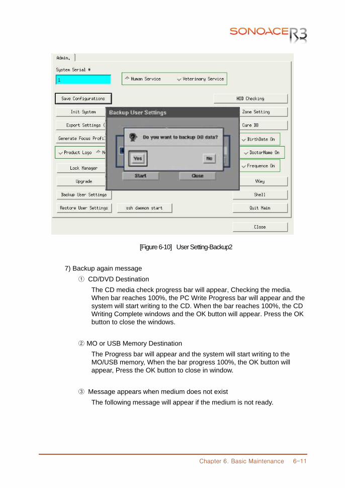
Chapter 6. Basic Maintenance 6-11
[Figure 6-10] User Setting-Backup2
7) Backup again message ① CD/DVD Destination The CD media check progress bar will appear, Checking the media. When bar reaches 100%, the PC Write Progress bar will appear and the system will start writing to the CD. When the bar reaches 100%, the CD Writing Complete windows and the OK button will appear. Press the OK button to close the windows. ② MO or USB Memory Destination The Progress bar will appear and the system will start writing to the MO/USB memory, When the bar progress 100%, the OK button will appear, Press the OK button to close in window. ③ Message appears when medium does not exist The following message will appear if the medium is not ready.
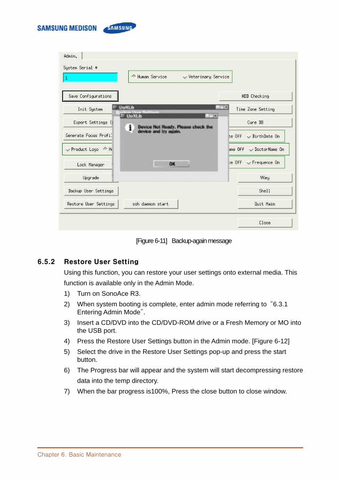
Chapter 6. Basic Maintenance
[Figure 6-11] Backup-again message 6.5.2 Restore User Setting
Using this function, you can restore your user settings onto external media. This function is available only in the Admin Mode. 1) Turn on SonoAce R3. 2) When system booting is complete, enter admin mode referring to “6.3.1 Entering Admin Mode”. 3) Insert a CD/DVD into the CD/DVD-ROM drive or a Fresh Memory or MO into the USB port. 4) Press the Restore User Settings button in the Admin mode. [Figure 6-12] 5) Select the drive in the Restore User Settings pop-up and press the start button. 6) The Progress bar will appear and the system will start decompressing restore data into the temp directory. 7) When the bar progress is100%, Press the close button to close window.
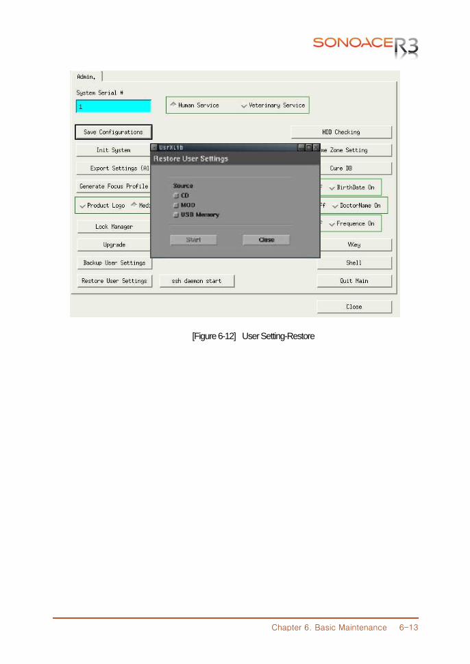
Chapter 6. Basic Maintenance 6-13
[Figure 6-12] User Setting-Restore
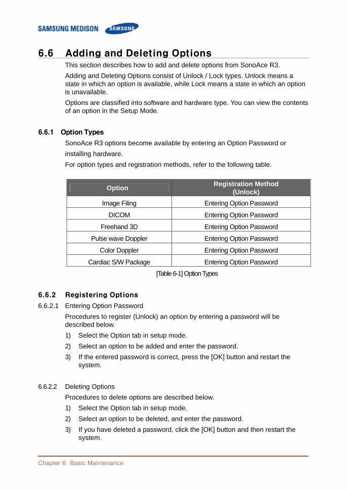
Chapter 6. Basic Maintenance
6.6 Adding and Deleting Options This section describes how to add and delete options from SonoAce R3. Adding and Deleting Options consist of Unlock / Lock types. Unlock means a state in which an option is available, while Lock means a state in which an option is unavailable. Options are classified into software and hardware type. You can view the contents of an option in the Setup Mode.
6.6.1 Option Types
SonoAce R3 options become available by entering an Option Password or installing hardware. For option types and registration methods, refer to the following table.
Option Registration Method (Unlock)
Image Filing Entering Option Password
DICOM Entering Option Password
Freehand 3D Entering Option Password
Pulse wave Doppler Entering Option Password
Color Doppler Entering Option Password
Cardiac S/W Package Entering Option Password
[Table 6-1] Option Types
6.6.2 Registering Options
6.6.2.1 Entering Option Password Procedures to register (Unlock) an option by entering a password will be described below. 1) Select the Option tab in setup mode. 2) Select an option to be added and enter the password. 3) If the entered password is correct, press the [OK] button and restart the
system.
6.6.2.2 Deleting Options Procedures to delete options are described below. 1) Select the Option tab in setup mode. 2) Select an option to be deleted, and enter the password. 3) If you have deleted a password, click the [OK] button and then restart the
system.
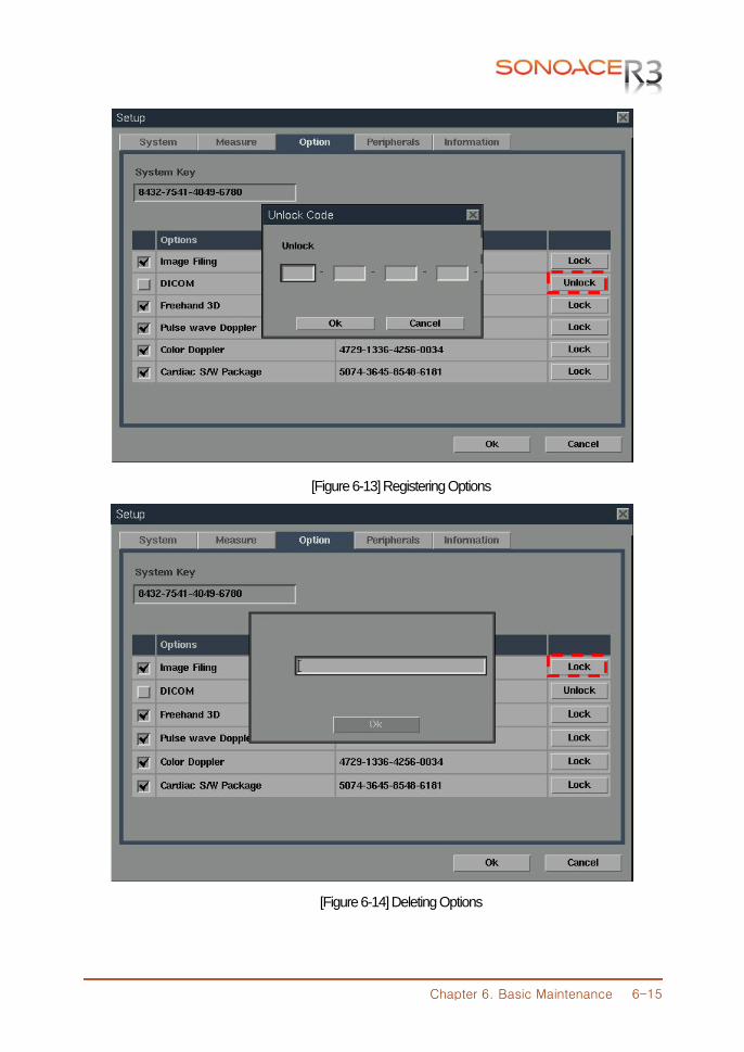
Chapter 6. Basic Maintenance 6-15
[Figure 6-13] Registering Options
[Figure 6-14] Deleting Options

Chapter 6. Basic Maintenance
6.7 Control Panel Test This section describes how to test control panel from SonoAce R3. 1) Turn on SonoAce R3. 2) When system booting is complete, enter admin mode referring to "6.3.1 Entering Admin Mode". 3) Select the Vkey button in Admin mode. 4) Start the Control panel Test in the Vkey pop. 5) When test is complete, Press the exit button to close in window.
Chapter 7. Troubleshooting 7-1
CChhaapptteerr 77.. TTrroouubblleesshhoooottiinngg
7.1 Overview Chapter 7 describes basic troubleshooting procedures.
NNOOTTEE˙ ˙ ˙ ˙
Procedures for troubleshooting expected problems are described. Unexpected situations may occur.
Procedures for troubleshooting normal problems are described.
Contents 7.1 Overview .......................................................................................................... 7-1 7.2 Power ............................................................................................................... 7-2 7.2.1 Power Failure ............................................................................... 7-2 7.2.2 Power cannot turned off ............................................................. 7-2 7.2.3 Power is automatically turned off ............................................... 7-2 7.3 Monitor ............................................................................................................. 7-3 7.3.1 Blank Screen ............................................................................... 7-3 7.3.2 Screen Color Abnormal .............................................................. 7-3 7.4 Error Messages .............................................................................................. 7-4 7.4.1 System hangs after an error during booting ............................. 7-4 7.4.2 System works even if error occurred ........................................ 7-4 7.5 Image ............................................................................................................... 7-5 7.5.1 No BW Image Echo & No BW Mode Image Format ......................... 7-5 7.5.2 Noise Link Rain over the BW Mode Image (Noise) ............................ 7-5 7.5.3 PW & Color Doppler Mode Trouble .......................................... 7-5

Chapter 7. Troubleshooting 7-2
7.2 Power
7.2.1 Power Failure This may occur if the power cord is not properly connected or the Power Supply is not working. 1) Check if the power cord is properly connected and if the cut-off switch of the ADM is turned on. 2) Check the fuse status. 3) Connect another device to the wall outlet and check if it works. If the device works, there is a Power Supply problem. If the device does not work, the problem is down to the wall outlet. 4) Check if the system fan works. If the fan works, the problem is not a power supply problem. If the fan does not work, a PC Power problem is likely.
7.2.2 Power cannot be turned off A software error or PC Motherboard or Main Board problem is likely. 1) The power is automatically turned off when the Power Switch is pressed for
more than 3 seconds. If software such as printer software is running or an operating system error occurs, the power is not turned off.
2) If you cannot turn the power off after completing the procedures in 1), a PC Motherboard or Main Board problem is likely.
7.2.3 Power is automatically turned off
Power cord, PC Mother Board, Main Board trouble is expected. 1) Check if the power cord is properly connected. 2) Check the fuse status. 3) Connect another device to the wall outlet and check if it works. If the device works, it is due to Power Supply problem. If the device does not work, it is due to wall outlet problem. 4) If the power is automatically turned off after completing the procedures of “1), 2), and 3)”, PC Mother Board, Main Board trouble is expected.
Chapter 7. Troubleshooting 7-3
7.3 Monitor
7.3.1 Blank Screen LCD Data Cable or PC Part trouble is expected. 1) Try to print to check the product status. If printing is normal, monitor or PC Part trouble is expected. 2) Check the cable is properly connected with the monitor. 3) If no problem has been found in the above “1) and 2)”, monitor and PC Part trouble is expected.
7.3.2 Screen Color is Abnormal
Data Cable of the monitor or PC Part is improperly connected or monitor or PC Part trouble is expected. 1) Check the monitor connection cable status. 2) If no problem has been found in the above “1)”, monitor and PC Part trouble is expected..
Chapter 7. Troubleshooting 7-4
7.4 Error Messages 7.4.1 System hangs after an error during booting
Temporary software error or product trouble is expected. 1) Turn the power off by force and then turn it on again after 1 to 2 minutes. 2) If the symptom continues after completing “1)”, check when the error message appears If the error message appears while SonoAce R3 logo appears, system software or ultrasound system part trouble is expected.
7.4.2 System works even if an error occurred
Temporary software error or product trouble is expected. 1) Turn the power off by force and then turn it on again after 1 to 2 minutes. 2) If the symptom continues after completing “1)”, check when the error message appears If the error message appears while SonoAce R3 logo appears, system software or ultrasound system part trouble is expected.
Chapter 7. Troubleshooting 7-5
7.5 Image 7.5.1 No BW Mode Image Echo & No BW Mode Image Format
Probe and the system connection, Main Board or Power trouble is expected. 1) Check the connection between the probe and the system. 2) Check if probe oscillation sound is heard. If oscillation sound is heard, the problem may be DDM trouble. 4) If no problem has been found in the above “1), 2) BF Board trouble is expected
7.5.2 Noise Like Rain over the BW Mode Image (Noise)
Power noise or BF Board trouble is expected. 1) Check if the system shares the wall outlet with another device. If the system shares the wall outlet with a device that uses electric motor or consumes high power, noise may be generated. 2) If the symptom continues when you connect the system to the wall outlet of another room, the problem is power noise. 3) If no problem has been found in the above “1) and 2)”, Main Board trouble is expected.
7.5.3 PW & Color Doppler Mode Trouble
Main Board trouble is expected.

Chapter 8. Disassembly and Ressembly 8-1
CChhaapptteerr 88.. DDiissaasssseemmbbllyy aanndd RReeaasssseemmbbllyy
8.1 Overview Chapter 8 describes how to disassemble SonoAce R3. Refer to this chapter when you upgrade or repair the hardware.
WWAARRNNIINNGG˙ ˙ ˙ ˙ ˙ ˙ ˙ The system contains dangerous high voltage. Never disassemble the system.
There is a risk of electric shock and injury. The repair of the system and the replacement of parts must be carried out by an
authorized engineer or the customer service department of SAMSUNG MEDISON Co., Ltd.
The company is not responsible for any injury and damage caused by not following this warning.
When working with the system on, do not wear a static electricity protective wristband There is a risk of electric shock and injury.
NNOOTTEE˙ ˙ ˙ ˙ When disassembling or reassembling the system, wear static electricity protective
gloves and a wristband. These will prevent any accidents due to carelessness, and damage to the system
due to static electricity.
[Figure 8-1] Static Electricity Protective Gloves and Wristband
Chapter 8. Disassembly and Ressembly 8-2
Contents 8.1 Overview ....................................................................................................8-1 8.2 Disassembly and Reassembly of the Body Cover .................................8-3 8.2.1 Preparations ............................................................................8-3 8.2.2 Body Rear & Middle Cover ....................................................8-3 8.2.3 Disassembly of the Main Part and LCD/Control Panel ........8-4 8.3 Disassembly and Reassembly of the Main System Part .....................8-5 8.3.1 Preparations ............................................................................8-5 8.3.2 Power & HDD & Side Fan ......................................................8-5 8.3.3 PSA & Rear & Rear Fan & Handle ........................................8-6 8.3.4 LCD & Inverter & USB Board .................................................8-7 8.4 Disassembly and Reassembly of the Control Panel ..............................8-8 8.4.1 Preparations ............................................................................8-8 8.4.2 Disassembly Control Panel and LCD ....................................8-8 8.4.3 Control Panel ...........................................................................8-9
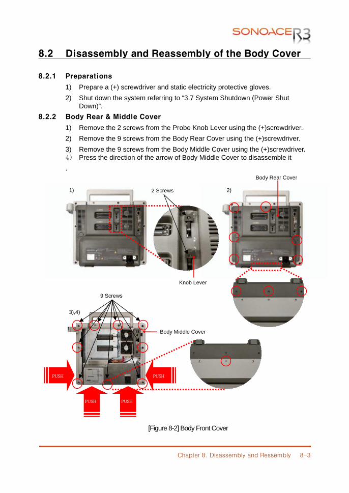
Chapter 8. Disassembly and Ressembly 8-3
8.2 Disassembly and Reassembly of the Body Cover
8.2.1 Preparations
1) Prepare a (+) screwdriver and static electricity protective gloves. 2) Shut down the system referring to “3.7 System Shutdown (Power Shut
Down)”. 8.2.2 Body Rear & Middle Cover
1) Remove the 2 screws from the Probe Knob Lever using the (+)screwdriver. 2) Remove the 9 screws from the Body Rear Cover using the (+)screwdriver. 3) Remove the 9 screws from the Body Middle Cover using the (+)screwdriver. 4) Press the direction of the arrow of Body Middle Cover to disassemble it .
[Figure 8-2] Body Front Cover
1)
3),4)
PUSH PUSH
PUSH PUSH
2 Screws
Body Rear Cover
9 Screws
2)
Knob Lever
Body Middle Cover
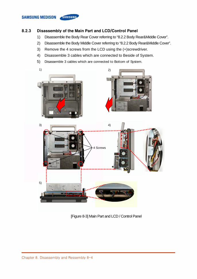
Chapter 8. Disassembly and Ressembly 8-4
8.2.3 Disassembly of the Main Part and LCD/Control Panel
1) Disassemble the Body Rear Cover referring to “8.2.2 Body Rear&Middle Cover”. 2) Disassemble the Body Middle Cover referring to “8.2.2 Body Rear&Middle Cover”. 3) Remove the 4 screws from the LCD using the (+)screwdriver. 4) Disassemble 3 cables which are connected to Beside of System. 5) Disassemble 3 cables which are connected to Bottom of System.
[Figure 8-3] Main Part and LCD / Control Panel
4)
4 Screws
1) 2)
3)
5)
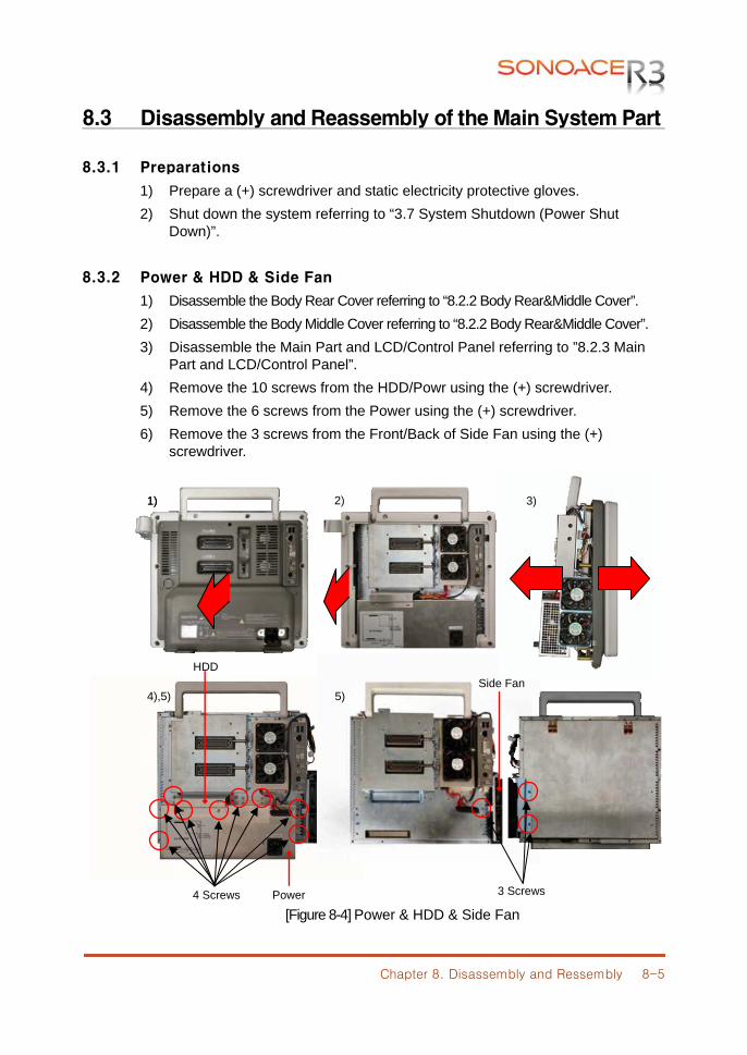
Chapter 8. Disassembly and Ressembly 8-5
3 Screws
Side Fan
8.3 Disassembly and Reassembly of the Main System Part
8.3.1 Preparations
1) Prepare a (+) screwdriver and static electricity protective gloves. 2) Shut down the system referring to “3.7 System Shutdown (Power Shut
Down)”.
8.3.2 Power & HDD & Side Fan
1) Disassemble the Body Rear Cover referring to “8.2.2 Body Rear&Middle Cover”. 2) Disassemble the Body Middle Cover referring to “8.2.2 Body Rear&Middle Cover”. 3) Disassemble the Main Part and LCD/Control Panel referring to ”8.2.3 Main Part and LCD/Control Panel”. 4) Remove the 10 screws from the HDD/Powr using the (+) screwdriver. 5) Remove the 6 screws from the Power using the (+) screwdriver. 6) Remove the 3 screws from the Front/Back of Side Fan using the (+)
screwdriver.
[Figure 8-4] Power & HDD & Side Fan
1)
4 Screws
2) 3) 1)
4),5) 5)
Power
HDD
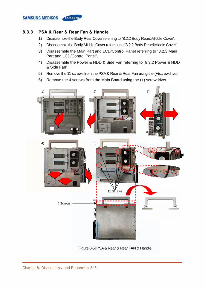
Chapter 8. Disassembly and Ressembly 8-6
8.3.3 PSA & Rear & Rear Fan & Handle
1) Disassemble the Body Rear Cover referring to “8.2.2 Body Rear&Middle Cover”. 2) Disassemble the Body Middle Cover referring to “8.2.2 Body Rear&Middle Cover”. 3) Disassemble the Main Part and LCD/Control Panel referring to ”8.2.3 Main Part and LCD/Control Panel”. 4) Disassemble the Power & HDD & Side Fan referring to ”8.3.2 Power & HDD
& Side Fan”. 5) Remove the 11 screws from the PSA & Rear & Rear Fan using the (+)screwdriver. 6) Remove the 4 screws from the Main Board using the (+) screwdriver.
6)
[Figure 8-5] PSA & Rear & Rear FAN & Handle
4 Screws
11 Screws
1) 2) 3)
4) 5)
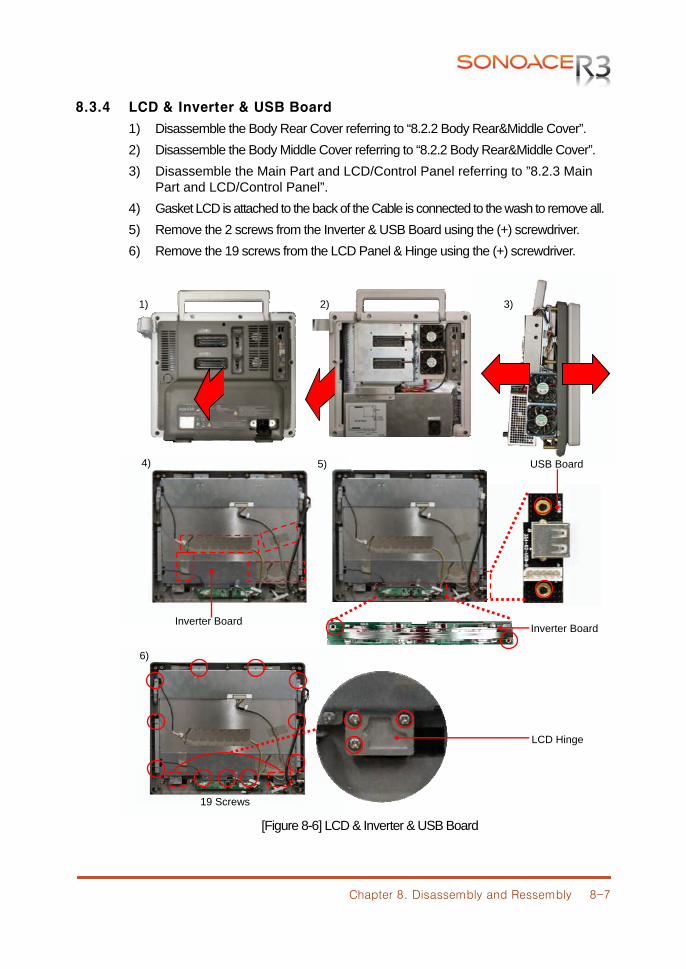
Chapter 8. Disassembly and Ressembly 8-7
8.3.4 LCD & Inverter & USB Board
1) Disassemble the Body Rear Cover referring to “8.2.2 Body Rear&Middle Cover”. 2) Disassemble the Body Middle Cover referring to “8.2.2 Body Rear&Middle Cover”. 3) Disassemble the Main Part and LCD/Control Panel referring to ”8.2.3 Main
Part and LCD/Control Panel”. 4) Gasket LCD is attached to the back of the Cable is connected to the wash to remove all. 5) Remove the 2 screws from the Inverter & USB Board using the (+) screwdriver. 6) Remove the 19 screws from the LCD Panel & Hinge using the (+) screwdriver.
[Figure 8-6] LCD & Inverter & USB Board
1)
5)
6)
19 Screws
2) 3)
4) USB Board
Inverter Board Inverter Board
LCD Hinge
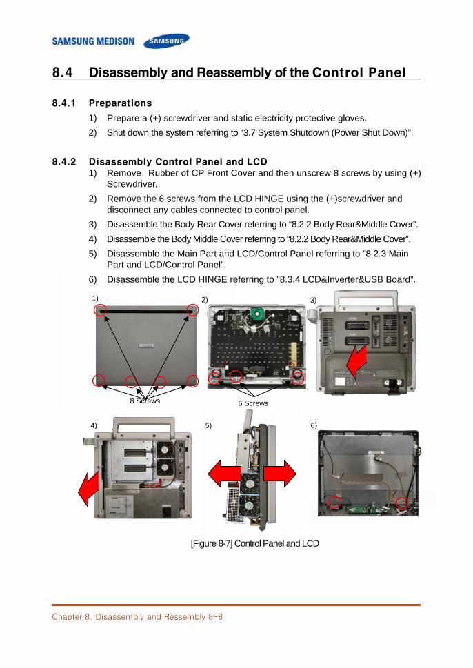
Chapter 8. Disassembly and Ressembly 8-8
6 Screws
8.4 Disassembly and Reassembly of the Control Panel
8.4.1 Preparations
1) Prepare a (+) screwdriver and static electricity protective gloves. 2) Shut down the system referring to “3.7 System Shutdown (Power Shut Down)”.
8.4.2 Disassembly Control Panel and LCD 1) Remove Rubber of CP Front Cover and then unscrew 8 screws by using (+) Screwdriver. 2) Remove the 6 screws from the LCD HINGE using the (+)screwdriver and
disconnect any cables connected to control panel. 3) Disassemble the Body Rear Cover referring to “8.2.2 Body Rear&Middle Cover”. 4) Disassemble the Body Middle Cover referring to “8.2.2 Body Rear&Middle Cover”. 5) Disassemble the Main Part and LCD/Control Panel referring to ”8.2.3 Main
Part and LCD/Control Panel”. 6) Disassemble the LCD HINGE referring to ”8.3.4 LCD&Inverter&USB Board”.
[Figure 8-7] Control Panel and LCD
1) 2)
8 Screws
3)
4) 5) 6)
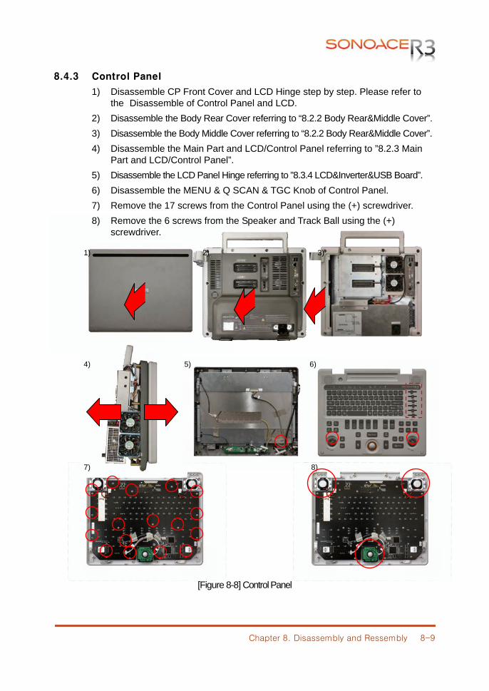
Chapter 8. Disassembly and Ressembly 8-9
8.4.3 Control Panel
1) Disassemble CP Front Cover and LCD Hinge step by step. Please refer to the Disassemble of Control Panel and LCD.
2) Disassemble the Body Rear Cover referring to “8.2.2 Body Rear&Middle Cover”. 3) Disassemble the Body Middle Cover referring to “8.2.2 Body Rear&Middle Cover”. 4) Disassemble the Main Part and LCD/Control Panel referring to ”8.2.3 Main
Part and LCD/Control Panel”. 5) Disassemble the LCD Panel Hinge referring to ”8.3.4 LCD&Inverter&USB Board”. 6) Disassemble the MENU & Q SCAN & TGC Knob of Control Panel. 7) Remove the 17 screws from the Control Panel using the (+) screwdriver. 8) Remove the 6 screws from the Speaker and Track Ball using the (+)
screwdriver.
[Figure 8-8] Control Panel
1)
4)
2) 3)
5) 6)
7) 8)
Chapter 9. Probe 9-1
CChhaapptteerr 99.. PPrroobbee
9.1 Overview The probe is a device that sends and receives ultrasound for acquiring image data. It is also called a Transducer or Scanhead. The system limits patient contact temperature to 43℃degrees Celsius, and acoustic output values to their respective U.S. FDA limits. A power protection fuse circuit protects against over-current conditions. If the power monitor protection circuit senses an overcurrent condition, then the drive current to the probe is shut off immediately, preventing overheating of the probe surfaces and limiting acoustic output. Validation of the power protection fuse circuit is performed under normal system operation. For invasive probes, additional protections are designed to keep patient contact surface temperature under 43℃ degrees Celsius in the event of a single fault failure.
Contents
9.1 Overview ....................................................................................... 9-1 9.2 Probe List ...................................................................................... 9-2 9.3 Thermal Index (TI Table) .............................................................. 9-5 9.4 Ultrasound Transmission Gel ....................................................... 9-6 9.5 Sheaths ......................................................................................... 9-7 9.6 Probe Precautions ........................................................................ 9-9
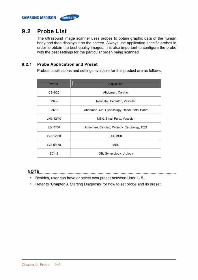
Chapter 9. Probe 9-2
9.2 Probe List The ultrasound image scanner uses probes to obtain graphic data of the human body and then displays it on the screen. Always use application-specific probes in order to obtain the best quality images. It is also important to configure the probe with the best settings for the particular organ being scanned
9.2.1 Probe Application and Preset
Probes, applications and settings available for this product are as follows.
Probe Application
C2-4/20 Abdomen, Cardiac
CN4-9 Neonatal, Pediatric, Vascular
CN2-8 Abdomen, OB, Gynecology, Renal, Fetal Heart
LN5-12/40 MSK, Small Parts, Vascular
L5-12/60 Abdomen, Cardiac, Pediatric Cardiology, TCD
LV5-12/60 OB, MSK
LV2-5/180 MSK
EC4-9 OB, Gynecology, Urology
NNOOTTEE˙ ˙ ˙ ˙
Besides, user can have or select own preset between User 1- 5. Refer to ‘Chapter 3. Starting Diagnosis’ for how to set probe and its preset.
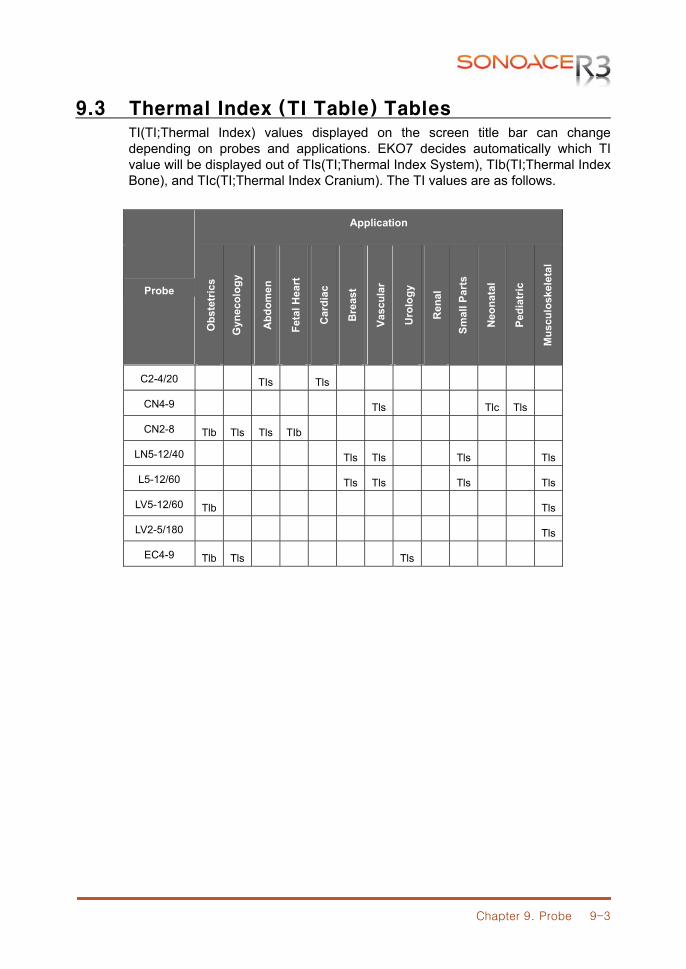
Chapter 9. Probe 9-3
9.3 Thermal Index (TI Table) Tables TI(TI;Thermal Index) values displayed on the screen title bar can change depending on probes and applications. EKO7 decides automatically which TI value will be displayed out of TIs(TI;Thermal Index System), TIb(TI;Thermal Index Bone), and TIc(TI;Thermal Index Cranium). The TI values are as follows.
Probe
Application O
bste
tric
s
Gyn
ecol
ogy
Abd
omen
Feta
l Hea
rt
Car
diac
Bre
ast
Vasc
ular
Uro
logy
Ren
al
Smal
l Par
ts
Neo
nata
l
Pedi
atric
Mus
culo
skel
etal
C2-4/20 TIs Tls
CN4-9 Tls Tlc Tls
CN2-8 Tlb Tls Tls TIb
LN5-12/40 Tls Tls Tls Tls
L5-12/60 Tls Tls Tls Tls
LV5-12/60 Tlb Tls
LV2-5/180 Tls
EC4-9 Tlb Tls Tls
Chapter 9. Probe 9-4
9.4 Ultrasound Transmission Gel Using an inappropriate ultrasound gel may damage the probe. For proper transmission of the acoustic beam, only use ultrasound transmission gel only approved by SAMSUNG MEDISON.
WWAARRNNIINNGG˙ ˙ ˙ ˙ ˙ ˙ ˙
Do not use mineral oil, iol-based solutions, or other non-approved material as they may cause damage to the probe.
Do not use gels that contain any of the following agents: - Acetone - Methanol - Denatured Ethyl Alcohol - Mineral Oil - Iodine - Lanolin - Any lotions or gels containing perfume
Chapter 9. Probe 9-5
9.5 Probe Precautions The probe can easily be damaged by improper use or by contacting certain chemical substances. Always follow the instructions in the user manual to inspect the probe cable, case and lens before and after each use. Check for cracks, broken parts, leaks and sharp edges. If there is any damage, immediately stop using the probe and contact the SAMSUNG MEDISON Customer Support Department. Using damaged probes may result in electric shocks and other hazards to the patients and/or users
CCAAUUTTIIOONN˙ ˙ ˙ ˙ ˙ ˙ ˙
Do not apply mechanical shock to the probe. Do not place the probe cable on the floor where the cable can be run over by
equipment wheels, etc. Do not apply excessive force to bend or pull the cable. Do not immerse the probe into any inappropriate substances such as alcohol,
bleach, ammonium chloride and hydrogen peroxide.
Do not expose the probe to temperatures of 50°C or higher.
9.5.1 Use and Infection Control of the Probe
The ultrasonographic image scanner uses ultrasound, and it makes direct contact with the patient when in use. Depending on the types of examinations, such contact can be made to a wide variety of locations including the ordinary skin or the location of blood transfusion during a surgery. The most effective method to prevent infection among patients is to use each probe only once. However, probes may need to be reused, as they are complex in design and expensive. Consequently, protective devices such as sheaths must be used, and the safety instructions must be followed carefully in order to minimize the risk of infection among patients.
WWAARRNNIINNGG˙ ˙ ˙ ˙ ˙ ˙ ˙
No neurosurgical treatments or examinations should be carried out on a patient with Creutzfeldt-Jakob disease (critical brain disease caused by virus). If the probe has been used on such a patient, it cannot be sterilized by any method whatsoever.
CCAAUUTTIIOONN˙ ˙ ˙ ˙ ˙ ˙ ˙
Sufficient washing and disinfecting must be carried out for preventing infection. This is the responsibility of the user who manages and maintains the disinfection procedures for the equipment. Always use legally approved detergents and sheaths.
Chapter 9. Probe 9-6
9.5.2 Electric Shocks
The probe uses electrical energy. If it touches conductive materials, there are risks of electric shocks to the patient or the user.
WWAARRNNIINNGG˙ ˙ ˙ ˙ ˙ ˙ ˙
Regularly receive short-circuit examination from the SAMSUNG MEDISON Service Department.
Do not immerse the probe into liquid. Do not drop the probe or apply mechanical shocks. Inspect the housing, stran relief, lens and seal for damage, and check for any
functional problem before and after each use. Do not apply excessive force to twist, pull or bend the probe cable. It may result in
a short circuit. The power protection fuse protects the probe and the product from excess current.
If the power monitoring protection circuit detects excess current, it immediately shuts off the current to the probe in order to prevent the probe surface from overheating and to restrict the ultrasound power output.
The temperature of the product for making contact with patients is limited under 43°C. The ultrasound power output (AP&I) is in compliance with US FDA standards.
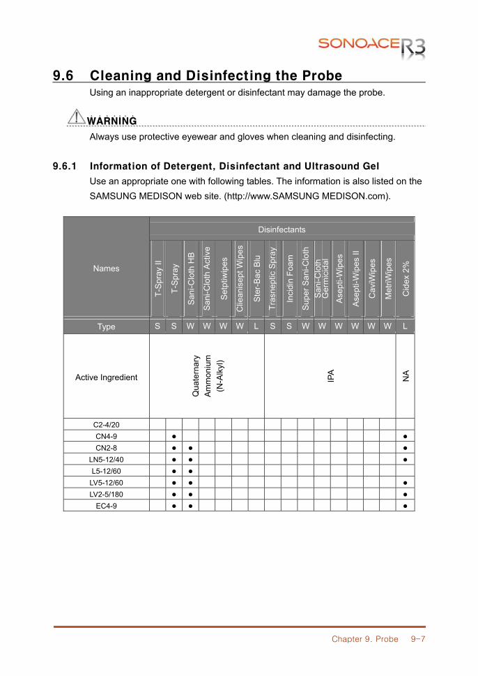
Chapter 9. Probe 9-7
9.6 Cleaning and Disinfecting the Probe Using an inappropriate detergent or disinfectant may damage the probe.
WWAARRNNIINNGG˙ ˙ ˙ ˙ ˙ ˙ ˙
Always use protective eyewear and gloves when cleaning and disinfecting.
9.6.1 Information of Detergent, Disinfectant and Ultrasound Gel
Use an appropriate one with following tables. The information is also listed on the SAMSUNG MEDISON web site. (http://www.SAMSUNG MEDISON.com).
Names
Disinfectants
T-S
pray
II
T-S
pray
San
i-Clo
th H
B
San
i-Clo
th A
ctiv
e
Set
ptiw
ipes
Clie
anis
ept W
ipes
Ste
r-B
ac B
lu
Tras
nept
ic S
pray
Inci
din
Foam
Sup
er S
ani-C
loth
S
ani-C
loth
G
erm
icid
al
Ase
pti-W
ipes
Ase
pti-W
ipes
II
Cav
iWip
es
Met
riWip
es
Cid
ex 2
%
Type S S W W W W L S S W W W W W W L
Active Ingredient
Qua
tern
ary
Am
mon
ium
(N
-Alk
yl)
IPA
NA
C2-4/20 CN4-9 ● ● CN2-8 ● ● ●
LN5-12/40 ● ● ● L5-12/60 ● ●
LV5-12/60 ● ● ● LV2-5/180 ● ● ●
EC4-9 ● ● ●
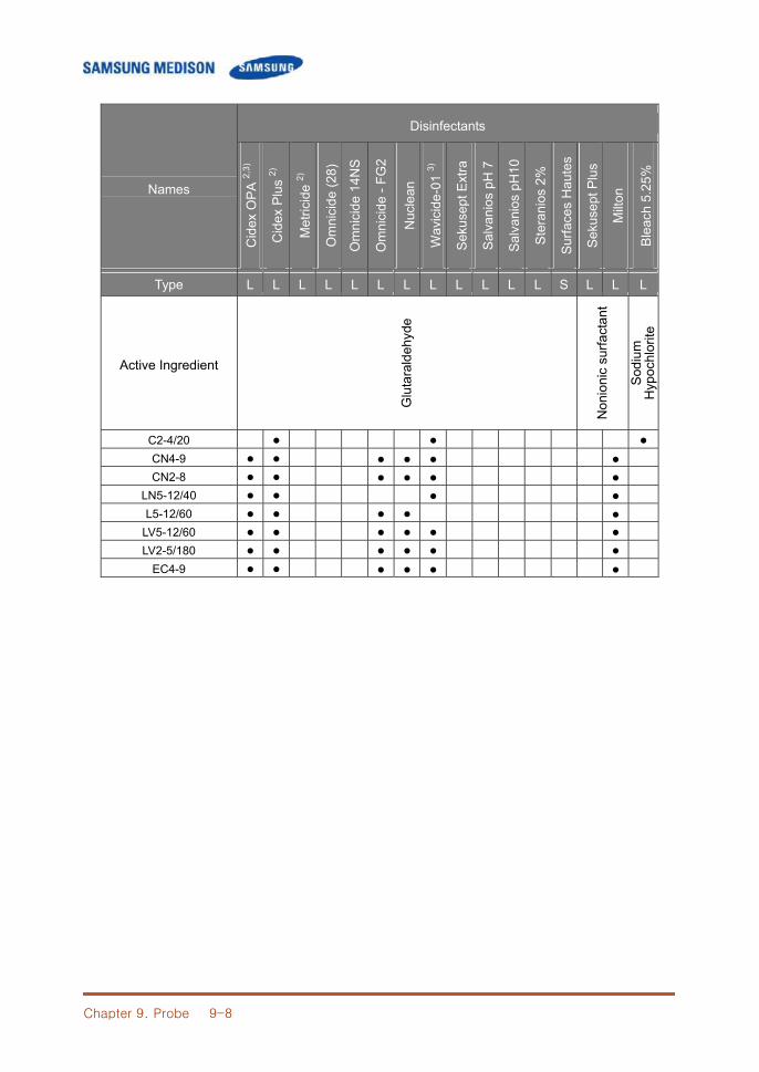
Chapter 9. Probe 9-8
Names
Disinfectants
Cid
ex O
PA
2,3)
Cid
ex P
lus
2)
Met
ricid
e 2)
Om
nici
de (2
8)
Om
nici
de 1
4NS
Om
nici
de -
FG2
Nuc
lean
Wav
icid
e-01
3)
Sek
usep
t Ext
ra
Sal
vani
os p
H 7
Sal
vani
os p
H10
Ste
rani
os 2
%
Sur
face
s H
aute
s
Sek
usep
t Plu
s
Milt
on
Blea
ch 5
.25%
Type L L L L L L L L L L L L S L L L
Active Ingredient
Glu
tara
ldeh
yde
Non
ioni
c su
rfact
ant
Sodi
um
Hyp
ochl
orite
C2-4/20 ● ● ● CN4-9 ● ● ● ● ● ● CN2-8 ● ● ● ● ● ●
LN5-12/40 ● ● ● ● L5-12/60 ● ● ● ● ●
LV5-12/60 ● ● ● ● ● ● LV2-5/180 ● ● ● ● ● ●
EC4-9 ● ● ● ● ● ●
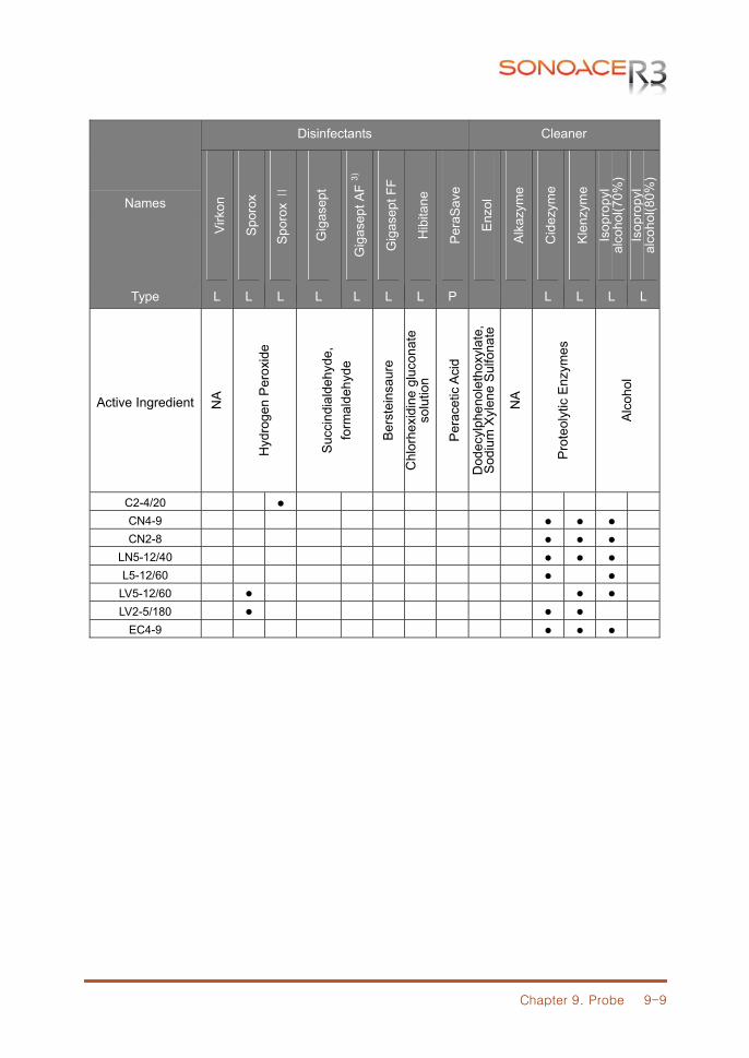
Chapter 9. Probe 9-9
Names
Disinfectants Cleaner
Virk
on
Spor
ox
Spo
rox
Ⅱ
Gig
asep
t
Gig
asep
t AF
3)
Gig
asep
t FF
Hib
itane
Pera
Save
Enz
ol
Alk
azym
e
Cid
ezym
e
Kle
nzym
e
Isop
ropy
l al
coho
l(70%
) Is
opro
pyl
alco
hol(8
0%)
Type L L L L L L L P L L L L
Active Ingredient NA
Hyd
roge
n P
erox
ide
Succ
indi
alde
hyde
, fo
rmal
dehy
de
Ber
stei
nsau
re
Chl
orhe
xidi
ne g
luco
nate
so
lutio
n
Per
acet
ic A
cid
Dod
ecyl
phen
olet
hoxy
late
, S
odiu
m X
ylen
e S
ulfo
nate
NA
Pro
teol
ytic
Enz
ymes
Alc
ohol
C2-4/20 ● CN4-9 ● ● ● CN2-8 ● ● ●
LN5-12/40 ● ● ● L5-12/60 ● ●
LV5-12/60 ● ● ● LV2-5/180 ● ● ●
EC4-9 ● ● ●
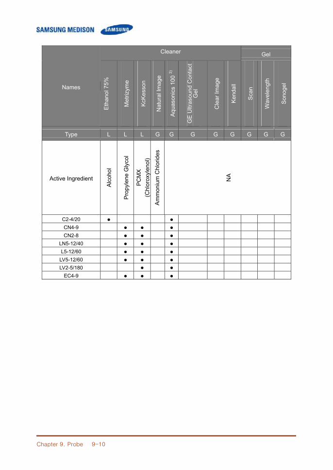
Chapter 9. Probe 9-10
Names
Cleaner Gel
Etha
nol 7
5%
Met
rizym
e
KcK
esso
n
Nat
ural
Imag
e
Aqua
soni
cs 1
00 3)
GE
Ultr
asou
nd C
onta
ct
Gel
Cle
ar Im
age
Kend
all
Sca
n
Wav
elen
gth
Sono
gel
Type L L L G G G G G G G G
Active Ingredient A
lcoh
ol
Prop
ylen
e G
lyco
l
PC
MX
(C
hlor
oxyl
enol
)
Am
mon
ium
Chl
orid
es
NA
C2-4/20 ● ● CN4-9 ● ● ● CN2-8 ● ● ●
LN5-12/40 ● ● ● L5-12/60 ● ● ●
LV5-12/60 ● ● ● LV2-5/180 ● ●
EC4-9 ● ● ●
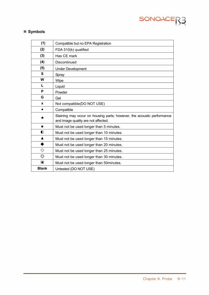
Chapter 9. Probe 9-11
※ Symbols
(1) Compatible but no EPA Registration (2) FDA 510(k) qualified (3) Has CE mark (4) Discontinued (5) Under Development S Spray W Wipe L Liquid P Powder G Gel x Not compatible(DO NOT USE) ● Compatible
★ Staining may occur on housing parts; however, the acoustic performance and image quality are not affected.
■ Must not be used longer than 5 minutes. ◐ Must not be used longer than 10 minutes. ▲ Must not be used longer than 15 minutes. ◆ Must not be used longer than 20 minutes. ◇ Must not be used longer than 25 minutes. ◎ Must not be used longer than 30 minutes. ▣ Must not be used longer than 50minutes.
Blank Untested (DO NOT USE)
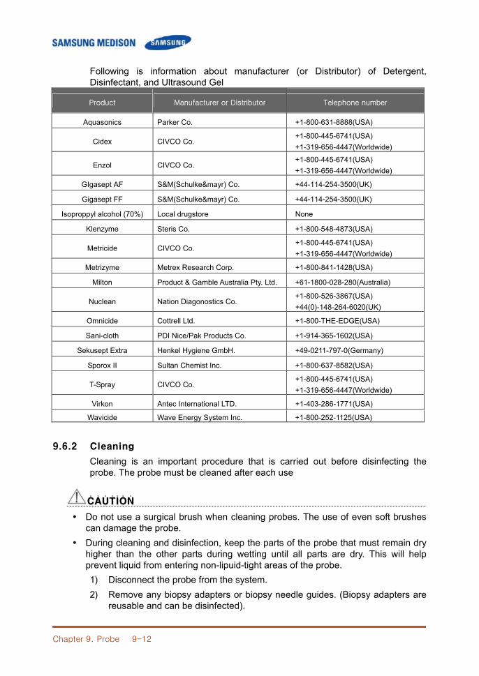
Chapter 9. Probe 9-12
Following is information about manufacturer (or Distributor) of Detergent, Disinfectant, and Ultrasound Gel
Product Manufacturer or Distributor Telephone number
Aquasonics Parker Co. +1-800-631-8888(USA)
Cidex CIVCO Co. +1-800-445-6741(USA) +1-319-656-4447(Worldwide)
Enzol CIVCO Co. +1-800-445-6741(USA) +1-319-656-4447(Worldwide)
GIgasept AF S&M(Schulke&mayr) Co. +44-114-254-3500(UK)
Gigasept FF S&M(Schulke&mayr) Co. +44-114-254-3500(UK)
Isoproppyl alcohol (70%) Local drugstore None
Klenzyme Steris Co. +1-800-548-4873(USA)
Metricide CIVCO Co. +1-800-445-6741(USA) +1-319-656-4447(Worldwide)
Metrizyme Metrex Research Corp. +1-800-841-1428(USA)
Milton Product & Gamble Australia Pty. Ltd. +61-1800-028-280(Australia)
Nuclean Nation Diagonostics Co. +1-800-526-3867(USA) +44(0)-148-264-6020(UK)
Omnicide Cottrell Ltd. +1-800-THE-EDGE(USA)
Sani-cloth PDI Nice/Pak Products Co. +1-914-365-1602(USA)
Sekusept Extra Henkel Hygiene GmbH. +49-0211-797-0(Germany)
Sporox II Sultan Chemist Inc. +1-800-637-8582(USA)
T-Spray CIVCO Co. +1-800-445-6741(USA) +1-319-656-4447(Worldwide)
Virkon Antec International LTD. +1-403-286-1771(USA)
Wavicide Wave Energy System Inc. +1-800-252-1125(USA)
9.6.2 Cleaning
Cleaning is an important procedure that is carried out before disinfecting the probe. The probe must be cleaned after each use
CCAAUUTTIIOONN˙ ˙ ˙ ˙ ˙ ˙ ˙
Do not use a surgical brush when cleaning probes. The use of even soft brushes can damage the probe.
During cleaning and disinfection, keep the parts of the probe that must remain dry higher than the other parts during wetting until all parts are dry. This will help prevent liquid from entering non-lipuid-tight areas of the probe. 1) Disconnect the probe from the system. 2) Remove any biopsy adapters or biopsy needle guides. (Biopsy adapters are
reusable and can be disinfected).

Chapter 9. Probe 9-13
3) Discard sheaths. ( Sheaths are single-use items). 4) Use a soft cloth lightly dampened with mild soap or compatible cleaning solution to remove any particulate matter and body fluid that remain on the probe or cable. 5) To remove remaining particulates, rinse with water up to the immersion point. 6) wipe with a dry cloth. 7) If necessary, wipe first with a water-dampened clothe to remove soap residue.
9.6.3 Disinfection
WWAARRNNIINNGG˙ ˙ ˙ ˙ ˙ ˙ ˙
If a pre-mixed solution is used, be sure to observe the solution expiration date. The type of tissue it will contact during use dictates the level of disinfection
required for a device. Ensure that the solution strength and duration of contact are appropriate for disinfection.
CCAAUUTTIIOONN˙ ˙ ˙ ˙ ˙ ˙ ˙
Using a non-recommended disinfectant or not following the recommended disinfection method can damage and or discolor the probe and will void the probe warranty.
Do not immerse probes for longer than one hour, unless they are sterilizable. Only sterilize probes using liquid solutions. Avoid using autoclave, gas (EtO) or
other non-SAMSUNG MEDISON-approved methods. 1) Follow the instructions on the disinfectant label for storage, use and disposition of the disinfectant. 2) Mix the disinfectant compatible with your probe according to lavel instructions for solution strength. 3) Immerse the instructions on the disinfectant, rinse the probe after the immersion process is complete. 4) Using the instructions on the disinfectant, rinse the probe after the immersion process is complete. 5) Air dry the probe or towel it dry with a clean cloth.
[Figure 9-1] Disinfection
Chapter 10. User Maintenance 10-1
CChhaapptteerr 1100.. UUsseerr MMaaiinntteennaannccee
10.1 Overview
Chapter 10 describes how to extend the life of SonoAce R3. It includes are how to maintain the product and how to backup information. Make sure to read this chapter for proper maintenance of the product.
Contents 10.1 Overview ..................................................................................... 10-1 10.2 System Maintenance .................................................................. 10-2 10.2.1 Installation Maintenance ............................................. 10-2 10.2.2 Cleaning and Disinfections ......................................... 10-2 10.2.3 Fuse Replacement ..................................................... 10-4 10.2.4 Accuracy Check.......................................................... 10-5 10.3 Administration of Information ...................................................... 10-6 10.3.1 User Setting Back-up ................................................. 10-6 10.3.2 Patient Information Back-up ....................................... 10-6 10.3.3 Software ..................................................................... 10-6
Chapter 10. User Maintenance 10-2
10.2 System Maintenance
10.2.1 Installation Requirements
When installing:. 1) Avoid humidity. 2) Avoid direct sunlight. 3) Avoid places with extreme temperature variations. 4) Optimal conditions for the system are temperatures of 10℃ ~ 35℃ and
humidity of 30% ~ 75%. 5) Avoid heat sources. 6) Avoid dusty and unventilated areas. 7) Avoid places where the system is likely to be exposed to vibration or impacts. 8) Avoid place wher the system is likely to be exposed to chemical substances
or gases
CCAAUUTTIIOONN˙ ˙ ˙ ˙ ˙ ˙ ˙
Placing the system near generators, X-Ray machines, or broadcast cables may result in screen noise and abnormal visual images. Using the power source with other electric devices may also induce noise.
10.2.2 Cleaning and disinfections
Using inappropriate detergent or disinfectant may damage the product. Please read the following carefully..
WWAARRNNIINNGG˙ ˙ ˙ ˙ ˙ ˙ ˙
Turn off the system and disconnect the system power cord from the wall outlet. Otherwise, it may result in electric shock or fire.
Always use protective eyewear and gloves when cleaning and disinfecting the equipment.
10.2.2.1 Cleaning
1) Console : Use a soft cloth lightly dampened in a mild soap or detergent solution to clean exterior surfaces on the system. 2) Cleaning Monitor : Wipe the LCD surface with a soft dry cloth. When the LCD panel has dirt on it, wipe it 2 – 3 times or more in one direction system.
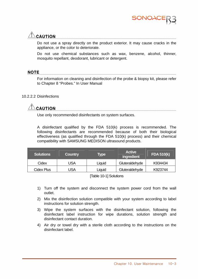
Chapter 10. User Maintenance 10-3
CCAAUUTTIIOONN˙ ˙ ˙ ˙ ˙ ˙ ˙
Do not use a spray directly on the product exterior. It may cause cracks in the appliance, or the color to deteriorate. Do not use chemical substances such as wax, benzene, alcohol, thinner, mosquito repellant, deodorant, lubricant or detergent.
NNOOTTEE˙ ˙ ˙ ˙
For information on cleaning and disinfection of the probe & biopsy kit, please refer to Chapter 8 “Probes.” In User Manual
10.2.2.2 Disinfections
CCAAUUTTIIOONN˙ ˙ ˙ ˙ ˙ ˙ ˙
Use only recommended disinfectants on system surfaces. A disinfectant qualified by the FDA 510(k) process is recommended. The following disinfectants are recommended because of both their biological effectiveness (as qualified through the FDA 510(k) process) and their chemical compatibility with SAMSUNG MEDISON ultrasound products.
Solutions Country Type Active ingredient FDA 510(k)
Cidex USA Liquid Gluteraldehyde K934434
Cidex Plus USA Liquid Gluteraldehyde K923744 [Table 10-1] Solutions
1) Turn off the system and disconnect the system power cord from the wall
outlet. 2) Mix the disinfection solution compatible with your system according to label
instructions for solution strength. 3) Wipe the system surfaces with the disinfectant solution, following the
disinfectant label instruction for wipe durations, solution strength and disinfectant contact duration.
4) Air dry or towel dry with a sterile cloth according to the instructions on the disinfectant label.
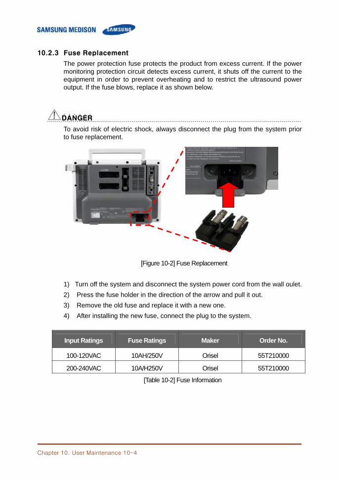
Chapter 10. User Maintenance 10-4
10.2.3 Fuse Replacement
The power protection fuse protects the product from excess current. If the power monitoring protection circuit detects excess current, it shuts off the current to the equipment in order to prevent overheating and to restrict the ultrasound power output. If the fuse blows, replace it as shown below.
DDAANNGGEERR˙ ˙ ˙ ˙ ˙ ˙
To avoid risk of electric shock, always disconnect the plug from the system prior to fuse replacement.
[Figure 10-2] Fuse Replacement 1) Turn off the system and disconnect the system power cord from the wall oulet. 2) Press the fuse holder in the direction of the arrow and pull it out. 3) Remove the old fuse and replace it with a new one. 4) After installing the new fuse, connect the plug to the system.
Input Ratings Fuse Ratings Maker Order No.
100-120VAC 10AH/250V Orisel 55T210000
200-240VAC 10A/H250V Orisel 55T210000
[Table 10-2] Fuse Information
Chapter 10. User Maintenance 10-5
10.2.4 Accuracy Check
The product's maintenance status may affect the measurements obtained using the product. The product should be maintained in an optimal state to ensure reliable measurements. To ensure optimal operation of the product, perform an accuracy check every year. The equations and table related to measurement accuracy are included in Chapter 5 "Measurements" in User manual
NNOOTTEE˙ ˙ ˙ ˙
Allow the wet filter to dry thoroughly before installing. The wet filter can cause the malfunction.
Chapter 10. User Maintenance 10-6
10.3 Administration of Information
CCAAUUTTII˙ ˙ ˙ ˙ ˙OONN
You may lose information files on user settings or patients, because of shock on the product or internal error. Thus, back-up on a regular basis.
10.3.1 User Setting Back-up
Always keep a separatebackup copy of theall information related to the user settings in case of data loss. Clients cannot back-up the user settings of the product. Please contact the SAMSUNG MEDISON Service Department to attain support for back-up. However, clients may back up the user setting on GA Table used in obstetrics diagnosis. For further information please refer to ‘Chapter 3. Settings of User Manual’.
10.3.2 Patient Information Back-up
The SonoView program can be used for backing up patients’ basic information and scanned images. The user can choose to save the data by himself/herself, and the data is also saved in the system by default. If the system needs to be reinstalled due to product failure, etc., the SAMSUNG MEDISON customer support staff will restore the patients’ basic information and scanned images that are saved in the system. For more information on this, see ‘Chapter 6 Image Management of User Manual.
10.3.3 Software
The product software may be updated to enhance performance. The user cannot make any changes to the software by himself/herself.. Please contact the SAMSUNG MEDISON customer service for help in software changes.
CCAAUUTTIIOONN˙ ˙ ˙ ˙ ˙ ˙ ˙
Minor software updates may be carried out without the prior notice from the manufacturer.
Should errors occur in the operating system and should you desire to upgrade the operating system, please follow the instructions of the operating system manufacturer.
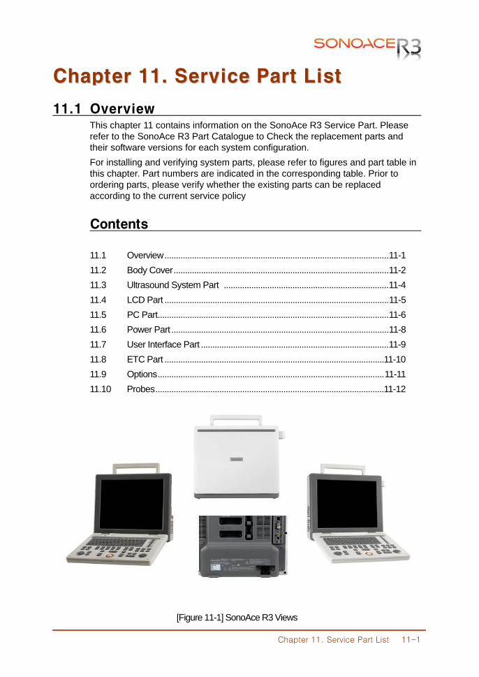
Chapter 11. Service Part List 11-1
CChhaapptteerr 1111.. SSeerrvviiccee PPaarrtt LLiisstt
11.1 Overview This chapter 11 contains information on the SonoAce R3 Service Part. Please refer to the SonoAce R3 Part Catalogue to Check the replacement parts and their software versions for each system configuration. For installing and verifying system parts, please refer to figures and part table in this chapter. Part numbers are indicated in the corresponding table. Prior to ordering parts, please verify whether the existing parts can be replaced according to the current service policy
Contents 11.1 Overview .................................................................................................. 11-1 11.2 Body Cover .............................................................................................. 11-2 11.3 Ultrasound System Part ........................................................................ 11-4 11.4 LCD Part .................................................................................................. 11-5 11.5 PC Part ..................................................................................................... 11-6 11.6 Power Part ............................................................................................... 11-8 11.7 User Interface Part .................................................................................. 11-9 11.8 ETC Part ................................................................................................ 11-10 11.9 Options ................................................................................................... 11-11 11.10 Probes .................................................................................................... 11-12
[Figure 11-1] SonoAce R3 Views
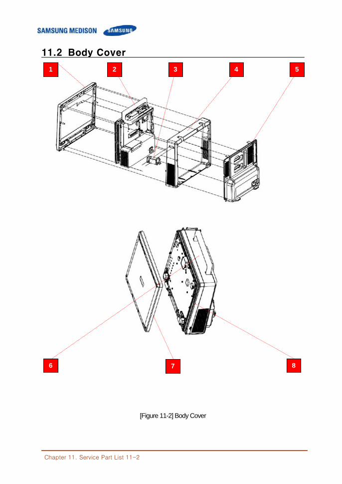
Chapter 11. Service Part List 11-2
11.2 Body Cover
[Figure 11-2] Body Cover
1 2 4
8 6
3 5
7
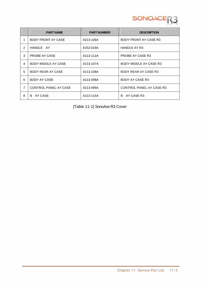
Chapter 11. Service Part List 11-3
PART NAME PART NUMBER DESCRIPTION
1 BODY FRONT AY CASE A213-106A BODY FRONT AY CASE R3
2 HANDLE AY A252-019A HANDLE AY R3
3 PROBE AY CASE A213-112A PROBE AY CASE R3
4 BODY MIDDLE AY CASE A213-107A BODY MIDDLE AY CASE R3
5 BODY REAR AY CASE A213-108A BODY REAR AY CASE R3
6 BODY AY CASE A213-098A BODY AY CASE R3
7 CONTROL PANEL AY CASE A213-099A CONTROL PANEL AY CASE R3
8 B AY CASE A213-115A B AY CASE R3
[Table 11-1] SonoAce R3 Cover

Chapter 11. Service Part List 11-4
11.3 Ultrasound System Part
[Figure 11-3] Ultrasound System Part
No PART NAME PART NUMBER DESCRIPTION
1 MAIN BOARD BD-354-MAIN MAIN BOARD R3
2 REAR BOARD BD-354-REAR REAR BOARD R3
3 PSA BOARD BD-354-PSA PSA BOARD R3
[Table 11-2] Ultrasound System Part
1
2
3
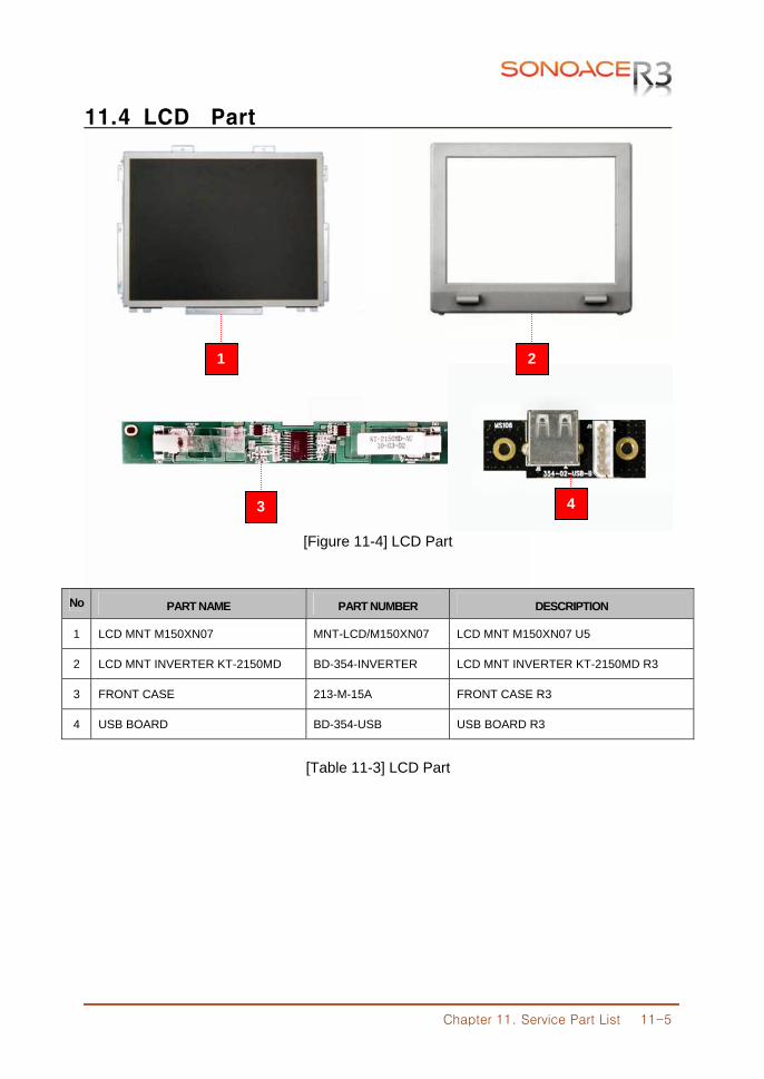
Chapter 11. Service Part List 11-5
11.4 LCD Part
[Figure 11-4] LCD Part
No PART NAME PART NUMBER DESCRIPTION
1 LCD MNT M150XN07 MNT-LCD/M150XN07 LCD MNT M150XN07 U5
2 LCD MNT INVERTER KT-2150MD BD-354-INVERTER LCD MNT INVERTER KT-2150MD R3
3 FRONT CASE 213-M-15A FRONT CASE R3
4 USB BOARD BD-354-USB USB BOARD R3
[Table 11-3] LCD Part
1 2
3 4
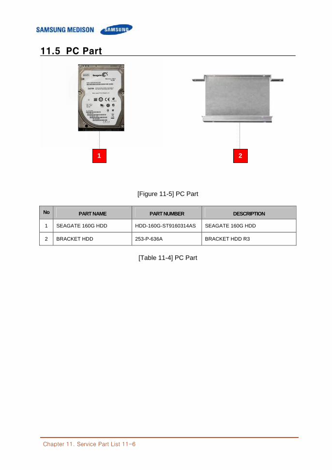
Chapter 11. Service Part List 11-6
11.5 PC Part
[Figure 11-5] PC Part
No PART NAME PART NUMBER DESCRIPTION
1 SEAGATE 160G HDD HDD-160G-ST9160314AS SEAGATE 160G HDD
2 BRACKET HDD 253-P-636A BRACKET HDD R3
[Table 11-4] PC Part
1 2
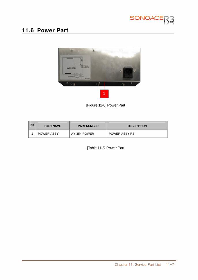
Chapter 11. Service Part List 11-7
11.6 Power Part
[Figure 11-6] Power Part
No PART NAME PART NUMBER DESCRIPTION
1 POWER ASSY AY-354-POWER POWER ASSY R3
[Table 11-5] Power Part
1
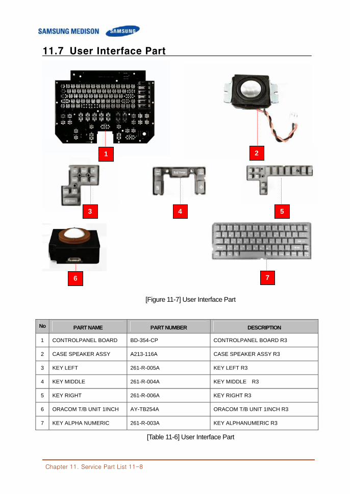
Chapter 11. Service Part List 11-8
11.7 User Interface Part
[Figure 11-7] User Interface Part
No PART NAME PART NUMBER DESCRIPTION
1 CONTROLPANEL BOARD BD-354-CP CONTROLPANEL BOARD R3
2 CASE SPEAKER ASSY A213-116A CASE SPEAKER ASSY R3
3 KEY LEFT 261-R-005A KEY LEFT R3
4 KEY MIDDLE 261-R-004A KEY MIDDLE R3
5 KEY RIGHT 261-R-006A KEY RIGHT R3
6 ORACOM T/B UNIT 1INCH AY-TB254A ORACOM T/B UNIT 1INCH R3
7 KEY ALPHA NUMERIC 261-R-003A KEY ALPHANUMERIC R3
[Table 11-6] User Interface Part
1
6
3 4 5
7
2
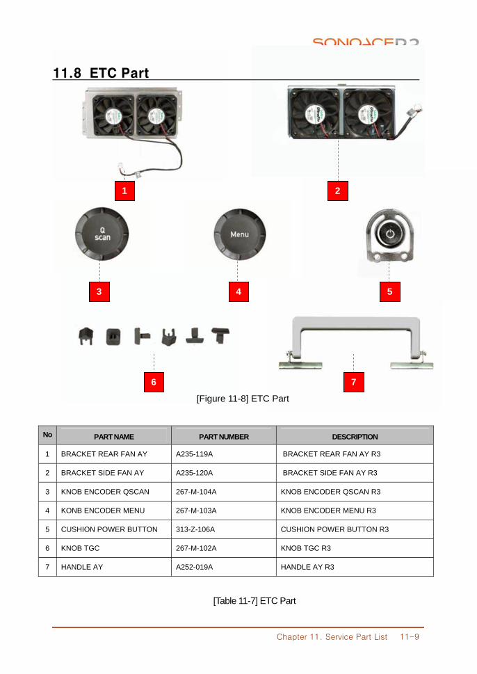
Chapter 11. Service Part List 11-9
11.8 ETC Part
[Figure 11-8] ETC Part
No PART NAME PART NUMBER DESCRIPTION
1 BRACKET REAR FAN AY A235-119A BRACKET REAR FAN AY R3
2 BRACKET SIDE FAN AY A235-120A BRACKET SIDE FAN AY R3
3 KNOB ENCODER QSCAN 267-M-104A KNOB ENCODER QSCAN R3
4 KONB ENCODER MENU 267-M-103A KNOB ENCODER MENU R3
5 CUSHION POWER BUTTON 313-Z-106A CUSHION POWER BUTTON R3
6 KNOB TGC 267-M-102A KNOB TGC R3
7 HANDLE AY A252-019A HANDLE AY R3
[Table 11-7] ETC Part
1 2
6 7
3 3 4 5
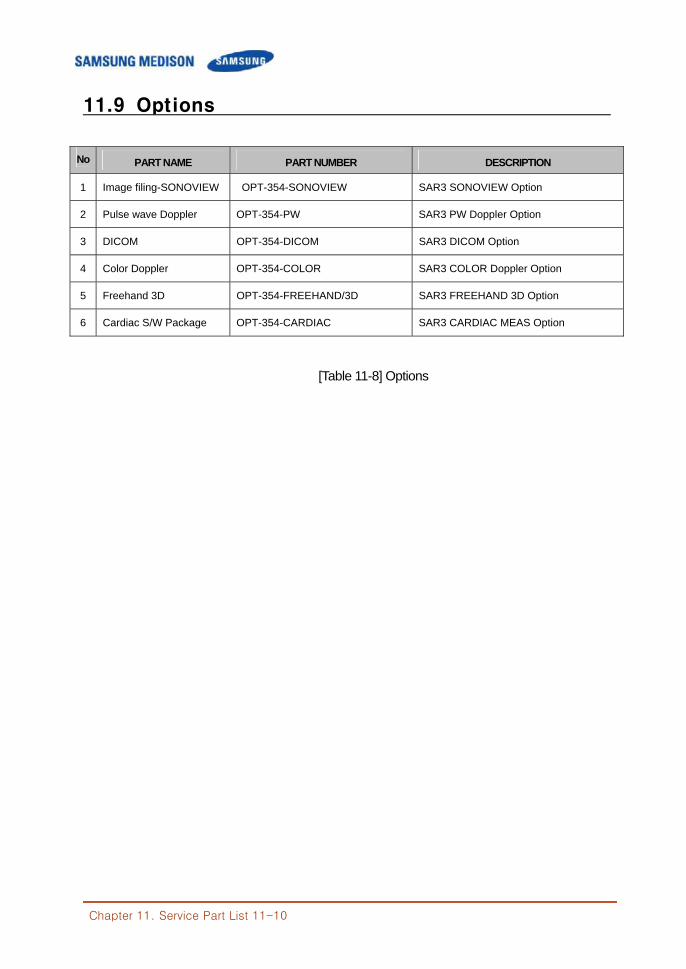
Chapter 11. Service Part List 11-10
11.9 Options
No PART NAME PART NUMBER DESCRIPTION
1 Image filing-SONOVIEW OPT-354-SONOVIEW SAR3 SONOVIEW Option
2 Pulse wave Doppler OPT-354-PW SAR3 PW Doppler Option
3 DICOM OPT-354-DICOM SAR3 DICOM Option
4 Color Doppler OPT-354-COLOR SAR3 COLOR Doppler Option
5 Freehand 3D OPT-354-FREEHAND/3D SAR3 FREEHAND 3D Option
6 Cardiac S/W Package OPT-354-CARDIAC SAR3 CARDIAC MEAS Option
[Table 11-8] Options
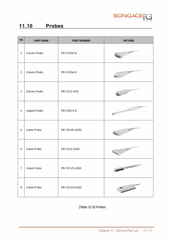
Chapter 11. Service Part List 11-11
11.10 Probes
No PART NAME PART NUMBER PICTURE
1 Convex Probe PB-TZCN2-8
2 Convex Probe PB-TZCN4-9
3 Convex Probe PB-TZC2-4/20
4 Vaginal Probe PB-TZEC4-9
5 Linear Probe PB-TZLN5-12/40
6 Linear Probe PB-TZL5-12/60
7 Linear Probe PB-TZLV5-12/60
8 Linear Probe PB-TZLV2-5/180
[Table 11-9] Probes

Publisher SAMSUNGMEDISON Co., Ltd Address SAMSUNGMEDISON Bldg., 1003, Deachi-dong, Gangnam-gu,
Seoul 135-280 Korea Homepage http://www.samsungmedison.com


