Embed Size (px)
Citation preview
Enterprise Analyzer 6.0
Enterprise Analyzer 6.0

Micro FocusThe Lawn22-30 Old Bath RoadNewbury, Berkshire RG14 1QNUKhttp://www.microfocus.com
© Copyright 2009-2020 Micro Focus or one of its affiliates.
MICRO FOCUS, the Micro Focus logo and Enterprise Analyzer are trademarks or registeredtrademarks of Micro Focus or one of its affiliates.
All other marks are the property of their respective owners.
2020-06-12
ii
Contents
Installation Guide ............................................................................................. 12Overview ........................................................................................................................... 12
Installation Tasks .................................................................................................... 12Deployment ............................................................................................................ 12Database Setup ......................................................................................................14
Hardware and Software Requirements ............................................................................. 17Repository Server Hardware Requirements ...........................................................17Repository Server Software Requirements ............................................................17EA Server Hardware Requirements ....................................................................... 17EA Server Software Requirements ........................................................................ 18EA Client Hardware Requirements ........................................................................ 19EA Client Software Requirements ..........................................................................19
EA Performance Optimization Guidelines ......................................................................... 20Choosing Hardware Configuration ......................................................................... 20Software Configuration ...........................................................................................24
Installing and Uninstalling Enterprise Analyzer .................................................................25Installing the Database Client .................................................................................25Installing EA on the Server or Client ...................................................................... 27Uninstalling Enterprise Analyzer ............................................................................ 27
Post-Installation Administrative Tasks ............................................................................... 27Configuring Enterprise Analyzer ............................................................................ 27Licensing ................................................................................................................ 28Configuring an ODBC Data Source Name .............................................................29Creating a Shared Folder for Workspaces ............................................................. 31Upgrading Workspaces .......................................................................................... 31
Troubleshooting the Installation .........................................................................................31Troubleshooting Oracle Errors ................................................................................31Troubleshooting Workspace Access .......................................................................32
Getting Started ................................................................................................. 33Introducing Enterprise Analyzer ........................................................................................33
Enterprise Analyzer Products .................................................................................33Differences between EA Analyst Client and EA Developer Client ..........................35How Enterprise Analyzer Models Applications .......................................................36Workspaces and Projects .......................................................................................37Single-User versus Multiuser Environments ...........................................................37Multiuser Environment Basics ................................................................................ 37
Enterprise Analyzer Basics ............................................................................................... 40Creating a Workspace in Oracle or DB2 ................................................................ 40Creating a Workspace in SQL Server .................................................................... 42Creating a Workspace Using the Workspace Build Wizard ....................................43Designating Users for Security Policies ..................................................................43Refreshing the Workspace Path .............................................................................44Connecting to a Workspace in Oracle or DB/2 .......................................................45Connecting to a Workspace in SQL Server ............................................................45Opening a Workspace ............................................................................................46Registering Source Files ........................................................................................ 47Queue Processor ................................................................................................... 51Check Workspace Queue .......................................................................................52Manage Queue .......................................................................................................52Verifying Source Files .............................................................................................52Quick Inventory .......................................................................................................53
Contents | 3
Using the Enterprise Analyzer Main Window ......................................................... 54Using Tool Windows ............................................................................................... 64Setting Options .......................................................................................................65Working with Reports and Diagrams ......................................................................69Using the Guide for a Tool ......................................................................................69Purge Activity Log .................................................................................................. 69
Preparing Projects ........................................................................................... 70Registering Source Files ...................................................................................................70
Host Environment Source Compatibility .................................................................71Refreshing Registered Source Paths ..................................................................... 74Setting Registration Options: Extensions Tab ........................................................ 74Setting Registration Options: Source Files Tab ......................................................75Creating New Source Files .....................................................................................76Updating Source Files with Source Synchronization ..............................................76Exporting Source Files from a Workspace .............................................................77Deleting Objects from a Workspace .......................................................................78Deleting a Workspace ............................................................................................ 78Japanese Language Support ................................................................................. 78
Setting Up Projects ........................................................................................................... 78Creating Projects ....................................................................................................78Sharing Projects .....................................................................................................79Protecting Projects ................................................................................................. 79Moving or Copying Files into Projects .................................................................... 79Including Referenced and Referencing Objects in a Project .................................. 80Removing Unused Support Objects from a Project ................................................80Emptying a Project ................................................................................................. 80Deleting a Project ................................................................................................... 80
Verifying Source Files ....................................................................................................... 80Enabling Parallel Verification .................................................................................. 81Invalidating Files Before Reverification ...................................................................82Setting Workspace Verification Options: Legacy Dialects Tab ............................... 82Setting Workspace Verification Options: Settings Tab ............................................85Setting Workspace Verification Options: Parallel Verification Tab .......................... 90Setting Project Verification Options ........................................................................ 90Identifying System Programs ................................................................................. 94Specifying Boundary Decisions ..............................................................................95Generating Copybooks ...........................................................................................95Performing Post-Verification Program Analysis ...................................................... 97
Using Post-Verification Reports ........................................................................................ 97Viewing Verification Reports ...................................................................................98Viewing Executive Reports .....................................................................................99Viewing CRUD Reports ........................................................................................107Distinguishing between Homonyms in the Reports ..............................................107
Inventorying Applications ................................................................................................ 108Using Reference Reports ..................................................................................... 108Using Orphan Analysis Reports ...........................................................................109Resolving Decisions ............................................................................................. 111
Identifying Interfaces for Generic API Analysis ............................................................... 115Identifying Unsupported API Calls to the Parser .................................................. 116Using Expressions ................................................................................................121Understanding Decisions ..................................................................................... 124Understanding Conditions .................................................................................... 125Usage Example .................................................................................................... 126Support for IMS Aliases ........................................................................................127
Analyzing Projects ......................................................................................... 129Managing Tags ................................................................................................................129
4 | Contents
Understanding the Tag Manager Window ............................................................ 129Creating Tags ....................................................................................................... 131Specifying Access to Tags ....................................................................................131Assigning Tags ..................................................................................................... 131Removing Tags .....................................................................................................132Creating Relationships Between Tags ..................................................................133Deleting Tags ........................................................................................................134Creating Tag Queries ........................................................................................... 134Deleting Tag Queries ............................................................................................135Refreshing the Tag Manager Window .................................................................. 135Cleaning Up the Tag Manager Window ................................................................135Generating Reports ..............................................................................................135
Analyzing Relationship Flows ......................................................................................... 135Understanding Relationship Flow Diagrams ........................................................ 136Understanding Diagram Scopes .......................................................................... 136Understanding Diagram Layouts .......................................................................... 136Generating a Diagram for the Selected Project ....................................................137Generating a Diagram for Objects Copied and Pasted onto the Canvas ............. 137Understanding the Diagrammer Window ..............................................................137Excluding Objects Outside the Project ................................................................. 141Showing Incomplete Composite Relationships .................................................... 141Colorizing Project Boundaries ..............................................................................141Showing and Hiding Object Labels ...................................................................... 141Working with Groups ............................................................................................ 142Black-Boxing Tagged Objects ...............................................................................142Filtering Objects ................................................................................................... 143Clustering Objects ................................................................................................144Setting Diagrams User Preferences ..................................................................... 145Using the Scope Editor .........................................................................................146Pruning a Scope ...................................................................................................152Mirroring a Scope .................................................................................................152
Analyzing Global Data Flow ............................................................................................ 152Understanding the Global Data Flow Panes ........................................................ 152Data Flow Relationships .......................................................................................153Assigning Business Names Manually .................................................................. 155Setting Global Data Flow User Preferences .........................................................155Setting Global Data Flow Project Options ............................................................ 155
Analyzing Batch Applications .......................................................................................... 156Understanding the Batch Application Viewer Window ..........................................156Generating Batch Application Diagrams ...............................................................158Assigning Business Names Manually .................................................................. 158Marking Items .......................................................................................................158Creating Job Dependencies in Batch Application Diagrams ................................ 158Creating User Names for Objects in Batch Application Diagrams ........................159Setting Batch Application Viewer Options ............................................................ 159
Estimating Complexity and Effort .................................................................................... 160Viewing Complexity Metrics ..................................................................................160Setting Complexity Metrics User Preferences ...................................................... 160Estimating Effort ................................................................................................... 161Setting Effort Estimation Options ......................................................................... 161Specifying the Change Magnitude for a Source File ............................................ 162
Identifying Classes of Data Items with Change Analyzer ................................................162Understanding Data Item Classification ............................................................... 162Getting Started in Change Analyzer .....................................................................163
Repository Exchange Protocol Syntax ............................................................................168Query Syntax ....................................................................................................... 168
Contents | 5
Example 1 ............................................................................................................ 170Example 2 ............................................................................................................ 170
Portability Assessment ....................................................................................................171Quality Assessment ........................................................................................................ 171
Analyzing Programs .......................................................................................172Introducing Interactive Analysis .......................................................................................172
Understanding Interactive Analysis Models ..........................................................172Using the Interactive Analysis Main Window ........................................................173Using Basic Navigation Controls .......................................................................... 174Using the Properties Window ...............................................................................174Assigning Business Names Manually .................................................................. 175
Understanding Program Context .....................................................................................176Using the Source Pane ........................................................................................176Using the Context Pane ........................................................................................178Using the Objects Pane ........................................................................................179Using the Watch Pane ..........................................................................................179Using the Screen Pane .........................................................................................180Using the Bird's Eye Pane ....................................................................................181Using the Model Reference Pane .........................................................................181
Performing Advanced Searches ......................................................................................182Defining a Search Filter ........................................................................................182Executing Advanced Searches .............................................................................187Advanced String Attribute Operations .................................................................. 188Working with Advanced Search Criteria ...............................................................189
Staging Program Analysis with Code Search ................................................................. 190Getting Started in Code Search ........................................................................... 190Understanding the Code Search Pane .................................................................191Executing Code Search Searches ........................................................................192Using Construct Lists to Narrow a Code Search ..................................................193Searching for Similar Constructs in Code Search ................................................ 194Extracting Business Rules in Code Search ..........................................................194Generating an Impact Subtree Report in Code Search ....................................... 195Marking and Colorizing Constructs in Code Search ............................................ 195Creating Projects in Code Search ........................................................................ 196Generating Metrics and Detailed Reports ............................................................ 196Running Code Search Reports in the Main Window ............................................196Running Code Search Reports in Interactive Analysis .........................................198
Analyzing Impact Traces ................................................................................................. 198Generating an Impact Trace ................................................................................. 198Understanding the Hierarchical View ................................................................... 199Understanding the Diagram View .........................................................................199Data Flow Relationships .......................................................................................199Setting Impact Pane User Preferences ................................................................ 201Setting Impact Pane Project Options: Processing Tab ......................................... 201Setting Impact Pane Project Options: Relationships Tab ..................................... 202Setting Impact Pane Project Options: Impact Reports Tab .................................. 204Exporting and Importing an Impact Trace ............................................................ 204Generating a Subtree Report ............................................................................... 204Generating a Pane Report ................................................................................... 206Generating an Affected Code Report (COBOL Only) ...........................................206
Analyzing Program Control Flows ...................................................................................206Using the Program Control Flow Pane ................................................................. 206Using the Execution Path Pane ............................................................................ 209Using the Flowchart Pane .................................................................................... 210Using the Animator ...............................................................................................212
Setting Up a Glossary ..................................................................................................... 213
6 | Contents
Understanding the Glossary Pane ....................................................................... 213Searching for Terms ............................................................................................. 214Assigning Business Attributes .............................................................................. 216Extracting Business Names from Screens ........................................................... 217Importing and Exporting Business Attributes ....................................................... 217Propagating Business Names .............................................................................. 218Deleting Business Attributes ................................................................................ 218Setting Glossary Workspace Options ...................................................................219Refreshing a Glossary ..........................................................................................219Generating Glossary Reports ...............................................................................219
Extracting Business Rules .............................................................................................. 219Understanding Business Rules ............................................................................ 220Extracting Business Rules Manually .................................................................... 222Performing Basic Tasks in the Rules Pane ...........................................................223Editing Rule Attributes ..........................................................................................225Propagating Rule Attributes ................................................................................. 227Identifying Triggered Rule Sets ............................................................................ 228Identifying I/O Data Elements ...............................................................................228Identifying Control Conditions .............................................................................. 230Searching for Rules ..............................................................................................231Batch Processing Rule Attributes .........................................................................233Synchronizing Sources .........................................................................................234Validating Rule Segments after Refreshing or Editing Code ................................234Setting Business Rule Manager Project Options ................................................. 234Customizing Rule Attributes ................................................................................. 236Generating Reports ..............................................................................................237
Using the Batch Duplicate Finder ....................................................................................238Finding Duplicates ................................................................................................238Marking Items for Comparison ............................................................................. 239Setting BDF Search Options ................................................................................ 239
Creating Components ....................................................................................242Introducing Logic Analyzer ..............................................................................................242
Componentization Methods ..................................................................................242Componentization Outputs ...................................................................................243Component Maker Basics .................................................................................... 244
Setting Component Maker Options ................................................................................. 249Setting General Options ....................................................................................... 249Setting Interface Options ......................................................................................250Setting Optimize Options ......................................................................................250Setting Document Options ................................................................................... 252Setting Component Type-Specific Options ...........................................................253Setting Component Conversion Options .............................................................. 255
Extracting Structure-Based Components ........................................................................255Understanding Ranges .........................................................................................255Understanding Parameterized Slices ................................................................... 256Extracting Structure-Based COBOL Components ............................................... 257Extracting Structure-Based PL/I Components ......................................................258Extracting Structure-Based RPG Components .................................................... 259
Extracting Computation-Based Components .................................................................. 259Understanding Variable-Based Extraction ............................................................260Understanding Blocking ....................................................................................... 260Understanding Parameterized Slices ................................................................... 260Extracting Computation-Based COBOL Components ..........................................261Extracting Computation-Based Natural Components ...........................................262
Extracting Domain-Based Components .......................................................................... 263Understanding Program Specialization in Simplified Mode ..................................263
Contents | 7
Understanding Program Specialization in Advanced Mode ................................. 265Understanding Program Specialization Lite ......................................................... 265Extracting Domain-Based COBOL Components ..................................................266Extracting Domain-Based PL/I Components ........................................................267
Eliminating Dead Code ................................................................................................... 268Generating Dead Code Statistics ......................................................................... 268Understanding Dead Code Elimination ................................................................ 268Extracting Optimized Components .......................................................................269
Performing Entry Point Isolation ......................................................................................269Extracting a COBOL Component with Entry Point Isolation .................................270
Technical Details ............................................................................................................. 270Verification Options .............................................................................................. 270Keep Legacy Copybooks Extraction Option ........................................................ 272How Parameterized Slices Are Generated for COBOL Programs ........................274Setting a Specialization Variable to Multiple Values .............................................274Arithmetic Exception Handling ............................................................................. 275
Using the Batch Refresh Process .................................................................277Using the Batch Refresh Process ................................................................................... 277
Understanding the Batch Refresh Process .......................................................... 277Configuring the Batch Refresh Process ............................................................... 277Preparing Files for Batch Refresh Processing ..................................................... 281Enabling Parallel Verification ................................................................................ 281Executing the Batch Refresh Process ..................................................................282Producing Utilities for BRP ................................................................................... 283Guidelines for BRP Utilities .................................................................................. 284Executing Batch Scripts ....................................................................................... 289
Using Batch Scripts .........................................................................................................292AddNew.bj ............................................................................................................ 292AffectedCodeReport.bj .........................................................................................293AnalyzeProgram.bj ............................................................................................... 294ApplyPCF.bj ..........................................................................................................295BusinessRulesReport.bj .......................................................................................295BusinessRulesValidation.bj .................................................................................. 296ChangeTraffic.bj ................................................................................................... 296CheckQueue.bj .....................................................................................................298ClipperDetails.bj ................................................................................................... 298ClipperMetrics.bj ...................................................................................................299ClipperMultiSearch.bj ........................................................................................... 300ClipperSearch.bj ...................................................................................................301CodeSearchReport.bj ...........................................................................................301ComplexityReport.bj ............................................................................................. 302CreatePCF.bj ........................................................................................................ 302CreateWS.bj ......................................................................................................... 303CRUDReport.bj .................................................................................................... 304DBA.Cobol.bj ........................................................................................................304DCE.bj .................................................................................................................. 306DiagramBAV.bj ......................................................................................................306DiagramCallie.bj ................................................................................................... 307DiagramFlowchart.bj ............................................................................................ 307DiagramProject.bj .................................................................................................308DiagramTS.bj ........................................................................................................309EffortReport.bj ...................................................................................................... 310ExecutiveReport.bj ............................................................................................... 311ExportDescriptions.bj ........................................................................................... 311ExportRules.bj ......................................................................................................312ExportScreens.bj ..................................................................................................312
8 | Contents
GenCopybooks.bj .................................................................................................313GenScreens.bj ......................................................................................................314ImpactReport.bj ....................................................................................................314ImpactReportFromList.bj ...................................................................................... 315ImportRules.bj ...................................................................................................... 316IMS Analysis.bj .....................................................................................................317IncludeReferences.bj ............................................................................................318Invalidate.bj .......................................................................................................... 319InventoryReport.bj ................................................................................................320MFCobolCLink.bj ..................................................................................................320Populate.bj ............................................................................................................321PortabilityAssessment.bj ...................................................................................... 321ProcessChangeUnit.bj ..........................................................................................322QualityAssessment.bj ...........................................................................................322ReferenceReport.bj .............................................................................................. 323Refresh.bj ............................................................................................................. 323Register.bj ............................................................................................................ 324Related.bj ............................................................................................................. 325ResolveDecisions.bj ............................................................................................. 326RestoreDecisions.bj ............................................................................................. 327RXP.bj ...................................................................................................................328SaveDecisions.bj .................................................................................................. 328SetChangeDate.bj ................................................................................................ 329SetProject.bj ......................................................................................................... 330TagCmd.bj ............................................................................................................ 330Unregister.bj ......................................................................................................... 331UpdateOnly.bj .......................................................................................................332UpdateTrendingSnapshot.bj ................................................................................. 333Upgrade.bj ............................................................................................................333Verify.bj ................................................................................................................. 333
Using Architecture Modeler ...........................................................................335Introducing Architecture Modeler ................................................................................... 335Opening Architecture Modeler ....................................................................................... 335Understanding the Application-Level Metamodel ............................................................336
Entity Type Properties .......................................................................................... 336Entity Type Attributes ............................................................................................338Relationship Type Properties ............................................................................... 338
Defining an Extension with Architecture Modeler ............................................................339Loading a Metamodel ...........................................................................................340Saving the Extended Metamodel ......................................................................... 340Adding a Sample Source File ...............................................................................340Defining Entity Types ............................................................................................342Defining Relationship Types ................................................................................. 343Architecture Modeler Internal Language Functions Description .......................... 343Mapping Regular Expressions to Text File Searches ...........................................345Mapping XPath Queries to XML File Searches ....................................................347Exporting the Extended Metamodel ..................................................................... 353Reconfiguring Enterprise Analyzer .......................................................................353Troubleshooting the Extended Metamodel ........................................................... 353
Using Galleries ................................................................................................................354EA Web ............................................................................................................355
Installing EA Web ............................................................................................................355Deploying EA Web .......................................................................................................... 355Troubleshooting ...............................................................................................................355Getting Started with EA Web .......................................................................................... 356EA Web Reports ............................................................................................................. 359
Contents | 9
Eclipse Plugins ...............................................................................................360Eclipse Plugins ................................................................................................................360Installing the Eclipse Plugins ...........................................................................................360Uninstalling the Eclipse Plugins ...................................................................................... 360Updating the Eclipse Plugins .......................................................................................... 361
Support Notes .................................................................................................362Supported Languages .....................................................................................................362Supported Features by Language ...................................................................................365AS/400 CL Support ......................................................................................................... 370Assembler Support ..........................................................................................................370
Specifying Relationships for Assembler Customizations ......................................370HyperCode for Assembler .................................................................................... 372Restrictions ...........................................................................................................372
C/C++ Support ................................................................................................................ 372Registering C/C++ Files ....................................................................................... 372Verifying C/C++ Files ............................................................................................372
CICS Support ..................................................................................................................373Case Sensitive Transaction Name ........................................................................373Deprecated CICS Statements .............................................................................. 373Keyword Permutations ..........................................................................................373Statements Taken to Be the Same .......................................................................374
COBOL Support ..............................................................................................................374Object-Oriented Statements .................................................................................375Separators Must Be Followed by Blanks ..............................................................375Copybooks in a Library .........................................................................................375How Enterprise Analyzer Calculates COBOL Dead Code Statistics ....................375Special Handling of Cobol Program Complexity Metrics ......................................376Possible Padding in MOVE Statements ................................................................377
ACUCOBOL Support ...................................................................................................... 377ECL Support ................................................................................................................... 377Hogan Framework Support ............................................................................................. 377
Overview .............................................................................................................. 377Inputs: Hogan Configuration File Preparation ...................................................... 378Validating EA Format Using HoganFileConvertor ................................................ 381Troubleshooting Hogan Framework Support ........................................................ 385
IDMS Support ................................................................................................................. 385COPY IDMS Statements ...................................................................................... 386NNCOPY Statements ...........................................................................................386Manipulation of Logical Records .......................................................................... 386
IMS Support .................................................................................................................... 386Troubleshooting IMS Analysis .............................................................................. 387Mapping Root Programs to PSBs in JCL or System Definition Files ................... 388Verification Order for IMS Applications .................................................................388Reverifying Files in IMS Applications ................................................................... 388Restrictions on IMS Support ................................................................................ 389
Java Support ................................................................................................................... 393JSP Support ....................................................................................................................394
Resolving the Location of Java Types and Packages Referenced in JSP Files ... 394Job Scheduler Support ................................................................................................... 394
Preparing CA-7 Job Schedule Information ...........................................................395Preparing TWS (OPC) Job Schedule Information ................................................395Using an XML Job Schedule Format for Unsupported Job Schedules ................ 396
JCL Support .................................................................................................................... 399Verification Output Notes ......................................................................................401JCL Control Cards Support .................................................................................. 401Naming Requirements for External Control Cards ............................................... 402
10 | Contents
Detecting Programs Started by Driver Utilities ..................................................... 402Natural Support ...............................................................................................................404
Verification Order for Natural Applications ............................................................405Restoring Line Numbers in Natural Source ..........................................................405Restrictions on Natural Support ........................................................................... 405
.NET Support .................................................................................................................. 406PL/I Support .................................................................................................................... 406
Verification ............................................................................................................407Change Analyzer ..................................................................................................407How Macros Are Modeled in Interactive Analysis ................................................ 407Execution Path Labelled Variables and Branching ............................................... 407Global Data Element Flow ....................................................................................407Common IMS, Domain Extraction, and Autoresolve Restrictions ........................ 408
PL/SQL Support ..............................................................................................................410RPG Support ...................................................................................................................410SQL Support ................................................................................................................... 410
Renaming DCLGEN Include Files ........................................................................410Prefixes for SQL Names .......................................................................................411
VB Support ......................................................................................................................411Generating Library Description Files ....................................................................411Restrictions on Visual Basic Support .................................................................. 412
WFL Support ...................................................................................................................413Mainframe Access ..........................................................................................414
Mainframe Access ...........................................................................................................414Introduction ...........................................................................................................414Mainframe Access ................................................................................................415
Contents | 11
Installation Guide
OverviewThis manual describes how to install and configure Micro Focus Enterprise Analyzer (EA), a suite ofsoftware products for analyzing and modernizing legacy applications.
Enterprise Analyzer provides insight into the technical reality of complex application portfolios, including
• Tools for application and program level understanding, utilizing extensive metrics, reports, diagrammaticviews and querying tools to support myriad of business initiatives.
• Quality Assessment with standard code quality queries to serve as a guidance to a code quality practicein both development and maintenance phases.
• Portability Assessment to help you generate various HTML reports to identify points of interest formigrations.
• In depth analysis tools to promote efficiency in the performance of daily tasks such as field changes,understanding of data propagation through a program, and dead code removal.
Business Rule Manager mines business logic from program code and encapsulates the logic in businessrules.
While all products are installed with Enterprise Analyzer, each product is licensed separately.
EA is deployed in a multi-user environment with access to a common repository of application objects.Repository setup is the responsibility of a master user, leaving team members free to focus on their tasks.The database for the repository is assumed to be the customer's own.
EA installations consist of the following components:
• The EA Server which hosts EA workspace files and related support files.• EA Clients which host the link files used to connect to workspaces on the server.
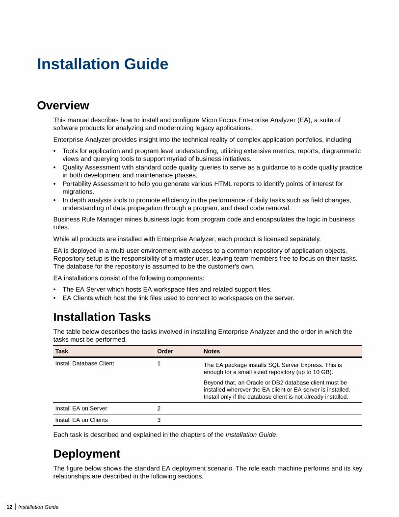
Installation TasksThe table below describes the tasks involved in installing Enterprise Analyzer and the order in which thetasks must be performed.
Task Order Notes
Install Database Client 1 The EA package installs SQL Server Express. This isenough for a small sized repository (up to 10 GB).
Beyond that, an Oracle or DB2 database client must beinstalled wherever the EA client or EA server is installed.Install only if the database client is not already installed.
Install EA on Server 2
Install EA on Clients 3
Each task is described and explained in the chapters of the Installation Guide.
DeploymentThe figure below shows the standard EA deployment scenario. The role each machine performs and its keyrelationships are described in the following sections.
12 | Installation Guide
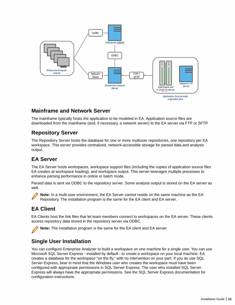
Mainframe and Network ServerThe mainframe typically hosts the application to be modeled in EA. Application source files aredownloaded from the mainframe (and, if necessary, a network server) to the EA server via FTP or SFTP.
Repository ServerThe Repository Server hosts the database for one or more multiuser repositories, one repository per EAworkspace. This server provides centralized, network-accessible storage for parsed data and analysisoutput.
EA ServerThe EA Server hosts workspaces, workspace support files (including the copies of application source filesEA creates at workspace loading), and workspace output. This server leverages multiple processes toenhance parsing performance in online or batch mode.
Parsed data is sent via ODBC to the repository server. Some analysis output is stored on the EA server aswell.
Note: In a multi-user environment, the EA Server cannot reside on the same machine as the EARepository. The installation program is the same for the EA client and EA server.
EA ClientEA Clients host the link files that let team members connect to workspaces on the EA server. These clientsaccess repository data stored in the repository server via ODBC.
Note: The installation program is the same for the EA client and EA server.
Single User InstallationYou can configure Enterprise Analyzer to build a workspace on one machine for a single user. You can useMicrosoft SQL Server Express - installed by default - to create a workspace on your local machine. EAcreates a database for the workspace "on the fly," with no intervention on your part. If you do use SQLServer Express, bear in mind that the Windows user who creates the workspace must have beenconfigured with appropriate permissions in SQL Server Express. The user who installed SQL ServerExpress will always have the appropriate permissions. See the SQL Server Express documentation forconfiguration instructions.
Installation Guide | 13
Restriction: The database size limit when using the SQL Server Express option is 10 GB.
Database SetupIf you use Oracle or DB2, your DBA must set up a schema for each repository you plan to create. Each EAuser who accesses the repository must supply credentials for a database user with appropriate accessprivileges to the repository.
If you use Microsoft SQL Server, the DBA must set up a SQL Server database for each workspacerepository you plan to create. EA users typically supply Windows credentials to access the repository.
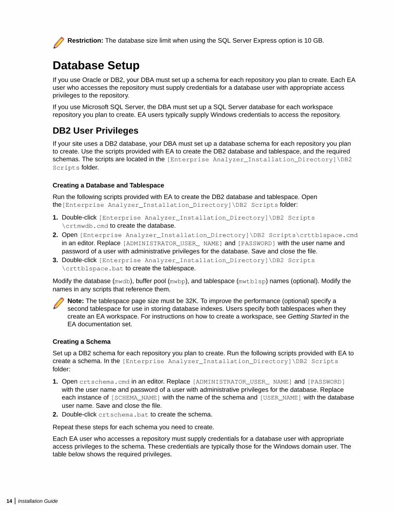
DB2 User PrivilegesIf your site uses a DB2 database, your DBA must set up a database schema for each repository you planto create. Use the scripts provided with EA to create the DB2 database and tablespace, and the requiredschemas. The scripts are located in the [Enterprise Analyzer_Installation_Directory]\DB2Scripts folder.
Creating a Database and Tablespace
Run the following scripts provided with EA to create the DB2 database and tablespace. Openthe[Enterprise Analyzer_Installation_Directory]\DB2 Scripts folder:
1. Double-click [Enterprise Analyzer_Installation_Directory]\DB2 Scripts\crtmwdb.cmd to create the database.
2. Open [Enterprise Analyzer_Installation_Directory]\DB2 Scripts\crttblspace.cmdin an editor. Replace [ADMINISTRATOR_USER_ NAME] and [PASSWORD] with the user name andpassword of a user with administrative privileges for the database. Save and close the file.
3. Double-click [Enterprise Analyzer_Installation_Directory]\DB2 Scripts\crttblspace.bat to create the tablespace.
Modify the database (mwdb), buffer pool (mwbp), and tablespace (mwtblsp) names (optional). Modify thenames in any scripts that reference them.
Note: The tablespace page size must be 32K. To improve the performance (optional) specify asecond tablespace for use in storing database indexes. Users specify both tablespaces when theycreate an EA workspace. For instructions on how to create a workspace, see Getting Started in theEA documentation set.
Creating a Schema
Set up a DB2 schema for each repository you plan to create. Run the following scripts provided with EA tocreate a schema. In the [Enterprise Analyzer_Installation_Directory]\DB2 Scriptsfolder:
1. Open crtschema.cmd in an editor. Replace [ADMINISTRATOR_USER_ NAME] and [PASSWORD]with the user name and password of a user with administrative privileges for the database. Replaceeach instance of [SCHEMA_NAME] with the name of the schema and [USER_NAME] with the databaseuser name. Save and close the file.
2. Double-click crtschema.bat to create the schema.
Repeat these steps for each schema you need to create.
Each EA user who accesses a repository must supply credentials for a database user with appropriateaccess privileges to the schema. These credentials are typically those for the Windows domain user. Thetable below shows the required privileges.
14 | Installation Guide
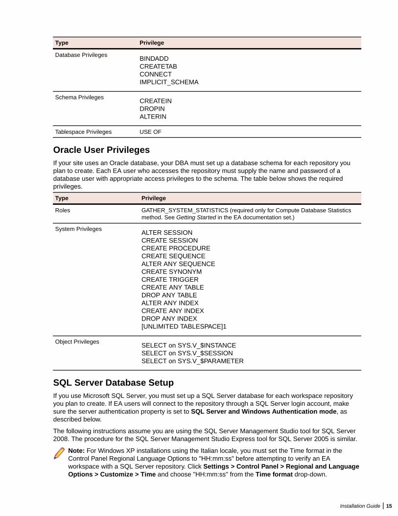
Type Privilege
Database PrivilegesBINDADDCREATETABCONNECTIMPLICIT_SCHEMA
Schema PrivilegesCREATEINDROPINALTERIN
Tablespace Privileges USE OF
Oracle User PrivilegesIf your site uses an Oracle database, your DBA must set up a database schema for each repository youplan to create. Each EA user who accesses the repository must supply the name and password of adatabase user with appropriate access privileges to the schema. The table below shows the requiredprivileges.
Type Privilege
Roles GATHER_SYSTEM_STATISTICS (required only for Compute Database Statisticsmethod. See Getting Started in the EA documentation set.)
System PrivilegesALTER SESSIONCREATE SESSIONCREATE PROCEDURECREATE SEQUENCEALTER ANY SEQUENCECREATE SYNONYMCREATE TRIGGERCREATE ANY TABLEDROP ANY TABLEALTER ANY INDEXCREATE ANY INDEXDROP ANY INDEX[UNLIMITED TABLESPACE]1
Object PrivilegesSELECT on SYS.V_$INSTANCESELECT on SYS.V_$SESSIONSELECT on SYS.V_$PARAMETER
SQL Server Database SetupIf you use Microsoft SQL Server, you must set up a SQL Server database for each workspace repositoryyou plan to create. If EA users will connect to the repository through a SQL Server login account, makesure the server authentication property is set to SQL Server and Windows Authentication mode, asdescribed below.
The following instructions assume you are using the SQL Server Management Studio tool for SQL Server2008. The procedure for the SQL Server Management Studio Express tool for SQL Server 2005 is similar.
Note: For Windows XP installations using the Italian locale, you must set the Time format in theControl Panel Regional Language Options to "HH:mm:ss" before attempting to verify an EAworkspace with a SQL Server repository. Click Settings > Control Panel > Regional and LanguageOptions > Customize > Time and choose "HH:mm:ss" from the Time format drop-down.
Installation Guide | 15
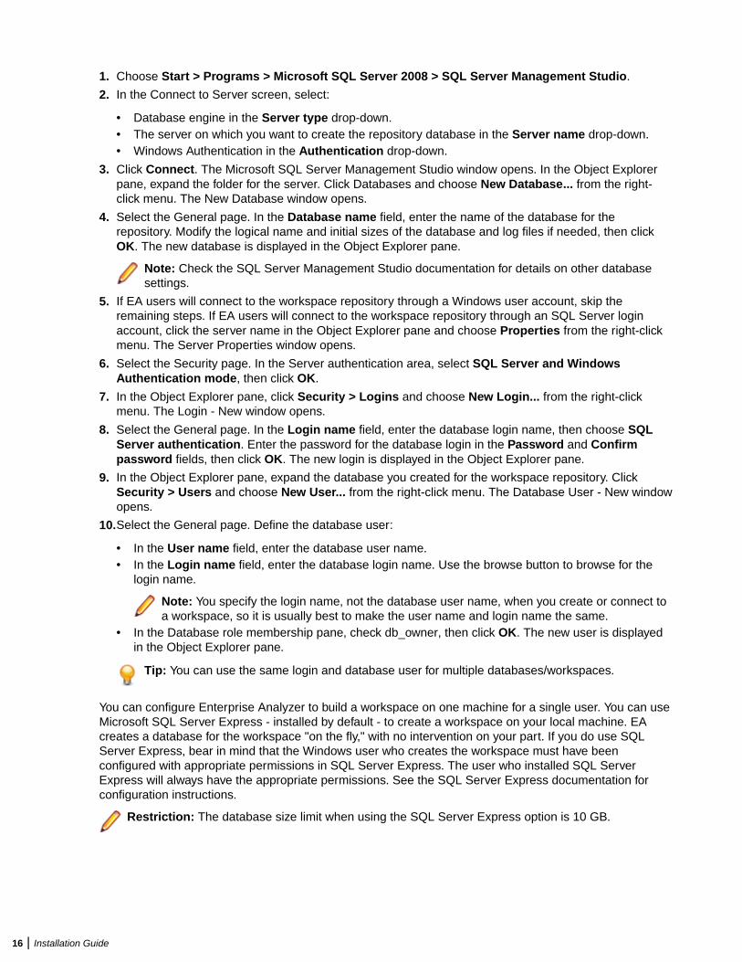
1. Choose Start > Programs > Microsoft SQL Server 2008 > SQL Server Management Studio.
2. In the Connect to Server screen, select:
• Database engine in the Server type drop-down.• The server on which you want to create the repository database in the Server name drop-down.• Windows Authentication in the Authentication drop-down.
3. Click Connect. The Microsoft SQL Server Management Studio window opens. In the Object Explorerpane, expand the folder for the server. Click Databases and choose New Database... from the right-click menu. The New Database window opens.
4. Select the General page. In the Database name field, enter the name of the database for therepository. Modify the logical name and initial sizes of the database and log files if needed, then clickOK. The new database is displayed in the Object Explorer pane.
Note: Check the SQL Server Management Studio documentation for details on other databasesettings.
5. If EA users will connect to the workspace repository through a Windows user account, skip theremaining steps. If EA users will connect to the workspace repository through an SQL Server loginaccount, click the server name in the Object Explorer pane and choose Properties from the right-clickmenu. The Server Properties window opens.
6. Select the Security page. In the Server authentication area, select SQL Server and WindowsAuthentication mode, then click OK.
7. In the Object Explorer pane, click Security > Logins and choose New Login... from the right-clickmenu. The Login - New window opens.
8. Select the General page. In the Login name field, enter the database login name, then choose SQLServer authentication. Enter the password for the database login in the Password and Confirmpassword fields, then click OK. The new login is displayed in the Object Explorer pane.
9. In the Object Explorer pane, expand the database you created for the workspace repository. ClickSecurity > Users and choose New User... from the right-click menu. The Database User - New windowopens.
10.Select the General page. Define the database user:
• In the User name field, enter the database user name.• In the Login name field, enter the database login name. Use the browse button to browse for the
login name.
Note: You specify the login name, not the database user name, when you create or connect toa workspace, so it is usually best to make the user name and login name the same.
• In the Database role membership pane, check db_owner, then click OK. The new user is displayedin the Object Explorer pane.
Tip: You can use the same login and database user for multiple databases/workspaces.
You can configure Enterprise Analyzer to build a workspace on one machine for a single user. You can useMicrosoft SQL Server Express - installed by default - to create a workspace on your local machine. EAcreates a database for the workspace "on the fly," with no intervention on your part. If you do use SQLServer Express, bear in mind that the Windows user who creates the workspace must have beenconfigured with appropriate permissions in SQL Server Express. The user who installed SQL ServerExpress will always have the appropriate permissions. See the SQL Server Express documentation forconfiguration instructions.
Restriction: The database size limit when using the SQL Server Express option is 10 GB.
16 | Installation Guide
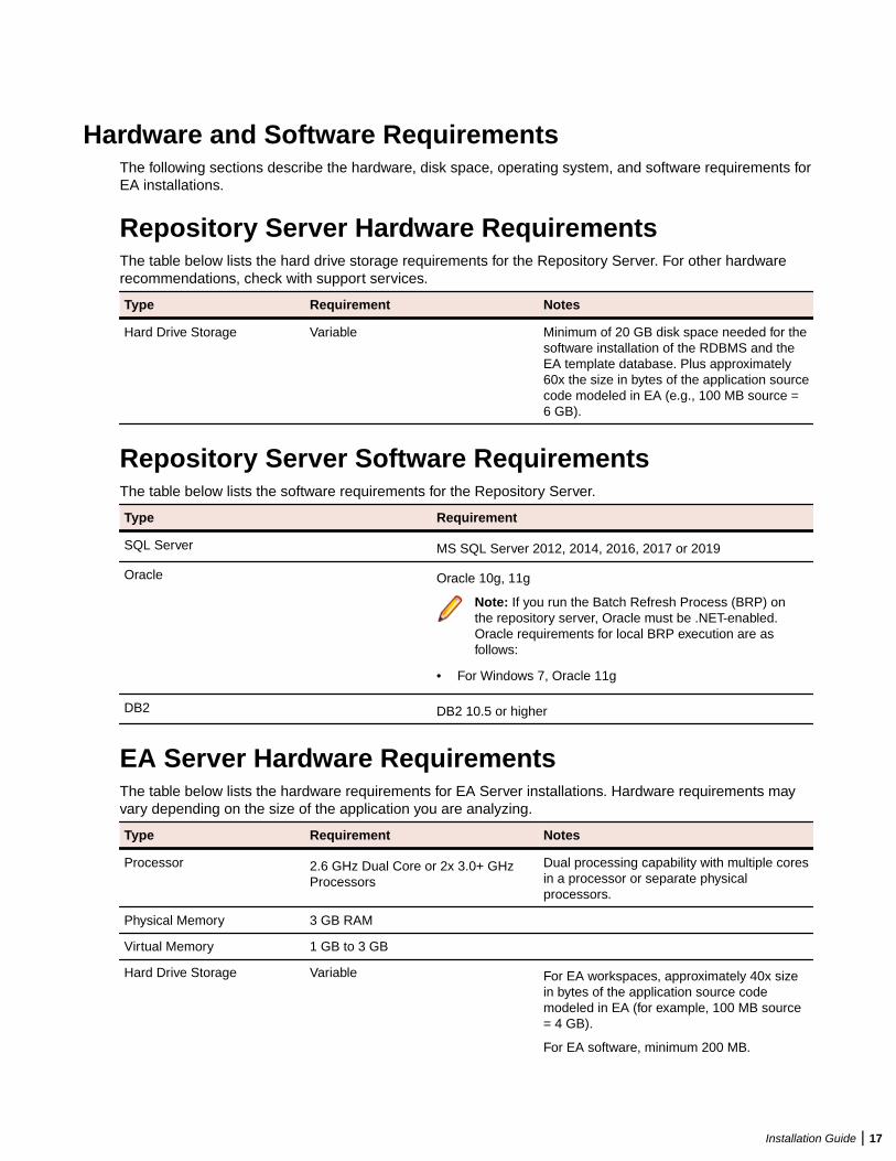
Hardware and Software RequirementsThe following sections describe the hardware, disk space, operating system, and software requirements forEA installations.
Repository Server Hardware RequirementsThe table below lists the hard drive storage requirements for the Repository Server. For other hardwarerecommendations, check with support services.
Type Requirement Notes
Hard Drive Storage Variable Minimum of 20 GB disk space needed for thesoftware installation of the RDBMS and theEA template database. Plus approximately60x the size in bytes of the application sourcecode modeled in EA (e.g., 100 MB source =6 GB).
Repository Server Software RequirementsThe table below lists the software requirements for the Repository Server.
Type Requirement
SQL Server MS SQL Server 2012, 2014, 2016, 2017 or 2019
Oracle Oracle 10g, 11g
Note: If you run the Batch Refresh Process (BRP) onthe repository server, Oracle must be .NET-enabled.Oracle requirements for local BRP execution are asfollows:
• For Windows 7, Oracle 11g
DB2 DB2 10.5 or higher
EA Server Hardware RequirementsThe table below lists the hardware requirements for EA Server installations. Hardware requirements mayvary depending on the size of the application you are analyzing.
Type Requirement Notes
Processor 2.6 GHz Dual Core or 2x 3.0+ GHzProcessors
Dual processing capability with multiple coresin a processor or separate physicalprocessors.
Physical Memory 3 GB RAM
Virtual Memory 1 GB to 3 GB
Hard Drive Storage Variable For EA workspaces, approximately 40x sizein bytes of the application source codemodeled in EA (for example, 100 MB source= 4 GB).
For EA software, minimum 200 MB.
Installation Guide | 17
Type Requirement Notes
For database client, minimum 200 MB.
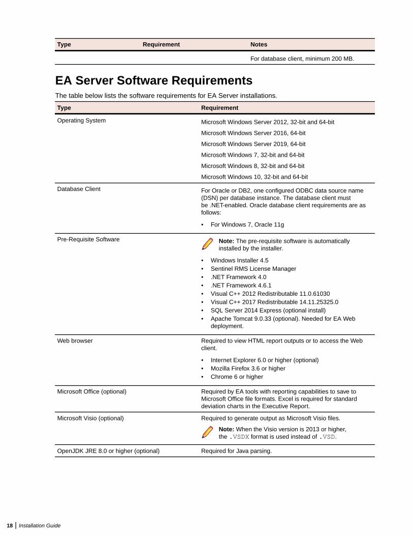
EA Server Software RequirementsThe table below lists the software requirements for EA Server installations.
Type Requirement
Operating System Microsoft Windows Server 2012, 32-bit and 64-bit
Microsoft Windows Server 2016, 64-bit
Microsoft Windows Server 2019, 64-bit
Microsoft Windows 7, 32-bit and 64-bit
Microsoft Windows 8, 32-bit and 64-bit
Microsoft Windows 10, 32-bit and 64-bit
Database Client For Oracle or DB2, one configured ODBC data source name(DSN) per database instance. The database client mustbe .NET-enabled. Oracle database client requirements are asfollows:
• For Windows 7, Oracle 11g
Pre-Requisite Software Note: The pre-requisite software is automaticallyinstalled by the installer.
• Windows Installer 4.5• Sentinel RMS License Manager• .NET Framework 4.0• .NET Framework 4.6.1• Visual C++ 2012 Redistributable 11.0.61030• Visual C++ 2017 Redistributable 14.11.25325.0• SQL Server 2014 Express (optional install)• Apache Tomcat 9.0.33 (optional). Needed for EA Web
deployment.
Web browser Required to view HTML report outputs or to access the Webclient.
• Internet Explorer 6.0 or higher (optional)• Mozilla Firefox 3.6 or higher• Chrome 6 or higher
Microsoft Office (optional) Required by EA tools with reporting capabilities to save toMicrosoft Office file formats. Excel is required for standarddeviation charts in the Executive Report.
Microsoft Visio (optional) Required to generate output as Microsoft Visio files.
Note: When the Visio version is 2013 or higher,the .VSDX format is used instead of .VSD.
OpenJDK JRE 8.0 or higher (optional) Required for Java parsing.
18 | Installation Guide
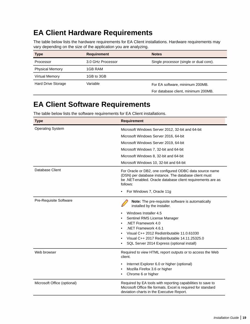
EA Client Hardware RequirementsThe table below lists the hardware requirements for EA Client installations. Hardware requirements mayvary depending on the size of the application you are analyzing.
Type Requirement Notes
Processor 3.0 GHz Processor Single processor (single or dual core).
Physical Memory 1GB RAM
Virtual Memory 1GB to 3GB
Hard Drive Storage Variable For EA software, minimum 200MB.
For database client, minimum 200MB.
EA Client Software RequirementsThe table below lists the software requirements for EA Client installations.
Type Requirement
Operating System Microsoft Windows Server 2012, 32-bit and 64-bit
Microsoft Windows Server 2016, 64-bit
Microsoft Windows Server 2019, 64-bit
Microsoft Windows 7, 32-bit and 64-bit
Microsoft Windows 8, 32-bit and 64-bit
Microsoft Windows 10, 32-bit and 64-bit
Database Client For Oracle or DB2, one configured ODBC data source name(DSN) per database instance. The database client mustbe .NET-enabled. Oracle database client requirements are asfollows:
• For Windows 7, Oracle 11g
Pre-Requisite Software Note: The pre-requisite software is automaticallyinstalled by the installer.
• Windows Installer 4.5• Sentinel RMS License Manager• .NET Framework 4.0• .NET Framework 4.6.1• Visual C++ 2012 Redistributable 11.0.61030• Visual C++ 2017 Redistributable 14.11.25325.0• SQL Server 2014 Express (optional install)
Web browser Required to view HTML report outputs or to access the Webclient.
• Internet Explorer 6.0 or higher (optional)• Mozilla Firefox 3.6 or higher• Chrome 6 or higher
Microsoft Office (optional) Required by EA tools with reporting capabilities to save toMicrosoft Office file formats. Excel is required for standarddeviation charts in the Executive Report.
Installation Guide | 19
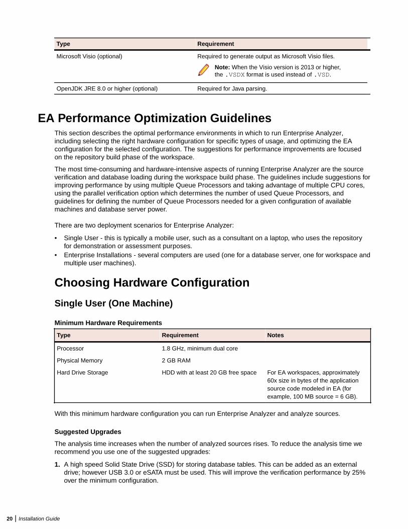
Type Requirement
Microsoft Visio (optional) Required to generate output as Microsoft Visio files.
Note: When the Visio version is 2013 or higher,the .VSDX format is used instead of .VSD.
OpenJDK JRE 8.0 or higher (optional) Required for Java parsing.
EA Performance Optimization GuidelinesThis section describes the optimal performance environments in which to run Enterprise Analyzer,including selecting the right hardware configuration for specific types of usage, and optimizing the EAconfiguration for the selected configuration. The suggestions for performance improvements are focusedon the repository build phase of the workspace.
The most time-consuming and hardware-intensive aspects of running Enterprise Analyzer are the sourceverification and database loading during the workspace build phase. The guidelines include suggestions forimproving performance by using multiple Queue Processors and taking advantage of multiple CPU cores,using the parallel verification option which determines the number of used Queue Processors, andguidelines for defining the number of Queue Processors needed for a given configuration of availablemachines and database server power.
There are two deployment scenarios for Enterprise Analyzer:
• Single User - this is typically a mobile user, such as a consultant on a laptop, who uses the repositoryfor demonstration or assessment purposes.
• Enterprise Installations - several computers are used (one for a database server, one for workspace andmultiple user machines).
Choosing Hardware Configuration
Single User (One Machine)
Minimum Hardware Requirements
Type Requirement Notes
Processor 1.8 GHz, minimum dual core
Physical Memory 2 GB RAM
Hard Drive Storage HDD with at least 20 GB free space For EA workspaces, approximately60x size in bytes of the applicationsource code modeled in EA (forexample, 100 MB source = 6 GB).
With this minimum hardware configuration you can run Enterprise Analyzer and analyze sources.
Suggested Upgrades
The analysis time increases when the number of analyzed sources rises. To reduce the analysis time werecommend you use one of the suggested upgrades:
1. A high speed Solid State Drive (SSD) for storing database tables. This can be added as an externaldrive; however USB 3.0 or eSATA must be used. This will improve the verification performance by 25%over the minimum configuration.
20 | Installation Guide
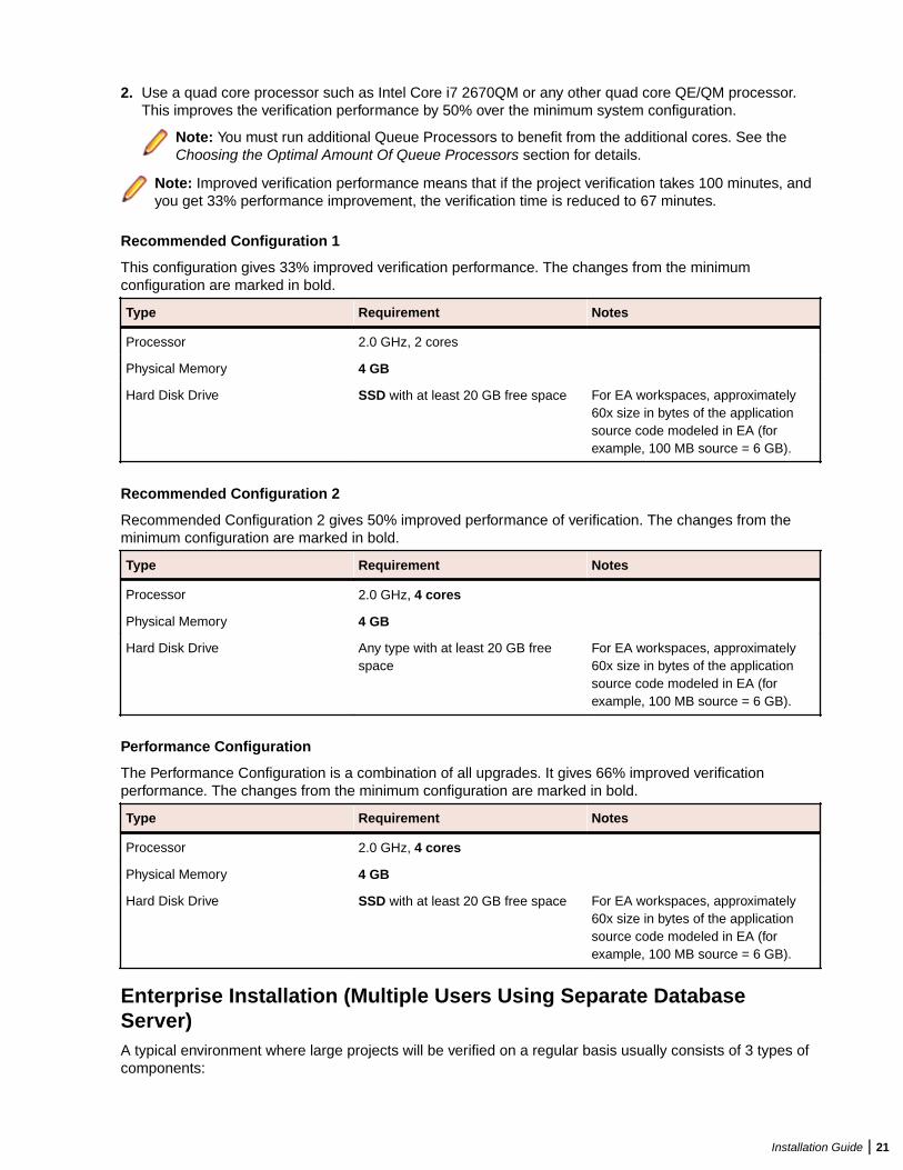
2. Use a quad core processor such as Intel Core i7 2670QM or any other quad core QE/QM processor.This improves the verification performance by 50% over the minimum system configuration.
Note: You must run additional Queue Processors to benefit from the additional cores. See theChoosing the Optimal Amount Of Queue Processors section for details.
Note: Improved verification performance means that if the project verification takes 100 minutes, andyou get 33% performance improvement, the verification time is reduced to 67 minutes.
Recommended Configuration 1
This configuration gives 33% improved verification performance. The changes from the minimumconfiguration are marked in bold.
Type Requirement Notes
Processor 2.0 GHz, 2 cores
Physical Memory 4 GB
Hard Disk Drive SSD with at least 20 GB free space For EA workspaces, approximately60x size in bytes of the applicationsource code modeled in EA (forexample, 100 MB source = 6 GB).
Recommended Configuration 2
Recommended Configuration 2 gives 50% improved performance of verification. The changes from theminimum configuration are marked in bold.
Type Requirement Notes
Processor 2.0 GHz, 4 cores
Physical Memory 4 GB
Hard Disk Drive Any type with at least 20 GB freespace
For EA workspaces, approximately60x size in bytes of the applicationsource code modeled in EA (forexample, 100 MB source = 6 GB).
Performance Configuration
The Performance Configuration is a combination of all upgrades. It gives 66% improved verificationperformance. The changes from the minimum configuration are marked in bold.
Type Requirement Notes
Processor 2.0 GHz, 4 cores
Physical Memory 4 GB
Hard Disk Drive SSD with at least 20 GB free space For EA workspaces, approximately60x size in bytes of the applicationsource code modeled in EA (forexample, 100 MB source = 6 GB).
Enterprise Installation (Multiple Users Using Separate DatabaseServer)A typical environment where large projects will be verified on a regular basis usually consists of 3 types ofcomponents:
Installation Guide | 21
1. Database server (Oracle, DB2, MS SQL Server).2. EA server with the workspace files. This is the machine where EA is installed and where the EA
workspace folder is located.
Note: There can be more than one workspace.
3. Processing node(s). This is one or more computers running Queue Processors, or hosting the users ofthe tool.
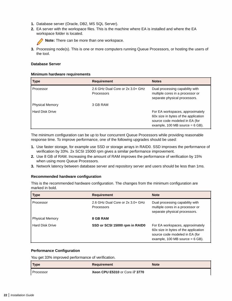
Database Server
Minimum hardware requirements
Type Requirement Notes
Processor 2.6 GHz Dual Core or 2x 3.0+ GHzProcessors
Dual processing capability withmultiple cores in a processor orseparate physical processors.
Physical Memory 3 GB RAM
Hard Disk Drive For EA workspaces, approximately60x size in bytes of the applicationsource code modeled in EA (forexample, 100 MB source = 6 GB).
The minimum configuration can be up to four concurrent Queue Processors while providing reasonableresponse time. To improve performance, one of the following upgrades should be used:
1. Use faster storage, for example use SSD or storage arrays in RAID0. SSD improves the performance ofverification by 33%. 2x SCSI 15000 rpm gives a similar performance improvement.
2. Use 8 GB of RAM. Increasing the amount of RAM improves the performance of verification by 15%when using more Queue Processors.
3. Network latency between database server and repository server and users should be less than 1ms.
Recommended hardware configuration
This is the recommended hardware configuration. The changes from the minimum configuration aremarked in bold.
Type Requirement Note
Processor 2.6 GHz Dual Core or 2x 3.0+ GHzProcessors
Dual processing capability withmultiple cores in a processor orseparate physical processors.
Physical Memory 8 GB RAM
Hard Disk Drive SSD or SCSI 15000 rpm in RAID0 For EA workspaces, approximately60x size in bytes of the applicationsource code modeled in EA (forexample, 100 MB source = 6 GB).
Performance Configuration
You get 33% improved performance of verification.
Type Requirement Note
Processor Xeon CPU E5310 or Core i7 3770
22 | Installation Guide
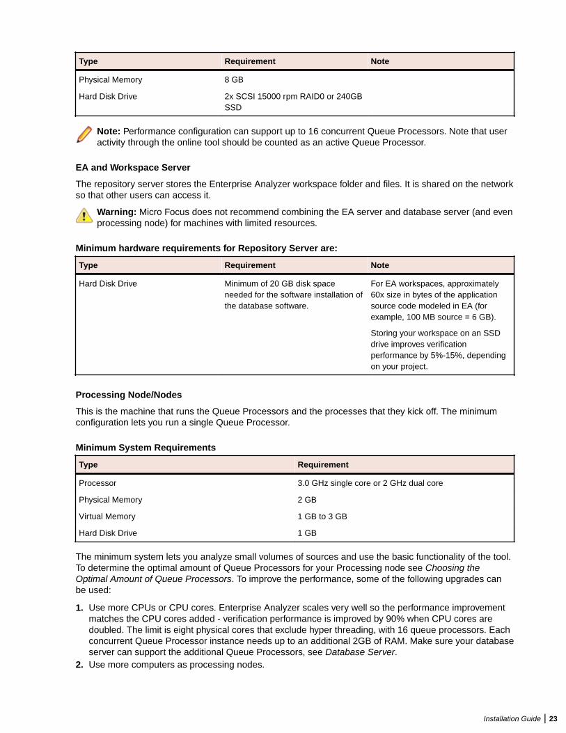
Type Requirement Note
Physical Memory 8 GB
Hard Disk Drive 2x SCSI 15000 rpm RAID0 or 240GBSSD
Note: Performance configuration can support up to 16 concurrent Queue Processors. Note that useractivity through the online tool should be counted as an active Queue Processor.
EA and Workspace Server
The repository server stores the Enterprise Analyzer workspace folder and files. It is shared on the networkso that other users can access it.
Warning: Micro Focus does not recommend combining the EA server and database server (and evenprocessing node) for machines with limited resources.
Minimum hardware requirements for Repository Server are:
Type Requirement Note
Hard Disk Drive Minimum of 20 GB disk spaceneeded for the software installation ofthe database software.
For EA workspaces, approximately60x size in bytes of the applicationsource code modeled in EA (forexample, 100 MB source = 6 GB).
Storing your workspace on an SSDdrive improves verificationperformance by 5%-15%, dependingon your project.
Processing Node/Nodes
This is the machine that runs the Queue Processors and the processes that they kick off. The minimumconfiguration lets you run a single Queue Processor.
Minimum System Requirements
Type Requirement
Processor 3.0 GHz single core or 2 GHz dual core
Physical Memory 2 GB
Virtual Memory 1 GB to 3 GB
Hard Disk Drive 1 GB
The minimum system lets you analyze small volumes of sources and use the basic functionality of the tool.To determine the optimal amount of Queue Processors for your Processing node see Choosing theOptimal Amount of Queue Processors. To improve the performance, some of the following upgrades canbe used:
1. Use more CPUs or CPU cores. Enterprise Analyzer scales very well so the performance improvementmatches the CPU cores added - verification performance is improved by 90% when CPU cores aredoubled. The limit is eight physical cores that exclude hyper threading, with 16 queue processors. Eachconcurrent Queue Processor instance needs up to an additional 2GB of RAM. Make sure your databaseserver can support the additional Queue Processors, see Database Server.
2. Use more computers as processing nodes.
Installation Guide | 23
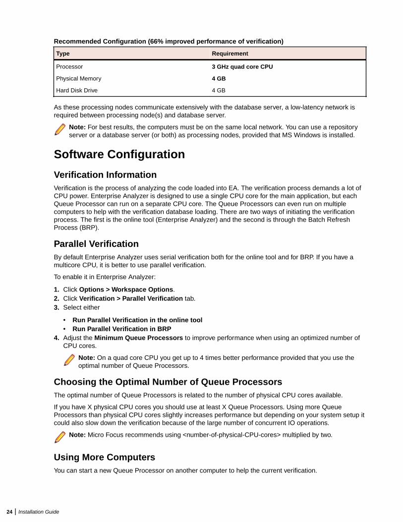
Recommended Configuration (66% improved performance of verification)
Type Requirement
Processor 3 GHz quad core CPU
Physical Memory 4 GB
Hard Disk Drive 4 GB
As these processing nodes communicate extensively with the database server, a low-latency network isrequired between processing node(s) and database server.
Note: For best results, the computers must be on the same local network. You can use a repositoryserver or a database server (or both) as processing nodes, provided that MS Windows is installed.
Software Configuration
Verification InformationVerification is the process of analyzing the code loaded into EA. The verification process demands a lot ofCPU power. Enterprise Analyzer is designed to use a single CPU core for the main application, but eachQueue Processor can run on a separate CPU core. The Queue Processors can even run on multiplecomputers to help with the verification database loading. There are two ways of initiating the verificationprocess. The first is the online tool (Enterprise Analyzer) and the second is through the Batch RefreshProcess (BRP).
Parallel VerificationBy default Enterprise Analyzer uses serial verification both for the online tool and for BRP. If you have amulticore CPU, it is better to use parallel verification.
To enable it in Enterprise Analyzer:
1. Click Options > Workspace Options.2. Click Verification > Parallel Verification tab.3. Select either
• Run Parallel Verification in the online tool• Run Parallel Verification in BRP
4. Adjust the Minimum Queue Processors to improve performance when using an optimized number ofCPU cores.
Note: On a quad core CPU you get up to 4 times better performance provided that you use theoptimal number of Queue Processors.
Choosing the Optimal Number of Queue ProcessorsThe optimal number of Queue Processors is related to the number of physical CPU cores available.
If you have X physical CPU cores you should use at least X Queue Processors. Using more QueueProcessors than physical CPU cores slightly increases performance but depending on your system setup itcould also slow down the verification because of the large number of concurrent IO operations.
Note: Micro Focus recommends using <number-of-physical-CPU-cores> multiplied by two.
Using More ComputersYou can start a new Queue Processor on another computer to help the current verification.
24 | Installation Guide
Note: EA must be installed on the computer that launches a Queue Processor.
1. Open Micro Focus Enterprise Analyzer Administration and click Administer > Build New Connection.This creates a local .rwp file to connect to the workspace that needs help during the verification anddatabase loading.
2. Click Administer > Launch Queue Processor. The Launch Queue Processor window opens.3. Specify the local .rwp file for the workspace and enter the number of Queue Processors that you want
to start.
Installing and Uninstalling Enterprise AnalyzerBefore running an installation program described in this section, make sure you have administrativepermissions for the machine on which you are performing the installation. If you do not have administrativepermissions, the installation program will not let you continue.
Note: You can run the Windows Installer (.msi) installation programs "silently." That is particularlyuseful when you are installing clients on a network. Check with support services for the appropriatesequence of commands.
Installing the Database ClientIf you use Oracle or DB2, a database client must be installed wherever the EA client or EA server isinstalled. If the RDBMS client software is not already installed on your machine, follow the instructions inthis section to install it.
Installing the Oracle ClientYou will need the following information from your DBA to install and configure Oracle client software:
• The TNS Service Name for the database in which your workspace repositories will be stored.• The host name for the computer on which the database resides.• The port number for communications with the host, if it is not the standard port number.• A database user ID and password.
1. Double-click the setup.exe program for the Oracle client installation. The Welcome screen opens.
2. Click Next. The Select Installation Type screen opens. Select Custom.
3. Click Next. The Specify Home Details screen opens. Enter an alternate name and path for theinstallation, if desired. Otherwise, accept the defaults.
4. Click Next. The Available Product Components screen opens. Select the following components:
• SQL *Plus• Oracle JDBC/THIN Interfaces• Oracle Windows Interfaces. Deselect every choice under Oracle Windows Interfaces except Oracle
ODBC Driver.• Oracle Call Interface (OCI)• Oracle Net
5. Click Next. The installer checks for prerequisites to ensure your environment meets the minimumrequirements for installation. Resolve any flagged items, if necessary.
6. Click Next. Review the Summary screen to confirm your selections. Use the Back button to correct anyerrors. When you are satisfied that all the information is correct, click Install.
7. When installation completes, the Oracle Net Configuration Assistant is launched.
8. Click Next. The Naming Methods Configuration screen opens. Verify that Local Naming is shown in theSelected Naming Methods field.
Installation Guide | 25
9. Click Next. The Net Service Name Configuration screen opens. In the Service Name field, enter theTNS Service Name for the database your workspace repositories will be stored in. This name isprovided by your DBA.
10.Click Next. The Select Protocols screen opens. Select TCP.
11.Click Next. The TCP/IP Protocol screen opens. Enter the host name for the computer on which theOracle database resides. This name is provided by your DBA. Use the standard port number of 1521unless otherwise instructed by your DBA.
12.Click Next. The Test screen opens. Select Yes, perform a test.
13.Click Next. You should receive a message that the test did not succeed. This is because the defaultlogin used for the test is the Oracle SYSTEM login. You must change the user name and password tothose provided by your DBA.
14.Click Change Login. In the Change Login dialog, enter the user ID and password provided by yourDBA.
15.Click OK. You should now receive a message that the connection test was successful. If the testremains unsuccessful, click Change Login and confirm that you entered the correct credentials asprovided by your DBA. If problems persist, contact your DBA for assistance.
16.Click Next. The Net Service Name screen opens.
17.The Net Service Name field is prefilled with the TNS Service Name you specified in Net Service NameConfiguration screen. Click Next. The Additional Net Service Names screen opens.
18.In the Additional Net Service Names screen, configure additional TNS Service Names, one perdatabase instance you need to connect with. This step is optional. Select Yes to configure additionalTNS Service Names. Select No to complete the configuration.
Note: If you need to connect to additional database instances at a later date, you can add TNSService Names by manually editing the tnsnames.ora file in Repository_Client_HOME. Seeyour DBA for details.
19.Click Next. Then click Next on the following two screens to complete the Oracle Net Configuration.
20.On the Oracle Net Configuration completion screen, click Finish to exit the Net Configuration Assistant.
21.The Oracle Installer window opens Click Exit. You are prompted to confirm that you want to exit. ClickYes.
Installing the DB2 ClientFollow the instructions in this section to install the DB2 client.
Note: The DB2 client must be .NET-enabled. Choosing the Typical DB2 client installation ensuresthat .NET support is available.
1. Double-click the setup.exe program for the DB2 client installation. The Welcome screen opens. ClickInstall a Product.
2. A screen prompts you to select the product you want to install. Under IBM Data Server Client, clickInstall New.
3. The DB2 Setup Wizard opens. Click Next.
4. The Software License Agreement screen opens. Read the License Agreement carefully. Click I acceptthe terms in the license agreement to accept its terms, then click Next.
5. A screen prompts you to select the installation type. Select Typical, then click Next.
6. A screen prompts you to install the IBM Data Server Client. Select Install IBM Data Server Client onthis computer, then click Next.
7. A screen prompts you to select an installation folder. To accept the prefilled value, click Next. To specifya different folder, click Change and follow the substeps below.
a) Navigate the folder structure to find a suitable location. If the destination folder does not exist, theinstallation creates it.
26 | Installation Guide
b) Click OK to exit the screen and return to the installation folder screen.c) Click Next in the installation folder screen.
8. A screen prompts you to enable operating system security for DB2 objects. Unless otherwise instructedby your system or database administrator, deselect Enable operating system security, then clickNext.
9. A screen prompts you to start copying installation files to your computer. Click Install to begintransferring files to your machine. A progress meter indicates the progress of the transfer.
10.When the transfer is complete, a screen informs you that setup is complete. Click Next.11.A screen prompts you to install additional products. Click Finish.
Installing EA on the Server or ClientThe EA Server hosts EA workspace files and related support files. EA Clients host the link files used toconnect to workspaces on the server. Follow the instructions in this section to install EA on the client orserver. The Micro Focus License Manager is packaged with the installation.
Note: Having the EA server and the database on separate machines could improve performance. Theinstallation program is the same for the EA client and EA server.
1. Double-click EnterpriseAnalyzer.exe. Note that there might be a version number in the name ofthe .exe file.
2. Change the installation directory if not installing to the default location.
3. Select which optional installs you want to include:
• Microsoft SQL Server - Express Edition• Web Client• Micro Focus MFA• Micro Focus Enterprise Analyzer Administration Tool (needed for server, not really needed for client).
4. Read the End User License Agreement and check I agree to the End User License Agreement.5. Click Install.
Uninstalling Enterprise AnalyzerFollow the instructions below to uninstall an Enterprise Analyzer product. Make sure you close any openEA programs before running the uninstall program.
1. Click Start > Control Panel > Programs > Programs and Features > Uninstall a program2. In the Uninstall or change a program window, right-click the product you want to uninstall, then click
Uninstall. You are prompted to confirm that you want to uninstall the product. Click Uninstall.
Post-Installation Administrative TasksBefore you can work in Enterprise Analyzer, you must complete the basic administrative tasks described inthis section. You are prompted to perform the first of these tasks, configuring the EA, when you completethe installation.
Configuring Enterprise AnalyzerUse the Configuration Manager in the Enterprise Analyzer Administration tool to configure EA options anddisplays for the programming languages, dialects, character sets, and products in use at your site.
If you configure your EA for COBOL, for example, you will see only the EA options and displays appropriatefor COBOL modernization. You need to configure your EA for PL/I as well, you can come back to theConfiguration Manager later and select PL/I in addition to COBOL.
Installation Guide | 27
Note: The Enterprise Analyzer Administration tool will prompt to be run with elevated privileges. Thisis required because some features of the tool require write access to the Program Files directory.
1. Open the Configuration Manager window.
• If you are installing EA, the Configuration Manager window opens after you finish the installation.• If you have previously installed EA and want to reconfigure it, choose Start > Programs > Micro
Focus > Enterprise Analyzer > Enterprise Analyzer Administration. The Enterprise AnalyzerAdministration window opens. In the Administer menu, choose Configure Micro Focus EnterpriseAnalyzer. The Configuration Manager window opens.
Note: If EA is open, you are prompted to exit. Click OK, then close EA.
2. Select each programming language, dialect, and character set in use at your site. Select each EAproduct you want to use at your site. The core Application Analyzer product is always selected. SelectAdditional Tools to enable tools not used in typical EA configurations. When you are satisfied with yourchoices, click OK.
Note: If you modify your EA configuration, make sure you upgrade workspaces created under theprevious configuration.
Note: The Enterprise Analyzer Administration tool will prompt tobe run with elevated privileges. This is required because somefeatures of the tool require write access to the Program Filesdirectory.
LicensingAlthough Enterprise Analyzer and Business Rule Manager) are both installed by the Enterprise Analyzerinstaller, each product is licensed separately. Follow the instructions in the topics listed below to manageyour licenses.
Upgrading CustomersA customer upgrading from Modernization Workbench version 3.1 or later may use the existing license keyto enable Enterprise Analyzer for the same number of users.
Concurrent UseYou can license Enterprise Analyzer and Business Rule Manager for concurrent use. In this mode, onelicense key for the purchased number of end users will be registered to a license server and each userinstance will contact it for authorization.
Enterprise Analyzer LicensingA Sentinel RMS license server is installed with Enterprise Analyzer.
Depending on the licensing model in use at your site, you can manage your license:
• Locally, using the installed Sentinel RMS license server.• Remotely, using a Sentinel RMS license server that has been configured to manage licenses centrally.
Note: The remote license server uses the same software as the local license server that isinstalled with Enterprise Analyzer.
You will need to apply a license in the Micro Focus License Administration to use Enterprise Analyzer. Tostart the Micro Focus License Administration, choose Start > All Programs > Micro Focus LicenseManager > License Administration.
28 | Installation Guide
• If you use a local license server, you can apply a license using an authorization code or a licensing filein the Install tab of the License Administration.
• Authorization code: Enter the 16-character license authorization code for Enterprise Analyzer, thenclick Authorize.
• Licensing file: Enter your downloaded license file (.mflic) by browsing or dropping the file, then clickInstall Licenses.
• If you use a remote license server, click Options > Advanced Configuration, then click Change in theLicense server field. Enter the IP address or server name of the license server, then click Save.
Your License System Administrator can tell you which licensing model your site uses and provide you withthe name of the remote license server if needed. For complete information, including how to configure aremote license server, refer to the help provided with the License Administration tool.
Business Rule Manager LicensingTrial licenses are not provided for Business Rule Manager. Before you can work with it, you must enter the16-character license authorization code:
• Choose Start > Programs > Micro Focus License Manager > License Management System. In theLicensing System Administration tool, click the Authorize tab, then enter the authorization code in theEnter authorization code field and click Authorize.
Configuring an ODBC Data Source NameAn ODBC data source name (DSN) is a set of credentials for connecting with a database instance. If youuse Oracle or DB2, you must configure a DSN for the database that holds your workspace repositories.
Configuring an Oracle ODBC Data Source NameTo configure an Oracle Data Source Name (DSN), you must have specified a TNS Service Name for thedatabase in which your workspace repositories will be stored. This is the TNS Service Name you enteredwhen you installed the repository client.
Check the file tnsnames.ora in Repository_Client_HOME to make sure the TNS Service Name exists.The entry should look like this, where RMWPROD is the TNS Service Name:
RMWPROD (DESCRIPTION= (ADDRESS_LIST= (ADDRESS=(PROTOCOL=TCP)(HOST=tiger)(PORT=1521)) ) (CONNECT_DATA= (SID=lnx) ) )
You will also need to obtain a database user ID and password from your DBA to configure the Oracle DSN.
Note: Keep the DSN handy. You will need to specify it when you create an EA workspace. Forinstructions on how to create a workspace, see Getting Started in the EA documentation set.
1. In the Windows Control Panel, double-click Administrative Tools. The Administrative tools windowopens.
2. Double-click Data Sources (ODBC). The ODBC Data Source Administrator window opens.
3. Select the System DSN tab and click Add. The Create New Data Source dialog opens.
4. Select an appropriate Oracle driver and click Finish. The Oracle ODBC Driver Configuration windowopens.
5. Specify the following information in the Oracle ODBC Driver Configuration window:
Installation Guide | 29
• In the Data Source Name field, enter a name of your choice to identify the data source. If your DBAhas supplied a common DSN for use across the enterprise, enter it here.
• In the Description field, enter an optional description for the data source.• In the TNS Service Name drop-down, select the TNS Service Name for the database in which your
workspace repositories will be stored. If no choices are shown, or if you are unsure which name toselect, contact your DBA.
• In the User ID field, enter the database user ID supplied by your DBA.
6. Click Test Connection. The Oracle ODBC Driver Connect window opens.
7. In the Oracle ODBC Driver Connect window the Service Name and User ID fields are prefilled with theinformation you supplied in the Oracle ODBC Driver Configuration window. Enter the password for youruser ID and click OK. You are notified that the connection was created successfully. Click OK.
Note: If you receive an error, verify the driver configuration settings and retest the connection. Seeyour DBA if the problem persists.
8. Click OK to exit the Driver Configuration window. Then click OK again to exit the ODBC Data SourceAdministrator window.
Configuring a DB2 ODBC Data Source NameYou will need the following information from your DBA to configure a DB2 ODBC data source name (DSN):
• The name of the database in which your workspace repositories will be stored.• The host name for the computer on which the database resides.• The port number for communications with the host, if it is not the standard port number.
Note: Keep the DSN handy. You will need to specify it when you create an EA workspace. Forinstructions on how to create a workspace, see Getting Started in the EA documentation set.
1. In the Windows Control Panel, double-click Administrative Tools. The Administrative tools windowopens.
2. Double-click Data Sources (ODBC). The ODBC Data Source Administrator window opens.
3. Select the System DSN tab and click Add. The Create New Data Source window opens.
4. Select IBM DB2 ODBC DRIVER - DB2COPY1 and click Finish. The ODBC IBM DB2 Driverconfiguration dialog opens.
5. In the Data Source Name field, enter a name of your choice to identify the data source. If your DBA hassupplied a common DSN for use across the enterprise, enter it here.
6. In the Description field, enter an optional description for the data source.
7. In the Database alias field, select an existing database alias from the drop-down, then click OK.
8. If a database alias has not been defined, click Add. The CLI/ODBC Settings window opens.
9. In the Data Source tab, the Data source name and Description fields are pre filled with the informationyou supplied in the ODBC IBM DB2 Driver configuration dialog. In the User ID field, enter your domainuser name. In the Password field, enter your domain user password. The fields are case-sensitive.
10.Select the TCP/IP tab and specify the following information:
• In the Database name field, enter the name of the database in which your workspace repositorieswill be stored.
• In the Database alias field, enter a database alias.• In the Host name field, enter the host name for the computer on which the database resides.• In the Port number field, enter the port number for communications with the host. Use the standard
port number of 50000 unless otherwise instructed by your DBA.
11.Click OK. You are returned to the ODBC Data Source Administrator window. Select the new datasource name and click Configure. The CLI/ODBC Settings window for the data source opens.
12.In the Data Source tab, the Data source name and Description fields are pre filled with the informationyou supplied in the ODBC IBM DB2 Driver configuration dialog. In the User ID field, enter your domain
30 | Installation Guide
user name. In the Password field, enter your domain user password. The fields are case-sensitive.Click Connect to test the database connection. You are notified that the connection was createdsuccessfully. Click OK.
Note: If you receive an error, verify the driver configuration settings and retest the connection. Seeyour DBA if the problem persists.
13.Click OK to exit the CLI/ODBC Settings window. Then click OK again to exit the ODBC Data SourceAdministrator window.
Creating a Shared Folder for WorkspacesThe folder in which you plan to create workspaces must be shared with team members. It is typically moreconvenient to share the folder before you create workspaces, but you can do it afterward if necessary, thenrefresh the workspace path as described in Getting Started in the EA documentation set.
Follow the instructions below to create a shared folder for workspaces. You must be an administrator tocreate a shared folder.
1. On the EA server, create a folder for EA workspaces.
2. Select the folder and choose Sharing and Security from the right-click menu. The Properties dialog forthe folder opens. In the Sharing tab for the Properties dialog, select Share this folder on the network(or, on a machine in a Windows domain, Share this folder). Enter the share name in the Share namefield and click Apply.
Note: Do not embed spaces in the share name. Doing so may cause other users to be unable toaccess the folder.
3. Click Permissions. The Permissions for Folder dialog opens. Specify the appropriate permissions forusers sharing the folder and click OK.
Upgrading WorkspacesWhen you modify your EA configuration, you must upgrade every workspace created with the previousconfiguration. Only the master user can upgrade a workspace.
1. Choose Start > All Programs > Micro Focus > Enterprise Analyzer > Enterprise AnalyzerAdministration. The EA Administration window opens.
2. In the Administration window, choose Administer > Upgrade Workspace. The Upgrade workspacedialog opens.
3. Choose the workspace you want to upgrade, then click Open. A Workspace Upgrade window opens.
4. Click Start to begin the upgrade. In the Workspace Upgrade window you see the upgrade process (Theparts that are being upgraded are highlighted and the checkbox next to each upgraded part is checkedwhen the upgrade is complete.) You can Pause the upgrade and Resume it later.
Note: Upgrades that have stopped due to an error can be reset from the File menu.
5. (optional) Click Workspace Upgrade > File >Export DDL Script to export the DDL script to performthe upgrade and give it to a DBA.
Troubleshooting the InstallationFollow the instructions in this section to troubleshoot an EA installation.
Troubleshooting Oracle ErrorsFollow the instructions in this section to troubleshoot common Oracle errors.
Installation Guide | 31
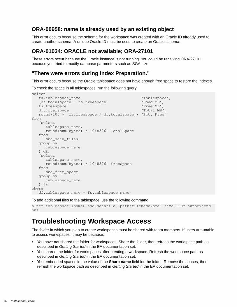
ORA-00958: name is already used by an existing objectThis error occurs because the schema for the workspace was created with an Oracle ID already used tocreate another schema. A unique Oracle ID must be used to create an Oracle schema.
ORA-01034: ORACLE not available; ORA-27101These errors occur because the Oracle instance is not running. You could be receiving ORA-27101because you tried to modify database parameters such as SGA size.
"There were errors during Index Preparation."This error occurs because the Oracle tablespace does not have enough free space to restore the indexes.
To check the space in all tablespaces, run the following query:
select fs.tablespace_name "Tablespace", (df.totalspace - fs.freespace) "Used MB", fs.freespace "Free MB", df.totalspace "Total MB", round(100 * (fs.freespace / df.totalspace)) "Pct. Free"from (select tablespace_name, round(sum(bytes) / 1048576) TotalSpace from dba_data_files group by tablespace_name ) df, (select tablespace_name, round(sum(bytes) / 1048576) FreeSpace from dba_free_space group by tablespace_name ) fswhere df.tablespace_name = fs.tablespace_name
To add additional files to the tablespace, use the following command:
alter tablespace <name> add datafile 'path\filename.ora' size 100M autoextend on;
Troubleshooting Workspace AccessThe folder in which you plan to create workspaces must be shared with team members. If users are unableto access workspaces, it may be because:
• You have not shared the folder for workspaces. Share the folder, then refresh the workspace path asdescribed in Getting Started in the EA documentation set.
• You shared the folder for workspaces after creating a workspace. Refresh the workspace path asdescribed in Getting Started in the EA documentation set.
• You embedded spaces in the value of the Share name field for the folder. Remove the spaces, thenrefresh the workspace path as described in Getting Started in the EA documentation set.
32 | Installation Guide
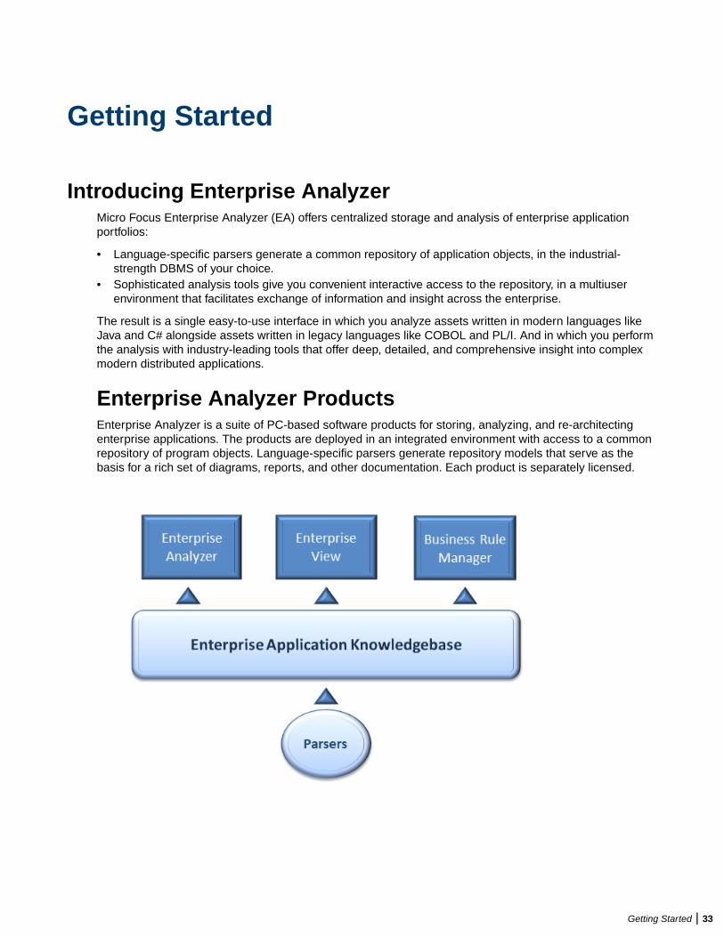
Getting Started
Introducing Enterprise AnalyzerMicro Focus Enterprise Analyzer (EA) offers centralized storage and analysis of enterprise applicationportfolios:
• Language-specific parsers generate a common repository of application objects, in the industrial-strength DBMS of your choice.
• Sophisticated analysis tools give you convenient interactive access to the repository, in a multiuserenvironment that facilitates exchange of information and insight across the enterprise.
The result is a single easy-to-use interface in which you analyze assets written in modern languages likeJava and C# alongside assets written in legacy languages like COBOL and PL/I. And in which you performthe analysis with industry-leading tools that offer deep, detailed, and comprehensive insight into complexmodern distributed applications.
Enterprise Analyzer ProductsEnterprise Analyzer is a suite of PC-based software products for storing, analyzing, and re-architectingenterprise applications. The products are deployed in an integrated environment with access to a commonrepository of program objects. Language-specific parsers generate repository models that serve as thebasis for a rich set of diagrams, reports, and other documentation. Each product is separately licensed.
Getting Started | 33
Enterprise AnalyzerEnterprise Analyzer is a robust set of non-invasive interactive tools that work with source code, systemfiles, DDL, screen maps, and more. Use it for analyzing and documenting legacy systems at both theapplication and program levels.
Use Enterprise Analyzer at the application level to:
• Create diagrams of applications.• Perform change analysis across applications.• Estimate application complexity and effort.
Use Enterprise Analyzer at the program level to:
• Perform program analysis in stages.• Perform impact analysis on a program.• Model and search the repository.
Enterprise ViewEnterprise View (EV) is a Web server-based tool that offers IT executives "at-a-glance" application portfoliomanagement (APM). EV charts and tables provide powerful graphical insight into APM trends and currentstatus, on dashboards that make it easy to drill down from the "big picture" captured at the highest level tothe lower-level details that support it.
With EV you can:
• Create, distribute, and gather responses to surveys about your organization’s application portfolio andbusiness processes.
• Mine application complexity metrics from the EA repository.• Track survey and repository metrics in EV's rich variety of interactive charts, displayed on dashboards
structured to show the rollup of data from lower to higher levels.
For users who need to drill down even deeper into an application portfolio, EV lets you search, filter, andanalyze EA repository data. You can:
• Query the repository for information about application objects.• Search, browse, and edit business rules and triggers.
Business Rule ManagerBusiness rule mining encapsulates your application’s business logic, making the application easier tounderstand, document, and test. It lowers the risk and cost of maintenance and enhancement, and ensuresthat all business logic is implemented in modernization efforts.
A business rule is a named container for program code that performs a discrete task in a business process.It identifies and documents the code segment that performs this task. A business rule named CalculateDate Difference, for example, might consist of this segment:
COMPUTE WS-DATE-VARIANCE = WS-C-CARD-DATE-CCYYMM - WS-TODAYS-DATE-CCYYMM.
Business Rule Manager (BRM) offers a powerful set of tools for autodocumenting, business rules. You canbatch edit rule attributes; create custom attributes suited to your particular needs; match input/output dataelements with the business names you’ve assigned to them in your project glossary; and much more.
34 | Getting Started
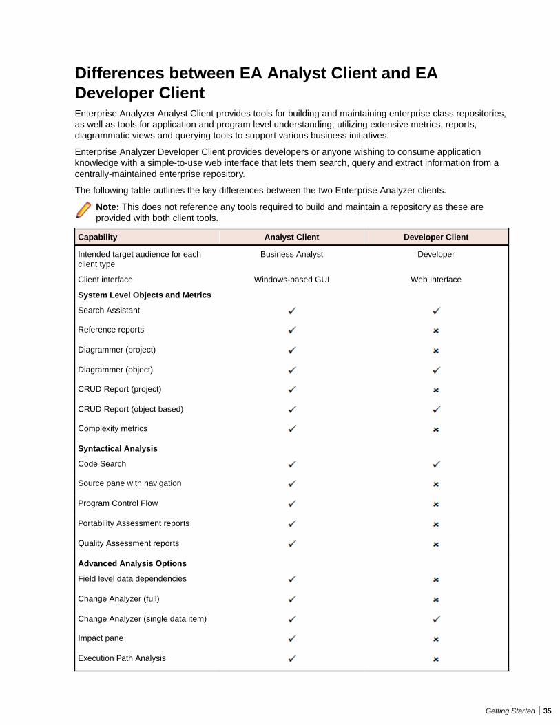
Differences between EA Analyst Client and EADeveloper ClientEnterprise Analyzer Analyst Client provides tools for building and maintaining enterprise class repositories,as well as tools for application and program level understanding, utilizing extensive metrics, reports,diagrammatic views and querying tools to support various business initiatives.
Enterprise Analyzer Developer Client provides developers or anyone wishing to consume applicationknowledge with a simple-to-use web interface that lets them search, query and extract information from acentrally-maintained enterprise repository.
The following table outlines the key differences between the two Enterprise Analyzer clients.
Note: This does not reference any tools required to build and maintain a repository as these areprovided with both client tools.
Capability Analyst Client Developer Client
Intended target audience for eachclient type
Business Analyst Developer
Client interface Windows-based GUI Web Interface
System Level Objects and Metrics
Search Assistant
Reference reports
Diagrammer (project)
Diagrammer (object)
CRUD Report (project)
CRUD Report (object based)
Complexity metrics
Syntactical Analysis
Code Search
Source pane with navigation
Program Control Flow
Portability Assessment reports
Quality Assessment reports
Advanced Analysis Options
Field level data dependencies
Change Analyzer (full)
Change Analyzer (single data item)
Impact pane
Execution Path Analysis
Getting Started | 35
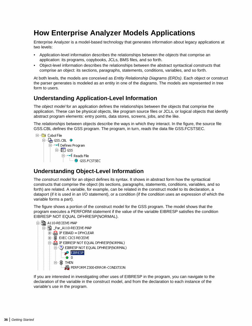
How Enterprise Analyzer Models ApplicationsEnterprise Analyzer is a model-based technology that generates information about legacy applications attwo levels:
• Application-level information describes the relationships between the objects that comprise anapplication: its programs, copybooks, JCLs, BMS files, and so forth.
• Object-level information describes the relationships between the abstract syntactical constructs thatcomprise an object: its sections, paragraphs, statements, conditions, variables, and so forth.
At both levels, the models are conceived as Entity Relationship Diagrams (ERDs). Each object or constructthe parser generates is modeled as an entity in one of the diagrams. The models are represented in treeform to users.
Understanding Application-Level InformationThe object model for an application defines the relationships between the objects that comprise theapplication. These can be physical objects, like program source files or JCLs, or logical objects that identifyabstract program elements: entry points, data stores, screens, jobs, and the like.
The relationships between objects describe the ways in which they interact. In the figure, the source fileGSS.CBL defines the GSS program. The program, in turn, reads the data file GSS.FCSTSEC.
Understanding Object-Level InformationThe construct model for an object defines its syntax. It shows in abstract form how the syntacticalconstructs that comprise the object (its sections, paragraphs, statements, conditions, variables, and soforth) are related. A variable, for example, can be related in the construct model to its declaration, adataport (if it is used in an I/O statement), or a condition (if the condition uses an expression of which thevariable forms a part).
The figure shows a portion of the construct model for the GSS program. The model shows that theprogram executes a PERFORM statement if the value of the variable EIBRESP satisfies the conditionEIBRESP NOT EQUAL DFHRESP(NORMAL).
If you are interested in investigating other uses of EIBRESP in the program, you can navigate to thedeclaration of the variable in the construct model, and from the declaration to each instance of thevariable’s use in the program.
36 | Getting Started
Workspaces and ProjectsEnterprise Analyzer uses the familiar notions of workspace and project to help users organize applicationsource files conveniently. A workspace is a named container for one or more applications. Everyworkspace has a corresponding database repository of model objects.
You can divide a workspace up into projects that represent different applications or different portions of anapplication. You might have a project for the batch portion of an application and another project for theonline portion, for example. You can also use a project to collect items for discrete tasks: all the source filesaffected by a change request, for example.
When you set up a workspace in Enterprise Analyzer, the system creates a default project with the samename as the workspace. You can create new projects and move or copy entities between projects asneeded.
A workspace can contain objects coded in different programming languages. You can create multipleworkspaces on the same machine.
Single-User versus Multiuser EnvironmentsEnterprise Analyzer can be deployed in a single-user or multiuser environment:
• In a single-user environment, the workspace repository resides on the local machine, and can beaccessed by the owner of the machine only. Limited facilities exist for sharing work with other users.
• In a multiuser environment, the workspace repository resides on a database server, and can beaccessed by any user with appropriate database privileges.
Most installations deploy Enterprise Analyzer in a multiuser environment. Single-user mode typically isreserved for special needs.
The guidelines that follow for multiuser environments apply equally to single-user environments. Forinstallation instructions, see the installation guide for your product.
Multiuser Environment BasicsA multiuser Enterprise Analyzer environment gives members of a development team common access to aworkspace repository on a database server. Workspace setup is the responsibility of a master user, leavingteam members free to focus on their tasks. Common access makes it easy to share insights across theteam, and ensures that team members view the same source and work with the same option settings.
Deployment ScenarioThe figure below shows a standard deployment scenario for the Enterprise Analyzer multiuserenvironment. The role each machine performs and its key relationships are described below. Keep in mindthat the view is logical. Machine roles can be combined or separated as required.
Getting Started | 37
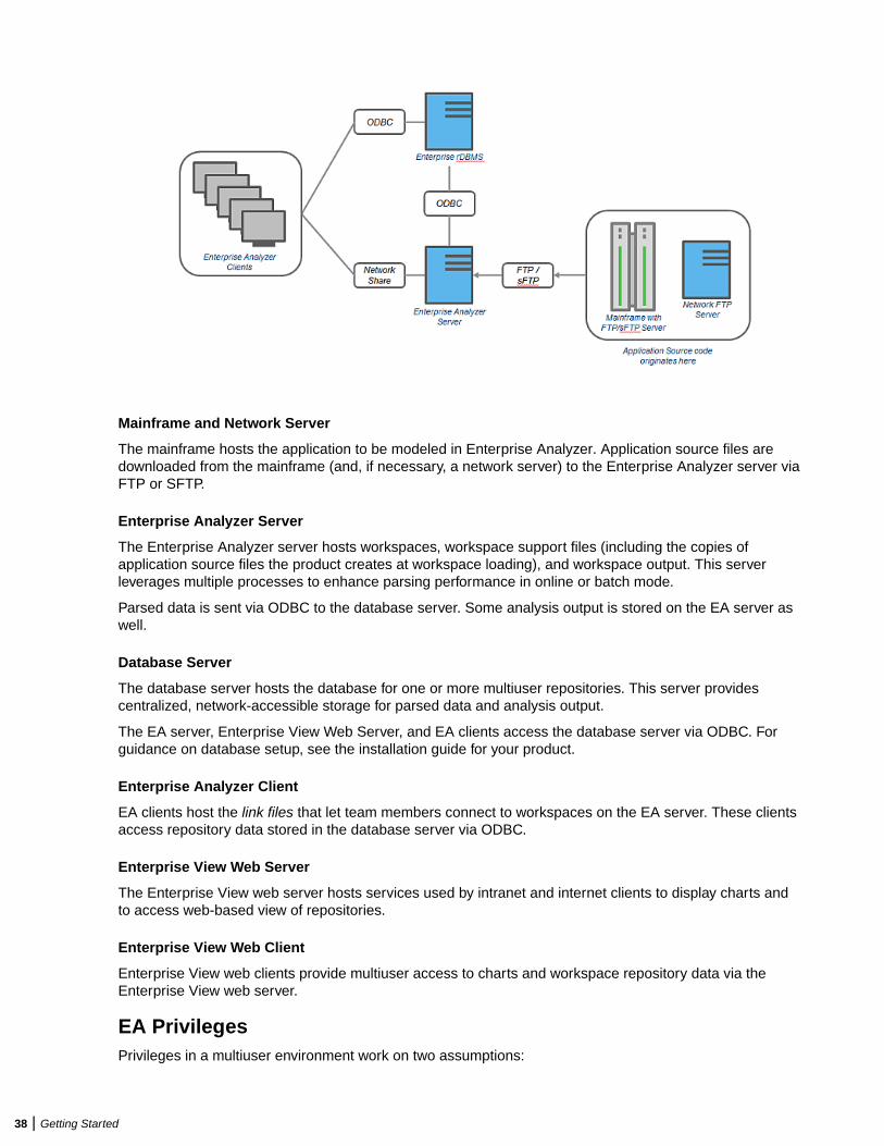
Mainframe and Network Server
The mainframe hosts the application to be modeled in Enterprise Analyzer. Application source files aredownloaded from the mainframe (and, if necessary, a network server) to the Enterprise Analyzer server viaFTP or SFTP.
Enterprise Analyzer Server
The Enterprise Analyzer server hosts workspaces, workspace support files (including the copies ofapplication source files the product creates at workspace loading), and workspace output. This serverleverages multiple processes to enhance parsing performance in online or batch mode.
Parsed data is sent via ODBC to the database server. Some analysis output is stored on the EA server aswell.
Database Server
The database server hosts the database for one or more multiuser repositories. This server providescentralized, network-accessible storage for parsed data and analysis output.
The EA server, Enterprise View Web Server, and EA clients access the database server via ODBC. Forguidance on database setup, see the installation guide for your product.
Enterprise Analyzer Client
EA clients host the link files that let team members connect to workspaces on the EA server. These clientsaccess repository data stored in the database server via ODBC.
Enterprise View Web Server
The Enterprise View web server hosts services used by intranet and internet clients to display charts andto access web-based view of repositories.
Enterprise View Web Client
Enterprise View web clients provide multiuser access to charts and workspace repository data via theEnterprise View web server.
EA PrivilegesPrivileges in a multiuser environment work on two assumptions:
38 | Getting Started

• Team members typically do not need to modify files until they have completed analysis and are ready totest a proposed change.
• The team lead is best situated to make the change and reverify the modified file.
For these reasons, the EA multiuser environment has no need for file checkout and locking of the kind seenin conventional multiuser environments.
Understanding Master Users
The user who creates a workspace on a Enterprise Analyzer server machine is referred to as its owner.Initially, only the owner has master user privileges for the workspace.
The master user can delete the workspace, upgrade the workspace configuration, register and verifysource files, modify source, autoresolve decisions, perform restricted Code Search searches, create,assign, and delete tags, and so forth. The master user can also designate new master users for theworkspace.
Ordinary users connect to the workspace from Enterprise Analyzer client machines. These users canperform any task not restricted to the master user: analyze programs, mine business rules, extractcomponents, and so forth.
If you do not have master user privileges for a workspace, you will not see menu choices for privilegedmethods. The same team member can be a master user for one workspace and an ordinary user foranother.
Understanding Workspace Security Policies
When you create a workspace, you can choose from two workspace security policies:
• The Simple Security Policy recognizes two classes of users, master users and ordinary users.• The Three-Group Security Policy recognizes a third class of users, subject matter experts (SMEs), with
special privileges to create, assign, and delete tags.
In each policy, the master user can create new master users.
Using the Optional File Server
When you create a workspace, you can restrict Windows access to workspace source files to masterusers, while using the optional File Server to make the source files available in EA only to ordinary users.As long as you set up workspace folder privileges correctly, ordinary users can view and analyze sourcesin the product, but cannot access them otherwise. For file server installation instructions, see theinstallation guide for your product.
Public and Private Visibility
In a multiuser environment, the user who creates a workspace resource (a project or a Code Search list,for example) is referred to as its owner. Only the owner can share the resource with other users.
A shared, or public, resource is visible to other members of your team. A private resource is not. If a publicresource is protected, team members can view but not edit or delete the resource. A Code Search list, forexample, is always protected.
You can turn sharing on and off in the tool you use to create the resource. Look for a symbol like this one
for a shared project to indicate that the resource is shared.
Protecting Projects
By default, projects are unprotected: any user to whom the project is visible can add source files, include orexclude objects.
Getting Started | 39
Note: Only a master user or the owner of a shared unprotected project can delete it.
The project owner or master user can designate a project as protected, in which case no user can delete ormodify the project, including the project owner or master user: the project is read-only, until the projectowner or master user turns protection off.
Turn on protection by selecting the project in the Repository pane and choosing Project > ToggleProtection. Choose Project > Toggle Protection again to turn it off. Look for a symbol like this one toindicate that a project is protected.
Dropping IndexesIf you are a master user with responsibility for verifying source files in a multiuser environment, you willalmost always want to drop database indexes to improve verification performance. You will be prompted todrop indexes when you verify the application, or you can drop indexes at a time of your own choosing byselecting Prepare > Drop Repository Indexes.
When you drop indexes, you are prompted to restore the indexes when you analyze the files. If you want torestore indexes at a time of your own choosing, choose Prepare > Restore Repository Indexes.
Computing StatisticsYou typically need to gather statistics for your system before the optimizer for your RDBMS can determinethe most efficient way to execute SQL statements. If you are a master user with responsibility for verifyingsource files in a multiuser environment, you will almost always want to gather system statistics afterverification to improve performance of the Enterprise Analyzer analysis tools.
Note: Check with your DBA before gathering system statistics. In Oracle, you must haveGATHER_SYSTEM_STATISTICS privileges to execute this method. Make sure to restore indexesbefore gathering system statistics.
To gather system statistics, choose Prepare > Compute Database Statistics. You can view the generatedstatistics in your RDBMS.
Enterprise Analyzer BasicsThis section describes elementary EA tasks: how to create a workspace and project, register and verifysource files, use the browser and other EA windows, set options, and export system diagrams and reports.
Creating a Workspace in Oracle or DB2You create a workspace on the Enterprise Analyzer server machine. Other users connect to the workspacefrom Enterprise Analyzer client machines. The workspace repository resides on a database server, andcan be accessed by any user with database privileges to the repository.
Note: Do not modify the name of the workspace after you create it. Doing so will cause unpredictableresults.
Before creating a workspace, you must configure an ODBC data source name (DSN) for the database thatholds the workspace repository, as described in the installation guide for your product. You will need thefollowing DSN configuration information to create the workspace:
• The data source name.• The database schema name your DBA created for the repository.• The database user name and password that give access to the schema.• If required by your DBMS, the name of the tablespace your DBA created for the repository. If the DBA
also created a tablespace for database indexes, you will need the name of that tablespace as well.
40 | Getting Started
The folder in which you plan to create workspaces must be shared with team members. It’s usually moreconvenient to share the folder before you create workspaces, but you can do it afterward if necessary, thenrefresh the workspace path.
It is the responsibility of the workspace creator to designate users for security policies. Perform this task assoon as you have finished creating the workspace, then periodically edit the list of users as required.
1. Choose Start > All Programs > Micro Focus > Enterprise Analyzer > Enterprise AnalyzerAdministration. The Administration window opens.
2. Choose Administer > New Workspace. The Create new workspace dialog opens.
3. In the Create new workspace dialog, double-click the New Workspace icon for the RDBMS in use atyour site or select it and click OK. The New workspace dialog opens.
4. In the New workspace dialog, choose the location for the workspace in the Save in drop-down. In theFile name field, enter the name of the workspace. Choose a name that describes the legacy applicationas closely as possible. Click Save. The Define Connection Parameters dialog opens.
5. In the Define Connection Parameters dialog, click the Connection tab. On the Connection tab, enter:
• The ODBC data source name you defined at ODBC data source configuration. If you have notdefined a data source name, or want to use a different data source name, click ODBC Manager toopen the data source name configuration dialog, then follow the instructions for ODBC data sourceconfiguration in the installation guide for your product.
• The database schema name your DBA created for the workspace repository.• The database user name and password that give access to the schema.• If required by your DBMS, the name of the tablespace your DBA created for the repository. If your
DBA also created a tablespace for database indexes, enter the name of that tablespace in theTablespace for Indexes field. These fields are displayed only for DBMSs that require a tablespacename to be specified.
6. Click the Security tab. In the Policies list box, select:
• Simple Security Policy if you want to enforce a workspace security policy that recognizes twoclasses of users, master users and ordinary users.
• Three-Group Security Policy if you want to enforce a workspace security policy that recognizes athird class of users, subject matter experts (SMEs), with special privileges to create, assign, anddelete tags.
7. In the Files access group box on the Security tab, select:
• Direct sources access via Windows share if your site does not restrict Windows access toworkspace source files to the master user.
• Secure sources access via EA file server if your site restricts Windows access to workspacesource files to the master user, while using the optional file server to make the source files availablein the product to ordinary users. Make sure the values for the server name and port number fieldsare correct.
Note: For File Server installation and setup instructions, see the installation guide for your product.
8. Click OK.
Note: If you created the workspace in a non-shared folder, you are warned to that effect andprompted to share the folder. After you share the folder, make sure to refresh the workspace path.
You are notified that the workspace was created successfully. Enterprise Analyzer creates a workspacefile (.rwp) and a folder with the same name in the specified location. The workspace folder containssupport files and subfolders for EA output. A project with the same name as the workspace is displayedin the Repository Browser.
Getting Started | 41
Creating a Workspace in SQL ServerYou create a workspace on the Enterprise Analyzer server machine. Other users connect to the workspacefrom Enterprise Analyzer client machines. The workspace repository resides on a database server, andcan be accessed by any user with database privileges to the repository.
Note: Do not modify the name of the workspace after you create it. Doing so will cause unpredictableresults.
The folder in which you plan to create workspaces must be shared with team members. It’s usually moreconvenient to share the folder before you create workspaces, but you can do it afterward if necessary, thenrefresh the workspace path.
It is the responsibility of the workspace creator to designate users for security policies. Perform this task assoon as you have finished creating the workspace, then periodically edit the list of users as required.
You can use Microsoft SQL Server Express to create a workspace on your local machine. EnterpriseAnalyzer creates a database for the workspace "on the fly," with no intervention on your part. If you do useSQL Server Express, keep in mind that the Windows user who creates the workspace must have beenconfigured with appropriate permissions in SQL Server Express. The user who installed SQL ServerExpress will always have the appropriate permissions. See the SQL Server Express documentation forconfiguration instructions.
Note: For Windows XP installations using the Italian locale, you must set the Time format in theControl Panel Regional Language Options to "HH:mm:ss" before attempting to verify an EAworkspace with a SQL Server repository. Click Settings > Control Panel > Regional and LanguageOptions > Customize > Time and choose "HH:mm:ss" from the Time format drop-down.
1. Choose Start > All Programs > Micro Focus > Enterprise Analyzer > Enterprise AnalyzerAdministration. The Administration window opens.
2. Choose Administer > New Workspace. The Create new workspace dialog opens.
3. In the Create new workspace dialog, double-click the New Workspace icon for the RDBMS in use atyour site or select it and click OK. The New workspace dialog opens.
4. In the New workspace dialog, choose the location for the workspace in the Save in drop-down. In theFile name field, enter the name of the workspace. Choose a name that describes the legacy applicationas closely as possible. Click Save. The Define Connection Parameters dialog opens.
Note: This dialog does not open for Microsoft SQL Server Express. The product starts creating theworkspace immediately.
5. In the Define Connection Parameters dialog, click the Connection tab. Define the connection:
• In the Server field, enter the server name. The server name must be of the form <machine>\<SQLserver>.
• In the Database Name field, enter the database name your DBA created for the workspacerepository.
• In the Integrated Security drop-down, select the integrated security provider interface in use at yoursite. Choose:
• Windows Authentication if users connect to the workspace repository through a Windows useraccount.
• Server Authentication if users connect to the workspace repository through an SQL Serverlogin account.
• If you chose Server Authentication, enter the database login name in the User Name field and thelogin password in the Password field.
Note: The database user name and login name are typically, but not always, the same. If youhave trouble connecting, it may be because you are specifying the database user name ratherthan the login name.
42 | Getting Started
6. Click the Security tab. In the Policies list box, select:
• Simple Security Policy if you want to enforce a workspace security policy that recognizes twoclasses of users, master users and ordinary users.
• Three-Group Security Policy if you want to enforce a workspace security policy that recognizes athird class of users, subject matter experts (SMEs), with special privileges to create, assign, anddelete tags.
7. In the Files access group box on the Security tab, select:
• Direct sources access via Windows share if your site does not restrict Windows access toworkspace source files to the master user.
• Secure sources access via EA file server if your site restricts Windows access to workspacesource files to the master user, while using the optional file server to make the source files availablein the product to ordinary users. Make sure the values for the server name and port number fieldsare correct.
Note: For File Server installation and setup instructions, see the installation guide for your product.
8. Click OK.
Note: If you created the workspace in a non-shared folder, you are warned to that effect andprompted to share the folder. After you share the folder, make sure to refresh the workspace path.
You are notified that the workspace was created successfully. Enterprise Analyzer creates a workspacefile (.rwp) and a folder with the same name in the specified location. The workspace folder containssupport files and subfolders for EA output. A project with the same name as the workspace is displayedin the Repository Browser.
Creating a Workspace Using the Workspace BuildWizardThe Workspace Build Wizard helps you create an Enterprise Analyzer workspace. Stepping through it, youadd your source files, associate files with source types and analyze the files so that they are ready to beused in Enterprise Analyzer.
Note: To use the wizard, you must have SQL Server Express installed on the machine.
Designating Users for Security PoliciesWhen you create a workspace, you choose from two workspace security policies:
• The Simple Security Policy recognizes two classes of users, master users and ordinary users.• The Three-Group Security Policy recognizes a third class of users, subject matter experts (SMEs), with
special privileges to create, assign, and delete tags.
In each policy, the master user can create new master users.
Designating Users in a Simple Security PolicyA Simple Security Policy recognizes two classes of users, master users and ordinary users. Initially, onlythe workspace creator has master user privileges. The master user can designate new master users asdescribed in this section.
1. Choose Start > All Programs > Micro Focus > Enterprise Analyzer > Enterprise AnalyzerAdministration. The Administration window opens.
2. Choose Administer > Edit Users. The Edit Users dialog opens.
3. In the Edit Users dialog, select the workspace (.rwp file) for which you want to edit users and clickOpen. The Security dialog opens.
Getting Started | 43
4. The Security dialog displays a list of users who have connected to the workspace in the Known Users
list box and a list of master users in the Master Users list box. Select a known user and click the
button to move the known user into the list of master users. Select a master user and click the buttonto move the master user into the list of known users.
Note: Click Refresh at any time to update the lists.
5. To create a new master user, click (New User...) in the Master User list box. A dialog opens promptingyou to enter the name of the new master user. Enter the name and click OK.
6. When you are satisfied with your entries, click Close.
Designating Users in a Three-Group Security PolicyA Three-Group Security Policy recognizes a third class of workspace users in addition to master users andordinary users: subject matter experts (SMEs), with special privileges to create, assign, and delete tags.Initially, only the workspace creator has master user privileges. The master user can designate SMEs andnew master users as described in this section.
1. Choose Start > All Programs > Micro Focus > Enterprise Analyzer > Enterprise AnalyzerAdministration. The Administration window opens.
2. Choose Administer > Edit Users. The Edit Users dialog opens.
3. In the Edit Users dialog, select the workspace (.rwp file) for which you want to edit users and clickOpen. The Security dialog opens.
4. The Subject Matter Experts and Master Users tabs of the Security dialog display a list of users whohave connected to the workspace in the Known Users list box and a list of subject matter experts and
master users, respectively, in the opposite list box. Select a known user and click the button to movethe known user into the list of subject matter experts or master users. Select a master user and click the
button to move the subject matter expert or master user into the list of known users.
Note: Click Refresh at any time to update the lists.
5. To create a new subject matter expert or master user, click (New User...) in the Subject Matter Expertsor Master Users list box. A dialog opens prompting you to enter the name of the new subject matterexpert or master user. Enter the name and click OK.
6. When you are satisfied with your entries, click Close.
Refreshing the Workspace PathThe folder in which you plan to create workspaces must be shared with team members. It’s usually moreconvenient to share the folder before you create workspaces, but you can do it afterward if necessary, thenrefresh the workspace path as described below. You can also use the refresh path feature when you movea workspace.
Note: For instructions on how to share a workspace folder, see the installation guide for your product.
1. Click Start > All Programs > Micro Focus > Enterprise Analyzer > Enterprise AnalyzerAdministration. The Administration window opens.
2. Click Administer > Refresh Workspace Path. The Select workspace dialog opens.
3. Select the workspace (.rwp file) you want to refresh and click Open. The Workspace directory networkpath dialog opens. The Workspace directory network path dialog opens.
4. In the Workspace directory network path dialog, enter the path of the workspace in the text field. Thepath must be of the form \machine_name\share_name\workspace_folder_name, wheremachine_name is the name of the machine where the shared folder resides, share_name is the valueof the Share name field on the Sharing tab of the Properties dialog for the shared folder, andworkspace_folder_name is the name of the folder for the workspace.
44 | Getting Started
Note: The shared folder is the folder that contains the .rwp file for the workspace, not theworkspace folder. The workspace folder (containing support files and subfolders for EA output)resides on the same level as the .rwp file.
5. Click OK.
Connecting to a Workspace in Oracle or DB/2Once a workspace has been created on the Enterprise Analyzer server machine, other users can connectto the workspace from EA clients. When you connect to a workspace, you create a link file with connectioninformation that points to the workspace. Because the connection information is already stored in the file,you don’t have to enter it again when you reopen the workspace connection. Like a workspace file, a linkfile has a .rwp extension.
Before connecting to a workspace, you must configure an ODBC data source name (DSN) for thedatabase that holds the workspace repository you want to link to, as described in the installation guide foryour product. You will need the following DSN configuration information to connect to the workspace:
• The data source name.• The database schema name your DBA created for the repository you want to link to.• The database user name and password that give access to the schema.
1. Choose Start > All Programs > Micro Focus > Enterprise Analyzer. The Open Existing workspacedialog opens above the Enterprise Analyzer main window. Click Cancel to dismiss the dialog.
2. Choose File > Build New Connection. The Define Server Workspace Connection dialog opens.
3. In the Define Server Workspace Connection dialog, select the ODBC driver for the RDBMS in use atyour site in the Database Provider drop-down. In the Required Parameters group box, enter:
• The ODBC data source name you defined at ODBC data source configuration. If you have notdefined a data source name, or want to use a different data source name, click ODBC Manager toopen the data source name configuration dialog, then follow the instructions for ODBC data sourceconfiguration in the installation guide for your product.
• The database schema name your DBA created for the workspace repository.• The database user name and password that give access to the schema.
Note: The Tablespace and Tablespace for Indexes fields are for future use.
4. When you are satisfied with your entries in the Define Server Workspace Connection dialog, click theBrowse button for the Save Link As (.rwp) field. The Save Server Workspace Connectivity dialogopens.
5. In the Save Server Workspace Connectivity dialog, choose the location for the workspace link in theSave in drop-down. In the File name field, enter the name of the link. Click Save. The linked workspaceopens in the Enterprise Analyzer main window. EA creates a link file (.rwp) in the specified location.
Connecting to a Workspace in SQL ServerOnce a workspace has been created on the Enterprise Analyzer server machine, other users can connectto the workspace from EA clients.
If you use the local MS SQL connection, you need db_owner permissions, because this type of connectioncreates a database. But if you use the left option, MS SQL via OLE DB, you need a database alreadycreated by an administrator. For this database you may have less permissions and the roles can be:db_writer and db_reader.
To grant permissions, run these queries:
USE mydatabase;GRANT ALTER TO myuser;GRANT REFERENCES TO myuser;GO
Getting Started | 45
ALTER permissions are required when upgrading, or using Configuration Manager in the Administrationtool. ALTER is also needed by the Batch Refresh Process and Code Search.
When you connect to a workspace, you create a link file with connection information that points to theworkspace. Because the connection information is already stored in the file, you don’t have to enter it againwhen you reopen the workspace connection. Like a workspace file, a link file has a .rwp extension.
1. Choose Start > All Programs > Micro Focus > Enterprise Analyzer. The Open Existing workspacedialog opens above the Enterprise Analyzer main window. Click Cancel to dismiss the dialog.
2. Choose File > Build New Connection. The Define Server Workspace Connection dialog opens.
3. In the Define Server Workspace Connection dialog, click the Connection tab. Define the connection:
• In the Server field, enter the server name. The server name must be of the form <machine>\<SQLserver>.
• In the Database Name field, enter the database name your DBA created for the workspacerepository.
• In the Integrated Security drop-down, select the integrated security provider interface in use at yoursite. Choose:
• Windows Authentication if you connect to the workspace repository through a Windows useraccount.
• Server Authentication if you connect to the workspace repository through an SQL Server loginaccount.
• If you chose Server Authentication, enter the database login name in the User Name field and thelogin password in the Password field.
Note: The database user name and login name are typically, but not always, the same. If youhave trouble connecting, it may be because you are specifying the database user name ratherthan the login name.
4. When you are satisfied with your entries in the Define Server Workspace Connection dialog, click theBrowse button for the Save Link As (.rwp) field. The Save Server Workspace Connectivity dialogopens.
5. In the Save Server Workspace Connectivity dialog, choose the location for the workspace link in theSave in drop-down. In the File name field, enter the name of the link. Click Save. The linked workspaceopens in the Enterprise Analyzer main window. EA creates a link file (.rwp) in the specified location.
Opening a WorkspaceThe procedure for opening a workspace is the same whether you created the workspace or simplyconnected to it. You can also open a workspace by double-clicking it in the file system. You don’t have toclose a workspace before opening another workspace.
1. Choose Start > All Programs > Micro Focus > Enterprise Analyzer. The Open Existing workspacedialog opens above the Enterprise Analyzer main window.
Note: If Enterprise Analyzer is already open, choose File > Open Workspace.
2. Click the tab you want to work in:
• In the Existing tab, choose the drive and folder for the workspace you want to open. A list ofworkspaces in the selected folder is displayed in the righthand pane. Double-click the workspace youwant to open, or select it and click OK.
• In the Recent tab, double-click the recently opened workspace you want to open, or select it andclick OK.
Note: If you created the workspace in a previous release of Enterprise Analyzer, the systemprompts you to upgrade the workspace to the new release. Click Yes.
46 | Getting Started
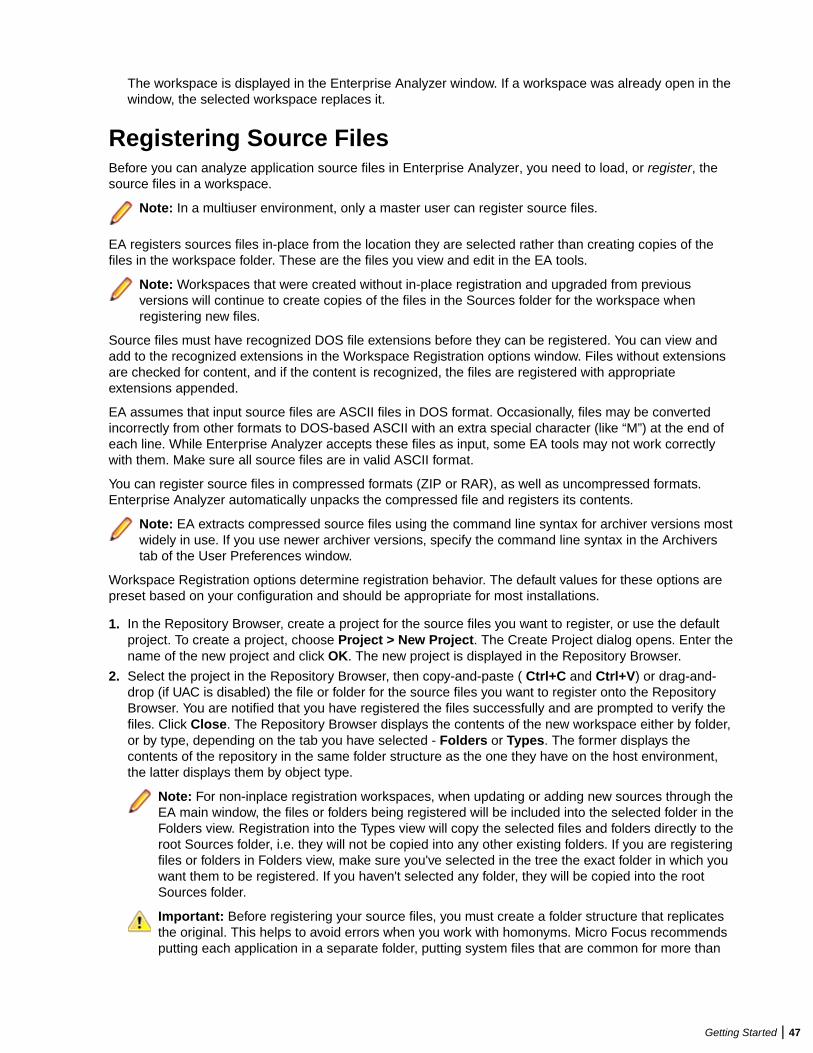
The workspace is displayed in the Enterprise Analyzer window. If a workspace was already open in thewindow, the selected workspace replaces it.
Registering Source FilesBefore you can analyze application source files in Enterprise Analyzer, you need to load, or register, thesource files in a workspace.
Note: In a multiuser environment, only a master user can register source files.
EA registers sources files in-place from the location they are selected rather than creating copies of thefiles in the workspace folder. These are the files you view and edit in the EA tools.
Note: Workspaces that were created without in-place registration and upgraded from previousversions will continue to create copies of the files in the Sources folder for the workspace whenregistering new files.
Source files must have recognized DOS file extensions before they can be registered. You can view andadd to the recognized extensions in the Workspace Registration options window. Files without extensionsare checked for content, and if the content is recognized, the files are registered with appropriateextensions appended.
EA assumes that input source files are ASCII files in DOS format. Occasionally, files may be convertedincorrectly from other formats to DOS-based ASCII with an extra special character (like “M”) at the end ofeach line. While Enterprise Analyzer accepts these files as input, some EA tools may not work correctlywith them. Make sure all source files are in valid ASCII format.
You can register source files in compressed formats (ZIP or RAR), as well as uncompressed formats.Enterprise Analyzer automatically unpacks the compressed file and registers its contents.
Note: EA extracts compressed source files using the command line syntax for archiver versions mostwidely in use. If you use newer archiver versions, specify the command line syntax in the Archiverstab of the User Preferences window.
Workspace Registration options determine registration behavior. The default values for these options arepreset based on your configuration and should be appropriate for most installations.
1. In the Repository Browser, create a project for the source files you want to register, or use the defaultproject. To create a project, choose Project > New Project. The Create Project dialog opens. Enter thename of the new project and click OK. The new project is displayed in the Repository Browser.
2. Select the project in the Repository Browser, then copy-and-paste ( Ctrl+C and Ctrl+V) or drag-and-drop (if UAC is disabled) the file or folder for the source files you want to register onto the RepositoryBrowser. You are notified that you have registered the files successfully and are prompted to verify thefiles. Click Close. The Repository Browser displays the contents of the new workspace either by folder,or by type, depending on the tab you have selected - Folders or Types. The former displays thecontents of the repository in the same folder structure as the one they have on the host environment,the latter displays them by object type.
Note: For non-inplace registration workspaces, when updating or adding new sources through theEA main window, the files or folders being registered will be included into the selected folder in theFolders view. Registration into the Types view will copy the selected files and folders directly to theroot Sources folder, i.e. they will not be copied into any other existing folders. If you are registeringfiles or folders in Folders view, make sure you've selected in the tree the exact folder in which youwant them to be registered. If you haven't selected any folder, they will be copied into the rootSources folder.
Important: Before registering your source files, you must create a folder structure that replicatesthe original. This helps to avoid errors when you work with homonyms. Micro Focus recommendsputting each application in a separate folder, putting system files that are common for more than
Getting Started | 47
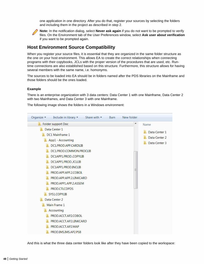
one application in one directory. After you do that, register your sources by selecting the foldersand including them in the project as described in step 2.
Note: In the notification dialog, select Never ask again if you do not want to be prompted to verifyfiles. On the Environment tab of the User Preferences window, select Ask user about verificationif you want to be prompted again.
Host Environment Source CompatibilityWhen you register your source files, it is essential that they are organized in the same folder structure asthe one on your host environment. This allows EA to create the correct relationships when connectingprograms with their copybooks, JCLs with the proper version of the procedures that are used, etc. Run-time connections are also established based on this structure. Furthermore, this structure allows for havingseveral members with the same name, i.e. homonyms.
The sources to be loaded into EA should be in folders named after the PDS libraries on the Mainframe andthose folders should be the ones loaded.
Example
There is an enterprise organization with 3 data centers: Data Center 1 with one Mainframe, Data Center 2with two Mainframes, and Data Center 3 with one Mainframe.
The following image shows the folders in a Windows environment:
And this is what the three data center folders look like after they have been copied to the workspace:
48 | Getting Started
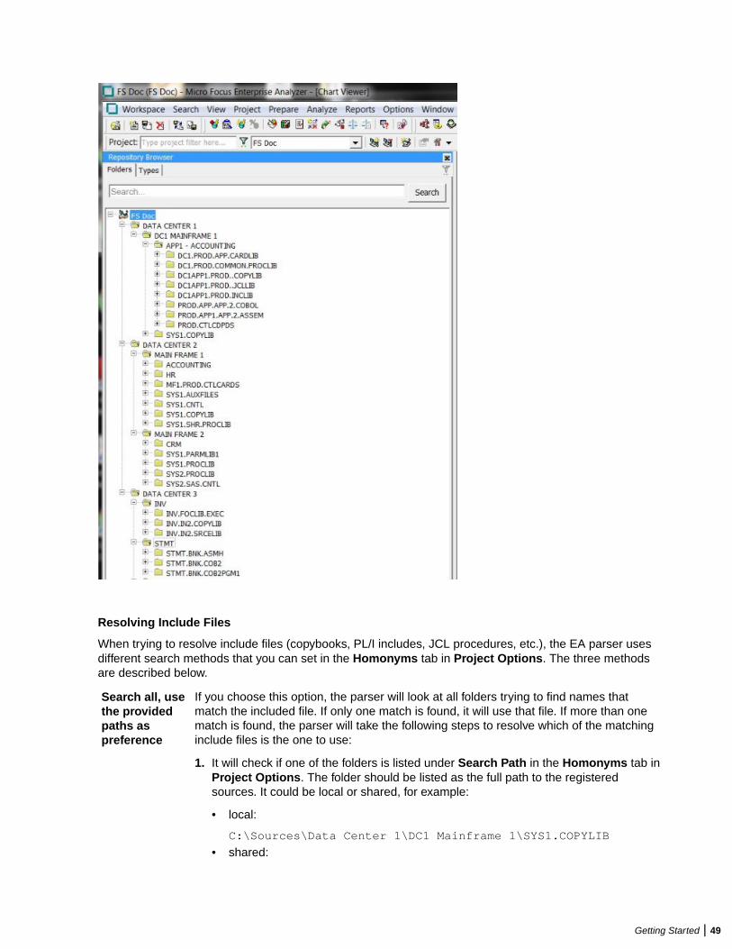
Resolving Include Files
When trying to resolve include files (copybooks, PL/I includes, JCL procedures, etc.), the EA parser usesdifferent search methods that you can set in the Homonyms tab in Project Options. The three methodsare described below.
Search all, usethe providedpaths aspreference
If you choose this option, the parser will look at all folders trying to find names thatmatch the included file. If only one match is found, it will use that file. If more than onematch is found, the parser will take the following steps to resolve which of the matchinginclude files is the one to use:
1. It will check if one of the folders is listed under Search Path in the Homonyms tab inProject Options. The folder should be listed as the full path to the registeredsources. It could be local or shared, for example:
• local:
C:\Sources\Data Center 1\DC1 Mainframe 1\SYS1.COPYLIB
• shared:
Getting Started | 49
\\server\Sources\Data Center 1\DC1 Mainframe 1\SYS1.COPYLIB
2. It will look for proximity of the included file to the including file in the source folderstructure. First it will check the files that are in the same folder as the "including"source, then the files in the dependent folder, and then up the folder hierarchy.
3. Finally, folder names will be matched and the "include" folder that has a name with abetter match to the source folder name will be selected.
Search only inthe providedpaths
When this option is selected, only the paths specified in the Search Path list will be usedas locations for looking for include files. As this option works on project level, you canconfigure each subsystem or application in a separate project, and then specify thecopybook locations for each project. This option is useful when the number ofapplications/subsystem is not too big.
Search incommonlocation andonly the samesubsystem
This option may help when there is a large number of applications/subsystems. It letsyou use the folder structure in the file system to define the boundaries betweensubsystems and to restrict retrieval of include files based on the physical folderstructure. If you choose it, you can put all the sources in a single project and thus youwon't need to add a list of folders to search in. If you choose this option, you need tospecify the following two paths:
Common folder All common libraries need to be located inside the same rootfolder, for example: C:\Sources\Common. Files in folders locatedhere will be "visible" to all programs being analyzed.
Subsystemsroot level
All subsystems need to have a common root folder, for example:C:\Sources\Subsystems. If you have two subsystems in thisfolder, one of them will not get copybooks from the other and viceversa, but they can both get copybooks from the common librariesfolder specified in the Common folder field.
Note: The subsystems root level selection is checked first and then the commonfolder.
Resolving Program-to-Program Calls
When resolving call relationships between programs, it is possible to reach a point where there is morethan one candidate for a called program. In this case EA works the same way as with includes (seeResolving Include Files), but since the program objects themselves don't have folders, the folders of thesource files that generated them are used.
Note: This same algorithm applies to any relations between non-legacy entities (e.g. PROGRAMreads TABLE, TRANSACTION starts PROGRAM, etc.).
Resolving Control Cards
Control cards can be any members explicitly mentioned in the JCL. When parsing JCLs, EA will look for afile with the member name in the JCL in a folder with a name matching the PDS name from the mainframe.
Resolving JCL Procedures
When looking for JCL procedures, the parser uses the JCLLIB statement, if present. If there is only onecopy of the searched procedure, that copy is used. Otherwise, if more than one copy is available, thelibraries specified with the JCLLIB statement are used to pick the right one.
50 | Getting Started
Example:
Path to the JCL file: <workspace_path>\Sources\APP1\MYJCL\MYJOB.JCL
//MYJOB1 JOB ...//MYLIBS1 JCLLIB ORDER=CAMPBEL.PROCS.JCL//S1 EXEC PROC=MYPROC1
In this case the procedure <workspace_path>\Sources\APP1\CAMPBEL.PROCS.JCL\MYPROC1, if present, will be used.
Refreshing Registered Source PathsThe Refresh Registered Source Paths feature allows you to change the location of registered source files.It is useful in cases when the sources have been moved to another location, or a folder that containssources has been moved or renamed, or sources were registered from a non-shared location, and thelocation has since been shared.
To use this feature:
1. Open Enterprise Analyzer Administration.2. From the Administer menu, select Refresh Registered Source Paths….3. Choose a workspace from the list in the Select Workspace window.4. Click OK. The Change Registered Source Paths window opens. It shows the registered source paths
and lets you select the new source paths.
You can choose whether to hide or show system paths in the list of source paths by checking andunchecking the Hide System Paths check box.
5. Click the yellow folder icon under New Source Path.6. Choose the new directory of the source files and click Select Folder. The selected path and a red cross
icon appear under New Source Path.
Note: Clicking removes the selected path.
7. Click Change. A message asking you if you are sure you want to change the registered source pathscomes up.
8. Click OK. You are notified that the paths have been refreshed.9. Click OK. The Change Registered Source Paths window closes.
Note: Alternatively, you can change the registered source paths from Source Synchronization. Formore information, see the Source Synchronization section.
Queue ProcessorThere are various ways to set parameters for the Queue Processor.
To launch the Queue Processor
1. Start EA Administration.2. Open Administer > Launch Queue Processor or press F7.
The Launch Queue Processor window opens.3. In the Serve workspace field type the name of the workspace you want to use or press the ... button to
browse for a workspace.4. Check the Processing Mode - Conversion, Verification or both.5. Choose the number of processors to start . The number depends on your system capabilities.6. Check Produce Log File if you want to produce a log file and then click OK to start the verification or
Cancel to quit.
Getting Started | 51
Check Workspace QueueCheck workspace Queue displays the queued processes that are waiting in queue for the currentworkspace. To view them:
1. Open Start > All Programs > Micro Focus > Enterprise Analyzer > Enterprise AnalyzerAdministration.
2. Select Tools > Check Workspace Queue. The Select workspace window opens.3. Select a workspace file (.rwp) and click Open. A message with the number of queued records is
displayed.
Manage Queue1. Click Start > All Programs > Micro Focus > Enterprise Analyzer > Enterprise Analyzer
Administration to start the Enterprise Analyzer Administration. Manage Queue shows the processesthat are waiting to be processed. After the Queue processor has finished the list is automaticallycleared.
2. Click Tools > Manage Queue. The Manage Queue window opens.
It contains a list of all processes waiting to be processed by the Queue Processor. The available actionsare:
• File > Close - closes the window.• Record > Delete - if you delete an item from the list it remains unverified and you must re-verify the
sources again.• Record > Unlock - unlocks records that are locked due to some verification error.• Record > Select All - selects all records from the queue list.• Record > Unselect All - deselects all records from the queue.• Queue > Refresh - refreshes the queue list.• Queue > Show All - shows all records for the queued processes.• Queue > Auto Refresh - automatically refreshes the list.
Verifying Source FilesParsing, or verifying, an application source file generates the object model for the file. Only a master usercan verify source files.
You can verify a single file, a group of files, all the files in a folder, or all the files in a project. It’s usuallybest to verify an entire project. Enterprise Analyzer parses the files in appropriate order, taking account oflikely dependencies between file types.
Note: You need not verify copybooks. Copybooks are parsed when the including source file isverified.
If your RPG or AS/400 COBOL application uses copy statements that reference Database Descriptionor Device Description files, or if your MCP Cobol application uses copy statements that referenceDMSII DASDL files, you need to generate copybooks for the application before you verify programfiles.
Workspace and Project Verification options determine verification behavior. The default values for theseoptions are preset based on your configuration and should be appropriate for most installations.
1. In the Repository Browser, select the project, folder, or files you want to verify and choose Prepare >Verify.
2. You are prompted to drop repository indexes to improve verification performance. Click Yes. You will beprompted to restore the indexes when you analyze the files.
52 | Getting Started
The parser builds an object model for each successfully verified file. For an unsuccessfully verified file, theparser builds an object model for as much of the file as it understands.
How Verification Results Are IndicatedIf you have not verified a workspace file, the file is displayed in the Repository pane in bold type. Since thesystem has not generated an object model of the file’s contents, only the file itself is displayed.
A verified file shows all the objects in the model generated for the file. Verification results are denoted asfollows:
• A blue dot means that the parser has verified the file successfully.• A red dot means that the parser has encountered an error in the file.• A yellow dot means that the parser has encountered an error in the file, but that the file has been
successfully verified under the relaxed parsing option.
Note: When you edit a file, the modified file and any dependent files are invalidated, and need to beverified again. You can learn more about how objects are invalidated and how the system refreshesthe repository in Preparing Projects in the product documentation set.
Quick InventoryQuick Inventory is a project related option that automatically registers and verifies referenced files usingJCL or PCT files as a starting point. Start by enabling and configuring Quick Inventory, register the JCL orPCT files to be used as the starting points, then verify those files. If you have set all paths correctly, theproduct will register and verify the external files. Enterprise Analyzer finds its dependencies registers themin the project, and verifies them.
To enable Quick Inventory:
1. In Enterprise Analyzer open Options > Project Options.2. On the Quick Inventory tab check Enable Quick Inventory and click Apply.
Quick Inventory first searches the workspace and if the files are not found there you need to specify thedirectory where your sources are located. There is a list of pre-defined source types that are supported byEnterprise Analyzer.
To edit, add, delete or select a search path where you want the Quick Inventory to look for sources:
1. In Enterprise Analyzer open Options > Project Options.
Click the Quick Inventory tab.2. There is a list with pre-defined search paths suggestions with the names of the object types most
commonly used. Select a suggestion, right-click the selected suggestion and then click Edit.
a. Enter the search path to the sources. For example: COBOL = c:\Sources\COBOL_Applications_Directory.
Note: Make sure you enter the correct path. Otherwise EA is not able to find the sources.
b. Press Enter, then check the search path to select it and click Apply.3. If the sources are located in more than one directory (for example if you need to search in more than
one COBOL directory outside the workspace), you have to add another entry to the Search Path list.Right-click in the list of suggested directories and then click Add. A new item is created in the list. Enterthe values you need. For example: COBOL = C:\Sources\COBOL_Applications_Directory_1.
Add a new entry for each separate directory you need to search.4. To delete an entry select it and right-click on it, then click Delete.5. Click OK to save the changes, or Cancel to undo them and get back to the main Enterprise Analyzer
window.
Getting Started | 53
Using the Enterprise Analyzer Main WindowThe Enterprise Analyzer main window lets you view and edit projects, set product options, and open EAtools. The window’s state is saved across sessions.
Open a pane in the main window by selecting the appropriate choice in the View menu. Resize a pane byusing the mouse to grab its border with another pane, called a splitter, and dragging it to a new location.Close a pane by clicking the button in the upper right corner.
When you start Enterprise Analyzer for the first time, the main window displays the following panes:Repository Browser, Getting Started, Chart Viewer and Activity Log.
The Getting Started pane gives you basic information about some of the main features and provides quickaccess to them.
The other panes are described in the topics below.
MenusEnterprise Analyzer menus let you access Enterprise Analyzer tools and other product functionality. Menusare displayed only for the products you have enabled in the Configuration Manager. The table below showsthe relationship between products and menus.
Note: The screens shown in the product documentation set display the menu bar with all productsinstalled.
Most Enterprise Analyzer menu choices have equivalent choices in the right-click menu. Menu selectionsfor panes in the main window are available only if the pane has the focus.
Product Menu
Enterprise Analyzer Analyze
Enterprise View Profile
Business Rule Manager Extract
ToolbarsYou can access a Enterprise Analyzer menu function by clicking its tool bar icon. The tool tip for an icontells you what it does. Place your cursor over the icon for a moment. The tool tip will display.
A tool bar is displayed only if its corresponding menu is displayed. You can change the position of a tool barby grabbing the delimiter at the left of the tool bar and dragging it to a new location.
Project FilteringFilter the projects in the repository browser to see only the one(s) that you want to work with. The Projectfilter field is on the toolbar. Enter the name of the project you want to see in the Project filter and all otherproject will be hidden. The filter string is saved when closing and reopening the workspace. To clear thefilter, delete the text in the input box and press Enter.
Use wildcards and regular expressions to refine the project filtering.
Note: An asterisk wildcard is assumed at the end of the filter name.
Example
If you have 5 projects named Project 1 through Project 5 and enter Project [1-3] in theproject filter, only Project 1, Project 2, and Project 3 will be shown in the browser. If noprojects match the filter, the Browser will be empty.
54 | Getting Started

Using the Repository Browser PaneThe Repository Browser pane shows the contents of the repository for the current workspace. It has twotabs:
Folders Displays the contents of the repository in the same folder structure as the one they have in thehost environment. This allows for elements with the same name (homonyms) to be loaded anddisplayed.
Types Displays the contents of the repository by project, object type, and object relationship.
Each of the two tabs consists of the following elements:
Browser Shows the objects in the repository of the current workspace in a tree structure. Depending onthe tab you have selected in the Repository Browser pane, the contents are displayed either bytype or by folder.
Search Lets you execute various searches in the repository of the current workspace.
In the Repository Browser window, hover your cursor over an object to display a tooltip that describes theobject in more detail.
Note: The Repository Browser pane displays automatically when you launch Enterprise Analyzer. Ifyou close it, you can reopen it by clicking View > Repository.
Using the Search Assistant
The Search Assistant is integrated in the Repository pane. It searches all sources in the currentworkspace. The results are displayed in a tree in the browser window, either by type or by folder,depending on the tab you have selected in the Repository pane - Folders or Types. The information in thetree is grouped in three levels:
• Project level - shows the projects that contain the objects.• Folder level - shows the relative folder structure. If there is more than one folder level, they are grouped
and displayed with slashes - Folder1/Folder2/Folder3(n). The number in brackets indicates thenumber of search result objects in the folder.
• Object level - shows the objects that are the result of the search.
Note: For information about customizing the search options, see Configuring the Search Assistant.
To use the Search Assistant:
1.Type in a search string in the search box and click . The search returns all workspace objectswhose names match the search criteria.
2. Drill down the tree to see the relationship types and available methods for the objects.3. Double-click an object in the search result tree to see its source code.
Note: To see the source code of a declaration, double-click it or right-click and select Go ToSource.
4. Right-click the search result objects in the Browser to see the list of available context-sensitive actionsfor the selected objects.
Note: Not all of the context menu options available in the Repository Browser are available in thesearch results tree.
Note: Multiselect is also available for the items in the search result tree.
To reset a search or change the search criteria in the search field:
Getting Started | 55
1. Click Close in the left corner of the search field.
The search is reset and the last Repository Browser view you used is displayed.
Enterprise Analyzer keeps a history of the searches you have done so when you start typing a searchstring, it lets you select from a list of search strings you have previously used that begin with the samecharacters as the ones you have typed.
Customizing the Search Assistant
You can customize the Search Assistant to suit your needs by setting some options in the WorkspaceOptions and User Preferences that you can access from the Options menu.
Setting Search Assistant options in the Workspace Options
There are two options that you can set in Options > Workspace Options > Search Assistant:
• Maximum number of results to display. The default is 10,000.• Timeout for displaying a complete set of results. It is configured in seconds and the default is 60
seconds.
Setting Search Assistant options in the User Preferences
From the Search Assistant tab in Options > User Preferences you can set the following options:
• Select the type of the objects that will be shown in the search results. The available types are: all legacy,system program, program entry point, data store, table, transaction and ADABAS file.
• Include hypercode objects. Depending on the source type, you can select different types of hypercodeentities. The table below displays the available source code types and their corresponding hypercodeobjects.
Source type Hypercode entity
COBOL file • Declaration
• Paragraph
• Variable
JCL file Data set
Natural file • Declaration
• Variable
PL/I file • Declaration
• Variable
RPG file • Declaration
• Variable
By default, declaration is selected for COBOL, Natural and PL/I files.
Using the Browser
The Browser displays the sources in the repository of the current workspace, organized in a tree.Depending on the tab you have selected in the Repository pane, the contents are displayed either by typeor by folder. Switch between them to browse the repository in different ways.
• Type view - shows the object model for the workspace, organized in a tree form by project, object type,and object relationship.
56 | Getting Started
• Folder view - shows the sources in the tree in the same folder structure as the one they have in the hostenvironment.
Note: When you work with homonyms, you will see a number in parentheses after the name of theobject if there is more than one instance of it.
Selecting Objects
Select an object in the Browser by clicking it with the left mouse button. You can select all, select multiple,or type-ahead select.
Use the Select choices in the Edit menu to select objects based on their verification status. The choicesoperate on the entire list in the Search tab and on the objects under the selected workspace, project, orfolder in the Browser.
The Project drop-down displays the current project. You can navigate quickly to another project in theBrowser by clicking the project name in the drop-down.
Note: In the Folders view, you can use mutliselect for objects in different folders on the same level.
You cannot use multiselect for child and parent nodes.
You cannot use multiselect across projects.
Selecting All
To select all the objects in the tree or all the objects in the selected node, choose Edit > Select All. Todeselect the objects, choose Edit > Unselect All.
Selecting Multiple
To select a range of objects, hold down the Shift key, click the first object in the range, then click the lastobject in the range. To select objects that are not in a range, hold down the Control key, then click eachobject you want to select.
Using the Type-Ahead Select Functions
Use the simple type-ahead select function to select displayed objects as you type. To use the simplefunction, make sure the Browser tab is current, then type the characters you want to match.
Note: You cannot use the simple type-ahead select function in the Search tab.
Use the advanced type ahead select function to select objects in the Browser or Search tab whether or notthey are currently displayed. To use the advanced function, click an object that has the same type as the
object you want to select, then click the button next to the button at the bottom of the Repository
pane (or if the filter subtree function is enabled, next to the button). From the drop-down menu, choose:
• Select to match text explicitly.• Wildcard Select to match text using wildcard patterns.
Enter the text you want to match in the field next to the button. The tool selects matched objects as
you type, as long as they are in the same subtree. Click the button to repeat the select with the samecriterion.
To select multiple objects, enter the text you want to match in the field next to the button, then click the
adjacent button. From the drop-down menu, choose:
• Select All to select multiple objects that match text explicitly.
Getting Started | 57

• Wildcard Select All to select multiple objects that match text using wildcard patterns.
The tool selects matched objects as long as they are in the same subtree. Click the button to repeatthe select with the same criterion.
Expanding Subtrees
Click the symbol next to an item to expand its subtree one level. Click the symbol to collapse thesubtree one level.
In the Repository Browser, select an item and choose Expand Subtree in the right-click menu to expandall its subtree levels in a single step. Select an item and choose Save Subtree in the right-click menu toexport the label text for expanded subtree levels to a text file.
Note: For subtrees with a great many objects, you can improve browser display performance byfiltering the subtree and/or by lowering the fetch buffer size in the General tab of the WorkspaceOptions window.
Filtering Subtrees
For a subtree with a great many objects, you can improve browser display performance by showing onlyobjects of interest in the subtree. To filter out objects from a subtree, select the subtree, then enter the text
you want to match in the field next to the button at the bottom of the Repository pane (or if the type-
ahead select function is enabled, next to the button). Click the adjacent button and choose Filterfrom the drop-down menu.
The tool filters out unmatched objects from the subtree, and places a symbol next to the subtree in thebrowser display. The filter and filter text are persistent for the subtree across sessions. To remove the filterand its text, enter an empty string in the text field and choose Filter again.
Refreshing the Browser
In a multiuser environment, you need to refresh the browser after another user adds, deletes, or modifies aworkspace file. Choose View > Refresh Browser to refresh the browser.
Viewing the Entire Workspace
By default, the Browser tab displays repository trees for projects only. These trees show only objects youcan act on in the browser. To view all the objects in the workspace, choose View > Entire Workspace, orselect (none) in the Project drop-down. Choose View > Entire Workspace again, or select a project inthe Project drop-down, to display the project only.
Performing a Text Search in the Repository
The Find functionality lets you do a plain text search in the repository files. The results are displayed in theFound Results tab in the Repository Browser. You can select to view the results by folder structure orobject types. Drilling down the results tree, you can see the object name as well as the specific line of codewhere the searched text is.
To use this functionality, go to Search > Find, type a text and click Find All.
Before you click Find All, you can select various options such as skipping comments from the search ormatching the whole words and/or the case of the searched text. You can also specify the search mode, i.e.whether to search for plain text, regular expressions and wildcards.
If you want to further specify your search, click Advanced Find. Here you can select the type of objects inwhich to search depending on their parse status: unverified, verified with errors, verified with relaxed parserand verified successfully. You can also specify the scope of the search (workspace or selection), the projectwhere to search and an object name.
58 | Getting Started
You can additionally customize the text search functionality from Options > Workspace Options > FindOptions. In this tab you can set the following options:
• Maximum number of results to display. The default is 10,000.• Font style of the results: regular (default), bold, italic, strikeout or underline.• Edge Color - lets you select the color in which the searched text appears in the results. The default color
is red.
Using Wildcard Patterns in Searches
In most searches you perform in the EA tools, you can use wildcard patterns allowed in LIKE statements byVisual Basic for Applications (VBA). The table below shows the wildcard characters and what they match.
Character Matches
? Any single character.
* Zero or more characters.
# Any single digit (0–9).
[charlist] Any single character in charlist.
[!charlist] Any single character not in charlist.
To match the special characters left bracket ([), question mark (?), number sign (#), and asterisk (*),enclose them in brackets. The right bracket (]) cannot be used within a group to match itself, but it can beused outside a group as an individual character.
Specify a range of characters in a charlist by using a hyphen (–) to separate the upper and lower bounds ofthe range. [A-Z], for example, results in a match if the corresponding character position in a string containsany uppercase letters in the range A–Z. You can specify multiple ranges in brackets without delimiters.
Finding and Replacing Text in Source Files
To find and replace text in the Editor:
1. In the Repository Browser, double-click a source file. The file opens in the Editor.
2. Right-click and select Find or click Edit > Find The Find and Replace dialog opens.
3. Click the tab for the operation you want to perform.The find functionality in the Find tab is bidirectional. You can search up or down, and specify if you wantthe search to wrap as well as match the whole word or the case. The find functionality in the Replacetab is unidirectional. From both tabs you can specify the search mode, i.e. whether to search for plaintext, regular expressions and wildcards.
Note: The remaining steps assume that you want to both search and replace.
4. In the Find What box, type the search criterion. Check the necessary check boxes.
5. In the Replace With box, select the replacement text. You can select text strings from previous replaceoperations or type a new replacement text. If you have selected to search for regular expressions, click
the button next to the box to display a list of elements you can insert in the replacement text field.
6. Click Find Next. When the search finds a match, click Replace. Click Find Next again to find the nextmatch, or click Replace All to replace all matching text.
Using the Editor and ViewerThe Editor lets you view and edit the source code for a file. The Viewer lets you view renderings of logicalobjects like screens and transformation target models. Double-click a file in the Repository pane to view itin the Editor or Viewer. Choose File > Recent Sources to open a file from a list of recently opened files.
Getting Started | 59
Editing Source
Edit file source as you would text in a word processor (cut-and-paste, drag-and-drop, undo, and so forth).Click File > Save to save your changes. Edits are saved in the copy of the file maintained in the\Workspace\Source subfolder.
Note: When you edit a file, the modified file and any dependent files are invalidated, and need to beverified again. Only a master user can edit and verify source in a multiuser environment.
Finding and Replacing Source in a Selection
To find and replace source in a selection of text, select the text, then follow the instructions for the sourcefile find and replace function.
Viewing a List of Errors
For a source files with errors or warnings, right-click in the Editor and choose:
• Errors > View Errors from the popup menu to list the errors and warnings in a separate pane below theEditor. Choose Edit > Errors > View Errors again to hide the pane.
• Errors > Next Error from the popup menu to navigate to the offending source code for the next error inthe list.
• Errors > Previous Error to navigate to the offending source code for the previous error in the list.• Errors > Severity Filter from the popup menu to filter the list by severity.
Note: You can set a severity filter for all your workspaces in the Editor User Preferences.
• Errors > Copy Errors in the pop-up menu to copy the list of errors and warnings to the clipboard.
To hide the Editor and show only the list of errors and warnings for the selected file, right-click in theRepository pane and choose Show Errors in the pop-up menu. Double-click the source file in theRepository pane to show the Editor again.
Commenting Out Source
To comment out a block of source, select the block and choose Edit > Comment Block. To uncommentthe block, select it and choose Edit > Uncomment Block.
Printing Source
To print the source for a file, choose File > Print.
Setting Editor User Preferences
Use the Editor tab of the User Preferences window to specify the display characteristics of the Editor.
1. Choose Tools > User Preferences. The User Preferences window opens. Click the Editor tab.
2. In the Font drop-down, select the display font for source code.
3. Select the Colorize Text check box if you want to use a color scheme to identify source elements, thenspecify the color of each source element.
4. In the Show Errors pane, select the check box for each type of error you want to show in the error list.
Specifying the Color of Items
You use a standard Windows color control to specify a color scheme for source elements and other items.Use the Palette tab to select a color from the Windows palette. Use the System tab to match the color of astandard Windows element. Depending on the element, you can specify the foreground color, backgroundcolor, and/or font color.
60 | Getting Started
Using the Chart ViewerThe Chart Viewer in the main window lets you view information about the objects in the workspace in theform of various charts. You can choose between two types of views: Interactive Chart View, which is thedefault one, and Report Chart View.
To switch between the two views, use the drop-down list at the top of the Chart Viewer.
To change the default chart view, go to Options > User Preferences > Environment > Chart Viewer andselect a new default view from the drop-down list. Note that there is also an option letting you choosewhether to have the Chart Viewer displayed when you start EA or not.
Note: To open Chart Viewer when it's not displayed in the main window, go to View > Chart Viewer.
To refresh the charts, click .
Interactive Chart View
The Interactive Chart View provides information about the objects in the workspace in the form ofinteractive charts. Clicking the charts lets you drill down and access more detailed information in the form
of charts and tables. To drill back up, click .
Right-clicking in the tables lets you select from a number of options: edit, copy or delete objects, include inor exclude from the project, assign tags, view properties. You can also choose to have the files shown inthe Repository Browser pane or to open Interactive Analysis. The last option in the context menu, QueryRepository, lets you view additional information about the object such as: dependent or used sources,direct references and what the legacy source is.
There are four main pie charts:
• Object Types - a pie chart representation of the types of objects and their number. Clicking on anysegment opens the Average Lines of Code chart which is a representation of all objects of theselected type grouped by the number of lines of code. Clicking on a segment in this chart displays atable with a list of all objects that fit into this segment as well as information about them such as: type,source name, source path and lines of code.
• Cyclomatic Complexity - presents the cyclomatic complexity index for programs of all types. Clickingon a segment in this chart displays a list of programs that fit the selected cyclomatic complexity indexboundary. The list is presented in a table containing information such as: type, program name,cyclomatic complexity, maintainability index and legacy name.
• Average Modifications - represents the objects that have been modified grouped by the number ofmodifications. Clicking on a segment drills down to the Object Types chart. Clicking further opens atable with information about object type, source name and source path.
• Average Modification Date - represents the number of files of all types that have been modified withinspecific time periods. Clicking on a segment drills down to the Object Types chart. Clicking furtheropens a table with information about object type, source name and source path.
Report Chart View
The Report Chart View displays information about the objects in the workspace in three charts: ObjectTypes, Inventory Report and Complexity Report.
The Object Types is a pie chart representation of the types of objects and their number.
The Inventory Report Chart shows the number of objects that are verified, unverified, erroneous andrelaxed, grouped by type.
The Complexity Report chart provides additional information about the various types of objects such asnumber of source lines, lines with comments, blank lines and include statements.
Getting Started | 61
Using the Object Information PaneThe Object Information pane displays comments you have entered for an object. Select an object in theRepository pane and choose View > Object Information to show the Object Information pane.
Enter comments for an object by selecting the object in the Repository pane and choosing Properties inthe right-click menu. In the Description tab, enter your comment in the text area and click OK.
Note: You cannot use this method to enter comments for a workspace (that is, when an entireworkspace is displayed in the Repository Browser). Use the General tab of the Workspace Optionswindow to enter comments for a workspace.
Viewing Object PropertiesThe properties of an object describe its characteristics: its language, complexity metrics, relationships, andthe like. Select an object in the Repository pane and choose View > Properties to display a set of tabswith object properties. The table below describes the tabs in the Properties window.
Note: In other EA tools, use the right-click menu or the View menu to display the properties of theselected object.
Tab Description
Description Displays comments you have entered for the object.
General Displays the name and other general information for the object.
Internal Displays verification option settings and other internal information forthe object.
System Displays system information for the object.
Statistic Displays the complexity metrics for the object and their values.
Relationships Displays the relationships of the object. Only the first relationship levelis shown but if you want to explore a particular branch you can do it bydouble-clicking the object. Select Restricted to the current projectto restrict relationships to those in the current project. SelectWorkspace wide to show all the relationships of the object in theworkspace.
Object Tags Displays the tags assigned to the object.
Viewing Inventory ReportsInventory Reports give high-level statistics for source file types in the current workspace: number of files ofeach type, whether verified, number of lines of source code (verified files only), and the like. To generate anInventory Report, choose Reports > Inventory Report . The table below describes the columns in theInventory Report.
Column Description
Type The source file type.
Source Lines The number of physical source code lines in the source text files(including blank lines and comments).
Quantity The number of source files of the specified type.
Unverified The number of source files of the specified type for which verificationwas not attempted or for which verification failed completely .
Note: Copybooks do not need to be verified. Copybooks areparsed when the including source file is verified.
62 | Getting Started
Column Description
Verified The number of successfully verified source files of the specified type.
Erroneous The number of unsuccessfully verified source files of the specifiedtype.
Relaxed The number of source files of the specified type that were verifieddespite errors, under the relaxed parsing option.
Missing The number of missing support files (copybooks, JCL procedures, andthe like).
Note: The workspace might have more copybooks or include files than the projects because somedefault system copybooks may be included automatically to support specific environments or dialects.
Viewing Key Object Relationships with Query RepositoryThe Query Repository feature lets you home in on key relationships of an object: all the programs that callanother program, or all the programs that update a data store, for example. From the results, you canlaunch further queries without having to return to the Repository Browser. You can create printablerelationship reports and export them to a variety of standard formats.
1. In the Repository pane, select the workspace, project, folder, files, or objects you want to viewrelationships for and choose Query Repository > <Relationship> in the right-click menu. The QueryRepository results pane opens over the Editor/Viewer.
2. To launch a query from the results, select one or more objects in the right-hand column and chooseQuery Repository > <Relationship> in the right-click menu.
Using the Activity LogThe Activity Log is a chronological record of your activities in the current session. Choose View > ActivityLog to show the Activity Log pane.
Viewing Errors
If the parser generated errors or warnings for a file, double-click the Activity Log entry for the file or selectthe entry and choose Expand in the right-click menu to show a list of the errors and/or warnings. Double-click a message to navigate to the offending source in the Editor. Choose Collapse in the right-click menuto collapse the list.
Viewing History
To view Activity Log entries across sessions, choose History in the right-click menu. Click a date to viewthe session log. To clear the session log, right-click in the log and choose Clear Log in the pop-up menu.To clear a log entry, select the entry and choose Delete in the right-click menu.
Copying Records
To copy Activity Log records to the clipboard, select the records and choose Copy in the right-click menu.
Generating Reports
To generate a report from the Activity Log, right-click in the log and choose Report in the pop-up menu.
Clearing the Log
To clear the Activity Log, right-click in the log and choose Clear Log in the pop-up menu. To clear a logentry, select the entry and choose Delete in the right-click menu.
Getting Started | 63
Hiding a Column
To hide a column in the Activity Log, right-click in the log and deselect the column name in the Columnschoice in the pop-up menu. Select the column name to show the column again.
Creating a To Do ListA to do list is a record of tasks you need to perform before completing your project. You can create a to dolist for a workspace, project, folder, source file, or extracted object.
1. In the Repository Browser, select a workspace, project, folder, source file, or generated object andchoose View > ToDo List. The ToDo List window opens.
2. If you selected:
• A workspace, project, or folder, choose Edit > Add to enter a task for the item and all the items itcontains. Otherwise, choose Add forItem to enter a task for the workspace, project, or folder only.
• A source file or generated object, choose Edit > Add to enter a task for the item.
3. The New Properties dialog opens. In the Subject field, enter the name of the task. In the Content field,enter a description of the task. Click OK. The task is listed in the ToDo List window.
Viewing a To Do ListTo view the to do list for an item, select the item in the Repository Browser and choose View > ToDo List.Use the options in the ToDo List window Edit menu to mark a task as done, delete a task, or view itsproperties. You can generate a report from a to do list by choosing File > Report.
Using Tool WindowsWhen you open a Enterprise Analyzer tool, the window for the tool appears above the product mainwindow. Simply move the tool window if you want to work in the main window again. A tool window’s stateis saved across sessions. Close a tool window by clicking the button in the upper righthand corner.
Tool windows are modeless: in principle, you can open as many tool windows as you want. In practice,Enterprise Analyzer will prompt you to close an “unprotected” tool window if the activity you want toperform could result in a repository change. An unprotected tool window cannot be updated to reflect aconcurrent repository change.
In tool windows with lists, you can select all, select multiple, size columns, and sort by column.
Resizing PanesResize a pane in a tool window by using the mouse to grab its border with another pane, called a splitter,and dragging the border to a new location. To control how panes are resized when you resize the window,select the splitter and choose one of the following in the right-click menu:
• For a vertical splitter, Keep First preserves the size of the panes to the left of the splitter. For ahorizontal splitter, Keep First preserves the size of the panes above the splitter.
• For a vertical splitter, Keep Second preserves the size of the panes to the right of the splitter. For ahorizontal splitter, Keep Second preserves the size of the panes below the splitter.
• Keep Proportion preserves the length and width ratio of the panes on either side of the splitter.
Moving PanesMove a pane in the window by grabbing its title bar to show the “virtual rectangle” for the pane. The virtualrectangle is a dotted color frame that you can drag to the position in the window at which you want thepane to appear. When you are satisfied with the new position, release the mouse button. The other panesin the window are adjusted as necessary.
64 | Getting Started
Note: You may have to drag the virtual rectangle beyond the edge of the tool window to achieve theeffect you want.
To swap the positions of the panes on either side of a splitter, select the splitter and choose Swap in theright-click menu. To change the color of the splitter when it is selected (and of its virtual rectangle), selectthe splitter and choose Color in the right-click menu. Use the standard Windows color control to specify thecolor.
Setting OptionsEnterprise Analyzer options control the look and feel of the product tools and how they perform their tasks.The Tools menu gives you access to three sets of options:
• Workspace Options control the appearance and behavior of EA tools for the current workspace.• Project Options control the appearance and behavior of EA tools for the current project.• User Preferences control the appearance and behavior of the Editor, Interactive Analysis, and Change
Analyzer across workspaces, and miscellaneous other tasks.
Each tool has an Options choice in the View menu that lets you set the options for that tool.
Note: Many options are preset based on your choices in the Enterprise Analyzer ConfigurationManager. For more information, see the installation guide for your product.
Tool options are described in detail in the relevant sections of the documentation set. This section showsyou how to manage option sets and how to set general EA and environment options
Managing Option SetsAn option set is a particular configuration of settings for one of the option groupings. In a given ProjectOptions set, for example, you might choose to show GO TO statements in the Interactive Analysis ProgramControl Flow tool, while in the other Project Options sets you would not.
Option sets let you switch back and forth between configurations in the same session, without having tochange settings manually. You can also use them to ensure uniform results across your team by sharingcustomized settings with team members.
Understanding the Options Manager Window
Use the Options Manager to define custom options sets. Choose Options > Options Manager to open theOptions Manager window.
The figure below shows the Options Manager window at startup, with the tab for the Workspace Optionsgrouping selected. For each grouping, there is an initial read-only default option set, denoted by a symbol, that reflects your current EA configuration. The active option set is displayed in bold type in theOptions Manager tab for the grouping. You make an option set active by assigning it. Assignments persistacross Enterprise Analyzer sessions.
The user who defines a custom option set is referred to as its owner. Only the owner can share a customoption set with other users, as indicated by a symbol. A shared option set cannot be deleted orunshared if it is being used. The Used By drop-down at the bottom of the owner’s Options Managerwindow lists the names of option set users. The owner’s name appears in the Owner column in the OptionsManager window displayed to other users (but not in the owner’s Options Manager window).
The initial default option set is always shared with other users. An owner can designate another option setas the default, provided the option set is shared. The new default option set will automatically be assignedto every user who has not explicitly defined a custom option set. A default option set cannot be modified ordeleted.
Getting Started | 65
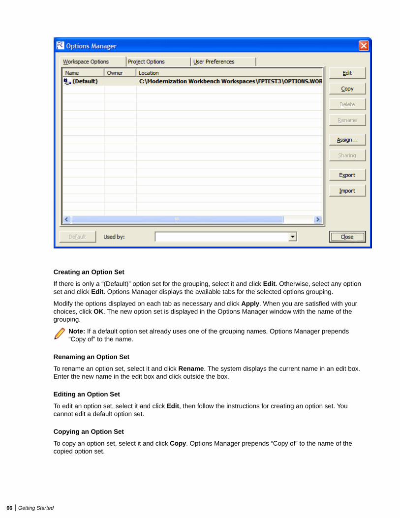
Creating an Option Set
If there is only a “(Default)” option set for the grouping, select it and click Edit. Otherwise, select any optionset and click Edit. Options Manager displays the available tabs for the selected options grouping.
Modify the options displayed on each tab as necessary and click Apply. When you are satisfied with yourchoices, click OK. The new option set is displayed in the Options Manager window with the name of thegrouping.
Note: If a default option set already uses one of the grouping names, Options Manager prepends“Copy of” to the name.
Renaming an Option Set
To rename an option set, select it and click Rename. The system displays the current name in an edit box.Enter the new name in the edit box and click outside the box.
Editing an Option Set
To edit an option set, select it and click Edit, then follow the instructions for creating an option set. Youcannot edit a default option set.
Copying an Option Set
To copy an option set, select it and click Copy. Options Manager prepends “Copy of” to the name of thecopied option set.
66 | Getting Started
Deleting an Option Set
To delete an option set, select it and click Delete. You cannot delete a default option set, or a shared optionset that has been assigned by another user.
Sharing an Option Set
To share an option set, select it and click Sharing. The button is a toggle. Select it again to revoke sharing.You cannot revoke sharing for an option set that has been assigned by another user.
Making an Option Set the Default
To make a custom option set the default, share it first, then select it and click Default.
Note: In the Project Options tab, a dialog opens that prompts you to select or create a new project.Select the project and click OK.
The new default option set is automatically assigned to every user who has not explicitly defined a customoption set. A default option set cannot be modified or deleted.
Assigning an Option Set
To make an option set active, select it and click Assign.
Note: In the Project Options tab, a dialog opens that prompts you to select or create a new project.Select the project and click OK.
Importing and Exporting Option Sets
To import an option set, click Import. A Load dialog opens, where you can specify the option set you wantto import.
To export an option set, select it and click Export. A Save dialog opens, where you can specify the nameand location of the option set.
Setting General OptionsUse the General tab of the Workspace Options window to specify the description of the workspacedisplayed in the Object Information pane, the attributes displayed in the Repository pane Search tab, andthe browser fetch buffer size.
1. Choose Options > Workspace Options. The Workspace Options window opens. Click the General tab.
2. In the Workspace description field, enter a description of your workspace. This description is shown inthe Object Information pane.
3. In Repository Browser (Search), check the boxes for the object attributes that should be displayed in theSearch tab of the Repository pane. Click Select All to check all the attributes.
Note: Only attributes in the repository model for an object are displayed. That is, if you chooseCyclomatic Complexity, and only JCL files appear in the Search tab results list, the attribute will notbe displayed in the list, because Cyclomatic Complexity is not an attribute of a JCL file.
4. In the Browser Fetch Buffer Size field, enter the size of the buffer Enterprise Analyzer uses topopulate the repository tree. When you expand a node in the Repository Browser, Enterprise Analyzerpopulates the display from a buffer that contains the objects last fetched from the repository. For verylarge repositories, you may want to lower the buffer size so that you can work with objects in theRepository Browser while the product performs subsequent fetches.
Setting Environment User PreferencesUse the Environment tab of the User Preferences window to specify whether you want to be prompted toverify source files after registering them and the scope of relationships shown in the Object Propertieswindow.
Getting Started | 67
1. Choose Options > User Preferences > Environment.
2. In After new files are registered, choose:
• Verify registered files if you want Enterprise Analyzer to verify files after they have been registered.• Ask user about verification if you want to be prompted to verify files after they have been
registered. Available whether or not Verify registered files is selected.
3. From the Code Search Report Options you can select whether to be prompted that queries will be runon all programs when you try to run a Code Search report for a project.
4. The Chart Viewer options let you select:
• Show Chart Viewer on startup - if you want to have the Chart Viewer displayed when you start EA.• Default Chart View - if you want to change the default chart view.
5. In Show relationships in the object properties view window, choose whether you want to restrict therelationships displayed in the Relationships tab of the Object Properties window:
• Restricted to the current project if you want to restrict the relationships of the object to those in thecurrent project.
• Workspace wide if you want to display all the relationships of the object in the current workspace.
6. Select a main menu scheme: simplified or classic.
7. For Java support, specify the path of the folder for the Java Runtime Environment (JRE) on yourmachine in the Path to JRE Folder field. If you do not enter a path, the current version specified in theWindows registry is used. You must use JRE version 1.5 or later.
Note: If your application was compiled with a previous version of the JRE, specify the path of theJava SE runtime library (rt.jar) used to compile the application in the Enter classpath to JARFiles and/or path to external Java file root directories field in Workspace Options > Verification> Settings.
Setting Archivers User PreferencesThe EA registration process extracts compressed source files using the command line syntax for archiverversions most widely in use. Use the Archivers tab of the User Preferences window to specify thecommand line syntax for newer archiver versions.
1. Choose Options > User Preferences. The User Preferences window opens. Click the Archivers tab.
2. In the Command Line for Archiver drop-down, choose the archiver whose command line syntax youwant to specify.
3. In the Unpack All field, enter the command line syntax for the unpack all operation.
4. In the Extract File field, enter the command line syntax for the extract file operation.
Setting Export OptionsUse the Export Options tab of the Project Options window to specify where Enterprise Analyzer storesgenerated files. The default location is the \<Workspace Home>\Output folder.
1. Choose Options > Project Options. The Project Options window opens. Click the Export Options tab.
2. In the Target directory field, enter the folder you want Enterprise Analyzer to store generated files in.
3. Deselect the Move Files check box if you want to copy generated files to both the default and thespecified directories.
Adding a Selectable ItemMany options windows allow you to add an item to a list of available items. In the Extensions tab of theWorkspace Registration options, for example, you can add an extension to the list of recognizedextensions.
68 | Getting Started
Add an item by right-clicking in the selection pane and choosing Add in the pop-up menu. The EA displaysan empty text field next to a selected check box. Enter the name of the item in the text field and clickoutside the field.
Note: If you are entering a file extension, make sure to enter the dot (.).
Edit an item by selecting it and choosing Edit in the right-click menu. Delete an extension by selecting itand choosing Delete in the right-click menu.
Working with Reports and DiagramsWhen you generate a diagram or report in the Enterprise Analyzer, you typically have the option of saving itto a file or printing it. You can save to a wide variety of standard formats.
Note: Word must be installed to save reports to RTF and Word. Excel must be installed to savereports to Excel, CSV, and TXT. Visio 2002 must be installed to save a diagram to Visio. Visio 2002 isnot required to save to Visio XML.
Click Page Setup in a report window to set up the page for a printed report. Click Print to print the report.The Print dialog opens, where you can set options for the print job. Click OK.
Click Save in a report window to export a report. A Save As dialog opens, where you can specify the name,location, and file type of the report.
Using the Guide for a ToolMany Enterprise Analyzer tools have guides that you can use to get started quickly in the tool. The guidesare help-like systems with hyperlinks that you can use to access functions otherwise available only inmenus and other program controls.
To open the guide for a tool, choose View > Guide. Use the table of contents in the Page drop-down tonavigate quickly to a topic.
Purge Activity LogActivity Log grows in size. To remove unwanted information, use Purge Activity Log to permanently deletecontents from the database.
1. Open Micro Focus Enterprise Analyzer Administration.
2. Click Tools > Purge Activity Log. The Purge Activity Log window opens.
3. Select a date from which to delete Activity Log data.
• Click Delete to proceed with log deletion. This will actually delete items from the Activity Log historytable in the database.
• Click Close to exit without any change.
Getting Started | 69
Preparing Projects
Registering Source FilesBefore you can analyze application source files in Enterprise Analyzer, you need to load, or register, thesource files in a workspace.
Note: In a multiuser environment, only a master user can register source files.
EA registers sources files in-place from the location they are selected rather than creating copies of thefiles in the workspace folder. These are the files you view and edit in the EA tools.
Note: Workspaces that were created without in-place registration and upgraded from previousversions will continue to create copies of the files in the Sources folder for the workspace whenregistering new files.
Source files must have recognized DOS file extensions before they can be registered. You can view andadd to the recognized extensions in the Workspace Registration options window. Files without extensionsare checked for content, and if the content is recognized, the files are registered with appropriateextensions appended.
EA assumes that input source files are ASCII files in DOS format. Occasionally, files may be convertedincorrectly from other formats to DOS-based ASCII with an extra special character (like “M”) at the end ofeach line. While Enterprise Analyzer accepts these files as input, some EA tools may not work correctlywith them. Make sure all source files are in valid ASCII format.
You can register source files in compressed formats (ZIP or RAR), as well as uncompressed formats.Enterprise Analyzer automatically unpacks the compressed file and registers its contents.
Note: EA extracts compressed source files using the command line syntax for archiver versions mostwidely in use. If you use newer archiver versions, specify the command line syntax in the Archiverstab of the User Preferences window.
Workspace Registration options determine registration behavior. The default values for these options arepreset based on your configuration and should be appropriate for most installations.
1. In the Repository Browser, create a project for the source files you want to register, or use the defaultproject. To create a project, choose Project > New Project. The Create Project dialog opens. Enter thename of the new project and click OK. The new project is displayed in the Repository Browser.
2. Select the project in the Repository Browser, then copy-and-paste ( Ctrl+C and Ctrl+V) or drag-and-drop (if UAC is disabled) the file or folder for the source files you want to register onto the RepositoryBrowser. You are notified that you have registered the files successfully and are prompted to verify thefiles. Click Close. The Repository Browser displays the contents of the new workspace either by folder,or by type, depending on the tab you have selected - Folders or Types. The former displays thecontents of the repository in the same folder structure as the one they have on the host environment,the latter displays them by object type.
Note: For non-inplace registration workspaces, when updating or adding new sources through theEA main window, the files or folders being registered will be included into the selected folder in theFolders view. Registration into the Types view will copy the selected files and folders directly to theroot Sources folder, i.e. they will not be copied into any other existing folders. If you are registeringfiles or folders in Folders view, make sure you've selected in the tree the exact folder in which youwant them to be registered. If you haven't selected any folder, they will be copied into the rootSources folder.
70 | Preparing Projects
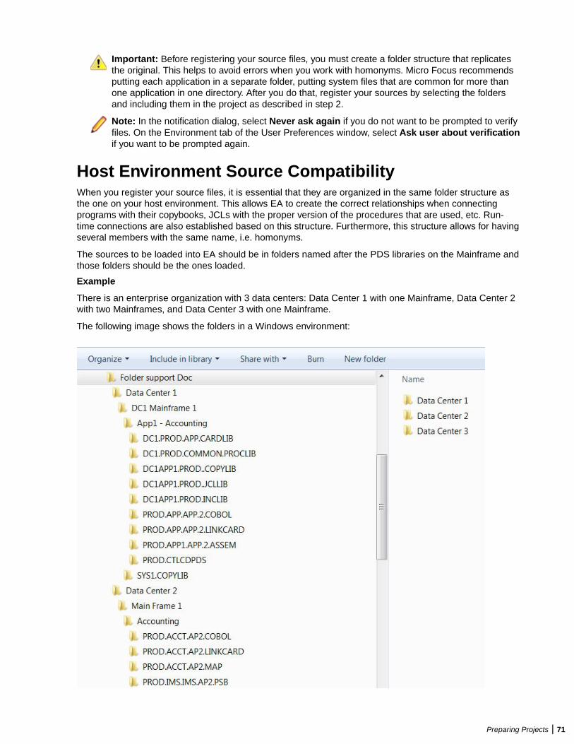
Important: Before registering your source files, you must create a folder structure that replicatesthe original. This helps to avoid errors when you work with homonyms. Micro Focus recommendsputting each application in a separate folder, putting system files that are common for more thanone application in one directory. After you do that, register your sources by selecting the foldersand including them in the project as described in step 2.
Note: In the notification dialog, select Never ask again if you do not want to be prompted to verifyfiles. On the Environment tab of the User Preferences window, select Ask user about verificationif you want to be prompted again.
Host Environment Source CompatibilityWhen you register your source files, it is essential that they are organized in the same folder structure asthe one on your host environment. This allows EA to create the correct relationships when connectingprograms with their copybooks, JCLs with the proper version of the procedures that are used, etc. Run-time connections are also established based on this structure. Furthermore, this structure allows for havingseveral members with the same name, i.e. homonyms.
The sources to be loaded into EA should be in folders named after the PDS libraries on the Mainframe andthose folders should be the ones loaded.
Example
There is an enterprise organization with 3 data centers: Data Center 1 with one Mainframe, Data Center 2with two Mainframes, and Data Center 3 with one Mainframe.
The following image shows the folders in a Windows environment:
Preparing Projects | 71
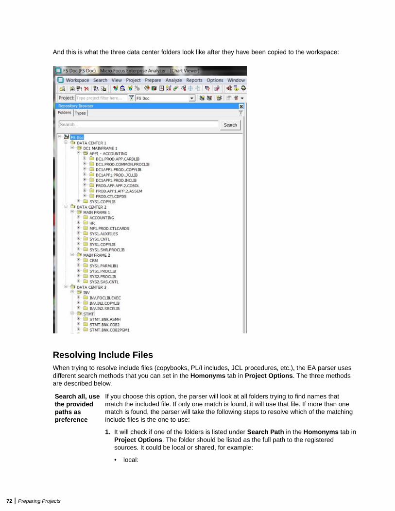
And this is what the three data center folders look like after they have been copied to the workspace:
Resolving Include FilesWhen trying to resolve include files (copybooks, PL/I includes, JCL procedures, etc.), the EA parser usesdifferent search methods that you can set in the Homonyms tab in Project Options. The three methodsare described below.
Search all, usethe providedpaths aspreference
If you choose this option, the parser will look at all folders trying to find names thatmatch the included file. If only one match is found, it will use that file. If more than onematch is found, the parser will take the following steps to resolve which of the matchinginclude files is the one to use:
1. It will check if one of the folders is listed under Search Path in the Homonyms tab inProject Options. The folder should be listed as the full path to the registeredsources. It could be local or shared, for example:
• local:
72 | Preparing Projects
C:\Sources\Data Center 1\DC1 Mainframe 1\SYS1.COPYLIB
• shared:
\\server\Sources\Data Center 1\DC1 Mainframe 1\SYS1.COPYLIB
2. It will look for proximity of the included file to the including file in the source folderstructure. First it will check the files that are in the same folder as the "including"source, then the files in the dependent folder, and then up the folder hierarchy.
3. Finally, folder names will be matched and the "include" folder that has a name with abetter match to the source folder name will be selected.
Search only inthe providedpaths
When this option is selected, only the paths specified in the Search Path list will be usedas locations for looking for include files. As this option works on project level, you canconfigure each subsystem or application in a separate project, and then specify thecopybook locations for each project. This option is useful when the number ofapplications/subsystem is not too big.
Search incommonlocation andonly the samesubsystem
This option may help when there is a large number of applications/subsystems. It letsyou use the folder structure in the file system to define the boundaries betweensubsystems and to restrict retrieval of include files based on the physical folderstructure. If you choose it, you can put all the sources in a single project and thus youwon't need to add a list of folders to search in. If you choose this option, you need tospecify the following two paths:
Common folder All common libraries need to be located inside the same rootfolder, for example: C:\Sources\Common. Files in folders locatedhere will be "visible" to all programs being analyzed.
Subsystemsroot level
All subsystems need to have a common root folder, for example:C:\Sources\Subsystems. If you have two subsystems in thisfolder, one of them will not get copybooks from the other and viceversa, but they can both get copybooks from the common librariesfolder specified in the Common folder field.
Note: The subsystems root level selection is checked first and then the commonfolder.
Resolving Program-to-Program CallsWhen resolving call relationships between programs, it is possible to reach a point where there is morethan one candidate for a called program. In this case EA works the same way as with includes (seeResolving Include Files), but since the program objects themselves don't have folders, the folders of thesource files that generated them are used.
Note: This same algorithm applies to any relations between non-legacy entities (e.g. PROGRAMreads TABLE, TRANSACTION starts PROGRAM, etc.).
Resolving Control CardsControl cards can be any members explicitly mentioned in the JCL. When parsing JCLs, EA will look for afile with the member name in the JCL in a folder with a name matching the PDS name from the mainframe.
Resolving JCL ProceduresWhen looking for JCL procedures, the parser uses the JCLLIB statement, if present. If there is only onecopy of the searched procedure, that copy is used. Otherwise, if more than one copy is available, thelibraries specified with the JCLLIB statement are used to pick the right one.
Preparing Projects | 73
Example:
Path to the JCL file: <workspace_path>\Sources\APP1\MYJCL\MYJOB.JCL
//MYJOB1 JOB ...//MYLIBS1 JCLLIB ORDER=CAMPBEL.PROCS.JCL//S1 EXEC PROC=MYPROC1
In this case the procedure <workspace_path>\Sources\APP1\CAMPBEL.PROCS.JCL\MYPROC1, if present, will be used.
Refreshing Registered Source PathsThe Refresh Registered Source Paths feature allows you to change the location of registered source files.It is useful in cases when the sources have been moved to another location, or a folder that containssources has been moved or renamed, or sources were registered from a non-shared location, and thelocation has since been shared.
To use this feature:
1. Open Enterprise Analyzer Administration.2. From the Administer menu, select Refresh Registered Source Paths….3. Choose a workspace from the list in the Select Workspace window.4. Click OK. The Change Registered Source Paths window opens. It shows the registered source paths
and lets you select the new source paths.
You can choose whether to hide or show system paths in the list of source paths by checking andunchecking the Hide System Paths check box.
5. Click the yellow folder icon under New Source Path.6. Choose the new directory of the source files and click Select Folder. The selected path and a red cross
icon appear under New Source Path.
Note: Clicking removes the selected path.
7. Click Change. A message asking you if you are sure you want to change the registered source pathscomes up.
8. Click OK. You are notified that the paths have been refreshed.9. Click OK. The Change Registered Source Paths window closes.
Note: Alternatively, you can change the registered source paths from Source Synchronization. Formore information, see the Source Synchronization section.
Setting Registration Options: Extensions TabSource files must have recognized DOS file extensions before they can be registered. Files withoutextensions are checked for content, and if the content is recognized, the files are registered withappropriate extensions appended.
Files with unknown extensions are flagged, provided that you uncheck Ignore Unknown and OverloadedExtensions on the Extensions tab of the Workspace Registration options window. If a file fails to registerbecause its extension is unknown, simply add the extension to the list of recognized extensions on theExtensions tab and register the file again.
1. Choose Options > Workspace Options. The Workspace Options window opens. Click the Registrationtab, then the Extensions tab.
2. In the Source Type pane, select the source file type whose extensions you want to view. The extensionsfor the file type are listed in the Extensions pane. Select each extension you want the system torecognize. Add extensions as necessary.
74 | Preparing Projects
Note: If a source file does not specify an extension when it references an included file, theverification process assumes that the included file has one of the recognized extensions. If multipleincluded files have the same name but different extensions, the system registers the file with thefirst extension in the list.
3. Check Ignore Unknown and Overloaded Extensions if you do not want the registration process toissue warnings about unrecognized and overloaded extensions. An overloaded extension is oneassigned to more than one file type.
4. For COBOL programs and copybooks, check Remove Sequence Numbers if you want the system toreplace preceding enumeration characters, or sequence numbers, with blanks. Sequence numbers areremoved only from the source file versions maintained by the product.
Setting Registration Options: Source Files TabIf your legacy application executes on a mainframe, it’s usually best to convert the application source toworkstation encoding. If that’s not practical, you can have Enterprise Analyzer convert it for you, using theoptions on the Registration > Source Files tab of the Workspace Options window.
1. Choose Options > Workspace Options. The Workspace Options window opens. Click the Registrationtab, then the Source Files tab.
2. In the Legacy Source Encoding group box, choose:
• Workstation if the source is workstation-encoded. For DBCS configurations, if Japanese-languagesource files were downloaded in workstation (text) mode, specify how DBCS escape controlcharacters were handled.
• Mainframe if the source is mainframe-encoded. When this option is selected, the registrationprocess automatically converts source files to workstation-encoding. Only the source filesmaintained by Enterprise Analyzer are converted.
3. In the Object System Encoding group box, choose:
• English - US (ANSI MS-1252) if the original source was U.S. English ANSI-encoded (Unisys 2200and HP3000 Cobol).
• English - US (EBCDIC-CCSID-37) if the original source was U.S. English EBCDIC-encoded (IBMCobol).
• Japanese (EBCDIC-CCSID-930, 5026) if the original source was Japanese EBCDIC-encoded,CCSID-930, 5026 (DBCS configurations only).
• Japanese (EBCDIC-CCSID-939, 5035) if the original source was Japanese EBCDIC-encoded,CCSID-939, 5035 (DBCS configurations only).
During analysis and transformation, hexadecimal literals in Cobol programs and BMS files aretranslated into character literals using this setting.
Note: Do not change these settings after source files are registered in a workspace.
4. Check Strip trailing numeration if you want the system to strip trailing numeration characters (columns73 through 80) from source lines. Trailing numeration characters are removed only from the source filesmaintained by EA.
5. Check Expand tabulation symbols if you want the system to replace tabulation symbols with acorresponding number of spaces. Tabulation symbols are replaced only in the source files maintainedby EA. You must select this option if you want to view Interactive Analysis information for C or C++programs.
6. Check Do not invalidate dependent files if you do not want the system to invalidate files that aredependent on a file you are refreshing. Normally, the system invalidates all dependent files. Selectingthis option shifts the burden of determining which files need to be invalidated (and reverified) onto theuser. If you select this option and know that a file is affected by a change in the file being refreshed, youmust reverify the affected file.
Preparing Projects | 75
Creating New Source FilesTo create a new source file, select the project for the source file in the Repository Browser and choose File> New. A dialog box opens, where you can specify the file name (with extension) and source file type. Tocreate a new source file with the same content as an existing file, select the file and choose File > SaveAs. The system automatically registers the created files and stores them in the appropriate folder.
Updating Source Files with Source SynchronizationSource Synchronization checks if the source files registered in Enterprise Analyzer have been modified ordeleted from their original location. It also detects if new files or folders have been added to a folderregistered in EA.
To use Source Synchronization, do one of the following:
• Select Workspace > Source Synchronization.•
Click .
If there are any new, modified or deleted files or folders, Source Synchronization informs you about thatand asks you if you want to synchronize the workspace. To view the updates, click Show Changes. ClickClose to go back to the Source Synchronization window.
If you click Yes, the new files will be added to the workspace and verified, the modified files be updatedand re-verified, and the deleted files will be removed.
Sources that were registered in-place but are not found in the expected locations are not automaticallydeleted from the repository during Source Synchronization. If files have been deleted from the originallocation, you can view them if you click Missing files button on the Source Synchronization confirmationdialog. You can then decide if you need to restore the missing files to the expected locations, or you canmanually select which of the missing files to be removed from the repository.
For in-place registration workspaces, source files removed from registered source directories can bedeleted from the workspace during BRP. If you check the Automatically unregister missing sourceswhen running update option in the BRP configuration Advanced tab, the missing sources will be deletedfrom the workspace when running BRP. The deleted files are logged in the Update.log. If the option isunchecked, the removed sources will not be deleted. This option is unchecked by default.
Source Synchronization SettingsTo set Source Synchronization options, go to Options > Workspace Options > Registration > SourceSynchronization.
The first option allows you to enable or disable Source Synchronization. The default is enabled. DisablingSource Synchronization stops any related checks and automated executions (if any were set). On a non-in-place workspace, Source Synchronization is automatically disabled if BRP registration is run. BRP on in-place registration workspace still uses Source Synchronization for updating, ignoring whether SourceSynchronization is enabled or not.
In this tab you can select to check for updated sources automatically. If you do so, you must select whetherto have the checks performed periodically or at a specific time. If you want to have periodic checks, youmust select an interval. The default is 20 hours. When this option is selected, the check is added as a taskto the Windows Task Scheduler.
Another option in this tab is to select to execute a batch file on the files in the original source locationbefore the workspace is synchronized.
If you select Synchronize the workspace after checking for outdated sources without asking me,
every time you click or select Workspace > Source Synchronization the workspace will beautomatically synchronized.
76 | Preparing Projects
Source Synchronization and Interactive AnalysisIf you select a file that has been modified in the original location and try to run Impact Analysis, you will benotified that it has been changed and will be asked to synchronize the workspace.
Note: If you have selected the Synchronize the workspace after checking for outdated sourceswithout asking me option in Options > Workspace Options > Registration > SourceSynchronization, the workspace will be synchronized when you try to run Impact Analysis on amodified file.
The Source Synchronization window also pops up when you try to select a file that has been modified inthe Objects pane in Interactive Analysis.
Using Source Synchronization to Change the Registered Source PathsWhen the folder containing the registered source files has been changed or renamed, or the files havebeen moved to a different location, or sources were registered from a non-shared location, and the locationhas since been shared, you can refresh the registered source paths from the Source Synchronizationwindow.
In these cases, a Change Registered Source Paths appears in the Source Synchronization window.
To refresh the registered source paths from the Source Synchronization window, follow the steps below:
1. Open Source Synchronization from the Workspace menu.2. Select the Removed folders / subfolders tab to see the list of folders that could not be found.
Note: Only top-level folders can be refreshed. This means that if the location of a top-level folderhas been changed, you can't choose to update only one or more of its subfolders.
3. Click Change Registered Source Paths. The Change Registered Source Paths window opens. Itshows the registered source paths and lets you select the new source paths.
You can choose whether to hide or show system paths in the list of source paths by checking andunchecking the Hide System Paths check box.
4. Click the yellow folder icon under New Source Path.5. Choose the new directory of the source files and click Select Folder. The selected path and a red cross
icon appear under New Source Path.
Note: Clicking removes the selected path.
6. Click Change. A message asking you if you are sure you want to change the registered source pathscomes up.
Note: If you click Change without selecting a new source path before that, a message that there isnothing to change will pop up.
7. Click OK. You are notified that the paths have been refreshed.8. Click OK. You are notified that all files are up-to-date.9. Click OK. Source Synchronization closes.
Note: Alternatively, you can change the registered source paths from the Enterprise AnalyzerAdministration tool. For more information, see Refreshing Registered Source Paths.
Exporting Source Files from a WorkspaceTo export the workspace source for a project or file to a new location, select the project or file in theRepository Browser and click File > Export Sources. A dialog box opens, where you can specify thelocation.
Preparing Projects | 77
Deleting Objects from a WorkspaceTo delete an object from a workspace, select it and choose File > Delete from Workspace. To delete afolder and all its contents from a workspace, select it and choose File > Delete Contents fromWorkspace.
Deleting a WorkspaceTo delete a workspace, choose Administer > Delete Workspace... in the Enterprise AnalyzerAdministration tool. A Delete workspace dialog opens, where you can select the workspace you want todelete.
Note: Only a master user can delete a workspace in a multiuser environment.
Japanese Language SupportEnterprise Analyzer provides full support for mainframe-based Cobol or PL/I Japanese-languageapplications. Make sure you set Windows system and user locales to Japanese before registering sourcefiles.
You can register Japanese source files downloaded in text or binary mode:
• Source files downloaded in text (workstation) mode must be in Shift-JIS encoding. If Shift-Out and Shift-In delimiters were replaced with spaces or removed during downloading, Enterprise Analyzer restoresthem at registration.
• Source files downloaded in binary (mainframe) mode are recoded by Enterprise Analyzer from EBCDICto Shift-JIS encoding at registration.
Use the options on the Registration > Source Files tab of the Workspace Options window to specify howDBCS escape control characters were handled in source file downloaded in text mode:
• Replaced with spaces if DBCS escape control characters were replaced with spaces.• Removed if DBCS escape control characters were removed.• Retained or not used if DBCS escape control characters were left as is or were not used.
We recommend you preserve delimiters during download. Replacing delimiters with spaces duringdownload generally yields better restoration results than removing them.
In all Enterprise Analyzer tools that offer search and replace facilities, you can insert Shift-Out and Shift-Indelimiters into patterns using Ctrl-Shift-O and Ctrl-Shift-I, respectively. You need only insert the delimiters ifyou are entering mixed strings.
Setting Up ProjectsWorkspace projects typically represent different portions of the application modeled in the workspace. Youmight have a project for the batch portion of the application and another project for the online portion. Youcan also use a project to collect items for discrete tasks: all the source files affected by a change request,for example.
Creating ProjectsWhen you set up a workspace in Enterprise Analyzer, the system creates a default project with the samename as the workspace. Create projects in addition to the default project when you need to analyzesubsystems separately or organize source files in more manageable groupings.
78 | Preparing Projects
1. Choose Project > New project. The Create Project dialog opens.
2. Enter the name of the new project and click OK. The new project is displayed in the RepositoryBrowser. The project is selected by default.
Sharing ProjectsIn a multiuser environment, the user who creates a project is referred to as its owner. Only the owner canshare the project with other users.
A shared, or public, project is visible to other members of your team. A private project is not. If the project isnot protected, these team members can delete the project, add source files, or remove source files.
Projects are private by default. Turn on sharing by choosing Project > Toggle Sharing. Choose Project >
Toggle Sharing again to turn it off. A symbol indicates that the project is shared.
Protecting ProjectsBy default, projects are unprotected: any user to whom the project is visible can add source files, include orexclude objects.
Note: Only a master user or the owner of a shared unprotected project can delete it.
The project owner or master user can designate a project as protected, in which case no user can delete ormodify the project, including the project owner or master user: the project is read-only, until the projectowner or master user turns protection off.
Turn on protection by selecting the project in the Repository pane and choosing Project > ToggleProtection. Choose Project > Toggle Protection again to turn it off. Look for a symbol like this one toindicate that a project is protected.
Moving or Copying Files into ProjectsCopy the contents of a project, folder, or file to a different project by selecting it and dragging and droppingthe selection onto the project, or by using the Edit menu choices to copy and paste the selection. Use theProject menu choices described below to move selections, or to include referenced or referencing objectsin a move or copy.
Note: In other EA tools, use the right-click menu or the File menu to include files in projects.
1. In the Repository Browser, select the project, folder, or file you want to move or copy, then chooseProject > Copy Project Contents (if you selected a project) or Project > Include into Project (if youselected a folder or file). The Select Project window opens.
2. In the Select Project window, select the target project. Click New to create a new project.
3. Select either:
• Include All Referenced Objects if you want to include objects referenced by the selected object(the Cobol copybooks included in a Cobol program file, for example).
• Include All Referencing Objects if you want to include objects that reference the selected object.
Note: This feature is available only for verified files.
4. Select:
• Copy to copy the selection to the target project.• Move From Current Project to move the selection to the target project.• Move From All Projects to move the selection from all projects to the target project.
Preparing Projects | 79
5. Click OK to move or copy the selection.
Including Referenced and Referencing Objects in aProjectAfter verifying a project, you can ensure a closed system by including referenced or referencing objects inthe project. The objects to be included must also have been verified, so it's best to verify every project inthe workspace before including objects.
You can include all referencing objects or only “directly referencing” objects: if program A calls program B,and program B calls program C, A is said to directly reference B and indirectly reference C.
To include in a project:
• Every object referenced by the objects in the project (including indirectly referenced objects), select theproject in the Repository Browser and choose Project > Include All Referenced Objects.
• Every object that references the objects in the project (including indirectly referencing objects), selectthe project in the Repository Browser and choose Project > Include All Referencing Objects.
• Every object that directly references the objects in the project, select the project in the RepositoryBrowser and choose Project > Include Directly Referencing Objects.
Removing Unused Support Objects from a ProjectTo move unused support objects (Cobol copybooks, JCL procedures, PL/I include files, and so forth) from aproject to the workspace, select the project in the Repository Browser and choose Project > CompactProject.
Emptying a ProjectTo empty a project (without deleting the project or its contents from the workspace), select the project andchoose Project > Empty Project Contents.
Deleting a ProjectTo delete a project from a workspace (without deleting its source files from the workspace), select it andchoose either File > Delete from Workspace or Project > Delete Project.
Note: Only the owner of a project can delete it.
Verifying Source FilesParsing, or verifying, an application source file generates the object model for the file. Only a master usercan verify source files.
You can verify a single file, a group of files, all the files in a folder, or all the files in a project. It’s usuallybest to verify an entire project. Enterprise Analyzer parses the files in appropriate order, taking account oflikely dependencies between file types.
Note: You need not verify copybooks. Copybooks are parsed when the including source file isverified.
If your RPG or AS/400 COBOL application uses copy statements that reference Database Descriptionor Device Description files, or if your MCP Cobol application uses copy statements that referenceDMSII DASDL files, you need to generate copybooks for the application before you verify programfiles.
80 | Preparing Projects

Workspace and Project Verification options determine verification behavior. The default values for theseoptions are preset based on your configuration and should be appropriate for most installations.
1. In the Repository Browser, select the project, folder, or files you want to verify and choose Prepare >Verify.
2. You are prompted to drop repository indexes to improve verification performance. Click Yes. You will beprompted to restore the indexes when you analyze the files.
The parser builds an object model for each successfully verified file. For an unsuccessfully verified file, theparser builds an object model for as much of the file as it understands.
Enabling Parallel VerificationParallel verification typically improves verification performance for very large workspaces by using multipleexecution agents, called Queue Processor, to process source files concurrently. You can start any numberof Queue Processors on the local machine, remote machines, or some combination of local and remotemachines. You can run parallel verification online in the Enterprise Analyzer or in batch mode with theBatch Refresh Process (BRP).
Important: When you run parallel verification on more than one machine, you need to make sure thatworkspace and project verification options are set identically on each machine. The easiest way to dothis is to log in as the same Windows user on each machine. Alternatively, you can define a defaultoption set that is automatically assigned to every user in the environment who has not explicitlydefined a custom option set. See the related topics for more information on option sets.
You enable parallel verification in three steps:
• Select the parallel verification method and the minimum number of concurrent Queue Processors on theVerification > Parallel Verification tab of the Workspace Options.
• Start the Queue Processors on the local and/or remote machines. If you start fewer than the minimumnumber of Queue Processors specified on the Parallel Verification tab, the verification process starts theneeded Queue Processors automatically on the local machine.
• Verify the workspace online in the Enterprise Analyzer or in batch mode using the Batch RefreshProcess (BRP).
Note: Verification results are reported in the Activity Log History window. They are not reported in theActivity Log itself (for online verification) or BRP log files (for batch verification). You can also use aVerification Report to view the results.
Follow the instructions below to launch Queue Processors and to specify the type of work they perform.You can launch multiple Queue Processors on the same machine. Once the minimum number of QueueProcessors has been started, you can launch them at any point in the verification process.
1. In the Enterprise Analyzer Administration window, choose Administer > Launch Queue Processor.The Launch Queue Processor window opens.
2. In the Serve workspace combo box, specify the workspace to be processed.
3. In the Processing Mode pane, select any combination of:
• Conversion to perform operations used to generate a Interactive Analysis construct model.• Verification to perform verification operations.• Code Search Query to perform Code Search searches in offline mode.
4. Select Produce Log File to generate a log file for parallel verification. The log file has a name of theform <workspace_name>HCC.<random_number>.log and is stored at the same level as the workspace(.rwp) file.
5. Click OK. The product launches the Queue Processor. Click the button on the Windows toolbar toview the Queue Processor window.
Preparing Projects | 81
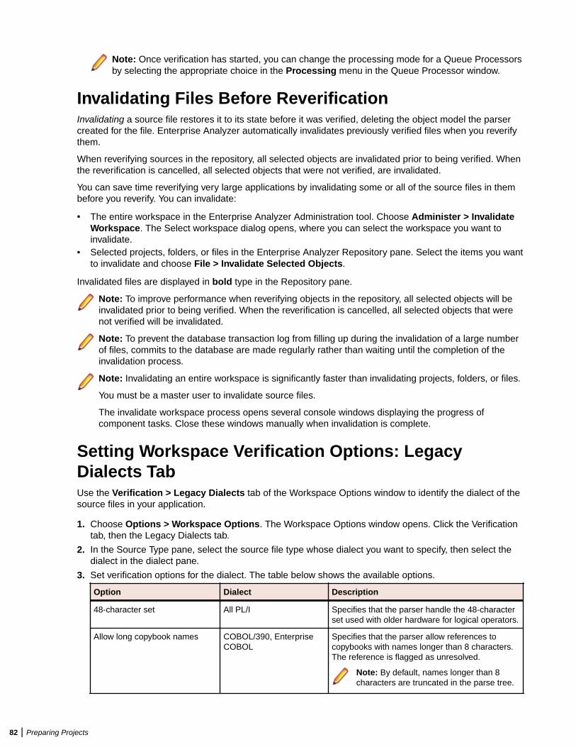
Note: Once verification has started, you can change the processing mode for a Queue Processorsby selecting the appropriate choice in the Processing menu in the Queue Processor window.
Invalidating Files Before ReverificationInvalidating a source file restores it to its state before it was verified, deleting the object model the parsercreated for the file. Enterprise Analyzer automatically invalidates previously verified files when you reverifythem.
When reverifying sources in the repository, all selected objects are invalidated prior to being verified. Whenthe reverification is cancelled, all selected objects that were not verified, are invalidated.
You can save time reverifying very large applications by invalidating some or all of the source files in thembefore you reverify. You can invalidate:
• The entire workspace in the Enterprise Analyzer Administration tool. Choose Administer > InvalidateWorkspace. The Select workspace dialog opens, where you can select the workspace you want toinvalidate.
• Selected projects, folders, or files in the Enterprise Analyzer Repository pane. Select the items you wantto invalidate and choose File > Invalidate Selected Objects.
Invalidated files are displayed in bold type in the Repository pane.
Note: To improve performance when reverifying objects in the repository, all selected objects will beinvalidated prior to being verified. When the reverification is cancelled, all selected objects that werenot verified will be invalidated.
Note: To prevent the database transaction log from filling up during the invalidation of a large numberof files, commits to the database are made regularly rather than waiting until the completion of theinvalidation process.
Note: Invalidating an entire workspace is significantly faster than invalidating projects, folders, or files.
You must be a master user to invalidate source files.
The invalidate workspace process opens several console windows displaying the progress ofcomponent tasks. Close these windows manually when invalidation is complete.
Setting Workspace Verification Options: LegacyDialects TabUse the Verification > Legacy Dialects tab of the Workspace Options window to identify the dialect of thesource files in your application.
1. Choose Options > Workspace Options. The Workspace Options window opens. Click the Verificationtab, then the Legacy Dialects tab.
2. In the Source Type pane, select the source file type whose dialect you want to specify, then select thedialect in the dialect pane.
3. Set verification options for the dialect. The table below shows the available options.
Option Dialect Description
48-character set All PL/I Specifies that the parser handle the 48-characterset used with older hardware for logical operators.
Allow long copybook names COBOL/390, EnterpriseCOBOL
Specifies that the parser allow references tocopybooks with names longer than 8 characters.The reference is flagged as unresolved.
Note: By default, names longer than 8characters are truncated in the parse tree.
82 | Preparing Projects
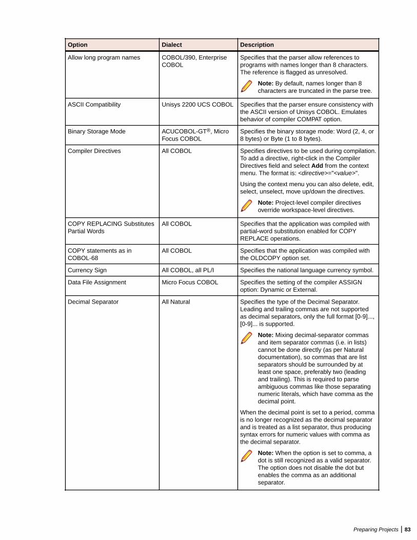
Option Dialect Description
Allow long program names COBOL/390, EnterpriseCOBOL
Specifies that the parser allow references toprograms with names longer than 8 characters.The reference is flagged as unresolved.
Note: By default, names longer than 8characters are truncated in the parse tree.
ASCII Compatibility Unisys 2200 UCS COBOL Specifies that the parser ensure consistency withthe ASCII version of Unisys COBOL. Emulatesbehavior of compiler COMPAT option.
Binary Storage Mode ACUCOBOL-GT®, MicroFocus COBOL
Specifies the binary storage mode: Word (2, 4, or8 bytes) or Byte (1 to 8 bytes).
Compiler Directives All COBOL Specifies directives to be used during compilation.To add a directive, right-click in the CompilerDirectives field and select Add from the contextmenu. The format is: <directive>="<value>".
Using the context menu you can also delete, edit,select, unselect, move up/down the directives.
Note: Project-level compiler directivesoverride workspace-level directives.
COPY REPLACING SubstitutesPartial Words
All COBOL Specifies that the application was compiled withpartial-word substitution enabled for COPYREPLACE operations.
COPY statements as inCOBOL-68
All COBOL Specifies that the application was compiled withthe OLDCOPY option set.
Currency Sign All COBOL, all PL/I Specifies the national language currency symbol.
Data File Assignment Micro Focus COBOL Specifies the setting of the compiler ASSIGNoption: Dynamic or External.
Decimal Separator All Natural Specifies the type of the Decimal Separator.Leading and trailing commas are not supportedas decimal separators, only the full format [0-9]...,[0-9]... is supported.
Note: Mixing decimal-separator commasand item separator commas (i.e. in lists)cannot be done directly (as per Naturaldocumentation), so commas that are listseparators should be surrounded by atleast one space, preferably two (leadingand trailing). This is required to parseambiguous commas like those separatingnumeric literals, which have comma as thedecimal point.
When the decimal point is set to a period, commais no longer recognized as the decimal separatorand is treated as a list separator, thus producingsyntax errors for numeric values with comma asthe decimal separator.
Note: When the option is set to comma, adot is still recognized as a valid separator.The option does not disable the dot butenables the comma as an additionalseparator.
Preparing Projects | 83
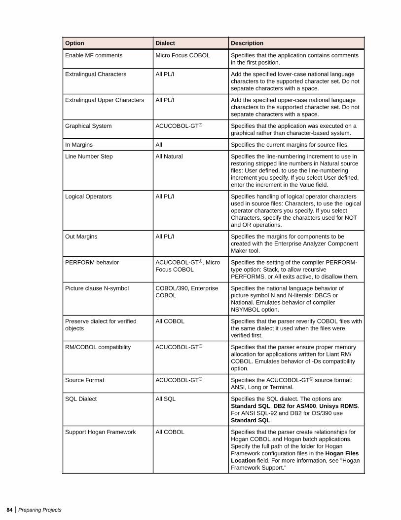
Option Dialect Description
Enable MF comments Micro Focus COBOL Specifies that the application contains commentsin the first position.
Extralingual Characters All PL/I Add the specified lower-case national languagecharacters to the supported character set. Do notseparate characters with a space.
Extralingual Upper Characters All PL/I Add the specified upper-case national languagecharacters to the supported character set. Do notseparate characters with a space.
Graphical System ACUCOBOL-GT® Specifies that the application was executed on agraphical rather than character-based system.
In Margins All Specifies the current margins for source files.
Line Number Step All Natural Specifies the line-numbering increment to use inrestoring stripped line numbers in Natural sourcefiles: User defined, to use the line-numberingincrement you specify. If you select User defined,enter the increment in the Value field.
Logical Operators All PL/I Specifies handling of logical operator charactersused in source files: Characters, to use the logicaloperator characters you specify. If you selectCharacters, specify the characters used for NOTand OR operations.
Out Margins All PL/I Specifies the margins for components to becreated with the Enterprise Analyzer ComponentMaker tool.
PERFORM behavior ACUCOBOL-GT®, MicroFocus COBOL
Specifies the setting of the compiler PERFORM-type option: Stack, to allow recursivePERFORMS, or All exits active, to disallow them.
Picture clause N-symbol COBOL/390, EnterpriseCOBOL
Specifies the national language behavior ofpicture symbol N and N-literals: DBCS orNational. Emulates behavior of compilerNSYMBOL option.
Preserve dialect for verifiedobjects
All COBOL Specifies that the parser reverify COBOL files withthe same dialect it used when the files wereverified first.
RM/COBOL compatibility ACUCOBOL-GT® Specifies that the parser ensure proper memoryallocation for applications written for Liant RM/COBOL. Emulates behavior of -Ds compatibilityoption.
Source Format ACUCOBOL-GT® Specifies the ACUCOBOL-GT® source format:ANSI, Long or Terminal.
SQL Dialect All SQL Specifies the SQL dialect. The options are:Standard SQL, DB2 for AS/400, Unisys RDMS.For ANSI SQL-92 and DB2 for OS/390 useStandard SQL.
Support Hogan Framework All COBOL Specifies that the parser create relationships forHogan COBOL and Hogan batch applications.Specify the full path of the folder for HoganFramework configuration files in the Hogan FilesLocation field. For more information, see "HoganFramework Support."
84 | Preparing Projects
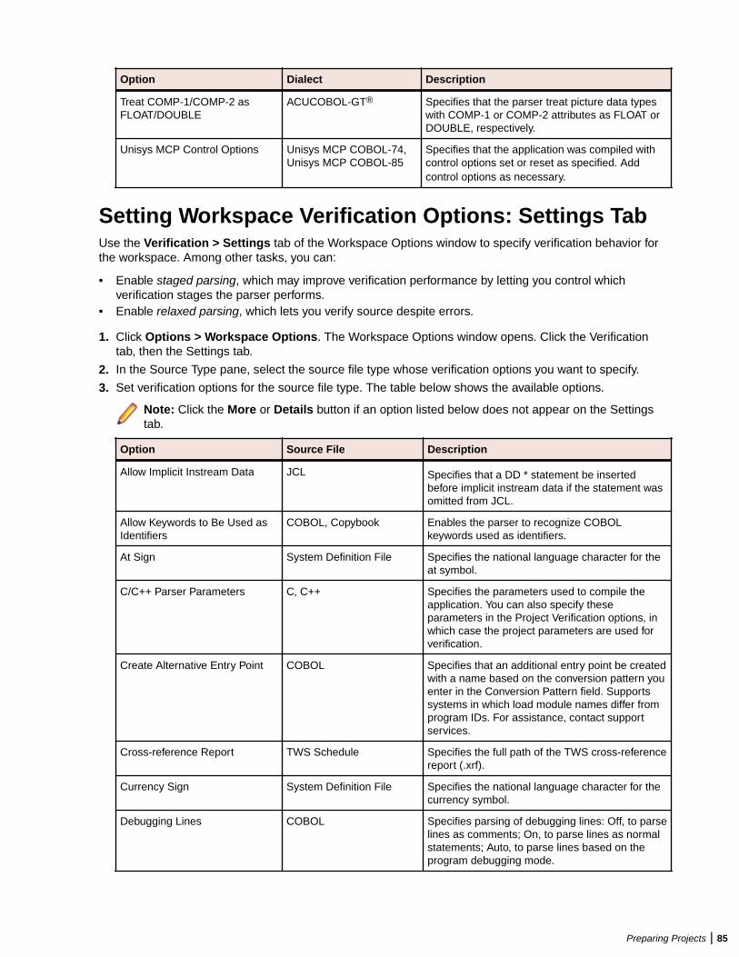
Option Dialect Description
Treat COMP-1/COMP-2 asFLOAT/DOUBLE
ACUCOBOL-GT® Specifies that the parser treat picture data typeswith COMP-1 or COMP-2 attributes as FLOAT orDOUBLE, respectively.
Unisys MCP Control Options Unisys MCP COBOL-74,Unisys MCP COBOL-85
Specifies that the application was compiled withcontrol options set or reset as specified. Addcontrol options as necessary.
Setting Workspace Verification Options: Settings TabUse the Verification > Settings tab of the Workspace Options window to specify verification behavior forthe workspace. Among other tasks, you can:
• Enable staged parsing, which may improve verification performance by letting you control whichverification stages the parser performs.
• Enable relaxed parsing, which lets you verify source despite errors.
1. Click Options > Workspace Options. The Workspace Options window opens. Click the Verificationtab, then the Settings tab.
2. In the Source Type pane, select the source file type whose verification options you want to specify.
3. Set verification options for the source file type. The table below shows the available options.
Note: Click the More or Details button if an option listed below does not appear on the Settingstab.
Option Source File Description
Allow Implicit Instream Data JCL Specifies that a DD * statement be insertedbefore implicit instream data if the statement wasomitted from JCL.
Allow Keywords to Be Used asIdentifiers
COBOL, Copybook Enables the parser to recognize COBOLkeywords used as identifiers.
At Sign System Definition File Specifies the national language character for theat symbol.
C/C++ Parser Parameters C, C++ Specifies the parameters used to compile theapplication. You can also specify theseparameters in the Project Verification options, inwhich case the project parameters are used forverification.
Create Alternative Entry Point COBOL Specifies that an additional entry point be createdwith a name based on the conversion pattern youenter in the Conversion Pattern field. Supportssystems in which load module names differ fromprogram IDs. For assistance, contact supportservices.
Cross-reference Report TWS Schedule Specifies the full path of the TWS cross-referencereport (.xrf).
Currency Sign System Definition File Specifies the national language character for thecurrency symbol.
Debugging Lines COBOL Specifies parsing of debugging lines: Off, to parselines as comments; On, to parse lines as normalstatements; Auto, to parse lines based on theprogram debugging mode.
Preparing Projects | 85
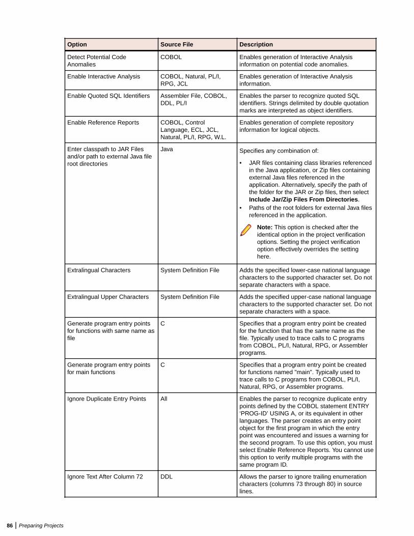
Option Source File Description
Detect Potential CodeAnomalies
COBOL Enables generation of Interactive Analysisinformation on potential code anomalies.
Enable Interactive Analysis COBOL, Natural, PL/I,RPG, JCL
Enables generation of Interactive Analysisinformation.
Enable Quoted SQL Identifiers Assembler File, COBOL,DDL, PL/I
Enables the parser to recognize quoted SQLidentifiers. Strings delimited by double quotationmarks are interpreted as object identifiers.
Enable Reference Reports COBOL, ControlLanguage, ECL, JCL,Natural, PL/I, RPG, W.L.
Enables generation of complete repositoryinformation for logical objects.
Enter classpath to JAR Filesand/or path to external Java fileroot directories
Java Specifies any combination of:
• JAR files containing class libraries referencedin the Java application, or Zip files containingexternal Java files referenced in theapplication. Alternatively, specify the path ofthe folder for the JAR or Zip files, then selectInclude Jar/Zip Files From Directories.
• Paths of the root folders for external Java filesreferenced in the application.
Note: This option is checked after theidentical option in the project verificationoptions. Setting the project verificationoption effectively overrides the settinghere.
Extralingual Characters System Definition File Adds the specified lower-case national languagecharacters to the supported character set. Do notseparate characters with a space.
Extralingual Upper Characters System Definition File Adds the specified upper-case national languagecharacters to the supported character set. Do notseparate characters with a space.
Generate program entry pointsfor functions with same name asfile
C Specifies that a program entry point be createdfor the function that has the same name as thefile. Typically used to trace calls to C programsfrom COBOL, PL/I, Natural, RPG, or Assemblerprograms.
Generate program entry pointsfor main functions
C Specifies that a program entry point be createdfor functions named "main". Typically used totrace calls to C programs from COBOL, PL/I,Natural, RPG, or Assembler programs.
Ignore Duplicate Entry Points All Enables the parser to recognize duplicate entrypoints defined by the COBOL statement ENTRY‘PROG-ID’ USING A, or its equivalent in otherlanguages. The parser creates an entry pointobject for the first program in which the entrypoint was encountered and issues a warning forthe second program. To use this option, you mustselect Enable Reference Reports. You cannot usethis option to verify multiple programs with thesame program ID.
Ignore Text After Column 72 DDL Allows the parser to ignore trailing enumerationcharacters (columns 73 through 80) in sourcelines.
86 | Preparing Projects
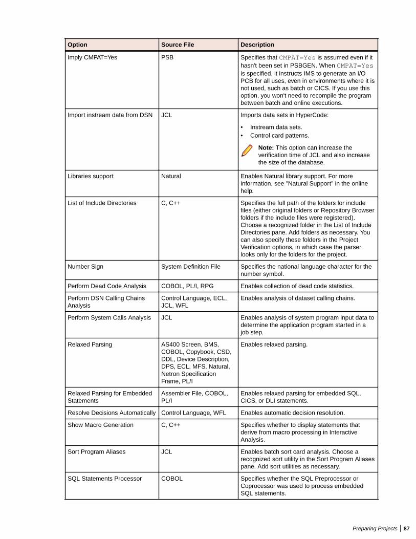
Option Source File Description
Imply CMPAT=Yes PSB Specifies that CMPAT=Yes is assumed even if ithasn't been set in PSBGEN. When CMPAT=Yesis specified, it instructs IMS to generate an I/OPCB for all uses, even in environments where it isnot used, such as batch or CICS. If you use thisoption, you won't need to recompile the programbetween batch and online executions.
Import instream data from DSN JCL Imports data sets in HyperCode:
• Instream data sets.• Control card patterns.
Note: This option can increase theverification time of JCL and also increasethe size of the database.
Libraries support Natural Enables Natural library support. For moreinformation, see "Natural Support" in the onlinehelp.
List of Include Directories C, C++ Specifies the full path of the folders for includefiles (either original folders or Repository Browserfolders if the include files were registered).Choose a recognized folder in the List of IncludeDirectories pane. Add folders as necessary. Youcan also specify these folders in the ProjectVerification options, in which case the parserlooks only for the folders for the project.
Number Sign System Definition File Specifies the national language character for thenumber symbol.
Perform Dead Code Analysis COBOL, PL/I, RPG Enables collection of dead code statistics.
Perform DSN Calling ChainsAnalysis
Control Language, ECL,JCL, WFL
Enables analysis of dataset calling chains.
Perform System Calls Analysis JCL Enables analysis of system program input data todetermine the application program started in ajob step.
Relaxed Parsing AS400 Screen, BMS,COBOL, Copybook, CSD,DDL, Device Description,DPS, ECL, MFS, Natural,Netron SpecificationFrame, PL/I
Enables relaxed parsing.
Relaxed Parsing for EmbeddedStatements
Assembler File, COBOL,PL/I
Enables relaxed parsing for embedded SQL,CICS, or DLI statements.
Resolve Decisions Automatically Control Language, WFL Enables automatic decision resolution.
Show Macro Generation C, C++ Specifies whether to display statements thatderive from macro processing in InteractiveAnalysis.
Sort Program Aliases JCL Enables batch sort card analysis. Choose arecognized sort utility in the Sort Program Aliasespane. Add sort utilities as necessary.
SQL Statements Processor COBOL Specifies whether the SQL Preprocessor orCoprocessor was used to process embeddedSQL statements.
Preparing Projects | 87
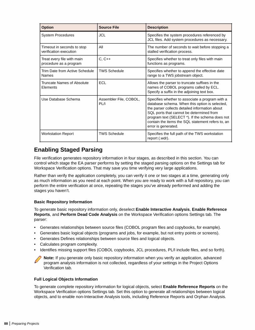
Option Source File Description
System Procedures JCL Specifies the system procedures referenced byJCL files. Add system procedures as necessary.
Timeout in seconds to stopverification execution
All The number of seconds to wait before stopping astalled verification process.
Treat every file with mainprocedure as a program
C, C++ Specifies whether to treat only files with mainfunctions as programs.
Trim Date from Active ScheduleNames
TWS Schedule Specifies whether to append the effective daterange to a TWS jobstream object.
Truncate Names of AbsoluteElements
ECL Allows the parser to truncate suffixes in thenames of COBOL programs called by ECL.Specify a suffix in the adjoining text box.
Use Database Schema Assembler File, COBOL,PL/I
Specifies whether to associate a program with adatabase schema. When this option is selected,the parser collects detailed information aboutSQL ports that cannot be determined fromprogram text (SELECT *). If the schema does notcontain the items the SQL statement refers to, anerror is generated.
Workstation Report TWS Schedule Specifies the full path of the TWS workstationreport (.wdr).
Enabling Staged ParsingFile verification generates repository information in four stages, as described in this section. You cancontrol which stage the EA parser performs by setting the staged parsing options on the Settings tab forWorkspace Verification options. That may save you time verifying very large applications.
Rather than verify the application completely, you can verify it one or two stages at a time, generating onlyas much information as you need at each point. When you are ready to work with a full repository, you canperform the entire verification at once, repeating the stages you’ve already performed and adding thestages you haven’t.
Basic Repository Information
To generate basic repository information only, deselect Enable Interactive Analysis, Enable ReferenceReports, and Perform Dead Code Analysis on the Workspace Verification options Settings tab. Theparser:
• Generates relationships between source files (COBOL program files and copybooks, for example).• Generates basic logical objects (programs and jobs, for example, but not entry points or screens).• Generates Defines relationships between source files and logical objects.• Calculates program complexity.• Identifies missing support files (COBOL copybooks, JCL procedures, PL/I include files, and so forth).
Note: If you generate only basic repository information when you verify an application, advancedprogram analysis information is not collected, regardless of your settings in the Project OptionsVerification tab.
Full Logical Objects Information
To generate complete repository information for logical objects, select Enable Reference Reports on theWorkspace Verification options Settings tab. Set this option to generate all relationships between logicalobjects, and to enable non-Interactive Analysis tools, including Reference Reports and Orphan Analysis.
88 | Preparing Projects
Note: If you select this staged parsing option only, verify all legacy objects in the workspacesynchronously to ensure complete repository information.
Interactive Analysis Information
To generate an Interactive Analysis construct model, select Enable Interactive Analysis on theWorkspace Verification options Settings tab. An Interactive Analysis construct model defines therelationships between the constructs that comprise the file being verified: its sections, paragraphs,statements, conditions, variables, and so forth.
To generate Interactive Analysis information on potential code anomalies, select Detect Potential CodeAnomalies on the Workspace Verification options Settings tab.
Note: If you do not generate Interactive Analysis information when you verify an application, impactanalysis, data flow, and execution flow information is not collected, regardless of your settings on theProject Verification options tab.
Dead Code Statistics
To generate dead code statistics, and to set the Dead attribute to True for dead constructs in InteractiveAnalysis, select Perform Dead Code Analysis on the Workspace Verification options > Settings tab. Thestatistics comprise:
• Number of dead statements in the source file and referenced copybooks. A dead statement is aprocedural statement that can never be reached during program execution.
• Number of dead data elements in the source file and referenced copybooks. Dead data elements areunused structures at any data level, all of whose parents and children are unused.
• Number of dead lines in the source file and referenced copybooks. Dead lines are source linescontaining dead statements or dead data elements.
You can view the statistics in the Statistic tab of the Properties window for an object or in the ComplexityMetrics tool.
Enabling Relaxed ParsingThe relaxed parsing option lets you verify a source file despite errors. Ordinarily, the parser stops at astatement when it encounters an error. Relaxed parsing tells the parser to continue to the next statement.
Use relaxed parsing when you are performing less rigorous analyses that do not need every statement tobe modeled (estimating the complexity of an application written in an unsupported dialect, for example).Select Relaxed Parsing or Relaxed Parsing for Embedded Statements as appropriate on theWorkspace Verification options Settings tab.
Note: Relaxed parsing may affect the behavior of other tools. You cannot generate component code,for example, from source files verified with the relaxed parsing option.
Truncating Names of Absolute ElementsIf you are verifying ECL files for an application in which absolute element names differ from program IDs,you can tell the parser to truncate suffixes in the names of Cobol programs called by ECL. Select TruncateNames of Absolute Elements on the Workspace Verification options Settings tab for the ECL file.
If a Cobol program named CAP13MS.cob, for example, defines the entry point CAP13M, and an ECLprogram named CAP13M.ecl executes an absolute element called CAP13MA, then setting this optioncauses the parser to create a reference to the entry point CAP13M rather than CAP13MA.
Preparing Projects | 89
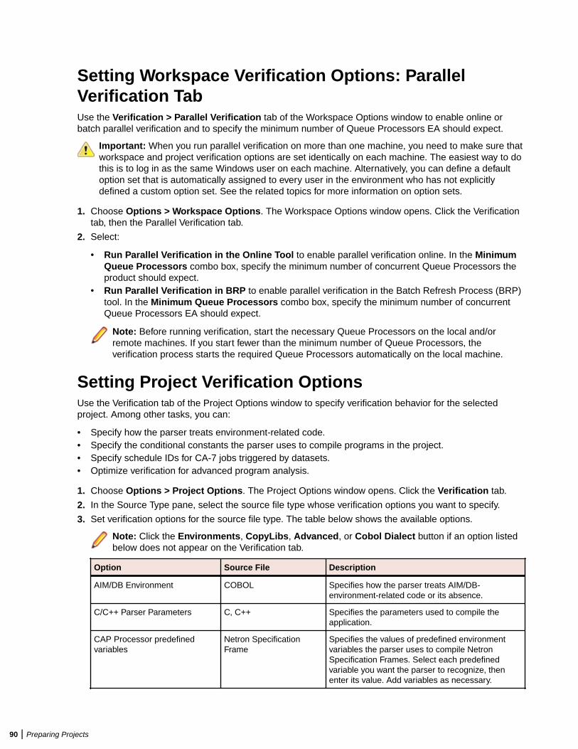
Setting Workspace Verification Options: ParallelVerification TabUse the Verification > Parallel Verification tab of the Workspace Options window to enable online orbatch parallel verification and to specify the minimum number of Queue Processors EA should expect.
Important: When you run parallel verification on more than one machine, you need to make sure thatworkspace and project verification options are set identically on each machine. The easiest way to dothis is to log in as the same Windows user on each machine. Alternatively, you can define a defaultoption set that is automatically assigned to every user in the environment who has not explicitlydefined a custom option set. See the related topics for more information on option sets.
1. Choose Options > Workspace Options. The Workspace Options window opens. Click the Verificationtab, then the Parallel Verification tab.
2. Select:
• Run Parallel Verification in the Online Tool to enable parallel verification online. In the MinimumQueue Processors combo box, specify the minimum number of concurrent Queue Processors theproduct should expect.
• Run Parallel Verification in BRP to enable parallel verification in the Batch Refresh Process (BRP)tool. In the Minimum Queue Processors combo box, specify the minimum number of concurrentQueue Processors EA should expect.
Note: Before running verification, start the necessary Queue Processors on the local and/orremote machines. If you start fewer than the minimum number of Queue Processors, theverification process starts the required Queue Processors automatically on the local machine.
Setting Project Verification OptionsUse the Verification tab of the Project Options window to specify verification behavior for the selectedproject. Among other tasks, you can:
• Specify how the parser treats environment-related code.• Specify the conditional constants the parser uses to compile programs in the project.• Specify schedule IDs for CA-7 jobs triggered by datasets.• Optimize verification for advanced program analysis.
1. Choose Options > Project Options. The Project Options window opens. Click the Verification tab.
2. In the Source Type pane, select the source file type whose verification options you want to specify.
3. Set verification options for the source file type. The table below shows the available options.
Note: Click the Environments, CopyLibs, Advanced, or Cobol Dialect button if an option listedbelow does not appear on the Verification tab.
Option Source File Description
AIM/DB Environment COBOL Specifies how the parser treats AIM/DB-environment-related code or its absence.
C/C++ Parser Parameters C, C++ Specifies the parameters used to compile theapplication.
CAP Processor predefinedvariables
Netron SpecificationFrame
Specifies the values of predefined environmentvariables the parser uses to compile NetronSpecification Frames. Select each predefinedvariable you want the parser to recognize, thenenter its value. Add variables as necessary.
90 | Preparing Projects
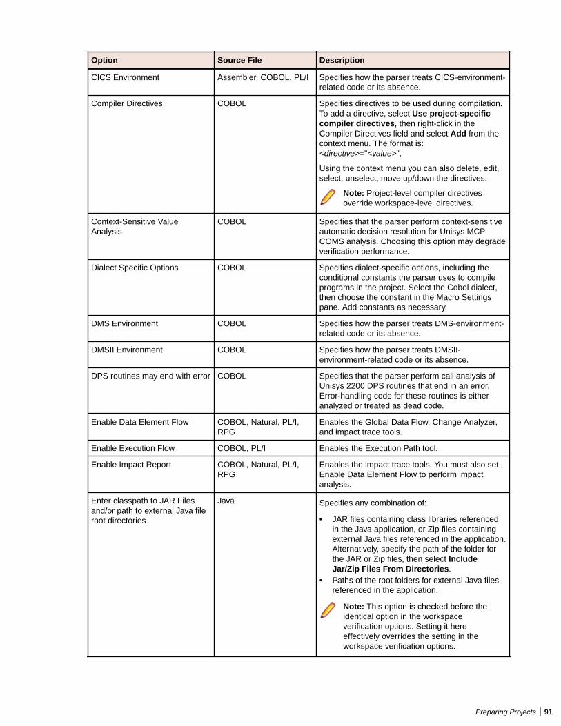
Option Source File Description
CICS Environment Assembler, COBOL, PL/I Specifies how the parser treats CICS-environment-related code or its absence.
Compiler Directives COBOL Specifies directives to be used during compilation.To add a directive, select Use project-specificcompiler directives, then right-click in theCompiler Directives field and select Add from thecontext menu. The format is:<directive>="<value>".
Using the context menu you can also delete, edit,select, unselect, move up/down the directives.
Note: Project-level compiler directivesoverride workspace-level directives.
Context-Sensitive ValueAnalysis
COBOL Specifies that the parser perform context-sensitiveautomatic decision resolution for Unisys MCPCOMS analysis. Choosing this option may degradeverification performance.
Dialect Specific Options COBOL Specifies dialect-specific options, including theconditional constants the parser uses to compileprograms in the project. Select the Cobol dialect,then choose the constant in the Macro Settingspane. Add constants as necessary.
DMS Environment COBOL Specifies how the parser treats DMS-environment-related code or its absence.
DMSII Environment COBOL Specifies how the parser treats DMSII-environment-related code or its absence.
DPS routines may end with error COBOL Specifies that the parser perform call analysis ofUnisys 2200 DPS routines that end in an error.Error-handling code for these routines is eitheranalyzed or treated as dead code.
Enable Data Element Flow COBOL, Natural, PL/I,RPG
Enables the Global Data Flow, Change Analyzer,and impact trace tools.
Enable Execution Flow COBOL, PL/I Enables the Execution Path tool.
Enable Impact Report COBOL, Natural, PL/I,RPG
Enables the impact trace tools. You must also setEnable Data Element Flow to perform impactanalysis.
Enter classpath to JAR Filesand/or path to external Java fileroot directories
Java Specifies any combination of:
• JAR files containing class libraries referencedin the Java application, or Zip files containingexternal Java files referenced in the application.Alternatively, specify the path of the folder forthe JAR or Zip files, then select IncludeJar/Zip Files From Directories.
• Paths of the root folders for external Java filesreferenced in the application.
Note: This option is checked before theidentical option in the workspaceverification options. Setting it hereeffectively overrides the setting in theworkspace verification options.
Preparing Projects | 91
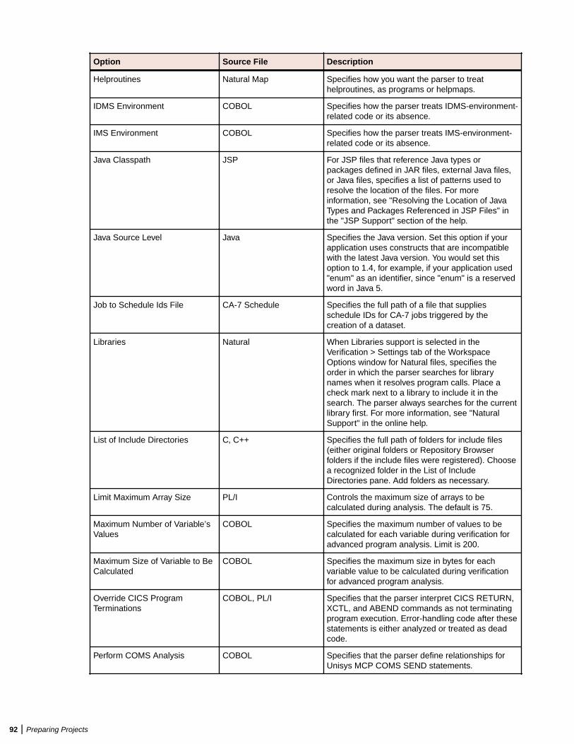
Option Source File Description
Helproutines Natural Map Specifies how you want the parser to treathelproutines, as programs or helpmaps.
IDMS Environment COBOL Specifies how the parser treats IDMS-environment-related code or its absence.
IMS Environment COBOL Specifies how the parser treats IMS-environment-related code or its absence.
Java Classpath JSP For JSP files that reference Java types orpackages defined in JAR files, external Java files,or Java files, specifies a list of patterns used toresolve the location of the files. For moreinformation, see "Resolving the Location of JavaTypes and Packages Referenced in JSP Files" inthe "JSP Support" section of the help.
Java Source Level Java Specifies the Java version. Set this option if yourapplication uses constructs that are incompatiblewith the latest Java version. You would set thisoption to 1.4, for example, if your application used"enum" as an identifier, since "enum" is a reservedword in Java 5.
Job to Schedule Ids File CA-7 Schedule Specifies the full path of a file that suppliesschedule IDs for CA-7 jobs triggered by thecreation of a dataset.
Libraries Natural When Libraries support is selected in theVerification > Settings tab of the WorkspaceOptions window for Natural files, specifies theorder in which the parser searches for librarynames when it resolves program calls. Place acheck mark next to a library to include it in thesearch. The parser always searches for the currentlibrary first. For more information, see "NaturalSupport" in the online help.
List of Include Directories C, C++ Specifies the full path of folders for include files(either original folders or Repository Browserfolders if the include files were registered). Choosea recognized folder in the List of IncludeDirectories pane. Add folders as necessary.
Limit Maximum Array Size PL/I Controls the maximum size of arrays to becalculated during analysis. The default is 75.
Maximum Number of Variable’sValues
COBOL Specifies the maximum number of values to becalculated for each variable during verification foradvanced program analysis. Limit is 200.
Maximum Size of Variable to BeCalculated
COBOL Specifies the maximum size in bytes for eachvariable value to be calculated during verificationfor advanced program analysis.
Override CICS ProgramTerminations
COBOL, PL/I Specifies that the parser interpret CICS RETURN,XCTL, and ABEND commands as not terminatingprogram execution. Error-handling code after thesestatements is either analyzed or treated as deadcode.
Perform COMS Analysis COBOL Specifies that the parser define relationships forUnisys MCP COMS SEND statements.
92 | Preparing Projects
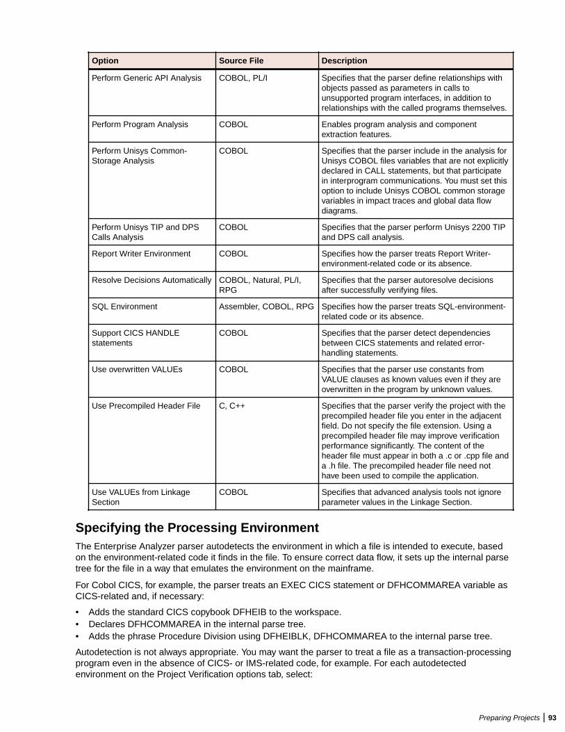
Option Source File Description
Perform Generic API Analysis COBOL, PL/I Specifies that the parser define relationships withobjects passed as parameters in calls tounsupported program interfaces, in addition torelationships with the called programs themselves.
Perform Program Analysis COBOL Enables program analysis and componentextraction features.
Perform Unisys Common-Storage Analysis
COBOL Specifies that the parser include in the analysis forUnisys COBOL files variables that are not explicitlydeclared in CALL statements, but that participatein interprogram communications. You must set thisoption to include Unisys COBOL common storagevariables in impact traces and global data flowdiagrams.
Perform Unisys TIP and DPSCalls Analysis
COBOL Specifies that the parser perform Unisys 2200 TIPand DPS call analysis.
Report Writer Environment COBOL Specifies how the parser treats Report Writer-environment-related code or its absence.
Resolve Decisions Automatically COBOL, Natural, PL/I,RPG
Specifies that the parser autoresolve decisionsafter successfully verifying files.
SQL Environment Assembler, COBOL, RPG Specifies how the parser treats SQL-environment-related code or its absence.
Support CICS HANDLEstatements
COBOL Specifies that the parser detect dependenciesbetween CICS statements and related error-handling statements.
Use overwritten VALUEs COBOL Specifies that the parser use constants fromVALUE clauses as known values even if they areoverwritten in the program by unknown values.
Use Precompiled Header File C, C++ Specifies that the parser verify the project with theprecompiled header file you enter in the adjacentfield. Do not specify the file extension. Using aprecompiled header file may improve verificationperformance significantly. The content of theheader file must appear in both a .c or .cpp file anda .h file. The precompiled header file need nothave been used to compile the application.
Use VALUEs from LinkageSection
COBOL Specifies that advanced analysis tools not ignoreparameter values in the Linkage Section.
Specifying the Processing EnvironmentThe Enterprise Analyzer parser autodetects the environment in which a file is intended to execute, basedon the environment-related code it finds in the file. To ensure correct data flow, it sets up the internal parsetree for the file in a way that emulates the environment on the mainframe.
For Cobol CICS, for example, the parser treats an EXEC CICS statement or DFHCOMMAREA variable asCICS-related and, if necessary:
• Adds the standard CICS copybook DFHEIB to the workspace.• Declares DFHCOMMAREA in the internal parse tree.• Adds the phrase Procedure Division using DFHEIBLK, DFHCOMMAREA to the internal parse tree.
Autodetection is not always appropriate. You may want the parser to treat a file as a transaction-processingprogram even in the absence of CICS- or IMS-related code, for example. For each autodetectedenvironment on the Project Verification options tab, select:
Preparing Projects | 93
• Auto, if you want the parser to autodetect the environment for the file.• Yes, if you want to force the parser to treat the file as environment-related even in the absence of
environment-related code.• No, if you want to force the parser to treat the file as unrelated to the environment even in the presence
of environment-related code. The parser classifies environment-related code as a syntax error.
Specifying Conditional Compiler ConstantsCompiler constant directives let you compile programs conditionally. Specify the conditional constants theparser uses to compile programs in the project in the Dialect Specific Options for your dialect on theProject Verification options tab. For Micro Focus COBOL, two formats are supported:
• constant_name=value (where no space is allowed around the equals sign). In the following example, ifyou specify WHERE=PC on the Project Verification options tab, the source that follows the $if clause iscompiled:
$if WHERE="PC" evaluate test-field when 5 perform test-a end-evaluate
• constant_name. In the following example, if you specify NOMF on the Project Verification options tab,the source that follows the $if clause is compiled:
$if NOMF set $display Not MF dialect go to test-a test-b depending on test-field $end
Optimizing Verification for Advanced Program AnalysisWhen you enable advanced program analysis options for COBOL projects, the parser calculates constantvalues for variables at every node in the Interactive Analysis parse tree. For this reason very large COBOLapplications may encounter performance or memory problems during verification.
You may be able to improve verification performance and avoid out-of-memory problems by manipulatingthe Maximum Number of Variable’s Values and Maximum Size of Variable to Be Calculated options inthe Project Verification Options tab. The lower the maximums, the better performance and memoryusage you can expect.
For each setting, you are warned during verification about variables for which the specified maximum isexceeded. It’s usually best to increase the overflowed maximum and re-verify the application.
Identifying System ProgramsA system program is a generic program provided by the underlying operating system and used inunmodified form in the legacy application: a mainframe sort utility, for example. You need to identify systemprograms to the parser so that it can distinguish them from application programs and create relationshipsfor them with their referencing files.
The most convenient way to identify the system programs your application uses is to run an unresolvedreport after verification. Once you learn from the report which system programs are referenced, you canidentify them in the System Programs tab of the Workspace Options window and reverify any one of theirreferencing source files.
Note: The reference report tool lets you bring up the System Programs tab of the Workspace Optionswindow while you are in the tool itself. Choose View > System Programs in the reference reportwindow to display the tab.
1. Choose Options > Workspace Options. The Workspace Options window opens. Click the SystemPrograms tab.
2. In the System Program Patterns pane, select the patterns that match the names of the systemprograms your application uses. Add patterns as necessary.
94 | Preparing Projects
Specifying Boundary DecisionsSpecify a boundary decision object if your application uses a method call to interface with a database,message queue, or other resource. Suppose the function f1f() in the following example writes to a queuenamed abc:
int f1f(char*){ return 0;}int f2f(){ return f1f(“abc”);}
As far as the parser is concerned, f1f(“abc”) is a method call like any other method call. There is noindication from the code that the called function is writing to a queue.
When you specify the boundary decisions for a workspace, you tell the parser to create a decision object ofa given resource type for each such call. Here is the decision object for the write to the queue:
int f2f().InsertsQueue.int f1f(char*)
You can resolve the decision objects to the appropriate resources in the Decision Resolution tool.
1. Choose Options > Workspace Options. The Workspace Options window opens. Click the BoundaryDecisions tab.
2. In the Decision Types pane, select the decision types associated with called procedures in yourapplication. For the example, you would select the Queue decision type.
3. In the righthand pane, select each signature of a given method type you want to associate with theselected decision type. For the example, the method type signature would be int f1f(char*). Addsignatures as necessary. Do not insert a space between the parentheses in the signature. You can usewildcard patterns allowed in LIKE statements by Visual Basic for Applications (VBA).
Note: Keep in mind that the signatures of C or C++ functions can contain an asterisk (*) character,as in the example. So if you specify a signature with a * character, you may receive resultscontaining not only the intended signatures but all signatures matching the wildcard pattern. Deletethe unwanted decision objects manually.
4. Select the project, folder, or source files for the application and choose:
• Prepare > Verify if the source files have not been verified.• Prepare > Apply Boundary Decisions if the source files have been verified, but boundary
decisions have not been specified for the application, or the specification has changed.
A decision object is added to the tree for the source files in the Repository Browser.
Generating CopybooksRPG programs and COBOL programs that execute in the AS/400 environment often use copy statementsthat reference Database Description or Device Description files rather than copybooks. MCP COBOLprograms occasionally use copy statements that reference DMSII DASDL files. If your application usescopy statements to reference these types of files, you need to verify the files and generate copybooks forthe application before you verify program files.
Copybook generation takes place in two steps:
• For each database and device file object generated at verification, the system creates a targetcopybook object.
Preparing Projects | 95
• For each target copybook object, the system creates one or more physical copybooks.
Settings on the Generate Copybooks tab of the Project Options window determine conversion behavior.The default values should be appropriate for most installations.
1. Verify:
• Database Description files. For each Database Description file, the system creates a database fileobject with the same name as the Database Description file.
• Device Description files. For each Device Description file, the system creates a device file object withthe same name as the Device Description file.
• DMSII DASDL files. For each DMSII DASDL file, the system creates a DMSII database file objectwith the same name as the DMSII DASDL file.
2. In the Repository Browser, select the project, database file, or device file and choose between:
• Prepare > Generate RPG Copybooks for Project for RPG.• Prepare > Generate Copybooks for Project for AS/400 COBOL or MCP COBOL.
Note: Skip this step for MCP Cobol if you selected Generate After Successful Verification onthe Generate Copybooks tab of the Project options window.
The system creates a target copybook for each database or device file object, with a name of the formdatabase file.DBCOPYBOOK or device file.DVCOPYBOOK, in the Target Copybooks folder.
3. The system automatically converts the target copybooks to physical copybooks if you selected ConvertTarget Copybooks to Legacy Objects on the Generate Copybooks tab of the Project options window.If you chose not to convert target copybooks automatically, select the target copybooks and choosePrepare > Convert to Legacy. The system generates physical copybooks with names of the formDD_OF_database file.CPY or DV_OF_device file.CPY.
Note: After generating copybooks, you can generate screens for AS/400 COBOL device fileobjects by selecting the objects in the Repository Browser and clicking Prepare > GenerateScreens.
Setting Generate Copybooks OptionsFor RPG or AS/400 Cobol application that use copy statements to reference Database Description orDevice Description files, or MCP Cobol applications that use copy statement to reference DMSII DASDLfiles, use the Generate Copybooks tab of the Project Options window to specify how the system convertsthe files to physical copybooks.
1. Choose Options > Project Options. The Project Options window opens. Click the GenerateCopybooks tab.
2. For Cobol MCP only, select Generate After Successful Verification if you want to generate targetcopybooks automatically on verification of DMSII DASDL files.
3. Select Convert Target Copybooks to Legacy Objects if you want to convert target copybooksautomatically to physical copybooks when they are generated, then select:
• Assign Converted Files to the Current Project if you want the system to create physicalcopybooks in the current project.
• Keep Old Legacy Objects if you want the system not to overwrite existing physical copybooks, orReplace Old Legacy Objects if you want the system to overwrite existing physical copybooks.
• Remove Target Copybooks After Successful Conversion if you want the system to remove targetcopybooks from the current project after physical copybooks are generated.
Copybook Generation OrderIt’s usually best to generate copybooks for an entire project, because the system processes objects in theappropriate order, taking account of the dependencies between them. That is not the case when yougenerate copybooks for given objects. Follow these rules to ensure correct results:
96 | Preparing Projects
• Copybooks for database file objects must be generated before copybooks for device file objects.• Copybooks for referenced objects must be generated before copybooks for referencing objects.
Performing Post-Verification Program AnalysisMuch of the performance cost of program verification for COBOL projects is incurred by the advancedprogram analysis options in the Project Verification Options window. These features enable impactanalysis, data flow analysis, and similar tasks.
You can improve verification performance by postponing some or all of advanced program analysis untilafter verification. As long as you have verified source files with the Enable Reference Reports and EnableInteractive Analysis workspace verification options, you can use the post-verification program analysisfeature to collect the remaining program analysis information without having to re-verify your entire legacyprogram.
To perform post-verification program analysis, select the project verification options for each programanalysis feature you want to enable. In the Repository Browser, select the programs you want to analyze(or the entire project) and click Prepare > Analyze Program.
The system collects the required information for each analysis feature you select. And it does soincrementally: if you verify a COBOL source file with the Enable Data Element Flow option selected, andthen perform post-verification analysis with both that option and the Enable Impact Analysis optionselected, only impact analysis information will be collected.
The same is true for information collected in a previous post-verification analysis. In fact, if all advancedanalysis information has been collected for a program, the post-verification analysis feature simply will notstart. In that case, you can only generate the analysis information again by reverifying the program.
Restrictions on Cobol Post-Verification Program AnalysisWith the exception of Enable Impact Report and Enable Execution Flow, you should select all of thePerform Program Analysis options you are going to need for Cobol program analysis the first time youcollect analysis information, whether during verification or subsequent post-verification analysis.This isbecause, with the exception of Enable Impact Report and Enable Execution Flow, selecting any of theoptions dependent on the Perform Program Analysis project verification option, whether during aprevious verification or a previous program analysis, results in none of the information for those optionsbeing collected in a subsequent post-verification program analysis.
Therefore if you verify a program with the Resolve Decisions Automatically option selected, then performa subsequent program analysis with the Perform Generic API Analysis option selected, API analysisinformation is not collected, whereas if you perform the subsequent program analysis with the EnableImpact Report option selected, impact analysis information is collected.
Similarly, if you perform program analysis with the Enable Impact Report option selected, then perform asubsequent program analysis with the Enable Parameterization of Components option selected, noparameterization information is collected, whereas if you perform the subsequent program analysis with theEnable Execution Flow option selected, execution flow information is collected.
Restrictions on PL/I Post-Verification Program AnalysisFor PL/I programs, selecting Resolve Decisions Automatically causes information for Enable DataElement Flow also to be collected, whether or not it already has been collected. Select these optionstogether when you perform program analysis.
Using Post-Verification ReportsUse Enterprise Analyzer post-verification reports to check verification results, perform detailed executiveassessments of the application, and view key data operations:
Preparing Projects | 97
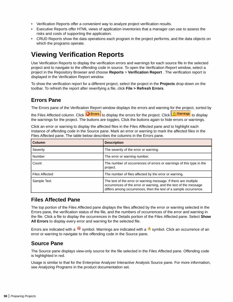
• Verification Reports offer a convenient way to analyze project verification results.• Executive Reports offer HTML views of application inventories that a manager can use to assess the
risks and costs of supporting the application.• CRUD Reports show the data operations each program in the project performs, and the data objects on
which the programs operate.
Viewing Verification ReportsUse Verification Reports to display the verification errors and warnings for each source file in the selectedproject and to navigate to the offending code in source. To open the Verification Report window, select aproject in the Repository Browser and choose Reports > Verification Report . The verification report isdisplayed in the Verification Report window.
To show the verification report for a different project, select the project in the Projects drop-down on thetoolbar. To refresh the report after reverifying a file, click File > Refresh Errors.
Errors PaneThe Errors pane of the Verification Report window displays the errors and warning for the project, sorted by
the Files Affected column. Click to display the errors for the project. Click to displaythe warnings for the project. The buttons are toggles. Click the buttons again to hide errors or warnings.
Click an error or warning to display the affected files in the Files Affected pane and to highlight eachinstance of offending code in the Source pane. Mark an error or warning to mark the affected files in theFiles Affected pane. The table below describes the columns in the Errors pane.
Column Description
Severity The severity of the error or warning.
Number The error or warning number.
Count The number of occurrences of errors or warnings of this type in theproject.
Files Affected The number of files affected by the error or warning.
Sample Text The text of the error or warning message. If there are multipleoccurrences of the error or warning, and the text of the messagediffers among occurrences, then the text of a sample occurrence.
Files Affected PaneThe top portion of the Files Affected pane displays the files affected by the error or warning selected in theErrors pane, the verification status of the file, and the numbers of occurrences of the error and warning inthe file. Click a file to display the occurrences in the Details portion of the Files Affected pane. Select ShowAll Errors to display every error and warning for the selected file.
Errors are indicated with a symbol. Warnings are indicated with a symbol. Click an occurrence of anerror or warning to navigate to the offending code in the Source pane.
Source PaneThe Source pane displays view-only source for the file selected in the Files Affected pane. Offending codeis highlighted in red.
Usage is similar to that for the Enterprise Analyzer Interactive Analysis Source pane. For more information,see Analyzing Programs in the product documentation set.
98 | Preparing Projects
Marking ItemsTo mark an item, place a check mark next to it. To mark all the items in the selected tab, choose Edit >Mark All. To unmark all the items in the selected tab, choose Edit > Unmark All.
Including Files into ProjectsIn very large workspaces, you may find it useful to move or copy files into different projects based on theerrors they contain. Follow the instructions below to move or copy files listed in a Verification Report into aproject.
1. In the Files Affected pane, mark the items you want to move and choose File > Include Into Project.The Select Project window opens.
2. In the Select Project window, select the target project. Click New to create a new project.
3. Select either:
• Include All Referenced Objects if you want to include objects referenced by the selected object(the Cobol copybooks included in a Cobol program file, for example).
• Include All Referencing Objects if you want to include objects that reference the selected object.
Note: This feature is available only for verified files.
4. Select:
• Copy to copy the selection to the target project.• Move From Current Project to move the selection to the target project.• Move From All Projects to move the selection from all projects to the target project.
5. Click OK to move or copy the selection.
Generating HTML ReportsTo generate HTML reports of Verification Report results, choose File > Report > <Report Type>. Beforegenerating the Details for Checked Files report, mark each file on which you want to report.
Tip: The Missing Files reports are a convenient alternative to an Unresolved Report when you areinterested only in missing source files, and not in unresolved objects like system programs. You cangenerate a missing files report for a project or for the entire workspace.
Viewing Executive ReportsExecutive Reports offer HTML views of application inventories that a manager can use to assess the risksand costs of supporting the application:
• The Application Summary view gives statistics for industry-standard metrics such as program volume,maintainability, cyclomatic complexity, and number of defects.
• The Potential Code Anomalies view gives statistics for potential code anomalies that may markprograms as candidates for re-engineering: GOTO non-exits, range overlaps, and the like. You cancustomize potential code anomalies using the Define Anomalies feature. To get potential codeanomalies to appear on the report, select the Code Defects option on the Options > Project Options> Reports > Executive Report tab.
Note: You must set Detect Potential Code Anomalies in the Verification > Settings tab of theWorkspace Options window to generate these statistics.
• The Repository Statistics view gives statistics for Enterprise Analyzer verification results and unresolvedor unreferenced application elements.
• The Standard Deviations view displays graphs that plot the deviation of the programs in the applicationfrom the means for six key industry-standard metrics.
Preparing Projects | 99
To generate an Executive Report, choose Reports > Executive Report . Project options on the Options >Project Options > Reports > Executive Report tab determine the entities included in the report, and thefunctions the report performs. The report is stored in \<Workspace Home>\Output\ExecutiveReport\Project\index.htm.
The figure below shows an Executive Report. The top page in each view displays the available statisticsand graphs. Click the links to view the detail for each type of statistic or graph. In the statistic or graphdetail page, click the link for a program to view the detail for that program.
Note: After generating an Executive Report, use the Executive Report category in the InteractiveAnalysis Code Search tool to view potential code anomalies in program context.
Setting Executive Report OptionsUse the Report > Executive Report tab of the Project Options window to specify the entities included inexecutive reports, and the functions the report performs. Generally, the fewer entities and functions youchoose, the better report generation performance you can expect. You should especially consider notreporting on:
• Detail for code anomalies. Leave Generate Details unchecked.• Data stores. Leave data store entities unchecked.• Relationships, if you do not need cross-reference information. Leave Relationships unchecked.
1. Choose Options > Project Options. The Project Options window opens. Click the Report tab, then theExecutive Report tab.
2. Click Functionality, then select each report function you want to enable. For the Application Summaryfunction, click Select Metrics. In the Application Summary (Averages) window, select ApplicationSummary (Averages) to enable the function, then choose each metric you want to include in thereport.
3. Select each type of entity you want to include in the report. To edit the attributes included in the reportfor the entity type, click Attributes. In the Attributes window, select each attribute of the selected entitytype to include in the report.
Defining Potential Code AnomaliesYou can view and modify existing definitions of potential code anomalies (other than range overlaps andrange jumps) in the Interactive Analysis advanced search criteria in the Coding Standards folder.
To define a new code anomaly, you must define an advanced search criterion for the anomaly and amatching entry in the file <EA Home>\Data\CodeDefects.xml. The entry has the form:
<DEFECT Id="name"Internal="True|False"Enabled="True|False"Caption="display name"ListName="list name"Criterion="path of criterion"Model="Model Type"/>
where:
• Id is a unique name identifying the code anomaly in the product.• Internal specifies whether the anomaly is implemented internally in program code (True), or
externally in an advanced search criterion (False).
Note: You must specify False. Code anomalies with an Internal value of True cannot be modified.
• Enabled specifies whether the code anomaly is displayed in the Executive Report.• Caption is the display name for the anomaly in the Executive Report.
100 | Preparing Projects
• ListName is the name of the list of anomalous code constructs displayed in the Executive Reportcategory of the Interactive Analysis Code Search tool.
• Criterion is the full path name of the criterion in the Interactive Analysis Advanced Search tool,including the tab name (General) and any folder names. For example, General:Coding Standards\MOVE Statements\Possible Data Padding.
• Model is the Interactive Analysis model for the source files to be searched, e.g., "COBOL".
Some of the commonly used model types are:
• COBOL - COBOL source files• JAVAFILE - Java source files• JCL - JCL source files• NATURAL - NATURAL source files• PLI - PL/I source files
Note: Not all possible model types are listed above. Some model types like PL/SQL files do nothave level 2 support, so cannot have Code Search queries run against them. For moreinformation, see Supported Features by Language.
For some languages, such as C and C++, there are no pre-defined Code Search queries, so theyhave not been listed.
Note: You can find the full list of models in the Enterprise Analyzer installation directory, under\Model\HyperCode. You can find the exact name of the model to use in the CodeDefects.xmlin the model file itself. For example, you can find the model name for COBOL in the NAME attributein the following line in the Cobol.xml file:
<HYPERCODEMODEL NAME="COBOL" DESCRIPTION="COBOL Programs" VERSION="1.1">
Note: To get the code anomalies to appear on the report, you need to not only enable the Codedefect entry, but to also select the Code Defects option from Project Options > Reports > ExecutiveReport.
The following are examples of different defect entries:
<DEFECT Criterion="General:Coding Standards\MOVE Statements\Possible Sign Loss" ListName="Possible Sign Loss" Caption="Possible Sign Loss" Group="Cobol Coding Standards" Enabled="True" Internal="False" Id="Sign" Model="COBOL"/>
<DEFECT Criterion="General:Coding Standards\Unaligned Assignments" ListName="Unaligned Assignment" Caption="Unaligned Assignment" Group="Pli Coding Standards" Enabled="True" Internal="False" Id="Unaligned" Model="PLI"/>
<DEFECT Criterion="General:Java Best Practices\Basic\Empty If Statements" ListName="Empty If Stats" Caption="Empty If Statements" Group="Java Results" Enabled="True" Internal="False" Id="EmpIfStnts" Model="JAVAFILE"/>
Preparing Projects | 101
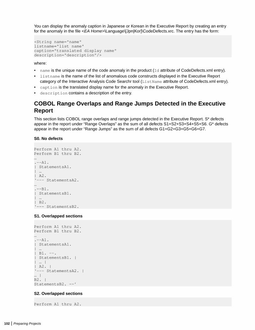
You can display the anomaly caption in Japanese or Korean in the Executive Report by creating an entryfor the anomaly in the file <EA Home>\Language\[Jpn|Kor]\CodeDefects.xrc. The entry has the form:
<String name="name"listname="list name"caption="translated display name"description="description"/>
where:
• name is the unique name of the code anomaly in the product (Id attribute of CodeDefects.xml entry).• listname is the name of the list of anomalous code constructs displayed in the Executive Report
category of the Interactive Analysis Code Searchr tool (ListName attribute of CodeDefects.xml entry).• caption is the translated display name for the anomaly in the Executive Report.• description contains a description of the entry.
COBOL Range Overlaps and Range Jumps Detected in the ExecutiveReportThis section lists COBOL range overlaps and range jumps detected in the Executive Report. S* defectsappear in the report under “Range Overlaps” as the sum of all defects S1+S2+S3+S4+S5+S6. G* defectsappear in the report under “Range Jumps” as the sum of all defects G1+G2+G3+G5+G6+G7.
S0. No defects
Perform A1 thru A2.Perform B1 thru B2.….--A1.| StatementsA1.| …| A2.‘--- StatementsA2.….--B1.| StatementsB1.| …| B2.‘--- StatementsB2.
S1. Overlapped sections
Perform A1 thru A2.Perform B1 thru B2.….--A1.| StatementsA1.| …| B1. --.| StatementsB1. || … || A2. |‘--- StatementsA2. |… |B2. |StatementsB2. –-’
S2. Overlapped sections
Perform A1 thru A2.
102 | Preparing Projects
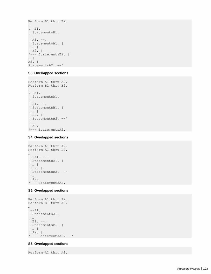
Perform B1 thru B2.….--B1.| StatementsB1.| …| A1. --.| StatementsA1. || … || B2. |‘--- StatementsB2. |… |A2. |StatementsA2. –-’
S3. Overlapped sections
Perform A1 thru A2.Perform B1 thru B2.….--A1.| StatementsA1.| …| B1. --.| StatementsB1. || … || B2. || StatementsB2. –-’| …| A2.‘--- StatementsA2.
S4. Overlapped sections
Perform A1 thru A2.Perform A1 thru B2.….--A1. --.| StatementsA1. || … || B2. || StatementsB2. –-’| …| A2.‘--- StatementsA2.
S5. Overlapped sections
Perform A1 thru A2.Perform B1 thru A2.….--A1.| StatementsA1.| …| B1. --.| StatementsB1. || … || A2. |‘--- StatementsA2. --’
S6. Overlapped sections
Perform A1 thru A2.
Preparing Projects | 103
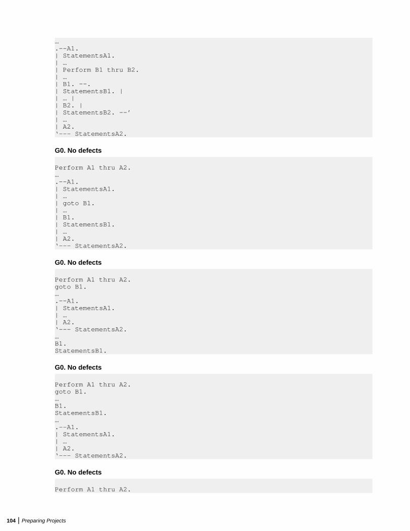
….--A1.| StatementsA1.| …| Perform B1 thru B2.| …| B1. --.| StatementsB1. || … || B2. || StatementsB2. –-’| …| A2.‘--- StatementsA2.
G0. No defects
Perform A1 thru A2.….--A1.| StatementsA1.| …| goto B1.| …| B1.| StatementsB1.| …| A2.‘--- StatementsA2.
G0. No defects
Perform A1 thru A2.goto B1.….--A1.| StatementsA1.| …| A2.‘--- StatementsA2.…B1.StatementsB1.
G0. No defects
Perform A1 thru A2.goto B1.…B1.StatementsB1.….--A1.| StatementsA1.| …| A2.‘--- StatementsA2.
G0. No defects
Perform A1 thru A2.
104 | Preparing Projects
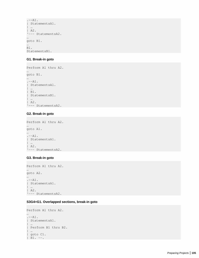
.--A1.| StatementsA1.| …| A2.‘--- StatementsA2.…goto B1.…B1.StatementsB1.
G1. Break-in goto
Perform A1 thru A2.…goto B1.….--A1.| StatementsA1.| …| B1.| StatementsB1.| …| A2.‘--- StatementsA2.
G2. Break-in goto
Perform A1 thru A2.…goto A1.….--A1.| StatementsA1.| …| A2.‘--- StatementsA2.
G3. Break-in goto
Perform A1 thru A2.…goto A2.….--A1.| StatementsA1.| …| A2.‘--- StatementsA2.
S3G4=G1. Overlapped sections, break-in goto
Perform A1 thru A2.….--A1.| StatementsA1.| …| Perform B1 thru B2.| …| goto C1.| B1. --.
Preparing Projects | 105
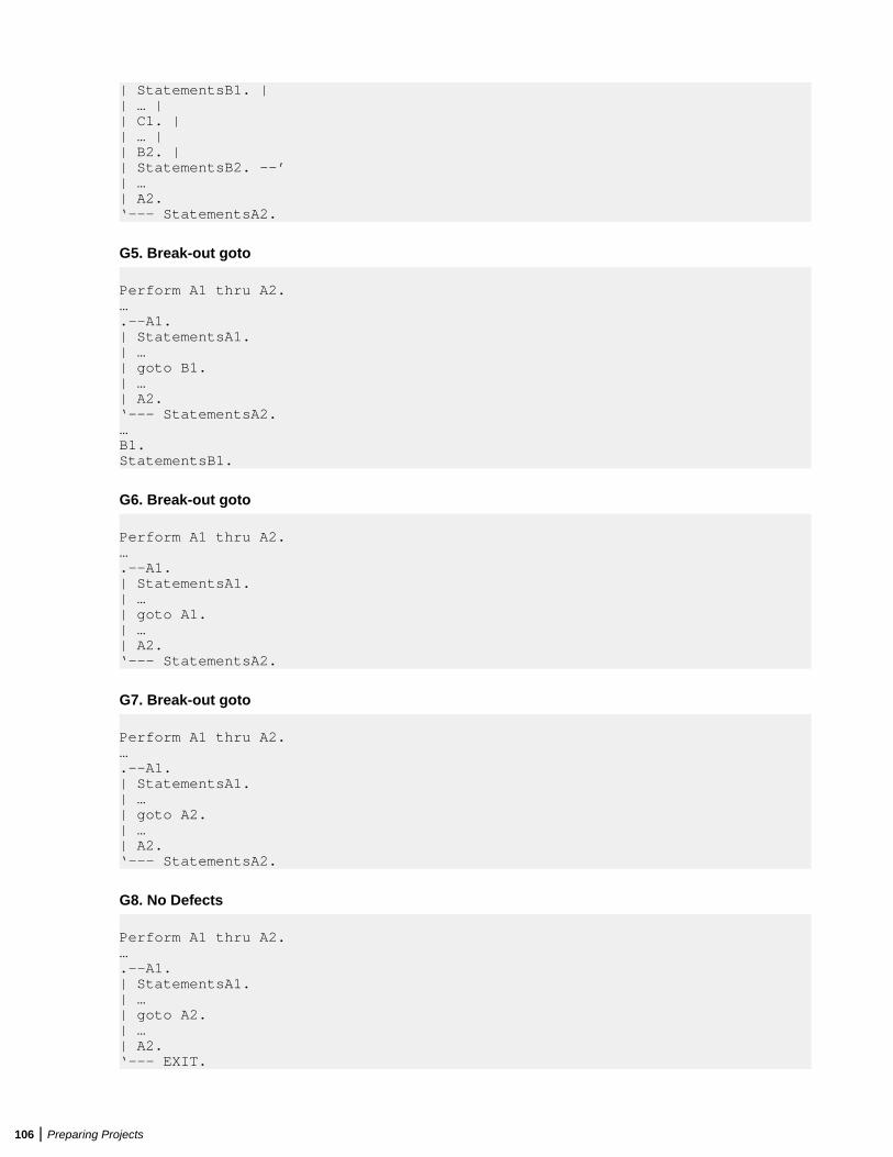
| StatementsB1. || … || C1. || … || B2. || StatementsB2. –-’| …| A2.‘--- StatementsA2.
G5. Break-out goto
Perform A1 thru A2.….--A1.| StatementsA1.| …| goto B1.| …| A2.‘--- StatementsA2.…B1.StatementsB1.
G6. Break-out goto
Perform A1 thru A2.….--A1.| StatementsA1.| …| goto A1.| …| A2.‘--- StatementsA2.
G7. Break-out goto
Perform A1 thru A2.….--A1.| StatementsA1.| …| goto A2.| …| A2.‘--- StatementsA2.
G8. No Defects
Perform A1 thru A2.….--A1.| StatementsA1.| …| goto A2.| …| A2.‘--- EXIT.
106 | Preparing Projects
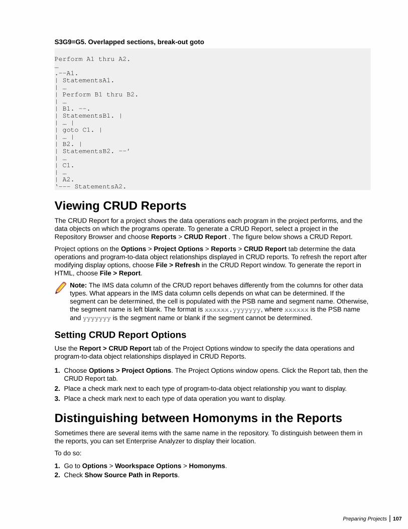
S3G9=G5. Overlapped sections, break-out goto
Perform A1 thru A2.….--A1.| StatementsA1.| …| Perform B1 thru B2.| …| B1. --.| StatementsB1. || … || goto C1. || … || B2. || StatementsB2. –-’| …| C1.| …| A2.‘--- StatementsA2.
Viewing CRUD ReportsThe CRUD Report for a project shows the data operations each program in the project performs, and thedata objects on which the programs operate. To generate a CRUD Report, select a project in theRepository Browser and choose Reports > CRUD Report . The figure below shows a CRUD Report.
Project options on the Options > Project Options > Reports > CRUD Report tab determine the dataoperations and program-to-data object relationships displayed in CRUD reports. To refresh the report aftermodifying display options, choose File > Refresh in the CRUD Report window. To generate the report inHTML, choose File > Report.
Note: The IMS data column of the CRUD report behaves differently from the columns for other datatypes. What appears in the IMS data column cells depends on what can be determined. If thesegment can be determined, the cell is populated with the PSB name and segment name. Otherwise,the segment name is left blank. The format is xxxxxx.yyyyyyy, where xxxxxx is the PSB nameand yyyyyyy is the segment name or blank if the segment cannot be determined.
Setting CRUD Report OptionsUse the Report > CRUD Report tab of the Project Options window to specify the data operations andprogram-to-data object relationships displayed in CRUD Reports.
1. Choose Options > Project Options. The Project Options window opens. Click the Report tab, then theCRUD Report tab.
2. Place a check mark next to each type of program-to-data object relationship you want to display.
3. Place a check mark next to each type of data operation you want to display.
Distinguishing between Homonyms in the ReportsSometimes there are several items with the same name in the repository. To distinguish between them inthe reports, you can set Enterprise Analyzer to display their location.
To do so:
1. Go to Options > Woorkspace Options > Homonyms.2. Check Show Source Path in Reports.
Preparing Projects | 107
Note: This option is unchecked by default.
When Show Source Path in Reports is enabled, the Complexity Metrics report, Unresolved Report, CrossReference Report, and CRUD Report will contain a column showing the path with the file name todistinguish between objects with the same name. In the Complexity Metrics report the column is calledSource Path.
Inventorying ApplicationsUsers often ask why the Enterprise Analyzer parser encounters errors in working production systems. Thereasons usually have to do with the source file delivery mechanism: incorrect versions or copybooks,corruption of special characters because of source code ambiguities, FTP errors, and so forth.
Use Enterprise Analyzer inventory analysis tools to ensure that all parts of your application are available tothe parser:
• Reference Reports let you track referential dependencies in verified source.• Orphan Analysis lets you analyze and resolve objects that do not exist in the reference tree for any top-
level program object, so-called orphans. Orphans can be removed from a system without altering itsbehavior.
• Decision Resolution identifies and lets you resolve dynamic calls and other relationships that the parsercannot resolve from static sources in Cobol, PL/I, and Natural programs.
Using Reference ReportsWhen you verify a legacy application, the parser generates a model of the application that describes theobjects in the application and how they interact. If a Cobol source file contains a COPY statement, forexample, the system creates a relationship between the file and the Cobol copybook referenced by thestatement. If the copybook doesn’t exist in the repository, the system flags it as missing by listing it with a
symbol in the tree view of the Repository Browser.
Reference Reports let you track these kinds of referential dependencies in verified source:
• An Unresolved Report identifies missing application elements.• An Unreferred Report identifies unreferenced application elements.• A Cross-reference Report identifies all application references.• An External Reference Report identifies references in object-oriented applications to external files that
are not registered in the workspace, such as .java, Java Archive (JAR), or C++ include files (assumingyou have identified the locations of these files in the Workspace Verification options window for thesource files). These references are not reported as unresolved in the Unresolved Report.
Tip: The Missing Files report in the Verification Report tool is a convenient alternative to anUnresolved Report when you are interested only in missing source files, and not in unresolved objectslike system programs.
Understanding the Reference Reports WindowUse Reference Reports to track referential dependencies in verified project source. To open the ReferenceReports window, select a project in the Repository Browser and choose Reports > Reference Reports .
When the Reference Reports window opens, choose the Reference Report type in the Report type drop-down. To limit the report to references in the current project, choose View > Restrict References toProject. To generate the report in HTML, choose File > Report.
The figure below shows an Unreferred Report window. The windows for the other reports are similar. Bydefault, all Reference Report panes are displayed. Select the appropriate choice in the View menu to hidea pane. Select the choice again to show the pane.
108 | Preparing Projects
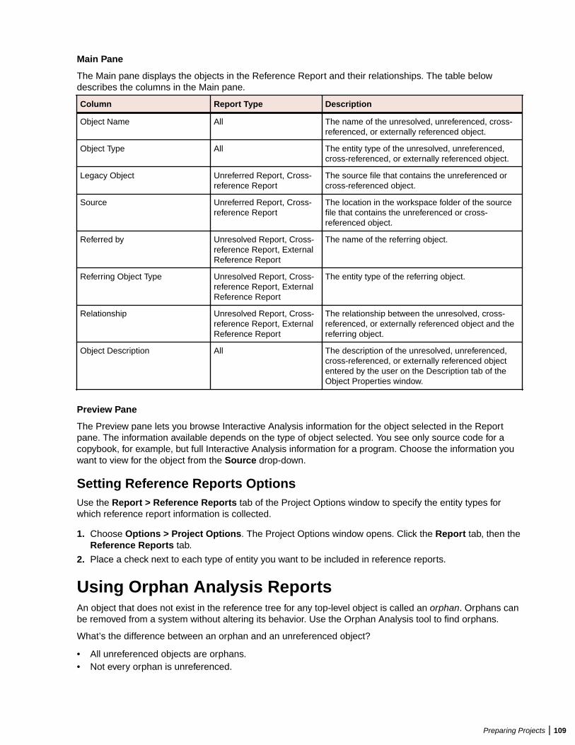
Main Pane
The Main pane displays the objects in the Reference Report and their relationships. The table belowdescribes the columns in the Main pane.
Column Report Type Description
Object Name All The name of the unresolved, unreferenced, cross-referenced, or externally referenced object.
Object Type All The entity type of the unresolved, unreferenced,cross-referenced, or externally referenced object.
Legacy Object Unreferred Report, Cross-reference Report
The source file that contains the unreferenced orcross-referenced object.
Source Unreferred Report, Cross-reference Report
The location in the workspace folder of the sourcefile that contains the unreferenced or cross-referenced object.
Referred by Unresolved Report, Cross-reference Report, ExternalReference Report
The name of the referring object.
Referring Object Type Unresolved Report, Cross-reference Report, ExternalReference Report
The entity type of the referring object.
Relationship Unresolved Report, Cross-reference Report, ExternalReference Report
The relationship between the unresolved, cross-referenced, or externally referenced object and thereferring object.
Object Description All The description of the unresolved, unreferenced,cross-referenced, or externally referenced objectentered by the user on the Description tab of theObject Properties window.
Preview Pane
The Preview pane lets you browse Interactive Analysis information for the object selected in the Reportpane. The information available depends on the type of object selected. You see only source code for acopybook, for example, but full Interactive Analysis information for a program. Choose the information youwant to view for the object from the Source drop-down.
Setting Reference Reports OptionsUse the Report > Reference Reports tab of the Project Options window to specify the entity types forwhich reference report information is collected.
1. Choose Options > Project Options. The Project Options window opens. Click the Report tab, then theReference Reports tab.
2. Place a check next to each type of entity you want to be included in reference reports.
Using Orphan Analysis ReportsAn object that does not exist in the reference tree for any top-level object is called an orphan. Orphans canbe removed from a system without altering its behavior. Use the Orphan Analysis tool to find orphans.
What’s the difference between an orphan and an unreferenced object?
• All unreferenced objects are orphans.• Not every orphan is unreferenced.
Preparing Projects | 109
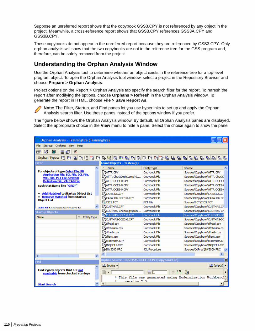
Suppose an unreferred report shows that the copybook GSS3.CPY is not referenced by any object in theproject. Meanwhile, a cross-reference report shows that GSS3.CPY references GSS3A.CPY andGSS3B.CPY.
These copybooks do not appear in the unreferred report because they are referenced by GSS3.CPY. Onlyorphan analysis will show that the two copybooks are not in the reference tree for the GSS program and,therefore, can be safely removed from the project.
Understanding the Orphan Analysis WindowUse the Orphan Analysis tool to determine whether an object exists in the reference tree for a top-levelprogram object. To open the Orphan Analysis tool window, select a project in the Repository Browser andchoose Prepare > Orphan Analysis.
Project options on the Report > Orphan Analysis tab specify the search filter for the report. To refresh thereport after modifying the options, choose Orphans > Refresh in the Orphan Analysis window. Togenerate the report in HTML, choose File > Save Report As.
Note: The Filter, Startup, and Find panes let you use hyperlinks to set up and apply the OrphanAnalysis search filter. Use these panes instead of the options window if you prefer.
The figure below shows the Orphan Analysis window. By default, all Orphan Analysis panes are displayed.Select the appropriate choice in the View menu to hide a pane. Select the choice again to show the pane.
110 | Preparing Projects
Found Objects Pane
The Found Objects pane shows the name, type, and source location of orphans. To show the list oforphans only, deselect View > Report View.
Orphan Source Pane
The Orphan Source pane lets you browse Interactive Analysis information for the object selected in theFound Objects pane. The information available depends on the type of object selected. You see onlysource code for a copybook, for example, but full Interactive Analysis information for a program. Choosethe information you want to view for the object from the Source drop-down.
Setting Orphan Analysis OptionsUse the Report > Orphan Analysis tab of the Project Options window to specify the search filter for anOrphan Analysis report.
1. Choose Options > Project Options. The Project Options window opens. Click the Report tab, then theOrphan Analysis tab.
2. In the Startup pane, click Select Startup Types. The Startup dialog opens.
3. In the Startup dialog, set up a search filter for the startup objects in the orphan analysis. You can filteron entity type, entity name, or both:
• To filter on entity type, place a check next to the entity type you want to search for in the Roots pane.• To filter on entity name, place a check next to a recognized matching pattern in the Like pane, the
Unlike pane, or both. Add patterns as necessary. You can use wildcard patterns allowed in LIKEstatements by Visual Basic for Applications (VBA).
4. When you are satisfied with your choices in the Startup dialog, click OK.
5. In the Find pane, define the terms of the search by selecting the appropriate choice in theRelationships to Checked Startups drop-down, the Relationships to Unchecked Startups drop-down, or both.
6. In the Entities pane, click Displayed Types. The Entities dialog opens. In the Entities dialog, place acheck next to each type of entity to include in the report. When you are satisfied with your choices in theEntities dialog, click OK.
Deleting Orphans from a ProjectTo delete an orphan from a project (but not the workspace), select the orphan in the Found Objects paneand choose Orphans > Exclude from Project.
Deleting Orphans from a WorkspaceTo delete an orphan from the workspace, select the orphan in the Found Objects pane and chooseOrphans > Delete from Workspace.
Resolving DecisionsYou need to have a complete picture of the control and data flows in a legacy application before you candiagram and analyze the application. The parser models the control and data transfers it can resolve fromstatic sources. Some transfers, however, are not resolved until run time. Decision resolution lets youidentify and resolve dynamic calls and other relationships that the parser cannot resolve from staticsources.
Preparing Projects | 111

Understanding DecisionsA decision is a reference to another object, a program or screen, for example, that is not resolved until runtime. Consider a Cobol program that contains the following statement:
CALL ‘NEXTPROG’.
The Enterprise Analyzer parser models the transfer of control to program NEXTPROG by creating a Callsrelationship between the original program and NEXTPROG.
But what if the statement read this way instead:
CALL NEXT.
where NEXT is a field whose value is only determined at run time. In this case, the parser creates a Callsrelationship between the program and an abstract decision object called PROG.CALL.NEXT, and lists the
decision object with a icon in the tree view of the Repository Browser.
The Decision Resolution tool creates a list of such decisions and helps you navigate to the program sourcecode that indicates how the decision should be resolved. You may learn from a declaration or MOVEstatement, for example, that the NEXT field takes either the value NEXTPROG or ENDPROG at run time.In that case, you would resolve the decision manually by telling the system to create resolves torelationships between the decision and the programs these literals reference.
Of course, where there are hundreds or even thousands of such decisions in an application, it may not bepractical to resolve each decision manually. In these situations, you can use the autoresolve feature toresolve decisions automatically.
The Decision Resolution tool analyzes declarations and MOVE statements, and any other means ofpopulating a decision point, to determine the target of the control or data transfer. The tool may not be ableto autoresolve every decision, or even every decision completely, but it should get you to a point where it ispractical to complete decision resolution manually.
Understanding the Decision Resolution Tool WindowUse the Decision Resolution tool to view and manually resolve decisions. To open the Decision Resolutiontool window, select a project in the Repository Browser and choose Prepare > Resolve Decisions.
To save decision resolutions to the repository, choose File > Save. To generate the Decision Resolutionreport in HTML, choose File > Report.
The figure below shows the Decision Resolution window. By default, all Decision Resolution panes aredisplayed. Select the appropriate choice in the View menu to hide a pane. Select the choice again to showthe pane.
112 | Preparing Projects
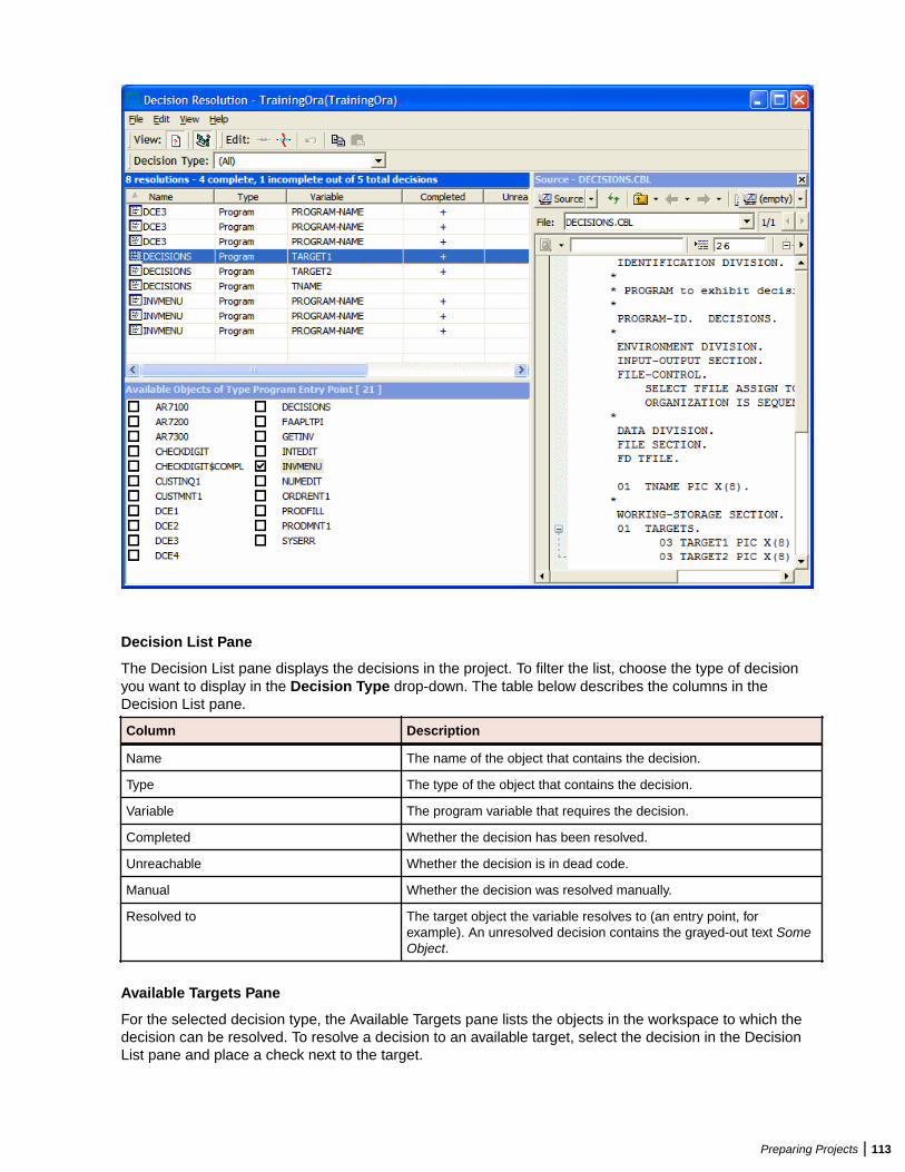
Decision List Pane
The Decision List pane displays the decisions in the project. To filter the list, choose the type of decisionyou want to display in the Decision Type drop-down. The table below describes the columns in theDecision List pane.
Column Description
Name The name of the object that contains the decision.
Type The type of the object that contains the decision.
Variable The program variable that requires the decision.
Completed Whether the decision has been resolved.
Unreachable Whether the decision is in dead code.
Manual Whether the decision was resolved manually.
Resolved to The target object the variable resolves to (an entry point, forexample). An unresolved decision contains the grayed-out text SomeObject.
Available Targets Pane
For the selected decision type, the Available Targets pane lists the objects in the workspace to which thedecision can be resolved. To resolve a decision to an available target, select the decision in the DecisionList pane and place a check next to the target.
Preparing Projects | 113
To limit the targets to objects in the current project, choose View > Restrict to Current Project. To deletea decision resolution, uncheck the target. To undo changes, choose Edit > Undo all changes.
Source Pane
The Source pane lets you browse Interactive Analysis information for the object selected in the DecisionList pane. The information available depends on the type of object selected. You see only source code for acopybook, for example, but full Interactive Analysis information for a program. Select the information youwant to view for the object from the drop-down in the upper lefthand corner of the pane.
Resolving Decisions ManuallyFollow the instructions below to resolve decisions manually to targets in or out of the workspace.
1. To resolve decisions to available targets, select one or more entries in the Decision List pane and checkone or more target objects in the Available Targets pane. If you link an entry to multiple targets, theDecision Resolution tool creates as many entries in the Decision List pane as there are targets.
Note: If you are linking an entry to multiple targets, you can save time by selecting the targets andchoosing Edit > Link Selected Targets. You can also choose Edit > Copy to copy selectedtargets to the clipboard, then Edit > Paste to link the targets to an entry.
2. To resolve decisions to targets not in the workspace, select one or more entries in the Decision Listpane and choose Edit > Link New Target. The Link New Target window opens.
3. In the Link New Target window, enter the name of the new target in the field on the righthand side of thewindow, or populate the field by clicking a literal in the list of program literals on the Literals tab. Filterthe list by using:
• The Minimum Literal Length slider to specify the minimum number of characters the literal cancontain.
• The Maximum Literal Length slider to specify the maximum number of characters the literal cancontain.
• The Names Like field to enter a matching pattern for the literal. You can use wildcard patternsallowed in LIKE statements by Visual Basic for Applications (VBA).
4. Check Completed if you want the resolution to be marked as completed. When you are satisfied withyour entry, click OK.
Restoring Manually Resolved DecisionsReverifying a file invalidates all of its objects, including its manually resolved decisions. The decisionpersistence feature lets you restore manually resolved decisions when you return to the DecisionResolution tool.
After reverifying a file for which you have manually resolved decisions, reopen the Decision Resolution tool.A dialog box prompts you to restore manually resolved decisions. Click Yes if you want to restore thedecisions. Click No otherwise.
Note: Check Don’t show me again if you want the Decision Resolution tool to open withoutprompting you to restore manually resolved decisions. In the Decision Resolution Tool tab of the UserPreferences window, check Ask before restoring previous manual changes if you want to beprompted again.
Resolving Decisions AutomaticallyYou can autoresolve decisions during verification by setting the Resolve decisions automatically optionon the Verification tab of the Project Options window for a source file type.
For programs only, you can autoresolve decisions after verification by selecting the project, folder, or filesfor which you want to autoresolve decisions and choosing Prepare > AutoResolve Decisions. Only amaster user can autoresolve decisions in a multiuser environment.
114 | Preparing Projects
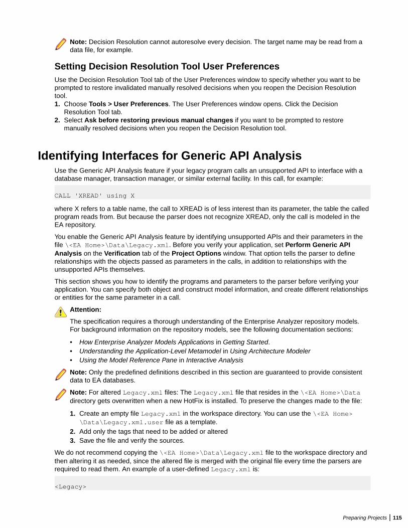
Note: Decision Resolution cannot autoresolve every decision. The target name may be read from adata file, for example.
Setting Decision Resolution Tool User PreferencesUse the Decision Resolution Tool tab of the User Preferences window to specify whether you want to beprompted to restore invalidated manually resolved decisions when you reopen the Decision Resolutiontool.1. Choose Tools > User Preferences. The User Preferences window opens. Click the Decision
Resolution Tool tab.2. Select Ask before restoring previous manual changes if you want to be prompted to restore
manually resolved decisions when you reopen the Decision Resolution tool.
Identifying Interfaces for Generic API AnalysisUse the Generic API Analysis feature if your legacy program calls an unsupported API to interface with adatabase manager, transaction manager, or similar external facility. In this call, for example:
CALL 'XREAD' using X
where X refers to a table name, the call to XREAD is of less interest than its parameter, the table the calledprogram reads from. But because the parser does not recognize XREAD, only the call is modeled in theEA repository.
You enable the Generic API Analysis feature by identifying unsupported APIs and their parameters in thefile \<EA Home>\Data\Legacy.xml. Before you verify your application, set Perform Generic APIAnalysis on the Verification tab of the Project Options window. That option tells the parser to definerelationships with the objects passed as parameters in the calls, in addition to relationships with theunsupported APIs themselves.
This section shows you how to identify the programs and parameters to the parser before verifying yourapplication. You can specify both object and construct model information, and create different relationshipsor entities for the same parameter in a call.
Attention:
The specification requires a thorough understanding of the Enterprise Analyzer repository models.For background information on the repository models, see the following documentation sections:
• How Enterprise Analyzer Models Applications in Getting Started.• Understanding the Application-Level Metamodel in Using Architecture Modeler• Using the Model Reference Pane in Interactive Analysis
Note: Only the predefined definitions described in this section are guaranteed to provide consistentdata to EA databases.
Note: For altered Legacy.xml files: The Legacy.xml file that resides in the \<EA Home>\Datadirectory gets overwritten when a new HotFix is installed. To preserve the changes made to the file:
1. Create an empty file Legacy.xml in the workspace directory. You can use the \<EA Home>\Data\Legacy.xml.user file as a template.
2. Add only the tags that need to be added or altered3. Save the file and verify the sources.
We do not recommend copying the \<EA Home>\Data\Legacy.xml file to the workspace directory andthen altering it as needed, since the altered file is merged with the original file every time the parsers arerequired to read them. An example of a user-defined Legacy.xml is:
<Legacy>
Preparing Projects | 115
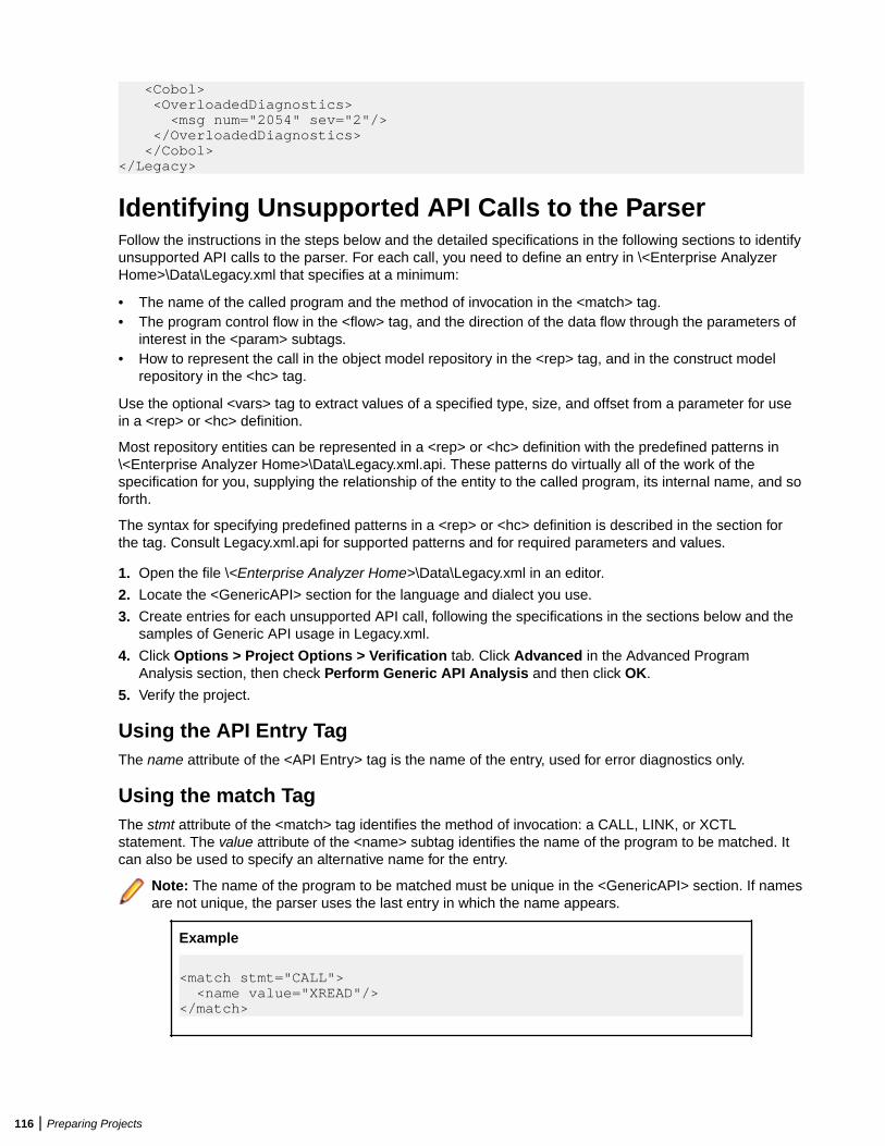
<Cobol> <OverloadedDiagnostics> <msg num="2054" sev="2"/> </OverloadedDiagnostics> </Cobol> </Legacy>
Identifying Unsupported API Calls to the ParserFollow the instructions in the steps below and the detailed specifications in the following sections to identifyunsupported API calls to the parser. For each call, you need to define an entry in \<Enterprise AnalyzerHome>\Data\Legacy.xml that specifies at a minimum:
• The name of the called program and the method of invocation in the <match> tag.• The program control flow in the <flow> tag, and the direction of the data flow through the parameters of
interest in the <param> subtags.• How to represent the call in the object model repository in the <rep> tag, and in the construct model
repository in the <hc> tag.
Use the optional <vars> tag to extract values of a specified type, size, and offset from a parameter for usein a <rep> or <hc> definition.
Most repository entities can be represented in a <rep> or <hc> definition with the predefined patterns in\<Enterprise Analyzer Home>\Data\Legacy.xml.api. These patterns do virtually all of the work of thespecification for you, supplying the relationship of the entity to the called program, its internal name, and soforth.
The syntax for specifying predefined patterns in a <rep> or <hc> definition is described in the section forthe tag. Consult Legacy.xml.api for supported patterns and for required parameters and values.
1. Open the file \<Enterprise Analyzer Home>\Data\Legacy.xml in an editor.
2. Locate the <GenericAPI> section for the language and dialect you use.
3. Create entries for each unsupported API call, following the specifications in the sections below and thesamples of Generic API usage in Legacy.xml.
4. Click Options > Project Options > Verification tab. Click Advanced in the Advanced ProgramAnalysis section, then check Perform Generic API Analysis and then click OK.
5. Verify the project.
Using the API Entry TagThe name attribute of the <API Entry> tag is the name of the entry, used for error diagnostics only.
Using the match TagThe stmt attribute of the <match> tag identifies the method of invocation: a CALL, LINK, or XCTLstatement. The value attribute of the <name> subtag identifies the name of the program to be matched. Itcan also be used to specify an alternative name for the entry.
Note: The name of the program to be matched must be unique in the <GenericAPI> section. If namesare not unique, the parser uses the last entry in which the name appears.
Example
<match stmt="CALL"> <name value="XREAD"/></match>
116 | Preparing Projects
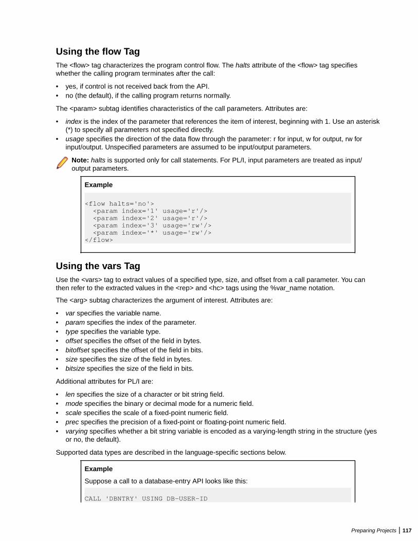
Using the flow TagThe <flow> tag characterizes the program control flow. The halts attribute of the <flow> tag specifieswhether the calling program terminates after the call:
• yes, if control is not received back from the API.• no (the default), if the calling program returns normally.
The <param> subtag identifies characteristics of the call parameters. Attributes are:
• index is the index of the parameter that references the item of interest, beginning with 1. Use an asterisk(*) to specify all parameters not specified directly.
• usage specifies the direction of the data flow through the parameter: r for input, w for output, rw forinput/output. Unspecified parameters are assumed to be input/output parameters.
Note: halts is supported only for call statements. For PL/I, input parameters are treated as input/output parameters.
Example
<flow halts='no'> <param index='1' usage='r'/> <param index='2' usage='r'/> <param index='3' usage='rw'/> <param index='*' usage='rw'/></flow>
Using the vars TagUse the <vars> tag to extract values of a specified type, size, and offset from a call parameter. You canthen refer to the extracted values in the <rep> and <hc> tags using the %var_name notation.
The <arg> subtag characterizes the argument of interest. Attributes are:
• var specifies the variable name.• param specifies the index of the parameter.• type specifies the variable type.• offset specifies the offset of the field in bytes.• bitoffset specifies the offset of the field in bits.• size specifies the size of the field in bytes.• bitsize specifies the size of the field in bits.
Additional attributes for PL/I are:
• len specifies the size of a character or bit string field.• mode specifies the binary or decimal mode for a numeric field.• scale specifies the scale of a fixed-point numeric field.• prec specifies the precision of a fixed-point or floating-point numeric field.• varying specifies whether a bit string variable is encoded as a varying-length string in the structure (yes
or no, the default).
Supported data types are described in the language-specific sections below.
Example
Suppose a call to a database-entry API looks like this:
CALL 'DBNTRY' USING DB-USER-ID
Preparing Projects | 117
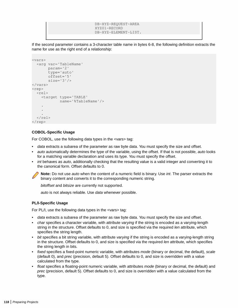
DB-XYZ-REQUEST-AREA XYZ01-RECORD DB-XYZ-ELEMENT-LIST.
If the second parameter contains a 3-character table name in bytes 6-8, the following definition extracts thename for use as the right end of a relationship:
<vars> <arg var='TableName' param='2' type='auto' offset='5' size='3'/></vars><rep> <rel> <target type='TABLE' name='%TableName'/> . . . </rel></rep>
COBOL-Specific Usage
For COBOL, use the following data types in the <vars> tag:
• data extracts a subarea of the parameter as raw byte data. You must specify the size and offset.• auto automatically determines the type of the variable, using the offset. If that is not possible, auto looks
for a matching variable declaration and uses its type. You must specify the offset.• int behaves as auto, additionally checking that the resulting value is a valid integer and converting it to
the canonical form. Offset defaults to 0.
Note: Do not use auto when the content of a numeric field is binary. Use int. The parser extracts thebinary content and converts it to the corresponding numeric string.
bitoffset and bitsize are currently not supported.
auto is not always reliable. Use data whenever possible.
PL/I-Specific Usage
For PL/I, use the following data types in the <vars> tag:
• data extracts a subarea of the parameter as raw byte data. You must specify the size and offset.• char specifies a character variable, with attribute varying if the string is encoded as a varying-length
string in the structure. Offset defaults to 0, and size is specified via the required len attribute, whichspecifies the string length.
• bit specifies a bit string variable, with attribute varying if the string is encoded as a varying-length stringin the structure. Offset defaults to 0, and size is specified via the required len attribute, which specifiesthe string length in bits.
• fixed specifies a fixed-point numeric variable, with attributes mode (binary or decimal, the default), scale(default 0), and prec (precision, default 5). Offset defaults to 0, and size is overridden with a valuecalculated from the type.
• float specifies a floating-point numeric variable, with attributes mode (binary or decimal, the default) andprec (precision, default 5). Offset defaults to 0, and size is overridden with a value calculated from thetype.
118 | Preparing Projects
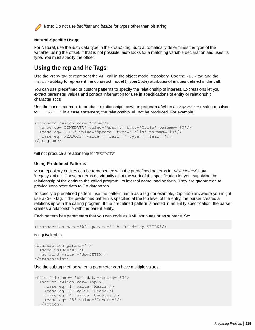
Note: Do not use bitoffset and bitsize for types other than bit string.
Natural-Specific Usage
For Natural, use the auto data type in the <vars> tag. auto automatically determines the type of thevariable, using the offset. If that is not possible, auto looks for a matching variable declaration and uses itstype. You must specify the offset.
Using the rep and hc TagsUse the <rep> tag to represent the API call in the object model repository. Use the <hc> tag and the<attr> subtag to represent the construct model (HyperCode) attributes of entities defined in the call.
You can use predefined or custom patterns to specify the relationship of interest. Expressions let youextract parameter values and context information for use in specifications of entity or relationshipcharacteristics.
Use the case statement to produce relationships between programs. When a Legacy.xml value resolvesto "__fail__" in a case statement, the relationship will not be produced. For example:
<progname switch-var='%fname'> <case eq='LINKDATA' value='%pname' type='Calls' params='%3'/> <case eq='LINK' value='%pname' type='Calls' params='%3'/> <case eq='READQTS' value='__fail__' type='__fail__'/> </progname>
will not produce a relationship for 'READQTS'
Using Predefined Patterns
Most repository entities can be represented with the predefined patterns in \<EA Home>\Data\Legacy.xml.api. These patterns do virtually all of the work of the specification for you, supplying therelationship of the entity to the called program, its internal name, and so forth. They are guaranteed toprovide consistent data to EA databases.
To specify a predefined pattern, use the pattern name as a tag (for example, <tip-file>) anywhere you mightuse a <rel> tag. If the predefined pattern is specified at the top level of the entry, the parser creates arelationship with the calling program. If the predefined pattern is nested in an entity specification, the parsercreates a relationship with the parent entity.
Each pattern has parameters that you can code as XML attributes or as subtags. So:
<transaction name='%2' params='' hc-kind='dpsSETRX'/>
is equivalent to:
<transaction params=''> <name value='%2'/> <hc-kind value ='dpsSETRX'/</transaction>
Use the subtag method when a parameter can have multiple values:
<file filename= '%2' data-record='%3'> <action switch-var='%op'> <case eq='1' value='Reads'/> <case eq='2' value='Reads'/> <case eq='4' value='Updates'/> <case eq='28' value='Inserts'/> </action>
Preparing Projects | 119
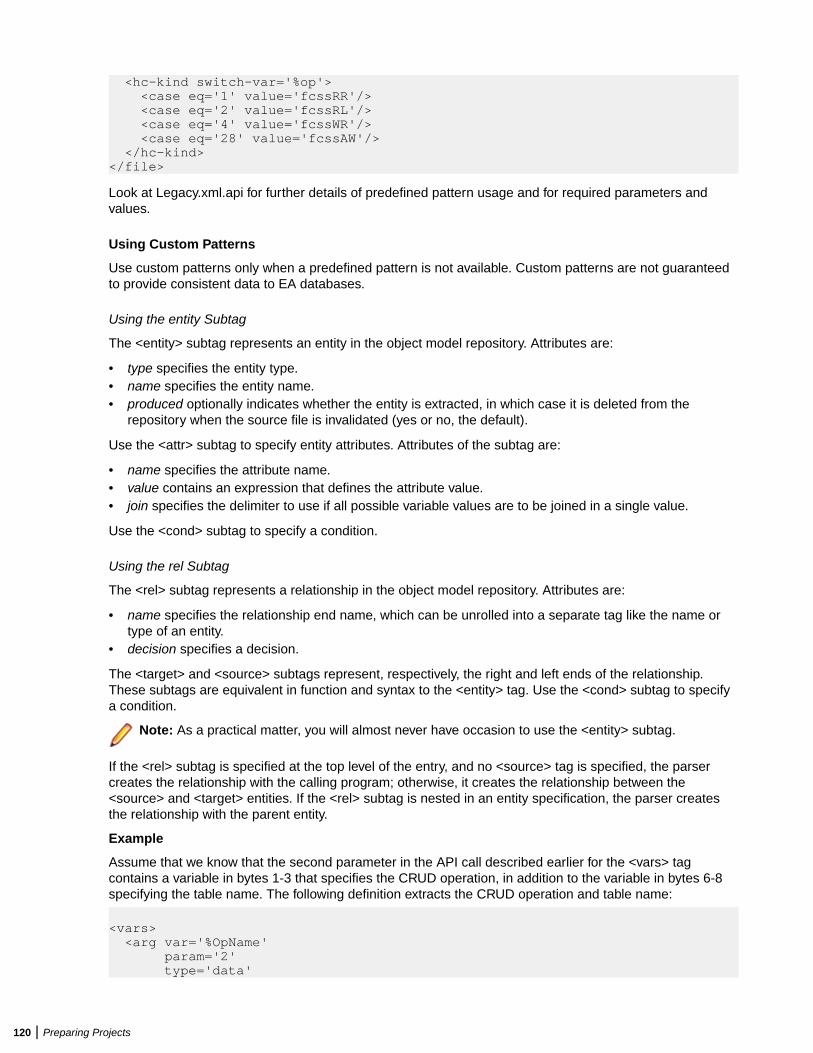
<hc-kind switch-var='%op'> <case eq='1' value='fcssRR'/> <case eq='2' value='fcssRL'/> <case eq='4' value='fcssWR'/> <case eq='28' value='fcssAW'/> </hc-kind></file>
Look at Legacy.xml.api for further details of predefined pattern usage and for required parameters andvalues.
Using Custom Patterns
Use custom patterns only when a predefined pattern is not available. Custom patterns are not guaranteedto provide consistent data to EA databases.
Using the entity Subtag
The <entity> subtag represents an entity in the object model repository. Attributes are:
• type specifies the entity type.• name specifies the entity name.• produced optionally indicates whether the entity is extracted, in which case it is deleted from the
repository when the source file is invalidated (yes or no, the default).
Use the <attr> subtag to specify entity attributes. Attributes of the subtag are:
• name specifies the attribute name.• value contains an expression that defines the attribute value.• join specifies the delimiter to use if all possible variable values are to be joined in a single value.
Use the <cond> subtag to specify a condition.
Using the rel Subtag
The <rel> subtag represents a relationship in the object model repository. Attributes are:
• name specifies the relationship end name, which can be unrolled into a separate tag like the name ortype of an entity.
• decision specifies a decision.
The <target> and <source> subtags represent, respectively, the right and left ends of the relationship.These subtags are equivalent in function and syntax to the <entity> tag. Use the <cond> subtag to specifya condition.
Note: As a practical matter, you will almost never have occasion to use the <entity> subtag.
If the <rel> subtag is specified at the top level of the entry, and no <source> tag is specified, the parsercreates the relationship with the calling program; otherwise, it creates the relationship between the<source> and <target> entities. If the <rel> subtag is nested in an entity specification, the parser createsthe relationship with the parent entity.
Example
Assume that we know that the second parameter in the API call described earlier for the <vars> tagcontains a variable in bytes 1-3 that specifies the CRUD operation, in addition to the variable in bytes 6-8specifying the table name. The following definition extracts the CRUD operation and table name:
<vars> <arg var='%OpName' param='2' type='data'
120 | Preparing Projects
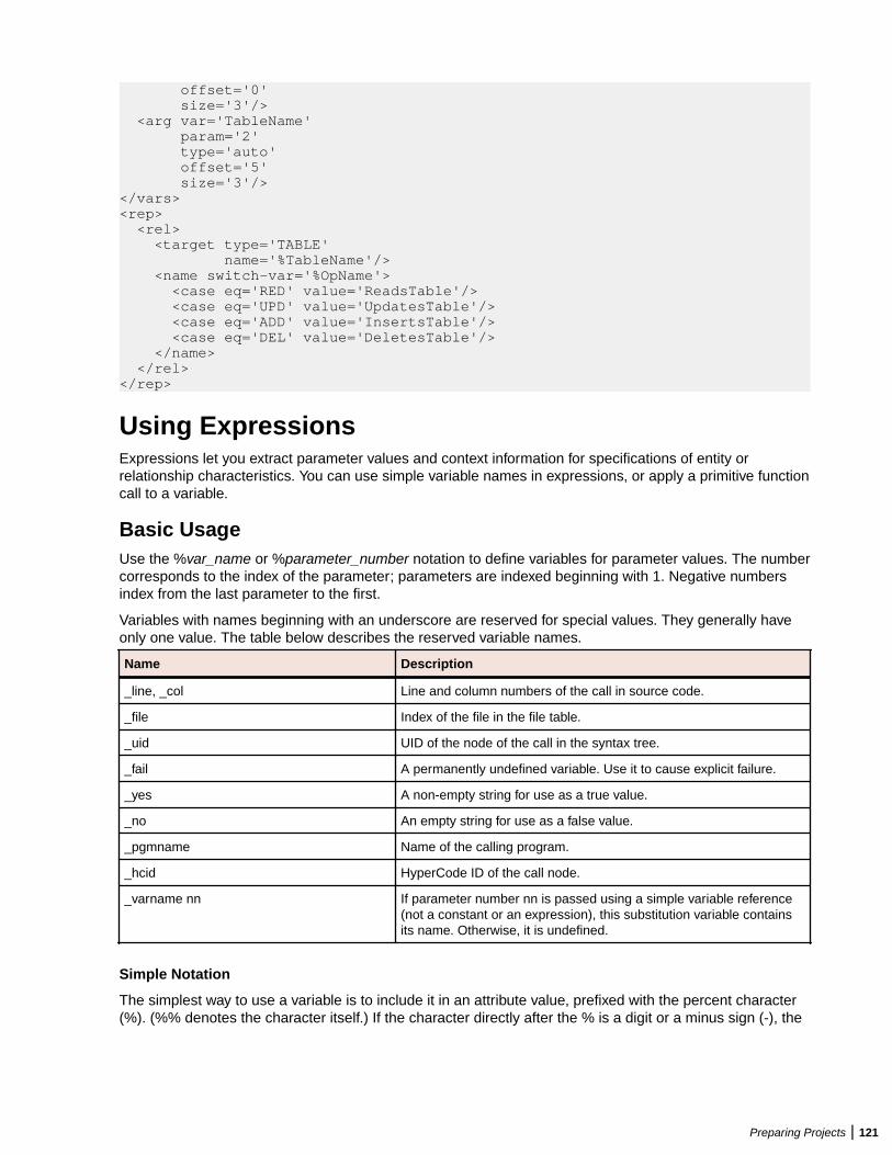
offset='0' size='3'/> <arg var='TableName' param='2' type='auto' offset='5' size='3'/></vars><rep> <rel> <target type='TABLE' name='%TableName'/> <name switch-var='%OpName'> <case eq='RED' value='ReadsTable'/> <case eq='UPD' value='UpdatesTable'/> <case eq='ADD' value='InsertsTable'/> <case eq='DEL' value='DeletesTable'/> </name> </rel></rep>
Using ExpressionsExpressions let you extract parameter values and context information for specifications of entity orrelationship characteristics. You can use simple variable names in expressions, or apply a primitive functioncall to a variable.
Basic UsageUse the %var_name or %parameter_number notation to define variables for parameter values. The numbercorresponds to the index of the parameter; parameters are indexed beginning with 1. Negative numbersindex from the last parameter to the first.
Variables with names beginning with an underscore are reserved for special values. They generally haveonly one value. The table below describes the reserved variable names.
Name Description
_line, _col Line and column numbers of the call in source code.
_file Index of the file in the file table.
_uid UID of the node of the call in the syntax tree.
_fail A permanently undefined variable. Use it to cause explicit failure.
_yes A non-empty string for use as a true value.
_no An empty string for use as a false value.
_pgmname Name of the calling program.
_hcid HyperCode ID of the call node.
_varname nn If parameter number nn is passed using a simple variable reference(not a constant or an expression), this substitution variable containsits name. Otherwise, it is undefined.
Simple Notation
The simplest way to use a variable is to include it in an attribute value, prefixed with the percent character(%). (%% denotes the character itself.) If the character directly after the % is a digit or a minus sign (-), the
Preparing Projects | 121
end of the variable name is considered to be the first non-digit character. Otherwise, the end of the name isconsidered to be the first non-alphanumeric, non-underscore character. In:
'%abc.%2def'
the first variable name is abc and the second is 2. It is also possible to specify the end of the variable nameexplicitly by enclosing the name in curly brackets:
'%{abc}.%{2}def'
When evaluated, a compound string like this produces a string value that concatenates variable values andsimple text fragments, or fails if any of the variables is undefined.
Switch Usage
Use a switch-var attribute instead of the value attribute when a tag expects a value with a compound stringexpression. The switch-var attribute contains a single variable name (which may be prefixed by %, butcannot be enclosed in curly brackets). Use <case>, <undef>, or <default> subtags to specify switch cases.These tags also expect the value attribute, so switches can be nested:
<name switch-var='%var'> <case eq='value1' value='...'/> <case eq='value2' switch-var='%var2'> <undef value='...'/> </case> <undef value='...'/> <default value='...'/></name>
When a switch is evaluated, the value of the variable specified using the switch-var attribute is matchedagainst the literal specified in the <case> tags. The literal must be the same size as the variable. (Theliterals value1 and value2 in the example assume that var is defined as having six bytes.) If anappropriate case is found, the corresponding case value is evaluated.
Set the value and type of the variable to __fail__ (two underscores) if you do not want a relationship tobe produced for the variable:
<progname switch-var="%fname"> <case eq="LINKDATA" value="%pname" type="Calls" params="%3" /> <case eq="LINK" value="%pname" type="Calls" params="%3" /> <case eq="READQTS" value="__fail__" type="__fail__" /> <default value="" /> </progname>
If the variable is undefined, and the <undef> tag is specified, its value is used; if not, the switch fails.Otherwise, if the <default> case is specified, it is used; if not, the switch fails.
Fallback Chain Usage
Whenever multiple tags specifying a single attribute are presented in a <name>, <type>, or <case>/<undef>/<default> specification, those tags are joined into a fallback chain. If an entry in the chain fails,evaluation proceeds to the next entry. Only when the last entry of the chain fails is the failure propagatedupward:
<name value='%a'/><name value='%b'/><name value='UNKNOWN'/>
If %a is defined, the name is its value. Otherwise, if %b is defined, the name is %b. Finally, if both areundefined, the name is UNKNOWN.
122 | Preparing Projects
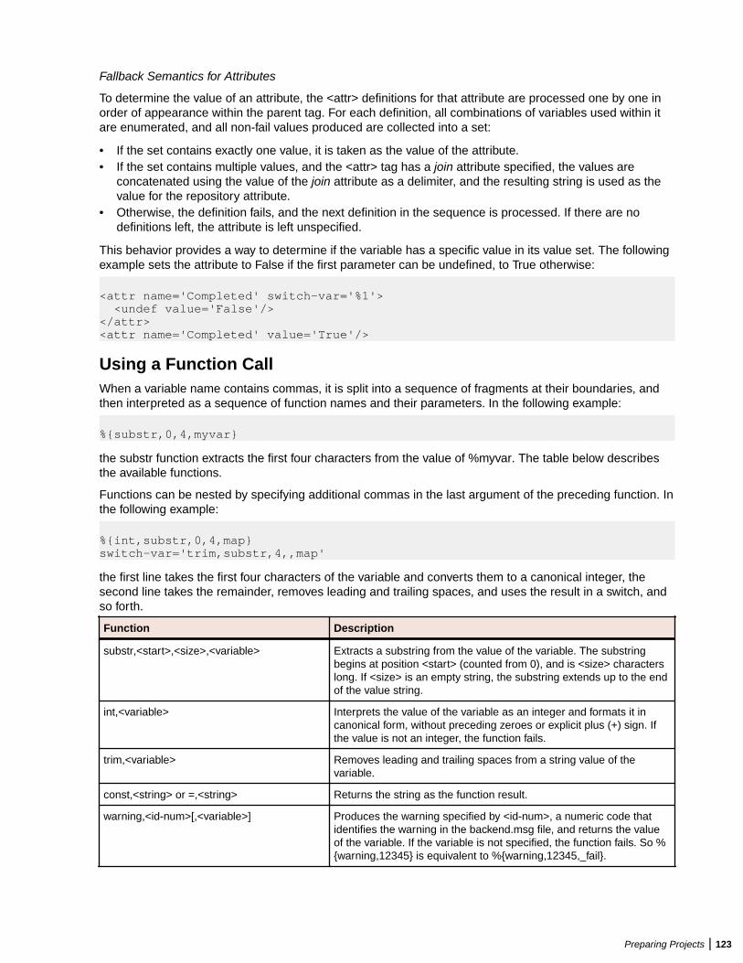
Fallback Semantics for Attributes
To determine the value of an attribute, the <attr> definitions for that attribute are processed one by one inorder of appearance within the parent tag. For each definition, all combinations of variables used within itare enumerated, and all non-fail values produced are collected into a set:
• If the set contains exactly one value, it is taken as the value of the attribute.• If the set contains multiple values, and the <attr> tag has a join attribute specified, the values are
concatenated using the value of the join attribute as a delimiter, and the resulting string is used as thevalue for the repository attribute.
• Otherwise, the definition fails, and the next definition in the sequence is processed. If there are nodefinitions left, the attribute is left unspecified.
This behavior provides a way to determine if the variable has a specific value in its value set. The followingexample sets the attribute to False if the first parameter can be undefined, to True otherwise:
<attr name='Completed' switch-var='%1'> <undef value='False'/></attr><attr name='Completed' value='True'/>
Using a Function CallWhen a variable name contains commas, it is split into a sequence of fragments at their boundaries, andthen interpreted as a sequence of function names and their parameters. In the following example:
%{substr,0,4,myvar}
the substr function extracts the first four characters from the value of %myvar. The table below describesthe available functions.
Functions can be nested by specifying additional commas in the last argument of the preceding function. Inthe following example:
%{int,substr,0,4,map}switch-var='trim,substr,4,,map'
the first line takes the first four characters of the variable and converts them to a canonical integer, thesecond line takes the remainder, removes leading and trailing spaces, and uses the result in a switch, andso forth.
Function Description
substr,<start>,<size>,<variable> Extracts a substring from the value of the variable. The substringbegins at position <start> (counted from 0), and is <size> characterslong. If <size> is an empty string, the substring extends up to the endof the value string.
int,<variable> Interprets the value of the variable as an integer and formats it incanonical form, without preceding zeroes or explicit plus (+) sign. Ifthe value is not an integer, the function fails.
trim,<variable> Removes leading and trailing spaces from a string value of thevariable.
const,<string> or =,<string> Returns the string as the function result.
warning,<id-num>[,<variable>] Produces the warning specified by <id-num>, a numeric code thatidentifies the warning in the backend.msg file, and returns the valueof the variable. If the variable is not specified, the function fails. So %{warning,12345} is equivalent to %{warning,12345,_fail}.
Preparing Projects | 123
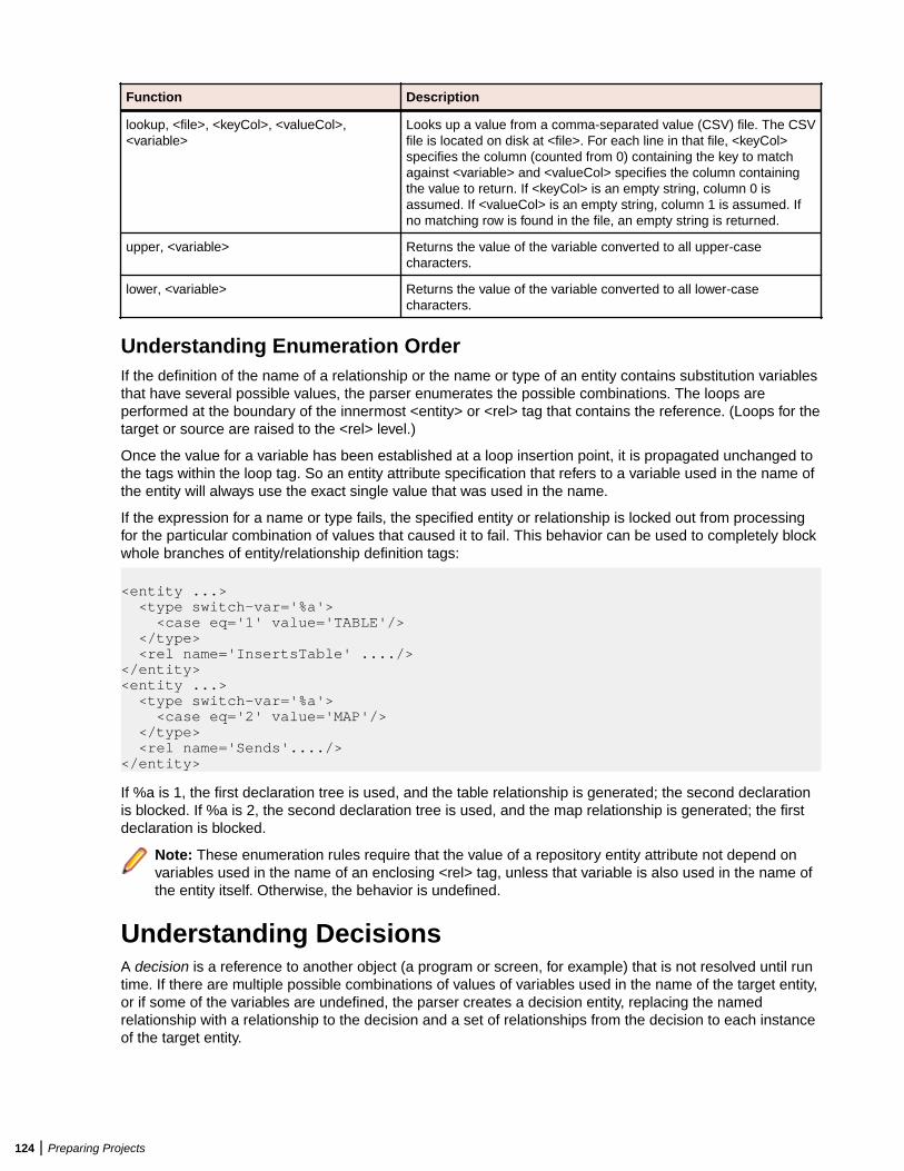
Function Description
lookup, <file>, <keyCol>, <valueCol>,<variable>
Looks up a value from a comma-separated value (CSV) file. The CSVfile is located on disk at <file>. For each line in that file, <keyCol>specifies the column (counted from 0) containing the key to matchagainst <variable> and <valueCol> specifies the column containingthe value to return. If <keyCol> is an empty string, column 0 isassumed. If <valueCol> is an empty string, column 1 is assumed. Ifno matching row is found in the file, an empty string is returned.
upper, <variable> Returns the value of the variable converted to all upper-casecharacters.
lower, <variable> Returns the value of the variable converted to all lower-casecharacters.
Understanding Enumeration OrderIf the definition of the name of a relationship or the name or type of an entity contains substitution variablesthat have several possible values, the parser enumerates the possible combinations. The loops areperformed at the boundary of the innermost <entity> or <rel> tag that contains the reference. (Loops for thetarget or source are raised to the <rel> level.)
Once the value for a variable has been established at a loop insertion point, it is propagated unchanged tothe tags within the loop tag. So an entity attribute specification that refers to a variable used in the name ofthe entity will always use the exact single value that was used in the name.
If the expression for a name or type fails, the specified entity or relationship is locked out from processingfor the particular combination of values that caused it to fail. This behavior can be used to completely blockwhole branches of entity/relationship definition tags:
<entity ...> <type switch-var='%a'> <case eq='1' value='TABLE'/> </type> <rel name='InsertsTable' ..../></entity><entity ...> <type switch-var='%a'> <case eq='2' value='MAP'/> </type> <rel name='Sends'..../></entity>
If %a is 1, the first declaration tree is used, and the table relationship is generated; the second declarationis blocked. If %a is 2, the second declaration tree is used, and the map relationship is generated; the firstdeclaration is blocked.
Note: These enumeration rules require that the value of a repository entity attribute not depend onvariables used in the name of an enclosing <rel> tag, unless that variable is also used in the name ofthe entity itself. Otherwise, the behavior is undefined.
Understanding DecisionsA decision is a reference to another object (a program or screen, for example) that is not resolved until runtime. If there are multiple possible combinations of values of variables used in the name of the target entity,or if some of the variables are undefined, the parser creates a decision entity, replacing the namedrelationship with a relationship to the decision and a set of relationships from the decision to each instanceof the target entity.
124 | Preparing Projects
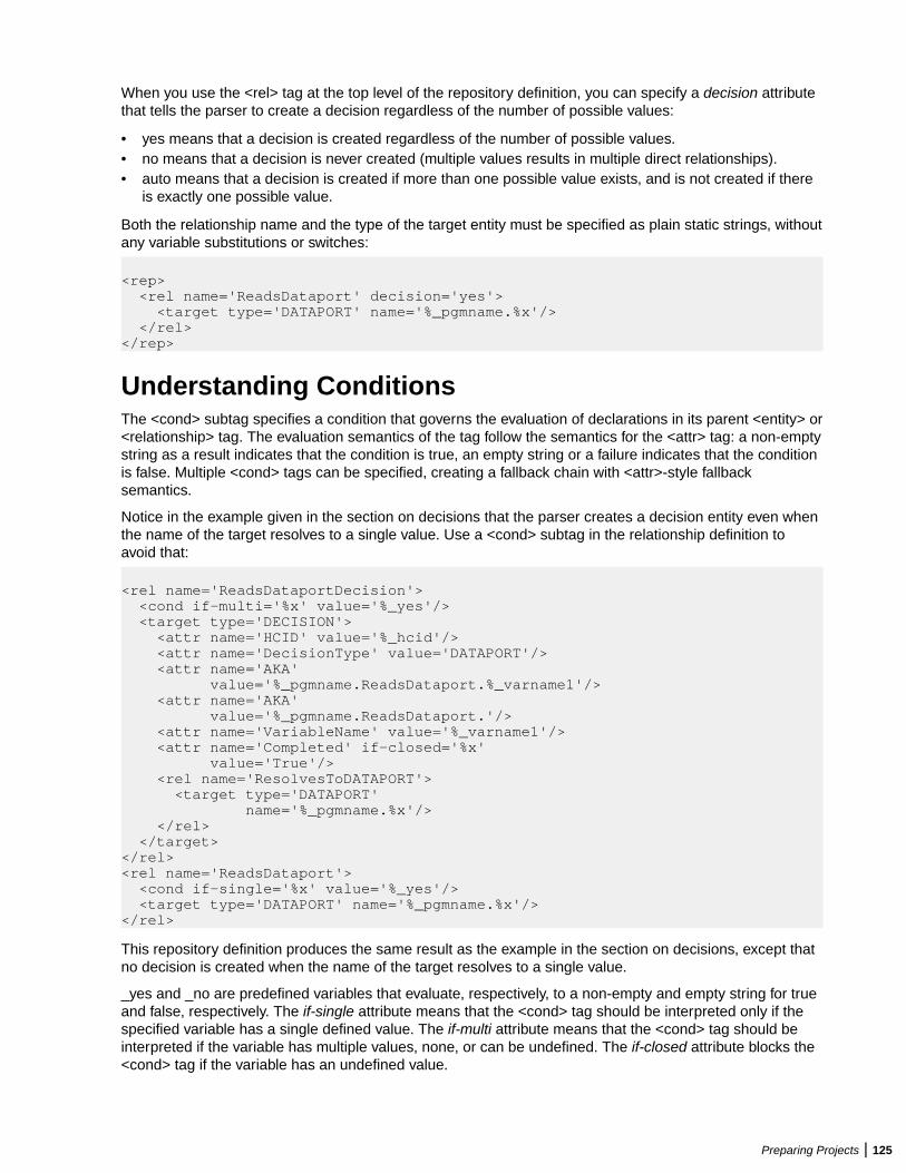
When you use the <rel> tag at the top level of the repository definition, you can specify a decision attributethat tells the parser to create a decision regardless of the number of possible values:
• yes means that a decision is created regardless of the number of possible values.• no means that a decision is never created (multiple values results in multiple direct relationships).• auto means that a decision is created if more than one possible value exists, and is not created if there
is exactly one possible value.
Both the relationship name and the type of the target entity must be specified as plain static strings, withoutany variable substitutions or switches:
<rep> <rel name='ReadsDataport' decision='yes'> <target type='DATAPORT' name='%_pgmname.%x'/> </rel></rep>
Understanding ConditionsThe <cond> subtag specifies a condition that governs the evaluation of declarations in its parent <entity> or<relationship> tag. The evaluation semantics of the tag follow the semantics for the <attr> tag: a non-emptystring as a result indicates that the condition is true, an empty string or a failure indicates that the conditionis false. Multiple <cond> tags can be specified, creating a fallback chain with <attr>-style fallbacksemantics.
Notice in the example given in the section on decisions that the parser creates a decision entity even whenthe name of the target resolves to a single value. Use a <cond> subtag in the relationship definition toavoid that:
<rel name='ReadsDataportDecision'> <cond if-multi='%x' value='%_yes'/> <target type='DECISION'> <attr name='HCID' value='%_hcid'/> <attr name='DecisionType' value='DATAPORT'/> <attr name='AKA' value='%_pgmname.ReadsDataport.%_varname1'/> <attr name='AKA' value='%_pgmname.ReadsDataport.'/> <attr name='VariableName' value='%_varname1'/> <attr name='Completed' if-closed='%x' value='True'/> <rel name='ResolvesToDATAPORT'> <target type='DATAPORT' name='%_pgmname.%x'/> </rel> </target></rel><rel name='ReadsDataport'> <cond if-single='%x' value='%_yes'/> <target type='DATAPORT' name='%_pgmname.%x'/></rel>
This repository definition produces the same result as the example in the section on decisions, except thatno decision is created when the name of the target resolves to a single value.
_yes and _no are predefined variables that evaluate, respectively, to a non-empty and empty string for trueand false, respectively. The if-single attribute means that the <cond> tag should be interpreted only if thespecified variable has a single defined value. The if-multi attribute means that the <cond> tag should beinterpreted if the variable has multiple values, none, or can be undefined. The if-closed attribute blocks the<cond> tag if the variable has an undefined value.
Preparing Projects | 125
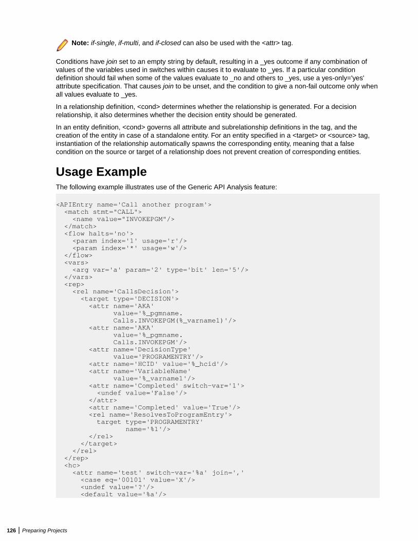
Note: if-single, if-multi, and if-closed can also be used with the <attr> tag.
Conditions have join set to an empty string by default, resulting in a _yes outcome if any combination ofvalues of the variables used in switches within causes it to evaluate to _yes. If a particular conditiondefinition should fail when some of the values evaluate to _no and others to _yes, use a yes-only='yes'attribute specification. That causes join to be unset, and the condition to give a non-fail outcome only whenall values evaluate to _yes.
In a relationship definition, <cond> determines whether the relationship is generated. For a decisionrelationship, it also determines whether the decision entity should be generated.
In an entity definition, <cond> governs all attribute and subrelationship definitions in the tag, and thecreation of the entity in case of a standalone entity. For an entity specified in a <target> or <source> tag,instantiation of the relationship automatically spawns the corresponding entity, meaning that a falsecondition on the source or target of a relationship does not prevent creation of corresponding entities.
Usage ExampleThe following example illustrates use of the Generic API Analysis feature:
<APIEntry name='Call another program'> <match stmt="CALL"> <name value="INVOKEPGM"/> </match> <flow halts='no'> <param index='1' usage='r'/> <param index='*' usage='w'/> </flow> <vars> <arg var='a' param='2' type='bit' len='5'/> </vars> <rep> <rel name='CallsDecision'> <target type='DECISION'> <attr name='AKA' value='%_pgmname. Calls.INVOKEPGM(%_varname1)'/> <attr name='AKA' value='%_pgmname. Calls.INVOKEPGM'/> <attr name='DecisionType' value='PROGRAMENTRY'/> <attr name='HCID' value='%_hcid'/> <attr name='VariableName' value='%_varname1'/> <attr name='Completed' switch-var='1'> <undef value='False'/> </attr> <attr name='Completed' value='True'/> <rel name='ResolvesToProgramEntry'> target type='PROGRAMENTRY' name='%1'/> </rel> </target> </rel> </rep> <hc> <attr name='test' switch-var='%a' join=',' <case eq='00101' value='X'/> <undef value='?'/> <default value='%a'/>
126 | Preparing Projects
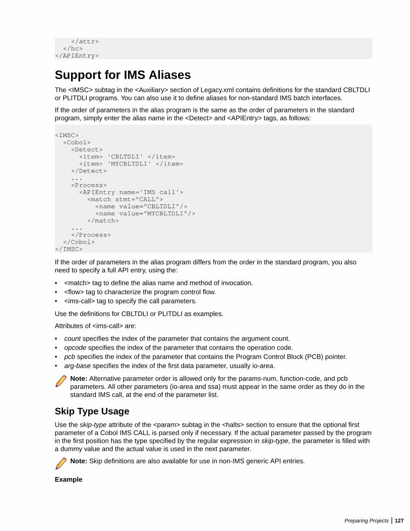
</attr> </hc></APIEntry>
Support for IMS AliasesThe <IMSC> subtag in the <Auxiliary> section of Legacy.xml contains definitions for the standard CBLTDLIor PLITDLI programs. You can also use it to define aliases for non-standard IMS batch interfaces.
If the order of parameters in the alias program is the same as the order of parameters in the standardprogram, simply enter the alias name in the <Detect> and <APIEntry> tags, as follows:
<IMSC> <Cobol> <Detect> <item> 'CBLTDLI' </item> <item> 'MYCBLTDLI' </item> </Detect> ... <Process> <APIEntry name='IMS call'> <match stmt="CALL"> <name value="CBLTDLI"/> <name value="MYCBLTDLI"/> </match> ... </Process> </Cobol></IMSC>
If the order of parameters in the alias program differs from the order in the standard program, you alsoneed to specify a full API entry, using the:
• <match> tag to define the alias name and method of invocation.• <flow> tag to characterize the program control flow.• <ims-call> tag to specify the call parameters.
Use the definitions for CBLTDLI or PLITDLI as examples.
Attributes of <ims-call> are:
• count specifies the index of the parameter that contains the argument count.• opcode specifies the index of the parameter that contains the operation code.• pcb specifies the index of the parameter that contains the Program Control Block (PCB) pointer.• arg-base specifies the index of the first data parameter, usually io-area.
Note: Alternative parameter order is allowed only for the params-num, function-code, and pcbparameters. All other parameters (io-area and ssa) must appear in the same order as they do in thestandard IMS call, at the end of the parameter list.
Skip Type UsageUse the skip-type attribute of the <param> subtag in the <halts> section to ensure that the optional firstparameter of a Cobol IMS CALL is parsed only if necessary. If the actual parameter passed by the programin the first position has the type specified by the regular expression in skip-type, the parameter is filled witha dummy value and the actual value is used in the next parameter.
Note: Skip definitions are also available for use in non-IMS generic API entries.
Example
Preparing Projects | 127

If the first parameter in a call is a 4-character picture, the following definition inserts a dummy value in thefirst position and treats the actual value as that of the second parameter:
<param index='1' usage='r' skip-type='PIC:(X\(4\)'/>
Note: Skip definitions are currently limited to declarations with picture clauses. Use regularexpression syntax to specify normalized picture strings.
128 | Preparing Projects
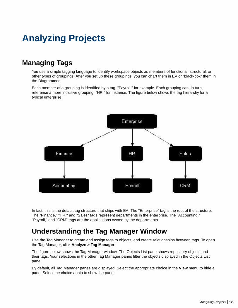
Analyzing Projects
Managing TagsYou use a simple tagging language to identify workspace objects as members of functional, structural, orother types of groupings. After you set up these groupings, you can chart them in EV or “black-box” them inthe Diagrammer.
Each member of a grouping is identified by a tag, "Payroll," for example. Each grouping can, in turn,reference a more inclusive grouping, "HR," for instance. The figure below shows the tag hierarchy for atypical enterprise:
In fact, this is the default tag structure that ships with EA. The "Enterprise" tag is the root of the structure.The "Finance," "HR," and "Sales" tags represent departments in the enterprise. The "Accounting,""Payroll," and "CRM" tags are the applications owned by the departments.
Understanding the Tag Manager WindowUse the Tag Manager to create and assign tags to objects, and create relationships between tags. To openthe Tag Manager, click Analyze > Tag Manager.
The figure below shows the Tag Manager window. The Objects List pane shows repository objects andtheir tags. Your selections in the other Tag Manager panes filter the objects displayed in the Objects Listpane.
By default, all Tag Manager panes are displayed. Select the appropriate choice in the View menu to hide apane. Select the choice again to show the pane.
Analyzing Projects | 129
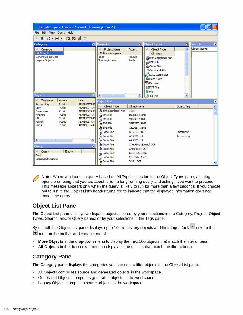
Note: When you launch a query based on All Types selection in the Object Types pane, a dialogopens prompting that you are about to run a long running query and asking if you want to proceed.This message appears only when the query is likely to run for more than a few seconds. If you choosenot to run it, the Object List's header turns red to indicate that the displayed information does notmatch the query.
Object List PaneThe Object List pane displays workspace objects filtered by your selections in the Category, Project, ObjectTypes, Search, and/or Query panes; or by your selections in the Tags pane.
By default, the Object List pane displays up to 100 repository objects and their tags. Click next to the
icon on the toolbar and choose one of:
• More Objects in the drop-down menu to display the next 100 objects that match the filter criteria.• All Objects in the drop-down menu to display all the objects that match the filter criteria.
Category PaneThe Category pane displays the categories you can use to filter objects in the Object List pane:
• All Objects comprises source and generated objects in the workspace.• Generated Objects comprises generated objects in the workspace.• Legacy Objects comprises source objects in the workspace.
130 | Analyzing Projects
Projects PaneThe Projects pane displays the workspace projects you can use to filter objects in the Object List pane.Entire Workspace comprises all the projects in the workspace.
Object Types PaneThe Object Types pane displays the object types you can use to filter objects in the Object List pane.
Search PaneThe Search pane lets you filter the objects in the Object List pane using wildcard patterns allowed in LIKEstatements by Visual Basic for Applications (VBA). Enter the pattern in the Object Name field. The ObjectList pane is refreshed as you type.
Note: In large repositories, the Object List pane may not immediately refresh as you type. Press theEnter key to instantly display matching objects for the current string.
Query PaneThe Query pane lets you filter the objects in the Object List pane using complex queries. Select a query tofilter the Object List by its terms. Select another query and choose one of:
• Add Tags > with <And> in the right-click menu to add its results to the results of previous queries.• Add Tags > with <Or> in the right-click menu to compare its results with the results of previous queries.
Tags PaneThe Tags pane lists the tags in the workspace. To view the objects that have tags assigned, select one ormore tags and the result will be displayed in the Object List pane.
Creating TagsTo create a tag, choose Edit > Create in the Tag Manager window. A dialog box prompts you to enter thename of the new tag. Enter the name and click OK. The tag is displayed in the Tags pane.
Specifying Access to TagsBy default, the tags you create are public. To make a tag private, that is, visible only to you, select it andchoose Set Access > Private in the right-click menu. To make the tag public again, choose Set Access >Public in the right-click menu.
Note: Tags shipped with the product are always public. You cannot change their access.
Assigning TagsYou can assign tags to objects individually, or to all the objects generated from a source file. You can alsoassign tags to objects in the Repository pane, by selecting the objects and choosing Assign/Remove Tagsin the right-click menu. Select a project or folder to assign tags to every first-level object in the project orfolder.
1. In the Object List pane, select the object(s) you want to assign a tag and choose Edit > Assign/Remove Tags. The Entity Tag Browser window opens.
Analyzing Projects | 131
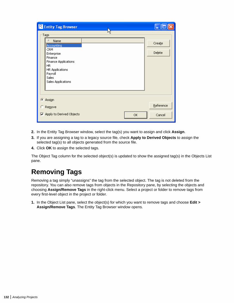
2. In the Entity Tag Browser window, select the tag(s) you want to assign and click Assign.
3. If you are assigning a tag to a legacy source file, check Apply to Derived Objects to assign theselected tag(s) to all objects generated from the source file.
4. Click OK to assign the selected tags.
The Object Tag column for the selected object(s) is updated to show the assigned tag(s) in the Objects Listpane.
Removing TagsRemoving a tag simply “unassigns” the tag from the selected object. The tag is not deleted from therepository. You can also remove tags from objects in the Repository pane, by selecting the objects andchoosing Assign/Remove Tags in the right-click menu. Select a project or folder to remove tags fromevery first-level object in the project or folder.
1. In the Object List pane, select the object(s) for which you want to remove tags and choose Edit >Assign/Remove Tags. The Entity Tag Browser window opens.
132 | Analyzing Projects
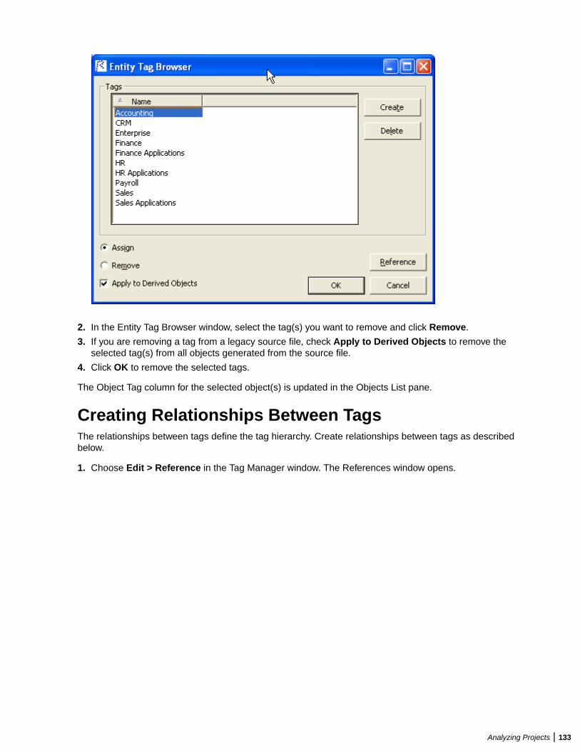
2. In the Entity Tag Browser window, select the tag(s) you want to remove and click Remove.
3. If you are removing a tag from a legacy source file, check Apply to Derived Objects to remove theselected tag(s) from all objects generated from the source file.
4. Click OK to remove the selected tags.
The Object Tag column for the selected object(s) is updated in the Objects List pane.
Creating Relationships Between TagsThe relationships between tags define the tag hierarchy. Create relationships between tags as describedbelow.
1. Choose Edit > Reference in the Tag Manager window. The References window opens.
Analyzing Projects | 133
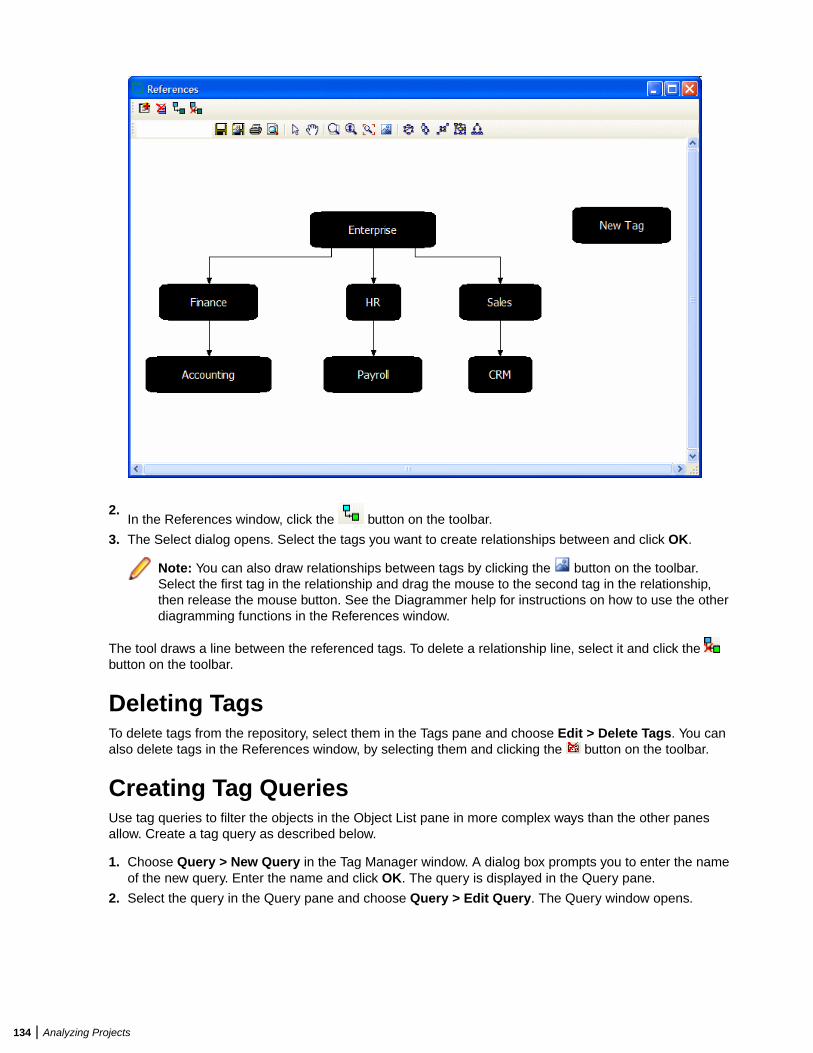
2.In the References window, click the button on the toolbar.
3. The Select dialog opens. Select the tags you want to create relationships between and click OK.
Note: You can also draw relationships between tags by clicking the button on the toolbar.Select the first tag in the relationship and drag the mouse to the second tag in the relationship,then release the mouse button. See the Diagrammer help for instructions on how to use the otherdiagramming functions in the References window.
The tool draws a line between the referenced tags. To delete a relationship line, select it and click the button on the toolbar.
Deleting TagsTo delete tags from the repository, select them in the Tags pane and choose Edit > Delete Tags. You canalso delete tags in the References window, by selecting them and clicking the button on the toolbar.
Creating Tag QueriesUse tag queries to filter the objects in the Object List pane in more complex ways than the other panesallow. Create a tag query as described below.
1. Choose Query > New Query in the Tag Manager window. A dialog box prompts you to enter the nameof the new query. Enter the name and click OK. The query is displayed in the Query pane.
2. Select the query in the Query pane and choose Query > Edit Query. The Query window opens.
134 | Analyzing Projects
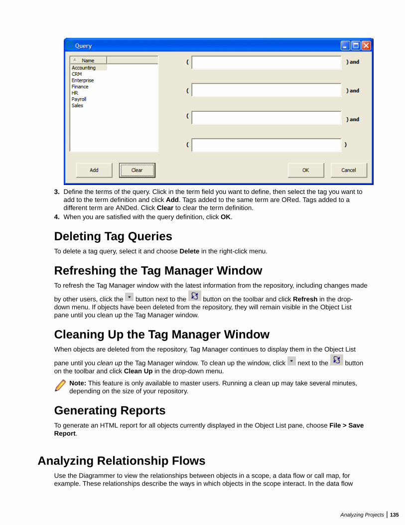
3. Define the terms of the query. Click in the term field you want to define, then select the tag you want toadd to the term definition and click Add. Tags added to the same term are ORed. Tags added to adifferent term are ANDed. Click Clear to clear the term definition.
4. When you are satisfied with the query definition, click OK.
Deleting Tag QueriesTo delete a tag query, select it and choose Delete in the right-click menu.
Refreshing the Tag Manager WindowTo refresh the Tag Manager window with the latest information from the repository, including changes made
by other users, click the button next to the button on the toolbar and click Refresh in the drop-down menu. If objects have been deleted from the repository, they will remain visible in the Object Listpane until you clean up the Tag Manager window.
Cleaning Up the Tag Manager WindowWhen objects are deleted from the repository, Tag Manager continues to display them in the Object List
pane until you clean up the Tag Manager window. To clean up the window, click next to the buttonon the toolbar and click Clean Up in the drop-down menu.
Note: This feature is only available to master users. Running a clean up may take several minutes,depending on the size of your repository.
Generating ReportsTo generate an HTML report for all objects currently displayed in the Object List pane, choose File > SaveReport.
Analyzing Relationship FlowsUse the Diagrammer to view the relationships between objects in a scope, a data flow or call map, forexample. These relationships describe the ways in which objects in the scope interact. In the data flow
Analyzing Projects | 135
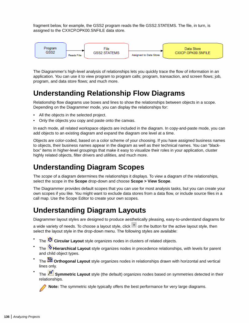
fragment below, for example, the GSS2 program reads the file GSS2.STATEMS. The file, in turn, isassigned to the CXXCP.OPK00.SNFILE data store.
The Diagrammer’s high-level analysis of relationships lets you quickly trace the flow of information in anapplication. You can use it to view program to program calls; program, transaction, and screen flows; job,program, and data store flows; and much more.
Understanding Relationship Flow DiagramsRelationship flow diagrams use boxes and lines to show the relationships between objects in a scope.Depending on the Diagrammer mode, you can display the relationships for:
• All the objects in the selected project.• Only the objects you copy and paste onto the canvas.
In each mode, all related workspace objects are included in the diagram. In copy-and-paste mode, you canadd objects to an existing diagram and expand the diagram one level at a time.
Objects are color-coded, based on a color scheme of your choosing. If you have assigned business namesto objects, their business names appear in the diagram as well as their technical names. You can “black-box” items in higher-level groupings that make it easy to visualize their roles in your application, clusterhighly related objects, filter drivers and utilities, and much more.
Understanding Diagram ScopesThe scope of a diagram determines the relationships it displays. To view a diagram of the relationships,select the scope in the Scope drop-down and choose Scope > View Scope.
The Diagrammer provides default scopes that you can use for most analysis tasks, but you can create yourown scopes if you like. You might want to exclude data stores from a data flow, or include source files in acall map. Use the Scope Editor to create your own scopes.
Understanding Diagram LayoutsDiagrammer layout styles are designed to produce aesthetically pleasing, easy-to-understand diagrams for
a wide variety of needs. To choose a layout style, click on the button for the active layout style, thenselect the layout style in the drop-down menu. The following styles are available:
• The Circular Layout style organizes nodes in clusters of related objects.• The Hierarchical Layout style organizes nodes in precedence relationships, with levels for parent
and child object types.• The Orthogonal Layout style organizes nodes in relationships drawn with horizontal and vertical
lines only.•
The Symmetric Layout style (the default) organizes nodes based on symmetries detected in theirrelationships.
Note: The symmetric style typically offers the best performance for very large diagrams.
136 | Analyzing Projects

• The Tree Layout style organizes nodes in parent-child relationships, with child nodes arranged onlevels farther from the root node than their parents.
Click a layout style button in the drop-down to change the style after a diagram is drawn.
Generating a Diagram for the Selected ProjectFollow the instructions below to generate a relationship flow diagram for the selected project. You canexclude related workspace objects that are not in the project, colorize project boundaries, and showincomplete relationship chains. You can use tags to “black-box” objects in the diagram.
Note: The Browser pane and project drop-down list in Diagrammer will use the same project filterfrom the main window when Diagrammer is opened. Any changes made to the project selection orproject filter in the main window after Diagrammer is opened will not be reflected in Diagrammer.
1. Chose the type of the diagram - Project Based or Entity Based.
2. Select a Project from the drop-down list.
3. In the Scope drop-down, choose the scope of the diagram.
4. Select a Group By criterion from the drop-down list.
5. On the Diagram pane tool bar, choose the layout style for the diagram.
6. In the Project drop-down or Browser pane, select the project.
7. Click Build Diagram on the Diagrammer tool bar. The diagram is displayed.
Generating a Diagram for Objects Copied and Pastedonto the CanvasFollow the instructions below to generate a relationship flow diagram for objects copied and pasted ontothe canvas. In this mode, you can expand the diagram one level at a time and add objects to an existingdiagram. You can exclude related workspace objects that are not in the project, colorize project boundaries,and show incomplete relationship chains. You can use tags to “black-box” objects in the diagram.
1. In the Scope drop-down, choose the scope of the diagram.
2. On the Diagram pane tool bar, choose the layout style for the diagram.
3. In the Browser pane, select the startup objects for the diagram, then press CTRL-C to copy them ontothe clipboard.
Note: Make sure to select startup objects in the diagram’s intended scope. Most scopes includelogical objects rather than source files.
4. To show the entire relationship flow for the selected objects, choose View > Auto Expand. Turn offAuto Expand if you want to expand the diagram one level at a time after it is drawn. Only immediaterelationships of the selected objects are drawn initially.
5. Click in the Diagram pane, then choose Diagram > Paste or press CTRL-V to paste the objects ontothe Diagrammer canvas.
6. Repeat the preceding step for each object whose relationships you want to add to the diagram. Thediagram is automatically redrawn.
Understanding the Diagrammer WindowUse the Diagrammer to view the relationships between application objects interactively. To open theDiagrammer, select a project in the Repository Browser and choose Analyze > Diagrammer.
By default all panes in the Diagrammer are empty. Select the attributes for your diagram and click BuildDiagram to create the diagram. Select the appropriate choice in the View menu to hide a pane. Select thechoice again to show the pane.
Analyzing Projects | 137

Diagram PaneThe Diagram pane displays the diagram for the selected scope. To save a diagram in one of the supported
diagram formats, click the on the Diagram pane tool bar. To save a diagram in one of the supported
image formats, click the on the Diagram pane tool bar.
To print a diagram, click the button on the Diagram pane tool bar. To preview the printed diagram, click
the button on the Diagram pane tool bar.
Selecting an Object or Relationship
To enable select mode, click the button on the Diagram pane tool bar.
• To select an object in a diagram, click it on the diagram canvas. Use Ctrl-click to select multiple objects,or click a blank area of the canvas, then drag the mouse over multiple objects to “lasso” the objects.Selected objects are displayed with handles that you can use to size the object.
• To select a relationship in a diagram, click it on the diagram canvas. The selected relationship isdisplayed in blue.
Searching for an Object
To search for an object in a diagram, enter the text you want to match in the Search field on theDiagrammer tool bar and press Enter. You can use wildcard patterns allowed in LIKE statements by VisualBasic for Applications (VBA).
Navigating to an Object from a Relationship
To navigate to the diagram object on the left side of a relationship, select the relationship and chooseLocate Left in the right-click menu. To navigate to the diagram object on the right side of a relationship,select the relationship and choose Locate Right in the right-click menu.
Note: Use the Overview pane to navigate to general locations in a diagram.
Expanding and Collapsing Relationships
To expand the incoming relationships for an object in a diagram generated in copy-and-paste mode, selectthe object on the diagram canvas and choose Expand > Expand Incoming in the right-click menu. Toexpand the outgoing relationships, select the object on the diagram canvas and choose Expand > ExpandOutgoing in the right-click menu.
To collapse the incoming relationships for an object, select the object on the diagram canvas and chooseCollapse > Collapse Incoming in the right-click menu. To expand the outgoing relationships, click theobject on the diagram canvas and choose Collapse > Collapse Outgoing in the right-click menu.
Moving an Object or Relationship
To move an object or relationship in a diagram, select it and drag it to the desired location on the diagramcanvas.
Resizing an Object
To resize an object in a diagram, select it on the diagram canvas and drag one of its handles to the desiredlocation.
Hiding an Object
To hide objects on the canvas, select an object and choose:
138 | Analyzing Projects
• Hide > Selected in the right-click menu to hide the selected object.• Hide > Incoming in the right-click menu to hide incoming nodes of the selected object.• Hide > Outgoing in the right-click menu to hide outgoing nodes of the selected object.
To display the object again, double-click the button for a related object.
Deleting an Object or Relationship
To delete an object or a relationship in a diagram, select it on the diagram canvas and choose DeleteSelected in the right-click menu.
Assigning Tags
You can assign tags manually in Diagrammer or automatically, to all the objects in a cluster. Follow theinstructions below to assign tags manually.
1. Select the objects you want to assign tags on the diagram canvas and click Assign Tags in the right-click menu. The Entity Tag Browser window opens.
2. In the Entity Tag Browser window, select the tag(s) you want to assign and click Assign.
3. If you are assigning a tag to a legacy source file, check Apply to Derived Objects to assign theselected tag(s) to all objects generated from the source file.
4. Click OK to assign the selected tags.
Assigning Business Names
To assign a business name and business description to an object, select the object and choose SetBusiness Attributes in the right-click menu. A dialog box opens, where you can enter the business nameand business description. To unassign a business name or business description, simply delete the value inthe dialog box.
Note: If multiple objects are selected, Diagrammer displays the dialog box as many times as there areobjects.
Displaying Labels for Multiple Relationships
The Diagrammer denotes that an object has multiple relationships with another object by displaying anumber in parentheses (n) along the relationship line, where n represents the number of relationships.Double-click the parenthesis to display the relationship labels. Double-click the relationship labels to hidethem again.
Hiding Relationship Labels
To hide relationship labels on the canvas, click the button on the tool bar and choose Hide
Relationship Labels in the drop-down menu. To show the relationship labels again, click the buttonon the tool bar and choose Show Relationship Labels in the drop-down menu. To show hidden nodes as
well as hidden relationship labels, click the button on the tool bar and choose Unhide All in the drop-down menu.
Displaying the Legend for a Diagram
To display the legend for a diagram, click the button on the tool bar and choose Show Legend in thedrop-down menu.
Analyzing Projects | 139
Zooming
To zoom in interactive mode, click button on the Diagram pane tool bar, then drag the mouse over thediagram to zoom in on it.
To zoom in marquee mode, click button on the Diagram pane tool bar, then drag the mouse over thediagram to draw a marquee. The Diagrammer displays the portion of the diagram inside the marquee.
To fit the diagram in the Diagram pane, click the button on the Diagram pane tool bar.
Moving a Diagram
To move a diagram in the Diagram pane, click the button on the Diagram pane tool bar to choosepanning mode, then hold down the left mouse button and drag the mouse to move the diagram.
Clearing a Diagram
To clear the Diagram pane, choose Diagram > Clear.
Saving a Diagram
Click the button on the Diagram pane tool bar to save a diagram in one of the supported diagramtypes. A Save dialog opens, where you can specify the name, type, and location of the file.
Click the button on the Diagram pane tool bar to save a diagram in one of the supported image types.A Save dialog opens, where you can specify the image type and characteristics. You may also change thename and location of the file.
Printing a Diagram
Click the button on the Diagram pane tool bar to print a diagram. A Print dialog opens, where you can
specify the properties of the print job. Click the button to preview the printed diagram.
Generating Diagram Reports
Choose File > Save Type Report to display a printable report based on a diagram. Choose File > SaveBlackbox Interface Report to display a printable report showing the relationships between objects indifferent black boxes. In the printable report, click Print to print the report. Click Save to export the report toHTML, Excel, RTF, Word, or formatted text.
Browser PaneThe Browser pane displays the workspace repository in tree form. The current project is expanded onelevel when you first open the Diagrammer.
Note: To improve Diagrammer startup performance in your next session, hide the Browser panebefore you end your current session. Click the close box in the upper righthand corner to hide thepane. To show the pane again, choose View > Browser.
Relationships PaneThe Relationships pane displays the relationships in the selected scope, as they appear from left to right inthe diagram. Select the relationship for an object in the Relationships pane to navigate to the object in theDiagram pane.
The list includes relationship chains, or composite relationships, such asProgram[IsDefinedInCobol]Cobol[Includes]Copybook[GeneratesTargetXml]TargetXML. If you chose View >
140 | Analyzing Projects

Potential Incomplete Composite Relationships when you drew the diagram, the list shows incompleterelationship chains, in which the final object in the chain is unresolved or otherwise unavailable.
Quick View PaneThe Quick View pane lets you browse Interactive Analysis information for the object selected in theDiagram pane. The information available depends on the type of object selected. You see only source codefor a copybook, for example, but full Interactive Analysis information for a program. Select the informationyou want to view for the object from the drop-down in the upper lefthand corner of the pane.
Overview PaneThe Overview pane lets you navigate to a general location in a diagram. It displays the entire diagram, witha frame surrounding the portion of the diagram visible in the Diagram pane. Drag the frame to the area ofthe diagram you want to view in the Diagram pane. Diagrammer displays the selected area in the Diagrampane.
Excluding Objects Outside the ProjectTo restrict the diagram to related objects in the current project, choose View > Exclude Objects OutsideProject. Otherwise, all related workspace objects are included in the diagram.
Showing Incomplete Composite RelationshipsA composite relationship defines the indirect interaction of two objects. If a job runs a program entry pointthat belongs to a program, for example, the relationship between the job and program is said to becomposite: defined by the chain of relationships between the job and program.
To show incomplete relationship chains in the diagram and list of relationships, choose View > PotentialIncomplete Composite Relationships. Intermediate objects in the chain are displayed even if the finalobject in the chain is unresolved or otherwise unavailable. Relationships are displayed in red in thediagram.
Colorizing Project BoundariesBoundary objects are objects with relationships to objects outside the project. To colorize boundary objectsin the diagram, choose View > Project Boundary Entities. Boundary objects are displayed in the diagramwith a red border. Related external objects are displayed in the diagram with a blue border.
Showing and Hiding Object LabelsThe View > Show in Label menu choice controls the labels displayed for objects in a diagram. Chooseone of:
• View > Show in Label > Show Type to display the type of an object in its label.• View > Show in Label > Show Name to display the name of an object in its label.• View > Show in Label > Show Business Name to display the business name of an object in its label.• View > Show in Label > Show Business Description to display the business description of an object
in its label.
A check mark next to a choice means that the label will be displayed. The choices are toggles. Click thechoice again to hide the information in the label.
Analyzing Projects | 141
Working with GroupsGrouping objects reduces diagram clutter and makes it easy to visualize the roles of the grouped objects inyour application. Groups are automatically created when you black-box tagged objects and when you filteror cluster objects.
Grouping and Ungrouping Objects
To group objects manually, select the objects on the diagram canvas, then click the button on the toolbar and choose Group Selected in the drop-down menu. Inclusive groups are allowed.
To ungroup objects, select the group on the diagram canvas, then click the button on the tool bar andchoose Ungroup Selected in the drop-down menu.
Expanding and Collapsing GroupsExpand a group to view its contents. Collapse a group to hide its contents.
• If a group is collapsed (including a group in a more inclusive group), double-click it to expand itscontents. To expand all the groups in an inclusive group, select the group on the diagram canvas, then
click the button on the tool bar and choose Expand Groups in the drop-down menu.• If a group is expanded (including a group in a more inclusive group), double-click it to collapse it. To
collapse all the groups in an inclusive group, select the group on the diagram canvas, then click the button on the tool bar and choose Collapse Groups in the drop-down menu.
To view a diagram consisting only of objects in a group, select the group and choose Navigate to Child
Diagram in the right-click menu. To restore the full diagram, click the button on the tool bar andchoose Return to Parent in the drop-down menu.
Moving Objects Between Groups
To move objects between groups, expand the groups, then click the button on the toolbar. Select theobject you want to move and drag it to the new group.
Naming GroupsTo rename a group, select it and choose Rename Group in the right-click menu.
Note: The name does not persist after ungrouping. You cannot rename a black box.
Deleting GroupsTo delete a group, select it and choose Delete Group in the right-click menu. You are prompted to confirmthe deletion. Click Yes.
Black-Boxing Tagged ObjectsThe deeper your understanding of your application, the more confidently you can abstract from its lower-level details to a “bigger picture” view, one that organizes related programs in functional, structural, or othertypes of groupings: a Customer Maintenance subsystem, for example, in an Order Acceptance application.This is the kind of view a subject matter expert uses to evaluate whether an application does everything itis supposed to do, in the appropriate order.
The Diagrammer black-box feature lets you assign lower-level objects to higher-level groupings that make iteasy to visualize their roles in your application. Your diagram might have one black box for the Customer
142 | Analyzing Projects
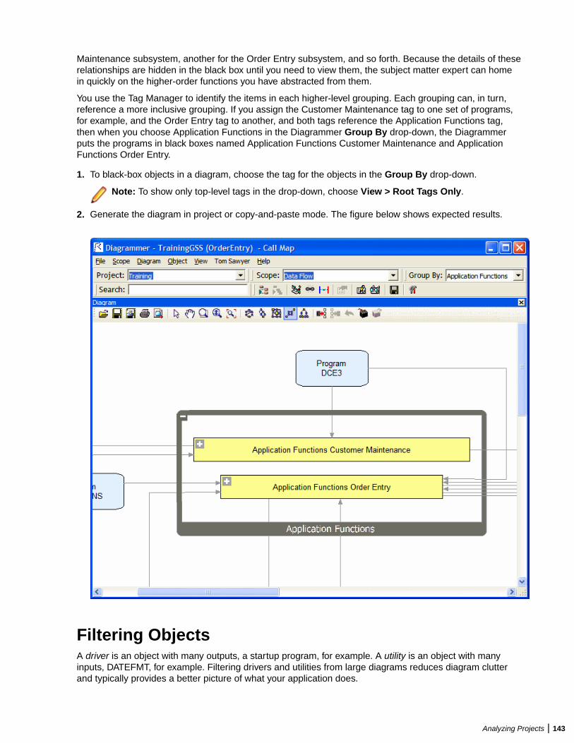
Maintenance subsystem, another for the Order Entry subsystem, and so forth. Because the details of theserelationships are hidden in the black box until you need to view them, the subject matter expert can homein quickly on the higher-order functions you have abstracted from them.
You use the Tag Manager to identify the items in each higher-level grouping. Each grouping can, in turn,reference a more inclusive grouping. If you assign the Customer Maintenance tag to one set of programs,for example, and the Order Entry tag to another, and both tags reference the Application Functions tag,then when you choose Application Functions in the Diagrammer Group By drop-down, the Diagrammerputs the programs in black boxes named Application Functions Customer Maintenance and ApplicationFunctions Order Entry.
1. To black-box objects in a diagram, choose the tag for the objects in the Group By drop-down.
Note: To show only top-level tags in the drop-down, choose View > Root Tags Only.
2. Generate the diagram in project or copy-and-paste mode. The figure below shows expected results.
Filtering ObjectsA driver is an object with many outputs, a startup program, for example. A utility is an object with manyinputs, DATEFMT, for example. Filtering drivers and utilities from large diagrams reduces diagram clutterand typically provides a better picture of what your application does.
Analyzing Projects | 143
You set thresholds for filtering in the Diagrams User Preferences. If you set the driver threshold for outgoingrelationships to 40, for example, then any object with 40 or more outgoing relationship will be considered adriver and displayed outside the main relationship flow. The driver and its related nodes in the relationshipflow appear with a symbol in the diagram. Click the symbol to display the relationships for the driverand its related nodes again.
You generate a filtered diagram the same way you generate any diagram. The only difference is that whenthe filtering thresholds are met, Diagrammer displays the Large Dataset Returned dialog. Choose EnableNode Filtering in the dialog to draw the diagram with the filter applied. Choose Disable Node Filtering
and Clustering in the dialog to draw the diagram without the filter applied. A symbol on the tool barindicates that a diagram is filtered.
Tip: Use the Filter Override options on the drop-down menu to override the thresholds in theDiagrams User Preferences. If the diagram has already been generated, choosing an override optionredraws the diagram with the new filter applied.
Setting Filter OverridesUse the Filter Override Options window to override the filtering thresholds in the Diagrams UserPreferences. If the diagram has already been generated, choosing an override option redraws the diagramwith the new filter applied.
Note: These settings do not persist between Diagrammer sessions.
1.Click on the tool bar and choose Filter Override Options in the drop-down. The Filter OverrideOptions window opens.
2. Select Filters Enabled to enable filtering.
3. Select Hide Utilities to hide objects with many inputs, DATEFMT, for example. Specify the filteringthresholds for inputs and outputs:
• In the Incoming Relationships field, enter the filtering threshold for incoming relationships.• In the Outgoing Relationships field, enter the filtering threshold for outgoing relationships.
4. Select Hide Drivers to hide objects with many outputs, a startup program, for example. Specify thefiltering thresholds for inputs and outputs:
• In the Incoming Relationships field, enter the filtering threshold for incoming relationships.• In the Outgoing Relationships field, enter the filtering threshold for outgoing relationships.
5. Select Hide High Input Nodes to hide objects with many inputs that do not meet the incomingrelationship threshold for utilities. Specify the thresholds for inputs in the With Incoming Relationshipsfield.
6. Select Hide High Output Nodes to hide objects with many outputs that do not meet the outgoingrelationships threshold for drivers. Specify the thresholds for outputs in the With OutgoingRelationships field.
Tip: Select Reset Values to restore the filtering thresholds totheir settings in the Diagrams User Preferences.
Clustering ObjectsClustering objects on a diagram groups them by their degree of relatedness. Once clusters are generated,you can move objects in and out of the groups, name the groups, and create new clusters as needed.When you are satisfied that a cluster meets your needs, you can assign an existing tag to its members orgenerate a tag from the cluster itself, each member of which receives the tag.
144 | Analyzing Projects
To enable clustering click and then click Clustering Options. Check if the appropriate filteringthresholds are met, drivers and utilities are grouped in special clusters named "Drivers" and "Utilities." Athird special cluster, "Miscellaneous Components," contains relationship flows with too few objects tocluster.
You generate a clustered diagram the same way you generate any diagram. The only difference is thatDiagrammer displays the Large Dataset Returned dialog. Choose Enable Node Clustering in the dialog todraw the diagram with clustering applied. Choose Disable Node Filtering and Clustering in the dialog todraw the diagram without clustering applied.
Creating Clusters ManuallyTo create a cluster manually, right-click on white space on the Diagrammer canvas. The Clustering dialogopens. Select Create New Cluster, then enter the cluster name in the Cluster Name field. Click OK.
Generating Tags from ClustersTo generate tags based on cluster names, right-click on white space on the Diagrammer canvas. TheClustering dialog opens. Select Create Tags from Clusters, then enter the name of the parent tag in theTop Level tag field.
Note: The parent tag is required.
Click OK. Each member of a cluster is assigned a tag based on the cluster name.
Setting Clustering FactorsUse the Clustering Options window to specify values to use when factoring how closely related clusterobjects are.
Note: These settings do not persist between Diagrammer sessions.
1.Click on the tool bar and choose Clustering Options. The Clustering Options window opens.
2. In the Quality drop-down, select one of:
• Draft for the lowest clustering quality and best performance.• Proof for the highest clustering quality and worst performance.• Medium for the best balance of clustering quality and performance.
3. In the Balance combo box, specify the clustering balance factor. The higher the balance factor, thelower the number of relationships between objects in different clusters.
4. In the Cluster Size Factor combo box, specify the clustering size factor. The higher the clustering sizefactor, the larger and fewer the clusters.
5. In the Max Number of Clusters combo box, specify the maximum number of clusters. A value of 0means any number of clusters.
6. In the Min Number of Clusters combo box, specify the minimum number of clusters. A value of 0means any number of clusters.
Setting Diagrams User PreferencesUse the Diagrams tab of the User Preferences window to specify the color-coding used in relationship flowdiagrams, the thresholds for clustering and filtering, and performance limits for large diagrams.
1. Choose Tools > User Preferences. The User Preferences window opens. Click the Diagrams tab.
2. Select Prompt When Diagram Mode Changes to be prompted when you switch between a diagramgenerated for a project and a diagram generated for copied-and-pasted objects.
Analyzing Projects | 145
3. In the Color Scheme pane, click the object type whose color you want to edit. The current backgroundcolor of the type (if any) is displayed in the Color drop-down.
4. Click the adjacent button and choose ForeColor from the pop-up menu if you want to specify thecolor of the caption for the object type, or BackColor if you want to specify the color of the backgroundfor the object type.
5. In the Shape drop-down, select the shape of the object type in the diagram. Select Lock Shape Aspectto specify that the shape not be adjusted to fit the caption.
6. Click Performance button. The Performance Option Limits dialog opens.
7. Deselect Relayout Subgraphs if you do not want child groups to be redrawn when you choose a newlayout style.
Note: Selecting this option may result in poor performance for very large diagrams.
8. In the Maximum relationships to return from repository field, enter the maximum number ofrelationships to display in the diagram. Relationships are truncated when the maximum is exceeded.
Note: Setting this option too high may result in poor performance for very large diagrams.
9. In the Force Symmetric Layout (all relationships) field, enter the maximum number of relationships todisplay in the diagram before forcing symmetric layout style.
Note: Symmetric layout style typically offers the best performance for very large diagrams. Settingthis option too high may result in poor performance for very large diagrams.
10.In the Offer Auto Clustering Layout (all relationships) field, enter the maximum number ofrelationships to display in the diagram before offering to perform clustering.
11.Select Filter Options Enabled to enable filtering.
12.In the Hide Drivers (all relationships) field, enter the maximum number of relationships to display inthe diagram before filtering drivers. (A driver is an object with many outputs, a startup program, forexample.) Specify the filtering thresholds for inputs and outputs:
• In the Incoming Relationships field, enter the filtering threshold for incoming relationships.• In the Outgoing Relationships field, enter the filtering threshold for outgoing relationships.
13.In the Hide Utilities (all relationships) field, enter the maximum number of relationships to display inthe diagram before filtering utilities. (A utility is an object with many inputs, DATEFMT, for example.)Specify the filtering thresholds for inputs and outputs:
• In the Incoming Relationships field, enter the filtering threshold for incoming relationships.• In the Outgoing Relationships field, enter the filtering threshold for outgoing relationships.
14.In the Hide High Output Nodes (all relationships) field, enter the maximum number of relationships todisplay in the diagram before filtering objects with many outputs that do not meet the outgoingrelationships threshold for drivers. Specify the filtering thresholds for outputs in the OutgoingRelationships field.
15.In the Hide High Input Nodes (all relationships) field, enter the maximum number of relationships todisplay in the diagram before filtering objects that do not meet the incoming relationship threshold forutilities. Specify the filtering threshold for inputs in the Incoming Relationships field.
Using the Scope EditorUse the Scope Editor to manage the scopes in your repository, create custom composite relationships, anddefine relationship filters. To open the Scope Editor, choose Scope > Scope Editor. The Scope Editoropens, with the workspace scopes listed in the lefthand pane and their relationships in the righthand pane.The figure below shows the Scope Editor.
146 | Analyzing Projects
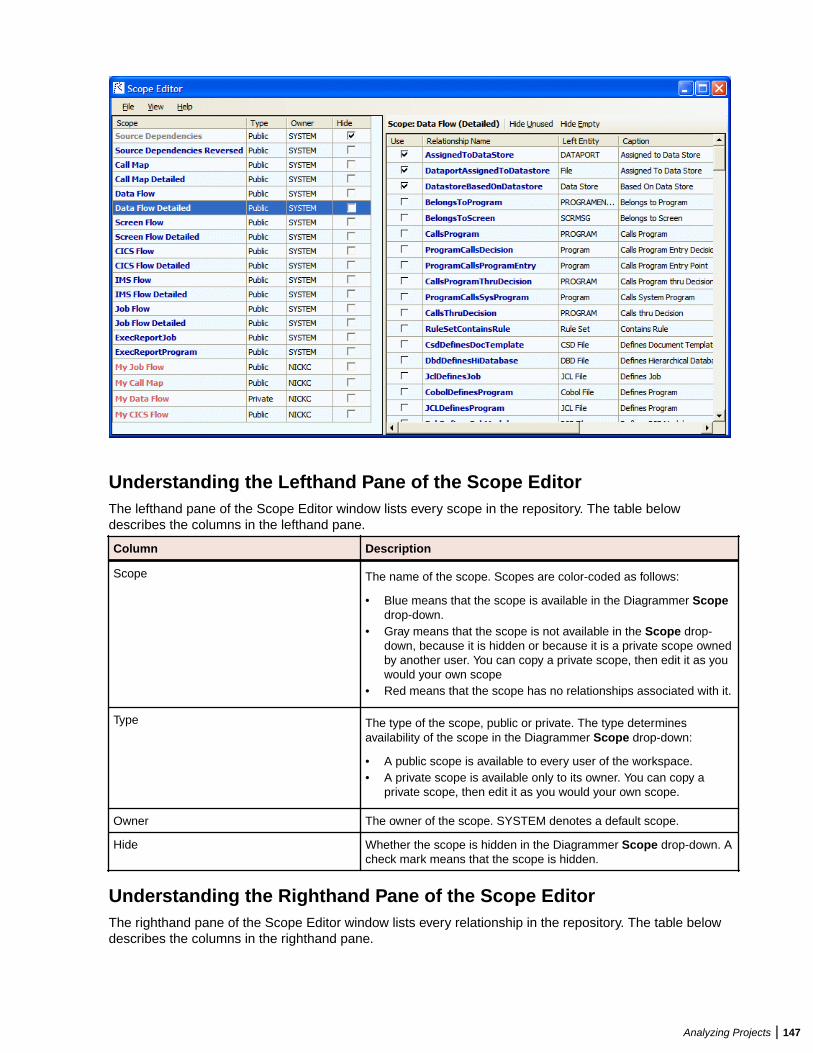
Understanding the Lefthand Pane of the Scope EditorThe lefthand pane of the Scope Editor window lists every scope in the repository. The table belowdescribes the columns in the lefthand pane.
Column Description
Scope The name of the scope. Scopes are color-coded as follows:
• Blue means that the scope is available in the Diagrammer Scopedrop-down.
• Gray means that the scope is not available in the Scope drop-down, because it is hidden or because it is a private scope ownedby another user. You can copy a private scope, then edit it as youwould your own scope
• Red means that the scope has no relationships associated with it.
Type The type of the scope, public or private. The type determinesavailability of the scope in the Diagrammer Scope drop-down:
• A public scope is available to every user of the workspace.• A private scope is available only to its owner. You can copy a
private scope, then edit it as you would your own scope.
Owner The owner of the scope. SYSTEM denotes a default scope.
Hide Whether the scope is hidden in the Diagrammer Scope drop-down. Acheck mark means that the scope is hidden.
Understanding the Righthand Pane of the Scope EditorThe righthand pane of the Scope Editor window lists every relationship in the repository. The table belowdescribes the columns in the righthand pane.
Analyzing Projects | 147
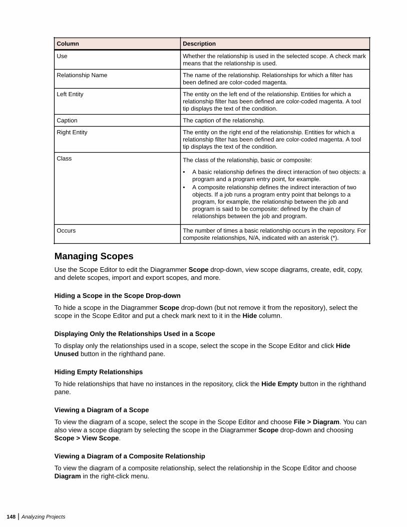
Column Description
Use Whether the relationship is used in the selected scope. A check markmeans that the relationship is used.
Relationship Name The name of the relationship. Relationships for which a filter hasbeen defined are color-coded magenta.
Left Entity The entity on the left end of the relationship. Entities for which arelationship filter has been defined are color-coded magenta. A tooltip displays the text of the condition.
Caption The caption of the relationship.
Right Entity The entity on the right end of the relationship. Entities for which arelationship filter has been defined are color-coded magenta. A tooltip displays the text of the condition.
Class The class of the relationship, basic or composite:
• A basic relationship defines the direct interaction of two objects: aprogram and a program entry point, for example.
• A composite relationship defines the indirect interaction of twoobjects. If a job runs a program entry point that belongs to aprogram, for example, the relationship between the job andprogram is said to be composite: defined by the chain ofrelationships between the job and program.
Occurs The number of times a basic relationship occurs in the repository. Forcomposite relationships, N/A, indicated with an asterisk (*).
Managing ScopesUse the Scope Editor to edit the Diagrammer Scope drop-down, view scope diagrams, create, edit, copy,and delete scopes, import and export scopes, and more.
Hiding a Scope in the Scope Drop-down
To hide a scope in the Diagrammer Scope drop-down (but not remove it from the repository), select thescope in the Scope Editor and put a check mark next to it in the Hide column.
Displaying Only the Relationships Used in a Scope
To display only the relationships used in a scope, select the scope in the Scope Editor and click HideUnused button in the righthand pane.
Hiding Empty Relationships
To hide relationships that have no instances in the repository, click the Hide Empty button in the righthandpane.
Viewing a Diagram of a Scope
To view the diagram of a scope, select the scope in the Scope Editor and choose File > Diagram. You canalso view a scope diagram by selecting the scope in the Diagrammer Scope drop-down and choosingScope > View Scope.
Viewing a Diagram of a Composite Relationship
To view the diagram of a composite relationship, select the relationship in the Scope Editor and chooseDiagram in the right-click menu.
148 | Analyzing Projects

Creating a Scope
To create a scope, choose File > New Scope. A dialog box prompts you to enter the name, optionalcaption, class, and owner of the scope. Enter the requested information and click Save.
Specifying the Relationships in a Scope
To specify the relationships in a scope, select the scope in the Scope Editor and put a check mark in theUse column next to each relationship you want to include in the scope. To save the scope, choose File >Save.
Note: You can specify relationships only for a scope you own.
Editing Scope Details
To edit the name, caption, class, and owner of a scope, select the scope in the Scope Editor and chooseFile > Edit. A dialog box displays the current details for the scope. Enter the new information and clickSave.
Note: You can edit details only for a scope you own.
Copying a Scope
To copy a scope, select the scope in the Scope Editor and choose File > Copy. A dialog box prompts youto enter the name, optional caption, class, and owner of the new scope. Enter the requested informationand click Save. You can copy default scopes and public or private scopes owned by another user, then editthem as you would your own scope.
Deleting a Scope
To delete a scope, select the scope in the Scope Editor and choose File > Delete.
Note: You can delete only a scope you own.
Deleting a Composite Relationship
To delete a composite relationship, select the relationship in the Scope Editor and choose Delete in theright-click menu.
Note: You can delete only a composite relationship you own.
Importing and Exporting Scopes
To import a scope from an XML file, choose File > Import. A dialog opens, where you can specify thescope you want to import. The type of an imported scope defaults to public. The owner defaults to thecurrent user.
Note: If a scope or relationship being imported conflicts with an existing scope or relationship, you arenotified and the conflicting item is ignored.
To export a scope to an XML file, select the scope in the Scope Editor and choose File > Export Selected.A Save dialog opens, where you can specify the name and location of the scope. To export all the scopesin the repository to an XML file, choose File > Export All.
Hiding Columns in the Scope Editor
To hide a column in the Scope Editor, deselect the column name in the View menu.
Analyzing Projects | 149
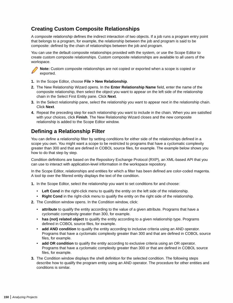
Creating Custom Composite RelationshipsA composite relationship defines the indirect interaction of two objects. If a job runs a program entry pointthat belongs to a program, for example, the relationship between the job and program is said to becomposite: defined by the chain of relationships between the job and program.
You can use the default composite relationships provided with the system, or use the Scope Editor tocreate custom composite relationships. Custom composite relationships are available to all users of theworkspace.
Note: Custom composite relationships are not copied or exported when a scope is copied orexported.
1. In the Scope Editor, choose File > New Relationship.
2. The New Relationship Wizard opens. In the Enter Relationship Name field, enter the name of thecomposite relationship, then select the object you want to appear on the left side of the relationshipchain in the Select First Entity pane. Click Next.
3. In the Select relationship pane, select the relationship you want to appear next in the relationship chain.Click Next.
4. Repeat the preceding step for each relationship you want to include in the chain. When you are satisfiedwith your choices, click Finish. The New Relationship Wizard closes and the new compositerelationship is added to the Scope Editor window.
Defining a Relationship FilterYou can define a relationship filter by setting conditions for either side of the relationships defined in ascope you own. You might want a scope to be restricted to programs that have a cyclomatic complexitygreater than 300 and that are defined in COBOL source files, for example. The example below shows youhow to do that step by step.
Condition definitions are based on the Repository Exchange Protocol (RXP), an XML-based API that youcan use to interact with application-level information in the workspace repository.
In the Scope Editor, relationships and entities for which a filter has been defined are color-coded magenta.A tool tip over the filtered entity displays the text of the condition.
1. In the Scope Editor, select the relationship you want to set conditions for and choose:
• Left Cond in the right-click menu to qualify the entity on the left side of the relationship.• Right Cond in the right-click menu to qualify the entity on the right side of the relationship.
2. The Condition window opens. In the Condition window, click:
• attribute to qualify the entity according to the value of a given attribute. Programs that have acyclomatic complexity greater than 300, for example.
• has (not) related object to qualify the entity according to a given relationship type. Programsdefined in COBOL source files, for example.
• add AND condition to qualify the entity according to inclusive criteria using an AND operator.Programs that have a cyclomatic complexity greater than 300 and that are defined in COBOL sourcefiles, for example.
• add OR condition to qualify the entity according to exclusive criteria using an OR operator.Programs that have a cyclomatic complexity greater than 300 or that are defined in COBOL sourcefiles, for example.
3. The Condition window displays the shell definition for the selected condition. The following stepsdescribe how to qualify the program entity using an AND operator. The procedure for other entities andconditions is similar.
150 | Analyzing Projects
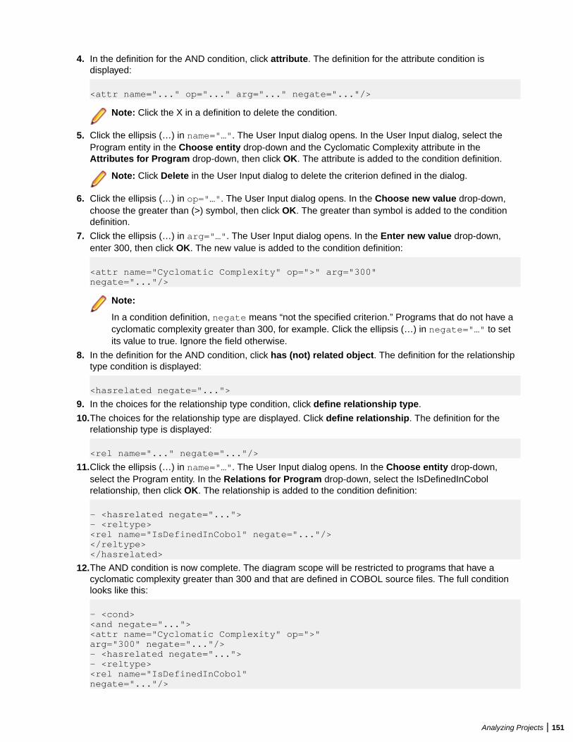
4. In the definition for the AND condition, click attribute. The definition for the attribute condition isdisplayed:
<attr name="..." op="..." arg="..." negate="..."/>
Note: Click the X in a definition to delete the condition.
5. Click the ellipsis (…) in name="…". The User Input dialog opens. In the User Input dialog, select theProgram entity in the Choose entity drop-down and the Cyclomatic Complexity attribute in theAttributes for Program drop-down, then click OK. The attribute is added to the condition definition.
Note: Click Delete in the User Input dialog to delete the criterion defined in the dialog.
6. Click the ellipsis (…) in op="…". The User Input dialog opens. In the Choose new value drop-down,choose the greater than (>) symbol, then click OK. The greater than symbol is added to the conditiondefinition.
7. Click the ellipsis (…) in arg="…". The User Input dialog opens. In the Enter new value drop-down,enter 300, then click OK. The new value is added to the condition definition:
<attr name="Cyclomatic Complexity" op=">" arg="300"negate="..."/>
Note:
In a condition definition, negate means “not the specified criterion.” Programs that do not have acyclomatic complexity greater than 300, for example. Click the ellipsis (…) in negate="…" to setits value to true. Ignore the field otherwise.
8. In the definition for the AND condition, click has (not) related object. The definition for the relationshiptype condition is displayed:
<hasrelated negate="...">
9. In the choices for the relationship type condition, click define relationship type.
10.The choices for the relationship type are displayed. Click define relationship. The definition for therelationship type is displayed:
<rel name="..." negate="..."/>
11.Click the ellipsis (…) in name="…". The User Input dialog opens. In the Choose entity drop-down,select the Program entity. In the Relations for Program drop-down, select the IsDefinedInCobolrelationship, then click OK. The relationship is added to the condition definition:
- <hasrelated negate="...">- <reltype><rel name="IsDefinedInCobol" negate="..."/></reltype></hasrelated>
12.The AND condition is now complete. The diagram scope will be restricted to programs that have acyclomatic complexity greater than 300 and that are defined in COBOL source files. The full conditionlooks like this:
- <cond><and negate="..."><attr name="Cyclomatic Complexity" op=">"arg="300" negate="..."/>- <hasrelated negate="...">- <reltype><rel name="IsDefinedInCobol"negate="..."/>
Analyzing Projects | 151
</reltype></hasrelated></and></cond>
Pruning a ScopeYou can prune relationships from a scope you own directly in the Diagrammer window. When you prune ascope, keep in mind that:
• You are deleting relationships from the current scope exactly as if you were deleting them in the ScopeEditor window. For that reason, you might want to save the original scope with a different name and usethe renamed scope as the basis for the pruned diagram.
• All the relationships of the selected type are deleted for the selected object, not just the singlerelationship you selected in the diagram.
1. To prune a scope, select the relationship you want to prune in the diagram and choose:
• Prune type for right object in the right-click menu to delete from the current scope all relationshipsof the selected type for the right object in the relationship.
• Prune type for left object in the right-click menu to delete from the current scope all relationships ofthe selected type for the left object in the relationship.
2. Generate the diagram in project or copy-and-paste mode. The Diagrammer deletes the relationshipsfrom the redrawn diagram.
Mirroring a ScopeBy default, Diagrammer shows the flow of relationships from a diagrammed object rather than to adiagrammed object. Choose Scope > Mirror Scope to show the flow of relationships to the object. ChooseScope > Mirror Scope again to return to the original view.
Analyzing Global Data FlowThe Global Data Flow traces incoming and outgoing data flows for a program variable up to a dataport, anI/O statement or call to or from another program. You can view the memory allocation and offset for thevariable to determine how changes to the variable may affect other variables, and trace assignments to andfrom the variable across programs.
Note: Projects must have been verified with the Enable Data Element Flow option set in the ProjectVerification options.
The Global Data Flow tool is available in Interactive Analysis by clicking View > Data Flow.
Understanding the Global Data Flow PanesUse the Global Data Flow panes to trace incoming and outgoing data flows for a program variable up to adataport, an I/O statement or call to or from another program. To open the Global Data Flow panes, selecta program in the Repository Browser and choose View > Data Flow.
By default, all Global Data Flow panes are displayed. If you want to show/hide one of the panes click Viewand then click the name of the pane you want to hide/show.
Data View PaneFor the selected program, the Data View pane shows variable structures, substructures, and fields inhierarchical order from left to right. Double-click a variable name to generate a data flow diagram for thevariable in the Data Flow pane, and a list of offsets and memory allocations for the variable and any relatedvariables in the Origin pane.
152 | Analyzing Projects
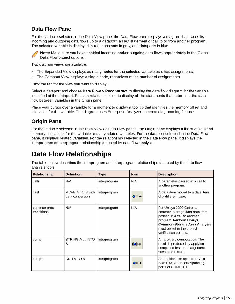
Data Flow PaneFor the variable selected in the Data View pane, the Data Flow pane displays a diagram that traces itsincoming and outgoing data flows up to a dataport, an I/O statement or call to or from another program.The selected variable is displayed in red, constants in gray, and dataports in blue.
Note: Make sure you have enabled incoming and/or outgoing data flows appropriately in the GlobalData Flow project options.
Two diagram views are available:
• The Expanded View displays as many nodes for the selected variable as it has assignments.• The Compact View displays a single node, regardless of the number of assignments.
Click the tab for the view you want to display.
Select a dataport and choose Data Flow > Reconstruct to display the data flow diagram for the variableidentified at the dataport. Select a relationship line to display all the statements that determine the dataflow between variables in the Origin pane.
Place your cursor over a variable for a moment to display a tool tip that identifies the memory offset andallocation for the variable. The diagram uses Enterprise Analyzer common diagramming features.
Origin PaneFor the variable selected in the Data View or Data Flow panes, the Origin pane displays a list of offsets andmemory allocations for the variable and any related variables. For the dataport selected in the Data Flowpane, it displays related variables. For the relationship selected in the Data Flow pane, it displays theintraprogram or interprogram relationship detected by data flow analysis.
Data Flow RelationshipsThe table below describes the intraprogram and interprogram relationships detected by the data flowanalysis tools.
Relationship Definition Type Icon Description
calls N/A interprogram N/A A parameter passed in a call toanother program.
cast MOVE A TO B withdata conversion
intraprogram A data item moved to a data itemof a different type.
common areatransitions
N/A interprogram N/A For Unisys 2200 Cobol, acommon-storage data area itempassed in a call to anotherprogram. Perform UnisysCommon-Storage Area Analysismust be set in the projectverification options.
comp STRING A ... INTOB
intraprogram An arbitrary computation. Theresult is produced by applyingcomplex rules to the argument,such as STRING.
comp+ ADD A TO B intraprogram An addition-like operation: ADD,SUBTRACT, or correspondingparts of COMPUTE.
Analyzing Projects | 153
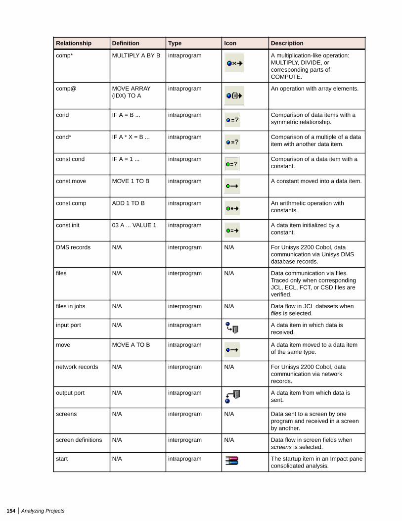
Relationship Definition Type Icon Description
comp* MULTIPLY A BY B intraprogram A multiplication-like operation:MULTIPLY, DIVIDE, orcorresponding parts ofCOMPUTE.
comp@ MOVE ARRAY(IDX) TO A
intraprogram An operation with array elements.
cond IF A = B ... intraprogram Comparison of data items with asymmetric relationship.
cond* IF A * X = B ... intraprogram Comparison of a multiple of a dataitem with another data item.
const cond IF A = 1 ... intraprogram Comparison of a data item with aconstant.
const.move MOVE 1 TO B intraprogram A constant moved into a data item.
const.comp ADD 1 TO B intraprogram An arithmetic operation withconstants.
const.init 03 A ... VALUE 1 intraprogram A data item initialized by aconstant.
DMS records N/A interprogram N/A For Unisys 2200 Cobol, datacommunication via Unisys DMSdatabase records.
files N/A interprogram N/A Data communication via files.Traced only when correspondingJCL, ECL, FCT, or CSD files areverified.
files in jobs N/A interprogram N/A Data flow in JCL datasets whenfiles is selected.
input port N/A intraprogram A data item in which data isreceived.
move MOVE A TO B intraprogram A data item moved to a data itemof the same type.
network records N/A interprogram N/A For Unisys 2200 Cobol, datacommunication via networkrecords.
output port N/A intraprogram A data item from which data issent.
screens N/A interprogram N/A Data sent to a screen by oneprogram and received in a screenby another.
screen definitions N/A interprogram N/A Data flow in screen fields whenscreens is selected.
start N/A intraprogram The startup item in an Impact paneconsolidated analysis.
154 | Analyzing Projects
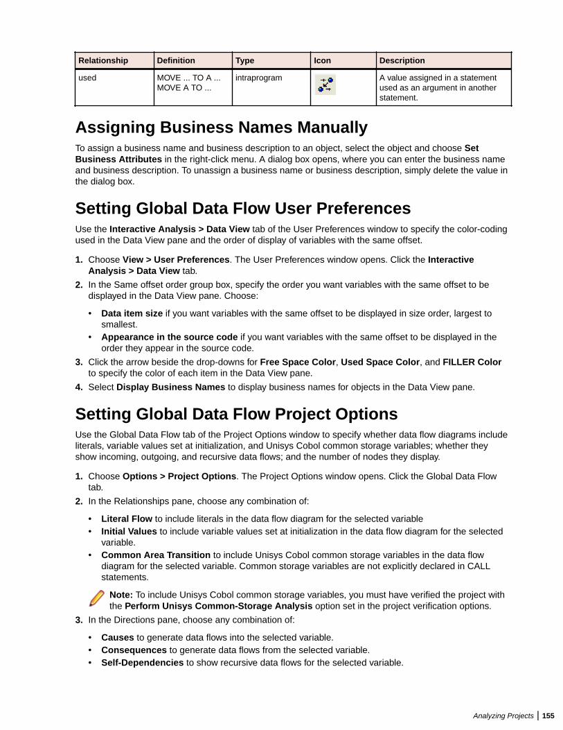
Relationship Definition Type Icon Description
used MOVE ... TO A ...MOVE A TO ...
intraprogram A value assigned in a statementused as an argument in anotherstatement.
Assigning Business Names ManuallyTo assign a business name and business description to an object, select the object and choose SetBusiness Attributes in the right-click menu. A dialog box opens, where you can enter the business nameand business description. To unassign a business name or business description, simply delete the value inthe dialog box.
Setting Global Data Flow User PreferencesUse the Interactive Analysis > Data View tab of the User Preferences window to specify the color-codingused in the Data View pane and the order of display of variables with the same offset.
1. Choose View > User Preferences. The User Preferences window opens. Click the InteractiveAnalysis > Data View tab.
2. In the Same offset order group box, specify the order you want variables with the same offset to bedisplayed in the Data View pane. Choose:
• Data item size if you want variables with the same offset to be displayed in size order, largest tosmallest.
• Appearance in the source code if you want variables with the same offset to be displayed in theorder they appear in the source code.
3. Click the arrow beside the drop-downs for Free Space Color, Used Space Color, and FILLER Colorto specify the color of each item in the Data View pane.
4. Select Display Business Names to display business names for objects in the Data View pane.
Setting Global Data Flow Project OptionsUse the Global Data Flow tab of the Project Options window to specify whether data flow diagrams includeliterals, variable values set at initialization, and Unisys Cobol common storage variables; whether theyshow incoming, outgoing, and recursive data flows; and the number of nodes they display.
1. Choose Options > Project Options. The Project Options window opens. Click the Global Data Flowtab.
2. In the Relationships pane, choose any combination of:
• Literal Flow to include literals in the data flow diagram for the selected variable• Initial Values to include variable values set at initialization in the data flow diagram for the selected
variable.• Common Area Transition to include Unisys Cobol common storage variables in the data flow
diagram for the selected variable. Common storage variables are not explicitly declared in CALLstatements.
Note: To include Unisys Cobol common storage variables, you must have verified the project withthe Perform Unisys Common-Storage Analysis option set in the project verification options.
3. In the Directions pane, choose any combination of:
• Causes to generate data flows into the selected variable.• Consequences to generate data flows from the selected variable.• Self-Dependencies to show recursive data flows for the selected variable.
Analyzing Projects | 155
4. In the Node Limit combo box, enter the maximum number of diagram nodes you want to display. Youmight restrict the number of nodes to improve performance or make the diagram easier to read. You canalso use the slider on the Node Limit tool bar to adjust the number of displayed nodes.
Note: All children of a parent node are displayed even if some of them exceed the specifiedmaximum.
Analyzing Batch ApplicationsThe Batch Application Viewer lets you perform low-level analysis of batch processes. Use the BatchApplication Viewer’s rich set of tables and diagrams to determine if batch jobs are dependent on oneanother, the programs that use a data store, and the flow of data into or out of a data store.
Note: Batch Application Viewer analyzes JCL jobs.
Understanding the Batch Application Viewer WindowUse the Batch Application Viewer to determine if batch jobs are dependent on one another, the programsthat use a data store, and the flow of data into or out of a data store. To open Batch Application Viewer,select a project in the Repository Browser and choose Analyze > Batch Application.
The Batch Application Viewer window displays job, procedure, and data set views of the batch application.Your selection in the current view, displayed in the lefthand pane, filters the objects displayed in the othertwo views. Click the appropriate tab at the bottom of the window to make a view current. To generate areport for the current view in HTML, choose File > Report.
Use the Search button and adjacent field on the toolbar to perform a standard Interactive Analysissearch of the current view. In any view or diagram, select an object and click Interactive Analysis at thebottom of the window to view the object in Interactive Analysis.
You can hide a view by clicking the close box in the top right corner of the pane. Select the appropriatechoice in the View menu To show the view again, .
The figure below shows the Batch Application Viewer window.
156 | Analyzing Projects
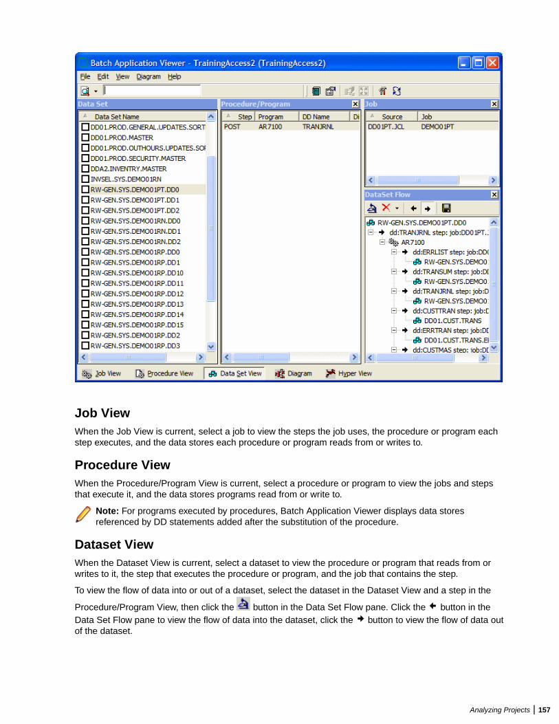
Job ViewWhen the Job View is current, select a job to view the steps the job uses, the procedure or program eachstep executes, and the data stores each procedure or program reads from or writes to.
Procedure ViewWhen the Procedure/Program View is current, select a procedure or program to view the jobs and stepsthat execute it, and the data stores programs read from or write to.
Note: For programs executed by procedures, Batch Application Viewer displays data storesreferenced by DD statements added after the substitution of the procedure.
Dataset ViewWhen the Dataset View is current, select a dataset to view the procedure or program that reads from orwrites to it, the step that executes the procedure or program, and the job that contains the step.
To view the flow of data into or out of a dataset, select the dataset in the Dataset View and a step in the
Procedure/Program View, then click the button in the Data Set Flow pane. Click the button in theData Set Flow pane to view the flow of data into the dataset, click the button to view the flow of data outof the dataset.
Analyzing Projects | 157
Generating Batch Application DiagramsBatch application diagrams show the relationships between jobs, programs or procedures, and data stores.The diagram uses Enterprise Analyzer common diagramming features.
1. In the current view, mark the objects you want to diagram.
2. In the Diagram menu, choose the relationships you want to view in the diagram:
• Job Dependencies shows dependencies between jobs. Jobs are regarded as dependent if onewrites to a dataset and the other reads from the same dataset.
• Data Set Usage shows interactions with datasets.• JCL Procedures Usage shows interactions with procedures.• Program Usage shows interactions with programs.
Note: The menu choice is grayed out with a check mark beside it if the relationship must bedisplayed in the diagram. You can also set these choices after you display the diagram.
3. Click Diagram at the bottom of the Batch Application Viewer window.
The diagram is displayed in the Diagram View.
Assigning Business Names ManuallyTo assign a business name and business description to an object, select the object and choose SetBusiness Attributes in the right-click menu. A dialog box opens, where you can enter the business nameand business description. To unassign a business name or business description, simply delete the value inthe dialog box.
Marking ItemsTo mark an item, place a check mark next to it. To mark all the items in the current view, choose Edit >Check All. To unmark all the items in the current view, choose Edit > Uncheck All.
To mark selected items, select the items and choose Edit > Check Selected. To unmark selected items,choose Edit > Uncheck Selected.
Creating Job Dependencies in Batch ApplicationDiagramsBatch Application Viewer treats jobs as dependent if one writes to a dataset and the other reads from thesame dataset. Occasionally, you may want to define dependencies between jobs based on other criteria:administrative needs such as scheduling, for example. Batch Application Viewer modifies the diagram only,not the repository.
Defining Dependencies Between JobsTo define dependencies between jobs in a batch application diagram, hold down the Alt key, select eitherjob, and drag-and-drop the relationship to the other job. The relationship is displayed in red with three plus(+) signs at either end of the relationship line.
Importing and Exporting Job DependenciesTo import job dependencies from a file, choose File > Import Dependency Changes. A dialog opens,where you can specify the file you want to import.
To export job dependencies to a file, choose File > Export Dependency Changes. A Save As dialogopens, where you can specify the name and location of the file.
158 | Analyzing Projects
Removing Job DependenciesTo remove all user-defined dependencies from a batch application diagram, choose File > Clean UpDependencies.
Note: In certain circumstances (jobs that use cataloged file generation, for example), BatchApplication Viewer may create false dependencies. You must remove these relationships manually byright-clicking the dependency and choosing Remove from the pop-up menu.
Creating User Names for Objects in Batch ApplicationDiagramsYou can give diagram objects friendlier names, called user names. Batch Application Viewer modifies thediagram only, not the repository.
Note: To display user names in a diagram, select User Names in the Batch Application Viewerworkspace options.
Specifying User NamesTo specify a user name for an object in a batch application diagram, select the object and choose View >User Name. The User Name dialog opens, where you can specify the user name.
Importing and Exporting User NamesTo import user names from a file, choose File > Import User Names. A dialog opens, where you canspecify the file you want to import.
To export user names to a file, choose File > Export User Names. A Save As dialog opens, where youcan specify the name and location of the file.
Removing User NamesTo remove all user names from a batch application diagram, choose File > Clean Up User Names.
Setting Batch Application Viewer OptionsUse the Batch Application Viewer tab of the Workspace Options window to specify the color-coding usedfor relationship lines in batch application diagrams. Diagram objects are color-coded based on the colorscheme in the Diagrams User Preferences.
1. Choose Options > Workspace Options. The Workspace Options window opens. Click the BatchApplication Viewer tab.
2. In the Diagram Relations pane, click the relationship type whose color you want to specify, then specifythe color in the Edge Color drop-down.
3. To display user names in a diagram, select User Names.
4. In the Node Limit combo box, enter the maximum number of diagram nodes you want to display. Youmight restrict the number of nodes to improve performance or make the diagram easier to read. You canalso use the slider on the Node Limit tool bar to adjust the number of displayed nodes.
Note: All children of a parent node are displayed even if some of them exceed the specifiedmaximum.
Analyzing Projects | 159
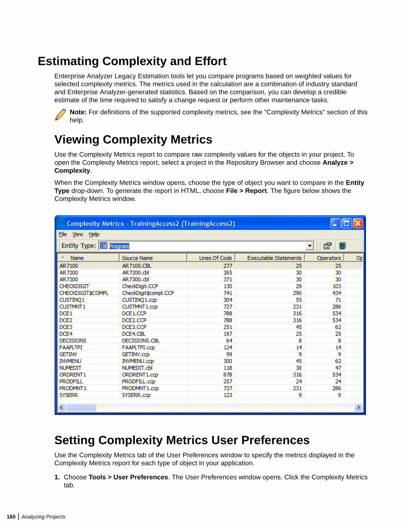
Estimating Complexity and EffortEnterprise Analyzer Legacy Estimation tools let you compare programs based on weighted values forselected complexity metrics. The metrics used in the calculation are a combination of industry standardand Enterprise Analyzer-generated statistics. Based on the comparison, you can develop a credibleestimate of the time required to satisfy a change request or perform other maintenance tasks.
Note: For definitions of the supported complexity metrics, see the "Complexity Metrics" section of thishelp.
Viewing Complexity MetricsUse the Complexity Metrics report to compare raw complexity values for the objects in your project. Toopen the Complexity Metrics report, select a project in the Repository Browser and choose Analyze >Complexity.
When the Complexity Metrics window opens, choose the type of object you want to compare in the EntityType drop-down. To generate the report in HTML, choose File > Report. The figure below shows theComplexity Metrics window.
Setting Complexity Metrics User PreferencesUse the Complexity Metrics tab of the User Preferences window to specify the metrics displayed in theComplexity Metrics report for each type of object in your application.
1. Choose Tools > User Preferences. The User Preferences window opens. Click the Complexity Metricstab.
160 | Analyzing Projects
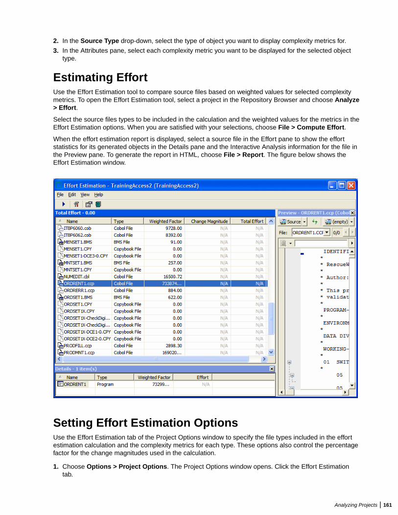
2. In the Source Type drop-down, select the type of object you want to display complexity metrics for.
3. In the Attributes pane, select each complexity metric you want to be displayed for the selected objecttype.
Estimating EffortUse the Effort Estimation tool to compare source files based on weighted values for selected complexitymetrics. To open the Effort Estimation tool, select a project in the Repository Browser and choose Analyze> Effort.
Select the source files types to be included in the calculation and the weighted values for the metrics in theEffort Estimation options. When you are satisfied with your selections, choose File > Compute Effort.
When the effort estimation report is displayed, select a source file in the Effort pane to show the effortstatistics for its generated objects in the Details pane and the Interactive Analysis information for the file inthe Preview pane. To generate the report in HTML, choose File > Report. The figure below shows theEffort Estimation window.
Setting Effort Estimation OptionsUse the Effort Estimation tab of the Project Options window to specify the file types included in the effortestimation calculation and the complexity metrics for each type. These options also control the percentagefactor for the change magnitudes used in the calculation.
1. Choose Options > Project Options. The Project Options window opens. Click the Effort Estimationtab.
Analyzing Projects | 161
2. In the Factors pane, select each source file type you want to include in the calculation.
3. For each source file type selected in the Factors pane, click Attributes to edit the complexity metricsused in the calculation.
4. In the Attributes window, select each complexity metric you want to use in the calculation, then enter itsweight in the Weighting Factor field. For example, if you want Cyclomatic Complexity to have twice theweight of Conditional Complexity, set the weighting factor for Cyclomatic Complexity to 2 and theweighting factor for Conditional Complexity to 1.
5. To set the percentage factor for the change magnitudes used in the calculation, enter the percentageyou want to be applied in the combo box for each change magnitude.
Specifying the Change Magnitude for a Source FileSuppose you are planning to implement a change request and want to know how long it will take tocomplete the change. In that situation, you typically run an effort estimation report for your project based onweighted values for selected complexity metrics.
But what if your own analysis of the project shows that a given program will actually take much less time tochange than the weighted calculation would suggest. The program might have thousands of source lines,for example, increasing its calculated complexity, while actually being very easy to modify.
A change magnitude is a way of overriding the calculated value for a source file. Your "subjective" estimateof the effort involved, Small, Medium, Large, Extra Large, becomes an input to the effort calculation, alongwith the weighted values.
You can specify a change magnitude in the Interactive Analysis Source or Context pane, or in the EffortEstimation tool itself. Select the source file and choose Set Change Magnitude in the right-click menu. Setthe change magnitude to S for Small, M for Medium, L for Large, or XL for Extra Large. The effortestimation calculation for the selected file is automatically updated.
Identifying Classes of Data Items with Change AnalyzerChange Analyzer identifies the class of data items used to perform a business function in a legacyapplication. Amongst other uses, it lets you answer the kind of “What if?” questions posed in the past byindustry-wide changes for Y2K, Zip+4, and the Euro dollar: “What if I change the type of this variable, orthe length of this field? What other fields in the class will I also have to change?”
For each field in the class, you can use Change Analyzer to perform an impact trace that shows the flow ofdata to the field, and to detect and resolve program ports. You can generate reports showing sourceentities that might require modification, lines of affected code, and the like.
Note: Projects must have been verified with the Enable Data Element Flow option set (see SettingProject Verification Options).
The project options on the Impact > Relationships tab of the Project Options window control therelationships detected during synonym and impact trace processing.
Understanding Data Item ClassificationSuppose your organization is considering adding support for a new currency and that you are going tohave to expand the existing exchange rate data field from 9(5)V9(3) to 9(5)V9(6) to accommodate thecurrency. You will need to know the data fields that are affected in the database, intermediate fields thatmight contain or use the exchange rate field in calculations, and so forth.
Seed Fields
Use Change Analyzer to search for the exchange rate field. The object of the search is called a seed field:
162 | Analyzing Projects
• If the application uses field names like EX-RATE, EXCH-RATE, EXCHANGE-RATE, and RATE-OF-EXCHG, you would search for data names that contain *EXCH* or *RATE*.
• If you know that some fields already contain the required number of decimal positions, and areinterested only in those that don’t, you might further limit the search by filtering on the PICTURE clauseformat of the variable, selecting only data items that have a format of 9(5)V9(3).
• You might limit the search even further by choosing fields that have a given initial value.• If you know there are data fields that will meet the search criteria for name, but are not what you are
looking for, you might set up a list of names to exclude, such as INTEREST-RATE and *PRORATE*.
Synonyms
Once you have found the exchange rate field, you can use Change Analyzer to detect its synonyms. Asynonym is a data field whose value is related to the value of a seed field: a field whose value is assignedby a MOVE or REDEFINE statement, for example. In these cases, if you increase the size of the seed field,you will probably need to increase the size of its synonyms as well.
Analyzing Seed Fields and Synonyms
Not every seed field or synonym will be affected by a proposed change. You need to examine the sourcecode for each instance of the field carefully in the Change Analyzer Source pane and in the InteractiveAnalysis tools accessible from the Source pane. You may want to perform an impact trace showing the flowof data to the field as documentation, or to ensure that you have accounted for each instance.
Seed Lists
Once you determine which fields are affected by a proposed change, you can move the fields betweenseed lists: Working and Affected, for example. You can generate reports based on your lists, as well asreports showing the affected source code in context.
Getting Started in Change Analyzer
Sample Usage of Change AnalyzerThis section describes a sample use of Change Analyzer that should help you get oriented in the tool.Assume that you want to evaluate the impact of changing the YEAR field in your application.
1. In the Repository Browser, select the project you want to analyze and choose Analyze > ChangeAnalyzer. The Change Analyzer window opens.
2. Go to Tools > Analysis Options, select Use Cross Program Analysis and click OK
3.
Select a file from the list of programs and click (Step 1: Populate starting point list). A messageinforming you that any existing lists will be deleted pops up. Click OK.
4. When the Search window opens, click on the tool bar to define a new criterion. In the New Criteriondialog, enter YEAR and click OK. The YEAR criterion is displayed in the list of recognized criteria in theChange Analyzer tab in the Search window.
5. In the Change Analyzer tab, select the YEAR criterion and then enter the following search text for thecriterion in the Name Like tab: *DATE*.
6. Click Find All Constructs. You are informed about the number of constructs found.
7. Click OK. The Starting point tab is now populated with the seed fields for the criterion.
8.
Click and then All Programs (all starting points). If a messages pops up informing you thatcross-program is enabled and the analysis might take excessive amount of time, click OK. The FindSynonyms dialog opens.
Analyzing Projects | 163
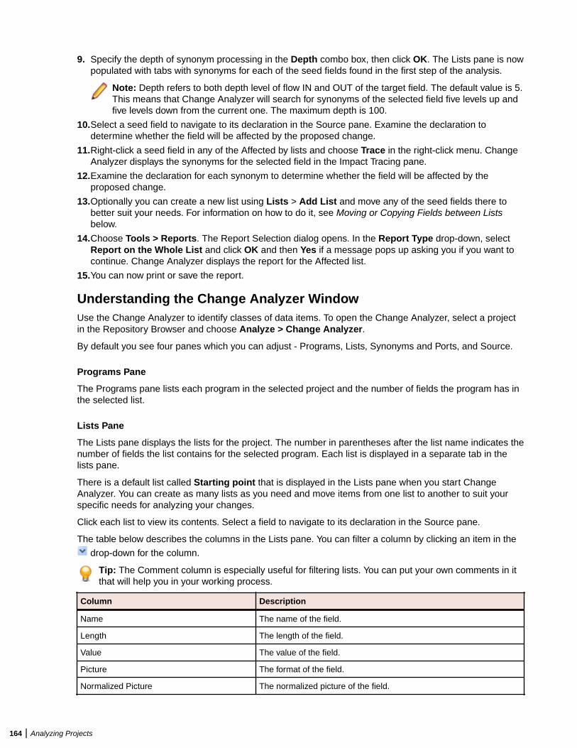
9. Specify the depth of synonym processing in the Depth combo box, then click OK. The Lists pane is nowpopulated with tabs with synonyms for each of the seed fields found in the first step of the analysis.
Note: Depth refers to both depth level of flow IN and OUT of the target field. The default value is 5.This means that Change Analyzer will search for synonyms of the selected field five levels up andfive levels down from the current one. The maximum depth is 100.
10.Select a seed field to navigate to its declaration in the Source pane. Examine the declaration todetermine whether the field will be affected by the proposed change.
11.Right-click a seed field in any of the Affected by lists and choose Trace in the right-click menu. ChangeAnalyzer displays the synonyms for the selected field in the Impact Tracing pane.
12.Examine the declaration for each synonym to determine whether the field will be affected by theproposed change.
13.Optionally you can create a new list using Lists > Add List and move any of the seed fields there tobetter suit your needs. For information on how to do it, see Moving or Copying Fields between Listsbelow.
14.Choose Tools > Reports. The Report Selection dialog opens. In the Report Type drop-down, selectReport on the Whole List and click OK and then Yes if a message pops up asking you if you want tocontinue. Change Analyzer displays the report for the Affected list.
15.You can now print or save the report.
Understanding the Change Analyzer WindowUse the Change Analyzer to identify classes of data items. To open the Change Analyzer, select a projectin the Repository Browser and choose Analyze > Change Analyzer.
By default you see four panes which you can adjust - Programs, Lists, Synonyms and Ports, and Source.
Programs Pane
The Programs pane lists each program in the selected project and the number of fields the program has inthe selected list.
Lists Pane
The Lists pane displays the lists for the project. The number in parentheses after the list name indicates thenumber of fields the list contains for the selected program. Each list is displayed in a separate tab in thelists pane.
There is a default list called Starting point that is displayed in the Lists pane when you start ChangeAnalyzer. You can create as many lists as you need and move items from one list to another to suit yourspecific needs for analyzing your changes.
Click each list to view its contents. Select a field to navigate to its declaration in the Source pane.
The table below describes the columns in the Lists pane. You can filter a column by clicking an item in the
drop-down for the column.
Tip: The Comment column is especially useful for filtering lists. You can put your own comments in itthat will help you in your working process.
Column Description
Name The name of the field.
Length The length of the field.
Value The value of the field.
Picture The format of the field.
Normalized Picture The normalized picture of the field.
164 | Analyzing Projects
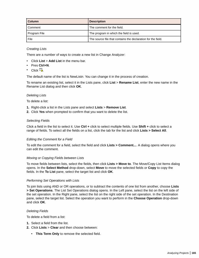
Column Description
Comment The comment for the field.
Program File The program in which the field is used.
File The source file that contains the declaration for the field.
Creating Lists
There are a number of ways to create a new list in Change Analyzer:
• Click List > Add List in the menu bar.• Pres Ctrl+N.• Click .
The default name of the list is NewListn. You can change it in the process of creation.
To rename an existing list, select it in the Lists pane, click List > Rename List, enter the new name in theRename List dialog and then click OK.
Deleting Lists
To delete a list:
1. Right-click a list in the Lists pane and select Lists > Remove List.2. Click Yes when prompted to confirm that you want to delete the list.
Selecting Fields
Click a field in the list to select it. Use Ctrl + click to select multiple fields. Use Shift + click to select arange of fields. To select all the fields on a list, click the tab for the list and click Lists > Select All.
Editing the Comment for a Field
To edit the comment for a field, select the field and click Lists > Comment.... A dialog opens where youcan edit the comment.
Moving or Copying Fields between Lists
To move fields between lists, select the fields, then click Lists > Move to. The Move/Copy List Items dialogopens. In the Select Method drop-down, select Move to move the selected fields or Copy to copy thefields. In the To List pane, select the target list and click OK.
Performing Set Operations with Lists
To join lists using AND or OR operations, or to subtract the contents of one list from another, choose Lists> Set Operations. The List Set Operations dialog opens. In the Left pane, select the list on the left side ofthe set operation. In the Right pane, select the list on the right side of the set operation. In the Destinationpane, select the target list. Select the operation you want to perform in the Choose Operation drop-downand click OK.
Deleting Fields
To delete a field from a list:
1. Select a field from the list.2. Click Lists > Clear and then choose between:
• This Term Only to remove the selected field.
Analyzing Projects | 165

• All List Contents to clear the whole list.
Impact Tracing Pane
The Impact Tracing pane shows in a tree view the impact traces of the fields in the Lists pane.
To display the synonyms and/or the impact traces, select the field in the Lists pane and click Trace in theImpact Tracing pane.
To delete an impact trace, select it in the tree and click Delete.
To clear the Impact Traces tree, click Delete All.
Source Pane
The Source pane lets you browse information for the object selected in the Lists or the Impact Tracingpane. You can select the information you want to view for the object from the drop-down in the upperlefthand corner of the pane. The available options are:
SourceContextCode SearchBird's EyeProgram Control FlowFlowchartData ViewData FlowImpactDiagrammerProperties.
Usage is similar to that for the Source pane in Interactive Analysis. For Interactive Analysis usageinformation, see Analyzing Programs in the product documentation set.
Searching for Seed Fields in Change AnalyzerThe Change Analyzer search facility contains two tabs:
• The General tab opens the Interactive Analysis advanced search facility.• The Change Analyzer tab opens a scoped version of the advanced search facility for Change Analyzer.
Ordinarily, the scoped version of the tool should be sufficient for most searches. If you are already familiarwith the advanced search facility, however, you may want to use it instead of the scoped tool.
Note: For COBOL programs, Change Analyzer returns only constants and literals found in theProcedure section.
1.
Select a file from the list of programs and click (Step 1: Populate starting point list). A messageinforming you that any existing lists will be deleted pops up. Click OK.
2. The Change Analyzer Search window opens. Click the Change Analyzer tab. The Change Analyzer tabdisplays a list of recognized search criteria.
Note: Define a new criterion as described in the help for the advanced search facility.
3. Select a criterion to edit its definition in the tabs in the right portion of the window. Each tab specifies acondition in the definition. The definition can consist of any combination of conditions.
4. For each condition, enter a list of patterns you want to match, one pattern per line. You can use wildcardpatterns allowed in LIKE statements by Visual Basic for Applications (VBA). Select:
166 | Analyzing Projects
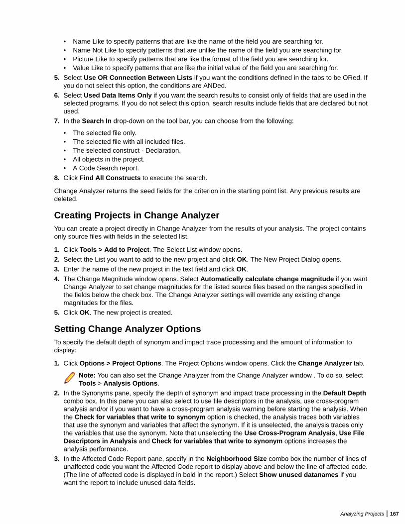
• Name Like to specify patterns that are like the name of the field you are searching for.• Name Not Like to specify patterns that are unlike the name of the field you are searching for.• Picture Like to specify patterns that are like the format of the field you are searching for.• Value Like to specify patterns that are like the initial value of the field you are searching for.
5. Select Use OR Connection Between Lists if you want the conditions defined in the tabs to be ORed. Ifyou do not select this option, the conditions are ANDed.
6. Select Used Data Items Only if you want the search results to consist only of fields that are used in theselected programs. If you do not select this option, search results include fields that are declared but notused.
7. In the Search In drop-down on the tool bar, you can choose from the following:
• The selected file only.• The selected file with all included files.• The selected construct - Declaration.• All objects in the project.• A Code Search report.
8. Click Find All Constructs to execute the search.
Change Analyzer returns the seed fields for the criterion in the starting point list. Any previous results aredeleted.
Creating Projects in Change AnalyzerYou can create a project directly in Change Analyzer from the results of your analysis. The project containsonly source files with fields in the selected list.
1. Click Tools > Add to Project. The Select List window opens.
2. Select the List you want to add to the new project and click OK. The New Project Dialog opens.
3. Enter the name of the new project in the text field and click OK.
4. The Change Magnitude window opens. Select Automatically calculate change magnitude if you wantChange Analyzer to set change magnitudes for the listed source files based on the ranges specified inthe fields below the check box. The Change Analyzer settings will override any existing changemagnitudes for the files.
5. Click OK. The new project is created.
Setting Change Analyzer OptionsTo specify the default depth of synonym and impact trace processing and the amount of information todisplay:
1. Click Options > Project Options. The Project Options window opens. Click the Change Analyzer tab.
Note: You can also set the Change Analyzer from the Change Analyzer window . To do so, selectTools > Analysis Options.
2. In the Synonyms pane, specify the depth of synonym and impact trace processing in the Default Depthcombo box. In this pane you can also select to use file descriptors in the analysis, use cross-programanalysis and/or if you want to have a cross-program analysis warning before starting the analysis. Whenthe Check for variables that write to synonym option is checked, the analysis traces both variablesthat use the synonym and variables that affect the synonym. If it is unselected, the analysis traces onlythe variables that use the synonym. Note that unselecting the Use Cross-Program Analysis, Use FileDescriptors in Analysis and Check for variables that write to synonym options increases theanalysis performance.
3. In the Affected Code Report pane, specify in the Neighborhood Size combo box the number of lines ofunaffected code you want the Affected Code report to display above and below the line of affected code.(The line of affected code is displayed in bold in the report.) Select Show unused datanames if youwant the report to include unused data fields.
Analyzing Projects | 167
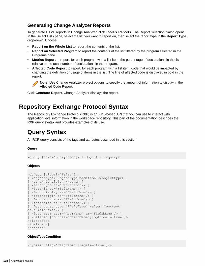
Generating Change Analyzer ReportsTo generate HTML reports in Change Analyzer, click Tools > Reports. The Report Selection dialog opens.In the Select Lists pane, select the list you want to report on, then select the report type in the Report Typedrop-down. Choose:
• Report on the Whole List to report the contents of the list.• Report on Selected Program to report the contents of the list filtered by the program selected in the
Programs pane.• Metrics Report to report, for each program with a list item, the percentage of declarations in the list
relative to the total number of declarations in the program.• Affected Code Report to report, for each program with a list item, code that would be impacted by
changing the definition or usage of items in the list. The line of affected code is displayed in bold in thereport.
Note: Use Change Analyzer project options to specify the amount of information to display in theAffected Code Report.
Click Generate Report. Change Analyzer displays the report.
Repository Exchange Protocol SyntaxThe Repository Exchange Protocol (RXP) is an XML-based API that you can use to interact withapplication-level information in the workspace repository. This part of the documentation describes theRXP query syntax and provides examples of its use.
Query SyntaxAn RXP query consists of the tags and attributes described in this section.
Query
<query [name='QueryName']> { Object } </query>
Objects
<object [global='false']>[ <objecttype> ObjectTypeCondition </objecttype> ][ <cond> Condition </cond> ][ <fetchtype as='FieldName'/> ][ <fetchid as='FieldName'/> ][ <fetchdisplay as='FieldName'/> ][ <fetchorigin as='FieldName'/> ][ <fetchsource as='FieldName'/> ][ <fetchsize as='FieldName'/> ]{ <fetchconst type='FieldType' value='Constant'as='FieldName'/> }{ <fetchattr attr='AttrName' as='FieldName'/> }[ <related [countas='FieldName'][optional='true']>RelatedSpec</related>]</object>
ObjectTypeCondition
<typeset flag='FlagName' [negate='true']/>
168 | Analyzing Projects
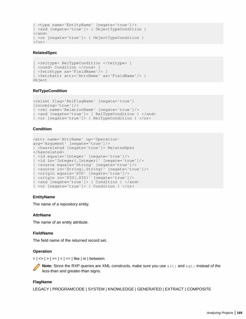
| <type name='EntityName' [negate='true']/>| <and [negate='true']> { ObjectTypeCondition }</and>| <or [negate='true']> { ObjectTypeCondition }</or>
RelatedSpec
[ <reltype> RelTypeCondition </reltype> ][ <cond> Condition </cond> ][ <fetchtype as='FieldName'/> ]{ <fetchattr attr='AttrName' as='FieldName'/> }Object
RelTypeCondition
<relset flag='RelFlagName' [negate='true'][incoming='true']/>| <rel name='RelationName' [negate='true']/>| <and [negate='true']> { RelTypeCondition } </and>| <or [negate='true']> { RelTypeCondition } </or>
Condition
<attr name='AttrName' op='Operation'arg='Argument' [negate='true']/>| <hasrelated [negate='true']> RelatedSpec</hasrelated>| <id equals='Integer' [negate='true']/>| <id in='Integer{,Integer}' [negate='true']/>| <source equals='String' [negate='true']/>| <source in='String{,String}' [negate='true']/>| <origin equals='SID' [negate='true']/>| <origin in='SID{,SID}' [negate='true']/>| <and [negate='true']> { Condition } </and>| <or [negate='true']> { Condition } </or>
EntityName
The name of a repository entity.
AttrName
The name of an entity attribute.
FieldName
The field name of the returned record set.
Operation
= | <> | > | >= | < | <= | like | in | between
Note: Since the RXP queries are XML constructs, make sure you use < and > instead of theless-than and greater-than signs.
FlagName
LEGACY | PROGRAMCODE | SYSTEM | KNOWLEDGE | GENERATED | EXTRACT | COMPOSITE
Analyzing Projects | 169
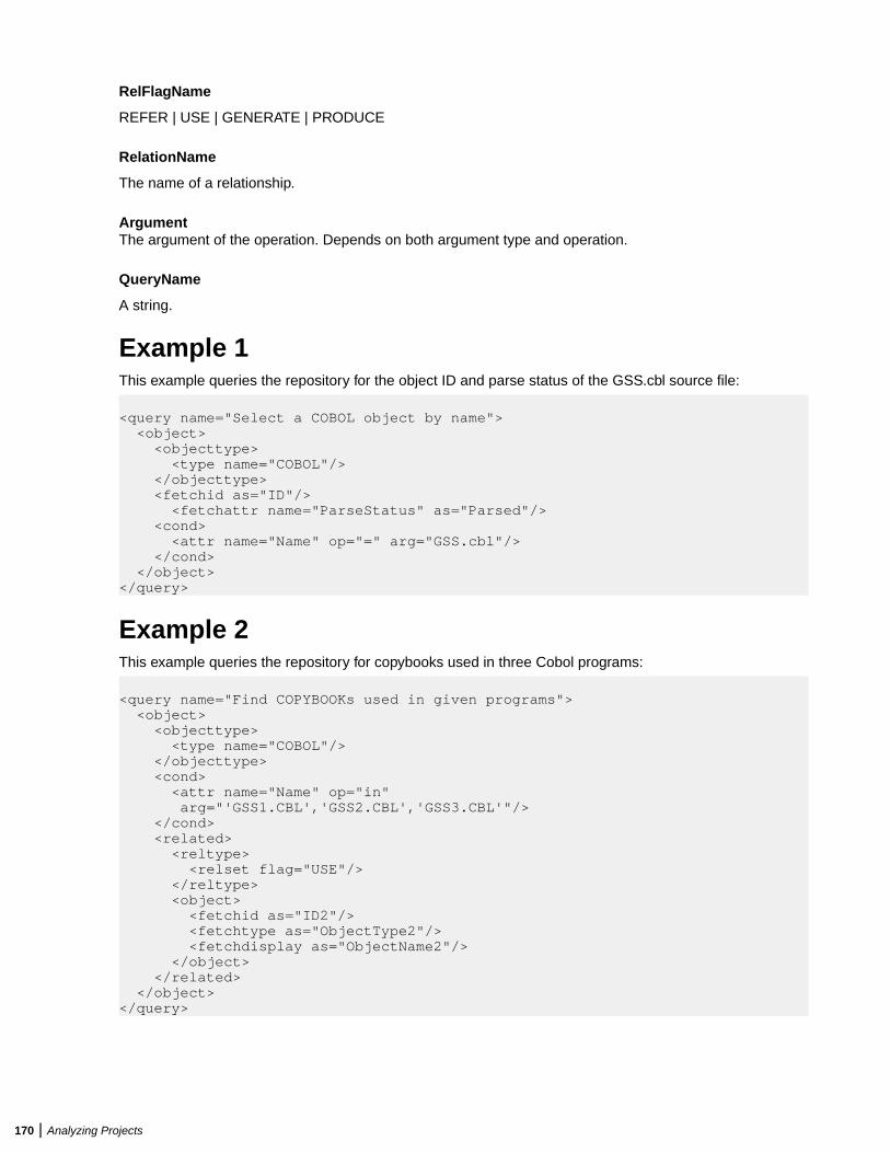
RelFlagName
REFER | USE | GENERATE | PRODUCE
RelationName
The name of a relationship.
ArgumentThe argument of the operation. Depends on both argument type and operation.
QueryName
A string.
Example 1This example queries the repository for the object ID and parse status of the GSS.cbl source file:
<query name="Select a COBOL object by name"> <object> <objecttype> <type name="COBOL"/> </objecttype> <fetchid as="ID"/> <fetchattr name="ParseStatus" as="Parsed"/> <cond> <attr name="Name" op="=" arg="GSS.cbl"/> </cond> </object> </query>
Example 2This example queries the repository for copybooks used in three Cobol programs:
<query name="Find COPYBOOKs used in given programs"> <object> <objecttype> <type name="COBOL"/> </objecttype> <cond> <attr name="Name" op="in" arg="'GSS1.CBL','GSS2.CBL','GSS3.CBL'"/> </cond> <related> <reltype> <relset flag="USE"/> </reltype> <object> <fetchid as="ID2"/> <fetchtype as="ObjectType2"/> <fetchdisplay as="ObjectName2"/> </object> </related> </object></query>
170 | Analyzing Projects
Portability AssessmentPortability Assessment lets you quickly generate HTML reports to identify points of interest for migrations.All reports are presented under an easy to navigate main page. To run the report:
• Start Enterprise Analyzer.• Click Reports > Portability Assessment.
The Portability Assessment window opens.• Select the types of HTML reports you want to generate. Use the checkbox next to each report or check
Enable/Disable All.• Enter the Folder Name and Folder Location where the report will be generated.• Click Start to generate the reports or Close to quit.
When the report is ready a message is displayed asking if you want to see the report.• Click Yes to view the report.
The results are displayed in your browser. Navigate through the reports. Check Hide empty reports tohide/display empty reports. The reports are organized in tables. Click on the heading of the columns tosort the data.
Note: Some of the reports may be available as advanced search queries in Interactive Analysis orin the Repository Browser > Query Repository feature. Running these queries interactively orediting them will not affect the results generated in the Portability Assessment report.
Quality AssessmentQuality Assessment lets you quickly generate HTML reports to monitor applications for conformity to qualityrules or to identify candidates for quality improvements. All reports are presented under an easy tonavigate main page. To run the report:
• Start Enterprise Analyzer.• Click Reports > Quality Assessment.
The Quality Assessment window opens.• Select the types of HTML reports you want to generate. Use the checkbox next to each report or check
Enable/Disable All.• Enter the Folder Name and Folder Location where the report will be generated.• Click Start to generate the reports or Close to quit.
When the report is ready a message is displayed asking if you want to see the report.• Click Yes to view the report.
The results are displayed in your browser. Navigate through the reports. Check Hide empty reports tohide/display empty reports. The reports are organized in tables. Click on the heading of the columns tosort the data.
Note: Some of the reports may be available as advanced search queries in Interactive Analysis.Running these queries interactively or editing them will not affect the results generated in theQuality Assessment report.
Analyzing Projects | 171
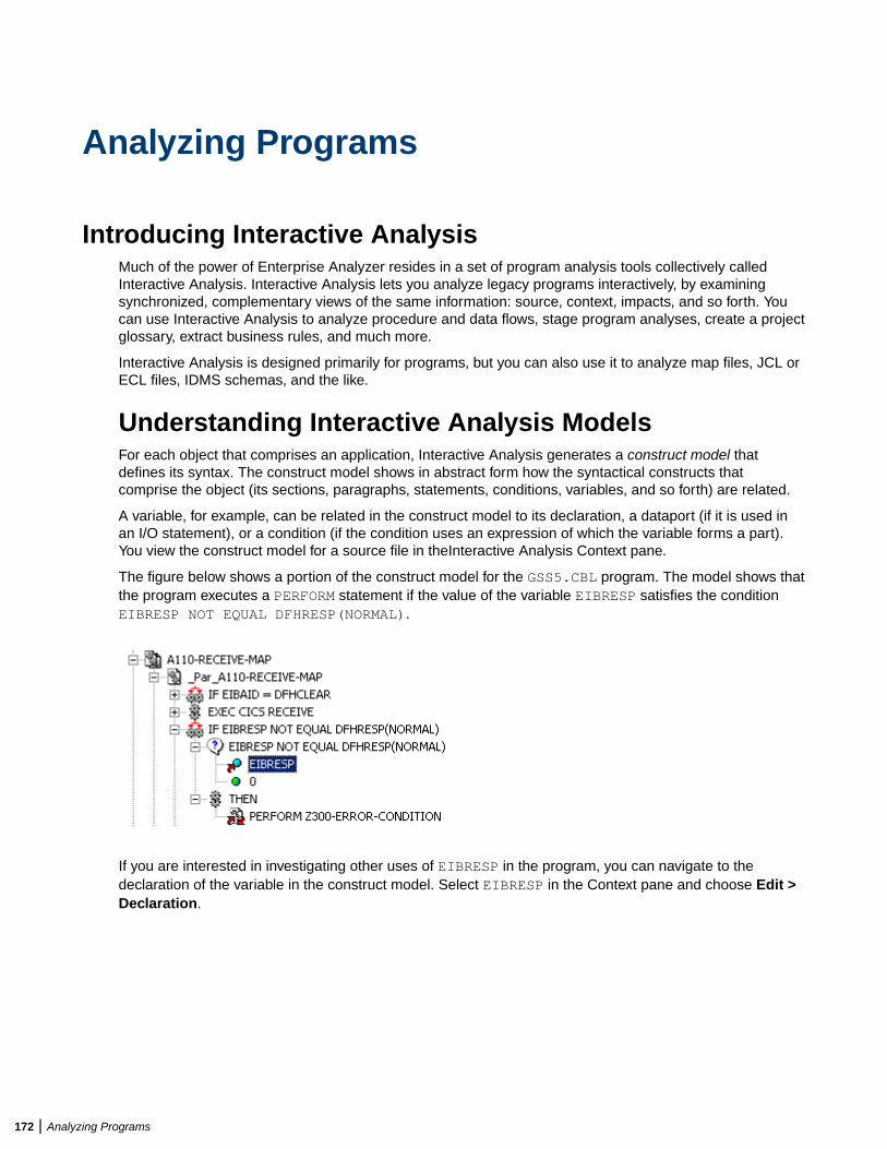
Analyzing Programs
Introducing Interactive AnalysisMuch of the power of Enterprise Analyzer resides in a set of program analysis tools collectively calledInteractive Analysis. Interactive Analysis lets you analyze legacy programs interactively, by examiningsynchronized, complementary views of the same information: source, context, impacts, and so forth. Youcan use Interactive Analysis to analyze procedure and data flows, stage program analyses, create a projectglossary, extract business rules, and much more.
Interactive Analysis is designed primarily for programs, but you can also use it to analyze map files, JCL orECL files, IDMS schemas, and the like.
Understanding Interactive Analysis ModelsFor each object that comprises an application, Interactive Analysis generates a construct model thatdefines its syntax. The construct model shows in abstract form how the syntactical constructs thatcomprise the object (its sections, paragraphs, statements, conditions, variables, and so forth) are related.
A variable, for example, can be related in the construct model to its declaration, a dataport (if it is used inan I/O statement), or a condition (if the condition uses an expression of which the variable forms a part).You view the construct model for a source file in theInteractive Analysis Context pane.
The figure below shows a portion of the construct model for the GSS5.CBL program. The model shows thatthe program executes a PERFORM statement if the value of the variable EIBRESP satisfies the conditionEIBRESP NOT EQUAL DFHRESP(NORMAL).
If you are interested in investigating other uses of EIBRESP in the program, you can navigate to thedeclaration of the variable in the construct model. Select EIBRESP in the Context pane and choose Edit >Declaration.
172 | Analyzing Programs
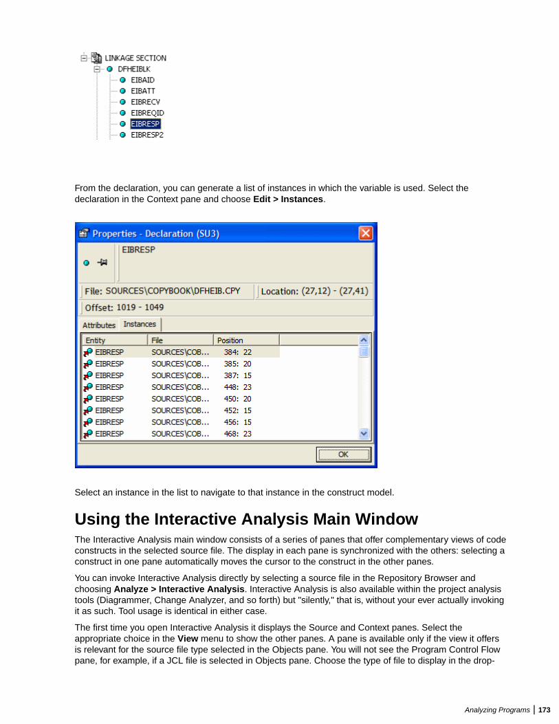
From the declaration, you can generate a list of instances in which the variable is used. Select thedeclaration in the Context pane and choose Edit > Instances.
Select an instance in the list to navigate to that instance in the construct model.
Using the Interactive Analysis Main WindowThe Interactive Analysis main window consists of a series of panes that offer complementary views of codeconstructs in the selected source file. The display in each pane is synchronized with the others: selecting aconstruct in one pane automatically moves the cursor to the construct in the other panes.
You can invoke Interactive Analysis directly by selecting a source file in the Repository Browser andchoosing Analyze > Interactive Analysis. Interactive Analysis is also available within the project analysistools (Diagrammer, Change Analyzer, and so forth) but "silently," that is, without your ever actually invokingit as such. Tool usage is identical in either case.
The first time you open Interactive Analysis it displays the Source and Context panes. Select theappropriate choice in the View menu to show the other panes. A pane is available only if the view it offersis relevant for the source file type selected in the Objects pane. You will not see the Program Control Flowpane, for example, if a JCL file is selected in Objects pane. Choose the type of file to display in the drop-
Analyzing Programs | 173
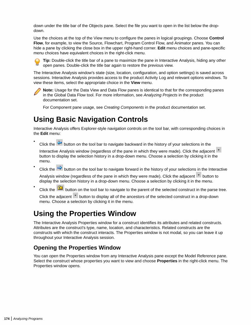
down under the title bar of the Objects pane. Select the file you want to open in the list below the drop-down.
Use the choices at the top of the View menu to configure the panes in logical groupings. Choose ControlFlow, for example, to view the Source, Flowchart, Program Control Flow, and Animator panes. You canhide a pane by clicking the close box in the upper right-hand corner. Edit menu choices and pane-specificmenu choices have equivalent choices in the right-click menu.
Tip: Double-click the title bar of a pane to maximize the pane in Interactive Analysis, hiding any otheropen panes. Double-click the title bar again to restore the previous view.
The Interactive Analysis window's state (size, location, configuration, and option settings) is saved acrosssessions. Interactive Analysis provides access to the product Activity Log and relevant options windows. Toview these items, select the appropriate choice in the View menu.
Note: Usage for the Data View and Data Flow panes is identical to that for the corresponding panesin the Global Data Flow tool. For more information, see Analyzing Projects in the productdocumentation set.
For Component pane usage, see Creating Components in the product documentation set.
Using Basic Navigation ControlsInteractive Analysis offers Explorer-style navigation controls on the tool bar, with corresponding choices inthe Edit menu:
•Click the button on the tool bar to navigate backward in the history of your selections in the
Interactive Analysis window (regardless of the pane in which they were made). Click the adjacent button to display the selection history in a drop-down menu. Choose a selection by clicking it in themenu.
•Click the button on the tool bar to navigate forward in the history of your selections in the Interactive
Analysis window (regardless of the pane in which they were made). Click the adjacent button todisplay the selection history in a drop-down menu. Choose a selection by clicking it in the menu.
•Click the button on the tool bar to navigate to the parent of the selected construct in the parse tree.
Click the adjacent button to display all of the ancestors of the selected construct in a drop-downmenu. Choose a selection by clicking it in the menu.
Using the Properties WindowThe Interactive Analysis Properties window for a construct identifies its attributes and related constructs.Attributes are the construct's type, name, location, and characteristics. Related constructs are theconstructs with which the construct interacts. The Properties window is not modal, so you can leave it upthroughout your Interactive Analysis session.
Opening the Properties WindowYou can open the Properties window from any Interactive Analysis pane except the Model Reference pane.Select the construct whose properties you want to view and choose Properties in the right-click menu. TheProperties window opens.
174 | Analyzing Programs
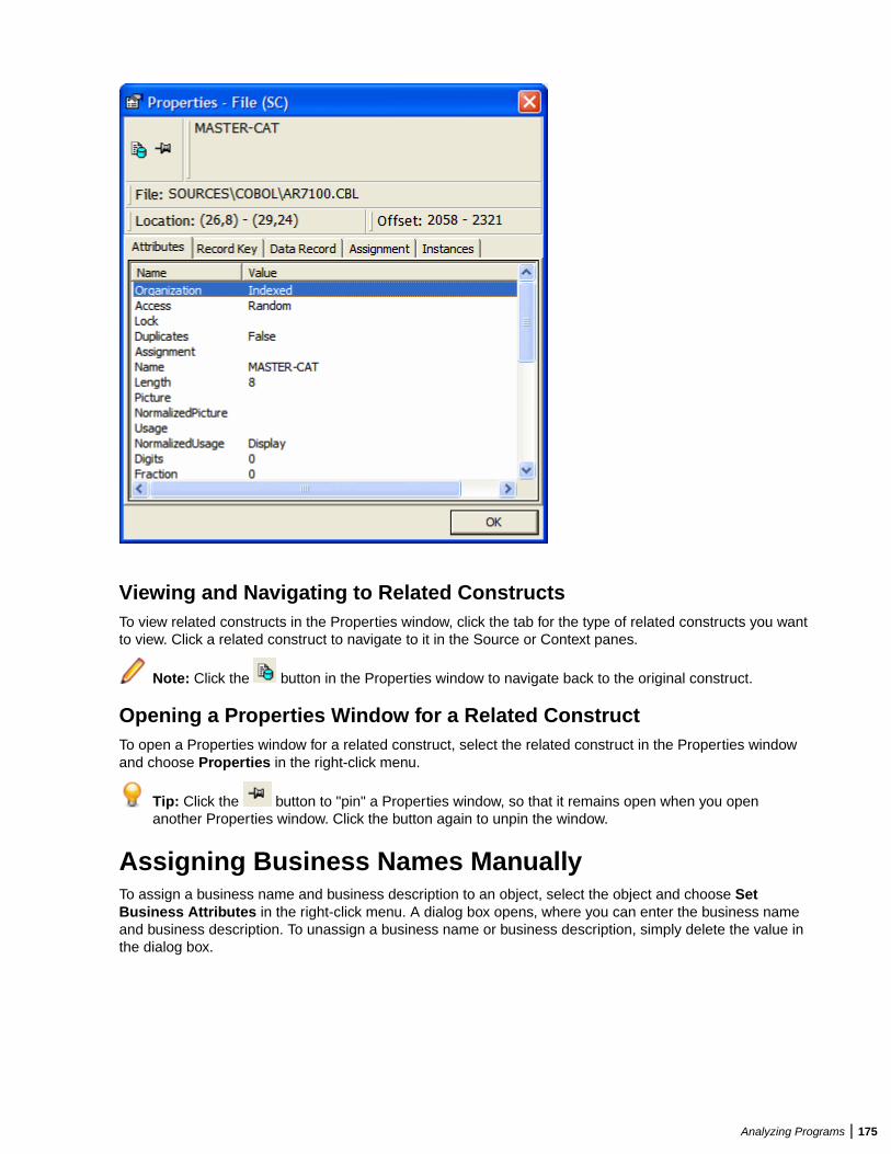
Viewing and Navigating to Related ConstructsTo view related constructs in the Properties window, click the tab for the type of related constructs you wantto view. Click a related construct to navigate to it in the Source or Context panes.
Note: Click the button in the Properties window to navigate back to the original construct.
Opening a Properties Window for a Related ConstructTo open a Properties window for a related construct, select the related construct in the Properties windowand choose Properties in the right-click menu.
Tip: Click the button to "pin" a Properties window, so that it remains open when you openanother Properties window. Click the button again to unpin the window.
Assigning Business Names ManuallyTo assign a business name and business description to an object, select the object and choose SetBusiness Attributes in the right-click menu. A dialog box opens, where you can enter the business nameand business description. To unassign a business name or business description, simply delete the value inthe dialog box.
Analyzing Programs | 175
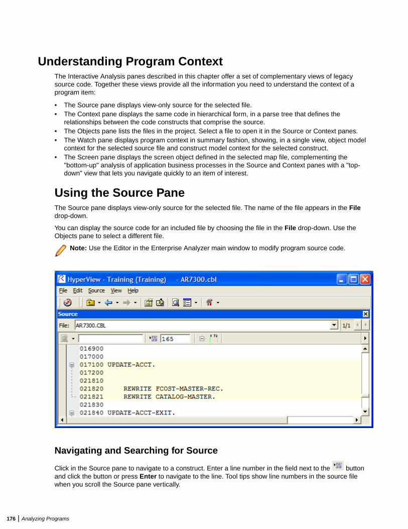
Understanding Program ContextThe Interactive Analysis panes described in this chapter offer a set of complementary views of legacysource code. Together these views provide all the information you need to understand the context of aprogram item:
• The Source pane displays view-only source for the selected file.• The Context pane displays the same code in hierarchical form, in a parse tree that defines the
relationships between the code constructs that comprise the source.• The Objects pane lists the files in the project. Select a file to open it in the Source or Context panes.• The Watch pane displays program context in summary fashion, showing, in a single view, object model
context for the selected source file and construct model context for the selected construct.• The Screen pane displays the screen object defined in the selected map file, complementing the
"bottom-up" analysis of application business processes in the Source and Context panes with a "top-down" view that lets you navigate quickly to an item of interest.
Using the Source PaneThe Source pane displays view-only source for the selected file. The name of the file appears in the Filedrop-down.
You can display the source code for an included file by choosing the file in the File drop-down. Use theObjects pane to select a different file.
Note: Use the Editor in the Enterprise Analyzer main window to modify program source code.
Navigating and Searching for Source
Click in the Source pane to navigate to a construct. Enter a line number in the field next to the buttonand click the button or press Enter to navigate to the line. Tool tips show line numbers in the source filewhen you scroll the Source pane vertically.
176 | Analyzing Programs
Using the Simple Search Facility
Interactive Analysis provides simple and advanced search facilities for source code. To use the simple
search facility, enter the text for the search in the field next to the button on the tool bar. Interactive
Analysis locates text matches as you type. Click the button or press Enter to navigate to the nextmatching construct.
To view matching constructs in a list, click the adjacent button. From the drop-down menu, choose:
• Find All to display pattern matches in a list.• Wildcard Find All to display wildcard pattern matches in a list. You can use wildcard patterns allowed
in LIKE statements by Visual Basic for Applications (VBA).• Recent Search List to display the results of the last simple search.
Double-click an item in a list to navigate to it in the Source pane.
Navigating to Related Constructs
The Edit menu lists choices corresponding to each type of relationship the selected construct has withother constructs in the parse tree. If you select a variable in the Source pane, for example, the Edit menushows Conditions, Port, and Declaration choices. The choices are grayed-out if no relationships of thegiven type exist for the selected construct.
To view all the constructs in the source file that have a given relationship with a construct, select theconstruct in the Source pane and choose the appropriate relationship in the Edit menu:
• If only one construct has the specified relationship, Interactive Analysis simply moves the cursor to thatconstruct in every open Interactive Analysis pane.
• If more than one construct has the specified relationship, Interactive Analysis opens a list of relatedconstructs in the Properties window and moves the cursor to the first item in the list in every openInteractive Analysis pane. To navigate to another item in the list, choose it in the Properties window.
Navigating to Multiple Occurrences of an Included Construct
If an included file is referenced multiple times in a program (in different structures, for example), you canuse the arrows in the upper right-hand corner of the Source pane to navigate between each occurrence ofan included construct in the Context pane.
In the Source pane, click on the construct in the included file. The numbers in the upper right-hand cornershow the sequence number of the current construct versus the total number of constructs. The notation"2/3," for example, identifies the second occurrence of a construct that occurs three times. Use the arrowsto navigate between each occurrence.
Selecting and Copying CodeThere are two ways to select and copy code in the Source pane, as construct or as text. The one youchoose depends on the task you want to perform.
Selecting and Copying Constructs
Click inside a construct in the Source pane to select it. The selected construct is highlighted. The numberof the first line of the selection is displayed in the Ln field above the source code. To copy the construct tothe clipboard, choose Copy Selected Construct in the Source menu.
Selecting and Copying Text
Copy code as text when you are assigning code segments to business rules manually and want to selecteither more or less code than a construct contains. To select a code segment as text, click-and-drag fromthe first line of the segment to the last line of the segment. The selected text is highlighted in blue. To copythe selected segment to the clipboard, choose Source > Copy Selected Text.
Analyzing Programs | 177
Tip: Click the minus sign (-) next to a paragraph, procedure, or data definition to collapse its contents.Click the plus sign (+) to expand its contents.
Setting Source Pane User PreferencesUse the Interactive Analysis > Source tab of the User Preferences window to specify the color-coding usedin the Source pane and other display features.
1. Choose Tools > User Preferences. The User Preferences window opens. Click the Interactive Analysis> Source tab.
2. Select Iconic cursor to specify that the icon for a selected construct ( for a data port, for example)replace the standard cursor.
3. In the Selected Construct Color field, click the adjacent button to edit the color used to highlightthe selected construct.
4. In the List Highlighting Color field, click the adjacent button to edit the color used to highlight lists.
5. In the Color Scheme pane, click the construct types whose text you want to colorize, or click Select Allto select all the construct types. The current color of the selected types (if any) is displayed in the Fore
Color drop-down. Click the adjacent button to edit the color of the construct types.
6. Select Display Business Names to display business names rather than original identifiers in theContext pane.
Collapsing and Expanding Paragraphs or SubprogramsIn very long programs, it may be helpful to display the names of paragraphs or subprograms only and hidetheir source code. To collapse paragraphs or subprograms, choose Edit > Collapse All. Click the plus sign(+) next to a collapsed paragraph or subprogram to show its source code again. To show the source codefor all collapsed paragraphs or subprograms, choose Edit > Expand All.
Showing Source Code BoundariesTo demarcate source code from leading and trailing enumeration characters in source lines, choose Edit >Show Boundaries.
Using the Context PaneThe Context pane displays the parse tree for the selected source file. The parse tree displays source codeconstructs (sections, paragraphs, statements, conditions, variables, and so forth) in hierarchical form,making it easy to locate code constructs quickly. Constructs are displayed in the order they appear in yourcode.
Note: Interactive Analysis adds artificial "owning" sections or paragraphs to the parse tree asnecessary. An added, or faked, section or paragraph is denoted in the parse tree with a leadingunderscore: _S1, for example.
The scope of the parse tree determines the constructs and relationships it displays: all constructs, onlycontrol statements, only declarations, and so forth. Scopes include the lists Interactive Analysis generateswhen you perform advanced searches, navigate to a related construct, or identify candidates in CodeSearch. Choose the scope of the parse tree in the Scopes drop-down on the Context pane tool bar.
Click the plus sign (+) next to a construct to expand its hierarchy. Click the minus sign (-) to collapse thehierarchy. The Edit menu lists every relationship type for the construct selected in the Context pane.
Perform other tasks as you do in the Source pane. Select Display Business Names in the UserPreferences for the Source pane to display business names rather than original identifiers in the Contextpane.
178 | Analyzing Programs
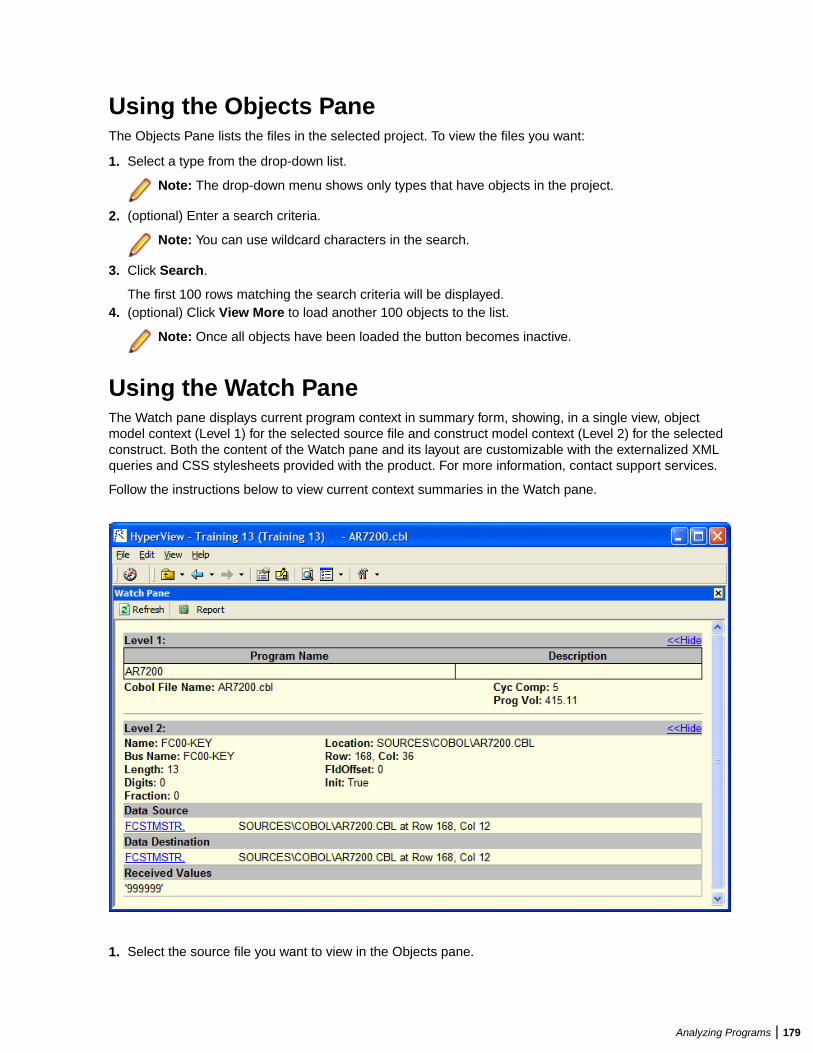
Using the Objects PaneThe Objects Pane lists the files in the selected project. To view the files you want:
1. Select a type from the drop-down list.
Note: The drop-down menu shows only types that have objects in the project.
2. (optional) Enter a search criteria.
Note: You can use wildcard characters in the search.
3. Click Search.
The first 100 rows matching the search criteria will be displayed.4. (optional) Click View More to load another 100 objects to the list.
Note: Once all objects have been loaded the button becomes inactive.
Using the Watch PaneThe Watch pane displays current program context in summary form, showing, in a single view, objectmodel context (Level 1) for the selected source file and construct model context (Level 2) for the selectedconstruct. Both the content of the Watch pane and its layout are customizable with the externalized XMLqueries and CSS stylesheets provided with the product. For more information, contact support services.
Follow the instructions below to view current context summaries in the Watch pane.
1. Select the source file you want to view in the Objects pane.
Analyzing Programs | 179
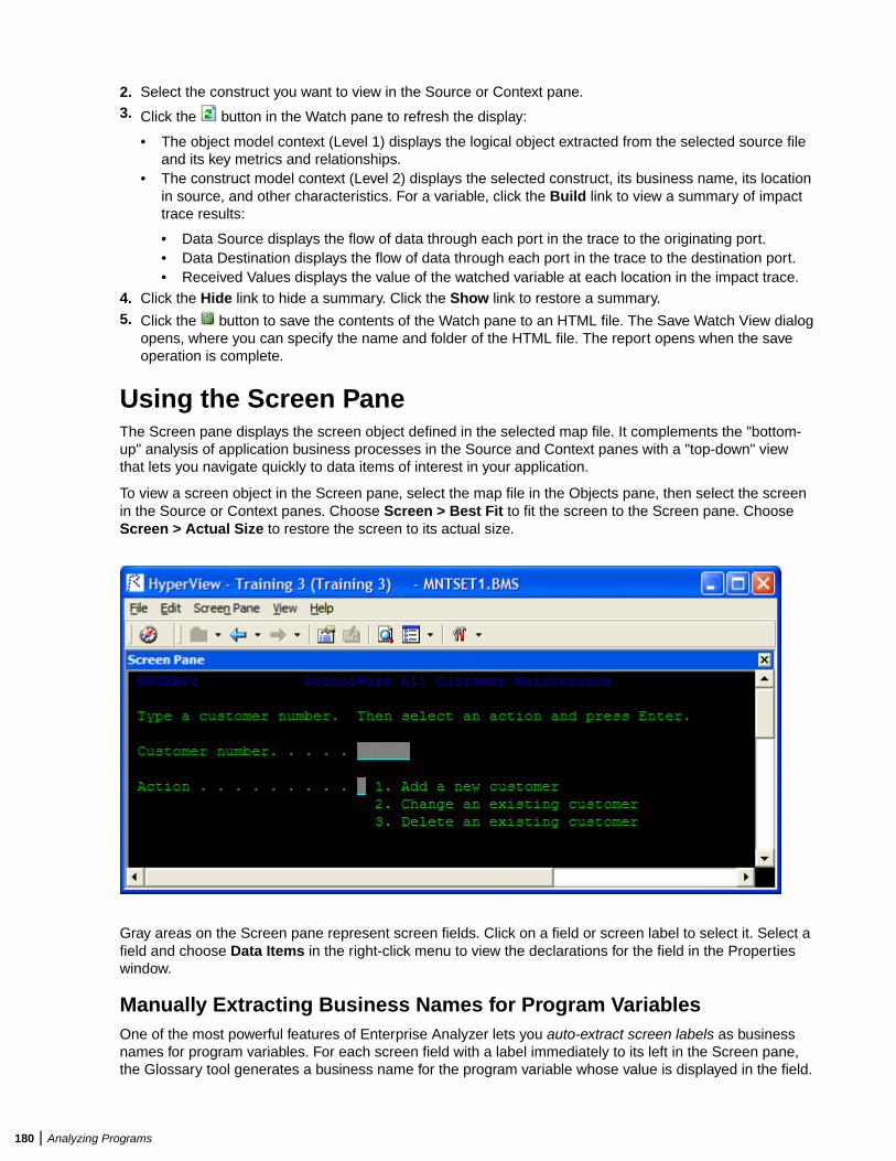
2. Select the construct you want to view in the Source or Context pane.3. Click the button in the Watch pane to refresh the display:
• The object model context (Level 1) displays the logical object extracted from the selected source fileand its key metrics and relationships.
• The construct model context (Level 2) displays the selected construct, its business name, its locationin source, and other characteristics. For a variable, click the Build link to view a summary of impacttrace results:
• Data Source displays the flow of data through each port in the trace to the originating port.• Data Destination displays the flow of data through each port in the trace to the destination port.• Received Values displays the value of the watched variable at each location in the impact trace.
4. Click the Hide link to hide a summary. Click the Show link to restore a summary.5. Click the button to save the contents of the Watch pane to an HTML file. The Save Watch View dialog
opens, where you can specify the name and folder of the HTML file. The report opens when the saveoperation is complete.
Using the Screen PaneThe Screen pane displays the screen object defined in the selected map file. It complements the "bottom-up" analysis of application business processes in the Source and Context panes with a "top-down" viewthat lets you navigate quickly to data items of interest in your application.
To view a screen object in the Screen pane, select the map file in the Objects pane, then select the screenin the Source or Context panes. Choose Screen > Best Fit to fit the screen to the Screen pane. ChooseScreen > Actual Size to restore the screen to its actual size.
Gray areas on the Screen pane represent screen fields. Click on a field or screen label to select it. Select afield and choose Data Items in the right-click menu to view the declarations for the field in the Propertieswindow.
Manually Extracting Business Names for Program VariablesOne of the most powerful features of Enterprise Analyzer lets you auto-extract screen labels as businessnames for program variables. For each screen field with a label immediately to its left in the Screen pane,the Glossary tool generates a business name for the program variable whose value is displayed in the field.
180 | Analyzing Programs
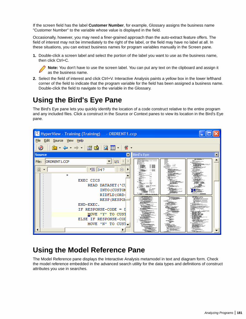
If the screen field has the label Customer Number, for example, Glossary assigns the business name"Customer Number" to the variable whose value is displayed in the field.
Occasionally, however, you may need a finer-grained approach than the auto-extract feature offers. Thefield of interest may not be immediately to the right of the label, or the field may have no label at all. Inthese situations, you can extract business names for program variables manually in the Screen pane.
1. Double-click a screen label and select the portion of the label you want to use as the business name,then click Ctrl+C.
Note: You don't have to use the screen label. You can put any text on the clipboard and assign itas the business name.
2. Select the field of interest and click Ctrl+V. Interactive Analysis paints a yellow box in the lower lefthandcorner of the field to indicate that the program variable for the field has been assigned a business name.Double-click the field to navigate to the variable in the Glossary.
Using the Bird's Eye PaneThe Bird's Eye pane lets you quickly identify the location of a code construct relative to the entire programand any included files. Click a construct in the Source or Context panes to view its location in the Bird's Eyepane.
Using the Model Reference PaneThe Model Reference pane displays the Interactive Analysis metamodel in text and diagram form. Checkthe model reference embedded in the advanced search utility for the data types and definitions of constructattributes you use in searches.
Analyzing Programs | 181
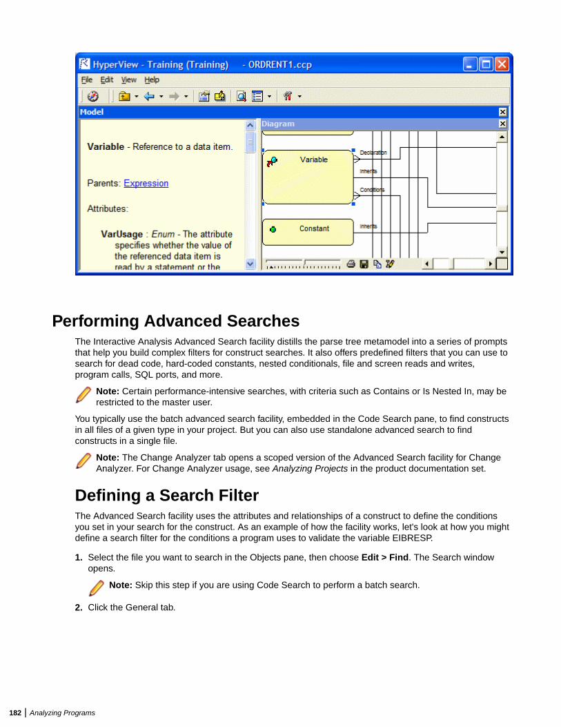
Performing Advanced SearchesThe Interactive Analysis Advanced Search facility distills the parse tree metamodel into a series of promptsthat help you build complex filters for construct searches. It also offers predefined filters that you can use tosearch for dead code, hard-coded constants, nested conditionals, file and screen reads and writes,program calls, SQL ports, and more.
Note: Certain performance-intensive searches, with criteria such as Contains or Is Nested In, may berestricted to the master user.
You typically use the batch advanced search facility, embedded in the Code Search pane, to find constructsin all files of a given type in your project. But you can also use standalone advanced search to findconstructs in a single file.
Note: The Change Analyzer tab opens a scoped version of the Advanced Search facility for ChangeAnalyzer. For Change Analyzer usage, see Analyzing Projects in the product documentation set.
Defining a Search FilterThe Advanced Search facility uses the attributes and relationships of a construct to define the conditionsyou set in your search for the construct. As an example of how the facility works, let's look at how you mightdefine a search filter for the conditions a program uses to validate the variable EIBRESP.
1. Select the file you want to search in the Objects pane, then choose Edit > Find. The Search windowopens.
Note: Skip this step if you are using Code Search to perform a batch search.
2. Click the General tab.
182 | Analyzing Programs
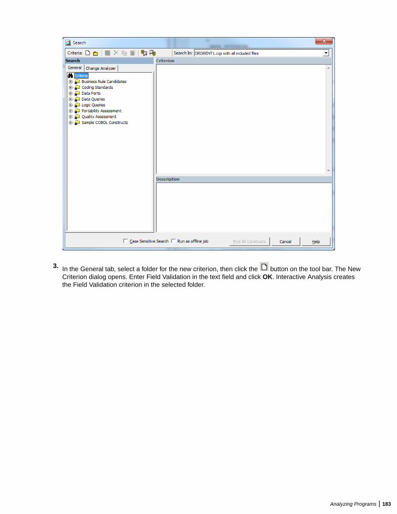
3. In the General tab, select a folder for the new criterion, then click the button on the tool bar. The NewCriterion dialog opens. Enter Field Validation in the text field and click OK. Interactive Analysis createsthe Field Validation criterion in the selected folder.
Analyzing Programs | 183
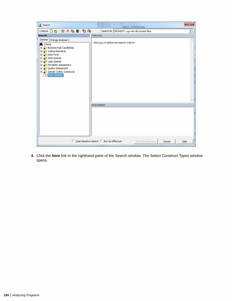
4. Click the here link in the righthand pane of the Search window. The Select Construct Types windowopens.
184 | Analyzing Programs
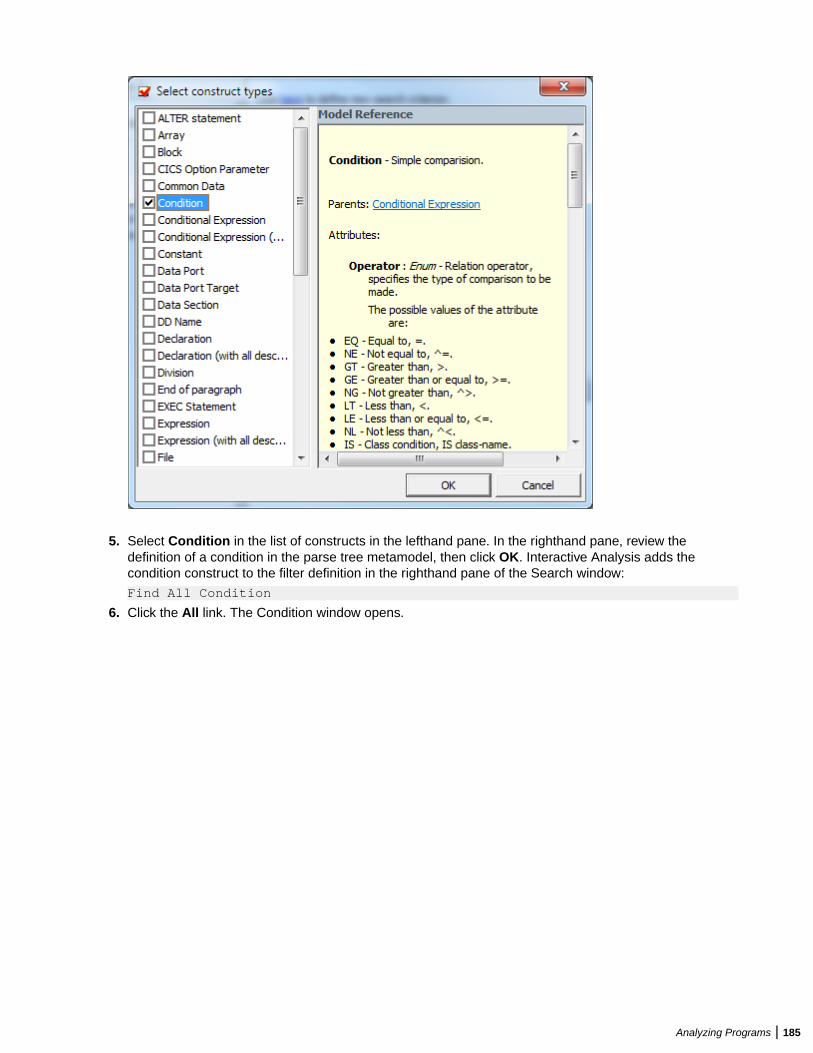
5. Select Condition in the list of constructs in the lefthand pane. In the righthand pane, review thedefinition of a condition in the parse tree metamodel, then click OK. Interactive Analysis adds thecondition construct to the filter definition in the righthand pane of the Search window:
Find All Condition
6. Click the All link. The Condition window opens.
Analyzing Programs | 185
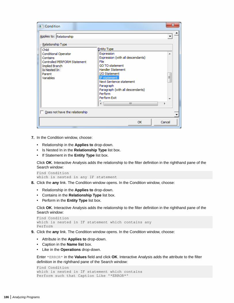
7. In the Condition window, choose:
• Relationship in the Applies to drop-down.• Is Nested In in the Relationship Type list box.• If Statement in the Entity Type list box.
Click OK. Interactive Analysis adds the relationship to the filter definition in the righthand pane of theSearch window:
Find Conditionwhich is nested in any IF statement
8. Click the any link. The Condition window opens. In the Condition window, choose:
• Relationship in the Applies to drop-down.• Contains in the Relationship Type list box.• Perform in the Entity Type list box.
Click OK. Interactive Analysis adds the relationship to the filter definition in the righthand pane of theSearch window:
Find Conditionwhich is nested in IF statement which contains anyPerform
9. Click the any link. The Condition window opens. In the Condition window, choose:
• Attribute in the Applies to drop-down.• Caption in the Name list box.• Like in the Operations drop-down.
Enter *ERROR* in the Values field and click OK. Interactive Analysis adds the attribute to the filterdefinition in the righthand pane of the Search window:
Find Conditionwhich is nested in IF statement which contains Perform such that Caption Like "*ERROR*"
186 | Analyzing Programs
Note: Except for the # symbol, you can use wildcard patterns allowed in LIKE statements byVisual Basic for Applications (VBA). Consult the Model Reference pane for attribute values.
10.Click the is nested in link. In the pop-up menu, choose And. The Condition window opens. In theCondition window, choose:
• Relationship in the Applies to drop-down.• Contains in the Relationship Type list box.• Variable in the Entity Type list box.
Click OK. Interactive Analysis adds the relationship to the filter definition in the righthand pane of theSearch window:
Find Conditionwhich is nested in IF statement which containsPerform such that Caption Like "*ERROR*"andwhich contains any Variable
11.Click the any link. The Condition window opens. In the Condition window, choose:
• Attribute in the Applies to drop-down.• Caption in the Name list box.• Like in the Operations drop-down.
Enter *EIB* in the Values field and click OK. Interactive Analysis adds the attribute to the filterdefinition in the righthand pane of the Search window:
Find Conditionwhich is nested in IF statement which containsPerform such that Caption Like "*ERROR*"andwhich contains Variable such that Caption Like "*EIB*"
Note: To edit an element in the filter definition, select its link and choose Edit in the pop-up menu.To delete an element from the filter definition, select its link and choose Delete in the pop-upmenu.
12.Enter a description of the filter definition in the Description pane.
13.Click on the tool bar to save the filter definition.
14.Click Find All Constructs to start the search.
Note: Check Run as Offline Job to run the search in background mode. You will see a messageCode Search job was successfully submitted to the Queue.
Executing Advanced SearchesYou can execute an advanced search in standalone mode, against the file or construct selected in theSource or Context pane, or in batch mode, in the embedded search pane in Code Search.
1. In the Search In drop-down on the tool bar, choose:
• Source file name with all included files if you want to execute the search against the selectedsource file and any included files.
• Source file name only if you want to execute the search against the selected source file only.• Selected Construct - Construct if you want to execute the search against the construct selected in
the Source or Context panes.
2. Choose the criterion for the search you want to execute from the list of criteria in the lefthand pane.
3. Select Case Sensitive Search if you want the search to match case.
4. Select Find All Constructs. Interactive Analysis displays a dialog box with the results of the search.Click OK. The dialog and Search window are dismissed. Interactive Analysis displays the results in a listnamed Last Search Results in the Internal category in Code Search.
Analyzing Programs | 187
Advanced String Attribute OperationsThe advanced string attribute operations can be set when you execute Code Search and when you havedefined a search filter.
Note: The operations are available only for string objects.
You can execute a Code Search using different criteria. When you set a condition to search stringattributes, you can specify the following operations:
Like / Not Like Performs a wildcard (mask) match where ? (question mark) represents anysingle character and * (asterisk) represents any character sequence.
Example:
• Select Name from the Name list, then select Like from the Operations drop-down list, and then write * DAY in the values field. The new criterion returns allnames ending with "DAY".
• If the search criterion is: "Name" like "???DAY", the search finds all 6 characterlong names ending with "DAY".
RegularExpression
Performs regular expression matching. This function uses syntax specific to theRDBMS.
Example (Oracle only): "Name" matches "^Ste(v|ph)en", will match names whichbegin with "Ste" and end with "en" with either "v" or "ph" in between, so both"Steven" and "Stephen" will be selected.
On Microsoft SQL Server databases, you need to install an additional package onthe SQL Server machine to get regular expression support. This package isprovided by Microsoft.
Note: There are significant differences in regular expression syntax betweenthe Oracle and MS SQL Server implementations. For more information checktheir corresponding documentation.
Note: Due to the nature of the regular expressions, utilization of a databaseindex is not possible for their evaluation, therefore the performance for suchqueries is expected to be relatively slower.
Length is Lessthan / Length isGreater than
Compares attribute value lengths.
Example: "Name" length is "6", finds all 6 character long names.
Match otherattribute value/ Donot match otherattribute value
Compares two attribute values.
Example: "Name" matches attribute "JobName", finds all names matching the"JobName" as well.
Contain otherattribute value/ Donot contain otherattribute value
Checks if an attribute value contains another attribute value.
Example: "Name" contains attribute "JobName", finds all names which also contain"JobName" value.
Partial Attributematch
Partial Match compares part of an attribute value with another part of anotherattribute value.
Example: "Name" pos 10-12 matches pos 5-7 of "JobName", finds all names wherethe value from character position 10 to 12 matches the "JobName" value fromcharacter position 5 to 7.
188 | Analyzing Programs
Working with Advanced Search CriteriaThis section describes common tasks you perform with advanced search criteria.
Creating a Search Criterion
To create a search criterion, select the folder for the new criterion in the General tab, then click the button on the tool bar. The New Criterion dialog opens. Enter the name of the criterion in the text field andclick OK.
Editing a Search CriterionTo edit a search criterion, select the criterion, then select the link for the element you want to change in thefilter definition. Choose Edit in the pop-up menu to edit the element, or Delete to delete the element.
Tip: To restore the original definition of a predefined search criterion, select the criterion and click the
button on the tool bar.
Copying a Search Criterion
To copy a search criterion, select the criterion and click the button on the tool bar. The New Criteriondialog opens. Enter the name of the new criterion in the text field and click OK.
Saving a Search Criterion
To save a search criterion, select the criterion and click the button on the tool bar. The criterion isavailable to every project in the workspace.
Deleting a Search Criterion
To delete a search criterion, select the criterion and click the button on the tool bar. You are promptedto confirm the deletion. Click OK.
Note: You cannot delete a predefined search criterion.
Creating a Folder for Search Criteria
To create a folder for search criteria, click the button on the tool bar. The New Folder dialog opens.Enter the name of the new folder in the text field and click OK. The new folder appears in alphabeticalorder in the tree in the lefthand pane of the window. Drag-and-drop search criteria to move them to thefolder. You can create folders within folders.
To copy a folder and all its contents, select the folder and click the button on the tool bar. The NewFolder dialog opens. In the text field, enter text to be prepended to the folder name and to the names ofeach of its subfolders and search criteria, and click OK.
To modify a folder name, click in the name area for the folder to make the name editable, enter the new
name, and press Enter. To delete a folder, select it and click the button on the tool bar. You areprompted to confirm the deletion. Click OK.
Saving a Search Criterion as HTML
To save a search criterion in an HTML file, select the criterion and click the button on the tool bar. TheSave Criteria dialog opens, where you can specify the name and folder for the HTML file.
Analyzing Programs | 189
Exporting and Importing a Search Criterion
To export a search criterion to an XML file, select the criterion and click the button on the tool bar. TheExport Criteria dialog opens, where you can specify the name and folder for the XML file.
To import a search criterion, click the button on the tool bar. The Import Criteria dialog opens, whereyou can select the criterion you want to import.
Staging Program Analysis with Code SearchUse the Code Search pane to stage the results of a batch search as input for subsequent tasks: viewingsource and context, colorizing sliced code, extracting business rules, and the like. A system analyst, forexample, might use Code Search to create a list of programs impacted by a change request, then create aproject that contains only the source files for those programs.
Code Search searches are executed against the current project. You can also execute searches againstthe results of a previous search.
Note: Certain performance-intensive Code Search searches, with criteria such as Contains or IsNested In, may be restricted to the master user.
Getting Started in Code SearchCode Search is project related. It executes a search over all verified files in the project.
This section describes a sample use of Code Search that should help you get oriented in the tool. Assumethat you want to create business rules for segments of code that write to a file.
1. In the Code Search pane, click the Top view link. The Top view opens.
2. Double-click the Rule Finder category. The Rule Finder view opens.
3. Click the button on the tool bar. The New List dialog opens.
4. Enter File Writes and click OK. An empty list named File Writes is added to the Rule Finder view.
5.Select the File Writes list, then click the button next to the button on the tool bar. In the drop-down, choose the type of object you want to execute the search against, COBOL File in our example.The Search window opens.
6. In the Search In drop-down, select All Objects.
7. Expand the Data Ports folder in the lefthand pane, then expand the Files folder. Select the predefinedFile Writes criterion and click Find All Constructs. Interactive Analysis displays a dialog box with theresults of the search operation. Click OK. A message with the number of constructs found is displayed.Click OK. The Search window is dismissed and the results of the search are displayed in a CodeSearch view, named after the File Writes list.
Note: Modify the predefined search criterion or create your own search criterion as you do in theAdvanced Search facility.
Tip: To add a construct manually to the list for a source file, select the source file in the File Writes
view, select the construct in the Source or Context panes, then click the button on the tool bar.
8. Click the button next to the button on the tool bar and choose Create Rules in the drop-downmenu. A message saying You are about to generate templated business rules into a specified rule set.Continue? Click Yes to continue. The Create Rule Set window opens.
9. Select an existing Business Function from the drop-down list or create New one:
190 | Analyzing Programs
a) If you choose New, the Business Function window opens.b) Enter Business Area (or select one from the drop-down list).c) Enter Name.d) (Optional) Enter Technical Description.e) (Optional) Enter Business Description.f) Click OK to create the business function and to return to the Create Rule Set window.
The newly created Business Function is selected. The Name field is populated with File Writes fromRule Finder (which shows the information from the Code Search pane). Optionally fill in the TechnicalDescription and Business Description fields. Click OK.
The Create Rules From List window opens.
10.Select Business Function from the drop-down list or create New.
11.Select Rule Set from the drop-down list or create a New one.
12.The Name template is automatically populated with CHECK IN [FileName] AT [FromRow] AS[Caption]
13.Enter the Business Description Template (optional).
14.Enter the Technical Description Template (optional).
15.If needed, edit the New Attributes.
16.Click OK. Creating Rules for File Writes. You then get a message telling you the number of rules thathave been created.
Understanding the Code Search PaneInteractive Analysis lists offer convenient ways to navigate program code and record the results of programanalyses. Use the hierarchy of views in the Code Search pane to display Interactive Analysis lists andperform other list-related tasks:
• The Top view displays the folders, or categories, for lists.• The Category view displays the lists in the selected category.• The List view displays source files with non-zero counts in the selected list.• The File view displays each construct in the list for the selected source file. Click a construct in the list to
navigate to it in other Interactive Analysis panes.
Each view gives you access to the next-level view in the hierarchy. Click the label for a view to navigate to
it. Double-click an item in the view to drill down to the next view in the hierarchy. Click the button onthe tool bar to navigate to the parent of the current view.
Working with CategoriesThe Top view of the Code Search pane displays the categories for Interactive Analysis lists. Categories aredisplayed only for lists you can create for the source file type selected in the Objects pane.
You can use predefined categories or create your own. All predefined categories are shared. Use theGeneral and Internal categories for unenumerated tasks.
Note: Interactive Analysis puts the results of standalone advanced searches in a predefined list calledLast Search Results in the Internal categories.
To create a category, select the parent category and click Code Search > Add. The New category dialogopens, where you can specify the new category name. A list with the category name is automaticallycreated in the category. To edit the category name, click the name and type over it in the text box.
By default, user-defined categories are not shared. To share a user-defined category, select it and click the
button on the tool bar. A symbol indicates that the category is shared. Click the button again toturn sharing off.
Analyzing Programs | 191
Note: Sharing a user-defined category automatically makes its parent categories shared. Unsharing auser-defined category automatically makes its children unshared.
Working with ListsThe Category view of the Code Search pane displays the lists in the selected category. You can usepredefined lists or create your own. Use Code Search to populate lists.
Creating a List
To create a list, double-click the category for the list in the Top view and choose Code Search > Add. TheNew List dialog opens, where you can specify the name of the new list.
Deleting a List
To delete a list, select it and click the button on the tool bar. You are prompted to confirm the deletion.Click OK.
Copying a List
To copy a list, select it and click the button on the tool bar. In the Top view, select the category you want
to copy the list into and click the button. The Copy List dialog opens, where you can enter the name ofthe new list. You can copy a list into the same category.
Sharing a List
By default, lists are not shared. To share a list, select it and click the
button on the tool bar. A symbol indicates that the list is shared. Click the button again to turnsharing off.
Adding a Construct to a List Manually
To add a construct to a list, select a source file in the List view, then choose a construct in the Source or
Context panes. Click the button on the tool bar to add the construct to the list of constructs for theselected file.
Deleting a Construct from a List
To delete a construct from a list, select the construct in the File view and click the button on the toolbar. You are prompted to confirm the deletion. Click OK.
Executing Code Search SearchesCode Search is project related. It executes a search over all verified files in the project. All categories,criteria and lists with results are global options for all repository projects and show the results for thecurrent search. After completing the search, the result is saved in the List View. The last executed searchcan be used as a starting point for the next search and can be accumulated with the new one by checkingAccumulate search results in the search view. Otherwise the previous content from the list will be lost.
Use a Code Search to generate Code Search lists. You can modify the predefined search criteria or createyour own criteria as needed. You can use a construct list itself to narrow the search.
1.Select a list, then click the button next to the button on the tool bar. In the drop-down, choosethe type of object you want to execute the search against. The Search window opens.
2. In the Search In drop-down, select:
192 | Analyzing Programs
• All Sources to execute the search against all the sources of the specified type in the project.• A list if you want to execute the search only against sources of the specified type with non-zero
counts in the selected list. If you select Rule Finder.File Writes, for example, the search will beexecuted only against sources of the specified type with non-zero counts in the File Writes list in theRule Finder folder.
3. Choose the criterion for the search you want to execute from the list of criteria in the lefthand pane.Modify the predefined criteria or create your own criteria as needed.
4. Select Accumulate Search Results if you want the results of the search to be added to the results ofthe previous search. Otherwise, the new results overwrite the previous results.
5. Select:
• Find All Constructs if you want Interactive Analysis to create for each searched file a list of all theconstructs found by the search.
• List Sources Only if you want Interactive Analysis simply to indicate for each searched file (with thenotation >0) whether the construct of interest exists in the file.
Interactive Analysis displays a dialog box with the results of the search operation. Click OK. The Searchwindow is dismissed and the results of the search are displayed in the List view.
Using Construct Lists to Narrow a Code SearchOnce you have generated a construct list in Code Search, you can use the list itself as a condition of asearch. That is, you can use the search results to refine a subsequent search.
Suppose you have performed a Code Search for duplicate paragraphs in COBOL programs, storing theresults in a list called Matched Paragraphs in the General folder. The next step might be to search for allPERFORM statements that reference the duplicate paragraphs. The example below shows how you mightuse a Code Search list of duplicate paragraphs as a condition of the search.
1.Select a list, then click the button next to the button on the tool bar. In the drop-down, choosethe type of object you want to execute the search against. The Search window opens.
2. Select a folder for the new criterion in the General tab, then click the button on the tool bar. The NewCriterion dialog opens. Enter Perform Duplicates in the text field and click OK. Interactive Analysiscreates the Perform Duplicates criterion in the selected folder.
3. Click the here link in the righthand pane of the Search window. The Select Construct Types windowopens.
4. Select Perform in the list of constructs in the lefthand pane, then click OK. Interactive Analysis adds thecondition construct to the filter definition in the righthand pane of the Search window:
Find All Perform
5. Click the All link. The Condition window opens. Choose:
• Relationship in the Applies to drop-down.• Called Paragraph in the Relationship Type list box.
6. Click OK. Interactive Analysis adds the relationship to the filter definition in the righthand pane of theSearch window:
Find Performwhich has related any Paragraph (as Called Paragraph)
7. Click the any link. The Condition window opens. Choose:
• List in the Applies to drop-down.• General.Matched Paragraphs in the Name drop-down.
You can filter out list constructs by selecting Does not belong to the list in the Condition window.
Analyzing Programs | 193
8. Click OK. Interactive Analysis adds the list to the filter definition in the righthand pane of the Searchwindow:
Find Performwhich has related Paragraph (as Called Paragraph) which is in list General.Matched Paragraphs
9. Execute the search. Interactive Analysis displays a dialog box with the results of the search operation.Click OK. The Search window is dismissed and the results of the search are displayed in the List view.
Tip: As a practical matter, you would probably also want to search for GO TO statements thatreference the duplicate paragraphs. You could simply add the results of this search to the results ofthe search for PERFORM statements by using the Accumulate Search Results button.
Searching for Similar Constructs in Code SearchTo search for similar constructs, select a construct in the Source or Context panes, then select a list. Click
the button on the tool bar. The New Criterion dialog opens. Enter a criterion name or accept thedefault.
The Search window opens with a predefined search criterion that will generate a list of constructs similar tothe selected construct. The new criterion is added to the General tab of the advanced search facility. Editthe criterion if necessary, then execute the search.
Extracting Business Rules in Code SearchTo extract business rules for multiple constructs, use the following method:
• Generate rules for listed constructs in a specified rule set. When you choose this option, you batchprocess rule attributes in the generation step.
Tip: As long as the Rules pane is open, you can generate a rule for a single construct by selecting theconstruct in the File view and choosing Rule > Create Rule.
Generating Business Rules in a Specified Rule SetFollow the instructions below to generate rules in a specified rule set with predefined attributes. CodeSearch creates a rule for each construct in the Code Search list.
1. Select a list in the Rule Finder category, then click the button next to the button on the tool barand choose Create Rules in the drop-down menu. The Select Method dialog opens.
2. In the Select Method dialog, select templated rules into a specified rule set and click OK. The CreateRule Set window opens.
3. In the Business Function drop-down, select the business function for the rule set. The currentbusiness function is displayed. To create a new business function, click New.
4. In the Name field, enter the name of the rule set for the rules you want to create and click OK. TheCreate Rules From List window opens.
194 | Analyzing Programs
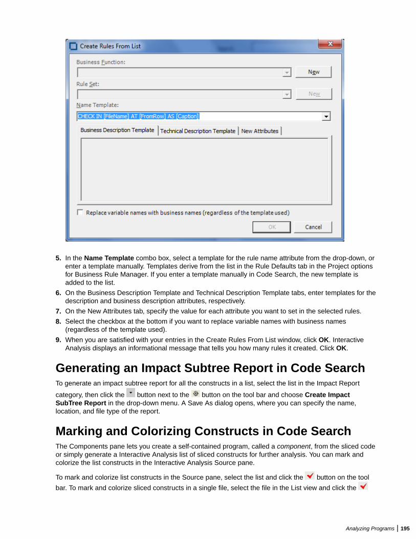
5. In the Name Template combo box, select a template for the rule name attribute from the drop-down, orenter a template manually. Templates derive from the list in the Rule Defaults tab in the Project optionsfor Business Rule Manager. If you enter a template manually in Code Search, the new template isadded to the list.
6. On the Business Description Template and Technical Description Template tabs, enter templates for thedescription and business description attributes, respectively.
7. On the New Attributes tab, specify the value for each attribute you want to set in the selected rules.
8. Select the checkbox at the bottom if you want to replace variable names with business names(regardless of the template used).
9. When you are satisfied with your entries in the Create Rules From List window, click OK. InteractiveAnalysis displays an informational message that tells you how many rules it created. Click OK.
Generating an Impact Subtree Report in Code SearchTo generate an impact subtree report for all the constructs in a list, select the list in the Impact Report
category, then click the button next to the button on the tool bar and choose Create ImpactSubTree Report in the drop-down menu. A Save As dialog opens, where you can specify the name,location, and file type of the report.
Marking and Colorizing Constructs in Code SearchThe Components pane lets you create a self-contained program, called a component, from the sliced codeor simply generate a Interactive Analysis list of sliced constructs for further analysis. You can mark andcolorize the list constructs in the Interactive Analysis Source pane.
To mark and colorize list constructs in the Source pane, select the list and click the button on the tool
bar. To mark and colorize sliced constructs in a single file, select the file in the List view and click the
Analyzing Programs | 195
button. To mark and colorize a single construct, select it in the File view and click the button. Click the
button again to turn off marking and colorizing.
Creating Projects in Code SearchYou can create a project based on the results of a Code Search analysis.
1. Select a list, then click the button next to the button on the tool bar and choose Create Project inthe drop-down menu. The New Project dialog opens. Enter the name of the new project in the text fieldand click OK.
2. The Change Magnitude window opens. Select Automatically calculate change magnitude if you wantCode Search to set change magnitudes for the listed source files based on the ranges specified in thefields below the check box. Modify the ranges as needed. The Code Search settings will override anyexisting change magnitudes for the files.
If you want COBOL source files with 6 to 10 constructs to have a Large change magnitude, for example,set the range for Medium to less than 6 and the range for Large to less than 11.
3. When you are satisfied with your choices, click OK.
Generating Metrics and Detailed ReportsUse Code Search to show the distribution of list instances across a project and view the details for eachinstance. The following reports are available:
• For each list in the selected category, the Metrics Report shows the number of list items in each
program. To generate a Metrics Report, select a category in the Top view, then click the button next
to the button on the tool bar and choose Metrics report in the drop-down menu.• For each source file in the selected list, the Details Report shows the constructs in the list, their type,
and their location in the file. You can customize the report to include any Interactive Analysis attribute
related to the constructs. To generate a Details Report, select a list in the Folder view, then click the
button next to the button on the tool bar and choose Detailed report in the drop-down menu. In theSelect Attributes dialog, choose the construct attributes you want to view in the report.
Running Code Search Reports in the Main WindowEnterprise Analyzer lets you select and run a set of Code Search queries from the Repository Browser.You can execute these sets of queries (Code Search reports) on a selection of files that belong to differentprojects and different object types. The selected queries can be predefined and/or created by you.
To run a report:
1. Select object and right-click in the Repository Browser or select objects and click Reports > CodeSearch Reports > Code Search Reports.
2. Click Code Search Reports > Code Search Reports.
From the Reports window you can select to view and run a report from the following three report types:
Migration The reports in this group are: Portability Assessment, Migrate Net Express to Visual COBOL,Migrate IBM PL/I to Open PL/I and Migrate Enterprise COBOL to 6.1.
Quality The reports in this group are: Quality Assessment and Performance Optimization.
Custom This contains the previously created custom reports (if any).
To view a report and edit it if necessary, click
To run a report, click
196 | Analyzing Programs
Creating a Custom Code Search ReportTo create a custom report:
1. Select objects from the Repository Browser.
Note: You can select objects from different projects with different object types. If you don't selectfiles but a project, the report will be run for all programs in it.
2. Select Code Search Reports > Code Search Reports... from the Reports menu or from the contextmenu in the Repository Browser.
3. When the Reports window opens, click Create New Custom Report.4. From the dropdown menu at the top of the Code Search Reports window, you can select <New
Report> or previously-created reports (if any).5. Select categories and subcategories of queries from the tree structure in the Code Searches tab and/or
the Repository Queries tab. Note that when you select a category, you automatically select all itsubcategories.
The Only show queries for project/object types is checked by default and the queries displayed inthe tree structure are only the ones for the project/object types that you have selected. If you uncheckthis option, all possible queries will be displayed.
When Only show selected queries for saved reports is checked and you have selected an alreadysaved report from the list at the top, only the queries selected for it will be displayed. If you are creatinga new report, all queries are shown in the tree.
6. Click the Preview Report button to add categories to the report, add queries to a category or changethe order of the queries.
7. In the Report name field write a name for the custom report or use the default one. The report namemust be unique and not used for any other report.
8. Select a save location for the report. The default one is the Output\CodeSearchReports folder ofthe workspace.
9. From the options below you can choose if you want to generate an HTML report and if you want tomake the report available to other users.
10.If you select to generate an HTML report, you can also select to generate a summary report which willshow the differences between an older report an a new one.
11.Click Save to save the report.12.Click Run to save and run the report.
Note: The report is generated in a folder with the same name as the report. It has a date/time stampso as to avoid overwriting.
Note: The last ten reports that were run will be saved and you can access them from the RepositoryBrowser by right-clicking and then selecting Code Search Reports > Code Search Reports >Custom. Running the report a report from the list of previously-created reports will show results butno report file will be generated.
Working with Saved ReportsYou can edit, delete or make copies of already created and saved reports from the Code Search Reportswindow.
To make edits to a saved report, select one from the list, make any necessary changes in the list ofselected queries, report name, save location and any of the other options.
You can also choose to overwrite the changes when running the report by selecting the checkbox next tothe Save button.
To create a copy of a report but use a different name, click Copy Report.
To delete a saved report click Delete Selected Report.
Analyzing Programs | 197
Code Search Report ResultsAfter you run a report, the output is saved in the selected location and the Code Search Reports windowcloses and the Queue Processor pops up. To view the report results, double-click the Activity Log linewhich shows that the report was successfully executed or from the View menu select Code SearchReport Results
The results are displayed in a tree view. Double-clicking a file in the tree, opens the source editor pane.
To open Interactive Analysis for a file, right-click it and select Interactive Analysis.
The Code Search Report Results window lets you view previously run reports by selecting them from thedrop-down list at the top. The report titles contain information about the execution date and time. You canalso choose to re-run a report, generate an HTML report and/or export for the Eclipse plugin.
To re-run a report, click .
To create a report, click .
To export for the Eclipse or Visual Studio plugins, click
Storing Code Search ReportsYou can store a predefined set of Code Search queries and a previously generated report as a customreport which can be later used to generate a Code Search report. These can be shared or private. Thepredefined reports need to be added in the HCSearch.xml file and will be loaded in the database as thestandard queries.
Running Code Search Reports in Interactive AnalysisYou can run Code Search reports in Interactive Analysis by clicking Selected Object or All Objects at thetop.
When the report has been executed, a message will pop up asking if you want to load the results. Click Yesand the results will be loaded in the Code Search pane.
Analyzing Impact TracesAn impact trace describes the flow of data within and between programs in an application: how data itemsexchange values, use each other in computations, and so forth. If you are extracting business rules, forexample, you might want to view an impact trace to make sure that a segment encapsulates all of thebusiness logic for a candidate rule. Or you might want to use a scoped trace to help locate candidates thatexhibit a particular type of relationship.
You can analyze the entire tree for a trace, or a consolidated tree that displays only the ports and leafnodes traversed in the trace. Options let you filter out unwanted relationships or variables. You can savetrace results and restore them in a later session.
Note: Projects must have been verified with the Enable Impact Report and Enable Data ElementFlow options set in the Project Verification options.
Generating an Impact TraceThe Interactive Analysis Impact pane displays a hierarchical view and diagram of an impact trace. Bothviews show the flow of data to or from a startup item.
1. In the Interactive Analysis Source or Context pane, select the construct that contains the startup item oritems and choose View > Impact. The Impact pane opens.
198 | Analyzing Programs
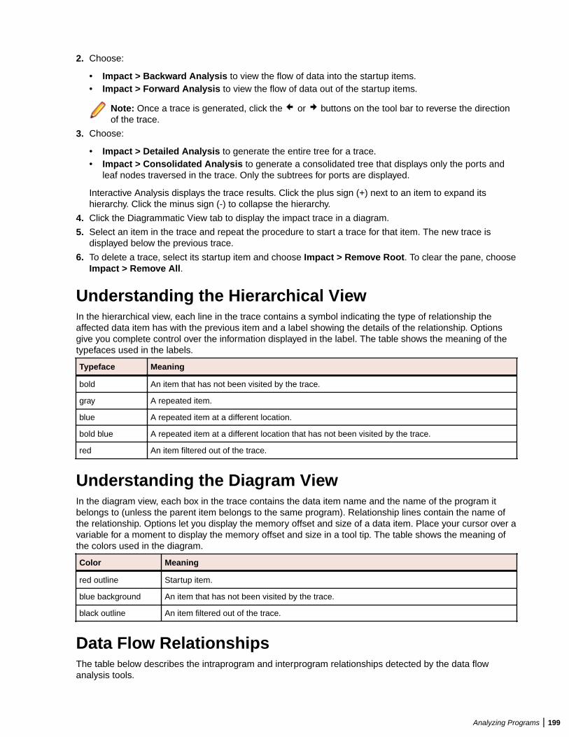
2. Choose:
• Impact > Backward Analysis to view the flow of data into the startup items.• Impact > Forward Analysis to view the flow of data out of the startup items.
Note: Once a trace is generated, click the or buttons on the tool bar to reverse the directionof the trace.
3. Choose:
• Impact > Detailed Analysis to generate the entire tree for a trace.• Impact > Consolidated Analysis to generate a consolidated tree that displays only the ports and
leaf nodes traversed in the trace. Only the subtrees for ports are displayed.
Interactive Analysis displays the trace results. Click the plus sign (+) next to an item to expand itshierarchy. Click the minus sign (-) to collapse the hierarchy.
4. Click the Diagrammatic View tab to display the impact trace in a diagram.
5. Select an item in the trace and repeat the procedure to start a trace for that item. The new trace isdisplayed below the previous trace.
6. To delete a trace, select its startup item and choose Impact > Remove Root. To clear the pane, chooseImpact > Remove All.
Understanding the Hierarchical ViewIn the hierarchical view, each line in the trace contains a symbol indicating the type of relationship theaffected data item has with the previous item and a label showing the details of the relationship. Optionsgive you complete control over the information displayed in the label. The table shows the meaning of thetypefaces used in the labels.
Typeface Meaning
bold An item that has not been visited by the trace.
gray A repeated item.
blue A repeated item at a different location.
bold blue A repeated item at a different location that has not been visited by the trace.
red An item filtered out of the trace.
Understanding the Diagram ViewIn the diagram view, each box in the trace contains the data item name and the name of the program itbelongs to (unless the parent item belongs to the same program). Relationship lines contain the name ofthe relationship. Options let you display the memory offset and size of a data item. Place your cursor over avariable for a moment to display the memory offset and size in a tool tip. The table shows the meaning ofthe colors used in the diagram.
Color Meaning
red outline Startup item.
blue background An item that has not been visited by the trace.
black outline An item filtered out of the trace.
Data Flow RelationshipsThe table below describes the intraprogram and interprogram relationships detected by the data flowanalysis tools.
Analyzing Programs | 199
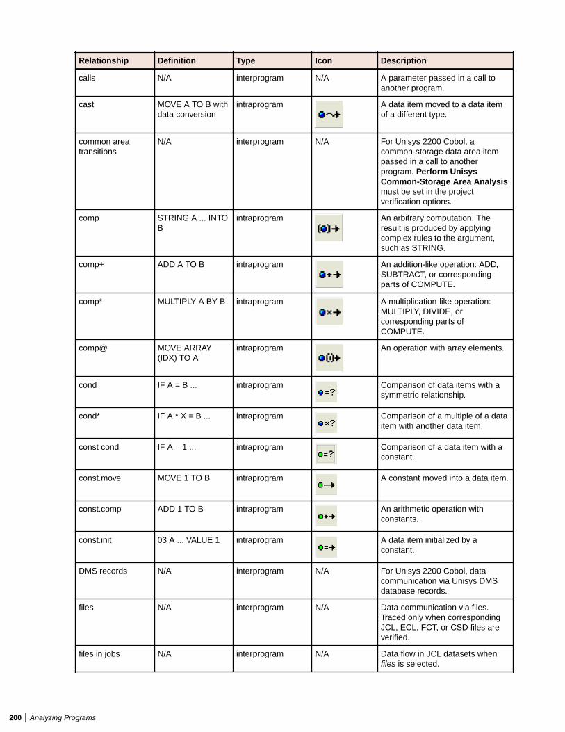
Relationship Definition Type Icon Description
calls N/A interprogram N/A A parameter passed in a call toanother program.
cast MOVE A TO B withdata conversion
intraprogram A data item moved to a data itemof a different type.
common areatransitions
N/A interprogram N/A For Unisys 2200 Cobol, acommon-storage data area itempassed in a call to anotherprogram. Perform UnisysCommon-Storage Area Analysismust be set in the projectverification options.
comp STRING A ... INTOB
intraprogram An arbitrary computation. Theresult is produced by applyingcomplex rules to the argument,such as STRING.
comp+ ADD A TO B intraprogram An addition-like operation: ADD,SUBTRACT, or correspondingparts of COMPUTE.
comp* MULTIPLY A BY B intraprogram A multiplication-like operation:MULTIPLY, DIVIDE, orcorresponding parts ofCOMPUTE.
comp@ MOVE ARRAY(IDX) TO A
intraprogram An operation with array elements.
cond IF A = B ... intraprogram Comparison of data items with asymmetric relationship.
cond* IF A * X = B ... intraprogram Comparison of a multiple of a dataitem with another data item.
const cond IF A = 1 ... intraprogram Comparison of a data item with aconstant.
const.move MOVE 1 TO B intraprogram A constant moved into a data item.
const.comp ADD 1 TO B intraprogram An arithmetic operation withconstants.
const.init 03 A ... VALUE 1 intraprogram A data item initialized by aconstant.
DMS records N/A interprogram N/A For Unisys 2200 Cobol, datacommunication via Unisys DMSdatabase records.
files N/A interprogram N/A Data communication via files.Traced only when correspondingJCL, ECL, FCT, or CSD files areverified.
files in jobs N/A interprogram N/A Data flow in JCL datasets whenfiles is selected.
200 | Analyzing Programs
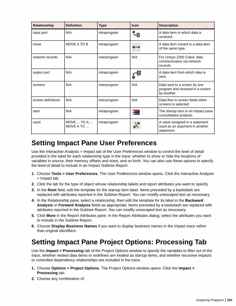
Relationship Definition Type Icon Description
input port N/A intraprogram A data item in which data isreceived.
move MOVE A TO B intraprogram A data item moved to a data itemof the same type.
network records N/A interprogram N/A For Unisys 2200 Cobol, datacommunication via networkrecords.
output port N/A intraprogram A data item from which data issent.
screens N/A interprogram N/A Data sent to a screen by oneprogram and received in a screenby another.
screen definitions N/A interprogram N/A Data flow in screen fields whenscreens is selected.
start N/A intraprogram The startup item in an Impact paneconsolidated analysis.
used MOVE ... TO A ...MOVE A TO ...
intraprogram A value assigned in a statementused as an argument in anotherstatement.
Setting Impact Pane User PreferencesUse the Interactive Analysis > Impact tab of the User Preferences window to control the level of detailprovided in the label for each relationship type in the trace: whether to show or hide the locations ofvariables in source, their memory offsets and sizes, and so forth. You can also use these options to specifythe level of detail to include in an Impact Subtree Report.
1. Choose Tools > User Preferences. The User Preferences window opens. Click the Interactive Analysis> Impact tab.
2. Click the tab for the type of object whose relationship labels and report attributes you want to specify.
3. In the Root field, edit the template for the startup item label. Items preceded by a backslash arereplaced with attributes reported in the Subtree Report. You can modify unescaped text as necessary.
4. In the Relationship pane, select a relationship, then edit the template for its label in the BackwardAnalysis or Forward Analysis fields as appropriate. Items preceded by a backslash are replaced withattributes reported in the Subtree Report. You can modify unescaped text as necessary.
5. Click More in the Report Attributes pane. In the Report Attributes dialog, select the attributes you wantto include in the Subtree Report.
6. Choose Display Business Names if you want to display business names in the impact trace ratherthan original identifiers.
Setting Impact Pane Project Options: Processing TabUse the Impact > Processing tab of the Project Options window to specify the variables to filter out of thetrace, whether nested data items or redefines are treated as startup items, and whether recursive impactsor controlled dependency relationships are included in the trace.
1. Choose Options > Project Options. The Project Options window opens. Click the Impact >Processing tab.
2. Choose any combination of:
Analyzing Programs | 201
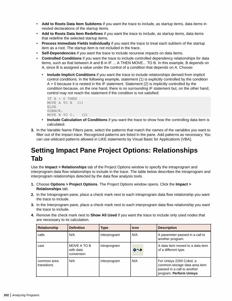
• Add to Roots Data Item Subitems if you want the trace to include, as startup items, data items innested declarations of the startup items.
• Add to Roots Data Item Redefines if you want the trace to include, as startup items, data itemsthat redefine the selected startup items.
• Process Immediate Fields Individually if you want the trace to treat each subitem of the startupitem as a root. The startup item is not included in the trace.
• Self-Dependencies if you want the trace to include recursive impacts on data items. • Controlled Conditions if you want the trace to include controlled dependency relationships for data
items, such as that between A and B in IF ... A THEN MOVE... TO B. In this example, B depends onA, since B is assigned a value under the control of a condition that depends on A. Choose:
• Include Implicit Conditions if you want the trace to include relationships derived from implicitcontrol conditions. In the following example, statement (1) is explicitly controlled by the conditionA > 0 because it is nested in the IF statement. Statement (2) is implicitly controlled by thecondition because, on the one hand, there is no surrounding IF statement but, on the other hand,control may not reach the statement if the condition is not satisfied:
IF A > 0 THENMOVE A TO B (1)ELSEGOBACK.MOVE B TO C. (2)
• Include Calculation of Conditions if you want the trace to show how the controlling data item iscalculated.
3. In the Variable Name Filters pane, select the patterns that match the names of the variables you want tofilter out of the impact trace. Recognized patterns are listed in the pane. Add patterns as necessary. Youcan use wildcard patterns allowed in LIKE statements by Visual Basic for Applications (VBA).
Setting Impact Pane Project Options: RelationshipsTabUse the Impact > Relationships tab of the Project Options window to specify the intraprogram andinterprogram data flow relationships to include in the trace. The table below describes the intraprogram andinterprogram relationships detected by the data flow analysis tools.
1. Choose Options > Project Options. The Project Options window opens. Click the Impact >Relationships tab.
2. In the Intraprogram pane, place a check mark next to each intraprogram data flow relationship you wantthe trace to include.
3. In the Interprogram pane, place a check mark next to each interprogram data flow relationship you wantthe trace to include.
4. Remove the check mark next to Show All Used if you want the trace to include only used nodes thatare necessary to its calculation.
Relationship Definition Type Icon Description
calls N/A interprogram N/A A parameter passed in a call toanother program.
cast MOVE A TO Bwith dataconversion
intraprogram A data item moved to a data itemof a different type.
common areatransitions
N/A interprogram N/A For Unisys 2200 Cobol, acommon-storage data area itempassed in a call to anotherprogram. Perform Unisys
202 | Analyzing Programs
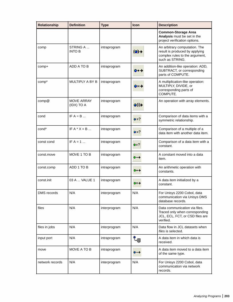
Relationship Definition Type Icon Description
Common-Storage AreaAnalysis must be set in theproject verification options.
comp STRING A ...INTO B
intraprogram An arbitrary computation. Theresult is produced by applyingcomplex rules to the argument,such as STRING.
comp+ ADD A TO B intraprogram An addition-like operation: ADD,SUBTRACT, or correspondingparts of COMPUTE.
comp* MULTIPLY A BY B intraprogram A multiplication-like operation:MULTIPLY, DIVIDE, orcorresponding parts ofCOMPUTE.
comp@ MOVE ARRAY(IDX) TO A
intraprogram An operation with array elements.
cond IF A = B ... intraprogram Comparison of data items with asymmetric relationship.
cond* IF A * X = B ... intraprogram Comparison of a multiple of adata item with another data item.
const cond IF A = 1 ... intraprogram Comparison of a data item with aconstant.
const.move MOVE 1 TO B intraprogram A constant moved into a dataitem.
const.comp ADD 1 TO B intraprogram An arithmetic operation withconstants.
const.init 03 A ... VALUE 1 intraprogram A data item initialized by aconstant.
DMS records N/A interprogram N/A For Unisys 2200 Cobol, datacommunication via Unisys DMSdatabase records.
files N/A interprogram N/A Data communication via files.Traced only when correspondingJCL, ECL, FCT, or CSD files areverified.
files in jobs N/A interprogram N/A Data flow in JCL datasets whenfiles is selected.
input port N/A intraprogram A data item in which data isreceived.
move MOVE A TO B intraprogram A data item moved to a data itemof the same type.
network records N/A interprogram N/A For Unisys 2200 Cobol, datacommunication via networkrecords.
Analyzing Programs | 203
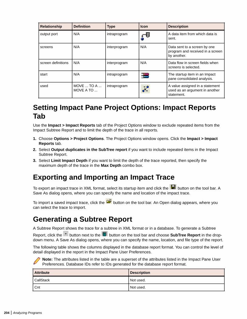
Relationship Definition Type Icon Description
output port N/A intraprogram A data item from which data issent.
screens N/A interprogram N/A Data sent to a screen by oneprogram and received in a screenby another.
screen definitions N/A interprogram N/A Data flow in screen fields whenscreens is selected.
start N/A intraprogram The startup item in an Impactpane consolidated analysis.
used MOVE ... TO A ...MOVE A TO ...
intraprogram A value assigned in a statementused as an argument in anotherstatement.
Setting Impact Pane Project Options: Impact ReportsTabUse the Impact > Impact Reports tab of the Project Options window to exclude repeated items from theImpact Subtree Report and to limit the depth of the trace in all reports.
1. Choose Options > Project Options. The Project Options window opens. Click the Impact > ImpactReports tab.
2. Select Output duplicates in the SubTree report if you want to include repeated items in the ImpactSubtree Report.
3. Select Limit Impact Depth if you want to limit the depth of the trace reported, then specify themaximum depth of the trace in the Max Depth combo box.
Exporting and Importing an Impact TraceTo export an impact trace in XML format, select its startup item and click the button on the tool bar. ASave As dialog opens, where you can specify the name and location of the impact trace.
To import a saved impact trace, click the button on the tool bar. An Open dialog appears, where youcan select the trace to import.
Generating a Subtree ReportA Subtree Report shows the trace for a subtree in XML format or in a database. To generate a Subtree
Report, click the button next to the button on the tool bar and choose SubTree Report in the drop-down menu. A Save As dialog opens, where you can specify the name, location, and file type of the report.
The following table shows the columns displayed in the database report format. You can control the level ofdetail displayed in the report in the Impact Pane User Preferences.
Note: The attributes listed in the table are a superset of the attributes listed in the Impact Pane UserPreferences. Database IDs refer to IDs generated for the database report format.
Attribute Description
CallStack Not used.
Cnt Not used.
204 | Analyzing Programs
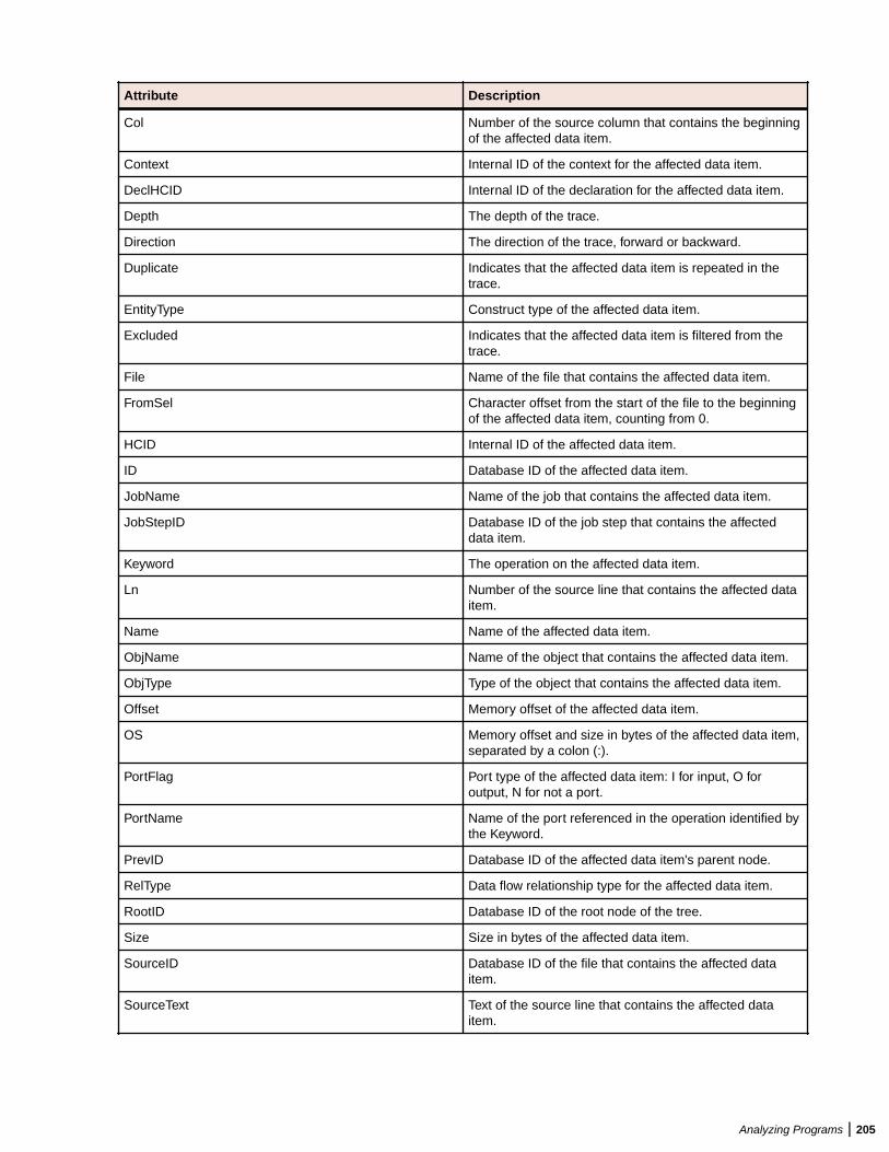
Attribute Description
Col Number of the source column that contains the beginningof the affected data item.
Context Internal ID of the context for the affected data item.
DeclHCID Internal ID of the declaration for the affected data item.
Depth The depth of the trace.
Direction The direction of the trace, forward or backward.
Duplicate Indicates that the affected data item is repeated in thetrace.
EntityType Construct type of the affected data item.
Excluded Indicates that the affected data item is filtered from thetrace.
File Name of the file that contains the affected data item.
FromSel Character offset from the start of the file to the beginningof the affected data item, counting from 0.
HCID Internal ID of the affected data item.
ID Database ID of the affected data item.
JobName Name of the job that contains the affected data item.
JobStepID Database ID of the job step that contains the affecteddata item.
Keyword The operation on the affected data item.
Ln Number of the source line that contains the affected dataitem.
Name Name of the affected data item.
ObjName Name of the object that contains the affected data item.
ObjType Type of the object that contains the affected data item.
Offset Memory offset of the affected data item.
OS Memory offset and size in bytes of the affected data item,separated by a colon (:).
PortFlag Port type of the affected data item: I for input, O foroutput, N for not a port.
PortName Name of the port referenced in the operation identified bythe Keyword.
PrevID Database ID of the affected data item's parent node.
RelType Data flow relationship type for the affected data item.
RootID Database ID of the root node of the tree.
Size Size in bytes of the affected data item.
SourceID Database ID of the file that contains the affected dataitem.
SourceText Text of the source line that contains the affected dataitem.
Analyzing Programs | 205
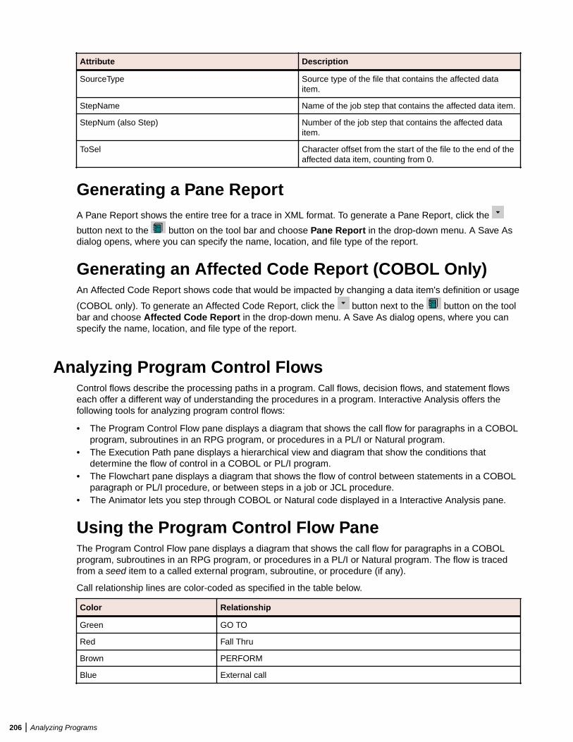
Attribute Description
SourceType Source type of the file that contains the affected dataitem.
StepName Name of the job step that contains the affected data item.
StepNum (also Step) Number of the job step that contains the affected dataitem.
ToSel Character offset from the start of the file to the end of theaffected data item, counting from 0.
Generating a Pane ReportA Pane Report shows the entire tree for a trace in XML format. To generate a Pane Report, click the
button next to the button on the tool bar and choose Pane Report in the drop-down menu. A Save Asdialog opens, where you can specify the name, location, and file type of the report.
Generating an Affected Code Report (COBOL Only)An Affected Code Report shows code that would be impacted by changing a data item's definition or usage
(COBOL only). To generate an Affected Code Report, click the button next to the button on the toolbar and choose Affected Code Report in the drop-down menu. A Save As dialog opens, where you canspecify the name, location, and file type of the report.
Analyzing Program Control FlowsControl flows describe the processing paths in a program. Call flows, decision flows, and statement flowseach offer a different way of understanding the procedures in a program. Interactive Analysis offers thefollowing tools for analyzing program control flows:
• The Program Control Flow pane displays a diagram that shows the call flow for paragraphs in a COBOLprogram, subroutines in an RPG program, or procedures in a PL/I or Natural program.
• The Execution Path pane displays a hierarchical view and diagram that show the conditions thatdetermine the flow of control in a COBOL or PL/I program.
• The Flowchart pane displays a diagram that shows the flow of control between statements in a COBOLparagraph or PL/I procedure, or between steps in a job or JCL procedure.
• The Animator lets you step through COBOL or Natural code displayed in a Interactive Analysis pane.
Using the Program Control Flow PaneThe Program Control Flow pane displays a diagram that shows the call flow for paragraphs in a COBOLprogram, subroutines in an RPG program, or procedures in a PL/I or Natural program. The flow is tracedfrom a seed item to a called external program, subroutine, or procedure (if any).
Call relationship lines are color-coded as specified in the table below.
Color Relationship
Green GO TO
Red Fall Thru
Brown PERFORM
Blue External call
206 | Analyzing Programs
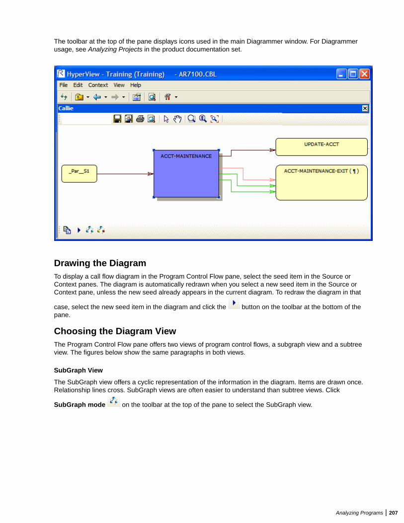
The toolbar at the top of the pane displays icons used in the main Diagrammer window. For Diagrammerusage, see Analyzing Projects in the product documentation set.
Drawing the DiagramTo display a call flow diagram in the Program Control Flow pane, select the seed item in the Source orContext panes. The diagram is automatically redrawn when you select a new seed item in the Source orContext pane, unless the new seed already appears in the current diagram. To redraw the diagram in that
case, select the new seed item in the diagram and click the button on the toolbar at the bottom of thepane.
Choosing the Diagram ViewThe Program Control Flow pane offers two views of program control flows, a subgraph view and a subtreeview. The figures below show the same paragraphs in both views.
SubGraph View
The SubGraph view offers a cyclic representation of the information in the diagram. Items are drawn once.Relationship lines cross. SubGraph views are often easier to understand than subtree views. Click
SubGraph mode on the toolbar at the top of the pane to select the SubGraph view.
Analyzing Programs | 207
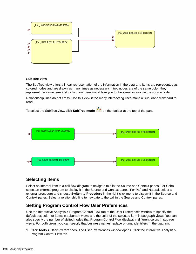
SubTree View
The SubTree view offers a linear representation of the information in the diagram. Items are represented ascolored nodes and are drawn as many times as necessary. If two nodes are of the same color, theyrepresent the same item and clicking on them would take you to the same location in the source code.
Relationship lines do not cross. Use this view if too many intersecting lines make a SubGraph view hard toread.
To select the SubTree view, click SubTree mode on the toolbar at the top of the pane.
Selecting ItemsSelect an internal item in a call flow diagram to navigate to it in the Source and Context panes. For Cobol,select an external program to display it in the Source and Context panes. For PL/I and Natural, select anexternal procedure and choose Switch to Procedure in the right-click menu to display it in the Source andContext panes. Select a relationship line to navigate to the call in the Source and Context panes.
Setting Program Control Flow User PreferencesUse the Interactive Analysis > Program Control Flow tab of the User Preferences window to specify thedefault box color for items in subgraph views and the color of the selected item in subgraph views. You canalso specify the number of visited nodes that Program Control Flow displays in different colors in subtreeviews. For both views, you can specify that business names replace original identifiers in the diagram.
1. Click Tools > User Preferences. The User Preferences window opens. Click the Interactive Analysis >Program Control Flow tab.
208 | Analyzing Programs
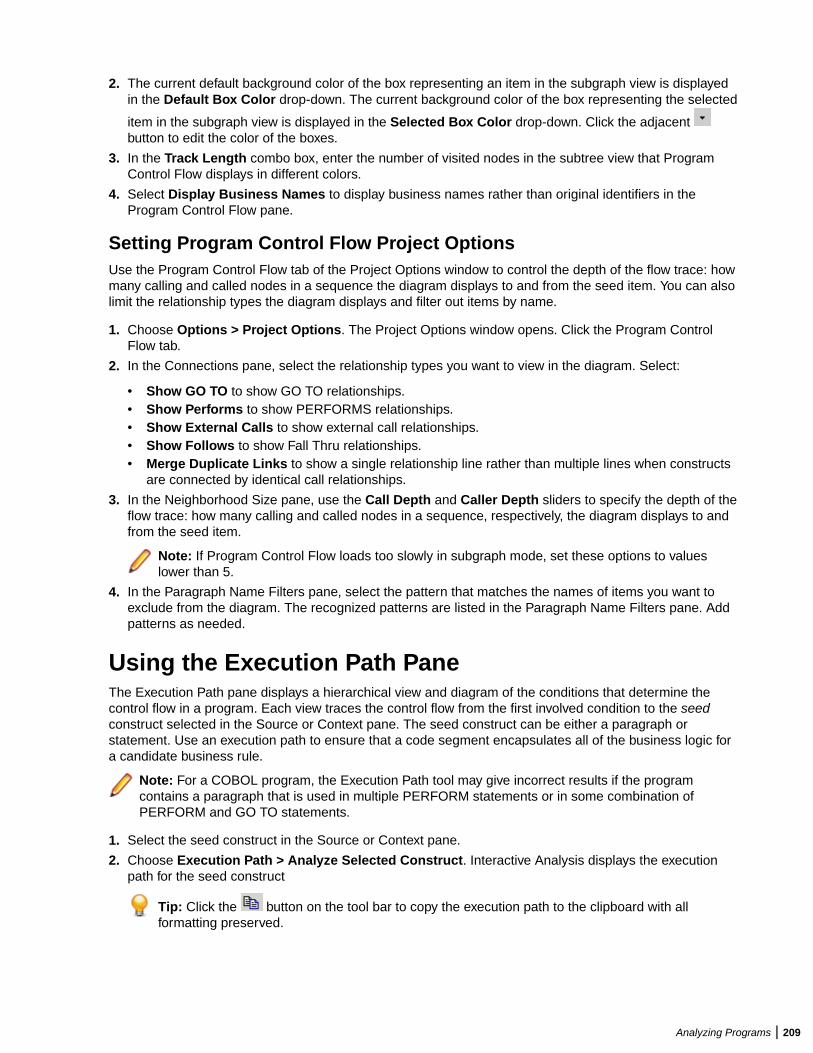
2. The current default background color of the box representing an item in the subgraph view is displayedin the Default Box Color drop-down. The current background color of the box representing the selected
item in the subgraph view is displayed in the Selected Box Color drop-down. Click the adjacent button to edit the color of the boxes.
3. In the Track Length combo box, enter the number of visited nodes in the subtree view that ProgramControl Flow displays in different colors.
4. Select Display Business Names to display business names rather than original identifiers in theProgram Control Flow pane.
Setting Program Control Flow Project OptionsUse the Program Control Flow tab of the Project Options window to control the depth of the flow trace: howmany calling and called nodes in a sequence the diagram displays to and from the seed item. You can alsolimit the relationship types the diagram displays and filter out items by name.
1. Choose Options > Project Options. The Project Options window opens. Click the Program ControlFlow tab.
2. In the Connections pane, select the relationship types you want to view in the diagram. Select:
• Show GO TO to show GO TO relationships.• Show Performs to show PERFORMS relationships.• Show External Calls to show external call relationships.• Show Follows to show Fall Thru relationships.• Merge Duplicate Links to show a single relationship line rather than multiple lines when constructs
are connected by identical call relationships.
3. In the Neighborhood Size pane, use the Call Depth and Caller Depth sliders to specify the depth of theflow trace: how many calling and called nodes in a sequence, respectively, the diagram displays to andfrom the seed item.
Note: If Program Control Flow loads too slowly in subgraph mode, set these options to valueslower than 5.
4. In the Paragraph Name Filters pane, select the pattern that matches the names of items you want toexclude from the diagram. The recognized patterns are listed in the Paragraph Name Filters pane. Addpatterns as needed.
Using the Execution Path PaneThe Execution Path pane displays a hierarchical view and diagram of the conditions that determine thecontrol flow in a program. Each view traces the control flow from the first involved condition to the seedconstruct selected in the Source or Context pane. The seed construct can be either a paragraph orstatement. Use an execution path to ensure that a code segment encapsulates all of the business logic fora candidate business rule.
Note: For a COBOL program, the Execution Path tool may give incorrect results if the programcontains a paragraph that is used in multiple PERFORM statements or in some combination ofPERFORM and GO TO statements.
1. Select the seed construct in the Source or Context pane.
2. Choose Execution Path > Analyze Selected Construct. Interactive Analysis displays the executionpath for the seed construct
Tip: Click the button on the tool bar to copy the execution path to the clipboard with allformatting preserved.
Analyzing Programs | 209
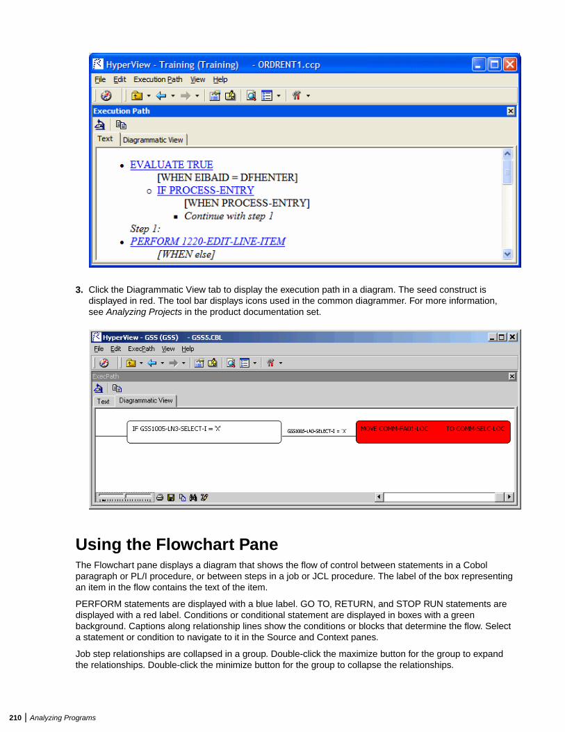
3. Click the Diagrammatic View tab to display the execution path in a diagram. The seed construct isdisplayed in red. The tool bar displays icons used in the common diagrammer. For more information,see Analyzing Projects in the product documentation set.
Using the Flowchart PaneThe Flowchart pane displays a diagram that shows the flow of control between statements in a Cobolparagraph or PL/I procedure, or between steps in a job or JCL procedure. The label of the box representingan item in the flow contains the text of the item.
PERFORM statements are displayed with a blue label. GO TO, RETURN, and STOP RUN statements aredisplayed with a red label. Conditions or conditional statement are displayed in boxes with a greenbackground. Captions along relationship lines show the conditions or blocks that determine the flow. Selecta statement or condition to navigate to it in the Source and Context panes.
Job step relationships are collapsed in a group. Double-click the maximize button for the group to expandthe relationships. Double-click the minimize button for the group to collapse the relationships.
210 | Analyzing Programs

Options control grouping of same-level statements and whether business names are displayed. The toolbarat the top of the pane displays icons used in the main Diagrammer window. For Diagrammer usage, seeAnalyzing Projects in the product documentation set.
Drawing the DiagramTo display a flowchart diagram in the Flowchart pane, select the paragraph, procedure, job, or JCLprocedure you want to analyze in the Source or Context panes. The diagram is automatically redrawnwhen you select a new startup item in the Source or Context pane.
Setting Flowchart User PreferencesUse the Interactive Analysis > Flowchart tab of the User Preferences window to control grouping of same-level statements and whether business names are displayed.1. Choose Tools > User Preferences. The User Preferences window opens. Click the Interactive Analysis
> Flowchart tab.
Analyzing Programs | 211
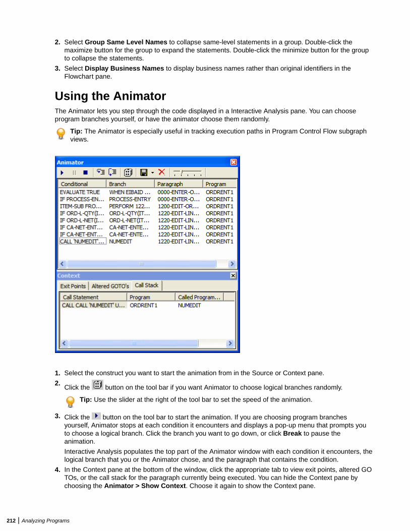
2. Select Group Same Level Names to collapse same-level statements in a group. Double-click themaximize button for the group to expand the statements. Double-click the minimize button for the groupto collapse the statements.
3. Select Display Business Names to display business names rather than original identifiers in theFlowchart pane.
Using the AnimatorThe Animator lets you step through the code displayed in a Interactive Analysis pane. You can chooseprogram branches yourself, or have the animator choose them randomly.
Tip: The Animator is especially useful in tracking execution paths in Program Control Flow subgraphviews.
1. Select the construct you want to start the animation from in the Source or Context pane.
2.Click the button on the tool bar if you want Animator to choose logical branches randomly.
Tip: Use the slider at the right of the tool bar to set the speed of the animation.
3. Click the button on the tool bar to start the animation. If you are choosing program branchesyourself, Animator stops at each condition it encounters and displays a pop-up menu that prompts youto choose a logical branch. Click the branch you want to go down, or click Break to pause theanimation.
Interactive Analysis populates the top part of the Animator window with each condition it encounters, thelogical branch that you or the Animator chose, and the paragraph that contains the condition.
4. In the Context pane at the bottom of the window, click the appropriate tab to view exit points, altered GOTOs, or the call stack for the paragraph currently being executed. You can hide the Context pane bychoosing the Animator > Show Context. Choose it again to show the Context pane.
212 | Analyzing Programs
Tip: Click the button on the tool bar to step through the code manually. Each time you click the
button the Animator steps into the next piece of program code. Click the button if you want tostep through the code manually but step over PERFORM statements.
5. Click the button on the tool bar to pause the animation. Click the button to restart the animation.
Click the button to stop the animation.
6. To save the animation results:
• To an Interactive Analysis list, click the button next to the button on the tool bar and chooseSave Trace As List in the drop-down menu. You can view the list in the Internal category in CodeSearch.
• To XML, click the button next to the button on the tool bar and choose Save Trace As XMLin the drop-down menu. A Save As dialog opens, where you can specify the name and location ofthe results report.
7. Click the to delete the results from the Animator window.
Setting Up a GlossaryUse the Glossary pane to create a dictionary, or glossary, of meaningful names for items of interest in yourworkspace: data elements, paragraphs, programs, screens, tables, and the like. A glossary is especiallyuseful for assigning business names to identifiers: natural language names that make it easy to documentand retrieve business rules. The field PLC_NUM, for example, might have the business name PolicyNumber.
The Glossary pane lets you assign business names to identifiers manually or in batch mode. You can auto-extract business names from screens, import business names into a glossary from a file, and much more.
Note:
• The scope for Glossary is the whole workspace.• We recommend that any mass updates should be done by a master user while no one else is
updating the Glossary.• Mass update functions such as Generate Business Names, Propagate Business Names, and
Import Business Attributes should not be executed by more than one master user at a time, fromone Interactive Analysis instance.
• All mass delete operations (Delete All, Delete Manual, Delete Automatic and so on) areWorkspace wide operations and we recommended that these be performed only by the masteruser.
• Users should not perform any update/delete functions while a mass update is in progress.
Understanding the Glossary PaneA term is the name of an item of interest in your workspace. The Glossary pane automatically generates alist of terms for the file selected in the Objects pane and any included files. Glossary search facilities let youhome in on terms of interest in the workspace.
The Glossary tool consists of two panes:
• The Terms pane displays the terms in the selected file, filtered by your choices in the workspace optionsfor the Glossary pane.
• The Search Result pane displays the terms returned by the most recent Glossary search. The scope ofthe search is workspace-wide, unless you use the advanced search feature to filter explicitly by project.
Each pane displays the term type, the business name and description assigned to the term, and how thebusiness name and description were assigned (Manual, Automatic, Extracted from Screen, or From
Analyzing Programs | 213
Propagation). To hide a pane, choose Glossary > View Terms or Glossary > View Search Result, asappropriate. Deselect the menu item to show the pane again.
To synch the Terms pane with other Interactive Analysis panes, choose Glossary > Synchronize withother views. Select a term in the Terms pane to navigate to the term in other Interactive Analysis panes.Deselect Glossary > Synchronize with other views to turn off synchronization.
Note: Turning off synchronization may improve Glossary performance for very large workspaces.
Searching for TermsGlossary search facilities let you home in on terms of interest in your workspace:
• Use a simple search to perform coarse-grained searches for terms.• Use an advanced search to perform narrowly targeted searches for terms.
The scope of all searches is workspace-wide, unless you use the advanced search feature to filter explicitlyby project. Results are returned in the Search Result pane. To clear the Search Result pane, chooseGlossary > Clear Search Result.
Using the Simple Search FacilityUse a simple search to perform coarse-grained searches for terms. Follow the instructions below to use thesimple search facility.
1. Enter the text for the search (or select the text of a recent search) in the Search combo box on the toolbar. You can use wildcard patterns allowed in LIKE statements by Visual Basic for Applications (VBA).
Note: Select a column heading and click the button on the tool bar, then enter text in theSearch combo box to scroll intelligently to items in that column. The tool matches text as you type.
2.Click the button on the tool bar to match business names only. Click both the button and the
button to match terms and business names (search terms are ORed).
3. Click the button on the tool bar. The results of the search are displayed in the Search Result pane.
Using the Advanced Search FacilityUse an advanced search to perform narrowly targeted searches for terms. Follow the instructions below touse the advanced search facility.
1. Choose Glossary > Advanced Search. The Advanced Search dialog opens.
214 | Analyzing Programs
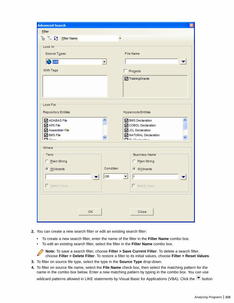
2. You can create a new search filter or edit an existing search filter:
• To create a new search filter, enter the name of the filter in the Filter Name combo box.• To edit an existing search filter, select the filter in the Filter Name combo box.
Note: To save a search filter, choose Filter > Save Current Filter. To delete a search filter,choose Filter > Delete Filter. To restore a filter to its initial values, choose Filter > Reset Values.
3. To filter on source file type, select the type in the Source Type drop-down.
4. To filter on source file name, select the File Name check box, then select the matching pattern for thename in the combo box below. Enter a new matching pattern by typing in the combo box. You can use
wildcard patterns allowed in LIKE statements by Visual Basic for Applications (VBA). Click the button
Analyzing Programs | 215
next to the drop-down to display a pop-up menu of elements you can insert in the pattern. Click anelement to insert it. The matching pattern is saved when you save or execute the filter.
5. To filter on tags, select each tag you want to filter on in the With Tags pane. The search will returnmatching repository objects that have been assigned the tag and matching HyperCode constructscontained in repository objects that have been assigned the tag.
6. To filter on projects, select the Project check box, then select the projects in the list pane below.
7. To filter on repository object type, select each object type you want to filter on in the Repository Entitiespane.
8. To filter on HyperCode construct type, select each construct type you want to filter on in the HypercodeEntities pane.
Note: Both repository and Hypercode entities are filtered by your choices in the workspace optionsfor the Glossary pane.
9. To filter on the text for a term and/or business name, enter a matching pattern for the text in the comboboxes for terms and/or business names in the Where pane. You can enter plain character strings orwildcard patterns.
a) Click the radio button for the type of pattern matching you want to use.b) For wildcard patterns, click the button next to the drop-down to display a list of elements you can
insert in the pattern. Click an element to insert it. You can use wildcard patterns allowed in LIKEstatements by Visual Basic for Applications (VBA). The matching pattern is saved when you save orexecute the filter.
c) In the Condition drop-down, select AND if you want the search terms to be ANDed, or OR if youwant the search terms to be ORed.
d) Select the Match Case check box if you want the search to match case.
10.Click OK to execute the filter. The Glossary tool displays the search results in the Search Result pane.
Note: If you execute another advanced search with the same criteria for the term or businessname, the contents of the Search Result pane act as a filter. If you don't want to filter on existingresults, choose Glossary > Clear Search Result to clear the Search Result pane.
Creating a List of Search ResultsTo create a Code Search list containing search results, choose Glossary > Add to Code Search List.Specify the list name in the New list dialog box and click OK. The list is displayed in the Glossary categoryin Code Search.
Assigning Business AttributesYou can assign business names manually or in batch mode. You can also export terms and businessattributes from the glossary for one workspace for import into the glossary of another.
Assigning Business Names ManuallyTo assign a business name and business description to an object, select the object and choose SetBusiness Attributes in the right-click menu. A dialog box opens, where you can enter the business nameand business description. To unassign a business name or business description, simply delete the value inthe dialog box.
Assigning Business Names in Batch ModeOrdinarily, you will want to assign business names in batch mode rather than manually. In the batchinterface, you enter replacement text for each token or string you want to change in a term. For the stringNUM, for example, you would enter the replacement text Number. You can also modify business namesthemselves in batch mode.
216 | Analyzing Programs
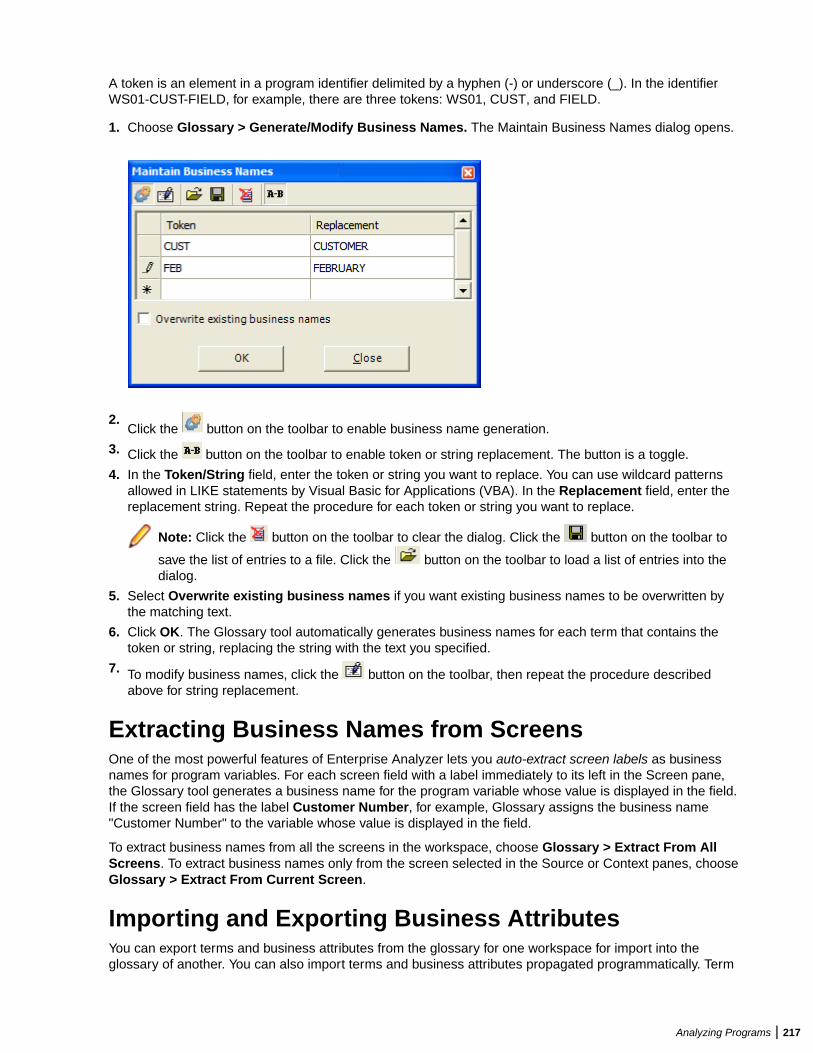
A token is an element in a program identifier delimited by a hyphen (-) or underscore (_). In the identifierWS01-CUST-FIELD, for example, there are three tokens: WS01, CUST, and FIELD.
1. Choose Glossary > Generate/Modify Business Names. The Maintain Business Names dialog opens.
2.Click the button on the toolbar to enable business name generation.
3. Click the button on the toolbar to enable token or string replacement. The button is a toggle.
4. In the Token/String field, enter the token or string you want to replace. You can use wildcard patternsallowed in LIKE statements by Visual Basic for Applications (VBA). In the Replacement field, enter thereplacement string. Repeat the procedure for each token or string you want to replace.
Note: Click the button on the toolbar to clear the dialog. Click the button on the toolbar to
save the list of entries to a file. Click the button on the toolbar to load a list of entries into thedialog.
5. Select Overwrite existing business names if you want existing business names to be overwritten bythe matching text.
6. Click OK. The Glossary tool automatically generates business names for each term that contains thetoken or string, replacing the string with the text you specified.
7. To modify business names, click the button on the toolbar, then repeat the procedure describedabove for string replacement.
Extracting Business Names from ScreensOne of the most powerful features of Enterprise Analyzer lets you auto-extract screen labels as businessnames for program variables. For each screen field with a label immediately to its left in the Screen pane,the Glossary tool generates a business name for the program variable whose value is displayed in the field.If the screen field has the label Customer Number, for example, Glossary assigns the business name"Customer Number" to the variable whose value is displayed in the field.
To extract business names from all the screens in the workspace, choose Glossary > Extract From AllScreens. To extract business names only from the screen selected in the Source or Context panes, chooseGlossary > Extract From Current Screen.
Importing and Exporting Business AttributesYou can export terms and business attributes from the glossary for one workspace for import into theglossary of another. You can also import terms and business attributes propagated programmatically. Term
Analyzing Programs | 217
(source), business name (replacement), and business description (description) must appear in XML fileformat as follows:
<glossary> <item source="CUST_INFO" replacement="CUSTOMERINFORMATION" description="customer information"/> ...</glossary>
To export business attributes, choose Glossary > Export Business Attributes. A save as dialog opens,where you can specify the name and location of the file to export.
To import business attributes, choose Glossary > Import Business Attributes. An open dialog displays,where you can specify the file to import. You are prompted to confirm whether you want to overwriteexisting business attributes. Select Overwrite existing business attributes if you want to replace existingbusiness attributes as well as add new ones. Click OK.
Propagating Business NamesYou can propagate the business name for one identifier to a related identifier with an identical meaning inthe data flow. Business names can be propagated in either direction of the relationship and transitively:
• For the statements MOVE A to B and MOVE B to C, if A has a business name, it is propagated to B andC.
• For the statements MOVE A to B and MOVE B to C, if C has a business name, it is propagated to B andA.
No business name is assigned to a variable if it receives values from variables with different businessnames:
Working-Storage Section.10 Cust-No PIC 9(7).10 Ord-No PIC 9(7).10 Display-No PIC 9(7).
Procedure Division....Move Cust-No to Display-No.Display Display-No.Move Ord-No to Display-No. Display Display-No....
If Cust-No has the business name Customer Number, and Ord-No has the business name Order Number,no business name is assigned to Display-No, since it receives values from variables with different businessnames.
To propagate business names from all existing business names, choose Glossary > Propagate All. Topropagate business names from selected business names, choose a single business name in the Termspane or multiple business names in the Search Result pane and choose Glossary > Propagate Selected.To propagate only from business names assigned in a specific way, choose Glossary > Propagate<Assignment Method>.
Deleting Business AttributesTo delete business attributes for a given term, select the term in the Terms or Search Result pane andchoose Set Business Attributes in the right-click menu. The Set Business Attributes dialog opens, whereyou can delete the values in the Business Name and Description fields.
To delete all business names, right-click in the Terms or Search Result pane and choose Delete BusinessNames > Delete All Business Names in the pop-up menu. To delete only business names assigned in a
218 | Analyzing Programs
specific way, right-click in the Terms or Search Result pane and choose Delete Business Names > Delete<Assignment Method> in the pop-up menu.
To delete all business descriptions, right-click in the Terms or Search Result pane and choose Delete AllDescriptions in the pop-up menu.
Note: Mass delete operations are workspace-wide, and should normally be performed by the masteruser only.
Setting Glossary Workspace OptionsUse the Glossary tab of the Workspace Options window to filter the objects and constructs available in theTerms pane and the Advanced Search dialog, and to specify the types of data flow relationships for whichbusiness names are propagated.
1. Choose Options > Workspace Options. The Workspace Options window opens. Click the Glossarytab.
2. Click the Entities tab, then the Hypercode tab. In the Source Type pane, select the source file typewhose constructs you want to include, then select the constructs in the HyperCode Entities pane.
3. Click the Repository tab. Select each type of repository object you want to include.
4. Click the Propagation tab. Select each data flow relationship you want to propagate business namesfor.
Note: Click Select All to select all the items on a tab. Click Select All again to deselect all theitems.
Refreshing a GlossaryYou need to refresh a glossary if, during the current Glossary session, you assign a business name to anobject in another tool and want the change to be reflected in the glossary. To refresh a glossary, chooseGlossary > Refresh Glossary.
Generating Glossary ReportsThe Glossary tool offers two reports:
• The Terms report prints the contents of the Terms pane. To generate a Terms report, choose Glossary> Terms Report.
• The Search report prints the contents of the Search Result pane. To generate a Search report, chooseGlossary > Search Report.
Extracting Business RulesMuch of the code in a legacy application, by some estimates as much as 80%, is devoted to tasks with onlya marginal relationship to the business logic of the application. Business rule extraction lets you separatethe application's business logic from data transfer and other tasks.
That makes the application easier to understand, document, maintain, and modernize. It also makes iteasier to determine the overlap between legacy applications on the one hand, and any gaps in theirfunctionality on the other.
Business Rule Manager (BRM) lets you batch edit rule attributes; create custom attributes suited to yourparticular needs; match input/output data elements with the business names you've assigned to them inyour project glossary; and much more.
Analyzing Programs | 219
Understanding Business RulesA business rule is a named container for program code that performs a discrete task in a business process.The rule identifies and documents the code segment that performs this task. A business rule namedCalculate Date Difference, for example, might consist of this segment:
COMPUTE WS-DATE-VARIANCE = WS-C-CARD-DATE-CCYYMM - WS-TODAYS-DATE-CCYYMM.
A business rule can contain one segment only. The same segment can be assigned to different rules.Rules are identified in the Rules pane with a symbol.
How Business Rules Are OrganizedYou organize business rules in rule sets. A rule set typically consists of rules executed together, such that ifone rule is executed, all are executed (the statements in a paragraph, for example). Think of a rule set as a
business process, like Validate Input or Update File. Rule sets are identified in the Rules pane with a symbol.
You organize rule sets, in turn, in business functions. A business function typically defines the order inwhich processes are triggered. Think of a business function as a use case, like Insert Customer or UpdateOrder. Business functions are identified in the Rules pane with a symbol.
Business function names must be unique in the workspace. The same rule set can exist in multiplebusiness functions; the same rule can exist in multiple rule sets. The figure below shows the InteractiveAnalysis Rules pane with a typical hierarchy of business functions, rule sets, and business rules.
220 | Analyzing Programs
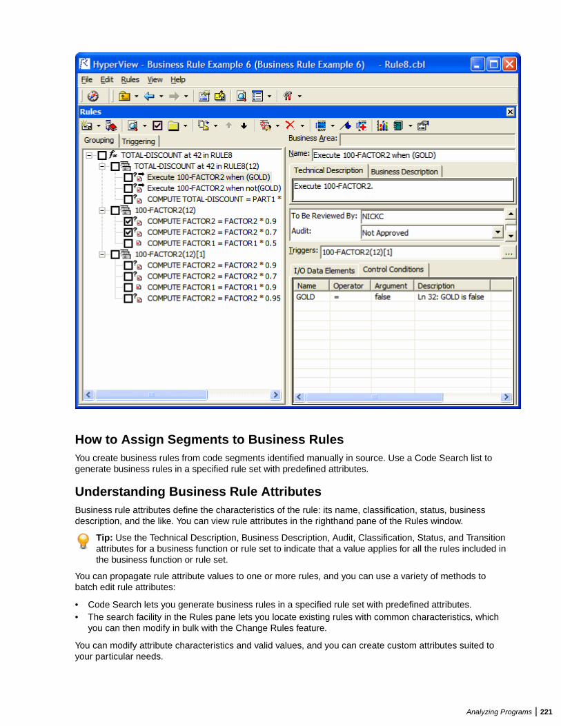
How to Assign Segments to Business RulesYou create business rules from code segments identified manually in source. Use a Code Search list togenerate business rules in a specified rule set with predefined attributes.
Understanding Business Rule AttributesBusiness rule attributes define the characteristics of the rule: its name, classification, status, businessdescription, and the like. You can view rule attributes in the righthand pane of the Rules window.
Tip: Use the Technical Description, Business Description, Audit, Classification, Status, and Transitionattributes for a business function or rule set to indicate that a value applies for all the rules included inthe business function or rule set.
You can propagate rule attribute values to one or more rules, and you can use a variety of methods tobatch edit rule attributes:
• Code Search lets you generate business rules in a specified rule set with predefined attributes.• The search facility in the Rules pane lets you locate existing rules with common characteristics, which
you can then modify in bulk with the Change Rules feature.
You can modify attribute characteristics and valid values, and you can create custom attributes suited toyour particular needs.
Analyzing Programs | 221
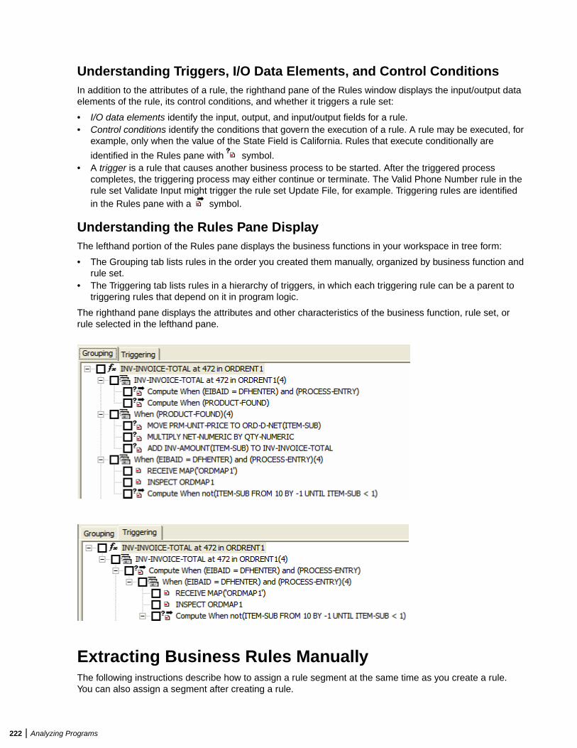
Understanding Triggers, I/O Data Elements, and Control ConditionsIn addition to the attributes of a rule, the righthand pane of the Rules window displays the input/output dataelements of the rule, its control conditions, and whether it triggers a rule set:
• I/O data elements identify the input, output, and input/output fields for a rule.• Control conditions identify the conditions that govern the execution of a rule. A rule may be executed, for
example, only when the value of the State Field is California. Rules that execute conditionally are
identified in the Rules pane with symbol.• A trigger is a rule that causes another business process to be started. After the triggered process
completes, the triggering process may either continue or terminate. The Valid Phone Number rule in therule set Validate Input might trigger the rule set Update File, for example. Triggering rules are identifiedin the Rules pane with a symbol.
Understanding the Rules Pane DisplayThe lefthand portion of the Rules pane displays the business functions in your workspace in tree form:
• The Grouping tab lists rules in the order you created them manually, organized by business function andrule set.
• The Triggering tab lists rules in a hierarchy of triggers, in which each triggering rule can be a parent totriggering rules that depend on it in program logic.
The righthand pane displays the attributes and other characteristics of the business function, rule set, orrule selected in the lefthand pane.
Extracting Business Rules ManuallyThe following instructions describe how to assign a rule segment at the same time as you create a rule.You can also assign a segment after creating a rule.
222 | Analyzing Programs
1. In the Source pane, select the segment you want to assign to a business rule. In the Rules pane, selectthe business function or rule set (if any) for the new rule, then choose Create Rule in the Rules menu.The Create Business Rule dialog opens.
Tip: You can select a code segment as construct or text. Select a segment as text when you wantto select either more or less code than a construct contains. To select a segment as text, click-and-drag from the first line of the segment to the last line of the segment. The segment is highlighted inblue. To select a segment as construct, click inside the construct in the Source pane. The segmentis highlighted in yellow.
2. In the Business Function drop-down, select the business function for the rule. The current businessfunction is displayed. To create a new business function, click New, then follow the instructions forcreating business functions.
3. In the Rule Set drop-down, select the rule set for the rule. The current rule set is displayed. To create anew rule set, click New, then follow the instructions for creating rule sets.
4. Specify the rule's attributes:
• In the Name field, enter the name of the rule.• On the Business Description tab, enter the business description for the rule.• On the Technical Description tab, enter the technical description for the rule.• On the Attributes tab, specify the remaining attributes of the rule.
5. Click OK.
Performing Basic Tasks in the Rules PaneThe lefthand pane of the Rules window lists every business rule in the current project, organized bybusiness function and rule set. To see their attributes in the righthand pane, select:
• A business function.• A rule set. If a rule set is triggered by a rule, the trigger is listed in the lower portion of the righthand
pane.• A rule to view its attributes and its segment in the Interactive Analysis Source and Context panes.
Creating Business FunctionsTo create a business function, choose Rules > Create Business Function. The Business Function dialogopens. In the Business Function dialog, enter the attributes of the new business function and click OK.
Creating Rule SetsTo create a rule set, select the business function for the rule set in the lefthand pane and choose Rules >Create Rule Set. The Create Rule Set dialog opens, with the current business function displayed in theBusiness Function drop-down. Select another business function if necessary, then enter the attributes ofthe new rule set and click OK.
Selecting Rules for Batch ProcessingThere are four ways to select rules for Batch Processing:
Defaultselection (usingonly the mouse)
It marks the current node with all its child nodes. In case of reused rule set, it selectsall instances. In the Triggering pane, all nodes down the triggering chains arechecked.
Check a rule to make it a candidate for batch processing. Check a rule set to select allrules in it. Check a business function to select all the rule sets and rules in it.
Analyzing Programs | 223
To check all rules, click Rules > Select All. Click Rules > Unselect All to clear theselection. To invert the current selection, so that unselected rules are selected andselected rules are unselected, click Rules > Invert Selection.
Note: Click Rules > Selected Only to display only the checked businessfunctions, rule sets, or rules (and their parents or children) in the Rules pane.
Using the Shiftkey
Shift + click marks only the current node.
Using the Ctrlkey
Ctrl + click marks the current node and all its sibling nodes.
Using Ctrl +Shift keys
Ctrl + Shift + click marks the current node with all its child nodes. In the Triggeringpane, the check does not affect the triggering chains.
Moving or Copying Rules or Rule SetsTo move or copy rules, place a check mark next to the rules and click Rules > Copy/Move SelectedRules. The Copy/Move Selected Rules dialog opens, where you can specify the rule set for the rules andwhether you want to move or copy them.
To move or copy rule sets, check the rule sets and click Rules > Copy/Move Selected Rule Sets. TheCopy/Move Selected Rule Sets dialog opens, where you can specify the business function for the rule setsand whether you want to move, copy, or reuse them. For copied rule sets, a number in curly brackets ({n})is appended to the name to guarantee uniqueness. For reused rule sets, no change is made to the name.
Note: If you attempt to delete a reused rule set, you are prompted to confirm whether you want todelete every instance or only the selected instance.
Copying a Rule or Rule Set with a Different NameTo copy a rule with a different name, select the rule and choose Rules > Copy/Move. The Copy/Movedialog opens, where you can specify the rule set for the rule and the new name of the rule.
Note: If you select Move rather than Copy in this dialog, the rule is moved unchanged to the newlocation.
To copy a rule set with a different name, select the rule set and choose Rules > Copy/Move. The Copy/Move dialog opens, where you can specify the business function for the rule set and the new name of therule set. You can also specify a technical description or business description. The rules in the rule set arenot copied to the new location.
Note: If you select Move rather than Copy in this dialog, the rule set and all its rules are movedunchanged to the new location.
Deleting Rules, Rules Sets, and Business FunctionsTo delete a rule, rule set, or business function, select it and choose Rules > Delete. You are prompted toconfirm the deletion. Click OK. You cannot delete a non-empty rule set or business function. To undo thedeletion, choose Rules > Undo Delete.
Changing the Order of Rules and Rule SetsTo move a rule up in the sequence for its rule set, select it and choose Rules > Move Up in Sequence. Tomove a rule down in the sequence for its rule set, select it and choose Rules > Move Down in Sequence.You can also use these menu choices to move a selected rule set up or down in the sequence for itsbusiness function.
Tip: For reporting purposes, it's usually best to list rules in order of execution.
224 | Analyzing Programs
Exporting Rules, Rule Sets, and Business FunctionsTo export rules, rule sets, or business functions to an ERD file, for import to another workspace or a third-party tool, select the items you want to export and choose Rules > Rule Export. You are prompted tocontinue. Click Yes. The Export Objects dialog opens, where you can specify the name and folder for theERD file.
Note: Only the parents of exported items are exported. Children are not. That is, if you export abusiness function, only the business function is exported. If you export a rule set, only the rule set andits business function are exported.
Importing Rules, Rule Sets, and Business FunctionsTo import rules, rule sets, or business functions from an ERD file, choose Rules > Rule Import. TheImport Rules dialog opens, where you can specify the name and folder for the ERD file.
Parents are also imported. If the parent for an imported item already exists in the workspace and hasdifferent children, the item is added to the existing children.
Note: If the segment for an imported rule does not exist in the workspace, the segment validityattribute for the rule is set to False.
Assigning Segments to Existing RulesTo assign a segment to an existing rule (whether or not a segment has already been assigned to it), selectthe rule, then select the segment in the Source pane. Choose Rules > Assign segment.
Deleting a Segment from a RuleTo delete a segment from a rule, select the rule and choose Rules > Delete segment.
Flagging Segments in SourceTo place a symbol in the Interactive Analysis Source pane display next to each line in the assigned
segment, click the button on the tool bar.
Viewing the Activity Log
To view a chronological record of your activities for a rule, select the rule and choose Rules > ActivityLog.
Editing Rule AttributesBefore a rule will be useful to other members of your organization, you need to define its attributes: whattask the rule performs, whether it has been approved, the last time it was validated, and so forth. You canview rule attributes in the righthand pane of the Interactive Analysis Rules window.
Tip: Use the Technical Description, Business Description, Audit, Classification, Status, and Transitionattributes for a business function or rule set to indicate that a value applies for all the rules included inthe business function or rule set. Use the Business Area attribute of a business function to classifybusiness functions as members of a still broader category of activity, such as Customer Management.
You can propagate rule attribute values to one or more rules, and you can use a variety of methods tobatch edit rule attributes:
• Code Search lets you generate business rules in a specified rule set with predefined attributes.• The search facility in the Rules pane lets you locate existing rules with common characteristics, which
you can then modify in bulk with the Change Rules feature.
Analyzing Programs | 225

You can modify attribute characteristics and valid values, and you can create custom attributes suited toyour particular needs.
Editing System AttributesThe names and characteristics of system attributes cannot be modified. The values for many of theseattributes are set programmatically.
Editing the Name Attribute
You specify the name of a business function, rule set, or rule when you create it. To edit the Name attribute,enter a new name in the Name field.
Editing the Business Area Attribute
The Business Area attribute of a business function identifies the business activity of which the businessfunction is a part, such as Customer Management. To edit the Business Area attribute, enter appropriatetext in the Business Area field.
Editing the Technical Description Attribute
The Technical Description attribute identifies the role of a rule in program logic. To edit the TechnicalDescription attribute, enter appropriate text in the Technical Description tab.
Editing the Business Description Attribute
The Business Description attribute identifies the business role of a rule. To edit the Business Descriptionattribute, enter appropriate text in the Business Description tab.
Editing the To Be Reviewed By Attribute
The To Be Reviewed By attribute identifies the business analyst responsible for reviewing and approving arule. To edit the To Be Reviewed By attribute, enter appropriate text in the To Be Reviewed By field.
Editing the Program Attribute
The Program attribute identifies the program that contains the rule segment. The value is supplied whenyou assign a segment to a rule.
Editing the Segment Validity Attribute
Refreshing or editing source code may result in a mismatch between rules and segments. Lines of codemay have been added or deleted during the refresh or edit, causing a rule to no longer to be synchronizedwith its segment after re-verification.
The Segment Validity attribute specifies whether a rule segment is valid. The value is supplied when asegment is validated or invalidated.
Editing the Last Validation Time Attribute
The Last Validation Time attribute identifies the date and time a rule segment was last validated. The valueis supplied when a segment is validated.
Editing User-Defined AttributesUser-defined attributes can be renamed, defined with different values, or deleted altogether. Their defaultnames and values are described below.
226 | Analyzing Programs
Editing the Audit Attribute
Newly created rules are considered unapproved, pending a decision that the rule represents valid businesslogic. The Audit attribute identifies whether the rule has been audited and approved. To edit the Auditattribute, choose one of the following from the Audit drop-down:
• Not Approved if the rule has not been accepted as valid business logic.• Approved if the rule has been accepted as valid business logic.
Editing the Classification Attribute
The Classification attribute identifies the programming task a rule performs. To edit the classificationattribute, choose one of the following from the Classification drop-down:
• I/O if the rule performs an input or output function.• Calculation if the rule performs a calculation.• Security if the rule performs a security function.• Decision if the rule resolves a decision.• Validation if the rule performs validation.• Flow if the rule performs a data flow function.
Editing the Status Attribute
The Status attribute identifies the status of a rule in a code extraction or other project. To edit the Statusattribute, choose one of the following from the Status drop-down:
• (none) if the rule has no extraction status.• Extracted if the rule has been extracted, but not accepted or rejected.• Working if the rule is still being extracted.• Accepted if the rule has been accepted.• Rejected if the rule has been rejected.
Editing the Transition Attribute
The Transition attribute identifies the status of a rule in an application redevelopment project. To edit theTransition attribute, choose one of the following from the Transition drop-down:
• Valid as is, if the rule is valid for redevelopment.• Complete, if the rule has been redeveloped.• Obsolete, if the rule is obsolete.• Requires modification, if the rule requires modification for redevelopment.• Duplicate, if the item is a duplicate of a rule being used for redevelopment.
Propagating Rule AttributesFollow the steps below to propagate one or more attribute values for a rule to another rule or to a group ofrules:
1. Select the rules to which you want to propagate attribute values.
2. Click the rule whose attribute values you want to propagate and choose Rules > Propagate fromHighlighted to Selected. You are prompted to continue. Click Yes. The Attribute Propagation windowopens.
Analyzing Programs | 227
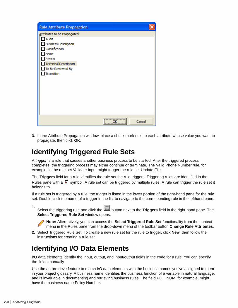
3. In the Attribute Propagation window, place a check mark next to each attribute whose value you want topropagate, then click OK.
Identifying Triggered Rule SetsA trigger is a rule that causes another business process to be started. After the triggered processcompletes, the triggering process may either continue or terminate. The Valid Phone Number rule, forexample, in the rule set Validate Input might trigger the rule set Update File.
The Triggers field for a rule identifies the rule set the rule triggers. Triggering rules are identified in theRules pane with a symbol. A rule set can be triggered by multiple rules. A rule can trigger the rule set itbelongs to.
If a rule set is triggered by a rule, the trigger is listed in the lower portion of the right-hand pane for the ruleset. Double-click the name of a trigger in the list to navigate to the corresponding rule in the lefthand pane.
1.Select the triggering rule and click the button next to the Triggers field in the right-hand pane. TheSelect Triggered Rule Set window opens.
Note: Alternatively, you can access the Select Triggered Rule Set functionality from the contextmenu in the Rules pane from the drop-down menu of the toolbar button Change Rule Attributes.
2. Select Triggered Rule Set. To create a new rule set for the rule to trigger, click New, then follow theinstructions for creating a rule set.
Identifying I/O Data ElementsI/O data elements identify the input, output, and input/output fields in the code for a rule. You can specifythe fields manually.
Use the autoretrieve feature to match I/O data elements with the business names you've assigned to themin your project glossary. A business name identifies the business function of a variable in natural language,and is invaluable in documenting and retrieving business rules. The field PLC_NUM, for example, mighthave the business name Policy Number.
228 | Analyzing Programs
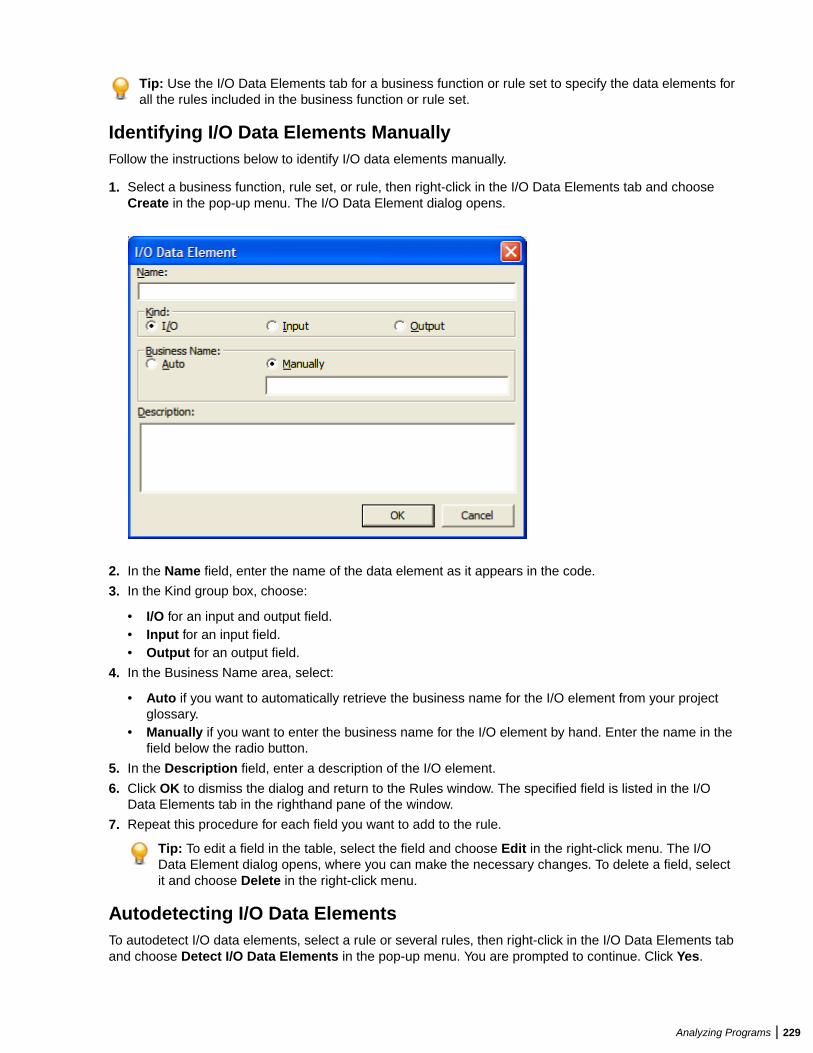
Tip: Use the I/O Data Elements tab for a business function or rule set to specify the data elements forall the rules included in the business function or rule set.
Identifying I/O Data Elements ManuallyFollow the instructions below to identify I/O data elements manually.
1. Select a business function, rule set, or rule, then right-click in the I/O Data Elements tab and chooseCreate in the pop-up menu. The I/O Data Element dialog opens.
2. In the Name field, enter the name of the data element as it appears in the code.
3. In the Kind group box, choose:
• I/O for an input and output field.• Input for an input field.• Output for an output field.
4. In the Business Name area, select:
• Auto if you want to automatically retrieve the business name for the I/O element from your projectglossary.
• Manually if you want to enter the business name for the I/O element by hand. Enter the name in thefield below the radio button.
5. In the Description field, enter a description of the I/O element.
6. Click OK to dismiss the dialog and return to the Rules window. The specified field is listed in the I/OData Elements tab in the righthand pane of the window.
7. Repeat this procedure for each field you want to add to the rule.
Tip: To edit a field in the table, select the field and choose Edit in the right-click menu. The I/OData Element dialog opens, where you can make the necessary changes. To delete a field, selectit and choose Delete in the right-click menu.
Autodetecting I/O Data ElementsTo autodetect I/O data elements, select a rule or several rules, then right-click in the I/O Data Elements taband choose Detect I/O Data Elements in the pop-up menu. You are prompted to continue. Click Yes.
Analyzing Programs | 229
Note: Alternatively, you can do this by selecting Detect I/O Data Elements from the context menu inthe Rules pane or from the drop-down menu of the toolbar button Change Rule Attributes.
When the autodetect process is complete, a dialog box displays the number of autodetected I/O elements.Click OK. Click the I/O Data Elements tab in the right-hand pane of the Rules window to view theautodetected I/O elements.
To roll back automatic detection, select a rule or several rules, then right-click in the I/O Data Elements taband choose Undo I/O Detection in the pop-up menu.
Note: Alternatively, you can do this by selecting Undo Last I/O Detection from the context menu inthe Rules pane or from the drop-down menu of the toolbar button Change Rule Attributes.
Note: When you verify the project, set Enable Impact Report and Enable Data Element Flow in theproject verification options to enable the autodetect method for I/O data elements.
The method is based on a set of heuristics designed to produce reasonable output. Results may needto be verified by a detailed impact analysis. For more information on the heuristics, contact supportservices.
Retrieving Business Names for I/O Data ElementsTo match I/O data elements with the business names you've assigned to them in your project glossary,select a business function, rule set, or rule, then right-click in the I/O Data Elements tab and choosePopulate I/O Business Names in the pop-up menu. You are prompted to continue. Click Yes.
When the autoretrieve process is complete, a dialog box displays the number of autoretrieved I/O businessnames. Click OK. Click the I/O Data Elements tab in the righthand pane of the Rules window to view theautoretrieved business names.
Identifying Control ConditionsControl conditions identify the conditions that govern the execution of a rule. A rule may be executed, forexample, only when the value of the State field is California. Rules that execute conditionally are identified
in the Rules pane with symbol.
Tip: Use the Control Conditions tab for a business function or rule set to specify the control conditionsfor all the rules included in the business function or rule set.
Use the autoreplace feature to replace variable names in control conditions with the business namesyou've assigned to them in your project glossary. A business name identifies the business function of avariable in natural language, and is invaluable in documenting and retrieving business rules. The fieldPLC_NUM, for example, might have the business name Policy Number.
Tip: Move a control condition up or down in the Control Conditions tab by selecting it and choosingMove Up or Move Down in the right-click menu.
Specifying Control ConditionsFollow the instructions below to specify control conditions for a rule.
1. Select a business function, rule set, or rule, then right-click in the Control Conditions tab and chooseCreate Control Condition in the pop-up menu. The Control Condition dialog opens.
Note: Alternatively, you can do this by selecting Create Control Condition from the context menuin the Rules pane or from the drop-down menu of the toolbar button Change Rule Attributes.
2. In the Name field, enter the name of the data item evaluated by the condition as it appears in the code.
3. In the Operator drop-down, choose the operator for the comparison that determines whether thecondition is met.
4. In the Argument field, enter the constant value to which the data item is compared. The value may bethe name of another field.
230 | Analyzing Programs

5. In the Description field, enter a description of the control condition.
6. Click OK to dismiss the dialog and return to the Rules window. The specified condition is listed in theControl Conditions tab in the righthand pane of the window.
Tip: To edit a field in the table, select the field and choose Edit in the right-click menu. The ControlCondition dialog opens, where you can make the necessary changes. To delete a field, select itand choose Delete in the right-click menu.
7. Repeat this procedure for each control condition you want to add to the rule.
Autoreplacing Variable Names in Control Conditions with BusinessNamesTo autoreplace variable names in control conditions with their business names in a project glossary, selecta business function, rule set, or rule, then right-click in the Control Conditions tab and choose SubstituteBusiness Names in the pop-up menu. You are prompted to continue. Click Yes.
When the autoreplace process is complete, a dialog box displays the number of autoreplaced variablenames. Click OK.
Searching for RulesUse the search facility in the Rules pane to find rules based on segment location and/or attribute values.Use the Change Rules feature to batch edit the rules returned by the search.
Note: There is also a simple search option, under the Rules toolbar, that selects business functions,rules sets and rules that match the search string. It is case-sensitive and is available for the Groupingtab only, however results appear as checked in the Triggering tab as well.
1. Select a business function, rule set, or rule and choose Rules > Start Search. The Rule Searchwindow opens.
Analyzing Programs | 231
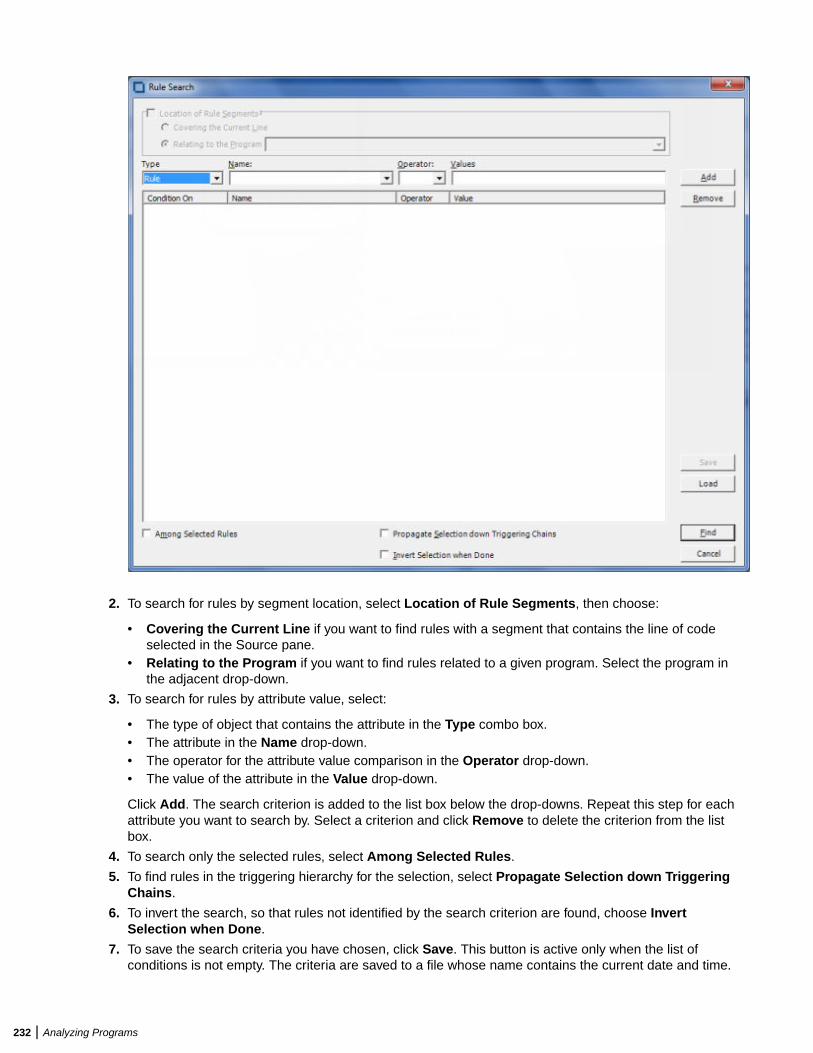
2. To search for rules by segment location, select Location of Rule Segments, then choose:
• Covering the Current Line if you want to find rules with a segment that contains the line of codeselected in the Source pane.
• Relating to the Program if you want to find rules related to a given program. Select the program inthe adjacent drop-down.
3. To search for rules by attribute value, select:
• The type of object that contains the attribute in the Type combo box.• The attribute in the Name drop-down.• The operator for the attribute value comparison in the Operator drop-down.• The value of the attribute in the Value drop-down.
Click Add. The search criterion is added to the list box below the drop-downs. Repeat this step for eachattribute you want to search by. Select a criterion and click Remove to delete the criterion from the listbox.
4. To search only the selected rules, select Among Selected Rules.
5. To find rules in the triggering hierarchy for the selection, select Propagate Selection down TriggeringChains.
6. To invert the search, so that rules not identified by the search criterion are found, choose InvertSelection when Done.
7. To save the search criteria you have chosen, click Save. This button is active only when the list ofconditions is not empty. The criteria are saved to a file whose name contains the current date and time.
232 | Analyzing Programs
Example: SearchCriterion_2014-Jan-16_04-24-22.BRM.xml. By default it is saved in theworkspace directory.
8. To load saved search criteria, click Load, select the file where the search criteria are saved and clickOpen.
9. When you are satisfied with your entries in the Rule Search window, click Find. The search facilityautomatically selects the check box for each rule returned by the search.
Batch Processing Rule AttributesUse the Change Rules feature to batch process rule attributes. You can select batch-processing candidatesmanually, or use the search facility to select candidates automatically.
Note: Attributes of I/O data elements and control conditions can only be used to replace a BusinessDescription or Technical Description. If there are multiple instances of I/O data elements or controlconditions, they are displayed in the Business Description or Technical Description on separate lines.
1. Select the check box for each rule you want to batch process. If you are batch processing rules returnedby a search, the check boxes are already selected.
2. Click Rules > Change Rule Attributes. You are prompted to continue. Click Yes. The Change Ruleswindow opens.
3. In the Attribute drop-down, select the attribute you want to batch edit. In the Find What field, enter apattern for the search text. In the Replace With field, enter a pattern for the replacement text. You canuse any combination of text and bracketed attribute names. For attributes with enumerated values, clickthe arrow button next to the Find What and Replace With fields to display the values in a drop-down.For the remaining attributes, click the arrow button to display the available attributes in a drop-down.Select an item in a drop-down to populate the adjacent field.
4. When you are satisfied with your entries in the Change Rules window, click Replace. BRM modifies theselected rules. Click Close to dismiss the window and return to the Rules pane.
Usage ExampleSuppose you wanted to use the Change Rules feature to rename two rules:
Rule 1 of program ABCRule 2 of program XYZ
as follows:
Rule 1 extracted from the ABC programRule 2 extracted from the XYZ program
1. Check Rule 1 of program ABC and Rule 2 of program XYX.
2. Choose Rules > Change Rule Attributes. You are prompted to continue. Click Yes. The Change Ruleswindow opens.
3. In the Select Attribute field, choose the name attribute.
4. In the Find What field, enter:
of program [Program]
5. In the Replace With field, enter:
extracted from the [Program] program
Substituting a Business Name for an I/O Element in an Attribute ValueYou can substitute a business name for an I/O element in an attribute value by appending "/bus" to theattribute name in either the Find What or Replace With fields in the Change Rules window.
Suppose the Catalog-Master variable has the business name Master Catalog. Now you want to replace theexisting Business Description for the Rewrite Catalog-Master rule with the text "Rewrite Master Catalog."
Analyzing Programs | 233
You would select the Business Description attribute in the Select Attribute field and enter in the ReplaceWith field:
[Name/bus]
Synchronizing SourcesSuppose a rule set in the current project is triggered by a rule in another project. When you synchronizesources, BRM includes the program that contains the segment for the triggering rule in the current project.To synchronize sources, choose Rules > Sync Sources.
Validating Rule Segments after Refreshing or EditingCodeRefreshing or editing source code may result in a mismatch between a rule and its segment. Lines of codemay have been added or deleted during the refresh or edit, causing a rule to no longer to be synchronizedwith the segment after reverification.
BRM automatically handles invalidated segments based on your instructions in the Business Rule Manager> Automatic Rule Validation tab of the Project options window. Use the procedure below when you need tooverride the specified handling for a rule.
1. Select the rules you want to validate and choose Rules > Validate. You are prompted to continue. ClickYes. The Automatic Rule Validation dialog opens.
2. In the Actions for invalid segments pane, select:
• Leave segment, set Valid to false if you want BRM to keep the invalid segment with the rule, butset the Segment Validity attribute of the rule to Invalid.
• Delete segment, set Valid to true if you want BRM to delete the invalid segment from the rule andset the Segment Validity attribute of the rule to Valid.
• Try to match if you want BRM to resynchronize the segment with the rule.
3. Place a check mark next to Collapse spaces in strings if you have added spaces to strings insegments and want BRM to ignore the spaces.
4. Click OK.
When the validation process is complete, a dialog box displays the number of validated rules. Click OK.The Segment Validity attribute for the rules is updated.
Limitations on Automatic Rule ValidationAutomatic rule validation will fail to resynchronize a segment if the segment has been modified in any wayduring the refresh or edit (if a line has been inserted in the segment code, for example, or if the text of aline has been changed). You must re-synchronize these segments manually. Blank lines are OK.
Note, too, that if the code for a segment is duplicated in a program, the autovalidation method willsynchronize the rule with the instance of the duplicated code nearest to its previous location, whether ornot that instance was originally associated with the rule. The rule will be the same, but the program contextmay be different from the one you intended. Here, too, you will have to recreate the rule manually.
Setting Business Rule Manager Project OptionsProject options for Business Rule Manager determine:
• The rule name templates available when you use Code Search to create rules in a specified rule set.• How BRM handles invalidated rule segments.• Whether BRM automatically includes triggered rule sets when it performs a rule export.
234 | Analyzing Programs
Setting Options on the Rule Defaults TabUse the Business Rule Manager > Rule Defaults tab of the Project options window to define the rulename templates available when you use Code Search to create rules in a specified rule set.
1. Choose Options > Project Options. The Project Options window opens. Click the Business RuleManager > Rule Defaults tab.
2. The Rule Defaults tab displays the rule name templates available when you use Code Search to createrules in a specified rule set. Add templates as necessary.
Defining Rule Name Templates
Use the Business Rule Manager > Rule Defaults tab of the Project options window to define the rule nametemplates available when you use Code Search to create rules in a specified rule set.
You can use any combination of text and bracketed property names in a rule name template. So if you arecreating rules for data ports, the entry:
File Write [Caption]
might produce the following rule names:
File Write REWRITE CATALOG-MASTERFile Write REWRITE FCOST-MASTER-RECFile Write WRITE DATASET('INVOICE')
Valid properties are any property of a construct, plus:
• Program: the name of the program that contains the construct.• FileName: the name of the source file that contains the construct.• FromRow: the number of the first line in the source that contains the construct.• Caption: the label of the construct in the parse tree.
You can substitute a business name for an I/O element in a property value by appending "/bus" to theproperty name. If the CATALOG-MASTER variable has the business name MASTER CATALOG:
File Write [Caption/bus]
produces the output:
File Write REWRITE MASTER CATALOG
Setting Options on the Automatic Rule Validation TabRefreshing or editing source code may result in a mismatch between a rule and its segment. Lines of codemay have been added or deleted during the refresh or edit, causing a rule to no longer to be synchronizedwith the segment after reverification. BRM automatically handles invalidated segments based on yourinstructions in the Business Rule Manager > Automatic Rule Validation tab of the Project optionswindow.
1. Choose Options > Project Options. The Project Options window opens. Click the Business RuleManager > Automatic Rule Validation tab.
2. In the Actions for invalid segments pane, select:
• Leave segment, set Valid to false if you want BRM to keep the invalid segment with the rule, butset the Segment Validity attribute of the rule to Invalid.
• Delete segment, set Valid to true if you want BRM to delete the invalid segment from the rule andset the Segment Validity attribute of the rule to Valid.
• Try to match if you want BRM to resynchronize the segment with the rule.
3. Place a check mark next to Collapse spaces in strings if you have added spaces to strings insegments and want BRM to ignore the spaces.
Analyzing Programs | 235
Setting Options on the Rule Export TabUse the Business Rule Manager > Rule Export tab of the Project options window to specify whetherBRM automatically includes triggered rule sets when it performs a rule export.
1. Choose Options > Project Options. The Project Options window opens. Click the Business RuleManager > Rule Export tab.
2. In the Close Dependencies pane, select:
• Only Selected if you want BRM to export only the selected rules.• Including Triggered Rule Set if you want BRM to include triggered rule sets when it performs the
rule export.
Setting Activity Log OptionsImporting, exporting and deleting rules with enabled activity log options affects the performance and mighttake too long. This is the reason why these options are disabled by default. If you need to have an activitylog report during import, export or deletion, go to Options > Project Options > Business Rule Manager> Activity Log Options and select the option that you need depending on the type of activity log recordthat you need:
• Add a log record during export/import• Add a detailed log record during delete
Customizing Rule AttributesUse the Enterprise Analyzer Administration tool to modify characteristics and valid values of user-definedattributes, and to create custom attributes suited to your particular needs. Custom attributes are availableto each workspace you create in the product.
The attribute definitions are stored in a file with a name of the form *.Repstry.xml. You can create multiplecustom attribute files if you want, and switch back and forth between them as needed. Enterprise Analyzerapplies the most recently saved definitions to your business rules.
Choose Rules > Extended Rule Attributes to open a limited version of this tool in which you can modifyor delete the values for character-type attributes. If you delete values in use in existing business functions,rule sets, or rules, the default value of the attribute is restored.
Note: You must upgrade workspaces after customizing rule attributes. For upgrade instructions, seethe installation manual for your product.
1. In the Enterprise Analyzer Administration window, choose Administer > Edit Rule Attributes.
• If you have never customized attributes, the Extended Rule Attributes window opens automaticallywith the default attributes.
• If you have already customized attributes, and Administer > Use Latest File is not selected, anOpen dialog appears where you can select the *.Repstry.xml file that contains the customizedattributes you want to modify. The Extended Rule Attributes window opens.
• If you have already customized attributes, and Administer > Use Latest File is selected, theExtended Rule Attributes window opens with the customized attributes for the *.Repstry.xml file youlast saved in the window.
2. Click the Business Function, Rule Set, or Business Rule tab as appropriate.
3. To modify an existing attribute, select the attribute in the lefthand pane, then edit the characteristics orvalues you want to modify in the righthand pane. To remove an attribute, select it and click Remove.
4. To create a new attribute, click Add, then edit the characteristics of the new attribute as necessary. Thenew attribute is added to the list in the lefthand pane.
236 | Analyzing Programs
Tip: To add a value in the Values pane, go to the end of any line containing a value, press Enter tocreate a new line, and type in the new value.
5. When you are satisfied with your entries, click OK. A Save As dialog opens, where you can specify thename and location of the *.Repstry.xml file. Enterprise Analyzer applies the definitions to your businessfunctions, rule sets, or rules.
Tip: To switch to the definitions in a different **.Repstry.xml file, deselect Administer > Use LatestFile, open the file in the Edit Rule Attributes window, and click OK (whether or not you makechanges to the file). Then save the file in the Save As dialog.
You must upgrade workspaces after customizing rule attributes. For upgrade instructions, see theinstallation manual for your product.
Generating ReportsBRM reports make it easy to develop the kind of detailed specification you'll need for a code extraction orredevelopment project. The following reports are available:
• The Business Rules Report lists the business function, rule set, segments, attributes, data elements,and control condition definitions of selected rules.
• The Process Outline Report shows the call context in which rules are executed for the selectedprogram.
• The Coverage Report shows the percentage of program logic, including blank lines and comments, thatcontains rule segments. It applies to all rules.
Generating Business Rule ReportsBusiness Rule Reports list the business function, rule set, segments, attributes, data elements, and controlcondition definitions of selected rules. Options let you filter out rules from the report and control theattributes displayed in the report.
1. Select the business functions, rule sets, or rules you want to report on, click the button on the toolbar, and choose Business Rule Report (selected rules) in the pull-down menu. The Configure ReportOptions window opens.
2. Select:
• Report rules with technical description if you want only rules with a technical description to beincluded in the report.
• Report rules with business description if you want only rules with a business description to beincluded in the report.
• Report all rules with all description types if you want all rules to be included in the report.
3. Place a check mark next to Print additional rule attributes if you want to display other rule attributes inthe report.
•In the righthand pane, select each attribute you want to display in the report and click the buttonto move the attribute into the lefthand pane. Attributes appear in the report in the order they are
listed in the lefthand pane. Click the button to move all the attributes into the lefthand pane.•
In the lefthand pane, select an attribute and click the button to move the attribute back into the
right pane. Click the button to move all the attributes into the righthand pane.
4. Click OK. The Business Rule Report window opens.
Analyzing Programs | 237
Generating Process Outline ReportsProcess Outline Reports show the context in which rules are executed. The report lists every paragraph inthe selected program, the call flow, or process outline, of the paragraph, every rule with a segment thatstarts in the paragraph, and the segment itself.
To generate a Process Outline Report, select the program you want to report on, click the button on thetool bar, and choose Process Outline Report (selected program) in the pull-down menu. The ProcessOutline Report window opens.
Generating Coverage ReportsThe Coverage Report shows the percentage of program logic (including blank lines and comments) thatcontains rule segments. The report lists the programs in the project, the total number of lines of code theycontain, the number of lines of code with program logic, the number of business rule segments the programcontains, and the percentage of program logic that contains business rule segments. It applies to all rules.
To generate a Coverage Report, click the button on the tool bar and choose Coverage Report (allrules) in the pull-down menu. The Coverage Report window opens.
Using the Batch Duplicate FinderUse the Batch Duplicate Finder (BDF) to perform sophisticated comparisons of similarly structuredparagraphs. You can also use it to analyze paragraphs or procedures across workspaces, and to compareentire programs for their similarity.
Finding DuplicatesFollow the instructions below to find duplicate paragraphs with BDF. Make sure you verify the workspacefiles you plan to compare before running the tool.
1. If BDF is not already open, double-click the file \<EA Home>\Bin\BDF.exe. If BDF is already open,choose Options > Startup Options. In either case, the BDF scope window opens.
2. In the BDF scope window, specify the scope of the comparison:
• In the Select Model drop-down, select the object model for the workspace(s) to be analyzed.• In the Select Unit drop-down, select the unit of comparison: Paragraph/Procedure or Program.• Select Compare Across Two Workspaces if you want to perform the comparison across
workspaces.• Select Show Paragraph List to view a list of paragraphs in the workspace(s) to be analyzed. You
must choose this option if you want to select and mark the paragraphs to compare. Otherwise, allparagraphs are marked for comparison.
Tip: For extremely large workspaces, deselect Show Paragraph List to avoid the performancecost of loading paragraphs in the BDF main window.
3. Click OK. The BDF main window opens.
4. Choose File > Open Workspace. The Open Workspace dialog opens. Select the workspace (.rwp) forthe comparison, then click Open.
Note: If you are performing the comparison across workspaces, the Open Workspace dialogappears again. Select the second workspace and click Open.
5. The Select Projects window opens. Select the projects for the comparison, then click OK.
Note: If you are performing the comparison across workspaces, the Select Projects windowappears again. Select the projects for comparison from the second workspace and click Open.
238 | Analyzing Programs
6. If you are performing the comparison in a single workspace, BDF loads the units of comparison in theList pane. If you are performing the comparison across workspaces, BDF loads the units of comparisonfor the first workspace at the top of the List pane with a value of A in the Workspace column, and for thesecond workspace at the bottom of the List pane with a value of B in the Workspace column.
Tip: Click an item to view its source in the Text pane. Select the appropriate choice in the Viewmenu to show or hide a pane.
7. Set BDF search options.
8. Select and mark the items you want to compare, then choose File > Find Duplicates.
BDF writes the results to the output file specified in the BDF search options. The output file renders theresults in tab-delimited text. Use a spreadsheet editor to view and manipulate the results.
Marking Items for ComparisonFor small projects, you can mark the items you want to compare manually. For larger projects, you canmark the items in batch mode, by defining a mask with the Select Paragraphs or Select Programs feature.
Marking Items ManuallyPlace a check mark next to an item to mark it. To mark all the items in a section, choose List > Check All.To unmark all the items in the section, choose List > Uncheck All.
To mark selected items in a section, select the items and choose List > Check Selected. To unmarkselected items in the section, choose List > Uncheck Selected.
Note: To select a range of items, hold down the Shift key, click the first item in the range, then click thelast item in the range. To select items that are not in a range, hold down the Control key, then clickeach item you want to select.
Marking Items in Batch ModeTo mark items in batch mode, choose List > Select Paragraphs or List > Select Programs. The BDFDefine Mask window opens.
Enter the mask for the items you want to select in the Paragraph name Like field, then click OK. You canuse wildcard patterns allowed in LIKE statements by Visual Basic for Applications (VBA).
Deselect Paragraph Action or Program Action to select items that do not match the mask. To mark theitems selected with the mask, choose Check Selected in the List menu.
Setting BDF Search OptionsBDF search options control the types of comparison BDF performs, the columns it displays in the output,the name and location of the output file, and how it handles copybooks.
1. Choose Options > Search Options. The BDF Options window opens.
2. In the BDF Options window, choose General Analysis if you want to compare items on the basis of theminimum number of executable statements they contain. Enter the number in the Minimum ParagraphSize or Minimum Program Size field. An entry of 0 means that all items satisfy the test.
3. Choose the type of comparison you want to perform. If a pair of paragraphs or programs fails to satisfythe specified value for the comparison, the pair is excluded from the report. Select:
• Paragraph Analysis or Program Analysis if you want to compare the statements in the pair fortheir minimum similarity on the Levenshtein edit distance metric. Select Perform Exact Text Matchif you want to compare the entire text of the pair (including paragraph names, parameter names,comments, and blank lines) for exact matches.
Analyzing Programs | 239
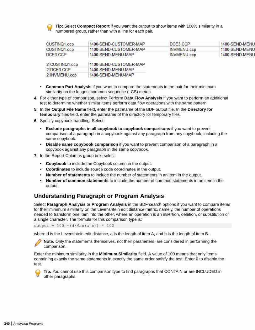
Tip: Select Compact Report if you want the output to show items with 100% similarity in anumbered group, rather than with a line for each pair.
• Common Part Analysis if you want to compare the statements in the pair for their minimum
similarity on the longest common sequence (LCS) metric.
4. For either type of comparison, select Perform Data Flow Analysis if you want to perform an additionaltest to determine whether similar items perform data flow operations with the same pattern.
5. In the Output File Name field, enter the pathname of the BDF output file. In the Directory fortemporary files field, enter the pathname of the directory for temporary files.
6. Specify copybook handling. Select:
• Exclude paragraphs in all copybook to copybook comparisons if you want to preventcomparison of a paragraph in a copybook against any paragraph from any copybook, including thesame copybook.
• Disable same copybook comparison if you want to prevent comparison of a paragraph in acopybook against any paragraph in the same copybook.
7. In the Report Columns group box, select:
• Copybook to include the Copybook column in the output.• Coordinates to include source code coordinates in the output.• Number of statements to include the number of statements in an item in the output.• Number of common statements to include the number of common statements in an item in the
output.
Understanding Paragraph or Program AnalysisSelect Paragraph Analysis or Program Analysis in the BDF search options if you want to compare itemsfor their minimum similarity on the Levenshtein edit distance metric, namely, the number of operationsneeded to transform one item into the other, where an operation is an insertion, deletion, or substitution ofa single character. The formula for this comparison type is:
output = 100 -(d/Max(a,b)) * 100
where d is the Levenshtein edit distance, a is the length of item A, and b is the length of item B.
Note: Only the statements themselves, not their parameters, are considered in performing thecomparison.
Enter the minimum similarity in the Minimum Similarity field. A value of 100 means that only itemscontaining exactly the same statements in exactly the same order satisfy the test. Enter 0 to disable thetest.
Tip: You cannot use this comparison type to find paragraphs that CONTAIN or are INCLUDED inother paragraphs.
240 | Analyzing Programs
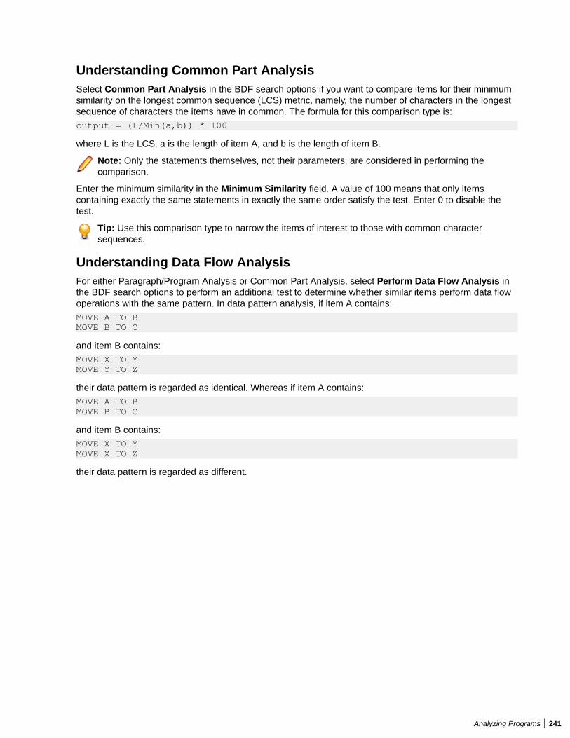
Understanding Common Part AnalysisSelect Common Part Analysis in the BDF search options if you want to compare items for their minimumsimilarity on the longest common sequence (LCS) metric, namely, the number of characters in the longestsequence of characters the items have in common. The formula for this comparison type is:
output = (L/Min(a,b)) * 100
where L is the LCS, a is the length of item A, and b is the length of item B.
Note: Only the statements themselves, not their parameters, are considered in performing thecomparison.
Enter the minimum similarity in the Minimum Similarity field. A value of 100 means that only itemscontaining exactly the same statements in exactly the same order satisfy the test. Enter 0 to disable thetest.
Tip: Use this comparison type to narrow the items of interest to those with common charactersequences.
Understanding Data Flow AnalysisFor either Paragraph/Program Analysis or Common Part Analysis, select Perform Data Flow Analysis inthe BDF search options to perform an additional test to determine whether similar items perform data flowoperations with the same pattern. In data pattern analysis, if item A contains:
MOVE A TO BMOVE B TO C
and item B contains:
MOVE X TO YMOVE Y TO Z
their data pattern is regarded as identical. Whereas if item A contains:
MOVE A TO BMOVE B TO C
and item B contains:
MOVE X TO YMOVE X TO Z
their data pattern is regarded as different.
Analyzing Programs | 241
Creating Components
Introducing Logic AnalyzerThe Logic Analyzer tool offers a variety of advanced algorithms for slicing logic from program source: allthe code you need for a computation, for example, or the code required to "specialize" a program based onthe value of a variable. You can create a self-contained program, called a component from the sliced codeor simply generate a list of sliced constructs for further analysis. You can mark and colorize the constructsin the Interactive Analysis Source pane.
Componentization MethodsThe supported componentization methods slice logic not only from program executables but associatedinclude files as well. Dead Code Elimination is an optimization tool built into the main methods and offeredseparately in case you want to use it on a standalone basis.
Note: Component Maker does not follow CALL statements into other programs to determine whetherpassed data items are actually modified by those programs. It makes the conservative assumptionthat all passed data items are modified. That guarantees that no dependencies are lost.
Structure-Based ComponentizationStructure-Based Componentization lets you build a component from a range of inline code, COBOLparagraphs, for example. Use traditional structure-based componentization to generate a new componentand its complement. A complement is a second component consisting of the original program minus thecode extracted in the slice. Component Maker automatically places a call to the new component in thecomplement, passing it data items as necessary.
For COBOL programs, you can generate parameterized slices, in which the input and output variablesrequired by the component are organized in group-level structures. These standard object-oriented datainterfaces make it easier to deploy the transformed component in modern service-oriented architectures.
Tip: You typically repeat structure-based componentization in incremental fashion until all of themodules you are interested in have been created. For COBOL programs, you can avoid doing thismanually by specifying multiple ranges in the same extraction. Component Maker automaticallyprocesses each range in the appropriate order.
Computation-Based ComponentizationComputation-Based Componentization lets you build a component that contains all the code necessary tocalculate the value of a variable at a point in the program where it is used to populate a report attribute orscreen. As with structure-based componentization, you can generate parameterized slices that make iteasy to deploy the transformed component in distributed architectures.
For COBOL programs, you can use a technique called blocking to produce smaller, better-definedparameterized components. Component Maker will not include in the slice any part of the calculation thatappears before the blocked statement. Fields from blocked input statements are treated as inputparameters of the component.
242 | Creating Components
Domain-Based ComponentizationDomain-Based Componentization lets you "specialize" a program based on the values of one or morevariables. The specialized program is typically intended for reuse "in place," in the original application, butunder new external circumstances.
After a change in your business practices, for example, a program that invokes processing for a "paymenttype" variable could be specialized on the value PAYMENT-TYPE = "CHECK". Component Maker isolatesevery process dependent on the CHECK value to create a functionally complete program that processescheck payments only.
Two modes of domain-based componentization are offered:
• In simplified mode, you set the specialization variable to its value anywhere in the program except adata port. The value of the variable is "frozen in memory." Operations that could change the value areignored.
• In advanced mode, you set the specialization variable to its value at a data port. Subsequent operationscan change the value, following the data and control flow of the program.
Use the simplified mode when you are interested only in the final value of a variable. Use the advancedmode when you need to account for data coming into a variable.
Dead Code Elimination (DCE)Dead Code Elimination is an option in each of the main component extraction methods, but you can alsoperform it on a standalone basis. For each program analyzed for dead code, standalone DCE generates acomponent that consists of the original source code minus any unreferenced data items or unreachableprocedural statements.
Note: Use the batch DCE feature to find dead code across your project. If you are licensed to use theBatch Refresh Process (BRP), you can use it to perform dead code elimination across a workspace.
Entry Point IsolationEntry Point Isolation lets you build a component based on one of multiple entry points in a legacy program(an inner entry point in a Cobol program, for example). Component Maker extracts only the functionalityand data definitions required for invocation from the selected point.
Entry Point Isolation is built into the main methods as an optional optimization tool. It's offered separately incase you want to use it on a standalone basis.
Language SupportThe following table describes the extraction methods available for the languages supported by ComponentMaker.
Method COBOL PL/I Natural RPG
Structure-based Yes Yes No Yes
Computation-based Yes No Yes No
Domain-based Yes Yes No No
Dead CodeElimination
Yes Yes Yes Yes
Entry Point Isolation Yes No No No
Componentization OutputsThe first step in the componentization process, called extraction, generates the following outputs:
Creating Components | 243
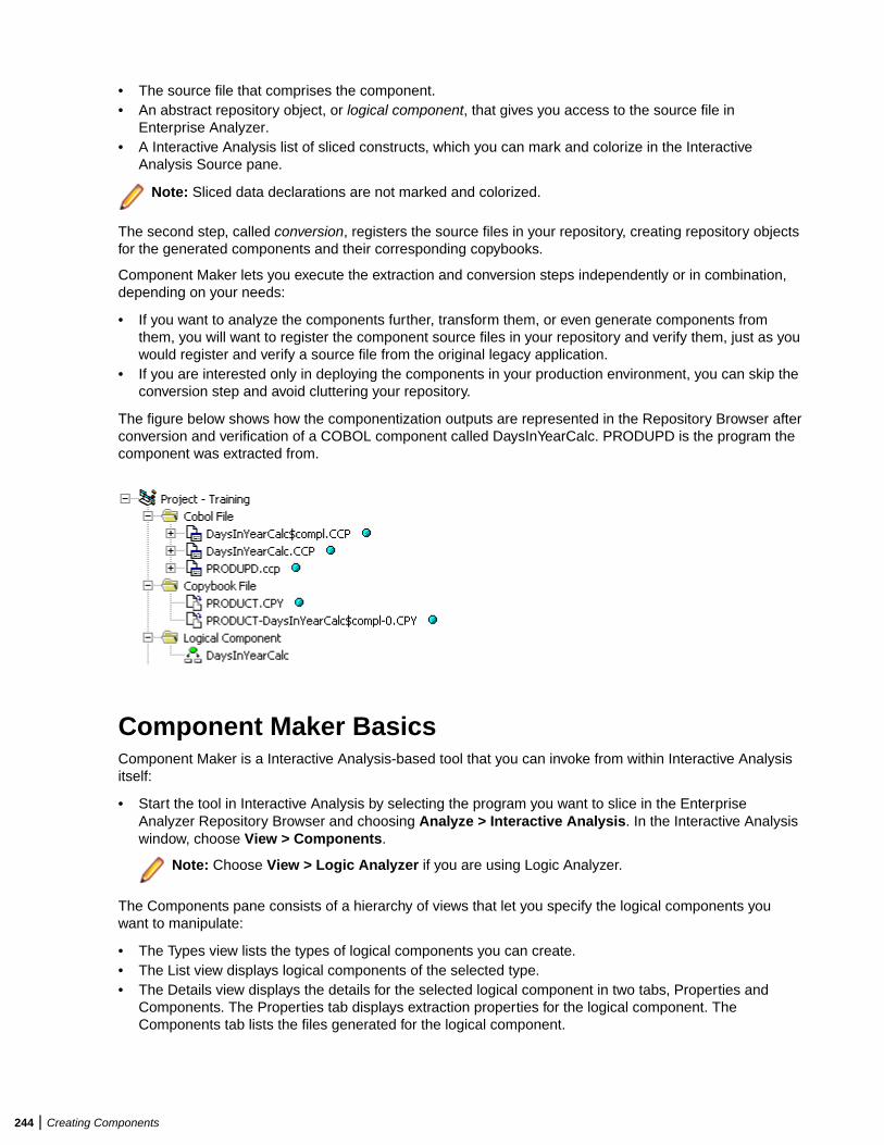
• The source file that comprises the component.• An abstract repository object, or logical component, that gives you access to the source file in
Enterprise Analyzer.• A Interactive Analysis list of sliced constructs, which you can mark and colorize in the Interactive
Analysis Source pane.
Note: Sliced data declarations are not marked and colorized.
The second step, called conversion, registers the source files in your repository, creating repository objectsfor the generated components and their corresponding copybooks.
Component Maker lets you execute the extraction and conversion steps independently or in combination,depending on your needs:
• If you want to analyze the components further, transform them, or even generate components fromthem, you will want to register the component source files in your repository and verify them, just as youwould register and verify a source file from the original legacy application.
• If you are interested only in deploying the components in your production environment, you can skip theconversion step and avoid cluttering your repository.
The figure below shows how the componentization outputs are represented in the Repository Browser afterconversion and verification of a COBOL component called DaysInYearCalc. PRODUPD is the program thecomponent was extracted from.
Component Maker BasicsComponent Maker is a Interactive Analysis-based tool that you can invoke from within Interactive Analysisitself:
• Start the tool in Interactive Analysis by selecting the program you want to slice in the EnterpriseAnalyzer Repository Browser and choosing Analyze > Interactive Analysis. In the Interactive Analysiswindow, choose View > Components.
Note: Choose View > Logic Analyzer if you are using Logic Analyzer.
The Components pane consists of a hierarchy of views that let you specify the logical components youwant to manipulate:
• The Types view lists the types of logical components you can create.• The List view displays logical components of the selected type.• The Details view displays the details for the selected logical component in two tabs, Properties and
Components. The Properties tab displays extraction properties for the logical component. TheComponents tab lists the files generated for the logical component.
244 | Creating Components
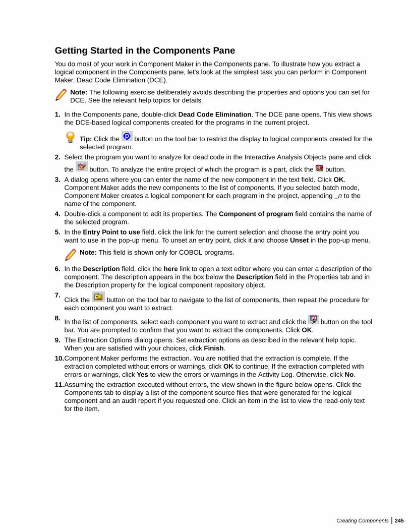
Getting Started in the Components PaneYou do most of your work in Component Maker in the Components pane. To illustrate how you extract alogical component in the Components pane, let's look at the simplest task you can perform in ComponentMaker, Dead Code Elimination (DCE).
Note: The following exercise deliberately avoids describing the properties and options you can set forDCE. See the relevant help topics for details.
1. In the Components pane, double-click Dead Code Elimination. The DCE pane opens. This view showsthe DCE-based logical components created for the programs in the current project.
Tip: Click the button on the tool bar to restrict the display to logical components created for theselected program.
2. Select the program you want to analyze for dead code in the Interactive Analysis Objects pane and click
the button. To analyze the entire project of which the program is a part, click the button.
3. A dialog opens where you can enter the name of the new component in the text field. Click OK.Component Maker adds the new components to the list of components. If you selected batch mode,Component Maker creates a logical component for each program in the project, appending _n to thename of the component.
4. Double-click a component to edit its properties. The Component of program field contains the name ofthe selected program.
5. In the Entry Point to use field, click the link for the current selection and choose the entry point youwant to use in the pop-up menu. To unset an entry point, click it and choose Unset in the pop-up menu.
Note: This field is shown only for COBOL programs.
6. In the Description field, click the here link to open a text editor where you can enter a description of thecomponent. The description appears in the box below the Description field in the Properties tab and inthe Description property for the logical component repository object.
7.Click the button on the tool bar to navigate to the list of components, then repeat the procedure foreach component you want to extract.
8. In the list of components, select each component you want to extract and click the button on the toolbar. You are prompted to confirm that you want to extract the components. Click OK.
9. The Extraction Options dialog opens. Set extraction options as described in the relevant help topic.When you are satisfied with your choices, click Finish.
10.Component Maker performs the extraction. You are notified that the extraction is complete. If theextraction completed without errors or warnings, click OK to continue. If the extraction completed witherrors or warnings, click Yes to view the errors or warnings in the Activity Log. Otherwise, click No.
11.Assuming the extraction executed without errors, the view shown in the figure below opens. Click theComponents tab to display a list of the component source files that were generated for the logicalcomponent and an audit report if you requested one. Click an item in the list to view the read-only textfor the item.
Creating Components | 245
Creating ComponentsTo create a component, select the program you want to slice in the Interactive Analysis Objects pane. In
the Types view, select the type of logical component you want to create and click the button on the tool
bar. (You can also click the button in the List or Details view.) A dialog opens where you can enter thename of the new component in the text field. Click OK.
Extracting ComponentsTo extract a single logical component, select the component you want to extract in the List view and click
the button on the tool bar. To extract multiple logical components, select the type of the components
you want to extract in the Types view and click the button. You are prompted to confirm that you want tocontinue. Click OK.
Tip: Logical components are converted as well as extracted if the Convert Resulting Componentsto Legacy Objects is set in the Component Conversion Options pane.
Converting ComponentsTo convert a single logical component, select the component you want to convert in the List view and click
the button on the tool bar. To convert multiple logical components, select the type of the components
you want to convert in the Types view and click the button. You are prompted to confirm that you wantto continue. Click OK.
Deleting Components
To delete a logical component, select it in the List view and click the button on the tool bar.
Note: Deleting a logical component does not delete the component and copybook repository objects.You must delete these objects manually in the Repository Browser.
246 | Creating Components
Viewing the Text for Generated FilesTo view the read-only text for a generated file, click the file in the list of generated files for in theComponents tab.
Tip: You can also view the text for a generated file in the Enterprise Analyzer main window. In theRepository Browser Logical Component folder, click the component whose generated files you want toview.
Restricting the Display to Program-Related Components
To restrict the display to logical components of a given program, select the program and click the button on the tool bar. The button is a toggle. Click it again to revert to the generic display.
Working with Interactive Analysis ListsWhen you extract a logical component, Component Maker generates a Interactive Analysis list of slicedconstructs. The list has the same name as the component. You can view the list in the Logic Analyzerfolder in Code Search.
To mark and colorize sliced constructs in the list, select the list in Code Search and click the button onthe tool bar. To mark and colorize sliced constructs in a single file, select the file in the List view and click
the button. To mark and colorize a single construct, select it in the File view and click the button.
Click the button again to turn off marking and colorizing.
Viewing Audit ReportsAn audit report contains a list of changed and deleted lines in the source files (including copybooks) fromwhich a logical component was extracted. The report has a name of the form <component>.audit.txt. Clickthe report in the Components tab to view its text.
An audit report optionally includes reason codes explaining why a line was changed or deleted. A reasoncode is a number keyed to the explanation for a change (for example, reason code 12 for computation-based componentization is RemoveUnusedVALUEs).
Creating Components | 247
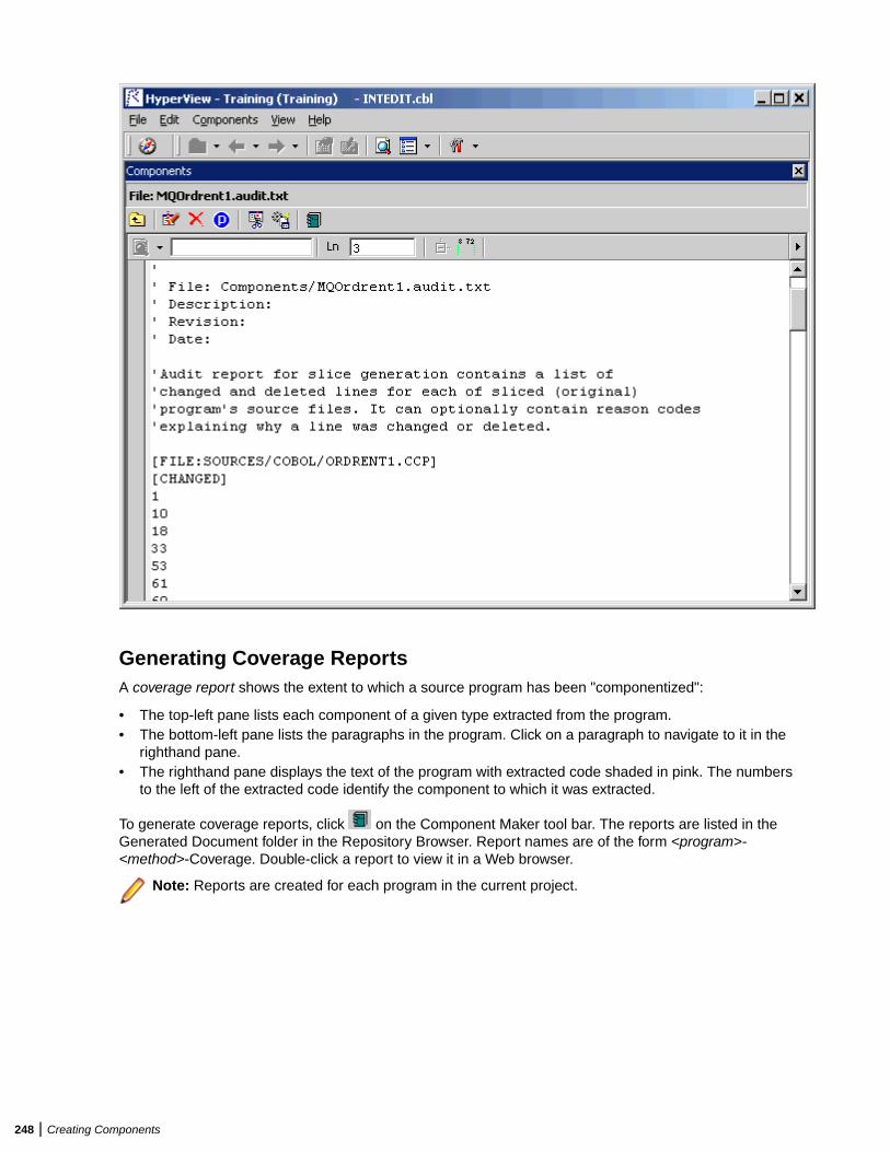
Generating Coverage ReportsA coverage report shows the extent to which a source program has been "componentized":
• The top-left pane lists each component of a given type extracted from the program.• The bottom-left pane lists the paragraphs in the program. Click on a paragraph to navigate to it in the
righthand pane.• The righthand pane displays the text of the program with extracted code shaded in pink. The numbers
to the left of the extracted code identify the component to which it was extracted.
To generate coverage reports, click on the Component Maker tool bar. The reports are listed in theGenerated Document folder in the Repository Browser. Report names are of the form <program>-<method>-Coverage. Double-click a report to view it in a Web browser.
Note: Reports are created for each program in the current project.
248 | Creating Components
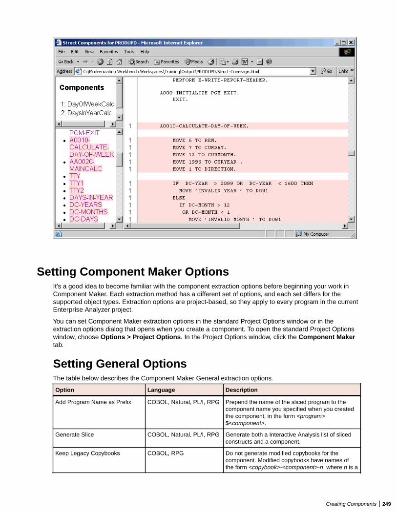
Setting Component Maker OptionsIt's a good idea to become familiar with the component extraction options before beginning your work inComponent Maker. Each extraction method has a different set of options, and each set differs for thesupported object types. Extraction options are project-based, so they apply to every program in the currentEnterprise Analyzer project.
You can set Component Maker extraction options in the standard Project Options window or in theextraction options dialog that opens when you create a component. To open the standard Project Optionswindow, choose Options > Project Options. In the Project Options window, click the Component Makertab.
Setting General OptionsThe table below describes the Component Maker General extraction options.
Option Language Description
Add Program Name as Prefix COBOL, Natural, PL/I, RPG Prepend the name of the sliced program to thecomponent name you specified when you createdthe component, in the form <program>$<component>.
Generate Slice COBOL, Natural, PL/I, RPG Generate both a Interactive Analysis list of slicedconstructs and a component.
Keep Legacy Copybooks COBOL, RPG Do not generate modified copybooks for thecomponent. Modified copybooks have names ofthe form <copybook>-<component>-n, where n is a
Creating Components | 249
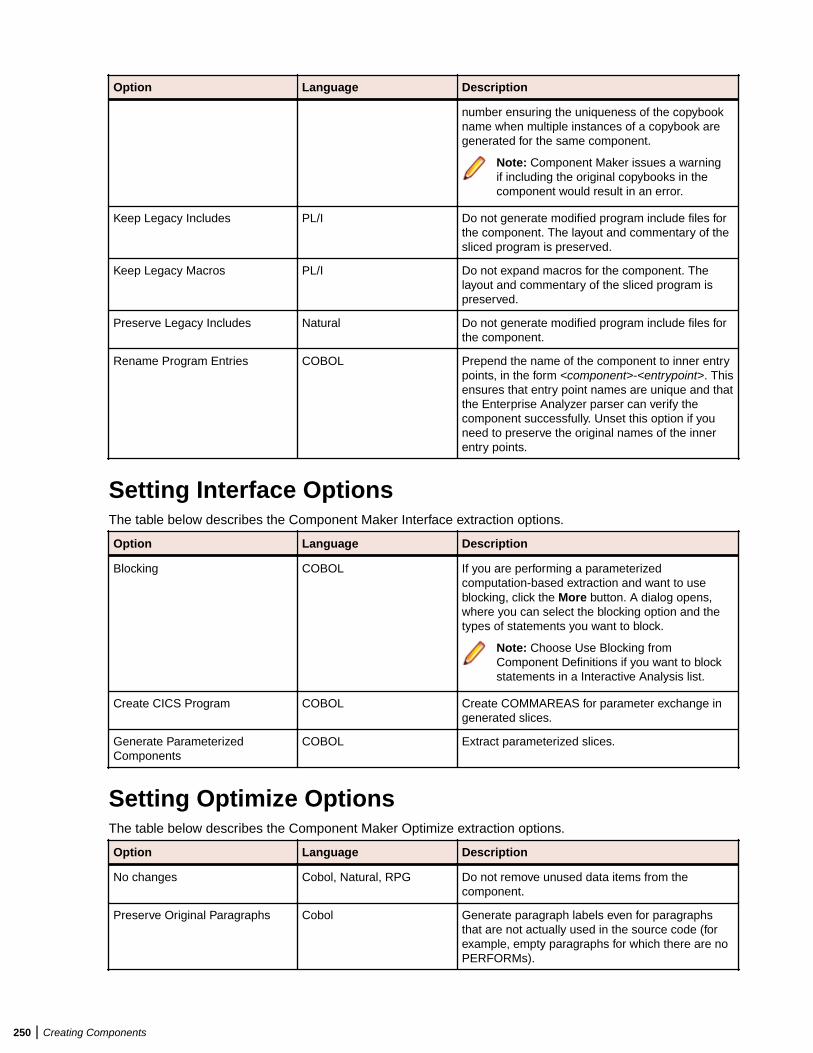
Option Language Description
number ensuring the uniqueness of the copybookname when multiple instances of a copybook aregenerated for the same component.
Note: Component Maker issues a warningif including the original copybooks in thecomponent would result in an error.
Keep Legacy Includes PL/I Do not generate modified program include files forthe component. The layout and commentary of thesliced program is preserved.
Keep Legacy Macros PL/I Do not expand macros for the component. Thelayout and commentary of the sliced program ispreserved.
Preserve Legacy Includes Natural Do not generate modified program include files forthe component.
Rename Program Entries COBOL Prepend the name of the component to inner entrypoints, in the form <component>-<entrypoint>. Thisensures that entry point names are unique and thatthe Enterprise Analyzer parser can verify thecomponent successfully. Unset this option if youneed to preserve the original names of the innerentry points.
Setting Interface OptionsThe table below describes the Component Maker Interface extraction options.
Option Language Description
Blocking COBOL If you are performing a parameterizedcomputation-based extraction and want to useblocking, click the More button. A dialog opens,where you can select the blocking option and thetypes of statements you want to block.
Note: Choose Use Blocking fromComponent Definitions if you want to blockstatements in a Interactive Analysis list.
Create CICS Program COBOL Create COMMAREAS for parameter exchange ingenerated slices.
Generate ParameterizedComponents
COBOL Extract parameterized slices.
Setting Optimize OptionsThe table below describes the Component Maker Optimize extraction options.
Option Language Description
No changes Cobol, Natural, RPG Do not remove unused data items from thecomponent.
Preserve Original Paragraphs Cobol Generate paragraph labels even for paragraphsthat are not actually used in the source code (forexample, empty paragraphs for which there are noPERFORMs).
250 | Creating Components
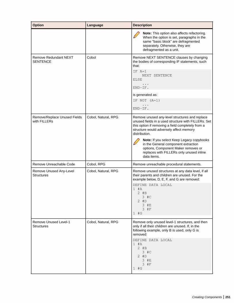
Option Language Description
Note: This option also affects refactoring.When the option is set, paragraphs in thesame "basic block" are defragmentedseparately. Otherwise, they aredefragmented as a unit.
Remove Redundant NEXTSENTENCE
Cobol Remove NEXT SENTENCE clauses by changingthe bodies of corresponding IF statements, suchthat:
IF A=1 NEXT SENTENCEELSE ...END-IF.
is generated as:
IF NOT (A=1) ...END-IF.
Remove/Replace Unused Fieldswith FILLERs
Cobol, Natural, RPG Remove unused any-level structures and replaceunused fields in a used structure with FILLERs. Setthis option if removing a field completely from astructure would adversely affect memorydistribution.
Note: If you select Keep Legacy copybooksin the General component extractionoptions, Component Maker removes orreplaces with FILLERs only unused inlinedata items.
Remove Unreachable Code Cobol, RPG Remove unreachable procedural statements.
Remove Unused Any-LevelStructures
Cobol, Natural, RPG Remove unused structures at any data level, if alltheir parents and children are unused. For theexample below, D, E, F, and G are removed:
DEFINE DATA LOCAL 1 #A 2 #B 3 #C 2 #D 3 #E 3 #F 1 #G
Remove Unused Level-1Structures
Cobol, Natural, RPG Remove only unused level-1 structures, and thenonly if all their children are unused. If, in thefollowing example, only B is used, only G isremoved:
DEFINE DATA LOCAL 1 #A 2 #B 3 #C 2 #D 3 #E 3 #F 1 #G
Creating Components | 251
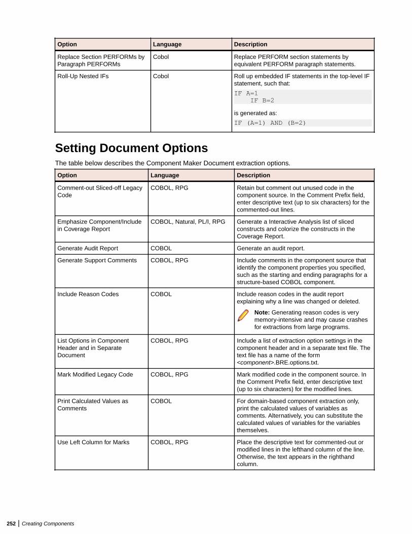
Option Language Description
Replace Section PERFORMs byParagraph PERFORMs
Cobol Replace PERFORM section statements byequivalent PERFORM paragraph statements.
Roll-Up Nested IFs Cobol Roll up embedded IF statements in the top-level IFstatement, such that:
IF A=1 IF B=2
is generated as:
IF (A=1) AND (B=2)
Setting Document OptionsThe table below describes the Component Maker Document extraction options.
Option Language Description
Comment-out Sliced-off LegacyCode
COBOL, RPG Retain but comment out unused code in thecomponent source. In the Comment Prefix field,enter descriptive text (up to six characters) for thecommented-out lines.
Emphasize Component/Includein Coverage Report
COBOL, Natural, PL/I, RPG Generate a Interactive Analysis list of slicedconstructs and colorize the constructs in theCoverage Report.
Generate Audit Report COBOL Generate an audit report.
Generate Support Comments COBOL, RPG Include comments in the component source thatidentify the component properties you specified,such as the starting and ending paragraphs for astructure-based COBOL component.
Include Reason Codes COBOL Include reason codes in the audit reportexplaining why a line was changed or deleted.
Note: Generating reason codes is verymemory-intensive and may cause crashesfor extractions from large programs.
List Options in ComponentHeader and in SeparateDocument
COBOL, RPG Include a list of extraction option settings in thecomponent header and in a separate text file. Thetext file has a name of the form<component>.BRE.options.txt.
Mark Modified Legacy Code COBOL, RPG Mark modified code in the component source. Inthe Comment Prefix field, enter descriptive text(up to six characters) for the modified lines.
Print Calculated Values asComments
COBOL For domain-based component extraction only,print the calculated values of variables ascomments. Alternatively, you can substitute thecalculated values of variables for the variablesthemselves.
Use Left Column for Marks COBOL, RPG Place the descriptive text for commented-out ormodified lines in the lefthand column of the line.Otherwise, the text appears in the righthandcolumn.
252 | Creating Components
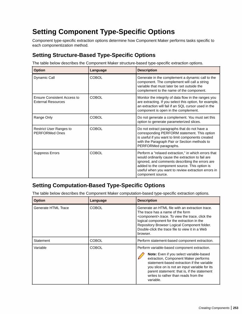
Setting Component Type-Specific OptionsComponent type-specific extraction options determine how Component Maker performs tasks specific toeach componentization method.
Setting Structure-Based Type-Specific OptionsThe table below describes the Component Maker structure-based type-specific extraction options.
Option Language Description
Dynamic Call COBOL Generate in the complement a dynamic call to thecomponent. The complement will call a stringvariable that must later be set outside thecomplement to the name of the component.
Ensure Consistent Access toExternal Resources
COBOL Monitor the integrity of data flow in the ranges youare extracting. If you select this option, for example,an extraction will fail if an SQL cursor used in thecomponent is open in the complement.
Range Only COBOL Do not generate a complement. You must set thisoption to generate parameterized slices.
Restrict User Ranges toPERFORMed Ones
COBOL Do not extract paragraphs that do not have acorresponding PERFORM statement. This optionis useful if you want to limit components createdwith the Paragraph Pair or Section methods toPERFORMed paragraphs.
Suppress Errors COBOL Perform a "relaxed extraction," in which errors thatwould ordinarily cause the extraction to fail areignored, and comments describing the errors areadded to the component source. This option isuseful when you want to review extraction errors incomponent source.
Setting Computation-Based Type-Specific OptionsThe table below describes the Component Maker computation-based type-specific extraction options.
Option Language Description
Generate HTML Trace COBOL Generate an HTML file with an extraction trace.The trace has a name of the form<component>.trace. To view the trace, click thelogical component for the extraction in theRepository Browser Logical Component folder.Double-click the trace file to view it in a Webbrowser.
Statement COBOL Perform statement-based component extraction.
Variable COBOL Perform variable-based component extraction.
Note: Even if you select variable-basedextraction, Component Maker performsstatement-based extraction if the variableyou slice on is not an input variable for itsparent statement: that is, if the statementwrites to rather than reads from thevariable.
Creating Components | 253
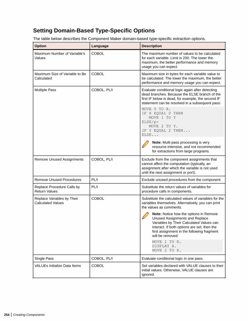
Setting Domain-Based Type-Specific OptionsThe table below describes the Component Maker domain-based type-specific extraction options.
Option Language Description
Maximum Number of Variable'sValues
COBOL The maximum number of values to be calculatedfor each variable. Limit is 200. The lower themaximum, the better performance and memoryusage you can expect.
Maximum Size of Variable to BeCalculated
COBOL Maximum size in bytes for each variable value tobe calculated. The lower the maximum, the betterperformance and memory usage you can expect.
Multiple Pass COBOL, PL/I Evaluate conditional logic again after detectingdead branches. Because the ELSE branch of thefirst IF below is dead, for example, the second IFstatement can be resolved in a subsequent pass:
MOVE 0 TO X. IF X EQUAL 0 THEN MOVE 1 TO YELSE/p> MOVE 2 TO Y.IF Y EQUAL 2 THEN... ELSE...
Note: Multi-pass processing is veryresource-intensive, and not recommendedfor extractions from large programs.
Remove Unused Assignments COBOL, PL/I Exclude from the component assignments thatcannot affect the computation (typically, anassignment after which the variable is not useduntil the next assignment or port).
Remove Unused Procedures PL/I Exclude unused procedures from the component.
Replace Procedure Calls byReturn Values
PL/I Substitute the return values of variables forprocedure calls in components.
Replace Variables by TheirCalculated Values
COBOL Substitute the calculated values of variables for thevariables themselves. Alternatively, you can printthe values as comments.
Note: Notice how the options in RemoveUnused Assignments and ReplaceVariables by Their Calculated Values caninteract. If both options are set, then thefirst assignment in the following fragmentwill be removed:
MOVE 1 TO X.DISPLAY X.MOVE 2 TO X.
Single Pass COBOL, PL/I Evaluate conditional logic in one pass.
VALUEs Initialize Data Items COBOL Set variables declared with VALUE clauses to theirinitial values. Otherwise, VALUE clauses areignored.
254 | Creating Components
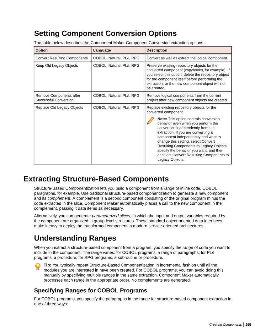
Setting Component Conversion OptionsThe table below describes the Component Maker Component Conversion extraction options.
Option Language Description
Convert Resulting Components COBOL, Natural, PL/I, RPG Convert as well as extract the logical component.
Keep Old Legacy Objects COBOL, Natural, PL/I, RPG Preserve existing repository objects for theconverted component (copybooks, for example). Ifyou select this option, delete the repository objectfor the component itself before performing theextraction, or the new component object will notbe created.
Remove Components afterSuccessful Conversion
COBOL, Natural, PL/I, RPG Remove logical components from the currentproject after new component objects are created.
Replace Old Legacy Objects COBOL, Natural, PL/I, RPG Replace existing repository objects for theconverted component.
Note: This option controls conversionbehavior even when you perform theconversion independently from theextraction. If you are converting acomponent independently and want tochange this setting, select ConvertResulting Components to Legacy Objects,specify the behavior you want, and thendeselect Convert Resulting Components toLegacy Objects.
Extracting Structure-Based ComponentsStructure-Based Componentization lets you build a component from a range of inline code, COBOLparagraphs, for example. Use traditional structure-based componentization to generate a new componentand its complement. A complement is a second component consisting of the original program minus thecode extracted in the slice. Component Maker automatically places a call to the new component in thecomplement, passing it data items as necessary.
Alternatively, you can generate parameterized slices, in which the input and output variables required bythe component are organized in group-level structures. These standard object-oriented data interfacesmake it easy to deploy the transformed component in modern service-oriented architectures.
Understanding RangesWhen you extract a structure-based component from a program, you specify the range of code you want toinclude in the component. The range varies: for COBOL programs, a range of paragraphs; for PL/Iprograms, a procedure; for RPG programs, a subroutine or procedure.
Tip: You typically repeat Structure-Based Componentization in incremental fashion until all themodules you are interested in have been created. For COBOL programs, you can avoid doing thismanually by specifying multiple ranges in the same extraction. Component Maker automaticallyprocesses each range in the appropriate order. No complements are generated.
Specifying Ranges for COBOL ProgramsFor COBOL programs, you specify the paragraphs in the range for structure-based component extraction inone of three ways:
Creating Components | 255
• Select a paragraph PERFORM statement to set the range to the performed paragraph or paragraphs.Component Maker includes each paragraph in the execution path between the first and last paragraphsin the range, except when control is transferred by a PERFORM statement or by an implicit RETURN-from-PERFORM statement.
• Select a pair of paragraphs to set the range to the selected paragraphs. You are responsible forensuring a continuous flow of control from the first to the last paragraph in the range.
• Select a section to set the range to the paragraphs in the section.
Note: For traditional structure-based COBOL components, Component Maker inserts in thecomplement the labels of the first and last paragraphs in the range. The first paragraph is replaced inthe complement with a CALL statement followed by a GO TO statement. The last paragraph is alwaysempty.
The GO TO statement transfers control to the last paragraph. If the GO TO statement and its targetparagraph are not required to ensure correct call flow, they are omitted.
Specifying Ranges for PL/I ProgramsFor PL/I programs, the range you specify for structure-based component extraction is an internal procedurethat Component Maker extracts as an external procedure. The slice contains the required parameters forglobal variables.
Specifying Ranges for RPG ProgramsFor RPG programs, the range you specify for structure-based component extraction is a subroutine orprocedure to extract as a component.
Understanding Parameterized SlicesFor COBOL programs, you can generate parameterized slices, in which the input and output variablesrequired by the component are organized in group-level structures. The component contains all the coderequired for input/output operations.
To extract a parameterized slice, select the Generate Parameterized Components option in the extractionoptions dialog. Note that you cannot generate a complement for a parameterized COBOL slice.
Note: For parameterized structure- and computation-based componentization of COBOL programs,you must select the Perform Program Analysis and Enable Parameterization of Componentsoptions in the project verification options.
COBOL Naming Conventions• Component input structures have names of the form BRE-INP-<STRUCT-NAME>. Input fields have
names of the form BRE-I-<FIELD-NAME>.• Component Output structures have names of the form BRE-OUT-STRUCT-NAME. Output fields have
names of the form BRE-O-<FIELD-NAME>.
Parameterization ExampleThe example below illustrates how Component Maker generates parameterized slices. Consider a COBOLprogram that contains the following structures:
WORKING-STORAGE SECTION. 01 A 03 A1 03 A2 01 B 03 B1 03 B2 03 B4
256 | Creating Components
Suppose that only A1 has been determined by Component Maker to be an input parameter, and only B1and B2 to be output parameters. Suppose further that the component is extracted with input and outputdata structures that use the default names, BRE-INP-INPUT-STRUCTURE and BRE-OUT-OUTPUT-STRUCTURE, respectively, and with the default Optimization options set. The component contains thefollowing code:
WORKING-STORAGE SECTION. 01 A 03 A1 03 A2 01 B 03 B1 03 B2 03 B4LINKAGE SECTION. 01 BRE-INP-INPUT-STRUCTURE 03 BRE-I-A 06 BRE-I-A101 BRE-OUT-OUTPUT-STRUCTURE 03 BRE-O-B 06 BRE-O-B1 06 BRE-O-B2PROCEDURE DIVISION USING BRE-INP-INPUT-STRUCTURE BRE-OUT-OUTPUT-STRUCTURE.BRE-INIT-SECTION SECTION. PERFORM BRE-COPY-INPUT-DATA. ........................ ....(Business Logic).... ........................ *Enterprise Analyzer added statement GO TO BRE-EXIT-PROGRAM.BRE-EXIT-PROGRAM-SECTION SECTION. BRE-EXIT-PROGRAM. PERFORM BRE-COPY-OUTPUT-DATA. GOBACK.BRE-COPY-INPUT-DATA. MOVE BRE-I-A TO A.BRE-COPY-OUTPUT-DATA. MOVE B TO BRE-O-B.
Extracting Structure-Based COBOL ComponentsFollow the instructions below to extract structure-based COBOL components.
1.Select the program you want to slice in the HyperView Objects pane and click the button. A dialogopens where you can enter the name of the new component in the text field. Click OK. ComponentMaker adds the new component to the list of components. Double-click the component to edit itsproperties.
2. In the Paragraphs field, click the here link. Choose one of the following methods in the pop-up menu:
• Paragraph Perform to set the range to the paragraph or paragraphs performed by the selectedPERFORM statement. Select the PERFORM statement in the Source pane, then click the link for thecurrent selection and choose Set in the pop-up menu.
• Pair of Paragraphs to set the range to the selected paragraphs. Select the first paragraph in the pairin the Source pane, then click the link for the current selection in the From field and choose Set inthe drop-down menu. Select the second paragraph in the pair, then click the link for the currentselection in the To field and choose Set in the pop-up menu.
Tip: You can set the From and To fields to the same paragraph.
Creating Components | 257
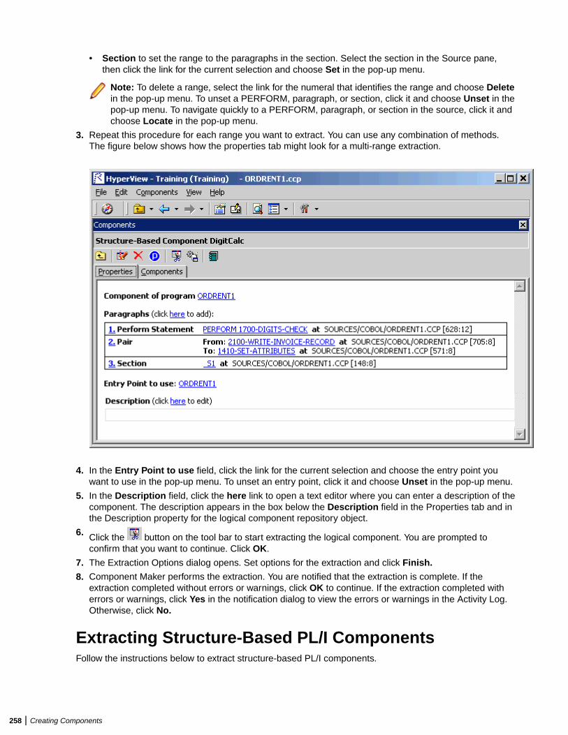
• Section to set the range to the paragraphs in the section. Select the section in the Source pane,then click the link for the current selection and choose Set in the pop-up menu.
Note: To delete a range, select the link for the numeral that identifies the range and choose Deletein the pop-up menu. To unset a PERFORM, paragraph, or section, click it and choose Unset in thepop-up menu. To navigate quickly to a PERFORM, paragraph, or section in the source, click it andchoose Locate in the pop-up menu.
3. Repeat this procedure for each range you want to extract. You can use any combination of methods.The figure below shows how the properties tab might look for a multi-range extraction.
4. In the Entry Point to use field, click the link for the current selection and choose the entry point youwant to use in the pop-up menu. To unset an entry point, click it and choose Unset in the pop-up menu.
5. In the Description field, click the here link to open a text editor where you can enter a description of thecomponent. The description appears in the box below the Description field in the Properties tab and inthe Description property for the logical component repository object.
6. Click the button on the tool bar to start extracting the logical component. You are prompted toconfirm that you want to continue. Click OK.
7. The Extraction Options dialog opens. Set options for the extraction and click Finish.
8. Component Maker performs the extraction. You are notified that the extraction is complete. If theextraction completed without errors or warnings, click OK to continue. If the extraction completed witherrors or warnings, click Yes in the notification dialog to view the errors or warnings in the Activity Log.Otherwise, click No.
Extracting Structure-Based PL/I ComponentsFollow the instructions below to extract structure-based PL/I components.
258 | Creating Components
1.Select the program you want to slice in the HyperView Objects pane and click the button. A dialogopens where you can enter the name of the new component in the text field. Click OK. ComponentMaker adds the new component to the list of components. Double-click the component to edit itsproperties.
2. Select the program entry point in the Source pane. In the Point field, click the link for the currentselection and choose Set in the pop-up menu.
Note: To unset an entry point, click it and choose Unset in the pop-up menu. To navigate quicklyto an entry point in the source, click it and choose Locate in the pop-up menu.
3. In the Description field, click the here link to open a text editor where you can enter a description of thecomponent. The description appears in the box below the Description field in the Properties tab and inthe Description property for the logical component repository object.
4. Click the button on the tool bar to start extracting the logical component. You are prompted toconfirm that you want to continue. Click OK.
5. The Extraction Options dialog opens. Set options for the extraction and click Finish.
6. Component Maker performs the extraction. You are notified that the extraction is complete. If theextraction completed without errors or warnings, click OK to continue. If the extraction completed witherrors or warnings, click Yes in the notification dialog to view the errors or warnings in the Activity Log.Otherwise, click No.
Extracting Structure-Based RPG ComponentsFollow the instructions below to extract structure-based RPG components.
1.Select the program you want to slice in the HyperView Objects pane and click the button. A dialogopens where you can enter the name of the new component in the text field. Click OK. ComponentMaker adds the new component to the list of components. Double-click the component to edit itsproperties.
2. Select the subroutine or procedure you want to slice in the Source pane. In the Point field, click the linkfor the current selection and choose Set in the pop-up menu.
Note: To unset an entry point, click it and choose Unset in the pop-up menu. To navigate quicklyto an entry point in the source, click it and choose Locate in the pop-up menu.
3. In the Description field, click the here link to open a text editor where you can enter a description of thecomponent. The description appears in the box below the Description field in the Properties tab and inthe Description property for the logical component repository object.
4. Click the button on the tool bar to start extracting the logical component. You are prompted toconfirm that you want to continue. Click OK.
5. The Extraction Options dialog opens. Set options for the extraction and click Finish.
6. Component Maker performs the extraction. You are notified that the extraction is complete. If theextraction completed without errors or warnings, click OK to continue. If the extraction completed witherrors or warnings, click Yes in the notification dialog to view the errors or warnings in the Activity Log.Otherwise, click No.
Extracting Computation-Based ComponentsComputation-Based Componentization lets you build a component that contains all the code necessary tocalculate the value of a variable at a point in the program where it is used to populate a report attribute orscreen. You can generate parameterized computation-based slices that make it easy to deploy thetransformed component in distributed architectures.
Creating Components | 259

Understanding Variable-Based ExtractionWhen you perform a computation-based extraction, you can slice by statement or by variable. What's thedifference? Suppose you are interested in calculations involving the variable X in the example below:
MOVE 1 TO X MOVE 1 TO Y DISPLAY X Y.
If you perform statement-based extraction (if you slice on the statement DISPLAY X Y), all three statementswill be included in the component. If you perform variable-based extraction (if you slice on the variable X),only the first and third statements will be included. In variable-based extraction, that is, Component Makertracks the dependency between X and Y, and having determined that the variables are independent,excludes the MOVE 1 to Y statement.
Note: If you slice on a variable for a COBOL component, you must select Variable in the ComponentType Specific options for computation-based extraction.
Understanding BlockingFor COBOL programs, you can use a technique called blocking to produce smaller, better-definedparameterized components. Component Maker will not include in the slice any part of the calculation thatappears before the blocked statement. Fields from blocked input statements are treated as inputparameters of the component.
Consider the following fragment:
INP1. DISPLAY "INPUT YEAR (1600-2099)". ACCEPT YEAR. CALL 'PROG' USING YEAR. IF YEAR > 2099 OR YEAR < 1600 THEN DISPLAY "WRONG YEAR".
If the CALL statement is selected as a block, then both the CALL and ACCEPT statements from thefragment are not included in the component, and YEAR is passed as a parameter to the component.
Tip: Specify blocking in the blocking dialog accessed from the Interface options pane.
Understanding Parameterized SlicesFor COBOL programs, you can generate parameterized slices, in which the input and output variablesrequired by the component are organized in group-level structures. The component contains all the coderequired for input/output operations.
To extract a parameterized slice, select the Generate Parameterized Components option in the extractionoptions dialog. Note that you cannot generate a complement for a parameterized COBOL slice.
Note: For parameterized structure- and computation-based componentization of COBOL programs,you must select the Perform Program Analysis and Enable Parameterization of Componentsoptions in the project verification options.
COBOL Naming Conventions• Component input structures have names of the form BRE-INP-<STRUCT-NAME>. Input fields have
names of the form BRE-I-<FIELD-NAME>.• Component Output structures have names of the form BRE-OUT-STRUCT-NAME. Output fields have
names of the form BRE-O-<FIELD-NAME>.
260 | Creating Components
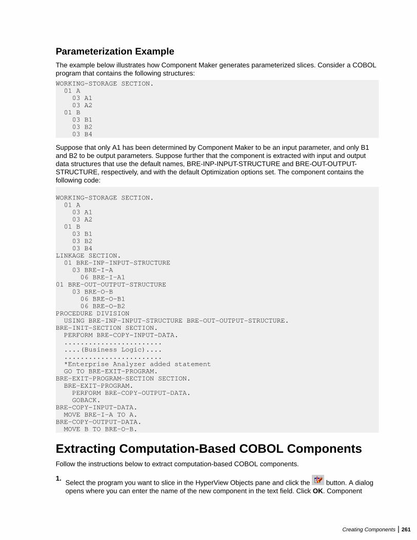
Parameterization ExampleThe example below illustrates how Component Maker generates parameterized slices. Consider a COBOLprogram that contains the following structures:
WORKING-STORAGE SECTION. 01 A 03 A1 03 A2 01 B 03 B1 03 B2 03 B4
Suppose that only A1 has been determined by Component Maker to be an input parameter, and only B1and B2 to be output parameters. Suppose further that the component is extracted with input and outputdata structures that use the default names, BRE-INP-INPUT-STRUCTURE and BRE-OUT-OUTPUT-STRUCTURE, respectively, and with the default Optimization options set. The component contains thefollowing code:
WORKING-STORAGE SECTION. 01 A 03 A1 03 A2 01 B 03 B1 03 B2 03 B4LINKAGE SECTION. 01 BRE-INP-INPUT-STRUCTURE 03 BRE-I-A 06 BRE-I-A101 BRE-OUT-OUTPUT-STRUCTURE 03 BRE-O-B 06 BRE-O-B1 06 BRE-O-B2PROCEDURE DIVISION USING BRE-INP-INPUT-STRUCTURE BRE-OUT-OUTPUT-STRUCTURE.BRE-INIT-SECTION SECTION. PERFORM BRE-COPY-INPUT-DATA. ........................ ....(Business Logic).... ........................ *Enterprise Analyzer added statement GO TO BRE-EXIT-PROGRAM.BRE-EXIT-PROGRAM-SECTION SECTION. BRE-EXIT-PROGRAM. PERFORM BRE-COPY-OUTPUT-DATA. GOBACK.BRE-COPY-INPUT-DATA. MOVE BRE-I-A TO A.BRE-COPY-OUTPUT-DATA. MOVE B TO BRE-O-B.
Extracting Computation-Based COBOL ComponentsFollow the instructions below to extract computation-based COBOL components.
1.Select the program you want to slice in the HyperView Objects pane and click the button. A dialogopens where you can enter the name of the new component in the text field. Click OK. Component
Creating Components | 261
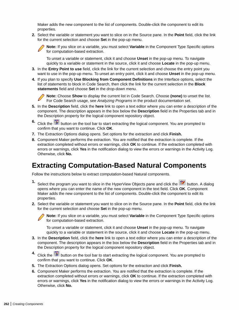
Maker adds the new component to the list of components. Double-click the component to edit itsproperties.
2. Select the variable or statement you want to slice on in the Source pane. In the Point field, click the linkfor the current selection and choose Set in the pop-up menu.
Note: If you slice on a variable, you must select Variable in the Component Type Specific optionsfor computation-based extraction.
To unset a variable or statement, click it and choose Unset in the pop-up menu. To navigatequickly to a variable or statement in the source, click it and choose Locate in the pop-up menu.
3. In the Entry Point to use field, click the link for the current selection and choose the entry point youwant to use in the pop-up menu. To unset an entry point, click it and choose Unset in the pop-up menu.
4. If you plan to specify Use Blocking from Component Definitions in the Interface options, select thelist of statements to block in Code Search, then click the link for the current selection in the Blockstatements field and choose Set in the drop-down menu.
Note: Choose Show to display the current list in Code Search. Choose (none) to unset the list.For Code Search usage, see Analyzing Programs in the product documentation set.
5. In the Description field, click the here link to open a text editor where you can enter a description of thecomponent. The description appears in the box below the Description field in the Properties tab and inthe Description property for the logical component repository object.
6. Click the button on the tool bar to start extracting the logical component. You are prompted toconfirm that you want to continue. Click OK.
7. The Extraction Options dialog opens. Set options for the extraction and click Finish.8. Component Maker performs the extraction. You are notified that the extraction is complete. If the
extraction completed without errors or warnings, click OK to continue. If the extraction completed witherrors or warnings, click Yes in the notification dialog to view the errors or warnings in the Activity Log.Otherwise, click No.
Extracting Computation-Based Natural ComponentsFollow the instructions below to extract computation-based Natural components.
1.Select the program you want to slice in the HyperView Objects pane and click the button. A dialogopens where you can enter the name of the new component in the text field. Click OK. ComponentMaker adds the new component to the list of components. Double-click the component to edit itsproperties.
2. Select the variable or statement you want to slice on in the Source pane. In the Point field, click the linkfor the current selection and choose Set in the pop-up menu.
Note: If you slice on a variable, you must select Variable in the Component Type Specific optionsfor computation-based extraction.
To unset a variable or statement, click it and choose Unset in the pop-up menu. To navigatequickly to a variable or statement in the source, click it and choose Locate in the pop-up menu.
3. In the Description field, click the here link to open a text editor where you can enter a description of thecomponent. The description appears in the box below the Description field in the Properties tab and inthe Description property for the logical component repository object.
4. Click the button on the tool bar to start extracting the logical component. You are prompted toconfirm that you want to continue. Click OK.
5. The Extraction Options dialog opens. Set options for the extraction and click Finish.6. Component Maker performs the extraction. You are notified that the extraction is complete. If the
extraction completed without errors or warnings, click OK to continue. If the extraction completed witherrors or warnings, click Yes in the notification dialog to view the errors or warnings in the Activity Log.Otherwise, click No.
262 | Creating Components
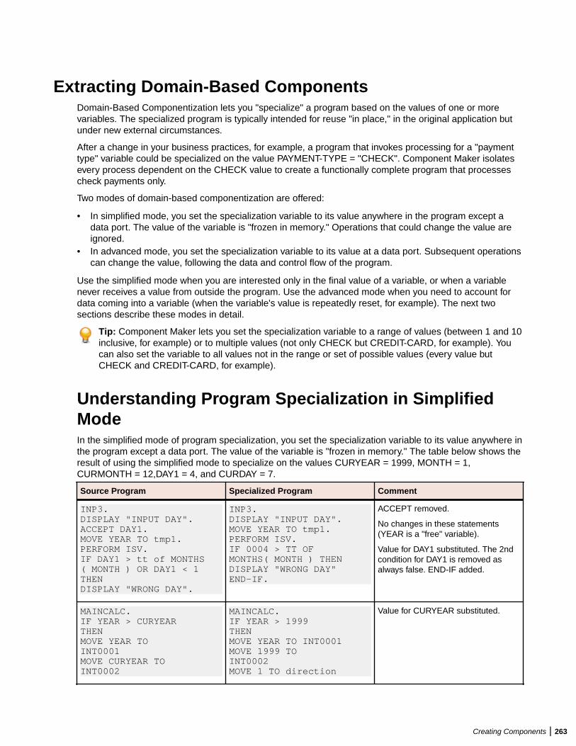
Extracting Domain-Based ComponentsDomain-Based Componentization lets you "specialize" a program based on the values of one or morevariables. The specialized program is typically intended for reuse "in place," in the original application butunder new external circumstances.
After a change in your business practices, for example, a program that invokes processing for a "paymenttype" variable could be specialized on the value PAYMENT-TYPE = "CHECK". Component Maker isolatesevery process dependent on the CHECK value to create a functionally complete program that processescheck payments only.
Two modes of domain-based componentization are offered:
• In simplified mode, you set the specialization variable to its value anywhere in the program except adata port. The value of the variable is "frozen in memory." Operations that could change the value areignored.
• In advanced mode, you set the specialization variable to its value at a data port. Subsequent operationscan change the value, following the data and control flow of the program.
Use the simplified mode when you are interested only in the final value of a variable, or when a variablenever receives a value from outside the program. Use the advanced mode when you need to account fordata coming into a variable (when the variable's value is repeatedly reset, for example). The next twosections describe these modes in detail.
Tip: Component Maker lets you set the specialization variable to a range of values (between 1 and 10inclusive, for example) or to multiple values (not only CHECK but CREDIT-CARD, for example). Youcan also set the variable to all values not in the range or set of possible values (every value butCHECK and CREDIT-CARD, for example).
Understanding Program Specialization in SimplifiedModeIn the simplified mode of program specialization, you set the specialization variable to its value anywhere inthe program except a data port. The value of the variable is "frozen in memory." The table below shows theresult of using the simplified mode to specialize on the values CURYEAR = 1999, MONTH = 1,CURMONTH = 12,DAY1 = 4, and CURDAY = 7.
Source Program Specialized Program Comment
INP3.DISPLAY "INPUT DAY".ACCEPT DAY1.MOVE YEAR TO tmp1.PERFORM ISV.IF DAY1 > tt of MONTHS( MONTH ) OR DAY1 < 1THENDISPLAY "WRONG DAY".
INP3.DISPLAY "INPUT DAY".MOVE YEAR TO tmp1.PERFORM ISV.IF 0004 > TT OFMONTHS( MONTH ) THENDISPLAY "WRONG DAY"END-IF.
ACCEPT removed.
No changes in these statements(YEAR is a "free" variable).
Value for DAY1 substituted. The 2ndcondition for DAY1 is removed asalways false. END-IF added.
MAINCALC.IF YEAR > CURYEARTHENMOVE YEAR TOINT0001MOVE CURYEAR TOINT0002
MAINCALC.IF YEAR > 1999THENMOVE YEAR TO INT0001MOVE 1999 TOINT0002MOVE 1 TO direction
Value for CURYEAR substituted.
Creating Components | 263
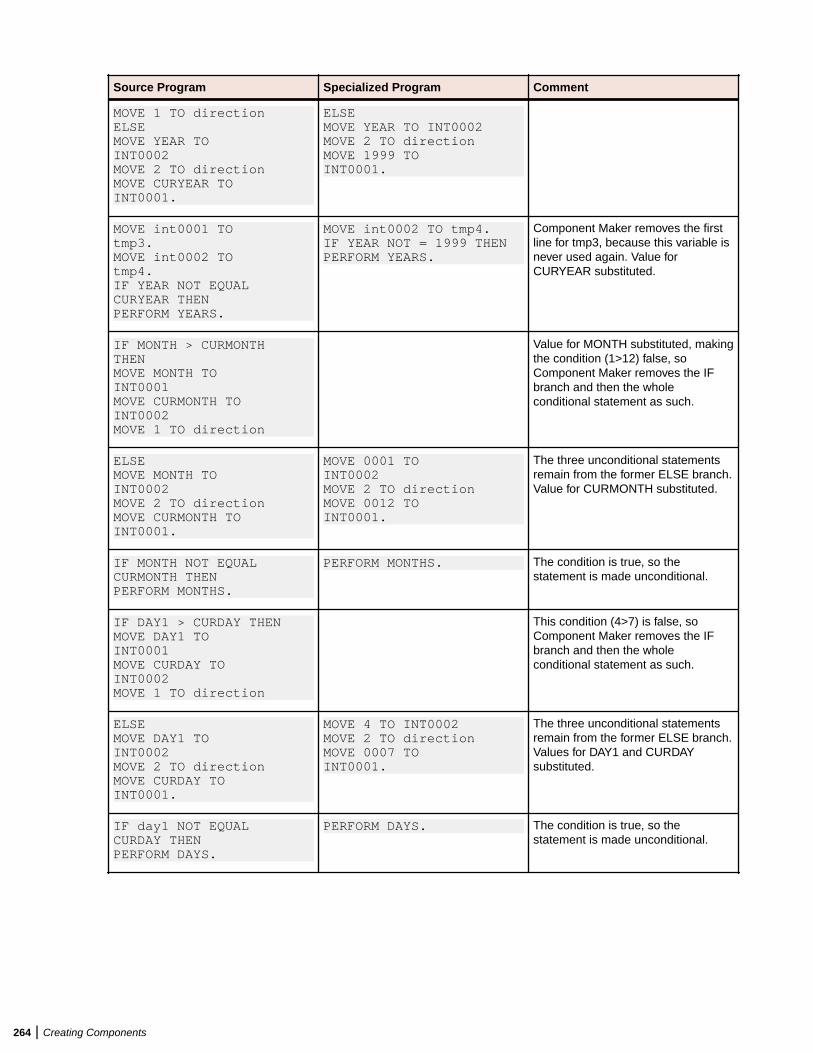
Source Program Specialized Program Comment
MOVE 1 TO directionELSEMOVE YEAR TOINT0002MOVE 2 TO directionMOVE CURYEAR TOINT0001.
ELSEMOVE YEAR TO INT0002MOVE 2 TO directionMOVE 1999 TOINT0001.
MOVE int0001 TOtmp3.MOVE int0002 TOtmp4.IF YEAR NOT EQUALCURYEAR THENPERFORM YEARS.
MOVE int0002 TO tmp4.IF YEAR NOT = 1999 THENPERFORM YEARS.
Component Maker removes the firstline for tmp3, because this variable isnever used again. Value forCURYEAR substituted.
IF MONTH > CURMONTHTHENMOVE MONTH TOINT0001MOVE CURMONTH TOINT0002MOVE 1 TO direction
Value for MONTH substituted, makingthe condition (1>12) false, soComponent Maker removes the IFbranch and then the wholeconditional statement as such.
ELSEMOVE MONTH TOINT0002MOVE 2 TO directionMOVE CURMONTH TOINT0001.
MOVE 0001 TOINT0002MOVE 2 TO directionMOVE 0012 TOINT0001.
The three unconditional statementsremain from the former ELSE branch.Value for CURMONTH substituted.
IF MONTH NOT EQUALCURMONTH THENPERFORM MONTHS.
PERFORM MONTHS. The condition is true, so thestatement is made unconditional.
IF DAY1 > CURDAY THENMOVE DAY1 TOINT0001MOVE CURDAY TOINT0002MOVE 1 TO direction
This condition (4>7) is false, soComponent Maker removes the IFbranch and then the wholeconditional statement as such.
ELSEMOVE DAY1 TOINT0002MOVE 2 TO directionMOVE CURDAY TOINT0001.
MOVE 4 TO INT0002MOVE 2 TO directionMOVE 0007 TOINT0001.
The three unconditional statementsremain from the former ELSE branch.Values for DAY1 and CURDAYsubstituted.
IF day1 NOT EQUALCURDAY THENPERFORM DAYS.
PERFORM DAYS. The condition is true, so thestatement is made unconditional.
264 | Creating Components
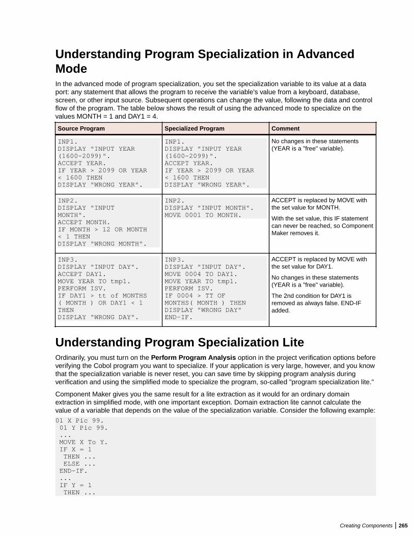
Understanding Program Specialization in AdvancedModeIn the advanced mode of program specialization, you set the specialization variable to its value at a dataport: any statement that allows the program to receive the variable's value from a keyboard, database,screen, or other input source. Subsequent operations can change the value, following the data and controlflow of the program. The table below shows the result of using the advanced mode to specialize on thevalues MONTH = 1 and DAY1 = 4.
Source Program Specialized Program Comment
INP1.DISPLAY "INPUT YEAR(1600-2099)".ACCEPT YEAR.IF YEAR > 2099 OR YEAR< 1600 THENDISPLAY "WRONG YEAR".
INP1.DISPLAY "INPUT YEAR(1600-2099)".ACCEPT YEAR.IF YEAR > 2099 OR YEAR< 1600 THENDISPLAY "WRONG YEAR".
No changes in these statements(YEAR is a "free" variable).
INP2.DISPLAY "INPUTMONTH".ACCEPT MONTH.IF MONTH > 12 OR MONTH< 1 THENDISPLAY "WRONG MONTH".
INP2.DISPLAY "INPUT MONTH".MOVE 0001 TO MONTH.
ACCEPT is replaced by MOVE withthe set value for MONTH.
With the set value, this IF statementcan never be reached, so ComponentMaker removes it.
INP3.DISPLAY "INPUT DAY".ACCEPT DAY1.MOVE YEAR TO tmp1.PERFORM ISV.IF DAY1 > tt of MONTHS( MONTH ) OR DAY1 < 1THENDISPLAY "WRONG DAY".
INP3.DISPLAY "INPUT DAY".MOVE 0004 TO DAY1.MOVE YEAR TO tmp1.PERFORM ISV.IF 0004 > TT OFMONTHS( MONTH ) THENDISPLAY "WRONG DAY"END-IF.
ACCEPT is replaced by MOVE withthe set value for DAY1.
No changes in these statements(YEAR is a "free" variable).
The 2nd condition for DAY1 isremoved as always false. END-IFadded.
Understanding Program Specialization LiteOrdinarily, you must turn on the Perform Program Analysis option in the project verification options beforeverifying the Cobol program you want to specialize. If your application is very large, however, and you knowthat the specialization variable is never reset, you can save time by skipping program analysis duringverification and using the simplified mode to specialize the program, so-called "program specialization lite."
Component Maker gives you the same result for a lite extraction as it would for an ordinary domainextraction in simplified mode, with one important exception. Domain extraction lite cannot calculate thevalue of a variable that depends on the value of the specialization variable. Consider the following example:
01 X Pic 99. 01 Y Pic 99. ... MOVE X To Y. IF X = 1 THEN ... ELSE ... END-IF. ... IF Y = 1 THEN ...
Creating Components | 265
ELSE ... END-IF.
If you set X to 1, both simplified mode and domain extraction lite resolve the IF X = 1 condition correctly.Only simplified mode, however, resolves the IF Y = 1 condition.
Extracting Domain-Based COBOL ComponentsFollow the instructions below to extract domain-based COBOL components.
1.Select the program you want to slice in the HyperView Objects pane and click the button. A dialogopens where you can enter the name of the new component in the text field. Click OK. ComponentMaker adds the new component to the list of components. Double-click the component to edit itsproperties.
2. In the Data Item Value field, click the here link. Choose one of the following methods in the pop-upmenu:
• HyperCode List to set the specialization variable to the constant values in a list of constants.• User Specified Value(s) to set the specialization variable to a value or values you specify.
3. Select the specialization variable or its declaration in the Source pane. Click the link for the currentselection in the Data Item field and choose Set in the drop-down menu. For advanced programspecialization, you can enter a structure in Data Item and a field inside the structure in Field.
Note: To delete an entry, select the link for the numeral that identifies it and choose Delete in thepop-up menu. To unset an entry, click it and choose Unset in the pop-up menu. To navigate quicklyto a variable or declaration in the source, click it and choose Locate in the pop-up menu.
4. In the Comparison field, click the link for the current comparison operator and choose:
• equals to set the specialization variable to the specified values.• not equals to set the specialization variable to every value but the specified values.
5. If you chose HyperCode List, select the list of constants in Code Search, then click the link for thecurrent selection in the List Name field and choose Set in the drop-down menu.
Note: Choose Show to display the current list in Code Search. Choose (none) to unset the list.For Code Search usage, see Analyzing Programs in the product documentation set.
6. If you chose User Specified Value(s), click the here link in the Values field. Choose one of thefollowing methods in the pop-up menu:
• Value to set the specialization variable to one or more values. In the Value field, click the link for thecurrent selection. A dialog opens where you can enter a value in the text field. Click OK.
Note: Put double quotation marks around a string constant with blank spaces at the beginningor end.
• Value Range to set the specialization variable to a range of values. In the Lower field, click the linkfor the current selection. A dialog opens where you can enter a value for the lower range end in thetext field. Click OK. Follow the same procedure for the Upper field.
Note: For value ranges, the specialization variable must have a numeric data type. Onlynumeric values are supported.
7. Repeat this procedure for each value or range of values you want to set and for each variable you wantto specialize on. For a given specialization variable, you can specify the methods in any combination.For a given extraction, you can specify simplified and advanced modes in any combination.
Note: To delete a value or range, select the link for the numeral that identifies it and choose Deletein the pop-up menu.
8. In the Entry Point to use field, click the link for the current selection and choose the entry point youwant to use in the pop-up menu. To unset an entry point, click it and choose Unset in the pop-up menu.
266 | Creating Components
9. In the Description field, click the here link to open a text editor where you can enter a description of thecomponent. The description appears in the box below the Description field in the Properties tab and inthe Description property for the logical component repository object.
10.Click the button on the tool bar to start extracting the logical component. You are prompted toconfirm that you want to continue. Click OK.
11.The Extraction Options dialog opens. Set options for the extraction and click Finish.
12.Component Maker performs the extraction. You are notified that the extraction is complete. If theextraction completed without errors or warnings, click OK to continue. If the extraction completed witherrors or warnings, click Yes in the notification dialog to view the errors or warnings in the Activity Log.Otherwise, click No.
Extracting Domain-Based PL/I ComponentsFollow the instructions below to extract domain-based PL/I components.
Note: Not-equals comparisons and value ranges are not supported in PL/I.
1.Select the program you want to slice in the HyperView Objects pane and click the button. A dialogopens where you can enter the name of the new component in the text field. Click OK. ComponentMaker adds the new component to the list of components. Double-click the component to edit itsproperties.
2. In the Data Item Value field (to set a single specialization variable) or the Value for Data Item List (toset a list of specialization variables), click the here link. Choose one of the following methods in the pop-up menu:
• HyperCode List to set the specialization variable(s) to the constant values in a list of constants.• User Specified Value(s) to set the specialization variable(s) to a value or values you specify.
3. If you are setting:
• A single specialization variable, select the specialization variable or its declaration in the Sourcepane. Click the link for the current selection in the Data Item field and choose Set in the drop-downmenu. For advanced program specialization, you can enter a structure in Data Item and a fieldinside the structure in Field.
• A list of specialization variables, click the link for the current selection and choose the list of variablesor declarations to use in the pop-up menu.
Note: To delete an entry, select the link for the numeral that identifies it and choose Delete in thepop-up menu. To unset an entry, click it and choose Unset in the pop-up menu. To navigate quicklyto a variable or declaration in the source, click it and choose Locate in the pop-up menu.
4. If you chose HyperCode List, select the list of constants in Code Search, then click the link for thecurrent selection in the List Name field and choose Set in the drop-down menu.
Note: Choose Show to display the current list in Code Search. Choose (none) to unset the list.For Code Search usage, see Analyzing Programs in the product documentation set.
5. If you chose User Specified Value(s), click the here link in the Values field. Choose one of thefollowing methods in the pop-up menu:
• Value to set the specialization variable to one or more values. In the Value field, click the link for thecurrent selection. A dialog opens where you can enter a value in the text field. Click OK.
Note: Put double quotation marks around a string constant with blank spaces at the beginningor end.
• Value Range to set the specialization variable to a range of values. In the Lower field, click the linkfor the current selection. A dialog opens where you can enter a value for the lower range end in thetext field. Click OK. Follow the same procedure for the Upper field.
Creating Components | 267
Note: For value ranges, the specialization variable must have a numeric data type. Onlynumeric values are supported.
6. Repeat this procedure for each value or range of values you want to set and for each variable you wantto specialize on. For a given specialization variable, you can specify the methods in any combination.For a given extraction, you can specify simplified and advanced modes in any combination.
Note: To delete a value or range, select the link for the numeral that identifies it and choose Deletein the pop-up menu.
7. In the Description field, click the here link to open a text editor where you can enter a description of thecomponent. The description appears in the box below the Description field in the Properties tab and inthe Description property for the logical component repository object.
8. Click the button on the tool bar to start extracting the logical component. You are prompted toconfirm that you want to continue. Click OK.
9. The Extraction Options dialog opens. Set options for the extraction and click Finish.10.Component Maker performs the extraction. You are notified that the extraction is complete. If the
extraction completed without errors or warnings, click OK to continue. If the extraction completed witherrors or warnings, click Yes in the notification dialog to view the errors or warnings in the Activity Log.Otherwise, click No.
Eliminating Dead CodeDead Code Elimination (DCE) is an option in each of the main component extraction methods, but you canalso perform it on a standalone basis. For each program analyzed for dead code, DCE generates acomponent that consists of the original source code minus any unreferenced data items or unreachableprocedural statements. Optionally, you can have DCE comment out dead code in Cobol and Naturalapplications, rather than remove it.
Note: Use the batch DCE feature to find dead code across your project. If you are licensed to use theBatch Refresh Process (BRP), you can use it to perform dead code elimination across a workspace.
Generating Dead Code StatisticsSet the Perform Dead Code Analysis option in the project verification options if you want the parser tocollect statistics on the number of unreachable statements and dead data items in a program, and to markthe constructs as dead in Interactive Analysis. You can view the statistics in the Legacy Estimation tool, asdescribed in Analyzing Projects in the product documentation set.
Note: You do not need to set this option to perform dead code elimination in Component Maker.
For COBOL programs, you can use a DCE coverage report to identify dead code in a source program. Thereport displays the text of the source program with its "live," or extracted, code shaded in pink.
Understanding Dead Code EliminationLet's look at a simple before-and-after example to see what you can expect from Dead Code Elimination.
Before:WORKING-STORAGE SECTION.
01 USED-VARS. 05 USED1 PIC 9.
01 DEAD-VARS. 05 DEAD1 PIC 9. 05 DEAD2 PIC X.
268 | Creating Components
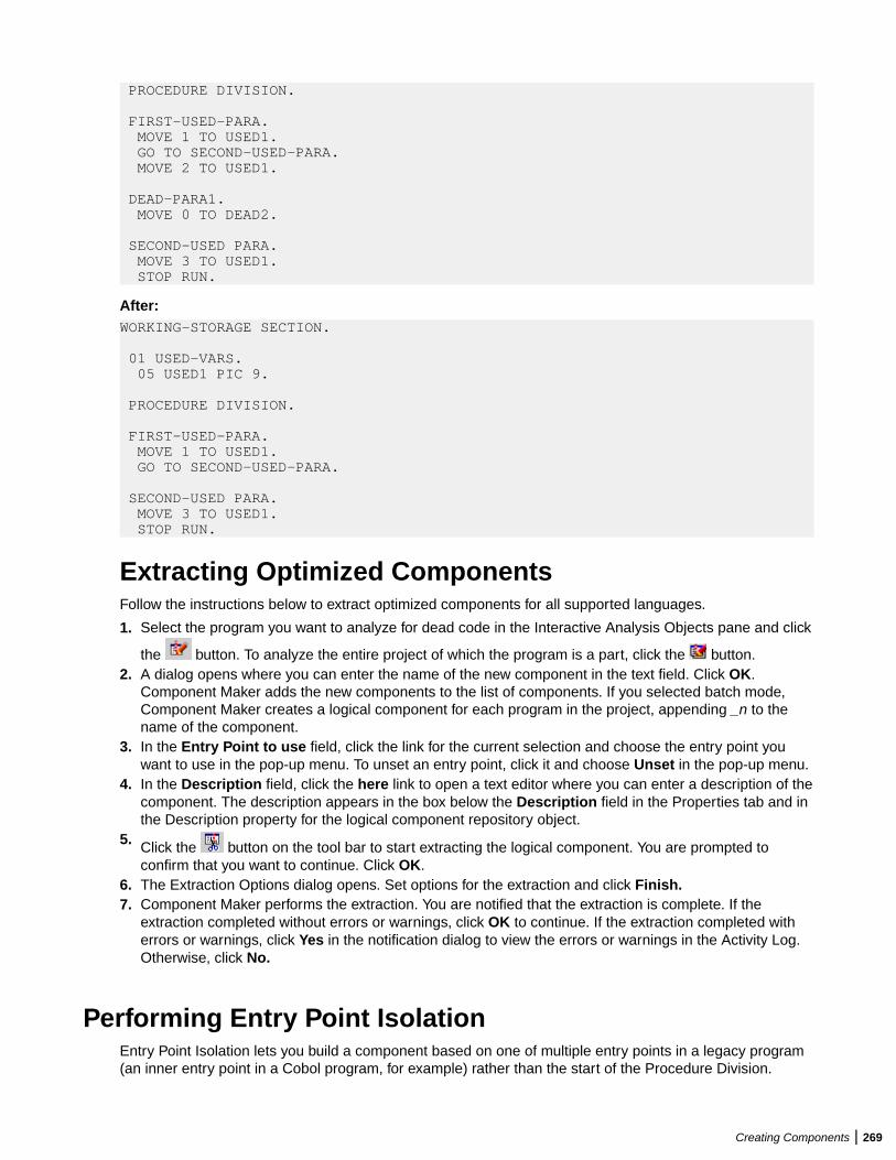
PROCEDURE DIVISION.
FIRST-USED-PARA. MOVE 1 TO USED1. GO TO SECOND-USED-PARA. MOVE 2 TO USED1.
DEAD-PARA1. MOVE 0 TO DEAD2. SECOND-USED PARA. MOVE 3 TO USED1. STOP RUN.
After:WORKING-STORAGE SECTION.
01 USED-VARS. 05 USED1 PIC 9.
PROCEDURE DIVISION.
FIRST-USED-PARA. MOVE 1 TO USED1. GO TO SECOND-USED-PARA. SECOND-USED PARA. MOVE 3 TO USED1. STOP RUN.
Extracting Optimized ComponentsFollow the instructions below to extract optimized components for all supported languages.
1. Select the program you want to analyze for dead code in the Interactive Analysis Objects pane and click
the button. To analyze the entire project of which the program is a part, click the button.2. A dialog opens where you can enter the name of the new component in the text field. Click OK.
Component Maker adds the new components to the list of components. If you selected batch mode,Component Maker creates a logical component for each program in the project, appending _n to thename of the component.
3. In the Entry Point to use field, click the link for the current selection and choose the entry point youwant to use in the pop-up menu. To unset an entry point, click it and choose Unset in the pop-up menu.
4. In the Description field, click the here link to open a text editor where you can enter a description of thecomponent. The description appears in the box below the Description field in the Properties tab and inthe Description property for the logical component repository object.
5. Click the button on the tool bar to start extracting the logical component. You are prompted toconfirm that you want to continue. Click OK.
6. The Extraction Options dialog opens. Set options for the extraction and click Finish.7. Component Maker performs the extraction. You are notified that the extraction is complete. If the
extraction completed without errors or warnings, click OK to continue. If the extraction completed witherrors or warnings, click Yes in the notification dialog to view the errors or warnings in the Activity Log.Otherwise, click No.
Performing Entry Point IsolationEntry Point Isolation lets you build a component based on one of multiple entry points in a legacy program(an inner entry point in a Cobol program, for example) rather than the start of the Procedure Division.
Creating Components | 269
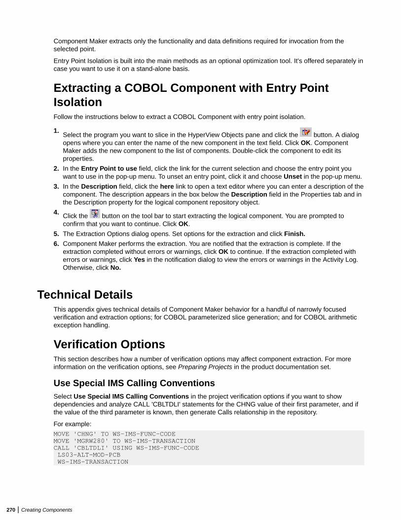
Component Maker extracts only the functionality and data definitions required for invocation from theselected point.
Entry Point Isolation is built into the main methods as an optional optimization tool. It's offered separately incase you want to use it on a stand-alone basis.
Extracting a COBOL Component with Entry PointIsolationFollow the instructions below to extract a COBOL Component with entry point isolation.
1.Select the program you want to slice in the HyperView Objects pane and click the button. A dialogopens where you can enter the name of the new component in the text field. Click OK. ComponentMaker adds the new component to the list of components. Double-click the component to edit itsproperties.
2. In the Entry Point to use field, click the link for the current selection and choose the entry point youwant to use in the pop-up menu. To unset an entry point, click it and choose Unset in the pop-up menu.
3. In the Description field, click the here link to open a text editor where you can enter a description of thecomponent. The description appears in the box below the Description field in the Properties tab and inthe Description property for the logical component repository object.
4. Click the button on the tool bar to start extracting the logical component. You are prompted toconfirm that you want to continue. Click OK.
5. The Extraction Options dialog opens. Set options for the extraction and click Finish.
6. Component Maker performs the extraction. You are notified that the extraction is complete. If theextraction completed without errors or warnings, click OK to continue. If the extraction completed witherrors or warnings, click Yes in the notification dialog to view the errors or warnings in the Activity Log.Otherwise, click No.
Technical DetailsThis appendix gives technical details of Component Maker behavior for a handful of narrowly focusedverification and extraction options; for COBOL parameterized slice generation; and for COBOL arithmeticexception handling.
Verification OptionsThis section describes how a number of verification options may affect component extraction. For moreinformation on the verification options, see Preparing Projects in the product documentation set.
Use Special IMS Calling ConventionsSelect Use Special IMS Calling Conventions in the project verification options if you want to showdependencies and analyze CALL 'CBLTDLI' statements for the CHNG value of their first parameter, and ifthe value of the third parameter is known, then generate Calls relationship in the repository.
For example:
MOVE 'CHNG' TO WS-IMS-FUNC-CODEMOVE 'MGRW280' TO WS-IMS-TRANSACTIONCALL 'CBLTDLI' USING WS-IMS-FUNC-CODE LS03-ALT-MOD-PCB WS-IMS-TRANSACTION
270 | Creating Components
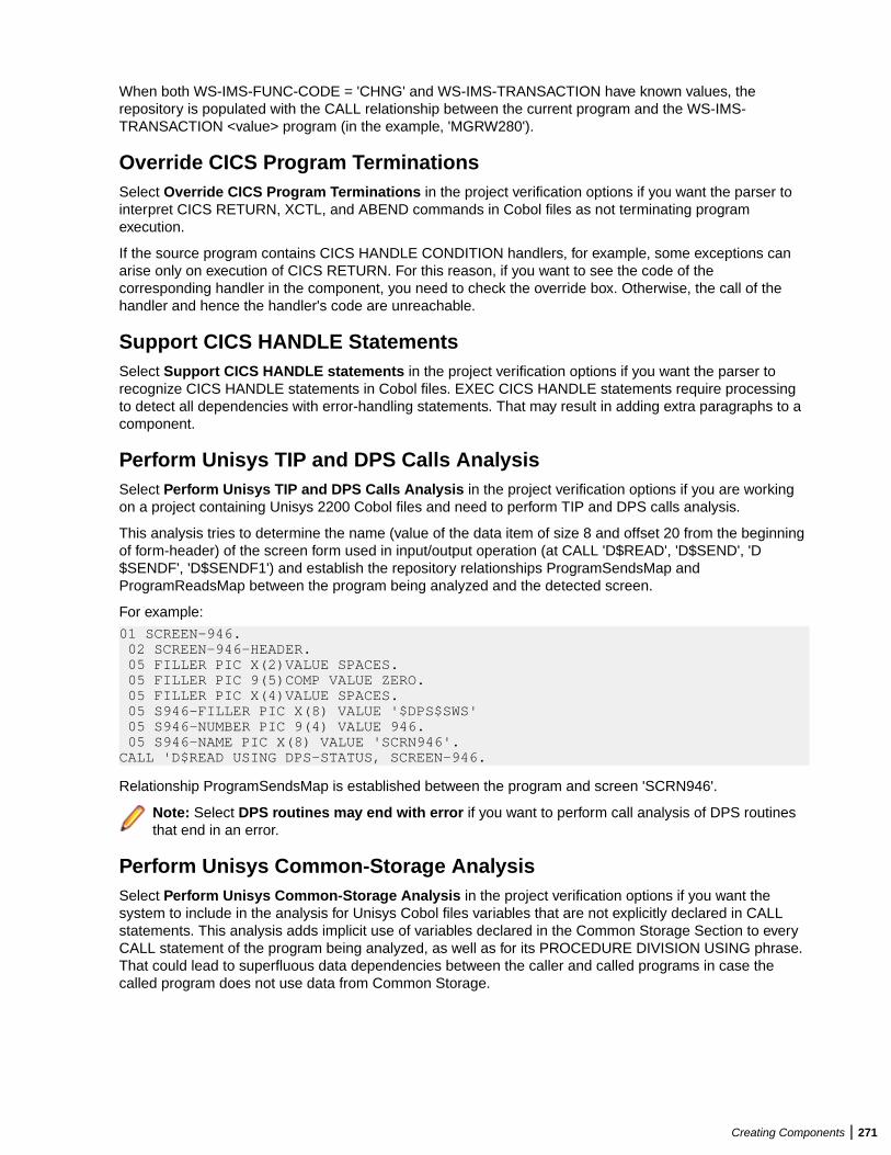
When both WS-IMS-FUNC-CODE = 'CHNG' and WS-IMS-TRANSACTION have known values, therepository is populated with the CALL relationship between the current program and the WS-IMS-TRANSACTION <value> program (in the example, 'MGRW280').
Override CICS Program TerminationsSelect Override CICS Program Terminations in the project verification options if you want the parser tointerpret CICS RETURN, XCTL, and ABEND commands in Cobol files as not terminating programexecution.
If the source program contains CICS HANDLE CONDITION handlers, for example, some exceptions canarise only on execution of CICS RETURN. For this reason, if you want to see the code of thecorresponding handler in the component, you need to check the override box. Otherwise, the call of thehandler and hence the handler's code are unreachable.
Support CICS HANDLE StatementsSelect Support CICS HANDLE statements in the project verification options if you want the parser torecognize CICS HANDLE statements in Cobol files. EXEC CICS HANDLE statements require processingto detect all dependencies with error-handling statements. That may result in adding extra paragraphs to acomponent.
Perform Unisys TIP and DPS Calls AnalysisSelect Perform Unisys TIP and DPS Calls Analysis in the project verification options if you are workingon a project containing Unisys 2200 Cobol files and need to perform TIP and DPS calls analysis.
This analysis tries to determine the name (value of the data item of size 8 and offset 20 from the beginningof form-header) of the screen form used in input/output operation (at CALL 'D$READ', 'D$SEND', 'D$SENDF', 'D$SENDF1') and establish the repository relationships ProgramSendsMap andProgramReadsMap between the program being analyzed and the detected screen.
For example:
01 SCREEN-946. 02 SCREEN-946-HEADER. 05 FILLER PIC X(2)VALUE SPACES. 05 FILLER PIC 9(5)COMP VALUE ZERO. 05 FILLER PIC X(4)VALUE SPACES. 05 S946-FILLER PIC X(8) VALUE '$DPS$SWS' 05 S946-NUMBER PIC 9(4) VALUE 946. 05 S946-NAME PIC X(8) VALUE 'SCRN946'.CALL 'D$READ USING DPS-STATUS, SCREEN-946.
Relationship ProgramSendsMap is established between the program and screen 'SCRN946'.
Note: Select DPS routines may end with error if you want to perform call analysis of DPS routinesthat end in an error.
Perform Unisys Common-Storage AnalysisSelect Perform Unisys Common-Storage Analysis in the project verification options if you want thesystem to include in the analysis for Unisys Cobol files variables that are not explicitly declared in CALLstatements. This analysis adds implicit use of variables declared in the Common Storage Section to everyCALL statement of the program being analyzed, as well as for its PROCEDURE DIVISION USING phrase.That could lead to superfluous data dependencies between the caller and called programs in case thecalled program does not use data from Common Storage.
Creating Components | 271
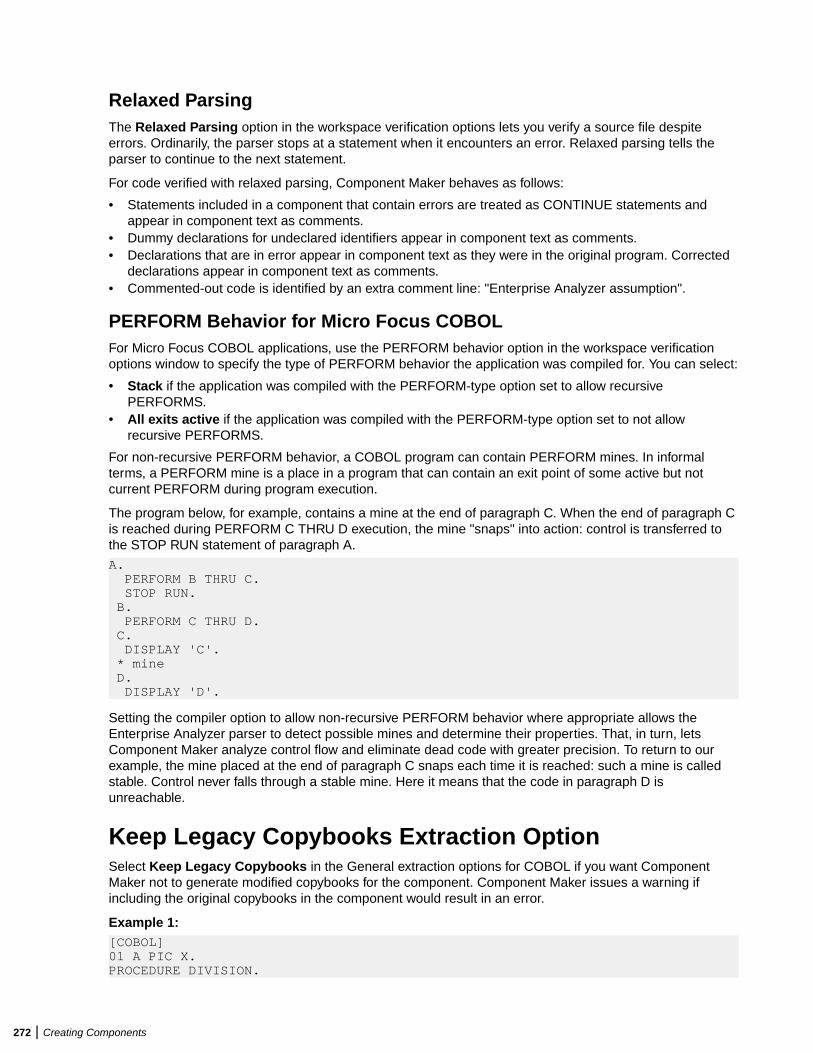
Relaxed ParsingThe Relaxed Parsing option in the workspace verification options lets you verify a source file despiteerrors. Ordinarily, the parser stops at a statement when it encounters an error. Relaxed parsing tells theparser to continue to the next statement.
For code verified with relaxed parsing, Component Maker behaves as follows:
• Statements included in a component that contain errors are treated as CONTINUE statements andappear in component text as comments.
• Dummy declarations for undeclared identifiers appear in component text as comments.• Declarations that are in error appear in component text as they were in the original program. Corrected
declarations appear in component text as comments.• Commented-out code is identified by an extra comment line: "Enterprise Analyzer assumption".
PERFORM Behavior for Micro Focus COBOLFor Micro Focus COBOL applications, use the PERFORM behavior option in the workspace verificationoptions window to specify the type of PERFORM behavior the application was compiled for. You can select:
• Stack if the application was compiled with the PERFORM-type option set to allow recursivePERFORMS.
• All exits active if the application was compiled with the PERFORM-type option set to not allowrecursive PERFORMS.
For non-recursive PERFORM behavior, a COBOL program can contain PERFORM mines. In informalterms, a PERFORM mine is a place in a program that can contain an exit point of some active but notcurrent PERFORM during program execution.
The program below, for example, contains a mine at the end of paragraph C. When the end of paragraph Cis reached during PERFORM C THRU D execution, the mine "snaps" into action: control is transferred tothe STOP RUN statement of paragraph A.
A. PERFORM B THRU C. STOP RUN. B. PERFORM C THRU D. C. DISPLAY 'C'. * mine D. DISPLAY 'D'.
Setting the compiler option to allow non-recursive PERFORM behavior where appropriate allows theEnterprise Analyzer parser to detect possible mines and determine their properties. That, in turn, letsComponent Maker analyze control flow and eliminate dead code with greater precision. To return to ourexample, the mine placed at the end of paragraph C snaps each time it is reached: such a mine is calledstable. Control never falls through a stable mine. Here it means that the code in paragraph D isunreachable.
Keep Legacy Copybooks Extraction OptionSelect Keep Legacy Copybooks in the General extraction options for COBOL if you want ComponentMaker not to generate modified copybooks for the component. Component Maker issues a warning ifincluding the original copybooks in the component would result in an error.
Example 1:[COBOL]01 A PIC X.PROCEDURE DIVISION.
272 | Creating Components
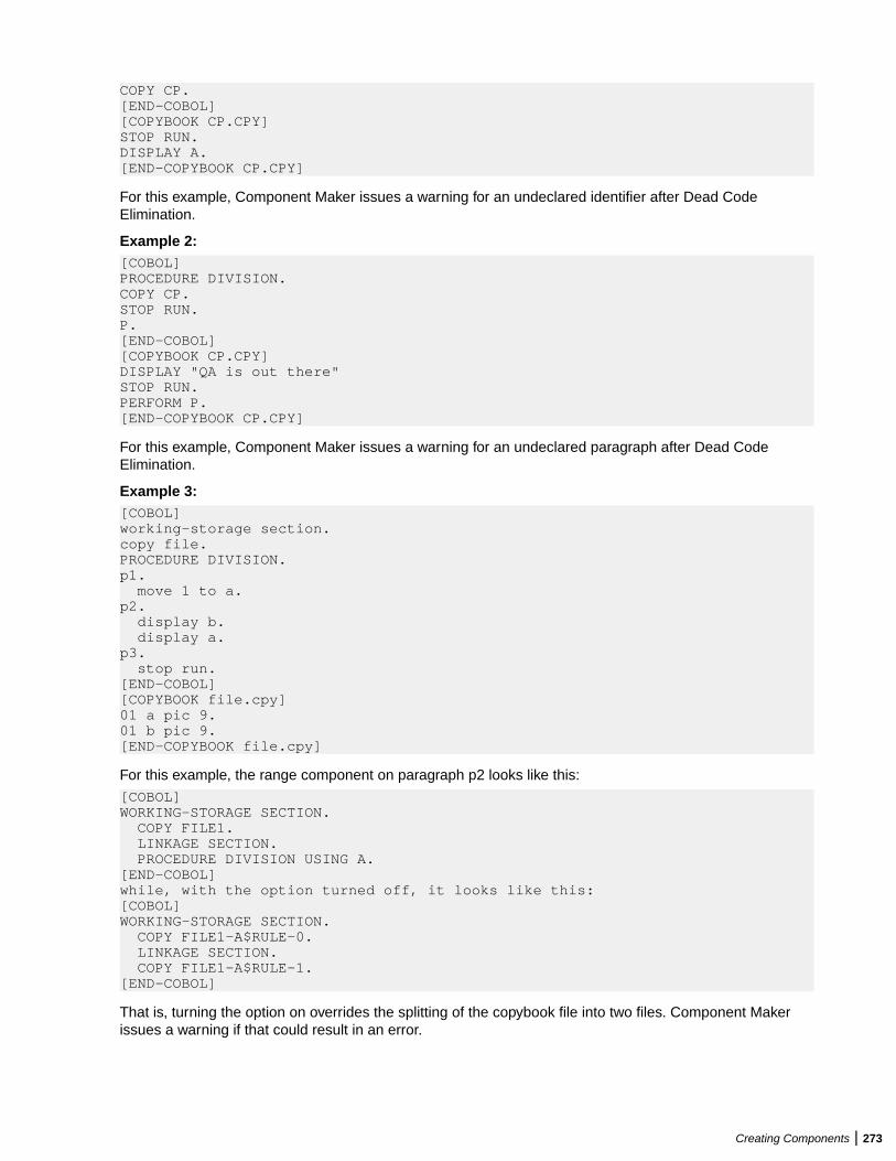
COPY CP.[END-COBOL][COPYBOOK CP.CPY]STOP RUN.DISPLAY A.[END-COPYBOOK CP.CPY]
For this example, Component Maker issues a warning for an undeclared identifier after Dead CodeElimination.
Example 2:[COBOL]PROCEDURE DIVISION.COPY CP.STOP RUN.P.[END-COBOL][COPYBOOK CP.CPY]DISPLAY "QA is out there"STOP RUN.PERFORM P.[END-COPYBOOK CP.CPY]
For this example, Component Maker issues a warning for an undeclared paragraph after Dead CodeElimination.
Example 3:[COBOL]working-storage section.copy file.PROCEDURE DIVISION.p1. move 1 to a.p2. display b. display a.p3. stop run.[END-COBOL][COPYBOOK file.cpy]01 a pic 9.01 b pic 9.[END-COPYBOOK file.cpy]
For this example, the range component on paragraph p2 looks like this:
[COBOL]WORKING-STORAGE SECTION. COPY FILE1. LINKAGE SECTION. PROCEDURE DIVISION USING A.[END-COBOL]while, with the option turned off, it looks like this:[COBOL]WORKING-STORAGE SECTION. COPY FILE1-A$RULE-0. LINKAGE SECTION. COPY FILE1-A$RULE-1.[END-COBOL]
That is, turning the option on overrides the splitting of the copybook file into two files. Component Makerissues a warning if that could result in an error.
Creating Components | 273
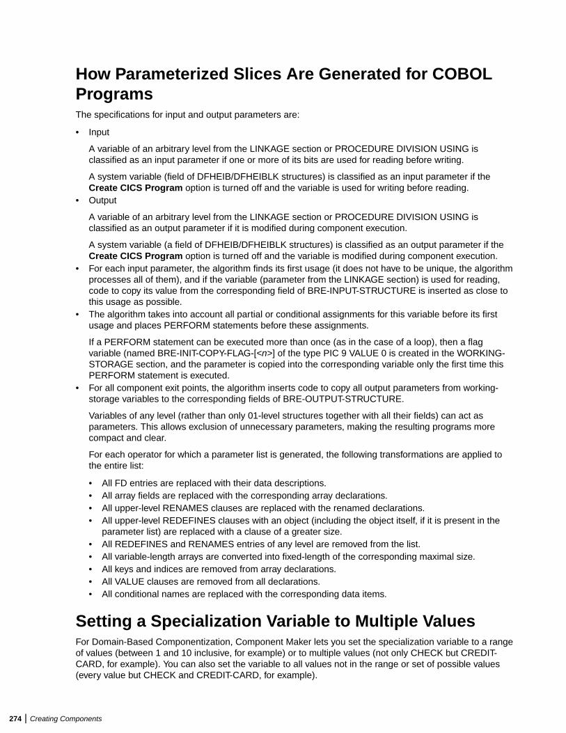
How Parameterized Slices Are Generated for COBOLProgramsThe specifications for input and output parameters are:
• Input
A variable of an arbitrary level from the LINKAGE section or PROCEDURE DIVISION USING isclassified as an input parameter if one or more of its bits are used for reading before writing.
A system variable (field of DFHEIB/DFHEIBLK structures) is classified as an input parameter if theCreate CICS Program option is turned off and the variable is used for writing before reading.
• Output
A variable of an arbitrary level from the LINKAGE section or PROCEDURE DIVISION USING isclassified as an output parameter if it is modified during component execution.
A system variable (a field of DFHEIB/DFHEIBLK structures) is classified as an output parameter if theCreate CICS Program option is turned off and the variable is modified during component execution.
• For each input parameter, the algorithm finds its first usage (it does not have to be unique, the algorithmprocesses all of them), and if the variable (parameter from the LINKAGE section) is used for reading,code to copy its value from the corresponding field of BRE-INPUT-STRUCTURE is inserted as close tothis usage as possible.
• The algorithm takes into account all partial or conditional assignments for this variable before its firstusage and places PERFORM statements before these assignments.
If a PERFORM statement can be executed more than once (as in the case of a loop), then a flagvariable (named BRE-INIT-COPY-FLAG-[<n>] of the type PIC 9 VALUE 0 is created in the WORKING-STORAGE section, and the parameter is copied into the corresponding variable only the first time thisPERFORM statement is executed.
• For all component exit points, the algorithm inserts code to copy all output parameters from working-storage variables to the corresponding fields of BRE-OUTPUT-STRUCTURE.
Variables of any level (rather than only 01-level structures together with all their fields) can act asparameters. This allows exclusion of unnecessary parameters, making the resulting programs morecompact and clear.
For each operator for which a parameter list is generated, the following transformations are applied tothe entire list:
• All FD entries are replaced with their data descriptions.• All array fields are replaced with the corresponding array declarations.• All upper-level RENAMES clauses are replaced with the renamed declarations.• All upper-level REDEFINES clauses with an object (including the object itself, if it is present in the
parameter list) are replaced with a clause of a greater size.• All REDEFINES and RENAMES entries of any level are removed from the list.• All variable-length arrays are converted into fixed-length of the corresponding maximal size.• All keys and indices are removed from array declarations.• All VALUE clauses are removed from all declarations.• All conditional names are replaced with the corresponding data items.
Setting a Specialization Variable to Multiple ValuesFor Domain-Based Componentization, Component Maker lets you set the specialization variable to a rangeof values (between 1 and 10 inclusive, for example) or to multiple values (not only CHECK but CREDIT-CARD, for example). You can also set the variable to all values not in the range or set of possible values(every value but CHECK and CREDIT-CARD, for example).
274 | Creating Components
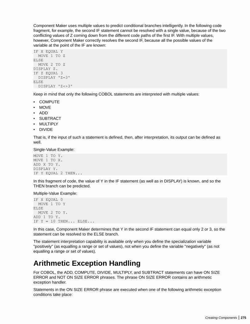
Component Maker uses multiple values to predict conditional branches intelligently. In the following codefragment, for example, the second IF statement cannot be resolved with a single value, because of the twoconflicting values of Z coming down from the different code paths of the first IF. With multiple values,however, Component Maker correctly resolves the second IF, because all the possible values of thevariable at the point of the IF are known:
IF X EQUAL Y MOVE 1 TO ZELSE MOVE 2 TO ZDISPLAY Z.IF Z EQUAL 3 DISPLAY "Z=3"ELSE DISPLAY "Z<>3"
Keep in mind that only the following COBOL statements are interpreted with multiple values:
• COMPUTE• MOVE• ADD• SUBTRACT• MULTIPLY• DIVIDE
That is, if the input of such a statement is defined, then, after interpretation, its output can be defined aswell.
Single-Value Example:
MOVE 1 TO Y.MOVE 1 TO X.ADD X TO Y.DISPLAY Y.IF Y EQUAL 2 THEN...
In this fragment of code, the value of Y in the IF statement (as well as in DISPLAY) is known, and so theTHEN branch can be predicted.
Multiple-Value Example:
IF X EQUAL 0 MOVE 1 TO YELSE MOVE 2 TO Y.ADD 1 TO Y.IF Y = 10 THEN... ELSE...
In this case, Component Maker determines that Y in the second IF statement can equal only 2 or 3, so thestatement can be resolved to the ELSE branch.
The statement interpretation capability is available only when you define the specialization variable"positively" (as equalling a range or set of values), not when you define the variable "negatively" (as notequalling a range or set of values).
Arithmetic Exception HandlingFor COBOL, the ADD, COMPUTE, DIVIDE, MULTIPLY, and SUBTRACT statements can have ON SIZEERROR and NOT ON SIZE ERROR phrases. The phrase ON SIZE ERROR contains an arithmeticexception handler.
Statements in the ON SIZE ERROR phrase are executed when one of the following arithmetic exceptionconditions take place:
Creating Components | 275
• The value of an arithmetic operation result is larger than the resultant-identifier picture size.• Division by zero.• Violation of the rules for the evaluation of exponentiation.
For MULTIPLY arithmetic statements, if any of the individual operations produces a size error condition, thestatements in the ON SIZE ERROR phrase is not executed until all of the individual operations arecompleted.
Control is transferred to the statements defined in the phrase NOT ON SIZE ERROR when a NOT ONSIZE ERROR phrase is specified and no exceptions occurred. In that case, the ON SIZE ERROR isignored.
Component Maker specialization processes an arithmetic statement with exception handlers in thefollowing way:
• If a (NOT) ON SIZE ERROR condition occurred in some interpreting pass, then the arithmetic statementis replaced by the statements in the corresponding phrase.
• Those statements will be interpreted at the next pass.
276 | Creating Components
Using the Batch Refresh Process
Using the Batch Refresh ProcessThe Enterprise Analyzer (EA) Batch Refresh Process (BRP) lets you register and verify source files inbatch mode. You typically use this process when sources on the mainframe have changed, and you needto synchronize the modified sources with the sources you are working with in EA. You can also use BRP toperform analysis and reporting functions.
Understanding the Batch Refresh ProcessProvides an overview of the Batch Refresh Process.
The Batch Refresh Process (BRP) is a utility that supports the synchronization of sources from amainframe or enterprise server with the EA repositories representing those sources. BRP is installed withthe EA server.
BRP is responsible for updating the workspace with sources provided to it from the mainframe andverifying all unverified sources. Optionally, BRP can be configured to run any required source code pre-processing, as well as certain analysis and reporting functions.
When sources are updated to a workspace, EA determines whether or not to load the file. When the nameof the incoming file matches the name of a file currently in the workspace, the two files are compared. Ifthey are different, the incoming file will replace the existing file. If they are the same, no change is made. Ifthe incoming file does not currently have a match in the workspace, the file is added to the default project.The default project is a project with the same name as the workspace. If this project does not exist, it isautomatically created.
Updating a source in a workspace causes that source to be invalidated. Any sources that are dependentupon the updated file will also be invalidated. For example, an update to a copybook will cause all theCOBOL files that use the copybook to become invalidated. That, in turn, will cause all JCL files thatexecute the programs in the source files to become invalidated. Once the update phase is completed, allinvalidated and unverified sources in the workspace will be verified.
Configuring the Batch Refresh ProcessThe Batch Refresh Process is installed with the EA server. For each workspace it processes, BRP refers toan initialization file containing configuration settings. Use the BRP Configurator in the Enterprise AnalyzerAdministration tool on the EA server to modify the initialization file settings.
1. In the EA Administration tool, choose Administer > Configure BRP. The BRP Configurator opens.
2. In the Current BRP Configurations pane, choose the BRP configuration file you want to edit and clickEdit.
Note: If the BRP configuration you want to edit is not listed in the pane, click Find to locate the filein the file system.
3. To create a new configuration, click Add. A Select Workspace dialog box opens, where you can specifythe workspace (.rwp) file you want to configure for BRP.
Note: To copy a configuration, select it and click Copy. To delete a configuration, select it and clickDelete.
4. The main BRP Configurator window opens, with a tab for each configuration task:
Using the Batch Refresh Process | 277
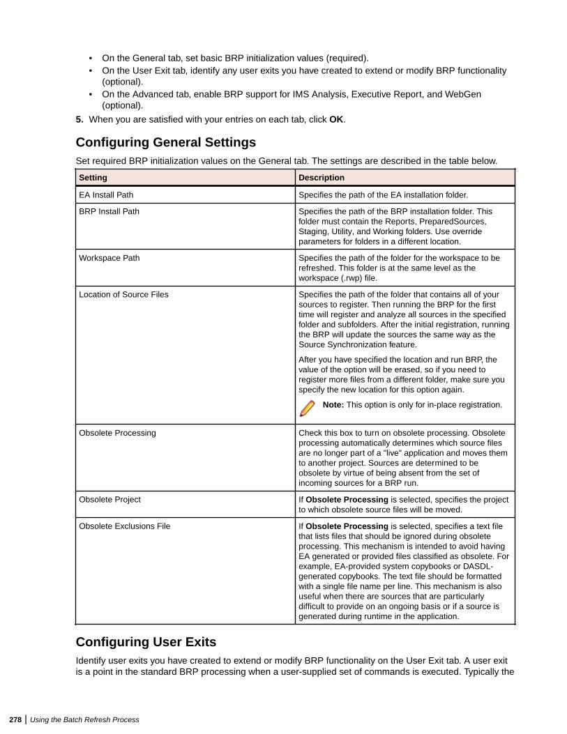
• On the General tab, set basic BRP initialization values (required).• On the User Exit tab, identify any user exits you have created to extend or modify BRP functionality
(optional).• On the Advanced tab, enable BRP support for IMS Analysis, Executive Report, and WebGen
(optional).
5. When you are satisfied with your entries on each tab, click OK.
Configuring General SettingsSet required BRP initialization values on the General tab. The settings are described in the table below.
Setting Description
EA Install Path Specifies the path of the EA installation folder.
BRP Install Path Specifies the path of the BRP installation folder. Thisfolder must contain the Reports, PreparedSources,Staging, Utility, and Working folders. Use overrideparameters for folders in a different location.
Workspace Path Specifies the path of the folder for the workspace to berefreshed. This folder is at the same level as theworkspace (.rwp) file.
Location of Source Files Specifies the path of the folder that contains all of yoursources to register. Then running the BRP for the firsttime will register and analyze all sources in the specifiedfolder and subfolders. After the initial registration, runningthe BRP will update the sources the same way as theSource Synchronization feature.
After you have specified the location and run BRP, thevalue of the option will be erased, so if you need toregister more files from a different folder, make sure youspecify the new location for this option again.
Note: This option is only for in-place registration.
Obsolete Processing Check this box to turn on obsolete processing. Obsoleteprocessing automatically determines which source filesare no longer part of a "live" application and moves themto another project. Sources are determined to beobsolete by virtue of being absent from the set ofincoming sources for a BRP run.
Obsolete Project If Obsolete Processing is selected, specifies the projectto which obsolete source files will be moved.
Obsolete Exclusions File If Obsolete Processing is selected, specifies a text filethat lists files that should be ignored during obsoleteprocessing. This mechanism is intended to avoid havingEA generated or provided files classified as obsolete. Forexample, EA-provided system copybooks or DASDL-generated copybooks. The text file should be formattedwith a single file name per line. This mechanism is alsouseful when there are sources that are particularlydifficult to provide on an ongoing basis or if a source isgenerated during runtime in the application.
Configuring User ExitsIdentify user exits you have created to extend or modify BRP functionality on the User Exit tab. A user exitis a point in the standard BRP processing when a user-supplied set of commands is executed. Typically the
278 | Using the Batch Refresh Process
commands execute utilities that accomplish tasks ranging from source code pre-processing to specializedreport generation.
Understanding Exits
There are seven user exits in BRP. Each is named and corresponds to a major division of processing, orstep, in a BRP run. The names are listed below in the order they are executed:
• Setup• Init (Initialization)• Staging• Update• Verification• Generation• End
With the exception of the Setup and End user exits, each is executed as the very first task of thecorresponding BRP step. For example, in the Generation step the Generation user exit is executed followedby executive report generation and WebGen generation.
There are some essential tasks that occur during the Setup step that make it impractical for user exitexecution to be first. The Setup step is where the main BRP log is opened and all parameter values aregenerated, if necessary, and checked for validity. The Setup user exit occurs after the log file is created, butbefore parameter values are generated and checked.
The End user exit occurs at the very end of the BRP run. There are no tasks that occur after it other thanclosing the main BRP log file.
Which user exit should be used to execute a particular piece of functionality depends upon the task thatneeds to be accomplished. For example, source code pre-processing usually needs to occur prior to thesources being loaded into the workspace. This would make the Staging or Update user exits ideal.However, it is best to do source code pre-processing once all sources are in a single spot and areguaranteed to have proper file extensions. That would eliminate the Staging user exit, since it is duringStaging that file extensions are added, if necessary. Therefore, the best place to execute source code pre-processing utilities is the Update user exit.
Other common uses of user exits are to run specific reporting or analysis functions. These typically requirethat the verification step has been completed. Therefore, the Generation user exit will typically work best forthese situations.
Configuring Exits
Configuring a user exit involves two separate tasks:
• Creating a BRP-enabled utility to accomplish the task at hand.• Pointing the user exit to that utility.
Creating a BRP-enabled utility is a non-trivial task. Guidelines and information on this subject can be foundin the section Producing Utilities for BRP. Use the User Exit tab of the BRP Configurator to point a user exitto the corresponding BRP-enabled utility.
Note: In the default configuration the Generation user exit is configured and provides a usefulexample.
BRP contains anchor points for all seven user exits. The DOS batch file should be named for the user exit itcorresponds to and it should be located in the BRP Utilities folder. Be sure to specify a full and completepath to the DOS file. Relative paths may not work properly in this context.
The DOS batch file must contain the actual commands that the user exit will execute. This also providesthe opportunity to do more than one task in any given user exit.
Using the Batch Refresh Process | 279
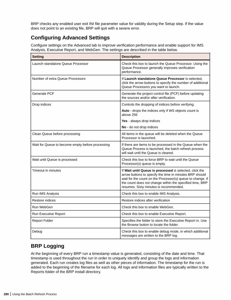
BRP checks any enabled user exit INI file parameter value for validity during the Setup step. If the valuedoes not point to an existing file, BRP will quit with a severe error.
Configuring Advanced SettingsConfigure settings on the Advanced tab to improve verification performance and enable support for IMSAnalysis, Executive Report, and WebGen. The settings are described in the table below.
Setting Description
Launch standalone Queue Processor Check this box to launch the Queue Processor. Using theQueue Processor generally improves verificationperformance.
Number of extra Queue Processors If Launch standalone Queue Processor is selected,click the arrow buttons to specify the number of additionalQueue Processors you want to launch.
Generate PCF Generate the project control file (PCF) before updatingthe sources and/or after verification.
Drop indices Controls the dropping of indices before verifying.
Auto - drops the indices only if WS objects count isabove 256
Yes - always drop indices
No - do not drop indices
Clean Queue before processing All items in the queue will be deleted when the QueueProcessor is launched.
Wait for Queue to become empty before processing If there are items to be processed in the Queue when theQueue Process is launched, the batch refresh processwill wait until the Queue is cleared.
Wait until Queue is processed Check this box to force BRP to wait until the QueueProcessor(s) queue is empty.
Timeout in minutes If Wait until Queue is processed is selected, click thearrow buttons to specify the time in minutes BRP shouldwait for the count on the Processor(s) queue to change. Ifthe count does not change within the specified time, BRPresumes. Sixty minutes is recommended.
Run IMS Analysis Check this box to enable IMS Analysis.
Restore indices Restore indices after verification
Run WebGen Check this box to enable WebGen.
Run Executive Report Check this box to enable Executive Report.
Report Folder Specifies the folder to store the Executive Report in. Usethe Browse button to locate the folder.
Debug Check this box to enable debug mode, in which additionalmessages are written to the BRP log.
BRP LoggingAt the beginning of every BRP run a timestamp value is generated, consisting of the date and time. Thattimestamp is used throughout the run in order to uniquely identify and group the logs and informationgenerated. Each run creates log files as well as other pieces of information. The timestamp for the run isadded to the beginning of the filename for each log. All logs and information files are typically written to theReports folder of the BRP install directory.
280 | Using the Batch Refresh Process
The main BRP log is, by default, named BRP log.txt, although the name can be altered by changing thecommand that is found in the runBRP.bat file in the BRP install directory. If more than one BRP installationis present, add the name of the workspace being refreshed to the main BRP log name.
The main BRP log contains basic information on when each major step of the run starts and finishes, aswell as any relevant summary or diagnostic information. This is the log to check to determine whether theBRP run completed successfully or not. A run to completion will result in the last message in the logindicating the process finished successfully. Log messages marked "ERROR" should be reviewed. Theseare problems that were encountered, but they are not bad enough to cause BRP to abend. Messagesmarked as "SEVERE" are issues encountered that required BRP to abend. These should be investigatedand corrected.
In addition to the main BRP log, the Update Log.txt and Verify Log.txt are also generated. These, as theirnames indicate, document the results of the update and verification steps respectively. The update logcontains an entry for each file that is added to the workspace, whether by virtue of being different (updated)or new (added). Files that are processed during update that have unknown file extensions will also bedocumented in this log. Files that are processed and rejected because they are not different from theversion in the workspace are not documented. The verification log lists the verification status of each filethat is processed during verification. Summary statistics appear at the end of the log.
The remainder of the logs and files that are generated during a BRP run are there to provide in-depthinformation for troubleshooting if there is a problem during the run. If there is a problem that requires theattention of support services, please be sure to include all the logs and files from a run. Sorting the filenames in the Reports directory by name will naturally group them together.
Preparing Files for Batch Refresh ProcessingOrganize your sources in folders in a structure that reflects your enterprise organization and place thosefolders under the prepared sources folder (…\Workspaces\BRP_ws\PreparedSources). The BRPprocess will not remove the folders after registering the files, allowing you to keep adding or changing filesin the structure.
Note: If your files have very long file names (248 characters for file name and 260 characters forabsolute path + file name), we recommend moving your BRP working folder closer to the rootdirectory. For example, move C:\Workspaces\BRP_Training\ to C:\BRP_Training\ or evenC:\BRP_T. This is especially applicable for files with nested folder structure as part of their filenames.
Enabling Parallel VerificationParallel verification typically improves verification performance for very large workspaces by using multipleexecution agents, called Queue Processor, to process source files concurrently. You can start any numberof Queue Processors on the local machine, remote machines, or some combination of local and remotemachines. You can run parallel verification online in the Enterprise Analyzer or in batch mode with theBatch Refresh Process (BRP).
Important: When you run parallel verification on more than one machine, you need to make sure thatworkspace and project verification options are set identically on each machine. The easiest way to dothis is to log in as the same Windows user on each machine. Alternatively, you can define a defaultoption set that is automatically assigned to every user in the environment who has not explicitlydefined a custom option set. See the related topics for more information on option sets.
You enable parallel verification in three steps:
• Select the parallel verification method and the minimum number of concurrent Queue Processors on theVerification > Parallel Verification tab of the Workspace Options.
• Start the Queue Processors on the local and/or remote machines. If you start fewer than the minimumnumber of Queue Processors specified on the Parallel Verification tab, the verification process starts theneeded Queue Processors automatically on the local machine.
Using the Batch Refresh Process | 281
• Verify the workspace online in the Enterprise Analyzer or in batch mode using the Batch RefreshProcess (BRP).
Note: Verification results are reported in the Activity Log History window. They are not reported in theActivity Log itself (for online verification) or BRP log files (for batch verification). You can also use aVerification Report to view the results.
Follow the instructions below to launch Queue Processors and to specify the type of work they perform.You can launch multiple Queue Processors on the same machine. Once the minimum number of QueueProcessors has been started, you can launch them at any point in the verification process.
1. In the Enterprise Analyzer Administration window, choose Administer > Launch Queue Processor.The Launch Queue Processor window opens.
2. In the Serve workspace combo box, specify the workspace to be processed.3. In the Processing Mode pane, select any combination of:
• Conversion to perform operations used to generate a Interactive Analysis construct model.• Verification to perform verification operations.• Code Search Query to perform Code Search searches in offline mode.
4. Select Produce Log File to generate a log file for parallel verification. The log file has a name of theform <workspace_name>HCC.<random_number>.log and is stored at the same level as the workspace(.rwp) file.
5. Click OK. The product launches the Queue Processor. Click the button on the Windows toolbar toview the Queue Processor window.
Note: Once verification has started, you can change the processing mode for a Queue Processorsby selecting the appropriate choice in the Processing menu in the Queue Processor window.
Executing the Batch Refresh ProcessThe BRP Configurator creates a runBRP.bat file and saves it to the location specified in the BRP InstallPath configuration option. Executing this batch file will start a BRP run.
The batch file executes the runBRP.exe executable file with appropriate parameters. The command formatis as follows:
runBRP.exe <INI file> <log file>
where INI file is the path to the BRP initialization file and log file is a path to the main BRP log file.
Note: The workspace is locked while BRP runs. It cannot be accessed by users. In the event of BRPfailure, you can unlock the workspace by choosing Administer > Unlock Workspace in theAdministration tool.
A full BRP run will produce several detailed log files in addition to the main BRP log. These detail files willalways be written to the Reports folder. The main BRP log also is written to the Reports folder by default.
Note: Running multiple BRP processes simultaneously on the same workspace is not supported.
Adding Source File ExtensionsIt is recommended that source files coming into BRP have proper file extensions already in place. In somecases, however, this is not possible and BRP can add them if needed. There is no need to configureinitialization file parameters to use the functionality.
To have BRP add the file extensions, you must separate the sources, by type, into separate folders in thePreparedSources directory. Each folder must be named for the source type it contains and the source typename must correspond to EA source type names.
EA source type names can be determined by examining the folder names found in the Sources folder of aworkspace directory. If the workspace already contains a source of a particular type, there will be a folder
282 | Using the Batch Refresh Process
in the Sources directory corresponding to that source type. For example, Cobol files are found in the Cobolfolder. The precise file extension that is added for any particular source type is determined by theconfiguration of the Registration Extensions tab in the target workspace's workspace options. The firstdefined file extension for each source type will be the extension that is added by BRP. For example, CobolFile has three default file extensions listed: .cbl, .cob, and .ccp. Since .cbl is listed first, that is the extensionused by BRP. The order that these values appear in the workspace options can be changed by removingextensions and adding them back in.
Note that file extensions are added onto the file without regard for any currently existing file extension if thisfunctionality is used. For example, if the files in a folder named Cobol currently have a .txt extension (whichis commonly added by some mainframe FTP applications), each file would end up having an extensionlike .txt.cbl. Various source file naming conventions include multiple "dots" in the source name. Since thisscenario is unpredictable and varies widely, it is risky and impractical to have BRP strip any possibleexisting file extensions.
If there is a mix of sources with and without file extensions, BRP can handle this. Any files with properextensions should be placed in the PreparedSources directory directly, as normal. Any files that needextensions should be dealt with as described above.
BRP LoggingAt the beginning of every BRP run a timestamp value is generated, consisting of the date and time. Thattimestamp is used throughout the run in order to uniquely identify and group the logs and informationgenerated. Each run creates log files as well as other pieces of information. The timestamp for the run isadded to the beginning of the filename for each log. All logs and information files are typically written to theReports folder of the BRP install directory.
The main BRP log is, by default, named BRP log.txt, although the name can be altered by changing thecommand that is found in the runBRP.bat file in the BRP install directory. If more than one BRP installationis present, add the name of the workspace being refreshed to the main BRP log name.
The main BRP log contains basic information on when each major step of the run starts and finishes, aswell as any relevant summary or diagnostic information. This is the log to check to determine whether theBRP run completed successfully or not. A run to completion will result in the last message in the logindicating the process finished successfully. Log messages marked "ERROR" should be reviewed. Theseare problems that were encountered, but they are not bad enough to cause BRP to abend. Messagesmarked as "SEVERE" are issues encountered that required BRP to abend. These should be investigatedand corrected.
In addition to the main BRP log, the Update Log.txt and Verify Log.txt are also generated. These, as theirnames indicate, document the results of the update and verification steps respectively. The update logcontains an entry for each file that is added to the workspace, whether by virtue of being different (updated)or new (added). Files that are processed during update that have unknown file extensions will also bedocumented in this log. Files that are processed and rejected because they are not different from theversion in the workspace are not documented. The verification log lists the verification status of each filethat is processed during verification. Summary statistics appear at the end of the log.
The remainder of the logs and files that are generated during a BRP run are there to provide in-depthinformation for troubleshooting if there is a problem during the run. If there is a problem that requires theattention of support services, please be sure to include all the logs and files from a run. Sorting the filenames in the Reports directory by name will naturally group them together.
Producing Utilities for BRPThe following are guidelines for producing utilities for BRP. These guidelines apply for any utility. Currentlythese utilities are normally written by support services and partners.
Using the Batch Refresh Process | 283
VersioningEach utility needs a version number. The version number should be the date of the last modification madeto the utility, formatted as follows:
yyyymmdd
The version number must appear in the first line of the log file that the utility produces.
LoggingLog files are often the only way to get reliable data. The task of analyzing output can become easier whenthe log files are used and recording appropriate levels of output.
At a minimum log files need to contain:
• Utility name• Utility version• Parameter names and values• Record of files modified/written (when appropriate)• Record of individual changes made to modified files (when appropriate)
The log message format should be as follows:
hh:mm:ss<tab>message type<tab>message
Message types can include INFO, WARN, ERROR, SEVERE, or DEBUG. These are generally self-explanatory, but SEVERE should not be used unless there is an abend (in Perl the die() command). Addnew message types if the situation calls for it. For example, BRP has a SETUP message type.
Source, Executable, and CFG FilesUtilities are produced by support services and partners and are delivered as a compiled executable withdocumentation and, if necessary, a CFG file.
Guidelines for BRP UtilitiesThis section focuses on guidelines for utilities that need to be "enabled" for BRP. The only difference iswhere input is coming from, output is going to, and how parameters are provided.
BRP and Non-BRP ModesIn general, any utility created for BRP should also be able to be run in a standalone manner; that is, itshould run outside of and separate from BRP as well. Typically this means getting parameters from a CFGfile. This is already being done for all pre-processing type utilities right now. There are occasional situationswhere this is not practical. The utility needs to be able to determine whether it is being executed in a BRPcontext or not. If the stand-alone mode requires a CFG file, the absence of a CFG file parameter can serveas a trigger for BRP-mode execution. Where this will not work, the first parameter of the utility should be"BRP" to trigger BRP-mode execution.
Using User ExitsThere are several user exit points in BRP. At different user exits potential input files are in different placesand output requirements are different as well. Knowing which user exit a utility is going to be run from iscrucial. It is recommended that support services be consulted regarding which user exit to employ for aparticular task. The majority of user exit utilities are source code pre-processors and all use the Updateuser exit.
284 | Using the Batch Refresh Process
Parameter DataParameter data typically comes from any of three general sources: command line, CFG file, or DOSenvironment variables. The first two are straightforward. DOS environment variables are easily acquired bycapturing the output of the DOS set command with the following line of Perl code:
$dos_env_vars_str = `set`;
Note: The special characters preceding and following the word "set" are not single quote characters;they are "backtick" characters.
The parameter values that drive a BRP run are made available to a user exit via DOS environmentvariables. BRP generates a DOS batch file that contains commands to set DOS environment variables.The user exit command is added to the end of the generated batch file and the batch file is executed usingthe backtick operator in Perl. The backtick operator executes a DOS command (in BRP the path to a batchfile) in a shell "nested" inside of the shell of the BRP executable. The environment variables set up for auser exit only exist during the execution of that user exit. The environment variable commands are re-generated and run for each user exit.
In general, the format of parameter names and values should be standardized. BRP job parameters are ofthe form:
Parameter Name = Parameter Value
DOS environment variables and CFG file parameters are formatted in the same way. Command lineparameters should follow the same standard. In general, command line parameters need to override thesame named parameter from a CFG file or DOS environment. This allows a way to alter behavior in caseswhere the user may not have direct control over all the values.
LoggingIn addition to the general logging guidelines, the name of the log file and where it is written need to beaddressed in BRP-mode utilities.
The log file name pattern is:
(timestamp)UtilityName Log.txt
where UtilityName is obvious and timestamp is a BRP environment parameter (BRP_TIMESTAMP) thatidentifies all logs for a BRP run.
Input/OutputInput and output locations will change depending on what files are needed and which user exit the utility isrun from. Most utilities (source code pre-processing) will be running from the Update user exit.
The sources coming into the BRP process will be in the following path:
BRP_STAGINGDIR\BRP_TIMESTAMP
where BRP_STAGINGDIR is a full path referring to the Staging folder of a BRP install andBRP_TIMESTAMP holds the timestamp value for the current BRP run.
Output sources must be written back to this same location. However, to maintain integrity should the user-exit utility fail or otherwise not finish, it is recommended that output sources be written to the BRP Workingfolder (BRP_WORKINGDIR) and only when processing is completed should they then be copied back tothe proper output location. A subfolder should be created in the Working folder for this purpose using thefollowing format:
timestamp_UtilityName
This naming convention is required.
Using the Batch Refresh Process | 285
Returning ValuesBRP determines the return state of a user exit by examining all the output written to the "console"(STDOUT in Perl terminology) by the commands executed by the user exit. The examination is done afterthe user exit completes execution and control returns back to the BRP run. If there is no output BRPassumes the user exit commands completed successfully. If there is any output found BRP assumes therewas a SEVERE level error and will immediately stop the run.
BRP will include any output it finds in a SEVERE level message in the main BRP log. Any user exitexecuted utility should be sure to make effective use of this behavior. User exits do not have anyknowledge of what commands or utilities they are executing. Therefore a message written to the consoleshould contain the utility or command name along with an appropriately brief message. The details behinda utility failure can be included in the utility's own log.
BRP Environment ParametersBRP parameter values are split into two groups. Ones prefixed with "BRP_" are for BRP specific values.Those prefixed with "EXT_" are for source file extension definitions. The tables below list all variables thatare set by BRP for use by user exits along with a short description. Any path value will be fully qualifiedunless otherwise noted.
The following parameter uniquely identifies a BRP run.
Name Description
BRP_TIMESTAMP Timestamp value that uniquely identifies a BRP run andthe logs that are generated during that run.
The following parameters are the paths to log files from BRP runs. Note that all the references to specificjobs are default settings only. There are very few cases where these exact jobs will not be used, but theydo exist.
Name Description
BRP_APPLYOBSOLETEPCFLOGFILE Log from ApplyPCF.bj job for applying theBRP_OBSOLETEPCF file.
BRP_BWGLOGFILE Log from BWG.exe (Batch WebGen).
BRP_CREATEBEGINPCFLOGFILE Log from CreatePCF.bj job. This is run at the beginning ofthe BRP run and creates the file BRP_BEGINPCF.
BRP_CREATEENDPCFLOGFILE Log from CreatePCF.bj job. This is run just beforeverification and creates the file BRP_ENDPCF.
BRP_EXECREPORTLOGFILE Log for the ExecutiveReport.bj job.
BRP_GETEXTLOGFILE Log for the GetExtensions2.mbu job. This is run at thebeginning of the BRP and creates the fileBRP_FILEEXTFILE. See the section below on extensionvalues for more information.
BRP_IMSANALYSISLOGFILE Log for the IMS Analysis.bj job.
BRP_UPDATELOGFILE Log for the UpdateOnly.bj job.
BRP_VERIFYLOGFILE Log for the VerifyOnly2.bj job.
The following parameters are for the various PCF files that are generated and used during a BRP run.
Name Description
BRP_BEGINPCF Generated at the beginning of a BRP run. Used for manypurposes in BRP including determining obsolete sources.
286 | Using the Batch Refresh Process
Name Description
BRP_ENDPCF Generated toward the end of a BRP run, after theBRP_OBSOLETEPCF is applied and before verification.
BRP_OBSOLETEPCF Generated during a Master BRP run ifBRP_OBSOLETEPROCESSING is set to 1. This will shiftsources missing from the current incoming set of files tothe project specified in BRP_OBSOLETEPROJECT.
The following parameters are data files that BRP uses, flags that turn certain processing on or off, BRPinstall folders, and other various values.
Name Description
BRP_DROPIND Flag (1/0) that drops database indexes to improveverification and IMS Analysis performance.
BRP_LAUNCHHCC Flag (1/0) that launches the Queue Processor to improveverification performance.
BRP_WAITHCC Time in minutes to wait for Queue Processor to respond.
BRP_BRPLOGFILE Main log file for a BRP run.
BRP_BRPINSTALLPATH Path where BRP is installed. This is specified in the BRPinitialization file. BRP will derive the path values for thesix BRP folders (PreparedSources, Reports, Staging,Utilities, and Working) based off this path if they are notspecified in the initialization file.
BRP_PREPAREDSOURCESDIR Path where sources coming into BRP start off. In caseswhere a utility is in place to handle getting the sources offa server or mainframe this is the location where thosesources are copied to.
BRP_REPORTDIR Path to the folder where all log files are written to. Otherresource files created during a BRP run are also writtenhere including all PCF files, file extension data file and allgenerated user exit batch files.
BRP_RMWINSTALLPATH Path to the install folder for EA.
BRP_STAGINGDIR Folder where sources reside for updating to theworkspace. Sources will actually be in a subfolder that isnamed with the BRP timestamp and not the Stagingfolder directly. This is also where the majority of sourcepre-processing utilities will look for inputs and writeoutputs.
BRP_UTILITIESDIR Path to directory that contains all the executables theBRP will need along with extra resource files and thestatic user exit batch files.
BRP_WORKINGDIR Folder user exit utilities should use for any work theyneed to perform.
BRP_WORKSPACEDIR Path to the target workspace.
BRP_FILEEXTFILE File containing the file extension definitions for the targetworkspace.
BRP_LASTRUNFILE Text file containing the timestamp of the last BRP run thatcompleted execution.
BRP_OBSOLETEEXCLUSIONSFILE File that lists any files that should be excluded fromobsolete processing. Typically this includes files
Using the Batch Refresh Process | 287
Name Description
generated by EA (ex. DASDL copybooks), but is oftenused for client-specific sources as well.
BRP_BRPRUNTYPE Must be set to "Master".
BRP_DEBUG Flag (1/0) that will increase the amount of messagingwritten to the main BRP log. Typically this is always set to1.
BRP_LASTRUNTIMESTAMP The timestamp value of the last BRP run that completedexecution.
BRP_OBSOLETEPROCESSING Flag (1/0) that turns obsolete processing on or off. Whenit is turned on the incoming set of files will be comparedagainst the set of file currently in the target workspace.Any files currently in the workspace, but not in theincoming set of files will be moved to an obsolete project(named in the BRP_OBSOLETEPROJECT parameter).
BRP_OBSOLETEPROJECT Name of a project where obsolete sources will be movedto.
BRP_SITE Documentation parameter that is set in the BRPinitialization file. The value here will be written to thebeginning of the main BRP log file. It is used mainly forsupport purposes to ensure that initialization and log filesproduced by a client match up.
The following parameters contain the command that will be executed by BRP. Typically this will specify astatic DOS batch file (as opposed to the generated batch file BRP generates for each user exit). The staticbatch file is used so that multiple commands can be executed in a single user exit. These parameters willonly exist if the user exit is being used. Below is a complete list of all user exit parameters, but it will be rareto see them all at once. They are listed in the order they would be executed in a BRP run. There is oneuser exit for each major step of the BRP. They always are the first task that is done in each step.
Name Description
BRP_USEREXIT_SETUP
BRP_USEREXIT_INIT
BRP_USEREXIT_STAGING
BRP_USEREXIT_UPDATE
BRP_USEREXIT_VERIFICATION
BRP_USEREXIT_GENERATION
BRP_USEREXIT_END
The following parameters contain information on the source file extensions that are valid for each legacyfile type for the target workspace. The exact parameters that will be here depend upon what options areactivated for the target workspace.
Name Description
Parameter Names The general format of the parameter names is EXT_type,where type is the name of the corresponding directory inthe workspace Sources folder. Note that in the past thisname is not necessarily the same as the type namefound in a PCF file. For example, PL/I included sourcesare contained in the Sources folder PLIInclude, but thatsource type is named "PLINC" in PCF files.
288 | Using the Batch Refresh Process
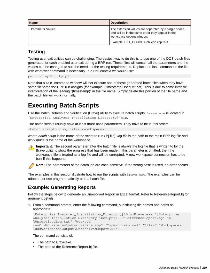
Name Description
Parameter Values The extension values are separated by a single spaceand will be in the same order they appear in theworkspace options window.
Example: EXT_COBOL = cbl cob ccp C74
TestingTesting user exit utilities can be challenging. The easiest way to do this is to use one of the DOS batch filesgenerated for each enabled user exit during a BRP run. These files will contain all the parameters and thevalues can be changed to suit the needs of the testing requirements. Replace the last command in the filewith whatever command is necessary. In a Perl context we would use:
perl -d myUtility.pl
Note that a DOS command window will not execute one of these generated batch files when they havesame filename the BRP run assigns (for example, (timestamp)UserExit.bat). This is due to some intrinsicinterpretation of the leading "(timestamp)" in the file name. Simply delete this portion of the file name andthe batch file will work normally.
Executing Batch ScriptsUse the Batch Refresh and Verification (Brave) utility to execute batch scripts. Brave.exe is located in[Enterprise Analyzer_Installation_Directory]\Bin.
The batch scripts usually have at least three base parameters. They have to be in this order:
<batch script> <log file> <workspace>
where batch script is the name of the script to run (.bj file), log file is the path to the main BRP log file andworkspace is the name of the workspace.
Important: The second parameter after the batch file is always the log file that is written to by theBrave utility to show the progress that has been made. If this parameter is omitted, then theworkspace file is treated as a log file and will be corrupted. A new workspace connection has to bebuilt if this happens.
Note: The parameters of the batch job are case-sensitive. If the wrong case is used, an error occurs.
The examples in this section illustrate how to run the scripts with Brave.exe. The examples can beadapted for use programmatically or in a batch file.
Example: Generating ReportsFollow the steps below to generate an Unresolved Report in Excel format. Refer to ReferenceReport.bj forargument details.
1. From a command prompt, enter the following command, substituting file names and paths asappropriate:
[Enterprise Analyzer_Installation_Directory]\Bin>Brave.exe "[Enterprise Analyzer_Installation_Directory]\Scripts\BRP\ReferenceReport.bj" "C:\UnresolvedLog.txt" "Workspace=C:\Workspaces\sdkworkspace.rwp" "Type=Unresolved" "File=C:\Workspaces\sdkworkspace\Output\UnresolvedReport.xls"
The command consists of:
• The path to Brave.exe.• The path to the ReferenceReport.bj file.
Using the Batch Refresh Process | 289
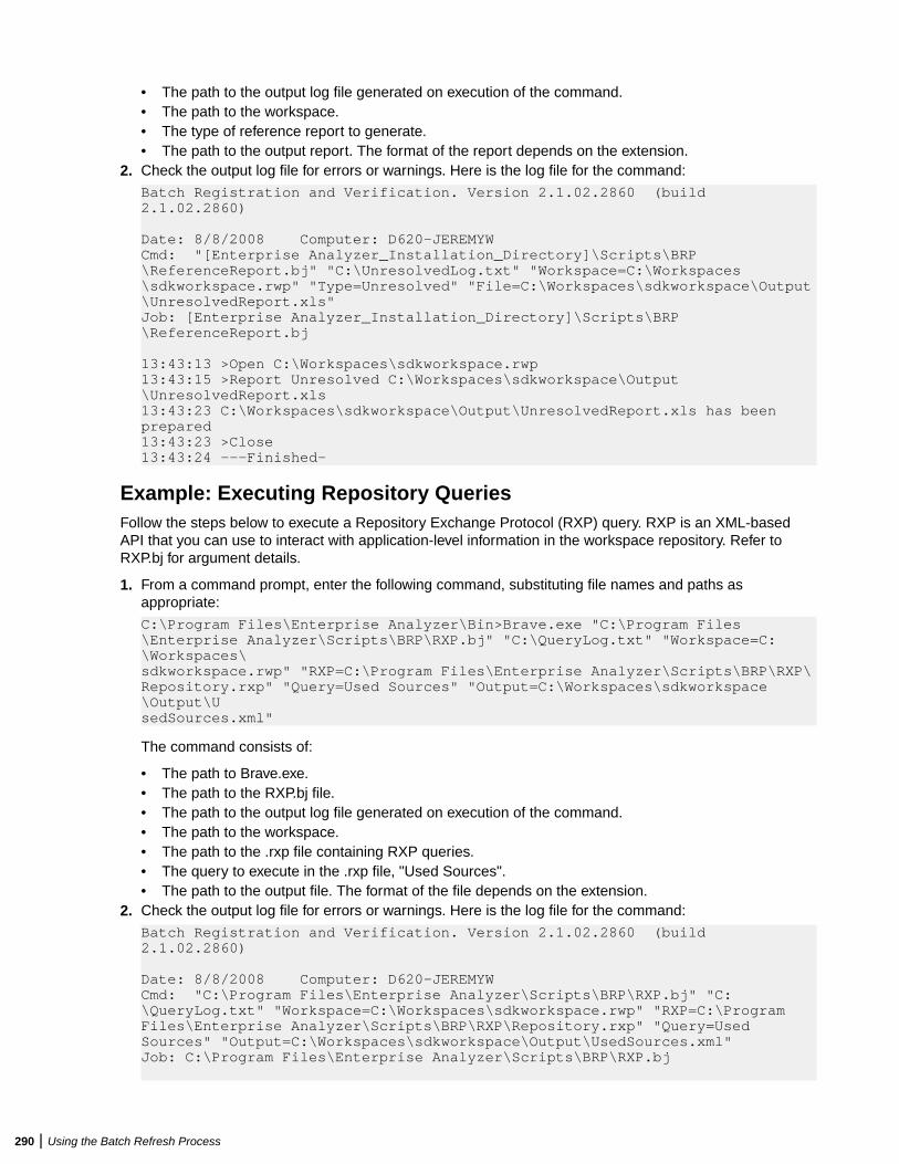
• The path to the output log file generated on execution of the command.• The path to the workspace.• The type of reference report to generate.• The path to the output report. The format of the report depends on the extension.
2. Check the output log file for errors or warnings. Here is the log file for the command:
Batch Registration and Verification. Version 2.1.02.2860 (build 2.1.02.2860)
Date: 8/8/2008 Computer: D620-JEREMYWCmd: "[Enterprise Analyzer_Installation_Directory]\Scripts\BRP\ReferenceReport.bj" "C:\UnresolvedLog.txt" "Workspace=C:\Workspaces\sdkworkspace.rwp" "Type=Unresolved" "File=C:\Workspaces\sdkworkspace\Output\UnresolvedReport.xls"Job: [Enterprise Analyzer_Installation_Directory]\Scripts\BRP\ReferenceReport.bj
13:43:13 >Open C:\Workspaces\sdkworkspace.rwp13:43:15 >Report Unresolved C:\Workspaces\sdkworkspace\Output\UnresolvedReport.xls13:43:23 C:\Workspaces\sdkworkspace\Output\UnresolvedReport.xls has been prepared13:43:23 >Close13:43:24 ---Finished—
Example: Executing Repository QueriesFollow the steps below to execute a Repository Exchange Protocol (RXP) query. RXP is an XML-basedAPI that you can use to interact with application-level information in the workspace repository. Refer toRXP.bj for argument details.
1. From a command prompt, enter the following command, substituting file names and paths asappropriate:
C:\Program Files\Enterprise Analyzer\Bin>Brave.exe "C:\Program Files\Enterprise Analyzer\Scripts\BRP\RXP.bj" "C:\QueryLog.txt" "Workspace=C:\Workspaces\sdkworkspace.rwp" "RXP=C:\Program Files\Enterprise Analyzer\Scripts\BRP\RXP\Repository.rxp" "Query=Used Sources" "Output=C:\Workspaces\sdkworkspace\Output\UsedSources.xml"
The command consists of:
• The path to Brave.exe.• The path to the RXP.bj file.• The path to the output log file generated on execution of the command.• The path to the workspace.• The path to the .rxp file containing RXP queries.• The query to execute in the .rxp file, "Used Sources".• The path to the output file. The format of the file depends on the extension.
2. Check the output log file for errors or warnings. Here is the log file for the command:
Batch Registration and Verification. Version 2.1.02.2860 (build 2.1.02.2860)
Date: 8/8/2008 Computer: D620-JEREMYWCmd: "C:\Program Files\Enterprise Analyzer\Scripts\BRP\RXP.bj" "C:\QueryLog.txt" "Workspace=C:\Workspaces\sdkworkspace.rwp" "RXP=C:\Program Files\Enterprise Analyzer\Scripts\BRP\RXP\Repository.rxp" "Query=Used Sources" "Output=C:\Workspaces\sdkworkspace\Output\UsedSources.xml"Job: C:\Program Files\Enterprise Analyzer\Scripts\BRP\RXP.bj
290 | Using the Batch Refresh Process
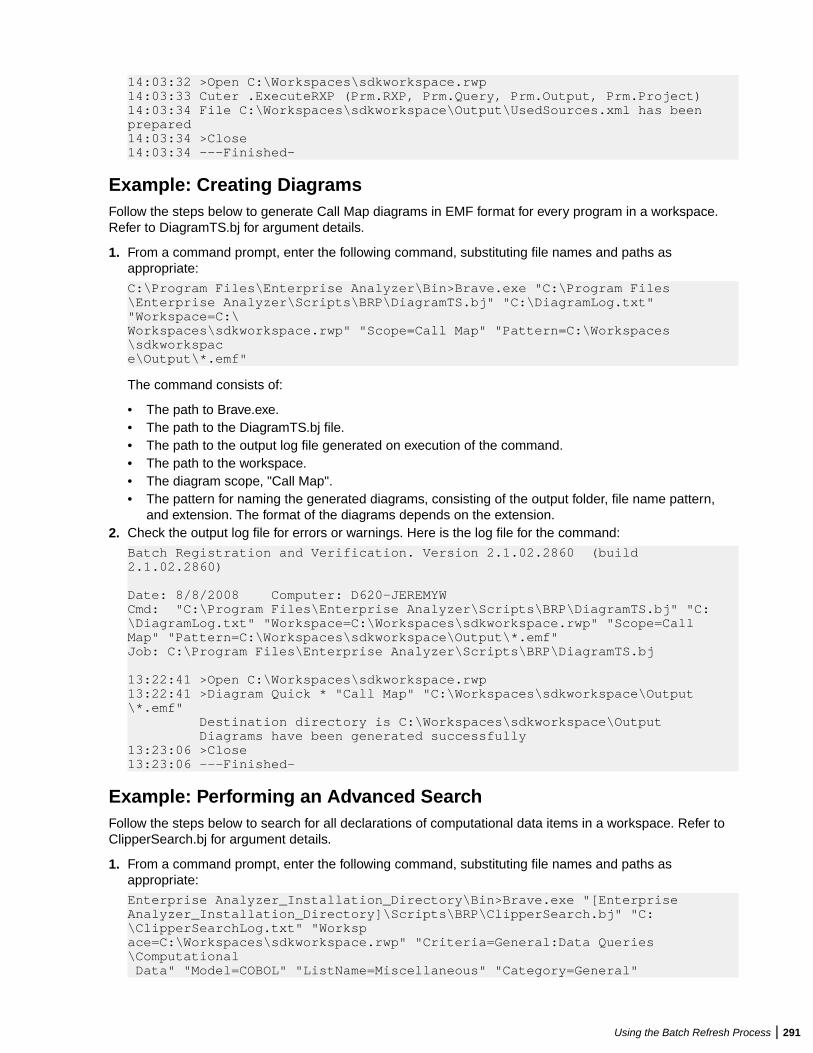
14:03:32 >Open C:\Workspaces\sdkworkspace.rwp14:03:33 Cuter .ExecuteRXP (Prm.RXP, Prm.Query, Prm.Output, Prm.Project)14:03:34 File C:\Workspaces\sdkworkspace\Output\UsedSources.xml has been prepared14:03:34 >Close14:03:34 ---Finished—
Example: Creating DiagramsFollow the steps below to generate Call Map diagrams in EMF format for every program in a workspace.Refer to DiagramTS.bj for argument details.
1. From a command prompt, enter the following command, substituting file names and paths asappropriate:
C:\Program Files\Enterprise Analyzer\Bin>Brave.exe "C:\Program Files\Enterprise Analyzer\Scripts\BRP\DiagramTS.bj" "C:\DiagramLog.txt" "Workspace=C:\Workspaces\sdkworkspace.rwp" "Scope=Call Map" "Pattern=C:\Workspaces\sdkworkspace\Output\*.emf"
The command consists of:
• The path to Brave.exe.• The path to the DiagramTS.bj file.• The path to the output log file generated on execution of the command.• The path to the workspace.• The diagram scope, "Call Map".• The pattern for naming the generated diagrams, consisting of the output folder, file name pattern,
and extension. The format of the diagrams depends on the extension.2. Check the output log file for errors or warnings. Here is the log file for the command:
Batch Registration and Verification. Version 2.1.02.2860 (build 2.1.02.2860)
Date: 8/8/2008 Computer: D620-JEREMYWCmd: "C:\Program Files\Enterprise Analyzer\Scripts\BRP\DiagramTS.bj" "C:\DiagramLog.txt" "Workspace=C:\Workspaces\sdkworkspace.rwp" "Scope=Call Map" "Pattern=C:\Workspaces\sdkworkspace\Output\*.emf"Job: C:\Program Files\Enterprise Analyzer\Scripts\BRP\DiagramTS.bj
13:22:41 >Open C:\Workspaces\sdkworkspace.rwp13:22:41 >Diagram Quick * "Call Map" "C:\Workspaces\sdkworkspace\Output\*.emf" Destination directory is C:\Workspaces\sdkworkspace\Output Diagrams have been generated successfully13:23:06 >Close13:23:06 ---Finished—
Example: Performing an Advanced SearchFollow the steps below to search for all declarations of computational data items in a workspace. Refer toClipperSearch.bj for argument details.
1. From a command prompt, enter the following command, substituting file names and paths asappropriate:
Enterprise Analyzer_Installation_Directory\Bin>Brave.exe "[Enterprise Analyzer_Installation_Directory]\Scripts\BRP\ClipperSearch.bj" "C:\ClipperSearchLog.txt" "Workspace=C:\Workspaces\sdkworkspace.rwp" "Criteria=General:Data Queries\Computational Data" "Model=COBOL" "ListName=Miscellaneous" "Category=General"
Using the Batch Refresh Process | 291
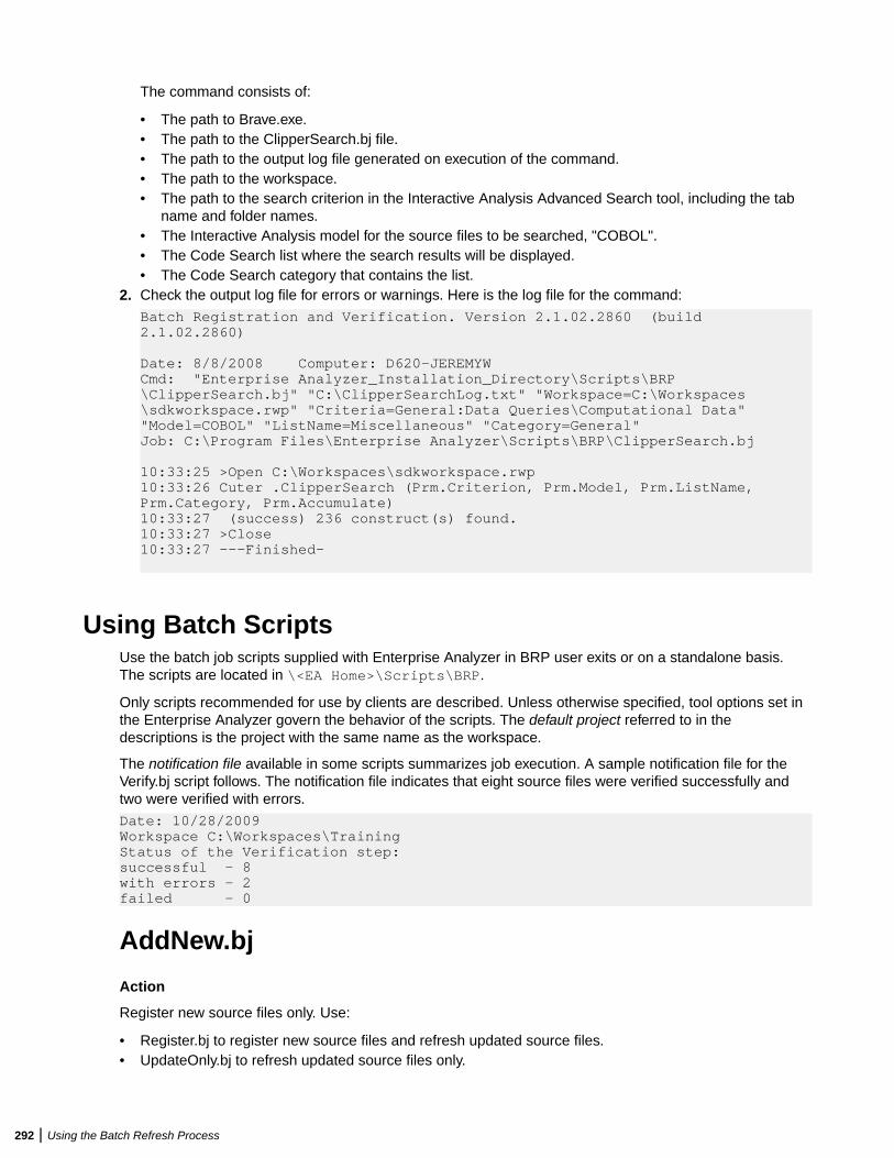
The command consists of:
• The path to Brave.exe.• The path to the ClipperSearch.bj file.• The path to the output log file generated on execution of the command.• The path to the workspace.• The path to the search criterion in the Interactive Analysis Advanced Search tool, including the tab
name and folder names.• The Interactive Analysis model for the source files to be searched, "COBOL".• The Code Search list where the search results will be displayed.• The Code Search category that contains the list.
2. Check the output log file for errors or warnings. Here is the log file for the command:
Batch Registration and Verification. Version 2.1.02.2860 (build 2.1.02.2860)
Date: 8/8/2008 Computer: D620-JEREMYWCmd: "Enterprise Analyzer_Installation_Directory\Scripts\BRP\ClipperSearch.bj" "C:\ClipperSearchLog.txt" "Workspace=C:\Workspaces\sdkworkspace.rwp" "Criteria=General:Data Queries\Computational Data" "Model=COBOL" "ListName=Miscellaneous" "Category=General"Job: C:\Program Files\Enterprise Analyzer\Scripts\BRP\ClipperSearch.bj
10:33:25 >Open C:\Workspaces\sdkworkspace.rwp10:33:26 Cuter .ClipperSearch (Prm.Criterion, Prm.Model, Prm.ListName, Prm.Category, Prm.Accumulate)10:33:27 (success) 236 construct(s) found.10:33:27 >Close10:33:27 ---Finished—
Using Batch ScriptsUse the batch job scripts supplied with Enterprise Analyzer in BRP user exits or on a standalone basis.The scripts are located in \<EA Home>\Scripts\BRP.
Only scripts recommended for use by clients are described. Unless otherwise specified, tool options set inthe Enterprise Analyzer govern the behavior of the scripts. The default project referred to in thedescriptions is the project with the same name as the workspace.
The notification file available in some scripts summarizes job execution. A sample notification file for theVerify.bj script follows. The notification file indicates that eight source files were verified successfully andtwo were verified with errors.
Date: 10/28/2009Workspace C:\Workspaces\TrainingStatus of the Verification step: successful - 8with errors - 2failed - 0
AddNew.bj
Action
Register new source files only. Use:
• Register.bj to register new source files and refresh updated source files.• UpdateOnly.bj to refresh updated source files only.
292 | Using the Batch Refresh Process
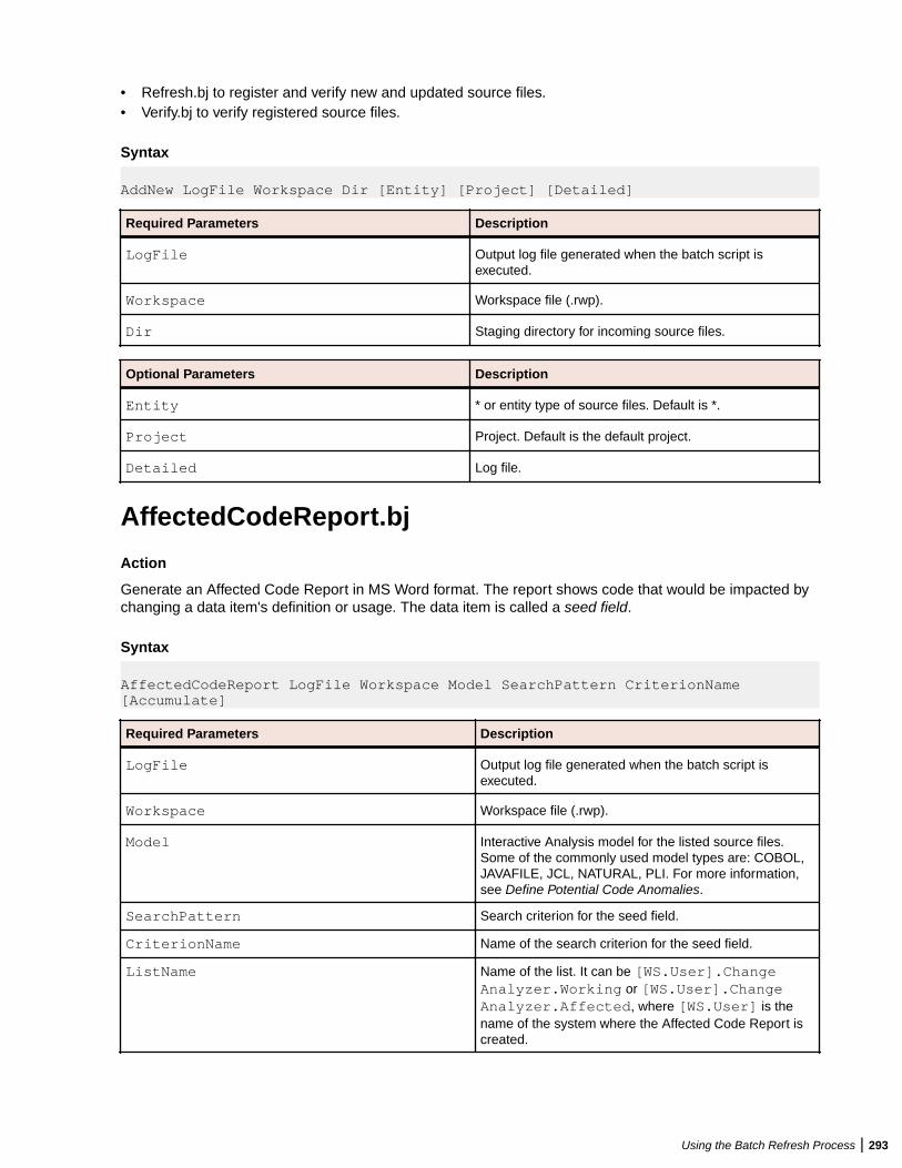
• Refresh.bj to register and verify new and updated source files.• Verify.bj to verify registered source files.
Syntax
AddNew LogFile Workspace Dir [Entity] [Project] [Detailed]
Required Parameters Description
LogFile Output log file generated when the batch script isexecuted.
Workspace Workspace file (.rwp).
Dir Staging directory for incoming source files.
Optional Parameters Description
Entity * or entity type of source files. Default is *.
Project Project. Default is the default project.
Detailed Log file.
AffectedCodeReport.bj
Action
Generate an Affected Code Report in MS Word format. The report shows code that would be impacted bychanging a data item's definition or usage. The data item is called a seed field.
Syntax
AffectedCodeReport LogFile Workspace Model SearchPattern CriterionName [Accumulate]
Required Parameters Description
LogFile Output log file generated when the batch script isexecuted.
Workspace Workspace file (.rwp).
Model Interactive Analysis model for the listed source files.Some of the commonly used model types are: COBOL,JAVAFILE, JCL, NATURAL, PLI. For more information,see Define Potential Code Anomalies.
SearchPattern Search criterion for the seed field.
CriterionName Name of the search criterion for the seed field.
ListName Name of the list. It can be [WS.User].ChangeAnalyzer.Working or [WS.User].ChangeAnalyzer.Affected, where [WS.User] is thename of the system where the Affected Code Report iscreated.
Using the Batch Refresh Process | 293
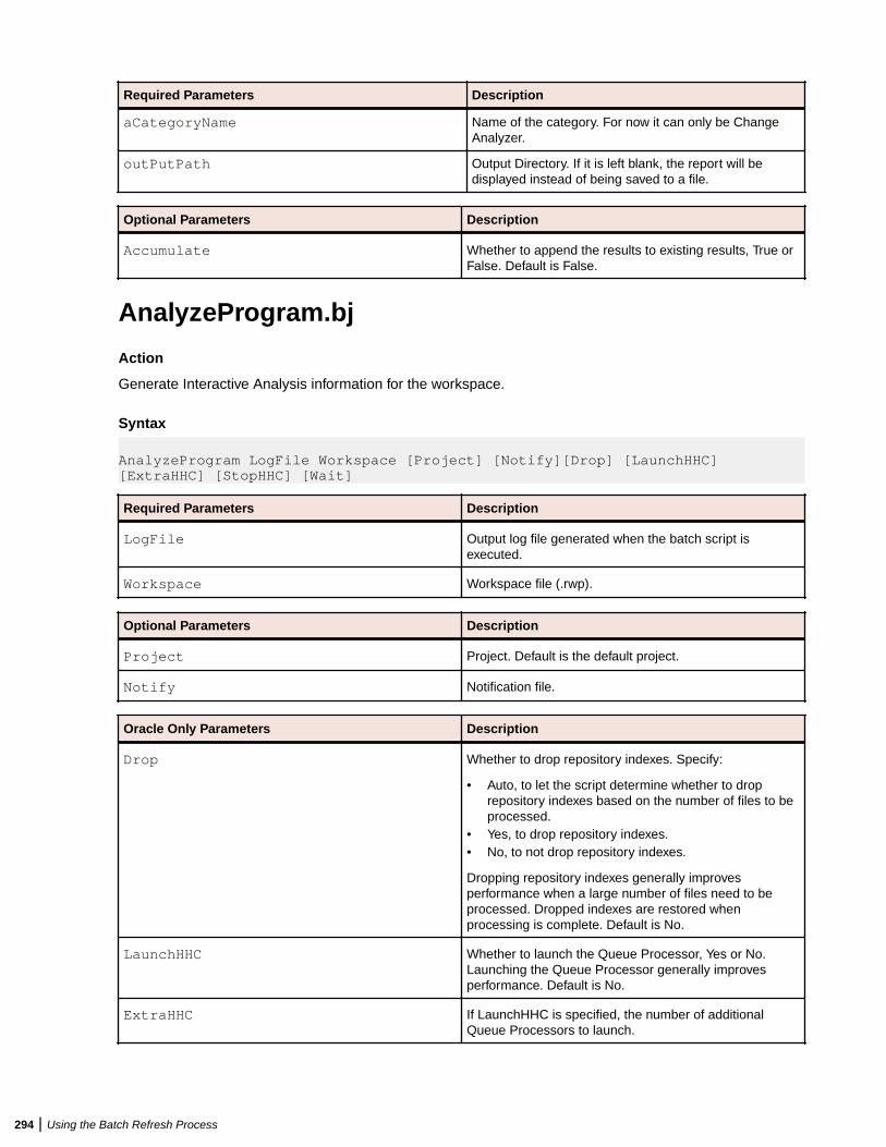
Required Parameters Description
aCategoryName Name of the category. For now it can only be ChangeAnalyzer.
outPutPath Output Directory. If it is left blank, the report will bedisplayed instead of being saved to a file.
Optional Parameters Description
Accumulate Whether to append the results to existing results, True orFalse. Default is False.
AnalyzeProgram.bj
Action
Generate Interactive Analysis information for the workspace.
Syntax
AnalyzeProgram LogFile Workspace [Project] [Notify][Drop] [LaunchHHC] [ExtraHHC] [StopHHC] [Wait]
Required Parameters Description
LogFile Output log file generated when the batch script isexecuted.
Workspace Workspace file (.rwp).
Optional Parameters Description
Project Project. Default is the default project.
Notify Notification file.
Oracle Only Parameters Description
Drop Whether to drop repository indexes. Specify:
• Auto, to let the script determine whether to droprepository indexes based on the number of files to beprocessed.
• Yes, to drop repository indexes.• No, to not drop repository indexes.
Dropping repository indexes generally improvesperformance when a large number of files need to beprocessed. Dropped indexes are restored whenprocessing is complete. Default is No.
LaunchHHC Whether to launch the Queue Processor, Yes or No.Launching the Queue Processor generally improvesperformance. Default is No.
ExtraHHC If LaunchHHC is specified, the number of additionalQueue Processors to launch.
294 | Using the Batch Refresh Process
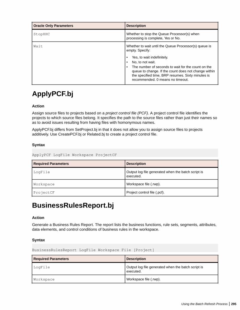
Oracle Only Parameters Description
StopHHC Whether to stop the Queue Processor(s) whenprocessing is complete, Yes or No.
Wait Whether to wait until the Queue Processor(s) queue isempty. Specify:
• Yes, to wait indefinitely.• No, to not wait.• The number of seconds to wait for the count on the
queue to change. If the count does not change withinthe specified time, BRP resumes. Sixty minutes isrecommended. 0 means no timeout.
ApplyPCF.bj
Action
Assign source files to projects based on a project control file (PCF). A project control file identifies theprojects to which source files belong. It specifies the path to the source files rather than just their names soas to avoid issues resulting from having files with homonymous names.
ApplyPCF.bj differs from SetProject.bj in that it does not allow you to assign source files to projectsadditively. Use CreatePCF.bj or Related.bj to create a project control file.
Syntax
ApplyPCF LogFile Workspace ProjectCF
Required Parameters Description
LogFile Output log file generated when the batch script isexecuted.
Workspace Workspace file (.rwp).
ProjectCF Project control file (.pcf).
BusinessRulesReport.bj
Action
Generate a Business Rules Report. The report lists the business functions, rule sets, segments, attributes,data elements, and control conditions of business rules in the workspace.
Syntax
BusinessRulesReport LogFile Workspace File [Project]
Required Parameters Description
LogFile Output log file generated when the batch script isexecuted.
Workspace Workspace file (.rwp).
Using the Batch Refresh Process | 295
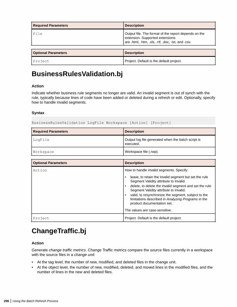
Required Parameters Description
File Output file. The format of the report depends on theextension. Supported extensionsare .html, .htm, .xls, .rtf, .doc, .txt, and .csv.
Optional Parameters Description
Project Project. Default is the default project.
BusinessRulesValidation.bj
Action
Indicate whether business rule segments no longer are valid. An invalid segment is out of synch with therule, typically because lines of code have been added or deleted during a refresh or edit. Optionally, specifyhow to handle invalid segments.
Syntax
BusinessRulesValidation LogFile Workspace [Action] [Project]
Required Parameters Description
LogFile Output log file generated when the batch script isexecuted.
Workspace Workspace file (.rwp).
Optional Parameters Description
Action How to handle invalid segments. Specify:
• leave, to retain the invalid segment but set the ruleSegment Validity attribute to Invalid.
• delete, to delete the invalid segment and set the ruleSegment Validity attribute to Invalid.
• valid, to resynchronize the segment, subject to thelimitations described in Analyzing Programs in theproduct documentation set.
The values are case-sensitive.
Project Project. Default is the default project.
ChangeTraffic.bj
Action
Generate change traffic metrics. Change Traffic metrics compare the source files currently in a workspacewith the source files in a change unit:
• At the tag level, the number of new, modified, and deleted files in the change unit.• At the object level, the number of new, modified, deleted, and moved lines in the modified files, and the
number of lines in the new and deleted files.
296 | Using the Batch Refresh Process
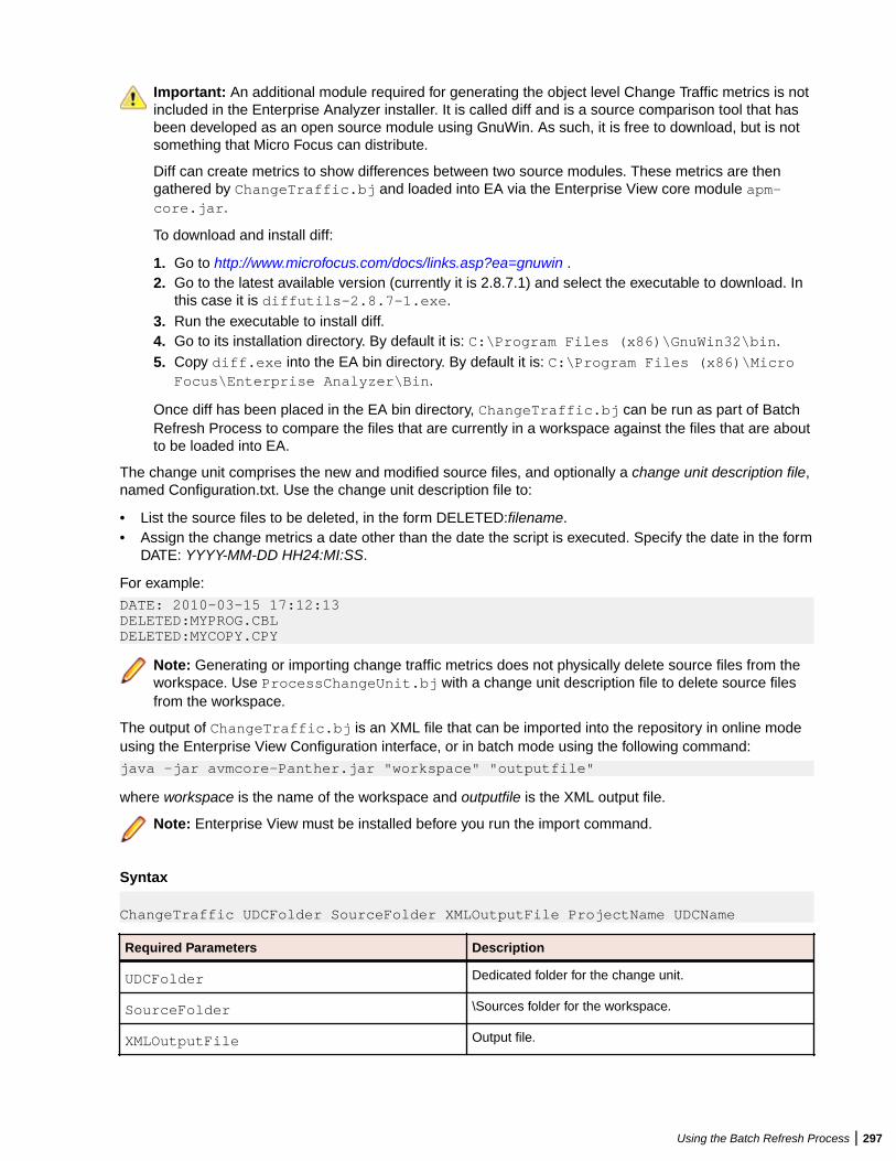
Important: An additional module required for generating the object level Change Traffic metrics is notincluded in the Enterprise Analyzer installer. It is called diff and is a source comparison tool that hasbeen developed as an open source module using GnuWin. As such, it is free to download, but is notsomething that Micro Focus can distribute.
Diff can create metrics to show differences between two source modules. These metrics are thengathered by ChangeTraffic.bj and loaded into EA via the Enterprise View core module apm-core.jar.
To download and install diff:
1. Go to http://www.microfocus.com/docs/links.asp?ea=gnuwin .2. Go to the latest available version (currently it is 2.8.7.1) and select the executable to download. In
this case it is diffutils-2.8.7-1.exe.3. Run the executable to install diff.4. Go to its installation directory. By default it is: C:\Program Files (x86)\GnuWin32\bin.5. Copy diff.exe into the EA bin directory. By default it is: C:\Program Files (x86)\Micro
Focus\Enterprise Analyzer\Bin.
Once diff has been placed in the EA bin directory, ChangeTraffic.bj can be run as part of BatchRefresh Process to compare the files that are currently in a workspace against the files that are aboutto be loaded into EA.
The change unit comprises the new and modified source files, and optionally a change unit description file,named Configuration.txt. Use the change unit description file to:
• List the source files to be deleted, in the form DELETED:filename.• Assign the change metrics a date other than the date the script is executed. Specify the date in the form
DATE: YYYY-MM-DD HH24:MI:SS.
For example:
DATE: 2010-03-15 17:12:13DELETED:MYPROG.CBLDELETED:MYCOPY.CPY
Note: Generating or importing change traffic metrics does not physically delete source files from theworkspace. Use ProcessChangeUnit.bj with a change unit description file to delete source filesfrom the workspace.
The output of ChangeTraffic.bj is an XML file that can be imported into the repository in online modeusing the Enterprise View Configuration interface, or in batch mode using the following command:
java -jar avmcore-Panther.jar "workspace" "outputfile"
where workspace is the name of the workspace and outputfile is the XML output file.
Note: Enterprise View must be installed before you run the import command.
Syntax
ChangeTraffic UDCFolder SourceFolder XMLOutputFile ProjectName UDCName
Required Parameters Description
UDCFolder Dedicated folder for the change unit.
SourceFolder \Sources folder for the workspace.
XMLOutputFile Output file.
Using the Batch Refresh Process | 297
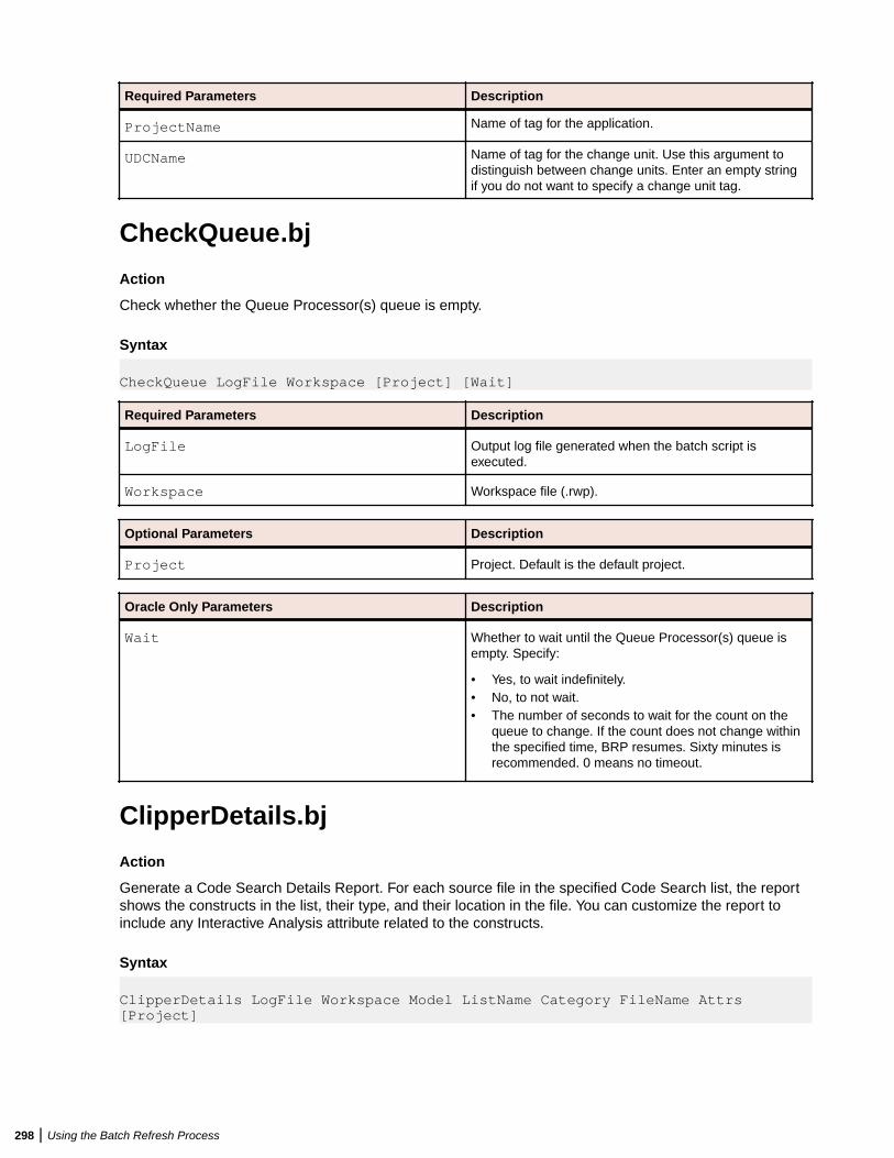
Required Parameters Description
ProjectName Name of tag for the application.
UDCName Name of tag for the change unit. Use this argument todistinguish between change units. Enter an empty stringif you do not want to specify a change unit tag.
CheckQueue.bj
Action
Check whether the Queue Processor(s) queue is empty.
Syntax
CheckQueue LogFile Workspace [Project] [Wait]
Required Parameters Description
LogFile Output log file generated when the batch script isexecuted.
Workspace Workspace file (.rwp).
Optional Parameters Description
Project Project. Default is the default project.
Oracle Only Parameters Description
Wait Whether to wait until the Queue Processor(s) queue isempty. Specify:
• Yes, to wait indefinitely.• No, to not wait.• The number of seconds to wait for the count on the
queue to change. If the count does not change withinthe specified time, BRP resumes. Sixty minutes isrecommended. 0 means no timeout.
ClipperDetails.bj
Action
Generate a Code Search Details Report. For each source file in the specified Code Search list, the reportshows the constructs in the list, their type, and their location in the file. You can customize the report toinclude any Interactive Analysis attribute related to the constructs.
Syntax
ClipperDetails LogFile Workspace Model ListName Category FileName Attrs [Project]
298 | Using the Batch Refresh Process
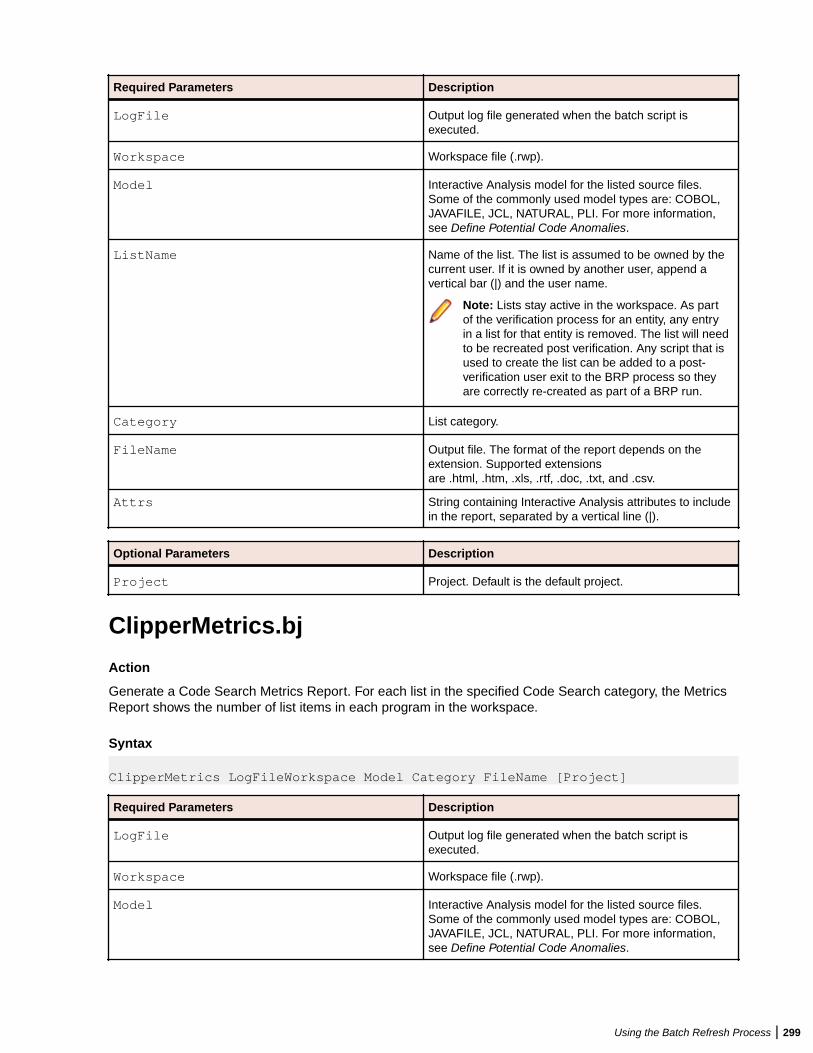
Required Parameters Description
LogFile Output log file generated when the batch script isexecuted.
Workspace Workspace file (.rwp).
Model Interactive Analysis model for the listed source files.Some of the commonly used model types are: COBOL,JAVAFILE, JCL, NATURAL, PLI. For more information,see Define Potential Code Anomalies.
ListName Name of the list. The list is assumed to be owned by thecurrent user. If it is owned by another user, append avertical bar (|) and the user name.
Note: Lists stay active in the workspace. As partof the verification process for an entity, any entryin a list for that entity is removed. The list will needto be recreated post verification. Any script that isused to create the list can be added to a post-verification user exit to the BRP process so theyare correctly re-created as part of a BRP run.
Category List category.
FileName Output file. The format of the report depends on theextension. Supported extensionsare .html, .htm, .xls, .rtf, .doc, .txt, and .csv.
Attrs String containing Interactive Analysis attributes to includein the report, separated by a vertical line (|).
Optional Parameters Description
Project Project. Default is the default project.
ClipperMetrics.bj
Action
Generate a Code Search Metrics Report. For each list in the specified Code Search category, the MetricsReport shows the number of list items in each program in the workspace.
Syntax ClipperMetrics LogFileWorkspace Model Category FileName [Project]
Required Parameters Description
LogFile Output log file generated when the batch script isexecuted.
Workspace Workspace file (.rwp).
Model Interactive Analysis model for the listed source files.Some of the commonly used model types are: COBOL,JAVAFILE, JCL, NATURAL, PLI. For more information,see Define Potential Code Anomalies.
Using the Batch Refresh Process | 299
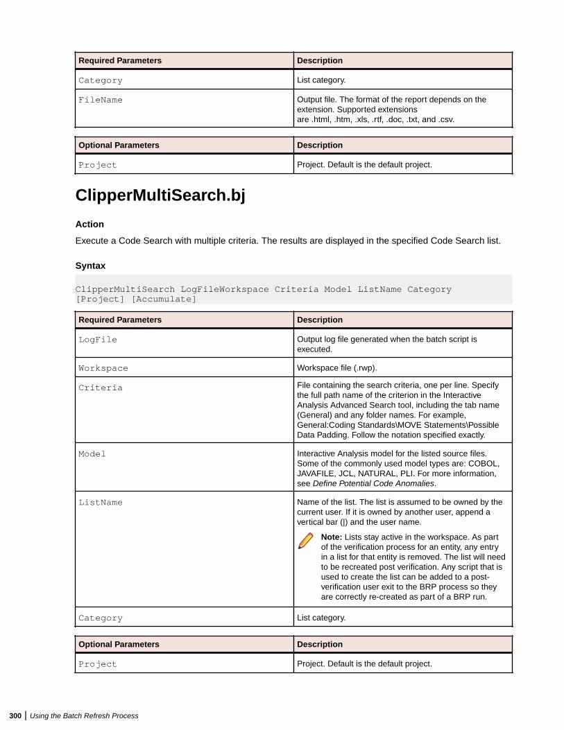
Required Parameters Description
Category List category.
FileName Output file. The format of the report depends on theextension. Supported extensionsare .html, .htm, .xls, .rtf, .doc, .txt, and .csv.
Optional Parameters Description
Project Project. Default is the default project.
ClipperMultiSearch.bj
Action
Execute a Code Search with multiple criteria. The results are displayed in the specified Code Search list.
Syntax
ClipperMultiSearch LogFileWorkspace Criteria Model ListName Category [Project] [Accumulate]
Required Parameters Description
LogFile Output log file generated when the batch script isexecuted.
Workspace Workspace file (.rwp).
Criteria File containing the search criteria, one per line. Specifythe full path name of the criterion in the InteractiveAnalysis Advanced Search tool, including the tab name(General) and any folder names. For example,General:Coding Standards\MOVE Statements\PossibleData Padding. Follow the notation specified exactly.
Model Interactive Analysis model for the listed source files.Some of the commonly used model types are: COBOL,JAVAFILE, JCL, NATURAL, PLI. For more information,see Define Potential Code Anomalies.
ListName Name of the list. The list is assumed to be owned by thecurrent user. If it is owned by another user, append avertical bar (|) and the user name.
Note: Lists stay active in the workspace. As partof the verification process for an entity, any entryin a list for that entity is removed. The list will needto be recreated post verification. Any script that isused to create the list can be added to a post-verification user exit to the BRP process so theyare correctly re-created as part of a BRP run.
Category List category.
Optional Parameters Description
Project Project. Default is the default project.
300 | Using the Batch Refresh Process
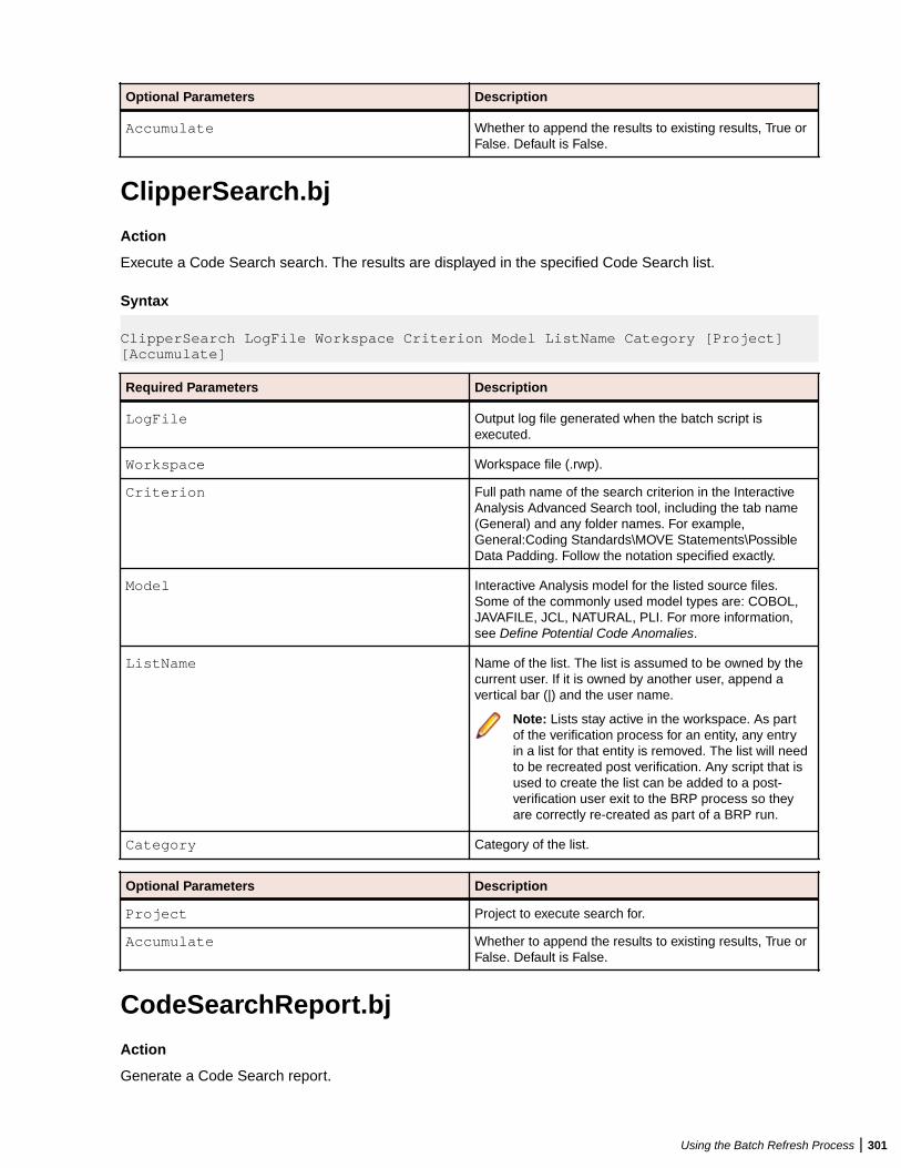
Optional Parameters Description
Accumulate Whether to append the results to existing results, True orFalse. Default is False.
ClipperSearch.bj
Action
Execute a Code Search search. The results are displayed in the specified Code Search list.
Syntax
ClipperSearch LogFile Workspace Criterion Model ListName Category [Project] [Accumulate]
Required Parameters Description
LogFile Output log file generated when the batch script isexecuted.
Workspace Workspace file (.rwp).
Criterion Full path name of the search criterion in the InteractiveAnalysis Advanced Search tool, including the tab name(General) and any folder names. For example,General:Coding Standards\MOVE Statements\PossibleData Padding. Follow the notation specified exactly.
Model Interactive Analysis model for the listed source files.Some of the commonly used model types are: COBOL,JAVAFILE, JCL, NATURAL, PLI. For more information,see Define Potential Code Anomalies.
ListName Name of the list. The list is assumed to be owned by thecurrent user. If it is owned by another user, append avertical bar (|) and the user name.
Note: Lists stay active in the workspace. As partof the verification process for an entity, any entryin a list for that entity is removed. The list will needto be recreated post verification. Any script that isused to create the list can be added to a post-verification user exit to the BRP process so theyare correctly re-created as part of a BRP run.
Category Category of the list.
Optional Parameters Description
Project Project to execute search for.
Accumulate Whether to append the results to existing results, True orFalse. Default is False.
CodeSearchReport.bj
Action
Generate a Code Search report.
Using the Batch Refresh Process | 301
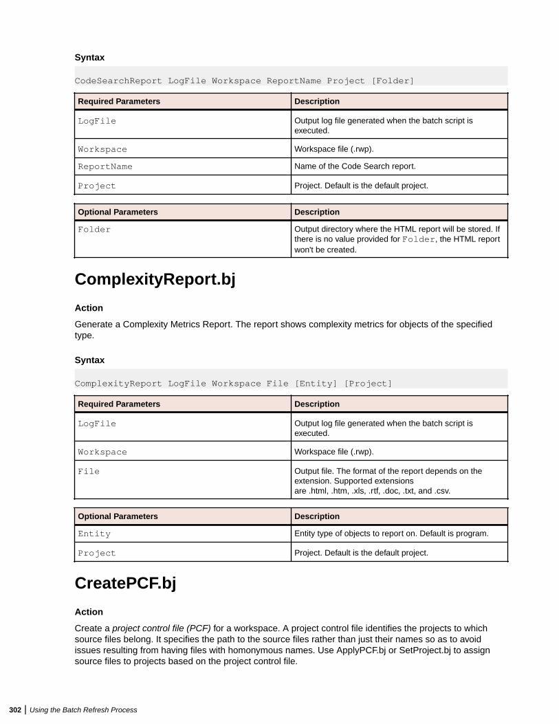
Syntax
CodeSearchReport LogFile Workspace ReportName Project [Folder]
Required Parameters Description
LogFile Output log file generated when the batch script isexecuted.
Workspace Workspace file (.rwp).
ReportName Name of the Code Search report.
Project Project. Default is the default project.
Optional Parameters Description
Folder Output directory where the HTML report will be stored. Ifthere is no value provided for Folder, the HTML reportwon't be created.
ComplexityReport.bj
Action
Generate a Complexity Metrics Report. The report shows complexity metrics for objects of the specifiedtype.
Syntax
ComplexityReport LogFile Workspace File [Entity] [Project]
Required Parameters Description
LogFile Output log file generated when the batch script isexecuted.
Workspace Workspace file (.rwp).
File Output file. The format of the report depends on theextension. Supported extensionsare .html, .htm, .xls, .rtf, .doc, .txt, and .csv.
Optional Parameters Description
Entity Entity type of objects to report on. Default is program.
Project Project. Default is the default project.
CreatePCF.bj
Action
Create a project control file (PCF) for a workspace. A project control file identifies the projects to whichsource files belong. It specifies the path to the source files rather than just their names so as to avoidissues resulting from having files with homonymous names. Use ApplyPCF.bj or SetProject.bj to assignsource files to projects based on the project control file.
302 | Using the Batch Refresh Process
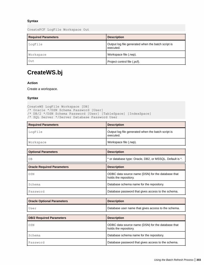
Syntax
CreatePCF LogFile Workspace Out
Required Parameters Description
LogFile Output log file generated when the batch script isexecuted.
Workspace Workspace file (.rwp).
Out Project control file (.pcf).
CreateWS.bj
Action
Create a workspace.
Syntax
CreateWS LogFile Workspace [DB] /* Oracle */DSN Schema Password [User] /* DB/2 */DSN Schema Password [User] [TableSpace] [IndexSpace]/* SQL Server */Server Database Password User
Required Parameters Description
LogFile Output log file generated when the batch script isexecuted.
Workspace Workspace file (.rwp).
Optional Parameters Description
DB * or database type: Oracle, DB2, or MSSQL. Default is *.
Oracle Required Parameters Description
DSN ODBC data source name (DSN) for the database thatholds the repository.
Schema Database schema name for the repository.
Password Database password that gives access to the schema.
Oracle Optional Parameters Description
User Database user name that gives access to the schema.
DB/2 Required Parameters Description
DSN ODBC data source name (DSN) for the database thatholds the repository.
Schema Database schema name for the repository.
Password Database password that gives access to the schema.
Using the Batch Refresh Process | 303
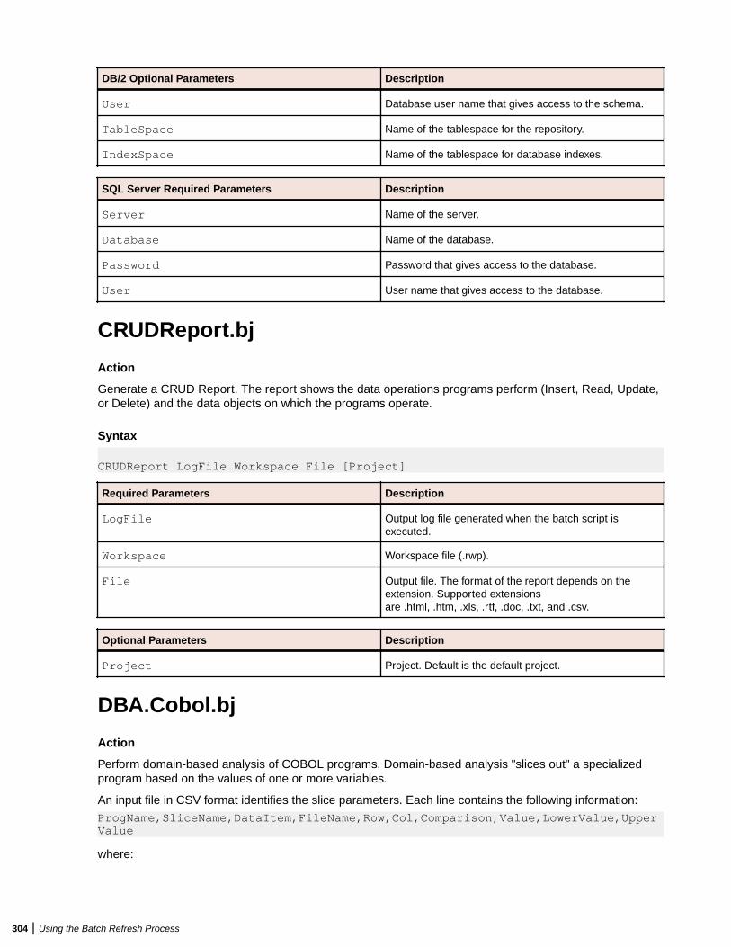
DB/2 Optional Parameters Description
User Database user name that gives access to the schema.
TableSpace Name of the tablespace for the repository.
IndexSpace Name of the tablespace for database indexes.
SQL Server Required Parameters Description
Server Name of the server.
Database Name of the database.
Password Password that gives access to the database.
User User name that gives access to the database.
CRUDReport.bj
Action
Generate a CRUD Report. The report shows the data operations programs perform (Insert, Read, Update,or Delete) and the data objects on which the programs operate.
Syntax
CRUDReport LogFile Workspace File [Project]
Required Parameters Description
LogFile Output log file generated when the batch script isexecuted.
Workspace Workspace file (.rwp).
File Output file. The format of the report depends on theextension. Supported extensionsare .html, .htm, .xls, .rtf, .doc, .txt, and .csv.
Optional Parameters Description
Project Project. Default is the default project.
DBA.Cobol.bj
Action
Perform domain-based analysis of COBOL programs. Domain-based analysis "slices out" a specializedprogram based on the values of one or more variables.
An input file in CSV format identifies the slice parameters. Each line contains the following information:
ProgName,SliceName,DataItem,FileName,Row,Col,Comparison,Value,LowerValue,UpperValue
where:
304 | Using the Batch Refresh Process
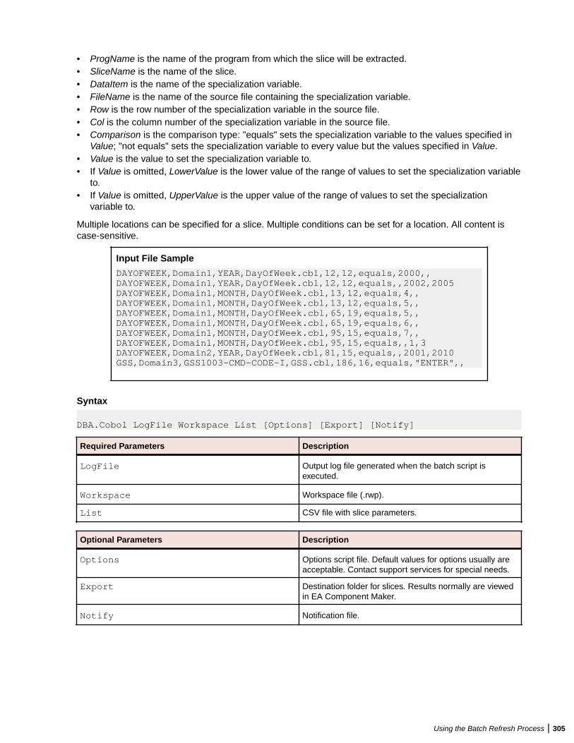
• ProgName is the name of the program from which the slice will be extracted.• SliceName is the name of the slice.• DataItem is the name of the specialization variable.• FileName is the name of the source file containing the specialization variable.• Row is the row number of the specialization variable in the source file.• Col is the column number of the specialization variable in the source file.• Comparison is the comparison type: "equals" sets the specialization variable to the values specified in
Value; "not equals" sets the specialization variable to every value but the values specified in Value.• Value is the value to set the specialization variable to.• If Value is omitted, LowerValue is the lower value of the range of values to set the specialization variable
to.• If Value is omitted, UpperValue is the upper value of the range of values to set the specialization
variable to.
Multiple locations can be specified for a slice. Multiple conditions can be set for a location. All content iscase-sensitive.
Input File Sample
DAYOFWEEK,Domain1,YEAR,DayOfWeek.cbl,12,12,equals,2000,, DAYOFWEEK,Domain1,YEAR,DayOfWeek.cbl,12,12,equals,,2002,2005 DAYOFWEEK,Domain1,MONTH,DayOfWeek.cbl,13,12,equals,4,, DAYOFWEEK,Domain1,MONTH,DayOfWeek.cbl,13,12,equals,5,, DAYOFWEEK,Domain1,MONTH,DayOfWeek.cbl,65,19,equals,5,, DAYOFWEEK,Domain1,MONTH,DayOfWeek.cbl,65,19,equals,6,, DAYOFWEEK,Domain1,MONTH,DayOfWeek.cbl,95,15,equals,7,, DAYOFWEEK,Domain1,MONTH,DayOfWeek.cbl,95,15,equals,,1,3 DAYOFWEEK,Domain2,YEAR,DayOfWeek.cbl,81,15,equals,,2001,2010 GSS,Domain3,GSS1003-CMD-CODE-I,GSS.cbl,186,16,equals,"ENTER",,
Syntax
DBA.Cobol LogFile Workspace List [Options] [Export] [Notify]
Required Parameters Description
LogFile Output log file generated when the batch script isexecuted.
Workspace Workspace file (.rwp).
List CSV file with slice parameters.
Optional Parameters Description
Options Options script file. Default values for options usually areacceptable. Contact support services for special needs.
Export Destination folder for slices. Results normally are viewedin EA Component Maker.
Notify Notification file.
Using the Batch Refresh Process | 305
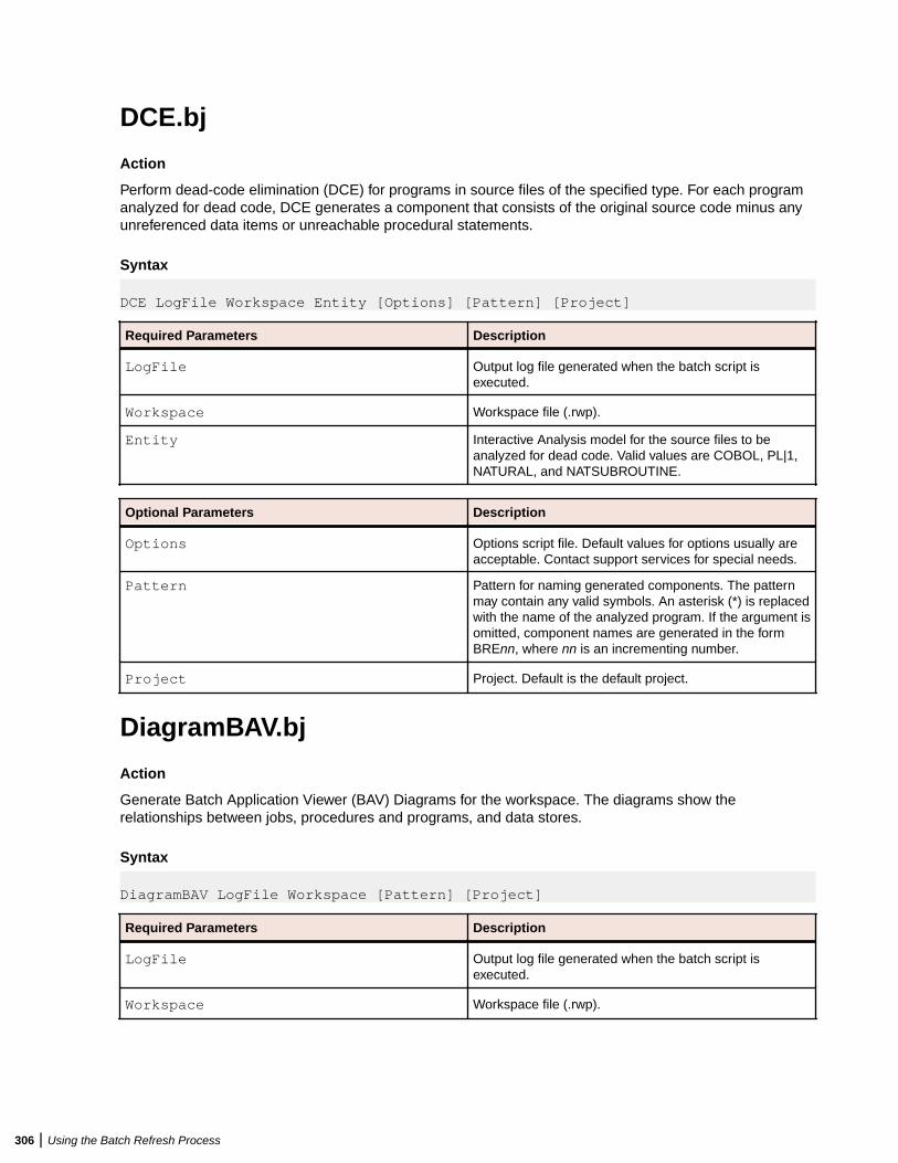
DCE.bj
Action
Perform dead-code elimination (DCE) for programs in source files of the specified type. For each programanalyzed for dead code, DCE generates a component that consists of the original source code minus anyunreferenced data items or unreachable procedural statements.
Syntax
DCE LogFile Workspace Entity [Options] [Pattern] [Project]
Required Parameters Description
LogFile Output log file generated when the batch script isexecuted.
Workspace Workspace file (.rwp).
Entity Interactive Analysis model for the source files to beanalyzed for dead code. Valid values are COBOL, PL|1,NATURAL, and NATSUBROUTINE.
Optional Parameters Description
Options Options script file. Default values for options usually areacceptable. Contact support services for special needs.
Pattern Pattern for naming generated components. The patternmay contain any valid symbols. An asterisk (*) is replacedwith the name of the analyzed program. If the argument isomitted, component names are generated in the formBREnn, where nn is an incrementing number.
Project Project. Default is the default project.
DiagramBAV.bj
Action
Generate Batch Application Viewer (BAV) Diagrams for the workspace. The diagrams show therelationships between jobs, procedures and programs, and data stores.
Syntax
DiagramBAV LogFile Workspace [Pattern] [Project]
Required Parameters Description
LogFile Output log file generated when the batch script isexecuted.
Workspace Workspace file (.rwp).
306 | Using the Batch Refresh Process
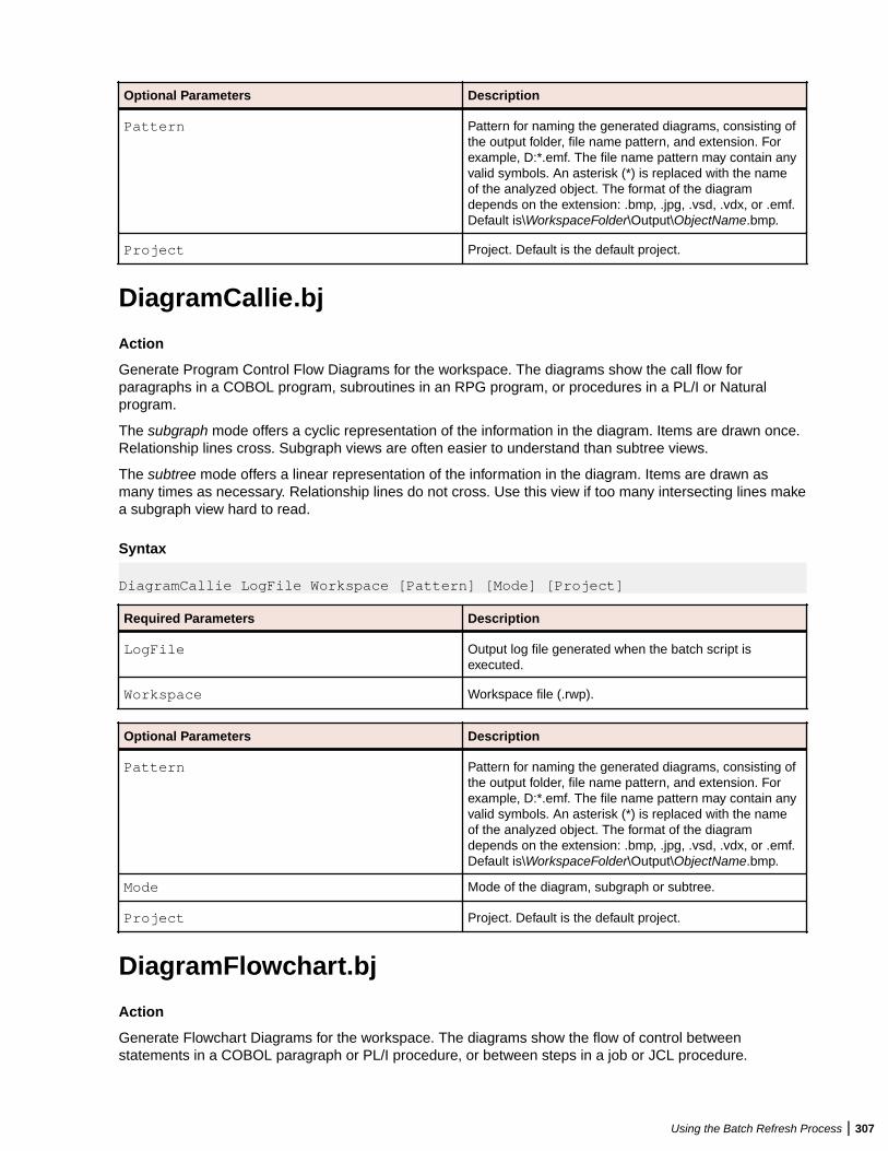
Optional Parameters Description
Pattern Pattern for naming the generated diagrams, consisting ofthe output folder, file name pattern, and extension. Forexample, D:*.emf. The file name pattern may contain anyvalid symbols. An asterisk (*) is replaced with the nameof the analyzed object. The format of the diagramdepends on the extension: .bmp, .jpg, .vsd, .vdx, or .emf.Default is\WorkspaceFolder\Output\ObjectName.bmp.
Project Project. Default is the default project.
DiagramCallie.bj
Action
Generate Program Control Flow Diagrams for the workspace. The diagrams show the call flow forparagraphs in a COBOL program, subroutines in an RPG program, or procedures in a PL/I or Naturalprogram.
The subgraph mode offers a cyclic representation of the information in the diagram. Items are drawn once.Relationship lines cross. Subgraph views are often easier to understand than subtree views.
The subtree mode offers a linear representation of the information in the diagram. Items are drawn asmany times as necessary. Relationship lines do not cross. Use this view if too many intersecting lines makea subgraph view hard to read.
Syntax
DiagramCallie LogFile Workspace [Pattern] [Mode] [Project]
Required Parameters Description
LogFile Output log file generated when the batch script isexecuted.
Workspace Workspace file (.rwp).
Optional Parameters Description
Pattern Pattern for naming the generated diagrams, consisting ofthe output folder, file name pattern, and extension. Forexample, D:*.emf. The file name pattern may contain anyvalid symbols. An asterisk (*) is replaced with the nameof the analyzed object. The format of the diagramdepends on the extension: .bmp, .jpg, .vsd, .vdx, or .emf.Default is\WorkspaceFolder\Output\ObjectName.bmp.
Mode Mode of the diagram, subgraph or subtree.
Project Project. Default is the default project.
DiagramFlowchart.bj
Action
Generate Flowchart Diagrams for the workspace. The diagrams show the flow of control betweenstatements in a COBOL paragraph or PL/I procedure, or between steps in a job or JCL procedure.
Using the Batch Refresh Process | 307
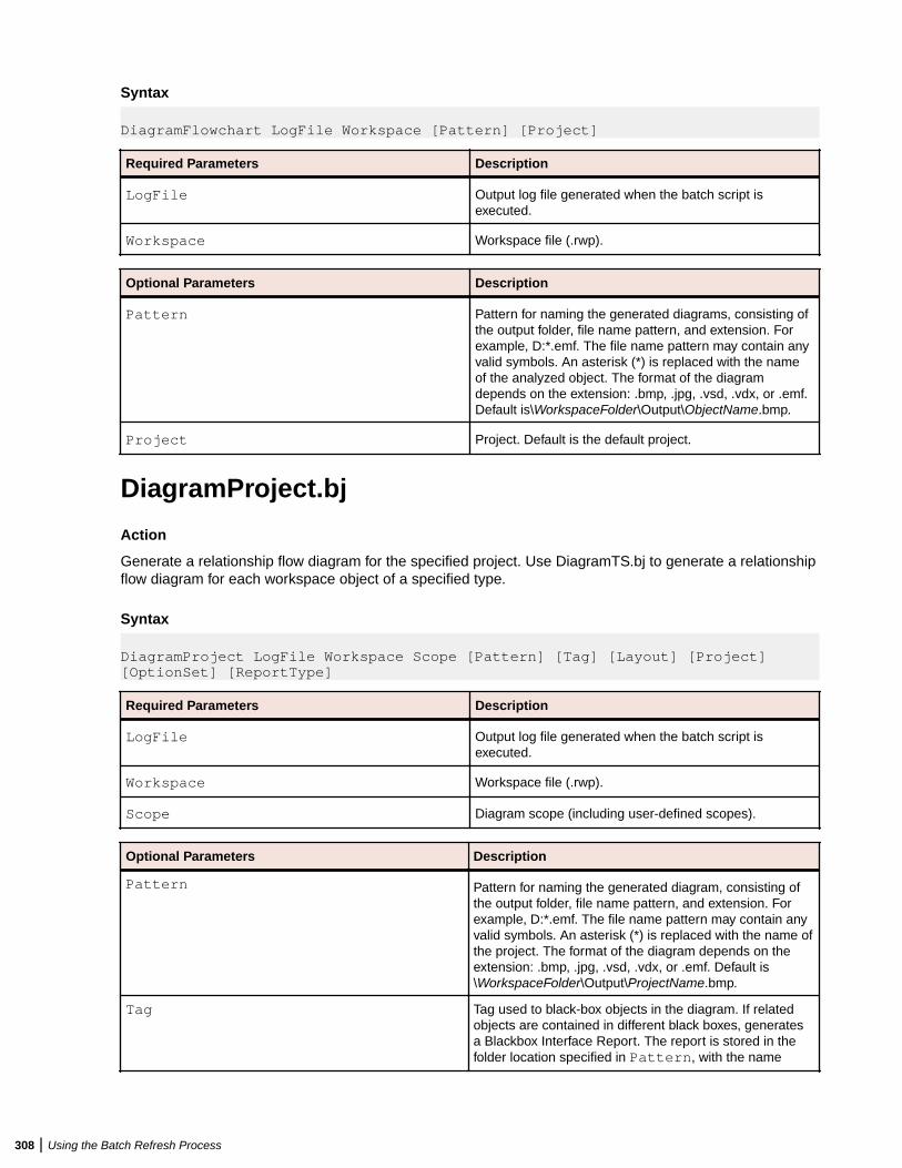
Syntax
DiagramFlowchart LogFile Workspace [Pattern] [Project]
Required Parameters Description
LogFile Output log file generated when the batch script isexecuted.
Workspace Workspace file (.rwp).
Optional Parameters Description
Pattern Pattern for naming the generated diagrams, consisting ofthe output folder, file name pattern, and extension. Forexample, D:*.emf. The file name pattern may contain anyvalid symbols. An asterisk (*) is replaced with the nameof the analyzed object. The format of the diagramdepends on the extension: .bmp, .jpg, .vsd, .vdx, or .emf.Default is\WorkspaceFolder\Output\ObjectName.bmp.
Project Project. Default is the default project.
DiagramProject.bj
Action
Generate a relationship flow diagram for the specified project. Use DiagramTS.bj to generate a relationshipflow diagram for each workspace object of a specified type.
Syntax
DiagramProject LogFile Workspace Scope [Pattern] [Tag] [Layout] [Project] [OptionSet] [ReportType]
Required Parameters Description
LogFile Output log file generated when the batch script isexecuted.
Workspace Workspace file (.rwp).
Scope Diagram scope (including user-defined scopes).
Optional Parameters Description
Pattern Pattern for naming the generated diagram, consisting ofthe output folder, file name pattern, and extension. Forexample, D:*.emf. The file name pattern may contain anyvalid symbols. An asterisk (*) is replaced with the name ofthe project. The format of the diagram depends on theextension: .bmp, .jpg, .vsd, .vdx, or .emf. Default is\WorkspaceFolder\Output\ProjectName.bmp.
Tag Tag used to black-box objects in the diagram. If relatedobjects are contained in different black boxes, generatesa Blackbox Interface Report. The report is stored in thefolder location specified in Pattern, with the name
308 | Using the Batch Refresh Process
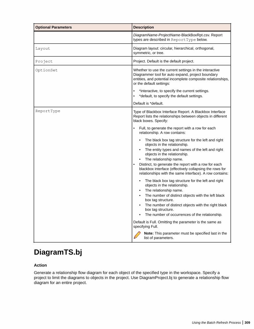
Optional Parameters Description
DiagramName-ProjectName-BlackBoxRpt.csv. Reporttypes are described in ReportType below.
Layout Diagram layout: circular, hierarchical, orthogonal,symmetric, or tree.
Project Project. Default is the default project.
OptionSet Whether to use the current settings in the interactiveDiagrammer tool for auto expand, project boundaryentities, and potential incomplete composite relationships,or the default settings:
• *interactive, to specify the current settings.• *default, to specify the default settings.
Default is *default.
ReportType Type of Blackbox Interface Report. A Blackbox InterfaceReport lists the relationships between objects in differentblack boxes. Specify:
• Full, to generate the report with a row for eachrelationship. A row contains:
• The black box tag structure for the left and rightobjects in the relationship.
• The entity types and names of the left and rightobjects in the relationship.
• The relationship name.• Distinct, to generate the report with a row for each
blackbox interface (effectively collapsing the rows forrelationships with the same interface). A row contains:
• The black box tag structure for the left and rightobjects in the relationship.
• The relationship name.• The number of distinct objects with the left black
box tag structure.• The number of distinct objects with the right black
box tag structure.• The number of occurrences of the relationship.
Default is Full. Omitting the parameter is the same asspecifying Full.
Note: This parameter must be specified last in thelist of parameters.
DiagramTS.bj
Action
Generate a relationship flow diagram for each object of the specified type in the workspace. Specify aproject to limit the diagrams to objects in the project. Use DiagramProject.bj to generate a relationship flowdiagram for an entire project.
Using the Batch Refresh Process | 309
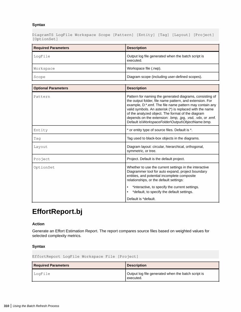
Syntax
DiagramTS LogFile Workspace Scope [Pattern] [Entity] [Tag] [Layout] [Project] [OptionSet]
Required Parameters Description
LogFile Output log file generated when the batch script isexecuted.
Workspace Workspace file (.rwp).
Scope Diagram scope (including user-defined scopes).
Optional Parameters Description
Pattern Pattern for naming the generated diagrams, consisting ofthe output folder, file name pattern, and extension. Forexample, D:*.emf. The file name pattern may contain anyvalid symbols. An asterisk (*) is replaced with the nameof the analyzed object. The format of the diagramdepends on the extension: .bmp, .jpg, .vsd, .vdx, or .emf.Default is\WorkspaceFolder\Output\ObjectName.bmp.
Entity * or entity type of source files. Default is *.
Tag Tag used to black-box objects in the diagrams.
Layout Diagram layout: circular, hierarchical, orthogonal,symmetric, or tree.
Project Project. Default is the default project.
OptionSet Whether to use the current settings in the interactiveDiagrammer tool for auto expand, project boundaryentities, and potential incomplete compositerelationships, or the default settings:
• *interactive, to specify the current settings.• *default, to specify the default settings.
Default is *default.
EffortReport.bj
Action
Generate an Effort Estimation Report. The report compares source files based on weighted values forselected complexity metrics.
Syntax
EffortReport LogFile Workspace File [Project]
Required Parameters Description
LogFile Output log file generated when the batch script isexecuted.
310 | Using the Batch Refresh Process
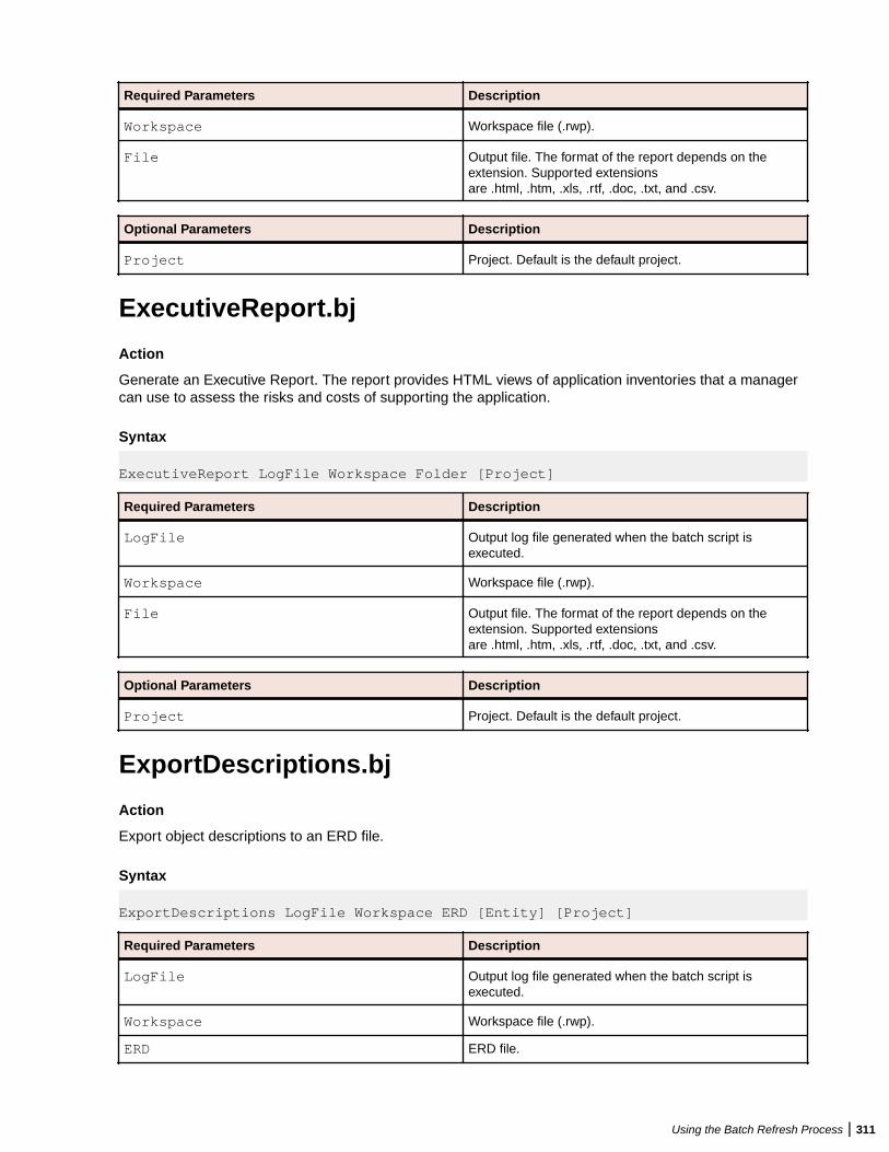
Required Parameters Description
Workspace Workspace file (.rwp).
File Output file. The format of the report depends on theextension. Supported extensionsare .html, .htm, .xls, .rtf, .doc, .txt, and .csv.
Optional Parameters Description
Project Project. Default is the default project.
ExecutiveReport.bj
Action
Generate an Executive Report. The report provides HTML views of application inventories that a managercan use to assess the risks and costs of supporting the application.
Syntax
ExecutiveReport LogFile Workspace Folder [Project]
Required Parameters Description
LogFile Output log file generated when the batch script isexecuted.
Workspace Workspace file (.rwp).
File Output file. The format of the report depends on theextension. Supported extensionsare .html, .htm, .xls, .rtf, .doc, .txt, and .csv.
Optional Parameters Description
Project Project. Default is the default project.
ExportDescriptions.bj
Action
Export object descriptions to an ERD file.
Syntax
ExportDescriptions LogFile Workspace ERD [Entity] [Project]
Required Parameters Description
LogFile Output log file generated when the batch script isexecuted.
Workspace Workspace file (.rwp).
ERD ERD file.
Using the Batch Refresh Process | 311
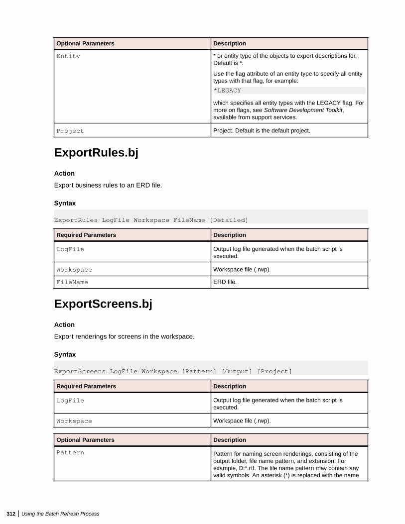
Optional Parameters Description
Entity * or entity type of the objects to export descriptions for.Default is *.
Use the flag attribute of an entity type to specify all entitytypes with that flag, for example:
*LEGACY
which specifies all entity types with the LEGACY flag. Formore on flags, see Software Development Toolkit,available from support services.
Project Project. Default is the default project.
ExportRules.bj
Action
Export business rules to an ERD file.
Syntax
ExportRules LogFile Workspace FileName [Detailed]
Required Parameters Description
LogFile Output log file generated when the batch script isexecuted.
Workspace Workspace file (.rwp).
FileName ERD file.
ExportScreens.bj
Action
Export renderings for screens in the workspace.
Syntax
ExportScreens LogFile Workspace [Pattern] [Output] [Project]
Required Parameters Description
LogFile Output log file generated when the batch script isexecuted.
Workspace Workspace file (.rwp).
Optional Parameters Description
Pattern Pattern for naming screen renderings, consisting of theoutput folder, file name pattern, and extension. Forexample, D:*.rtf. The file name pattern may contain anyvalid symbols. An asterisk (*) is replaced with the name
312 | Using the Batch Refresh Process
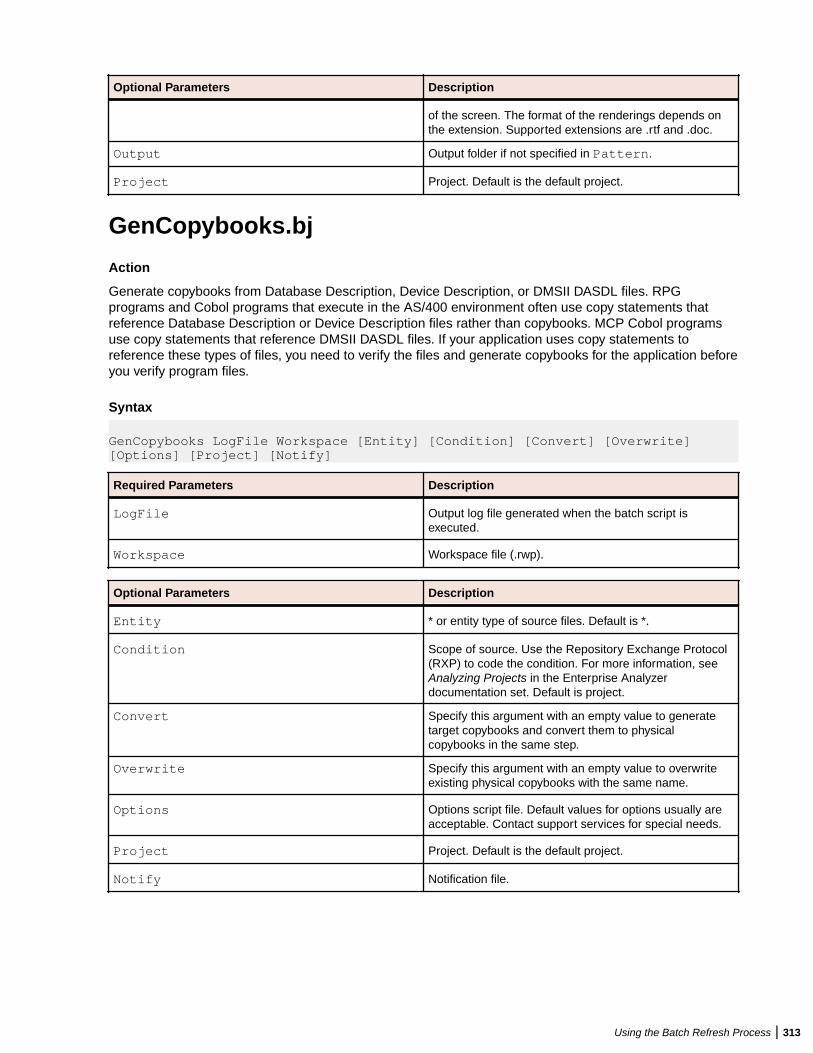
Optional Parameters Description
of the screen. The format of the renderings depends onthe extension. Supported extensions are .rtf and .doc.
Output Output folder if not specified in Pattern.
Project Project. Default is the default project.
GenCopybooks.bj
Action
Generate copybooks from Database Description, Device Description, or DMSII DASDL files. RPGprograms and Cobol programs that execute in the AS/400 environment often use copy statements thatreference Database Description or Device Description files rather than copybooks. MCP Cobol programsuse copy statements that reference DMSII DASDL files. If your application uses copy statements toreference these types of files, you need to verify the files and generate copybooks for the application beforeyou verify program files.
Syntax
GenCopybooks LogFile Workspace [Entity] [Condition] [Convert] [Overwrite] [Options] [Project] [Notify]
Required Parameters Description
LogFile Output log file generated when the batch script isexecuted.
Workspace Workspace file (.rwp).
Optional Parameters Description
Entity * or entity type of source files. Default is *.
Condition Scope of source. Use the Repository Exchange Protocol(RXP) to code the condition. For more information, seeAnalyzing Projects in the Enterprise Analyzerdocumentation set. Default is project.
Convert Specify this argument with an empty value to generatetarget copybooks and convert them to physicalcopybooks in the same step.
Overwrite Specify this argument with an empty value to overwriteexisting physical copybooks with the same name.
Options Options script file. Default values for options usually areacceptable. Contact support services for special needs.
Project Project. Default is the default project.
Notify Notification file.
Using the Batch Refresh Process | 313
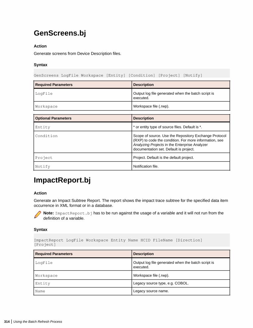
GenScreens.bj
Action
Generate screens from Device Description files.
Syntax
GenScreens LogFile Workspace [Entity] [Condition] [Project] [Notify]
Required Parameters Description
LogFile Output log file generated when the batch script isexecuted.
Workspace Workspace file (.rwp).
Optional Parameters Description
Entity * or entity type of source files. Default is *.
Condition Scope of source. Use the Repository Exchange Protocol(RXP) to code the condition. For more information, seeAnalyzing Projects in the Enterprise Analyzerdocumentation set. Default is project.
Project Project. Default is the default project.
Notify Notification file.
ImpactReport.bj
Action
Generate an Impact Subtree Report. The report shows the impact trace subtree for the specified data itemoccurrence in XML format or in a database.
Note: ImpactReport.bj has to be run against the usage of a variable and it will not run from thedefinition of a variable.
Syntax
ImpactReport LogFile Workspace Entity Name HCID FileName [Direction] [Project]
Required Parameters Description
LogFile Output log file generated when the batch script isexecuted.
Workspace Workspace file (.rwp).
Entity Legacy source type, e.g. COBOL.
Name Legacy source name.
314 | Using the Batch Refresh Process
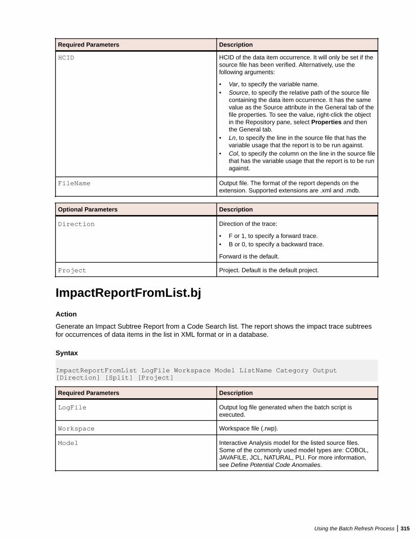
Required Parameters Description
HCID HCID of the data item occurrence. It will only be set if thesource file has been verified. Alternatively, use thefollowing arguments:
• Var, to specify the variable name.• Source, to specify the relative path of the source file
containing the data item occurrence. It has the samevalue as the Source attribute in the General tab of thefile properties. To see the value, right-click the objectin the Repository pane, select Properties and thenthe General tab.
• Ln, to specify the line in the source file that has thevariable usage that the report is to be run against.
• Col, to specify the column on the line in the source filethat has the variable usage that the report is to be runagainst.
FileName Output file. The format of the report depends on theextension. Supported extensions are .xml and .mdb.
Optional Parameters Description
Direction Direction of the trace:
• F or 1, to specify a forward trace.• B or 0, to specify a backward trace.
Forward is the default.
Project Project. Default is the default project.
ImpactReportFromList.bj
Action
Generate an Impact Subtree Report from a Code Search list. The report shows the impact trace subtreesfor occurrences of data items in the list in XML format or in a database.
Syntax
ImpactReportFromList LogFile Workspace Model ListName Category Output [Direction] [Split] [Project]
Required Parameters Description
LogFile Output log file generated when the batch script isexecuted.
Workspace Workspace file (.rwp).
Model Interactive Analysis model for the listed source files.Some of the commonly used model types are: COBOL,JAVAFILE, JCL, NATURAL, PLI. For more information,see Define Potential Code Anomalies.
Using the Batch Refresh Process | 315
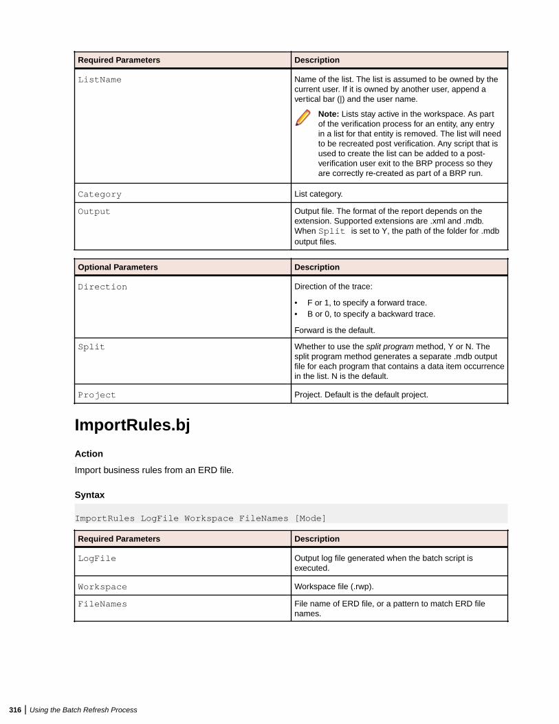
Required Parameters Description
ListName Name of the list. The list is assumed to be owned by thecurrent user. If it is owned by another user, append avertical bar (|) and the user name.
Note: Lists stay active in the workspace. As partof the verification process for an entity, any entryin a list for that entity is removed. The list will needto be recreated post verification. Any script that isused to create the list can be added to a post-verification user exit to the BRP process so theyare correctly re-created as part of a BRP run.
Category List category.
Output Output file. The format of the report depends on theextension. Supported extensions are .xml and .mdb.When Split is set to Y, the path of the folder for .mdboutput files.
Optional Parameters Description
Direction Direction of the trace:
• F or 1, to specify a forward trace.• B or 0, to specify a backward trace.
Forward is the default.
Split Whether to use the split program method, Y or N. Thesplit program method generates a separate .mdb outputfile for each program that contains a data item occurrencein the list. N is the default.
Project Project. Default is the default project.
ImportRules.bj
Action
Import business rules from an ERD file.
Syntax
ImportRules LogFile Workspace FileNames [Mode]
Required Parameters Description
LogFile Output log file generated when the batch script isexecuted.
Workspace Workspace file (.rwp).
FileNames File name of ERD file, or a pattern to match ERD filenames.
316 | Using the Batch Refresh Process
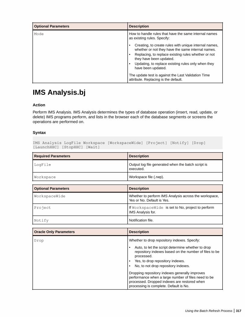
Optional Parameters Description
Mode How to handle rules that have the same internal namesas existing rules. Specify:
• Creating, to create rules with unique internal names,whether or not they have the same internal names.
• Replacing, to replace existing rules whether or notthey have been updated.
• Updating, to replace existing rules only when theyhave been updated.
The update test is against the Last Validation Timeattribute. Replacing is the default.
IMS Analysis.bj
Action
Perform IMS Analysis. IMS Analysis determines the types of database operation (insert, read, update, ordelete) IMS programs perform, and lists in the browser each of the database segments or screens theoperations are performed on.
Syntax
IMS Analysis LogFile Workspace [WorkspaceWide] [Project] [Notify] [Drop] [LaunchHHC] [StopHHC] [Wait]
Required Parameters Description
LogFile Output log file generated when the batch script isexecuted.
Workspace Workspace file (.rwp).
Optional Parameters Description
WorkspaceWide Whether to perform IMS Analysis across the workspace,Yes or No. Default is Yes.
Project If WorkspaceWide is set to No, project to performIMS Analysis for.
Notify Notification file.
Oracle Only Parameters Description
Drop Whether to drop repository indexes. Specify:
• Auto, to let the script determine whether to droprepository indexes based on the number of files to beprocessed.
• Yes, to drop repository indexes.• No, to not drop repository indexes.
Dropping repository indexes generally improvesperformance when a large number of files need to beprocessed. Dropped indexes are restored whenprocessing is complete. Default is No.
Using the Batch Refresh Process | 317
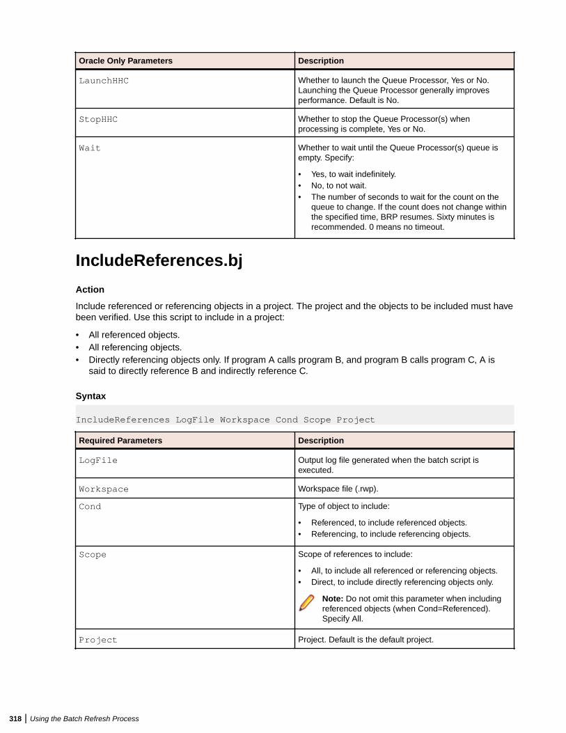
Oracle Only Parameters Description
LaunchHHC Whether to launch the Queue Processor, Yes or No.Launching the Queue Processor generally improvesperformance. Default is No.
StopHHC Whether to stop the Queue Processor(s) whenprocessing is complete, Yes or No.
Wait Whether to wait until the Queue Processor(s) queue isempty. Specify:
• Yes, to wait indefinitely.• No, to not wait.• The number of seconds to wait for the count on the
queue to change. If the count does not change withinthe specified time, BRP resumes. Sixty minutes isrecommended. 0 means no timeout.
IncludeReferences.bj
Action
Include referenced or referencing objects in a project. The project and the objects to be included must havebeen verified. Use this script to include in a project:
• All referenced objects.• All referencing objects.• Directly referencing objects only. If program A calls program B, and program B calls program C, A is
said to directly reference B and indirectly reference C.
Syntax
IncludeReferences LogFile Workspace Cond Scope Project
Required Parameters Description
LogFile Output log file generated when the batch script isexecuted.
Workspace Workspace file (.rwp).
Cond Type of object to include:
• Referenced, to include referenced objects.• Referencing, to include referencing objects.
Scope Scope of references to include:
• All, to include all referenced or referencing objects.• Direct, to include directly referencing objects only.
Note: Do not omit this parameter when includingreferenced objects (when Cond=Referenced).Specify All.
Project Project. Default is the default project.
318 | Using the Batch Refresh Process
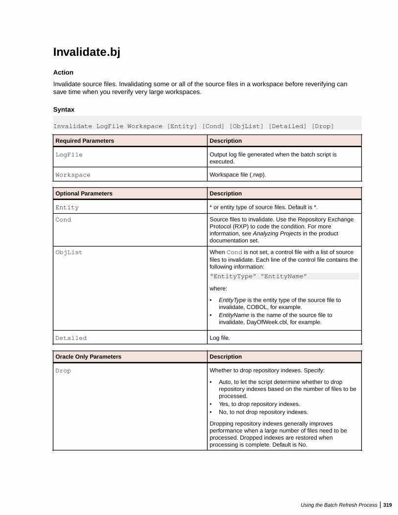
Invalidate.bj
Action
Invalidate source files. Invalidating some or all of the source files in a workspace before reverifying cansave time when you reverify very large workspaces.
Syntax
Invalidate LogFile Workspace [Entity] [Cond] [ObjList] [Detailed] [Drop]
Required Parameters Description
LogFile Output log file generated when the batch script isexecuted.
Workspace Workspace file (.rwp).
Optional Parameters Description
Entity * or entity type of source files. Default is *.
Cond Source files to invalidate. Use the Repository ExchangeProtocol (RXP) to code the condition. For moreinformation, see Analyzing Projects in the productdocumentation set.
ObjList When Cond is not set, a control file with a list of sourcefiles to invalidate. Each line of the control file contains thefollowing information:
"EntityType" "EntityName"
where:
• EntityType is the entity type of the source file toinvalidate, COBOL, for example.
• EntityName is the name of the source file toinvalidate, DayOfWeek.cbl, for example.
Detailed Log file.
Oracle Only Parameters Description
Drop Whether to drop repository indexes. Specify:
• Auto, to let the script determine whether to droprepository indexes based on the number of files to beprocessed.
• Yes, to drop repository indexes.• No, to not drop repository indexes.
Dropping repository indexes generally improvesperformance when a large number of files need to beprocessed. Dropped indexes are restored whenprocessing is complete. Default is No.
Using the Batch Refresh Process | 319
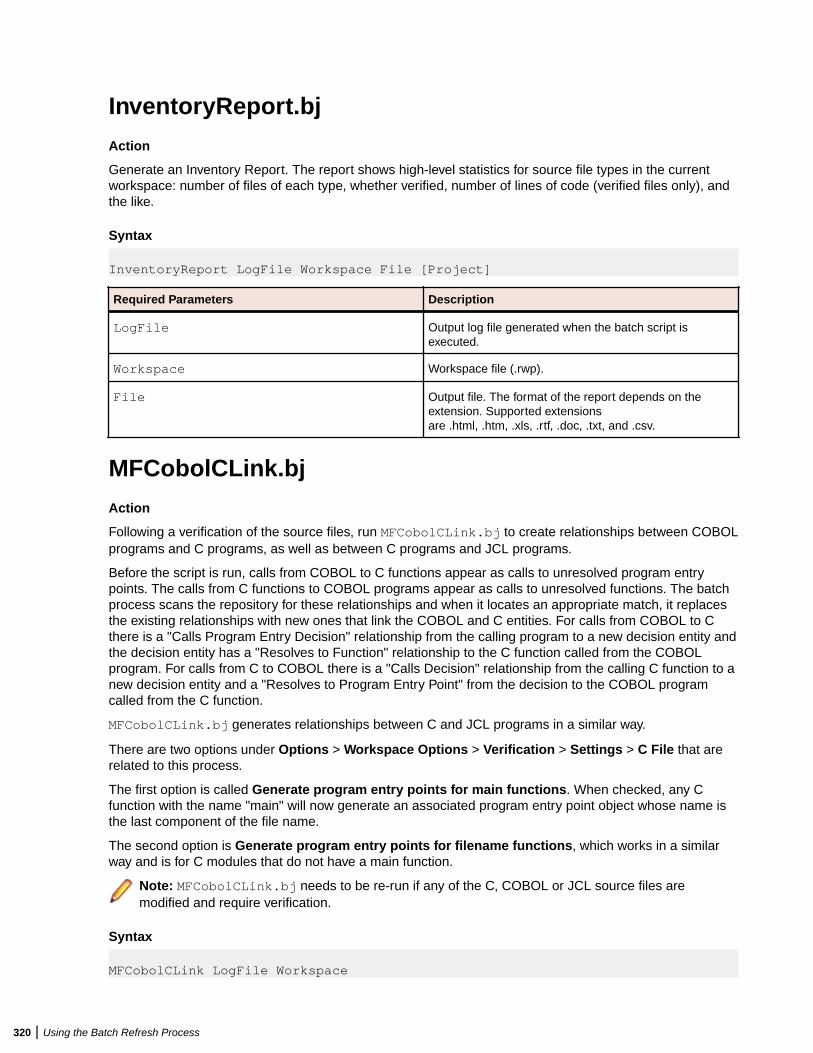
InventoryReport.bj
Action
Generate an Inventory Report. The report shows high-level statistics for source file types in the currentworkspace: number of files of each type, whether verified, number of lines of code (verified files only), andthe like.
Syntax
InventoryReport LogFile Workspace File [Project]
Required Parameters Description
LogFile Output log file generated when the batch script isexecuted.
Workspace Workspace file (.rwp).
File Output file. The format of the report depends on theextension. Supported extensionsare .html, .htm, .xls, .rtf, .doc, .txt, and .csv.
MFCobolCLink.bj
Action
Following a verification of the source files, run MFCobolCLink.bj to create relationships between COBOLprograms and C programs, as well as between C programs and JCL programs.
Before the script is run, calls from COBOL to C functions appear as calls to unresolved program entrypoints. The calls from C functions to COBOL programs appear as calls to unresolved functions. The batchprocess scans the repository for these relationships and when it locates an appropriate match, it replacesthe existing relationships with new ones that link the COBOL and C entities. For calls from COBOL to Cthere is a "Calls Program Entry Decision" relationship from the calling program to a new decision entity andthe decision entity has a "Resolves to Function" relationship to the C function called from the COBOLprogram. For calls from C to COBOL there is a "Calls Decision" relationship from the calling C function to anew decision entity and a "Resolves to Program Entry Point" from the decision to the COBOL programcalled from the C function.
MFCobolCLink.bj generates relationships between C and JCL programs in a similar way.
There are two options under Options > Workspace Options > Verification > Settings > C File that arerelated to this process.
The first option is called Generate program entry points for main functions. When checked, any Cfunction with the name "main" will now generate an associated program entry point object whose name isthe last component of the file name.
The second option is Generate program entry points for filename functions, which works in a similarway and is for C modules that do not have a main function.
Note: MFCobolCLink.bj needs to be re-run if any of the C, COBOL or JCL source files aremodified and require verification.
Syntax
MFCobolCLink LogFile Workspace
320 | Using the Batch Refresh Process
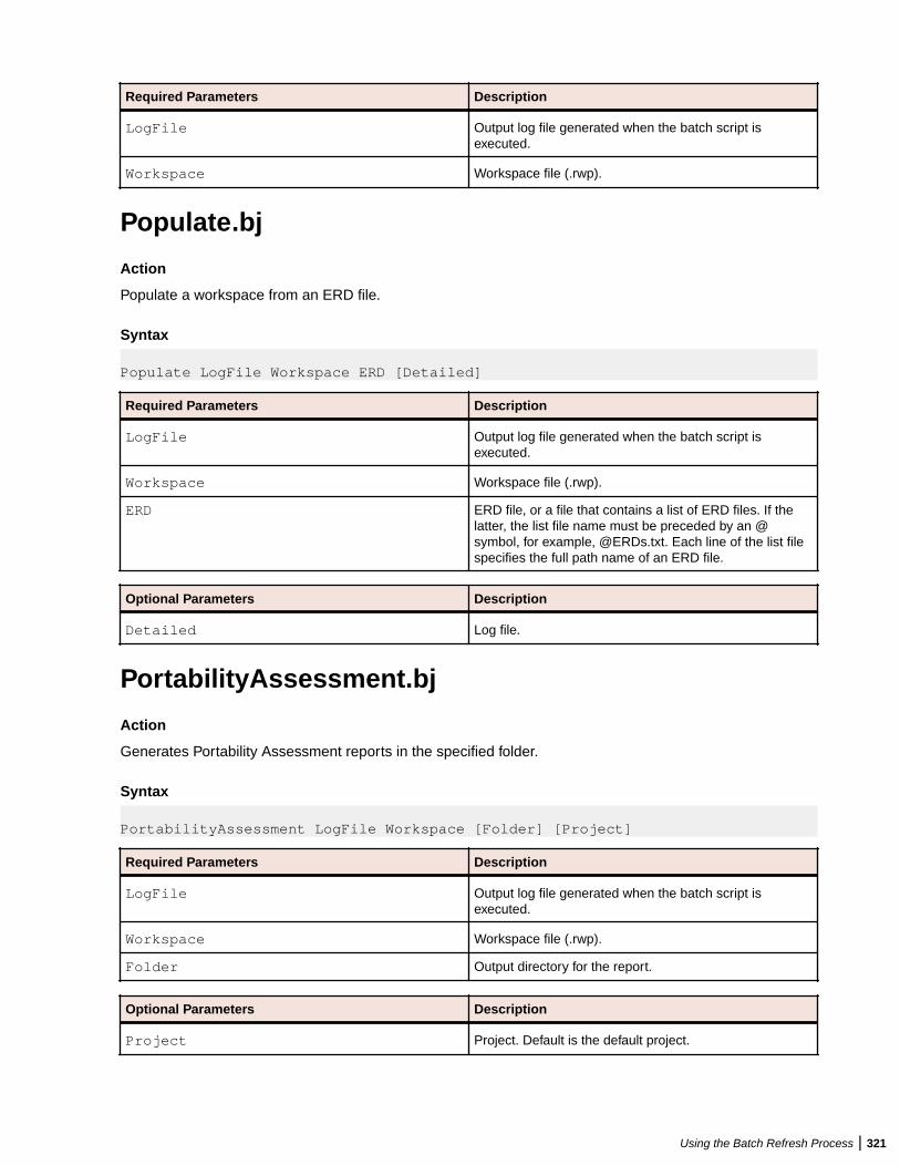
Required Parameters Description
LogFile Output log file generated when the batch script isexecuted.
Workspace Workspace file (.rwp).
Populate.bj
Action
Populate a workspace from an ERD file.
Syntax
Populate LogFile Workspace ERD [Detailed]
Required Parameters Description
LogFile Output log file generated when the batch script isexecuted.
Workspace Workspace file (.rwp).
ERD ERD file, or a file that contains a list of ERD files. If thelatter, the list file name must be preceded by an @symbol, for example, @ERDs.txt. Each line of the list filespecifies the full path name of an ERD file.
Optional Parameters Description
Detailed Log file.
PortabilityAssessment.bj
Action
Generates Portability Assessment reports in the specified folder.
Syntax
PortabilityAssessment LogFile Workspace [Folder] [Project]
Required Parameters Description
LogFile Output log file generated when the batch script isexecuted.
Workspace Workspace file (.rwp).
Folder Output directory for the report.
Optional Parameters Description
Project Project. Default is the default project.
Using the Batch Refresh Process | 321

ProcessChangeUnit.bj
Action
Set a change date for complexity metrics other than the date source files are verified, and/or delete sourcefiles from the workspace. Specify the date and the files to be deleted in a change unit description file.
Note: Execute this script before registering the source files.
Use SetChangeDate.bj to clear the change date from the system. Use ChangeTraffic.bj to generate changetraffic metrics.
Syntax
ProcessChangeUnit LogFile Workspace File
Required Parameters Description
LogFile Output log file generated when the batch script isexecuted.
Workspace Workspace file (.rwp).
File Change unit description file. A flat file containing thechange date, in the form DATE: YYYY-MM-DDHH24:MI:SS, and the files to be deleted, in the formDELETED:filename. For example:
DATE: 2010-03-15 17:12:13DELETED:MYPROG.CBLDELETED:MYPROG.CPY
QualityAssessment.bj
Action
Generates a Quality Assessment report in the specified folder.
Syntax
QualityAssessment LogFile Workspace [Folder] [Project]
Required Parameters Description
LogFile Output log file generated when the batch script isexecuted.
Workspace Workspace file (.rwp).
Folder Output directory for the report.
Optional Parameters Description
Project Project. Default is the default project.
322 | Using the Batch Refresh Process
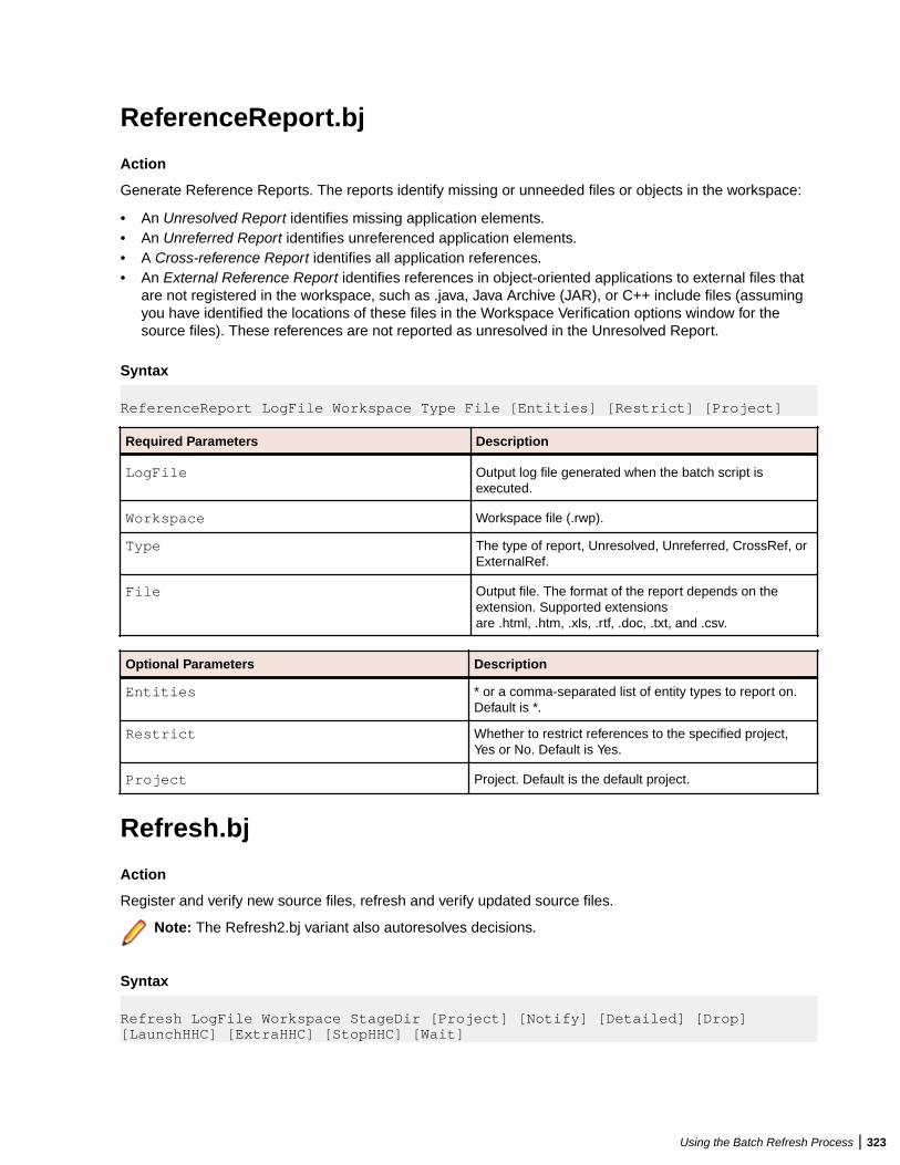
ReferenceReport.bj
Action
Generate Reference Reports. The reports identify missing or unneeded files or objects in the workspace:
• An Unresolved Report identifies missing application elements.• An Unreferred Report identifies unreferenced application elements.• A Cross-reference Report identifies all application references.• An External Reference Report identifies references in object-oriented applications to external files that
are not registered in the workspace, such as .java, Java Archive (JAR), or C++ include files (assumingyou have identified the locations of these files in the Workspace Verification options window for thesource files). These references are not reported as unresolved in the Unresolved Report.
Syntax
ReferenceReport LogFile Workspace Type File [Entities] [Restrict] [Project]
Required Parameters Description
LogFile Output log file generated when the batch script isexecuted.
Workspace Workspace file (.rwp).
Type The type of report, Unresolved, Unreferred, CrossRef, orExternalRef.
File Output file. The format of the report depends on theextension. Supported extensionsare .html, .htm, .xls, .rtf, .doc, .txt, and .csv.
Optional Parameters Description
Entities * or a comma-separated list of entity types to report on.Default is *.
Restrict Whether to restrict references to the specified project,Yes or No. Default is Yes.
Project Project. Default is the default project.
Refresh.bj
Action
Register and verify new source files, refresh and verify updated source files.
Note: The Refresh2.bj variant also autoresolves decisions.
Syntax
Refresh LogFile Workspace StageDir [Project] [Notify] [Detailed] [Drop] [LaunchHHC] [ExtraHHC] [StopHHC] [Wait]
Using the Batch Refresh Process | 323
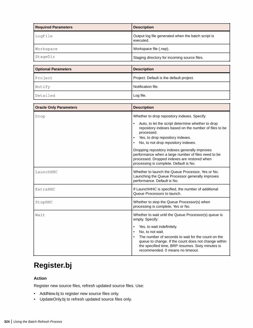
Required Parameters Description
LogFile Output log file generated when the batch script isexecuted.
Workspace Workspace file (.rwp).
StageDir Staging directory for incoming source files.
Optional Parameters Description
Project Project. Default is the default project.
Notify Notification file.
Detailed Log file.
Oracle Only Parameters Description
Drop Whether to drop repository indexes. Specify:
• Auto, to let the script determine whether to droprepository indexes based on the number of files to beprocessed.
• Yes, to drop repository indexes.• No, to not drop repository indexes.
Dropping repository indexes generally improvesperformance when a large number of files need to beprocessed. Dropped indexes are restored whenprocessing is complete. Default is No.
LaunchHHC Whether to launch the Queue Processor, Yes or No.Launching the Queue Processor generally improvesperformance. Default is No.
ExtraHHC If LaunchHHC is specified, the number of additionalQueue Processors to launch.
StopHHC Whether to stop the Queue Processor(s) whenprocessing is complete, Yes or No.
Wait Whether to wait until the Queue Processor(s) queue isempty. Specify:
• Yes, to wait indefinitely.• No, to not wait.• The number of seconds to wait for the count on the
queue to change. If the count does not change withinthe specified time, BRP resumes. Sixty minutes isrecommended. 0 means no timeout.
Register.bj
Action
Register new source files, refresh updated source files. Use:
• AddNew.bj to register new source files only.• UpdateOnly.bj to refresh updated source files only.
324 | Using the Batch Refresh Process
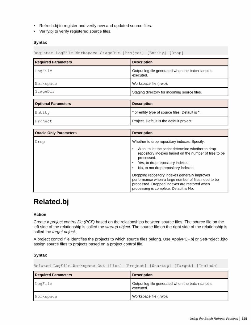
• Refresh.bj to register and verify new and updated source files.• Verify.bj to verify registered source files.
Syntax
Register LogFile Workspace StageDir [Project] [Entity] [Drop]
Required Parameters Description
LogFile Output log file generated when the batch script isexecuted.
Workspace Workspace file (.rwp).
StageDir Staging directory for incoming source files.
Optional Parameters Description
Entity * or entity type of source files. Default is *.
Project Project. Default is the default project.
Oracle Only Parameters Description
Drop Whether to drop repository indexes. Specify:
• Auto, to let the script determine whether to droprepository indexes based on the number of files to beprocessed.
• Yes, to drop repository indexes.• No, to not drop repository indexes.
Dropping repository indexes generally improvesperformance when a large number of files need to beprocessed. Dropped indexes are restored whenprocessing is complete. Default is No.
Related.bj
Action
Create a project control file (PCF) based on the relationships between source files. The source file on theleft side of the relationship is called the startup object. The source file on the right side of the relationship iscalled the target object.
A project control file identifies the projects to which source files belong. Use ApplyPCF.bj or SetProject .bjtoassign source files to projects based on a project control file.
Syntax
Related LogFile Workspace Out [List] [Project] [Startup] [Target] [Include]
Required Parameters Description
LogFile Output log file generated when the batch script isexecuted.
Workspace Workspace file (.rwp).
Using the Batch Refresh Process | 325

Required Parameters Description
Out Project control file (.pcf).
Optional Parameters Description
List A control file with a list of startup objects. Each line of thecontrol file contains the following information:
"EntityType" "EntityName"
where:
• EntityType is the entity type of the startup object,COBOL, for example.
• EntityName is the name of the startup object,DayOfWeek.cbl, for example.
Project When List is not specified, the project containing thestartup objects.
Startup When List is not specified, the entity type of the startupobjects. Enclose multiple entity types in parentheses in avertical-line-separated list, for example:
(COBOL|COPYBOOK|BMS)
Use the flag attribute of an entity type to specify all entitytypes with that flag, for example:
*LEGACY
which specifies all entity types with the LEGACY flag, thedefault. For more on entity flags, see SoftwareDevelopment Toolkit, available from support services.
Note: Additional operators are available forspecial needs. Contact support services fordetails.
Target The entity type of the target objects. The notation is as forStartup. Default is (BMS|PSB|DBD|CSD).
Include Whether to include source files related to other sourcefiles in relationships flagged R_USE, such as CobolIncludes Copybook File. Default is Yes. Specify NONE forNo.
Restrict the result to source files of given types byspecifying the types, for example:
Include=(COBOL|JCL)
The notation is as for Startup. For more onrelationship flags, see Software Development Toolkit,available from support services.
ResolveDecisions.bj
Action
Resolve decisions automatically.
326 | Using the Batch Refresh Process
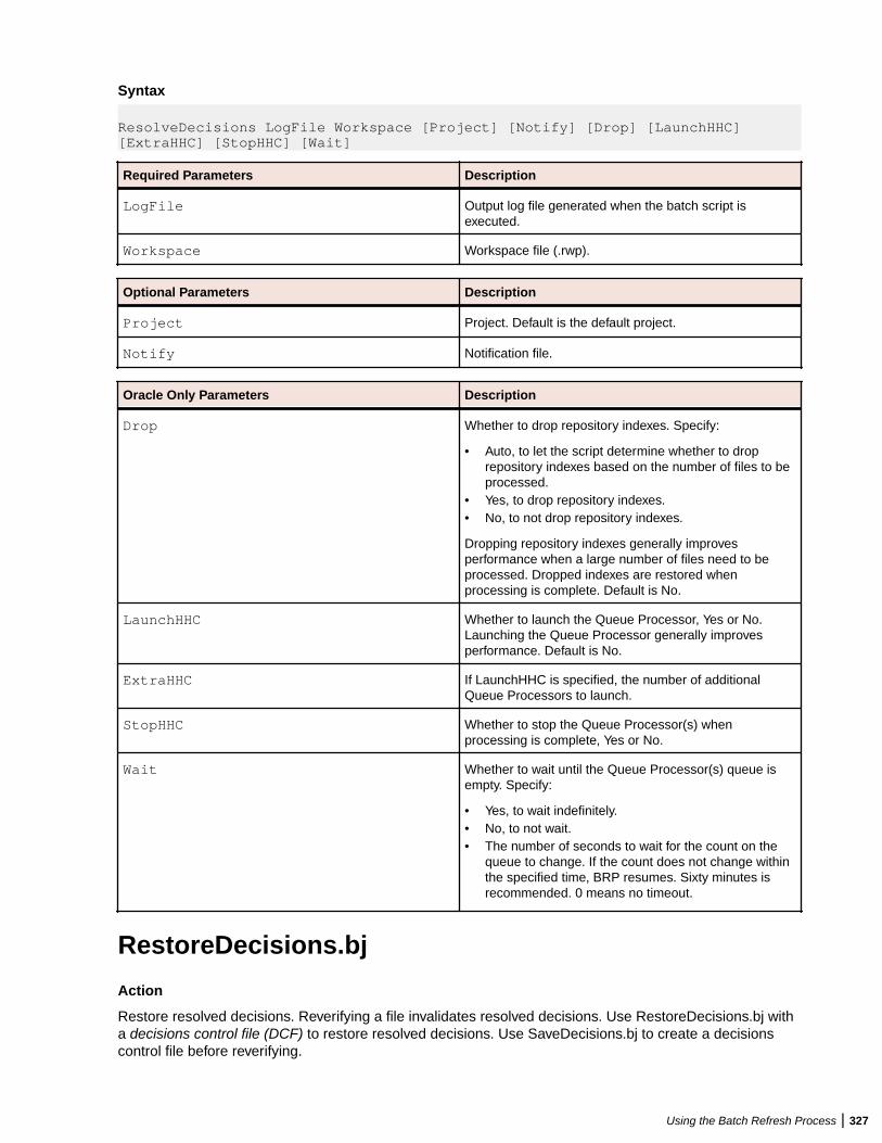
Syntax
ResolveDecisions LogFile Workspace [Project] [Notify] [Drop] [LaunchHHC] [ExtraHHC] [StopHHC] [Wait]
Required Parameters Description
LogFile Output log file generated when the batch script isexecuted.
Workspace Workspace file (.rwp).
Optional Parameters Description
Project Project. Default is the default project.
Notify Notification file.
Oracle Only Parameters Description
Drop Whether to drop repository indexes. Specify:
• Auto, to let the script determine whether to droprepository indexes based on the number of files to beprocessed.
• Yes, to drop repository indexes.• No, to not drop repository indexes.
Dropping repository indexes generally improvesperformance when a large number of files need to beprocessed. Dropped indexes are restored whenprocessing is complete. Default is No.
LaunchHHC Whether to launch the Queue Processor, Yes or No.Launching the Queue Processor generally improvesperformance. Default is No.
ExtraHHC If LaunchHHC is specified, the number of additionalQueue Processors to launch.
StopHHC Whether to stop the Queue Processor(s) whenprocessing is complete, Yes or No.
Wait Whether to wait until the Queue Processor(s) queue isempty. Specify:
• Yes, to wait indefinitely.• No, to not wait.• The number of seconds to wait for the count on the
queue to change. If the count does not change withinthe specified time, BRP resumes. Sixty minutes isrecommended. 0 means no timeout.
RestoreDecisions.bj
Action
Restore resolved decisions. Reverifying a file invalidates resolved decisions. Use RestoreDecisions.bj witha decisions control file (DCF) to restore resolved decisions. Use SaveDecisions.bj to create a decisionscontrol file before reverifying.
Using the Batch Refresh Process | 327
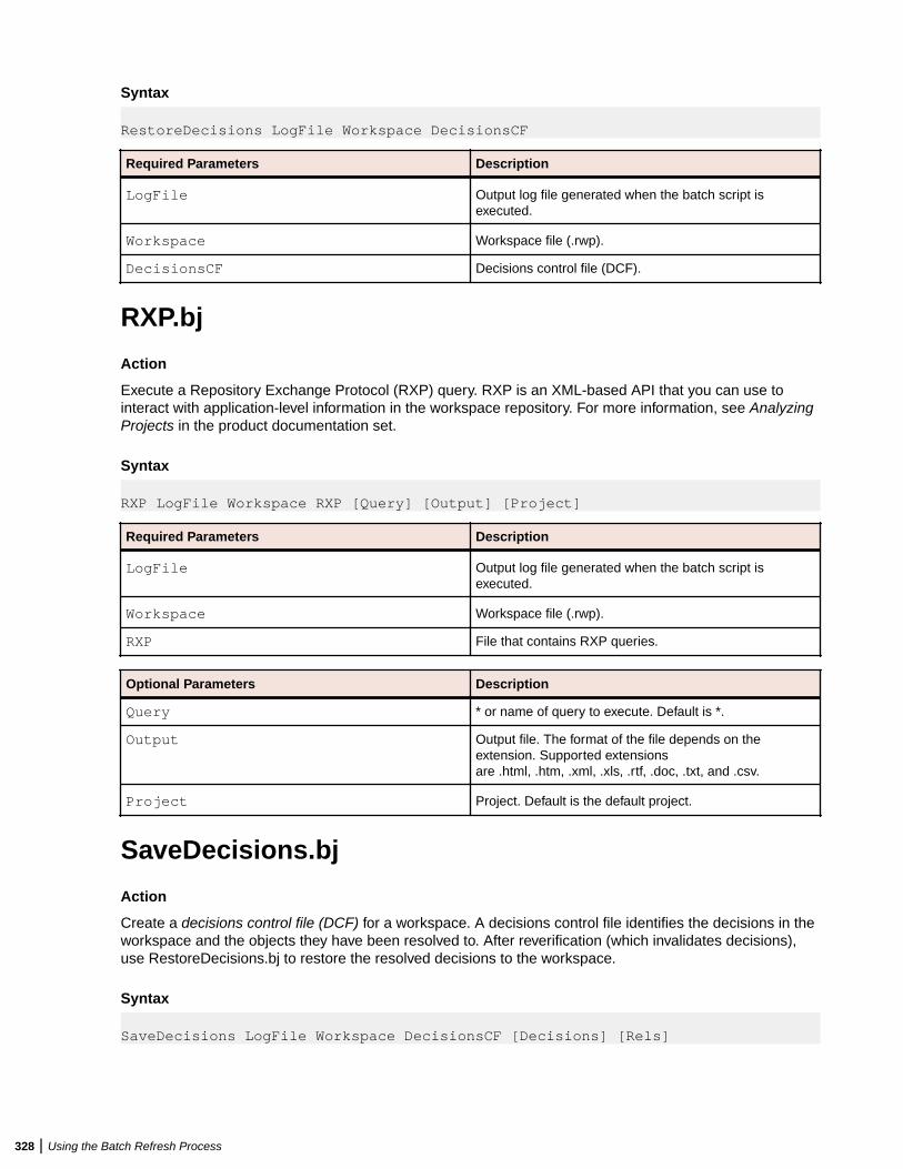
Syntax
RestoreDecisions LogFile Workspace DecisionsCF
Required Parameters Description
LogFile Output log file generated when the batch script isexecuted.
Workspace Workspace file (.rwp).
DecisionsCF Decisions control file (DCF).
RXP.bj
Action
Execute a Repository Exchange Protocol (RXP) query. RXP is an XML-based API that you can use tointeract with application-level information in the workspace repository. For more information, see AnalyzingProjects in the product documentation set.
Syntax
RXP LogFile Workspace RXP [Query] [Output] [Project]
Required Parameters Description
LogFile Output log file generated when the batch script isexecuted.
Workspace Workspace file (.rwp).
RXP File that contains RXP queries.
Optional Parameters Description
Query * or name of query to execute. Default is *.
Output Output file. The format of the file depends on theextension. Supported extensionsare .html, .htm, .xml, .xls, .rtf, .doc, .txt, and .csv.
Project Project. Default is the default project.
SaveDecisions.bj
Action
Create a decisions control file (DCF) for a workspace. A decisions control file identifies the decisions in theworkspace and the objects they have been resolved to. After reverification (which invalidates decisions),use RestoreDecisions.bj to restore the resolved decisions to the workspace.
Syntax
SaveDecisions LogFile Workspace DecisionsCF [Decisions] [Rels]
328 | Using the Batch Refresh Process
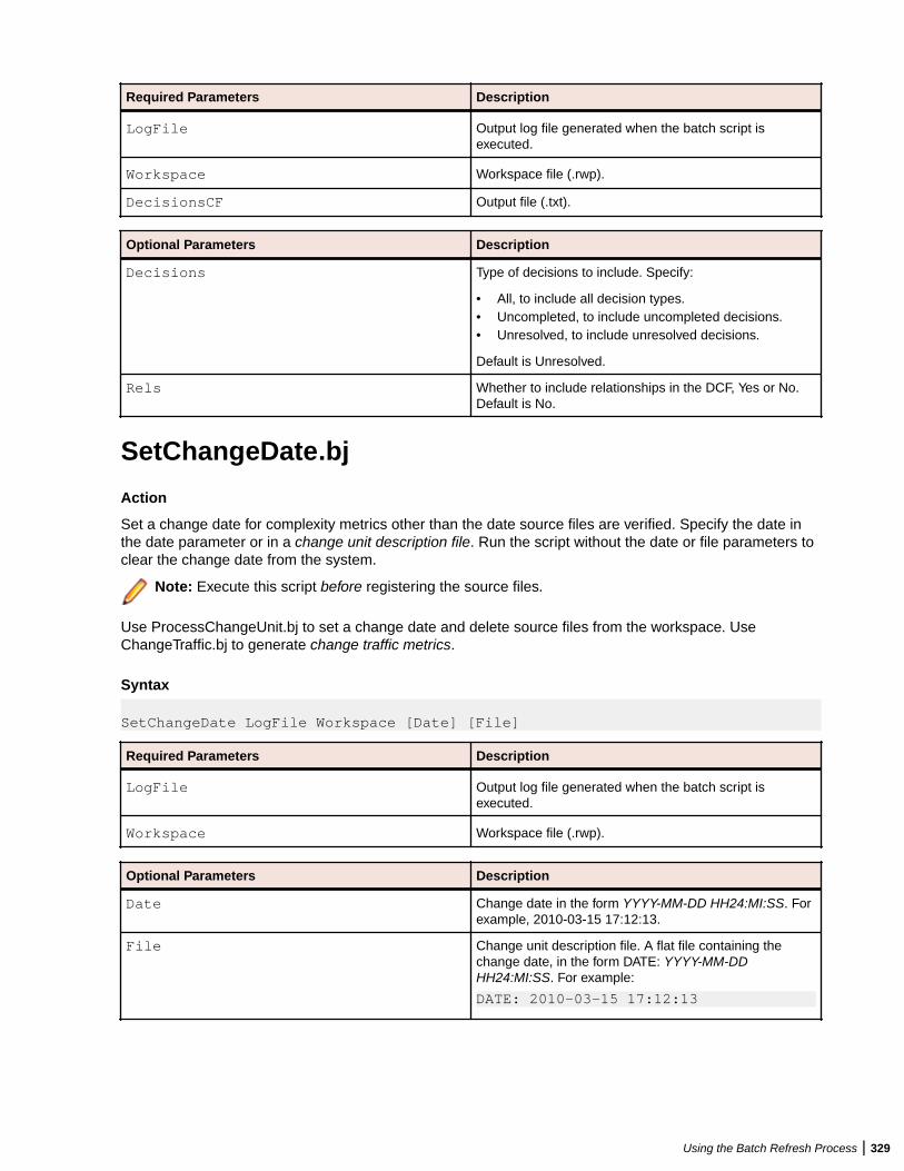
Required Parameters Description
LogFile Output log file generated when the batch script isexecuted.
Workspace Workspace file (.rwp).
DecisionsCF Output file (.txt).
Optional Parameters Description
Decisions Type of decisions to include. Specify:
• All, to include all decision types.• Uncompleted, to include uncompleted decisions.• Unresolved, to include unresolved decisions.
Default is Unresolved.
Rels Whether to include relationships in the DCF, Yes or No.Default is No.
SetChangeDate.bj
Action
Set a change date for complexity metrics other than the date source files are verified. Specify the date inthe date parameter or in a change unit description file. Run the script without the date or file parameters toclear the change date from the system.
Note: Execute this script before registering the source files.
Use ProcessChangeUnit.bj to set a change date and delete source files from the workspace. UseChangeTraffic.bj to generate change traffic metrics.
Syntax
SetChangeDate LogFile Workspace [Date] [File]
Required Parameters Description
LogFile Output log file generated when the batch script isexecuted.
Workspace Workspace file (.rwp).
Optional Parameters Description
Date Change date in the form YYYY-MM-DD HH24:MI:SS. Forexample, 2010-03-15 17:12:13.
File Change unit description file. A flat file containing thechange date, in the form DATE: YYYY-MM-DDHH24:MI:SS. For example:
DATE: 2010-03-15 17:12:13
Using the Batch Refresh Process | 329
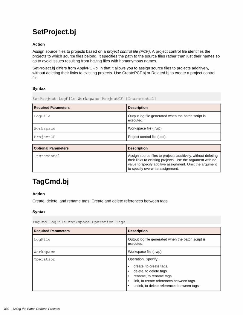
SetProject.bj
Action
Assign source files to projects based on a project control file (PCF). A project control file identifies theprojects to which source files belong. It specifies the path to the source files rather than just their names soas to avoid issues resulting from having files with homonymous names.
SetProject.bj differs from ApplyPCF.bj in that it allows you to assign source files to projects additively,without deleting their links to existing projects. Use CreatePCF.bj or Related.bj to create a project controlfile.
Syntax
SetProject LogFile Workspace ProjectCF [Incremental]
Required Parameters Description
LogFile Output log file generated when the batch script isexecuted.
Workspace Workspace file (.rwp).
ProjectCF Project control file (.pcf).
Optional Parameters Description
Incremental Assign source files to projects additively, without deletingtheir links to existing projects. Use the argument with novalue to specify additive assignment. Omit the argumentto specify overwrite assignment.
TagCmd.bj
Action
Create, delete, and rename tags. Create and delete references between tags.
Syntax
TagCmd LogFile Workspace Operation Tags
Required Parameters Description
LogFile Output log file generated when the batch script isexecuted.
Workspace Workspace file (.rwp).
Operation Operation. Specify:
• create, to create tags.• delete, to delete tags.• rename, to rename tags.• link, to create references between tags.• unlink, to delete references between tags.
330 | Using the Batch Refresh Process
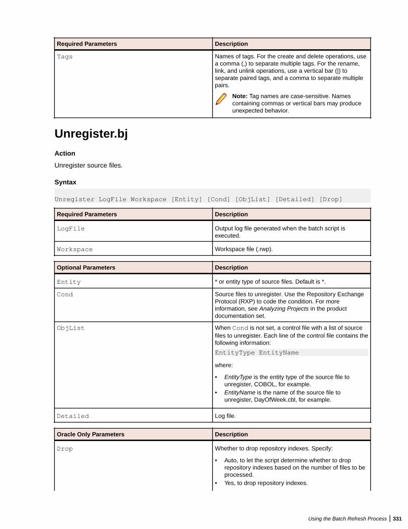
Required Parameters Description
Tags Names of tags. For the create and delete operations, usea comma (,) to separate multiple tags. For the rename,link, and unlink operations, use a vertical bar (|) toseparate paired tags, and a comma to separate multiplepairs.
Note: Tag names are case-sensitive. Namescontaining commas or vertical bars may produceunexpected behavior.
Unregister.bj
Action
Unregister source files.
Syntax
Unregister LogFile Workspace [Entity] [Cond] [ObjList] [Detailed] [Drop]
Required Parameters Description
LogFile Output log file generated when the batch script isexecuted.
Workspace Workspace file (.rwp).
Optional Parameters Description
Entity * or entity type of source files. Default is *.
Cond Source files to unregister. Use the Repository ExchangeProtocol (RXP) to code the condition. For moreinformation, see Analyzing Projects in the productdocumentation set.
ObjList When Cond is not set, a control file with a list of sourcefiles to unregister. Each line of the control file contains thefollowing information:
EntityType EntityName
where:
• EntityType is the entity type of the source file tounregister, COBOL, for example.
• EntityName is the name of the source file tounregister, DayOfWeek.cbl, for example.
Detailed Log file.
Oracle Only Parameters Description
Drop Whether to drop repository indexes. Specify:
• Auto, to let the script determine whether to droprepository indexes based on the number of files to beprocessed.
• Yes, to drop repository indexes.
Using the Batch Refresh Process | 331
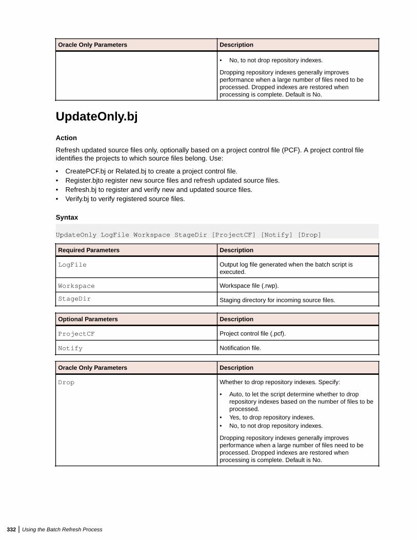
Oracle Only Parameters Description
• No, to not drop repository indexes.
Dropping repository indexes generally improvesperformance when a large number of files need to beprocessed. Dropped indexes are restored whenprocessing is complete. Default is No.
UpdateOnly.bj
Action
Refresh updated source files only, optionally based on a project control file (PCF). A project control fileidentifies the projects to which source files belong. Use:
• CreatePCF.bj or Related.bj to create a project control file.• Register.bjto register new source files and refresh updated source files.• Refresh.bj to register and verify new and updated source files.• Verify.bj to verify registered source files.
Syntax
UpdateOnly LogFile Workspace StageDir [ProjectCF] [Notify] [Drop]
Required Parameters Description
LogFile Output log file generated when the batch script isexecuted.
Workspace Workspace file (.rwp).
StageDir Staging directory for incoming source files.
Optional Parameters Description
ProjectCF Project control file (.pcf).
Notify Notification file.
Oracle Only Parameters Description
Drop Whether to drop repository indexes. Specify:
• Auto, to let the script determine whether to droprepository indexes based on the number of files to beprocessed.
• Yes, to drop repository indexes.• No, to not drop repository indexes.
Dropping repository indexes generally improvesperformance when a large number of files need to beprocessed. Dropped indexes are restored whenprocessing is complete. Default is No.
332 | Using the Batch Refresh Process
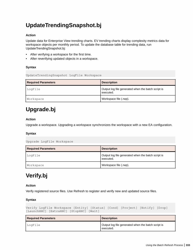
UpdateTrendingSnapshot.bj
Action
Update data for Enterprise View trending charts. EV trending charts display complexity metrics data forworkspace objects per monthly period. To update the database table for trending data, runUpdateTrendingSnapshot.bj:
• After verifying a workspace for the first time.• After reverifying updated objects in a workspace.
Syntax
UpdateTrendingSnapshot LogFile Workspace
Required Parameters Description
LogFile Output log file generated when the batch script isexecuted.
Workspace Workspace file (.rwp).
Upgrade.bj
Action
Upgrade a workspace. Upgrading a workspace synchronizes the workspace with a new EA configuration.
Syntax
Upgrade LogFile Workspace
Required Parameters Description
LogFile Output log file generated when the batch script isexecuted.
Workspace Workspace file (.rwp).
Verify.bj
Action
Verify registered source files. Use Refresh to register and verify new and updated source files.
Syntax
Verify LogFile Workspace [Entity] [Status] [Cond] [Project] [Notify] [Drop] [LaunchHHC] [ExtraHHC] [StopHHC] [Wait]
Required Parameters Description
LogFile Output log file generated when the batch script isexecuted.
Using the Batch Refresh Process | 333
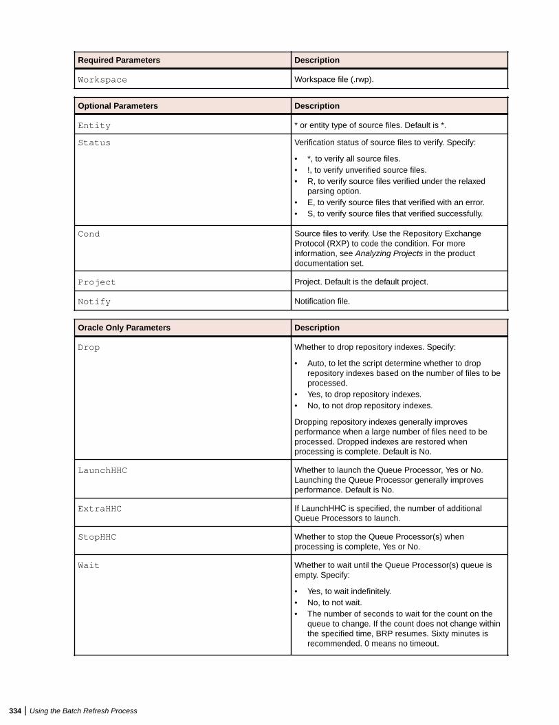
Required Parameters Description
Workspace Workspace file (.rwp).
Optional Parameters Description
Entity * or entity type of source files. Default is *.
Status Verification status of source files to verify. Specify:
• *, to verify all source files.• !, to verify unverified source files.• R, to verify source files verified under the relaxed
parsing option.• E, to verify source files that verified with an error.• S, to verify source files that verified successfully.
Cond Source files to verify. Use the Repository ExchangeProtocol (RXP) to code the condition. For moreinformation, see Analyzing Projects in the productdocumentation set.
Project Project. Default is the default project.
Notify Notification file.
Oracle Only Parameters Description
Drop Whether to drop repository indexes. Specify:
• Auto, to let the script determine whether to droprepository indexes based on the number of files to beprocessed.
• Yes, to drop repository indexes.• No, to not drop repository indexes.
Dropping repository indexes generally improvesperformance when a large number of files need to beprocessed. Dropped indexes are restored whenprocessing is complete. Default is No.
LaunchHHC Whether to launch the Queue Processor, Yes or No.Launching the Queue Processor generally improvesperformance. Default is No.
ExtraHHC If LaunchHHC is specified, the number of additionalQueue Processors to launch.
StopHHC Whether to stop the Queue Processor(s) whenprocessing is complete, Yes or No.
Wait Whether to wait until the Queue Processor(s) queue isempty. Specify:
• Yes, to wait indefinitely.• No, to not wait.• The number of seconds to wait for the count on the
queue to change. If the count does not change withinthe specified time, BRP resumes. Sixty minutes isrecommended. 0 means no timeout.
334 | Using the Batch Refresh Process

Using Architecture Modeler
Introducing Architecture ModelerUse Architecture Modeler to add support for unsupported languages and frameworks to EnterpriseAnalyzer (EA). You can also use it to extend support for already supported languages and frameworks.Architecture Modeler's:
• Graphical user interface, with error checking and metamodel lookup, makes it easy to define new entityand relationship types in EA.
• Regular expression generator simplifies the task of specifying the search patterns the EA parser uses toextract entities and relationships from source code.
Based on your input,Architecture Modeler creates a plug-in that defines an extension, or add-on, to the EAmetamodel. The add-on specifies the entity and relationship types of interest in the newly supportedsource files.
The plug-in also references a universal parser configuration file that defines the search patterns EA uses toextract entities and relationships from newly supported files. For text files, search patterns are mappedfrom regular expressions. For XML files, search patterns are mapped from XPath queries.
Here in schematic form are the tasks you perform in Architecture Modeler:
1. Load an existing metamodel.2. Save the metamodel with the name of your extension.3. Add a sample source file of the type you want to support in EA.4. Define the entity types for the add-on.5. Define the relationship types for the add-on.6. Map search patterns for the entity and relationship instances you want the parser to extract.7. Export the model to EA.8. Reconfigure EA.
Before turning to these tasks, users who are new to EA may want to familiarize themselves with theconcepts underlying the EA metamodel. Experienced users can skip straight to the tasks.
Note: Architecture Modeler currently supports the level-1, or application-level, metamodel only.Support for the level-2, or object-level, metamodel (Interactive Analysis) will be available in a futurerelease.
Entity extension mode is currently not available for the following entities: EZT, CA7, JSP, JSX,NetronSPC, NetronSpec, TLD, TS, and WebConfig.
Important: If you are using Windows 7 or Windows 8, make sure you are running the ArchitectureModeler with administrator rights. Otherwise some operations might fail.
Opening Architecture Modeler1. Open the Enterprise Analyzer installation directory
2. Double-click \bin\Architecture Modeler.exe. The Architecture Modeler window opens.
Note:
Using Architecture Modeler | 335
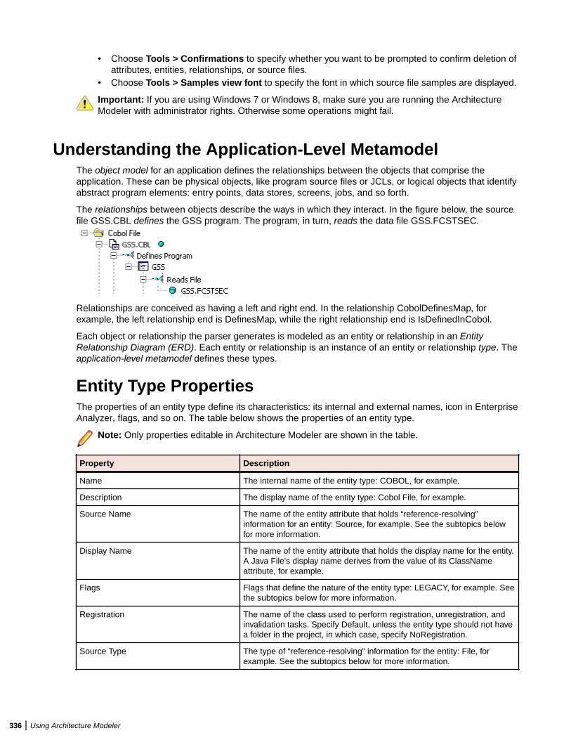
• Choose Tools > Confirmations to specify whether you want to be prompted to confirm deletion ofattributes, entities, relationships, or source files.
• Choose Tools > Samples view font to specify the font in which source file samples are displayed.
Important: If you are using Windows 7 or Windows 8, make sure you are running the ArchitectureModeler with administrator rights. Otherwise some operations might fail.
Understanding the Application-Level MetamodelThe object model for an application defines the relationships between the objects that comprise theapplication. These can be physical objects, like program source files or JCLs, or logical objects that identifyabstract program elements: entry points, data stores, screens, jobs, and so forth.
The relationships between objects describe the ways in which they interact. In the figure below, the sourcefile GSS.CBL defines the GSS program. The program, in turn, reads the data file GSS.FCSTSEC.
Relationships are conceived as having a left and right end. In the relationship CobolDefinesMap, forexample, the left relationship end is DefinesMap, while the right relationship end is IsDefinedInCobol.
Each object or relationship the parser generates is modeled as an entity or relationship in an EntityRelationship Diagram (ERD). Each entity or relationship is an instance of an entity or relationship type. Theapplication-level metamodel defines these types.
Entity Type PropertiesThe properties of an entity type define its characteristics: its internal and external names, icon in EnterpriseAnalyzer, flags, and so on. The table below shows the properties of an entity type.
Note: Only properties editable in Architecture Modeler are shown in the table.
Property Description
Name The internal name of the entity type: COBOL, for example.
Description The display name of the entity type: Cobol File, for example.
Source Name The name of the entity attribute that holds “reference-resolving”information for an entity: Source, for example. See the subtopics belowfor more information.
Display Name The name of the entity attribute that holds the display name for the entity.A Java File's display name derives from the value of its ClassNameattribute, for example.
Flags Flags that define the nature of the entity type: LEGACY, for example. Seethe subtopics below for more information.
Registration The name of the class used to perform registration, unregistration, andinvalidation tasks. Specify Default, unless the entity type should not havea folder in the project, in which case, specify NoRegistration.
Source Type The type of “reference-resolving” information for the entity: File, forexample. See the subtopics below for more information.
336 | Using Architecture Modeler
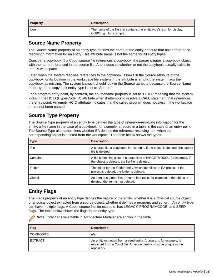
Property Description
Icon The name of the file that contains the entity type’s icon for display:COBOL.gif, for example.
Source Name PropertyThe Source Name property of an entity type defines the name of the entity attribute that holds “reference-resolving” information for an entity. This attribute name is not the same for all entity types.
Consider a copybook. If a Cobol source file references a copybook, the parser creates a copybook objectwith the name referenced in the source file. And it does so whether or not the copybook actually exists inthe EA workspace.
Later, when the system resolves references to the copybook, it looks in the Source attribute of thecopybook for its location in the workspace file system. If the attribute is empty, the system flags thecopybook as missing. The system knows it should look in the Source attribute because the Source Nameproperty of the copybook entity type is set to “Source.”
For a program entry point, by contrast, the sourcename property is set to “HCID,” meaning that the systemlooks in the HCID (HyperCode ID) attribute when it attempts to resolve a CALL statement that referencesthe entry point. An empty HCID attribute indicates that the called program does not exist in the workspaceor has not been parsed.
Source Type PropertyThe Source Type property of an entity type defines the type of reference-resolving information for theentity: a file name in the case of a copybook, for example, a record in a table in the case of an entry point.The Source Type also determines whether EA deletes the reference-resolving item when thecorresponding object is deleted from the workspace. The table below shows the types.
Type Description
File A source file: a copybook, for example. If the object is deleted, the sourcefile is deleted.
Container A file containing a list of source files: a TARGETMODEL, for example. Ifthe object is deleted, the list file is deleted.
Folder The folder for the Folder entity, which identifies an EA project. If theproject is deleted, the folder is deleted.
Global An item in a global file: a record in a table, for example. If the object isdeleted, the item is not deleted.
Entity FlagsThe Flags property of an entity type defines the nature of the entity: whether it is a physical source objector a logical object extracted from a source object, whether it defines a program, and so forth. An entity typecan have multiple flags. A Cobol source file, for example, has LEGACY, PROGRAMCODE, and SEEDflags. The table below shows the flags for an entity type.
Note: Only flags selectable in Architecture Modeler are shown in the table.
Flag Description
COMPOSITE n/a
EXTRACT An entity extracted from a seed entity. A program, for example, isextracted from a Cobol file. An extract entity must be unique in therepository.
Using Architecture Modeler | 337
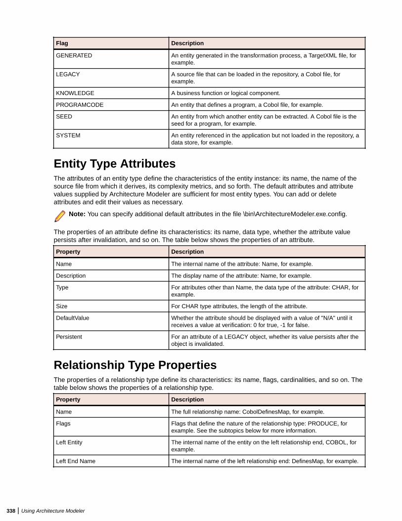
Flag Description
GENERATED An entity generated in the transformation process, a TargetXML file, forexample.
LEGACY A source file that can be loaded in the repository, a Cobol file, forexample.
KNOWLEDGE A business function or logical component.
PROGRAMCODE An entity that defines a program, a Cobol file, for example.
SEED An entity from which another entity can be extracted. A Cobol file is theseed for a program, for example.
SYSTEM An entity referenced in the application but not loaded in the repository, adata store, for example.
Entity Type AttributesThe attributes of an entity type define the characteristics of the entity instance: its name, the name of thesource file from which it derives, its complexity metrics, and so forth. The default attributes and attributevalues supplied by Architecture Modeler are sufficient for most entity types. You can add or deleteattributes and edit their values as necessary.
Note: You can specify additional default attributes in the file \bin\ArchitectureModeler.exe.config.
The properties of an attribute define its characteristics: its name, data type, whether the attribute valuepersists after invalidation, and so on. The table below shows the properties of an attribute.
Property Description
Name The internal name of the attribute: Name, for example.
Description The display name of the attribute: Name, for example.
Type For attributes other than Name, the data type of the attribute: CHAR, forexample.
Size For CHAR type attributes, the length of the attribute.
DefaultValue Whether the attribute should be displayed with a value of "N/A" until itreceives a value at verification: 0 for true, -1 for false.
Persistent For an attribute of a LEGACY object, whether its value persists after theobject is invalidated.
Relationship Type PropertiesThe properties of a relationship type define its characteristics: its name, flags, cardinalities, and so on. Thetable below shows the properties of a relationship type.
Property Description
Name The full relationship name: CobolDefinesMap, for example.
Flags Flags that define the nature of the relationship type: PRODUCE, forexample. See the subtopics below for more information.
Left Entity The internal name of the entity on the left relationship end, COBOL, forexample.
Left End Name The internal name of the left relationship end: DefinesMap, for example.
338 | Using Architecture Modeler
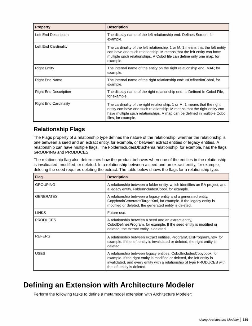
Property Description
Left End Description The display name of the left relationship end: Defines Screen, forexample.
Left End Cardinality The cardinality of the left relationship, 1 or M. 1 means that the left entitycan have one such relationship; M means that the left entity can havemultiple such relationships. A Cobol file can define only one map, forexample.
Right Entity The internal name of the entity on the right relationship end, MAP, forexample.
Right End Name The internal name of the right relationship end: IsDefinedInCobol, forexample.
Right End Description The display name of the right relationship end: Is Defined In Cobol File,for example.
Right End Cardinality The cardinality of the right relationship, 1 or M. 1 means that the rightentity can have one such relationship; M means that the right entity canhave multiple such relationships. A map can be defined in multiple Cobolfiles, for example.
Relationship FlagsThe Flags property of a relationship type defines the nature of the relationship: whether the relationship isone between a seed and an extract entity, for example, or between extract entities or legacy entities. Arelationship can have multiple flags. The FolderIncludesDbSchema relationship, for example, has the flagsGROUPING and PRODUCES.
The relationship flag also determines how the product behaves when one of the entities in the relationshipis invalidated, modified, or deleted. In a relationship between a seed and an extract entity, for example,deleting the seed requires deleting the extract. The table below shows the flags for a relationship type.
Flag Description
GROUPING A relationship between a folder entity, which identifies an EA project, anda legacy entity, FolderIncludesCobol, for example.
GENERATES A relationship between a legacy entity and a generated entity,CopybookGeneratesTargetXml, for example. If the legacy entity ismodified or deleted, the generated entity is deleted.
LINKS Future use.
PRODUCES A relationship between a seed and an extract entity,CobolDefinesProgram, for example. If the seed entity is modified ordeleted, the extract entity is deleted.
REFERS A relationship between extract entities, ProgramCallsProgramEntry, forexample. If the left entity is invalidated or deleted, the right entity isdeleted.
USES A relationship between legacy entities, CobolIncludesCopybook, forexample. If the right entity is modified or deleted, the left entity isinvalidated, and every entity with a relationship of type PRODUCES withthe left entity is deleted.
Defining an Extension with Architecture ModelerPerform the following tasks to define a metamodel extension with Architecture Modeler:
Using Architecture Modeler | 339
1. Load an existing metamodel.2. Save the metamodel with the name of your extension.3. Add a sample source file of the type you want to support in EA.4. Define the entity types for the add-on.5. Define the relationship types for the add-on.6. Map search patterns for the entity and relationship instances you want the parser to extract.7. Export the model to EA.8. Reconfigure EA.
Before turning to these tasks, users who are new to EA may want to familiarize themselves with theconcepts underlying the EA metamodel. Experienced users can skip straight to the tasks.
Loading a MetamodelYou can load an existing metamodel to use as a shell for your extension, or create a new metamodel.Loading an existing metamodel is probably a better choice, because it ensures against duplicating existingentity and relationship names.
• To load an existing metamodel, choose Model > Open. An Open dialog is displayed, where you canbrowse for \Model\Repository\Common.Repstry.xml in the Enterprise Analyzer installationdirectory. Click Open to load the metamodel.
• To create a new metamodel, choose Model > New > Model. Nothing is displayed in the ArchitectureModeler window until you add files, entities, or relationships.
Saving the Extended MetamodelWhether you load an existing metamodel or create a new one, you must save the extended metamodel topreserve your changes. To save an extended metamodel, choose Model > Save. A Save As dialog opens,where you can save the extension with a new or an existing file name. Click Save to return to theArchitecture Modeler window.
Adding a Sample Source FileWhen you add a sample source file to Architecture Modeler, you define the entity type for the source file inthe extended metamodel, and make available the code you will use to generate regular expressions. Toadd support for Objective C, for example, you would define an entity type that represents an Objective Csource file, then add one or more Objective C source files to Architecture Modeler.
Choose a sample that contains the kinds of entities and relationships you want the parser to extract. If youwant the parser to model calls to Objective C functions, make sure your sample contains a function call!
Note: Architecture Modeler supplies default values for the properties and attributes of the source filetype you are adding. Except for the value of the Description property, which holds the entity typename displayed to the end user, the default values usually are sufficient. You can change theDescription (and any other property or attribute values) when you edit the source file type.
1. Click the Files button in Architecture Modeler and choose Add New in the drop-down menu. The AddNew File window opens.
2. In the Name field, enter the name of the entity type for the source file. For an Objective C source file,you might choose the name "OBJC" for the entity type.
Note: If you are extending support for an already supported source file, the name you specifycannot be the same as the name of the already supported source file. No entity type is created forthe specified name. The extension is simply a mechanism for naming the universal parserconfiguration file that contains the search patterns with which you are extending support.
3. In the Type drop-down, select the type of the source file you are adding, XML or Text. If you select Text,click the Format button to view formatting options.
340 | Using Architecture Modeler
Note: Think of Text as any kind of file other than XML.
4. Select as an extension to if you are extending support for an already supported source file, thenchoose the source file type in the adjacent combo box.
Note: The Metrics and Name Pattern areas are disabled in entity extension mode.
5. In the Metrics group box, select each metric you want EA to calculate for the source file.
6. In the Source samples group box, click Add new. An Open dialog is displayed, where you can browsefor the sample source file. Click Open to add the file. Repeat this procedure for each sample you wantto add. To delete a file, select it and click Delete.
7. In the Name Patterns group box, click Add new. An editable text field is displayed. Click inside the fieldand enter the extension, including the dot (.), for the source file type. You can use wildcard patternsallowed in LIKE statements by Visual Basic for Applications (VBA). Click outside the field to add theextension. Repeat this procedure for each extension you want to add. To delete an extension, select itand click Delete.
8. When you are satisfied with your choices, click OK.
Architecture Modeler displays the new source file type in the Name area in the central pane of the window,and the text of the sample source file in the righthand pane. If more than one source file type is listed, clickthe name of the type to display the corresponding sample.
Note: Select a source file type and click Files > Edit to modify its file characteristics. Select a sourcefile type and click Files > Delete to delete the type.
Specifying Formatting Options for Text FilesComments, strings, and fixed formats may create "noise" in parser extractions. The more specific you arein defining how you want the parser to handle these and similar text file characteristics, the cleaner yourresults will be.
1. To specify formatting options for a text file, click the Format button in the Add New File or Edit Filewindow. The Input Source Format window opens.
2.In the Input Source Format window, click the button to sort the list by category, click the buttonto sort the list alphabetically.
3. Edit the formatting options as necessary:
• For Boolean values, choose from the drop-down list inside the value field.• For string values, enter the text of the string in the value field.• For the StringLiteralSymbol option, click the browse button in the value field. The Char Collection
Editor window opens. Click the Add button to add a symbol for the start of a string literal.Architecture Modeler displays the new collection member in the lefthand pane. Select the member,then enter its value in the righthand pane. Repeat this procedure for each symbol you want to define.
To delete a collection member, select it and click Remove. Click the button to sort the list by
category, click the button to sort the list alphabetically. Click OK to confirm your changes.
The table below shows the formatting options in alphabetical order. Option values are modifiedautomatically depending on your choices in other fields.
Option Description
EndingColumn The last valid column of the source.
HasEndingColumn Whether the source has an ending column.
HasLiteralContinuationSymbol Whether the source has a literal continuation symbol.
Using Architecture Modeler | 341
Option Description
HasMultiLineComment Whether the source has multiline comments.
HasSingleLineComment Whether the source has single line comments.
HasSingleLineCommentContinuation Whether the source has single line comment continuations.
HasStartingColumn Whether the source has a starting column.
HasStringLiteralSymbol Whether the source has symbols used to start string literals.
IgnoreColumns Whether to ignore column information before the starting column andafter the ending column.
IgnoreComments Whether to ignore comments.
IgnoreStringLiterals Whether to ignore string literals.
MultiLineCommentEnd Symbol for the end of a multiline comment.
MultiLineCommentStart Symbol for the start of a multiline comment.
SingleLineCommentContinuationSymbol Symbol for the continuation of a single line comment.
SingleLineCommentStart Symbol for the start of a single line comment.
StartingColumn The first valid column of the source.
StringLiteralContinuationSymbol Symbol for the continuation of a string literal.
StringLiteralSymbol Symbols for the start of string literals.
4. When you are satisfied with your choices in the Input Source Format window, click OK.
Defining Entity TypesEach object the parser generates is an instance of an entity type. You need to define these types in theextended metamodel. If you are adding support for Objective C, for example, you would define an entitytype that represents an Objective C function.
For each entity type, you specify two kinds of information:
• The properties of the entity type define its characteristics: its internal and external names, icon inEnterprise Analyzer, flags, and so on.
• The attributes of the entity type define the characteristics of the entity instance: its name, the name ofthe source file from which it derives, its complexity metrics, and so forth. The default attributes andattribute values supplied by Architecture Modeler are sufficient for most entity types. You can add ordelete attributes and edit their values as necessary.
1. Click the Entities button in Architecture Modeler and choose Add New in the drop-down menu. Theproperties definition page of the Add New Entity window opens.
2. On the properties definition page, fill in the properties of the entity type. Architecture Modeler flags anyerrors with a symbol.
Note: Do not enter spaces in the Name property.
3.When you are satisfied with your entries on the properties definition page, click the button. Theattributes definition page opens.
4. On the attributes definition page, add, edit, or delete attributes as necessary:
• To add an attribute, click the Add New button. The Add New Attribute dialog opens, where you canspecify the values for each property of the attribute. Architecture Modeler flags any errors with a symbol. When you are satisfied with your entries, click OK.
342 | Using Architecture Modeler
• To edit an attribute, click the Edit button. The Edit Attribute dialog opens, where you can specify thevalues for each property of the attribute. Architecture Modeler flags any errors with a symbol.When you are satisfied with your entries, click OK.
• To delete an attribute, click the Delete button.
5.
When you are satisfied with your entries on the attributes definition page, click the button.Architecture Modeler flags any errors with a symbol.
Note: The errors may not be immediately visible. If you are on the attributes definition page, errorsmay be flagged on the properties definition page, and vice versa.
Assuming there are no errors in your entries, Architecture Modeler saves the entity type definition, anddisplays the entity type in the list of entity types in the righthand pane of the window.
Note: Select an entity type and click Entities > Edit to modify its definition. Select an entity type andclick Entities > Delete to delete the definition.
Defining Relationship TypesEach relationship the parser generates is an instance of a relationship type. You need to define these typesin the extended metamodel. If you are adding support for Objective C, for example, you would define arelationship type that represents the relationship between an Objective C source file and an Objective Cfunction.
1. Click the Relations button in Architecture Modeler and choose Add New in the drop-down menu. TheAdd New Relation window opens.
2. In the Add New Relation window, fill in the properties of the relationship type. Architecture Modeler flagsany errors with a symbol.
Note: Do not enter spaces in the Name property.
3. When you are satisfied with your entries, click OK.
Assuming there are no errors in your entries, Architecture Modeler saves the relationship type definition,and displays the relationship type in the list of relationship types in the righthand pane of the window.
Note: Select a relationship type and click Relations > Edit to modify its definition. Select arelationship type and click Relations > Delete to delete the definition.
Architecture Modeler Internal Language FunctionsDescription
string.substr(pos1,pos2)
string.substr(pos1,pos2) – returns a substring, derived from pos1 to pos2 of string.
Examples:
expressionid.0.substr ( 5, 4 )expressionid.0.substr(expressionid.0.length() - 5, 4 )expressionid.0.substr( 4 , expressionid.0.length() - 5 )expressionid.0.substr(expressionid.0.length() - 9 , expressionid.0.length() - 5 )expressionid.sourcefilename.substr(1,5)expressionid.sourcefilename.substr(expressionid.0.sourcefilename.length() - 11 , 3 )expressionid.sourcefilename.substr( 0, expressionid.0.sourcefilename.length() - 4 )
Using Architecture Modeler | 343
expressionid.sourcefilename.substr(expressionid.0.sourcefilename.length() – 15 )
string1.append(string2)
string1.append(string2) - appends string2 to string1.
Examples:
expressionid.0.append( \"._abcd_\" )expressionid.0.append(expressionid.0 )expressionid.0.append(expressionid.0.sourcefilename )expressionid.sourcefilename.append( \"_001\" )expressionid.sourcefilename.append( expressionid.0 )
string.length()
string.length() - returns the length of the string.
Examples:
expressionid.sourcefilename.length()expressionid.sourcefilename.length()-3expressionid.sourcefilename.length()+13expressionid.sourcefilename.length( )
concat(string1, string2)
concat(string1, string2) – returns concatenation of string1 and string2
Examples:
concat(\"ab_\", \"cd__\" )concat( expressionid.0,expressionid.0)concat( expressionid.0, \"_test_\" )concat( \"_test_\" , expressionid.0 )concat( expressionid.sourcefilename , expressionid.0 )concat(expressionid.0, expressionid.sourcefilename )concat(expressionid.sourcefilename.substr(0, expressionid.sourcefilename.length()-3), expressionid.0)concat(expressionid.sourcefilename.append( \"...\"), expressionid.0)concat(expressionid.sourcefilename, \"_abc_\" )concat( \"_abc_\" , expressionid.sourcefilename )concat( \"_abc_\" , concat( \"_efg_\" , \"_xy_z_\") )concat( concat( \"_efg_\" , \"_xy_z_\"), \"_abc_\" )concat( concat( \"_efg_\" , concat(\"_val1_\", \"_val2_\")) , \"_abc_\" )concat( concat(expressionid.sourcefilename.append( \"...\") , \"_val_\" ) , expressionid.0)
replace(string1,string2,string3)
replace(string1,string2,string3) – replaces all occurrences of string2 in string1 withstring3.
Examples:
replace( \"ab_\", \"_\", \"__\" ) // equals “ab__”replace( \"ab_\", \"ab\", \"cd\" ) // equals “cd_”replace(expressionid.sourcefilename.substr(1,5), \"a\", \"b\" ) // replaces ‘a’ with ‘b’ in the first 5 letters of expressionid.sourcefilenamereplace(expressionid.sourcefilename, '/' . '\' ) // converts backslashes to slashes
344 | Using Architecture Modeler
getpath(string)
getpath(string) – returns a string, trimmed starting from the last occurrence of ‘\’ or ‘/’ . Returnsthe absolute path as string before the last occurrence of \ or /.
Examples:
getpath(“c:\path1\path2\filename.ext”) // returns c:\path1\path2\getpath(“..\path1\path2\filename.ext”) // returns ..\path1\path2\getpath(expressionid.sourcefilename) // returns the path of the sourcefilename
getfilename(string)
getfilename(string) – .returns the filenames in paths as a string after the last occurrence of the \ or /?
Examples:
getfilename (“c:\path1\path2\filename.ext”) // returns filename.extgetfilename (“..\path1\path2\filename.ext”) // returns filename.extgetfilename (expressionid.sourcefilename) // returns filename of the sourcefilename
unifypath(string)
unifypath(string) – returns transformed string by the following rules:
• Converting all backslashes to slashes.
Example:
/path1/path2 is transformed into \path1\path2• Removing duplicate slashes.
Example:
//path1/\path2 is transformed into \path1\path2• Removing references to current directory
Example:
\.\path1/.\path2 is transformed into \path1\path2• Removing references to parent directory (if not in the beginning) examples
Examples:
\path1\..\path2 is transformed into \path2
..\path1\..\path2\path3 is transformed into ..\path2\path3
Mapping Regular Expressions to Text File SearchesThe Enterprise Analyzer parser extracts entity and relationship instances from text files using searchpatterns you define in Architecture Modeler. In schematic form, the parser uses these patterns to:
• Match relationship instances in the code.• Form the names of entity instances.• Form the names of relationship instances.
Architecture Modeler's regular expression generator simplifies the task of defining these patterns. Followthe steps below to map regular expressions to text file searches.
1. Click Files in Architecture Modeler. Architecture Modeler displays the defined source file types in theName area in the central pane of the window, and the text of the corresponding sample in the right-handpane. If more than one source file type is listed, click the name of the type to display the sample.
Using Architecture Modeler | 345
2. Generate the pattern the parser uses to match relationship instances:
a) Select the code of interest in the sample source file.b) Choose Pick in the right-click menu.
The Add Expression window opens.
3. Add an expression ID, e.g. "function" for the selected function call. All expression IDs appear in themiddle-bottom left-hand side of the screen in a tree form.
4. Select the expression ID and choose Edit in the right-click menu. The Edit Regular Expression Mappingwindow opens. Expressions are represented in a hierarchical manner. Each expression contains itsregular expression pattern and all direct children expressions.
5. Select the expression pattern and choose Edit in the right-click menu. The Edit Regular Expressionwindow opens. The generated regular expression is displayed in the upper part of the left-hand pane intree form. The expression does not require further editing.
Note: Do not manually edit the generated regular expression unless you have modified itinadvertently.
6. In the left-hand pane of the Edit Regular Expression window, define the regular expression the parseruses to form the names of entity instances:
a) Expand the tree for the generated regular expression.b) Use a subexpression of the generated regular expression to match the names of entity instances.
Follow the instructions in Editing Subexpressions to edit the subexpression.c) Click Apply Changes after each modification.
7. In the right-hand pane of the Edit Regular Expression Mapping window, map the regular expression forthe names of entity instances. You do not need to map a regular expression for the source file name:
a) In the Entity group box, select the entity type you want to match in the Type drop-down.b) Drag-and-drop the subexpression for the names of entity instances from the expression tree to the
cell beside the Name attribute. The subexpression is mapped to a variable with a name reflecting theorder of grouped expressions in the expression tree, counting from the regular expression for thematched relationship. For example if (\w+) is the only other grouped expression besides theexpression for the matched relationship, the mapped variable is named %[ExpressionID].2%.
c) Assuming you are defining a relationship between a source file and an extracted object, enter thesystem variable %[ExpressionID].sourcefilename in the cell beside the Source attribute. Ifyou are defining another type of relationship, reference-resolving information may be contained in adifferent attribute.
d) You can use functions to help you resolve entities' relationship ends. These functions are:substr,append, length, concat, replace, getpath, getfilename, unifypath. For more details onthe usage of these functions, read Application Modeler Internal Language Functions Description.
8. Click Save in the Entity group box. The entity mapping is added to the list of mappings in the MappingList group box. Repeat this procedure for each entity mapping you want to define.
9. In the right-hand pane of the Edit Regular Expression Mapping window, map the regular expression forthe names of relationship instances:
a) In the Relation group box, select the relationship type you want to map in the Type drop-down.b) Drag-and-drop the subexpression for the left entity name from the expression tree to the cell beside
the Left Entity Name attribute. If you are defining a relationship between a source file and anextracted object, enter the system variable %[expressionid].sourcefilename% in the cellbeside the Left Entity Name attribute.
c) Drag-and-drop the subexpression for the right entity name from the expression tree to the cell besidethe Right Entity Name attribute.
10.Click Save in the Relation group box. The relationship mapping is added to the list of mappings in theMapping List group box.
346 | Using Architecture Modeler
Note: To edit a mapping definition, select it in the Mapping List group box and click Edit. Followthe procedure you used to define the mapping. To delete a mapping definition, select it in theMapping List group box and click Remove.
11.When you finish editing your entries in the Edit Regular Expression Mapping window, click Save.Architecture Modeler displays the edited expression ID in the central pane of the window.
Note:
• Select the expression ID and choose Edit in the right-click menu to modify the pattern.• Select it and choose Delete in the right-click menu to delete the pattern.
Editing SubexpressionsEditing subexpressions consists of two tasks:
• Grouping and quantifying subexpressions.• Providing Scope for recursive regular expressions.
The subexpression for the entity you want to match must either be grouped or an exact match. Any otherinput is not accepted.
1. In the Edit Regular Expression dialog, edit the expression manually, or use the buttons to modify teexpression.a) Click Convert to Exact match to match the Item Value to the Matched Value sample only.b) Click Convert to Group if you want to group the expression.c) Click Revert Changes if you want to cancel any last changes or Apply Changes to save them.
Note: The subexpression for the entity you want to match must either be grouped or an exactmatch. Any other input is not accepted.
2. If you need to qualify the expression further, edit the regular expression in the Item Value fieldconsidering the following:
• Plus equates to the quantifier +, which denotes one or more occurrence.• Star equates to the quantifier *, which denotes 0 or more occurrences.• Optional equates to the quantifier ?, which denotes 0 or 1 occurrence.
3. Click Apply Changes after each modification.
4. Click OK when you are done editing your entries in Edit Regular Expression dialog.
Architecture Modeler displays the edited subexpression in the expression tree.
Mapping XPath Queries to XML File SearchesThe EA parser extracts entity and relationship instances from XML using search patterns you define inArchitecture Modeler. In schematic form, the parser uses these patterns to:
• Match relationship instances in the code.• Form the names of entity instances:
• Form the names of relationship instances:
Using Architecture Modeler | 347

Architecture Modeler's XPath query generator simplifies the task of defining these patterns. Follow thesteps below to map XPath queries to XML file searches.
1. Click the Files button in Architecture Modeler. Architecture Modeler displays the defined source filetypes in the Name area in the central pane of the window, and the text of the corresponding sample inthe right-hand pane. If more than one source file type is listed, click the name of the type to display thesample.
2. Define the XPath query the parser uses to match relationship instances:
• Select the node of interest in the sample, then use the right-click menu to form the XPath query. Tomatch the relationship OrgChartDefinesOrgChartEmployee in the XML code shown below, theXPath query would be:
/def:OrgChart/def:Employees/child::def:Employee
To form the query, select the <Employees> node and choose Select All <Employees> childrenelements > /child::def:Employee from the right-click menu.
• The XPath query is displayed in the XPath Query field. When you are satisfied with the query, clickPick.
348 | Using Architecture Modeler
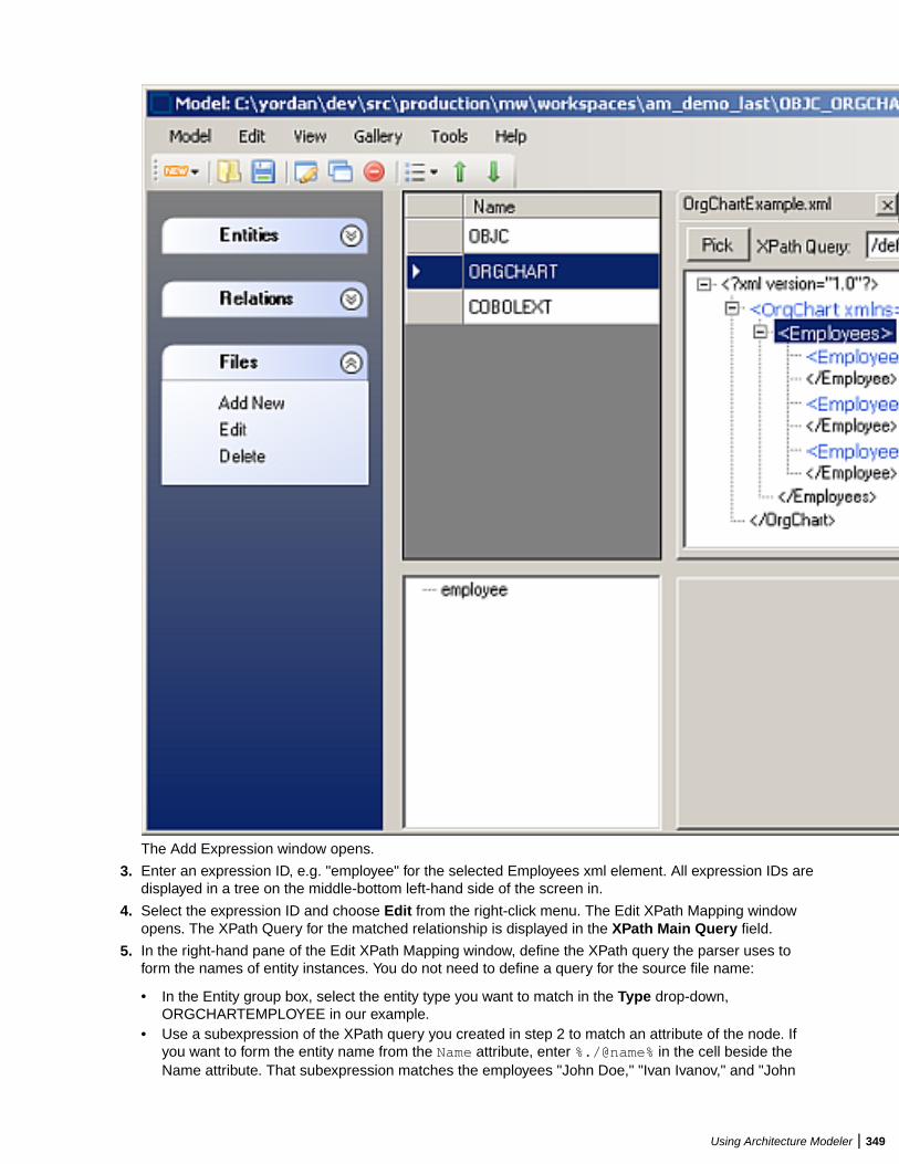
The Add Expression window opens.
3. Enter an expression ID, e.g. "employee" for the selected Employees xml element. All expression IDs aredisplayed in a tree on the middle-bottom left-hand side of the screen in.
4. Select the expression ID and choose Edit from the right-click menu. The Edit XPath Mapping windowopens. The XPath Query for the matched relationship is displayed in the XPath Main Query field.
5. In the right-hand pane of the Edit XPath Mapping window, define the XPath query the parser uses toform the names of entity instances. You do not need to define a query for the source file name:
• In the Entity group box, select the entity type you want to match in the Type drop-down,ORGCHARTEMPLOYEE in our example.
• Use a subexpression of the XPath query you created in step 2 to match an attribute of the node. Ifyou want to form the entity name from the Name attribute, enter %./@name% in the cell beside theName attribute. That subexpression matches the employees "John Doe," "Ivan Ivanov," and "John
Using Architecture Modeler | 349
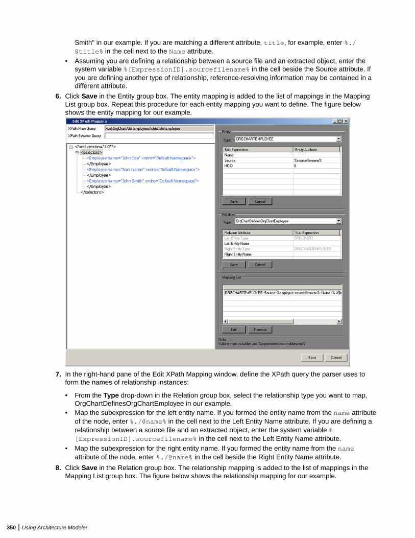
Smith" in our example. If you are matching a different attribute, title, for example, enter %./@title% in the cell next to the Name attribute.
• Assuming you are defining a relationship between a source file and an extracted object, enter thesystem variable %[ExpressionID].sourcefilename% in the cell beside the Source attribute. Ifyou are defining another type of relationship, reference-resolving information may be contained in adifferent attribute.
6. Click Save in the Entity group box. The entity mapping is added to the list of mappings in the MappingList group box. Repeat this procedure for each entity mapping you want to define. The figure belowshows the entity mapping for our example.
7. In the right-hand pane of the Edit XPath Mapping window, define the XPath query the parser uses toform the names of relationship instances:
• From the Type drop-down in the Relation group box, select the relationship type you want to map,OrgChartDefinesOrgChartEmployee in our example.
• Map the subexpression for the left entity name. If you formed the entity name from the name attributeof the node, enter %./@name% in the cell next to the Left Entity Name attribute. If you are defining arelationship between a source file and an extracted object, enter the system variable %[ExpressionID].sourcefilename% in the cell next to the Left Entity Name attribute.
• Map the subexpression for the right entity name. If you formed the entity name from the nameattribute of the node, enter %./@name% in the cell beside the Right Entity Name attribute.
8. Click Save in the Relation group box. The relationship mapping is added to the list of mappings in theMapping List group box. The figure below shows the relationship mapping for our example.
350 | Using Architecture Modeler

Note: To edit a mapping definition, select it in the Mapping List group box and click Edit. Followthe procedure you used to define the mapping. To delete a mapping definition, select it in theMapping List group box and click Remove.
Using Architecture Modeler | 351
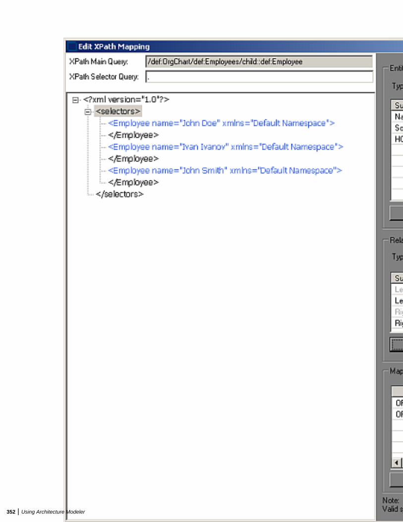
352 | Using Architecture Modeler
9. When you are satisfied with your entries in the Edit XPath Mapping window, click Save.
Architecture Modeler displays the search pattern for the matched relationship in the Match pattern area inthe central pane of the window.
Note: Select the search pattern for the matched relationship and choose Edit in the right-click menuto modify the pattern. Select it and choose Delete from the right-click menu to delete the pattern.
Exporting the Extended MetamodelBased on your input, Architecture Modeler creates a plug-in that defines an extension, or add-on, to the EAmetamodel. The add-on specifies the entity and relationship types of interest in the newly supportedsource files.
To export the plug-in to EA:
1. Select the source file type for the extension in the Name area in the central pane of the ArchitectureModeler window.
2. Choose Export to EA in the right-click menu.
A Browse dialog opens.3. Browse for the Plugins folder in the Enterprise Analyzer installation directory.4. Click OK to export the extended metamodel. The plug-in has a name of the form
<SourceFileType>Plugin.xml.
Important: If you are using Windows 7 or Windows 8, make sure you are running the ArchitectureModeler with administrator rights. Otherwise some operations might fail.
Reconfiguring Enterprise AnalyzerEA After exporting an extended metamodel to Enterprise Analyzer, you need to reconfigure EA for the newsource file type. To reconfigure EA after plug-in export,
1. Double-click \bin\rescan.exe in the Enterprise Analyzer installation directory.
The Configuration Manager window opens, with a check box in the Programming Languages folder forthe new extension.
2. Select the check box and click OK.
Make sure to upgrade the configuration of any workspaces you want to use the new extension in.
Troubleshooting the Extended MetamodelThe plug-in for an extended metamodel references a universal parser configuration file that defines thesearch patterns EA uses to extract entities and relationships from newly supported files. EA issues thefollowing errors for problems it encounters processing the universal parser configuration file at verification:
• Error - 404 3 Error while processing XML file '%1' . Logged when the Universal Parser configuration fileis corrupt or missing.
• Error - 407 3 Error while processing regular expression '%1'. Logged when a regular expression definedin the Universal Parser configuration file is invalid.
• Error - 409 3 Input source file '%1' not found. Logged when the file to be parsed is not found.• Error - 411 3 Error creating expression with Id '%1'. Logged when an expression with a given Id failed to
be created.• Error - 412 3 Expression Id '%1' already exists. Logged when an expression Id is not unique.• Error - 413 3 Error in attribute value '%1': Unexisting expression Id. Logged when a non existing
expression Id is found in an attribute value.• Error - 414 3 Error in attribute value '%1': Match not found. Logged when a not existing match index is
found in an attribute value.
Using Architecture Modeler | 353
• Error - 415 3 Error in attribute value '%1': Match group not found. Logged when a not existing matchgroup was detected in an attribute value.
• Error - 416 3 Error in attribute value '%1': Syntax error. Logged when an attribute value is notsyntactically correct.
• Error - 417 3 Error in attribute value '%1': Type mismatch. Logged when an attribute value contains typemismatching.
Using GalleriesIn Architecture Modeller you can export or import model extensions to a common location known asGallery.
1. To export to Gallery:
a) Select the extension you want to export and click Gallery>Export. The Export to Gallery windowopens.
b) Write a short description for the Gallery item and click OK. The Select gallery for export windowopens.
c) Browse to the current Gallery file location and click OK .
The selected model extension has been successfully exported to the selected gallery.
2. To Import from Gallery:
a) Click on Gallery > Import menu item. The Import from Gallery window appears.b) Select the short description for the model extension you want to import from the gallery and click
OK.
354 | Using Architecture Modeler
EA Web
Installing EA WebThe following steps assume you have created a workspace. See Getting Started for more information.
Typically, EA Web is installed together with Enterprise Analyzer, by selecting the Web Client option in theinstaller. If you have already installed Enterprise Analyzer but haven't installed EA Web with it, follow thesteps below:
1. Install Enterprise Analyzer. For instructions on how to do this see the Installation Guide.2. Install JRE 7 (jre-7u21-windows-i586.exe). The JRE installer is provided with the EA installer in
CD1 - Enterprise Analyzer\EA Web Server Pre-requisites\.3. Install Apache Tomcat (apache-tomcat-6.0.16.exe). The Apache Tomcat installer is provided with
the EA installer in CD1 - Enterprise Analyzer\EA Web Server Pre-requisites\. Followthe screen prompts and accept the defaults, except:
• On the Choose Components screen, expand the Tomcat option and check Service to have Tomcatstart automatically.
4. Stop the Apache Tomcat service from Windows Control Panel > Administrative Tools > Services.5. Copy EAWeb.war from the Web Client folder in the Enterprise Analyzer installation directory to C:
\Program Files (x86)\Apache Software Foundation\Tomcat 6.0\webapps.6. Start the Apache Tomcat service from Windows Control Panel > Administrative Tools > Services.
Deploying EA WebAfter installing EA Web follow these steps:
1. In Windows Control Panel > Administrative Tools > Services start the Apache Tomcat service.2. While you are still in Windows Control Panel > Administrative Tools > Services, right-click the
Enterprise Analyzer Web service and choose Properties. Go to the Log On tab, choose This accountand enter the username and password of a user that has access to EA and the workspace.
Note: The logon user for the Enterprise Analyzer Web service is also significant because the userpreferences of this user will impact the types of repository and Hypercode objects that will bereturned in the search. Diagrams shown in EA Web will also use the options set for this user.
3. Restart the Enterprise Analyzer Web service.4. Open Enterprise Analyzer Administration and select Configure Web Service from the Administer
menu.5. Click Add and point to your workspace .rwp file. The workspace that is checked as the default will be
the workspace that is used with EA Web.6. Click Save.7. Go to http://[servername]:8080/EAWeb.
Troubleshooting• Mozilla Firefox and Google Chrome might work better than Internet Explorer. With Internet Explorer you
might need to click Search to actually execute the search instead of just pressing Enter.
EA Web | 355
• Do not use Compatibility View when using EA Web in Internet Explorer. It might cause problems withthe Go to source feature.
• If you are unable to access the site, try re-deploying the EAWeb.war following these steps:
1. Stop the Apache Tomcat service.2. Delete the EA Web folder from: C:\Program Files (x86)\Apache Software Foundation
\Tomcat 6.0\webapps. Leave the EAWeb.war file.3. Delete all the files found in the following folders:
• C:\Program Files (x86)\Apache Software Foundation\Tomcat 6.0\webapps
• C:\Program Files (x86)\Apache Software Foundation\Tomcat 6.0\temp
• C:\Program Files (x86)\Apache Software Foundation\Tomcat 6.0\work\Catalina\localhost
4. Start the Apache Tomcat service.5. If you still cannot access the site from the server, check the Apache Tomcat Java configuration and
make sure it is using JRE version 7 or higher.
• You might have to configure the Apache Tomcat service to use a user account that has access to EAand the workspace. To do so:
1. Right-click the Apache Tomcat service and choose Properties.2. Go to the Log On tab, choose This account and enter your username and password.3. Restart the service.
• If you still do not see data on the site try the following in this order:
1. Restart the Enterprise Analyzer Web service.2. Delete the browser’s temporary Internet files.
• If searches or queries are returning no results, refresh the Web page to check the connection status. Ifthe status is Disconnected, you need to restart Enterprise Analyzer Web service. To do so:
1. Right-click the service and choose Properties.2. In the Recovery tab choose Restart the Service for the first, second, and subsequent failures.3. Click OK and restart the service.
Getting Started with EA WebThe starting page of EA Web consists of a few different sections - a banner, Repository pane, Code Searchpane and results pane with the Inventory tab displayed in it.
356 | EA Web
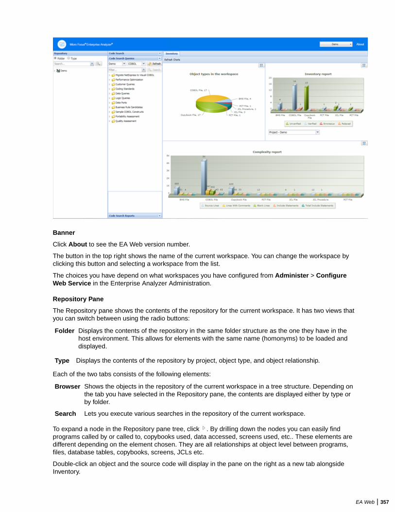
Banner
Click About to see the EA Web version number.
The button in the top right shows the name of the current workspace. You can change the workspace byclicking this button and selecting a workspace from the list.
The choices you have depend on what workspaces you have configured from Administer > ConfigureWeb Service in the Enterprise Analyzer Administration.
Repository Pane
The Repository pane shows the contents of the repository for the current workspace. It has two views thatyou can switch between using the radio buttons:
Folder Displays the contents of the repository in the same folder structure as the one they have in thehost environment. This allows for elements with the same name (homonyms) to be loaded anddisplayed.
Type Displays the contents of the repository by project, object type, and object relationship.
Each of the two tabs consists of the following elements:
Browser Shows the objects in the repository of the current workspace in a tree structure. Depending onthe tab you have selected in the Repository pane, the contents are displayed either by type orby folder.
Search Lets you execute various searches in the repository of the current workspace.
To expand a node in the Repository pane tree, click . By drilling down the nodes you can easily findprograms called by or called to, copybooks used, data accessed, screens used, etc.. These elements aredifferent depending on the element chosen. They are all relationships at object level between programs,files, database tables, copybooks, screens, JCLs etc.
Double-click an object and the source code will display in the pane on the right as a new tab alongsideInventory.
EA Web | 357
Right-click an object, and a context menu with the following menu items comes up: Query Repository,Diagrammer and Open.
QueryRepository
Shows all the queries available for the selected type of source.
• Related Java Packages• Boundary Points (potential) - Points that could lead to requests resources outside of
Java• Boundary Points (resolved) - Points that lead to requests resources outside of Java• Is Invoked By• Related Java Files• Dependent Sources• Direct References (outgoing)• Direct References (incoming) - This makes references to usage directly. A program is
called through a Program Entry Point so this won't return the list of Called Programs,but the includes and copies.
• Is Called By• Is CRUD By• Used Data Stores• Used Sources
Diagrammer Creates a small graph. The information on the graph depends on the requested type ofgraph. For example, Call Map will show all the links between programs.
the following table displays the Diagrammer scopes:
Call Map Program to program calls
CICS Flow Interactions between transactions, programs,and screens
Job Flow Process to program to data port to data store
Screen Flow Program to screen send/receive
AS/400 Flow DBFile links
Data Flow Program to data
IMS Flow Interactions between transactions, programs,screens and segments.
Job Executive Report Job to program, sys-program and data store
Natural Flow Natural links between programs, screens, etc.
Program Executive Report All links coming from a program
Source Dependencies Links between sources (copies, includes, etc.)
Unisys Flow Unisys links
Open Opens the source file.
Code Search
From the Code Search pane you can execute queries. By default, the queries are the same as inEnterprise Analyzer but you can create your own queries in the tool and add them to the Code Search tab.
In this pane you have two different views: Code Search Queries and Code Search Reports. From CodeSearch Queries you can execute queries defined in Code Search in EA and from Code Search Reportsyou can execute pre-defined reports such as QA report, coding standards report, migration assessment,etc.
358 | EA Web
From the top left dropdown list you can choose the project that you want to use as the scope for the CodeSearch Query.
The dropdown list next to it lets you choose the language of the sources.
Click Refresh to update the list depending on your choices.
Filter lets you search in the list of queries. You can then use the Search button to execute the query, or youcan right-click a query and then select Search. All queries results appear in the Inventory pane.
Results Pane
When you start EA Web, this pane displays the Inventory tab with three different types of charts:
• Object types in the workspace - the types and number of elements in the workspace.• Inventory report - the verification results for each type of element.• Complexity report.
When you execute a query, the results from it appear in this pane as a new tab named after the query.
Doubleclick an element to see its source code. It will appear in a new view in this pane.
Doubleclick a result of a query to open the source code with the cursor on the corresponding line.
You can also right-click a variable and create an "Impact trace" for the variable. The impact trace will showyou how the data flows to and from other variables, files, screens etc.
EA Web ReportsThere are several reports that you can create and export from the Web Client. All report exports are startedfrom the buttons at the bottom of the Results pane.
Export Table (Generic XML) Exports the query results table in an XML format.
Export to Eclipse/VisualStudio
Exports the Code Search results in an XML format to be used byEnterprise Developer in Eclipse and Visual Studio.
Export to CSV Exports the results to CSV format.
EA Web | 359

Eclipse Plugins
Eclipse PluginsEnterprise Analyzer provides two Eclipse plugins: the Search Assistant plugin and the Code Search Viewplugin.
The Search Assistant plugin lets you execute EA repository searches and queries from Eclipse/EnterpriseDeveloper/Enterprise Developer.
The Code Search View plugin helps visualize POI results from the EA Code Search module in an Eclipseproject.
Installing the Eclipse PluginsTo install the Eclipse plugins, follow these steps:
1. Start Eclipse (version 3.7.2 or higher).2. Go to Help > Install New Software.3. Click the Add button next to the Work with drop-down menu.4. On the Add Repository dialog, click Archive and browse to the EA Integration.repository.zip
file in the Bin folder in your install directory.5. Add a meaningful name, for example EAInstall and click OK.6. Select the checkbox in front of Enterprise Analyzer Access and click Next.7. Make sure Enterprise Analyzer Access appears in the list of items to be installed and click Next.8. Read the license text and click I accept the terms of the license agreement.9. Click Finish and when prompted, restart Eclipse.10.You may not see the plugins in your perspective automatically. If this is the case, go to Window > Show
View > Other.11.Under Micro Focus, select Clipper View and click Open.12.Do the same for the Search Assistant plugin.13.They appear as tabbed views in the bottom right part of the IDE.
Uninstalling the Eclipse PluginsTo uninstall the Eclipse plugins:
1. In the IDE, go to Help > Install New Software.2. Click the What is already installed? hyperlink in the Install window. The Eclipse Installation Details
window opens.3. In the Installed Software tab find Enterprise Analyzer Access and click Uninstall.4. Click Finish and when prompted, restart Eclipse.
360 | Eclipse Plugins

Updating the Eclipse PluginsTo install a newer version of the plugins, remove the current plugins and create a new site that points to thenew .zip file.
Eclipse Plugins | 361
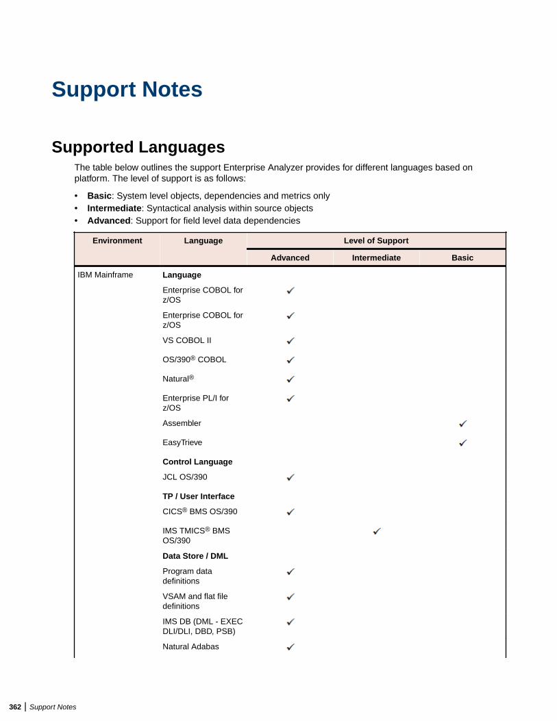
Support Notes
Supported LanguagesThe table below outlines the support Enterprise Analyzer provides for different languages based onplatform. The level of support is as follows:
• Basic: System level objects, dependencies and metrics only• Intermediate: Syntactical analysis within source objects• Advanced: Support for field level data dependencies
Environment Language Level of Support
Advanced Intermediate Basic
IBM Mainframe Language
Enterprise COBOL forz/OS
Enterprise COBOL forz/OS
VS COBOL II
OS/390® COBOL
Natural®
Enterprise PL/I forz/OS
Assembler
EasyTrieve
Control Language
JCL OS/390
TP / User Interface
CICS® BMS OS/390
IMS TMICS® BMSOS/390
Data Store / DML
Program datadefinitions
VSAM and flat filedefinitions
IMS DB (DML - EXECDLI/DLI, DBD, PSB)
Natural Adabas
362 | Support Notes
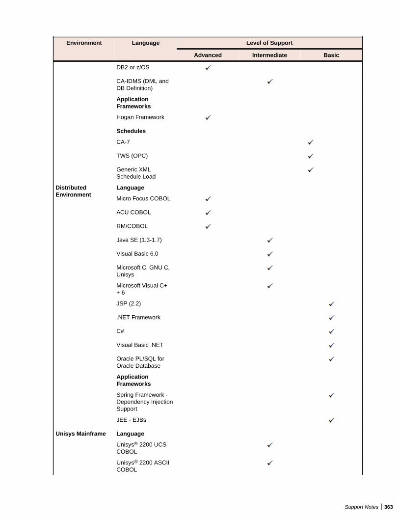
Environment Language Level of Support
Advanced Intermediate Basic
DB2 or z/OS
CA-IDMS (DML andDB Definition)
ApplicationFrameworks
Hogan Framework
Schedules
CA-7
TWS (OPC)
Generic XMLSchedule Load
DistributedEnvironment
Language
Micro Focus COBOL
ACU COBOL
RM/COBOL
Java SE (1.3-1.7)
Visual Basic 6.0
Microsoft C, GNU C,Unisys
Microsoft Visual C++ 6
JSP (2.2)
.NET Framework
C#
Visual Basic .NET
Oracle PL/SQL forOracle Database
ApplicationFrameworks
Spring Framework -Dependency InjectionSupport
JEE - EJBs
Unisys Mainframe Language
Unisys® 2200 UCSCOBOL
Unisys® 2200 ASCIICOBOL
Support Notes | 363
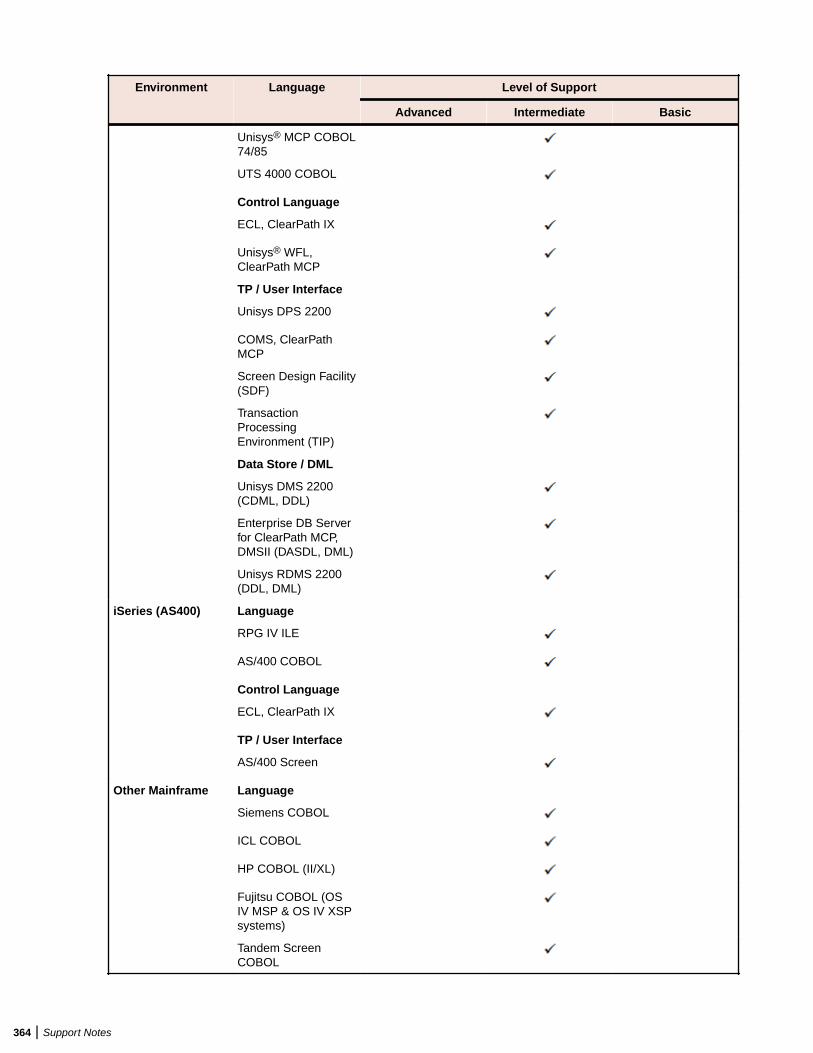
Environment Language Level of Support
Advanced Intermediate Basic
Unisys® MCP COBOL74/85
UTS 4000 COBOL
Control Language
ECL, ClearPath IX
Unisys® WFL,ClearPath MCP
TP / User Interface
Unisys DPS 2200
COMS, ClearPathMCP
Screen Design Facility(SDF)
TransactionProcessingEnvironment (TIP)
Data Store / DML
Unisys DMS 2200(CDML, DDL)
Enterprise DB Serverfor ClearPath MCP,DMSII (DASDL, DML)
Unisys RDMS 2200(DDL, DML)
iSeries (AS400) Language
RPG IV ILE
AS/400 COBOL
Control Language
ECL, ClearPath IX
TP / User Interface
AS/400 Screen
Other Mainframe Language
Siemens COBOL
ICL COBOL
HP COBOL (II/XL)
Fujitsu COBOL (OSIV MSP & OS IV XSPsystems)
Tandem ScreenCOBOL
364 | Support Notes
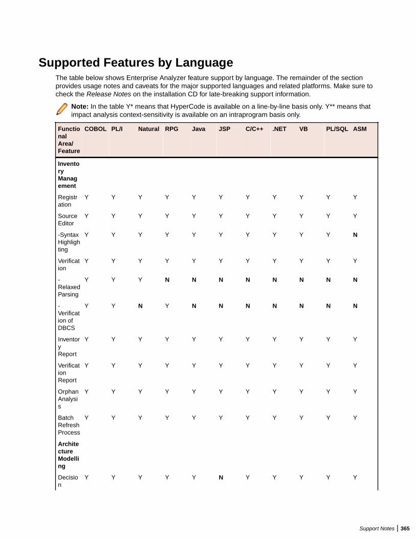
Supported Features by LanguageThe table below shows Enterprise Analyzer feature support by language. The remainder of the sectionprovides usage notes and caveats for the major supported languages and related platforms. Make sure tocheck the Release Notes on the installation CD for late-breaking support information.
Note: In the table Y* means that HyperCode is available on a line-by-line basis only. Y** means thatimpact analysis context-sensitivity is available on an intraprogram basis only.
FunctionalArea/Feature
COBOL PL/I Natural RPG Java JSP C/C++ .NET VB PL/SQL ASM
InventoryManagement
Registration
Y Y Y Y Y Y Y Y Y Y Y
SourceEditor
Y Y Y Y Y Y Y Y Y Y Y
-SyntaxHighlighting
Y Y Y Y Y Y Y Y Y Y N
Verification
Y Y Y Y Y Y Y Y Y Y Y
-RelaxedParsing
Y Y Y N N N N N N N N
-Verification ofDBCS
Y Y N Y N N N N N N N
InventoryReport
Y Y Y Y Y Y Y Y Y Y Y
VerificationReport
Y Y Y Y Y Y Y Y Y Y Y
OrphanAnalysis
Y Y Y Y Y Y Y Y Y Y Y
BatchRefreshProcess
Y Y Y Y Y Y Y Y Y Y Y
ArchitectureModelling
Decision
Y Y Y Y Y N Y Y Y Y Y
Support Notes | 365
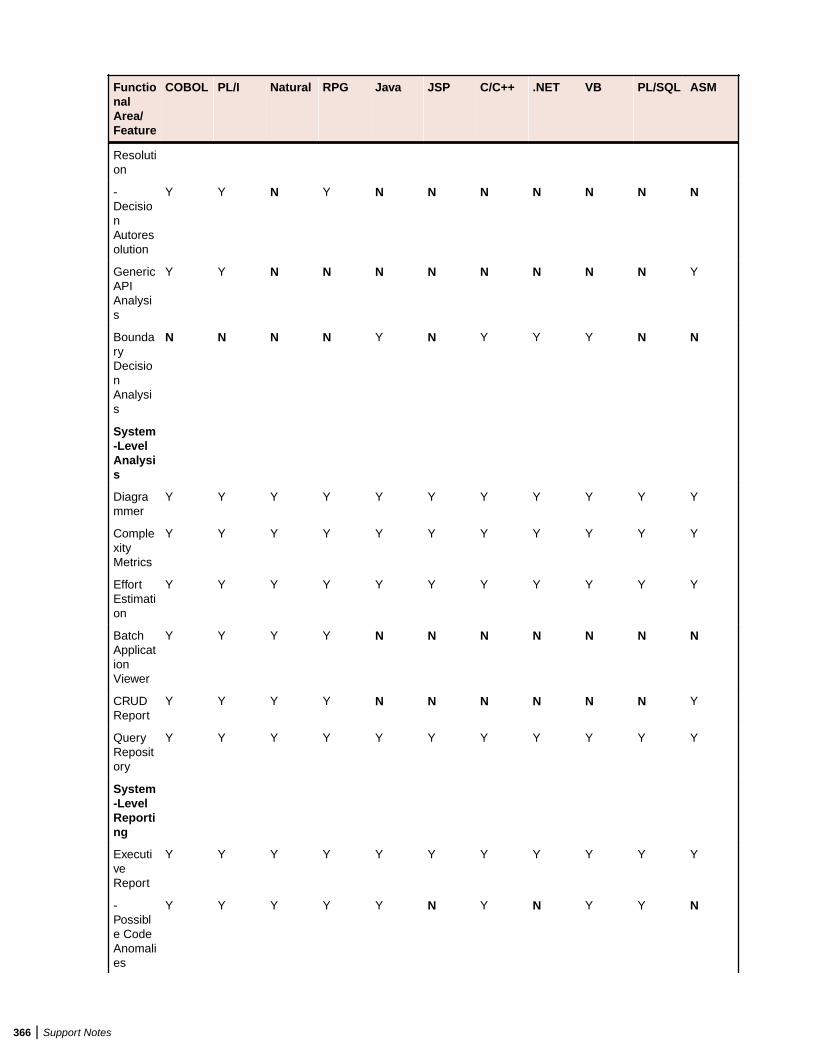
FunctionalArea/Feature
COBOL PL/I Natural RPG Java JSP C/C++ .NET VB PL/SQL ASM
Resolution
-DecisionAutoresolution
Y Y N Y N N N N N N N
GenericAPIAnalysis
Y Y N N N N N N N N Y
BoundaryDecisionAnalysis
N N N N Y N Y Y Y N N
System-LevelAnalysis
Diagrammer
Y Y Y Y Y Y Y Y Y Y Y
ComplexityMetrics
Y Y Y Y Y Y Y Y Y Y Y
EffortEstimation
Y Y Y Y Y Y Y Y Y Y Y
BatchApplicationViewer
Y Y Y Y N N N N N N N
CRUDReport
Y Y Y Y N N N N N N Y
QueryRepository
Y Y Y Y Y Y Y Y Y Y Y
System-LevelReporting
ExecutiveReport
Y Y Y Y Y Y Y Y Y Y Y
-Possible CodeAnomalies
Y Y Y Y Y N Y N Y Y N
366 | Support Notes
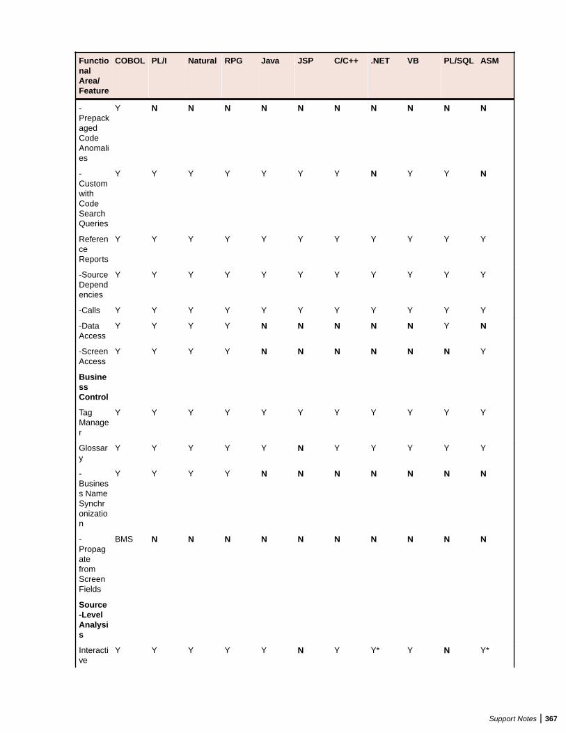
FunctionalArea/Feature
COBOL PL/I Natural RPG Java JSP C/C++ .NET VB PL/SQL ASM
-PrepackagedCodeAnomalies
Y N N N N N N N N N N
-CustomwithCodeSearchQueries
Y Y Y Y Y Y Y N Y Y N
ReferenceReports
Y Y Y Y Y Y Y Y Y Y Y
-SourceDependencies
Y Y Y Y Y Y Y Y Y Y Y
-Calls Y Y Y Y Y Y Y Y Y Y Y
-DataAccess
Y Y Y Y N N N N N Y N
-ScreenAccess
Y Y Y Y N N N N N N Y
BusinessControl
TagManager
Y Y Y Y Y Y Y Y Y Y Y
Glossary
Y Y Y Y Y N Y Y Y Y Y
-Business NameSynchronization
Y Y Y Y N N N N N N N
-PropagatefromScreenFields
BMS N N N N N N N N N N
Source-LevelAnalysis
Interactive
Y Y Y Y Y N Y Y* Y N Y*
Support Notes | 367
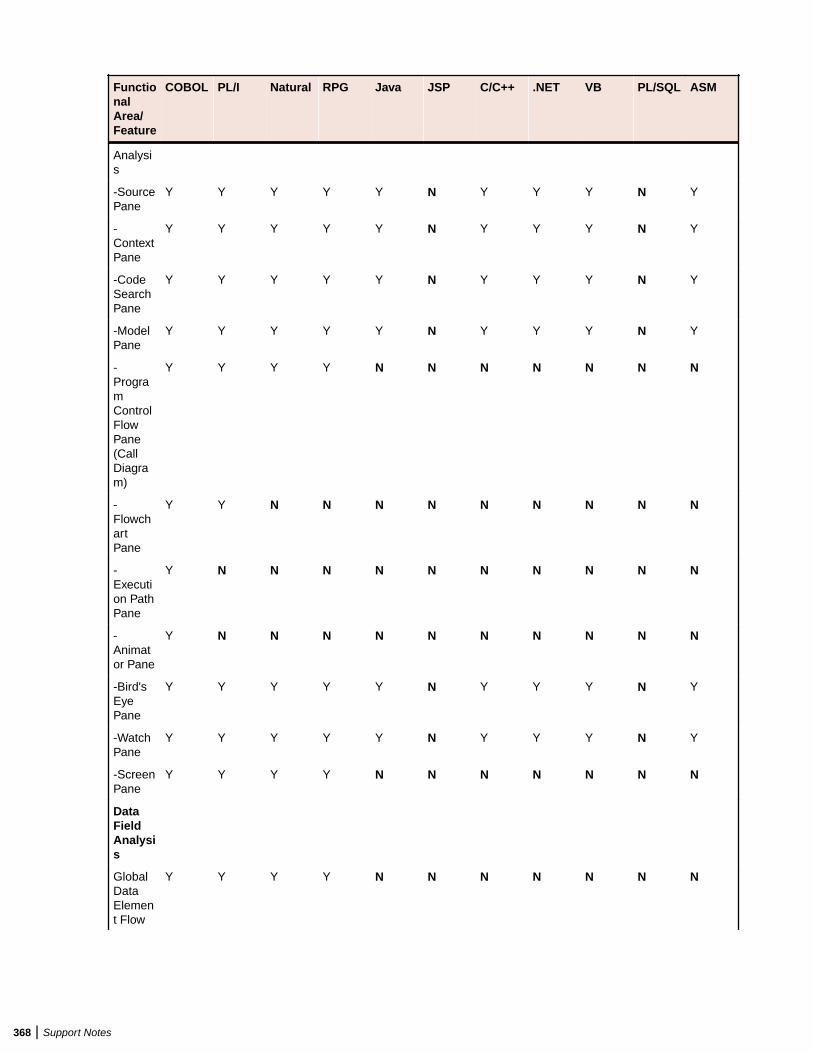
FunctionalArea/Feature
COBOL PL/I Natural RPG Java JSP C/C++ .NET VB PL/SQL ASM
Analysis
-SourcePane
Y Y Y Y Y N Y Y Y N Y
-ContextPane
Y Y Y Y Y N Y Y Y N Y
-CodeSearchPane
Y Y Y Y Y N Y Y Y N Y
-ModelPane
Y Y Y Y Y N Y Y Y N Y
-ProgramControlFlowPane(CallDiagram)
Y Y Y Y N N N N N N N
-FlowchartPane
Y Y N N N N N N N N N
-Execution PathPane
Y N N N N N N N N N N
-Animator Pane
Y N N N N N N N N N N
-Bird'sEyePane
Y Y Y Y Y N Y Y Y N Y
-WatchPane
Y Y Y Y Y N Y Y Y N Y
-ScreenPane
Y Y Y Y N N N N N N N
DataFieldAnalysis
GlobalDataElement Flow
Y Y Y Y N N N N N N N
368 | Support Notes
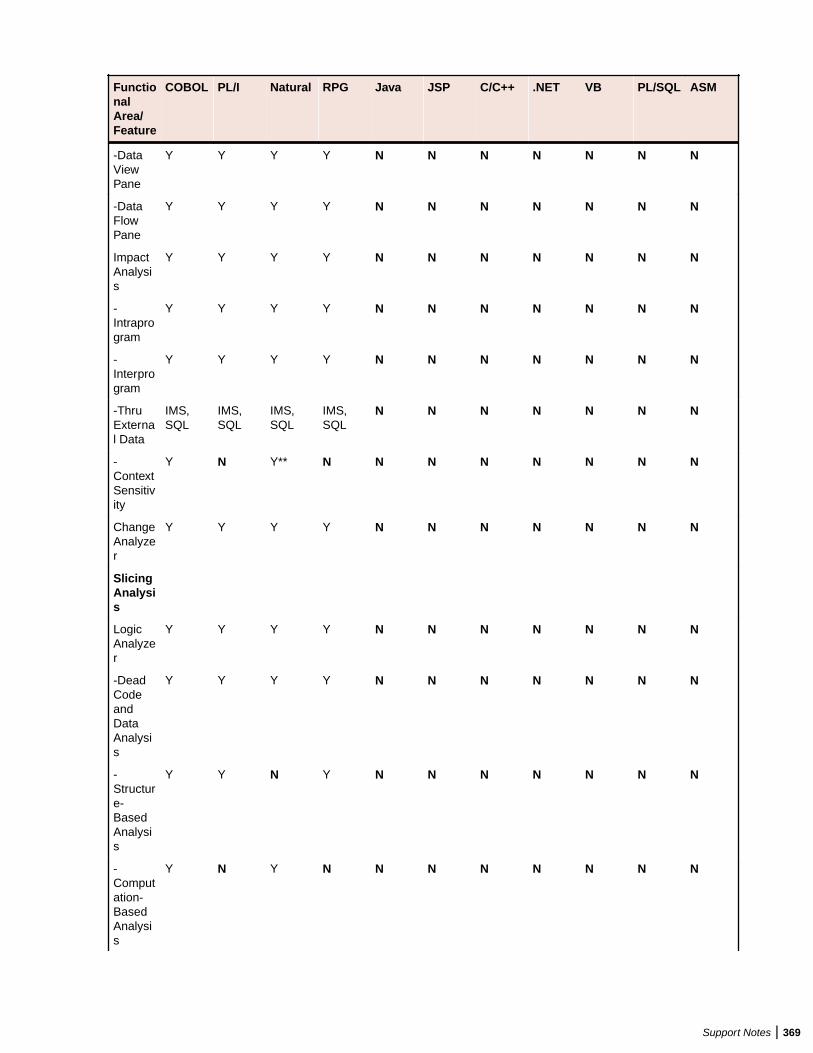
FunctionalArea/Feature
COBOL PL/I Natural RPG Java JSP C/C++ .NET VB PL/SQL ASM
-DataViewPane
Y Y Y Y N N N N N N N
-DataFlowPane
Y Y Y Y N N N N N N N
ImpactAnalysis
Y Y Y Y N N N N N N N
-Intraprogram
Y Y Y Y N N N N N N N
-Interprogram
Y Y Y Y N N N N N N N
-ThruExternal Data
IMS,SQL
IMS,SQL
IMS,SQL
IMS,SQL
N N N N N N N
-ContextSensitivity
Y N Y** N N N N N N N N
ChangeAnalyzer
Y Y Y Y N N N N N N N
SlicingAnalysis
LogicAnalyzer
Y Y Y Y N N N N N N N
-DeadCodeandDataAnalysis
Y Y Y Y N N N N N N N
-Structure-BasedAnalysis
Y Y N Y N N N N N N N
-Computation-BasedAnalysis
Y N Y N N N N N N N N
Support Notes | 369
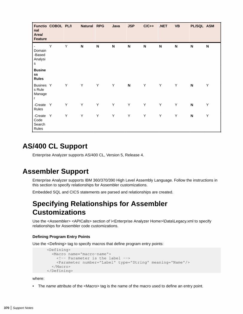
FunctionalArea/Feature
COBOL PL/I Natural RPG Java JSP C/C++ .NET VB PL/SQL ASM
-Domain-BasedAnalysis
Y Y N N N N N N N N N
BusinessRules
Business RuleManager
Y Y Y Y Y N Y Y Y N Y
-CreateRules
Y Y Y Y Y Y Y Y Y N Y
-CreateCodeSearchRules
Y Y Y Y Y Y Y Y Y N Y
AS/400 CL SupportEnterprise Analyzer supports AS/400 CL, Version 5, Release 4.
Assembler SupportEnterprise Analyzer supports IBM 360/370/390 High Level Assembly Language. Follow the instructions inthis section to specify relationships for Assembler customizations.
Embedded SQL and CICS statements are parsed and relationships are created.
Specifying Relationships for AssemblerCustomizationsUse the <Assembler> <APICalls> section of \<Enterprise Analyzer Home>\Data\Legacy.xml to specifyrelationships for Assembler code customizations.
Defining Program Entry Points
Use the <Defining> tag to specify macros that define program entry points:
<Defining> <Macro name="macro-name"> <!-- Parameter is the label --> <Parameter number="Label" type="String" meaning="Name"/> </Macro> </Defining>
where:
• The name attribute of the <Macro> tag is the name of the macro used to define an entry point.
370 | Support Notes
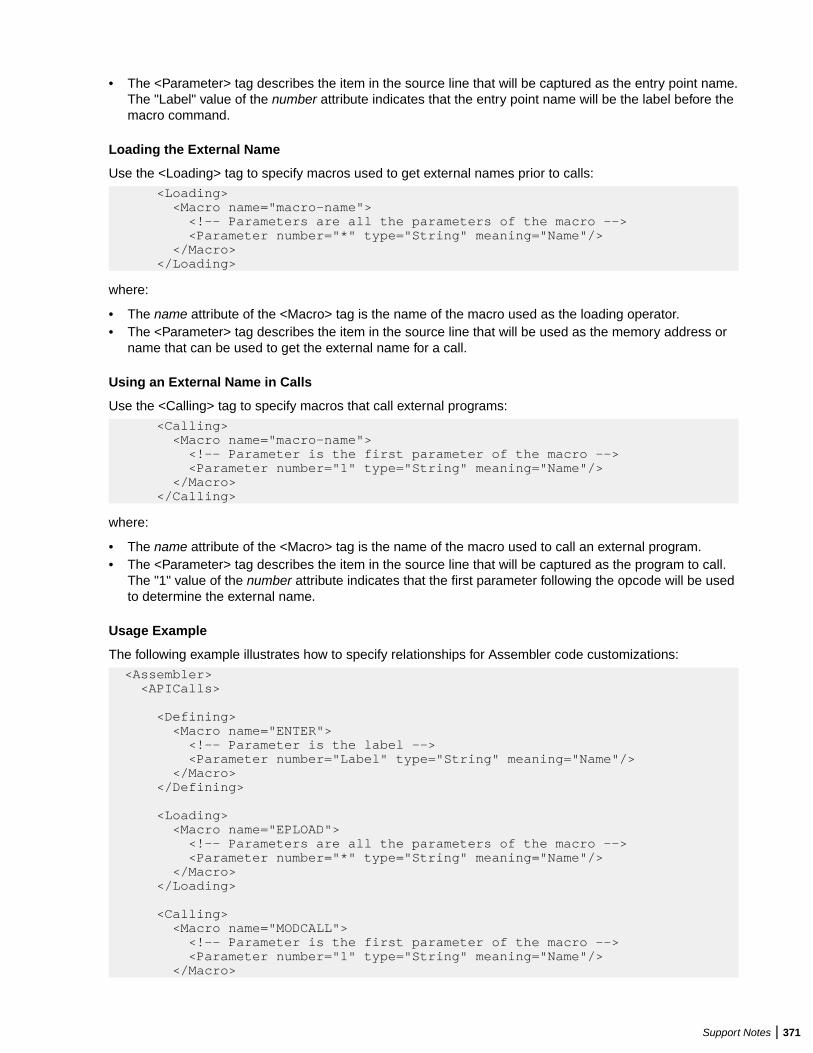
• The <Parameter> tag describes the item in the source line that will be captured as the entry point name.The "Label" value of the number attribute indicates that the entry point name will be the label before themacro command.
Loading the External Name
Use the <Loading> tag to specify macros used to get external names prior to calls:
<Loading> <Macro name="macro-name"> <!-- Parameters are all the parameters of the macro --> <Parameter number="*" type="String" meaning="Name"/> </Macro> </Loading>
where:
• The name attribute of the <Macro> tag is the name of the macro used as the loading operator.• The <Parameter> tag describes the item in the source line that will be used as the memory address or
name that can be used to get the external name for a call.
Using an External Name in Calls
Use the <Calling> tag to specify macros that call external programs:
<Calling> <Macro name="macro-name"> <!-- Parameter is the first parameter of the macro --> <Parameter number="1" type="String" meaning="Name"/> </Macro> </Calling>
where:
• The name attribute of the <Macro> tag is the name of the macro used to call an external program.• The <Parameter> tag describes the item in the source line that will be captured as the program to call.
The "1" value of the number attribute indicates that the first parameter following the opcode will be usedto determine the external name.
Usage Example
The following example illustrates how to specify relationships for Assembler code customizations:
<Assembler> <APICalls>
<Defining> <Macro name="ENTER"> <!-- Parameter is the label --> <Parameter number="Label" type="String" meaning="Name"/> </Macro> </Defining> <Loading> <Macro name="EPLOAD"> <!-- Parameters are all the parameters of the macro --> <Parameter number="*" type="String" meaning="Name"/> </Macro> </Loading>
<Calling> <Macro name="MODCALL"> <!-- Parameter is the first parameter of the macro --> <Parameter number="1" type="String" meaning="Name"/> </Macro>
Support Notes | 371
</Calling>
</APICalls> </Assembler>
HyperCode for AssemblerThe Hypercode metamodel represents the relationships between constructs in the model at the programlevel.
HyperCode for Assembler consists of line-by-line constructs and does not allow for navigation and analysisof an abstract syntax tree metamodel that is usually associated with HyperCode support. There are noexplicit relationships at the program level between objects and constructs in the Assembler language. Thecall statements are identified separately so they can be searched in Code Search.
Note: For more information on the advanced searches included in the product, read the PerformingAdvanced Searches section of the documentation.
RestrictionsThe following known limitations are found in this release:
MacroGeneration
Macro expansion is not currently supported for Assembler. As a result, calculations ofthe Assembler program metrics will not be affected by macros and some decisions willbe unresolved after verification.
C/C++ SupportEnterprise Analyzer supports Microsoft C 6.0 and Microsoft Visual C++ 6.0. Follow the instructions in thissection to register and verify C and C++ source files.
Registering C/C++ FilesBefore registering C/C++ files, set:
• Expand tabulation symbols on the Registration > Source Files tab of the Workspace Options.Tabulation symbols are replaced with a corresponding number of spaces when you register the files.You must select this option if you want to view Interactive Analysis information for C or C++ programs.
Verifying C/C++ FilesBefore verifying C/C++ files:
• On the Verification > Settings tab of the Workspace Options, list the folders for include files used bythe application (either original folders or folders in EA, if the include files were registered).
Tip: You can also specify these folders in the verification options for a project, in which case EAlooks only at the folders for the project.
• On the Verification > Settings tab of the Workspace Options, enter the parameters used to compile theapplication in the C/C++ Parser Parameters field. For example, the parameters would be -D_DEBUG -D_UNICODE -D_WINDLL -D_DLL for an MFC application.
Tip: You can also specify these parameters in the verification options for a project, in which caseonly the project parameters are used for verification.
• On the Verification tab of the Project Options, select Use Precompiled Header File if you want theparser to use a precompiled header file when it verifies the project. In the adjacent field, enter the fullpath of the header file. Do not specify the file extension. Using a precompiled header file may improveverification performance significantly.
372 | Support Notes
Note: The content of the header file must appear in both a .c or .cpp file and a .h file. Theprecompiled header file need not have been used to compile the application.
• On the Boundary Decisions tab of the Workspace Options, specify the resource types for method callsyour application uses to interface with databases, message queues, or other resources.
CICS SupportEnterprise Analyzer supports the following CICS versions:
• CICS Transaction Server for OS/390, Version 1, Release 3.• CICS Transaction Server for z/OS, Version 3, Release 1.
Case Sensitive Transaction NameEnterprise Analyzer supports case sensitive transaction IDs for CSD files. You can choose the wayEnterprise Analyzer treats transaction IDs. This option is needed when you have transactions defined withthe same name but spelled with a different case. To activate the Case Sensitive Transaction Name support:
1. Open Start > All Programs > Micro Focus > Enterprise Analyzer > Enterprise AnalyzerAdministration. The Enterprise Analyzer Administration opens.
2. Choose Administer > Configure Micro Focus Enterprise Analyzer. The Configuration Managerwindow opens.
3. Check Case Sensitive Transaction Name under Legacy Configuration, and then click OK.
Note: You must upgrade your workspace after the configuration change.
Deprecated CICS StatementsDeprecated CICS statements are supported. Programs containing these statements verify successfully.
Keyword PermutationsKeywords without parameters cannot be permuted if they start a statement. SEND TEXT NOEDIT, forexample, must start with SEND TEXT NOEDIT. TEXT or NOEDIT should not be placed after otherstatement’s keywords and parameters. The following statement is invalid, for example:
EXEC CICS SEND TEXT LENGTH (10) NOEDIT
Generally, you can permute statement keywords with parameters in any order, keeping in mind that the firstkeyword should not be permuted with the others. Below is a list of statements for which you cannotpermute the second keyword. That is, the keywords must appear in the order shown:
• CHANGE PASSWORD• CHANGE TASK• CHECK ACQPROCESS• CHECK ACTIVITY• CHECK ACQACTIVITY• CHECK TIMER• DEFINE ACTIVITY• DEFINE COMPOSITE• DEFINE INPUT EVENT• DEFINE PROCESS• DEFINE TIMER
Support Notes | 373
• DELETE CONTAINER• DELETE COUNTER• DELETE DCOUNTER• EXTRACT CERTIFICATE• GET CONTAINER• GETNEXT ACTIVITY• GETNEXT CONTAINER• GETNEXT EVENT• GETNEXT PROCESS• INQUIRE ACTIVITYID• INQUIRE CONTAINER• INQUIRE EVENT• INQUIRE TIMER• LINK PROGRAM• RETRIEVE SUBEVENT• WAIT CONVID• WAIT JOURNALNAME• WAIT JOURNALNUM• WRITE JOURNALNAME• WRITE JOURNALNUM
Statements Taken to Be the SameThe statements in each set of statements below are recognized as the same statement and assumed tohandle a united set of conditions:
• DOCUMENT CREATE, DOCUMENT INSERT, DOCUMENT RETRIEVE, DOCUMENT SET• ENDBROWSE ACTIVITY, ENDBROWSE CONTAINER, ENDBROWSE EVENT, ENDBROWSE
PROCESS• START, START CHANNEL• SYNCPOINT, SYNCPOINT ROLLBACK• WEB ENDBROWSE HTTPHEADER, WEB ENDBROWSE FORMFIELD• WEB READ FORMFIELD, WEB READ HTTPHEADER• WEB READNEXT FORMFIELD, WEB READNEXT• WEB STARTBROWSE FORMFIELD, WEB STARTBROWSE HTTPHEADER
BTS and CHANNEL versions of statements are not distinguished and assumed to handle a united set ofconditions.
COBOL SupportEnterprise Analyzer supports the following COBOL versions:
• COBOL for OS/390, Version 2, Release 2.• Enterprise COBOL for z/OS, Version 4.2.• VS COBOL II, Release 4.• Micro Focus COBOL, V3.2 (level 10).• ACUCOBOL-GT®, Version 6.1.• ILE COBOL for AS/400, Version 4, Release 4.• HP3000, HP COBOL II/XL.• RM/COBOL
374 | Support Notes
• Unisys COBOL
• UCOB – Unisys 2200 UCS COBOL.• ACOB – Unisys 2200 ASCII COBOL.• UTS – UTS 4000 COBOL.
• Unisys MCP COBOL
• Cobol-74.• Cobol-85.
• Fujitsu COBOL (for OS IV MSP and OS IV XSP systems).• Siemens COBOL, Version 2.3 (BS2000/OSD).• ICL C2 COBOL for OpenVME, Version 3.• Tandem Screen COBOL, Pathway/TS D42+ (alpha offering).
Note: Tandem Server COBOL is not supported.
Object-Oriented StatementsObject-oriented COBOL statements are not supported.
Separators Must Be Followed by BlanksThe Cobol parser assumes that every separator must be followed by a blank. If you index a variable with aseparator that is not followed by a blank, MY-VARIABLE(1,1), the parser may treat (1,1) as a numericliteral, especially when the program was compiled with the DECIMAL POINT IS COMMA option. To index avariable, use the format MY-VARIABLE(1, 1)or MY-VARIABLE(1 1).
Copybooks in a LibraryIf the copybooks used in a Cobol program are in a library, and the library is referenced in a COPYstatement with the format COPY text-name IN library-name or COPY text-name OF library-name, the parser looks first for a copybook named library-name.text-name, and if it does not exist, for acopybook named text-name. If text-name does not exist, the parser reports library-name.text-name as anunresolved reference.
It is your responsibility to prefix library member names with library names or filepaths and dot (.)separators: dir1.dir2.member.cpy represents the copybook dir1/dir2/member, for example. When the parserencounters a reference to a member, it first searches for the longest possible name, dir1.dir2.member.cpy,and if not found, then the shorter versions, dir2.member.cpy and member.cpy.
Note: Unresolved references to library members are always reported with the longest name. Thismeans that if you subsequently register a missing copybook with a short name, the referencingsource file will not be invalidated. It’s up to you to remember that the referencing source needs to bereverified.
How Enterprise Analyzer Calculates COBOL DeadCode StatisticsThis section provides details on how EA calculates COBOL dead code statistics.
Dead StatementsA dead statement is a statement that can never be reached during program execution. Only control flowanalysis techniques (static analysis) are used for the detection of dead statements. Domain-based analysisis not performed.
Support Notes | 375
Statements directly connected with dead statements are also considered to be dead. For instance, EXECCICS HANDLE statements are dead when all EXEC CICS statements are dead or there are no EXECCICS statements at all.
Dead Data ElementsDead data elements are unused structures at any data level, all of whose parents and children are unused.Condition names (88-level items) are dead if unused.
Only user-defined data elements can be counted as dead. Data elements from system copybooks arenever counted as dead.
Dead ConstructsA paragraph consisting solely of dead statements is a dead paragraph. A section consisting solely of deadparagraphs or that is empty is a dead section. The exception to this is the Configuration Section. Becausethere are no candidate dead constructs (statements or data elements) in the Configuration Section, thissection is not processed and does not contribute to dead code metrics. A division is never considereddead.
A file description entry (FD) containing only dead data elements and not used in any file operation is adead file description. A file section containing only dead file descriptions is a dead section. A SELECTstatement referring to a dead file description is a dead construct.
A file-control paragraph consisting solely of dead SELECT statements is a dead paragraph. An input-outputsection consisting solely of dead file-control paragraphs is a dead section.
Dead Statements, Dead Data Elements, and Dead Lines fromCopybooksDead statements and dead data elements from copybooks (that either start or end in a copybook) arecounted in the Dead Statements, Dead Data Elements, and Dead Lines metrics. They are also countedseparately in the Dead Statements from Includes, Dead Data Elements from Includes, and Dead Linesfrom Includes metrics.
If a copybook is included multiple times, then each instance of the copybook is considered to be anindependent source file, and all dead constructs and dead lines from the copybook are counted as manytimes as they are identified as dead. For instance, if a copybook is included twice and both inclusions resultin a dead data element, the result is Dead Data Elements from Includes=2 and Dead Lines fromIncludes=2 (assuming each dead data element occupies only one line of the included copybook). If thesame copybook is included twice but only one instance results in a dead data element, then Dead DataElements from Includes=1 and Dead Lines from Includes=1.
All “Dead from Includes” metrics are for the specified program only. These metrics do not include ananalysis of the same copybook over the entire application.
Interactive Analysis UsageIn Interactive Analysis, all dead statements, dead paragraphs, dead sections, dead data declarations, deadfiles, and instances of dead files in statements will have the attribute Dead set to True.
Note: Not all language syntax phrases are represented in the Interactive Analysis model, so not alldead constructs contributing to dead lines can be identified using Code Search. In other words, CodeSearch can identify all dead data elements and all dead statements, but not necessarily all dead lines.
Special Handling of Cobol Program Complexity Metrics• Abbreviated conditions are expanded before calculations.• DECLARATIVEs content and other exception-handling statements are counted once, as ordinary
statements.
376 | Support Notes
• Handling of EVALUATE formats:
EVALUATE … [ALSO …] Conditional StatementWHEN … [ALSO …] Binary Decision, Conditional StatementWHEN OTHER Conditional StatementEND-EVALUATE
• Handling of SEARCH formats:
SEARCH … AT END … Binary DecisionWHEN … Binary Decision, Conditional StatementWHEN …AND… Binary Decision, Conditional StatementEND-SEARCH
Possible Padding in MOVE StatementsThe Advanced Search criterion for Possible Data Padding defects in MOVE statements (in which theinternal representation of the source variable in the assignment is shorter than the internal representationof the destination variable) finds only MOVE statements involving at least one group data item. It does notfind MOVE statements involving assignments of elementary data items.
ACUCOBOL SupportIn Enterprise Analyzer ACUCOBOL's displays of message boxes generate screen output relationships. Ifthe message box has no title, it can appear as program.display. This happens when there are twoDISPLAY MESSAGE BOX statements that do not specify screen.
ECL SupportEnterprise Analyzer supports ECL, ClearPath IX, Release 6.
Hogan Framework Support
OverviewHogan COBOL applications use calls to Process Environment Manager (PEM) to identify programoperations, or activities, mapped in Hogan Framework configuration files. These activities include LINK(invoke programs), SDB (read files), HDB (read hierarchical data segments), and DC (read screens). Otheractivities include WORK, DUMP, EXCEP, END, ABEND, CHECK, and special user-defined operations.
Each activity the program performs is identified in a variable moved to the program's Transaction-Control-Block (TCB). On finding a call to PEM:
CALL 'PEM' USING TRANSACTION-CONTROL-BLOCK.
Enterprise Analyzer matches the activity IDs in the TCB with the corresponding operations in HoganFramework configuration files. EA then uses the configuration file information to create repositoryrelationships between programs, activity IDs, and related application artifacts.
Support Notes | 377
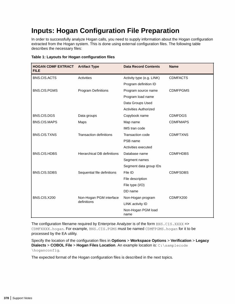
Inputs: Hogan Configuration File PreparationIn order to successfully analyze Hogan calls, you need to supply information about the Hogan configurationextracted from the Hogan system. This is done using external configuration files. The following tabledescribes the necessary files:
Table 1: Layouts for Hogan configuration files
HOGAN CDMF EXTRACTFILE
Artifact Type Data Record Contents Name
BNS.CIS.ACTS Activities Activity type (e.g. LINK)
Program definition ID
CDMFACTS
BNS.CIS.PGMS Program Definitions Program source name
Program load name
Data Groups Used
Activities Authorized
CDMFPGMS
BNS.CIS.DGS Data groups Copybook name CDMFDGS
BNS.CIS.MAPS Maps Map name
IMS tran code
CDMFMAPS
BNS.CIS.TXNS Transaction definitions Transaction code
PSB name
Activities executed
CDMFTXNS
BNS.CIS.HDBS Hierarchical DB definitions Database name
Segment names
Segment data group IDs
CDMFHDBS
BNS.CIS.SDBS Sequential file definitions File ID
File description
File type (I/O)
DD name
CDMFSDBS
BNS.CIS.X200 Non-Hogan PGM interfacedefinitions
Non-Hogan program
LINK activity ID
Non-Hogan PGM loadname
CDMFX200
The configuration filename required by Enterprise Analyzer is of the form BNS.CIS.XXXX =>CDMFXXXX.hogan. For example, BNS.CIS.PGMS must be named CDMFPGMS.hogan for it to beprocessed by the EA utility.
Specify the location of the configuration files in Options > Workspace Options > Verification > LegacyDialects > COBOL File > Hogan Files Location. An example location is: C:\samplecode\hoganconfig.
The expected format of the Hogan configuration files is described in the next topics.
378 | Support Notes
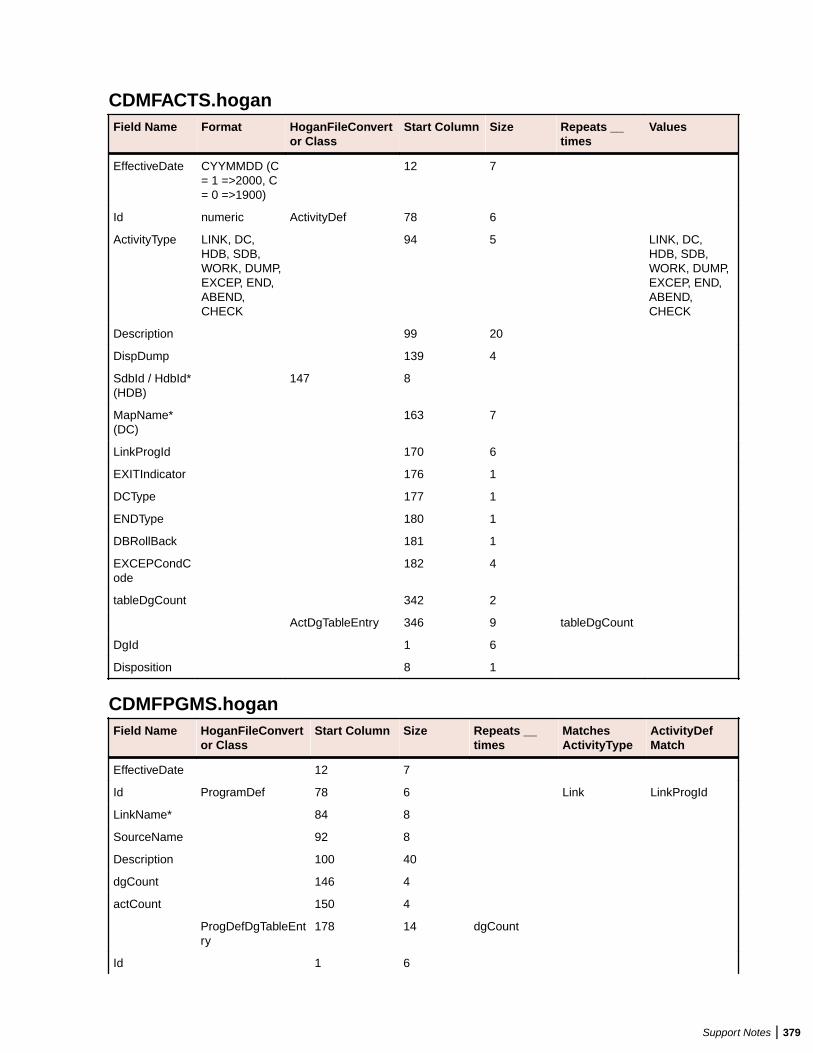
CDMFACTS.hoganField Name Format HoganFileConvert
or ClassStart Column Size Repeats __
timesValues
EffectiveDate CYYMMDD (C= 1 =>2000, C= 0 =>1900)
12 7
Id numeric ActivityDef 78 6
ActivityType LINK, DC,HDB, SDB,WORK, DUMP,EXCEP, END,ABEND,CHECK
94 5 LINK, DC,HDB, SDB,WORK, DUMP,EXCEP, END,ABEND,CHECK
Description 99 20
DispDump 139 4
SdbId / HdbId*(HDB)
147 8
MapName*(DC)
163 7
LinkProgId 170 6
EXITIndicator 176 1
DCType 177 1
ENDType 180 1
DBRollBack 181 1
EXCEPCondCode
182 4
tableDgCount 342 2
ActDgTableEntry 346 9 tableDgCount
DgId 1 6
Disposition 8 1
CDMFPGMS.hoganField Name HoganFileConvert
or ClassStart Column Size Repeats __
timesMatchesActivityType
ActivityDefMatch
EffectiveDate 12 7
Id ProgramDef 78 6 Link LinkProgId
LinkName* 84 8
SourceName 92 8
Description 100 40
dgCount 146 4
actCount 150 4
ProgDefDgTableEntry
178 14 dgCount
Id 1 6
Support Notes | 379
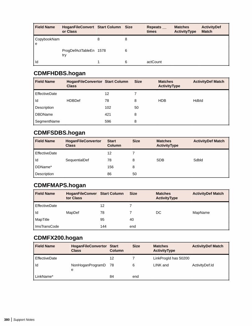
Field Name HoganFileConvertor Class
Start Column Size Repeats __times
MatchesActivityType
ActivityDefMatch
CopybookName
8 8
ProgDefActTableEntry
1578 6
Id 1 6 actCount
CDMFHDBS.hoganField Name HoganFileConvertor
ClassStart Column Size Matches
ActivityTypeActivityDef Match
EffectiveDate 12 7
Id HDBDef 78 8 HDB HdbId
Description 102 50
DBDName 421 8
SegmentName 596 8
CDMFSDBS.hoganField Name HoganFileConvertor
ClassStartColumn
Size MatchesActivityType
ActivityDef Match
EffectiveDate 12 7
Id SequentialDef 78 8 SDB Sdbld
DDName* 156 8
Description 86 50
CDMFMAPS.hoganField Name HoganFileConver
tor ClassStart Column Size Matches
ActivityTypeActivityDef Match
EffectiveDate 12 7
Id MapDef 78 7 DC MapName
MapTitle 95 40
ImsTransCode 144 end
CDMFX200.hoganField Name HoganFileConvertor
ClassStartColumn
Size MatchesActivityType
ActivityDef Match
EffectiveDate 12 7 LinkProgId has 50200
Id NonHoganProgramDe
78 6 LINK and ActivityDef.Id
LinkName* 84 end
380 | Support Notes
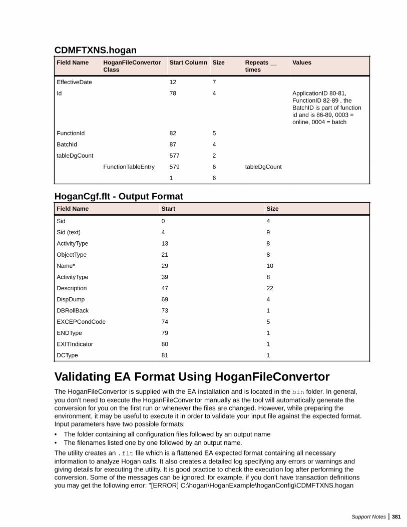
CDMFTXNS.hoganField Name HoganFileConvertor
ClassStart Column Size Repeats __
timesValues
EffectiveDate 12 7
Id 78 4 ApplicationID 80-81,FunctionID 82-89 , theBatchID is part of functionid and is 86-89, 0003 =online, 0004 = batch
FunctionId 82 5
BatchId 87 4
tableDgCount 577 2
FunctionTableEntry 579 6 tableDgCount
1 6
HoganCgf.flt - Output FormatField Name Start Size
Sid 0 4
Sid (text) 4 9
ActivityType 13 8
ObjectType 21 8
Name* 29 10
ActivityType 39 8
Description 47 22
DispDump 69 4
DBRollBack 73 1
EXCEPCondCode 74 5
ENDType 79 1
EXITIndicator 80 1
DCType 81 1
Validating EA Format Using HoganFileConvertorThe HoganFileConvertor is supplied with the EA installation and is located in the bin folder. In general,you don't need to execute the HoganFileConvertor manually as the tool will automatically generate theconversion for you on the first run or whenever the files are changed. However, while preparing theenvironment, it may be useful to execute it in order to validate your input file against the expected format.Input parameters have two possible formats:
• The folder containing all configuration files followed by an output name• The filenames listed one by one followed by an output name.
The utility creates an .flt file which is a flattened EA expected format containing all necessaryinformation to analyze Hogan calls. It also creates a detailed log specifying any errors or warnings andgiving details for executing the utility. It is good practice to check the execution log after performing theconversion. Some of the messages can be ignored; for example, if you don't have transaction definitionsyou may get the following error: "[ERROR] C:\hogan\HoganExample\hoganConfig\CDMFTXNS.hogan
Support Notes | 381

does not exist." but the program will continue and generate the output. As long as you don't needtransaction definitions, you can proceed with the analysis. Here is an example command for using theHoganFileConvertor from a command prompt:
C:\Program Files (x86)\Micro Focus\Enterprise Analyzer\Bin\HoganFileConvertor.exe ”C:\samplecode\hoganconfig”, ”C:\samplecode\hoganconfig\HoganCfg.flt”
Turning on Hogan SupportTo turn on Hogan support, check Support Hogan Framework under Options > Workspace Options >Verification > Legacy Dialects > COBOL File. The location of the Hogan configuration files is specified inthe Hogan Files Location field under the Support Hogan Framework checkbox.
Set the Hogan Framework support options before verifying the COBOL files in the Enterprise Analyzerworkspace. The verification process generates the HoganCfg.flt file in the Hogan Files Location optiondirectory. This file includes all the information collected from the extracted Hogan configuration files and willbe recreated whenever a file in the specified subdirectory is modified.
Preparing for AnalysisBy default, EA analyzes variable values up to 1000 bytes in size. As this is not enough for Hogan support,you need to change the project options. Go to Options > Project Options > Verification, select COBOLFile and click Advanced.... Then, in the Advanced Program Analysis window, change the value in theMaximum Size of Variable to be Calculated option from 1000 to 5000 as shown in the followingscreenshot:
382 | Support Notes
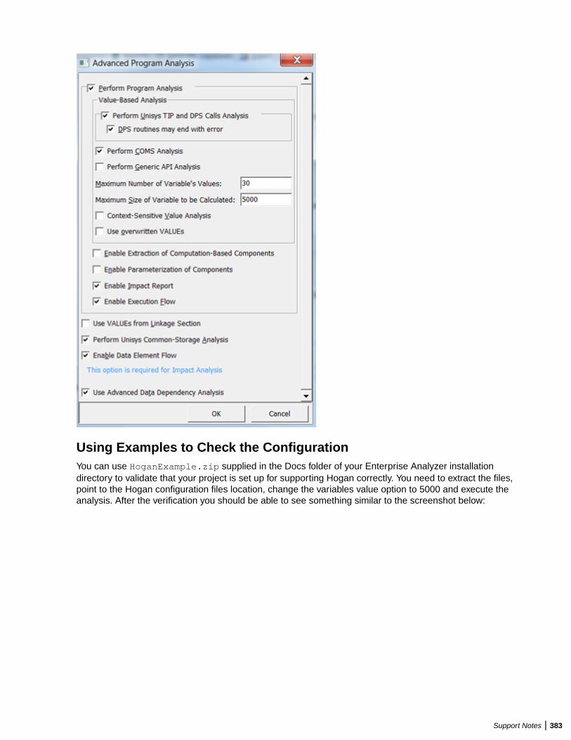
Using Examples to Check the ConfigurationYou can use HoganExample.zip supplied in the Docs folder of your Enterprise Analyzer installationdirectory to validate that your project is set up for supporting Hogan correctly. You need to extract the files,point to the Hogan configuration files location, change the variables value option to 5000 and execute theanalysis. After the verification you should be able to see something similar to the screenshot below:
Support Notes | 383
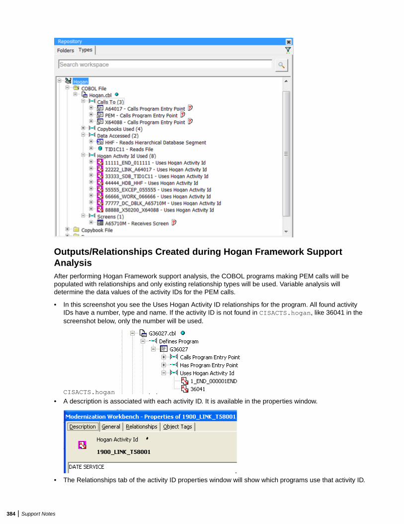
Outputs/Relationships Created during Hogan Framework SupportAnalysisAfter performing Hogan Framework support analysis, the COBOL programs making PEM calls will bepopulated with relationships and only existing relationship types will be used. Variable analysis willdetermine the data values of the activity IDs for the PEM calls.
• In this screenshot you see the Uses Hogan Activity ID relationships for the program. All found activityIDs have a number, type and name. If the activity ID is not found in CISACTS.hogan, like 36041 in thescreenshot below, only the number will be used.
CISACTS.hogan
• A description is associated with each activity ID. It is available in the properties window.
• The Relationships tab of the activity ID properties window will show which programs use that activity ID.
384 | Support Notes

• The Cross Reference report shows Programs and Hogan activity IDs.
Resolved RelationsThe flattened configuration information translates the activity IDs to programs, files, maps, and databaserelations.
Hogan relation EA relation EA type Name represents
Link Calls Program entry point PROGRAMENTRY program
X50200 Calls Program entry point PROGRAMENTRY program
SDB Reads File DATAPORT Data name
HDB Reads HierarchicalDatabase Segment
HISEGMENT Hierarchical segment
DC Receives Screen MAP Map
ACTIVITYID Uses Hogan activity ID ACTIVITYID Hogan activity ID
WORK, DUMP, EXCEP,END, ABEND, CHECK
Uses Hogan activity ID HOGAN ITEM Hogan activity ID
Validating Results after AnalysisFor any activity being used by the program (calls to PEM), the analysis will generate a correspondingactivity ID. If the activity ID is found in the .flt file, it will be prefixed by a sequential number and anactivity name. For example, if you have an activity with ID: 0000001, then the resulting activity will be1_END000001_END and this is an activity found inside the configuration files. If the tool cannot find anactivity ID in the configuration files, it will still be reported but without a prefix. For example, if your programis using an activity with ID: 321456 and it is not described in the configuration files, the program willgenerate an activity with ID: 321456. Usually, this means that the activity doesn't need to be linked toanything and that having information that it is used is enough. These activity IDs can be used to confirmthat all information was exported from Hogan.
Troubleshooting Hogan Framework SupportIf you receive the message "Number of paths exceeded the processing limit of nn," set the processing limitto a higher value in the Maximum Number of Variable's Values field in Project Options > Verification >Advanced for the Cobol File type.
IDMS SupportEnterprise Analyzer supports CA-IDMS, Release 15.0.
Support Notes | 385
COPY IDMS StatementsCOPY IDMS statements are the source manipulation statements for IDMS DML:
– [level-number] COPY IDMS [RECORD] copybook-name [REDEFINES data-item-name]
You must register a a separate copybook <copybook-name> for each COPY IDMS statement in theapplication. These copybooks should describe corresponding IDMS database records. They can beextracted manually from IDMS-preprocessed sources.
If the COPY IDMS statement depends on a schema or subschema:
– COPY IDMS SUBSCHEMA-< copybook>
the copybook name must be <schema_name>$<subschema_name>$SUBSCHEMA-<copybook>.SUBSCHEMA-CTRL and SUBSCHEMA-LR-CTRL are considered to be independent of schema/subschema and should not be prefixed.
NNCOPY StatementsThe NNCOPY statement is an extension of the common COPY statement:
– [level-number] NNCOPY copybook-name [ ([struct, ] substruct)] [suffix]
Select Handle NNCOPY syntax in the project verification options for Cobol files if you want the parser torecognize NNCOPY statements.
Manipulation of Logical RecordsManipulation of logical records in Cobol programs is not supported.
IMS SupportCobol and PL/I applications that use IMS/DB and/or IMS/DC interact with IMS via CBLTDLI calls andPLITDLI calls, respectively. CICS and batch applications may use EXEC DLI commands to interface withIMS. The Enterprise Analyzer IMS Analysis feature examines these call- and command-level interfaces todetermine the interactions between programs and the IMS database. It analyzes:
• The DLI-FUNC-CODE parameter to determine the type of operation requested from IMS.• The PCB-MASK parameter to determine the target segment or target MFS screen for the operation.
IMS Analysis then follows the call chain from the programs performing these calls up to the programstriggered by the operating system, known as root programs. Since the root programs have a PSBassociated with them, the analysis can establish which PCB is used in the call to IMS. With thisinformation, Enterprise Analyzer can create repository relationships that reflect the interactions betweenprograms and the IMS database. Before IMS analysis, in other words, you will see only calls to CBLTDLI,PLITDLI, or EXEC DLI. After IMS analysis, you will see CRUD information and MFS screen interactions.
Follow the steps below to perform IMS Analysis:
1. In addition to the basic source files for the Cobol or PL/I application, register the source files thatdescribe the IMS environment for the application. Enterprise Analyzer supports the following IMS-related file types:
• DBD files (.dbd). These files contain definitions for IMS segments and are the input to the macroDBDGEN in IMS.
386 | Support Notes
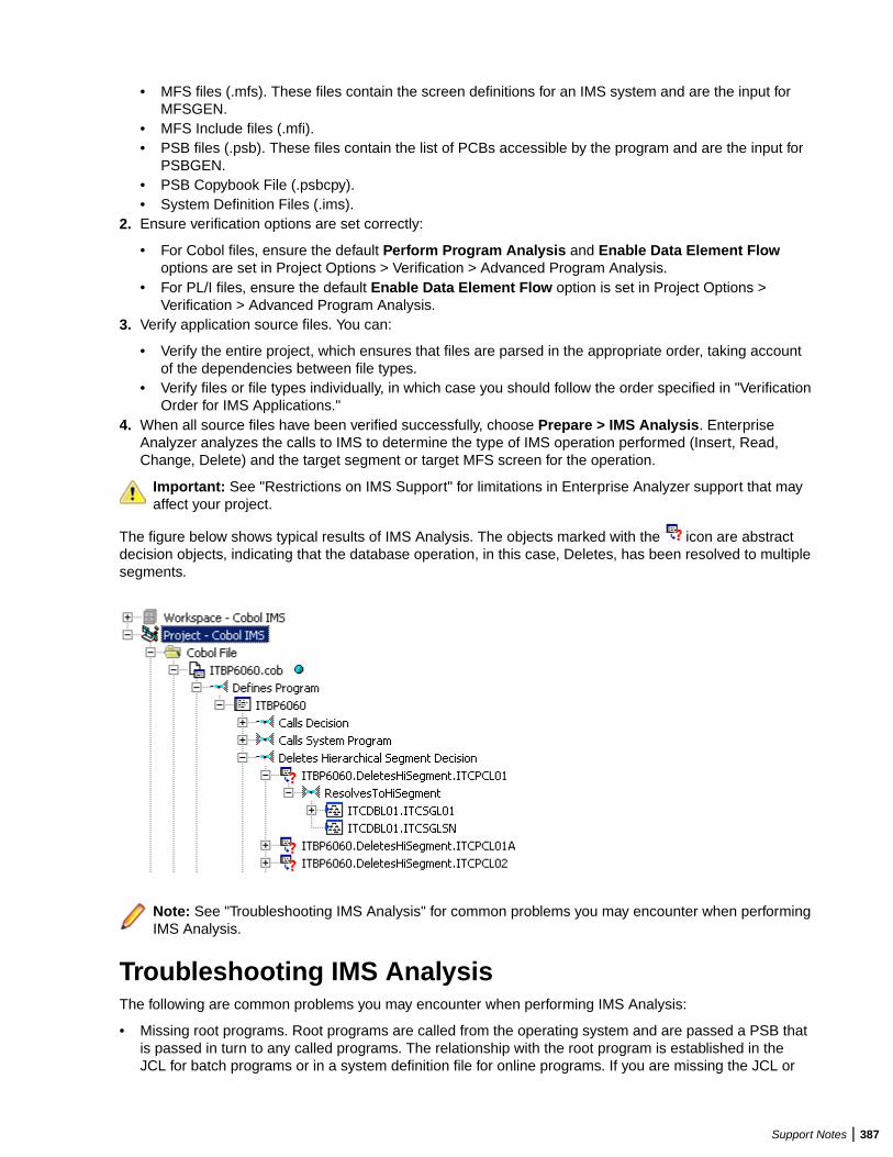
• MFS files (.mfs). These files contain the screen definitions for an IMS system and are the input forMFSGEN.
• MFS Include files (.mfi).• PSB files (.psb). These files contain the list of PCBs accessible by the program and are the input for
PSBGEN.• PSB Copybook File (.psbcpy).• System Definition Files (.ims).
2. Ensure verification options are set correctly:
• For Cobol files, ensure the default Perform Program Analysis and Enable Data Element Flowoptions are set in Project Options > Verification > Advanced Program Analysis.
• For PL/I files, ensure the default Enable Data Element Flow option is set in Project Options >Verification > Advanced Program Analysis.
3. Verify application source files. You can:
• Verify the entire project, which ensures that files are parsed in the appropriate order, taking accountof the dependencies between file types.
• Verify files or file types individually, in which case you should follow the order specified in "VerificationOrder for IMS Applications."
4. When all source files have been verified successfully, choose Prepare > IMS Analysis. EnterpriseAnalyzer analyzes the calls to IMS to determine the type of IMS operation performed (Insert, Read,Change, Delete) and the target segment or target MFS screen for the operation.
Important: See "Restrictions on IMS Support" for limitations in Enterprise Analyzer support that mayaffect your project.
The figure below shows typical results of IMS Analysis. The objects marked with the icon are abstractdecision objects, indicating that the database operation, in this case, Deletes, has been resolved to multiplesegments.
Note: See "Troubleshooting IMS Analysis" for common problems you may encounter when performingIMS Analysis.
Troubleshooting IMS AnalysisThe following are common problems you may encounter when performing IMS Analysis:
• Missing root programs. Root programs are called from the operating system and are passed a PSB thatis passed in turn to any called programs. The relationship with the root program is established in theJCL for batch programs or in a system definition file for online programs. If you are missing the JCL or
Support Notes | 387
system definition files, you can create them manually, as described in "Mapping Root Programs to PBSin JCL or System Definition Files."
• All content is present but no relationships are created from programs to IMS segments. Try setting theIMS Environment to Yes in Project Options > Verification > Source Type: COBOL File. Also, see"Restrictions on IMS Support" for coding patterns that are not supported by IMS Analysis.
Mapping Root Programs to PSBs in JCL or SystemDefinition FilesRoot programs are called from the operating system and passed a PSB that is passed, in turn, to anycalled programs. The relationship with the root program is established in the JCL for batch programs or in asystem definition file for online programs.
If you do not have actual JCL or System Definition files, you must create dummy ones. Analyzing theapplication without these files does nothing. Sample JCL and System Definition files follow:
Sample JCL file://imsbatch JOB//S1 EXEC PGM=DFSRRC00,REGION=2048K,//PARM=(DLI,progname,psbname,7,0000,,0,,N,0,T,0,,N,,,N)//
Sample System Definition file:APPLCTN PSB=prognameTRANSACT CODE=trnname
Verification Order for IMS ApplicationsIf you verify an entire project for an IMS application, EA parses the source files in appropriate order, takingaccount of the dependencies between file types. Otherwise, verify source files in the following order:
• DBD files (for GSAM databases)• MFS files• PSB files• Cobol or PL/I files
Note: For Cobol files, make sure the default Perform Program Analysis and Enable DataElement Flow project verification options are set. For PL/I files, make sure the default EnableData Element Flow project verification option is set.
• JCL or System Definition files
Reverifying Files in IMS ApplicationsIf you reverify a root program, the JCL or System Definition file that maps the program to a PSB will beinvalidated. If you reverify non-root programs, all call chains leading to them will be analyzed and any JCLsor System Definition files that start corresponding root programs will be invalidated. Make sure to reverifyinvalidated files.
Conversely, if you change a program-to-PSB mapping inside a JCL or System Definition file, or change thePSB file itself, make sure to reverify the mapped program before reverifying the JCL or System Definitionfile.
When you rerun IMS Analysis, it will process all complete call chains, starting from all reverified JCLs andSystem Definition files. You can limit the number of root programs that are re-analyzed in subsequent runsof IMS calls analysis by setting up System Definition files so that they reference one transaction pcf only.
388 | Support Notes
Note: If you rerun IMS Analysis without changing anything in the project, it will end with the warning“No information to perform IMS Analysis.” If you receive this message on the first run of IMS Analysis,make sure that all JCLs, System Definition files, and corresponding root programs have been verified,and that you have a call chain from root to every IMS-relevant program in the project (check for thestrings “+IMSC” or “+IMSE” in the Environment attribute on the System tab of the properties for theprogram).
Restrictions on IMS SupportEnterprise Analyzer supports IMS/MFS, Version 7. Refer to the topics below for restrictions on EnterpriseAnalyzer support for IMS.
Generic IMS RestrictionsBefore analyzing IMS applications in Enterprise Analyzer, you need to be aware of the following genericrestrictions on IMS support.
AIB Interface
The AIB interface is not supported.
Manual Decision Resolutions
Manual resolution of IMS-related decisions (PSB module decisions and the like) do not affect the results ofIMS call analysis.
SYSSERVE Parameter of SCHD Call
The SYSSERVE parameter of the SCHD call does not affect analysis. The number of PCB blocks in thePSB is determined statically during PSB verification. IO PCBs are added automatically as needed. Thatmight affect PCB numbering.
CALL Without Parameters
The active PSB name is not traced between programs if CALL without parameters is used.
Active PSB Name Calculated in Called Subroutine
The active PSB name is not detected if it is calculated in a called subroutine. Only “forward” passing ofparameters is supported from calling to called module.
Impact Analysis and Interprogram Data Flows
Impact analysis and interprogram data flows are not supported.
Extra Dependencies Between Variables
There may be extra dependencies between variables in IMS calls (in intraprogram analysis, computationalcomponents, and so forth) because all CALL arguments except function-code are considered as beingused in INOUT mode while in fact some CALLs have input-only and output-only parameters. This also maycause decisions to appear not to have been resolved, when in fact they have been.
When PCB Content Is Considered to Be Altered
PCB content is considered to be altered only by CBLTDLI(PLITDLI) calls or via a group MOVE of the wholePCB structure to another structure. Presence of MOVEs to subfields of a PCB may lead to incorrectanalysis results. GU call is not considered as nullifying alternate PCBs.
Support Notes | 389
Port Analysis for IMS Database Calls
For unqualified IMS database calls (without SSAs), port analysis uses only PCB information and does notanalyze preceding IMS calls (for example, GNP after GU). Similarly, dependencies between any other IMScalls are not traced except the CHNG – ISRT pair.
For qualified database calls, only the unqualified portion of SSA is analyzed. Command codes are notsupported (for example, a path call will be interpreted as a call reading only the last segment in a path).
PARMCOUNT Parameter
The PARMCOUNT parameter is accepted but not analyzed. All CALL parameters are considered as valid.
CHNG Calls
All CHNG calls are treated as setting transaction code destinations because, with no indicators ofdestination type, it is impossible to distinguish between transaction and terminal names. System tables withtransactions and terminal names are needed to check type.
ISRT Calls
ISRT calls to IO-PCB without MOD name are ignored. Most likely they represent the construction of multi-segment messages.
Parsing of Macro Statements
PSB/DBD parsers do not perform full semantic checks of corresponding macro statements. Moreover, thePSB parser does not check that all referenced segments and fields are defined in corresponding DBDs.
Online CICS Applications Using IMS
Online CICS applications using IMS do no need System Definition files. They need only native CICS PCTfiles.
SET ADDRESS OF and PSB Scheduling
Limited support is available for SET ADDRESS OF <variable> to <PCB> and scheduling of PSBs (calls toPCB functions in CICS programs).
IMS Restrictions for Cobol EXEC DLI SupportBoth batch and online CICS programs with EXEC DLI are supported. In addition to the generic restrictionsdescribed earlier in this section, the following restrictions apply to IMS support in Cobol EXEC DLIapplications.
Subsequent Runs of IMS Call Analysis for Online CICS Applications
Subsequent runs of IMS call analysis for online CICS applications may produce incorrect results. Makesure that all root programs and PCT files are reverified before you repeat IMS call analysis.
Order of Command Options
The order of command options should correspond to the order of options as they are specified in the EXECDLI reference manual (there is no free format there). Exceptions are the various options for SEGMENT,which can be coded in any order.
Quoted Literals
Quoted literals, where not defined by command syntax, are treated exactly as non-quoted IMS names. Theonly exception is the LOCKCLASS option.
390 | Support Notes
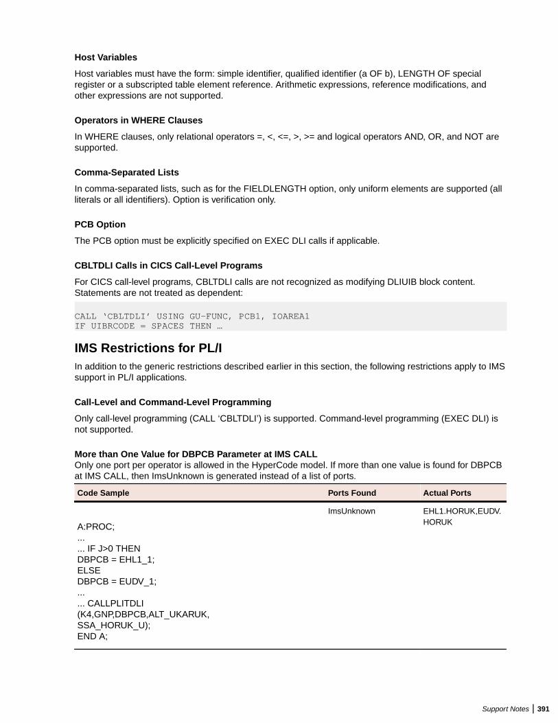
Host Variables
Host variables must have the form: simple identifier, qualified identifier (a OF b), LENGTH OF specialregister or a subscripted table element reference. Arithmetic expressions, reference modifications, andother expressions are not supported.
Operators in WHERE Clauses
In WHERE clauses, only relational operators =, <, <=, >, >= and logical operators AND, OR, and NOT aresupported.
Comma-Separated Lists
In comma-separated lists, such as for the FIELDLENGTH option, only uniform elements are supported (allliterals or all identifiers). Option is verification only.
PCB Option
The PCB option must be explicitly specified on EXEC DLI calls if applicable.
CBLTDLI Calls in CICS Call-Level Programs
For CICS call-level programs, CBLTDLI calls are not recognized as modifying DLIUIB block content.Statements are not treated as dependent:
CALL ‘CBLTDLI’ USING GU-FUNC, PCB1, IOAREA1IF UIBRCODE = SPACES THEN …
IMS Restrictions for PL/IIn addition to the generic restrictions described earlier in this section, the following restrictions apply to IMSsupport in PL/I applications.
Call-Level and Command-Level Programming
Only call-level programming (CALL ‘CBLTDLI’) is supported. Command-level programming (EXEC DLI) isnot supported.
More than One Value for DBPCB Parameter at IMS CALLOnly one port per operator is allowed in the HyperCode model. If more than one value is found for DBPCBat IMS CALL, then ImsUnknown is generated instead of a list of ports.
Code Sample Ports Found Actual Ports
A:PROC;...... IF J>0 THENDBPCB = EHL1_1;ELSEDBPCB = EUDV_1;...... CALLPLITDLI(K4,GNP,DBPCB,ALT_UKARUK,SSA_HORUK_U);END A;
ImsUnknown EHL1.HORUK,EUDV.HORUK
Support Notes | 391
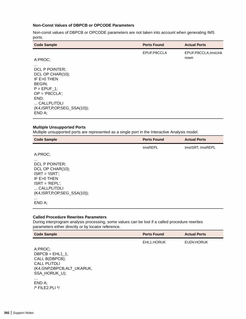
Non-Const Values of DBPCB or OPCODE Parameters
Non-const values of DBPCB or OPCODE parameters are not taken into account when generating IMSports.
Code Sample Ports Found Actual Ports
A:PROC;...DCL P POINTER;DCL OP CHAR(10);IF E>0 THENBEGIN;P = EPUF_1;OP = 'P8CCLA';END;... CALLPLITDLI(K4,ISRT,P,OP,SEG_SSA(10));END A;
EPUF.P8CCLA EPUF.P8CCLA,ImsUnknown
Multiple Unsupported PortsMultiple unsupported ports are represented as a single port in the Interactive Analysis model.
Code Sample Ports Found Actual Ports
A:PROC;...DCL P POINTER;DCL OP CHAR(10);ISRT = 'ISRT';IF E>0 THENISRT = 'REPL';... CALLPLITDLI(K4,ISRT,P,OP,SEG_SSA(10));...END A;
ImsREPL ImsISRT, ImsREPL
Called Procedure Rewrites ParametersDuring interprogram analysis processing, some values can be lost if a called procedure rewritesparameters either directly or by locator reference.
Code Sample Ports Found Actual Ports
A:PROC;DBPCB = EHL1_1;CALL B(DBPCB);CALL PLITDLI(K4,GNP,DBPCB,ALT_UKARUK,SSA_HORUK_U);…END A;/* FILE2.PLI */
EHL1.HORUK EUDV.HORUK
392 | Support Notes
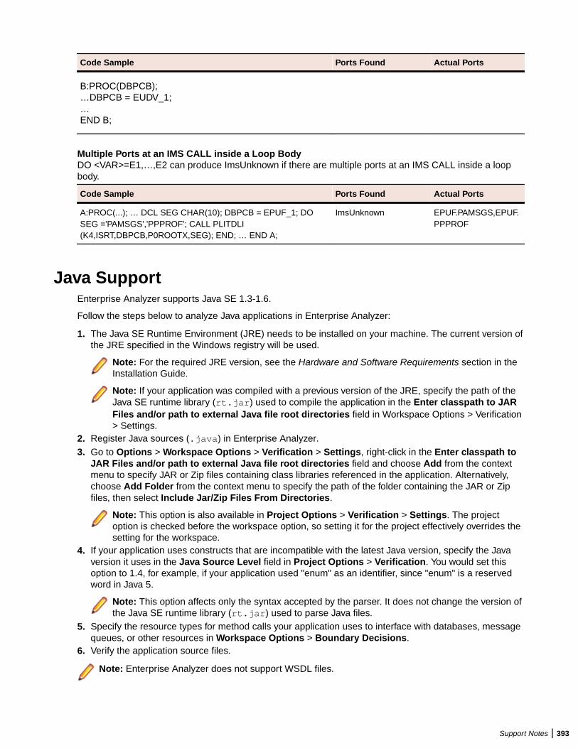
Code Sample Ports Found Actual Ports
B:PROC(DBPCB);…DBPCB = EUDV_1;…END B;
Multiple Ports at an IMS CALL inside a Loop BodyDO <VAR>=E1,…,E2 can produce ImsUnknown if there are multiple ports at an IMS CALL inside a loopbody.
Code Sample Ports Found Actual Ports
A:PROC(...); … DCL SEG CHAR(10); DBPCB = EPUF_1; DOSEG ='PAMSGS','PPPROF'; CALL PLITDLI(K4,ISRT,DBPCB,P0ROOTX,SEG); END; … END A;
ImsUnknown EPUF.PAMSGS,EPUF.PPPROF
Java SupportEnterprise Analyzer supports Java SE 1.3-1.6.
Follow the steps below to analyze Java applications in Enterprise Analyzer:
1. The Java SE Runtime Environment (JRE) needs to be installed on your machine. The current version ofthe JRE specified in the Windows registry will be used.
Note: For the required JRE version, see the Hardware and Software Requirements section in theInstallation Guide.
Note: If your application was compiled with a previous version of the JRE, specify the path of theJava SE runtime library (rt.jar) used to compile the application in the Enter classpath to JARFiles and/or path to external Java file root directories field in Workspace Options > Verification> Settings.
2. Register Java sources (.java) in Enterprise Analyzer.3. Go to Options > Workspace Options > Verification > Settings, right-click in the Enter classpath to
JAR Files and/or path to external Java file root directories field and choose Add from the contextmenu to specify JAR or Zip files containing class libraries referenced in the application. Alternatively,choose Add Folder from the context menu to specify the path of the folder containing the JAR or Zipfiles, then select Include Jar/Zip Files From Directories.
Note: This option is also available in Project Options > Verification > Settings. The projectoption is checked before the workspace option, so setting it for the project effectively overrides thesetting for the workspace.
4. If your application uses constructs that are incompatible with the latest Java version, specify the Javaversion it uses in the Java Source Level field in Project Options > Verification. You would set thisoption to 1.4, for example, if your application used "enum" as an identifier, since "enum" is a reservedword in Java 5.
Note: This option affects only the syntax accepted by the parser. It does not change the version ofthe Java SE runtime library (rt.jar) used to parse Java files.
5. Specify the resource types for method calls your application uses to interface with databases, messagequeues, or other resources in Workspace Options > Boundary Decisions.
6. Verify the application source files.
Note: Enterprise Analyzer does not support WSDL files.
Support Notes | 393
JSP SupportEnterprise Analyzer provides application-level support for JSP 2.2. You must install the Java add-on toenable JSP support. For installation instructions, see the installation manual for your product.
Follow the steps below to analyze JSP applications in Enterprise Analyzer:
1. Register JSP (.jsp), Tag Library Descriptor (.tld), and Web Config ( web.xml) files in EnterpriseAnalyzer.
2. If your JSP files reference Java types or packages defined in JAR files, external Java files, or Java files,specify a list of patterns used to resolve the location of the files in Project Options > Verification >Settings for the JSP file type.
3. Verify JSP and Tag Library Descriptor files. Web Config files ( web.xml) do not need to be verified.
Resolving the Location of Java Types and PackagesReferenced in JSP FilesWhen references are resolved to Java types from JPS files during verification, some references may not beresolved due to ambiguous names.
For example, Id.java in the app1 folder is registered as app1\com\company\Id.java and Id.javain the app2 folder is registered as app2\com\company\Id.java.
JSP cannot find the classes because there are now two possible definitions of the class com.company.Idin the workspace. If your JSP files reference this class, you need to specify which Java file defines theclass in the Java Classpath field for the JSP file type in Project Options > Verification > Settings.Otherwise, the relationship between JSP and the class is marked as unresolved in the workspace.
Java Classpath contains a list of patterns used to resolve the location of Java types and packagesreferenced in JSP files. Each pattern describes the path to a Java file that defines the referenced type orpackage. In our case, the pattern might be app1\*, which matches any Java source file registered in theworkspace from the app1 folder.
You can also match JAR files or external files referenced in Java applications but not registered in theworkspace, as specified in the Enter classpath to JAR Files and/or path to external Java file rootdirectories field for the Java file type in Workspace Options > Verification > Settings. The pattern *\jre6\lib\rt.jar would find the Java 6 run-time library, for example.
Right-click in the Java Classpath field and choose Add in the pop-up menu to enter a pattern. You canuse asterisk symbol to match any sequence of characters.
Relationships that cannot be resolved by any of the specified patterns are marked as unresolved in theworkspace. Once the classes are resolved, only the base name of the referenced class or packageappears in the relationship (in the Repository Browser). Use the Unresolved Report in the ReferenceReports window to see what is still unresolved and determine the patterns you need to add.
Job Scheduler SupportEnterprise applications use job scheduling software to define dependencies between jobs. EnterpriseAnalyzer supports CA-7 and TWS (OPC) job scheduling formats. It also provides an XML job scheduleformat that you can use to define unsupported job schedules.
394 | Support Notes
Preparing CA-7 Job Schedule InformationYou make CA-7 job schedule information available to Enterprise Analyzer in LJOB reports. Use the LJOButility with the LIST=NODD parameter to generate the reports on the mainframe.
The reports must have a .ca7 extension. Each report should have ANSI carriage control characters incolumn 1. You can create a report with carriage control characters in column 1 by specifyingDCB=RECFM=FBA (or FA) in the JCL used to run the LJOB utility.
Supplying Schedule IDs for a CA-7 Job Triggered by a DatasetWhen a CA-7 job is triggered by the creation of a dataset, rather than by a job or manual operation, theparser cannot always determine which schedule IDs are used to run the triggered job. You can supply thisinformation in a file.
The file should have the same name as the .CA7 file, and be in the same directory, but have an .SIDextension. Specify the location of the file in the Job to Schedule Ids File field for a CA-7 Schedule on theProject Verification options tab.
Each line of the file should contain a comma-separated list with the job name and schedule IDs used forthe job. For example, if job JOB0001 has the trigger:
--- TRIGGERED BY JOBS/DATASETS/NETWORKS ---DSN=DS00061219(POSTED.BY.XXXX.YYY.ZZZZ)SCHID=000 QTM=0030 LEADTM=0010 SUBMTM=0000
you would enter the following line in the .SID file:
JOB0001,10,30
That line identifies schedule IDs 10 and 30 for JOB0001.
Preparing TWS (OPC) Job Schedule InformationYou make TWS job schedule information available to Enterprise Analyzer in three reports:
• The application description report contains most of the information about jobs and how they arescheduled. Use the EQQADPRT utility to generate application description reports on the mainframe.The reports must have a .adr extension. Only these reports are registered in the workspace.
• The workstation description report identifies components and the tasks they perform. Use theEQQWSPRT utility to generate workstation description reports on the mainframe. The reports musthave a .wdr extension. These reports are not registered in the workspace, but must be identified in theWorkstation Report field for a TWS Schedule on the Verification > Settings tab of the WorkspaceOptions.
• The optional cross reference of applications and external dependencies report resolves job names. Usethe EQQADDEP utility to generate cross-reference reports on the mainframe. The reports must havea .xrf extension. These reports are not registered in the workspace, but must be identified in the Cross-reference Report field for a TWS Schedule on the Verification > Settings tab of the WorkspaceOptions.
Each report should have ANSI carriage control characters in column 1. You can create a report withcarriage control characters in column 1 by specifying DCB=RECFM=FBA (or FA) in the JCL used to runthe utility.
Support Notes | 395
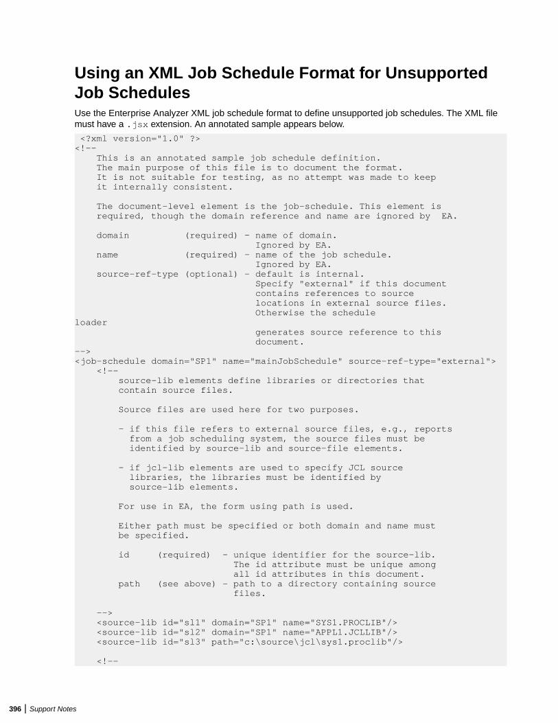
Using an XML Job Schedule Format for UnsupportedJob SchedulesUse the Enterprise Analyzer XML job schedule format to define unsupported job schedules. The XML filemust have a .jsx extension. An annotated sample appears below.
<?xml version="1.0" ?> <!-- This is an annotated sample job schedule definition. The main purpose of this file is to document the format. It is not suitable for testing, as no attempt was made to keep it internally consistent.
The document-level element is the job-schedule. This element is required, though the domain reference and name are ignored by EA.
domain (required) - name of domain. Ignored by EA. name (required) - name of the job schedule. Ignored by EA. source-ref-type (optional) - default is internal. Specify "external" if this document contains references to source locations in external source files. Otherwise the schedule loader generates source reference to this document. --> <job-schedule domain="SP1" name="mainJobSchedule" source-ref-type="external"> <!-- source-lib elements define libraries or directories that contain source files.
Source files are used here for two purposes.
- if this file refers to external source files, e.g., reports from a job scheduling system, the source files must be identified by source-lib and source-file elements.
- if jcl-lib elements are used to specify JCL source libraries, the libraries must be identified by source-lib elements.
For use in EA, the form using path is used.
Either path must be specified or both domain and name must be specified.
id (required) - unique identifier for the source-lib. The id attribute must be unique among all id attributes in this document. path (see above) - path to a directory containing source files.
--> <source-lib id="sl1" domain="SP1" name="SYS1.PROCLIB"/> <source-lib id="sl2" domain="SP1" name="APPL1.JCLLIB"/> <source-lib id="sl3" path="c:\source\jcl\sys1.proclib"/>
<!--
396 | Support Notes
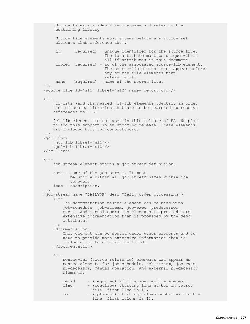
Source files are identified by name and refer to the containing library.
Source file elements must appear before any source-ref elements that reference them.
id (required) - unique identifier for the source file. The id attribute must be unique within all id attributes in this document. libref (required) - id of the associated source-lib element. The source-lib element must appear before any source-file elements that reference it. name (required) - name of the source file. --> <source-file id="sf1" libref="sl2" name="report.ctm"/>
<!-- jcl-libs (and the nested jcl-lib elements identify an order list of source libraries that are to be searched to resolve references to JCL.
jcl-lib element are not used in this release of EA. We plan to add this support in an upcoming release. These elements are included here for completeness. --> <jcl-libs> <jcl-lib libref="sl1"/> <jcl-lib libref="sl2"/> </jcl-libs>
<!-- job-stream element starts a job stream definition.
name - name of the job stream. It must be unique within all job stream names within the schedule. desc - description. --> <job-stream name="DAILYOP" desc="Daily order processing"> <!-- The documentation nested element can be used with job-schedule, job-stream, job-exec, predecessor, event, and manual-operation elements to provied more extensive documentation than is provided by the desc attribute. --> <documentation> This element can be nested under other elements and is used to provide more extensive information than is included in the description field. </documentation>
<!-- source-ref (source reference) elements can appear as nested elements for job-schedule, job-stream, job-exec, predecessor, manual-operation, and external-predecessor elements.
refid - (required) id of a source-file element. line - (required) starting line number in source file (first line is 1). col - (optional) starting column number within the line (first column is 1).
Support Notes | 397
If omitted, column 1 is assumed. endline - (optional) end line. if omitted, starting line is assumed. endcolumn - (optional) end column. If omitted, last character of endline is assumed. --> <source-ref refid="sf1" line="100" col="1" endline="102" endcol="70"/>
<!-- job-exec (job execution) element. defines the execution of a job within a job stream.
name - (required) name of the job execution. Must be unique among all job executions, manual operations, and events within the job stream, within the schedule. jobname - (required) name of the JCL member to be executed. desc - (optional) description of the job execution. --> <job-exec name="job1" jobname="job1" desc="Description">
<!-- The predecessor nested element specifies a dependency on another job stream operation (another job-exec, external-predecessor, manual operation, or event. --> <predecessor name="mo1">
<!-- attr elements can be nested within most other elements. Specifically, attr elements can be contained by predecessor, external-predecessor, job-exec, manual-operation, and event. attr elements are never required but can be used to provide values that are, for example, specific to a particular job scheduling system.
The exact processing of these values varies with the specific implementation. The XML schedule loader keeps these values as named attributes of the parent object.
The dep.type nested element for predecessor can have one of the following values: GENERAL, EXCLUSION, TRIGGER. --> <attr name="dep.type" value="GENERAL"/> </predecessor>
<!-- External predecessor elements can be nested under job-exec and manual-operation elements to indicate a predecessor that is not in the current job stream.
All attributes are required, though some may be ignored by EA.
name - name of this external-predecessor. Must be unique among all job-exec manual- operation, event, and external-predecessor elements in the job stream. domain - containing domain. Ignored by EA.
398 | Support Notes
sched - containing schedule. Ignored by EA. stream - containing job stream. opername - name of the operation (job-exec, manual-operation, or event) in the external job stream. --> <external-predecessor name="ep1" domain="dom1" sched="sch1" stream="strname" opername="ref1"/> </job-exec> <!-- The manual-operation element defines a manual operation.
It can have predecessor and external-predecessor nested elements.
name - (required). The name of the operation must be unique within manual-operation, job-exec, and even elements within the job stream. --> <manual-operation name="JobPrep" desc="Description"> </manual-operation> <event name="Event1" desc="description" type="evtype"> </event> </job-stream> </job-schedule>
JCL SupportEnterprise Analyzer supports JCL, OS/390 Version 2, Release 10:
• Batch Application Viewer performs low-level analysis of batch processes: whether batch jobs aredependent on one another, the programs that use a data store, and the flow of data into or out of a datastore.
• System calls analysis analyzes system program input to determine the application program started in ajob step.
• Advanced data flow analysis traces the flow of data into or out of a dataset through the entire callingchain: not only the program referenced in the control language file (whether or not that program writesto or reads from the dataset), but also any programs that program calls, and any programs they call inturn.
• Sort card analysis traces the flow of data through control cards supplied for SORT utility invocations(sort cards). Both inline cards (DD *) and external cards (DSN=) are supported.
• Driver utility analysis lets you model batch programs started by a driver utility.
Follow the steps below to analyze JCL applications in Enterprise Analyzer:
1. Depending on the application, the following file types may need to be registered:
• JCL files (.jcl)• JCL procedure files (.prc)• External control card files (.crd, .srt). For more information, see "Naming Requirements for External
Control Cards."2. In Workspace Options > Verification > Settings for the JCL file type:
• Select Perform System Calls Analysis to enable system calls analysis.• Select Perform DSN Calling Chains Analysis to enable advanced data flow analysis.• Choose the names of the SORT utilities the application uses in Sort Program Aliases. Add names
as necessary.• Choose the names of the system procedures the application uses in System Procedures. Add
names as necessary.
Support Notes | 399
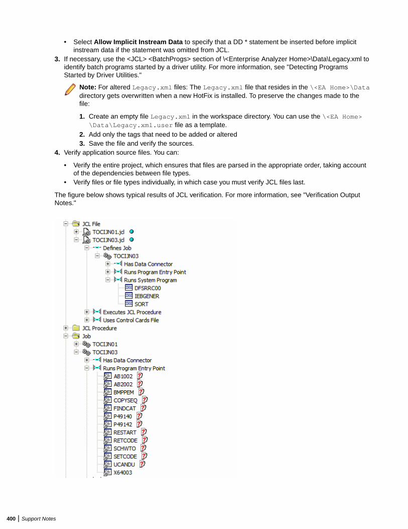
• Select Allow Implicit Instream Data to specify that a DD * statement be inserted before implicitinstream data if the statement was omitted from JCL.
3. If necessary, use the <JCL> <BatchProgs> section of \<Enterprise Analyzer Home>\Data\Legacy.xml toidentify batch programs started by a driver utility. For more information, see "Detecting ProgramsStarted by Driver Utilities."
Note: For altered Legacy.xml files: The Legacy.xml file that resides in the \<EA Home>\Datadirectory gets overwritten when a new HotFix is installed. To preserve the changes made to thefile:
1. Create an empty file Legacy.xml in the workspace directory. You can use the \<EA Home>\Data\Legacy.xml.user file as a template.
2. Add only the tags that need to be added or altered3. Save the file and verify the sources.
4. Verify application source files. You can:
• Verify the entire project, which ensures that files are parsed in the appropriate order, taking accountof the dependencies between file types.
• Verify files or file types individually, in which case you must verify JCL files last.
The figure below shows typical results of JCL verification. For more information, see "Verification OutputNotes."
400 | Support Notes
Verification Output Notes• Job steps are enumerated from the beginning of the job, after all procedures are expanded. The EXEC
PROC= command is counted first, as a separate step. Thereafter, all steps inside the invoked procedureare enumerated. The number of job steps, then, is the number of all EXEC commands processedduring job execution.
• No relationships are generated for EXECs to internal procedures.• For steps placed directly in a job, the Step Full Name attribute of the Data Connector object generated
from DD statements is <execName> if specified, or “Ln <line-number>” if <execName> is empty. Forsteps within procedures, the following is the path to the step from the EXEC PROC= command placedinside the job through all intermediate procedures:
<jobExecName>[/<ProcName>.<procExecName>]…
• The parser creates an artificial program entity that defines the inputs and outputs for each sort utilityinvocation. The program has a name of the form JCLFileName.JobName.StepName.SequenceNumber,where SequenceNumber identifies the order of the step in the job. For every sort invocation in theprogram, you can view data structures for sort input and output records and the data movementsbetween them in the HyperCode for the JCL file.
• An invoked program is known as a system program if it is defined with a sort utility alias in SortProgram Aliases in Workspace Options > Verification > Settings for the JCL file type, or specified in the\<Enterprise Analyzer Home>\Data\Legacy.xml.
JCL Control Cards SupportJCL EXECs can reference input data defined in-stream or by using control cards. By default, EA processesthe control cards that are passed as parameters to the SORT program and generates relationships tothem. For example:
//STEP1 EXEC PGM=SORT...//SYSIN DD DSN=DD1.PROD.CNTL(SORTCOPY),DISP=SHR...
EA creates a relationship between the JOB and the control card DD1.PROD.CNTL(SORTCOPY) whichdefines parameters for the SORT program.
If you want EA to process relationships to other control cards, you must specify them in the Legacy.xmlfile. The XML section you must edit is used to define which DSNs refer to control card files. It is locatedunder the JCL section, in a subsection called ProgUsesCard:
<JCL> <!-- to generate relationship Program Uses ControlCard --> <ProgUsesCard> <item> IDCAMS,SYSIN,.* </item> </ProgUsesCard></JCL>
Each item element contains a specification with three parts separated by comma (in the following order):
• The PGM name.• The DD name.• The DSN name.
These are regular expressions. In the Legacy.xml template, the DSN name part is set to ".* ", which is amatch against any string. This instructs EA to do control card processing for the SYSIN DD on any call toIDCAMS, regardless of the DSN name.
Support Notes | 401
Naming Requirements for External Control CardsSource files for external cards are registered in the repository as Control Cards files, and must be namedas follows, where .srt is the default file extension:
• For an ordinary dataset, if the SYSIN DD statement is:
//SYSIN DD DSN=MY.SORTCARDS.LIB.FILE1
the source file name must be MY.SORTCARDS.LIB.FILE1.srt.• For a PDS member, if the SYSIN DD statement is:
//SYSIN DD DSN=MY.SORTCARDS.LIB(FILE2)
the source file name must be MY.SORTCARDS.LIB(FILE2).srt, or if the member name is unique,FILE2.srt.
• For a generation dataset, if the SYSIN DD statement is:
//SYSIN DD DSN=MY.SORTCARDS.LIB.FILE3(+1)
the source file name must be MY.SORTCARDS.LIB.FILE3.srt, without the generation number.
Detecting Programs Started by Driver UtilitiesBatch applications often use jobs to launch driver utilities that start other programs. If you want to modelthe relationship between jobs and these kinds of programs, you need to define entries that identify theprograms in the <JCL> <BatchProgs> section of \<Enterprise Analyzer Home>\Data\Legacy.xml.
<BatchProgs> entries have the form:
<item> <driver_utility>,PARM|DD*|DSN,<search_value>
where:
• driver_utility is the name of the driver utility.• PARM, DD*, and DSN are the available search options:
• PARM searches the PARM= parameter of the EXEC statement.• DD* searches the instream data of a DD statement.• DD* searches the DSN name of a DD statement.
• search_value is the value of the specified search option.
Tip: The <BatchProgsNames> section of Legacy.xml contains patterns you can use to filter programnames from other input data. Use <Accept> to specify patterns for valid program names, <Except> forinvalid program names. For example: <Accept> ^([A-Z]\w{4,7})$ </Accept>.
Using the PARM Option
The PARM option searches for the name of the program of interest in the PARM= parameter of the EXECstatement. You can also use it to find the PSB name for an IMS application. The syntax is:
PARM,<prg_parm_num>[,%P,<psb_parm_num>,%B]
where:
• <prg_parm_num> is the number of the parameter that specifies the program name.• <psb_parm_num> is the number of the parameter that specifies the PSB name.
The value is either a string literal, with parameters separated by blanks or by commas, or a list of comma-separated parameters enclosed in brackets.
402 | Support Notes
For example, the entry:
<item> IKJEFT01,PARM,3 </item>
identifies the programs APPPRG1 and APPPRG in the following code fragment:
//step1 EXEC PGM=IKJEFT01,// PARM='APP DB2P APPPRG1 APPPRG1L'//SYSTSIN DD DUMMY,DCB=BLKSIZE=80
//step2 EXEC PGM=IKJEFT01,REGION=2048K,DYNAMNBR=20,// PARM=('APP',DB2P,APPPRG2,APPPRG2L)//SYSTSIN DD DUMMY,DCB=BLKSIZE=80
For IMS:
<item> DFSRRC00,PARM,2,%P,3,%B </item>
identifies the program IMSPRG1 and the PSB PSBM1 in the following code fragment:
// EXEC PGM=DFSRRC00,REGION=2048K, // PARM=(DLI,IMSPRG1,PSBM1,7,0000,,0,,N,0,T,0,,N,,,N)
Using the DD* Option
The DD* option searches for the name of the program of interest in the instream data of a DD statement.You can also use it to find Natural library names. The syntax is:
DD*,<dd_name>,<search_string>[%L] %P[+] [,%?]
where:
• <dd_name> is the name of the DD statement.• <search_string> is the string to match. Matched code can appear on different lines in the source.• %L specifies the position of the Natural library name relative to the matched string.• %P specifies the position of the program name relative to the matched string. %P+ indicates that
multiple program names are at the specified position.• %? specifies the position relative to the matched string of the program name to be ignored by the
parser.
Note: So <item> IKJEFT01,DD*,SYSTSIN,PARMS('%?,%?,%P) </item> matches onlyBF4P422 in the code fragment PARMS ('BF422DA1,STEP1,BF4P422 /').
For example, the entry:
<item> IKJEFT01,DD*,SYSTSIN,RUN PROGRAM(%P) </item>
identifies the programs MYPRG1 and MYPRG3 in the following code fragment:
//step4 EXEC PGM=IKJEFT01//SYSTSIN DD * RUN PROGRAM(MYPRG1) qqq/*
//step5 EXEC PGM=IKJEFT01//SYSTSIN DD * PROFILE PREFIX(C34) DSN SYSTEM(DSN) RETRY(0) TEST(0) RUN PROGRAM(MYPRG3) PLAN(MYPLAN) - LIB('CO737.PDS.MCPBR2.LOAD') -
For Natural:
<item> ADANATV3,DD*,CMSYNIN,LOGON %L %P+ </item>
Support Notes | 403
identifies the library MYLIB and the programs MYNAT1 and MYNAT2 in the following code fragment:
//S040 EXEC PROG=ADANATV3//CMSYNIN DD * LOGON MYLIB MYNAT1MYNAT2
Using the DSN Option
The DSN option searches for the name of the program of interest in the DSN name of a DD statement. Thesyntax is:
DSN,<dd_name>,<search_string>%P
where:
• <dd_name> is the name of the DD statement.• <search_string> is the string to match.• %P specifies the position of the program name relative to the matched string.
For example, the entry:
<item> IKJEFT01,DSN,SYSTSIN,RUNCARDS(%P) </item>
identifies the programs PROG1 and PROG2 in the following code fragment:
///step8 EXEC PGM=IKJEFT01//SYSTSIN DD DSN=SYS.DP.TE.RUNCARDS(PROG1),DISP=SHR
//step9 EXEC PGM=IKJEFT01//SYSTSIN DD DSN=RUNCARDS(PROG2),DISP=SHR
Natural Support1. Register Natural sources in Enterprise Analyzer. The following objects must be registered:
• Natural Data Areas (.nda, .nsl)• Natural DDM files (.nsd, .ddm)• Natural files (.nat, .nsn, .nsp, ..nsh)• Natural Include files (.ncp, .inc)• Natural Maps (.nsm, .map)• Natural Subroutine files (.nss)
Note: It's almost always useful to qualify Natural programs with their library names in call diagramsand the like. To enable library name qualification, register Natural files with names of the formlibrary.program.extension. For assistance renaming files, contact support services.
2. For Natural files registered with library names:
• Ensure the default Libraries support option is set in Workspace Options > Verification > Settings forthe Natural File type.
• In the Libraries field in Project Options > Verification for the Natural File type, specify the order inwhich the parser searches for library names when it resolves program calls. Right-click in the fieldand choose Add in the pop-up menu to enter a library name. Place a check mark next to a library toinclude it in the search. The parser always searches for the library of the object being verified, thecurrent library, first. You can specify a different library search order for each project in yourworkspace.
404 | Support Notes
Tip: For example, if Lib2 appears in the list before Lib1, a call to ProgA is resolved toLib2.ProgA rather than Lib1.ProgA (assuming the current library is not Lib1).
3. In the Helproutines field in Project Options > Verification for the Natural Map file type, specify how youwant the parser to treat helproutines, as programs (the default) or helpmaps.
4. Verify application source files. You can:
• Verify the entire project, which ensures that files are parsed in the appropriate order, taking accountof the dependencies between file types.
• Verify files or file types individually, in which case you should follow the order specified in "VerificationOrder for Natural Applications."
Important: Before registering Natural sources, see Restrictions on Natural Support for limitations inEnterprise Analyzer support that may affect your project.
Verification Order for Natural ApplicationsIf you verify an entire project for a Natural application, EA parses the source files in appropriate order,taking account of the dependencies between file types. Otherwise, verify source files in the following order:
• Natural DDM files (.nsd, .ddm)• Natural Data Areas (.nda, .nsl)• Natural Maps• Natural Subroutine files (.nss)• Natural files
Restoring Line Numbers in Natural SourceTo restore stripped line numbers in Natural source, choose Edit > Restore Line Numbers in NaturalSource.
Restrictions on Natural SupportBefore analyzing Natural applications in Enterprise Analyzer, you need to be aware of the followingrestrictions on Natural support.
Supported CALLDBPROC Syntax
The following syntax of the CALLDBPROC statement is supported:
CALLDBPROC dbproc ddm-name [USING] [ parameter [ AD = {M | O | A}] ]…[ RESULT SETS result-set…] [ GIVING sqlcode ] [ CALLMODE = { NONE | NATURAL }]
Supported READ RESULT SET Syntax
The following syntax of the READ RESULT SET statement in structure mode is supported:
READ [(limit)] { RESULT-SET | RESULT SET } result-setINTO { VIEW view-name | parameter,… }FROM ddm-name[ GIVING sqlcode]statement…END-RESULT
The following syntax of the READ RESULT SET statement in reporting mode is supported:
READ [(limit)] { RESULT-SET | RESULT SET } result-setINTO { VIEW view-name | parameter,… }FROM ddm-name[ GIVING sqlcode]
Support Notes | 405
statement…[ [ CLOSE ] LOOP [(r)] ]
Program Analysis
The following notes apply to tools related to control flow and/or data flow analysis for programs and tocomponent extraction.
• It is assumed that IF, DECIDE ON, and DECIDE FOR statements always have a FALL THRU, even if allthe control flows of the branches do not reach the statement after these statements.
• Definition and usage of array slices are treated as whole array variables.• Control flow of cyclic constructs, such as FOR loops, have no backward edge. This rough bit of the
analysis may lead to insufficiency in data dependencies between definitions inside a loop body andusages at the top of a loop body.
• Control flow analysis between subroutines is call site-independent. It is assumed that there are pathsfrom any call site to any return point of a subroutine. This may lead to superfluous data dependenciesbetween definitions inside a subroutine and their usages beyond the return points.
Component Extraction
Both Computation-Based Extraction and Dead Code Elimination are supported. For Computation-BasedExtraction:
• A PERFORM statement without parameters cannot be selected as a slice point.• An ON ERROR statement and all statements inside an ON ERROR block cannot be selected as a slice
point.
For Dead Code Elimination, statements and declarations that are unused INDIRECTLY are not detected.This means that constructions included in unused constructions are retained.
Impact Analysis
Group MOVEs are split into field MOVEs and data flow relationships are calculated for these split MOVEs.This means there are no relationships between whole structures for group MOVEs.
.NET SupportEnterprise Analyzer supports Microsoft .NET Framework 3.5, Visual C# 3.0, and Visual Basic .NET 9.0.The table below shows the supported file types and their entity types in the repository. Register the entirefolder for the project to avoid problems with duplicate file names.
File Type Entity Type
.csproj, .vbproj .Net Project
.cs, .vb .Net File
PL/I SupportEnterprise Analyzer supports the following PL/I versions:
• VisualAge PL/I for OS/390, Version 2.• Enterprise PL/I for z/OS, Version 3, Release 6.
406 | Support Notes
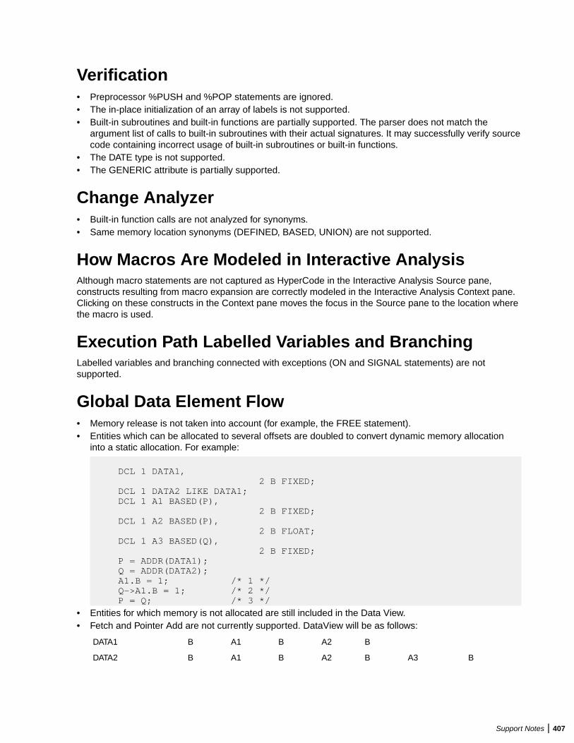
Verification• Preprocessor %PUSH and %POP statements are ignored.• The in-place initialization of an array of labels is not supported.• Built-in subroutines and built-in functions are partially supported. The parser does not match the
argument list of calls to built-in subroutines with their actual signatures. It may successfully verify sourcecode containing incorrect usage of built-in subroutines or built-in functions.
• The DATE type is not supported.• The GENERIC attribute is partially supported.
Change Analyzer• Built-in function calls are not analyzed for synonyms.• Same memory location synonyms (DEFINED, BASED, UNION) are not supported.
How Macros Are Modeled in Interactive AnalysisAlthough macro statements are not captured as HyperCode in the Interactive Analysis Source pane,constructs resulting from macro expansion are correctly modeled in the Interactive Analysis Context pane.Clicking on these constructs in the Context pane moves the focus in the Source pane to the location wherethe macro is used.
Execution Path Labelled Variables and BranchingLabelled variables and branching connected with exceptions (ON and SIGNAL statements) are notsupported.
Global Data Element Flow• Memory release is not taken into account (for example, the FREE statement).• Entities which can be allocated to several offsets are doubled to convert dynamic memory allocation
into a static allocation. For example:
DCL 1 DATA1, 2 B FIXED; DCL 1 DATA2 LIKE DATA1; DCL 1 A1 BASED(P), 2 B FIXED; DCL 1 A2 BASED(P), 2 B FLOAT; DCL 1 A3 BASED(Q), 2 B FIXED; P = ADDR(DATA1); Q = ADDR(DATA2); A1.B = 1; /* 1 */ Q->A1.B = 1; /* 2 */ P = Q; /* 3 */
• Entities for which memory is not allocated are still included in the Data View.• Fetch and Pointer Add are not currently supported. DataView will be as follows:
DATA1 B A1 B A2 B
DATA2 B A1 B A2 B A3 B
Support Notes | 407
Common IMS, Domain Extraction, and AutoresolveRestrictionsRestrictions described in this section are common to IMS analysis, domain-based extraction, and decisionautoresolution.
Analysis• Analysis is call-site independent, that is, all calls of a procedure are considered simultaneously. First, all
the actual parameter values from the call sites are evaluated and collected at the formal parameters andthen the procedure constant propagation is performed.
• Analysis is performed for a given file without processing other PL/I files that could be called from the filebeing analyzed. ‘NonConst’ means that the variable obtains no value and so will not be substituted.Moreover, since it has no value, other variables may not be resolved as well.
Variable Value Processing• When an assignment to a structure field or an array element is interpreted, the entire structure and
array value is calculated and stored to the value set. Calculation of values of structure fields of arrayelements avoids this redundancy, but a ‘Nonconst’ value may appear, or some values may not beevaluated because of value set overflow.
• Entire alias values are calculated and stored in variables during processing, with the result that morethan one alias value may be stored in a variable even if the variable has only one proper value.Calculation of proper values of the variable avoids this redundancy, but a ‘Nonconst’ value may appear,or some values may not be evaluated because of value set overflow.
• Maximum size of the value set of a variable is 32. This means that analysis will not be fully completewhen the amount of possible values exceeds this number. A ‘NonConst’ value indicates that there arevalues that are not calculated. Warnings about overflow of value sets of variables are not generated.
• For performance reasons, the maximum size of a memory block is limited to 32KB. Every accessbeyond this limit is ignored. (Memory blocks are used for structures, arrays, and variables accessedthrough a DEFINED attribute or pointers). This means that strings, structures and arrays that do not fitin 32KB are not processed correctly.
• Read variables of a statement are enumerated independently from each other in the sense that thestatement is interpreted for all combinations (no more than 16) of the values of the variables used in thestatement. It may lead to superfluous write values when the statement is evaluated for somecombinations that cannot occur during real program execution.
• A ‘NonConst’ value is added to a value set if some values cannot be evaluated or the number of thevalues exceeds the value set limit.
• During interpretation of an operator, a ‘NonConst’ value is added to write variables if the number ofcombinations of values of read variables exceeds the limit.
Loop Analysis• Loops are executed until value sets of variables inside the loop body stop expanding. Because lower
and upper bounds and WHILE conditions are ignored, the resulting sets of variable values may besuperfluous.
• DO statements with a cyclic header are always treated as a loop control flow construction, though thebody of this statement can be executed only once when the program is executed (for example, DOI=1;).
408 | Support Notes
Array Processing• If all values of an index in a slice expression cannot be evaluated, then the slice is interpreted for all
index values from the appropriate array bound interval. The maximum size of the implicit set of indexvalues is 32.
• All arithmetic operations (including built-ins) are performed with DOUBLE values (there is no artificialincrease/decrease of digit number). Excess precision may be rounded away during arithmetic typecasting.
• Assignment to an array is supported only if no two asterisks in the array reference are separated withan ordinary array index or a structure member selection. The system would try to minimize the amountof memory erased by an unsupported array write, but it can destroy the whole array.
• Complex DEFINED is not supported (the DEFINED declaration is mapped to the base field by field anddimension by dimension). DEFINED(X) is interpreted strictly as if it was BASED(ADDR(X)).
• POSITION for variables defined on bit strings is not supported. Also, no alignment other than on a one-byte boundary is supported.
• DEFINED on sparse areas is not supported. In a real system, one can write DEFINED(A(*,4)) and ifstructures match it would map the newly defined array on top of sparse array A(*,4). Structurematching, however, is unsupported. This means that although this type of definition is valid in a realsystem, it is not supported.
Note: With one possible exception: A(4,*) might work as expected if structures are not onlymatching but strictly equivalent
• Array expressions are not supported, so A(*) = B(*) + 5 will not work.• Out-of-bounds access is always ignored and a warning is issued.• Dynamic-sized arrays are not supported and are interpreted as fixed-sized arrays with extent 10.
External Call Processing• When external calls and unresolved dynamic internal calls are interpreted, values of whole aliases are
passed, so that such calls are treated as rewriting their parameters, with the result that the values of thewhole aliases are assumed to be rewritten and are set to ‘NonConst’.
• It is assumed that interprocedure dynamic calls do not rewrite any context variables (exceptparameters).
Unsupported Constructions• Dynamic control flow is unsupported. The following cases are classified as dynamic control flow:
• Jumps to expression of label type, such as label-variable, element of array of labels, field ofstructure, and so forth (treated as program stop).
• Jumps by GOTO outside procedure (treated as program stop).• Condition handling:
• Control flow is constructed as if condition-handling operators are replaced by empty operators.Nested operators are also skipped.
• Alias analysis processing:
• Aliases induced by RETURN(<addr expression>) are not supported• Non-null pointers in structures are lost when the structure is passed as a parameter to a top-level
procedure (except PSB pointers).
Unsupported Evaluations• Calculation of values of CONTROLLED or AREA variables.• Calculation of initial values of variables declared in packages is unlike the declaration of the variables in
contained procedures.
Support Notes | 409
• SUBSTR as a pseudovariable will not assign a value to a string with a previously undetermined valueeven if the substring covers the entire string.
• Assignment to the first argument of SUBSTR when this argument is an array.• VARYINGZ strings are handled as simple VARYING, that is, as using a length field instead of a zero
terminator.• ALLOCATE is only supported if it is used on a single BASED variable and each statement produces
only one value of the pointer, no matter how many times it may be called.• Calculation with multibyte character set values for variables may or may not work correctly.
PL/SQL SupportEnterprise Analyzer supports Oracle PL/SQL for Oracle Database 11g, Release 1.
RPG SupportEnterprise Analyzer supports RPG IV ILE, Version 5, Release 3.
Note: RPG programs often use copy statements that reference Database Description or DeviceDescription files rather than copybooks. If your application uses copy statements to reference thesetypes of files, you need to verify the files and generate copybooks for the application before you verifyprogram files. For instructions on generating copybooks, see Preparing Projects in the productdocumentation set.
Preparing for RPG Source Files Registration
If the source files are not in RPGIV format, then the appropriate IBM RPG conversion tool must be run toconvert them to the RPGIV format before the files are downloaded:
• RPGII: Convert to RPGIII using a manual process or direct to RPGIV using a third party tool such asTarget/400 or RPG Tool Box
• RPGIII: Convert to RPGIV using CVTRPGSRC (IBM)• RPG400: Convert to RPGIV using CVTRPGSRC (IBM)
Remember: The iSeries is an EBCDIC platform, so ensure the correct conversion is performed. Thismight require changes to the code page used for unprintable characters.
SQL SupportEnterprise Analyzer supports DB2 UDB for z/OS, Version 8 (DCLGENs, SQL, DDL).
Renaming DCLGEN Include FilesIn previous releases, DCLGEN include files with the same names as ordinary include files had to berenamed with a DCLGEN prefix and dot (.) separator so that both types of file could be registered:ATTR.<valid extension>, for example, and DCLGEN.ATTR.<valid extension>.
You don't have to rename these files anymore. If fact, if you have the files renamed already, you should nowrename them back to not have the DCLGEN. prefix.
Note: Unresolved references to library members are always reported with the short name. Thismeans that if you subsequently register a missing include file with a long name, the referencingsource file will not be invalidated. It's up to you to remember that the referencing source needs to bereverified.
410 | Support Notes
Prefixes for SQL NamesTo maintain uniqueness of ERD entity names, EA specifies SQL names with an SQLID prefix, defined by acorresponding SET CURRENT SQLID statement. Names of Table objects are prefixed with CURRENTSQLID when it is set by a preceding SET CURRENT SQLID statement.
VB SupportEnterprise Analyzer supports Microsoft Visual Basic 6.0. Follow the steps below to analyze VB applicationsin Enterprise Analyzer.
1. Use the XDL.exe utility shipped with EA to generate Library Description files for ActiveX componentsreferenced in VB Project files but not contained in the projects themselves. For more information, see"Generating Library Description Files."
Note: Enterprise Analyzer provides Library Description files for ActiveX system libraries in the EA\Templates\VB directory.
2. Register the VB application in Enterprise Analyzer. The following objects must be registered:
• VB project files (.vbp)• System Library Description files (.xdl) in the EA \Templates\VB directory• Generated Library Description files (.xdl)• Source files (.bas, .cls, .ctl, .frm)
3. Specify the resource types for method calls your application uses to interface with databases, messagequeues, or other resources on the Workspace Options > Boundary Decisions tab.
4. Verify Library Description files and VB project files.
Note: Library Description files must be verified before VB project files. As long as you verify theentire project for your Visual Basic application, EA parses the source files in appropriate order,taking account of the dependencies between file types.
Bear in mind that dependencies between EA projects are not taken into account. If VB Project1references VB Project2, VB Project2 must be verified first. To check for dependency-relatedverification errors, run verification iteratively, verifying only those files in each project that have notbeen verified successfully. If the number of unsuccessfully verified files does not decrease after arun, the remaining issues are not dependency-related.
Important: Before registering VB sources, see "Restrictions on Visual Basic Support" for limitations inEnterprise Analyzer support that may affect your project.
Generating Library Description FilesActiveX components referenced in VB Project files but not contained in the projects themselves must beregistered in an EA project as Library Description files (.xdl). The following ActiveX component types maybe referenced:
• DLLs (.dll)• OCX controls (.ocx)• TLBs (type libraries, .tlb)• OLBs (object libraries, .olb)
Enterprise Analyzer provides Library Description files for ActiveX system libraries in the EA \Templates\VBfolder. Use the XDL.exe utility shipped with EA to generate Library Description files for the remainingActiveX components.
Support Notes | 411
1. Open a VB Project file and locate the first referenced ActiveX component. Referencing statements usea Reference= or Object= format:
Reference=*\G{6B263850-900B-11D0-9484-00A0C91110ED}#1.0#0#D:\WINNT\System32\msstdfmt.dll#Microsoft Data Formatting Object LibraryObject={5E9E78A0-531B-11CF-91F6-C2863C385E30}#1.0#0; MSFLXGRD.OCX
2. Run the XDL.exe utility. You can use a command prompt window or the graphical user interfaceprovided with the utility:
• In a command prompt window, enter \<EA Home>\Bin\XDL.execomponent_name.file_extension "C:\XDLS\component_name.XDL"
• In the EA \bin directory. double-click XDL.exe. The XDL Report window opens. Choose File > Open,then browse to the location of the referenced file (.dll, .ocx, .tlb, or .olb) and click Open. In the XDLReport window, choose File > Save As and save the XDL file to a location outside the workspace.
3. Repeat these steps for each referenced Active X component and each VB Project file.
Restrictions on Visual Basic SupportThe following constructs are not supported and are marked with the "Item was ignored by parser" messageduring verification:
AppActivateChDirChDriveCloseDeftypeDeleteSettingEraseErrorEventGetGoSub...ReturnGoToImplementsInput #KillLine Input #LockLsetMkDirNameOpenOption BaseOption CompareOption PrivatePutRaiseEventRandomizeResumeRmDirRsetSaveSetting
412 | Support Notes

SeekStopTimeExitWidth #
WFL SupportEnterprise Analyzer supports Unisys WFL, ClearPath MCP, Release 7.
Support Notes | 413

Mainframe Access
Mainframe Access
IntroductionMainframe Access is the OS/390 and z/OS server for Micro Focus development environments. It is acommon component providing access to host resources for environments. One installation of MainframeAccess can support all of these products, providing connectivity to any number of DB2, IMS, and CICSsystems located anywhere in an enterprise. It can also provide access to JES facilities, VSAM data sets,non-VSAM data sets, and data controlled by external library management products such as Panvalet,Librarian and Endevor.
Note: Mainframe Access is supported on z/OS and OS/390 environments. Unless specifically statedotherwise, references to z/OS also apply to OS/390.
Mainframe Access is data and transaction middleware that exploits the best features of workgroup andenterprise architectures. Micro Focus client programs can achieve the same performance levels, security,and data integrity that native mainframe applications deliver. The technology requires no changes toexisting mainframe security, database, and transaction processing systems.
Mainframe Access provides access to:
• DB2 for z/OS and OS/390 from clients.• CICS transactions and data from clients.• IMS data from clients via the Remote IMS Serve.• Non-relational data sets (VSAM, sequential, partitioned, etc.) from Mainframe Access Client.• Mainframe source control systems the Mainframe Access Client.• JES2 and JES3 from the Mainframe Access Client.
The figure below illustrates the relationships between Mainframe Access, its client systems and the z/OSservices it provides.
414 | Mainframe Access
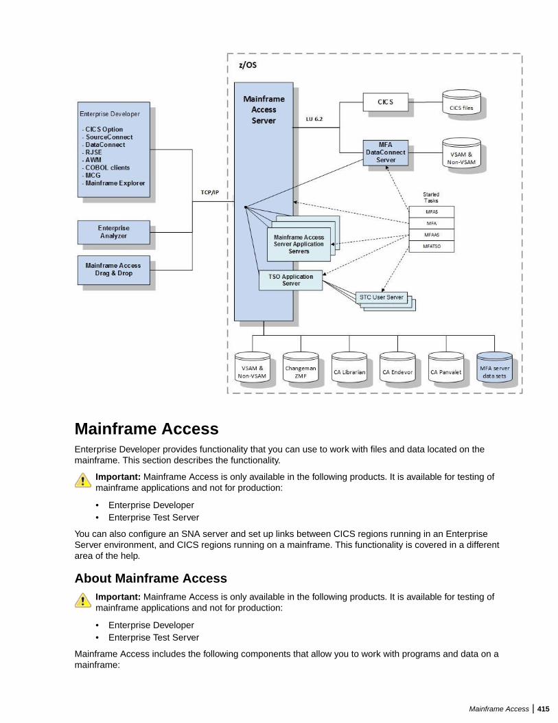
Mainframe AccessEnterprise Developer provides functionality that you can use to work with files and data located on themainframe. This section describes the functionality.
Important: Mainframe Access is only available in the following products. It is available for testing ofmainframe applications and not for production:
• Enterprise Developer• Enterprise Test Server
You can also configure an SNA server and set up links between CICS regions running in an EnterpriseServer environment, and CICS regions running on a mainframe. This functionality is covered in a differentarea of the help.
About Mainframe AccessImportant: Mainframe Access is only available in the following products. It is available for testing ofmainframe applications and not for production:
• Enterprise Developer• Enterprise Test Server
Mainframe Access includes the following components that allow you to work with programs and data on amainframe:
Mainframe Access | 415
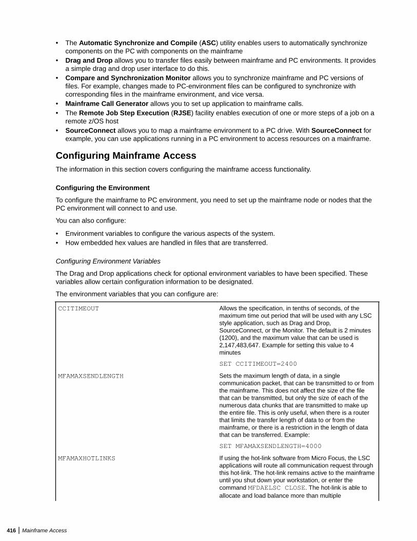
• The Automatic Synchronize and Compile (ASC) utility enables users to automatically synchronizecomponents on the PC with components on the mainframe
• Drag and Drop allows you to transfer files easily between mainframe and PC environments. It providesa simple drag and drop user interface to do this.
• Compare and Synchronization Monitor allows you to synchronize mainframe and PC versions offiles. For example, changes made to PC-environment files can be configured to synchronize withcorresponding files in the mainframe environment, and vice versa.
• Mainframe Call Generator allows you to set up application to mainframe calls.• The Remote Job Step Execution (RJSE) facility enables execution of one or more steps of a job on a
remote z/OS host• SourceConnect allows you to map a mainframe environment to a PC drive. With SourceConnect for
example, you can use applications running in a PC environment to access resources on a mainframe.
Configuring Mainframe AccessThe information in this section covers configuring the mainframe access functionality.
Configuring the Environment
To configure the mainframe to PC environment, you need to set up the mainframe node or nodes that thePC environment will connect to and use.
You can also configure:
• Environment variables to configure the various aspects of the system.• How embedded hex values are handled in files that are transferred.
Configuring Environment Variables
The Drag and Drop applications check for optional environment variables to have been specified. Thesevariables allow certain configuration information to be designated.
The environment variables that you can configure are:
CCITIMEOUT Allows the specification, in tenths of seconds, of themaximum time out period that will be used with any LSCstyle application, such as Drag and Drop,SourceConnect, or the Monitor. The default is 2 minutes(1200), and the maximum value that can be used is2,147,483,647. Example for setting this value to 4minutes
SET CCITIMEOUT=2400
MFAMAXSENDLENGTH Sets the maximum length of data, in a singlecommunication packet, that can be transmitted to or fromthe mainframe. This does not affect the size of the filethat can be transmitted, but only the size of each of thenumerous data chunks that are transmitted to make upthe entire file. This is only useful, when there is a routerthat limits the transfer length of data to or from themainframe, or there is a restriction in the length of datathat can be transferred. Example:
SET MFAMAXSENDLENGTH=4000
MFAMAXHOTLINKS If using the hot-link software from Micro Focus, the LSCapplications will route all communication request throughthis hot-link. The hot-link remains active to the mainframeuntil you shut down your workstation, or enter thecommand MFDAELSC CLOSE. The hot-link is able toallocate and load balance more than multiple
416 | Mainframe Access
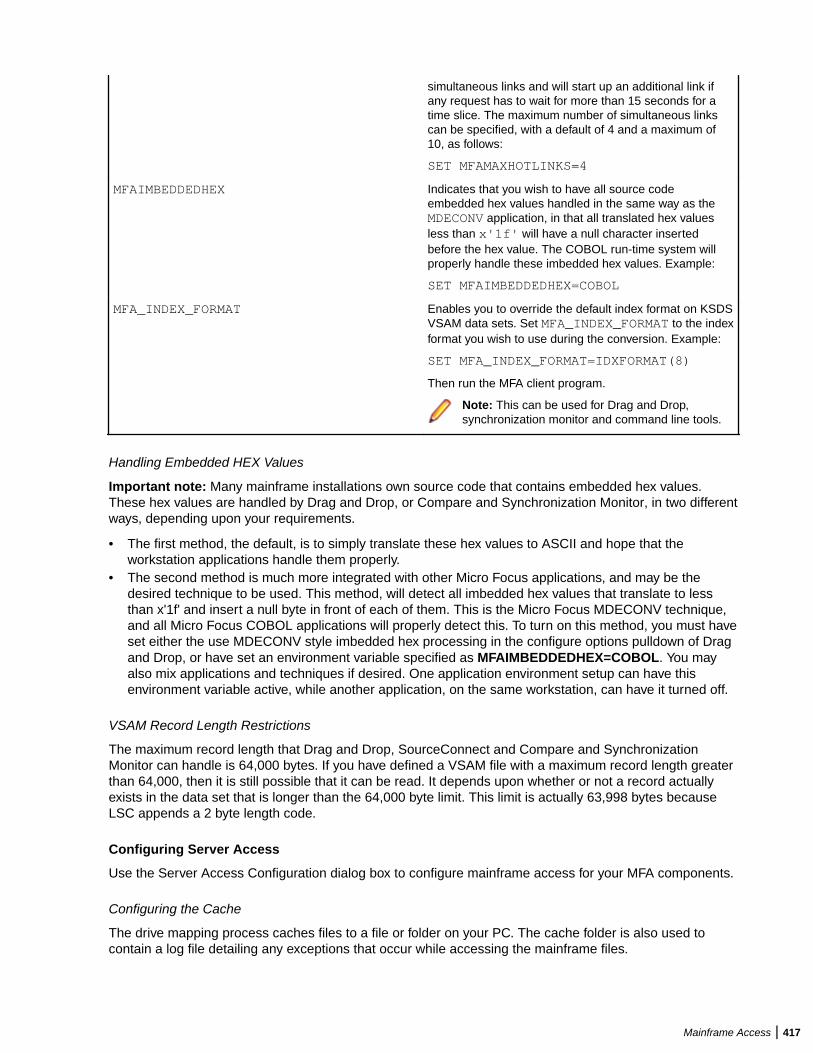
simultaneous links and will start up an additional link ifany request has to wait for more than 15 seconds for atime slice. The maximum number of simultaneous linkscan be specified, with a default of 4 and a maximum of10, as follows:
SET MFAMAXHOTLINKS=4
MFAIMBEDDEDHEX Indicates that you wish to have all source codeembedded hex values handled in the same way as theMDECONV application, in that all translated hex valuesless than x'1f' will have a null character insertedbefore the hex value. The COBOL run-time system willproperly handle these imbedded hex values. Example:
SET MFAIMBEDDEDHEX=COBOL
MFA_INDEX_FORMAT Enables you to override the default index format on KSDSVSAM data sets. Set MFA_INDEX_FORMAT to the indexformat you wish to use during the conversion. Example:
SET MFA_INDEX_FORMAT=IDXFORMAT(8)
Then run the MFA client program.
Note: This can be used for Drag and Drop,synchronization monitor and command line tools.
Handling Embedded HEX Values
Important note: Many mainframe installations own source code that contains embedded hex values.These hex values are handled by Drag and Drop, or Compare and Synchronization Monitor, in two differentways, depending upon your requirements.
• The first method, the default, is to simply translate these hex values to ASCII and hope that theworkstation applications handle them properly.
• The second method is much more integrated with other Micro Focus applications, and may be thedesired technique to be used. This method, will detect all imbedded hex values that translate to lessthan x'1f' and insert a null byte in front of each of them. This is the Micro Focus MDECONV technique,and all Micro Focus COBOL applications will properly detect this. To turn on this method, you must haveset either the use MDECONV style imbedded hex processing in the configure options pulldown of Dragand Drop, or have set an environment variable specified as MFAIMBEDDEDHEX=COBOL. You mayalso mix applications and techniques if desired. One application environment setup can have thisenvironment variable active, while another application, on the same workstation, can have it turned off.
VSAM Record Length Restrictions
The maximum record length that Drag and Drop, SourceConnect and Compare and SynchronizationMonitor can handle is 64,000 bytes. If you have defined a VSAM file with a maximum record length greaterthan 64,000, then it is still possible that it can be read. It depends upon whether or not a record actuallyexists in the data set that is longer than the 64,000 byte limit. This limit is actually 63,998 bytes becauseLSC appends a 2 byte length code.
Configuring Server Access
Use the Server Access Configuration dialog box to configure mainframe access for your MFA components.
Configuring the Cache
The drive mapping process caches files to a file or folder on your PC. The cache folder is also used tocontain a log file detailing any exceptions that occur while accessing the mainframe files.
Mainframe Access | 417
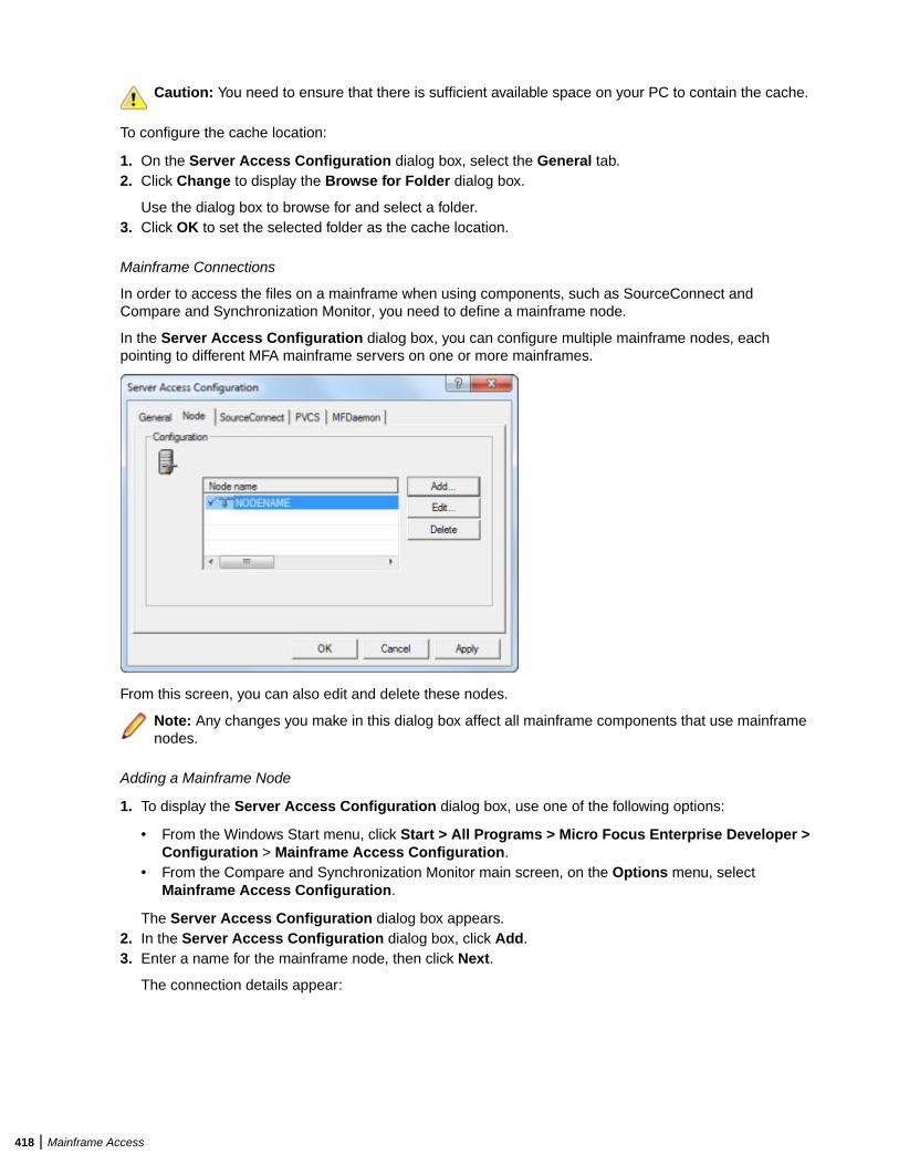
Caution: You need to ensure that there is sufficient available space on your PC to contain the cache.
To configure the cache location:
1. On the Server Access Configuration dialog box, select the General tab.2. Click Change to display the Browse for Folder dialog box.
Use the dialog box to browse for and select a folder.3. Click OK to set the selected folder as the cache location.
Mainframe Connections
In order to access the files on a mainframe when using components, such as SourceConnect andCompare and Synchronization Monitor, you need to define a mainframe node.
In the Server Access Configuration dialog box, you can configure multiple mainframe nodes, eachpointing to different MFA mainframe servers on one or more mainframes.
From this screen, you can also edit and delete these nodes.
Note: Any changes you make in this dialog box affect all mainframe components that use mainframenodes.
Adding a Mainframe Node
1. To display the Server Access Configuration dialog box, use one of the following options:
• From the Windows Start menu, click Start > All Programs > Micro Focus Enterprise Developer >Configuration > Mainframe Access Configuration.
• From the Compare and Synchronization Monitor main screen, on the Options menu, selectMainframe Access Configuration.
The Server Access Configuration dialog box appears.2. In the Server Access Configuration dialog box, click Add.3. Enter a name for the mainframe node, then click Next.
The connection details appear:
418 | Mainframe Access
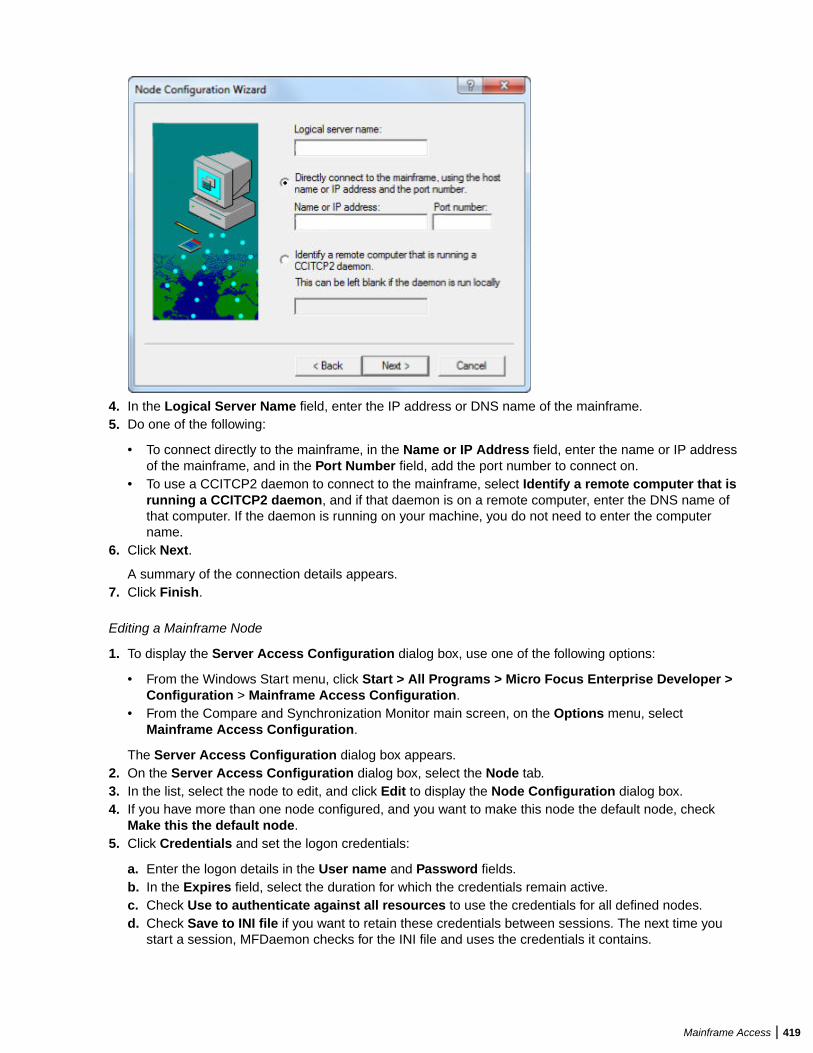
4. In the Logical Server Name field, enter the IP address or DNS name of the mainframe.5. Do one of the following:
• To connect directly to the mainframe, in the Name or IP Address field, enter the name or IP addressof the mainframe, and in the Port Number field, add the port number to connect on.
• To use a CCITCP2 daemon to connect to the mainframe, select Identify a remote computer that isrunning a CCITCP2 daemon, and if that daemon is on a remote computer, enter the DNS name ofthat computer. If the daemon is running on your machine, you do not need to enter the computername.
6. Click Next.
A summary of the connection details appears.7. Click Finish.
Editing a Mainframe Node
1. To display the Server Access Configuration dialog box, use one of the following options:
• From the Windows Start menu, click Start > All Programs > Micro Focus Enterprise Developer >Configuration > Mainframe Access Configuration.
• From the Compare and Synchronization Monitor main screen, on the Options menu, selectMainframe Access Configuration.
The Server Access Configuration dialog box appears.2. On the Server Access Configuration dialog box, select the Node tab.3. In the list, select the node to edit, and click Edit to display the Node Configuration dialog box.4. If you have more than one node configured, and you want to make this node the default node, check
Make this the default node.5. Click Credentials and set the logon credentials:
a. Enter the logon details in the User name and Password fields.b. In the Expires field, select the duration for which the credentials remain active.c. Check Use to authenticate against all resources to use the credentials for all defined nodes.d. Check Save to INI file if you want to retain these credentials between sessions. The next time you
start a session, MFDaemon checks for the INI file and uses the credentials it contains.
Mainframe Access | 419
Note: If you do not save these credentials, components such as SourceConnect prompt you forthem each time they require mainframe access.
e. Click OK.
The node details appear again.6. Edit the Name and Network details, as appropriate, then click OK.
The node is updated.
Deleting a Mainframe Node
1. To display the Server Access Configuration dialog box, use one of the following options:
• From the Windows Start menu, click Start > All Programs > Micro Focus Enterprise Developer >Configuration > Mainframe Access Configuration.
• From the Compare and Synchronization Monitor main screen, on the Options menu, selectMainframe Access Configuration.
The Server Access Configuration dialog box appears.2. On the Server Access Configuration dialog box, select the Node tab.3. In the list, select the node to delete, and click Delete.
The node is deleted.
About MFDaemon
MFDaemon is a process that runs on your PC to maintain mainframe login access details. With mainframecredentials:
• When you start a mainframe access session on your PC, MFDaemon checks for an .INI file and loadsany login configurations that it contains.
• When you edit a node to set login credentials for the node, MFDaemon saves these credentials andsupplies them as required when access authentication is required.
Note: Although not encrypted, the password is saved in the .INI file in a non-human-readableformat.
You can use the MFACLIENTINI environment variable to set the name of the .INI file. If this variable isnot set, the default name and path of the .INI file is:
c:\users\USERNAME\appdata\roaming\micro focus\mfaclient.ini
Viewing the status of MFDaemon
1. To display the Server Access Configuration dialog box, use one of the following options:
• From the Windows Start menu, click Start > All Programs > Micro Focus Enterprise Developer >Configuration > Mainframe Access Configuration.
• From the Compare and Synchronization Monitor main screen, on the Options menu, selectMainframe Access Configuration.
The Server Access Configuration dialog box appears.2. Click the MFDaemon tab.
The status of the daemon appears.3. To stop or start the daemon, click Stop Daemon or Start Daemon, as appropriate.
Note: Stopping the daemon will affect all Mainframe Access components.
Using Mainframe AccessThe information in this section describes how to use the mainframe access functionality.
420 | Mainframe Access
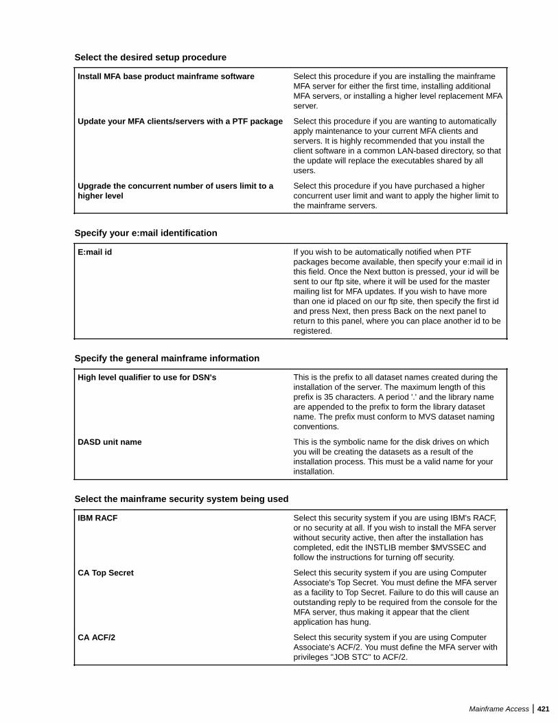
Select the desired setup procedure
Install MFA base product mainframe software Select this procedure if you are installing the mainframeMFA server for either the first time, installing additionalMFA servers, or installing a higher level replacement MFAserver.
Update your MFA clients/servers with a PTF package Select this procedure if you are wanting to automaticallyapply maintenance to your current MFA clients andservers. It is highly recommended that you install theclient software in a common LAN-based directory, so thatthe update will replace the executables shared by allusers.
Upgrade the concurrent number of users limit to ahigher level
Select this procedure if you have purchased a higherconcurrent user limit and want to apply the higher limit tothe mainframe servers.
Specify your e:mail identification
E:mail id If you wish to be automatically notified when PTFpackages become available, then specify your e:mail id inthis field. Once the Next button is pressed, your id will besent to our ftp site, where it will be used for the mastermailing list for MFA updates. If you wish to have morethan one id placed on our ftp site, then specify the first idand press Next, then press Back on the next panel toreturn to this panel, where you can place another id to beregistered.
Specify the general mainframe information
High level qualifier to use for DSN's This is the prefix to all dataset names created during theinstallation of the server. The maximum length of thisprefix is 35 characters. A period '.' and the library nameare appended to the prefix to form the library datasetname. The prefix must conform to MVS dataset namingconventions.
DASD unit name This is the symbolic name for the disk drives on whichyou will be creating the datasets as a result of theinstallation process. This must be a valid name for yourinstallation.
Select the mainframe security system being used
IBM RACF Select this security system if you are using IBM's RACF,or no security at all. If you wish to install the MFA serverwithout security active, then after the installation hascompleted, edit the INSTLIB member $MVSSEC andfollow the instructions for turning off security.
CA Top Secret Select this security system if you are using ComputerAssociate's Top Secret. You must define the MFA serveras a facility to Top Secret. Failure to do this will cause anoutstanding reply to be required from the console for theMFA server, thus making it appear that the clientapplication has hung.
CA ACF/2 Select this security system if you are using ComputerAssociate's ACF/2. You must define the MFA server withprivileges "JOB STC" to ACF/2.
Mainframe Access | 421
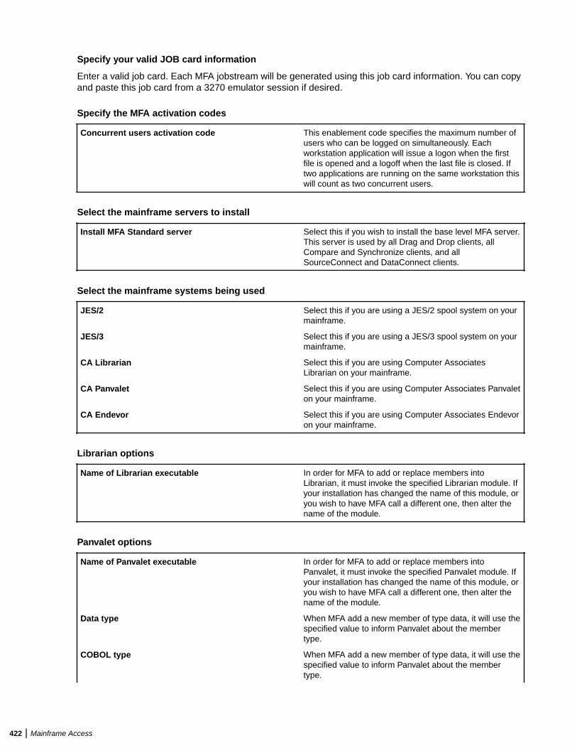
Specify your valid JOB card information
Enter a valid job card. Each MFA jobstream will be generated using this job card information. You can copyand paste this job card from a 3270 emulator session if desired.
Specify the MFA activation codes
Concurrent users activation code This enablement code specifies the maximum number ofusers who can be logged on simultaneously. Eachworkstation application will issue a logon when the firstfile is opened and a logoff when the last file is closed. Iftwo applications are running on the same workstation thiswill count as two concurrent users.
Select the mainframe servers to install
Install MFA Standard server Select this if you wish to install the base level MFA server.This server is used by all Drag and Drop clients, allCompare and Synchronize clients, and allSourceConnect and DataConnect clients.
Select the mainframe systems being used
JES/2 Select this if you are using a JES/2 spool system on yourmainframe.
JES/3 Select this if you are using a JES/3 spool system on yourmainframe.
CA Librarian Select this if you are using Computer AssociatesLibrarian on your mainframe.
CA Panvalet Select this if you are using Computer Associates Panvaleton your mainframe.
CA Endevor Select this if you are using Computer Associates Endevoron your mainframe.
Librarian options
Name of Librarian executable In order for MFA to add or replace members intoLibrarian, it must invoke the specified Librarian module. Ifyour installation has changed the name of this module, oryou wish to have MFA call a different one, then alter thename of the module.
Panvalet options
Name of Panvalet executable In order for MFA to add or replace members intoPanvalet, it must invoke the specified Panvalet module. Ifyour installation has changed the name of this module, oryou wish to have MFA call a different one, then alter thename of the module.
Data type When MFA add a new member of type data, it will use thespecified value to inform Panvalet about the membertype.
COBOL type When MFA add a new member of type data, it will use thespecified value to inform Panvalet about the membertype.
422 | Mainframe Access
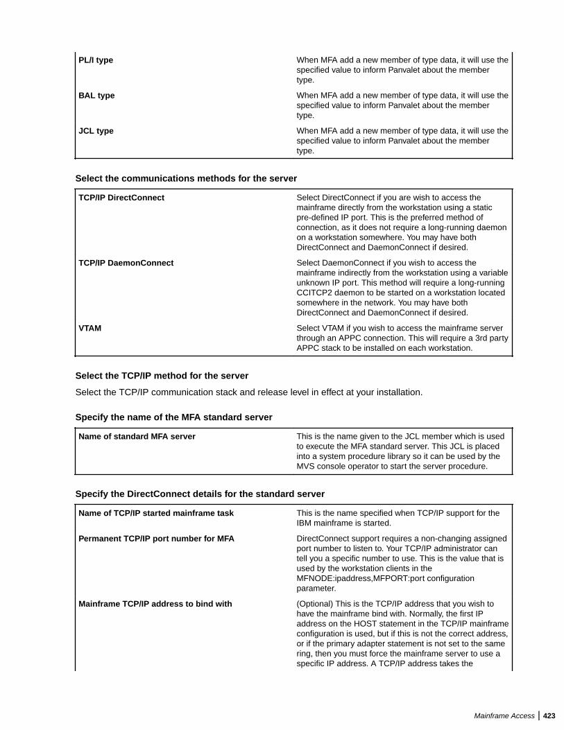
PL/I type When MFA add a new member of type data, it will use thespecified value to inform Panvalet about the membertype.
BAL type When MFA add a new member of type data, it will use thespecified value to inform Panvalet about the membertype.
JCL type When MFA add a new member of type data, it will use thespecified value to inform Panvalet about the membertype.
Select the communications methods for the server
TCP/IP DirectConnect Select DirectConnect if you are wish to access themainframe directly from the workstation using a staticpre-defined IP port. This is the preferred method ofconnection, as it does not require a long-running daemonon a workstation somewhere. You may have bothDirectConnect and DaemonConnect if desired.
TCP/IP DaemonConnect Select DaemonConnect if you wish to access themainframe indirectly from the workstation using a variableunknown IP port. This method will require a long-runningCCITCP2 daemon to be started on a workstation locatedsomewhere in the network. You may have bothDirectConnect and DaemonConnect if desired.
VTAM Select VTAM if you wish to access the mainframe serverthrough an APPC connection. This will require a 3rd partyAPPC stack to be installed on each workstation.
Select the TCP/IP method for the server
Select the TCP/IP communication stack and release level in effect at your installation.
Specify the name of the MFA standard server
Name of standard MFA server This is the name given to the JCL member which is usedto execute the MFA standard server. This JCL is placedinto a system procedure library so it can be used by theMVS console operator to start the server procedure.
Specify the DirectConnect details for the standard server
Name of TCP/IP started mainframe task This is the name specified when TCP/IP support for theIBM mainframe is started.
Permanent TCP/IP port number for MFA DirectConnect support requires a non-changing assignedport number to listen to. Your TCP/IP administrator cantell you a specific number to use. This is the value that isused by the workstation clients in theMFNODE:ipaddress,MFPORT:port configurationparameter.
Mainframe TCP/IP address to bind with (Optional) This is the TCP/IP address that you wish tohave the mainframe bind with. Normally, the first IPaddress on the HOST statement in the TCP/IP mainframeconfiguration is used, but if this is not the correct address,or if the primary adapter statement is not set to the samering, then you must force the mainframe server to use aspecific IP address. A TCP/IP address takes the
Mainframe Access | 423
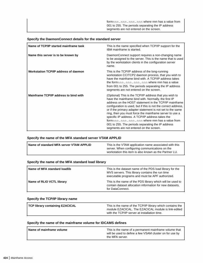
formnnn.nnn.nnn.nnn where nnn has a value from001 to 255. The periods separating the IP addresssegments are not entered on the screen.
Specify the DaemonConnect details for the standard server
Name of TCP/IP started mainframe task This is the name specified when TCP/IP support for theIBM mainframe is started.
Name this server is to be known by DaemonConnect support requires a non-changing nameto be assigned to the server. This is the name that is usedby the workstation clients in the configuration servername.
Workstation TCP/IP address of daemon This is the TCP/IP address of the long-runningworkstation CCITCP2 daemon process, that you wish tohave the mainframe bind with. A TCP/IP address takesthe formnnn.nnn.nnn.nnn where nnn has a valuefrom 001 to 255. The periods separating the IP addresssegments are not entered on the screen.
Mainframe TCP/IP address to bind with (Optional) This is the TCP/IP address that you wish tohave the mainframe bind with. Normally, the first IPaddress on the HOST statement in the TCP/IP mainframeconfiguration is used, but if this is not the correct address,or if the primary adapter statement is not set to the samering, then you must force the mainframe server to use aspecific IP address. A TCP/IP address takes theformnnn.nnn.nnn.nnn where nnn has a value from001 to 255. The periods separating the IP addresssegments are not entered on the screen.
Specify the name of the MFA standard server VTAM APPLID
Name of standard MFA server VTAM APPLID This is the VTAM application name associated with thisserver. When configuring communications on theworkstation this item is also known as the Partner LU.
Specify the name of the MFA standard load library
Name of MFA standard loadlib This is the dataset name of the PDS load library for theMVS servers. This library contains the run timeexecutable programs and must be APF authorized.
Name of RLIO VCTL library This is the name of the PDS library which will be used tocontain dataset allocation information for new datasets,for DataConnect.
Specify the TCP/IP library name
TCP library containing EZACICAL This is the name of the TCP/IP library which contains themodule EZACICAL. The EZACICAL module is link-editedwith the TCP/IP server at installation time.
Specify the name of the mainframe volume for IDCAMS defines
Name of mainframe volume This is the name of a permanent mainframe volume thatwill be used to define a few VSAM cluster on for use bythe MFA server.
424 | Mainframe Access
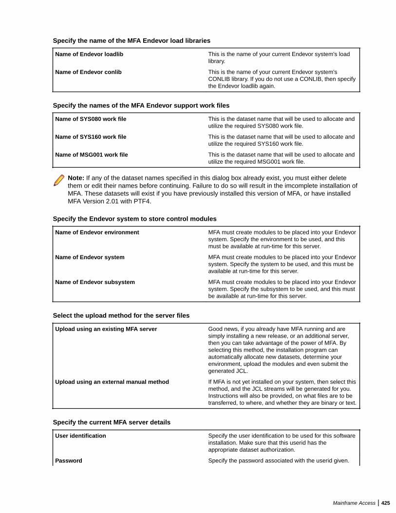
Specify the name of the MFA Endevor load libraries
Name of Endevor loadlib This is the name of your current Endevor system's loadlibrary.
Name of Endevor conlib This is the name of your current Endevor system'sCONLIB library. If you do not use a CONLIB, then specifythe Endevor loadlib again.
Specify the names of the MFA Endevor support work files
Name of SYS080 work file This is the dataset name that will be used to allocate andutilize the required SYS080 work file.
Name of SYS160 work file This is the dataset name that will be used to allocate andutilize the required SYS160 work file.
Name of MSG001 work file This is the dataset name that will be used to allocate andutilize the required MSG001 work file.
Note: If any of the dataset names specified in this dialog box already exist, you must either deletethem or edit their names before continuing. Failure to do so will result in the imcomplete installation ofMFA. These datasets will exist if you have previously installed this version of MFA, or have installedMFA Version 2.01 with PTF4.
Specify the Endevor system to store control modules
Name of Endevor environment MFA must create modules to be placed into your Endevorsystem. Specify the environment to be used, and thismust be available at run-time for this server.
Name of Endevor system MFA must create modules to be placed into your Endevorsystem. Specify the system to be used, and this must beavailable at run-time for this server.
Name of Endevor subsystem MFA must create modules to be placed into your Endevorsystem. Specify the subsystem to be used, and this mustbe available at run-time for this server.
Select the upload method for the server files
Upload using an existing MFA server Good news, if you already have MFA running and aresimply installing a new release, or an additional server,then you can take advantage of the power of MFA. Byselecting this method, the installation program canautomatically allocate new datasets, determine yourenvironment, upload the modules and even submit thegenerated JCL.
Upload using an external manual method If MFA is not yet installed on your system, then select thismethod, and the JCL streams will be generated for you.Instructions will also be provided, on what files are to betransferred, to where, and whether they are binary or text.
Specify the current MFA server details
User identification Specify the user identification to be used for this softwareinstallation. Make sure that this userid has theappropriate dataset authorization.
Password Specify the password associated with the userid given.
Mainframe Access | 425
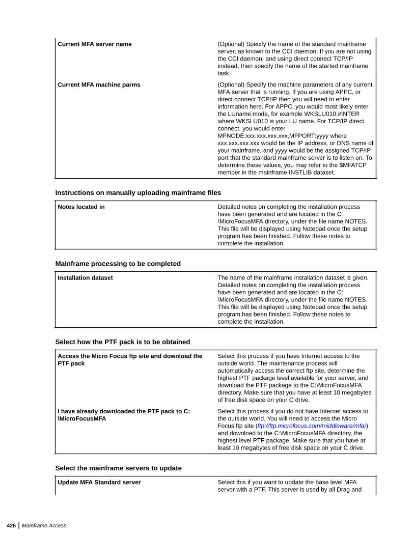
Current MFA server name (Optional) Specify the name of the standard mainframeserver, as known to the CCI daemon. If you are not usingthe CCI daemon, and using direct connect TCP/IPinstead, then specify the name of the started mainframetask.
Current MFA machine parms (Optional) Specify the machine parameters of any currentMFA server that is running. If you are using APPC, ordirect connect TCP/IP then you will need to enterinformation here. For APPC, you would most likely enterthe LUname.mode, for example WKSLU010.#INTERwhere WKSLU010 is your LU name. For TCP/IP directconnect, you would enterMFNODE:xxx.xxx.xxx.xxx,MFPORT:yyyy wherexxx.xxx.xxx.xxx would be the IP address, or DNS name ofyour mainframe, and yyyy would be the assigned TCP/IPport that the standard mainframe server is to listen on. Todetermine these values, you may refer to the $MFATCPmember in the mainframe INSTLIB dataset.
Instructions on manually uploading mainframe files
Notes located in Detailed notes on completing the installation processhave been generated and are located in the C:\MicroFocusMFA directory, under the file name NOTES.This file will be displayed using Notepad once the setupprogram has been finished. Follow these notes tocomplete the installation.
Mainframe processing to be completed
Installation dataset The name of the mainframe installation dataset is given.Detailed notes on completing the installation processhave been generated and are located in the C:\MicroFocusMFA directory, under the file name NOTES.This file will be displayed using Notepad once the setupprogram has been finished. Follow these notes tocomplete the installation.
Select how the PTF pack is to be obtained
Access the Micro Focus ftp site and download thePTF pack
Select this process if you have Internet access to theoutside world. The maintenance process willautomatically access the correct ftp site, determine thehighest PTF package level available for your server, anddownload the PTF package to the C:\MicroFocusMFAdirectory. Make sure that you have at least 10 megabytesof free disk space on your C drive.
I have already downloaded the PTF pack to C:\MicroFocusMFA
Select this process if you do not have Internet access tothe outside world. You will need to access the MicroFocus ftp site (ftp://ftp.microfocus.com/middleware/mfa/)and download to the C:\MicroFocusMFA directory, thehighest level PTF package. Make sure that you have atleast 10 megabytes of free disk space on your C drive.
Select the mainframe servers to update
Update MFA Standard server Select this if you want to update the base level MFAserver with a PTF. This server is used by all Drag and
426 | Mainframe Access
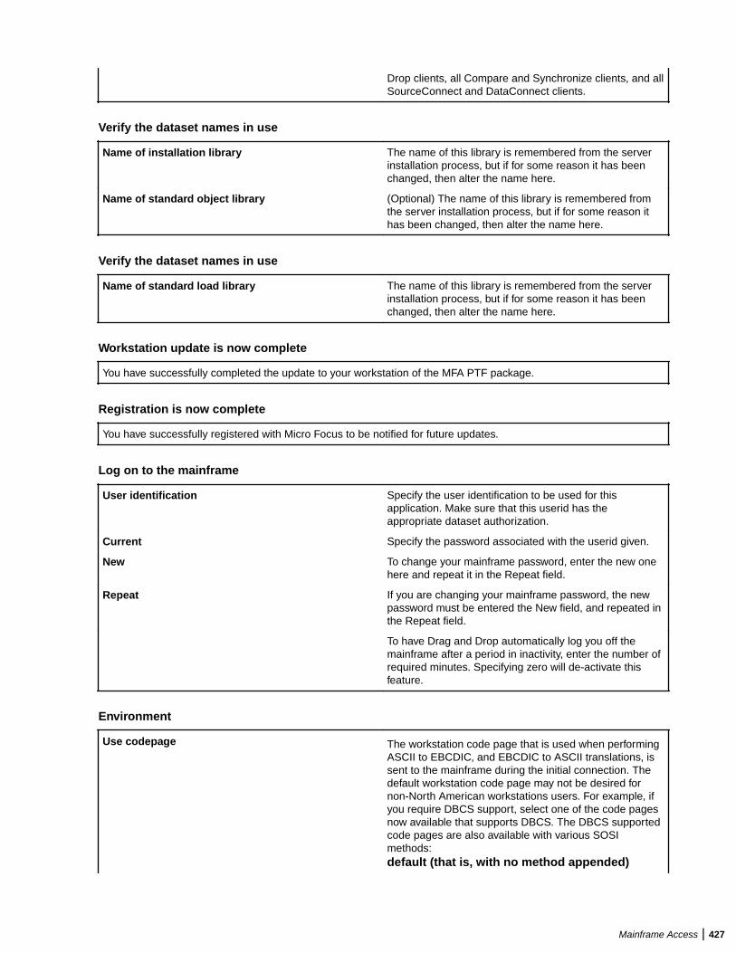
Drop clients, all Compare and Synchronize clients, and allSourceConnect and DataConnect clients.
Verify the dataset names in use
Name of installation library The name of this library is remembered from the serverinstallation process, but if for some reason it has beenchanged, then alter the name here.
Name of standard object library (Optional) The name of this library is remembered fromthe server installation process, but if for some reason ithas been changed, then alter the name here.
Verify the dataset names in use
Name of standard load library The name of this library is remembered from the serverinstallation process, but if for some reason it has beenchanged, then alter the name here.
Workstation update is now complete
You have successfully completed the update to your workstation of the MFA PTF package.
Registration is now complete
You have successfully registered with Micro Focus to be notified for future updates.
Log on to the mainframe
User identification Specify the user identification to be used for thisapplication. Make sure that this userid has theappropriate dataset authorization.
Current Specify the password associated with the userid given.
New To change your mainframe password, enter the new onehere and repeat it in the Repeat field.
Repeat If you are changing your mainframe password, the newpassword must be entered the New field, and repeated inthe Repeat field.
To have Drag and Drop automatically log you off themainframe after a period in inactivity, enter the number ofrequired minutes. Specifying zero will de-activate thisfeature.
Environment
Use codepage The workstation code page that is used when performingASCII to EBCDIC, and EBCDIC to ASCII translations, issent to the mainframe during the initial connection. Thedefault workstation code page may not be desired fornon-North American workstations users. For example, ifyou require DBCS support, select one of the code pagesnow available that supports DBCS. The DBCS supportedcode pages are also available with various SOSImethods:default (that is, with no method appended)
Mainframe Access | 427
EBCDIC SI/SO added onupload, removed on download
-SOSI-KEBCDIC SI/SO assumed onupload, preserved on download
-SOSI-AASCII SI/SO assumed onupload, preserved on download
-SOSI-SSpaces converted to SI/SO onupload. SI/SO converted tospaces on download
Note: This willonly workcorrectly withtext thatoriginates on ahost.
To enable DBCS support, you must edit the started taskJCL procedure; see MFA Started JCL Procedure for moreinformation.
By setting the Use Codepage field to the proper codepage, the associated code page is sent to the mainframe,instead of the workstation default one. By setting this fieldto mainframe default, no code page is sent fromthe workstation, but instead the default mainframetranslate tables located in MFLSCTRN on the mainframeare used instead. The proper tables must have beenselected during the mainframe installation of the server.
Limit browse lines to This numeric field limits the number of lines that will beread and transferred when double clicking on a file ormember. If you specify zero, there is no limit.
Default editor specification You may specify the command and any optionalparameters for a default editor to be used, when using theright mouse context button for the edit function. Thisdefault editor will be used, unless a Windows editor forthe specific file extension has already been set up. Youmust fully qualify the editor command, include the pathand extension of the program to invoke.
Add Command Click this to add an editor to the Open with popup menuitem (which is displayed when you right-click on a file).After clicking Add Command specify the editor's detailsin the Description, Command and Parameters fields,check Save Mainframe Edits? if appropriate, then clickSave Commands.
Delete Command Click this to delete the selected editor.
Save Commands Click this to save the changes you have made to anyeditor definitions.
Reset All Commands Click this to reset all editor commands to the default .After clicking this button (and clicking Yes on thesubsequent confirmation message box), the only editor
428 | Mainframe Access
on the Open with popup menu item is Notepad. Anydefinitions you have added are lost.
Description The name that will appear on the Open with menu itemfor an editor that you have defined. Specifying a singleampersand (&) causes an underscore to be displayedbeneath the character following the ampersand, signalinga keyboard shortcut. To display an ampersand you needto specify two consecutive ampersands (&&).
Command The command to run for the selected editor.
Parameters The parameters to use on the command line for theselected editor. %s is used to denote the file that is to beedited.
Save Mainframe Edits? Specifies whether the files changed by the selected editorare exported to the mainframe. This has no effect whenusing the editor on the PC side.
Options
EBCDIC/ASCII translation Set this flag for each data set type that is to be translatedto/from ASCII/EBCDIC.
Warn if the target name does not match the source Set this flag if you want to be warned that dragging a fileor member would result in the target file having a differentname from the source file.
Warn if the target exists Set this flag if you want to be warned when dragging a fileor member if the file already exists. Note that there is anoverhead when using this flag as the mainframe must bechecked for the existence of the file or member.
Warn if the source files contain embedded hex Set this flag if you want to be informed in an importedsource file contains unusual or unprintable characters.
Use MDECONV style embedded hex processing This method, when selected, will detect all embedded hexvalues that translate to less than x'20' and insert a nullbyte in front of each of them. This is the Micro FocusWorkbench MDECONV technique, and all Micro FocusCOBOL applications will properly detect this.
Inform when submitted jobs have completed Set this flag if you wish to be informed when yoursubmitted jobstream has finished.
Inform when migrated datasets have been recalled Set this flag if you want to be informed when a datasetyou have asked to be recalled has completed.
Prompt for an extension on import Set this flag if you want to ensure that a dragged memberwill be written out with a PC extension.
Use Associated Extensions Set this flag to enable any extension that you haveassociated with data set members; these are appliedwhen you import the members to your local system.
When enabled, any associations set via Drag and Dropwill override any set via Source Connect.
Refresh mainframe member lists after subsetting Set this flag if you want to force a refreshed member listafter using the directory subsetting feature. There is asmall overhead to this option.
files after transfer completes Set this flag if after transferring VSAM files you want todelete the temporary files that were created during thetransfer.
Mainframe Access | 429
Suppress Set this flag to specify that you do not want aninformational message box to be displayed each time afile is automatically converted to Micro Focus format.
Set this flag to prevent a search filter being added with an* in the HLQ.
Set this flag to prevent a DFCONV conversion beingperformed on VSAM files imported on the PC.
Member download threshold Specifies the maximum number of data set members thatcan be expanded before Drag and Drop displays awarning message advising that the operation will takesome time.
Scan imported members for copy statements Set this flag if you want to have the file or member beingdragged from the mainframe checked for copy typestatements and allow an automatic import of the relatedcopy files.
Copy Statement Scanner Parameters When the Scan imported members for copy statementscheckbox is checked, the downloaded files are scannedaccording to the rules in this group. Each rule consists ofa description, a regular expression and an enabled flag.
The description is a free format description and caninclude any descriptive text. This text appears as part ofthe title of the selection dialog of found copy members.
The regular expression is a UNIX style regular searchexpression. The most important part is the grouping place holder signified by the contents of the bracket pair.i.e. ([A-Z0-9]*). See Below for a general explanation ofregular expressions.
Add Scan Rule adds a new scan rule to the scan list.
Delete Rule deletes the selected rule from the list.
Save Rules saves the rules.
Reset All Rules resets the entire rule list to Micro FocusDefaults.
The Scan Enabled checkbox enables or disables theselected scan rule.
Drag and Drop Utility - Regular Expression Overview
Regular expression matching allows you to test whether a string fits into a specific syntactic shape. Youcan also search a string for a substring that fits a pattern.
A regular expression describes a set of strings. The simplest case is one that describes a particular string;for example, the string 'foo' when regarded as a regular expression matches 'foo' and nothing else.Nontrivial regular expressions use certain special constructs so that they can match more than one string.For example, the regular expression 'foo\|bar' matches either the string 'foo' or the string 'bar'; the regularexpression 'c[ad]*r' matches any of the strings 'cr', 'car', 'cdr', 'caar', 'cadddar' and all other such strings withany number of 'a's and 'd's.
The first step in matching a regular expression is to compile it. You must supply the pattern string and alsoa pattern buffer to hold the compiled result. That result contains the pattern in an internal format that iseasier to use in matching.
Having compiled a pattern, you can match it against strings. You can match the compiled pattern anynumber of times against different strings.
430 | Mainframe Access
Drag and Drop Utility - Syntax of Regular Expressions
Regular expressions have a syntax in which a few characters are special constructs and the rest are"ordinary". An ordinary character is a simple regular expression which matches that character and nothingelse. The special characters are '\$', '^', '.', '*', '+', '?', '[', ']' and '\'. Any other character appearing in a regularexpression is ordinary, unless a '\' precedes it.
For example, 'f' is not a special character, so it is ordinary, and therefore 'f' is a regular expression thatmatches the string 'f' and no other string. (It does *not* match the string 'ff'.) Likewise, 'o' is a regularexpression that matches only 'o'.
Any two regular expressions A and B can be concatenated. The result is a regular expression whichmatches a string if A matches some amount of the beginning of that string and B matches the rest of thestring.
As a simple example, we can concatenate the regular expressions 'f' and 'o' to get the regular expression'fo', which matches only the string 'fo'. Still trivial.
The following are the characters and character sequences which have special meaning within regularexpressions. Any character not mentioned here is not special; it stands for exactly itself for the purposes ofsearching and matching.
. Aspecialcharacterthatmatchesanythingexcept
Mainframe Access | 431

anewline.Usingconcatenation,wecanmakeregularexpressionslikea.bwhichm
432 | Mainframe Access

atchesanythree-characterstringwhichbeginswithaandendswithb.
* Notaco
Mainframe Access | 433

nstructbyitself;itisasuffix,whichmeanstheprecedingregularexpressionistob
434 | Mainframe Access

erepeatedasmanytimesaspossible.Fotrexample,Info*,the*appliestothe
Mainframe Access | 435

o,sofo*matchesffollowedbyanynumberofo's.
Thecaseofzeroo'sisallowed
436 | Mainframe Access
:fo*doesmatchf.
*alwaysappliestothesmallestpossibleprecedingexpr
Mainframe Access | 437
ession.Thus,fo*hasarepeatingo,notarepeatingfo.
Thematcherprocess
438 | Mainframe Access

esa*constructbymatching,immediately,asmanyrepetitionsascanbefound
Mainframe Access | 439
.Thenitcontinueswiththerestofthepattern.Ifthatfails,backtrackingoccur
440 | Mainframe Access

s,discardingsomeofthematchesofthe*'dconstructincasethatmakesitpo
Mainframe Access | 441
ssibletomatchtherestofthepattern.Forexample,matchingc[ad]*aragain
442 | Mainframe Access
stthestringcaddaar,the[ad]*firstmatchesaddaa,butthisdoesnotallowt
Mainframe Access | 443

henextainthepatterntomatch.Sothelastofthematchesof[ad]isundonea
444 | Mainframe Access

ndthefollowingaistriedagain.Nowitsucceeds.
+ Like*exceptthatatleaston
Mainframe Access | 445

ematchfortheprecedingpatternisrequiredfor+.Thus,c[ad]+rdoesnotmat
446 | Mainframe Access

chcrbutdoesmatchanythingelsethatc[ad]*rwouldmatch.
? Like*excepttha
Mainframe Access | 447
titallowseitherzerooronematchfortheprecedingpattern.Thus,c[ad]?rma
448 | Mainframe Access

tchescrorcarorcdr,andnothingelse.
[ Beginsa"characterset",whichiste
Mainframe Access | 449

rminatedbya].Inthesimplestcase,thecharactersbetweenthetwoformth
450 | Mainframe Access
eset.Thus,[ad]matcheseitheraord,and[ad]*matchesanystringofa'sandd's
Mainframe Access | 451
(includingtheemptystring),fromwhichitfollowsthatc[ad]*rmatchescar,etc.
452 | Mainframe Access
Characterrangescanalsobeincludedinacharacterset,bywritingtwocharac
Mainframe Access | 453
terswitha-(hyphen)betweenthem.Thus,[a-z]matchesanylower-caselett
454 | Mainframe Access

er.Rangesmaybeintermixedfreelywithindividualcharacters,asin[a-z$%.]
Mainframe Access | 455

,whichmatchesanylowercaseletteror$,%orperiod.
Notethattheusualspe
456 | Mainframe Access

cialcharactersarenotspecialanymoreinsideacharacterset.Acompletelyd
Mainframe Access | 457

ifferentsetofspecialcharactersexistsinsidecharactersets:],-and^.
458 | Mainframe Access

Toincludea]inacharacterset,youmustmakeitthefirstcharacter.Forexamp
Mainframe Access | 459

le,[]a]matches]ora.Toincludea-,youmustuseitinacontextwhereitcanno
460 | Mainframe Access

tpossiblyindicatearange:thatis,asthefirstcharacter,orimmediatelyafter
Mainframe Access | 461

arange.
[^ Beginsa"complementcharacterset",whichmatchesanycharacter
462 | Mainframe Access
excepttheonesspecified.So,[^a-z0-9A-Z]matchesallcharactersexceptl
Mainframe Access | 463
ettersanddigits.
^ Notspecialinacharactersetunlessitisthefirstcharacte
464 | Mainframe Access

r.Thecharacterfollowingthe^istreatedasifitwerefirst(itmaybea-ora]).
^isa
Mainframe Access | 465

specialcharacterthatmatchestheemptystring--butonlyifatthebeginning
466 | Mainframe Access

ofalineinthetextbeingmatched.Otherwiseitfailstomatchanything.Thus
Mainframe Access | 467

,^foomatchesafoowhichoccursatthebeginningofaline.
$ Similarto^butma
468 | Mainframe Access

tchesonlyattheendofaline.Thus,xx*$matchesastringofoneormorex'satt
Mainframe Access | 469

heendofaline.
\ Hastwofunctions:itquotestheabovespecialcharacters(incl
470 | Mainframe Access

uding\),anditintroducesadditionalspecialconstructs.
Because\quotesspe
Mainframe Access | 471

cialcharacters,\$isaregularexpressionwhichmatchesonly$,and\[isaregu
472 | Mainframe Access

larexpressionwhichmatchesonly[,andsoon.
Forthemostpart,\followedbya
Mainframe Access | 473
nycharactermatchesonlythatcharacter.However,thereareseveralexcep
474 | Mainframe Access

tions:characterswhich,whenprecededby\,arespecialconstructs.Suchch
Mainframe Access | 475

aractersarealwaysordinarywhenencounteredontheirown.
Nonewspecial
476 | Mainframe Access

characterswilleverbedefined.Allextensionstotheregularexpressionsynt
Mainframe Access | 477

axaremadebydefiningnewtwo-characterconstructsthatbeginwith\.
\| Speci
478 | Mainframe Access

fiesanalternative.TworegularexpressionsAandBwith\|inbetweenformanex
Mainframe Access | 479
pressionthatmatchesanythingthateitherAorBwillmatch.
Thus,foo\|bar
480 | Mainframe Access
matcheseitherfooorbarbutnootherstring.
\|appliestothelargestpossi
Mainframe Access | 481
blesurroundingexpressions.Onlyasurrounding\(...\)groupingcanlimitth
482 | Mainframe Access
egroupingpowerof\|.
Fullbacktrackingcapabilityexistswhenmultiple\|'sar
Mainframe Access | 483

eused.
\( ... \) Agroupingconstruct .Tomarkamatchedsubstringforfuturerefere
484 | Mainframe Access
nce.IntheMicroFocusimplementation,thereisonlyonegroupingallowed.The
Mainframe Access | 485
contentsofthisgroupingaretreatedasthefoundfilenamefortransfer.
Thisla
486 | Mainframe Access

stapplicationisnotaconsequenceoftheideaofaparentheticalgrouping;it
Mainframe Access | 487

isaseparatefeaturewhichhappenstobeassignedasasecondmeaningtothes
488 | Mainframe Access
ame\(...\)constructbecausethereisnoconflictinpracticebetweenthetwo
Mainframe Access | 489
meanings.Hereisanexplanationofthisfeature:
\n Aftertheendofa\(...\)c
490 | Mainframe Access

onstruct,thematcherremembersthebeginningandendofthetextmatchedby
Mainframe Access | 491
thatconstruct.Then,lateronintheregularexpression,youcanuse\followe
492 | Mainframe Access
dbyntomean"matchthesametextmatchedthen'thtimebythe\(...\)constru
Mainframe Access | 493

ct."The\(...\)constructsarenumberedinorderofcommencementinthere
494 | Mainframe Access
gularexpression.
Thestringsmatchingthefirstnine\(...\)constructsa
Mainframe Access | 495

ppearinginaregularexpressionareassignednumbers1through9inorderof
496 | Mainframe Access
theirbeginnings.\1through\9maybeusedtorefertothetextmatchedbyt
Mainframe Access | 497
hecorresponding\(...\)construct.
Forexample,\(.*\)\1matchesanys
498 | Mainframe Access
tringthatiscomposedoftwoidenticalhalves.The\(.*\)matchesthefirstha
Mainframe Access | 499

lf,whichmaybeanything,butthe\1thatfollowsmustmatchthesameexactte
500 | Mainframe Access
xt.
\b Matchestheemptystring,butonlyifitisatthebeginningorendofaword.Th
Mainframe Access | 501
us,\bfoo\bmatchesanyoccurrenceoffooasaseparateword.\bball\(s\
502 | Mainframe Access
|\)\bmatchesballorballsasaseparateword.
\B Matchestheemptystring,
Mainframe Access | 503

provideditisnotatthebeginningorendofaword.
\< Matchestheemptystring,b
504 | Mainframe Access
utonlyifitisatthebeginningofaword.
\> Matchestheemptystring,butonlyifitisa
Mainframe Access | 505
ttheendofaword.
\w Matchesanyword-constituentcharacter.
\W Matchesanych
506 | Mainframe Access
aracterthatisnotaword-constituent.
Allocate a new partitioned or sequential dataset
Dataset name Specify the dataset name to be created on themainframe.
Quantity Specify the number of either cylinders, tracks or blocks tobe allocated.
Type Select the type of dataset to be created.
Directory blocks This field is present only for the allocation of partitioneddatasets. It is to contain the number of directory blocks tobe placed in the mainframe partitioned dataset.
Logical record length Specify the logical record length of the dataset
Block size (Optional) If specified, the dataset will be created with thisblock size, otherwise the mainframe operating system willselect the appropriate block size to be used.
Volume (Optional) If specified, the dataset will be created on thisvolume, otherwise the mainframe operating system willselect the appropriate volume to be used.
SMS storage class (Optional) If specified, the dataset will be created with thisSMS storage class information.
SMS data class (Optional) If specified, the dataset will be created with thisSMS data class information.
Expiration date (Optional) If specified, both the YYYY and DDD fieldsmust be filled in, and must contain a valid 4 digit year and3 digit day of year field.
Mainframe Access | 507
Get DCB from existing dataset Select this button if you wish to read the DCB informationfrom a existing mainframe dataset, and populate some ofthe fields on this panel.
Enter the required information
Specify the fully qualified mainframe dataset name that is to be looked up, so that some of the DCB information canbe used to populate the fields in the allocate new dataset request.
Enter the required VSAM profile information
Minimum record length Specify the minimum record length to be associated withthis workstation indexed file.
Maximum record length Specify the maximum record length to be associated withthis workstation indexed file.
Key position The mainframe VSAM relative key position is displayedfor indexed datasets.
Key length The mainframe VSAM key length is displayed for indexeddatasets.
Enter the required CCC/LCM profile information
System Specify the LCM system to be used.
Config Specify the LCM configuration to be used within thissystem
Lock member on download If you wish to automatically have the member lockedwhen downloaded, then select this option.
Enter the required CCC/LCM profile information
Type Specify the LCM member type for this member.
Change name Specify the change name to be associated with thisupdate.
Enter the required Endevor profile information
Type Specify the Endevor member type for this member.
CCID Specify any required change control identification for thismember.
Comment Specify any required comment for this member.
Enter the required Endevor profile information
Type Specify the Endevor member type for this member.
CCID Specify any required change control identification for thismember.
Comment Specify any required comment for this member.
Signout member If you wish to have the member automatically signed out,then select this option.
Override existing signout If you wish to override any existing signout for thismember, then select this option.
508 | Mainframe Access
Enter the required Endevor profile information
Type Specify the Endevor member type for this member.
CCID Specify any required change control identification for thismember.
Comment Specify any required comment for this member.
Override existing signout If you wish to override any existing signout for thismember, then select this option.
Bypass generate processor If you wish to bypass any mainframe generation, thenselect this option.
Env Specify the environment to be used for this update.
Sys Specify the system to be used for this update.
Sub Specify the subsystem to be used for this update.
Stg Specify the stage to be used for this update.
Copy statements detected
Select the copy members you wish to have locatedand downloaded
You have been presented with a list of detected copymembers. If you wish to import any of the members fromthe list, select one or more of them using the standardselection keys or mouse clicks. The copy file patternmatching algorithm tries to locate the proper copy filenames, but since it is not a compiler, it will sometime pickup names that are not really copy files.
Search one or more mainframe dataset, eachdelimited by comma
This field allows you to specify the list of mainframedatasets, or source code control system libraries tosearch in. If the member is not found in the first dataset,then and only then is the next checked for the member.
Write copy members to directory or MainframeExpress dataset
This field allows you to alter the location that the copymembers are to be stored into. You may also specify aMainframe Express partitioned dataset.
Write members with extension This field allows you to set or alter the file extension thatthe copy members are to be stored as.
Enter the required VSAM record selection criteria
Download all records Select this option if all of the mainframe records are to beretrieved for the download.
Download record by low/high key range Select this option if you wish to select records within arange. You may specify the lower key to select a startingrange, or the upper key to select an ending range, or bothkeys for a lower and upper range. The data entered in thisfield is not converted to upper case. In addition, you mayspecify hexadecimal data in either of these fields byspecifying hex bytes within X' ', such as X'C140C2E7F0'.Greater than and equal searches are done for the lowerkey, and less than or equal searches are done for theupper key.
Limit record count to the first Select this option if the first N records are to bedownloaded from the file.
Mainframe Access | 509
Enter the required QSAM/VSAM record selection criteria
Download all records Select this option if all of the mainframe records are to beretrieved for the download.
Limit record count to the first Select this option if the first N records are to bedownloaded from the file.
Enter the required IMS conversion information
Database name This field specifies the name of the PCIMS database toload.
Location of segment name in data record This field defines the offset in the unloaded databasesequential file layout that the reload utility is to find thestarting byte of the segment name. This field is relative to1.
Location of segment data in data record This field defines the offset in the unloaded databasesequential file layout that the reload utility is to find thestarting byte of the segment data. This field is relative to1.
Enter the required DB2 conversion information
Location This field specifies the name of the location containingthe target table. If not specified, then the default locationis used. You must use the mainframe DSNTIAUL utility tocreate the source data file.
Authid This field specifies the authorization identifier of the table.
Table name This field specifies the name of the table to be replaced.
EBCDIC code page This field defines the mainframe code page in use.
ASCII code page This field defines the workstation code page in use.
Page size This field defines whether you wish to use a 4K or 32Kpage.
Enter the required information
Specify the name of the subdirectory to be created.
Enter the required information
Specify the new name of the member.
Enter the required information
Alter the name, if desired, that the file is to be pasted as.
Enter the required information
Specify the member subsetting to be performed. You may specify a specific member name, or use filter characters tobe creative about a collection of members to be displayed. The filter characters are embedded with any othercharacters for pattern matching of the member name, similar to the usage of the wildcard characters on theworkstation directory command. The filter characters are:
* any character may follow
510 | Mainframe Access
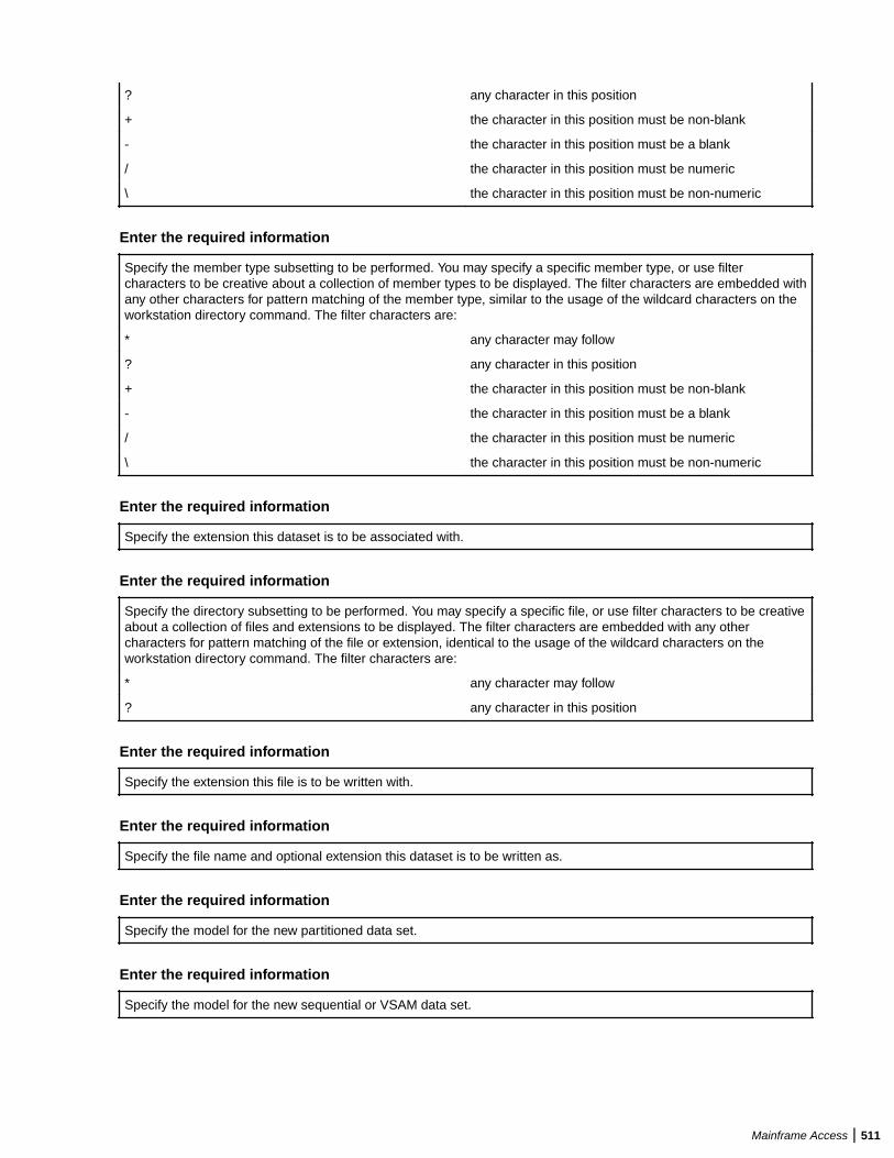
? any character in this position
+ the character in this position must be non-blank
- the character in this position must be a blank
/ the character in this position must be numeric
\ the character in this position must be non-numeric
Enter the required information
Specify the member type subsetting to be performed. You may specify a specific member type, or use filtercharacters to be creative about a collection of member types to be displayed. The filter characters are embedded withany other characters for pattern matching of the member type, similar to the usage of the wildcard characters on theworkstation directory command. The filter characters are:
* any character may follow
? any character in this position
+ the character in this position must be non-blank
- the character in this position must be a blank
/ the character in this position must be numeric
\ the character in this position must be non-numeric
Enter the required information
Specify the extension this dataset is to be associated with.
Enter the required information
Specify the directory subsetting to be performed. You may specify a specific file, or use filter characters to be creativeabout a collection of files and extensions to be displayed. The filter characters are embedded with any othercharacters for pattern matching of the file or extension, identical to the usage of the wildcard characters on theworkstation directory command. The filter characters are:
* any character may follow
? any character in this position
Enter the required information
Specify the extension this file is to be written with.
Enter the required information
Specify the file name and optional extension this dataset is to be written as.
Enter the required information
Specify the model for the new partitioned data set.
Enter the required information
Specify the model for the new sequential or VSAM data set.
Mainframe Access | 511
Filtering catalog items
Specify a filter criteria with which to filter your local catalog, displaying only those items that match the filter. You canspecify fully-qualified or partial names, or use an asterisk for additional matching possibilities.
Catalog Location
Enter the path and name of your catalog file (CATALOG.DAT).
Drag and Drop Utility General information
The Micro Focus Data Access Services File Transfer Utility (commonly known as Drag and Drop) providesa powerful drag-and-drop style GUI access to mainframe datasets, including support for the following datatypes:
• Sequential (QSAM)• Partitioned (BPAM)• Librarian• Panvalet• Endevor• Keyed (VSAM KSDS)• Entry (VSAM ESDS)• Relative (VSAM RRDS)• JES system
You may drag files, individual members, or entire sets of members from the mainframe to the workstation,or back again. When importing from the mainframe, support for all file types is provided. When exportingfrom the workstation, support for most file types is available. In order for you to use this utility, theMainframe Access Product must be purchased and successfully installed on your mainframe system.
Drag and Drop Utility Overview
The utility provides two scalable windows on the desktop. The left hand window provides a list of theworkstation drives, directories and files. To expand a drive or directory, double click on the desired name.To contract an expanded drive or directory, double click again on the desired name. To browse a specificfile, double click on the desired name. The field icon may be used in place of the right mouse contextbutton. You may reposition a member list by using any alphabetic key. The right hand window provides alist of the mainframe datasets that are related to the catalog search criteria, asked for during theconfiguration options at initial start-up. The utility attempts to determine the dataset type, but certain filesare impossible to determine. To inform the utility of the dataset type, single click on the right hand mousebutton over the desired dataset to view the context menu. You may select the appropriate dataset type fromthe list. The utility will store this selection so that you do not have to repeat this process for this dataset. Toexpand a partitioned, Librarian, Panvalet, Endevor, or JES spool double click on the desired dataset. Tocontract an expanded dataset, double click again on the desired dataset. To browse a specific dataset ormember, double click on the desired name. The drag and drop utility supports multiple selection as well assingle selection for its actions. This works in the same way as other utilities available with the operatingsystem. If you select an item by single-clicking on it without having either the Ctrl or Shift key depressed,then only that item will be selected and any other selected items in the same window will be de-selected foryou. If you select an item by single-clicking on it and have the Ctrl key depressed, then the item selectedwill join any other selected items in the same window. If you select an item by single-clicking on it and havethe Shift key depressed, then all items in the range of the last non-Shift selection to this line item will beselected. To copy a dataset, file or member from one platform to the other, you must: hold down the leftmouse button over a desired dataset or file drag it over to the opposite window position the mouse over thedesired target location release the mouse You may drag entire mainframe partitioned, Librarian, Panvaletor Endevor datasets, if you wish to copy all members to the workstation, or simply drag an individual file, ormember if you wish to copy them one at a time. Likewise, the same can be done with workstationdirectories and files that are to be copied to the mainframe. All VSAM datasets, when copied from themainframe to the workstation, are automatically converted to the appropriate workstation file format. For
512 | Mainframe Access
these files, however, the EBCDIC to ASCII conversion is not performed. You must use the Micro FocusData File Convertor Utility (DFCONV) on your own.
Drag and Drop Utility Hints
The high performance Data Access Services is a drag and drop style utility. To copy files to and from themainframe, simply single-click on the desired file names, and drag them to the required location in theopposite window. Entire directories or datasets, containing multiple files can be dragged, if desired. To setglobal options, use the Options action in the Configure pull-down. To set specific types for mainframedatasets, use the right mouse context button over the desired mainframe dataset name. To expand thedrive, directory, or mainframe dataset, and produce a member list, double-click on the desired item. Tocontract these expanded lists, double-click once again. To display a limited number of lines of a workstationfile or a mainframe dataset or member, double-click on the desired item to produce a browse window. Thebrowse limit can be altered by using the Options action. The drag and drop utility supports multipleselection as well as single selection for its actions. This works in the same way as other utilities availablewith the operating system. If you select an item by single-clicking on it without having either the Ctrl or Shiftkey depressed, then only that item will be selected and any other selected items in the same window willbe de-selected for you. If you select an item by single-clicking on it and have the Ctrl key depressed, thenthe item selected will join any other selected items in the same window. If you select an item by single-clicking on it and have the Shift key depressed, then all items in the range of the last non-Shift selection tothis line item will be selected. You may dynamically alter the mainframe list of datasets by changing the'Catalog search criteria' field by using the 'Options' action under the 'File' pull-down. You may dynamicallyalter the mainframe Endevor qualification by changing the 'Endevor qualification' field by using the 'Options'action under the 'File' pull-down.
Log on to the mainframe
User identification Specify the user identification to be used for thisapplication. Make sure that this userid has theappropriate dataset authorization.
Current Password Specify the password associated with the userid given.
CCI Communication Type Select either TCP/IP or VTAM's APPC as yourcommunication method. You must make sure that theappropriate communication stack has been installed.
Standard Server Name (Optional) Specify the name of the standard mainframeserver, as known to the CCI daemon. If you are not usingthe CCI daemon, and using direct connect TCP/IPinstead, then specify the name of the started mainframetask.
Standard Server IP node and Port (Optional) Specify the machine parameters of any currentMFA server that is running. If you are using direct connectTCP/IP then you will need to enter information here. Youwould enter either the DNS name of your mainframe, orthe IP address in the form xxx.xxx.xxx.xxx for the IPnode, and the assigned port number of the MFA server inthe form yyyy for the port. To determine these values, youmay refer to the $MFATCP member in the mainframeINSTLIB dataset.
Standard Server LU name and Mode Specify the LU name and mode to be used with thisAPPC connection. Typically, #INTER is the usual mode tobe used.
Endevor Server Name (Optional) Specify the name of the Endevor supportmainframe server, as known to the CCI daemon. If youare not using the CCI daemon, and using direct connectTCP/IP instead, then specify the name of the startedmainframe task.
Mainframe Access | 513
Endevor Server IP node and Port (Optional) Specify the machine parameters of any currentMFA server that is running. If you are using direct connectTCP/IP then you will need to enter information here. Youwould enter either the DNS name of your mainframe, orthe IP address in the form xxx.xxx.xxx.xxx for the IPnode, and the assigned port number of the MFA server inthe form yyyy for the port. To determine these values, youmay refer to the $MFATCP member in the mainframeINSTLIB dataset.
Endevor Server LU name and Mode Specify the LU name and mode to be used with thisAPPC connection. Typically, #INTER is the usual mode tobe used.
Configuration
Configure options
Title The text to be used on the application task bar. Thisenables you to easily identify a specific monitor sessionfrom the task list.
Startup This time you want the monitor to start up. This isgenerally used in conjunction with the wakeup option. Ifused, the format is in 24 hour time, and must be in therange of 00:00 to 23:59.
Wakeup The length of time the monitor should remain dormantafter the initial analysis has completed but beforeanalyzing the environment for subsequent changes to beprocessed. The default is to remain dormant for 8 hours.
Perform this many monitor iterations before shuttingdown
The number of times the monitor is to do the analysisscan. The default is forever, but if you wish to invoke thisprocess a limited number of times, then specify a value.
Allow a maximum of this many transfers in aniteration
The maximum number of imports or exports the monitordoes per cycle. The default is to transfer all required files.
Clean up mainframe connection after this manytransfers
The number of mainframe server requests to make beforethe monitor automatically terminates the connection tothe mainframe and then initiate a new connection. Somemainframe source code control systems and operatingsystem functions allocate mainframe memory which is notfreed by the routines called by the MFA server subtasks.This memory tends to accumulate and make the MFAserver's memory usage increase. By setting a value tocause this automatic termination and re-connection, thisso-called dead memory, tends to get freed up. Generally,disconnections and connections are fairly fast, so areasonable value for this parameter is about 500.
Delete workstation file if mainframe member isdeleted
When checked, the monitor deletes workstation fileswhen it notices that the corresponding mainframemember has been deleted. This is especially useful inenvironments that do promotions of mainframe membersto higher level datasets, and want to mirror this promotionon the workstation. The default is to ignore this situationand not delete the workstation files.
When checked, the monitor also deletes workstation filesthat were placed in the target directory by a process otherthat the synchronization process. This deletion onlyoccurs if this option is checked, the mainframe file is
514 | Mainframe Access
deleted, and the direction of the synchronization is downto the PC only.
Handle embedded hex in the Micro Focus MDECONVformat
When checked, all source code embedded hex values arehandled in the same way as the Workbench MDECONVapplication, in that all translated hex values less than x'20'will have a null character inserted before the hex value.The COBOL run-time system will properly handle theseembedded hex values. Revolve users may or may notwant to turn on this option.
Suppress embedded hex warning messages When checked, suppresses the hex character indownloaded file warning messages.
Monitor the following A list of workstation/dataset monitor relationships isprovided. Use the Add button to add a new relationship,the Remove button to delete a selected relationship, orthe Configure button to alter a selected relationship.
Configure Advanced Filter Database
The Advanced filter database contains filter rules that can be strung together during the optionconfiguration process. These filters can include and exclude files during the transfer process.
The database is held in text format in file called monrule.ini .
Add Click this button to add a new rule to the database
Remove Select an item in the list box, and click this button toremove it from the database.
Configure Select an item in the list box, and click this button toconfigure the rule.
OK Click this button to store any modifications to thedatabase
Cancel Click this button to abandon any changes made to thedatabase
Enter the required information
Specify the name of the Panvalet user code on which to filter the data set.
Advanced filter details.
The Advanced filter database contains filter rules that can be strung together during the optionconfiguration process. These filters can include and exclude files during the transfer process.
The database is held in text format in a file called monrule.ini.
Rule Name The name that the rule is known by. The only restrictionon this field is that it cannot contain spaces.
Rule Description Free format field containing a meaningful description ofthe rule. This description is displayed during the selectionof rules during the options configuration process.
Rule A free format field containing the rule expression. Therule itself is called a "regular expression". The syntax issimple, but the expressions can be very complex. Thereis a short description of the syntax below. There arenumerous tutorials on the Internet. Using any Internetsearch engine, search for "regexp tutorials".
Mainframe Access | 515
OK Click this button to store any changes to the database.
Cancel Click this button to abandon any changes made to thedatabase
Regular expressions have a syntax in which a few characters are special constructs and the rest are"ordinary". An ordinary character is a simple regular expression which matches that character and nothingelse. The special characters are '\$', '^', '.', '*', '+', '?', '[', ']' and '\'. Any other character appearing in a regularexpression is ordinary, unless preceded by '\'.
For example, 'f' is not a special character, so it is ordinary. It is a regular expression that matches the string'f' and no other string. (It does not match the string 'ff'.) Likewise, 'o' is a regular expression that matchesonly 'o'.
Any two regular expressions A and B can be concatenated. The result is a regular expression whichmatches a string if A matches some amount of the beginning of that string and B matches the rest of thestring.
As a simple example, we can concatenate the regular expressions 'f' and 'o' to get the regular expression'fo', which matches only the string 'fo'.
The following are the characters and character sequences which have special meaning within regularexpressions. Any character not mentioned here is not special; it stands for exactly itself for the purposes ofsearching and matching.
. Aspecialcharacterthatmatchesanythingex
516 | Mainframe Access

ceptanewline.Usingconcatenation,wecanmakeregularexpressionslikea.bw
Mainframe Access | 517
hichmatchesanythree-characterstringwhichbeginswithaandendswithb.
* No
518 | Mainframe Access

taconstructbyitself;itisasuffix,whichmeanstheprecedingregularexpression
Mainframe Access | 519

istoberepeatedasmanytimesaspossible.Forexample,Info*,the*appliest
520 | Mainframe Access
otheo,sofo*matchesffollowedbyanynumberofo's.
Thecaseofzeroo'sisall
Mainframe Access | 521

owed:fo*doesmatchf.
*alwaysappliestothesmallestpossiblepreceding
522 | Mainframe Access

expression.Thismeansthatfo*hasarepeatingo,notarepeatingfo.
Themat
Mainframe Access | 523

cherprocessesa*constructbymatching,immediately,asmanyrepetitionsa
524 | Mainframe Access
scanbefound.Thenitcontinueswiththerestofthepattern.Ifthatfails,back
Mainframe Access | 525

trackingoccurs,discardingsomeofthematchesofthe*'dconstructincaset
526 | Mainframe Access

hatmakesitpossibletomatchtherestofthepattern.Forexample,matching
Mainframe Access | 527
c[ad]*aragainstthestringcaddaar,the[ad]*firstmatchesaddaa,butthis
528 | Mainframe Access

doesnotallowthenextainthepatterntomatch.Sothelastofthematchesof
Mainframe Access | 529

[ad]isundoneandthefollowingaistriedagain.Nowitsucceeds.
+ Like*except
530 | Mainframe Access

thatatleastonematchfortheprecedingpatternisrequiredfor+.Thismeanst
Mainframe Access | 531

hatc[ad]+rdoesnotmatchcrbutdoesmatchanythingelsethatc[ad]*rwouldm
532 | Mainframe Access

atch.
? Like*exceptthatitallowseitherzerooronematchfortheprecedingpa
Mainframe Access | 533

ttern.Thismeansthatc[ad]?rmatchescrorcarorcdr,andnothingelse.
[ Beg
534 | Mainframe Access

insa"characterset",whichisterminatedbya].Inthesimplestcase,thechar
Mainframe Access | 535

actersbetweenthetwosquarebracketsformtheset.Thismeansthat[ad]ma
536 | Mainframe Access
tcheseitheraord,and[ad]*matchesanystringofa'sandd's(includingtheempt
Mainframe Access | 537

ystring),fromwhichitfollowsthatc[ad]*rmatchescar,andsoforth.
Character
538 | Mainframe Access

rangescanalsobeincludedinacharacterset,bywritingtwocharacterswitha-
Mainframe Access | 539

(hyphen)betweenthem.Thismeansthat[a-z]matchesanylower-caseletter.
540 | Mainframe Access

Rangesmaybeintermixedfreelywithindividualcharacters,asin[a-z$%.],w
Mainframe Access | 541

hichmatchesanylowercaseletteror$,%orperiod.
Notethattheusualspecia
542 | Mainframe Access
lcharactersarenotspecialanymoreinsideacharacterset.Acompletelydiff
Mainframe Access | 543
erentsetofspecialcharactersexistsinsidecharactersets:],-and^.
Toi
544 | Mainframe Access

ncludea]inacharacterset,youmustmakeitthefirstcharacter.Forexample,
Mainframe Access | 545

[]a]matches]ora.Toincludea-,youmustuseitinacontextwhereitcannotpo
546 | Mainframe Access

ssiblyindicatearange:thatis,asthefirstcharacter,orimmediatelyafterara
Mainframe Access | 547

nge.
[^ Beginsa"complementcharacterset",whichmatchesanycharacterexc
548 | Mainframe Access
epttheonesspecified.So,[^a-z0-9A-Z]matchesallcharactersexceptlette
Mainframe Access | 549

rsanddigits.
^ Notspecialinacharactersetunlessitisthefirstcharacter.Th
550 | Mainframe Access

echaracterfollowingthe^istreatedasifitwerefirst(itmaybea-ora]).
^isaspe
Mainframe Access | 551

cialcharacterthatmatchestheemptystring--butonlyifatthebeginningofa
552 | Mainframe Access
lineinthetextbeingmatched.Otherwiseitfailstomatchanything.Thismean
Mainframe Access | 553

sthat^foomatchesafoowhichoccursatthebeginningofaline.
$ Similarto^b
554 | Mainframe Access
utmatchesonlyattheendofaline.Thismeansthatxx*$matchesastringofone
Mainframe Access | 555

ormorex'sattheendofaline.
\ Hastwofunctions:itquotestheabovespecialch
556 | Mainframe Access

aracters(including\),anditintroducesadditionalspecialconstructs.
Becaus
Mainframe Access | 557
e\quotesspecialcharacters,\$isaregularexpressionwhichmatchesonly$,
558 | Mainframe Access

and\[isaregularexpressionwhichmatchesonly[,andsoon.
Forthemostpart,
Mainframe Access | 559

\followedbyanycharactermatchesonlythatcharacter.However,thereares
560 | Mainframe Access

everalexceptions:characterswhich,whenprecededby\,arespecialconstr
Mainframe Access | 561

ucts.Suchcharactersarealwaysordinarywhenencounteredontheirown.
562 | Mainframe Access
Nonewspecialcharactersareeverdefined.Allextensionstotheregularexp
Mainframe Access | 563

ressionsyntaxaremadebydefiningnewtwo-characterconstructsthatbegi
564 | Mainframe Access

nwith\.
\| Specifiesanalternative.TworegularexpressionsAandBwith\|inbetw
Mainframe Access | 565

eenformanexpressionthatmatchesanythingthateitherAorBmatch.
Thisme
566 | Mainframe Access

ansthatfoo\|barmatcheseitherfooorbarbutnootherstring.
\|applies
Mainframe Access | 567
tothelargestpossiblesurroundingexpressions.Onlyasurrounding\(...\)
568 | Mainframe Access
groupingcanlimitthegroupingpowerof\|.
Fullbacktrackingcapabilityexists
Mainframe Access | 569

whenmultiple\|'sareused.
\( ... \) Specifiesagroupingconstructtomarkamatchedsu
570 | Mainframe Access

bstringforfuturereference.IntheMicroFocusimplementation,thereisonly
Mainframe Access | 571

onegroupingallowed.Thecontentsofthisgroupingaretreatedasthefoundfil
572 | Mainframe Access

enamefortransfer.
Thislastapplicationisnotaconsequenceoftheideaofapa
Mainframe Access | 573

rentheticalgrouping;itisaseparatefeaturewhichhappenstobeassignedas
574 | Mainframe Access
asecondmeaningtothesame\(...\)constructbecausethereisnoconflictin
Mainframe Access | 575
practicebetweenthetwomeanings.Hereisanexplanationofthisfeature:
\n Aft
576 | Mainframe Access

ertheendofa\(...\)construct,thematcherremembersthebeginningande
Mainframe Access | 577

ndofthetextmatchedbythatconstruct.Then,lateronintheregularexpres
578 | Mainframe Access

sion,youcanuse\followedbyntomean"matchthesametextmatchedthen'thtim
Mainframe Access | 579

ebythe\(...\)construct."The\(...\)constructsarenumberedinordero
580 | Mainframe Access

fcommencementintheregularexpression.
Thestringsmatchingthefirstni
Mainframe Access | 581

ne\(...\)constructsappearinginaregularexpressionareassignednumber
582 | Mainframe Access
s1through9inorderoftheirbeginnings.\1through\9maybeusedtorefer
Mainframe Access | 583

tothetextmatchedbythecorresponding\(...\)construct.
Forexample,\
584 | Mainframe Access
(.*\)\1matchesanystringthatiscomposedoftwoidenticalhalves.The\(.
Mainframe Access | 585

*\)matchesthefirsthalf,whichmaybeanything,butthe\1thatfollowsmust
586 | Mainframe Access
matchthesameexacttext.
\b Matchestheemptystring,butonlyifitisatthebegin
Mainframe Access | 587
ningorendofaword.Thismeansthat\bfoo\bmatchesanyoccurrenceoffooa
588 | Mainframe Access
saseparateword.\bball\(s\|\)\bmatchesballorballsasaseparatew
Mainframe Access | 589

ord.
\B Matchestheemptystring,provideditisnotatthebeginningorendofawo
590 | Mainframe Access

rd.
\< Matchestheemptystring,butonlyifitisatthebeginningofaword.
\> Matche
Mainframe Access | 591
stheemptystring,butonlyifitisattheendofaword.
\w Matchesanyword-constit
592 | Mainframe Access
uentcharacter.
\W Matchesanycharacterthatisnotaword-constituent.
Examples
• ^NULLFILE matches a file called NULLFILE and nothing else.
Mainframe Access | 593
• ^NUL[0-9][0-9].* matches files beginning with NUL, followed by two numerics inthe range 0-9, followed by any number of characters.
• .*3$ matches any file ending with the number 3.• ^A.*[0-3][1-2]$ matches any file beginning with the letter A, followed by any
number of characters, the last two must be numeric and in the range 0-3 for thesecond last digit, and 1-2 for the last digit.
• ^(CON)|^(NUL)|^(COM[0-9])|^(LPT[1-9])|^(AUX)|^(CLOCK\$) excludesinvalid DOS file names.
Note: You can include the $ character as part of the stringby preceding it with a backslash.
If a rule is created like this and put in as an exclude filter when building thesynchronisation item it would exclude all the invalid DOS filenames listed in thisexpression.
The above would also hold true for a file called CONTROL. To stop this put a $metacharacter as follows : ^(CON)$ .... This would ensure that only CON would berecognised by the filter.
Rename Catalog File
Enter the new name for the data set or item.
Note: The new name is only used when displaying the catalog in Server Explorer. The file or directory nameon disk is not renamed.
Specify the dataset type
Select the dataset type to be monitored Specify the type of the mainframe dataset that arelationship is to be build.
Specify the mainframe dataset name
Specify the dataset name to be monitored Enter the fully qualified mainframe dataset name to bemonitored.
Specify the mainframe Librarian dataset name
Specify the Librarian dataset nameto be monitored
Enter the fully qualified name of the mainframe Librarian dataset to bemonitored.
Specify the optional type, with orwithout filter characters
If your installation has gone to the trouble of setting up valid Librarian typeson the mainframe, then you can take advantage of this information inselecting specific member types for you monitor relationship. You may specifya specific type, or use filter characters to be creative about a collection oftypes to be monitored. The filter characters are embedded with any othercharacters for pattern matching of the Librarian type, similar to the usage ofthe wildcard characters on the workstation directory command. The filtercharacters are:
* any character may follow
? any character in this position
+ the character in this position must benon-blank
- the character in this position must bea blank
594 | Mainframe Access
/ the character in this position must benumeric
\ the character in this position must benon-numeric
Specify the mainframe Panvalet dataset name
Specify the Panvalet dataset nameto be monitored
Enter the fully qualified name of the mainframe Panvalet dataset to bemonitored.
Specify the optional type, with orwithout filter characters
If your installation has gone to the trouble of setting up valid Panvalet typeson the mainframe, then you can take advantage of this information inselecting specific member types for you monitor relationship. You may specifya specific type, or use filter characters to be creative about a collection oftypes to be monitored. The filter characters are embedded with any othercharacters for pattern matching of the Panvalet type, similar to the usage ofthe wildcard characters on the workstation directory command. The filtercharacters are:
* any character may follow
? any character in this position
+ the character in this position must benon-blank
- the character in this position must bea blank
/ the character in this position must benumeric
\ the character in this position must benon-numeric
Panvalet Status Processing The groups of radio buttons in this section enable you choose to process onlythose Panvalet members that have the specified attributes set. For example, ifEnabled, Active and Both are selected, the Compare and SynchronizeMonitor downloads all members with Enabled and Active statuses; Productionand Test statuses are both acceptable for download because of the Bothoption.Selecting these radio buttons only has an effect if you have updatedyour Mainframe Access server with one of the following PTFs: 2002PTF1,2001PTF5, or MFAPANEH.EXE. If you have not installed one of these PTFs,these radio buttons have no effect. Contact your Micro Focus Supportrepresentative if you are not sure which of these PTFs is appropriate for yourcopy of Mainframe Access.
Specify the mainframe Endevor environment
Specify the environment Enter the Endevor environment to be monitored.
System Enter the Endevor system to be monitored.
Subsystem Enter the Endevor sub-system to be monitored.
Specify the type Endevor the specific Endevor type to be monitored.
Specify the CCID If your environment requires a change control ID to beprovided, then enter it here.
Specify the comment If your environment requires a comment to be provided,or if you desire one, then enter it here.
Mainframe Access | 595
Specify the mainframe LCM/CCC dataset name
Specify the LCM dataset name to be monitored Enter the fully qualified name of the mainframe LCMdataset to be monitored.
Specify the system Specify the LCM system to be monitored.
Specify the configuration Specify the LCM configuration that is related to the LCMsystem to be monitored.
Specify the type Specify the LCM type to be monitored.
Specify the mainframe sequential dataset name
Specify the sequential dataset name to be monitored Enter the fully qualified name of the mainframe QSAMdataset to be monitored.
Specify the mainframe VSAM dataset name
Specify the VSAM dataset name to be monitored Enter the fully qualified name of the mainframe VSAMdataset to be monitored.
Handle as a fixed length file The resulting imported file will be converted to the properMicro Focus format in fixed format, with the minimumrecord length set to the maximum record length.
Specify the directions to monitor
Monitor for both upload and download Monitor, and allow both uploads and downloads to occur.
Monitor for upload to the mainframe only Monitor, but do not allow a download to occur. This willallow upload synchronization to occur.
Monitor for download to the workstation only Monitor, but do not allow an upload to occur. This willallow download synchronization to occur.
Monitor, but do not upload or download Monitor, but do not allow an upload or download to occur.This will produce a report only.
Disable EBCDIC/ASCII translation (binary transfer) Check this to specify that you do not want EBCDIC/ASCIItranslation to occur. This option is useful if you have aPDS containing binary data, and is only available if youhave selected a PDS to be monitored.
Specify any member subsetting to be done
Use Advanced Filter Method Checkthistomaketh
596 | Mainframe Access
emonitorusetheadvancedfilteringsystem.Iftheboxisleftuncheckedt
Mainframe Access | 597
hentheoldfilterexpressionmethodwillbeused.
Old filter method expression Youmayspecifyaspeci
598 | Mainframe Access
ficmembername,orusefiltercharacterstobecreativeaboutacollectio
Mainframe Access | 599
nofmemberstobemonitored.Thefiltercharactersareembeddedwithanyo
600 | Mainframe Access
thercharactersforpatternmatchingofthemembername,similartotheus
Mainframe Access | 601
ageofthewildcardcharactersontheworkstationdirectorycommand.The
602 | Mainframe Access
filtercharactersare:
*anycharactermayfollow
?anycharacterinthispo
Mainframe Access | 603
sition
+thecharacterinthispositionmustbenon-blank
-thecharacterin
604 | Mainframe Access

thispositionmustbeablank
/thecharacterinthispositionmustbenumer
Mainframe Access | 605
ic
\thecharacterinthispositionmustbenon-numeric
Advanced filter method Whentheadvancedf
606 | Mainframe Access
iltermethodcheckboxischecked,theCurrentActiveFilterlistbox,and
Mainframe Access | 607
theFilterDatabaselistboxbecomeactive.Toaddrulestothecurrentact
608 | Mainframe Access
ivefilters,selectitinthefilterdatabaselistbox,andclickoneither
Mainframe Access | 609
theIncludebutton,ortheExcludebuttonthatbecomeactivebetweenthet
610 | Mainframe Access

wolistboxes.ClickingontheIncludebuttonaddsthefilterruletotheac
Mainframe Access | 611
tivefiltersasanIncludefilter.Thismeansthatanyfilespassedbythef
612 | Mainframe Access
ilterwillbeincludedinthefileprocessingbetweenthehostandPCandvi
Mainframe Access | 613
ceversa.ClickingontheExcludebuttonaddsthefilterruletotheactive
614 | Mainframe Access
filtersasanExcludefilter.Thismeansthatanyfilespassedbythefilte
Mainframe Access | 615

rwillbeExcludedfromthefileprocessingbetweenthehostandPCandvice
616 | Mainframe Access

versa.
Inthescreenshotabove,whenthefiltersareappliedtothesynch
Mainframe Access | 617
ronisationprocess,anyfilesfoundbytheHIGHCHARACTERrulewillbeex
618 | Mainframe Access
cluded,andanythingfoundbytheEVERYTHINGrulewillbeincluded.
NB,a
Mainframe Access | 619
nexcluderulewillalwaystakeprecedenceoveranyincluderule.Soalth
620 | Mainframe Access

ougheverythingisrequestedintheEVERYTHINGrule,thefilesexcluded
Mainframe Access | 621

bytheHIGHCHARACTERrulewillbeexcluded.
Therulesdatabaseismainta
622 | Mainframe Access
inedfromthe"Configureadvancedfilterdatabase"menuitemundertheC
Mainframe Access | 623
onfigureoptiononthemainmenu.Pleaserefertothehelpavailabethere
624 | Mainframe Access
formoreinformationonbuildingadvancedfilterrules.
Remove Selectanitemi
Mainframe Access | 625

ntheCurrentActiveFilterlistbox,andthenclicktheremovebuttontore
626 | Mainframe Access
moveitfromthelist.
Toggle SelectanitemintheCurrentActiveFilterlistbox
Mainframe Access | 627

,andthenclicktheTogglebuttontotoggleitbetweenincludeprocessing
628 | Mainframe Access
andexcludeprocessing.
Old Filter Method IftheUseAdvancedFilterMethodcheckboxisno
Mainframe Access | 629
tchecked,thenthefollowingfilterruleapplies:
Youcanspecifyaspec
630 | Mainframe Access

ificmembername,orusefiltercharacterstobecreativeaboutacollect
Mainframe Access | 631

ionofmemberstobemonitored.Thefiltercharactersareembeddedwitha
632 | Mainframe Access

nyothercharactersforpatternmatchingofthemembername,similartot
Mainframe Access | 633

heusageofthewildcardcharactersontheworkstationdirectorycomman
634 | Mainframe Access
d.Thefiltercharactersare:
*anycharactermayfollow
?anycharacterin
Mainframe Access | 635
thisposition
+thecharacterinthispositionmustbenon-blank
-thechara
636 | Mainframe Access
cterinthispositionmustbeablank
/thecharacterinthispositionmustb
Mainframe Access | 637
enumeric
\thecharacterinthispositionmustbenon-numeric
Specify the workstation location
Location of workstation directory You must specify the fully qualified location of aworkstation directory to complete the monitor relationship.This is the name of the directory without any additionalcharacters such as *.CBL. You may use the browsebutton to aid in the location of the directory.
638 | Mainframe Access
Location of PVCS archive You must specify the fully qualified location of a PVCSarchive CFG file to complete the monitor relationship.This is the name of the archive with the usualARCHIVENAME.CFG at the end. You may use thebrowse button to aid in the location of the archive file.
Extension You must specify the specific extension, such as all CBLfiles in the directory, to be monitored against, or writtenas.
If you specify the extension as three asterisks (***), thedownload initially downloads the file with no extension. Ifthe file extension is then changed, the nextsynchronization operation finds the first matchingfilename with any extension. Only one file with the samefilename can exist in the target directory. For example, if ahost PDS member name is ACCTOPEN and no file withthe prefix ACCTOPEN exists in the PC target directory,the file is downloaded as ACCTOPEN. If the extension isthen modified to ACCTOPEN.CBL, the nextsynchronization detects the target filename asACCTOPEN.CBL and synchronizes against that.
Monitor against Select whether you are monitoring against a directory ofstandard files, or a PVCS archive.
Optional version label If you are monitoring against PVCS, then you maymonitor against a specific version label, if desired.
Optional promotion group If you are monitoring against PVCS, then you maymonitor against a specific promotion group, if desired.
Compare and Synchronize Monitor General Information
The Compare and Synchronize Monitor allows users to interrogate both workstation and mainframe sourcecode and data files, and determine if any changes have occurred. If changes have occurred, then the userthrough configuration information, instructs the Monitor on the automatic action to be taken, such asdownloading or uploading the change files. This enables an environment to be set up that allows a user tomirror workstation and mainframe files, and to automatically transport all changes to the mirroredcounterpart.
Compare and Synchronize Monitor Overview
To use the Compare and Synchronize Monitor, the user must perform a configuration. This is done in theMFMONMX program by using the Configure Options pull-down. This pull-down invoked the GUIconfiguration utility where the user instructs the Monitor on the workstation locations and mainframedatasets to be mirrored.
Compare and Synchronize Monitor Hints
The Compare and Synchronize Monitor is useful for creating a local workstation directory that is identical tothe mainframe datasets. This is helpful when using other products such as Mainframe Express, or Revolve,as the access to the workstation files is always faster than going over a communications link to anymainframe.
Synchronization filters
Select the type of filter to add to the rule:
Simple Filter Enter a simple filter
Note: Hover over the field for tips of the syntaxyou can use.
Mainframe Access | 639
Advanced Filters 1. Select Use Advanced Filters, then click Add Filters.
The Add Advanced Filter dialog box appears.2. Choose the required filter, then select how it should
filter:
• Include to include matching items• Exclude to exclude matching items
3. Click OK.
Synchronization rules
Data Set Name The name of the data set being synchronized
Type The type of data set being synchronized
Sync Mode One of:
• BOTH - changes on either the mainframe or theworkstation are synchronized
• UPLOAD - only changes on the workstation aresynchronized to the mainframe
• DOWNLOAD - only changes on the mainframe aresynchronized to the workstation
• MONITOR - mimics the BOTH setting withoutchanges being made
Advanced Set the following options:
• Delete workstation file if mainframe member isdeleted - during synchronization, if a member hasbeen deleted on the mainframe, it will also be deletedon the workstation.
• Delete workstation folder if library is deleted -during synchronization, if a library has been deletedon the mainframe, the workstation folder is alsodeleted if it contains no other synchronized members.
• Handle embedded hex in MF MDECONV format -uses the MDECONV technique to deal withembedded hex values, that is, all translated hexvalues less than x'1f' have a null characterinserted before the hex value, and the COBOL run-time system handles these embedded hex values.
• Suppress embedded hex warning messages - pop-up messages when a non-printing character isreceived from the mainframe are not displayed; anentry is recorded in the log file instead.
Filters Add a simple or advanced filter to the rule.
Binary Data Transfer Transfer the data in binary format. Only available withPDS data sets.
Member Type Specify the type of member in an Endevor, Panvalet orLibrarian container,
Directory The workstation directory used during synchronization
File Extension The file extension to append to each membersynchronized
Enter the required information
Specify the pattern to be used for pre- and post-download member filtering.
640 | Mainframe Access
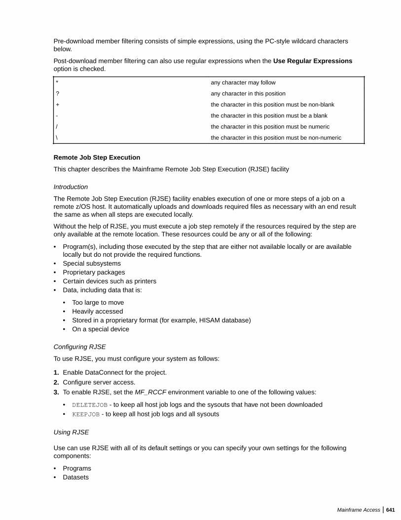
Pre-download member filtering consists of simple expressions, using the PC-style wildcard charactersbelow.
Post-download member filtering can also use regular expressions when the Use Regular Expressionsoption is checked.
* any character may follow
? any character in this position
+ the character in this position must be non-blank
- the character in this position must be a blank
/ the character in this position must be numeric
\ the character in this position must be non-numeric
Remote Job Step Execution
This chapter describes the Mainframe Remote Job Step Execution (RJSE) facility
Introduction
The Remote Job Step Execution (RJSE) facility enables execution of one or more steps of a job on aremote z/OS host. It automatically uploads and downloads required files as necessary with an end resultthe same as when all steps are executed locally.
Without the help of RJSE, you must execute a job step remotely if the resources required by the step areonly available at the remote location. These resources could be any or all of the following:
• Program(s), including those executed by the step that are either not available locally or are availablelocally but do not provide the required functions.
• Special subsystems• Proprietary packages• Certain devices such as printers• Data, including data that is:
• Too large to move• Heavily accessed• Stored in a proprietary format (for example, HISAM database)• On a special device
Configuring RJSE
To use RJSE, you must configure your system as follows:
1. Enable DataConnect for the project.
2. Configure server access.
3. To enable RJSE, set the MF_RCCF environment variable to one of the following values:
• DELETEJOB - to keep all host job logs and the sysouts that have not been downloaded• KEEPJOB - to keep all host job logs and all sysouts
Using RJSE
Use can use RJSE with all of its default settings or you can specify your own settings for the followingcomponents:
• Programs• Datasets
Mainframe Access | 641
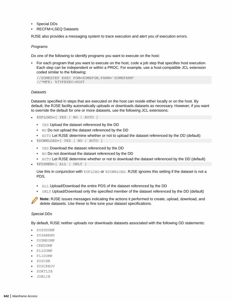
• Special DDs• RECFM=LSEQ Datasets
RJSE also provides a messaging system to trace execution and alert you of execution errors.
Programs
Do one of the following to identify programs you want to execute on the host:
• For each program that you want to execute on the host, code a job step that specifies host execution.Each step can be independent or within a PROC. For example, use a host-compatible JCL extensioncoded similar to the following:
//SOMESTEP EXEC PGM=SOMEPGM,PARM='SOMEPARM'//*MFE: %TYPEXEC=HOST
Datasets
Datasets specified in steps that are executed on the host can reside either locally or on the host. Bydefault, the RJSE facility automatically uploads or downloads datasets as necessary. However, if you wantto override the default for one or more datasets, use the following JCL extensions:
• %UPLOAD=[ YES | NO | AUTO ]
• YES Upload the dataset referenced by the DD• NO Do not upload the dataset referenced by the DD• AUTO Let RJSE determine whether or not to upload the dataset referenced by the DD (default)
• %DOWNLOAD=[ YES | NO | AUTO ]
• YES Download the dataset referenced by the DD• NO Do not download the dataset referenced by the DD• AUTO Let RJSE determine whether or not to download the dataset referenced by the DD (default)
• %PDSMEM=[ ALL | ONLY ]
Use this in conjunction with %UPLOAD or %DOWNLOAD. RJSE ignores this setting if the dataset is not aPDS.
• ALL Upload/Download the entire PDS of the dataset referenced by the DD• ONLY Upload/Download only the specified member of the dataset referenced by the DD (default)
Note: RJSE issues messages indicating the actions it performed to create, upload, download, anddelete datasets. Use these to fine tune your dataset specifications.
Special DDs
By default, RJSE neither uploads nor downloads datasets associated with the following DD statements:
• SYSUDUMP
• SYSABEND
• SYSMDUMP
• CEEDUMP
• PLIDUMP
• PL1DUMP
• SYSCHK
• SYSCKEOV
• SORTLIB
• JOBLIB
642 | Mainframe Access
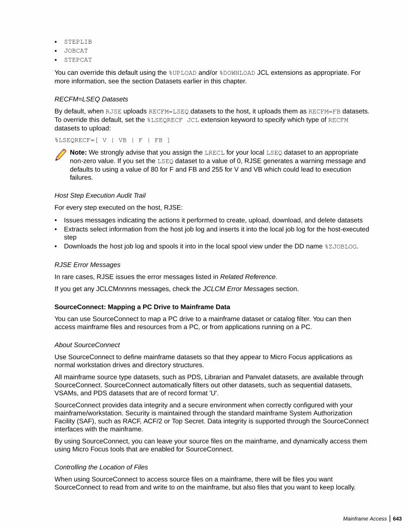
• STEPLIB
• JOBCAT
• STEPCAT
You can override this default using the %UPLOAD and/or %DOWNLOAD JCL extensions as appropriate. Formore information, see the section Datasets earlier in this chapter.
RECFM=LSEQ Datasets
By default, when RJSE uploads RECFM=LSEQ datasets to the host, it uploads them as RECFM=FB datasets.To override this default, set the %LSEQRECF JCL extension keyword to specify which type of RECFMdatasets to upload:
%LSEQRECF=[ V | VB | F | FB ]
Note: We strongly advise that you assign the LRECL for your local LSEQ dataset to an appropriatenon-zero value. If you set the LSEQ dataset to a value of 0, RJSE generates a warning message anddefaults to using a value of 80 for F and FB and 255 for V and VB which could lead to executionfailures.
Host Step Execution Audit Trail
For every step executed on the host, RJSE:
• Issues messages indicating the actions it performed to create, upload, download, and delete datasets• Extracts select information from the host job log and inserts it into the local job log for the host-executed
step• Downloads the host job log and spools it into in the local spool view under the DD name %ZJOBLOG.
RJSE Error Messages
In rare cases, RJSE issues the error messages listed in Related Reference.
If you get any JCLCMnnnns messages, check the JCLCM Error Messages section.
SourceConnect: Mapping a PC Drive to Mainframe Data
You can use SourceConnect to map a PC drive to a mainframe dataset or catalog filter. You can thenaccess mainframe files and resources from a PC, or from applications running on a PC.
About SourceConnect
Use SourceConnect to define mainframe datasets so that they appear to Micro Focus applications asnormal workstation drives and directory structures.
All mainframe source type datasets, such as PDS, Librarian and Panvalet datasets, are available throughSourceConnect. SourceConnect automatically filters out other datasets, such as sequential datasets,VSAMs, and PDS datasets that are of record format 'U'.
SourceConnect provides data integrity and a secure environment when correctly configured with yourmainframe/workstation. Security is maintained through the standard mainframe System AuthorizationFacility (SAF), such as RACF, ACF/2 or Top Secret. Data integrity is supported through the SourceConnectinterfaces with the mainframe.
By using SourceConnect, you can leave your source files on the mainframe, and dynamically access themusing Micro Focus tools that are enabled for SourceConnect.
Controlling the Location of Files
When using SourceConnect to access source files on a mainframe, there will be files you wantSourceConnect to read from and write to on the mainframe, but also files that you want to keep locally.
Mainframe Access | 643
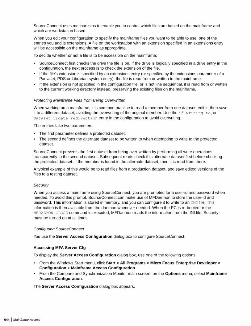
SourceConnect uses mechanisms to enable you to control which files are based on the mainframe andwhich are workstation based.
When you edit your configuration to specify the mainframe files you want to be able to use, one of theentries you add is extensions. A file on the workstation with an extension specified in an extensions entrywill be accessible on the mainframe as appropriate.
To decide whether or not a file is to be accessible on the mainframe:
• SourceConnect first checks the drive the file is on. If the drive is logically specified in a drive entry in theconfiguration, the next process is to check the extension of the file.
• If the file's extension is specified by an extensions entry (or specified by the extensions parameter of aPanvalet, PDS or Librarian system entry), the file is read from or written to the mainframe.
• If the extension is not specified in the configuration file, or is not line sequential, it is read from or writtento the current working directory instead, preserving the existing files on the mainframe.
Protecting Mainframe Files from Being Overwritten
When working on a mainframe, it is common practice to read a member from one dataset, edit it, then saveit to a different dataset, avoiding the overwriting of the original member. Use the if-writing-to, ordataset update redirection entry in the configuration to avoid overwriting.
The entries take two parameters:
• The first parameter defines a protected dataset.• The second defines the alternate dataset to be written to when attempting to write to the protected
dataset.
SourceConnect prevents the first dataset from being over-written by performing all write operationstransparently to the second dataset. Subsequent reads check this alternate dataset first before checkingthe protected dataset. If the member is found in the alternate dataset, then it is read from there.
A typical example of this would be to read files from a production dataset, and save edited versions of thefiles to a testing dataset.
Security
When you access a mainframe using SourceConnect, you are prompted for a user-id and password whenneeded. To avoid this prompt, SourceConnect can make use of MFDaemon to store the user-id andpassword. This information is stored in memory, and you can configure it to write to an INI file. Thisinformation is then available from the daemon whenever needed. When the PC is re-booted or theMFDAEMON CLOSE command is executed, MFDaemon reads the information from the INI file. Securitymust be turned on at all times.
Configuring SourceConnect
You use the Server Access Configuration dialog box to configure SourceConnect.
Accessing MFA Server Cfg
To display the Server Access Configuration dialog box, use one of the following options:
• From the Windows Start menu, click Start > All Programs > Micro Focus Enterprise Developer >Configuration > Mainframe Access Configuration.
• From the Compare and Synchronization Monitor main screen, on the Options menu, select MainframeAccess Configuration.
The Server Access Configuration dialog box appears.
644 | Mainframe Access
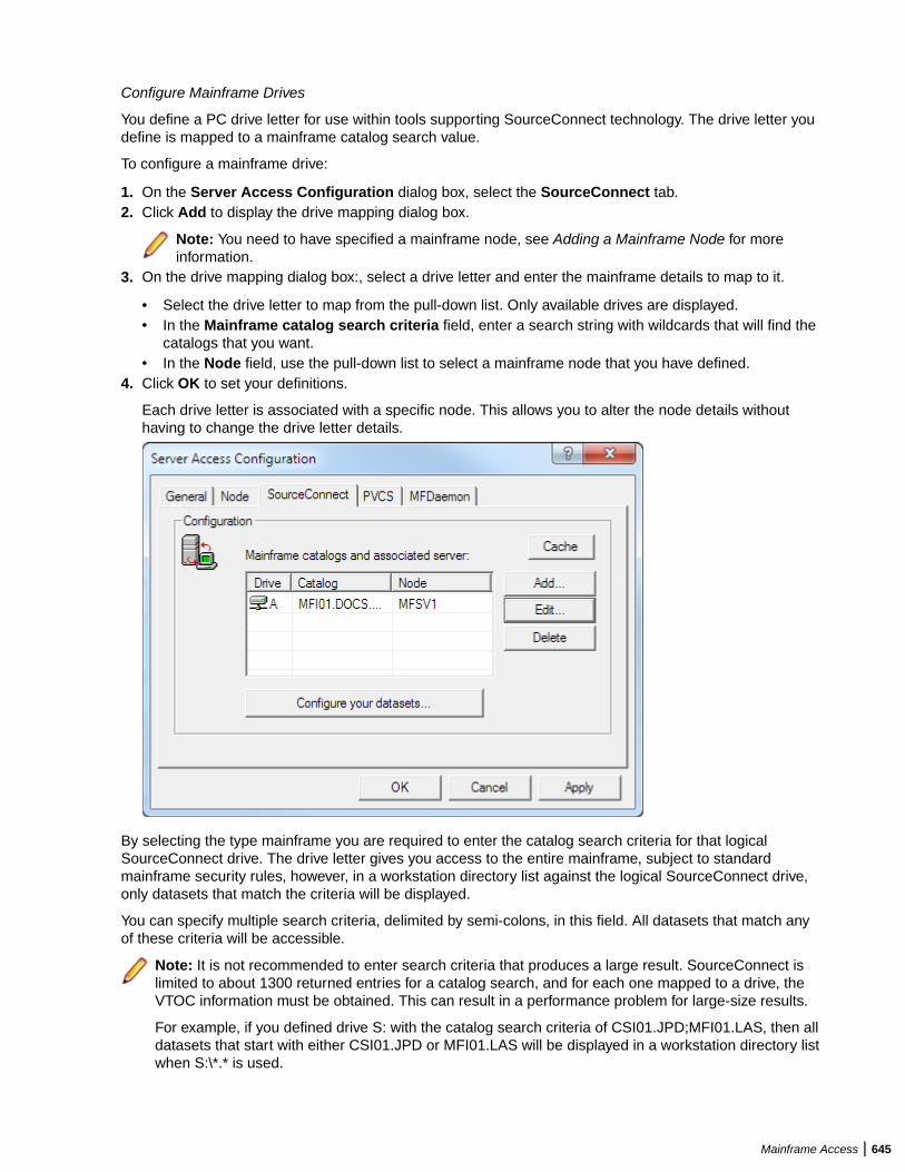
Configure Mainframe Drives
You define a PC drive letter for use within tools supporting SourceConnect technology. The drive letter youdefine is mapped to a mainframe catalog search value.
To configure a mainframe drive:
1. On the Server Access Configuration dialog box, select the SourceConnect tab.2. Click Add to display the drive mapping dialog box.
Note: You need to have specified a mainframe node, see Adding a Mainframe Node for moreinformation.
3. On the drive mapping dialog box:, select a drive letter and enter the mainframe details to map to it.
• Select the drive letter to map from the pull-down list. Only available drives are displayed.• In the Mainframe catalog search criteria field, enter a search string with wildcards that will find the
catalogs that you want.• In the Node field, use the pull-down list to select a mainframe node that you have defined.
4. Click OK to set your definitions.
Each drive letter is associated with a specific node. This allows you to alter the node details withouthaving to change the drive letter details.
By selecting the type mainframe you are required to enter the catalog search criteria for that logicalSourceConnect drive. The drive letter gives you access to the entire mainframe, subject to standardmainframe security rules, however, in a workstation directory list against the logical SourceConnect drive,only datasets that match the criteria will be displayed.
You can specify multiple search criteria, delimited by semi-colons, in this field. All datasets that match anyof these criteria will be accessible.
Note: It is not recommended to enter search criteria that produces a large result. SourceConnect islimited to about 1300 returned entries for a catalog search, and for each one mapped to a drive, theVTOC information must be obtained. This can result in a performance problem for large-size results.
For example, if you defined drive S: with the catalog search criteria of CSI01.JPD;MFI01.LAS, then alldatasets that start with either CSI01.JPD or MFI01.LAS will be displayed in a workstation directory listwhen S:\*.* is used.
Mainframe Access | 645
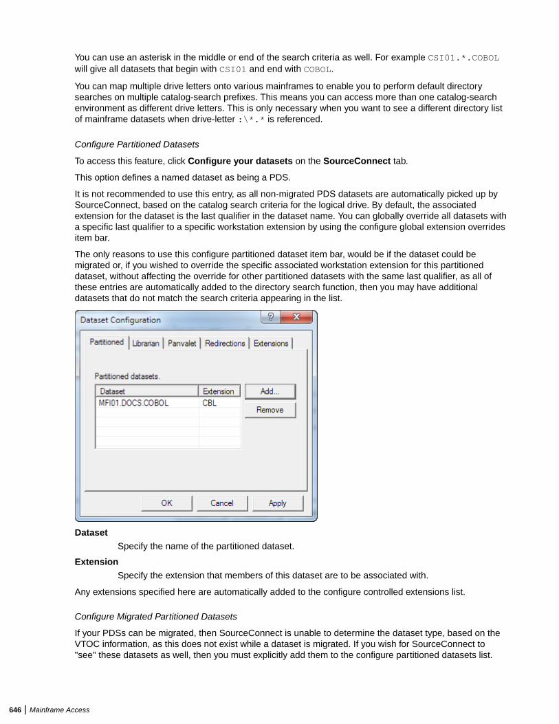
You can use an asterisk in the middle or end of the search criteria as well. For example CSI01.*.COBOLwill give all datasets that begin with CSI01 and end with COBOL.
You can map multiple drive letters onto various mainframes to enable you to perform default directorysearches on multiple catalog-search prefixes. This means you can access more than one catalog-searchenvironment as different drive letters. This is only necessary when you want to see a different directory listof mainframe datasets when drive-letter :\*.* is referenced.
Configure Partitioned Datasets
To access this feature, click Configure your datasets on the SourceConnect tab.
This option defines a named dataset as being a PDS.
It is not recommended to use this entry, as all non-migrated PDS datasets are automatically picked up bySourceConnect, based on the catalog search criteria for the logical drive. By default, the associatedextension for the dataset is the last qualifier in the dataset name. You can globally override all datasets witha specific last qualifier to a specific workstation extension by using the configure global extension overridesitem bar.
The only reasons to use this configure partitioned dataset item bar, would be if the dataset could bemigrated or, if you wished to override the specific associated workstation extension for this partitioneddataset, without affecting the override for other partitioned datasets with the same last qualifier, as all ofthese entries are automatically added to the directory search function, then you may have additionaldatasets that do not match the search criteria appearing in the list.
DatasetSpecify the name of the partitioned dataset.
ExtensionSpecify the extension that members of this dataset are to be associated with.
Any extensions specified here are automatically added to the configure controlled extensions list.
Configure Migrated Partitioned Datasets
If your PDSs can be migrated, then SourceConnect is unable to determine the dataset type, based on theVTOC information, as this does not exist while a dataset is migrated. If you wish for SourceConnect to"see" these datasets as well, then you must explicitly add them to the configure partitioned datasets list.
646 | Mainframe Access
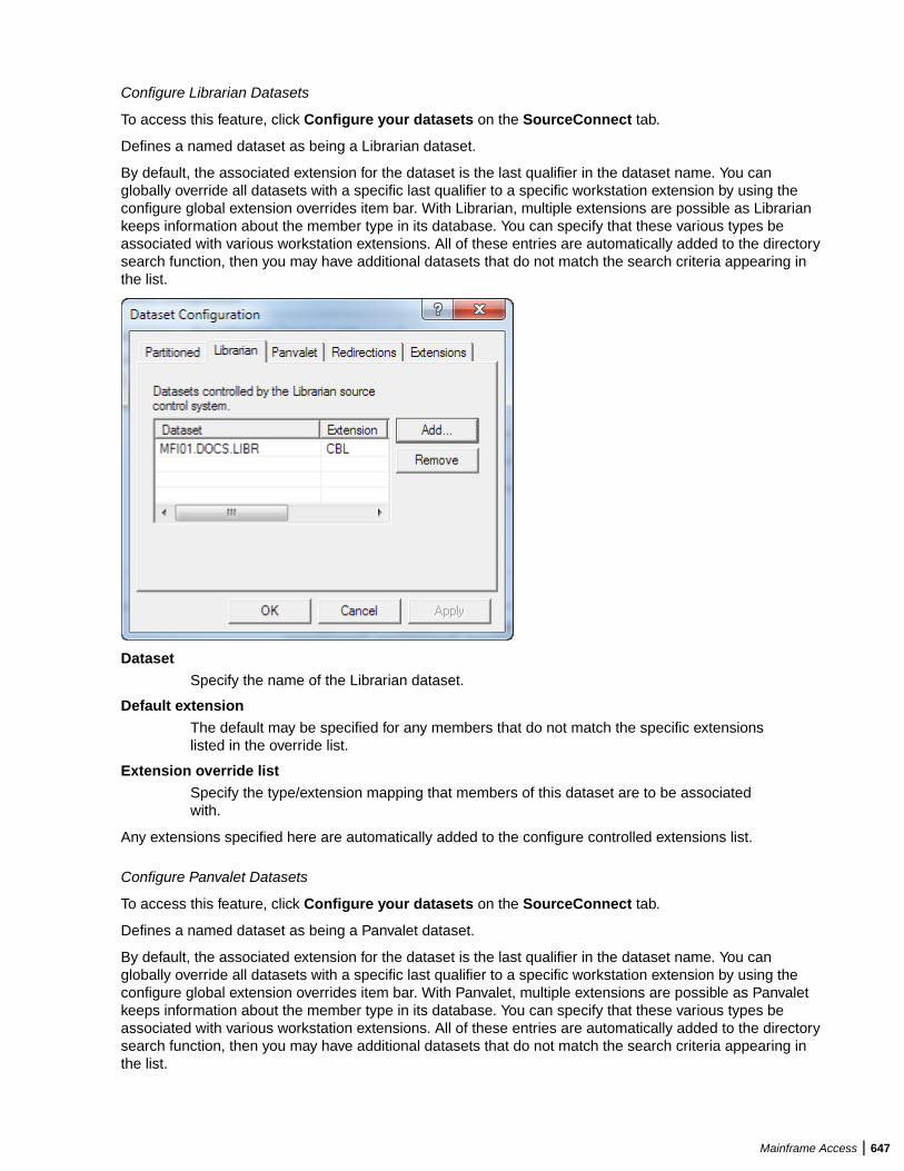
Configure Librarian Datasets
To access this feature, click Configure your datasets on the SourceConnect tab.
Defines a named dataset as being a Librarian dataset.
By default, the associated extension for the dataset is the last qualifier in the dataset name. You canglobally override all datasets with a specific last qualifier to a specific workstation extension by using theconfigure global extension overrides item bar. With Librarian, multiple extensions are possible as Librariankeeps information about the member type in its database. You can specify that these various types beassociated with various workstation extensions. All of these entries are automatically added to the directorysearch function, then you may have additional datasets that do not match the search criteria appearing inthe list.
DatasetSpecify the name of the Librarian dataset.
Default extensionThe default may be specified for any members that do not match the specific extensionslisted in the override list.
Extension override listSpecify the type/extension mapping that members of this dataset are to be associatedwith.
Any extensions specified here are automatically added to the configure controlled extensions list.
Configure Panvalet Datasets
To access this feature, click Configure your datasets on the SourceConnect tab.
Defines a named dataset as being a Panvalet dataset.
By default, the associated extension for the dataset is the last qualifier in the dataset name. You canglobally override all datasets with a specific last qualifier to a specific workstation extension by using theconfigure global extension overrides item bar. With Panvalet, multiple extensions are possible as Panvaletkeeps information about the member type in its database. You can specify that these various types beassociated with various workstation extensions. All of these entries are automatically added to the directorysearch function, then you may have additional datasets that do not match the search criteria appearing inthe list.
Mainframe Access | 647
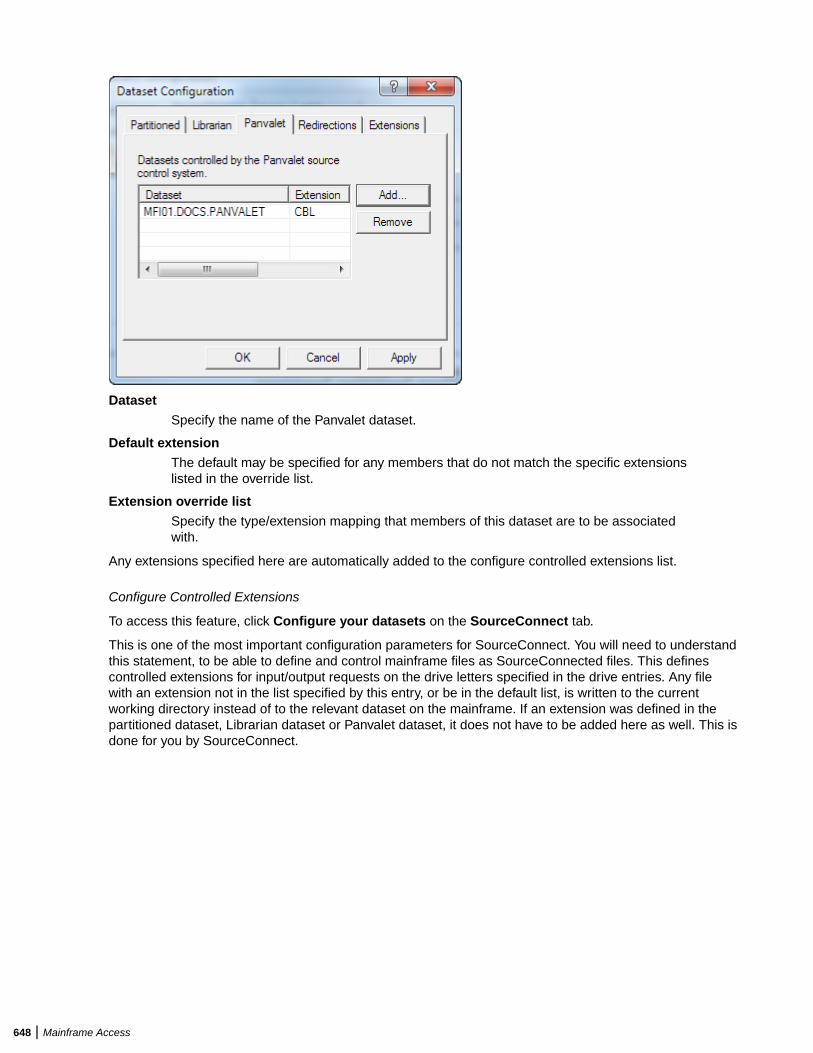
DatasetSpecify the name of the Panvalet dataset.
Default extensionThe default may be specified for any members that do not match the specific extensionslisted in the override list.
Extension override listSpecify the type/extension mapping that members of this dataset are to be associatedwith.
Any extensions specified here are automatically added to the configure controlled extensions list.
Configure Controlled Extensions
To access this feature, click Configure your datasets on the SourceConnect tab.
This is one of the most important configuration parameters for SourceConnect. You will need to understandthis statement, to be able to define and control mainframe files as SourceConnected files. This definescontrolled extensions for input/output requests on the drive letters specified in the drive entries. Any filewith an extension not in the list specified by this entry, or be in the default list, is written to the currentworking directory instead of to the relevant dataset on the mainframe. If an extension was defined in thepartitioned dataset, Librarian dataset or Panvalet dataset, it does not have to be added here as well. This isdone for you by SourceConnect.
648 | Mainframe Access
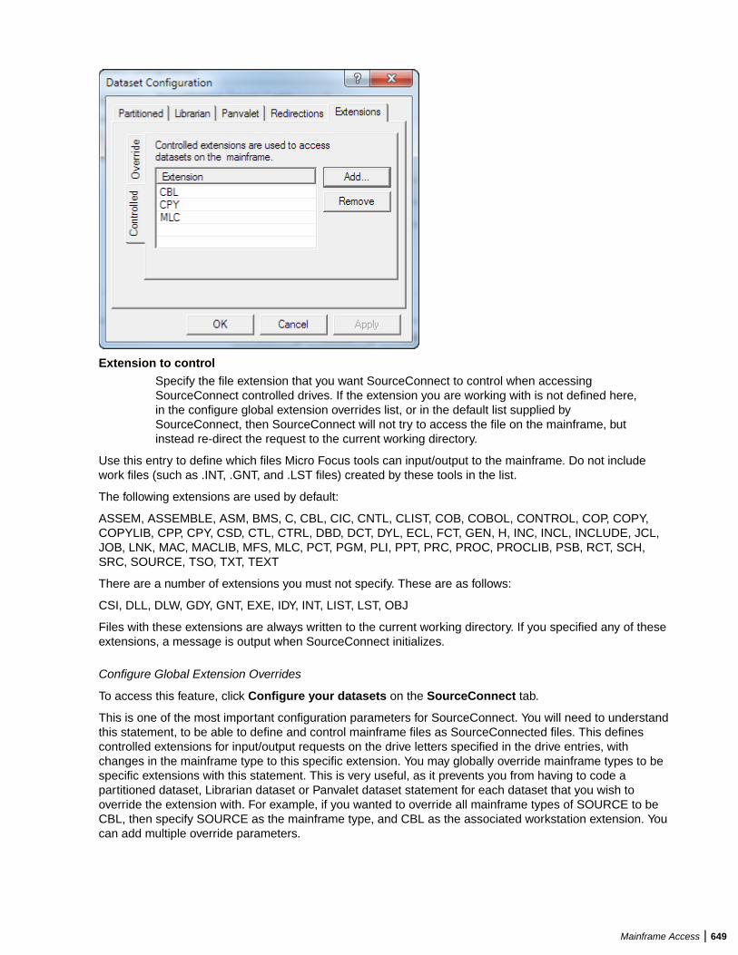
Extension to controlSpecify the file extension that you want SourceConnect to control when accessingSourceConnect controlled drives. If the extension you are working with is not defined here,in the configure global extension overrides list, or in the default list supplied bySourceConnect, then SourceConnect will not try to access the file on the mainframe, butinstead re-direct the request to the current working directory.
Use this entry to define which files Micro Focus tools can input/output to the mainframe. Do not includework files (such as .INT, .GNT, and .LST files) created by these tools in the list.
The following extensions are used by default:
ASSEM, ASSEMBLE, ASM, BMS, C, CBL, CIC, CNTL, CLIST, COB, COBOL, CONTROL, COP, COPY,COPYLIB, CPP, CPY, CSD, CTL, CTRL, DBD, DCT, DYL, ECL, FCT, GEN, H, INC, INCL, INCLUDE, JCL,JOB, LNK, MAC, MACLIB, MFS, MLC, PCT, PGM, PLI, PPT, PRC, PROC, PROCLIB, PSB, RCT, SCH,SRC, SOURCE, TSO, TXT, TEXT
There are a number of extensions you must not specify. These are as follows:
CSI, DLL, DLW, GDY, GNT, EXE, IDY, INT, LIST, LST, OBJ
Files with these extensions are always written to the current working directory. If you specified any of theseextensions, a message is output when SourceConnect initializes.
Configure Global Extension Overrides
To access this feature, click Configure your datasets on the SourceConnect tab.
This is one of the most important configuration parameters for SourceConnect. You will need to understandthis statement, to be able to define and control mainframe files as SourceConnected files. This definescontrolled extensions for input/output requests on the drive letters specified in the drive entries, withchanges in the mainframe type to this specific extension. You may globally override mainframe types to bespecific extensions with this statement. This is very useful, as it prevents you from having to code apartitioned dataset, Librarian dataset or Panvalet dataset statement for each dataset that you wish tooverride the extension with. For example, if you wanted to override all mainframe types of SOURCE to beCBL, then specify SOURCE as the mainframe type, and CBL as the associated workstation extension. Youcan add multiple override parameters.
Mainframe Access | 649
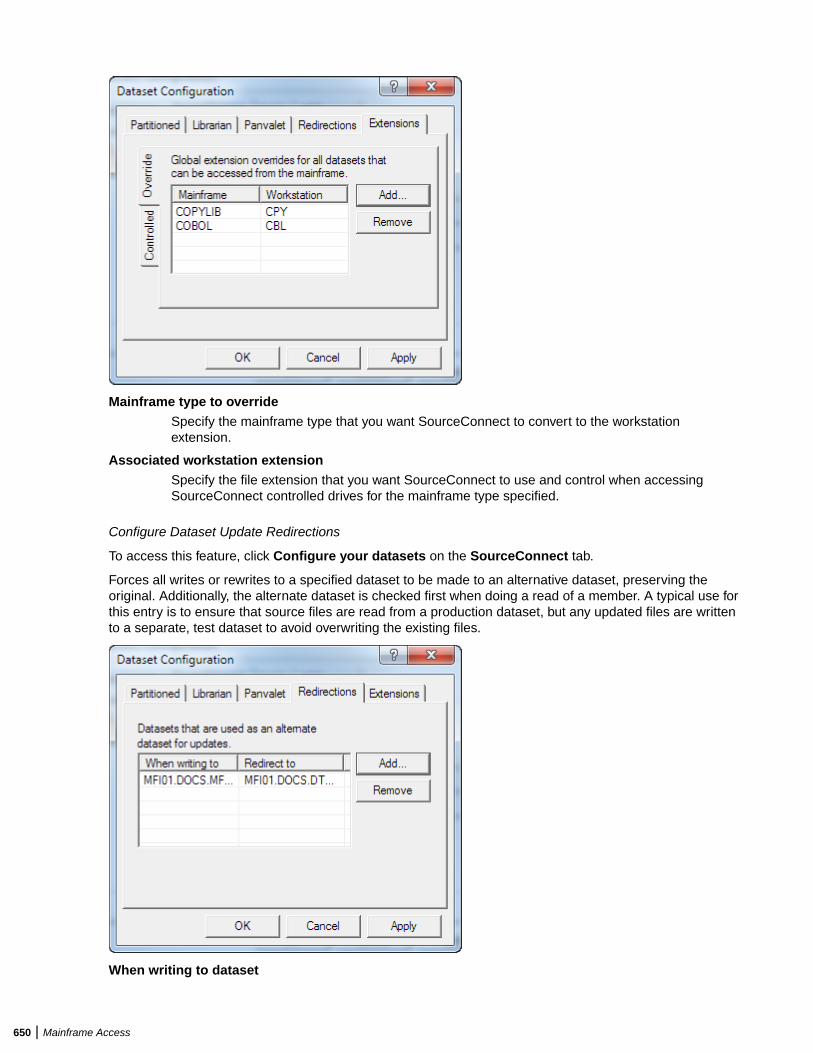
Mainframe type to overrideSpecify the mainframe type that you want SourceConnect to convert to the workstationextension.
Associated workstation extensionSpecify the file extension that you want SourceConnect to use and control when accessingSourceConnect controlled drives for the mainframe type specified.
Configure Dataset Update Redirections
To access this feature, click Configure your datasets on the SourceConnect tab.
Forces all writes or rewrites to a specified dataset to be made to an alternative dataset, preserving theoriginal. Additionally, the alternate dataset is checked first when doing a read of a member. A typical use forthis entry is to ensure that source files are read from a production dataset, but any updated files are writtento a separate, test dataset to avoid overwriting the existing files.
When writing to dataset
650 | Mainframe Access
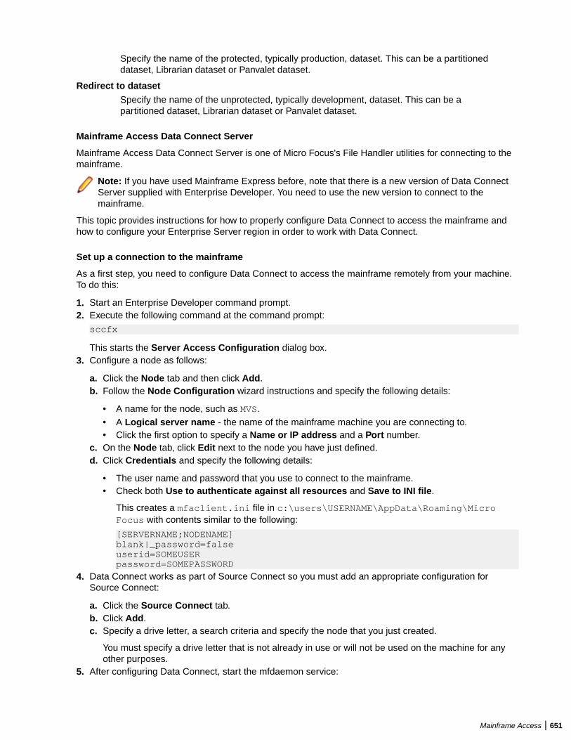
Specify the name of the protected, typically production, dataset. This can be a partitioneddataset, Librarian dataset or Panvalet dataset.
Redirect to datasetSpecify the name of the unprotected, typically development, dataset. This can be apartitioned dataset, Librarian dataset or Panvalet dataset.
Mainframe Access Data Connect Server
Mainframe Access Data Connect Server is one of Micro Focus's File Handler utilities for connecting to themainframe.
Note: If you have used Mainframe Express before, note that there is a new version of Data ConnectServer supplied with Enterprise Developer. You need to use the new version to connect to themainframe.
This topic provides instructions for how to properly configure Data Connect to access the mainframe andhow to configure your Enterprise Server region in order to work with Data Connect.
Set up a connection to the mainframe
As a first step, you need to configure Data Connect to access the mainframe remotely from your machine.To do this:
1. Start an Enterprise Developer command prompt.2. Execute the following command at the command prompt:
sccfx
This starts the Server Access Configuration dialog box.3. Configure a node as follows:
a. Click the Node tab and then click Add.b. Follow the Node Configuration wizard instructions and specify the following details:
• A name for the node, such as MVS.• A Logical server name - the name of the mainframe machine you are connecting to.• Click the first option to specify a Name or IP address and a Port number.
c. On the Node tab, click Edit next to the node you have just defined.d. Click Credentials and specify the following details:
• The user name and password that you use to connect to the mainframe.• Check both Use to authenticate against all resources and Save to INI file.
This creates a mfaclient.ini file in c:\users\USERNAME\AppData\Roaming\MicroFocus with contents similar to the following:
[SERVERNAME;NODENAME]blank|_password=falseuserid=SOMEUSERpassword=SOMEPASSWORD
4. Data Connect works as part of Source Connect so you must add an appropriate configuration forSource Connect:
a. Click the Source Connect tab.b. Click Add.c. Specify a drive letter, a search criteria and specify the node that you just created.
You must specify a drive letter that is not already in use or will not be used on the machine for anyother purposes.
5. After configuring Data Connect, start the mfdaemon service:
Mainframe Access | 651
a. Click the MFDaemon tab.b. Click Start Daemon.
This starts the daemon. Check the details on the MFDaemon tab to ensure that it shows theresources associated with the saved logon credentials. This must match the information that isspecified on the Node tab. Ensure that the resources in this list exist.
Note: MFDaemon and MFDS on the machine must run with the same user credentials. Thismust not be the SYSTEM user.
c. Start the enterprise server instance using the cas command.d. Also start the MFDAEMON from the command prompt.
Configure the region
Finally, you need to enable your Enterprise Server region to work with Data Connect. In order to do this,you need to exclusively specify the following environment variables in the server's ConfigurationInformation section:
• MFASERV=ON• MF_RCCF=KEEPJOB• HOST_DISP=ON• HOST_NEW=ON
See Mainframe Access Environment Variables and JCL-specific Environment Variables for moreinformation on these variables.
652 | Mainframe Access


