Embed Size (px)
Citation preview

Energy Conversion and Management 86 (2014) 1078–1090
Contents lists available at ScienceDirect
Energy Conversion and Management
journal homepage: www.elsevier .com/locate /enconman
Feasibility analysis of a small-scale ORC energy recovery systemfor vehicular application
http://dx.doi.org/10.1016/j.enconman.2014.06.0240196-8904/� 2014 Elsevier Ltd. All rights reserved.
⇑ Corresponding author. Tel.: +39 0644585272; fax: +39 0644585850.E-mail address: [email protected] (C. Toro).
Roberto Capata, Claudia Toro ⇑Department of Mechanical and Aerospace Engineering, University of Roma ‘‘Sapienza’’, Italy
a r t i c l e i n f o
Article history:Received 9 December 2013Accepted 10 June 2014
Keywords:ORC energy recovery systemR245faComponents designSystem simulation
a b s t r a c t
This paper analyses the feasibility of an ‘‘on-board’’ innovative and patented ORC recovery system. Thevehicle thermal source can be either a typical diesel engine (1400 cc) or a small gas turbine set(15–30 kW). The sensible heat recovered from the exhaust gases feeds the energy recovery system thatcan produce sufficient extra power to sustain the conditioning system and other auxiliaries. The conceptis suitable for all types of thermally propelled vehicles, but it is studied here for automotive applications.The characteristics of the organic cycle-based recovery system are discussed, and a preliminary design ofthe main components, such as the heat recovery exchanger, the evaporator and the pre-heater ispresented. The main challenge are the imposed size and weight limitations that require a particulardesign for this compact recovery system. A possible system layout is analyzed and the requirementsfor a prototypal application are investigated.
� 2014 Elsevier Ltd. All rights reserved.
1. The ‘‘on board’’ ORC recovery energy system longer thermodynamically efficient, certain organic fluids, can be
1.1. ORC system overview
The Organic Rankine Cycle (ORC) is similar to a conventionalsteam power plant, with the exception of the working fluid, whichin this case is constituted by an organic fluid with suitablechemical–physical proprieties potentially feasible in recoveringlow temperature heat sources (800–350 K).
An ORC is a closed cycle plant, constituted by a pump, two heatexchangers and an expander: the working fluid, at liquid state andhigh pressure, is first vaporized in the evaporator, where it absorbsthe sensible heat of the exhaust gases. The vapor expands in theturbine and, then, condenses in another heat exchanger (whichincidentally may also represent a possible thermal user, forinstance for vehicle heating). Finally the liquid is pumped back tothe evaporator, closing the cycle. Depending on the systems possi-bilities, additional intermediate heat recoveries can be considered.
The efficiency of an ORC is typically between 10% and 20%,depending on temperature levels and availability of a suitablymatched fluid. ORC is an attractive option for heat recovery inthe range of 150–200 �C, particularly if no other use for the wasteheat is available on site. The greater the difference between sourceand sink temperatures, the higher the cycle efficiency. Whensource temperatures drop low enough that a steam cycle is no
conveniently used.As analyzed by Ref. [1] several studies and applications of
recovery waste heat Organic Rankine Cycle (ORC) systems can befound in literature. There is a wide range of heat sources whichcan be applied to the ORC systems such as waste heat from thecondenser of a conventional or a nuclear power plant [2], wasteheat from industrial processes [3,4], solar radiation [5], and geo-thermal energy [6]. In Ref. [7] the potential improvement of theoverall efficiency of a heavy-duty truck diesel engine equippedwith an ORC bottoming cycle is investigated.
In this work a small-scale ORC energy recovery system (patentID RM2011 A 000671) fed by the exhaust gases of a diesel engine orGT device has been considered and analyzed. Once the heat sourceavailable is defined, a thermodynamic simulation of the system hasbeen carried out and a preliminary design of one of the mostimportant component, the heat recovery steam generator (HRSG)has been performed and presented by providing design steps andequations. Aim of the study is to verify the feasibility of the system.Different cases have been analyzed, varying the thermal source andthe operating fluid. Once the maximum size of components isknown, a 3D sketch, to see the possible location inside the vehicle,has been realized in order to build, at a later stage, a bench test tovalidate the preliminary calculations and the accuracy of ourchoices.
The considered ORC operates as a ‘‘bottoming energy recoverysystem’’, part of this ‘‘waste heat’’ energy amount is directly con-verted in mechanical work through the turbine, and supplied, by

Nomenclature
b space between two baffles (m)BP boiling pointc space between baffles and shell (m)cc cubic centimeterD, d diameter (m)e tube thicknessEV evaporatorF Fouling factorh enthalpy (kJ/kg), Section 3h convective heat coefficient, section 5HRSG heat recovery steam generatorICE internal combustion engineL characteristic length (m)LMTD Logarithmic Mean Temperature Differencem mass flow rate (kg/s)N number of tube, baffles
Nu Nusselt numberORC Organic Rankine Cyclep pitch (m), Section 5p pressure (Pa)P power (W)q qualityR thermal resistanceRe Reynolds numberS surface (m2)SH superheaterT temperature (K)U conductivity coefficientv velocity (m/s)
Greek letterk thermal conductivity
R. Capata, C. Toro / Energy Conversion and Management 86 (2014) 1078–1090 1079
an electric generator/inverter, to an auxiliary battery package. Theremaining amount of energy at low temperature at the condenser,can be used, if necessary, for heating the vehicle interior. The work-ing fluid for the ORC cycle is an organic compound (or a mixture)characterized by high molecular weight: this reduces the expanderrpms and allows for a direct connection to the electric generator.Another peculiar characteristic of the working fluid is that it be a‘‘dry fluid’’, with a positive slope in the curve of saturated steam.This causes the steam to be in the superheated region at the endof the expansion, with the absence of condensing bubbles in theexpander and consequent reduction of erosion damage of the partsin contact with the fluid. Since the main design specification is thethermal source temperature, the choice of the working fluid and ofthe appropriate engine layout is strictly depending on this value,that also affects system efficiency.
Fig. 1. The Lethe� configuration.
1.2. A possible ‘‘on board’’ application: the LETHE� vehicle
The series hybrid configuration developed by this researchgroup [8], nicknamed LETHE� (Low Emission Turbo-HybridEngine), is a vehicle in which one small turbo gas set, fuelled bynatural gas, is coupled to a high-speed electrical generator and abattery package: the vehicle can operate in electric-only mode ifrequested, or in hybrid mode, where the gas turbine and thebattery package operate together to satisfy the power demand. Inaddition, the electric motor can also act as a brake, recovering asubstantial portion of the energy that is otherwise lost (the KERSKinetic Energy Recovery System concept). In order to maximizethe recovered energy and to avoid possible battery overloading,an additional dynamic storage unit has been included: a smallflywheel capable of storing the excess power from the regenerativebraking and of releasing it at a later time as dictated by the instan-taneous power demand. A scheme of the LETHE� configuration isshown in Fig. 1.
The main characteristic of the proposed onboard ‘‘mini’’ ORCsystem is its low power output. The plant has the followingcharacteristics:
(a) The heat source consists of the exhaust gases and possibly ofthe oil and water from lubricating and cooling system.
(b) The high exhausts temperature can be coupled with a rela-tively high condenser temperature, so that the condensercooling medium can also feed an auxiliary vehicle condition-ing system.
Considering as an example a commercial sedan of about110 kW (1400 cc), and comparing the data supplied by severalautomotive manufacturers, it can be estimated that approximately5 kW are needed for the interior space conditioning. In traditionalcars such consumption decreases, obviously, the performance ofthe propulsive system. In our case this consumption could be cov-ered by the ORC system for about the 50%. For a Diesel ICE of110 kW with an efficiency of approximately 40%, the temperatureof the exhaust gas is approximately Texau = 845 K (experimentalresults in our laboratory). The mass flow rate is approximatelymout = 0.15 kg/s. With these data it can be calculated that, betweenthe muffler (that in our case would become the boiler of the ORCsystem) and the radiator (the preheater) approximately 53 kWare available. For a gas turbine, that has a lower thermal efficiencyand a higher gas exhaust temperature, the amount of recoveredenergy is even higher. The surplus of electric power potentiallyproducible by the ORC can be used in two ways:
(a) Directly: by means of a VMU, it supplies energy to the con-ditioning system of the vehicle.
(b) Indirectly: by means of the VMU, it recharges a battery pack-age that allows an ‘‘on demand’’ energetic surplus utiliza-tion, like a ‘‘excess power reserve’’ that can be drawn offonly when it is expressly demanded by the driver.

1080 R. Capata, C. Toro / Energy Conversion and Management 86 (2014) 1078–1090
For the LETHE� vehicle the gas has a temperature of approxi-mately 853 K (for an expansion ratio b = 4 and a regenerated Bray-ton cycle [9]). At this temperature, with an exhaust gases massflow rate of mgas = 0.31 kg/s are still available about 60 kWt. Thecalculation of the ORC performance for different operative condi-tions and working fluids is presented in the following sections.
1.2.1. Simulation of the vehicle and validation of resultsIn previous papers [10,11] numerical tests have been carried
out to compute the vehicle performance, in two different drivingmissions: a combination of 10 consecutive urban cycles ECE151
and a ‘‘complex driving mission’’ composed of 4 consecutive extra-urban cycles EUDC1 and 72 min of continuous highway drive at120 km/h. A brief summary of the results is here reported.
Eight different computer simulations have been performed (2types of mission respectively simulated under 2 different controllogic protocols [9], each with 2 different Battery Recharge LimitsBRL). Notice that the BRL does not exceed 2C here: possible highervalues can be obtained only at the expenses of the battery packageMTBF.
Our objective was to find the optimal configuration comparingall configurations that ensure the instantaneous coverage of thetotal demand power of the vehicle at all times t, selected on thebasis of an heuristic balance between the respective advantagesand drawbacks, ‘‘measured’’ on the basis of the following parame-ters [9]:
� Total gross weight of the battery package.� SOC trend during the mission.� Number of GT ignitions during the mission.� Instantaneous coverage of the total demand power of the
vehicle.� Size of the relevant devices (GT, battery package, flywheel).
Yet another simulation was currently run, using Advisor�
software has been performed, to compare and improve wheneverpossible the VMU logic. The definition of the vehicle characteristicshas been the first step in this last simulation.
As in the previous case the cycles considered are listed below:
� EUDC� ECE� ECE + EUDC� URBTA (urban and extra-urban bypass)� City route (London, Nurnberg, New York)
The first three cases are the standard cycles for prototypehomologation, while the remaining cycles, even if non-standard,are very helpful to calibrate the simulation code and to obtainmore meaningful and realistic comparisons. All these simulationconfirm the innovative proposal of using a GT device as‘‘Range extender’’ and the feasibility of the LETHE hybrid vehicle.Figs. 2–5 show the results previously described [9,11].
3. Thermodynamic analysis of the ORC
3.1. Process simulation with CAMEL-Pro™
Steady state simulations of the plant have been performed withthe CAMEL-Pro™ process simulator to identify the most suitableworking fluid and analyze the ORC plant performance.
1 EEC Directive 90/C81/01: this is a series of regulations that prescribe both theemissions limits (adjusted every year) and the methods for testing and qualifyingpassenger and commercial vehicles. The test driving are in one urban cycle (EuropeanCycle Emission) and an extra urban driving mission (Extra Urban Driving Cycle).
The CAMEL-Pro™ (CAlculation by Modular ELements) softwarehas been developed at the Department of Mechanical and AerospaceEngineering of the University of Roma ‘‘Sapienza’’ [12,13], is writtenin C++ and C#, is based on a completely and genuine object-oriented approach, and is equipped with a user-friendly graphicalinterface that allows for the simulation and analysis of severalenergy conversion processes. In CAMEL a system/plant is repre-sented as a network of components connected by material andenergy streams; each component being characterized by a set ofequations describing the thermodynamic changes imposed on thestreams; in mathematical terms, this equation system is not closed,and, therefore, needs of a proper number of boundary conditions interms of known flow parameters. In practical terms, this means thatthe computed solution depends on both the plant configuration andon the assigned boundary conditions. An optimized iterativeNewton–Raphson algorithm is used to solve the global equationsystem. The main feature of CAMEL is its modularity that enablesusers to expand the code by adding new components or by modify-ing the model of the existing ones: we exploited these capabilitiesto introduce the proper process equations for the ORC plant compo-nents. In particular the original models of the pump, heat exchang-ers and turbine have been modified to account for the new workingfluids. The analysis of a plant in CAMEL-Pro is based on energy andmass balance criteria and takes into account specific features thatcharacterize the thermodynamic phenomenology of each compo-nent as well as the thermodynamic properties of each stream. Aproper thermodynamic library [14] is integrated within the code.As mentioned a critical issue for an ORC plant is the choice of theworking fluid which is directly related to the performance of theplant. A market inquiry would easily show that there are more than30 fluids that can be used for ORC plants within the temperatureranges considered here; for this study we selected R245fa for itsavailability, cost and thermal properties. Refrigerant R245fa ismainly used in centrifugal chillers and its high heat transfercoefficient and high critical temperature (427 K) make it suitablefor ORC cycles [8]. Physical characteristic and the main environ-mental factors for this refrigerant can be found in Ref. [15]. In oursimulation different feasible heat sources have been considered toanalyze the performance of the plant by varying the temperatureand the mass flow rate of the thermal source. To put the resultsin a more practical perspective, a comparison is made with anORC mounted on a standard diesel engine: while it is clear that suchan engine cannot be compared to the GT-hybrid object of our study,the comparison is interesting because it shows that the ORC haspotential even outside of our specific turbo-hybrid configuration.
3.2. ORC power plant simulations
3.2.1. Preliminary considerations about organic fluidsBy contrast with ‘‘wet’’ fluids such as water, ‘‘dry’’ fluids like
R245fa [15] have a saturated vapor curve with a positive slope ina (T, s) diagram. At the outlet of the expander/turbine the vaporis still in the dry (superheated) region, and while this is favorablefor the expander, which is not affected by erosion due to liquiddroplets, it imposes a penalty on the useful specific work thatcan be extracted from the expanding fluid. The implementing ofOrganic Rankine Cycles aims to recover the heat from low temper-atures sources within 333–573 K. By comparing the characteristicsof the organic fluid used here (R245fa) with those of water (seeTable 1), the possible advantages and drawbacks of the formerscan be easily highlighted.
(a) Since the molar mass of R245fa is higher than that of water,the same specific work can be extracted (under similar DT)by a smaller flow rate, and this leads in a smaller turbine/expander diameter.

Fig. 2. ECE Simulated driving cycle.
Fig. 3. EUDC Simulated driving cycle.
R. Capata, C. Toro / Energy Conversion and Management 86 (2014) 1078–1090 1081
(b) However, the specific vaporization enthalpy of R245fa isalmost ten times lower than that of water, and this implieshigher mass flow rates eliminating the advantage broughtabout by the higher molar mass.
(c) As a consequence, bigger circulating pumps are necessaryfor the ORC.
(d) The critical pressure of R245fa is much lower than that ofwater, and so the circuitry can be designed for lower pres-sures. For R245fa, the boiling point at ambient pressure isalso very low, so that it can be used for low evaporationtemperatures, and that is the crucial point for low-T heatrecovery.
(e) One other very interesting feature of a ‘‘dry’’ fluid is that,contrary to water, no over-heat of the vapor above the
saturation temperature is necessary in the cycle, at leasttheoretically. While it is good practice to adopt a substantialamount of superheat, this can be used as an additionaldesign variable to optimize the heat capture at high T.
3.3. Simulations
This simulation is aimed at a detailed study of the sensitivity ofthe cycle to variations in different process parameters: a sensitivityanalysis provides very useful insight before performing an optimi-zation work.
In our simulation different heat source have been considered, toanalyze the performance of the plant by varying the temperatureand the mass flow rate of the thermal source:

Fig. 4. ECE + EUDC Simulated driving cycle.
Fig. 5. URBTA Simulated driving cycle.
Table 1Thermo-physical properties of water and R245fa.
Fluid Formula MW (kg/mol) Tcrit (K) pcrit (Pa) BP (K)
Water H2O 0.018 646 220 � 105 373R245fa C3H3F5 0.134 427 36 � 105 288
1082 R. Capata, C. Toro / Energy Conversion and Management 86 (2014) 1078–1090
� Exhaust gases from a commercial GT (JetCat P200-SX Microtur-bine [16]): Tgas = 853 K and mgas = 0.31 kg/s, gel = 25%.� Diesel engine (commercial sedan of about 110 kW) exhaust
gases: Tgas = 845 K and mgas = 0.15 kg/s.
We will describe the following simulations:
� Operating fluids:1. Steam.2. R245fa organic fluid.� Cases:
A. steam bottomingplant:
Pnet = 1.5 kW, thermalsource:
DieselICE;
B. steam bottomingplant:
Pnet = 2.5 kW, thermalsource:
DieselICE;
C. ORC plant, R245fa:
Pnet = 1.5 kW, thermalsource:DieselICE;
D. ORC plant, R245fa:
Pnet = 2.5 kW, thermalsource:DieselICE;
E. steam bottomingplant:
Pnet = 1.5 kW, thermalsource:
GT set;
F. steam bottomingplant:
Pnet = 2.5 kW, thermalsource:
GT set;
G. ORC plant, R245fa:
Pnet = 1.5 kW, thermalsource:GT set;
H. ORC plant, R245fa:
Pnet = 2.5 kW, thermalsource:GT set.

Table 2bExpander data for green turbine and infinity turbine respectively.
Inlet pressure (Pa) 5.2 � 105 Inlet pressure (Pa) >2 � 105
Inlet temperature (K) 453–473 Inlet temperature (K) 353–403Working fluid Water Working fluid R134, R245Outlet pressure (Pa) 10 � 103 Outlet pressure (Pa) 170Outlet temperature (K) 313 Outlet temperature (K) 332Mass flow rate (kg/s) 0.008 Mass flow rate (kg/s) 0.08–0.13Expander efficiency (%) 0.85 Expander efficiency (%) 0.85
R. Capata, C. Toro / Energy Conversion and Management 86 (2014) 1078–1090 1083
The size of the ORC plant (1–3 kW) is imposed by size and weightlimitations for this compact recovery system and by commercialavailability of the expanders.
3.3.1. Data and constraintsThe first design task addressed in this study is that of recovering
thermal energy from a typical diesel engine (1400 cc) to produceelectricity. The engine specifications are known and all exhaustgas data are available: mass flow rate (kg/s), temperature (K),pressure bar (Pa) and composition. A first design solution is thatof adding a bottoming steam Rankine cycle fed by the hot exhaustgas and producing some electrical power: the technical feasibilityof this solution is examined first, Cases 1-A and 1-B. A seconddesign task is that of considering as the thermal source a smallGT set (15 kW) for which all specifications are known: thetechnical feasibility of this solution is examined as well, Cases1-E and 1-F. To increase the combined cycle electrical output(and therefore the process efficiency), a second working mediumhas been considered: therefore, in Cases 2-C and 2-D, the simula-tions have been repeated using R245fa as the working fluid: thesecases are labeled ‘‘ORC’’, from Organic Rankine Cycle. The sameprocedure has been then repeated for the GT-based combinedcycle, with Cases 2-G and 2-H as the corresponding options. Anadditional constraint, applying to either configuration, concernsthe size of the bench, whose dimensions must not exceed the avail-able volume in the plant (in stationary application) or on a vehicle.
Thermal sources (ICE and GT exhausts) main data are reportedin Table 2a.
At the onset of the design procedure, for Cases 1A and 1B, weconsidered adopting the thermodynamic cycle parameters (maxT, max p) so as to maximize efficiency. It soon became clear that,since the construction of a reliable and performing steam turbinefor such a small capacity is a task for which our group does notpossess the necessary resources, the use a commercially availableturbine/expander was inevitable. Consequently, the ‘‘optimization’’presented here is performed under a hidden additional set of con-straints, namely the manufacturer’s design specifications providedfor the expander. For Cases 1A and 1B, we selected a mini steamexpander marketed by Green Turbine� [17]. The same procedurehas been implemented for Cases 1C and 1D (using R245fa as theworking fluid): in this case, the turbine of choice was the Infinity�
[18]. Expanders main data are reported in Table 2b.
3.3.2. Plant layout3.3.2.1. Thermal source: Diesel ICE (Cases A–D). The operative condi-tions for each simulated cases are reported in Table 3. The layout ofthe ORC in CAMEL-Pro™ is reported in Fig. 6. The inputs to the sys-tem are exhaust hot gases (Stream #1 in Fig. 6) and cold water(Stream #11). The main outputs are electric power (Stream # 14)and hot water (Stream #12).
3.3.2.2. Thermal source: GT set (Cases E–H). The layout used for thesimulation is similar in principle to the one adopted for the ICE,and is shown in Fig. 7.
The main results of ORC simulations for the two working fluidsand different exhaust gas temperature and mass flow rates are pre-sented in Table 3.
The bottoming steam Rankine cycle reaches an efficiency ofabout 6.8%, while the ORC of about 7.9%.
Table 2aThermal sources main data.
Diesel Gas turbine
Mass flow rate (kg/s) 0.15 0.31Exhausts temperature (K) 845 853Pressure (Pa) 101.3 101.3
4. Cases 1-A and 1-B (ICE bottoming steam Rankine cycles):preliminary design of heat exchangers
4.1. Preliminary design of the HRSG
To improve the efficiency and the reliability of the HRSG, it wasdecided to split it into two distinct heat exchangers, a boiler inwhich the working fluid evaporates, and a superheater in whichthe hot gases heat the saturated steam to bring it to superheatedconditions at the prescribed pressure. For the sizing of these heatexchangers, which together constitute the HRSG, in this first stagewe shall neglect both the pressure drops in pipes and componentsand the thermal losses towards the external environment [19–21]that will be included in the prototypal phase. The values of the glo-bal heat exchange coefficients were derived from well-establishedliterature data [20].
The HRSG is divided into two separate heat exchangers:
– The evaporator where a total vaporization of the water isachieved.
– The super-heater which raises the steam to its finaltemperature.
To optimize the heat exchange throughout the HRSG, a counter-flow global configuration has been adopted. The assigned bound-ary conditions at the inlet section of expander are:
Psteam ¼ 520 kPa
T inlet;ex ¼ 473 K
The steam conditions at the output section of the HRSG areimposed by the maximum allowable turbine inlet temperaturedeclared by the manufacturer.
The evaporation temperature and the latent heat of vaporiza-tion of the water at a pressure of 520 kPa are also derived, whilethe input temperature and pressure of the gas are a design specifi-cation and are shown in Table 4.
Notice again that in the design of all components both thepressure drop during the heat exchange and the external thermalloss have been neglected [20].
4.2. Superheater (SH) design
For this component the input parameters for the water and thegas are known (Table 4).
The exchanger is considered adiabatic and leakage-free, and itsenergy conservation equation is:
Mgascp;gasðTgas;in � Tgas;outÞ ¼ msteamcpðTsh � TvapÞ ð1Þ
According to the adiabaticity hypothesis, the heat flux is givenby:
U ¼ F U S LMTD ð2Þ
where LMTD is the Logarithmic Mean Temperature Difference and Fis a correction factor calculated from the F/LMTD nomograms [20].Eq. (2) is then solved to obtain the required heat exchange surface S.

Table 3CAMEL-Pro™ simulations main results: steam Rankine bottoming cycle, Pnet = 1.5 kW (Case 1-A) and 2.5 kW (Case 1-B), T0 = 298.15; p0 = 101.3 kPa; (standard air condition andcomposition: CO2,0 = 0.0005; CO0 = ; O2,0 = 0.23; N2,0 = 0.76; H2O = 0.012) and ORC with R245fa fluid and Pnet = 1.5 kW (Case 2-C) and 2.5 kW (Case 2-D) and ORC with steam fluidand Pnet = 1.5 kW (Case 1-E) and 2.5 kW (Case 1-F) and ORC with R245fa fluid and Pnet = 1.5 kW (Case 2-G) and 2.5 kW (Case 2-H).
Case 1-A 1-B 2-C 2-D 1-E 1-F 2-G 2-H
mgas,in (kg/s) 0.15 0.15 0.15 0.15 0.31 0.31 0.31 0.31pgas,in (kPa) 101 101 101 101 101 101 101 101Tgas,in (K) 845 845 845 845 853 853 853 853Tgas,out (K) 718 652 732 656 790 759 799 762pgas,outlet (kPa) 99.2 99.2 99.2 99.2 99.2 99.2 99.2 99.2mwater/R245fa (kg/s) 0.008 0.012 0.075 0.12 0.008 0.012 0.075 0.12Twater/R245fa at boiler inlet (K) 308 308 301 301 308 308 301 301Twater/R245fa at boiler outlet (K) 473 473 363 363 473 473 363 363Twater/R245fa at condenser inlet (K) 318 318 332 332 318 318 332 332Twater/R245fa at condenser outlet (K) 308 308 301 301 308 308 301 301pwater/R245fa at boiler inlet (kPa) 520 520 900 900 520 520 900 900pwater/R245fa at boiler outlet (kPa) 509 509 900 900 509 509 900 900pwater/R245fa at condenser inlet (kPa) 10 10 170 170 10 10 170 170pwater/R245fa at condenser outlet (kPa) 9.9 9.9 170 170 9.9 9.9 170 170Q rejected at condenser (kW) 0.142 0.212 17.28 17.28 142 212 17.28 17.28Power output (kW) 1.455 2.425 1.455 2.425 1.455 2.425 1.455 2.425Pump Power (kW) 0.0045 0.007 0.045 0.075 0.0045 0.007 0.045 0.075ORC efficiency (%) 6.8 6.8 7.9 7.9 6.8 6.8 7.9 7.9
Fig. 6. Plant layout with H2O/steam as working fluid.
1084 R. Capata, C. Toro / Energy Conversion and Management 86 (2014) 1078–1090
The global heat transfer coefficient U is the reciprocal of the thermalresistance RTH calculated as:
RTH ¼ 1=hw þ 1=hgas þ etube=ktube ð3Þ
With: h = convective heat coefficient (h = ki Nui/Li, where Nu is theNusselt2 number, k is the thermal conductivity, L a characteristiclength and e is tube thickness).
The chosen exchanger configuration has staggered rows ofwater tubes running through a shell in a quasi-counter flow with
2 Nusselt number [1,2,7]:for water: Nu ¼ðð0:79 ln Re�1:64Þ�2 Þ
8 �ðRe�1000Þ�Pr
1þ1:27 ðð0:79 ln Re�1:64Þ�2 Þ8
� �0:5�ðPr2=3�1Þ
for gas: one
tube: Nu = 0.174 Re0.618beam of tubes: Nu = 0.33 Re0.6Pr0.33.
the gas stream. Whereas the steam velocity is simple to calculate,it is far more difficult to estimate that of the gas. The assumptionmade here is that the gas velocity is approximately determinedby calculating a conventional flow area in the horizontal symmetryplane of the shell between two baffles.
In Fig. 8a section of the exchanger between two baffles isreported (in the case of Ntube,row = 3). The flow area is:
Spassage ¼ ðb� ebaffleÞ½D� Ntube;rowðdþ 2eÞ� ð4Þ
So the gas velocity is given by:
Vgas ¼ Q gas=Spassage ð5Þ

Fig. 7. Plant layout with R245fa as working fluid.
Table 4Water physical parameters in the HRSG, evaporation temperature and heat of evaporation of the water at 520 kPa and gas inlet main data (Cases 1-A and 1-B).
Water Inlet Exit Evaporation conditions at 520 kPa Gas inlet parameters
m (kg/s) 0.008 0.008 Tevap (K) 426 m (kg/s) 0.15P (kPa) 520 520 hsat_liq (kJ/kg) 541 p (bar) 2T (K) 308 473 hsat_steam (kJ/kg) 2644 T (K) 845h (kJ/kg) 44.84 2749 Dhvap (kJ/kg) 2103
R. Capata, C. Toro / Energy Conversion and Management 86 (2014) 1078–1090 1085
The thickness of the shell and of the baffles is set to 0.005 m.The triangular pitch ‘‘p’’ (Fig. 8) must be higher than 1.25 timesthe external diameter of the tubes [20] and here we set it equalto 1.5 dexternal. The final assembly of the heat exchanger is reportedin Fig. 9.
The unknowns in the design procedure are:
� The number of tubes: Ntube.� The number of tubes on the central row: Ntube,raw.� The internal diameter of the tubes: d.� The internal diameter of the shell: D.� The number of baffles: Nbaffle.� The space between two baffles: b.
To perform a preliminary design of the heat exchangers, acareful analysis of existing models and the indication available[20–22] in the technical literature leads to the following andequations:
� Shell diameter:
Dmin ¼ ðNtube;row þ 1Þp� ðdþ 2etubeÞ ð6Þ
� Heat exchange surface:S ¼ NtubeðpdÞL ð7Þ
� Spacing between two baffles and between the shell extremitiesand the first and the last baffles:
c ¼ ðLþ ebaffleÞ=ðNbaffle þ 1Þ ð8Þ
Constraints:
� The Gnielinski correlation: Rewater > 3000� Vwater < 20 m/s
� Vgas > 30 m/s� D0,min = 0.005 m
In the choice of the number of the baffles the gas average veloc-ity is assumed to be perpendicular to the tubes.
4.2.1. ResultsThe above described design procedure produced the results
shown in Table 5.The proposed SH configuration is shown in Fig. 8. In this case,
we see how the configuration used is quite compact and of reduceddimensions. The 4 tubes allow the fluid to operate the last transfor-mation, from steam to superheated steam. It can be notice how thenumber of baffles is the minimum to ensure that hot gas directionis always perpendicular to the direction of organic fluid.
4.3. Evaporator (EV) design
The design of the evaporator was carried out according to thesame procedure previously described for the superheater, withthe additional complication of the phase change. The evaporatorboundary conditions are:
Tgas;in;ev ¼ Tgas;outðSHÞ ð9Þ
Thus the only unknown is the gas outlet temperature Tgas,out,ev,which can be calculated from the energy conservation equation ofthe evaporator:
mgascp;gasðTgas;out;ev � Tgas;in;evÞ ¼ ml�wDhvapTvap ð10Þ
Notice that the vaporization process, water side, requires anhigher amount of heat than the super-heating. The assigned gasstream parameters suggest the design of the exchanger with a
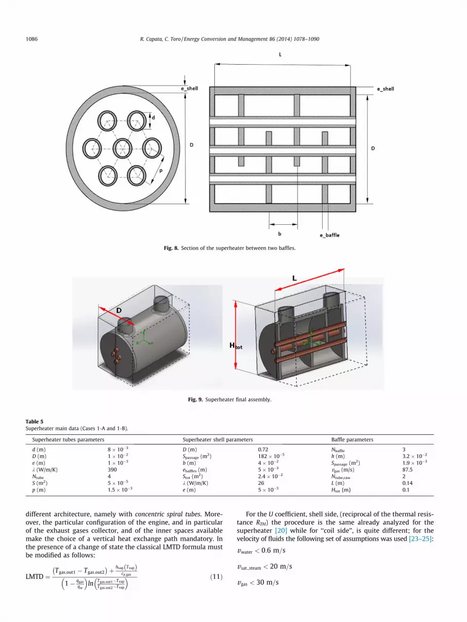
Fig. 8. Section of the superheater between two baffles.
Fig. 9. Superheater final assembly.
Table 5Superheater main data (Cases 1-A and 1-B).
Superheater tubes parameters Superheater shell parameters Baffle parameters
d (m) 8 � 10�3 D (m) 0.72 Nbaffle 3D (m) 1 � 10�2 Spassage (m2) 182 � 10�5 h (m) 3.2 � 10�2
e (m) 1 � 10�3 b (m) 4 � 10�2 Spassage (m2) 1.9 � 10�3
k (W/m/K) 390 ebaffles (m) 5 � 10�3 vgas (m/s) 87.5Ntube 4 Stot (m2) 2.4 � 10�2 Ntube,raw 2S (m2) 5 � 10�5 k (W/m/K) 26 L (m) 0.14p (m) 1.5 � 10�3 e (m) 5 � 10�3 Htot {m} 0.1
1086 R. Capata, C. Toro / Energy Conversion and Management 86 (2014) 1078–1090
different architecture, namely with concentric spiral tubes. More-over, the particular configuration of the engine, and in particularof the exhaust gases collector, and of the inner spaces availablemake the choice of a vertical heat exchange path mandatory. Inthe presence of a change of state the classical LMTD formula mustbe modified as follows:
LMTD ¼Tgas;out1 � Tgas;out2� �
þ hvap Tvapð Þcp;gas
1� qgasqw
� �ln Tgas;out1�Tvap
Tgas;out2�Tvap
� � ð11Þ
For the U coefficient, shell side, (reciprocal of the thermal resis-tance RTH) the procedure is the same already analyzed for thesuperheater [20] while for ‘‘coil side’’, is quite different; for thevelocity of fluids the following set of assumptions was used [23–25]:
vwater < 0:6 m=s
vsat steam < 20 m=s
vgas < 30 m=s
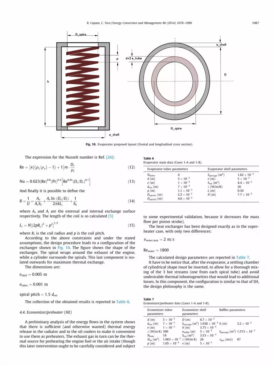
Fig. 10. Evaporator proposed layout (frontal and longitudinal cross section).
Table 6Evaporator main data (Cases 1-A and 1-B).
Evaporator tubes parameters Evaporator shell parameters
Ntubes 4 Spassage (m2) 1.62 � 10�3
d (m) 5 � 10�3 e (m) 5 � 10�3
e (m) 1 � 10�3 Stot (m2) 4.4 � 10�2
dext (m) 7 � 10�3 k (W/m/K) 26p (m) 1.1 � 10�2 L (m) 0.30Dspiral1 (m) 2.5 � 10�2 D (m) 7.7 � 10�2
Dspiral2 (m) 4.6 � 10�2
Table 7Economizer/preheater data (Cases 1-A and 1-B).
Economizer tubesparameters
Economizer shellparameters
Baffles parameters
d (m) 5 � 10�3 D (m) 6.7 � 10�2
dext (m) 7 � 10�3 Spassage (m2) 1.038 � 10�3 h (m) 3.2 � 10�2
e (m) 1 � 10�3 b (m) 3.75 � 10�2
k (W/m K) 390 ebaffle (m) 5 � 10�3 Spassage (m2) 1.573 � 10�3
Ntube 19 Stot (m2) 3.53 � 10�3
Sint (m2) 1.963 � 10�5 k (W/m K) 26 vgas (m/s) 87p (m) 1.05 � 10�2 e (m) 5 � 10�3
R. Capata, C. Toro / Energy Conversion and Management 86 (2014) 1078–1090 1087
The expression for the Nusselt number is Ref. [26]:
Re ¼ x ql=qv� �
� 1� �
þ 1� �
m � Dc
llð12Þ
Nu ¼ 0:023ðReÞ0:8ðPrÞ0:4 Re0:05ðDi=DcÞ0:1h i
ð13Þ
And finally it is possible to define the
R ¼ 1U¼ Ae
Achcþ Ae ln � De=Dið Þ
2pkLcþ 1
heð14Þ
where Ae and Ai are the external and internal exchange surfacerespectively. The length of the coil is so calculated [5]
Lc ¼ N½ð2pRcÞ2 þ p2�
1=2ð15Þ
where Rc is the coil radius and p is the coil pitch.According to the above constraints and under the stated
assumptions, the design procedure leads to a configuration of theexchanger shown in Fig. 10. The figure shows the shape of theexchanger. The spiral wraps around the exhaust of the engine,while a cylinder surrounds the spirals. This last component is iso-lated outwards for maximum thermal exchange.
The dimensions are:
eshell ¼ 0:005 m
etubes ¼ 0:001 m
spiral pitch ¼ 1:5 dext
The collection of the obtained results is reported in Table 6.
4.4. Economizer/preheater (HE)
A preliminary analysis of the energy flows in the system showsthat there is sufficient (and otherwise wasted) thermal energyrelease in the radiator and in the oil coolers to make it convenientto use them as preheaters. The exhaust gas in turn can be the ther-mal source for preheating the engine fuel or the air intake (thoughthis later intervention ought to be carefully considered and subject
to some experimental validation, because it decreases the massflow per piston stroke).
The heat exchanger has been designed exactly as in the super-heater case, with only two differences:
vwater;max ¼ 2 m=s
Rewater ¼ 1800
The calculated design parameters are reported in Table 7.It have to be notice that, after the evaporator, a settling chamber
of cylindrical shape must be inserted, to allow for a thorough mix-ing of the 3 hot streams (one from each spiral tube) and avoidundesirable thermal inhomogeneities that would lead to additionallosses. In this component, the configuration is similar to that of SH,the design philosophy is the same.

Table 8Superheater main data (Cases 1-E and 1-F).
Superheater tubesparameters
Superheater shellparameters
Baffle parameters
d (m) 8 � 10�3 D (m) 7.2 � 10�2 Nbaffles 3dext (m) 1 � 10�2 Spassage (m2) 1.82 � 10�3 h (m) 3.2 � 10�2
E (m) 1 � 10�3 B (m) 4 � 10�2 Spassage (m2) 1.865 � 10�3
k (W/m/K) 390 ebaffles (m) 5 � 10�3 vgas (m/s) 180Ntube 4 Stot (m2) 2.2 � 10�2 L (m) 9.8 � 10�2
S (m2) 5.02 � 10�5 k (W/m K) 26 D (m) 1.36 � 10�1
P (m) 1.5 � 10�2 e (m) 5 � 10�3
Table 9Evaporator main data (Cases 1-E and 1-F).
Evaporator tubes parameters Evaporator shell parameters
Ntubes 3d (m) 5 � 10�3 Spassage (m2) 1.584 � 10�3
e (m) 1 � 10�3 e (m) 5 � 10�3
dext (m) 7 � 10�3 Stot (m2) 2.86 � 10�2
p (m) 1.05 � 10�2 k (W/m/K) 26Dspiral1 (m) 2.5 � 10�2 L (m) 2.86 � 10�1
Dspiral2 (m) 4.6 � 10�2 D (m) 7.7 � 10�2
Dspiral3 (m) 6.7 � 10�2
ktube (W/m K) 390
Table 10Economizer/preheater data (Cases 1-E and 1-F).
Economizer tubesparameters
Economizer shellparameters
Baffles parameters
d (m) 5 � 10�3 D (m) 6.7 � 10�2
dext (m) 7 � 10�3 Spassage (m2) 1.04 � 10�3 h (m) 3.2 � 10�2
e (m) 1 � 10�3 b (m) 3.75 � 10�2
k (W/m K) 390 ebaffle (m) 5 � 10�3 Spassage (m2) 1.573 � 10�3
Ntube 19 Stot (m2) 3.53 � 10�3
Sint (m2) 1,96 � 10�5 k (W/m K) 26 vgas (m/s) 180p (m) 1.05 � 10�2 e (m) 5 � 10�3
Table 11Superheater main data (Cases 2-C, 2-D, 2-E and 2-H).
Superheater tubesparameters
Superheater shellparameters
Baffle parameters
d (m) 8 � 10�3 D (m) 7 � 10�2 Nbaffles 3dext (m) 1 � 10�2 Spassage (m2) 1.82 � 10�3 h (m) 3.2 � 10�2
e (m) 1 � 10�3 b (m) 0.04 Spassage (m2) 1.847 � 10�3
k (W/m/K) 390 ebaffles (m) 5 � 10�3 vgas (m/s) 86Ntube 4 Stot (m2) 5.272 � 10�1 L (m) 3.5 � 10�2
S (m2) 4.82 � 10�5 k (W/m K) 26 D (m) 1.5 � 10�1
p (m) 1.5 � 10�2 e (m) 6 � 10�3
Table 12Evaporator main data (Cases 2-C, 2-D, 2-E and 2-H).
Evaporator tubes parameters Evaporator shell parameters
Ntubes 3d (m) 6 � 10�3 Spassage (m2) 1.622 � 10�3
e (m) 1.5 � 10�3 e (m) 6 � 10�3
dext (m) 9 � 10�3 Stot (m2) 1.1 � 10�3
p (m) 1.35 � 10�2 k (W/m K) 26Dspiral1 (m) 2.6 � 10�2 L (m) 1.5 � 10�1
Dspiral2 (m) 4.6 � 10�2 D (m) 7.87 � 10�1
Dspiral3 (m) 6.6 � 10�2
ktube (W/m K) 390
Fig. 11. 3D view of the assembled plant.
1088 R. Capata, C. Toro / Energy Conversion and Management 86 (2014) 1078–1090
4.5. Condenser
Once the condensing pressure is established by the availablecooling medium (in all cases studied here, well water is considered,at a pressure of 1 bar and temperature of 293 K) the condenser willbe designed assuming the following operating conditions:
1. No incondensable gas at the outlet of the condenser.2. A complete condensation of the steam is achieved inside the
condenser.3. The saturated liquid is sub-cooled by 10 K.4. The temperature increase of the cooling water has been set
equal to 10 �C so that a downstream closed loop could be usedto ‘‘recycle’’ the water after due cooling.
5. Pressure drops in the condenser are neglected.
The design of the condenser is not yet completed and, at thisstage, only operative data are presented.
This next step of our research will also include the verificationof the possible use of the existing vehicle radiator as heat rejecter.
5. Cases 1-E and 1-F (GT bottoming steam Rankine cycles):preliminary design of heat exchangers
The components for Cases 1-E and 1-F have been designed withthe same procedure as above.
From the results (reported in Tables 8–10) it can be noticed thatthe changes in the heat exchangers dimensions are minimal(superheater shell side: D = 0.072 m instead 0.08 m; evaporatorStot = 0.03 m2 instead 0.04 m2), since the difference between theexhaust temperatures is), and despite the mass flow rate is twicethan in the previous case: thus, to simplify the subsequent exper-imental phase, it was decided to use the same heat previouslydesigned.
6. Cases 2-C, 2-D, 2-G and 2-H (ICE and GT bottoming ORC):preliminary design of heat exchangers
6.1. Preliminary design with organic fluid R245fa
The superheater and evaporator preliminary design obtainedwith the same procedure discussed above are reported in Tables11 and 12. The results obtained by the simulation, with R245fa,enlighten that the changes in the heat exchangers dimensionsare minimal (superheater shell side: D = 0.069 m instead 0.08 m;evaporator Stot = 0.0312 m2 instead 0.04 m2). Also in this case, to

Fig. 12. Sport sedan prototype and dimensions of the engine compartment.
R. Capata, C. Toro / Energy Conversion and Management 86 (2014) 1078–1090 1089
simplify the subsequent experimental phase, it was decided to usethe same heat exchangers as in the steam cases.
7. Proposed system layout
Once all components have been designed, materials and thepossible layout of the plant have been studied and evaluated. Thematerial chosen is copper for steam/water tubes and stainless steelfor exchangers case, baffles and connection. The steam/waterpiping are enclosed in an insulating stainless steel tube, to avoidundesirable thermal losses towards the external environmentand to improve the heat exchange. The final assembly is reportedin Fig. 11, that shows our proposal for the plant with the overalldimensions with a total length of 1.03 m, a width of 0.83 m anda maximum height of 0.40 m.
Once all dimensions are known, we have chosen a possibleapplication and location in a sport sedan developed atUniversity laboratory. The engine compartment dimensions are1.10 � 1.20 � 0.80 (length, width and depth in meters, Fig. 12).Remembering that the battery package is located in the forwardcompartment, eliminating the Diesel ICE, the available volume isabout 1056 dm3. The 90 kW electric engine dimensions has, now,a total available volume of about 15.36 dm3 (typical tractionengine D = 0.32 m and L = 0.60 m). That means the ORC plant canbe located in the remaining available volume.
8. Conclusions
A preliminary feasibility analysis of the ‘‘on-board’’ ORC recov-ery system for vehicular application has been performed.
The novelty of the technological solution we propose is basedon commercially available components, arranged in an innovativefashion. The fact that no ‘‘optimization’’ is performed depends onour strictly engineering-like approach: we seek a technically andeconomically feasible solution rather than a mathematical‘‘optimum’’. Considering such an approach the working fluids havebeen selected for their commercial availability and reliability froman engineering and environmental prospect.
The performance of the recovery cycle has been simulated withCAMEL-Pro™ process simulator by varying the main operativeparameters and considering two different working fluids R245faand water. Relevant heat exchange components have beendesigned, under a set of specifications derived from the previoussimulations and always keeping in mind the requirement for thehighest possible compactness of the system. Approximate charac-teristics dimensions of the heat exchangers (HRSG and condenser)have been calculated and a preliminary layout provided (also apossible ‘‘constructive’’ layout has been supplied).
The possibility of including a preheater (designed as well) in theORC circuit has been investigated, and possible engineering
solutions for the condenser, which at the moment has not beendesigned, have been presented.
Last step, in this first phase of the project, has been the assem-bling of the system ‘‘mock up’’ (a virtual mock up, since testing ofcomponents is under way, and of course, the necessary modifica-tions will be made, which could change the size of HRSG) to eval-uate the possible insertion into an engine compartment of a typicalsport sedan. For this case an electric sport sedan developed at theUniversity laboratory has been chosen. The configuration adoptedfor the ORC system results suitable with the available volume. Nextstep will be the realization of components and the assembling ofthe ORC plant into the engine compartment.
As last consideration it is useful to enlighten as, at the presentstage of the study, it is possible to predict that an ORC system usedas an on-board energy recovery system for thermally-propelledvehicles will indisputably introduce a benefit in terms of fuel con-sumption and emission reductions. This is because most, if not all,of the vehicle auxiliaries (lighting, heating, conditioning, pumpingsystems) would be powered by the energy produced by the ORCsystem, thus reducing the fuel requirements per unit time ofoperation, at any load.
The results obtained confirm the system technical feasibility,under the current technological constraints leading to the con-struction of a prototype sufficiently ‘‘mature’’ to be actuallyinstalled on real vehicles.
The system, described in this paper, could be a viable solution tomake a fully efficient vehicle. Our goal is to be able to realize andbuild the device, making it modular, to achieve a system that canbe used on any type of vehicle equipped with a heat engine (cars,boats, trains, etc.).
References
[1] Hung TC, Shai TY, Wang SK. A review of organic Rankine cycles (ORCs) for therecovery of low-grade waste heat. Energy 1997;22(7):661–7.
[2] Hung T-C. Waste heat recovery of organic Rankine cycle using dry fluids.Energy Convers Manage 2001;42(5):539–53.
[3] Desai NB, Bandyopadhyay S. Process integration of organic Rankine cycle.Energy 2009;34(10):1674–86.
[4] Hipólito-Valencia BJ, Rubio-Castro E, Ponce-Ortega JM, Serna-González M,Nápoles-Rivera F, El-Halwagi MM. Optimal integration of organic Rankinecycles with industrial processes. Energy Convers Manage 2013;73:285–302.
[5] Al-Sulaiman FA. Exergy analysis of parabolic trough solar collectors integratedwith combined steam and organic Rankine cycles. Energy Convers Manage2014;77:441–9.
[6] El-Emam RS, Dincer I. Exergy and exergoeconomic analyses and optimizationof geothermal organic Rankine cycle. Appl Therm Eng 2013;59(1–2):435–44.
[7] Katsanos CO, Hountalas DT, Pariotis EG. Thermodynamic analysis of a Rankinecycle applied on a diesel truck engine using steam and organic medium.Energy Convers Manage 2012;60:68–76.
[8] Capata R, Sciubba E, Toro C. The gas turbine hybrid vehicle Lethe� at UDR1: theon-board innovative ORC energy recovery system – feasibility analysis. In:IMECE2012-85237, Proc. ASME 2012 IMECE, November 9–15, Houston, Texas,USA, 2012.

1090 R. Capata, C. Toro / Energy Conversion and Management 86 (2014) 1078–1090
[9] Capata R, Sciubba E. The low emission turbo gas hybrid vehicle concept –preliminary simulation and vehicle packaging. J Energy Resour Technol (JERT)2013;135(3). ISSN 0195-0738; eISSN 1528–899.
[10] Capata R, Coccia A, Lora M. A proposal for the CO2 abatement in urban areas:the UDR1-Lethe� turbo hybrid vehicle. Energies, Hybrid Vehicle Spec Issue –Energies 2011;4(3):368–88. http://dx.doi.org/10.3390/en4030368.
[11] Capata R, Sciubba E. The LETHE� city car of the University of Roma 1: finalproposed configuration. J Energy (EGY). Special section: ECOS 2012. 2013; 58:178–184. http://dx.doi.org/10.1016/j.energy.2013.06.019 [ISSN 0360-5442]..
[12] CAMEL-Pro Users Manual, rev4, 2008 <www.turbomachinery.it>.[13] Falcetta M, Sciubba E. A computational modular approach to the simulation of
power plants. ASME-AES Heat Recovery Syst CHP 1995;15(2).[14] Colonna P, van der Stelt TP. FluidProp: a program for the estimation of thermo
physical properties of fluids. Energy Technol Sec, Delft Tech. U., 2004<www.FluidProp.com>.
[15] R245fa properties: <http://gobestech.com/R-245fa.html>.[16] Microturbine datasheet <www.jetcatusa.com/p200.html>.[17] www.greenturbine.eu.[18] http://www.infinityturbine.com.[19] Awwad A, Xin RC, Dong ZF, Ebadianit MA, Soliman HM. Measurement and
correlation of the pressure drop in air-water two-phase flow in horizontalhelicoidal pipes. J Multiphase Flow 1995;21(4):607–19. 0301-9322(95)00011-9, pages 607–619.
[20] Afgan N, Schlunder EU. In: Heat exchangers – design and theorysourcebook. Washington D.C.: McGraw Hill; 1974.
[21] Naphon P, Wongwises S. A review of flow and heat transfer characteristics incurved tubes. Renew Sustain Energy Rev 2006;10:463–90. http://dx.doi.org/10.1016/j.rser.2004.09.014.
[22] Rennie TJ, Raghavan Vijaya GS. Effect of fluid thermal properties on the heattransfer characteristics in a double-pipe helical heat exchanger. Int J Therm Sci2006;45:1158–65. http://dx.doi.org/10.1016/j.ijthermalsci.2006.02.004.
[23] Malavolta M, Beyene A, Venturini M. Experimental implementation of a micro-scale ORC-Based CHP energy system for domestic applications. In: Proc ASME2010 IMECE, November 9–15, Vancouver, Canada, 2010.
[24] Salimpour MR. Heat transfer coefficients of shell and coiled tube heatexchangers. Exp Thermal Fluid Sci 2009;33:203–7. http://dx.doi.org/10.1016/j.expthermflusci.2008.07.015.
[25] Bai B, Guo L, Feng Z, Chen X. Turbulent heat transfer in a horizontal helicallycoiled tube. Heat Transfer–Asian Res 1999;28(5):395–403.
[26] Doty FD, Shevgoor S. A dual-source organic Rankine cycle (DORC) for improvedefficiency in conversion of dual low- and mid-grade heat sources. In:Proceedings of the ASME 2009 3rd International Conference of EnergySustainability ES2009 July 19–23, San Francisco, California, ES2009-90220,2009.