Embed Size (px)
Citation preview

Filtration and Air D
rying Products
ww
w.parker.com
/balston
Filtration and Air Drying ProductsBalston Product CatalogBulletin FNS-G
Parker Hannifin CorporationFiltration and Separation Division242 Neck RoadHaverhill, MA 01835T 978 858 0505, F 978 478 25011 800 343 4048 (US & Canada)www.parker.com/balston
ISO 9001ISO 14001
© 2013 Parker Hannifin Corporation. Product names are trademarks or registered trademarks of their respective companies. October 2013 / Bulletin FNS-G
North AmericaCompressed Air TreatmentFiltration & Separation/BalstonHaverhill, MA 978 858 0505 www.parker.com/balston
Finite Airtek FiltrationLancaster, NY 716 686 6400 www.parker.com/pdf
Finite Airtek FiltrationOxford, MI 248 628 6400 www.parker.com/finitefilter
Engine Filtration & Water PurificationRacor Modesto, CA 209 521 7860 www.parker.com/racor
RacorHolly Springs, MS 662 252 2656 www.parker.com/racor
RacorBeaufort, SC 843 846 3200 www.parker.com/racor
Racor – Village Marine Tec.Gardena, CA 310 516 9911 desalination.parker.com
Hydraulic FiltrationHydraulic FilterMetamora, OH 419 644 4311 www.parker.com/hydraulicfilter
Process Filtration domnick hunter Process FiltrationOxnard, CA 805 604 3400 www.parker.com/processfiltration
Worldwide Filtration Manufacturing LocationsEuropeCompressed Air Treatmentdomnick hunter Filtration & Separation Gateshead, England +44 (0) 191 402 9000 www.parker.com/dhfns
Parker Gas SeparationsEtten-Leur, Netherlands +31 76 508 5300www.parker.com/dhfns
Hiross Zander Padova Business Unit Padova, Italy +39 049 9712 111 www.parker.com/hzd
Hiross ZanderEssen Business Unit Essen, Germany +49 2054 9340 www.parker.com/hzd
Engine Filtration & Water PurificationRacor Dewsbury, England +44 (0) 1924 487 000 www.parker.com/rfde
Racor Research & DevelopmentStuttgart, Germany +49 (0)711 7071 290-10www.parker.com/rfde
Hydraulic FiltrationHydraulic Filter Arnhem, Holland +31 26 3760376 www.parker.com/hfde
Urjala Operation Urjala, Finland +358 20 753 2500 www.parker.com/hfde
Condition Monitoring Center Norfolk, England +44 1842 763 299 www.parker.com/hfde
Process Filtration domnick hunter Process FiltrationBirtley, England +44 (0) 191 410 5121 www.parker.com/processfiltration
Asia PacificAustralia Castle Hill, Australia +61 2 9634 7777 www.parker.com/australia
China Shanghai, China +86 21 5031 2525 www.parker.com/china
IndiaNavi Mumbai, India +91 22 651 370 8185 www.parker.com/india
Japan Tokyo, Japan +81 45 870 1522 www.parker.com/japan
Korea Hwaseon-City +82 31 359 0852 www.parker.com/korea
SingaporeJurong Town, Singapore +65 6887 6300 www.parker.com/singapore
Thailand Bangkok, Thailand +66 2 186 7000 www.parker.com/thailand
Latin AmericaParker Comercio Ltda. Filtration Division Sao Paulo, Brazil +55 12 4009 3500 www.parker.com/br
Pan American Division Miami, FL 305 470 8800 www.parker.com/panam
AfricaAeroport Kempton Park, South Africa +27 11 9610700 www.parker.com/africa
Front_BackCoversFNSCat_G.indd 1 10/7/2013 9:18:36 AM

Parker Hannifin CorporationThe Global Leader in Motion and Control Technologies
We engineer success of our customers around the world, drawing upon nine core motion and control technologies. These technolgies enable virtually every machine and process to operate accurately, efficiently and dependably.
As the global leader in motion and control, we partner with our distributors to increase our customers’ productivity and profitability by delivering an unmatch-able breadth of engineered components and value-added services.
We continue to grow with our customers by creating application-focused prod-ucts and system solutions. A key to our global expansion has been to follow our customers and establish operations, sales and service wherever they are needed. No single competitor matches Parker’s global presence.
Corporate Headquarters in Cleveland, Ohio.
Parker’s Motion and Control Technologies
AerospaceClimate ControlElectromechanicalFiltrationFluid & Gas Handling
HydraulicsPneumaticsProcess Control
Sealing & Shielding
FAILURE OR IMPROPER SELECTION OR IMPROPER USE OF THE PRODUCTS AND/OR SYSTEMS DESCRIBED HEREIN OR RELATED ITEMS CAN CAUSE DEATH, PERSONAL INJURY AND PROPERTY DAMAGE.This document and other information from Parker Hannifin Corporation, its subsidiaries and authorized distributors provide product and/or system options for further investigation by users having technical expertise. It is important that you analyze all aspects of your application and review the information concerning the product or system in the current product catalog. Due to the variety of operating conditions and applications for these products or systems, the user, through its own analysis and testing, is solely responsible for making the final selection of the products and systems and assuring that all performance, safety and warning requirements of the application are met.The products described herein, including without limitation, product features, specifications, designs, availability and pricing, are subject to change by Parker Hannifin Corporation and its subsidiaries at any time without notice.
WARNING
The items described in this document are hereby offered for sale by Parker Hannifin Corporation, its subsidiaries or its authorized distributors. This offer and its acceptance are governed by the provisions stated in the "Offer of Sale".
Offer of Sale
© Copyright 1995, 2013, Parker Hannifin Corporation, All Rights Reserved.
Legal Notifications
!
11. Improper use and Indemnity. Buyer shall indemnify, defend, and hold Seller harmless from any claim, liability, damages, lawsuits, and costs (including attorney fees), whether for personal injury, property damage, patent, trademark or copyright infringement or any other claim, brought by or incurred by Buyer, Buyer’s employees, or any other person, arising out of: (a) improper selection, improper application or other misuse of Products purchased by Buyer from Seller; (b) any act or omission, negligent or otherwise, of Buyer; (c) Seller’s use of patterns, plans, drawings, or specifications furnished by Buyer to manufacture Product; or (d) Buyer’s failure to comply with these terms and conditions. Seller shall not indemnify Buyer under any circumstance except as otherwise provided.12. Cancellations and Changes. Orders shall not be subject to cancellation or change by Buyer for any reason, except with Seller’s written consent and upon terms that will indem-nify, defend and hold Seller harmless against all direct, incidental and consequential loss or damage. Seller may change product features, specifications, designs and availability with notice to Buyer.13. Limitation on Assignment. Buyer may not assign its rights or obligations under this agreement without the prior written consent of Seller.14. Force Majeure. Seller does not assume the risk and shall not be liable for delay or failure to perform any of Seller’s obligations by reason of circumstances beyond the reason-able control of Seller (hereinafter “Events of Force Majeure”). Events of Force Majeure shall include without limitation: accidents, strikes or labor disputes, acts of any government or government agency, acts of nature, delays or failures in delivery from carriers or suppliers, shortages of materials, or any other cause beyond Seller’s reasonable control. 15. Waiver and Severability. Failure to enforce any provision of this agreement will not waive that provision nor will any such failure prejudice Seller’s right to enforce that provi-sion in the future. Invalidation of any provision of this agreement by legislation or other rule of law shall not invalidate any other provision herein. The remaining provisions of this agreement will remain in full force and effect.16. Termination. Seller may terminate this agreement for any reason and at any time by giving Buyer thirty (30) days written notice of termination. Seller may immediately terminate this agreement, in writing, if Buyer: (a) commits a breach of any provision of this agreement (b) appointments a trustee, receiver or custodian for all or any part of Buyer’s property (c) files a petition for relief in bankruptcy on its own behalf, or by a third party (d) makes an assignment for the benefit of creditors, or (e) dissolves or liquidates all or a majority of its assets.17. Governing Law. This agreement and the sale and delivery of all Products hereunder shall be deemed to have taken place in and shall be governed and construed in accordance with the laws of the State of Ohio, as applicable to contracts executed and wholly performed therein and without regard to conflicts of laws principles. Buyer irrevocably agrees and consents to the exclusive jurisdiction and venue of the courts of Cuyahoga County, Ohio with respect to any dispute, controversy or claim arising out of or relating to this agreement. 18. Indemnity for Infringement of Intellectual Property Rights. Seller shall have no li-ability for infringement of any patents, trademarks, copyrights, trade dress, trade secrets or similar rights except as provided in this Section. Seller will defend and indemnify Buyer against allegations of infringement of U.S. patents, U.S. trademarks, copyrights, trade dress and trade secrets (“Intellectual Property Rights”). Seller will defend at its expense and will pay the cost of any settlement or damages awarded in an action brought against Buyer based on an allegation that a Product sold pursuant to this Agreement infringes the Intel-lectual Property Rights of a third party. Seller’s obligation to defend and indemnify Buyer is contingent on Buyer notifying Seller within ten (10) days after Buyer becomes aware of such allegations of infringement, and Seller having sole control over the defense of any allegations or actions including all negotiations for settlement or compromise. If a Product is subject to a claim that it infringes the Intellectual Property Rights of a third party, Seller may, at its sole expense and option, procure for Buyer the right to continue using the Prod-uct, replace or modify the Product so as to make it noninfringing, or offer to accept return of the Product and return the purchase price less a reasonable allowance for depreciation. Notwithstanding the foregoing, Seller shall have no liability for claims of infringement based on information provided by Buyer, or directed to Products delivered hereunder for which the designs are specified in whole or part by Buyer, or infringements resulting from the modification, combination or use in a system of any Product sold hereunder. The forego-ing provisions of this Section shall constitute Seller’s sole and exclusive liability and Buyer’s sole and exclusive remedy for infringement of Intellectual Property Rights.19. Entire Agreement. This agreement contains the entire agreement between the Buyer and Seller and constitutes the final, complete and exclusive expression of the terms of sale. All prior or contemporaneous written or oral agreements or negotiations with respect to the subject matter are herein merged.20. Compliance with Law, U. K. Bribery Act and U.S. Foreign Corrupt Practices Act. Buyer agrees to comply with all applicable laws and regulations, including both those of the United Kingdom and the United States of America, and of the country or countries of the Territory in which Buyer may operate, including without limitation the U. K. Bribery Act, the U.S. Foreign Corrupt Practices Act (“FCPA”) and the U.S. Anti-Kickback Act (the “Anti-Kickback Act”), and agrees to indemnify and hold harmless Seller from the consequences of any vio-lation of such provisions by Buyer, its employees or agents. Buyer acknowledges that they are familiar with the provisions of the U. K. Bribery Act, the FCPA and the Anti-Kickback Act, and certifies that Buyer will adhere to the requirements thereof. In particular, Buyer repre-sents and agrees that Buyer shall not make any payment or give anything of value, directly or indirectly to any governmental official, any foreign political party or official thereof, any candidate for foreign political office, or any commercial entity or person, for the purpose of influencing such person to purchase products or otherwise benefit the business of Seller.
Offer of SaleThe items described in this document and other documents and descriptions provided by Parker Hannifin Corporation, its subsidiaries and its authorized distributors (“Seller”) are hereby offered for sale at prices to be established by Seller. This offer and its acceptance by any customer (“Buyer”) shall be governed by all of the following Terms and Condi-tions. Buyer’s order for any item described in its document, when communicated to Seller verbally, or in writing, shall constitute acceptance of this offer. All goods, services or work described will be referred to as “Products”.1. Terms and Conditions. Seller’s willingness to offer Products, or accept an order for Products, to or from Buyer is subject to these Terms and Conditions or any newer version of the terms and conditions found on-line at www.parker.com/saleterms/. Seller objects to any contrary or additional terms or conditions of Buyer’s order or any other document issued by Buyer.2. Price Adjustments; Payments. Prices stated on Seller’s quote or other documentation offered by Seller are valid for 30 days, and do not include any sales, use, or other taxes unless specifically stated. Unless otherwise specified by Seller, all prices are F.C.A. Seller’s facility (INCOTERMS 2010). Payment is subject to credit approval and is due 30 days from the date of invoice or such other term as required by Seller’s Credit Department, after which Buyer shall pay interest on any unpaid invoices at the rate of 1.5% per month or the maximum allowable rate under applicable law.3. Delivery Dates; Title and Risk; Shipment. All delivery dates are approximate and Seller shall not be responsible for any damages resulting from any delay. Regardless of the man-ner of shipment, title to any products and risk of loss or damage shall pass to Buyer upon placement of the products with the shipment carrier at Seller’s facility. Unless otherwise stated, Seller may exercise its judgment in choosing the carrier and means of delivery. No deferment of shipment at Buyers’ request beyond the respective dates indicated will be made except on terms that will indemnify, defend and hold Seller harmless against all loss and additional expense. Buyer shall be responsible for any additional shipping charges incurred by Seller due to Buyer’s acts or omissions.4. Warranty. Seller warrants that the Products sold hereunder shall be free from defects in material or workmanship for a period of twelve months from the date of delivery to Buyer or 2,000 hours of normal use, whichever occurs first. The prices charged for Seller’s products are based upon the exclusive limited warranty stated above, and upon the follow-ing disclaimer: DISCLAIMER OF WARRANTY: THIS WARRANTY COMPRISES THE SOLE AND ENTIRE WARRANTY PERTAINING TO PRODUCTS PROVIDED HEREUNDER. SELLER DISCLAIMS ALL OTHER WARRANTIES, EXPRESS AND IMPLIED, INCLUDING DESIGN, MERCHANTABILITY AND FITNESS FOR A PARTICULAR PURPOSE.5. Claims; Commencement of Actions. Buyer shall promptly inspect all Products upon de-livery. No claims for shortages will be allowed unless reported to the Seller within 10 days of delivery. No other claims against Seller will be allowed unless asserted in writing within 30 days after delivery. Buyer shall notify Seller of any alleged breach of warranty within 30 days after the date the defect is or should have been discovered by Buyer. Any action based upon breach of this agreement or upon any other claim arising out of this sale (other than an action by Seller for an amount due on any invoice) must be commenced within 12 months from the date of the breach without regard to the date breach is discovered.6. LIMITATION OF LIABILITY. UPON NOTIFICATION, SELLER WILL, AT ITS OPTION, REPAIR OR REPLACE A DEFECTIVE PRODUCT, OR REFUND THE PURCHASE PRICE. IN NO EVENT SHALL SELLER BE LIABLE TO BUYER FOR ANY SPECIAL, INDIRECT, INCIDENTAL OR CONSEQUENTIAL DAMAGES ARISING OUT OF, OR AS THE RESULT OF, THE SALE, DELIV-ERY, NON-DELIVERY, SERVICING, USE OR LOSS OF USE OF THE PRODUCTS OR ANY PART THEREOF, OR FOR ANY CHARGES OR EXPENSES OF ANY NATURE INCURRED WITHOUT SELLER’S WRITTEN CONSENT, EVEN IF SELLER HAS BEEN NEGLIGENT, WHETHER IN CONTRACT, TORT OR OTHER LEGAL THEORY. IN NO EVENT SHALL SELLER’S LIABILITY UNDER ANY CLAIM MADE BY BUYER EXCEED THE PURCHASE PRICE OF THE PRODUCTS.7. User Responsibility. The user, through its own analysis and testing, is solely responsible for making the final selection of the system and Product and assuring that all performance, endurance, maintenance, safety and warning requirements of the application are met. The user must analyze all aspects of the application and follow applicable industry standards and Product information. If Seller provides Product or system options, the user is respon-sible for determining that such data and specifications are suitable and sufficient for all applications and reasonably foreseeable uses of the Products or systems.8. Loss to Buyer’s Property. Any designs, tools, patterns, materials, drawings, confidential information or equipment furnished by Buyer or any other items which become Buyer’s property, will be considered obsolete and may be destroyed by Seller after two consecutive years have elapsed without Buyer ordering the items manufactured using such property. Seller shall not be responsible for any loss or damage to such property while it is in Seller’s possession or control.9. Special Tooling. A tooling charge may be imposed for any special tooling, including without limitation, dies, fixtures, molds and patterns, acquired to manufacture Products. Such special tooling shall be and remain Seller’s property notwithstanding payment of any charges by Buyer. In no event will Buyer acquire any interest in apparatus belonging to Seller which is utilized in the manufacture of the Products, even if such apparatus has been specially converted or adapted for such manufacture and notwithstanding any charges paid by Buyer. Unless otherwise agreed, Seller shall have the right to alter, discard or otherwise dispose of any special tooling or other property in its sole discretion at any time.10. Buyer’s Obligation; Rights of Seller. To secure payment of all sums due or otherwise, Seller shall retain a security interest in the goods delivered and this agreement shall be deemed a Security Agreement under the Uniform Commercial Code. Buyer authorizes Seller as its attorney to execute and file on Buyer’s behalf all documents Seller deems necessary to perfect its security interest.
Front_BackCoversFNSCat_G.indd 2 10/7/2013 9:18:36 AM

Balston Complete Air and Gas Solutions iv
Compressed Air Filters 1-70
International ISO Standards 2Compressed Air and Gas Water Separators 3-4Filter Installation Recommendations 5-6, 9-10Filter Cartridge and Housing Selection 6Flow Rates 7-81/4” and 1/2” Line Size Filters 11-123/4” to 2” Line Size Filters 13-143” to 10” Line Size Filters 15-19High Pressure Compressed Air Filters 20Stainless Steel Compressed Air Filters for Harsh Environments 21-25Disposable Filter Silencers 26-27Low Flow, Compact Compressed Air Filters 28-29Filter Regulators 30-31Mist Lubricators 32-33Air Preparation Filters 34-62Automatic Drains - High and Normal Capacity 63Condensate Drain - Zero Air / Zero Energy Loss 64-66Differential Pressure Indicator Kit 67Miniature Disposable Filter Units 68-69
Sample Filters 71-116
Sample Filter Functions 72-75Application Recommendations 76-77Filter Cartridge and Housing Selection 78Vapor Adsorption Cartridges 79Stainless Steel Sintered Metal Filter 80-81Filter Cartridge, Housing Selection/Chemical and Temperature
Resistance Selection 82Flow Rates for Liquid Filters 83Flow Rates for Air and Gas Filters 84-85Miniature Disposable Filter Units / Nylon and PVDF Construction 86-881/4” and 1/2” Stainless Steel In Line Filters 89Sample Filter Cartridge and Housing Selection 90Balston OEM Disposable Filter Solutions 91-93High Flow Stainless Steel Filter Housings for Moderate to High Pressure Applications 95-95High Pressure Filter Housings for High Purity, Low Flow Applications 96Stainless Steel Filter Housings for Liquids with a High Solids content 97Miniature Filter Housings Convenient T-Type Filters 98Low Internal Volume Filter Housings 1/4” and 1/2” Port Size 99High Internal Volume Filter Housings for Removing Large Volumes of Contaminants 100
Table of Contents

1/4” to 3/4” Plastic Filter Housings 101-102Filters for Vehicle Emission Analyzers 103 Filters for Diesel Engine Analyzers 104Series 98 Membrane Filters - Hydrophobic Membrane Protection 105Series 98 Membrane Filters 1/4” Line Size 106Series A98 Coalescer Membrane Combination Filters 107Series A98/11 Series Coalescer Membrane Combination Filter 108Series A39/12 Coalescer Membrane Combination Filter 109-11039 Series Membrane Filters 111-112Fast Loop Filters 113-114Horizontally Mounted Sample Filter 115
Vacuum Pump Exhaust and Inlet Filters 117-142
Exhaust Filters for Hazardous/Corrosive Applications 118-119Vacuum Pump Exhaust Filters for Non-Hazardous/Non-Corrosive Applications 120-121Vacuum Pump Inlet Filters for Vacuum Service to 10-6 Torr 122-123Vacuum Pump Inlet Filters for Vacuum Service to 2 Torr 124-125Recommended Exhaust Filters for Vacuum Pumps 126-140Pump to Filter Adaptors Straight Thread to NPT Thread 141Pump to Filter Adaptors Flange to NPT Thread 142
Balston Liquid Filters 143-152
Filter Cartridge and Housing Selection 144Chemical and Solvent Compatibility 1451/4” to 3/4” Line Size 146-1471” Line Size 1481/2” to 2” Line Size 149Disposable Filter Units for Liquids 150-151Water Filter 152
Filters for Steam Sterilization Systems 153-158
Steam Filters for Sterilizers 154-155Water Filters for Washer Sterilizers 156-157EtO Filters 158
Natural Gas Filters 159-168
2” Through 10” Line Size Filters 1602” Through 4” Line Size 1616” Through 10” Line Size 162Flow Rates 163Low Pressure Natural Gas Filters 164-167
Table of Contents
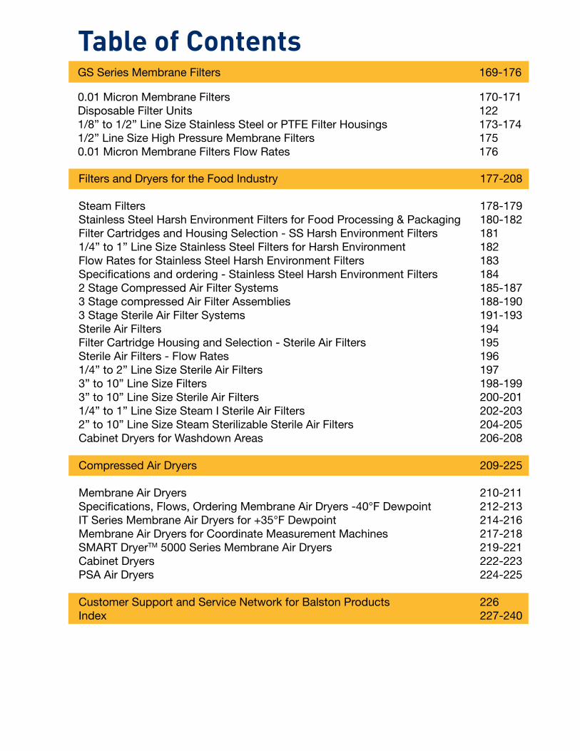
GS Series Membrane Filters 169-176
0.01 Micron Membrane Filters 170-171Disposable Filter Units 1221/8” to 1/2” Line Size Stainless Steel or PTFE Filter Housings 173-1741/2” Line Size High Pressure Membrane Filters 1750.01 Micron Membrane Filters Flow Rates 176
Table of Contents
Filters and Dryers for the Food Industry 177-208
Steam Filters 178-179Stainless Steel Harsh Environment Filters for Food Processing & Packaging 180-182Filter Cartridges and Housing Selection - SS Harsh Environment Filters 1811/4” to 1” Line Size Stainless Steel Filters for Harsh Environment 182Flow Rates for Stainless Steel Harsh Environment Filters 183Specifications and ordering - Stainless Steel Harsh Environment Filters 1842 Stage Compressed Air Filter Systems 185-1873 Stage compressed Air Filter Assemblies 188-1903 Stage Sterile Air Filter Systems 191-193Sterile Air Filters 194Filter Cartridge Housing and Selection - Sterile Air Filters 195Sterile Air Filters - Flow Rates 1961/4” to 2” Line Size Sterile Air Filters 1973” to 10” Line Size Filters 198-199 3” to 10” Line Size Sterile Air Filters 200-2011/4” to 1” Line Size Steam I Sterile Air Filters 202-2032” to 10” Line Size Steam Sterilizable Sterile Air Filters 204-205Cabinet Dryers for Washdown Areas 206-208
Compressed Air Dryers 209-225
Membrane Air Dryers 210-211Specifications, Flows, Ordering Membrane Air Dryers -40°F Dewpoint 212-213IT Series Membrane Air Dryers for +35°F Dewpoint 214-216Membrane Air Dryers for Coordinate Measurement Machines 217-218SMART DryerTM 5000 Series Membrane Air Dryers 219-221Cabinet Dryers 222-223PSA Air Dryers 224-225
Customer Support and Service Network for Balston Products 226Index 227-240


1
Compressed Air Filters
www.parker.com/balston
Compressed
Air Filters
Product Features:
Balston Coalescing Compressed Air Filters protect your equipment and delicate instruments from the dirt, water, and oil usually found in compressed air. Balston Coalescing Filters remove these contaminants at a very high efficiency up to 99.99% for 0.01 micron particles and droplets. Liquid releases from the filter car-tridge to an automatic drain as rapidly as it enters the filter. This allows a Balston Coalescing Filter to continue removing liquids for an unlimited time without loss of efficiency or flow capacity. Select 1/4” to 2” line filters come with a lifetime (20 year) war-ranty which guarantees the product against defects and other failures.
Compressed Air Systems Pnuematic Tools and CylindersInstrumentation and Automated Pnuematic Controls
Coalescing Compressed Air Filters
• Remove99.99%of0.01micron particlesofoil,water,anddirtfromcompressedairandothergases
• Continuouslytrapanddrainliquids
• ServiceflowrangesfromafewSCFMto40,000SCFM
• Removetraceoilvaporwith adsorbentcartridges
• Lifetimewarranty(20year)withselect1/4”to2”linefilters
BalstonMicrofiber® FilterAssemblies:
2
Compressed Air Filters
1-800-343-4048
Com
pres
sed
Air F
ilter
s
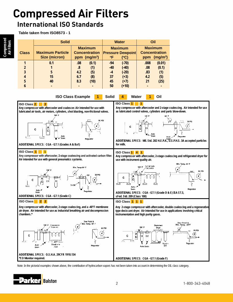
International ISO Standards
ISO Class 1 4 1Any compressor with aftercooler, 2-stage coalescing and refrigerated dryer for use with instrument quality air.
ADDITIONAL SPECS: CGA - G7.1 (Grade D & E) ISA S7.3, sFed. Std. 209 (Class 100)
Any compressor with aftercooler, 2-stage coalescing and activated carbon filter. Air intended for use with general pneumatics systems.
ADDITIONAL SPECS: CGA - G7.1 (Grade C)
Any compressor with aftercooler, 2-stage coalescing, and a -40°F membrane air dryer. Air intended for use as industrial breathing air and decompression chambers.*
ADDITIONAL SPECS: O.S.H.A. 29CFR 1910.134*CO Monitor required.
Table taken from ISO8573 - 1
ISO Class 1 1
Any compressor with aftercooler and coalescer. Air intended for use with lubricated air tools, air motors, cylinders, shot blasting, non-frictional valves.
ADDITIONAL SPECS: CGA - G7.1 (Grades A & Ba1)
ADDITIONAL SPECS: CGA - G7.1 (Grade F)
Any 2-stage compressor with aftercooler, double coalescing and a regenerative-type desiccant dryer. Air intended for use in applications involving critical instrumentation and high purity gases.
ISO Class Example 1 Solid 4 Water 1 Oil ISO Class 1 1
ISO Class 1 1 1
Any compressor with aftercooler and 2-stage coalescing. Air intended for use as lubricated control valves, cylinders and parts blow-down.
ADDITIONAL SPECS: Mil. Std. 282 H.E.P.A., U.S.P.H.S. 3A accepted particles for milk.
AutoDrain▼
▼
AutoDrain
▼AutoDrain
▼
ISO Class 2 2
Note: In the pictorial examples shown above, the contribution of hydrocarbon vapors has not been taken into account in determining the OIL class category.
Maximum Particle Size (micron)
MaximumConcentrationppm (mg/m3)
Maximum Pressure Dewpoint oF (oC)
1 0.1 .08 (0.1) -94 (-70) .008 (0.01) 2 1 .8 (1) -40 (-40) .08 (0.1) 3 5 4.2 (5) -4 (-20) .83 (1) 4 15 6.7 (8) 37 (+3) 4.2 (5) 5 40 8.3 (10) 45 (+7) 21 (25) 6 - - - 50 (+10) - -
Solid Water Oil
ClassMaximum
Concentration ppm (mg/m3)
ISO Class 2 2

3
Compressed Air Filters
www.parker.com/balston
Compressed
Air Filters
INTERNATIONAL APPROVALS
CRNASME VIII National Board
Q 05240
ISO 9001:2000
AS1210
ISO 14001
High Efficiency Bulk Liquid RemovalGRADE WS
OIL-X EVOLUTION
OIL-X EVOLUTION WS Water Separators have been designed for the efficientremoval of bulk liquid contamination from compressed air.
Today, many products are offered for the removal of bulk liquid from compressedair, however, these are often selected only upon their initial purchase cost, withlittle or no regard for the separation efficiency they provide or the cost ofoperation throughout their life.
domnick hunter OIL-X EVOLUTION WS Water Separators have been designed fromthe ground up with the key design focus concentrated in critical areas such as airflow management, separation efficiency at all flow conditions, minimal pressurelosses and independently validated performance.
Typical Applications
■ Bulk liquid removal at any point in a compressed air system
■ Protection of refrigeration and adsorption dryer pre-filtration
■ Liquid removal from compressor inter-coolers / after-coolers
■ Liquid separation within refrigeration dryers
Benefits
■ Tested in accordance with ISO 8573.9
■ Performance independently verified by Lloyds Register
■ High liquid removal efficiencies at all flow conditions
■ Low pressure losses for low operational costs
■ Multiple port sizes for a given flow rate providesincreased flexibility during installation
■ Suitable for variable flow compressors
■ Works with all types of compressor and compressor condensate
■ Low maintenance
■ 10 Year Housing Guarantee
Separation Efficiency
Tested with an Inlet challenge concentration of 33ml/m3hr and in accordance with ISO 8573.9. Performance shown is an average for all models in range. Individual model performance available on request.
Compressed Air and Gas Water Separators
Protectyourequipmentfromcontamination:Balston’s new water separators have been designed for the efficient removal of bulk liquid contamination from compressed air. Today, many products are offered for the removal of bulk liquid from compressed air, however, these are often selected based only upon their initial purchase cost, with little or no regard for the separation efficiency they provide or the cost of operation throughout their life. Balston’s water separators have been designed from the ground up with the key design focus on air flow management, separation efficiency at all flow conditions, minimal pressure losses and independently validated performance.
Product Features:
• TestedinaccordancewithISO8573.9
• Highliquidremovalefficien-ciesatallflowconditions
• Floatdrainautomatically expelscondensatebuild-up
• Lowpressurelossesforlowoperationalcosts
• Suitableforvariableflowcompressors
• Workswithalltypesofcom-pressorandcompressorcondensate
• Lowmaintenance
Applications:
• Bulkliquidremovalatanypointinacompressedairsystem
• Protectiontomembraneanddesiccantdryerprefiltration
• Liquidremovalfromcom-pressorinter-coolers/after-coolers
• Liquidseparationwithinre-frigerationdryers

4
Compressed Air Filters
1-800-343-4048
Com
pres
sed
Air F
ilter
s
Compressed Air and Gas Water Separators
dh, domnick hunter, OIL-X and PNEUDRI areregistered trademarks of domnick hunter limited.
Copyright domnick hunter limited 2005Publication Reference: 754 11/05 Rev. 000Stock No: 17 400 4754
domnick hunter limited has a continuous policyof product development and although theCompany reserves the right to changespecifications, it attempts to keep customersinformed of any alterations. This publication isfor general information only and customers arerequested to contact our Industrial Division SalesDepartment for detailed information and adviceon a products suitability for specific applications.All products are sold subject to the Company’sstandard conditions of sale.
domnick hunter limitedDukesway, Team Valley Trading Estate,
Gateshead, Tyne and Wear, England NE11 0PZ
Tel: +44 (0)191 402 9000 Telefax: +44 (0)191 482 6296
www.domnickhunter.com a member of the domnick hunter group plc
Selecting a Water Separator model to match a system �ow rate and pressure.
Example: System �ow 1050 m3/hr at a pressure of 8 bar g
1. Obtain pressure correction factor from table.Correction factor for 8 bar g = 1.06
2. Divide system �ow by correction factor to give equivalent �ow rate at 7 bar g 1050m3/hr ÷ 1.06 = 984 m3/hr (at 7 bar g)
3. Select a �lter model from the above table with a �ow rate above or equal to 984 m3/hr. Suitable Water Separator models: 035 or 040
4. Select pipe connection & Thread typeSystem uses 1 1/2" piping and BSP threads : Model WS040GB
5. Select drain typePressure is below 16 bar g (232 psi g), automatic �oat drain �tted as standard. Model WS040GBFX
Product Selection & Technical Data
Line Pressure
bar g psi g
CorrectionFactor
1 15 0.25
2 29 0.38
3 44 0.50
4 58 0.63
5 73 0.75
6 87 0.88
7 100 1.00
8 116 1.06
9 131 1.12
10 145 1.17
11 160 1.22
12 174 1.27
13 189 1.32
14 203 1.37
15 218 1.41
16 232 1.46
When ordering a WS water separator for pressures above 16 bar g(232 psi g), use manual drain. Replace F with M in product code.
E.g. WS010ABFX now WS010ABMX.
17 247 1.50
18 261 1.54
19 275 1.58
20 290 1.62
Model Pipe Size L/s m3/min m3/hr cfmMax Operating Pressure
bar g psi gMin OperatingTemperature
Max OperatingTemperature
Product Coding and Selection
GRADE MODEL PIPESIZE
CONNECTION TYPE
DRAIN OPTION MONITOR
WS3 digitcode
shownabove
Letterdenotespipe size
B = BSPTN = NPT
F = FloatM = Manual
X = Non
Available
WS 010 A B F X
Model Pipe SizeA
insmm
B
insmm
C
insmm
Weight
lbskgWS010A FX 1/4" 76 3 181.5 7.2 153 6 0.6 1.3
WS010B FX 3/8" 76 3 181.5 7.2 153 6 0.6 1.3
WS010C FX 1/2" 76 3 181.5 7.2 153 6 0.6 1.3
WS015B FX 3/8" 97.5 3.8 235 9.3 201 7.9 1.1 2.4
WS020C FX 1/2" 97.5 3.8 235 9.3 201 7.9 1.1 2.4
WS020D FX 3/4" 97.5 3.8 235 9.3 201 7.9 1.1 2.4
WS020E FX 1" 97.5 3.8 235 9.3 201 7.9 1.1 2.4
WS025D FX 3/4" 129 5.1 275 10.8 232.5 9.2 2.2 4.8
WS030E FX 1" 129 5.1 275 10.8 232.5 9.2 2.2 4.8
WS030F FX 11/4" 129 5.1 275 10.8 232.5 9.2 2.2 4.8
WS030G FX 11/2" 129 5.1 275 10.8 232.5 9.2 2.2 4.8
WS035F FX 11/4" 170 6.7 432.5 17 382.5 15 5.1 11.2
WS040G FX 11/2" 170 6.7 432.5 17 382.5 15 5.1 11.2
WS045H FX 2" 170 6.7 432.5 17 382.5 15 5.1 11.2
WS055I FX 21/2" 205 8.1 505 19.9 444.5 17.5 10 22
WS055J FX 3" 205 8.1 505 19.9 444.5 17.5 10 22
Weights and Dimensions
WS models are supplied with a float drain as standard. For Pressures of 16 to 20 bar g (232 to 290 psi g) a manual drain must be used.
WS010A FX 1/4" 10 0.6 36 21 16 232 80°C 176°F 1.5°C 35°F
WS010B FX 3/8" 10 0.6 36 21 16 232 80°C 176°F 1.5°C 35°F
WS010C FX 1/2" 10 0.6 36 21 16 232 80°C 176°F 1.5°C 35°F
WS015B FX 3/8" 40 2.4 144 85 16 232 80°C 176°F 1.5°C 35°F
WS020C FX 1/2" 40 2.4 144 85 16 232 80°C 176°F 1.5°C 35°F
WS020D FX 3/4" 40 2.4 144 85 16 232 80°C 176°F 1.5°C 35°F
WS020E FX 1" 40 2.4 144 85 16 232 80°C 176°F 1.5°C 35°F
WS025D FX 3/4" 110 6.6 396 233 16 232 80°C 176°F 1.5°C 35°F
WS030E FX 1" 110 6.6 396 233 16 232 80°C 176°F 1.5°C 35°F
WS030F FX 11/4" 110 6.6 396 233 16 232 80°C 176°F 1.5°C 35°F
WS030G FX 11/2" 110 6.6 396 233 16 232 80°C 176°F 1.5°C 35°F
WS035F FX 11/4" 350 21 1260 742 16 232 80°C 176°F 1.5°C 35°F
WS040G FX 11/2" 350 21 1260 742 16 232 80°C 176°F 1.5°C 35°F
WS045H FX 2" 350 21 1260 742 16 232 80°C 176°F 1.5°C 35°F
WS055I FX 21/2" 800 48 2880 1695 16 232 80°C 176°F 1.5°C 35°F
WS055J FX 3" 800 48 2880 1695 16 232 80°C 176°F 1.5°C 35°F
Stated flows are for operation at 7 bar (g) (102 psi g) with reference to 20°C, 1 bar (a), 0% relative water vapour pressure.
Part Port Size SCFM/Nm3/hr. Max Operating Max Min Number (inches) at Pressure Operating Operating NPT 100 psig (7 barg) psig (barg) Temp °F (°C) Temp °F (°C)WS002N 1/4” 25 (42) 232 (16) 176 (80) 35 (1.7)WS003N 3/8” 25 (42) 232 (16) 176 (80) 35 (1.7)WS004N 1/2” 25 (4) 232 (16) 176 (80) 35 (1.7)WSOH3N 3/8” 100 (170) 232 (16) 176 (80) 35 (1.7)WS0H4N 1/2” 100 (170) 232 (16) 176 (80) 35 (1.7)WS006N 3/4” 100 (170) 232 (16) 176 (80) 35 (1.7)WS008N 1” 100 (170) 232 (16) 176 (80) 35 (1.7)WS0H6N 3/4” 250 (425) 232 (16) 176 (80) 35 (1.7)WS0H8N 1” 250 (425) 232 (16) 176 (80) 35 (1.7)WS0010N 1-1/4” 250 (425) 232 (16) 176 (80) 35 (1.7)WS0012N 1-1/2” 250 (425) 232 (16) 176 (80) 35 (1.7)WS0H10N 1-1/4” 750 (1274) 232 (16) 176 (80) 35 (1.7)WS0H12N 1-1/2” 750 (1274) 232 (16) 176 (80) 35 (1.7)WS0016N 2” 750 (1274) 232 (16) 176 (80) 35 (1.7)WS0020N 2-1/2” 1700 (2888) 232 (16) 176 (80) 35 (1.7)WS0024N 3” 1700 (2888) 232 (16) 176 (80) 35 (1.7)
Line Pressure Correction psig (barg) Factor
15 (1) 0.25 29 (2) 0.38 44 (3) 0.50 58 (4) 0.63 73 (5) 0.75 87 (6) 0.88 100 (7) 1.00 116 (8) 1.06 131 (9) 1.12 145 (10) 1.17 160 (11) 1.22 174 (12) 1.27 189 (13) 1.32 203 (14) 1.37 218 (15) 1.41 232 (16) 1.46
Dimensions and WeightsPart Port Size Dimensions inches (cm) Weight Number (inches) A B C lbs (kg) WS002N 1/4” 3 (8) 7.2 (18) 6 (15) 1.3 (0.6) WS003N 3/8” 3 (8) 7.2 (18) 6 (15) 1.3 (0.6)WS004N 1/2” 3 (8) 7.2 (18) 6 (15) 1.3 (0.6)WSOH3N 3/8” 3.8 (10) 9.3 (24) 7.9 (20) 2.4 (1.1)WS0H4N 1/2” 3.8 (10) 9.3 (24) 7.9 (20) 2.4 (1.1)WS006N 3/4” 3.8 (10) 9.3 (24) 7.9 (20) 2.4 (1.1)WS008N 1” 3.8 (10) 9.3 (24) 7.9 (20) 2.4 (1.1)WS0H6N 3/4” 5.1 (13) 10.8 (27) 9.2 (23) 4.8 (2.2)WS0H8N 1” 5.1 (13) 10.8 (27) 9.2 (23) 4.8 (2.2)WS0010N 1-1/4” 5.1 (13) 10.8 (27) 9.2 (23) 4.8 (2.2)WS0012N 1-1/2” 5.1 (13) 10.8 (27) 9.2 (23) 4.8 (2.2)WS0H10N 1-1/4” 6.7 (17) 17 (43) 15 (38) 11.2 (5.1)WS0H12N 1-1/2” 6.7 (17) 17 (43) 15 (38) 11.2 (5.1)WS0016N 2” 6.7 (17) 17 (43) 15 (38) 11.2 (5.1)WS0020N 2-1/2” 8.1 (21) 19.9 (51) 17.5 (44) 22 (10.0)WS0024N 3” 8.1 (21) 19.9 (51) 17.5 (44) 22 (10.0)
Product Selection and Technical Data Flow/Pressure Correction Factors (to calculate flow rates below and above 100 PSIG use this table)

5
Compressed Air Filters
www.parker.com/balston
Compressed
Air Filters
Line Pressure Correction psig (barg) Factor
15 (1) 0.25 29 (2) 0.38 44 (3) 0.50 58 (4) 0.63 73 (5) 0.75 87 (6) 0.88 100 (7) 1.00 116 (8) 1.06 131 (9) 1.12 145 (10) 1.17 160 (11) 1.22 174 (12) 1.27 189 (13) 1.32 203 (14) 1.37 218 (15) 1.41 232 (16) 1.46
Selecting the proper location for a filter in a compressed air line is as important as selecting the proper filter. In most cases you will probably be able to base your own installation on these recommendations for typical instal-lations.
The standard compressor installation consists of a prefilter (mounted on the compressor), a compressor, aftercooler, and a receiver. The Balston filter should be installed downstream from the receiver. In a system with an efficient aftercooler, the distance from the receiver to the filter is not important. Since the filter is usually main-tained by the personnel responsible for the compressor, it is often convenient to install the filter downstream from the receiver. If there is no aftercooler, or the aftercooler is not efficient, coalescing filter be installed as close to the point(s) of use as possible.
Some compressor installations do not have an after-cooler (this is an undesirable situation). Air saturated with water vapor leaves a compressor at 240°F to 400°F (116°C to 204°C). Without an aftercooler, the air cools close to room temperature in the distribution lines and water condenses throughout the air distribution system. About two-thirds of the total water content of the air
Compressor Filter Specifications
Microfibre Filter Cartridge Grade DX
Filter Housing Determinefiltersizefromflowcharton page3,butportsizemustbeequaltoor largerthanthelinesize
Automatic Drain Recommended
Differential Pressure Indicator Recommended
Recommendations for Typical Filter Installations
will be condensed when the air has cooled to 100°F (38°C). A filter located just before the main air line branches into smaller distribution lines will remove most of the water load from the system. The filter requirements for the main line are described above; they are the same as for a system with an aftercooler. However, since the air will continue to cool in the dis-tribution system, additional filters located at end- use points will be required to remove water condensed downstream from the main line filter.
The mechanism of coalescing leads to three important considerations in selecting and installing a coalescing filter:
1 The filter should be large enough to ensure that the air exits the filter at low velocity and does not carry over coalesced liquid. Proper sizing of a Balston coalesc-ing filter is easily done by using the recommendations or the maximum flow rate data. There is no danger on oversizing the filter. A Balston coalescing filter is even more efficient at extremely low flow rates than at its maximum rated flow capacity.
2 To avoid liquid carryover, the coalesced liquid should not be allowed to build up in the filter housing above the level of the bottom of the filter tube.
Rather than relying on operator attention to this easily-overlooked job, Parker Hannifn Corp. recommends automatic drains with all coalescing filters.
3 The flow direction through the Microfibre filter tube must be inside-to-outside to permit the liquid to drip from the outside of the tube to the drain in the filter housing. If installed outside-to-inside, the filter will at first function as a coalescing filter, but liquid will collect on the inside of the filter tube. Since there is no way of draining the liquid, the level will build up rapidly until it begins to be carried downstream by the air flow. The filter will work at removing liquids for a short time, and then not work at all. If the Balston coalesc-ing filter exhibits these symptoms, reversing the flow direction will solve the problem.
HowtoObtainaTrouble-FreeCoalescer
AFTERCOOLER
Placing the Filter at the Compressor
Filter Installation Recommendations

6
Compressed Air Filters
1-800-343-4048
Com
pres
sed
Air F
ilter
sFilter Cartridge and Housing Selection
BalstonFilterCartridges
Balston provides two grades of coalescing filter car-tridges, Grade DX and Grade BX. Singly or in tandem, these filters satisfy all requirements for removing liquid and solid contaminants from compressed air. Balston also has an activated carbon adsorbent CI-type cartridge for the removal of trace oil vapors from a compressed air line. The activated carbon cartridge is Grade 000.
Singlestagefiltration.UseaGradeDXfiltercartridge
Twostagefiltrationisnecessary.UseaGradeDXfollowedbyaGradeBXfiltercar-tridge.Asageneralrule,aGradeBXfiltercartridge should not be used alone.
For rare instances where even a trace amount of oil vapor can cause a problem, threestagefiltrationisnecessary.UseaGrade DX followed by a Grade BX, and a type CI cartridge.
General purpose applications such as plant compressed air
Filter Cartridge Description
Removal of trace com-pressor oil vapor
Instrument air and other critical air requirements
HowtoOrdertheFilterAssembly
Temperature Range -150°F to 300°F (-100°C - 149°C)
Maximum PressureDifferential Across Filter,Inside-to-Outside Flow: 100 psi (7 bar)
Materials of Construction Borosilicateglassmicrofiberswith fluorocarbonresinbinder.Resistantto water, all hydrocarbon and synthetic lubricants.
Physical Properties, Microfibre Filter Cartridges
Retention Efficiency
Grade Efficiency for 0.01 Micron Particles and DropletsDX 93%BX 99.99%
1 Decide which grade(s) of filter cartridges fits the application (see selection boxes at left).
2 Select the filter housing with a port size equal to the line size where the filter is to be located.
3 For a new installation in which the line size has yet to be selected, determine the gas flow rate and pressure at the point where the filter will be located, and then refer to the flow chart on the reverse side of this data sheet. NOTE: The filter port size must be equal to or larger than the line size (when speci-fied).
1 Build your own custom filter assembly using the guideline matrix on Page 12 and specify your model number. Example: 1/2” filter with DPI and Auto Drain with Grade DX Filter = 6004N-01A-DX.
2 Each assembly is shipped with the filter cartridge in-stalled. To order additional filter cartridges, indicate the model number of the cartridges, and the grade. Examples 050-05-DX, 050-05-BX. The grade used for Type CI cartridges is 000 (CI-100-12-000).
Note: Assemblies with CI Cartridges are shipped with the adsorbent cartridge wrapped separately. This ship-ping method prolongs the life of the cartridge.
HowtoSelecttheFilterCartridgeandHousing
Filter Cartridge and Housing Selection

7
Compressed Air Filters
www.parker.com/balston
Compressed
Air Filters
Flow Rates
Filter Housing Port Filter Flow rates SCFM, at 2 psi drop at indicated line pressure. Refer to Principal Specification for maximum pressureModel Size Cartridge rating of each housing Grade psig 2 20 40 80 100 125 150 200 250 400 650
A94A 1/4” DX 4 9 13 24 29 36 43 55 67A914, A914D, A914P BX 1.2 2.4 4 7 8 9 12 15 17
2002 1/4” DX 9 19 30 51 63 76 90 117 1452003 3/8” BX 3 8 11 21 25 31 36 47 582004 1/2” CI 2 5 7 12 15 18 22 28 35
2104 1/2” DX 19 41 65 113 137 166 196 257 316 BX 9 19 30 51 63 76 90 117 145 CI 6 12 19 32 39 48 56 73 90
2206 3/4” DX 37 78 123 214 259 315 371 484 596 BX 10 21 34 56 70 85 101 131 162 CI 8 16 26 44 53 65 76 99 122
2208 1” DX 55 115 181 314 380 463 546 711 877 BX 11 23 37 64 77 94 111 144 178 CI 10 20 32 56 67 82 96 125 154
2312 1 1/2” DX 98 203 319 554 670 816 963 1254 1546 BX 22 46 74 129 155 189 223 290 358 CI 16 33 52 91 110 134 158 206 253
A15/80 2” DX 160 333 525 908 1100 1340 1580 2060 2540 BX 45 94 148 256 310 378 445 580 715 CI 23 49 77 133 161 197 231 301 371
3” DX 364 760 1190 2060 2500 3045 3600 4680 5770 9030 14480AKH-0280 BX 90 190 300 510 620 755 890 1160 1430 2240 3590 CI 47 98 154 266 322 394 462 602 742 1160 1860
4” DX 740 1540 2430 4210 5100 6210 7300 9550 11750 18400 29480AKH-0480 BX 180 380 590 1020 1240 1510 1780 2320 2860 4480 7180 CI 94 196 308 632 644 780 920 1200 1480 2320 3710
6” DX 1500 3120 4910 8500 10300 12550 14800 19300 23700 37120 59460AKH-0880 BX 360 750 1180 2050 2480 3020 3560 4640 5710 8940 14330 CI 188 392 616 1064 1280 1560 1840 2390 2950 4620 7400
8” DX 2620 5450 8580 14860 18000 21900 25800 33700 41540 65050 104200AKH-1480 BX 630 1310 2070 3580 4340 5300 6230 8120 10010 15680 25100 CI 329 686 1078 1860 2250 2740 3230 4210 5190 8130 13020
10” DX 4080 8470 13350 23110 28000 34100 40200 52400 64590 101150 162050AKH-2280 BX 1000 2070 3270 5660 6850 8340 9840 12800 15780 24700 39600 CI 516 1077 1690 2920 3540 4310 5070 6610 8150 12760 20450
8
Compressed Air Filters
1-800-343-4048
Com
pres
sed
Air F
ilter
s
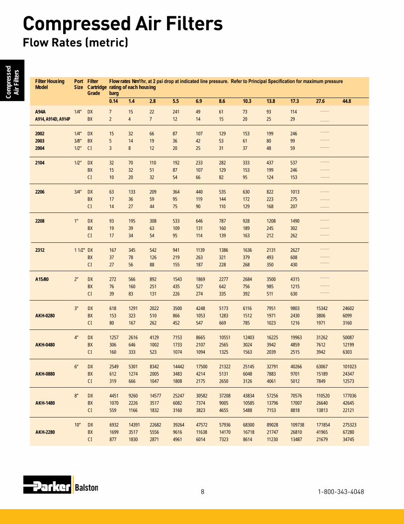
Flow Rates (metric)
Filter Housing Port Filter Flow rates Nm3/hr, at 2 psi drop at indicated line pressure. Refer to Principal Specification for maximum pressureModel Size Cartridge rating of each housing Grade barg 0.14 1.4 2.8 5.5 6.9 8.6 10.3 13.8 17.3 27.6 44.8
A94A 1/4” DX 7 15 22 241 49 61 73 93 114A914, A914D, A914P BX 2 4 7 12 14 15 20 25 29
2002 1/4” DX 15 32 66 87 107 129 153 199 2462003 3/8” BX 5 14 19 36 42 53 61 80 992004 1/2” CI 3 8 12 20 25 31 37 48 59
2104 1/2” DX 32 70 110 192 233 282 333 437 537 BX 15 32 51 87 107 129 153 199 246 CI 10 20 32 54 66 82 95 124 153
2206 3/4” DX 63 133 209 364 440 535 630 822 1013 BX 17 36 59 95 119 144 172 223 275 CI 14 27 44 75 90 110 129 168 207
2208 1” DX 93 195 308 533 646 787 928 1208 1490 BX 19 39 63 109 131 160 189 245 302 CI 17 34 54 95 114 139 163 212 262
2312 1 1/2” DX 167 345 542 941 1139 1386 1636 2131 2627 BX 37 78 126 219 263 321 379 493 608 CI 27 56 88 155 187 228 268 350 430
A15/80 2” DX 272 566 892 1543 1869 2277 2684 3500 4315 BX 76 160 251 435 527 642 756 985 1215 CI 39 83 131 226 274 335 392 511 630
3” DX 618 1291 2022 3500 4248 5173 6116 7951 9803 15342 24602AKH-0280 BX 153 323 510 866 1053 1283 1512 1971 2430 3806 6099 CI 80 167 262 452 547 669 785 1023 1216 1971 3160
4” DX 1257 2616 4129 7153 8665 10551 12403 16225 19963 31262 50087AKH-0480 BX 306 646 1002 1733 2107 2565 3024 3942 4859 7612 12199 CI 160 333 523 1074 1094 1325 1563 2039 2515 3942 6303
6” DX 2549 5301 8342 14442 17500 21322 25145 32791 40266 63067 101023AKH-0880 BX 612 1274 2005 3483 4214 5131 6048 7883 9701 15189 24347 CI 319 666 1047 1808 2175 2650 3126 4061 5012 7849 12573
8” DX 4451 9260 14577 25247 30582 37208 43834 57256 70576 110520 177036AKH-1480 BX 1070 2226 3517 6082 7374 9005 10585 13796 17007 26640 42645 CI 559 1166 1832 3160 3823 4655 5488 7153 8818 13813 22121
10” DX 6932 14391 22682 39264 47572 57936 68300 89028 109738 171854 275323AKH-2280 BX 1699 3517 5556 9616 11638 14170 16718 21747 26810 41965 67280 CI 877 1830 2871 4961 6014 7323 8614 11230 13487 21679 34745

9
Compressed Air Filters
www.parker.com/balston
Compressed
Air Filters
The source of oil in compressed air is the compres-sor lubricant. The common plant problems resulting from oil in the air are caused by liquid oil depositing in valves, instrument control surfaces, and other critical points in the air distribution system.Balston often receives inquiries from users of com-pressed air about removing oil vapor from the air, yet the only reason for concern about oil vapor in most applications is that it may condense to liquid oil. Just like water vapor, oil vapor will condense to liquid when the temperature is reduced or the air pressure is in-creased at constant temperature. However, the table below show that while in theory, condensation of oil vapor and water vapor are similar, in practice the effect of condensation of the two vapors is quite different.
RemovingOilfromCompressedAir
Concentration of vapor, parts per million by weight (ppm) in air at 100 psig (7 barg), at indicated temperature
Petroleum Synthetic Water Base Oil Oil80°F (27°C) 0.012 0.002 2,743.100°F (38°C) 0.05 0.01 5,137.125°F (52°C) 0.2 0.06 10,508.150°F (66°C) 0.7 0.2 20,119.200°F (93°C) 3.5 2.4 62,371.
PlacingtheFilteratthePoint-Of-Use
Point-of-Use Filter Recommendations
Microfibre Filter Cartridge Grade BX
Filter Housing Sizefromflowchartorbylinesize
Automatic Drain Recommended (refer to Page 18)
Whether or not the system has an aftercooler, Balston strongly recommends a filter at each critical end-use point, even if a main line Grade DX filter has been used. The point-of-use filters will remove dirt and oil which may have been in the distribution lines, as well as water that has condensed downstream from the main filter. If there is a pressure regulator at the end-use point, the filter should be installed immediately upstream from the regu-lator. Alternatively, replace the existing regulator with a combination Balston filter-regulator.
From the above figures, one can calculate that if 100 SCFM (170Nm3/h) of air is filtered at 125°F (52°C) to remove all liquids, and is subsequently cooled to 80°F (27°C), condensed liquids would consist of: water 3.6 lbs. (1.64 kg) per hour, and either petroleum base oil 0.001 lbs. (0.46 g)per hour, or synthetic oil 0.0003 lbs. (1.4 g) per hour. Condensed water is potentially a serious problem, but the quantity of condensed oil vapor is extremely small.Field tests show that the liquid oil in air from a well-maintained reciprocating compressor is typically in the range of 15 to 30 ppm.With an oil-sealed rotary screw compressor, liquid oil content in the compressed air can vary from 10 to more than 100 ppm, depending upon the efficiency of the bulk oil separator. Com-pared to these figures, the approximate 0.2 ppm of liquid oil which could result from oil vapor condensa-tion is for practical purposes negligible.Therefore, removing the liquid oil from compressed air with a Balston coalescing filter, even at tempera-tures as high as 125°F (52°C), will eliminate the chance of oil-caused problems downstream in virtu-ally all installations.
There are rare instances in which even 0.2 ppm oil vapor in the air or gas can cause a problem; for example, in contact with a sensitive catalyst or other highly reactive material.In those cases, the trace quantity of oil vapor can be reduced using an adsorbent-loaded cartridge, following coalescing filter to remove the liquid oil.
If there is no Grade DX filter upstream from the final filter, or if a significant amount of water or oil is expected, then a two-stage system, Grade DX followed by Grade BX, is required at each use point. The housing and automatic drain for the Grade DX prefilter should be the same as for the Grade BX final filter (if the flow capaci-ties permit).
Even if the application is not particularly sensitive to impurities in the air - for example, an air-driven tool - it is still good practice to remove condensed water with a filter at the end of the line. Parker recommends a single-stage Grade DX filter with automatic drain.
Filter Installation Recommendations

10
Compressed Air Filters
1-800-343-4048
Com
pres
sed
Air F
ilter
s Properly specified filters are relatively inexpensive pro-tection for air dryers. Both refrigerated and desiccant dryers benefit from filter protection.
Refrigerated DryersA Grade DX prefilter with automatic drain should be installed upstream from a refrigerated dryer to prevent oil and condensed water from entering the dryer. Oil entering a dryer coats the cooling coil and reduces its ef-ficiency; condensed water increases the cooling load and reduces dryer capacity. A dryer that was in operation before a Balston filter was installed may already have oil inside it. Therefore a second filter, a Grade BX filter with automatic drain, must be installed downstream from the dryer if oil-free air is required.
Desiccant DryersDesiccant dryers are very sensitive to water and oil droplets. Water can saturate the desiccant and reduce its drying efficiency or even destroy it. Oil can coat the desiccant, rendering it ineffective, or the oil can accumu-late on the desiccant and create a combustion hazard when the desiccant is heated for regeneration.
For maximum protection of the desiccant dryer, a two-stage filter (Grade DX followed by Grade BX) system with automatic drains should installed upstream from the dryer. To protect downstream delivery points from abra-sive desiccant particles, a high efficiency filter with high solids holding capacity should be installed downstream from the dryer. The Balston Grade DX filter cartridge is recommended for this downstream installation location. (Note: All Balston desiccant dryers are equipped with prefilters and final filters, as recommended above).
Membrane DryersMembrane air dryers are sensitive to water and oil droplets. Oil can permanently damage the hollow fiber core. Balston Membrane Air Dryers are assembled with maximum protection, two stage coalescing filters (Grade DX followed by BX) designed to remove all contaminants down to 0.01 microns. Most all other membrane dryers are not assembled with adequate prefiltration protection and should be protected with a two stage Balston Filter System (Grade DX, Grade BX).
UsingFiltersWithAirDryers
In a typical compressed air delivery system, a properly specified Balston filter cartridge can be expected to last for one year. The filter cartridge can continue to co-alesce indefinitely, but solids loading in the depth of the cartridge will cause a pressure drop through the housing. The filter should be changed when the pressure drop reaches 10 psi (0.7 barg). At pressure drops higher than 10 psig (0.7 barg), the cartridge will continue to perform at its rated efficiency, but downstream instrumentation may be affected by the pressure drop.
To monitor the condition of the filters, install Balston Differential Pressure Indicators (DPI) on the filters or across a multi-filter installation. The DPI gives a vi-sual indication of differential pressure through the filter cartridge. The Balston Differential Pressure Indicator is factory-installed on 1/4” and larger line size Balston Compressed Air Filter Assemblies. To use a DPI with a smaller Balston Compressed Air Filter, pressure taps must be provided with “tees” on the line upstream and downstream from the filter.
Filter Installation RecommendationsMaintainingTheFilters

11
Compressed Air Filters
www.parker.com/balston
Compressed
Air Filters
1/4” and 1/2” Line Size Filters
Models A914D, A914P, A914, A914AModels A914P and A914D are 1/4” line size assemblies with simple, reliable “automatic” drains used for low flow applications with moderate levels of liquid contaminate. The A914P is designed to empty condensate when there is a sudden pressure drop through the system (intermittent compressed air demand applications). The A914D incorporates an overnight drain which will drain liquid contaminate when the compressed air system pressure drops below 5 psig (0.4 barg). The standard A914 utilizes a standard manual threaded drain. All models have a transparent polycarbonate bowl with an aluminum head. The Model A914A has a zinc bowl.
Models 2002, 2003, and 2004Models 2002 and 2003 are 1/4” and 3/8” line size assemblies. These filters have increased liquid hold-ing capacity and are equipped with high capacity float drains, differential pressure indicators, sightglass, pres-sure relief valve, and 1/4 turn bayonet bowl closures. The 2004 series is designed to service 1/2” compressed air lines with low flow rates.
Model 2104The Model 2104 is a 1/2” line size assembly with an aluminum bowl. The filter housing has a large liquid holding capacity and a high capacity float drain, differen-tial pressure indicator, sightglass, pressure relief valve, and 1/4 turn bayonet bowl closure.
Model A914A
Model A914D,A914P, A914
Model 2104 Series
Model 200X Series

12
Compressed Air Filters
1-800-343-4048
Com
pres
sed
Air F
ilter
s
How to Order the Filter Assembly*
Model A914 A914A 2002, 2003, 2004 (1) 2104 (1)
PortSize 1/4”NPT 1/4”NPT 1/4”,3/8”,1/2”NPT 1/2”NPTMaterials of Construction Head Anod. Alum. Anod. Alum. Anod. Alum. Anod. Alum. Bowl Polycarbonate Zinc Anod. Alum. Anod. Alum. Internals Nylon Nylon Nylon Nylon Seals Buna-N Buna-N Buna-N Buna-NMaximum Temperature 120°F (49°C) 220°F (104°C) 130°F (54°C) (2) 130°F (54°C) (2)Maximum Pressure 150 psig (10.3 barg) (3) 250 psig (17.2 barg) (3) 250 psig (17.2 barg) (3) 250 psig (17.2 barg) (3)Minimum Pressure 5 psig (0.4 barg) (4) 5 psig (0.4 barg) (4) 15 psig (1.03 barg) (4) 15 psig (1.03 barg) (4)Shipping Weight 0.5 lbs. (0.2 kg) 0.5 lbs. (0.2 kg) 2.0 lbs. (0.9 kg) 2.5 lbs. (1.1 kg)Dimensions 1.5”W X 4.0”L 1.5”W x 4.0”L 3.3”W X 8.5L” 3.3”W X 11.3”L (4cm X 10cm) (4cm X 10cm) (8cm X 20cm) (8cm X 28cm)
Principal Specifications
Ordering InformationFor assistance, call toll-free at 1-800-343-4048 8AM to 5PM Eastern Time
Model A914 A914A (8) 2002, 2003, 2004 (1) 2104 (1)
Differential Pressure Not Included (7) Not Included (7) Included (7) Included (7)IndicatorReplacement Filter CartridgesNo.Required 1 1 1 1Box of 5 5/050-05-❑ (5) 5/050-05-❑ (5) 5/100-12-❑ (5) 5/100-18-❑ (5) Cartridges Box of 10 050-05-❑ (5) 050-05-❑ (5) 100-12-❑ (5) 100-18-❑ (5) CI Cartridge Box of 1 ––– ––– CI-100-12-000 (5) CI-100-25-000 (5)
Notes:1 Lifetime (20 year) Warranty included. Contact your local representative for details.2 Automatic drain and Differential Pressure Indicator are temperature limiting factors. For Temperature capabilities to 220°F (104°C), order assemblies without automatic Drain and Differential Pressure Indicator.3 Maximum pressure ratings are for temperatures to 130°F (54°C). Please consult factory for maximum pressure ratings at elevated temperatures.4Requiredforproperoperationofpistondrain,overnightdrain,orfloatdrain.
Build your own custom filter assembly using the guideline matrix below and specify your model number. Example: 1/2” filter with DPI and Auto Drain with Grade DX Filter = 2104N-1B1-DX.*Consult Factory. Not all configurations are available.
1/4” and 1/2” Line Size Filters
5Indicategradeoffiltercartridgebyputtingappropriateletterafterorderingnumber.Toorderassembly with Type CI cartridges, add-000 after assembly number. Example: 2104N-0A0-0006 Automatic drains not supplied with assemblies containing Type CI cartridges.7 Differential Pressure Indicator (DPI) Kit may be ordered separately, P/N 41-071. DPI is sensitive in the range of 0-7 psi differential.8 OrderA914D-_Xforovernightdraininstalledinthefilterassembly. OrderA914P-_Xforpistondraininstalledinthefilterassembly. Order A914A-_X for aluminum bowl and 250 psig rating.
0A0No DPIDrain Plugged1B1DPIAuto Drain1B2DPIManual Drain
Filter Grade000SADXBXLeave blank for nofilterCartridge
2002 1/4” Ports2003 3/8” Ports2004 1/2” Ports2104 1/2” Ports22063/4” Ports22081” Ports23121-1/2” Ports
NNPT Thread Inlet & Outlet PortsGBSPP Thread Inlet & Outlet Ports

13
Compressed Air Filters
www.parker.com/balston
Compressed
Air Filters
3/4” to 2” Line Size FiltersModels 2206, 2208, 2312, and A15/80The Model A15/80 filter assembly has 2” NPT inlet and outlet ports, an automatic float drain and differential pressure indicator installed. The Models 2206, 2208, and 2312 filter assemblies have 3/4”, 1”, and 1 1/2” NPT inlet and outlet ports, respectively; these models are also equipped with automatic drains, sight glasses, pressure relief valve, bayonet closures, and differential pressure indicators. Materials of construction are shown below.
Model 2206N
Model A15/80
Model 2312N
Ordering Information
For assistance, call toll-free at 1-800-343-4048 8AM to 5PM Eastern Time
Model 2206 2208 2312 A15/80Differential Pressure Indicator Included (6) Included (6) Included (6) Included (6) Replacement Filter Cartridges No.Required 1 1 1 1Box of 5 5/150-19-❑ (5) 5/150-19-❑ (5) 5/200-35-❑ (5) 5/200-80-❑ (5)Box of 10 150-19-❑ (5) 150-19-❑ (5) 200-35-❑ (5) 200-80-❑ (5) CI Cartridge (Box of 1) CI150-19-000 CI150-19-000 CI200-35-000 CI200-80-000
Model 2206 (1) 2208 (1) 2312 (1) A15/80
PortSize 3/4”NPT 1”NPT 11/2”NPT 2”NPTMaterials of ConstructionHead Anod. Alum. Anod. Alum. Anod. Alum. Anod. Alum.Bowl Anod. Alum. Anod. Alum. Anod. Alum. SteelInternals Aluminum Aluminum Aluminum St. SteelSeals Buna-N Buna-N Nuna-N Buna-NMaximum Temperature 130°F (54°C) (2) 130°F (54°C) (2) 130°F (54°C) (2) 130°F (54°C) (2)Maximum Pressure 250 psig (17.2 barg) (3) 250 psig (17.2 barg) (3) 250 psig (17.2 barg) (3) 250 psig (17.2 barg) (3)Minimum Pressure 15 psig (1 barg) (4) 15 psig (1 barg) (4) 15 psig (1 barg) (4) 15 psig (1 barg) (4)Shipping Weight 8 lbs. (3.6 kg) 8 lbs. (3.6 kg) 15 lbs. (6.8 kg) 11 lbs. (5 kg)Dimensions 4”W X 13”L 4”W X 13”L 5.0”W X 17L” 6.3”W X 28”L (10cm X 33cm) (10cm X 33cm) (13cm X 43cm) (16cm X 71cm)
Principal Specifications
Notes:1 Lifetime (20 year) Warranty included. Contact your local representative for details.2 Automatic Drain and Differential Pressure Indicator are limiting factors. For temperature capabilities to 220°F (104°C), order assemblies without Auto Drain and Differential Pressure Indicator.3 Maximum pressure ratings are for temperatures to 130°F (54°C). Please consult factory for maximum pressure ratings at elevated temperatures.4Requiredforproperoperationofthefloatdrain.5Indicategradeoffiltercartridgebyputting appropriate letter after ordering number (please refer to PK1-2). Example: 5/150-19-DX, 200-35-BX.6 The DPI is sensitive in the range of 0-5 psi differential.7 Pressure taps pre-drilled to accom-modate DPI (P/N 41-070).

14
Compressed Air Filters
1-800-343-4048
Com
pres
sed
Air F
ilter
s
Model 2A-2002, 2003, 2004 2A-2104 2A-2206 2A-2208 2A-2312
PortSize 1/4”NPT 1/2”NPT 3/4”NPT 1”NPT 1.5”NPTMaterials of Construction Head Aluminum Bowl Aluminum Internals Aluminum Seals Buna-N Food Grade Maximum Temperature (1) 130°F (54°C) Maximum Pressure 250 psig (17.2 barg) Minimum Pressure (2) 15 psig (1 barg) Shipping Weight 4.2 lbs. (1.9 kg) 5 lbs. (2.3 kg) 11.7 lbs. (5.3 kg) 11.7 lbs. (5.3 kg) 27 lbs. (12 kg)Dimensions 6.25”W X 8.5”L 6.25”W X 11”L 8.3”W X 13”L 8.3”W X 13”L 10.5”W X 17”L
Principal Specifications
Notes:1 Max. temperature with auto drain 2Requiredforproperoperationofautodrain.
Ordering Information For assistance, call toll-free at 1-800-343-4048 8AM to 5PM Eastern Time
Assembly Ordering InformationModel P/N Replacement Cartridge Box of 5 Box of 102A-2002N-3B1 1/4” 2-Stage (DX, BX) Filter Assembly 5/100-12-DX 100-12-DX 2A-2003N-3B1 3/8” 2-Stage (DX, BX) Filter Assembly 5/100-12-BX 100-12-BX2A-2004N-3B1 1/2” 2-Stage (DX, BX) Filter Assembly
2A-2104N-3B1 1/2" 2-Stage (DX, BX) Filter Assembly 5/100-18-DX 100-18-DX 5/100-18-BX 100-18-BX 2A-2206N-3B1 3/4" 2-Stage (DX, BX) Filter Assembly 5/150-19-DX 150-19-DX 5/150-19-BX 150-19-BX 5/150-19-SA 2A-2208N-3B1 1" 2-Stage (DX, BX) Stainless Assembly 5/150-19-DX 150-19-DX 5/150-19-BX 150-19-BX 5/150-19-SA 2A-2312N-3B1 1” 2-Stage (DX, BX) Stainless Assembly 5/200-35-DX 200-35-DX 5/200-35-BX 200-35-BX 42eachofmountingbracketsarerequiredforadequatesupport. 5 For CRN rated assemblies add a "C" to the Model Number. Example: 2A-C2104N-3B1
2A-2002N-3B1, 2A-2004N-3B12A-2003N-3B1
2A-2104N-3B1 2A-2206N-3B1, 2A-2208N-3B11 2A-2312N-3B1
6.25" (16 cm)
6.25" (16 cm)
8.3" (21 cm)
10.5" (27 cm)
8.5" (22 cm)
11"(28 cm)
13"(33 cm)
17"(43 cm)

15
Compressed Air Filters
www.parker.com/balston
Compressed
Air Filters
3” to 10” Line Size FiltersNew LF/FF Series Multiple Cartridge Filter Assemblies These filter assemblies provide high efficiency filtration of compressed air and other compressed gases at very high flow rates. With inlet and outlet ports accommodating 3” to 10” pipe sizes, the new LF/FF Series hous-ings are capable of flow rates up to a maximum capacity of 37,350 SCFM (63,458 m3/h) at 100 psig (6.9 barg). The standard carbon steel units, which are generally in stock (through 6” line sizes), have pressure ratings up to 250 psig (17.2 barg). All LF/FF series housings are ASME Code Stamped for the rated maxi-mum operating pressure. All FF Series vessels have built-in legs for floor mounting. Selected models have swing bolt enclosures for easy access to the internals. The filter cartridges in all models are sealed by tighten-ing the threaded retainer cap onto the rigid tie rod, ensuring a leak tight seal on both ends of the cartridge. Each assembly is equipped with a carbon steel automatic float drain, dif-ferential pressure indicator, and a set of filter cartridges (except where noted).
Low Pressure DropLower Change out/Labor CostsLower Energy CostsHigh Dirt Holding Capacity
BenefitsHeat and Chemical ResistantNo Wet ZoneOleophobic/HydrophobicHigh Burst Strength
Calculation with Part-Load Operation (100 hp compressor)
Annual Electricity Costs = [(Motor full-load brake horsepower) x (0.746 kW/hp) x (Annual Hours of Operation) x (Electricity Cost in $/kWh)] x [(Percent of time running fully loaded) + (0.30) x (Percent of time running unloaded)]For example: Full load motor efficiency = 90%Motor full load bhp = 100 hpAnnual hours of operation = 8,760 hours (3-shift, continuous operation)Runs 65% of the time fully loaded, 35% of the time unloadedUnloaded operation consumes 30 percent of the electricity of fully loaded operationCost of electricity = $0.10/kWhAnnual electricity costs =[(100 hp) x (0.746 hp/kW) x (8,760 hrs) x $0.10/kWh) / 0.9] x [0.65 + (0.30) x (0.35)] = $54,272.00

16
Compressed Air Filters
1-800-343-4048
Com
pres
sed
Air F
ilter
s HFC Savings Annual electricity costs to operate a 100 HP Compressor can be as high as $50,000. Pressure loss in the sys-tem adds to this expense. For a system operating at 100 psig (7 barg) that loses 2 psig (0.14 barg) of pressure through a filter, requires an additional 1% in operating energy costs (1). Installing a single stage HFC Filter in place of a standard brand X filter, will reduce the pressure drop by 2+ psi (0.14 barg).Based on a standard 100 HP (74.6 kW) compressor operating at a 65% load cycle, a 1% reduction in annual operating costs would be equal to $542.00
High Efficiency Coalescing MediaHEC Grade
Efficiency: 99.97% @ 0.01 micron
Air Flow: Inside to Outside
This coalescing element is composed of an epoxy saturated borosilicate glass micro-fiber tube. The HEC grade filter has a pleated cellulose inner layer as a built-in prefilter. This element is metal retained for added strength, and includes a synthetic fabric layer.
HEC filters are used when “total removal of liquid aerosols and suspended fines” is required. Because of its overall performance characteristics, this grade is most often recommended.
The HEC element is great prefilter protection for desiccant air dryers. This element prevents oil or varnish from coating the desiccant, while maintaining the dryer efficiency.
NEW!High Flow Coalescing Filter Media
HFC Grade Efficiency: 99.5% @ 0.5 micron
Balston’s HFC media consists of two layers. The outer layer features a dense matrix of glass fibers. It provides highly efficient coalescing aerosol removal and very low pressure drop. The inner layer, or initial stage of filtration, effectively traps dirt particles, protecting and extending the life of the outer layer. A metal retainer is used for strength and stability. This media is used in bulk coalesc-ing applications and when relatively high efficiency and low pressure drop are required.
3” to 10” Line Size Filters
(1) Compressed Air Challenge, Doc # F9-1, April, 1998-Rev.0.

17
Compressed Air Filters
www.parker.com/balston
Compressed
Air Filters
HFC MEDIA Max. Rated Flows (SCFM) at Various Operating Pressures(0.25 psi pressure drop)
Model Number 2 psig 20 psig 40 psig 80 psig 100 psig 125psig 150 psig 175 psig 200 psig 220 psig 250 psig ALN3-0128-HFC 363 753 1187 2056 2490 3033 3575 4118 4661 5095 5746 ALF3-0128-HFC 363 753 1187 2056 2490 3033 3575 4118 4661 5095 5746 ALF4-0125-HFC 483 1004 1583 2741 3320 4044 4767 5491 6215 6793 N/A ALF6-0136-HFC 725 1507 2375 4112 4980 6065 7151 8236 9322 10190 N/A ALF6-0328-HFC 1088 2260 3562 6167 7470 9098 10726 12354 13983 15285 N/A AFN3-0128-HFC 363 753 1187 2056 2490 3033 3575 4118 4661 5095 5746 AFF3-0128-HFC 363 753 1187 2056 2490 3033 3575 4118 4661 5095 5746 AFF4-0125-HFC 483 1004 1583 2741 3320 4044 4767 5491 6215 6793 N/A AFF6-0136-HFC 725 1507 2375 4112 4980 6065 7151 8236 9322 10190 11493 AFF6-0328-HFC 1088 2260 3562 6167 7470 9098 10726 12354 13983 15285 N/A AFF8-0428-HFC 1450 3013 4750 8223 9960 12131 14302 16472 18644 20380 22984 AFF10-0728-HFC 2538 5273 8312 14391 17430 21229 25028 28826 32627 35665 40222 AFF12-1128-HFC 3988 8286 13062 22614 27390 33360 39330 45298 51271 56045 63206 AFF16-1528-HFC 5438 11299 17812 30837 37350 45491 53632 61770 69915 76425 86190
HEC MEDIA Max. Rated Flows (SCFM) at Various Operating Pressures(1.5 psi pressure drop)
Model Number 2 psig 20 psig 40 psig 80 psig 100 psig 125 psig 150 psig 175 psig 200 psig 220 psig 250 psig ALN3-0128-HEC 218 454 715 1238 1500 1827 2154 2481 2808 3069 3462 ALF3-0128-HEC 218 454 715 1238 1500 1827 2154 2481 2808 3069 3462 ALF4-0125-HEC 219 605 954 1651 2000 2436 2872 3308 3744 4092 N/A ALF6-0136-HEC 437 908 1431 2477 3000 3654 4308 4962 5616 6139 N/A ALF6-0328-HEC 654 1362 2145 3714 4500 5481 6462 7443 8424 9207 N/A AFN3-0128-HEC 218 454 715 1238 1500 1827 2154 2481 2808 3069 3462 AFF3-0128-HEC 218 454 715 1238 1500 1827 2154 2481 2808 3069 3462 AFF4-0125-HEC 291 605 954 1651 2000 2436 2872 3308 3744 4092 N/A AFF6-0136-HEC 437 908 1431 2477 3000 3654 4308 4962 5616 6139 6923 AFF6-0328-HEC 654 1362 2145 3714 4500 5481 6462 7443 8424 9207 N/A AFF8-0428-HEC 872 1816 2860 4952 6000 7308 8616 9924 11232 12276 13848 AFF10-0728-HEC 1526 3178 5005 8666 10500 12789 15078 17367 19656 21483 24234 AFF12-1128-HEC 2398 4994 7865 13618 16500 20097 23694 27291 30888 33759 38082 AFF16-1528-HEC 3270 6810 10725 18570 22500 27405 32310 37215 42120 46035 51930

18
Compressed Air Filters
1-800-343-4048
Com
pres
sed
Air F
ilter
s
HFC MEDIA Max. Rated Flows (Nm3/hr) at Various Operating Pressures(0.017 barg pressure drop)
Model Number 0.2 barg 1.4 barg 3 barg 4 barg 7barg 9 barg 10 barg 12 barg 14 barg 17 barg 20 barg
ALN3-0128-HFC 649 1291 2147 2681 4286 5355 5890 6960 8029 9634 11238 ALF3-0128-HFC 649 1291 2147 2681 4286 5355 5890 6960 8029 9634 11238 ALF4-0125-HFC 865 1721 2862 3575 5714 7141 7854 9280 10706 12846 N/A ALF6-0136-HFC 1299 2582 4293 5363 8572 10711 11781 13920 16059 19268 N/A ALF6-0336-HFC 1947 3873 6440 8044 12857 16066 17671 20879 24088 28901 N/A AFN3-0128-HFC 649 1291 2147 2681 4286 5355 5890 6980 8029 9634 11238 AFF3-0128-HFC 649 1291 2147 2681 4286 5355 5890 6980 8029 9634 11238 AFF4-0125-HFC 865 1721 2862 3575 5714 7141 7854 9280 10706 12846 N/A AFF6-0136-HFC 1233 2532 4265 5348 8597 10763 11846 14012 16178 19427 22676 AFF6-0328-HFC 1947 3873 6440 8044 12857 16066 17671 20879 24088 28901 N/A AFF8-0428-HFC 2597 5164 8587 10726 17143 21422 23561 27839 32118 38535 44953 AFF10-0728-HFC 4519 9013 15005 18750 29984 37474 41219 48709 56199 67433 78668 AFF12-1128-HFC 7141 14200 23613 29496 47144 58909 64792 76557 88323 105971 123619 AFF16-1528-HFC 9738 19364 32199 40221 64287 80331 88353 104396 120440 144506 168572
Housing Selection Chart HFC HEC Replacement Replacement Port Port # of Model Number Element Element Size Type Elements
LINE MOUNT VESSELS ALN3-0128-H?C 510-28- HFC 510-28-HEC 3 NPT 1 ALF3-0128-H?C 510-28- HFC 510-28- HEC 3 FLANGE 1 ALF4-0125-H?C 850-25- HFC 850-25- HEC 4 FLANGE 1 ALF6-0136-H?C 850-36- HFC 850-36- HEC 6 FLANGE 1 ALF6-0328-H?C 510-28- HFC 510-28- HEC 6 FLANGE 3 FLOOR MOUNT VESSELS AFN3-0128-H?C 510-28- HFC 510-28- HEC 3 NPT 1 AFF3-0128-H?C 510-28- HFC 510-28- HEC 3 FLANGE 1 AFF4-0125-H?C 850-25- HFC 850-25- HEC 4 FLANGE 1 AFF6-0136-H?C 850-36- HFC 850-36- HEC 6 FLANGE 1 AFF6-0328-H?C 510-28- HFC 510-28- HEC 6 FLANGE 3 AFF8-0428-H?C 510-28- HFC 510-28- HEC 8 FLANGE 4 AFF10-0728-H?C 510-28- HFC 510-28- HEC 10 FLANGE 7 AFF12-1128-H?C 510-28- HFC 510-28- HEC 12 FLANGE 11 AFF16-1528-H?C 510-28- HFC 510-28- HEC 16 FLANGE 15
▼
▼
▼
▼
HEC MEDIA Max. Rated Flows (Nm3/hr) at Various Operating Pressures(0.10 barg pressure drop)
Model Number 0.2 barg 1.4 barg 3 barg 4 barg 7barg 9 barg 10 barg 12 barg 14 barg 17 barg 20 barg
ALN3-0128-HEC 391 777 1293 1615 2582 3227 3549 4194 4839 5805 6772 ALF3-0128-HEC 391 777 1293 1615 2582 3227 3549 4194 4839 5805 6772 ALF4-0125-HEC 481 1001 1695 2128 3429 4295 4729 5596 6463 7763 N/A ALF6-0136-HEC 782 1556 2587 3232 5165 6454 7099 8388 9677 11611 N/A ALF6-0328-HEC 1172 2332 3879 4846 7747 9681 10648 12581 14515 17416 N/A AFN3-0128-HEC 391 777 1293 1615 2582 3227 3549 4194 4839 5805 6772 AFF3-0128-HEC 391 777 1293 1615 2582 3227 3549 4194 4839 5805 6772 AFF4-0125-HEC 481 1001 1695 2128 3429 4295 4729 5596 6463 7763 N/A AFF6-0136-HEC 782 1556 2587 3232 5165 6454 7099 8388 9677 11611 13544 AFF6-0328-HEC 1172 2332 3879 4846 7747 9681 10648 12581 14515 17416 N/A AFF8-0428-HEC 1563 3110 5172 6462 10329 12908 14197 16775 19354 23221 27089 AFF10-0728-HEC 2735 5442 9052 11308 18076 22588 24844 29357 33869 40637 47405 AFF12-1128-HEC 4297 8552 14224 17770 28406 35497 39042 46133 53224 63860 74496 AFF16-1528-HEC 3449 6864 11416 14262 22798 28489 31335 37026 42717 51253 59790

19
Compressed Air Filters
www.parker.com/balston
Compressed
Air Filters
Drawings, Dimensions & Specifications
1/2” NPT Vent
1/4” NPT Gauge Ports
1/2” NPT Drain
A
B
C
D
Refer to this drawing for:
ALN3ALF3ALF4
ALF6-0136
1/2” NPT Vent
1/4” NPT Gauge Ports
1/2” NPT Drain
A
B
C
D
Refer to this drawing for:ALF6-0328
1/2” NPT Vent
1/4” NPT Gauge Port
1/4” NPT Gauge Port
1/2” NPT Drain
1/2” NPT Drain
A
B
C
D
E
Refer to this drawing for:
AFN3AFF3AFF4
AFF6-0136
1/2” NPT Vent
1/4” NPT Gauge Port
1/4” NPT Gauge Port
1/2” NPT Drain
1/2” NPT Drain
A
B
C
D
E
Refer to this drawing for:AFF6-0328
AFF8AFF10AFF12AFF16
Element Removal Sump Dimensions A B C D E Clearance Capacity Weight Inches (centimeters) gallons (liters) pounds (kilograms) ALN3 43.1 (109.5) 15.0 (38.1) 7.7 (19.5) 35.4 (89.9) – 28 (71.1) 0.81 (3) 190 (86)
ALF3 43.1 (109.5) 16.0 (40.6) 7.7 (19.5) 35.4 (89.9) – 28 (71.1) 0.81 (3) 190 (86)
ALF4 42.7 (108.5) 20.0 (50.8) 9.7 (24.6) 33.0 (83.8) – 25 (63.5) 2.0 (7) 380 (173)
ALF6-0136 56.4 (143.3) 20.0 (50.8) 11.4 (29.0) 45.0 (114.3) – 36 (91.4) 2.0 (7) 380 (173)
ALF6-0328 57.8 (146.8) 26.0 (66.0) 11.0 (27.9) 39.8 (101.1) – 28 (71.1) 2.0 (7) 340 (155)
AFN3 58.9 (149.6) 15.0 (38.1) 9.4 (23.8) 37.5 (95.2) 12.0 (30.4) 28 (71.1) 1.1 (4) 190 (86)
AFF3 58.9 (149.6) 16.0 (40.6) 9.4 (23.8) 37.5 (95.2) 12.0 (30.4) 28 (71.1) 1.2 (4) 200 (91)
AFF4 63.3 (160.7) 20.0 (50.8) 12.3 (31.2) 35.0 (88.9) 16.0 (40.6) 25 (63.5) 4.2 (16) 370 (168)
AFF6-0136 75.3 (191.2) 20.0 (50.8) 12.3 (31.2) 47.0 (119.3) 16.0 (40.6) 36 (91.4) 3.6 (14) 410 (186)
AFF6-0328 77.3 (196.3) 26.0 (66.0) 20.8 (52.8) 40.5 (102.8) 16.0 (40.6) 28 (71.1) 5.0 (19) 340 (155)
AFF8 87.3 (221.7) 30.0 (76.2) 25.8 (65.5) 42.5 (108.0) 19.0 (48.3) 28 (71.1) 8.7 (33) 550 (250)
AFF10 96.0 (243.8) 34.0 (86.3) 28.5 (72.4) 45.5 (115.5) 22.0 (55.8) 28 (71.1) 14.8 (56) 750 (341)
AFF12 101.0 (256.5) 44.0 (111.7) 27.5 (69.8) 47.5 (120.6) 26.0 (66.0) 28 (71.1) 25.5 (97) 1300 (591)
AFF16 112.0 (28.4) 52.0 (132.0) 32.0 (81.3) 50.0 (127.0) 30.0 (76.2) 28 (71.1) 56.2 (213) 1700 (773)
Body: Carbon SteelPaint: Epoxy Enamel (Gray)Internals: Epoxy powder painted carbon steelSeals: Inorganic flange gasket (single element vessels) Fluorocarbon o-ring (multi element vessels)Internal Coating: Epoxy enamel
Materials of ConstructionMax Pressure: Up to 220-250 PSIG (15.2-17.2 barg) (Consult Flow Chart)
Max Temperature: 225°F (107°C)Meets A.S.M.E. Code, Section VIII, Division 1: Note: Consult factory for special requirements
Specifications

20
Compressed Air Filters
1-800-343-4048
Com
pres
sed
Air F
ilter
s
Ordering Information - High Pressure Group (4)
For assistance, call toll-free at 1-800-343-4048 8AM to 5PM Eastern Time
Model (3) AKH-0280-❑ AKH-0480-❑ AKH-0880-❑ AKH-1480-❑ AKH-2280-❑Replacement Filter Cartridges No.Required 2 4 8 14 22Box of 5 5/200-80-❑ (4) 5/200-80-❑ (4) 5/200-80-❑ (4) 5/200-80-❑ (4) 5/200-80-❑ (4)Box of 10 200-80-❑ (4) 200-80-❑ (4) 200-80-❑ (4) 200-80-❑ (4) 200-80-❑ (4)CI Cartridge (Box of 1) CI-200-80-000 CI-200-80-000 CI-200-80-000 CI-200-80-000 CI-200-80-000 Notes:1 Maximum operating temperature of carbon steel vessel is 650°F (343°C). Minimum operating (process and ambient pressure) temperature is -20°F (29°C). Max. Temps.
2 Vessel is ASME Section VIII, Div. 1 code stamped for rated pressure. 3 Differential Pressure Indicator and Automatic Drain are not included with AKH Assemblies, or with assemblies containing Type CI Cartridges.
4Toorderfiltercartridges,indicategradeoffiltercartridgebyplacingappropriatelettercartridge designation after the last digit. Example: 200-80-DX.
Principal Specifications - High Pressure Group
Model (5) AKH-0280 AKH-0480 AKH-0880 AKH-1480 AKH-2280
PortSize 3”FLG 4”FLG 6”FLG 8”FLG 10”FLGMaterials of ConstructionVessel Carbon Steel Carbon Steel Carbon Steel Carbon Steel Carbon SteelFilter Cartridge Holders 303 St. Steel 303 St. Steel 303 St. Steel 303 St. Steel 303 St. SteelSeals Buna-N Buna-N Buna-N Buna-N Buna-NMaximum Temperature 250°F (121°C) (1) 250°F (14°C) (1) 250°F (121°C) (1) 250°F (121°C) (1) 250°F (121°C) (1)Maximum Pressure 665 psig (45.9 barg) (2) 665 psig (45.9 barg) (2) 665 psig (45.9 barg) (2) 665 psig (45.9 barg) (2) 665 psig (45.9 barg) (2)Minimum Pressure 10 psig (0.69 barg) 10 psig (0.69 barg) 10 psig (0.69 barg) 10 psig (0.69 barg) 10 psig (0.69 barg)Shipping Weight 150 lbs. (68 kg) 270 lbs. (123 kg) 560 lbs. (254 kg) 1120 lbs. (508 kg) 1430 lbs. (649 kg)Dimensions 16”W X 41”H 21”W X 40”H 25”W X 43”H 34”W X 54”H 36”W X 57”H (41cm X 104cm) (53cm X 102cm) (64cm X 109cm) (86cm X 137cm) (91cm X 145cm)Flange Center Line to 7.75” (20cm) 6.25” (16cm) 8.5” (22cm) 16.25” (41cm) 17.25” (44cm)Floor Dimension
Flange to Flange Dimension 15.63” (40cm) 20.63” (52cm) 24.75” (63cm) 34” (86cm) 36” (91cm)
Balston High Pressure Compressed Air FiltersBalston high pressure compressed air filters offer exceptionally high efficiency coalescing filtration of compressed air at high flow rates. The housings are ASME Code stamped to 665 psig.
Since the coalesced liquid drains continuously from the filter car-tridges as rapidly as it is collected, the filters have an unlimited capacity for liquid removal.
Each filter cartridge is mounted on a rigid permanent filter holder with a vibration-resistant removable tube retainer. The filter car-tridge is self gasketing, and the filter holder is designed so that a perfect seal is easily made, even when the tube is replaced by an operator unfamiliar with the equipment.
AKH housings are available with inlet and outlet ports covering the range from 3” to 10” pipe sizes.
for Seal material: 250°F (Buna), 400°F (Viton), 450°F (Silicone). Seal material may not be the limiting factor. Maximum temperature for assemblies with DPI is 130°F (54°C)

21
Compressed Air Filters
www.parker.com/balston
Compressed
Air Filters
Pulp and PaperTextiles RefineriesPetrochemical
Product Features:
Balston Compressed Air Filters protect your equipment and delicate instru-ments from the dirt, water, and oil usually found in compressed air and other gases. These filters will remove contaminants at a very high efficiency - up to 99.99% for 0.01 micron particles and droplets. Liquid releases from the filter cartridge to an automatic drain as rapidly as it enters the filter. This al-lows the filter to continue removing liq-uids for an unlimited time without loss of efficiency or flow capacity. Select 1/4” to 1” line filters are constructed of 304 stainless steel and are designed to hold up to the harshest environments.
Stainless Steel Compressed Air Filters for Harsh Environments
• All304stainlesssteelcon-struction,idealstandinguptoaggressivewashdownchemi-cals
• Remove99.99%of0.01micronparticlesofoil,water,anddirtfromcompressedairandothergases
• ForSterileAirRequirements:
• USDAacceptedforuseinfederallyinspectedmeatandpoultryplants
• Lowpressuredrop
• Continuouslytrapanddrainliquids
• Removetraceoilvaporwithadsorbentcartridges
BalstonStainlessSteelCompressedAirFilterAssemblies:

22
Compressed Air Filters
1-800-343-4048
Com
pres
sed
Air F
ilter
s Filter Cartridge Description BalstonFilterCartridgesBalston provides two grades of coalescing filter car-tridges, Grade DX and Grade BX. Singly or in tandem, these filters satisfy all requirements for removing liquid and solid contaminants from compressed air. Bal-ston also has an activated carbon adsorbent CI-type cartridge for the removal of trace oil vapors from a compressed air line. The activated carbon cartridge is Grade 000.
HowtoSelecttheFilterCartridge andHousing
Singlestagefiltration.UseaGradeDXfiltercartridge
Twostagefiltrationisnecessary.UseaGradeDXfollowedbyaGradeBXfiltercar-tridge.Asageneralrule,aGradeBXfiltercartridge should not be used alone.
For rare instances where even a trace amount of oil vapor can cause a problem, threestagefiltrationisnecessary.UseaGrade DX followed by a Grade BX, and a type CI cartridge.
General purpose applications such as plant compressed air
Filter Cartridge Description
Removal of trace com-pressor oil vapor
Instrument air and other critical air requirements
HowtoOrdertheFilterAssembly
Temperature Range -40°F to 300°F (-40°C - 149°C)
Maximum PressureDifferential Across Filter,Inside-to-Outside Flow: 100 psi (7 barg)
Materials of Construction Borosilicateglassmicrofiberswith fluorocarbonresinbinder.Resistantto water, all hydrocarbon and synthetic lubricants.
Physical Properties, Microfibre Filter Cartridges
Retention Efficiency
Grade Efficiency for 0.01 Micron Particles and DropletsDX 93%BX 99.99%
1 Decide which grade(s) of filter cartridges fits the application (see selection boxes at left).
2 Select the filter housing with a port size equal to the line size where the filter is to be located.
3 For a new installation in which the line size has yet to be selected, determine the gas flow rate and pressure at the point where the filter will be located, and then refer to the flow chart on the reverse side of this data sheet. NOTE: The filter port size must be equal to or larger than the line size (when speci-fied).
1 Build your own custom filter assembly using the guideline matrix on Page 16 and specify your model number. Example: 1/2” filter with DPI and Auto Drain with Grade DX Filter = 6004N-01A-DX.
2 Each assembly is shipped with the filter cartridge in-stalled. To order additional filter cartridges, indicate the model number of the cartridges, and the grade. Examples 050-05-DX, 050-05-BX. The grade used for Type CI cartridges is 000 (CI-100-12-000).
Note: Assemblies with CI Cartridges are shipped with the adsorbent cartridge wrapped separately. This ship-ping method prolongs the life of the cartridge.
Stainless Steel Filters for Harsh Environments

23
Compressed Air Filters
www.parker.com/balston
Compressed
Air Filters
Models6102,6002,6904The 6102 and 6002 series models are 1/4” line size filters designed for lower flow systems and installa-tions with space limitations. It is offered with two drain options, a manual drain or an auto float drain for mainte-nance free operation. The model 6904 offers 1/2” inlet and outlet connections, for applications requiring 1/2” pipe with space limitation requirements.
Model6004The 6004 series models are 1/2” line size filters de-signed for moderate flow rate systems. This series has increased liquid holding capacity which safeguards sensitive end use points from system upsets and morn-ing start ups.
Models6006and6008The 6006 and 6008 series models are 3/4” and 1” line size filters respectively. These are designed for high flow rate systems servicing multiple end use points. These are also offered with a high capacity auto float drain option.
Model 6004Models 6102, 6002, 6904
Models 6006 and 6008
How to Order the Filter Assembly*
Build your own custom filter assembly using the guideline matrix below and specify your model number. Example: 1/2” filter with Auto Drain and Grade DX Filter = 6004N-0A1-DX.
*Consult Factory. Not all configurations are available.
NNPT Thread Inlet & Outlet Ports
0A2ManualDrain 0A1Auto Drain
Filter Grade000SADXBXLeave blank for nofilterCartridge
Stainless Steel Filters for Harsh Environments
61021/4” Ports6002 1/4” Ports69041/2” Ports Short Bowl6004 1/2” Ports6006 3/4” Ports 60081” Ports

24
Compressed Air Filters
1-800-343-4048
Com
pres
sed
Air F
ilter
s
FlowRates
Filter Housing Port Filter Flow rates SCFM (Nm3/hr), at 7 psi drop at indicated line pressure (over 3 stages). Refer to Principal Model Size Cartridge Specification Charts in each product data sheet for maximum pressure rating of each housing Grade psig (barg) 2 (0.14) 20 (1.4) 40 (3) 80 (6) 100 (7) 125 (9) 150 (10) 200 (14) 250 (17)
6102N 1/4” DX 3.5 (6) 8 (13) 11 (18) 20 (33) 25 (42) 30 (50) 36 (60) --- --- BX 1 (2) 2 (3) 3.5 (6) 5.7 (10) 6.8 (11) 8 (13) 10 (17) --- ---
6002N 1/4” DX 9 (15) 19 (32) 39 (66) 51 (87) 63 (107) 76 (129) 90 (153) 117 (199) 145 (246)
6904N 1/2” BX 3 (5) 8 (14) 11 (19) 21 (36) 25 (42) 31 (53) 36 (61) 47 (80) 58 (99) CI 2 (3) 5 (8) 7 (12) 12 (20) 15 (25) 18 (31) 22 (37) 28 (48) 35 (59) SA --- 8 (14) 11 (19) 21 (36) 25 (42) 31 (53) 36 (61) --- ---
6004N 1/2” DX 19 (32) 41 (70) 65 (110) 113 (192) 137 (233) 166 (181) 196 (333) 257 (437) 316 (537) BX 9 (15) 19 (32) 30 (51) 51 (87) 63 (107) 76 (129) 90 (153) 117 (199) 145 (246) CI 6 (10) 12 (20) 19 (32) 32 (54) 39 (66) 48 (82) 56 (95) 73 (124) 90 (153) SA --- 19 (32) 30 (51) 51 (87) 63 (107) 76 (129) 90 (153) --- ---
6006N 3/4” DX 37 (63) 78 (133) 123 (209) 214 (364) 259 (440) 315 (535) 371 (630) 484 (822) 596 (1013) BX 10 (17) 21 (36) 34 (58) 56 (95) 70 (119) 85 (144) 101 (172) 131 (223) 162 (275) CI 8 (14) 16 (27) 26 (44) 44 (75) 53 (90) 65 (110) 76 (129) 99 (168) 122 (207) SA --- 21 (36) 34 (58) 56 (95) 70 (119) 85 (144) 101 (172) --- ---
6008N 1” DX 55 (93) 115 (195) 181 (308) 314 (533) 380 (646) 463 (787) 546 (928) 711 (1208) 877 (1490) BX 11 (19) 23 (39) 37 (63) 64 (109) 77 (131) 94 (160) 111 (189) 144 (245) 178 (302) CI 10 (17) 20 (34) 32 (54) 56 (95) 67 (114) 82 (139) 96 (163) 125 (212) 154 (262) SA --- 23 (34) 37 (70) 64 (116) 77 (144) 94 (177) 111 (209) --- ---
Balston grade SA filter cartridges, rated at 99.9999+% efficiency for 0.01 micron particles, is at least 30 times better than the accepted standard for sterile air filters developed by independent research organizations in the U.S. and U.K. (request bulletin TI-105A for a detailed discussion on Balston filter efficiency rating procedure, and Bulletin TI-935 for an independent test report on balstonSterile Air Filters). Balston Sterile Air Filters are in full compliance with the requirements of the FDA.
SterileAirFilters SteamSterilizationProcedure
In installations where the sterile air filter requires steam sterilization, we recommend the following procedures:
The steam sterilization pressure should not exceed 60 psig (4 barg). Preferably, it should be held to 40 psig (3 barg) or less. A typical sterilization cycle is 30 psig (2 barg) steam for 30 minutes. Steaming time can be increased as desired without harm to the filter cartridges. The steam flow should not exceed the normal air flow for the unit. To ensure no buildup of condensate in the housing, condensate should be drained from the filter by a condensate drain valve during the steaming process. The cleanliness of the steam is an important factor influ-encing the life of the Sterile Air Filter cartridges. Parker strongly recommends using Model 23 Steam Filters to ensure optimum operating life. When autoclaving, the Grade SA filter cartridges will tolerate temperatures to 300°F (149°C) in dry gas. Viton or other heat resistant seals should be used in the housing.
Stainless Steel Filters for Harsh Environments

25
Compressed Air Filters
www.parker.com/balston
Compressed
Air Filters
Principal Specifications
Ordering Information For assistance, call toll-free at 1-800-343-4048 8AM to 5PM Eastern Time
Stainless Steel Filters for Harsh Environments
Model 6102 6002 6904 6004 6006 6008
PortSize 1/4”NPT 1/4”NPT 1/2”NPT 1/2”NPT 3/4”NPT 1”NPTMaterials of Construction Head 316 Stainless Steel 304 Stainless Steel Bowl 316 Stainless Steel 304 Stainless Steel Internals Acetal Stainless Steel Seals Viton Buna-N Food Grade Maximum Temperature 140°F (60°C) (1) 120°F (49°C) (1) Maximum Pressure 150 psig (12.1 barg) (2) 175 psig (10.3 barg) (2) Minimum Pressure 15 psig (11 barg) (3) 15 psig (11 barg) (3) Shipping Weight 3.5 lbs. (1.6 Kg) 3.5 lbs. (1.6 Kg) 3.5 lbs. (1.6 Kg) 4.0 lbs. (1.8 Kg) 11 lbs. (4.9 Kg) 12 lbs. (5.4 Kg)Dimensions 1.5”W x 4.2”L 3”W X 7”L 3”W X 7”L 3”W X 10”L 4”W X 10”L 4”W X 12”L (3.8cm x 11.7cm) (7cm X 18cm) (7cm X 18cm) (7cm X 25cm) (10cm X 25cm) (10cm X 30cm)
Assembly Ordering InformationModel P/N Filter Tube Drain (Manual) Drain (Auto. Float) Mounting Bracket (stainless steel)6102N-0A0-(?X) 070-063-(?X) SAP05481 N/A N/A6102N-0A1-(?X) 070-063-(?X) N/A C02-2392 N/A6002N-0A2-(?X) 100-12-(?X) C01-0108 N/A C01-00946002N-0A1-(?X) 100-12-(?X) N/A C01-0109 C01-00946002N-0A2-SA 100-12-SA C01-0108 N/A C01-00946002N-0A2-000 CI-100-12-000 C01-0108 N/A C01-00946904N-0A2-(?X) 100-12-(?X) C01-0108 N/A C01-00946904N-0A2-(?X) 100-12-(?X) N/A C01-0109 C01-00946904N-0A2-SA 100-12-SA C01-0108 N/A C01-00946904N-0A2-000 CI-100-12-000 C01-0108 N/A C01-00946004N-0A2-(?X) 100-18-(?X) C01-0108 N/A C01-00946004N-0A1-(?X) 100-18-(?X) N/A C01-0109 C01-00946004N-0A2-SA 100-18-SA C01-0108 N/A C01-00946004N-0A2-000 CI-100-18-000 C01-0108 N/A C01-00946006N-0A2-(?X) 200-176-(?X) C01-0108 N/A C01-00946006N-0A1-(?X) 200-176-(?X) N/A C01-0109 C01-00946006N-0A2-SA 200-176-SA C01-0108 N/A C01-00946006N-0A2-000 200-176-000 C01-0108 N/A C01-00946008N-0A2-(?X) 200-185-(?X) C01-0108 N/A C01-00946008N-0A1-(?X) 200-185-(?X) N/A C01-0109 C01-00946008N-0A2-SA 200-185-SA C01-0108 N/A C01-00946008N-0A2-000 200-185-000 C01-0108 N/A C01-0094Replacement Filter Cartridge Ordering InformationModel P/N 6102 6002/6904 6004 6006 6008Replacement Filter CartridgesNumberrequired 1 1 1 1 1Box of 5 5/070-063-(?X) 5/100-12-(?X) 5/100-18-(?X) 5/200-176-(?X) 5/200-185-(?X)Box of 10 070-063-(?X) 100-12-(?X) 100-18-(?X) 200-176-(?X) 200-185-(?X)Box of 10 070-063-SA 100-12-SA 100-18-SA 200-176-SA 200-185-SACI Cartridges (box of 1) --- CI100-12-000 CI100-18-000 CI200-176-000 CI200-185-000
Notes:1 Max. temperature with auto drain Max. tem-perature with manual drain is 275°F (135°C).
2 Max. pressure with auto drain. Max. pres-sure with manual drain is 250 psi (17 barg).
3Requiredforproperoperationofautodrain.

26
Compressed Air Filters
1-800-343-4048
Com
pres
sed
Air F
ilter
s
Models9955-05-DX,9955-11-DX, 9955-12-DX,AR-009-DXBalston Filter/Silencers for air exhausts offer the combi-nation of unusually effective sound attenuation and filtra-tion of all visible oil mist from the exhaust air. The Filter/Silencers are available in 1/8”, 1/4”, 1/2”, and 3/4” port sizes. They contain a Grade DX Microfiber Filter Cartridge sealed into a molded nylon or steel holder.
Balston Filter/Silencers are remarkably efficient sound mufflers, far more efficient than the felts, pleated paper, sintered plastic, and sintered metal products commonly used in other exhaust silencers. A sound attenuation ef-ficiency test comparing a 9955-12-DX, 1/2” Filter/Silencer with a sintered polyethylene silencer is described below.
This silencing efficiency test simulates the action of an air cylinder discharging rapidly to atmosphere. A length of 1/2” line between two ball valves is pressurized with air to a controlled pressure. The upstream valve is closed and then the downstream valve is opened rapidly to discharge the fixed volume of air under pressure to atmosphere. Noise levels were measured at a 3 foot (1 meter) distance with no silencer on the end of the line, with the Balston Filter Silencer, and with competitive silencers.
Model 9955-11-DX
Model 9955-05-DX
Model 9955-12-DX
Model AR-009-DXWithout Silencer 102 102 101 99 95With Balston Silencer 70 70 69 67 65 With Sintered Polyethylene Silencer 88 88 87 87 81
A similar test of the Model AR-009-DX on a 3/4” air line gave the following results:
Without Silencer With Model AR-009-DX 113 dBA 94 dBA
Sound Level 3 ft. from 3/4” Air Line Discharging Air At 100 PSIG Atmosphere
Noise Level Upstream Pressure psig (barg)(dBA) 100 (7) 80 (5.5) 60 (4.3) 40 (2.7) 20 (1.5)
Disposable Filter Silencers

27
Compressed Air Filters
www.parker.com/balston
Compressed
Air Filters
Principal Specifications
Model 9955-05-DX 9955-11-DX 9955-12-DX AR-009-DX Inlet Port 1/8” NPT (Male) 1/4” NPT (Male) 1/2” NPT (Male) 3/4” NPT (Female)Drain Port 1/4” OD Tubing 1/4” OD Tubing 1/4” OD Tubing 1/8” NPT (Female)Materials of ConstructionFilterCartridge BorosilicateglassmicrofiberswithfluorocarbonresinbinderHolder Nylon Nylon Nylon AluminumInternals ––– ––– ––– AluminumMaximum Internal Pressure at 110°F (43°F) 100 psig (7 barg) (1) 100 psig (7 barg) (1) 100 psig (7 barg) (1) 100 psig (7 barg) (1)Maximum Temp. at0 psig Internal Pressure 260°F (127°C) 260°F (127°C) 260°F (127°C) 300°F (149°C)Shipping Weight 0.5 lb (0.2 kg) 0.5 lb (0.2 kg) 0.5 lb (0.2 kg) 1 lb (0.5 kg)Dimensions 1.4” dia. X 2.0”h 1.4” dia. X 3.0”h 2.0” dia. X 3.7”h 3.95” dia. X 5.13”h (4cm X 5cm) (4cm X 8cm) (5cm X 9cm) (10cm X 13cm)
Ordering Information
For assistance, call toll-free at 1-800-343-4048 8AM to 5PM Eastern Time
Model Description9955-05-DX, 9955-11-DX, 9955-12-DX Standard Pack 10 Filter Silencers per box, individually wrapped
AR-009-DX CompleteAssemblywithonefilterelementReplacement Element for AR-009-DX 2/BE200-168-DX Boxes of 2 BE200-168-DX Boxes of 10
Notes:1 With the outlet open to atmosphere. Otherwise, maximum internal pressure is 15 psig.
Flow Rates Flow Rate from Pressured Line through Filter to Atmosphere (cu. ft. per sec.)
Filter Housing Type 100 psig (6.9 barg) Line Pressure 60 psig (4.1 barg) Line Pressure 20 psig (1.4 barg) Line Pressure
9955-05-DX 3 (4.9) 1.2 (2.5) 0.2 (0.7)
9955-11-DX 10 (16.2) 4 (8.2) 0.7 (0.5)
9955-12-DX 35 (57) 14 (29) 2.2 (1)
AR-009-DX 105 (171) 42 (86) 6.6 (4)
Disposable Filter Silencers
Table 1

28
Compressed Air Filters
1-800-343-4048
Com
pres
sed
Air F
ilter
s
Low Flow, Compact Compressed Air Filters
Balston 92-800 Series Compressed Air and Gas Filters
Safeguard critical end use points from water, oil, rust and pipescale. The 92-800 series compressed air filters are small and compact making them ideal for portable pneumatics, instru-mentation, and other applications re-quiring small pneumatic components.
The 92-800 Series are available with anodized aluminum heads and poly-carbonate bowls, anodized aluminum bowls, or pyrex glass bowls. Capable of up to 250 PSIG and 250°F, these filters can be applied to the most de-manding applications. High efficiency filtration media is available from 93% at 0.01 micron to 99.9999+% at 0.01 micron.
The 92-800 series are available with 1/4” and 1/2” NPT connections.
Product Features
• Smallcompactdesign
• Anodizedaluminumwithpolycarbonate,Pyrex,oraluminumbowls
• Continuouslytrapanddrainliquids
• Removeupto99.9999+%of0.01micronparticlesofoil,water,anddirt from compressed air and other gases
• Highflowratecapacity
• Lowpressuredrop
The Parker Balston 92-800 Series offer the best protection to all your pneumatic equipment and instrumentation. These high efficiency filtration systems will eliminate costly maintenance and unexpected downtime due to contaminated compressed air.
Applications
These filters are ideal for safe-guarding critical production equip-ment from corrosive compressor condensate that can cause cata-strophic failures and unexpected shutdowns. Ideal applications are:
• Instrumentation• Airactuatorsandaircylinders• Pneumaticpackagingma-
chines• Pneumaticconveyors• Airoperatedproduction
equipment• Airoperatedlifts
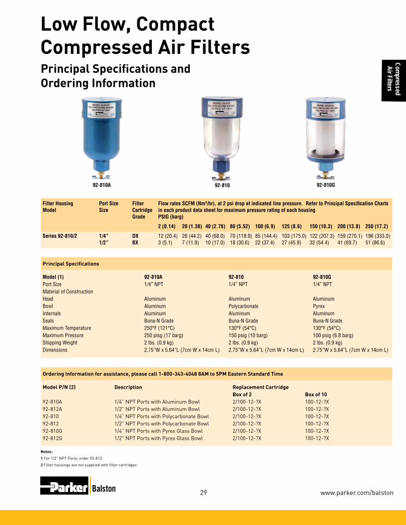
29
Compressed Air Filters
www.parker.com/balston
Compressed
Air Filters
Low Flow, Compact Compressed Air FiltersPrincipal Specifications and Ordering Information
Principal Specifications
Model (1) 92-810A 92-810 92-810GPort Size 1/4” NPT 1/4” NPT 1/4” NPT Material of Construction Head Aluminum Aluminum AluminumBowl Aluminum Polycarbonate PyrexInternals Aluminum Aluminum AluminumSeals Buna-N Grade Buna-N Grade Buna-N GradeMaximum Temperature 250°F (121°C) 130°F (54°C) 130°F (54°C)Maximum Pressure 250 pisg (17 barg) 150 psig (10 barg) 100 psig (6.8 barg)Shipping Weight 2 lbs. (0.9 kg) 2 lbs. (0.9 kg) 2 lbs. (0.9 kg)Dimensions 2.75”W x 5.64”L (7cm W x 14cm L) 2.75”W x 5.64”L (7cm W x 14cm L) 2.75”W x 5.64”L (7cm W x 14cm L)
Ordering Information for assistance, please call 1-800-343-4048 8AM to 5PM Eastern Standard Time
Model P/N (2) Description Replacement Cartridge Box of 2 Box of 1092-810A 1/4” NPT Ports with Aluminum Bowl 2/100-12-?X 100-12-?X 92-812A 1/2” NPT Ports with Aluminum Bowl 2/100-12-?X 100-12-?X92-810 1/4” NPT Ports with Polycarbonate Bowl 2/100-12-?X 100-12-?X 92-812 1/2” NPT Ports with Polycarbonate Bowl 2/100-12-?X 100-12-?X 92-810G 1/4”NPTPortswithPyrexGlassBowl 2/100-12-?X 100-12-?X92-812G 1/2”NPTPortswithPyrexGlassBowl 2/100-12-?X 100-12-?X
Notes:
1 For 1/2” NPT Ports, order 92-812
2 Filter housings are not supplied with filter cartridges
Filter Housing Port Size Filter Flow rates SCFM (Nm3/hr), at 2 psi drop at indicated line pressure. Refer to Principal Specification Charts Model Size Cartridge in each product data sheet for maximum pressure rating of each housing Grade PSIG (barg)
2 (0.14) 20 (1.38) 40 (2.76) 80 (5.52) 100 (6.9) 125 (8.6) 150 (10.3) 200 (13.8) 250 (17.2)
Series 92-810/2 1/4” DX 12 (20.4) 26 (44.2) 40 (68.0) 70 (118.9) 85 (144.4) 103 (175.0) 122 (207.3) 159 (270.1) 196 (333.0) 1/2” BX 3 (5.1) 7 (11.9) 10 (17.0) 18 (30.6) 22 (37.4) 27 (45.9) 32 (54.4) 41 (69.7) 51 (86.6)
92-810A 92-810 92-810G

30
Compressed Air Filters
1-800-343-4048
Com
pres
sed
Air F
ilter
s
Filter-RegulatorCombinationsBalston Filter-Regulators combine a high efficiency coalescing filter with a high quality pressure regulator. Air flows through the filter, then to the pressure regula-tor. The filter is a Balston coalescing compressed air filter (Grade BX) and will completely remove oil, water, and dirt from compressed air and other compressed gases. Flow direction through the element is inside-to-outside for optimum oil and water removal. An automatic drain is installed on the 3/8”, 1/2”, and 3/4” models offering maintenance-free operation. Pressure gauges are standard and are available in up to 4 dif-ferent ranges (see ordering information).
AFR-940, AFR-940A
12E Series
Control CharacteristicsModel AFR-940, AFR-940A Model 12E
Filter Regulators
00
Flow Characteristics12E37E13A*
10 20 30 40 50
0
20
60
80
40
100
5 25 30
10 60 70
5 10 15 20
0
1
2
3
4
5
6
1/2 Inch Ports100 PSIG (6.9 bar)Primary Pressure
Sec
on
dar
y P
ress
ure
- P
SIG
Sec
on
dar
y P
ress
ure
- b
ar
Rated Flow - SCFM
Flow - dm /s3
n

31
Compressed Air Filters
www.parker.com/balston
Compressed
Air Filters
Notes:1 Minimum operating pressure for automatic drain is 15 psig (1.03 barg).2 Maximum pressure ratings are for tem-
peratures to 130°F (54°C). Please consult the factory for maximum pressure ratings at elevated temperatures.
To order product with desired port size and Regulating Pressure Range, select the indicator digits from the matrix (at right). This will complete the entire model number which is needed to place an order.
HowtoOrder 12E 7 BX A
4 3/4” Ports
3 1/2” PortsAutoDrain
16 60 psig
18 125 psig
21 250 psig
With Gage
A non-rising knob, relieving
Grade BXFilter
Model AFR-940 AFR-940A 12E37 12E47
PortSize 1/4”NPT 1/4”NPT 1/2”NPT 3/4”NPTGauge Ports 1/8” NPT 1/8” NPT 1/4” NPT 1/4” NPTMaterials of ConstructionHead Anod. Alum. Anod. Alum. Zinc ZincBowl Polycarb. Anod. Alum. Zinc ZincBonnet Polycarb. Polycarb. Plastic PlasticInternals Brass/Buna Brass/Buna Zinc/Nitrile Zinc/NitrileMaximum Temperature 220°F (104°C) 220°F (104°C) 125°F (52°C) 125°F (52°C) Maximum Pressure 150 psig (10.3 barg) (2) 250 psig (17.2 barg) (2) 250 psig (17.2 barg) (2) 250 psig (17.2 barg) (2)Minimum Pressure ––– ––– 15 psig/1.03 barg (1) 15 psig/1.03 barg (1)Shipping Weight 0.5 lbs. (0.2 kg) 0.5 lbs. (0.2 kg) 2.5 lbs. (1.1 kg) 2.5 lbs. (1.1 kg)Dimensions 1.2”W X 6”L 1.2”W X 6”L 3.25”W X 13”L 3.25”W X 13”L (3cm X 15cm) (3cm X 15cm) 8cm X 33cm) 8cm X 33cm)
Principal Specifications
Ordering Information
For assistance, call toll-free at 1-800-343-4048 8AM to 5PM Eastern Time
Model AFR-940 AFR-940A 12E37 12E47Control Gauge Pressure Range0-30 psig AFR-940-30 AFR-940A-30 see ordering matrix below 5-60 psig AFR-940-60 AFR-940A-60 see ordering matrix below 10-130 psig AFR-940-130 AFR-940A-130 see ordering matrix below
Auto. Drain N/A (1) N/A (1) Included (1) Included (1)
Replacement Filter Cartridges NumberRequired 1 1 1 1Box of 5 5/050-05-BX 5/050-05-BX 5/130-14-BX 5/130-14-BXBox or 10 050-05-BX 050-05-BX 130-14-BX 130-14-BXMounting Bracket 11536 11536 PS807P PS807P
▼▼
▼
Filter Regulators

32
Compressed Air Filters
1-800-343-4048
Com
pres
sed
Air F
ilter
s
Model17LSeriesMany pneumatic system components and most tools require oil lubrication for proper operation and long service life. This lubricant is typically carried by the air stream. Too little oil can cause exces-sive wear and premature failure. Too much oil is wasteful and can become a contaminant. Use of the proper lubricator can greatly extend the life of expensive downstream pneumatic equipment.
The 17L Series Micro-Mist Lubricators offer pro-portional oil delivery over a wide range of air flows. The precision needle valve assures repeatable oil delivery and provides simple adjustment of delivery rate. They are designed to generate oil droplets of 5 microns or smaller downstream to lubricate systems having complex piping arrangements. The 17L series are ideal for low and high flow applica-tions with changing air flow.
Once the required flow is determined for a pneumat-ic application, the lubricator can be selected by us-ing the flow chart. To read the lubricator flow chart, first determine the inlet pressure that will be used. Find the appropriate pressure curve on the graph. Each graph will contain three pressure curves. If the required inlet pressure is not on the graph, interpolate a similar curve for the required pressure.
HowtoSelecttheCorrectLubricator
Next, determine the acceptable pressure drop across the lubricator and locate it on the vertical axis. Find the intersection point of the acceptable pressure drop and the inlet pressure curve. At this point, follow a vertical path downward to view the flow in SCFM. If the flow is too low, select a larger port size or body size to give the required flow. If the flow is higher than necessary, select a smaller port size or body size to give the required flow.
Model 17L22B Model 17L32B and 17L42B
17L Series
0 5 10 15 20 25 30 35 40 45 50 55 60 7065
00
10 20 30 40
7
1
2
3
4
5
6
0
.1
.2
.3
.4
50 60 70 80 90 100 110 120 130 140 150
Flow Characteristics17L32B* 1/2 Inch Ports
&17L42B* 3/4 Inch Ports
Pre
ssu
re D
rop
- P
SIG
Pre
ssu
re D
rop
- b
ar
35 PSIG 90 PSIG 150 PSIGPrimary Pressure - PSIG
2.4 bar 6.2 bar 10.3 barPrimary Pressure - bar
Flow - SCFM
Flow - dm /s3
n
Mist Lubricators
0 5 10 15 20 25 30 35 40 45
00
10 20 30 40
7
1
2
3
4
5
6
0
.1
.2
.3
.4
50 60 70 80 90 100
Flow Characteristics17L22B* 3/8 Inch Ports
Pre
ssu
re D
rop
- P
SIG
Pre
ssu
re D
rop
- b
ar
35 PSIG 90 PSIG 150 PSIGPrimary Pressure - PSIG
2.4 bar 6.2 bar 10.3 barPrimary Pressure - bar
Flow - SCFM
Flow - dm /s3
n

33
Compressed Air Filters
www.parker.com/balston
Compressed
Air Filters
Model 17L22BE 17L32BE 17L42BE
PortSize 3/8”NPT 1/2”NPT 3/4”NPTGauge Ports 1/4” NPT 1/4” NPT 1/4” NPTMaterials of ConstructionHead Zinc Zinc ZincBowl Polycarbonate Polycarbonate PolycarbonateBowl Guard Steel Steel SteelCollar Plastic Plastic PlasticSeal Nitrile Nitrile NitrileSight Dome Polycarbonate Polycarbonate PolycarbonateSight Gage Polyamide Polyamide PolyamideMaximum Temperature 125°F (52°C) 125°F (52°C) 125°F (52°C) Maximum Pressure 150 psig (10.3 barg) 150 psig (10.3 barg) 150 psig (10.3 barg)Minimum Pressure 15 psig (1.03 barg) 15 psig (1.03 barg) 15 psig (1.03 barg)Shipping Weight 1.9 lbs. (0.9 kg) 1.9 lbs. (0.9 kg) 1.9 lbs. (0.9 kg)Dimensions 3.25”W X 9.27”L 3.25”W X 9.27”L 3.25”W X 9.27”L (85mm X 235mm) (85mm X 235mm) (85mm X 235mm)
Principal Specifications
Ordering Information
For assistance, call toll-free at 1-800-343-4048 8AM to 5PM Eastern Time
Model 17L22BE (3/8”NPT) 17L32BE (1/2”NPT) 17L42BE (3/4”NPT)Service Kit PS748P PS748P PS748P
Mist Lubricators

34
Compressed Air Filters
1-800-343-4048
Com
pres
sed
Air F
ilter
s
Basic Unit Series
Port Size (inches) Bowls
Capacity
Elements
(Micron)Page
1/8 1/4 3/8 1/2 3/4 1 1-1/4 1-1/2 2 2-1/2 3 Poly Metal Metal SG 5
F I L T E R S
FF10 X 316 Stainless Steel 4 oz. (113 ml) Standard 37
10F X X X X X 1 oz. (28 ml)
Grade 6 Std., Grade 10 Opt. 39
C O A L E S C E R S
FF501 X 316 Stainless Steel 1 oz. (28 ml) Grade 6 41
FF11 X 316 Stainless Steel 4 oz. (113 ml) Grade 6 43
Product Selection Chart
Basic Unit Series
Port Size (inches) SpringPage
1/8 1/4 3/8 1/2 3/4 1 1-1/2 125
R E G U L A T O R S
S T A N D A R D
FR364 X Standard 45
05R X X Standard 47
FR10 X Standard 49
07R X X X Standard 51
P3NR X X X Standard 53
*Sight gauge
Selection Chart Prep-Air® II Air Preparation Units

35
Compressed Air Filters
www.parker.com/balston
Compressed
Air Filters
Product Selection Chart
Basic Unit Series
Port Size BowlsCapacity
Elements (Micron) Spring Range
Page1/8 1/4 3/8 1/2 3/4 1 1-1/2 Poly Metal Metal
SG 5 125
F I L T E R / R E G U L A T O R S
14E X X X X N/A 1 oz. (28 ml) Standard Standard 55
FB548 X 316 Stainless Steel
1 oz. (28 ml) Standard Standard 57
06E X X X X X X 4.4 oz. (125 ml) Standard Standard 59
FB11 X 316 Stainless Steel
4 oz. (113 ml) Standard Standard 61
*Sight gauge
Selection Chart Prep-Air® II Air Preparation Units

36
Compressed Air Filters
1-800-343-4048
Com
pres
sed
Air F
ilter
s
(Spitter Drain)The diaphragm in this drain pulses when there is a pres-sure differential such as a valve cycling or cylinder stroking downstream. This actionflexesthediaphragmand allows the filter to drain the entrapped water.
The float internal to this drain rises with increased liquid level. When the float rises, it opens a seat area allowing the trapped liquids to drain through the bottom. A manual override can be pushed in the bottom of the drain to unseat the float if par-ticulates create a block.
1/8" NPTAccepts1/8 I.D. Tubing
Accepts3/16 I.D. Tubing
Automatic Pulse Drain Automatic Float Drain
Air Preparation Units - Drains

37
Compressed Air Filters
www.parker.com/balston
Compressed
Air Filters
D E
C
B Dia.Distance RequiredTo Remove All Bowls Regardless of Drain Option
F
A Dia.
Optional Sight GaugeA1
1/8”FemaleThread*
PortSize
NPT without sight gauge NPT with sight gauge
Manual Twist Drain
Automatic Float Drain
Manual Twist Drain
Automatic Float Drain
1/2" FF10-04DGSS FF10-04DGRSS FF10-04WGSS FF10-04WGRSS
F10 Filter Dimensions
A2.38(60)
A1
2.50(64)
B1.75(44)
C.56(14)
D5.00(127)
E5.56(141)
F2.12(54)
inches (mm)
Features•Stainlesssteelconstruction
handles most corrosive environments.
•MeetsNACEspecificationsMR-01-75/ISO15156.
• 1/8"femalethreadeddrain.•HighFlow:1/2"-70SCFM
(119 Nm3/hr) §
Air Preparation Units - FF10 Filter - Standard 1/2” NPT Ports
Ordering Information
FF10 - 04 W G SS
Material
SS Stainless Steel
Options
Blank Manual Twist Drain R Automatic Float Drain
Element
G 5 Micron
Bowl
D Metal Bowl without Sight Gauge W Metal Bowl with Sight Gauge
Port Size
04 1/2 Inch
Port Type
- NPT
§ SCFM = Standard cubic feet per minute at 90 PSIG inlet and 5 PSIG pressure drop. Nm3/hr= Normal cubic meters per hour.

38
Compressed Air Filters
1-800-343-4048
Com
pres
sed
Air F
ilter
s
0
1
2
3
4
5
0 10 20 30 40 50 60 70 80
Pre
ssu
re D
rop
- P
SIG
0
0 5 10 15 20 25 30 35
Flow - SCFM
Flow - dm /s
Pre
ssu
re D
rop
- b
ar
3
n
.1
.2
.3
Flow CharacteristicsFF10-04DGSS1/2 Inch Ports
25 PSIG 50 PSIG 75 PSIG 100 PSIGPrimary Pressure - PSIG
1.7 bar 3.4 bar 5.2 bar 6.9 barPrimary Pressure - bar
FF10 Filter Kits & AccessoriesDrain Kit – Automatic Float Drain ......................................................SA602MDSS Manual Twist Drain– Small (Old) ................................................................. SA600Y7-1SS Large (New) .....................................................................SAP05481Filter Element Kits – Particulate (5 Micron) Element ..................................................... EK55GPipe Nipple – 1/2" 316 Stainless Steel .................................. 616A28-SS
SpecificationsBowl Capacity .............................................................4.0 Ounces (28 ml)FilterRating ...............................................................................5 MicronSump Capacity .........................................................................1.7 OuncePort Threads ............................................................................... 1/2 InchPressure&TemperatureRatings– Manual Twist Drain (D-Bowl) ..................0 to 300 PSIG (0 to 20.7 bar) 0°F to 180°F (-18°C to 82°C) Manual Twist Drain (W-Bowl) .................0 to 250 PSIG (0 to 17.2 bar) 0°F to 150°F (-18°C to 66°C) Automatic Float Drain ..............................15 to 175 PSIG (1 to 12 bar) 40°F to 125°F (4°C to 52°C) Note: Air must be dry enough to avoid ice formation at temperatures below 32°F (2°C).Weight .............................................................................. 1.9 lb. (0.85 kg)
Materials of ConstructionBody ..........................................................................316 Stainless SteelBowls ........................................................................316 Stainless SteelDeflector ........................................................................................AcetalDrain .........................................................................316 Stainless SteelElement Holder .............................................................................AcetalFilter Element .................................................................... PolyethyleneSeals ..................................................................................FluorocarbonSight Gauge ................................................................................Isoplast
Air Preparation Units - FF10 Air Line FiltersTechnical Information

39
Compressed Air Filters
www.parker.com/balston
Compressed
Air Filters
Air Preparation Units - 10F Coalescing Filters - Miniature1/8”, 1/4” Basic 1/8” Body
Parker Hannifin CorporationPneumatic DivisionRichland, Michiganwww.parker.com/pneumatic
34
10F Coalescing Filters – Miniature
Prep-Air® II, 10F Series1/8", 1/4" – Basic 1/8" Body
Catalog 0700P-3/USA
Miniature 10F Series
A
B
DE
C
Distance RequiredTo Remove All BowlsRegardless OfDrain Option
F
Standard part numbers shown bold, with Grade 6 Elements (for Grade 10 Elements, replace “E” with “H” in the 6th position). For other models refer to ordering information below.‡ For polycarbonate bowl see Caution on page 2.§ SCFM = Standard cubic feet per minute at 90 PSIG inlet and 5 PSIG
pressure drop.Nm3/hr = Normal cubic meters per hour @ 6 barg inlet and 0.34 bar pressure drop.
Accepts1/8" Tubing
Automatic Drain
Features• Removes liquid aerosols and sub-micron particles.
• Liquids gravitate to the bottom of the element and will not re-enter the airstream.
• Oil free air for critical applications, such as air gauging and pneumatic instrumentation and controls.
• Interchangeable twist and automatic pulse drains.
• Grade 6 element, 99.97% DOP efficiency.
• High Flow: Grade 6 Element 1/8" – 17 SCFM (29 Nm3/hr) §
1/4" – 20 SCFM (34 Nm3/hr) §
Grade 10 Element 1/8" – 19 SCFM (32 Nm3/hr) §
1/4" – 24 SCFM (41 Nm3/hr) §
10F Coalescing Filter Dimensions
A1.69(43)
B1.56
(39,6)
C0.39(10)
D3.82(97)
D†
3.67(93)
E4.21(107)
E†
4.06(103)
F1.60(41)
Port Size
NPT
Twist Drain Automatic Pulse Drain
Poly Bowl ‡
1/8" 10F01E* 10F05E*
1/4" 10F11E* 10F15E*
Metal Bowl without Sight Gauge
1/8" 10F03E* 10F07E*
1/4" 10F13E* 10F17E*
Inches (mm)
† With Automatic Pulse Drain.
Bowl Options
Polycarbonate Bowl 1 Twist Drain 5 Automatic Pulse Drain
Metal Bowl 3 Twist Drain 7 Automatic Pulse Drain
10F 1 1 E * —
Elements
E Grade 6 H Grade 10
Port Size
0 1/8 Inch 1 1/4 Inch
Ordering Information
Port Type
Blank NPT 1 BSPP 2 BSPT
Engineering Level
* Will be Entered at Factory
NOTE: BOLD OPTIONS ARE STANDARD.
10F Coalescing Filter Dimen-
sionsA
1.69(43)
B1.56
(39,6)
C0.39(10)
Inches (mm)† With Automatic Pulse Drain.
E†
4.06(103)
F1.60(41)
D3.82(97)
D†
3.67(93)
E4.21(107)
§ SCFM = Standard cubic feet per minute. Nm3/hr= Normal cubic meters per hour.

40
Compressed Air Filters
1-800-343-4048
Com
pres
sed
Air F
ilter
s
Air Preparation Units - 10F Coalescing FiltersTechnical Information
10F Coalescing Filter Kits & AccessoriesBowl Kits – Poly Bowl – Automatic Pulse Drain .................................. PS408BP Twist Drain .......................................................PS404P MetalBowl–AutomaticPulseDrain .................................. PS451BP Twist Drain .................................................. PS447BPFilter Element Kits – Grade 6 (Standard) ..................................PS446P Grade 10 (Optional) PS456PMountingBracketKit PS417BP
SpecificationsAutomatic Pulse Drain Tube Barb ............................................ 1/8InchBowl Capacity ............................................................... 1 Ounce (28 ml)Operation – Normal Operating Pressure Drop ......................... 2PSIG(0.14bar) MaximumRecommendedPressureDrop .......... 10PSIG(1.03bar) (Element should be replaced) Port Threads ................................................................... 1/8,1/4InchPressure&TemperatureRatings– Polycarbonate Bowl ...............................0to150PSIG(0to10.3bar) 32°F to 125°F (0°C to 52°C) MetalBowl .............................................0to250PSIG(0to17.2bar) 32°F to 175°F (0°C to 80°C) Automatic Pulse Drain......................10to250PSIG(0.7to17.2bar) at 125°F (52°C) or lessWeight ....................................................................... 0.41 lb. (0.18 kg)
Materials of ConstructionBody .................................................................................................ZincBowls ......................................................... Transparent Polycarbonate Metal(Zinc)WithoutSightGaugeDrains – Twist Drain – Body & Stem ........................................................... Plastic Seals ......................................................................... Nitrile Automatic Pulse Drain – Piston & Seals .......................................................... Nitrile Stem, Seat, Adaptor & Washers ....................... AluminumElement Holder .......................................................................... PlasticFilter Element – Borosilicate & felt glass fibers 99.97% DOP efficiency Largest Aerosol Particle Passed (Grade 6) .....................0.01Micron Largest Solid Particle Passed (Grade 6) .........................0.30MicronSeals ............................................................................................ Nitrile
Grade 6
0 5 10 15 20 25 30 35 40 45 50
35 PSIG 90 PSIG 150 PSIGPrimary Pressure - PSIG
2.4 bar 6.2 bar 10.3 barPrimary Pressure - bar
0 5 10 15 20
Flow - SCFM
Flow - dm /s3
n
Flow Characteristics10F11H*
1/4 Inch Ports0
1
2
3
4
5
6
7
8
10
9
Pre
ssu
re D
rop
- P
SIG
0
.1
Pre
ssu
re D
rop
- b
ar
.2
.3
.4
.5
.6
0 5 10 15 20 25 30 35 40 45
35 PSIG 90 PSIG 150 PSIGPrimary Pressure - PSIG
2.4 bar 6.2 bar 10.3 barPrimary Pressure - bar
0 5 10 15 20
Flow - SCFM
Flow - dm /s3
n
Flow Characteristics10F01E*
1/8 Inch Ports0
1
2
3
4
5
6
7
8
10
9
Pre
ssu
re D
rop
- P
SIG
0
.1
Pre
ssu
re D
rop
- b
ar
.2
.3
.4
.5
.6
0 5 10 15 20 25 30 35 40 45
35 PSIG 90 PSIG 150 PSIGPrimary Pressure - PSIG
2.4 bar 6.2 bar 10.3 barPrimary Pressure - bar
0 5 10 15 20
Flow - SCFM
Flow - dm /s3
n
Flow Characteristics10F01E*
1/8 Inch Ports0
1
2
3
4
5
6
7
8
10
9
Pre
ssu
re D
rop
- P
SIG
0
.1
Pre
ssu
re D
rop
- b
ar
.2
.3
.4
.5
.6
0 5 10 15 20 25 30 35 40 45
35 PSIG 90 PSIG 150 PSIGPrimary Pressure - PSIG
2.4 bar 6.2 bar 10.3 barPrimary Pressure - bar
0 5 10 15 20
Flow - SCFM
Flow - dm /s3
n
Flow Characteristics10F01H*
1/8 Inch Ports0
1
2
3
4
5
6
7
8
10
9
Pre
ssu
re D
rop
- P
SIG
0
.1
Pre
ssu
re D
rop
- b
ar
.2
.3
.4
.5
.6
Grade 10

41
Compressed Air Filters
www.parker.com/balston
Compressed
Air Filters
Air Preparation Units - 10F Coalescing FiltersTechnical Information
Ordering Information
D
F
C
E
A Dia.
DistanceRequiredTo RemoveAll Bowls
1/8”FemaleThread*
PortSize
NPT
Manual Twist Drain
1/4" FF501-02DHSS
F501 Coalescing Filter Dimensions
A1.56(40)
C0.31(8)
D3.69(94)
E4.00(102)
F1.58(40)
inches (mm)
Standard part numbers shown bold. For other models refer to ordering information below.§ SCFM = Standard cubic feet per minute. Nm3/hr= Normal cubic meters per hour.
Features•Stainlesssteelconstructionhandles
most corrosive environments.•MeetsNACEspecifications
MR-01-75/ISO 15156.•1/8"femalethreadeddrain*.•HighFlow:1/4"-16SCFM(27Nm3/hr) §
Port Type
- NPT
Port Size
02 1/4 InchBowl
D Metal Bowl without Sight Gauge
Element
H .3 Micron
Material
SS Stainless Steel
FF501 - 02 D H SS
Air Preparation Units FF501 Coalescing Filter - Miniature 1/4” Ports

42
Compressed Air Filters
1-800-343-4048
Com
pres
sed
Air F
ilter
s
0
1
2
3
6
7
8
9
10
4
5
0 5 10 15 20 25 30 35
Pre
ssu
re D
rop
- P
SIG
0
0 5 10 15
Flow - SCFM
Flow - dm /s
Pre
ssu
re D
rop
- b
ar
3
n
.2
.4
.6
Flow CharacteristicsF501-02DHSS1/4 Inch Ports
35 PSIG 90 PSIG 150 PSIGPrimary Pressure - PSIG
2.4 bar 6.2 bar 10.3 barPrimary Pressure - bar
FF501 Filter Kits & AccessoriesFilter Element Kits – 0.3 Micron ...................................................................................EKF31ManualTwistDrain– Small (Old) ..................................................................... SA600Y7-1SS Large (New) .........................................................................SAP05481Pipe Nipple – 1/4" 316 Stainless Steel ......................................................616Y28-SS
SpecificationsBowl Capacity .............................................................1.0 Ounces (28 ml)FilterRating ............................................................................ 0.3 MicronPort Threads ............................................................................... 1/4 InchPressure&TemperatureRatings –Manual Twist Drain......................................0 to 300 PSIG (0 to 20.7 bar) 0°F to 180°F (-18°C to 82°C)
Note: Air must be dry enough to avoid ice formation at temperatures below 32°F (2°C)Sump Capacity .............................................................0.4 Ounce (11 ml)Weight ............................................................................. 0.6 lb. (0.27 kg)
Materials of ConstructionBody ..........................................................................316 Stainless SteelBowls ........................................................................316 Stainless SteelDrain ........................................................................................................ 316 Stainless SteelElement Holder .............................................................................AcetalFilter Element ............................................................Borosilicate FiberSeals ..................................................................................Fluorocarbon
Air Preparation Units - F501 Series Technical Information

43
Compressed Air Filters
www.parker.com/balston
Compressed
Air Filters
Air Preparation Units - F501 Series Technical Information
Ordering Information
D E
C
B Dia.Distance RequiredTo Remove All Bowls Regardless of Drain Option
F
A Dia.
Optional Sight GaugeA1
1/8”FemaleThread*
F11 Coalescing Filter Dimensions
A2.38(60)
A1
2.50(64)
B1.75(44 )
C0.56(14)
D5.00(127)
E5.56(141)
F2.12(54)
inches (mm)
Features•Stainlesssteelconstructionhandles
most corrosive environments.•MeetsNACEspecifications
MR-01-75/ISO 15156.•1/8"femalethreadeddrain*.•HighFlow:1/2"-45SCFM(77Nm3/hr) §
* Beginning January 2008
Material
SS Stainless SteelElement
J .01 Micron
Port Size
04 1/2 Inch
Port Type
- NPT G BSPP
FF11 - 04 W J SS
PortSize
NPT without sight gauge NPT with sight gauge
Manual Twist Drain
Automatic Float Drain
Manual Twist Drain
Automatic Float Drain
1/2"Metal Bowl With Sight Gauge
F11-04DJSS F11-04DJRSS F11G04WJSS F11G04WJRSS
Options
Blank Manual Twist Drain R Automatic Float Drain
Bowl
D Metal Bowl without Sight Gauge W Metal Bowl with Sight Gauge
Standard part numbers shown bold. For other models refer to ordering information below.§ SCFM = Standard cubic feet per minute. Nm3/hr= Normal cubic meters per hour.
Air Preparation Units - FF11 Coalescing Filter Standard 1/2” Ports

44
Compressed Air Filters
1-800-343-4048
Com
pres
sed
Air F
ilter
s
0
1
2
3
6
7
8
9
10
4
5
0 10 20 30 40 50 60 70 80
Pre
ssu
re D
rop
- P
SIG
0
0 5 10 15 20 25 30 35
Flow - SCFM
Flow - dm /s
Pre
ssu
re D
rop
- b
ar
3
n
.2
.4
.6
Flow CharacteristicsFF11-04DJSS1/2 Inch Ports
35 PSIG 90 PSIG 150 PSIGPrimary Pressure - PSIG
2.4 bar 6.2 bar 10.3 barPrimary Pressure - bar
F11 Filter Kits & AccessoriesDrain Kit – Automatic Float Drain ......................................................SA602MDSS Manual Twist Drain– Small (Old) ................................................................. SA600Y7-1SS Large (New) .....................................................................SAP05481Filter Element Kits – 0.3 Micron ...................................................................................EKF71Pipe Nipple – 1/2" 316 Stainless Steel ..................................................... 616A28-SS
SpecificationsBowl Capacity ......................................................................... 4.0 OuncesFilterRating .......................................................................... 0.01 MicronSump Capacity .........................................................................1.7 OuncePort Threads ............................................................................... 1/2 InchPressure&TemperatureRatings– Manual Twist Drain ................................0 to 300 PSIG (0 to 20.7 bar) 0°F to 180°F (-18°C to 82°C) Manual Twist Drain (W) ...........................0 to 250 PSIG (0 to 17.2 bar) 0°F to 150°F (-18°C to 66°C) Automatic Float Drain ...............................0 to 175 PSIG (0 to 12 bar) 40°F to 125°F (4°C to 52°C) Note: Air must be dry enough to avoid ice formation at temperatures below 32°F (2°C).Weight .............................................................................. 1.9 lb. (0.85 kg)
Materials of ConstructionBody ..........................................................................316 Stainless SteelBowls ........................................................................316 Stainless SteelDrain .........................................................................316 Stainless Steel
Element Holder .............................................................................AcetalFilter Element ............................................................Borosilicate FiberSeals ..................................................................................FluorocarbonSight Gauge ................................................................................ Isoplast
1Tested per ISO 12500-1 at 40 ppm inlet. 2Add dry + wet for total pressure drop.
GradeDesig-nation
Coalescing Efficiency0.3 to 0.6 Micron
Particles
MaximumOil
Carryover1
PPM w/w
Micron Rating
Pressure Drop PSID (bar)
@ Rated Flow2
Flow:SCFM
@3 PSID Operating Pressure 100 PSIG
MediaDry
MediaWet With
10-20 wt. oil
6 99.97% 0.008 0.01 1.0 (0.07)
2-3 (0.14-0.21) ??
10 95% 0.85 1.0 0.5 (0.03) 0.5 (0.03) ??
FF11MediaSpecifications
Air Preparation Units - FF11 Series Technical Information

45
Compressed Air Filters
www.parker.com/balston
Compressed
Air Filters
Air Preparation Units - FF11 Series Technical Information
Ordering Information
Features•Stainlesssteelconstructionhandles
most corrosive environments.•Largediaphragmtovalvearearatiofor
precise regulation and high flow capacity.•MeetsNACEspecifications
MR-01-75/ISO 15156.•HighFlow:1/4"–12SCFM(20Nm3/hr)§
C1
E1
D
ADia.
Material
SS Stainless SteelPressure Range
C 0-125 PSIG (0-8.5 bar)
Port Size
02 1/4 Inch
§ SCFM = Standard cubic feet per minute. Nm3/hr= Normal cubic meters per hour.
Series Adjustment Type
PortSize NPT
FR364 Knob 1/4" FR364-02CSS
R364 Regulator Dimensions
A1.56(40)
C1
2.56(65)
D0.50(13)
E1
3.06(78)
inches (mm)
NOTE:1.25Dia.(32mm) hole required for panel mounting.
FR364 - 02 C SS
Port Type
- NPT
Series
R364 Standard Knob
R364
! WARNINGProduct rupture can cause serious injury.Do not connect regulator to bottled gas.
Do not exceed maximum primary pressure rating.
R364
Air Preparation Units - FR364 Regulator -Miniature 1/4” Ports
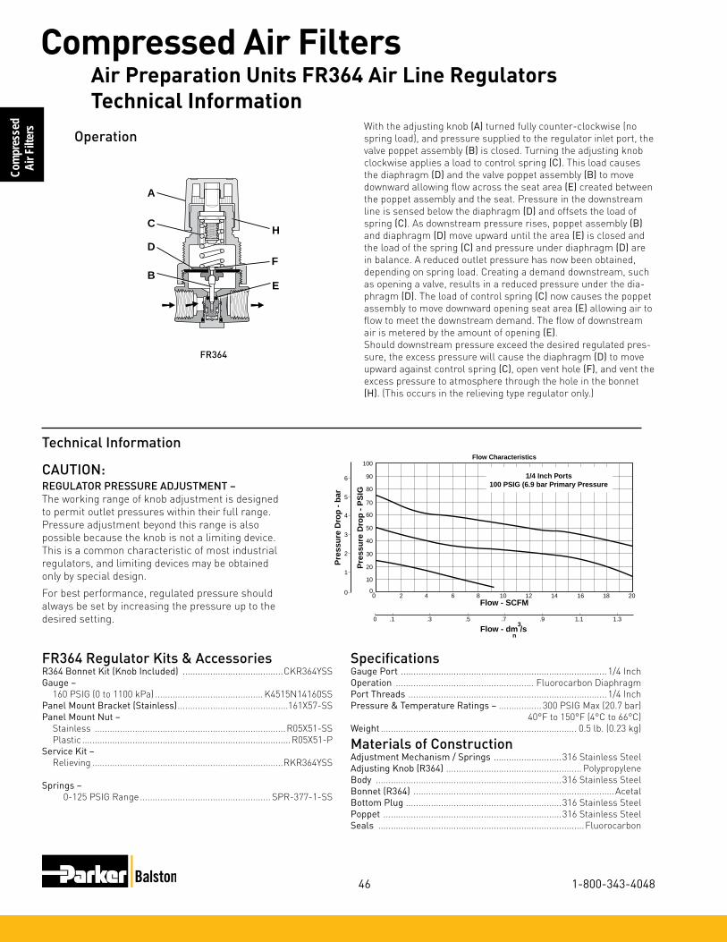
46
Compressed Air Filters
1-800-343-4048
Com
pres
sed
Air F
ilter
s
0
20
30
50
10
40
60
70
90
80
100
0 2 4 6 8 10 12 14 16 18 20
Pre
ssu
re D
rop
- P
SIG
0
0 .1 .3 .5 .7 .9 1.1 1.3
Flow - SCFM
Flow - dm /s
Pre
ssu
re D
rop
- b
ar
3
n
1
2
3
4
5
6
Flow Characteristics
1/4 Inch Ports100 PSIG (6.9 bar Primary Pressure
Operation
SpecificationsGauge Port .................................................................................. 1/4 InchOperation ....................................................... Fluorocarbon DiaphragmPort Threads ............................................................................... 1/4 InchPressure&TemperatureRatings– ................. 300 PSIG Max (20.7 bar) 40°F to 150°F (4°C to 66°C)Weight .............................................................................. 0.5 lb. (0.23 kg)
Materials of ConstructionAdjustmentMechanism/Springs ...........................316 Stainless SteelAdjustingKnob(R364) ...................................................... PolypropyleneBody ..........................................................................316 Stainless SteelBonnet(R364) ................................................................................AcetalBottom Plug ..............................................................316 Stainless SteelPoppet .......................................................................316 Stainless SteelSeals ..................................................................................Fluorocarbon
FR364 Regulator Kits & AccessoriesR364BonnetKit(KnobIncluded) ........................................CKR364YSSGauge – 160 PSIG (0 to 1100 kPa) ........................................... K4515N14160SSPanelMountBracket(Stainless) ............................................161X57-SSPanelMountNut– Stainless ............................................................................R05X51-SS Plastic ...................................................................................R05X51-PService Kit – Relieving ............................................................................RKR364YSS
Springs – 0-125 PSIG Range .................................................... SPR-377-1-SS
Technical Information
With the adjusting knob (A) turned fully counter-clockwise (no spring load), and pressure supplied to the regulator inlet port, the valve poppet assembly (B) is closed. Turning the adjusting knob clockwise applies a load to control spring (C). This load causes the diaphragm (D) and the valve poppet assembly (B) to move downward allowing flow across the seat area (E) created between the poppet assembly and the seat. Pressure in the downstream line is sensed below the diaphragm (D) and offsets the load of spring (C). As downstream pressure rises, poppet assembly (B) and diaphragm (D) move upward until the area (E) is closed and the load of the spring (C) and pressure under diaphragm (D) are in balance. A reduced outlet pressure has now been obtained, depending on spring load. Creating a demand downstream, such as opening a valve, results in a reduced pressure under the dia-phragm (D). The load of control spring (C) now causes the poppet assembly to move downward opening seat area (E) allowing air to flow to meet the downstream demand. The flow of downstream air is metered by the amount of opening (E).Should downstream pressure exceed the desired regulated pres-sure, the excess pressure will cause the diaphragm (D) to move upward against control spring (C), open vent hole (F), and vent the excess pressure to atmosphere through the hole in the bonnet (H). (This occurs in the relieving type regulator only.)
H
F
E
A
D
C
B
FR364
CAUTION:REGULATOR PRESSURE ADJUSTMENT – The working range of knob adjustment is designed to permit outlet pressures within their full range. Pressure adjustment beyond this range is also possible because the knob is not a limiting device. This is a common characteristic of most industrial regulators, and limiting devices may be obtained only by special design.
For best performance, regulated pressure should always be set by increasing the pressure up to the desired setting.
Air Preparation Units FR364 Air Line RegulatorsTechnical Information

47
Compressed Air Filters
www.parker.com/balston
Compressed
Air Filters
Air Preparation Units FR364 Air Line RegulatorsTechnical Information
Features•Secondaryaspirationplusbalancedpoppetprovides
quick response and accurate pressure regulation.•Rollingdiaphragmforextendedlife.•Removablenon-risingknobforpanelmounting
and tamper resistance.•Easilyserviced.•ReverseFlow.•HighFlow: 1/4" – 30 SCFM (51 Nm3/hr)§
3/8" – 40 SCFM (68 Nm3/hr)§
NOTE:1.53Dia.(39mm)holerequiredforpanelmounting.§ SCFM = Standard cubic feet per minute. Nm3/hr= Normal cubic meters per hour.
A
B
PU
SH TO LOCK
C
D
E
1/4" NPTGauge Ports
(2)
Options
Blank No Options
Preset / Pressure Limited
Blank None
Port Type Blank NPT
Port Size
1 1/4 Inch 2 3/8 Inch
Pressure Range
Without Gauge 13 125 PSIG/
8.62 bargWith Gauge**
18 125 PSIG/ 8.62 barg
05R 1 13 A * — — ---
Port Size NPT
Without Gauge
1/4" 05R113A*3/8" 05R213A*
With 160 PSI Gauge
1/4" 05R118A*3/8" 05R218A*
05RRegulatorDimensions
A2.00(51)
B2.06(52)
C3.16(80)
D1.28(32)
E4.44(113)
Inches (mm)
Ordering Information
** Includes 1-1/2" Dial Face Gauge
Engineering Level
* Will be Entered at Factory
† Inlet Pressure is 100 PSIG. For other pressures, contact factory.
Relief
A Relieving
* 1/4 & 3/8 inch meet ISO 1179-1 Standard.
Air Preparation Units - 05R Regulators - Economy1/4”, 3/8” NPT - Basic 1/4” Body

48
Compressed Air Filters
1-800-343-4048
Com
pres
sed
Air F
ilter
s
SpecificationsGauge Ports (2) ...........................................................................1/4 InchPort Threads ........................................................................1/4, 3/8 InchPrimaryPressureRating– Maximum Primary Pressure .......................250 PSIG (17.2 bar) Max. For Secondary Pressure Ranges see above charts.TemperatureRating ....................................32°F to 175°F (0°C to 80°C) Low Temperature .................................-4°F to 125°F (-20°C to 52°C) Weight ............................................................................ 1.1 lb. (0.49 kg)
Materials of ConstructionAdjusting Stem .............................................................................. BrassBonnet ...........................................................................................PlasticBody ................................................................................................... ZincCollar, Knob ...................................................................................PlasticDiaphragm .....................................................................................NitrilePoppet & Cap ................................................................................PlasticSeals ...............................................................................................NitrileSprings – Poppet & Control .............................................................Steel
05R Regulator Kits & AccessoriesBonnet Assembly Kit .................................................................. PS915PControl Knob ................................................................................P04420Gauges – 1-1/2" Dial Face ????
30 PSIG (0 to 2.1 bar) ....................................... K4515N1403060 PSIG (0 to 4.1 bar) ....................................... K4515N14060160 PSIG (0 to 11.0 bar) ................................... K4515N14160300 PSIG (0 to 20.0 bar) ................................... K4515N14300
2" Dial Face 60 PSIG (0 to 4.1 bar) ..................................... K4520N14060160 PSIG (0 to 11.0 bar) ..................................K4520N14160
Mounting Bracket Kit ................................................................PS963PPanelMountNut– Metal ........................................................... PS964PSprings – 1-30 PSIG Range ........................................................P04427 1-60 PSIG Range ........................................................P04426 2-125 PSIG Range ......................................................P04425 2-200 PSIG ..................................................................P02934Service Kit – Relieving ............................................................ PS908P
0
15
30
45
60
75
90
105
120
10 0 10 20 30 40 50 60 70 80
Relief and Flow Characteristics05R113A*
05 5 10 15 20 25 30 35
Flow (SCFM)
Flow - dm /s3
n
0
1 Sec
on
dar
y P
ress
ure
- P
SIG
Sec
on
dar
y P
ress
ure
- b
ar
2
3
4
5
6
7
8
1/4 Inch PortsPrimary Pressure 100 PSIG (6.9 bar)
0
15
30
45
60
75
90
105
120
10 0 10 20 30 40 50 60 70 80
Relief and Flow Characteristics05R213A*
05 5 10 15 20 25 30 35
Flow (SCFM)
Flow - dm /s3
n
0
1 Sec
on
dar
y P
ress
ure
- P
SIG
Sec
on
dar
y P
ress
ure
- b
ar
2
3
4
5
6
7
8
3/8 Inch PortsPrimary Pressure 100 PSIG (6.9 bar)
! WARNINGProduct rupture can cause serious injury.Do not connect regulator to bottled gas.
Do not exceed maximum primary pressure rating.
CAUTION:REGULATOR PRESSURE ADJUSTMENT – The working range of knob adjustment is designed to permit outlet pressures within their full range. Pressure adjustment beyond this range is also possible because the knob is not a limiting device. This is a common characteristic of most industrial regulators, and limiting devices may be obtained only by special design.
For best performance, regulated pressure should always be set by increasing the pressure up to the desired setting.
Air Preparation Units 05R Air Line Regulators Technical Information

49
Compressed Air Filters
www.parker.com/balston
Compressed
Air Filters
Air Preparation Units 05R Air Line Regulators Technical Information
Ordering Information
A
B
C
E
D
Features•Stainlesssteelconstructionhandles
most corrosive environments.•Largediaphragmtovalvearea
ratio for precise regulation and high flow capacity.
•MeetsNACEspecifications MR-01-75/ISO 15156.
•Lowtemperatureversionavailable.•HighFlow:1/2"–80SCFM(136Nm3/hr)§
PortSize NPT
1/2" FR10-04CSS
Material
SS Stainless SteelPressure Range
C 0-125 PSIG (0-8.5 bar)
Port Size
04 1/2 Inch
FR10 - 04 C SS
Port Type
- NPT
§ SCFM = Standard cubic feet per minute. Nm3/hr= Normal cubic meters per hour.
R10, R11 Regulator Dimensions
A2.34(60)
B2.43(62)
C3.59(91)
D1.38(35)
E4.97(126)
inches (mm)NOTE:1.75Dia.(44mm)holerequired for panel mounting.
Series
R10 Standard Knob
R10
! WARNINGProduct rupture can cause serious injury.Do not connect regulator to bottled gas.
Do not exceed maximum primary pressure rating.
R10
Air Preparation Units - FR10 Regulator - Standard 1/2” Ports

50
Compressed Air Filters
1-800-343-4048
Com
pres
sed
Air F
ilter
s
0
20
30
50
10
40
60
70
90
80
100
0 10 20 30 40 50 60 70 80 90 100
Pre
ssu
re D
rop
- P
SIG
0
0 5 10 15 20 25 30 35 40 45
Flow - SCFM
Flow - dm /s
Pre
ssu
re D
rop
- b
ar
3
n
1
2
3
4
5
6
Flow Characteristics
1/2 Inch Ports100 PSIG (6.9 bar Primary Pressure
SpecificationsGauge Port .................................................................................. 1/4 InchOperation ....................................................... Fluorocarbon DiaphragmPort Threads ............................................................................... 1/2 InchPressure&TemperatureRatings– ................. 300 PSIG Max (20.7 bar) 0°F to 150°F (-18°C to 66°C) Note: Air must be dry enough to avoid ice formation at temperatures below 32°F (2°C).Weight ............................................................................ 1.79 lb. (0.81 kg)
Materials of ConstructionAdjustmentMechanism/Springs ...........................316 Stainless SteelBody ..........................................................................316 Stainless SteelBonnet/Knob(R10) ......................................................................AcetalBottom Plug ..............................................................316 Stainless SteelPoppet .......................................................................316 Stainless SteelSeals ..................................................................................Fluorocarbon
FR10 Regulator Kits & AccessoriesR10BonnetKit(KnobIncluded) ............................................CKR10YSSGauge – 160 PSIG (0 to 1100 kPa), 2" Face ............................. K4520N14160SSPanelMountBracket(Stainless) ............................................161X57-SSPanelMountNut– Stainless ............................................................................R10X51-SS Plastic ...................................................................................R10X51-PService Kit – Relieving ..............................................................................RKR10YSS
Springs – 0-125 PSIG Range ........................................................ SPR-389-1-SS
Operation
D
A
C
B
H
F
E
Technical Information
With the adjusting knob (A) turned fully counter-clockwise (no spring load), and pressure supplied to the regulator inlet port, the valve poppet assembly (B) is closed. Turning the adjusting knob clockwise applies a load to control spring (C). This load causes the diaphragm (D) and the valve poppet assembly (B) to move downward allowing flow across the seat area (E) created between the poppet assembly and the seat. Pressure in the downstream line is sensed below the diaphragm (D) and offsets the load of spring (C). As downstream pressure rises, poppet assembly (B) and diaphragm (D) move upward until the area (E) is closed and the load of the spring (C) and pressure under diaphragm (D) are in balance. A reduced outlet pressure has now been obtained, depending on spring load. Creating a demand downstream, such as opening a valve, results in a reduced pressure under the diaphragm (D). The load of control spring (C) now causes the poppet assembly to move downward opening seat area (E) allowing air to flow to meet the downstream demand. The flow of downstream air is metered by the amount of opening (E).
Should downstream pressure exceed the desired regulated pressure, the excess pressure will cause the diaphragm (D) to move upward against control spring (C), open vent hole (F), and vent the excess pressure to atmosphere through the hole in the bonnet (H). (This occurs in the relieving type regulator only.)
CAUTION:REGULATOR PRESSURE ADJUSTMENT – The working range of knob adjustment is designed to permit outlet pressures within their full range. Pressure adjustment beyond this range is also possible because the knob is not a limiting device. This is a common characteristic of most industrial regulators, and limiting devices may be obtained only by special design.
For best performance, regulated pressure should always be set by increasing the pressure up to the desired setting.
Air Preparation Units FR10 Air Line Regulators Technical Information

51
Compressed Air Filters
www.parker.com/balston
Compressed
Air Filters
Air Preparation Units FR10 Air Line Regulators Technical Information
C
E
D
B
AP
USH TO LOC
K
1/4" NPTGauge Ports
(2)
Features•Secondaryaspirationplusbalancedpoppetprovides
quick response and accurate pressure regulation.•Rollingdiaphragmforextendedlife.•Twohighflow1/4"gaugeportscanbeusedasaddi-
tional outlets.•Easilyserviced.•Removablenon-risingknobforpanelmounting
and tamper resistance.•HighFlow: 3/8"–70SCFM (119 Nm3/hr) §
1/2" – 90 SCFM (153 Nm3/hr) §
3/4" – 90 SCFM (153 Nm3/hr) §
NOTE:2.00Dia.(51mm)holerequiredforpanelmounting.§ SCFM = Standard cubic feet per minute. Nm3/hr= Normal cubic meters per hour.
Options
Blank No Options
Preset / Pressure Limited
Blank None† Inlet Pressure is 100 PSIG/
6.89 barg. For other pressures, contact factory.
Port Type Blank NPT
Port Size
2 3/8 Inch 3 1/2 Inch 4 3/4 Inch
Pressure Range
Without Gauge 13 125 PSIG/ 8.6 barg
Relief
A Relieving
07R 3 13 A * — — ---
! WARNINGProduct rupture can cause serious injury.Do not connect regulator to bottled gas.
Do not exceed maximum primary pressure rating.
Port Size NPT
Without Gauge
3/8" 07R213A*1/2" 07R313A*3/4" 07R413A*
Ordering Information
Engineering Level
* Will be Entered at Factory
07RRegulatorDimensions
A3.24(82)
B2.74(70)
C4.79(122)
D1.61(41)
E6.40(163)
Inches (mm)
* 3/8 & 1/2 inch meet ISO 1179-1 Standard.
Air Preparation Units - 07R Regulators - Standard 3/8”, 1/2”, 3/4” NPT - Basic 1/2” Body

52
Compressed Air Filters
1-800-343-4048
Com
pres
sed
Air F
ilter
s
07R Regulator Kits & AccessoriesBonnet Assembly Kit .................................................................. PS715PControl Knob ............................................................................. P04069BGauges – 60 PSIG (0 to 4.1 bar) ...................................... K4520N14060 160 PSIG (0 to 11.0 bar) .................................. K4520N14160
MountingBracketKit (Includes Panel Mount Nut) .................... PS807PPanelMountNut– Plastic ........................................................P04082 Metal ....................................................... P04079B
Service Kit – Relieving (Includes Poppet) ............................... PS808P
Springs – 2-125 PSIG Range ...............................................P04063
Tamperproof Kit ......................................................................... PS737P
SpecificationsGauge Ports (2) ...........................................................................1/4 Inch (CanbeusedasadditionalHighFlow1/4InchOutletPorts)Port Threads .................................................................3/8, 1/2, 3/4 InchPrimaryPressureRating– Maximum Primary Pressure .................................250 PSIG (17.2 bar)SecondaryPressureRange– Standard Pressure .................................... 2 to 125 PSIG (0 to 8.6 bar) TemperatureRating ....................................32°F to 175°F (0°C to 80°C)Weight 2.5 lb. (1.1 kg)
Materials of ConstructionAdjusting Stem ............................................................................... SteelBody ................................................................................................... ZincBonnet, Piston Stem, Valve Poppet & Cap ..................................PlasticCollar, Knob ...................................................................................PlasticDiaphragm .....................................................................................NitrileSeals ...............................................................................................NitrileSprings – Poppet ....................................................................Stainless Control ...........................................................................Steel
00
Relief And Flow Characteristics07R213A*
10 30 50 70 900
20
60
80
40
100
1
2
3
4
5
6
10 110 130
0 5 45 555 15 25 35
Sec
on
dar
y P
ress
ure
- P
SIG
Sec
on
dar
y P
ress
ure
- b
ar
Rated Flow - SCFM
Flow - dm /s3
n
3/8 Inch Ports100 PSIG (6.9 bar) Primary Pressure
00
Relief And Flow Characteristics07R313A*
10 30 50 70 900
20
60
80
40
100
1
2
3
4
5
6
10 110 130
0 5 45 555 15 25 35
Sec
on
dar
y P
ress
ure
- P
SIG
Sec
on
dar
y P
ress
ure
- b
ar
Rated Flow - SCFM
Flow - dm /s3
n
1/2 Inch Ports100 PSIG (6.9 bar) Primary Pressure
00
Relief And Flow Characteristics07R413A*
10 30 50 70 900
20
60
80
40
100
1
2
3
4
5
6
10 110 130 150 170
0 5 45 55 65 755 15 25 35
Sec
on
dar
y P
ress
ure
- P
SIG
Sec
on
dar
y P
ress
ure
- b
ar
Rated Flow - SCFM
Flow - dm /s3
n
3/4 Inch Ports100 PSIG (6.9 bar) Primary Pressure
CAUTION:REGULATOR PRESSURE ADJUSTMENT – The working range of knob adjustment is designed to permit outlet pressures within their full range. Pressure adjustment beyond this range is also possible because the knob is not a limiting device. This is a common characteristic of most industrial regulators, and limiting devices may be obtained only by special design.
For best performance, regulated pressure should always be set by increasing the pressure up to the desired setting.
Air Preparation Units 07R Air Line Regulators Technical Information

53
Compressed Air Filters
www.parker.com/balston
Compressed
Air Filters
Air Preparation Units 07R Air Line Regulators Technical Information
Features•Portblocks(PB)availabletoprovide1-1/2"
port extension to 1" ported bodies.•Selfrelievingfeatureplusbalancedpoppet
provides quick response and accurate pres-sure regulation.
•Solidcontrolpistonforextendedlife.•HighFlow: 3/4"–200SCFM (340 Nm3/hr) §
1" – 300 SCFM (510 Nm3/hr) §
1½" – 300 SCFM (510 Nm3/hr) §
B
CE
D
AA (PB)
PU
SH TO LOCK
1/4" NPTGauge Ports
(2)
P3N R A 9 8 B N N
Pressure Gauge
Without Gauge N 125 PSI (0 to 8 bar)
Adjustment
N Non-Rising Knob
Relief
B Relieving
Port Size
6 3/4" (w/o Port Blocks) 8 1" (w/o Port Blocks) P 1-1/2" Port Blocks (w/ 1" Ported Body)
Port Type
9 NPT Female
Design Level
NOTE:2.00Dia.(51mm)holerequiredforpanelmounting.§ SCFM = Standard cubic feet per minute. Nm3/hr= Normal cubic meters per hour.
! WARNINGProduct rupture can cause serious injury.Do not connect regulator to bottled gas.
Do not exceed maximum primary pressure rating.
Port Size NPT
Without Gauge
3/4" P3NRA96BNN1" P3NRA98BNN1½ P3NRA9PBNN
Ordering Information
P3NRRegulatorDimensions
A3.62(92)
A(PB)
5.91(150)
B3.62(92)
C6.38(162)
D2.08(53)
E8.46(215)
Inches (mm)
* 3/4 & 1 inch meet ISO 1179-1 Standard.
Air Preparation Units - P3NR Regulators - High Flow3/4”, 1”, 1 1/2” NPT - Basic 1” Body
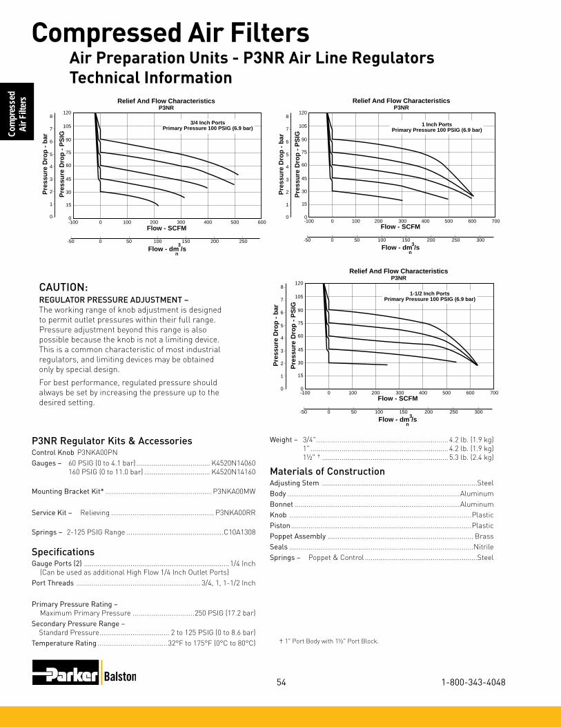
54
Compressed Air Filters
1-800-343-4048
Com
pres
sed
Air F
ilter
s
† 1" Port Body with 1½" Port Block.
P3NR Regulator Kits & AccessoriesControl Knob P3NKA00PNGauges – 60 PSIG (0 to 4.1 bar) ...................................... K4520N14060 160 PSIG (0 to 11.0 bar) .................................. K4520N14160
MountingBracketKit* ....................................................... P3NKA00MW
Service Kit – Relieving ..................................................... P3NKA00RR
Springs – 2-125 PSIG Range ..................................................C10A1308
SpecificationsGauge Ports (2) ...........................................................................1/4 Inch (CanbeusedasadditionalHighFlow1/4InchOutletPorts)Port Threads ................................................................ 3/4, 1, 1-1/2 Inch
PrimaryPressureRating– Maximum Primary Pressure ................................250 PSIG (17.2 bar)SecondaryPressureRange– Standard Pressure .................................... 2 to 125 PSIG (0 to 8.6 bar)TemperatureRating ....................................32°F to 175°F (0°C to 80°C)
0
15
30
45
60
75
120
105
90
0 200100-100 300 400 500 600
0 50-50 100 150 200 250
Flow - SCFM
Pre
ssu
re D
rop
- P
SIG
0
1
Pre
ssu
re D
rop
- b
ar
2
3
4
5
7
6
83/4 Inch Ports
Primary Pressure 100 PSIG (6.9 bar)
Relief And Flow CharacteristicsP3NR
Flow - dm /s3
n
0
15
30
45
60
75
120
105
90
0 200100-100 300 400 500 700600
Pre
ssu
re D
rop
- P
SIG
0
1
0 50-50 100 150 200 250 300
Flow - SCFM
Pre
ssu
re D
rop
- b
ar
2
3
4
5
7
6
8
1 Inch PortsPrimary Pressure 100 PSIG (6.9 bar)
Relief And Flow CharacteristicsP3NR
Flow - dm /s3
n
0
15
30
45
60
75
120
105
90
0 200100-100 300 400 500 700600
Pre
ssu
re D
rop
- P
SIG
0
1
0 50-50 100 150 200 250 300
Flow - SCFM
Pre
ssu
re D
rop
- b
ar
2
3
4
5
7
6
81-1/2 Inch Ports
Primary Pressure 100 PSIG (6.9 bar)
Relief And Flow CharacteristicsP3NR
Flow - dm /s3
n
CAUTION:REGULATOR PRESSURE ADJUSTMENT – The working range of knob adjustment is designed to permit outlet pressures within their full range. Pressure adjustment beyond this range is also possible because the knob is not a limiting device. This is a common characteristic of most industrial regulators, and limiting devices may be obtained only by special design.
For best performance, regulated pressure should always be set by increasing the pressure up to the desired setting.
Weight – 3/4" .................................................................... 4.2 lb. (1.9 kg) 1" ....................................................................... 4.2 lb. (1.9 kg) 1½" † ................................................................. 5.3 lb. (2.4 kg)
Materials of ConstructionAdjusting Stem ................................................................................SteelBody .........................................................................................AluminumBonnet .....................................................................................AluminumKnob ..............................................................................................PlasticPiston .............................................................................................PlasticPoppet Assembly ........................................................................... BrassSeals ...............................................................................................NitrileSprings – Poppet & Control ..........................................................Steel
Air Preparation Units - P3NR Air Line Regulators Technical Information

55
Compressed Air Filters
www.parker.com/balston
Compressed
Air Filters
Air Preparation Units - P3NR Air Line Regulators Technical Information
14E 1 1 B 13 F * — — ---
Port Size
0 1/8 Inch 1 1/4 Inch
Bowl Options
Polycarbonate Bowl 1 Twist Drain 5 Automatic Drain
Metal Bowl 3 Twist Drain 7 Automatic Drain
Elements B 5 Micron
Relief
F Relieving
Pressure Range
13 125 PSIG
Port Type Blank NPT
† Inlet Pressure is 100 PSIG. For other pressures, contact factory.
Preset / Pressure Limited
Blank None
Options
Blank No Options
Features•Excellentwaterremovalefficiency.•Unbalancedpoppetstandard.•Solidcontrolpistonforextendedlife.•Spacesavingpackageoffersbothfilter
and regulator features in one integral unit.•Non-risingadjustmentknob.•Twofullflow1/8"gaugeports.•HighFlow: 1/8"–16SCFM(27 Nm3/hr) §
1/4" – 18 SCFM (31 Nm3/hr) §
‡ For polycarbonate bowl see Caution on page A2.§ SCFM = Standard cubic feet per minute. Nm3/hr= Normal cubic meters per hour.
NOTE:1.218 Dia. (31mm) hole required for panel mounting.
PortSize
NPT
Twist Drain Automatic Pulse Drain
Poly Bowl‡
1/8" 14E01B13F* 14E05B13F*
1/4" 14E11B13F* 14E15B13F*Metal Bowl
1/8" 14E03B13F* 14E07B13F*
1/4" 14E13B13F* 14E17B13F*
Ordering Information
A
B
D
E
C
Distance RequiredTo Remove All BowlsRegardless OfDrain Option
F
1/8" NPTGauge Ports
(2)
Accepts1/8" Tubing
Automatic Drain
14EFilter/Regu-lator Dimensions
A1.62(41)
B1.58(40)
C2.42(61)
D3.79(96)
D †3.64(92)
E6.21(158)
E †6.06(154)
F1.60(41)
Inches (mm)† With Auto Drain
Engineering Level
* Will be Entered at Factory
Air Preparation Units - 14E Filter/Regulator - Miniature 1/8”, 1/4” NPT - Basic 1/8” Body

56
Compressed Air Filters
1-800-343-4048
Com
pres
sed
Air F
ilter
s
14E Filter / Regulator Kits & AccessoriesBowl Kits – Poly Bowl – Automatic Drain ..............................................PS408BP Twist Drain......................................................... PS404P Metal Bowl – Automatic Drain ..............................................PS451BP Twist Drain.......................................................PS447BPFilter Element Kits – 5 Micron .................................................. PS403P
Gauges –???? 30 PSIG (0 to 2.1 bar) ....................K4515N18030 60 PSIG (0 to 4.1 bar) ....................K4515N18060 160 PSIG (0 to 11.0 bar) ................ K4515N18160
Mounting Bracket Kit (Includes Panel Mount Nut) .................PS417BPPanel Mount Nut .........................................................................P78652Poppet Kit – Unbalanced ......................................................PS424BP
Service Kit – Relieving ............................................................ PS423PSprings – 2- 125 PSIG Range (Gold) ..........................................P01173
SpecificationsAutomatic Pulse Drain Tube Barb .............................................1/8 InchBowl Capacity .............................................................................1 OunceGauge Ports (2) (Can be used for Full Flow) ..............................1/8 InchPort Threads ........................................................................1/8, 1/4 InchPressure & Temperature Ratings – Polycarbonate Bowl 0 to 150 PSIG (0 to 10.3 bar), 32°F to 125°F (0°C to 52°C) Metal Bowl 0 to 250 PSIG (0 to 17.2 bar), 32°F to 175°F (0°C to 80°C)
Secondary Pressure Ranges – Standard Pressure .............................. 2 to 125 PSIG (0 to 8.6 bar) Weight .............................................................................. 0.4 lb. (0.18 kg)
Materials of ConstructionAdjusting Nut ................................................................................. BrassAdjusting Stem & Spring ................................................................SteelBody ................................................................................................... ZincBonnet, Knob, Seat, Piston, Holder & Deflector ........................PlasticBowls Available – Transparent ..................................... Polycarbonate Metal (Without Sight Gauge) ........................... Zinc Drains – Manual – Twist Type Body & Stem .............................................................Plastic Seals ...........................................................................Nitrile Automatic – Pulse Type Piston & Seals ...........................................................Nitrile Stem, Seat, Adaptor & Washers ........................AluminumFilter Elements – 5 Micron (Standard) ........................................Plastic Seals ............................................................................................Nitrile
00
20
60
80
40
100
1
2
3
4
5
6
0 4 8 12 16 20 24 28 32
0 2 4 6 8 10 12 14
Relief And Flow Characteristics14E01B13F*
Sec
on
dar
y P
ress
ure
- P
SIG
Sec
on
dar
y P
ress
ure
- b
ar
Rated Flow - SCFM
Flow - dm /s3
n
1/8 Inch Ports100 PSIG (6.9 bar) Primary Pressure
00
4 8 12 16 20 24 28 32
0
0
20
60
80
40
100
1
2
3
4
5
6
2 4 6 8 10 12 14
Relief And Flow Characteristics14E11B13F*
Sec
on
dar
y P
ress
ure
- P
SIG
Sec
on
dar
y P
ress
ure
- b
ar
Rated Flow - SCFM
Flow - dm /s3
n
1/4 Inch Ports100 PSIG (6.9 bar) Primary Pressure
! WARNINGProduct rupture can cause serious injury.Do not connect regulator to bottled gas.
Do not exceed maximum primary pressure rating.
CAUTION:REGULATOR PRESSURE ADJUSTMENT – The working range of knob adjustment is designed to permit outlet pressures within their full range. Pressure adjustment beyond this range is also possible because the knob is not a limiting device. This is a common characteristic of most industrial regulators, and limiting devices may be obtained only by special design.
For best performance, regulated pressure should always be set by increasing the pressure up to the desired setting.
Air Preparation Units - Prep Air II, 14E Filter/Regulators Technical Information

57
Compressed Air Filters
www.parker.com/balston
Compressed
Air Filters
Air Preparation Units - Prep Air II, 14E Filter/Regulators Technical Information
Reduced Pressure
Range
C 0-125 PSIG (0-8.5 bar)
Ordering Information
Features•StainlessSteelConstructionHandles
Most Corrosive Environments•LargeDiaphragmToValveAreaRatioForPreciseRegulationAndHighFlowCapacity
•1/8"FemaleThreadedDrain*•MeetsNACESpecifications
MR-01-75/ISO 15156.•HighFlow:1/4"–12SCFM (20 Nm3/hr) §
* Beginning January 2008
D
C1
E1
A Dia.
DistanceRequiredTo RemoveAll Bowls
F
1/8”FemaleThread
PortSize NPT
1/4" FB548-02DGCSS
Port Type
- NPT
Port Size
02 1/4 Inch
Bowl
D Metal Bowl without Sight Gauge
Element
G 5 Micron
Options
Blank Relieving
Material
SS Stainless Steel
FB548 - 02 D G C SS
§ SCFM = Standard cubic feet per minute. Nm3/hr= Normal cubic meters per hour.
FB548 Piggyback Dimensions
A1.56(40)
C1
2.17(55)
D3.63(92)
E1
3.06(78)
F1.58(40)
inches (mm)NOTE:1.25Dia.(32mm)holerequired for panel mounting.
B548
Series
B548 Standard Knob
! WARNINGProduct rupture can cause serious injury.Do not connect regulator to bottled gas.
Do not exceed maximum primary pressure rating.
Air Preparation Units - FB548 Filter/Regulator - Miniature 1/4” Ports

58
Compressed Air Filters
1-800-343-4048
Com
pres
sed
Air F
ilter
s
0
20
30
50
10
40
60
70
90
80
100
0 2 4 6 8 10 12 14 16 18 20
Pre
ssu
re D
rop
- P
SIG
0
0 .1 .3 .5 .7 .9 1.1 1.3
Flow - SCFM
Flow - dm /s
Pre
ssu
re D
rop
- b
ar
3
n
1
2
3
4
5
6
Flow Characteristics
1/4 Inch Ports100 PSIG (6.9 bar Primary Pressure
Operation
SpecificationsBowl Capacity ...............................................................1.0 Ounces/28 mlFilterRating ...............................................................................5 MicronGauge Port .................................................................................. 1/4 InchOperation ....................................................... Fluorocarbon DiaphragmPort Threads ............................................................................... 1/4 InchPressure&TemperatureRatings– ................. 300 PSIG Max (20.7 bar) 0°F to 150°F (-18°C to 66°C) Note: Air must be dry enough to avoid ice formation at temperatures below 32°F (2°C).
Sump Capacity .............................................................0.4 Ounce (11 ml)Weight .............................................................................. 0.6 lb. (0.27 kg)
Materials of ConstructionAdjustmentMechanism/Springs ...........................316 Stainless SteelBody ..........................................................................316 Stainless SteelBonnet (B548) ................................................................................AcetalBottom Plug ..............................................................316 Stainless SteelKnob (B548) ...................................................................... PolypropylenePoppet .......................................................................316 Stainless SteelSeals ..................................................................................Fluorocarbon
FB548, Regulator Kits & AccessoriesFB548BonnetKit(KnobIncluded) ......................................CKR364YSSFilter Element Kits – Particulate (5 Micron).............................................................EK504VYGauge – 160 PSIG (0 to 1100 kPa), 2" Face ............................. K4515N14160SSManualTwistDrain ........................................................... SA600Y7-1SSPanelMountBracket(Stainless) ............................................161X57-SSPanelMountNut– Stainless ............................................................................R05X51-SS Plastic ...................................................................................R05X51-PService Kit – Relieving .............................................................................. RK549YSS
Springs – 0-125 PSIG Range ........................................................ SPR-377-1-SS
Technical Information
L
F
G
D
A
BK
C
E
J
H
Turning the adjusting knob clockwise applies a load tocontrol spring (B) which forces diaphragm (C) and valve poppet assembly (D) to movedownwardallowingfilteredairtoflowthroughtheseatarea(E) created between the poppet assembly and the seat. “First stage filtration”. Air pressure supplied to the inlet port is directed through deflector plate (F) causing a swirling centrifugal action forcing liquids and coarse particles to the inner bowl wall (G) and down below the lower baffle (H) to the quiet zone. After liquids and large particles areremovedinthefirststageoffiltration“second stage filtration” occurs as air flows through element (J) where smaller particles are filteredoutandretained.Theairflownowpassesthroughseatarea(E) to the outlet port of the unit. Pressure in the downstream line is sensed below the diaphragm (C) and offsets the load of spring (B). When downstream pressure reaches the set-point, poppet valve assembly (D) and diaphragm (C) move upward closing seat area (E). Should downstream pressure exceed the desired regulated pressure, the excess pressure will cause the diaphragm (C) to move upward opening vent hole (K) venting the excess pressure to atmosphere through the hole in the bonnet (L). (This occurs in the standard relievingtypefilter/regulatorsonly.)
CAUTION:REGULATOR PRESSURE ADJUSTMENT – The working range of knob adjustment is designed to permit outlet pressures within their full range. Pressure adjustment beyond this range is also possible because the knob is not a limiting device. This is a common characteristic of most industrial regulators, and limiting devices may be obtained only by special design.
For best performance, regulated pressure should always be set by increasing the pressure up to the desired setting.
Air Preparation Units - FB548 Filter/RegulatorsTechnical Information

59
Compressed Air Filters
www.parker.com/balston
Compressed
Air Filters
Air Preparation Units - FB548 Filter/RegulatorsTechnical Information
Features•Spacesavingpackageoffersbothfilterand
regulator features for optimal performance.•Excellentwaterremovalefficiency.•Rollingdiaphragmforextendedlife.•Quickresponse,andaccuratepressureregulation
regardless of changing flow or inlet pressure.•Twohighflow1/4"gaugeportscanbeusedasaddi-
tional outlets.•Shownwithrecommendedmetalbowlguard.•HighFlow: 1/4"–46SCFM(78 Nm3/hr) §
3/8" – 55 SCFM (93 Nm3/hr) §
1/2" – 61 SCFM (104 Nm3/hr) §
‡ For polycarbonate bowl see Caution on page 2.§ SCFM = Standard cubic feet per minute. Nm3/hr= Normal cubic meters per hour.
NOTE:2.00Dia.(50.8mm)holerequiredforpanelmounting.Max.panelthickness1/4".
PU
SH TO LOCK
A
B
D
E
C
Distance RequiredTo Remove All BowlsRegardless OfDrain Option
F
1/4" NPTGauge Ports
(2)
06E 1 2 B 13 A * — — ---Ordering Information
Port Size
1 1/4 Inch 2 3/8 Inch 3 1/2 Inch
Polycarbonate Bowl 2 Metal Bowl Guard / Twist Drain 6 Metal Bowl Guard / Auto Float Drain
Port Type Blank NPT
Options Blank No Options
† Inlet Pressure is 100 PSIG. For other pressures, contact factory.
Preset Blank None
Relief
A Relieving
Elements B 5 Micron
Pressure Range
13 125 PSIG Metal Bowl
4 Sight Gauge / Twist Drain 8 Sight Gauge / Auto Float Drain
Bowl Options
PortSize
NPTTwist Drain Automatic Float Drain
Poly Bowl‡ / Metal Guard
1/4" 06E12B13A* 06E16B13A*3/8" 06E22B13A* 06E26B13A*1/2" 06E32B13A* 06E36B13A*
Metal Bowl / Sight Gauge
1/4" 06E14B13A* 06E18B13A*3/8" 06E24B13A* 06E28B13A*1/2" 06E34B13A* 06E38B13A*
06EFilter/RegulatorDimensions
A2.81(71)
B2.74(70)
C4.69(119)
D5.69(145)
D †5.74(146)
E 10.38(264)
E †10.43(265)
F2.25(57)
Inches (mm)† With Twist Drain or Auto
Pulse Drain
Engineering Level
* Will be Entered at Factory
! WARNINGProduct rupture can cause serious injury.Do not connect regulator to bottled gas.
Do not exceed maximum primary pressure rating.
* 1/4 & 3/8 inch meet ISO 1179-1 Standard.
Air Preparation Units - 06E Filter/Regulator - Compact1/4”, 3/8”, 1/2” NPT - Basic 3/8” Body

60
Compressed Air Filters
1-800-343-4048
Com
pres
sed
Air F
ilter
s
Pressure&TemperatureRatings– Polycarbonate Bowl – 0 to 150 PSIG (0 to 10.4 bar)
32°F to 125°F (0°C to 52°C) Metal Bowl – 0 to 250 PSIG (0 to 17.2 bar)
32°F to 175°F (0°C to 80°C) Automatic Float Drain – 15 to 250 PSIG (1.0 to 17.2 bar)SecondaryPressureRange–
Standard Pressure ............................................... 2 to 125 PSIG (0 to 8.6 bar)
Sump Capacity ...................................................................................1.75 OuncesWeight .............................................................................................1.6 lb. (0.7 kg)
Materials of ConstructionAdjusting Stem ............................................................................................. SteelBody ................................................................................................................ZincBonnet,InternalParts ...............................................................................PlasticBowls Available – Transparent ................................................. Polycarbonate Metal (With or Without Sight Gauge) ..........................Zinc Bowl Guard ................................................................................................... SteelCollar ..........................................................................................................PlasticDiaphragm ...................................................................................................NitrileDrains – Manual Twist Drain Standard Body & Nut ............................................................................Plastic Automatic Float Drain Optional (Interchangeable for Field Conversions) Operating Range.............................. 10 to 250 PSIG (.7 to 17.2 bar) Housing,Float .......................................................................Plastic Seals .......................................................................................Nitrile Springs, Push Rod ................................................... Stainless SteelKnob .........................................................................................................Plastic Filter Elements – 5 Micron (Optional) ................................................... Plastic
Seals ....................................................................................NitrileSight Gauge ..........................................................................................PolyamideSprings – Poppet ................................................................................Stainless Control ...................................................................................... Steel
06E Filter / Regulator Kits & AccessoriesBonnet Assembly Kit ................................................................................ PS715PBowl Guard Kit ......................................................................................... PS705PBowl Kits – Poly Bowl – Automatic Float Drain ................................................. PS722P Twist Drain ................................................................... PS732P Metal Bowl – Sight Gauge / Automatic Drain ................................... PS723P Sight Gauge / Twist Drain ............................................ PS735PControl Knob........................................................................................... P04069BDrain Kit – Automatic Float Drain ................................................. PS506P Twist Drain ................................................................... PS512P
Filter Element Kits – 5 Micron ................................................................... PS702
Gauges – 60 PSIG (0 to 4.1 bar) ......................................... K4520N14060 160 PSIG (0 to 11.0 bar) ..................................... K4520N14160
MountingBracketKit (Includes Panel Mount Nut) ................................ PS707PPanelMountNut .......................................................................................P04082
Service Kits – Non-Relieving (Includes Poppet) ................................. PS711P Relieving (Includes Poppet) .......................................... PS710PSeatInsertKit .......................................................................................... PS713PSpring – 2- 125 PSIG Range.................................................................P04063
Tamperproof Kit (Key Lock) ..................................................................... PS737P
SpecificationsBowl Capacity ....................................................................... 4.4 Ounces (125 ml)Gauge Ports (2) ........................................................................................1/4 Inch
(Can be used as Additional Full Flow 1/4" Outlet Ports)Port Threads ............................................................................. 1/4, 3/8, 1/2 Inch
00
10 20 30 40 50
0
20
60
80
40
100
5 25 30
10 60 70 80 90
5 10 15 20 35 40
0
1
2
3
4
5
6
Relief And Flow Characteristics06E32A13A*
Sec
on
dar
y P
ress
ure
- P
SIG
Sec
on
dar
y P
ress
ure
- b
ar
Rated Flow - SCFM
Flow - dm /s3
n
1/2 Inch Ports100 PSIG (6.9 bar) Primary Pressure
00
10 20 30 40 50
0
20
60
80
40
100
5 25 30
10 60 70
5 10 15 20
0
1
2
3
4
5
6
Relief And Flow Characteristics06E12A13A*
Sec
on
dar
y P
ress
ure
- P
SIG
Sec
on
dar
y P
ress
ure
- b
ar
Rated Flow - SCFM
Flow - dm /s3
n
1/4 Inch Ports100 PSIG (6.9 bar) Primary Pressure
00
10 20 30 40 50
0
20
60
80
40
100
5 25 30
10 60 70
5 10 15 20
0
1
2
3
4
5
6
Relief And Flow Characteristics06E22A13A*
Sec
on
dar
y P
ress
ure
- P
SIG
Sec
on
dar
y P
ress
ure
- b
ar
Rated Flow - SCFM
Flow - dm /s3
n
3/8 Inch Ports100 PSIG (6.9 bar) Primary Pressure
CAUTION:REGULATOR PRESSURE ADJUSTMENT – The working range of knob adjustment is designed to permit outlet pressures within their full range. Pressure adjustment beyond this range is also possible because the knob is not a limiting device. This is a common characteristic of most industrial regulators, and limiting devices may be obtained only by special design.
For best performance, regulated pressure should always be set by increasing the pressure up to the desired setting.
Air Preparation Units - 06E Filter/Regulators Technical Information

61
Compressed Air Filters
www.parker.com/balston
Compressed
Air Filters
Air Preparation Units - 06E Filter/Regulators Technical Information
Series
FB11 Standard Knob
Features•Stainlesssteelconstruction
handles most corrosive environments.
•Largediaphragmtovalve area ratio for precise regulation and high flow capacity.
•1/8"femalethreadeddrain.•MeetsNACEspecifications
MR-01-75/ISO-15156.•Lowtemperatureversion
available.•HighFlow:1/2"–72SCFM (122 Nm3/hr) §
Ordering Information
D
E
C
B Dia.Distance RequiredTo Remove All Bowls Regardless of Drain Option
F
A
Optional Sight GaugeA1
1/8”FemaleThread
Port Type
- NPT
Port Size
04 1/2 Inch
Bowl
D Metal Bowl without Sight Gauge W Metal Bowl with Sight Gauge
Element
G 5 Micron Reduced Pressure
Range
C 0-125 PSIG (0-8.5 bar)
Options
Blank Relieving
Material
SS Stainless Steel
FB11 - 04 W G C — SS
Port Size
Adjustment Type
NPT BSPP
Manual Twist Drain
Automatic Float Drain Manual Twist Drain Automatic Float Drain
1/2"Metal Bowl with Sight Gauge
Knob FB11-04WGCSS FB11-04WGCRSS FB11G04WGCSS FB11G04WGCRSS
Standard part numbers shown bold. For other models refer to ordering information below.§ SCFM = Standard cubic feet per minute. Nm3/hr= Normal cubic meters per hour.
FB11 Piggyback Dimensions
A2.34(60)
A1
2.50(64)
B1.75(44)
C3.59(91)
D5.00(127)
E8.59(218)
F2.12(54)
inches (mm)NOTE:1.75Dia.(44mm)holerequired for panel mounting.
B11FB11
! WARNINGProduct rupture can cause serious injury.Do not connect regulator to bottled gas.
Do not exceed maximum primary pressure rating.
Air Preparation Units - FB11 Filter/Regulator - Standard1/2” Ports

62
Compressed Air Filters
1-800-343-4048
Com
pres
sed
Air F
ilter
s
F
G
J
B
D
K
A
H
C
L
E
0
20
30
50
10
40
60
70
90
80
100
0 10 20 30 40 50 60 70 80 90 100
Pre
ssu
re D
rop
- P
SIG
0
0 5 10 15 20 25 30 35 40 45
Flow - SCFM
Flow - dm /s
Pre
ssu
re D
rop
- b
ar
3
n
1
2
3
4
5
6
Flow CharacteristicsFB11-04DGC-SS
1/2 Inch Ports100 PSIG (6.9 bar Primary Pressure
SpecificationsBowl Capacity .............................................................4.0 Ounces/114 mlFilterRating ...............................................................................5 MicronGauge Port .................................................................................. 1/4 InchOperation ....................................................... Fluorocarbon DiaphragmPort Threads ............................................................................... 1/2 InchPressure&TemperatureRatings– Metal Bowl (D) ............................................... 300 PSIG Max (20.7 bar) 0°F to 150°F (-18°C to 66°C) Metal Bowl (W) ........................................0 to 250 PSIG (0 to 17.2 bar) 0°F to 150°F (-18°C to 66°C) Automatic Float Drain ..............................15 to 175 PSIG (1 to 12 bar) 40°F to 125°F (4°C to 52°C) Note: Air must be dry enough to avoid ice formation at temperatures below 32°F (2°C).Sump Capacity .........................................................................1.7 OunceWeight ............................................................................ 2.42 lb. (1.09 kg)
Operation
Technical Information
Turning the adjusting knob clockwise applies a load to control spring (B) which forces diaphragm (C) and valve poppet assembly (D)tomovedownwardallowingfilteredair to flow through the seat area (E) created between the poppet assembly and the seat. “First stage filtration”.Air pressure supplied to the inlet port is directed through deflector plate (F) causing a swirling centrifugal action forcing liquids and coarse particles to the inner bowl wall (G) and down below the lower baffle (H) to the quiet zone. After liquids and largeparticlesareremovedinthefirststageoffiltration“second stage filtration” occurs as air flows through element (J) where smallerparticlesarefilteredoutandretained.Theairflownow passes through seat area (E) to the outlet port of the unit. Pressure in the downstream line is sensed below the diaphragm (C) and offsets the load of spring (B). When downstream pressure reaches the set-point, poppet valve assembly (D) and diaphragm (C) move upward closing seat area (E). Should downstream pressure exceed the desired regulated pressure, the excess pressure will cause the diaphragm (C) to move upward opening vent hole (K) venting the excess pressure to atmosphere through the hole in the bonnet (L). (This occurs in the standard relievingtypefilter/regulatorsonly.)
CAUTION:REGULATOR PRESSURE ADJUSTMENT – The working range of knob adjustment is designed to permit outlet pressures within their full range. Pressure adjustment beyond this range is also possible because the knob is not a limiting device. This is a common characteristic of most industrial regulators, and limiting devices may be obtained only by special design.
For best performance, regulated pressure should always be set by increasing the pressure up to the desired setting.
Air Preparation Units - FB11 Filter/Regulators Technical Information
FB11 Regulator Kits & AccessoriesFB11BonnetKit(KnobIncluded) ..........................................CKR10YSSDrain Kit – Automatic Float Drain ......................................................SA602MDSS Manual Twist Drain ........................................................ SA600Y7-1SSFilter Element Kit – Particulate (5 Micron).............................................................EKF10VYGauge – 160 PSIG (0 to 1100 kPa), 2" Face ............................. K4520N14160SSPanelMountBracket(Stainless) ........................................... R10Y57-SSPanelMountNut– Stainless ............................................................................R10X51-SS Plastic ...................................................................................R10X51-PService Kit – Relieving ..............................................................................RKR10YSS
Spring – 0-125 PSIG Range ........................................................ SPR-389-1-SS
Materials of ConstructionAdjustmentMechanism/Springs ...........................316 Stainless SteelBody ..........................................................................316 Stainless SteelBonnet / Knob (B11) ......................................................................AcetalBottom Plug ..............................................................316 Stainless SteelPoppet .......................................................................316 Stainless SteelSeals ..................................................................................FluorocarbonSight Gauge ................................................................................Isoplast

63
Compressed Air Filters
www.parker.com/balston
Compressed
Air Filters
Air Preparation Units - FB11 Filter/Regulators Technical Information
20-440
20-211
High Capacity Electric Solenoid DrainThe Balston Automatic Drain Assembly, P/N 20-440 automatically removes water from Balston filter housings. The autodrain consists of a solenoid valve and an auto-matic timer that can be adjusted to the desired cycle time and is powered by 120/240 VAC, 50/60 Hz. To drain receiving tanks, use any commercially available Y-strainer (ex. Keystone 911 Series or Watts Model 7771) to protect the 20-440.
High Capacity Non-Electrical Float DrainIn the 20-211 design, a sealed stainless steel float oper-ates a needle valve by means of a lever. All internal parts are stainless steel. The 20-211 drain is a rugged design for high volumes of liquid.
Normal Capacity Non-Electrical Float DrainIn the 20-402 design, a float rises to operate a pilot-con-trolled valve when the liquid level in the body of the drain reaches a predetermined level. The float is reseated by the force of line pressure as soon as the liquid is drained.
20-402
Principal Specifications and Ordering Information
Model 20-211 20-440 20-402 PortSize 1/2”NPT 1/4”NPT 1/4”NPTMaximum Pressure 440 psig (27.6 barg) 300 psig (20.7 barg) 200 psig (13.8 barg)Minimum Pressure 10 psig (0.69 barg) 20 psig (14 barg) 40 psig (2.8 barg)Maximum Temperature 500°F (260°C) 122°F (50°C) 130°F (54°C)Shipping Weight 2 lbs. (0.9 kg) 2 lbs. (0.9 kg) 2 lbs. (0.9 kg)Dimensions 2.5”W X 7.3”L 3”W X 4”L 3”W X 4L (6cm X 19cm) (7cm X 10cm) (7cm X 10cm)
Automatic Drains - High and Normal Capacity

64
Compressed Air Filters
1-800-343-4048
Com
pres
sed
Air F
ilter
s
What is a zero air loss condensate drain?Zero air loss condensate drains are designed for economical removal of unwanted water, oil emulsions, and other liquids. These drains will only open when liquid is present and will not allow any compressed air to escape from the system.
• Condensate is always present in a compressed air system.
• If condensate is not removed from a compressed air system, it will adversely affect product quality and production efficiency and will eventually lead to costly downtime.
Why are they needed?
How does the Zero Air Loss Condensate drain compare to other drains?Condensate Removal Method Disadvantages of Other Drains Advantages of ZLD
Manual Drain (operators must manually open valves to discharge condensate)
Float Drain (usesafloatconnectedtoadrainvalvethatopens when enough condensate is present and closes when condensate has been removed)
Solenoid Operated Drain Valves (uses a timer which allows user to open and closevalveatspecifiedintervals)
• Requiresconstantattention• Alwaysleadstoexcessairlossbecauseair escapes whenthe valve is left open to drain the condensate
• Floatissusceptibletoblockagefromparticulate contamination in condensate
• Oftensticksinopen(leaksexcessair)orclosedposition (no condensate is drained)
• Theperiodforwhichthevalveisopenmightnotbelong enoughforadequatedrainageofaccumulatedcondensate• Thevalvewilloperateeveniflittleornocondensateis present, resulting in air loss• Oftenrequiresastrainertoremoveparticulatecontamination which can block the inlet and outlet ports
• Automaticallydrainscondensate• Whenaminimumlevelofcondensateisreached,the valve closes in time before compressed air can escape
• Includesanintegrateddirtscreenbetweenthelevel measurement and drain valve to protect the diaphragm valve• Particulatecontaminationisremovedbytheintegrated dirt screen before fouling the moving parts
• Drainwillremovecondensatewhenliquidreachesthe high level sensor• Thedrainwillnotoperateuntiltheliquidlevelreaches the high level sensor• Particulatecontaminationisremovedbytheintegrated dirt screen before fouling the outlet port
Compressor with Aftercooler Receiver Tank Filter Air Dryer Drip LegRemoves the condensate that is collected after the air cools in the aftercooler
Removes the condensate that is collected when the air cools inside of the receiver tank
Removes the condensate that is collected in the filterbowl
Removes the condensate that is collected in the air dryer
Point-of-use applications: removes the condensate from compressed air pipes in a plant
Finite®
Finite®
Finite®
Finite®
Finite®
Where are condensate drains used?
Condensate Drains - Zero Air / Zero Energy Loss

65
Compressed Air Filters
www.parker.com/balston
Compressed
Air Filters
Thecostofcompressedairwhenusingatimeddrainvalve
TheannualcostofcompressedairwascalculatedusingdatafromtheU.S.DepartmentofEnergyandseveralcompressedairconsultants.Theaverageannualenergycosttomaintain a compressed air system is $0.23 per 1000 ft3. If a timed solenoid drain valve opens 3-4 times per hour, the cost of the wasted air will be $80 per valve, per year.
Zero Loss Drains don’t waste any compressed air and have a payback of approximately 6 months - 1 year.
Annual Savings of a Zero Air Loss DrainVersus Timed Solenoid Drain Valves
$83$828
$1,656$2,484
$3,312$4,140
$0$500
$1,000$1,500$2,000$2,500$3,000$3,500$4,000$4,500
0 10 20 30 40 50
Number of Drain Valves in Facility
Annu
al E
nerg
y Co
sts
This collection vessel stores condensate until it is drained away.
Thiselectroniclevelcontrollercontinuouslymonitorstheliquidlevelinside the drain.
This depicts the electric drain valve. As soon as the electronic level controllerdetectsabuildupofliquid,thevalveopensandconden-sateisdrained.Whenaminimumliquidlevelisreached,thevalvecloses before compressed air can escape.
Thediaphragmvalveensuresthatcontaminantsareflushedoutand that the condensate is prevented from forming an emulsion that would need expensive condensate treatment.
If an error has occurred (i.e. if the condensate cannot be dis-charged), the electronic control board (5) of the condensate drain generates an alarm signal. This allows timely detection of a problem and helps avoid excessive costs associated with condensate car-ryover to downstream components.
Uniqueswivelinletconnectionforeasyadaptabilityon20-613and20-623. This allows the condensate line to be connected from the top or the rear. The 20-606 has a fixed inlet port with dynamic seal which allows the filter bowl to be removed while the drain is attached (not shown).
Anadditionalliquidinletonthe20-623allowsfortheconnectionofabalance or vent line. This provides new connections so that conden-sate can no longer back up into the feed lines.
6
7
1
3
4
5
2
Howdoesthisdrainwork?
Easy installation&servicing!
Condensate Drain - Zero Air / Zero Energy Loss
1
2
4
6
7 3
5

66
Compressed Air Filters
1-800-343-4048
Com
pres
sed
Air F
ilter
s
Model Number
Maximum Compressor
Capacity
MaximumRefrigerated
Dryer Capacity*1
Maximum Filter
Capacity*2
Pressure Range
TemperatureRange
Connection Size
Drain Capacity Electrical Requirement
20-606 Not Recommended Not Recommended
424 SCFM(720 m3/h)
3 - 232 PSIG (0.2 - 16 bar)
35 -140°F(2 – 60 °C)
3/8” NPT 6 Gallons/23 litersper day
120VAC
(60Hz)20-613 141 SCFM
(240 m3/h)283 SCFM(480 m3/h)
1413 SCFM(2,400 m3/h)
3 - 232 PSIG (0.2 - 16 bar)
35 -140°F(2 – 60 °C)
1/2” NPT 13 Gallons/49 liters per day
120VAC
(60Hz)20-623 247 SCFM
(420 m3/h)494 SCFM(840 m3/h)
2472 SCFM(4,200 m3/h)
3 - 232 PSIG (0.2 - 16 bar)
35 -140°F(2 – 60 °C)
1/2” NPT 23 Gallons/87 liters per day
120VAC
(60Hz)*1Based on 100 psi (6.9 bar) working pressure, air compressor inlet at 77°F (25°C) at 60% RH, air discharge temperature of 95°F (35°C) following the aftercooler, pressure dewpoint of 37°F (2.8°C) after the refrigerated dryer.*2 Condensatefromaftercoolerorrefrigerateddryertobedrainedupstream–onlyforresidualoilcontentorsmallquantitiesofcondensate.Note: Drains are available with BSP threads; 24V/50 - 60Hzversionsareavailable;24VDConrequest.A6ft.(2m)linecordwillbeincludedwitheachdrain.
20-606
11 cm
6.66 cm
12.8 cm
14.6 cm
1.2 cm
/0.89 cm/0.79 cm
Dimensions (Inches/cm)
10.1 cm
6.66 cm
12.1 cm
13.9 cm
1.2 cm
11.1 cm
/0.89 cm/0.79 cm
Dimensions (Inches/cm)
12.2 cm
4.95 cm
6.66 cm
12.3 cm
1.2 cm
/0.79 cm/0.89 cm
Dimensions (Inches/cm)
DimensionsandSpecifications
20-613 20-623
Condensate Drain - Zero Air / Zero Energy Loss

67
Compressed Air Filters
www.parker.com/balston
Compressed
Air Filters
BalstonDifferentialPressureIndicatorThe Balston Differential Pressure Indicator (DPI) is used to monitor the pressure drop across the filters or other components in a compressed air system. The DPI is sensitive in the range of 0 to 5 psi differential.
41-070
Note1Installationkitincludesfittingsandtubingnecessary for line-mounting the 41-070 DPI
41-070 Mounted on Filter Assembly
Principal Specifications & Ordering Information
Model 41-070 C02-2377Differential Pressure Indicator 41-070 C02-2377
Indicator and Installation Kit (1) 41-071 N/APortSize 1/8”NPT 3/8”-24Maximum Pressure 250 psig (17.2 barg) 250 psig (17.2 barg)Maximum Temperature 130°F (54°C) 130°F (54°C)Dimensions 1.7”W X 1.8”H 2.9”W X 2.25”H (4cm X 5cm) (7cm X 6cm)
C02-2377
Differential Pressure Indicator Kit

68
Compressed Air Filters
1-800-343-4048
Com
pres
sed
Air F
ilter
s
Model 99XX-05
Models 9922-05, 9933-05, 4433-05 and 9900-05The 99XX-05 Models are the smallest Disposable Fil-ter Units with 0.4 oz (11.7 ml) internal volume. These models are used in low flow gas or liquid sampling ap-plications, such as liquids to specific-ion analyzers or gases to personal samplers. The Model 4433-05 has 1/4” and 3/8” barb connections molded into the inlet/outlet ports. The 9900-05 and 4433-05 are available with a color indicator that turns red when saturated with oil.
Models 9922-11 and 9933-11Models 9922-11 and 9933-11 are used for applica-tions similar to the smaller DFUs (Models 9922-05 and 9933-05) which require greater solids holding capacity and can tolerate the increased retention time.
Model 8833-11These Disposable Filter Units are used as continuous coalescing filters with a third port serving as the drain, slip-stream, or by-pass port.
Flow Rates Air Flow at 2 psi (0.14 bar) drop, standard cu. ft. (normal cubic meters) per min. SCFM (Nm3/hr) at indicated line pressure
Table 1
Filter Volume of Filter Flow Rate (CFM) Housing Housing Tube At 10” Water Press. 2 psig 20 psig 40 psig 60 psig 80 psig 100 psig 125 psigType (CU. FT.) Grade Drop., 0 PSIG (barg) (0.14 barg) (1.4 barg) (2.8 barg) (4.1 barg) (5.5 barg) (6.9 barg) (8.6 barg)9900-05 DQ 0.2 (0.23) 1.2 (1.40) 2.5 (2.92) 3.9 (2.56) 5.4 (6.32) 6.8 (7.96) 8.3 (9.71) 10.1 (11.82)9922-05 0.00049933-05 BQ/BK (1) 0.1 (0.12) 0.8 (0.94) 1.6 (1.87) 2.6 (3.04) 3.5 (4.09) 4.5 (5.26) 5.4 (6.32) 6.6 (7.72) 4433-05
8822-11 DX 0.4 (0.47) 1.8 (2.11) 3.6 (4.21) 6 (7.02) 8 (9.36) 10 (11.70) 12 (14.04) 14.6 (17.08)8833-11 0.00079922-11 BX 0.2 (0.23) 0.9 (1.05) 1.8 (2.11) 3 (3.51) 4 (4.68) 5 (5.85) 6 (7.02) 7.3 (8.54)
For connections to low pressure plastic tubing
Tubingwith1/4”IDmaybeslippedovertheDFUendfittingsandheldwithtubingclamps.ParkerHannifinCorp.suppliesplasticbarbstoconnecttheDFUtosmallerdiameter plastic tubing. The connection is suitable for pressures to 50 psig.
DFUto1/16”IDtubing P/N14000(bagof20barbs)DFUto1/8”IDtubing P/N14001(bagof20barbs)
ParkerHannifinCorp.alsooffersamanualdrainvalveforremovalofcoalescedliquidsfromtheType8833-11-DX
Drain Valve 1/8” NPT (male) x 1/8” ID tubing (requiresfittingpart11977) P/N 20120
Model 9922-05
Model8833-11
Retention EfficiencyModel Efficiency for 0.01 Micron Particles and Droplets
DX, DQ 93%BX, BK, BQ 99.99%
Miniature Disposable Filter Units Constructed of Nylon and PVDF
Installation Information
Compression fittings for 1/4” O.D. tubing may be obtained from the followingmanufacturers: Hoke, Inc. (Gyrolock); Crawford Fitting Co.(Swagelok);Parker-HannifinCorp.(CPI);Legris,Inc.(push-on fittings);JacoMfg.Co.(plasticfittings).ThefollowingbrassfittingssealbyO-ringcompressionandmaybecompletelyrecoveredandreusedwhenchangingfilters.TheymaybepurchasedfromParkerHannifinCorp.
Connector 1/4” tubing to 1/4” NPT, female - P/N 11970Connector 1/4” tubing to 1/4” tubing - P/N 11971Elbow 1/4” tubing to 1/8” NPT female (for manual drain on Type 8833-11) - P/N 11972
1 BK = Red color indicator when saturated with oil.

69
Compressed Air Filters
www.parker.com/balston
Compressed
Air FiltersMiniatureDisposableFilterUnitsConstructedofNylonandPVDF
Principal SpecificationsModel 9922-05 9900-05, 9933-05 4433-05 9922-11 9933-11 8833-11
Inlet and Outlet Ports 1/4” Tubing 1/4” Tubing 1st Tier/Barb 1/4” Tube 1/4” Tubing 1/4” Tubing 1/4” Tubing 2nd Tier/Barb 3/8” TubeDrain None None None None None 1/4” TubingMaterial of Construction PVDF Nylon Nylon PVDF Nylon NylonFilter Cartridge Length 1.25” (3.2 cm) 1.25” (3.2 cm) 1.25” (3.2 cm) 2.25” (5.7 cm) 2.25” (5.7 cm) 2 1/4” Maximum Temperature 275°F (135°C) (1) 230°F (110°C) (1) 230°F (110°C) (1) 275°F (135°C) (1) 230°F (110°C) (1) 230°F (110°C) (1)Maximum Pressure 125 psig/8.62 barg (2) 125 psig/8.62 barg (2) 125 psig/8.62 barg (2) 125 psig/8.62 barg (2) 125 psig/8.62 barg (2) 125 psig/8.62 barg (2)Dimensions 1.0”D X 3.25”L 1.0”D X 3.25”L 1.0”D X 3.43”L 1.4”D X 4.6”L 1.4”D X 4.6”L 1.4”D X 4.6”L (2.5 cm X 6 cm) (2.5 cm X 6 cm) (2.5 cm X 8.72 cm) (9.1 cm X 12 cm) (9.1cm X 12 cm) (9.1 cm X 12 cm)
Ordering InformationFor assistance, call toll-free at 1-800-343-4048 8AM to 5PM Eastern Time
Model 9922-05 9900-05 4433-05 9933-05 9922-11 9933-11 8833-11Filter Cartridges 9922-05-❑ (3) 9900-05-❑ (3) 4433-05-❑ (3) 9933-05-❑ (3) 9922-11-❑ (3) 9933-11-❑ (3) 8833-11-❑ (3) Box of 10Available in types Q and X
Notes:1 At 0 psig
2 At 110°F (43°C)
3TodesignatethegradeoffiltertubeintheDFU,insertGradelettersafterDFUdesignation.Forexample,toobtainagradeBQfiltertubeinaDFU9922-05,order:9922-05-BQ.Pleasenote the following limitations:
Supplied WithDFU These Grades
4433-05, 9900-05, 9922-05, 9933-05 DQ, BQ, AQ (BK) (4)9922-11, 9933-11 DX, BX, AQ8822-11, 8833-11 DX, BX
4 BK Grade has a color indicating feature, which turns the cartridge red when saturated with oil. Available only in types 4433-05 and 9900-05.
Miniature Disposable Filter Units Constructed of Nylon and PVDF

70
Compressed Air Filters
1-800-343-4048
Com
pres
sed
Air F
ilter
sApplication Notes

71
Compressed Air Filters
www.parker.com/balston
Sample Filters
Compressed
Air Filters
Specialty Gas and Chemical Filtration
Emissions Monitoring and Analysis
Slip Stream and By-Pass Sampling Filtration
Process Instrumentation and Controls
Sample
Filters
Product Features:
Balston Gas and Liquid Sample AnalyzerFiltersprotectanalyzersfrom sample impurities by removing solids and liquids from gases with 99.99999+%efficiencyat0.01micron.Balston Sample Filters offer liquid filtration to 1 micron or lower. Com-posed of borosilicate glass microfibers with a resin binder, Balston sample filters are inert to most any gas or liquid.
Tosatisfytheextremelywiderangeofrequirementsforanalyzersamplefilters, Parker Hannifin Corporation supplies a complete line of filter housings in stainless steel, polypro-pylene, and other corrosion resistant materials, as well as a choice of high efficiency filter elements which are inert to most all liquids and gases.
• Removeliquidsandsolidsfromgassamples
• Removesolidsandgasbubblesfromliquidsamples
• Coalesceandseparatetwoliquidphases
• Filtersolidsandliquids fromgaseswith99.99999+%efficiencyat0.01µm
• Temperatureresistanceto900°F(482°C)
• Lowpressuredrop
• Longlifebetweenfilterelementchanges
BalstonSampleFiltersProtect SensitiveAnalyzers:

Sam
ple
Filte
rs
72
Sample Filters
1-800-343-4048
Microfibre Filter Cartridges efficiently separate suspend-ed liquids from gases. The micro fibers capture the fine liquid droplets suspended in the gas and cause the drop-lets to run together to form large drops within the depth of the filter cartridge. The large drops, forced by the gas, flow to the downstream surface of the filter cartridge, from which the liquid drains by gravity. This process is called “coalescing”. Since the coalesced liquid drains from the cartridge at the same rate that liquid droplets enter the cartridge, the cartridge has an unlimited life when coalescing liquids from relatively clean gases, and the filters operate at their initial retention efficiency even when wet with liquid (see Figure 1). Note that the flow direction is inside-to-outside, to permit the liquid to drip from the outside of the filter to the housing drain.Since the coalesced liquid drips from the downstream surface of the filter cartridge in the presence of filtered gas, it is important to avoid carryover, or entrainment, of liquid droplets by the gas leaving the filter housing. The possibility of entraining coalesced liquid is mini-mized by using an X-Type filter cartridge. The X-Type filter cartridges are constructed of two layers, an inner high-efficiency coalescing layer and an outer layer of coarse glass fibers. The coarse, rapidly-draining outer layer ensures that the liquid drips continuously from the bottom of the filter cartridge and minimizes the chance of liquid carryover. (The small internal volume of some filter housings does not permit use of the thick-wall X-Type cartridges, and therefore Q-Type cartridges must be used.) Re-entrainment of coalesced liquid is also avoided by ensuring that the gas flow rate through the housing is safely below the maximum shown in the flow charts on page 40. For most requirements for removing liquid from gas samples, Grade DX or DQ filter cartridg-es should be used.
Coalescing Filtration: Separating Liquids From Gases
Figure 1
Balston Compressed Air Filter
Draining Collected Liquid
If liquid is carried into the filter in slugs rather than dispersed as droplets in the gas, a filter which is prop-erly sized for steady-state conditions can be flooded and permit liquid carryover. If slugging of liquid is expected, a filter with a relatively large bowl should be selected to provide adequate liquid holding capac-ity and provisions should be made to drain the liquid automatically from the bowl of the housing as fast as it accumulates. An automatic float drain can be used if the pressure is in the 10-400 psig (0.69-28 barg) range. Above 400 psig (28 barg), the possibilities are: a constant bleed drain, a valve with automatic timed actuator (supplied by customer), or an exter-nal reservoir with manual valves (see Figure 2). The external reservoir can be constructed of pipe or tubing with sufficient volume to hold all the liquid which is ex-pected to be collected during any period of unattended operation.If the filter is under vacuum, the external reservoir is a practical method of collecting coalesced liquid for manual draining from time to time. If an external vacuum source, such as an aspirator, is available, the liquid may be drained continuously from the housing drain port.
Figure 2
To drain liquid while filter is operating at pressure or vacuum conditions, close valve #1, and open valve #2
Sample Filter Functions

Sample
Filters
73
Sample Filters
www.parker.com/balston
Coalescing Filtration: Separating Two Liquid Phases
In principle, Microfibre Filter Cartridges separate sus-pended droplets of a liquid which is immiscible in anoth-er liquid by the same process as they separate droplets of liquid from a gas. The liquid droplets suspended in the continuous liquid phase are trapped on the fibers and run together to form large drops, which are then forced through the filter to the downstream surface. The large drops separate from the continuous liquid phase by gravity difference, settling if heavier than the continu-ous phase and rising if lighter. The coalescing action of Balston® filters is effective with aqueous droplets sus-pended in oil or other hydrocarbons, and also with oil in water suspensions.
In practice, liquid-liquid separations are much more dif-ficult than liquid-gas separations. The specific gravity difference between two liquids is always less than be-tween a liquid and a gas, and therefore a longer phase separation time is needed. Either the filter housing must be oversized or the flow rate greatly reduced to avoid carryover of the coalesced phase. As a rule of thumb, flow rate for liquid-liquid separation should be no more than one-fifth the flow rate for solid- liquid separation shown in the chart on page 77. Even at low flow rates, if the specific gravity difference between the two liquids is less than 0.1 units (for example, if an oil suspended in water has a specific gravity between 0.9 and 1.1), the separation time for the coalesced phase may be imprac-ticably long. In that case, if there is only a small quantity of suspended liquid, the filter tube can be used until saturated with the suspended liquid and then changed.
Another practical problem with liquid-liquid separations is that small quantities of impurities can act as surface-active agents and interfere with the coalescing action. For that reason it is not possible to predict accurately the performance of a liquid-liquid coalescing filter, and each system must be tested on site. The general guidelines for the system to start testing are to use Grade DX filter cartridges, and flow inside-to-outside at very low flow rates. If the suspended liquid is lighter than the continu-ous phase, the housing should be oriented so that the drain port is up. In general, Microfibre Filter Cartridges should be used for liquid-liquid coalescing in slipstream sampling applications only.
Membrane Separation ofSample Streams
A Coalescer Membrane Combination Filter is de-signed to remove entrained liquid and particulate in gas samples for a wide variety of applications, and to prevent contamination or damage to the analyzers and sample system components. Microscopic pores con-tained within the membrane permit molecules of gas or vapor to flow through easily, allowing the composition of the sample gas to remain unchanged. However, even the smallest liquid molecules remain trapped and are unable to flow through the membrane’s small passages under normal operating conditions. This is due to the high surface tension which causes liquid molecules to bind tightly together to form a group of molecules, mov-ing together, which is too large to fit through the pores of the membrane.
The membrane is extremely inert, and is recommended for most process liquid applications, with the exception of hydrofluoric acid. It is also recommended for use in systems designed for PPB, PPM, and “percent level” component concentrations, as a result of its very low absorption characteristics. The membrane is strong and durable, but also very soft and pliable. Typically located upstream from the analyzer or component it is protecting, the Coalescer Membrane Combination provides protection even if other sample system com-ponents fail.
Removing Gas Bubbles from Liquids
Microfibre Filter Cartridges readily remove suspended gas bubbles from liquid, eliminating the need for deaera-tion tanks, baffles, or other separation devices. Flow direction through the filter is outside-to-inside. The sepa-rated gas bubbles rise to the top of the housing and are vented through the drain port. If slipstream sampling is used, the separated bubbles are swept out of the hous-ing with the bypassed liquid. Grade DX or Grade DQ is a good choice for gas bubble separation.
Sample Filter Functions

Sam
ple
Filte
rs
74
Sample Filters
1-800-343-4048
Slipstream or Bypass Sampling
Instrument sample use rates are invariably quite low, yet it is essential to minimize lag time in the sample system. Since analyzers often are located some distance from the sampling point, samples are usu-ally transported to the analyzer at a relatively high flow rate to minimize lag time. The sample is divided at the analyzer, with the analyzer using the portion it requires (usually a very small fraction of the total sample), and the balance recycled to the process, or vented.If the sample filter is located in the low-flow line to the analyzer, it will have good life between filter element changes because the solids loading rate is very low; however, the filter must be carefully selected to avoid introducing unacceptable lag time. If the filter is located in the high-flow portion of the sample system, its effect on sample lag time can be relatively low, but the life between filter changes may be inconveniently short because the element is filtering a much greater volume of material than the analyzer is using.Ideally, a filter should be located at the point where the low-flow stream is withdrawn to the analyzer (Figure 4). This arrangement permits the main volume of the filter to be swept continuously by the high flow rate stream, thus minimizing lag time; at the same time, only the low-flow stream to the analyzer is filtered, thus maximizing filter life.A slipstream filter requires inlet and outlet ports at op-posite ends of the filter element to allow the high flow rate of the by-passed material to sweep the surface of the filter element and the filter reservoir, and a third port connected to the low flow rate line to the analyzer, which allows filtered samples to be withdrawn from the filter reservoir.The Model 95 housings, 31GCFL, 41GCFL, 48S6, 49S6, DFU 8822-11, and DFU 8833-11 are ideal designs for slipstream sampling, since the inlet and the bypass ports are located at opposite ends of the housing, and the bypass port is as large as the inlet port. Larger housings, such as the Model 33S6, Model 45S6, and Model 27/35, can also be used for slipstream sampling, but the relatively small size of the drain port may limit the slipstream rate in some applications.If bubble removal from a liquid is a requirement, this function may be combined with slipstream filtration, since the recommended flow direction for bubble re-moval is outside-to-inside, and the separated bubbles will be swept out of the housing by the bypass stream. In this case, the liquid feed should enter at the bottom of the housing and the bypass liquid exit at the top of the housing.
Figure 3
Filter cartridge and retainer disc of Model 30 housing may be weighed as a unit for quantita-tive determination of solids in gases.
Quantitative Measurement of Solids in Gas
Quantitative determination of solids in gas, often a requirement in stack gas or other exhaust gas sam-pling, is readily accomplished using a Balston® Model 30 filter housing. In the Model 30 housing, the filter cartridge is sealed in place by a stainless steel spring acting on a lightweight stainless retainer disc (Figure 3). The retainer disc is pressed firmly into the end of the filter cartridge. When the housing is disassembled, the filter cartridge and retainer disc may be easily removed as a unit. At the beginning of the run, a tare weight is obtained on the filter cartridge-retainer disc assem-bly. When the filter is in service, flow through the filter cartridge is inside-to-outside so that even large solid particles which fall off the filter cartridge are held in the cartridge-disc assembly. At the conclusion of the run with a known volume of gas, the cartridge-disc assem-bly is reweighed, and the increase in weight can be ex-pressed as solids concentration in the gas. Grade DH Filter Cartridges are recommended for high temperature sampling (up to 900°F/482°C). If the sampling or oven-drying temperatures do not exceed 300°F (149°C), Grade DQ may be used.
Sample Filter Functions

Sample
Filters
75
Sample Filters
www.parker.com/balston
A special problem arises in slipstream sampling if the filter is to coalesce and continuously drain suspended liquid from a gas stream or to coalesce liquid droplets from a liquid stream. As noted earlier (see page 32), the coalesced liquid is removed in the form of large drops from the downstream side of the filter. There-fore, the coalescing filter requires two outlet ports, one for the dry gas and one for the liquid drain. To com-bine coalescing and slipstream filtration, a filter hous-ing would need four ports - two for inlet and bypass and two for filtered gas and coalesced liquid - which is not a practical design. Therefore, slipstream-ing plus coalescing requires two stages of filtration (Figure 5). The second (coalescing) stage must be located in the sample line to the analyzer, and should be as small as possible to minimize lag time. If the quantity of suspended liquid is not large, an in-line Disposable Filter Unit (9933-05 or 9922-05) may be considered as a trap for the suspended liquid, to be replaced when saturated.
Figure 5
Slipstream Filtration plus coalescing filtration
Figure 4
Slipstream or bypass filtration
Quantitative determination of nonvolatile liquids sus-pended in a gas may be accomplished by a procedure similar to the solids determination (see page 68). In the case of liquids, the test is designed so that all the liquid entering the filter cartridge during the test period remains trapped on the fibers; i.e., the sample period is short enough that the filter cartridge does not become saturated and begin to drain liquid.
Any convenient filter housing may be used. The filter cartridge should be Grade BQ, to assure quantitative retention of aerosols, no matter what droplet size. With a known gas flow rate and test duration, the increase in weight of the filter cartridge will be a mea-sure of the weight concentration of aerosol in the gas.
Considerable care must be taken to obtain a repre-sentative sample of aerosol in gas. If sampling from a large line, the sample probe should enter the pipe from above and if possible, extend into the pipe to avoid picking up liquid clinging to the wall of the pipe. There should be no valves, reducers, or sharp elbows in the sample line upstream from the filter.
Quantitative Measurement of Liquids in Gas
Slipstream Sampling Plus Coalescing Filtration
Sample Filter Functions

Sam
ple
Filte
rs
76
Sample Filters
1-800-343-4048
A frequently encountered sampling requirement is to analyze the gas composition in the exhaust from absorbers or scrubbers in acid manufacturing plants. The exhaust gas invariably contains droplets of dilute acid, which must be removed from the sample before it enters the analyzer. The recommendations are simi-lar to those for natural gas sample filtration: Grade DQ or DX filter tube, inside-to-outside flow, and two stages of filtration if slipstream sampling is required. Depending upon the composition of the suspended liquid, housings may be stainless steel, PTFE (Model 95T), Monel (Model 95M), or PVDF (DFU 8822-11).
Sampling Ambient Air or Other Atmospheric Pressure Gas
The filtration requirement for ambient air samplers is usually to remove solid particles or liquid droplets which could deposit on analyzer optical surfaces or cause other calibration problems. Grade DX or DQ filter cartridges are recommended. For low flow rate personal samplers, the compact and lightweight DFU 9933-05-DQ is often used. For higher flow rates, the Model 90 filter holder with Grade DX or DQ filters is recommended.
Ambient air sampling systems are often under nega-tive pressure, induced by the sampling pump. If it is necessary to drain coalesced liquid from the system, the external reservoir is often the most convenient method (see Figure 2 on page 66).
Sampling Water
Most water analyzers are well protected against the damage or calibration drift caused by solid contami-nation if a 10 micron (LP Grade 30) filter cartridge is used. If long filter life is desired in a system with high solids loading (including most tap water, well water, and cooling water), a two stage LP cartridge system is recommended: LP Grade 10 followed by LP Grade 30.
Liquid effluent analyzers usually deal with aqueous streams having a high solids content. In addition, the analyzers are often located in remote areas of the plant and are infrequently serviced. Therefore, the sample filter system must have long life between filter cartridge changes, even in a high solids situation. The general recommendation for this requirement is a two stage filter system, LP Grade 10 filter cartridge followed by LP Grade 30 filter cartridge. The filters should be oversized as much as possible without causing excessive lag time. Plastic filter housings are usually a good choice.
Measurements of steam and condensate conductiv-ity, specific ion concentrations, and feedwater additive concentrations are often required in high pressure boiler systems. In a continuous sampling system, the high pressure steam or condensate is cooled to below 100°F (38°C) and then the pressure is reduced to near atmo-spheric pressure for metering to the analyzers. Filtration is required upstream from the pressure reducing valves, to prevent pitting of the valve seats by suspended particles and to eliminate variations in flow rate to the analyzers.
A stainless steel filter housing with the appropriate pressure rating and Grade DX or DQ filter cartridge is recommended. Since the analyzer system is often lo-cated some distance from the sampling point, slipstream filtration is usually required. Figure 9 shows a sampling system in operation at a nuclear steam generating facil-ity.
Sampling Liquid Effluent StreamsAcid Plant Stack Gas
Figure 9
Model 27 filter with Grade DX filter cartridge protects pressure reducing valves in a steam condensate sampling system.
Application Recommendations

Sample
Filters
77
Sample Filters
www.parker.com/balston
On-Line Process Analyzers
The variety of filtration requirements for on-line process analyzers precludes making general recommendations above for the required filtration functions. The filter housings most frequently used for process analyzer ap-plications are the Model 95S6 and Model 91S6, which provide the corrosion resistance of Model 316 stainless steel (complies with NACE specification MR-01-75), a pressure rating of 5000 psig (345 barg), have full slipstream sampling capability, and minimum internal volume.
Figure 6
Model 95S6, 316 stainless steel with 5,000 psig pres-sure rating, is the filter housing most frequently used in process analyzers
Natural Gas Analyzers
To protect gas composition analyzers from liquids and solids, Grade DX or DQ filter tubes are recommended, with inside-out flow direction. If both slipstream sampling and coalescing are required, a two stage system must be used, as described on page 75.
The Model 85, 5000 psig (345 barg) rating and Model 37, 4000 psig (276 barg) rating housings comply with NACE specification MR-01-75. For lower pressure ap-plications, any stainless steel housing of appropriate flow capacity may be used.
Figure 7
Model 85 (left) or Model 37/12 (right) are used for natural gas sample filtration when a housing larger than the Model 95S6 is required
Stack Gas Sampling
The Model 30 housing with Grade DH filter cartridge is used for quantitative determination of solids in stack gas, as described on page 68. The Model 30 may also be used as a beginning-of-the-line filter at stack gas temperature up to 900°F (95°C), to prevent solids from entering the gas sample line. Grade DH is used for this purpose. After the sample is cooled, a coalescing filter with Grade DX tube is used to remove suspended liquids before the sample goes to the analyzer. Flow direction is inside-to-outside. Model 33G or 45G hous-ings are often used in this application to permit a visual check on the liquid level in the filter housing. Since there often is a considerable amount of liquid present at this point, positive steps must be taken to drain the housing to ensure that liquid does not build up and carry downstream to the analyzer.
The coalescing filter should be located as close to the analyzer as possible to minimize the chance of con-densation between the filter and the analyzer. Addi-tional precautions which can be taken to avoid down-stream condensation are to cool the sample below ambient temperature upstream from the coalescing filter, and to heat the line.
Figure 8
Stack gas sample lines usually require a high temperature solids filter at the sample point and a condensate separator immediately upstream from the analyzer
Application Recommendations

Sam
ple
Filte
rs
78
Sample Filters
1-800-343-4048
Table 2 Retention Efficiency of Filter Cartridges for Gas and Liquid Sample Filtration
1 When selecting a cartridge, do not overspecify. Select the coarsest grade which will adequately protect the instrument. Coarser grade filters pro-vide lower pressure drop and longer life than finer grades.
2 When selecting X, Q, or H type cartridges, a D or B positioned before the cartridge type will deter-mine the retention efficiency (see chart to the left). For LP and Sintered Stainless Steel Cartridges, the numerical Grade value indicates retention ef-ficiency (see Table 2).
3 Refer to the chemical compatibility chart on page 38 to confirm compatibility of the filter cartridge material with the sample composition.
How To Select The Filter Cartridge
Filter Cartridge Description
Parker Hannifin supplies filter cartridges in three differ-ent designs: LP Cartridges, Sintered Stainless Steel Cartridges, and Microfibre Filter Cartridges (X, H, or Q-type). See Table 1 for descriptions:
How To Select The Filter Housing
Gas Filtration at 0.01 µm Microfibre Filter Cartridges Grades DX, DQ, DH 93%Grades BX, BQ, BH 99.99%Grade AQ 99.9999+%Grade AAQ 99.99999+%
Liquid and Gas Filtration at Indicated Micron SizeSintered SS CartridgesGrade 5M 5 µm NominalGrade 10M 10 µm NominalGrade 20M 20 µm NominalGrade 40M 40 µm NominalGrade 70M 70 µm NominalGrade 00M 100 µm Nominal
Liquid FiltrationMicrofibre Filter Cartridges (98% retention) Grades DX, DQ, DH 25 µmGrades CX, CQ, CH 8 µmGrades BX, BQ, BH 2 µmGrade AQ 0.9 µmGrade AAQ 0.3 µm
LP Cartridges (80% retention)Grade 10 75 µmGrade 20 25 µmGrade 30 10 µmGrade 50 1 µm
1 Select a filter housing in the material appropriate for your application. Please refer to the Applica-tion Index on page 76, and the appropriate data sheet.
2 Select a filter housing with a port size equal to the line size where the filter is to be located. If the line size at the filter has not yet been selected, deter-mine the gas flow rate and pressure at the point where the filter will be located, and refer to the appropriate flow chart on pages 77 and 78 of this bulletin. Flow rates for liquids are located on page 77 and flow rates for air and gas sample filters are located on page 78.
Designed to filter liquids with high solids contents. Have an integral prefilter and an external support structure (flow direction is inside-to-outside).Used for solids and relatively large amounts of sus-pended liquids in gases. Provide excellent chemical resistance, temperature resistance to 300°F (150°C), and good mechanical handling properties. These cartridges have thick walls for improved coalescing efficiency. Should be used whenever permitted by housing internal volume. Fluorocarbon Resin Binder.Used for solids and trace amounts of liquids in gases. Also ideal for liquid service and removal of particulates. Similar to X-Type cartridges in chemical and tempera-ture resistance. Fluorocarbon Resin Binder.Recommended for oxygen service or when X-Type or Q-Type are unsuitable. H-Type cartridges have temperature resistance to 1000°F (538°C) in dry gas, 100°F (38°C) in liquid . Quartz construction,Designed for applications having heavy loading of solid contaminants. These cartridges are also suitable for removing heavy, viscous liquids from gases and as prefilters to high efficiency final filters. Constructed of 316 stainless steel with molded viton end seals. Used to remove trace quantities of oil vapor. Activated carbon sandwiched between two layers of microfiber filter media absorbs oil vapor. Must be prefiltered with Grade DX and Grade BX. Max. operating temp. is 180°F/82°C.
LP Cartridges:
X-Type Cartridges:
Q-Type Cartridges:
H-Type Cartridges:
M Type Sintered Stainless Steel Cartridges:
Table 1 Filter Cartridge Description
CI Cartridges:
Filter Cartridge and Housing Selection

Sample
Filters
79
Sample Filters
www.parker.com/balston
The following factors should be considered when selecting a vapor adsorbent cartridge:
1 Solid adsorbents are effective only for vapors. Since liquids will damage or inactivate most solid adsorbents, the Type CI cartridge or DAU must be preceded by an efficient coalescing filter.
2 In contrast with Microfibre Filters, which operate at their initial efficiency throughout their life, adsorbent cartridges have a limited holding capacity. When the adsorption capacity is reached, no further adsorption occurs. The limiting capacity, or “break-through” point, is not sharply defined, and the exit vapor concentration will increase rapidly as saturation is approached. To avoid unwanted vapor contaminants down-stream, it is necessary to change the adsorbent cartridge well before it has reached its ultimate adsorption capacity.
3 Adsorption is reversible, if operating conditions change, a vapor may desorb rather than adsorb. For example, if a temporary surge in vapor impurity concentration causes a relatively high concentration to be absorbed on the solid, a subsequent de-crease in inlet vapor composition will result in desorption of vapor from the solid to the gas stream.
4 The efficiency of a given adsorbent for a given vapor depends upon the specific oper-ating conditions. Therefore, again in contrast to filtration, it is not possible to assign a single efficiency rating to an adsorbent. While it is not possible to predict or guarantee an adsorption efficiency for any specific set of conditions, it is possible to enhance the conditions beneficial to adsorption and avoid conditions which interfere with adsorp-tion. Conditions which aid adsorption are: low temperature, high pressure, low flow rate, and absence of competing vapors (particularly water vapor).
Type CI Vapor Adsorption Cartridges contain a bed of adsorbent granules in the annular space between two Microfibre Filter Tubes, with permanently bonded end caps. Utilizing a wide choice of adsorbents, the Type CI cartridges selectively remove vapors from air and other gases. Flow direction is inside-to-outside through the cartridge, and the outer Microfibre Filter cartridge serves as an integral final filter to prevent carryover of adsor-bent particles.
For low flow applications, Disposable Adsorption Units (DAU) provide a means of utilizing the same choice of adsorbents used in the Type CI cartridges in a completely disposable package.
Because the absorbed vapor remains trapped in the solid bed, the Type CI cartridge has a fixed upper limit of total weight of vapor which can be captured. It is usually not fea-sible to regenerate the cartridge when it has reached its adsorption limit. Type CI car-tridges should be used only when small quantities of vapor are to be removed.
Adsorbents used in Type CI Cartridges
Adsorbent Grade No. Use For
Carbon 000 Compressor oil vapors, C5 and heavier hydrocarbons, aromatics, oxygenated hydrocarbons, chlorinated organics, freons, carbon disulfide.
Molecular Sieve 103 Most C4 and lighter hydrocarbons, etylene, propylene, acetylene, ethylene Type 13X oxide, ammonia, mercaptans, sulfur hexafluoride, triethylamine, and smaller amines.
Mixed Sodium and 107 all acidic gasses, including sulfur trioxide, sulfur dioxide, nitrogen dioxide, Calcium Hydroxides carbon dioxide, hydrogen sulfide, hydrogen chloride, phosphorus trichloride, boron triflouride.
Considerations in Using Adsorbent Cartridges
Vapor Adsorption Cartridges

Sam
ple
Filte
rs
80
Sample Filters
1-800-343-4048
Remove solids and liquids from gas samples
Remove solids from liquid samples
Filtration efficiencies from 5 to 100 micron
316L stainless steel construction
Long life, cleanable filter cartridges
Temperature resistance to 400°F (204°F)
Up to 200 psid (14 barg) (differential pressure)
AdvantagesThe Balston Stainless Steel Sintered Metal Filter is suitable for applications which require a durable, low maintenance reusable stainless steel filter. The filter cartridge is constructed of 316 stainless steel with two molded Viton gaskets. It may be installed in select Balston filter housings which are designed to accommodate an 050-11, 100-12, and 100-25 size filter cartridge. The Balston Stainless Steel Sintered Metal Filters may be used in liquid or gas service, to filter particulate sized from 5 micron to 100 micron, depending on the grade of the filter used.The Balston Stainless Steel Sintered Metal Filter has excellent chemical resistance characteristics.Installation of the Balston Stainless Steel Sintered Metal Filter is straightforward and requires approxi-mately 2-3 minutes. First, remove the filter bowl from the filter housing into which the filter will be installed. Next, place the molded Viton gaskets on to the ends of the cartridge. For 050-11 elements, make sure the shoulder of the gasket fits snugly onto the outer diameter of the cartridge. Finally, holding the gaskets in place on the cartridge, slide the car-tridge on the support core or tie rod of the housing, and reassemble the filter housing.
Check the filter housing for leaks after reassembling.The Balston Stainless Steel Metal Filter Cartridge should be removed from service and cleaned annually, or when the pressure drop across the filter is significant enough to adversely affect the user’s application. The cartridge may be cleaned by backflushing or ultra-sonic methods. After cleaning, visually inspect the filter cartridge to confirm it’s integrity for continued service.
Samples with heavy loading of solid contaminants
Removal of heavy, viscous liquids from gas samples
Prefilters to final high efficiency filters
Ideal for sample lines that are periodically back-flushed
High temperature applications
Applications
Stainless Steel Sintered Metal Filter

Sample
Filters
81
Sample Filters
www.parker.com/balston
Filter Filter Max Housing Filter Cartridge Porosity 2 psig/ 20 psig/ 40 psig/ 60 psig/ 80 psig/ 100 psig/ 125 psig/ 160 psig/ 200 psig/ 250 psig/ 300 psig/ 500 psig/ Model Size Grade (Micron) 0.3 barg 1.3 barg 2.8 barg 4.1 barg 5.5 barg 6.9 barg 8.6 barg 11 barg 13.8 barg 17.2 barg 20.7 barg 34.5 barg
95, 85, 91,48S6 050-11 05M 5 0.8 (1.4) 1.6 (2.7) 2.6 (4.4) 3.6 (6.1) 4.4 (7.5) 5.4 (9.2) 6.6 (11.2) 7.8 (13.3) 10 (17.0) 12 (20.4) 15 (25.5) 24 (40.8)
Series 10M 10 1.2 (2.0) 2.4 (4.1) 3.9 (6.6) 5.4 (9.2) 6.6 (11.2) 8.1 (13.8) 9.9 (16.8) 12 (20.4) 15 (25.5) 19 (32.3) 22 (37.4) 36 (61.2)
20M 20 1.6 (1.6) 3.2 (3.2) 5.2 (5.2) 7.2 (7.2) 8.8 (8.8) 11 (11.0) 13 (13.0) 16 (16.0) 20 (20.0) 25 (25.0) 30 (30.0) 48 (48.0)
40M 40 2.4 (4.1) 4.8 (8.2) 7.8 (13.3) 11 (18.7) 13 (22.1) 16 (27.2) 20 (34.0) 23 (39.1) 31 (52.7) 37 (62.9) 44 (74.8) 73 (124.0)
70M 70 3.4 (5.8) 6.8 (11.6) 11 (18.7) 15 (25.5) 19 (32.3) 23 (39.1) 28 (47.6) 33 (56.1) 43 (73.1) 53 (90.0) 63 (107.0) 103 (175.0)
00M 100 4.4 (7.5) 8.8 (15.0) 14 (23.8) 20 (34.0) 24 (40.8) 30 (51.0) 36 (61.2) 43 (73.1) 56 (95.1) 68 (115.5) 81 (137.6) 133 (226.0)
31S6, 33S6, 100-12 05M 5 2.4 (4.1) 5.2 (8.8) 8.0 (13.6) 11 (18.7) 14 (23.8) 17 (28.9) 21 (35.7) 24 (40.8) 32 (54.4) 39 (66.3) 47 (79.9) 76 (129.1)
31G,33G, 10M 10 3.6 (6.1) 7.8 (13.3) 12 (20.4) 17 (28.9) 21 (35.7) 26 (44.2) 31 (52.7) 37 (62.9) 48 (81.6) 69 (117.2) 70 (118.9) 114 (193.7)
37/12 20M 20 4.8 (8.2) 10 (17.0) 16 (27.2) 22 (37.4) 28 (47.6) 34 (57.8) 41 (70.0) 49 (83.3) 64 (108.7) 78 (132.5) 93 (158.3) 152 (258.2)
40M 40 7.2 (12.2) 16 (27.2) 24 (40.8) 33 (56.1) 42 (71.4) 51 (86.6) 62 (105.3) 73 (124.0) 95 (161.4) 118 (200.5) 140 (237.9) 229 (389.1)
70M 70 10 (17.0) 22 (37.4) 34 (57.8) 47 (79.9) 60 (101.9) 72 (122.3) 88 (4.1) 104 (176.7) 135 (229.4) 167 (283.7) 198 (336.4) 324 (550.0)
00M 100 13 (22.1) 29 (49.3) 44 (74.8) 61 (103.6) 77 (30.8) 94 (159.7) 113 (192.0) 134 (227.7) 175 (297.3) 216 (367.0) 256 (434.9) 419 (711.9)
41S6, 45S6 100-25 05M 5 3.4 (5.8) 7.2 (12.2) 11 (18.7) 16 (7.2) 20 ( 34.0) 24 ( 0.8) 29 (49.3) 34 (57.8) 45 (76.5) 55 (93.4) 66 (112.1) 108 (183.5)
41G, 45G 10M 10 5.1 (8.7) 11 (17.7) 17 ( (28.9) 23 (9.1) 30 (51.0) 36 (61.2) 44 (74.8) 52 (88.3) 68 (115.5) 83 (141.0) 99 (168.2) 161 (273.5)
37/25 20M 20 6.8 (11.6) 14 (23.8) 23 (39.1) 31 (2.7) 40 (68.0) 48 (81.6) 58 (98.5) 69 (117.2) 90 (152.9) 111 (188.6) 132 (224.3) 215 (365.3)
40M 40 10 (17.0) 22 (37.4) 34 (57.8) 47 (9.9) 59 (100.2) 72 (122.3) 88 (149.5) 103 (175.0) 135 (229.4) 166 (282.0) 197 (334.7) 323 (548.8)
70M 70 14 (23.8) 31 (52.7) 48 (81.6) 66 (12.1) 84 (142.7) 102 (173.3) 124 (210.7) 146 (248.1) 191 (324.5) 235 (399.3) 280 (475.7) 457 (776.4)
00M 100 19 (32.3) 40 (68.0) 63 (107.0) 86 (46.1) 109 (185.2) 132 (224.3) 161 (237.5) 189 (321.1) 248 (421.4) 305 (518.2) 362 (615.0) 592 (1,005.8)
Flow Rates, SCFM (barg), at 2 psi (0.14 bar) drop at indicated line pressure, psig (barg)
SpecificationsBalston Sintered Metal FilterFilter Efficiency 5 micron to 100 micron (nominal) in gas and liquidMaterials of Construction 316L Stainless Steel Cartridge, Viton GasketMaximum Temperature 400°F (204°C)Maximum Pressure Drop 200 psid (14 bar)Dimensions (including gaskets)050-11 size .75”OD x 2.28”L100-12 size 1.21”OD x 2.48”L100-25 size 1.21”OD x 6.98”LShipping Weight 0.5 lb. (0.2 kg)
Filter HousingModel
FilterCartridge
Grade
Water Flow Rate in GPH at 1 PSI pressure drop
FilterSize
050-11 Size 100-12 Size 100-25 SizeSintered Metal Filter 050-11-( ) 100-12-( ) 100-25-( )Replacement Viton Gaskets A05-0045 A05-0046 A05-0046Example: 100-12-40M
Ordering Information for assistance, call 800-343-4048. 8am to 5pm Eastern Time.
Sintered Stainless Steel Cartridges
95, 85, 91 050-11 05M 11 10M 26 20M 30 40M 35 70M 38 00M 38
31S6, 33S6 100-12 05M 2631G, 33G 10M 6237/12 20M 71 40M 82 70M 93 00M 93
41S6, 45S6 100-25 05M 6141G, 45G 10M 11137/25 20M 128 40M 148 70M 154 00M 154
Flow Rates (SCFM/Nm3/hr)
Stainless Steel Sintered Metal Filter

Sam
ple
Filte
rs
82
Sample Filters
1-800-343-4048
Chemical or Solvent X-Type or Q-Type with H-Type With LP Cartridge With Fluorocarbon Resin Binder Quartz Construction Polypropylene SupportCold Water Excellent Fair ExcellentHot Water (to 180°F/82°C) Excellent Not Recommended ExcellentSteam (to 20 psig/1.4 barg) Excellent Not Recommended Not RecommendedAcids, except Hydrofluoric:
Dilute concentrations Excellent Excellent ExcellentIntermediate concentrations Excellent Excellent GoodConcentrated, except phosphoric Good-Fair Excellent Not RecommendedConcentrated phosphoric acid Not Recommended Not Recommended Not RecommendedHydrofluoric Acid Not Recommended Not Recommended Not Recommended
Caustic, below 45% Excellent Not Recommended FairCaustic, above 45% Fair Not Recommended Not RecommendedChlorine, liquid or gas Excellent Excellent Not RecommendedAmmonia, liquid or gas Not Recommended Not Recommended FairEthylene Oxide, liquid or gas Not Recommended Not Recommended See Pack 5Aromatic Hydrocarbons Excellent Excellent GoodAll other Hydrocarbons Excellent Excellent ExcellentKetones Not Recommended Excellent FairAlcohols Excellent Excellent ExcellentFreons Excellent Excellent Not RecommendedPhenol Excellent Excellent Not RecommendedChlorinated Solvents Excellent Excellent FairEthylene Diamine Excellent Excellent Not RecommendedEthanolamine Not Recommended Excellent Not RecommendedOther Amines Good-Fair Excellent Not RecommendedPolar Solvents, including: DMF, DMAC, NMP, DMSO Not Recommended Excellent Not RecommendedMaximum Operating Temperature 300°F (150°C) 1000°F (538°C) 180°F (82°C)
Filter Stainless Steel, Monel, Plastic Operating Requirement Cartridge Type or Aluminum Housing Housing
Severe Operating Conditions Pressure 250 to 5000 psig (17.2 to 345 barg) All 91S6, 97S6, 95M, 85, 37/12, 37/25, 27/35 N/A 27/80, 95S6, 95A, 48S6, 49S6, 105S6, 47S6
Temperature 300°F (150°C) to 600°F (315°C) H, M Any stainless steel or Monel housing N/A with Viton seals
Temperature 600°F (315°C) to 900°F (480°C) H, M 30/12, 30/25 N/A
Exceptional Chemical Resistance See chart above 95M/Monel 9922-❑-❑, 8822❑-❑/PVDF, 95T/PTFE 90/Polypropylene
NACE Compliance All 95S6, 85, 37/12, 37/25, 27/35, 27/80 NA
Functional Requirements
Separate liquids from gases X, Q All housings except 97S6, 30/12, 30/25, 8822-11, 8833-11, 95T 48S6, 49S6, 47S6
Separate two liquid phases X, LP All housings except 97S6, 30/12, 30/25, 8822-11, 8833-11, 95T 48S6, 49S6, 47S6
Remove gas bubbles from liquids X, Q All housings except 97S6, 30/12, 30/25, 8822-11, 95T 48S6, 49S6, 47S6
Quantitative measurement of solids in gases H, Q 30/12, 30/25 N/A
Slipstream or Bypass Filtration X, Q, LP, M All housings except 97S6, 30/12, 30/25 8822-11, 95T, 53/18, 53/50
Filter liquids with high solids content LP, M All housings All housings
Filter gas or liquid samples to analyzers X, Q, LP, M All housings 9933-05, 9922-05, 90
Chemical and Temperature Resistance of Filter Cartridges (For Temperatures Up To 75°F/24°C)*
Application Index
*Consult factory for compatibility at elevated temperatures
Chemical and Temperature Resistance Selection
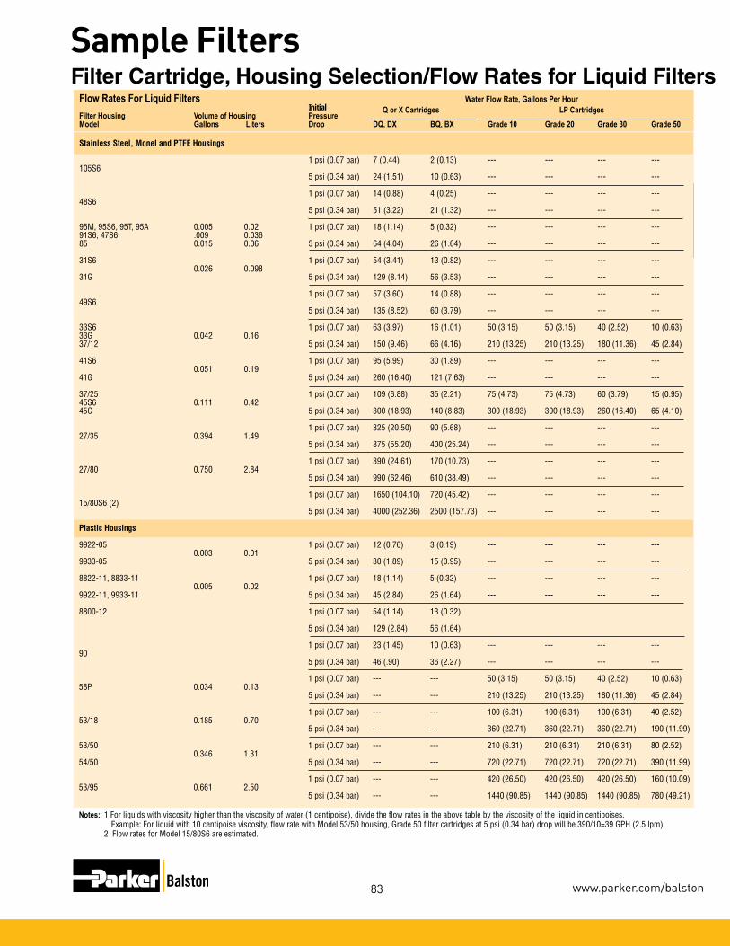
Sample
Filters
83
Sample Filters
www.parker.com/balston
Flow Rates For Liquid Filters Water Flow Rate, Gallons Per Hour Initial Q or X Cartridges LP CartridgesFilter Housing Volume of Housing PressureModel Gallons Liters Drop DQ, DX BQ, BX Grade 10 Grade 20 Grade 30 Grade 50 Stainless Steel, Monel and PTFE Housings
1 psi (0.07 bar) 7 (0.44) 2 (0.13) --- --- --- ---105S6 5 psi (0.34 bar) 24 (1.51) 10 (0.63) --- --- --- ---
1 psi (0.07 bar) 14 (0.88) 4 (0.25) --- --- --- ---48S6 5 psi (0.34 bar) 51 (3.22) 21 (1.32) --- --- --- ---
95M, 95S6, 95T, 95A 0.005 0.02 1 psi (0.07 bar) 18 (1.14) 5 (0.32) --- --- --- --- 91S6, 47S6 .009 0.03685 0.015 0.06 5 psi (0.34 bar) 64 (4.04) 26 (1.64) --- --- --- ---
31S6 1 psi (0.07 bar) 54 (3.41) 13 (0.82) --- --- --- --- 0.026 0.09831G 5 psi (0.34 bar) 129 (8.14) 56 (3.53) --- --- --- ---
1 psi (0.07 bar) 57 (3.60) 14 (0.88) --- --- --- ---49S6 5 psi (0.34 bar) 135 (8.52) 60 (3.79) --- --- --- ---
33S6 1 psi (0.07 bar) 63 (3.97) 16 (1.01) 50 (3.15) 50 (3.15) 40 (2.52) 10 (0.63)33G 0.042 0.16 37/12 5 psi (0.34 bar) 150 (9.46) 66 (4.16) 210 (13.25) 210 (13.25) 180 (11.36) 45 (2.84)
41S6 1 psi (0.07 bar) 95 (5.99) 30 (1.89) --- --- --- --- 0.051 0.1941G 5 psi (0.34 bar) 260 (16.40) 121 (7.63) --- --- --- ---
37/25 1 psi (0.07 bar) 109 (6.88) 35 (2.21) 75 (4.73) 75 (4.73) 60 (3.79) 15 (0.95)45S6 0.111 0.42 45G 5 psi (0.34 bar) 300 (18.93) 140 (8.83) 300 (18.93) 300 (18.93) 260 (16.40) 65 (4.10)
1 psi (0.07 bar) 325 (20.50) 90 (5.68) --- --- --- ---27/35 0.394 1.49 5 psi (0.34 bar) 875 (55.20) 400 (25.24) --- --- --- --- 1 psi (0.07 bar) 390 (24.61) 170 (10.73) --- --- --- ---27/80 0.750 2.84 5 psi (0.34 bar) 990 (62.46) 610 (38.49) --- --- --- ---
1 psi (0.07 bar) 1650 (104.10) 720 (45.42) --- --- --- ---15/80S6 (2) 5 psi (0.34 bar) 4000 (252.36) 2500 (157.73) --- --- --- ---
Plastic Housings
9922-05 1 psi (0.07 bar) 12 (0.76) 3 (0.19) --- --- --- --- 0.003 0.01 9933-05 5 psi (0.34 bar) 30 (1.89) 15 (0.95) --- --- --- ---
8822-11, 8833-11 1 psi (0.07 bar) 18 (1.14) 5 (0.32) --- --- --- --- 0.005 0.029922-11, 9933-11 5 psi (0.34 bar) 45 (2.84) 26 (1.64) --- --- --- ---
8800-12 1 psi (0.07 bar) 54 (1.14) 13 (0.32)
5 psi (0.34 bar) 129 (2.84) 56 (1.64)
1 psi (0.07 bar) 23 (1.45) 10 (0.63) --- --- --- --- 90 5 psi (0.34 bar) 46 (.90) 36 (2.27) --- --- --- ---
1 psi (0.07 bar) --- --- 50 (3.15) 50 (3.15) 40 (2.52) 10 (0.63)58P 0.034 0.13 5 psi (0.34 bar) --- --- 210 (13.25) 210 (13.25) 180 (11.36) 45 (2.84)
1 psi (0.07 bar) --- --- 100 (6.31) 100 (6.31) 100 (6.31) 40 (2.52)53/18 0.185 0.70 5 psi (0.34 bar) --- --- 360 (22.71) 360 (22.71) 360 (22.71) 190 (11.99)
53/50 1 psi (0.07 bar) --- --- 210 (6.31) 210 (6.31) 210 (6.31) 80 (2.52) 0.346 1.3154/50 5 psi (0.34 bar) --- --- 720 (22.71) 720 (22.71) 720 (22.71) 390 (11.99)
1 psi (0.07 bar) --- --- 420 (26.50) 420 (26.50) 420 (26.50) 160 (10.09)53/95 0.661 2.50 5 psi (0.34 bar) --- --- 1440 (90.85) 1440 (90.85) 1440 (90.85) 780 (49.21)
Notes: 1 For liquids with viscosity higher than the viscosity of water (1 centipoise), divide the flow rates in the above table by the viscosity of the liquid in centipoises. Example: For liquid with 10 centipoise viscosity, flow rate with Model 53/50 housing, Grade 50 filter cartridges at 5 psi (0.34 bar) drop will be 390/10=39 GPH (2.5 lpm). 2 Flow rates for Model 15/80S6 are estimated.
Filter Cartridge, Housing Selection/Flow Rates for Liquid Filters

Sam
ple
Filte
rs
84
Sample Filters
1-800-343-4048
9922
-05
4433
-05
9900
-05
9933
-05
8833
-1199
22-11
9933
-11
84
Flow
Rate
(CFM
) at
(1
) Flow
Rate
s, SC
FM, a
t 2 P
SI D
rop a
t Indic
ated L
ine P
ress
ure,
PSIG
Filte
r Vo
lume o
f Fil
ter
10” W
ater
Refer
to P
rodu
ct Sp
ecific
ation
Cha
rts fo
r Max
imum
Pre
ssur
e Rati
ng of
Eac
h Hou
sing
\ Hou
sing
Hous
ing (m
l) Tu
be
Pres
s. Dr
op.
2 20
40
60
80
10
0 12
5 15
0 20
0 25
0 30
0 50
0 75
0 10
00
1500
20
00
2500
30
00
3500
40
00
4500
50
00 M
odel
Gr
ade
0 psig
ps
ig ps
ig ps
ig ps
ig ps
ig ps
ig ps
ig ps
ig ps
ig ps
ig ps
ig ps
ig ps
ig ps
ig ps
ig ps
ig ps
ig ps
ig ps
ig ps
ig ps
ig ps
ig
DQ
0.2
1.2
2.5
3.9
5.4
6.8
8.3
10
.1 ---
---
---
---
---
---
---
---
---
---
---
---
---
---
---
11.33
BQ
0.1
0.8
1.6
2.6
3.5
4.5
5.4
6.6
---
---
---
---
---
---
---
---
---
---
---
---
---
---
---
DAU
N/A
0.5
1.2
---
2.6
3.3
4.0
---
---
---
---
---
---
---
---
---
---
---
---
---
---
---
---
DX
0.4
1.8
3.6
6 8
10
12
14.6
---
---
---
---
---
---
---
---
---
---
---
---
---
---
---
19.82
BX
0.2
0.9
1.8
3
4 5
6 7.3
---
---
---
---
---
---
---
---
---
---
---
---
---
---
---
DA
U N/
A 0.7
1.7
10
3.7
4.3
5
27
32
41
52
60
99
147
195
290
386
482
578
674
770
886
962
105S
6 16
DQ
0.7
3 7
10
14
18
22
27
32
41
51
60
99
147
195
290
386
482
578
674
770
886
962
97S6
11
.33
BQ
0.2
0.9
1.8
3
4 5
6 7
9 11
14
16
26
39
52
77
10
3 12
8 15
4 17
9 20
5 23
0 25
6
95A,
95M
19.82
DQ
1.5
3.9
8
13
18
22
27
33
39
51
62
74
121
180
239
357
470
590
710
830
940
1060
11
80 95
S6, 9
5T
91S6
, 47S
6
BQ
1.5
0.3
3 5
7 8
10
12
14
19
23
27
45
67
88
132
180
220
260
310
350
390
440
21
DQ
N/
A 2.5
10
16
23
28
33
40
47
61
75
89
14
5 21
0 28
0 42
0 56
0 70
0 84
0 98
0 11
20
1260
14
0048
S6
BQ
N/
A 2
5 8
9 10
1 1
13
16
20
25
29
46
70
90
13
0 18
0 22
0 26
0 30
0 34
0 38
0 42
0
DX
2.2
5.9
12
19.5
26
32
41
50
58
76
92
111
182
270
360
540
710
890
1065
12
45
1420
16
00
1770
85
59.47
BX
0.4
2.2
4.6
7.7
10
12
15
18
22
28
34
41
68
113
134
200
265
325
400
475
530
590
660
DQ, D
X 3.0
---
---
---
---
---
---
---
---
---
---
---
---
---
---
---
---
---
---
---
---
---
---
90
23.3
BQ, B
X 0.5
---
---
---
---
---
---
---
---
---
---
---
---
---
---
---
---
---
---
---
---
---
---
8800
-12 (
2)
DQ
, DX
2.6
10
22
35
48
61
74
90
107
140
172
205
---
---
---
---
---
---
---
---
---
---
---
31S6
, 31G
93
.45
BQ, B
X 0.4
5 2
6 9
12
16
20
24
29
37
46
54
---
---
---
---
---
---
---
---
---
---
---
DAU
1.5
4.5
6.8
30
/12, 3
3S6
DX
3.0
12
26
40
55
70
85
10
3 12
2 15
9 19
6 23
3 38
1 56
7 75
2 1 1
22
1493
18
63
2234
26
00
2970
---
---
15
8.58
33G,
37/12
BX
0.5
3 7
10
14
18
22
27
32
41
51
60
99
147
195
291
387
483
579
695
770
---
---
17
0 DQ
N/
A 13
28
45
61
78
94
11
5 13
5 17
7 21
8 25
9 42
3 62
9 83
4 12
45
---
---
---
---
---
---
---
49S6
BQ
N/A
6 13
21
28
35
43
53
62
81
10
0 1 1
9 19
4 28
8 38
3 57
1 ---
---
---
---
---
---
---
DQ
, DX
6.6
15
32
50
69
87
106
129
152
199
245
291
---
---
---
---
---
---
---
---
---
---
---
41S6
, 41G
22
0.87
BQ, D
X 1.1
7
15
24
32
41
50
61
72
93
115
139
---
---
---
---
---
---
---
---
---
---
---
30/25
DQ, D
X 7.5
17
36
57
78
99
12
0 14
6 17
2 22
5 27
7 32
9 53
8 80
0 10
62
1585
21
08
2631
31
56
3680
42
00
---
---45
S6, 4
5G
419.0
937
/25
BQ
, BX
1.3
8 17
26
36
45
55
67
79
10
3 12
7 15
1 24
7 36
7 48
7 72
7 97
6 12
07
1447
16
90
1930
---
---
27/35
DX
13.3
40
83
130
178
225
273
332
392
510
629
748
1220
18
20
2410
36
00
4780
59
70
7160
83
40
9530
10
720
1190
0
1500
.8026
/35
BX
3.3
19
39
62
84
10
7 12
9 15
7 18
5 24
1 29
7 35
3 57
8 85
8 11
40
1700
22
60
2820
33
80
3940
45
00
5060
56
30
DX
20.0
43
90
142
193
245
297
362
426
555
684
814
1330
19
80
2625
39
00
---
---
---
---
---
---
---
27/80
28
60.02
BX
5.8
28
59
93
127
161
195
237
280
365
449
534
873
1300
17
22
2540
---
---
---
---
---
---
---
DX
20.0
160
333
525
717
908
1100
13
40
1580
20
60
2540
30
20
4940
---
---
---
---
---
---
---
---
---
---
15
/80S6
47
00
BX
5.8
45
94
14
8 20
2 25
6 31
0 37
8 44
5 58
0 71
5 85
0 13
90
---
---
---
---
---
---
---
---
---
---
NA =
DAT
A NO
T AVA
ILABL
E
1 F
or lin
e pre
ssur
es ab
ove 1
50 P
SIG,
flow
rate
value
s are
estim
ated.
2
Max
imum
oper
ating
pres
sure
in ga
s ser
vice i
s 50 P
SIG
.
Flo
w R
ates
for
Air
an
d G
as F
ilter
s
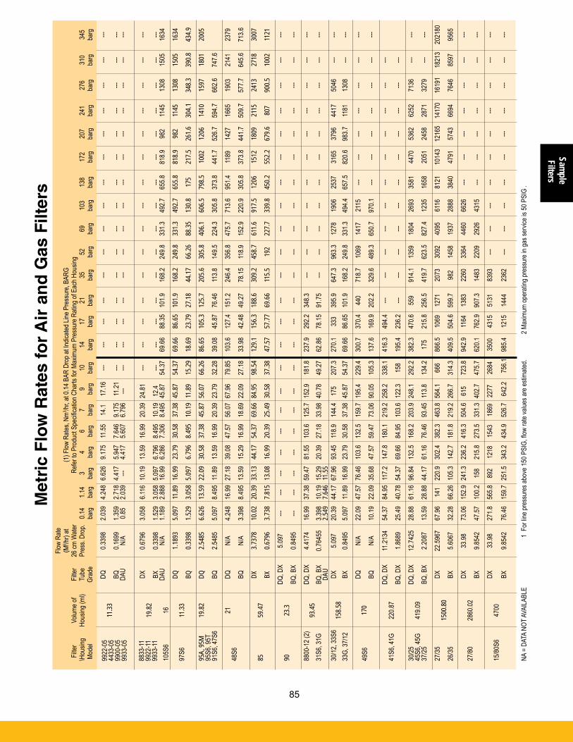
Sample
Filters
85
Sample Filters
www.parker.com/balston
Flow
Rate
(CFM
) at
(1
) Flow
Rate
s, SC
FM, a
t 2 P
SI D
rop a
t Indic
ated L
ine P
ress
ure,
PSIG
Filte
r Vo
lume o
f Fil
ter
10” W
ater
Refer
to P
rodu
ct Sp
ecific
ation
Cha
rts fo
r Max
imum
Pre
ssur
e Rati
ng of
Eac
h Hou
sing
\ Hou
sing
Hous
ing (m
l) Tu
be
Pres
s. Dr
op.
2 20
40
60
80
10
0 12
5 15
0 20
0 25
0 30
0 50
0 75
0 10
00
1500
20
00
2500
30
00
3500
40
00
4500
50
00 M
odel
Gr
ade
0 psig
ps
ig ps
ig ps
ig ps
ig ps
ig ps
ig ps
ig ps
ig ps
ig ps
ig ps
ig ps
ig ps
ig ps
ig ps
ig ps
ig ps
ig ps
ig ps
ig ps
ig ps
ig ps
ig
DQ
0.2
1.2
2.5
3.9
5.4
6.8
8.3
10
.1 ---
---
---
---
---
---
---
---
---
---
---
---
---
---
---
11.33
BQ
0.1
0.8
1.6
2.6
3.5
4.5
5.4
6.6
---
---
---
---
---
---
---
---
---
---
---
---
---
---
---
DAU
N/A
0.5
1.2
---
2.6
3.3
4.0
---
---
---
---
---
---
---
---
---
---
---
---
---
---
---
---
DX
0.4
1.8
3.6
6 8
10
12
14.6
---
---
---
---
---
---
---
---
---
---
---
---
---
---
---
19.82
BX
0.2
0.9
1.8
3
4 5
6 7.3
---
---
---
---
---
---
---
---
---
---
---
---
---
---
---
DA
U N/
A 0.7
1.7
10
3.7
4.3
5
27
32
41
52
60
99
147
195
290
386
482
578
674
770
886
962
105S
6 16
DQ
0.7
3 7
10
14
18
22
27
32
41
51
60
99
147
195
290
386
482
578
674
770
886
962
97S6
11
.33
BQ
0.2
0.9
1.8
3
4 5
6 7
9 11
14
16
26
39
52
77
10
3 12
8 15
4 17
9 20
5 23
0 25
6
95A,
95M
19.82
DQ
1.5
3.9
8
13
18
22
27
33
39
51
62
74
121
180
239
357
470
590
710
830
940
1060
11
80 95
S6, 9
5T
91S6
, 47S
6
BQ
1.5
0.3
3 5
7 8
10
12
14
19
23
27
45
67
88
132
180
220
260
310
350
390
440
21
DQ
N/
A 2.5
10
16
23
28
33
40
47
61
75
89
14
5 21
0 28
0 42
0 56
0 70
0 84
0 98
0 11
20
1260
14
0048
S6
BQ
N/
A 2
5 8
9 10
11
13
16
20
25
29
46
70
90
13
0 18
0 22
0 26
0 30
0 34
0 38
0 42
0
DX
2.2
5.9
12
19.5
26
32
41
50
58
76
92
111
182
270
360
540
710
890
1065
12
45
1420
16
00
1770
85
59.47
BX
0.4
2.2
4.6
7.7
10
12
15
18
22
28
34
41
68
113
134
200
265
325
400
475
530
590
660
DQ, D
X 3.0
---
---
---
---
---
---
---
---
---
---
---
---
---
---
---
---
---
---
---
---
---
---
90
23.3
BQ, B
X 0.5
---
---
---
---
---
---
---
---
---
---
---
---
---
---
---
---
---
---
---
---
---
---
8800
-12 (
2)
DQ
, DX
2.6
10
22
35
48
61
74
90
107
140
172
205
---
---
---
---
---
---
---
---
---
---
---
31S6
, 31G
93
.45
BQ, B
X 0.4
5 2
6 9
12
16
20
24
29
37
46
54
---
---
---
---
---
---
---
---
---
---
---
DAU
1.5
4.5
6.8
30
/12, 3
3S6
DX
3.0
12
26
40
55
70
85
10
3 12
2 15
9 19
6 23
3 38
1 56
7 75
2 11
22
1493
18
63
2234
26
00
2970
---
---
15
8.58
33G,
37/12
BX
0.5
3 7
10
14
18
22
27
32
41
51
60
99
147
195
291
387
483
579
695
770
---
---
17
0 DQ
N/
A 13
28
45
61
78
94
11
5 13
5 17
7 21
8 25
9 42
3 62
9 83
4 12
45
---
---
---
---
---
---
---
49S6
BQ
N/A
6 13
21
28
35
43
53
62
81
10
0 11
9 19
4 28
8 38
3 57
1 ---
---
---
---
---
---
---
DQ
, DX
6.6
15
32
50
69
87
106
129
152
199
245
291
---
---
---
---
---
---
---
---
---
---
---
41S6
, 41G
22
0.87
BQ, D
X 1.1
7
15
24
32
41
50
61
72
93
115
139
---
---
---
---
---
---
---
---
---
---
---
30/25
DQ, D
X 7.5
17
36
57
78
99
12
0 14
6 17
2 22
5 27
7 32
9 53
8 80
0 10
62
1585
21
08
2631
31
56
3680
42
00
---
---45
S6, 4
5G
419.0
937
/25
BQ
, BX
1.3
8 17
26
36
45
55
67
79
10
3 12
7 15
1 24
7 36
7 48
7 72
7 97
6 12
07
1447
16
90
1930
---
---
27/35
DX
13.3
40
83
130
178
225
273
332
392
510
629
748
1220
18
20
2410
36
00
4780
59
70
7160
83
40
9530
10
720
1190
0
1500
.8026
/35
BX
3.3
19
39
62
84
10
7 12
9 15
7 18
5 24
1 29
7 35
3 57
8 85
8 11
40
1700
22
60
2820
33
80
3940
45
00
5060
56
30
DX
20.0
43
90
142
193
245
297
362
426
555
684
814
1330
19
80
2625
39
00
---
---
---
---
---
---
---
27/80
28
60.02
BX
5.8
28
59
93
127
161
195
237
280
365
449
534
873
1300
17
22
2540
---
---
---
---
---
---
---
DX
20.0
160
333
525
717
908
1100
13
40
1580
20
60
2540
30
20
4940
---
---
---
---
---
---
---
---
---
---
15
/80S6
47
00
BX
5.8
45
94
14
8 20
2 25
6 31
0 37
8 44
5 58
0 71
5 85
0 13
90
---
---
---
---
---
---
---
---
---
---
NA =
DAT
A NO
T AVA
ILABL
E
1 F
or lin
e pre
ssur
es ab
ove 1
50 P
SIG,
flow
rate
value
s are
estim
ated.
2
Max
imum
oper
ating
pres
sure
in ga
s ser
vice i
s 50 P
SIG
.
9922
-05
4433
-05
9900
-05
9933
-05
8833
-1199
22-11
9933
-11
85
Flow
Rate
(M3 /hr
) at
(
1) F
low R
ates,
Nm3 /hr
, at 0
.14 B
AR D
rop a
t Indic
ated L
ine P
ress
ure,
BARG
Filte
r Vo
lume o
f Fil
ter
26 cm
Wate
r
Re
fer to
Pro
duct
Spec
ificati
on C
harts
for M
axim
um P
ress
ure R
ating
of E
ach H
ousin
g\ H
ousin
g Ho
using
(ml)
Tube
Pr
ess.
Drop
. 0.1
4 1.1
4 3
4 6
7 9
10
14
17
21
35
52
69
103
138
172
207
241
276
310
345
Mod
el
Grad
e
barg
ba
rg
barg
ba
rg
barg
ba
rg
barg
ba
rg
barg
ba
rg
barg
ba
rg
barg
ba
rg
barg
ba
rg
barg
ba
rg
barg
ba
rg
barg
ba
rg
DQ
0.3
398
2.039
4.2
48 6
.626
9.175
11
.55
14.1
17.16
---
---
---
---
---
---
---
---
---
---
---
---
---
---
---
11.33
BQ
0.1
699
1.359
2.7
18 4
.417
5.947
7.6
46
9.175
11
.21
---
---
---
---
---
---
---
---
---
---
---
---
---
---
---
DA
U N/
A 0.8
5 2.0
39
---
4.417
5.6
07
6.796
---
---
---
---
---
---
---
---
---
---
---
---
---
---
---
---
DX
0.6
796
3.058
6.1
16 1
0.19
13.59
16
.99
20.39
24.8
1 ---
---
---
---
---
---
---
---
---
---
---
---
---
---
---
19
.82
BX
0.339
8 1.5
29
3.058
5.09
7 6.7
96
8.495
10
.19
12.4
---
---
---
---
---
---
---
---
---
---
---
---
---
---
---
DAU
N/A
1.189
2.8
88 1
6.99
6.286
7.3
06
8.495
45.8
7 54
.37
69.66
88
.35
101.9
16
8.2
249.8
33
1.3
492.7
65
5.8
818.9
98
2 11
45
1308
15
05
1634
105S
6 16
DQ
1.189
3 5.0
97
11.89
16.9
9 23
.79
30.58
37
.38 4
5.87
54.37
69
.66
86.65
10
1.9
168.2
24
9.8
331.3
49
2.7
655.8
81
8.9
982
1145
13
08
1505
16
3497
S6
11.33
BQ
0.339
8 1.5
29
3.058
5.09
7 6.7
96
8.495
10
.19 1
1.89
15.29
18
.69
23.79
27
.18
44.17
66
.26
88.35
13
0.8
175
217.5
26
1.6
304.1
34
8.3
390.8
43
4.9
95A,
95M
19.82
DQ
2.5
485
6.626
13
.59 2
2.09
30.58
37
.38
45.87
56.0
7 66
.26
86.65
10
5.3
125.7
20
5.6
305.8
40
6.1
606.5
79
8.5
1002
12
06
1410
15
97
1801
20
05 95
S6, 9
5T
91S6
, 47S
6
BQ
2.548
5 5.0
97
8.495
11.8
9 13
.59
16.99
20
.39 2
3.79
32.28
39
.08
45.87
76
.46
113.8
14
9.5
224.3
30
5.8
373.8
44
1.7
526.7
59
4.7
662.6
74
7.6
21
DQ
N/
A 4.2
48
16.99
27.1
8 39
.08
47.57
56
.07 6
7.96
79.85
10
3.6
127.4
15
1.2
246.4
35
6.8
475.7
71
3.6
951.4
11
89
1427
16
65
1903
21
41
2379
48S6
BQ
N/A
3.398
8.4
95 1
3.59
15.29
16
.99
18.69
22.0
9 27
.18
33.98
42
.48
49.27
78
.15
118.9
15
2.9
220.9
30
5.8
373.8
44
1.7
509.7
57
7.7
645.6
71
3.6
DX
3.737
8 10
.02
20.39
33.1
3 44
.17
54.37
69
.66 8
4.95
98.54
12
9.1
156.3
18
8.6
309.2
45
8.7
611.6
91
7.5
1206
15
12
1809
21
15
2413
27
18
3007
85
59.47
BX
0.679
6 3.7
38
7.815
13.0
8 16
.99
20.39
25
.49 3
0.58
37.38
47
.57
57.77
69
.66
115.5
19
2 22
7.7
339.8
45
0.2
552.2
67
9.6
807
900.5
10
02
1121
DQ, D
X 5.0
97
---
---
---
---
---
---
---
---
---
---
---
---
---
---
---
---
---
---
---
---
---
---90
23
.3
BQ
, BX
0.849
5 ---
---
---
---
---
---
---
---
---
---
---
---
---
---
---
---
---
---
---
---
---
---
8800
-12 (
2)
DQ
, DX
4.417
4 16
.99
37.38
59.4
7 81
.55
103.6
12
5.7 1
52.9
181.8
23
7.9
292.2
34
8.3
---
---
---
---
---
---
---
---
---
---
---
31S6
, 31G
93
.45
BQ, B
X 0.7
6455
3.3
98
10.19
15.2
9 20
.39
27.18
33
.98 4
0.78
49.27
62
.86
78.15
91
.75
---
---
---
---
---
---
---
---
---
---
---
DAU
2.5
49
7.646
11.5
5
30/12
, 33S
6
DX
5.097
20
.39
44.17
67.9
6 93
.45
118.9
14
4.4
175
207.3
27
0.1
333
395.9
64
7.3
963.3
12
78
1906
25
37
3165
37
96
4417
50
46
---
---
158.5
8 33
G, 37
/12
BX
0.8
495
5.097
11
.89 1
6.99
23.79
30
.58
37.38
45.8
7 54
.37
69.66
86
.65
101.9
16
8.2
249.8
33
1.3
494.4
65
7.5
820.6
98
3.7
1181
13
08
---
---
17
0 DQ
N/
A 22
.09
47.57
76.4
6 10
3.6
132.5
15
9.7 1
95.4
229.4
30
0.7
370.4
44
0 71
8.7
1069
14
17
2115
---
---
---
---
---
---
---
49
S6
BQ
N/
A 10
.19
22.09
35.6
8 47
.57
59.47
73
.06 9
0.05
105.3
13
7.6
169.9
20
2.2
329.6
48
9.3
650.7
97
0.1
---
---
---
---
---
---
---
DQ, D
X 11
.2134
54
.37
84.95
117
.2 14
7.8
180.1
21
9.2 2
58.2
338.1
41
6.3
494.4
---
---
---
---
---
---
---
---
---
---
---
41
S6, 4
1G
220.8
7
BQ
, DX
1.868
9 25
.49
40.78
54.3
7 69
.66
84.95
10
3.6 1
22.3
158
195.4
23
6.2
---
---
---
---
---
---
---
---
---
---
---
30/25
DQ, D
X 12
.7425
28
.88
61.16
96.8
4 13
2.5
168.2
20
3.9 2
48.1
292.2
38
2.3
470.6
55
9 91
4.1
1359
18
04
2693
35
81
4470
53
62
6252
71
36
---
---45
S6, 4
5G
419.0
937
/25
BQ
, BX
2.208
7 13
.59
28.88
44.1
7 61
.16
76.46
93
.45 1
13.8
134.2
17
5 21
5.8
256.5
41
9.7
623.5
82
7.4
1235
16
58
2051
24
58
2871
32
79
---
---
27/35
DX
22.59
67
67.96
14
1 22
0.9
302.4
38
2.3
463.8
564
.1 66
6 86
6.5
1069
12
71
2073
30
92
4095
61
16
8121
10
143
1216
5 14
170
1619
1 18
213
2021
80
1500
.8026
/35
BX
5.6
067
32.28
66
.26 1
05.3
142.7
18
1.8
219.2
266
.7 31
4.3
409.5
50
4.6
599.7
98
2 14
58
1937
28
88
3840
47
91
5743
66
94
7646
85
97
9565
DX
33.98
73
.06
152.9
241
.3 23
6.2
416.3
50
4.6
615
723.8
94
2.9
1 164
13
83
2260
33
64
4460
66
26
---
---
---
---
---
---
---
27/80
28
60.02
BX
9.854
2 47
.57
100.2
15
8 21
5.8
273.5
33
1.3 4
02.7
475.7
62
0.1
762.9
90
7.3
1483
22
09
2926
43
15
---
---
---
---
---
---
---
DX
33.98
27
1.8
565.8
89
2 12
18
1543
18
69
2277
26
84
3500
43
15
5131
83
93
---
---
---
---
---
---
---
---
---
---
15/80
S6
4700
BX
9.854
2 76
.46
159.7
251
.5 34
3.2
434.9
52
6.7
642.2
75
6.1
985.4
12
15
1444
23
62
---
---
---
---
---
---
---
---
---
---
NA =
DAT
A NO
T AVA
ILABL
E
1 F
or lin
e pre
ssur
es ab
ove 1
50 P
SIG,
flow
rate
value
s are
estim
ated.
2
Max
imum
oper
ating
pres
sure
in ga
s ser
vice i
s 50 P
SIG
.
Met
ric
Flo
w R
ates
for
Air
an
d G
as F
ilter
s
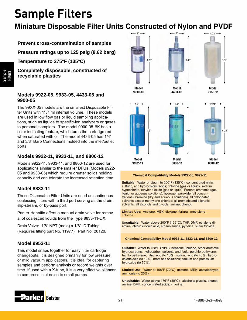
Sam
ple
Filte
rs
86
Sample Filters
1-800-343-4048
t
t
1”
t
Models 9922-05, 9933-05, 4433-05 and 9900-05The 99XX-05 models are the smallest Disposable Fil-ter Units with 11.7 ml internal volume. These models are used in low flow gas or liquid sampling applica-tions, such as liquids to specific-ion analyzers or gases to personal samplers. The model 9900-05-BK has a color indicating feature, which turns the cartridge red when saturated with oil. The model 4433-05 has 1/4” and 3/8” Barb Connections molded into the inlet/outlet ports.
Models 9922-11, 9933-11, and 8800-12Models 9922-11, 9933-11, and 8800-12 are used for applications similar to the smaller DFUs (Models 9922-05 and 9933-05) which require greater solids holding capacity and can tolerate the increased retention time.
Model 8833-11These Disposable Filter Units are used as continuous coalescing filters with a third port serving as the drain, slip-stream, or by-pass port.
Parker Hannifin offers a manual drain valve for remov-al of coalesced liquids from the Type 8833-11-DX.
Drain Valve: 1/8” NPT (male) x 1/8” ID Tubing. (Requires fitting part No. 11977). Part No. 20120.
Model 9953-11This model snaps together for easy filter cartridge changeouts. It is designed primarily for low pressure or mild vacuum applications. It is ideal for capturing samples and perform analysis or record weights over time. If used with a X-tube, it is a very effective silencer to compress inlet noise to small pumps.
Chemical Compatibility Models 9922-05, 9922-11
Suitable: Water or steam to 200°F (135°C); concentrated nitric, sulfuric, and hydrochloric acids; chlorine (gas or liquid); sodium hypochlorite, ethylene oxide (gas or liquid); Freons; ammonia (gas, liquid, or aqueous solutions); hydrogen peroxide (all concen-trations); bromine (dry and aqueous solutions); all chlorinated solvents except methylene chloride; all aromatic and aliphatic solvents; all alcohols and glycols; aniline; phenol.
Limited Use: Acetone, MEK, dioxane, furfural, methylene chloride.
Unsuitable: Water above 200°F (135°C), THF, DMF, ethylene di-amine, chlorosulfonic acid, ethanolamine, pyridine, sulfur trioxide.
Chemical Compatibility Model 9933-11, 8833-11, and 8800-12
Suitable: Water to 158°F (70°C); benzene, toluene, other aromatic hydrocarbons; hydrocarbon solvents and fuels, perchloroethylene; trichloroethylene, nitric acid (to 10%); sulfuric acid (to 40%); hydro-chloric acid (to 10%); most salt solutions; sodium and potassium hydroxide (to 50%).
Limited Use: Water at 158°F (70°C); acetone; MEK, acetaldehyde; ammonia (to 25%).
Unsuitable: Water above 176°F (80°C); alcohols; glycols, phenol; aniline; DMF; concentrated acids; chlorine.
Prevent cross-contamination of samples
Pressure ratings up to 125 psig (8.62 barg)
Temperature to 275°F (135°C)
Completely disposable, constructed of recyclable plastics
Model99XX-05
Model4433-05
Model9953-11
t
3.28”
1”
t
t
t
3.43”
t
t
t
3.57”
1.22”
t
t
t
4.6”
1.4”
t
t
t
t
Model 9922-11
Model8833-11
Model8800-12
4.6”
1.4”
t
t
t
t
6.24”
2.24”
t
t
t
Miniature Disposable Filter Units Constructed of Nylon and PVDF
t
1”

Sample
Filters
87
Sample Filters
www.parker.com/balston
Miniature Disposable Filter Units Constructed of Nylon and PVDF
Principal Specifications
Model 9922-05 9900-05 4433-05 9933-05 9922-11 9933-11 8833-11 8800-12 9953-11
Inlet and Outlet Ports 1/4” Tubing 1/4” Tubing 1st Tier/Barb 1/4”Tube 1/4” Tubing 1/4” Tubing 1/4” Tubing 1/4” Tubing 1/2” Tubing 0.32” OD 2nd Tier/Barb 3/8”Tube Drain None None None None None None 1/4” Tubing None NoneMaterial of Construction PVDF Nylon Nylon Nylon PVDF Nylon Nylon Nylon PolypropyleneFilter Cartridge Length 1.25” (3.2 cm) 1.25” (3.2 cm) 1.25” (3.2cm) 1.25” (3.2 cm) 2.25” (5.7 cm) 2.25” (5.7 cm) 2.25” (5.7 cm) 2.5” (5.71 cm) 2.28” 6.35 cm)Maximum Temperature 275°F (135°C)(1) 230°F (110°C)(1) 230°F (110°C)(1) 230°F (110°C)(1) 275°F (135°C)(1) 230°F (110°C)(1) 230°F (110°C)(1) 150°F (66°C)(1) 125°F (52°C)(1)Maximum Pressure 125 psig 125 psig 125 psig 125 psig 125 psig 125 psig 125 psig 50 psig 2 psig (8.6 barg) (2) (8.6 barg) (2) (8.6 barg) (2) (8.6 barg) (2) 8.6 barg (2) (8.6 barg) (2) (8.6 barg) (2) (3.03 barg) (2) (8) (0.14 barg) (2)Dimensions 1.0”D x 3.25”L 1.0”D x 3.25”L 1.0”D x 3.43”L 1.0”D x 3.25”L 1.4”D x 4.6”L 1.4”D x 4.6”L 1.4”D x 4.6”L 2.24”D x 6.24”L 1.22”D x 3.57”L (2.5 cm x 8 cm) (2.5 cm x 8 cm) (2.5 cm x 8.72 cm) (2.5 cm x 8 cm) (3.6 cm x 12 cm) (3.6 cm x 12 cm) (3.6 cm x 12 cm) (5.69 cm x 15.85 cm) (3.1 cm x 9.07 cm)
DFU Model Volume of Housing Initial Pressure Grade Grade Grade Grade Grade Gallons Liters Drop DQ, DX CQ, CX BQ, BX AQ AAQ
9922-05 1 psi (0.07 bar) 12 (0.76) 10 (0.63) 3 (0.19) 1.5 (0.09) 0.4 (0.03)4433-05 0.003 0.01 9933-05 5 psi ( 0.34 bar) 30 (1.90) 25 (1.58) 15 (0.95) 7.3 (0.46) 1.9 (0.12)
9922-11 1 psi ( 0.07 bar) 18 (1.14) 15 (0.95) 5 (0.34) 2.5 (0.16) 0.6 (0.04) 0.0005 0.02 9933-11 5 psi ( 0.34 bar) 45 (2.84) 37 (2.33) 26 (1.64) 12 (0.76) 3.1 (0.20)
1 psi ( 0.07 bar) 54 (3.74) 44 (3.03) 13 (0.90) 6 (0.41) 1.4 (0.10)8800-12 .003 .014 5 psi ( 0.34 bar) 129 (8.89) 106 (7.31) 56 (3.86) 26 (1.79) 6.5 (0.45)
Flow Rates Water Flow Rate, Gallons per Hour
Miniature Disposable Filter Units Constructed of Nylon and PVDF
Notes:1 At 0 psig 2 At 110°F (43°C)
3 To designate adsorbent in the DAU, insert adsorbent numbers after DAU designation. For example, to obtain a miniature clear nylon DAU
with carbon adsorbent, order 9933-05-000. Adsorbent numbers are listed on page 73.4 Available only in Q grades.
5 Available in Q or X media.6 Available only in X media.7 9953-11 is designed for maximum pressure of 2 psig.
8 Pressure rating in liquid service is 70 PSIG (4.83 barg) maximum.

Sam
ple
Filte
rs
88
Sample Filters
1-800-343-4048
To low pressure plastic tubing: Tubing with 1/4” ID may be slipped over the DFU and fittings and held with tubing clamps. Parker Han-nifin supplies plastic barbs to connect the DFU to smaller diameter plastic tubing. The connection is suitable for pressures to 50 psig.
DFU to 1/16” ID tubing: Part No. 14000 (bag of 20 barbs)DFU to 1/8” ID tubing: Part No. 14001 (bag of 20 barbs)
To pressure pipe or tubing: Compression fittings for 1/4” O.D. tub-ing may be obtained from the following manufacturers. Hoke, Inc. (“Gyrolok”); Crawford Fitting Co. (“Swagelok”); Parker-Hannifin Corp. (“CPI”); Legris, Inc. (push-on fittings); Jaco Mfg. Co. (plastic fittings).The following brass fittings which seal by O-ring compression and which may be completely recovered and reused when changing filters may be purchased from Parker/Balston:
Connector: 1/4” tubing to 1/4” NPT female - Part No. 11970 (1 per pkg.)
Connector: 1/4” tubing to 1/4” tubing - Part No. 11971 (1 per pkg.)
Installation Information
Notes:1 At 0 psig 2 At 110°F (43°C)
For assistance, call toll-free at 1-800-343-4048 8AM to 5PM Eastern Time
Model 9922-05 9900-05 4433-05 9933-05 9922-11 9933-11 8833-11 8800-12 9953-11
Box of 10 DFUs 9922-05-❑ 9900-05-❑ (4) 4433-05-❑ (4) 9933-05-❑ 9922-11-❑ 9933-11-❑ 8833-11-❑ (6) 8800-12-❑ box of 1 9953-11-❑ (5) Available only in Q-gradesBox 10 DAU'S (3) 9922-05-❑ N/A N/A 9933-05-❑ 9922-11-❑ 9933-11-❑ N/A N/A N/A
3 To designate adsorbent in the DAU, insert adsorbent numbers after DAU designation. For example, to obtain a miniature clear nylon DAU
Ordering Information
with carbon adsorbent, order 9933-05-000. Adsorbent numbers are listed on page 73.4 Available only in Q grades.
5 Available in Q or X media.6 Available only in X media.7 9953-11 is designed for maximum pressure of 2 psig.
8 Pressure rating in liquid service is 70 PSIG (4.83 barg) maximum.
Miniature Disposable Filter Units Constructed of Nylon and PVDF

Sample
Filters
89
Sample Filters
www.parker.com/balston
Model 97S6 30/12 30/25
Inlet and Outlet Ports 1/4” NPT 1/2” NPT 1/2” NPTDrain Port None None NoneMaterials of ConstructionHead 316SS 303SS 303SSBowl 316SS 304SS 304SSInternals 316SS 303SS 303SSSeals Viton Carbon Fiber Carbon FiberMaximum Temperature 400°F (204°C) 600°F (315°C) (2) 600°F (315°C)(2)Maximum Pressure 5000 psig (345 barg) (1) 100 psig (6.89 barg) (3) 100 psig (6.89 barg) (3)Shipping Weight 0.75 lbs. (0.3 kg) 2 lbs. (0.9 kg) 3 lbs. (1.4 kg)Dimensions 1.25”D X 3.1”L 1.9”D X 4.4”L 1.9”D X 8.6”L (3.2cm X 7.9cm) (4.8cm X 11.2cm) (4.8cm X 22cm)
For assistance, call toll-free at 1-800-343-4048 8AM to 5PM Eastern Time
Filter Housing Model 97S6 30/12 30/25
Support Core, Required for Liquid Filtration Included N/A N/AFilter Cartridges 050-05-❑ 100-12-❑ 100-25-❑Important Notes: X-type cartridges are not available for the Model 97S6. For high temperature quantitative measurement applications order 100-12-DH/BH-F896 for use with the 30/12 or 100-25-DH/BH-F896 for use with the 30/25.
Stainless steel construction
Pressure to 5000 psig (345 barg)
Temperature to 600°F (315°C)
Ideal end use filter
Model 97S6Miniature 316 stainless steel filter with 1/4” NPT in-line ports, and 5000 psig (345 barg) rating. Since it does not have a drain port, the Model 97S6 is used as an end-of-the-line compressed gas filter when little or no liquid is expected, or as a cylinder gas filter.
Models 30/12 and 30/25Designed specifically for quantitative measurement of solids in gases to 600°F (315°C), the filter cartridge and element retainer disc in the Model 30 housings may be weighed as a unit (see notes below).
Model 97S6
Model 30/12 and 30/25
Notes:1 Maximum pressure ratings are for tempera-tures to 200°F (93°C). Please consult factory for maximum pressure ratings at elevated temperatures.2 For temperatures greater than 600°F (315°C) consult factory for proper recom-mended seals3 100 psig at 450°F (241°C).
Principal Specifications
Ordering Information
Stainless Steel In-Line Filter Housings: 1/4” and 1/2” Port Size

Sam
ple
Filte
rs
90
Sample Filters
1-800-343-4048
Disposable Adsorption Units (DAUs) contain a bed of adsorbent granules. Utilizing a wide choice of adsorbents, the DAUs selectively remove vapors from air and other gases.
Because the adsorbed vapor remains trapped in the solid bed, the DAU has a fixed upper limit of total weight of vapor which can be captured. It is usually not feasible to regenerate the filter when it has reached its adsorption limit. DAUs should be used only when small quantities of vapor are to be removed.
Considerations in Using Adsorbent CartridgesThe following factors should be considered when selecting a DAU:
1 Solid adsorbents are effective only for vapors. Since liquids will damage or inactivate most solid adsorbents, the DAU must be preceded by an efficient coalescing filter.
2 In contrast with Microfibre Filters, which operate at their initial efficiency throughout their life, adsorbent cartridges have a limited holding capacity. When the adsorption capacity is reached, no further adsorption occurs. The limiting capacity, or “break-through” point, is not sharply defined, and the exit vapor concentration will increase rapidly as saturation is approached. To avoid unwanted vapor contaminants down-stream, it is necessary to change the adsorbent cartridge well before it has reached its ultimate adsorption capacity.
3 Adsorption is reversible, if operating conditions change, a vapor may desorb rather than adsorb. For example, if a temporary surge in vapor impurity concentration causes a relatively high concentration to be adsorbed on the solid, a subsequent decrease in inlet vapor composition will result in desorption of vapor from the solid to the gas stream.
4 The efficiency of a given adsorbent for a given vapor depends upon the specific operating conditions. Therefore, again in contrast to filtration, it is not possible to assign a single efficiency rating to an adsorbent. While it is not possible to predict or guarantee an adsorption efficiency for any specific set of conditions, it is possible to enhance the conditions beneficial to adsorption and avoid conditions which interfere with adsorption. Conditions which aid adsorption are: low temperature, high pres-sure, low flow rate, and absence of competing vapors (particularly water vapor).
Adsorbent Grade Use For
Carbon 000
Silica Gel 101
Molecular 103Sieve Type 13X
Mixed 107Sodium & Calcium Hydroxides
Compressor oil vapors, C5 and heavier hydrocarbons, aromatics, oxygenated hydrocarbons, chlorinated organics, freons, carbon disulfide.
Most C4 and lighter hydrocarbons, ethylene, propylene, acetylene, ethylene oxide, ammonia, mercaptans, sulfur hexa-fluoride, triethylamine, and smaller amines.
All acidic gases, including sulfur trioxide, sulfur dioxide, nitrogen dioxide, carbon dioxide, hydrogen sulfide, hydrogen chloride, phosphorus trichloride, boron trifluoride.
Notes:1 Please refer to Ordering Information for complete explana-tion of nomenclature.2 In DAU 9933-05-107 and DAU 9933-11-107, color indicator turns violet when adsorbent is spent.3 In DAU 9933-05-101 and 9933-11-101, adsorbent turns pink when vapor capacity is reached.4 Maximum operating temperature is 180°F (82°C).
Recommended only for water vapor.
Filter Cartridge and Housing Selection

Sample
Filters
91
Sample Filters
www.parker.com/balston
This section is designed to help customers choose the best Balston disposable filter product for industrial, commercial, measurement and control applications.
Balston brand disposable filter units (DFU) consist of a microfibre filter cartridge permanently bonded into a sealed plastic holder with 125 psig (8.62 barg) pressure ratings, temperatures to 275°F (135°C), and available in low and high flow models. The economi-cal DFU offers all of the advantages of microfibre filter cartridges for high efficiency liquid and gas filtration, combined with the economics and convenience of complete disposability.
Our years of experience in fitting products to individual applications has led to the creation of a variety of stan-dard products that can be ordered off the shelf for gen-eral purpose filtration requirements or can be custom designed for all types of specialty applications.
If you do not see the specific configuration, size or material that you are looking for, our OEM engineering team will be happy to review your requirements and design product to your exact specifications.
If you have questions, or would like to place an order, please call 1-800-343-4048.
Balston Disposable Filter Units
Ideal for the following gas filtration applications:Final filter for air logic devicesProtection of pneumatic componentsFiltration of portable environmental sampling devicesFiltration of samples to on-line analyzersProtection of Pneumatic temperature controls
Ideal for the following liquid filtration applications:Filtration of liquid with minimum holdup volumeFiltration of liquid samples to analyzers
Additional applications in the following industries:Instrument & ControlsHVACDental AutomotiveFood Packaging
Balston OEM Disposable Filter Solutions

Sam
ple
Filte
rs
92
Sample Filters
1-800-343-4048
Max. Pressure at 110°F (43°C): 125 psig (8.62 barg)Max. Temp. at 0 psig: 230°F (110°C)Inlet / Outlet Ports: 1/4" TubeDrain: NoneHousing Material of Construction: NylonInternal Volume: .01L
General Purpose DFU - Low Flow GasSpecifications
Model 9933-05
Ordering Information
9933-05-❏ Box of 10Available in Type Q and in the following grades: A, B, C, BK, and D. Also available with adsorbents 000, 101, 103, and 107.
Max. Pressure at 110°F (43°C): 125 psig (8.62 barg)Max. Temp. at 0 psig: 230°F (110°C)Inlet / Outlet Ports: 1/4" TubeDrain: NoneHousing Material of Construction: NylonInternal Volume: .02L
General Purpose DFU - Higher Flow
Specifications Ordering Information
9933-11-❏ Box of 10Available in Type Q and in the following grades: A, B, C, and D. Also available with adsorbents 000, 101, 103, and 107.
Model 9933-11
Model 8833-11
General Purpose with Integral Barb Fittings
Max. Pressure at 110°F (43°C): 125 psig (8.62 barg)Max. Temp. at 0 psig: 230°F (110°C)Inlet / Outlet Ports: 1st Tier: 1/4" Tube 2nd Tier: 3/8" TubeDrain: NoneMaterial of Construction: NylonInternal Volume: .01L
Specifications Ordering Information4433-05-❏ Box of 10Available in Type Q and in grades: A, B, C and D.
Model 4433-05
General Purpose with Drain Port
Specifications Ordering Information
8833-11-❏ Box of 10Available in Types Q and X and in the following grades: A, B, C, D, and S.
Max. Pressure at 110°F (43°C): 125 psig (8.62 barg)Max. Temp. at 0 psig: 230°F (110°C)Inlet / Outlet Ports: 1/4" TubeDrain: 1/4" TubeHousing Material of Construction: NylonInternal Volume: .02L
OEM Disposable Filter Solutions

Sample
Filters
93
Sample Filters
www.parker.com/balston
Max. Pressure at 110°F (43°C): 125 psig (8.62 barg)Max. Temp. at 0 psig: 275°F (135°C)Inlet / Outlet Ports: 1/4" TubeDrain: NoneHousing Material of Construction: PVDFInternal Volume: .01L
Specifications
Model 9922-05
Ordering Information
9922-05-❏ Box of 10Available in Type Q and in the following grades: A, B, C, D. Also available with adsorbents 000, 101, 103, and 107.
Max. Pressure at 110°F (43°C): 125 psig (8.62 barg)Max. Temp. at 0 psig: 275°F (135°C)Inlet / Outlet Ports: 1/4" TubeDrain: NoneHousing Material of Construction: PVDFInternal Volume: .02L
Specifications Ordering Information
9922-11-❏ Box of 10Available in Types Q and in the following grades: A, B, C, and D. Also available with adsorbents 000, 101, 103, and 107.
High Chemical Resistance DFU -Higher Flow
Model 9922-11
Max. Pressure at 110°F (43°C): 125 psig (8.62 barg)Max. Temp. at 0 psig: 230°F (110°C)Inlet / Outlet Ports: 1/4" TubeDrain: NoneHousing Material of Construction: NylonInternal Volume: .01L
Oil Indicating DFUSpecifications Ordering Information
9900-05-❏ Box of 10Available in Type K and in grade B.
Model 9900-05
High Chemical Resistance - Low Flow
Max. Pressure at 110°F (43°C): 50 psig (3.4 barg)Max. Temp. at 0 psig: 150°FInlet / Outlet Ports: 1/2" TubeDrain: NoneHousing Material of Construction: NylonInternal Volume: .0138L
Specifications Ordering Information8800-12-❏ Box of 1Available in Types Q and X and in the following grades: A, B, C, and D. Also avail-able with adsorbents 000, 101, 103, and 107.
Large Capacity High Flow DFU
Model 8800-12
Max. Pressure at 110°F (43°C): 2 psig (0.14 barg)Max. Temp. at 0 psig: 125°FInlet / Outlet Ports: .032" ODDrain: NoneHousing Material of Construction: PolypropyleneInternal Volume: 0.033L
Specifications Ordering Information9953-11-❏ Box of 10Available in Types Q and X and in the following grades: A, B, C, and D.Replacement element:050-11-?Q050-11-?X
Large Capacity High Flow DFU Intake Filter
Model 9953-11
OEM Disposable Filter Solutions

Sam
ple
Filte
rs
94
Sample Filters
1-800-343-4048
Models 27/35, 27/80 and 15/80S6Model 27 housings are among the largest 316 stainless steel filters available with high pressure capability. The 27/35 and 27/80 housings are used when 800 psig rat-ing is required. The 27/35-3000 and 27/80-3000 mod-els are suitable for service up to 3000 psig. The Model 15/80S6 is designed for 2” pipe systems and pressures to 500 psig (35 barg).
Models 26/35D-3000 and 26/35D-5000Model 26/35D filter housings are constructed of car-bon steel for high pressure applications. The Model 26/35D-3000 is ASME Code stamped at the rated pres-sure of 3000 psig (207 barg). The Model 26/35D-5000 complies with ASME Code design criteria.
Models 26/35D-3000and 26/35D-5000
Models 27/35 and 27/80 (27/35 Shown)
Stainless steel construction
Pressure to 5000 psig (345 barg)
Temperature to 400°F (204°C)
Ideal for high pressure applications
High Flow Stainless Steel Filter Housings: Moderate to High Pressure Applications

Sample
Filters
95
Sample Filters
www.parker.com/balston
Model 27/35 27/35-3000 27/80 27/80-3000 26/35D-3000, 26/35D-5000 15/80S6
Inlet and Outlet Ports 1” NPT 1” NPT 1” NPT 1” NPT 1” NPT 1” NPT 2” NPTDrain Port 1/4” NPT 1/4” NPT 1/4” NPT 1/4” NPT 1/4” NPT 1/4” NPT 1/4” NPT Materials of ConstructionHead 316SS (1) 316SS (1) 316SS (1) 316SS (1) Carbon Steel Carbon Steel Stainless SteelBowl 316SS (1) 316SS (1) 316SS (1) 316SS (1) Carbon Steel Carbon Steel Stainless SteelInternals 316SS (1) 316SS (1) 316SS (1) 316SS (1) Stainless Steel Stainless Steel Stainless SteelSeals Viton Viton Viton Viton Buna-N Buna-N VitonMaximum Temperature 400°F(204°C) 400°F(204°C) 400°F(204°C) 400°F(204°C) 250°F(120°C) 250°F(120°C) 400°F(204°C)Maximum Pressure 800 psig 3000 psig 800 psig 3000 psig 3000 psig 5000 psig 800 psig (55.2 barg) (2) (207 barg) (2) (55.2 barg) (2) (207 barg) (2) (207 barg) (3) (345 barg) (3) (35 barg) (2)Shipping Weight 16 lbs (7.3 kg) 25 lbs. (11 kg) 33 lbs. (14.9 kg) 42 lbs. ( 19kg) 80 lbs. (36 kg)(4) 170 lbs. 32 lbs. (14.4 kg)Dimensions 4.0”D X 16”L 4.3”D X 16”L 4.0”D X 27”L 4.3”D X 27”L 7.0”D X 17”L 8.5”D X 16.25”L 6.3”D X 28”L (10 cm X 41 cm) (11 cm X 41 cm) (10 cm X 69 cm) (11 cm X 69 cm) (18 cm X 93 cm) (16 cm X 71 cm)
Principal Specifications
Ordering Information
Notes:1 Constructed of materials which comply with NACE Specification MR-01-75. Request certificate of compliance2 Maximum pressure ratings are for tempera-tures to 200°F (93°C). Please consult factory for maximum pressure ratings at elevated temperatures.
3 Vessel is ASME Section VIII, Div. 1 code stamped for rated pressure at 200°F (93°C). For 5000 psig pressure rating without the ASME code stamp, order Model 26/35D-5000.4 Shipping weight of Model 26/35-5000 is 170 lbs (77kg)
For assistance, call toll-free at 1-800-343-4048 8AM to 5PM Eastern Time Filter Housing Model 27/35 27/35-3000 27/80 27/80-3000 26/35D-3000, 26/35D-5000 15/80S6
Support Core, Required for Liquid Filtration SS-200-35 SS-200-35 SS-200-80 SS-200-80 Included Included SS-200-80
Filter Cartridges 200-35-❑ 200-35-❑ 200-80-❑ 200-80-❑ 200-35-❑ 200-35-❑ 200-80-❑
Use only these X, H, Q, CI (5) X, H, Q, CI (5) X, H, Q, CI (5) X, H, Q, CI (5) X, H, Q, CI(5) X, H, Q, CI(5) X,H,Q,CI(5) cartridge types
5 To order CI Cartridges, indicate type of adsorbent desired by putting three digit designation after size code. For example, to order a carbon cartridge for Model 27/35 housing, order CI-200-35-000. CI cartridges are sold in boxes of 1.
High Flow Stainless Steel Filter Housings: Moderate to High Pressure Applications

Sam
ple
Filte
rs
96
Sample Filters
1-800-343-4048
Model 85 37/12 37/25
Inlet and Outlet Ports 1/4” NPT 1/2” NPT 1/2” NPT Drain Port 1/4” NPT 1/8” NPT 1/8” NPT Materials of ConstructionHead 316SS (1) 316SS (1) 316SS (1) Bowl 316SS (1) 316SS (1) 316SS (1)Internals 316SS (1) 316SS (1) 316SS (1)Seals Viton Viton Viton Maximum Temperature 400°F (204°C) 400°F (204°C) 400°F(204°C) Maximum Pressure 5000 psig (345 barg) (2) 4000 psig (276 barg) (2) 4000 psig (276 barg) (2)Shipping Weight 4 lbs. (2 kg) 6 lbs. (3 kg) 10 lbs. (5 kg)Dimensions 2.5”D X 5”L 2.75”D X 5.75”L 2.75”D X 10.25” L (6cm X 13cm) (7cm X 14.6cm) (7cm X 26cm)
Principal Specifications
Stainless steel construction
Pressure to 5000 psig (345 barg)
Temperature to 400°F (204°C)
Ideal for removing solids and large quantities of liquids from gas
Model 85The Model 85 filter housing is constructed of 316 stain-less steel, and has a pressure rating of 5,000 psig (345 barg). This Model can accommodate extended life, X-type filter cartridges and is used when larger quanti-ties of liquids are expected.
Models 37/12 and 37/25These T-type filter housings are also constructed of 316 stainless steel, and have a 4000 psig (276 barg) rat-ing. These models are used as sample filters for on-line sample analyzers when a larger line size, higher flow rate, or larger bowl reservoir capacity is required.
Ordering Information For assistance, call toll-free at 1-800-343-4048 8AM to 5PM Eastern Time
Filter Housing Model 85 37/12 37/25 Support Core, Required for Liquid Filtration Included SS-100-12 SS-100-25 Filter Cartridges 050-11-❑ 100-12-❑ 100-25-❑
Use only these filter cartridge types X, H, Q X, H, Q, CI, SMF (3) X, H, Q, CI (3)
Notes:1 Constructed of materials which comply with NACE Specification MR-01-75. Re-quest certificate of compliance2 Maximum pressure ratings are for tem-peratures to 200°F (93°C). Please consult factory for maximum pressure ratings at elevated temperatures.3 To order CI Cartridges, indicate type of adsorbent desired by putting three digit designation after size code. For example, to order a carbon cartridge for Model 27/35 housing, order CI-200-35-000. CI cartridges are sold in boxes of 1.
Model 85
Models 37/12, 37/25 (37/25 Shown)
High Pressure Filter Housings: For High Purity, Low Flow Applications

Sample
Filters
97
Sample Filters
www.parker.com/balston
Stainless steel construction
Pressure to 425 psig (30 barg)
Temperature to 220°F (104°C)
Models 33S6 and 45S6Models 33S6 and 45S6 Filter Housings are constructed of stainless steel and have 1/2” NPT ports. The Model 33S6 uses a 2 1/2” long filter cartridge, and the Model 45S6 uses a 7” long filter cartridge. Both filters are also available with a transparent Pyrex glass bowl (100 psig/7 barg rating) with breakage-protecting external plastic shield.
Models 33G and 45GThese models offer a transparent Pyrex glass bowl (100 psig rating) with breakage-protecting external plastic shield. They also offer convenient molded gaskets to ensure quick and safe filter change-outs.
Filter Cartridges X-type cartridges with integral prefilters are recommended for filtration of all liquids with high solids content, including samples from cooling water, well water, and effluent streams.
Principal Specifications
Model 33G 45G 33S6 45S6Inlet and Outlet Ports 1/2” NPT (1) 1/2” NPT (1) 1/2” NPT (1) 1/2” NPT (1) Materials of ConstructionHead 316SS 316SS 316SS (5) 316SS (5)Bowl Pyrex Pyrex 316SS (5) 316SS (5)Internals 316SS 316SS 316SS (5) 316SS (5)Seals Viton Viton Viton VitonMaximum Temperature 160°F (71°C) (2) 160°F (71°C) (2) 400°F (204°C) (3) 400°F (204°C) (3)Maximum Pressure 100 psig (6.89 barg) (3) 100 psig (6.89 barg) ((3) 425 psig (29.3 barg) ((3) 250 psig (17.24 barg) ((3) Shipping Weight 3 lbs (1.4 kg) 5 lbs. (2.3 kg) 3 lbs. (1.4 kg) 5 lbs. (2.3 kg)Dimensions 2.6”D X 4.5”L 2.6”D X 9.3”L 2.6”D X 4.5”L 2.6”D X 9”L (6.7cm X 12cm) (6.7cm X 24cm) (6.6cm X 11.4cm) (6.6cm X 22.9cm)
2 Limited by maximum temperature of acrylic bowl guards.3 Maximum pressure ratings are for tempera-tures to 160°F (71°C). Please consult factory
for maximum pressure ratings at elevated temperatures.4 Support core for use with X-type cartridges. Flow is outside to inside.
Notes:1 Also available with 1/4” ports. To order with 1/4” NPT ports, use designation Model 33G-1/4, etc.
Models 33S6 and 45S6 (45S6 Shown)
Models 33G and 45G (45G Shown)
Consult factory for maximum pressure ratings at elevated temperatures.5 Materials comply with NACE Specification MR-01-75. Request certificate of compliance.
Stainless Steel Filter Housings: For Liquids with a High Solids Content
For assistance, call toll-free at 1-800-343-4048 8AM to 5PM Eastern Time
Filter Housing Model 33G 45G 33S6 45S6 Filter Cartridge 100-12-❑ 100-25-❑ 100-12-❑ 100-25-❑Use only these Filter cartridge types LP, M, X, CI LP, X, CI LP, M, X, CI LP, X, CISupport Core (optional) (4) SS-100-12 (4) SS-100-25 (4) SS-100-12 (4) SS-100-25 (4)
Ordering Information

Sam
ple
Filte
rs
98
Sample Filters
1-800-343-4048
Models 91S6, 95A, 95M, 95S6, 95T, 105S6
Stainless steel, PTFE, or Monel construction
Pressure to 5000 psig (345 barg)
T-type construction allows for non-disruptive maintenance
Ideal sample filters for on-line analyzers
Principal Specifications
Model 105S6 91S6 95A 95M 95S6 95T
Inlet and Outlet Ports 1/8” NPT (1) 1/8” NPT (1) 1/8” NPT (1) 1/8” NPT (1) 1/8” NPT (1) 1/8” NPT (1)Drain Port 1/8” NPT 1/8” NPT 1/8” NPT 1/8” NPT 1/8” NPT 1/8” NPTMaterials of ConstructionHead 316SS (2) 316SS (2) Aluminum Monel 316SS (2) PTFE (2) Bowl 316SS (2) 316SS (2) Aluminum Monel 316SS (2) PTFE (2)Internals 316SS (2) 316SS (2) Aluminum Teflon 316SS (2) PTFE (2)Seals Viton Viton Viton Viton Viton PTFE/VitonMaximum Temperature 400°F (204°C) 400°F (204°C) 200°F (93°C) 400°F (204°C) 400°F (204°C) 300°F (149°C)Maximum Pressure 5000 psig (345 barg) (3) 1500 psig (103 barg) (3) 2500 psig (172 barg) (3) 5000 psig (345 barg) (3) 5000 psig (345 barg) (3) 150 psig (10.3 barg) (3)Shipping Weight 1 lb. (0.4 kg) 1 lb. (0.4 kg) 0.5 lb. (0.2 kg) 1 lb. (0.4 kg) 1 lb. (0.4 kg) 0.5 lb. (0.2 kg)Dimensions 1.8”D X 3.3”L 1.5”D X 3.7”L 1.8”D X 4”L 1.8”D X 4”L 1.8”D X 4”L 1.8”D X 4”L (4cm X 8cm) (3.8cm X 9.4cm) (4cm X 10cm) (4cm X 10cm) (4.6cm X 10.2cm) (4.6cm X 10.2cm)
Notes:1 Also available with 1/4” NPT ports. To order with 1/4” NPT ports, use designation Model 95S6-1/4, etc.
2 Constructed of materials which comply with NACE Specification MR-01-75. Request certificate of compliance.
3 Maximum pressure ratings are for tempera-tures to 200°F (93°C). Please consult factory for maximum pressure ratings at elevated temperatures.
For assistance, call toll-free at 1-800-343-4048 8AM to 5PM Eastern Time
Model 105S6 91S6 95A 95M 95S6 95T
Support Core, Requiredfor Liquid Filtration Included Included Included Included Included IncludedFilter Cartridges 050-07-❑ 050-11-❑ 050-11-❑ 050-11-❑ 050-11-❑ 050-11-❑Use only these filter types Q, H Q, H Q, H Q, H, M Q, H, M Q, H, M
Model 105S6
These models are miniature T-type filters constructed of 316 stainless steel (5000 psig/345 barg), PTFE (150 psig/10.3 barg), and other specialty materials. With only 19 ml internal volume and the opportunity for by-pass or slipstream filtration using the drain port as an exit port, the model 95 filters are ideal sample filters for on-line analyzers. The model 105S6 has a small internal volume of 15 ml, which is ideal for applications requiring fast sampling response time.
Ordering Information
Models 91S6, 95A, 95M, 95S6, 95T (95S6 Shown)
Miniature Filter Housings: Convenient T-type Filters

Sample
Filters
99
Sample Filters
www.parker.com/balston
Stainless steel construction
Pressure to 250 psig (17 barg)
Temperature to 400°F (204°C)
Compact design
These models offer compact designs and half the dead volume of other sample filters resulting in faster sampling times. They are constructed of stainless steel and available with a variety of seals for easy adaptation to demanding applications. If larger amounts of condensate are expected, specify 33 or 45 series.
Principal Specifications
Model 91S6 31G 41G 31S6 41S6
Inlet and Outlet Ports 1/8” NPT (1) 1/2” NPT (1) 1/2” NPT (1) 1/2” NPT (1) 1/2” NPT (1) Drain Port 1/8” NPT 1/4” NPT 1/4” NPT 1/4” NPT 1/4” NPTMaterials of ConstructionHead 316SS (2) 316SS 316SS 316SS 316SSBowl 316SS (2) Pyrex Pyrex 316SS 316SSInternals 316SS (2) 316SS 316SS 316SS 316SSSeals Viton Viton Viton Viton VitonMaximum Temperature 400°F (204°C) 160°F (71°C) 160°F (71°C) 400°F (204°C) 400°F (204°C)Maximum Pressure 1500 psig (103 barg) (3) 100 psig (6.9 barg) (3) 100 psig (6.9 barg) (3) 425 psig (29.3 barg) (3) 250 psig (17.2) (3) Shipping Weight 1 lb. (0.4 kg) 2 lbs (0.9 kg) 4 lbs (1.8 kg) 3 lbs (1.4 kg) 5 lbs (2.3 kg)Dimensions 1.5”D X 3.7”L 2.2”D X 5.5”L 2.2”D X 10.0”L 2.25”D X 5.5”L 2.25”D X 10”L (3.8cm X 9.4cm) (5.7cm X 14cm) (5.7cm X 26cm) (5.7cm X 14cm) (5.7cm X 25.4cm)
Notes:1 Also available with 1/4” NPT ports. To order with 1/4” NPT ports, use designation Model 31G-1/4 etc.
2 Constructed of materials which comply with NACE Specification MR-01-75. Request certificate of compliance.
Models 91S6, 31S6, 31G, 41S6, 41G
3 Maximum pressure ratings are for tempera-tures to 200°F (104°C). Please consult factory for maximum pressure ratings at elevated temperatures.
Models 31G, 41G (41G Shown)
Model 91S6 Models 31S6, 41S6 (31S6 Shown)
For assistance, call toll-free at 1-800-343-4048 8AM to 5PM Eastern Time
Filter Housing Model 91S6 31G 41G 31S6 41S6 Support Core, Required for Liquid Filtration Included SS-100-12 SS-100-25 SS-100-12 SS-100-25Filter Cartridges 050-11-❑ 100-12-❑ 100-25-❑ 100-12-❑ 100-25-❑Use only these Filter cartridge types Q, H, M X, H, Q, M X, H, Q X, H, Q, M X, H, Q
Ordering Information
Low Internal Volume Filter Housings: 1/4” and 1/2” Port Size

Sam
ple
Filte
rs
100
Sample Filters
1-800-343-4048
Models 33S6, 33G, 45S6, 45G
Stainless steel construction
Pressure to 425 psig (30 barg)
Temperature to 400°F (204°F)
Ideal when a large volume of condensed liquid is expected
These models are higher flow rate filters. All models are available with 1/4” or 1/2” NPT ports. These filters are also available with clear Pyrex glass bowls (125 psig rating) with breakage protecting external plastic shields. These housings are useful for gas sampling when a large volume of suspended liquid is expected.
Model 33G 33S6 45G 45S6
Inlet and Outlet Ports 1/2” NPT (1) 1/2” NPT (1) 1/2” NPT (1) 1/2” NPT (1) Drain Port 1/8” NPT 1/8” NPT 1/8” NPT 1/8” NPT Materials of ConstructionHead 316SS 316SS 316SS 316SS Bowl Pyrex 316SS Pyrex 316SS Internals 316SS 316SS 316SS 316SS Seals Viton Viton Viton VitonMaximum Temperature 160°F (71°C) (2) 400°F (204°C) (3) 160°F (71°C) (2) 400°F (204°C) (3) Maximum Pressure 125 psig (8.6 barg) (2) 425 psig (30 barg) (2) 125 psig (8.6 barg) (2) 250 psig (17.2 barg) (2) Shipping Weight 3 lbs/1.4kg 3 lbs./1.4 kg 5 lbs./2.3 kg 5 lbs./2.3 kgDimensions 2.6”D X 4.5”L 2.6”D X 4.5”L 2.6”D X 9.3”L 2.6”D X 9”L (7cm X 11cm) (6.6cm X 11.4cm) (6.6cm X 22.9cm) (6.6cm X 22.9cm)
Principal Specifications
For assistance, call toll-free at 1-800-343-4048 8AM to 5PM Eastern Time
Model 33G 33S6 45G 45S6
Support Core, Required for Liquid Filtration SS-100-12 SS-100-12 SS-100-25 SS-100-25
Filter Cartridges 100-12-❑ 100-12-❑ 100-25-❑ 100-25-❑
Use only these filter cartridge types X, H, Q, M, CI X, H, Q, M, CI X, H, Q, CI, M X, H, Q, CI, M
Notes:1 Also available with 1/4” NPT ports. To order with 1/4” NPT ports, use designation Model 33G-1/4, etc.
2 Limited by maximum temperature of acrylic bowl guards.
Models 33G and 45G (45G Shown)
Models 33S6 and 45S6 (45S6 Shown)
4 To order CI Cartridges, indicate type of adsorbent desired by putting three digit designation after size code. For example, to order a carbon cartridge for Model 27/35 housing, order CI-200-35-000. CI cartridges are sold in boxes of 1.
3 Maximum pressure ratings are for temperatures to 200°F (93°C). Please consult factory for maximum pressure ratings at elevated temperatures.
High Internal Volume Filter Housings: For Removing Large Volumes of Contaminants
Ordering Information

Sample
Filters
101
Sample Filters
www.parker.com/balston
Model 90The Model 90 filter holder is designed to accept grade X or Q type filter cartridges. This model is used as the inlet filter on air, gas or liquid sample analyzers. It can also be used as a vent/breather filter on storage ves-sels. The disposable filter cartridge is easily replaced in the field, requiring no tools.
Model 58PThe Model 58P housing has a nylon head and inter-nals and a transparent nylon bowl, and replaceable fil-ter cartridges. It is used for filtration of water or mildly acidic or caustic solutions.
Model 53 The Model 53 housings are constructed of polypro-pylene, and are designed for a single LP-200 filter cartridge in 5”, 10”, or 20” lengths. The polypropylene construction provides excellent resistance to non-oxi-dizing acids, such as HCL in any concentration, sulfu-ric to 70% concentration, brines, hydrocarbon liquids, alcohols, and concentrated caustic. The Model 53 can be used with certain ketones and chlorinated solvents.
Model 54The Model 54 housings have a polypropylene head and a transparent styrene-acrylonitrile (SAN) bowl. The transparent bowl is available only in the 10” length. Model 54 housings are used for filtration of water or mildly acidic solutions at temperatures below 100°F (38°C).
Model 53/18
Model 90
Filter solids and liquids from gases with 99.99% efficiency at 0.01 micron
Liquid filtration efficiency to 1 micron
Temperature to 230°F (110°C)
Models 54/50 and 53/50 (53/50 Shown)
Model 58P
Plastic Filter Housings: 1/4” to 3/4” Line Size

Sam
ple
Filte
rs
102
Sample Filters
1-800-343-4048
Principal Specifications
Model 90 58P 53/18 53/50 54/50
Inlet and Outlet Ports 1/4” Tubing 1/4” NPT 3/8” NPT 3/4” NPT 3/4” NPT Materials of ConstructionHead Polyprop. Nylon Polyprop. Polyprop. Polyprop.Bowl Polyprop. Nylon Polyprop. Polyprop. SANInternals ––– Nylon Polyprop. Polyprop. Polyprop. Seals ––– ––– EPR EPR EPRMaximum Temperature 230°F (110°C) 150°F (66°C) 125°F (52°C) 125°F (52°C) 100°F (38°C)Maximum Pressure 60 psig (4.1 barg) (1)(2) 125 psig (4.1 barg) (1) 125 psig (4.1 barg) (1) 125 psig (4.1 barg) (1) 125 psig (4.1 barg) (1)Shipping Weight 0.2 lbs. (0.1 kg) 1lbs. (0.5 kg) 3 lbs. (1.4 kg) 4 lbs. (1.8 kg) 4 lbs. (1.8 kg)Dimensions 1.4”D X 3.8”L 2.7”D X 6.1”L 5”D X 6.6”L 5”D X 12”L 5”D X 12”L (4cm X 10cm) (7cm X 16cm) (11cm X 17cm) (13cm X 30cm) (13cm X 30cm)
Ordering Information For assistance, call toll-free at 1-800-343-4048 8AM to 5PM Eastern Time
Filter Housing 90 58P 53/18 53/50 54/50
Filter Cartridge 100-12-❑ LP-100-12-❑ LP-200-18-❑ LP-200-50-❑ LP-200-50-❑
Notes:
1 Maximum pressure ratings are for tempera-tures to 125°F (52°C). Please consult factory for maximum pressure ratings at elevated temperatures.
2 60 psig (4.1 barg) pressure rating with flow direction from inside to out. Consult factory for other operating conditions.
Plastic Filter Housings: 1/4” to 3/4” Line Size

Sample
Filters
103
Sample Filters
www.parker.com/balston
Ordering Information Filter Housing Model 58N Replacement Filter Cartridges (box of 10) 100-12-404 Note: Filter cartridge not included. Must be ordered separately
Principal Specifications Model 58N
Inlet and Outlet Ports 1/4” NPT Drain Port 1/8” NPT Materials of ConstructionHead Nylon Bowl Polycarbonate Internals Nylon Seals Buna Maximum Temperature 150°F (66°C) Maximum Pressure 10 psig (0.7 barg)Shipping Weight 1lb. (0.5 kg)Dimensions 2.8”D X 6.3”L (7cm X 16cm)
Model 58N
Model 58NThe Model 58N housing is a rugged, economical hous-ing with a 1/8” NPT drain. The transparent polycarbon-ate bowl and the nylon head, tie rod, and element retain-er are resistant and non-absorbent to all components of the sample stream. The Balston 58N filter housing has much better corrosion resistance and is more economi-cal than other filters used in this application.
The Balston Grade 404 Microfibre Filter Cartridges were developed specifically for use in sample lines to Gaso-line Engine Analyzers. The filter cartridges are com-posed of borosilicate glass and polyolefin fibers. They have a 93% retention efficiency at 0.1 micron and offer a significantly higher solids holding capacity and lower pressure drop than conventional resin-bonded glass microfiber filter cartridges. The Balston Grade 404 filter cartridges are hydrophobic and drain water much more rapidly than all-glass fiber cartridges, greatly reducing the possibility of loss of NO2 and other water-soluble components from the gas sample.
When installed with inside-to-outside flow direction, the Grade 404 filter cartridges are efficient, fast-draining coalescing filters. When installed with outside-to-inside flow direction, the pure white surface of the filter tube permits quick visual estimation of the dirt loading on the filter cartridge.
In addition to the standard 100-12 size, Grade 404 Microfibre Filter Cartridges are available in sizes to fit all Vehicle Emission Analyzer filter housings.
Complete removal of solid particles, condensed water, and oils
Long filter life, even in high use conditions
No effect by the filter on the composition of the gas
Complete resistance to corrosion
Filters for Vehicle Emission Analyzers: Filter System for Gas Engine Analyzers

Sam
ple
Filte
rs
104
Sample Filters
1-800-343-4048
Totally inorganic filter cartridge is inert and contains no extractables
Temperature capability to 450°F (232°C)
Filter housing designed for convenient external heating
The Problem:Diesel engine exhaust has a much higher concentra-tion of suspended solid particles and nonvolatile liquid droplets.
Diesel engine exhaust has a high dew point and must be kept hot to prevent liquid condensation which would affect the accuracy of the analysis. To avoid contami-nation of sample lines with dirt and oil, most diesel engine analysis systems are designed with the primary filter close to the inlet of the sample system. The filter is externally heated to prevent liquid condensation when the system is started up, but during prolonged operation, the filter often is subjected to engine ex-haust gas temperatures, which normally range from 350°F to 450°F (176°C to 232°C) and occasionally get as high as 600°F (315°C).
The Solution:Model 38 filters, designed specifically for diesel engine exhaust, are all-stainless steel housings with silicone seals (maximum temperature 600°F/315°C). The 1/4” NPT inlet and outlet ports are located at one end of the cylindrical body, and the bayonet closure for changing the filter cartridge is located at the opposite end. To maintain constant temperature, the body may be wrapped in heating tape or enclosed in an oven. The novel closure design permits an operator wear-ing gloves to replace a filter element rapidly, without disturbing the heating provisions or gas flow connec-tions. The filter housing may be oriented horizontally, vertically, or at any other convenient attitude.
The standard size Model 38/25 housing has a 10-inch (25 cm) long body. Where the installation requires a smaller size housing, the Model 38/12 with 5 1/2 inch (14 cm) long body is available.
Model 38/12, 38/25 (38/25 Shown)
The Grade DH21 filter cartridge, composed of borosili-cate glass microfibers and inorganic binder, is inert to all components in the gas and stable to 900°F (482°C). The retention efficiency is 93% of 0.1 micron particles and 100% of 2 micron and larger particles. With flow direction through the filter tube inside-to-outside, the internal prefilter in the Grade DH21 cartridge provides satisfactory life in a relatively dirty environment. Since the dirt is trapped on the inside of the cartridge, the external surface of the cartridge and the filter housing remain free of contaminants.
Notes:1 Dimension without handle. Handle adds 3.75” (9.5 cm).2 If an H-Type filter cartridge is being used, order a modified element retainer kit, P/N 30205.
Principal Specifications
Filter Housing Model Filter Cartridge
38/25 (box of 10) 100-25-DH21 (2) Standard Length
38/12 (box of 10) 100-12-DH21 (2)Short Length
Note: Filter cartridge not included. Must be ordered separately.
Model 38/12 38/25
Inlet and Outlet Ports 1/4” NPT 1/4” NPT Materials of ConstructionHead Stainless Steel Stainless Steel Bowl Stainless Steel Stainless Steel Internals Stainless Steel Stainless Steel Seals Silicone Silicone Maximum Temperature 450°F (232°C) 450°F (232°C)Maximum Pressure 20 PSIG (1.4 barg) 20 PSIG (1.4 barg) Shipping Weight 5 lbs. (2.3 kg) 4 lbs. (1.8 kg)Dimensions 2.25”D x 5.5”L (1) 2.25”D x 10.0”L (1) (6cm x 14cm) (6cm x 25cm)
Ordering Information
Filters for Diesel Engine Analyzers: Remove Impurities from Gas Stream
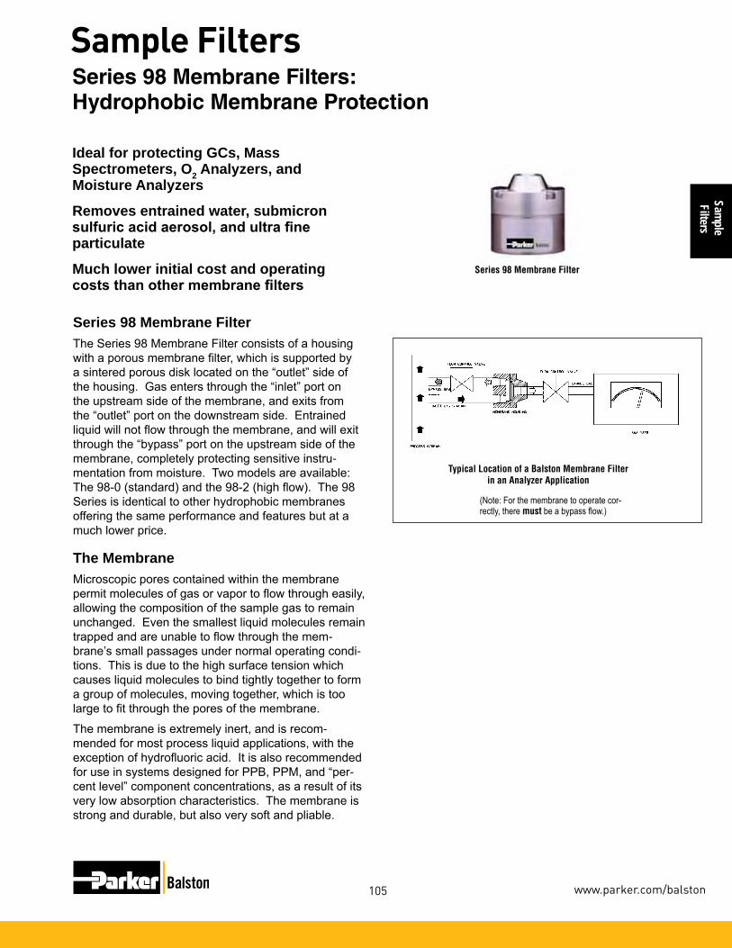
Sample
Filters
105
Sample Filters
www.parker.com/balston
Series 98 Membrane FilterThe Series 98 Membrane Filter consists of a housing with a porous membrane filter, which is supported by a sintered porous disk located on the “outlet” side of the housing. Gas enters through the “inlet” port on the upstream side of the membrane, and exits from the “outlet” port on the downstream side. Entrained liquid will not flow through the membrane, and will exit through the “bypass” port on the upstream side of the membrane, completely protecting sensitive instru-mentation from moisture. Two models are available: The 98-0 (standard) and the 98-2 (high flow). The 98 Series is identical to other hydrophobic membranes offering the same performance and features but at a much lower price.
Ideal for protecting GCs, Mass Spectrometers, O2 Analyzers, and Moisture Analyzers
Removes entrained water, submicron sulfuric acid aerosol, and ultra fine particulate
Much lower initial cost and operating costs than other membrane filters
Series 98 Membrane Filter
The MembraneMicroscopic pores contained within the membrane permit molecules of gas or vapor to flow through easily, allowing the composition of the sample gas to remain unchanged. Even the smallest liquid molecules remain trapped and are unable to flow through the mem-brane’s small passages under normal operating condi-tions. This is due to the high surface tension which causes liquid molecules to bind tightly together to form a group of molecules, moving together, which is too large to fit through the pores of the membrane.
The membrane is extremely inert, and is recom-mended for most process liquid applications, with the exception of hydrofluoric acid. It is also recommended for use in systems designed for PPB, PPM, and “per-cent level” component concentrations, as a result of its very low absorption characteristics. The membrane is strong and durable, but also very soft and pliable.
(Note: For the membrane to operate cor-rectly, there must be a bypass flow.)
Typical Location of a Balston Membrane Filter in an Analyzer Application
Series 98 Membrane Filters: Hydrophobic Membrane Protection

Sam
ple
Filte
rs
106
Sample Filters
1-800-343-4048
Table 1 Housing and Membrane Selection GuidePrincipal Model 98-0 98-2 Membrane Type Standard (1) High Flow (2)Max. RecommendedFlow Rate in L/Min. 0.60 (3) 10 (3)Normal Amount ofLiquid Present in Gas Low to Medium (4) Low to Medium (4)
Notes:1 Standard membrane is suitable for most suspended liquids.2 High flow membrane is suitable for suspended water, solutions consisting primarily of water, sulfuric acid, caustic, glycols, oily liquids, other high surface-tension type liquids.3 Maximum recommended flow rate of gas through the membrane. Does not include the “bypass” flow rate.4 Amount of liquid normally expected to be present in the sample gas: Low: aerosol or oc-casional droplets. Medium: continuous droplets. High: continuous flowing liquid.
Specifications
Model 98 Inlet, Outlet, Bypass Ports 1/4” NPTMaterials of Construction Housing 316 Stainless Steel (2) O-rings Viton (standard) Kalrez, Buna, EPDM (optional)Maximum Operating Pressure 1000 psig @ 200°F (69 barg @ 93°C)Maximum Temperature 212°F (100°C) Maximum Flow RateStandard Membrane .60 L/Min.High Flow Membrane 10 L/Min.Typical Membrane Pressure Drop Standard Membrane 1 psig (0.07 barg) per 100 cc/min. flow through membrane (1) High Flow Membrane 1 psig (0.07 barg) per 3.8 liters/min. flow through the membrane (1)Outside Dimensions 2”D x 2”L (5cm X 5cm) Shipping Weight 1.5 lbs. (0.7 kg)
Notes:1 Pressure Drops are for temperatures to 212°F (100°C).
Ordering Information
Filter Assembly 98-0 (Standard) 98-2 (High Flow) Maintenance Kits 98014 5 each Membranes & Viton O-Rings for 98-098015 5 each Membranes & Viton O-Rings for 98-298002 5 each Membranes 98-098020 5 each Membranes 98-2
Model 98-0
Model 98-2
HSF* Pressure Drop - STDTypical Pressure Drop: 1 psi/0.07 barg
per 100 cc/min
HSF* Pressure Drop - HFTypical Pressure Drop: 1 psi/0.07 barg
per 3.8 lpm
* HSF= Hydrophobic Sample Filter
How to Select the Membrane and Model1. Determine the following application requirements:
A. Gas flow rate to the analyzer excluding the bypass flow. B. Type of suspended liquid to be separated and amount normally present in the sample. C. Gas sample supply pressure at membrane filter inlet.
2. Use Table 1 to select a membrane filter model and membrane type which meet your application require-ments. Note that the membrane differential pressure for the model and membrane type selected must be lower than the available gas sample supply pressure.
Selecting the Appropriate Type of MembraneThere are two basic types of membranes for the 98 Series Membrane Filters: The Model 98-0 (Standard) is suitable for separation of most liquids from gases. The Model 98-2 (High Flow) is best suited for the separa-tion of water and other high surface-tension liquids from gases.
Series 98 Membrane Filters: 1/4” Line Size

Sample
Filters
107
Sample Filters
www.parker.com/balston
A98 Series offers continuous coalescing of all liquid and the security of hydropho-bic membrane protection all in one unit
Fewer fittings required - reducing risk of leaks
More compact - no need for separate coalescers
Less maintenance and downtime as the membrane is fully protected from solids & liquids
Series A98 Coalescer Membrane Combination FilterThe Balston Coalescer Membrane Combination Filter is designed to remove entrained liquid and particu-late in gas samples for a wide variety of applications, and thereby prevents contamination or damage to the analyzers and sample system components. Typically located upstream from the analyzer or component it is protecting, the Coalescer Membrane Combination provides protection even if other sample system compo-nents fail.
The Coalescer Membrane Combination offers the perfor-mance and protection of the 98 Series Membrane Filter with the additional benefits of coalescing liquids and en-trapment of particulates, offering maximum protection of the membrane. There is no need for prefiltration which places more volume in the sample system, and requires more space for installation and more potential for leaks.
The Series A98 consists of a housing with a porous membrane filter, which is supported by a sintered porous disk located on the “outlet” side of the housing. Gas enters through the “inlet” port and is directed down through the coalescing filter. The coalescer traps all particulates and continuously drains liquid contaminants. The sample gas then flows upward to the upstream side of the membrane, and exits from the “outlet” port on the downstream side. Entrained liquid will not flow through the membrane, and will exit through the drain port on the downstream side of the coalescer.
The MembraneMicroscopic pores contained within the membrane permit molecules of gas or vapor to flow through easily, allowing the composition of the sample gas to remain unchanged. Even the smallest liquid mol-ecules remain trapped and are unable to flow through the membrane’s small passages under normal operat-ing conditions. This is due to the high surface tension which causes liquid molecules to bind tightly together to form a group of molecules, moving together, which is too large to fit through the pores of the membrane.
The membrane is extremely inert, and is recom-mended for most process liquid applications, with the exception of hydrofluoric acid. It is also recommended for use in systems designed for PPB, PPM, and “per-cent level” component concentrations, as a result of its very low absorption characteristics. The membrane is strong and durable, but also very soft and pliable.
Series A98 Coalescer Membrane Combination Filter
Typical Location of a Balston Membrane Filterin an Analyzer Application
(Note: For the membrane to operate cor-rectly, there must be a bypass flow.)
Series A98 Coalescer Membrane Combination Filters

Sam
ple
Filte
rs
108
Sample Filters
1-800-343-4048
How to Select the Membrane and Model1. Determine the following application requirements:
A. Gas flow rate to the analyzer excluding the bypass flow. B. Type of suspended liquid to be separated and amount normally present in the sample. C. Gas sample supply pressure at Membrane Filter inlet.
2. Use Table 1 to select a Membrane Filter model and Membrane type which meet your application require-ments. Note that the membrane differential pressure for the model and membrane type selected must be lower than the available gas sample supply pressure.
Selecting the Appropriate Type of MembraneThere are two basic types of membranes for the A98/11 Series Membrane Filters: The Model A98/11-__Q-0 (Standard) is suitable for separation of most liquids from gases. The Model A98/11-__Q-2 (High Flow) is best suited for the separation of water and other high surface-tension liquids from gases.
Table 1 Housing and Membrane Selection Guide
Model A98/11-__Q-0 A98/11-__Q-2Membrane Type Standard (1) High Flow (2)Max. RecommendedFlow Rate in L/Min. 0.60 (3) 10 (3)Normal Amount ofLiquid Present in Gas Low to Medium (4) Low to Medium (4)
Model A98/11-__Q-0
Model A98/11-__Q-2
Notes:1 Standard membrane is suitable for most suspended liquids.2 High flow membrane is suitable for suspended water, solutions consisting primarily or water, sulfuric acid, caustic, glycols, oily liquids, other high surface-tension type liquids.3 Maximum recommended flow rate of gas through the membrane. Does not include the “bypass” flow rate.4 Amount of liquid normally expected to be present in the sample gas: Low: aerosol or occasional droplets. Medium: continuous droplets. High: continuous flowing liquid.
HSF* Pressure Drop - STDTypical Pressure Drop: 1 psi per 100 cc/min
Principal Specifications
Model A98/11- [ ] Q - [ ] Inlet, Outlet, Bypass Ports 1/4” NPTMaterials of Construction Housing 316 Stainless Steel O-rings Viton (standard) Kalrez, Buna, EPDM (optional)Maximum Operating Pressure 1000 psig @ 200°F (69 barg @ 93°C)Maximum Temperature 212°F (100°C) Maximum Flow RateStandard Membrane .60 L/Min.High Flow Membrane 10 L/Min.Typical Membrane Pressure Drop Standard Membrane 1 psig (0.07 barg) per 100 cc/min. flow through membrane (1) High Flow Membrane 1 psig (0.07 barg) per 3.8 liters/min. flow through the membrane (1)Outside Dimensions 2”D x 4”L (5cm X 10cm) Shipping Weight 2.4 lbs. (1.1 kg)
Notes:1 Pressure Drops are for temperatures to 212°F (100°C). 2 Constructed of materials which comply with NACE Specification MR-01-75. Request certificate of compliance.
Ordering InformationFilter/Membrane Replacement Kits A98/11-__Q-0 A98/11-__Q-2
98011 5 ea. DQ Filters, Viton O-Rings and Membranes for A98/11-DQ-O
98012 5 ea. BQ Filters, Viton O-Rings and Membranes for A98/11-BQ-2
98013 5 ea. DQ Filters, Viton O-Rings and Membranes for A98/11-DQ-2
98010 5 ea. BQ Filters, Viton O-Rings and Membranes for A98/11-BQ-O
98002 5 ea. Membranes for A98-0 or A98/11_Q-O
98020 5 ea. Membranes for A98-2 or A98/11_Q-2
050-11-__Q 10 ea. Coalescing Filter Cartridges
* HSF= Hydrophobic Sample Filter
A98/11 Series Coalescer: Membrane Combination Filter
HSF* Pressure Drop - STDTypical Pressure Drop: 1 psi/0.07 barg
per 100 cc/min
HSF* Pressure Drop - HFTypical Pressure Drop: 1 psi/0.07 barg
per 3.8 lpm

Sample
Filters
109
Sample Filters
www.parker.com/balston
The A39/12 Series offers continuous coalescing of all liquid and the security of hydrophobic membrane protection all in one unit
Fewer fittings required - reducing risk of leaks
More compact - no need for separate coalescers
Less maintenance and downtime as the membrane is fully protected from solids & liquids
Series A39/12 Coalescer Membrane Combination FilterThe Balston Coalescer Membrane Combination Filter is designed to remove entrained liquid and particu-late in gas samples for a wide variety of applications, and thereby prevents contamination or damage to the analyzers and sample system components. Typically located upstream from the analyzer or component it is protecting, the Coalescer Membrane Combination provides protection even if other sample system com-ponents fail.
The Coalescer Membrane Combination offers the performance and protection of the A39/12 Series Mem-brane Filter with the additional benefits of coalescing liquids and entrapment of particulates, offering maxi-mum protection of the membrane. There is no need for prefiltration which places more volume in the sample system, and requires more space for installation and more potential for leaks.
The A39/12 Series consists of a housing with a po-rous membrane filter, which is supported by a sintered porous disk located on the “outlet” side of the hous-ing. Gas enters through the “inlet” port and is directed down through the coalescing filter. The coalescer traps all particulates and continuously drains liquid contaminants. The sample gas then flows upward to the upstream side of the membrane, and exits from the “outlet” port on the downstream side. Entrained liquid will not flow through the membrane, and will exit through the drain port on the downstream side of the coalescer.
The MembraneMicroscopic pores contained within the membrane permit molecules of gas or vapor to flow through easily, allowing the composition of the sample gas to remain unchanged. Even the smallest liquid molecules remain trapped and are unable to flow through the membrane’s small passages under normal operating conditions. This is due to the high surface tension which causes liquid molecules to bind tightly together to form a group of mol-ecules, moving together, which is too large to fit through the pores of the membrane.
The membrane is extremely inert, and is recommended for most process liquid applications, with the exception of hydrofluoric acid. It is also recommended for use in systems designed for PPB, PPM, and “percent level” component concentrations, as a result of its very low absorption characteristics. The membrane is strong and durable, but also very soft and pliable.
Series A39/12 Coalescer Membrane Combination Filter
Typical Location of a Balston Membrane Filterin an Analyzer Application
(Note: For the membrane to operate cor-rectly, there must be a bypass flow.)
A39/12 Series Coalescer: Membrane Combination Filter

Sam
ple
Filte
rs
110
Sample Filters
1-800-343-4048
Table 1 Housing and Membrane Selection GuideModel A39-0 Series A39-2 SeriesMembrane Type Standard (1) High Flow (2)Max. RecommendedFlow Rate in L/Min. 1.0 lpm (3) 70 lpm (3)Normal Amount ofLiquid Present in Gas Low to Medium (4) Low to Medium (4)
Notes:1 Standard membrane is suitable for most suspended liquids.2 High flow membrane is suitable for suspended water, solutions consisting primarily or water, sulfuric acid, caustic, glycols, oily liquids, other high surface-tension type liquids.3 Maximum recommended flow rate of gas through the membrane. Does not include the “bypass” flow rate.4 Amount of liquid normally expected to be present in the sample gas: Low: aerosol or oc-casional droplets. Medium: continuous droplets. High: continuous flowing liquid.
Principal SpecificationsModel A39/12 Series Bypass Ports 1/2” NPTSample Port 1/4” NPTMaterials of Construction Housing 316 Stainless Steel (2) O-rings Viton (standard) Kalrez, Buna, EPDM (optional)Maximum Operating Pressure 425 psig/29.3 barg @ 200°F/93°C (100 psig/6.9 barg @ 200°F/ 93°C with Pyrex bowl)Maximum Temperature 212°F (100°C) Maximum Flow Rate Standard Membrane 1 L/Min.High Flow Membrane 70 L/Min.Typical Membrane Pressure Drop Standard Membrane 1 psig (0.07 barg) per 250 cc/min. flow through membrane (1) High Flow Membrane 1 psig (0.07 barg) per 20 liters/min. flow through the membrane (1)Outside Dimensions 3.3”D x 7.3”L (8.4 cm X 18.5 cm)
Shipping Weight 7 lbs. (1.1 kg)
Notes:1 Pressure Drops are for temperatures to 212°F (100°C). 2 Constructed of materials which comply with NACE Specification MR-01-75. Request certificate of compliance.
Ordering Information
Filter/Membrane Replacement Kits A39/12-__X-0, A39/12-__X-239014 5 ea. Viton O-Rings and Membranes for A39/12-039015 5 ea. Viton O-Rings and Membranes for A39/12-239002 5 ea. Membranes for A39/12-039020 5 ea. Membranes for A39/12-2150-12-__X 10 ea. Coalescing Filter Cartridges
* HSF= Hydrophobic Sample Filter
Notes:1 For Glass Bowl version order: A39/12G-_X-(0)-(2)
Model A39-0
How to Select the Membrane and Model1. Determine the following application requirements:
A. Gas flow rate to the analyzer excluding the bypass flow. B. Type of suspended liquid to be separated and amount normally present in the sample. C. Gas sample supply pressure at Membrane Filter inlet.
2. Use Table 1 to select a Membrane Filter model and Membrane type which meet your application require-ments. Note that the membrane differential pressure for the model and membrane type selected must be lower than the available gas sample supply pressure.
Selecting the Appropriate Type of MembraneThere are two basic types of membranes for the A39/12 Series Membrane Filters: The Model A39/12-0 (Standard) is suitable for separation of most liquids from gases. The Model A39/12-2 (High Flow) is best suited for the separation of water and other high sur-face-tension liquids from gases. A Pyrex bowl is avail-able which offers full visibility of coalescing chamber.
Model A39-2
A39/12 Series Coalescer: Membrane Combination Filters

Sample
Filters
111
Sample Filters
www.parker.com/balston
The 39 Series Membrane FilterThe 39 Series Membrane Filter consists of a housing with a porous membrane filter, which is supported by a sin-tered porous disk located on the “outlet” side of the hous-ing. Gas enters through the “inlet” port on the upstream side of the membrane, and exits from the “outlet” port on the downstream side. Entrained liquid will not flow through the membrane, and will exit through the “bypass” port on the upstream side of the membrane, completely protecting sensitive instrumentation from moisture. Two models are available: The 39-0 (standard) and the 39-2 (high flow). The 39 Series is identical to other hydro-phobic membranes offering the same performance and features but at a much lower price.
The MembraneMicroscopic pores contained within the membrane permit molecules of gas or vapor to flow through easily, allowing the composition of the sample gas to remain unchanged. Even the smallest liquid molecules remain trapped and are unable to flow through the membrane’s small passages under normal operating conditions. This is due to the high surface tension which causes liquid molecules to bind tightly together to form a group of mol-ecules, moving together, which is too large to fit through the pores of the membrane.
The membrane is extremely inert, and is recommended for most process liquid applications, with the exception of hydrofluoric acid. It is also recommended for use in systems designed for PPB, PPM, and “percent level” component concentrations, as a result of its very low absorption characteristics. The membrane is strong and durable, but also very soft and pliable.
Ideal for protecting GCs, Mass Spectrometers, O2 Analyzers, and Moisture Analyzers
Removes entrained water, submicron sulfuric acid aerosol, and ultra fine particulate
Much lower initial cost and operating costs than other membrane filters
39 Series
(Note: For the membrane to operate cor-rectly, there must be a bypass flow.)
Typical Location of a Balston Membrane Filterin an Analyzer Application
39 Series Membrane Filters

Sam
ple
Filte
rs
112
Sample Filters
1-800-343-4048
Membrane Type Standard (1) High Flow (2)Max. RecommendedFlow Rate in L/Min. 0.04 scfm (1.0 lpm) (3) 2.5 scfm (70 lpm) (3)Normal Amount ofLiquid Present in Gas Low to Medium (4) Low to Medium (4)
How to Select the Membrane and Model1. Determine the following application requirements:
A. Gas flow rate to the analyzer excluding the bypass flow. B. Type of suspended liquid to be separated and amount normally present in the sample. C. Gas sample supply pressure at membrane filter inlet.
2. Use Table 1 to select a membrane filter model and membrane type which meet your application require-ments. Note that the membrane differential pressure for the model and membrane type selected must be lower than the available gas sample supply pressure.
Selecting the Appropriate Type of MembraneThere are two basic types of membranes for the 39-2 Series Membrane Filters: The Model 39-0 (Standard) is suitable for separation of most liquids from gases. The Model 39-2 (High Flow) is best suited for the separation of water and other high surface-tension liquids from gases.
Table 1 Housing and Membrane Selection GuideModel 39-0 39-2 Series
Notes:1 Standard membrane is suitable for most suspended liquids.2 High flow membrane is suitable for suspended water, solutions consisting primarily of water, sulfuric acid, caustic, glycols, oily liquids, other high surface-tension type liquids.3 Maximum recommended flow rate of gas through the membrane. Does not include the “bypass” flow rate.4 Amount of liquid normally expected to be present in the sample gas: Low: aerosol or oc-casional droplets. Medium: continuous droplets. High: continuous flowing liquid.
Principal Specifications
Notes:1 Pressure Drops are for temperatures to 212°F (100°C).2 Constructed of materials which comply with NACE Specification MR-01-75. Request certificate of compliance.
Ordering Information
Model 39 Series Bypass Ports 1/2” NPTSample Port 1/4” NPTMaterials of Construction Housing 316 Stainless Steel (2) O-rings Viton (standard) Kalrez, Buna, EPDM (optional)Maximum Operating Pressure 500 psig (35 barg) @ 200°F (93°C) (100 psig (6.9 barg) @ 200°F (93°C ) with Pyrex bowl)Maximum Temperature 212°F (100°C) Maximum Flow Rate Standard Membrane 0.04 scfm (1 L/Min.)High Flow Membrane 2.5 scfm (70 L/Min.)Typical Membrane Pressure Drop Standard Membrane 1 psig (0.07 barg) per 250 cc/min. flow through membrane (1) High Flow Membrane 1 psig (0.07 barg) per 20 liters/min. flow through the membrane (1)Outside Dimensions 3.3”D x 2”L (8.4cm X 5.1cm) Shipping Weight 3 lbs. (1.4 kg)
Filter/Membrane 39-0, 39-2Replacement Kits 39014 5 ea. Viton O-Rings and Membranes for 39-039015 5 ea. Viton O-Rings and Membranes for 39-239002 5 ea. Membranes for 39-039020 5 ea. Membranes for 39-2
Model 39-0
Model 39-2
39 Series Membrane Filters: 1/4” Line Size

Sample
Filters
113
Sample Filters
www.parker.com/balston
All 316 Stainless steel/Pyrex construction
Accepts Balston disposable microfibre filter cartridge and stainless steel cartridge
Compact design for fast response time
Process stream inlet/outlet ports and sample flow ports are identical, eliminating backup pressure in the system
DescriptionBalston fast loop filters are constructed of 316 stain-less steel with an optional stainless steel bowl or pyrex bowl. This flow through design continuously flushes the filter cartridge carrying the contaminates back out to the process stream, thus maximizing the filter cartridge life. The low flow sample stream pulled into the analyzer is filtered to ranges of 100 micron to 0.01 micron (depend-ing on the filtration efficiency required). Two designs are available. The T-type design is suitable for high flow, high volume applications. The In-line design is ideal for heavily contaminated applications.
OperationAxial velocity flushes the bulk contaminants through the filter housing back to the process stream. The sample stream passes through the filter cartridge wall with low flow and radial velocity. The clean side of the sample filter system has very low volume which minimizes lag time. A four to one flow rate is recommended to realize the benefits of prolonged filter cartridge life associated with continuous flushing.
Model 41GCFL-1/4
Model 48S6
Model 49S6
Fast Loop Filters: Filtration Efficiency from 100µm to 0.01µm

Sam
ple
Filte
rs
114
Sample Filters
1-800-343-4048
Model 31GCFL-1/4 31S6CFL-1/4 41GCFL-1/4 41S6CFL-1/4 48S6 49S6
Inlet and Outlet Ports 1/4” NPT 1/4” NPT 1/4” NPT 1/4” NPT 1/4” NPT 1/2” NPT Drain Port 1/4” NPT 1/4” NPT 1/4” NPT 1/4” NPT ––– –––Materials of ConstructionHead 316 SS 316 SS (2) 316 SS 316 SS (2) 316 SS (2) 316 SS (2) Bowl Pyrex (1) 316SS (1)(2) Pyrex (1) 316 SS (1)(2) 316 SS (1)(2) 316 SS (1)(2)Internals 316SS 316 SS (2) 316 SS 316 SS (2) 316 SS (2) 316 SS (2) Seals Viton Viton Viton Viton Viton Viton Maximum Temperature 160°F (71°C) 400°F (204°C) 160°F (71°C) 400°F (204°C) 400°F (204°C) 400°F (204°C)Maximum Pressure 100 psig (7 barg) (2) 425 psig (30 barg) (2) 100 psig (7 barg) (2) 250 psig (17 barg) (2) 5,000 psig (345 barg) (2) 1,500 psig (100 barg) (1)Shipping Weight 2 lbs (0.9 kg) 3 lbs (1.4 kg) 4 lbs (1.8 kg) 5 lbs (2.3 kg) 1.1 lbs (0.2 kg) 2.5 lbs (0.4 kg)Dimensions 2.2”D x 5.5”L 2.2”D x 5.5”L 2.2”D x 10”L 2.2”D x 10”L 1.35”D x 4”L 1.9”D x 7”L (5.7cm x 14cm) (5.7cm x 14cm) (5.7cm x 25cm) (5.7cm x 25cm) (3.2cm x 10cm) (4.8cm x 17.8cm)
Principal Specifications
Notes:1 Maximum pressure ratings are for tempera-tures to 200°F (104°C). Please consult factory for maximum pressure ratings at elevated temperatures.
Ordering Information For Assistance, call toll-free at 1-800-343-4048 8AM to 5PM Eastern Time Filter Housing Model 31GCFL-1/4 31S6CFL-1/4 41GCFL-1/4 41S6CFL-1/4 48S6 49S6
Support Core, Requiredfor Liquid Filtration SS-100-12 SS-100-12 SS-100-25 SS-100-25 Included ----- Filter Cartridges 100-12-❑ 100-12-❑ 100-25-❑ 100-25-❑ 050-11-❑ 100-185-❑ Use only these Filter types X, H, Q, M X, H, Q, M X, H, Q, M X, H, Q, M X, H, Q, M X, H, Q
2 Constructed of materials which comply with NACE Specification MR-01-75. Request certificate of compliance.
Fast Loop Filters: Filtration Efficiency from 100µm to 0.01µm
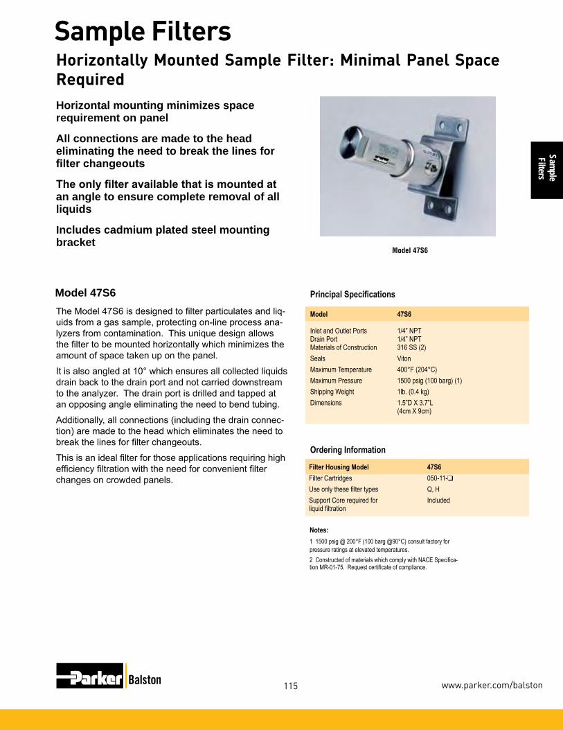
Sample
Filters
115
Sample Filters
www.parker.com/balston
Model 47S6
Horizontal mounting minimizes space requirement on panel
All connections are made to the head eliminating the need to break the lines for filter changeouts
The only filter available that is mounted at an angle to ensure complete removal of all liquids
Includes cadmium plated steel mounting bracket
The Model 47S6 is designed to filter particulates and liq-uids from a gas sample, protecting on-line process ana-lyzers from contamination. This unique design allows the filter to be mounted horizontally which minimizes the amount of space taken up on the panel.
It is also angled at 10° which ensures all collected liquids drain back to the drain port and not carried downstream to the analyzer. The drain port is drilled and tapped at an opposing angle eliminating the need to bend tubing.
Additionally, all connections (including the drain connec-tion) are made to the head which eliminates the need to break the lines for filter changeouts.
This is an ideal filter for those applications requiring high efficiency filtration with the need for convenient filter changes on crowded panels.
Model 47S6
Principal Specifications Model 47S6
Inlet and Outlet Ports 1/4” NPT Drain Port 1/4” NPT Materials of Construction 316 SS (2)Seals Viton Maximum Temperature 400°F (204°C) Maximum Pressure 1500 psig (100 barg) (1)Shipping Weight 1lb. (0.4 kg)Dimensions 1.5”D X 3.7”L (4cm X 9cm)
Notes:1 1500 psig @ 200°F (100 barg @90°C) consult factory for pressure ratings at elevated temperatures.2 Constructed of materials which comply with NACE Specifica-tion MR-01-75. Request certificate of compliance.
Ordering Information Filter Housing Model 47S6 Filter Cartridges 050-11-❑Use only these filter types Q, HSupport Core required for Includedliquid filtration
Horizontally Mounted Sample Filter: Minimal Panel Space Required

Sam
ple
Filte
rs
116
Sample Filters
1-800-343-4048
Small Scale Laboratory Vacuum Pumps
Application Notes

Sample
Filters
117
Sample Filters
www.parker.com/balston
• Protectvacuumpumpsandreduce costly maintenance
• Easytoinstallandmaintain
Vacuum Pump Inlet & Exhaust Filters
Product Features:
Balston Vacuum Pump Exhaust Filters remove 99.9% of 0.1 micron oil mist and smoke particles. Balston Grade 30 Vacuum Pump Inlet Filters remove 90% of all 0.1 micron particles and droplets. Balston Grade 102 Vacuum Pump Inlet Filters prevent oil back-streaming from the pump to the evac-uated chamber, and protect the pump from damage by submicron particles (at relatively low concentrations).
All Balston filters are available for haz-ardous and non-hazardous applica-tions, and offer superior chemical and solvent resistance. Balston Vacuum Pump Filters increase productivity by eliminating costly shutdown time and maintenance.
• Exhaustfilterseliminateoil mist and smoke from vacuumpumpexhaust
• Preventoilbackstreaming
• Preventoilaccumulationin ductwork
Balston Vacuum Pump Filters
Small Scale Laboratory Vacuum Pumps High Volume Vacuum for Process PackagingSpecialized Vacuum Electronics Manufacturing

Vacu
um
Pum
p Fi
lters
118
Vacuum Pump Inlet & Exhaust Filters
1-800-343-4048
Eliminate 99.9% oil mist and smoke from vacuum pump exhaust
Prevent oil accumulation in ductwork
Recover expensive lubricating oils, and automatically return filtered oil to pump
Eliminate potential OSHA and EPA violations
Balston Vacuum Pump Exhaust FiltersBalston Vacuum Pump Exhaust Filters remove all visible oil mist and smoke from vacuum pump exhaust, even when it is saturated with oil. The high efficiency filter cartridge continuously drains the collected liquid, allow-ing the user to recover expensive lubricating fluid.
How To Select The FilterFor most applications, simply select the filter assembly which has a flow capacity equal to or greater than the vacuum pump exhaust flow output (see chart on the next page). The Filter Assemblies are shipped with filter cartridges, and final filter pad. Optional adaptors are available for KF and NW connections.
CV-0118
Filter Selection Chart (for hazardous/corrosive applications)
Max. Pump Recommended Filter Model NumberFlow Rate (CFM)
3 (5 m3/h) CV-0112-371H
9 (15 m3/h) CV-0118-371H
Exhaust Filters for Hazardous/Corrosive Applications

Vacuum
Pump Filters
119
Vacuum Pump Inlet & Exhaust Filters
www.parker.com/balston
Principal SpecificationsModel CV-0112-371H CV-0118-371H
Port Size 1/2” NPT 3/4” NPT Max. Flow Rate 3 CFM 9 CFM Materials of Construction Head ––– ––– Bowl 304 SS 304 SS Internals 304 SS 304 SS Seals None None Maximum Temperature 250°F (121°C) 250°F (121°C) Maximum Pressure 15 psig (1.0 barg) 15 psig (1.0 barg) Shipping Weight 0.5 lbs. (0.2 kg) 0.8 lbs. (0.4 kg) Dimensions 2.9”Dia. X 4.2”H 4.0”Dia. X 5.3”H (7cm X 11cm) (10cm X 13cm)
Ordering Information
For assistance, call toll-free at 1-800-343-4048 8AM to 5PM Eastern Time
Model CV-0112-371H (1) CV-0118-371H (1)
Number of Filter Cartridges Required ––– ––– Replacement Filter Cartridges Box of 3 ––– ––– Box of 7 ––– ––– Box of 10 ––– ––– Number of Pressure ReliefRetainers #20222 ––– ––– Optional Accessories: #11015 Back Pressure Gage, Stainless Steel, 0-15 psi (0-1.0 barg) rating,1/4”NPTfitting.VacuumPump-to-FilterAdaptors: Please refer to Pages 141 - 142.
Notes:1 Filter cartridge is permanently sealed into housing. The entire unit is disposable. Pressurerelieffiltertuberetainernotavail-able in these models.
Exhaust Filters for Hazardous/Corrosive Applications

Vacu
um
Pum
p Fi
lters
120
Vacuum Pump Inlet & Exhaust Filters
1-800-343-4048
Eliminate 99.9% oil mist and smoke from vacuum pump exhaust
Prevent oil accumulation in ductwork
Recover expensive lubricating oils, and automatically return filtered oil to pump
Eliminate potential OSHA and EPA violations
Balston Vacuum Pump Exhaust FiltersBalston Vacuum Pump Exhaust Filters remove all vis-ible oil mist and smoke from vacuum pump exhaust, even when it is saturated with oil. The high efficiency filter cartridge continuously drains the collected liquid, allowing the user to recover expensive lubricating fluid. Filters are available for pumps with flow ratings ranging from 3 to 850 cfm (5-1440 m3/h).
How To Select The FilterFor most applications, simply select the filter assembly which has a flow capacity equal to or greater than the vacuum pump exhaust flow output (see chart below). The filter assemblies are shipped with filter cartridges, pressure gage (20 cfm and larger), and final filter pad. Optional adaptors are available for KF and NW connec-tions.
Model AR-009
Model AR-0316
Model 9955-12
Model AR-0780
Model AR-3080
Max. Pump Recommended Filter Model NumberFlow Rate (CFM/m3/h) 3 (5) 9955-12-371H, 9956-12-371H9 (15) AR-009-371H15 (25) AR-015-371H20 (34) AR-0316-371H43 (73) AR-0335-371H100 (170) AR-0735-371H200 (340) AR-0780-371H300 (510) AR-1280-371H450 (765) AR-1680-371H850 (1440) AR-3080-371H
Filter Selection Chart (for non-hazardous/non-corrosive applications)
Exhaust Filters for Non-Hazardous/Non-Corrosive Applications

Vacuum
Pump Filters
121
Vacuum Pump Inlet & Exhaust Filters
www.parker.com/balston
Ordering Information
For assistance, call toll-free at 1-800-343-4048 8AM to 5PM Eastern Time
Model No. of Filter Replacement Filter Cartridges Cover (2) No. Pressure Relief Cartridges Required Box of 3 Box of 7 Box of 10 (Optional) Retainers #202229955-12-371H (3) 1 3/9955-12-371H ––– 9955-12-371H ––– (4)9956-12-371H (3) 1 3/9956-12-371H ––– 9956-12-371H ––– (4)AR-009-371H 1 2/BE200-168-371H (6) ––– BE200-168-371H ––– (4)AR-015-371H 1 2/BE200-248-371H (6) ––– BE200-248-371H ––– (4)AR-0316-371H 3 3/200-16-371H ––– ––– 19158 1AR-0335-371H 3 3/200-35-371H ––– ––– 19158 1AR-0735-371H 7 ––– 7/200-35-371H ––– 19206 2AR-0780-371H 7 ––– 7/200-80-371H ––– 19206 2AR-1280-371H 12 ––– ––– 200-80-371H Included 4 AR-1680-371H 16 ––– ––– 200-80-371H Included 4 AR-3080-371H 30 ––– ––– 200-80-371H Included 6Optional Accessories: #20222 Pressure Relief Filter Cartridge Retainer, 4-7 psig (0.3-0.5 barg). #20217PressureReliefValve,3-7psig(0.2-0.5barg),1/4”NPTmalefitting. #11010PressureGage,0-15psig(0-1.0barg),1/4”malefitting(incl.onTypeARFilterAssemblies) Vacuumpump-to-filteradaptors:refertopages141-142. #19291 Stand for AR-1680-371H, #19290 Stand for AR-3080-371H. #19202 Weather Cap for AR-0735-371H, AR-0780-371H. #A05-0097 Seal Set for AR-009-371H, AR-015-371H.
Notes:1 ANSI 150 lb. hole pattern.2Coverdoesnotprovideleaktightseal.3 Filter cartridge is permanently sealed into housing. The entire unit is disposable.4Pressurerelieffiltertuberetainernotavail-able in these models.
5Heightdimensionrepresentsfilterhousingalone. When assembled with a stand, the height is adjustable from 46” to 56” (117cm to 142 cm).
Principal Specifications
6 This model comes in box of 2, not box of 3.
Exhaust Filters for Non-Hazardous/Non-Corrosive Applications
Model Port Size Max. Flow Materials of Construction Max. Max. Shipping Dimensions Rate Head Bowl Internals Seals Temp. Press. Wt.
9955-12-371H 1/2” NPT 3 CFM ––– Nylon Nylon None 250°F (121°C) 15 PSIG (1.0 barg) .25 lbs (0.1 kg) 2”Dia. X 3.7”H 9956-12-371H KF-16 3 CFM ––– Nylon Nylon None 250°F (121°C) 15 PSIG (1.0 barg) .25 lbs (0.1 kg) 2”Dia. X 3.7”HAR-009-371H 3/4” NPT 9CFM Aluminum Aluminum Alum./SS/Nylon Viton 300°F(149°C) 15 PSIG (1.0 barg) 1.0lbs(0.45kg) 3.95”Dia.X5.13”HAR-015-371H 3/4” NPT 15 CFM Aluminum Aluminum Alum./SS/Nylon Viton 300°F(149°C) 15 PSIG (1.0 barg) 1.25lbs (0.57kg) 3.95”Dia.X8.13”HAR-0316-371H 1” NPT 20 CFM Steel Steel Anod. Alum. Buna/Neo 300°F (149°C) 15 PSIG (1.0 barg) 8 lbs (4 kg) 7.4”Dia. X 8.8”HAR-0335-371H 1 1/2” NPT 43 CFM Steel Steel Anod. Alum. Buna/Neo 300°F (149°C) 15 PSIG (1.0 barg) 11 lbs (5 kg) 7.4”Dia. X 15”HAR-0735-371H 3” NPT 100 CFM Steel Steel Anod. Alum. Buna/Neo 300°F (149°C) 15 PSIG (1.0 barg) 17 lbs (8 kg) 10”Dia. X 18”HAR-0780-371H 3” NPT 200 CFM Steel Steel Anod. Alum. Buna/Neo 300°F (149°C) 15 PSIG (1.0 barg) 23 lbs (10 kg) 10”Dia. X 28”HAR-1280-371H 4” Flg. (1) 300 CFM Steel Steel Anod. Alum. Buna/Neo 300°F (149°C) 15 PSIG (1.0 barg) 90 lbs (41 kg) 19”Dia. X 43”H (5)AR-1680-371H 4” Flg. (1) 450 CFM Steel Steel Anod. Alum. Buna/Neo 300°F (149°C) 15 PSIG (1.0 barg) 100 lbs (45 kg) 19”Dia. X 43”H (5)AR-3080-371H 6” Flg. (1) 850 CFM Steel Steel Anod. Alum. Buna/Neo 300°F (149°C) 15 PSIG (1.0 barg) 150 lbs (68kg) 23”Dia. X 43”H (5)

Vacu
um
Pum
p Fi
lters
122
Vacuum Pump Inlet & Exhaust Filters
1-800-343-4048
CF-0118-30
Protect vacuum pumps from damage by solids and liquids
Prevent loss of valuable or hazardous materials
Prevent oil backstreaming
Model CF-0112 and CF-0118 for Vacuum Service to 10-6 TorrStainless steel housings with welded KF flange inlet and outlet ports and no drain ports. They are designed to be used primarily with the Grade 102 adsorbent cartridges for prevention of oil backstreaming (see cartridge selection chart to the right). They may also be used with Grade 30 cartridges for removal of high concentrations of solids, but the absence of drain ports precludes the use of CF housings for liquid removal in vacuum applications.
Filter Selection Chart
Grade 30 Cartridges For removal of relatively high concentrations of solids
Efficiency: 90%at0.1micronLossinpumpingspeed: 9%atmaximumflowrateMaterials of construction: Polypropylene cartridge, EPR sealsMaximum temperature: 180°F (82°C)
Grade 102 Cartridges For prevention of oil backstreaming and filtra-tion of relatively low concentrations of solids
Efficiencyforpreventingoilbackstreaming: 99.99%Life: Approximately 1000 hours at 10 microns vacuumEfficiencyforsolidsfiltration: 99.99%at0.1micronMaterialsofconstruction: MolecularSieveType4Aadsorbent,EPRsealsMaximum temperature: 100°F (38°C)
Inlet Filters for Vacuum Service to 10-6 Torr

Vacuum
Pump Filters
123
Vacuum Pump Inlet & Exhaust Filters
www.parker.com/balston
Model CF-0112 CF-0118
RecommendedVacuumService 10-6 Torr 10-6 Torr Max. Flow Rating of Vacuum Pump 3 CFM (5 m3/hr) 9 CFM (15 m3/hr)Inlet and Outlet Ports KF-25 KF-25Materials of Construction Head 304 SS 304 SS Bowl 304 SS 304 SS Internals 304 SS 304 SS Seals None NoneMaximum Temperature 180°F (82°C) (1) 180°F (82°C) (1)Shipping Weight 0.5 lbs. (0.2 kg) 0.8 lbs. (0.4 kg)Dimensions 2.9”W X 4.4”L 3.9”W X 5.9”L (7cm X 11cm) (10cm X 15cm)
Principal Specifications
Ordering Information
For assistance, call toll-free at 1-800-343-4048 8AM to 5PM Eastern Time
Assembly with Grade 30 Assembly with Grade 102 Number of Filter CartridgesParticulate Filter Backstreaming Filter Required (2)
CF-0112-30 CF-0112-102 N/ACF-0118-30 CF-0118-102 N/A
Notes:1 Maximum temperature grade 102 Cartridge is 100°F (38°F).2 Filter Cartridge is permanently sealed into housing. The entire unit is dispos-able.
Inlet Filters for Vacuum Service to 10-6 Torr

Vacu
um
Pum
p Fi
lters
124
Vacuum Pump Inlet & Exhaust Filters
1-800-343-4048
Protect vacuum pumps from damage by solids and liquids
Prevent loss of valuable or hazardous materials
Prevent oil backstreaming
Models CV-0112-30 and CV-0118-30 for hazardous/corrosive applications and low flow applications
Stainless steel housings with NPT inlet, outlet and drain ports. Used only with Grade 30 filter cartridges.
Models R-009-30 and R-015-30 for non-hazardous/non-corrosive applications and higher flow applications
Steel housing with NPT inlet, outlet and drain ports. Used only with Grade 30 filter cartridges.
Filter Selection Chart
Grade 30 Cartridges For removal of relatively high concentrations of solids and liquids
Efficiency: 90%at0.1micronLossinpumpingspeed: 9%atmaximumflowrateMaterials of construction: Polypropylene cartridge, EPR sealsMaximum temperature: 180°F (82°C)
R-009-30
Inlet Filters for Vacuum Service to 2 Torr
R-015-30

Vacuum
Pump Filters
125
Vacuum Pump Inlet & Exhaust Filters
www.parker.com/balston
Principal Specifications
Model CV-0112-30 CV-0118-30 R-009-30 R-015-30
RecommendedVacuumService 2Torr 2Torr 2Torr 2Torr Max. Flow Rating of Vacuum Pump 3 CFM 9 CFM 9 CFM 15 CFM(1) Inlet and Outlet Ports 1/2” NPT 3/4” NPT 3/4” NPT 3/4” NPT Drain Port 1/8” NPT (2) 1/8” NPT (2) 1/8” NPT (2) 1/8” NPT (2) Materials of Construction Head 304 SS 304 SS Aluminum Aluminum Bowl 304 SS 304 SS Aluminum Aluminum Internals 304 SS 304 SS Aluminum/SS/Nylon Aluminum/SS/Nylon Seals None None Viton Viton Maximum Temperature 180°F (82°C) 180°F (82°C) 180°F (82°C) 180°F (82°C) Shipping Weight 0.5 lbs. (0.2 kg) 0.8 lbs. (0.4 kg) 1.0 lbs. (0.45 kg) 1.25 lbs. (0.57 kg) Dimensions 2.9”W X 4.4”L 3.9”W X 5.9”L 3.95”W X 5.13”L 3.95”W X 8.13”L (7cm X 11cm) (10cm X 15cm) (10cm X 13cm) (10cm X 21cm)
Ordering Information
For assistance, call toll-free at 1-800-343-4048 8AM to 5PM Eastern Time
Assembly with Grade 30 Number of Filter Cartridges Box of 2 Box of 10 Particulate Filter Required
CV-0112-30 (3) ––– CV-0118-30 (3) ––– R-009-30 1 2/BE100-163-30 BE100-163-30R-015-30 1 2/BE100-235-30 BE100-235-30
Notes:1Forhigherflowcapacityinletfilters,pleaseconsult factory.2 Drain port must be downward for liquid removal.3 Filter cartridge is permanently sealed into housing. The entire unit is disposable.
Inlet Filters for Vacuum Service to 2 Torr

Vacu
um
Pum
p Fi
lters
126
Vacuum Pump Inlet & Exhaust Filters
1-800-343-4048
Recommended Exhaust Filters for Vacuum Pumps Recommended Recommended Pump Pump Exhaust Balston Filter Balston Filter Rating (NPT Female Non-Hazardous Balston Anodized Hazardous and Balston StainlessPump CFM (m3/hr) Unless Otherwise Non-Corrosive Aluminum Pump-To- Corrosive Steel Pump-To-Model No. (Free Air) Noted) Applications Filter Adaptor (1) Applications Filter Adaptor (1)
Alcatel Pumps
ZM/ZT 1004A/AC 3.2 (5.4) NW 25 AR-009 14175 CV-0112 14182ZM/ZT 1012A 11 (19) NW 25 AR-015 14173 ZM/ZT 1030 17 (29) 1” OD Tube AR-0316 ZM/ZT 1033 27 (46) NW 40 AR-0335 14174 ZT 1060 30 (51) 1.63” OD Tube AR-0335 ZT 1063 50 (85) NW 40 AR-0735 14174 (2) ZT 1200A 150 (255) 1.63” OD Tube AR-0780 ZM/ZT 2004A 3.2 (5.4) NW 25 AR-009 14173 CV-0112 14182ZM/ZT 2007 7 (12) NW 25 AR-009 14173 CV-0118 14182ZM/ZT 2008A/AC 7 (12) NW 25 AR-009 14173 CV-0118 14182ZM/ZT 2012A/AC/H 11 (19) NW 25 AR-015 14173 UM/UT 2020 15.9 (27) NW 25 AR-015 14173 ZM/ZT 2030/H 17 (29) 1” OD Tube AR-0316 ZM/ZT 2033/C 27 (46) NW 40 AR-0335 14174 ZT 2060/H/HUS 30 (51) 1.63” OD Tube AR-0335 ZT 2063/C 50 (85) NW 40 AR-0735 14174 (2) ZT 2100A/AC 90 (153) NW 50 AR-0735 2002A 1.4 (2.4) DN16 9955-12, 9956-12 CV-01122005 3.8 (6.5) DN25 AR-009 CV-01182015 10.6 (18) DN25 AR-015 2021 14.6 (25) DN25 AR-015 2010 6.8 (12) DN25 AR-009 CV-0118AMD1 0.82 (1.4) DN16 9955-12, 9956-12 CV-0112AMD4 2.36 (4.0) DN16 9955-12, 9956-12 CV-0112A100L 55.8 (95) DN25 AR-0735
Roots Vaccuum Pumps
RSV 151 89 (151) ISO/DN63 AR-0735 RSV 301 177 (301) ISO/DN63 AR-0780 RSV 601 354 (601) ISO/DN100 AR-1680 RSV 1002 594 (1009) ISO/DN100 LRS1RSV 151B+RVP2033D 106 (180) DN40 AR-0780 RSV 301B+2033D 212 (360) DN40 AR-1280 RSV 301B+RVP 2063D 212 (360) DN40 AR-1280 LRS2RSV 151+RVP 2021 106 (180) DN25 AR-0780 RSV 601+RVP 2033 424 (720) DN40 AR-1680 MRS1RSV 301B+AMV 200/300 212 (360) DN50 AR-1280 RSV 601B+AMV 200/300 212 (360) DN40 AR-1280 RSV 1002AMV200/300 424 (720) DN40 AR-1680
Notes:1Ifnopartnumberislisted,adaptorisnotsuppliedbyParker.Inmostcases,customercanassembleadaptorfromstandardpipefittings.Refertopages141-142.2 Requires 3” Male x 1 1/2” Female reducing bushing supplied by customer.

Vacuum
Pump Filters
127
Vacuum Pump Inlet & Exhaust Filters
www.parker.com/balston
Recommended Recommended Pump Pump Exhaust Balston Filter Balston Filter Rating (NPT Female Non-Hazardous Balston Anodized Hazardous and Balston StainlessPump CFM (m3/hr) Unless Otherwise Non-Corrosive Aluminum Pump-To- Corrosive Steel Pump-To-Model No. (Free Air) Noted) Applications Filter Adaptor (1) Applications Filter Adaptor (1)
Balzers Pumps
UNO/DUO 1.5A 1.0 (2) KF10 9955-12 CV-0112UNO/DUO 004A/B 2.7 (5) KF25 9955-12 14175 CV-0112 14182UNO/DUO 008A/B 5.2 (9) KF25 R-009 14173 CV-0118 14182UNO/DUO 012A 8.2 (14) KF25 R-009 14173 CV-0118 14182UNO/DUO 016B 10.6 (18) KF25 R-015 14173 UNO/DUO 030A 19.7 (33) KF40 AR-0316 14174 UNO/DUO 060A 39.3 (67) KF40 AR-0335 14174 UNO/DUO 250A 157 (267) ISO 100 AR-0780 UNO 100 56 (95) 32mm OD Tube (4) AR-0735 DUO 100 57 (97) 32mm OD Tube (4) AR-0735 UNO/DUO 120A 75.3 (128) ISO 63 AR-0735 UNO 170 91.2 (155) 32mm OD Tube (4) AR-0735 DUO 170 100 (170) 32mm OD Tube (4) AR-0735 BA 251 158.9 (270) ISO 63 AR-0780 BA 501 320.7 (545) ISO 100 AR-1680UNO 2.5 1.7 (3) DN16 9955-12, 9956-12 CV-0112UNO 6 3.5 (6) G 3/8 R-009 CV-0118UNO 20 12.4 (21) ISO-KF25 R-015 UNO 60 36.5 (62) AR-0735 UNO 90 55.3 (94) DN40 AR-0735 UNO 200 123.6 (210) DN AR-1280 UNO 240 158.9 (270) DN AR-1280 UNO 400 270.7 (460) DN63 ISO-F AR-3080 UNO 630 400.2 (680) DN63 ISO-F AR-3080 DUO 5 3.5 (6) DN16 R-009 CV-0118 DUO 10 7 (12) DN25 R-015 CV-0118DUO 20 14.1 (24) DN25 R-015 DUO 35 21.2 (36) DN40 AR-0335 DUO 65 41.2 (70) DN100 AR-0735 DUO 120 84.7 (144) DN63 AR-0780 DUO 250 176.6 (300) DN100 AR-1280
Beach-Russ Pumps
SS 1 6 (10) 3/4” R-009 CV-0118SS 1 1/2 9 (15) 3/4” R-009 CV-0118SS 2 15 (25) 3/4” R-015 SS 3 28 (48) 1” AR-0335 SS 4 45 (76) 1 1/4” AR-0735 SS 5 60 (102) 1 1/2” AR-0735 RP/RV 6 8.5 (14) 1/2” R-009 CV-0118SS 6 75 (127) 1 1/2” AR-0735 SS 7 110 (187) 2” AR-0780 SS 8 150 (255) 2 1/2” AR-0780 SS 9 225 (382) 4” AR-1280 SS 10 375 (637) 6” AR-1680 RP/RV 12 18 (31) 3/4” AR-0316 RP 15 30 (51) 1 1/2” AR-0335 RP 15-6 30 (51) 1” AR-0335 RP 30 50 (85) 1 1/2” AR-0735 RP 30-6 50 (85) 1” AR-0735 RP 50/50-6 80 (136) 2” AR-0735 Notes:3 Requires 2” Male x 1 1/2” Female reducing bushing supplied by customer.4Exhaustportishorizontal.Customershouldprovideelbowsothatfilterismountedvertically.5 Requires 1” Male x 1 1/2” Female bushing supplied by customer.6Multiplefilterspipedinparallelarerequired.
Recommended Exhaust Filters for Vacuum Pumps

Vacu
um
Pum
p Fi
lters
128
Vacuum Pump Inlet & Exhaust Filters
1-800-343-4048
Recommended Recommended Pump Pump Exhaust Balston Filter Balston Filter Rating (NPT Female Non-Hazardous Balston Anodized Hazardous and Balston StainlessPump CFM (m3/hr) Unless Otherwise Non-Corrosive Aluminum Pump-To- Corrosive Steel Pump-To-Model No. (Free Air) Noted) Applications Filter Adaptor (1) Applications Filter Adaptor (1)
Beach-Russ Pumps
RP 135/135-12 140 (238) 3” AR-0780 RP-150/150-12 175 (297) 3” AR-0780 RP 250 310 (527) 5” AR-1280 RP 250-12 310 (527) 4” AR-1280 RP 325 375 (637) 5” AR-1680 RP 325-12 375 (637) 4” AR-1680 RP 375 500 (850) 6” AR-3080 RP 375-50 500 (850) 4” AR-3080 RP 750 900 (1529) 8” AR-1680 (2) RP 750-50 900 (1529) 5” AR-1680 (2) RP 1000 1100 (1869) 8” AR-3080 (2) RP 1000-50 1100 (1869) 5” AR-3080 (2)84-A-RVF 250 (425) AR1280 98-A-RVF 410 (697) AR1680 14 8.5 (14) 4” R-009 CV-011820 12 (20) 4” R-015 25 17 (29) 4” AR-0316 42 25 (42) 4” AR-0335 60 38 (65) 4” AR-0335 82 49 (83) 4” AR-0735 128 75 (127) 4” AR-0735 170 103 (175) 4” AR-0780 240 141 (240) 4” AR-0780 320 189 (321) 4” AR-0780 480 285 (484) 4” AR1280 642 378 (642) 4” AR1680 910 540 (917) 4” AR-3080 1210 710 (1206) 4” AR-3080 OTL/VP30 50 (85) 1.5” AR-0735 OTL/VP50 80 (136) 2” AR-0735 OTL/VP135 140 (238) 3” AR-0780 OTL/VP150 175 (297) 3” AR-0780 OTL/VP250 310 (527) 5” AR-1680 OTL/VP325 375 (637) 5” AR-1680 3P 48 (82) 1.5” AR-0735 4P 73 (124) 1.5” AR-0735 5P 100 (170) 2.5” AR-0780 6P 125 (212) 2.5” AR-0780 7P 175 (297) 3” AR-0780 8P 225 (382) 3” AR-1280 9P 300 (510) 4” AR-1280 0 1 (2) 1/4” 9955-12, 9956-12 CV-01121 2 (3) 1/4” 9955-12, 9956-12 CV-0112
Notes:1Ifnopartnumberislisted,adaptorisnotsuppliedbyParker.Inmostcases,customercanassembleadaptorfromstandardpipefittings.Refertopages141-142.2Multiplefilterspipedinparallelarerequired.
Recommended Exhaust Filters for Vacuum Pumps

Vacuum
Pump Filters
129
Vacuum Pump Inlet & Exhaust Filters
www.parker.com/balston
Recommended Recommended Pump Pump Exhaust Balston Filter Balston Filter Rating (NPT Female Non-Hazardous Balston Anodized Hazardous and Balston StainlessPump CFM (m3/hr) Unless Otherwise Non-Corrosive Aluminum Pump-To- Corrosive Steel Pump-To-Model No. (Free Air) Noted) Applications Filter Adaptor (1) Applications Filter Adaptor (1)
Busch Pumps
002-192 1.4 (2.4) KF-16 9956-12 CV-0112 14181004-192 2.8 (4.8) KF-16 9956-12 CV-0112 14181008-192 5.6 (10) KF-16 R-009 14172 CV-0118 14181 (4)010-112/118 6 (10) 3/4” R-009 CV-0118 016-192 11.2 (19) KF-16 R-015 016-112/118 8 (14) 3/4” (3) R-009 CV-0118 021-336/338 15 (25) 3/4” (3) R-015 025-132/138 20 (34) 1 1/4” (3) AR-0316 040-132/138 28 (48) 1 1/4” (3) AR-0335 063-132/138 41 (70) 1 1/4” (3) AR-0335 110-132/138 63 (107) 1 1/4” (3) AR-0735 160-112/118/132/138 117 (199) 2” (3) AR-0780 216-002 125 (212) 2” AR-0780 225-002 200 (340) 2” AR-0780 240-002 300 (510) 2” AR-1280 250-112/118/132/138 174 (296) 2” (3) AR-0780 263-002 500 (850) 2” AR-3080 400-212/218 300 (510) 2” AR-1280 630-212/218 430 (731) 3” (3) AR-1680 1000-212/228 650 (1104) 6” (3) AR-3080 1600-212/228 1100 (1869) 6” (3) AR-3080 (2) 429 125 (212) 2” AR-0780 433 200 (340) 2” AR-0780 437 310 (527) 2” AR-1280 441 580 (985) 2” AR-3080 445 780 (1325) 6” (3) AR-30800004 3.3 (506) 3/8” R-009 CV-01180006 4.2 (701) 3/8” R-009 CV-01180012 7.1 (12) 3/4” R-009 CV-01180016 11.2 (19) 3/4” R-015 0100 63 (107) 3/4” AR-0735 0165 117 (199) 2” AR-0780 0205 141 (240) 2” AR-0780 0255 180 (306) 2” AR-0780 0305 212 (360) 2” AR-1280 0400 330 (561) 3” AR-1680 0502 413 (702) 3” AR-1680 0630 490 (833) 3x AR-3080 1000 704 (1196) 6”(ASA) AR-3080 1600 1130 (1920) 6”(ASA) AR-3080(2) HO 0429 113 (192) 2” AR-0780 HO 0433 176 (299) 2” AR-0780 HO 0437 282 (479) 3” AR-1280 HO 0441 444 (754) 3” AR-1680 LC 0030 20.6 (35) G1 AR-0335 LC0060 38.3 (65) G1 AR-0335 LC0080 54.1 (92) DIN40 AR-0735 LC0110 74.7 (127) DIN40 AR-0735 LC0150 100 (170) DIN40 AR-0735 LC0220 153 (260) DIN50 AR-0780 LC0280 200 (340) DIN65 AR-0780 LC0400 271 (460) DIN65 AR-1280 Notes:1Ifnopartnumberislisted,adaptorisnotsuppliedbyParker.Inmostcases,customercanassembleadaptorfromstandardpipefittings.Refertopages141-142.2Multiplefilterspipedinparallelarerequired.3RequiresflangetoNPTadaptorfrompumpmanufacturer.4 Requires 3/4” Male x 1/2” Female reducing bushing supplied by customer.
Recommended Exhaust Filters for Vacuum Pumps
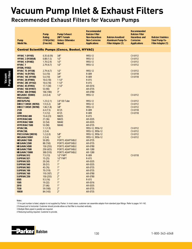
Vacu
um
Pum
p Fi
lters
130
Vacuum Pump Inlet & Exhaust Filters
1-800-343-4048
Recommended Recommended Pump Pump Exhaust Balston Filter Balston Filter Rating (NPT Female Non-Hazardous Balston Anodized Hazardous and Balston StainlessPump CFM (m3/hr) Unless Otherwise Non-Corrosive Aluminum Pump-To- Corrosive Steel Pump-To-Model No. (Free Air) Noted) Applications Filter Adaptor (1) Applications Filter Adaptor (1)
Central Scientific Pumps (Cenco, Boekel, HYVAC)
HYVAC 1 (91105) 0.35 (0.59) 3/8” 9955-12 CV-0112HYVAC 2 (91305/8) 0.88 (1.5) 1/2” 9955-12 CV-0112HYVAC 4 (91482) 1.70 (2.9) 1/2” 9955-12 CV-0112HYVAC 7 2.79 (4.7) 1/2” 9955-12 CV-0112(91506, 91502)HYVAC 7S (91138) 2.79 (4.7) 1/2” 9955-12 CV-0112HYVAC 14 (91705) 5.6 (10) 3/4” R-009 CV-0118HYVAC 14S (91140) 5.6 (10) 3/4” R-009 CV-0118HYVAC 28 (91905) 10.6 (18) 1 1/2” R-015 HYVAC 28S (91142) 10.6 (18) 1 1/2” R-015 HYVAC 45 (91955) 17.7 (30) 1 1/2” AR-0316 HYVAC 150 (91957) 53 (90) 3” AR-0735 HYVAC 300 (91960) 106 (180) 3” AR-0780 MEGAVAC (92003) 2.0 (3.4) 1/2” 9955-12 CV-0112PRESSOVAC (90510/15/16) 1.23 (2.1) 3.8” OD Tube 9955-12 CV-0112DIRECT DRIVE (90703) 1.9 (3.2) 3/8” 9955-12 CV-0112DIRECT DRIVE (90700) 1.06 (1.8) 3/8” 9955-12 CV-01122120 4.4 (7.5) KF25 R-009 CV-01182200 7.3 (12) KF25 R-009 CV-0118HYPERVAC400 13.4 (23) NW25 R-015 HYPERVAC600 21 (36) NW25 AR-0335 HYPERVAC1000 32 (54) NW40 AR-0335 HYPERVAC1500 53 (90) NW40 AR-0735 HYVAC30L 1.1 (1.9) 9955-12, 9956-12 CV-0112HYVAC50L 2 (3.4) 9955-12, 9956-12 CV-0112PRESSOVAC(90510) 1.2 (2.0) 5/8” 9955-12, 9956-12 CV-0112MEGAVAC92001 2 (3.4) 1/2” 9955-12, 9956-12 CV-0112MEGAVAC1500 50 (85) PORTS ADAPTABLE AR-0735 MEGAVAC2500 88 (150) PORTS ADAPTABLE AR-0735 MEGAVAC4500 150 (255) PORTS ADAPTABLE AR-0780 MEGAVAC7500 250 (425) PORTS ADAPTABLE AR-1280 MEGAVAC15000 300 (510) PORTS ADAPTABLE AR-1280 SUPRVAC012 7.5 (13) 1/2” FNPT R-009 CV-0118SUPRVAC021 15 (25) 1/2” FNPT R-015 SUPRVAC025 20 (34) 1” AR-0335 SUPRVAC040 30 (51) 1” AR-0335 SUPRVAC063 45 (76) 1” AR-0735 SUPRVAC100 70 (119) 1” AR-0735 SUPRVAC160 110 (187) 2” AR-0780 SUPRVAC250 150 (255) 2” AR-0780 0505 9.5 (16) 1” R-015 1505 19 (32) 1” AR-0316 2010 27 (46) 1” AR-0335 7530 59 (100) 2” AR-0735 10030 84 (143) 2” AR-0735
Notes:1Ifnopartnumberislisted,adaptorisnotsuppliedbyParker.Inmostcases,customercanassembleadaptorfromstandardpipefittings.Refertopages141-142.2Exhaustportishorizontal.Customershouldprovideelbowsothatfilterismountedvertically.3Multiplefilterspipedinparallelarerequired.4Reducingbushingrequired.Customertoprovide.
Recommended Exhaust Filters for Vacuum Pumps

Vacuum
Pump Filters
131
Vacuum Pump Inlet & Exhaust Filters
www.parker.com/balston
Recommended Recommended Pump Pump Exhaust Balston Filter Balston Filter Rating (NPT Female Non-Hazardous Balston Anodized Hazardous and Balston StainlessPump CFM (m3/hr) Unless Otherwise Non-Corrosive Aluminum Pump-To- Corrosive Steel Pump-To-Model No. (Free Air) Noted) Applications Filter Adaptor (1) Applications Filter Adaptor (1)
Central Scientific Pumps (Cenco, Boekel, HYVAC)
HYVAC 1 (91105) 0.35 (0.59) 3/8” 9955-12 CV-0112HYVAC 2 (91305/8) 0.88 (1.5) 1/2” 9955-12 CV-0112HYVAC 4 (91482) 1.70 (2.9) 1/2” 9955-12 CV-0112HYVAC 7 2.79 (4.7) 1/2” 9955-12 CV-0112(91506, 91502)HYVAC 7S (91138) 2.79 (4.7) 1/2” 9955-12 CV-0112HYVAC 14 (91705) 5.6 (10) 3/4” R-009 CV-0118HYVAC 14S (91140) 5.6 (10) 3/4” R-009 CV-0118HYVAC 28 (91905) 10.6 (18) 1 1/2” R-015 HYVAC 28S (91142) 10.6 (18) 1 1/2” R-015 HYVAC 45 (91955) 17.7 (30) 1 1/2” AR-0316 HYVAC 150 (91957) 53 (90) 3” AR-0735 HYVAC 300 (91960) 106 (180) 3” AR-0780 MEGAVAC (92003) 2.0 (3.4) 1/2” 9955-12 CV-0112PRESSOVAC (90510/15/16) 1.23 (2.1) 3.8” OD Tube 9955-12 CV-0112DIRECT DRIVE (90703) 1.9 (3.2) 3/8” 9955-12 CV-0112DIRECT DRIVE (90700) 1.06 (1.8) 3/8” 9955-12 CV-01122120 4.4 (7.5) KF25 R-009 CV-01182200 7.3 (12) KF25 R-009 CV-0118HYPERVAC400 13.4 (23) NW25 R-015 HYPERVAC600 21 (36) NW25 AR-0335 HYPERVAC1000 32 (54) NW40 AR-0335 HYPERVAC1500 53 (90) NW40 AR-0735 HYVAC30L 1.1 (1.9) 9955-12, 9956-12 CV-0112HYVAC50L 2 (3.4) 9955-12, 9956-12 CV-0112PRESSOVAC(90510) 1.2 (2.0) 5/8” 9955-12, 9956-12 CV-0112MEGAVAC92001 2 (3.4) 1/2” 9955-12, 9956-12 CV-0112MEGAVAC1500 50 (85) PORTS ADAPTABLE AR-0735 MEGAVAC2500 88 (150) PORTS ADAPTABLE AR-0735 MEGAVAC4500 150 (255) PORTS ADAPTABLE AR-0780 MEGAVAC7500 250 (425) PORTS ADAPTABLE AR-1280 MEGAVAC15000 300 (510) PORTS ADAPTABLE AR-1280 SUPRVAC012 7.5 (13) 1/2” FNPT R-009 CV-0118SUPRVAC021 15 (25) 1/2” FNPT R-015 SUPRVAC025 20 (34) 1” AR-0335 SUPRVAC040 30 (51) 1” AR-0335 SUPRVAC063 45 (76) 1” AR-0735 SUPRVAC100 70 (119) 1” AR-0735 SUPRVAC160 110 (187) 2” AR-0780 SUPRVAC250 150 (255) 2” AR-0780 0505 9.5 (16) 1” R-015 1505 19 (32) 1” AR-0316 2010 27 (46) 1” AR-0335 7530 59 (100) 2” AR-0735 10030 84 (143) 2” AR-0735
Notes:1Ifnopartnumberislisted,adaptorisnotsuppliedbyParker.Inmostcases,customercanassembleadaptorfromstandardpipefittings.Refertopages141-142.2Exhaustportishorizontal.Customershouldprovideelbowsothatfilterismountedvertically.3Multiplefilterspipedinparallelarerequired.4Reducingbushingrequired.Customertoprovide.
Recommended Exhaust Filters for Vacuum Pumps
Recommended Recommended Pump Pump Exhaust Balston Filter Balston Filter Rating (NPT Female Non-Hazardous Balston Anodized Hazardous and Balston StainlessPump CFM (m3/hr) Unless Otherwise Non-Corrosive Aluminum Pump-To- Corrosive Steel Pump-To-Model No. (Free Air) Noted) Applications Filter Adaptor (1) Applications Filter Adaptor (1)
Edwards High Vacuum Pumps
SPEEDIVAC 2 1.9 (3.2) 3/8 BSPT 9955-12 14157 CV-0112E2M1 1.3 (2.2) 3/8 BSPT 9955-12 14157 CV-0112E2M2 2 (3.4) 3/4 BSPT 9955-12 14158 CV-0112E1/E2M5 4 (6.8) 3/4 BSPT R-009 14159 CV-0118EDM6 5 (8.5) 1/2” R-009 CV-0118E1/E2M8 6.7 (11.4) 3/4 BSPT R-009 14159 CV-0118EDM12 10.3 (17.5) 1/2” R-015 E1/E2M18 14.7 (25.0) 3/4” R-015 EDM20 14.5 (24.6) 1/2” R-015 E2M30 30 (51.0) KF25 AR-0335 14183 E1/E2M40 30 (51.0) KF25 AR-0335 14183 ED/ES 50 3.5 (5.9) 1/4” R-009 CV-0118 ED/ES65 2.3 (3.9) 1/4” (2) 9955-12 CV-0112E1/E2M80 57 (96.8) KF25 AR-0735 14183 (4) ED/ES100 3.5 (5.9) 1/4” (2) R-009 CV-0118E1/E2M175 125 (212.4) 1 1/2” AR-0780 ED/ES200 6.7 (11.4) 3/8” (2) R-009 CV-0118E1/E2M275 145 (246.4) 1 1/2” AR-0780 ES330 11.8 (20.0) 3/8” (2) R-015 ISC 450 19.6 (33.3) 1/2” AR-0316 ED 500 17.7 (30.1) 1/2” AR-0316 ED660 23.3 (39.6) 1/2” (2) AR-0335 ISC 900 39.2 (66.6) 3/4” AR-0335 ES2000 71 (120.6) 1 1/2” AR-0735 ES4000 145 (246.4) 1 1/2” AR-0780 ES7500 275 (467.2) 2 1/2” AR-1280 RV3 2.7 (4.6) 3/4” 9955-12 (4) CV-0112 (4)RV5 4.1 (7.0) NW25 R-009 14173 CV-0118 14182RV8 6.9 (11.7) NW25 R-009 14173 CV-0118 14182RV12 10.0 (17.0) NW25 R-015 14173
Gast Pumps
0211 1.1 (1.9) 1/4” 9955-12 CV-01120240 1.9 (3.2) 1/4” 9955-12 CV-01120322 2.5 (4.2) 1/4” 9955-12 CV-01120440 4.0 (6.8) 1/4” R-009 CV-01180465 4.0 (6.8) 3/8” R-009 CV-01180522 4.0 (6.8) 1/4” R-009 CV-01180740 5.9 (10.0) 3/8” R-009 CV-01180765 5.9 (10.0) 3/8” R-009 CV-01180822 7.2 (12.2) 3/8” R-009 CV-01181022 10.0 (17.0) 3/8” R-015 1065 8.3 (14.1) 1/2” R-009 CV-01181550 11.5 (19.5) 1/2” R-015 2065 17.0 (28.9) 3/4” AR-0316 2067 17.0 (28.9) 3/4” AR-0316 2565 21.0 (35.7) 3/4” AR-0335 3040 31.0 (52.7) 1” AR-0335 4565 48.0 (81.6) 3/4” AR-0735 5565 55.0 (93.4) 1” AR-0735
Notes:1Ifnopartnumberislisted,adaptorisnotsuppliedbyParker.Inmostcases,customercanassembleadaptorfromstandardpipefittings.Refertopages141-142.2Exhaustportishorizontal.Customershouldprovideelbowsothatfilterismountedvertically.3Multiplefilterspipedinparallelarerequired.4Reducingbushingrequired.Customertoprovide.

Vacu
um
Pum
p Fi
lters
132
Vacuum Pump Inlet & Exhaust Filters
1-800-343-4048
Recommended Recommended Pump Pump Exhaust Balston Filter Balston Filter Rating (NPT Female Non-Hazardous Balston Anodized Hazardous and Balston StainlessPump CFM (m3/hr) Unless Otherwise Non-Corrosive Aluminum Pump-To- Corrosive Steel Pump-To-Model No. (Free Air) Noted) Applications Filter Adaptor (1) Applications Filter Adaptor (1)
Gast Pumps
4BA-1-G482X 1.8 (3.1) 1/2” 9955-12 CV-01124AB-1-G482X 1.8 (3.1) 1/2” 9955-12 CV-01124BA-1-G492X 1.8 (3.1) 1/2” 9955-12 CV-01124BA-1-G499 1.8 (3.1) 1/2” 9955-12 CV-01124BA-1-G511X 1.8 (3.1) 1/2” 9955-12 CV-01124BA-1-G538X 1.8 (3.1) 1/2” 9955-12 CV-01125BA-1-G482X 3.5 (3.1) 1/2” R-009 CV-01185AB-1-G482X 3.5 (5.9) 1/2” R-009 CV-01185BB-1-G482X 3.5 (5.9) 1/2” R-009 CV-01186BA-1-G535X 7.0 (12) 1” R-009 6AB-1-G504X 7.0 (12) 1” R-009 7BA-1-G506X 10.6 (18) 1” R-015 7AB-1-G506X 10.6 (18) 1” R-015 8BA-1-G506X 14.1 (24) 1 1/4” R-015 8AB-G506X 14.1 (24) 1 1/4” R-0151531 1.5 (2.5) 1/8” 9955-12, 9956-12 CV-01120532 0.6 (1.0) 1/8” 9955-12, 9956-12 CV-01121032 1.1 (1.9) 1/4” 9955-12, 9956-12 CV-01121532 1.5 (2.5) 1/4” 9955-12, 9956-12 CV-01122032 2.5 (4.2) 1/4” 9955-12, 9956-12 CV-01123032 2.6 (4.4) 1/4” 9955-12, 9956-12 CV-01120211 1.3 (2.2) 1/4” 9955-12, 9956-12 CV-01122070 20 (34) 1” AR-0335 0323-1423 13 (22) 3/4” AR-03160533 0.6 (1.0) 1/4” 9955-12, 9956-12 CV-01121033 1.1 (1.9) 1/4” 9955-12, 9956-12 CV-01121034 1.6 (2.7) 1/4” 9955-12, 9956-12 CV-01121534 2.2 (3.7) 1/4” 9955-12, 9956-12 CV-01120240-0740 6 (10) 3/8” R-009 CV-01180456 4 (6.8) 3/8” R-009 CV-01180765 6 (10) 3/8” R-009 CV-01181550 14.5 (25) 1/2” R-015 1065-2565 8.5-21 (14-36) 3/4” AR-0335 2067-2567 17-21 (29-36) 3/4” AR-0335 3040 40 (68) 3/4” AR-0335 4565 47.5 (81) 1” AR-0735 5565 55 (93) 1” AR-0735 6066 55 (93) 1” AR-0735 1290 112 (190) 1” AR-0780 Hitachi Pumps
SVF 10F 3.6 (6.1) M24 x 1 R-009 14168 CV-0118SVR 16F 5.7 (10) M24 x 1 R-009 14168 CV-0118100 VPS 3.6 (6.1) M24 x 1 R-009 14168 CV-0118160 VPD/VPS 5.7 (10) M24 x 1 R-009 14168 CV-011816 VP 5.7 (10) M24 x 1 R-009 14168 CV-01183 VPC 1.8 (3.1) M14 x 1 9955-12 CV-01124 VPC 3.5 (5.9) M14 x 1 R-009 CV-0118
Notes:1Ifnopartnumberislisted,adaptorisnotsuppliedbyParker.Inmostcases,customercanassembleadaptorfromstandardpipefittings.Refertopages141-142.2Multiplefilterspipedinparallelarerequired.
Recommended Exhaust Filters for Vacuum Pumps

Vacuum
Pump Filters
133
Vacuum Pump Inlet & Exhaust Filters
www.parker.com/balston
Recommended Recommended Pump Pump Exhaust Balston Filter Balston Filter Rating (NPT Female Non-Hazardous Balston Anodized Hazardous and Balston StainlessPump CFM (m3/hr) Unless Otherwise Non-Corrosive Aluminum Pump-To- Corrosive Steel Pump-To-Model No. (Free Air) Noted) Applications Filter Adaptor (1) Applications Filter Adaptor (1)
Ingersoll-Rand Pumps
AV/AVX2 2.7 (4.6) 3/8” 9955-12 CV-0112BV/BVX2 5.4 (9.2) 3/8” R-009 CV-0118V23A/V23AX7 9 (15) 3/4” R-009 CV-0118V235/V235X1 18 (31) 1” AR-0316 V244/V244X2 32 (54) 1 1/4” AR-0335 V255/V255X3 60 (102) 1 1/2” AR-0735 V255X5 60 (102) 1 1/2” AR-0735 7V/7VX5 99 (168) 1 1/2” AR-0735 15V/15VX7 133 (226) 2” AR-0780 20VX10 214 (364) 2 1/2” AR-1280 20V/20VX15 294 (500) 2 1/2” AR-128015VD7.5 132 (224) 2” AR-0780 20VX15 214 (364) 2.5” AR-1280 2V235D1.5 36 (61) AR-0335 2-V244D2 36 (61) AR-0335 2-V255031D5 120 (204) AR-0780 2-7E7.5 198 (336) AR-0780 2-15VE7.5 264 (449) AR-1280 2-20VA15 428 (727) AR-1680 2-20VA20 588 (999) AR-3080 255 60 (102) 1.5” AR-0735
ITT Pneumotive (Leiman Brothers)
B 10 (17) 3/4” R-015 C 18 (31) 1” AR-0316 29-3J 20 (34) 1” AR-0316 195-2 20 (34) 3/4” AR-0316 C-3 22 (37) 1” AR-0335 30-3 35 (59) 1” AR-0335 C-6 37 (63) 1 1/2” AR-0335 29-6J 50 (85) 1 1/2” AR-0735 30-6 60 (102) 1 1/2” AR-0735 100 112 (190) 1 1/2” AR-0780 100J 125 (212) 1 1/2” AR-0780 107/107J 200 (340) 3’ AR-0780
Notes:1Ifnopartnumberislisted,adaptorisnotsuppliedbyParker.Inmostcases,customercanassembleadaptorfromstandardpipefittings.Refertopages141-142.2Multiplefilterspipedinparallelarerequired.
Recommended Exhaust Filters for Vacuum Pumps

Vacu
um
Pum
p Fi
lters
134
Vacuum Pump Inlet & Exhaust Filters
1-800-343-4048
2 Exhaust port is horizontal. Customer should provideelbowsothatfilterismountedvertically.
3 Multiplefilterspipedinparallelarerequired.
Recommended Recommended Pump Pump Exhaust Balston Filter Balston Filter Rating (NPT Female Non-Hazardous Balston Anodized Hazardous and Balston StainlessPump CFM (m3/hr) Unless Otherwise Non-Corrosive Aluminum Pump-To- Corrosive Steel Pump-To-Model No. (Free Air) Noted) Applications Filter Adaptor (1) Applications Filter Adaptor (1)
Kinney Pumps
KC/KVS/KVC-2 2 (3.4) 3/4” 9955-12 CV-0112KC/KVC-3 3 (5.1) 3/4” 9955-12 CV-0112KC-5 5 (8.5) 3/4” R-009 CV-0118KVC-6 5.8 (9.9) 3/4” R-009 CV-0118KC-8 8 (13.6) 3/4” R-009 KS-13 13 (22.1) 1 1/4” R-015 TCS-14 14 (23.8) 3/4” R-015 KC-15 15 (25.5) 1 1/4 R-015 KS-15 15 (25.5) 1 1/4” R-015 KTC-21 21 (35.7) 1” AR-0335 TCS-21 21 (35.7) 3/4” AR-0335 KD-30 33 (56.1) 1 1/4” AR-0335 TCS-35 30 (51.0) 1 1/4” AR-0335 14174 KD-50 52 (88.3) 1 1/4” AR-0735 TCS-55 54 (91.7) 1 1/2” AR-0735 KTC-60 60 (101.9) 1 1/2” (2) AR-0735 KDH-65 69 (117.2) 1 1/2” AR-0735 TCS-70 71 (120.6) 1 1/2” AR-0735 KDH-80 83 (141.0) 1 1/2” AR-0735 TCS-90 88 (149.5) 2” AR-0735 KTC-112 107 (181.8) 2” (2) AR-0780 KDH-130 134 (227.7) 2” AR-0780 KDH-150 165 (280.3) 2” AR-0780 KT-150 144 (244.7) 2” (2) AR-0780 KTC-225 221 (375.5) 3” (2) AR-1280 KT-300 296 (502.9) 3” (2) AR-1280 KT-500 494 (839.3) 3” (2) AR-3080 KT-850 778 (1321.8) 4” Flange AR-3080KT-170LP 100 (169.9) 2” AR-0735 KT-275LP 162 (275.2) 2” AR-0780 KT-505LP 300 (509.7) 3” AR1680 KT-840FP 490 (832.5) 4” AR-3080 KT-135VFP 780 (1325.2) 5” AR-3080
Lammert Pumps
10301 2 (3.4) 1/2” 9955-12 CV-011210302 2 (3.4) 1/2” 9955-12 CV-011210305/01131 5 (8.5) 3/4” R-009 CV-011810307/01133 7.5 (12.7) 1” R-009 CV-011810310/02131 10 (17.0) 1” R-015 02133 15 (25.5) 3/4” R-015 03131/03231 20 (34.0) 1 1/4” AR-0316 04231/04131 30 (51.0) 1 1/4” AR-0335 03133/03233 30 (51.0) 1 1/4 AR-0335 04133/04233 50 (85.0) 1 1/4” AR-0735 05131/05231 75 (127.4) 2” AR-0735 06231/05133/05233 100 (169.9) 2” AR-0735 07231 125 (212.4) 3” AR-0780 06233/08231 150 (254.9) 3” AR-0780 07233 200 (339.8) 3” AR-0780 08233/09231 250 (424.8) 3” AR-1280 09233 350 (594.7) 3” AR-1680
Recommended Exhaust Filters for Vacuum Pumps
Notes:1 If no part number is listed, adaptor is not supplied by Parker.In most cases, customer can assembleadaptorfromstandardpipefittings.Refer to pages 141-142.

Vacuum
Pump Filters
135
Vacuum Pump Inlet & Exhaust Filters
www.parker.com/balston
Recommended Recommended Pump Pump Exhaust Balston Filter Balston Filter Rating (NPT Female Non-Hazardous Balston Anodized Hazardous and Balston StainlessPump CFM (m3/hr) Unless Otherwise Non-Corrosive Aluminum Pump-To- Corrosive Steel Pump-To-Model No. (Free Air) Noted) Applications Filter Adaptor (1) Applications Filter Adaptor (1)
Leybold Heraeus Pumps
D/S 2A 2.2 (3.7) KF 16 9956-12 CV-0112 14181D/S 4A 4.5 (7.6) KF 16 R-009 14172 CV-0118 14181 (3)D/S 8A 7.0 (12) KF 25 R-009 14173 CV-0118 14182D 4B 3.4 (5.8) KF 16 R-009 14172 CV-0118 14181 (3)D 8B 6.9 (12) KF 16 R-009 14172 CV-0118 14181 (3)D/S 16A 14.1 (24) KF 25 R-015 14173 D25 20 (34) KF 25 AR-0316 14173 D/S 30A 26.8 (46) KF 40 AR-0335 14178 SV 40 30 (51) 1 1/4” AR-0335 DK 50 32 (54) KF 50 AR-0335 D/S 60A 36.7 (62) KF 40 AR-0335 14178 D 65 53 (90) KF 40 AR-0735 14174 (4) SV 65 45 (76) 1 1/4” AR-0335 E 75 49 (83) KF 50 AR-0735 D/S 90A 55 (93) KF 40 AR-0735 14174 (4) DK 100 65 (110) KF 50 AR-0735 SV 100 70 (119) 2” AR-0735 E 150 94 (160) KF 50 AR-0735 SV 180 125 (212) 2” AR-0780 DK 200 130 (221) 3” ASA Flange AR-0780 E 250 162 (275) 3” ASA Flange AR-0780 SV 280 200 (340) 2” AR-0780 SV 500 318 (540) 3” AR-1280 SV 580 339 (574) 3” AR-1680D25BCS 20 (34) AR-0316 D40BCS 32.5 (55) AR-0335 D65BCS 53 (90) AR-0735 D25B 20.9 (36) AR-0335 SV16B 11.2 (19) AR-0316 SV25B 18.3 (31) 1/2” NPT AR-0136 SV65B 41.8 (71) AR-0335 SV100B 68.9 (117) AR-0735 SV200 129.5 (220) AR-0780 SV300 200 (340) 2” BSP AR-0780 SV500 336 (571) AR-1680 SV630 494.8 (841) AR-3080 SV1200 677 (1150) AR-3080 SP250 177 (301) AR-0780 SP630 371 (630) AR-1680 SV40B 31.2 (53) AR-0335 D10E 9.3 (16) R-015
Notes:1Ifnopartnumberislisted,adaptorisnotsuppliedbyParker.Inmostcases,customercanassembleadaptorfromstandardpipefittings.Refertopages141-142.2 Requires 2” Male x 1 1/2” Female reducing bushing supplied by customer.3 Requires 3/4” Male x 1/2” Female reducing bushing supplied by customer.4 Requires 3” Male x 1 1/2” Female reducing bushing supplied by customer.5 Requires Multiple Filters piped in parallel.
Recommended Exhaust Filters for Vacuum Pumps

Vacu
um
Pum
p Fi
lters
136
Vacuum Pump Inlet & Exhaust Filters
1-800-343-4048
Recommended Recommended Pump Pump Exhaust Balston Filter Balston Filter Rating (NPT Female Non-Hazardous Balston Anodized Hazardous and Balston StainlessPump CFM (m3/hr) Unless Otherwise Non-Corrosive Aluminum Pump-To- Corrosive Steel Pump-To-Model No. (Free Air) Noted) Applications Filter Adaptor (1) Applications Filter Adaptor (1)
Marvac Pumps
A-1 1.06 (1.8) 3/8” 9955-12 CV-0112A-2 1.06 (1.8) 3/8” 9955-12 CV-0112A-10 1.6 (2.7) 3/8” 9955-12 CV-0112A-20 1.6 (2.7) 3/8” 9955-12 CV-0112A-222 3.5 (5.9) 1/2” R-009 CV-0118B-2 2.65 (4.5) 1/2” 9955-12 CV-0112B-3 5.5 (9.3) 3/4” R-009 B-6 20 (34.0) 1 1/4” AR-0316 B-20 3.53 (6.0) 1/2” R-009 CV-0118B-30 8.8 (15.0) 1” R-009 CV-0118B-222 7 (11.9) 3/4” R-009 CV-0118R-10 1.5 (2.5) 3/8” 9955-12 CV-0112R-20 1.5 (2.5) 3/8” 9955-12 CV-0112R-22 2.65 (4.5) 3/8” 9955-12 CV-0112R-55 5.5 (9.3) 3/8” R-009 CV-0118
Maxima Pumps (Fisher Scientific)
D2A (01-057-2A) 2.2 (3.7) KF 16 9956-12 CV-0112 14181D4A (01-057-4A) 4.5 (7.6) KF 16 R-009 14172 CV-0118 14181 (3)D8A (01-057-8A) 7.0 (11.9) KF 25 R-009 14173 CV-0118 14182D16A (01-057-16A) 14.1 (24.0) KF 25 AR-0316 14173 D30A (01-057-30A) 26.8 (45.5) KF 40 AR-0335 14174 D60A (01-057-60A) 36.7 (62.4) KF 40 AR-0335 14174 (4) D90A (01-057-90A) 55 (93.4) KF 40 AR-0735M4C 2.6 (4.4) 9955-12, 9956-12 CV-0112M6C 3.4 (5.8) R-009 CV-0118M8C 6.1 (10.4) R-009 CV-0118
Precision Scientific Pumps
DD-20 0.7 (1.2) 3/4” 9955-12 CV-0112D-25 0.9 (1.5) 3/4” 9955-12 CV-0112S/PV-35 1.25 (2.1) 3/4” 9955-12 CV-0112DD-50 1.77 (3.0) 3/4” 9955-12 CV-0112D-75 2.7 (4.6) 3/4” 9955-12 CV-0112DD-90 3.2 (5.4) 3/4” R-009 CV-0118DD-100 3.54 (6.0) 3/4” R-009 CV-0118D-150 5.3 (9.0) 3/4” R-009 CV-0118DD/DDC-195 7 (11.9) 3/4” R-009 CV-0118S/D-300 10.6 (18.0) 1” R-015 DD/DDC 310 11 (18.7) 3/4” R-015 DD/DDC 475 17 (28.9) 3/4” AR-0316 S/D-500 17.6 (29.9) 1 1/4” AR-0316 S/D-1000 35.3 (60.0) 1 1/2” AR-0335 S/D-1500 53 (90.0) 1 1/2” AR-0735
Notes:1Ifnopartnumberislisted,adaptorisnotsuppliedbyParker.Inmostcases,customercanassembleadaptorfromstandardpipefittings.Refertopages141-142.2Multiplefilterspipedinparallelarerequired.3 Requires 1 1/2” Male x 1” Female reducing bushing supplied by customer.4 Requires 3” Male x 1 1/2” Female reducing bushing supplied by customer.5 Requires 2” Male x 1 1/2” Female reducing bushing supplied by customer.
Recommended Exhaust Filters for Vacuum Pumps

Vacuum
Pump Filters
137
Vacuum Pump Inlet & Exhaust Filters
www.parker.com/balston
Recommended Recommended Pump Pump Exhaust Balston Filter Balston Filter Rating (NPT Female Non-Hazardous Balston Anodized Hazardous and Balston StainlessPump CFM (m3/hr) Unless Otherwise Non-Corrosive Aluminum Pump-To- Corrosive Steel Pump-To-Model No. (Free Air) Noted) Applications Filter Adaptor (1) Applications Filter Adaptor (1)
Quincy Pumps
QSVB-10 79 (134) 1 1/4” AR-0735 QSVB-20 134 (228) 1 1/4” AR-0780 QSVI-20 159 (270) 2 1/2” AR-0780 QSVI-40 315 (535) 2 1/2” AR-1280QV-.75 8.5 (14) .5” NPT R-009 CV-0118QV-1 12 (20) .5” NPT R-015 QV-1.5 25 (42) .75” NPT AR-0335 QV-2 38 (65) 1” NPT AR-0335 QV-3 50 (85) 1” NPT AR-0735 QV-5 75 (127) 1.5” NPT AR-0735 QV-5.5 103 (175) 1.5” NPT AR-0780 QV-7.5 141 (240) 2” NPT AR-0780 QV-10 189 (621) 2” NPT AR-0780 QV-15 245 (416) 3” NPT AR-1280 QV-20 378 (642) 3” NPT AR-1680 QV-30 540 (917) 4” NPT AR-3080 QV-40 716 (1216) 4” NPT AR-3080
Notes:1Ifnopartnumberislisted,adaptorisnotsuppliedbyParker.Inmostcases,customercanassembleadaptorfromstandardpipefittings.Refertopages141-142.2Multiplefilterspipedinparallelarerequired.3 Requires 1 1/2” Male x 1” Female reducing bushing supplied by customer.4 Requires 3” Male x 1 1/2” Female reducing bushing supplied by customer.5 Requires 2” Male x 1 1/2” Female reducing bushing supplied by customer.
Recommended Exhaust Filters for Vacuum Pumps

Vacu
um
Pum
p Fi
lters
138
Vacuum Pump Inlet & Exhaust Filters
1-800-343-4048
Recommended Recommended Pump Pump Exhaust Balston Filter Balston Filter Rating (NPT Female Non-Hazardous Balston Anodized Hazardous and Balston StainlessPump CFM (m3/hr) Unless Otherwise Non-Corrosive Aluminum Pump-To- Corrosive Steel Pump-To-Model No. (Free Air) Noted) Applications Filter Adaptor (1) Applications Filter Adaptor (1)
Rietschle Pumps
VAL/VL/VE 10 6.8 (12) NW 25 R-009 14173 CV-0118 14182VF/VFE/CLFG 11 6.8 (12) 1/2” R-009 CV-0118 VF/VFE 16 10.2 (17) 1/2” R-015 CLFG/CLF/CLFE 16 10.2 (17) 1/2” R-015 VAL/VL/VLV 25 16.9 (29) NW 25 AR-0316 14173 VF/VFE 26 16.9 (29) 3/4” AR-0316 CLFG/CLF/CLFE 26 16.9 (29) 3/4” AR-0316 VL/VLV 40 30 (51) NW 25 AR-0335 14183 VF/VFE 41 27 (46) 3/4” AR-0335 CLFG/CLF/CLFE 41 27 (46) 3/4” AR-0335 VL/VLV 60 40 (68) 3/4” AR-0335 VF/VFE 61 40 (68) 3/4” AR-0335 CLFG/CLF/CLFE 61 40 (68) 3/4” AR-0335 VL/VLV 80 54 (92) NW 40 AR-0735 14174 (4) VF/VFE 81 54 (92) 1 AR-0735 CLFG/CLF/CLFE 81 54 (92) 1 AR-0735 VL/VLV 100 67 (114) NW 40 AR-0735 14174 (4) VF/VFE 101 67 (114) 1 1/4” AR-0735 CLFG/CLF/CLFE 101 67 (114) 1 1/4” AR-0735 VWZ 102 67 (114) NW 65 AR-0735 CLF/CLFE 141 94 (160) 1 1/2” AR-0735 VFH/VFEH 161 108 (183) 2 AR-0780 VWZ 162 108 (183) NW 65 AR-0780 CLF/CLFE 181 108 (183) 2” AR-0780 VWZ 252 169 (287) NW 65 AR-0780 CLFH/CLFEH 341 230 (391) 3” AR-1280 VWZ 402 270 (459) NW 65 AR-1280 CLFH/CLFEH 501 338 (574) 3” AR-1680 CLFH/CLFEH 631 426 (724) 3” AR-1680 CLFH/CLFEH 1001 677 (1150) 3” AR-3080VLV25-2 18 (31) 3/4” NPT AR-0316 VLV25-3 18 (31) AR-0316 VLV40-2 28 (48) 3/4” NPT AR-0335 VLV40-3 28 (48) AR-0335 VWZ702 494 (839) AR-3080 VWZ1002 706 (1199) AR-3080 VGD10 7 (12) R-009 CV-0118VGD15 11 (19) R-015 VCE15 11 (2) 1/2” NPT R-015 VCE25 18 (31) 3/4” NPT AR-0316 VCE40 28 (48) 1” NPT AR-0335 VC50 35 (59) 1-1/4” NPT AR-0335 VCE60 42 (71) 1” NPT AR-0335 VC75 49 (83) 1-1/4” NPT AR-0735 VC100 71 (121) 1-1/2” NPT AR-0735 VC150 105 (178) 1-1/2” NPT AR-0780 VC200 141 (240) 2” NPT AR-0780 VC300 212 (360) 2” NPT AR-1280 VC400 282 (479) 3” NPT AR-1280 VC500 388 (659) 3” NPT AR-1680 VC700 494 (839) 3” NPT AR-3080 VC900 636 (1081) 4” NPT AR-3080 VC1100 777 (1320) 4” NPT AR-3080 VC1300 918 (1560) 4” NPT VLR100 72 (122) 1-1/2” NPT AR-0735 VLR250 166 (282) 2” NPT AR-0780 VL5300 212 (360) 2” NPT AR-1280 VLR400 272 (462) 3” NPT AR-1280 VLR500 353 (600) 3” NPT AR-1680
Notes:1 If no part number is listed, adaptor is not supplied by Parker. In most cases, customer can assemble adaptor from standard pipe fittings.Refertopages141-142.
2Multiplefilterspipedinparallelarerequired.3 Requires 1 1/2” Male x 1” Female reducing bushing supplied by customer.
4 Requires 3” Male x 1 1/2” Female reducing bushing supplied by customer.5 Requires 2” Male x 1 1/2” Female reducing bushing supplied by customer.
Recommended Exhaust Filters for Vacuum Pumps
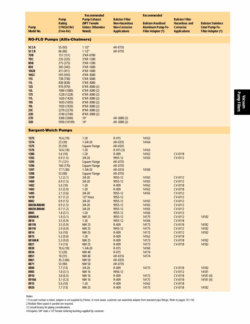
Vacuum
Pump Filters
139
Vacuum Pump Inlet & Exhaust Filters
www.parker.com/balston
Recommended Exhaust Filters for Vacuum Pumps Recommended Recommended Pump Pump Exhaust Balston Filter Balston Filter Rating (NPT Female Non-Hazardous Balston Anodized Hazardous and Balston StainlessPump CFM (m3/hr) Unless Otherwise Non-Corrosive Aluminum Pump-To- Corrosive Steel Pump-To-Model No. (Free Air) Noted) Applications Filter Adaptor (1) Applications Filter Adaptor (1)
RO-FLO Pumps (Allis-Chalmers)
5CCA 55 (93) 1 1/2” AR-0735 5CCB 86 (86) 1 1/2” AR-0735 7DB 151 (151) 3” AR-0780 7DC 235 (235) 3” AR-1280 8DB 275 (275) 3” AR-1280 8DE 345 (345) 3” AR-1680 10GB 411 (411) 4” AR-1680 10GC 593 (593) 4” AR-3080 11S 738 (738) 5” AR-3080 11L 838 (838) 5” AR-3080 12S 970 (970) 6” AR-3080 (2)12L 1080 (1080) 6” AR-3080 (2)17S 1228 (1228) 6” AR-3080 (2)17L 1420 (1420) 6” AR-3080 (2)19S 1693 (1693) 8” AR-3080 (2)19L 1920 (1920) 8” AR-3080 (2)23C 2270 (2270) 8” AR-3080 (2)23D 2740 (2740) 8” AR-3080 (2)27D 3300 (3300) 10” AR-3080 (2)33D 5950 (10109) 14” AR-3080 (2)
Sargent-Welch Pumps
1373 10.6 (19) 1-20 R-015 14163 1374 23 (39) 1-3/4-20 AR-0335 14164 1375 35 (59) Square Flange AR-0335 1376 10.6 (18) 1-20 R-015 (3) 14163 1380 5.6 (10) 1-20 R-009 14162 CV-01181392 0.9 (1.5) 3/4-20 9955-12 14165 CV-01121395 71 (121) Square Flange AR-0735 1396 100 (170) Square Flange AR-0735 1397 17.7 (30) 1-3/4-20 AR-0316 14160 1398 53 (90) Square Flange AR-0735 1399 1.2 (2.1) 3/4-20 9955-12 14165 CV-01121400 0.9 (1.5) 3/4-20 9955-12 14165 CV-01121402 5.6 (10) 1-20 R-009 14162 CV-01181403 3.5 (5.9) 1-20 R-009 14162 CV-01181405 2.1 (3.6) 3/4-20 9955-12 14165 CV-01121410 0.7 (1.2) 1/2” Hose 9955-12 CV-01128802 0.9 (1.5) 3/4-20 9955-12 14165 CV-01128803B/8804B 0.9 (1.5) 3/4-20 9955-12 14165 CV-01128803K/8804K 0.7 (1.2) 3/4-20 9955-12 14165 CV-01128805 1.8 (3.1) 1-20 9955-12 14166 CV-01128806B/K 1.8 (3.1) NW 25 9955-12 14175 CV-0112 141828810 3.5 (5.9) 1-20 9955-12 14166 CV-01188811B 3.5 (5.9) NW 25 R-009 14173 CV-0118 141828811K 2.9 (4.9) NW 25 9955-12 14175 CV-0112 141828814 5.6 (10) NW 25 R-009 14173 CV-0112 141828815 5.3 (9.0) 1-20 R-009 14162 CV-0118 8816B/K 5.3 (9.0) NW 25 R-009 14173 CV-0118 141828821 7.4 (13) NW 25 R-009 14173 CV-0118 141828830 10.6 (18) 1-3/4-20 R-015 14160 8834 12 (20) NW 40 R-015 14174 8851 18 (31) NW 40 AR-0316 14174 8861 35.3 (60) NW 50 AR-0335 8871 53 (90) NW 50 AR-0735 8890 7.7 (13) 3/4-20 R-009 14173 CV-0118 141828905 1.8 (3.1) NW 16 9956-12 CV-0112 141818910 3.8 (6.5) NW 16 R-009 14172 CV-0118 14181 (4)8910A 3.1 (5.3) NW 16 R-009 14172 CV-0118 14181 (4)8915 5.6 (10) 1-20 R-009 14162 CV-0118 8920 7.7 (13) NW 25 R-009 14173 CV-0118 14182
Notes:1Ifnopartnumberislisted,adaptorisnotsuppliedbyParker.Inmostcases,customercanassembleadaptorfromstandardpipefittings.Refertopages141-142.2Multiplefilterspipedinparallelarerequired.3 Consult factory for piping considerations.4 Requires 3/4” male x 1/2” female reducing bushing supplied by customer.

Vacu
um
Pum
p Fi
lters
140
Vacuum Pump Inlet & Exhaust Filters
1-800-343-4048
Recommended Recommended Pump Pump Exhaust Balston Filter Balston Filter Rating (NPT Female Non-Hazardous Balston Anodized Hazardous and Balston StainlessPump CFM (m3/hr) Unless Otherwise Non-Corrosive Aluminum Pump-To- Corrosive Steel Pump-To-Model No. (Free Air) Noted) Applications Filter Adaptor (1) Applications Filter Adaptor (1)
Stokes Pumps
V-005 7 (12) NW 25 R-009 14173 CV-0118 14182V-009 11 (19) NW 25 R-015 14173 V-013-2 20 (34) NW 40 AR-0316 14174 V-017-2 36.7 (62) NW 40 AR-0335 14174 V-23 55 (93) NW 40 AR-0735 14174 (3) 146H 30 (51) 1 1/4” AR-0335 148H 50 (85) 1 1/2” AR-0735 149H 80 (136) 1 1/2” AR-0735 149HS 100 (170) 1 1/2” AR-0735 212HS 150 (255) 2” AR-0780 412H 300 (510) 3” AR-1280 612H 600 (1019) 3” AR-3080 912H 728 (1237) 5” AR-3080212J 150 (255) ” NPT AR-0780 412J 300 (510) 3” NPT AR-1280 612J 600 (1019) 3” NPT AR-3080
Ulvac Pumps
G-5 0.21 (0.4) M17 x 1 9955-12 CV-0112G-15 0.63 (1.1) 3/4” 9955-12 CV-0112G/GC-25S 0.84 (1.4) 3/4” 9955-12 CV-0112G/GC-20D 0.84 (1.4) 3/4” 9955-12 CV-0112G-50S/D 2.1 (3.6) 3/4” 9955-12 CV-0112GC-50D 2.1 (3.6) 3/4” 9955-12 CV-0112G-100S/D 4.2 (7.1) 1” R-009 CV-0118GC-100D 4.2 (7.1) 1” R-009 CV-0118GVD-050 2.1 (3.6) 3/4” 9955-12 CV-0112GVD-100 5.6 (10) 1” R-009 CV-0118GVD-165 7 (12) 3/4” R-009 CV-0118DA-30S 1.1 (1.9) 3/4” 9955-12 CV-0112DA-60S 2.5 (4.2) 3/4” 9955-12 CV-0112D-330D 9 (15) 1 1/2” R-009 CV-0118D-650D 18 (31) 1 1/2” AR-0316 D-950D 27 (46) 2” AR-0335 PKS-016 57 (97) 2” AR-0735 PKS-030 107 (182) 3” AR-0780 PKS-070 250 (425) 4” AR-1280 PVD-180 6.4 (11) 3/4” R-009 CV-0118PDV-360 13 (22) 1” R-015
Varian Pumps
CS/SS/SD-90 3.2 (5.4) NW 25 R-009 14173 CV-0118 14182EVAC 200 7 (12) 3/4” R-009 CV-0118 EVAC 300 11 (19) 3/4” R-015 CD/SD-200 7 (12) NW 25 R-009 14173 CV-0118 14182CD/SS/SD-300 11 (19) NW 25 R-015 14173 CD/SS/SD-700 27 (46) NW 40 AR-0335 14174 CD/SS/SD-1400 50 (85) NW 40 AR-0735 14173 (3) CD/SD-2500 90 (153) NW 50 AR-0735
Notes:1Ifnopartnumberislisted,adaptorisnotsuppliedbyParker.Inmostcases,customercanassembleadaptorfromstandardpipefittings.Refertopages141-142.2Multiplefilterspipedinparallelarerequired.3 Requires 3” Male x 1 1/2” Female reducing bushing supplied by customer.4 Requires 2” Male x 1 1/2” Female reducing bushing supplied by customer.
Recommended Exhaust Filters for Vacuum Pumps
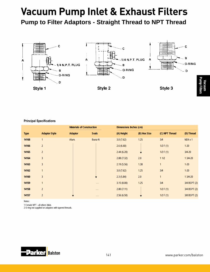
Vacuum
Pump Filters
141
Vacuum Pump Inlet & Exhaust Filters
www.parker.com/balston
▼
▼
▼
▼
Materials of Construction Dimensions Inches (cm) Type Adaptor Style Adaptor Seals (A) Height (B) Hex Size (C) NPT Thread (D) Thread
14168 1 Alum. Buna-N 3.0 (7.62) 1.25 3/4 M24 x 1
14166 2 2.6 (6.60) 1/2 F (1) 1-20
14165 2 2.44 (6.20) 1/2 F (1) 3/4-20
14164 3 2.88 (7.32) 2.0 1 1/2 1 3/4-20
14163 3 2.19 (5.56) 1.38 1 1-20
14162 1 3.0 (7.62) 1.25 3/4 1-20
14160 3 2.3 (5.84) 2.0 1 1 3/4-20
14159 1 3.15 (8.00) 1.25 3/4 3/4 BSPT (2)
14158 2 2.80 (7.11) 1/2 F (1) 3/4 BSPT (2)
14157 2 2.56 (6.50) 1/2 F (1) 3/8 BSPT (2)
Notes:1 Female NPT - all others Male.2 O-ring not supplied on adaptors with tapered threads.
Pump to Filter Adaptors - Straight Thread to NPT Thread
Principal Specifications

Vacu
um
Pum
p Fi
lters
142
Vacuum Pump Inlet & Exhaust Filters
1-800-343-4048
Pump to Filter Adaptors - Flange to NPT Thread
Materials of Construction Dimensions Other FittingsType Adaptor Style Adaptor Clamp Seals (A) Height inches (cm) (B) NPT Thread (Inches) (C) KF Flange (2) Included
14183 6 Alum. 2.38 (6.05) 1 1/2 KF-25
14182 4 Stain. St. 2.06 (5.23) 1/2 KF-25 3/4” x 1/2” Reducing Bushing
14181 4 Stain. St. 2.12 (5.38) 1/2 KF-16
14178 2.38 (6.05) 1 1/2 KF-40
14177 2.0 (5.08) 1 KF-25
14175 5 Alum. 1/2 F (1) KF-25
14174 6 1 KF-40 1 1/2” x 1” Reducing Bushing
14173 4 2.06 (5.23) 3/4 KF-25 1” x 3/4” Reducing Bushing
14172 4 2.12 (5.83) 1/2 KF-16 1/2” coupling and 3/4” x 1/2” Reducing Bushing
Notes:1 Female NPT - all others are Male2 The designation “KF” and “NW” are interchangeable
Principal Specifications
▼ ▼
▼
▼ ▼▼

Vacuum
Pump Filters
143
Vacuum Pump Inlet & Exhaust Filters
www.parker.com/balston
Gas and Liquid Sample Filtration Specialized Chemical or Solvent FiltrationProcess Filtration
Liquid Filters
Product Features:
The LP-Grades 10,20, and 30 depth filter cartridges are constructed entirely of polypropylene, and the LP-Grades 50, 60, 70, and 80 depth filter cartridges are constructed of polypro-pylene, borosilicate glass and polyeth-ylene binder. Both types of cartridges provide excellent chemical and solvent resistance. All LP cartridges have a graded efficiency construction: the filtration efficiency increases from the inside surface to the outside surface, in the direction of flow. This construc-tion provides exceptionally high solids holding capacity, which translates into a longer life of the filter cartridge. The seven retention efficiency grades of-fered cover the ranges from 75 micron to 0.22 micron (see table, on next page).
The Balston LP depth filter cartridges may be used for fine filtration of liquids with heavy dirt loading, when chemical or solvent resistance is required, or as prefilters to ultra-high efficiency or membrane filtration applications.
• Filtrationto0.22micronwithexceptional filter life, even for the dirtiest liquids
• Excellentchemicalandsolventresistance
Balston LP Depth Filters:
• CompliancewithFDAregula-tions for food contact sur-faces
• Sevenretentionefficiency gradescovertherangefrom 75micronto0.22micron

Liqu
idFi
lters
144
Liquid Filters
1-800-343-4048
Filter Cartridge and Housing Selection
Cross Section of LP-200-50 and LP-200-95 cartridges. Construc-tion of LP-100-12 and LP-100-25 cartridges is similar, but without end caps and gaskets.
Retention Efficiency Ratings
LP Depth Filter CartridgesGrade 80% Capture Rating10 75 micron20 25 micron30 10 micron50 1 micron60 0.6 micron70 0.4 micron80 0.22 micron
Retention efficiency v. particle size for the four finer grades of LP depth filters1 Specifytheleveloffinalfiltrationrequired,withinthe
rangeof75micronto0.22micron.
2 SelectthefiltersystemusingtheFinalFilterSelec-tionTablebelow.
Note: Therecommendationsarebasedontheassumptionthattheinitialliquidfeedisrelativelydirty.Ifthefeedhasbeen prefilteredtoabout10micron,thefirststageoffiltrationmay beomitted.
How To Select The Filter Housing
How To Select The Filter Cartridge
Notes:1 For a liquid with viscosity higher than the viscosity of water (1 centipoise), divide the flow rates in the above table by the viscosity of the liquid in centipoises. Example: for liquid with 10 centipoise viscosity, flow rate with C-0395 housing, Grade 20 cartridges at 10 psi (0.69 barg) drop will be 132/10 = 13.2 GPM.
Flow Rates of Filter with LP CartridgesFilter Cartridge Initial Water Flow Rate, Gallons (Liters) per Minute LP Cartridges Housing Number of Length & Pressure Grade Grade Grade Grade Grade Grade Grade Model Cartridges Designation Drop 10 20 30 50 60 70 80 2 1/2” 5 psi (0.3 bar) 3.5 (13) 3.5 (13) 3.0 (11) 0.75 (2.8) 0.60 (2.3) 0.30 (1.1) 0.07 (0.3) 33S6, 33G 1 LP-100-12 58P 10 psi (0.7 bar) 4.3 (16) 4.2 (16) 3.9 (15) 0.95 (3.6) 0.80 (2.0) 0.37 (1.4) 0.10 (0.4)
7” 5 psi (0.3 bar) 5.0 (19) 5.0 (19) 4.3 (16) 1.1 (4.2) 0.90 (3.4) 0.45 (1.7) 0.11 (0.4) 45S6 1 LP-100-2545G 10 psi (0.7 bar) 6.2 (23) 6.2 (23) 5.4 (20) 1.4 (5.3) 1.2 (4.5) 0.60 (2.3) 0.15 (0.6)
5” 5 psi (0.3 bar) 6 (23) 6 (23) 6 (23) 3.2 (12) 1.3 (4.9) 0.6 (2.3) 0.5 (1.9) 53/18 1 LP-200-18 10 psi (0.7 bar) 11 (42) 11 (42) 11 (42) 6 (23) 2.5 (9.5) 1.0 (3.8) 0.9 (3.4)
27/50 1 10” 5 psi (0.3 bar) 12 (45) 12 (45) 12 (45) 6.4 (24) 2.5 (9.5) 1.2 (4.5) 1.0 (3.8) 53/50, 54/50 1 LP-200-50 10 psi (0.7 bar) 22 (83) 22 (83) 22 (83) 12 (45) 5 (19) 2.0 (7.6) 1.7 (6.4) 1 20” 5 psi (0.3 bar) 24 (91) 24 (91) 24 (91) 13 (49) 5 (19) 2.4 (9.1) 2.0 (7.6) 53/95, 27/95 1 20” 5 psi (0.3 bar) 24 (91) 24 (91) 24 (91) 13 (49) 5 (19) 2.4 (9.1) 2.0 (7.6) 1 LP-200-95 10 psi (0.7 bar) 44 (167) 44 (167) 44 (167) 24 (91) 10 (38) 4.0 (15) 3.4 (13)
If the Final Filtration Use This LP Cartridge System Filtration Requirement is: 1st Stage 2nd Stage 3rd Stage 75 micron LP Grade 10 ––– –––25 micron LP Grade 20 ––– –––10 micron LP Grade 10 LP Grade 30 –––1 micron LP Grade 20 LP Grade 50 –––0.6 micron LP Grade 10 LP Grade 30 LP Grade 600.4 micron LP Grade 20 LP Grade 50 LP Grade 700.22 micron LP Grade 20 LP Grade 50 LP Grade 80
Table I Final Filter LP Depth Cartridge
1 DeterminethenumberofLPFilterCartridgestagesandGradeoffilterateachstage,usingtheFinalFilterSelectionTablebelow.
2 Usetheflowchart(nextpage)todeterminethesizesofhousingsrequiredbasedonthegradeoffiltercartridgeandtheliquidflowrate.
3 Selectthehousingsofthecorrectsizewhichareconstructedofmaterialssuitablefortheapplication.

LiquidFilters
145
Liquid Filters
www.parker.com/balston
Filter Cartridge and Housing Selection
Chemical and Solvent Compatibility
Food Grade Applications:All LP Filter Cartridges are constructed entirely of materials which are in compliance with FDA regulations for food contact surfaces. All stain-less steel liquid filter in this bulletin comply with FDA regulations for food contact applications.
Chemical Compatibility:The above compatibility data is for the filter cartridges only, at an operating temperature of 70°F (21°C). The filter housing is not neces-sarily compatible with the same chemicals and solvents.
Liquid LP Cartridge
Hydrochloric Acid (35%) R
Hydrofluoric Acid NR
Hydrogen Peroxide NR
N-Methyl Pyrrolidone (NMP) R
Methyl Ethyl Ketone (MEK) R
Methyl Isobutyl Ketone (MIBK) R
Methylene Chloride NR
Metal Etch (H3PO4/HAC/HNO3) N
Nitric Acid (30%) R
Nitrobenzene R
Pentane NR
Perchlorethylene NR
Phenol NR
Plating Solutions R
Phosphoric Acid (50%) R
Silicone Oils R
Sodium Hydroxide
Below 20% R
20-45% R
Above 45% NR
Steam NR
Sulfuric Acid (50%) R
Toluene NR
Trichloroethane NR
Trichloroethylene NR
Water to 180°F (82°C) R
Xylene NR
Liquid LP Cartridge Acetic Acid (Glacial) NR
Acetic Acid (5%) R
Acetone R
Acetonitrile R
Alcohols R
Ammonia, Liquid or Gas R (1)
Amyl Acetate N
Ammonium Hydroxide (6N) R
B.O.E. (NH4 F/HF) NR
Butyl Acetate N
Carbon Tetrachloride NR
Chlorine, Liquid or Gas NR
Chloroform NR
Cyclohexane NR
Dimethyl Acetamide(DMAC) R
Dimethyl Formamide(DMF) R
Dimethyl Sulfoxide (DMSO) R
Esters NR
Ethanolamine R
Ethyl Acetate R
Ethylene Diamine R
Ethylene Glycol R
Ethylene Oxide R
Formaldahyde (37%) R
Freon TF NR
Freon TMC NR
Hexane NR
Notes:1 Grades 10, 20, 30 large diameters only. In LP200- sizes only.R - RecommendedNR - Not RecommendedN - No data available; consult factory

Liqu
idFi
lters
146
Liquid Filters
1-800-343-4048
Miniature Model 58P HousingHasanylonhead,nyloninternals,andaclearnylonbowl.TheModel58PHousingacceptsasingleLPcartridge,andmaybeusedtofilterwater,mildlyacidic,orcausticsolutions.
Model 53 HousingsAreall-polypropylene,designedforasingleLP-200filtercartridge.Polypropyleneconstructionprovidesexcellentresistancetonon-oxidizingacids,suchasHCLinanyconcentration,sulfuricto70%concentra-tion,brines,hydrocarbonliquids,alcoholsandconcen-tratedcaustic.
TheModel53Housingsmaybeusedwithcertainketonesandchlorinatedsolvents.Pleaseseepage105orcontacttheTechnicalServicesDept.forspecificrecommendations.
Model54/50
Models53/18, 53/50,
and 53/95 (shown)
Model58P
1/4” to 3/4” Line Size

LiquidFilters
147
Liquid Filters
www.parker.com/balston
Ordering Information
Notes:
1 Inside-out flow, LP filter cartridges.2 To order filter cartridges, indicate grade by putting appropriate grade number after size designation. For example, to obtain 0.22 micron depth filter cartridges for the model 53/18, order LP-200-18-80.
Ordering Information
Model 58P 53/18 53/50 53/95 54/50
Port Size (NPT) 1/4” 3/8” 3/4” 3/4” 3/4” Material of ConstructionHead Nylon Polypropylene Polypropylene Polypropylene PolypropyleneBowl Nylon Polypropylene Polypropylene Polypropylene SANInternals Nylon ––– ––– ––– –––Seals EPR EPR EPR EPR EPRMax. Temperature 150°F (66°C) 125°F (52°C) 125°F (52°C) 125°F (52°C) 125°F (52°C) Max. Pressure 125 psig (8.6 barg) 125 psig (8.6 barg) 125 psig (8.6 barg) 125 psig (8.6 barg) 60 psig (4.1 barg) Max. Differential Press. 60 psig (4.1 barg) (1) 60 psig (4.1 barg) (1) 60 psig (4.1 barg) (1) 60 psig (4.1 barg) (1) 60 psig (4.1 barg) (1) Shipping Weight 1 lb. (0.5 kg) 3 lbs. (1.3 kg) 4 lbs. (1.8 kg) 6 lbs. (2.7 kg) 4 lbs. (1.8 kg)
Dimensions 2.7”D x 6.1”L 4.4”D x 6.6”L 5.0”D x 12”L 5.0”D x 22”L 5.0”D x 12”L (6.9cm x 15cm) (11cm x 17cm) (13cm x 30cm) (13cm x 56cm) (13cm x 30cm)
For assistance, call toll-free at 1-800-343-4048 8AM to 5PM Eastern Time
Model 58P 53/18 53/50 53/95 54/50LP Filter Cartridges,Depth Filters (2) LP-100-12-❑ LP-200-18-❑ LP-200-50-❑ LP-200-95-❑ LP-200-50-❑
Number ofCartridges required ––– 1 1 1 1
1/4” to 3/4” Line Size
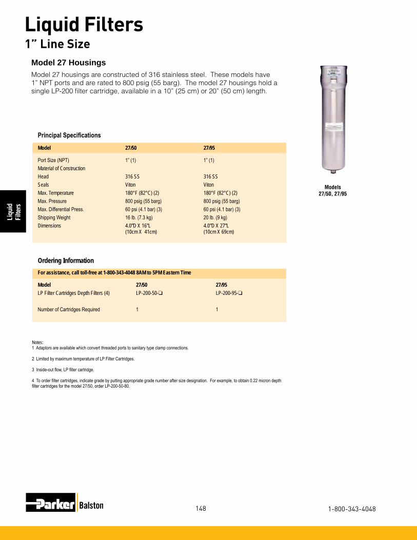
Liqu
idFi
lters
148
Liquid Filters
1-800-343-4048
Models 27/50, 27/95
Model 27 HousingsModel 27 housings are constructed of 316 stainless steel. These models have 1” NPT ports and are rated to 800 psig (55 barg). The model 27 housings hold a single LP-200 filter cartridge, available in a 10” (25 cm) or 20” (50 cm) length.
Principal Specifications
Model 27/50 27/95
Port Size (NPT) 1” (1) 1” (1)Material of ConstructionHead 316 SS 316 SSSeals Viton VitonMax. Temperature 180°F (82°C) (2) 180°F (82°C) (2)Max. Pressure 800 psig (55 barg) 800 psig (55 barg)Max. Differential Press. 60 psi (4.1 bar) (3) 60 psi (4.1 bar) (3) Shipping Weight 16 lb. (7.3 kg) 20 lb. (9 kg)Dimensions 4.0”D X 16”L 4.0”D X 27”L (10cm X 41cm) (10cm X 69cm)
Ordering InformationFor assistance, call toll-free at 1-800-343-4048 8AM to 5PM Eastern Time
Model 27/50 27/95LP Filter Cartridges Depth Filters (4) LP-200-50-❑ LP-200-95-❑
Number of Cartridges Required 1 1
Notes:1 Adaptors are available which convert threaded ports to sanitary type clamp connections.
2 Limited by maximum temperature of LP Filter Cartridges.
3 Inside-out flow, LP filter cartridge.
4 To order filter cartridges, indicate grade by putting appropriate grade number after size designation. For example, to obtain 0.22 micron depth filter cartridges for the model 27/50, order LP-200-50-80.
1” Line Size

LiquidFilters
149
Liquid Filters
www.parker.com/balston
Models 33S6 and 45S6
Model 33S6 and 45S6 FiltersAll-stainlesssteelwith1/2”NPTinletandoutletports.BothfiltersarealsoavailablewithclearPyrex®glassbowl,100psig(6.9barg)ratingwithbreakage-protectionexternalplasticshield.
Principal Specifications
Notes:1 Adaptors are available which convert threaded ports to sanitary type clamp connections.
2 Limited by maximum temperature of LP Filter Cartridges.
3 Maximum pressure ratings are for temperatures to 200°F (93°C). Please consult the Technical Services Dept. for maximum pressure ratings at elevated temperatures.
4 Inside-out flow, LP filter cartridges.
5 To order filter cartridges, indicate grade by putting appropriate grade number after size designation. For example, to obtain 0.22 micron depth filter cartridges for the model 33S6, order LP-200-12-80.
Adaptor Ordering Information:
P/N 73803 1” NPT x 1” SanitaryP/N 73804 1 1/2” NPT x 1 1/2” SanitaryP/N 73805 2” NPT c 2” Sanitary
Ordering Information
Model 33S6 33G 45S6 45G
Port Size (NPT) 1/2” (1) 1/2” (1) 1/2” (1) 1/2” (1) Material of ConstructionHead 316SS 316SS 316SS 316SS Bowl 316SS Pyrex 316SS Pyrex Internals 316SS 316SS 316SS 316SS Seals Viton Viton Viton Viton Max. Temperature 180°F (82°C) (2) 160°F (71°C) (2) 180°F (82°C) (2) 160°F (71°C) (2)Max. Pressure 425 psig (29 barg) (3) 100 psig (6.9 barg) (3) 250 psig (17 barg) (3) 100 psig (6.9 barg) (3) Max. Differential Press. 60 psi (4.1 bar) (4) 60 psi (4.1 bar) (4) 60 psi (4.1 bar) (4) 60 psi (4.1 bar) (4) Shipping Weight 3 lb. (1.3 kg) 3 lb. (1.3 kg) 5 lb. (2.3 kg) 5 lb. (2.3 kg)Dimensions 2.6”D x 4.8”L 2.6”D x 4.5”L 2.6”D x 9.0”L 2.6”D x 9.3”L (7cm x 12cm) (7cm x 11cm) (7cm x 23cm) (7cm x 23cm)
For assistance, call toll-free at 1-800-343-4048 8AM to 5PM Eastern Time
Model 33S6 33G 45S6 45G LP Filter Cartridges,Depth Filters (5) LP-100-12-❑ LP-100-12-❑ LP-100-25-❑ LP-100-25-❑ Number ofCartridges required 1 1 1 1
1/2” to 2” Line Size

Liqu
idFi
lters
150
Liquid Filters
1-800-343-4048
Model 9933-05
Disposable Filter UnitsBalstonMicrofibre®DisposableFilterUnit(DFU)consistsofaMicrofibreFilterCartridgepermanentlybondedintoasealedplasticholderwith125psig (8.6barg)pressurerating.TheeconomicalDFUof-fersalltheadvantagesofMicrofibreFilterCartridgesforhighefficiencyliquidfiltrations,combinedwiththeconvenienceofcompletedisposability.The1/4”O.D.portspermitpressure-tightconnectionsusingstandardcompressionfittings.Slip-on1/4”timbingorplasticbarbsmaybeusedforlowpressureapplications.
Thehousingsareavailableintwodifferentmateri-alsofconstruction:clearnylonorcorrosion-resistant(opaque)PVDF.ThenylonDFU’saredesignatedwiththeprefix9933,andthePVDFDFU’saredesignatedwiththeprefix9922.
Model 9922-05TheModel99XX-05DFU’sarethesmallestDFU’savailable.Theyhaveaninternalvolumeoflessthan12ml.theDFU’smaybeusedinlowflowliquidap-plicationsorsamplingsystemswhichrequireshortretentiontimes.
Model 9933-11TheModel99XX-11DFU’saresimilarinconstructiontotheModel99XX-05DFU’s,buttheyhaveapproxi-matelytwicethesolidsholdingcapacity.The99XX-11DFU’smaybeusedinhigherflowliquidapplicationsorinsamplingapplicationswherelongerretentiontimesareacceptable.
Filter samples to on-line liquid analyzers
Prevent cross-contamination of samples
Pressure ratings up to 125 psig (8.6 barg)
Temperature to 275°F (135°C)
Completely disposable, constructed of recyclable plastics
Model 9922-11
Retention Efficiency Ratings
DFU Grade 98% retention particle size
DQ 25 micron
CQ 8 micron
BQ 2 micron
AQ 0.9 micron
AAQ 0.3 micron
Disposable Filter Units for Liquids

LiquidFilters
151
Liquid Filters
www.parker.com/balston
Principal Specifications
Notes:1 At 0 psig
2 At 110°F (43°C)
Installation Information:Please contact the Technical Services Department for manufacturers of com-pression and brass fittings.
To Pressure Pipe or Tubing:Connector 1/4” tubing to 1/4”NPT female P/N 11970 (1 per pkg)
Connector 1/4” tubing to 1/4” tubing P/N 11971 (1 per pkg)
To Low Pressure Plastic Tubing:
Tubing with 1/4” ID may be slipped over the DFU and fittings and held with tubing clamps. Parker supplies plastic barbs to connect the DFU to smaller diameter plastic tubing. The connection is suitable for pressures to 50 psig (3.4 barg).
DFU to 1/16” ID tubing P/N 14000 (bag of 20 barbs)
DFU to 1/8” ID tubingP/N 14001 (bag of 20 barbs)
Ordering Information
Model 9922-05 9933-05 4433-05 9922-11 9933-11
Inlet and Outlet Ports 1/4” Tubing 1/4” Tubing 1st Tier/Barb 1/4”Tubing 1/4” Tubing 1/4” Tubing 2nd Tier/Barb 3/8”TubingConstruction Material PVDF Nylon Nylon PVDF Nylon Max. Temperature (1) 275°F (135°C) 230°F (110°C) 230°F (110°C) 275°F (135°C) 230°F (110°C) Max. Pressure 125 psig 125 psig 125 psig 125 psig 125 psig (8.6 barg) (2) (8.6 barg) (2) (8.6 barg) (2) (8.6 barg) (2) (8.6 barg) (2)Dimensions 1.0”D x 3.25”L 1.0”D x 3.25”L 1.0”D x 3.43”L 1.4”D x 4.6”L 1.4”D x 4.6”L (2.5cm x 6cm) (2.5cm x 6cm) (2.5cm x 8.72cm) (3.6cm x 12cm) (3.6cm x 12cm)
For assistance, call toll-free at 1-800-343-4048 8AM to 5PM Eastern Time
Model 9922-05 9933-05 4433-05 9922-11 9933-11Box of 10 DFUs 9922-05-❑ 9933-05-❑ 4433-05-❑ 9922-11-❑ 9933-11-❑Grades supplied DQ, CQ, BQ, DQ, CQ, BQ, DQ, CQ, BQ, DQ, CQ, BQ, DQ, CQ, BQ, AQ, AAQ AQ, AAQ AQ, AAQ AQ, AAQ AQ, AAQ
Flow Rates Initial Water Flow Rate, Gallons (Liters) per Hour DFU Volume of Housing Pressure Grade Grade Grade Grade Grade Model Gallons Liters Drop DQ, DX CQ, CX BQ, BX AQ AAQ 9922-05 1 psi (0.07 barg) 12 (45) 10 (38) 3 (11) 1.5 (5.7) 0.4 (1.5) 4433-05 0.003 0.01 9933-05 5 psi (0.34 barg) 30 (114) 25 (95) 15 (57) 7.3 (28) 1.9 (7.2)
9922-11 1 psi (0.07 barg) 18 (68) 15 (57) 5 (19) 2.5 (9.5) 0.6 (2.3) 0.005 0.02 9933-11 5 psi (0.34 barg) 45 (170) 37 (140) 26 (98) 12 (45) 3.1 (12)
Models9922-05,9922-11
Suitable:Waterorsteamto275°F(135°C);concen-tratednitric,sulfuric,andhydrochloricacids;chlorine(gasorliquid);sodiumhypochlorite,ethyleneoxide(gasorliquid);Freons;ammonia(gas,liquid,oraque-oussolutions);hydrogenperoxide(allconcentrations);bromine(dryandaqueoussolutions);allchlorinatedsolventsexceptmethylenechloride;allaromaticandaliphaticsolvents;allalcoholsandglycols;aniline;phenol.LimitedUse:Acetone,MEK,dioxane,furfural,methy-lenechloride.Unsuitable:Waterabove275°F(135°C),THF,DMF,ethylenediamine,chlorosulfonicacid,ethanolamine,pyridine,sulfurtrioxide.
Models9933-05,9933-11,4433-05
Suitable:Waterto158°F(70°C);benzene,toluene,otheraromatichydrocarbons;hydrocarbonsolventsandfuels,perchloroethylene;trichloroethylene,nitricacid(to10%);sulfuricacid(to40%);hydrochloricacid(to10%);mostsaltsolutions;sodiumandpotassiumhydroxide(to50%).LimitedUse:Waterat176°F(80°C);acetone;MEK,acetaldehyde;ammonia(to25%).Unsuitable:Waterabove158°F(70°C).alcohols;glycols,phenol;aniline;DMF;concentratedacids;chlorine.
Chemical Compatibility
Disposable Filter Units for Liquids

Liqu
idFi
lters
152
Liquid Filters
1-800-343-4048
Water Filter
Balston Water FilterTheBalston57-501Serieswaterfiltersprovideeco-nomical,efficientliquidfiltrationinaone-stepfilter.Thesefiltersaredesignedtofitmost3/4”watersup-plylinesandareavailableinthreedifferentefficiencyranges.
Remove contaminants to 5 micron
Prevent fixture discoloration
Materials comply with USFDA regulations
Constructed of non-corrosive materials
Ideal for drinking water systems
Inexpensive replacement filter cartridges
Transparent bowl for visual monitoring
Retention Efficiency Ratings Retention efficiency Water Flow RateModel Nominal µm rating 5 psi 10 psi57-501-C 80 (course grade) 15 GPM (57 lpm) 30 GPM (114 lpm)57-501-M 30 (medium grade) 10 GPM (38 lpm) 20 GPM (76 lpm)57-501-F 5 (fine grade) 8 GPM (30 lpm) 16 GPM (61 lpm)
Principal Specifications
Ordering Information
Model Materials of construction Max. Max. Port Shipping Head Bowl Cartridge Press. (1) Temp. Size Weight Dimensions57-501-C Polypro. SAN Polypro. 150 psi (10.3 bar) 125°F (52°C) 3/4” NPT 3.5 lbs. (1/6 kg) 5.5”D x 17”L (14cm x 43cm)57-501-M Polypro. SAN Polypro. 150 psi (10.3 bar) 125°F (52°C) 3/4” NPT 3.5 lbs. (1/6 kg) 5.5”D x 17”L (14cm x 43cm)57-501-F Polypro. SAN Polypro. 150 psi (10.3 bar) 125°F (52°C) 3/4” NPT 3.5 lbs. (1/6 kg) 5.5”D x 17”L (14cm x 43cm)
For assistance, call toll-free at 1-800-343-4048 8AM to 5PM Eastern Time
Model Replacement Filter Cartridges Box of 3 Box of 1057-501-C (Course grade) WF-3/200-50-C WF-200-50-C57-501-M (Medium grade) WF-3/200-50-M WF-200-50-M57-501-F (Fine grade) WF-3/200-50-F WF-200-50-FMounting Bracket Kit P/N 11057
Notes:1 Maximum pressure at 70°F (21°C)
Model 57-501
Water Filter

LiquidFilters
153
Liquid Filters
www.parker.com/balston
Clean In Place (CIP) Steam Filtration Steam Filtration to Sterilizers and AutoclavesRoom Humidification
Product Features:
The23RSteamFiltercontainsapatentedMicrofibre®FilterCartridgeinaruggedstainlesssteelhousingdesignedespeciallyforsteamservice.Includedasstandarditemswiththe23RSteamFilterareastainlesssteelcondensatedrainandahighqualitybleedervalve.Theunit,asreceived,iscompleteandreadyforinstallation.
• Eliminateinstrumentstaining,spotting,andrusting
• Reducedcontaminationofsterilizer interiors
• Reducedmaintenance
Balston SteamFilters:
Filters for Steam Sterilization Systems

Stea
mFi
lters
154
Steam Filters
1-800-343-4048
How the Balston Steam Filter Works
The 23/75R Steam Filter contains a patented Microfi-bre® Filter Cartridge in a rugged stainless steel housing designed especially for steam service. Included as standard items with the 23/75R Steam Filter are a stain-less steel condensate drain and a high quality bleeder valve. The unit, as received, is complete and ready for installation.
Steam enters the housing and moves into an expansion chamber, where much of the condensate is removed from the steam by the abrupt change in flow direction and velocity. The steam then flows upward in the hous-ing, through the Grade R Microfibre filter cartridge, and downward to the exit port. The water draining from the filter cartridges and expansion chamber is removed from the housing by the automatic condensate drain.
The Grade R Microfibre filter cartridge, the heart of the 23/75R Steam Filter, combines sturdy construction with remarkably efficient filtration of solid particles and liquid droplets. The cartridge is rated at 98+% at 0.1 micron. Solid particles remain trapped in the depth of the filter cartridge, and liquid water drips from the filter cartridge to the automatic drain. The Microfibre filter cartridge is constructed from chemically inert borosilicate glass fibers and fluorocarbon resin binder. The filter cartridge is completely free of impurities which could extract into the steam.
The Balston 23/75R Steam Filter is recommended for use on 3/4" and 1" steam lines (line sizes for the vast major-ity of steam sterilization systems). Please consult our technical support department for recommendations on filters for larger steam lines. Use only products designed specifically for steam filtration in steam installations.
Model 23/75R
for Steam Sterilization Systems

SteamFilters
155
Steam Filters
www.parker.com/balston
Typical Sterilizer Recommended Installation
For assistance, call toll-free at 1-800-343-4048 8AM to 5PM Eastern Time
Model Automatic Drain No. Filter Cartridges Required Replacement Filter Cartridges (box of 15)23/75R Included 1 200-75-R
Ordering Information
Notes:1 The 1" port size can be installed in a 3/4" line by using the appropriate reducing bushings.
2 Each filter is supplied with one filter cartridge installed. Replacement filter cartridges are sold in boxes of 15. To order, use complete size and grade designation; for example 200-75-R.
for Steam Sterilization Systems
Principal Specifications
Port Filter Cartridge Materials of Construction Maximum Steam ShippingModel Size Designation Head Bowl Internals Seals Pressure Weight23/75R 1" NPT (1) 200-75-R (2) 304SS 304SS 304SS EPR 80 psig (5.5 barg) 25 lbs. (11 kg)

Stea
mFi
lters
156
Steam Filters
1-800-343-4048
Filtering Water with the Balston LP-20 Water Filter
Dirt and rust in the hot or cold water supply to washer-sterilizers leave deposits and stains on valuable instruments and sterilizers. In most hospitals, the cleanliness of the water depends upon the efficiency of the municipal water treatment system. Exces-sive dirt in the water can be an intermittent problem caused by a drought, a fire in the neighborhood, water main problems, or scores of other random events well beyond the control of the hospital engi-neers. This unpredictable, expensive problem can be permanently solved by installing an inexpensive and easily maintained Balston LP Grade 20 water filter on the water line to the washer-sterilizer. On any washer-sterilizer, installing a Balston 23/75R Steam Filter on the steam line and a Balston LP Grade 20 Water Filter on the water line guarantees freedom from the outside contaminants.
How the cartridge works
The LP Grade 20 liquid filter cartridge is constructed entirely from polypropylene, rendering it safe and inert for use in hospital water supplies. The polypropylene construction makes this filter acceptable for use in cold and hot (to 180°F/82°C) water supplies. The filter cartridge consists of a polypropylene external sup-port structure with EPR seals and an internal filtering element. The internal filter is made of self-bonded polypropylene fibers which are graded from coarse to fine in the direction of flow (inside-to-outside). Since the coarse inner layer acts as a prefilter for the finer outer layer, the life of this cartridge is exceptionally long. For example: Approximately 50,000 gallons (190,000 liters)of water can be filtered by a single 20" liquid filter cartridge.
Filter Assembly Selection RecommendationsWater Cold WaterLine Size below 125°F (52°C)3/4" 53/95 with LP-200-95-20
1/2" 53/50 with LP-200-50-20
Model 53/50
Model 53/95
Unique, graded efficiency design provides exceptionally long filter life
Reduces costly sterilizer maintenance
Easy to change filter cartridge - no tools required
Safe, inert materials of construction
Models 53/50 and 53/95
These models are constructed entirely of polypropylene and designed for a single filter cartridge in the 10" and 20" lengths. The Model 53 housings are used for cold water service only.
for Steam Sterilization Systems
Water Filters for Washer Sterilizers

SteamFilters
157
Steam Filters
www.parker.com/balston
Principal Specifications
Port Materials of Construction Maximum Maximum Maximum Shipping DimensionsModel Size Head Bowl Internals Seals Temperature Pressure Diff. Press. (1) WeightCOLD WATER FILTER 53/50 3/4" NPT Polypro. Polypro. ––– EPR 125°F (52°C) 125 psig (8.6 barg) 60 psig (4.1 barg) 4 lbs (2 kg) 5"D x 12"L (13cm x 31cm)53/95 3/4" NPT Polypro. Polypro. ––– EPR 125°F (52°C) 125 psig (8.6 barg) 60 psig (4.1 barg) 6 lbs (3 kg) 5"D x 22"L (13cm x 56cm)
For assistance, call toll-free at 1-800-343-4048 8AM to 5PM Eastern Time
Model No. Filter Cartridges Required (2) Filter Cartridge Designation53/50 1 LP-200-50-2053/95 1 LP-200-95-20
Ordering Information
Notes:1 LP Grade 20 Filter Cartridge. Inside-to-outside flow.2 Filter Cartridge not included with housing and must be ordered separately.
for Steam Sterilization Systems
Water Filters for Washer Sterilizers

Stea
mFi
lters
158
Steam Filters
1-800-343-4048
Model A34
The cleanliness of Ethylene Oxide (EtO) typically varies from supplier to supplier and from delivery to delivery. In addition, EtO inherently polymerizes, causing valves to clog and regulators to malfunction. Filtering EtO at the point of use assures the delivery of clean EtO to the sterilizers, significantly improves sterilizer performance, and reduces sterilizer maintenance.
Balston EtO Filters, specifically designed for ethylene oxide service, are constructed of stainless steel with PTFE seals. The ET Grade 30 filter cartridge is inexpen-sive and simple to replace when necessary.
The model A34 is sized for most hospital sterilizer ap-plications.
Model A34
For assistance, call toll-free at 1-800-343-4048 8AM to 5PM Eastern Time
Model Filter Cartridge DesignationA34 Included ET-100-12-30
Ordering Information
Notes:1 Each filter is supplied with one filter cartridge installed.
2 Each filter is supplied with one spare PTFE seal set.
Long filter life
Easy to change filter cartridge
Eliminate unexpected downtime due to clogged components
Stainless steel and PTFE provide safe, trouble-free operation
EtO Filters
for Steam Sterilization Systems
EtO Filters
Principal Specifications
Port Filter Cartridge Materials of Construction Maximum Steam ShippingModel Size Designation Head Bowl Internals Seals Pressure WeightA34 1/4" NPT ET-100-12-30 (1) 316SS 316SS 316SS PTFE (2) 250 psig (17 barg) 4 lbs. (2 kg)

SteamFilters
159
Steam Filters
www.parker.com/balston
Sample and Instrumentation Filtration
Stainless Steel Filtration Vessels for Corrosive Environments
High Pressure Process Gas Filtration
High VolumeGas Filtration
Product Features:
Balston high flow rate compressed gas filters offer exceptionally high efficiency coalescing filtration of compressed gas at high flow rates. Specifically designed to remove suspended liquids and dirt from pipeline natural gas, the housings are ASME Code Stamped up to 1440 psig (100 barg). Equipped with Balston Microfibre® Grade DX Dis-posable Filter Cartridges, the filters are rated at 93% retention of 0.01 micron.
• Pressureratingto1440psig(100barg)
• MeetsUSandCanadiancodesfor natural gas filters
BalstonCompressedGas Filters:
• Flowratesto183millionstan-dardcubicfeetperday
• Highefficiencyremovalofsuspended liquid and solid impurities
Natural Gas Filters

Natu
ral G
asFi
lters
160
Natural Gas Filters
1-800-343-4048
2” Through 10” Line Size Filters
Balston Compressed Gas FiltersBalston high flow rate compressed gas filters offer ex-ceptionally high efficiency coalescing filtration of com-pressed gas at high flow rates. Specifically designed to remove suspended liquids and dirt from pipeline natural gas, the housings are ASME Code Stamped up to 1440 psig. Equipped with Balston Microfibre® Grade DX Disposable Filter Cartridges, the filters are rated at 93% retention of 0.01 micron and essentially 100% retention of 5 micron liquid droplets and particles.
Since the coalesced liquid drains continuously from the filter cartridges as rapidly as it is collected, the filters have an unlimited capacity for liquid removal.
Each filter cartridge is mounted on a rigid permanent filter holder with a vibration-resistant removable tube re-tainer. The filter cartridge is self-gasketing, and the filter holder is designed so that a perfect seal is easily made, even when the tube is replaced by an operator unfamil-iar with the equipment.
Series AKH, and AHC housings are available with inlet and outlet ports covering the range from 2” to 10” pipe sizes. The standard carbon steel units have pressure ratings from 665 to 1440 psig (46 to 99 barg).
Each AHC assembly is equipped with internal support cores and one set of filter cartridges. Also available is a complete line of stainless steel filter housings ASME code stamped for a rated maximum operating pressure of 200 psig (14 barg).
Model AKH-0880
Model AKH-0280
2” Through 10” Line Size Filters

Natural GasFilters
161
Natural Gas Filters
www.parker.com/balston
Port Size Closure Maximum Maximum Shipping Dimensions (7, 10) Flange to FlangeModel Flange (7) Type* Temperature (3) Pressure (1) Weight Dimension
AHC-0180-[ ] 2” SD 130°F (54°C) 1440 psig (99 barg) 98 lbs.(44 kg) 32”H x 15”W x 4.5” 14.5” (37cm) (81cm x 38cm x 11cm) AKH-0280-[ ] 3” FSO 250°F (121°C) 665 psig (46 barg) 235 lbs.(107 kg) 41”H x 16”W x 8” 15.63” (40cm) (104cm x 41cm x 20cm)AHC-0280-[ ] 3” SD 130°F (54°C) 1440 psig (99 barg) 220 lbs.(100 Kg) 43”H x 17”W x 12” 16.63” (42cm) (109cm x 43cm x 30cm)AKH-0480-[ ] 4” FSO 250°F (121°C) 665 psig (46 barg) 270 lbs.(122 kg) 40”H x 21”W x 6” 20.63” (52cm) (102cm x 53cm x 15cm)AHC-0480-[ ] 4” SD 130°F (54°C) 1440 psig (99 barg) 450 lbs.(204 kg) 50”H x 21”W x 15” 20.63” (52cm) (127cm x 53cm x 38cm)
Principal Specifications
For assistance, call toll-free at 1-800-343-4048 8AM to 5PM Eastern Time
Automatic Differential Filter CartridgesModel Float Drain Pressure Indicator (5) No. Required Box of 10 Cartridges (8)AHC-0180-DX ––– ––– 1 200-80-DXAKH-0280-DX 20-211 (13) ––– 2 200-80-DXAHC-0280-DX ––– ––– 2 200-80-DXAKH-0480-DX 20-211 (13) ––– 4 200-80-DXAHC-0480-DX ––– ––– 4 200-80-DXAKS-0280-DX 20-211 or 20-440 (13) ––– 2 200-80-❑ AKS-0480-DX 20-211 or 20-440 (13) ––– 4 200-80-❑
Ordering Information
Notes:8 To order filter cartridges, indicate Grade by putting appropriate letters after size designation. For example, to order Grade DX cartridges for KS-0280-3 housing, order 200-80-DX. Microfibre Filter Cartridges are sold in boxes of 10.
9 Vessel is ASME Section VIII, Division 1 code stamped for rated pressure at 200°F (93°C). Maximum pressure ratings are for temperatures to 200°F (93°C). Please consult factory for maximum pressure ratings at elevated temperatures.
10 All dimensions are approximate. Request certified drawing for installation dimensions.11 Requires element retainer #27900, one for each cartridge. Order separately.
12 All flanges are ANSI 150#RFSO.13 20-211 Auto Float Drain, 20-440 Auto Electric Solenoid Drain.
Port Size Materials of Maximum Maximum Shipping Flange to FlangeModel Flange (12) Construction Temperature Pressure (9) Weight Dimensions (7, 10) Dimension
KS-0280-3 3” 316SS Housing, Viton Seals 200°F (93°C) 200 psig (14 barg) 140 lbs. 36”h x 15.6”w x 7.75” 15.62” (40cm) (91cm x 40cm x 20cm)KS-0480-4 4” 316SS Housing, Viton Seals 200°F (93°C) 200 psig (14 barg) 210 lbs. 35.5”h x 20.6”w x 6.25” 20.63” (52cm) (90cm x 52cm x 16cm)
Notes 1 Vessel is ASME Section VIII, Div. 1 code stamped for rated pressure. 2 All vessels are constructed of carbon steel with Type 303 stainless steel filter cartridge holders and Buna-N seals.3 Maximum operating temperature of carbon steel vessel is 650°F (343°C). Minimum operating (process and ambient) temperature is -20°F (-30°C).
Max. Temp. Seal Material 250°F (121°C) Buna 400°F (204°C) Viton 500°F (260°C) Silicone4 Model 20-211 drain is installed on all AKS housings. Maximum operating pressure for the 20-211 drain is 400 psig (28 barg).5 Differential Pressure Indicator and Auto-
matic Drain are not included with AHC and AKH Assemblies. Series AHC Assemblies are equipped with internal support cores and one set of filter cartridges.6 ANSI Flange Classes:AKH Series: 300 lbs. (136 kg) R.F.S.O. AHC Series: 600 lbs. (273 kg) R.F.S.O.
7 Dimensions are height x width x center of flange-to-floor height.*Closure Abbreviations:SD: Screw type closure with Buna N “O” ringFSO: Flat (flanged) top with swing bolts and Buna N “O” ring.
2” Through 4” Line Size Filters
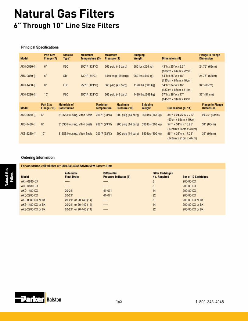
Natu
ral G
asFi
lters
162
Natural Gas Filters
1-800-343-4048
6” Through 10” Line Size Filters
For assistance, call toll-free at 1-800-343-4048 8AM to 5PM Eastern Time
Automatic Differential Filter CartridgesModel Float Drain Pressure Indicator (5) No. Required Box of 10 CartridgesAKH-0880-DX ––– ––– 8 200-80-DXAHC-0880-DX ––– ––– 8 200-80-DXAKC-1480-DX 20-211 41-071 14 200-80-DXAKC-2280-DX 20-211 41-071 22 200-80-DXAKS-0880-DX or BX 20-211 or 20-440 (14) ––– 8 200-80-DX or BX AKS-1480-DX or BX 20-211 or 20-440 (14) ––– 14 200-80-DX or BXAKS-2280-DX or BX 20-211 or 20-440 (14) ––– 22 200-80-DX or BX
Ordering Information
Port Size Closure Maximum Maximum Shipping Flange to FlangeModel Flange (7) Type* Temperature (3) Pressure (1) Weight Dimensions (8) Dimension
AKH-0880-[ ] 6” FSO 250°F (121°C) 665 psig (46 barg) 560 lbs.(254 kg) 43”h x 25”w x 8.5” 24.75” (63cm) (109cm x 64cm x 22cm)AHC-0880-[ ] 6” SD 130°F (54°C) 1440 psig (99 barg) 980 lbs.(445 kg) 54”h x 25”w x 18” 24.75” (63cm) (137cm x 64cm x 46cm)AKH-1480-[ ] 8” FSO 250°F (121°C) 665 psig (46 barg) 1120 lbs.(508 kg) 54”h x 34”w x 16” 34” (86cm) (137cm x 86cm x 41cm)AKH-2280-[ ] 10” FSO 250°F (121°C) 665 psig (46 barg) 1430 lbs.(649 kg) 57”h x 36”w x 17” 36” (91 cm) (145cm x 91cm x 43cm)
Principal Specifications
Port Size Materials of Maximum Maximum Shipping Flange to FlangeModel Flange (13) Construction Temperature Pressure (10) Weight Dimensions (8, 11) Dimension
AKS-0880-[ ] 6” 316SS Housing, Viton Seals 200°F (93°C) 200 psig (14 barg) 360 lbs.(163 kg) 38”h x 24.75”w x 7.5” 24.75” (63cm) (97cm x 63cm x 19cm)AKS-1480-[ ] 8” 316SS Housing, Viton Seals 200°F (93°C) 200 psig (14 barg) 590 lbs.(268 kg) 54”h x 34”w x 16.25” 34” (86cm) (137cm x 86cm x 41cm)AKS-2280-[ ] 10” 316SS Housing, Viton Seals 200°F (93°C) 200 psig (14 barg) 880 lbs.(400 kg) 56”h x 36”w x 17.25” 36” (91cm) (142cm x 91cm x 44cm)

Natural GasFilters
163
Natural Gas Filters
www.parker.com/balston
Flow Rates
Flow Rate at 2 psi (0.14 bar) Drop at Indicated Line Pressure with 200-80-DX filter Cartridges
High Pressure Filter Housings
Flow Rate SCFM (Nm3/hr) at 2 psi Drop at Indicated Line Pressure
Assembly Grade 2 psig (0.14 barg) 20 psig (1.4 barg) 60 psig (4.1 barg) 80 psig (5.5 barg) 100 psig (6.9 barg) 150 psig (10 barg) 200 psig (14 barg) AKS-0280 DX 364 (10) 760 (22) 1630 (44) 2065 (58) 2500 (71) 3600 (102) 4680 (133) BX 90 (3) 190 (5) 400 (11) 510 (14) 620 (18) 890 (25) 1160 (33)
AKS-0480 DX 760 (22) 1540 (44) 3320 (94) 4210 (119) 5100 (144) 7300 (207) 9550 (270) BX 180 (5) 380 (11) 810 (23) 1025 (29) 1240 (35) 1780 (50) 2320 (66)
AKS-0880 DX 1500 (42) 3120 (88) 6710 (190) 8505 (241) 10300 (92) 14800 (419) 19300 (547) BX 360 (10) 750 (21) 1620 (46) 2050 (58) 2480 (70) 3560 (101) 4640 (131)
AKS-1480 DX 2620 (74) 5450 (154) 11720 (332) 14860 (421) 18000 (510) 25800 (731) 33700 (954) BX 630 (18) 1310 (37) 2830 (80) 3585 (102) 4340 (23) 6230 (176) 8120 (230)
AKS-2280 DX 4080 (116) 8470 (240) 18230 (516) 23115 (655) 28000 (793) 40200 (1138) 52400 (1484) BX 1000 (28) 2070 (59) 4460 (126) 5655 (160) 6850 (94) 9840 (279) 12800 (362)
Stainless Steel Filter Housings
MM SCFD = Million Standard Cubic Feet per Day MSm3/d = Million Standard Cubic Meters per DaySCFM = Standard Cubic Feet per Minute Sm3 = Cubic Meters per Minute
40 psig (3 bar ) 100 psig (7 bar ) 200 psig (14 bar ) 400 psig (28 bar ) 600 psig (41 bar) 1000 psig (69 bar ) 1400 psig (97bar) Assembly MM SCFD SCFM MM SCFD SCFM MM SCFD SCFM MM SCFD SCFM MM SCFD SCFM MM SCFD SCFM MM SCFD SCFM (MNm3/hr) (Nm3/min) (MNm3/hr) (Nm3/min) (MNm3/hr) (Nm3/min) (MNm3/hr) (Nm3/min) (MNm3/hr) (Nm3/min) (MNm3/hr) (Nm3/min) (MNm3/hr) (Nm3/min)
AHC-0180 0.8 (0.02) 595 (16.9) 1.8 (0.05) 1250 (35.4) 3.3 (0.09) 2340 (66.3) 6.5 (0.18) 4515 (128) 9.4 (0.27) 6700 (190) 15.9 (0.45) 11050 (313) 22.2 (0.63) 15400 (436) AKH-0280 1.7 (0.05) 1190 (33.7) 3.6 (0.10) 2500 (70.8) 6.7 (0.19) 4680 (133) 13.0 (0.37) 9030 (256) 19.2 (0.54) 13400 (379) 31.8 (0.90) 22100 (626) 44.4 (1.26) 30800 (872)AHC-0280 AKH-0480 3.5 (0.10) 2430 (68.8) 7.3 (0.21) 5100 (144) 13.8 (0.39) 9550 (270) 26.5 (0.75) 18400 (521) 39.5 (1.12) 27300 (773) 64.9 (1.84) 45100 (1277) 90.5 (2.56) 62900 (1781)AHC-0480 AKH-0880 7.0 (0.20) 4910 (139) 14.8 (0.42) 10300 (292) 27.8 (0.79) 19300 (547) 53.6 (1.52) 37200 (1054) 79.5 (2.25) 55200 (1563) 131 (3.71) 91100 (2580) 183 (5.18) 127000 (3597)AHC-0880 AKH-1480 12.3 (0.35) 8580 (243) 25.9 (0.73) 18000 (510) 48.5 (1.73) 33700 (954) 93.6 (2.65) 65050 (1842) 139 (3.94) 96400 (2730) –– –– –– –– AKH-2280 19.2 (0.54) 13350 (378) 40.3 (1.14) 28000 (793) 75.4 (2.14) 52400 (1484) 145 (4.11) 101000 (2860) 216 (6.12) 150000 (425) –– –– –– ––

Natu
ral G
asFi
lters
164
Natural Gas Filters
1-800-343-4048
Low Pressure Natural Gas FiltersNew LF/FF Series Multiple Cartridge Filter Assemblies These filter assemblies provide high efficiency fil-tration of gas at very high flow rates. With inlet and outlet ports accommodat-ing 3” to 10” pipe sizes, the new LF/FF Series housings are capable of flow rates up to a maxi-mum capacity of 37,350 SCFM (63,450 m3/h) at 100 psig (7 barg). The standard carbon steel units, which are generally in stock (through 6” line sizes), have pressure rat-ings up to 250 psig. All LF/FF series housings are ASME Code Stamped for the rated maximum operating pressure. All FF Series vessels have built-in legs for floor mounting. Selected models have swing bolt enclosures for easy access to the internals. The filter cartridges in all models are sealed by tightening the threaded retainer cap onto the rigid tie rod, ensuring a leak tight seal on both ends of the cartridge. Each assembly is equipped with a carbon steel automatic float drain, differential pressure indicator, and a set of filter cartridges (except where noted).
Low Pressure DropLower Change out/Labor CostsLower Energy CostsHigh Dirt Holding Capacity
BenefitsHeat and Chemical ResistantNo Wet ZoneOleophobic/HydrophobicHigh Burst Strength
High Efficiency Coalescing MediaHEC Grade
Efficiency: 99.97% @ 0.01 micronAir Flow: Inside to Outside
This coalescing element is composed of an epoxy saturated borosilicate glass micro-fiber tube. The HEC grade filter has a pleated cellulose inner layer as a built-in prefilter. This element is metal retained for added strength, and includes a synthetic fabric layer.
HEC filters are used when “total removal of liquid aerosols and suspended fines” is required. Because of its overall performance characteristics, this grade is most often recommended.
NEW!High Flow Coalescing Filter Media
HFC Grade Efficiency: 99.5% @ 0.5 micronBalston’s HFC media consists of two layers. The outer layer features a dense matrix of glass fibers. It provides highly efficient coalescing aerosol removal and very low pressure drop. The inner layer, or initial stage of filtration, effectively traps dirt particles, protecting and extending the life of the outer layer. A metal retainer is used for strength and stability. This media is used in bulk coalesc-ing applications and when relatively high efficiency and low pressure drop are required.

Natural GasFilters
165
Natural Gas Filters
www.parker.com/balston
HFC MEDIA Max. Rated Flows SCFM at Various Operating Pressures(0.25 psi pressure drop)
Model Number 2 PSIG 20 PSIG 40 PSIG 80 PSIG 100 PSIG 125 PSIG 150 PSIG 175 PSIG 200 PSIG 220 PSIG 250 PSIG
ALN3-0128-HFC 363 753 1187 2056 2490 3033 3575 4118 4661 5095 5746 ALF3-0128-HFC 363 753 1187 2056 2490 3033 3575 4118 4661 5095 5746 ALF4-0125-HFC 483 1004 1583 2741 3320 4044 4767 5491 6215 6793 N/A ALF6-0136-HFC 725 1507 2375 4112 4980 6065 7151 8236 9322 10190 N/A ALF6-0336-HFC 1088 2260 3562 6167 7470 9098 10726 12354 13983 15285 N/A AFN3-0128-HFC 363 753 1187 2056 2490 3033 3575 4118 4661 5095 5746 AFF3-0128-HFC 363 753 1187 2056 2490 3033 3575 4118 4661 5095 5746 AFF4-0125-HFC 483 1004 1583 2741 3320 4044 4767 5491 6215 6793 N/A AFF6-0136-HFC 725 1507 2375 4112 4980 6065 7151 8236 9322 10190 11493 AFF6-0328-HFC 1088 2260 3562 6167 7470 9098 10726 12354 13983 15285 N/A AFF8-0428-HFC 1450 3013 2464 8223 9960 12131 14302 16472 18644 20380 22984 AFF10-0728-HFC 2538 5273 8312 14391 17430 21229 25028 28826 32627 35665 40222 AFF12-1128-HFC 3988 8286 13062 22614 27390 33360 39330 45298 51271 56045 63206 AFF16-1528-HFC 5438 11299 17812 30837 37350 45491 53632 61770 69915 76425 86190
HEC MEDIA Max. Rated Flows SCFM at Various Operating Pressures(1.5 psi pressure drop)
Model Number 2 PSIG 20 PSIG 40 PSIG 80 PSIG 100 PSIG 125 PSIG 150 PSIG 175 PSIG 200 PSIG 220 PSIG 250 PSIG
ALN3-0128-HEC 218 454 715 1238 1500 1827 2154 2481 2808 3069 3462 ALF3-0128-HEC 218 454 715 1238 1500 1827 2154 2481 2808 3069 3462 ALF4-0125-HEC 219 605 954 1651 2000 2436 2872 3308 3744 4092 N/A ALF6-0136-HEC 437 908 1431 2477 3000 3654 4308 4962 5616 6139 N/A ALF6-0328-HEC 654 1362 2145 3714 4500 5481 6462 7443 8424 9207 N/A AFN3-0128-HEC 218 454 715 1238 1500 1827 2154 2481 2808 3069 3462 AFF3-0128-HEC 218 454 715 1238 1500 1827 2154 2481 2808 3069 3462 AFF4-0125-HEC 291 605 954 1651 2000 2436 2872 3308 3744 4092 N/A AFF6-0136-HEC 437 908 1431 2477 3000 3654 4308 4962 5616 6139 6923 AFF6-0328-HEC 654 1362 2145 3714 4500 5481 6462 7443 8424 9207 N/A AFF8-0428-HEC 872 1816 2860 4952 6000 7308 8616 9924 11232 12276 13848 AFF10-0728-HEC 1526 3178 5005 8666 10500 12789 15078 17367 19656 21483 24234 AFF12-1128-HEC 2398 4994 7865 13618 16500 20097 23694 27291 30888 33759 38082 AFF16-1528-HEC 3270 6810 10725 18570 22500 27405 32310 37215 42120 46035 51930
Low Pressure Natural Gas Filters

Natu
ral G
asFi
lters
166
Natural Gas Filters
1-800-343-4048
HFC MEDIA Max. Rated Flows Nm3/hr at Various Operating Pressures(0.02 bar pressure drop)
Model Number 0.14 barg 1.4 barg 2.8 barg 5.5 barg 6.9 barg 8.6 barg 10 barg 12 barg 14 barg 15 barg 17 barg
ALN3-0128-HFC 617 1279 2017 3493 4231 5153 6074 6996 7919 8656 9762 ALF3-0128-HFC 617 1279 2017 3493 4231 5153 6074 6996 7919 8656 9762 ALF4-0125-HFC 821 1706 2690 4657 5641 6871 8099 9329 10559 11541 N/A ALF6-0136-HFC 1232 2560 4035 6986 8461 10304 12150 13993 15838 17313 N/A ALF6-0336-HFC 1849 3840 6052 10478 12692 15458 18223 20989 23757 25969 N/A AFN3-0128-HFC 617 1279 2017 3493 4231 5153 6074 6996 7919 8656 9762 AFF3-0128-HFC 617 1279 2017 3493 4231 5153 6074 6996 7919 8656 9762 AFF4-0125-HFC 821 1706 2690 4657 5641 6871 8099 9329 10559 11541 N/A AFF6-0136-HFC 1232 2560 4035 6986 8461 10304 12150 13993 15838 17313 19527 AFF6-0328-HFC 1849 3840 6052 10478 12692 15458 18223 20989 23757 25969 N/A AFF8-0428-HFC 2464 5119 8070 13971 16922 20611 24299 27989 31676 34626 39050 AFF10-0728-HFC 4312 8959 14122 24450 29614 36068 42523 48975 55433 60595 68337 AFF12-1128-HFC 6776 14078 22192 38421 46536 56679 66822 76961 87109 95220 107387 AFF16-1528-HFC 9239 19197 30263 52392 63458 77289 91121 104947 118786 129846 146437
Housing Selection Chart HFC HEC Replacement Replacement Port Port # of Model Number Element Element Size Type Elements
LINE MOUNT VESSELS ALN3-0128-H?C 510-28- HFC 510-28-HEC 3 NPT 1 ALF3-0128-H?C 510-28- HFC 510-28- HEC 3 FLANGE 1 ALF4-0125-H?C 850-25- HFC 850-25- HEC 4 FLANGE 1 ALF6-0136-H?C 850-36- HFC 850-36- HEC 6 FLANGE 1 ALF6-0328-H?C 510-28- HFC 510-28- HEC 6 FLANGE 3 FLOOR MOUNT VESSELS AFN3-0128-H?C 510-28- HFC 510-28- HEC 3 NPT 1 AFF3-0128-H?C 510-28- HFC 510-28- HEC 3 FLANGE 1 AFF4-0125-H?C 850-25- HFC 850-25- HEC 4 FLANGE 1 AFF6-0136-H?C 850-36- HFC 850-36- HEC 6 FLANGE 1 AFF6-0328-H?C 510-28- HFC 510-28- HEC 6 FLANGE 3 AFF8-0428-H?C 510-28- HFC 510-28- HEC 8 FLANGE 4 AFF10-0728-H?C 510-28- HFC 510-28- HEC 10 FLANGE 7 AFF12-1128-H?C 510-28- HFC 510-28- HEC 12 FLANGE 11 AFF16-1528-H?C 510-28- HFC 510-28- HEC 16 FLANGE 15
t
t
t
t
HEC MEDIA Max. Rated Flows Nm3/hr at Various Operating Pressures(0.1 bar pressure drop)
Model Number 0.14 barg 1.4 barg 2.8 barg 5.5 barg 6.9 barg 8.6 barg 10 barg 12 barg 14 barg 15 barg 17 barg
ALN3-0128-HEC 370 771 1215 2103 2549 3104 3660 4215 4771 5214 4183 ALF3-0128-HEC 370 771 1215 2103 2549 3104 3660 4215 4771 5214 4183 ALF4-0125-HEC 372 1028 1621 2805 3398 4139 4880 5620 6361 6952 N/A ALF6-0136-HEC 742 1543 2431 4208 5097 6208 7319 8430 9542 10430 N/A ALF6-0328-HEC 1111 2314 3466 6310 7646 9312 10979 12646 14312 15643 N/A AFN3-0128-HEC 370 771 1215 2103 2549 3104 3660 4215 4771 5214 4183 AFF3-0128-HEC 370 771 1215 2103 2549 3104 3660 4215 4771 5214 4183 AFF4-0125-HEC 494 1028 1621 2805 3398 4139 4880 5620 6361 6952 N/A AFF6-0136-HEC 742 1543 2431 4208 5097 6208 7319 8432 9542 10430 11762 AFF6-0328-HEC 1111 2314 3644 6310 7646 9312 10979 12646 14312 15643 N/A AFF8-0428-HEC 1482 3085 4859 8413 10194 12416 14639 16861 19083 20857 23528 AFF10-0728-HEC 2593 5399 8503 14724 17840 21729 25618 29507 33396 36500 41174 AFF12-1128-HEC 4074 8485 13363 23137 28034 34145 40256 46367 52479 57357 64701 AFF16-1528-HEC 5556 11570 18222 31550 38228 46561 54895 63228 71562 78213 88229
Low Pressure Natural Gas Filters

Natural GasFilters
167
Natural Gas Filters
www.parker.com/balston
Drawings, Dimensions & Specifications
1/2” NPT Vent
1/4” NPT Gauge Ports
1/2” NPT Drain
A
B
C
D
Refer to this drawing for:
ALN3ALF3ALF4
ALF6-0136
1/2” NPT Vent
1/4” NPT Gauge Ports
1/2” NPT Drain
A
B
C
D
Refer to this drawing for:ALF6-0328
1/2” NPT Vent
1/4” NPT Gauge Port
1/4” NPT Gauge Port
1/2” NPT Drain
1/2” NPT Drain
A
B
C
D
E
Refer to this drawing for:
AFN3AFF3AFF4
AFF6-0136
1/2” NPT Vent
1/4” NPT Gauge Port
1/4” NPT Gauge Port
1/2” NPT Drain
1/2” NPT Drain
A
B
C
D
E
Refer to this drawing for:AFF6-0328
AFF8AFF10AFF12AFF16
Element Removal Sump Dimensions A B C D E Clearance Capacity Weight inches (centimeters) gallons (liters) pounds (kilograms) ALN3 43.1 (109.5) 15.0 (38.1) 7.7 (19.5) 35.4 (89.9) – 28 (71.1) 0.81 (3) 190 (86)
ALF3 43.1 (109.5) 16.0 (40.6) 7.7 (19.5) 35.4 (89.9) – 28 (71.1) 0.81 (3) 190 (86)
ALF4 42.7 (108.5) 20.0 (50.8) 9.7 (24.6) 33.0 (83.8) – 25 (63.5) 2.0 (7) 380 (173)
ALF6-0136 56.4 (143.3) 20.0 (50.8) 11.4 (29.0) 45.0 (114.3) – 36 (91.4) 2.0 (7) 380 (173)
ALF6-0328 57.8 (146.8) 26.0 (66.0) 11.0 (27.9) 39.8 (101.1) – 28 (71.1) 2.0 (7) 340 (155)
AFN3 58.9 (149.6) 15.0 (38.1) 9.4 (23.8) 37.5 (95.2) 12.0 (30.4) 28 (71.1) 1.1 (4) 190 (86)
AFF3 58.9 (149.6) 16.0 (40.6) 9.4 (23.8) 37.5 (95.2) 12.0 (30.4) 28 (71.1) 1.2 (4) 200 (91)
AFF4 63.3 (160.7) 20.0 (50.8) 12.3 (31.2) 35.0 (88.9) 16.0 (40.6) 25 (63.5) 4.2 (16) 370 (168)
AFF6-0136 75.3 (191.2) 20.0 (50.8) 12.3 (31.2) 47.0 (119.3) 16.0 (40.6) 36 (91.4) 3.6 (14) 410 (186)
AFF6-0328 77.3 (196.3) 26.0 (66.0) 20.8 (52.8) 40.5 (102.8) 16.0 (40.6) 28 (71.1) 5.0 (19) 340 (155)
AFF8 87.3 (221.7) 30.0 (76.2) 25.8 (65.5) 42.5 (108.0) 19.0 (48.3) 28 (71.1) 8.7 (33) 550 (250)
AFF10 96.0 (243.8) 34.0 (86.3) 28.5 (72.4) 45.5 (115.5) 22.0 (55.8) 28 (71.1) 14.8 (56) 750 (341)
AFF12 101.0 (256.5) 44.0 (111.7) 27.5 (69.8) 47.5 (120.6) 26.0 (66.0) 28 (71.1) 25.5 (97) 1300 (591)
AFF16 112.0 (28.4) 52.0 (132.0) 32.0 (81.3) 50.0 (127.0) 30.0 (76.2) 28 (71.1) 56.2 (213) 1700 (773)
Body: Carbon SteelPaint: Epoxy Enamel (Gray)Internals: Epoxy powder painted carbon steelSeals: Inorganic flange gasket (single element vessels) Fluorocarbon o-ring (multi element vessels)Internal Coating: Epoxy enamel
Materials of ConstructionMax Pressure: Up to 220-250 PSIG (15-17 barg)(Consult Flow Chart)Max Temperature: 225°F (107°C)Meets A.S.M.E. Code, Section VIII, Division 1 code stamped for rated pressure. Note: Consult factory for special requirements
Specifications

Natu
ral G
asFi
lters
168
Natural Gas Filters
1-800-343-4048
Application Notes
Specialty Gas Filtration

Natural GasFilters
169
Natural Gas Filters
www.parker.com/balston
Specialty Gas Filtration Process Gas FiltrationAnalytical Gas Filtration Critical Blow Off Applications
GS Series Membrane Filters
Product Features:
The Balston GS Series Membrane Filter Cartridges combine absolute membrane filtration down to 0.01 µm, with an integral pre-filter to protect the membrane.
Ideally suited for high purity com-pressed air and gas requirements, these membrane cartridges are avail-able in several housing configurations shown above.
Use as a Final Filter for:
Ultra-high purity gases
Corrosive or toxic gases
Cylinder gases
Doping gases
• Filtrationto0.01micron
• Noparticleshedding
• Integralprefilterprotectsthemembrane
• Corrosionresistanthousings
Balston GS Series Membrane Filters
• Pressureto5,000psig
• Noparticleshedding
• PTFEmembranewithglassandfluorocarbonprefilter
• Chemicallyinerttomost gases
• Easytoinstall

Mem
bran
eFi
lters
170
0.01 Micron Membrane Filters
1-800-343-4048
0.01 µm Membrane Filters
The GS Membrane Cartridges represent state-of-the-art membrane filtration technology. An integral prefil-ter, bonded to a porous PTFE membrane, provides the user with extended membrane life, 0.01 µm filtration rating, and, most importantly, zero fiber shedding. The Balston GS Membrane filter also offers excellent chemical compatibility as a result of the inert materials of construction. All of these features combine to make the Balston GS cartridges the ideal choice for critical process gas filtration requirements.
Membrane Life Expectancy Comparison
Balston GS Membrane Cartridges, with their unique integral prefilter, offer up to 18 times the operating life of conventional membrane cartridges (as indicated in the life expectancy comparison below).
Physical Properties, GS Membrane Cartridges Temperature Range -40°F to 250°F (-40°C to 121°C) Maximum pressure differentialacross membrane, 20 psi (size code 100 and 200)Inside-to-outside flow: 60 psi (size code 050) Materials of Construction: Borosilicate glass with fluorocarbon resinbinderprefilter andPTFEmembrane
Retention Efficiency: 0.01 µm

Membrane
Filters
171
0.01 Micron Membrane Filters
www.parker.com/balston
The retention efficiencies of the Balston GS Series membrane cartridges were derived by John McCar-thy, a staff research scientist at M.I.T. Dr. McCarthy used a submicron particle detection and sizing device to collect and analyze the filter efficiency data. The test procedure consisted of challenging the mem-brane filter with a sodium chloride aerosol solution which contained aerosol particles in a narrowly defined size range. Downstream from the filter, the effluent gas was evaluated for particulate contaminant size using a condensation nucleus counter.
There was no detectable penetration of 0.01 µm particles through the membrane filters. Bulletin TI-834 details the efficiency rating procedure and experimen-tal results of this study.
Retention Efficiency Rating
Chlorine (dry)
Diborane
Dichlorosilane
Fluorine (dry)
Freon
Helium
Hydrogen
Hydrogen Bromide
Methylene Chloride
Nitrogen
Nitrous Oxide
Phosphorous Oxychloride (dry)
Phosphine
Silane
Chemical Compatibility
The GS Series Membrane Filter cartridges are compatible with the following gases (when in-stalled in a stainless steel filter housing with PTFE seals).
Ammonia
Air (Compressed)
Argon
Arsine
Boron Trichloride
Carbon Dioxide
Carbon Tetrafluoride

Mem
bran
eFi
lters
172
0.01 Micron Membrane Filters
1-800-343-4048
Disposable Filter Units (DFU’s)Consist of a membrane filter and an integral prefilter, permanently bonded into a plastic housing. DFU’s have pressure ratings to 125 psig (8.6 barg), and may be installed using a variety of fitting systems.
9933-05-95Available in a transparent nylon housing, this DFU is an ideal choice for an economical membrane filter for use where its chemical compatibility is suitable.
9922-11-95This opaque PVDF DFU, with approximately double the membrane area of the 9933-05-95, is used where exceptional chemical compatibility is required.
Notes:1DisposableFilterUnitsaresoldinboxesof3or10.Forexample,aboxof3DFU’sinnylonhousings,order:3(9933-05-95.Foraboxof10,order:9933-05-95.
Model 9933-05-95
Model 9922-11-95
Principal Specifications Model 9933-05-95 9922-11-95
InletandOutletPorts 1/4”Tube 1/4”TubeMaterialsofConstructionHousing Nylon PVDFCartridge PTFE (Glass PTFE (GlassSeals None NoneMaximumTemperature 230°F(110°C) 250°F(121°C)MaximumPressure 125psig(8.6barg) 125psig(8.6barg)MaximumÐPressure 60psi(4bar) 60psi(4bar)ShippingWeight 0.1lb(45g) 0.2lb(90g)Dimensions 3.25”Hx1.0”W 4.6”Hx1.43”W (8cmx2.5cm) (12cmx3.6cm)
Ordering Information
For assistance, call toll-free at 1-800-343-4048 Filter Assembly (1)Complete with MembraneFilter Cartridge Description 9933-05-95 In-lineNylondisposablefilter withGSMembraneCartridge
9922-11-95 In-LinedisposablePVDFfilterwith GSMembraneCartridge
Disposable Membrane Assemblies

Membrane
Filters
173
0.01 Micron Membrane Filters
www.parker.com/balston
97S6Miniature 316 stainless steel filter, with 1/4” NPT in-line ports, 5000 psig (345 barg) rating. The 97S6 has a replaceable membrane cartridge and is an eco-nomical alternative when a disposable product is not required.
91S6, 95S6, 95TMiniature T-Type filters in 316 stainless steel. The 91S6 is rated for 650 psig (45 barg), the 95S6 is rated for 5000 psig (345 barg). The 95T is constructed of PTFE, and is rated at 150 psig (10 barg). The mem-brane cartridge is changed without breaking the inlet or outlet connections.
31S6, 33S6Have 1/4” or 1/2” ports, 425 psig (29 barg) rating, can handle a higher gas flow rate, and have greater solids holding capacity than the Type 95 filters.
41S6, 45S6Are higher flow rate stainless steel filters with 1/4” or 1/2” NPT ports. The Type 45, with stainless steel bowl, has a 250 psig (17 barg) rating.
Model 97S6
Model 91S6, 95S6, 95T (95S6 Shown)
Model 31S6, 41S6 (31S6 Shown)
Model 33S6, 45S6 (45S6 Shown)
Stainless Steel or PTFE Filter Housings - 1/8” to 1/2” Line Size

Mem
bran
eFi
lters
174
0.01 Micron Membrane Filters
1-800-343-4048
Model 97S6 91S6 95S6 95T 31S6, 33S6 41S6, 45S6
InletandOutletPorts 1/4”NPT 1/8”NPT(2) 1/8”NPT(2) 1/8”NPT(2) 1/2”NPT(2) 1/2”NPT(2)DrainPort None 1/8”NPT 1/8”NPT 1/8”NPT 1/4”,1/8”NPT(6) 1/4”,1/8”NPT(6)MaterialsofConstructionHead 316SS 316SS 316SS (4) PTFE (4) 316SS 316SSBowl 316SS 316SS 316SS (4) PTFE (4) 316SS 316SSInternals 316SS 316SS 316SS (4) PTFE (4) 316SS 316SSSeals Viton(5) PTFE(3) PTFE(3) Viton(3,5) Viton(5) Viton(5)MaximumTemperature 400°F(204°C) 400°F(204°C) 400°F(204°C) 300°F(149°C) 400°F(204°C) 400°F(204°C)MaximumPressure 5000psig 1500psig 5000psig 150psig 425psig 250psi (345barg)(1) (45barg)(1) (345barg)(1) (10barg)(1) (29barg)(1) (17barg)(1)ShippingWeight 0.8lbs(0.4kg) 1.2lbs.(0.5kg) 1.3lbs.(0.6kg) 0.5lbs.(0.2kg) 5lbs.(2.3kg) 5.5lbs.(2.5kg)Dimensions 1.25”DX3.1”L 1.5”DX3.7”L 1.8”DX4”L 1.8”DX4”L 2.25”DX5.5”L(31S6) 2.25”DX10”L(41S6) (3.2cmX7.9cm) (3.8cmX9.4cm) (4.6cmX10.2cm) (4.6cmX10.2cm) 2.6”DX4.5”L(33S6) 2.6”DX9”L(45S6) (5.7cmX14cm)(31S6) (5.7cmX25.4cm)(41S6) (6.6cmX11.4cm)(33S6) (6.6cmX22.9cm)(45S6)
Ordering InformationFor assistance, call toll-free at 1-800-343-4048 8AM to 6PM Eastern Time
Notes1Maximumpressureratingsarefortem-peraturesto200°F(93°C).Pleaseconsultfactoryformaximumpressureratingsatelevatedtemperatures.2Alsoavailablewith1/4”NPTports,usedesignationType33S6-1/4or45S6-1/4.3PTFEencapsulatedVitonsealsarestandard.4ConstructedofmaterialswhichcomplywithNACESpecificationMR-01-75.RequestCertificateofCompliance.5PTFEencapsulatedVitonandothersealsareavailableuponrequest.Pleaseconsultfactory.6Drainportfortypes31S6&41S6is1/4”.
Principal Specifications
Stainless Steel or PTFE Filter Housings - 1/8” to 1/2” Line Size
Housing Only Membrane Cartridge Membrane Cartridges (Order Separately)Model No. Required Box of 3 Box of 10
97S6 1 GS-3/050-05-95 GS-050-05-95
91S6 1 GS-3/050-11-95 GS-050-11-95
95S6 1 GS-3/050-11-95 GS-050-11-95 95T 1 GS-3/050-11-95 GS-050-11-95
31S6,33S6 1 GS-3/100-12-95 GS-100-12-95 41S6,45S6 1 GS-3/100-25-95 GS-100-25-95
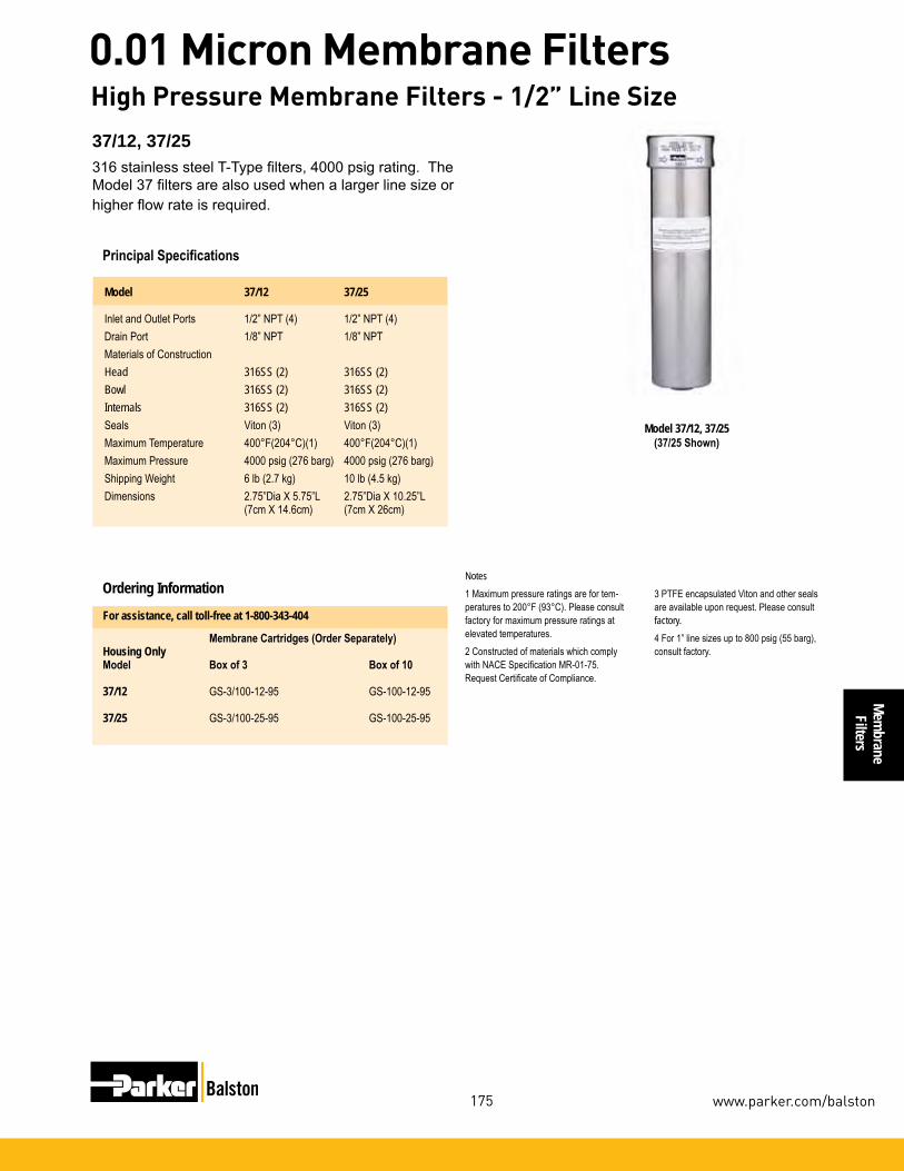
Membrane
Filters
175
0.01 Micron Membrane Filters
www.parker.com/balston
37/12, 37/25316 stainless steel T-Type filters, 4000 psig rating. The Model 37 filters are also used when a larger line size or higher flow rate is required.
Model 37/12, 37/25 (37/25 Shown)
Notes1Maximumpressureratingsarefortem-peraturesto200°F(93°C).Pleaseconsultfactoryformaximumpressureratingsatelevatedtemperatures.2ConstructedofmaterialswhichcomplywithNACESpecificationMR-01-75.RequestCertificateofCompliance.
Principal Specifications Model 37/12 37/25
InletandOutletPorts 1/2”NPT(4) 1/2”NPT(4)DrainPort 1/8”NPT 1/8”NPTMaterialsofConstructionHead 316SS (2) 316SS (2)Bowl 316SS (2) 316SS (2)Internals 316SS (2) 316SS (2)Seals Viton(3) Viton(3)MaximumTemperature 400°F(204°C)(1) 400°F(204°C)(1)MaximumPressure 4000psig(276barg) 4000psig(276barg)ShippingWeight 6lb(2.7kg) 10lb(4.5kg)Dimensions 2.75”DiaX5.75”L 2.75”DiaX10.25”L (7cmX14.6cm) (7cmX26cm)
Ordering Information
Membrane Cartridges (Order Separately)Housing Only Model Box of 3 Box of 10
37/12 GS-3/100-12-95 GS-100-12-95
37/25 GS-3/100-25-95 GS-100-25-95
3PTFEencapsulatedVitonandothersealsareavailableuponrequest.Pleaseconsultfactory.4For1”linesizesupto800psig(55barg),consultfactory.
For assistance, call toll-free at 1-800-343-404
High Pressure Membrane Filters - 1/2” Line Size
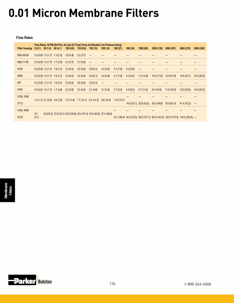
Mem
bran
eFi
lters
176
0.01 Micron Membrane Filters
1-800-343-4048
Flow Rates
Clean In Place (CIP) Filtration
Flow Rates
Flow Rates, SCFM (Nm3/hr), at 2 psi (0.14 bar) Drop at Indicated Line Pressure (barg)Filter Housing 2 (0.1) 20 (1.4) 60 (4.1) 100 (6.9) 125 (8.6) 150 (10) 200 (14) 300 (21) 500 (34) 1000 (69) 2000 (138) 3000 (207) 4000 (276) 5000 (345)
9933-05-95 0.5(0.8) 1.0(1.7) 1.5 (2.5) 2.0 (3.4) 2.2(3.7) –– –– –– –– –– –– –– –– ––
9922-11-95 0.5(0.8) 1.0(1.7) 1.7(2.9) 2.2(3.7) 2.3(3.9) –– –– –– –– –– –– –– –– ––
91S6 0.5(0.8) 1.0(1.7) 1.8(3.1) 2.5 (4.2) 2.8(4.8) 3.0 (5.1) 3.4(5.8) 4.1(7.0) 5.3(9.0) –– –– –– –– ––
95S6 0.5(0.8) 1.0(1.7) 1.8(3.1) 2.5 (4.2) 2.8(4.8) 3.0 (5.1) 3.4(5.8) 4.1(7.0) 5.3(9.0) 7.4(12.6) 10.5(17.8) 12.9(21.9) 14.8(25.1) 16.5(28.0)
95T 0.5(0.8) 1.0(1.7) 1.8(3.1) 2.5 (4.2) 2.8(4.8) 3.0 (5.1) –– –– –– –– –– –– –– ––
97S6 0.5(0.)8 1.0(1.7) 1.7(2.9) 2.3(3.9) 2.5 (4.2) 2.7(4.6) 3.1 (5.3) 3.7(6.3) 4.8(8.2) 6.7(11.4) 9.4(16.0) 11.5(19.5) 13.3 (22.6) 14.9(25.3)
31S6,33S6 –– –– –– –– –– –– 1.0(1.7) 2.1 (3.6) 4.6(7.8) 7.0(11.9) 7.7(13.1) 8.4(14.3) 9.6(16.3) 11.6(19.7) 37/12 14.8(25.1) 20.8(35.3) 29.3(49.8) 35.9(61.0) 41.4(70.3) ––
41S6,45S6 –– –– –– –– –– –– –– 3.0 6.0 (10.2) 13.0 (22.1) 20.0 (34.0) 22.0(37.4) 24.0(40.8) 27.4(46.6) 37/25 (5.1) 33.1(56.2) 42.4(72.0) 59.5(101.1) 83.8(142.4) 102.0(173.3) 118.0(200.5) ––

Membrane
Filters
177
0.01 Micron Membrane Filters
www.parker.com/balston
Clean In Place (CIP) Filtration Sterile Air Filtration
Product Features:
Steam Filters
Balston Steam Filters are in full compliance with the requirements of the US Food, Drug, and Cosmetic Act. These filters may be used with steam, air, and other gases which directly contact food and food ingre-dients, including milk, alcoholic, and non-alcoholic liquids.
Sterile Air Filters
Balston Stainless Steel Compressed Air Filter Assemblies safeguard your operations from rust, pipescale, wa-ter, oil, and organisms usually found in compressed air. These filters will remove contaminants at a very high efficiency - up to 99.99% for 0.01 mi-cron particles and droplets. Liquid releases from the filter cartridge to an automatic drain as rapidly as it enters the filter. This allows the filter to continue removing liquids for an unlimited time without loss of efficiency or flow capacity. The final stage of filtration removes all viable organisms with an efficiency rating of 99.9999+% at 0.01 micron. Select 1/4” to 1” line filters are constructed of 304 stainless steel and are de-signed to hold up to the harshest environments.
• Remove98+%of0.1micronpar-ticlesandremoveliquidconden-sate at same efficiency
• Removeessentiallyallnonvolatileboiler feedwater chemicals
• ComplywithUSFDA,USDA, Health Protection Branch of Health and Welfare Canada, and 3-A accepted practices
Balston Filters
• All304stainlesssteelconstruc-tion, ideal for standing up to aggressivewashdownchemicals
• Remove99.99%of0.01micronparticles of oil, water, and dirt
• USDA(FSISacceptedforusein federally inspected meat and poultry plants
Filters and Dryers for the Food Industry
Steam Filters Sterile Air Filters
Culinary Quality Steam

Filte
rs fo
r the
Food
Indu
stry
178
Filters for the Food Industry
1-800-343-4048
Balston Series SR Filters are in full compliance with the requirements of the US Food, Drug and Cosmetic Act. They also meet the regulations for Indirect Food Additives used as Basic Components for Repeated Use Food Contact Surfaces as specified in 21 CFR Part 177, and Current Good Manufacturing Practices, 21 CFR Part 110. These filters have been accepted by the USDA for use in federally inspected meat and poultry plants. Balston Steam Filters are in full compli-ance with the 3A Accepted Practices (Number 609-04) for producing steam of culinary quality. They are also in full compliance with the requirements of the Health Protection Branch of Health and Welfare Canada.
Benefits Balston Steam Filters eliminate particulate contamina-tion of food products caused by direct contact with dirty steam. Other benefits include: reduction in steam condensate mixing with food products when steam is used for agitating, mixing, or cooking; elimi-nate taste and odor problems by reducing boiler feed-water carryover; Reduced maintenance requirements.
How it Works The steam filter contains a patented Microfibre® filter cartridge in a rugged stainless steel housing designed specifically for steam service.
As shown in the cutaway drawing, steam enters the housing into an expansion chamber, where much of the condensate is knocked out of the steam as a result of the abrupt change in flow direction and velocity. The steam then flows upward in the housing, through the Balston grade SR microfibre filter cartridge (outside-to-inside flow), and then downward to the exit port. The grade SR filter cartridge, rated at 98+% efficiency for 0.1 micron and larger particles, removes essentially all the suspended solid particles and the remaining water droplets. The water draining from the filter cartridge and the expansion chamber is auto-matically removed from the housing by the automatic condensate drain.
Model SP6-23/75SR
Steam Filters
Model 23/75SR
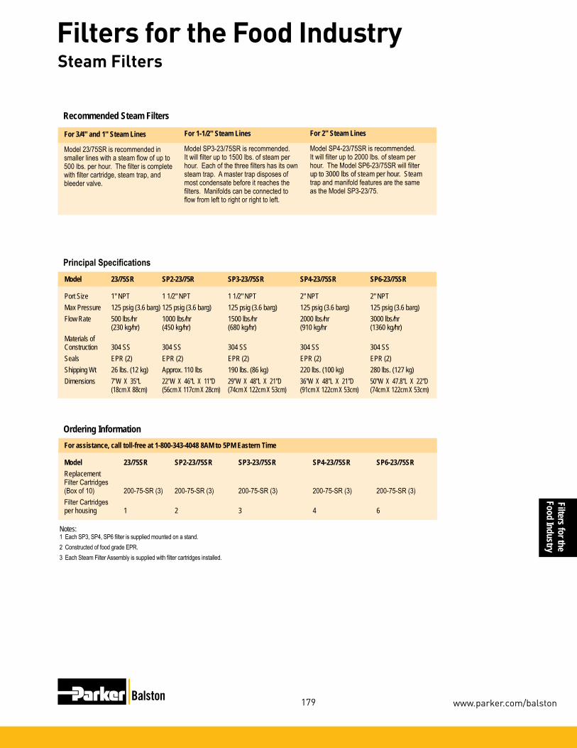
Filters for theFood Industry
179
Filters for the Food Industry
www.parker.com/balston
Model 23/75SR SP2-23/75R SP3-23/75SR SP4-23/75SR SP6-23/75SR
Port Size 1" NPT 1 1/2" NPT 1 1/2" NPT 2" NPT 2" NPTMax Pressure 125 psig (3.6 barg) 125 psig (3.6 barg) 125 psig (3.6 barg) 125 psig (3.6 barg) 125 psig (3.6 barg)Flow Rate 500 lbs/hr 1000 lbs/hr 1500 lbs/hr 2000 lbs/hr 3000 lbs/hr (230 kg/hr) (450 kg/hr) (680 kg/hr) (910 kg/hr (1360 kg/hr) Materials of Construction 304 SS 304 SS 304 SS 304 SS 304 SS Seals EPR (2) EPR (2) EPR (2) EPR (2) EPR (2) Shipping Wt 26 lbs. (12 kg) Approx. 110 lbs 190 lbs. (86 kg) 220 lbs. (100 kg) 280 lbs. (127 kg)Dimensions 7"W X 35"L 22"W X 46"L X 11"D 29"W X 48"L X 21"D 36"W X 48"L X 21"D 50"W X 47.8"L X 22"D (18cm X 88cm) (56cm X 117cm X 28cm) (74cm X 122cm X 53cm) (91cm X 122cm X 53cm) (74cm X 122cm X 53cm)
Principal Specifications
Notes:1 Each SP3, SP4, SP6 filter is supplied mounted on a stand.2 Constructed of food grade EPR.3 Each Steam Filter Assembly is supplied with filter cartridges installed.
Recommended Steam Filters
For 3/4" and 1" Steam Lines
Model 23/75SR is recommended in smaller lines with a steam flow of up to 500 lbs. per hour. The filter is complete with filter cartridge, steam trap, and bleeder valve.
For 2" Steam Lines
Model SP4-23/75SR is recommended. It will filter up to 2000 lbs. of steam per hour. The Model SP6-23/75SR will filter up to 3000 lbs of steam per hour. Steam trap and manifold features are the same as the Model SP3-23/75.
For assistance, call toll-free at 1-800-343-4048 8AM to 5PM Eastern Time
Model 23/75SR SP2-23/75SR SP3-23/75SR SP4-23/75SR SP6-23/75SRReplacement Filter Cartridges(Box of 10) 200-75-SR (3) 200-75-SR (3) 200-75-SR (3) 200-75-SR (3) 200-75-SR (3)Filter Cartridges per housing 1 2 3 4 6
Ordering Information
For 1-1/2" Steam Lines
Model SP3-23/75SR is recommended. It will filter up to 1500 lbs. of steam per hour. Each of the three filters has its own steam trap. A master trap disposes of most condensate before it reaches the filters. Manifolds can be connected to flow from left to right or right to left.
Steam Filters

Filte
rs fo
r the
Food
Indu
stry
180
Filters for the Food Industry
1-800-343-4048
All 304 stainless steel construction, ideal standing up to aggressive washdown chemicals
Remove 99.99% of 0.01 micron particles of oil, water, and dirt from compressed air and other gases
For Sterile Air Requirements:
Remove all viable organisms
USDA/FSIS accepted for use in federally inspected meat and poultry plants
Low pressure drop
Continuously trap and drain liquids
Remove trace oil vapor with adsorbent cartridges
Balston® Stainless Steel Compressed Air Filter Assemblies Protect your equipment and delicate instruments from the dirt, water, and oil usually found in compressed air and other gases. These filters will remove contaminants at a very high efficiency - up to 99.99% for 0.01 micron particles and droplets. Liquid releases from the filter cartridge to an automatic drain as rapidly as it enters the filter. This allows the filter to continue removing liquids for an unlimited time without loss of efficiency for flow capacity. Select 1/4" to 1" line filters are constructed of 304 stainless steel and are designed to hold up to the harshest environments.
Models 6006 and 6008
Stainless Steel Harsh Environment Filters forFood Processing and Packaging

Filters for theFood Industry
181
Filters for the Food Industry
www.parker.com/balston
Filter Cartridge Description Balston Filter Cartridges
Parker provides two grades of coalescing filter car-tridges, Grade DX and Grade BX. Singly or in tandem, these filters satisfy all requirements for removing liquid and solid contaminants from compressed air. Parker also has an activated carbon adsorbent CI-type cartridge for the removal of trace oil vapors from a compressed air line. The activated carbon cartridge is Grade 000.
How to Select the Filter Cartridge and Housing
Single stage filtration. Use a Grade DX filter cartridge
Two stage filtration is necessary. Use a Grade DX followed by a Grade BX filter car-tridge. As a general rule, a Grade BX filter cartridge should not be used alone.
For rare instances where even a trace amount of oil vapor can cause a problem, three stage filtration is necessary. Use a Grade DX followed by a Grade BX, and a type CI cartridge.
General purpose applications such as plant compressed air
Filter Cartridge Description
Removal of trace com-pressor oil vapor
Instrument air and other critical air requirements
How to Order the Filter Assembly
Temperature Range -150°F to 300°F (-100°C - 149°C)
Maximum PressureDifferential Across Filter,Inside-to-Outside Flow: 100 psi (7 barg)
Materials of Construction Borosilicate glass microfibers with fluorocarbon resin binder. Resistant to water, all hydrocarbon and synthetic lubricants.
Physical Properties, Microfibre Filter Cartridges
Retention Efficiency
Grade Efficiency for 0.01 Micron Particles and DropletsDX 93%BX 99.99%
1 Decide which grade(s) of filter cartridges fits the application (see selection boxes at left).
2 Select the filter housing with a port size equal to the line size where the filter is to be located.
3 For a new installation in which the line size has yet to be selected, determine the gas flow rate and pressure at the point where the filter will be located, and then refer to the flow chart on the reverse side of this data sheet. NOTE: The filter port size must be equal to or larger than the line size (when speci-fied).
1 Build your own custom filter assembly using the guideline matrix on Page 170 and specify your model number. Example: 1/2” filter with DPI and Auto Drain with Grade DX Filter = 6004N-01A-DX.
2 Each assembly is shipped with the filter cartridge in-stalled. To order additional filter cartridges, indicate the model number of the cartridges, and the grade. Examples 050-05-DX, 050-05-BX. The grade used for Type CI cartridges is 000 (CI-100-12-000).
Note: Assemblies with CI Cartridges are shipped with the adsorbent cartridge wrapped separately. This ship-ping method prolongs the life of the cartridge.
Stainless Steel Harsh Environment Filters forFood Processing and Packaging

Filte
rs fo
r the
Food
Indu
stry
182
Filters for the Food Industry
1-800-343-4048
Models 6102, 6002, 6904The 6002 series models are 1/4” line size filters de-signed for lower flow systems and installations with space limitations. Models 6102 and 6002 are offered with two drain options: a manual drain or an auto float drain, for maintenance-free operation. Model 6904 offers 1/2” inlet and outlet connections for applications requiring 1/2” pipe with space limitations.
Model 6004The 6004 series models are 1/2” line size filters de-signed for moderate flow rate systems. This series has increased liquid holding capacity, which safeguards sensitive end use points from system upsets and morn-ing start ups.
Models 6006 and 6008The 6006 and 6008 series models are 3/4” and 1” line size filters respectively. These are designed for high flow rate systems servicing multiple end use points. These are also offered with a high capacity auto float drain option.
Model 6004Models 6102, 6002, 6904
Models 6006 and 6008
How to Order the Filter Assembly*
Build your own custom filter assembly using the guideline matrix below and specify your model number. Example: 1/2” filter with Auto Drain and Grade DX Filter = 6004N-0A1-DX.
*Consult Factory. Not all configurations are available.
NNPT Thread Inlet & Outlet Ports
0A2ManualDrain 0A1Auto Drain
Filter Grade000SADXBXLeave blank for no filterCartridge
Stainless Steel Harsh Environment Filters1/4" to 1" Line Size
61021/4” Ports6002 1/4” Ports69041/2” Ports Short Bowl6004 1/2” Ports6006 3/4” Ports 60081” Ports

Filters for theFood Industry
183
Filters for the Food Industry
www.parker.com/balston
Flow Rates
Filter Housing Port Filter Flow rates SCFM (Nm3/hr), at 2 psi (0.14 bar) drop at indicated line pressure. Refer to PrincipalModel Size Cartridge Specification Charts in each product data sheet for maximum pressure rating of each housing Grade PSIG 2 (0.1) 20 (1.4) 40 (2.8) 80 (5.5) 100 (6.9) 125 (8.6) 150 (10) 200 (14) 250 (17)
6102N 1/4" DX 13.5 (23) 8 (14) 11 (19) 20 (34) 25 (42) 30 (51) 36 (61) --- --- BX 1 (2) 2 (3) 3.5 (6) 5.7 (10) 6.8 (12) 8 (14) 10 (17) --- ---
6002N 1/4” DX 9 (15) 19 (32) 39 (66) 51 (87) 63 (107) 76 (129) 90 (153) 117 (199) 145 (246)6904N 1/2" BX 3 (5) 8 (14) 11 (19) 21 (36) 25 (42) 31 (53) 36 (61) 47 (80) 58 (99) CI 2 (3) 5 (8) 7 (12) 12 (20) 15 (25) 18 (31) 22 (37) 28 (48) 35 (59) SA --- 8 (14) 11 (19) 21 (36) 25 (42) 31 (53) 36 (61) --- ---
6004N 1/2” DX 19 (32) 41 (70) 65 (110) 113 (192) 137 (233) 166 (282) 196 (333) 257 (473) 316 (537) BX 9 (15) 19 (32) 30 (51) 51 (87) 63 (107) 76 (129) 90 (153) 117 (199) 145 (246) CI 6 (10) 12 (20) 19 (32) 32 (54) 39 (66) 48 (82) 56 (95) 73 (124) 90 (153) SA --- 19 (32) 30 (51) 51 (87) 63 (107) 76 (129) 90 (153) --- ---
6006N 3/4” DX 37 (63) 78 (133) 123 (209) 214 (364) 259 (440) 315 (535) 371 (630) 484 (822) 596 (1013) BX 10 (17) 21 (36) 34 (58) 56 (95) 70 (119) 85 (144) 101 (172) 131 (223) 162 (275) CI 8 (14) 16 (27) 26 (44) 44 (75) 53 (90) 65 (110) 76 (129) 99 (168) 122 (207) SA --- 21 (36) 34 (58) 56 (95) 70 (119) 85 (144) 101 (172) --- ---
6008N 1” DX 55 (93) 115 (195) 181 (308) 314 (533) 380 (646) 463 (787) 546 (928) 711 (1208) 877 (1490) BX 11 (19) 23 (39) 37 (63) 64 (109) 77 (131) 94 (160) 111 (189) 144 (245) 178 (302) CI 10 (17) 20 (34) 32 (54) 56 (95) 67 (114) 82 (139) 96 (163) 125 (212) 154 (262) SA --- 23 (39) 37 (63) 64 (109) 77 (131) 94 (160) 111 (189) --- ---
Balston grade SA filter cartridges, rated at 99.9999+% efficiency for 0.01 micron particles, is at least 30 times better than the accepted standard for sterile air filters developed by independent research organizations in the U.S. and U.K. (request bulletin TI-105A for a detailed discussion on Balston filter efficiency rating procedure, and Bulletin TI-935 for an independent test report on balstonSterile Air Filters). Balston Sterile Air Filters are in full compliance with the requirements of the FDA.
Sterile Air Filters Steam Sterilization ProcedureIn installations where the sterile air filter requires steam sterilization, we recommend the following procedures:
The steam sterilization pressure should not exceed 60 psig (4 barg). Preferably, it should be held to 40 psig (3 barg) or less. A typical sterilization cycle is 30 psig (2 barg) steam for 30 minutes. Steaming time can be increased as desired without harm to the filter cartridges. The steam flow should not exceed the normal air flow for the unit. To ensure no buildup of condensate in the housing, condensate should be drained from the filter by a condensate drain valve during the steaming process. The cleanliness of the steam is an important factor influencing the life of the Sterile Air Filter cartridges. Parker strongly recommends using Model 23 Steam Filters to ensure optimum operating life. When autoclaving, the Grade SA filter cartridges will tolerate temperatures to 300°F (149°C) in dry gas. Viton or other heat resistant seals should be used in the housing.
Stainless Steel Harsh Environment Filters1/4" to 1" Line Size

Filte
rs fo
r the
Food
Indu
stry
184
Filters for the Food Industry
1-800-343-4048
Principal Specifications
Notes:1 Max. temperature with auto drain Max. tem-perature with manual drain is 275°F (135°C).
2 Max. pressure with auto drain. Max. pres-sure with manual drain is 250 psi (17 barg).
3 Required for proper operation of auto drain.
Stainless Steel Harsh Environment Filters
Ordering Information For assistance, call toll-free at 1-800-343-4048 8AM to 5PM Eastern Time
Model 6102 6002 6904 6004 6006 6008
Port Size 1/4” NPT 1/4” NPT 1/2” NPT 1/2” NPT 3/4” NPT 1” NPTMaterials of Construction Head 316 Stainless Steel 304 Stainless Steel Bowl 316 Stainless Steel 304 Stainless Steel Internals Acetal Stainless Steel Seals Viton Buna-N Food Grade Maximum Temperature 140°F (60°C) (1) 120°F (49°C) (1) Maximum Pressure 150 psig (10 barg) (2) 175 psig (12 barg) (2) Minimum Pressure 15 psig (1 barg) (3) 15 psig (1 barg) (3) Shipping Weight 3.5 lbs. (1.6 kg) 3.5 lbs. (1.6 kg) 3.5 lbs. (1.6 kg) 4.0 lbs. (18 kg) 11 lbs. (5 kg) 12 lbs. (5.5 kg)Dimensions 1.5”W x 4.2”L 3”W X 7”L 3”W X 7”L 3”W X 10”L 4”W X 10”L 4”W X 12”L (3.8cm x 11.7cm) (7cm X 18cm) (7cm X 18cm) (7cm X 25cm) (10cm X 25cm) (10cm X 30cm)
Assembly Ordering InformationModel P/N Filter Tube Drain (Manual) Drain (Auto. Float) Mounting Bracket (stainless steel)6102N-0A0-(?X) 070-063-(?X) SAP05481 N/A N/A6102N-0A1-(?X) 070-063-(?X) N/A C02-2392 N/A6002N-0A2-(?X) 100-12-(?X) C01-0108 N/A C01-00946002N-0A1-(?X) 100-12-(?X) N/A C01-0109 C01-00946002N-0A2-SA 100-12-SA C01-0108 N/A C01-00946002N-0A2-000 CI-100-12-000 C01-0108 N/A C01-00946904N-0A2-(?X) 100-12-(?X) C01-0108 N/A C01-00946904N-0A1-(?X) 100-12-(?X) N/A C01-0109 C01-00946904N-0A2-SA 100-12-SA C01-0108 N/A C01-00946904N-0A2-000 CI-100-12-000 C01-0108 N/A C01-00946004N-0A2-(?X) 100-18-(?X) C01-0108 N/A C01-00946004N-0A1-(?X) 100-18-(?X) N/A C01-0109 C01-00946004N-0A2-SA 100-18-SA C01-0108 N/A C01-00946004N-0A2-000 CI-100-18-000 C01-0108 N/A C01-00946006N-0A2-(?X) 200-176-(?X) C01-0108 N/A C01-00946006N-0A1-(?X) 200-176-(?X) N/A C01-0109 C01-00946006N-0A2-SA 200-176-SA C01-0108 N/A C01-00946006N-0A2-000 200-176-000 C01-0108 N/A C01-00946008N-0A2-(?X) 200-185-(?X) C01-0108 N/A C01-00946008N-0A1-(?X) 200-185-(?X) N/A C01-0109 C01-00946008N-0A2-SA 200-185-SA C01-0108 N/A C01-00946008N-0A2-000 CI-200-185-000 C01-0108 N/A C01-0094Replacement Filter Cartridge Ordering InformationModel P/N 6102 6002/6904 6004 6006 6008Replacement Filter CartridgesNumber required 1 1 1 1 1Box of 5 5/070-063-(?X) 5/100-12-(?X) 5/100-18-(?X) 5/200-176-(?X) 5/200-185-(?X)Box of 10 070-063-(?X) 100-12-(?X) 100-18-(?X) 200-176-(?X) 200-185-(?X)Box of 10 070-063-SA 100-12-SA 100-18-SA 200-176-SA 200-185-SACI Cartridges (box of 1) --- CI-100-12-000 CI-100-18-000 CI-200-176-000 CI-200-185-000

Filters for theFood Industry
185
Filters for the Food Industry
www.parker.com/balston
Safeguard your operations from rust, pipescale, water, and oil. The prefilters will remove contaminants at a very high efficiency - up to 93% for 0.01 micron particles and drop-lets. Liquid releases from the filter cartridge to an automat-ic drain as rapidly as it enters the filter. This allows the filter to continue removing liquids for an unlimited time without loss of efficiency or flow capacity.
The final stage of filtration removes all remaining contami-nates with an efficiency rating of 99.99+% at 0.01 microns. Select 1/4” to 1 1/2” line filters are constructed of aluminum with a durable powder coating designed to hold up to the dirtiest compressed air systems.
Full-featured with differential pressure indicators, auto drains, sight glasses, pressure relief valve, and bayonet bowl-to-head connection
Lifetime (20 year) warranty
Continuously trap and drain liquids
Remove 99.99% of 0.01 micron particles of oil, water, and dirt from compressed air and other gases
USDA accepted for use in federally inspected meat and poultry plants
Low pressure drop
Applications:These filters are ideal for safeguarding critical production equipment from corrosive compressor condensate that can cause catastrophic failures and unexpected downtime. Ideal applications are:
• Instrumentation
• Air actuators and air cylinders
• Pneumatic packaging machines
• Pneumatic conveyors
• Air operated production equipment
• Air operated lifts
The Parker Balston 2 stage filter systems offer the best protection to all your pneumatic equipment and instrumentation. These high efficiency filtration systems will eliminate costly maintenance and unexpected downtime due to contaminated compressed air.
Balston 2 Stage Compressed Air Filter Systems
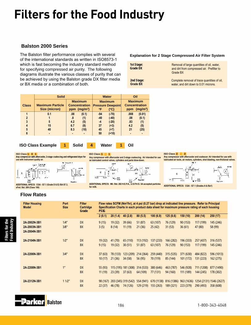
Filte
rs fo
r the
Food
Indu
stry
186
Filters for the Food Industry
1-800-343-4048
The Balston filter performance complies with several of the international standards as written in ISO8573-1 which is fast becoming the industry standard method for specifying compressed air purity. The following diagrams illustrate the various classes of purity that can be achieved by using the Balston grade DX filter media or BX media or a combination of both.
Complete removal of trace quantities of oil, water, and dirt down to 0.01 microns.
Removal of large quantities of oil, water, and dirt from compressed air. Prefilter to Grade BX
1st Stage:Grade DX
Explanation for 2 Stage Compressed Air Filter System
2nd Stage:Grade BX
Flow Rates Filter Housing Port Filter Flow rates SCFM (Nm3/hr), at 4 psi (0.27 bar) drop at indicated line pressure. Refer to PrincipalModel Size Cartridge Specification Charts in each product data sheet for maximum pressure rating of each housing Grade PSIG 2 (0.1) 20 (1.4) 40 (2.8) 80 (5.5) 100 (6.9) 125 (8.6) 150 (10) 200 (14) 250 (17)
2A-2002N-3B1 1/4” DX 9 (15) 19 (32) 39 (66) 51 (87) 63 (107) 76 (129) 90 (153) 117 (199) 145 (246)2A-2003N-3B1 3/8" BX 3 (5) 8 (14) 11 (19) 21 (36) 25 (42) 31 (53) 36 (61) 47 (80) 58 (99)2A-2004N-3B1
2A-2104N-3B1 1/2” DX 19 (32) 41 (70) 65 (110) 113 (192) 137 (233) 166 (282) 196 (333) 257 (437) 316 (537) BX 9 (15) 19 (32) 30 (51) 51 (87) 63 (107) 76 (129) 90 (153) 117 (199) 145 (246)
2A-2206N-3B1 3/4” DX 37 (63) 78 (133) 123 (209) 214 (364) 259 (440) 315 (535) 371 (630) 484 (822) 596 (1013) BX 10 (17) 21 (36) 34 (58) 56 (95) 70 (119) 85 (144) 101 (172) 131 (223) 162 (275)
2A-2208N-3B1 1” DX 55 (93) 115 (195) 181 (308) 314 (533) 380 (646) 463 (787) 546 (928) 711 (1208) 877 (1490) BX 11 (19) 23 (39) 37 (63) 64 (109) 77 (131) 94 (160) 111 (189) 144 (245) 178 (302)
2A-2312N-3B1 1 1/2” DX 98 (167) 203 (345) 319 (542) 554 (941) 670 (1138) 816 (1386) 963 (1636) 1254 (2131) 1546 (2627) BX 22 (37) 46 (78) 74 (126) 129 (219) 155 (263) 189 (321) 223 (379) 290 (493) 358 (608)
Maximum Particle Size (micron)
MaximumConcentrationppm (mg/m3)
Maximum Pressure Dewpoint oF (oC)
1 0.1 .08 (0.1) -94 (-70) .008 (0.01) 2 1 .8 (1) -40 (-40) .08 (0.1) 3 5 4.2 (5) -4 (-20) .83 (1) 4 15 6.7 (8) 37 (+3) 4.2 (5) 5 40 8.3 (10) 45 (+7) 21 (25) 6 - - - 50 (+10) - -
Solid Water Oil
ClassMaximum
Concentration ppm (mg/m3)
ISO Class Example 1 Solid 4 Water 1 Oil
Balston 2000 Series
ISO Class 1 1Any compressor with aftercooler and 2-stage coalescing. Air intended for use as lubricated control valves, cylinders and parts blow-down.
ADDITIONAL SPECS: Mil. Std. 282 H.E.P.A., U.S.P.H.S. 3A accepted particles for milk.
ISO Class 1 4 1Any compressor with aftercooler, 2-stage coalescing and refrigerated dryer for use with instrument quality air.
ADDITIONAL SPECS: CGA - G7.1 (Grade D & E) ISA S7.3, sFed. Std. 209 (Class 100)
Any compressor with aftercooler and coalescer. Air intended for use with lubricated air tools, air motors, cylinders, shot blasting, non-frictional valves.
ADDITIONAL SPECS: CGA - G7.1 (Grades A & Ba1)
▼
AutoDrain
ISO Class 2 2
AutoDrain▼▼

Filters for theFood Industry
187
Filters for the Food Industry
www.parker.com/balston
Model 2A-2002, 2003, 2004 2A-2104 2A-2206 2A-2208 2A-2312
Port Size 1/4” NPT 1/2” NPT 3/4” NPT 1” NPT 1.5” NPTMaterials of Construction Head Aluminum Bowl Aluminum Internals Aluminum Seals Buna-N Food Grade Maximum Temperature (1) 130°F (54°C) Maximum Pressure (2) 175 psig (12 barg) Minimum Pressure (3) 15 psig (1 barg) Shipping Weight 4.2 lbs. (1.9 kg) 5 lbs. (2.3 kg) 11.7 lbs. (5.3 kg) 11.7 lbs. (5.3 kg) 27 lbs. (12 kg)Dimensions 6.25”W X 8.5”L 6.25”W X 11”L 8.3”W X 13”L 8.3”W X 13”L 10.5”W X 17”L
Principal Specifications
Notes:1 Max. temperature with auto drain 2 Max. pressure with auto drain. Max. pres-
sure with manual drain is 250 psi (17 barg).3 Required for proper operation of auto drain.
Ordering Information For assistance, call toll-free at 1-800-343-4048 8AM to 5PM Eastern Time
Assembly Ordering InformationModel P/N Replacement Cartridge Box of 5 Box of 102A-2002N-3B1 1/4” 2-Stage (DX, BX) Filter Assembly 5/100-12-DX 100-12-DX 2A-2003N-3B1 3/8” 2-Stage (DX, BX) Filter Assembly 5/100-12-BX 100-12-BX2A-2004N-3B1 1/2” 2-Stage (DX, BX) Filter Assembly
2A-2104N-3B1 1/2" 2-Stage (DX, BX) Filter Assembly 5/100-18-DX 100-18-DX 5/100-18-BX 100-18-BX 2A-2206N-3B1 3/4" 2-Stage (DX, BX) Filter Assembly 5/150-19-DX 150-19-DX 5/150-19-BX 150-19-BX 5/150-19-SA 2A-2208N-3B1 1" 2-Stage (DX, BX) Stainless Assembly 5/150-19-DX 150-19-DX 5/150-19-BX 150-19-BX 5/150-19-SA 2A-2312N-3B1 1” 2-Stage (DX, BX) Stainless Assembly 5/200-35-DX 200-35-DX 5/200-35-BX 200-35-BX 4 2 each of mounting brackets are required for adequate support. 5 For CRN rated assemblies add a "C" to the Model Number. Example: 2A-C2104N-3B1
2A-2002N-3B1, 2A-2004N-3B12A-2003N-3B1
2A-2104N-3B1 2A-2206N-3B1, 2A-2208N-3B11 2A-2312N-3B1
6.25" (16 cm)
6.25" (16 cm)
8.3" (21 cm)
10.5" (27 cm)
8.5" (22 cm)
11"(28 cm)
13"(33 cm)
17"(43 cm)

Filte
rs fo
r the
Food
Indu
stry
188
Filters for the Food Industry
1-800-343-4048
Balston 3 Stage Compressed Air Filter AssembliesSafeguard your operations from rust, pipescale, water, oil, and organisms. The prefilters will remove contami-nants at a very high efficiency - up to 99.99% for 0.01 micron particles and droplets. Liquid releases from the filter cartridge to an automatic drain as rapidly as it enters the filter. This allows the filter to continue removing liquids for an unlimited time without loss of efficiency or flow capacity.
The final stage of filtration removes all viable organisms with an efficiency rating of 99.9999+% at 0.01 microns. Select 1/4” to 1 1/2” aluminum with a durable powder coating designed to hold up to the dirtiest compressed air systems.
•Remove all viable organisms - at 99.9999+% @0.01 microns
•Remove 99.99% of 0.01 micron particles of oil, water, and dirt from compressed air and other gases
Product Features:•USDA accepted for use in
federally inspected meat and poultry plants
•Low pressure drop
•Continuously trap and drain liquids
Compressed air is contaminated with compressor oil, water condensate, pipe scale and rust all of which provide the ideal environment and means to grow bacteria. This natural occurring contaminate can also effect the taste, appearance and shelf life of food product. The food processing and packaging industry utilizes compressed air extensively throughout their facilities. Compressed air is used to push and propel product, cut and
mix product in addition to packaging product.
Cahoon Farms in Walcott, New York uses Parker Balston three stage filtration systems for all their compressed air and sterile air applications. Cahoon Farms packages fresh sliced apples and cherries, dried apples, and other assorted dried fruits. Compressed air is used extensively throughout the facility servicing pneumatic equipment, slicing and mixing food product, and packaging. The
sterile compressed air applications are filtered to an efficiency of 99.9999+% at 0.01 microns, which is 30 times better than the accepted industry standard. Cahoon Farms safeguards their food product from any possible contamination that could lead to bacteria and mold growth. The investment in these filtration systems ensures Cahoon Farms’ products will maintain superior taste, quality and freshness with an extended shelf life.
The Application:

Filters for theFood Industry
189
Filters for the Food Industry
www.parker.com/balston
Sterile Air Filter Rating InformationBalston grade SA filter cartridges, rated at 99.9999+% efficiency for 0.01 micron particles, is at least 30 times better than the accepted standard for sterile air filters developed by independent research organizations in the U.S. and U.K. (request bulletin TI-105 for a detailed dis-cussion on Balston filter efficiency rating procedure, and Bulletin TI-935 for an independent test report on Balston Sterile Air Filters). Balston Sterile Air Filters are in full compliance with the requirements of the FDA.
Complete removal of trace quantities of oil, water, and dirt down to 0.01 microns.
Removal of large quantities of oil, water, and dirt from compressed air. Prefilter to Grade BX
1st Stage:Grade DX
3rd Stage:Grade SA
2nd Stage:Grade BX
Removal of bacteria providing sterile air.
Flow Rates Filter Housing Port Filter Flow rates SCFM (Nm3/hr), at 7 psi (0.48 bar) drop at indicated line pressure. Refer to PrincipalModel Size Cartridge Specification Charts in each product data sheet for maximum pressure rating of each housing Grade PSIG 2 (0.1) 20 (1.4) 40 (2.8) 80 (5.5) 100 (6.9) 125 (8.6) 150 (10)
3B-2002N-3B1 1/4” DX 9 (15) 19 (32) 39 (87) 51 (107) 63 (107) 76 (129) 90 (153)3B-2003N-3B1 3/8" BX 3 (5) 8 (14) 11 (36) 21 (42) 25 (42) 31 (53) 36 (61)3B-2004N-3B1 1/2” SA --- 8 (14) 11 (36) 21 (42) 25 (42) 31 (53) 36 (61)
3B-2104N-3B1 1/2” DX 19 (32) 41 (70) 65 (192) 113 (233) 137 (233) 166 (282) 196 (333) BX 9 (15) 19 (32) 30 (87) 51 (107) 63 (107) 76 (129) 90 (153) SA --- 19 (32) 30 (87) 51 (107) 63 (107) 76 (129) 90 (153)
3B-2206N-3B1 3/4” DX 37 (63) 78 (133) 123 (364) 214 (440) 259 (440) 315 (535) 371 (630) BX 10 (17) 21 (36) 34 (95) 56 (119) 70 (119) 85 (144) 101 (172) SA --- 21 (36) 34 (95) 56 (119) 70 (119) 85 (144) 101 (172)
3B-2208N-3B1 1” DX 55 (93) 115 (195) 181 (533) 314 (646) 380 (646) 463 (787) 546 (928) BX 11 (19) 23 (39) 37 (109) 64 (131) 77 (131) 94 (160) 111 (189) SA --- 23 (39) 37 (109) 64 (131) 77 (131) 94 (160) 111 (189)
3B-2312N-3B1 1 1/2” DX 98 (167) 203 (345) 319 (941) 554 (1138) 670 (1138) 816 (1386) 963 (1636) BX 22 (37) 46 (78) 74 (219) 129 (263) 155 (263) 189 (321) 223 (379) SA 16 (27) 33 (56) 52 (155) 91 (187) 110 (187) 134 (228) 158 (223)
1 For CRN rated assemblies add a "C" to the Model Number. Example: 3B-C2104N-3B1
Explanation for 3 Stage Sterile Air System

Filte
rs fo
r the
Food
Indu
stry
190
Filters for the Food Industry
1-800-343-4048
Model 3B-2002, 2003, 2004 3B-2104 3B-2206 3B-2208 3B-2312
Port Size 1/4” NPT 1/2” NPT 3/4” NPT 1” NPT 1.5” NPTMaterials of Construction Head Aluminum Bowl Aluminum Internals Aluminum Seals Buna-N Food Grade Maximum Temperature (1) 130°F (54°C) Maximum Pressure (2) 175 psig (12 barg) Minimum Pressure (3) 15 psig (1 barg) Shipping Weight 6.75 lbs. (3.1 kg) 7.5 lbs. (3.4 kg) 17.5 lbs. (8.0 kg) 17.5 lbs. 8.0 kg) 41.25 lbs. (18.8 kg)Dimensions 10”W X 11”L 10”W X 11”L 13.5”W X 13”L 13”W X 13”L 17”W X 17”L
Principal Specifications
Notes:1 Max. temperature with auto drain 2 Max. pressure with auto drain. Max. pres-
sure with manual drain is 250 psig (17 barg).3 Required for proper operation of auto drain.
3 Stage Sterile Air Filter Systems
Ordering Information For assistance, call toll-free at 1-800-343-4048 8AM to 5PM Eastern Time
3B-2002N-3B1, 3B-2004N-3B13B-2003N
3B-2104N-3B1 3B-2206N-3B1, 3B-2208N-3B1 3B-2312N-3B1
11"(28 cm)
11"(28 cm)
13"(33 cm)
17"(43 cm)
17"(43 cm)
13.5"(34 cm)10"
(25 cm)10"(25 cm)
Assembly Ordering InformationModel P/N Replacement Cartridge Box of 5 Box of 103B-2002N-3B1 1/4” 3-Stage (DX, BX, SA) Filter Assembly 5/100-12-DX 100-12-DX 3B-2003N-3B1 3/8” 3-Stage (DX, BX, SA) Filter Assembly 5/100-12-BX 100-12-BX3B-2004N-3B1 1/2” 3-Stage (DX, BX, SA) Filter Assembly 5/100-12-SA 100-12-SA
3B-2104N-3B1 1/2" 3-Stage (DX, BX, SA) Filter Assembly 5/100-18-DX 100-18-DX 5/100-18-BX 100-18-BX 5/100-18-SA 100-18-SA
3B-2206N-3B1 3/4" 3-Stage (DX, BX, SA) Filter Assembly 5/150-19-DX 150-19-DX 5/150-19-BX 150-19-BX 5/150-19-SA 150-19-SA
3B-2208N-3B1 1" 3-Stage (DX, BX, SA) Stainless Assembly 5/150-19-DX 150-19-DX 5/150-19-BX 150-19-BX 5/150-19-SA 150-19-SA
3B-2312N-3B1 1 1/2” 3-Stage (DX, BX, SA) Stainless Assembly 5/200-35-DX 200-35-DX 5/200-35-BX 200-35-BX 5/200-35-SA 200-35-SA
4 2 each of mounting brackets are required for adequate support.
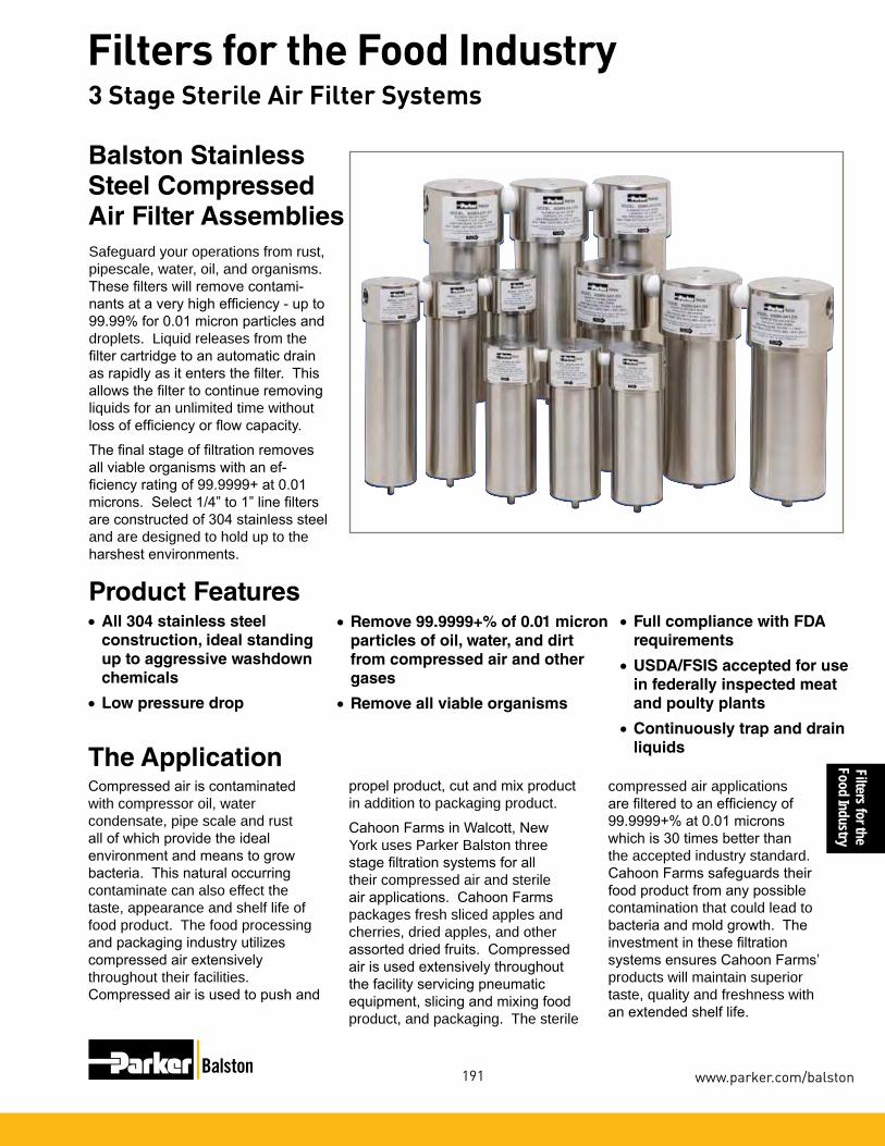
Filters for theFood Industry
191
Filters for the Food Industry
www.parker.com/balston
3 Stage Sterile Air Filter Systems
•All 304 stainless steel construction, ideal standing up to aggressive washdown chemicals
•Low pressure drop
Balston Stainless Steel Compressed Air Filter Assemblies
Product Features
Safeguard your operations from rust, pipescale, water, oil, and organisms. These filters will remove contami-nants at a very high efficiency - up to 99.99% for 0.01 micron particles and droplets. Liquid releases from the filter cartridge to an automatic drain as rapidly as it enters the filter. This allows the filter to continue removing liquids for an unlimited time without loss of efficiency or flow capacity.
The final stage of filtration removes all viable organisms with an ef-ficiency rating of 99.9999+ at 0.01 microns. Select 1/4” to 1” line filters are constructed of 304 stainless steel and are designed to hold up to the harshest environments.
•Remove 99.9999+% of 0.01 micron particles of oil, water, and dirt from compressed air and other gases
•Remove all viable organisms
The ApplicationCompressed air is contaminated with compressor oil, water condensate, pipe scale and rust all of which provide the ideal environment and means to grow bacteria. This natural occurring contaminate can also effect the taste, appearance and shelf life of food product. The food processing and packaging industry utilizes compressed air extensively throughout their facilities. Compressed air is used to push and
propel product, cut and mix product in addition to packaging product.
Cahoon Farms in Walcott, New York uses Parker Balston three stage filtration systems for all their compressed air and sterile air applications. Cahoon Farms packages fresh sliced apples and cherries, dried apples, and other assorted dried fruits. Compressed air is used extensively throughout the facility servicing pneumatic equipment, slicing and mixing food product, and packaging. The sterile
compressed air applications are filtered to an efficiency of 99.9999+% at 0.01 microns which is 30 times better than the accepted industry standard. Cahoon Farms safeguards their food product from any possible contamination that could lead to bacteria and mold growth. The investment in these filtration systems ensures Cahoon Farms’ products will maintain superior taste, quality and freshness with an extended shelf life.
•Full compliance with FDA requirements
•USDA/FSIS accepted for use in federally inspected meat and poulty plants
•Continuously trap and drain liquids

Filte
rs fo
r the
Food
Indu
stry
192
Filters for the Food Industry
1-800-343-4048
3 Stage Sterile Air Filter Systems
Steam Sterilization ProcedureIn installations where the sterile air filter requires steam sterilization, we recommend the following procedures:
The steam sterilization pressure should not exceed 60 psig (4.1 barg). Preferably, it should be held to 40 psig (2.8 barg) or less. A typical sterilization cycle is 30 psig (2.1 barg) steam for 30 minutes. Steaming time can be increased as desired without harm to the filter cartridges. The steam flow should not exceed the normal air flow for the unit. To ensure no buildup of condensate in the housing, condensate should be drained from the filter by a condensate drain valve during the steaming process. The cleanliness of the steam is an important factor influencing the life of the sterile air filter cartridges. Parker strongly recom-mends using model 23 steam filters to ensure optimum operating life. When autoclaving, the grade SA filter cartridges will tolerate temperatures to 300°F (149°C) in dry gas. Viton or other heat resistant seals should be used in the housing.
Sterile Air Filter Rating InformationBalston grade SA filter cartridges, rated at 99.9999+% efficiency for 0.01 micron particles, is at least 30 times better than the accepted standard for sterile air filters developed by independent research organizations in the U.S. and U.K. (request bulletin TI-105 for a detailed dis-cussion on Balston filter efficeincy rating procedure, and Bulletin TI-935 for an independent test report on Balston Sterile Air Filters). Balston Sterile Air Filters are in full compliance with the requirements of the FDA.
Complete removal of trace quantities of oil, water, and dirt down to 0.01 microns.
Removal of large quantities of oil, water, and dirt from compressed air. Prefilter to Grade BX
1st Stage:Grade DX
Explanation for 3 Stage Sterile Air System
3rd Stage:Grade SA
2nd Stage:Grade BX
Removal of bacteria providing sterile air.
Flow Rates Filter Housing Port Filter Flow rates SCFM (Nm3/hr), at 7 psi (0.48 bar) drop at indicated line pressure. Refer to PrincipalModel Size Cartridge Specification Charts in each product data sheet for maximum pressure rating of each housing Grade PSIG 2 20 40 80 100 125 150 200 250
3B-6002N-0A1 1/4” DX 9 (15) 19 (32) 39 (66) 51 (87) 63 (107) 76 (129) 90 (153) 117 (199) 145 (246)3B-6904N-0A1 1/2" BX 3 (5) 8 (14) 11 (19) 21 (36) 25 (42) 31 (53) 36 (61) 47 (80) 58 (99) SA --- 8 (14) 11 (19) 21 (36) 25 (42) 31 (53) 36 (61) --- ---
3B-6004N-0A1 1/2” DX 19 (32) 41 (70) 65 (110) 113 (192) 137 (233) 166 (282) 196 (333) 257 (437) 316 (537) BX 9 (15) 19 (32) 30 (51) 51 (87) 63 (107) 76 (129) 90 (153) 117 (199) 145 (246) SA --- 19 (32) 30 (51) 51 (87) 63 (107) 76 (129) 90 (153) --- ---
3B-6006N-0A1 3/4” DX 37 (63) 78 (133) 123 (209) 214 (364) 259 (440) 315 (535) 371 (630) 484 (822) 596 (1013) BX 10 (17) 21 (36) 34 (58) 56 (95) 70 (119) 85 (144) 101 (172) 131 (223) 162 (275) SA --- 21 (36) 34 (58) 56 (95) 70 (119) 85 (144) 101 (172) --- ---
3B-6008N-0A1 1” DX 55 (93) 115 (195) 181 (308) 314 (533) 380 (646) 463 (787) 546 (928) 711 (1208) 877 (1490) BX 11 (19) 23 (39) 37 (63) 64 (109) 77 (131) 94 (160) 111 (189) 144 (245) 178 (302) SA --- 23 (39) 37 (63) 64 (109) 77 (131) 94 (160) 111 (189) --- ---

Filters for theFood Industry
193
Filters for the Food Industry
www.parker.com/balston
Model 3B-6002 3B-6904 3B-6004 3B-6006 3B-6008
Port Size 1/4” NPT 1/2” NPT 1/2” NPT 3/4” NPT 1” NPTMaterials of Construction Head 304 Stainless Steel Bowl 304 Stainless Steel Internals Stainless Steel Seals Buna-N Food Grade Maximum Temperature (1) 120°F (49°C) Maximum Pressure (2) 175 psig (12 barg) Minimum Pressure (3) 15 psig (1 barg) Shipping Weight 10.5 lbs. (4.77 kg) 10.5 lbs. (4.77 kg) 11.8 lbs. (5.4 kg) 33.7 lbs. (15.3 kg) 34 lbs. (15.5 kg)Dimensions 9”W X 3"D X 8”L 9”W X 3"D X 8”L 9”W X 3"D X 8”L 13”W X 4"D X 11”L 13”W X 4"D X 12”L
Principal Specifications
Notes:1 Max. temperature with auto drain Max. tem-perature with manual drain is 275°F (135°C).
2 Max. pressure with auto drain. Max. pres-sure with manual drain is 250 psi (17 bar).
3 Required for proper operation of auto drain.
3 Stage Sterile Air Filter Systems
Ordering Information For assistance, call toll-free at 1-800-343-4048 8AM to 5PM Eastern Time
Assembly Ordering Information Model P/N Mounting Bracket (stainless steel) Replacement Cartridge Mounting Bracket (stainless steel) (4) Box of 5 Box of 103B-6002N-0A1 1/4" 3-Stage (DX, BX, SA) Stainless Filter Assembly 5/100-12-DX 100-12-DX C01-0094 5/100-12-BX 100-12-BX 5/100-12-SA 100-12-SA
3B-6904N-0A1 1/2" 3-Stage (DX, BX, SA) Stainless Filter Assembly 5/100-12-DX 100-12-DX C01-0094 5/100-12-BX 100-12-BX 5/100-12-SA 100-12-SA
3B-6004N-0A1 1/2" 3-Stage (DX, BX, SA) Stainless Filter Assembly 5/100-18-DX 100-18-DX C01-0094 5/100-18-BX 100-18-BX 5/100-18-SA 100-18-SA
3B-6006N-0A1 3/4" 3-Stage (DX, BX, SA) Stainless Filter Assembly 5/200-176-DX 200-176-DX C01-0094 5/200-176-BX 200-176-BX 5/200-176-SA 200-176-SA
3B-6008N-0A1 1" 3-Stage (DX, BX, SA) Stainless Filter Assembly 5/200-185-DX 200-185-DX C01-0094 5/200-185-BX 200-185-BX 5/200-185-SA 200-185-SA
4 Two each of mounting brackets are required for adequate support.
3B-6002N-0A13B-6904N-0A1
3B-6004N-0A1 3B-6006N-0A1 3B-6008N-0A1
9" (23 cm)
8" (20 cm)
8" (20 cm)
11" (28 cm)
12" (31 cm)
9" (23 cm)
13" (33 cm)
13" (33 cm)

Filte
rs fo
r the
Food
Indu
stry
194
Filters for the Food Industry
1-800-343-4048
Remove all viable organisms
USDA/FSIS accepted for use in federally inspected Meat and Poultry plants
Low pressure drop
Full compliance with FDA requirements
Balston® Sterile Air FiltersBalston grade SA filter cartridges, rated at 99.9999+% efficiency for 0.01 micron particles, is at least 30 times better than the accepted standard for sterile air filters developed by independent research organizations in the U.S. and U.K. (request Bulletin TI-105 for a detailed discussion on Balston filter efficiency rating procedure, and Bulletin TI-935 for an independent test report on Balston Sterile Air Filters). Balston Sterile Air Filters are in full compliance with the requirements of the FDA.
Here’s what one of your colleagues found:
A Balston sterile air filter assembly, consisting of Models 200X Series, was tested at the University of Massachu-setts, Department of Food Science and Nutrition, under the direction of Professor David A. Evans, Ph.D.
“This sterile air system produced commercially sterile air and, to the limits of detection, no viable colonies of microorganisms were found”.
- Professor David A. Evans, Ph.D.
Model 200X Series Model 2104 Series
Model A15/80
Model 2312Model 2206, 2208
8.5”(22 cm)
t
3.3”(8.4 cm)
t
t
3.3”(8.4 cm)
t
t
t
11.3”(29 cm)
t
t
t
t
t
t
28”(71 cm)
6.3”(16 cm)
t
t
t
t
Sterile Air Filters
4”(10 cm)
t
t
5”(13 cm)
t
t
13”(33 cm)
17”(43 cm)

Filters for theFood Industry
195
Filters for the Food Industry
www.parker.com/balston
For removal of large quantities of oil, water, and dirt from com-pressed air. Prefilter to Grade BX.
1st Stage:Grade DX
Balston Filter Cartridge and Housing Selection
Balston provides two grades of coalescing filter car-tridges, Grade DX and Grade BX. Singly or in tandem, these filters satisfy all requirements for removing liquid and solid contaminants from compressed air. These filters are recommended as prefilters in sterile air sys-tems. The Balston Grade SA filter removes bacteria from compressed air. It is the final filter in a sterile air system.
Temperature Range -150°F to 300°F (-100°C - 149°C)
Maximum Pressure 100 psi (6.9 bar), 60 psi (4 bar) for Grade SA Filter Differential Across Filter, TubesInside-to-Outside Flow: Materials of Construction Borosilicate glass microfibers with fluorocarbon resin binder. Resistant to water, all hydrocarbon and synthetic lubricants.
Physical Properties, Microfibre Filter Cartridges
Retention Efficiency
Grade Efficiency for 0.01 Micron Particles and Droplets DX 93% @ 0.01 µm
BX 99.99% @ 0.01 µm
SA 99.9999+% @ 0.01 µm
3rd Stage:Grade SA
2nd Stage:Grade BX
1 Build your own custom filter assembly using the guideline matrix to the left and specify your model number. Example: 1/2" filter with DPI and Auto Drain with Grade DX Filter = 2104N-1B1-DX.
2 Each assembly is shipped with the filter cartridge installed. To order additional filter cartridges, indicate the model number of the cartridges, and the grade. Examples 100-12-DX, 100-12-BX, or 100-12-SA, etc.
How to Select the Filter Cartridge and Housing
How to Order the Filter Assembly
For complete removal of trace quantities of oil, water, and dirt.
For removal of bacteria when providing sterile air.
NNPT Thread Inlet & Outlet Ports
0A0No DPIDrain Plugged1B1DPIAuto Drain1B2DPIManual Drain
Filter Grade000SADXBXLeave blank for no filterCartridge
2002 1/4" Ports2003 3/8" Ports2004 1/2" Ports2104 1/2" Ports22063/4" Ports22081" Ports23121-1/2" Ports
NNPT Thread Inlet & Outlet PortsGBSPP Thread Inlet & Outlet Ports
Filter Cartridge Description
1 Decide which grade(s) of filter cartridges fits the application (see selection boxes at left).
2 Select the filter housing with a port size equal to the line size where the filter is to be located.
3 For a new installation in which the line size has yet to be selected, determine the gas flow rate and pressure at the point where the filter will be located, and then refer to the flow chart on the reverse side of this data sheet. The filter port size must be equal to or larger than the line size (when specified).
4 If the sterile air filter assembly requires steam sterilization, stainless steel filter assemblies specifi-cally designed for in-line steam sterilization must be used. These assemblies are identified by the RED print in the flow chart on the next page.
Sterile Air Filters
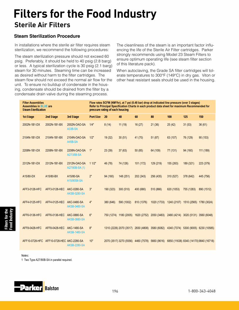
Filte
rs fo
r the
Food
Indu
stry
196
Filters for the Food Industry
1-800-343-4048
Filter Assemblies Flow rates SCFM (NM3/hr), at 7 psi (0.48 bar) drop at indicated line pressure (over 3 stages) Assemblies in BLUE are Refer to Principal Specification Charts in each product data sheet for maximum Recommended forSteam Sterilization pressure rating of each housing
1st Stage 2nd Stage 3rd Stage Port Size 20 40 60 80 100 125 150 2002N-1B1-DX 2002N-1B1-BX 2002N-OAO-SA 1/4" 8 (14) 11 (19) 16 (27) 21 (36) 25 (42) 31 (53) 36 (61) A33B-SA
2104N-1B1-DX 2104N-1B1-BX 2104N-OAO-SA 1/2" 19 (32) 30 (51) 41 (70) 51 (87) 63 (107) 76 (129) 90 (153) A45B-SA
2208N-1B1-DX 2208N-1B1-BX 2208N-OAO-SA 1" 23 (39) 37 (63) 50 (85) 64 (109) 77 (131) 94 (160) 111 (189) A27/35B-SA
2312N-1B1-DX 2312N-1B1-BX 2312N-OAO-SA 1 1/2" 46 (78) 74 (126) 101 (172) 129 (219) 155 (263) 189 (321) 223 (379) A27/80B-SA (1)
A15/80-DX A15/80-BX A15/80-SA 2" 94 (160) 148 (251) 202 (343) 256 (435) 310 (527) 378 (642) 445 (756) A15/80S6-SA
AFF3-0128-HFC AFF3-0128-HEC AKC-0280-SA 3" 190 (323) 300 (510) 400 (680) 510 (866) 620 (1053) 755 (1283) 890 (1512) AKSB-0280-SA
AFF4-0125-HFC AFF4-0125-HEC AKC-0480-SA 4" 380 (646) 590 (1002) 810 (1376) 1020 (1733) 1240 (2107) 1510 (2565) 1780 (3024) AKSB-0480-SA
AFF6-0136-HFC AFF6-0136-HEC AKC-0880-SA 6" 750 (1274) 1180 (2005) 1620 (2752) 2050 (3483) 2480 (4214) 3020 (5131) 3560 (6048) AKSB-0880-SA
AFF8-0428-HFC AFF8-0428-HEC AKC-1480-SA 8" 1310 (2226) 2070 (3517) 2830 (4808) 3580 (6082) 4340 (7374) 5300 (9005) 6230 (10585) AKSB-1480-SA
AFF10-0728-HFC AFF10-0728-HEC AKC-2280-SA 10" 2070 (3517) 3270 (5556) 4460 (7578) 5660 (9616) 6850 (11638) 8340 (14170) 9840 (16718) AKSB-2280-SA
Notes:1 Two Type A27/80B-SA in parallel required.
In installations where the sterile air filter requires steam sterilization, we recommend the following procedures:
The steam sterilization pressure should not exceed 60 psig. Preferably, it should be held to 40 psig (2.8 barg) or less. A typical sterilization cycle is 30 psig (2.1 barg)steam for 30 minutes. Steaming time can be increased as desired without harm to the filter cartridges. The steam flow should not exceed the normal air flow for the unit. To ensure no buildup of condensate in the hous-ing, condensate should be drained from the filter by a condensate drain valve during the steaming process.
Steam Sterilization Procedure
The cleanliness of the steam is an important factor influ-encing the life of the Sterile Air Filter cartridges. Parker strongly recommends using Model 23 Steam Filters to ensure optimum operating life (see steam filter section of this literature pack).
When autoclaving, the Grade SA filter cartridges will tol-erate temperatures to 300°F (149°C) in dry gas. Viton or other heat resistant seals should be used in the housing.
Sterile Air Filters
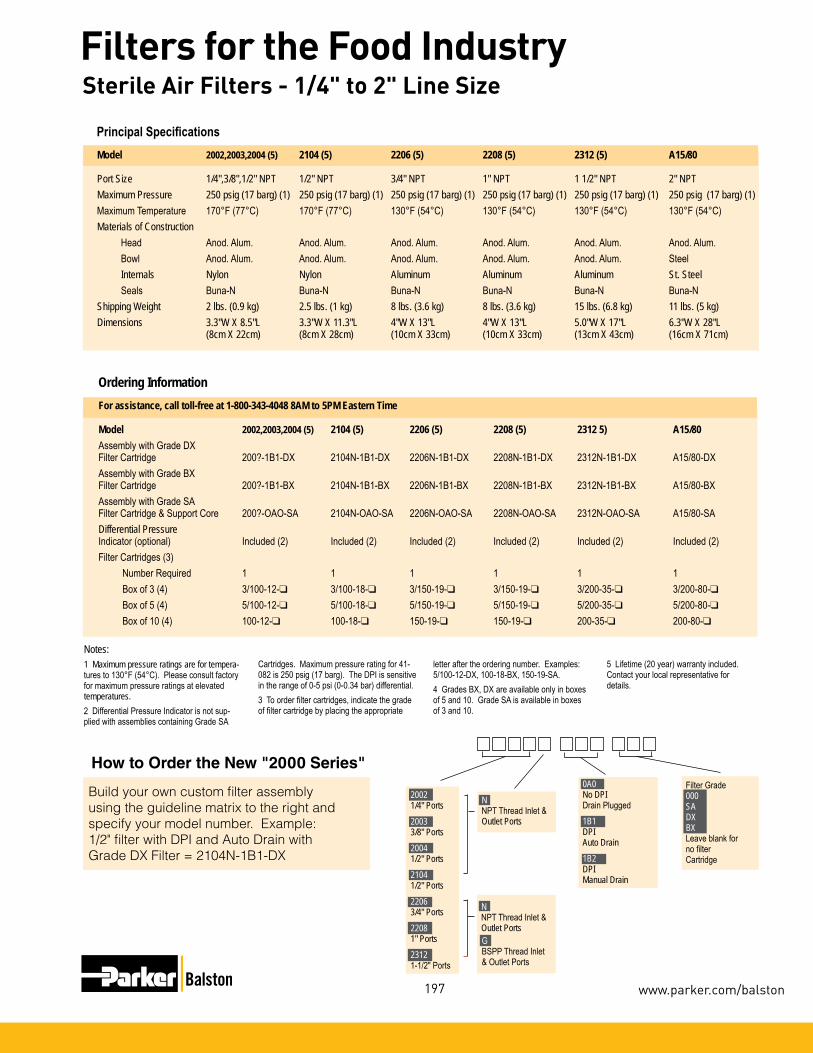
Filters for theFood Industry
197
Filters for the Food Industry
www.parker.com/balston
Model 2002,2003,2004 (5) 2104 (5) 2206 (5) 2208 (5) 2312 (5) A15/80
Port Size 1/4",3/8",1/2" NPT 1/2" NPT 3/4" NPT 1" NPT 1 1/2" NPT 2" NPTMaximum Pressure 250 psig (17 barg) (1) 250 psig (17 barg) (1) 250 psig (17 barg) (1) 250 psig (17 barg) (1) 250 psig (17 barg) (1) 250 psig (17 barg) (1) Maximum Temperature 170°F (77°C) 170°F (77°C) 130°F (54°C) 130°F (54°C) 130°F (54°C) 130°F (54°C)Materials of Construction Head Anod. Alum. Anod. Alum. Anod. Alum. Anod. Alum. Anod. Alum. Anod. Alum. Bowl Anod. Alum. Anod. Alum. Anod. Alum. Anod. Alum. Anod. Alum. Steel Internals Nylon Nylon Aluminum Aluminum Aluminum St. Steel Seals Buna-N Buna-N Buna-N Buna-N Buna-N Buna-NShipping Weight 2 lbs. (0.9 kg) 2.5 lbs. (1 kg) 8 lbs. (3.6 kg) 8 lbs. (3.6 kg) 15 lbs. (6.8 kg) 11 lbs. (5 kg)Dimensions 3.3"W X 8.5"L 3.3"W X 11.3"L 4"W X 13"L 4"W X 13"L 5.0"W X 17"L 6.3"W X 28"L (8cm X 22cm) (8cm X 28cm) (10cm X 33cm) (10cm X 33cm) (13cm X 43cm) (16cm X 71cm)
Principal Specifications
Notes:1 Maximum pressure ratings are for tempera-tures to 130°F (54°C). Please consult factory for maximum pressure ratings at elevated temperatures.2 Differential Pressure Indicator is not sup-plied with assemblies containing Grade SA
For assistance, call toll-free at 1-800-343-4048 8AM to 5PM Eastern Time
Model 2002,2003,2004 (5) 2104 (5) 2206 (5) 2208 (5) 2312 5) A15/80Assembly with Grade DXFilter Cartridge 200?-1B1-DX 2104N-1B1-DX 2206N-1B1-DX 2208N-1B1-DX 2312N-1B1-DX A15/80-DXAssembly with Grade BXFilter Cartridge 200?-1B1-BX 2104N-1B1-BX 2206N-1B1-BX 2208N-1B1-BX 2312N-1B1-BX A15/80-BXAssembly with Grade SAFilter Cartridge & Support Core 200?-OAO-SA 2104N-OAO-SA 2206N-OAO-SA 2208N-OAO-SA 2312N-OAO-SA A15/80-SADifferential PressureIndicator (optional) Included (2) Included (2) Included (2) Included (2) Included (2) Included (2)Filter Cartridges (3) Number Required 1 1 1 1 1 1 Box of 3 (4) 3/100-12-❑ 3/100-18-❑ 3/150-19-❑ 3/150-19-❑ 3/200-35-❑ 3/200-80-❑ Box of 5 (4) 5/100-12-❑ 5/100-18-❑ 5/150-19-❑ 5/150-19-❑ 5/200-35-❑ 5/200-80-❑ Box of 10 (4) 100-12-❑ 100-18-❑ 150-19-❑ 150-19-❑ 200-35-❑ 200-80-❑
Ordering Information
Cartridges. Maximum pressure rating for 41-082 is 250 psig (17 barg). The DPI is sensitive in the range of 0-5 psi (0-0.34 bar) differential.3 To order filter cartridges, indicate the grade of filter cartridge by placing the appropriate
letter after the ordering number. Examples: 5/100-12-DX, 100-18-BX, 150-19-SA. 4 Grades BX, DX are available only in boxes of 5 and 10. Grade SA is available in boxes of 3 and 10.
5 Lifetime (20 year) warranty included. Contact your local representative for details.
How to Order the New "2000 Series"
Build your own custom filter assembly using the guideline matrix to the right and specify your model number. Example: 1/2" filter with DPI and Auto Drain with Grade DX Filter = 2104N-1B1-DX
NNPT Thread Inlet & Outlet Ports
0A0No DPIDrain Plugged1B1DPIAuto Drain1B2DPIManual Drain
Filter Grade000SADXBXLeave blank for no filterCartridge
2002 1/4" Ports2003 3/8" Ports2004 1/2" Ports2104 1/2" Ports22063/4" Ports22081" Ports23121-1/2" Ports
NNPT Thread Inlet & Outlet PortsGBSPP Thread Inlet & Outlet Ports
Sterile Air Filters - 1/4" to 2" Line Size

Filte
rs fo
r the
Food
Indu
stry
198 1-800-343-4048
Filters for the Food Industry3” to 10” Line Size FiltersNew LF/FF Series Multiple Cartridge Filter Assemblies These filter assemblies provide high efficiency filtration of compressed air and other compressed gases at very high flow rates. With inlet and outlet ports accommodating 3” to 10” pipe sizes, the new LF/FF Series hous-ings are capable of flow rates up to a maximum capacity of 37,350 SCFM (63,458 m3/h) at 100 psig (6.9 barg). The standard carbon steel units, which are generally in stock (through 6” line sizes), have pressure ratings up to 250 psig (17.2 barg). All LF/FF series housings are ASME Code Stamped for the rated maxi-mum operating pressure. All FF Series vessels have built-in legs for floor mounting. Selected models have swing bolt enclosures for easy access to the internals. The filter cartridges in all models are sealed by tighten-ing the threaded retainer cap onto the rigid tie rod, ensuring a leak tight seal on both ends of the cartridge. Each assembly is equipped with a carbon steel automatic float drain, dif-ferential pressure indicator, and a set of filter cartridges (except where noted).
Low Pressure DropLower Change out/Labor CostsLower Energy CostsHigh Dirt Holding Capacity
BenefitsHeat and Chemical ResistantNo Wet ZoneOleophobic/HydrophobicHigh Burst Strength
Calculation with Part-Load Operation (100 hp compressor)
Annual Electricity Costs = [(Motor full-load brake horsepower) x (0.746 kW/hp) x (Annual Hours of Operation) x (Electricity Cost in $/kWh)] x [(Percent of time running fully loaded) + (0.30) x (Percent of time running unloaded)]For example: Full load motor efficiency = 90%Motor full load bhp = 100 hpAnnual hours of operation = 8,760 hours (3-shift, continuous operation)Runs 65% of the time fully loaded, 35% of the time unloadedUnloaded operation consumes 30 percent of the electricity of fully loaded operationCost of electricity = $0.10/kWhAnnual electricity costs =[(100 hp) x (0.746 hp/kW) x (8,760 hrs) x $0.10/kWh) / 0.9] x [0.65 + (0.30) x (0.35)] = $54,272.00

Filters for theFood Industry
199
Filters for the Food Industry
www.parker.com/balston
HFC Savings Annual electricity costs to operate a 100 HP Compressor can be as high as $50,000. Pressure loss in the sys-tem adds to this expense. For a system operating at 100 psig (7 barg) that loses 2 psig (0.14 barg) of pressure through a filter, requires an additional 1% in operating energy costs (1). Installing a single stage HFC Filter in place of a standard brand X filter, will reduce the pressure drop by 2+ psi (0.14 barg).Based on a standard 100 HP (74.6 kW) compressor operating at a 65% load cycle, a 1% reduction in annual operating costs would be equal to $542.00
3” to 10” Line Size Filters
High Efficiency Coalescing MediaHEC Grade
Efficiency: 99.97% @ 0.01 micron
Air Flow: Inside to Outside
This coalescing element is composed of an epoxy saturated borosilicate glass micro-fiber tube. The HEC grade filter has a pleated cellulose inner layer as a built-in prefilter. This element is metal retained for added strength, and includes a synthetic fabric layer.
HEC filters are used when “total removal of liquid aerosols and suspended fines” is required. Because of its overall performance characteristics, this grade is most often recommended.
The HEC element is great prefilter protection for desiccant air dryers. This element prevents oil or varnish from coating the desiccant, while maintaining the dryer efficiency.
NEW!High Flow Coalescing Filter Media
HFC Grade Efficiency: 99.5% @ 0.5 micron
Balston’s HFC media consists of two layers. The outer layer features a dense matrix of glass fibers. It provides highly efficient coalescing aerosol removal and very low pressure drop. The inner layer, or initial stage of filtration, effectively traps dirt particles, protecting and extending the life of the outer layer. A metal retainer is used for strength and stability. This media is used in bulk coalesc-ing applications and when relatively high efficiency and low pressure drop are required.
(1) Compressed Air Challenge, Doc # F9-1, April, 1998-Rev.0.
HFC MEDIA Max. Rated Flows (SCFM) at Various Operating Pressures(0.25 psi pressure drop)
Model Number 2 psig 20 psig 40 psig 80 psig 100 psig 125psig 150 psig 175 psig 200 psig 220 psig 250 psig AFF3-0128-HFC 363 753 1187 2056 2490 3033 3575 4118 4661 5095 5746 AFF4-0125-HFC 483 1004 1583 2741 3320 4044 4767 5491 6215 6793 N/A AFF6-0136-HFC 725 1507 2375 4112 4980 6065 7151 8236 9322 10190 11493 AFF6-0328-HFC 1088 2260 3562 6167 7470 9098 10726 12354 13983 15285 N/A AFF8-0428-HFC 1450 3013 4750 8223 9960 12131 14302 16472 18644 20380 22984 AFF10-0728-HFC 2538 5273 8312 14391 17430 21229 25028 28826 32627 35665 40222 AFF12-1128-HFC 3988 8286 13062 22614 27390 33360 39330 45298 51271 56045 63206 AFF16-1528-HFC 5438 11299 17812 30837 37350 45491 53632 61770 69915 76425 86190
HEC MEDIA Max. Rated Flows (SCFM) at Various Operating Pressures(1.5 psi pressure drop)
Model Number 2 psig 20 psig 40 psig 80 psig 100 psig 125 psig 150 psig 175 psig 200 psig 220 psig 250 psig AFF3-0128-HEC 218 454 715 1238 1500 1827 2154 2481 2808 3069 3462 AFF4-0125-HEC 291 605 954 1651 2000 2436 2872 3308 3744 4092 N/A AFF6-0136-HEC 437 908 1431 2477 3000 3654 4308 4962 5616 6139 6923 AFF6-0328-HEC 654 1362 2145 3714 4500 5481 6462 7443 8424 9207 N/A AFF8-0428-HEC 872 1816 2860 4952 6000 7308 8616 9924 11232 12276 13848 AFF10-0728-HEC 1526 3178 5005 8666 10500 12789 15078 17367 19656 21483 24234 AFF12-1128-HEC 2398 4994 7865 13618 16500 20097 23694 27291 30888 33759 38082 AFF16-1528-HEC 3270 6810 10725 18570 22500 27405 32310 37215 42120 46035 51930

Filte
rs fo
r the
Food
Indu
stry
200
Filters for the Food Industry
1-800-343-4048
Page 7
Remove all viable organisms
Full compliance with FDA requirements
High flow rates
USDA/FSIS accepted for use in federally inspected meat and poultry plants
Balston® Sterile Air FiltersBalston grade SA filter cartridges, rated at 99.9999+% efficiency for 0.1 micron particles, is at least 30 times better than the accepted standard for sterile air filters developed by independent research organizations in the U.S. and U.K. (request Bulletin TI-105 for a detailed discussion on Balston filter efficiency rating procedure, and Bulletin TI-935 for an independent test report on Balston Sterile Air Filters). Balston Sterile Air Filters are in full compliance with the requirements of the FDA.
Model AKC-0280
Model AKC-1480
Sterile Air Filters - 3" to 10" Line Size
Here’s what one of your colleagues found:
A Balston sterile air filter assembly, consisting of 1/4" Models of Grade DX, Grade BX, and Grade SA were tested at the University of Massachusetts, Department of Food Science and Nutrition, under the direction of Professor David A. Evans, Ph.D.
“This sterile air system produced commercially sterile air and, to the limits of detection, no viable colonies of microorganisms were found”.
- Professor David A. Evans, Ph.D

Filters for theFood Industry
201
Filters for the Food Industry
www.parker.com/balston
Model AKC-0280 AKC-0480 AKC-0880 AKC-1480 AKC-2280
Port Size 3" Flange 4" Flange 6" Flange 8" Flange 10" FlangeMaximum Pressure 250 psig (17 barg) (1) 250 psig (17 barg) (1) 200 psig (14 barg) (1) 200 psig (14 barg) (1) 200 psig (14 barg) (1)Maximum Temperature 230°F (110°C) (2) 230°F (110°C) (2) 250°F (110°C) (2) 250°F (110°C) (2) 250°F (110°C) (2)Materials of Construction Carbon steel vessel with 303 Stainless Steel filter tube holders and Buna N seals.Closure Type Flat flanged top with swing bolts and Buna N "O" rings. Shipping Weight 132 lbs. (60 kg) 210 lbs. (95 kg) 360 lbs. (163 kg) 590 lbs. (268 kg) 880 lbs. (400 kg)Dimensions 36"H X 16"W 36"H X 21"W 38"H X 25"W 54"H X 34"W 56"H X 36"W (91cm X 40cm) (91cm X 53cm) (97cm X 64cm) (137cm X 86cm) (142cm X 91cm) Flange Center Line to Floor Dimension 7.75" (20cm) 6.25" (11cm) 7.5" (19cm) 16.25" (41cm) 17.25" (44cm)
Principal Specifications
For assistance, call toll-free at 1-800-343-4048 8AM to 5PM Eastern Time
Model AKC-0280 AKC-0480 AKC-0880 AKC-1480 AKC-2280Assembly with Grade SAFilter Cartridge & Support Core AKC-0280-SA AKC-0480-SA AKC-0880-SA AKC-1480-SA AKC-2280-SA Filter Cartridges (4) Number Required 2 4 8 14 22 Box of 3 3/200-80-❑ 3/200-80-❑ 3/200-80-❑ 3/200-80-❑ 3/200-80-❑ Box of 5 5/200-80-❑ 5/200-80-❑ 5/200-80-❑ 5/200-80-❑ 5/200-80-❑ Box of 10 200-80-❑ 200-80-❑ 200-80-❑ 200-80-❑ 200-80-❑
Ordering Information (3)
Notes:1 Vessel is ASME Section VIII, Division 1 code stamped for rated pressure. All AKC series housings have CRN registration numbers as-signed in all Canadian provinces.2 Maximum operating temperature may be limited by seal material. Consult factory for recommendations at elevated temperatures.3 Filter assemblies are shipped complete with automatic drain, filter cartridges, and differential pressure indicator.Automatic DrainThe maximum operating pressure for the
Model 20-211 Automatic Drain is 400 psig (28 barg). Minimum operating pressure is 10 psig (0.7 barg).Differential Pressure IndicatorThe maximum operating pressure for the Differential Pressure Indicator Model 41-071 is 250 psig (14 barg). The DPI is sensitive in the range of 0-5 psi (0-0.3 bar). The Automatic Drain and Differential Pressure Indicator are not included with assemblies containing SA cartridges.
4 To order filter cartridges, indicate the grade of filter cartridge by placing the appropriate letter after the ordering number. Examples: 5/100-12-SA, 100-18-SA, 150-19-SA.
Sterile Air Filters - 3" to 10" Line Size

Filte
rs fo
r the
Food
Indu
stry
202
Filters for the Food Industry
1-800-343-4048
Remove all viable organisms
In-line steam sterilization
Low pressure drop
Full compliance with FDA requirements
USDA/FSIS accepted for use in federally inspected meat and poultry plants
Balston® Sterile Air FiltersBalston grade SA filter cartridges, rated at 99.9999+% efficiency for 0.1 micron particles, is at least 30 times better than the accepted standard for sterile air filters developed by independent research organizations in the U.S. and U.K. (request Bulletin TI-105 for a detailed discussion on Balston filter efficiency rating procedure, and Bulletin TI-935 for an independent test report on Balston Sterile Air Filters). Balston Sterile Air Filters are in full compliance with the requirements of the FDA.
Model A33B-SA
Model A45B-SA
Model A27/35B-SA, A27/80B-SA
Here’s what one of your colleagues found:
A Balston sterile air filter assembly, consisting of 1/4" Models of Grade DX, Grade BX, and Grade SA were tested at the University of Massachusetts, Department of Food Science and Nutrition, under the direction of Professor David A. Evans, Ph.D.
“This sterile air system produced commercially sterile air and, to the limits of detection, no viable colonies of microorganisms were found”.
- Professor David A. Evans, Ph.D
Steam Sterilizable Sterile Air Filters - 1/4" to 1" Line Size

Filters for theFood Industry
203
Filters for the Food Industry
www.parker.com/balston
Model A33B A45B A27/35B A27/80B
Inlet and Outlet Ports 1/4" NPT 1/2" NPT 1" NPT 1" NPTDrain Port 1/8" NPT (1) 1/8" NPT (1) 1/4" NPT (1) 1/4" NPT (1)Materials of Construction Head 316SS 316SS 316SS 316SS Bowl 316SS 316SS 316SS 316SS Internals 316SS 316SS 316SS 316SS Seals Viton (2) Viton (2) Viton (2) Viton (2)Maximum Temperature 400°F (204°C) 400°F (204°C) 400°F (204°C) 400°F (204°C)Maximum Pressure 425 psig (29 barg) (3) 250 psig (17 barg) (3) 800 psig (55 barg) (3) 800 psig (55 barg) (3)Maximum Steam Pressurefor Sterilization 60 psig (4 barg) 60 psig (4 barg) 60 psig (4 barg) 60 psig (4 barg)Shipping Weight 3 lbs. (1 kg) 5 lbs. (2 kg) 16 lbs. (7 kg) 20 lbs. (9 kg)Dimensions 2.6"Dia X 4.9"L 2.6"Dia. X 8.4"L 4.0"Dia. X 16"L 4.0"Dia. X 27"L (7cm X 12cm) (7cm X 21cm) (10cm X 40cm) (10cm X 69cm)
Principal Specifications
Notes:1 Condensate drain valve required. Supplied by customer.2 Constructed of food grade Viton.3 Maximum pressure ratings are for temperatures to 130°F (54°C). Please consult factory for maximum pressure rat-ings at elevated temperatures.
For assistance, call toll-free at 1-800-343-4048 8AM to 5PM Eastern Time
Model A33B A45B A27/35B A27/80BAssembly with Grade SA Filter Cartridge A33B-SA A45B-SA A27/35B-SA A27/80B-SAFilter Cartridges:
Number Required 1 1 1 1Box of 3 3/100-12-SA 3/100-25-SA 3/200-35-SA 3/200-80-SABox of 10 100-12-SA 100-25-SA 200-35-SA 200-80-SA
Ordering Information
Steam Sterilizable Sterile Air Filters - 1/4" to 1" Line Size

Filte
rs fo
r the
Food
Indu
stry
204
Filters for the Food Industry
1-800-343-4048
For the Food and Dairy Industry
Remove all viable organisms
In-line steam sterilization
High flow rates
Full compliance with FDA requirements
USDA/FSIS accepted for use in federally inspected meat and poultry plants
Model AKSB-0280-3-SA
Model AKSB-1480-SA
Steam Sterilizable Sterile Air Filters - 2" to 10" Line Size
Balston® Sterile Air FiltersBalston grade SA filter cartridges, rated at 99.9999+% efficiency for 0.01 micron particles, is at least 30 times better than the accepted standard for sterile air filters developed by independent research organizations in the U.S. and U.K. (request Bulletin TI-105 for a detailed discussion on Balston filter efficiency rating procedure, and Bulletin TI-935 for an independent test report on Balston Sterile Air Filters). Balston Sterile Air Filters are in full compliance with the requirements of the FDA.
Here’s what one of your colleagues found:
A Balston sterile air filter assembly, consisting of 1/4" Models of Grade DX, Grade BX, and Grade SA were tested at the University of Massachusetts, Department of Food Science and Nutrition, under the direction of Professor David A. Evans, Ph.D.
“This sterile air system produced commercially sterile air and, to the limits of detection, no viable colonies of microorganisms were found”.
- Professor David A. Evans, Ph.D

Filters for theFood Industry
205
Filters for the Food Industry
www.parker.com/balston
For the Food and Dairy Industry
Model AKSB-0280-2-SA AKSB-0280-SA AKSB-0480-SA AKSB-0880-SA AKSB-1480-SA AKSB-2280-SA
Port Size 2" Flange 3" Flange 4" Flange 6" Flange 8" Flange 10" FlangeMaterials of Construction 316SS 316SS 316SS 316SS 316SS 316SSSeals Viton (1) Viton (1) Viton (1) Viton (1) Viton (1) Viton (1)Maximum Pressure 200 psig (14 barg) (2) 200 psig (14 barg) (2) 200 psig (14 barg) (2) 200 psig (14 barg) (2) 200 psig (14 barg) (2) 200 psig (14 barg) (2)Maximum Temperature 200°F (93°C) 200°F (93°C) 200°F (93°C) 200°F (93°C) 200°F (93°C) 200°F (93°C) Maximum Steam Pressurefor Sterilization 60 psig (4 barg) 60 psig (4 barg) 60 psig (4 barg) 60 psig (4 barg) 60 psig (4 barg) 60 psig (4 barg)Shipping Weight 140 lbs. (64 kg) 140 lbs. (64 kg) 210 lbs. (95 kg) 360 lbs. (163 kg) 590 lbs. (268 kg) 880 lbs. (400 kg)Dimensions 16"W X 36"L 16"W X 36"L 20"W X 36"L 25"W X 38"L 34"W X 54"L 36"W X 56"L (41cm X 91cm) (41cm X 91cm) (53cm X 91cm) (64cm X 97cm) (86cm X 137cm) (91cm X 142cm)
Principal Specifications
Notes:1 Constructed of food grade Viton.2 Vessel is ASME Section VIII Division 1 Code stamped for rated pressure.
For assistance, call toll-free at 1-800-343-4048 8AM to 5PM Eastern Time
Model AKSB-0280-2 AKSB-0280-3 AKSB-0480 AKSB-0880 AKSB-1480 AKSB-2280
Assembly with Grade SAFilter Cartridge AKSB-0280-2-SA AKSB-0280-SA AKSB-0480-SA AKSB-0880-SA AKSB-1480-SA AKSB-0280-SAFilter Cartridges:
Box of 3 3/200-80-SA 3/200-80-SA 3/200-80-SA 3/200-80-SA 3/200-80-SA 3/200-80-SABox of 10 200-80-SA 200-80-SA 200-80-SA 200-80-SA 200-80-SA 200-80-SANumber per housing 2 2 4 8 14 22
Ordering Information
Steam Sterilizable Sterile Air Filters - 2" to 10" Line Size

Filte
rs fo
r the
Food
Indu
stry
206
Filters for the Food Industry
1-800-343-4048
Cabinet Dryers for Wash Down Areas
Product Features:•Designed specifically for wash down areas
•Protects electrical cabinet components from damage caused by water and high humidity
•Minimizes pools of water inside cabinets
•Positive pressure keeps dust out
•Adds no heat to the cabinet
•Reduces cabinet humidity to less than 10% RH
•Requires no electricity, low operating costs
•Easy to install and maintain
•Quiet operation
•Protect motors, touch screens, drives and other critical components
Balston CD Series Cabinet DryersYou demand a lot from your electrical cabinets and motors. They are subject to nightly high pressure, hot wash downs and then expected to remain dry in a refrigerated area. Over time most cabinets develop moisture inside which leads to premature com-ponent failures. This interrupts production and costs you money. Expensive vortex coolers or heaters don’t work. Vortex coolers use a considerable amount of air and have a high operating cost. Heat-ers simply raise the humidity of the air inside the cabinet and don’t eliminate the moisture.
The Parker Balston Cabinet Dryer serves to reduce the humidity inside the cabinet to less than 10% RH. Any water that infiltrates the cabinet evaporates quickly. Electrical components stay clean and dry which prolongs their life.
Avoid costly down time!Many plants struggle with moisture problems by managing downtime emergencies. Emergencies divert limited mainte-nance personnel and disrupt production at the cost of thou-sands of dollars per hour. The Cabinet Dryer reduces these maintenance and lost production costs by 80% or more. A typical customer will see savings of $10K - 15K per year. The Cabinet Dryer will operate continuously and reliably without operator attention thus freeing up valuable maintenance per-sonnel who are better devoted to important routine mainte-nance work rather than daily emergency response.
Do Your Cabinets Look Like This?
Water accumulation in electrical cabinet
Corrosion leads to premature component failure
A Cabinet Dryer will keep your cabinets looking as good as new
Eliminate Moisture Problems in Electrical Cabinets and Motors

Filters for theFood Industry
207
Filters for the Food Industry
www.parker.com/balston
Cabinet Dryers for Wash Down AreasEliminate Moisture Problems in Electrical Cabinets and Motors
Notes: 1 Delivered dewpoint is specified for saturated inlet air at 100°F (38°C) and 100 psig (6.9 BAR). 2 If the cabinet is not tightly sealed, consider upsizing to the next module size.3 Filtration efficiency: 99.99% at 0.01micron.4 For heavily contaminated air lines, install additional prefiltration.
Principal Specifications
Ordering Information For assistance call toll free at 800-343-4048, 8AM to 5PM EST
Model Number CD0005 CD0010 CD0030 Replacement Filter Elements 070-063-BX 070-063-BX 070-063-BXReplacement Auto Drain C02-2392 C02-2392 C02-2392
Model Number CD0005 CD0010 CD0030Cabinet Size Range (2) 0 - 4 FT3 4 - 12 FT3 12 - 36 FT3 (0 - 0.11m3) (0.11m3 - 0.34m3) (0.34m3 - 1m3)Min/Max Inlet Air Temp 40°F/120°F 40°F/120°F 40°F/120°F (4°C/49°C) (4°C/49°C) (4°C/49°C)Min/Max Ambient Air Temp 35°F/120°F 35°F/120°F 35°F/120°F (2°C/49°C) (2°C/49°C) (2°C/49°C)Air Consumption 0.6 SCFM (1 Nm3/hr) 1.25 SCFM (2 Nm3/hr) 3.5 SCFM (6 Nm3/hr) (17 slpm) (35.4 slpm) (99 slpm)Min/Max Air Pressure 60 psi/150 psi 60 psi/150 psi 60 psi/150 psi (4.1 BAR/10.3 BAR) (4.1 BAR/10.3 BAR) (4.1 BAR/10.3 BAR)Delivered Dew Point -7°F(-22°C) (1) -7°F(-22°C) (1) -7°F(-22°C) (1)Inlet Port Size 1/4” NPT 1/4” NPT 1/4” NPTOutlet Port Size 1/4” NPT 1/4” NPT 1/4” NPTElectrical Requirements None None NoneDimensions 3”w x 9.2”h x 2”d 3”w x 15.2”h x 2”d 4.6”w x 15.3”h x 2.9”d (7.6cm x 2.34cm x 5cm) (7.6cm x 38.6cm x 5cm) (11.7cm x 38.9cm x 7.4cm) Shipping Weight 1.5 lbs (0.68 kg) 2 lbs (0.9 kg) 2.5 lbs (1.1 kg)
CompressedAir In
Dry Purge Air Out
Here’s what our customers say:
“We tried heaters, fans and vortex coolers, our only solution was to use a Parker Balston dryer that continuously purges the cabinet with dry air.”
- Lee Clarkson Ross Industries
“I've been with Smithfield for 15 years and we've had issues with wet electrical cabinets for 15 years. We installed the cabinet dryer on our wettest cabi-net to see if it would work. Our Multivac™ packager was having significant issues. It was out of service 2-3 times per week due to condensation inside the cabinet. When we installed the dryer we noticed a difference right away. The water droplets on the walls of the cabinet were gone and our downtime from moisture was completely eliminated. It worked just like they told me.”
Maintenance ManagerLarge Meat Processing Plant

Filte
rs fo
r the
Food
Indu
stry
208
Filters for the Food Industry
1-800-343-4048
Application Notes
Moisture Sensitive Point of Use Areas

Filters for theFood Industry
209
Filters for the Food Industry
www.parker.com/balston
Main Ring Applications Process and Production EquipmentMoisture Sensitive Point of Use Areas
Balston offers both membrane and PSA technology. Balston Membrane Air Dryers combine superior co-alescing technology with a proven, innovative membrane system to sup-ply clean, dry compressed air with dewpoints as low as -40°F (-40°C).
Balston PSA Compressed Air Dryers will reduce the dewpoint of com-pressed air to -100°F (-73°C). Each dryer is delivered complete and ready for easy installation.
Product Features:• Unattended24houroperation
• Compact
• MembraneandPSAtechnolo-gies available
Balston Compressed Air Dryers
• Silentoperation
• Nodesiccanttochange
• Easytoinstallandoperate
Compressed Air Dryers

Com
pres
sed
Air D
ryer
s
210
Compressed Air Dryers
1-800-343-4048
Membrane Air Dryers
Membrane Air Dryers
Balston Membrane Air Dryers combine a superior coalescing technology with a proven, innovative mem-brane system to supply clean, dry compressed air with dewpoints as low as -40°F (-40°C). The Membrane Air Dryers are engineered for easy installation, operation, and long term reliability. The dryers incorporate high efficiency coalescing filtration and the highest efficiency membrane available to provide low cost operation and minimal maintenance.
Balston Membrane Air Dryers
Offer a reliable, efficient, and economi-cal alternative to pressure swing and refrigerant dryer technologies
Require no electricity thus lowering operating costs
Dewpoints as low as -40°F (-40°C) prevent freeze-ups
Explosion proof
Silent operation
No desiccant to change
Low dewpoint instrument airPneumatic equipmentPressurizing electroni cabinetsAnalytical instrumentationInstrument air for analyzer buildings
Applications
- “We have not had one shutdown due to freeze-ups since the Balston Membrane Dryer was installed.”
Peter VogtInternational Filler Corp.
Prevention of freeze-upsDry air for hazardous areasGeneral laboratory air supplyProtect electrical panel compo-nents from moisture damage
Membrane Air Dryers
State-of-the-Art Membrane Technology
Water vapor from the compressed air supply passes through the hollow fibers of the membrane. At the same time, a small portion of the dry air product is redirected along the length of the fibers to sweep out the water vapor laden air which has permeated the membrane. The moisture-laden sweep gas is then vented to the atmosphere, and clean, dry air is supplied to the application. The drying power of the membrane is controlled by varying the compressed air flow rate and pressure. The Balston Membrane Air Dryer is designed to operate continuously, 24 hours per day, 7 days per week. The only maintenance re-quired is changing the prefilter cartridge twice a year. This semi-annual maintenance takes approximately 5 minutes.

Compressed
Air Dryers
211
Compressed Air Dryers
www.parker.com/balston
Figure 1
Hollowmicrofibers
Figure 4
Figure 3
Figure 5
Figure 2
Phase I - Coalescing
Phase II - Air Drying
Captive ‘O’ Rings- less need for spares
Dual layer filter element- long life and high efficiency
Simple Construction -economical consumables
and kinder to theenvironment
Phase I - Coalescing FiltrationPrior to entering the membrane drying module, the compressed air passes through a high efficiency coalesc-ing filter to remove oil and water droplets and particulate contamination with an efficiency of 99.99% at 0.01 mi-cron. The liquids removed by the filter cartridge continu-ously drip from the filter cartridge into the bottom of the housing, where they are automatically emptied by an autodrain assembly (see Fig. 1 and Fig. 2). The air leav-ing the prefilter, therefore, is laden only with water vapor, which will be removed in the membrane module.
Phase II - Drying
The water vapor in the compressed air is removed by the principle of selective permeation through a mem-brane (see Fig. 3). The membrane module consists of bundles of hollow membrane fibers (see Fig. 4), each permeable only to water vapor. As the compressed air passes through the center of these fibers, water vapor permeates through the walls of the fiber, and dry air exits from the other end of the fiber. A small portion of the dry air (regeneration flow) is redirected along the length of the membrane fiber to carry away the moisture-laden air which surrounds the membrane fibers. The remainder of the dry air is piped to the application.
Membrane Air Dryer - Principle of Operation

Com
pres
sed
Air D
ryer
s
212
Compressed Air Dryers
1-800-343-4048
Product Specifications
Model 76-40Model 76-20Model 76-02Model 76-01
Flow Rates Outlet Flow in SCFM (Nm3/hr) at Indicated Operating Pressure for -40°F (-40°C) Atmospheric Dewpoint
Membrane ModuleRegeneration Flow Regeneration Flow in SCFM (Nm3/hr) at Indicated Operating Pressure and all dewpoints
Pressure Dewpoint 60 psig (4.1 barg) 80 psig (5.5 barg) 100 psig (6.9 barg) 120 psig (8.3 barg) 140 psig (7.7 barg) -40°F(-40°C) -40°F(-40°C) -40°F(-40°C) -40°F(-40°C) -40°F(-40°C)Model 76-01 .3 (0.5) .6 (1.0) 1 (1.7) 1.3 (2.2) 1.7 (2.9)
Model 76-02 .6 (1.0) 1 (1.7) 2 (3.4) 2.4 (4.1) 3.4 (5.8)
Model 76-10 3.0 (5.1) 5 (8.5) 10 (17) 13 (22) 17 (29)
Model 76-20 6.0 (10) 10 (17) 20 (34) 26 (44) 34 (58)
Model 76-40 12.0 (20) 20 (34) 40 (68) 52 (88) 68 (116)
Pressure Dewpoint 60 psig (4.1 barg) 80 psig (5.5 barg) 100 psig (6.9 barg) 120 psig (8.3 barg) 140 psig (7.7 barg)Model 76-01 .2 (.3) .2 (0.3) .3 (0.5) .3 (0.5) .3 (0.5)
Model 76-02 .34 (0.6) .4 (0.7) .5 (0.8) .6 (1.0) .7 (1.2)
Model 76-10 1.7 (2.9) 2.1 (3.6) 2.5 (4.2) 3 (5.1) 3.3 (5.6)
Model 76-20 3.4 (5.8) 4.2 (7.1) 5 (8.5) 6 (10) 6.6 (11)
Model 76-40 6.8 (12) 8.4 (14) 10 (17) 12 (20) 14 (24)
Model 76-10
Membrane Air Dryers for -40°F (-40°C) Dewpoint

Compressed
Air Dryers
213
Compressed Air Dryers
www.parker.com/balston
Notes:1 Dewpoint specified for saturated inlet air at 100°F (38°C) and 100 psig (6.9 barg). Outlet flows will vary slightly for other inlet conditions.
Ordering InformationDescription Model Number Balston Membrane Air Dryer 76-01 76-02 76-10 76-20 76-40 Replacement PrefilterCartridges 100-12-BX 100-12-BX 100-18-BX 150-19-BX 200-35-BX Optional Additional Coalescing Prefilter 2002N-1B1-DX 2002N-1B1-DX 2104N-1B1-DX 2208N-1B1-DX 2312N-1B1-DX Replacement Filter Cartridgesfor Optional Prefilter 100-12-DX 100-12-DX 100-18-DX 150-19-DX 200-35-DX Pressure Regulator (0-130 psig) 1/2” NPT Ports 72-130 72-130 72-130 ------- –––
For Assistance, call toll-free at 1-800-343-4048 8AM to 5PM Eastern Time
2 Inlet compressed air dewpoint must not exceed the ambient air temperature.3 5 psid (.34 bard) at -40°F (-40°C) dewpoint operating parameters.
Principal Specifications
Model 76-01 76-02 76-10 76-20 76-40
Nominal Flow Rate At -40°F (-40°C) Dewpoint 1 SCFM (1.7 Nm3/Hr)(1) 2 SCFM (3.4 Nm3/Hr)(1) 10 SCFM (1.7 Nm3/Hr)(1) 20 SCFM (3.4 Nm3/Hr)(1) 40 SCFM (6.8 Nm3/Hr)(1) Min/Max Inlet Air Temp. 40°F/120°F (4°C/49°C) (2) Ambient Temp. Range 40°F - 120°F (4°C - 49°C)Min/Max Inlet Pressure 60 psig (4.1 barg)/150 psig (10.3 barg)Compressed Air Requirement Total Air Consumption: Regeneration Flow + Outlet Flow Requirements (see tables on pg.166)Max. Pressure Drop 5 psid (.34 bard) (3) 5 psid ( .34 bard) (3) 5 psid (.34 bard) (3) 5 psid (.34 bard) (3) 5 psid (.34 bard) (3) Wall Mountable Yes Yes Yes Yes Yes Prefilter (included) Yes (4) Yes (4) Yes (4) Yes (4) Yes (4) Inlet/Outlet Port Size 1/4” NPT (female) 1/4” NPT (female) 1/2” NPT (female) 1” NPT (female) 1 1/2” NPT (female)/ 3/4” NPT (female) Electrical Requirements None None None None NoneDimensions 6”W x 22”H x 5”D 6”W x 23”H x 5”D 6”W x 37”H x 5”D 12”W x 37”H x 7”D 19”W x 39”H x 8”D (15cm x 58cm x 13cm) (15cm x 58cm x 13cm) (15cm x 94cm x 13cm) (30cm x 94cm x 18cm) (48cm x 99cm x 21cm) Shipping Weight 9 lbs. (4 kg) 10 lbs. (5 kg) 18 lbs. (9 kg) 20 lbs. (9 kg) 35 lbs. (16 kg)
▼▼
▼
4 If compressed air is extremely contaminated, a Balston Grade DX prefilter should be installed directly upstream from the membrane dryer.5 Filtration efficiency: 99.99% at 0.01 micron.
Membrane Air Dryers for -40°F (-40°C) Dewpoint

Com
pres
sed
Air D
ryer
s
214
Compressed Air Dryers
1-800-343-4048
Offer a reliable, efficient, and economical alternative to pressure swing and refrigerant dryer technologies
Require no electricity thus lowering operating costs
Produce +35°F (2°C) pressure dewpoint, ideal for critical points of use
Produce +15°F (-9°C) dewpoint in air sys-tems with existing refrigerated air dryers
No moving parts
Silent operation
No desiccant to change
IT Series Membrane Dryers
There are many variables that will affect the output specification of compressed air. By the time air reaches all its intended point of use, changes in pressure and temperature can contribute to potential contamination. As capital equipment tolerances become tighter and more sensitive to this contamination, maintenance costs will escalate if equipment is not adequately protected. In cases where standard air filtration is not sufficient or where the reliability, performance and operating cost of older dryer technologies is becoming more significant, a Balston Membrane Dryer provides a reliable and economical alternative.
IT Series Point of Use Membrane Dryers
Balston Membrane Air Dryers combine superior coalescing filtration technology with a proven, innovative membrane system to supply clean, dry, +35°F (2°C) pressure dewpoint compressed air. If the house compressed air is equipped with a refrigerated dryer, the dewpoint drops to +15°F (-9°C). The Balston Membrane Dryers are available in 8 different models which can deliver compressed air at flow rates up to 100 SCFM (170 NM3/Hr) .dewpoint. The systems are engineered for easy installation, operation, and long term reliability. By incorporating high efficien-cy coalescing filtration and the highest efficiency membrane available, the systems provide low cost operation with the lowest minimal maintenance.
Food processing and automation
Electronics/Dry Boxes
Coordinate Measure-ment Machines
Critical Pneumatic Valves
Protection of Pneumatic Instrumentation
Low Dewpoint Instrument Air
Pneumatic Equipment
Dry Air for Hazardous Areas
Applications Product Specifications
IT Series Membrane Air Dryers for +35°F (2°C) Dewpoint*
* If the house compressed air is equipped with a refrigerated dryer, the dewpoint drops to +15°F (-9°C).

Compressed
Air Dryers
215
Compressed Air Dryers
www.parker.com/balston
t
t
t
Flow Rates
Easy to Operate and Maintain
Installation consists of simply connecting a standard compressed air line to the inlet and connecting the outlet to your application. The unit is ready for trouble-free operation. This system is designed to operate 24 hours per day, 7 days per week.
Once the system is operating, it requires little monitoring. The only maintenance involves changing the coalescing prefilter cartridges periodically. The membrane module does not require any maintenance.
IT0030-35
18.1”(46cm)
10”(25cm) t
t
t
t
IT0080-35
24”(70cm)
11.1”(28cm) t
t
t
IT0500-35XX
39”(99cm)
21”(53cm) t
t
t
IT0150-35
25”(64cm)
16”(41cm) t
t
t
IT0250-35XX
26”(66cm)
18”(46cm) t
t
t
IT0010-35
17.5”(45cm)
8” (20cm)
t
t
t
t
IT Series Membrane Air Dryers for +35°F (2°C) Dewpoint*
* If the house compressed air is equipped with a refrigerated dryer, the outlet dewpoint drops to +15°F (-9°C). t
Model Number IT0010-35 IT0030-35 IT0080-35 IT0150-35 IT0250-3560 IT0250-3500 IT0500-3560 IT0500-3500 IT1000-3560 IT1000-3500
Flow @ 100 psig 1 (1.7) 3 (5.1) 8 (13.6) 15 (25.5) 25 (42.5) N/A 50 (85) N/A 100 (170) N/A Inlet Pressure, scfm (Nm3/Hr)
Flow @ 101-150 psig 1 (1.7) 3 (5.1) 8 (13.6) 15 (25.5) N/A 25 (42.5) N/A 50 (85) N/A 100 (170)Inlet Pressure, scfm (Nm3/Hr)
Regeneration Flow @ 0.25 (.42) 0.5 (.85) 1.5 (2.5) 2.7 (4.6) 4.5 (7.6) 4.5 (7.6) 9.0 (15.3) 9.0 (15.3) 18.0 (30.6) 18.0 (30.6)100 psig, scfm (Nm3/Hr) (1)
(1) Total Air Consumption = Regeneration + Outlet Flow.

Com
pres
sed
Air D
ryer
s
216
Compressed Air Dryers
1-800-343-4048
Model Number IT0010-35 IT0030-35 IT0080-35 IT0150-35 IT0250-3560 IT0250-3500 IT0500-3560 IT0500-3500 IT1000-3560 IT1000-3500Min/Max Inlet Air Temp. 40°F/120°F 40°F/120°F 40°F/120°F 40°F/120°F 40°F/120°F 40°F/120°F 40°F/120°F 40°F/120°F 40°F/120°F 40°F/120°F (4°C/49°C) (4°C/49°C) (4°C/49°C) (4°C/49°C) (4°C/49°C) (4°C/49°C) (4°C/49°C) (4°C/49°C) (4°C/49°C) (4°C/49°C)
Min/Max Ambient 40°F/120°F 40°F/120°F 40°F/120°F 40°F/120°F 40°F/120°F 40°F/120°F 40°F/120°F 40°F/120°F 40°F/120°F 40°F/120°FAir Temp. (4°C/49°C) (4°C/49°C) (4°C/49°C) (4°C/49°C) (4°C/49°C) (4°C/49°C) (4°C/49°C) (4°C/49°C) (4°C/49°C) (4°C/49°C) Min/Max Inlet 60/150 psig 60/150 psig 60/150 psig 60/150 psig 60/100 psig 100/150 psig 60/100 psig 100/150 psig 100/150 psig 100/150 psigPressure (4.1/10 barg) (4.1/10 barg) (4.1/10 barg) (4.1/10 barg) (4.1/6.9 barg) (6.9/10 barg) (4.1/6.9 barg) (6.9/10 barg) (6.9/10 barg) (6.9/10 barg)
Max. Pressure Drop (1) 3 psid (.2 bard) 3 psid (.2 bard) 3 psid (.2 bard) 3 psid (.2 bard) 5 psid (.34 bard) 5 psid (.34 bard) 5 psid (.34 bard) 5 psid (.34 bard) 5 psid (.34 bard) 5 psid (.34 bard)
Wall Mountable Yes Yes Yes Yes Yes Yes Yes Yes Yes Yes
Mechanical Separator F14F17B F06F18B F06F18B F07F38B F07F38B F07F38B F07F38B F07F38B F602-08WJR F602-08WJR (Included)
Coalescing Prefilters (1) 8A02N-OB2-BX 2002N-0B1-BX 2002N-0B1-BX 2004N-1B1-DX 2104N-1B1-DX 2104N-1B1-DX 2208N-1B1-DX 2208N-1B1-DX 2208N-1B1-DX 2208N-1B1-DX 2004N-0B1-BX 2104N-0B1-BX 2104N-0B1-BX 2208N-0B1-BX 2208N-0B1-BX 2208N-0B1-BX 2208N-0B1-BX
inlet Port Size 1/4” NPT 1/4” NPT 1/4” NPT 1/2” NPT 1/2” NPT 1/2” NPT 1/2” NPT 1/2” NPT 1” NPT 1” NPT
Outlet Port Size 1/4” NPT 1/4” NPT 1/4” NPT 1/2” NPT 1” NPT 1” NPT 1” NPT 1” NPT 1” NPT 1” NPT
Electrical Requirements None None None None None None None None None None
Dimensions 17.5”Lx8”Wx2.5”D 18.1”Lx10”Wx4”D 24”Lx11.1”Wx4”D 25”Lx16”Wx4.5”D 26”Lx18”Wx6”D 26”Lx18”Wx6”D 39”Lx21”Wx6”D 39”Dx21”Wx6”D 47”Dx28”Wx7”D 47”Dx28”Wx7”D(cm) (44.5 x 20.3 x 6.3) (45.2 x 10.5 x 6.3) (61 x 28.2 x 6.3) (63.5 x 40.6 x 11.4) (66 x 45.7 x 15.2) (66 x 45.7 x 15.2) (99 x 53.3 x 15.2) (99 x 53.3 x 15.2) (119 x 71 x 18) (119 x 71 x 18)
Shipping Weight 1.62 lbs (.73 kg) 6.68 lbs (3 kg) 6.68 lbs (3 kg) 14.88 lbs (6.75 kg) 24.5 lbs (11.11 kg) 24.5 lbs (11.11 kg) 36.5 lbs (16.55 kg) 36.5 lbs (16.55 kg) 52 lbs (24 kg) 52 lbs (24 kg)
Notes:1 If compressed air is extremely contaminated, a Grade DX prefilter should be installed directly upstream of the membrane dryer.2 Filtration efficiency: 99.99% at 0.01 micron.
Model Number IT0010-35 IT0030-35 IT0080-35 IT0150-35 IT0250-3560 IT0250-3500 IT0500-3560 IT0500-3500 IT1000-3560 IT1000-3500
Replacement Prefilter Cartridges*
Stage 1 PS403 PS702 PS702 PS802 PS802 PS802 PS802 PS802 EK602VB EK602VB
Stage 2 --- --- --- 5/100-12-DX 5/100-18-DX 5/100-18-DX 5/100-19-DX 5/150-19-DX 5/150-19-DX 5/150-19-DX
Stage 3 5/050-05-BX 5/100-12-BX 5/100-12-BX 5/100-12-BX 5/100-18-BX 5/100-18-BX 5/150-19-BX 5/150-19-BX 5/150-19-BX 5/150-19-BX
Ordering Information for assistance call toll free at 800-343-4048, 8AM to 5PM EST
Principal Specifications
Product Specifications
IT Series Membrane Air Dryers for +35°F (2°C) Pressure Dewpoint*
* If the house compressed air is equipped with a refrigerated dryer, the dewpoint drops to +15°F (-9°C).

Compressed
Air Dryers
217
Compressed Air Dryers
www.parker.com/balston
Membrane Air Dryers for Coordinate Measurement Machines
• DesignedspecificallyforusewithCMMs
• ProtectsCMMsfromcostlyrepairscausedbyoil and water
• Idealforsupplyingpure,dryairtoBrown&Sharpe, Zeiss, IMS and MTI CMMs
• Noheatorvibrationgenerated;preventsinaccurate measurements
• Guaranteedpressuredewpointof35°F(2°C)
• Requiresnoelectricityresultinginloweroperating costs
• Completesystemwithhighefficiencycoalescing filters
• Silentoperation
• Minimalmaintenancerequired
The Only Way To Remove Oil and Dry Compressed Air!
Now there is only one sensible way to remove oil and dry compressed air! Refrigerant air dryers are becoming a thing of the past. High efficiency, durable membrane technology is quickly becoming the standard for drying compressed air. Parker Hannifin is leading the way with membrane technology that consumes the least amount of compressed air for regeneration.
Balston CMM Air Dryers combine a superior coalescing technology with a proven, innovative membrane system to supply clean, dry compressed air with a constant dewpoint to 35°F (2°C). The Balston CMM Air Dryers are available in 2 different models which can deliver dry, compressed air at flow rates up to 15 SCFM (25.5 Nm3/Hr). The Balston Dryers are engineered for easy instal-lation, operation, and long term reliability.
Customer Testimonial:
“Before we bought a Balston Membrane Dryer, we required two repairs to our CMM; the first cost $10,000 and the next was over $6,000. In the more than two years since installing the Balston Membrane Dryer we have not needed any repairs.”
Rick Nisula Maintenance BuyerSmith’s Aerospace
Product Features:

Com
pres
sed
Air D
ryer
s
218
Compressed Air Dryers
1-800-343-4048
A CMM has 26 highly sensitive air bearings per machine. If oil and moisture are present in the air system supplying the air bearings, the .5mm hole in the bottom of the air bearing will become clogged producing a “drag” in the machine. As the resistance builds, it causes hysteresis in the measurements producing an inaccurate measurement.
If this problem is allowed to continue, the bearing will drag on the aluminum ways and wear a groove in the machine. Once a groove develops, the air bearing will not produce lift if air is leaking out through the groove in the machine ways. To correct the problem, a complete rebuild of the machine at the factory is necessary which can be as costly as purchasing a n ew machine.
If the problem is caught in time, a service team will be required to come to the facility to repair the machine. The team will remove the bearings and the holes and grooves are cleaned with alcohol. Each bearing is then resurfaced with 600-1500 grit paper. Badly corroded or pitted air bearings are replaced at a cost of $200.00 per bearing. Air hoses are also replaced, and all air passages are cleaned. The machine is then reassembled, and the time-consuming and costly task of recalibrating the machine with the ball bar and a B89 test is performed as the final step in repairing the machine.
Problems that cause costly repairs to Coordinate Measurement Machines:
How to avoid costly maintenance problems:Many repairs average upwards of $5,000.00. These costly re-pairs and downtime can easily be avoided by installing a Balston high efficiency Membrane Air Dryer. The Balston Membrane Air Dryer will provide extremely clean, dry air to a CMM, eliminat-ing the possibility of contamination. The Dryer utilizes patented membrane technology, unsurpassed in performance and dura-bility to dehydrate and purify the compressed air. The Balston Membrane Dryer is the only system designed specifically for CMM applications.
Membrane Air Dryers for Coordinate Measurement Machines
Notes: 1 Dewpoint specified for saturated inlet air at 100°F (38°C) and 100 psig.2 Filtration efficiency: 99.99% at 0.01 micron.
35°F (2°C) Pressure Dewpoint (1)Principal Specifications
Ordering InformationFor assistance call toll free at 800-343-4048, 8AM to 5PM EST
Model Number CM0080-35 CM0150-35Flow @ 100 psig 8 scfm (13.6 Nm3/Hr) 15 scfm (25.5 Nm3/Hr) Inlet Pressure Compressed Air Requirements 9.5 scfm (16.1 Nm3/Hr) 17.7 scfm (30 Nm3/Hr)Min/Max Inlet Air Temp. 40°F/120°F 40°F/120°F (4°C/49°C) (4°C/49°C) Min/Max Ambient Air Temp. 40°F/120°F 40°F/120°F (4°C/49°C) (4°C/49°C) Min/Max Inlet Pressure 60/150 psig 60/150 psig (4.1/10 barg) (4.1/10 barg) Max. Pressure Drop 3 psid (.2 bard) 3 psid (.2 bard) Wall Mountable Yes Yes Mechanical Separator Included F06F18B F07F38B Coalescing Prefilters – 8004N-1A1-DX 8002N-0A1-BX 8004N-0A1-BX inlet Port Size 1/4” NPT 1/2” NPT Outlet Port Size 1/4” NPT 1/2” NPT Electrical Requirements None None Dimensions (cm) 24”L x 11.1”W x 4”D 25”L x 16”W x 4.5”D (61cm x 28.2cm x 6.3cm) (63.5cm x 40.6cm x 11.4cm) Shipping Weight 6.68 lbs (3 kg) 14.88 lbs (6.75 kg)
Model Number CM0080-35 CM0150-35 Replacement Filter Elements 1st Stage PS702 PS8022nd Stage 100-12-BX 100-12-DX 3rd Stage --- 100-12-BX
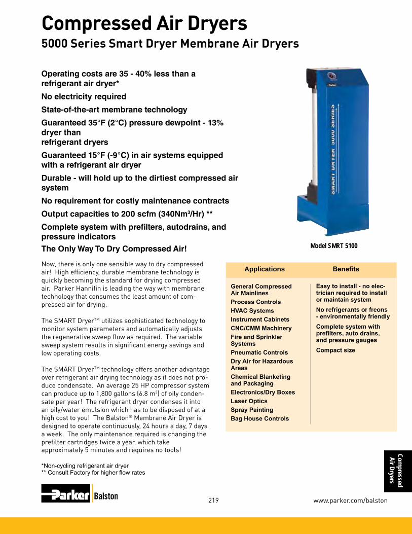
Compressed
Air Dryers
219
Compressed Air Dryers
www.parker.com/balston
Operatingcostsare35-40%lessthana refrigerant air dryer*
No electricity required
State-of-the-art membrane technology
Guaranteed35°F(2°C)pressuredewpoint-13%dryer than refrigerant dryers
Guaranteed15°F(-9°C)inairsystemsequippedwith a refrigerant air dryer
Durable - will hold up to the dirtiest compressed air system
No requirement for costly maintenance contracts
Outputcapacitiesto200scfm(340Nm3/Hr) **
Complete system with prefilters, autodrains, and pressure indicators
Applications Benefits
Model SMRT 5100The Only Way To Dry Compressed Air!
Now, there is only one sensible way to dry compressed air! High efficiency, durable membrane technology is quickly becoming the standard for drying compressed air. Parker Hannifin is leading the way with membrane technology that consumes the least amount of com-pressed air for drying.
The SMART DryerTM utilizes sophisticated technology to monitor system parameters and automatically adjusts the regenerative sweep flow as required. The variable sweep system results in significant energy savings and low operating costs.
The SMART DryerTM technology offers another advantage over refrigerant air drying technology as it does not pro-duce condensate. An average 25 HP compressor system can produce up to 1,800 gallons (6.8 m3) of oily conden-sate per year! The refrigerant dryer condenses it into an oily/water emulsion which has to be disposed of at a high cost to you! The Balston® Membrane Air Dryer is designed to operate continuously, 24 hours a day, 7 days a week. The only maintenance required is changing the prefilter cartridges twice a year, which takeapproximately 5 minutes and requires no tools!
*Non-cycling refrigerant air dryer** Consult Factory for higher flow rates
General Compressed Air MainlinesProcess ControlsHVAC SystemsInstrument CabinetsCNC/CMM MachineryFire and Sprinkler SystemsPneumatic ControlsDry Air for Hazardous AreasChemical Blanketing and PackagingElectronics/Dry BoxesLaser OpticsSpray PaintingBag House Controls
Easy to install - no elec-trician required to install or maintain systemNo refrigerants or freons - environmentally friendlyComplete system with prefilters, auto drains, and pressure gaugesCompact size
5000 Series Smart Dryer Membrane Air Dryers

Com
pres
sed
Air D
ryer
s
220
Compressed Air Dryers
1-800-343-4048
WhybuyaBalstonSMARTDryerTM instead of a cycling refrigerant air dryer?
“Our compressed air system is now completely dry and clean at a very reasonable cost. And we gain at least three hours of production time each week by not having to shut down to clean rusted valves...”
Wayne Etchells, Vice PresidentMelton Corporation, Cranston, R.I.
“This new type of membrane dryer was just what we needed to eliminate problems with water building up in compressed air lines...Since the day we installed it, we haven’t had a single problem with rust. The time and money we save by not having to repair spindles and air motors pays for the cost of the dryer every few months.”
John Napier, Maintenance EngineerKing Machine, Akron, OH
Annual Operating CostsBalston SMART Dryer vs. Cycling and Non-Cycling Refrig. Dryers (100 scfm)
Here’s What Our Customers Say
running at 75% capacity (on average over the 8 hour shift), a typical cycling refrigerant air dryer would cost $454.00 in electrical costs alone, compared to the Balston SMART Dryer with only $436.00 in electrical costs. If you factor in the annual maintenance cost of $800 for a cycling refrigerant dryer compared to $130.00 for the Balston SMART Dryer, there is a total annual savings of over $685.00Additionally, there are no moving parts, no freons that need recharging, no compressors to be serviced and no cooling coils to be cored and cleaned. Most importantly, the Balston SMART Dryer is pro-ducing a constant 35°F dewpoint which is 13% dryer than a cycling refrigerant air dryer (ppm weight in air).
-$
00.002$
00.004$
00.006$
00.008$
00.000,1$
00.002,1$
00.004,1$
00.006,1$
girfeR gnilcyCgirfeR gnilcyC-noNREYRD TRAMS
ecnanetniaMlacirtcelE
5000 Series Smart Dryer Membrane Air Dryers
The Balston SMART Dryer will save YOU money and offer better performance!All Balston SMART Dryers require no electricity.All air dryers are sized based on the maximum capacity output of a compressed air system with inlet conditions assumed to be 100°F (38°C) inlet temperature, 100 psig (7 barg) inlet pressure and 100°F (38°C) ambient tem-perature. In the majority of installations, it is unlikely air dryers will be required to operate under these extreme conditions. Most importantly, the majority of compressed air systems are not operating at the maximum output capacity.Refrigerant and desiccant air dryers, sized to meet these operating conditions are designed to run continuously regardless of the system’s demands, when in fact the actual system conditions are far less.The result is significant operating costs in wasted energy and wear and tear on refrigerant compressors, cooling systems, drains and other componentry.In a typical manufacturing plant operating one 8 hour shift with a 100 SCFM (170 Nm3/Hr) compressor system running at 75% capacity (on average over the 8 hour shift), a typical non-cycling refrigerant air dryer would cost $716 in just electrical costs alone, compared to the Balston SMART Dryer with only $436 in electrical costs. If you factor in the annual maintenance costs of $600 for a non-cycling refrigerant dryer compared to $130 for the Balston SMART Dryer, there is a total annual savings of over $750.Recently, refrigerant manufacturers have responded to this issue by developing a cycling air dryer which cools a cold storage heat sink reservoir. Once the reservoir is cooled to the minimum temperature the compressor (refrigerant) is shut off. The compressor cycles back on when the temperature of the storage reservoir reaches a preset upper limit. This reduces the total energy con-sumption of the dryer however it could produce signifi-cant variations in output dewpoints.The Balston SMART Dryer does not require refrigerant, compressors, cooling systems or other componentry that carries high operating costs (energy) and maintenance costs. The Balston SMART Dryer utilizes sophisticated technology to monitor the system parameters and auto-matically adjusts the regenerative sweep flow as re-quired. The variable sweep system results in significant energy savings and low operating costs with no fluctua-tion in output dewpoints.In a typical manufacturing plant operating an 8 hour shift with 100 SCFM (170 Nm3/Hr) compressor system

Compressed
Air Dryers
221
Compressed Air Dryers
www.parker.com/balston
Model SMRT5100Front View
Model SMRT5200Front View
Principal Specifications
Membrane Air Dryers Model Number SMRT5100 SMRT5200Max Flow Rate @35°F(2°C) dewpoint 100 SCFM (170 Nm3/Hr) 200 SCFM (340 Nm3/Hr)Pressure Dewpoint 35°F (2°C) / 15°F (-9°C) (1) 35°F (2°C) / 15°F (-9°C) (1)Min/Max Inlet Air Temp. 40°F/120°F (4°C/49°C) 40°F/120°F (4°C/49°C)Ambient Temp. Range 40°F/110°F (4°/43°C) 40°F/110°F (4°/43°C)Min/Max Inlet Pressure 80 psig/150 psig (5.5 barg/10 barg) 80 psig/150 psig (5.5 barg/10 barg)Max Input Dewpoint 120°F (49°F) 120°F (49°F)Max Compressed Air 113 SCFM (192 Nm3/Hr) 226 SCFM (384 Nm3/Hr) Requirement Max Pressure Drop 10 psid (0.7 bard) (2) 10 psid (0.7 bard) (2)Inlet/Outlet Port Size 1 1/2”NPT(male) 2”NPT(male)Physical Dimensions 12.5”w x 43.25”h x 16”d (3) 12.5”w x 43.25”h x 16”d (3) (31.75cm x 109.9cm x 40.6cm) (31.75cm x 109.9cm x 40.6cm) Shipping Weight 175 lbs(86 kg) 250 lbs(113kg)
1 35°F (2°C) Pressure Dewpoint specified for saturated inlet air at 100°F(38°C) and max. flow at 100 psig (6.9 barg). 15°F (-9°C) Dewpoint specified for saturated inlet air at 50°F (10°C) and max. flow at 100 psig (6.9 barg).
2 Max. pressure drop measured at max flow rate @ 100 psig (6.9 barg). Pressure drop will increase at lower feed pressures - consult factory.
3 Excluding coalescing prefilter as-sembly.
4 Filtration efficiency: 99.99% at 0.01 micron.
Notes:
Ordering Information For assistance call 1-800-343-4048
Model Number SMRT5100 SMRT5200Coalescing Prefilter 2312N-1B1-DX A15/80-DX Assembly 2312N-1B1-BX A15/80-BXReplacement Prefilter 200-35-DX 200-80-DX Cartridges (every 6 months) 200-35-BX 200-80-BXMembrane Replacement Module D01-0086 D01-0086Automatic Drain Kit 21552 21552
5000 Series Smart Dryer Membrane Air Dryers

Com
pres
sed
Air D
ryer
s
222
Compressed Air Dryers
1-800-343-4048
Do Your Cabinets Look Like This?
Water accumulation in electrical cabinet
Corrosion leads to premature component failure
A Cabinet Dryer will keep your cabinets looking as good as new
Cabinet Dryers Eliminate Moisture Problems in Electrical Cabinets and Motors
Product Features:•Designed specifically for wash down areas
•Protects electrical cabinet components from damage caused by water and high humidity
•Minimizes pools of water inside cabinets
•Positive pressure keeps dust out
•Adds no heat to the cabinet
•Reduces cabinet humidity to less than 10%RH
•Requires no electricity, low operating costs
•Easy to install and maintain
•Quiet operation
•Protect motors, touch screens, drives and other critical components
Balston CD Series Cabinet DryersYou demand a lot from your electrical cabinets and mo-tors. They are subject to nightly high pressure, hot wash downs and then expected to remain dry in a refrigerated area. Over time most cabinets develop moisture inside which leads to premature component failures. This interrupts production and costs you money. Expensive vortex coolers or heaters don’t work. Vortex coolers use a considerable amount of air and have a high operating cost. Heaters simply raise the humidity of the air inside the cabinet and don’t eliminate the moisture.
The Parker Balston Cabinet Dryer serves to reduce the humidity inside the cabinet to less than 10% RH. Any water that infiltrates the cabinet evaporates quickly. Electrical components stay clean and dry which prolongs their life.
Avoid costly down time!Many plants struggle with moisture problems by manag-ing downtime emergencies. Emergencies divert limited maintenance personnel and disrupt production at the cost of thousands of dollars per hour. The Cabinet Dryer reduces these maintenance and lost production costs by 80% or more. A typical customer will see savings of $10K - 15K per year. The Cabinet Dryer will oper-ate continuously and reliably without operator attention thus freeing up valuable maintenance personnel who are better devoted to important routine maintenance work rather than daily emergency response.

Compressed
Air Dryers
223
Compressed Air Dryers
www.parker.com/balston
Principal Specifications
Ordering InformationFor assistance call toll free at 800-343-4048, 8AM to 5PM EST
Model Number CD0005 CD0010 CD0030 Replacement Filter Elements 070-063-BX 070-063-BX 070-063-BX
Replacement Auto Drain C02-2392 C02-2392 C02-2392
CompressedAir In
Dry Purge Air Out
Cabinet Dryers Eliminate Moisture Problems in Electrical Cabinets and Motors
Notes: 1 Delivered dewpoint is specified for saturated inlet air at 100°F (38°C) and 100 psig (6.9 BAR). 2 If the cabinet is not tightly sealed, consider upsizing to the next module size.3 Filtration efficiency: 99.99% at 0.01micron.4 For heavily contaminated air lines, install additional prefiltration.
Model Number CD0005 CD0010 CD0030Cabinet Size Range (2) 0 - 4 FT3 4 - 12 FT3 12 - 36 FT3 (0 - 0.11m3) (0.11m3 - 0.34m3) (0.34m3 - 1m3)
Min/Max Inlet Air Temp 40°F/120°F 40°F/120°F 40°F/120°F (4°C/49°C) (4°C/49°C) (4°C/49°C)
Min/Max Ambient Air Temp 35°F/120°F 35°F/120°F 35°F/120°F (2°C/49°C) (2°C/49°C) (2°C/49°C)
Air Consumption 0.6 SCFM 1.25 SCFM 3.5 SCFM (17 slpm) (35.4 slpm) (99 slpm)
Min/Max Air Pressure 60 psi/150 psi 60 psi/150 psi 60 psi/150 psi (4.1 BAR/10.3 BAR) (4.1 BAR/10.3 BAR) (4.1 BAR/10.3 BAR)
Delivered Dew Point -7°F(-22°C) (1) -7°F(-22°C) (1) -7°F(-22°C) (1)
Inlet and Outlet Port Size 1/4” NPT 1/4” NPT 1/4” NPT
Electrical Requirements None None None
Dimensions 3”w x 9.2”h x 2”d 3”w x 15.2”h x 2”d 4.6”w x 15.3”h x 2.9”d (7.6cm x 2.34cm x 5cm) (7.6cm x 38.6cm x 5cm) (11.7cm x 38.9cm x 7.4cm)
Shipping Weight 1.5 lbs (0.68 kg) 2 lbs (0.9 kg) 2.5 lbs (1.1 kg)
Here’s what our customers say:
“We tried heaters, fans and vortex coolers, our only solution was to use a Parker Balston dryer that con-tinuously purges the cabinet with dry air.”
- Lee Clarkson Ross Industries
“I've been with Smithfield for 15 years and we've had issues with wet electrical cabinets for 15 years. We installed the cabinet dryer on our wettest cabinet to see if it would work. Our Multivac™ packager was having significant issues. It was out of service 2-3 times per week due to condensation inside the cabinet. When we installed the dryer we noticed a difference right away. The water droplets on the walls of the cabinet were gone and our downtime from moisture was completely eliminated. It worked just like they told me.”
Maintenance ManagerLarge Meat Processing Plant
Hollowmicrofibers
Phase I - Coalescing
Phase II - Air Drying
Principle of Operation

Com
pres
sed
Air D
ryer
s
224
Compressed Air Dryers
1-800-343-4048
PSA Air Dryers
Balston Compressed Air Dryer
Pneumatic Tool StationsHVAC SystemsPurge Electrical BoxesAir Lines Subject to Sub-Freezing TemperaturesBlanketing Moisture Sensitive MaterialsSpray PaintingPneumatic InstrumentationRoboticsLasersDry Boxes
Applications Model75-A20
Balston regenerative PSA desiccant dryer reduces the atmospheric dewpoint of compressed air without operator attention. Model 75-A20 will reduce the dew-point to -100°F (-73°C). The dryer is delivered complete and ready for easy installation. The dryer has coalesc-ing prefilters with automatic drains, PSA drying towers, a particulate final filter, a moisture indicator, differential pressure indicator, and pretested controls.
The Balston regenerative dryer has safe, 12 VDC elec-trical controls. To install, simply attach the inlet (60 psig/4.1 BARG minimum) and outlet air lines, plug the electrical transformer into a wall outlet - no elec-trician required - and the unit is ready for trouble-free operation.
This reliable dryer can be easily installed, operated, and maintained by personnel not trained in instrumentation. The Balston dryer is useful when air comes into con-tact with moisture-sensitive materials, or when outside compressed air lines are subjected to sub-freezing temperatures.
The 75-A20 is a wall mountable unit. It has a 10 SCFM(17 Nm3/hr)/min. (283 lpm) capacity (at 100 psig/6.9 BARG inlet pressure).
Reduce the dewpoint of compressed air to-100°F(-73°C)
Unattended24houroperation
Lightweight and compact
No desiccant to change
PSA Air Dryer

Compressed
Air Dryers
225
Compressed Air Dryers
www.parker.com/balston
Principal Specifications
Dewpoint -100°F (-73°C) (1)Max. Dry (outlet) Air Flow Rate forSpecified Dew Point (1) Inlet Pressure 125 psig 12.0 SCFM (340 lpm) (20 Nm3/hr) Inlet Pressure 100 psig 10.0 SCFM (283 lpm) (17 Nm3/hr) Inlet Pressure 80 psig 8.3 SCFM (235 lpm) (14 Nm3/hr) Inlet Pressure 60 psig 6.5 SCFM (184 lpm) (11 Nm3/hr)Air Loss for Regeneration 2.5 SCFM (71 lpm) (2) (4.2 Nm3/hr)Min/Max Inlet Air Pressure 60 psig/125 psig (4.1 BARG/8.6 BARG)Max. Inlet Air Temperature 78°F (25°C) (3)Pressure Drop at Max. Flow Rate 8 psid (0.055 BARD)Inlet/Outlet Port Size (female) 1/4” NPTElectrical Requirements 120 VAC/60 Hz. (4)Shipping Weight 50 lbs. (23 kg) Dimensions 15”W X 41”H (38cm X 104cm)
Notes:1 Dewpoint will be lower than specified at lower air flow.
2 Total air required = air loss for regeneration + process demand (up to max. dry air flow rate).
3 Outlet dewpoint will increase at higher inlet compressed air temperatures.
4 Power consumption - less than 10 watts. Each dryer is shipped with a 12 VDC plug-in transformer to connect to the local electrical supply.
5 Filtration efficiency: 99.99% at 0.01 micron.
Ordering Information
For Assistance, call toll-free at 1-800-343-4048 8AM to 5PM Eastern Time
Description Model Number Balston Compressed Air Dryer 75-A20Replacement Filter Cartridges 1st stage (box of 10) 100-18-DXReplacement Filter Cartridges 2nd stage (box of 10) 100-18-BXMaintenance Kit, 1 year supply of filter cartridges MK7525P
Model 75-A20
PSA Air Dryer

Com
pres
sed
Air D
ryer
s
226
Compressed Air Dryers
1-800-343-4048
Customer Support and AssistanceBalston products are supported by a staff of 70+ highly trained sales and service specialists located through-out North America and Canada.The Specialists are continuously trained and updated on all Balston branded products and technologies, ensuring prompt, accurate customer service.When on-site service isn’t practical, replacement items are shipped the same day you contact us directly to your facility from one of our near by Stocking Centers or directly from our Manufacturing Plant. We guarantee overnight delivery and we pay the freight!
World Class Manufacturing
If you have technical questions, special product modifications or unique applications, Balston’s technical information and sup-port staff are available to assist you with your requirements.These highly trained applica-tion engineers are committed to ensuring your questions are answered accurately, and your special needs are attended to. In addition, they will work closely with you on new and unique applications.This team of engineers can be contacted at 1-800-343-4048 8AM to 5PM Eastern Time.
Customer Support and Service Network for Balston® Products
All Balston branded products are manufactured within strict guide-lines of a total quality management program. Each product incorporates superior workmanship and the best quality components available ensur-ing long term reliability and trouble free operation. Your complete satis-faction is guaranteed.
Technical Support Staff

227
Index
www.balstonfilters.com
Index
Part Number Page Number(s)
050-05-( ) 12, 31, 89
050-07-( ) 98
050-11 81
050-11-_Q 108
050-11-( ) 98, 99, 114, 115
05R 34, 47, 48
05R113A 47
05R118A 47
05R213A 47
05R218A 47
070-063-( ) 25, 184, 207, 223
070-063-SA 184
07R 34, 51, 52
07R213A 51
07R313A 51
07R413A 51
06E 35, 59, 60
06E12B13A 59
06E14B13A 59
06E16B13A 59
06E18B13A 59
06E22B13A 59
06E24B13A 59
06E26B13A 59
06E28B13A 59
06E32B13A 59
06E34B13A 59
06E36B13A 59
06E38B13A 59
10F 34, 39, 40
10F01E 39
10F03E 39
10F05E 39
10F07E 39
10F11E 39
10F13E 39
10F15E 39
10F17E 39
100-12-404 103
100-12-BX 14, 25, 184, 187, 190, 193, 213, 218
100-12-DH21 104
100-12-DX 14, 25, 184, 187, 190, 193, 213, 218
100-12-SA 25, 184, 190, 193, 203
100-12 81
100-12-( ) 12, 25, 29, 81, 89, 97, 99, 100, 102, 114, 184, 197, 203
100-185-( ) 114
100-18-BX 14, 25, 184, 187, 193, 213, 225, 227, 239
100-18-DX 14, 25, 184, 187, 193, 213, 225, 227, 239
100-18-SA 25, 184
100-18-( ) 12, 184, 197
100-25-BX 215
100-25-DH21 104100-25-( ) 81, 89, 97, 99, 100, 114, 203, 205

228
Index
1-800-343-4048
Inde
x
105S6 82, 83, 84, 85, 98
11010 121
11015 47
11970 68
11971 68
11972 68
11977 31
12E 30
12E 27 31
12E 37 30, 31
12E 47 30, 31
130-14-( ) 68
14000 68
14001 121
14157 131, 141
14158 131, 140
14159 131, 140
14160 139, 140
14162 139, 140
14163 139, 140
14164 139, 140
14165 139, 140
14166 141
14168 132, 141
14172 129, 135, 136, 142
14173 126, 127, 131, 132, 133, 134, 135, 136, 138, 140, 142
14174 126, 127, 134, 135, 136, 138, 139, 140, 142
14175 126, 127, 139, 142
14177 142
14178 135, 142
14179 139, 140, 142
14181 129, 135, 136, 139, 142
14182 126, 127, 131, 135, 136, 138, 139, 140, 142
14183 131, 138, 142
14E 34, 55, 56
14E01B13F 55
14E03B13F 55
14E05B13F 55
14E07B13F 55
14E11B13F 55
14E13B13F 55
14E15B13F 55
14E17B13F 55
150-12-_X 110
150-19-BX 14, 187, 190, 213, 227
150-19-DX 14, 187, 190, 213, 227
150-19-( ) 13, 197
150-19-SA 192
15/80S6 83, 84, 85, 94, 95
17L 32
17L22BE 33
17L32BE 33
17L42BE 331/7825-08-000 215

229
Index
www.balstonfilters.com
Index
19158 121
19202 121
19206 121
19290 121
19291 121
2/BE100-163-30 125
2/BE100-235-30 125
2/BE200-168-371H 121
2/BE200-168-DX 27
2/BE200-248-371H 121
200-176-( ) 25, 184, 195
200-176-BX 193
200-176-DX 193
200-176-SA 25, 184, 195
2000 186
200-185-( ) 25, 184, 195
200-185-BX 193
200-185-DX 193
200-185-SA 25, 184, 195
2002 3, 4, 11, 12, 195, 197
2002N-0A0-( ) 12, 196, 197
2002N-0B1-BX 216
2002N-1B1-( ) 12, 197
2002N-1B1-BX 196, 197
2002N-1B1-DX 196, 197, 213
2002N-1B2-( ) 12, 197
2003 3, 4, 11, 12, 195, 197
200-35-BX 14, 187, 213, 221
200-35-DX 14, 187, 213, 221
200-35-SA 203
200-35-( ) 13, 95, 197
2003N-1B1-( ) 12, 197
2003N-1B2-( ) 12, 197
2003N-0A0-( ) 12, 197
2004 3, 4, 11, 12, 195, 197
2004N-0A0-( ) 12, 197
2004N-0B1-BX 216
2004N-1B1-( ) 12, 197, 216
2004N-1B2-( ) 12, 197
200-75-R 155
200-75-SR 179
200-80-371H 121
200-80-BX 162, 221
200-80-DX 161, 162, 163, 221
200-80-SA 203, 205
200-80-( ) 13, 20, 95, 161, 197, 201, 203
2008N-0B1-BX 216
2008N-1B1-DX 12, 197, 216
200X 11, 194
20125 68, 86
20-211 63, 161, 162
20217 68, 86, 121
20222 12120-402 63

230
Index
1-800-343-4048
Inde
x
20-440 63, 161, 162
20-606 66
20-613 66
20-623 66
2/100-12-( ) 29
2104 3, 4, 11, 12, 194, 195, 197
2104N-0B1-BX 216
2104N-0B1-DX 216
2104N-1B1-( ) 12
2104N-1B1-BX 196, 197
2104N-1B1-DX 196, 197, 213, 216
2104N-1B2-( ) 12, 197
2104N-0A0-SA 12, 197
21552 221
2206G-1B1-( ) 12
2206G-1B2-( ) 12
2206G-0A0-( ) 12
2206 3, 4, 13, 194, 195, 197
2206N-1B1-( ) 12, 197
2206N-1B2-( ) 12, 197
2206N-0A0-( ) 12, 197
2208 3, 4, 13, 194, 195, 197
2208G-1B1-( ) 12, 197
2208G-1B2-( ) 12, 197
2208G-0A0-( ) 12, 197
2208N-1B1-( ) 12, 197
2208N-1B1-BX 196, 197
2208N-1B1-DX 196, 197, 213
2208N-1B2-( ) 12, 197
2208N-0A0-( ) 12, 196, 197
23R 153
2312 3, 4, 13, 194, 195, 197
2312G-1B1-( ) 12, 197
2312G-1B2-( ) 12, 197
2312G-0A0-( ) 12, 197
2312N-1B1-( ) 197
2312N-1B1-BX 196, 197, 221
2312N-1B1-DX 196, 197, 213, 221
2312N-1B2-( ) 12, 197
2312N-0A0-( ) 12, 196, 197
23/75R 154, 155
23/75SR 178, 179
26/35 84, 85
26/35D-3000 94, 95
26/35D-5000 94, 95
27 94, 148
27/35 82, 83, 84, 85, 94, 95
27/35-3000 94 95
27/50 144, 148
27/ 75SR 180
27/80 82, 83, 84, 85, 94, 95
27/80-3000 94 95
27/95 144, 1482A-2002N-3B1 14, 186, 187

231
Index
www.balstonfilters.com
Index
2A-2003N-3B1 14, 186, 187
2A-2004N-3B1 14, 186, 187
2A-2104N-3B1 14, 186, 187
2A-2206N-3B1 14, 186, 187
2A-2208N-3B1 14, 186, 187
2A-2312N-3B1 14, 186, 187
30 77
30/12 82, 84, 85, 89
30/25 82, 84, 85, 89
3/100-12-SA 203
3/100-12-( ) 197
3/100-18-( ) 197
3/100-25-SA 203
31G 81, 83, 84, 85, 99
31GCFL 74
31GCFL-1/4 113, 114
31S6 81, 83, 84, 85, 99, 173, 174, 176
31S6CFL-1/4 113, 114
3/150-19-( ) 197
3/200-16-371H 121
3/200-35-SA 203
3/200-35-( ) 197
3/200-35-371H 121
3/200-80-SA 203, 205
3/200-80-( ) 197, 199, 203
3290 220
33G 81, 83, 84, 85, 97, 100, 144, 149,
33S6 81, 83, 84, 85, 97, 100, 144, 149, 173, 174, 176
37 77, 177
37/12 81, 82, 83, 84, 85, 96, 175, 176
37/25 81, 82, 83, 84, 85, 96, 175, 176
38 104
38/12 104
38/25 104
39 111, 112
39-0 112
39002 110, 112
39014 110, 112
39015 110, 112
39020 110, 112
39-2 112
3/9955-12-371H 121
3/9956-12-371H 121
3B-2002N-3B1 189, 190
3B-2003N-3B1 189, 190
3B-2004N-3B1 189, 190
3B-2104N-3B1 189, 190
3B-2206N-3B1 189, 190
3B-2208N-3B1 189, 190
3B-2312N-3B1 189, 190
3B-6002N-0A1 192, 193
3B-6904N-0A1 192, 193
3B-6004N-0A1 192, 1933B-6006N-0A1 192, 193

232
Index
1-800-343-4048
Inde
x
3B-6008N-0A1 192, 193
41-070 67
41-071 162
41G 81, 83, 84, 85, 99
41GCFL 74
41GCFL-1/4 113, 114
41S6 81, 83, 84, 85, 99, 173, 174, 176
41S6CFL-1/4 113, 114
4433-05 68, 69, 84, 85, 86, 87, 88, 92, 151
4433-05-BX 68, 69
4433-05-( ) 68, 69, 88, 92, 151
45G 81, 83, 84, 85, 97, 100, 144, 149
45S6 81, 83, 84, 85, 97, 100,144, 149, 173, 174, 176
47S6 82, 83, 84, 85, 115
48S6 81, 82, 83, 84, 85, 113, 114
49S6 82, 83, 84, 85, 113, 114
5/050-05-( ) 12, 31, 216
5/070-063-(?x) 25, 184, 209, 237
5/100-12-BX 14, 187, 190, 216
5/100-12-DX 14, 187, 190, 216
5/100-12-SA 192, 195
5/100-12-( ) 12, 25, 186, 201
5/100-18-BX 14, 187, 190, 216
5/100-18-DX 14, 187, 190, 216
5/100-18-SA 14, 187, 190, 216
5/100-18-( ) 12, 25, 186, 201
5/100-19-( ) 230
5/130-14-( ) 31
5/150-19-( ) 13, 192, 201
5/150-19-BX 14, 187, 190, 216
5/150-19-DX 14, 187, 190, 216
5/150-19-SA 14, 187, 190, 216
5/180-19-BX 14, 187, 190
5/180-19-DX 14, 187, 190
5/180-19-SA 14, 187, 190
5/200-35-( ) 13, 201
5/200-35-BX 14, 187, 190, 235
5/200-35-DX 14, 187, 190, 235
5/200-35-SA 190
5/200-176-( ) 25, 186
5/200-176-BX 195
5/200-176-DX 195
5/200-176-SA 186, 195
5/200-185-( ) 25, 186
5/200-185-BX 195
5/200-185-DX 195
5/200-185-SA 186, 195
5/200-80-( ) 13, 20, 201
510--28-HEC 18, 166
510-36-HEC 18
510-28-HFC 18, 166
510-36-HFC 18
53 101, 14653/18 83, 101, 102, 144, 146, 147

233
Index
www.balstonfilters.com
Index
53/50 83, 101, 102, 144, 146, 147, 156, 157
53/95 83, 144, 146, 147, 156, 157
54 101
54/50 83, 101, 102, 144, 146, 147
57-501 152
57-501-C 152
57-501-F 152
57-501-M 152
58N 103
58P 83, 101, 102, 144, 146, 147
6102 23, 24, 25, 182, 183, 184, 185
6102N-0A0-( ) 184
6102N-0A1-( ) 23, 24, 25, 184, 186
6102N-0A2-( ) 23, 24, 25, 184, 186
6002 23, 24, 25, 182, 183, 184
6002N-0A1-( ) 23, 24, 25, 184, 186
6002N-0A2-( ) 23, 24, 25, 184, 186
6004 23, 24, 25, 182, 183, 184, 185
6004G-0A1-( ) 23, 25, 184
6004G-0A2-( ) 23, 25, 184
6004N-0A1- ( ) 23, 24, 25, 184, 186
6004N-0A2-( ) 23, 24, 25, 184, 186
6006 23, 24, 25, 180, 182, 183, 184
6006G-0A1-( ) 23, 25, 184
6006G-0A2-( ) 23, 25, 184
6006N-0A1-( ) 23, 24, 25, 184, 186
6006N-0A2-( ) 23, 24, 25, 184, 186
6008 23, 24, 25, 180, 182, 183, 184
6008N-0A1-( ) 23, 24, 25, 184, 186
6008N-0A2-( ) 23, 24, 25, 184, 186
6904 23, 24, 25, 182, 183, 184, 185
6904N-0A1-( ) 23, 24, 25, 184, 186
6904N-0A2-( ) 23, 24, 25, 184, 186
7/200-35-371H 121
7/200-80-371H 121
72-130 213
75-A20 224
76-01 212, 213
76-02 212, 213
76-10 212, 213
76-20 212, 213
76-40 212, 213
8002N-0A1-BX 218
8004N-0A1-BX 218
8004N-1A1-DX 218
850-25-HEC 18, 166
850-25-HFC 18, 166
850-36-HEC 18, 166
850-36-HFC 18, 166
8800-12 83, 84, 85, 86, 87, 88, 92
8800-12-( ) 88, 92
8822-( )-( ) 82
8822-11 82, 838822-11-( ) 82

234
Index
1-800-343-4048
Inde
x
8833-11 68, 69, 83, 84, 85, 86, 87, 88, 92
8833-11-BX 68, 69
8833-11-DX 68, 69
8833-11-( ) 68, 69, 88, 92
85 81, 82, 83, 84, 85, 96
8A02N-082-BX 214
90 82, 83, 84, 85, 101, 102
91 81
91S6 82, 83, 84, 85, 98, 99, 173, 174, 176
92-810 29
92-810A 29
92-810G 29
92-812 29
92-812A 29
92-812G 29
95 81
95A 82, 83, 84, 85, 98
95M 82, 83, 84, 85, 98
95S6 82, 84, 85, 98, 173, 174, 176
95T 82, 83, 84, 85, 98, 173, 174, 176
97S6 82, 83, 84, 85, 89, 173, 174
98 105, 106
98-0 105, 106
98002 106, 108
98010 108
98011 108
98012 108
98013 108
98014 106
98015 106
98020 106, 108
98-2 105, 106
9900-05 68, 69, 84,85, 86, 87, 88, 92
9900-05-BK 68, 69
9900-05-( ) 68, 69, 88, 92
9922-05 68, 69, 82, 83, 84, 85, 86, 87, 88, 92, 150, 151
9922-05-( ) 68, 69, 82, 88, 92, 151
9922-11 68, 69, 82. 83, 84, 85, 86, 87, 88, 92, 150, 151
9922-11-95 82, 172, 176
9922-11-( ) 68, 69, 82, 88, 92, 151
9933-05 68, 69, 83, 84, 85, 86, 87, 88, 92, 150, 151
9933-05-95 172, 176, 215
9933-05-DQ 76
9933-05-( ) 68, 69, 88, 92, 151
9933-11 68, 69, 83, 84, 85, 86, 87, 88, 92, 150, 151
9933-11-( ) 68, 69, 88, 92, 151
9953-11 86, 87, 88, 92
9953-11-( ) 88, 92
9953-11-BX 87, 88
9953-11-DX 87, 88
9955-05-DX 26, 27
9955-11-DX 26, 27
9955-12 120, 121, 126, 127, 128, 130, 131, 132, 133, 134, 136, 139, 1409955-12-371H 120, 121

235
Index
www.balstonfilters.com
Index
9955-12-DX 26, 27
9956-12 120, 121, 126, 127, 128, 129, 130, 132, 135, 136, 139
9956-12-371H 120, 121
A05-0045 81
A05-0046 81
A05-0097 121
A15/80 3, 4, 13, 194, 197
A15/80-BX 196, 197, 221
A15/80-DX 196, 197, 221
A15/80-SA 196, 197
A15/80S6-SA 196, 197
A27/35B 203
A27/35B-SA 196, 200, 202, 203
A27/80B 203
A27/80B-SA 196, 200, 202, 203
A33B 203
A33B-SA 196, 200, 202, 203
A34 158
A39/12 109, 110
A39/12-_X-0 110
A39/12-_X-2 110
A39-0 110
A39-2 110
A45B 201
A45B-SA 196, 200, 202, 203
A914 3, 4, 11, 12
A914A 11, 12
A914D 3, 4, 11
A914P 3, 4, 11
A94A-( ) 3, 4
A98 107, 108
A98/11 108
A98/11-( )Q-( ) 108
A98/11-_Q 108
A98/11-_Q-0 108
A98/11-_Q-2 108
A98/11-BQ-0 108
A98/11-BQ-2 108
A98/11-DQ-0 108
A98/11-DQ-2 108
AFF10-0728-HEC 17, 18, 19, 165, 166, 167, 196, 198
AFF10-0728-HFC 17, 18, 19, 165, 166, 167, 196, 198
AFF12-1128-HEC 17, 18, 19, 165, 166, 167, 198
AFF12-1128-HFC 17, 18, 19, 165, 166, 167, 198
AFF16-1528-HEC 17, 18, 19, 165, 166, 167, 198
AFF16-1528-HFC 17, 18, 19, 165, 166, 167, 198
AFF3-0128-HEC 17, 18, 19, 165, 166, 167, 196, 198
AFF3-0128-HFC 17, 18, 19, 165, 166, 167, 196, 198
AFF4-0125-HEC 17, 18, 19, 165, 166, 167, 196, 198
AFF4-0125-HFC 17, 18, 19, 165, 166, 167, 196, 198
AFF6-0136-HEC 17, 18, 19, 165, 166, 167, 196, 198
AFF6-0136-HFC 17, 18, 19, 165, 166, 167, 196, 198
AFF6-0328-HEC 17, 18, 19, 165, 166, 167, 198AFF6-0328-HFC 17, 18, 19, 165, 166, 167, 198

236
Index
1-800-343-4048
Inde
x
AFF8-0428-HEC 17, 18, 19, 165, 166, 167, 196, 198
AFF8-0428-HFC 17, 18, 19, 165, 166, 167, 196, 198
AFN3-0128-HEC 17, 18, 19, 165, 166, 167
AFN3-0128-HFC 17, 18, 19, 165, 166, 167
AFR-940 30, 31
AFR-940-( ) 31
AFR-940-130 31
AFR-940-30 31
AFR-940-60 31
AFR-940A 30, 31
AFR-940A-( ) 31
AFR-940A-30 31
AFR-940A-60 31
AFR-940A-130 31
AHC-0180 161, 163
AHC-0180-( ) 161
AHC-0180-DX 161
AHC-0280 161, 163
AHC-0280-( ) 161
AHC-0280-DX 161
AHC-0480 161, 163
AHC-0480-( ) 161
AHC-0480-DX 161
AHC-0880 162, 163
AHC-0880- ( ) 162
AHC-0880- DX 162
AKC-0280 200, 201
AKC-0280-( ) 202
AKC-0280-SA 196, 201
AKC-0480 201
AKC-0480-SA 196, 201
AKC-0880 201
AKC-0880-( ) 162
AKC-0880-SA 196, 201
AKC-1480 200, 201
AKC-1480-DX 162
AKC-1480-SA 196, 201
AKC-2280 201
AKC-2280-DX 162
AKC-2280-SA 196, 201
AKH-0280 3, 4, 20, 160, 161, 163
AKH-0280-( ) 20, 161
AKH-0280-3 159
AKH-0280-DX 161
AKH-0480 3, 4, 20, 161, 163
AKH-0480-( ) 20, 161
AKH-0480-DX 161
AKH-0880 3, 4, 20, 160, 162, 163
AKH-0880-( ) 20, 162
AKH-0880-DX 162
AKH-1480 3, 4, 20, 162, 163
AKH-1480-( ) 20, 162
AKH-1480-DX 20, 162AKH-2280 3,4, 20, 162, 163

237
Index
www.balstonfilters.com
Index
AKH-2280-( ) 20, 162
AKH-2280-DX 20, 162
AKS-0280 161, 163
AKS-0280-DX 161, 163
AKS-0480 161, 163
AKS-0480-DX 161, 163
AKS-0880 162, 163
AKS-0880-( ) 162, 163
AKS-1480 162, 163
AKS-1480-( ) 162, 163
AKS-2280 162, 163
AKS-2280-( ) 162, 163
AKSB-0280-2 205
AKSB-0280-2-SA 205
AKSB-0280-3 205
AKSB-0280-3-SA 204, 206
AKSB-0280-SA 196, 205
AKSB-0480 205
AKSB-0480-SA 196, 205
AKSB-0880 205
AKSB-0880-SA 196, 205
AKSB-1480 205
AKSB-1480-SA 204, 206
AKSB-2280 205
AKSB-2280-SA 196
ALF3-0128-HEC 17, 18, 19, 165, 166, 167
ALF3-0128-HFC 17, 18, 19, 165, 166, 167
ALF4-0125-HEC 17, 18, 19, 165, 166, 167
ALF4-0125-HFC 17, 18, 19, 165, 166, 167
ALF6-0136-HEC 17, 18, 19, 165, 166, 167
ALF6-0136-HFC 17, 18, 19, 165, 166, 167
ALF6-0328-HEC 17, 18, 19, 165, 166, 167
ALF6-0336-HFC 17, 18, 165, 166
ALN3-0128-HEC 17, 18, 19, 165, 166, 167
ALN3-0128-HFC 17, 18, 19, 165, 166, 167
ALN6-0336-HEC 18
ALN6-0336-HFC 54
AR-009 120, 126
AR-009-DX 26, 27
AR-009-371H 120, 121
AR-015 126
AR-015-371H 120, 121
AR-0316 120, 121, 126, 127, 128, 129, 130, 131, 132, 133, 134, 135, 136, 138, 139, 140
AR-0316-371H 120, 121
AR-0335 120, 121, 126, 127, 128, 129, 130, 131, 132, 133, 134, 135, 136, 137, 138, 140
AR-0335-371H 120, 121
AR-0735 120, 121, 126, 127, 128, 129, 130, 131, 132, 133, 134, 135, 136, 137, 138, 139, 140
AR-0735-371H 120, 121
AR-0780 120, 121, 126, 127, 128, 129, 130, 131, 132, 133, 134, 135, 137, 138, 140
AR-0780-371H 120, 121
AR-1280 120, 121, 126, 127, 128, 129, 130, 133, 134, 135, 137, 138, 140
AR-1280-371H 120, 121
AR-1680 120, 121, 126, 127, 128, 129, 133, 134, 135, 137, 138AR-1680-371H 120, 121

238
Index
1-800-343-4048
Inde
x
AR-3080 120, 121, 127, 128, 129, 133, 134, 135, 137, 138, 139, 140
AR-3080-371H 120, 121
B2C 218
BE100-163-30 125
BE100-235-30 125
BE200-168-371H 121
BE200-168-DX 27
BE200-248-371H 121
C01-0094 184
C01-0108 184
C01-0109 184
C02-2377 67
C02-2392 184, 207, 209, 223, 237
C10A1308 95, 96, 100
CD0005 203, 209, 223, 237
CD0010 203, 209, 223, 237
CD0030 203, 209, 223, 237
CF-0112 122, 123
CF-0112-102 123
CF-0112-30 123
CF-0118 122, 123
CF-0118-102 123
CF-0118-30 122, 123
CI-100-12-000 12, 25, 184
CI-100-18-000 25, 184
CI-100-25-000 12
CI150-19-000 13
CI200-35-000 13
CI200-80-000 13, 20
CI-200-176-000 25, 184
CI-200-185-000 25, 184
CI-200-35-000 104
CM0080-35 218
CM0150-35 218
CV-0112 124, 125, 126, 127, 128, 129, 130, 131, 132, 133, 134, 135, 136, 139, 140
CV-0112-30 124, 125
CV-0112-371H 118, 119
CV-0118 118, 119, 126, 127, 128, 129, 130, 131, 132, 133, 134, 135, 136, 137, 138, 139, 140
CV-0118-30 124, 125
CV-0118-371H 118, 119
D01-0086 221
DH21 54
EK602VB 216
ET-100-12-30 158
FB11 35, 61, 62
FB11-04DGC-SS 61
FB11-04WGCSS 61
FB11-04WGCRSS 61
FB11G04WGCSS 61
FB11G04WGCRSS 61
FB548 35, 57, 58
FB548-02DGCSS 57
FF10 34, 37, 38FF10-04DGSS 37

239
Index
www.balstonfilters.com
Index
FF10-04DGRSS 37
FF10-04WGSS 37
FF10-04WGRSS 37
FF11 34, 43, 44
FF11-04DJSS 43
FF11-04DJRS 43
FF11G04WJSS 43
FF11G04WJRSS 43
FF501 34, 41, 42
FF501-02DHSS 41
FR10 34, 49, 50
FR10-04CSS 49
FR364 34, 45, 46
FR364-02CSS 45
GS-050-05-95 174
GS-050-11-95 174
GS-100-12-95 174, 215
GS-100-25-95 174, 215
GS-3/050-05-95 174
GS-3/050-11-95 174
GS-3/100-12-95 174, 175
GS-3/100-25-95 174, 175
IT0010-35 215, 216
IT0030-35 215, 216
IT0080-35 215, 216
IT0150-35 215, 216
IT0250-3500 215, 216
IT0250-3560 215, 216
IT0500-3500 215, 216
IT0500-3560 215, 216
IT1000-3500 215, 216
IT1000-3560 215, 216
K4520N14060 54
K4520N14160 54
KS-0280-3 161
KS-0480-4 161
LP-100-12-( ) 102, 144, 147, 149
LP-100-25-( ) 144, 149
LP-200 101, 146,
LP-200-12-80 149
LP-200-18-( ) 102, 144, 147
LP-200-18-80 147
LP-200-50-( ) 102, 144, 147, 148
LP-200-50-20 144, 157
LP-200-50-80 148
LP-200-95-( ) 144, 147, 148
LP-200-95-20 144, 157
MK7525P 225
P3NKA00MW 54
P3NKA00PN 54
P3NKA00RR 54
P3NR 34, 53, 54
P3NRA96BNN 53P3NRA98BNN 53

240
Index
1-800-343-4048
Inde
x
P3NRA9PBNN 53
PS403 216
PS702 216, 218
PS748P 33
PS802 216, 216
R-009 120, 124, 127, 128, 129, 130, 131, 132, 133, 134, 135, 136, 137, 138, 139, 140
R-009-30 124, 125
R-015 124, 125, 127, 128, 129, 130, 131, 132, 133, 134, 135, 136, 138, 139, 140
R-015-30 124, 125
SAP05481 184
SMRT5100 219, 221
SMRT5200 221
SP2-23/75SR 179
SP3-23-75SR 179
SP4-23-75SR 179
SP6-23/75SR 178, 179
SS-100-12 97, 99, 100, 114
SS-100-25 97, 99, 100, 114
SS-200-35 95
SS-200-80 95
WF-200-50-C 152
WF-200-50-F 152
WF-200-50-M 152
WF-3/200-50-C 152
WF-3/200-50-F 152
WF-3/200-50-M 152
WS002N 7
WS003N 7
WS004N 7
WS0H3N 7
WS0H4N 7
WS006N 7
WS008N 7
WS0H6N 7
WH0H8N 7
WS0010N 7
WS0012N 7
WS0H10N 7
WS0H12N 7
WS0016N 7
WS0020N 7WS0024N 7

Parker Hannifin CorporationThe Global Leader in Motion and Control Technologies
We engineer success of our customers around the world, drawing upon nine core motion and control technologies. These technolgies enable virtually every machine and process to operate accurately, efficiently and dependably.
As the global leader in motion and control, we partner with our distributors to increase our customers’ productivity and profitability by delivering an unmatch-able breadth of engineered components and value-added services.
We continue to grow with our customers by creating application-focused prod-ucts and system solutions. A key to our global expansion has been to follow our customers and establish operations, sales and service wherever they are needed. No single competitor matches Parker’s global presence.
Corporate Headquarters in Cleveland, Ohio.
Parker’s Motion and Control Technologies
AerospaceClimate ControlElectromechanicalFiltrationFluid & Gas Handling
HydraulicsPneumaticsProcess Control
Sealing & Shielding
FAILURE OR IMPROPER SELECTION OR IMPROPER USE OF THE PRODUCTS AND/OR SYSTEMS DESCRIBED HEREIN OR RELATED ITEMS CAN CAUSE DEATH, PERSONAL INJURY AND PROPERTY DAMAGE.This document and other information from Parker Hannifin Corporation, its subsidiaries and authorized distributors provide product and/or system options for further investigation by users having technical expertise. It is important that you analyze all aspects of your application and review the information concerning the product or system in the current product catalog. Due to the variety of operating conditions and applications for these products or systems, the user, through its own analysis and testing, is solely responsible for making the final selection of the products and systems and assuring that all performance, safety and warning requirements of the application are met.The products described herein, including without limitation, product features, specifications, designs, availability and pricing, are subject to change by Parker Hannifin Corporation and its subsidiaries at any time without notice.
WARNING
The items described in this document are hereby offered for sale by Parker Hannifin Corporation, its subsidiaries or its authorized distributors. This offer and its acceptance are governed by the provisions stated in the "Offer of Sale".
Offer of Sale
© Copyright 1995, 2013, Parker Hannifin Corporation, All Rights Reserved.
Legal Notifications
!
11. Improper use and Indemnity. Buyer shall indemnify, defend, and hold Seller harmless from any claim, liability, damages, lawsuits, and costs (including attorney fees), whether for personal injury, property damage, patent, trademark or copyright infringement or any other claim, brought by or incurred by Buyer, Buyer’s employees, or any other person, arising out of: (a) improper selection, improper application or other misuse of Products purchased by Buyer from Seller; (b) any act or omission, negligent or otherwise, of Buyer; (c) Seller’s use of patterns, plans, drawings, or specifications furnished by Buyer to manufacture Product; or (d) Buyer’s failure to comply with these terms and conditions. Seller shall not indemnify Buyer under any circumstance except as otherwise provided.12. Cancellations and Changes. Orders shall not be subject to cancellation or change by Buyer for any reason, except with Seller’s written consent and upon terms that will indem-nify, defend and hold Seller harmless against all direct, incidental and consequential loss or damage. Seller may change product features, specifications, designs and availability with notice to Buyer.13. Limitation on Assignment. Buyer may not assign its rights or obligations under this agreement without the prior written consent of Seller.14. Force Majeure. Seller does not assume the risk and shall not be liable for delay or failure to perform any of Seller’s obligations by reason of circumstances beyond the reason-able control of Seller (hereinafter “Events of Force Majeure”). Events of Force Majeure shall include without limitation: accidents, strikes or labor disputes, acts of any government or government agency, acts of nature, delays or failures in delivery from carriers or suppliers, shortages of materials, or any other cause beyond Seller’s reasonable control. 15. Waiver and Severability. Failure to enforce any provision of this agreement will not waive that provision nor will any such failure prejudice Seller’s right to enforce that provi-sion in the future. Invalidation of any provision of this agreement by legislation or other rule of law shall not invalidate any other provision herein. The remaining provisions of this agreement will remain in full force and effect.16. Termination. Seller may terminate this agreement for any reason and at any time by giving Buyer thirty (30) days written notice of termination. Seller may immediately terminate this agreement, in writing, if Buyer: (a) commits a breach of any provision of this agreement (b) appointments a trustee, receiver or custodian for all or any part of Buyer’s property (c) files a petition for relief in bankruptcy on its own behalf, or by a third party (d) makes an assignment for the benefit of creditors, or (e) dissolves or liquidates all or a majority of its assets.17. Governing Law. This agreement and the sale and delivery of all Products hereunder shall be deemed to have taken place in and shall be governed and construed in accordance with the laws of the State of Ohio, as applicable to contracts executed and wholly performed therein and without regard to conflicts of laws principles. Buyer irrevocably agrees and consents to the exclusive jurisdiction and venue of the courts of Cuyahoga County, Ohio with respect to any dispute, controversy or claim arising out of or relating to this agreement. 18. Indemnity for Infringement of Intellectual Property Rights. Seller shall have no li-ability for infringement of any patents, trademarks, copyrights, trade dress, trade secrets or similar rights except as provided in this Section. Seller will defend and indemnify Buyer against allegations of infringement of U.S. patents, U.S. trademarks, copyrights, trade dress and trade secrets (“Intellectual Property Rights”). Seller will defend at its expense and will pay the cost of any settlement or damages awarded in an action brought against Buyer based on an allegation that a Product sold pursuant to this Agreement infringes the Intel-lectual Property Rights of a third party. Seller’s obligation to defend and indemnify Buyer is contingent on Buyer notifying Seller within ten (10) days after Buyer becomes aware of such allegations of infringement, and Seller having sole control over the defense of any allegations or actions including all negotiations for settlement or compromise. If a Product is subject to a claim that it infringes the Intellectual Property Rights of a third party, Seller may, at its sole expense and option, procure for Buyer the right to continue using the Prod-uct, replace or modify the Product so as to make it noninfringing, or offer to accept return of the Product and return the purchase price less a reasonable allowance for depreciation. Notwithstanding the foregoing, Seller shall have no liability for claims of infringement based on information provided by Buyer, or directed to Products delivered hereunder for which the designs are specified in whole or part by Buyer, or infringements resulting from the modification, combination or use in a system of any Product sold hereunder. The forego-ing provisions of this Section shall constitute Seller’s sole and exclusive liability and Buyer’s sole and exclusive remedy for infringement of Intellectual Property Rights.19. Entire Agreement. This agreement contains the entire agreement between the Buyer and Seller and constitutes the final, complete and exclusive expression of the terms of sale. All prior or contemporaneous written or oral agreements or negotiations with respect to the subject matter are herein merged.20. Compliance with Law, U. K. Bribery Act and U.S. Foreign Corrupt Practices Act. Buyer agrees to comply with all applicable laws and regulations, including both those of the United Kingdom and the United States of America, and of the country or countries of the Territory in which Buyer may operate, including without limitation the U. K. Bribery Act, the U.S. Foreign Corrupt Practices Act (“FCPA”) and the U.S. Anti-Kickback Act (the “Anti-Kickback Act”), and agrees to indemnify and hold harmless Seller from the consequences of any vio-lation of such provisions by Buyer, its employees or agents. Buyer acknowledges that they are familiar with the provisions of the U. K. Bribery Act, the FCPA and the Anti-Kickback Act, and certifies that Buyer will adhere to the requirements thereof. In particular, Buyer repre-sents and agrees that Buyer shall not make any payment or give anything of value, directly or indirectly to any governmental official, any foreign political party or official thereof, any candidate for foreign political office, or any commercial entity or person, for the purpose of influencing such person to purchase products or otherwise benefit the business of Seller.
Offer of SaleThe items described in this document and other documents and descriptions provided by Parker Hannifin Corporation, its subsidiaries and its authorized distributors (“Seller”) are hereby offered for sale at prices to be established by Seller. This offer and its acceptance by any customer (“Buyer”) shall be governed by all of the following Terms and Condi-tions. Buyer’s order for any item described in its document, when communicated to Seller verbally, or in writing, shall constitute acceptance of this offer. All goods, services or work described will be referred to as “Products”.1. Terms and Conditions. Seller’s willingness to offer Products, or accept an order for Products, to or from Buyer is subject to these Terms and Conditions or any newer version of the terms and conditions found on-line at www.parker.com/saleterms/. Seller objects to any contrary or additional terms or conditions of Buyer’s order or any other document issued by Buyer.2. Price Adjustments; Payments. Prices stated on Seller’s quote or other documentation offered by Seller are valid for 30 days, and do not include any sales, use, or other taxes unless specifically stated. Unless otherwise specified by Seller, all prices are F.C.A. Seller’s facility (INCOTERMS 2010). Payment is subject to credit approval and is due 30 days from the date of invoice or such other term as required by Seller’s Credit Department, after which Buyer shall pay interest on any unpaid invoices at the rate of 1.5% per month or the maximum allowable rate under applicable law.3. Delivery Dates; Title and Risk; Shipment. All delivery dates are approximate and Seller shall not be responsible for any damages resulting from any delay. Regardless of the man-ner of shipment, title to any products and risk of loss or damage shall pass to Buyer upon placement of the products with the shipment carrier at Seller’s facility. Unless otherwise stated, Seller may exercise its judgment in choosing the carrier and means of delivery. No deferment of shipment at Buyers’ request beyond the respective dates indicated will be made except on terms that will indemnify, defend and hold Seller harmless against all loss and additional expense. Buyer shall be responsible for any additional shipping charges incurred by Seller due to Buyer’s acts or omissions.4. Warranty. Seller warrants that the Products sold hereunder shall be free from defects in material or workmanship for a period of twelve months from the date of delivery to Buyer or 2,000 hours of normal use, whichever occurs first. The prices charged for Seller’s products are based upon the exclusive limited warranty stated above, and upon the follow-ing disclaimer: DISCLAIMER OF WARRANTY: THIS WARRANTY COMPRISES THE SOLE AND ENTIRE WARRANTY PERTAINING TO PRODUCTS PROVIDED HEREUNDER. SELLER DISCLAIMS ALL OTHER WARRANTIES, EXPRESS AND IMPLIED, INCLUDING DESIGN, MERCHANTABILITY AND FITNESS FOR A PARTICULAR PURPOSE.5. Claims; Commencement of Actions. Buyer shall promptly inspect all Products upon de-livery. No claims for shortages will be allowed unless reported to the Seller within 10 days of delivery. No other claims against Seller will be allowed unless asserted in writing within 30 days after delivery. Buyer shall notify Seller of any alleged breach of warranty within 30 days after the date the defect is or should have been discovered by Buyer. Any action based upon breach of this agreement or upon any other claim arising out of this sale (other than an action by Seller for an amount due on any invoice) must be commenced within 12 months from the date of the breach without regard to the date breach is discovered.6. LIMITATION OF LIABILITY. UPON NOTIFICATION, SELLER WILL, AT ITS OPTION, REPAIR OR REPLACE A DEFECTIVE PRODUCT, OR REFUND THE PURCHASE PRICE. IN NO EVENT SHALL SELLER BE LIABLE TO BUYER FOR ANY SPECIAL, INDIRECT, INCIDENTAL OR CONSEQUENTIAL DAMAGES ARISING OUT OF, OR AS THE RESULT OF, THE SALE, DELIV-ERY, NON-DELIVERY, SERVICING, USE OR LOSS OF USE OF THE PRODUCTS OR ANY PART THEREOF, OR FOR ANY CHARGES OR EXPENSES OF ANY NATURE INCURRED WITHOUT SELLER’S WRITTEN CONSENT, EVEN IF SELLER HAS BEEN NEGLIGENT, WHETHER IN CONTRACT, TORT OR OTHER LEGAL THEORY. IN NO EVENT SHALL SELLER’S LIABILITY UNDER ANY CLAIM MADE BY BUYER EXCEED THE PURCHASE PRICE OF THE PRODUCTS.7. User Responsibility. The user, through its own analysis and testing, is solely responsible for making the final selection of the system and Product and assuring that all performance, endurance, maintenance, safety and warning requirements of the application are met. The user must analyze all aspects of the application and follow applicable industry standards and Product information. If Seller provides Product or system options, the user is respon-sible for determining that such data and specifications are suitable and sufficient for all applications and reasonably foreseeable uses of the Products or systems.8. Loss to Buyer’s Property. Any designs, tools, patterns, materials, drawings, confidential information or equipment furnished by Buyer or any other items which become Buyer’s property, will be considered obsolete and may be destroyed by Seller after two consecutive years have elapsed without Buyer ordering the items manufactured using such property. Seller shall not be responsible for any loss or damage to such property while it is in Seller’s possession or control.9. Special Tooling. A tooling charge may be imposed for any special tooling, including without limitation, dies, fixtures, molds and patterns, acquired to manufacture Products. Such special tooling shall be and remain Seller’s property notwithstanding payment of any charges by Buyer. In no event will Buyer acquire any interest in apparatus belonging to Seller which is utilized in the manufacture of the Products, even if such apparatus has been specially converted or adapted for such manufacture and notwithstanding any charges paid by Buyer. Unless otherwise agreed, Seller shall have the right to alter, discard or otherwise dispose of any special tooling or other property in its sole discretion at any time.10. Buyer’s Obligation; Rights of Seller. To secure payment of all sums due or otherwise, Seller shall retain a security interest in the goods delivered and this agreement shall be deemed a Security Agreement under the Uniform Commercial Code. Buyer authorizes Seller as its attorney to execute and file on Buyer’s behalf all documents Seller deems necessary to perfect its security interest.
Front_BackCoversFNSCat_G.indd 2 10/7/2013 9:18:36 AM

Filtration and Air D
rying Products
ww
w.parker.com
/balston
Filtration and Air Drying ProductsBalston Product CatalogBulletin FNS-G
Parker Hannifin CorporationFiltration and Separation Division242 Neck RoadHaverhill, MA 01835T 978 858 0505, F 978 478 25011 800 343 4048 (US & Canada)www.parker.com/balston
ISO 9001ISO 14001
© 2013 Parker Hannifin Corporation. Product names are trademarks or registered trademarks of their respective companies. October 2013 / Bulletin FNS-G
North AmericaCompressed Air TreatmentFiltration & Separation/BalstonHaverhill, MA 978 858 0505 www.parker.com/balston
Finite Airtek FiltrationLancaster, NY 716 686 6400 www.parker.com/pdf
Finite Airtek FiltrationOxford, MI 248 628 6400 www.parker.com/finitefilter
Engine Filtration & Water PurificationRacor Modesto, CA 209 521 7860 www.parker.com/racor
RacorHolly Springs, MS 662 252 2656 www.parker.com/racor
RacorBeaufort, SC 843 846 3200 www.parker.com/racor
Racor – Village Marine Tec.Gardena, CA 310 516 9911 desalination.parker.com
Hydraulic FiltrationHydraulic FilterMetamora, OH 419 644 4311 www.parker.com/hydraulicfilter
Process Filtration domnick hunter Process FiltrationOxnard, CA 805 604 3400 www.parker.com/processfiltration
Worldwide Filtration Manufacturing LocationsEuropeCompressed Air Treatmentdomnick hunter Filtration & Separation Gateshead, England +44 (0) 191 402 9000 www.parker.com/dhfns
Parker Gas SeparationsEtten-Leur, Netherlands +31 76 508 5300www.parker.com/dhfns
Hiross Zander Padova Business Unit Padova, Italy +39 049 9712 111 www.parker.com/hzd
Hiross ZanderEssen Business Unit Essen, Germany +49 2054 9340 www.parker.com/hzd
Engine Filtration & Water PurificationRacor Dewsbury, England +44 (0) 1924 487 000 www.parker.com/rfde
Racor Research & DevelopmentStuttgart, Germany +49 (0)711 7071 290-10www.parker.com/rfde
Hydraulic FiltrationHydraulic Filter Arnhem, Holland +31 26 3760376 www.parker.com/hfde
Urjala Operation Urjala, Finland +358 20 753 2500 www.parker.com/hfde
Condition Monitoring Center Norfolk, England +44 1842 763 299 www.parker.com/hfde
Process Filtration domnick hunter Process FiltrationBirtley, England +44 (0) 191 410 5121 www.parker.com/processfiltration
Asia PacificAustralia Castle Hill, Australia +61 2 9634 7777 www.parker.com/australia
China Shanghai, China +86 21 5031 2525 www.parker.com/china
IndiaNavi Mumbai, India +91 22 651 370 8185 www.parker.com/india
Japan Tokyo, Japan +81 45 870 1522 www.parker.com/japan
Korea Hwaseon-City +82 31 359 0852 www.parker.com/korea
SingaporeJurong Town, Singapore +65 6887 6300 www.parker.com/singapore
Thailand Bangkok, Thailand +66 2 186 7000 www.parker.com/thailand
Latin AmericaParker Comercio Ltda. Filtration Division Sao Paulo, Brazil +55 12 4009 3500 www.parker.com/br
Pan American Division Miami, FL 305 470 8800 www.parker.com/panam
AfricaAeroport Kempton Park, South Africa +27 11 9610700 www.parker.com/africa
Front_BackCoversFNSCat_G.indd 1 10/7/2013 9:18:36 AM


