Embed Size (px)
Citation preview

TH/P4-15 1
Flux-expansion divertor studies in TJ-II
F. Castejón 1,3), J. L. Velasco 2,3), A. López-Fraguas 1), A. Tarancón 2,3), J. Guasp 1), F. Tabarés 1), M. A. Pedrosa 1), E. de la Cal 1), and M. A. Ochando 1)
1 Laboratorio Nacional de Fusión. Asociación Euratom/Ciemat, Madrid-28040, Spain 2 Departamento de Física Teórica. Universidad de Zaragoza, Zaragoza-50009, Spain
3 BIFI: Instituto de Biocomputación y Física de Sistemas Complejos, Zaragoza-50009, Spain e-mail address of submitting author: [email protected] Asbtract. The flux-expansion divertor concept is explored in TJ-II, since it seems to be the most suitable for this flexible stellarator in which the positions of the resonances can be varied. As a first step, a family of configurations that present flux expansion is identified. Then, the three-dimensional map of the collisional particle flux has been obtained for two different plasma regimes using the full-f Monte Carlo code ISDEP. The particle trajectories, including collisions and electric field, rather than the field lines must be considered since ion orbits can suffer large drifts in TJ-II. We have checked that it is possible to strongly reduce the heat and particle fluxes by intersecting the trajectories at a given zone of the space. These calculations are done for thermal and for fast ions coming form the NBI heating. Preliminary experimental data show the validity of these calculations.
1. Introduction The future stellarator reactor needs a robust divertor concept to guarantee low plasma-wall interaction and power exhaust [1]. A good divertor should strongly reduce the particle and heat fluxes on the vessel and concentrate the plasma-wall interaction in favourable zones, where plates of a low-Z material may be located and additional pumping is operative. In this way, the impurity incoming can be reduced and so can the flux of recycled neutrals. To guarantee this latter property, and also as its result, the plasma should present a steep pressure gradient in the edge, which hinders the reentering of neutrals. Ideally, with these conditions the recycled neutrals cannot go back to the plasma centre, minimizing the radiation and ionization losses. The geometry of the divertor plates and chamber must be designed in such a way that the amount of delivered impurities is also minimized. In tokamaks, the divertor configuration based on locating one or two X points inside the vacuum vessel has been demonstrated as a good solution (see e. g. [2]). This configuration has the property of deviating the fluxes onto the divertor chamber, provided with pumping and suitable plates. This design, together with a power and density thresholds, allows operating the tokamaks in H mode. On the other hand, the divertor programme in stellarators needs to consider a wide range of concepts due to the diverse possible configurations that are presently in operation and those that will appear in the future. For instance, LHD presents the helical divertor concept, which is based on a natural ergodic zone of its magnetic configuration that rotates with the same law as the helical coils of the device [3]. This configuration ensures that almost all the flux escaping from the plasma hits the divertor plates, instead of the vacuum chamber, due to the open field lines outside the last closed flux surface (LCFS). Another conception based on a natural property of the magnetic configuration is the island-based divertor. This is a promising concept, as has been demonstrated in W7-AS [4]. In this device, the plasma-wall interaction was strongly reduced and the High Density H (HDH) mode was reached [5]. This HDH mode is a high quality H mode that presents high density and low impurity accumulation in the plasma core. This concept is also suitable for the W7-X device, provided with a fixed robust configuration. In order that these two former divertor models are effective, the positions and widths of island and ergodic zones should not change substantially. Nevertheless, there are several reasons that can strongly change the magnetic topology: 1) The magnetic configuration relies partially on the bootstrap current, which happens in QPS (Quasi Poloidal Symmetric Stellarator, projected
TH/P4-15 2
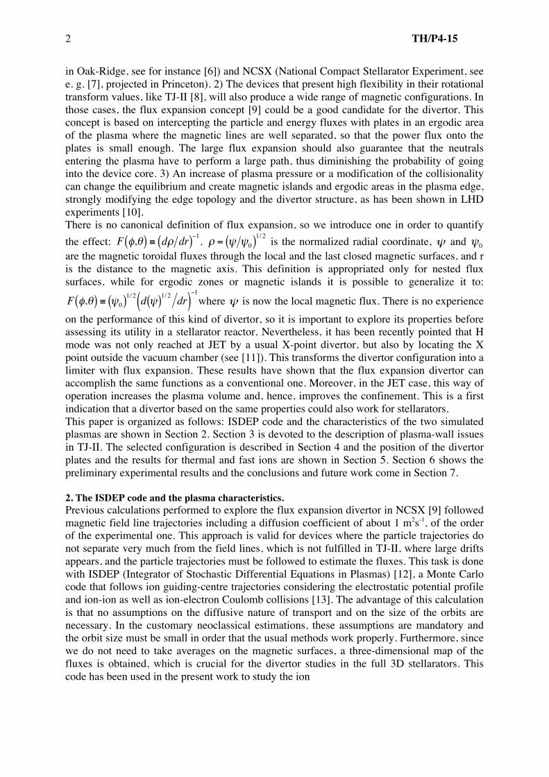
in Oak-Ridge, see for instance [6]) and NCSX (National Compact Stellarator Experiment, see e. g. [7], projected in Princeton). 2) The devices that present high flexibility in their rotational transform values, like TJ-II [8], will also produce a wide range of magnetic configurations. In those cases, the flux expansion concept [9] could be a good candidate for the divertor. This concept is based on intercepting the particle and energy fluxes with plates in an ergodic area of the plasma where the magnetic lines are well separated, so that the power flux onto the plates is small enough. The large flux expansion should also guarantee that the neutrals entering the plasma have to perform a large path, thus diminishing the probability of going into the device core. 3) An increase of plasma pressure or a modification of the collisionality can change the equilibrium and create magnetic islands and ergodic areas in the plasma edge, strongly modifying the edge topology and the divertor structure, as has been shown in LHD experiments [10]. There is no canonical definition of flux expansion, so we introduce one in order to quantify the effect:
€
F φ,θ( ) ≡ dρ dr( )−1.
€
ρ = ψ ψ0( )1/ 2 is the normalized radial coordinate,
€
ψ and
€
ψ0 are the magnetic toroidal fluxes through the local and the last closed magnetic surfaces, and r is the distance to the magnetic axis. This definition is appropriated only for nested flux surfaces, while for ergodic zones or magnetic islands it is possible to generalize it to:
€
F φ,θ( ) ≡ ψ0( )1/ 2 d ψ( )1/ 2 dr( )−1
where
€
ψ is now the local magnetic flux. There is no experience on the performance of this kind of divertor, so it is important to explore its properties before assessing its utility in a stellarator reactor. Nevertheless, it has been recently pointed that H mode was not only reached at JET by a usual X-point divertor, but also by locating the X point outside the vacuum chamber (see [11]). This transforms the divertor configuration into a limiter with flux expansion. These results have shown that the flux expansion divertor can accomplish the same functions as a conventional one. Moreover, in the JET case, this way of operation increases the plasma volume and, hence, improves the confinement. This is a first indication that a divertor based on the same properties could also work for stellarators. This paper is organized as follows: ISDEP code and the characteristics of the two simulated plasmas are shown in Section 2. Section 3 is devoted to the description of plasma-wall issues in TJ-II. The selected configuration is described in Section 4 and the position of the divertor plates and the results for thermal and fast ions are shown in Section 5. Section 6 shows the preliminary experimental results and the conclusions and future work come in Section 7. 2. The ISDEP code and the plasma characteristics. Previous calculations performed to explore the flux expansion divertor in NCSX [9] followed magnetic field line trajectories including a diffusion coefficient of about 1 m2s-1, of the order of the experimental one. This approach is valid for devices where the particle trajectories do not separate very much from the field lines, which is not fulfilled in TJ-II, where large drifts appears, and the particle trajectories must be followed to estimate the fluxes. This task is done with ISDEP (Integrator of Stochastic Differential Equations in Plasmas) [12], a Monte Carlo code that follows ion guiding-centre trajectories considering the electrostatic potential profile and ion-ion as well as ion-electron Coulomb collisions [13]. The advantage of this calculation is that no assumptions on the diffusive nature of transport and on the size of the orbits are necessary. In the customary neoclassical estimations, these assumptions are mandatory and the orbit size must be small in order that the usual methods work properly. Furthermore, since we do not need to take averages on the magnetic surfaces, a three-dimensional map of the fluxes is obtained, which is crucial for the divertor studies in the full 3D stellarators. This code has been used in the present work to study the ion

TH/P4-15 3
collisional flux properties in the chosen magnetic configuration and various plasma regimes. Obviously, the quantitative results will depend on the plasma characteristics, namely the collisionality and the electrostatic potential. Nevertheless, we expect our results on the divertor hold in a wide range of plasma parameters, especially in the high density regime, since the divertor must work mainly in these conditions. In order to check this, two characteristic plasma regimes have been chosen in this work. The plasma profiles are shown in Figure 1 as a function of the effective radius. The plasma parameters used in our simulations are taken similar to those obtained experimentally in the two former regimes. The density and electron temperature are obtained from Thomson-Scattering measurements (the error bars are not plotted in these smoothed profiles, but they are of the order of 10% for the electron temperature and 5% for the density). The ion temperature profiles are taken from CX-NPA diagnostic [14], in shot to shot experiments. The typical error bars for these measurements are about 10%. Finally, the electrostatic potential comes from HIBP measurements. In green, we show a low density, low collisional ECRH (electron cyclotron resonance heating) plasma. It is characterized by a positive electric field in the core, according to the electron root confinement. The ion temperature profile is almost flat within the error bars [15], and that of the electron temperature is peaked. The density profile is hollow, due to the ECRH-induced pump-out. This
ECRH case corresponds to an intermediate plasma density and the electrostatic potential is non-monotonic: it shows a transition from the electron root (positive electric field) in the centre of the device to the ion root (negative electric field) in the edge. Therefore, the electrostatic potential presents a minimum at ρ ≈ 0.6, which implies that the ions tend to accumulate close to this zone. In red, we plot an NBI (neutral beam injection) plasma. The density is high and the electron temperature is lower than in the ECRH plasma, with parabolic profiles, as in [16]. In this case, the ion temperature is not flat and presents steeper gradient than in the ECRH case. The potential is negative, corresponding to the ion root, and monotonic (except in the centre) and negative. Not surprisingly, this potential tends to enhance the ion confinement, which will have
Figure 2. Calculated ion impacts on the TJ-II walls (top view). The groove and the steps of the chamber suffer the largest fraction of the flux.
Figure 1. Density, electron and ion temperatures, and electrostatic potential profiles used for the simulations. The red ones correspond to an NBI plasma and the green ones to an ECRH plasma.

TH/P4-15 4
strong consequences on the flux structure.
3. The plasma-wall interaction in TJ-II. The TJ-II vacuum chamber has a groove that surrounds the central conductor and intercepts some of the vacuum magnetic surfaces in most of the configurations, hence acting as a helical limiter that intersects the magnetic field lines and receives the particle and heat parallel fluxes. The groove is very close to he magnetic axis (about 12 — 14 cm, depending on the configuration) and due to its position and to the
€
B × ∇ B drifts, it is the preferred zone for the
escaping particles to strike, as will be discussed in Section 5. All these facts make that TJ-II presents specific plasma-wall interaction issues. Figure 2 shows the impacts of particles on the TJ-II walls (106 particles have been considered), showing a large density of hits just on the groove. Since this element is physically close to the centre of the plasma, one should try to diminish the fluxes on it by intersecting the particle trajectories far from that position. Otherwise it is guaranteed that a large fraction of the recycled neutrals will return to the plasma and reach its inner part, with a strong impact on the confinement. We have found several magnetic configurations suitable for the flux expansion divertor, since they have plasma zones where the flux expansion is large enough. The point is to find a position in which the efficiency of the divertor is maximum (i.e. intersects a large fraction of the heat and particle fluxes) and to try to make this requirement compatible with a low enough heat flux on the plates. No natural ergodic zones appear outside the LCFS in TJ-II. Therefore, a second phase of this work may imply the creation of this ergodic zone. 4. Choice of Configurations. One of the main properties of TJ-II heliac is its flexibility: the plasma size and shape as well as the rotational transform can be modified by changing the currents that circulate by the two coils of the central conductor. The standard TJ-II configurations have a small separation between the plasma and the groove, and the flux expansion is rather low. These configurations have a value of the central rotational transform
€
ι ≡ι 2π ≈1.5or below. However, the high
€
ι (of order 2 and higher) configurations present larger clearance, more indented shape and, hence, larger flux expansion , which makes them more suitable for divertor requirements. We have chosen the configuration 100_68_91 (the numbers stand for the currents that circulate by the coils), shown in Figure 3, which belongs to a family that presents a large flux expansion at given toroidal positions. This configuration has some space available for divertor targets and pumping systems between the plasma and the vessel. This configuration, selected to evaluate the feasibility of a flux expansion divertor for TJ-II, presents average plasma minor radius a=0.2 m and rotational transform in the edge
€
ι =1.825 . Similarly to the majority of TJ-II magnetic configurations, a large fraction of the particle fluxes strike the groove in this one, as will be shown in Section 5. Therefore, the neutrals coming from the wall appear very close to the plasma centre, as it has been commented above. Besides the thermal ions, it is also very important to estimate the flux of fast ions coming from NBI that are not thermalised by the plasma. As we will see below, it is the groove again the preferred destination for such particles. Hence, the main goal of the
Figure 3. Toroidal cut of the magnetic surfaces of the chosen configuration together with the groove of the vacuum vessel. The arrows mark the distance from the magnetic axis.

TH/P4-15 5
divertor designed for TJ-II is to diminish as much as possible the fluxes that are directed to the groove. In this way the plasma-wall interaction would concentrate in a much more
favourable region, far from the plasma centre. It can be seen in Figure 3 that the distance from the magnetic axis to the groove is about 12 cm in this configuration, and only a thin layer of plasma of about 5 cm separates the edge and the plasma bulk (distance between the axis and the
LCFS at the groove poloidal position). Nevertheless, this layer is about 25 cm at the poloidal position that corresponds to one of the extremes of the plasma “bean”. Therefore, if the plasma-wall interaction can be concentrated at the zone where the flux expansion is maximum (about a factor 5 higher), the particle flux onto the groove will be strongly reduced. The amount of neutrals that enter the plasma bulk will also decrease since the physical distance is multiplied by a factor 5, thus improving the plasma performance.
5. Plate location and results. In order to search for the optimal position of the plates, we have performed a 3D
map of the ion flux on several magnetic surfaces and at different toroidal and poloidal angles using the code ISDEP and the plasmas presented in Section 2. Since TJ-II is a four-period device, our results are (statistically) identical in each period. Therefore, we will consider all of them in our calculations and show them averaged in the first period, hence multiplying by a factor 4 the statistics of our Monte Carlo code. This has been done by adding the values of the fluxes at equivalent toroidal angles. We have accomplished our task defining our plates as the locus of points (ρ, θ, φ) such that:
€
ρ > ρ0,2πNφ
i < φ <2πNφ
i +1( ), 2πNθ
j < θ <2πNθ
j +1( )
By setting Nφ=16 (four intervals per period) and Nθ=32, we have 128 plates tangent to the magnetic surface defined in each period, corresponding to 512 different plates in TJ-II. An sketch of one ensemble is shown in Figure 4. 5.1 Thermal ions We follow a large number of ion trajectories and study the individual effect of each plate on the particle flux. More precisely, in Figure 4 we show, for the ECH plasma, the fraction of the trajectories that would be intercepted by each plate in the case that this were the only one in our device. Note that the contributions of two plates cannot be directly added, since they may partly shadow each other. Studying the structures that appear in the flux (see Figure 5) it is possible to infer the optimum positions where a plate can be more effective. We will be
Figure 4. Ensemble of plates located at maximum flux expansion along a toroidal period. The 0.9<ρ<1 corona is also plotted.
Figure 5. Proportion of ions intersected by the toroidally extended plate as a function of the angular position of the plate for the ECH plasma. The four toroidal plates cover a single period.

TH/P4-15 6
interested in plates in the outer region of the plasma, where ρ >1.0, for an acceptable interaction of the plate with the hot plasma. In such radial positions, the plates defined by
€
θ ≈ 3π 2 for
€
π 4 < φ < 3π 8 and
€
3π 8 < φ < 2 look promising, since 10% of all the particles would be intercepted by each of them. Considering the mirror images of these
plates in the other three periods (although, as we know, their contributions do not simply add up), one could expect to concentrate a great proportion of the plasma-wall interaction on these plates. Note that our choice is not the optimal on intercepting particles, but it is the best that makes it far from the groove. In this case, our plates intercept about half the particles that escape from the plasma, including ions that end their trajectories in the groove and ions that do not. The high original peaks correspond to collisions with the groove, which in usual
operation represent around 60% of the collisions with the vacuum chamber. The effect of our plates is to diminish this quantity so that it is around 35%, about half the proportion existing before. New peaks appear, corresponding to the location of our plates, which means that a great part of the plasma-wall interaction is concentrated there. In the NBI case, the radial electric field clearly improves the confinement, especially in the plasma edge. One of the consequences is that each ion has more probability of being intercepted by each plate, since it performs more toroidal turns around TJ-II before
leaving the plasma. The proportion of the total trajectories that are intercepted is about
63%. Nevertheless, from about 50% of ions colliding with the groove, this amount get reduced to about 35%. Our former proposal for the plate position still seems one of the best possible, as can be seen in Figure 6. These are good news, since one would desire a divertor design valid for a wide range of plasma parameters. Looking at Figures 5 and 6, our first tentative design will be plates located atρ >1.0,
€
11π 8 < θ < 23π 16 along the whole toroidal angle. This configuration is plotted in Figure 5. 5.2 Fast ions Beyond the effect of thermal ions, it is mandatory to consider the trajectories of fast ions that come from NBI to evaluate the extra flux provided by theses particles. The dynamics of NBI ions is important since there can be a lot of particles that escape from the plasma and transport a large momentum to the vacuum chamber. The Monte Carlo Fafner code, which was adapted to TJ-II geometry [17], has been used to estimate the birth points of such fast ions together with their velocities. The trajectories of these ions have been followed up to the walls using ISDEP and considering again the collisions with the background plasma and the effect of the
Figure 6. Same as Figure 5 for the NBI plasma.
Figure 7. Escape points of thermal (red) and fast (green) ions in TJ-II (the distances are in m).

TH/P4-15 7
electrostatic potential. Figure 8 shows the escaping points of thermal (red) and fast ions (green) and the tendency of the latter to escape to the groove is even more pronounced than in the thermal ones. This is not surprising since these trajectories are due to the
€
B × ∇ B drift,
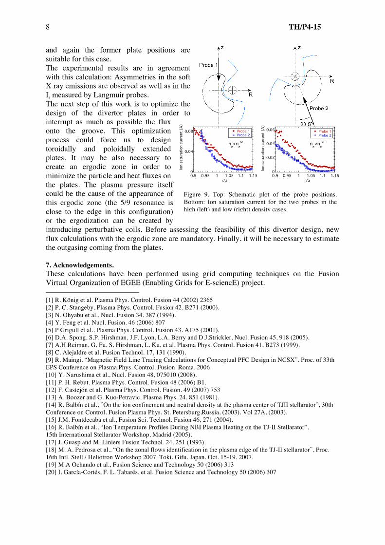
which is larger for higher energy ions. The distribution of fast ion fluxes with and without divertor is seen in Figure 11. The position of the former plates happens to be appropriated also for the fast ions. A fraction of 90% particles escape to the groove before considering the plates, which is reduced to 25% when the plates are located intersecting the trajectories. 6. Preliminary experimental results. The theoretical studies performed with ISDEP must be validated with experiments that show that, in fact, the 3D flux map calculated is in agreement with the experimental measurements. Preliminary measurements performed by Langmuir probes [18] present different ion saturation current (Is) profiles at different toroidal and poloidal positions (See figure 10), in agreement with the calculations performed with ISDEP: the higher Is appears for the probe close to the “bean” of the plasma, in comparison with the probe inserted by convex zone of the magnetic surfaces. And this happens in the low and high density cases. The same preliminary agreement is found with the measurements performed by bolometer and Soft X Ray detector arrays [19]. Further experimental measurements in different plasma conditions and magnetic configurations will be performed with the above cited systems together with a visible camera and the probes inserted in the two poloidal limiters, which are located at different toroidal and poloidal positions of TJ-II. The experimental methods used in previous works that explored the possibility of developing an island divertor in TJ-II [20] will be also very useful in our exploration. 7. Conclusions and future work. The feasibility of flux expansion divertor concept is being investigated in TJ-II. We have found a promising family of configurations that present large flux expansion, which are characterized by having a very indented plasma shape and for a high rotational transform value (above 1.8). The three-dimensional particle collisional flux maps are characterized by their strong poloidal and toroidal asymmetries, showing a high value in the poloidal position corresponding to one of the extremes of the ”bean”. The same can be said for the fast ions coming from NBI. This particular characteristic of TJ-II ensures that locating the divertor plates close to the position where these fluxes are maximum will ensure that the particle and heat fluxes onto the groove of the vacuum chamber are strongly diminished. This kind of magnetic configurations has the property that the flux expansion is maximum in a region where the main part of the particle flux that goes onto the groove passes through. Therefore, one may minimize at the same time the flux onto the groove and onto the plates. Due to the TJ-II configuration characteristics, this effect is beneficial because we move the main plasma wall interaction to a zone much farther from the plasma core: the physical distance is enhanced by a factor 5. The beneficial effect of the divertor is larger in the NBI regime despite of the fact that this case presents a shorter mean free path, because the structure of electrostatic potential ensures that a large fraction of particles is intercepted. Regarding the fast ion coming from NBI, their direct losses are mainly towards the groove,
0
0.05
0.1
0.15
0.2
0.5 1 1.5 2
ang
ula
r co
llis
ion
dis
trib
uti
on
NB
I io
ns
!/"
0 < # < "/8
orig.div.
0.5 1 1.5 2
!/"
"/8 < # < "/4
0.5 1 1.5 2
!/"
"/4 < # < 3"/8
0.5 1 1.5 2
!/"
3"/8 < # < "/2
Figure 8. Same as Figure 6 for fast ions.
TH/P4-15 8
and again the former plate positions are suitable for this case. The experimental results are in agreement with this calculation: Asymmetries in the soft X ray emissions are observed as well as in the Is measured by Langmuir probes. The next step of this work is to optimize the design of the divertor plates in order to interrupt as much as possible the flux onto the groove. This optimization process could force us to design toroidally and poloidally extended plates. It may be also necessary to create an ergodic zone in order to minimize the particle and heat fluxes on the plates. The plasma pressure itself could be the cause of the appearance of this ergodic zone (the 5/9 resonance is close to the edge in this configuration) or the ergodization can be created by introducing perturbative coils. Before assessing the feasibility of this divertor design, new flux calculations with the ergodic zone are mandatory. Finally, it will be necessary to estimate the outgasing coming from the plates. 7. Acknowledgements. These calculations have been performed using grid computing techniques on the Fusion Virtual Organization of EGEE (Enabling Grids for E-sciencE) project. [1] R. König et al. Plasma Phys. Control. Fusion 44 (2002) 2365 [2] P. C. Stangeby, Plasma Phys. Control. Fusion 42, B271 (2000). [3] N. Ohyabu et al., Nucl. Fusion 34, 387 (1994). [4] Y. Feng et al. Nucl. Fusion. 46 (2006) 807 [5] P Grigull et al., Plasma Phys. Control. Fusion 43, A175 (2001). [6] D.A. Spong, S.P. Hirshman, J.F. Lyon, L.A. Berry and D.J.Strickler, Nucl. Fusion 45, 918 (2005). [7] A.H.Reiman, G. Fu, S. Hirshman, L. Ku, et al, Plasma Phys. Control. Fusion 41, B273 (1999). [8] C. Alejaldre et al. Fusion Technol. 17, 131 (1990). [9] R. Maingi. “Magnetic Field Line Tracing Calculations for Conceptual PFC Design in NCSX”. Proc. of 33th EPS Conference on Plasma Phys. Control. Fusion. Roma, 2006. [10] Y. Narushima et al., Nucl. Fusion 48, 075010 (2008). [11] P. H. Rebut, Plasma Phys. Control. Fusion 48 (2006) B1. [12] F. Castejón et al. Plasma Phys. Control. Fusion. 49 (2007) 753 [13] A. Boozer and G. Kuo-Petravic, Plasma Phys. 24, 851 (1981). [14] R. Balbín et al., ”On the ion confinement and neutral density at the plasma center of TJII stellarator”, 30th Conference on Control. Fusion Plasma Phys. St. Petersburg,Russia, (2003). Vol 27A, (2003). [15] J.M. Fontdecaba et al., Fusion Sci. Technol. Fusion 46, 271 (2004). [16] R. Balbín et al., “Ion Temperature Profiles During NBI Plasma Heating on the TJ-II Stellarator”, 15th International Stellarator Workshop, Madrid (2005). [17] J. Guasp and M. Liniers Fusion Technol. 24, 251 (1993). [18] M. A. Pedrosa et al., “On the zonal flows identification in the plasma edge of the TJ-II stellarator”, Proc. 16th Intl. Stell./ Heliotron Workshop 2007. Toki, Gifu, Japan, Oct. 15-19, 2007. [19] M.A Ochando et al., Fusion Science and Technology 50 (2006) 313 [20] I. García-Cortés, F. L. Tabarés, et al. Fusion Science and Technology 50 (2006) 307
Figure 9. Top: Schematic plot of the probe positions. Bottom: Ion saturation current for the two probes in the high (left) and low (right) density cases.
!
0
0.04
0.08 Probe 1Probe 2
0.9 0.95 1 1.05 1.1 1.15
Ion s
atu
rati
on c
urr
ent
(A)
ne>n
e
cr
r/a
0
0.02
0.04
0.06 Probe 1Probe 2
0.9 0.95 1 1.05 1.1 1.15
Ion s
atu
rati
on c
urr
ent
(A)
ne<n
e
cr
r/a


