Embed Size (px)
Citation preview

IEEE TRANSACTIONS ON PARALLEL AND DISTRIBUTED SYSTEMS 1
Virtual Appliance Size Optimizationwith Active Fault Injection
Gabor Kecskemeti, Gabor Terstyanszky and Peter Kacsuk
Abstract—Virtual appliances store the required information to instantiate a functional virtual machine on Infrastructure as aService (IaaS) cloud systems. Large appliance size obstructs IaaS systems to deliver dynamic and scalable infrastructures according totheir promise. To overcome this issue, this article offers a novel technique for virtual appliance developers to publish appliances for thedynamic environments of IaaS systems. Our solution achieves faster virtual machine instantiation by reducing the appliance size whilemaintaining its key functionality. The new virtual appliance optimization algorithm identifies the removable parts of the appliance. Then,it applies active fault injection to remove the identified parts. Afterwards, our solution assesses the functionality of the reduced virtualappliance by applying the – appliance developer provided – validation algorithms. We also introduce a technique to parallelize the faultinjection and validation phases of the algorithm. Finally, the prototype implementation of the algorithm is discussed to demonstratethe efficiency of the proposed algorithm through the optimization of two well-known virtual appliances. Results show that the algorithmsignificantly decreased virtual machine instantiation time and increased dynamism in IaaS systems.
Index Terms—Virtual appliance, Optimization, Cloud Computing, IaaS
�
1 INTRODUCTION
INFRASTRUCTURE as a service (IaaS – [1], [2]) cloudsystems promise to provide on demand and scalable
infrastructures. The scalability of this new kind of infras-tructure is provided through virtualization [3]. Even themost basic IaaS systems offer service interfaces to createand manage virtual machines (VMs) hosted by variousvirtual machine monitors [4], [5], [6]. From the earliestcommercial IaaS systems – like Amazon EC2 – thesesystems are marketed as an approach to dynamicallyextend service infrastructures. Users prepare virtual ap-pliances (VAs – [7]) hosting the dynamic components oftheir service-based applications. These appliances storethe necessary information to instantiate a functional vir-tual machine (e.g. an operating system, the dependenciesand the code of the dynamic component itself).
One of the most frequently referred scenarios of com-mercial IaaS providers offers a solution to handle thepeak demand periods of service-based applications [8],[9], [10]. The highly dynamic [11], [12] nature of theseapplications require IaaS users to instantiate their vir-tual appliances on demand within a minimal amountof time. However, the virtual appliance instantiationtime is mainly dependent on the size of the appliance.Therefore, appliance developers should create virtual
• G. Kecskemeti and P. Kacsuk are with the Laboratory of Parallel and Dis-tributed Systems at Computer and Automation Institute of the HungarianAcademy of Sciences, Kende u. 13-17, Budapest 1111, HungaryE-mail: {kecskemeti,kacsuk}@sztaki.hu
• G. Terstyanszky is with the Centre of Parallel Computing at Universityof Westminster, 309 Regent Street, London W1B 2UW, United KingdomE-mail: [email protected]
The research leading to these results has received funding from the EuropeanCommunity‘s Seventh Framework Programme FP7/2007-2013 under grantagreement 215483 (S-Cube).
appliances with the smallest size while they still main-tain the key functionality of the appliance. The manualcreation of such appliances requires expertise and timenot available for most IaaS users. Consequently, highlydynamic service environments require techniques forcreating virtual appliances.
Already existing automated appliance creation tech-niques (e.g. [13]) utilize the dependencies between thevarious software components of the future virtual appli-ance. These techniques require the appliance developerto define the dependencies and requirements of its dy-namic components before creating the appliance itself.Then, they construct the virtual appliance according tothe previous definitions. As a result, these techniquesrely on the virtual appliance developer’s skills of prepar-ing optimally sized appliances for dynamic service en-vironments. This research reduces the demands on theappliance developers by requiring them to only definethe intended usage scenarios (referred as the key func-tionality) of dynamic components.
Active fault injection is a well-discussed topic fordetermining the fault tolerance of various software sys-tems [14], [15], [16], [17]. This article introduces theconcept of active fault injection to a new domain: virtualappliance size minimization. We propose to inject faultsto virtual appliances by removing their parts while theyare executed in virtual machines. The article offers afault injection technique that is independent from thegranularity of the virtual appliance parts (e.g. they canbe software packages or files). This technique first identi-fies the smallest individually handled parts of the virtualappliance. Afterwards, the technique identifies the partsmore favorable for removal. After their removal, the re-duced virtual appliance is validated against the intendedusage scenarios specified by the appliance developer.
Digital Object Indentifier 10.1109/TPDS.2011.309 1045-9219/11/$26.00 © 2011 IEEE
This article has been accepted for publication in a future issue of this journal, but has not been fully edited. Content may change prior to final publication.

2 IEEE TRANSACTIONS ON PARALLEL AND DISTRIBUTED SYSTEMS
Finally, the article discusses an approach to parallelizethe removal and validation tasks of our technique.
This new technique is based on the assumption thatthe appliance developer intends to create single purposevirtual appliances. These appliances have a well definedand single functionality (e.g. provide a specific website).We assume that the appliance developer is capable todescribe the purpose of the appliance by providing val-idation algorithms for the key functionality. In contrast,generic appliances are designed to be customizable bythird parties (e.g. LAMP – Linux, Apache, MySQL, php –appliances that allow their arbitrary customization afterdeployment). As the developers cannot clearly specifythe later use of their appliances they cannot define thevalidation algorithms. Consequently, the approach is notapplicable to generic virtual appliances but only to asubclass of virtual appliances paired with the definitionof their validator algorithms. The research results are uti-lized as part of an Automated Virtual appliance creationService that was introduced and discussed in [18], [19].
This article discusses our implementation that is in-stantly applicable to IaaS systems similar to AmazonElastic Compute Cloud (EC2 – [20]). Then, we evaluatethe proposed technique through experiments executedon a Eucalyptus [21] based testbed. The experimentsfirst present the significant virtual appliance size reduc-tion (e.g. more than 90%) achievable with our technique.Second, the article reveals how the optimization timeis reduced by refining the proposed technique reachingless than 2-hour optimization time with a 32 CPU basedcluster on our test VAs (Apache and SSH).
This paper is organized as follows. Section 2 providesan overview about the related works. Then, Section 3highlights the architecture that is proposed to includethe optimization approach described in the article. Later,in Section 4, we discuss the basics of the optimizationalgorithm. Then, Section 5 reveals the details and thedecisions we made for the first implementation. Finally,in Section 6 we measure the effectiveness of the imple-mented optimization algorithm.
2 RELATED WORKS
Virtual appliance distribution can be optimized by eitheroptimizing the delivery path of the appliance (e.g. bycaching or replicating some of the appliance contentsfor faster, multi-sourced delivery [19], [22], [23]) or byreducing its size. Size reduction results immediate effectson appliance instantiation time even without deliverypath changes. This article is focused on the secondapproach, therefore this related works section is onlyfocusing on the appliance size optimization approaches.
The discussed approaches can be classified based ontheir input requirements. The pre-optimizing approach re-quires the appliance developer to provide the applicationand its known dependencies that should be offered bythe appliance. In contrast, the post-optimizing approachuses already existing but non-optimized appliances.
With pre-optimizing algorithms the dependencies of theuser applications are prepared as reusable virtual appli-ance components. The appliance developers select fromthese components so that they can form the base of theuser application. These algorithms then form the virtualappliance with the selected reusable components and theapplication itself. RBuilder [13] applies this algorithmwith an extension that supports creating custom virtualappliances by building from the source code.
The extreme case of pre-optimizing algorithms is theminimalist pre-optimizing approach that offers opti-mized virtual appliances with known software environ-ments. To support this approach several OS and reusableapplication vendors offer the minimalist version of theirproduct packaged together with their just-enough op-erating system (JeOS – [24]) in virtual appliances [25],[26], [27], [28]. For example, there are several virtualappliances available prepared to host a simple LAMPproject. However, this approach requires the appliancedeveloper to manually install its application to a suitableoptimized virtual appliance. The advantage of thesealgorithms is the fast creation of the appliances but atthe price that the developer has to trust the optimizationattempt of the used virtual appliance’s vendor. If theappliance is not well optimized, or the vendor offers ageneric appliance for all uses then the descendant virtualappliances cannot be optimal without further efforts.
Other pre-optimizing algorithms determine depen-dencies within the virtual appliance by using its sourcecode. Software clone [29] and dependency [30] detec-tion techniques identify all of the required underlyingsoftware components by analyzing the sources. Oncethe dependencies are detected these algorithms leaveonly those components that are required for serving thekey functionality of the virtual appliance. Optimizinga virtual appliance with these techniques require thesource code of all the software encapsulated within theappliance. Thus they also need to analyze the underlyingsystems (e.g. the operating system) of the application.Unfortunately this last requirement renders these tech-niques unfeasible in most cases.
The most widely used post-optimizing algorithms areoptimizing the free space in the disk images of thevirtual appliance. If virtual appliances are created frompreviously used software systems then their disk imagescontain their available free space fragmented throughoutthe entire image. Before publication, virtual appliancesare usually compressed for easier transfer. However, thefragmented free space is harder to compress. Therefore,these post optimizing algorithms analyze the availablefree space and first they fill them with easily compress-ible data. Next, they offer their users the option to de-fragment the disk images. As a result, these disk imagescan be shrunk so they are not only more compressiblebut they do not even store the free space in the diskimage if they are not required. The advantage of thisalgorithm, that it can operate on any virtual applianceso long it can understand and use its file system. This
This article has been accepted for publication in a future issue of this journal, but has not been fully edited. Content may change prior to final publication.

KECSKEMETI ET AL.: VIRTUAL APPLIANCE SIZE OPTIMIZATION WITH ACTIVE FAULT INJECTION 3
technique is utilized by [31].Our investigations show that the field of post-
optimizing algorithms is less developed, even thoughthey could bring remedy for the vast amounts of alreadyexisting virtual appliances that are currently unusablein dynamic service environments. Consequently, the sizeoptimization technique discussed in this article can alsobe classified as a post-optimizing algorithm.
3 THE AUTOMATIC SERVICE DEPLOYMENTARCHITECTURE
In our previous work [18] we introduced the AutomaticService Deployment (ASD) architecture as seen in Fig. 1.The architecture provides a framework to our recent andfuture works. This section gives a short overview of thearchitecture and contextualizes current research results.
Fig. 1 presents the service deployment architecturethat supports various tasks of the virtual appliance-based deployment and also depicts several issues thatthe current solutions do not aim at. First, the architectureoffers a solution for initial virtual appliance creation.Virtual appliances are acquired and managed by theAutomated Virtual appliance creation Service [19]. In thearticle only the following virtual appliance preparationtasks were solved: (i) extracting a virtual appliance froma running system, (ii) transformation of the appliancebetween various virtual machine image formats, and(iii) uploading the virtual appliance to a repository.Through the functionality of the optimization facility, thisarticle extends these tasks with the size optimization ofthe previously extracted virtual appliances.
Second, the architecture also supports developers tocreate appliances more suitable for highly dynamic en-vironments via minimal manageable virtual appliances [32]that they can use as the base of their appliance. This ap-pliance provides management interfaces offering packageinstallation, configuration and removal operations.
Third, the architecture defines active repositories withthe following automatic entry management functional-ity: (i) appliance decomposition, (ii) package merging,(iii) destruction and (iv) partial replication. Therefore,
Automatic Service Deployment (ASD)
IaaSSystems
Scheduler Assistant Service(SAS)
Automatic Virtual appliance creation Service (AVS)
Virtual Appliance Optimization
Facility
Manageable Virtual
Appliances
Active Repositories
Fig. 1. Appliance optimization within ASD
these repositories have the ability to identify commonvirtual appliance parts and optimize their storage.
Finally, the architecture also offers decision-makingsupport for schedulers and other high level entitiesthat make deployment related decisions in a dynamicservice ecosystem. Service deployment can be initiatedby higher-level components (such as service schedulersor service composition engines), the Scheduler AssistanceService (SAS) aids their deployment decisions by offeringinterfaces to identify deployable services and rank sitesthat can host them. The research issues and designconsiderations of the SAS are discussed in [33].
4 VIRTUAL APPLIANCE OPTIMIZATION PRIN-CIPLES
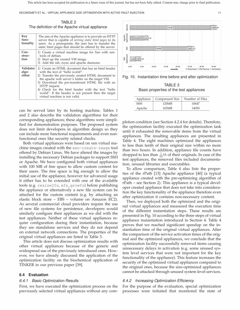
As the first step towards the optimization algorithm,this section identifies the time reduction options forvirtual appliance instantiation. We have defined theinstantiation as a composite task of three major steps:(i) download the appliance, (ii) initialize the VM andstart up its operating system and finally, (iii) activatethe service in the VM. Fig. 10 presents the averageexecution time of these three tasks for two typical virtualappliances described in Section 6.3.
It can be observed in Fig. 10 that instantiation timemainly depends on the download time of the virtualappliance. This time can be optimized in two ways:(i) storing the virtual appliance in a repository withthe smallest latency and largest transfer rate towards itsexecutor host and (ii) minimizing the size of the virtualappliance while still maintaining its key functionality.The first option is only viable with IaaS systems thatsupport multiple repositories (this is not the case withAmazon EC2 [20] or Eucalyptus [21]), therefore to sup-port wider range of IaaS systems we only focus on thesize minimization in this article. Throughout this article,we did not make any assumptions on the IaaS behavior;therefore, this approach is applicable to any IaaS system.
4.1 The Virtual Appliance Optimization Facility
Before detailing the features of our size optimizationtechnique, we define the constraints of the optimizationfacility and system. The optimization facility incorporatesthe algorithms described in this article. It resides ona single host of the optimization system (ϕ). The opti-mization system incorporates multiple hosts (hx ∈ ϕ)within a single administrative domain. These hosts alsoimplement an IaaS system offering the required virtualmachine management functionality for the facility.
The main task of the optimization facility is to solvethe optimize : P × C → P ′ function. Where the setP refers to all virtual appliances in the optimizationsystem, and C defines the possible completion conditionsthat can limit the optimization according to the appliancedeveloper. At the end of the optimization operation, thep′σ := optimize(pσ, c) function provides a smaller sized
This article has been accepted for publication in a future issue of this journal, but has not been fully edited. Content may change prior to final publication.

4 IEEE TRANSACTIONS ON PARALLEL AND DISTRIBUTED SYSTEMS
version (p′σ) of the original virtual appliance (pσ) andpublish it among the other virtual appliances: P ′ :=P ∪{p′σ}. If the optimization function receives an emptycompletion condition set (c = ∅) then the optimization isexecuted until p′σ becomes optimally sized – see Eq. (4).
Active fault injection uses fault injection techniques thatgenerate hardware and software level faults to test thefault tolerant behavior of software. However, for virtualappliance optimization, we do not test for fault tolerantbehavior. Instead, fault injection identifies those parts ofthe pσ that are not needed for its key functionality.
First, we define the faults that can be injected inorder to achieve size reduction. Having a virtualizedenvironment enables the simulation of both software andhardware level faults. Software level faults could ariseon the file system – e.g. simulating the corruption ofthe file system by removing a file or some of its parts.Hardware faults could occur in the memory or the disksubsystem. Simulating hardware faults need changes invirtual machine monitors. This requirement seriouslyreduces the adoptability of an optimization technique;thus, this article only considers software fault injection.
4.2 Appliance Contents Removal
This section describes the basic algorithm of the opti-mization procedure that is split into four tasks as seenin Fig. 2. The first task is the selection of the virtual ap-pliance’s removable parts. The selection task is the mostcomplex and critical task of the optimization approach.This task analyzes the package (pσ ∈ P ) of the virtualappliance and proposes how to partition the appliance.
The selection task also assigns a weight value toappliance parts. The highest weighted parts are tem-porarily erased from the appliance by the removal task.The third task is the validation of the modified applianceusing validation algorithms provided by the appliancedeveloper. This task decides whether the erased itemsshould be permanently removed from the VA. Later, werefer to the triplet of selection, removal and validation asthe optimization iteration (see the bold arrows in Fig. 2).
The last task of the algorithm decides whether thesystem should initiate further optimization iterations.The decision is based on the appliance developer pro-vided completion conditions. If the conditions are met thealgorithm publishes the optimized appliance. Otherwise,the algorithm proceeds with the next iteration. Thesefour tasks are further outlined in the next sub-sections.
Repository
Original VA ReducedVA
Selection Removal Validation
[Conditions not met]
<<decisionInput>>:
Check completion conditions
Fig. 2. Basic appliance optimization technique
4.2.1 SelectionAs it was discussed previously, the main task of theselection is to identify parts to be removed. From theselection point of view the granularity of the parts in theVA is not important. However, the selection algorithmshould use the same appliance part granularity that theremoval task uses. Virtual appliance parts can rangefrom single bytes, sectors, file contents, files to evendirectories or software packages.
The identification of the different parts and their meta-data is called itemization. Items (i ∈ I) are the internal rep-resentation of the virtual appliance parts with metadata.Different itemization techniques use different kinds ofvirtual appliance parts as items. The set of I representsall possible items created with a particular itemizationtechnique. Items are the smallest entities handled by theselection and removal algorithms. The entire item set ofan appliance is represented with the function it : P → I .
If multiple itemization techniques are available, thenthe optimization is executed in several phases. In the firstphase, the facility removes and validates the item set ofthe current itemization technique. If there are no moreitems to validate and the completion conditions allow,the facility initiates a new phase using an itemizationtechnique with smaller granularity.
For example, if the first applied itemization techniqueuses software package managers (e.g. the debian pack-age manager [34] – dpkg), then the facility first removesall software packages not related to the key function-ality of the appliance. The facility switches to smallergranularity when it cannot purge more packages fromthe VA with the package manager. Consequently, duringlater executed phases, the facility could even erase thesoftware package manager itself if it is not required forthe key functionality of the appliance.
The second subtask of selection categorizes the var-ious items according to the following list: (i) the coreitems – ic –, (ii) the volatile items – iv – and finally,(iii) the fuzzy items – if . Those items that the selectionalgorithm does not have any prior knowledge aboutare called volatile and are primarily exposed to activefault injection by the optimization facility. In contrast tovolatile items, the core and fuzzy items are identifiedby the past knowledge of the selection task. The coreitems cannot be removed from an appliance under anycircumstances (e.g. the init application in SystemVcompatible UNIX systems); these items are predefinedin the knowledge base of the selection task. Initially nofuzzy items are defined. They are identified as thoseitems that – according to the knowledge base – wererepeatedly validated unsuccessfully in prior optimiza-tion operations. If the developer specified completionconditions could not be reached, then the facility startsremoving and validating fuzzy items before offering theoptimized appliance.
Weight functions (w : I × P → V ) assign weightvalues (V = {v ∈ R : (0 ≤ v < 1)}) for each item ofthe virtual appliance under optimization (i ∈ it(pσ)).
This article has been accepted for publication in a future issue of this journal, but has not been fully edited. Content may change prior to final publication.

KECSKEMETI ET AL.: VIRTUAL APPLIANCE SIZE OPTIMIZATION WITH ACTIVE FAULT INJECTION 5
Items with higher weight values are more likely to beremoved. As a result, for any combination of core, fuzzyand volatile items the following statement is always true:
0 = w(ic, p) < w(if , p) < w(iv, p) (1)
Weight functions utilize metadata available about theitems. As a result, methods for collecting new metadatahave to be specified along with the new weightingalgorithms. Therefore, details of the weight functionsand the collected metadata are discussed in Section 5.1.
The optimization facility decides on the use of thevarious weight functions based on the time and costconstraints specified in the completion conditions. Thefacility can even decide whether to use a single ormultiple weight functions throughout the optimizationprocess. Alternatively, different weight functions can beused during the different stages of the optimizationprocess. This strategy ensures that the more expensiveand more precise weight calculations used only if theywould result faster size reduction.
4.2.2 RemovalThe removal task sorts the items according to theirweights and removes the highest weighted item (ihw ∈ I)from the original virtual appliance (pσ).
ihw := i ∈ it(pσ) :(w(i, pσ) = max
j∈it(pσ)w(j, pσ)
)(2)
it(pred) := it(pσ)\{ihw} (3)
Where pred represents the newly created reduced virtualappliance that no longer includes ihw. For the removaloperation the optimization facility has to understand thestructure of the appliance and the item type of the useditemization technique to be able to remove the highestweighted item. For instance, the facility has to handlethe file system of the VA in case of file based itemization.We have identified two basic techniques for removal: (i)pre-execution and (ii) during execution.
First, pre-execution removal operates on the items of thevirtual appliance while it is not running. This techniquefirst attaches the disk images of the original virtualappliance to the optimization facility’s host, and removesthe item with the highest weight. Then to allow thevalidation of the new appliance, it is initiated in a virtualmachine. However, IaaS systems similar to Amazon EC2only initiate virtual machines with virtual appliancesstored in their repositories. This requirement forces theoptimization facility to upload the reduced virtual ap-pliance to the repository of the IaaS system before vali-dation. Thus, the facility applies this removal techniqueif the optimization system uses an IaaS system capableof instantiating virtual machines with appliances fromexternal sources (e.g., from the optimization facility).
Second, if the virtual appliance under optimizationoffers management interfaces (e.g. [35], [36]) then itenables a new removal technique, called removal dur-ing execution. This approach requires the original vir-tual appliance instantiated in a virtual machine before
the removal operation takes place. Then, the highestweighted items are removed using the managementcapabilities of the virtual machine. Consequently, thereduced virtual appliance (pred) is created by alteringthe virtual machine of the original appliance. However,the functionality of the appliance could remain intacteven after the management interfaces remove ihw fromthe virtual machine because its memory still holds theremoved item. Thus, the VM is restarted to erase itsmemory before validation. The restart cleans up theclaimed address space of the VM, thus avoids securityissues unclaimed memory could cause – beyond thisscope we did not consider further security issues. Thevalidation automatically fails if the restart fails; other-wise it is executed on the running virtual machine. Thisapproach is the only practical solution in EC2 like IaaSsystems, because it does not require the repeated uploadof the reduced virtual appliances. This article applies themanagement interfaces for active fault injection only, thedetailed definition of these interfaces and their furtherusage options are discussed in [32].
Based on the availability of the management inter-faces the optimization facility automatically determinesthe applied removal technique. Before the optimizationstarts, the facility tests the management interfaces ofthe original virtual appliance. If the appliance offersthem, then the optimization will apply removal duringexecution, otherwise the system automatically falls backto pre-execution removal.
4.2.3 ValidationThe optimization facility requires validation algorithmsto ensure that reduced appliances still offer the key func-tionality of their original appliances. As appliance devel-opers precisely know the key functionality, we assumethat they can accompany original virtual applianceswith their validation algorithms. For example, to de-fine validation algorithms, developers could reuse unitand integration tests (available because of the softwaredevelopment process [37]). However, these algorithmsmust evaluate virtual appliances both semantically andfunctionally. E.g., they could ensure response time re-quirements or they could also confirm the absence ofknown security issues. Obviously, validator algorithmscannot be discussed in the article, therefore we assumethat these algorithms are available for the appliancedevelopers before they start the optimization process.
Validator algorithms are applied by the valid : P ×ϕ → {true, false} function. This function calls theappliance’s (pσ ∈ P ) validator algorithm that evalu-ates the virtual machine (vm ∈ ϕ) instantiated withthe reduced appliance (vm := initV M(pred)). WhereinitV M : P → ϕ depicts the instantiation of a virtualappliance in a virtual machine. Non-successful valida-tion (valid(pσ, vm) = false) leads to the restoration ofthe original virtual appliance and to the omission of thepreviously removed item (ihw) from future optimizationiterations.
This article has been accepted for publication in a future issue of this journal, but has not been fully edited. Content may change prior to final publication.

6 IEEE TRANSACTIONS ON PARALLEL AND DISTRIBUTED SYSTEMS
Itemization
Queueing
Item pooling
Item grouping
Remove item from
pool
Group weighting
Adjust weights
Refetch removed
items
Validate new VA
Remove group from
VA
Check Completion conditions
Knowledge base
Repository
Fetch initial VA
Publish final VA
Storage Selection ValidationRemoval
[Conditions
not met]
[Validation Failed]
Fig. 3. Overview of the proposed optimization technique
4.2.4 Completion
Before every new optimization iteration, the facility de-cides if it has reached the completion condition of theappliance developer. The completion condition limits thetime and resource usage of the optimization facility andallows the creation of sub-optimally sized appliances.
The decision is made by evaluating the completioncondition specified as an arbitrary conditional expressionbased on five metrics: (i) the number of optimizationiterations executed, (ii) the current size of the virtualappliance, (iii) the size reduction achieved by the op-timization iterations, (iv) the wall time for the entireoptimization process and (v) the size of the remaining (ornot validated) items of the virtual appliance.
If the completion conditions have not been met yet,then the optimization facility evaluates the feasibilityof creating an intermediate virtual appliance: pσ := pred.Therefore, the evaluation takes into consideration thecost of the intermediate virtual appliance creation andcompares it to the possible gains on future optimizationiterations (assuming that the optimization facility willinitiate a virtual machine for every non-validated item).As a result, the system reduces the time required forfuture virtual machine initiations (as the size of pσ isdecreased during the optimization process). In otherwords, the facility reduces the optimization time byutilizing the effects of optimization through intermediateappliances before reaching the final optimized VA.
The optimization process concludes with the publi-cation of the final virtual appliance when the completionconditions are met or there are no more items (optisize :P → {true, false}) to remove from the appliance:
optisize(p) :=
⎧⎪⎪⎨⎪⎪⎩
true �i ∈ it(p) :((
it(px) = it(p)\{i})
∧(valid(p, initV M(px)) = true))
false otherwise(4)
During this step the optimization facility first fetches theoriginal virtual appliance from the repository. Then at-taches it to the facility’s host machine where the success-fully validated items are removed from the appliance.Finally, it uploads the locally modified appliance to therepository as an optimized version of the original one.
5 IMPLEMENTATION OF THE VIRTUAL APPLI-ANCE OPTIMIZATION
Fig. 3 depicts the entire optimization process, howeverit gives details of the selection related operations only,the rest of the operations are discussed in later sections.
5.1 Item Selection
5.1.1 Virtual Appliance ItemizationWhen the optimization facility receives a request forminimizing a virtual appliance (pσ), it first fetches theappliance from the repository. The disk image of the ap-pliance is analyzed by the file-based itemization techniquethat reads its file system and identifies items (files inthe current implementation) of the appliance. Duringitemization our technique collects and passes the follow-ing metadata about each file: (i) the item size (size(i)),(ii) dependencies representing item relations (e.g. inclu-sion, parent/child relationships) and (iii) creation andmodification timestamps.
The optimization facility contains an item pool usedas a metadata cache to avoid frequent queries on theappliance’s file system. This pool stores metadata forall items that are ready for the further tasks of theoptimization iteration. The item queue is used as anintermediary between the file system and the item pool.The queue is the source to fill the unused item capacity ofthe pool. The length of this queue is automatically deter-mined by the amount of removable items during a singleoptimization iteration. The maximum value is the same
This article has been accepted for publication in a future issue of this journal, but has not been fully edited. Content may change prior to final publication.

KECSKEMETI ET AL.: VIRTUAL APPLIANCE SIZE OPTIMIZATION WITH ACTIVE FAULT INJECTION 7
as the number of virtual machines used for validationas discussed in Section 5.3. If the queue is full, then theitemization procedure is blocked until the optimizationfacility removes items from the pool. Therefore the itemqueue remains full while the itemization processes allparts of the appliance.
5.1.2 Grouping
The file-based itemization algorithm produces so manyitems from a virtual appliance (see Table 3) that creatinga virtual machine for each item’s removal and valida-tion is inefficient. Therefore, the algorithm groups theseitems together to decrease the number of removal andvalidation operations. Grouping has two tasks: (i) formgroups from items that are more likely to be removedtogether and (ii) aggregate the metadata attached to theindividual items and present them as group metadata.
We propose three different grouping techniques: (i) di-rectory structure based – items in the same directory willform a common group – , (ii) software package based –items in the same package (e.g. dpkg) form a group –and (iii) creation time proximity based – items createdwithin specific time periods belong to the same group.
Item grouping operates on the items in the pool. Thealgorithm waits until the pool is either full or theitemization has completed. As a result, grouping alwayshandles the maximum amount of items.
If the removal of a group fails the validation thenit is split into smaller groups (or items). The previousgroupings of an item are stored among its metadataenabling the evaluation of the prior group participationcoefficient – see Eq. (7). If the validation fails on an itemthen the facility saves its metadata as a negative examplein the knowledge base. Later, this example helps thecalculation of the removal success rate coefficient – seeEq. (8) – during the optimization of other appliances.
Grouping efficiency is measured through the groupingfailure rate that is the ratio between the number ofsuccessfully and unsuccessfully validated groups formedby a specific grouping solution (see Fig. 4). The groupingfailure rate can reveal if the applied grouping technique
Fig. 4. Typical group failure rate of the directory-basedgrouping algorithm during optimization
cannot be used for a given appliance. We found thatfailure rates over 30% indicate the need for switchingbetween grouping techniques. The current implementa-tion uses the directory-based grouping.
5.1.3 Item Weight CalculationAfter grouping, we discuss the item weighting step inthe selection phase. This step was already introducedin Section 4.2.1. Here only the implemented weightcalculation algorithm is described as composite of a baseweight function and several coefficients:
wA(i, p) := γ(i)κ(i)wS(i, p) (5)
Where wA : I × P → V is the composite weightfunction of volatile items. This function is based on thesize-based weight function (wS : I × P → V ). Thevalue of the wS(i, p) function is modified by the priorgroup participation (γ : I → V ) coefficient that prefersitems with successfully validated group siblings. Theκ : I → V coefficient favors items with high removalsuccess rates of prior optimizations.
First, we define the base weight function that assignsweights considering only the item size (size(i)). Conse-quently, the optimization facility will choose removableitems that have higher impact on the appliance size. Asa result, the facility significantly reduces the applianceeven with highly constrained completion conditions:
wS(i, p) :=size(i)
maxj∈it(p)
(size(j))(6)
Therefore, validation progresses from the largest itemstowards the smaller ones. As an advantage, this weightvalue can be calculated without the knowledge base.
Coefficient γ uses information about prior group par-ticipation. Thus, previously improperly grouped itemsmodify each other’s weight. Item metadata stores theprevious groupings of an item along with all previoussiblings. If an item has participated in a wrong groupand some of its group siblings have already passedvalidation, then their success rate alters the base weight:
γ(i) :=
{M(i) > 0 min(1, 1 +
Msuccess(i)−Mfaulty(i)M(i) )
M(i) = 0 1(7)
Where M : I → N defines the number of alreadyvalidated siblings in a previously faulty grouping wherethe current item was a member. Mfaulty : I → N specifiesthe number of those siblings that already failed thevalidation phase. Consequently, Msuccess : I → N is thenumber of successfully validated siblings.
Coefficient κ alters the base weight value with pre-vious removal success rate of the individual items. As aprerequisite, validation results of items from previouslyoptimized virtual appliances are stored in and restoredfrom the knowledge base. With the help of the knowl-edge base this coefficient encourages the removal of
This article has been accepted for publication in a future issue of this journal, but has not been fully edited. Content may change prior to final publication.

8 IEEE TRANSACTIONS ON PARALLEL AND DISTRIBUTED SYSTEMS
those items that were previously removed successfully.
κ(i) :=NT (i)−NF (i)
NT (i)(8)
Where NF : I → N is the number of unsuccessfulremovals of a given item, and NT : I → N is the numberof trials made on the item.
5.2 Parallel ValidationFig. 5 exemplifies the items and groups available forvalidation throughout an optimization process. Duringthe individual iterations the removal action has hadmore than 400 candidate items (or groups). Our removaland validation technique (see Sections 4.2.2 and 4.2.3)requires an individual virtual machine for the evaluationof each item (or group). However, according to ourmeasurements seen in Fig. 10, virtual machine instan-tiation is the most time consuming operation of theoptimization facility. Therefore, multiple removal andvalidation tasks has to be executed in parallel. To allowparallelism, the optimization system must be deployedon a cluster capable to execute several virtual machinessimultaneously.
Fig. 6 reveals that parallelism in the facility starts afterassigning the weight values. First, the system selectsthe highest weighted groups or items, and for each oneof them it initiates a removal and validation task in adedicated virtual machine (see the “multiple selection”action in Fig. 6). As a result, we receive the successreports on several validation tasks in parallel.
These validation success reports are independent fromeach other. However, the key functionality of the appli-ance could depend on some interchangeable items (e.g.at least one of the items should be present for the keyfunctionality). To avoid interchangeability problems, theoptimization facility creates a group with the union ofthe successfully removed items. This group is removedfrom the original appliance and validated (final vali-dation) to ensure that removed items does not causeinterchangeability problems. On validation success, thegroup members are removed from the item pool and
Fig. 5. Number of groups formed from the items availableduring optimization
[Fai
led]Selection of
items with the highest weight
Runs on all the available VMs in the pool
Multiple selection
«parallel»
Removal ValidateRemovable
Item or group
Set of successful
items or groups
Remove all succeeded
Final validation
[Failed]Mark all successful
Mark best successful
Fig. 6. Parallelism in the validation process
from the appliance. Afterwards, their removal success isadded to the positive examples of the knowledge base.
If the final validation fails, the facility selects thehighest weighted successful item or group for perma-nent removal. Other successfully validated items remainin the item pool with a successful validation marker.This enables their early revalidation with the highestweighted element already removed from the appliance.
However, our strategy for selecting permanently re-moved items may lead to a suboptimal solution. Forthe optimal selection, the optimization facility shouldevaluate all possible combinations of the successfullyvalidated removals and mark the combination with thehighest cumulative size. The cost of evaluating all pos-sible combinations renders the optimal selection pro-cedure beyond reason and therefore our system neverapplies it.
5.3 Virtual Machine Management StrategyParallel validation requires multiple virtual machinesready to be validated. Therefore, the virtual machinemanagement strategy aims at pre-initializing virtual ma-chines before their actual use by the validation tasks.However, initializing a virtual machine requires substan-tial amounts of bandwidth and time (see Table 3 andFig. 10 for details). Therefore, the management strategydefines a virtual machine lifecycle (see Fig. 7) that allowsthe reuse of previously successfully validated virtualmachines for future optimization iterations.
To reduce the delays between removal and validationthe algorithm prepares a virtual machine pool that liststhose virtual machines that are available for validation.Our strategy automatically determines the size of thepool as the number of available virtualized CPUs in theoptimization system. If the optimization system sharesthe underlying IaaS system with other services then thesystem administrator of the facility can set up resourceusage limitations relative to the entire system.
This article has been accepted for publication in a future issue of this journal, but has not been fully edited. Content may change prior to final publication.

KECSKEMETI ET AL.: VIRTUAL APPLIANCE SIZE OPTIMIZATION WITH ACTIVE FAULT INJECTION 9
Prepare VMInit VM
(pending state)
Conform-ance checkCancel VM
Configure
Remove all marked
Remove highest
weighted
Bind Validator
Free
Validate
Defunct
Configneeded
Failed
FrequentFailures
TerminateFailed
Success
Fig. 7. Virtual machine management states
The first task of the management strategy (designatedwith the “Prepare VM” state) uses the IaaS system toallocate as many VMs as possible for the optimization.Each acquired virtual machine is instantiated with theoriginal appliance (initV M(pσ)) during its “Init VM”state. Then the “conformance check” state confirms theaccessibility of the created virtual machine to avoidfalse validation failure reports on improperly initializedvirtual machines. If the conformance check fails, thenthe system repeats the allocation task. Otherwise, theappliances are “configured” to run inside their virtualmachines. The configuration step handles internal con-figuration provided by the appliance developer, then italso manages the external network configuration of thevirtual machine (e.g. setting up the firewall). After theVMs are initialized they are ready to be used for theremoval and validation tasks (detailed in Section 5.2).
When the virtual machine reaches the “free” statethen it becomes usable for the removal and validationprocesses. Afterwards, the next state “binds the validator”task with a virtual machine. During this phase thevirtual machine handler first removes all the previouslysuccessfully validated (“remove all marked”) items fromthe virtual machine. Then it generates the list of re-moval requests (e.g. through the management interfacesof the appliance) for the highest weighted removableitems (ihw) or groups. Next, the VM enters the “vali-dation” state when the handler evaluates the validationalgorithms on the virtual machine running the reducedvirtual appliance (pred). If both the evaluation and the re-moval requests were successful then the virtual machinebecomes “free” – reusable – again.
Faulty validation renders the affected virtual machine“defunct”. This leads towards the second task of themanagement strategy: the recovery of the defunct VM.This could imply the addition of the previously removeditem. However, the addition would require the revalida-tion of the restored virtual machine. Therefore, insteadof trying to recover the defunct VM, the manager termi-nates it, then initiates a new virtual machine. Next, themanager synchronizes the successfully removed itemsin the new VM. After recovery, the parallel validationbranches compete with each other for the new VMs.
The parallel execution of the validation leads toVMs running slightly more optimized virtual appliances.Therefore, on successful validation, the final task ofthe manager prepares the content synchronization of allthe successfully validated VMs to allow their reuse forlater validations. The content synchronization is accom-plished by generating the list of permanently removableitems for the “remove all marked” operation.
6 OPTIMIZATION RESULTS
This section presents the experimental results with theoptimization facility: (i) we introduce the methodologyand the aim of the experiments; (ii) the testbed infras-tructure for the experiments is detailed; (iii) the testvirtual appliances are discussed; finally, (iv) we evaluateand analyze the experimental results.
6.1 Methodology
This article represents measurements with the func-tion M : F → R. This function evaluates its argu-ments (F represents an arbitrary function and a specificparameter set) repeatedly and measures the executiontime (tev) for each individual evaluation. Measurementsare executed until the sample standard deviation (sN ) ofthe tev values becomes stable, thus the value of two sub-sequent standard deviation calculations are within 1%:
sN (tev)− sN+1(tev)
sN (tev)< 0.01 where N ≥ 2 (9)
Function M calculates the median of the measuredevaluation times of F after the deviation is stabilized.
6.1.1 Speedup
We have defined the efficiency of the optimization facil-ity with the speedup function – S : (P ) → R:
S(pσ) =
baseline︷ ︸︸ ︷M(initV M(pσ))
M(initV M(p′σ))︸ ︷︷ ︸optimized
(10)
Speedup (S(pσ)) is the ratio of the measured instantia-tion times of a service package before (pσ) and after (p′σ)
Repository
IaaSDeploy Client
4 6
5
pσOptimization
Facility
1,7
pσ'
2,8
39
Fig. 8. Efficiency of size optimization
This article has been accepted for publication in a future issue of this journal, but has not been fully edited. Content may change prior to final publication.

10 IEEE TRANSACTIONS ON PARALLEL AND DISTRIBUTED SYSTEMS
the size optimization was applied. We consider the op-timization algorithm successful if the optimized virtualappliance can be instantiated faster than the original:
S(pσ) > 1 (11)
The baseline measurement (M(initV M(pσ))) for thespeedup values is presented in step 1-3 in Fig. 8. Duringthis measurement, we used the deployment client torequest the IaaS system for the instantiation of pσ .
Fig. 8 reveals that the baseline measurement is fol-lowed by the request to optimize the original appli-ance (pσ – steps 4-5). After the completion of the op-timization process, the final reduced appliance (p′σ) isstored in the repository (step 6). Finally, the testbed isready to evaluate the speedup by measuring the instan-tiation time of p′σ in steps 7-9 – M(initV M(p′σ)).
6.1.2 Cost EfficiencyThere is a tradeoff applying the technique introducedin this article. For example, before any user initiateddeployment could occur, the optimization process cre-ates virtual machines on purpose to allow the validationof the reduced appliance. To evaluate this tradeoff, wemeasure the time spent during the optimization processaccording to steps 4-6 in Fig. 8. Then, we calculatethe number of virtual machine instantiations (or userinitiated deployments – Ndep) required to compensatethe time spent on the appliance size optimization task:
Ndep(pσ) :=M(optimize(pσ, ∅))
M(initV M(pσ))−M(initV M(p′σ))(12)
By default, the optimization – and therefore the measure-ment – is executed until p′σ := optimize(pσ, ∅) reaches itsminimal size: optisize(p′σ) = true.
6.2 Testbed Infrastructure
The optimization facility is designed for implementationon top of IaaS systems (e.g. Eucalyptus [21] or VirtualWorkspaces Service [38] that is part of Nimbus). In thisarticle, we discuss an implementation based on Euca-lyptus, because of its two advantages: (i) Eucalyptussupports all functionalities of the optimization facilitywithout extensions or modifications, and (ii) Eucalyp-tus could be easily replaced with Amazon EC2 [20] topresent the viability of the optimization facility on acommercial IaaS cloud system.
Fig. 9 shows the infrastructure used for the experi-ments. In this infrastructure there is a single Internet con-nection available only for the Eucalyptus HeadNode. Thisnode runs as the controller of the local cluster by man-aging both its IaaS behavior and also its networking –e.g. DHCP, DNS and routing. We also have the internalEucalyptus repository, Walrus, installed on this node.Finally, this node also hosts the optimization facility itselfin order to have a low latency and high bandwidthconnection with the IaaS system and its repository. This
Host1
Node control
Xen
Host2
Node control
Xen
Host4
Node control
Xen
Host3
Node control
Xen
Host6
Node control
Xen
Host5
Node control
Xen
Host7
Node control
Xen
Host8
Node control
XenHeadNode
Cloud controllerCluster
controller
Repo-sitory
Internet
Local Cluster
Optimization Facility
Internet
Fig. 9. The testbed
infrastructure satisfies the facility’s requirement to havea high bandwidth connection with the repository.
The remaining hosts are configured with the samesoftware. They run the Xen virtual machine monitor [6]in order to enable virtual machine creation and manage-ment on the nodes. They also execute the Eucalyptusnode controller that enables the remote access to thelocally available virtual machine monitor. All the nodeshave the same hardware configuration (4 CPUs, 4GB ofRAM and 80GB of HDD) and they are connected withgigabit Ethernet towards the HeadNode.
6.3 The Experimental Virtual AppliancesIn this subsection, we outline the virtual appliancesselected to test the optimization facility. Based on thepopularity of basic Internet services we have selectedand defined two appliances: the SSH and the Apacheweb server appliance. The key functionality of the SSHappliance (see Table 1) enables a user to transfer shellscripts to the machine and allows their execution. In con-trast, the key functionality of the Apache appliance (seeTable 2) does not allow arbitrary code execution, how-ever it enables users to upload static html content that
TABLE 1The definition of the SSH virtual appliance
Keyfunc-tionality
The SSH virtual appliance should offer a virtual ma-chine image that provides remote execution and transfercapabilities. Therefore, this is a general-purpose virtualappliance that enables the execution of arbitrary code.As a prerequisite, the user has to transfer the executableand its dependencies before execution.
Con-struc-tion
1) Create a virtual machine image for Xen with xen-tools of debian.
2) Start up the created VM image.3) Add the ssh daemon and the rsync transfer utility.4) Enable remote ssh based root logins in the VM.
Validatoralgo-rithm
1) Create a shell script that prints out “hello world”.2) Transfer the previously created shell script to the
target virtual machine with rsync.3) Remotely execute the transferred script.4) Check whether the execution returns with “hello
world”. If not then the virtual machine is not valid.
This article has been accepted for publication in a future issue of this journal, but has not been fully edited. Content may change prior to final publication.
KECSKEMETI ET AL.: VIRTUAL APPLIANCE SIZE OPTIMIZATION WITH ACTIVE FAULT INJECTION 11
TABLE 2The definition of the Apache virtual appliance
Keyfunc-tionality
The aim of the Apache appliance is to provide an HTTPserver that is capable of serving static html pages to itsusers. As a prerequisite, the user has to transfer thestatic html pages that should be offered by the server.
Con-struc-tion
1) Create a virtual machine image for Xen with xen-tools of debian.
2) Start up the created VM image.3) Add the ssh, rsync and apache daemons.
Validatoralgo-rithm
1) Create an HTML document that has an html headerwith the text of “hello world”.
2) Transfer the previously created HTML document tothe apache web server’s folder on the target VM.
3) Download the pre-transferred HTML file with anHTTP request.
4) Check for the html header with the text “helloworld”. If the header is not present then the targetvirtual machine is not valid.
can be served later by its hosting machine. Tables 1and 2 also describe the validation algorithms for theircorresponding appliances; these algorithms were simpli-fied for demonstration purposes. The proposed systemdoes not limit developers in algorithm design so theycan include more functional requirements and even non-functional ones like security related checks.
Both virtual appliances were based on xen virtual ma-chine images created with the xen-create-image tooloffered by Debian Linux. We have altered the images byinstalling the necessary Debian packages to support SSHor Apache. We have configured both virtual applianceswith 100 MB of free space to allow custom content fortheir users. The free space is big enough to allow theinitial use of the appliance, however for advanced usageit either has to be extended with one of the availabletools (e.g. resize2fs, xfs_growfs) before publishingthe appliance or alternatively a new file system can beattached for the custom content (e.g. by attaching anelastic block store – EBS – volume on Amazon EC2).As several commercial cloud providers require the useof new file systems for persistence, developers wouldsimilarly configure their appliances as we did with thetest appliances. Neither of these virtual appliances re-quire configuration during their instantiation, becausethey are standalone services and they do not dependon external network connections. The properties of theoriginal virtual appliances are listed in Table 3.
This article does not discuss optimization results withother virtual appliances because of the generic andwidespread use of the previously introduced ones. How-ever, we have already discussed the application of theoptimization facility on the biochemical application ofTINKER in our previous paper [39].
6.4 Evaluation6.4.1 Basic Optimization ResultsFirst, we have executed the optimization process on thepreviously selected virtual appliances without any com-
Fig. 10. Instantiation time before and after optimization
TABLE 3Basic properties of the test appliances
Appliance Compressed Size Number of FilesSSH 120MB 10647Apache 165MB 14050
pletion condition (see Section 4.2.4 for details). Therefore,the optimization facility executed the optimization taskuntil it exhausted the removable items from the virtualappliances. The resulting appliances are presented inTable 4. The eight machines optimized the appliancesto less than tenth of their original size within no morethan two hours. In addition, appliance file counts havedropped to less than 1
50 th of their originals. In case of thetest appliances, the removed files included documenta-tion, unused libraries and executables.
To allow comparison, Table 4 also lists the proper-ties of the rPath [13] Apache appliance [40] (a typicalappliance created with the pre-optimizing algorithm ofrPath – see Section 2). This appliance is a typical devel-oper created appliance that does not take into considera-tion the key functionality of the appliance therefore evenafter optimization it contains non-necessary content.
Then, we deployed both the optimized and the origi-nal virtual appliances and measured the execution timeof the different instantiation steps. These results arepresented in Fig. 10 according to the three steps of virtualappliance instantiation introduced in Section 4. Table 4proves that we reached significant speedup on the in-stantiation time of the original virtual appliances. Afterthe comparison of the service activation times of the orig-inal and the optimized appliances, we conclude that theoptimization facility successfully removed items causingunnecessary delays in activation (e.g. some unused sys-tem level services that were not important for the keyfunctionality of the appliance). This feature increases thesecurity of the optimized virtual appliances compared tothe original ones, because the size-optimized appliancescannot be attacked through unused system level services.
6.4.2 Increasing Optimization EfficiencyFor the purpose of the evaluation, special optimizationprocesses were initiated that monitored the state of
This article has been accepted for publication in a future issue of this journal, but has not been fully edited. Content may change prior to final publication.

12 IEEE TRANSACTIONS ON PARALLEL AND DISTRIBUTED SYSTEMS
(a) Effects of intermediate virtual appliance creation (b) Stability of completion conditions
(c) Effects of remaining size completion condition onexecution time
(d) Required number of future instantiations to over-come the optimization time of the Apache appliance
Fig. 11. Increasing the effectiveness of the optimization facility
TABLE 4Basic virtual appliance properties of the optimized test
appliances
Appliance Compressed Size Files Opt. time S(pσ)
SSH’ 6.6MB 197 4958 secs 4.72×Apache’ 13MB 236 7468 secs 5.85×rPath Apache 152MB 28923 N/A N/A
the optimization system at the end of the optimizationiterations (see Section 5.1). The gathered data includes(i) the items removed, (ii) the current value of the fivecompletion condition metrics (defined in Section 4.2.4),(iii) the number of virtual machines used, (iv) thenumber of validations passed, (v) the average time toinitiate a virtual machine, etc. Based on these values, thesystem’s behavior can be evaluated without executingthe optimization process in too many configurations.
As it was depicted in Table 4, the unlimited optimiza-tion process requires hours to complete. We have imple-mented a snapshotting technique that creates an inter-mediate virtual appliance after the optimization iterationsas discussed in Section 4.2.4. Fig. 11a presents the opti-mization of the SSH virtual appliance with and withoutthe creation of the intermediate virtual appliances. Thefigure reveals that intermediate VAs can dramaticallydecrease (e.g. from twenty minutes to less than five) the
time and cost of later optimization iterations. As a result,this technique immediately results in the reduction of thetotal optimization time.
However, this approach still does not exploit thecompletion condition evaluation. We have observed, thatthe optimization process could not reach significant sizereduction in its late stages (the size of the remaining non-validated items follows a Pareto distribution). Thus, toavoid the tail problem, we have investigated the vari-ous completion conditions (introduced in Section 4.2.4)whether they can predict the inefficiencies of the lastphase of the optimization process. Unfortunately, most ofthe completion conditions cannot predict inefficiencies,because they are either not stable enough throughoutthe entire optimization process (see reduction in Fig. 11b),or their inefficiency threshold cannot be generalized formultiple appliances (e.g. optimization time). A stablecompletion condition has to be monotonic, in orderto allow the definition of a threshold value that thecompletion condition variable only crosses once duringthe optimization process. Consequently, we define ineffi-ciency indicators as special completion condition variablesthat reveal the inefficiency of the optimization processafter passing a predefined threshold value.
From the list of Section 4.2.4, we have identified twocompletion condition variables as candidates for therole of inefficiency indicator. The first one is the sizereduction percentage achieved during a single iteration.
This article has been accepted for publication in a future issue of this journal, but has not been fully edited. Content may change prior to final publication.

KECSKEMETI ET AL.: VIRTUAL APPLIANCE SIZE OPTIMIZATION WITH ACTIVE FAULT INJECTION 13
The second one is the percentage of the cumulativesize of the remaining (non-validated) items compared tothe current size of the intermediate virtual appliance.Fig. 11b presents the changes of these two completionconditions throughout an entire optimization process.We have chosen the remaining completion condition forfurther investigation because its monotonic nature.
Fig. 11c demonstrates the effects of applying differentremaining completion condition variables. In this figure,we have normalized the optimization time for bettercomparison (for the explicit optimization time values seeTable 4). In order to decrease optimization time but stillmaintain adequate appliance size we have identified thatthe remaining completion condition variable can be usedas an inefficiency indicator with the threshold 10%. Thisthreshold reduces the optimization time by 40% and stillmaintains close to optimal virtual appliance sizes.
Finally, using the previously introduced options forincreasing effectiveness we have calculated the Ndep
values (see Eq. 12) based on the statistical informa-tion collected during the execution of the optimizationprocesses. Fig. 11d presents the calculated values andpresents the minimum amount of the future instanti-ations required before the optimization becomes prof-itable. According to the figure, the cost of the optimiza-tion procedure is high in the early stages reflecting thehigh grouping failure rates (see Fig. 4) and the longiteration lengths (see Fig. 11a). Later, the cost increaseslinearly with the executed optimization iterations be-cause the last iterations of the process are not reducingthe instantiation time considerably.
7 CONCLUSIONS
In this article, we have outlined the challenges of usingvirtual appliance based deployment in highly dynamicservice environments and Infrastructure as a Servicecloud systems. We have shown how to address thesechallenges by virtual appliance size optimization. Theproposed approach uses active fault injection to removeparts of virtual appliances. The reduced virtual appli-ances are validated with appliance developer providedvalidator algorithms in order to maintain the key func-tionality of the appliance. The algorithm also includesseveral item selection and grouping techniques in orderto decrease the number of validation steps required toachieve the optimized virtual appliance.
The proposed size optimization approach offers sev-eral advantages over the existing solutions. First, theappliance developer does not need to know the depen-dencies of the service that it plans to encapsulate in avirtual appliance, instead this article assumes the appli-ance developers can define the key functionality of theirdesired appliance in the form of validation algorithms.Second, this solution could also be used with existingvirtual appliances. Thus, it can significantly reduce theoperating costs of those appliances that are already usedin highly dynamic service environments. The proposed
technique not only reduces the virtual machine instantia-tion time, but it also provides a technique that minimizesthe virtual appliance optimization time and allows theearly release of the optimal appliances.
We have presented our implementation by experi-menting on two well-known services encapsulated invirtual appliances. The results revealed that the size oftypical virtual appliances could be significantly opti-mized. Based on these experiments, we have also identi-fied that the time and cost efficiency of the optimizationalgorithm can be improved by (i) creating intermedi-ate virtual appliances and by (ii) terminating the opti-mization process using the ratio of the remaining non-validated items in the suboptimal VA as the completioncondition.
Future research considers the further optimization ofthe item selection and grouping techniques. We arealso considering research on more efficient schedulingalgorithms for the parallel validation phase in order toreduce the resource usage caused by the revalidation ofpreviously successful validation results. We also planto investigate the security related effects of the pro-posed optimization approach including the effects of vir-tual machine reuse for multiple removal and validationphases and whether the optimized appliance is morevulnerable than the original.
REFERENCES[1] M. Armbrust, A. Fox, R. Griffith, A. Joseph, R. Katz, A. Konwin-
ski, G. Lee, D. Patterson, A. Rabkin, I. Stoica, and M. Zaharia,“Above the clouds: A berkeley view of cloud computing,” Uni-versity of California at Berkley, Tech. Rep. UCB/EECS-2009-28,Febr. 2009.
[2] R. Buyya, C. S. Yeo, S. Venugopal, J. Broberg, and I. Brandic,“Cloud computing and emerging it platforms: Vision, hype, andreality for delivering computing as the 5th utility,” Future Gener-ation Computer Systems, vol. 25, no. 6, pp. 599–616, June 2009.
[3] N. Susanta and C. Tzi-Cker, “A survey on virtualization tech-nologies,” ECSL-TR-179, Stony Brook University, Tech. Rep., Febr.2005.
[4] F. Bellard, “Qemu, a fast and portable dynamic translator,” inProceedings of the USENIX Annual Technical Conference, FREENIXTrack, 2005, pp. 41–46.
[5] Vmware. [Online]. Available: http://www.vmware.com[6] P. Barham, B. Dragovic, K. Fraser, S. Hand, T. Harris, A. Ho,
R. Neugebar, I. Pratt, and A. Warfield, “Xen and the art ofvirtualization,” in ACM Symposium on Operating Systems Principles(SOSP), 2003.
[7] C. Sapuntzakis, D. Brumley, R. Chandra, N. Zeldovich, J. Chow,M. S. Lam, and M. Rosenblum, “Virtual appliances for deployingand maintaining software,” in LISA ’03: Proceedings of the 17thUSENIX conference on System administration. Berkeley, CA, USA:USENIX Association, 2003, pp. 181–194.
[8] L. M. Vaquero, L. Rodero-Merino, J. Caceres, and M. Lindner,“A break in the clouds: towards a cloud definition,” SIGCOMMComputer Communication Review, vol. 39, pp. 50–55, Dec. 2008.
[9] L. Youseff, M. Butrico, and D. Da Silva, “Toward a unifiedontology of cloud computing,” in Grid Computing EnvironmentsWorkshop, 2008. GCE’08. DOI: 10.1109/GCE.2008.4738443: IEEE,2009, pp. 1–10.
[10] I. Foster, Y. Zhao, I. Raicu, and S. Lu, “Cloud computing and gridcomputing 360-degree compared,” in Grid Computing Environ-ments Workshop, 2008. GCE’08. DOI: 10.1109/GCE.2008.4738445:IEEE, 2009, pp. 1–10.
[11] B. Benatallah, Q. Sheng, and M. Dumas, “The self-serv environ-ment for web services composition,” IEEE Internet Computing,vol. 7, no. 1, pp. 40–48, 2003.
This article has been accepted for publication in a future issue of this journal, but has not been fully edited. Content may change prior to final publication.

14 IEEE TRANSACTIONS ON PARALLEL AND DISTRIBUTED SYSTEMS
[12] E. Di Nitto, C. Ghezzi, A. Metzger, M. Papazoglou, and K. Pohl,“A journey to highly dynamic, self-adaptive service-based appli-cations,” Automated Software Engineering, vol. 15, no. 3, pp. 313–341, 2008.
[13] rPath - rBuilder, http://www.rpath.com/rbuilder/.[14] M. Sußkraut, S. Creutz, and C. Fetzer, “Fast fault injections
with virtual machines,” in the Fast Abstracts track of the 37thAnnual IEEE/IFIP International Conference on Dependable Systemsand Networks, Edinburgh, UK, June 2007.
[15] J. Arlat, M. Aguera, L. Amat, Y. Crouzet, J.-C. Fabre, J.-C. Laprie,E. Martins, and D. Powell, “Fault injection for dependabilityvalidation: A methodology and some applications,” IEEE Trans.Softw. Eng., vol. 16, no. 2, pp. 166–182, 1990.
[16] J. A. Clark and D. K. Pradhan, “Fault injection,” Computer, vol. 28,no. 6, pp. 47–56, 1995.
[17] S. Bruning, S. Weißleder, and M. Malek, “A fault taxonomy forservice-oriented architecture,” in Proceedings of the 10th IEEE HighAssurance Systems Engineering Symposium, 2007.
[18] G. Kecskemeti, P. Kacsuk, G. Terstyanszky, T. Kiss, and T. Delaitre,“Automatic service deployment using virtualisation,” in Proceed-ings of 16th Euromicro International Conference on Parallel, Distributedand network-based Processing. IEEE Computer Society, Febr. 2008.
[19] G. Kecskemeti, G. Terstyanszky, P. Kacsuk, and Z. Nemeth, “Anapproach for virtual appliance distribution for service deploy-ment,” Future Generation Computer Systems, vol. 27, no. 3, pp. 280–289, Mar. 2011.
[20] Amazon Web Services LLC. (2009) Amazon elastic computecloud. [Online]. Available: http://aws.amazon.com/ec2/
[21] D. Nurmi, R. Wolski, C. Grzegorczyk, G. Obertelli, S. Soman,L. Youseff, and D. Zagorodnov, “The eucalyptus open-sourcecloud-computing system.” in CCGRID, F. Cappello, C.-L. Wang,and R. Buyya, Eds. IEEE Computer Society, 2009, pp. 124–131.
[22] T. Zhanga, Z. Dua, Y. Chenb, X. Jic, and X. Wang, “Typical virtualappliances: An optimized mechanism for virtual appliances pro-visioning and management,” The Journal of Systems and Software,vol. 84, pp. 377–387, 2011.
[23] K. Wang, J. Rao, and C.-Z. Xu, “Rethink the virtual machinetemplate,” in Proceedings of the 7th ACM SIGPLAN/SIGOPS interna-tional conference on Virtual execution environments, Newport Beach,California, USA, Mar. 2011.
[24] D. Geer, “The os faces a brave new world,” Computer, vol. 42, pp.15–17, Oct. 2009.
[25] Public Amazon Machine Images, http://developer.amazonwebservices.com/connect/kbcategory.jspa?categoryID=171, 2010.
[26] VMWare public virtual appliances, “http://www.vmware.com/appliances/,” 2010.
[27] SUSE Appliance tookit, “Suse galery,” http://susegallery.com/,Jan. 2011.
[28] Science Clouds, “http://scienceclouds.org/marketplace/,” Jan.2011.
[29] H. A. Basit and S. Jarzabek, “Detecting higher-level similaritypatterns in programs,” in Proceedings of the 10th European softwareengineering conference held jointly with 13th ACM SIGSOFT inter-national symposium on Foundations of software engineering, Lisbon,Portugal, Sept 2005, pp. 156 – 165.
[30] N. Sangal, E. Jordan, V. Sinha, and D. Jackson, “Using dependencymodels to manage complex software architecture,” SIGPLANNotices, vol. 40, no. 10, pp. 167–176, Oct. 2005.
[31] Vizioncore Inc., “voptimizer, optimization of virtual machine sizeand performance,” 2008.
[32] G. Kecskemeti, G. Terstyanszky, P. Kacsuk, and Z. Nemeth, “Im-proving virtual appliance deployment using minimal manageablevirtual appliances,” Submitted: IEEE Transactions on Computers.
[33] A. Kertesz, G. Kecskemeti, and I. Brandic, “An sla-based resourcevirtualization approach for on-demand service provision,” in Pro-ceedings of the International Conference on Autonomic Computing, 3rdInternational Workshop on Virtualization Technologies in DistributedComputing, 2009, pp. 27–34.
[34] D. Blackman, “Debian package management, part 1: A user’sguide,” Linux Journal, vol. http://www.linuxjournal.com/article/4352?page=0,0, Dec. 2000.
[35] W. Vambenepe, “Services distributed management: Man-agement using web services (muws 1.0),” web, Aug.2005. [Online]. Available: http://docs.oasis-open.org/wsdm/wsdm-mows-1.1-spec-os-01.pdf
[36] S.-M. Yoo, J. W.-K. Hong, J.-G. Park, C.-W. Ahn, and S.-W. Kim,“Performance evaluation of wbem implementations,” KNOM Re-view, vol. 8, no. 2, p. 7, Febr. 2006.
[37] A. Bertolino, “Software testing research: Achievements, chal-lenges, dreams,” Future of Software Engineering, pp. 85–103, 2007.
[38] K. Keahey, I. Foster, T. Freeman, X. Zhang, and D. Galron, “Virtualworkspaces in the grid,” ANL/MCS-P1231-0205, 2005.
[39] A. Kertesz, G. Kecskemeti, and I. Brandic, “Autonomic sla-awareservice virtualization for distributed systems,” in Proceedings of the19th Euromicro Conference on Parallel, Distributed and Network-BasedProcessing (PDP 2011). Ayia Napa, Cyprus: IEEE, Febr. 2011.
[40] rPath, “Apache appliance,” http://www.rpath.org/project/aa/releases, 07 2010.
Gabor Kecskemeti has received his MSc de-gree from the Institute of Information Technol-ogy at the University of Miskolc, in 2004. He iscurrently working on his Ph.D. in the Centre ofParallel Computing at the University of Westmin-ster. He also participates in the research of theLaboratory of Parallel and Distributed Systemsat MTA-SZTAKI, Hungary. He has got involved inseveral successful grid related projects and re-search resulting the P-Grade Grid Portal of MTA-SZTAKI and the Grid Execution Management for
Legacy Code Applications (GEMLCA) of the University of Westminster.
Gabor Terstyanszky is Reader in DistributedSystems at the University of Westminster, Lon-don, United Kingdom. He is the co-leader of theCentre for Parallel Computing at the Universityof Westminster. He received his MSc degree atthe Electrotechnical University, St. Petersburg,Russia. He obtained his MPhil and Ph.D. degreeat the University of Miskolc, Hungary in 1990 and1997, respectively. His research interests coverdistributed and parallel computing systems in-cluding clouds, desktop and service grids. He
was involved in more than 20 research projects either as Local Co-ordinator or Principal Investigator. He has published more than 100papers in periodicals and conference proceedings on distributed andparallel computing systems. He was member of Program Committee ofseveral European and world conferences. He was also Guest Editor ofseveral special issues published in periodicals on distributed computinginfrastructures.
Peter Kacsuk is the Head of the Laboratory ofParallel and Distributed Systems in MTA SZTAKIComputer and Automation Research Institute ofthe Hungarian Academy of Sciences. He re-ceived his MSc and university doctorate degreesfrom the Technical University of Budapest in1976 and 1984, respectively. He received thekandidat degree (equivalent to Ph.D.) from theHungarian Academy in 1989. He habilitated atthe University of Vienna in 1997. He receivedhis professor title from the Hungarian President
in 1999 and the Doctor of Academy degree (DSc) from the HungarianAcademy of Sciences in 2001. He has been a part-time full professorat the Cavendish School of Computer Science of the University ofWestminster and the Eotvos Lorand University of Science Budapestsince 2001. He has published two books, two lecture notes and morethan 200 scientific papers on parallel computer architectures, parallelsoftware engineering and Grid computing. He is co-editor-in-chief of theJournal of Grid Computing published by Springer.
This article has been accepted for publication in a future issue of this journal, but has not been fully edited. Content may change prior to final publication.


