Embed Size (px)
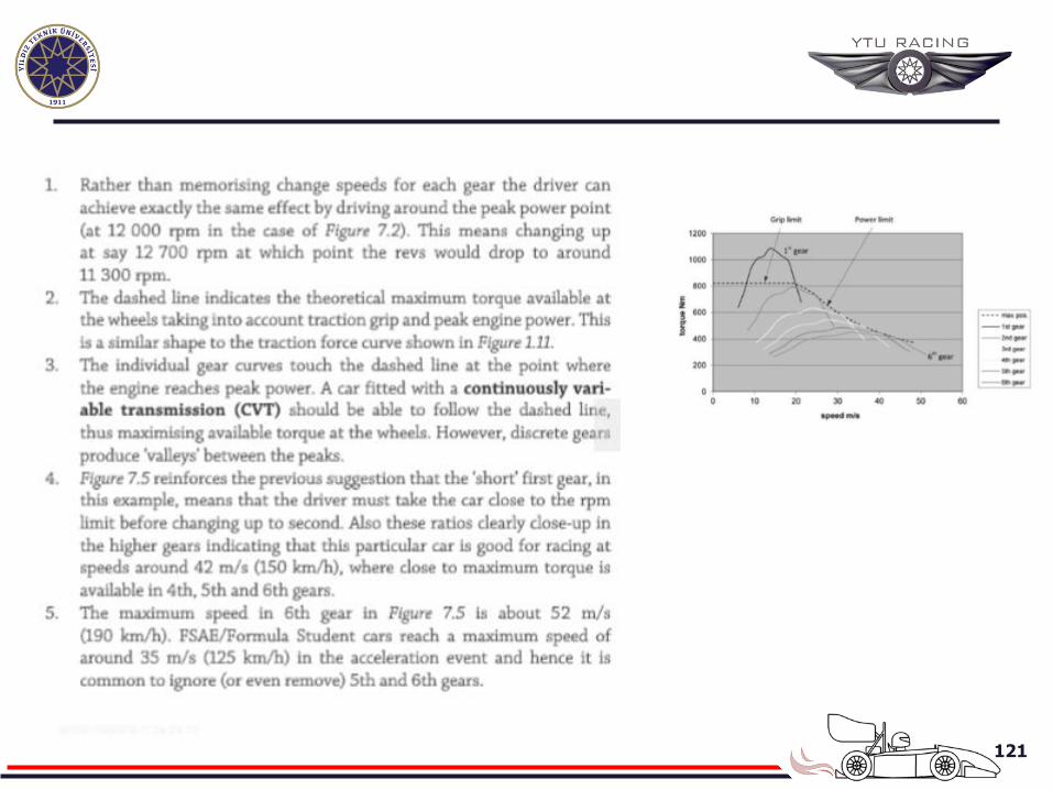
Citation preview
1
FUNDAMENTALS OF RACE CAR DESIGN

2
Doç. Dr. Alp Tekin Ergenç Mail Adress: [email protected] Telephone: +90 212 3832835 Office: E-Blok 2. Kat No:5
3
4
REFERENCES BOOKS
1. Raca car Design, Derek Seward 2. Rennwagentechnik, Michael Trzesniowski 3. To Win Series, Caroll Smith 4. Automotive Engineering Fundamentals, Richard Stone
5
The aim of this course is to explain the fundamentals of race car design basics using basic principles of engineering secience and elemantary mathematics.
It will also be of interest to people who is interested in understanding why racing cars are the way they are and what they perform so much better than normal cars on the track.
Design process for a racing car is much simplier than that for a
conventional passenger car because the racing car has a highly focused mission to propel a driver around a circuit in the shortest time possible.
6
1. RACE CAR BASICS By its nature, racing is a highly competitive activity
and the job of the designer is to provide the driver with the best possible car that hopefully has a competitive advantage.
7
We need answers to the following questions:
What does a racing car have to do? What is the basic layout of a car for achieving what it has to do? How can the car be optimised yo perform better than the competition?
What loads and stresses is the car subjected to, and how can it be made
Adequately safe and robust?
8
THE ELEMENTS OF RACING Motor racing can take many forms ranging from short hill
sprints, where the driver competes against the clock, ton convetional head to head circuit racing such as Formula 1 and IndyCar;
In general the aim of all racing is to cover a particular piece of road or circuit in the shortest possible time. To do this the driver must do three things: Accelerate the car to the fastest possible speed.
Brake the car as late as possible over the minimum possible distance
Go round the corners in the minimum time and, more importantly, emerge from corners carrying the maximum possible velocity so that a speed advantage is carried over the ensuing straight.
9
The three basic elements of racing all involve a form of acceleration or change in velocity.
In the case of cornering this is lateral acceleration and braking can be considered to be negative acceleration.
We know from ‘Newton’s first law’ of motion thart: «An object in motion stays in motion with the same speed
and in the same direction unless acted upon by an external forces.»
10
Consequently in order to accelerate or change direction, the car must be subject to an external force and principal source is at the interface between the tyres and the road-known as the tyre contact patch.
The friction force between rubber tyre and road surface is normally referred to as traction or grip and its aximisation is an important design criterion for competitive car.
FRICTION FORCE: Normal Load X µ
11
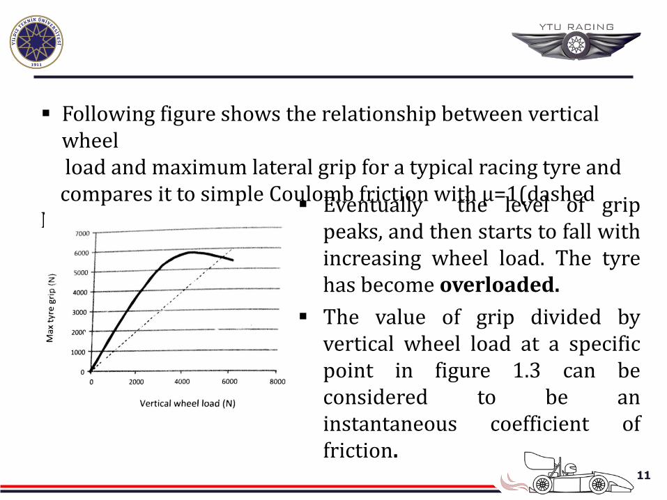
Following figure shows the relationship between vertical wheel
load and maximum lateral grip for a typical racing tyre and compares it to simple Coulomb friction with µ=1(dashed line).
Eventually the level of grip peaks, and then starts to fall with increasing wheel load. The tyre has become overloaded.
The value of grip divided by vertical wheel load at a specific point in figure 1.3 can be considered to be an instantaneous coefficient of friction.
12
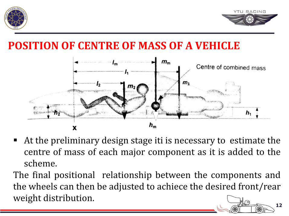
POSITION OF CENTRE OF MASS OF A VEHICLE
At the preliminary design stage iti is necessary to estimate the centre of mass of each major component as it is added to the scheme.
The final positional relationship between the components and the wheels can then be adjusted to achiece the desired front/rear weight distribution.
13
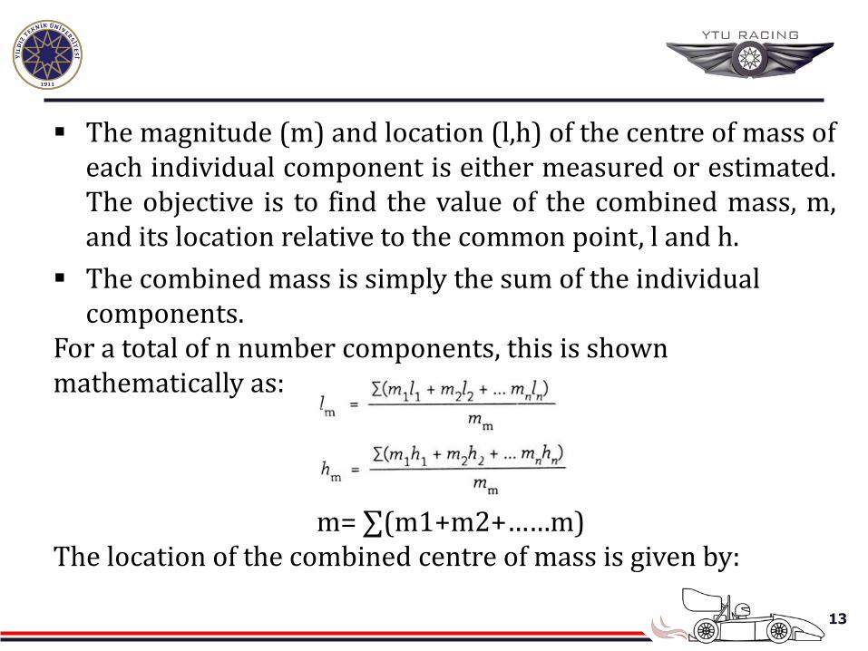
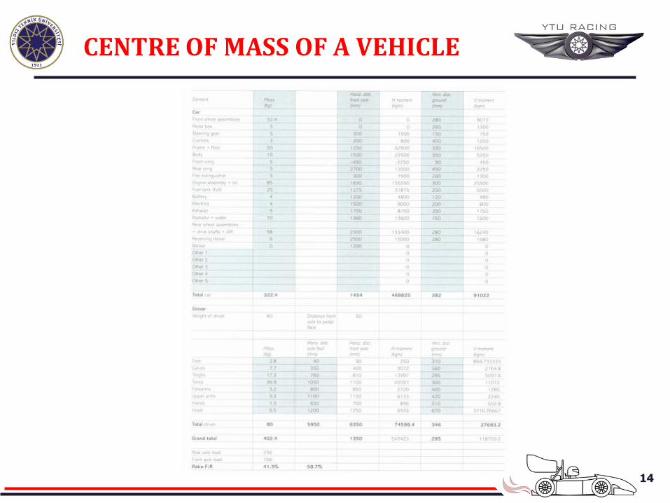
The magnitude (m) and location (l,h) of the centre of mass of each individual component is either measured or estimated. The objective is to find the value of the combined mass, m, and its location relative to the common point, l and h.
The combined mass is simply the sum of the individual components.
For a total of n number components, this is shown mathematically as:
m= ∑(m1+m2+……m) The location of the combined centre of mass is given by:
14
CENTRE OF MASS OF A VEHICLE
15
STATIC WHEEL LOADS FRONT AND REAR WEIGHT DISTRIBUTION
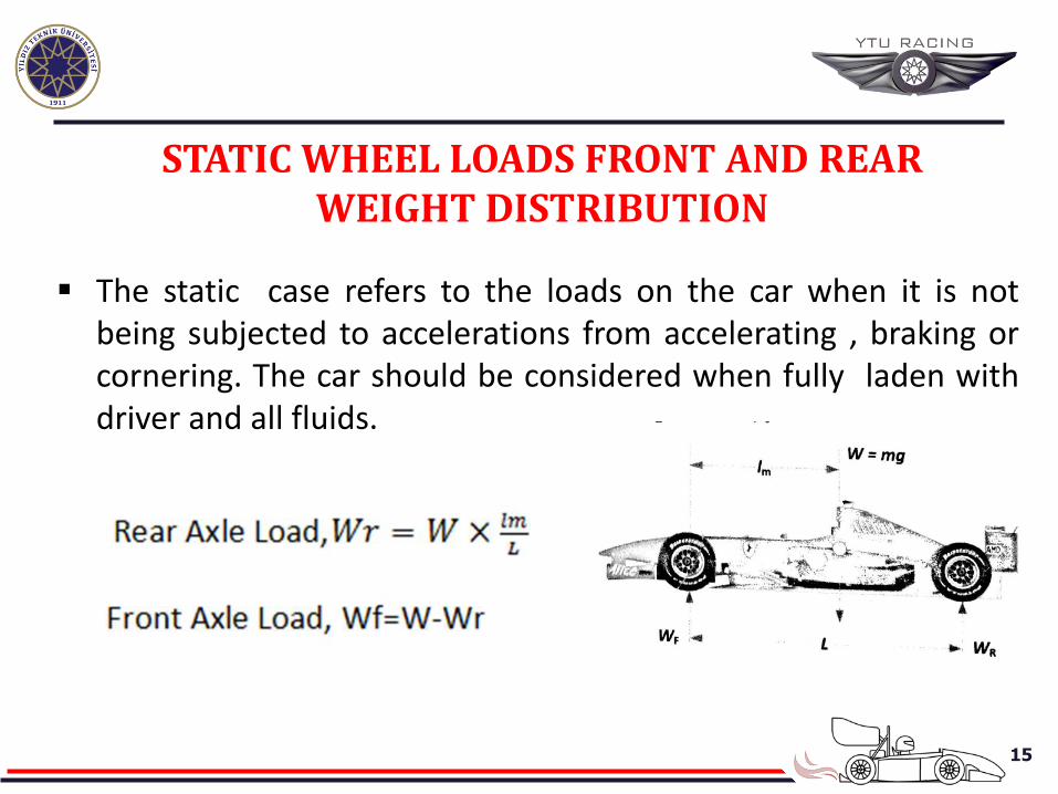
The static case refers to the loads on the car when it is not
being subjected to accelerations from accelerating , braking or cornering. The car should be considered when fully laden with driver and all fluids.
16
The designer can influence the front/rear weight balance by moving certain components, such as the battery or hydrolic pumps.
The competitive car are invariably built significantly lighter than the minimum weight specified in their formula technical regulations. The difference is then made up by the addition of heavy ballast which is strategically placed to give the best front/rear balance.
17
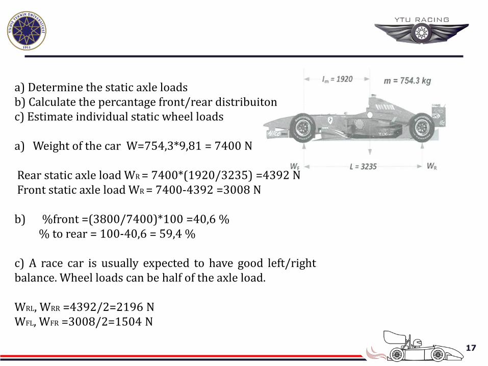
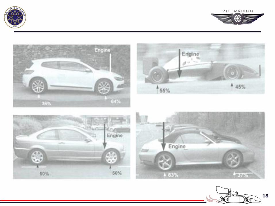
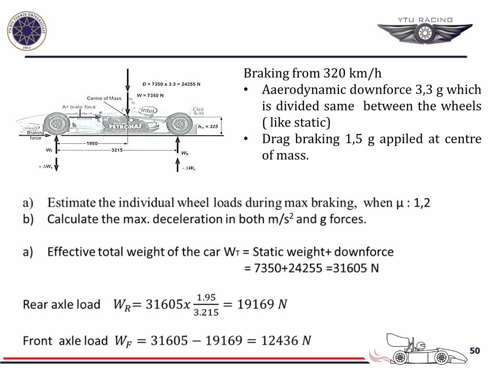
a) Determine the static axle loads b) Calculate the percantage front/rear distribuiton c) Estimate individual static wheel loads a) Weight of the car W=754,3*9,81 = 7400 N Rear static axle load WR = 7400*(1920/3235) =4392 N Front static axle load WR = 7400-4392 =3008 N b) %front =(3800/7400)*100 =40,6 % % to rear = 100-40,6 = 59,4 % c) A race car is usually expected to have good left/right balance. Wheel loads can be half of the axle load. WRL, WRR =4392/2=2196 N WFL, WFR =3008/2=1504 N
18
19
What is the optimum weight ratio?
From a handling point of view it can be argued that a 50:50 ratio is optimum. However , as we shall see shortly, for accelerating off the line, there is a clear advantage in having more weight over the driven wheels. Racing cars typically aim for about a 45:55 front/rear ratio and adresses the handling issue by means of weder rear tyres.
The posiiton of fuel tanks presents a challenge as the weight of fuel Clearly cvaries throughtout the race. In formula 1, where refueling is no longer allowed. The vars start with up to 170 kg of fuel. The solution is to put the fuel tanks as close to the centre of mass a possible.
20
LINEAR ACCELERATION ABD LONGITUDIONAL LOAD TRANSFER
Newton’s Second Law: ‘’The acceleration (a) of an object is directyly proportional to the magnitude of the applied force (F) and inversely propotional to the mass of the object(m)’’
a=F/m
21
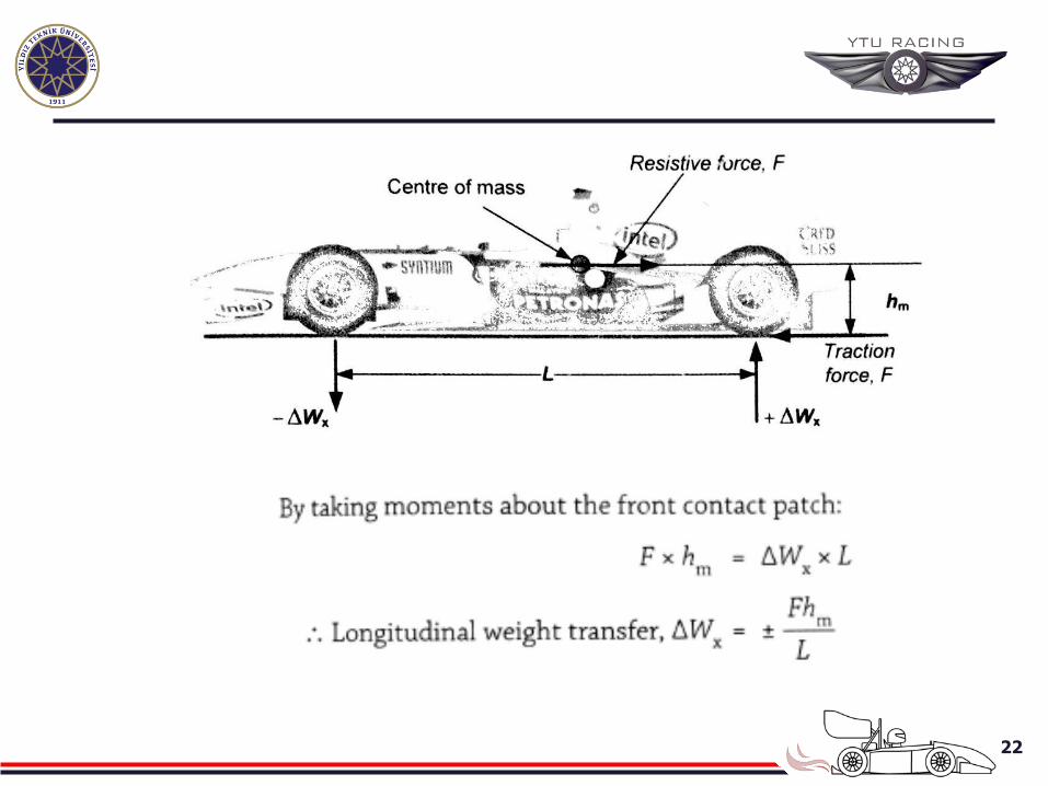
The traction force occurs at road level and the resistive force at level of the centre of mass means that an out-of-balance couple or moment is set up. This causes change to the static loads, Wf and Wr.
The magnitude of the change, ∆Wx,is known as longitudial
Load Transfer and it is added to the static rear axle load and subtracted from static front axle load .
When accelerating hard, the front of a car rises and the rear
drops- known as squat.
22
23
When accelerating a car from the start line up to its maximum Speed, we can consider two district stages:
Stage 1- Traction Limited
During initial acceleration off the start-line the vakue of the traciton
Forca,F, is limited by the frictional grip taht can be generated by the driven tyres. The problem, at this stage, for the driver, is to avoid wheel-spin.
Stage 2-Power Limited
As the speed of the car increases the point will be reached where the engine can not provide enough power to spin the wheels, and from this point
24
Stage 2-Power Limited
Maximum acceleration is limited by engine power. As speed increases still further, aerodynamic drag
force and other loses build until all of the engine power is needed to overcome them.
At this point further acceleration is not possible and the car has reached its maximum speed or terminal velocity.
25
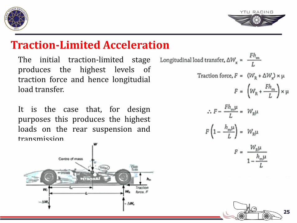
Traction-Limited Acceleration The initial traction-limited stage produces the highest levels of traction force and hence longitudial load transfer. It is the case that, for design purposes this produces the highest loads on the rear suspension and transmission.
26
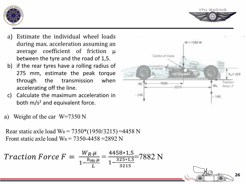
a) Estimate the individual wheel loads during max. acceleration assuming an average coefficient of friction μ between the tyre and the road of 1,5.
b) if the rear tyres have a rolling radius of 275 mm, estimate the peak torque through the transmission when accelerating off the line.
c) Calculate the maximum acceleration in both m/s2 and equivalent force.
27
28
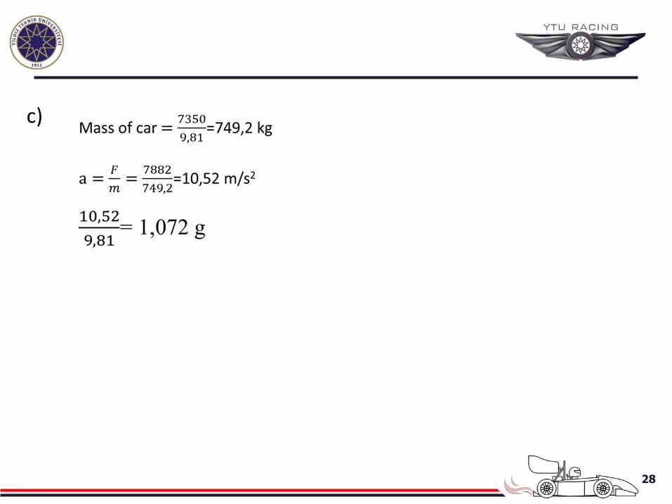
c)
29
Power-limited Acceleration
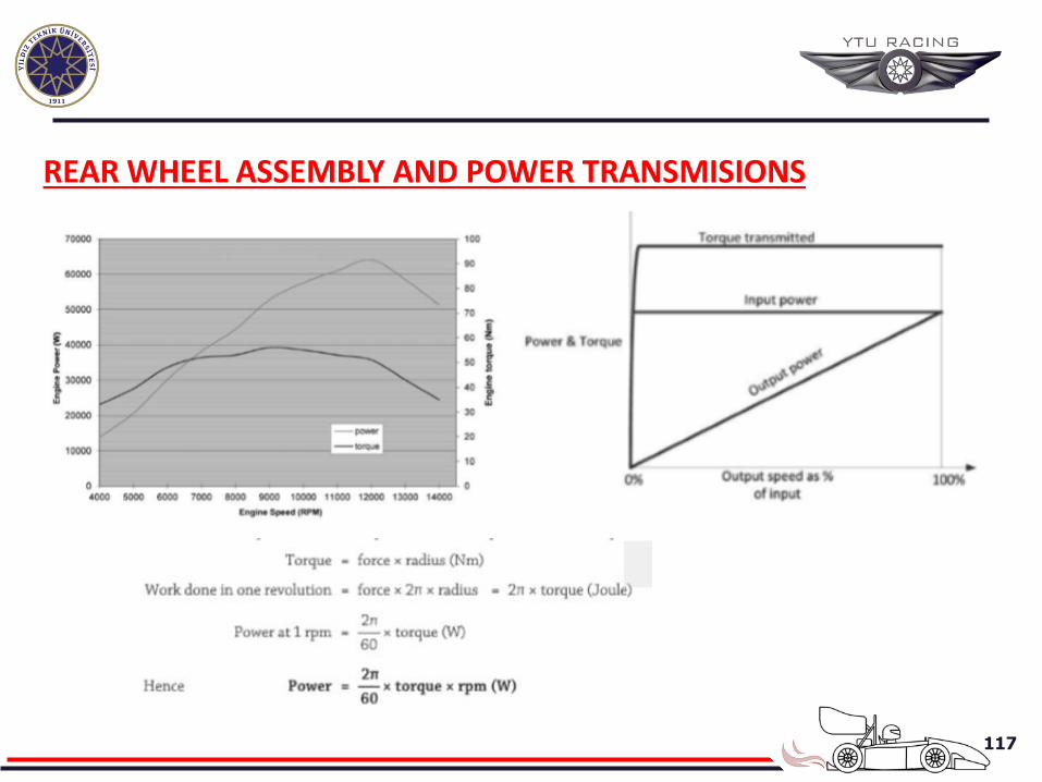
Work=forcexdistance (Nm or Joule) Power is the rate of doing work: Power = (force x distance)/time = force x speed (Nm/s or Watts) or Force = power/speed (N)
30
If power is limited, The traction force must reduce as speed increases.
In this case it is not apprpriate to consider absolute peak
engine power as this is generally only available at specific engine revs.
The average power available at the wheels as the driver moves
through the gears will be a bit less. In addition some power is lost in spinning-up the
transmission components and wheels as well as overcoming transmission friction.
31
If power is limited, Furthermore not all of the traction force is available for
accelerating the car. Some of it must be used overcome further loses.
The two principal additional losses are: Rolling resistance from the tyres, The energy used to heat the tyre as the rubber tread deform during rolling.The degree of resistance is related to the vertical load carried by each tyre as well as the rolling velocity. ( in racing cars %2 approximatly) • Depends upon tyre construction • Wheel diameter • The road surface
Aerodynamic drag Increases with the square of the velocity • Depends on the frontal area of the car • Degree of streamlining.
32
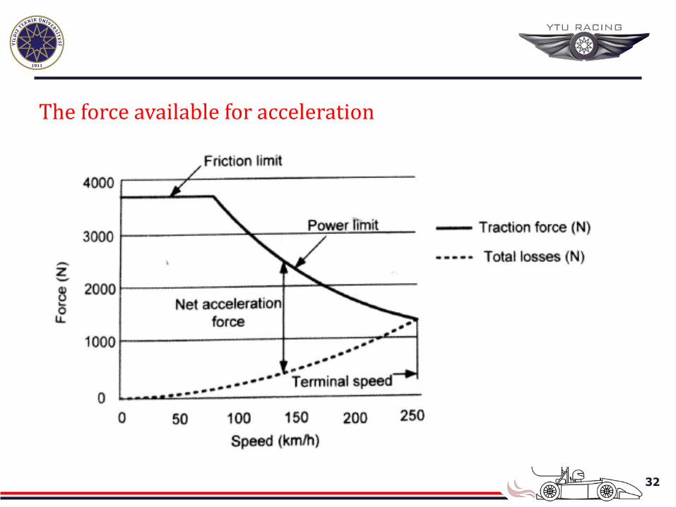
The force available for acceleration
33
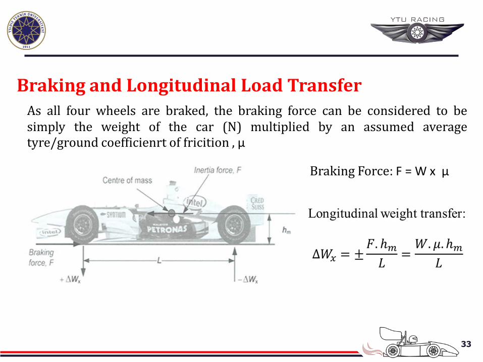
Braking and Longitudinal Load Transfer
As all four wheels are braked, the braking force can be considered to be simply the weight of the car (N) multiplied by an assumed average tyre/ground coefficienrt of fricition , μ
Braking Force: F = W x μ
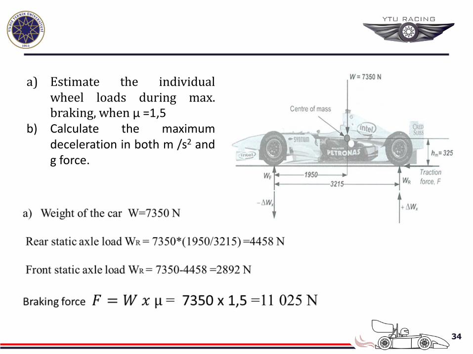
34
a) Estimate the individual wheel loads during max. braking, when μ =1,5
b) Calculate the maximum deceleration in both m /s2 and g force.
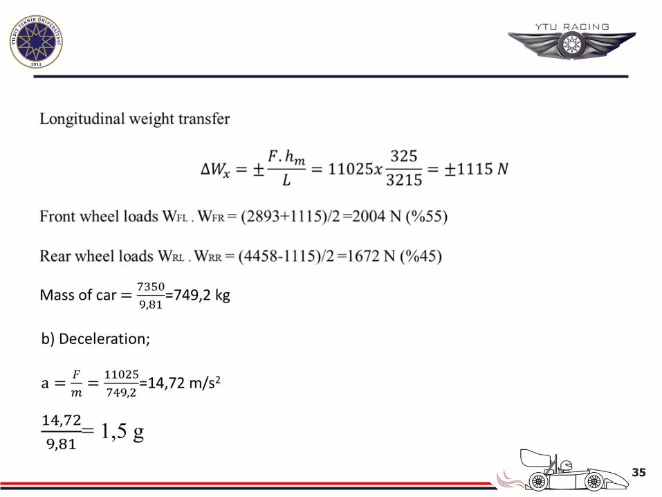
35
36
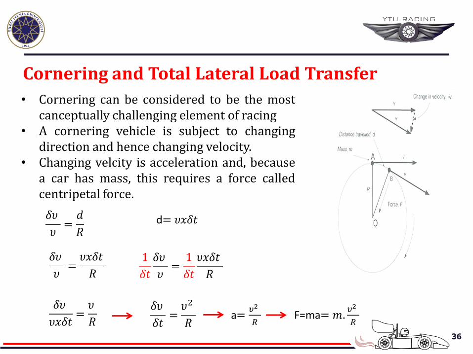
Cornering and Total Lateral Load Transfer
• Cornering can be considered to be the most canceptually challenging element of racing
• A cornering vehicle is subject to changing direction and hence changing velocity.
• Changing velcity is acceleration and, because a car has mass, this requires a force called centripetal force.
37
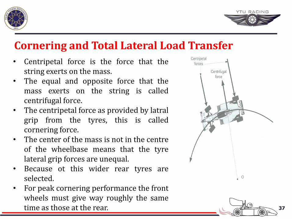
Cornering and Total Lateral Load Transfer
• Centripetal force is the force that the string exerts on the mass.
• The equal and opposite force that the mass exerts on the string is called centrifugal force.
• The centripetal force as provided by latral grip from the tyres, this is called cornering force.
• The center of the mass is not in the centre of the wheelbase means that the tyre lateral grip forces are unequal.
• Because ot this wider rear tyres are selected.
• For peak cornering performance the front wheels must give way roughly the same time as those at the rear.
38
Cornering and Total Lateral Load Transfer
• If the front wheels give way before the rears the car is said to understeer. The car will refuse to turn and carry straight on at a bend.
• If the rear wheels give way before the fronts the car is said to oversteer. The car is likely to spin.
• For fine tuning; (in a curcuit) a) Driver b) Tyres c) Road surfaces d) Weather conditions • The desginers are intersterested to maximise the cornering force.
(Lateral g forces that the car can attain) • In braking; μ is average, the downforce wtih no aerodynamic effect,
F= Wx μ (N)
39
Cornering and Total Lateral Load Transfer
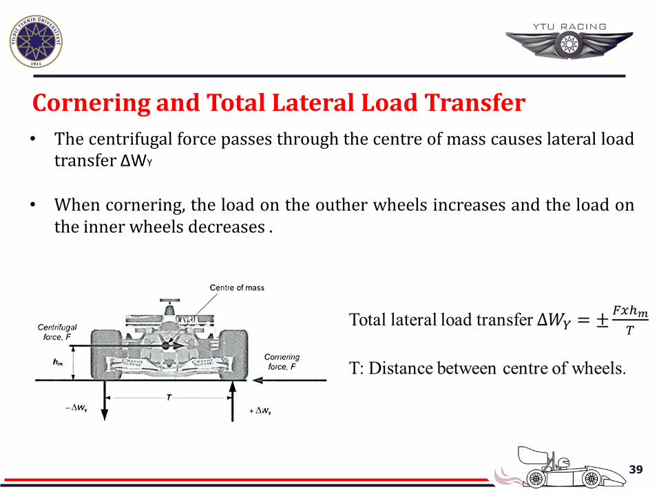
• The centrifugal force passes through the centre of mass causes lateral load transfer ΔWY
• When cornering, the load on the outher wheels increases and the load on
the inner wheels decreases .
40
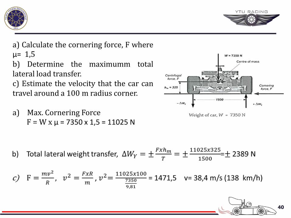
a) Calculate the cornering force, F where μ= 1,5 b) Determine the maximumm total lateral load transfer. c) Estimate the velocity that the car can travel around a 100 m radius corner. a) Max. Cornering Force F = W x μ = 7350 x 1,5 = 11025 N
41
• The total load that is transferred from the inside wheels to the outside wheels when a car corners.
• The distribution of this load depends on; a) Realtive stiffness of the front and rear suspensions, b) Suspension geometry c) Realtive track widths, d) Anti-roll bars etc.
• The proportion of lateral load transfer between front and rear wheels is
an important means by which suspension is tuned to achieve a balanced car.
Cornering and tyre sensitivity
42
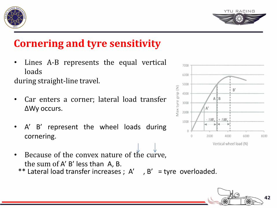
• Lines A-B represents the equal vertical loads
during straight-line travel. • Car enters a corner; lateral load transfer
ΔWy occurs.
• A’ B’ represent the wheel loads during cornering.
• Because of the convex nature of the curve, the sum of A’ B’ less than A, B.
Cornering and tyre sensitivity
** Lateral load transfer increases ; A’ , B’ = tyre overloaded.
43
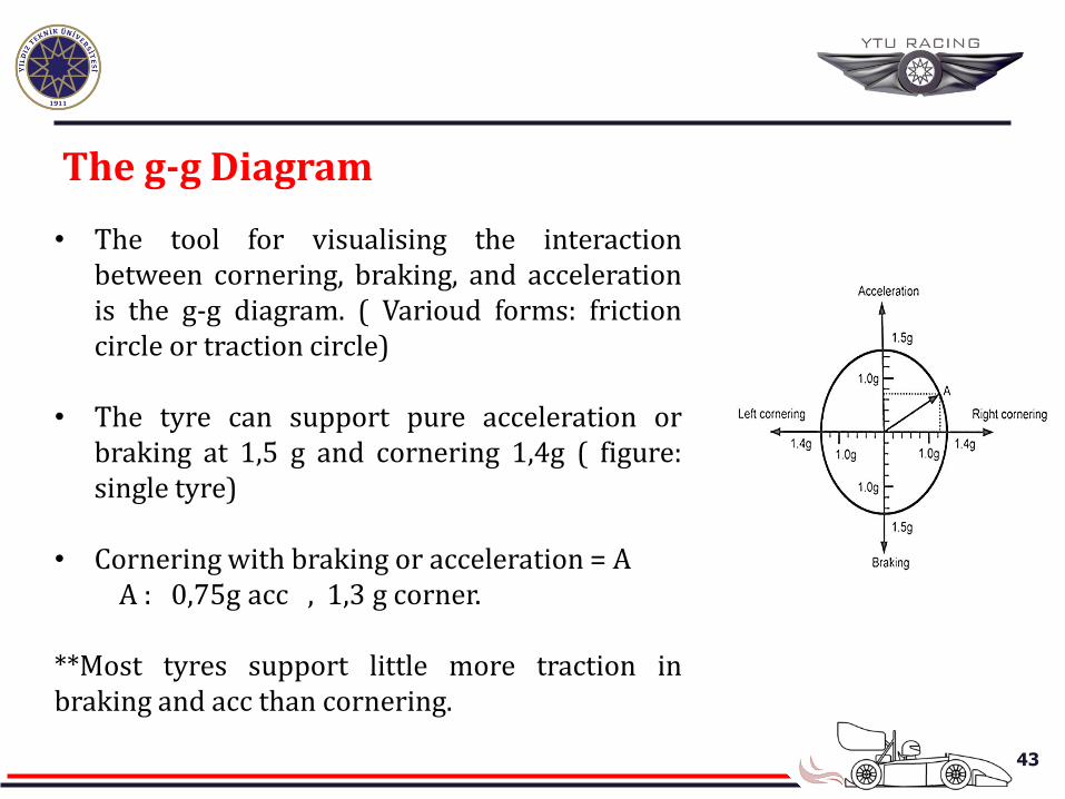
• The tool for visualising the interaction between cornering, braking, and acceleration is the g-g diagram. ( Varioud forms: friction circle or traction circle)
• The tyre can support pure acceleration or braking at 1,5 g and cornering 1,4g ( figure: single tyre)
• Cornering with braking or acceleration = A A : 0,75g acc , 1,3 g corner. **Most tyres support little more traction in braking and acc than cornering.
The g-g Diagram
44
The g-g Diagram
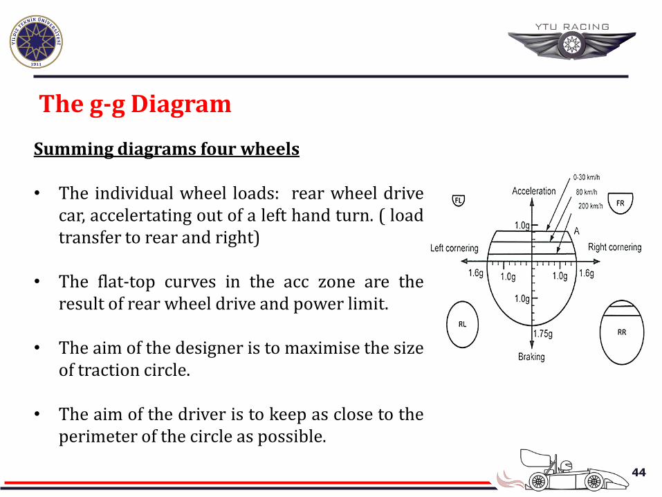
Summing diagrams four wheels
• The individual wheel loads: rear wheel drive car, accelertating out of a left hand turn. ( load transfer to rear and right)
• The flat-top curves in the acc zone are the
result of rear wheel drive and power limit.
• The aim of the designer is to maximise the size of traction circle.
• The aim of the driver is to keep as close to the
perimeter of the circle as possible.
45
The g-g Diagram
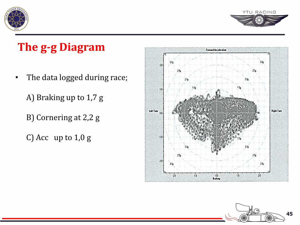
• The data logged during race;
A) Braking up to 1,7 g B) Cornering at 2,2 g C) Acc up to 1,0 g
46
The effect of aerodynamic downforce
• Three major elements that produce downforce; a) Front wing b) Rear wing c) Underbody • Aerodynamic forces are proportional to the square of the velocity of
the airflow relative to the car. ( different speeds, forces change)
• Downforce: increased aerodynamic loss or drag ( reduced top speed ? )
• Low power cars can only run low-downforce aerodynamic set-ups.
• The power of the engine increases, a more aggressive downforce package can be adopted.
47
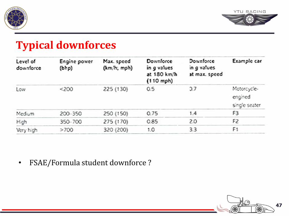
• FSAE/Formula student downforce ?
Typical downforces
48
Acc and downforce
• Downforce has only a realtively small effect on acceleration.
• Low-power cars traction-limited stage is relatively short and the car move to power-limited stage. ( 90 km/h)
• In 90 km/h : little downforce, increased traction no benefit in acc, small increase in drag = reduce performance.
• Up to 150 km/h significant downforce developed.
• In 150 km/h : 0,7 g additional vertical force produced.
49
Braking and downforce
• Aerodynamic downforce has a signifcant effect on braking from high speeds.
• Ex. in F1 car : braking at 320 km/h = 1,0 g extra downforce ( plus from 3,3 g)
• Because of the tyre sensitivity the average coeff. of friction μ reduced 1,5 to 1,2.
• Car slowed by air braking ( aerodynamic drag)
• At 320 km/h ( lift off throttle) car slow at about 1,5 g without pushing brake. • This air braking force applied at the centre of pressure on the front of the
car, close to the centre of mass position. (little effect on longitudial weight transfer)
50
Braking from 320 km/h • Aaerodynamic downforce 3,3 g which
is divided same between the wheels ( like static)
• Drag braking 1,5 g appiled at centre of mass.
51
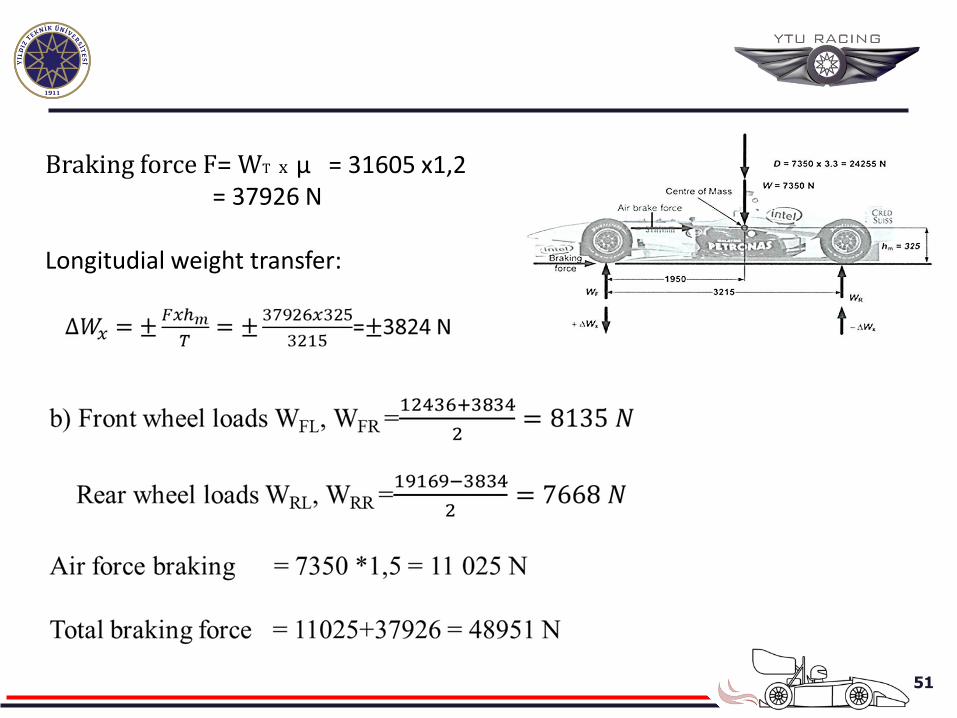
Braking force F= WT x μ = 31605 x1,2 = 37926 N Longitudial weight transfer:
52
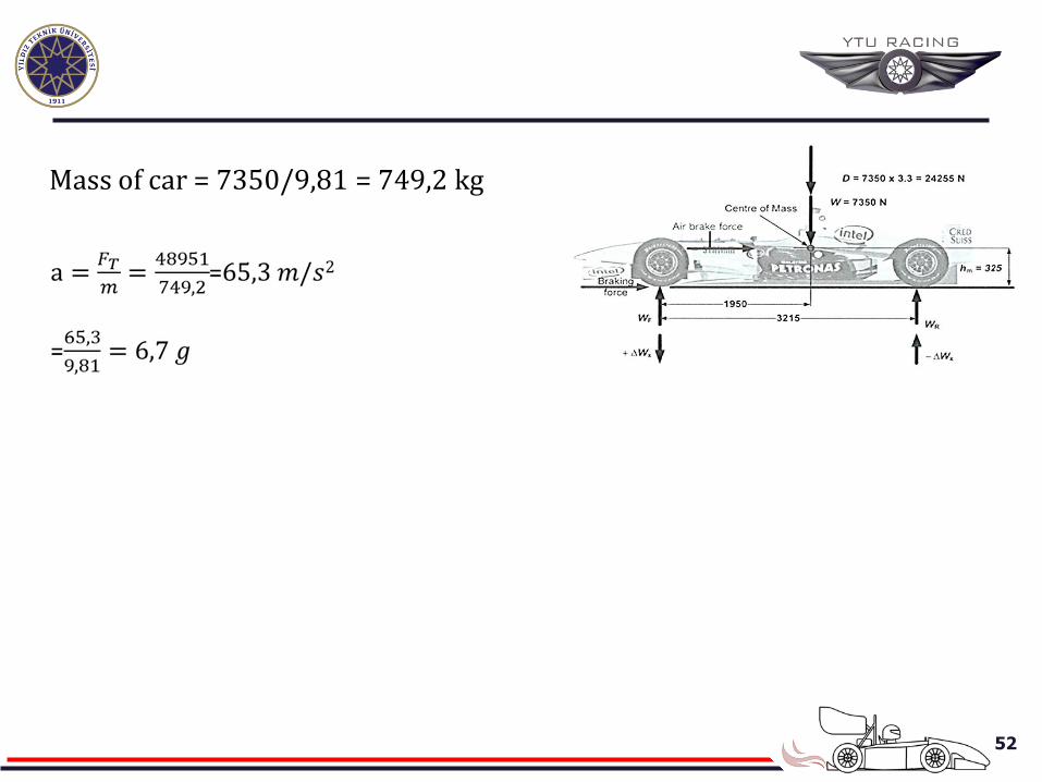
Mass of car = 7350/9,81 = 749,2 kg
53
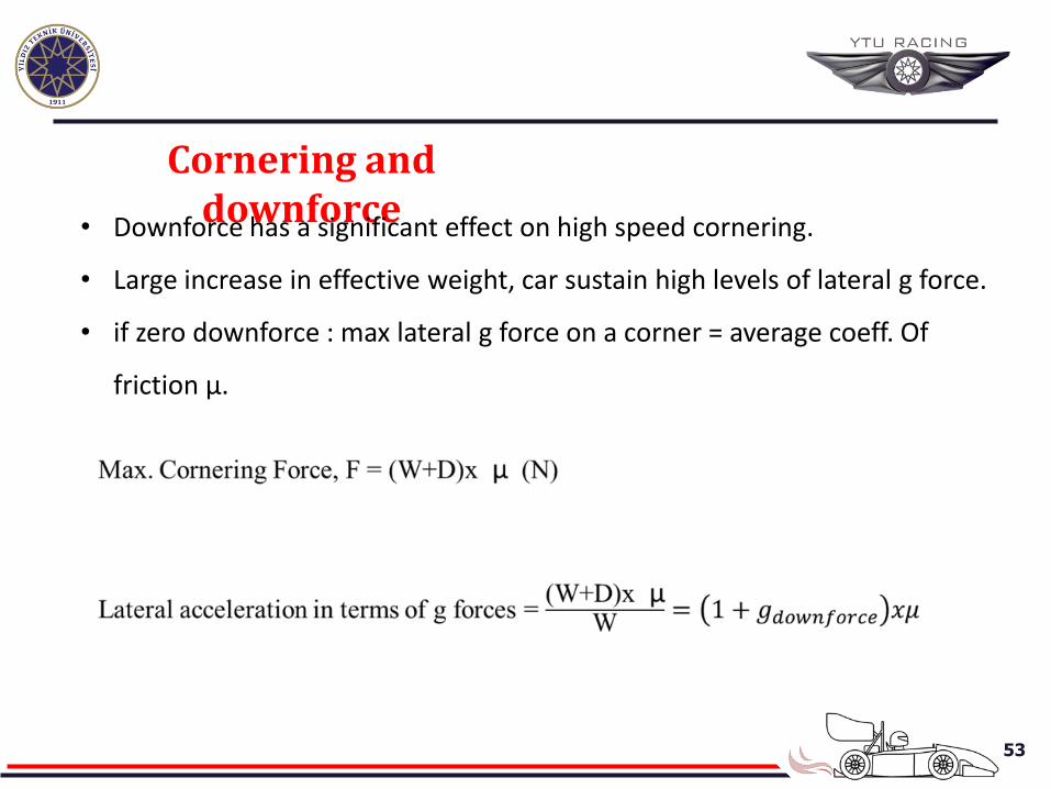
Cornering and downforce
• Downforce has a significant effect on high speed cornering.
• Large increase in effective weight, car sustain high levels of lateral g force.
• if zero downforce : max lateral g force on a corner = average coeff. Of
friction μ.
54
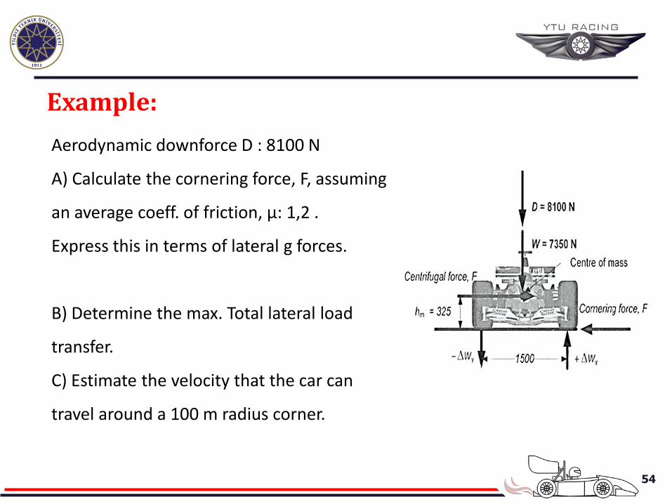
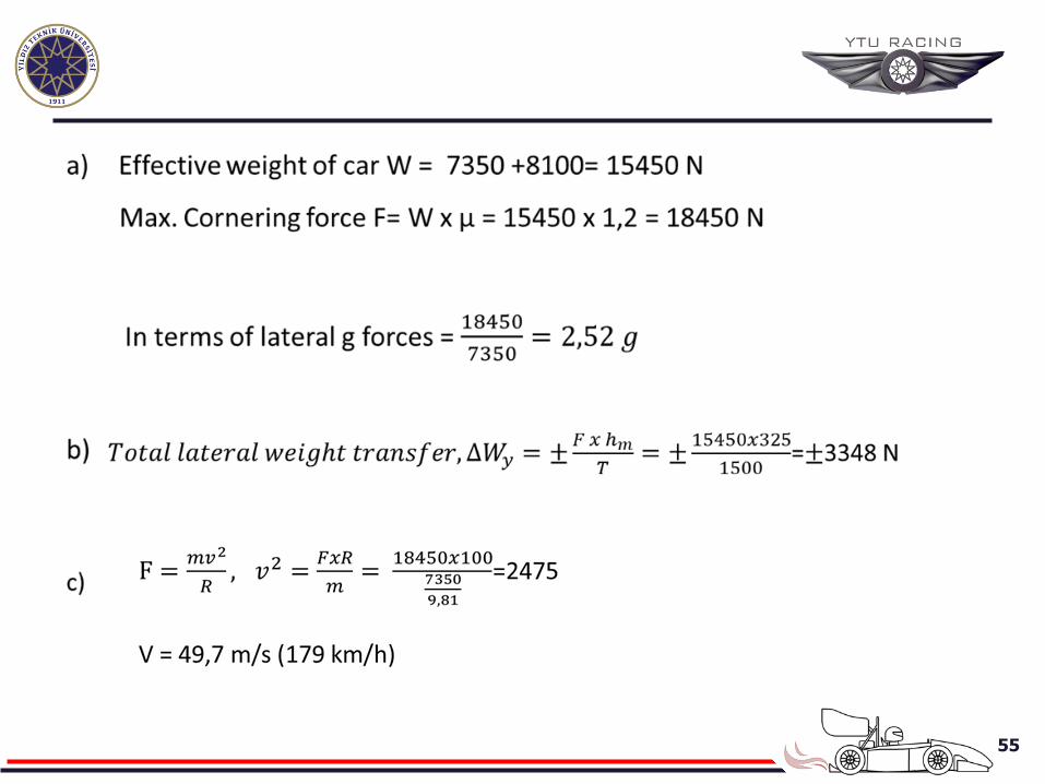
Example:
Aerodynamic downforce D : 8100 N
A) Calculate the cornering force, F, assuming
an average coeff. of friction, μ: 1,2 .
Express this in terms of lateral g forces.
B) Determine the max. Total lateral load
transfer.
C) Estimate the velocity that the car can
travel around a 100 m radius corner.
55
56
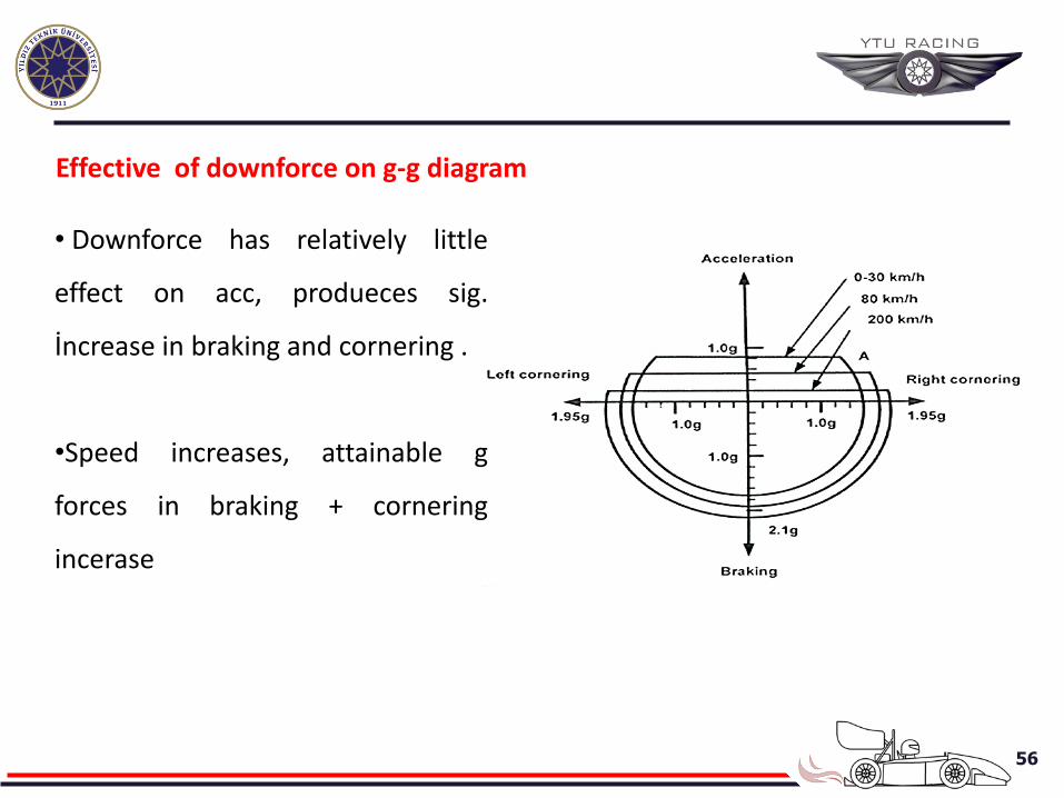
Effective of downforce on g-g diagram
• Downforce has relatively little
effect on acc, produeces sig.
İncrease in braking and cornering .
•Speed increases, attainable g
forces in braking + cornering
incerase
57
Racing car design issues
a) Mass
• To maximise these acc –need to maximise the force = minimise mass
• The force = contact patch between the tyre and road.
• A light car will accelerate, brake and corner better than a heavy one.
• A car is adequately stiff, robust and safe : with minimum mass
• Weight reduction: Stress calculation for all components to optimise the shape
and thickness of material.
• The number and size of bolts should bu questioned.
• Engine used as a part of chassis.
• For lihgter car, need to use expensive part (carbon fiber etc)
58
b) Position of the centre of mass
• The positioning of the wheels and the other components : the center of mass
the car is in the opt location.
• The centre of mass needs to lie as close as possible to the longitudinal centre –
line of the car ( wheels on each side are evenly loaded) –offsetting small comp.
like battery.
• More weight over the driven wheels during acc.
• 45:55 , 40:60 front*rear optimum
• Wider rear tyres to balance the car during cornering.
• The cntre of mass height small as possible. ( less roll when cornering)
• The change mass should be centre of mass = like fuel
59
c) Engine/drive configuration
• All modern single seat open wheel racing cars adopt the rear/mid engine
position with rear wheel drive.
• Good location of the centre of mass, sort transmission of power to the rear
wheels and small frontal area for aero eff.
• Wider tyres at the rear.
d) Wheelbase and track
• Short wheelsbase cars are nimble and hence good at cornering on twisty
circuits, long wheelbase cars are more stable on fast straights.
• Short : 2.0-2.5 m, Long : 2.5-2.8 m, F1 : 3.1-3.2m ( for downforce)
• Short cars are lighter than a long one.
• FSAE: narrow and twisting circuits: light car , 1.5-1.7 wheelbase
60
CHASSİS STRUCTURE The basic requirements of the structural chassis :
a) To comply with relevant formula regulations,
b) To provide secure location for all the components of the car like engine, fuel
tank, battery etc.,
c) To provide sufficient strenght and stiffness to resist the forces from the
suspension and steering components when the car accelerates, brakes and
cornering at high g forces,
d) To accommodate and protect the driver in the case of collision and to provide
a secure anchorage for the safety harness,
e) To support wings and other bodyworks (high aero force)
61
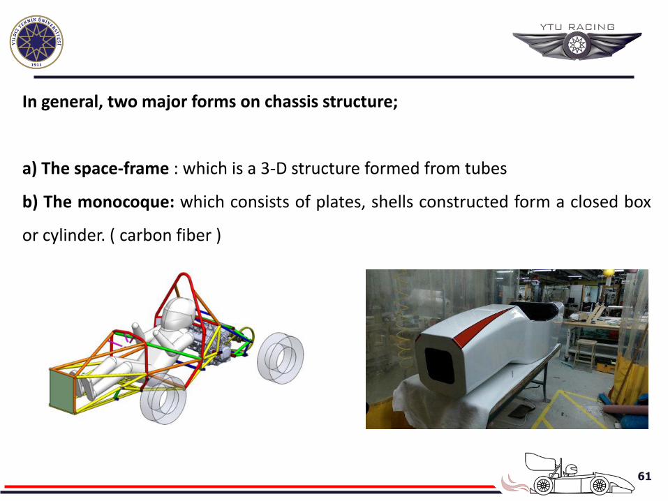
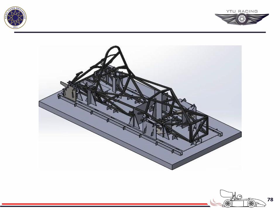
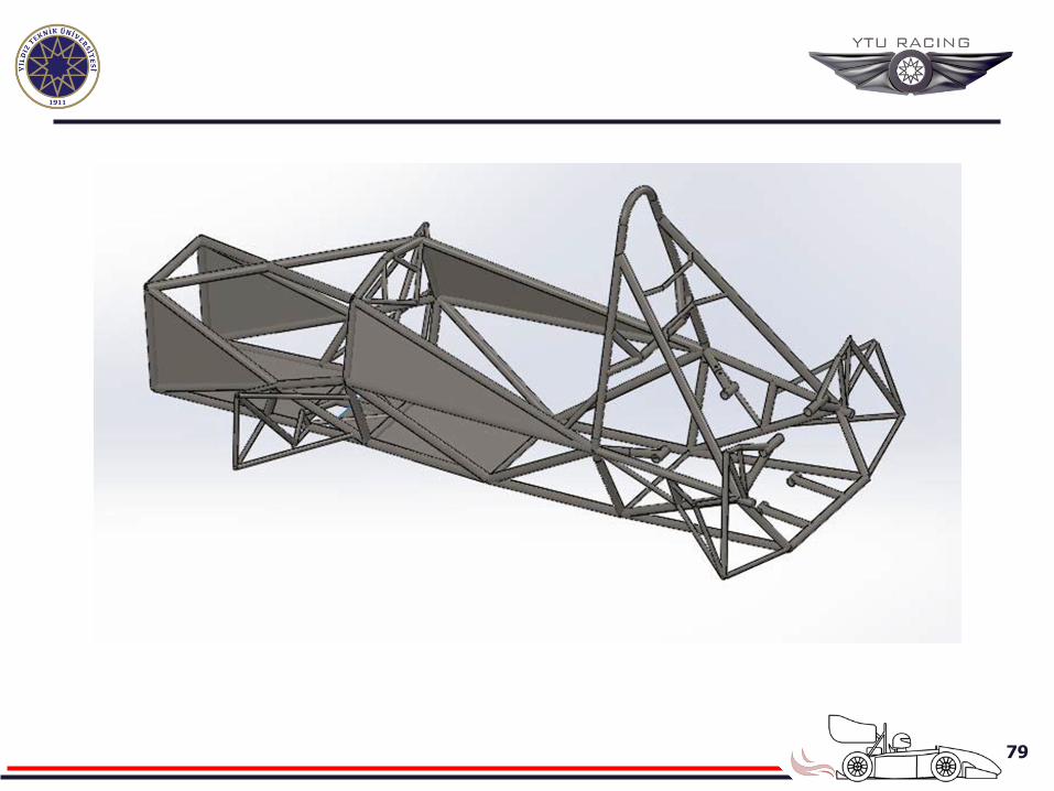
In general, two major forms on chassis structure;
a) The space-frame : which is a 3-D structure formed from tubes
b) The monocoque: which consists of plates, shells constructed form a closed box
or cylinder. ( carbon fiber )
62
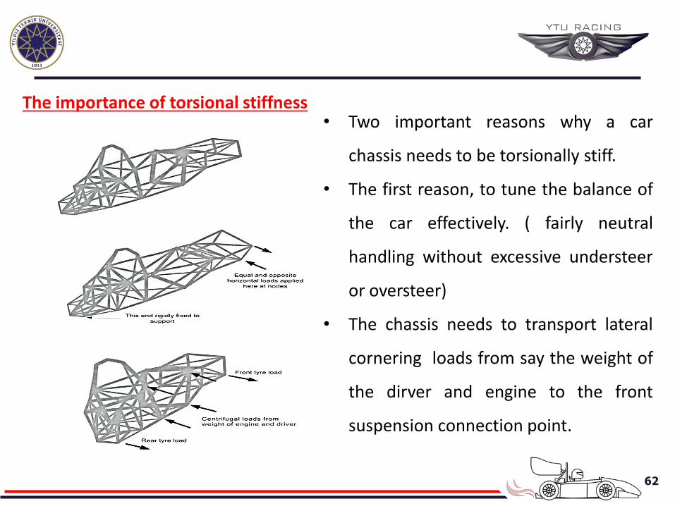
The importance of torsional stiffness
• Two important reasons why a car
chassis needs to be torsionally stiff.
• The first reason, to tune the balance of
the car effectively. ( fairly neutral
handling without excessive understeer
or oversteer)
• The chassis needs to transport lateral
cornering loads from say the weight of
the dirver and engine to the front
suspension connection point.
63
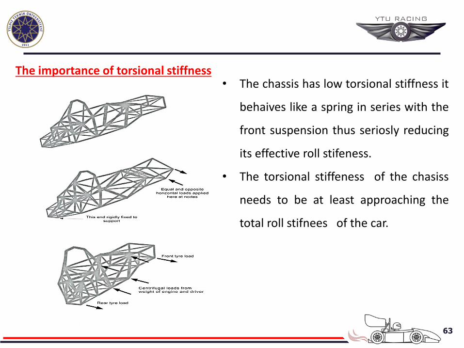
The importance of torsional stiffness
• The chassis has low torsional stiffness it
behaives like a spring in series with the
front suspension thus seriosly reducing
its effective roll stifeness.
• The torsional stiffeness of the chasiss
needs to be at least approaching the
total roll stifnees of the car.
64
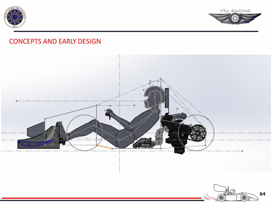
CONCEPTS AND EARLY DESIGN
65
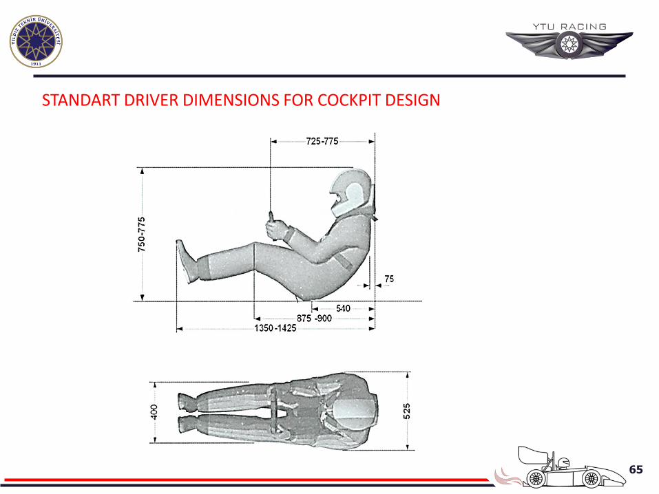
STANDART DRIVER DIMENSIONS FOR COCKPIT DESIGN
66
CONCEPTS AND EARLY DESIGN
67
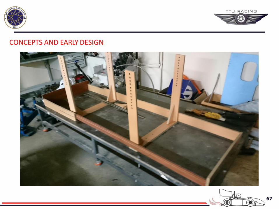
CONCEPTS AND EARLY DESIGN
68
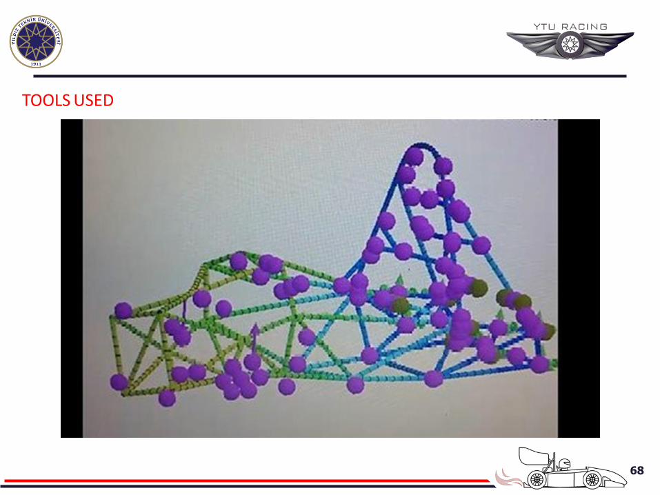
TOOLS USED
69
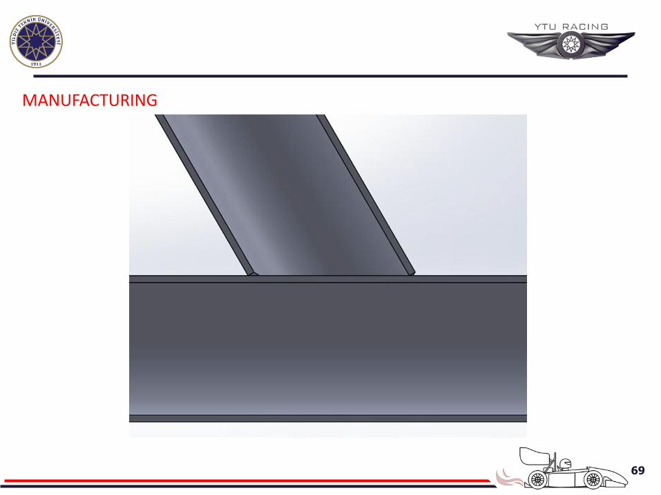
MANUFACTURING
70
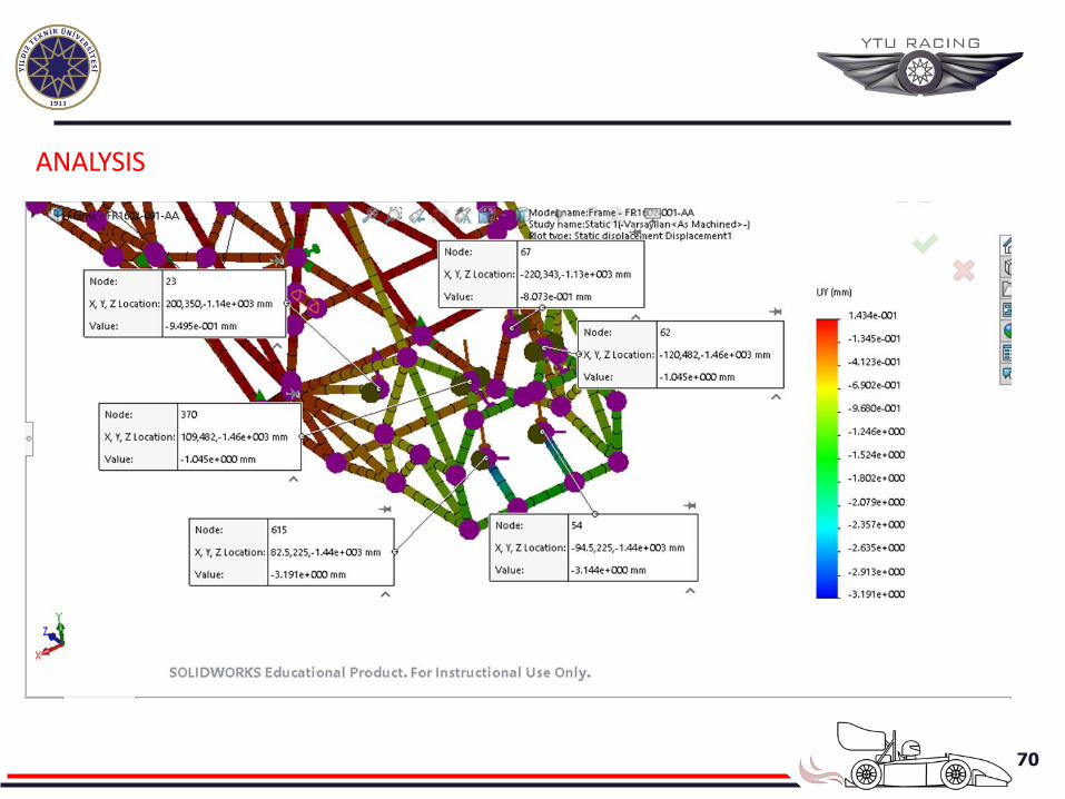
ANALYSIS
71
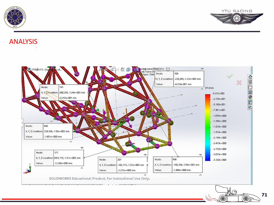
ANALYSIS
72
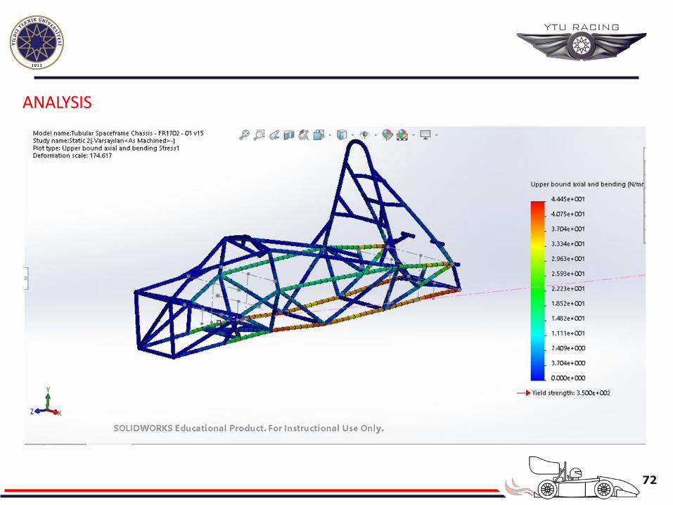
ANALYSIS
73
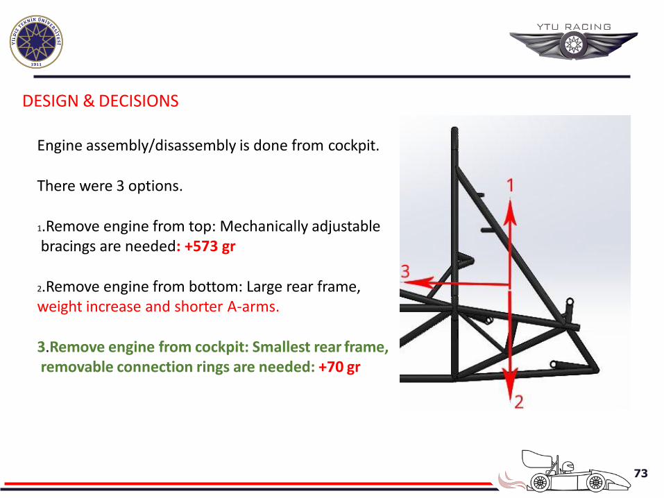
DESIGN & DECISIONS
Engine assembly/disassembly is done from cockpit.
There were 3 options.
1.Remove engine from top: Mechanically adjustable bracings are needed: +573 gr
2.Remove engine from bottom: Large rear frame, weight increase and shorter A-arms.
3.Remove engine from cockpit: Smallest rear frame, removable connection rings are needed: +70 gr
74
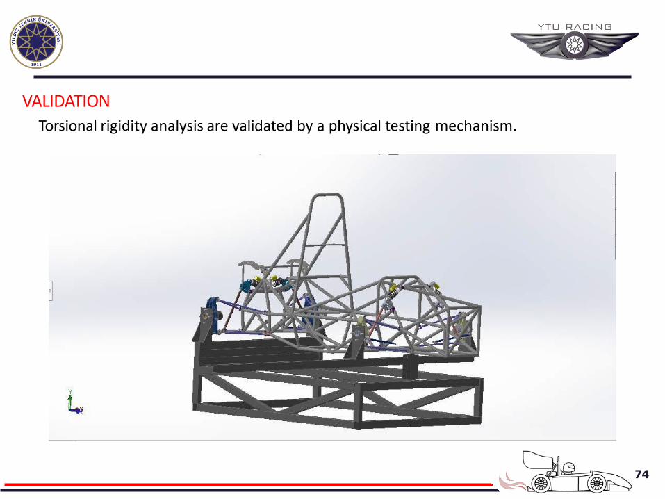
VALIDATION
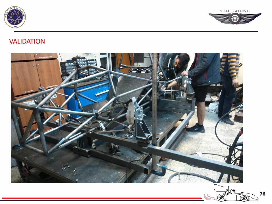
Torsional rigidity analysis are validated by a physical testing mechanism.
75
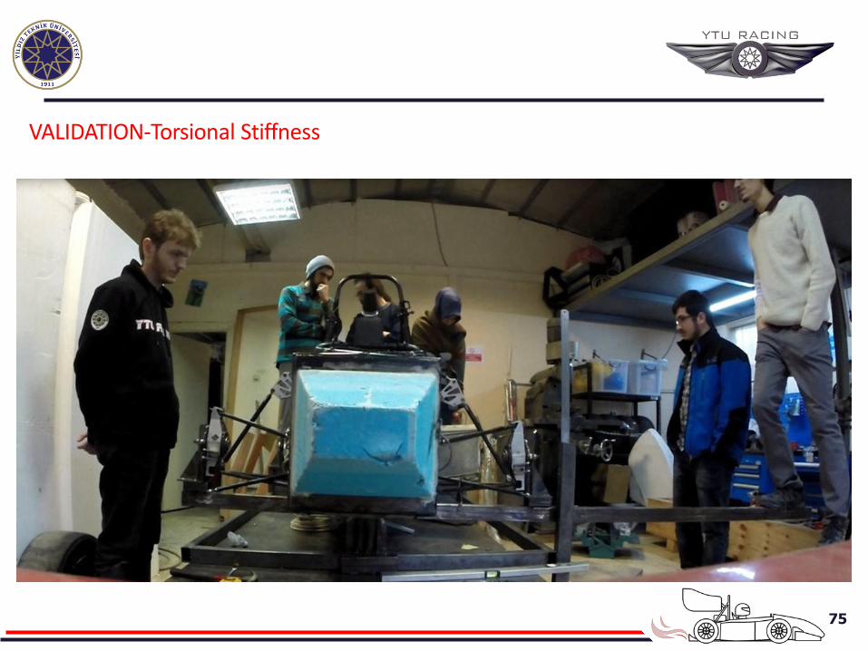
VALIDATION-Torsional Stiffness
76
VALIDATION
77
78
79

80
81
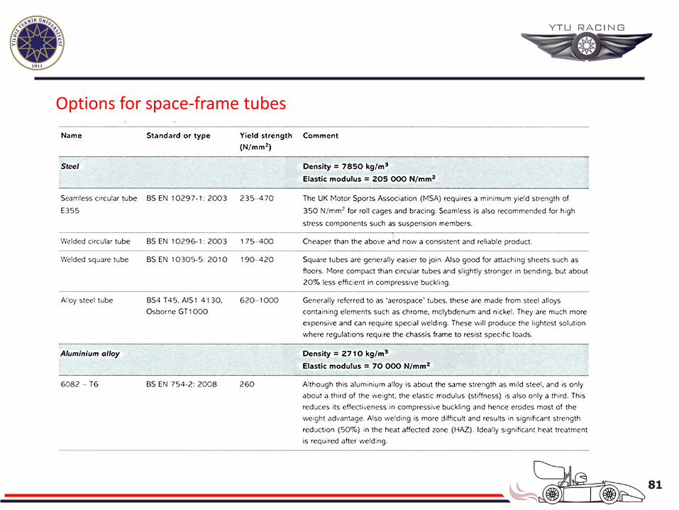
Options for space-frame tubes
82
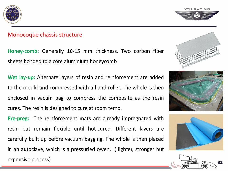
Monocoque chassis structure
Honey-comb: Generally 10-15 mm thickness. Two corbon fiber
sheets bonded to a core aluminium honeycomb
Wet lay-up: Alternate layers of resin and reinforcement are added
to the mould and compressed with a hand-roller. The whole is then
enclosed in vacum bag to compress the composite as the resin
cures. The resin is designed to cure at room temp.
Pre-preg: The reinforcement mats are already impregnated with
resin but remain flexible until hot-cured. Different layers are
carefully built up before vacuum bagging. The whole is then placed
in an autoclave, which is a pressuried owen. ( lighter, stronger but
expensive process)
83
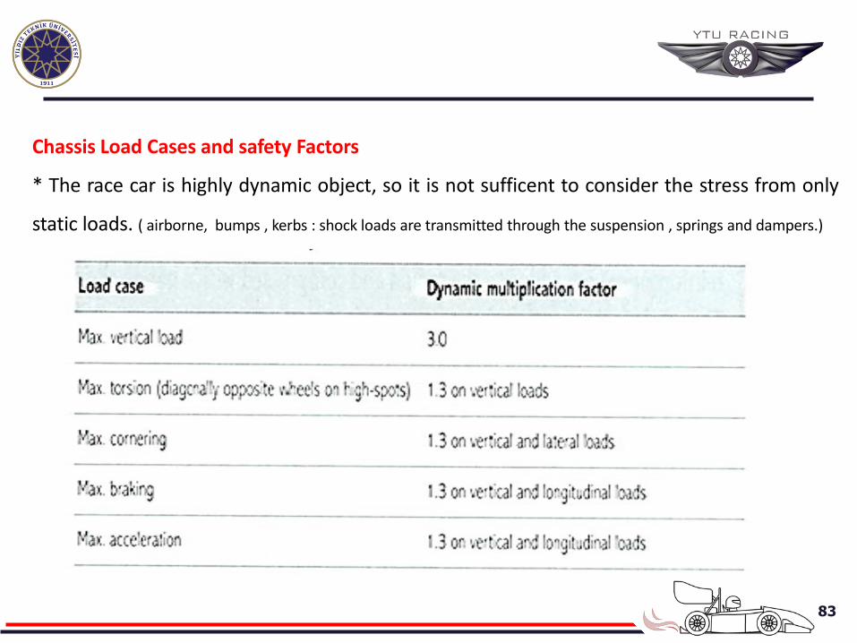
Chassis Load Cases and safety Factors
* The race car is highly dynamic object, so it is not sufficent to consider the stress from only
static loads. ( airborne, bumps , kerbs : shock loads are transmitted through the suspension , springs and dampers.)
84
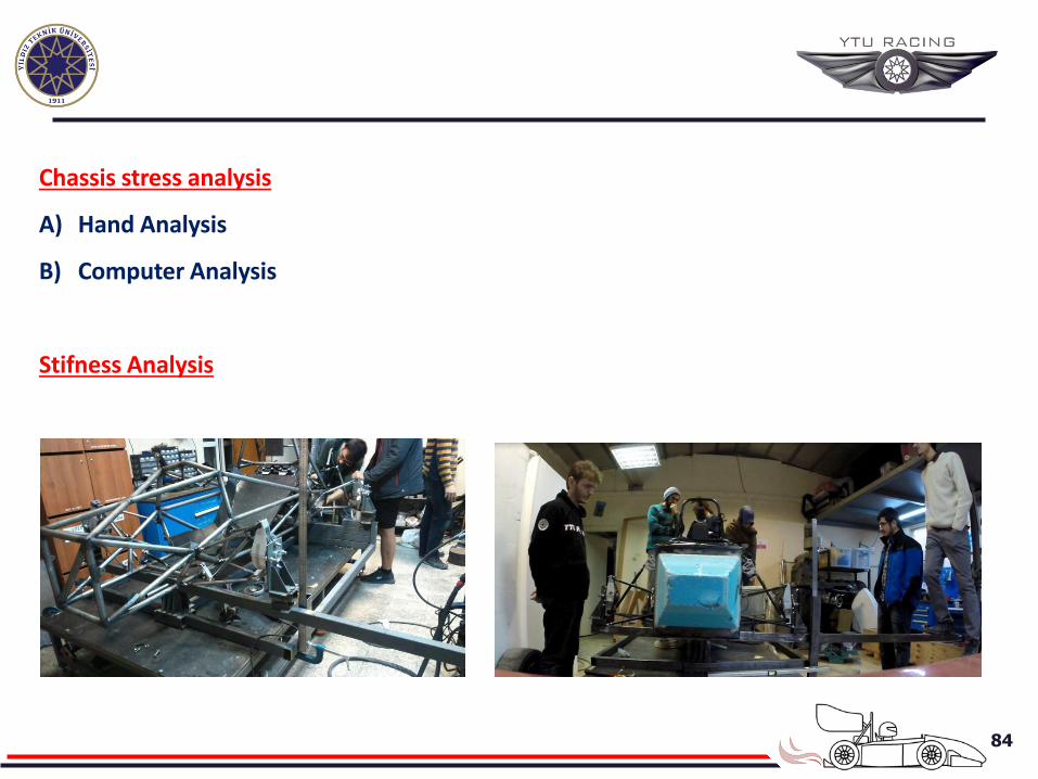
Chassis stress analysis
A) Hand Analysis
B) Computer Analysis
Stifness Analysis
85
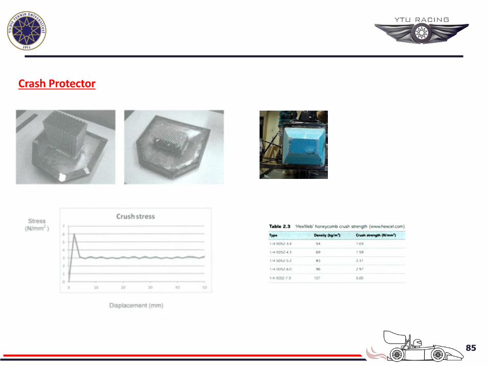
Crash Protector
86
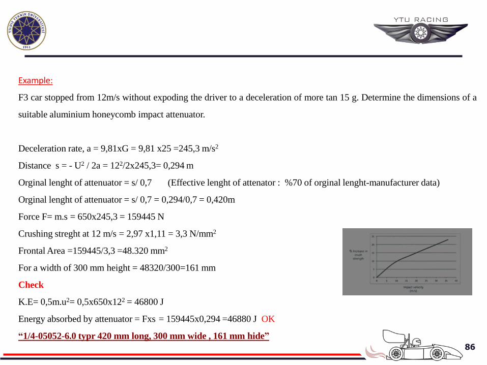
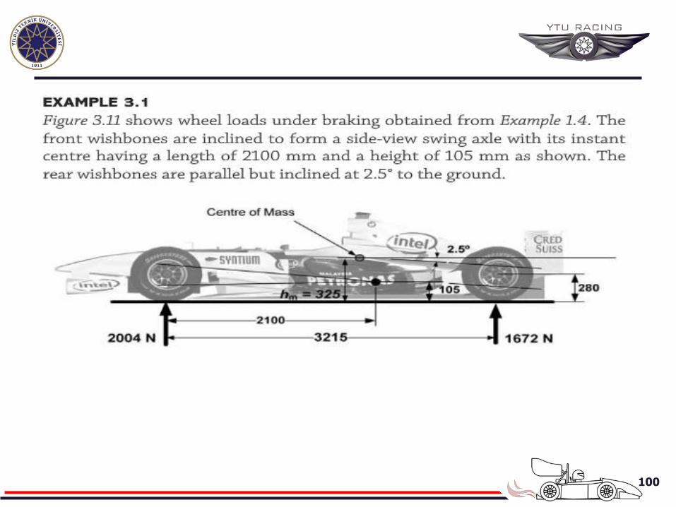
Example:
F3 car stopped from 12m/s without expoding the driver to a deceleration of more tan 15 g. Determine the dimensions of a
suitable aluminium honeycomb impact attenuator.
Deceleration rate, a = 9,81xG = 9,81 x25 =245,3 m/s2
Distance s = - U2 / 2a = 122/2x245,3= 0,294 m
Orginal lenght of attenuator = s/ 0,7 (Effective lenght of attenator : %70 of orginal lenght-manufacturer data)
Orginal lenght of attenuator = s/ 0,7 = 0,294/0,7 = 0,420m
Force F= m.s = 650x245,3 = 159445 N
Crushing streght at 12 m/s = 2,97 x1,11 = 3,3 N/mm2
Frontal Area =159445/3,3 =48.320 mm2
For a width of 300 mm height = 48320/300=161 mm
Check
K.E= 0,5m.u2= 0,5x650x122 = 46800 J
Energy absorbed by attenuator = Fxs = 159445x0,294 =46880 J OK
“1/4-05052-6.0 typr 420 mm long, 300 mm wide , 161 mm hide”
87
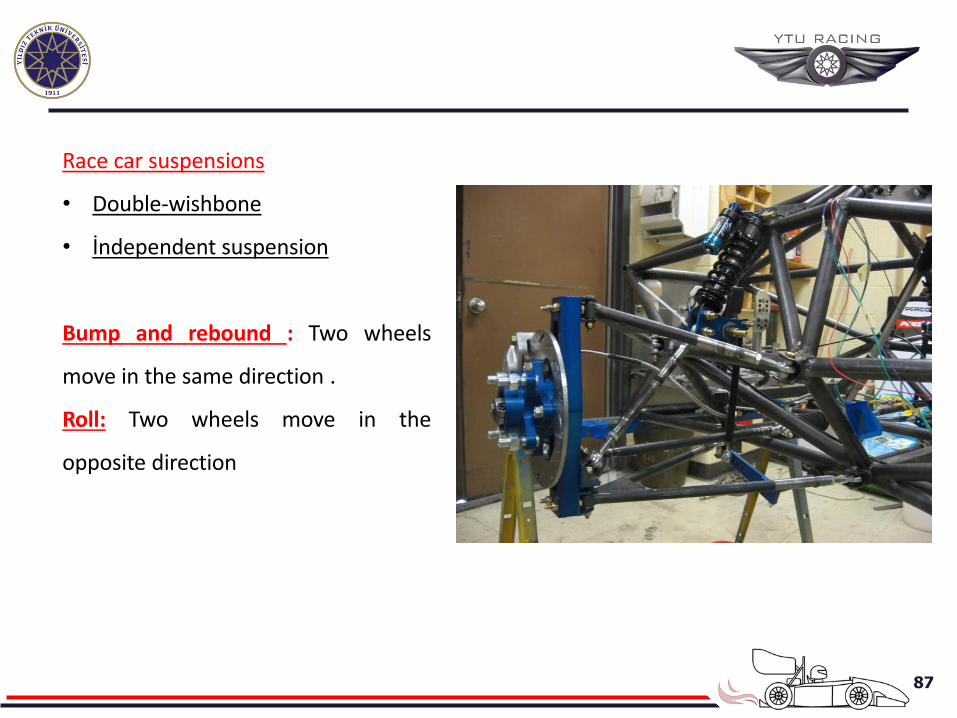
Race car suspensions
• Double-wishbone
• İndependent suspension
Bump and rebound : Two wheels
move in the same direction .
Roll: Two wheels move in the
opposite direction
88
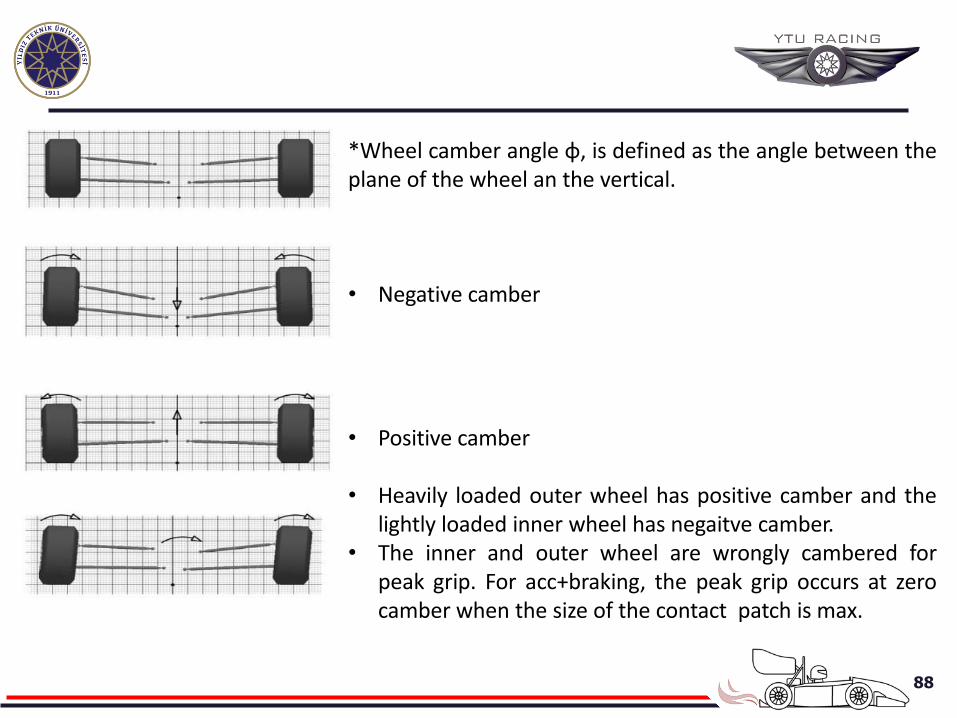
*Wheel camber angle φ, is defined as the angle between the plane of the wheel an the vertical.
• Negative camber
• Positive camber
• Heavily loaded outer wheel has positive camber and the lightly loaded inner wheel has negaitve camber.
• The inner and outer wheel are wrongly cambered for peak grip. For acc+braking, the peak grip occurs at zero camber when the size of the contact patch is max.
89
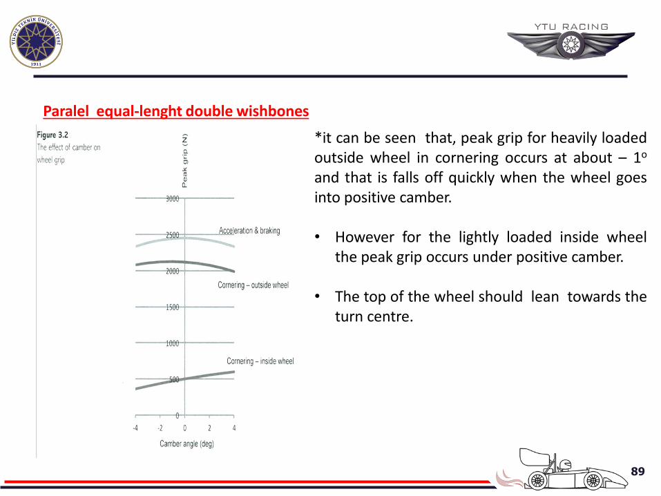
Paralel equal-lenght double wishbones
*it can be seen that, peak grip for heavily loaded outside wheel in cornering occurs at about – 1o and that is falls off quickly when the wheel goes into positive camber. • However for the lightly loaded inside wheel
the peak grip occurs under positive camber.
• The top of the wheel should lean towards the turn centre.
90
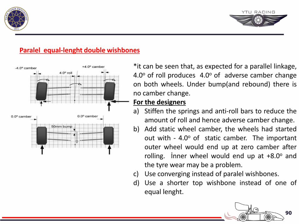
Paralel equal-lenght double wishbones
*it can be seen that, as expected for a parallel linkage, 4.0o of roll produces 4.0o of adverse camber change on both wheels. Under bump(and rebound) there is no camber change. For the designers a) Stiffen the springs and anti-roll bars to reduce the
amount of roll and hence adverse camber change. b) Add static wheel camber, the wheels had started
out with - 4.0o of static camber. The important outer wheel would end up at zero camber after rolling. İnner wheel would end up at +8.0o and the tyre wear may be a problem.
c) Use converging instead of paralel wishbones. d) Use a shorter top wishbone instead of one of
equal lenght.
91
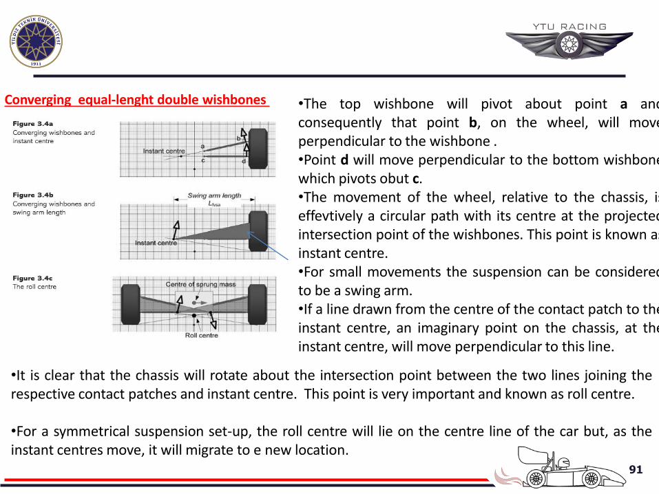
Converging equal-lenght double wishbones
•It is clear that the chassis will rotate about the intersection point between the two lines joining the respective contact patches and instant centre. This point is very important and known as roll centre. •For a symmetrical suspension set-up, the roll centre will lie on the centre line of the car but, as the instant centres move, it will migrate to e new location.
•The top wishbone will pivot about point a and consequently that point b, on the wheel, will move perpendicular to the wishbone . •Point d will move perpendicular to the bottom wishbone which pivots obut c. •The movement of the wheel, relative to the chassis, is effevtively a circular path with its centre at the projected intersection point of the wishbones. This point is known as instant centre. •For small movements the suspension can be considered to be a swing arm. •If a line drawn from the centre of the contact patch to the instant centre, an imaginary point on the chassis, at the instant centre, will move perpendicular to this line.
92
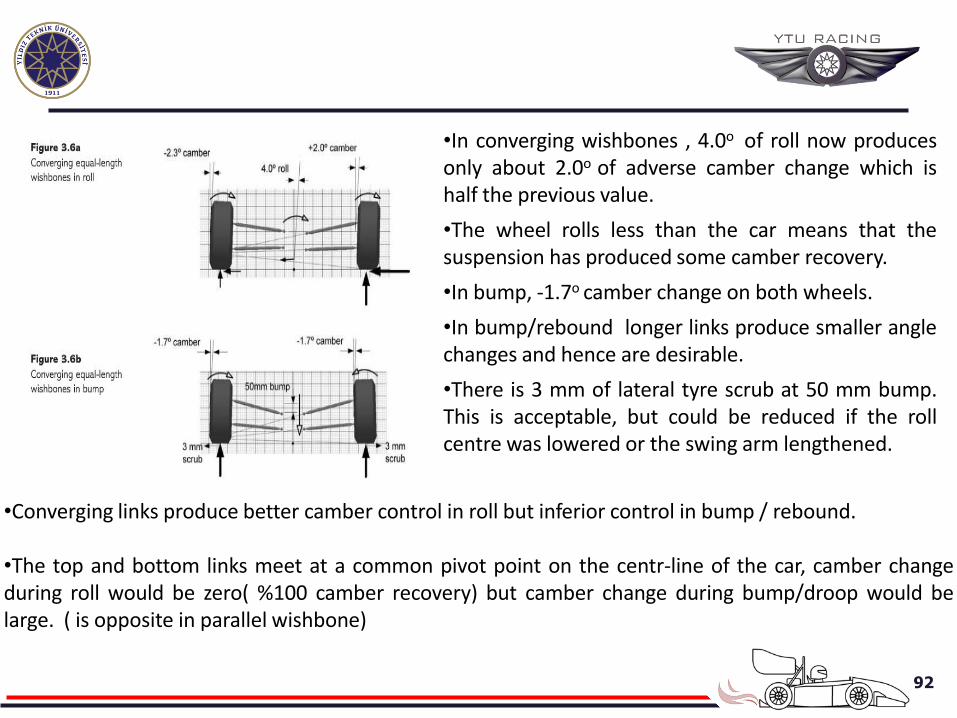
•In converging wishbones , 4.0o of roll now produces only about 2.0o of adverse camber change which is half the previous value.
•The wheel rolls less than the car means that the suspension has produced some camber recovery.
•In bump, -1.7o camber change on both wheels.
•In bump/rebound longer links produce smaller angle changes and hence are desirable.
•There is 3 mm of lateral tyre scrub at 50 mm bump. This is acceptable, but could be reduced if the roll centre was lowered or the swing arm lengthened.
•Converging links produce better camber control in roll but inferior control in bump / rebound. •The top and bottom links meet at a common pivot point on the centr-line of the car, camber change during roll would be zero( %100 camber recovery) but camber change during bump/droop would be large. ( is opposite in parallel wishbone)
93
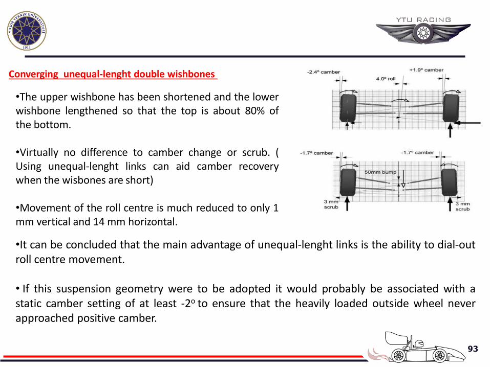
Converging unequal-lenght double wishbones
•The upper wishbone has been shortened and the lower wishbone lengthened so that the top is about 80% of the bottom. •Virtually no difference to camber change or scrub. ( Using unequal-lenght links can aid camber recovery when the wisbones are short) •Movement of the roll centre is much reduced to only 1 mm vertical and 14 mm horizontal. •It can be concluded that the main advantage of unequal-lenght links is the ability to dial-out roll centre movement. • If this suspension geometry were to be adopted it would probably be associated with a static camber setting of at least -2o to ensure that the heavily loaded outside wheel never approached positive camber.
94
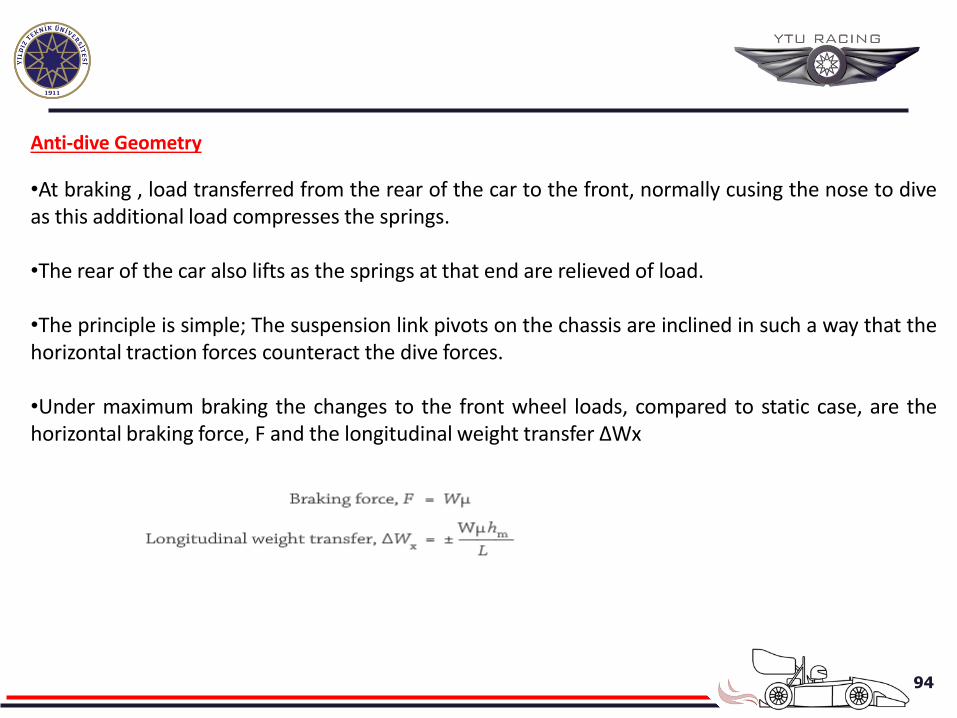
Anti-dive Geometry
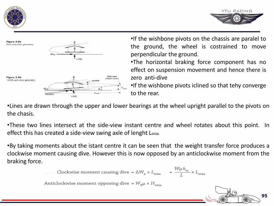
•At braking , load transferred from the rear of the car to the front, normally cusing the nose to dive as this additional load compresses the springs. •The rear of the car also lifts as the springs at that end are relieved of load. •The principle is simple; The suspension link pivots on the chassis are inclined in such a way that the horizontal traction forces counteract the dive forces. •Under maximum braking the changes to the front wheel loads, compared to static case, are the horizontal braking force, F and the longitudinal weight transfer ΔWx
95
•If the wishbone pivots on the chassis are paralel to the ground, the wheel is costrained to move perpendicular the ground. •The horizontal braking force component has no effect on suspension movement and hence there is zero anti-dive •If the wishbone pivots iclined so that tehy converge to the rear.
•Lines are drawn through the upper and lower bearings at the wheel upright parallel to the pivots on the chasis.
•These two lines intersect at the side-view instant centre and wheel rotates about this point. In effect this has created a side-view swing axle of lenght Lsvsa.
•By taking moments about the istant centre it can be seen that the weight transfer force produces a clockwise moment causing dive. However this is now opposed by an anticlockwise moment from the braking force.
96
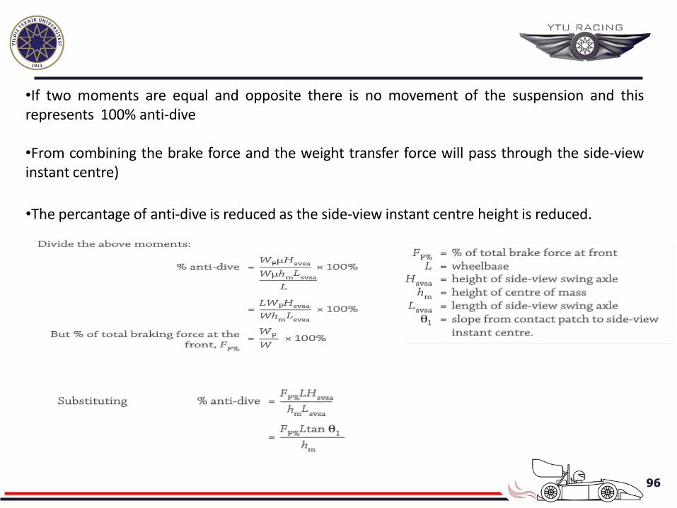
•If two moments are equal and opposite there is no movement of the suspension and this represents 100% anti-dive •From combining the brake force and the weight transfer force will pass through the side-view instant centre)
•The percantage of anti-dive is reduced as the side-view instant centre height is reduced.
97
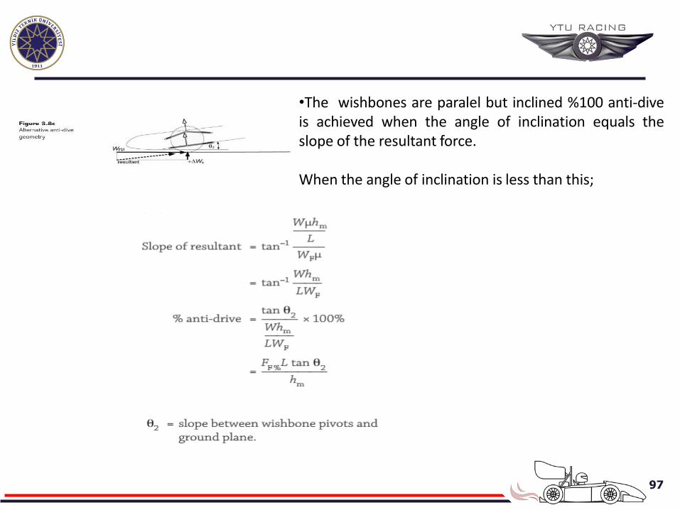
•The wishbones are paralel but inclined %100 anti-dive is achieved when the angle of inclination equals the slope of the resultant force.
When the angle of inclination is less than this;
98
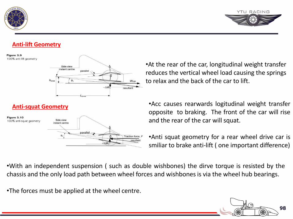
Anti-lift Geometry
•At the rear of the car, longitudinal weight transfer reduces the vertical wheel load causing the springs to relax and the back of the car to lift.
Anti-squat Geometry •Acc causes rearwards logitudinal weight transfer opposite to braking. The front of the car will rise and the rear of the car will squat. •Anti squat geometry for a rear wheel drive car is smiliar to brake anti-lift ( one important difference)
•With an independent suspension ( such as double wishbones) the dirve torque is resisted by the chassis and the only load path between wheel forces and wishbones is via the wheel hub bearings. •The forces must be applied at the wheel centre.
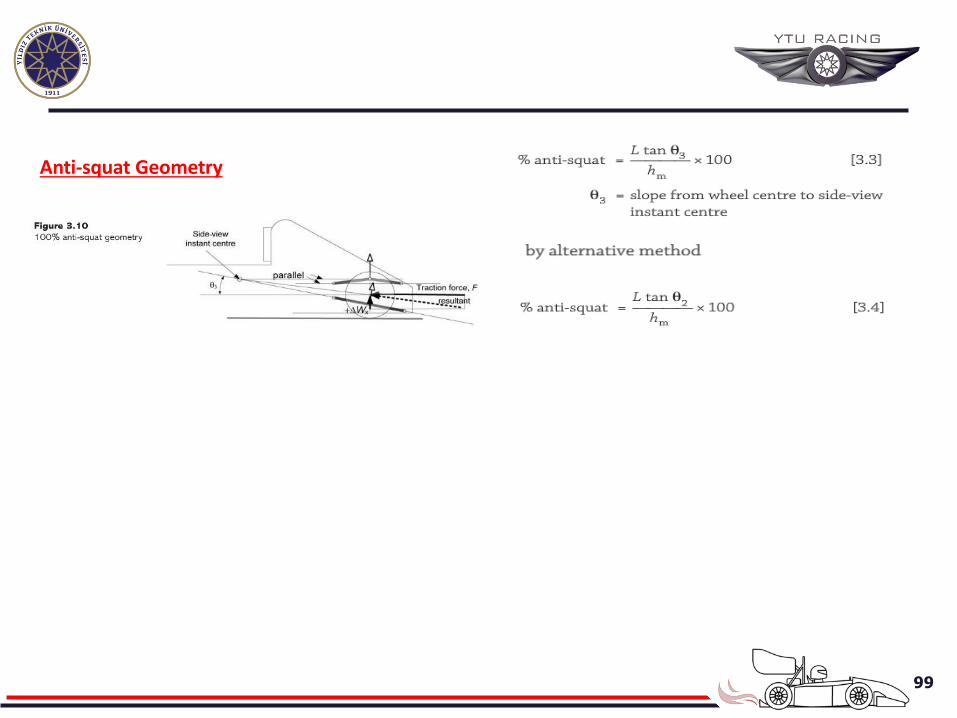
99
Anti-squat Geometry
100
101
102
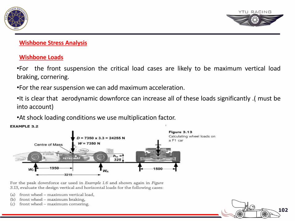
Wishbone Stress Analysis
Wishbone Loads
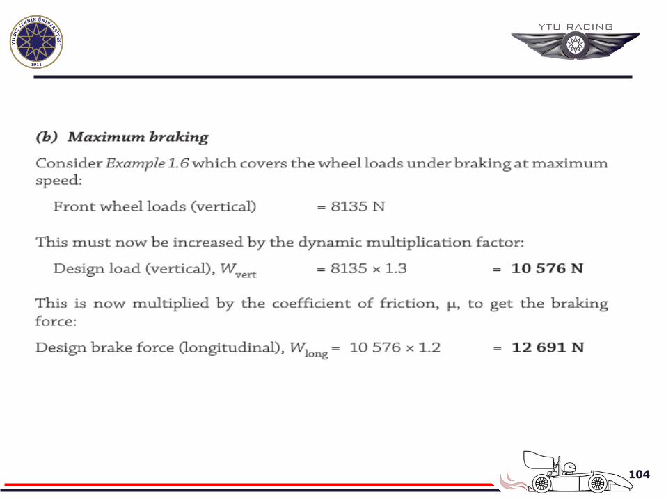
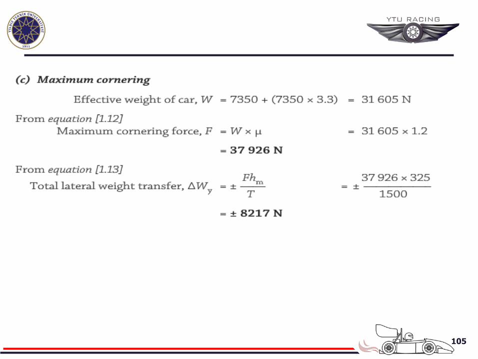
•For the front suspension the critical load cases are likely to be maximum vertical load braking, cornering.
•For the rear suspension we can add maximum acceleration.
•It is clear that aerodynamic downforce can increase all of these loads significantly .( must be into account)
•At shock loading conditions we use multiplication factor.
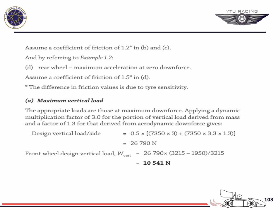
103
104
105
106
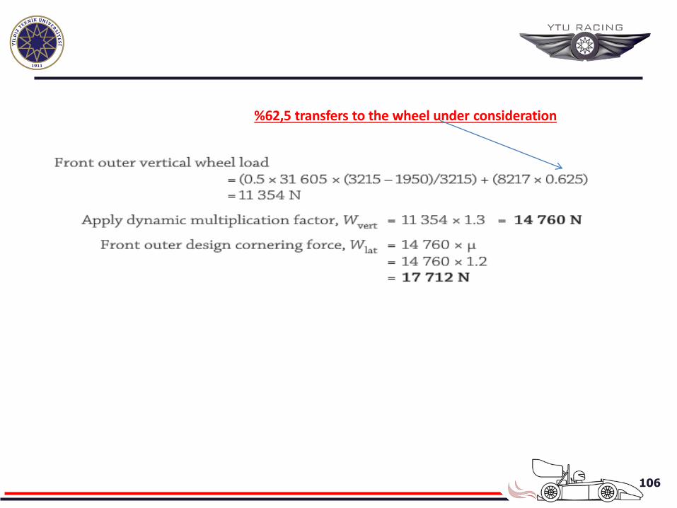
%62,5 transfers to the wheel under consideration
107
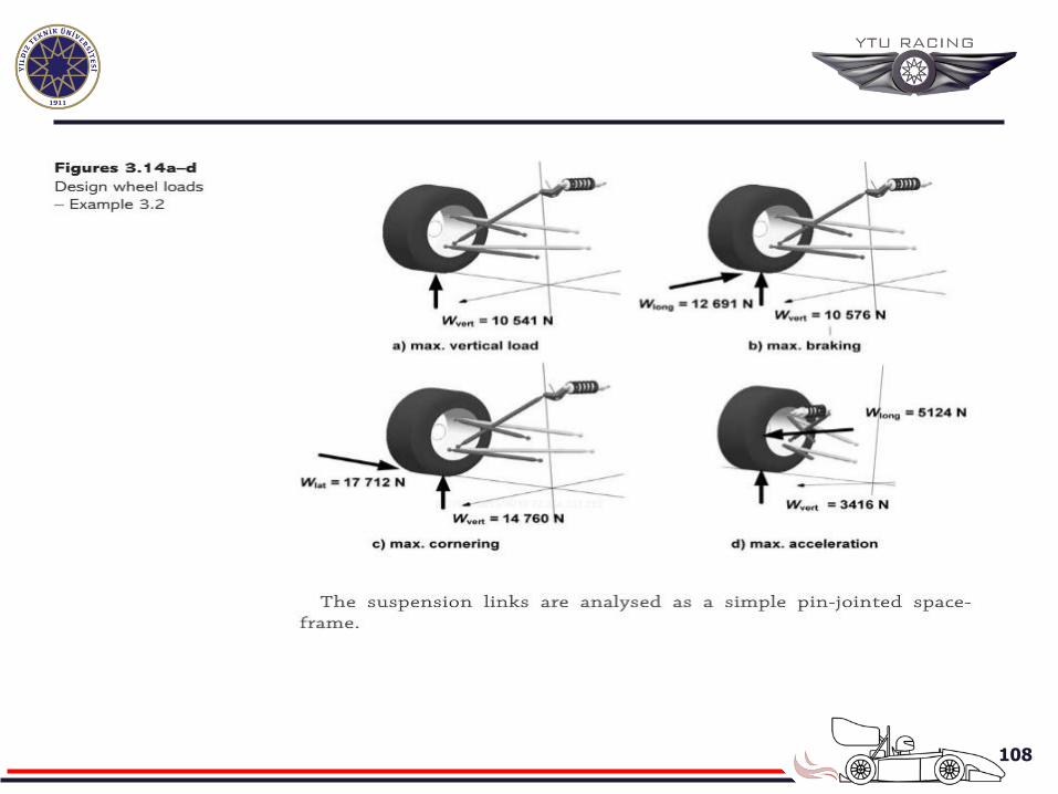
108
109
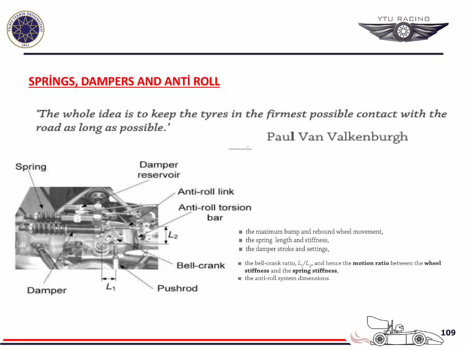
SPRİNGS, DAMPERS AND ANTİ ROLL
110
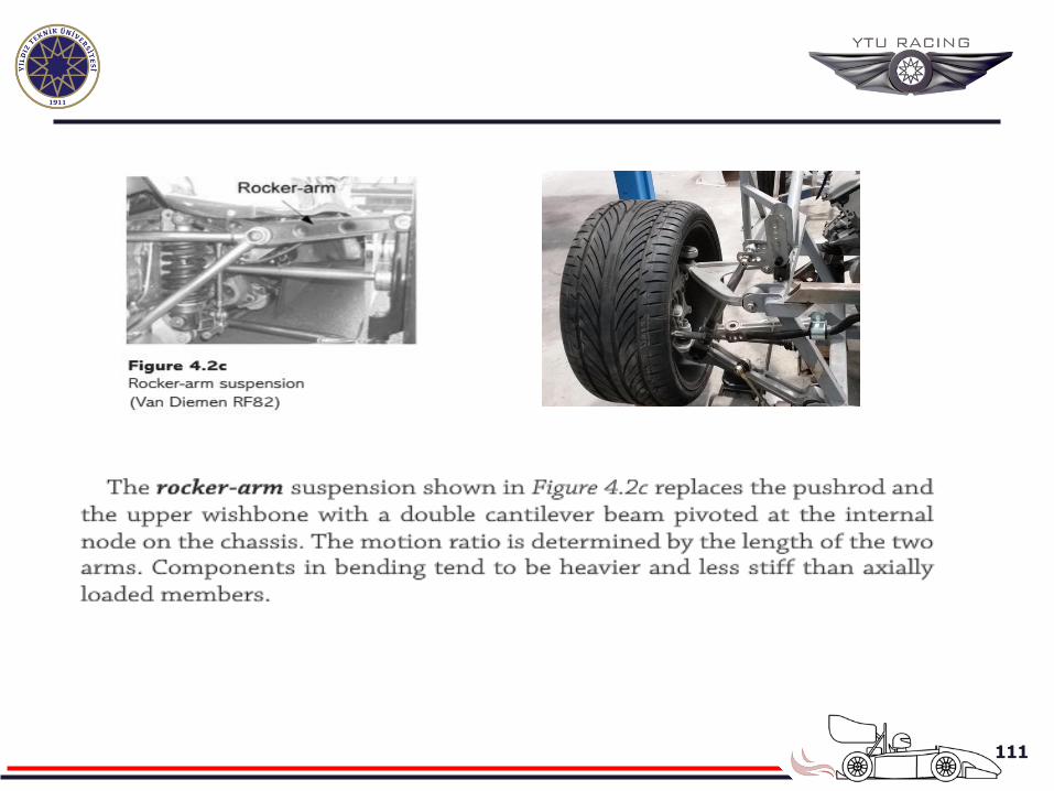
111
112
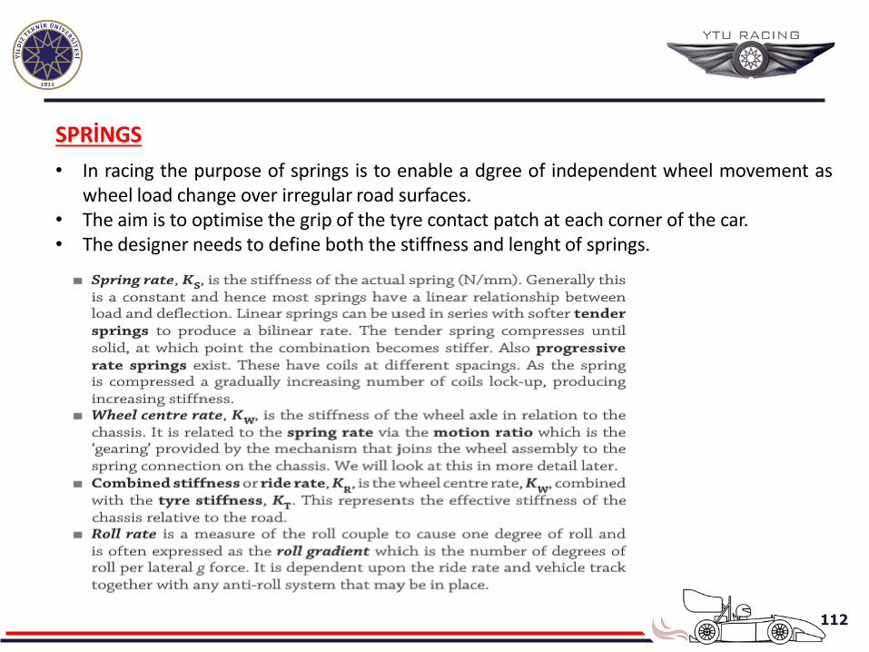
SPRİNGS
• In racing the purpose of springs is to enable a dgree of independent wheel movement as wheel load change over irregular road surfaces.
• The aim is to optimise the grip of the tyre contact patch at each corner of the car. • The designer needs to define both the stiffness and lenght of springs.
113
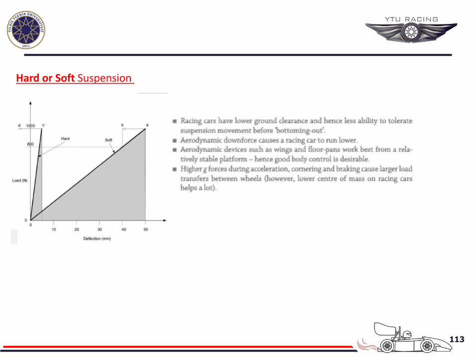
Hard or Soft Suspension
114
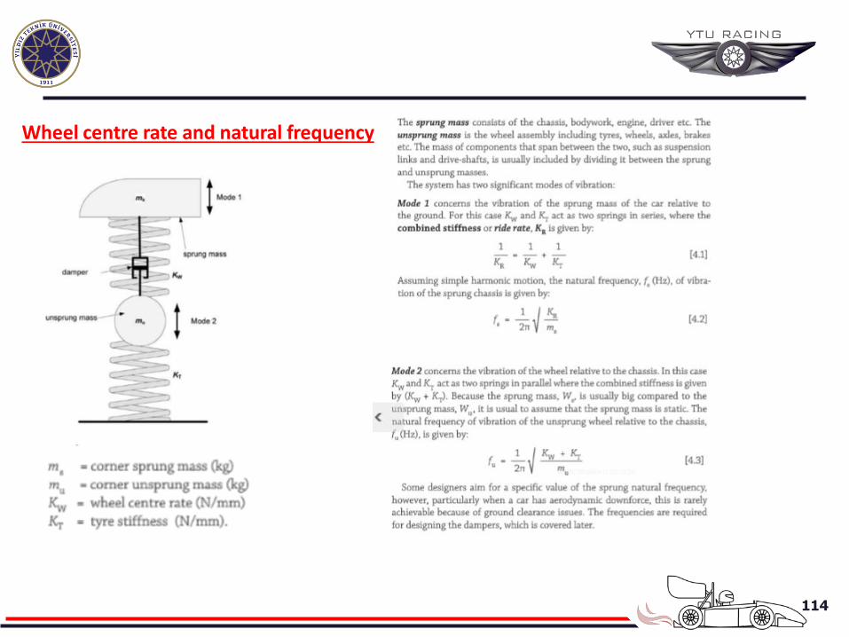
Wheel centre rate and natural frequency
115
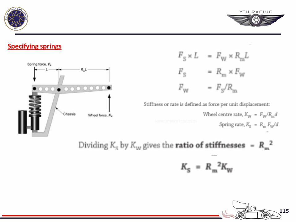
Specifying springs
116
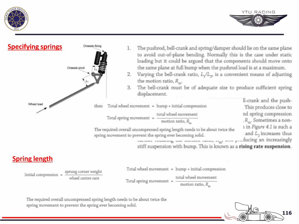
Spring length
Specifying springs
117
REAR WHEEL ASSEMBLY AND POWER TRANSMISIONS
118
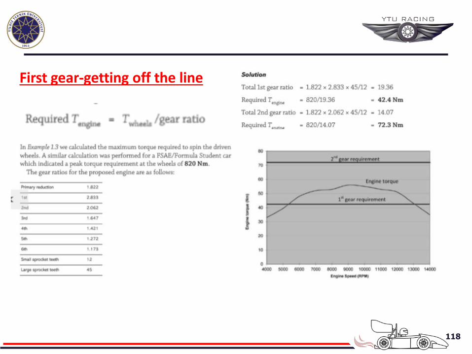
First gear-getting off the line
119
120
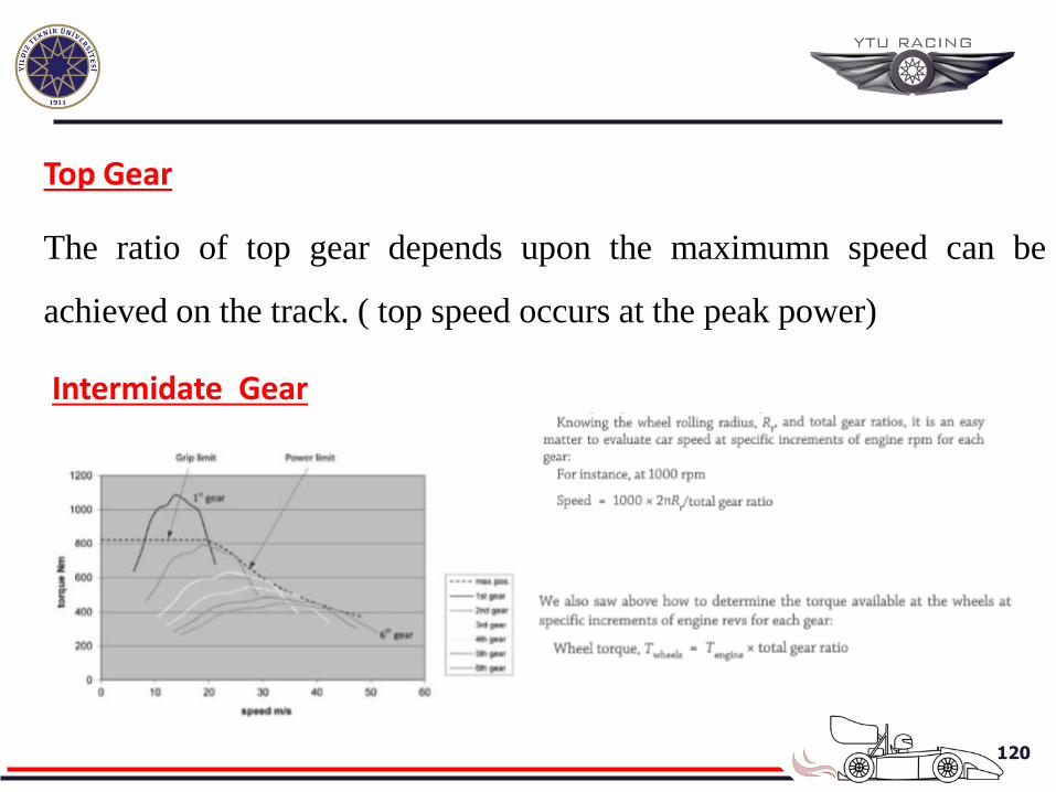
Top Gear
The ratio of top gear depends upon the maximumn speed can be
achieved on the track. ( top speed occurs at the peak power)
Intermidate Gear
121
122
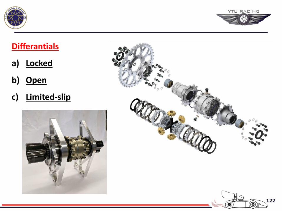
Differantials
a) Locked
b) Open
c) Limited-slip
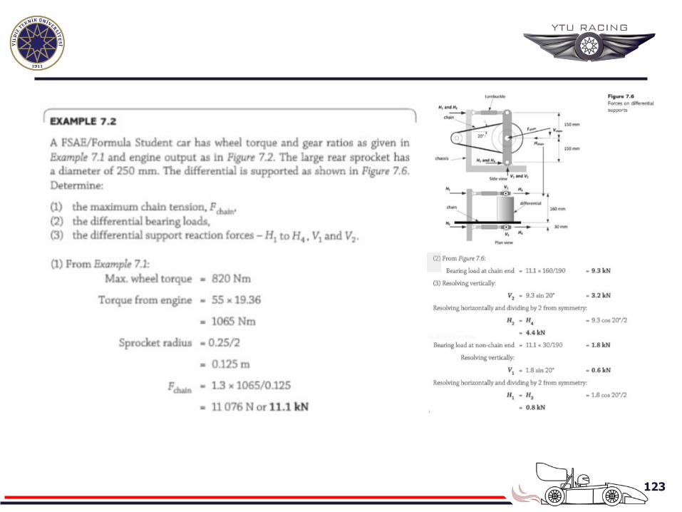
123
124
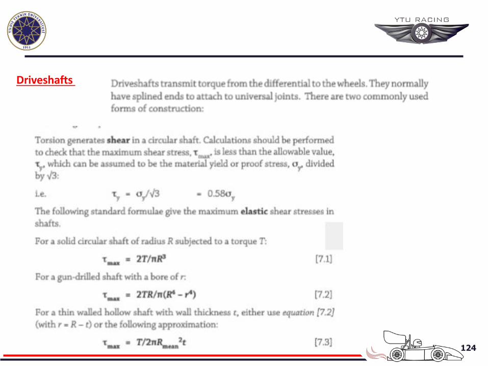
Driveshafts
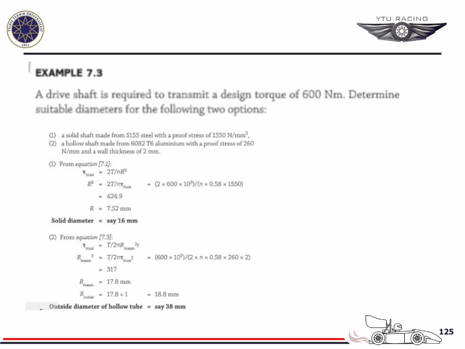
125
126
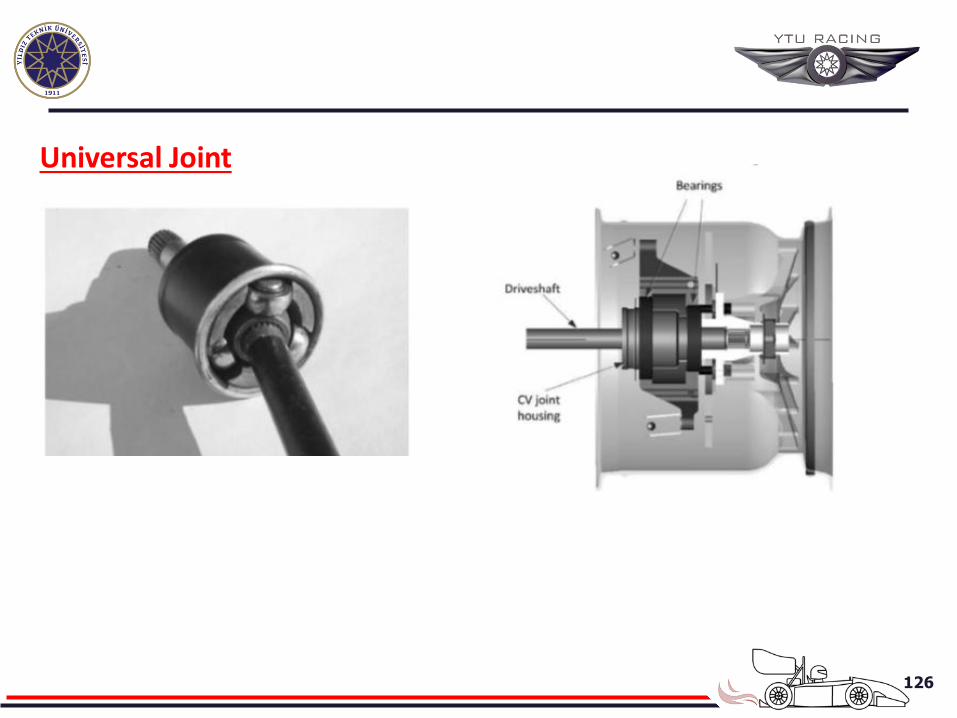
Universal Joint
127
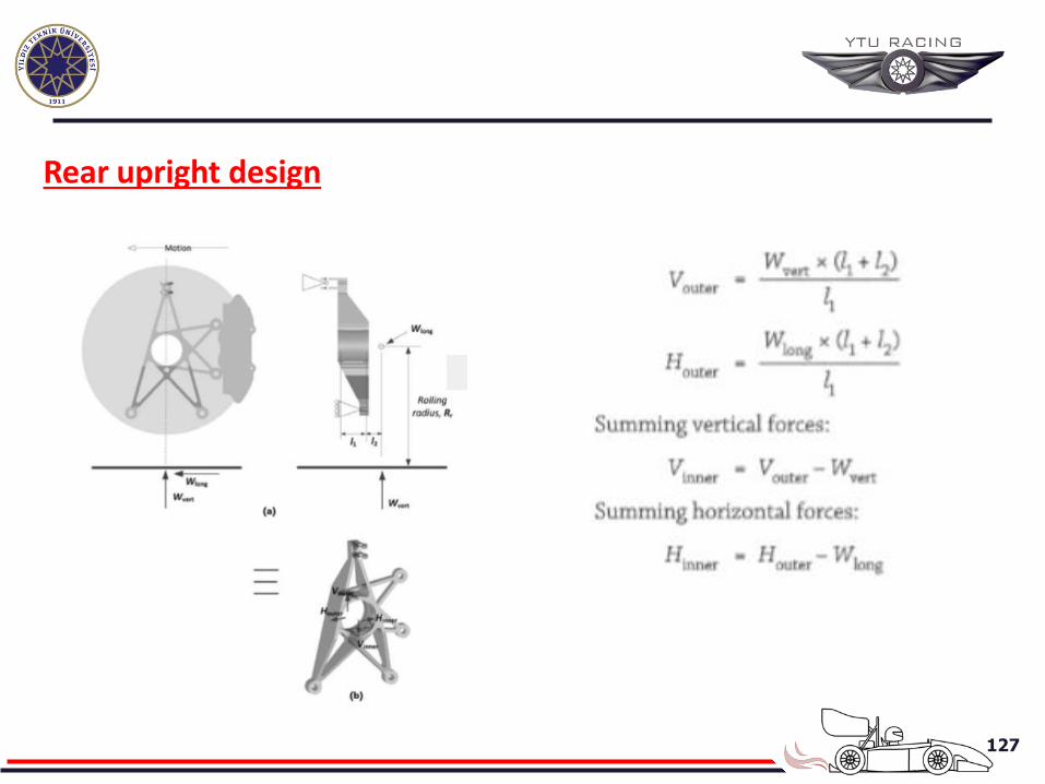
Rear upright design
128
ENGINE SYSTEM OF RACE CAR
For a four stroke petrol engine these include:
Air induction
Fuel induction
Exhaust
Engine management and ignition
Cooling
Lubrication
129
INTAKE CYCLE: As the piston descends, the inlet valve opens and air is
drawn into the cylinder. At the same time the fuel injector opens and a jet of
petrol is squirted in.
COMPRESSION CYCLE: The rising piston compresses the air and petrol
mixture
POWER CYCLE:The air and petrol mixture is ignited by the spark plug.
The resulting explosion forces the piston down, generating power.
EXHAUST CYCLE:As the piston rises again the exhasut valve opens and the
combustion products are forced out of the exhasut valve.
130
Air Induction-Normally Aspirated Engine The normally aspirated engine relies upon a partial vacuum created
by the descending piston to draw air into the cylinder.
Modern high revving engine is a highly dynamic system with many subtleties to
improve efficiency and power out. For instance, at the end of the exhaust cycle,
the exhaust valve does not close until after the inlet valve has opened to start the
inlet cycle. This is known as valve overlap.
Exploits the fact that the out-rushing exhaust gases suck in more incoming air
than would otherwise be the case. The cylinder has become overcharged. This
means that more petrol can be added and more power generated
The degree of over-charging is expressed as the volumetic efficiency and a key
aim in tuning an engine is to maximise the volumetric efficiency.
131
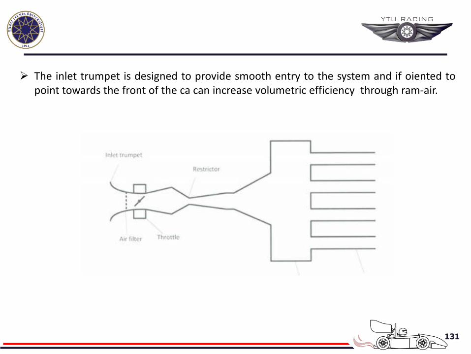
The inlet trumpet is designed to provide smooth entry to the system and if oiented to point towards the front of the ca can increase volumetric efficiency through ram-air.
132
The throttle is the means by wich the driver, via the acclerator pedal, controls the
air flow and hence the speed of the vehicle. The throttle body contains an angle
sensor that is used by the engine management unit to determine the fuel
requiements.
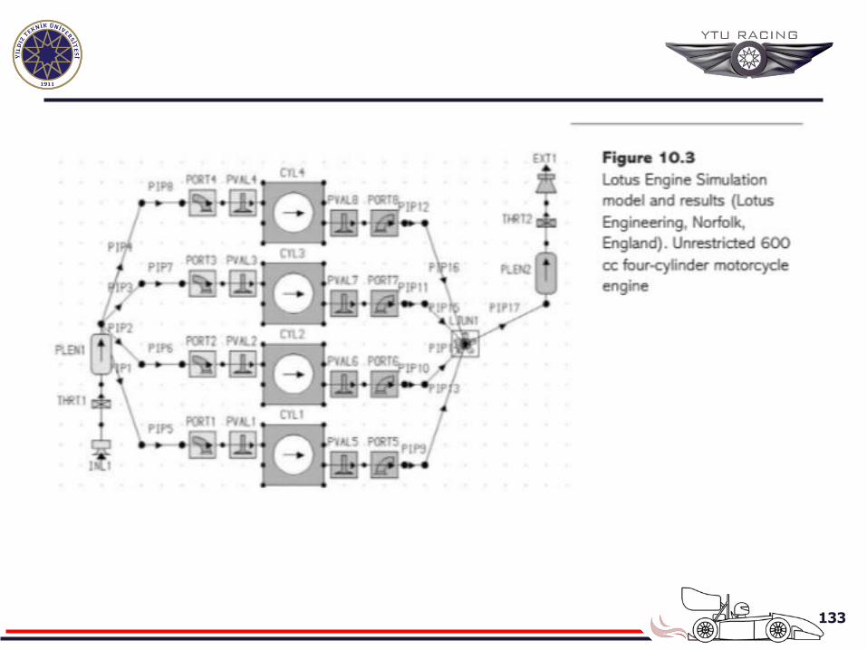
The plenum, intake chamber or air box provides a resonating volume of Air
downstream of any restrictor. In a tuned system this works in conjuction with
the inlet runners to increase the volumetric efficiency of the engine.
The exhaust system is tuned to eerate a boost in volumetric from pulsed waves.
The two extreme choices are:Optimise the length of inlet and exhaut pipes to
concentrate maximum Volumetric efficiency at the toop end of rpm range. This
will maximise the headline power output of the engine but produce a peaky
engine with reduced bottom end torque. Th drive will need to rev the engine
hard and make frequent gear changes to keep within the power band.
133
134
2. Optimise the length of inlet and exhasut pipes to distribute the
individual peaks from the inlet and exhaust pipes throughtout the mid-
range engine rpm, taking care to avoid a mid-range ‘trough’.
Hand techniques, such as Helmholtz resonator method, exist to estimate
the inlet runner lengths; However they invariably involve siplifications
such as assuming the speed of the shockwaves is constant.
135
The Forced Induction Engine
The previous title considered air entering the engine under atmospheric
pressure plus the additionof pulsed shockwaves. The torque, and hence power,
output of an engne can be increased considerably if the air is comressed an enters
the engine under pressure-known as forced induction. Tihs is achieved by the
use of eiter a supercharger or a turbocharger.
A supercharger is usually driven by a belt and pulley from engine. The degree
of bost or pressure increase is directy related to engine speed. Superchargers are
relatively simle to install and manage but can only be adjusted by changing
the pulley diameters.
136
• A turbocharger is driven by engine exhaust gases. Turbochargers can be designed
to produce peak booost at relatively ow engine speed which is then sustained up to
the rev limit.
• Excess pressure is controlled by a pressure relief valve knon as a wastegate.
• The use of exhaust gases can cause heat problems and may require the use of an
intercooler.
• These are more complex to install and manage and often introdue a delay between
the driver pressing the accelerator and the actual power boost-known as turbo lag.
137
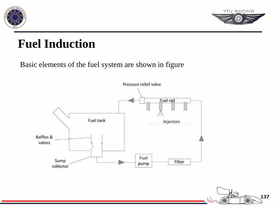
Fuel Induction
Basic elements of the fuel system are shown in figure
138
• The fuel tank can either be a rigid, often aluminum alloy, container or a
flexible polymer bag or bladder. Bladders are often placed inisde a rigid
container for protection.
• There generally needs to be some form of system to prevent fuel surge.
• The main fuel pump must be of teh high-pressure type for fuek injection
engines.
• The pump may be contained within the fuel tank as on most road vehicles. The
fuel rail is generally held at a pressure of about 3 bar by pressure regulator and
surplus fuel return to the tank.The fuel injectors spray fuel into the cylnders
and are simply turned on for the appropriate duration by the ECU.
139
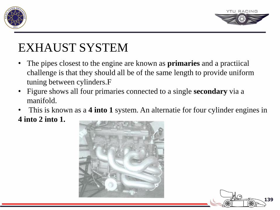
EXHAUST SYSTEM • The pipes closest to the engine are known as primaries and a practiical
challenge is that they should all be of the same length to provide uniform
tuning between cylinders.F
• Figure shows all four primaries connected to a single secondary via a
manifold.
• This is known as a 4 into 1 system. An alternatie for four cylinder engines in
4 into 2 into 1.
140
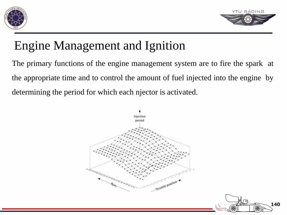
Engine Management and Ignition
The primary functions of the engine management system are to fire the spark at
the appropriate time and to control the amount of fuel injected into the engine by
determining the period for which each njector is activated.
141
• The look-up table data is often presented in the form of –D graphs and
consequently they are often preferred to as engine maps. Figure shows a typical
fuel map. The hrizontal axes present rpm and throttle position and the vertical
axis represents the time period during wich the fuel injectors are open.
• A better option to the standart engine ECUis the adoption of a stand-alone
Specialist performance engine management system.
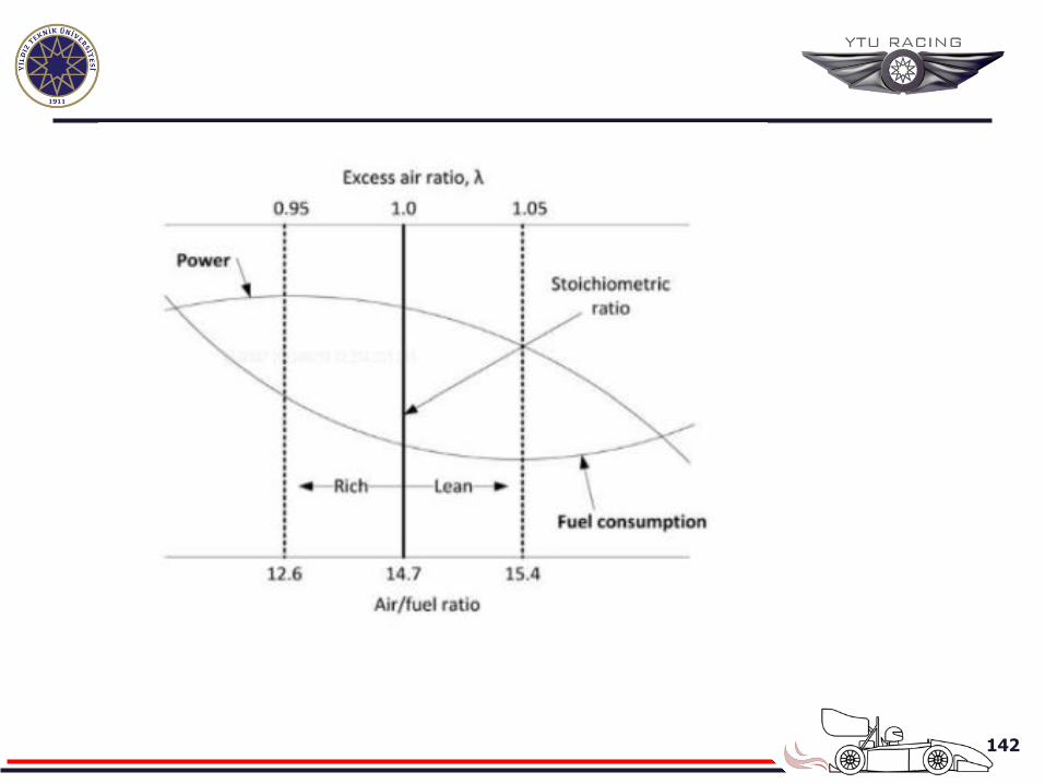
• The general aim of engine tuning is to program the ECU so that it maintains an
optimum target air/fuel mixture under mst running conditions.
• The stşchometric ratio is 14.68 parts of air to one part of premium petrol
fuel(gasoline). Another way of expressing this ratio is the lambda excess oxygen
ratio. A value of lambda:1.0 represents the stoichiometric ratio.
142
143
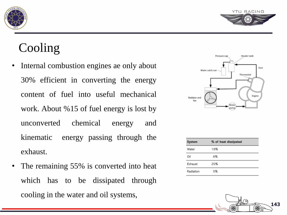
Cooling
• Internal combustion engines ae only about
30% efficient in converting the energy
content of fuel into useful mechanical
work. About %15 of fuel energy is lost by
unconverted chemical energy and
kinematic energy passing through the
exhaust.
• The remaining 55% is converted into heat
which has to be dissipated through
cooling in the water and oil systems,
144
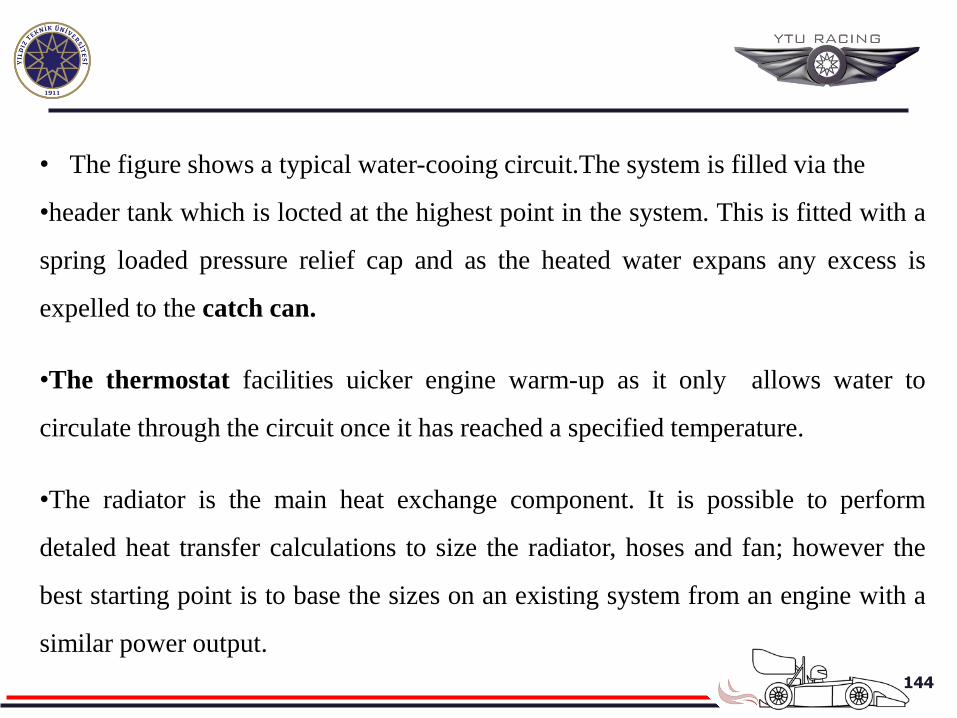
• The figure shows a typical water-cooing circuit.The system is filled via the
•header tank which is locted at the highest point in the system. This is fitted with a
spring loaded pressure relief cap and as the heated water expans any excess is
expelled to the catch can.
•The thermostat facilities uicker engine warm-up as it only allows water to
circulate through the circuit once it has reached a specified temperature.
•The radiator is the main heat exchange component. It is possible to perform
detaled heat transfer calculations to size the radiator, hoses and fan; however the
best starting point is to base the sizes on an existing system from an engine with a
similar power output.
145
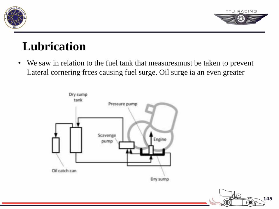
Lubrication
• We saw in relation to the fuel tank that measuresmust be taken to prevent
Lateral cornering frces causing fuel surge. Oil surge ia an even greater
problem.