Embed Size (px)
Citation preview

Seediscussions,stats,andauthorprofilesforthispublicationat:https://www.researchgate.net/publication/5915687
Gate-TunedHighFrequencyResponseofCarbonNanotubeJosephsonJunctions
ARTICLEinPHYSICALREVIEWLETTERS·OCTOBER2007
ImpactFactor:7.51·DOI:10.1103/PhysRevLett.99.117001·Source:PubMed
CITATIONS
20
READS
28
7AUTHORS,INCLUDING:
WolfgangWernsdorfer
FrenchNationalCentreforScientificResearch
612PUBLICATIONS32,550CITATIONS
SEEPROFILE
SergeFlorens
FrenchNationalCentreforScientificResearch
66PUBLICATIONS1,188CITATIONS
SEEPROFILE
MarcMonthioux
FrenchNationalCentreforScientificResearch
176PUBLICATIONS5,899CITATIONS
SEEPROFILE
Allin-textreferencesunderlinedinbluearelinkedtopublicationsonResearchGate,
lettingyouaccessandreadthemimmediately.
Availablefrom:MarcMonthioux
Retrievedon:03February2016

Gate-tuned high frequency response of carbon nanotube
Josephson junctions
J.-P. Cleuziou1, W. Wernsdorfer2, S. Andergassen2, S.
Florens2, V. Bouchiat2, Th. Ondarcuhu1, M. Monthioux1
1CEMES-CNRS, BP 94347, 31055 Toulouse Cedex 4, France
2Institut Neel, CNRS/UJF, BP 166, 38042 Grenoble Cedex 9, France
(Dated: April 20, 2007)
Abstract
Carbon nanotube (CNT) Josephson junctions in the open quantum dot limit exhibit supercon-
ducting switching currents which can be controlled with a gate electrode. Shapiro voltage steps
can be observed under radiofrequency current excitations, with a damping of the phase dynam-
ics that strongly depends on the gate voltage. These measurements are described by a standard
RCSJ model showing that the switching currents from the superconducting to the normal state are
close to the critical current of the junction. The effective dynamical capacitance of the nanotube
junction is found to be strongly gate-dependent, suggesting a diffusive contact of the nanotube.
PACS numbers: 74.50.+r, 74.45.+c, 73.63.Kv, 73.63.Fg
1
arX
iv:0
705.
2033
v1 [
cond
-mat
.mes
-hal
l] 1
4 M
ay 2
007

It was recently demonstrated that carbon nanotube (CNT) weak links, connecting two
superconducting leads [1], can be gate-controlled Josephson junctions [2, 3, 4, 5, 6, 7, 8]
and even gate-controlled π-junctions [6]. The first interesting application of CNT Josephson
junctions are superconducting transistors [4, 5] and superconducting quantum interference
devices (SQUIDs) [6], which are promising candidates for the detection of individual mag-
netic molecules. They might also prove useful as building blocks for more complicated
superconducting devices [9] and new readout schemes [10, 11].
For all theses devices, the critical current Ic and the high frequency response of CNT
Josephson junctions plays an important role, which is studied in this letter. Indeed, previous
investigations showed that the magnitude of the switching current Isw of such CNT devices
appeared to be very different from theoretical predictions: in the first experiments it was
observed to be 10 times larger [1] and later 10 times smaller [4, 5, 6, 7, 8] than the result of
Ambegaokar and Baratoff [12], reformulated for a quantum dot (QD) in [13]. Moreover, all
these previous measurements were performed for a static bias, without retrieving the effect
of radiofrequency (RF) irradiation.
The electronic transport through a CNT junction can be described by a QD in between
two conducting leads. The energy level spacing ∆E depends on the length of the junc-
tion and the nature of the conducting leads. The transport can be classified into three
limits depending on the ratio between the transparency Γ of the QD barriers and the
charging energy U [14]: (i) for hΓ << U , the maximum conductance at zero bias obeys
Gmax << 2e2/h. In this so-called closed QD regime the charging effects dominate the trans-
port characterized by well-resolved Coulomb blockade diamonds [15]. (ii) for hΓ ≈ U holds
e2/h <∼ Gmax<∼ 2e2/h. In this intermediate transparency regime charging effects as well as
higher-order tunneling processes are very important. Here, transport measurements show
that Coulomb blockade diamonds, corresponding to an odd number of electrons, are con-
nected by Kondo ridges [2, 16]. For superconducting leads, higher-order multiple Andreev
reflections (MARs) are well resolved [3, 4]. (iii) For hΓ >> U , the conductance is close to
4e2/h and corresponds to the open QD regime (the factor 4 reflects the two modes of the
CNT band structure as well as the two spin orientations), where Coulomb blockade dia-
monds are not observed. This leads to a relatively high supercurrent for all gate voltages.
Gate-modulated Fabry-Perot interferences can be observed in the last two regimes [17].
An important advantage of these devices is that backgate and sidegate electrodes can
2
be used to vary both Γ and the energy levels position in the nanotube, thus permitting to
change the electric transport regime [18]. This tunability allowed us in a previous study to
capture both Kondo screened and unscreened junctions, leading to the observation of a 0-π
transition [6]. Similarly, we found that the QD barrier can be varied with the thickness of
the Pd contacts, enabling to access also all three transport regimes.
Previous measurements on CNT Josephson junctions were in the intermediated or closed
QD regime [19]. Here we present the first measurements in the open QD regime using a
Pd thickness of 7 nm. The present description concentrates on a single device, similar data
were however obtained on a couple of other devices fabricated on the same chip.
The CNT Josephson junction were fabricated as presented earlier [6]. We started from
a degenerately n-doped silicon substrate with 350 nm thick thermally grown SiO2 layer on
top used as a backgate. Single-walled CNTs were deposited using a combing technique [20].
The nanotube location was imaged by atomic force microscopy (AFM) and aligned e-beam
lithography patterned the contacts [21]. The length of the tube section between the contacts
was about 200 nm. Metal electrodes consisting of a thickness of 3 to 7 nm of Pd followed by
50 nm of Al, were deposited using electron-gun evaporation. Pd provides high-transparency
contacts to the carbon nanotubes. Al is a superconductor having a critical temperature
of about 1.2 K. The room temperature resistance varied between 10 and 60 kΩ, strongly
depending on the thickness of Pd. Only devices with no significant gate effect at room
temperature were used for our studies. We found that for Pd thicknesses below about 3 nm,
the CNT junction was in the closed QD regime, for 4 to 6 nm in the intermediate, and for
7 nm and more in the open QD regime.
The measurements were performed in a shielded cryostat having heavily filtered lines in
order to minimize the electronic noise reaching the sample, since electronic noise can reduce
and even suppress the switching current of the CNT-SQUID. Our home-built filtering system
was presented in [6]. We used mainly a four-probe, current-biased method. with a bias
resistance of about 65 MΩ at 4.5 K and voltage dividers at room temperature. The voltage
signal of the sample was first pre-amplified by a factor of 104 and then measured using an
oscilloscope or a look-in amplifier. High frequency ac current modulations in the frequency
range between 1 and 12 GHz were induced via an inductive coupling.
The effective BCS gap ∆eff of the superconducting leads felt by the CNT was estimated
by voltage versus current measurements as a function of temperature. We found a transition
3

FIG. 1: (Color online) Electric transport through a CNT junction as a function of gate-voltage Vg.
(a) Differential conductivity dI/dV versus Vg at zero bias. (b) dI/dV -map versus current bias Isd
and Vg in the normal state (Hz = 50 mT). (c) Differential resistivity dV/dI-map versus Isd and
Vg in the superconducting state (Hz = 0). The dotted lines indicates the off-state and on-state,
which are further studied in Figs. 2 to 4.
temperature Tc = 0.7 K, yielding a ∆eff = 1.76 kBTc = 0.1 meV. The energy level spacing
of the CNT were determined ∼ 10 meV [6]. However, due to the high transparency of the
contacts the effect of the Coulomb energy is much smaller here.
In Fig. 1a and 1b, a magnetic field of Hz = 50 mT was applied perpendicular to the
electrode plane in order to suppress the superconductivity of the leads. The differential
conductivity dI/dV is plotted versus gate voltage at zero bias in Fig. 1a and, in addition,
as a function of source-drain current Isd in Fig. 1b. dI/dV oscillates between about 1.8 and
3.5 e2/h and is Isd-independent in the considered range. dI/dV is maximal when a quantum
level of the CNT is aligned with respect to the Fermi energy of the leads. A current can
4

then flow by resonant tunneling through the CNT, and we denominate this regime as an
on-state. When the quantum levels are far from the Fermi energy, the current is reduced
(off-state). This CNT junction is clearly in the open QD regime because the reduction is
only about a factor of two and Coulomb blockade effects are not directly observable.
Fig. 1c presents the same measurements as in Fig. 1b but with superconducting leads
(Hz = 0). Because dI/dV diverges, the differential resistivity dV/dI is plotted. For small
Isd a supercurrent is observed, which is evidenced by a nearly zero-resistance state. At
a certain bias current denoted by switching current Isw, the junction switches from the
superconducting to the normal state. Isw is strongly gate-voltage dependent: it is maximal
(minimal) in the on-state (off-state). Most of the on-states are split into two Isw maxima
suggesting that there is still a small influence of Coulomb interaction. Note that higher-order
MARs are not observed, which is probably due to strong broadening effects induced by the
high transparency contacts.
Fig. 2a and 2b show typical voltage versus current curves at several temperatures for the
on- and off-state. The on-state is characterized by the largest Isw and small hysteresis effects,
that is the retrapping current is close to Isw. Furthermore, dV/dI increase for Isd > Isw in the
considered range. In the off-state, the hysteresis effects are very large and dV/dI decrease
for Isd > Isw. A small temperature-dependent resistance is observed at zero-bias, which is
mainly due to temperature-induced phase diffusion [22].
The high frequency response of the CNT junctions is examined by voltage-current curves
in the presence of RF-fields. Figs. 3a and 4a show the appearance of constant voltage Shapiro
steps, which are due to the harmonical synchronization of the Josephson oscillations and
the applied RF excitations. The steps appear at voltages equal to nfφ0 where n = 1, 2, ...
and φ0 is a flux quanta. We checked this linear relation in the frequency range between f
= 1 to 15 GHz (data not shown). The influence of the RF current IRF on the Shapiro steps
is presented on Figs. 3b and 4b for the on- and off-state, respectively. The plots show the
differential resistance as a function of IRF and Isd, giving rise to a complicated pattern of
non-dissipative lobes.
We modelled the data with a phenomenological description of time-dependent transport
in superconducting junctions based on both the standard Josephson relations and on classical
circuit theory, the so-called resistively and capacitively shunted junction (RCSJ) model [23,
24]. This invokes simple differential equations that govern the dynamics of the phase φ
5

FIG. 2: (Color online) Voltage versus current characteristics for a CNT junction in (a) the on-
state and (b) off-state at several temperatures. (a) and (b) correspond to maximal and minimal
switching currents in Fig. 1c, respectively. The current was swept at the sweep rates of 5 and 0.2
nA/s for (a) and (b), respectively. Note that each curve is a single sweep (no data averaging was
performed) and the slope at the switching currents was limited by the filtering.
across the junction:
hdφ
dt= 2eV (1a)
I(t) = CdV
dt+ Iqp(V ) + Ic sinφ , (1b)
where V is the instantaneous voltage drop, I(t) = Isd + IRF sin(ωt) the injected current with
an oscillating part at the radiofrequency f = ω/2π, Iqp(V ) the quasiparticle contribution to
the current, Ic the critical supercurrent, and C the capacitance of the junction.
6
Assuming an ohmic quasiparticle current Iqp = V/R and defining a basic frequency scale
γ = 2eRIc/h, one obtains two relevant dimensionless parameters in the analysis of the
Shapiro steps: i) the reduced pulsation ω = ω/γ characterizing the shape of the Shapiro
steps [25, 26] (pure Bessel functions are obtained in the limit ω 1 only); ii) the quality
factor Q =√γRC that controls the damping of the phase dynamics.
The parameters are adjusted to the experimental data in the RF driven regime where
the dynamics is less sensitive to phase diffusion [22]. The analysis of the experimental data
in the on-state reveals a globally good agreement for Q <∼ 1, i.e. the RSJ model with no
capacitance. Indeed, the geometrical capacitance of CNT junctions is very small (∼ 30 aF).
This finding is supported by the small hysteresis effects of the V I-curves (Fig. 2a). Note
that the predicted Ic is very close to Isw at IRF = 0. The Shapiro step positions present
however small but appreciable deviations to the pure Bessel functions. Their precise shape
can indeed be more accurately described using a reduced pulsation ω ∼ 0.35. Furthermore,
a clear downward dispersion of the lobes is observed, which may be attributed to the non-
ohmic character of the quasiparticle current Iqp(V ) above the threshold Isw. Simulations
of the phase dynamics with such non-linear RSJ model, where the non-linear R from the
V I-curves in the resistive state of Fig. 2 was included, are provided in Fig. 3c and compare
favorably to the experimental data.
Regarding the off-state, several issues point to additional underdamping effects: the
V I-curves are strongly hysteretic and the degree of hysteresis diminishes with increasing
temperature (Fig. 2b) [24]. Moreover, the low-bias Shapiro steps present a peculiar threshold
behavior (Fig. 4b), while the lobes show an upward dispersion. These properties can not be
explained within the usual RCSJ model, and may be only accounted for at a qualitative level
by introducing a rather large effective capacitance C ≈ 1 fF and a non-linear quasiparticle
resistance (stronger than in the on-state discussed above). Fig. 4c shows a partial agreement
between our simulations and the data. The gate-dependence of C suggests a diffusive CNT
contact in the off-state, i.e. additional capacities coming from the CNT contacts. Indeed,
for the off state, the electrode/nanotube capacitance has to be taken into account since the
Pd/nanotube contact is known to be distributed over a larger part of the contact [27]. Its
value can be rather strong (∼ 1 fF). For the on-state however, the capacitance of the contact
can be strongly renormalized by the tunnel effect [28] and the capacitance of the junction is
mainly due to the nanotube self-capacitance estimated as 30 aF for a nanotube portion of
7

FIG. 3: (Color online) RF response in the on-state. (a) Voltage versus current characteristics at
several RF amplitudes IRF. (b) Differential resistance dI/dV -maps versus Isd and IRF for f = 3
GHz. (c) Simulation of the data in (b) using the non-linear RSJ model.
200 nm [29]. A more thorough analysis of quantum and thermal fluctuation effects on the
Shapiro steps in the spirit of references [30, 31] is clearly beyond the scope of the present
study. We point out however that these effects probably do not account for the strong
reduction of the critical current, as the above analysis demonstrated in the on-state.
In conclusion, we studied the critical currents and the constant-voltage Shapiro steps un-
der RF irradiation of a strongly coupled CNT Josephson junction, and discovered a strong
gate-voltage dependence. These junctions are therefore very promising as tunable RF build-
ing blocks for superconducting devices.
This work was partially supported by the CNRS ACI NOCIEL and ANR QuSpins pro-
grams. Clean room processes were supported by the CNRS RTB program using the techno-
logical facilities of the Laboratory for Analysis and Architecture of Systems (University of
8

FIG. 4: (Color online) RF response in the off-state. (a) V I-characteristics at several IRF. (b)
dI/dV -maps versus Isd and IRF for f = 4 GHz. (c) Simulation of the data in (b) using the
non-linear RCSJ model.
Toulouse - France). We thanks F. Balestro, O. Buisson, F. Carcenac, J. Clarke, E. Eyraud,
D. Feinberg, and I. Siddiqi for valuable contributions and helful discussions.
[1] A. Y. Kasumov and et al., Science 397, 598 (1999).
[2] M. R. Buitelaar, T. Nussbaumer, and C. Schonenberger, Phys. Rev. Lett. 89, 256801 (2002).
[3] M. R. Buitelaar, W. Belzig, T. Nussbaumer, B. Babic, C. Bruder, and C. Schonenberger,
Phys. Rev. Lett. 91, 057005 (2003).
[4] P. Jarillo-Herrero, J.A. van Dam, and L.P. Kouwenhoven, Nature 439, 953 (2006).
[5] H. I. Jorgensen, K. Grove-Rasmussen, T. Novotny, K. Flensberg, and P. E. Lindelof, Phys.
Rev. Lett. 96, 207003 (2006).
9

[6] J.-P. Cleuziou, W. Wernsdorfer, V. Bouchiat, Th. Ondarcuhu, and M. Monthioux, Nature
Nanotech. 1, 53 (2006).
[7] T. Tsuneta, L. Lechner, and P. J. Hakonen, Phys. Rev. Lett. 98, 087002 (2007).
[8] A. Eichler, M. Weiss, S. Oberholzer, C. Schonenberger, A. Levy Yeyati, and J. C. Cuevas,
cond-mat/0703082.
[9] I. Chiorescu, Y. Nakamura, C.J.P.M. Harmans, and J.E. Mooij, Science 299, 1869 (2003).
[10] I. Siddiqi, R. Vijay, F. Pierre, C. M. Wilson, M. Metcalfe, C. Rigetti, L. Frunzio, and M. H.
Devoret, Phys. Rev. Lett. 93, 207002 (2004).
[11] I. Siddiqi, R. Vijay, F. Pierre, C. M. Wilson, L. Frunzio, M. Metcalfe, C. Rigetti, R. J.
Schoelkopf, M. H. Devoret, D. Vion, and D. Esteve, Phys. Rev. Lett. 94, 027005 (2005).
[12] V. Ambegaokar and A. Baratoff, Phys. Rev. Lett. 10, 486 (1963).
[13] C. W. J. Beenakker and H. van Houten, in see also condmat/0111505, edited by H. Koch and
H. Luebbig (Springer, Berlin, 1992), pp. 175–179.
[14] For short CNT junction of few 100 nm, ∆E > hΓ, U .
[15] D. H. Cobden and J. Nygard, Phys. Rev. Lett. 89, 046803 (2002).
[16] D. Goldhaber-Gordon, J. Gores, M. A. Kastner, Hadas Shtrikman, D. Mahalu, and U. Meirav,
Phys. Rev. Lett. 81, 5225 (1998).
[17] W.J. Liang and et al., Nature 411, 665 (2001).
[18] J.-P. Cleuziou, W. Wernsdorfer, V. Bouchiat, Th. Ondarcuhu, and M. Monthioux, cond-
mat/0610622.
[19] The data in [4] were interpreted to be in the open QD regime. However, we think that the
well-resolved higher-order MAR fine-structures as well as the high resistivity in the off-states
suggest that these devices operated in the intermediate transport regime. The observation of
Gmax ≈ 4e2/h could be explained by the large CNT diameter of 4 to 7 nm and the observation
of Fano resonances suggesting that the junction was not made out of an individual single-walled
CNT.
[20] S. Gerdes, T. Ondarcuhu, S. Cholet, and C. Joachim, EuroPhys. Lett. 48, 292 (1999).
[21] M. Sagnes, J.M. Broto, B. Raquet, T. Ondarauhu, C. Laurent, E. Flahaut, C. Vieu, and F.
Carcenac, Microelec. Eng. 67, 683 (2003).
[22] D. Vion, M. Gotz, P. Joyez, D. Esteve, and M.H. Devoret, Phys. Rev. Lett. 77, 3435 (1996).
[23] A. Barone and G. Paterno, Physics and Applications of the Josephson effect (John Wiley and
10

Sons, New York, 1982), Vol. 1.
[24] M. Tinkham, Introduction to Superconductivity, 2 ed. (McGraw-Hill, New York, 1996), Vol. 1.
[25] K. K. Likharev and V. K. Semenov, Radiotech. Elektron. 16, 2167 (1971).
[26] P. Russer, J. Appl. Phys. 43, 2008 (1972).
[27] N. Nemec, D. Tomanek, and G. Cuniberti, Phys. Rev. Lett. 96, 076802 (2006).
[28] K. Flensberg, Phys. Rev. B 48, 11156 (1993).
[29] Note that in the on-state we neglected the quantum capacitance of the nanotube, which is
estimated ∼ 100 aF. See also S. Rosenblatt et al., Nano Lett. 2, 869 (2002), and S. Ilani, L.
A. K. Donev, M. Kindermann and P. L. McEuen, Nature Physics 2, 687 (2006).
[30] Y. M. Ivanchenko and L. A. Zilberman, Sov. Phys. JETP. 28, 1272 (1969).
[31] Raphael Duprat and Alfredo Levy Yeyati, Phys. Rev. B 71, 054510 (2005).
ANNEX
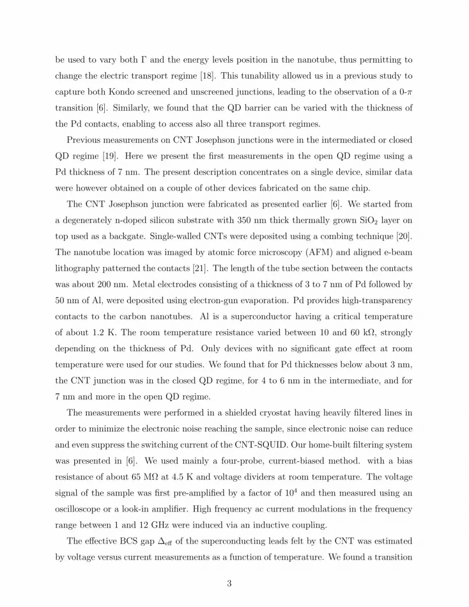
We present here additional data measured at different temperatures and microwave fre-
quencies. Fig. 5 shows differential resistance maps for the on-state at several temperature.
Although the Shapiro steps are blurred because of phase diffusion induced by the tempera-
ture, the step positions are nearly temperature independent.
The frequency dependence of the pattern of non-dissipative lobes is present in the differ-
ential resistance maps of Figs. 6 and 7 for the on-state and off-state, respectively.
11
FIG. 5: (Color online) RF response in the on-state at four different temperatures. dI/dV -maps
versus Isd and IRF are displayed for f = 3 GHz.
12

FIG. 6: (Color online) RF response in the on-state at different microwave frequencies. dI/dV -maps
versus Isd and IRF are displayed for 40 mK.
13

FIG. 7: (Color online) RF response in the off-state at different microwave frequencies. dI/dV -maps
versus Isd and IRF are displayed for 40 mK.
14
![Josephson spectroscopy of terahertz losses in [100]-tilt YBa 2 Cu 3 O 7-x bicrystal junctions](https://img.pdfslide.net/doc/110x75/63551b3221a0f893210b5b9f/josephson-spectroscopy-of-terahertz-losses-in-100-tilt-yba-2-cu-3-o-7-x-bicrystal.jpg)


