Embed Size (px)
Citation preview
Project Manual
FOR
Project: H12-9923-JM-DELECTRICAL DISTRIBUTION SYSTEM
UPGRADES AND REPLACEMENTSPACKAGE D – MEDIUM VOLTAGE SWITCHGEAR
CLEMSON, SC
Issue for BiddingJune 15, 2018
Prepared by:
2705 Bee Cave RdSuite 300
Austin, TX 78746
JEG FEWE5601

PAGE INTENTIONALLY LEFT BLANK
PROJECT: H12-9923-JM-D
ELECTRICAL DISTRIBUTION SYSTEM
UPGRADES AND REPLACEMENTS
PACKAGE D – MEDIUM VOLTAGE SWITCHGEAR
CLEMSON, SC
Issue for Bidding
June 15, 2018
2705 Bee Cave Rd
Suite 300
Austin, TX 78746
JEG FEWE5601

PAGE INTENTIONALLY LEFT BLANK
Project: H12-9923-JM-DELECTRICAL DISTRIBUTION SYSTEM
UPGRADES AND REPLACEMENTSPACKAGE D – MEDIUM VOLTAGE SWITCHGEAR PROCUREMENT
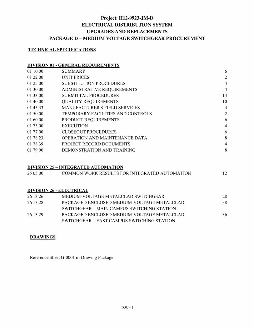
TOC - 1
TECHNICAL SPECIFICATIONS
DIVISION 01 - GENERAL REQUIREMENTS01 10 00 SUMMARY 601 22 00 UNIT PRICES 201 25 00 SUBSTITUTION PROCEDURES 401 30 00 ADMINISTRATIVE REQUIREMENTS 401 33 00 SUBMITTAL PROCEDURES 1401 40 00 QUALITY REQUIREMENTS 1001 43 33 MANUFACTURER'S FIELD SERVICES 401 50 00 TEMPORARY FACILITIES AND CONTROLS 201 60 00 PRODUCT REQUIREMENTS 601 73 00 EXECUTION 401 77 00 CLOSEOUT PROCEDURES 601 78 23 OPERATION AND MAINTENANCE DATA 801 78 39 PROJECT RECORD DOCUMENTS 401 79 00 DEMONSTRATION AND TRAINING 8
DIVISION 25 – INTEGRATED AUTOMATION25 05 00 COMMON WORK RESULTS FOR INTEGRATED AUTOMATION 12
DIVISION 26 - ELECTRICAL26 13 26 MEDIUM-VOLTAGE METALCLAD SWITCHGEAR 2826 13 28 PACKAGED ENCLOSED MEDIUM-VOLTAGE METALCLAD
SWITCHGEAR – MAIN CAMPUS SWITCHING STATION 38
26 13 29 PACKAGED ENCLOSED MEDIUM-VOLTAGE METALCLAD SWITCHGEAR – EAST CAMPUS SWITCHING STATION
36
DRAWINGS
Reference Sheet G-0001 of Drawing Package

FEWE5601 - Pkg. D - Issue for Bidding SUMMARYJune 15, 2018 01 10 00 - 1
SECTION 01 10 00 - SUMMARY
PART 1 - GENERAL
1.1 RELATED DOCUMENTS
A. The Drawings and general provisions of the contract, including General and Supplementary Conditions of the Specifications apply to this section. Provisions and requirements specified in the General and Supplementary Conditions and other front-end sections shall govern any inconsistencies between them and requirements specified in any section of the specifications. Applicable parts of other technical specifications that require coordination with the work specified in this Section also apply to this Section.
1.2 PROJECT INFORMATION
A. Project Identification: Clemson University Electrical Distribution System Upgrades & Replacements – Package D – Medium Voltage Switchgear.
1. Project Location: Clemson University. Clemson, South Carolina.
B. Owner: Clemson University
1. Owner's Representative: Bret McCarley, (864) 643.6173
C. Engineer: Jacobs Engineering Group, Austin, Texas| J. Darrell Widner, P.E.| Project Manager, (512) 732.7505, [email protected].
1.3 WORK COVERED BY CONTRACT DOCUMENTS
A. Work of this Agreement comprises the design, fabrication, testing, storing, and delivery of switchgear, circuit breakers, complete with specified auxiliary components, required spare parts, and loose shipped materials for Clemson University.
B. The switchgear procurement and corresponding proposal submission will consist of three (3) distinct line items and associated costs, and shall be awarded to the same Manufacturer. The items are as follows and as detailed within this project manual and the attached drawings:
1. 15 kV Class Medium Voltage Switchgear as follows:a. Main Campus Switching Station (MCSS) – Packaged Enclosed Medium Voltage
Metal Clad Switchgear Building as detailed in Section 26 13 28 of this Project Manual.
b. East Campus Switching Station (ECSS) – Packaged Enclosed Medium Voltage Metal Clad Switchgear Building as detailed in Section 26 13 29 of this Project Manual.
c. West Campus Switching Station (WCSS) – Free standing Medium Voltage Metal Clad Switchgear lineups (Bus A and B) and accessories as detailed in Section 26 13 26 of this Project Manual, to be installed in a new, site built building on

FEWE5601 - Pkg. D - Issue for Bidding SUMMARYJune 15, 2018 01 10 00 - 2
campus. The WCSS structure housing the lineups of switchgear will be provided by Others.
2. Manufacturer Field Services as detailed in Section 01 43 33 of this Project Manual. Provide Separate Line Item pricing for field services corresponding to each equipment component detailed above in 1.3-B.1.
3. Unit Pricing for additional day(s) of Field Service Engineer duties as outlined in Section 01 22 00 of this Project Manual.
C. Delivery Location = FOB Site: Clemson University; Clemson, South Carolina.
D. Anticipated Delivery Dates (+/- 2 weeks):
1. MCSS (July 12, 2019)2. ECSS (July 19, 2019)3. WCSS (July 19, 2019)
E. In addition to Manufacturer’s standard tests, work shall include factory support for and testing/troubleshooting of integrated SCADA system and switchgear.
F. Distribution of software from relay manufacturer(s) to Owner and Engineer.
G. Field wiring of shipping splits.
H. Field Engineering during equipment commissioning and final testing.
I. Service engineering and support for field testing of integrated SCADA and switchgear system with field corrections as required.
J. The Manufacturer shall obtain and pay for all other required permits and licenses; pay all fees, comply with all local, state laws, ordinances, rules, regulations applicable to Manufacture and Shipment.
1.4 WORK BY OTHERS
A. Receiving, unloading, and setting of equipment under supervision of Manufacturer’s Field Service Engineer.
B. Furnishing and placing of foundations and supports.
C. Furnishing and installing external wiring.
D. Furnishing and installing external fiber optic communication cable and equipment.
1.5 ACCESS TO SITE
A. General: Manufacturer shall have use of the Project site for delivery and field engineering operations during construction period. Manufacturer's use of Project site may be limited by the Owner due to campus activities, special events and/or campus normal or emergency operations. Weekend and after hours work must be coordinated with the Owner’s Representative and with

FEWE5601 - Pkg. D - Issue for Bidding SUMMARYJune 15, 2018 01 10 00 - 3
not less than five (5) days’ written notice to Owner of proposed activities and schedule. Manufacturer shall not procced with work until written authorization is provided from Owner.
B. Use of Site(s): Limit use of Project site(s) to areas within the Contract limits indicated. Do not disturb portions of Project site beyond areas in which the Work is indicated.
1. Limits: Confine construction operations to areas where switchgear is to be installed.2. Driveways, Walkways and Entrances: Keep driveways, loading areas and entrances
serving premises clear and available to Owner, Owner's employees, and others as approved by the Owner, including the mobility impaired as well as emergency vehicles at all times. Do not use these areas for parking or storage of materials.
a. Schedule deliveries to minimize use of driveways and entrances by construction operations.
b. Schedule deliveries to minimize space and time requirements for storage of materials and equipment on-site.
C. The Manufacturer shall assume full responsibility for the protection and safe-keeping of materials and equipment. Do not unreasonably encumber the site with materials and equipment that may pose unnecessary risk to both pedestrian and vehicular traffic.
D. Temporary office and tool storage: Manufacturer shall provide and maintain facilities and enclosures needed for his work in Owner designated locations.
E. Manufacturer Parking: Review with Owner’s Representative parking locations for Manufacturer’s vehicles. Comply with University Parking and Transportation Services traffic and parking regulations, including permitting requirements. Cost for parking is to be included in the Contract Sum. On-site parking must comply with emergency vehicle access and with minimum impact on Owner operations.
1.6 PROTECTION
A. The Manufacturer and his Subcontractors shall not use adjacent property or the public domain for any purpose whatsoever, but shall confine apparatus, equipment, storage of materials and operations of workmen to limits provided by law, ordinances, or permits and in an orderly manner. He shall make all necessary or required provisions for the protection of the public.
B. The Manufacturer shall protect all existing streets and curbs and all walks, paving, etc. All damage caused by him or his Subcontractors shall be made good at the Manufacturer's expense. No patching will be allowed; broken or cracked walks shall be fully replaced. Maintain adequate protection with barricades and other apparatus as required to provide adequate protection to the public. Barricades shall conform to all state, local codes and regulations, and insurance requirements governing same.
1.7 OCCUPANCY COORDINATION
A. The University will maintain normal operations during the entire construction period. Cooperate with Owner during operations to minimize conflicts and facilitate Owner normal
FEWE5601 - Pkg. D - Issue for Bidding SUMMARYJune 15, 2018 01 10 00 - 4
operations. Perform the Work so as not to interfere with Owner's operations or maintenance. Maintain existing exits, pathways, and traffic corridors unless otherwise indicated.
1. Maintain access to existing walkways, corridors, and other adjacent occupied or used facilities. Do not close or obstruct walkways, corridors, or other occupied or used facilities without written permission from Owner and authorities having jurisdiction.
2. Provide not less than five (5) days’ written notice to Owner of activities that will affect Owner's operations. Manufacturer shall not procced with work until written authorization is provided from Owner.
B. The Owner may be performing work adjacent to this site during the construction period.
1.8 WORK RESTRICTIONS
A. On-Site Work Hours: Typical work hours are 7:00 AM – 5:00 PM. Work hours outside of this time frame are not prohibited, however shall be scheduled and coordinated with campus activities, special events, and specific restricted time frames as dictated by the campus schedule and noise ordinances.
B. Noise, Vibration, and Odors: Coordinate operations that may result in high levels of noise and vibration, odors, or other disruption to Owner occupancy with Owner. Owner reserves the right to limit excessive noise caused by the construction during academic examination or quiet periods.
1. Notify Owner not less than two days in advance of proposed disruptive operations.2. Obtain Owner's written permission before proceeding with disruptive operations.
C. Clemson University is a tobacco-free campus. All forms of tobacco and smoke related products are prohibited under this policy. Along with cigarettes, the ban includes chewing tobacco, smokeless tobacco and electronic cigarettes. This ban applies to all university faculty, staff, students, Manufacturers and campus visitors and is in place for all Clemson campuses, as well as university-owned and leased facilities.
D. Controlled Substances: Use of other controlled substances on the campus is strictly prohibited.
1.9 PRODUCT DELIVERY, STORAGE, AND HANDLING
A. Deliver, and advise receiving Contractor on best practices for storage, and handling of products using means and methods that will prevent damage, deterioration, and loss, including theft and vandalism. Ensure Contractor’s compliance with Manufacturer's written instructions.
B. Delivery and Handling:
1. Schedule delivery to minimize long-term storage at Project site and to prevent overcrowding of construction spaces.
2. Coordinate delivery with installation time to ensure minimum holding time for items that are flammable, hazardous, easily damaged, or sensitive to deterioration, theft, and other losses.
FEWE5601 - Pkg. D - Issue for Bidding SUMMARYJune 15, 2018 01 10 00 - 5
3. Deliver products to Project site in an undamaged condition in Manufacturer's original sealed container or other packaging system, complete with labels and instructions for handling, storing, unpacking, protecting, and installing.
4. Inspect products on delivery to determine compliance with the Contract Documents and to determine that products are undamaged and properly protected.
C. Storage – Instruct Receiving Contractor on best practices for storing in accordance with Manufacturer’s instructions:
1. Store products to allow for inspection and measurement of quantity or counting of units.2. Store materials in a manner that will not endanger Project structure.3. Store products that are subject to damage by the elements, under cover in a weather tight
enclosure above ground, with ventilation adequate to prevent condensation.4. Store foam plastic from exposure to sunlight, except to extent necessary for period of
installation and concealment.5. Comply with product manufacturer's written instructions for temperature, humidity,
ventilation, and weather-protection requirements for storage.6. Protect stored products from damage and liquids from freezing.
1.10 SPECIFICATION AND DRAWING CONVENTIONS
A. Specification Content: The Specifications use certain conventions for the style of language and the intended meaning of certain terms, words, and phrases when used in particular situations. These conventions are as follows:
1. Imperative mood and streamlined language are generally used in the Specifications. The words "shall," "shall be," or "shall comply with," depending on the context, are implied where a colon (:) is used within a sentence or phrase.
2. Specification requirements are to be performed by Manufacturer unless specifically stated otherwise.
B. Division 01 General Requirements: Requirements of Sections in Division 01 apply to the Work of all Sections in the Specifications.
C. Drawing Coordination: Requirements for materials and products identified on the Drawings are described in detail in the Specifications. One or more of the following are used on the Drawings to identify materials and products:
1. Terminology: Materials and products are identified by the typical generic terms used in the individual Specifications Sections.
2. Abbreviations: Materials and products are identified by abbreviations published as part of the U.S. National CAD Standard and scheduled on Drawings.
3. Keynoting: Materials and products are identified by reference keynotes referencing Specification Section numbers found in this Project Manual.
PART 2 - PRODUCTS (Not Used)
PART 3 - EXECUTION (Not Used)

FEWE5601 - Pkg. D - Issue for Bidding SUMMARYJune 15, 2018 01 10 00 - 6
END OF SECTION 01 10 00
FEWE5601 - Pkg. D - Issue for Bidding UNIT PRICESJune 15, 2018 01 22 00 - 1
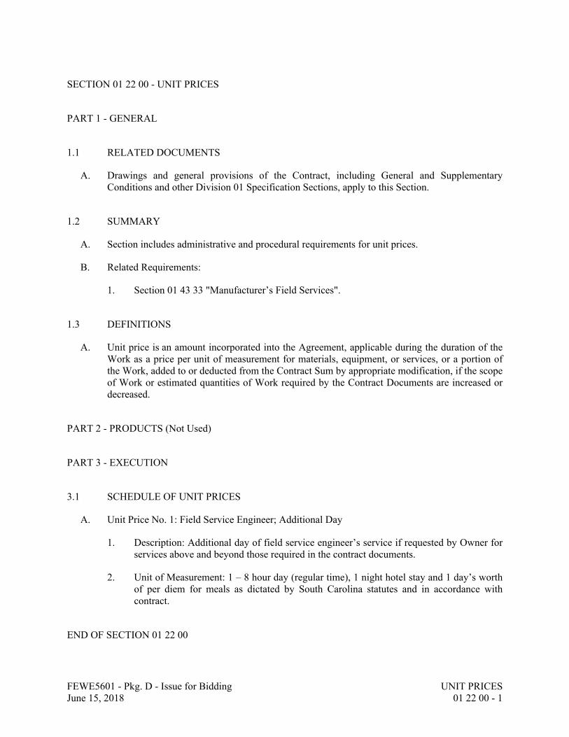
SECTION 01 22 00 - UNIT PRICES
PART 1 - GENERAL
1.1 RELATED DOCUMENTS
A. Drawings and general provisions of the Contract, including General and Supplementary Conditions and other Division 01 Specification Sections, apply to this Section.
1.2 SUMMARY
A. Section includes administrative and procedural requirements for unit prices.
B. Related Requirements:
1. Section 01 43 33 "Manufacturer’s Field Services".
1.3 DEFINITIONS
A. Unit price is an amount incorporated into the Agreement, applicable during the duration of the Work as a price per unit of measurement for materials, equipment, or services, or a portion of the Work, added to or deducted from the Contract Sum by appropriate modification, if the scope of Work or estimated quantities of Work required by the Contract Documents are increased or decreased.
PART 2 - PRODUCTS (Not Used)
PART 3 - EXECUTION
3.1 SCHEDULE OF UNIT PRICES
A. Unit Price No. 1: Field Service Engineer; Additional Day
1. Description: Additional day of field service engineer’s service if requested by Owner for services above and beyond those required in the contract documents.
2. Unit of Measurement: 1 – 8 hour day (regular time), 1 night hotel stay and 1 day’s worth of per diem for meals as dictated by South Carolina statutes and in accordance with contract.
END OF SECTION 01 22 00

FEWE5601 - Pkg. D - Issue for Bidding UNIT PRICESJune 15, 2018 01 22 00 - 2
PAGE INTENTIONALLY LEFT BLANK
FEWE5601 - Pkg. D - Issue for Bidding SUBSTITUTION PROCEDURES
June 15, 2018 01 25 00 - 1
SECTION 01 25 00 - SUBSTITUTION PROCEDURES
PART 1 - GENERAL
1.1 RELATED DOCUMENTS
A. Drawings and general provisions of the Contract, including General and Supplementary
Conditions and other Division 01 Specification Sections, apply to this Section.
1.2 SUMMARY
A. Section includes administrative and procedural requirements for substitutions.
1.3 DEFINITIONS
A. Substitutions: Changes in products, materials, equipment, and methods of construction from
those required by the Contract Documents and proposed by Manufacturer.
1. Substitutions for Cause: Changes proposed by Manufacturer that are required due to
changed Project conditions, such as unavailability of product, regulatory changes, or
unavailability of required warranty terms.
2. Substitutions for Convenience: Changes proposed by Manufacturer or Owner that are not
required in order to meet other Project requirements but may offer advantage to
Manufacturer or Owner.
1.4 SUBMITTALS
A. It is not the intent of the Drawings and/or Specifications to limit products to any particular
manufacturer or to discriminate against an "APPROVED EQUAL" product as produced by
another manufacturer. Some products are mentioned to set a definite standard for acceptance
and to serve as a reference in comparison with other products. All submitted materials shall
meet all of the provisions of the appropriate specification(s).
B. Within fifteen (15) working days after the date of contract award or work order, whichever is
later, and before purchasing or starting installation of materials or equipment, the Manufacturer
shall submit for review, a complete list of suppliers, contractors and manufacturers for all
materials and equipment which will be submitted for incorporation into the project. The list
shall be arranged in accordance with the organization of the Specifications. This initial list shall
include the manufacturer's name and type or catalog number as required to identify the quality
of material or equipment proposed. This list will be reviewed by the Engineer and the Owner
and will be returned to the Manufacturer with comments as to which items are acceptable
without further submittal data and which items will require detailed submittal data for further
review and subsequent approval. The initial list shall be submitted as herein specified.
Materials and equipment requiring detailed submittal data shall be submitted with sufficient
data to indicate that all requirements of these Specifications have been met and samples shall be
furnished when requested. All manufacturers’ data used as part of the submittal shall have all

FEWE5601 - Pkg. D - Issue for Bidding SUBSTITUTION PROCEDURES
June 15, 2018 01 25 00 - 2
inapplicable features crossed out or deleted in a manner that will clearly indicate exactly what is
to be furnished
C. Substitution Requests: Submit three copies of each request for consideration. Identify product
or fabrication or installation method to be replaced. Include Specification Section number and
title and Drawing numbers and titles.
1. Substitution Request Form: Use CSI Form 13.1A.
2. Documentation: Show compliance with requirements for substitutions and the following,
as applicable:
a. Statement indicating why specified product or fabrication or installation cannot be
provided, if applicable.
b. Coordination information, including a list of changes or modifications needed to
other parts of the Work and to construction performed by Owner and separate
contractors that will be necessary to accommodate proposed substitution.
c. Detailed comparison of significant qualities of proposed substitution with those of
the Work specified. Include annotated copy of applicable specification section.
Significant qualities may include attributes such as performance, weight, size,
durability, visual effect, sustainable design characteristics, warranties, and specific
features and requirements indicated. Indicate deviations, if any, from the Work
specified.
d. Product Data, including drawings and descriptions of products and fabrication and
installation procedures.
e. Samples, where applicable or requested.
f. Certificates and qualification data, where applicable or requested.
g. List of similar installations for completed projects with project names and
addresses and names and addresses of architects and owners.
h. Material test reports from a qualified testing agency indicating and interpreting test
results for compliance with requirements indicated.
i. Research reports evidencing compliance with building code in effect for Project.
j. Detailed comparison of Manufacturer's construction schedule using proposed
substitution with products specified for the Work, including effect on the overall
Contract Time. If specified product or method of construction cannot be provided
within the Contract Time, include letter from manufacturer, on manufacturer's
letterhead, stating date of receipt of purchase order, lack of availability, or delays
in delivery.
k. Cost information, including a proposal of change, if any, in the Contract Sum.
l. Manufacturer's certification that proposed substitution complies with requirements
in the Contract Documents except as indicated in substitution request, is
compatible with related materials, and is appropriate for applications indicated.
m. Manufacturer's waiver of rights to additional payment or time that may
subsequently become necessary because of failure of proposed substitution to
produce indicated results.
3. Engineer’s Action: If necessary, Engineer will request additional information or
documentation for evaluation within seven days of receipt of a request for substitution.
Engineer will notify Manufacturer through Construction Manager of acceptance or
rejection of proposed substitution within 15 days of receipt of request, or seven days of
receipt of additional information or documentation, whichever is later.
FEWE5601 - Pkg. D - Issue for Bidding SUBSTITUTION PROCEDURES
June 15, 2018 01 25 00 - 3
a. Forms of Acceptance: Change Order, Construction Change Directive, or
Engineer’s Supplemental Instructions for minor changes in the Work.
b. Use product specified if Engineer does not issue a decision on use of a proposed
substitution within time allocated.
1.5 QUALITY ASSURANCE
A. Compatibility of Substitutions: Investigate and document compatibility of proposed
substitution with related products and materials. Engage qualified testing agency to perform
compatibility tests recommended by manufacturers.
1.6 PROCEDURES
A. Coordination: Modify or adjust affected work as necessary to integrate work of the approved
substitutions.
PART 2 - PRODUCTS
2.1 SUBSTITUTIONS
A. Substitutions for Cause: Submit requests for substitution immediately upon discovery of need
for change, but not later than 15 working days prior to time required for preparation and review
of related submittals. Substitution procedures outlined herein shall be followed.
1. Conditions: Engineer will consider Manufacturer's request for substitution when the
following conditions are satisfied. If the following conditions are not satisfied, Engineer
will return requests without action, except to record noncompliance with these
requirements:
a. Requested substitution is consistent with the Contract Documents and will produce
indicated results.
b. Substitution request is fully documented and properly submitted.
c. Requested substitution will not adversely affect Manufacturer's construction
schedule.
d. Requested substitution has received necessary approvals of authorities having
jurisdiction.
e. Requested substitution is compatible with other portions of the Work.
f. Requested substitution has been coordinated with other portions of the Work.
g. Requested substitution provides specified warranty.
h. If requested substitution involves more than one contractor, requested substitution
has been coordinated with other portions of the Work, is uniform and consistent, is
compatible with other products, and is acceptable to all contractors involved.
B. Substitutions for Convenience: Engineer will consider requests for substitution if received
within 15 working days after Notice to Proceed. Requests received after that time may be
considered or rejected at discretion of Engineer. Substitution procedures outlined herein shall
be followed.
FEWE5601 - Pkg. D - Issue for Bidding SUBSTITUTION PROCEDURES
June 15, 2018 01 25 00 - 4
1. Conditions: Engineer will consider Manufacturer's request for substitution when the
following conditions are satisfied. If the following conditions are not satisfied, Engineer
will return requests without action, except to record noncompliance with these
requirements:
a. Requested substitution offers Owner a substantial advantage in cost, time, energy
conservation, or other considerations, after deducting additional responsibilities
Owner must assume. Owner's additional responsibilities may include
compensation to Engineer for redesign and evaluation services, increased cost of
other construction by Owner, and similar considerations.
b. Requested substitution does not require extensive revisions to the Contract
Documents.
c. Requested substitution is consistent with the Contract Documents and will produce
indicated results.
d. Substitution request is fully documented and properly submitted.
e. Requested substitution will not adversely affect Manufacturer's construction
schedule.
f. Requested substitution has received necessary approvals of authorities having
jurisdiction.
g. Requested substitution is compatible with other portions of the Work.
h. Requested substitution has been coordinated with other portions of the Work.
i. Requested substitution provides specified warranty.
j. If requested substitution involves more than one contractor, requested substitution
has been coordinated with other portions of the Work, is uniform and consistent, is
compatible with other products, and is acceptable to all contractors involved.
PART 3 - EXECUTION (Not Used)
END OF SECTION 01 25 00

FEWE5601 - Pkg. D - Issue for Bidding ADMINISTRATIVE REQUIREMENTS
June 15, 2018 01 30 00 - 1
SECTION 01 30 00 - ADMINISTRATIVE REQUIREMENTS
PART 1 GENERAL
1.1 RELATED DOCUMENTS
A. Drawings and General Provisions of the Contract, including General and Supplementary
Conditions and other Division 01 Specification Sections, apply to this Section.
1.2 SUMMARY
A. Section Includes:
1. Coordination and project conditions.
2. Project site administration.
3. Field engineering.
4. Prebid meeting.
5. Progress meetings.
6. Site mobilization meetings.
1.3 COORDINATION AND PROJECT CONDITIONS
A. Coordinate scheduling, submittals, and Work of the various sections of the Project Manual to
ensure efficient and orderly sequence of installation of interdependent construction elements.
B. Verify utility requirements and characteristics of operating equipment are compatible with
building utilities. Coordinate work of various sections having interdependent responsibilities for
installing, connecting to, and placing in service, such equipment.
C. Coordinate space requirements, supports, and installation of Work, which are required for
installation of Manufacturer provided equipment. Utilize spaces efficiently to maximize
accessibility for other installations, for maintenance, and for repairs.
D. Coordinate completion and clean-up of Work of separate sections in preparation for completion.
1.4 PROJECT ADMINISTRATION
A. Manufacturer shall provide competent, suitably qualified personnel to design and lay out Work
and perform fabrication and testing as required by Purchase Order Documents. Manufacturer
shall at all times maintain good discipline and order.
B. While on Owner Premises, incompetent or incorrigible employees shall be dismissed from Work
by Manufacturer or its representative when requested by Owner, and such persons shall not again
be permitted to return to Work without written consent of Owner.

FEWE5601 - Pkg. D - Issue for Bidding ADMINISTRATIVE REQUIREMENTS
June 15, 2018 01 30 00 - 2
C. Workmanship shall be of best quality.
1.5 PREBID MEETING
A. Owner’s representative will schedule a meeting at the Project site prior to bid due date.
B. Manufacturer attendance is Optional however, Owner and Engineer will be present to field
questions regarding technical documents and contract related items.
C. Location: Clemson, South Carolina.
D. Agenda:
1. Use of premises by Owner and Manufacturer.
2. Owner's requirements.
3. Schedules.
4. Application for payment procedures.
5. Review coordination with related work.
6. Procedures for maintaining record documents.
7. Requirements for testing and start-up of equipment.
8. Inspection and acceptance of equipment put into service during construction period.
9. Shop drawing requirements.
10. Bid security.
11. Insurance requirements.
12. Manufacturers field service requirements.
13. Shipping requirements.
14. Bid evaluation procedures.
E. Owner will record minutes and distribute copies within 5 days after meeting to participants and
those affected by decisions made.
1.6 FABRICATION PROGRESS MEETINGS
A. Manufacturer to host meetings throughout progress of the Work at maximum of bi-weekly
intervals.
B. Manufacturer will make arrangements for meetings, prepare agenda with copies for participants,
preside at meetings.
C. Attendance Required: Manufacturer, Owner and Engineer, as appropriate to agenda topics for
each meeting.
D. Agenda:
1. Review minutes of previous meetings.
2. Review of Work progress.
3. Manufacturing observations, problems, and decisions.
4. Identification of problems that impede planned progress.
5. Review of submittals schedule and status of submittals.

FEWE5601 - Pkg. D - Issue for Bidding ADMINISTRATIVE REQUIREMENTS
June 15, 2018 01 30 00 - 3
6. Review of off-site fabrication and delivery schedules.
7. Maintenance of progress schedule.
8. Corrective measures to regain projected schedules.
9. Planned progress during succeeding work period.
10. Coordination of projected progress.
11. Maintenance of quality and work standards.
12. Effect of proposed changes on progress schedule and coordination.
13. Other business relating to Work.
E. Manufacturer will record minutes and distribute copies within 2 days after meeting to participants
and those affected by decisions made.
1.7 SITE MOBILIZATION MEETING
A. Manufacturer’s representative will schedule a meeting at the Project sites prior to Equipment and
Delivery and Manufacturer wiring and commissioning of switchgear to coordinate potential
conflicts with Owner operation of the electric system and on-site construction activities.
B. Attendance Required: Owner, Engineer, Manufacturer, Manufacturer's Field Engineer, and
major Installing Contractor.
C. Agenda:
1. Use of premises by Owner and Manufacturer.
2. Owner's requirements and occupancy.
3. Construction facilities and controls provided by Owner.
4. Temporary utilities provided by Owner.
5. Outages and project coordination.
6. Security and housekeeping procedures.
7. Schedules.
8. Review coordination with related work.
9. Procedures for testing.
10. Requirements for start-up of equipment.
11. Inspection and acceptance of equipment put into service during construction period.
D. Manufacturer will record minutes and distribute copies within 2 days after meeting to participants
and those affected by decisions made.
1.8 INSTALLATION PROGRESS MEETINGS
A. Attend meetings throughout progress of the Work at maximum of bi-weekly intervals when on-
site for equipment assembly and commissioning.
B. Installing Contractor will make arrangements for meetings, prepare agenda with copies for
participants, preside at meetings.
C. Attendance Required: Manufacturer, Owner and Engineer, as appropriate to agenda topics for
each meeting.
FEWE5601 - Pkg. D - Issue for Bidding ADMINISTRATIVE REQUIREMENTS
June 15, 2018 01 30 00 - 4
D. Agenda:
1. Review minutes of previous meetings.
2. Review of Work progress.
3. Manufacturing observations, problems, and decisions.
4. Identification of problems that impede planned progress.
5. Review of submittals schedule and status of submittals.
6. Review of off-site fabrication and delivery schedules.
7. Maintenance of progress schedule.
8. Corrective measures to regain projected schedules.
9. Planned progress during succeeding work period.
10. Coordination of projected progress.
11. Maintenance of quality and work standards.
12. Effect of proposed changes on progress schedule and coordination.
13. Other business relating to Work.
E. Installing Contractor will record minutes and distribute copies within 2 days after meeting to
participants and those affected by decisions made.
PART 2 PRODUCTS
NOT USED
PART 3 EXECUTION
NOT USED
END OF SECTION 01 30 00

FEWE5601 - Pkg. D - Issue for Bidding SUBMITTAL PROCEDURES
June 15, 2018 01 33 00 - 1
SECTION 01 33 00 - SUBMITTAL PROCEDURES
PART 1 - GENERAL
1.1 RELATED DOCUMENTS
A. Drawings and general provisions of the Contract, including General and Supplementary
Conditions and other Division 01 Specification Sections, apply to this Section.
1.2 SUMMARY
A. Section includes requirements for the submittal schedule and administrative and procedural
requirements for submitting Shop Drawings, Product Data, Samples, and other submittals.
B. Related Sections:
1. Division 01 Section "Operation and Maintenance Data" for submitting operation and
maintenance manuals.
2. Division 01 Section "Project Record Documents" for submitting record Drawings, record
Specifications, and record Product Data.
1.3 DEFINITIONS
A. Action Submittals: Written and graphic information and physical samples that require
Engineer's responsive action. Action submittals are those submittals indicated in individual
Specification Sections as action submittals.
B. Informational Submittals: Written and graphic information and physical samples that do not
require Engineer's responsive action. Submittals may be rejected for not complying with
requirements. Informational submittals are those submittals indicated in individual
Specification Sections as informational submittals.
C. File Transfer Protocol (FTP): Communications protocol that enables transfer of files to and
from another computer over a network and that serves as the basis for standard Internet
protocols. An FTP site is a portion of a network located outside of network firewalls within
which internal and external users are able to access files.
D. Portable Document Format (PDF): An open standard file format licensed by Adobe Systems
used for representing documents in a device-independent and display resolution-independent
fixed-layout document format.
FEWE5601 - Pkg. D - Issue for Bidding SUBMITTAL PROCEDURES
June 15, 2018 01 33 00 - 2
1.4 ACTION SUBMITTALS
A. Fabrication and Delivery Schedule: Submit within fifteen (15) days of Award of Contract.
Include a detailed narrative of the sequence of construction including start and end dates, key
fabrication and delivery milestones.
B. Submittal Schedule: Submit a schedule of submittals, arranged in chronological order by dates.
Include time required for review, ordering, manufacturing, fabrication, and delivery when
establishing dates. Include additional time required for making corrections or modifications to
submittals noted by the Engineer and additional time for handling and reviewing submittals
required by those corrections.
1. Coordinate submittal schedule with list of subcontracts, the schedule of values, and
Manufacturer's construction schedule.
2. Initial Submittal: Submit concurrently with start-up fabrication schedule. Include
submittals required during the first 30 days from Award of Contract. List those
submittals required to maintain orderly progress of the Work and those required early
because of long lead time for manufacture or fabrication.
3. Final Submittal: Submit concurrently with the first complete submittal of Manufacturer's
construction schedule.
a. Submit revised submittal schedule to reflect changes in current status and timing
for submittals.
4. Format: Arrange the following information in a tabular format:
a. Scheduled date for first submittal.
b. Specification Section number and title.
c. Submittal category: Action, informational.
d. Name of subcontractor.
e. Description of the Work covered.
f. Scheduled date for Engineer's final release or approval.
g. Scheduled dates for purchasing.
h. Scheduled dates for installation.
i. Activity or event number.
1.5 SUBMITTAL ADMINISTRATIVE REQUIREMENTS
A. All submittals and requests for information shall be transmitted electronically to Owner and
Engineer via Manufacturer provided and maintained, web based, digital plan room/project
management software.
1. Format: Portable Document Format (.pdf) for all submittal materials.
2. Format: AutoCAD 2016 for all approved and record drawings.
3. Minimum Drawing Size = 18” x 24”; Maximum = 24” x 36”.
4. Normal material or equipment data sheets may be 8.5” x 11”, minimum.
B. All submittals shall include a copy of the specification pertinent to the submittal and shall
include a line by line compliance or deviation statement and explanation. Submittals provided

FEWE5601 - Pkg. D - Issue for Bidding SUBMITTAL PROCEDURES
June 15, 2018 01 33 00 - 3
without compliance statement will be rejected without review and are required to be
resubmitted.
C. Designate in the construction schedule, or in a separate coordinated schedule, the dates for
submission and the dates that reviewed shop drawings, product data and samples will be
needed.
D. Engineer's Digital Data Files: Electronic copies of CAD Drawings of the Contract Drawings
will be provided by Engineer for Manufacturer's use in preparing submittals.
1. Engineer will furnish Manufacturer one set of digital data drawing files of the Contract
Drawings for use in preparing Shop Drawings and Project record drawings.
a. Engineer makes no representations as to the accuracy or completeness of digital
data drawing files as they relate to the Contract Drawings.
b. Digital Drawing Software Program: The Contract Drawings are available in
AutoCad 2016 format.
c. Manufacturer shall execute a data licensing agreement in the form of an
Agreement form acceptable to the Owner and Engineer.
E. Coordination: Coordinate preparation and processing of submittals with performance of
fabrication activities.
1. Coordinate each submittal with fabrication, purchasing, testing, delivery, other
submittals, and related activities that require sequential activity.
2. Submit all submittal items required for each Specification Section concurrently unless
partial submittals for portions of the Work are indicated on approved submittal schedule.
3. Submit action submittals and informational submittals required by the same Specification
Section as separate packages under separate transmittals.
4. Coordinate transmittal of different types of submittals for related parts of the Work so
processing will not be delayed because of need to review submittals concurrently for
coordination.
a. Engineer reserves the right to withhold action on a submittal requiring
coordination with other submittals until related submittals are received.
F. Processing Time: Allow time for submittal review, including time for resubmittals, as follows.
Time for review shall commence on Engineer's receipt of submittal. No extension of the
Contract Time will be authorized because of failure to transmit submittals enough in advance of
the Work to permit processing, including resubmittals.
1. Initial Review: Allow 10 work days for initial review of each submittal. Allow
additional time if coordination with subsequent submittals is required. Engineer will
advise Manufacturer when a submittal being processed must be delayed for coordination.
2. Intermediate Review: If intermediate submittal is necessary, process it in same manner
as initial submittal.
3. Resubmittal Review: Allow 7 work days for review of each resubmittal.
4. Concurrent Consultant Review: Where the Contract Documents indicate that submittals
may be transmitted simultaneously to Engineer and to Engineer's consultants, allow 15
work days for review of each submittal. Submittal will be returned to Engineer before
being returned to Manufacturer.
FEWE5601 - Pkg. D - Issue for Bidding SUBMITTAL PROCEDURES
June 15, 2018 01 33 00 - 4
G. Identification and Information: Place a permanent label or title block on each paper copy
submittal item for identification.
1. Indicate name of firm or entity that prepared each submittal on label or title block.
2. Include the following information for processing and recording action taken:
a. Project name.
b. Date.
c. Name of Engineer.
d. Name of Manufacturer.
e. Name of subcontractor.
f. Name of supplier.
g. Name of manufacturer.
h. Submittal number or other unique identifier, including revision identifier.
1) Submittal number shall use Specification Section number followed by a
decimal point and then a sequential number (e.g., 061000.01). Resubmittals
shall include an alphabetic suffix after another decimal point (e.g.,
061000.01.A).
i. Number and title of appropriate Specification Section.
j. Drawing number and detail references, as appropriate.
k. Location(s) where product is to be installed, as appropriate.
l. Other necessary identification.
H. Identification and Information: Identify and incorporate information in each electronic
submittal file as follows:
1. Assemble complete submittal package into a single indexed file with links enabling
navigation to each item.
2. Name file with submittal number and specification section name, including revision
identifier.
a. File name shall use project identifier and Specification Section number followed
by a decimal point and then a sequential number and the name of the submittal
section (e.g., 061000.01-Carpentry). Resubmittals shall include an alpha-numeric
suffix after another decimal point denoting revision number (e.g., 061000.01.R1-
Carpentry).
3. Provide means for insertion to permanently record Manufacturer's review and approval
markings and action taken by Engineer.
4. Include the following information on an inserted cover sheet:
a. Project name.
b. Date.
c. Name and address of Engineer.
d. Name of Manufacturer.
e. Name of firm or entity that prepared submittal.
f. Name of subcontractor.
g. Name of supplier.
h. Name of manufacturer.

FEWE5601 - Pkg. D - Issue for Bidding SUBMITTAL PROCEDURES
June 15, 2018 01 33 00 - 5
i. Number and title of appropriate Specification Section.
j. Drawing number and detail references, as appropriate.
k. Location(s) where product is to be installed, as appropriate.
l. Related physical samples submitted directly.
m. Other necessary identification.
5. Include the following information as keywords in the electronic file metadata:
a. Project name.
b. Number and title of appropriate Specification Section.
c. Manufacturer name.
d. Product name.
I. Options: Identify options requiring selection by the Engineer.
J. Deviations: Identify deviations from the Contract Documents on submittals.
K. Additional Paper Copies: Unless additional copies are required for final submittal, and unless
Engineer observes noncompliance with provisions in the Contract Documents, initial submittal
may serve as final submittal.
1. Submit one copy of submittal to concurrent reviewer in addition to specified number of
copies to Engineer.
L. Transmittal: Assemble each submittal individually and appropriately for transmittal and
handling. Transmit each submittal using a transmittal form. Engineer will discard submittals
received from sources other than Manufacturer.
1. Transmittal Form: Provide locations on form for the following information:
a. Project name.
b. Date.
c. Destination (To:).
d. Source (From:).
e. Names of subcontractor, manufacturer, and supplier.
f. Category and type of submittal.
g. Submittal purpose and description.
h. Specification Section number and title.
i. Indication of full or partial submittal.
j. Drawing number and detail references, as appropriate.
k. Transmittal number, numbered consecutively.
l. Submittal and transmittal distribution record.
m. Remarks.
n. Signature of transmitter.
2. On an attached separate sheet, prepared on Manufacturer's letterhead, record relevant
information, requests for data, revisions other than those requested by Engineer on
previous submittals, and deviations from requirements in the Contract Documents,
including minor variations and limitations. Include same identification information as
related submittal.

FEWE5601 - Pkg. D - Issue for Bidding SUBMITTAL PROCEDURES
June 15, 2018 01 33 00 - 6
3. Include an 8 in. x 8 in. blank space for Manufacturer, Engineer, and Owner stamps.
Provide Manufacturer's stamp, initialed or signed, certifying to review of submittals,
verification of products, field measurements and field construction criteria, and
coordination of the information within the submittal with requirements of the Work and
of Contract Documents. Stamp shall be applied to each sepia and opaque copy of each
drawing, and to the cover or title page of each data booklet.
M. Manufacturer Certification: Submittals will be submitted only by Manufacturer. Indicate by
signed stamp that Contract Documents have been checked, that the work shown in the
submittals is in accordance with contract requirements and that dimensions and relationship
with work of other trades have been checked. Submittals submitted for review that have not
been checked and signed by Manufacturer will be returned for checking before being
considered by the Engineer.
1. Preparation:
a. All documents, drawings, and data submitted shall be in the English language, with
all units in English.
b. Include information relevant to particular equipment or materials to be furnished,
where product data published by manufacturer is part of submittal. All
information shall be submitted in English only.
c. Provide documentation of compliance with manufacturer's published literature or
drawings or letter signed by officer of manufacturer in cases where compliance
with UL, FM, ARI, or other similar organization standards are required.
d. Furnish submittal schedule with bid.
e. Include identifying symbols and equipment numbers used in Contract Documents
for all equipment and material submitted.
f. Submit only requested submittals complete by types of equipment labeled with
applicable specification section(s) included. Each submittal will be handled
separately. Should any item not be acceptable, the entire submittal will be returned
to Manufacturer for correction and resubmittal. Partial submittals will not be
acceptable. The intent of this requirement is that all approved bound sets of data
will be identical and will contain only acceptable information.
g. Submit a compliance sheet for each submittal indicating the submittal is in full
compliance with the drawings and specifications. Indicate by drawing number or
specification section number and paragraph numbers all exceptions taken and
include an explanation.
h. The review of submittals does not relieve or modify Manufacturer's responsibility
for compliance with Contract Documents or dimensions or errors contained in the
submittal or quantity count. It is clearly understood that, in the review process,
noting of some discrepancies but overlooking others does not grant Manufacturer
permission to proceed in error. Regardless of any information contained in the
submittals, Contract Documents govern the work, and are neither waived nor
suspended in any way by the review of the submittals.
i. A minimum review period of two weeks, exclusive of transmittal time, will be
required in Engineer office for each submittal. Take this time period into
consideration when scheduling work.
j. Include in submittals sufficient plans, elevations, sections, performance data,
dimensions, bolt locations, ratings, sound data, weights and schematics to clearly
describe the equipment and to show compliance with these specifications. Provide
FEWE5601 - Pkg. D - Issue for Bidding SUBMITTAL PROCEDURES
June 15, 2018 01 33 00 - 7
a cover or title sheet for the submittal (provided in 013300 Attachment A)
containing the following:
1) Name of Manufacturer or Supplier originating the submittal.
2) Name of project for which the submittal is made.
3) An index of all items submitted including:
a) Mark of equipment on drawings.
b) Manufacturer.
c) Catalog number.
d) Specification section number.
4) Date of submittal and date of each revision.
5) Manufacturer's certification of review.
6) Manufacturer's certification of compliance.
k. Drawings and data which do not comply with specified requirements will be
returned for resubmittal.
l. One copy will be returned to Manufacturer marked FURNISH AS SUBMITTED,
FURNISH AS CORRECTED or REVISE AND RESUBMIT. If it is marked
FURNISH AS SUBMITTED or FURNISH AS CORRECTED, no additional
submittal is required. If it is marked REVISE AND RESUBMIT, repeat the
submittal in accordance with this section. It is intended that Manufacturer submit
complete and accurate shop drawings and product data at the first submittal. If the
submittals are returned to Manufacturer marked REVISE AND RESUBMIT, only
one additional submission is permitted. It is intended that Manufacturer submit
complete and accurate shop drawings and product data at the first submittal.
m. If the drawing or product data marked FURNISH AS SUBMITTED or FURNISH
AS CORRECTED is altered for any reason after it has been stamped, the
REVIEWED stamp shall automatically be voided.
n. Provide all work in accordance with the submittals stamped FURNISH AS
SUBMITTED or FURNISH AS CORRECTED inasmuch as they are in agreement
with Contract Documents. Where differences occur between the submittals and
Contract Documents, Contract Documents shall govern the work.
N. Resubmittals: Make resubmittals in same form and number of copies as initial submittal.
1. Note date and content of previous submittal.
2. Note date and content of revision in label or title block and clearly indicate extent of
revision.
3. Resubmit submittals until they are marked with approval notation from Engineer's action
stamp.
O. Distribution: Furnish copies of final submittals to manufacturers, subcontractors, suppliers,
fabricators, installers, authorities having jurisdiction, and others as necessary for performance of
construction activities. Show distribution on transmittal forms.
P. Use for Fabrication: Use only final submittals that are marked with approval notation from
Engineer's action stamp.

FEWE5601 - Pkg. D - Issue for Bidding SUBMITTAL PROCEDURES
June 15, 2018 01 33 00 - 8
PART 2 - PRODUCTS
2.1 SUBMITTAL PROCEDURES
A. Designate in the fabrication schedule, or in a separate coordinated schedule, the dates for
submission and the dates that reviewed shop drawings, product data and samples will be
needed.
B. General Submittal Procedure Requirements: Prepare and submit submittals required by
individual Specification Sections. Types of submittals are indicated in individual Specification
Sections.
1. Submit electronic submittals via the Manufacturer’s web based project management
software as PDF electronic files.
a. Engineer will return annotated file. Annotate and retain one copy of file as an
electronic Project record document file.
2. Action Submittals: Submit each submittal, unless otherwise indicated. Engineer will
return retain one copy and return remaining copies.
3. Informational Submittals: Submit as specified. Engineer will not return copies.
4. Closeout Submittals and Maintenance Material Submittals: Comply with requirements
specified in Division 01 Section "Closeout Procedures."
5. Certificates and Certifications Submittals: Provide a statement that includes signature of
entity responsible for preparing certification. Certificates and certifications shall be
signed by an officer or other individual authorized to sign documents on behalf of that
entity.
a. Provide a digital signature with digital certificate on electronically-submitted
certificates and certifications where indicated.
b. Provide a notarized statement on original paper copy certificates and certifications
where indicated.
6. Test and Inspection Reports Submittals: Comply with requirements specified in
Division 01 Section "Quality Requirements."
C. Product Data: Collect information into a single submittal for each element of construction and
type of product or equipment.
1. If information must be specially prepared for submittal because standard published data
are not suitable for use, submit as Shop Drawings, not as Product Data.
2. Mark each copy of each submittal to show which products and options are applicable.
3. Include the following information, as applicable:
a. Manufacturer's catalog cuts.
b. Manufacturer's product specifications.
c. Standard color charts.
d. Statement of compliance with specified referenced standards.
e. Testing by recognized testing agency.
f. Application of testing agency labels and seals.

FEWE5601 - Pkg. D - Issue for Bidding SUBMITTAL PROCEDURES
June 15, 2018 01 33 00 - 9
g. Notation of coordination requirements.
h. Availability and delivery time information.
4. For equipment, include the following in addition to the above, as applicable:
a. Wiring diagrams showing factory-installed wiring.
b. Printed performance curves.
c. Operational range diagrams.
d. Clearances required to other construction, if not indicated on accompanying Shop
Drawings.
5. Submit Product Data before or concurrent with Samples.
6. Submit Product Data in the following format:
a. PDF electronic file.
b. Three paper copies of Product Data, unless otherwise indicated. Engineer will
retain one copy and return remaining copies.
D. Shop Drawings: Prepare Project-specific information, drawn accurately to scale. Do not base
Shop Drawings on reproductions of the Contract Documents or standard printed data.
1. Preparation: Fully illustrate requirements in the Contract Documents. Include the
following information, as applicable:
a. Identification of products.
b. Schedules.
c. Compliance with specified standards.
d. Notation of coordination requirements.
e. Notation of dimensions established by field measurement.
f. Relationship and attachment to adjoining construction clearly indicated.
g. Seal and signature of professional engineer if specified.
2. Sheet Size: Except for templates, patterns, and similar full-size drawings, submit Shop
Drawings on sheets at least 8-1/2 by 11 inches but no larger than 30 by 42 inches.
3. Submit Shop Drawings in the following format:
a. PDF electronic file.
b. Five opaque (bond) copies of each submittal. Engineer and Owner will retain one
copy each.
E. Product Schedule: As required in individual Specification Sections, prepare a written summary
indicating types of products required for the Work and their intended location. Include the
following information in tabular form:
1. Type of product. Include unique identifier for each product indicated in the Contract
Documents.
2. Manufacturer and product name, and model number if applicable.
3. Number and name of room or space.
4. Location within room or space.
5. Submit product schedule in the following format:
FEWE5601 - Pkg. D - Issue for Bidding SUBMITTAL PROCEDURES
June 15, 2018 01 33 00 - 10
a. PDF electronic file.
b. Three paper copies of product schedule or list, unless otherwise indicated.
Engineer will return two copies.
F. Qualification Data: Prepare written information that demonstrates capabilities and experience
of firm or person. Include lists of completed projects with project names and addresses, contact
information of Engineers and owners, and other information specified.
G. Product Certificates: Submit written statements on manufacturer's letterhead certifying that
product complies with requirements in the Contract Documents.
H. Material Test Reports: Submit reports written by a qualified testing agency, on testing agency's
standard form, indicating and interpreting test results of material for compliance with
requirements in the Contract Documents.
I. Product Test Reports: Submit written reports indicating current product produced by
manufacturer complies with requirements in the Contract Documents. Base reports on
evaluation of tests performed by manufacturer and witnessed by a qualified testing agency, or
on comprehensive tests performed by a qualified testing agency.
J. Schedule of Tests and Inspections: Comply with requirements specified in Division 01 Section
"Quality Requirements."
K. Preconstruction Test Reports: Submit reports written by a qualified testing agency, on testing
agency's standard form, indicating and interpreting results of tests performed before installation
of product, for compliance with performance requirements in the Contract Documents.
L. Field Test Reports: Submit reports indicating and interpreting results of field tests performed
either during installation of product or after product is installed in its final location, for
compliance with requirements in the Contract Documents.
M. Maintenance Data: Comply with requirements specified in Division 01 Section "Operation and
Maintenance Data."
PART 3 - EXECUTION
3.1 MANUFACTURER'S REVIEW
A. Action and Informational Submittals: Review each submittal and check for coordination with
other Work of the Contract and for compliance with the Contract Documents. Note corrections
and field dimensions. Mark with approval stamp before submitting to Engineer.
B. Approval Stamp: Stamp each submittal with a uniform, approval stamp. Include Project name
and location, submittal number, Specification Section title and number, name of reviewer, date
of Manufacturer's approval, and statement certifying that submittal has been reviewed, checked,
and approved for compliance with the Contract Documents.
3.2 ENGINEER'S ACTION
FEWE5601 - Pkg. D - Issue for Bidding SUBMITTAL PROCEDURES
June 15, 2018 01 33 00 - 11
A. General: Engineer will not review submittals that do not bear Manufacturer's approval stamp
and will return them without action.
B. Action Submittals: Engineer will review each submittal, make marks to indicate corrections or
modifications required, and return it. Engineer will stamp each submittal with an action stamp
and will mark stamp appropriately to indicate action.
C. Informational Submittals: Engineer will review each submittal and will not return it, or will
return it if it does not comply with requirements. Engineer will forward each submittal to
appropriate party.
D. Partial submittals prepared for a portion of the Work will be reviewed when use of partial
submittals has received prior approval from Engineer.
E. Incomplete submittals are not acceptable, will be considered nonresponsive, and will be
returned without review.
F. Submittals not required by the Contract Documents may not be reviewed and may be discarded.
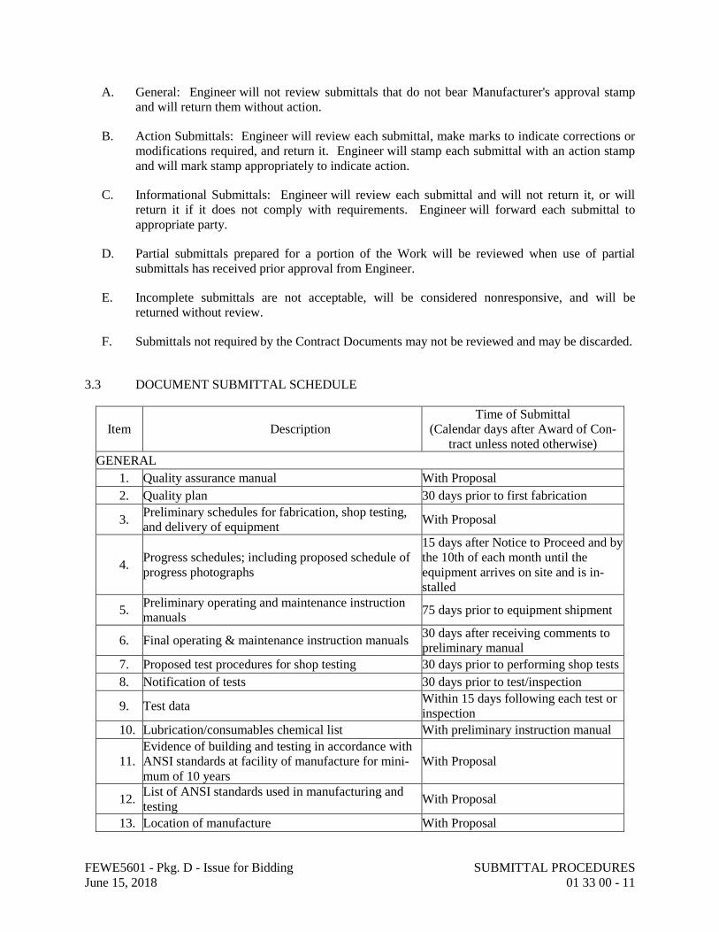
3.3 DOCUMENT SUBMITTAL SCHEDULE
Item Description
Time of Submittal
(Calendar days after Award of Con-
tract unless noted otherwise)
GENERAL
1. Quality assurance manual With Proposal
2. Quality plan 30 days prior to first fabrication
3. Preliminary schedules for fabrication, shop testing,
and delivery of equipment With Proposal
4. Progress schedules; including proposed schedule of
progress photographs
15 days after Notice to Proceed and by
the 10th of each month until the
equipment arrives on site and is in-
stalled
5. Preliminary operating and maintenance instruction
manuals 75 days prior to equipment shipment
6. Final operating & maintenance instruction manuals 30 days after receiving comments to
preliminary manual
7. Proposed test procedures for shop testing 30 days prior to performing shop tests
8. Notification of tests 30 days prior to test/inspection
9. Test data Within 15 days following each test or
inspection
10. Lubrication/consumables chemical list With preliminary instruction manual
11. Evidence of building and testing in accordance with
ANSI standards at facility of manufacture for mini-
mum of 10 years
With Proposal
12. List of ANSI standards used in manufacturing and
testing With Proposal
13. Location of manufacture With Proposal
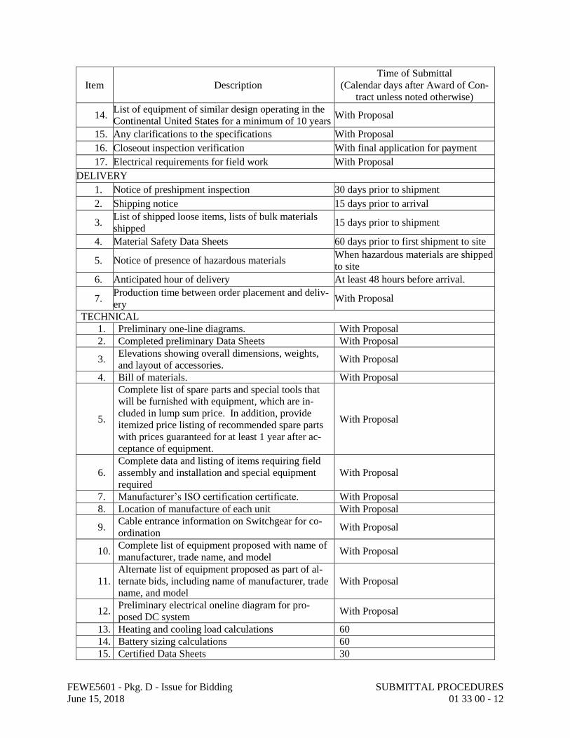
FEWE5601 - Pkg. D - Issue for Bidding SUBMITTAL PROCEDURES
June 15, 2018 01 33 00 - 12
Item Description
Time of Submittal
(Calendar days after Award of Con-
tract unless noted otherwise)
14. List of equipment of similar design operating in the
Continental United States for a minimum of 10 years With Proposal
15. Any clarifications to the specifications With Proposal
16. Closeout inspection verification With final application for payment
17. Electrical requirements for field work With Proposal
DELIVERY
1. Notice of preshipment inspection 30 days prior to shipment
2. Shipping notice 15 days prior to arrival
3. List of shipped loose items, lists of bulk materials
shipped 15 days prior to shipment
4. Material Safety Data Sheets 60 days prior to first shipment to site
5. Notice of presence of hazardous materials When hazardous materials are shipped
to site
6. Anticipated hour of delivery At least 48 hours before arrival.
7. Production time between order placement and deliv-
ery With Proposal
TECHNICAL
1. Preliminary one-line diagrams. With Proposal
2. Completed preliminary Data Sheets With Proposal
3. Elevations showing overall dimensions, weights,
and layout of accessories. With Proposal
4. Bill of materials. With Proposal
5.
Complete list of spare parts and special tools that
will be furnished with equipment, which are in-
cluded in lump sum price. In addition, provide
itemized price listing of recommended spare parts
with prices guaranteed for at least 1 year after ac-
ceptance of equipment.
With Proposal
6.
Complete data and listing of items requiring field
assembly and installation and special equipment
required
With Proposal
7. Manufacturer’s ISO certification certificate. With Proposal
8. Location of manufacture of each unit With Proposal
9. Cable entrance information on Switchgear for co-
ordination With Proposal
10. Complete list of equipment proposed with name of
manufacturer, trade name, and model With Proposal
11. Alternate list of equipment proposed as part of al-
ternate bids, including name of manufacturer, trade
name, and model
With Proposal
12. Preliminary electrical oneline diagram for pro-
posed DC system With Proposal
13. Heating and cooling load calculations 60
14. Battery sizing calculations 60
15. Certified Data Sheets 30
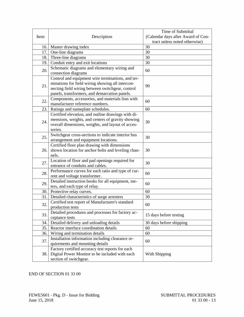
FEWE5601 - Pkg. D - Issue for Bidding SUBMITTAL PROCEDURES
June 15, 2018 01 33 00 - 13
Item Description
Time of Submittal
(Calendar days after Award of Con-
tract unless noted otherwise)
16. Master drawing index 30
17. One-line diagrams 30
18. Three-line diagrams 30
19. Conduit entry and exit locations 30
20. Schematic diagrams and elementary wiring and
connection diagrams 60
21.
Control and equipment wire terminations, and ter-
minations for field wiring showing all intercon-
necting field wiring between switchgear, control
panels, transformers, and demarcation panels.
90
22. Components, accessories, and materials lists with
manufacturer reference numbers. 60
23. Ratings and nameplate schedules. 60
24.
Certified elevation, and outline drawings with di-
mensions, weights, and centers of gravity showing
overall dimensions, weights, and layout of acces-
sories.
30
25. Switchgear cross-sections to indicate interior bus
arrangement and equipment locations. 30
26. Certified floor plan drawing with dimensions
shown location for anchor bolts and leveling chan-
nels.
30
27. Location of floor and pad openings required for
entrance of conduits and cables. 30
28. Performance curves for each ratio and type of cur-
rent and voltage transformer. 60
29. Detailed instruction books for all equipment, me-
ters, and each type of relay. 60
30. Protective relay curves. 60
31. Detailed characteristics of surge arresters 30
32. Certified test report of Manufacturer's standard
production tests 60
33. Detailed procedures and processes for factory ac-
ceptance tests 15 days before testing
34. Detailed delivery and unloading details 30 days before shipping
35. Reactor interface coordination details 60
36. Wiring and termination details 60
37. Installation information including clearance re-
quirements and mounting details 60
38. Factory certified accuracy test reports for each
Digital Power Monitor to be included with each
section of switchgear.
With Shipping
END OF SECTION 01 33 00

FEWE5601 - Pkg. D - Issue for Bidding SUBMITTAL PROCEDURES
June 15, 2018 01 33 00 - 14
PAGE INTENTIONALLY LEFT BLANK

FEWE5601 - Pkg. D - Issue for Bidding QUALITY REQUIREMENTSJune 15, 2018 01 40 00 - 1
SECTION 01 40 00 - QUALITY REQUIREMENTS
PART 1 - GENERAL
1.1 RELATED DOCUMENTS
A. Drawings and general provisions of the Contract, including General and Supplementary Conditions and other Division 01 Specification Sections, apply to this Section.
1.2 SUMMARY
A. Section includes administrative and procedural requirements for quality assurance and quality control.
B. Testing and inspecting services are required to verify compliance with requirements specified or indicated. These services do not relieve Manufacturer of responsibility for compliance with the Contract Document requirements.
1. Specific quality-assurance and -control requirements for individual activities are specified in the Sections that specify those activities. Requirements in those Sections may also cover production of standard products.
2. Specified tests, inspections, and related actions do not limit Manufacturer's other quality-assurance and -control procedures that facilitate compliance with the Contract Document requirements.
3. Requirements for Manufacturer to provide quality-assurance and -control services required by Engineer, Owner or authorities having jurisdiction are not limited by provisions of this Section.
C. Related Sections:
1. Divisions 02 through 49 for all specific testing and inspection requirements.
2. All other tests, inspections and quality requirements as specified within this project manual and the drawings are the responsibility of the Manufacturer and are included in the contractor’s scope.
1.3 DEFINITIONS
A. Quality-Assurance Services: Activities, actions, and procedures performed before and during execution of the Work to guard against defects and deficiencies and substantiate that proposed construction will comply with requirements.
B. Quality-Control Services: Tests, inspections, procedures, and related actions during and after execution of the Work to evaluate that actual products incorporated into the Work and completed construction comply with requirements. Services do not include contract enforcement activities performed by Engineer.

FEWE5601 - Pkg. D - Issue for Bidding QUALITY REQUIREMENTSJune 15, 2018 01 40 00 - 2
C. Preconstruction Testing: Tests and inspections performed specifically for the Project before products and materials are incorporated into the Work to verify performance or compliance with specified criteria.
D. Product Testing: Tests and inspections that are performed by an NRTL, an NVLAP, or a testing agency qualified to conduct product testing and acceptable to authorities having jurisdiction, to establish product performance and compliance with specified requirements.
E. Source Quality-Control Testing: Tests and inspections that are performed at the source, i.e., plant, mill, factory, or shop.
F. Field Quality-Control Testing: Tests and inspections that are performed on-site for installation of the Work and for completed Work.
G. Testing Agency: An entity engaged to perform specific tests, inspections, or both. Testing laboratory shall mean the same as testing agency.
H. Installer/Applicator/Erector: Manufacturer or another entity engaged by Manufacturer as an employee, Subcontractor, or Sub-subcontractor, to perform a particular construction operation, including installation, erection, application, and similar operations.
1. Use of trade-specific terminology in referring to a trade or entity does not require that certain construction activities be performed by accredited or unionized individuals, or that requirements specified apply exclusively to specific trade or trades.
I. Experienced: When used with an entity or individual, "experienced" means having successfully completed a minimum of five previous projects similar in nature, size, and extent to this Project; being familiar with special requirements indicated; and having complied with requirements of authorities having jurisdiction.
1.4 CONFLICTING REQUIREMENTS
A. Referenced Standards: If compliance with two or more standards is specified and the standards establish different or conflicting requirements for minimum quantities or quality levels, comply with the most stringent requirement. Refer conflicting requirements that are different, but apparently equal, to Engineer for a decision before proceeding.
B. Minimum Quantity or Quality Levels: The quantity or quality level shown or specified shall be the minimum provided or performed. The actual installation may comply exactly with the minimum quantity or quality specified, or it may exceed the minimum within reasonable limits. To comply with these requirements, indicated numeric values are minimum or maximum, as appropriate, for the context of requirements. Refer uncertainties to Engineer for a decision before proceeding.
1.5 INFORMATIONAL SUBMITTALS
A. Testing Qualifications: For testing specified in "Quality Assurance" and other Sections herin to demonstrate their capabilities and experience. Include proof of qualifications in the form of a recent report on the inspection of the testing agency by a recognized authority.

FEWE5601 - Pkg. D - Issue for Bidding QUALITY REQUIREMENTSJune 15, 2018 01 40 00 - 3
B. Schedule of Tests and Inspections: Prepare in tabular form and include the following:
1. Specification Section number and title.2. Entity responsible for performing tests and inspections.3. Description of test and inspection.4. Identification of applicable standards.5. Identification of test and inspection methods.6. Number of tests and inspections required.7. Time schedule or time span for tests and inspections.8. Requirements for obtaining samples.9. Unique characteristics of each quality-control service.
1.6 MANUFACTURER'S QUALITY-CONTROL PLAN
A. Quality-Control Plan, General: Identify personnel, procedures, controls, instructions, tests, records, and forms to be used to carry out Manufacturer's quality-assurance and quality-control responsibilities. Coordinate with Manufacturer's construction schedule.
B. Quality-Control Personnel Qualifications: Engage qualified full-time personnel trained and experienced in managing and executing quality-assurance and quality-control procedures similar in nature and extent to those required for Project.
C. Submittal Procedure: Describe procedures for ensuring compliance with requirements through review and management of submittal process. Indicate qualifications of personnel responsible for submittal review.
D. Testing and Inspection: Include in quality-control plan a comprehensive schedule of Work requiring testing or inspection, including the following:
1. Manufacturer-performed tests and inspections including subcontractor-performed tests and inspections. Include required tests and inspections and Manufacturer-elected tests and inspections.
2. Special inspections required by authorities having jurisdiction and indicated on the "Statement of Special Inspections."
3. Owner-performed tests and inspections indicated in the Contract Documents.
E. Continuous Inspection of Workmanship: Describe process for continuous inspection during construction to identify and correct deficiencies in workmanship in addition to testing and inspection specified. Indicate types of corrective actions to be required to bring work into compliance with standards of workmanship established by Contract requirements and approved mockups.
F. Monitoring and Documentation: Maintain testing and inspection reports including log of approved and rejected results. Include work Engineer has indicated as nonconforming or defective. Indicate corrective actions taken to bring nonconforming work into compliance with requirements. Comply with requirements of authorities having jurisdiction.
1.7 REPORTS AND DOCUMENTS

FEWE5601 - Pkg. D - Issue for Bidding QUALITY REQUIREMENTSJune 15, 2018 01 40 00 - 4
A. Test and Inspection Reports: Prepare and submit certified written reports specified in other Sections. Include the following:
1. Date of issue.2. Project title and number.3. Name, address, and telephone number of testing agency.4. Dates and locations of samples and tests or inspections.5. Names of individuals making tests and inspections.6. Description of the Work and test and inspection method.7. Identification of product and Specification Section.8. Complete test or inspection data.9. Test and inspection results and an interpretation of test results.10. Record of temperature and weather conditions at time of sample taking and testing and
inspecting.11. Comments or professional opinion on whether tested or inspected Work complies with
the Contract Document requirements.12. Name and signature of laboratory inspector.13. Recommendations on retesting and reinspecting.14. Note deficiencies found and corrective actions taken.
B. Manufacturer's Technical Representative's Field Reports: Prepare written information documenting manufacturer's technical representative's tests and inspections specified in other Sections. Include the following:
1. Name, address, and telephone number of technical representative making report.2. Statement on condition of substrates and their acceptability for installation of product.3. Statement that products at Project site comply with requirements.4. Summary of installation procedures being followed, whether they comply with
requirements and, if not, what corrective action was taken.5. Results of operational and other tests and a statement of whether observed performance
complies with requirements.6. Statement whether conditions, products, and installation will affect warranty.7. Other required items indicated in individual Specification Sections.
C. Factory-Authorized Service Representative's Reports: Prepare written information documenting manufacturer's factory-authorized service representative's tests and inspections specified in other Sections. Include the following:
1. Name, address, and telephone number of factory-authorized service representative making report.
2. Statement that equipment complies with requirements.3. Results of operational and other tests and a statement of whether observed performance
complies with requirements.4. Statement whether conditions, products, and installation will affect warranty.5. Other required items indicated in individual Specification Sections.
D. Permits, Licenses, and Certificates: For Owner's records, submit copies of permits, licenses, certifications, inspection reports, releases, jurisdictional settlements, notices, receipts for fee payments, judgments, correspondence, records, and similar documents, established for compliance with standards and regulations bearing on performance of the Work.

FEWE5601 - Pkg. D - Issue for Bidding QUALITY REQUIREMENTSJune 15, 2018 01 40 00 - 5
1.8 QUALITY ASSURANCE
A. General: Qualifications paragraphs in this article establish the minimum qualification levels required; individual Specification Sections specify additional requirements.
B. Manufacturer Qualifications: A firm experienced in manufacturing products or systems similar to those indicated for this Project and with a record of successful in-service performance, as well as sufficient production capacity to produce required units.
C. Fabricator Qualifications: A firm experienced in producing products similar to those indicated for this Project and with a record of successful in-service performance, as well as sufficient production capacity to produce required units.
D. Installer Qualifications: A firm or individual experienced in installing, erecting, or assembling work similar in material, design, and extent to that indicated for this Project, whose work has resulted in construction with a record of successful in-service performance.
E. Professional Engineer Qualifications: A professional engineer who is legally qualified to practice in jurisdiction where Project is located and who is experienced in providing engineering services of the kind indicated. Engineering services are defined as those performed for installations of the system, assembly, or products that are similar to those indicated for this Project in material, design, and extent.
F. Specialists: Certain Specification Sections require that specific construction activities shall be performed by entities who are recognized experts in those operations. Specialists shall satisfy qualification requirements indicated and shall be engaged for the activities indicated.
1. Requirements of authorities having jurisdiction shall supersede requirements for specialists.
G. Testing Agency Qualifications: An NRTL, an NVLAP, or an independent agency with the experience and capability to conduct testing and inspecting indicated, as documented according to ASTM E 329; and with additional qualifications specified in individual Sections; and where required by authorities having jurisdiction, that is acceptable to authorities.
1. NRTL: A nationally recognized testing laboratory according to 29 CFR 1910.7.2. NVLAP: A testing agency accredited according to NIST's National Voluntary
Laboratory Accreditation Program.
H. Manufacturer's Technical Representative Qualifications: An authorized representative of manufacturer who is trained and approved by manufacturer to observe and inspect installation of manufacturer's products that are similar in material, design, and extent to those indicated for this Project.
I. Factory-Authorized Service Representative Qualifications: An authorized representative of manufacturer who is trained and approved by manufacturer to inspect installation of manufacturer's products that are similar in material, design, and extent to those indicated for this Project with a minimum of 5 years of experience on similar equipment.
1.9 QUALITY CONTROL

FEWE5601 - Pkg. D - Issue for Bidding QUALITY REQUIREMENTSJune 15, 2018 01 40 00 - 6
A. Manufacturer Responsibilities: Tests and inspections are Manufacturer's responsibility. Provide quality-control services specified and those required by authorities having jurisdiction. Perform quality-control services required of Manufacturer by authorities having jurisdiction, whether specified or not.
1. Where services are indicated as Manufacturer's responsibility, engage a qualified testing agency to perform these quality-control services.
2. Notify testing agencies at least 24 hours in advance of time when Work that requires testing or inspecting will be performed.
3. Where quality-control services are indicated as Manufacturer's responsibility, submit a certified written report, in duplicate, of each quality-control service.
4. Submit additional copies of each written report directly to authorities having jurisdiction, when they so direct.
5. Retesting/Reinspecting: Regardless of whether original tests or inspections were Manufacturer's responsibility, provide quality-control services, including retesting and reinspecting, for construction that replaced Work that failed to comply with the Contract Documents.
B. Manufacturer's Field Services:
1. Reference section 01 43 33 “Manufacturer’s Field Services” for further details.2. Where indicated or specified in specific equipment specifications, engage a factory-
authorized service representative to inspect, check, adjust field-assembled components and equipment installation, including service connections.
3. Field Services representative shall be present when Equipment is started up and placed into operation, and shall revisit the Site as often as necessary until problems are corrected, and Equipment installation and operation are acceptable to Owner and Engineer.
4. Submit to Engineer the Field Services representative's completed record forms as required and written report certifying that the Equipment has been properly installed and lubricated; is in accurate alignment; is free from undue stress imposed by connecting piping or anchor bolts; and has been successfully operated under expected full load conditions.
C. Coordination: Coordinate sequence of activities to accommodate required quality-assurance and -control services with a minimum of delay and to avoid necessity of removing and replacing construction to accommodate testing and inspecting.
1. Schedule times for tests, inspections, obtaining samples, and similar activities.
D. Schedule of Tests and Inspections: Prepare a schedule of tests, inspections, and similar quality-control services required by the Contract Documents as a component of the Manufacturer's quality-control plan. Coordinate and submit concurrently with Manufacturer's construction schedule. Update as the Work progresses.
1. Distribution: Distribute schedule to Owner, Engineer, testing agencies, and each party involved in performance of portions of the Work where tests and inspections are required.
1.10 FACTORY ACCEPTANCE TESTS AND INSPECTIONS
FEWE5601 - Pkg. D - Issue for Bidding QUALITY REQUIREMENTSJune 15, 2018 01 40 00 - 7
A. Owner and Engineer will witness factory acceptance tests.
B. Factory witness testing shall be conducted in a facility that meets all requirements outlined herein and shall be conducted in the contiguous 48 states of the United States of America (USA).
C. Manufacturer shall employ and pay for testing services.
D. Prior to shipment of equipment, perform following shop tests:
1. Production tests on circuit breakers in accordance with IEEE C37.09.2. Production tests on complete switchgear assembly in accordance with IEEE C37.20.2.
E. Each circuit breaker furnished shall be completely assembled and tested at manufacturer's facility.
1. Perform production tests in accordance with NEMA SG4 and IEEE C37.09.2. Operating mechanisms shall be tested for proper operating speed in accordance with
IEEE C37.09.3. Components shall be given dielectric test, if applicable, in accordance with IEEE C37.09.4. Furnish certification that bushing-type current transformers have been tested and meet
requirements of IEEE C57.13 for continuous thermal current, thermal short-time and mechanical short-time ratings, and applied potential.
5. Before being installed in equipment, newly manufactured vacuum interrupter units shall be tested before and after a storage period in factory. Minimum storage period shall be 20 days.
F. Switchgear shop tests:
1. Notify Engineer 15 working days prior to tests. Engineer will provide settings for the programming of relays. Vendor shall program all power monitors.
2. Assemble switchgear and equipment in manufacturer's plant as required and test all communications and circuits to assure proper functioning of all items of equipment.
3. Program relays and power monitors.4. Perform production tests on complete switchgear assemblies in accordance with IEEE
C37.20.2:
a. Power frequency dielectric tests.b. Mechanical operation tests.c. Grounding of instrument transformer cases tests.d. Control wiring insulation tests.e. Instrument transformer polarity tests; CT testing shall utilize primary current
injection testing methods.f. Functional tests on all relays, instruments, meters, and control devices by
application of secondary 3-phase voltage to voltage circuits, and injection of current in current transformer secondary circuits. This shall include testing for proper operation and direction of relays.
g. Functional test on all control and trip circuits. Test devices shall be connected into circuits to simulate operation of controlled remote equipment such as breaker trip coils, close coil, auxiliary contacts, and SCADA inputs and outputs. This test shall include testing for proper operation of relay targets.
FEWE5601 - Pkg. D - Issue for Bidding QUALITY REQUIREMENTSJune 15, 2018 01 40 00 - 8
5. Operating devices shall be unblocked, checked, and reblocked after test as applicable for shipment.
G. Tests shall be performed at 60 Hz.
1.11 FIELD PERFORMANCE TESTING
A. After Products and other equipment necessary for operation of Products are installed and in operating condition, Manufacturer shall supervise operation of Products for period sufficient to assure proper functioning, and make necessary observations, investigations, and adjustment.
B. Notify Owner in writing when Products are installed, in operating condition, and ready for inspection and tests.
C. Owner will conduct tests it deems necessary to determine if Products function properly.
D. If Products fail to function properly, Manufacturer shall make necessary corrections, including replacement, at no cost to Owner, and after such corrections are completed, demonstrate to Owner that Products function properly.
1.12 TOLERANCES
A. Monitor fabrication and installation tolerance control of products to produce acceptable Work. Do not permit tolerances to accumulate.
B. Comply with manufacturers' tolerances. Should manufacturers' tolerances conflict with Purchase Order Documents, request clarification from Engineer before proceeding.
C. Adjust products to appropriate dimensions; position before securing products in place.
PART 2 - PRODUCTS (Not Used)
PART 3 - EXECUTION
3.1 TEST AND INSPECTION LOG
A. Prepare a record of tests and inspections. Include the following:
1. Date test or inspection was conducted.2. Description of the Work tested or inspected.3. Date test or inspection results were transmitted to Engineer.4. Identification of testing agency or special inspector conducting test or inspection.
B. Maintain log and post changes and modifications as they occur. Provide access to test and inspection log for Engineer's reference during normal working hours.
FEWE5601 - Pkg. D - Issue for Bidding QUALITY REQUIREMENTSJune 15, 2018 01 40 00 - 9
3.2 REPAIR AND PROTECTION
A. General: On completion of testing, inspecting, sample taking, and similar services, repair damaged construction and restore substrates and finishes.
END OF SECTION 01 40 00

FEWE5601 - Pkg. D - Issue for Bidding QUALITY REQUIREMENTSJune 15, 2018 01 40 00 - 10
PAGE INTENTIONALLY LEFT BLANK

FEWE5601 - Pkg. D - Issue for Bidding MANUFACTURER'S FIELD SERVICES
June 15, 2018 01 43 33 - 1
SECTION 01 43 33 - MANUFACTURER'S FIELD SERVICES
PART 1 - GENERAL
1.1 RELATED DOCUMENTS
A. Drawings and general provisions of the Contract, including General and Supplementary
Conditions and Division 01 Specification Sections, apply to this Section.
1.2 SUMMARY
A. Section Includes:
1. Field Service Engineer responsibilities.
1.3 SERVICE ENGINEER RESPONSIBILITIES
A. Manufacturer shall provide qualified Field Service Engineer(s), as necessary to:
1. Instruct and advise Owner/Installer regarding proper method for unloading, erecting, and
installing equipment to assure installation in accordance with Manufacturer's instructions.
2. Assure that alignment and clearances of equipment are checked and adjusted to allowable
tolerances.
3. Rewire shipping splits to approved and certified “pre-shipped” condition.
4. Inspect completed installation to assure that apparatus is in operating condition, making
such detailed checks of equipment installation as are necessary to ascertain that equipment
is assembled, installed, aligned, connected, lubricated, and prepared for operation in
accordance with manufacturer's instructions and recommendations.
5. Supervise preliminary operation of equipment and necessary adjustments.
6. Fully instruct Owner’s operating personnel in operation and maintenance of equipment.
7. Witness on-site acceptance tests and assist in their performance.
B. Presence of Field Service Engineer will in no way relieve Manufacturer of any responsibility
assumed under Agreement.
C. Provide services of Field Service Engineer(s) on site for a minimum of 20 days (1-2week trip and
2-1 week trips), including 3 round trips from point of origin to site. Trips shall be coordinated
with the delivery and installation of switchgear. Staged construction will require multiple trips.
If required, approved additional service days and trips shall be compensated at unit adjustment
prices.
D. Work and abilities of Field Service Engineer shall be subject to review of Owner. If Owner
determines that any Field Service Engineer is not properly qualified, Manufacturer shall replace
Field Service Engineer upon written notification by Owner. Expended contract days on
unqualified personnel shall not be deducted from the requirements herein.

FEWE5601 - Pkg. D - Issue for Bidding MANUFACTURER'S FIELD SERVICES
June 15, 2018 01 43 33 - 2
E. Manufacturer shall provide continuity in assignment of Field Service Engineer to Work. In event
substitution of Field Service Engineer is made which is not at request of Owner, substitute's time
for "familiarization" shall be at Manufacturer’s expense.
F. Field Service Engineer shall make trips only with approval of Owner, shall report in person daily
to Owner’s Project Representative while at site, and shall submit written record of time spent at
site and report on results of trip to site to Owner’s Project Representative. Per diem unit
adjustment price is based on 8 hours at site each day and includes out-of-pocket expenses at site.
Only that time spent by Field Service Engineer at site with Owner’s approval shall be credited
against total service day as estimated in Agreement. Hours worked in excess of normal 8 hours
in any day will be paid for at one-eighth of per diem rate per hour.
G. If any of Field Service Engineer's time spent at site or if any of his trips to site are required to
make corrections to equipment supplied under Agreement resulting from defective design,
material or workmanship used in manufacture of equipment, such time and trips will be
considered warranty work and at Manufacturer’s expense and will not be counted against number
of working days or trips specified, nor will unit adjustment prices apply.
1.4 ON-SITE TRAINING
A. Provide training program in sufficient depth that Owner’s staff can maintain all equipment
supplied including all hardware and software.
B. Minimal courses shall include:
1. Routine maintenance of circuit breakers, wiring, relays, and all auxiliary equipment.
2. Operation and maintenance of all software systems.
3. Sufficient classroom and field experience time to provide Owner’s staff with training to
perform tasks efficiently.
C. On-site training:
1. Classroom setting.
2. Oriented toward installed equipment and software.
3. Taught by person with significant training experience.
4. All training materials shall be supplied by Manufacturer in quantities to match the number
of attendees plus 2 spare.
5. Instructor and course materials shall be approved in advance of training.
D. Training shall be performed by qualified instructor subject to Owner approval. Instructor’s
primary language shall be English. If instructor is Field Service Engineer, training days shall be
deducted from those provided for equipment installation or commissioning, but shall be included
in overall proposal.

FEWE5601 - Pkg. D - Issue for Bidding MANUFACTURER'S FIELD SERVICES
June 15, 2018 01 43 33 - 3
PART 2 - PRODUCTS (Not Used)
PART 3 - EXECUTION (Not Used)
END OF SECTION 01 43 33

FEWE5601 - Pkg. D - Issue for Bidding MANUFACTURER'S FIELD SERVICES
June 15, 2018 01 43 33 - 4
PAGE INTENTIONALLY LEFT BLANK

FEWE5601 - Pkg. D - Issue for Bidding TEMPORARY FACILITIES AND CONTROLS
June 15, 2018 01 50 00 - 1
SECTION 01 50 00 - TEMPORARY FACILITIES AND CONTROLS
PART 1 - GENERAL
1.1 RELATED DOCUMENTS
A. Drawings and General Provisions of the Contract, including General and Supplementary
Conditions and other Division 01 Specification Sections, apply to this Section.
1.2 SUMMARY
A. Section includes requirements for temporary utilities, support facilities, and security and
protection facilities during Factory Witness Testing and Field Services.
1.3 TEMPORARY UTILITIES FOR FACTORY TESTING
A. Temporary Plant Services
1. Provide electrical energy in reasonable quantities at factory testing site for use by Owner
and Engineer for testing.
2. Service point shall be equipped to supply 1-phase, 120-volt, 60 Hz power will be
provided by Manufacturer.
3. Provide indoor working area of approximately 100 square feet equipped with table, bench
or other suitable support to assemble and temporarily operate systems to the extent
necessary to fully test all interfaces and functionality. Testing shall be repeated on
different gear for staged delivery.
B. Temporary Space Conditioning
1. Provide and pay for heating and cooling as needed to maintain comfortable working
conditions for testing operations.
C. Telephone and Data Service
1. Provide, maintain, and pay for dedicated telephone and data service at testing site for
Owner and Engineer use.
D. Sanitary Facilities
1. Provide restroom facilities near the work area.
2. Provide potable water at cooler fill stations and drinking fountains.
E. Parking
1. Provide parking for Owner and Engineer at testing facility.

FEWE5601 - Pkg. D - Issue for Bidding TEMPORARY FACILITIES AND CONTROLS
June 15, 2018 01 50 00 - 2
1.4 TEMPORARY UTILITIES FOR FIELD SERVICES
A. Temporary Plant Services
1. Electrical energy in reasonable quantities will be furnished at job site for use in
installation and testing. If Manufacturer’s requirements are in excess of Owner’s
facilities, Manufacturer shall furnish additional service at own expense
2. Service point equipped to supply 1-phase, 120-volt, 60 Hz power will be provided by
Owner.
3. Requirements for electrical services must be stated in Proposal and will be reviewed by
Owner for availability.
B. Telephone and Data Service
1. Telephone and data services required by Manufacturer’s Field Service representative(s)
shall be provided by Manufacturer.
C. Temporary Sanitary Facilities
1. Temporary restrooms will be made available by Owner near the work area.
2. Potable water shall be provided by Manufacturer for their own use.
3. Additional facilities required will be Manufacturer's responsibility.
D. Parking
1. Review with Owner’s Representative parking locations for Manufacturer’s vehicles while
onsite.
2. Comply with University Parking and Transportation Services traffic and parking
regulations, including permitting requirements.
3. Cost for parking is to be included in the Contract Sum.
4. On-site parking must comply with emergency vehicle access and with minimum impact
on Owner operations.
E. Security
1. The substation site will have construction fencing, but permanent perimeter fencing and
access gate will likely not be completed at time of field services.
2. Additional security shall be Manufacturer’s responsibility.
PART 2 - PRODUCTS (Not Used)
PART 3 - EXECUTION (Not Used)
END OF SECTION 01 50 00
FEWE5601 - Pkg. D - Issue for Bidding PRODUCT REQUIREMENTS
June 15, 2018 01 60 00 - 1
SECTION 01 60 00 - PRODUCT REQUIREMENTS
PART 1 - GENERAL
1.1 RELATED DOCUMENTS
A. Drawings and general provisions of the Contract, including General and Supplementary
Conditions and other Division 01 Specification Sections, apply to this Section.
1.2 SUMMARY
A. Section includes administrative and procedural requirements for selection of products for use in
Project; product delivery, storage, and handling; manufacturers' standard warranties on
products; special warranties; and comparable products.
B. Related Sections:
1. Division 01 Section "Substitution Procedures" for requests for substitutions.
1.3 DEFINITIONS
A. Products: Items obtained for incorporating into the Work, whether purchased for Project or
taken from previously purchased stock. The term "product" includes the terms "material,"
"equipment," "system," and terms of similar intent.
1. Named Products: Items identified by manufacturer's product name, including make or
model number or other designation shown or listed in Manufacturer's published product
literature that is current as of date of the Contract Documents.
2. New Products: Items that have not previously been incorporated into another project or
facility. Products salvaged or recycled from other projects are not considered new
products.
3. Comparable Product: Product that is demonstrated and approved through submittal
process to have the indicated qualities related to type, function, dimension, in-service
performance, physical properties, appearance, and other characteristics that equal or
exceed those of specified product.
B. Basis-of-Design Product Specification: A specification in which a specific manufacturer's
product is named and accompanied by the words "basis-of-design product," including make or
model number or other designation, to establish the significant qualities related to type,
function, dimension, in-service performance, physical properties, appearance, and other
characteristics for purposes of evaluating comparable products of additional manufacturers
named in the specification.
1.4 ACTION SUBMITTALS
FEWE5601 - Pkg. D - Issue for Bidding PRODUCT REQUIREMENTS
June 15, 2018 01 60 00 - 2
A. Comparable Product Requests: Submit request for consideration of each comparable product.
Identify product or fabrication or installation method to be replaced. Include Specification
Section number and title and Drawing numbers and titles.
1. Include data to indicate compliance with the requirements specified in "Comparable
Products" Article.
2. Engineer's Action: If necessary, Engineer will request additional information or
documentation for evaluation within one week of receipt of a comparable product
request. Engineer will notify Manufacturer of approval or rejection of proposed
comparable product request within 15 days of receipt of request, or seven days of receipt
of additional information or documentation, whichever is later.
a. Form of Approval: As specified in Division 01 Section "Submittal Procedures."
b. Use product specified if Engineer does not issue a decision on use of a comparable
product request within time allocated.
B. Basis-of-Design Product Specification Submittal: Comply with requirements in Division 01
Section "Submittal Procedures." Show compliance with requirements.
1.5 QUALITY ASSURANCE
A. Compatibility of Options: If Manufacturer is given option of selecting between two or more
products for use on Project, select product compatible with products previously selected, even if
previously selected products were also options.
1.6 PRODUCT DELIVERY, STORAGE, AND HANDLING
A. Deliver, store, and handle products using means and methods that will prevent damage,
deterioration, and loss, including theft and vandalism. Comply with manufacturer's written
instructions.
B. Delivery and Handling:
1. Schedule delivery to minimize long-term storage at Project site and to prevent
overcrowding of construction spaces.
2. Coordinate delivery with installation time to ensure minimum holding time for items that
are flammable, hazardous, easily damaged, or sensitive to deterioration, theft, and other
losses.
3. Deliver products to Project site in an undamaged condition in Manufacturer's original
sealed container or other packaging system, complete with labels and instructions for
handling, storing, unpacking, protecting, and installing.
4. Inspect products on delivery to determine compliance with the Contract Documents and
to determine that products are undamaged and properly protected.
C. Storage:
1. Store products to allow for inspection and measurement of quantity or counting of units.
2. Store materials in a manner that will not endanger Project structure.

FEWE5601 - Pkg. D - Issue for Bidding PRODUCT REQUIREMENTS
June 15, 2018 01 60 00 - 3
3. Store products that are subject to damage by the elements, under cover in a weather tight
enclosure above ground, with ventilation adequate to prevent condensation.
4. Store foam plastic from exposure to sunlight, except to extent necessary for period of
installation and concealment.
5. Comply with product Manufacturer's written instructions for temperature, humidity,
ventilation, and weather-protection requirements for storage.
6. Protect stored products from damage and liquids from freezing.
7. Provide a secure location and enclosure at Project site for storage of materials and
equipment by Owner's construction forces. Coordinate location with Owner.
1.7 WARRANTIES AND BONDS
A. General:
1. Compile specified warranties and bonds.
2. Compile specified service and maintenance contracts.
3. Review submittals to verify compliance with Contract Documents.
4. Submit five copies of all warranties, bonds, maintenance contracts, etc., to Owner.
5. Related requirements in other parts of the Project Manual:
a. Bid or Proposal Bonds: Instructions to Bidders.
b. Performance Bond, Statutory Bond and Defect Bond: Conditions of the Contract.
c. General Warranty of Construction: Conditions of the Contract.
B. Related Work Specified Elsewhere:
1. Closeout Procedures: Section 01 77 00.
2. Warranties and bonds required for specific products in each respective section of
specifications.
3. Provisions of Warranties and Bonds, Duration: The respective section of specifications
which specifies the product.
C. Submittal Requirements:
1. Assemble warranties, bonds and service and maintenance contracts, executed by each of
the respective manufacturers, suppliers, and subcontractors.
2. Number of original signed copies required: Two each.
3. Table of Contents: Neatly typed, in orderly sequence. Provide complete information for
each item.
a. Product or work item.
b. Firm, with name of principal, address and telephone number.
c. Scope.
d. Date of beginning of warranty, bond or service and maintenance of contract.
e. Duration of warranty, bond or service maintenance contract.
f. Provide information for Owner's personnel:
1) Proper procedure in case of failure.
2) Instances which might affect the validity of warranty of bond.
FEWE5601 - Pkg. D - Issue for Bidding PRODUCT REQUIREMENTS
June 15, 2018 01 60 00 - 4
g. Manufacturer, name of responsible principal, address and telephone number.
D. Form of Submittals
1. Prepare in two duplicate packets.
2. Format:
a. Size: 8-1/2 in. x 11 in., punch sheets for 3-ring ‘D’ binder.
b. Cover: Identify each packet with typed or printed title "WARRANTIES AND
BONDS." List:
1) Title of Project.
2) Name of Manufacturer.
c. Binders: Commercial quality, three-ring ‘D’ binder, with durable and cleanable
plastic covers.
d. Also provide all materials in electronic portable document format (PDF) on flash
drive.
E. Time of Submittals
1. Make submittals within ten days after date of substantial completion and prior to final
request for payment.
2. For items of work, where acceptance is delayed materially beyond the date of substantial
completion, provide updated submittal within ten days after acceptance, listing the date of
acceptance as the start of the warranty period.
PART 2 - PRODUCTS
2.1 PRODUCT SELECTION PROCEDURES
A. General Product Requirements: Provide products that comply with the Contract Documents,
are undamaged and, unless otherwise indicated, are new at time of installation.
1. Provide products complete with accessories, trim, finish, fasteners, and other items
needed for a complete installation and indicated use and effect.
2. Standard Products: If available, and unless custom products or nonstandard options are
specified, provide standard products of types that have been produced and used
successfully in similar situations on other projects.
3. Owner reserves the right to limit selection to products with warranties not in conflict with
requirements of the Contract Documents.
4. Where products are accompanied by the term "as selected," Engineer will make selection.
5. Descriptive, performance, and reference standard requirements in the Specifications
establish salient characteristics of products.
6. Or Equal: Materials or products selected by the Manufacturer that are considered "or
equal," or "or approved equal," maintain the burden of proof, similar to named products,
to comply with all technical requirements in the contract documents.
FEWE5601 - Pkg. D - Issue for Bidding PRODUCT REQUIREMENTS
June 15, 2018 01 60 00 - 5
B. Product Selection Procedures:
1. Products:
a. Where Specifications include a list of names of both manufacturers and products,
provide one of the products listed that complies with requirements. Comparable
products or substitutions that do not meet technical requirements and are
considered for Manufacturer's convenience will not be considered.
2. Manufacturers:
a. Where Specifications include a list of manufacturers' names, provide a product by
one of the manufacturers listed that complies with requirements. Comparable
products or substitutions that do not meet technical requirements and are
considered for Manufacturer's convenience will not be considered.
3. Basis-of-Design Product: Where Specifications name a product, or refer to a product
indicated on Drawings, and include a list of manufacturers, provide the specified or
indicated product or a comparable product by one of the other named manufacturers.
Drawings and Specifications indicate sizes, profiles, dimensions, and other characteristics
that are based on the product named. Comparable products or substitutions that do not
meet technical requirements and are considered for Manufacturer's convenience will not
be considered.
2.2 COMPARABLE PRODUCTS
A. Conditions for Consideration: Engineer will consider Manufacturer's request for comparable
product when the following conditions are satisfied. If the following conditions are not
satisfied, Engineer may return requests without action, except to record noncompliance with
these requirements:
1. Evidence that the proposed product does not require revisions to the Contract Documents,
that it is consistent with the Contract Documents and will produce the indicated results,
and that it is compatible with other portions of the Work.
2. Detailed comparison of significant qualities of proposed product with those named in the
Specifications. Significant qualities include attributes such as performance, weight, size,
durability, visual effect, and specific features and requirements indicated.
3. Evidence that proposed product provides specified warranty.
4. List of similar installations for completed projects with project names and addresses and
names and addresses of Engineers and owners, if requested.
5. Samples, if requested.
PART 3 - EXECUTION (Not Used)
END OF SECTION 01 60 00

FEWE5601 - Pkg. D - Issue for Bidding PRODUCT REQUIREMENTS
June 15, 2018 01 60 00 - 6
PAGE INTENTIONALLY LEFT BLANK

FEWE5601 - Pkg. D - Issue for Bidding EXECUTION
June 15, 2018 01 73 00 - 1
SECTION 01 73 00 - EXECUTION
PART 1 - GENERAL
1.1 RELATED DOCUMENTS
A. Drawings and General Provisions of the Contract, including General and Supplementary
Conditions and other Division 01 Specification Sections, apply to this Section.
1.2 SUMMARY
A. Section includes general administrative and procedural requirements governing execution of the
Work including, but not limited to, the following:
1. Installation of the Work.
2. Progress cleaning.
3. Starting and adjusting.
B. Related Sections:
1. Division 01 Section "Submittal Procedures" for submitting surveys.
2. Division 01 Section "Closeout Procedures" for submitting final survey with Project
Record Documents, recording of Owner-accepted deviations from indicated lines and
levels, and final cleaning.
PART 2 - PRODUCTS (Not Used)
PART 3 - EXECUTION
3.1 INSTALLATION
A. General: Locate the Work and components of the Work accurately, in correct alignment and
elevation, as indicated.
1. Make vertical work plumb and make horizontal work level.
2. Where space is limited, install components to maximize space available for maintenance
and ease of removal for replacement.
3. Maintain minimum headroom clearance of 96 inches.
B. Comply with manufacturer's written instructions and recommendations for installing products in
applications indicated.
C. Install products at the time and under conditions that will ensure the best possible results.
Maintain conditions required for product performance until Substantial Completion.
FEWE5601 - Pkg. D - Issue for Bidding EXECUTION
June 15, 2018 01 73 00 - 2
D. Conduct construction operations so no part of the Work is subjected to damaging operations or
loading in excess of that expected during normal conditions of occupancy.
E. Templates: Obtain and distribute to the parties involved templates for work specified to be
factory prepared and field installed. Check Shop Drawings of other work to confirm that
adequate provisions are made for locating and installing products to comply with indicated
requirements.
F. Attachment: Provide blocking and attachment plates and anchors and fasteners of adequate size
and number to securely anchor each component in place, accurately located and aligned with
other portions of the Work. Where size and type of attachments are not indicated, verify size
and type required for load conditions.
1. Mounting Heights: Where mounting heights are not indicated, mount components at
heights directed by Engineer.
2. Allow for building movement, including thermal expansion and contraction.
3. Coordinate installation of anchorages. Furnish setting drawings, templates, and
directions for installing anchorages, including sleeves, concrete inserts, anchor bolts, and
items with integral anchors, that are to be embedded in concrete or masonry. Deliver
such items to Project site in time for installation.
G. Hazardous Materials: Use products, cleaners, and installation materials that are not considered
hazardous.
3.2 PROGRESS CLEANING
A. General: Clean work areas daily. Enforce requirements strictly.
1. Disposal Requirements: Conduct cleaning and disposal operations to comply with codes,
ordinances, regulations, and antipollution laws.
2. Materials:
a. Use only those cleaning materials which will not create hazards to health or
property and which will not damage surfaces.
b. Use only those cleaning materials and methods recommended by manufacturer of
the surface material to be cleaned.
3. Comply with requirements in NFPA 241 for removal of combustible waste materials and
debris.
4. Do not hold waste materials more than seven days during normal weather or three days if
the temperature is expected to rise above 80 deg F
5. Containerize hazardous and unsanitary waste materials separately from other waste.
Mark containers appropriately and dispose of legally, according to regulations.
a. Utilize containers intended for holding waste materials of type to be stored.
6. Coordinate progress cleaning for joint-use areas where more than one installer has
worked.
B. Dust Control:

FEWE5601 - Pkg. D - Issue for Bidding EXECUTION
June 15, 2018 01 73 00 - 3
1. Clean interior spaces prior to the start of finish painting and continue cleaning on an as-
needed basis until painting is finished.
2. Schedule operations so that dust and other contaminants resulting from cleaning process
will not fall on wet or newly coated surfaces.
C. Work Areas: Clean areas where work is in progress to the level of cleanliness necessary for
proper execution of the Work.
1. Remove liquid spills promptly.
2. Where dust would impair proper execution of the Work, broom-clean or vacuum the
entire work area, as appropriate.
3. Ensure walkways and other traffic areas are kept clean or are cleaned regularly to prevent
tracking of soils and debris.
D. Installed Work: Keep installed work clean. Clean installed surfaces according to written
instructions of manufacturer or fabricator of product installed, using only cleaning materials
specifically recommended. If specific cleaning materials are not recommended, use cleaning
materials that are not hazardous to health or property and that will not damage exposed surfaces.
E. Concealed Spaces: Remove debris from concealed spaces before enclosing the space.
F. Exposed Surfaces in Finished Areas: Clean exposed surfaces and protect as necessary to ensure
freedom from damage and deterioration at time of Substantial Completion.
G. During handling and installation, clean and protect installation in progress and adjoining
materials already in place. Apply protective covering where required to ensure protection from
damage or deterioration at Substantial Completion.
H. Clean and provide maintenance on completed installation as frequently as necessary through the
remainder of the construction period. Adjust and lubricate operable components to ensure
operability without damaging effects.
I. Final Cleaning:
1. Employ skilled workmen for final cleaning.
2. Remove grease, mastic, adhesives, dust, dirt, stains, fingerprints, labels, and other foreign
materials from sight-exposed interior and exterior surfaces.
3. Wash and shine glazing and mirrors.
4. Polish glossy surfaces to a clean shine.
5. Ventilating Systems:
a. Clean permanent filters and replace disposable filters if units were operated during
fabrication.
b. Clean ducts, blowers and coils if units were operated without filters during
construction.
6. Prior to requesting an inspection for Substantial Completion, Manufacturer shall conduct
an inspection of sight-exposed interior and exterior surfaces, and all work areas, to verify
that the entire work is clean.
7. Comply with the manufacturer’s instructions in the use of cleaning equipment, materials,
or products.

FEWE5601 - Pkg. D - Issue for Bidding EXECUTION
June 15, 2018 01 73 00 - 4
8. Clean rubbish, litter, and other foreign substances. Sweep floor surfaces broom clean;
remove stains, spills, and other foreign deposits.
9. Remove any temporary protection and facilities installed for protection of work during
construction.
3.3 STARTING AND ADJUSTING
A. Start equipment and operating components to confirm proper operation. Remove
malfunctioning units, replace with new units, and retest.
B. Adjust equipment for proper operation. Adjust operating components for proper operation
without binding.
C. Test each piece of equipment to verify proper operation. Test and adjust controls and safeties.
Replace damaged and malfunctioning controls and equipment.
D. Manufacturer's Field Service: Comply with qualification requirements in Division 01 Section
"Quality Requirements."
3.4 PROTECTION OF INSTALLED CONSTRUCTION
A. Provide final protection and maintain conditions that ensure installed Work is without damage
or deterioration at time of Substantial Completion.
B. Comply with manufacturer's written instructions for temperature and relative humidity.
END OF SECTION 01 73 00

FEWE5601 - Pkg. D - Issue for Bidding CLOSEOUT PROCEDURES
June 15, 2018 01 77 00 - 1
SECTION 01 77 00 - CLOSEOUT PROCEDURES
PART 1 - GENERAL
1.1 RELATED DOCUMENTS
A. Drawings and general provisions of the Contract, including General and Supplementary
Conditions and other Division 01 Specification Sections, apply to this Section.
1.2 SUMMARY
A. Section includes administrative and procedural requirements for contract closeout, including,
but not limited to, the following:
1. Substantial Completion procedures.
2. Final completion procedures.
3. Warranties.
4. Final cleaning.
B. Related Sections:
1. Division 01 Section "Execution" for progress cleaning of Project site.
2. Division 01 Section "Operation and Maintenance Data" for operation and maintenance
manual requirements.
3. Division 01 Section "Project Record Documents" for submitting Record Drawings,
Record Specifications, and Record Product Data.
4. Division 01 Section "Demonstration and Training" for requirements for instructing
Owner's personnel.
5. Divisions 02 through 49 Sections for specific closeout and special cleaning requirements
for the Work in those Sections.
1.3 SUBSTANTIAL COMPLETION
A. Preliminary Procedures: Before requesting inspection for determining date of Substantial
Completion, complete the following. List items below that are incomplete with request.
1. Prepare a list of items to be completed and corrected (punch list), the value of items on
the list, and reasons why the Work is not complete.
2. Advise Owner of pending insurance changeover requirements.
3. Submit specific warranties, workmanship bonds, maintenance service agreements, final
certifications, and similar documents.
4. Obtain and submit releases permitting Owner unrestricted use of the Work and access to
services and utilities. Include occupancy permits, operating certificates, and similar
releases.
5. Prepare and submit Project Record Documents, operation and maintenance manuals, final
completion construction photographic documentation, and similar final record
information.

FEWE5601 - Pkg. D - Issue for Bidding CLOSEOUT PROCEDURES
June 15, 2018 01 77 00 - 2
6. Deliver tools, spare parts, extra materials, and similar items to location designated by
Owner. Label with manufacturer's name and model number where applicable.
7. Make final changeover of permanent locks and deliver keys to Owner. Advise Owner's
personnel of changeover in security provisions.
8. Complete startup testing of systems.
9. Complete final cleaning requirements, including touchup painting.
10. Touch up and otherwise repair and restore marred exposed finishes to eliminate visual
defects.
B. When Manufacturer considers the work is substantially complete, he shall submit to Owner and
Engineer a written notice that the work, or designated portion thereof, is substantially complete.
1. Within a reasonable time after receipt of such notice, Engineer and Owner will determine
the status of completion on the basis of his on-site observations.
2. Should Engineer and Owner determine that the work is not substantially complete:
a. Owner will promptly notify the Manufacturer in writing, giving the reasons
therefor.
b. Manufacturer shall remedy the deficiencies in the work and send a second written
notice of substantial completion to the Owner's Representative.
c. Engineer will reevaluate the work.
C. When Engineer concurs that the work is substantially complete, he will:
1. Prepare a Certificate of Substantial Completion on AIA Form G704, accompanied by
Manufacturer's list of items to be complete or corrected, as verified and amended by the
Engineer and Owner, all in three originals.
2. Submit the three original Certificates to Owner and Manufacturer for their written
acceptance of the responsibilities assigned to them in the Certificate.
1.4 FINAL COMPLETION
A. Preliminary Procedures: Before requesting final inspection for determining final completion,
complete the following:
1. Submit a final Application for Payment according to Contract Procedures.
2. Submit certified copy of Engineer's Substantial Completion inspection list of items to be
completed or corrected (punch list), endorsed and dated by Engineer. The certified copy
of the list shall state that each item has been completed or otherwise resolved for
acceptance.
3. Submit evidence of final, continuing insurance coverage complying with insurance
requirements.
4. Submit final inspection report and warranty.
B. Final Inspection:
1. When Manufacturer considers the work is complete, he shall submit written certification
that:
a. Contract Documents have been reviewed.

FEWE5601 - Pkg. D - Issue for Bidding CLOSEOUT PROCEDURES
June 15, 2018 01 77 00 - 3
b. Work has been inspected for compliance with Contract Documents.
c. Work has been completed in accordance with Contract Documents.
d. Equipment and systems have been tested in the presence of the Engineer and
Owner and are operational.
e. Work is completed and ready for final inspection.
2. Engineer will make an on-site visit to verify the status of completion with reasonable
promptness after receipt of such certification.
3. Should Engineer consider that the work is incomplete or defective:
a. Engineer will promptly notify the Manufacturer in writing, listing the incomplete
or defective work.
b. Manufacturer shall take immediate steps to remedy the stated deficiencies, and
send a second written certification to Engineer that the work is complete.
c. Engineer will reevaluate the work.
4. When the Engineer finds that the work is acceptable under the Contract Documents, he
shall request the Manufacturer to make closeout submittals.
C. Reinspection Fees:
1. Should Engineer perform additional on-site visits due to failure of the work to comply
with the claims of status of completion made by the Manufacturer:
a. Owner will compensate Engineer for such additional services.
b. Owner will deduct the amount of such compensation from the final payment to the
Manufacturer.
1.5 LIST OF INCOMPLETE ITEMS (PUNCH LIST)
A. Organization of List: Include name and identification of each space and area affected by
construction operations for incomplete items and items needing correction including, if
necessary, areas disturbed by Manufacturer that are outside the limits of construction.
1. Organize list of spaces in sequential order.
2. Organize items applying to each space by major element, including categories for ceiling,
individual walls, floors, equipment, and building systems.
3. Include the following information at the top of each page:
a. Project name.
b. Date.
c. Name of Manufacturer.
d. Page number.
4. Submit list of incomplete items in the following format:
a. PDF electronic file.
1.6 WARRANTIES

FEWE5601 - Pkg. D - Issue for Bidding CLOSEOUT PROCEDURES
June 15, 2018 01 77 00 - 4
A. Submittal Time: Submit written warranties on request of Engineer for designated portions of
the Work where commencement of warranties other than date of Substantial Completion is
indicated.
B. Partial Occupancy: Submit properly executed warranties within 15 days of completion of
designated portions of the Work that are completed and occupied or used by Owner during
construction period by separate agreement with Manufacturer.
C. Organize warranty documents into an orderly sequence based on the table of contents of the
Project Manual.
1. Bind warranties and bonds in heavy-duty, three-ring, vinyl-covered, loose-leaf binders,
thickness as necessary to accommodate contents, and sized to receive 8-1/2-by-11-inch
paper.
2. Provide heavy paper dividers with plastic-covered tabs for each separate warranty. Mark
tab to identify the product or installation. Provide a typed description of the product or
installation, including the name of the product and the name, address, and telephone
number of Installer.
3. Identify each binder on the front and spine with the typed or printed title
"WARRANTIES," Project name, and name of Manufacturer.
4. Scan warranties and bonds and assemble complete warranty and bond submittal package
into a single indexed electronic PDF file with links enabling navigation to each item.
Provide table of contents at beginning of document.
D. Provide additional copies of each warranty to include in operation and maintenance manuals.
1.7 CONTRACT CLOSEOUT
A. Manufacturer's Closeout Submittals to Engineer:
1. Evidence of compliance with requirements of governing authorities.
2. Project Record Documents to requirements of Section 01 78 39.
3. Operating and Maintenance Data, Instructions to Owner's Personnel.
4. Warranties and Bonds: To requirements of Section 01 60 00.
5. Keys and Keying Schedule: To Owner’s requirements.
6. Evidence of Payment and Release of Liens, utilizing forms AIA G706 and AIA G706A.
7. Certificate of Insurance for Products and Completed Operations.
8. Consent of Surety to Final Payment, utilizing form AIA G707.
B. Final Adjustment of Accounts
1. Submit a final statement of accounting to Owner.
2. Statement shall reflect adjustments to the Contract Sum:
a. The original Contract Sum.
b. Additions and deductions resulting from:
1) Previous change orders
2) Allowances
3) Unit prices
FEWE5601 - Pkg. D - Issue for Bidding CLOSEOUT PROCEDURES
June 15, 2018 01 77 00 - 5
4) Deductions for uncorrected work
5) Deductions for reinspection payments
6) Other adjustments
c. Total Contract Sum, as adjusted.
d. Previous payments.
e. Sum remaining due.
3. Owner will prepare a final Change Order, reflecting approved adjustments to the Contract
Sum which were not previously made by Change Orders.
C. Final Application for Payment: Manufacturer shall submit the final Application for Payment in
accordance with procedures and requirements stated in the Agreement.
D. Correction of Work After Final Payment: Neither the Final Payment nor any provision in the
Contract Documents shall relieve the Manufacturer of responsibility for faulty materials or
workmanship, and unless otherwise specified, the Manufacturer shall remedy any defects due
thereto and pay for any damage to other work resulting therefrom which may appear within a
period of one (1) year from the date of acceptance of the completed building or installation.
The Owner shall give notice of observed defects with reasonable promptness.
PART 2 - PRODUCTS
2.1 MATERIALS
A. Cleaning Agents: Use cleaning materials and agents recommended by manufacturer or
fabricator of the surface to be cleaned. Do not use cleaning agents that are potentially
hazardous to health or property or that might damage finished surfaces.
1. Use cleaning products that meet Green Seal GS-37, or if GS-37 is not applicable, use
products that comply with the California Code of Regulations maximum allowable VOC
levels.
PART 3 - EXECUTION
3.1 FINAL CLEANING
A. General: Perform final cleaning. Conduct cleaning and waste-removal operations to comply
with local laws and ordinances and Federal and local environmental and antipollution
regulations.
B. Cleaning: Employ experienced workers or professional cleaners for final cleaning. Clean each
surface or unit to condition expected in an average commercial building cleaning and
maintenance program. Comply with manufacturer's written instructions.
1. Complete the following cleaning operations before requesting inspection for certification
of Substantial Completion for entire Project or for a portion of Project:
FEWE5601 - Pkg. D - Issue for Bidding CLOSEOUT PROCEDURES
June 15, 2018 01 77 00 - 6
a. Remove tools, construction equipment, machinery, and surplus material from
Project site.
b. Clean exposed exterior and interior hard-surfaced finishes to a dirt-free condition,
free of stains, films, and similar foreign substances. Avoid disturbing natural
weathering of exterior surfaces. Restore reflective surfaces to their original
condition.
c. Remove debris and surface dust from limited access spaces, including roofs,
plenums, shafts, trenches, equipment vaults, manholes, attics, and similar spaces.
d. Clean transparent materials, including mirrors and glass in doors and windows.
Remove glazing compounds and other noticeable, vision-obscuring materials.
Replace chipped or broken glass and other damaged transparent materials.
e. Remove labels that are not permanent.
f. Touch up and otherwise repair and restore marred, exposed finishes and surfaces.
Replace finishes and surfaces that cannot be satisfactorily repaired or restored or
that already show evidence of repair or restoration.
1) Do not paint over "UL" and other required labels and identification,
including mechanical and electrical nameplates.
C. Construction Waste Disposal: Comply with waste disposal requirements in accordance with
Owner requirements. Construction waste shall be removed from site daily.
END OF SECTION 01 77 00

FEWE5601 - Pkg. D - Issue for Bidding OPERATION AND MAINTENANCE DATA
June 15, 2018 01 78 23 - 1
SECTION 01 78 23 - OPERATION AND MAINTENANCE DATA
PART 1 - GENERAL
1.1 RELATED DOCUMENTS
A. Drawings and general provisions of the Contract, including General and Supplementary
Conditions and other Division 01 Specification Sections, apply to this Section.
1.2 SUMMARY
A. Section includes administrative and procedural requirements for preparing operation and
maintenance manuals, including the following:
1. Operation and maintenance documentation directory.
2. Emergency manuals.
3. Operation manuals for systems, subsystems, and equipment.
4. Product maintenance manuals.
5. Systems and equipment maintenance manuals.
B. Related Sections:
1. Division 01 Section "Submittal Procedures" for submitting copies of submittals for
operation and maintenance manuals.
2. Divisions 02 through 49 Sections for specific operation and maintenance manual
requirements for the Work in those Sections.
1.3 DEFINITIONS
A. System: An organized collection of parts, equipment, or subsystems united by regular
interaction.
B. Subsystem: A portion of a system with characteristics similar to a system.
1.4 CLOSEOUT SUBMITTALS
A. Manual Content: Operations and maintenance manual content is specified in individual
specification sections to be reviewed at the time of Section submittals. Submit reviewed
manual content formatted and organized as required by this Section.
1. Where applicable, clarify and update reviewed manual content to correspond to
modifications and field conditions.
B. Format: Submit operations and maintenance manuals in the following format:

FEWE5601 - Pkg. D - Issue for Bidding OPERATION AND MAINTENANCE DATA
June 15, 2018 01 78 23 - 2
1. PDF electronic file. Assemble each manual into a composite electronically-indexed file.
Submit on digital media acceptable to Engineer.
a. Name each indexed document file in composite electronic index with applicable
item name. Include a complete electronically-linked operation and maintenance
directory.
b. Enable inserted reviewer comments on draft submittals.
2. Three paper copies. Include a complete operation and maintenance directory. Enclose
title pages and directories in clear plastic sleeves. Engineer will return two copies.
C. Initial Manual Submittal: Submit draft copy of each manual at least 30 days before
commencing demonstration and training. Engineer will comment on whether general scope and
content of manual are acceptable.
D. Final Manual Submittal: Submit each manual in final form prior to requesting inspection for
Substantial Completion and at least 15 days before commencing demonstration and training.
1. Correct or modify each manual to comply with Engineer's Comments. Submit copies of
each corrected manual within 15 days of receipt of Engineer's Comments and prior to
commencing demonstration and training.
2. Provide three (3) copies and 1 electronic copy on Digital Media (CD/DVD) of approved
Operations and Maintenance manuals to Owner. CD/DVD’s shall be supplied with laser
printed labels and shall contain the Project Name, Owner Project number, Date, and
revision.
PART 2 - PRODUCTS
2.1 OPERATION AND MAINTENANCE DOCUMENTATION DIRECTORY
A. Organization: Include a section in the directory for each of the following:
1. List of documents.
2. List of systems.
3. List of equipment.
4. Table of contents.
5. As-Built Drawings
B. List of Systems and Subsystems: List systems alphabetically. Include references to operation
and maintenance manuals that contain information about each system.
C. List of Equipment: List equipment for each system, organized alphabetically by system. For
pieces of equipment not part of system, list alphabetically in separate list.
D. Tables of Contents: Include a table of contents for each emergency, operation, and maintenance
manual.
E. Identification: In the documentation directory and in each operation and maintenance manual,
identify each system, subsystem, and piece of equipment with same designation used in the
FEWE5601 - Pkg. D - Issue for Bidding OPERATION AND MAINTENANCE DATA
June 15, 2018 01 78 23 - 3
Contract Documents. If no designation exists, assign a designation according to
ASHRAE Guideline 4, "Preparation of Operating and Maintenance Documentation for Building
Systems."
2.2 REQUIREMENTS FOR EMERGENCY, OPERATION, AND MAINTENANCE MANUALS
A. Organization: Unless otherwise indicated, organize each manual into a separate section for each
system and subsystem, and a separate section for each piece of equipment not part of a system.
Each manual shall contain the following materials, in the order listed:
1. Title page.
2. Table of contents.
3. Manual contents.
B. Title Page: Include the following information:
1. Subject matter included in manual.
2. Name and address of Project.
3. Name and address of Owner.
4. Date of submittal.
5. Name and contact information for Manufacturer.
6. Name and contact information for Manufacturer’s Field Services.
7. Name and contact information for Engineer.
8. Cross-reference to related systems in other operation and maintenance manuals.
C. Table of Contents: List each product included in manual, identified by product name, indexed
to the content of the volume, and cross-referenced to Specification Section number in Project
Manual.
1. If operation or maintenance documentation requires more than one volume to
accommodate data, include comprehensive table of contents for all volumes in each
volume of the set.
D. Manual Contents: Organize into sets of manageable size. Arrange contents alphabetically by
system, subsystem, and equipment. If possible, assemble instructions for subsystems,
equipment, and components of one system into a single binder.
E. Manuals, Electronic Files: Submit manuals in the form of a multiple file composite electronic
PDF file for each manual type required.
1. Electronic Files: Use electronic files prepared by manufacturer where available. Where
scanning of paper documents is required, configure scanned file for minimum readable
file size.
2. File Names and Bookmarks: Enable bookmarking of individual documents based upon
file names. Name document files to correspond to system, subsystem, and equipment
names used in manual directory and table of contents. Group documents for each system
and subsystem into individual composite bookmarked files, then create composite
manual, so that resulting bookmarks reflect the system, subsystem, and equipment names
in a readily navigated file tree. Configure electronic manual to display bookmark panel
upon opening file.
FEWE5601 - Pkg. D - Issue for Bidding OPERATION AND MAINTENANCE DATA
June 15, 2018 01 78 23 - 4
F. Manuals, Paper Copy: Submit manuals in the form of hard copy, bound and labeled volumes.
1. Binders: Heavy-duty, three-ring, vinyl-covered, post-type binders, in thickness necessary
to accommodate contents, sized to hold 8-1/2-by-11-inch paper; with clear plastic sleeve
on spine to hold label describing contents and with pockets inside covers to hold folded
oversize sheets.
a. If two or more binders are necessary to accommodate data of a system, organize
data in each binder into groupings by subsystem and related components. Cross-
reference other binders if necessary to provide essential information for proper
operation or maintenance of equipment or system.
b. Identify each binder on front and spine, printed as shown in Attachment A.
2. Dividers: Heavy-paper dividers with plastic-covered tabs for each section of the manual.
Mark each tab to indicate contents. Include typed list of products and major components
of equipment included in the section on each divider, cross-referenced to Specification
Section number and title of Project Manual.
3. Protective Plastic Sleeves: Transparent plastic sleeves designed to enclose diagnostic
software storage media for computerized electronic equipment.
4. Supplementary Text: Prepared on 8-1/2-by-11-inch white bond paper.
5. Drawings: Attach reinforced, punched binder tabs on drawings and bind with text.
Drawings shall be final as built drawings incorporating all modifications/corrections
identified and corrected as part of the factory testing and the field service start up and
commissioning activities.
a. If oversize drawings are necessary, fold drawings to same size as text pages and
use as foldouts.
b. If drawings are too large to be used as foldouts, fold and place drawings in labeled
envelopes and bind envelopes in rear of manual. At appropriate locations in
manual, insert typewritten pages indicating drawing titles, descriptions of contents,
and drawing locations.
2.3 OPERATION MANUALS
A. Content: In addition to requirements in this Section, include operation data required in
individual Specification Sections and the following information:
1. System, subsystem, and equipment descriptions. Use designations for systems and
equipment indicated on Contract Documents.
2. Performance and design criteria if Manufacturer is delegated design responsibility.
3. Operating standards.
4. Operating procedures.
5. Operating logs.
6. Wiring diagrams.
7. Control diagrams.
8. Piped system diagrams.
9. Precautions against improper use.
10. License requirements including inspection and renewal dates.
B. Descriptions: Include the following:
FEWE5601 - Pkg. D - Issue for Bidding OPERATION AND MAINTENANCE DATA
June 15, 2018 01 78 23 - 5
1. Product name and model number. Use designations for products indicated on Contract
Documents.
2. Manufacturer's name.
3. Equipment identification with serial number of each component.
4. Equipment function.
5. Operating characteristics.
6. Limiting conditions.
7. Performance curves.
8. Engineering data and tests.
9. Complete nomenclature and number of replacement parts.
C. Operating Procedures: Include the following, as applicable:
1. Startup procedures.
2. Equipment or system break-in procedures.
3. Routine and normal operating instructions.
4. Regulation and control procedures.
5. Instructions on stopping.
6. Normal shutdown instructions.
7. Special operating instructions and procedures.
D. Systems and Equipment Controls: Describe the sequence of operation, and diagram controls as
installed.
2.4 PRODUCT MAINTENANCE MANUALS
A. Content: Organize manual into a separate section for each product, material, and finish.
Include source information, product information, maintenance procedures, repair materials and
sources, and warranties and bonds, as described below.
B. Source Information: List each product included in manual, identified by product name and
arranged to match manual's table of contents. For each product, list name, address, and
telephone number of Installer or supplier and maintenance service agent, and cross-reference
Specification Section number and title in Project Manual and drawing or schedule designation
or identifier where applicable.
C. Product Information: Include the following, as applicable:
1. Product name and model number.
2. Manufacturer's name.
3. Color, pattern, and texture.
4. Material and chemical composition.
5. Reordering information for specially manufactured products.
D. Maintenance Procedures: Include manufacturer's written recommendations and the following:
1. Inspection procedures.
2. Types of cleaning agents to be used and methods of cleaning.
3. List of cleaning agents and methods of cleaning detrimental to product.
4. Schedule for routine cleaning and maintenance.

FEWE5601 - Pkg. D - Issue for Bidding OPERATION AND MAINTENANCE DATA
June 15, 2018 01 78 23 - 6
5. Repair instructions.
E. Repair Materials and Sources: Include lists of materials and local sources of materials and
related services.
F. Warranties and Bonds: Include copies of warranties and bonds and lists of circumstances and
conditions that would affect validity of warranties or bonds.
1. Include procedures to follow and required notifications for warranty claims.
2.5 SYSTEMS AND EQUIPMENT MAINTENANCE MANUALS
A. Content: For each system, subsystem, and piece of equipment not part of a system, include
source information, manufacturers' maintenance documentation, maintenance procedures,
maintenance and service schedules, spare parts list and source information, maintenance service
contracts, and warranty and bond information, as described below.
B. Source Information: List each system, subsystem, and piece of equipment included in manual,
identified by product name and arranged to match manual's table of contents. For each product,
list name, address, and telephone number of Installer or supplier and maintenance service agent,
and cross-reference Specification Section number and title in Project Manual and drawing or
schedule designation or identifier where applicable.
C. Manufacturers' Maintenance Documentation: Manufacturers' maintenance documentation
including the following information for each component part or piece of equipment:
1. Standard maintenance instructions and bulletins.
2. Drawings, diagrams, and instructions required for maintenance, including disassembly
and component removal, replacement, and assembly.
3. Identification and nomenclature of parts and components.
4. List of items recommended to be stocked as spare parts.
D. Maintenance Procedures: Include the following information and items that detail essential
maintenance procedures:
1. Test and inspection instructions.
2. Troubleshooting guide.
3. Precautions against improper maintenance.
4. Disassembly; component removal, repair, and replacement; and reassembly instructions.
5. Aligning, adjusting, and checking instructions.
E. Maintenance and Service Schedules: Include service and lubrication requirements, list of
required lubricants for equipment, and separate schedules for preventive and routine
maintenance and service with standard time allotment.
1. Scheduled Maintenance and Service: Tabulate actions for daily, weekly, monthly,
quarterly, semiannual, and annual frequencies.
2. Maintenance and Service Record: Include manufacturers' forms for recording
maintenance.

FEWE5601 - Pkg. D - Issue for Bidding OPERATION AND MAINTENANCE DATA
June 15, 2018 01 78 23 - 7
F. Spare Parts List and Source Information: Include lists of replacement and repair parts, with
parts identified and cross-referenced to manufacturers' maintenance documentation and local
sources of maintenance materials and related services.
G. Maintenance Contacts: Include name, e-mail address and telephone number of Manufacturer
Service Representative.
H. Warranties and Bonds: Include copies of warranties and bonds and lists of circumstances and
conditions that would affect validity of warranties or bonds.
1. Include procedures to follow and required notifications for warranty claims.
PART 3 - EXECUTION
3.1 MANUAL PREPARATION
A. Operation and Maintenance Documentation Directory: Prepare a separate manual that provides
an organized reference to emergency, operation, and maintenance manuals.
B. Product Maintenance Manual: Assemble a complete set of maintenance data indicating care
and maintenance of each product, material, and finish incorporated into the Work.
C. Operation and Maintenance Manuals: Assemble a complete set of operation and maintenance
data indicating operation and maintenance of each system, subsystem, and piece of equipment
not part of a system.
1. Engage a factory-authorized service representative to assemble and prepare information
for each system, subsystem, and piece of equipment not part of a system.
2. Prepare a separate manual for each system and subsystem, in the form of an instructional
manual for use by Owner's operating personnel.
D. Manufacturers' Data: Where manuals contain manufacturers' standard printed data, include
only sheets pertinent to product or component installed. Mark each sheet to identify each
product or component incorporated into the Work. If data include more than one item in a
tabular format, identify each item using appropriate references from the Contract Documents.
Identify data applicable to the Work and delete references to information not applicable.
1. Prepare supplementary text if manufacturers' standard printed data are not available and
where the information is necessary for proper operation and maintenance of equipment or
systems.
E. Drawings: Prepare drawings supplementing manufacturers' printed data to illustrate the
relationship of component parts of equipment and systems and to illustrate control sequence and
flow diagrams. Coordinate these drawings with information contained in record Drawings to
ensure correct illustration of completed installation.
1. Do not use original project record documents as part of operation and maintenance
manuals. Drawings shall be final as built drawings incorporating all

FEWE5601 - Pkg. D - Issue for Bidding OPERATION AND MAINTENANCE DATA
June 15, 2018 01 78 23 - 8
modifications/corrections identified and corrected as part of the factory testing and the
field service start up and commissioning activities.
2. Comply with requirements of newly prepared record Drawings in Division 01 Section
"Project Record Documents."
F. Comply with Division 01 Section "Closeout Procedures" for schedule for submitting operation
and maintenance documentation.
END OF SECTION 01 78 23

FEWE5601 - Pkg. D - Issue for Bidding PROJECT RECORD DOCUMENTS
June 15, 2018 01 78 39 - 1
SECTION 01 78 39 - PROJECT RECORD DOCUMENTS
PART 1 - GENERAL
1.1 RELATED DOCUMENTS
A. Drawings and general provisions of the Contract, including General and Supplementary
Conditions and other Division 01 Specification Sections, apply to this Section.
1.2 SUMMARY
A. Section includes administrative and procedural requirements for project record documents,
including the following:
1. Record Drawings.
2. Record Specifications.
3. Record Product Data.
4. Miscellaneous record submittals.
B. Related Sections:
1. Division 01 Section "Closeout Procedures" for general closeout procedures.
2. Division 01 Section "Operation and Maintenance Data" for operation and maintenance
manual requirements.
3. Division 26 Section(s) for specific requirements for project record documents of the
Work in those Sections.
1.3 CLOSEOUT SUBMITTALS
A. Record Drawings: Comply with the following:
1. Number of Copies: Submit one set(s) of marked-up record prints and digital record
drawings as described herein.
2. Number of Copies: Submit copies of record Drawings as follows:
a. Initial Submittal: Submit one electronic set of marked-up record prints and one set
of plots from corrected record digital data files. Engineer will indicate whether
general scope of changes, additional information recorded, and quality of drafting
are acceptable.
b. Final Submittal: Submit one paper copy set of marked-up record prints, one set of
record digital data files (AutoCAD 2016 or later version) reflecting hand drafted
changes, and one set of record digital data file plots (PDF).
B. Record Specifications: Submit one electronic copy of Project's Specifications, including
addenda and contract modifications.
C. Record Product Data: Submit one electronic copy of each submittal.

FEWE5601 - Pkg. D - Issue for Bidding PROJECT RECORD DOCUMENTS
June 15, 2018 01 78 39 - 2
1. Where record Product Data are required as part of operation and maintenance manuals,
submit duplicate marked-up Product Data as a component of manual.
D. Miscellaneous Record Submittals: Refer to other Specification Sections for miscellaneous
record-keeping requirements and submittals in connection with various construction activities.
Submit one paper copy of each submittal.
E. Reports: Submit written report weekly indicating items incorporated in Project record
documents concurrent with progress of the Work, including modifications, concealed
conditions, field changes, product selections, and other notations incorporated.
PART 2 - PRODUCTS
2.1 AS-BUILT RECORD DRAWINGS
A. Record Prints: Maintain one set of marked-up paper copies of the Contract Drawings and Shop
Drawings.
1. Preparation: Mark record prints to show the actual installation where installation varies
from that shown originally. Require individual or entity who obtained record data,
whether individual or entity is Installer, sub Manufacturer, or similar entity, to provide
information for preparation of corresponding marked-up record prints.
a. Give particular attention to information on concealed elements that would be
difficult to identify or measure and record later.
b. Accurately record information in an acceptable drawing technique.
c. Record data as soon as possible after obtaining it.
d. Record and check the markup before enclosing concealed installations.
e. Cross-reference record prints to corresponding archive photographic
documentation.
2. Content: Types of items requiring marking include, but are not limited to, the following:
a. Dimensional changes to Drawings.
b. Revisions to details shown on Drawings.
c. Revisions to routing of piping and conduits.
d. Revisions to electrical circuitry.
e. Actual equipment locations.
f. Locations of concealed internal utilities.
g. Changes made by Change Order or Construction Change Directive.
h. Changes made following Engineer's written orders.
i. Details not on the original Contract Drawings.
j. Field records for variable and concealed conditions.
k. Record information on the Work that is shown only schematically.
3. Manufacturer’s Field Service Engineers shall verify as-builts for deviations. This
information shall be made available to Owner and/or Engineer in electronic format for
review and coordination with other planned construction upon request.
FEWE5601 - Pkg. D - Issue for Bidding PROJECT RECORD DOCUMENTS
June 15, 2018 01 78 39 - 3
4. Manufacturer shall provide up-to-date field data for interim update and review in
AutoCAD, and .pdf formats.
5. Mark the Contract Drawings and Shop Drawings completely and accurately. Utilize
personnel proficient at recording graphic information in production of marked-up record
prints.
6. Mark record sets with erasable, red-colored pencil. Use other colors to distinguish
between changes for different categories of the Work at same location.
7. Mark important additional information that was either shown schematically or omitted
from original Drawings.
8. Note Construction Change Directive numbers, alternate numbers, Change Order
numbers, and similar identification, where applicable.
B. Format: Identify and date each record Drawing; include the designation "AS-BUILT RECORD
DRAWING" in a prominent location.
1. As-Built Record Prints: Organize record prints and newly prepared record Drawings into
manageable sets. Bind each set with durable paper cover sheets. Include identification
on cover sheets.
2. Format: Annotated PDF electronic file with Comment function enabled and Digital Data
AutoCAD files.
3. As-Built Record Digital Data Files: Organize digital data information into separate
electronic files that correspond to each sheet of the Contract Drawings. Name each file
with the sheet identification. Include identification in each digital data file.
4. Identification: As follows:
a. Project name.
b. Date.
c. Designation "AS-BUILT RECORD DRAWINGS."
d. Name of Engineer.
e. Name of Manufacturer.
2.2 RECORD PRODUCT DATA
A. Preparation: Mark Product Data to indicate the actual product installation where installation
varies substantially from that indicated in Product Data submittal.
1. Give particular attention to information on concealed products and installations that
cannot be readily identified and recorded later.
2. Include significant changes in the product delivered to Project site and changes in
manufacturer's written instructions for installation.
3. Note related Change Orders, record Specifications, and record Drawings where
applicable.
B. Format: Submit record Product Data as annotated PDF electronic file.
1. Include record Product Data directory organized by specification section number and
title, electronically linked to each item of record Product Data.
2.3 MISCELLANEOUS RECORD SUBMITTALS
FEWE5601 - Pkg. D - Issue for Bidding PROJECT RECORD DOCUMENTS
June 15, 2018 01 78 39 - 4
A. Assemble miscallaneous records required by other Specification Sections for miscellaneous
record keeping and submittal in connection with actual performance of the Work. Bind or file
miscellaneous records and identify each, ready for continued use and reference.
B. Format: Submit miscellaneous record submittals as PDF electronic file.
1. Include miscellaneous record submittals directory organized by specification section
number and title, electronically linked to each item of miscellaneous record submittals.
PART 3 - EXECUTION (Not Used)
END OF SECTION 01 78 39
FEWE5601 - Pkg. D - Issue for Bidding DEMONSTRATION AND TRAINING
June 15, 2018 01 79 00 - 1
SECTION 01 79 00 - DEMONSTRATION AND TRAINING
PART 1 - GENERAL
1.1 RELATED DOCUMENTS
A. Drawings and general provisions of the Contract, including General and Supplementary
Conditions and other Division 01 Specification Sections, apply to this Section.
1.2 RELATED SECTIONS
A. Section 26 13 26, this manual.
B. Section 26 13 28, this manual.
C. Section 26 13 29, this manual.
1.3 SUMMARY
A. Section includes administrative and procedural requirements for instructing Owner's personnel,
including the following:
1. Demonstration of operation of systems, subsystems, and equipment.
2. Training in operation and maintenance of systems, subsystems, and equipment.
3. Demonstration and training video recordings.
1.4 INFORMATIONAL SUBMITTALS
A. Instruction Program: Submit outline of instructional program for demonstration and training,
including a list of training modules and a schedule of proposed dates, times, length of
instruction time, and instructors' names for each training module. Include learning objective
and outline for each training module.
1. Indicate proposed training modules utilizing manufacturer-produced demonstration and
training video recordings for systems, equipment, and products in lieu of video recording
of live instructional module.
B. Qualification Data: For instructor.
C. Attendance Record: For each training module, submit list of participants and length of
instruction time.
1.5 CLOSEOUT SUBMITTALS

FEWE5601 - Pkg. D - Issue for Bidding DEMONSTRATION AND TRAINING
June 15, 2018 01 79 00 - 2
A. Demonstration and Training Video Recordings: Submit two copies within seven days of end of
each training module.
1. Identification: On each copy, provide an applied label with the following information:
a. Name of Project.
b. Name and address of videographer.
c. Name of Engineer.
d. Name of Manufacturer.
e. Date of video recording.
2. Transcript: Prepared on 8-1/2-by-11-inch paper, punched and bound in heavy-duty,
three-ring, vinyl-covered binders. Mark appropriate identification on front and spine of
each binder. Include a cover sheet with same label information as the corresponding
video recording. Include name of Project and date of video recording on each page.
3. At completion of training, submit complete training manual(s) for Owner's use in
electronic (PDF) and hard copy formats.
1.6 QUALITY ASSURANCE
A. Facilitator Qualifications: A firm or individual experienced in training or educating
maintenance personnel in a training program similar in content and extent to that indicated for
this Project, and whose work has resulted in training or education with a record of successful
learning performance.
B. Instructor Qualifications: A factory-authorized service representative, complying with
requirements in Division 01 Section "Quality Requirements," experienced in operation and
maintenance procedures and training.
C. Videographer Qualifications: A professional videographer who is experienced photographing
demonstration and training events similar to those required.
1.7 COORDINATION
A. Coordinate instruction schedule with Owner's operations. Adjust schedule as required to
minimize disrupting Owner's operations.
B. Coordinate instructors, including providing notification of dates, times, length of instruction
time, and course content.
C. Coordinate content of training modules with content of approved emergency, operation, and
maintenance manuals. Do not submit instruction program until operation and maintenance data
has been reviewed and approved by Engineer.
PART 2 - PRODUCTS
2.1 INSTRUCTION PROGRAM

FEWE5601 - Pkg. D - Issue for Bidding DEMONSTRATION AND TRAINING
June 15, 2018 01 79 00 - 3
A. Provide training so that the Owner can operate, maintain, and repair the complete system.
B. Provide competent, factory authorized personnel to provide instruction to O&M personnel.
Include sufficient hours of training to provide complete training for operation and maintenance
of the equipment and system.
C. Provide the name and resume of proposed instructor; instructor must have at least 10 years
experience as an instructor and 5 years experience teaching the designated course. Instructor’s
primary language shall be English.
D. Owner reserves right to reject proposed instructor. Owner reserves right to have the Contractor
repeat portions of the training (at Contractor’s expense) if Owner feels training was inadequate.
E. Program Structure: Develop an instruction program that includes individual training modules
for each system and for equipment not part of a system.
F. Provide training manual that includes, as a minimum, the following:
1. Course objective.
2. Course outline.
3. Theory of operation.
4. Case studies that demonstrate application, operation, troubleshooting, repair and
maintenance of equipment.
5. Notes that supplement and enhance information provided in the manufacturer's operation
and maintenance manuals.
6. List of references for further independent study.
G. Training Modules: Develop a learning objective and teaching outline for each module. Include
a description of specific skills and knowledge that participant is expected to master. For each
module, include instruction for the following as applicable to the system, equipment, or
component:
1. Basis of System Design, Operational Requirements, and Criteria: Include the following:
a. System, subsystem, and equipment descriptions.
b. Performance and design criteria if Manufacturer is delegated design responsibility.
c. Operating standards.
d. Regulatory requirements.
e. Equipment function.
f. Operating characteristics.
g. Limiting conditions.
2. Documentation: Review the following items in detail:
a. Emergency manuals.
b. Operations manuals.
c. Maintenance manuals.
d. Project record documents.
e. Identification systems.
f. Warranties and bonds.
g. Maintenance service agreements and similar continuing commitments.
FEWE5601 - Pkg. D - Issue for Bidding DEMONSTRATION AND TRAINING
June 15, 2018 01 79 00 - 4
3. Emergencies: Include the following, as applicable:
a. Instructions on meaning of warnings, trouble indications, and error messages.
b. Instructions on stopping.
c. Shutdown instructions for each type of emergency.
d. Operating instructions for conditions outside of normal operating limits.
e. Sequences for electric or electronic systems.
f. Special operating instructions and procedures.
4. Operations: Include the following, as applicable:
a. Startup procedures.
b. Equipment or system break-in procedures.
c. Routine and normal operating instructions.
d. Control sequences.
e. Safety procedures.
f. Operating procedures for emergencies.
g. Operating procedures for system, subsystem, or equipment failure.
h. Required sequences for electric or electronic systems.
i. Special operating instructions and procedures.
5. Adjustments: Include the following:
a. Alignments.
b. Checking adjustments.
c. Noise and vibration adjustments.
6. Troubleshooting: Include the following:
a. Diagnostic instructions.
b. Test and inspection procedures.
7. Maintenance: Include the following:
a. Inspection procedures.
b. Types of cleaning agents to be used and methods of cleaning.
c. List of cleaning agents and methods of cleaning detrimental to product.
d. Procedures for routine cleaning
e. Procedures for preventive maintenance.
f. Procedures for routine maintenance.
g. Instruction on use of special tools.
8. Repairs: Include the following:
a. Diagnosis instructions.
b. Repair instructions.
c. Disassembly; component removal, repair, and replacement; and reassembly
instructions.
d. Instructions for identifying parts and components.
e. Review of spare parts needed for operation and maintenance.
FEWE5601 - Pkg. D - Issue for Bidding DEMONSTRATION AND TRAINING
June 15, 2018 01 79 00 - 5
H. Maintenance Training:
1. The course shall be conducted at the Owner’s facility and provide an in-depth instruction
and training material for 5 persons on the system maintenance including, as a minimum,
the following topics:
a. Power Circuit Breakers.
b. Low Voltage AC Power Systems.
c. DC Power Systems.
d. Instrument Transformers.
e. PLC.
f. Instrumentation.
2. The course shall enable the students to be proficient in the following topics, as a
minimum:
a. Performing preventative and scheduled maintenance.
b. Diagnosis of hardware and software failures.
c. Removal and replacement of serviceable equipment.
d. Emergency maintenance and restoration procedures.
e. Calibration procedures.
f. Review content and meaning of system reference materials.
I. Operator Training:
1. The operator course shall be conducted at the Owner’s facility, at times that
accommodate a multiple shift schedule.
a. Describe system architecture, interconnections, functions and capabilities.
b. Review system terminology, abbreviations and acronyms.
c. Review alarm types and displays.
d. Review data reports information and generation.
e. Review trending plots information and generation of plots.
2. The course shall be an in-depth instruction on the following topics:
a. Display organization.
b. Alarms.
c. Device control.
d. System communications.
3. The course shall enable the students to be proficient in the following topics, as a
minimum:
a. Power-up and shutdown of all devices.
b. Interpretation and access to all displays.
c. Response actions to hardware and software errors.
d. Response to system alarms.
e. Modifying and locating setpoints.
f. Review system interface to system(s) operations for control and monitoring of
plant equipment.
FEWE5601 - Pkg. D - Issue for Bidding DEMONSTRATION AND TRAINING
June 15, 2018 01 79 00 - 6
PART 3 - EXECUTION
3.1 PREPARATION
A. Assemble educational materials necessary for instruction, including documentation and training
module. Assemble training modules into a training manual organized in coordination with
requirements in Division 01 Section "Operations and Maintenance Data."
B. Set up instructional equipment at instruction location.
3.2 INSTRUCTION
A. Facilitator: Engage a qualified facilitator to prepare instruction program and training modules,
to coordinate instructors, and to coordinate between Manufacturer and Owner for number of
participants, instruction times, and location.
B. Engage qualified instructors to instruct Owner's personnel to adjust, operate, and maintain
systems, subsystems, and equipment not part of a system.
1. Engineer will furnish an instructor to describe basis of system design, operational
requirements, criteria, and regulatory requirements.
2. Owner will furnish an instructor to describe Owner's operational philosophy.
3. Owner will furnish Manufacturer with names and positions of participants.
C. Scheduling: Provide instruction at mutually agreed on times. For equipment that requires
seasonal operation, provide similar instruction at start of each season.
1. Schedule training with Owner, with at least 14 days' advance notice.
D. Cleanup: Collect used and leftover educational materials and give to Owner. Remove
instructional equipment. Restore systems and equipment to condition existing before initial
training use.
3.3 DEMONSTRATION AND TRAINING VIDEO RECORDINGS
A. General: Engage a qualified commercial videographer to record demonstration and training
video recordings. Record each training module separately. Include classroom instructions and
demonstrations, board diagrams, and other visual aids, but not student practice.
1. At beginning of each training module, record each chart containing learning objective
and lesson outline.
B. Video Recording Format: Provide high-quality color video recordings with menu navigation in
format acceptable to Engineer.
C. Recording: Mount camera on tripod before starting recording, unless otherwise necessary to
show area of demonstration and training. Display continuous running time.

FEWE5601 - Pkg. D - Issue for Bidding DEMONSTRATION AND TRAINING
June 15, 2018 01 79 00 - 7
D. Transcript: Provide a transcript of the narration. Display images and running time captured
from videotape opposite the corresponding narration segment.
END OF SECTION 01 79 00

FEWE5601 - Pkg. D - Issue for Bidding DEMONSTRATION AND TRAINING
June 15, 2018 01 79 00 - 8
PAGE INTENTIONALLY LEFT BLANK
FEWE5601 - Pkg. D - Issue for Bidding COMMON WORK RESULTS
FOR INTEGRATED AUTOMATION
June 15, 2018 25 05 00 - 1
SECTION 25 05 00 - COMMON WORK RESULTS FOR INTEGRATED AUTOMATION
PART 1 - GENERAL
1.1 SUMMARY
A. Section Includes
1. Furnish, install and test wire and cable, including:
a. Control Cable.
b. Instrument Cable.
c. Fiber Optic Cable.
d. Data Communications Cable
e. Wiring connections and terminations
2. Furnish and install raceways, supports and fittings required for the wiring and cables
included for the complete and operational automation system specified herein and
indicated on the drawings.
3. Provide materials, equipment, labor and other incidental items necessary to provide a
complete and functional system regardless of any materials or equipment not listed in this
specification.
B. This specification section only applies to the communication (both fiber optic and Ethernet) and
I/O related cabling to be installed by the Manufacturer as it relates to the automation and
communications of the SCADA related components included herein. Switchgear instrument
and control wiring is specified elsewhere within this project manual.
1.2 REFERENCES
A. ICEA S-95-658 / NEMA WC70 – Non-shielded 0-2kV Cables.
B. ICEA S-104-696 / Standard for Indoor-Outdoor Optical Fiber Cable
C. IEEE STD-802.3 - Carrier Sense Multiple Access with Collision Detection Access Method and
Physical Layer Specifications.
D. NFPA 70 – National Electric Code.
E. TIA/EIA Publication TSB67 - Transmission Performance Specifications for Field Testing of
Unshielded Twisted-Pair Cabling Systems.
F. TIA/EIA-455-25B - Repeated Impact Testing of Fiber Optic Cables and Cable Assemblies.
G. TIA/EIA-455-41A - Compressive Loading Resistance of Fiber Optic Cables.
H. TIA/EIA-455-104A - Fiber Optic Cable Cyclic Flexing Test.
FEWE5601 - Pkg. D - Issue for Bidding COMMON WORK RESULTS
FOR INTEGRATED AUTOMATION
June 15, 2018 25 05 00 - 2
I. TIA/EIA-568 - Commercial Building Telecommunications Cabling Standard.
J. TIA/EIA-606 - Administrative Standard for the Telecommunications Infrastructure of
Commercial Buildings.
K. TIA/EIA Publication TSB67 - Transmission Performance Specifications for Field Testing of
Unshielded Twisted-Pair Cabling Systems.
L. UL-44 - Thermoset-Insulated Wires and Cables.
M. UL-2024 - Optical Fiber Cable Raceway.
N. IEEE 802 Series - Information and Technology Standards for Local & Metropolitan Area
Networks (LAN/MAN).
O. IEEE Std-1100 - Recommended Practice for Powering and Grounding Electronic Equipment.
P. UL-508A- Industrial Control Panels.
1.3 DOCUMENTATION
A. Submittals, provide the following information after receipt of order:
1. Product Data: Submit manufacturer’s data sheets, clearly marked to show full part
number for specific products furnished.
2. Installation Instructions/Manuals: Submit manufacturer’s documents for
materials/equipment provided.
3. Submit as-built documents for final configuration, including any updated manuals, data
sheets and redlined drawings.
4. Fiber optic cable dB loss determination budgets for the defined cable routings showing
the selected equipment (coordinate with transmit and receive devices to ensure are proper
selection for system functionality).
5. Test Reports:
a. Submit test results for copper wire and cable continuity testing.
b. Submit test results for communications cable continuity, attenuation and crosstalk
testing.
c. Submit test results for fiber optic cables on the reel, after installation and after
termination.
d. Document test equipment used (manufacturer, model, and serial number) date
tested, and person(s) performing test.
e. Manufacturer's Certificate: Certify that products meet or exceed specified
requirements.
1.4 QUALITY ASSURANCE
A. Regulatory Requirements: Comply with NFPA 70 – National Electric Code with State
amendments.

FEWE5601 - Pkg. D - Issue for Bidding COMMON WORK RESULTS
FOR INTEGRATED AUTOMATION
June 15, 2018 25 05 00 - 3
B. Manufacturer Qualifications: Company specializing in manufacturing of products specified in
this Section with minimum ten years documented experience.
C. Installer Qualifications: Company performing Work of this Section with minimum five years
documented experience, and approved by manufacturer.
D. Testing Qualifications: Test personnel shall have a minimum of five years documented
experience with cable testing.
1.5 INTEPRETATION OF DRAWINGS
A. Raceways installed concealed shall be run in the center of concrete floor slabs, above suspended
ceilings, or in partitions as required.
B. All necessary fittings, boxes and supports shall be provided for a complete raceway installation.
Where home-runs indicate conduit is to be installed concealed or exposed the entire circuit shall
be installed in the same manner.
C. Verify the exact locations and mounting heights of equipment prior to the installation of
raceways, conductors and cables.
D. Except where dimensions are shown, the locations of equipment, field and control devices
shown on the Drawings are approximate only. Exact locations shall be determined by the
Manufacturer during construction. Obtain information relevant to the placing of electrical work
required herein with other work, proceed as directed by the Engineer and furnish all labor and
materials necessary to complete the work in an approved manner.
E. Redesign of any work, which is required due to the Manufacturer's use of an alternate item,
arrangement of equipment and/or layout other than specified herein, shall be done by the
Manufacturer at his/her own expense. Redesign and detailed plans shall be submitted to the
Engineer for approval. No additional compensation will be provided for changes in the work,
either his/her own or others, caused by such redesign.
F. It is the intent of these Specifications that the raceway, conductor and cabling system shall be
suitable in every way for the service required. All materials and all work that may be implied as
being incidental to the work of this Section shall be furnished at no additional cost to the
Owner.
1.6 ENVIRONMENTAL REQUIREMENTS
A. Normal Indoor Ambient Environment:
1. Temperature: 60 to 85 degrees F.
2. Relative Humidity: 40 to 80 percent.
B. Average Annual Outdoor Ambient Environment.
1. Temperature: 16 to 102 degrees F.
2. Relative Humidity: 80%.
3. Rain: 2.6 to 5.3in per month; 50-60in per year
4. Snow: low probability; 2in annually (Jan-Feb)
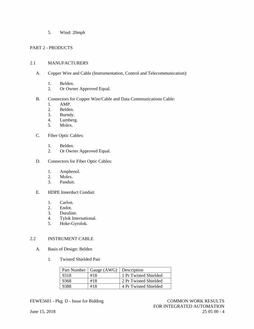
FEWE5601 - Pkg. D - Issue for Bidding COMMON WORK RESULTS
FOR INTEGRATED AUTOMATION
June 15, 2018 25 05 00 - 4
5. Wind: 20mph
PART 2 - PRODUCTS
2.1 MANUFACTURERS
A. Copper Wire and Cable (Instrumentation, Control and Telecommunication):
1. Belden.
2. Or Owner Approved Equal.
B. Connectors for Copper Wire/Cable and Data Communications Cable:
1. AMP.
2. Belden.
3. Burndy.
4. Lumberg.
5. Molex.
C. Fiber Optic Cables:
1. Belden.
2. Or Owner Approved Equal.
D. Connectors for Fiber Optic Cables:
1. Amphenol.
2. Molex.
3. Panduit.
E. HDPE Innerduct Conduit
1. Carlon.
2. Endot.
3. Duraline.
4. Tylok International.
5. Hoke-Gyrolok.
2.2 INSTRUMENT CABLE
A. Basis of Design: Belden
1. Twisted Shielded Pair
Part Number Gauge (AWG) Description
9318 #18 1 Pr Twisted Shielded
9368 #18 2 Pr Twisted Shielded
9388 #18 4 Pr Twisted Shielded
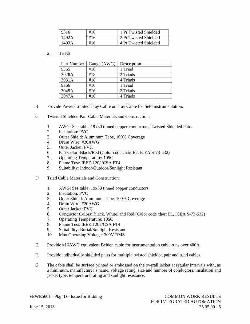
FEWE5601 - Pkg. D - Issue for Bidding COMMON WORK RESULTS
FOR INTEGRATED AUTOMATION
June 15, 2018 25 05 00 - 5
9316 #16 1 Pr Twisted Shielded
1492A #16 2 Pr Twisted Shielded
1493A #16 4 Pr Twisted Shielded
2. Triads
Part Number Gauge (AWG) Description
9365 #18 1 Triad
3028A #18 2 Triads
3031A #18 4 Triads
9366 #16 1 Triad
3045A #16 2 Triads
3047A #16 4 Triads
B. Provide Power-Limited Tray Cable or Tray Cable for field instrumentation.
C. Twisted Shielded Pair Cable Materials and Construction:
1. AWG: See table, 19x30 tinned copper conductors, Twisted Shielded Pairs
2. Insulation: PVC
3. Outer Shield: Aluminum Tape, 100% Coverage
4. Drain Wire: #20AWG
5. Outer Jacket: PVC
6. Pair Color: Black/Red (Color code chart E2, ICEA S-73-532)
7. Operating Temperature: 105C
8. Flame Test: IEEE-1202/CSA FT4
9. Suitability: Indoor/Outdoor/Sunlight Resistant
D. Triad Cable Materials and Construction:
1. AWG: See table, 19x30 tinned copper conductors
2. Insulation: PVC
3. Outer Shield: Aluminum Tape, 100% Coverage
4. Drain Wire: #20AWG
5. Outer Jacket: PVC
6. Conductor Colors: Black, White, and Red (Color code chart E1, ICEA S-73-532)
7. Operating Temperature: 105C
8. Flame Test: IEEE-1202/CSA FT4
9. Suitability: Burial/Sunlight Resistant
10. Max Operating Voltage: 300V RMS
E. Provide #16AWG equivalent Belden cable for instrumentation cable runs over 400ft.
F. Provide individually shielded pairs for multiple twisted shielded pair and triad cables.
G. The cable shall be surface printed or embossed on the overall jacket at regular intervals with, as
a minimum, manufacturer’s name, voltage rating, size and number of conductors, insulation and
jacket type, temperature rating and sunlight resistance.
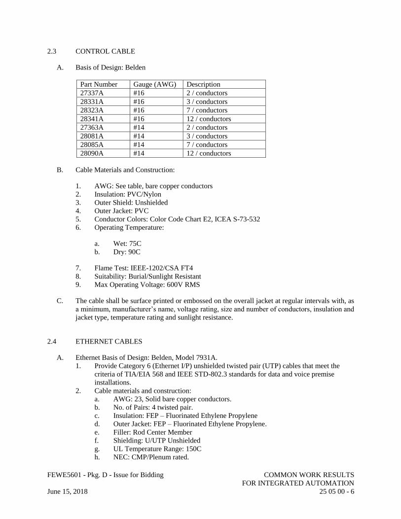
FEWE5601 - Pkg. D - Issue for Bidding COMMON WORK RESULTS
FOR INTEGRATED AUTOMATION
June 15, 2018 25 05 00 - 6
2.3 CONTROL CABLE
A. Basis of Design: Belden
Part Number Gauge (AWG) Description
27337A #16 2 / conductors
28331A #16 3 / conductors
28323A #16 7 / conductors
28341A #16 12 / conductors
27363A #14 2 / conductors
28081A #14 3 / conductors
28085A #14 7 / conductors
28090A #14 12 / conductors
B. Cable Materials and Construction:
1. AWG: See table, bare copper conductors
2. Insulation: PVC/Nylon
3. Outer Shield: Unshielded
4. Outer Jacket: PVC
5. Conductor Colors: Color Code Chart E2, ICEA S-73-532
6. Operating Temperature:
a. Wet: 75C
b. Dry: 90C
7. Flame Test: IEEE-1202/CSA FT4
8. Suitability: Burial/Sunlight Resistant
9. Max Operating Voltage: 600V RMS
C. The cable shall be surface printed or embossed on the overall jacket at regular intervals with, as
a minimum, manufacturer’s name, voltage rating, size and number of conductors, insulation and
jacket type, temperature rating and sunlight resistance.
2.4 ETHERNET CABLES
A. Ethernet Basis of Design: Belden, Model 7931A.
1. Provide Category 6 (Ethernet I/P) unshielded twisted pair (UTP) cables that meet the
criteria of TIA/EIA 568 and IEEE STD-802.3 standards for data and voice premise
installations.
2. Cable materials and construction:
a. AWG: 23, Solid bare copper conductors.
b. No. of Pairs: 4 twisted pair.
c. Insulation: FEP – Fluorinated Ethylene Propylene
d. Outer Jacket: FEP – Fluorinated Ethylene Propylene.
e. Filler: Rod Center Member
f. Shielding: U/UTP Unshielded
g. UL Temperature Range: 150C
h. NEC: CMP/Plenum rated.
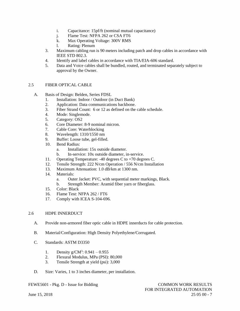
FEWE5601 - Pkg. D - Issue for Bidding COMMON WORK RESULTS
FOR INTEGRATED AUTOMATION
June 15, 2018 25 05 00 - 7
i. Capacitance: 15pf/ft (nominal mutual capacitance)
j. Flame Test: NFPA 262 or CSA FT6
k. Max Operating Voltage: 300V RMS
l. Rating: Plenum
3. Maximum cabling run is 90 meters including patch and drop cables in accordance with
IEEE STD 802.3.
4. Identify and label cables in accordance with TIA/EIA-606 standard.
5. Data and Voice cables shall be bundled, routed, and terminated separately subject to
approval by the Owner.
2.5 FIBER OPTICAL CABLE
A. Basis of Design: Belden, Series FDSL
1. Installation: Indoor / Outdoor (in Duct Bank)
2. Application: Data communications backbone.
3. Fiber Strand Count: 6 or 12 as defined on the cable schedule.
4. Mode: Singlemode.
5. Category: OS2
6. Core Diameter: 8-9 nominal micron.
7. Cable Core: Waterblocking
8. Wavelength: 1310/1550 nm
9. Buffer: Loose tube, gel-filled.
10. Bend Radius:
a. Installation: 15x outside diameter.
b. In-service: 10x outside diameter, in-service.
11. Operating Temperature: -40 degrees C to +70 degrees C.
12. Tensile Strength: 222 N/cm Operation / 556 N/cm Installation
13. Maximum Attenuation: 1.0 dB/km at 1300 nm.
14. Materials:
a. Outer Jacket: PVC, with sequential meter markings, Black.
b. Strength Member: Aramid fiber yarn or fiberglass.
15. Color: Black
16. Flame Test: NFPA 262 / FT6
17. Comply with ICEA S-104-696.
2.6 HDPE INNERDUCT
A. Provide non-armored fiber optic cable in HDPE innerducts for cable protection.
B. Material/Configuration: High Density Polyethylene/Corrugated.
C. Standards: ASTM D3350
1. Density g/CM3: 0.941 – 0.955
2. Flexural Modulus, MPa (PSI): 80,000
3. Tensile Strength at yield (psi): 3,000
D. Size: Varies, 1 to 3 inches diameter, per installation.
FEWE5601 - Pkg. D - Issue for Bidding COMMON WORK RESULTS
FOR INTEGRATED AUTOMATION
June 15, 2018 25 05 00 - 8
E. Color: Orange.
F. Packaging: Reels or coils, per installation.
G. Accessories:
1. Pull tape: 1/2 inch.
2. Couplings: Self threading, tapered threads.
3. Pulling harness and eyes.
4. End Caps: used before cable installation for protection.
2.7 TERMINATIONS AND CONNECTORS
A. Provide high conductivity ring or spade lugs as required for copper conductor termination at
terminal blocks.
B. Provide manufacturer recommended connectors for control network cables.
PART 3 - EXECUTION
3.1 DELIVERY, STORAGE, AND HANDLING
A. Materials are to be packed and shipped to ensure undamaged and complete arrival at the
destination.
B. Containers are to have their contents listed on a packing slip secured to the outside of the
container.
C. Protect materials from construction operations, dust and adverse environmental conditions by
storing indoors.
3.2 EXAMINATION
A. Inspect wire and cable for physical damage before and after installation.
B. Inspect cables for proper connectors and termination.
3.3 ELECTRICAL INSTALLATION
A. General:
1. The installation shall be in compliance with the current version of the National Electrical
Code, the California Electrical Codes, and local amendments.
2. Wire and cable to be installed in conduit, unless indicated otherwise.
3. Do not exceed manufacturer’s maximum pull tension value.
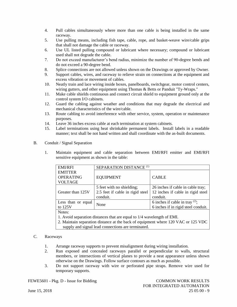
FEWE5601 - Pkg. D - Issue for Bidding COMMON WORK RESULTS
FOR INTEGRATED AUTOMATION
June 15, 2018 25 05 00 - 9
4. Pull cables simultaneously where more than one cable is being installed in the same
raceway.
5. Use pulling means, including fish tape, cable, rope, and basket-weave wire/cable grips
that shall not damage the cable or raceway.
6. Use UL listed pulling compound or lubricant where necessary; compound or lubricant
used shall not degrade the cable.
7. Do not exceed manufacturer’s bend radius, minimize the number of 90-degree bends and
do not exceed a 90-degree bend.
8. Splice connections are not allowed unless shown on the Drawings or approved by Owner.
9. Support cables, wires, and raceway to relieve strain on connections at the equipment and
excess vibration or movement of cables.
10. Neatly train and lace wiring inside boxes, panelboards, switchgear, motor control centers,
wiring gutters, and other equipment using Thomas & Betts or Panduit "Ty-Wraps."
11. Make cable shields continuous and connect circuit shield to equipment ground only at the
control system I/O cabinets.
12. Guard the cabling against weather and conditions that may degrade the electrical and
mechanical characteristics of the wire/cable.
13. Route cabling to avoid interference with other service, system, operation or maintenance
purposes.
14. Leave 36 inches excess cable at each termination at system cabinets.
15. Label terminations using heat shrinkable permanent labels. Install labels in a readable
manner; text shall be not hand written and shall coordinate with the as-built documents.
B. Conduit / Signal Separation
1. Maintain equipment and cable separation between EMI/RFI emitter and EMI/RFI
sensitive equipment as shown in the table:
EMI/RFI
EMITTER
OPERATING
VOLTAGE
SEPARATION DISTANCE (1)
EQUIPMENT CABLE
Greater than 125V
5 feet with no shielding;
2.5 feet if cable in rigid steel
conduit.
26 inches if cable in cable tray;
12 inches if cable in rigid steel
conduit.
Less than or equal
to 125V None
6 inches if cable in tray (2);
6 inches if in rigid steel conduit.
Notes:
1. Avoid separation distances that are equal to 1/4 wavelength of EMI.
2. Maintain separation distance at the back of equipment where 120 VAC or 125 VDC
supply and signal lead connections are terminated.
C. Raceways
1. Arrange raceway supports to prevent misalignment during wiring installation.
2. Run exposed and concealed raceways parallel or perpendicular to walls, structural
members, or intersections of vertical planes to provide a neat appearance unless shown
otherwise on the Drawings. Follow surface contours as much as possible.
3. Do not support raceway with wire or perforated pipe straps. Remove wire used for
temporary supports.
FEWE5601 - Pkg. D - Issue for Bidding COMMON WORK RESULTS
FOR INTEGRATED AUTOMATION
June 15, 2018 25 05 00 - 10
4. Do not attach raceway to ceiling support wires or other piping systems.
5. Do not notch structural members for passage of raceways.
6. Maintain clearance between raceway and piping for maintenance purposes.
7. Maintain 12-inch clearance between raceway and surfaces with temperatures exceeding
104 degrees F.
8. Cut conduit square using saw or pipe cutter; de-burr cut ends.
9. Insert conduit to shoulder of fittings; fasten securely.
10. Install no more than equivalent of three 90-degree bends between boxes. Install conduit
bodies to make sharp changes in direction, as around beams. Install factory elbows for
bends in metal conduit larger than 2-inch size.
11. Avoid moisture traps; install conduit with drip legs and drain fitting at low points in
conduit system.
12. Install fittings to accommodate expansion and deflection where raceway crosses seismic,
control and expansion joints.
13. Install suitable pull string or cord in each empty raceway except sleeves and nipples.
14. Install suitable caps to protect installed conduit against entrance of dirt and moisture.
15. Close ends and unused openings in wireway.
16. Install flexible conduit connection to local instrumentation or other equipment where
flexible connection is required to minimize vibration or where required to facilitate
removal or adjustment of equipment. The flexible conduit shall be long enough to allow
the item to which it is connected to be withdrawn or moved off its base. Maximum length
allowed is 48-inches.
17. Seal around all raceways entering structures at the first box or outlet with suitable plastic
expandable compound to prevent the entrance into the structure of gases, liquids, or
rodents.
18. Conduits routed perpendicular through floors, walls, or other concrete structures shall
pass through cast-in-place openings wherever possible or appropriate size holes shall be
bored through the concrete to accommodate the conduit passage. The size and location of
the holes shall not impair the integrity of the structure. Grout around conduit and finish to
match existing surroundings.
19. Conduits entering electrical devices, cabinets, J-boxes, etc. in wet locations or outside
shall use water-tight gasketed sealed fittings; such as, Myers Hub, with an insulated-
bonding-bushing installed.
20. Sleeves shall have bushings installed at open ends. Where sleeves are used for cable
exiting cable trays, grounding bushings shall be used and shall be bonded to the cable
tray system grounding.
21. Sleeves entering electrical enclosures shall be sealed with suitable sealing compound,
such as “Duxseal” to prevent entry of rodents or dirt after installation of cables. Fire
rated walls shall be sealed with appropriate fire rated compound.
22. Conduit, cable tray fill shall not exceed 40 percent of total cross-sectional area.
23. Install cable so that entry to and exit from cable tray is supported and not stressed.
24. Cables shall drop perpendicular (slope shall be less than one foot along tray) for
transition from conduit to cable tray.
25. Cables routed through manholes or handholds shall be provided with a 15-foot service
loop at each manhole or handhold. Cable shall be neatly managed and racked to side
walls of vault.
26. Cable shall be routed as close as possible to the ceiling, floor, or corners to ensure that
adequate wall or backboard space is available for future equipment.
27. Raceways, conductors and cables shall be provided as required for a complete and
operating system. Homeruns, where shown on the Drawings, are to assist the

FEWE5601 - Pkg. D - Issue for Bidding COMMON WORK RESULTS
FOR INTEGRATED AUTOMATION
June 15, 2018 25 05 00 - 11
Manufacturer in identifying raceways to be run exposed and raceways to be run
concealed.
28. Raceways shall be installed concealed in all finished spaces and may be installed exposed
or concealed in all process spaces. Raceways installed exposed shall be near the ceiling
or along walls of the areas through which they pass and shall be routed to avoid conflicts
with HVAC ducts, cranes hoists, monorails, equipment hatches, doors, windows, etc.
3.4 COPPER WIRE AND CABLE INSTALLATION
A. General Wiring Methods:
1. Neatly train and lace wiring inside boxes, panelboards, switchgear, motor control centers,
wiring gutters, and other equipment using Thomas & Betts or Panduit "Ty-Wraps."
2. Provide equal conductor lengths for parallel circuits.
3. Do not install wire splices in conduit or raceways.
B. Wiring Installed in Raceways:
1. Completely and thoroughly swab raceway system before installing conductors.
2. Pull conductors into a raceway at the same time. Use UL listed wire pulling lubricant.
Do not exceed manufacturer's recommended tension.
3. Install wire in raceway after mechanical work likely to injure conductors has been
completed.
4. Remove and discard conductors cut too short or installed in wrong raceway. Do not
install conductors which have been removed from a raceway.
5. Do not install conductors in conduit which contains wires already in place.
C. Wiring Terminations and Connections:
1. Clean wires before installing lugs and connectors.
2. Terminate spare conductors on terminal blocks.
3. Terminate spare cables with electrical tape, coil, and lay neatly at point of termination.
4. Identify and label conductor terminations as specified in electrical identification.
5. Properly terminate indicated conductors in equipment furnished and provide properly
sized lugs.
3.5 FIELD QUALITY CONTROL
A. General:
1. Testing shall be performed in the presence of Owner or Owner's Representative.
Construction Manager must provide 48 hours notice prior to conducting tests.
2. In the event of a test failure, the Manufacturer is required to remedy the failure.
3. Prepare a test report upon completion of testing activities. Report format shall include the
following information:
a. Summary of test results.
b. Test equipment summary (model number, accuracy, calibration date).
c. Test personnel names and sign-offs.
FEWE5601 - Pkg. D - Issue for Bidding COMMON WORK RESULTS
FOR INTEGRATED AUTOMATION
June 15, 2018 25 05 00 - 12
d. Completed data sheets.
e. Test log and observations.
f. Certificate of Compliance.
B. Cable Testing:
1. Copper Instrument & Control Cable: perform continuity checks on conductors post
installation, prior to termination.
2. Data Communications Cable:
a. Test to ANSI/TIA 568-C.2 standards for Category 6 installations as appropriate
using a Fluke DSX-5000 Cable Analyzer.
b. Cabling testing shall include determination of opens, shorts, polarity reversals,
transposition and presence of AC voltage.
c. In the event of a test failure the Manufacturer shall re-test the failed cable and
document the successful re-test.
3. Fiber Optic Cable:
a. Test cables on reels prior to installation with an Optical Time Domain
Reflectometer (OTDR) in accordance with TIA/EIA-455-59. Test cable at 850nm
and 1300 nm wavelength.
b. Test cables after installation and termination with an OTDR in accordance with
TIA/EIA-455-59 at 850nm and 1300nm wavelengths. Reject and replace cables if
either condition exists:
1) Attenuation exceeds factory specifications.
2) Localized discontinuity exceeds 0.2dB.
END OF SECTION 25 05 00
FEWE5601 - Pkg. D - Issue for Bidding MEDIUM-VOLTAGE METALCLAD SWITCHGEAR - WEST CAMPUS SWITCHING STATION (WCSS)
June 15, 2018 26 13 26 - 1
SECTION 26 13 26 - MEDIUM-VOLTAGE METALCLAD SWITCHGEAR - WEST CAMPUS SWITCHING STATION (WCSS)
PART 1 - GENERAL
1.1 RELATED DOCUMENTS
A. Drawings and general provisions of the Contract, including General and Supplementary Conditions and Division 01 Specification Sections, apply to this Section.
1.2 SUMMARY
A. Complete switchgear system, including:
1. West Campus Switching Station (WCSS Bus A & B) Switchgear.2. Controls and Relaying.3. Communications Ethernet Switches and I/O module.4. Auxiliaries.5. Batteries, Battery Charger, and battery rack
1.3 REFERENCES
A. All equipment shall meet or exceed the latest editions of the applicable standards listed below.
B. ASTM (ASTM): ASTM B187 "Standard Specification for Copper, Bus Bar, Rod, and Shapes".
C. Institute of Electrical and Electronics Engineers, Inc. (IEEE):
1. ANSI/IEEE C37.010 - "Application Guide for AC High Voltage Circuit Breakers > 1000VAC Rated on a Symmetrical Current Basis" (copyrighted by IEEE, ANSI approved).
2. IEEE C37.2 - "Electrical Power System Device Function Numbers, Acronyms, and Contact Designations".
3. IEEE C37.20.2 - "Metal Clad Switchgear" IEEE C37.20.7 - "Guide for Testing Medium-Voltage Metal-Enclosed Switchgear Rated up to 38kV for Internal Arcing Faults.
4. IEEE C37.21 - "Control Switchboards" (copyrighted by IEEE, ANSI approved).5. ANSI/IEEE C37.90 - "Relays and Relay Systems Associated with Electric Power
Apparatus" (copyrighted by IEEE, ANSI approved).6. IEEE C57.13 – “IEEE Standard Requirements for Instrument Transformers”7. IEEE C37.90 - Relays and Relay Systems Associated with Electric Power Apparatus.8. IEEE-1613: Environmental and Testing Requirements for Communications Networking
Devices Installed in Electric Power Substations9. IEEE-C37.90: Relays and Relay Systems Associated with Electric Power Apparatus10. IEC 60068-2: Environmental Tests
FEWE5601 - Pkg. D - Issue for Bidding MEDIUM-VOLTAGE METALCLAD SWITCHGEAR - WEST CAMPUS SWITCHING STATION (WCSS)
June 15, 2018 26 13 26 - 2
11. IEC 60255-21: Vibration and shock Tests12. IEC-60255-22: RFI and Interference Tests13. IEC 60825-1: Laser (LED) Safety14. IEC-61000-4: Electromagnetic Compatibility15. IEC-61000-6: Electromagnetic Compatibility16. IEC-61850 Series: Communication Networks and Systems for Power Utility Automation17. CFR 47 Parts 15 and 18, Code of Federal Regulations - Federal Communications
Commission (FCC) Rules and Regulations pertaining to EMI
D. National Electrical Contractors Association (NECA): NECA 430-2016 Standard for Installing and Maintaining Medium-Voltage Switchgear
E. National Electrical Manufacturers Association (NEMA):
1. NEMA SG 4 - "Alternating Current High Voltage Circuit Breakers".2. NEMA C37.55 "Conformance Test Procedures for Switchgear – Medium Voltage Metal
Clad Assemblies".
F. National Fire Protection Association (NFPA):
1. NFPA 70 - "National Electrical Code" (copyrighted by NFPA, ANSI approved) hereinafter referred to as NEC.
2. NFPA 70B - "Recommended Practice for Electrical Equipment Maintenance" (copyrighted by NFPA, ANSI approved).
3. NFPA 70E – “Standard For Electrical Safety In The Workplace” (copyrighted by NFPA, ANSI approved) hereinafter referred to as NEC.
G. Underwriters Laboratories, Inc. (UL):
1. UL 486A-B - "UL Standard for Safety Wire Connectors 2. UL 1236 - "UL Standard for Safety Battery Chargers for Charging Engine-Starter
Batteries" (copyrighted by UL, ANSI approved).
1.4 SITE CONDITIONS
A. Seismic Loads
1. Risk Category = II2. Seismic Importance Factor – I =1.03. Mapped Spectral Response Accelerations – Ss = 0.279 g, S1=0.106 g4. Site Class – D5. Spectral Response Coefficient – Sds = 0.293 g, Sd1=0.167 g6. Seismic Design Category C
1.5 SUBMITTALS
A. Product Data: Submit manufacturer's product data showing material and equipment proposed.
FEWE5601 - Pkg. D - Issue for Bidding MEDIUM-VOLTAGE METALCLAD SWITCHGEAR - WEST CAMPUS SWITCHING STATION (WCSS)
June 15, 2018 26 13 26 - 3
1. Product data shall include, but shall not be limited to, the following equipment and materials:
a. Circuit breakers.b. Buses.c. Transformers.d. Panelboards.e. Control, Relaying, and Metering equipment and software.f. HMI Panel, door mounted, with programming software..g. Communications networking equipment.h. Wire and cable.i. Batteries and charger.
2. The ratings for the equipment shall include, but shall not be limited to, the following:
a. Voltages.b. Frequency.c. Number of phases.d. Current, continuous and interrupting.e. Accuracy.f. Power requirements.g. Power losses at full and half load.
3. Physical characteristics and materials shall include, but shall not be limited to, the following:
a. Size/dimensions.b. Weight.c. Finishes.
4. Accessories shall include, but shall not be limited to, the following:
a. Indicating lights.b. Terminal blocks.c. Test switches.d. Auxiliary contacts.
B. Shop Drawings: Submit complete shop drawings as required to determine acceptability. Shop drawings shall include, but shall not be limited to, the following:
1. Bill of materials and components.2. Outline drawings, dimensioned plans, elevations, sections, supports, materials, and
finishes, showing weights, bolt spacing, clearances, tolerances, conduit, cable entrances, terminal strips, and methods of assembly.
3. Cubicle and compartment layouts.4. Bus and circuit breaker ratings and arrangements including dimensions of bus bars,
including the ground bus, and the type and spacing of bus supports.5. Nameplate details (size and legend).

FEWE5601 - Pkg. D - Issue for Bidding MEDIUM-VOLTAGE METALCLAD SWITCHGEAR - WEST CAMPUS SWITCHING STATION (WCSS)
June 15, 2018 26 13 26 - 4
6. Detail drawings showing incoming line terminations and location of cable termination with dimensions. Shop drawings shall verify sufficient conductor space and compliance with codes.
7. Shipping arrangements and packaging methods.
C. Wiring Diagrams: Submit with shop drawings, specific wiring diagrams and instructions for equipment, controls, communications, or devices which are furnished or which are to be field wired and connected. The diagrams and instructions shall not be of a general or typical nature, but shall be applicable only to this Project. Include identical diagrams and instructions to install the equipment as are included in the operating and maintenance manuals. Wiring diagrams shall include, but shall not be limited to, the following:
1. Single and three line diagrams.2. Electrical wiring diagrams for communications, instrumentation, metering and relaying.3. Control schematic diagrams including interface diagrams having terminals identified for
remote equipment.4. Wiring diagrams for switchgear showing connections to distribution branches.5. Wiring diagrams for communication sections showing field connections by others.
D. Calculations: Submit calculations supporting the selection of the devices and components furnished. Devices requiring submittal of calculations shall include, but shall not be limited to, the following:
1. Instrument Transformers: Sizes and burdens.2. Control power transformers.3. DC Power System components.4. Low Voltage AC Power system components.
E. Operating and Maintenance Manuals: Prepare and deliver complete operating and maintenance manuals. Provide information pertinent to the equipment for preventive maintenance and for replacement of expendable components. Manuals shall include the items listed below and other information recommended by the manufacturer:
1. Manufacturer's published information.2. Set of shop drawings.3. Wiring diagrams of electrical components.4. Acceptance test reports.5. Electrical characteristics and ratings of components.6. Recommended spare parts list.7. Maintenance Procedures 8. Complete list of parts.9. Factory Test Data: Provide factory test data certified by a professional engineer that
switchgear test results fulfill the specified requirements.
F. Submit with proposals
1. Preliminary Data Sheets.2. Preliminary one-line diagrams.3. Elevations showing overall dimensions, weights, and layout of accessories.4. Bill of materials for each cubicle with manufacturer reference number.
FEWE5601 - Pkg. D - Issue for Bidding MEDIUM-VOLTAGE METALCLAD SWITCHGEAR - WEST CAMPUS SWITCHING STATION (WCSS)
June 15, 2018 26 13 26 - 5
5. Complete list of spare parts and special tools that will be furnished with equipment, which are included in lump sum price. In addition, provide itemized price listing of recommended spare parts with prices guaranteed for at least 1 year after acceptance of equipment.
6. Complete data and listing of items requiring field assembly and installation and special equipment required.
7. Manufacturer’s ISO certification certificate.8. Location of manufacture of each unit.
G. Submit after Notice of Award
1. Certified Data Sheets.2. Master drawing index.3. One-line diagrams.4. Three-line diagrams.5. Conduit entry and exit locations.6. Schematic diagrams and elementary wiring and connection diagrams.7. Control and equipment wire terminations.8. Material lists with manufacturer reference numbers.9. Ratings and nameplate schedules.10. Elevations showing overall dimensions, weights, and layout of accessories.11. Switchgear cross-sections to indicate interior bus arrangement and equipment locations.12. Floor plan drawing shown location for anchor bolts and leveling channels.13. Location of floor and pad openings required for entrance of conduits and cables.14. Performance curves for each ratio and type of current and voltage transformer.15. Detailed instruction books for all equipment, meters, and each type of relay.16. Detailed characteristics of surge arresters.17. Detailed procedures and processes for factory acceptance tests.18. Certified test report of manufacturer's standard production tests19. Wiring diagrams for field installed breaker test cell that is to be shipped loose (see 2.19).20. Elevations and floor plans of batteries, battery rack, and charger.21. Battery sizing calculations.
1.6 SYSTEM DESCRIPTION
A. Provide complete free standing assembly as shown on drawings consisting of circuit breakers, protective relays and control devices for operation and control of the distribution feeders, tie breaker(s) and the main breaker(s). Ethernet switches for communications, and other accessories as applicable.
B. Metalclad switchgear shall be provided with remote closed door racking provisions for all circuit breakers. Closed door racking provisions for circuit breakers shall not require the end user to install any extension arms through the door for operation of the racking mechanism. A motorized racking device shall be provided for use with this option.
FEWE5601 - Pkg. D - Issue for Bidding MEDIUM-VOLTAGE METALCLAD SWITCHGEAR - WEST CAMPUS SWITCHING STATION (WCSS)
June 15, 2018 26 13 26 - 6
1.7 QUALITY ASSURANCE
A. After fabrication, perform an operational test in the manufacturer's plant to check out the entire system before delivery. Include calibration of meters, operation of temperature sensors, relays and device settings; control wiring, including polarity, of all instrument transformers; complete assembly and control function testing. Submit certified written test reports.
B. Provide written data certifying a minimum of ten years' experience in the building of metal clad switchgear and at least ten successful working installations of this type of equipment.
1.8 WARRANTY
A. The manufacturer shall provide a warranty against defects in material and workmanship for a period of 3 years from the date of factory acceptance testing. During the first 3 years of operation, there shall be no cost to the owner for any corrective repairs. Individual component warranties may be longer and will be coordinated with manufacturer after the first 3 years of operation.
PART 2 - PRODUCTS
2.1 MANUFACTURERS
A. Eaton/Cutler Hammer.
B. GE.
C. Powell Industries.
D. Siemens.
E. Square D.
2.2 GENERAL
A. Standards: The switchgear shall consist of stationary steel structures containing vacuum type, drawout power circuit breakers with overcurrent devices, instruments, buses, and system control devices. The switchgear shall be UL approved as service entrance equipment and designed, built, and tested in accordance with ANSI/IEEE and NEMA standards for metal clad switchgear.
B. Unless otherwise specified this equipment is intended for use in ambient temperatures that do not exceed a maximum of 104 degrees F or a minimum of -22 degrees F.
C. This equipment is intended for use in an area where the elevation is less than 3300 feet above sea level. Above 3300 feet a de-rating factor as prescribed by ANSI standards will apply.
FEWE5601 - Pkg. D - Issue for Bidding MEDIUM-VOLTAGE METALCLAD SWITCHGEAR - WEST CAMPUS SWITCHING STATION (WCSS)
June 15, 2018 26 13 26 - 7
D. The switchgear shall be suitable, tested and certified to meet all applicable seismic requirements of the 2015 South Carolina Building Code as detailed in above site conditions section.
2.3 SWITCHGEAR ENCLOSURE
A. Vertical Sections: The stationary enclosure shall consist of self supported, vertical sections housing circuit breakers, buses, cables, system controls, and accessories. The vertical sections shall be bolted together to form a rigid metal clad switchgear assembly. The vertical sections shall have separate front compartments for circuit breakers and controls, and rear compartments for buses and outgoing cables. The vertical section framework shall consist of a welded and bolted steel frame with reinforcing gussets. Assembled to this framework shall be doors and top, side, and rear covers.
B. Base: The vertical sections shall be supported on a steel base assembly consisting of die formed steel and commercial channel welded and bolted together. The base shall provide a rigid support for the switchgear assembly.
C. Each front and rear compartment door shall be provided with a formed steel hinged door with hand operated door latches and three-point closure. Each door shall have provisions for padlocking. Rear doors on cable compartments shall be equipped with IR viewing windows with removable dustproof covers; two high sections shall include IR viewing windows for each upper and lower compartment.
D. Lifting Equipment: Circuit breaker lifting equipment shall be provided to remove circuit breakers. The equipment shall be a portable lifting device manufactured by the equipment supplier. Qty = 1 for WCSS location.
E. Breaker Compartment: The front compartment of the switchgear shall contain the drawout circuit breakers. Each vertical feeder section shall provide the space to accommodate two circuit breakers if frame size allows. Each circuit breaker shall be mounted in a barriered cell. Breaker compartments for future use as indicated as "equipped breaker cell" on the drawings, shall be fully equipped with drawout assemblies and current carrying parts required to permit completion of the unit by the addition of only a circuit breaker. Provide a LED light source in the top and bottom of the front and rear compartments operated by a light switch on the door.
F. Cable Compartment: The cable compartment shall be sized to accommodate incoming and outgoing cables or busway required for each vertical section. The bus compartment shall be segregated from the feeder cable compartment by means of grounded metal barriers. The cable compartment shall also contain a copper ground bus bolted directly to the switchgear frame. The incoming and tie breaker feeder cable compartments (Section Types 1, 2, and 3) shall be capable of terminating up to 6-750 kcmil, 15 kV, MV-105, 133% insulated conductors. All other sections (section type 4) shall be capable of terminating up to 2-500 kcmil, 15 kV, MV-105, 133% insulated conductors. The depth of the finished equipment shall be sufficient to allow for entrance, bending, and termination of power cables. Individual units shall be provided for bottom entrance. A minimum of 26 inches of vertical clearance between terminal pads and the cable entrance shall be provided. Two high sections shall provide a separate chute or channel to isolate and route bottom entry cables to upper compartments.
FEWE5601 - Pkg. D - Issue for Bidding MEDIUM-VOLTAGE METALCLAD SWITCHGEAR - WEST CAMPUS SWITCHING STATION (WCSS)
June 15, 2018 26 13 26 - 8
G. Each switchgear cubicle shall have, at a minimum, 11-gauge sheet steel side panels. Construction shall provide two (2) steel sheets between adjacent sections so as to minimize the chance of fault propagation between sections.
H. Provide electric heaters in each switchgear compartment.
1. Voltage: 240-volt, single-phase operated at 120V.2. Watts: As required to maintain temperature.3. Provide thermostat for each compartment with minimum set point of 50°F.
I. The switchgear shall be capable of extension from opposite end of communications/remote I/O section at a future date without modification to the existing structural members.
J. Control Compartment: Each Vertical Section shall include a dedicated and isolated control compartment. Upper and lower or Side by Side control compartments shall be isolated from each other with each control compartment dedicated to its associated breaker. Provide a LED light source in the compartment and a switch accessible from the exterior of the gear. The Control Compartment shall house the respective relays, indicating lights, test switches, and other required auxiliary equipment for the respective breaker.
K. Communications/Remote I/O Section: Each Switchgear shall include a dedicated and isolated section for the communications Ethernet switches, door mounted HMI, fiber optic patch panel, and remote I/O module; additional equipment, such as firewalls, controllers, servers, network time clock, will be added later by the SCADA Contractor. These devices will be 19-inch rack configuration and the communication section is to include supports for mounting same. Ethernet cables from protective relays and metering shall be routed to the Ethernet switches separate from the power bus and cables. The section shall be accessible from the side of the gear. Provide overhead cable tray or wireway with 50% spare capacity for manufacturer provided and field installed communication cabling between Bus A and Bus B. Provide tray or conduit for remote I/O point cabling.
L. Finish: Indoor: The switchgear enclosure parts shall be given an iron phosphate pretreatment, a primer, and a coat of baked enamel. After assembly, a finish coat of air drying enamel of gray color (ANSI #61) shall be applied to exterior surfaces.
2.4 BUSES
A. General: The bus structure shall consist of copper bus with silver plated bolted connections mounted on track resistant glass polyester and porcelain insulators. The bus system shall be insulated with fluidized bed epoxy insulation. The copper bus shall be of sufficient size to limit the temperature rise as specified in ANSI/IEEE C37.20.2. Bus bracing shall be adequate to withstand mechanical and thermal stresses due to short circuits at least equal to those specified for the main circuit breaker. Provide ASTM B 187 copper throughout the switchgear. Bus joints shall be provided in each unit. The temperature rise of the bus and connections shall be in accordance with ANSI standards and documented by design test.
B. Power bus orientation shall be A-B-C top to bottom, front to back, and left to right when viewed from the front of the switchgear.
FEWE5601 - Pkg. D - Issue for Bidding MEDIUM-VOLTAGE METALCLAD SWITCHGEAR - WEST CAMPUS SWITCHING STATION (WCSS)
June 15, 2018 26 13 26 - 9
C. Phase Buses: Provide continuous phase buses as sized on the drawings for the full length of the switchgear lineup excluding the communications/remote I/O section. Tap buses shall have the same ampacity as the section design rating.
D. Neutral Bus: Provide continuous fully sized neutral bus for the full length of the switchgear lineup excluding the communications/remote I/O section. Neutral bus shall be bonded to ground in two locations per bus lineup as shown on drawings.
E. Ground Bus: Provide a minimum size ground bus of 2 inch by 1/4 inch cross sectional area, for the full length of the switchgear lineup excluding the communications/remote I/O section. Provide compression indent type lugs to accept No. 4/0 AWG copper cable.
F. Connections: Bus connections for shipping breaks, extension, and taps shall be silver plated bolted pressure joints. Provide insulating boots for bus joints and cable terminations. Selection of cable termination boots to be based on installed cable diameter (type 15kV Cooper BOL-T or equal).
G. Safety Shutters: The switchgear shall be furnished with grounded shutters or a means by which to cover the stationary primary disconnects when the breaker is moved from the connected position.
2.5 POWER CIRCUIT BREAKERS
A. General: The power circuit breakers shall be medium voltage, drawout, vacuum circuit breaker type, having electrically charged, stored energy mechanisms which shall be mechanically and electrically trip free. Provision shall be included for manual charging of the operating mechanism. The breakers shall be mounted on a rigid, self-aligning drawout mechanism. The breaker shall be removable and shall roll out on horizontal guide rails.
B. Breaker Positions: Each drawout breaker shall be provided with four position operation. Each position shall be clearly identified by an indicator on the circuit breaker front panel.
1. Connected Position: In the connected position, the main line and load terminals and auxiliary control contacts and circuitry shall be connected and the breaker shall be fully operable. The breaker shall be interlocked to automatically trip before racking into or out of position.
2. Test Position: In the test position, the circuit breaker auxiliary control contacts and circuitry only shall be connected to permit testing of the complete control system without actually connecting the sources or loads to the main bus.
3. Disconnected Position: In the disconnected position, main and auxiliary control contacts and circuitry shall be completely disconnected.
4. Remove Position: In the remove position circuitry shall be disconnected and the breaker can be removed from the compartment.
C. Operating Mechanism:
1. The breaker operating mechanism shall be the two step, stored energy quick make, quick break type. The close operation of the circuit breaker shall automatically charge the

FEWE5601 - Pkg. D - Issue for Bidding MEDIUM-VOLTAGE METALCLAD SWITCHGEAR - WEST CAMPUS SWITCHING STATION (WCSS)
June 15, 2018 26 13 26 - 10
opening springs. The operating mechanism shall be front located and designed for servicing without removing breaker from rails.
2. Manual charging of the breaker shall be possible by means of a manual charging lever,3. Close trip indicator, mechanically connected to the breaker, shall be provided to indicate
the breaker position.4. Circuit breaker operating mechanism shall be completely trip free both mechanically and
electrically. Mechanical tripping of a closed circuit breaker shall be possible with the front cubicle door closed.
5. A contact wear gap indicator shall be provided and shall be easily visible.
D. Mechanical Interlocks: The switchgear shall be provided with mechanical interlocks to:
1. Prevent moving the breaker to or from the connected position when the breaker contacts are in the closed position.
2. Prevent closing the breaker unless the primary disconnects are fully engaged or the breaker is in the test or disconnect position.
3. Automatically discharge the closing springs when the breaker is moved between the connected and test positions or when it is inserted into or withdrawn from the compartment.
E. Mechanism Operator Cell Breaker Auxiliary Switches: Each circuit breaker shall be equipped with mechanism operated auxiliary switches which shall operate when the breaker is open or closed. These switches shall be enabled in the operating and test position. Provide four normally open and four normally closed contacts in addition to those required for the circuit breaker operating mechanism and control schemes. All contacts to be wired to accessible terminal blocks for customer use.
F. Truck Operated Cell Switches: Each breaker compartment shall be equipped with cell mounted switches which shall operate when the circuit breaker is levered into or out of the operating position. Provide two six stage switches, each six stage switch shall provide six normally open and six normally closed contacts. All contacts to be wired to accessible terminal blocks for customer use.
G. A steel interference plate shall be mounted in the bottom of each circuit breaker cell assembly which only allows a higher rated circuit breaker (voltage, current, interrupting rating) to be inserted into a lower rated cell assembly.
H. For operator safety the circuit breaker shall have provision for padlocking it in the disconnected position.
I. Circuit breaker shall have the capability of racking between the connected, disconnected and test positions with the cubicle door closed.
J. Power circuit breakers shall be shipped and packaged separately from the switchgear structure.
2.6 RATING AND PERFORMANCE REQUIREMENTS POWER CIRCUIT BREAKERS
A. Metal Clad Switchgear Ratings and Requirements for IEEE C37.06 Table 1 rated breakers:
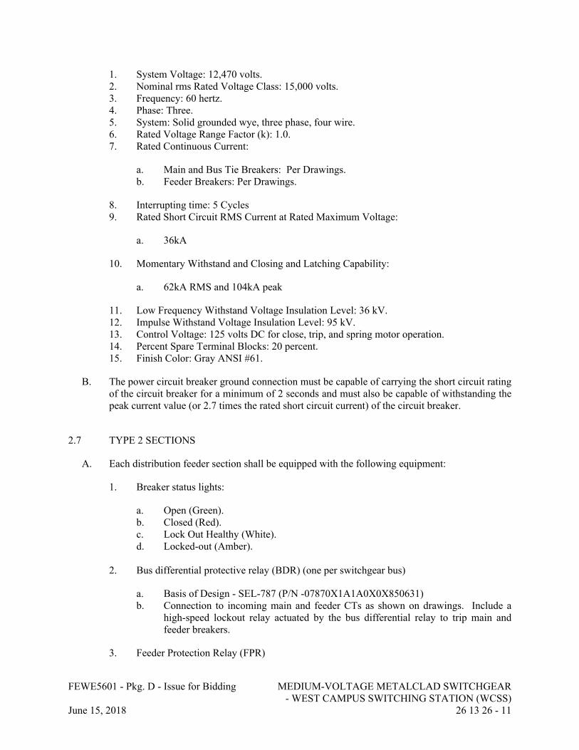
FEWE5601 - Pkg. D - Issue for Bidding MEDIUM-VOLTAGE METALCLAD SWITCHGEAR - WEST CAMPUS SWITCHING STATION (WCSS)
June 15, 2018 26 13 26 - 11
1. System Voltage: 12,470 volts.2. Nominal rms Rated Voltage Class: 15,000 volts.3. Frequency: 60 hertz.4. Phase: Three.5. System: Solid grounded wye, three phase, four wire.6. Rated Voltage Range Factor (k): 1.0.7. Rated Continuous Current:
a. Main and Bus Tie Breakers: Per Drawings.b. Feeder Breakers: Per Drawings.
8. Interrupting time: 5 Cycles9. Rated Short Circuit RMS Current at Rated Maximum Voltage:
a. 36kA
10. Momentary Withstand and Closing and Latching Capability:
a. 62kA RMS and 104kA peak
11. Low Frequency Withstand Voltage Insulation Level: 36 kV.12. Impulse Withstand Voltage Insulation Level: 95 kV.13. Control Voltage: 125 volts DC for close, trip, and spring motor operation.14. Percent Spare Terminal Blocks: 20 percent.15. Finish Color: Gray ANSI #61.
B. The power circuit breaker ground connection must be capable of carrying the short circuit rating of the circuit breaker for a minimum of 2 seconds and must also be capable of withstanding the peak current value (or 2.7 times the rated short circuit current) of the circuit breaker.
2.7 TYPE 2 SECTIONS
A. Each distribution feeder section shall be equipped with the following equipment:
1. Breaker status lights:
a. Open (Green).b. Closed (Red).c. Lock Out Healthy (White).d. Locked-out (Amber).
2. Bus differential protective relay (BDR) (one per switchgear bus)
a. Basis of Design - SEL-787 (P/N -07870X1A1A0X0X850631)b. Connection to incoming main and feeder CTs as shown on drawings. Include a
high-speed lockout relay actuated by the bus differential relay to trip main and feeder breakers.
3. Feeder Protection Relay (FPR)
FEWE5601 - Pkg. D - Issue for Bidding MEDIUM-VOLTAGE METALCLAD SWITCHGEAR - WEST CAMPUS SWITCHING STATION (WCSS)
June 15, 2018 26 13 26 - 12
a. Basis of Design - SEL-751 (P/N 751201A3A2A0X850631).b. Provide relay inputs and outputs as shown on drawings with a minimum of 25%
spare.
4. Customer connection points for 3 external trip signals directly to breaker. 5. One 86 lockout relay for use with FPR as shown on drawings.6. Heavy –duty distribution class surge arresters.
a. Maximum Rated Line to Line Voltage (VLL) – 13.1 kV.b. MCOV – 7.65 kV.
7. Current transformers and voltage transformers as specified in paragraph 2.14 and as shown on drawings.
8. Test switches as specified in paragraph 2.15 and as shown on drawings.
2.8 TYPE 3 SECTIONS
A. Each distribution feeder section shall be equipped with the following equipment:
1. Breaker status lights:
a. Open (green)b. Closed (red)c. Lock Out Healthy (White).d. Locked-out (Amber).
2. Feeder protective relay (FPR)
a. Basis of Design: SEL-751 (P/N 751201A3A2A0X850631). b. Provide relay inputs and outputs as shown on drawings with a minimum of 25%
spare.c. Customer connection points for 2 external trip signals directly to breaker.
3. One 86 lockout relay for use with FPR as shown on drawings.4. Heavy –duty distribution class surge arresters.
a. Maximum Rated Line to Line Voltage (VLL) – 13.1 kV.b. MCOV – 7.65 kV.
5. Current transformers and voltage transformers as specified in paragraph 2.14.6. Test switches as specified in paragraph 2.15.
2.9 TYPE 4 SECTIONS
A. Each distribution feeder section shall be equipped with the following equipment:
1. Breaker status lights:
FEWE5601 - Pkg. D - Issue for Bidding MEDIUM-VOLTAGE METALCLAD SWITCHGEAR - WEST CAMPUS SWITCHING STATION (WCSS)
June 15, 2018 26 13 26 - 13
a. Open (green)b. Closed (red)
2. Feeder protective relay (FPR)
a. Basis of Design: SEL-751 (P/N 751201A3A2A0X850631). b. Provide relay inputs and outputs as shown on drawings with a minimum of 25%
spare.c. Customer connection points for 2 external trip signals directly to breaker.
3. Heavy –duty distribution class surge arresters.
a. Maximum Rated Line to Line Voltage (VLL) – 13.1 kV.b. MCOV – 7.65 kV.
4. Current transformers and voltage transformers as specified in paragraph 2.14.5. Test switches as specified in paragraph 2.15.
2.10 COMMUNICATIONS/REMOTE I/O SECTION
A. Provide dedicated communication/remote I/O switchgear section to end section of switchgear lineup with two doors accessible from side of switchgear per project drawings. Doors shall swing outward and have key lock handles for lockable three point latching mechanism.
B. Provide grounding bar with cable connection to ground bus in switchgear lineup.
C. Provide 120VAC power feed to cabinet with local circuit breaker.
D. Provide fused terminal block for 125Vdc power distribution throughout switchgear.
E. Provide 125vdc to 24vdc converter for the Remote I/O Unit.
F. Provide Remote I/O unit:
1. Basis of Design: SEL-2516
2. Digital Inputs: 8
3. Digital Outputs: 84. Power: 24VDC5. Communications:
a. Protocol: Modbus TCP/IP, DNP3, or Ethernet/IPb. Ports: 2 - RJ45, 10/100BaseT
6. Temperature Range: -40 to 75C7. Relative Humidity: 5-95% non-condensing8. Mounting:19-inch Rack.9. Software configuration package
FEWE5601 - Pkg. D - Issue for Bidding MEDIUM-VOLTAGE METALCLAD SWITCHGEAR - WEST CAMPUS SWITCHING STATION (WCSS)
June 15, 2018 26 13 26 - 14
10. Comply with IEC-61000-3, -4, and -6 for electromagnetic susceptibility and compatibility.
G. Provide industrial grade managed Ethernet switches (layer 3) per the following:
1. Manufacturers:a. Cisco Industrial Ethernet Series Switches 3000 – 5000 (Basis of Design)b. Hirschmann (A Belden company)c. Moxad. Siemens (Rugged Com)
2. Port Configurations:
a. 8 Fiber Optic, Single-Mode, 1000 Mbps, ring loopb. 28 Copper RJ-45, 10/100 Mbps
3. The SCADA system uses a redundant Ethernet Communications ring such that there is an A and B channel. Multiple Ethernet switches may be connected together to meet or exceed the number and type of required port connections.
4. Security: SNMPv3, HTTPS, MAC for configurable access control and traffic management.
5. Network:
a. Configuration and monitoring software to provide network health and security indicators.
b. Support tagged and untagged VLANs and IEC 61850 GOOSE messages from other traffic.
c. Prioritize traffic per IEEE 802.1pd. Security: restrict access to select end stations via IEEE 802.1X.e. Failover & Redundancy: Enable fast network recovery via IEEE 802/1D, Rapid
Spanning Tree Protocol (RSTP).f. Employ VLAN configurations where appropriate to segregate the traffic of
dissimilar network protocols or equipment
6. Time Synchronization: SNTP server & client per 15887. Mounting:19inch Rack.8. Power Supplies: Redundant, Hot-Swappable, 125VDC input.9. Rated for harsh environment:
a. -40F to 185F; device shall have conformal coating applied to circuit boards.b. 5-95% RH
10. Comply with IEEE 1588, IEEE 1613, IEC 61000-4, FCC 15, IEEE C37.90, IEEE 802.1X and IEC 61850 standards.
H. Provide the following accessories:
1. Doorstop kit to secure door in open position.2. Metal data pocket to provide place to store documentation inside enclosure.
FEWE5601 - Pkg. D - Issue for Bidding MEDIUM-VOLTAGE METALCLAD SWITCHGEAR - WEST CAMPUS SWITCHING STATION (WCSS)
June 15, 2018 26 13 26 - 15
I. Electrical:
1. Provide a 120VAC power strip with 8 receptacles for associated equipment.2. Provide internal cabling management system for routing and protection of wiring.3. Provide LED lighting package with door activate switch.
J. Provide engraved nameplates per drawings.
2.11 LOCKOUT RELAYS
A. Electroswitch Type LOR Series 24, decks as required per drawings and to achieve necessary spare contacts, suitable for control power supplied. Integral LED’s will not be accepted.
B. Rated operating trip voltage shall be low enough to allow coil operation at 75% of rated voltage.
C. Contacts: Minimum 10 N.C. and 10 N.O., wired to terminal blocks located in auxiliary compartments for interlock provisions and owner’s use.
2.12 ELECTRONIC PROTECTIVE RELAYS
A. Relays: Electric power apparatus relays shall be utility grade specifically designed for power switchgear. Protective relay shall be solid state type, meeting surge withstand requirements of ANSI/IEEE C37.90. Relay device number shall be in accordance with IEEE C37.2.
B. Relay Types: Protective relays shall be as specified herein under the breaker type classification specification sections in this document. The relays shall be capable of directly interfacing with the SCADA system per IEC 61850. The relays shall meet the following performance requirements:
1. Standards: Shall meet applicable IEEE C37.90 standards.2. Temperature Range: 2 degrees C (28 degrees F) to 55 degrees C (131 degrees F)
(operating), 4 IC (25 degrees F) to 70 IC (158 degrees F) (storage).3. Alarm Contact: Normally closed contact (contact closed if loss of power or self check
failure).4. The relays shall transmit metering, event, alarm and status information to SCADA
system.
C. Manufacturer to supply a minimum of three (3) licenses for all software required to communicate with and set relays as well as analyze oscillography obtained from event reports. Fully optioned software for advanced analysis and setting capabilities is required. Minimal freeware versions of software will not be accepted.
2.13 WIRING
A. Type: Control, meter, and transducer wiring, except hinge wire and current and Voltage transformer secondary leads, shall be Type SIS, 194 degrees F, copper, single conductor 600 volt, Class B stranding, No. 14 AWG minimum. Wiring over door hinges or other locations
FEWE5601 - Pkg. D - Issue for Bidding MEDIUM-VOLTAGE METALCLAD SWITCHGEAR - WEST CAMPUS SWITCHING STATION (WCSS)
June 15, 2018 26 13 26 - 16
where leads may be subject to flexing shall employ the use of No. 14 AWG, 41 strand, extra flexible copper conductors. Current transformer secondary leads shall be No. 10 AWG minimum and shall be wired with crimp type solderless terminals. Ethernet communication cables shall meet requirements of Section 25 05 00.
B. Terminations: Wiring for control and relaying circuits requiring external connections and unused terminals of relays and auxiliary contacts shall be brought to conveniently located terminal blocks. The terminal blocks shall be of the screw type to accommodate ring tongue, crimp type, solderless connections. Wiring shall not have more than two wires connected to a terminal point. External wiring termination points for Owner’s connections shall be arranged for one wire to each terminal point. Twenty percent (20%) spare terminal points shall be provided. Terminal block shall be furnished and installed at switchgear splits or shipping splits for wire. CT leads shall be wired to short circuiting type terminal blocks. Utilize GE/ITI IKU style terminal blocks.
C. Wire Markings: Every wire shall have source and destination identification which shall be visible at each termination point. Wire markers shall be heat shrinkable or plastic interlocking sleeve type. Cloth wire markers are not acceptable. Spare contacts on relays, lockout relays, control switches, etc., shall be assigned wire numbers, wired to terminal blocks, and labeled accordingly.
D. Methods: Hinge wiring shall be arranged so that any twisting shall take place in the longitudinal plane of the conductor, rather than across the conductor. Control wires shall be armored or enclosed in grounded metal troughs where they pass through primary compartments.
2.14 INSTRUMENT TRANSFORMERS
A. General: Instrument transformers shall be the type for switchgear installations. Transformers and associated components shall be in a drawout section. Instrument transformers shall be provided with test blocks.
1. Voltage Transformers
a. Voltage transformers and associated fuse assemblies shall be installed in drawout assemblies so that they may be readily disengaged from the power bus.
b. Where physical size restrictions do not allow the Voltage transformer to be mounted in a drawout assembly, the voltage transformer may be stationary mounted with the fuses only mounted in the drawout unit. The appropriate interlocks shall be provided to insure maximum operator safety.
c. When moved to the withdrawn position, the transformer drawout unit shall automatically ground the transformer primary windings and the fuses. A visible indication of positive ground is required. The ground may be a momentary or sweeping action that occurs as the unit moved out of the connected position.
d. Voltage transformers shall have 120 volt secondaries unless otherwise specified.e. Voltage transformers shall have an accuracy rating comparable to the metering
equipment and a burden capacity equal to twice the initial load.f. Current limiting fuse protection shall be provided on the primary side of each
Voltage transformer.
FEWE5601 - Pkg. D - Issue for Bidding MEDIUM-VOLTAGE METALCLAD SWITCHGEAR - WEST CAMPUS SWITCHING STATION (WCSS)
June 15, 2018 26 13 26 - 17
g. Voltage transformers shall be designed to withstand the basic impulse level of the switchgear.
h. ANSI accuracy class of 0.15 with burdens of W, X, and Y.i. Provide fused access to secondary output of each Voltage transformer in a readily
accessible dedicated terminal block for future connection to synchronization equipment.
2. Current Transformers
a. Unless specified otherwise, the polarity marking shall be toward the circuit breaker.
b. Each current transformer shall be rated to withstand the thermal and mechanical stresses imposed by the short circuit rating of the applied circuit breaker.
c. The secondary termination of current transformers shall be on a shorting terminal block.
d. Current transformers shall have a rated 5 ampere secondary current unless otherwise specified.
e. Current transformers connected to solid state relays shall be single-ratio or multi-ratio and rated as shown on project drawings.
f. Bus differential protective current transformers shall be identical throughout entire bus differential protective circuit. Current transformers used for differential schemes shall not be used for other relaying or metering circuits. Multi-ratio CT’s shall not be used.
g. Relaying accuracy classification shall be suitable for the connected burden.h. Current transformers, when installed, shall be fully rated for the appropriate
voltage class. i. Current transformers shall have a thermal rating of 2.0. j. Relaying CTs
1) Accuracy Class: ANSI 0.3S2) CT Class: C2003) Burden: B1.8
2.15 TEST SWITCHES
A. Provide test switches for metering and for all relays whether or not furnished with drawout cases, including a test switch for device control power.
B. Test switches:
1. Knife blade test switch: 10-pole with Control Power, Voltage and Current elements as required, clear cover, ABB "Flexitest" Type FT-1, or equal.
2. Identify each voltage and each pair of current switches with a "V" or "C" and phase designation "1," "2," or "3" with an engraved nameplate.
3. All trip circuit test switches shall be RED in color and labeled with an engraved nameplate according to relay output.
4. All nameplates shall be affixed to switchgear structure utilizing screws.
C. Extend 3-phase bus voltage circuits to all cubicles and combine with metering current transformer circuits on common test block for use with OWNER’s portable instruments.
FEWE5601 - Pkg. D - Issue for Bidding MEDIUM-VOLTAGE METALCLAD SWITCHGEAR - WEST CAMPUS SWITCHING STATION (WCSS)
June 15, 2018 26 13 26 - 18
D. Lockout test switches: 10 single-pole potential elements, cover, wired in series with coils and normally open contacts of lockout relays, ABB"Flexitest" Type FT-1, or equal.
E. Covers: Black, shallow cover with thumbnuts.
2.16 INDICATING LIGHTS
A. Type: LED as manufactured by Data Display Products, or equal.
B. Red "closed" pilot light wired in series with breaker trip coil, and green "open" pilot light wired in series with auxiliary "b" contact.
C. White “Healthy” lockout relay coil status and amber “lockout trip” indication.
D. Pilot lamps: LED type with sockets, resistors, and round lenses (similar to ET-16), suitable for operation at 125 volts dc.
2.17 DC POWER SYSTEM
A. Provide battery and charging system shipped loose for 2-wire, 125-volt DC for control power to WCSS Bus A and B and communications sections equipment. Furnish internal switchgear wiring required to distribute control power to each switchgear unit. DC System equipment, batteries, battery rack, and charger included herein shall be packaged and shipped loose for field installation.
B. System Description
1. The equipment furnished shall include but not be limited to:
a. Chargers/rectifiers.b. Batteries.c. Battery racks.d. Interconnecting cables.e. Terminations.f. Meters and relays.g. Accessories and appurtenances.
2. Under normal operating conditions the charger/rectifier shall be fed from an AC source and supply DC power to the loads and inverter while simultaneously maintaining the charge on the batteries.
3. During an interruption of the AC source, the batteries shall automatically supply DC power to the loads and inverter.
4. Upon restoration of the normal AC power source, the charger/rectifier shall automatically, and without interruption, provide power to DC loads, inverter, and simultaneously recharge the batteries.
5. Equipment furnished shall be capable of continuous normal operation under conditions encountered at Project Site.
FEWE5601 - Pkg. D - Issue for Bidding MEDIUM-VOLTAGE METALCLAD SWITCHGEAR - WEST CAMPUS SWITCHING STATION (WCSS)
June 15, 2018 26 13 26 - 19
6. System shall be capable of supplying regulated output during overloads of up to 125% of system rating for a period of at least 90 seconds.
C. Enclosures
1. Enclosures shall be Battery Manufacturer’s standard for freestanding types. Where enclosure weight is greater than 50 lb, supply with lifting eyes for handling.
2. Provide adequate space within each enclosure for the associated components and connections. Allow sufficient space to access each component without requiring the removal of the component or other components. Furnish sufficient space and separation to accommodate external wires and cables to be connected.
3. Provide a copper NEMA 2-hole grounding pad on outside and inside of enclosure.
D. Charger/Rectifier
1. Chargers shall be industrial grade, thyristor based, designed for high efficiency conversion of AC to DC power, while simultaneously supplying power to the DC loads, and capable of charging the station batteries at equalizing voltage level.
2. Reliability of the charger shall be no less than 140,000 hours MTBF.3. Furnish input AC and output DC molded case circuit breakers.
a. AC breaker shall be 3 pole with a minimum interrupting current rating of 10 KAIC.
b. DC breaker shall be 2 pole with a minimum interrupting current rating of 10 KAIC.
4. Mount instruments such as breakers, lights, meters, and pushbuttons that provide external interface on the front doors such that they are visible and accessible without opening doors or covers.
a. Provide the following features:
1) LEDs for indicator lights.2) Lighted mimic panel display.3) Float/equalize pushbuttons, 0-100 Hr equalize timer with manual start and
auto reset, float voltage and equalize voltage potentiometers.4) DC output volt and amp meters.5) Low DC Voltage.6) AC power available.7) Common summary alarm.8) Standard and optional alarms shall include SPDT contacts for customer use.9) Communication card to communicate with SCADA system per IEC 61850.
5. The internal components shall be front accessible through hinged front doors side or rear access shall not be required.
6. The charger shall be capable of continuous operation with a 95% relative humidity and ambient operating temperature range inside building.
7. Surge protection shall be contained within the charger cabinet.8. Ripple shall be less than 2% rms with the battery connected, from full load to no load
while maintaining a 1% output voltage.
FEWE5601 - Pkg. D - Issue for Bidding MEDIUM-VOLTAGE METALCLAD SWITCHGEAR - WEST CAMPUS SWITCHING STATION (WCSS)
June 15, 2018 26 13 26 - 20
9. AC-DC conversion shall not be less than 90% efficient.10. Audible noise shall be less than 60 dBA at 1-meter distance.11. Float and equalize voltages shall be individually settable with 1% of nominal available.12. Charger/rectifier shall have sufficient capacity to support a fully loaded inverter and to
recharge fully discharged battery bank to 95% of full capacity within eight hours.13. Surge capacity: 150% with load at unity power factor.14. Charging system shall be capable of supplying DC power to all loads associated with
WCSS Bus A and B without reducing performance with the batteries disconnected.15. Float and equalizing charge voltages shall be in compliance with recommendation of
battery Manufacturer.16. Acceptable Manufacturers
a. Solid State Controls.b. LaMarche.c. Hindle Power.d. Primax.e. GNP.
E. Batteries
1. The battery bank shall be used to provide the DC power to VDC loads.2. The method of determining battery capacity shall be IEEE 485.3. Furnish battery sizing calculation sheets with the drawing submittal based on the duty
cycle of the associated equipment.4. Battery cells shall be maintenance free and shall comply with UL 924. The design of the
cells shall be pre-filled with immobilized type electrolyte, hermetically sealed and ready for service. The “Oxygen recombination” principle shall be used to achieve non-watering criteria for the cells.
5. The battery bank shall be designed for a 5-year float life cycle at 25 degrees Celsius.6. Battery cell containers and covers shall be constructed of a non-conductive, flame and
heat retardant material.
a. The cell cover shall be hermetically sealed to the container to form a non-leaking seal.
b. The cells shall not require a special room or special installation or ventilation requirements.
7. Separators: Spun glass, microporous matrix.8. The arrester vents used on the batteries shall comply with UL 924.9. When installed the system shall be compatible with the seismic requirements and site
conditions as detailed in this section.10. Stainless steel bolts washers and nuts shall be supplied and installed for high-torque, low
resistance cable terminations.11. The batteries shall be supplied factory pre-charged to 90% of their capacity to minimize
the charging time in the field.12. Water additions and scheduled equalization charges shall not be required. Scheduled
maintenance shall be limited to visual inspections, voltage readings, and connection re-torqueing.
13. Maintenance accessories shall be provided as follows:
FEWE5601 - Pkg. D - Issue for Bidding MEDIUM-VOLTAGE METALCLAD SWITCHGEAR - WEST CAMPUS SWITCHING STATION (WCSS)
June 15, 2018 26 13 26 - 21
a. Cell Numbering scheme.b. Warning labels.c. Minimum of one cell removal device.
14. Provide 10% spare connecting hardware for rack and cell terminals.15. Accessories:
a. Cell and rack connectors.b. Five connectors to connect cells on either side of removed cell. Connectors shall
be slotted to allow horizontal adjustment to compensate for unequal cell spacing.c. Connector bolts with acid resistant nuts.d. Solderless lugs for each battery.e. Cell lifting apparatus including strap and spreader board.f. Vinyl-coated assembly wrenches.g. No-Ox-Id grease.h. One set of numerals (one unique number per cell) suitable for permanent
attachment to cells.
F. Battery Racks
1. Racks shall be supplied using the Battery Supplier’s standard design and furnished in quantities sufficient to assemble the batteries in the smallest footprint available.
2. Batteries shall be stacked in a horizontal configuration.3. Ship Loose for installation in the field.
2.18 NAMEPLATES
A. Nameplates shall be provided for each section, unit, instrument, transformer, light, meter, switch, control, terminal strip, rear panel mounted component (including fuses), fuse blocks, timers, relays, auxiliary relays, etc., in accordance with a nameplate schedule. Color coding shall be used for equipment and functional identification.
1. Nameplates shall be laminated two ply plastic (white face to black core) with legend engraved to black core.
2. Characters shall be uniform block style not smaller than 1/2 inch for switchgear and not smaller than 1/4 inch for instrument transformers, relays, alarms, instruments, and control devices.
3. Nameplates shall be secured using No. 4, 36 RH nickel plated brass machine screws.
2.19 ACCESSORIES
A. Fiber Optic Patch Panel.
1. Manufacturers:
a. Corningb. Fibertronicsc. Optical Cable Corporation

FEWE5601 - Pkg. D - Issue for Bidding MEDIUM-VOLTAGE METALCLAD SWITCHGEAR - WEST CAMPUS SWITCHING STATION (WCSS)
June 15, 2018 26 13 26 - 22
2. Quantity/Location: 1, installed in communications section of the switchgear per drawings3. Ports: 72 Duplex LC connectors4. Mounting: Panel5. Enclosure: Metal, Hinged door with lock, Black (preferred color)6. Plastic components are high impact self-extinguishing 94V-0 UL listed.
B. HMI Panel
1. Basis of Design: Allen Bradley Panel View Plus7 Performance2. Display Size: 15 inch3. Display Type: Color TFT LCD, 18-Bit Color Graphics4. Ram: 512MB5. Operating Temperature: 32-131F6. Enclosure Rating: NEMA 127. Communication Ports:
a. 2 - 10/100Base-Tb. 2 – USB-A and 1 – USB-B
8. Power: 120VAC9. Software: Standard programming tools10. Software: Standard programming tools11. Mounting: Panel door, provide all necessary mounting hardware12. Accessories: Anti-Glare Overlay Kit (10 sheets)
C. Breaker Lifting Truck (1 ea. at WCSS, ECSS, and MCSS).
D. Breaker Racking Equipment and tools.
E. Remote racking motor and corresponding accessories; Qty. = 2; 1 normal, 1 spare.
F. Single Shunt Trip Breaker Test Cell and umbilical cord shipped loose for field installation.
2.20 EXTRA MATERIALS
A. Touch up paint: Provide 2 quarts of each color used.
B. Spare fuses: 10% of each style and rating installed.
C. Spare Indicating lights: Provide 2 of each color installed.
D. Spare Lockout Relays: Provide 1.
E. Terminal Blocks: Provide 2 of each size and style installed.
F. Test Switches: Provide 2 of each style installed.
G. Lamps: Provide 10 of each style installed. Provide protective packaging and ship loose.

FEWE5601 - Pkg. D - Issue for Bidding MEDIUM-VOLTAGE METALCLAD SWITCHGEAR - WEST CAMPUS SWITCHING STATION (WCSS)
June 15, 2018 26 13 26 - 23
PART 3 - EXECUTION
3.1 CONTRACTOR RECEIPT AND EXAMINATION
A. Contractor on site, under a separate contract, will receive and install the Switchgear in accordance with switchgear manufacturer’s requirements and as directed by Manufacturer’s Field Representative.
3.2 FIELD INSTALLATION BY MANUFACTURER’S REPRESENTATIVE
A. Prior to Contractor pouring foundations for equipment, Manufacturer’s Field Engineer will visit the site to:
1. Examine roughing-in of conduits to verify the following:
a. Wiring entries comply with layout requirements.b. Entries are within conduit-entry tolerances specified by manufacturer and no
feeders will have to cross section barriers to reach load or line lugs.c. Examine structural concrete foundations for suitable mounting conditions where
switchgear will be installed.
2. Report site deficiencies in writing to Owner’s Representative and Engineer.
B. Manufacturer’s field representative(s) shall inspect the area and assist with lifting and installation of the switchgear only after unsatisfactory conditions have been corrected or accommodated as previously noted.
C. Temporary Lifting Provisions: Remove temporary lifting eyes, channels, and brackets and temporary blocking of moving parts from switchgear units and components.
D. Remove all packing and shipping materials.
E. Remove crating and place breakers in proper cubicles.
F. Terminate all power, control, and communications cabling and all connections associated with shipping splits.
G. Tighten and torque bus joints, electrical connectors, and terminals according to manufacturer's published torque-tightening values. If manufacturer's torque values are not indicated, use those specified in UL 486A and UL 486B.
H. Verify that ground connections are in place.
3.3 IDENTIFICATION
A. Provide warning signs as specified by OSHA and Industry Standards.
FEWE5601 - Pkg. D - Issue for Bidding MEDIUM-VOLTAGE METALCLAD SWITCHGEAR - WEST CAMPUS SWITCHING STATION (WCSS)
June 15, 2018 26 13 26 - 24
3.4 QUALITY CONTROL
A. Factory Test: Each switchgear shall be completely assembled, wired, and functionally tested at the factory (as integrated switchgear sections with simulated inputs, as appropriate) in accordance with NETA ATS, latest edition, ANSI/IEEE C37.09, ANSI/IEEE C37.20.2, NEMA C37.55, and NFPA 70B. The factory tests shall include, but shall not be limited to, the following:
1. Design Tests: The manufacturer shall certify that representative breakers of basically the same design, the same interrupter, the same contact speed, and similar dielectric strength have been tested for design adequacy in accordance with ANSI/IEEE C37.09.
2. Production Tests: Production tests shall be made and shall include the following as appropriate for the type of equipment concerned:
a. Medium Voltage Power Circuit Breaker:
1) Calibration.2) Control and secondary wiring and device check tests.3) Dielectric withstand tests.4) No load operating tests.5) Mechanical test.
b. Switchgear Lineup (in accordance with ANSI/IEEE C37.20.2):
1) Dielectric tests.2) Mechanical operation tests.3) Grounding of instrument transformer cases tests.4) Electrical operation and control wiring tests.
3. Functional Tests: The intent of functional tests is to prove the proper interactions of sensors, instruments, protective devices, communications equipment, and control system so as to ensure total system operating capability. Local, remote, and interlocking control modes shall be tested. The manufacturer shall provide devices necessary to simulate such control for test purposes. Device operation, control and interlock operation, protective operations, and alarm and status system activation shall be tested and verified. All protective relays to undergo acceptance testing, commissioning and primary and secondary current injection testing.
4. Witnesses: Manufacturer shall allow for three (3) representatives of the Owner to witness testing of the equipment.
B. Provide services of competent factory based service engineer for the coordination and connection of switchgear components.
C. Provide switchgear manufacturer's field service for complete system startup services.
D. Provide a competent factory service organization that is available for service on a 24 hour call basis for duration of warranty period.
FEWE5601 - Pkg. D - Issue for Bidding MEDIUM-VOLTAGE METALCLAD SWITCHGEAR - WEST CAMPUS SWITCHING STATION (WCSS)
June 15, 2018 26 13 26 - 25
3.5 DEMONSTRATION
A. Demonstrate to Owner's maintenance personnel how to adjust, operate, and maintain medium-voltage switchgear and all associated auxiliary systems.
3.6 DATA SHEETS
A. If values submitted by manufacturer are estimated, Data Sheets shall be updated and resubmitted after values are known.
B. Single set of data sheets for multiple switchgear with exact same characteristics may be used as long as tag numbers contained on sheets and clearly identifiable.
C. Data Sheets may require information that will not be known until engineering is complete. Data shall be estimated based on good engineering judgment for similar projects completed, and so indicated on the data sheets indicating “est.” next to data.
D. Do not leave items blank or label “To Be Determined”, or “Later”.
E. Do not submit manufacturer product data sheets in place of Data Sheets.
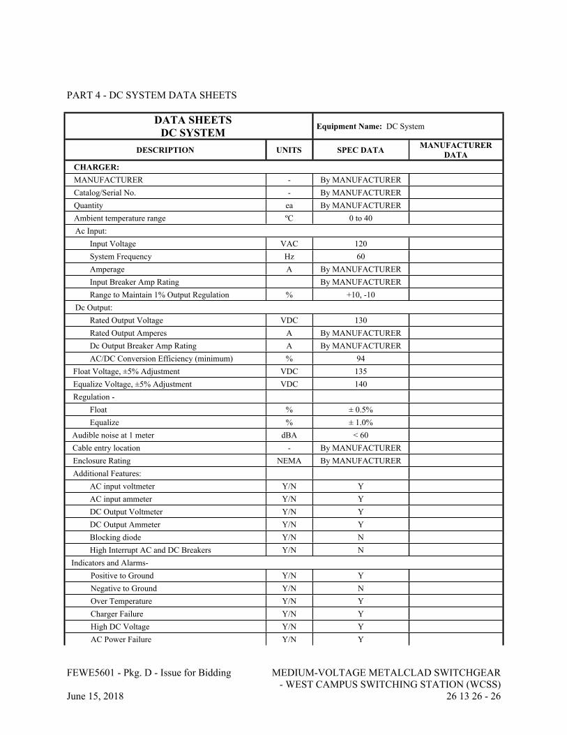
FEWE5601 - Pkg. D - Issue for Bidding MEDIUM-VOLTAGE METALCLAD SWITCHGEAR - WEST CAMPUS SWITCHING STATION (WCSS)
June 15, 2018 26 13 26 - 26
PART 4 - DC SYSTEM DATA SHEETS
DATA SHEETSDC SYSTEM
Equipment Name: DC System
DESCRIPTION UNITS SPEC DATA MANUFACTURER DATA
CHARGER:MANUFACTURER - By MANUFACTURERCatalog/Serial No. - By MANUFACTURERQuantity ea By MANUFACTURERAmbient temperature range ºC 0 to 40Ac Input:
Input Voltage VAC 120System Frequency Hz 60Amperage A By MANUFACTURERInput Breaker Amp Rating By MANUFACTURERRange to Maintain 1% Output Regulation % +10, -10
Dc Output:Rated Output Voltage VDC 130Rated Output Amperes A By MANUFACTURERDc Output Breaker Amp Rating A By MANUFACTURERAC/DC Conversion Efficiency (minimum) % 94
Float Voltage, ±5% Adjustment VDC 135Equalize Voltage, ±5% Adjustment VDC 140Regulation -
Float % ± 0.5%Equalize % ± 1.0%
Audible noise at 1 meter dBA < 60Cable entry location - By MANUFACTUREREnclosure Rating NEMA By MANUFACTURERAdditional Features:
AC input voltmeter Y/N YAC input ammeter Y/N YDC Output Voltmeter Y/N YDC Output Ammeter Y/N YBlocking diode Y/N NHigh Interrupt AC and DC Breakers Y/N N
Indicators and Alarms-Positive to Ground Y/N YNegative to Ground Y/N NOver Temperature Y/N YCharger Failure Y/N YHigh DC Voltage Y/N YAC Power Failure Y/N Y
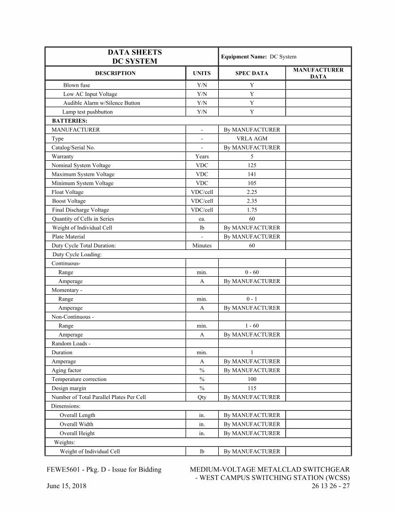
FEWE5601 - Pkg. D - Issue for Bidding MEDIUM-VOLTAGE METALCLAD SWITCHGEAR - WEST CAMPUS SWITCHING STATION (WCSS)
June 15, 2018 26 13 26 - 27
DATA SHEETSDC SYSTEM
Equipment Name: DC System
DESCRIPTION UNITS SPEC DATA MANUFACTURER DATA
Blown fuse Y/N YLow AC Input Voltage Y/N YAudible Alarm w/Silence Button Y/N YLamp test pushbutton Y/N Y
BATTERIES:MANUFACTURER - By MANUFACTURERType - VRLA AGMCatalog/Serial No. - By MANUFACTURERWarranty Years 5Nominal System Voltage VDC 125Maximum System Voltage VDC 141Minimum System Voltage VDC 105Float Voltage VDC/cell 2.25Boost Voltage VDC/cell 2.35Final Discharge Voltage VDC/cell 1.75Quantity of Cells in Series ea. 60Weight of Individual Cell lb By MANUFACTURERPlate Material - By MANUFACTURERDuty Cycle Total Duration: Minutes 60Duty Cycle Loading:Continuous-
Range min. 0 - 60Amperage A By MANUFACTURER
Momentary -Range min. 0 - 1Amperage A By MANUFACTURER
Non-Continuous - Range min. 1 - 60Amperage A By MANUFACTURER
Random Loads - Duration min. 1Amperage A By MANUFACTURERAging factor % By MANUFACTURERTemperature correction % 100Design margin % 115Number of Total Parallel Plates Per Cell Qty By MANUFACTURERDimensions:
Overall Length in. By MANUFACTUREROverall Width in. By MANUFACTUREROverall Height in. By MANUFACTURER
Weights:Weight of Individual Cell lb By MANUFACTURER
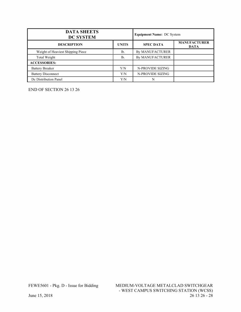
FEWE5601 - Pkg. D - Issue for Bidding MEDIUM-VOLTAGE METALCLAD SWITCHGEAR - WEST CAMPUS SWITCHING STATION (WCSS)
June 15, 2018 26 13 26 - 28
DATA SHEETSDC SYSTEM
Equipment Name: DC System
DESCRIPTION UNITS SPEC DATA MANUFACTURER DATA
Weight of Heaviest Shipping Piece lb. By MANUFACTURERTotal Weight lb. By MANUFACTURER
ACCESSORIES:Battery Breaker Y/N N-PROVIDE SIZINGBattery Disconnect Y/N N-PROVIDE SIZINGDc Distribution Panel Y/N N
END OF SECTION 26 13 26
FEWE5601 - Pkg. D - Issue for Bidding PACKAGED ENCLOSED MEDIUM-VOLTAGE METALCLAD SWITCHGEAR - MAIN
CAMPUS SWITCHING STATION (MCSS)June 15, 2018 26 13 28 - 1
SECTION 26 13 28 - PACKAGED ENCLOSED MEDIUM-VOLTAGE METALCLAD SWITCHGEAR - MAIN CAMPUS SWITCHING STATION (MCSS)
PART 1 - GENERAL
1.1 RELATED DOCUMENTS
A. Drawings and general provisions of the Contract, including General and Supplementary Conditions and Division 01 Specification Sections, apply to this Section.
1.2 SUMMARY
A. Section includes:
1. Complete switchgear system, including:
a. Main Campus Switching Station Switchgear (MCSS Bus-A & MCSS Bus-B).b. Controls and Relaying.c. Communications: Ethernet Switches, I/O module & fiber optic patch panel. d. Outdoor Switchgear Enclosure.e. Auxiliaries.f. AC and DC Distribution Systems.
1.3 REFERENCES
A. All equipment shall meet or exceed the latest editions of the applicable standards listed below.
1. ASTM (ASTM): ASTM B187 "Standard Specification for Copper, Bus Bar, Rod, and Shapes".
2. Institute of Electrical and Electronics Engineers, Inc. (IEEE):3. ANSI/IEEE C37.010 - "Application Guide for AC High Voltage Circuit Breakers >
1000VAC Rated on a Symmetrical Current Basis" (copyrighted by IEEE, ANSI approved).
4. IEEE C37.2 - "Electrical Power System Device Function Numbers, Acronyms, and Contact Designations".
5. IEEE C37.20.2 - "Metal Clad Switchgear" IEEE C37.20.7 - "Guide for Testing Medium-Voltage Metal-Enclosed Switchgear Rated up to 38kV for Internal Arcing Faults.
6. IEEE C37.21 - "Control Switchboards" (copyrighted by IEEE, ANSI approved).7. ANSI/IEEE C37.90 - "Relays and Relay Systems Associated with Electric Power
Apparatus" (copyrighted by IEEE, ANSI approved).8. IEEE C57.13 – “IEEE Standard Requirements for Instrument Transformers”9. IEEE C37.90 - Relays and Relay Systems Associated with Electric Power Apparatus.10. IEEE-1613: Environmental and Testing Requirements for Communications Networking
Devices Installed in Electric Power Substations
FEWE5601 - Pkg. D - Issue for Bidding PACKAGED ENCLOSED MEDIUM-VOLTAGE METALCLAD SWITCHGEAR - MAIN
CAMPUS SWITCHING STATION (MCSS)June 15, 2018 26 13 28 - 2
11. IEEE-C37.90: Relays and Relay Systems Associated with Electric Power Apparatus12. IEC 60068-2: Environmental Tests13. IEC 60255-21: Vibration and shock Tests14. IEC-60255-22: RFI and Interference Tests15. IEC 60825-1: Laser (LED) Safety16. IEC-61000-4: Electromagnetic Compatibility17. IEC-61000-6: Electromagnetic Compatibility18. IEC-61850 Series: Communication Networks and Systems for Power Utility Automation19. CFR 47 Parts 15 and 18, Code of Federal Regulations - Federal Communications
Commission (FCC) Rules and Regulations pertaining to EMI
B. National Electrical Contractors Association (NECA): NECA 430-2016 Standard for Installing and Maintaining Medium-Voltage Switchgear
C. National Electrical Manufacturers Association (NEMA):
1. NEMA SG 4 - "Alternating Current High Voltage Circuit Breakers".2. NEMA C37.55 "Conformance Test Procedures for Switchgear – Medium Voltage Metal
Clad Assemblies".
D. National Fire Protection Association (NFPA):
1. NFPA 70 - "National Electrical Code" (copyrighted by NFPA, ANSI approved) hereinafter referred to as NEC.
2. NFPA 70B - "Recommended Practice for Electrical Equipment Maintenance" (copyrighted by NFPA, ANSI approved).
3. NFPA 70E – “Standard for Electrical Safety In The Workplace” (copyrighted by NFPA, ANSI approved) hereinafter referred to as NEC.
4. Underwriters Laboratories, Inc. (UL):5. UL 486A-B - "UL Standard for Safety Wire Connectors 6. UL 1236 - "UL Standard for Safety Battery Chargers for Charging Engine-Starter
Batteries" (copyrighted by UL, ANSI approved).
1.4 SITE CONDITIONS
A. Live Loads
1. Roof Live Uniform Load: 20 PSF
B. Wind Loads
1. Ultimate Wind Speed (3 Second Peak Gust) - Vult = 115MPH2. Risk Category = II3. Importance Factor – Iw = 1.04. Exposure – C
C. Snow Loads
FEWE5601 - Pkg. D - Issue for Bidding PACKAGED ENCLOSED MEDIUM-VOLTAGE METALCLAD SWITCHGEAR - MAIN
CAMPUS SWITCHING STATION (MCSS)June 15, 2018 26 13 28 - 3
1. Risk Category = II2. Ground Snow Load – Pg = 10 PSF3. Flat Roof Snow Load – Pf = 7 PSF4. Importance Factor – Is = 1.05. Exposure – Ce = 1.06. Thermal Factor – Ct = 1.0
D. Seismic Loads
1. Risk Category = II2. Seismic Importance Factor – I =1.03. Mapped Spectral Response Accelerations – Ss = 0.279 g, S1=0.106 g4. Site Class – D5. Spectral Response Coefficient – Sds = 0.293 g, Sd1=0.167 g6. Seismic Design Category C
1.5 SUBMITTALS
A. Product Data: Submit manufacturer's product data showing material and equipment proposed.
1. Product data shall include, but shall not be limited to, the following equipment and materials:
a. Circuit breakers.b. Buses.c. Transformers.d. Panelboards.e. Control, Relaying, and Metering equipment.f. HMI Panel, door mounted, with programming software.g. Networking equipment.h. Wire and cable.i. Batteries, charger, and battery rack.
2. The ratings for the equipment shall include, but shall not be limited to, the following:
a. Voltages.b. Frequency.c. Number of phases.d. Current, continuous and interrupting.e. Accuracy.f. Power requirements.g. Power losses at full and half load.
3. Physical characteristics and materials shall include, but shall not be limited to, the following:
a. Size/dimensions.b. Weight.
FEWE5601 - Pkg. D - Issue for Bidding PACKAGED ENCLOSED MEDIUM-VOLTAGE METALCLAD SWITCHGEAR - MAIN
CAMPUS SWITCHING STATION (MCSS)June 15, 2018 26 13 28 - 4
c. Finishes.
4. Accessories shall include, but shall not be limited to, the following:
a. Indicating lights.b. Terminal blocks.c. Test switches.d. Auxiliary contacts.
B. Shop Drawings: Submit complete shop drawings as required to determine acceptability. Shop drawings shall include, but shall not be limited to, the following:
1. Bill of materials and components.2. Outline drawings, dimensioned plans, elevations, sections, supports, materials, and
finishes, showing weights, bolt spacing, clearances, tolerances, conduit, cable entrances, terminal strips, and methods of assembly.
3. Cubicle and compartment layouts.4. Bus and circuit breaker ratings and arrangements including dimensions of bus bars,
including the ground bus, and the type and spacing of bus supports.5. Nameplate details (size and legend).6. Detail drawings showing incoming line terminations and location of cable termination
with dimensions. Shop drawings shall verify sufficient conductor space and compliance with codes.
7. Shipping arrangements and packaging methods.
C. Wiring Diagrams: Submit with shop drawings, specific wiring diagrams and instructions for equipment, controls, or devices which are furnished or which are to be field wired and connected. The diagrams and instructions shall not be of a general or typical nature, but shall be applicable only to this Project. Include identical diagrams and instructions to install the equipment as are included in the operating and maintenance manuals. Wiring diagrams shall include, but shall not be limited to, the following:
1. Single and three line diagrams.2. Electrical wiring diagrams for communications, instrumentation, metering and relaying.3. Control schematic diagrams including interface diagrams having terminals identified for
remote equipment.4. Wiring diagrams for switchgear showing connections to distribution branches.5. Wiring diagrams for communication sections showing field connections by others.
D. Calculations: Submit calculations supporting the selection of the devices and components furnished. Devices requiring submittal of calculations shall include, but shall not be limited to, the following:
1. Instrument Transformers: Sizes and burdens.2. Control power transformers.3. DC Power System components.4. Low Voltage AC Power system components.5. Lighting foot candle calculations.
FEWE5601 - Pkg. D - Issue for Bidding PACKAGED ENCLOSED MEDIUM-VOLTAGE METALCLAD SWITCHGEAR - MAIN
CAMPUS SWITCHING STATION (MCSS)June 15, 2018 26 13 28 - 5
E. Operating and Maintenance Manuals: Prepare and deliver complete operating and maintenance manuals. Provide information pertinent to the equipment for preventive maintenance and for replacement of expendable components. Manuals shall include the items listed below and other information recommended by the manufacturer:
1. Manufacturer's published information.2. Set of shop drawings.3. Wiring diagrams of electrical components.4. Acceptance test reports.5. Electrical characteristics and ratings of components.6. Recommended spare parts list.7. Maintenance Procedures 8. Complete list of parts.9. Factory Test Data: Provide factory test data certified by a professional engineer that
switchgear test results fulfill the specified requirements.
F. Submit with proposals
1. Preliminary Data Sheets.2. Preliminary one-line diagrams.3. Elevations showing overall dimensions, weights, and layout of accessories.4. Bill of materials for each cubicle with manufacturer reference number.5. Complete list of spare parts and special tools that will be furnished with equipment,
which are included in lump sum price. In addition, provide itemized price listing of recommended spare parts with prices guaranteed for at least 1 year after acceptance of equipment.
6. Complete data and listing of items requiring field assembly and installation and special equipment required.
7. Manufacturer’s ISO certification certificate.8. Location of manufacture of each unit.9. Preliminary electrical oneline diagram of proposed DC System.
G. Submit after Notice of Award
1. Certified Data Sheets.2. Master drawing index.3. One-line diagrams.4. Three-line diagrams.5. Conduit entry and exit locations.6. Schematic diagrams and elementary wiring and connection diagrams.7. Control and equipment wire terminations, and terminations for field wiring showing all
interconnecting field wiring between switchgear, control panels, transformers, and demarcation panels.
8. Material lists with manufacturer reference numbers.9. Ratings and nameplate schedules.10. Elevations showing overall dimensions, weights, and layout of accessories.11. Switchgear cross-sections to indicate interior bus arrangement and equipment locations.12. Floor plan drawing shown location for anchor bolts and leveling channels.13. Location of floor and pad openings required for entrance of conduits and cables.
FEWE5601 - Pkg. D - Issue for Bidding PACKAGED ENCLOSED MEDIUM-VOLTAGE METALCLAD SWITCHGEAR - MAIN
CAMPUS SWITCHING STATION (MCSS)June 15, 2018 26 13 28 - 6
14. Performance curves for each ratio and type of current and voltage transformer.15. Detailed instruction books for all equipment, meters, and each type of relay.16. Detailed characteristics of surge arresters.17. Detailed procedures and processes for factory acceptance tests.18. Certified test report of manufacturer's standard production tests.19. Heating load and cooling load calculations.20. Battery sizing calculation.
1.6 SYSTEM DESCRIPTION
A. Provide complete free standing assembly as shown on drawings to house equipment consisting of switchgear (circuit breakers, protective relays and control devices), AC and DC Power systems, HVAC, Ethernet switches for communications and other accessories.
B. Metalclad switchgear shall be provided with remote closed door racking provisions for all circuit breakers. Closed door racking provisions for circuit breakers shall not require the end user to install any extension arms through the door for operation of the racking mechanism. A motorized racking device shall be provided for use with this option.
1.7 QUALITY ASSURANCE
A. After fabrication, perform an operational test in the manufacturer's plant to check out the entire system before delivery. Include calibration of meters, operation of temperature sensors, relays and device settings; control wiring, including polarity, of all instrument transformers; complete assembly and control function testing. Submit certified written test reports.
B. Provide written data certifying a minimum of ten years' experience in the building of metal clad switchgear and at least ten successful working installations of this type of equipment.
1.8 WARRANTY
A. The manufacturer shall provide a warranty against defects in material and workmanship for a period of 3 years from the date of factory acceptance testing. During the first 3 years of operation, there shall be no cost to the Owner for any corrective repairs. Individual component warranties may be longer and will be coordinated with manufacturer after the first 3 years of operation.
PART 2 - PRODUCTS
2.1 MANUFACTURERS
A. Powell Industries.
B. Square D.
FEWE5601 - Pkg. D - Issue for Bidding PACKAGED ENCLOSED MEDIUM-VOLTAGE METALCLAD SWITCHGEAR - MAIN
CAMPUS SWITCHING STATION (MCSS)June 15, 2018 26 13 28 - 7
C. GE.
D. Eaton/Cutler Hammer.
E. Siemens
2.2 GENERAL
A. Standards: The switchgear shall consist of stationary steel structures containing vacuum type, drawout power circuit breakers with digital relay protection devices, instruments, buses, and system control devices. The switchgear shall be UL approved as service entrance equipment and designed, built, and tested in accordance with ANSI/IEEE and NEMA standards for metal clad switchgear.
B. Unless otherwise specified this equipment is intended for use in ambient temperatures that do not exceed a maximum of 40°C (104°F) or a minimum of -30°C (-22°F).
C. This equipment is intended for use in an area where the elevation is less than 3300 feet above sea level. Above 3300 feet a de-rating factor as prescribed by ANSI standards will apply.
D. The switchgear and Building Assembly shall be suitable, tested and certified to meet all applicable seismic requirements of the 2015 South Carolina Building Code.
2.3 SWITCHGEAR ENCLOSURE
A. Vertical Sections: The stationary enclosure shall consist of self supported, vertical sections housing circuit breakers, buses, cables, system controls, and accessories. The vertical sections shall be bolted together to form a rigid metal clad switchgear assembly. The vertical sections shall have separate front compartments for circuit breakers and controls, and rear compartments for buses and outgoing cables. The vertical section framework shall consist of a welded and bolted steel frame with reinforcing gussets. Assembled to this framework shall be doors and top, side, and rear covers.
B. Base: The vertical sections shall be supported on a steel base assembly consisting of die formed steel and commercial channel welded and bolted together. The base shall provide a rigid support for the switchgear assembly.
C. Each front compartment door shall be provided with a formed steel hinged door with hand operated door latches and three-point closure. Each door shall have provisions for padlocking.
D. Rear access to cable compartments and CPT sections shall be integrated into the overall switchgear enclosure package; reference 2.18 this section. A second interior door or panel interior to rear access doors as described in section 2.18 will not be accepted.
E. Lifting Equipment: Circuit breaker lifting equipment shall be provided to remove circuit breakers. The equipment shall be a portable lifting device manufactured by the equipment supplier. Qty. = 1 for MCSS location.

FEWE5601 - Pkg. D - Issue for Bidding PACKAGED ENCLOSED MEDIUM-VOLTAGE METALCLAD SWITCHGEAR - MAIN
CAMPUS SWITCHING STATION (MCSS)June 15, 2018 26 13 28 - 8
F. Breaker Compartment: The front compartment of the switchgear shall contain the drawout circuit breakers. Each vertical feeder section shall provide the space to accommodate two circuit breakers if frame size allows. Each circuit breaker shall be mounted in a barriered cell. Breaker compartments for future use as indicated as "equipped breaker cell" on the drawings, shall be fully equipped with drawout assemblies and current carrying parts required to permit completion of the unit by the addition of only a circuit breaker. Provide a LED light source in the top and bottom of the front and rear compartments operated by a light switch on the door.
G. Cable Compartment: The cable compartment shall be sized to accommodate incoming and outgoing cables or busway required for each vertical section. The bus compartment shall be segregated from the feeder cable compartment by means of grounded metal barriers. The cable compartment shall also contain a copper ground bus bolted directly to the switchgear frame. The incoming and tie breaker feeder cable compartments (Section Types 1, 2, and 3) shall be capable of terminating up to 6-750 kcmil, 15 kV, MV-105, 133% insulated conductors. All other sections (section type 4) shall be capable of terminating up to 2-500 kcmil, 15 kV, MV-105, 133% insulated conductors. The depth of the finished equipment shall be sufficient to allow for entrance, bending, and termination of power cables. Individual units shall be provided for bottom entrance. A minimum of 26 inches of vertical clearance between terminal pads and the cable entrance shall be provided. Two high sections shall provide a separate chute or channel to isolate and route bottom entry cables to upper compartments.
H. Each switchgear cubicle shall have, at a minimum, 11-gauge sheet steel side panels. Construction shall provide two (2) steel sheets between adjacent sections so as to minimize the chance of fault propagation between sections.
I. Provide electric heaters in each switchgear compartment.
1. Voltage: 240-volt, single-phase operated at 120V.2. Watts: As required to maintain temperature.3. Provide thermostat for each compartment with minimum set point of 50°F.
J. The switchgear shall be capable of extension from opposite end of communication/remote I/O section at a future date without modification to the existing structural members.
K. Control Compartment: Each Vertical Section shall include a dedicated and isolated control compartment. Upper and lower or Side by Side control compartments shall be isolated from each other with each control compartment dedicated to its associated breaker. Provide a LED light source in the compartment and a switch accessible from the exterior of the gear. The Control Compartment shall house the respective relays, indicating lights, test switches, and other required auxiliary equipment for the respective breaker.
L. Communications/Remote I/O Section: Each Switchgear shall include a dedicated and isolated section for the communications Ethernet switches, door mounted HMI, fiber optic patch panel, and remote I/O module; additional equipment, such as firewalls, controllers, servers, network time clock, will be added later by the SCADA Contractor. These devices will be 19-inch rack configuration and the communication section is to include supports for mounting same. Ethernet cables and communication cables from protective relays and other equipment shall be routed to the Ethernet switches and I/O module separate from the power bus and cables. The section shall be accessible from the side of the gear. Provide overhead cable tray or wireway
FEWE5601 - Pkg. D - Issue for Bidding PACKAGED ENCLOSED MEDIUM-VOLTAGE METALCLAD SWITCHGEAR - MAIN
CAMPUS SWITCHING STATION (MCSS)June 15, 2018 26 13 28 - 9
with 50% spare capacity for manufacturer provided and field installed communication cabling between Bus A and Bus B. Provide tray or conduit for remote I/O point cabling.
M. Finish: Indoor: The switchgear enclosure parts shall be given an iron phosphate pretreatment, a primer, and a coat of baked enamel. After assembly, a finish coat of air drying enamel of gray color (ANSI #61) shall be applied to exterior surfaces.
2.4 BUSES
A. General: The bus structure shall consist of copper bus with silver plated bolted connections mounted on track resistant glass polyester and porcelain insulators. The bus system shall be insulated with fluidized bed epoxy insulation. The copper bus shall be of sufficient size to limit the temperature rise as specified in ANSI/IEEE C37.20.2. Bus bracing shall be adequate to withstand mechanical and thermal stresses due to short circuits at least equal to those specified for the main circuit breaker. Provide ASTM B 187 copper throughout the switchgear. Bus joints shall be provided in each unit. The temperature rise of the bus and connections shall be in accordance with ANSI standards and documented by design test.
B. Power bus orientation shall be A-B-C top to bottom, front to back, and left to right when viewed from the front of the switchgear.
C. Phase Buses: Provide continuous phase buses as sized on the drawings for the full length of the switchgear lineup excluding the communications/remote I/O section. Tap buses shall have the same ampacity as the section design rating.
D. Neutral Bus: Provide continuous fully sized neutral bus for the full length of the switchgear lineup excluding the communications/remote I/O section.
E. Ground Bus: Provide a minimum size ground bus of 2 inch by 1/4 inch cross sectional area, for the full length of the switchgear lineup excluding the communications/remote I/O section. Provide compression indent type lugs to accept No. 4/0 AWG copper cable.
F. Connections: Bus connections for shipping breaks, extension, and taps shall be silver plated bolted pressure joints. Provide insulating boots for bus joints and cable terminations. Cable termination boots suitable for 15kV 750kcmil cable (4 cables / phase). Selection of boots to be based on installed cable diameter (type Cooper BOL-T or equal).
G. Safety Shutters: The switchgear shall be furnished with grounded shutters or a means by which to cover the stationary primary disconnects when the breaker is moved from the connected position.
2.5 POWER CIRCUIT BREAKERS
A. General: The power circuit breakers shall be medium voltage, drawout, vacuum circuit breaker type, having electrically charged, stored energy mechanisms which shall be mechanically and electrically trip free. Provision shall be included for manual charging of the operating
FEWE5601 - Pkg. D - Issue for Bidding PACKAGED ENCLOSED MEDIUM-VOLTAGE METALCLAD SWITCHGEAR - MAIN
CAMPUS SWITCHING STATION (MCSS)June 15, 2018 26 13 28 - 10
mechanism. The breakers shall be mounted on a rigid, self-aligning drawout mechanism. The breaker shall be removable and shall roll out on horizontal guide rails.
B. Breaker Positions: Each drawout breaker shall be provided with four position operation. Each position shall be clearly identified by an indicator on the circuit breaker front panel.
1. Connected Position: In the connected position, the main line and load terminals and auxiliary control contacts and circuitry shall be connected and the breaker shall be fully operable. The breaker shall be interlocked to automatically trip before racking into or out of position.
2. Test Position: In the test position, the circuit breaker auxiliary control contacts and circuitry only shall be connected to permit testing of the complete control system without actually connecting the sources or loads to the main bus.
3. Disconnected Position: In the disconnected position, main and auxiliary control contacts and circuitry shall be completely disconnected.
4. Remove Position: In the remove position circuitry shall be disconnected and the breaker can be removed from the compartment.
C. Operating Mechanism:
1. The breaker operating mechanism shall be the two step, stored energy quick make, quick break type. The close operation of the circuit breaker shall automatically charge the opening springs. The operating mechanism shall be front located and designed for servicing without removing breaker from rails.
2. Manual charging of the breaker shall be possible by means of a manual charging lever,3. Close trip indicator, mechanically connected to the breaker, shall be provided to indicate
the breaker position.4. Circuit breaker operating mechanism shall be completely trip free both mechanically and
electrically. Mechanical tripping of a closed circuit breaker shall be possible with the front cubicle door closed.
5. A contact wear gap indicator shall be provided and shall be easily visible.
D. Mechanical Interlocks: The switchgear shall be provided with mechanical interlocks to:
1. Prevent moving the breaker to or from the connected position when the breaker contacts are in the closed position.
2. Prevent closing the breaker unless the primary disconnects are fully engaged or the breaker is in the test or disconnect position.
3. Automatically discharge the closing springs when the breaker is moved between the connected and test positions or when it is inserted into or withdrawn from the compartment.
E. Mechanism Operator Cell Breaker Auxiliary Switches: Each circuit breaker shall be equipped with mechanism operated auxiliary switches which shall operate when the breaker is open or closed. These switches shall be enabled in the operating and test position. Provide four normally open and four normally closed contacts in addition to those required for the circuit breaker operating mechanism and control schemes. All contacts to be wired to accessible terminal blocks for customer use.

FEWE5601 - Pkg. D - Issue for Bidding PACKAGED ENCLOSED MEDIUM-VOLTAGE METALCLAD SWITCHGEAR - MAIN
CAMPUS SWITCHING STATION (MCSS)June 15, 2018 26 13 28 - 11
F. Truck Operated Cell Switches: Each breaker compartment shall be equipped with cell mounted switches which shall operate when the circuit breaker is levered into or out of the operating position. Provide two six stage switches, each six stage switch shall provide six normally open and six normally closed contacts. All contacts to be wired to accessible terminal blocks for customer use.
G. A steel interference plate shall be mounted in the bottom of each circuit breaker cell assembly which only allows a higher rated circuit breaker (voltage, current, interrupting rating) to be inserted into a lower rated cell assembly.
H. For operator safety the circuit breaker shall have provision for padlocking it in the disconnected position.
I. Circuit breaker shall have the capability of racking between the connected, disconnected and test positions with the cubicle door closed.
J. Power circuit breakers shall be shipped and packaged separately from the switchgear structure.
2.6 RATING AND PERFORMANCE REQUIREMENTS POWER CIRCUIT BREAKERS
A. Metal Clad Switchgear Ratings and Requirements for IEEE C37.06 Table 1 rated breakers:
1. System Voltage: 12,470 volts.2. Nominal rms Rated Voltage Class: 15,000 volts.3. Frequency: 60 hertz.4. Phase: Three.5. System: Multi-point, solid grounded wye, three phase, four wire.6. Rated Voltage Range Factor (k): 1.0.7. Rated Continuous Current:
a. Main Breakers: Per Drawings.b. Feeder Breakers: Per Drawings.
8. Interrupting time: 3 Cycles9. Rated Short Circuit RMS Current at Rated Maximum Voltage:
a. 36kA
10. Momentary Withstand and Closing and Latching Capability:
a. 62kA RMS and 104kA peak
11. Low Frequency Withstand Voltage Insulation Level: 36 kV.12. Impulse Withstand Voltage Insulation Level: 95 kV.13. Control Voltage: 125 volts DC for close, trip, and spring motor operation.14. Percent Spare Terminal Blocks: 20 percent.15. Finish Color: Gray ANSI #61.
FEWE5601 - Pkg. D - Issue for Bidding PACKAGED ENCLOSED MEDIUM-VOLTAGE METALCLAD SWITCHGEAR - MAIN
CAMPUS SWITCHING STATION (MCSS)June 15, 2018 26 13 28 - 12
B. The power circuit breaker ground connection must be capable of carrying the short circuit rating of the circuit breaker for a minimum of 2 seconds and must also be capable of withstanding the peak current value (or 2.7 times the rated short circuit current) of the circuit breaker.
2.7 TYPE 1 SECTIONS
A. The main breaker sections shall each be equipped with the following devices, digital representations of these devices are not acceptable:
1. Breaker status lights:
a. Open (Green).b. Closed (Red).c. Lock Out Healthy (White).d. Locked-out (Amber).
2. Digital power meter. Refer to Paragraph 2.13.3. Main breaker protective relay
a. Basis of Design: SEL-751 (P/N 751201A3A2A0X850631). b. Provide relay inputs and outputs as shown on drawings with a minimum of 25%
spare.4. Customer connection points for 3 external trip signals directly to breaker. 5. One 86 lockout relay for use with 751 relay as shown on drawings.6. Heavy –duty distribution class surge arresters.
a. Maximum Rated Line to Line Voltage (VLL) – 13.1 kV.b. MCOV – 7.65 kV.
7. Current transformers and voltage transformers as specified in paragraph 2.15 and as shown on drawings.
8. Test switches as specified in paragraph 2.16 and as shown on drawings.
2.8 TYPE 2 SECTIONS
A. Each distribution feeder section shall be equipped with the following equipment:
1. Breaker status lights:
a. Open (green)b. Closed (red)c. Lock Out Healthy (White).d. Locked-out (Amber).
2. Bus differential protective relay (BDR) (one per switchgear bus)
a. Basis of Design: SEL-787 (P/N -07870X1A1A0X0X850631)
FEWE5601 - Pkg. D - Issue for Bidding PACKAGED ENCLOSED MEDIUM-VOLTAGE METALCLAD SWITCHGEAR - MAIN
CAMPUS SWITCHING STATION (MCSS)June 15, 2018 26 13 28 - 13
b. Connection to incoming main and feeder CTs as shown on drawings. Include a high-speed lockout relay actuated by the bus differential relay to trip main and feeder breakers.
3. Feeder protective relay (FPR)
a. Basis of Design: SEL-751 (P/N 751201A3A2A0X850631). b. Provide relay inputs and outputs as shown on drawings with a minimum of 25%
spare.
4. Customer connection points for 2 external trip signals directly to breaker. 5. One 86 lockout relay for use with FPR as shown on drawings.6. Heavy –duty distribution class surge arresters.
a. Maximum Rated Line to Line Voltage (VLL) – 13.1 kV.b. MCOV – 7.65 kV.
7. Current transformers and voltage transformers as specified in paragraph 2.15.8. Test switches as specified in paragraph 2.16.
2.9 TYPE 4 SECTIONS
A. Each distribution feeder section shall each be equipped with the following equipment:
1. Breaker status lights:
a. Open (Green).b. Closed (Red).
2. Feeder protective relay (FPR)
a. Basis of Design: SEL-751 (P/N 751201A3A2A0X850631). b. Provide relay inputs and outputs as shown on drawings with a minimum of 25%
spare.
3. Customer connection points for 3 external trip signals directly to breaker. 4. Heavy –duty distribution class surge arresters.
a. Maximum Rated Line to Line Voltage (VLL) – 13.1 kV.b. MCOV – 7.65 kV.
5. Current transformers as specified in paragraph 2.15 and as shown on drawings.6. Test switches as specified in paragraph 2.16 and as shown on drawings.

FEWE5601 - Pkg. D - Issue for Bidding PACKAGED ENCLOSED MEDIUM-VOLTAGE METALCLAD SWITCHGEAR - MAIN
CAMPUS SWITCHING STATION (MCSS)June 15, 2018 26 13 28 - 14
2.10 COMMUNICATIONS/REMOTE I/O SECTION
A. Provide dedicated communications/remote I/O switchgear section to end section of switchgear lineup with two doors accessible from side of switchgear per project drawings. Doors shall swing outward and have key lock handles for lockable three point latching mechanism.
B. Provide grounding bar with cable connection to ground bus in switchgear lineup.
C. Provide 120VAC power feed to cabinet with local circuit breaker and fused terminal blocks for 120VAC power distribution.
D. Provide 125Vdc power feed to cabinet with local circuit breaker and fused terminal blocks for 125Vdc power distribution throughout switchgear.
1. Terminal blocks and wiring to be provided in communication section for external wiring connections as follows: Quantity (10) – twelve pole.
2. Utilize GE/ITI IKU style terminal blocks.3. Switchgear manufacturer to reference DC schematic diagrams for factory required wiring
from switchgear sections to communications section.
E. Provide Remote I/O Unit.
1. Basis of Design: SEL-25162. Digital Inputs: 83. Digital Outputs: 84. Power: 24VDC5. Communications:
a. Protocol: Modbus TCP/IP, DNP3, or Ethernet/IPb. Ports: 2 - RJ45, 10/100Base T
6. Temperature Range: -40 to 75C7. Relative Humidity: 5-95% non-condensing8. Mounting: 19-inchRack9. Software configuration package10. Comply with IEC-61000-3, -4, and -6 for electromagnetic susceptibility and
compatibility.
F. Provide industrial grade managed Ethernet switches (layer 3) per the following:
1. Manufacturers:a. Cisco Industrial Ethernet Series Switches 3000 – 5000 (Basis of Design)b. Hirschmann (A Belden company)c. Moxad. Siemens (Rugged Com)
2. Port Configurations:
a. 8 Fiber Optic, Single-Mode, 1000 Mbps, ring loop
FEWE5601 - Pkg. D - Issue for Bidding PACKAGED ENCLOSED MEDIUM-VOLTAGE METALCLAD SWITCHGEAR - MAIN
CAMPUS SWITCHING STATION (MCSS)June 15, 2018 26 13 28 - 15
b. 24 Copper RJ-45, 10/100 Mbps
3. The SCADA system uses a redundant Ethernet Communications ring such that there is an A and B channel. Multiple Ethernet switches may be connected together to meet or exceed the number and type of required port connections.
4. Security: SNMPv3, HTTPS, MAC for configurable access control and traffic management.
5. Network:
a. Configuration and monitoring software to provide network health and security indicators.
b. Support tagged and untagged VLANs and IEC 61850 GOOSE messages from other traffic.
c. Prioritize traffic per IEEE 802.1pd. Security: restrict access to select end stations via IEEE 802.1X.e. Failover & Redundancy: Enable fast network recovery via IEEE 802/1D, Rapid
Spanning Tree Protocol (RSTP).f. Employ VLAN configurations where appropriate to segregate the traffic of
dissimilar network protocols or equipment
6. Time Synchronization: SNTP server & client per IEEE 15887. Mounting: 19-inch Rack8. Power Supplies: Redundant, Hot-Swappable, 125VDC input.9. Rated for harsh environment:
a. -40F to 185F; device shall have conformal coating applied to circuit boards.b. 5-95% RH
10. Comply with IEEE 1588, IEEE 1613, IEC 61000-4, FCC 15, IEEE C37.90, IEEE 802.1X and IEC 61850 standards.
G. Provide the following accessories:
1. Doorstop kit to secure door in open position.2. Metal data pocket to provide place to store documentation inside enclosure.
H. Electrical:
1. Provide a 120VAC power strip with 8 receptacles for associated equipment.2. Provide internal cabling management system for routing and protection of wiring.3. Provide LED lighting package with door activate switch.
I. Provide engraved nameplates per drawings.
2.11 LOCKOUT RELAYS
A. Electroswitch Type LOR Series 24, decks as required per drawings and to achieve necessary spare contacts, suitable for control power supplied. Integral LED’s will not be accepted.
FEWE5601 - Pkg. D - Issue for Bidding PACKAGED ENCLOSED MEDIUM-VOLTAGE METALCLAD SWITCHGEAR - MAIN
CAMPUS SWITCHING STATION (MCSS)June 15, 2018 26 13 28 - 16
1. Rated operating trip voltage shall be low enough to allow coil operation at 75% of rated voltage.
2. Contacts: Minimum 10 N.C. and 10 N.O., wired to terminal blocks located in auxiliary compartments for interlock provisions and owner’s use.
2.12 ELECTRONIC PROTECTIVE RELAYS
A. Relays: Electric power apparatus relays shall be utility grade specifically designed for power switchgear. Protective relay shall be solid state type, meeting surge withstand requirements of ANSI/IEEE C37.90. Relay device number shall be in accordance with IEEE C37.2.
B. Relay Types: Protective relays shall be as specified within breaker type classification specification sections in this document. The relays shall be capable of directly interfacing with the SCADA system per IEC 61850. The relays shall meet the following performance requirements:
1. Standards: Shall meet applicable IEEE C37.90 standards.2. Temperature Range: 28 degrees F to 131 degrees F (operating), 25 degrees F to 158
degrees F (storage).3. Alarm Contact: Normally closed contact (contact closed if loss of power or self check
failure).4. The relays shall transmit metering, event, alarm and status information to SCADA
system.
C. Manufacturer to supply a minimum of three (3) licenses for all software required to communicate with and set relays as well as analyze oscillography obtained from event reports. Fully optioned software for advanced analysis and setting capabilities is required. Minimal freeware versions of software will not be accepted.
2.13 DIGITAL POWER MONITOR
A. Digital Main Meters (DMM):
1. Microprocessor-based, 3-phase, revenue quality power monitor unit with digital display and touch keys, suitable for local and remote display of power measurements. Unit shall have nonvolatile memory and on-board clock and calendar
2. UL listed; IEEE 37.90.1 for surge withstand and fast transient voltage.3. Parameter accuracy tolerances refer to one-cycle performance in accordance with ANSI
C12.1 for revenue metering. 4. Parameters measured (minimum):
a. Volts line-line for all phases.b. Volts line-neutral for all phases.c. Phase current for each phase and neutral.d. Kilowatts each phase and total.e. Kilovars each phase and total.f. Kilovolt-amperes each phase and total.

FEWE5601 - Pkg. D - Issue for Bidding PACKAGED ENCLOSED MEDIUM-VOLTAGE METALCLAD SWITCHGEAR - MAIN
CAMPUS SWITCHING STATION (MCSS)June 15, 2018 26 13 28 - 17
g. Kilowatt-hours total.h. Kilovar-hours total.i. Time and date tagged peak demand amperes.j. Time and date tagged peak demand kilowatts.k. Power factor each phase and total.l. Frequency in Hz.
5. Measurement criteria:
a. Demand kilowatts calculations shall have adjustable window of 5 to 30 minutes.b. Frequency: Suitable for 60 Hz systems.c. Unit shall be suitable for 3- or 4-wire systems.d. Measurements shall be real time RMS values, except peak demand quantities.
6. Inputs:
a. Voltage: 120 volts secondary Voltage transformers.b. Current: 5 amperes secondary current transformers.c. Transformer ratios shall be locally programmable.
7. Display:
a. Configurable LCD screen.
8. Data communication ports: Standard RS-232, RS-485, 10 BaseT Ethernet per IEC 61850 with DNP3.0. Include a fully licensed copy of all configuration and utilization software including all memory maps for Owner’s integration.
9. Mounting:
a. Suitable for recessed or semi-recessed switchboard front instrument panel mounting.
b. Temperature range: -20 to 60ºC.
10. Power supply: 125-volt dc.11. Time synch: Provide IRIG-B input for time synch for sequence of events recording
(minimum of 1 msec time stamping accuracy).12. Certification: NEMA C12.16 approved, meeting ANSI C12.20 Class 0.2 accuracy at
23ºC. Manufacturer must provide accuracy certification for every meter.13. Manufacturer: Square D Powerlogic PM-8000 (P/N METSEP8240).14. Manufacturer to supply a minimum of three (3) licenses for all software required to
communicate with and set meters. Fully optioned software for advanced analysis and setting capabilities is required. Minimal freeware versions of software will not be accepted.
2.14 WIRING
A. Type: Control, meter, and transducer wiring, except hinge wire and current and Voltage transformer secondary leads, shall be Type SIS, 90 degrees C (194 degrees F), copper, single

FEWE5601 - Pkg. D - Issue for Bidding PACKAGED ENCLOSED MEDIUM-VOLTAGE METALCLAD SWITCHGEAR - MAIN
CAMPUS SWITCHING STATION (MCSS)June 15, 2018 26 13 28 - 18
conductor 600 volt, Class B stranding, No. 14 AWG minimum. Wiring over door hinges or other locations where leads may be subject to flexing shall employ the use of No. 14 AWG, 41 strand, extra flexible copper conductors. Current transformer secondary leads shall be No. 10 AWG minimum and shall be wired with crimp type solderless terminals. Ethernet communication cables shall meet requirements of Section 25 05 00.
B. Terminations: Wiring for control and relaying circuits requiring external connections and unused terminals of relays and auxiliary contacts shall be brought to conveniently located terminal blocks. The terminal blocks shall be of the screw type to accommodate ring tongue, crimp type, solderless connections. Wiring shall not have more than two wires connected to a terminal point. External wiring termination points for Owner’s connections shall be arranged for one wire to each terminal point. Twenty percent (20%) spare terminal points shall be provided. Terminal block shall be furnished and installed at switchgear splits or shipping splits for wire. CT leads shall be wired to short circuiting type terminal blocks. Utilize GE/ITI IKU style terminal blocks.
C. Wire Markings: Every wire shall have source and destination identification which shall be visible at each termination point. Wire markers shall be heat shrinkable or plastic interlocking sleeve type. Cloth wire markers are not acceptable. Spare contacts on relays, lockout relays, control switches, etc., shall be assigned wire numbers, wired to terminal blocks, and labeled accordingly.
D. Methods: Hinge wiring shall be arranged so that any twisting shall take place in the longitudinal plane of the conductor, rather than across the conductor. Control wires shall be armored or enclosed in grounded metal troughs where they pass through primary compartments.
E. All wiring external to switchgear shall be routed in EMT conduit (3/4” minimum), cable tray, or wireway
F. Communications and control wiring in between switchgear shall be via aluminum ladder style cable tray. Vertical raceway from cable tray down to switchgear or respective jbox may be conduit or cable tray.
G. 208Y/120 VAC power and lighting wiring shall be THWN-2 in conduit. Conductor jacket shall be color coded according to phase as follows:
1. Phase A – Black2. Phase B – Red3. Phase C – Blue4. Neutral – White w/ color coded tracer according to phase conductor.5. Ground – Green.
2.15 INSTRUMENT TRANSFORMERS
A. General: Instrument transformers shall be the type for switchgear installations. Transformers and associated components shall be in a drawout section. Instrument transformers shall be provided with test blocks.
FEWE5601 - Pkg. D - Issue for Bidding PACKAGED ENCLOSED MEDIUM-VOLTAGE METALCLAD SWITCHGEAR - MAIN
CAMPUS SWITCHING STATION (MCSS)June 15, 2018 26 13 28 - 19
1. Voltage Transformers
a. Voltage transformers and associated fuse assemblies shall be installed in drawout assemblies so that they may be readily disengaged from the power bus.
b. Where physical size restrictions do not allow the Voltage transformer to be mounted in a drawout assembly, the voltage transformer may be stationary mounted with the fuses only mounted in the drawout unit. The appropriate interlocks shall be provided to insure maximum operator safety.
c. When moved to the withdrawn position, the transformer drawout unit shall automatically ground the transformer primary windings and the fuses. A visible indication of positive ground is required. The ground may be a momentary or sweeping action that occurs as the unit moved out of the connected position.
d. Voltage transformers shall have 120 volt secondaries unless otherwise specified.e. Voltage transformers shall have an accuracy rating comparable to the metering
equipment and a burden capacity equal to twice the initial load.f. Current limiting fuse protection shall be provided on the primary side of each
Voltage transformer.g. Voltage transformers shall be designed to withstand the basic impulse level of the
switchgear.h. ANSI accuracy class of 0.15 with burdens of W, X, and Y.i. Provide fused access to secondary output of each Voltage transformer in a readily
accessible dedicated terminal block for future connection to synchronization equipment.
2. Current Transformers
a. Unless specified otherwise, the polarity marking shall be toward the circuit breaker.
b. Each current transformer shall be rated to withstand the thermal and mechanical stresses imposed by the short circuit rating of the applied circuit breaker.
c. The secondary termination of current transformers shall be on a shorting terminal block.
d. Current transformers shall have a rated 5 ampere secondary current unless otherwise specified.
e. Current transformers connected to solid state relays shall be single-ratio or multi-ratio and rated as shown on project drawings.
f. Current transformers connected to meters shall be multi-ratio with tap setting as shown on project drawings.
g. Bus differential protective current transformers shall be identical throughout entire bus differential protective circuit. Current transformers used for differential schemes shall not be used for other relaying or metering circuits. Multi-ratio CT’s shall not be used.
h. Metering and relaying accuracy classification shall be suitable for the connected burden.
i. Current transformers, when installed, shall be fully rated for the appropriate voltage class.
j. Current transformers shall have a thermal rating of 2.0. k. Relaying CTs
FEWE5601 - Pkg. D - Issue for Bidding PACKAGED ENCLOSED MEDIUM-VOLTAGE METALCLAD SWITCHGEAR - MAIN
CAMPUS SWITCHING STATION (MCSS)June 15, 2018 26 13 28 - 20
1) Accuracy Class: ANSI 0.3S2) CT Class: C2003) Burden: B1.8
2.16 TEST SWITCHES
A. Provide test switches for metering and for all relays whether or not furnished with drawout cases.
B. Test switches:
1. Knife blade test switch: 10-pole with Voltage and current elements as required, clear cover, ABB "Flexitest" Type FT-1, or equal.
2. Identify each potential and each pair of current switches with a "P" or "C" and phase designation "1," "2," or "3" with an engraved nameplate.
3. All trip circuit test switches shall be RED in color and labeled with an engraved nameplate according to relay output.
4. All nameplates shall be affixed to switchgear structure utilizing screws.
C. Extend 3-phase bus potential circuits to all cubicles and combine with metering current transformer circuits on common test block for use with OWNER’s portable instruments.
D. Lockout test switches: 10 single-pole potential elements, cover, wired in series with coils and normally open contacts of lockout relays, ABB"Flexitest" Type FT-1, or equal.
E. Covers: Black, shallow cover with thumbnuts.
2.17 INDICATING LIGHTS
A. Type: LED as manufactured by Data Display Products, or equal.
B. Red "closed" pilot light wired in series with breaker trip coil, and green "open" pilot light wired in series with auxiliary "b" contact.
C. White “Healthy” lockout relay coil status and amber “lockout trip” indication.
D. Pilot lamps: LED type with sockets, resistors, and round lenses (similar to ET-16), suitable for operation at 125 volts dc.
2.18 OUTDOOR SWITCHGEAR ENCLOSURE
A. Provide prefabricated enclosure suitable for minimal installation lifting (one shipping split only). Enclosure shall house all items specified herein and shall be fully assembled and tested prior to shipment to site as discussed in Part 3.

FEWE5601 - Pkg. D - Issue for Bidding PACKAGED ENCLOSED MEDIUM-VOLTAGE METALCLAD SWITCHGEAR - MAIN
CAMPUS SWITCHING STATION (MCSS)June 15, 2018 26 13 28 - 21
B. Manufacturer to design provisions into the building access to ensure future installation of vertical sections is feasible without dismantling any building shell components.
C. Provide insulated, 14 gauge weatherproof doors with cylinder locks and fire rated panic hardware at each end of prefabricated enclosure. Panic hardware to be Advantex Panic 10 wide style hardware or equal. Door lock hardware shall incorporate 7 pin housing with interchangeable cores as manufactured by Stanley Security Solutions (Best Universal). Owner locksmith will remove Manufacturer provided cores and build and install new cores, keyed as required by Clemson Facilities, after substantial completion.
D. Provide hinged and pad-lockable rear doors for each circuit breaker and auxiliary compartment for cable termination and equipment access. Each cable compartment shall be equipped with IR viewing windows with removable weatherproof covers; two high sections shall include IR viewing windows for each upper and lower compartment. Cable and CPT compartments shall be fully accessible by opening this rear enclosure door; no interior doors or panels covering access to the cable terminations or equipment will be accepted.
E. Provide complete insulation in accordance with following:
1. Roof and walls: Provide minimum of 1" of rigid foam type insulation with minimum 22-gage interior liner panels. Minimum R value is R-11.
2. Floors: Polyurethane spray foam insulation below steel floor plate. Minimum R value is R-11.
3. Insulation system shall be durable, weatherproof, insect-proof, and rodent-proof.
F. Equip enclosure with duplex receptacles with GFI, LED lights, and 3-way switches at each door. Provide minimum level of 50 foot-candles horizontally at 30" above floor level and vertically at 5' from floor level on control panels.
G. Provide outside LED lighting above each entrance and two (2) along each long side of enclosure lineup. Exterior lighting shall be controlled via photoelectric cell. Exterior lighting above personnel doors on end of enclosure shall be equipped with 90-minute emergency battery backup to provide full illumination under loss of AC power.
H. Provide 3 way switch inside each door for house lighting.
I. Provide two (2) 90 Minute emergency battery pack lights in unit for lighting under loss of AC power.
J. Heating, Ventilation, and Air Conditioning (HVAC)
1. HVAC shall be wall-mount unit design, thermostatically controlled from within enclosure.
2. HVAC shall provide a slight positive pressure to prevent entry of dust laden air and contaminants.
3. Heating and cooling load calculations to be provided by Manufacturer. Manufacturer to account for all heat loads associated with SCADA equipment installed in within communications section specified herein as well as equipment to be installed in communications section provided by SCADA vendor.
FEWE5601 - Pkg. D - Issue for Bidding PACKAGED ENCLOSED MEDIUM-VOLTAGE METALCLAD SWITCHGEAR - MAIN
CAMPUS SWITCHING STATION (MCSS)June 15, 2018 26 13 28 - 22
4. The air conditioner shall be able to maintain a temperature of 80°F considering outside ambient temperatures in accordance with ASHRAE Cooling and Dehumidification Design Conditions.
5. The heater shall be able to maintain a temperature of 70°F considering outside ambient temperatures in accordance with ASHRAE Heating and Wind Design Conditions.
6. Heating load shall be calculated considering all equipment load losses, Manufacturer equipment, and defined future and spare spaces.
7. Ventilation system to provide a minimum of six (6) air changes per hour.8. Provide one (1) form C contact to activate an alarm if interior temperature exceeds 90°F.9. Replaceable filters shall be accessible from within the enclosure. Vendor to provide five
(5) spare filters per assembly.10. Duct air if required to get sufficient air distribution in enclosure.
K. Enclosure shall be provided with a fire protection system. The fire protection shall be designed to at least meet the minimum recommendations of NFPA 850. It shall include, at a minimum, heat and smoke detection. Hand held fire extinguishers (with appropriate placards) shall be located inside the enclosure at the doors. Heat and smoke detectors shall have dry alarm contacts capable of being monitored by Owners Campus Fire Protection System (by others). The Manufacturer shall provide, install and connect a red warning beacon, to be mounted on the outside of the enclosure above roof level over the personnel door; the warning beacon shall become energized when heat or smoke is detected in the enclosure.
L. Finish
1. All surfaces to be thoroughly cleaned prior to finishing.2. Enclosure shall have a 3 mil electrostatically applied powder coat finish.3. Finish shall be tested per ASTM D3363.4. Shall successfully pass ASTM B117 salt spray test for a minimum of 1000 hours.5. Colors:
a. Interior : Whiteb. Exterior: Burnished Slate, SRI 36 (Star Building Systems Color Chart) to match
surrounding architectural elements.
2.19 HOUSE POWER
A. House power for packaged electrical center shall be provided by redundant Control Power Transformers (CPTs). Each CPT shall be fully rated to supply entire assembly.
B. Auto Transfer Switch (ATS):
1. Shall conform to the requirements of:
a. UL 1008 - Standard for Transfer Switch Equipmentb. NFPA 70 - National Electrical Code.c. NFPA 110 - Emergency and Standby Power Systems.d. IEEE Standard 446 - IEEE Recommended Practice for Emergency and Standby
Power Systems for Commercial and Industrial Applications.

FEWE5601 - Pkg. D - Issue for Bidding PACKAGED ENCLOSED MEDIUM-VOLTAGE METALCLAD SWITCHGEAR - MAIN
CAMPUS SWITCHING STATION (MCSS)June 15, 2018 26 13 28 - 23
e. NEMA Standard ICS10-2005 Electromechanical AC Transfer Switch Equipmentf. NEC Articles 700, 701, 702.g. International Standards Organization ISO 9001: 2000.
2. Microprocessor controlled, fully rated, open transition 4 pole, simultaneously switched, electrically operated, mechanically held ATS.
3. Ampere rating and interrupting rating (kAIC) as shown on one-line diagram.4. The switch shall be positively locked and unaffected by momentary outages so that
contact pressure is maintained at a constant value and temperature rise at the contacts is minimized for maximum reliability and operating life.
5. An adjustable time delay shall be provided to override momentary normal source outages and delay all transfer signals.
6. An adjustable time delay shall be provided on transfer to emergency, adjustable from 0 to 5 minutes for controlled timing of transfer of loads to emergency.
7. An adjustable time delay shall be provided on retransfer to normal, adjustable to 30 minutes. Time delay shall be automatically bypassed if emergency source fails and normal source is acceptable.
8. Enclosure: NEMA 250 Wall Mount Type 1.9. The controller shall direct the operation of the transfer switch. The controller's sensing
and logic shall be controlled by a built-in microprocessor for maximum reliability, minimum maintenance, and inherent serial communications capability. The controller shall be connected to the transfer switch by an interconnecting wiring harness. The harness shall include a keyed disconnect plug to enable the controller to be disconnected from the transfer switch for routine maintenance.
10. The controller shall be enclosed with a protective cover and be mounted separate from the transfer switch unit for safety and ease of maintenance. Sensing and control logic shall be provided on printed circuit boards. Interfacing relays shall be industrial grade plug-in type with dust covers.
11. Controller shall have flush-mounted display with LED indicators for switch position and source acceptability. It shall also include test and time delay bypass switches.
C. Manual Transfer Switch (MTS):
1. Shall conform to the requirements of:
a. UL 1008 - Standard for Transfer Switch Equipmentb. NFPA 70 - National Electrical Code.c. NFPA 110 - Emergency and Standby Power Systems.d. IEEE Standard 446 - IEEE Recommended Practice for Emergency and Standby
Power Systems for Commercial and Industrial Applications.e. NEMA Standard ICS10-2005 – Electromechanical AC Transfer Switch Equipmentf. NEC Articles 700, 701, 702.g. International Standards Organization ISO 9001: 2000.
2. Fully rated, open transition, 4 pole, double-throw switching arrangement incapable of pauses or intermediate position stops during switching sequence.
3. Ampere rating and interrupting rating (kAIC) as shown on one-line diagram.4. Enclosure: NEMA 250 Wall Mount Type 1.
FEWE5601 - Pkg. D - Issue for Bidding PACKAGED ENCLOSED MEDIUM-VOLTAGE METALCLAD SWITCHGEAR - MAIN
CAMPUS SWITCHING STATION (MCSS)June 15, 2018 26 13 28 - 24
5. Operation: Electrically actuated by push buttons designated "Normal Source" and "Alternate Source." In addition, removable manual handle provides quick-make, quick-break manual-switching action. Switch shall be capable of electrically or manually transferring load in either direction with either or both sources energized. Control circuit disconnects from electrical operator during manual operation
6. Pilot Lights: Indicate source to which load is connected.7. Source-Available Indicating Lights: Supervise sources via transfer-switch normal- and
alternate-source sensing circuits.8. Normal Power Supervision: Green light with nameplate engraved "Normal Source
Available."9. Emergency Power Supervision: Red light with nameplate engraved "Alternate Source
Available."10. Unassigned Auxiliary Contacts: One set of normally closed contacts for each switch
position, rated 10 A at 240-V ac.
D. Disconnect Switches:
1. Disconnect switches shall be 3 pole, solid 100% neutral, non-fusible, heavy duty, rated 600V with a continuous current rating as indicated on the drawings and as required by the load.
a. Shall be either molded case or blade type.b. Shall utilize high conductivity copper for current carrying parts.
2. Switches shall be positive, quick-make, and quick-break mechanisms.
a. The switch assembly plus operating handle shall be an integral part of the enclosure base.
b. Each switch shall have a handle whose position is easily recognizable and which can be locked in the “Off” position with three padlocks, “On” and “Off” positions shall be clearly marked.
3. Switches shall be UL listed and horsepower rated. Switches shall have defeatable door interlocks that prevent the door from being opened while the operating handle is in the “On” position.
E. Heavy Duty Double Throw Generator Quick Connect Switch
1. Ratings
a. 250 VAC, 3 Phase, 4 Wireb. 400 Ampc. Upper utility switch to be fusible.d. Lower generator switch shall be non-fusible.e. Mechanical lugs suitable for aluminum or copper conductors.
2. Construction
a. Switch blades and jaws and bus bars shall be visible and plated copper.
FEWE5601 - Pkg. D - Issue for Bidding PACKAGED ENCLOSED MEDIUM-VOLTAGE METALCLAD SWITCHGEAR - MAIN
CAMPUS SWITCHING STATION (MCSS)June 15, 2018 26 13 28 - 25
b. Switches shall have a red handle that is easily pad-lockable with three 3/8-inch shank locks in the OFF position.
c. Switches shall be of double throw design such that both switches may not be closed simultaneously. Handle operation shall have an “off” position between the two on positions.
d. Switch shall be equipped with a separate interlocked receptacle compartment containing receptacles for quick-connection and disconnection of portable cord-connected equipment.
1) Interlock shall prevent the lower generator switch from being closed while cable compartment door is open, and shall prevent the door from being opened while the switch is closed.
2) Compartment shall be equipped with a spring-assisted door to allow portable cords to exit the compartment while in use, but shall close when not in use to effectively seal the compartment to prevent insects and small animals from entry.
3) Compartment shall be equipped with receptacles for sufficient cable connection for the ampacity of the switch.
4) Receptacles for switches 200 amps and greater shall be of the single cable per phase design – utilizing quarter turn cam type connections.
5) Receptacles shall be: Cam-Lok type EZ 1016, 400 Amp.
e. Switches shall have deionizing arc chutes.f. Switches shall have factory-installed ground lug kit.g. Switch assembly and operating handle shall be an integral part of the enclosure
base.h. Switch blades shall be readily visible in the “ON” and “OFF” position.i. Switch operating mechanism shall be non-teasable, positive quick-make/quick-
break type. Bail type mechanisms are not acceptable.j. Fusible switches shall be suitable for service entrance equipment. k. Switches shall have a switched neutral.l. Switches shall have line terminal shields.m. Switches shall be suitable for systems capable of 100 kA at 600 Vn. Engraved ON-OFF indication shall be providedo. Double-make, double-break switch blade feature shall be providedp. Enclosures
1) All enclosures shall be NEMA 3R rainproof.2) Paint color shall be Burnished Slate, SRI 36 (Star Building Systems Color
Chart) to match Building Exterior.3) Lock ON provisions.4) Factory installed neutral assemblies.5) Factory installed copper lugs.6) Factory installed auxiliary contacts.7) Cover mounted controls: indicating lights, selector switches and
pushbuttons.8) Factory installed UL listed switching neutral bonding kit for 3 or 4 pole
double throw switches requiring a switching neutral

FEWE5601 - Pkg. D - Issue for Bidding PACKAGED ENCLOSED MEDIUM-VOLTAGE METALCLAD SWITCHGEAR - MAIN
CAMPUS SWITCHING STATION (MCSS)June 15, 2018 26 13 28 - 26
F. Power Distribution Panels
1. Standards UL 67 and NEMA PB1.2. Type: Dead-front with main circuit breaker and molded case branch circuit breakers.3. Bus: Copper, tin-plated4. Neutral: Isolated neutral bar with removable bonding jumper.5. Ratings: Service entrance rated, 120/208 volts, 3-phase, 4-wire, solid neutral, capacity of
mains by switchgear Manufacturer. Provide minimum 50% spare capacity.6. Breakers:
a. Type: Bolted-on, enclosed, thermal-magnetic protective, quick-make, quick-break, trip-free from handle, trip indicating.
b. Quantity, trip ratings, and number of poles: As determined by Manufacturer.c. Minimum interrupting capacity: 10,000 rms symmetrical amperes at 240 volts.
7. Panel and box:
a. Galvanized steel box, plain steel front, complete with hinged door, polished metal catch and lock. Panels keyed alike. Provide 2 keys. Manufacturer’s standard finish.
b. Mounting: Surface.c. Service: Indoor.d. Cardholder on inside of door, with clear plastic cover and complete typewritten
schedule of panel branch circuits. Leave “spare” circuits blank.
8. Nameplate: Required each panel, with identification shown on Drawings.9. Manufacturer: General Electric Type NLAB, Square D Type NQOB, Westinghouse
Type B10B, or equal.10. Provide integral, Class 2 UL 1449, 3rd edition compliant surge protection device (SPD)
with surge counter and audible alarm. Supply 60 Amp 3 pole branch mounted breaker as means of disconnect to SPD.
G. Receptacles
1. Provide convenience receptacles located throughout enclosure for maintenance. 2. All receptacles shall be Ground Fault Interrupter (GFI) type. Ground fault circuit
interrupter receptacles shall be duplex, 20 amperes, and 125 volts, feed through type.3. Provide weatherproof “in-use” covers for all exterior receptacles.4. Provide two (2) 20 Amp, 125 V duplex GFCI receptacles in each communication section
for power to communication auxiliaries installed in the rack. Each duplex receptacle shall be connected to a dedicated, single pole 20 Amp circuit breaker in the distribution panel.
2.20 DC POWER SYSTEM
A. Provide battery and charging system for 2-wire, 125-volt DC for control power to MCSS Bus A and B and communications sections equipment, plus SCADA vendor supplied equipment to be

FEWE5601 - Pkg. D - Issue for Bidding PACKAGED ENCLOSED MEDIUM-VOLTAGE METALCLAD SWITCHGEAR - MAIN
CAMPUS SWITCHING STATION (MCSS)June 15, 2018 26 13 28 - 27
installed in the field. Furnish internal switchgear wiring required to distribute control power to each switchgear unit and communications section components.
B. System Description
1. The equipment furnished shall include but not be limited to:
a. Chargers/rectifiers.b. Batteries.c. Battery racks.d. Interconnecting cables.e. Terminations.f. Meters and relays.g. Dc distribution panels.h. Accessories and appurtenances.
2. Under normal operating conditions the charger/rectifier shall be fed from an AC source and supply DC power to the loads and inverter while simultaneously maintaining the charge on the batteries.
3. During an interruption of the AC source, the batteries shall automatically supply DC power to the loads and inverter.
4. Upon restoration of the normal AC power source, the charger/rectifier shall automatically, and without interruption, provide power to DC loads, inverter, and simultaneously recharge the batteries.
5. Equipment furnished shall be capable of continuous normal operation under conditions encountered at Project Site.
6. System shall be capable of supplying regulated output during overloads of up to 125% of system rating for a period of at least 90 seconds.
C. Enclosures
1. Enclosures shall be Battery Manufacturer’s standard for freestanding types. Where enclosure weight is greater than 50 lb, supply with lifting eyes for handling.
2. Provide adequate space within each enclosure for the associated components and connections. Allow sufficient space to access each component without requiring the removal of the component or other components. Furnish sufficient space and separation to accommodate external wires and cables to be connected.
3. Provide a copper NEMA 2-hole grounding pad on outside and inside of enclosure.
D. Charger/Rectifier
1. Chargers shall be industrial grade, thyristor based, designed for high efficiency conversion of AC to DC power, while simultaneously supplying power to the DC loads, and capable of charging the station batteries at equalizing voltage level.
2. Reliability of the charger shall be no less than 140,000 hours MTBF.3. Furnish input AC and output DC molded case circuit breakers.
a. AC breaker shall be 3 pole with a minimum interrupting current rating of 10 KAIC.
FEWE5601 - Pkg. D - Issue for Bidding PACKAGED ENCLOSED MEDIUM-VOLTAGE METALCLAD SWITCHGEAR - MAIN
CAMPUS SWITCHING STATION (MCSS)June 15, 2018 26 13 28 - 28
b. DC breaker shall be 2 pole with a minimum interrupting current rating of 10 KAIC.
4. Mount instruments such as breakers, lights, meters, and pushbuttons that provide external interface on the front doors such that they are visible and accessible without opening doors or covers.
a. Provide the following features:
1) LEDs for indicator lights.2) Lighted mimic panel display.3) Float/equalize pushbuttons, 0-100 Hr equalize timer with manual start and
auto reset, float voltage and equalize voltage potentiometers.4) DC output volt and amp meters.5) Low DC Voltage.6) AC power available.7) Common summary alarm.8) Standard and optional alarms shall include SPDT contacts for customer use.9) Communication card to communicate with SCADA system per IEC 61850.
5. The internal components shall be front accessible through hinged front doors side or rear access shall not be required.
6. The charger shall be capable of continuous operation with a 95% relative humidity and ambient operating temperature range inside Packaged Electrical Center.
7. Surge protection shall be contained within the charger cabinet.8. Ripple shall be less than 2% rms with the battery connected, from full load to no load
while maintaining a 1% output voltage.9. AC-DC conversion shall not be less than 90% efficient.10. Audible noise shall be less than 60 dBA at 1-meter distance.11. Float and equalize voltages shall be individually settable with 1% of nominal available.12. Charger/rectifier shall have sufficient capacity to support a fully loaded inverter and to
recharge fully discharged battery bank to 95% of full capacity within eight hours.13. Surge capacity: 150% with load at unity power factor.14. Charging system shall be capable of supplying DC power to all loads associated with
MCSS Bus A and B without reducing performance with the batteries disconnected.15. Float and equalizing charge voltages shall be in compliance with recommendation of
battery Manufacturer.16. Acceptable Manufacturers
a. Solid State Controls.b. LaMarche.c. Hindle Power.d. Primax.e. GNP.
E. Batteries
1. The battery bank shall be used to provide the DC power to VDC loads.2. The method of determining battery capacity shall be IEEE 485.
FEWE5601 - Pkg. D - Issue for Bidding PACKAGED ENCLOSED MEDIUM-VOLTAGE METALCLAD SWITCHGEAR - MAIN
CAMPUS SWITCHING STATION (MCSS)June 15, 2018 26 13 28 - 29
3. Furnish battery sizing calculation sheets with the drawing submittal based on the duty cycle of the associated equipment.
4. Battery cells shall be maintenance free and shall comply with UL 924. The design of the cells shall be pre-filled with immobilized type electrolyte, hermetically sealed and ready for service. The “Oxygen recombination” principle shall be used to achieve non-watering criteria for the cells.
5. The battery bank shall be designed for a 5-year float life cycle at 25 degrees Celsius.6. Battery cell containers and covers shall be constructed of a non-conductive, flame and
heat retardant material.
a. The cell cover shall be hermetically sealed to the container to form a non-leaking seal.
b. The cells shall not require a special room or special installation or ventilation requirements.
7. Separators: Spun glass, microporous matrix.8. The arrester vents used on the batteries shall comply with UL 924.9. When installed the system shall be compatible with the seismic requirements and site
conditions as detailed in this section.10. Stainless steel bolts washers and nuts shall be supplied and installed for high-torque, low
resistance cable terminations.11. The batteries shall be supplied factory pre-charged to 90% of their capacity to minimize
the charging time in the field.12. Water additions and scheduled equalization charges shall not be required. Scheduled
maintenance shall be limited to visual inspections, voltage readings, and connection re-torqueing.
13. Maintenance accessories shall be provided as follows:
a. Cell Numbering scheme.b. Warning labels.c. Minimum of one cell removal device.
14. Provide 10% spare connecting hardware for rack and cell terminals.15. Accessories:
a. Cell and rack connectors.b. Five connectors to connect cells on either side of removed cell. Connectors shall
be slotted to allow horizontal adjustment to compensate for unequal cell spacing.c. Connector bolts with acid resistant nuts.d. Solderless lugs for each battery.e. Cell lifting apparatus including strap and spreader board.f. Vinyl-coated assembly wrenches.g. No-Ox-Id grease.h. One set of numerals (one unique number per cell) suitable for permanent
attachment to cells.
F. Battery Racks

FEWE5601 - Pkg. D - Issue for Bidding PACKAGED ENCLOSED MEDIUM-VOLTAGE METALCLAD SWITCHGEAR - MAIN
CAMPUS SWITCHING STATION (MCSS)June 15, 2018 26 13 28 - 30
1. Racks shall be supplied using the Battery Manufacturer’s standard design and furnished in quantities sufficient to assemble the batteries in the smallest footprint available.
2. Batteries shall be stacked in a horizontal configuration.
G. DC Distribution Panels
1. Quality and identification: One.2. Standards: UL 67 and NEMA PB1.3. Type: Dead-front with molded case air circuit breakers.4. Ratings: 125 VDC capacity of mains by switchgear Manufacturer. Provide minimum of
50% space capacity.5. Batteries shall utilize breaker for main disconnect.6. Breakers:
a. Type: Bolted-on, enclosed, thermal-magnetic protective, quick-make, quick-break, trip-free from handle, trip indicating.
b. Quality, trip ratings, and number of poles: By Battery Manufacturer.
7. Panel and box:
a. Galvanized steel box, plain steel front, complete with hinged door, polished metal catch and lock. Panels keyed alike. Provide 2 keys. Manufacturer’s standard finish.
b. Mounting: Surface.c. Service: Indoor.d. Cardholder on inside of door, with clear plastic cover and complete typewritten
schedule of panel branch circuits. Leave “spare” circuits blank.
8. Nameplates: Required each panel.9. Manufacturer: General Electric, Square D, or equal.10. Provide raceway, wiring, and connections to all equipment.
2.21 NAMEPLATES
A. Nameplates shall be provided for each section, unit, instrument, transformer, light, meter, switch, control, terminal strip, rear panel mounted component (including fuses), fuse blocks, timers, relays, auxiliary relays, etc., in accordance with a nameplate schedule. Color coding shall be used for equipment and functional identification.
1. Nameplates shall be laminated two ply plastic (white face to black core) with legend engraved to black core.
2. Characters shall be uniform block style not smaller than 1/2 inch for switchgear sections, switching devices, and panelboards, and not smaller than 1/4 inch for instrument transformers, relays, alarms, instruments, and control devices.
3. Nameplates shall be secured using No. 4, 36 RH nickel plated brass machine screws.

FEWE5601 - Pkg. D - Issue for Bidding PACKAGED ENCLOSED MEDIUM-VOLTAGE METALCLAD SWITCHGEAR - MAIN
CAMPUS SWITCHING STATION (MCSS)June 15, 2018 26 13 28 - 31
2.22 ACCESSORIES
A. Fiber Optic Patch Panel.
1. Manufacturers:
a. Corningb. Fibertronicsc. Optical Cable Corporation
2. Quantity/Location: 1, installed in communications section of the switchgear per drawings3. Ports: 54 Duplex LC connectors4. Mounting: Panel5. Enclosure: Metal, Hinged door with lock, Black (preferred color)6. Plastic components are high impact self-extinguishing 94V-0 UL listed.
B. HMI Panel
1. Basis of Design: Allen Bradley Panel View Plus7 Performance2. Display Size: 15 inch3. Display Type: Color TFT LCD, 18-Bit Color Graphics4. Ram: 512MB5. Operating Temperature: 32-131F6. Enclosure Rating: NEMA 127. Communication Ports:
a. 2 - 10/100Base-Tb. 2 – USB-A and 1 – USB-B
8. Power: 120VAC9. Software: Standard programming tools10. Software: Standard programming tools11. Mounting: Panel door, provide all necessary mounting hardware12. Accessories: Anti-Glare Overlay Kit (10 sheets)
C. Interior Ground Bus: Continuous 1/4” x 2” hard drawn copper ground bar mounted on insulated standoffs routed around perimeter of building interior for connections to equipment. All interior grounds to be bolted to bus (#4/0 AWG bare copper wire).
D. Exterior Ground Pads: NEMA 2-hole copper ground pads on each corner of building. Ground pads to be connected to interior ground bus using #4/0 bare copper wire.
E. Breaker Lifting Truck (1 ea. at WCSS, ECSS, and MCSS).
F. Breaker Racking Equipment and tools.
G. Remote racking motor and corresponding accessories; Qty. = 2; 1 normal, 1 spare.

FEWE5601 - Pkg. D - Issue for Bidding PACKAGED ENCLOSED MEDIUM-VOLTAGE METALCLAD SWITCHGEAR - MAIN
CAMPUS SWITCHING STATION (MCSS)June 15, 2018 26 13 28 - 32
H. Single Shunt Trip Breaker Test Cell Cabinet and umbilical cord mounted inside electrical package.
I. Portable, self-contained gravity fed eyewash station (Honeywell Fendall Pure Flow 1000 or equal).
2.23 EXTRA MATERIALS
A. Touch up paint: Provide 2 quarts of each color used.
B. Spare fuses: 10% of each style and rating installed.
C. Spare Indicating lights: Provide 2 of each color installed.
D. Spare Lockout Relays: Provide 1.
E. Spare circuit breakers for DC and AC panels:
1. Provide a minimum of 5 for each size under 30 Amps.2. Provide one of each size for all breakers 30 Amps and larger, excluding mains.
F. Terminal Blocks: Provide 2 of each size and style installed.
G. Test Switches: Provide 2 of each style installed.
H. Lamps: Provide 10 of each style installed. Provide protective packaging and ship loose.
PART 3 - EXECUTION
3.1 CONTRACTOR RECEIPT AND EXAMINATION
A. Contractor on site, under a separate contract, will receive and install the Switchgear in accordance with switchgear manufacturer’s requirements and as directed by Manufacturer’s Field Representative.
3.2 FIELD INSTALLATION BY MANUFACTURER’S REPRESENTATIVE
A. Prior to Contractor pouring foundations for equipment, Manufacturer’s Field Engineer will visit the site to:
1. Examine roughing-in of conduits to verify the following:
a. Wiring entries comply with layout requirements.b. Entries are within conduit-entry tolerances specified by manufacturer and no
feeders will have to cross section barriers to reach load or line lugs.
FEWE5601 - Pkg. D - Issue for Bidding PACKAGED ENCLOSED MEDIUM-VOLTAGE METALCLAD SWITCHGEAR - MAIN
CAMPUS SWITCHING STATION (MCSS)June 15, 2018 26 13 28 - 33
c. Examine structural concrete foundations for suitable mounting conditions where switchgear will be installed.
2. Report site deficiencies in writing to Owner’s Representative and Engineer.
B. Manufacturer’s field representative(s) shall inspect the area and assist with lifting and installation of the switchgear only after unsatisfactory conditions have been corrected or accommodated as previously noted.
C. Temporary Lifting Provisions: Remove temporary lifting eyes, channels, and brackets and temporary blocking of moving parts from switchgear units and components.
D. Remove all packing and shipping materials.
E. Remove crating and place breakers in proper cubicles.
F. Terminate all power, control, and communications cabling and all connections associated with shipping splits.
G. Tighten and torque bus joints, electrical connectors, and terminals according to manufacturer's published torque-tightening values. If manufacturer's torque values are not indicated, use those specified in UL 486A and UL 486B.
H. Verify that ground connections are in place.
3.3 IDENTIFICATION
A. Provide warning signs as specified in Section 26 05 53.
B. Diagram and Instructions:
1. Frame under clear acrylic plastic on front of metal-clad switchgear only.
a. Operating Instructions: Printed basic instructions for switchgear, including control and key-interlock sequences and emergency procedures.
b. System Power Riser Diagrams: Depict power sources, feeders, distribution components, and major loads.
2. Storage for Maintenance: Include a rack or holder, near the operating instructions, for a copy of maintenance manual.
3.4 QUALITY CONTROL
A. Factory Test: Each switchgear shall be completely assembled, wired, and functionally tested at the factory (as integrated switchgear sections with simulated inputs, as appropriate) in accordance with NETA ATS, latest edition, ANSI/IEEE C37.09, ANSI/IEEE C37.20.2, NEMA
FEWE5601 - Pkg. D - Issue for Bidding PACKAGED ENCLOSED MEDIUM-VOLTAGE METALCLAD SWITCHGEAR - MAIN
CAMPUS SWITCHING STATION (MCSS)June 15, 2018 26 13 28 - 34
C37.55, and NFPA 70B. The factory tests shall include, but shall not be limited to, the following:
1. Design Tests: The manufacturer shall certify that representative breakers of basically the same design, the same interrupter, the same contact speed, and similar dielectric strength have been tested for design adequacy in accordance with ANSI/IEEE C37.09.
2. Production Tests: Production tests shall be made and shall include the following as appropriate for the type of equipment concerned:
a. Medium Voltage Power Circuit Breaker:
1) Calibration.2) Control and secondary wiring and device check tests.3) Dielectric withstand tests.4) No load operating tests.5) Mechanical test.
b. Switchgear Lineup (in accordance with ANSI/IEEE C37.20.2):
1) Dielectric tests.2) Mechanical operation tests.3) Grounding of instrument transformer cases tests.4) Electrical operation and control wiring tests.
3. Functional Tests: The intent of functional tests is to prove the proper interactions of sensors, instruments, protective devices, communications equipment, and control system so as to ensure total system operating capability. Local, remote, and interlocking control modes shall be tested. The manufacturer shall provide devices necessary to simulate such control for test purposes. Device operation, control and interlock operation, protective operations, and alarm and status system activation shall be tested and verified. All protective relays to undergo acceptance testing, commissioning and primary and secondary current injection testing.
4. Witnesses: Manufacturer shall allow for three (3) representatives of the Owner to witness testing of the equipment.
B. Provide services of competent factory based service engineer for the coordination and connection of switchgear components.
C. Provide switchgear manufacturer's field service for complete system startup services.
D. Provide a competent factory service organization that is available for service on a 24 hour call basis for duration of warranty period.
3.5 DEMONSTRATION
A. Demonstrate to Owner's maintenance personnel how to adjust, operate, and maintain medium-voltage switchgear and all associated auxiliary systems.
FEWE5601 - Pkg. D - Issue for Bidding PACKAGED ENCLOSED MEDIUM-VOLTAGE METALCLAD SWITCHGEAR - MAIN
CAMPUS SWITCHING STATION (MCSS)June 15, 2018 26 13 28 - 35
3.6 DATA SHEETS
A. If values submitted by manufacturer are estimated, Data Sheets shall be updated and resubmitted after values are known.
B. Single set of data sheets for multiple switchgear with exact same characteristics may be used as long as tag numbers contained on sheets and clearly identifiable.
C. Data Sheets may require information that will not be known until engineering is complete. Data shall be estimated based on good engineering judgment for similar projects completed, and so indicated on the data sheets indicating “est.” next to data.
D. Do not leave items blank or label “To Be Determined”, or “Later”. Do not submit manufacturer product data sheets in place of Data Sheets.
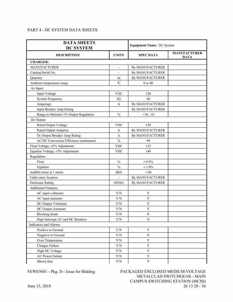
FEWE5601 - Pkg. D - Issue for Bidding PACKAGED ENCLOSED MEDIUM-VOLTAGE METALCLAD SWITCHGEAR - MAIN
CAMPUS SWITCHING STATION (MCSS)June 15, 2018 26 13 28 - 36
PART 4 - DC SYSTEM DATA SHEETS
DATA SHEETSDC SYSTEM
Equipment Name: DC System
DESCRIPTION UNITS SPEC DATA MANUFACTURER DATA
CHARGER:MANUFACTURER - By MANUFACTURERCatalog/Serial No. - By MANUFACTURERQuantity ea By MANUFACTURERAmbient temperature range ºC 0 to 40Ac Input:
Input Voltage VAC 120System Frequency Hz 60Amperage A By MANUFACTURERInput Breaker Amp Rating By MANUFACTURERRange to Maintain 1% Output Regulation % +10, -10
Dc Output:Rated Output Voltage VDC 130Rated Output Amperes A By MANUFACTURERDc Output Breaker Amp Rating A By MANUFACTURERAC/DC Conversion Efficiency (minimum) % 94
Float Voltage, ±5% Adjustment VDC 135Equalize Voltage, ±5% Adjustment VDC 140Regulation -
Float % ± 0.5%Equalize % ± 1.0%
Audible noise at 1 meter dBA < 60Cable entry location - By MANUFACTUREREnclosure Rating NEMA By MANUFACTURERAdditional Features:
AC input voltmeter Y/N YAC input ammeter Y/N YDC Output Voltmeter Y/N YDC Output Ammeter Y/N YBlocking diode Y/N NHigh Interrupt AC and DC Breakers Y/N N
Indicators and Alarms-Positive to Ground Y/N YNegative to Ground Y/N NOver Temperature Y/N YCharger Failure Y/N YHigh DC Voltage Y/N YAC Power Failure Y/N YBlown fuse Y/N Y
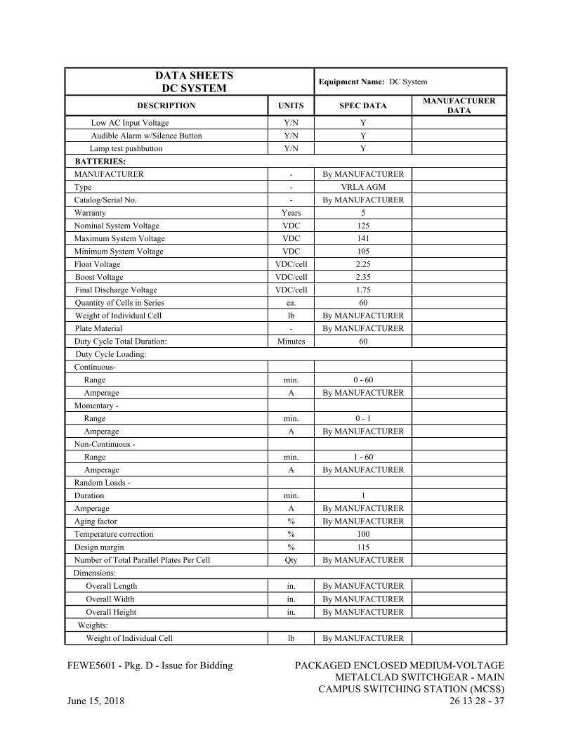
FEWE5601 - Pkg. D - Issue for Bidding PACKAGED ENCLOSED MEDIUM-VOLTAGE METALCLAD SWITCHGEAR - MAIN
CAMPUS SWITCHING STATION (MCSS)June 15, 2018 26 13 28 - 37
DATA SHEETSDC SYSTEM
Equipment Name: DC System
DESCRIPTION UNITS SPEC DATA MANUFACTURER DATA
Low AC Input Voltage Y/N YAudible Alarm w/Silence Button Y/N YLamp test pushbutton Y/N Y
BATTERIES:MANUFACTURER - By MANUFACTURERType - VRLA AGMCatalog/Serial No. - By MANUFACTURERWarranty Years 5Nominal System Voltage VDC 125Maximum System Voltage VDC 141Minimum System Voltage VDC 105Float Voltage VDC/cell 2.25Boost Voltage VDC/cell 2.35Final Discharge Voltage VDC/cell 1.75Quantity of Cells in Series ea. 60Weight of Individual Cell lb By MANUFACTURERPlate Material - By MANUFACTURERDuty Cycle Total Duration: Minutes 60Duty Cycle Loading:Continuous-
Range min. 0 - 60Amperage A By MANUFACTURER
Momentary -Range min. 0 - 1Amperage A By MANUFACTURER
Non-Continuous - Range min. 1 - 60Amperage A By MANUFACTURER
Random Loads - Duration min. 1Amperage A By MANUFACTURERAging factor % By MANUFACTURERTemperature correction % 100Design margin % 115Number of Total Parallel Plates Per Cell Qty By MANUFACTURERDimensions:
Overall Length in. By MANUFACTUREROverall Width in. By MANUFACTUREROverall Height in. By MANUFACTURER
Weights:Weight of Individual Cell lb By MANUFACTURER

FEWE5601 - Pkg. D - Issue for Bidding PACKAGED ENCLOSED MEDIUM-VOLTAGE METALCLAD SWITCHGEAR - MAIN
CAMPUS SWITCHING STATION (MCSS)June 15, 2018 26 13 28 - 38
DATA SHEETSDC SYSTEM
Equipment Name: DC System
DESCRIPTION UNITS SPEC DATA MANUFACTURER DATA
Weight of Heaviest Shipping Piece lb. By MANUFACTURERTotal Weight lb. By MANUFACTURER
ACCESSORIES:Battery Breaker Y/N YBattery Disconnect Y/N YDc Distribution Panel Y/N Y
END OF SECTION 26 13 28
FEWE5601 - Pkg. D - Issue for Bidding PACKAGED ENCLOSED MEDIUM-VOLTAGE METALCLAD SWITCHGEAR - EAST CAMPUS
SWITCHING STATION (ECSS)June 15, 2018 26 13 29 - 1
SECTION 26 13 29 - PACKAGED ENCLOSED MEDIUM-VOLTAGE METALCLAD SWITCHGEAR - EAST CAMPUS SWITCHING STATION (ECSS)
PART 1 - GENERAL
1.1 RELATED DOCUMENTS
A. Drawings and general provisions of the Contract, including General and Supplementary Conditions and Division 01 Specification Sections, apply to this Section.
1.2 SUMMARY
A. Section includes:
1. Complete switchgear system, including:
a. East Campus Switching Station Switchgear (ECSS Bus-A & ECSS Bus-B).b. Controls and Relaying.c. Communications: Ethernet Switches, I/O module & fiber optic patch panel. d. Outdoor Switchgear Enclosure.e. Auxiliaries.f. AC and DC Distribution Systems.
1.3 REFERENCES
A. All equipment shall meet or exceed the latest editions of the applicable standards listed below.
1. ASTM (ASTM): ASTM B187 "Standard Specification for Copper, Bus Bar, Rod, and Shapes".
2. Institute of Electrical and Electronics Engineers, Inc. (IEEE):3. ANSI/IEEE C37.010 - "Application Guide for AC High Voltage Circuit Breakers >
1000VAC Rated on a Symmetrical Current Basis" (copyrighted by IEEE, ANSI approved).
4. IEEE C37.2 - "Electrical Power System Device Function Numbers, Acronyms, and Contact Designations".
5. IEEE C37.20.2 - "Metal Clad Switchgear" IEEE C37.20.7 - "Guide for Testing Medium-Voltage Metal-Enclosed Switchgear Rated up to 38kV for Internal Arcing Faults.
6. IEEE C37.21 - "Control Switchboards" (copyrighted by IEEE, ANSI approved).7. ANSI/IEEE C37.90 - "Relays and Relay Systems Associated with Electric Power
Apparatus" (copyrighted by IEEE, ANSI approved).8. IEEE C57.13 – “IEEE Standard Requirements for Instrument Transformers”9. IEEE C37.90 - Relays and Relay Systems Associated with Electric Power Apparatus.10. IEEE-1613: Environmental and Testing Requirements for Communications Networking
Devices Installed in Electric Power Substations
FEWE5601 - Pkg. D - Issue for Bidding PACKAGED ENCLOSED MEDIUM-VOLTAGE METALCLAD SWITCHGEAR - EAST CAMPUS
SWITCHING STATION (ECSS)June 15, 2018 26 13 29 - 2
11. IEEE-C37.90: Relays and Relay Systems Associated with Electric Power Apparatus12. IEC 60068-2: Environmental Tests13. IEC 60255-21: Vibration and shock Tests14. IEC-60255-22: RFI and Interference Tests15. IEC 60825-1: Laser (LED) Safety16. IEC-61000-4: Electromagnetic Compatibility17. IEC-61000-6: Electromagnetic Compatibility18. IEC-61850 Series: Communication Networks and Systems for Power Utility Automation19. CFR 47 Parts 15 and 18, Code of Federal Regulations - Federal Communications
Commission (FCC) Rules and Regulations pertaining to EMI
B. National Electrical Contractors Association (NECA): NECA 430-2016 Standard for Installing and Maintaining Medium-Voltage Switchgear
C. National Electrical Manufacturers Association (NEMA):
1. NEMA SG 4 - "Alternating Current High Voltage Circuit Breakers".2. NEMA C37.55 "Conformance Test Procedures for Switchgear – Medium Voltage Metal
Clad Assemblies".
D. National Fire Protection Association (NFPA):
1. NFPA 70 - "National Electrical Code" (copyrighted by NFPA, ANSI approved) hereinafter referred to as NEC.
2. NFPA 70B - "Recommended Practice for Electrical Equipment Maintenance" (copyrighted by NFPA, ANSI approved).
3. NFPA 70E – “Standard for Electrical Safety In The Workplace” (copyrighted by NFPA, ANSI approved) hereinafter referred to as NEC.
4. Underwriters Laboratories, Inc. (UL):5. UL 486A-B - "UL Standard for Safety Wire Connectors 6. UL 1236 - "UL Standard for Safety Battery Chargers for Charging Engine-Starter
Batteries" (copyrighted by UL, ANSI approved).
1.4 SITE CONDITIONS
A. Live Loads
1. Roof Live Uniform Load: 20 PSF
B. Wind Loads
1. Ultimate Wind Speed (3 Second Peak Gust) - Vult = 115MPH2. Risk Category = II3. Importance Factor – Iw = 1.04. Exposure – C
C. Snow Loads

FEWE5601 - Pkg. D - Issue for Bidding PACKAGED ENCLOSED MEDIUM-VOLTAGE METALCLAD SWITCHGEAR - EAST CAMPUS
SWITCHING STATION (ECSS)June 15, 2018 26 13 29 - 3
1. Risk Category = II2. Ground Snow Load – Pg = 10 PSF3. Flat Roof Snow Load – Pf = 7 PSF4. Importance Factor – Is = 1.05. Exposure – Ce = 1.06. Thermal Factor – Ct = 1.0
D. Seismic Loads
1. Risk Category = II2. Seismic Importance Factor – I =1.03. Mapped Spectral Response Accelerations – Ss = 0.279 g, S1=0.106 g4. Site Class – D5. Spectral Response Coefficient – Sds = 0.293 g, Sd1=0.167 g6. Seismic Design Category C
1.5 SUBMITTALS
A. Product Data: Submit manufacturer's product data showing material and equipment proposed.
1. Product data shall include, but shall not be limited to, the following equipment and materials:
a. Circuit breakers.b. Buses.c. Transformers.d. Panelboards.e. Control, Relaying, and Metering equipment.f. HMI, door mounted.g. Networking equipment.h. Wire and cable.i. Batteries, charger, and battery rack.
2. The ratings for the equipment shall include, but shall not be limited to, the following:
a. Voltages.b. Frequency.c. Number of phases.d. Current, continuous and interrupting.e. Accuracy.f. Power requirements.g. Power losses at full and half load.
3. Physical characteristics and materials shall include, but shall not be limited to, the following:
a. Size/dimensions.b. Weight.
FEWE5601 - Pkg. D - Issue for Bidding PACKAGED ENCLOSED MEDIUM-VOLTAGE METALCLAD SWITCHGEAR - EAST CAMPUS
SWITCHING STATION (ECSS)June 15, 2018 26 13 29 - 4
c. Finishes.
4. Accessories shall include, but shall not be limited to, the following:
a. Indicating lights.b. Terminal blocks.c. Test switches.d. Auxiliary contacts.
B. Shop Drawings: Submit complete shop drawings as required to determine acceptability. Shop drawings shall include, but shall not be limited to, the following:
1. Bill of materials and components.2. Outline drawings, dimensioned plans, elevations, sections, supports, materials, and
finishes, showing weights, bolt spacing, clearances, tolerances, conduit, cable entrances, terminal strips, and methods of assembly.
3. Cubicle and compartment layouts.4. Bus and circuit breaker ratings and arrangements including dimensions of bus bars,
including the ground bus, and the type and spacing of bus supports.5. Nameplate details (size and legend).6. Detail drawings showing incoming line terminations and location of cable termination
with dimensions. Shop drawings shall verify sufficient conductor space and compliance with codes.
7. Shipping arrangements and packaging methods.
C. Wiring Diagrams: Submit with shop drawings, specific wiring diagrams and instructions for equipment, controls, or devices which are furnished or which are to be field wired and connected. The diagrams and instructions shall not be of a general or typical nature, but shall be applicable only to this Project. Include identical diagrams and instructions to install the equipment as are included in the operating and maintenance manuals. Wiring diagrams shall include, but shall not be limited to, the following:
1. Single and three line diagrams.2. Electrical wiring diagrams for communications, instrumentation, metering and relaying.3. Control schematic diagrams including interface diagrams having terminals identified for
remote equipment.4. Wiring diagrams for switchgear showing connections to distribution branches.5. Wiring diagrams for communication sections showing field connections by others.
D. Calculations: Submit calculations supporting the selection of the devices and components furnished. Devices requiring submittal of calculations shall include, but shall not be limited to, the following:
1. Instrument Transformers: Sizes and burdens.2. Control power transformers.3. DC Power System components.4. Low Voltage AC Power system components.5. Lighting foot candle calculations.
FEWE5601 - Pkg. D - Issue for Bidding PACKAGED ENCLOSED MEDIUM-VOLTAGE METALCLAD SWITCHGEAR - EAST CAMPUS
SWITCHING STATION (ECSS)June 15, 2018 26 13 29 - 5
E. Operating and Maintenance Manuals: Prepare and deliver complete operating and maintenance manuals. Provide information pertinent to the equipment for preventive maintenance and for replacement of expendable components. Manuals shall include the items listed below and other information recommended by the manufacturer:
1. Manufacturer's published information.2. Set of shop drawings.3. Wiring diagrams of electrical components.4. Acceptance test reports.5. Electrical characteristics and ratings of components.6. Recommended spare parts list.7. Maintenance Procedures 8. Complete list of parts.9. Factory Test Data: Provide factory test data certified by a professional engineer that
switchgear test results fulfill the specified requirements.
F. Submit with proposals
1. Preliminary Data Sheets.2. Preliminary one-line diagrams.3. Elevations showing overall dimensions, weights, and layout of accessories.4. Bill of materials for each cubicle with manufacturer reference number.5. Complete list of spare parts and special tools that will be furnished with equipment,
which are included in lump sum price. In addition, provide itemized price listing of recommended spare parts with prices guaranteed for at least 1 year after acceptance of equipment.
6. Complete data and listing of items requiring field assembly and installation and special equipment required.
7. Manufacturer’s ISO certification certificate.8. Location of manufacture of each unit.9. Preliminary electrical oneline diagram of proposed DC System.
G. Submit after Notice of Award
1. Certified Data Sheets.2. Master drawing index.3. One-line diagrams.4. Three-line diagrams.5. Conduit entry and exit locations.6. Schematic diagrams and elementary wiring and connection diagrams.7. Control and equipment wire terminations, and terminations for field wiring showing all
interconnecting field wiring between switchgear, control panels, transformers, and demarcation panels.
8. Material lists with manufacturer reference numbers.9. Ratings and nameplate schedules.10. Elevations showing overall dimensions, weights, and layout of accessories.11. Switchgear cross-sections to indicate interior bus arrangement and equipment locations.12. Floor plan drawing shown location for anchor bolts and leveling channels.13. Location of floor and pad openings required for entrance of conduits and cables.

FEWE5601 - Pkg. D - Issue for Bidding PACKAGED ENCLOSED MEDIUM-VOLTAGE METALCLAD SWITCHGEAR - EAST CAMPUS
SWITCHING STATION (ECSS)June 15, 2018 26 13 29 - 6
14. Performance curves for each ratio and type of current and voltage transformer.15. Detailed instruction books for all equipment, meters, and each type of relay.16. Detailed characteristics of surge arresters.17. Detailed procedures and processes for factory acceptance tests.18. Certified test report of manufacturer's standard production tests.19. Heating load and cooling load calculations.20. Battery sizing calculations.
1.6 SYSTEM DESCRIPTION
A. Provide complete free standing assembly as shown on drawings to house equipment consisting of switchgear (circuit breakers, protective relays and control devices), AC and DC Power systems, HVAC, Ethernet switches for communications and other accessories.
B. Metalclad switchgear shall be provided with remote closed door racking provisions for all circuit breakers. Closed door racking provisions for circuit breakers shall not require the end user to install any extension arms through the door for operation of the racking mechanism. A motorized racking device shall be provided for use with this option.
1.7 QUALITY ASSURANCE
A. After fabrication, perform an operational test in the manufacturer's plant to check out the entire system before delivery. Include calibration of meters, operation of temperature sensors, relays and device settings; control wiring, including polarity, of all instrument transformers; complete assembly and control function testing. Submit certified written test reports.
B. Provide written data certifying a minimum of ten years' experience in the building of metal clad switchgear and at least ten successful working installations of this type of equipment.
1.8 WARRANTY
A. The manufacturer shall provide a warranty against defects in material and workmanship for a period of 3 years from the date of factory acceptance testing. During the first 3 years of operation, there shall be no cost to the Owner for any corrective repairs. Individual component warranties may be longer and will be coordinated with manufacturer after the first 3 years of operation.
PART 2 - PRODUCTS
2.1 MANUFACTURERS
A. Powell Industries.
B. Square D.

FEWE5601 - Pkg. D - Issue for Bidding PACKAGED ENCLOSED MEDIUM-VOLTAGE METALCLAD SWITCHGEAR - EAST CAMPUS
SWITCHING STATION (ECSS)June 15, 2018 26 13 29 - 7
C. GE.
D. Eaton/Cutler Hammer.
E. Siemens
2.2 GENERAL
A. Standards: The switchgear shall consist of stationary steel structures containing vacuum type, drawout power circuit breakers with digital relay protection devices, instruments, buses, and system control devices. The switchgear shall be UL approved as service entrance equipment and designed, built, and tested in accordance with ANSI/IEEE and NEMA standards for metal clad switchgear.
B. Unless otherwise specified this equipment is intended for use in ambient temperatures that do not exceed a maximum of 40°C (104°F) or a minimum of -30°C (-22°F).
C. This equipment is intended for use in an area where the elevation is less than 3300 feet above sea level. Above 3300 feet a de-rating factor as prescribed by ANSI standards will apply.
D. The switchgear and Building Assembly shall be suitable, tested and certified to meet all applicable seismic requirements of the 2015 South Carolina Building Code.
2.3 SWITCHGEAR ENCLOSURE
A. Vertical Sections: The stationary enclosure shall consist of self-supported, vertical sections housing circuit breakers, buses, cables, system controls, and accessories. The vertical sections shall be bolted together to form a rigid metal clad switchgear assembly. The vertical sections shall have separate front compartments for circuit breakers and controls, and rear compartments for buses and outgoing cables. The vertical section framework shall consist of a welded and bolted steel frame with reinforcing gussets. Assembled to this framework shall be doors and top, side, and rear covers.
B. Base: The vertical sections shall be supported on a steel base assembly consisting of die formed steel and commercial channel welded and bolted together. The base shall provide a rigid support for the switchgear assembly.
C. Each front compartment door shall be provided with a formed steel hinged door with hand operated door latches and three-point closure. Each door shall have provisions for padlocking.
D. Rear access to cable compartments and CPT sections shall be integrated into the overall switchgear enclosure package; reference 2.17 this section. A second interior door or panel interior to rear access doors as described in section 2.17 will not be accepted.
E. Lifting Equipment: Circuit breaker lifting equipment shall be provided to remove circuit breakers. The equipment shall be a portable lifting device manufactured by the equipment supplier. Qty. = 1 for ECSS location.
FEWE5601 - Pkg. D - Issue for Bidding PACKAGED ENCLOSED MEDIUM-VOLTAGE METALCLAD SWITCHGEAR - EAST CAMPUS
SWITCHING STATION (ECSS)June 15, 2018 26 13 29 - 8
F. Breaker Compartment: The front compartment of the switchgear shall contain the drawout circuit breakers. Each vertical feeder section shall provide the space to accommodate two circuit breakers if frame size allows. Each circuit breaker shall be mounted in a barriered cell. Breaker compartments for future use as indicated as "equipped breaker cell" on the drawings, shall be fully equipped with drawout assemblies and current carrying parts required to permit completion of the unit by the addition of only a circuit breaker. Provide a LED light source in the top and bottom of the front and rear compartments operated by a light switch on the door.
G. Cable Compartment: The cable compartment shall be sized to accommodate incoming and outgoing cables or busway required for each vertical section. The bus compartment shall be segregated from the feeder cable compartment by means of grounded metal barriers. The cable compartment shall also contain a copper ground bus bolted directly to the switchgear frame. The incoming and tie breaker feeder cable compartments (Section Types 1, 2, and 3) shall be capable of terminating up to 6-750 kcmil, 15 kV, MV-105, 133% insulated conductors. All other sections (section type 4) shall be capable of terminating up to 2-500 kcmil, 15 kV, MV-105, 133% insulated conductors. The depth of the finished equipment shall be sufficient to allow for entrance, bending, and termination of power cables. Individual units shall be provided for bottom entrance. A minimum of 26 inches of vertical clearance between terminal pads and the cable entrance shall be provided. Two high sections shall provide a separate chute or channel to isolate and route bottom entry cables to upper compartments.
H. Each switchgear cubicle shall have, at a minimum, 11-gauge sheet steel side panels. Construction shall provide two (2) steel sheets between adjacent sections so as to minimize the chance of fault propagation between sections.
I. Provide electric heaters in each switchgear compartment.
1. Voltage: 240-volt, single-phase operated at 120V.2. Watts: As required to maintain temperature.3. Provide thermostat for each compartment with minimum set point of 50°F.
J. The switchgear shall be capable of extension from opposite end of communication/remote I/O section at a future date without modification to the existing structural members.
K. Control Compartment: Each Vertical Section shall include a dedicated and isolated control compartment. Upper and lower or Side by Side control compartments shall be isolated from each other with each control compartment dedicated to its associated breaker. Provide a LED light source in the compartment and a switch accessible from the exterior of the gear. The Control Compartment shall house the respective relays, indicating lights, test switches, and other required auxiliary equipment for the respective breaker.
L. Communications/Remote I/O Section: Each Switchgear shall include a dedicated and isolated section for the communications Ethernet switches, door mounted HMI, fiber optic patch panel, and remote I/O module; additional equipment, such as firewalls, controllers, servers, network time clock, will be added later by the SCADA Contractor. These devices will be 19-inch rack configuration and the communication section is to include supports for mounting same. Ethernet cables and communication cables from protective relays and other equipment shall be routed to the Ethernet switches and I/O module separate from the power bus and cables. The section shall be accessible from the side of the gear. Provide overhead cable tray or wireway
FEWE5601 - Pkg. D - Issue for Bidding PACKAGED ENCLOSED MEDIUM-VOLTAGE METALCLAD SWITCHGEAR - EAST CAMPUS
SWITCHING STATION (ECSS)June 15, 2018 26 13 29 - 9
with 50% spare capacity for manufacturer provided and field installed communication cabling between Bus A and Bus B. Provide tray or conduit for remote I/O point cabling.
M. Finish: Indoor: The switchgear enclosure parts shall be given an iron phosphate pretreatment, a primer, and a coat of baked enamel. After assembly, a finish coat of air drying enamel of gray color (ANSI #61) shall be applied to exterior surfaces.
2.4 BUSES
A. General: The bus structure shall consist of copper bus with silver plated bolted connections mounted on track resistant glass polyester and porcelain insulators. The bus system shall be insulated with fluidized bed epoxy insulation. The copper bus shall be of sufficient size to limit the temperature rise as specified in ANSI/IEEE C37.20.2. Bus bracing shall be adequate to withstand mechanical and thermal stresses due to short circuits at least equal to those specified for the main circuit breaker. Provide ASTM B 187 copper throughout the switchgear. Bus joints shall be provided in each unit. The temperature rise of the bus and connections shall be in accordance with ANSI standards and documented by design test.
B. Power bus orientation shall be A-B-C top to bottom, front to back, and left to right when viewed from the front of the switchgear.
C. Phase Buses: Provide continuous phase buses as sized on the drawings for the full length of the switchgear lineup excluding the communications/remote I/O section. Tap buses shall have the same ampacity as the section design rating.
D. Neutral Bus: Provide continuous fully sized neutral bus for the full length of the switchgear lineup excluding the communications/remote I/O section.
E. Ground Bus: Provide a minimum size ground bus of 2 inch by 1/4 inch cross sectional area, for the full length of the switchgear lineup excluding the communications/remote I/O section. Provide compression indent type lugs to accept No. 4/0 AWG copper cable.
F. Connections: Bus connections for shipping breaks, extension, and taps shall be silver plated bolted pressure joints. Provide insulating boots for bus joints and cable terminations. Cable termination boots suitable for 15kV 750kcmil cable (4 cables / phase). Selection of boots to be based on installed cable diameter (type Cooper BOL-T or equal).
G. Safety Shutters: The switchgear shall be furnished with grounded shutters or a means by which to cover the stationary primary disconnects when the breaker is moved from the connected position.
2.5 POWER CIRCUIT BREAKERS
A. General: The power circuit breakers shall be medium voltage, drawout, vacuum circuit breaker type, having electrically charged, stored energy mechanisms which shall be mechanically and electrically trip free. Provision shall be included for manual charging of the operating

FEWE5601 - Pkg. D - Issue for Bidding PACKAGED ENCLOSED MEDIUM-VOLTAGE METALCLAD SWITCHGEAR - EAST CAMPUS
SWITCHING STATION (ECSS)June 15, 2018 26 13 29 - 10
mechanism. The breakers shall be mounted on a rigid, self-aligning drawout mechanism. The breaker shall be removable and shall roll out on horizontal guide rails.
B. Breaker Positions: Each drawout breaker shall be provided with four position operation. Each position shall be clearly identified by an indicator on the circuit breaker front panel.
1. Connected Position: In the connected position, the main line and load terminals and auxiliary control contacts and circuitry shall be connected and the breaker shall be fully operable. The breaker shall be interlocked to automatically trip before racking into or out of position.
2. Test Position: In the test position, the circuit breaker auxiliary control contacts and circuitry only shall be connected to permit testing of the complete control system without actually connecting the sources or loads to the main bus.
3. Disconnected Position: In the disconnected position, main and auxiliary control contacts and circuitry shall be completely disconnected.
4. Remove Position: In the remove position circuitry shall be disconnected and the breaker can be removed from the compartment.
C. Operating Mechanism:
1. The breaker operating mechanism shall be the two step, stored energy quick make, quick break type. The close operation of the circuit breaker shall automatically charge the opening springs. The operating mechanism shall be front located and designed for servicing without removing breaker from rails.
2. Manual charging of the breaker shall be possible by means of a manual charging lever,3. Close trip indicator, mechanically connected to the breaker, shall be provided to indicate
the breaker position.4. Circuit breaker operating mechanism shall be completely trip free both mechanically and
electrically. Mechanical tripping of a closed circuit breaker shall be possible with the front cubicle door closed.
5. A contact wear gap indicator shall be provided and shall be easily visible.
D. Mechanical Interlocks: The switchgear shall be provided with mechanical interlocks to:
1. Prevent moving the breaker to or from the connected position when the breaker contacts are in the closed position.
2. Prevent closing the breaker unless the primary disconnects are fully engaged or the breaker is in the test or disconnect position.
3. Automatically discharge the closing springs when the breaker is moved between the connected and test positions or when it is inserted into or withdrawn from the compartment.
E. Mechanism Operator Cell Breaker Auxiliary Switches: Each circuit breaker shall be equipped with mechanism operated auxiliary switches which shall operate when the breaker is open or closed. These switches shall be enabled in the operating and test position. Provide four normally open and four normally closed contacts in addition to those required for the circuit breaker operating mechanism and control schemes. All contacts to be wired to accessible terminal blocks for customer use.
FEWE5601 - Pkg. D - Issue for Bidding PACKAGED ENCLOSED MEDIUM-VOLTAGE METALCLAD SWITCHGEAR - EAST CAMPUS
SWITCHING STATION (ECSS)June 15, 2018 26 13 29 - 11
F. Truck Operated Cell Switches: Each breaker compartment shall be equipped with cell mounted switches which shall operate when the circuit breaker is levered into or out of the operating position. Provide two six stage switches, each six stage switch shall provide six normally open and six normally closed contacts. All contacts to be wired to accessible terminal blocks for customer use.
G. A steel interference plate shall be mounted in the bottom of each circuit breaker cell assembly which only allows a higher rated circuit breaker (voltage, current, interrupting rating) to be inserted into a lower rated cell assembly.
H. For operator safety the circuit breaker shall have provision for padlocking it in the disconnected position.
I. Circuit breaker shall have the capability of racking between the connected, disconnected and test positions with the cubicle door closed.
J. Power circuit breakers shall be shipped and packaged separately from the switchgear structure.
2.6 RATING AND PERFORMANCE REQUIREMENTS POWER CIRCUIT BREAKERS
A. Metal Clad Switchgear Ratings and Requirements for IEEE C37.06 Table 1 rated breakers:
1. System Voltage: 12,470 volts.2. Nominal rms Rated Voltage Class: 15,000 volts.3. Frequency: 60 hertz.4. Phase: Three.5. System: Multi-point, solid grounded wye, three phase, four wire.6. Rated Voltage Range Factor (k): 1.0.7. Rated Continuous Current:
a. Main Breakers: Per Drawings.b. Feeder Breakers: Per Drawings.
8. Interrupting time: 3 Cycles9. Rated Short Circuit RMS Current at Rated Maximum Voltage:
a. 36kA
10. Momentary Withstand and Closing and Latching Capability:
a. 62kA RMS and 104kA peak
11. Low Frequency Withstand Voltage Insulation Level: 36 kV.12. Impulse Withstand Voltage Insulation Level: 95 kV.13. Control Voltage: 125 volts DC for close, trip, and spring motor operation.14. Percent Spare Terminal Blocks: 20 percent.15. Finish Color: Gray ANSI #61.
FEWE5601 - Pkg. D - Issue for Bidding PACKAGED ENCLOSED MEDIUM-VOLTAGE METALCLAD SWITCHGEAR - EAST CAMPUS
SWITCHING STATION (ECSS)June 15, 2018 26 13 29 - 12
B. The power circuit breaker ground connection must be capable of carrying the short circuit rating of the circuit breaker for a minimum of 2 seconds and must also be capable of withstanding the peak current value (or 2.7 times the rated short circuit current) of the circuit breaker.
2.7 TYPE 2 SECTIONS
A. Each distribution feeder section shall be equipped with the following equipment:
1. Breaker status lights:
a. Open (green)b. Closed (red)c. Lock Out Healthy (White).d. Locked-out (Amber).
2. Bus differential protective relay (BDR) (one per switchgear bus)
a. Basis of Design: SEL-787 (P/N -07870X1A1A0X0X850631) b. Connection to incoming main and feeder CTs as shown on drawings. Include a
high-speed lockout relay actuated by the bus differential relay to trip main and feeder breakers.
3. Feeder protective relay (FPR)
a. Basis of Design: SEL-751 (P/N 751201A3A2A0X850631). b. Provide relay inputs and outputs as shown on drawings with a minimum of 25%
spare.
4. Customer connection points for 2 external trip signals directly to breaker. 5. One 86 lockout relay for use with FPR as shown on drawings.6. Heavy –duty distribution class surge arresters.
a. Maximum Rated Line to Line Voltage (VLL) – 13.1 kV.b. MCOV – 7.65 kV.
7. Current transformers and voltage transformers as specified in paragraph 2.14.8. Test switches as specified in paragraph 2.15.
2.8 TYPE 3 SECTIONS
A. Each distribution feeder section shall be equipped with the following equipment:
1. Breaker status lights:
a. Open (green)b. Closed (red)c. Lock Out Healthy (White).
FEWE5601 - Pkg. D - Issue for Bidding PACKAGED ENCLOSED MEDIUM-VOLTAGE METALCLAD SWITCHGEAR - EAST CAMPUS
SWITCHING STATION (ECSS)June 15, 2018 26 13 29 - 13
d. Locked-out (Amber).
2. Feeder protective relay (FPR)
a. Basis of Design: – SEL-751 (P/N 751201A3A2A0X850631). b. Provide relay inputs and outputs as shown on drawings with a minimum of 25%
spare.
3. Customer connection points for 2 external trip signals directly to breaker. 4. One 86 lockout relay for use with FPR as shown on drawings.5. Heavy –duty distribution class surge arresters.
a. Maximum Rated Line to Line Voltage (VLL) – 13.1 kV.b. MCOV – 7.65 kV.
6. Current transformers and voltage transformers as specified in paragraph 2.14.7. Test switches as specified in paragraph 2.15.
2.9 TYPE 4 SECTIONS
A. Each distribution feeder section shall each be equipped with the following equipment:
1. Breaker status lights:
a. Open (Green).b. Closed (Red).
2. Feeder protective relay (FPR)
a. Basis of Design: SEL-751 (P/N 751201A3A2A0X850631). b. Provide relay inputs and outputs as shown on drawings with a minimum of 25%
spare.
3. Customer connection points for 3 external trip signals directly to breaker. 4. Heavy –duty distribution class surge arresters.
a. Maximum Rated Line to Line Voltage (VLL) – 13.1 kV.b. MCOV – 7.65 kV.
5. Current transformers as specified in paragraph 2.14 and as shown on drawings.6. Test switches as specified in paragraph 2.15 and as shown on drawings.
FEWE5601 - Pkg. D - Issue for Bidding PACKAGED ENCLOSED MEDIUM-VOLTAGE METALCLAD SWITCHGEAR - EAST CAMPUS
SWITCHING STATION (ECSS)June 15, 2018 26 13 29 - 14
2.10 COMMUNICATIONS/REMOTE I/O SECTION
A. Provide dedicated communications/remote I/O switchgear section to end section of switchgear lineup with two doors accessible from side of switchgear per project drawings. Doors shall swing outward and have key lock handles for lockable three point latching mechanism.
B. Provide grounding bar with cable connection to ground bus in switchgear lineup.
C. Provide 120VAC power feed to cabinet with local circuit breaker and fused terminal blocks for 120VAC power distribution.
D. Provide 125Vdc power feed to cabinet with local circuit breaker and fused terminal blocks for 125Vdc power distribution throughout switchgear.
E. Provide Remote I/O Unit.
1. Basis of Design: SEL-25162. Digital Inputs: 83. Digital Outputs: 84. Power: 24VDC5. Communications:
a. Protocol: Modbus TCP/IP, DNP3, or Ethernet/IPb. Ports: 2 - RJ45, 10/100Base T
6. Temperature Range: -40 to 75C7. Relative Humidity: 5-95% non-condensing8. Mounting:19-inch Rack9. Software configuration package10. Comply with IEC-61000-3, -4, and -6 for electromagnetic susceptibility and
compatibility.
F. Provide industrial grade managed Ethernet switches (layer 3) per the following:
1. Manufacturers:a. Cisco Industrial Ethernet Series Switches 3000 – 5000 (Basis of Design)b. Hirschmann (A Belden company)c. Moxad. Siemens (Rugged Com)
2. Port Configurations:
a. 8 Fiber Optic, Single-Mode, 1000 Mbps, ring loop b. 28 Copper RJ-45, 10/100 Mbps
3. The SCADA system uses a redundant Ethernet Communications ring such that there is an A and B channel. Multiple Ethernet switches may be connected together to meet or exceed the number and type of required port connections.
FEWE5601 - Pkg. D - Issue for Bidding PACKAGED ENCLOSED MEDIUM-VOLTAGE METALCLAD SWITCHGEAR - EAST CAMPUS
SWITCHING STATION (ECSS)June 15, 2018 26 13 29 - 15
4. Security: SNMPv3, HTTPS, MAC for configurable access control and traffic management.
5. Network:
a. Configuration and monitoring software to provide network health and security indicators.
b. Support tagged and untagged VLANs and IEC 61850 GOOSE messages from other traffic.
c. Prioritize traffic per IEEE 802.1pd. Security: restrict access to select end stations via IEEE 802.1X.e. Failover & Redundancy: Enable fast network recovery via IEEE 802/1D, Rapid
Spanning Tree Protocol (RSTP).f. Employ VLAN configurations where appropriate to segregate the traffic of
dissimilar network protocols or equipment
6. Time Synchronization: SNTP server & client per IEEE 15887. Mounting: 19-inch Rack8. Power Supplies: Redundant, Hot-Swappable, 125VDC input.9. Rated for harsh environment:
a. -40F to 185F; device shall have conformal coating applied to circuit boards.b. 5-95% RH
10. Comply with IEEE 1588, IEEE 1613, IEC 61000-4, FCC 15, IEEE C37.90, IEEE 802.1X and IEC 61850 standards.
G. Provide the following accessories:
1. Doorstop kit to secure door in open position.2. Metal data pocket to provide place to store documentation inside enclosure.
H. Electrical:
1. Provide a 120VAC power strip with 8 receptacles for associated equipment.2. Provide internal cabling management system for routing and protection of wiring.3. Provide LED lighting package with door activate switch.
I. Provide engraved nameplates per drawings.
2.11 LOCKOUT RELAYS
A. Electroswitch Type LOR Series 24, decks as required per drawings and to achieve necessary spare contacts, suitable for control power supplied. Integral LED’s will not be accepted.
1. Rated operating trip voltage shall be low enough to allow coil operation at 75% of rated voltage.
2. Contacts: Minimum 10 N.C. and 10 N.O., wired to terminal blocks located in auxiliary compartments for interlock provisions and owner’s use.
FEWE5601 - Pkg. D - Issue for Bidding PACKAGED ENCLOSED MEDIUM-VOLTAGE METALCLAD SWITCHGEAR - EAST CAMPUS
SWITCHING STATION (ECSS)June 15, 2018 26 13 29 - 16
2.12 ELECTRONIC PROTECTIVE RELAYS
A. Relays: Electric power apparatus relays shall be utility grade specifically designed for power switchgear. Protective relay shall be solid state type, meeting surge withstand requirements of ANSI/IEEE C37.90. Relay device number shall be in accordance with IEEE C37.2.
B. Relay Types: Protective relays shall be as specified within breaker type classification specification sections in this document. The relays shall be capable of directly interfacing with the SCADA system per IEC 61850. The relays shall meet the following performance requirements:
1. Standards: Shall meet applicable IEEE C37.90 standards.2. Temperature Range: 28 degrees F to 131 degrees F (operating), 25 degrees F to 158
degrees F (storage).3. Alarm Contact: Normally closed contact (contact closed if loss of power or self check
failure).4. The relays shall transmit metering, event, alarm and status information to SCADA
system.
C. Manufacturer to supply a minimum of three (3) licenses for all software required to communicate with and set relays as well as analyze oscillography obtained from event reports. Fully optioned software for advanced analysis and setting capabilities is required. Minimal freeware versions of software will not be accepted.
2.13 WIRING
A. Type: Control, meter, and transducer wiring, except hinge wire and current and Voltage transformer secondary leads, shall be Type SIS, 90 degrees C (194 degrees F), copper, single conductor 600 volt, Class B stranding, No. 14 AWG minimum. Wiring over door hinges or other locations where leads may be subject to flexing shall employ the use of No. 14 AWG, 41 strand, extra flexible copper conductors. Current transformer secondary leads shall be No. 10 AWG minimum and shall be wired with crimp type solderless terminals. Ethernet communication cables shall meet requirements of Section 25 05 00.
B. Terminations: Wiring for control and relaying circuits requiring external connections and unused terminals of relays and auxiliary contacts shall be brought to conveniently located terminal blocks. The terminal blocks shall be of the screw type to accommodate ring tongue, crimp type, solderless connections. Wiring shall not have more than two wires connected to a terminal point. External wiring termination points for Owner’s connections shall be arranged for one wire to each terminal point. Twenty percent (20%) spare terminal points shall be provided. Terminal block shall be furnished and installed at switchgear splits or shipping splits for wire. CT leads shall be wired to short circuiting type terminal blocks. Utilize GE/ITI IKU style terminal blocks.
C. Wire Markings: Every wire shall have source and destination identification which shall be visible at each termination point. Wire markers shall be heat shrinkable or plastic interlocking sleeve type. Cloth wire markers are not acceptable. Spare contacts on relays, lockout relays,

FEWE5601 - Pkg. D - Issue for Bidding PACKAGED ENCLOSED MEDIUM-VOLTAGE METALCLAD SWITCHGEAR - EAST CAMPUS
SWITCHING STATION (ECSS)June 15, 2018 26 13 29 - 17
control switches, etc., shall be assigned wire numbers, wired to terminal blocks, and labeled accordingly.
D. Methods: Hinge wiring shall be arranged so that any twisting shall take place in the longitudinal plane of the conductor, rather than across the conductor. Control wires shall be armored or enclosed in grounded metal troughs where they pass through primary compartments.
E. All wiring external to switchgear shall be routed in EMT conduit (3/4” minimum), cable tray, or wireway
F. Communications and control wiring in between switchgear shall be via aluminum ladder style cable tray. Vertical raceway from cable tray down to switchgear or respective jbox may be conduit or cable tray.
G. 208Y/120 VAC power and lighting wiring shall be THWN-2 in conduit. Conductor jacket shall be color coded according to phase as follows:
1. Phase A – Black2. Phase B – Red3. Phase C – Blue4. Neutral – White w/ color coded tracer according to phase conductor.5. Ground – Green.
2.14 INSTRUMENT TRANSFORMERS
A. General: Instrument transformers shall be the type for switchgear installations. Transformers and associated components shall be in a drawout section. Instrument transformers shall be provided with test blocks.
1. Voltage Transformers
a. Voltage transformers and associated fuse assemblies shall be installed in drawout assemblies so that they may be readily disengaged from the power bus.
b. Where physical size restrictions do not allow the Voltage transformer to be mounted in a drawout assembly, the voltage transformer may be stationary mounted with the fuses only mounted in the drawout unit. The appropriate interlocks shall be provided to insure maximum operator safety.
c. When moved to the withdrawn position, the transformer drawout unit shall automatically ground the transformer primary windings and the fuses. A visible indication of positive ground is required. The ground may be a momentary or sweeping action that occurs as the unit moved out of the connected position.
d. Voltage transformers shall have 120 volt secondaries unless otherwise specified.e. Voltage transformers shall have an accuracy rating comparable to the metering
equipment and a burden capacity equal to twice the initial load.f. Current limiting fuse protection shall be provided on the primary side of each
Voltage transformer.g. Voltage transformers shall be designed to withstand the basic impulse level of the
switchgear.
FEWE5601 - Pkg. D - Issue for Bidding PACKAGED ENCLOSED MEDIUM-VOLTAGE METALCLAD SWITCHGEAR - EAST CAMPUS
SWITCHING STATION (ECSS)June 15, 2018 26 13 29 - 18
h. ANSI accuracy class of 0.15 with burdens of W, X, and Y.i. Provide fused access to secondary output of each Voltage transformer in a readily
accessible dedicated terminal block for future connection to synchronization equipment.
2. Current Transformers
a. Unless specified otherwise, the polarity marking shall be toward the circuit breaker.
b. Each current transformer shall be rated to withstand the thermal and mechanical stresses imposed by the short circuit rating of the applied circuit breaker.
c. The secondary termination of current transformers shall be on a shorting terminal block.
d. Current transformers shall have a rated 5 ampere secondary current unless otherwise specified.
e. Current transformers connected to solid state relays shall be single-ratio or multi-ratio and rated as shown on project drawings.
f. Current transformers connected to meters shall be multi-ratio with tap setting as shown on project drawings.
g. Bus differential protective current transformers shall be identical throughout entire bus differential protective circuit. Current transformers used for differential schemes shall not be used for other relaying or metering circuits. Multi-ratio CT’s shall not be used.
h. Metering and relaying accuracy classification shall be suitable for the connected burden.
i. Current transformers, when installed, shall be fully rated for the appropriate voltage class.
j. Current transformers shall have a thermal rating of 2.0. k. Relaying CTs
1) Accuracy Class: ANSI 0.3S2) CT Class: C2003) Burden: B1.8
2.15 TEST SWITCHES
A. Provide test switches for metering and for all relays whether or not furnished with drawout cases.
B. Test switches:
1. Knife blade test switch: 10-pole with Voltage and current elements as required, clear cover, ABB "Flexitest" Type FT-1, or equal.
2. Identify each potential and each pair of current switches with a "P" or "C" and phase designation "1," "2," or "3" with an engraved nameplate.
3. All trip circuit test switches shall be RED in color and labeled with an engraved nameplate according to relay output.
4. All nameplates shall be affixed to switchgear structure utilizing screws.
FEWE5601 - Pkg. D - Issue for Bidding PACKAGED ENCLOSED MEDIUM-VOLTAGE METALCLAD SWITCHGEAR - EAST CAMPUS
SWITCHING STATION (ECSS)June 15, 2018 26 13 29 - 19
C. Extend 3-phase bus potential circuits to all cubicles and combine with metering current transformer circuits on common test block for use with OWNER’s portable instruments.
D. Lockout test switches: 10 single-pole potential elements, cover, wired in series with coils and normally open contacts of lockout relays, ABB"Flexitest" Type FT-1, or equal.
E. Covers: Black, shallow cover with thumbnuts.
2.16 INDICATING LIGHTS
A. Type: LED as manufactured by Data Display Products, or equal.
B. Red "closed" pilot light wired in series with breaker trip coil, and green "open" pilot light wired in series with auxiliary "b" contact.
C. White “Healthy” lockout relay coil status and amber “lockout trip” indication.
D. Pilot lamps: LED type with sockets, resistors, and round lenses (similar to ET-16), suitable for operation at 125 volts dc.
2.17 OUTDOOR SWITCHGEAR ENCLOSURE
A. Provide prefabricated enclosure suitable for minimal installation lifting (one shipping split only). Enclosure shall house all items specified herein and shall be fully assembled and tested prior to shipment to site as discussed in Part 3.
B. Manufacturer to design provisions into the building access to ensure future installation of vertical sections is feasible without dismantling any building shell components.
C. Provide insulated, 14 gauge weatherproof doors with cylinder locks and fire rated panic hardware at each end of prefabricated enclosure. Panic hardware to be Advantex Panic 10 wide style hardware or equal. Door lock hardware shall incorporate 7 pin housing with interchangeable cores as manufactured by Stanley Security Solutions (Best Universal). Owner locksmith will remove Manufacturer provided cores and build and install new cores, keyed as required by Clemson Facilities, after substantial completion.
D. Provide hinged and pad-lockable rear doors for each circuit breaker and auxiliary compartment for cable termination and equipment access. Each cable compartment shall be equipped with IR viewing windows with removable weatherproof covers; two high sections shall include IR viewing windows for each upper and lower compartment. Cable and CPT compartments shall be fully accessible by opening this rear enclosure door; no interior doors or panels covering access to the cable terminations or equipment will be accepted.
E. Provide complete insulation in accordance with following:
1. Roof and walls: Provide minimum of 1" of rigid foam type insulation with minimum 22-gage interior liner panels. Minimum R value is R-11.

FEWE5601 - Pkg. D - Issue for Bidding PACKAGED ENCLOSED MEDIUM-VOLTAGE METALCLAD SWITCHGEAR - EAST CAMPUS
SWITCHING STATION (ECSS)June 15, 2018 26 13 29 - 20
2. Floors: Polyurethane spray foam insulation below steel floor plate. Minimum R value is R-11.
3. Insulation system shall be durable, weatherproof, insect-proof, and rodent-proof.
F. Equip enclosure with duplex receptacles with GFI, LED lights, and 3-way switches at each door. Provide minimum level of 50 foot-candles horizontally at 30" above floor level and vertically at 5' from floor level on control panels.
G. Provide outside LED lighting above each entrance and two (2) along each long side of enclosure lineup. Exterior lighting shall be controlled via photoelectric cell. Exterior lighting above personnel doors on end of enclosure shall be equipped with 90-minute emergency battery backup to provide full illumination under loss of AC power.
H. Provide 3 way switch inside each door for house lighting.
I. Provide two (2), 90 Minute emergency battery pack lights in unit for lighting under loss of AC power.
J. Provide electric heaters in each switchgear compartment.
1. Voltage: 240-volt, single-phase operated at 120V.2. Watts: As required to maintain temperature.3. Provide thermostat for each compartment with minimum set point of 50°F.
K. Heating, Ventilation, and Air Conditioning (HVAC)
1. HVAC shall be wall-mount unit design, thermostatically controlled from within enclosure.
2. HVAC shall provide a slight positive pressure to prevent entry of dust laden air and contaminants.
3. Heating and cooling load calculations to be provided by Manufacturer. Manufacturer to account for all heat loads associated with SCADA equipment installed in within communications section specified herein as well as equipment to be installed in communications section provided by SCADA vendor.
4. The air conditioner shall be able to maintain a temperature of 80°F considering outside ambient temperatures in accordance with ASHRAE Cooling and Dehumidification Design Conditions.
5. The heater shall be able to maintain a temperature of 70°F considering outside ambient temperatures in accordance with ASHRAE Heating and Wind Design Conditions.
6. Heating load shall be calculated considering all equipment load losses, Manufacturer equipment, and defined future and spare spaces.
7. Ventilation system to provide a minimum of six (6) air changes per hour.8. Provide one (1) form C contact to activate an alarm if interior temperature exceeds 90°F.9. Replaceable filters shall be accessible from within the enclosure. Manufacturer to provide
five (5) spare filters per assembly.10. Duct air if required to get sufficient air distribution in enclosure.
L. Enclosure shall be provided with a fire protection system. The fire protection shall be designed to at least meet the minimum recommendations of NFPA 850. It shall include, at a minimum,

FEWE5601 - Pkg. D - Issue for Bidding PACKAGED ENCLOSED MEDIUM-VOLTAGE METALCLAD SWITCHGEAR - EAST CAMPUS
SWITCHING STATION (ECSS)June 15, 2018 26 13 29 - 21
heat and smoke detection. Hand held fire extinguishers (with appropriate placards) shall be located inside the enclosure at the doors. Heat and smoke detectors shall have dry alarm contacts capable of being monitored by Owners Campus Fire Protection System (by others). The Manufacturer shall provide, install and connect a red warning beacon, to be mounted on the outside of the enclosure above roof level over the personnel door; the warning beacon shall become energized when heat or smoke is detected in the enclosure.
M. Finish
1. All surfaces to be thoroughly cleaned prior to finishing.2. Enclosure shall have a 3 mil electrostatically applied powder coat finish.3. Finish shall be tested per ASTM D3363.4. Shall successfully pass ASTM B117 salt spray test for a minimum of 1000 hours.5. Colors:
a. Interior : Whiteb. Exterior: Burnished Slate, SRI 36 (Star Building Systems Color Chart) to match
surrounding architectural elements.
2.18 HOUSE POWER
A. House power for packaged electrical center shall be provided by redundant Control Power Transformers (CPTs). Each CPT shall be fully rated to supply entire assembly.
B. Auto Transfer Switch (ATS):
1. Shall conform to the requirements of:
a. UL 1008 - Standard for Transfer Switch Equipmentb. NFPA 70 - National Electrical Code.c. NFPA 110 - Emergency and Standby Power Systems.d. IEEE Standard 446 - IEEE Recommended Practice for Emergency and Standby
Power Systems for Commercial and Industrial Applications.e. NEMA Standard ICS10-2005 Electromechanical AC Transfer Switch Equipmentf. NEC Articles 700, 701, 702.g. International Standards Organization ISO 9001: 2000.
2. Microprocessor controlled, fully rated, open transition 4 pole, simultaneously switched, electrically operated, mechanically held ATS.
3. Ampere rating and interrupting rating (kAIC) as shown on one-line diagram.4. The switch shall be positively locked and unaffected by momentary outages so that
contact pressure is maintained at a constant value and temperature rise at the contacts is minimized for maximum reliability and operating life.
5. An adjustable time delay shall be provided to override momentary normal source outages and delay all transfer signals.
6. An adjustable time delay shall be provided on transfer to emergency, adjustable from 0 to 5 minutes for controlled timing of transfer of loads to emergency.

FEWE5601 - Pkg. D - Issue for Bidding PACKAGED ENCLOSED MEDIUM-VOLTAGE METALCLAD SWITCHGEAR - EAST CAMPUS
SWITCHING STATION (ECSS)June 15, 2018 26 13 29 - 22
7. An adjustable time delay shall be provided on retransfer to normal, adjustable to 30 minutes. Time delay shall be automatically bypassed if emergency source fails and normal source is acceptable.
8. Enclosure: NEMA 250 Wall Mount Type 1.9. The controller shall direct the operation of the transfer switch. The controller's sensing
and logic shall be controlled by a built-in microprocessor for maximum reliability, minimum maintenance, and inherent serial communications capability. The controller shall be connected to the transfer switch by an interconnecting wiring harness. The harness shall include a keyed disconnect plug to enable the controller to be disconnected from the transfer switch for routine maintenance.
10. The controller shall be enclosed with a protective cover and be mounted separate from the transfer switch unit for safety and ease of maintenance. Sensing and control logic shall be provided on printed circuit boards. Interfacing relays shall be industrial grade plug-in type with dust covers.
11. Controller shall have flush-mounted display with LED indicators for switch position and source acceptability. It shall also include test and time delay bypass switches.
C. Manual Transfer Switch (MTS):
1. Shall conform to the requirements of:
a. UL 1008 - Standard for Transfer Switch Equipmentb. NFPA 70 - National Electrical Code.c. NFPA 110 - Emergency and Standby Power Systems.d. IEEE Standard 446 - IEEE Recommended Practice for Emergency and Standby
Power Systems for Commercial and Industrial Applications.e. NEMA Standard ICS10-2005 – Electromechanical AC Transfer Switch Equipmentf. NEC Articles 700, 701, 702.g. International Standards Organization ISO 9001: 2000.
2. Fully rated, open transition, 4 pole, double-throw switching arrangement incapable of pauses or intermediate position stops during switching sequence.
3. Ampere rating and interrupting rating (kAIC) as shown on one-line diagram.4. Enclosure: NEMA 250 Wall Mount Type 1. 5. Operation: Electrically actuated by push buttons designated "Normal Source" and
"Alternate Source." In addition, removable manual handle provides quick-make, quick-break manual-switching action. Switch shall be capable of electrically or manually transferring load in either direction with either or both sources energized. Control circuit disconnects from electrical operator during manual operation
6. Pilot Lights: Indicate source to which load is connected.7. Source-Available Indicating Lights: Supervise sources via transfer-switch normal- and
alternate-source sensing circuits.8. Normal Power Supervision: Green light with nameplate engraved "Normal Source
Available."9. Emergency Power Supervision: Red light with nameplate engraved "Alternate Source
Available."10. Unassigned Auxiliary Contacts: One set of normally closed contacts for each switch
position, rated 10 A at 240-V ac.
FEWE5601 - Pkg. D - Issue for Bidding PACKAGED ENCLOSED MEDIUM-VOLTAGE METALCLAD SWITCHGEAR - EAST CAMPUS
SWITCHING STATION (ECSS)June 15, 2018 26 13 29 - 23
D. Disconnect Switches:
1. Disconnect switches shall be 3 pole, solid 100% neutral, non-fusible, heavy duty, rated 600V with a continuous current rating as indicated on the drawings and as required by the load.
a. Shall be either molded case or blade type.b. Shall utilize high conductivity copper for current carrying parts.
2. Switches shall be positive, quick-make, and quick-break mechanisms.
a. The switch assembly plus operating handle shall be an integral part of the enclosure base.
b. Each switch shall have a handle whose position is easily recognizable and which can be locked in the “Off” position with three padlocks, “On” and “Off” positions shall be clearly marked.
3. Switches shall be UL listed and horsepower rated. Switches shall have defeatable door interlocks that prevent the door from being opened while the operating handle is in the “On” position.
E. Heavy Duty Double Throw Generator Quick Connect Switch
1. Ratings
a. 250 VAC, 3 Phase, 4 Wireb. 400 Ampc. Upper utility switch to be fusible.d. Lower generator switch shall be non-fusible.e. Mechanical lugs suitable for aluminum or copper conductors.
2. Construction
a. Switch blades and jaws and bus bars shall be visible and plated copper.b. Switches shall have a red handle that is easily pad-lockable with three 3/8-inch
shank locks in the OFF position.c. Switches shall be of double throw design such that both switches may not be
closed simultaneously. Handle operation shall have an “off” position between the two on positions.
d. Switch shall be equipped with a separate interlocked receptacle compartment containing receptacles for quick-connection and disconnection of portable cord-connected equipment.
1) Interlock shall prevent the lower generator switch from being closed while cable compartment door is open, and shall prevent the door from being opened while the switch is closed.
2) Compartment shall be equipped with a spring-assisted door to allow portable cords to exit the compartment while in use, but shall close when not
FEWE5601 - Pkg. D - Issue for Bidding PACKAGED ENCLOSED MEDIUM-VOLTAGE METALCLAD SWITCHGEAR - EAST CAMPUS
SWITCHING STATION (ECSS)June 15, 2018 26 13 29 - 24
in use to effectively seal the compartment to prevent insects and small animals from entry.
3) Compartment shall be equipped with receptacles for sufficient cable connection for the ampacity of the switch.
4) Receptacles for switches 200 amps and greater shall be of the single cable per phase design – utilizing quarter turn cam type connections.
5) Receptacles shall be: Cam-Lok type EZ 1016, 400 Amp. e. Switches shall have deionizing arc chutes.f. Switches shall have factory-installed ground lug kit.g. Switch assembly and operating handle shall be an integral part of the enclosure
base.h. Switch blades shall be readily visible in the “ON” and “OFF” position.i. Switch operating mechanism shall be non-teasable, positive quick-make/quick-
break type. Bail type mechanisms are not acceptable.j. Fusible switches shall be suitable for service entrance equipment. k. Switches shall have a switched neutral.l. Switches shall have line terminal shields.m. Switches shall be suitable for systems capable of 100 kA at 600 Vn. Engraved ON-OFF indication shall be providedo. Double-make, double-break switch blade feature shall be providedp. Enclosures
1) All enclosures shall be NEMA 3R rainproof.2) Paint color shall be Burnished Slate, SRI 36 (Star Building Systems Color
Chart) to match Building Exterior.3) Lock ON provisions.4) Factory installed neutral assemblies.5) Factory installed copper lugs.6) Factory installed auxiliary contacts.7) Cover mounted controls: indicating lights, selector switches and
pushbuttons.8) Factory installed UL listed switching neutral bonding kit for 3 or 4 pole
double throw switches requiring a switching neutral
F. Power Distribution Panels
1. Standards UL 67 and NEMA PB1.2. Type: Dead-front with main circuit breaker and molded case branch circuit breakers.3. Bus: Copper, tin-plated4. Neutral: Isolated neutral bar with removable bonding jumper.5. Ratings: Service entrance rated, 120/208 volts, 3-phase, 4-wire, solid neutral, capacity of
mains by switchgear Manufacturer. Provide minimum 50% spare capacity.6. Breakers:
a. Type: Bolted-on, enclosed, thermal-magnetic protective, quick-make, quick-break, trip-free from handle, trip indicating.
b. Quantity, trip ratings, and number of poles: As determined by Manufacturer.c. Minimum interrupting capacity: 10,000 rms symmetrical amperes at 240 volts.
FEWE5601 - Pkg. D - Issue for Bidding PACKAGED ENCLOSED MEDIUM-VOLTAGE METALCLAD SWITCHGEAR - EAST CAMPUS
SWITCHING STATION (ECSS)June 15, 2018 26 13 29 - 25
7. Panel and box:
a. Galvanized steel box, plain steel front, complete with hinged door, polished metal catch and lock. Panels keyed alike. Provide 2 keys. Manufacturer’s standard finish.
b. Mounting: Surface.c. Service: Indoor.d. Cardholder on inside of door, with clear plastic cover and complete typewritten
schedule of panel branch circuits. Leave “spare” circuits blank.
8. Nameplate: Required each panel, with identification shown on Drawings.9. Manufacturer: General Electric Type NLAB, Square D Type NQOB, Westinghouse
Type B10B, or equal.10. Provide integral, Class 2 UL 1449, 3rd edition compliant surge protection device (SPD)
with surge counter and audible alarm. Supply 60 Amp 3 pole branch mounted breaker as means of disconnect to SPD.
G. Receptacles
1. Provide convenience receptacles located throughout enclosure for maintenance. 2. All receptacles shall be Ground Fault Interrupter (GFI) type. Ground fault circuit
interrupter receptacles shall be duplex, 20 amperes, and 125 volts, feed through type.3. Provide weatherproof “in-use” covers for all exterior receptacles.4. Provide two (2) 20 Amp, 125 V duplex GFCI receptacles in each communication section
for power to communication auxiliaries installed in the rack. Each duplex receptacle shall be connected to a dedicated, single pole 20 Amp circuit breaker in the distribution panel.
2.19 DC POWER SYSTEM
A. Provide battery system for 2-wire, 125-volt DC for control power. Furnish internal switchgear wiring required to distribute control power to each switchgear unit.
B. System Description
1. The equipment furnished shall include but not be limited to:
a. Chargers/rectifiers.b. Batteries.c. Battery racks.d. Interconnecting cables.e. Terminations.f. Meters and relays.g. Dc distribution panels.h. Accessories and appurtenances.
FEWE5601 - Pkg. D - Issue for Bidding PACKAGED ENCLOSED MEDIUM-VOLTAGE METALCLAD SWITCHGEAR - EAST CAMPUS
SWITCHING STATION (ECSS)June 15, 2018 26 13 29 - 26
2. Under normal operating conditions the charger/rectifier shall be fed from an AC source and supply DC power to the loads and inverter while simultaneously maintaining the charge on the batteries.
3. During an interruption of the AC source, the batteries shall automatically supply DC power to the loads and inverter.
4. Upon restoration of the normal AC power source, the charger/rectifier shall automatically, and without interruption, provide power to DC loads, inverter, and simultaneously recharge the batteries.
5. Equipment furnished shall be capable of continuous normal operation under conditions encountered at Project Site.
6. System shall be capable of supplying regulated output during overloads of up to 125% of system rating for a period of at least 90 seconds.
C. Enclosures
1. Enclosures shall be Battery Manufacturer’s standard for freestanding types. Where enclosure weight is greater than 50 lb, supply with lifting eyes for handling.
2. Provide adequate space within each enclosure for the associated components and connections. Allow sufficient space to access each component without requiring the removal of the component or other components. Furnish sufficient space and separation to accommodate external wires and cables to be connected.
3. Provide a copper NEMA 2-hole grounding pad on outside and inside of enclosure.
D. Charger/Rectifier
1. Chargers shall be industrial grade, thyristor based, designed for high efficiency conversion of AC to DC power, while simultaneously supplying power to the DC loads, and capable of charging the station batteries at equalizing voltage level.
2. Reliability of the charger shall be no less than 140,000 hours MTBF.3. Furnish input AC and output DC molded case circuit breakers.
a. AC breaker shall be 3 pole with a minimum interrupting current rating of 10 KAIC.
b. DC breaker shall be 2 pole with a minimum interrupting current rating of 10 KAIC.
4. Mount instruments such as breakers, lights, meters, and pushbuttons that provide external interface on the front doors such that they are visible and accessible without opening doors or covers.
a. Provide the following features:
1) LEDs for indicator lights.2) Lighted mimic panel display.3) Float/equalize pushbuttons, 0-100 Hr equalize timer with manual start and
auto reset, float voltage and equalize voltage potentiometers.4) DC output volt and amp meters.5) Low DC Voltage.6) AC power available.
FEWE5601 - Pkg. D - Issue for Bidding PACKAGED ENCLOSED MEDIUM-VOLTAGE METALCLAD SWITCHGEAR - EAST CAMPUS
SWITCHING STATION (ECSS)June 15, 2018 26 13 29 - 27
7) Common summary alarm.8) Standard and optional alarms shall include SPDT contacts for customer use.9) Communication card to communicate with SCADA system per IEC 61850.
5. The internal components shall be front accessible through hinged front doors side or rear access shall not be required.
6. The charger shall be capable of continuous operation with a 95% relative humidity and ambient operating temperature range inside Packaged Electrical Center.
7. Surge protection shall be contained within the charger cabinet.8. Ripple shall be less than 2% rms with the battery connected, from full load to no load
while maintaining a 1% output voltage.9. AC-DC conversion shall not be less than 90% efficient.10. Audible noise shall be less than 60 dBA at 1-meter distance.11. Float and equalize voltages shall be individually settable with 1% of nominal available.12. Charger/rectifier shall have sufficient capacity to support a fully loaded inverter and to
recharge fully discharged battery bank to 95% of full capacity within eight hours.13. Surge capacity: 150% with load at unity power factor.14. Charging system shall be capable of supplying DC power to all loads associated with
ECSS Bus A and B without reducing performance with the batteries disconnected.15. Float and equalizing charge voltages shall be in compliance with recommendation of
battery Manufacturer.16. Acceptable Manufacturers
a. Solid State Controls.b. LaMarche.c. Hindle Power.d. Primax.e. GNP.
E. Batteries
1. The battery bank shall be used to provide the DC power to VDC loads.2. The method of determining battery capacity shall be IEEE 485.3. Furnish battery sizing calculation sheets with the drawing submittal based on the duty
cycle of the associated equipment.4. Battery cells shall be maintenance free and shall comply with UL 924. The design of the
cells shall be pre-filled with immobilized type electrolyte, hermetically sealed and ready for service. The “Oxygen recombination” principle shall be used to achieve non-watering criteria for the cells.
5. The battery bank shall be designed for a 5-year float life cycle at 25 degrees Celsius.6. Battery cell containers and covers shall be constructed of a non-conductive, flame and
heat retardant material.
a. The cell cover shall be hermetically sealed to the container to form a non-leaking seal.
b. The cells shall not require a special room or special installation or ventilation requirements.
7. Separators: Spun glass, microporous matrix.
FEWE5601 - Pkg. D - Issue for Bidding PACKAGED ENCLOSED MEDIUM-VOLTAGE METALCLAD SWITCHGEAR - EAST CAMPUS
SWITCHING STATION (ECSS)June 15, 2018 26 13 29 - 28
8. The arrester vents used on the batteries shall comply with UL 924.9. When installed the system shall be compatible with the seismic requirements and site
conditions as detailed in this section.10. Stainless steel bolts washers and nuts shall be supplied and installed for high-torque, low
resistance cable terminations.11. The batteries shall be supplied factory pre-charged to 90% of their capacity to minimize
the charging time in the field.12. Water additions and scheduled equalization charges shall not be required. Scheduled
maintenance shall be limited to visual inspections, voltage readings, and connection re-torqueing.
13. Maintenance accessories shall be provided as follows:
a. Cell Numbering scheme.b. Warning labels.c. Minimum of one cell removal device.
14. Provide 10% spare connecting hardware for rack and cell terminals.15. Accessories:
a. Cell and rack connectors.b. Five connectors to connect cells on either side of removed cell. Connectors shall
be slotted to allow horizontal adjustment to compensate for unequal cell spacing.c. Connector bolts with acid resistant nuts.d. Solderless lugs for each battery.e. Cell lifting apparatus including strap and spreader board.f. Vinyl-coated assembly wrenches.g. No-Ox-Id grease.h. One set of numerals (one unique number per cell) suitable for permanent
attachment to cells.
F. Battery Racks
1. Racks shall be supplied using the Battery Supplier’s standard design and furnished in quantities sufficient to assemble the batteries in the smallest footprint available.
2. Batteries shall be stacked in a horizontal configuration.
G. DC Distribution Panels
1. Quality and identification: One.2. Standards: UL 67 and NEMA PB1.3. Type: Dead-front with molded case air circuit breakers.4. Ratings: 125 VDC capacity of mains by switchgear Manufacturer. Provide minimum of
50% space capacity.5. Batteries shall utilize breaker for main disconnect.6. Breakers:
a. Type: Bolted-on, enclosed, thermal-magnetic protective, quick-make, quick-break, trip-free from handle, trip indicating.
b. Quality, trip ratings, and number of poles: By Manufacturer.

FEWE5601 - Pkg. D - Issue for Bidding PACKAGED ENCLOSED MEDIUM-VOLTAGE METALCLAD SWITCHGEAR - EAST CAMPUS
SWITCHING STATION (ECSS)June 15, 2018 26 13 29 - 29
7. Panel and box:
a. Galvanized steel box, plain steel front, complete with hinged door, polished metal catch and lock. Panels keyed alike. Provide 2 keys. Manufacturer’s standard finish.
b. Mounting: Surface.c. Service: Indoor.d. Cardholder on inside of door, with clear plastic cover and complete typewritten
schedule of panel branch circuits. Leave “spare” circuits blank.
8. Nameplates: Required each panel.9. Manufacturer: General Electric, Square D, or equal.10. Provide raceway, wiring, and connections to all equipment.
2.20 NAMEPLATES
A. Nameplates shall be provided for each section, unit, instrument, transformer, light, meter, switch, control, terminal strip, rear panel mounted component (including fuses), fuse blocks, timers, relays, auxiliary relays, etc., in accordance with a nameplate schedule. Color coding shall be used for equipment and functional identification.
1. Nameplates shall be laminated two ply plastic (white face to black core) with legend engraved to black core.
2. Characters shall be uniform block style not smaller than 1/2 inch for switchgear sections, switching devices, and panelboards, and not smaller than 1/4 inch for instrument transformers, relays, alarms, instruments, and control devices.
3. Nameplates shall be secured using No. 4, 36 RH nickel plated brass machine screws.
2.21 ACCESSORIES
A. Fiber Optic Patch Panel.
1. Manufacturers:
a. Corningb. Fibertronicsc. Optical Cable Corporation
2. Quantity/Location: 1, installed in communications section of switchgear per drawings3. Ports: 72 Duplex LC connectors4. Mounting: Panel5. Enclosure: Metal, Hinged door with lock, Black (preferred color)6. Plastic components are high impact self-extinguishing 94V-0 UL listed
B. HMI Panel
1. Basis of Design: Allen Bradley Panel View Plus7 Performance
FEWE5601 - Pkg. D - Issue for Bidding PACKAGED ENCLOSED MEDIUM-VOLTAGE METALCLAD SWITCHGEAR - EAST CAMPUS
SWITCHING STATION (ECSS)June 15, 2018 26 13 29 - 30
2. Display:
a. Size: 15 inchb. Type: Color TFT LCD, 18-Bit Color Graphicsc. Controls: Touchpad or combination of Touchpad and Keypad
3. Ram: 512MB4. Operating Temperature: 32-131F5. Enclosure Rating: NEMA 126. Communication Ports:
a. 2 - 10/100Base-Tb. 2 – USB-A and 1 – USB-B
7. Power: 120VAC8. Software: Standard programming tools9. Mounting: Panel door, provide all necessary mounting hardware10. Accessories: Anti-Glare Overlay Kit (10 sheets)
C. Interior Ground Bus: Continuous 1/4” x 2” hard drawn copper ground bar mounted on insulated standoffs routed around perimeter of building interior for connections to equipment. All interior grounds to be bolted to bus (#4/0 AWG bare copper wire).
D. Exterior Ground Pads: NEMA 2-hole copper ground pads on each corner of building. Ground pads to be connected to interior ground bus using #4/0 bare copper wire.
E. Breaker Lifting Truck (1 ea. at WCSS, ECSS, and MCSS).
F. Breaker Racking Equipment and tools.
G. Remote racking motor and corresponding accessories; Qty. = 2; 1 normal, 1 spare.
H. Single Shunt Trip Breaker Test Cell Cabinet and umbilical cord mounted inside electrical package.
I. Portable, self-contained gravity fed eyewash station (Honeywell Fendall Pure Flow 1000 or equal).
2.22 EXTRA MATERIALS
A. Touch up paint: Provide 2 quarts of each color used.
B. Spare fuses: 10% of each style and rating installed.
C. Spare Indicating lights: Provide 2 of each color installed.
D. Spare Lockout Relays: Provide 1.
E. Spare circuit breakers for DC and AC panels:

FEWE5601 - Pkg. D - Issue for Bidding PACKAGED ENCLOSED MEDIUM-VOLTAGE METALCLAD SWITCHGEAR - EAST CAMPUS
SWITCHING STATION (ECSS)June 15, 2018 26 13 29 - 31
1. Provide a minimum of 5 for each size under 30 Amps.2. Provide one of each size for all breakers 30 Amps and larger, excluding mains.
F. Terminal Blocks: Provide 2 of each size and style installed.
G. Test Switches: Provide 2 of each style installed.
H. Lamps: Provide 10 of each style installed. Provide protective packaging and ship loose.
PART 3 - EXECUTION
3.1 CONTRACTOR RECEIPT AND EXAMINATION
A. Contractor on site, under a separate contract, will receive and install the Switchgear in accordance with switchgear manufacturer’s requirements and as directed by Manufacturer’s Field Representative.
3.2 FIELD INSTALLATION BY MANUFACTURER’S REPRESENTATIVE
A. Prior to Contractor pouring foundations for equipment, Manufacturer’s Field Engineer will visit the site to:
1. Examine roughing-in of conduits to verify the following:
a. Wiring entries comply with layout requirements.b. Entries are within conduit-entry tolerances specified by manufacturer and no
feeders will have to cross section barriers to reach load or line lugs.c. Examine structural concrete foundations for suitable mounting conditions where
switchgear will be installed.
2. Report site deficiencies in writing to Owner’s Representative and Engineer.
B. Manufacturer’s field representative(s) shall inspect the area and assist with lifting and installation of the switchgear only after unsatisfactory conditions have been corrected or accommodated as previously noted.
C. Temporary Lifting Provisions: Remove temporary lifting eyes, channels, and brackets and temporary blocking of moving parts from switchgear units and components.
D. Remove all packing and shipping materials.
E. Remove crating and place breakers in proper cubicles.
F. Terminate all power, control, and communications cabling and all connections associated with shipping splits.

FEWE5601 - Pkg. D - Issue for Bidding PACKAGED ENCLOSED MEDIUM-VOLTAGE METALCLAD SWITCHGEAR - EAST CAMPUS
SWITCHING STATION (ECSS)June 15, 2018 26 13 29 - 32
G. Tighten and torque bus joints, electrical connectors, and terminals according to manufacturer's published torque-tightening values. If manufacturer's torque values are not indicated, use those specified in UL 486A and UL 486B.
H. Verify that ground connections are in place.
3.3 IDENTIFICATION
A. Provide warning signs as specified in Section 26 05 53.
B. Diagram and Instructions:
1. Frame under clear acrylic plastic on front of metal-clad switchgear only.
a. Operating Instructions: Printed basic instructions for switchgear, including control and key-interlock sequences and emergency procedures.
b. System Power Riser Diagrams: Depict power sources, feeders, distribution components, and major loads.
2. Storage for Maintenance: Include a rack or holder, near the operating instructions, for a copy of maintenance manual.
3.4 QUALITY CONTROL
A. Factory Test: Each switchgear shall be completely assembled, wired, and functionally tested at the factory (as integrated switchgear sections with simulated inputs, as appropriate) in accordance with NETA ATS, latest edition, ANSI/IEEE C37.09, ANSI/IEEE C37.20.2, NEMA C37.55, and NFPA 70B. The factory tests shall include, but shall not be limited to, the following:
1. Design Tests: The manufacturer shall certify that representative breakers of basically the same design, the same interrupter, the same contact speed, and similar dielectric strength have been tested for design adequacy in accordance with ANSI/IEEE C37.09.
2. Production Tests: Production tests shall be made and shall include the following as appropriate for the type of equipment concerned:
a. Medium Voltage Power Circuit Breaker:
1) Calibration.2) Control and secondary wiring and device check tests.3) Dielectric withstand tests.4) No load operating tests.5) Mechanical test.
b. Switchgear Lineup (in accordance with ANSI/IEEE C37.20.2):
1) Dielectric tests.
FEWE5601 - Pkg. D - Issue for Bidding PACKAGED ENCLOSED MEDIUM-VOLTAGE METALCLAD SWITCHGEAR - EAST CAMPUS
SWITCHING STATION (ECSS)June 15, 2018 26 13 29 - 33
2) Mechanical operation tests.3) Grounding of instrument transformer cases tests.4) Electrical operation and control wiring tests.
3. Functional Tests: The intent of functional tests is to prove the proper interactions of sensors, instruments, protective devices, communications equipment, and control system so as to ensure total system operating capability. Local, remote, and interlocking control modes shall be tested. The manufacturer shall provide devices necessary to simulate such control for test purposes. Device operation, control and interlock operation, protective operations, and alarm and status system activation shall be tested and verified. All protective relays to undergo acceptance testing, commissioning and primary and secondary current injection testing.
4. Witnesses: Manufacturer shall allow for three (3) representatives of the Owner to witness testing of the equipment.
B. Provide services of competent factory based service engineer for the coordination and connection of switchgear components.
C. Provide switchgear manufacturer's field service for complete system startup services.
D. Provide a competent factory service organization that is available for service on a 24 hour call basis for duration of warranty period.
3.5 DEMONSTRATION
A. Demonstrate to Owner's maintenance personnel how to adjust, operate, and maintain medium-voltage switchgear and all associated auxiliary systems.
3.6 DATA SHEETS
A. If values submitted by manufacturer are estimated, Data Sheets shall be updated and resubmitted after values are known.
B. Single set of data sheets for multiple switchgear with exact same characteristics may be used as long as tag numbers contained on sheets and clearly identifiable.
C. Data Sheets may require information that will not be known until engineering is complete. Data shall be estimated based on good engineering judgment for similar projects completed, and so indicated on the data sheets indicating “est.” next to data.
D. Do not leave items blank or label “To Be Determined”, or “Later”.Do not submit manufacturer product data sheets in place of Data Sheets.
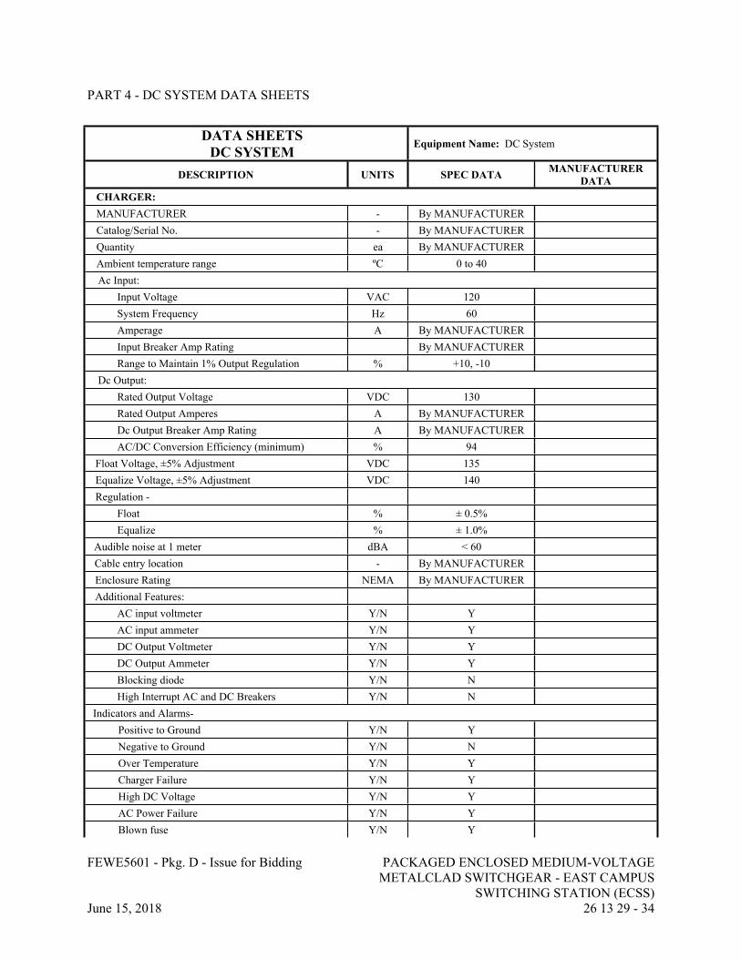
FEWE5601 - Pkg. D - Issue for Bidding PACKAGED ENCLOSED MEDIUM-VOLTAGE METALCLAD SWITCHGEAR - EAST CAMPUS
SWITCHING STATION (ECSS)June 15, 2018 26 13 29 - 34
PART 4 - DC SYSTEM DATA SHEETS
DATA SHEETSDC SYSTEM
Equipment Name: DC System
DESCRIPTION UNITS SPEC DATA MANUFACTURER DATA
CHARGER:MANUFACTURER - By MANUFACTURERCatalog/Serial No. - By MANUFACTURERQuantity ea By MANUFACTURERAmbient temperature range ºC 0 to 40Ac Input:
Input Voltage VAC 120System Frequency Hz 60Amperage A By MANUFACTURERInput Breaker Amp Rating By MANUFACTURERRange to Maintain 1% Output Regulation % +10, -10
Dc Output:Rated Output Voltage VDC 130Rated Output Amperes A By MANUFACTURERDc Output Breaker Amp Rating A By MANUFACTURERAC/DC Conversion Efficiency (minimum) % 94
Float Voltage, ±5% Adjustment VDC 135Equalize Voltage, ±5% Adjustment VDC 140Regulation -
Float % ± 0.5%Equalize % ± 1.0%
Audible noise at 1 meter dBA < 60Cable entry location - By MANUFACTUREREnclosure Rating NEMA By MANUFACTURERAdditional Features:
AC input voltmeter Y/N YAC input ammeter Y/N YDC Output Voltmeter Y/N YDC Output Ammeter Y/N YBlocking diode Y/N NHigh Interrupt AC and DC Breakers Y/N N
Indicators and Alarms-Positive to Ground Y/N YNegative to Ground Y/N NOver Temperature Y/N YCharger Failure Y/N YHigh DC Voltage Y/N YAC Power Failure Y/N YBlown fuse Y/N Y
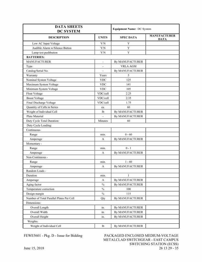
FEWE5601 - Pkg. D - Issue for Bidding PACKAGED ENCLOSED MEDIUM-VOLTAGE METALCLAD SWITCHGEAR - EAST CAMPUS
SWITCHING STATION (ECSS)June 15, 2018 26 13 29 - 35
DATA SHEETSDC SYSTEM
Equipment Name: DC System
DESCRIPTION UNITS SPEC DATA MANUFACTURER DATA
Low AC Input Voltage Y/N YAudible Alarm w/Silence Button Y/N YLamp test pushbutton Y/N Y
BATTERIES:MANUFACTURER - By MANUFACTURERType - VRLA AGMCatalog/Serial No. - By MANUFACTURERWarranty Years 5Nominal System Voltage VDC 125Maximum System Voltage VDC 141Minimum System Voltage VDC 105Float Voltage VDC/cell 2.25Boost Voltage VDC/cell 2.35Final Discharge Voltage VDC/cell 1.75Quantity of Cells in Series ea. 60Weight of Individual Cell lb By MANUFACTURERPlate Material - By MANUFACTURERDuty Cycle Total Duration: Minutes 60Duty Cycle Loading:Continuous-
Range min. 0 - 60Amperage A By MANUFACTURER
Momentary -Range min. 0 - 1Amperage A By MANUFACTURER
Non-Continuous - Range min. 1 - 60Amperage A By MANUFACTURER
Random Loads - Duration min. 1Amperage A By MANUFACTURERAging factor % By MANUFACTURERTemperature correction % 100Design margin % 115Number of Total Parallel Plates Per Cell Qty By MANUFACTURERDimensions:
Overall Length in. By MANUFACTUREROverall Width in. By MANUFACTUREROverall Height in. By MANUFACTURER
Weights:Weight of Individual Cell lb By MANUFACTURER
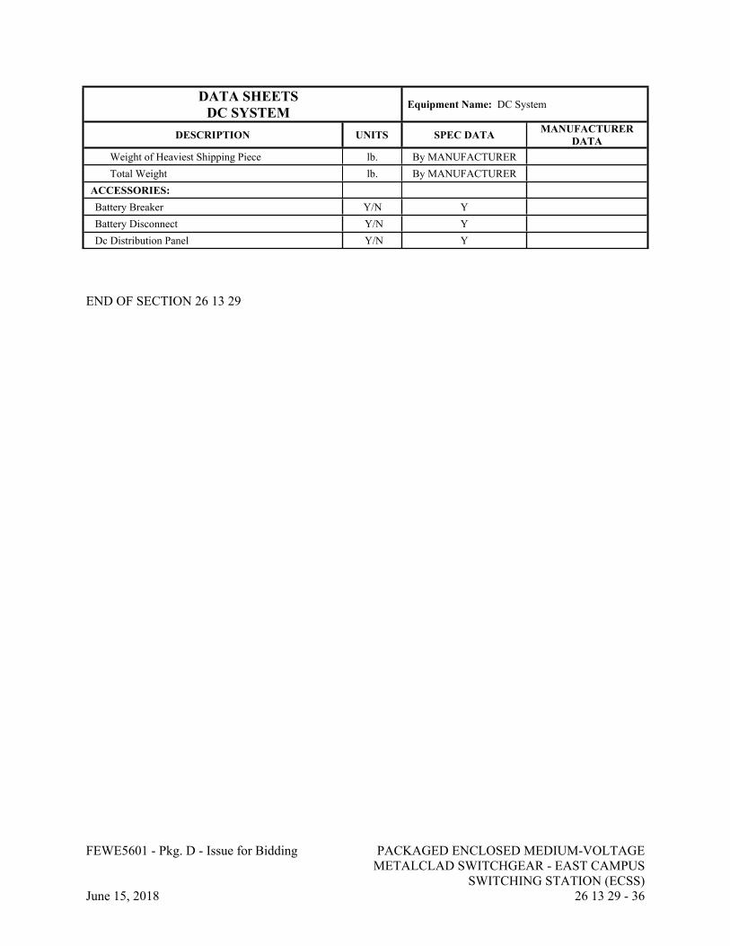
FEWE5601 - Pkg. D - Issue for Bidding PACKAGED ENCLOSED MEDIUM-VOLTAGE METALCLAD SWITCHGEAR - EAST CAMPUS
SWITCHING STATION (ECSS)June 15, 2018 26 13 29 - 36
DATA SHEETSDC SYSTEM
Equipment Name: DC System
DESCRIPTION UNITS SPEC DATA MANUFACTURER DATA
Weight of Heaviest Shipping Piece lb. By MANUFACTURERTotal Weight lb. By MANUFACTURER
ACCESSORIES:Battery Breaker Y/N YBattery Disconnect Y/N YDc Distribution Panel Y/N Y
END OF SECTION 26 13 29