Embed Size (px)
Citation preview

GEOMECHANICAL ANALYSIS OF VOLCANIC ROCK ON THE ISLAND OF SABA (NETHERLANDS ANTILLES) Richard Rijkers 1 & Robert Hack 2
ABSTRACT A geomechanical analysis of a shallow small scale landslide in the harbour of Saba was carried out to calculate the risk of new landslides and in order to advise local authorities on practical measures to improve safety. Geotechnical investigations and geological mapping were carried out to study the failure mechanism and slope stability. Comparison of shear box tests, field natural slope angle observations and calculations of slope stability probability showed a good agreement. INTRODUCTION In February 1997 a small scale landslide occurred on the island of Saba (Netherlands Antilles) in the Caribbean Sea. The landslide occurred during heavy rainfall in the harbour Fort Bay on the southern coast of Saba. The landslide is located along a road cut at the westerly part of the harbour. The unsafe situation on the slope was recognised quickly as a serious threat to historical building and harbour works at the toe of the slope (Figure 1). Initial site investigations and research were carried out because of large threatening boulders hanging halfway up the collapsed slope.
Figure 1 : Landslide in the harbour of Fort Bay of February 1997. ________________________ 1 Netherlands Institute of Applied Geosciences, (NITG-TNO), Geomechanical Research, PO box 97, 2600 JA Delft,
The Netherlands, tel.: +31 15 2697222, [email protected] 2 International Institute for Aerospace Survey and Earth Sciences (ITC), Centre for Technical Geosciences, Section
Engineering Geology, Kanaalweg 3, 2628 EB Delft, The Netherlands, tel.: +31 15 2748847, [email protected]
Rijkers, R., Hack, H.R.G.K., 2000. Geomechanical analysis of volcanic rock on the island of Saba, Netherlands Antilles. In: Littletidd, J.W., Drinan, J., Bucher, L.R., Hill, H.Z., Parker, T.S., Quincey, R.V. (Eds) GeoEng 2000; International Conference On Geotechnical and Geological Engineering, Melbourne, Australia, 19-24 November 2000. Taylor & Francis/Technomic Publishing Co,
Lancaster, PA, USA. 1 (Invited papers), p. 6.
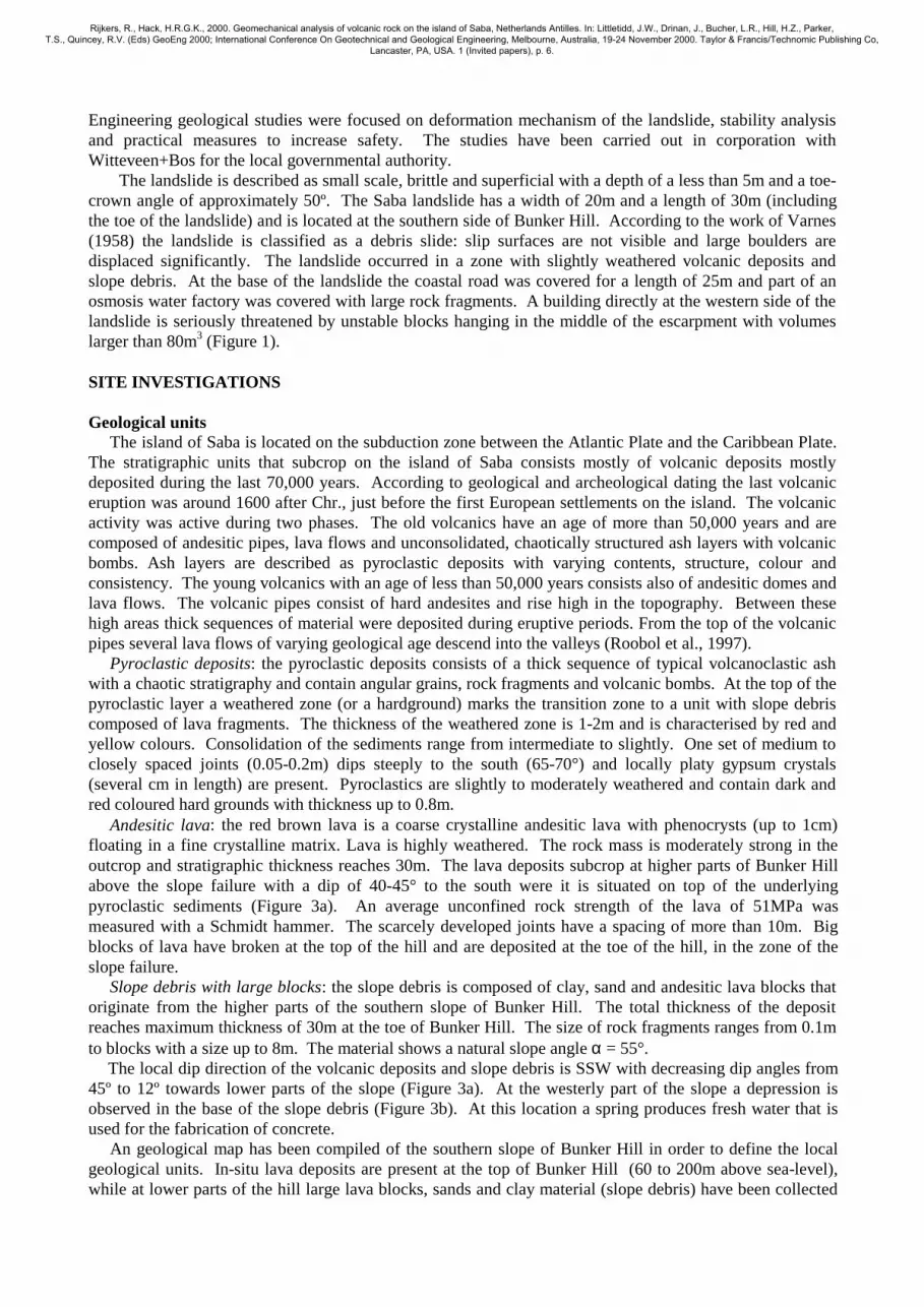
Engineering geological studies were focused on deformation mechanism of the landslide, stability analysis and practical measures to increase safety. The studies have been carried out in corporation with Witteveen+Bos for the local governmental authority. The landslide is described as small scale, brittle and superficial with a depth of a less than 5m and a toe-crown angle of approximately 50º. The Saba landslide has a width of 20m and a length of 30m (including the toe of the landslide) and is located at the southern side of Bunker Hill. According to the work of Varnes (1958) the landslide is classified as a debris slide: slip surfaces are not visible and large boulders are displaced significantly. The landslide occurred in a zone with slightly weathered volcanic deposits and slope debris. At the base of the landslide the coastal road was covered for a length of 25m and part of an osmosis water factory was covered with large rock fragments. A building directly at the western side of the landslide is seriously threatened by unstable blocks hanging in the middle of the escarpment with volumes larger than 80m3 (Figure 1). SITE INVESTIGATIONS Geological units The island of Saba is located on the subduction zone between the Atlantic Plate and the Caribbean Plate. The stratigraphic units that subcrop on the island of Saba consists mostly of volcanic deposits mostly deposited during the last 70,000 years. According to geological and archeological dating the last volcanic eruption was around 1600 after Chr., just before the first European settlements on the island. The volcanic activity was active during two phases. The old volcanics have an age of more than 50,000 years and are composed of andesitic pipes, lava flows and unconsolidated, chaotically structured ash layers with volcanic bombs. Ash layers are described as pyroclastic deposits with varying contents, structure, colour and consistency. The young volcanics with an age of less than 50,000 years consists also of andesitic domes and lava flows. The volcanic pipes consist of hard andesites and rise high in the topography. Between these high areas thick sequences of material were deposited during eruptive periods. From the top of the volcanic pipes several lava flows of varying geological age descend into the valleys (Roobol et al., 1997). Pyroclastic deposits: the pyroclastic deposits consists of a thick sequence of typical volcanoclastic ash with a chaotic stratigraphy and contain angular grains, rock fragments and volcanic bombs. At the top of the pyroclastic layer a weathered zone (or a hardground) marks the transition zone to a unit with slope debris composed of lava fragments. The thickness of the weathered zone is 1-2m and is characterised by red and yellow colours. Consolidation of the sediments range from intermediate to slightly. One set of medium to closely spaced joints (0.05-0.2m) dips steeply to the south (65-70°) and locally platy gypsum crystals (several cm in length) are present. Pyroclastics are slightly to moderately weathered and contain dark and red coloured hard grounds with thickness up to 0.8m. Andesitic lava: the red brown lava is a coarse crystalline andesitic lava with phenocrysts (up to 1cm) floating in a fine crystalline matrix. Lava is highly weathered. The rock mass is moderately strong in the outcrop and stratigraphic thickness reaches 30m. The lava deposits subcrop at higher parts of Bunker Hill above the slope failure with a dip of 40-45° to the south were it is situated on top of the underlying pyroclastic sediments (Figure 3a). An average unconfined rock strength of the lava of 51MPa was measured with a Schmidt hammer. The scarcely developed joints have a spacing of more than 10m. Big blocks of lava have broken at the top of the hill and are deposited at the toe of the hill, in the zone of the slope failure. Slope debris with large blocks: the slope debris is composed of clay, sand and andesitic lava blocks that originate from the higher parts of the southern slope of Bunker Hill. The total thickness of the deposit reaches maximum thickness of 30m at the toe of Bunker Hill. The size of rock fragments ranges from 0.1m to blocks with a size up to 8m. The material shows a natural slope angle α = 55°. The local dip direction of the volcanic deposits and slope debris is SSW with decreasing dip angles from 45º to 12º towards lower parts of the slope (Figure 3a). At the westerly part of the slope a depression is observed in the base of the slope debris (Figure 3b). At this location a spring produces fresh water that is used for the fabrication of concrete. An geological map has been compiled of the southern slope of Bunker Hill in order to define the local geological units. In-situ lava deposits are present at the top of Bunker Hill (60 to 200m above sea-level), while at lower parts of the hill large lava blocks, sands and clay material (slope debris) have been collected
Rijkers, R., Hack, H.R.G.K., 2000. Geomechanical analysis of volcanic rock on the island of Saba, Netherlands Antilles. In: Littletidd, J.W., Drinan, J., Bucher, L.R., Hill, H.Z., Parker, T.S., Quincey, R.V. (Eds) GeoEng 2000; International Conference On Geotechnical and Geological Engineering, Melbourne, Australia, 19-24 November 2000. Taylor & Francis/Technomic Publishing Co,
Lancaster, PA, USA. 1 (Invited papers), p. 6.

at the toe of Bunker Hill (Figure 3a). In-situ lava deposits and slope debris are lying unconformably on top of the pyroclastic deposits. The slope debris dips with low angles to the west and to the east (Figure 3b). Engineering geological zones In the direct surroundings of the collapsed slope four engineering geological units are mapped and have been characterised by lithological and geotechnical parameters established from field and laboratory investigations (Figure 2; Table 1). Zone I is the landslide area itself. Resulting from the slope failure the slope angle was lowered to 45°. Large blocks with volumes of more than 80m3 are lying halfway up the slope. Zone II is the westerly continuation of the slope directly behind the Harbour Office with an height of more than 20m and a slope angle of 65-70°. Zone III is the most eastern part of the studied slope with low heights of 3-12m. Zone IV is oriented perpendicular to the dip of the strata and the jointing.
Figure 2 : Engineering-geological map of the slope directly behind the buildings of Aqua Design (osmosis
factory) and the Harbour office. The studied slope is divided into four geotechnical zones.
Figure 3a : Geological section A-A’ (N-S) Figure 3b : Geological section B-B’ (E-W)
Rijkers, R., Hack, H.R.G.K., 2000. Geomechanical analysis of volcanic rock on the island of Saba, Netherlands Antilles. In: Littletidd, J.W., Drinan, J., Bucher, L.R., Hill, H.Z., Parker, T.S., Quincey, R.V. (Eds) GeoEng 2000; International Conference On Geotechnical and Geological Engineering, Melbourne, Australia, 19-24 November 2000. Taylor & Francis/Technomic Publishing Co,
Lancaster, PA, USA. 1 (Invited papers), p. 6.

Geotechnical laboratory investigations During site investigations samples have been taken from the pyroclastic and lava deposits (Table 1). Both standard volumetric unit weights and shear box tests with dry and wet samples have been done in a geotechnical laboratory. Water contents of pyroclastic and andestic rock are almost zero because of the dry status of the upper part of the slope during the sampling period. The water contents in deeper parts of the slope is not known, but is likely to be higher as showed by the spring at the most westerly part of the slope. The porosity of the pyroclastic deposits is 15% which are possibly filled with water during periods of rain. The lava is impermeable, but is characterised by non-connecting vuggy pores with measured porosity of 14.5%. Shear box tests have been carried out on pyroclastic deposits to obtain friction angle and cohesion. As a result cohesion c of dry samples showed values two times higher than those on wet samples. The high cohesion of the material is decreased when the sample is water-saturated (Figure 4). The MBA-value of 3.2 g/100g indicates the presence of swelling clay minerals in the pyroclastic rock structure. Table 1 : Geotechnical characteristics of pyroclastics
Geotechnical parameter Pyroclastic Andesitic deposits lava
Dry vol. unit weight γd 14.3 kN/m2 -
Wet vol. unit weigth γw 21.5 kN/m2 23.2 kN/m2
Particle density Wg 2.67 kg/m3 2.77 kg/m3
Water contents w nihil nihil Porosity P 15.2 % 14.5 %
Methylene blue test (swelling clay) MBA 3.2 g/100g 3.3 g/100g Compressional strength τc - 51 MPa
Internal friction (dry and wet) φ 27 ° - Cohesion (dry) cdry 40 kPa -
Cohesion (wet) cwet 22 kPa -
Natural stable slope angle α 65-70° 75-80°
Figure 4 : Results of the direct shear box tests FAILURE MECHANISM AND STABILITY ANALYSIS Geohydrology and failure mechanism The southern slope of Bunker Hill (to heights of more than 200m above sea level) drains rainwater into a flat area at a height of approx. 40-50m directly above the collapsed slope. At this flat the collected water penetrates into the slope deposits. Especially during heavy rainfalls, water pressures decreases cohesion and
Rijkers, R., Hack, H.R.G.K., 2000. Geomechanical analysis of volcanic rock on the island of Saba, Netherlands Antilles. In: Littletidd, J.W., Drinan, J., Bucher, L.R., Hill, H.Z., Parker, T.S., Quincey, R.V. (Eds) GeoEng 2000; International Conference On Geotechnical and Geological Engineering, Melbourne, Australia, 19-24 November 2000. Taylor & Francis/Technomic Publishing Co,
Lancaster, PA, USA. 1 (Invited papers), p. 6.
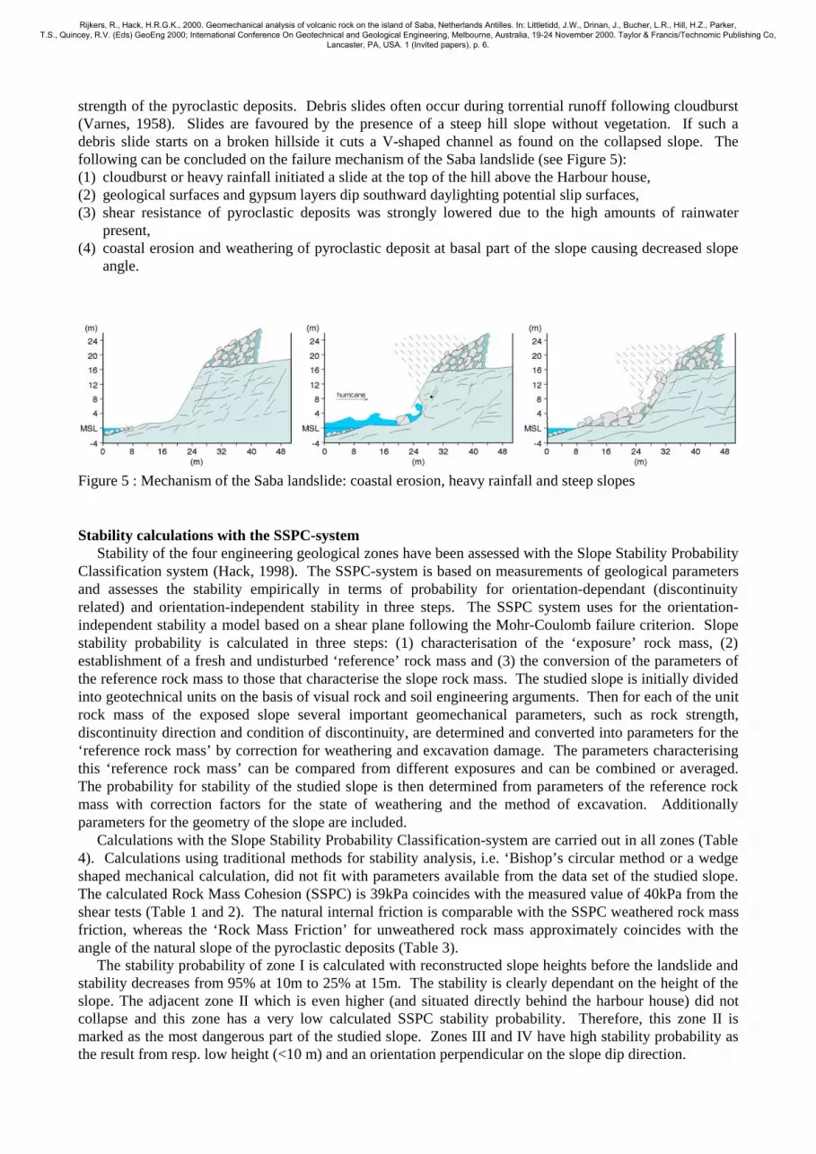
strength of the pyroclastic deposits. Debris slides often occur during torrential runoff following cloudburst (Varnes, 1958). Slides are favoured by the presence of a steep hill slope without vegetation. If such a debris slide starts on a broken hillside it cuts a V-shaped channel as found on the collapsed slope. The following can be concluded on the failure mechanism of the Saba landslide (see Figure 5): (1) cloudburst or heavy rainfall initiated a slide at the top of the hill above the Harbour house, (2) geological surfaces and gypsum layers dip southward daylighting potential slip surfaces, (3) shear resistance of pyroclastic deposits was strongly lowered due to the high amounts of rainwater
present, (4) coastal erosion and weathering of pyroclastic deposit at basal part of the slope causing decreased slope
angle.
Figure 5 : Mechanism of the Saba landslide: coastal erosion, heavy rainfall and steep slopes Stability calculations with the SSPC-system Stability of the four engineering geological zones have been assessed with the Slope Stability Probability Classification system (Hack, 1998). The SSPC-system is based on measurements of geological parameters and assesses the stability empirically in terms of probability for orientation-dependant (discontinuity related) and orientation-independent stability in three steps. The SSPC system uses for the orientation-independent stability a model based on a shear plane following the Mohr-Coulomb failure criterion. Slope stability probability is calculated in three steps: (1) characterisation of the ‘exposure’ rock mass, (2) establishment of a fresh and undisturbed ‘reference’ rock mass and (3) the conversion of the parameters of the reference rock mass to those that characterise the slope rock mass. The studied slope is initially divided into geotechnical units on the basis of visual rock and soil engineering arguments. Then for each of the unit rock mass of the exposed slope several important geomechanical parameters, such as rock strength, discontinuity direction and condition of discontinuity, are determined and converted into parameters for the ‘reference rock mass’ by correction for weathering and excavation damage. The parameters characterising this ‘reference rock mass’ can be compared from different exposures and can be combined or averaged. The probability for stability of the studied slope is then determined from parameters of the reference rock mass with correction factors for the state of weathering and the method of excavation. Additionally parameters for the geometry of the slope are included. Calculations with the Slope Stability Probability Classification-system are carried out in all zones (Table 4). Calculations using traditional methods for stability analysis, i.e. ‘Bishop’s circular method or a wedge shaped mechanical calculation, did not fit with parameters available from the data set of the studied slope. The calculated Rock Mass Cohesion (SSPC) is 39kPa coincides with the measured value of 40kPa from the shear tests (Table 1 and 2). The natural internal friction is comparable with the SSPC weathered rock mass friction, whereas the ‘Rock Mass Friction’ for unweathered rock mass approximately coincides with the angle of the natural slope of the pyroclastic deposits (Table 3). The stability probability of zone I is calculated with reconstructed slope heights before the landslide and stability decreases from 95% at 10m to 25% at 15m. The stability is clearly dependant on the height of the slope. The adjacent zone II which is even higher (and situated directly behind the harbour house) did not collapse and this zone has a very low calculated SSPC stability probability. Therefore, this zone II is marked as the most dangerous part of the studied slope. Zones III and IV have high stability probability as the result from resp. low height (<10 m) and an orientation perpendicular on the slope dip direction.
Rijkers, R., Hack, H.R.G.K., 2000. Geomechanical analysis of volcanic rock on the island of Saba, Netherlands Antilles. In: Littletidd, J.W., Drinan, J., Bucher, L.R., Hill, H.Z., Parker, T.S., Quincey, R.V. (Eds) GeoEng 2000; International Conference On Geotechnical and Geological Engineering, Melbourne, Australia, 19-24 November 2000. Taylor & Francis/Technomic Publishing Co,
Lancaster, PA, USA. 1 (Invited papers), p. 6.

Table 2 : Comparison of calculated friction angle/cohesion of pyroclastic deposits.
Pyroclastic deposits Calculated SSPC Laboratory / field Rock mass friction 35° 27° (measured)
Rock mass cohesion 39kPa 40kPa (measured) Calculated maximum possible height on the slope 13m 15m (observed)
Table 3 : Laboratory internal friction, rock mass friction and natural slope angle of pyroclastic deposits.
Friction angle value Effective internal friction (direct shear box) 27 °
Rock Mass Friction weathered (SSPC) 35 ° Rock Mass Friction unweathered (SSPC) 57 ° Natural slope angle (field observation) 65-70 °
Table 4 : SSPC stability calculations performed on pyroclastic deposits.
Zone number height (m) Dip direction slope / dip slope [º]
Calculated SSPC stability probability
Zone I 10-15 195 / 70 25 - 95% (collapsed zone) Zone II 15-18 195 / 70 0-25% (slope directly behind building) Zone III < 10 195 / 70 >95% Zone IV 5-18 125 / 65 100 %
DISCUSSION AND PRACTICAL MEASURES From comparison of laboratory tests, field slope angle observations and calculations of SSPC stability probability in the pyroclastic deposits it is observed that (shear box) friction angle, cohesion, natural slope angle and SSPC parameters correlate well. From simple field observations on potential slip surfaces, weathering and rock mass strength the stability probability of the rock slope is assessed for four different geotechnical zones. Zone I (the collapsed slope) gives very low stability probability for slope heights of 15m; this calculated height correlates with the height of the collapsed landslide. Zone II is higher than the collapsed zone and has not yet collapsed, but calculations emphasises the dangerous situation of the slope directly behind the Harbour house. The SSPC slope assessment has proved to be a very comprehensive tool to asseses the stability of the slope; output of the analysis as calculated risk have helped governmental and non-technical people to understand the danger of the site. Drainage for the upper part of the slope is urgently advised as an essential tool for stabilisation of the slope, because water traditionally had major impact on the initiation of the debris slide. Moreover, various other practical mechanical measures have been advised to be taken in zone I such as the removal of large lava boulders and erosion protection at the base of the slope to prevent the sea washing away the material from the landslide escarpment. Secondly, for the most instable zone II various measures were advised: rock bolting, meshed grout at higher parts of the slope and erosion protection at base of slope to protect the slope from the Caribbean Sea during hurricanes and other heavy weather conditions. REFERENCES Hack, H.R.G.K. (1998). “Slope Stability Probability Classification SSPC”. ITC publications no. 43, Delft. Roobol, M.J., Smith, A.L. and Tomblin, J.F. (1997). “Volcanology of the Island of Saba and St.Eustatius in
the northern lesser Antilles”. Part 1 - Geology, pyroclastic stratigraphy and petrology of Saba and St. Eustatius, NITG - TNO, Haarlem, pp. 256.
Varnes, D.J. (1958). “Landslide Types and Processes”. Landslides and Engineering Practice, E.B., Eckel Ed., HRB Special report, Vol. 29, pp. 20-47.
Rijkers, R., Hack, H.R.G.K., 2000. Geomechanical analysis of volcanic rock on the island of Saba, Netherlands Antilles. In: Littletidd, J.W., Drinan, J., Bucher, L.R., Hill, H.Z., Parker, T.S., Quincey, R.V. (Eds) GeoEng 2000; International Conference On Geotechnical and Geological Engineering, Melbourne, Australia, 19-24 November 2000. Taylor & Francis/Technomic Publishing Co,
Lancaster, PA, USA. 1 (Invited papers), p. 6.


