Embed Size (px)
Citation preview
GEOSPATIAL DATABASE UPDATING SYSTEM with WMS and DIRECT
CONNECTION METHOD
B. Yüksel 1, A. Yilmaz 1, *
1 General Command of Mapping, Photogrammetry Department, 06590 Dikimevi Ankara, Turkey - (bekir.yuksel,
altan.yilmaz)@hgk.msb.gov.tr
Commission IV, ICWG IV/III
KEY WORDS: TOPOVT, Updating of Geodatabase, Topographic Database, WMS, Direct Connection
ABSTRACT:
The demand for up-to-date geospatial data is in an upward trend. This brings a continuous and sustainable review and update of the
geospatial data itself and database design. Turkish Topographic Vector Database (TOPOVT) is the main database of Turkey consisting
1:25.000 and higher scale resolution 3D topographic vector data covering whole country. It also consists of contours and geonames.
TOPOVT has been and is still being produced by General Command of Mapping of Turkey mainly from 30 cm resolution stereo aerial
photos and completed in the field. TOPOVT is seamless and topologic database. The updating objective is five years cycle. The first
production cycle of TOPOVT in vector has been completed recently. Before the updating cycle began, a system was designed to update
TOPOVT efficiently and without losing any information content. It also holds historical background of the features updated.
With this topographic data update system, geospatial data can be updated rapidly and served to the users. Hereby both the process for
map printing fastens and answers to the need of updated data for the TOPOVT database can be achieved. With this system, the data
which will be updated can be displayed on the personal computer by TOPOVT database connection and the users can perform add,
update and delete actions in the data according to their authorization. All the updates executed in the field can be monitored on the
TOPOVT database in real time via internet connection.
1. INTRODUCTION
Earth’s surface is changing continuously due to natural and/or
artificial factors. While natural change is slow, artificial/man
made change occurs more rapidly. Especially in developing
countries these changes take place even faster. In order to keep
up pace with the changing situations, decision makers have to be
informed on time geospatially (Maras and Altan, 2000). The
geospatial data can be updated by field survey, remote sensing
techniques, compilation, or by comparing existing data by a new
reference (Samen et al., 2014).
Classical methods cannot keep up pace with the speed of
geospatial data change. Some researchers are put forth methods
for geospatial data updating. Pan et al., (2014) discussed raster to
raster data, raster to vector data and vector to vector data update
technology. They claimed that these methods are efficient and
accurate enough. Lopez-Pellicer et al., (2011) looked for the web
based geoprocessing and Open Geospatial Consortium (OGC)
means of updating geodata. They found that Web Processing
Service (WPS) compliant features are lacking in data providers
and service providers have to provide semantic interoperability
in geospatial systems. Samen et al., (2014) proposed a new
method in order to enter geospatial data to database by HTML
Object Library and Open Source GIS. They transferred the data
to geospatial database by an interface.
Maras and Altan (2000) proposed the history of the update
process has to be stored. They inserted that deleted features had
to be accessible for their information content. They also
suggested that feature addition and updating should be included
in their attributes.
Pla and Lleopart (2010) asserted the collaborative updating by
using OGC, Geographic Markup Language (GML) and Web
Feature Service (WFS) standards. They tried to coproduce The
Institut Cartogràfic de Catalunya (ICC) vector data with
shareholders. They also improved ICC geospatial databases by
means of the data model improvement holding unique identifiers
and attributes for versioning and step-by-step updating. They
hoped for quality enhancement and wide usage of geospatial
databases.
Turkish Topographic Vector Database (TOPOVT) is the
geospatial database consisting of topographic features in
1:25.000 and larger scales covering whole Turkey. So far,
TOPOVT is produced by General Command of Mapping. Yılmaz
and Canıberk (2018) proposed a web based updating system for
TOPOVT. This real time updating system allows shareholders to
facilitate and update TOPOVT by an internet browser with a
direct connection to the geospatial database.
When a vector database link is established on Esri ArcGIS, all
the geodata is on the screen and the database is busy with this
query as in other Geographic Information Systems (GIS)
software. If the size of the mentioned data is large, it will cause
slowdown both in display and update operations. Since this
slowness prevents updating the data quickly and effectively, a
more efficient method of updating TOPOVT, which includes
continuous large size data covering the whole country have been
searched for.
As a result of the analyses made; it is determined that there is no
need to be present on the screen as a vector if the update is not
performed first. If the user wants to update the data that he / she
has reviewed, it is thought that it can be an effective method to
The International Archives of the Photogrammetry, Remote Sensing and Spatial Information Sciences, Volume XLII-4, 2018 ISPRS TC IV Mid-term Symposium “3D Spatial Information Science – The Engine of Change”, 1–5 October 2018, Delft, The Netherlands
This contribution has been peer-reviewed. https://doi.org/10.5194/isprs-archives-XLII-4-737-2018 | © Authors 2018. CC BY 4.0 License.
737
update the data by calling the prepared program and send it back
to the database at the end of the process.
In order to implement this method, it is necessary to transform
the current version of the data into its own symbols and to use it
as a vector to be updated, if necessary. The design of the system
was carried out in three main groups related to each other. These
are:
1. Preparing the WMS service which will bring the
appropriate images of the data to the screen at the desired
scales,
2. Designing the personal vector database in the user side
and making the necessary changes and additions in the
enterprise vector database,
3. Development of the software that will provide the link
between the WMS publication and the vector data structure
prepared in the first and second articles.
2. PREPARATION OF WMS SERVICE
All existing vector data in the database is added to ArcMap
screen and WMS service is prepared by using its own symbols.
In order to provide vector data link over this service later, some
rules were put in the layer naming. These rules are as follows:
1. The layer names will be identical to the name of the
corresponding feature class. For example, the layer name
that receives data from the “FOREST” feature class must
begin with the FOREST statement.
2. The "-" sign will be used to distinguish the expression
to be used after the feature class name.
3. After the feature class names: if it is desired to write
active and passive scale ranges on the screen then the values
will be written as 3 missing and with a "_" sign in between.
4. The expressions used with the "_" sign tell what the
features of the feature class are.
According to these rules, an example layer naming scheme is:
The name "MUNHANI-15_5_ANA" is the name of the
"CONTOUR" layer and the feature class that the layer receives
data from. The "-" sign indicates that the subsequent statements
are meant to be informative. "15" refers to a scale of 1: 15,000,
and "5" refers to a scale of 1: 5,000.
These values provide information about the minimum and
maximum scale ranges that the layer will occupy on the screen.
The interval at which the layer is shown is already present in the
properties of the WMS layer. The purpose of writing these values
is to ensure that the layers that are not included in any group layer
can be directly distinguished by the names of the minimum and
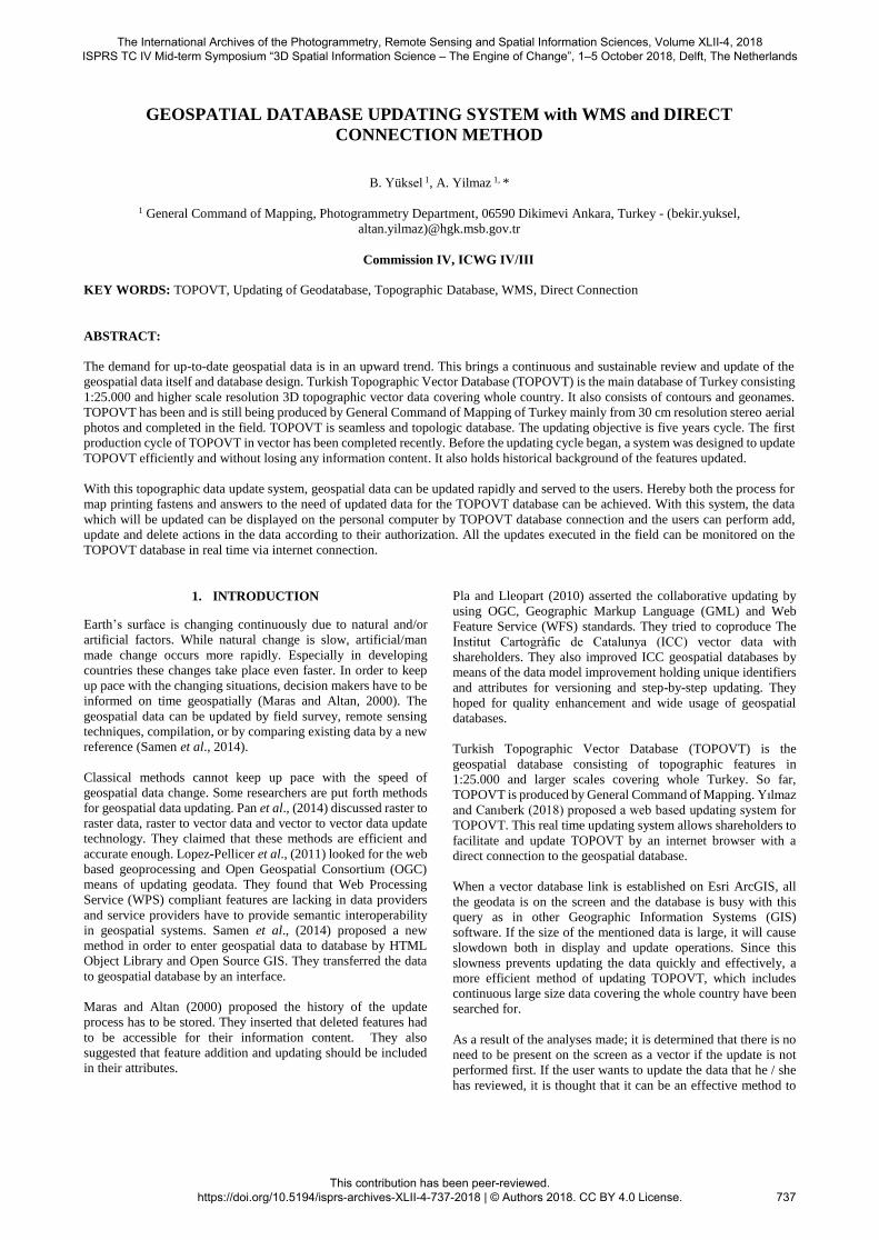
maximum scale ranges. "ANA (means MAIN)" is the name of
the subtypes of the features shown on this layer. This
demonstration is intended only to prevent the mess that will occur
when there are only 2 layers in the same name. Which features
are shown are already present in the "Description" section of the
layer's properties as an SQL statement. For example, the
"Description" value of this layer is "topodetayalttipno = 4".
(Figure 1) How this phrase is used will be explained in detail in
the next section.
Figure 1. Layers and properties of WMS service
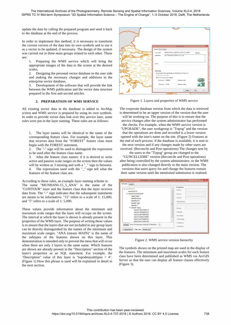
The corporate database version from which the data is retrieved
is determined to be an upper version of the version that the user
will be working on. The purpose of this is to ensure that the
service changes after the system administrator has performed
the checks. For example, when the WMS service version is
"UPGRADE", the user workgroup is "Topog" and the version
that the operations are done and recorded is a lower version
opened with the user's name on the site. (Figure 2) Features at
the end of each process: if the database is available, it is sent to
the next version and if any changes made by other users are
received. (Reconcile and Post operations) The changes sent by
the users to the "Topog" group are changed to the
"GUNCELLEME" version (Reconcile and Post operations)
after being controlled by the system administrator, or the WMS
publication is also changed directly to the main version. The
versions that users query for and change the features remain
their same version until the mentioned submission is realized.
Figure 2. WMS service version hierarchy
The symbols shown on the printed map are used in the display of
the features. The minimum and maximum scales for each feature
class have been determined and published as WMS via ArcGIS
Server so that the user can display all feature classes effectively
(Figure 3).
The International Archives of the Photogrammetry, Remote Sensing and Spatial Information Sciences, Volume XLII-4, 2018 ISPRS TC IV Mid-term Symposium “3D Spatial Information Science – The Engine of Change”, 1–5 October 2018, Delft, The Netherlands
This contribution has been peer-reviewed. https://doi.org/10.5194/isprs-archives-XLII-4-737-2018 | © Authors 2018. CC BY 4.0 License.
738
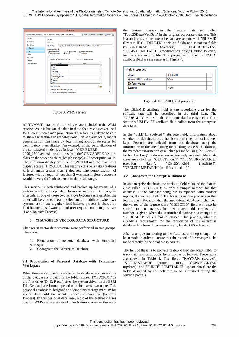
Figure 3. WMS service
All TOPOVT database feature classes are included in the WMS
service. As it is known, the data in these feature classes are used
for 1: 25.000 scale map production. Therefore, in order to be able
to show the features in readable condition at every scale, model
generalization was made by determining appropriate scales for
each feature class display. An example of the generalization of
the constructed model is as follows: "GENISDERE-
2200_250 "layer shows features from the" GENISDERE "feature
class on the screen with" st_length (shape)> 2 "description value.
The minimum display scale is 1: 2,200,000 and the maximum
display scale is 1: 250,000. This feature class only takes features
with a length greater than 2 degrees. The demonstration of
features with a length of less than 2 was meaningless because it
would be very difficult to detect in this scale range.
This service is both reinforced and backed up by means of a
system which is independent from one another but at regular
intervals. If one of these two services becomes unavailable, the
other will be able to meet the demands. In addition, when two
systems are in use together, load-balance process is shared by
load balancing software to load user requests on a single server
(Load-Balance Process).
3. CHANGES IN VECTOR DATA STRUCTURE
Changes in vector data structure were performed in two groups.
These are:
1. Preparation of personal database with temporary
workspace,
2. Changes to the Enterprise Database.
3.1 Preparation of Personal Database with Temporary
Workspace
When the user calls vector data from the database, a schema copy
of the database is created in the folder named TOPO25LOG in
the first drive (D, E, F etc.) after the system driver in the ESRI
File Geodatabase format opened with the user's own name. This
personal database is designed as a temporary storage medium for
vector data until the update process is complete (Sending
Process). In this personal data base, most of the feature classes
used in WMS service are used. The feature classes in these are
the feature classes in the feature data set called
"Topo25DetayVeriSeti" in the original corporate database. This
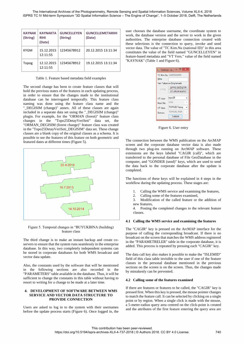
is a small copy of the enterprise database schema with "ISLEMID
(Process ID)", "DELETE" attribute fields and metadata fields
("OLUSTURAN (creator)", "OLUDURDATA",
"DEGISTIRMETARIHI (modification date)") added to every
feature class in this file. The properties of the "ISLEMID"
attribute field are the same as in Figure 4.
Figure 4. ISLEMID field properties
The ISLEMID attribute field is the recordable area for the
software that will be described in the third item. The
"GLOBALID" value in the corporate database is recorded in
feature’s "ISLEMID" attribute field called from the enterprise
data base.
In the "SILINDI (deleted)" attribute field, information about
whether the deleting process has been performed or not has been
kept. Features are deleted from the database using the
information in this area during the sending process. In addition,
the metadata information of all changes made using the "ArcGIS
Editor Tracking" feature is instantaneously retained. Metadata
areas are as follows: "OLUSTURAN", "OLUSTURMATARIHI
(creation date)", "DEGISTIREN (modifier)",
"DEGISTIRMETARIHI (modification date)".
3.2 Changes to the Enterprise Database
In an enterprise database, the attribute field value of the feature
class called "OBJECTID" is only a unique number for that
database. If the database being run is replaced with another
replica, the value "OBJECTID" loses its unique property in that
feature class. Because when the institutional database is changed,
the values of the feature class "OBJECTID" field will also be
specific to that database. In order to avoid this confusion, a
number is given when the institutional database is changed to
"GLOBALID" for all feature classes. This process, which is
already a requirement for the replication of the enterprise
database, has been done automatically by ArcGIS software.
After a unique numbering of the features, a 4-step change has
been made in order to ensure that the record of the changes to be
made directly in the database is correct.
The first of these is to provide feature-based metadata fields to
track data entries through the attributes of feature. These areas
are shown in Table 1. The fields "KAYNAK (source)",
"KAYNAKTARIHI (source date)", "GUNCELLEYEN
(updater)" and "GUNCELLEMETARIHI (update date)" are the
fields designed by the software to be submitted during the
sending process.
The International Archives of the Photogrammetry, Remote Sensing and Spatial Information Sciences, Volume XLII-4, 2018 ISPRS TC IV Mid-term Symposium “3D Spatial Information Science – The Engine of Change”, 1–5 October 2018, Delft, The Netherlands
This contribution has been peer-reviewed. https://doi.org/10.5194/isprs-archives-XLII-4-737-2018 | © Authors 2018. CC BY 4.0 License.
739
KAYNAK (String)
KAYNAKTARIHI (Date)
GUNCELLEYEN (String)
GUNCELLEMETARIHI (Date)
KYGM 15.12.2015 12:11:55
12345678912 20.12.2015 13:11:34
Topog 12.12.2015 12:11:55
12345678912 19.12.2015 13:11:34
Table 1. Feature based metadata field examples
The second change has been to create feature classes that will
hold the previous states of the features in each updating process,
in order to ensure that the changes made to the institutional
database can be interrogated temporally. This feature class
naming was done using the feature class name and the
"_DEGISIM (change)" annex. All of these classes are again
included in a separate data set using the "_DEGISIM (change)"
plugin. For example, for the "ORMAN (forest)" feature class
changes in the "Topo25DetayVeriSeti" data set, the
"ORMAN_DEGISIM (forest change)" feature class was created
in the "Topo25DetayVeriSeti_DEGISIM" data set. These change
classes are a blank copy of the original classes as a schema. It is
possible to see the features of this feature on both geometric and
featured dates at different times (Figure 5).
Figure 5. Temporal changes in “BUYUKBINA (building)
feature class
The third change is to make an instant backup and create co-
servers to ensure that the system runs seamlessly in the enterprise
database. In this way, two completely independent systems can
be stored in corporate databases for both WMS broadcast and
vector data update.
Also, the constants used by the software that will be mentioned
in the following sections are also recorded in the
"PARAMETERS" table available in the database. Thus, it will be
sufficient to change the constants in this table without having to
resort to writing for a change to be made at a later time.
4. DEVELOPMENT OF SOFTWARE BETWEEN WMS
SERVICE AND VECTOR DATA STRUCTURE TO
PROVIDE CONNECTION
Users are asked to log in to the system with their usernames
before the update process starts (Figure 6). Once logged in, the
user chooses the database username, the coordinate system to
work, the database version and the server to work in the given
authorities. The enterprise database connection created with
these selections is the connection to query, invoke and send
vector data. The value of "TC Kim.Nu (national ID)" in this area
constitutes the value of the field named "GUNCELLEYEN" in
feature-based metadata and "VT Vers." value of the field named
"KAYNAK" (Table 1 and Figure 6).
Figure 6. User entry
The connection between the WMS publication on the ArcMAP
screen and the corporate database vector data is also made
through two plug-ins running on ArcMAP software. These
extensions are the keys labeled "CAGIR (call)", which are
transferred to the personal database of File GeoDatabase in the
computer, and "GONDER (send)" keys, which are used to send
the data back to the corporate database after the update is
completed.
The functions of these keys will be explained in 4 steps in the
workflow during the updating process. These stages are:
1. Calling the WMS service and examining the features,
2. Calling some of the features examined,
3. Modification of the called feature or the addition of
new features,
4. Posting the completed changes to the relevant feature
classes.
4.1 Calling the WMS service and examining the features
The "CAGIR" key is pressed on the ArcMAP interface for the
purpose of calling the corresponding broadcast. If there is no
broadcast on the screen that matches the WMS address registered
in the "PARAMETRELER" table in the corporate database, it is
added. This process is repeated by pressing each "CAGIR" key.
The data call key also makes it possible to make the "ISLEMID"
field of this class table invisible to the user if one of the feature
classes in the personal database mentioned in the previous
sections on the screen is on the screen. Thus, the changes made
by mistakenly can be prevented.
4.2 Calling some of the features examined
If there are features or features to be called, the "CAGIR" key is
pressed first. When this key is pressed, the mouse pointer changes
to match the feature call. It can be selected by clicking on a single
point or by region. When a single click is made with the mouse,
a 5-meter-radius query area centred on the click-point is created
and the attributes of the first feature entering the query area are
The International Archives of the Photogrammetry, Remote Sensing and Spatial Information Sciences, Volume XLII-4, 2018 ISPRS TC IV Mid-term Symposium “3D Spatial Information Science – The Engine of Change”, 1–5 October 2018, Delft, The Netherlands
This contribution has been peer-reviewed. https://doi.org/10.5194/isprs-archives-XLII-4-737-2018 | © Authors 2018. CC BY 4.0 License.
740
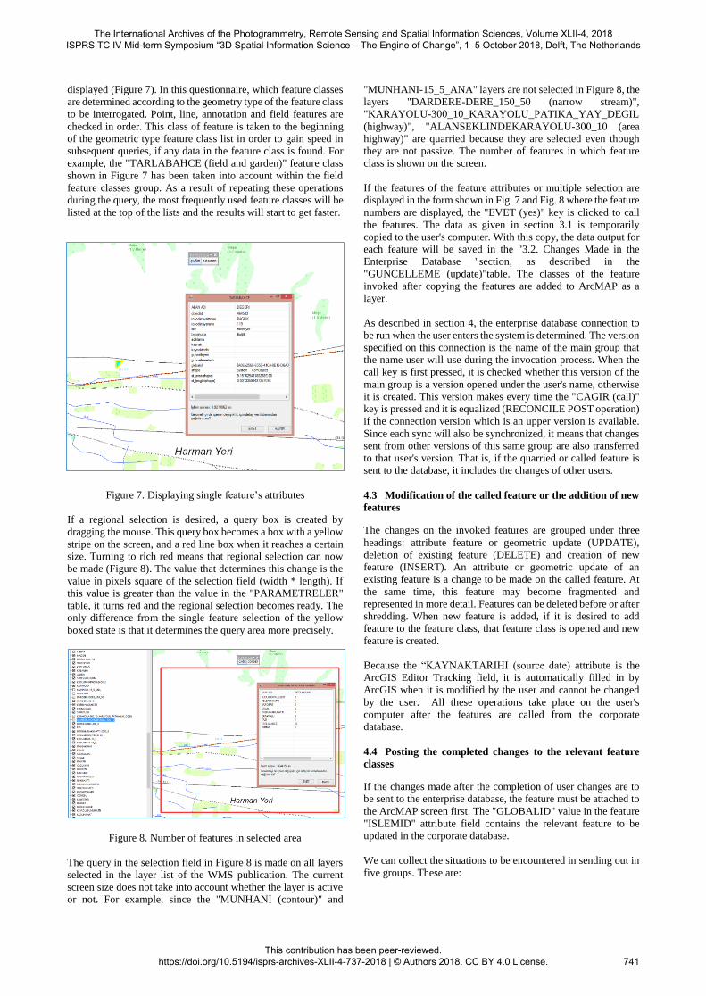
displayed (Figure 7). In this questionnaire, which feature classes
are determined according to the geometry type of the feature class
to be interrogated. Point, line, annotation and field features are
checked in order. This class of feature is taken to the beginning
of the geometric type feature class list in order to gain speed in
subsequent queries, if any data in the feature class is found. For
example, the "TARLABAHCE (field and garden)" feature class
shown in Figure 7 has been taken into account within the field
feature classes group. As a result of repeating these operations
during the query, the most frequently used feature classes will be
listed at the top of the lists and the results will start to get faster.
Figure 7. Displaying single feature’s attributes
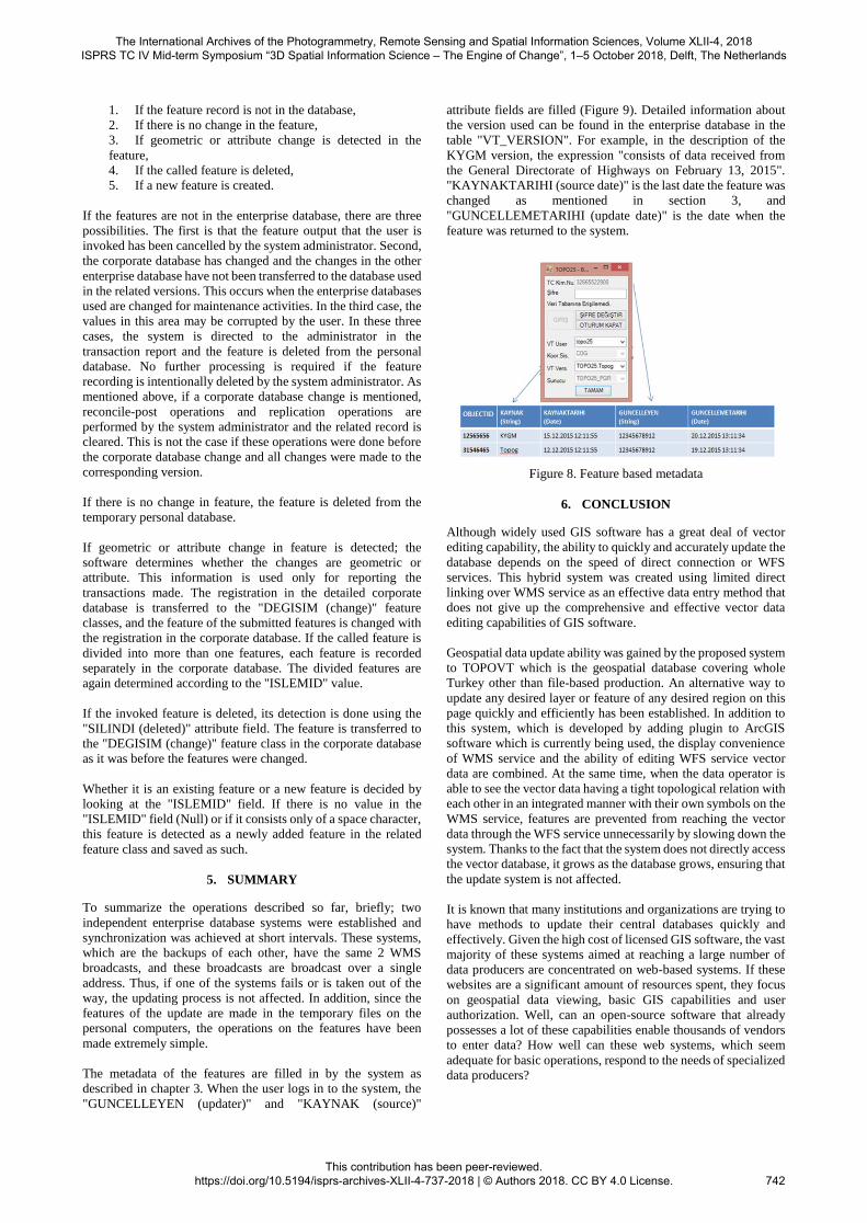
If a regional selection is desired, a query box is created by
dragging the mouse. This query box becomes a box with a yellow
stripe on the screen, and a red line box when it reaches a certain
size. Turning to rich red means that regional selection can now
be made (Figure 8). The value that determines this change is the
value in pixels square of the selection field (width * length). If
this value is greater than the value in the "PARAMETRELER"
table, it turns red and the regional selection becomes ready. The
only difference from the single feature selection of the yellow
boxed state is that it determines the query area more precisely.
Figure 8. Number of features in selected area
The query in the selection field in Figure 8 is made on all layers
selected in the layer list of the WMS publication. The current
screen size does not take into account whether the layer is active
or not. For example, since the "MUNHANI (contour)" and
"MUNHANI-15_5_ANA" layers are not selected in Figure 8, the
layers "DARDERE-DERE_150_50 (narrow stream)",
"KARAYOLU-300_10_KARAYOLU_PATIKA_YAY_DEGIL
(highway)", "ALANSEKLINDEKARAYOLU-300_10 (area
highway)" are quarried because they are selected even though
they are not passive. The number of features in which feature
class is shown on the screen.
If the features of the feature attributes or multiple selection are
displayed in the form shown in Fig. 7 and Fig. 8 where the feature
numbers are displayed, the "EVET (yes)" key is clicked to call
the features. The data as given in section 3.1 is temporarily
copied to the user's computer. With this copy, the data output for
each feature will be saved in the "3.2. Changes Made in the
Enterprise Database "section, as described in the
"GUNCELLEME (update)"table. The classes of the feature
invoked after copying the features are added to ArcMAP as a
layer.
As described in section 4, the enterprise database connection to
be run when the user enters the system is determined. The version
specified on this connection is the name of the main group that
the name user will use during the invocation process. When the
call key is first pressed, it is checked whether this version of the
main group is a version opened under the user's name, otherwise
it is created. This version makes every time the "CAGIR (call)"
key is pressed and it is equalized (RECONCILE POST operation)
if the connection version which is an upper version is available.
Since each sync will also be synchronized, it means that changes
sent from other versions of this same group are also transferred
to that user's version. That is, if the quarried or called feature is
sent to the database, it includes the changes of other users.
4.3 Modification of the called feature or the addition of new
features
The changes on the invoked features are grouped under three
headings: attribute feature or geometric update (UPDATE),
deletion of existing feature (DELETE) and creation of new
feature (INSERT). An attribute or geometric update of an
existing feature is a change to be made on the called feature. At
the same time, this feature may become fragmented and
represented in more detail. Features can be deleted before or after
shredding. When new feature is added, if it is desired to add
feature to the feature class, that feature class is opened and new
feature is created.
Because the “KAYNAKTARIHI (source date) attribute is the
ArcGIS Editor Tracking field, it is automatically filled in by
ArcGIS when it is modified by the user and cannot be changed
by the user. All these operations take place on the user's
computer after the features are called from the corporate
database.
4.4 Posting the completed changes to the relevant feature
classes
If the changes made after the completion of user changes are to
be sent to the enterprise database, the feature must be attached to
the ArcMAP screen first. The "GLOBALID" value in the feature
"ISLEMID" attribute field contains the relevant feature to be
updated in the corporate database.
We can collect the situations to be encountered in sending out in
five groups. These are:
The International Archives of the Photogrammetry, Remote Sensing and Spatial Information Sciences, Volume XLII-4, 2018 ISPRS TC IV Mid-term Symposium “3D Spatial Information Science – The Engine of Change”, 1–5 October 2018, Delft, The Netherlands
This contribution has been peer-reviewed. https://doi.org/10.5194/isprs-archives-XLII-4-737-2018 | © Authors 2018. CC BY 4.0 License.
741
1. If the feature record is not in the database,
2. If there is no change in the feature,
3. If geometric or attribute change is detected in the
feature,
4. If the called feature is deleted,
5. If a new feature is created.
If the features are not in the enterprise database, there are three
possibilities. The first is that the feature output that the user is
invoked has been cancelled by the system administrator. Second,
the corporate database has changed and the changes in the other
enterprise database have not been transferred to the database used
in the related versions. This occurs when the enterprise databases
used are changed for maintenance activities. In the third case, the
values in this area may be corrupted by the user. In these three
cases, the system is directed to the administrator in the
transaction report and the feature is deleted from the personal
database. No further processing is required if the feature
recording is intentionally deleted by the system administrator. As
mentioned above, if a corporate database change is mentioned,
reconcile-post operations and replication operations are
performed by the system administrator and the related record is
cleared. This is not the case if these operations were done before
the corporate database change and all changes were made to the
corresponding version.
If there is no change in feature, the feature is deleted from the
temporary personal database.
If geometric or attribute change in feature is detected; the
software determines whether the changes are geometric or
attribute. This information is used only for reporting the
transactions made. The registration in the detailed corporate
database is transferred to the "DEGISIM (change)" feature
classes, and the feature of the submitted features is changed with
the registration in the corporate database. If the called feature is
divided into more than one features, each feature is recorded
separately in the corporate database. The divided features are
again determined according to the "ISLEMID" value.
If the invoked feature is deleted, its detection is done using the
"SILINDI (deleted)" attribute field. The feature is transferred to
the "DEGISIM (change)" feature class in the corporate database
as it was before the features were changed.
Whether it is an existing feature or a new feature is decided by
looking at the "ISLEMID" field. If there is no value in the
"ISLEMID" field (Null) or if it consists only of a space character,
this feature is detected as a newly added feature in the related
feature class and saved as such.
5. SUMMARY
To summarize the operations described so far, briefly; two
independent enterprise database systems were established and
synchronization was achieved at short intervals. These systems,
which are the backups of each other, have the same 2 WMS
broadcasts, and these broadcasts are broadcast over a single
address. Thus, if one of the systems fails or is taken out of the
way, the updating process is not affected. In addition, since the
features of the update are made in the temporary files on the
personal computers, the operations on the features have been
made extremely simple.
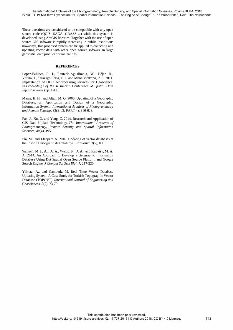
The metadata of the features are filled in by the system as
described in chapter 3. When the user logs in to the system, the
"GUNCELLEYEN (updater)" and "KAYNAK (source)"
attribute fields are filled (Figure 9). Detailed information about
the version used can be found in the enterprise database in the
table "VT_VERSION". For example, in the description of the
KYGM version, the expression "consists of data received from
the General Directorate of Highways on February 13, 2015".
"KAYNAKTARIHI (source date)" is the last date the feature was
changed as mentioned in section 3, and
"GUNCELLEMETARIHI (update date)" is the date when the
feature was returned to the system.
Figure 8. Feature based metadata
6. CONCLUSION
Although widely used GIS software has a great deal of vector
editing capability, the ability to quickly and accurately update the
database depends on the speed of direct connection or WFS
services. This hybrid system was created using limited direct
linking over WMS service as an effective data entry method that
does not give up the comprehensive and effective vector data
editing capabilities of GIS software.
Geospatial data update ability was gained by the proposed system
to TOPOVT which is the geospatial database covering whole
Turkey other than file-based production. An alternative way to
update any desired layer or feature of any desired region on this
page quickly and efficiently has been established. In addition to
this system, which is developed by adding plugin to ArcGIS
software which is currently being used, the display convenience
of WMS service and the ability of editing WFS service vector
data are combined. At the same time, when the data operator is
able to see the vector data having a tight topological relation with
each other in an integrated manner with their own symbols on the
WMS service, features are prevented from reaching the vector
data through the WFS service unnecessarily by slowing down the
system. Thanks to the fact that the system does not directly access
the vector database, it grows as the database grows, ensuring that
the update system is not affected.
It is known that many institutions and organizations are trying to
have methods to update their central databases quickly and
effectively. Given the high cost of licensed GIS software, the vast
majority of these systems aimed at reaching a large number of
data producers are concentrated on web-based systems. If these
websites are a significant amount of resources spent, they focus
on geospatial data viewing, basic GIS capabilities and user
authorization. Well, can an open-source software that already
possesses a lot of these capabilities enable thousands of vendors
to enter data? How well can these web systems, which seem
adequate for basic operations, respond to the needs of specialized
data producers?
The International Archives of the Photogrammetry, Remote Sensing and Spatial Information Sciences, Volume XLII-4, 2018 ISPRS TC IV Mid-term Symposium “3D Spatial Information Science – The Engine of Change”, 1–5 October 2018, Delft, The Netherlands
This contribution has been peer-reviewed. https://doi.org/10.5194/isprs-archives-XLII-4-737-2018 | © Authors 2018. CC BY 4.0 License.
742
These questions are considered to be compatible with any open
source code (QGIS, SAGA, GRASS ...) while this system is
developed using ArcGIS libraries. Together with the use of open
source GIS software is rapidly increasing in public institutions
nowadays, this proposed system can be applied to collecting and
updating vector data with other open source software in large
geospatial data producer organizations.
REFERENCES
Lopez-Pellicer, F. J., Rentería-Agualimpia, W., Béjar, R.,
Valiño, J., Zarazaga-Soria, F. J., and Muro-Medrano, P. R. 2011.
Implantation of OGC geoprocessing services for Geoscience.
In Proceedings of the II Iberian Conference of Spatial Data
Infrastructures (pp. 1-12).
Maras, H. H., and Altan, M. O. 2000. Updating of a Geographic
Database: an Application and Design of a Geographic
Information System. International Archives of Photogrammetry
and Remote Sensing, 33(B4/2; PART 4), 616-623.
Pan, J., Xu, Q. and Yang, C. 2014. Research and Application of
GIS Data Update Technology. The International Archives of
Photogrammetry, Remote Sensing and Spatial Information
Sciences, 40(4), 195.
Pla, M., and Lleopart, A. 2010. Updating of vector databases at
the Institut Cartogràfic de Catalunya. Catalonia, 1(5), 000.
Sameen, M. I., Ali, A. A., Wahid, N. O. A., and Kubaisy, M. A.
A. 2014. An Approach to Develop a Geographic Information
Database Using Dot Spatial Open Source Platform and Google
Search Engine. J Comput Sci Syst Biol, 7, 217-220.
Yilmaz, A., and Caniberk, M. Real Time Vector Database
Updating System: A Case Study for Turkish Topographic Vector
Database (TOPOVT). International Journal of Engineering and
Geosciences, 3(2), 73-79.
The International Archives of the Photogrammetry, Remote Sensing and Spatial Information Sciences, Volume XLII-4, 2018 ISPRS TC IV Mid-term Symposium “3D Spatial Information Science – The Engine of Change”, 1–5 October 2018, Delft, The Netherlands
This contribution has been peer-reviewed. https://doi.org/10.5194/isprs-archives-XLII-4-737-2018 | © Authors 2018. CC BY 4.0 License.
743


