Embed Size (px)
Citation preview
www.mars-antennas.com
2018Product
Catalogue
April, 2018

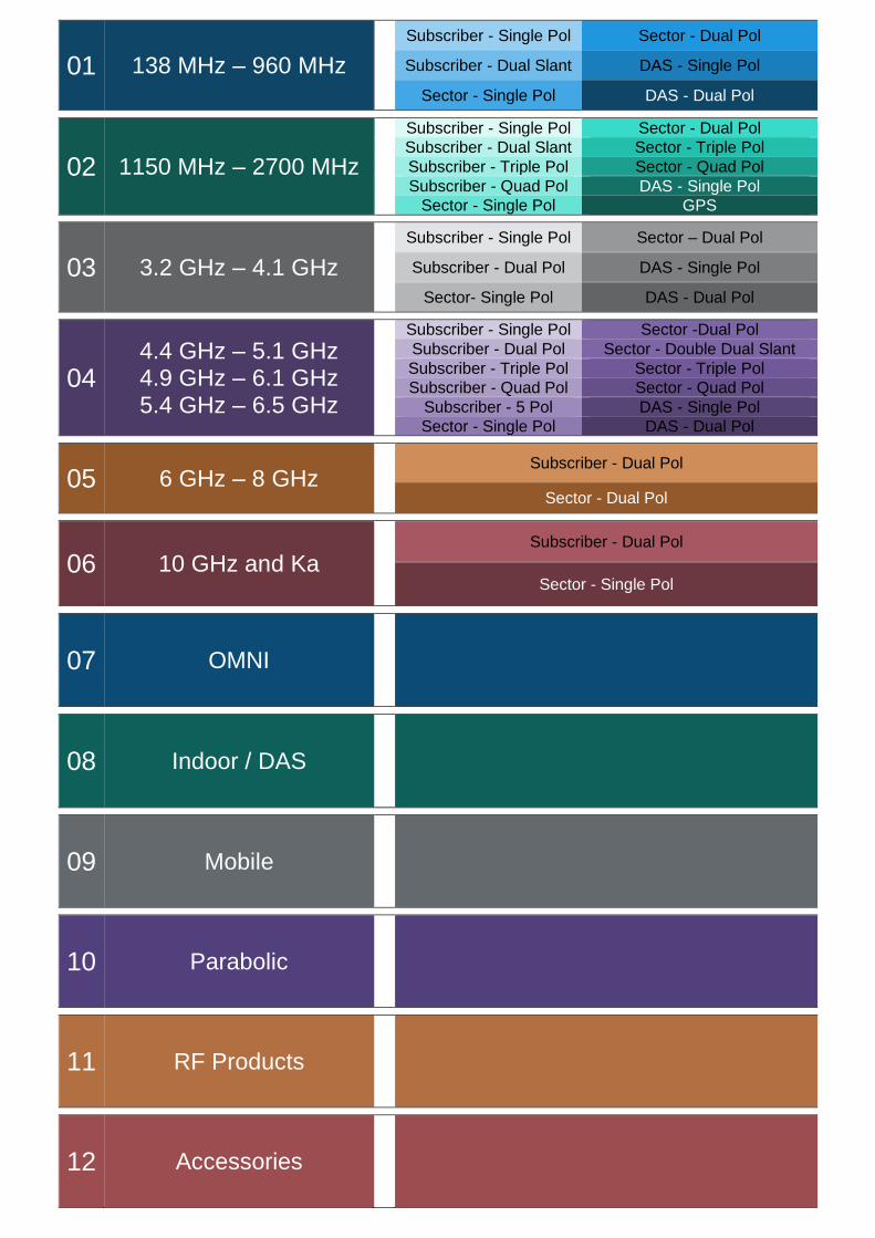
01 138 MHz – 960 MHz
Subscriber - Single Pol Sector - Dual Pol
Subscriber - Dual Slant DAS - Single Pol
Sector - Single Pol DAS - Dual Pol
02 1150 MHz – 2700 MHz
Subscriber - Single Pol Sector - Dual Pol
Subscriber - Dual Slant Sector - Triple Pol
Subscriber - Triple Pol Sector - Quad Pol
Subscriber - Quad Pol DAS - Single Pol
Sector - Single Pol GPS
03 3.2 GHz – 4.1 GHz
Subscriber - Single Pol Sector – Dual Pol
Subscriber - Dual Pol DAS - Single Pol
Sector- Single Pol DAS - Dual Pol
04 4.4 GHz – 5.1 GHz 4.9 GHz – 6.1 GHz 5.4 GHz – 6.5 GHz
Subscriber - Single Pol Sector -Dual Pol
Subscriber - Dual Pol Sector - Double Dual Slant
Subscriber - Triple Pol Sector - Triple Pol
Subscriber - Quad Pol Sector - Quad Pol
Subscriber - 5 Pol DAS - Single Pol
Sector - Single Pol DAS - Dual Pol
05 6 GHz – 8 GHz Subscriber - Dual Pol
Sector - Dual Pol
06 10 GHz and Ka Subscriber - Dual Pol
Sector - Single Pol
07 OMNI
08 Indoor / DAS
09 Mobile
10 Parabolic
11 RF Products
12 Accessories

MARS Antennas & RF Systems proprietary information MARS reserves the right to make technical changes or modifications to any of its products and specifications without prior notice and without implementing such changes to prior supplied products. Product images are representative and indicative only. Warranty terms and general conditions of sale are applicable on any purchase of any product, available on MARS website.
3 Hamanor st. Holon 5886103, P.O.Box 1852 Holon 5811801, Israel
Tel: +972-3-5599661 Fax: +972-3-5599677 e-mail: [email protected] web: www.mars-antennas.com
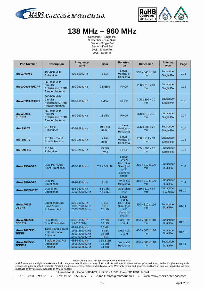
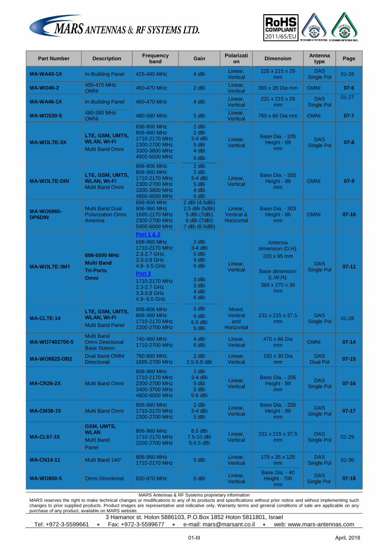
138 MHz – 960 MHz Subscriber - Single Pol Subscriber - Dual Slant
Sector - Single Pol Sector - Dual Pol DAS - Single Pol DAS - Dual Pol
Part Number Description Frequency
band Gain
Polarization
Dimension Antenna
type Page
MA-WA640-6 49 8-0 60 MHz Subscriber
49 8-0 60 MHz 6 dBi Linear,
Vertical or Horizontal
500 x 345 x 140 mm
Subscriber
Single Pol 01-1
MA-WC910-RHCP7
860-960 MHz Circular Polarization, RFID Reader Antenna
860-960 MHz 7.5 dBic RHCP 230 x 215 x 37
mm
Subscriber
Single Pol 01-2
MA-WC910-RHCP9
860-960 MHz Circular Polarization, RFID Reader Antenna
860-960 MHz 9 dBic RHCP 305 x 305 x 30
mm
Subscriber
Single Pol 01-3
MA-WC910-RHCP11
860-960 MHz Circular Polarization, RFID Reader Antenna
860-960 MHz 11 dBic RHCP 370 x 370 x 40
mm
Subscriber
Single Pol 01-4
MA-IS91-T2 915 MHz Subscriber
902-928 MHz 10.5 dBi
(min.)
Linear Vertical or Horizontal
305 x 305 x 25 mm
Subscriber
Single Pol 01-5
MA-IS91-T3 915 MHz Small Size Subscriber
902-928 MHz 8 dBi
(min.)
Linear, Vertical or Horizontal
230 x 214 x 31 mm
Subscriber
Single Pol 01-6
MA-IS91-R1 915 MHz Subscriber 902-928 MHz
10 dBi
(typ.) RHCP
305 x 305 x 25 mm
Subscriber
Single Pol 01-7
MA-WA580-DP8 Dual Pol / Dual Slant Directional
470-698 MHz 7.5 ± 0.5 dBi
Linear, Ver &
Hor., Dual Slant (opt.
±45° diamond shape)
310 x 310 x 126 mm
Subscriber
Dual Pol 01-8
MA-WA820-DP8 Dual Pol Directional
698-960 MHz 8 dBi Vertical & Horizontal
310 x 310 x 126 mm
Subscriber
Dual Pol 01-9
MA-WA6927-DS7 Dual Slant Directional
698-960 MHz 1700-2700 MHz
4 ± 1 dBi 7 ± 1 dBi
Dual Slant ±45°
310 x 310 x 67 mm
Subscriber
Dual Slant 01-10
MA-WA6927-DBDP8
Directional Dual Band / Dual Polarized Ant.
698-960 MHz 1695-2300 MHz 2300-2700 MHz
8 dBi 9 dBi
11 dBi
Linear, Ver &
Hor., Dual Slant (opt.
±45° diamond shape)
310 x 310 x 126 mm
Subscriber Dual Pol 01-11
MA-WA82220-DBDP14
Dual Band Dual Polarization
698-960 MHz 1.7-2.7 GHz
12 dBi 16 dBi
Dual Pole V & H
800 x 600 x 110 mm
Subscriber Dual Pol 01-12
MA-WA692755-TBDP8
Triple Band & Dual Pol Directional Antenna
698-960 MHz 1695-2300 MHz 2300-2700 MHz 5100-5900 MHz
7.5 dBi 8 dBi
10 dBi 9 dBi
Dual Pole V & H
400 x 308 x 126 mm
Subscriber Dual Pol 01-13
MA-WA692755-TBDP14
Stadium Dual Pol Directional Antenna
698-960 MHz 1695-2700 MHz 5150-5925 MHz
12-13 dBi 13 dBi 14 dBi
Vertical & Horizontal
800 x 600 x 110 mm
Subscriber
Dual Pol 01-14
April, 201801-I
MARS Antennas & RF Systems proprietary information MARS reserves the right to make technical changes or modifications to any of its products and specifications without prior notice and without implementing such changes to prior supplied products. Product images are representative and indicative only. Warranty terms and general conditions of sale are applicable on any purchase of any product, available on MARS website.
3 Hamanor st. Holon 5886103, P.O.Box 1852 Holon 5811801, Israel
Tel: +972-3-5599661 Fax: +972-3-5599677 e-mail: [email protected] web: www.mars-antennas.com
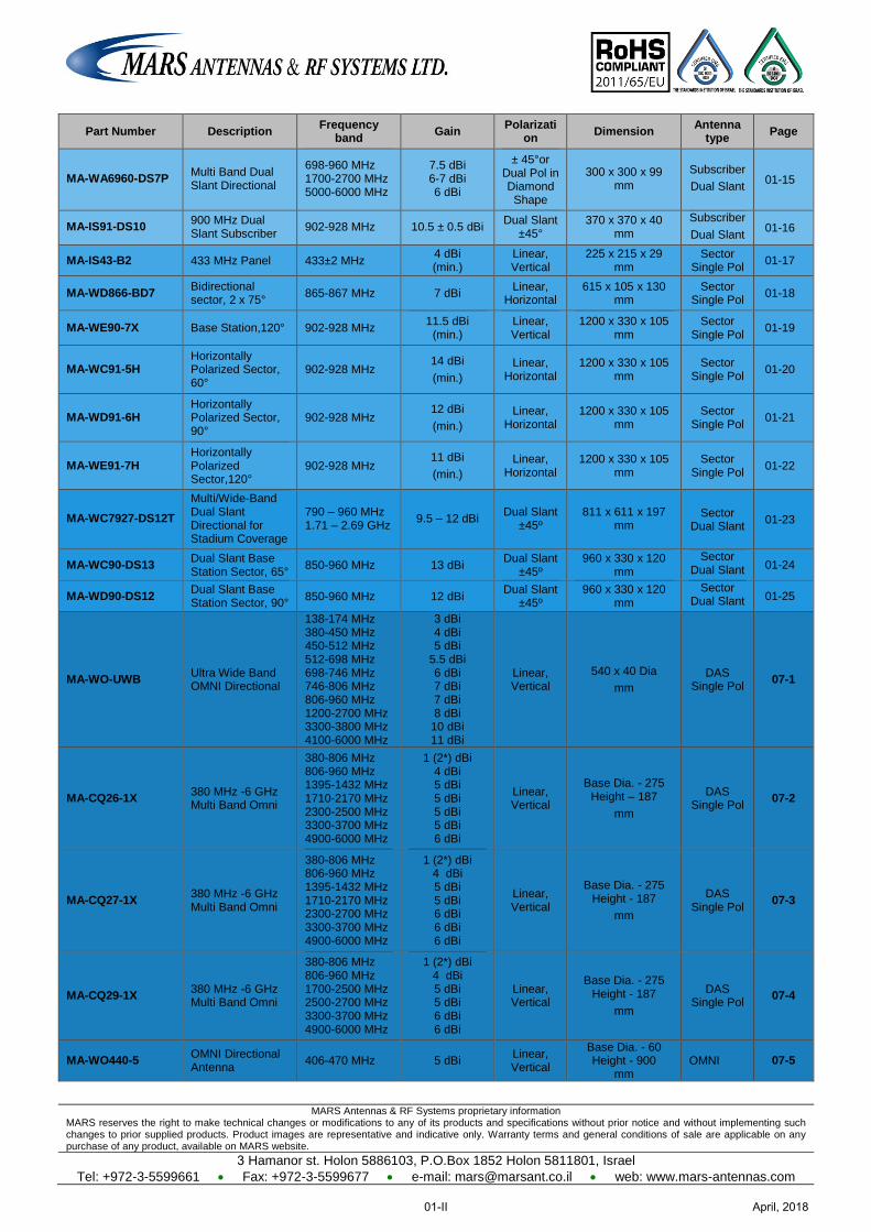
Part Number Description Frequency
band Gain
Polarization
Dimension Antenna
type Page
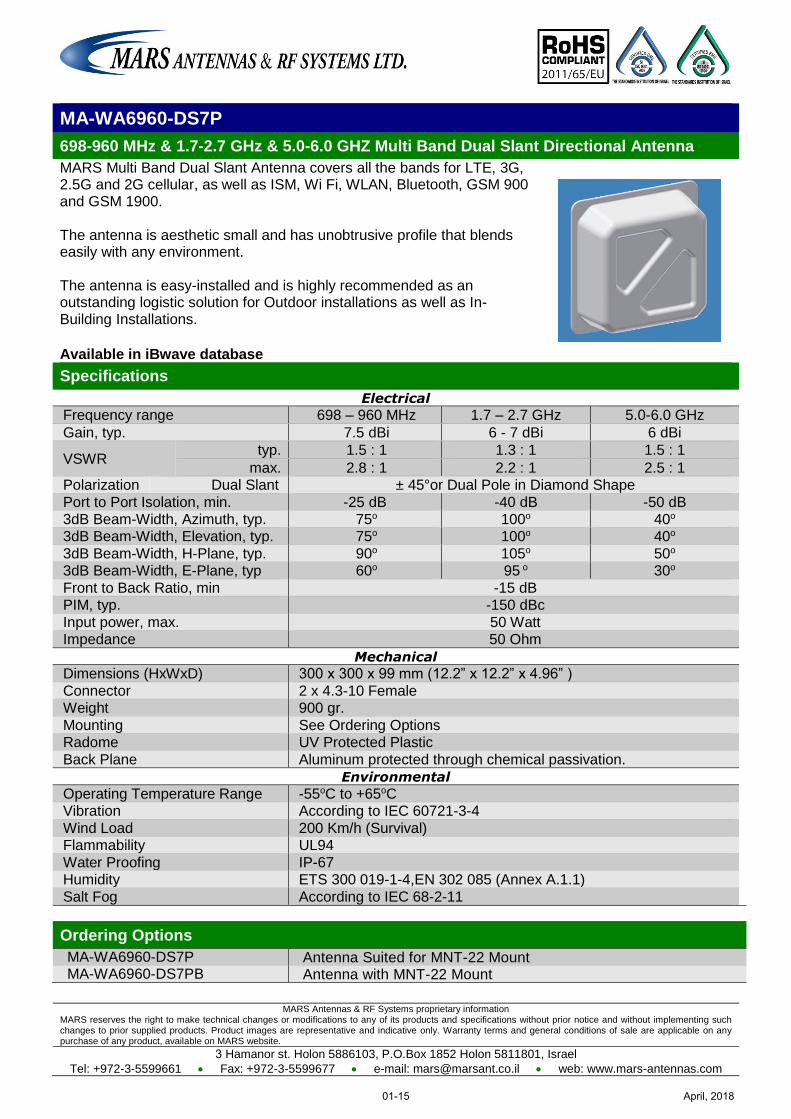
MA-WA6960-DS7P Multi Band Dual Slant Directional
698-960 MHz 1700-2700 MHz 5000-6000 MHz
7.5 dBi 6-7 dBi 6 dBi
± 45°or Dual Pol in Diamond Shape
300 x 300 x 99 mm
Subscriber
Dual Slant 01-15
MA-IS91-DS10 900 MHz Dual Slant Subscriber
902-928 MHz 10.5 ± 0.5 dBi Dual Slant
±45° 370 x 370 x 40
mm
Subscriber
Dual Slant 01-16
MA-IS43-B2 433 MHz Panel 433±2 MHz 4 dBi (min.)
Linear, Vertical
225 x 215 x 29 mm
Sector Single Pol
01-17
MA-WD866-BD7 Bidirectional sector, 2 x 75°
865-867 MHz 7 dBi Linear,
Horizontal 615 x 105 x 130
mm Sector
Single Pol 01-18
MA-WE90-7X Base Station,120° 902-928 MHz 11.5 dBi
(min.) Linear, Vertical
1200 x 330 x 105 mm
Sector Single Pol
01-19
MA-WC91-5H Horizontally Polarized Sector, 60°
902-928 MHz 14 dBi
(min.)
Linear, Horizontal
1200 x 330 x 105 mm
Sector Single Pol
01-20
MA-WD91-6H Horizontally Polarized Sector, 90°
902-928 MHz 12 dBi
(min.)
Linear, Horizontal
1200 x 330 x 105 mm
Sector Single Pol
01-21
MA-WE91-7H Horizontally Polarized Sector,120°
902-928 MHz 11 dBi
(min.)
Linear, Horizontal
1200 x 330 x 105 mm
Sector Single Pol
01-22
MA-WC7927-DS12T
Multi/Wide-Band Dual Slant Directional for Stadium Coverage
790 – 960 MHz 1.71 – 2.69 GHz
9.5 – 12 dBi Dual Slant
±45º 811 x 611 x 197
mm Sector
Dual Slant 01-23
MA-WC90-DS13 Dual Slant Base Station Sector, 65°
850-960 MHz 13 dBi Dual Slant
±45º 960 x 330 x 120
mm
Sector Dual Slant 01-24
MA-WD90-DS12 Dual Slant Base Station Sector, 90°
850-960 MHz 12 dBi Dual Slant
±45º 960 x 330 x 120
mm
Sector Dual Slant 01-25
MA-WO-UWB Ultra Wide Band OMNI Directional
138-174 MHz 380-450 MHz 450-512 MHz 512-698 MHz 698-746 MHz 746-806 MHz 806-960 MHz 1200-2700 MHz 3300-3800 MHz 4100-6000 MHz
3 dBi 4 dBi 5 dBi
5.5 dBi 6 dBi 7 dBi 7 dBi 8 dBi
10 dBi 11 dBi
Linear, Vertical
540 x 40 Dia
mm
DAS Single Pol
07-1
MA-CQ26-1X 380 MHz -6 GHz Multi Band Omni
380-806 MHz 806-960 MHz 1395-1432 MHz 1710-2170 MHz 2300-2500 MHz 3300-3700 MHz 4900-6000 MHz
1 (2*) dBi 4 dBi 5 dBi 5 dBi 5 dBi 5 dBi 6 dBi
Linear, Vertical
Base Dia. - 275 Height – 187
mm
DAS Single Pol
07-2
MA-CQ27-1X 380 MHz -6 GHz Multi Band Omni
380-806 MHz 806-960 MHz 1395-1432 MHz 1710-2170 MHz 2300-2700 MHz 3300-3700 MHz 4900-6000 MHz
1 (2*) dBi 4 dBi 5 dBi 5 dBi 6 dBi 6 dBi 6 dBi
Linear, Vertical
Base Dia. - 275 Height - 187
mm
DAS Single Pol
07-3
MA-CQ29-1X 380 MHz -6 GHz Multi Band Omni
380-806 MHz 806-960 MHz 1700-2500 MHz 2500-2700 MHz 3300-3700 MHz 4900-6000 MHz
1 (2*) dBi 4 dBi 5 dBi 5 dBi 6 dBi 6 dBi
Linear, Vertical
Base Dia. - 275 Height - 187
mm
DAS Single Pol
07-4
MA-WO440-5 OMNI Directional Antenna
406-470 MHz 5 dBi Linear, Vertical
Base Dia. - 60 Height - 900
mm OMNI 07-5
April, 201801-II
MARS Antennas & RF Systems proprietary information MARS reserves the right to make technical changes or modifications to any of its products and specifications without prior notice and without implementing such changes to prior supplied products. Product images are representative and indicative only. Warranty terms and general conditions of sale are applicable on any purchase of any product, available on MARS website.
3 Hamanor st. Holon 5886103, P.O.Box 1852 Holon 5811801, Israel
Tel: +972-3-5599661 Fax: +972-3-5599677 e-mail: [email protected] web: www.mars-antennas.com
Part Number Description Frequency
band Gain
Polarization
Dimension Antenna
type Page
MA-WA43-1X In-Building Panel 425-445 MHz 4 dBi Linear, Vertical
225 x 215 x 29 mm
DAS Single Pol
01-26
MA-WO46-2 450-470 MHz OMNI
450-470 MHz 2 dBi Linear, Vertical
360 x 26 Dia mm OMNI 07-6
MA-WA46-1X In-Building Panel 450-470 MHz 4 dBi Linear, Vertical
231 x 215 x 29 mm
DAS Single Pol
01-27
MA-WO530-5 480-580 MHz OMNI
480-580 MHz 5 dBi Linear, Vertical
760 x 60 Dia mm OMNI 07-7
MA-WOLTE-3X
LTE, GSM, UMTS, WLAN, Wi-Fi
Multi Band Omni
698-806 MHz 806-960 MHz 1710-2170 MHz 2300-2700 MHz 3300-3800 MHz 4900-6500 MHz
2 dBi 2 dBi
3-4 dBi 5 dBi 4 dBi
6 dBi
Linear, Vertical
Base Dia. - 205 Height - 89
mm
DAS Single Pol
07-8
MA-WOLTE-DIN LTE, GSM, UMTS, WLAN, Wi-Fi Multi Band Omni
698-806 MHz 806-960 MHz 1710-2170 MHz 2300-2700 MHz 3300-3800 MHz 4900-6500 MHz
2 dBi 2 dBi
3-4 dBi 5 dBi 4 dBi 6 dBi
Linear, Vertical
Base Dia. - 205 Height - 89
mm OMNI 07-9
MA-WO6960-DP6DIN
Multi Band Dual Polarization Omni Antenna
698-806 MHz 806-960 MHz 1695-2170 MHz 2300-2700 MHz 5000-6000 MHz
2 dBi (4.5dBi) 2.5 dBi (5dBi) 5 dBi (7dBi) 6 dBi (7dBi)
7 dBi (8.5dBi)
Linear, Vertical & Horizontal
Base Dia. - 303 Height - 86
mm OMNI 07-10
MA-WOLTE-3M1
698-6500 MHz
Multi Band
Tri-Ports
Omni
Port 1 & 2
698-960 MHz 1710-2170 MHz 2.3-2.7 GHz. 3.3-3.8 GHz 4.9- 6.5 GHz
Port 3
1710-2170 MHz 2.3-2.7 GHz 3.3-3.8 GHz 4.9- 6.5 GHz
2 dBi 3-4 dBi 5 dBi 4 dBi 6 dBi
3 dBi 3 dBi 4 dBi 6 dBi
Linear, Vertical
Antenna dimension (D,H):
220 x 95 mm
Base dimension (L,W,H):
369 x 270 x 30 mm
DAS Single Pol
07-11
MA-CLTE-14
LTE, GSM, UMTS, WLAN, Wi-Fi
Multi Band Panel
698-806 MHz 806-960 MHz 1710-2170 MHz 2200-2700 MHz
5 dBi
6 dBi 6.5 dBi 5 dBi
Mixed, Vertical
and Horizontal
231 x 215 x 37.5 mm
DAS Single Pol
01-28
MA-WO7402700-5 Multi Band Omni Directional Base Station
740-960 MHz 1710-2700 MHz
4 dBi 6 dBi
Linear, Vertical
470 x 66 Dia mm
OMNI 07-14
MA-WO8622-DB2 Dual Band OMNI Directional
790-960 MHz 1695-2700 MHz
2 dBi 2.5-5.8 dBi
Linear, Vertical
192 x 30 Dia mm
DAS Dual Pol
07-15
MA-CR26-2X Multi Band Omni
806-960 MHz 1710-2170 MHz 2300-2700 MHz 3400-3700 MHz 4900-6000 MHz
2 dBi 3-4 dBi 5 dBi 5 dBi
5-6 dBi
Linear, Vertical
Base Dia. - 205 Height - 89
mm
DAS Single Pol
07-16
MA-CM36-15 Multi Band Omni 806-960 MHz 1710-2170 MHz 2300-2700 MHz
2 dBi 3-4 dBi 5 dBi
Linear, Vertical
Base Dia. - 205 Height - 89
mm
DAS Single Pol
07-17
MA-CL67-15
GSM, UMTS, WLAN
Multi Band
Panel
806-960 MHz 1710-2170 MHz 2200-2700 MHz
8.5 dBi 7.5-10 dBi 5-6.5 dBi
Linear, Vertical
231 x 215 x 37.5 mm
DAS Single Pol
01-29
MA-CN14-11 Multi Band 140° 806-960 MHz 1710-2170 MHz
5 dBi Linear, Vertical
175 x 35 x 125 mm
DAS Single Pol
01-30
MA-WO850-5 Omni-Directional 830-870 MHz 5 dBi Linear, Vertical
Base Dia. - 40 Height - 700
mm
DAS Single Pol
07-18
April, 201801-III
MARS Antennas & RF Systems proprietary information MARS reserves the right to make technical changes or modifications to any of its products and specifications without prior notice and without implementing such changes to prior supplied products. Product images are representative and indicative only. Warranty terms and general conditions of sale are applicable on any purchase of any product, available on MARS website.
3 Hamanor st. Holon 5886103, P.O.Box 1852 Holon 5811801, Israel
Tel: +972-3-5599661 Fax: +972-3-5599677 e-mail: [email protected] web: www.mars-antennas.com
Part Number Description Frequency
band Gain
Polarization
Dimension Antenna
type Page
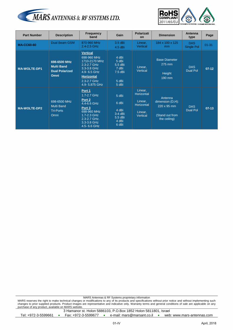
MA-CC60-60 Dual Beam GSM 870-960 MHz
2.4-2.5 GHz 3.5 dBi
4.5 dBi
Linear, Vertical
184 x 100 x 125 mm
DAS Single Pol
01-31
MA-WOLTE-DP1
698-6500 MHz
Multi Band
Dual Polarized
Omni
Vertical
698-960 MHz 1710-2170 MHz 2.3-2.7 GHz 3.3-3.8 GHz 4.9- 6.5 GHz
Horizontal
2.3-2.7 GHz 4.9- 5.875 GHz
4 dBi 5 dBi
5.5 dBi 7 dBi
7.5 dBi
5 dBi 5 dBi
Linear, Vertical
Base Diameter
275 mm
Height
190 mm
DAS Dual Pol
07-12
MA-WOLTE-DP2
698-6500 MHz
Multi Band
Tri-Ports
Omni
Port 1
1.7-2.7 GHz
Port 2 4.4-6.6 GHz
Port 3 698-960 MHz 1.7-2.3 GHz 2.3-2.7 GHz. 3.3-3.8 GHz 4.5- 6.6 GHz
5 dBi
6 dBi
4 dBi
3-4 dBi 5.5 dBi 4 dBi 6 dBi
Linear, Horizontal
Linear,
Horizontal
Linear, Vertical
Antenna dimension (D,H):
220 x 95 mm
(Stand out from the ceiling)
DAS Dual Pol
07-13
April, 201801-IV
MARS Antennas & RF Systems proprietary information MARS reserves the right to make technical changes or modifications to any of its products and specifications without prior notice and without implementing such changes to prior supplied products. Product images are representative and indicative only. Warranty terms and general conditions of sale are applicable on any purchase of any product, available on MARS website.
3 Hamanor st. Holon 5886103, P.O.Box 1852 Holon 5811801, Israel
Tel: +972-3-5599661 Fax: +972-3-5599677 e-mail: [email protected] web: www.mars-antennas.com
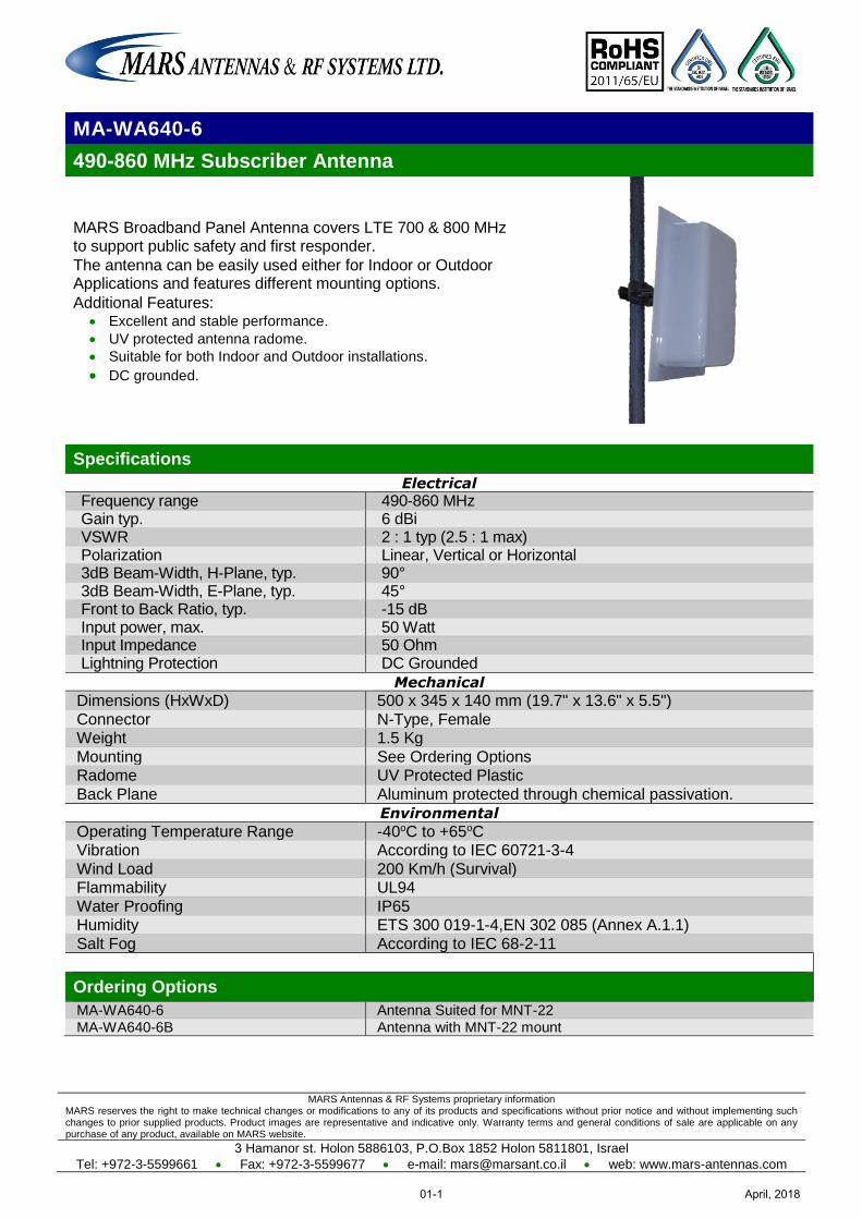
MA-WA640-6
49 8-0 60 MHz Subscriber Antenna
MARS Broadband Panel Antenna covers LTE 700 & 800 MHz to support public safety and first responder.
The antenna can be easily used either for Indoor or Outdoor Applications and features different mounting options.
Additional Features: Excellent and stable performance.
UV protected antenna radome.
Suitable for both Indoor and Outdoor installations.
DC grounded.
Specifications
Electrical
Frequency range 490-860 MHz Gain typ. 6 dBi VSWR 2 : 1 typ (2.5 : 1 max) Polarization Linear, Vertical or Horizontal 3dB Beam-Width, H-Plane, typ. 90° 3dB Beam-Width, E-Plane, typ. 45° Front to Back Ratio, typ. -15 dB Input power, max. 50 Watt Input Impedance 50 Ohm Lightning Protection DC Grounded
Mechanical
Dimensions (HxWxD) 500 x 345 x 140 mm (19.7" x 13.6" x 5.5")
Connector N-Type, Female Weight 1.5 Kg
Mounting See Ordering Options Radome UV Protected Plastic
Back Plane Aluminum protected through chemical passivation.
Environmental
Operating Temperature Range -40oC to +65oC Vibration According to IEC 60721-3-4
Wind Load 200 Km/h (Survival) Flammability UL94
Water Proofing IP65 Humidity ETS 300 019-1-4,EN 302 085 (Annex A.1.1)
Salt Fog According to IEC 68-2-11
Ordering Options
MA-WA640-6 Antenna Suited for MNT-22
MA-WA640-6B Antenna with MNT-22 mount
April, 201801-1
MARS Antennas & RF Systems proprietary information MARS reserves the right to make technical changes or modifications to any of its products and specifications without prior notice and without implementing such changes to prior supplied products. Product images are representative and indicative only. Warranty terms and general conditions of sale are applicable on any purchase of any product, available on MARS website.
3 Hamanor st. Holon 5886103, P.O.Box 1852 Holon 5811801, Israel
Tel: +972-3-5599661 Fax: +972-3-5599677 e-mail: [email protected] web: www.mars-antennas.com
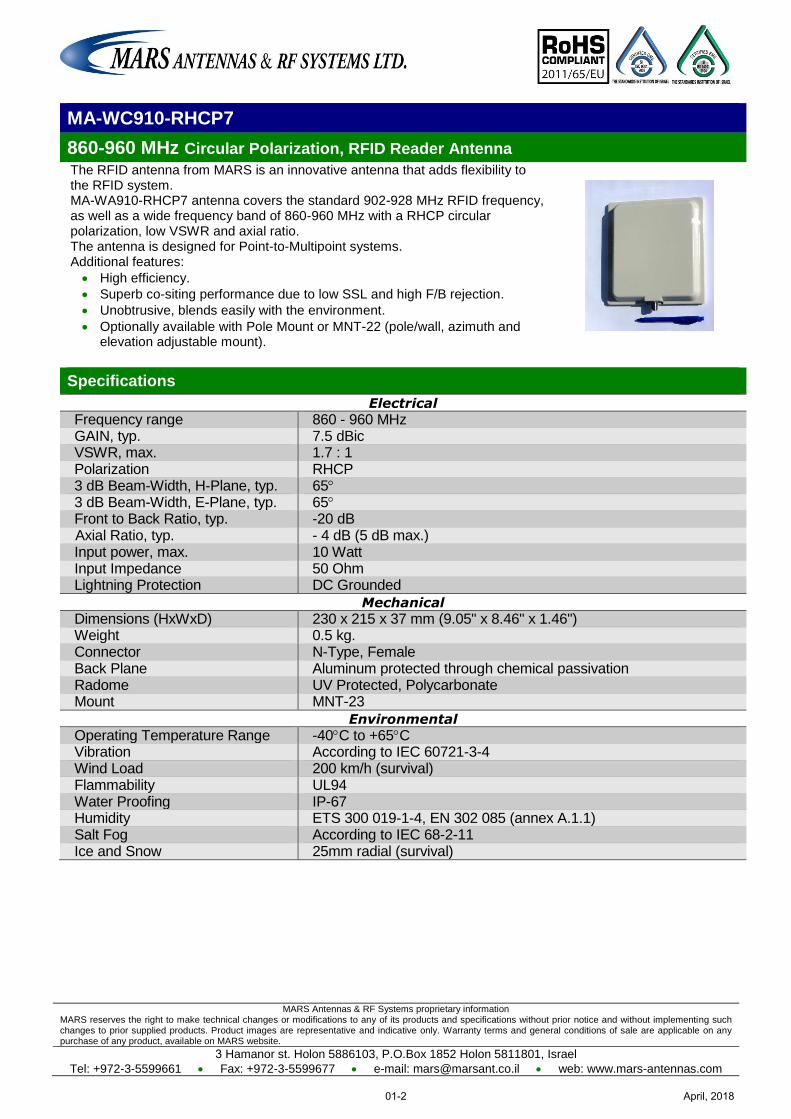
MA-WC910-RHCP7
860-960 MHz Circular Polarization, RFID Reader Antenna
The RFID antenna from MARS is an innovative antenna that adds flexibility to the RFID system. MA-WA910-RHCP7 antenna covers the standard 902-928 MHz RFID frequency, as well as a wide frequency band of 860-960 MHz with a RHCP circular polarization, low VSWR and axial ratio. The antenna is designed for Point-to-Multipoint systems. Additional features:
High efficiency.
Superb co-siting performance due to low SSL and high F/B rejection.
Unobtrusive, blends easily with the environment.
Optionally available with Pole Mount or MNT-22 (pole/wall, azimuth and elevation adjustable mount).
Specifications
Electrical
Frequency range 860 - 960 MHz GAIN, typ. 7.5 dBic VSWR, max. 1.7 : 1 Polarization RHCP 3 dB Beam-Width, H-Plane, typ. 65 3 dB Beam-Width, E-Plane, typ. 65 Front to Back Ratio, typ. -20 dB
Axial Ratio, typ. - 4 dB (5 dB max.) Input power, max. 10 Watt Input Impedance 50 Ohm Lightning Protection DC Grounded
Mechanical
Dimensions (HxWxD) 230 x 215 x 37 mm (9.05" x 8.46" x 1.46") Weight 0.5 kg. Connector N-Type, Female Back Plane Aluminum protected through chemical passivation Radome UV Protected, Polycarbonate Mount MNT-23
Environmental
Operating Temperature Range -40C to +65C Vibration According to IEC 60721-3-4 Wind Load 200 km/h (survival) Flammability UL94 Water Proofing IP-67 Humidity ETS 300 019-1-4, EN 302 085 (annex A.1.1) Salt Fog According to IEC 68-2-11 Ice and Snow 25mm radial (survival)
April, 201801-2
MARS Antennas & RF Systems proprietary information MARS reserves the right to make technical changes or modifications to any of its products and specifications without prior notice and without implementing such changes to prior supplied products. Product images are representative and indicative only. Warranty terms and general conditions of sale are applicable on any purchase of any product, available on MARS website.
3 Hamanor st. Holon 5886103, P.O.Box 1852 Holon 5811801, Israel
Tel: +972-3-5599661 Fax: +972-3-5599677 e-mail: [email protected] web: www.mars-antennas.com
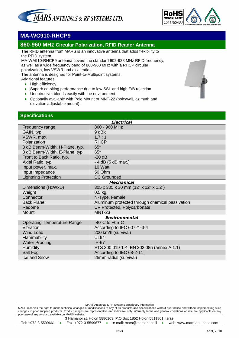
MA-WC910-RHCP9
860-960 MHz Circular Polarization, RFID Reader Antenna
The RFID antenna from MARS is an innovative antenna that adds flexibility to the RFID system. MA-WA910-RHCP9 antenna covers the standard 902-928 MHz RFID frequency, as well as a wide frequency band of 860-960 MHz with a RHCP circular polarization, low VSWR and axial ratio. The antenna is designed for Point-to-Multipoint systems. Additional features:
High efficiency.
Superb co-siting performance due to low SSL and high F/B rejection.
Unobtrusive, blends easily with the environment.
Optionally available with Pole Mount or MNT-22 (pole/wall, azimuth and elevation adjustable mount).
Specifications
Electrical
Frequency range 860 - 960 MHz GAIN, typ. 9 dBic VSWR, max. 1.7 : 1 Polarization RHCP 3 dB Beam-Width, H-Plane, typ. 65 3 dB Beam-Width, E-Plane, typ. 65 Front to Back Ratio, typ. -20 dB
Axial Ratio, typ. - 4 dB (5 dB max.) Input power, max. 10 Watt Input Impedance 50 Ohm Lightning Protection DC Grounded
Mechanical
Dimensions (HxWxD) 305 x 305 x 30 mm (12" x 12" x 1.2") Weight 0.5 kg. Connector N-Type, Female Back Plane Aluminum protected through chemical passivation Radome UV Protected, Polycarbonate Mount MNT-23
Environmental
Operating Temperature Range -40C to +65C Vibration According to IEC 60721-3-4 Wind Load 200 km/h (survival) Flammability UL94 Water Proofing IP-67 Humidity ETS 300 019-1-4, EN 302 085 (annex A.1.1) Salt Fog According to IEC 68-2-11 Ice and Snow 25mm radial (survival)
April, 201801-3
MARS Antennas & RF Systems proprietary information MARS reserves the right to make technical changes or modifications to any of its products and specifications without prior notice and without implementing such changes to prior supplied products. Product images are representative and indicative only. Warranty terms and general conditions of sale are applicable on any purchase of any product, available on MARS website.
3 Hamanor st. Holon 5886103, P.O.Box 1852 Holon 5811801, Israel
Tel: +972-3-5599661 Fax: +972-3-5599677 e-mail: [email protected] web: www.mars-antennas.com
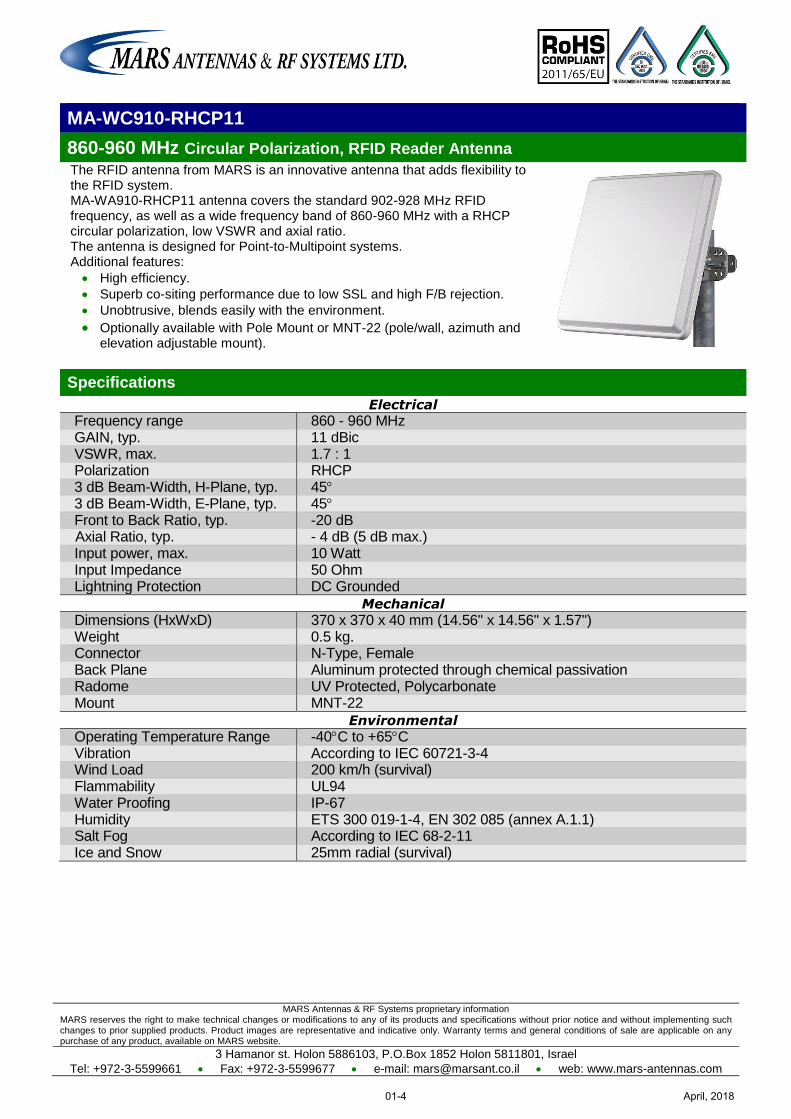
MA-WC910-RHCP11
860-960 MHz Circular Polarization, RFID Reader Antenna
The RFID antenna from MARS is an innovative antenna that adds flexibility to the RFID system. MA-WA910-RHCP11 antenna covers the standard 902-928 MHz RFID frequency, as well as a wide frequency band of 860-960 MHz with a RHCP circular polarization, low VSWR and axial ratio. The antenna is designed for Point-to-Multipoint systems. Additional features:
High efficiency.
Superb co-siting performance due to low SSL and high F/B rejection.
Unobtrusive, blends easily with the environment.
Optionally available with Pole Mount or MNT-22 (pole/wall, azimuth and elevation adjustable mount).
Specifications
Electrical
Frequency range 860 - 960 MHz GAIN, typ. 11 dBic VSWR, max. 1.7 : 1 Polarization RHCP 3 dB Beam-Width, H-Plane, typ. 45 3 dB Beam-Width, E-Plane, typ. 45 Front to Back Ratio, typ. -20 dB
Axial Ratio, typ. - 4 dB (5 dB max.) Input power, max. 10 Watt Input Impedance 50 Ohm Lightning Protection DC Grounded
Mechanical
Dimensions (HxWxD) 370 x 370 x 40 mm (14.56" x 14.56" x 1.57") Weight 0.5 kg. Connector N-Type, Female Back Plane Aluminum protected through chemical passivation Radome UV Protected, Polycarbonate Mount MNT-22
Environmental
Operating Temperature Range -40C to +65C Vibration According to IEC 60721-3-4 Wind Load 200 km/h (survival) Flammability UL94 Water Proofing IP-67 Humidity ETS 300 019-1-4, EN 302 085 (annex A.1.1) Salt Fog According to IEC 68-2-11 Ice and Snow 25mm radial (survival)
April, 201801-4
MARS Antennas & RF Systems proprietary information MARS reserves the right to make technical changes or modifications to any of its products and specifications without prior notice and without implementing such changes to prior supplied products. Product images are representative and indicative only. Warranty terms and general conditions of sale are applicable on any purchase of any product, available on MARS website.
3 Hamanor st. Holon 5886103, P.O.Box 1852 Holon 5811801, Israel Tel: +972-3-5599661 Fax: +972-3-5599677 e-mail: [email protected] web: www.mars-antennas.com
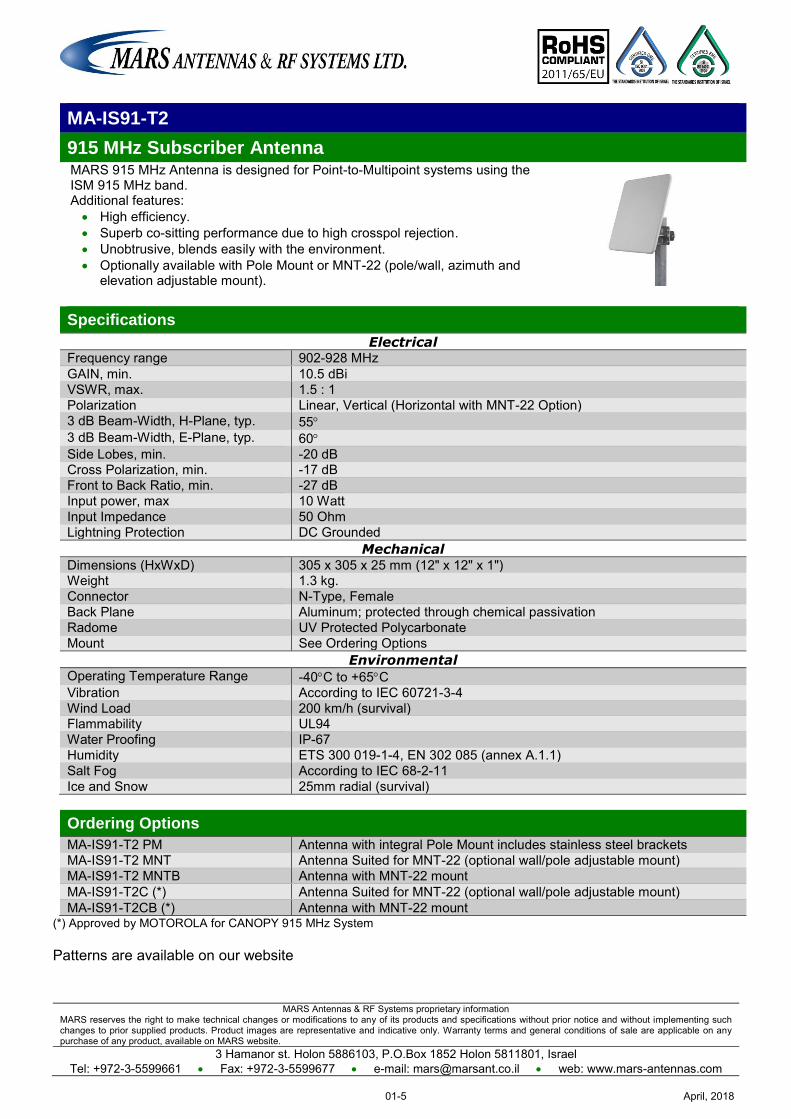
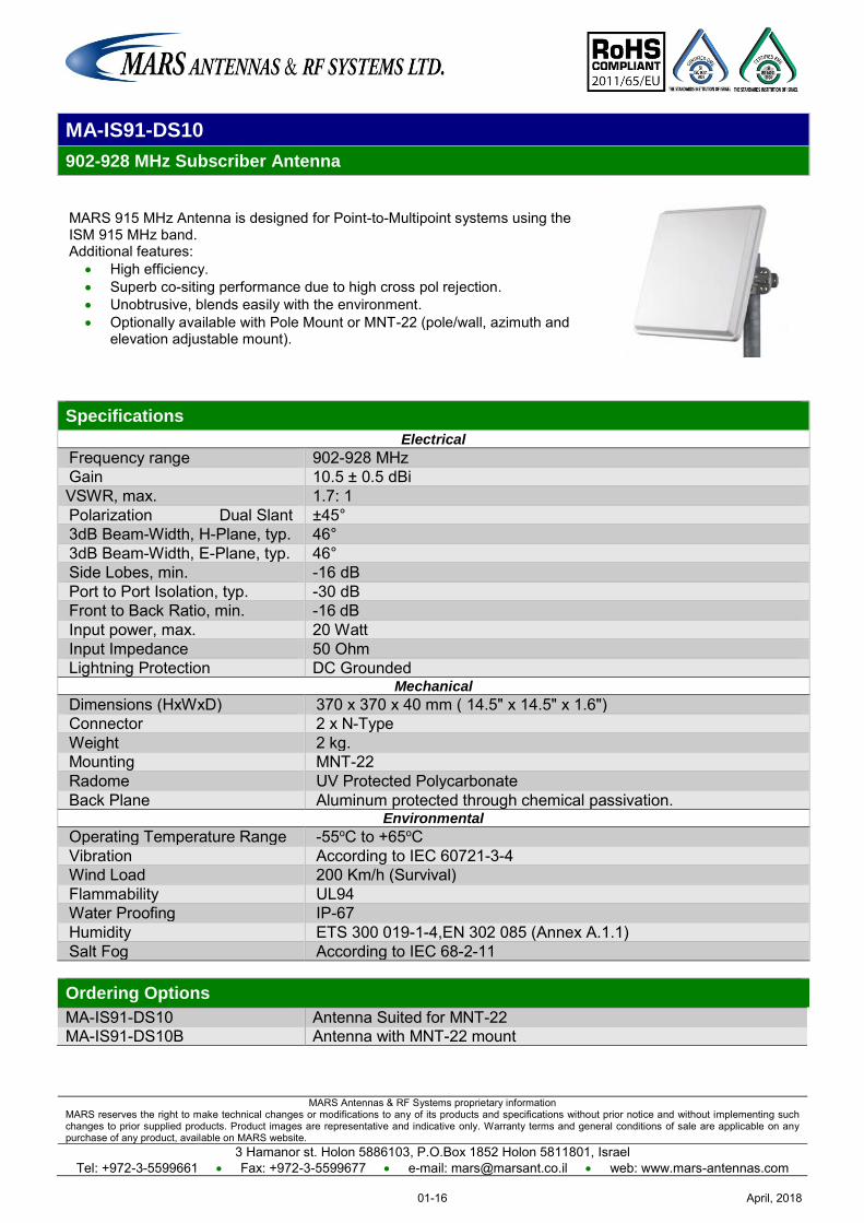
MA-IS91-T2
915 MHz Subscriber Antenna MARS 915 MHz Antenna is designed for Point-to-Multipoint systems using the ISM 915 MHz band. Additional features: High efficiency. Superb co-sitting performance due to high crosspol rejection. Unobtrusive, blends easily with the environment. Optionally available with Pole Mount or MNT-22 (pole/wall, azimuth and
elevation adjustable mount).
Specifications
Electrical Frequency range 902-928 MHz GAIN, min. 10.5 dBi VSWR, max. 1.5 : 1 Polarization Linear, Vertical (Horizontal with MNT-22 Option) 3 dB Beam-Width, H-Plane, typ. 55 3 dB Beam-Width, E-Plane, typ. 60 Side Lobes, min. -20 dB
Cross Polarization, min. -17 dB Front to Back Ratio, min. -27 dB
Input power, max 10 Watt Input Impedance 50 Ohm Lightning Protection DC Grounded
Mechanical Dimensions (HxWxD) 305 x 305 x 25 mm (12" x 12" x 1") Weight 1.3 kg. Connector N-Type, Female Back Plane Aluminum; protected through chemical passivation Radome UV Protected Polycarbonate Mount See Ordering Options
Environmental Operating Temperature Range -40C to +65C Vibration According to IEC 60721-3-4 Wind Load 200 km/h (survival) Flammability UL94 Water Proofing IP-67 Humidity ETS 300 019-1-4, EN 302 085 (annex A.1.1) Salt Fog According to IEC 68-2-11 Ice and Snow 25mm radial (survival)
Ordering Options
MA-IS91-T2 PM Antenna with integral Pole Mount includes stainless steel brackets MA-IS91-T2 MNT Antenna Suited for MNT-22 (optional wall/pole adjustable mount) MA-IS91-T2 MNTB Antenna with MNT-22 mount MA-IS91-T2C (*) Antenna Suited for MNT-22 (optional wall/pole adjustable mount) MA-IS91-T2CB (*) Antenna with MNT-22 mount
(*) Approved by MOTOROLA for CANOPY 915 MHz System Patterns are available on our website
April, 201801-5
MARS Antennas & RF Systems proprietary information MARS reserves the right to make technical changes or modifications to any of its products and specifications without prior notice and without implementing such changes to prior supplied products. Product images are representative and indicative only. Warranty terms and general conditions of sale are applicable on any purchase of any product, available on MARS website.
3 Hamanor st. Holon 5886103, P.O.Box 1852 Holon 5811801, Israel Tel: +972-3-5599661 Fax: +972-3-5599677 e-mail: [email protected] web: www.mars-antennas.com
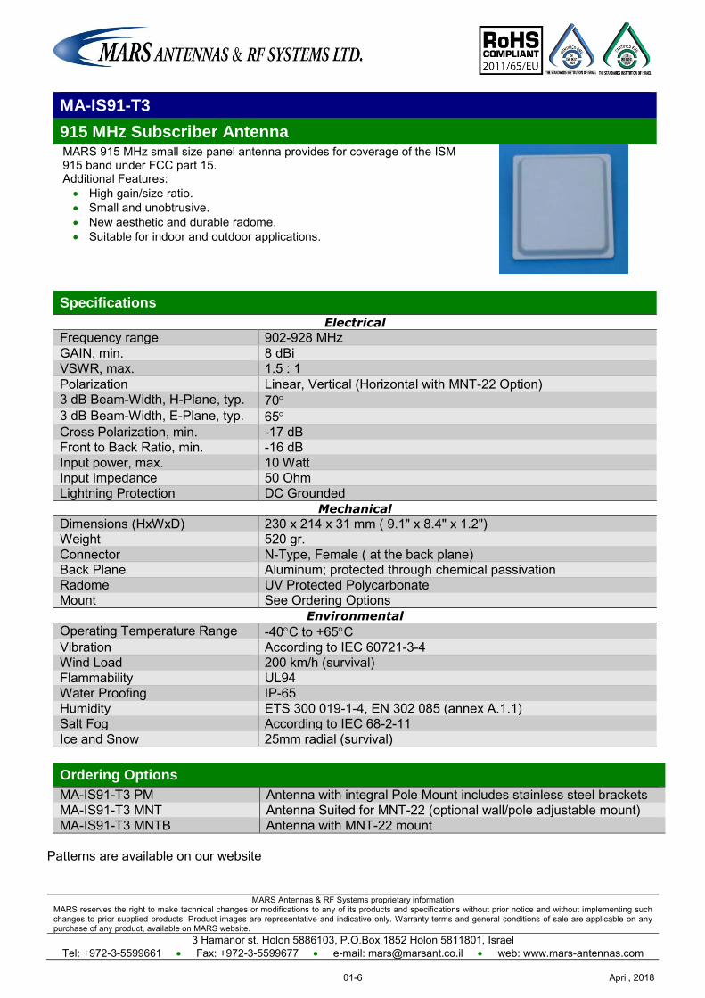
MA-IS91-T3
915 MHz Subscriber Antenna MARS 915 MHz small size panel antenna provides for coverage of the ISM 915 band under FCC part 15. Additional Features: High gain/size ratio. Small and unobtrusive. New aesthetic and durable radome. Suitable for indoor and outdoor applications.
Specifications
Electrical
Frequency range 902-928 MHz GAIN, min. 8 dBi VSWR, max. 1.5 : 1 Polarization Linear, Vertical (Horizontal with MNT-22 Option) 3 dB Beam-Width, H-Plane, typ. 70 3 dB Beam-Width, E-Plane, typ. 65 Cross Polarization, min. -17 dB Front to Back Ratio, min. -16 dB
Input power, max. 10 Watt Input Impedance 50 Ohm Lightning Protection DC Grounded
Mechanical
Dimensions (HxWxD) 230 x 214 x 31 mm ( 9.1" x 8.4" x 1.2") Weight 520 gr. Connector N-Type, Female ( at the back plane) Back Plane Aluminum; protected through chemical passivation Radome UV Protected Polycarbonate Mount See Ordering Options
Environmental
Operating Temperature Range -40C to +65C Vibration According to IEC 60721-3-4 Wind Load 200 km/h (survival) Flammability UL94 Water Proofing IP-65 Humidity ETS 300 019-1-4, EN 302 085 (annex A.1.1) Salt Fog According to IEC 68-2-11 Ice and Snow 25mm radial (survival)
Ordering Options
MA-IS91-T3 PM Antenna with integral Pole Mount includes stainless steel brackets MA-IS91-T3 MNT Antenna Suited for MNT-22 (optional wall/pole adjustable mount) MA-IS91-T3 MNTB Antenna with MNT-22 mount
Patterns are available on our website
April, 201801-6
MARS Antennas & RF Systems proprietary information MARS reserves the right to make technical changes or modifications to any of its products and specifications without prior notice and without implementing such changes to prior supplied products. Product images are representative and indicative only. Warranty terms and general conditions of sale are applicable on any purchase of any product, available on MARS website.
3 Hamanor st. Holon 5886103, P.O.Box 1852 Holon 5811801, Israel Tel: +972-3-5599661 Fax: +972-3-5599677 e-mail: [email protected] web: www.mars-antennas.com
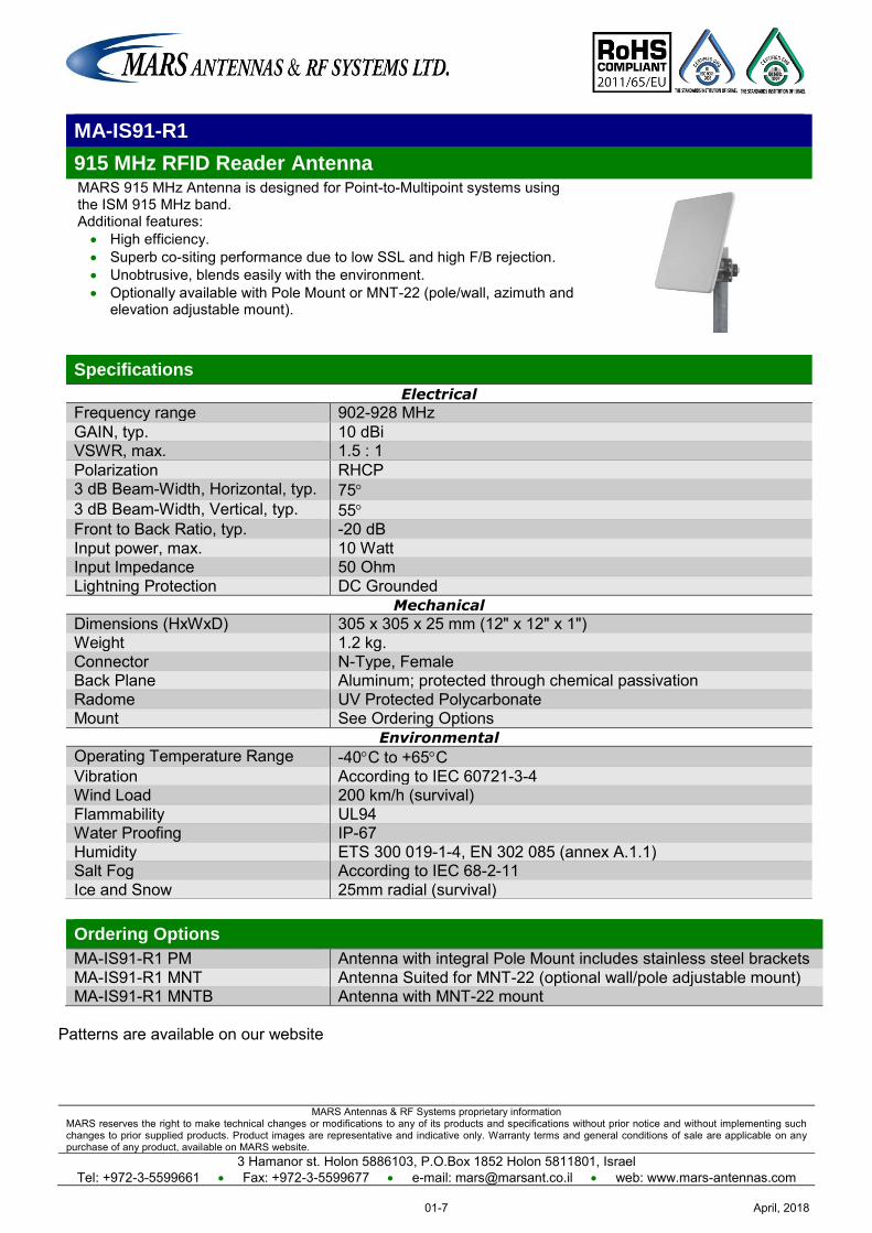
MA-IS91-R1
915 MHz RFID Reader Antenna MARS 915 MHz Antenna is designed for Point-to-Multipoint systems using the ISM 915 MHz band. Additional features: High efficiency. Superb co-siting performance due to low SSL and high F/B rejection. Unobtrusive, blends easily with the environment. Optionally available with Pole Mount or MNT-22 (pole/wall, azimuth and
elevation adjustable mount).
Specifications
Electrical
Frequency range 902-928 MHz GAIN, typ. 10 dBi VSWR, max. 1.5 : 1 Polarization RHCP 3 dB Beam-Width, Horizontal, typ. 75 3 dB Beam-Width, Vertical, typ. 55 Front to Back Ratio, typ. -20 dB
Input power, max. 10 Watt Input Impedance 50 Ohm Lightning Protection DC Grounded
Mechanical
Dimensions (HxWxD) 305 x 305 x 25 mm (12" x 12" x 1") Weight 1.2 kg. Connector N-Type, Female Back Plane Aluminum; protected through chemical passivation Radome UV Protected Polycarbonate Mount See Ordering Options
Environmental
Operating Temperature Range -40C to +65C Vibration According to IEC 60721-3-4 Wind Load 200 km/h (survival) Flammability UL94 Water Proofing IP-67 Humidity ETS 300 019-1-4, EN 302 085 (annex A.1.1) Salt Fog According to IEC 68-2-11 Ice and Snow 25mm radial (survival)
Ordering Options
MA-IS91-R1 PM Antenna with integral Pole Mount includes stainless steel brackets MA-IS91-R1 MNT Antenna Suited for MNT-22 (optional wall/pole adjustable mount) MA-IS91-R1 MNTB Antenna with MNT-22 mount
Patterns are available on our website
April, 201801-7
MARS Antennas & RF Systems proprietary information MARS reserves the right to make technical changes or modifications to any of its products and specifications without prior notice and without implementing such changes to prior supplied products. Product images are representative and indicative only. Warranty terms and general conditions of sale are applicable on any purchase of any product, available on MARS website.
3 Hamanor st. Holon 5886103, P.O.Box 1852 Holon 5811801, Israel
Tel: +972-3-5599661 Fax: +972-3-5599677 e-mail: [email protected] web: www.mars-antennas.com
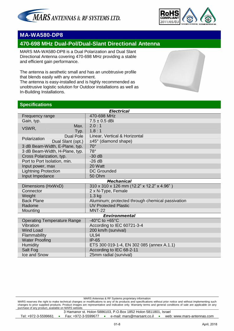
MA-WA580-DP8
470-698 MHz Dual-Pol/Dual-Slant Directional Antenna
MARS MA-WA580-DP8 is a Dual Polarization and Dual Slant Directional Antenna covering 470-698 MHz providing a stable and efficient gain performance.
The antenna is aesthetic small and has an unobtrusive profile that blends easily with any environment. The antenna is easy-installed and is highly recommended as unobtrusive logistic solution for Outdoor installations as well as In-Building Installations.
Specifications
Electrical
Frequency range 470-698 MHz Gain, typ. 7.5 ± 0.5 dBi
VSWR, Max. 2.0 : 1
Typ. 1.8 : 1
Polarization Dual Pole Linear, Vertical & Horizontal
Dual Slant (opt.) ±45° (diamond shape)
3 dB Beam-Width, E-Plane, typ. 70° 3 dB Beam-Width, H-Plane, typ. 78° Cross Polarization, typ. -30 dB Port to Port Isolation, min. -26 dB Input power, max 20 Watt Lightning Protection DC Grounded Input Impedance 50 Ohm
Mechanical
Dimensions (HxWxD) 310 x 310 x 126 mm (12.2” x 12.2” x 4.96” ) Connector 2 x N-Type, Female Weight 1.3 kg Back Plane Aluminum; protected through chemical passivation Radome UV Protected Plastic Mounting MNT-22
Environmental
Operating Temperature Range -40°C to +65°C Vibration According to IEC 60721-3-4 Wind Load 200 km/h (survival) Flammability UL94 Water Proofing IP-65 Humidity ETS 300 019-1-4, EN 302 085 (annex A.1.1) Salt Fog According to IEC 68-2-11 Ice and Snow 25mm radial (survival)
April, 201801-8
MARS Antennas & RF Systems proprietary information MARS reserves the right to make technical changes or modifications to any of its products and specifications without prior notice and without implementing such changes to prior supplied products. Product images are representative and indicative only. Warranty terms and general conditions of sale are applicable on any purchase of any product, available on MARS website.
3 Hamanor st. Holon 5886103, P.O.Box 1852 Holon 5811801, Israel
Tel: +972-3-5599661 Fax: +972-3-5599677 e-mail: [email protected] web: www.mars-antennas.com
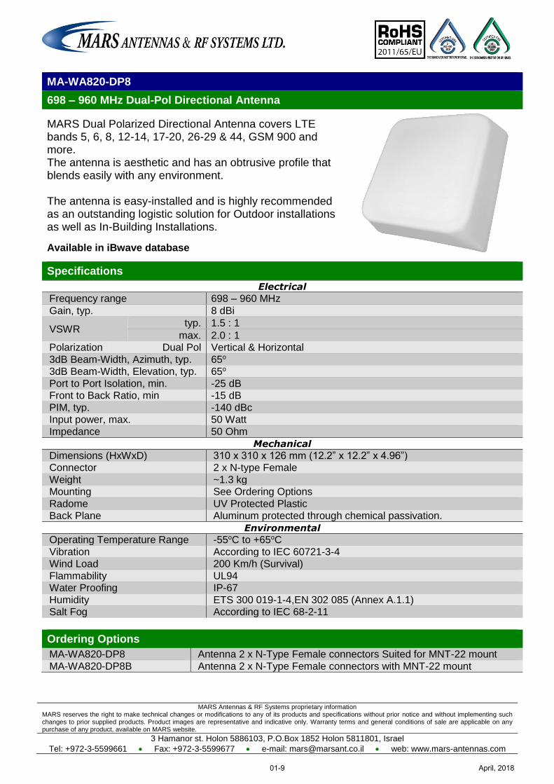
MA-WA820-DP8
698 – 960 MHz Dual-Pol Directional Antenna
MARS Dual Polarized Directional Antenna covers LTE bands 5, 6, 8, 12-14, 17-20, 26-29 & 44, GSM 900 and more. The antenna is aesthetic and has an obtrusive profile that blends easily with any environment. The antenna is easy-installed and is highly recommended as an outstanding logistic solution for Outdoor installations as well as In-Building Installations.
Available in iBwave database
Specifications
Electrical
Frequency range 698 – 960 MHz
Gain, typ. 8 dBi
VSWR typ. 1.5 : 1
max. 2.0 : 1 Polarization Dual Pol Vertical & Horizontal
3dB Beam-Width, Azimuth, typ. 65o 3dB Beam-Width, Elevation, typ. 65o
Port to Port Isolation, min. -25 dB Front to Back Ratio, min -15 dB
PIM, typ. -140 dBc Input power, max. 50 Watt
Impedance 50 Ohm
Mechanical
Dimensions (HxWxD) 310 x 310 x 126 mm (12.2” x 12.2” x 4.96”) Connector 2 x N-type Female
Weight ~1.3 kg Mounting See Ordering Options
Radome UV Protected Plastic Back Plane Aluminum protected through chemical passivation.
Environmental
Operating Temperature Range -55oC to +65oC
Vibration According to IEC 60721-3-4 Wind Load 200 Km/h (Survival)
Flammability UL94 Water Proofing IP-67
Humidity ETS 300 019-1-4,EN 302 085 (Annex A.1.1) Salt Fog According to IEC 68-2-11
Ordering Options
MA-WA820-DP8 Antenna 2 x N-Type Female connectors Suited for MNT-22 mount
MA-WA820-DP8B Antenna 2 x N-Type Female connectors with MNT-22 mount
April, 201801-9
Mars Antennas & RF Systems proprietary information MARS reserves the right to make technical changes or modifications to any of its products and specifications without prior notice and without implementing such changes to prior supplied products. Product images are representative and indicative only. Warranty terms and general conditions of sale are applicable on any purchase of any product, available on MARS website.
3 Hamanor st. Holon 5886103, P.O.Box 1852 Holon 5811801, Israel
Tel: +972-3-5599661 Fax: +972-3-5599677 e-mail: [email protected] web: www.mars-antennas.com
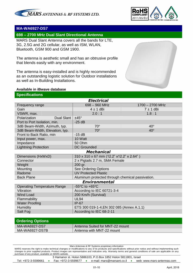
MA-WA6927-DS7
698 – 2700 MHz Dual Slant Directional Antenna
MARS Dual Slant Antenna covers all the bands for LTE, 3G, 2.5G and 2G cellular, as well as ISM, WLAN, Bluetooth, GSM 900 and GSM 1900. The antenna is aesthetic small and has an obtrusive profile that blends easily with any environment. The antenna is easy-installed and is highly recommended as an outstanding logistic solution for Outdoor installations as well as In-Building Installations. Available in iBwave database
Specifications
Electrical Frequency range 698 – 960 MHz 1700 – 2700 MHz
Gain 4 ± 1 dBi 7 ± 1 dBi
VSWR, max. 2.0 : 1 1.8 : 1
Polarization Dual Slant ±45°
Port to Port Isolation, min. -25 dB 3dB Beam-Width, Azimuth, typ. 70o 40o
3dB Beam-Width, Elevation, typ. 70o 40o Front to Back Ratio, min -15 dB Input power, max. 10 Watt
Impedance 50 Ohm Lightning Protection DC Grounded
Mechanical Dimensions (HxWxD) 310 x 310 x 67 mm (12.2” x12.2” x 2.64” ) Connector 2 x Pigtails 2.7 m, SMA Female
Weight 200 gr. Mounting See Ordering Options
Radome UV Protected Plastic Back Plane Aluminum protected through chemical passivation.
Environmental Operating Temperature Range -55oC to +65oC
Vibration According to IEC 60721-3-4 Wind Load 200 Km/h (Survival)
Flammability UL94 Water Proofing IP-67
Humidity ETS 300 019-1-4,EN 302 085 (Annex A.1.1) Salt Fog According to IEC 68-2-11
Ordering Options
MA-WA6927-DS7 Antenna Suited for MNT-22 mount
MA-WA6927-DS7B Antenna with MNT-22 mount
April, 201801-10
MARS Antennas & RF Systems proprietary information MARS reserves the right to make technical changes or modifications to any of its products and specifications without prior notice and without implementing such changes to prior supplied products. Product images are representative and indicative only. Warranty terms and general conditions of sale are applicable on any purchase of any product, available on MARS website.
3 Hamanor st. Holon 5886103, P.O.Box 1852 Holon 5811801, Israel
Tel: +972-3-5599661 Fax: +972-3-5599677 e-mail: [email protected] web: www.mars-antennas.com
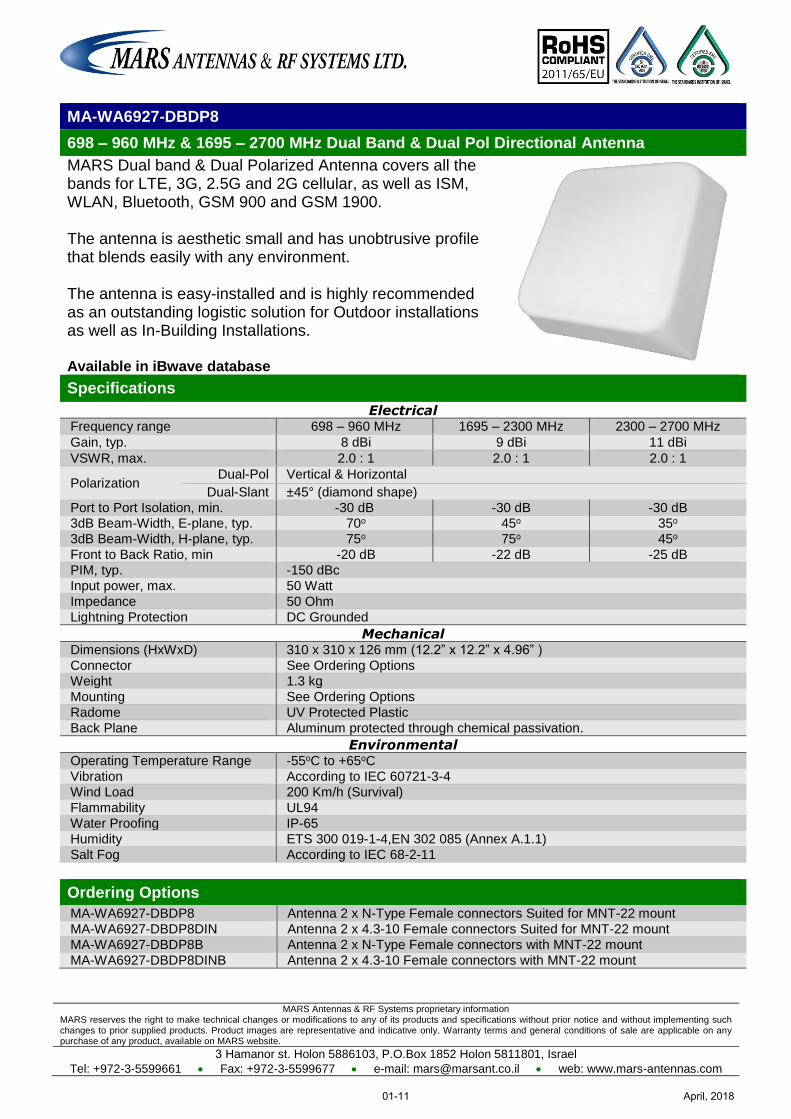
MA-WA6927-DBDP8
698 – 960 MHz & 1695 – 2700 MHz Dual Band & Dual Pol Directional Antenna
MARS Dual band & Dual Polarized Antenna covers all the bands for LTE, 3G, 2.5G and 2G cellular, as well as ISM, WLAN, Bluetooth, GSM 900 and GSM 1900. The antenna is aesthetic small and has unobtrusive profile that blends easily with any environment. The antenna is easy-installed and is highly recommended as an outstanding logistic solution for Outdoor installations as well as In-Building Installations. Available in iBwave database
Specifications
Electrical Frequency range 698 – 960 MHz 1695 – 2300 MHz 2300 – 2700 MHz
Gain, typ. 8 dBi 9 dBi 11 dBi
VSWR, max. 2.0 : 1 2.0 : 1 2.0 : 1
Polarization Dual-Pol Vertical & Horizontal
Dual-Slant ±45° (diamond shape)
Port to Port Isolation, min. -30 dB -30 dB -30 dB 3dB Beam-Width, E-plane, typ. 70o 45o 35o
3dB Beam-Width, H-plane, typ. 75o 75o 45o
Front to Back Ratio, min -20 dB -22 dB -25 dB
PIM, typ. -150 dBc
Input power, max. 50 Watt
Impedance 50 Ohm
Lightning Protection DC Grounded
Mechanical Dimensions (HxWxD) 310 x 310 x 126 mm (12.2” x 12.2” x 4.96” )
Connector See Ordering Options
Weight 1.3 kg
Mounting See Ordering Options
Radome UV Protected Plastic
Back Plane Aluminum protected through chemical passivation.
Environmental Operating Temperature Range -55oC to +65oC
Vibration According to IEC 60721-3-4
Wind Load 200 Km/h (Survival)
Flammability UL94
Water Proofing IP-65
Humidity ETS 300 019-1-4,EN 302 085 (Annex A.1.1)
Salt Fog According to IEC 68-2-11
Ordering Options
MA-WA6927-DBDP8 Antenna 2 x N-Type Female connectors Suited for MNT-22 mount
MA-WA6927-DBDP8DIN Antenna 2 x 4.3-10 Female connectors Suited for MNT-22 mount
MA-WA6927-DBDP8B Antenna 2 x N-Type Female connectors with MNT-22 mount
MA-WA6927-DBDP8DINB Antenna 2 x 4.3-10 Female connectors with MNT-22 mount
April, 201801-11
MARS Antennas & RF Systems proprietary information MARS reserves the right to make technical changes or modifications to any of its products and specifications without prior notice and without implementing such changes to prior supplied products. Product images are representative and indicative only. Warranty terms and general conditions of sale are applicable on any purchase of any product, available on MARS website.
3 Hamanor st. Holon 5886103, P.O.Box 1852 Holon 5811801, Israel
Tel: +972-3-5599661 Fax: +972-3-5599677 e-mail: [email protected] web: www.mars-antennas.com
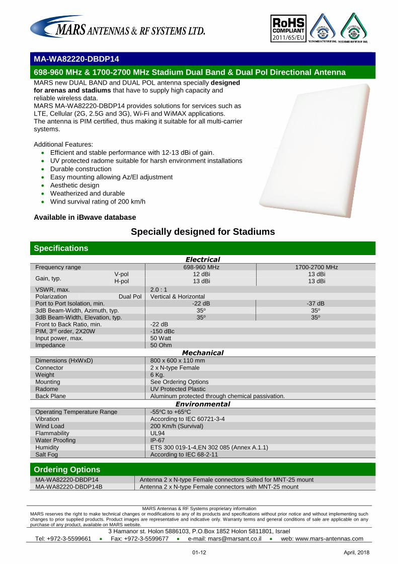
MA-WA82220-DBDP14
698-960 MHz & 1700-2700 MHz Stadium Dual Band & Dual Pol Directional Antenna
MARS new DUAL BAND and DUAL POL antenna specially designed for arenas and stadiums that have to supply high capacity and reliable wireless data. MARS MA-WA82220-DBDP14 provides solutions for services such as LTE, Cellular (2G, 2.5G and 3G), Wi-Fi and WiMAX applications. The antenna is PIM certified, thus making it suitable for all multi-carrier systems. Additional Features:
Efficient and stable performance with 12-13 dBi of gain.
UV protected radome suitable for harsh environment installations
Durable construction
Easy mounting allowing Az/El adjustment
Aesthetic design
Weatherized and durable
Wind survival rating of 200 km/h
Available in iBwave database
Specially designed for Stadiums
Specifications
Electrical Frequency range 698-960 MHz 1700-2700 MHz
Gain, typ. V-pol 12 dBi 13 dBi H-pol 13 dBi 13 dBi
VSWR, max. 2.0 : 1 Polarization Dual Pol Vertical & Horizontal Port to Port Isolation, min. -22 dB -37 dB 3dB Beam-Width, Azimuth, typ. 35o 35o 3dB Beam-Width, Elevation, typ. 35o 35o Front to Back Ratio, min. -22 dB PIM, 3rd order, 2X20W -150 dBc Input power, max. 50 Watt Impedance 50 Ohm
Mechanical Dimensions (HxWxD) 800 x 600 x 110 mm
Connector 2 x N-type Female
Weight 6 Kg.
Mounting See Ordering Options
Radome UV Protected Plastic
Back Plane Aluminum protected through chemical passivation.
Environmental Operating Temperature Range -55oC to +65oC
Vibration According to IEC 60721-3-4
Wind Load 200 Km/h (Survival)
Flammability UL94
Water Proofing IP-67
Humidity ETS 300 019-1-4,EN 302 085 (Annex A.1.1)
Salt Fog According to IEC 68-2-11
Ordering Options
MA-WA82220-DBDP14 Antenna 2 x N-type Female connectors Suited for MNT-25 mount
MA-WA82220-DBDP14B Antenna 2 x N-type Female connectors with MNT-25 mount
April, 201801-12
Mars Antennas & RF Systems proprietary information MARS reserves the right to make technical changes or modifications to any of its products and specifications without prior notice and without implementing such changes to prior supplied products. Product images are representative and indicative only. Warranty terms and general conditions of sale are applicable on any purchase of any product, available on MARS website.
3 Hamanor st. Holon 5886103, P.O.Box 1852 Holon 5811801, Israel
Tel: +972-3-5599661 Fax: +972-3-5599677 e-mail: [email protected] web: www.mars-antennas.com
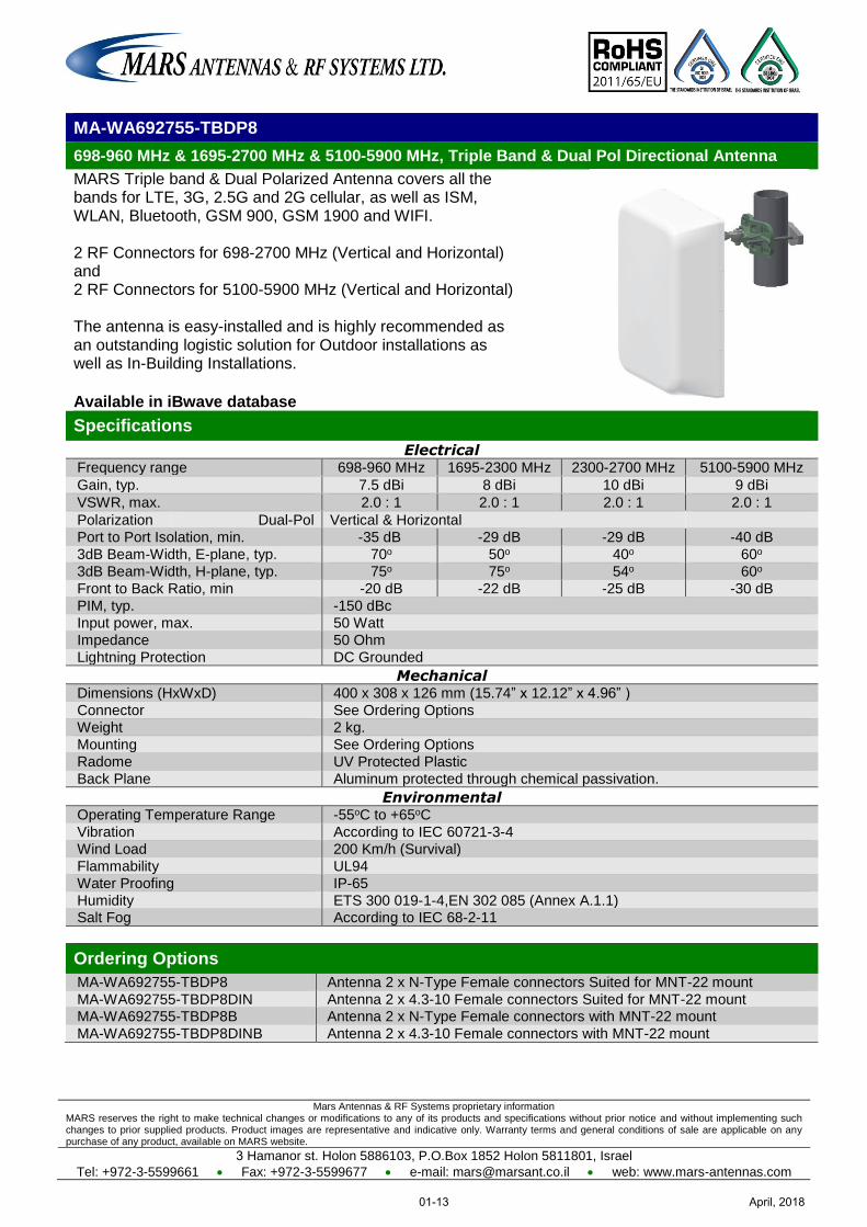
MA-WA692755-TBDP8
698-960 MHz & 1695-2700 MHz & 5100-5900 MHz, Triple Band & Dual Pol Directional Antenna
MARS Triple band & Dual Polarized Antenna covers all the bands for LTE, 3G, 2.5G and 2G cellular, as well as ISM, WLAN, Bluetooth, GSM 900, GSM 1900 and WIFI. 2 RF Connectors for 698-2700 MHz (Vertical and Horizontal) and 2 RF Connectors for 5100-5900 MHz (Vertical and Horizontal) The antenna is easy-installed and is highly recommended as an outstanding logistic solution for Outdoor installations as well as In-Building Installations. Available in iBwave database
Specifications
Electrical Frequency range 698-960 MHz 1695-2300 MHz 2300-2700 MHz 5100-5900 MHz
Gain, typ. 7.5 dBi 8 dBi 10 dBi 9 dBi
VSWR, max. 2.0 : 1 2.0 : 1 2.0 : 1 2.0 : 1
Polarization Dual-Pol Vertical & Horizontal
Port to Port Isolation, min. -35 dB -29 dB -29 dB -40 dB
3dB Beam-Width, E-plane, typ. 70o 50o 40o 60o
3dB Beam-Width, H-plane, typ. 75o 75o 54o 60o
Front to Back Ratio, min -20 dB -22 dB -25 dB -30 dB
PIM, typ. -150 dBc
Input power, max. 50 Watt
Impedance 50 Ohm
Lightning Protection DC Grounded
Mechanical Dimensions (HxWxD) 400 x 308 x 126 mm (15.74” x 12.12” x 4.96” )
Connector See Ordering Options
Weight 2 kg.
Mounting See Ordering Options
Radome UV Protected Plastic
Back Plane Aluminum protected through chemical passivation.
Environmental Operating Temperature Range -55oC to +65oC
Vibration According to IEC 60721-3-4
Wind Load 200 Km/h (Survival)
Flammability UL94
Water Proofing IP-65
Humidity ETS 300 019-1-4,EN 302 085 (Annex A.1.1) Salt Fog According to IEC 68-2-11
Ordering Options
MA-WA692755-TBDP8 Antenna 2 x N-Type Female connectors Suited for MNT-22 mount
MA-WA692755-TBDP8DIN Antenna 2 x 4.3-10 Female connectors Suited for MNT-22 mount MA-WA692755-TBDP8B Antenna 2 x N-Type Female connectors with MNT-22 mount
MA-WA692755-TBDP8DINB Antenna 2 x 4.3-10 Female connectors with MNT-22 mount
April, 201801-13
Mars Antennas & RF Systems proprietary information MARS reserves the right to make technical changes or modifications to any of its products and specifications without prior notice and without implementing such changes to prior supplied products. Product images are representative and indicative only. Warranty terms and general conditions of sale are applicable on any purchase of any product, available on MARS website.
3 Hamanor st. Holon 5886103, P.O.Box 1852 Holon 5811801, Israel
Tel: +972-3-5599661 Fax: +972-3-5599677 e-mail: [email protected] web: www.mars-antennas.com
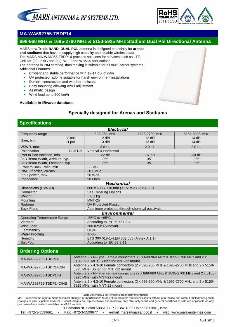
MA-WA692755-TBDP14
698-960 MHz & 1695-2700 MHz & 5150-5925 MHz Stadium Dual Pol Directional Antenna
MARS new Triple BAND, DUAL POL antenna is designed especially for arenas and stadiums that have to supply high capacity and reliable wireless data.
The MARS MA-WA6955-TBDP14 provides solutions for services such as LTE, Cellular (2G, 2.5G and 3G), Wi-Fi and WiMAX applications. The antenna is PIM certified, thus making is suitable for all multi-carrier systems. Additional Features:
Efficient and stable performance with 12-14 dBi of gain
UV protected radome suitable for harsh environment installations
Durable construction and weather resistant
Easy mounting allowing Az/El adjustment
Aesthetic design
Wind load up to 200 km/h
Available in iBwave database
Specially designed for Arenas and Stadiums
Specifications
Electrical Frequency range 698-960 MHz 1695-2700 MHz 5150-5925 MHz
Gain, typ. V-pol 12 dBi 13 dBi 14 dBi H-pol 13 dBi 13 dBi 14 dBi
VSWR, max. 2.0 : 1 2.0 : 1 2.0 : 1 Polarization Dual Pol Vertical & Horizontal Port to Port Isolation, min. -22 dB -37 dB -24 dB 3dB Beam-Width, Azimuth, typ. 35o 35o 35o 3dB Beam-Width, Elevation, typ. 35o 35o 35o Front to Back Ratio, min. -22 dB PIM, 3rd order, 2X20W -150 dBc Input power, max. 50 Watt Impedance 50 Ohm
Mechanical Dimensions (HxWxD) 800 x 600 x 110 mm (31.5" x 23.6" x 4.33")
Connector See Ordering Options
Weight ~ 6.1 kg
Mounting MNT-25
Radome UV Protected Plastic
Back Plane Aluminum protected through chemical passivation.
Environmental Operating Temperature Range -55oC to +65oC
Vibration According to IEC 60721-3-4
Wind Load 200 Km/h (Survival)
Flammability UL94
Water Proofing IP-65
Humidity ETS 300 019-1-4,EN 302 085 (Annex A.1.1)
Salt Fog According to IEC 68-2-11
Ordering Options
MA-WA692755-TBDP14 Antenna 2 x N-Type Female connectors (2 x 698-960 MHz & 1695-2700 MHz and 2 x 5150-5925 MHz) Suited for MNT-22 mount
MA-WA692755-TBDP14DIN Antenna 2 x 4.3-10 Female connectors (2 x 698-960 MHz & 1695-2700 MHz and 2 x 5150-5925 MHz) Suited for MNT-22 mount
MA-WA692755-TBDP14B Antenna 2 x N-Type Female connectors (2 x 698-960 MHz & 1695-2700 MHz and 2 x 5150-5925 MHz) with MNT-22 mount
MA-WA692755-TBDP14DINB Antenna 2 x 4.3-10 Female connectors (2 x 698-960 MHz & 1695-2700 MHz and 2 x 5150-5925 MHz) with MNT-22 mount
April, 201801-14
MARS Antennas & RF Systems proprietary information MARS reserves the right to make technical changes or modifications to any of its products and specifications without prior notice and without implementing such changes to prior supplied products. Product images are representative and indicative only. Warranty terms and general conditions of sale are applicable on any purchase of any product, available on MARS website.
3 Hamanor st. Holon 5886103, P.O.Box 1852 Holon 5811801, Israel
Tel: +972-3-5599661 Fax: +972-3-5599677 e-mail: [email protected] web: www.mars-antennas.com
Ordering Options
MA-WA6960-DS7P Antenna Suited for MNT-22 Mount MA-WA6960-DS7PB Antenna with MNT-22 Mount
MA-WA6960-DS7P
698-960 MHz & 1.7-2.7 GHz & 5.0-6.0 GHZ Multi Band Dual Slant Directional Antenna
MARS Multi Band Dual Slant Antenna covers all the bands for LTE, 3G, 2.5G and 2G cellular, as well as ISM, Wi Fi, WLAN, Bluetooth, GSM 900 and GSM 1900. The antenna is aesthetic small and has unobtrusive profile that blends easily with any environment. The antenna is easy-installed and is highly recommended as an outstanding logistic solution for Outdoor installations as well as In-Building Installations.
Available in iBwave database
Specifications
Electrical
Frequency range 698 – 960 MHz 1.7 – 2.7 GHz 5.0-6.0 GHz
Gain, typ. 7.5 dBi 6 - 7 dBi 6 dBi
VSWR typ. 1.5 : 1 1.3 : 1 1.5 : 1
max. 2.8 : 1 2.2 : 1 2.5 : 1 Polarization Dual Slant ± 45°or Dual Pole in Diamond Shape
Port to Port Isolation, min. -25 dB -40 dB -50 dB 3dB Beam-Width, Azimuth, typ. 75o 100o 40o 3dB Beam-Width, Elevation, typ. 75o 100o 40o
3dB Beam-Width, H-Plane, typ. 90o 105o 50o 3dB Beam-Width, E-Plane, typ 60o 95 o 30o
Front to Back Ratio, min -15 dB PIM, typ. -150 dBc
Input power, max. 50 Watt Impedance 50 Ohm
Mechanical
Dimensions (HxWxD) 300 x 300 x 99 mm (12.2” x 12.2” x 4.96” )
Connector 2 x 4.3-10 Female Weight 900 gr.
Mounting See Ordering Options Radome UV Protected Plastic
Back Plane Aluminum protected through chemical passivation.
Environmental
Operating Temperature Range -55oC to +65oC Vibration According to IEC 60721-3-4
Wind Load 200 Km/h (Survival) Flammability UL94
Water Proofing IP-67 Humidity ETS 300 019-1-4,EN 302 085 (Annex A.1.1)
Salt Fog According to IEC 68-2-11
April, 201801-15
MARS Antennas & RF Systems proprietary information MARS reserves the right to make technical changes or modifications to any of its products and specifications without prior notice and without implementing such changes to prior supplied products. Product images are representative and indicative only. Warranty terms and general conditions of sale are applicable on any purchase of any product, available on MARS website.
3 Hamanor st. Holon 5886103, P.O.Box 1852 Holon 5811801, Israel Tel: +972-3-5599661 Fax: +972-3-5599677 e-mail: [email protected] web: www.mars-antennas.com
MA-IS91-DS10
902-928 MHz Subscriber Antenna
MARS 915 MHz Antenna is designed for Point-to-Multipoint systems using the ISM 915 MHz band. Additional features:
High efficiency. Superb co-siting performance due to high cross pol rejection. Unobtrusive, blends easily with the environment. Optionally available with Pole Mount or MNT-22 (pole/wall, azimuth and
elevation adjustable mount).
Specifications
Electrical
Frequency range 902-928 MHz Gain 10.5 ± 0.5 dBi VSWR, max. 1.7: 1 Polarization Dual Slant ±45° 3dB Beam-Width, H-Plane, typ. 46° 3dB Beam-Width, E-Plane, typ. 46° Side Lobes, min. -16 dB Port to Port Isolation, typ. -30 dB Front to Back Ratio, min. -16 dB Input power, max. 20 Watt Input Impedance 50 Ohm Lightning Protection DC Grounded
Mechanical
Dimensions (HxWxD) 370 x 370 x 40 mm ( 14.5" x 14.5" x 1.6") Connector 2 x N-Type Weight 2 kg. Mounting MNT-22 Radome UV Protected Polycarbonate Back Plane Aluminum protected through chemical passivation.
Environmental
Operating Temperature Range -55oC to +65oC Vibration According to IEC 60721-3-4 Wind Load 200 Km/h (Survival) Flammability UL94 Water Proofing IP-67 Humidity ETS 300 019-1-4,EN 302 085 (Annex A.1.1) Salt Fog According to IEC 68-2-11
Ordering Options
MA-IS91-DS10 Antenna Suited for MNT-22 MA-IS91-DS10B Antenna with MNT-22 mount
April, 201801-16
MARS Antennas & RF Systems proprietary information MARS reserves the right to make technical changes or modifications to any of its products and specifications without prior notice and without implementing such changes to prior supplied products. Product images are representative and indicative only. Warranty terms and general conditions of sale are applicable on any purchase of any product, available on MARS website.
3 Hamanor st. Holon 5886103, P.O.Box 1852 Holon 5811801, Israel Tel: +972-3-5599661 Fax: +972-3-5599677 e-mail: [email protected] web: www.mars-antennas.com
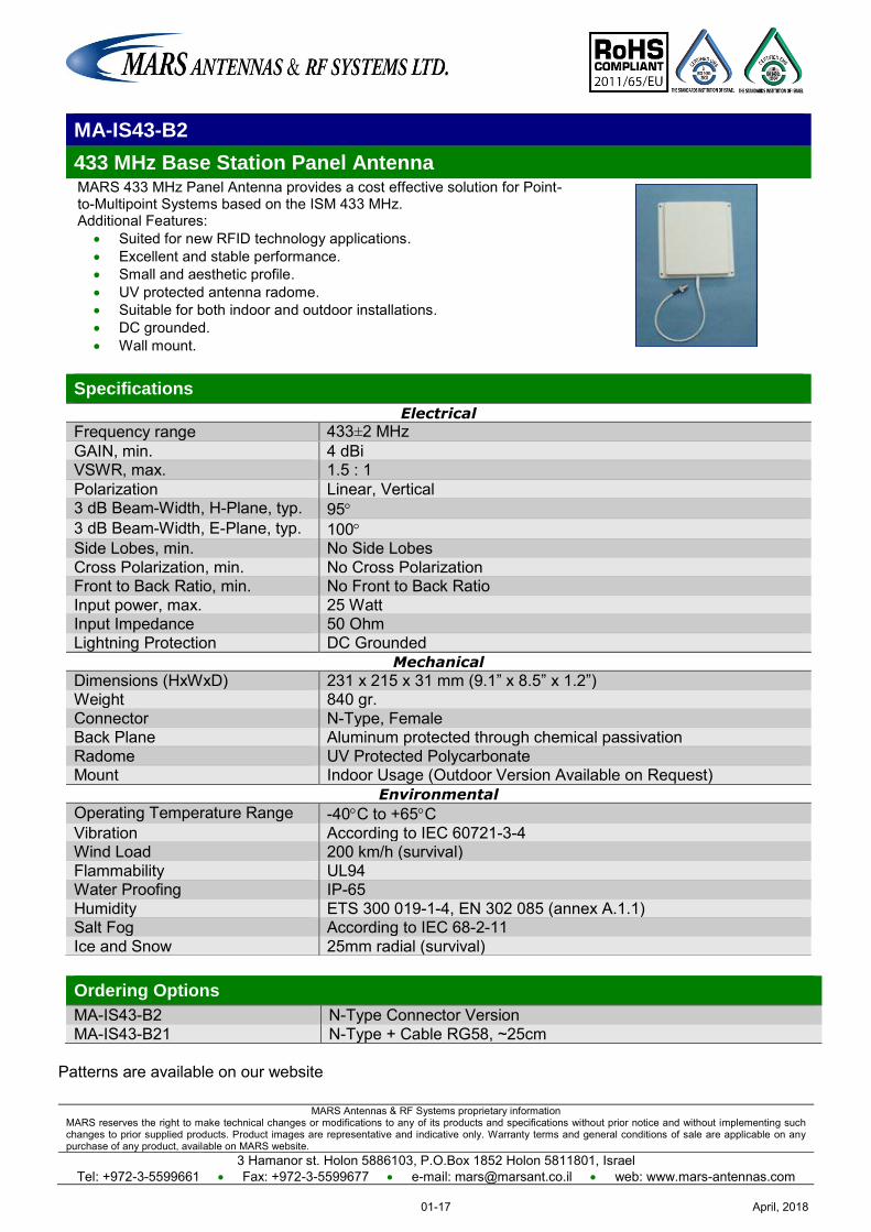
MA-IS43-B2
433 MHz Base Station Panel Antenna MARS 433 MHz Panel Antenna provides a cost effective solution for Point-to-Multipoint Systems based on the ISM 433 MHz. Additional Features:
Suited for new RFID technology applications. Excellent and stable performance. Small and aesthetic profile. UV protected antenna radome. Suitable for both indoor and outdoor installations. DC grounded. Wall mount.
Specifications
Electrical
Frequency range 433±2 MHz GAIN, min. 4 dBi VSWR, max. 1.5 : 1 Polarization Linear, Vertical 3 dB Beam-Width, H-Plane, typ. 95 3 dB Beam-Width, E-Plane, typ. 100 Side Lobes, min. No Side Lobes Cross Polarization, min. No Cross Polarization Front to Back Ratio, min. No Front to Back Ratio Input power, max. 25 Watt Input Impedance 50 Ohm Lightning Protection DC Grounded
Mechanical
Dimensions (HxWxD) 231 x 215 x 31 mm (9.1” x 8.5” x 1.2”) Weight 840 gr. Connector N-Type, Female Back Plane Aluminum protected through chemical passivation Radome UV Protected Polycarbonate Mount Indoor Usage (Outdoor Version Available on Request)
Environmental
Operating Temperature Range -40C to +65C Vibration According to IEC 60721-3-4 Wind Load 200 km/h (survival) Flammability UL94 Water Proofing IP-65 Humidity ETS 300 019-1-4, EN 302 085 (annex A.1.1) Salt Fog According to IEC 68-2-11 Ice and Snow 25mm radial (survival)
Ordering Options
MA-IS43-B2 N-Type Connector Version MA-IS43-B21 N-Type + Cable RG58, ~25cm
Patterns are available on our website
April, 201801-17
MARS Antennas & RF Systems proprietary information MARS reserves the right to make technical changes or modifications to any of its products and specifications without prior notice and without implementing such changes to prior supplied products. Product images are representative and indicative only. Warranty terms and general conditions of sale are applicable on any purchase of any product, available on MARS website.
3 Hamanor st. Holon 5886103, P.O.Box 1852 Holon 5811801, Israel
Tel: +972-3-5599661 Fax: +972-3-5599677 e-mail: [email protected] web: www.mars-antennas.com
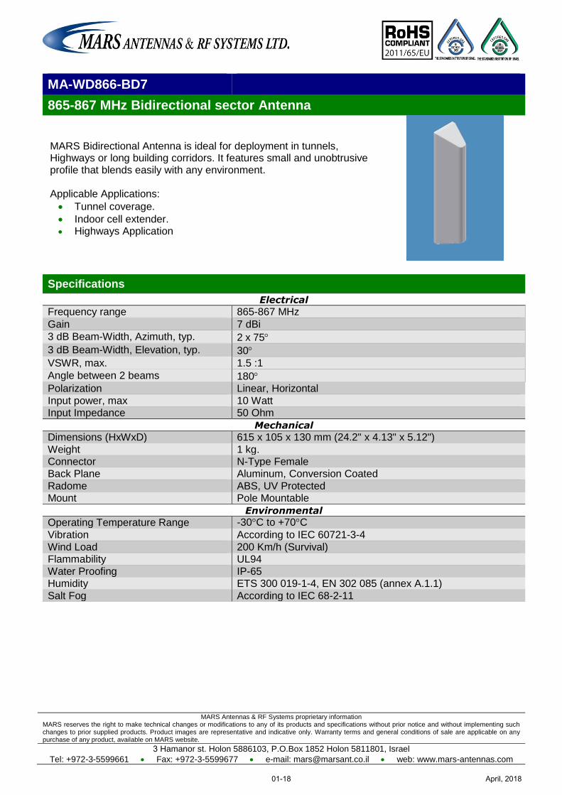
MA-WD866-BD7
865-867 MHz Bidirectional sector Antenna
MARS Bidirectional Antenna is ideal for deployment in tunnels, Highways or long building corridors. It features small and unobtrusive profile that blends easily with any environment. Applicable Applications:
Tunnel coverage.
Indoor cell extender. Highways Application
Specifications
Electrical
Frequency range 865-867 MHz
Gain 7 dBi
3 dB Beam-Width, Azimuth, typ. 2 x 75
3 dB Beam-Width, Elevation, typ. 30
VSWR, max. 1.5 :1
Angle between 2 beams 180 Polarization Linear, Horizontal
Input power, max 10 Watt Input Impedance 50 Ohm
Mechanical
Dimensions (HxWxD) 615 x 105 x 130 mm (24.2" x 4.13" x 5.12")
Weight 1 kg. Connector N-Type Female Back Plane Aluminum, Conversion Coated
Radome ABS, UV Protected Mount Pole Mountable
Environmental
Operating Temperature Range -30°C to +70°C
Vibration According to IEC 60721-3-4
Wind Load 200 Km/h (Survival) Flammability UL94
Water Proofing IP-65 Humidity ETS 300 019-1-4, EN 302 085 (annex A.1.1)
Salt Fog According to IEC 68-2-11
April, 201801-18
MARS Antennas & RF Systems proprietary information MARS reserves the right to make technical changes or modifications to any of its products and specifications without prior notice and without implementing such changes to prior supplied products. Product images are representative and indicative only. Warranty terms and general conditions of sale are applicable on any purchase of any product, available on MARS website.
3 Hamanor st. Holon 5886103, P.O.Box 1852 Holon 5811801, Israel Tel: +972-3-5599661 Fax: +972-3-5599677 e-mail: [email protected] web: www.mars-antennas.com
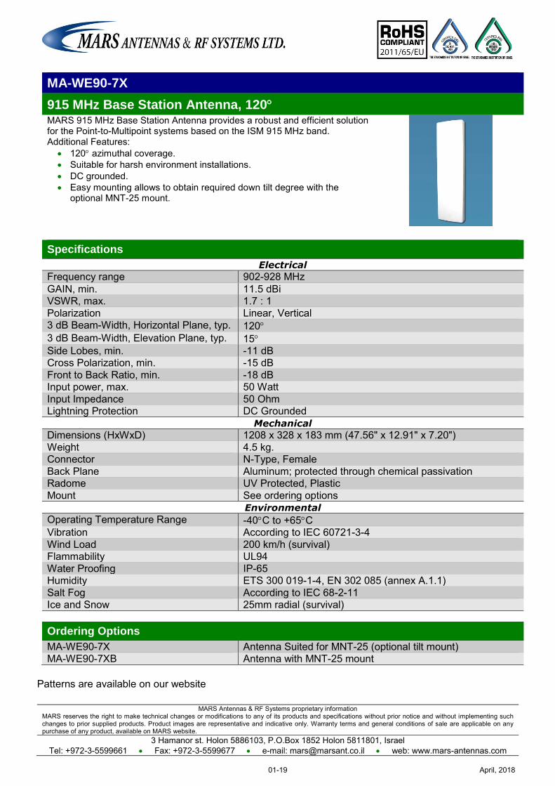
MA-WE90-7X
915 MHz Base Station Antenna, 120 MARS 915 MHz Base Station Antenna provides a robust and efficient solution for the Point-to-Multipoint systems based on the ISM 915 MHz band. Additional Features:
120 azimuthal coverage. Suitable for harsh environment installations. DC grounded. Easy mounting allows to obtain required down tilt degree with the
optional MNT-25 mount.
Specifications
Electrical
Frequency range 902-928 MHz GAIN, min. 11.5 dBi VSWR, max. 1.7 : 1 Polarization Linear, Vertical 3 dB Beam-Width, Horizontal Plane, typ. 120 3 dB Beam-Width, Elevation Plane, typ. 15 Side Lobes, min. -11 dB Cross Polarization, min. -15 dB Front to Back Ratio, min. -18 dB Input power, max. 50 Watt Input Impedance 50 Ohm Lightning Protection DC Grounded
Mechanical
Dimensions (HxWxD) 1208 x 328 x 183 mm (47.56" x 12.91" x 7.20") Weight 4.5 kg. Connector N-Type, Female Back Plane Aluminum; protected through chemical passivation Radome UV Protected, Plastic Mount See ordering options
Environmental
Operating Temperature Range -40C to +65C Vibration According to IEC 60721-3-4 Wind Load 200 km/h (survival) Flammability UL94 Water Proofing IP-65 Humidity ETS 300 019-1-4, EN 302 085 (annex A.1.1) Salt Fog According to IEC 68-2-11 Ice and Snow 25mm radial (survival) Ordering Options
MA-WE90-7X Antenna Suited for MNT-25 (optional tilt mount) MA-WE90-7XB Antenna with MNT-25 mount
Patterns are available on our website
April, 201801-19
MARS Antennas & RF Systems proprietary information MARS reserves the right to make technical changes or modifications to any of its products and specifications without prior notice and without implementing such changes to prior supplied products. Product images are representative and indicative only. Warranty terms and general conditions of sale are applicable on any purchase of any product, available on MARS website.
3 Hamanor st. Holon 5886103, P.O.Box 1852 Holon 5811801, Israel Tel: +972-3-5599661 Fax: +972-3-5599677 e-mail: [email protected] web: www.mars-antennas.com
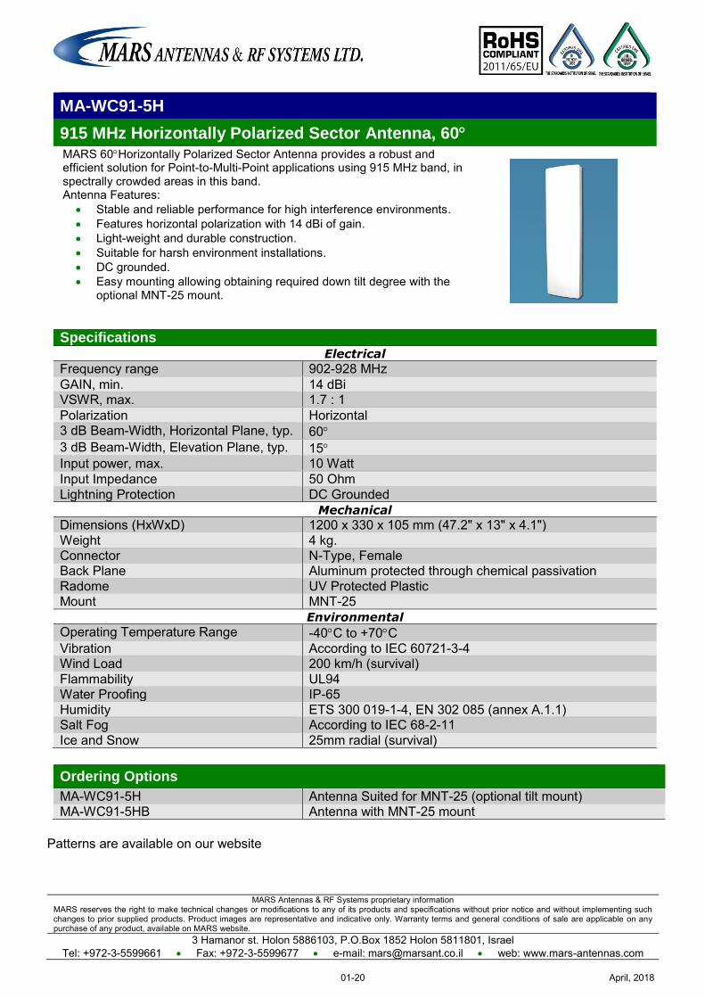
MA-WC91-5H
915 MHz Horizontally Polarized Sector Antenna, 60 MARS 60Horizontally Polarized Sector Antenna provides a robust and efficient solution for Point-to-Multi-Point applications using 915 MHz band, in spectrally crowded areas in this band. Antenna Features:
Stable and reliable performance for high interference environments. Features horizontal polarization with 14 dBi of gain. Light-weight and durable construction. Suitable for harsh environment installations. DC grounded. Easy mounting allowing obtaining required down tilt degree with the
optional MNT-25 mount.
Specifications Electrical
Frequency range 902-928 MHz GAIN, min. 14 dBi VSWR, max. 1.7 : 1 Polarization Horizontal 3 dB Beam-Width, Horizontal Plane, typ. 60 3 dB Beam-Width, Elevation Plane, typ. 15 Input power, max. 10 Watt Input Impedance 50 Ohm Lightning Protection DC Grounded
Mechanical
Dimensions (HxWxD) 1200 x 330 x 105 mm (47.2" x 13" x 4.1") Weight 4 kg. Connector N-Type, Female Back Plane Aluminum protected through chemical passivation Radome UV Protected Plastic Mount MNT-25
Environmental
Operating Temperature Range -40C to +70C Vibration According to IEC 60721-3-4 Wind Load 200 km/h (survival) Flammability UL94 Water Proofing IP-65 Humidity ETS 300 019-1-4, EN 302 085 (annex A.1.1) Salt Fog According to IEC 68-2-11 Ice and Snow 25mm radial (survival)
Ordering Options
MA-WC91-5H Antenna Suited for MNT-25 (optional tilt mount) MA-WC91-5HB Antenna with MNT-25 mount
Patterns are available on our website
April, 201801-20
MARS Antennas & RF Systems proprietary information MARS reserves the right to make technical changes or modifications to any of its products and specifications without prior notice and without implementing such changes to prior supplied products. Product images are representative and indicative only. Warranty terms and general conditions of sale are applicable on any purchase of any product, available on MARS website.
3 Hamanor st. Holon 5886103, P.O.Box 1852 Holon 5811801, Israel Tel: +972-3-5599661 Fax: +972-3-5599677 e-mail: [email protected] web: www.mars-antennas.com
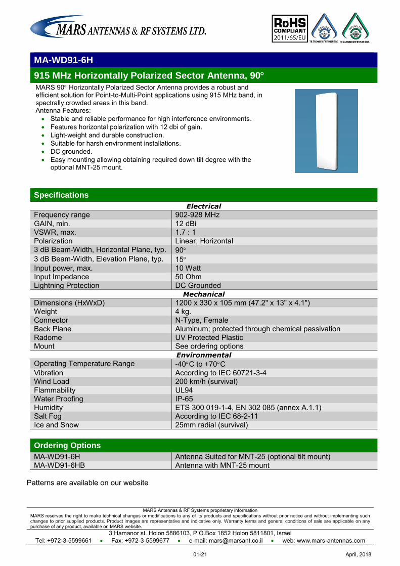
MA-WD91-6H
915 MHz Horizontally Polarized Sector Antenna, 90 MARS 90 Horizontally Polarized Sector Antenna provides a robust and efficient solution for Point-to-Multi-Point applications using 915 MHz band, in spectrally crowded areas in this band. Antenna Features: Stable and reliable performance for high interference environments. Features horizontal polarization with 12 dbi of gain. Light-weight and durable construction. Suitable for harsh environment installations. DC grounded. Easy mounting allowing obtaining required down tilt degree with the
optional MNT-25 mount.
Specifications
Electrical
Frequency range 902-928 MHz GAIN, min. 12 dBi VSWR, max. 1.7 : 1 Polarization Linear, Horizontal 3 dB Beam-Width, Horizontal Plane, typ. 90 3 dB Beam-Width, Elevation Plane, typ. 15 Input power, max. 10 Watt Input Impedance 50 Ohm Lightning Protection DC Grounded
Mechanical
Dimensions (HxWxD) 1200 x 330 x 105 mm (47.2" x 13" x 4.1") Weight 4 kg. Connector N-Type, Female Back Plane Aluminum; protected through chemical passivation Radome UV Protected Plastic Mount See ordering options
Environmental
Operating Temperature Range -40C to +70C Vibration According to IEC 60721-3-4 Wind Load 200 km/h (survival) Flammability UL94 Water Proofing IP-65 Humidity ETS 300 019-1-4, EN 302 085 (annex A.1.1) Salt Fog According to IEC 68-2-11 Ice and Snow 25mm radial (survival)
Ordering Options
MA-WD91-6H Antenna Suited for MNT-25 (optional tilt mount) MA-WD91-6HB Antenna with MNT-25 mount
Patterns are available on our website
April, 201801-21
MARS Antennas & RF Systems proprietary information MARS reserves the right to make technical changes or modifications to any of its products and specifications without prior notice and without implementing such changes to prior supplied products. Product images are representative and indicative only. Warranty terms and general conditions of sale are applicable on any purchase of any product, available on MARS website.
3 Hamanor st. Holon 5886103, P.O.Box 1852 Holon 5811801, Israel Tel: +972-3-5599661 Fax: +972-3-5599677 e-mail: [email protected] web: www.mars-antennas.com
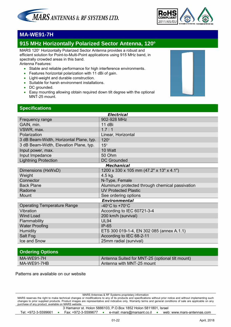
MA-WE91-7H
915 MHz Horizontally Polarized Sector Antenna, 120 MARS 120 Horizontally Polarized Sector Antenna provides a robust and efficient solution for Point-to-Multi-Point applications using 915 MHz band, in spectrally crowded areas in this band. Antenna Features:
Stable and reliable performance for high interference environments. Features horizontal polarization with 11 dBi of gain. Light-weight and durable construction. Suitable for harsh environment installations. DC grounded. Easy mounting allowing obtain required down tilt degree with the optional
MNT-25 mount.
Specifications
Electrical
Frequency range 902-928 MHz GAIN, min. 11 dBi VSWR, max. 1.7 : 1 Polarization Linear, Horizontal 3 dB Beam-Width, Horizontal Plane, typ. 120 3 dB Beam-Width, Elevation Plane, typ. 15 Input power, max. 10 Watt Input Impedance 50 Ohm Lightning Protection DC Grounded
Mechanical
Dimensions (HxWxD) 1200 x 330 x 105 mm (47.2" x 13" x 4.1") Weight 4.5 kg. Connector N-Type, Female Back Plane Aluminum protected through chemical passivation Radome UV Protected Plastic Mount See ordering options
Environmental
Operating Temperature Range -40C to +70C Vibration According to IEC 60721-3-4 Wind Load 200 km/h (survival) Flammability UL94 Water Proofing IP-65 Humidity ETS 300 019-1-4, EN 302 085 (annex A.1.1) Salt Fog According to IEC 68-2-11 Ice and Snow 25mm radial (survival) Ordering Options
MA-WE91-7H Antenna Suited for MNT-25 (optional tilt mount) MA-WE91-7HB Antenna with MNT-25 mount
Patterns are available on our website
April, 201801-22
MARS Antennas & RF Systems proprietary information MARS reserves the right to make technical changes or modifications to any of its products and specifications without prior notice and without implementing such changes to prior supplied products. Product images are representative and indicative only. Warranty terms and general conditions of sale are applicable on any purchase of any product, available on MARS website.
3 Hamanor st. Holon 5886103, P.O.Box 1852 Holon 5811801, Israel
Tel: +972-3-5599661 Fax: +972-3-5599677 e-mail: [email protected] web: www.mars-antennas.com
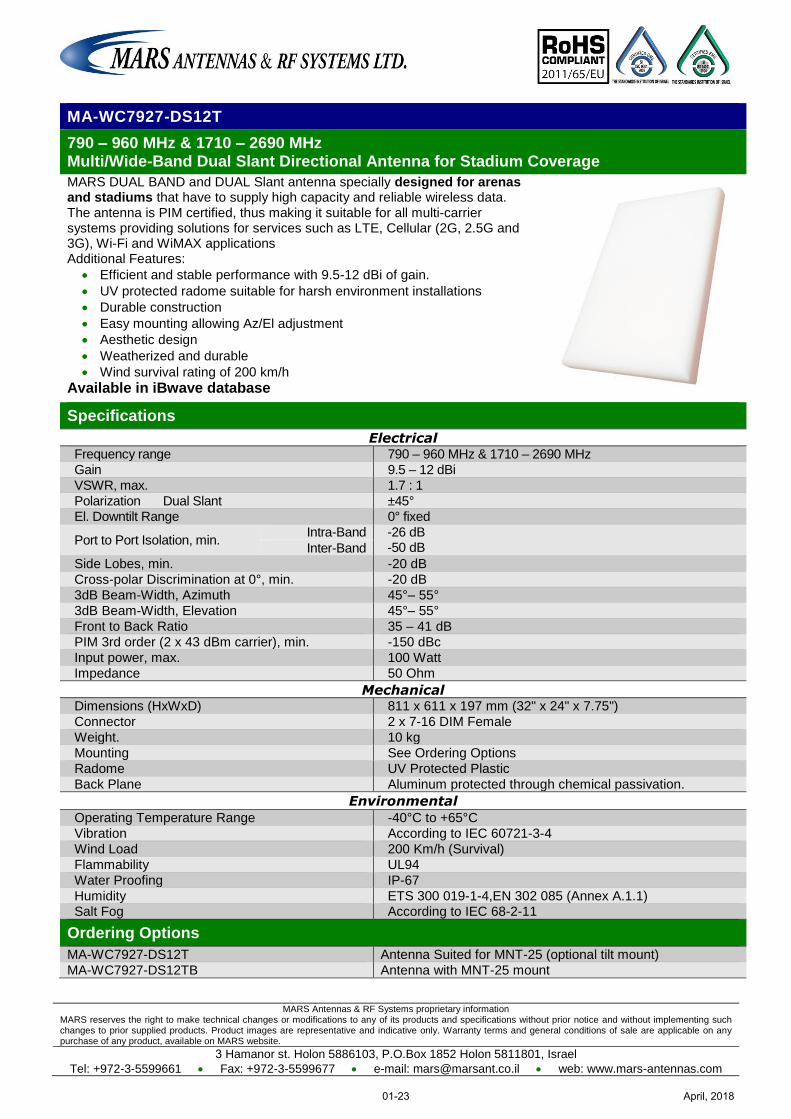
MA-WC7927-DS12T
790 – 960 MHz & 1710 – 2690 MHz Multi/Wide-Band Dual Slant Directional Antenna for Stadium Coverage
MARS DUAL BAND and DUAL Slant antenna specially designed for arenas and stadiums that have to supply high capacity and reliable wireless data. The antenna is PIM certified, thus making it suitable for all multi-carrier systems providing solutions for services such as LTE, Cellular (2G, 2.5G and 3G), Wi-Fi and WiMAX applications Additional Features:
Efficient and stable performance with 9.5-12 dBi of gain.
UV protected radome suitable for harsh environment installations
Durable construction
Easy mounting allowing Az/El adjustment
Aesthetic design
Weatherized and durable
Wind survival rating of 200 km/h
Available in iBwave database
Specifications
Electrical Frequency range 790 – 960 MHz & 1710 – 2690 MHz
Gain 9.5 – 12 dBi
VSWR, max. 1.7 : 1
Polarization Dual Slant ±45° El. Downtilt Range 0° fixed
Port to Port Isolation, min. Intra-Band -26 dB
-50 dB Inter-Band
Side Lobes, min. -20 dB
Cross-polar Discrimination at 0°, min. -20 dB
3dB Beam-Width, Azimuth 45°– 55°
3dB Beam-Width, Elevation 45°– 55°
Front to Back Ratio 35 – 41 dB
PIM 3rd order (2 x 43 dBm carrier), min. -150 dBc
Input power, max. 100 Watt
Impedance 50 Ohm
Mechanical Dimensions (HxWxD) 811 x 611 x 197 mm (32" x 24" x 7.75")
Connector 2 x 7-16 DIM Female
Weight. 10 kg
Mounting See Ordering Options
Radome UV Protected Plastic
Back Plane Aluminum protected through chemical passivation.
Environmental
Operating Temperature Range -40°C to +65°C
Vibration According to IEC 60721-3-4
Wind Load 200 Km/h (Survival)
Flammability UL94
Water Proofing IP-67
Humidity ETS 300 019-1-4,EN 302 085 (Annex A.1.1) Salt Fog According to IEC 68-2-11
Ordering Options
MA-WC7927-DS12T Antenna Suited for MNT-25 (optional tilt mount)
MA-WC7927-DS12TB Antenna with MNT-25 mount
April, 201801-23
MARS Antennas & RF Systems proprietary information MARS reserves the right to make technical changes or modifications to any of its products and specifications without prior notice and without implementing such changes to prior supplied products. Product images are representative and indicative only. Warranty terms and general conditions of sale are applicable on any purchase of any product, available on MARS website.
3 Hamanor st. Holon 5886103, P.O.Box 1852 Holon 5811801, Israel
Tel: +972-3-5599661 Fax: +972-3-5599677 e-mail: [email protected] web: www.mars-antennas.com
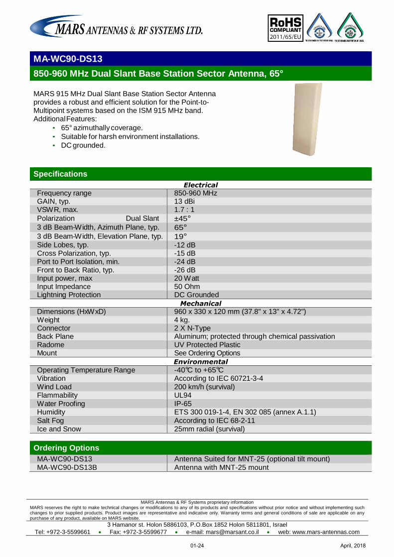
MA-WC90-DS13
850-960 MHz Dual Slant Base Station Sector Antenna, 65°
MARS 915 MHz Dual Slant Base Station Sector Antenna provides a robust and efficient solution for the Point-to-Multipoint systems based on the ISM 915 MHz band. Additional Features:
• 65° azimuthally coverage.
• Suitable for harsh environment installations.
• DC grounded.
Specifications
Electrical
Frequency range 850-960 MHz GAIN, typ. 13 dBi VSWR, max. 1.7 : 1
Polarization Dual Slant ±45° 3 dB Beam-Width, Azimuth Plane, typ. 65° 3 dB Beam-Width, Elevation Plane, typ. 19° Side Lobes, typ. -12 dB Cross Polarization, typ. -15 dB Port to Port Isolation, min. -24 dB Front to Back Ratio, typ. -26 dB Input power, max 20 Watt Input Impedance 50 Ohm Lightning Protection DC Grounded
Mechanical
Dimensions (HxWxD) 960 x 330 x 120 mm (37.8" x 13" x 4.72") Weight 4 kg. Connector 2 X N-Type Back Plane Aluminum; protected through chemical passivation Radome UV Protected Plastic Mount See Ordering Options
Environmental
Operating Temperature Range -40°C to +65°C Vibration According to IEC 60721-3-4 Wind Load 200 km/h (survival) Flammability UL94 Water Proofing IP-65 Humidity ETS 300 019-1-4, EN 302 085 (annex A.1.1) Salt Fog According to IEC 68-2-11 Ice and Snow 25mm radial (survival)
Ordering Options
MA-WC90-DS13 Antenna Suited for MNT-25 (optional tilt mount) MA-WC90-DS13B Antenna with MNT-25 mount
April, 201801-24
MARS Antennas & RF Systems proprietary information MARS reserves the right to make technical changes or modifications to any of its products and specifications without prior notice and without implementing such changes to prior supplied products. Product images are representative and indicative only. Warranty terms and general conditions of sale are applicable on any purchase of any product, available on MARS website.
3 Hamanor st. Holon 5886103, P.O.Box 1852 Holon 5811801, Israel
Tel: +972-3-5599661 Fax: +972-3-5599677 e-mail: [email protected] web: www.mars-antennas.com
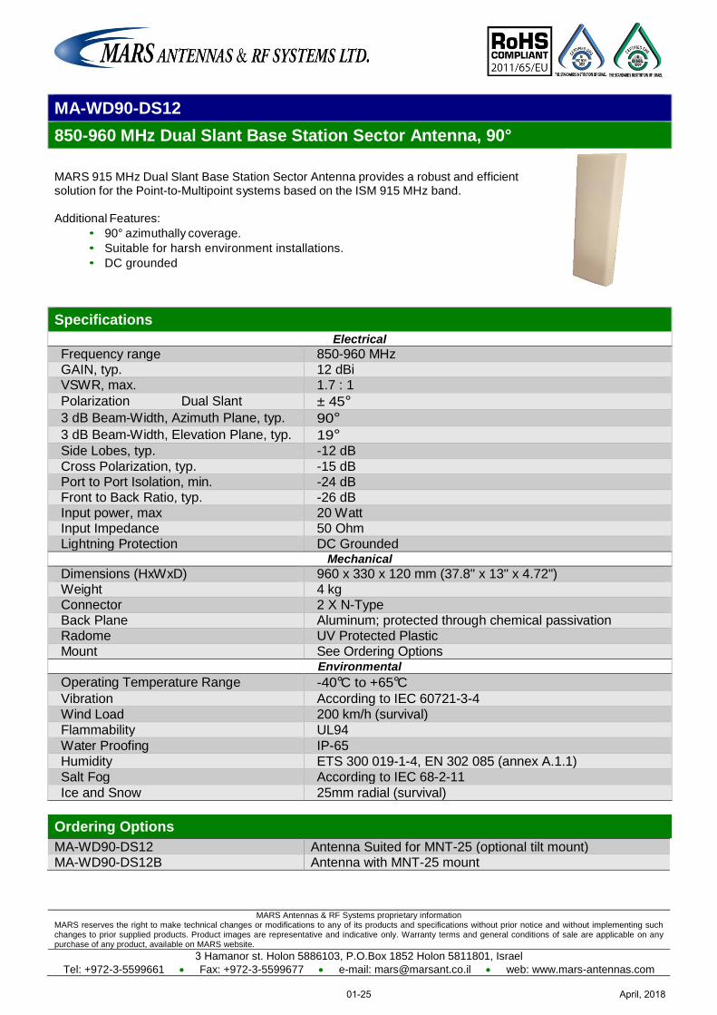
MA-WD90-DS12
850-960 MHz Dual Slant Base Station Sector Antenna, 90°
MARS 915 MHz Dual Slant Base Station Sector Antenna provides a robust and efficient solution for the Point-to-Multipoint systems based on the ISM 915 MHz band. Additional Features:
• 90° azimuthally coverage.
• Suitable for harsh environment installations.
• DC grounded
Specifications
Electrical
Frequency range 850-960 MHz GAIN, typ. 12 dBi VSWR, max. 1.7 : 1
Polarization Dual Slant ± 45° 3 dB Beam-Width, Azimuth Plane, typ. 90° 3 dB Beam-Width, Elevation Plane, typ. 19° Side Lobes, typ. -12 dB
Cross Polarization, typ. -15 dB Port to Port Isolation, min. -24 dB Front to Back Ratio, typ. -26 dB Input power, max 20 Watt Input Impedance 50 Ohm Lightning Protection DC Grounded
Mechanical
Dimensions (HxWxD) 960 x 330 x 120 mm (37.8" x 13" x 4.72") Weight 4 kg Connector 2 X N-Type Back Plane Aluminum; protected through chemical passivation Radome UV Protected Plastic Mount See Ordering Options
Environmental
Operating Temperature Range -40°C to +65°C
Vibration According to IEC 60721-3-4
Wind Load 200 km/h (survival)
Flammability UL94
Water Proofing IP-65
Humidity ETS 300 019-1-4, EN 302 085 (annex A.1.1)
Salt Fog According to IEC 68-2-11
Ice and Snow 25mm radial (survival)
Ordering Options
MA-WD90-DS12 Antenna Suited for MNT-25 (optional tilt mount) MA-WD90-DS12B Antenna with MNT-25 mount
April, 201801-25
MARS Antennas & RF Systems proprietary information MARS reserves the right to make technical changes or modifications to any of its products and specifications without prior notice and without implementing such changes to prior supplied products. Product images are representative and indicative only. Warranty terms and general conditions of sale are applicable on any purchase of any product, available on MARS website.
3 Hamanor st. Holon 5886103, P.O.Box 1852 Holon 5811801, Israel Tel: +972-3-5599661 Fax: +972-3-5599677 e-mail: [email protected] web: www.mars-antennas.com
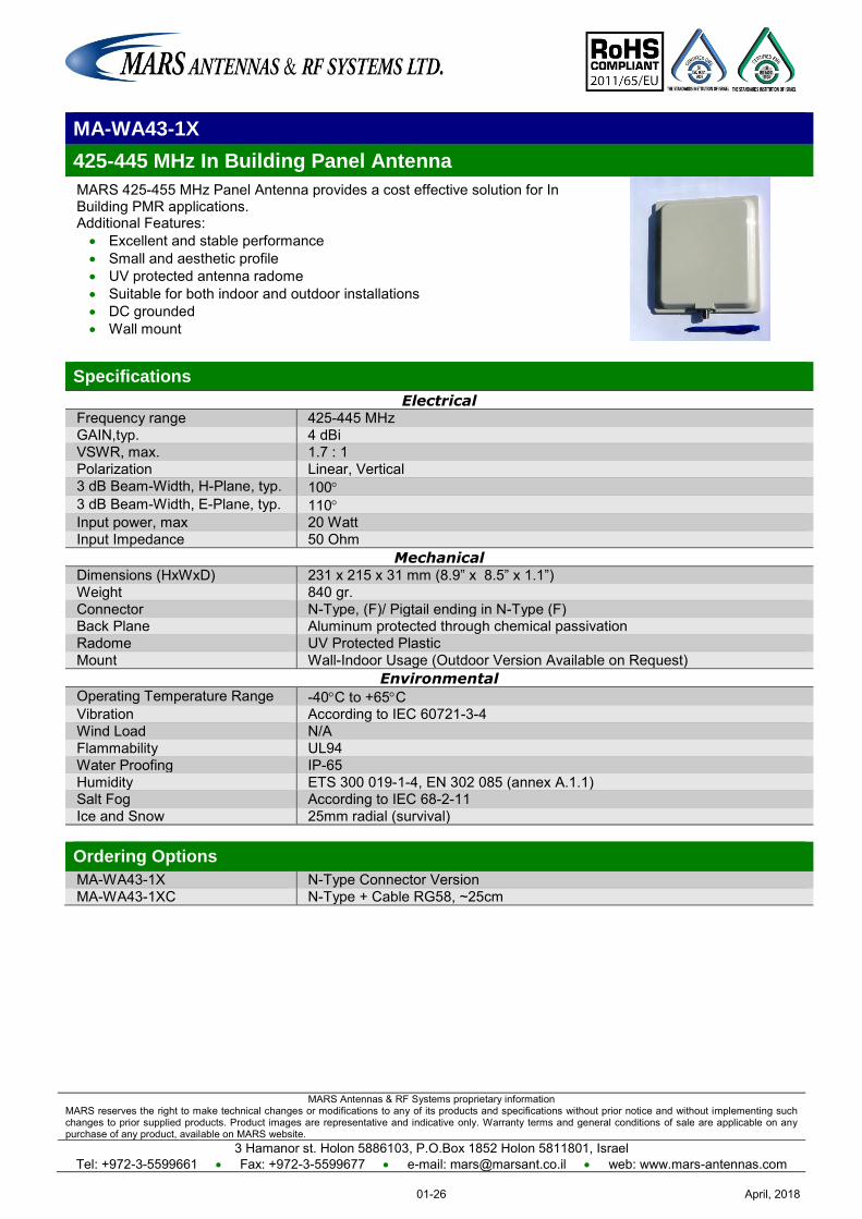
MA-WA43-1X
425-445 MHz In Building Panel Antenna
MARS 425-455 MHz Panel Antenna provides a cost effective solution for In Building PMR applications. Additional Features: Excellent and stable performance Small and aesthetic profile UV protected antenna radome Suitable for both indoor and outdoor installations DC grounded Wall mount
Specifications
Electrical Frequency range 425-445 MHz GAIN,typ. 4 dBi VSWR, max. 1.7 : 1 Polarization Linear, Vertical 3 dB Beam-Width, H-Plane, typ. 100 3 dB Beam-Width, E-Plane, typ. 110 Input power, max 20 Watt Input Impedance 50 Ohm
Mechanical Dimensions (HxWxD) 231 x 215 x 31 mm (8.9” x 8.5” x 1.1”) Weight 840 gr. Connector N-Type, (F)/ Pigtail ending in N-Type (F) Back Plane Aluminum protected through chemical passivation Radome UV Protected Plastic Mount Wall-Indoor Usage (Outdoor Version Available on Request)
Environmental Operating Temperature Range -40C to +65C Vibration According to IEC 60721-3-4 Wind Load N/A Flammability UL94 Water Proofing IP-65 Humidity ETS 300 019-1-4, EN 302 085 (annex A.1.1) Salt Fog According to IEC 68-2-11 Ice and Snow 25mm radial (survival) Ordering Options
MA-WA43-1X N-Type Connector Version MA-WA43-1XC N-Type + Cable RG58, ~25cm
April, 201801-26
MARS Antennas & RF Systems proprietary information MARS reserves the right to make technical changes or modifications to any of its products and specifications without prior notice and without implementing such changes to prior supplied products. Product images are representative and indicative only. Warranty terms and general conditions of sale are applicable on any purchase of any product, available on MARS website.
3 Hamanor st. Holon 5886103, P.O.Box 1852 Holon 5811801, Israel Tel: +972-3-5599661 Fax: +972-3-5599677 e-mail: [email protected] web: www.mars-antennas.com
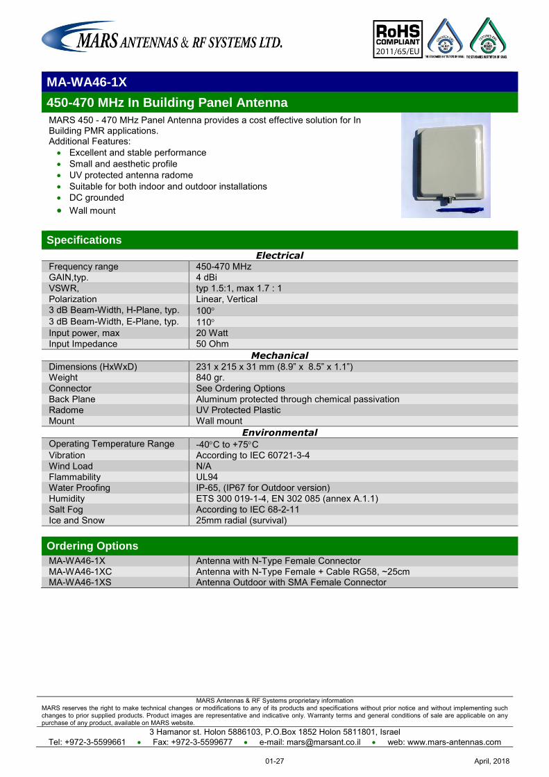
MA-WA46-1X
450-470 MHz In Building Panel Antenna
MARS 450 - 470 MHz Panel Antenna provides a cost effective solution for In Building PMR applications. Additional Features: Excellent and stable performance Small and aesthetic profile UV protected antenna radome Suitable for both indoor and outdoor installations DC grounded Wall mount
Specifications
Electrical Frequency range 450-470 MHz GAIN,typ. 4 dBi VSWR, typ 1.5:1, max 1.7 : 1 Polarization Linear, Vertical 3 dB Beam-Width, H-Plane, typ. 100 3 dB Beam-Width, E-Plane, typ. 110 Input power, max 20 Watt Input Impedance 50 Ohm
Mechanical Dimensions (HxWxD) 231 x 215 x 31 mm (8.9” x 8.5” x 1.1”) Weight 840 gr. Connector See Ordering Options Back Plane Aluminum protected through chemical passivation Radome UV Protected Plastic Mount Wall mount
Environmental Operating Temperature Range -40C to +75C Vibration According to IEC 60721-3-4 Wind Load N/A Flammability UL94 Water Proofing IP-65, (IP67 for Outdoor version) Humidity ETS 300 019-1-4, EN 302 085 (annex A.1.1) Salt Fog According to IEC 68-2-11 Ice and Snow 25mm radial (survival) Ordering Options
MA-WA46-1X Antenna with N-Type Female Connector MA-WA46-1XC Antenna with N-Type Female + Cable RG58, ~25cm MA-WA46-1XS Antenna Outdoor with SMA Female Connector
April, 201801-27
MARS Antennas & RF Systems proprietary information MARS reserves the right to make technical changes or modifications to any of its products and specifications without prior notice and without implementing such changes to prior supplied products. Product images are representative and indicative only. Warranty terms and general conditions of sale are applicable on any purchase of any product, available on MARS website.
3 Hamanor st. Holon 5886103, P.O.Box 1852 Holon 5811801, Israel
Tel: +972-3-5599661 Fax: +972-3-5599677 e-mail: [email protected] web: www.mars-antennas.com
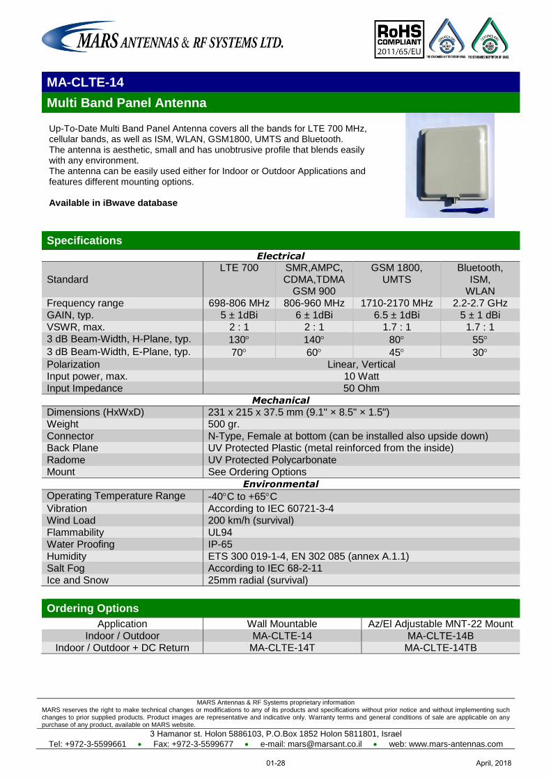
MA-CLTE-14
Multi Band Panel Antenna
Up-To-Date Multi Band Panel Antenna covers all the bands for LTE 700 MHz, cellular bands, as well as ISM, WLAN, GSM1800, UMTS and Bluetooth. The antenna is aesthetic, small and has unobtrusive profile that blends easily with any environment. The antenna can be easily used either for Indoor or Outdoor Applications and features different mounting options. Available in iBwave database
Specifications
Electrical
Standard LTE 700 SMR,AMPC,
CDMA,TDMA GSM 900
GSM 1800, UMTS
Bluetooth, ISM,
WLAN
Frequency range 698-806 MHz 806-960 MHz 1710-2170 MHz 2.2-2.7 GHz GAIN, typ. 5 ± 1dBi 6 ± 1dBi 6.5 ± 1dBi 5 ± 1 dBi
VSWR, max. 2 : 1 2 : 1 1.7 : 1 1.7 : 1 3 dB Beam-Width, H-Plane, typ. 130 140 80 55
3 dB Beam-Width, E-Plane, typ. 70 60 45 30 Polarization Linear, Vertical Input power, max. 10 Watt
Input Impedance 50 Ohm
Mechanical
Dimensions (HxWxD) 231 x 215 x 37.5 mm (9.1" × 8.5" × 1.5") Weight 500 gr.
Connector N-Type, Female at bottom (can be installed also upside down) Back Plane UV Protected Plastic (metal reinforced from the inside)
Radome UV Protected Polycarbonate Mount See Ordering Options
Environmental
Operating Temperature Range -40C to +65C
Vibration According to IEC 60721-3-4 Wind Load 200 km/h (survival)
Flammability UL94 Water Proofing IP-65
Humidity ETS 300 019-1-4, EN 302 085 (annex A.1.1) Salt Fog According to IEC 68-2-11
Ice and Snow 25mm radial (survival)
Ordering Options
Application Wall Mountable Az/El Adjustable MNT-22 Mount
Indoor / Outdoor MA-CLTE-14 MA-CLTE-14B Indoor / Outdoor + DC Return MA-CLTE-14T MA-CLTE-14TB
April, 201801-28
MARS Antennas & RF Systems proprietary information MARS reserves the right to make technical changes or modifications to any of its products and specifications without prior notice and without implementing such changes to prior supplied products. Product images are representative and indicative only. Warranty terms and general conditions of sale are applicable on any purchase of any product, available on MARS website.
3 Hamanor st. Holon 5886103, P.O.Box 1852 Holon 5811801, Israel
Tel: +972-3-5599661 Fax: +972-3-5599677 e-mail: [email protected] web: www.mars-antennas.com
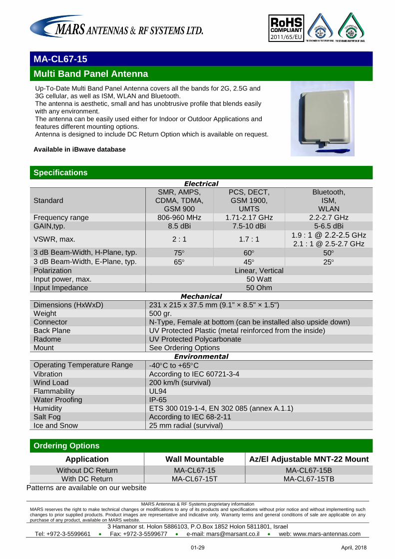
MA-CL67-15
Multi Band Panel Antenna
Up-To-Date Multi Band Panel Antenna covers all the bands for 2G, 2.5G and 3G cellular, as well as ISM, WLAN and Bluetooth. The antenna is aesthetic, small and has unobtrusive profile that blends easily with any environment. The antenna can be easily used either for Indoor or Outdoor Applications and features different mounting options. Antenna is designed to include DC Return Option which is available on request. Available in iBwave database
Specifications
Electrical
Standard SMR, AMPS,
CDMA, TDMA, GSM 900
PCS, DECT, GSM 1900,
UMTS
Bluetooth, ISM,
WLAN
Frequency range 806-960 MHz 1.71-2.17 GHz 2.2-2.7 GHz GAIN,typ. 8.5 dBi 7.5-10 dBi 5-6.5 dBi
VSWR, max. 2 : 1 1.7 : 1 1.9 : 1 @ 2.2-2.5 GHz
2.1 : 1 @ 2.5-2.7 GHz 3 dB Beam-Width, H-Plane, typ. 75 60 50
3 dB Beam-Width, E-Plane, typ. 65 45 25 Polarization Linear, Vertical Input power, max. 50 Watt
Input Impedance 50 Ohm
Mechanical
Dimensions (HxWxD) 231 x 215 x 37.5 mm (9.1" × 8.5" × 1.5") Weight 500 gr.
Connector N-Type, Female at bottom (can be installed also upside down) Back Plane UV Protected Plastic (metal reinforced from the inside)
Radome UV Protected Polycarbonate Mount See Ordering Options
Environmental
Operating Temperature Range -40C to +65C
Vibration According to IEC 60721-3-4 Wind Load 200 km/h (survival)
Flammability UL94 Water Proofing IP-65
Humidity ETS 300 019-1-4, EN 302 085 (annex A.1.1) Salt Fog According to IEC 68-2-11
Ice and Snow 25 mm radial (survival)
Ordering Options
Application Wall Mountable Az/El Adjustable MNT-22 Mount
Without DC Return MA-CL67-15 MA-CL67-15B With DC Return MA-CL67-15T MA-CL67-15TB
Patterns are available on our website
April, 201801-29
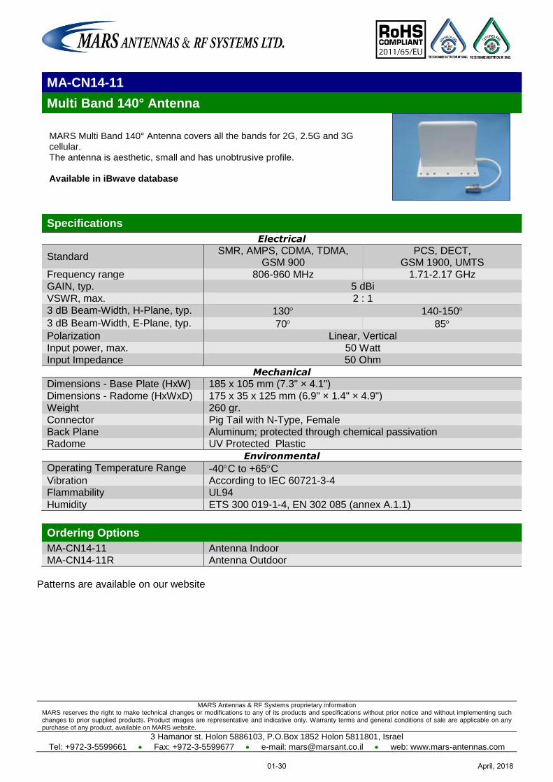
MARS Antennas & RF Systems proprietary information MARS reserves the right to make technical changes or modifications to any of its products and specifications without prior notice and without implementing such changes to prior supplied products. Product images are representative and indicative only. Warranty terms and general conditions of sale are applicable on any purchase of any product, available on MARS website.
3 Hamanor st. Holon 5886103, P.O.Box 1852 Holon 5811801, Israel
Tel: +972-3-5599661 Fax: +972-3-5599677 e-mail: [email protected] web: www.mars-antennas.com
MA-CN14-11
Multi Band 140° Antenna
MARS Multi Band 140° Antenna covers all the bands for 2G, 2.5G and 3G cellular. The antenna is aesthetic, small and has unobtrusive profile. Available in iBwave database
Specifications
Electrical
Standard SMR, AMPS, CDMA, TDMA,
GSM 900 PCS, DECT,
GSM 1900, UMTS
Frequency range 806-960 MHz 1.71-2.17 GHz GAIN, typ. 5 dBi
VSWR, max. 2 : 1 3 dB Beam-Width, H-Plane, typ. 130 140-150
3 dB Beam-Width, E-Plane, typ. 70 85 Polarization Linear, Vertical
Input power, max. 50 Watt Input Impedance 50 Ohm
Mechanical
Dimensions - Base Plate (HxW) 185 x 105 mm (7.3" × 4.1")
Dimensions - Radome (HxWxD) 175 x 35 x 125 mm (6.9" × 1.4" × 4.9") Weight 260 gr.
Connector Pig Tail with N-Type, Female Back Plane Aluminum; protected through chemical passivation Radome UV Protected Plastic
Environmental
Operating Temperature Range -40C to +65C Vibration According to IEC 60721-3-4 Flammability UL94
Humidity ETS 300 019-1-4, EN 302 085 (annex A.1.1)
Ordering Options
MA-CN14-11 Antenna Indoor MA-CN14-11R Antenna Outdoor
Patterns are available on our website
April, 201801-30
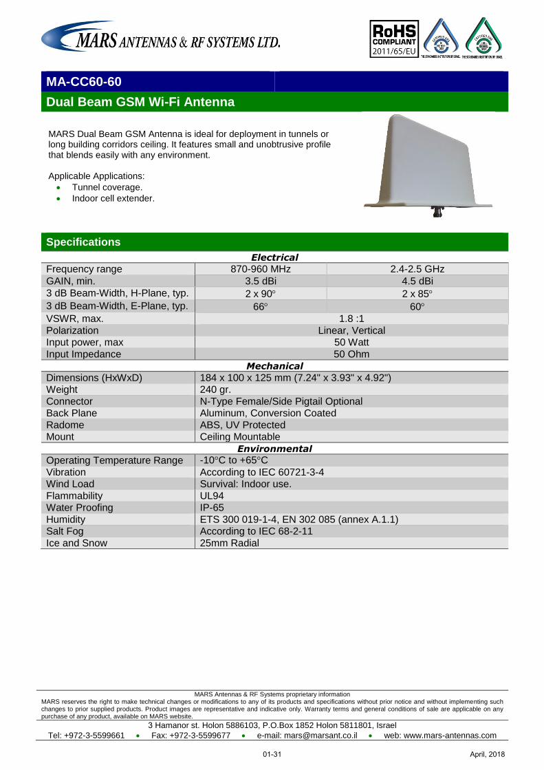
MARS Antennas & RF Systems proprietary information MARS reserves the right to make technical changes or modifications to any of its products and specifications without prior notice and without implementing such changes to prior supplied products. Product images are representative and indicative only. Warranty terms and general conditions of sale are applicable on any purchase of any product, available on MARS website.
3 Hamanor st. Holon 5886103, P.O.Box 1852 Holon 5811801, Israel
Tel: +972-3-5599661 Fax: +972-3-5599677 e-mail: [email protected] web: www.mars-antennas.com
MA-CC60-60
Dual Beam GSM Wi-Fi Antenna
MARS Dual Beam GSM Antenna is ideal for deployment in tunnels or long building corridors ceiling. It features small and unobtrusive profile that blends easily with any environment. Applicable Applications:
Tunnel coverage.
Indoor cell extender.
Specifications
Electrical
Frequency range 870-960 MHz 2.4-2.5 GHz
GAIN, min. 3.5 dBi 4.5 dBi
3 dB Beam-Width, H-Plane, typ. 2 x 90 2 x 85
3 dB Beam-Width, E-Plane, typ. 66 60
VSWR, max. 1.8 :1
Polarization Linear, Vertical Input power, max 50 Watt
Input Impedance 50 Ohm
Mechanical
Dimensions (HxWxD) 184 x 100 x 125 mm (7.24" x 3.93" x 4.92") Weight 240 gr.
Connector N-Type Female/Side Pigtail Optional Back Plane Aluminum, Conversion Coated
Radome ABS, UV Protected Mount Ceiling Mountable
Environmental
Operating Temperature Range -10°C to +65°C
Vibration According to IEC 60721-3-4 Wind Load Survival: Indoor use.
Flammability UL94 Water Proofing IP-65
Humidity ETS 300 019-1-4, EN 302 085 (annex A.1.1) Salt Fog According to IEC 68-2-11
Ice and Snow 25mm Radial
April, 201801-31

MARS Antennas & RF Systems proprietary information MARS reserves the right to make technical changes or modifications to any of its products and specifications without prior notice and without implementing such changes to prior supplied products. Product images are representative and indicative only. Warranty terms and general conditions of sale are applicable on any purchase of any product, available on MARS website.
3 Hamanor st. Holon 5886103, P.O.Box 1852 Holon 5811801, Israel
Tel: +972-3-5599661 Fax: +972-3-5599677 e-mail: [email protected] web: www.mars-antennas.com
1150 MHz – 2700 MHz Subscriber - Single Pol Subscriber - Dual Slant Subscriber - Triple Pol Subscriber - Quad Pol
Sector - Single Pol Sector - Dual Pol
Sector - Double Dual Slant Sector - Triple Pol Sector - Quad Pol DAS - Single Pol
GPS
Part Number Description Frequency
band Gain Polarization Dimension
Antenna type
Page
MA-WA12-9 1150-1375 MHz Directional Antenna
1150-1375 MHz 9 dBi Linear,
Vertical or Horizontal
175 x 96 Dia
mm
Subscriber
Single Pol 02-1
MA-WA14-1X 1425-1525 MHz Directional
1425-1525 MHz 13.5 dBi
(min.)
Linear, Vertical
305 x 305 x 25 mm
Subscriber
Single Pol 02-2
MA-WA19-4X 1.9 GHz Directional 1.85-1.99 GHz 15 dBi
(min.)
Linear, Vertical
305 x 305 x 25 mm
Subscriber
Single Pol 02-3
MA-WA24-2X Subscriber, High Gain
2.3-2.7 GHz 18 dBi (typ.)
Linear, Vertical or Horizontal
305 x 305 x 15 mm
Subscriber
Single Pol 02-4
MA-WA25-20 Subscriber, High Gain 2.3-2.7 GHz
20 dBi
(typ.)
Linear, Vertical or Horizontal
370 x 370 x 40 mm
Subscriber
Single Pol 02-5
MA-WA24-12 Small Size Subscriber
2.4-2.7 GHz 12 dBi (min.)
Linear, Vertical
155 x 155 x 28 mm
Subscriber
Single Pol 02-6
MA-WS2455-1X
Dual Band Subscriber, High Gain
2.4-2.5 GHz 4.9-5.875 GHz
18 dBi 12 dBi (typ.)
Linear, Vertical or Horizontal
305 x 305 x 25 mm
Subscriber
Single Pol 02-7
MA-WA6927-DS7
Dual Slant Directional
698-960 MHz 1700-2700 MHz
4 ± 1 dBi 7 ± 1 dBi
Dual Slant ±45°
310 x 310 x 67 mm
Subscriber
Dual Slant 01-10
MA-WA6927-DBDP8
Directional Dual Band / Dual Polarized Ant.
698-960 MHz 1695-2300 MHz 2300-2700 MHz
8 dBi 9 dBi 11 dBi
Linear, Ver & Hor., Dual Slant (opt.
±45° diamond shape)
310 x 310 x 126 mm
Subscriber
Dual Pol 01-11
MA-WA82220-DBDP14
Dual Band Dual Polarization
698-960 MHz 1.7-2.7 GHz
12 dBi 16 dBi
Dual Pole V & H
800 x 600 x 110 mm
Subscriber
Dual Pol 01-12
MA-WA692755-TBDP8
Triple Band & Dual Pol Directional Antenna
698-960 MHz 1695-2300 MHz 2300-2700 MHz 5100-5900 MHz
7.5 dBi 8 dBi 10 dBi 9 dBi
Dual Pole V & H
400 x 308 x 126 mm
Subscriber Dual Pol 01-13
MA-WA692755-TBDP14
Stadium Dual Pol Directional Antenna
698-960 MHz 1695-2700 MHz 5150-5925 MHz
12-13 dBi 13 dBi 14 dBi
Vertical & Horizontal
800 x 600 x 110 mm
Subscriber
Dual Pol 01-14
MA-WA6960-DS7P
Multi Band Dual Slant Directional
698-960 MHz 1700-2700 MHz 5150-6000 MHz
7.5 dBi 6-7 dBi 6 dBi
Dual Slant ±45°
300 x 300 x 99 mm
Subscriber
Dual Slant 01-15
MA-WA22-DP8
Dual Polarized / Dual Slant Subscriber
1.7-2.7 GHz 8 dBi (typ.)
Dual Pole V & H Dual Slant
±45°
112 x 112 x 33.5 mm
Subscriber Dual Pol
02-8
MA-WA22-DP14
Dual Polarization 1.7-2-2 GHz 2.2-2.7 GHz
13 dBi 14 dBi
Linear, V & H 430 x 240 x 48
mm
Subscriber
Dual Pol 02-9
MA-WA18-DP12
Dual Polarized / Dual Slant Subscriber
1.75-1.85 GHz 14 dBi
(typ.)
Dual Pol V&H Dual Slant
±45°
305 x 305 x 15 mm
Subscriber
Dual Pol 02-10
April, 201802-I
MARS Antennas & RF Systems proprietary information MARS reserves the right to make technical changes or modifications to any of its products and specifications without prior notice and without implementing such changes to prior supplied products. Product images are representative and indicative only. Warranty terms and general conditions of sale are applicable on any purchase of any product, available on MARS website.
3 Hamanor st. Holon 5886103, P.O.Box 1852 Holon 5811801, Israel
Tel: +972-3-5599661 Fax: +972-3-5599677 e-mail: [email protected] web: www.mars-antennas.com
Part Number Description Frequency
band Gain Polarization Dimension
Antenna type
Page
MA-WA18-DP18
Dual Polarized / Dual Slant Subscriber
1.75-1.85 GHz 17 dBi
(typ.)
Dual Pol V&H Dual Slant
±45°
370 x 370 x 40 mm
Subscriber
Dual Pol 02-11
MA-WA25-DP9
Dual Polarized / Dual Slant Subscriber
2.3-2.7 GHz 8 ±1 dBi Dual Pol V&H
Dual Slant ±45°
112 x 112 x 33.5 mm
Subscriber
Dual Pol 02-12
MA-WA2458-2DP18
Dual Band Dual Pol Subscriber
2.3-2.7 GHz 4.9-5.95 GHz
13 dBi 18 dBi
Linear, Vertical & Horizontal
370 x 370 x 40 mm
Subscriber
Double Dual Pol
02-13
MA-WA25-DP14
Dual Polarized / Dual Slant Subscriber
2.3-2.7 GHz 14 dBi
(typ.)
Dual Pole V & H Dual Slant
±45°
200 x 200 x 33 mm
Subscriber
Dual Pol 02-14
MA-WA25-DP17
Dual Polarized / Dual Slant Subscriber
2.3-2.7 GHz 17.5 dBi
(typ.)
Dual Pole V & H Dual Slant
±45°
305 x 305 x 40 mm
Subscriber
Dual Pol 02-15
MA-WA25-DP19
Dual Polarized / Dual Slant Subscriber
2.3-2.7 GHz 19 ± 1 dBi
(typ.)
Dual Pole V & H Dual Slant
±45°
370 x 370 x 40 mm
Subscriber
Dual Pol 02-16
MA-WA25-DP23
Dual Polarized / Dual Slant Subscriber
2.3-2.7 GHz 23 ± 1 dBi
(typ.)
Dual Pole V & H Dual Slant
±45°
600 x 600 x 30 mm
Subscriber
Dual Pol 02-17
MA-WA24-TPMIMO
Triple Polarization MIMO Subscriber
2.3-2.7 GHz
Vertical 15±1 dBi
Dual Slant 12±1 dBi
Dual Slant ± 45° & Vertical
305 x 305 x 15 mm
Subscriber
Triple Pol 02-18
MA-WA2455-QPMIMO
Dual Band Quad Polarization
2.3-2.7 GHz 5.15-5.875 GHz
12 dBi 16 dBi
Dual Slant ±45°
Dual Pol V&H
305 x 305 x 15 mm
Subscriber
QUAD Pol 02-19
MA-WA25-QP4MIMO14
Quad Polarization 4X4 Subscriber
2.3-2.7 GHz 4 x 13.5
dBi
Dual Slant ±45°
Dual Pol V&H
370 x 370 x 40 mm
Subscriber
QUAD Pol 02-20
MA-WD24-13 Base Station, 90 2.3-2.7 GHz 13 dBi Linear, Vertical
380 x 75 x 80 mm
Sector Single Pol
02-21
MA-WE24-11 Base Station, 120 2.3-2.7 GHz 11.5 dBi Linear, Vertical
380 x 75 x 80 mm
Sector Single Pol
02-22
MA-WC24-17 Base Station, 60 2.3-2.7 GHz 17 dBi Linear, Vertical
800 x 120 x 65 mm
Sector Single Pol
02-23
MA-WD24-15 Base Station, 90 2.3-2.7 GHz 15.5 dBi Linear, Vertical
800 x 120 x 65 mm
Sector Single Pol
02-24
MA-WE24-14 Base Station, 120 2.3-2.7 GHz 14 dBi Linear, Vertical
800 x 120 x 65 mm
Sector Single Pol
02-25
MA-DBO2458-6 Dual Band Omni 2.3-2.7 GHz
4.9-6 GHz
4-5 dBi /
7 dBi
Linear, Vertical
210 x 28.5 Dia. mm
Sector Single Pol
07-26
MA-WD24-13MIMO
MIMO Base Station, 90° 2.3-2.7 GHz 3 x 13 dBi
Linear, Vertical
400 x 308 x 80 mm
Sector
Single Pol 02-26
MA-WE24-14MIMO
MIMO Base Station, 120° 2.3-2.7 GHz 4 X 14 dBi
Linear, Vertical
812 x 470 x 70 mm
Sector
Single Pol 02-27
MA-DBO-3H Dual Band MIMO Omni
2.3-2.7 GHz 4.9-6.1 GHz
3 X 2.5 dBi
3 X 3.5 dBi
Linear, Vertical
200 x 200 x 33 mm
Sector
Single Pol 07-27
MA-DBO-3MIMO
Dual Band MIMO Omni
2.3-2.7 GHz 4.9-6 GHz
3 X 4 dBi
3 X 7 dBi
Linear, Vertical
205 x 330 mm Sector
Single Pol 07-28
MA-WC2458-6 Dual Band 60 2.4-2.5 GHz
5.15-5.875 GHz 6 dBi
Linear Vertical or Horizontal
112 x 112 x 33.5 mm
Sector Single Pol
02-28
MA-WC2458-10
Dual Band 60 2.4-2.5 GHz 5.15-5.875 GHz
9.5 dBi 10.5 dBi
Linear Vertical or Horizontal
112 x 112 x 33.5 mm
Sector Single Pol
02-29
April, 201802-II
MARS Antennas & RF Systems proprietary information MARS reserves the right to make technical changes or modifications to any of its products and specifications without prior notice and without implementing such changes to prior supplied products. Product images are representative and indicative only. Warranty terms and general conditions of sale are applicable on any purchase of any product, available on MARS website.
3 Hamanor st. Holon 5886103, P.O.Box 1852 Holon 5811801, Israel
Tel: +972-3-5599661 Fax: +972-3-5599677 e-mail: [email protected] web: www.mars-antennas.com
Part Number Description Frequency
band Gain Polarization Dimension
Antenna type
Page
MA-WC7927-DS12T
Multi/Wide-Band Dual Slant Directional for Stadium Coverage
790 – 960 MHz 1.71 – 2.69 GHz
9.5 – 12 dBi
Dual Slant ±45º
811 x 611 x 197 mm
Sector Dual Slant
01-23
MA-WE2458-MIMO4-5
Dual Band Sector, 120°
2.3-2.7 GHz 4.9-6.1 GHz
4 X 5 dBi 2 x Dual Slant
±45º 200 x 200 x 33
mm
Sector
Dual Slant 02-30
MA-WD2455-DS18
4X4 Dual Band, Dual-Slant Base
Station, 90
2.3-2.7 GHz 5.1-5.9 GHz
16 dBi 18 dBi
2 x Dual Slant ±45º
807 x 464 x 50 mm
Sector
Dual Slant 02-31
MA-WC25-DP14
Dual Polarized Base Station 60° 2.3-2.7 GHz 14 dBi
Dual, Vertical & Horizontal
370 x 370 x 40 mm
Sector
Dual Pol 02-32
MA-WD25-DP13
Dual Polarized Base Station 90°
2.3-2.7 GHz 12.5 dBi Dual, Vertical & Horizontal
370 x 370 x 40 mm
Sector
Dual Pol 02-33
MA-WC25-DS16
Dual Slant Base Station 65° 2.3-2.7 GHz 2 x 16 dBi
Dual Slant ±45º
800 x 225 x 67 mm
Sector
Dual Pol 02-34
MA-WD25-DS15
Dual Slant Base Station 90°
2.3-2.7 GHz 2 x 15 dBi Dual Slant
±45º 800 x 225 x 67
mm
Sector
Dual Pol 02-35
MA-WC25-DS18
Dual Slant Base Station 60° 2.3-2.7 GHz 17 dBi
Dual Slant ±45º
1200 x 200 x 70 mm
Sector
Dual Pol 02-36
MA-WD25-MIMO3
Dual Polarization Array 90°
2.3-2.7 GHz 6 X 14 dBi
Dual Slant ±
45º 800 x 600 x 40
mm
Sector
Dual Pol 02-37
MA-WC2458-MIMO4-8
Dual Band Sector 60°
2.4-2.5 GHz 5.15-5.875 GHz
4 X 6 dBi Dual Slant
±45º & ±135º 200 x 200 x 33
mm
Sector Double dual
slant 02-38
MA-WC2458-2H
Dual Band , Dual
Slant Sector, 60
2.4-2.5 GHz 5.15-5.875 GHz
2 X 7.5 dBi Dual Slant
±45° 200 x 200 x 33
mm
Sector
Dual Slant 02-39
MA-WE2458-2H
Dual Slant Base Station 120°
2.4-2.5 GHz 4.9-5.875 GHz
5 dBi Dual Slant
±45° 200 x 200 x 33
mm
Sector
Dual Slant 02-40
MA-WC25-2DS17
2 x Dual Slant Base Station, 65°
2.3-2.7 GHz 4 x 17 dBi 2 x Dual Pol
±45
812 X 470 X 70 mm
Sector Double Dual
Slant 02-41
MA-WE2458-3H
Triple Polarization MIMO Dual Band Sector 120°
2.3-2.7 GHz 4.9-6.1 GHz
3 X 5 dBi Dual Slant ±
45° & Vertical 200 x 200 x 33
mm
Sector
Triple Pol 02-42
MA-WC2458-3H
Triple Polarization MIMO Dual Band Sector 60°
2.4-2.5 GHz 5.15-5.875 GHz
3 X 7.5 dBi Dual Slant ±
45° & Vertical 200 x 200 x 33
mm
Sector
Triple Pol 02-43
MA-WC2458-QP6
Dual Band Quad pole Sector 60°
2.4-2.5 GHz 5.15-5.875 GHz
4 X 6 dBi Dual Slant
±45º & V & H 200 x 200 x 33
mm
Sector
QUAD Pol 02-44
MA-WO-UWB Ultra Wide Band OMNI Directional
138-174 MHz 380-450 MHz 450-512 MHz 512-698 MHz 698-746 MHz 746-806 MHz 806-960 MHz 1200-2700 MHz 3300-3800 MHz 4100-6000 MHz
3 dBi 4 dBi 5 dBi
5.5 dBi 6 dBi 7 dBi 7 dBi 8 dBi 10 dBi 11 dBi
Linear, Vertical
540 x 40 Dia
mm
DAS Single Pol
07-1
MA-CQ26-1X 380 MHz -6 GHz Multi Band Omni
380-806 MHz 806-960 MHz 1395-1432 MHz 1710-2170 MHz 2300-2500 MHz 3300-3700 MHz 4900-6000 MHz
1 (2*) dBi 4 dBi 5 dBi 5 dBi 5 dBi 5 dBi 6 dBi
Linear, Vertical
Base Dia. - 275 Height – 187
mm
DAS Single Pol
07-2
MA-CQ27-1X 380 MHz -6 GHz Multi Band Omni
380-806 MHz 806-960 MHz 1395-1432 MHz 1710-2170 MHz 2300-2700 MHz 3300-3700 MHz 4900-6000 MHz
1 (2*) dBi 4 dBi 5 dBi 5 dBi 6 dBi 6 dBi 6 dBi
Linear, Vertical
Base Dia. - 275 Height - 187
mm
DAS Single Pol
07-3
April, 201802-III
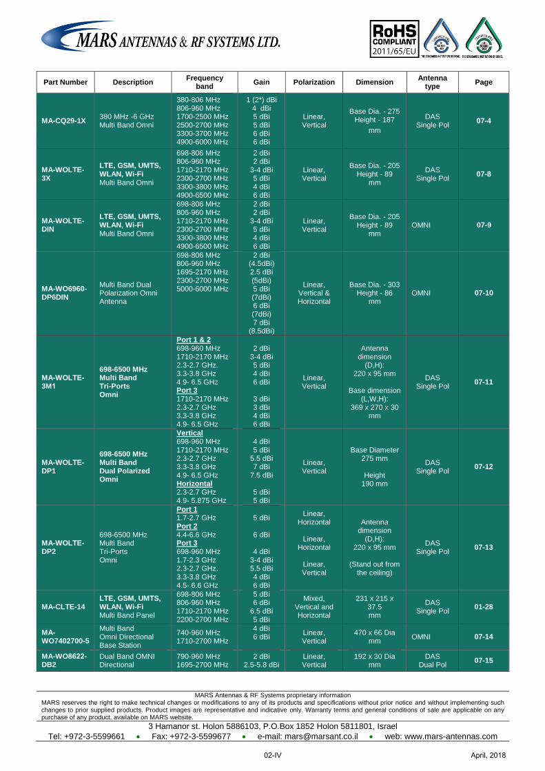
MARS Antennas & RF Systems proprietary information MARS reserves the right to make technical changes or modifications to any of its products and specifications without prior notice and without implementing such changes to prior supplied products. Product images are representative and indicative only. Warranty terms and general conditions of sale are applicable on any purchase of any product, available on MARS website.
3 Hamanor st. Holon 5886103, P.O.Box 1852 Holon 5811801, Israel
Tel: +972-3-5599661 Fax: +972-3-5599677 e-mail: [email protected] web: www.mars-antennas.com
Part Number Description Frequency
band Gain Polarization Dimension
Antenna type
Page
MA-CQ29-1X 380 MHz -6 GHz Multi Band Omni
380-806 MHz 806-960 MHz 1700-2500 MHz 2500-2700 MHz 3300-3700 MHz 4900-6000 MHz
1 (2*) dBi 4 dBi 5 dBi 5 dBi 6 dBi 6 dBi
Linear, Vertical
Base Dia. - 275 Height - 187
mm
DAS Single Pol
07-4
MA-WOLTE-3X
LTE, GSM, UMTS, WLAN, Wi-Fi Multi Band Omni
698-806 MHz 806-960 MHz 1710-2170 MHz 2300-2700 MHz 3300-3800 MHz 4900-6500 MHz
2 dBi 2 dBi
3-4 dBi 5 dBi 4 dBi 6 dBi
Linear, Vertical
Base Dia. - 205 Height - 89
mm
DAS Single Pol
07-8
MA-WOLTE-DIN
LTE, GSM, UMTS, WLAN, Wi-Fi Multi Band Omni
698-806 MHz 806-960 MHz 1710-2170 MHz 2300-2700 MHz 3300-3800 MHz 4900-6500 MHz
2 dBi 2 dBi
3-4 dBi 5 dBi 4 dBi 6 dBi
Linear, Vertical
Base Dia. - 205 Height - 89
mm OMNI 07-9
MA-WO6960-DP6DIN
Multi Band Dual Polarization Omni Antenna
698-806 MHz 806-960 MHz 1695-2170 MHz 2300-2700 MHz 5000-6000 MHz
2 dBi (4.5dBi) 2.5 dBi (5dBi) 5 dBi (7dBi) 6 dBi (7dBi) 7 dBi
(8.5dBi)
Linear, Vertical & Horizontal
Base Dia. - 303 Height - 86
mm OMNI 07-10
MA-WOLTE-3M1
698-6500 MHz Multi Band Tri-Ports Omni
Port 1 & 2 698-960 MHz 1710-2170 MHz 2.3-2.7 GHz. 3.3-3.8 GHz 4.9- 6.5 GHz Port 3 1710-2170 MHz 2.3-2.7 GHz 3.3-3.8 GHz 4.9- 6.5 GHz
2 dBi
3-4 dBi 5 dBi 4 dBi 6 dBi
3 dBi 3 dBi 4 dBi 6 dBi
Linear, Vertical
Antenna dimension
(D,H): 220 x 95 mm
Base dimension
(L,W,H): 369 x 270 x 30
mm
DAS Single Pol
07-11
MA-WOLTE-DP1
698-6500 MHz Multi Band Dual Polarized Omni
Vertical 698-960 MHz 1710-2170 MHz 2.3-2.7 GHz 3.3-3.8 GHz 4.9- 6.5 GHz Horizontal 2.3-2.7 GHz 4.9- 5.875 GHz
4 dBi 5 dBi
5.5 dBi 7 dBi
7.5 dBi
5 dBi 5 dBi
Linear, Vertical
Base Diameter 275 mm
Height
190 mm
DAS Single Pol
07-12
MA-WOLTE-DP2
698-6500 MHz Multi Band Tri-Ports Omni
Port 1 1.7-2.7 GHz Port 2 4.4-6.6 GHz Port 3 698-960 MHz 1.7-2.3 GHz 2.3-2.7 GHz. 3.3-3.8 GHz 4.5- 6.6 GHz
5 dBi
6 dBi
4 dBi
3-4 dBi 5.5 dBi 4 dBi 6 dBi
Linear, Horizontal
Linear,
Horizontal
Linear, Vertical
Antenna dimension
(D,H): 220 x 95 mm
(Stand out from
the ceiling)
DAS Single Pol
07-13
MA-CLTE-14 LTE, GSM, UMTS, WLAN, Wi-Fi Multi Band Panel
698-806 MHz 806-960 MHz 1710-2170 MHz 2200-2700 MHz
5 dBi 6 dBi
6.5 dBi 5 dBi
Mixed, Vertical and Horizontal
231 x 215 x 37.5 mm
DAS Single Pol
01-28
MA-WO7402700-5
Multi Band Omni Directional Base Station
740-960 MHz 1710-2700 MHz
4 dBi 6 dBi
Linear, Vertical
470 x 66 Dia mm
OMNI 07-14
MA-WO8622-DB2
Dual Band OMNI Directional
790-960 MHz 1695-2700 MHz
2 dBi 2.5-5.8 dBi
Linear, Vertical
192 x 30 Dia mm
DAS Dual Pol
07-15
April, 201802-IV
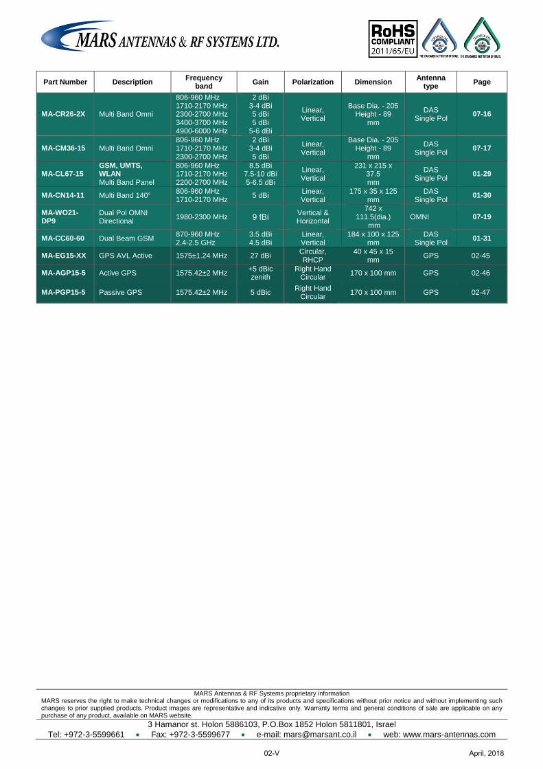
MARS Antennas & RF Systems proprietary information MARS reserves the right to make technical changes or modifications to any of its products and specifications without prior notice and without implementing such changes to prior supplied products. Product images are representative and indicative only. Warranty terms and general conditions of sale are applicable on any purchase of any product, available on MARS website.
3 Hamanor st. Holon 5886103, P.O.Box 1852 Holon 5811801, Israel
Tel: +972-3-5599661 Fax: +972-3-5599677 e-mail: [email protected] web: www.mars-antennas.com
Part Number Description Frequency
band Gain Polarization Dimension
Antenna type
Page
MA-CR26-2X Multi Band Omni
806-960 MHz 1710-2170 MHz 2300-2700 MHz 3400-3700 MHz 4900-6000 MHz
2 dBi 3-4 dBi 5 dBi 5 dBi
5-6 dBi
Linear, Vertical
Base Dia. - 205 Height - 89
mm
DAS Single Pol
07-16
MA-CM36-15 Multi Band Omni 806-960 MHz 1710-2170 MHz 2300-2700 MHz
2 dBi 3-4 dBi 5 dBi
Linear, Vertical
Base Dia. - 205 Height - 89
mm
DAS Single Pol
07-17
MA-CL67-15 GSM, UMTS, WLAN Multi Band Panel
806-960 MHz 1710-2170 MHz 2200-2700 MHz
8.5 dBi 7.5-10 dBi 5-6.5 dBi
Linear, Vertical
231 x 215 x 37.5 mm
DAS Single Pol
01-29
MA-CN14-11 Multi Band 140° 806-960 MHz 1710-2170 MHz
5 dBi Linear, Vertical
175 x 35 x 125 mm
DAS Single Pol
01-30
MA-WO21-DP9
Dual Pol OMNI Directional
1980-2300 MHz 9 fBi Vertical & Horizontal
742 x 111.5(dia.)
mm OMNI 07-19
MA-CC60-60 Dual Beam GSM 870-960 MHz 2.4-2.5 GHz
3.5 dBi 4.5 dBi
Linear, Vertical
184 x 100 x 125 mm
DAS Single Pol
01-31
MA-EG15-XX GPS AVL Active 1575±1.24 MHz 27 dBi Circular, RHCP
40 x 45 x 15 mm
GPS 02-45
MA-AGP15-5 Active GPS 1575.42±2 MHz +5 dBic zenith
Right Hand Circular
170 x 100 mm GPS 02-46
MA-PGP15-5 Passive GPS 1575.42±2 MHz 5 dBic Right Hand
Circular 170 x 100 mm GPS 02-47
April, 201802-V
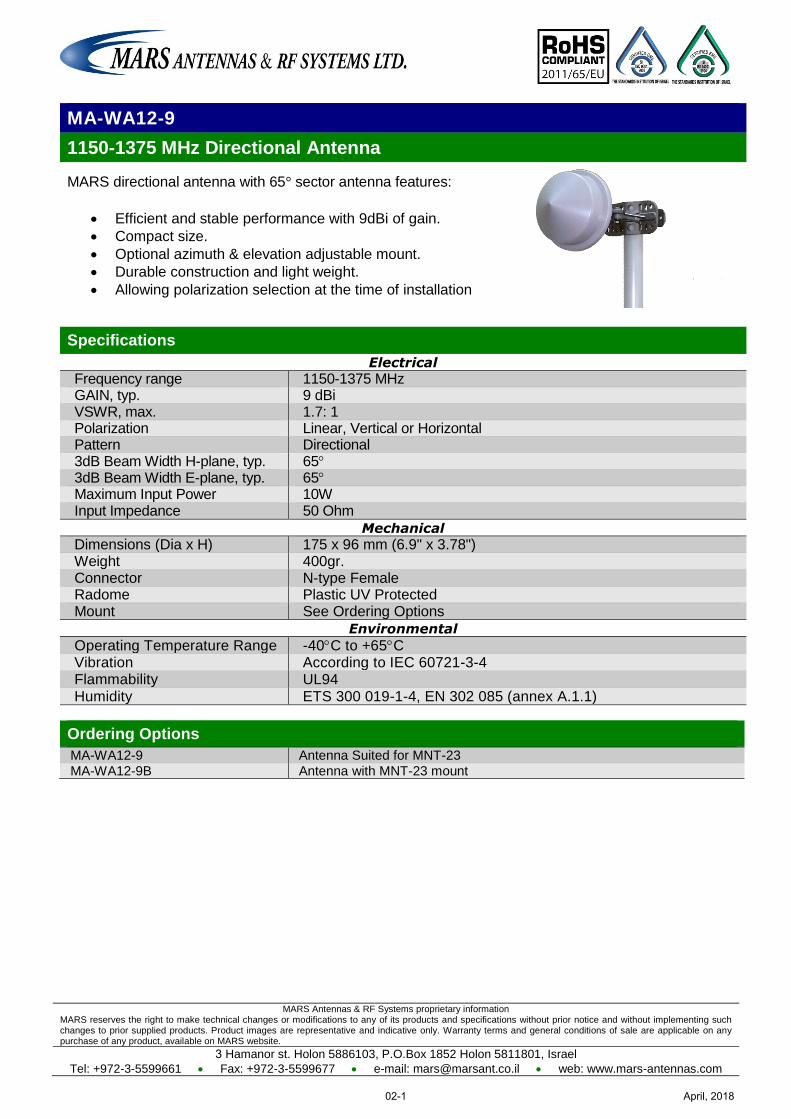
MARS Antennas & RF Systems proprietary information MARS reserves the right to make technical changes or modifications to any of its products and specifications without prior notice and without implementing such changes to prior supplied products. Product images are representative and indicative only. Warranty terms and general conditions of sale are applicable on any purchase of any product, available on MARS website.
3 Hamanor st. Holon 5886103, P.O.Box 1852 Holon 5811801, Israel
Tel: +972-3-5599661 Fax: +972-3-5599677 e-mail: [email protected] web: www.mars-antennas.com
MA-WA12-9
1150-1375 MHz Directional Antenna
MARS directional antenna with 65° sector antenna features:
Efficient and stable performance with 9dBi of gain.
Compact size.
Optional azimuth & elevation adjustable mount.
Durable construction and light weight.
Allowing polarization selection at the time of installation
Specifications
Electrical
Frequency range 1150-1375 MHz GAIN, typ. 9 dBi VSWR, max. 1.7: 1 Polarization Linear, Vertical or Horizontal Pattern Directional 3dB Beam Width H-plane, typ. 65 3dB Beam Width E-plane, typ. 65 Maximum Input Power 10W Input Impedance 50 Ohm
Mechanical
Dimensions (Dia x H) 175 x 96 mm (6.9" x 3.78") Weight 400gr. Connector N-type Female Radome Plastic UV Protected Mount See Ordering Options
Environmental
Operating Temperature Range -40C to +65C Vibration According to IEC 60721-3-4 Flammability UL94 Humidity ETS 300 019-1-4, EN 302 085 (annex A.1.1)
Ordering Options
MA-WA12-9 Antenna Suited for MNT-23
MA-WA12-9B Antenna with MNT-23 mount
April, 201802-1
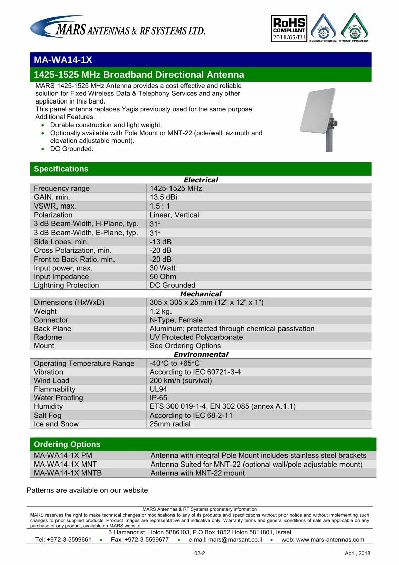
MARS Antennas & RF Systems proprietary information MARS reserves the right to make technical changes or modifications to any of its products and specifications without prior notice and without implementing such changes to prior supplied products. Product images are representative and indicative only. Warranty terms and general conditions of sale are applicable on any purchase of any product, available on MARS website.
3 Hamanor st. Holon 5886103, P.O.Box 1852 Holon 5811801, Israel Tel: +972-3-5599661 Fax: +972-3-5599677 e-mail: [email protected] web: www.mars-antennas.com
MA-WA14-1X
1425-1525 MHz Broadband Directional Antenna MARS 1425-1525 MHz Antenna provides a cost effective and reliable solution for Fixed Wireless Data & Telephony Services and any other application in this band. This panel antenna replaces Yagis previously used for the same purpose. Additional Features: Durable construction and light weight. Optionally available with Pole Mount or MNT-22 (pole/wall, azimuth and
elevation adjustable mount). DC Grounded.
Specifications
Electrical
Frequency range 1425-1525 MHz GAIN, min. 13.5 dBi VSWR, max. 1.5 : 1 Polarization Linear, Vertical 3 dB Beam-Width, H-Plane, typ. 31 3 dB Beam-Width, E-Plane, typ. 31 Side Lobes, min. -13 dB
Cross Polarization, min. -20 dB Front to Back Ratio, min. -20 dB
Input power, max. 30 Watt Input Impedance 50 Ohm Lightning Protection DC Grounded
Mechanical
Dimensions (HxWxD) 305 x 305 x 25 mm (12" x 12" x 1") Weight 1.2 kg. Connector N-Type, Female Back Plane Aluminum; protected through chemical passivation Radome UV Protected Polycarbonate Mount See Ordering Options
Environmental
Operating Temperature Range -40°C to +65°C Vibration According to IEC 60721-3-4 Wind Load 200 km/h (survival) Flammability UL94 Water Proofing IP-65 Humidity ETS 300 019-1-4, EN 302 085 (annex A.1.1) Salt Fog According to IEC 68-2-11 Ice and Snow 25mm radial
Ordering Options
MA-WA14-1X PM Antenna with integral Pole Mount includes stainless steel brackets MA-WA14-1X MNT Antenna Suited for MNT-22 (optional wall/pole adjustable mount) MA-WA14-1X MNTB Antenna with MNT-22 mount
Patterns are available on our website
April, 201802-2
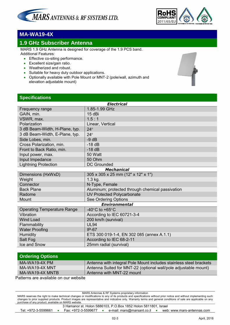
MARS Antennas & RF Systems proprietary information MARS reserves the right to make technical changes or modifications to any of its products and specifications without prior notice and without implementing such changes to prior supplied products. Product images are representative and indicative only. Warranty terms and general conditions of sale are applicable on any purchase of any product, available on MARS website.
3 Hamanor st. Holon 5886103, P.O.Box 1852 Holon 5811801, Israel Tel: +972-3-5599661 Fax: +972-3-5599677 e-mail: [email protected] web: www.mars-antennas.com
MA-WA19-4X
1.9 GHz Subscriber Antenna MARS 1.9 GHz Antenna is designed for coverage of the 1.9 PCS band. Additional Features: Effective co-siting performance. Excellent size/gain ratio. Weatherized and robust. Suitable for heavy duty outdoor applications. Optionally available with Pole Mount or MNT-2 (pole/wall, azimuth and
elevation adjustable mount)
Specifications
Electrical
Frequency range 1.85-1.99 GHz GAIN, min. 15 dBi VSWR, max. 1.5 : 1 Polarization Linear, Vertical 3 dB Beam-Width, H-Plane, typ. 24 3 dB Beam-Width, E-Plane, typ. 24 Side Lobes, min. -9 dB
Cross Polarization, min. -18 dB Front to Back Ratio, min. -18 dB
Input power, max. 50 Watt Input Impedance 50 Ohm Lightning Protection DC Grounded
Mechanical
Dimensions (HxWxD) 305 x 305 x 25 mm (12" x 12" x 1") Weight 1.3 kg. Connector N-Type, Female Back Plane Aluminum; protected through chemical passivation Radome UV Protected Polycarbonate Mount See Ordering Options
Environmental
Operating Temperature Range -40C to +65C Vibration According to IEC 60721-3-4 Wind Load 200 km/h (survival) Flammability UL94 Water Proofing IP-67 Humidity ETS 300 019-1-4, EN 302 085 (annex A.1.1) Salt Fog According to IEC 68-2-11 Ice and Snow 25mm radial (survival)
Ordering Options
MA-WA19-4X PM Antenna with integral Pole Mount includes stainless steel brackets MA-WA19-4X MNT Antenna Suited for MNT-22 (optional wall/pole adjustable mount) MA-WA19-4X MNTB Antenna with MNT-22 mount
Patterns are available on our website
April, 201802-3
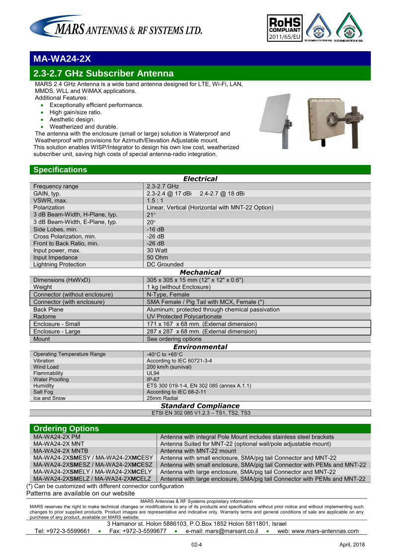
MARS Antennas & RF Systems proprietary information MARS reserves the right to make technical changes or modifications to any of its products and specifications without prior notice and without implementing such changes to prior supplied products. Product images are representative and indicative only. Warranty terms and general conditions of sale are applicable on any purchase of any product, available on MARS website.
3 Hamanor st. Holon 5886103, P.O.Box 1852 Holon 5811801, Israel Tel: +972-3-5599661 Fax: +972-3-5599677 e-mail: [email protected] web: www.mars-antennas.com
MA-WA24-2X
2.3-2.7 GHz Subscriber Antenna MARS 2.4 GHz Antenna is a wide band antenna designed for LTE, Wi-Fi, LAN, MMDS, WLL and WiMAX applications. Additional Features:
Exceptionally efficient performance. High gain/size ratio. Aesthetic design. Weatherized and durable.
The antenna with the enclosure (small or large) solution is Waterproof and Weatherproof with provisions for Azimuth/Elevation Adjustable mount. This solution enables WISP/Integrator to design his own low cost, weatherized subscriber unit, saving high costs of special antenna-radio integration.
Specifications Electrical
Frequency range 2.3-2.7 GHz GAIN, typ. 2.3-2.4 @ 17 dBi 2.4-2.7 @ 18 dBi VSWR, max. 1.5 : 1 Polarization Linear, Vertical (Horizontal with MNT-22 Option) 3 dB Beam-Width, H-Plane, typ. 21 3 dB Beam-Width, E-Plane, typ. 20 Side Lobes, min. -16 dB
Cross Polarization, min. -26 dB Front to Back Ratio, min. -26 dB
Input power, max. 30 Watt Input Impedance 50 Ohm Lightning Protection DC Grounded
Mechanical Dimensions (HxWxD) 305 x 305 x 15 mm (12" x 12" x 0.6") Weight 1 kg (without Enclosure) Connector (without enclosure) N-Type, Female Connector (with enclosure) SMA Female / Pig Tail with MCX, Female (*) Back Plane Aluminum; protected through chemical passivation Radome UV Protected Polycarbonate Enclosure - Small 171 x 167 x 68 mm. (External dimension) Enclosure - Large 287 x 287 x 68 mm. (External dimension) Mount See ordering options
Environmental Operating Temperature Range -40C to +65C Vibration According to IEC 60721-3-4 Wind Load 200 km/h (survival) Flammability UL94 Water Proofing IP-67 Humidity ETS 300 019-1-4, EN 302 085 (annex A.1.1) Salt Fog According to IEC 68-2-11 Ice and Snow 25mm Radial
Standard Compliance ETSI EN 302 085 V1.2.3 – TS1, TS2, TS3
Ordering Options MA-WA24-2X PM Antenna with integral Pole Mount includes stainless steel brackets MA-WA24-2X MNT Antenna Suited for MNT-22 (optional wall/pole adjustable mount) MA-WA24-2X MNTB Antenna with MNT-22 mount MA-WA24-2XSMESY / MA-WA24-2XMCESY Antenna with small enclosure, SMA/pig tail Connector and MNT-22 MA-WA24-2XSMESZ / MA-WA24-2XMCESZ Antenna with small enclosure, SMA/pig tail Connector with PEMs and MNT-22 MA-WA24-2XSMELY / MA-WA24-2XMCELY Antenna with large enclosure, SMA/pig tail Connector and MNT-22 MA-WA24-2XSMELZ / MA-WA24-2XMCELZ Antenna with large enclosure, SMA/pig tail Connector with PEMs and MNT-22
(*) Can be customized with different connector configuration Patterns are available on our website
April, 201802-4
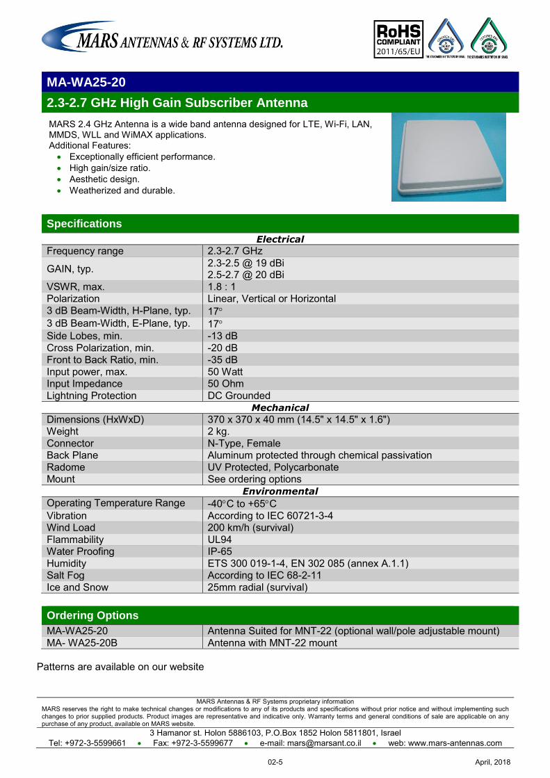
MARS Antennas & RF Systems proprietary information MARS reserves the right to make technical changes or modifications to any of its products and specifications without prior notice and without implementing such changes to prior supplied products. Product images are representative and indicative only. Warranty terms and general conditions of sale are applicable on any purchase of any product, available on MARS website.
3 Hamanor st. Holon 5886103, P.O.Box 1852 Holon 5811801, Israel Tel: +972-3-5599661 Fax: +972-3-5599677 e-mail: [email protected] web: www.mars-antennas.com
MA-WA25-20
2.3-2.7 GHz High Gain Subscriber Antenna
MARS 2.4 GHz Antenna is a wide band antenna designed for LTE, Wi-Fi, LAN, MMDS, WLL and WiMAX applications. Additional Features: Exceptionally efficient performance. High gain/size ratio. Aesthetic design. Weatherized and durable.
Specifications
Electrical
Frequency range 2.3-2.7 GHz
GAIN, typ. 2.3-2.5 @ 19 dBi 2.5-2.7 @ 20 dBi
VSWR, max. 1.8 : 1 Polarization Linear, Vertical or Horizontal 3 dB Beam-Width, H-Plane, typ. 17 3 dB Beam-Width, E-Plane, typ. 17 Side Lobes, min. -13 dB Cross Polarization, min. -20 dB Front to Back Ratio, min. -35 dB Input power, max. 50 Watt Input Impedance 50 Ohm Lightning Protection DC Grounded
Mechanical
Dimensions (HxWxD) 370 x 370 x 40 mm (14.5" x 14.5" x 1.6") Weight 2 kg. Connector N-Type, Female Back Plane Aluminum protected through chemical passivation Radome UV Protected, Polycarbonate Mount See ordering options
Environmental
Operating Temperature Range -40C to +65C Vibration According to IEC 60721-3-4 Wind Load 200 km/h (survival) Flammability UL94 Water Proofing IP-65 Humidity ETS 300 019-1-4, EN 302 085 (annex A.1.1) Salt Fog According to IEC 68-2-11 Ice and Snow 25mm radial (survival)
Ordering Options
MA-WA25-20 Antenna Suited for MNT-22 (optional wall/pole adjustable mount) MA- WA25-20B Antenna with MNT-22 mount
Patterns are available on our website
April, 201802-5
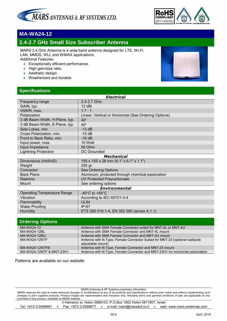
MARS Antennas & RF Systems proprietary information MARS reserves the right to make technical changes or modifications to any of its products and specifications without prior notice and without implementing such changes to prior supplied products. Product images are representative and indicative only. Warranty terms and general conditions of sale are applicable on any purchase of any product, available on MARS website.
3 Hamanor st. Holon 5886103, P.O.Box 1852 Holon 5811801, Israel Tel: +972-3-5599661 Fax: +972-3-5599677 e-mail: [email protected] web: www.mars-antennas.com
MA-WA24-12
2.4-2.7 GHz Small Size Subscriber Antenna
MARS 2.4 GHz Antenna is a wide band antenna designed for LTE, Wi-Fi, LAN, MMDS, WLL and WiMAX applications. Additional Features: Exceptionally efficient performance. High gain/size ratio. Aesthetic design. Weatherized and durable.
Specifications
Electrical Frequency range 2.4-2.7 GHz GAIN, typ. 12 dBi VSWR, max. 1.7 : 1 Polarization Linear, Vertical or Horizontal (See Ordering Options) 3 dB Beam-Width, H-Plane, typ. 40 3 dB Beam-Width, E-Plane, typ. 40 Side Lobes, min. -13 dB Cross Polarization, min. -15 dB Front to Back Ratio, min. -16 dB Input power, max. 10 Watt Input Impedance 50 Ohm Lightning Protection DC Grounded
Mechanical Dimensions (HxWxD) 155 x 155 x 28 mm (6.1" x 6.1" x 1.1") Weight 250 gr. Connector See Ordering Options Back Plane Aluminum; protected through chemical passivation Radome UV Protected Polycarbonate Mount See ordering options
Environmental Operating Temperature Range -40C to +65C Vibration According to IEC 60721-3-4 Flammability UL94 Water Proofing IP-67 Humidity ETS 300 019-1-4, EN 302 085 (annex A.1.1) Ordering Options
MA-WA24-12 Antenna with SMA Female Connector suited for MNT-4L or MNT-4U MA-WA24-12BL Antenna with SMA Female Connector and MNT-4L mount MA-WA24-12BU Antenna with SMA Female Connector and MNT-4U mount MA-WA24-12NTF Antenna with N-Type, Female Connector Suited for MNT-23 (optional wall/pole
adjustable mount) MA-WA24-12NTFB Antenna with N-Type, Female Connector and MNT-23 mount MA-WA24-12NTF & MNT-23H1 Antenna with N-Type, Female Connector and MNT-23H1 for horizontal polarization
Patterns are available on our website
April, 201802-6
MARS Antennas & RF Systems proprietary information MARS reserves the right to make technical changes or modifications to any of its products and specifications without prior notice and without implementing such changes to prior supplied products. Product images are representative and indicative only. Warranty terms and general conditions of sale are applicable on any purchase of any product, available on MARS website.
3 Hamanor st. Holon 5886103, P.O.Box 1852 Holon 5811801, Israel
Tel: +972-3-5599661 Fax: +972-3-5599677 e-mail: [email protected] web: www.mars-antennas.com
MA-WS2455-1X
2.4-2.5 GHz & 4.9-5.875 GHz Dual Band Antenna MARS Dual Band antenna provides coverage of 2.4 to 2.5. GHz & 4.9 to 5.875 GHz in a single antenna radome. Additional Features:
Simultaneous coverage of 802.11 a,b,g, WiMAX & 4.9 GHz Public Safety Bands.
High gain/size ratio.
Light weight and durable construction.
UV protected radome made of polycarbonate suitable for harsh weather installations.
Easy mounting allowing Az/El adjustment.
Available in iBwave database
Specifications
Electrical Frequency range 2.4-2.5 GHz & 4.9-5.875 GHz
GAIN,typ. 2.4-2.5 GHz @ 12 dBi 4.9-5.875 GHz @ 18 dBi
VSWR, max. 1.7 : 1
Polarization Linear Vertical
3 dB Beam-Width, H-Plane, typ. 2.4-2.5 GHz @ 30° 4.9-5.875 GHz @ 12°
3 dB Beam-Width, E-Plane, typ. 2.4-2.5 GHz @ 60° 4.9-5.875 GHz @ 18°
Side Lobes, max. -10 dB Cross Polarization, max. -12 dB
Front to Back Ratio, min. ETSI TS3, TS4, TS5
Input power, max. 50 Watt
Input Impedance 50 Ohm
Mechanical Dimensions (HxWxD) 305 x 305 x 25 mm (12" x 12" x 1")
Connector 2 x N-Type, Female Weight 1.5 kg.
Back Plane Aluminum; protected through chemical passivation
Radome UV Protected Polycarbonate
Mounting See ordering options
Environmental Operating Temperature Range -40°C to +70°C
Vibration According to IEC 60721-3-4 Wind Load 200 km/h (survival)
Flammability UL94
Water Proofing IP-67
Humidity ETS 300 019-1-4, EN 302 085 (annex A.1.1)
Salt Fog According to IEC 68 -2-11
Ice and Snow 25 mm radial (survival)
Ordering Options
MA-WS2455-1X Antenna Suited for MNT-22 (optional wall/pole adjustable mount)
MA-WS2455-1XB Antenna with MNT-22 mount
Patterns are available on our website
April, 201802-7
MARS Antennas & RF Systems proprietary information MARS reserves the right to make technical changes or modifications to any of its products and specifications without prior notice and without implementing such changes to prior supplied products. Product images are representative and indicative only. Warranty terms and general conditions of sale are applicable on any purchase of any product, available on MARS website.
3 Hamanor st. Holon 5886103, P.O.Box 1852 Holon 5811801, Israel
Tel: +972-3-5599661 Fax: +972-3-5599677 e-mail: [email protected] web: www.mars-antennas.com
MA-WA22-DP8
1.7-2.7 GHz Dual Polarization Antenna
MARS 1.7-2.7 GHz Dual Polarized Antenna is a wide band antenna designed for LTE, Wi-Fi, LAN, MMDS, WLL and WiMAX applications. Additional Features:
Exceptionally efficient performance.
High gain/size ratio.
Aesthetic design.
Weatherized and durable.
Available in iBwave database
Specifications
Electrical Frequency range 1.7-2.7 GHz
Gain, typ. 8 dBi
VSWR 2.0: 1 max. 1.7: 1 typ.
Polarization Dual Pole Linear, Vertical & Horizontal
Dual Slant (opt.) ±45o (diamond shape)
3dB Beam-Width, H-Plane, typ. 75o
3dB Beam-Width, E-Plane, typ. 60o Cross Polarization, typ. -20 dB
Front to Back Ratio, min. -15 dB
Port to Port Isolation, min. -30 dB @ 1.7-2.3 GHz -22 dB @ 2.3-2.7 GHz
Input power, max. 50 Watt
Input Impedance 50 Ohm
Lightning Protection DC Grounded
Mechanical Dimensions (HxWxD) 112 x 112 x 33.5 mm (4.41" x 4.41" x 1.32")
Connector 2 x SMA Right Angle, Female
Weight 147 gr.
Mounting See Ordering Options
Radome UV Protected Polycarbonate
Back Plane Aluminum protected through chemical passivation.
Environmental Operating Temperature Range -55oC to +65oC
Vibration According to IEC 60721-3-4
Wind Load 200 Km/h (Survival)
Flammability UL94
Water Proofing IP-67
Humidity ETS 300 019-1-4,EN 302 085 (Annex A.1.1)
Salt Fog According to IEC 68-2-11
Ordering Options
MA-WA22-DP8 Antenna 2 x Right Angle SMA, Female connectors Suited for MNT-4L or 4LU mount
MA-WA22-DP8B Antenna 2 x Right Angle SMA, Female connectors with MNT-4L or 4LU mount
Patterns are available on our website
April, 201802-8
MARS Antennas & RF Systems proprietary information MARS reserves the right to make technical changes or modifications to any of its products and specifications without prior notice and without implementing such changes to prior supplied products. Product images are representative and indicative only. Warranty terms and general conditions of sale are applicable on any purchase of any product, available on MARS website.
3 Hamanor st. Holon 5886103, P.O.Box 1852 Holon 5811801, Israel
Tel: +972-3-5599661 Fax: +972-3-5599677 e-mail: [email protected] web: www.mars-antennas.com
MA-WA22-DP14
1.7-2.7 GHz Stadium Dual Polarization Antenna
MARS 1.7-2.7 GHz Dual Polarized wide band antenna specially designed for arenas and stadiums that have to supply high capacity and reliable wireless data. The MA-WA22-DP14 antenna designed for LTE, Wi-Fi, LAN, MMDS, WLL and WiMAX applications. Additional Features:
Exceptionally efficient performance.
High gain/size ratio.
Aesthetic design.
Weatherized and durable.
Wind survival rating of 200 km/h.
Available in iBwave database
Specially designed for Stadiums
Specifications
Electrical Frequency range 1.7-2.2 GHz 2.2-2.7 GHz
Gain, typ. 13 dBi 14 dBi
VSWR, max. 2.0 : 1 1.7 : 1
Polarization Dual Pole Linear, Vertical & Horizontal
3dB Beam-Width, H-Plane, typ. 33o
3dB Beam-Width, E-Plane, typ. 33o
Cross Polarization, typ. -20 dB Front to Back Ratio, min. -20 dB
Port to Port Isolation, min. -30 dB -40 dB
Input power, max. 50 Watt
Input Impedance 50 Ohm
Lightning Protection DC Grounded
Mechanical Dimensions (HxWxD) 430 x 240 x 48 mm (16.93" x 9.45" x 1.89") Connector 2 x N-type, Female
Weight 2.5 kg.
Mounting See Ordering Options
Radome UV Protected Polycarbonate
Back Plane Aluminum protected through chemical passivation.
Environmental Operating Temperature Range -40oC to +65oC
Vibration According to IEC 60721-3-4
Wind Load 200 Km/h (Survival)
Flammability UL94
Water Proofing IP-65
Humidity ETS 300 019-1-4,EN 302 085 (Annex A.1.1)
Salt Fog According to IEC 68-2-11
Ordering Options
MA-WA22-DP14 Antenna 2 x N-type, Female connectors Suited for MNT-22 mount
MA-WA22-DP14B Antenna 2 x N-type, Female connectors with MNT-22 mount
April, 201802-9
MARS Antennas & RF Systems proprietary information MARS reserves the right to make technical changes or modifications to any of its products and specifications without prior notice and without implementing such changes to prior supplied products. Product images are representative and indicative only. Warranty terms and general conditions of sale are applicable on any purchase of any product, available on MARS website.
3 Hamanor st. Holon 5886103, P.O.Box 1852 Holon 5811801, Israel Tel: +972-3-5599661 Fax: +972-3-5599677 e-mail: [email protected] web: www.mars-antennas.com
MA-WA18-DP12
1750-1850 MHz Dual Polarization/ Dual Slant Subscriber Antenna Additional Features: Dual slant if mounted diagonally. Efficient and stable performance. High gain/size ratio. Light weight and durable construction. UV protected radome made of polycarbonate suitable for harsh weather
installations. Easy mounting allowing Az/El adjustment and 45deg. turn installation.
Specifications
Electrical
Frequency range 1.75-1.85 GHz GAIN, typ. 14 dBi VSWR, max. 1.7 : 1
Polarization Dual Pole Linear, Vertical & Horizontal Dual Slant (opt.) ±45°
3 dB Beam-Width, H-Plane, typ. 30 3 dB Beam-Width, E-Plane, typ. 30 Side Lobes, min. -12 dB Cross Polarization, min. -15 dB Port to Port Isolation, typ. -25 dB Front to Back Ratio, min. -20 dB Input power, max. 10 Watt Input Impedance 50 Ohm Lightning Protection DC Grounded
Mechanical
Dimensions (HxWxD) 305 x 305 x 15 mm (12" x 12" x 0.6") Connector 2 x N-Type Female Weight 1.3 kg. Back Plane Aluminum; protected through chemical passivation Radome UV Protected Polycarbonate Mounting See ordering options
Environmental
Operating Temperature Range -40°C to +65°C Vibration According to IEC 60721-3-4 Wind Load 200 km/h (Survival) Flammability UL94 Water Proofing IP-67 Humidity ETS 300 019-1-4,EN 302 085 (Annex A.1.1) Salt Fog According to IEC 68-2-11
Ordering Options
MA-WA18-DP12 Antenna Suited for MNT-22 (optional wall/pole adjustable mount) MA-WA18-DP12B Antenna with MNT-22 mount
Patterns are available on our website
April, 201802-10
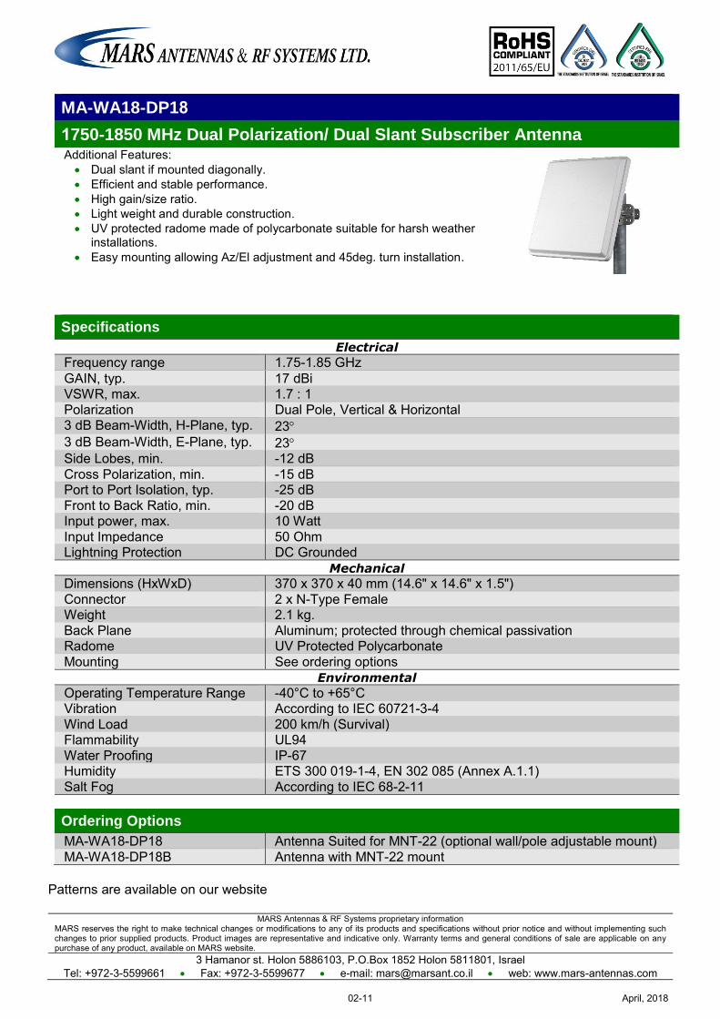
MARS Antennas & RF Systems proprietary information MARS reserves the right to make technical changes or modifications to any of its products and specifications without prior notice and without implementing such changes to prior supplied products. Product images are representative and indicative only. Warranty terms and general conditions of sale are applicable on any purchase of any product, available on MARS website.
3 Hamanor st. Holon 5886103, P.O.Box 1852 Holon 5811801, Israel Tel: +972-3-5599661 Fax: +972-3-5599677 e-mail: [email protected] web: www.mars-antennas.com
MA-WA18-DP18
1750-1850 MHz Dual Polarization/ Dual Slant Subscriber Antenna Additional Features: Dual slant if mounted diagonally. Efficient and stable performance. High gain/size ratio. Light weight and durable construction. UV protected radome made of polycarbonate suitable for harsh weather
installations. Easy mounting allowing Az/El adjustment and 45deg. turn installation.
Specifications
Electrical
Frequency range 1.75-1.85 GHz GAIN, typ. 17 dBi VSWR, max. 1.7 : 1 Polarization Dual Pole, Vertical & Horizontal 3 dB Beam-Width, H-Plane, typ. 23 3 dB Beam-Width, E-Plane, typ. 23 Side Lobes, min. -12 dB Cross Polarization, min. -15 dB Port to Port Isolation, typ. -25 dB Front to Back Ratio, min. -20 dB Input power, max. 10 Watt Input Impedance 50 Ohm Lightning Protection DC Grounded
Mechanical
Dimensions (HxWxD) 370 x 370 x 40 mm (14.6" x 14.6" x 1.5") Connector 2 x N-Type Female Weight 2.1 kg. Back Plane Aluminum; protected through chemical passivation Radome UV Protected Polycarbonate Mounting See ordering options
Environmental
Operating Temperature Range -40°C to +65°C Vibration According to IEC 60721-3-4 Wind Load 200 km/h (Survival) Flammability UL94 Water Proofing IP-67 Humidity ETS 300 019-1-4, EN 302 085 (Annex A.1.1) Salt Fog According to IEC 68-2-11 Ordering Options
MA-WA18-DP18 Antenna Suited for MNT-22 (optional wall/pole adjustable mount) MA-WA18-DP18B Antenna with MNT-22 mount
Patterns are available on our website
April, 201802-11
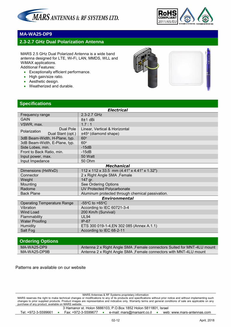
MARS Antennas & RF Systems proprietary information MARS reserves the right to make technical changes or modifications to any of its products and specifications without prior notice and without implementing such changes to prior supplied products. Product images are representative and indicative only. Warranty terms and general conditions of sale are applicable on any purchase of any product, available on MARS website.
3 Hamanor st. Holon 5886103, P.O.Box 1852 Holon 5811801, Israel Tel: +972-3-5599661 Fax: +972-3-5599677 e-mail: [email protected] web: www.mars-antennas.com
MA-WA25-DP9
2.3-2.7 GHz Dual Polarization Antenna
MARS 2.5 GHz Dual Polarized Antenna is a wide band antenna designed for LTE, Wi-Fi, LAN, MMDS, WLL and WiMAX applications. Additional Features: Exceptionally efficient performance. High gain/size ratio. Aesthetic design. Weatherized and durable.
Specifications
Electrical Frequency range 2.3-2.7 GHz GAIN 8±1 dBi VSWR, max. 1.7 : 1
Polarization Dual Pole Linear, Vertical & Horizontal Dual Slant (opt.) ±45o (diamond shape)
3dB Beam-Width, H-Plane, typ. 60o 3dB Beam-Width, E-Plane, typ. 60o Side Lobes, min. -15dB Front to Back Ratio, min. -15dB Input power, max. 50 Watt Input Impedance 50 Ohm
Mechanical Dimensions (HxWxD) 112 x 112 x 33.5 mm (4.41" x 4.41" x 1.32") Connector 2 x Right Angle SMA ,Female Weight 147 gr. Mounting See Ordering Options Radome UV Protected Polycarbonate Back Plane Aluminum protected through chemical passivation.
Environmental Operating Temperature Range -55oC to +65oC Vibration According to IEC 60721-3-4 Wind Load 200 Km/h (Survival) Flammability UL94 Water Proofing IP-67 Humidity ETS 300 019-1-4,EN 302 085 (Annex A.1.1) Salt Fog According to IEC 68-2-11 Ordering Options
MA-WA25-DP9 Antenna 2 x Right Angle SMA ,Female connectors Suited for MNT-4LU mount MA-WA25-DP9B Antenna 2 x Right Angle SMA ,Female connectors with MNT-4LU mount
Patterns are available on our website
April, 201802-12
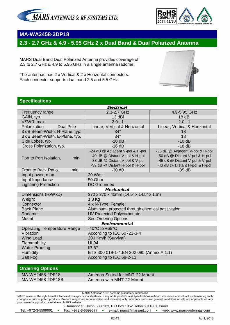
MARS Antennas & RF Systems proprietary information MARS reserves the right to make technical changes or modifications to any of its products and specifications without prior notice and without implementing such changes to prior supplied products. Product images are representative and indicative only. Warranty terms and general conditions of sale are applicable on any purchase of any product, available on MARS website.
3 Hamanor st. Holon 5886103, P.O.Box 1852 Holon 5811801, Israel
Tel: +972-3-5599661 Fax: +972-3-5599677 e-mail: [email protected] web: www.mars-antennas.com
MA-WA2458-2DP18
2.3 - 2.7 GHz & 4.9 - 5.95 GHz 2 x Dual Band & Dual Polarized Antenna
MARS Dual Band Dual Polarized Antenna provides coverage of 2.3 to 2.7 GHz & 4.9 to 5.95 GHz in a single antenna radome.
The antennas has 2 x Vertical & 2 x Horizontal connectors.
Each connector supports dual band 2.5 and 5.5 GHz.
Specifications
Electrical
Frequency range 2.3-2.7 GHz 4.9-5.95 GHz GAIN, typ. 13 dBi 18 dBi VSWR, max. 2.0 : 1 2.0 : 1 Polarization Dual Pole Linear, Vertical & Horizontal Linear, Vertical & Horizontal 3 dB Beam-Width, H-Plane, typ. 34° 18° 3 dB Beam-Width, E-Plane, typ. 34° 18° Side Lobes, typ. -10 dB -10 dB Cross Polarization, typ. -16 dB -18 dB
Port to Port Isolation, min.
-24 dB @ Adjacent V-pol & H-pol
-40 dB @ Distant V-pol & H-pol
-38 dB @ Distant V-pol & V-pol
-39 dB @ Distant H-pol & H-pol
-28 dB @ Adjacent V-pol & H-pol
-50 dB @ Distant V-pol & H-pol
-45 dB @ Distant V-pol & V-pol
-43 dB @ Distant H-pol & H-pol
Front to Back Ratio, min. -30 dB -35 dB Input power, max. 20 Watt Input Impedance 50 Ohm Lightning Protection DC Grounded
Mechanical
Dimensions (HxWxD) 370 x 370 x 40mm (14.5" x 14.5" x 1.6") Weight 1.8 Kg Connector 4 x N-Type, Female Back Plane Aluminum; protected through chemical passivation Radome UV Protected Polycarbonate Mount See Ordering Options
Environmental
Operating Temperature Range -40°C to +65°C Vibration According to IEC 60721-3-4 Wind Load 200 Km/h (Survival) Flammability UL94 Water Proofing IP-67 Humidity ETS 300 019-1-4,EN 302 085 (Annex A.1.1) Salt Fog According to IEC 68-2-11
Ordering Options
MA-WA2458-2DP18 Antenna Suited for MNT-22 Mount MA-WA2458-2DP18B Antenna with MNT-22 Mount
April, 201802-13
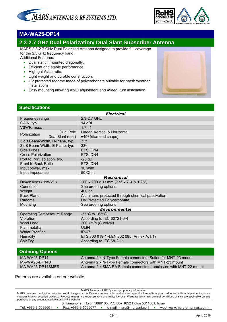
MARS Antennas & RF Systems proprietary information MARS reserves the right to make technical changes or modifications to any of its products and specifications without prior notice and without implementing such changes to prior supplied products. Product images are representative and indicative only. Warranty terms and general conditions of sale are applicable on any purchase of any product, available on MARS website.
3 Hamanor st. Holon 5886103, P.O.Box 1852 Holon 5811801, Israel Tel: +972-3-5599661 Fax: +972-3-5599677 e-mail: [email protected] web: www.mars-antennas.com
MA-WA25-DP14
2.3-2.7 GHz Dual Polarization/ Dual Slant Subscriber Antenna MARS 2.3-2.7 GHz Dual Polarized Antenna designed to provide full coverage for the 2.5 GHz frequency band. Additional Features: Dual slant if mounted diagonally. Efficient and stable performance. High gain/size ratio. Light weight and durable construction. UV protected radome made of polycarbonate suitable for harsh weather
installations. Easy mounting allowing Az/El adjustment and 45deg. turn installation.
Specifications
Electrical Frequency range 2.3-2.7 GHz GAIN, typ. 14 dBi VSWR, max. 1.7 : 1
Polarization Dual Pole Linear, Vertical & Horizontal Dual Slant (opt.) ±45o (diamond shape)
3 dB Beam-Width, H-Plane, typ. 33o 3 dB Beam-Width, E-Plane, typ. 33o Side Lobes ETSI DN4 Cross Polarization ETSI DN4 Port to Port Isolation, typ. -25 dB Front to Back Ratio ETSI DN4 Input power, max. 10 Watt Input Impedance 50 Ohm
Mechanical Dimensions (HxWxD) 200 x 200 x 33 mm (7.9" x 7.9" x 1.25") Connector See ordering options Weight 400 gr. Back Plane Aluminum; protected through chemical passivation Radome UV Protected Polycarbonate Mounting See ordering options
Environmental Operating Temperature Range -55oC to +65oC Vibration According to IEC 60721-3-4 Wind Load 200 km/h (Survival) Flammability UL94 Water Proofing IP-67 Humidity ETS 300 019-1-4,EN 302 085 (Annex A.1.1) Salt Fog According to IEC 68-2-11 Ordering Options
MA-WA25-DP14 Antenna 2 x N-Type Female connectors Suited for MNT-23 mount MA-WA25-DP14B Antenna 2 x N-Type Female connectors with MNT-23 mount MA-WA25-DP14SMES Antenna 2 x SMA RA Female connectors, enclosure with MNT-22 mount
Patterns are available on our website
April, 201802-14
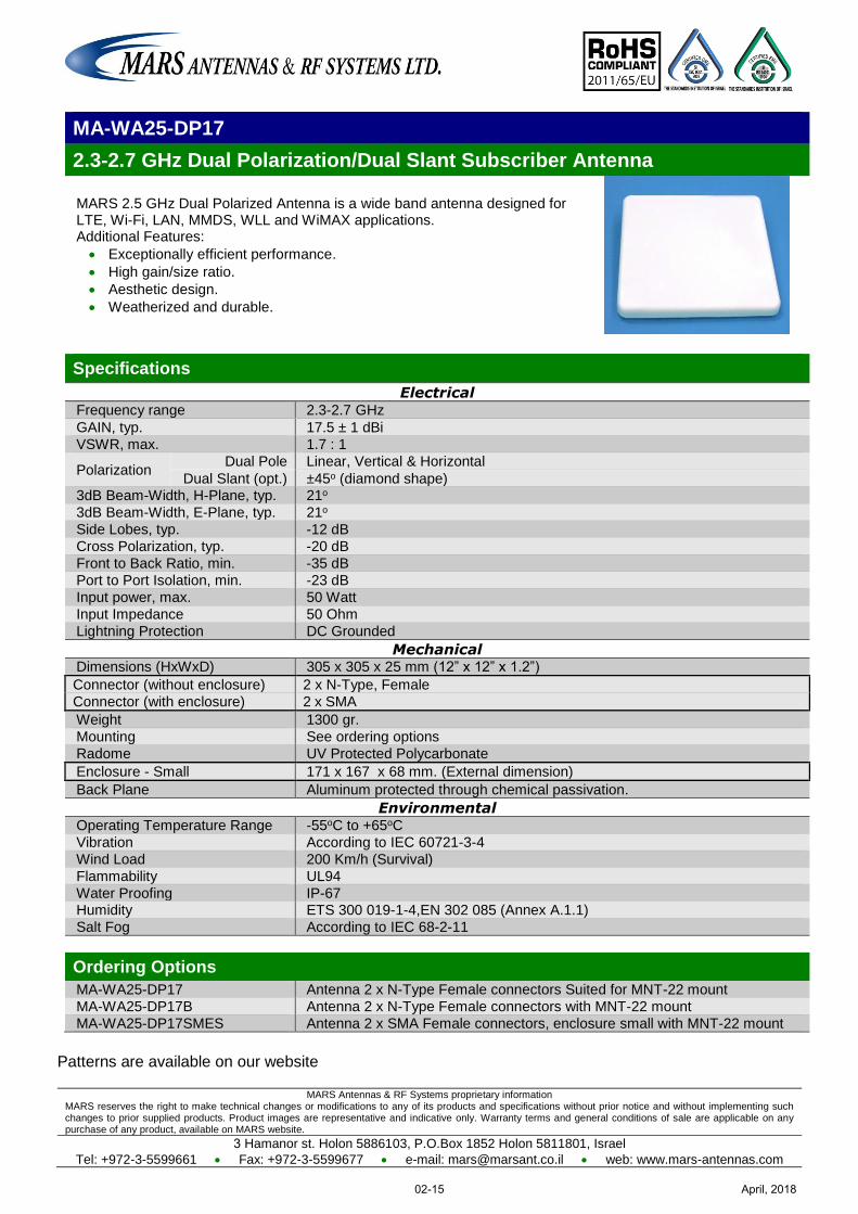
MARS Antennas & RF Systems proprietary information MARS reserves the right to make technical changes or modifications to any of its products and specifications without prior notice and without implementing such changes to prior supplied products. Product images are representative and indicative only. Warranty terms and general conditions of sale are applicable on any purchase of any product, available on MARS website.
3 Hamanor st. Holon 5886103, P.O.Box 1852 Holon 5811801, Israel
Tel: +972-3-5599661 Fax: +972-3-5599677 e-mail: [email protected] web: www.mars-antennas.com
MA-WA25-DP17
2.3-2.7 GHz Dual Polarization/Dual Slant Subscriber Antenna
MARS 2.5 GHz Dual Polarized Antenna is a wide band antenna designed for LTE, Wi-Fi, LAN, MMDS, WLL and WiMAX applications. Additional Features:
Exceptionally efficient performance.
High gain/size ratio.
Aesthetic design.
Weatherized and durable.
Specifications
Electrical Frequency range 2.3-2.7 GHz
GAIN, typ. 17.5 ± 1 dBi
VSWR, max. 1.7 : 1
Polarization Dual Pole Linear, Vertical & Horizontal
Dual Slant (opt.) ±45o (diamond shape) 3dB Beam-Width, H-Plane, typ. 21o
3dB Beam-Width, E-Plane, typ. 21o
Side Lobes, typ. -12 dB
Cross Polarization, typ. -20 dB
Front to Back Ratio, min. -35 dB
Port to Port Isolation, min. -23 dB
Input power, max. 50 Watt
Input Impedance 50 Ohm
Lightning Protection DC Grounded
Mechanical Dimensions (HxWxD) 305 x 305 x 25 mm (12” x 12” x 1.2”)
Connector (without enclosure) 2 x N-Type, Female
Connector (with enclosure) 2 x SMA
Weight 1300 gr.
Mounting See ordering options
Radome UV Protected Polycarbonate
Enclosure - Small 171 x 167 x 68 mm. (External dimension)
Back Plane Aluminum protected through chemical passivation.
Environmental Operating Temperature Range -55oC to +65oC
Vibration According to IEC 60721-3-4
Wind Load 200 Km/h (Survival)
Flammability UL94
Water Proofing IP-67 Humidity ETS 300 019-1-4,EN 302 085 (Annex A.1.1)
Salt Fog According to IEC 68-2-11
Ordering Options
MA-WA25-DP17 Antenna 2 x N-Type Female connectors Suited for MNT-22 mount
MA-WA25-DP17B Antenna 2 x N-Type Female connectors with MNT-22 mount
MA-WA25-DP17SMES Antenna 2 x SMA Female connectors, enclosure small with MNT-22 mount
Patterns are available on our website
April, 201802-15
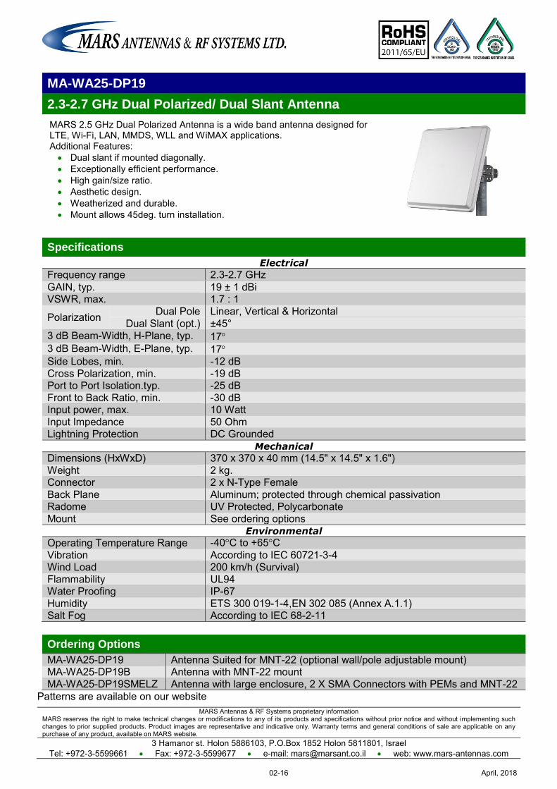
MARS Antennas & RF Systems proprietary information MARS reserves the right to make technical changes or modifications to any of its products and specifications without prior notice and without implementing such changes to prior supplied products. Product images are representative and indicative only. Warranty terms and general conditions of sale are applicable on any purchase of any product, available on MARS website.
3 Hamanor st. Holon 5886103, P.O.Box 1852 Holon 5811801, Israel Tel: +972-3-5599661 Fax: +972-3-5599677 e-mail: [email protected] web: www.mars-antennas.com
MA-WA25-DP19
2.3-2.7 GHz Dual Polarized/ Dual Slant Antenna
MARS 2.5 GHz Dual Polarized Antenna is a wide band antenna designed for LTE, Wi-Fi, LAN, MMDS, WLL and WiMAX applications. Additional Features: Dual slant if mounted diagonally. Exceptionally efficient performance. High gain/size ratio. Aesthetic design. Weatherized and durable. Mount allows 45deg. turn installation.
Specifications
Electrical
Frequency range 2.3-2.7 GHz GAIN, typ. 19 ± 1 dBi VSWR, max. 1.7 : 1
Polarization Dual Pole Linear, Vertical & Horizontal Dual Slant (opt.) ±45°
3 dB Beam-Width, H-Plane, typ. 17 3 dB Beam-Width, E-Plane, typ. 17 Side Lobes, min. -12 dB Cross Polarization, min. -19 dB Port to Port Isolation.typ. -25 dB Front to Back Ratio, min. -30 dB Input power, max. 10 Watt Input Impedance 50 Ohm Lightning Protection DC Grounded
Mechanical
Dimensions (HxWxD) 370 x 370 x 40 mm (14.5" x 14.5" x 1.6") Weight 2 kg. Connector 2 x N-Type Female Back Plane Aluminum; protected through chemical passivation Radome UV Protected, Polycarbonate Mount See ordering options
Environmental
Operating Temperature Range -40°C to +65°C Vibration According to IEC 60721-3-4 Wind Load 200 km/h (Survival) Flammability UL94 Water Proofing IP-67 Humidity ETS 300 019-1-4,EN 302 085 (Annex A.1.1) Salt Fog According to IEC 68-2-11
Ordering Options
MA-WA25-DP19 Antenna Suited for MNT-22 (optional wall/pole adjustable mount) MA-WA25-DP19B Antenna with MNT-22 mount MA-WA25-DP19SMELZ Antenna with large enclosure, 2 X SMA Connectors with PEMs and MNT-22
Patterns are available on our website
April, 201802-16
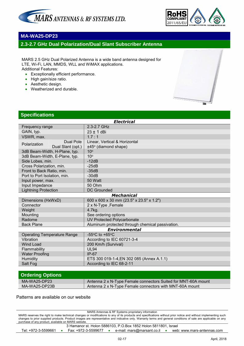
MARS Antennas & RF Systems proprietary information MARS reserves the right to make technical changes or modifications to any of its products and specifications without prior notice and without implementing such changes to prior supplied products. Product images are representative and indicative only. Warranty terms and general conditions of sale are applicable on any purchase of any product, available on MARS website.
3 Hamanor st. Holon 5886103, P.O.Box 1852 Holon 5811801, Israel Tel: +972-3-5599661 Fax: +972-3-5599677 e-mail: [email protected] web: www.mars-antennas.com
MA-WA25-DP23
2.3-2.7 GHz Dual Polarization/Dual Slant Subscriber Antenna
MARS 2.5 GHz Dual Polarized Antenna is a wide band antenna designed for LTE, Wi-Fi, LAN, MMDS, WLL and WiMAX applications. Additional Features: Exceptionally efficient performance. High gain/size ratio. Aesthetic design. Weatherized and durable.
Specifications
Electrical Frequency range 2.3-2.7 GHz GAIN, typ. 23 ± 1 dBi VSWR, max. 1.7 : 1
Polarization Dual Pole Linear, Vertical & Horizontal Dual Slant (opt.) ±45o (diamond shape)
3dB Beam-Width, H-Plane, typ. 10o 3dB Beam-Width, E-Plane, typ. 10o Side Lobes, min. -12dB Cross Polarization, min. -25dB Front to Back Ratio, min. -35dB Port to Port Isolation, min. -30dB Input power, max. 50 Watt Input Impedance 50 Ohm Lightning Protection DC Grounded
Mechanical Dimensions (HxWxD) 600 x 600 x 30 mm (23.5" x 23.5" x 1.2") Connector 2 x N-Type ,Female Weight 4.7kg. Mounting See ordering options Radome UV Protected Polycarbonate Back Plane Aluminum protected through chemical passivation.
Environmental Operating Temperature Range -55oC to +65oC Vibration According to IEC 60721-3-4 Wind Load 200 Km/h (Survival) Flammability UL94 Water Proofing IP-67 Humidity ETS 300 019-1-4,EN 302 085 (Annex A.1.1) Salt Fog According to IEC 68-2-11 Ordering Options
MA-WA25-DP23 Antenna 2 x N-Type Female connectors Suited for MNT-60A mount MA-WA25-DP23B Antenna 2 x N-Type Female connectors with MNT-60A mount
Patterns are available on our website
April, 201802-17
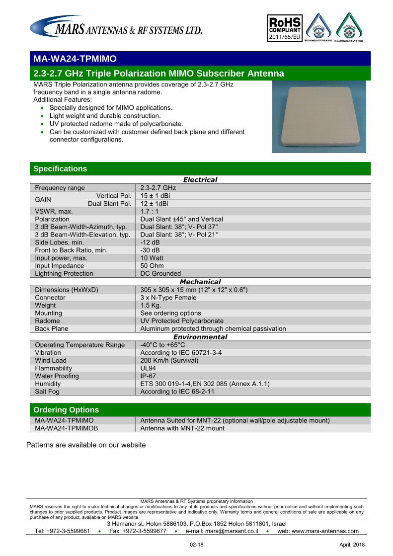
MARS Antennas & RF Systems proprietary information MARS reserves the right to make technical changes or modifications to any of its products and specifications without prior notice and without implementing such changes to prior supplied products. Product images are representative and indicative only. Warranty terms and general conditions of sale are applicable on any purchase of any product, available on MARS website.
3 Hamanor st. Holon 5886103, P.O.Box 1852 Holon 5811801, Israel Tel: +972-3-5599661 Fax: +972-3-5599677 e-mail: [email protected] web: www.mars-antennas.com
MA-WA24-TPMIMO
2.3-2.7 GHz Triple Polarization MIMO Subscriber Antenna MARS Triple Polarization antenna provides coverage of 2.3-2.7 GHz frequency band in a single antenna radome. Additional Features:
Specially designed for MIMO applications. Light weight and durable construction. UV protected radome made of polycarbonate. Can be customized with customer defined back plane and different
connector configurations.
Specifications
Electrical Frequency range 2.3-2.7 GHz
GAIN Vertical Pol. 15 ± 1 dBi Dual Slant Pol. 12 ± 1dBi
VSWR, max. 1.7 : 1 Polarization Dual Slant ±45° and Vertical 3 dB Beam-Width-Azimuth, typ. Dual Slant: 38°; V- Pol 37° 3 dB Beam-Width-Elevation, typ. Dual Slant: 38°; V- Pol 21° Side Lobes, min. -12 dB Front to Back Ratio, min. -30 dB Input power, max. 10 Watt Input Impedance 50 Ohm Lightning Protection DC Grounded
Mechanical Dimensions (HxWxD) 305 x 305 x 15 mm (12" x 12" x 0.6") Connector 3 x N-Type Female Weight 1.5 Kg. Mounting See ordering options Radome UV Protected Polycarbonate Back Plane Aluminum protected through chemical passivation
Environmental Operating Temperature Range -40°C to +65°C Vibration According to IEC 60721-3-4 Wind Load 200 Km/h (Survival) Flammability UL94 Water Proofing IP-67 Humidity ETS 300 019-1-4,EN 302 085 (Annex A.1.1) Salt Fog According to IEC 68-2-11 Ordering Options
MA-WA24-TPMIMO Antenna Suited for MNT-22 (optional wall/pole adjustable mount) MA-WA24-TPMIMOB Antenna with MNT-22 mount
Patterns are available on our website
April, 201802-18
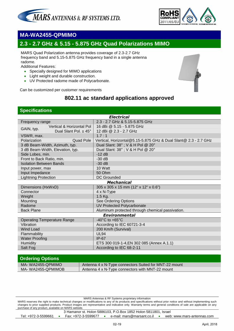
MARS Antennas & RF Systems proprietary information MARS reserves the right to make technical changes or modifications to any of its products and specifications without prior notice and without implementing such changes to prior supplied products. Product images are representative and indicative only. Warranty terms and general conditions of sale are applicable on any purchase of any product, available on MARS website.
3 Hamanor st. Holon 5886103, P.O.Box 1852 Holon 5811801, Israel
Tel: +972-3-5599661 Fax: +972-3-5599677 e-mail: [email protected] web: www.mars-antennas.com
MA-WA2455-QPMIMO
2.3 - 2.7 GHz & 5.15 - 5.875 GHz Quad Polarizations MIMO
MARS Quad Polarization antenna provides coverage of 2.3-2.7 GHz frequency band and 5.15-5.875 GHz frequency band in a single antenna radome. Additional Features:
Specially designed for MIMO applications
Light weight and durable construction.
UV Protected radome made of Polycarbonate. Can be customized per customer requirements
802.11 ac standard applications approved
Specifications
Electrical Frequency range 2.3 - 2.7 GHz & 5.15-5.875 GHz
GAIN, typ. Vertical & Horizontal Pol 16 dBi @ 5.15 - 5.875 GHz
Dual Slant Pol. ± 45° 12 dBi @ 2.3 - 2.7 GHz VSWR, max. 1.7 : 1
Polarization Quad Pole Vertical, [email protected] GHz & Dual Slant@ 2.3 - 2.7 GHz 3 dB Beam-Width, Azimuth, typ. Dual Slant: 38° ; V & H Pol @ 20°
3 dB Beam-Width, Elevation, typ. Dual Slant: 38° ; V & H Pol @ 20°
Side Lobes, min. -12 dB
Front to Back Ratio, min. -30 dB
Isolation Between Bands -30 dB
Input power, max 10 Watt
Input Impedance 50 Ohm
Lightning Protection DC Grounded
Mechanical Dimensions (HxWxD) 305 x 305 x 15 mm (12" x 12" x 0.6")
Connector 4 x N-Type
Weight 1.5 Kg.
Mounting See Ordering Options
Radome UV Protected Polycarbonate
Back Plane Aluminum protected through chemical passivation.
Environmental Operating Temperature Range -40°C to +65°C
Vibration According to IEC 60721-3-4
Wind Load 200 Km/h (Survival)
Flammability UL94
Water Proofing IP-67
Humidity ETS 300 019-1-4,EN 302 085 (Annex A.1.1) Salt Fog According to IEC 68-2-11
Ordering Options
MA- WA2455-QPMIMO Antenna 4 x N-Type connectors Suited for MNT-22 mount
MA- WA2455-QPMIMOB Antenna 4 x N-Type connectors with MNT-22 mount
April, 201802-19
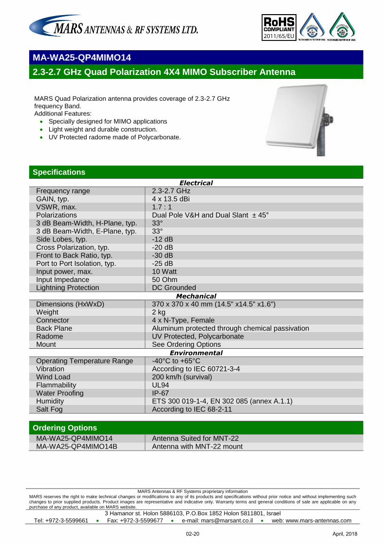
MARS Antennas & RF Systems proprietary information MARS reserves the right to make technical changes or modifications to any of its products and specifications without prior notice and without implementing such changes to prior supplied products. Product images are representative and indicative only. Warranty terms and general conditions of sale are applicable on any purchase of any product, available on MARS website.
3 Hamanor st. Holon 5886103, P.O.Box 1852 Holon 5811801, Israel
Tel: +972-3-5599661 Fax: +972-3-5599677 e-mail: [email protected] web: www.mars-antennas.com
MA-WA25-QP4MIMO14
2.3-2.7 GHz Quad Polarization 4X4 MIMO Subscriber Antenna
MARS Quad Polarization antenna provides coverage of 2.3-2.7 GHz frequency Band. Additional Features:
Specially designed for MIMO applications
Light weight and durable construction.
UV Protected radome made of Polycarbonate.
Specifications
Electrical
Frequency range 2.3-2.7 GHz GAIN, typ. 4 x 13.5 dBi VSWR, max. 1.7 : 1 Polarizations Dual Pole V&H and Dual Slant ± 45° 3 dB Beam-Width, H-Plane, typ. 33° 3 dB Beam-Width, E-Plane, typ. 33° Side Lobes, typ. -12 dB Cross Polarization, typ. -20 dB Front to Back Ratio, typ. -30 dB Port to Port Isolation, typ. -25 dB Input power, max. 10 Watt Input Impedance 50 Ohm Lightning Protection DC Grounded
Mechanical
Dimensions (HxWxD) 370 x 370 x 40 mm (14.5" x14.5" x1.6") Weight 2 kg Connector 4 x N-Type, Female Back Plane Aluminum protected through chemical passivation Radome UV Protected, Polycarbonate Mount See Ordering Options
Environmental
Operating Temperature Range -40°C to +65°C Vibration According to IEC 60721-3-4 Wind Load 200 km/h (survival) Flammability UL94 Water Proofing IP-67 Humidity ETS 300 019-1-4, EN 302 085 (annex A.1.1) Salt Fog According to IEC 68-2-11
Ordering Options
MA-WA25-QP4MIMO14 Antenna Suited for MNT-22 MA-WA25-QP4MIMO14B Antenna with MNT-22 mount
April, 201802-20
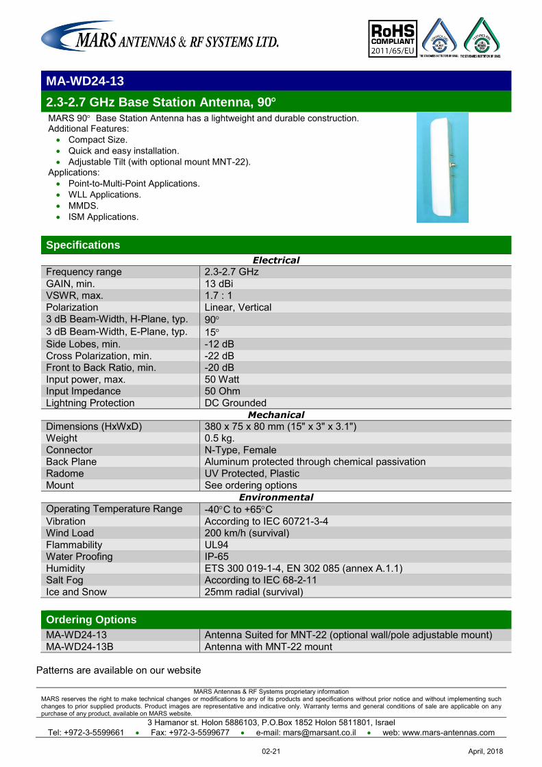
MARS Antennas & RF Systems proprietary information MARS reserves the right to make technical changes or modifications to any of its products and specifications without prior notice and without implementing such changes to prior supplied products. Product images are representative and indicative only. Warranty terms and general conditions of sale are applicable on any purchase of any product, available on MARS website.
3 Hamanor st. Holon 5886103, P.O.Box 1852 Holon 5811801, Israel Tel: +972-3-5599661 Fax: +972-3-5599677 e-mail: [email protected] web: www.mars-antennas.com
MA-WD24-13
2.3-2.7 GHz Base Station Antenna, 90 MARS 90 Base Station Antenna has a lightweight and durable construction. Additional Features: Compact Size. Quick and easy installation. Adjustable Tilt (with optional mount MNT-22).
Applications: Point-to-Multi-Point Applications. WLL Applications. MMDS. ISM Applications.
Specifications
Electrical
Frequency range 2.3-2.7 GHz GAIN, min. 13 dBi VSWR, max. 1.7 : 1 Polarization Linear, Vertical 3 dB Beam-Width, H-Plane, typ. 90 3 dB Beam-Width, E-Plane, typ. 15 Side Lobes, min. -12 dB Cross Polarization, min. -22 dB Front to Back Ratio, min. -20 dB Input power, max. 50 Watt Input Impedance 50 Ohm Lightning Protection DC Grounded
Mechanical
Dimensions (HxWxD) 380 x 75 x 80 mm (15" x 3" x 3.1") Weight 0.5 kg. Connector N-Type, Female Back Plane Aluminum protected through chemical passivation Radome UV Protected, Plastic Mount See ordering options
Environmental
Operating Temperature Range -40C to +65C Vibration According to IEC 60721-3-4 Wind Load 200 km/h (survival) Flammability UL94 Water Proofing IP-65 Humidity ETS 300 019-1-4, EN 302 085 (annex A.1.1) Salt Fog According to IEC 68-2-11 Ice and Snow 25mm radial (survival)
Ordering Options
MA-WD24-13 Antenna Suited for MNT-22 (optional wall/pole adjustable mount) MA-WD24-13B Antenna with MNT-22 mount
Patterns are available on our website
April, 201802-21

MARS Antennas & RF Systems proprietary information MARS reserves the right to make technical changes or modifications to any of its products and specifications without prior notice and without implementing such changes to prior supplied products. Product images are representative and indicative only. Warranty terms and general conditions of sale are applicable on any purchase of any product, available on MARS website.
3 Hamanor st. Holon 5886103, P.O.Box 1852 Holon 5811801, Israel Tel: +972-3-5599661 Fax: +972-3-5599677 e-mail: [email protected] web: www.mars-antennas.com
MA-WE24-11
2.3-2.7 GHz Base Station Antenna, 120 MARS 120 Base Station Antenna has a lightweight and durable construction. Additional Features: Compact Size. Quick and easy installation. Adjustable Tilt (with optional mount MNT-22).
Applications: Point-to-Multi-Point Applications. WLL Applications. MMDS. ISM Applications.
Specifications
Electrical
Frequency range 2.3-2.7 GHz GAIN, typ. 11.5 dBi VSWR, max. 1.7 : 1 Polarization Linear, Vertical 3 dB Beam-Width, H-Plane, typ. 120 3 dB Beam-Width, E-Plane, typ. 15 Side Lobes, min. -12 dB Cross Polarization, min. -22 dB Front to Back Ratio, min. -17 dB Input power, max. 50 Watt Input Impedance 50 Ohm Lightning Protection DC Grounded
Mechanical
Dimensions (HxWxD) 380 x 75 x 80 mm (15" x 3" x 3.1") Weight 0.5 kg. Connector N-Type, Female Back Plane Aluminum protected through chemical passivation Radome UV Protected, Plastic Mount See ordering options
Environmental
Operating Temperature Range -40C to +65C Vibration According to IEC 60721-3-4 Wind Load 200 km/h (survival) Flammability UL94 Water Proofing IP-65 Humidity ETS 300 019-1-4, EN 302 085 (annex A.1.1) Salt Fog According to IEC 68-2-11 Ice and Snow 25mm radial (survival)
Ordering Options
MA-WE24-11 Antenna Suited for MNT-22 (optional wall/pole adjustable mount) MA-WE24-11B Antenna with MNT-22 mount
Patterns are available on our website
April, 201802-22
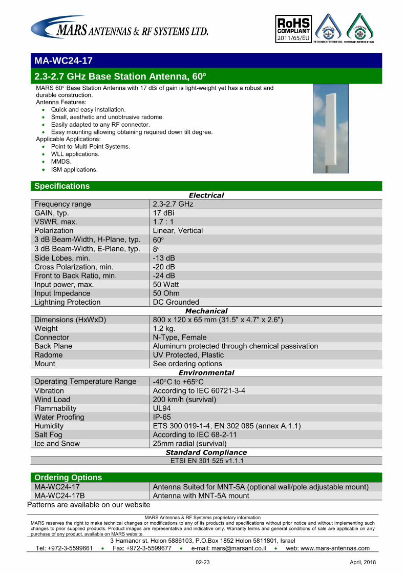
MARS Antennas & RF Systems proprietary information MARS reserves the right to make technical changes or modifications to any of its products and specifications without prior notice and without implementing such changes to prior supplied products. Product images are representative and indicative only. Warranty terms and general conditions of sale are applicable on any purchase of any product, available on MARS website.
3 Hamanor st. Holon 5886103, P.O.Box 1852 Holon 5811801, Israel Tel: +972-3-5599661 Fax: +972-3-5599677 e-mail: [email protected] web: www.mars-antennas.com
MA-WC24-17
2.3-2.7 GHz Base Station Antenna, 60 MARS 60 Base Station Antenna with 17 dBi of gain is light-weight yet has a robust and durable construction. Antenna Features:
Quick and easy installation. Small, aesthetic and unobtrusive radome. Easily adapted to any RF connector. Easy mounting allowing obtaining required down tilt degree.
Applicable Applications: Point-to-Multi-Point Systems. WLL applications. MMDS. ISM applications.
Specifications Electrical
Frequency range 2.3-2.7 GHz GAIN, typ. 17 dBi VSWR, max. 1.7 : 1 Polarization Linear, Vertical 3 dB Beam-Width, H-Plane, typ. 60 3 dB Beam-Width, E-Plane, typ. 8 Side Lobes, min. -13 dB Cross Polarization, min. -20 dB Front to Back Ratio, min. -24 dB Input power, max. 50 Watt Input Impedance 50 Ohm Lightning Protection DC Grounded
Mechanical
Dimensions (HxWxD) 800 x 120 x 65 mm (31.5" x 4.7" x 2.6") Weight 1.2 kg. Connector N-Type, Female Back Plane Aluminum protected through chemical passivation Radome UV Protected, Plastic Mount See ordering options
Environmental
Operating Temperature Range -40C to +65C Vibration According to IEC 60721-3-4 Wind Load 200 km/h (survival) Flammability UL94 Water Proofing IP-65 Humidity ETS 300 019-1-4, EN 302 085 (annex A.1.1) Salt Fog According to IEC 68-2-11 Ice and Snow 25mm radial (survival)
Standard Compliance ETSI EN 301 525 v1.1.1
Ordering Options MA-WC24-17 Antenna Suited for MNT-5A (optional wall/pole adjustable mount) MA-WC24-17B Antenna with MNT-5A mount
Patterns are available on our website
April, 201802-23
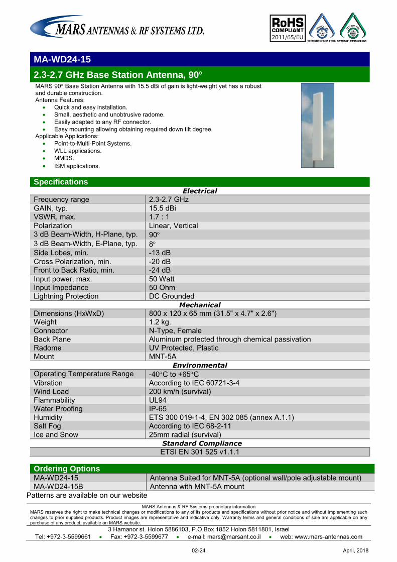
MARS Antennas & RF Systems proprietary information MARS reserves the right to make technical changes or modifications to any of its products and specifications without prior notice and without implementing such changes to prior supplied products. Product images are representative and indicative only. Warranty terms and general conditions of sale are applicable on any purchase of any product, available on MARS website.
3 Hamanor st. Holon 5886103, P.O.Box 1852 Holon 5811801, Israel Tel: +972-3-5599661 Fax: +972-3-5599677 e-mail: [email protected] web: www.mars-antennas.com
MA-WD24-15
2.3-2.7 GHz Base Station Antenna, 90 MARS 90 Base Station Antenna with 15.5 dBi of gain is light-weight yet has a robust and durable construction. Antenna Features:
Quick and easy installation. Small, aesthetic and unobtrusive radome. Easily adapted to any RF connector. Easy mounting allowing obtaining required down tilt degree.
Applicable Applications: Point-to-Multi-Point Systems. WLL applications. MMDS. ISM applications.
Specifications Electrical
Frequency range 2.3-2.7 GHz GAIN, typ. 15.5 dBi VSWR, max. 1.7 : 1 Polarization Linear, Vertical 3 dB Beam-Width, H-Plane, typ. 90 3 dB Beam-Width, E-Plane, typ. 8 Side Lobes, min. -13 dB Cross Polarization, min. -20 dB Front to Back Ratio, min. -24 dB Input power, max. 50 Watt Input Impedance 50 Ohm Lightning Protection DC Grounded
Mechanical
Dimensions (HxWxD) 800 x 120 x 65 mm (31.5" x 4.7" x 2.6") Weight 1.2 kg. Connector N-Type, Female Back Plane Aluminum protected through chemical passivation Radome UV Protected, Plastic Mount MNT-5A
Environmental
Operating Temperature Range -40C to +65C Vibration According to IEC 60721-3-4 Wind Load 200 km/h (survival) Flammability UL94 Water Proofing IP-65 Humidity ETS 300 019-1-4, EN 302 085 (annex A.1.1) Salt Fog According to IEC 68-2-11 Ice and Snow 25mm radial (survival)
Standard Compliance
ETSI EN 301 525 v1.1.1
Ordering Options MA-WD24-15 Antenna Suited for MNT-5A (optional wall/pole adjustable mount) MA-WD24-15B Antenna with MNT-5A mount
Patterns are available on our website
April, 201802-24
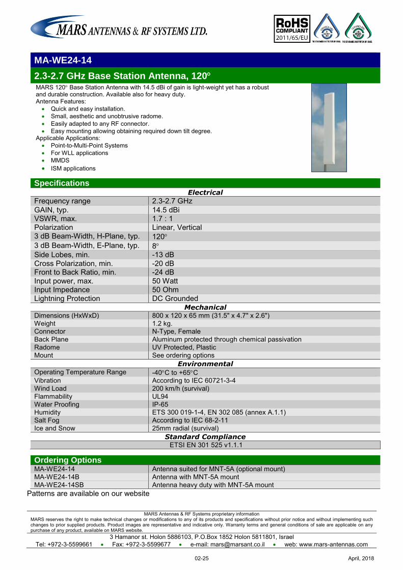
MARS Antennas & RF Systems proprietary information MARS reserves the right to make technical changes or modifications to any of its products and specifications without prior notice and without implementing such changes to prior supplied products. Product images are representative and indicative only. Warranty terms and general conditions of sale are applicable on any purchase of any product, available on MARS website.
3 Hamanor st. Holon 5886103, P.O.Box 1852 Holon 5811801, Israel Tel: +972-3-5599661 Fax: +972-3-5599677 e-mail: [email protected] web: www.mars-antennas.com
MA-WE24-14
2.3-2.7 GHz Base Station Antenna, 120 MARS 120 Base Station Antenna with 14.5 dBi of gain is light-weight yet has a robust and durable construction. Available also for heavy duty. Antenna Features:
Quick and easy installation. Small, aesthetic and unobtrusive radome. Easily adapted to any RF connector. Easy mounting allowing obtaining required down tilt degree.
Applicable Applications: Point-to-Multi-Point Systems For WLL applications MMDS ISM applications
Specifications Electrical
Frequency range 2.3-2.7 GHz GAIN, typ. 14.5 dBi VSWR, max. 1.7 : 1 Polarization Linear, Vertical 3 dB Beam-Width, H-Plane, typ. 120 3 dB Beam-Width, E-Plane, typ. 8 Side Lobes, min. -13 dB Cross Polarization, min. -20 dB Front to Back Ratio, min. -24 dB Input power, max. 50 Watt Input Impedance 50 Ohm Lightning Protection DC Grounded
Mechanical Dimensions (HxWxD) 800 x 120 x 65 mm (31.5" x 4.7" x 2.6") Weight 1.2 kg. Connector N-Type, Female Back Plane Aluminum protected through chemical passivation Radome UV Protected, Plastic Mount See ordering options
Environmental Operating Temperature Range -40C to +65C Vibration According to IEC 60721-3-4 Wind Load 200 km/h (survival) Flammability UL94 Water Proofing IP-65 Humidity ETS 300 019-1-4, EN 302 085 (annex A.1.1) Salt Fog According to IEC 68-2-11 Ice and Snow 25mm radial (survival)
Standard Compliance ETSI EN 301 525 v1.1.1
Ordering Options MA-WE24-14 Antenna suited for MNT-5A (optional mount) MA-WE24-14B Antenna with MNT-5A mount MA-WE24-14SB Antenna heavy duty with MNT-5A mount
Patterns are available on our website
April, 201802-25
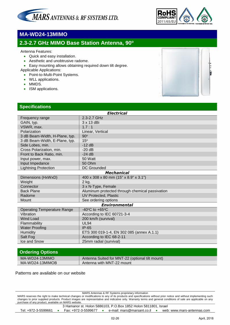
MARS Antennas & RF Systems proprietary information MARS reserves the right to make technical changes or modifications to any of its products and specifications without prior notice and without implementing such changes to prior supplied products. Product images are representative and indicative only. Warranty terms and general conditions of sale are applicable on any purchase of any product, available on MARS website.
3 Hamanor st. Holon 5886103, P.O.Box 1852 Holon 5811801, Israel
Tel: +972-3-5599661 Fax: +972-3-5599677 e-mail: [email protected] web: www.mars-antennas.com
MA-WD24-13MIMO
2.3-2.7 GHz MIMO Base Station Antenna, 90o
Antenna Features:
Quick and easy installation.
Aesthetic and unobtrusive radome.
Easy mounting allows obtaining required down tilt degree. Applicable Applications:
Point-to-Multi-Point Systems.
WLL applications.
MMDS.
ISM applications.
Specifications
Electrical Frequency range 2.3-2.7 GHz
GAIN, typ. 3 x 13 dBi
VSWR, max. 1.7 : 1
Polarization Linear, Vertical
3 dB Beam-Width, H-Plane, typ. 90o
3 dB Beam-Width, E-Plane, typ. 15o Side Lobes, min. -12 dB
Cross Polarization, min. -20 dB
Front to Back Ratio, min. -24 dB
Input power, max. 50 Watt
Input Impedance 50 Ohm
Lightning Protection DC Grounded
Mechanical Dimensions (HxWxD) 400 x 308 x 80 mm (15" x 8.9" x 3.1")
Weight 2 kg.
Connector 3 x N-Type, Female
Back Plane Aluminum protected through chemical passivation
Radome UV Protected, Plastic
Mount See ordering options
Environmental Operating Temperature Range -40oC to +65oC
Vibration According to IEC 60721-3-4
Wind Load 200 km/h (survival)
Flammability UL94
Water Proofing IP-65
Humidity ETS 300 019-1-4, EN 302 085 (annex A.1.1)
Salt Fog According to IEC 68-2-11
Ice and Snow 25mm radial (survival)
Ordering Options
MA-WD24-13MIMO Antenna Suited for MNT-22 (optional tilt mount)
MA-WD24-13MIMOB Antenna with MNT-22 mount
Patterns are available on our website
April, 201802-26
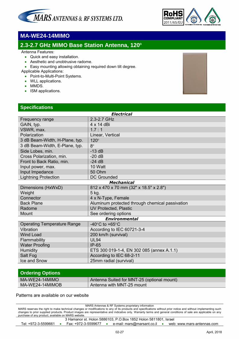
MARS Antennas & RF Systems proprietary information MARS reserves the right to make technical changes or modifications to any of its products and specifications without prior notice and without implementing such changes to prior supplied products. Product images are representative and indicative only. Warranty terms and general conditions of sale are applicable on any purchase of any product, available on MARS website.
3 Hamanor st. Holon 5886103, P.O.Box 1852 Holon 5811801, Israel Tel: +972-3-5599661 Fax: +972-3-5599677 e-mail: [email protected] web: www.mars-antennas.com
MA-WE24-14MIMO
2.3-2.7 GHz MIMO Base Station Antenna, 120 Antenna Features: Quick and easy installation. Aesthetic and unobtrusive radome. Easy mounting allowing obtaining required down tilt degree.
Applicable Applications: Point-to-Multi-Point Systems. WLL applications. MMDS. ISM applications.
Specifications
Electrical
Frequency range 2.3-2.7 GHz GAIN, typ. 4 x 14 dBi VSWR, max. 1.7 : 1 Polarization Linear, Vertical 3 dB Beam-Width, H-Plane, typ. 120 3 dB Beam-Width, E-Plane, typ. 8 Side Lobes, min. -13 dB Cross Polarization, min. -20 dB Front to Back Ratio, min. -24 dB Input power, max. 10 Watt Input Impedance 50 Ohm Lightning Protection DC Grounded
Mechanical
Dimensions (HxWxD) 812 x 470 x 70 mm (32" x 18.5" x 2.8") Weight 5 kg. Connector 4 x N-Type, Female Back Plane Aluminum protected through chemical passivation Radome UV Protected, Plastic Mount See ordering options
Environmental
Operating Temperature Range -40C to +65C Vibration According to IEC 60721-3-4 Wind Load 200 km/h (survival) Flammability UL94 Water Proofing IP-65 Humidity ETS 300 019-1-4, EN 302 085 (annex A.1.1) Salt Fog According to IEC 68-2-11 Ice and Snow 25mm radial (survival)
Ordering Options
MA-WE24-14MIMO Antenna Suited for MNT-25 (optional mount) MA-WE24-14MIMOB Antenna with MNT-25 mount
Patterns are available on our website
April, 201802-27
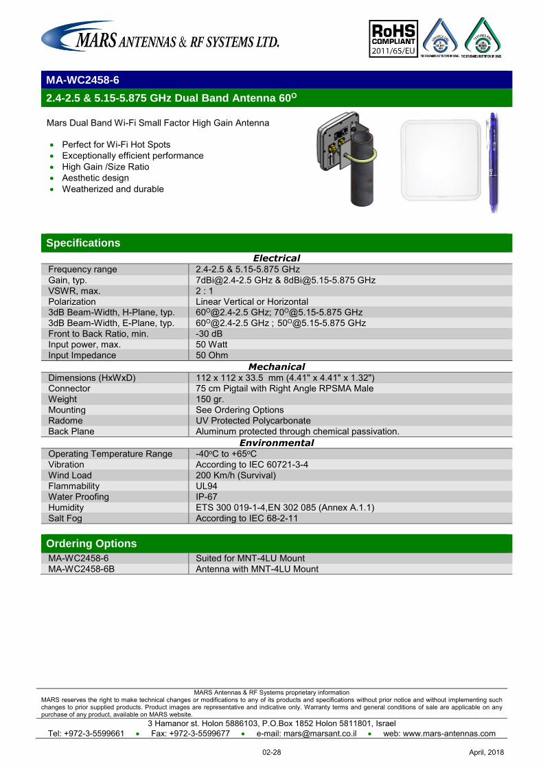
MARS Antennas & RF Systems proprietary information MARS reserves the right to make technical changes or modifications to any of its products and specifications without prior notice and without implementing such changes to prior supplied products. Product images are representative and indicative only. Warranty terms and general conditions of sale are applicable on any purchase of any product, available on MARS website.
3 Hamanor st. Holon 5886103, P.O.Box 1852 Holon 5811801, Israel Tel: +972-3-5599661 Fax: +972-3-5599677 e-mail: [email protected] web: www.mars-antennas.com
MA-WC2458-6
2.4-2.5 & 5.15-5.875 GHz Dual Band Antenna 60O
Mars Dual Band Wi-Fi Small Factor High Gain Antenna Perfect for Wi-Fi Hot Spots Exceptionally efficient performance High Gain /Size Ratio Aesthetic design Weatherized and durable
Specifications
Electrical Frequency range 2.4-2.5 & 5.15-5.875 GHz Gain, typ. [email protected] GHz & [email protected] GHz VSWR, max. 2 : 1 Polarization Linear Vertical or Horizontal 3dB Beam-Width, H-Plane, typ. [email protected] GHz; [email protected] GHz 3dB Beam-Width, E-Plane, typ. [email protected] GHz ; [email protected] GHz Front to Back Ratio, min. -30 dB Input power, max. 50 Watt Input Impedance 50 Ohm
Mechanical Dimensions (HxWxD) 112 x 112 x 33.5 mm (4.41" x 4.41" x 1.32") Connector 75 cm Pigtail with Right Angle RPSMA Male Weight 150 gr. Mounting See Ordering Options Radome UV Protected Polycarbonate Back Plane Aluminum protected through chemical passivation.
Environmental Operating Temperature Range -40oC to +65oC Vibration According to IEC 60721-3-4 Wind Load 200 Km/h (Survival) Flammability UL94 Water Proofing IP-67 Humidity ETS 300 019-1-4,EN 302 085 (Annex A.1.1) Salt Fog According to IEC 68-2-11 Ordering Options
MA-WC2458-6 Suited for MNT-4LU Mount MA-WC2458-6B Antenna with MNT-4LU Mount
April, 201802-28
MARS Antennas & RF Systems proprietary information MARS reserves the right to make technical changes or modifications to any of its products and specifications without prior notice and without implementing such changes to prior supplied products. Product images are representative and indicative only. Warranty terms and general conditions of sale are applicable on any purchase of any product, available on MARS website.
3 Hamanor st. Holon 5886103, P.O.Box 1852 Holon 5811801, Israel Tel: +972-3-5599661 Fax: +972-3-5599677 e-mail: [email protected] web: www.mars-antennas.com
MA-WC2458-10
2.4-2.5 & 5.15-5.875 GHz Dual Band Antenna 60O
Mars Dual Band Wi-Fi Small Factor High Gain Antenna Perfect for Wi-Fi Hotspots Exceptionally efficient performance High Gain /Size Ratio Aesthetic design Weatherized and durable
Specifications
Electrical Frequency range 2.4-2.5 & 5.15-5.875 GHz Gain, range 10dBi @ 2.4-2.5 GHz ; 11dBi @ 5.15-5.875 GHz VSWR, max. 2 : 1 Polarization Linear Vertical or Horizontal 3dB Beam-Width, H-Plane, typ. 60o 3dB Beam-Width, E-Plane, typ. 60o@ 2.4-2.5 GHz ; [email protected] GHz Front to Back Ratio, min. -30 dB Input power, max. 50 Watt Input Impedance 50 Ohm
Mechanical Dimensions (HxWxD) 112 x 112 x 33.5 mm (4.41" x 4.41" x 1.32") Connector 2 x N-Type ,Female Weight 147 gr. Mounting See Ordering Options Radome UV Protected Polycarbonate Back Plane Aluminum protected through chemical passivation.
Environmental Operating Temperature Range -40oC to +65oC Vibration According to IEC 60721-3-4 Wind Load 200 Km/h (Survival) Flammability UL94 Water Proofing IP-67 Humidity ETS 300 019-1-4,EN 302 085 (Annex A.1.1) Salt Fog According to IEC 68-2-11 Ordering Options
MA-WC2458-10 Suited for MNT-4LU mount MA-WC2458-10B With MNT-4LU mount
April, 201802-29
MARS Antennas & RF Systems proprietary information MARS reserves the right to make technical changes or modifications to any of its products and specifications without prior notice and without implementing such changes to prior supplied products. Product images are representative and indicative only. Warranty terms and general conditions of sale are applicable on any purchase of any product, available on MARS website.
3 Hamanor st. Holon 5886103, P.O.Box 1852 Holon 5811801, Israel Tel: +972-3-5599661 Fax: +972-3-5599677 e-mail: [email protected] web: www.mars-antennas.com
MA-WE2458-MIMO4-5
2.3-2.7 GHz & 4.9-6.1 GHz Dual Band MIMO Applications Sector Antenna, 120°
MARS Dual Band Sector antenna provides coverage of 2.3 to 2.7 GHz & 4.9 to 6.1 GHz in a single antenna radome. Additional Features: Simultaneous coverage of 802.11 a, b, g, e, n, WiMAX & 4.9 GHz Public
Safety Bands. Light weight and durable construction. UV protected radome made of plastic.
Specifications
Electrical Frequency range 2.3-2.7 GHz & 4.9-6.1 GHz Peak Gain, typ. 4 x 5 dBi VSWR, max. 2 : 1 (typ. 1.5 : 1) Polarization Double dual Slant ±45º 3 dB Beam-Width, H-Plane, typ. 120 3 dB Beam-Width, E-Plane, typ. 70 Input power, max. 20 Watt Input Impedance 50 Ohm
Mechanical Dimensions (W x L x H) 200 x 200 x 33 mm (7.9" x 7.9" x 1.25") Connector See Ordering Options Weight 260 gr. Back Plane Aluminum; protected through chemical passivation Radome UV Protected Polycarbonate Mount See Ordering Options
Environmental Operating Temperature Range -40°C to +70°C Vibration According to IEC 60721-3-4 Flammability UL94 Humidity ETS 300 019-1-4, EN 302 085 (annex A.1.1) Ordering Options
MA-WE2458-MIMO4-5 Antenna 4 x 75cm Pigtail RG 316 with right angle RPSMA Male with provision for Az/El adjustable for MNT-22 mount
MA-WE2458-MIMO4-5B Antenna 4 x 75cm Pigtail RG 316 with right angle RPSMA Male with MNT-22 mount MA-WE2458-MIMO4-5W Antenna 4 x 75cm Pigtail RG 316 with right angle RPSMA Male, wall mountable
MA-WE2458-MIMO4-5N Antenna 4 x 75cm Pigtail RG 316 with N-Type Male with provision for Az/El adjustable for MNT-22 mount
MA-WE2458-MIMO4-5NB Antenna 4 x75cm Pigtail RG 316 with N-Type Male with MNT-22 mount
April, 201802-30
MARS Antennas & RF Systems proprietary information MARS reserves the right to make technical changes or modifications to any of its products and specifications without prior notice and without implementing such changes to prior supplied products. Product images are representative and indicative only. Warranty terms and general conditions of sale are applicable on any purchase of any product, available on MARS website.
3 Hamanor st. Holon 5886103, P.O.Box 1852 Holon 5811801, Israel
Tel: +972-3-5599661 Fax: +972-3-5599677 e-mail: [email protected] web: www.mars-antennas.com
MA-WD2455-DS18
2.3 – 2.7 GHz & 5.1 – 5.9 GHz, 4X4 Dual Band, Dual-Slant Base Station Antenna, 90
MARS MA-WD2455-DS18 is a 4X4 (MIMO) high gain antenna with Dual band, Dual Slant antenna provides coverage of 2.3-2.7 GHz frequency band and 5.1-5.9
GHz frequency band in a single antenna radome.
Additional Features:
Designed to meet WAVE2, 802.11ac & more.
Easy mounting allowing Az/El adjustment.
Specifications
Electrical
Frequency range 2.3-2.7 GHz 5.1-5.9 GHz Gain, typ. 16 dBi 18 dBi VSWR, max. 2.0 : 1 Polarization, Dual-Slant ±45° ±45° 3 dB Beam-Width, Azimuth, typ. 90 90 3 dB Beam-Width, Elevation, typ. 8 4 Side Lobes, min. -10 dB Cross Polarization, typ. -15 dB Front to Back Ratio, min. -32 dB Port to Port Isolation, min. Intra-band Inter-band
-17 dB -30 dB
-35 dB Input power, max 50 Watt Input Impedance 50 Ohm Lightning Protection DC Grounded
Mechanical
Dimensions (HxWxD) 807 x 464 x 50 mm (31.77” x 18.27” x 1.97” ) Weight 3 Kg. Connector 4 x N-Type, Female Back Plane Aluminum protected through chemical passivation Radome UV Protected Plastic Mount MNT-25
Environmental
Operating Temperature Range -40C to +65C Vibration According to IEC 60721-3-4
Wind Load 200 km/h (survival) Flammability UL94 Water Proofing IP-65
Humidity ETS 300 019-1-4, EN 302 085 (annex A.1.1) Salt Fog According to IEC 68-2-11
April, 201802-31
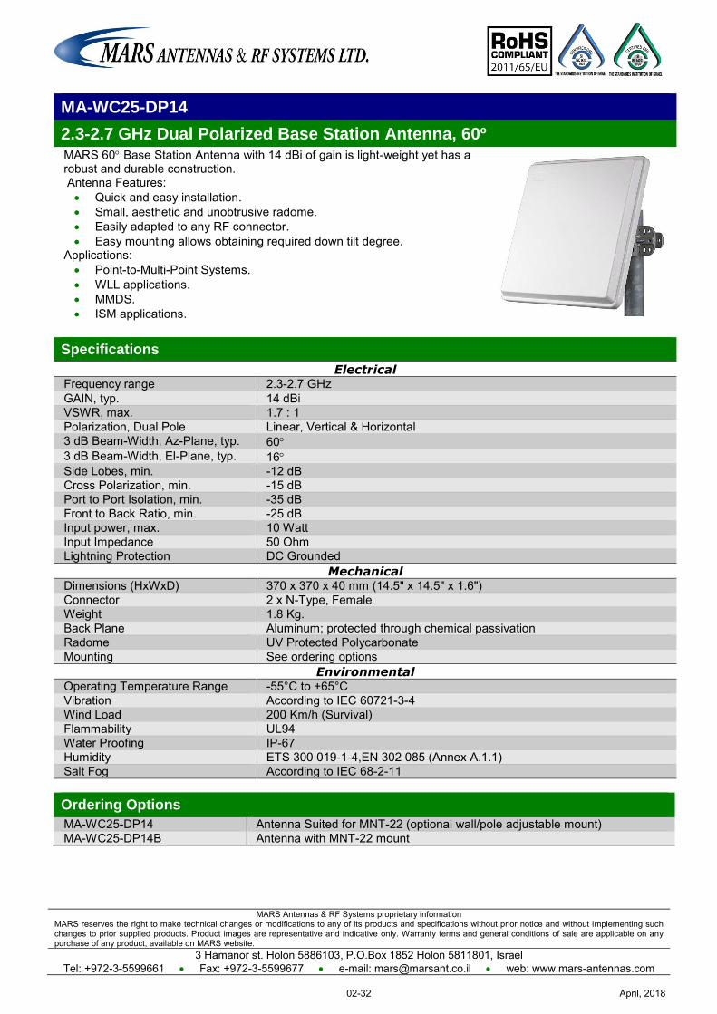
MARS Antennas & RF Systems proprietary information MARS reserves the right to make technical changes or modifications to any of its products and specifications without prior notice and without implementing such changes to prior supplied products. Product images are representative and indicative only. Warranty terms and general conditions of sale are applicable on any purchase of any product, available on MARS website.
3 Hamanor st. Holon 5886103, P.O.Box 1852 Holon 5811801, Israel Tel: +972-3-5599661 Fax: +972-3-5599677 e-mail: [email protected] web: www.mars-antennas.com
MA-WC25-DP14
2.3-2.7 GHz Dual Polarized Base Station Antenna, 60º MARS 60 Base Station Antenna with 14 dBi of gain is light-weight yet has a robust and durable construction. Antenna Features: Quick and easy installation. Small, aesthetic and unobtrusive radome. Easily adapted to any RF connector. Easy mounting allows obtaining required down tilt degree.
Applications: Point-to-Multi-Point Systems. WLL applications. MMDS. ISM applications.
Specifications
Electrical Frequency range 2.3-2.7 GHz GAIN, typ. 14 dBi VSWR, max. 1.7 : 1 Polarization, Dual Pole Linear, Vertical & Horizontal 3 dB Beam-Width, Az-Plane, typ. 60 3 dB Beam-Width, El-Plane, typ. 16 Side Lobes, min. -12 dB Cross Polarization, min. -15 dB Port to Port Isolation, min. -35 dB Front to Back Ratio, min. -25 dB Input power, max. 10 Watt Input Impedance 50 Ohm Lightning Protection DC Grounded
Mechanical Dimensions (HxWxD) 370 x 370 x 40 mm (14.5" x 14.5" x 1.6") Connector 2 x N-Type, Female Weight 1.8 Kg. Back Plane Aluminum; protected through chemical passivation Radome UV Protected Polycarbonate Mounting See ordering options
Environmental Operating Temperature Range -55°C to +65°C Vibration According to IEC 60721-3-4 Wind Load 200 Km/h (Survival) Flammability UL94 Water Proofing IP-67 Humidity ETS 300 019-1-4,EN 302 085 (Annex A.1.1) Salt Fog According to IEC 68-2-11 Ordering Options
MA-WC25-DP14 Antenna Suited for MNT-22 (optional wall/pole adjustable mount) MA-WC25-DP14B Antenna with MNT-22 mount
April, 201802-32
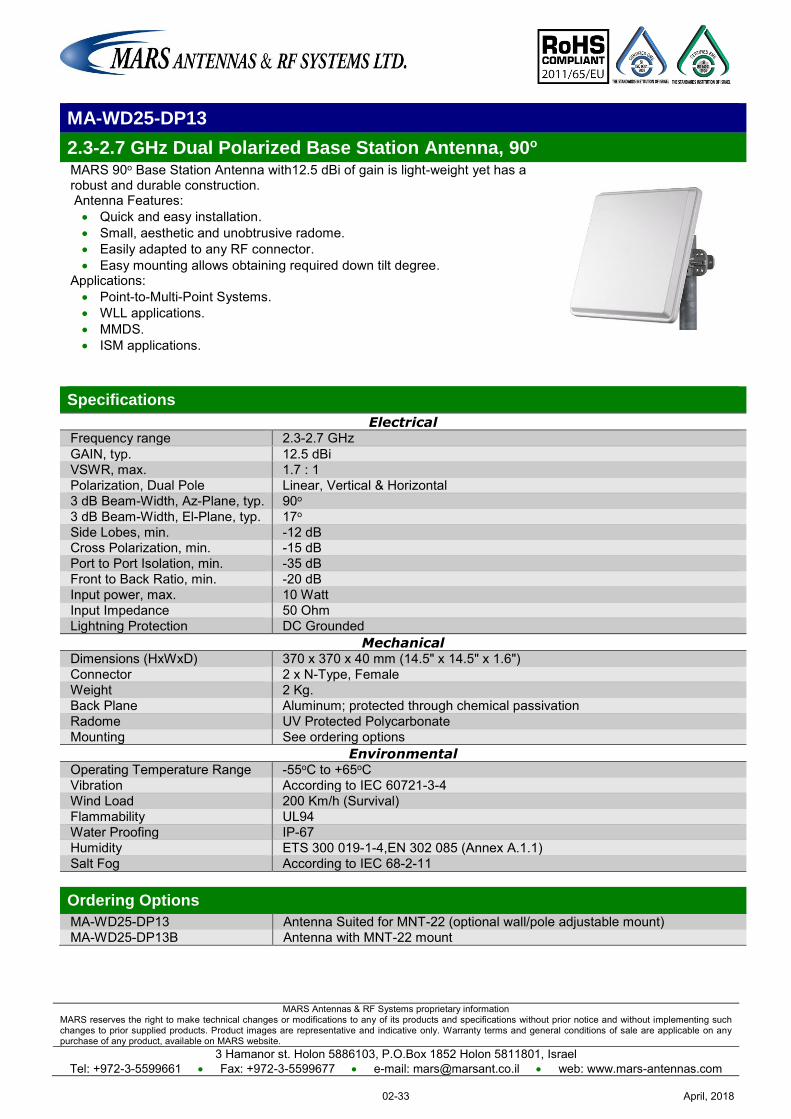
MARS Antennas & RF Systems proprietary information MARS reserves the right to make technical changes or modifications to any of its products and specifications without prior notice and without implementing such changes to prior supplied products. Product images are representative and indicative only. Warranty terms and general conditions of sale are applicable on any purchase of any product, available on MARS website.
3 Hamanor st. Holon 5886103, P.O.Box 1852 Holon 5811801, Israel Tel: +972-3-5599661 Fax: +972-3-5599677 e-mail: [email protected] web: www.mars-antennas.com
MA-WD25-DP13
2.3-2.7 GHz Dual Polarized Base Station Antenna, 90o MARS 90o Base Station Antenna with12.5 dBi of gain is light-weight yet has a robust and durable construction. Antenna Features: Quick and easy installation. Small, aesthetic and unobtrusive radome. Easily adapted to any RF connector. Easy mounting allows obtaining required down tilt degree.
Applications: Point-to-Multi-Point Systems. WLL applications. MMDS. ISM applications.
Specifications
Electrical Frequency range 2.3-2.7 GHz GAIN, typ. 12.5 dBi VSWR, max. 1.7 : 1 Polarization, Dual Pole Linear, Vertical & Horizontal 3 dB Beam-Width, Az-Plane, typ. 90o 3 dB Beam-Width, El-Plane, typ. 17o Side Lobes, min. -12 dB Cross Polarization, min. -15 dB Port to Port Isolation, min. -35 dB Front to Back Ratio, min. -20 dB Input power, max. 10 Watt Input Impedance 50 Ohm Lightning Protection DC Grounded
Mechanical Dimensions (HxWxD) 370 x 370 x 40 mm (14.5" x 14.5" x 1.6") Connector 2 x N-Type, Female Weight 2 Kg. Back Plane Aluminum; protected through chemical passivation Radome UV Protected Polycarbonate Mounting See ordering options
Environmental Operating Temperature Range -55oC to +65oC Vibration According to IEC 60721-3-4 Wind Load 200 Km/h (Survival) Flammability UL94 Water Proofing IP-67 Humidity ETS 300 019-1-4,EN 302 085 (Annex A.1.1) Salt Fog According to IEC 68-2-11 Ordering Options
MA-WD25-DP13 Antenna Suited for MNT-22 (optional wall/pole adjustable mount) MA-WD25-DP13B Antenna with MNT-22 mount
April, 201802-33

MARS Antennas & RF Systems proprietary information MARS reserves the right to make technical changes or modifications to any of its products and specifications without prior notice and without implementing such changes to prior supplied products. Product images are representative and indicative only. Warranty terms and general conditions of sale are applicable on any purchase of any product, available on MARS website.
3 Hamanor st. Holon 5886103, P.O.Box 1852 Holon 5811801, Israel Tel: +972-3-5599661 Fax: +972-3-5599677 e-mail: [email protected] web: www.mars-antennas.com
MA-WC25-DS16
2.2-2.2 GHz Dual Slant Base Station Antenna, 65
MARS Dual Slant ±45 degrees 65º sector antenna features: Efficient and stable performance with 2 X16 dBi of gain. Full 2.3-2.7 GHz band coverage. High Isolation ratio. Compact size. Optional Azimuth & Elevation Adjustable mount.
UV protected radome suitable for harsh environment installations. Can be customized per customer requirements
Specifications
Electrical Frequency range 2.3-2.7 GHz GAIN, typ. 2 x 16dBi VSWR, max. 1.7 : 1 Polarization Dual Slant ±45º 4 dB Beam-Width, Azimuth, typ. 65º 3 dB Beam-Width, Elevation, typ. 9º Side Lobe level ( Elevation),typ. -12 dB Port to Port Isolation, typ. -20 dB Front to Back Ratio, min. -30 dB Input power, max. 20 Watt Input Impedance 50 Ohm Lightning Protection DC Grounded
Mechanical Dimensions (HxWxD) 800 x 225 x 67 mm (31.3" x 8.8" x 2.6") Weight 2.5 kg. Connector 2 x N-Type, Female Back Plane Aluminum; protected through chemical passivation Radome UV Protected, Plastic Mount See Ordering Options
Environmental Operating Temperature Range -55ºC to +65ºC Vibration According to IEC 60721-3-4 Wind Load 200 km/h (survival) Flammability UL94 Water Proofing IP-65 Humidity ETS 300 019-1-4, EN 302 085 (annex A.1.1) Salt Fog According to IEC 68-2-11 Ice and Snow 25mm radial (survival) Ordering Options
MA-WC25-DS16 Antenna 2 x N-Type Female connectors Suited for MNT-5A mount MA-WC25-DS16B Antenna 2 x N-Type Female connectors with MNT-5A mount
April, 201802-34
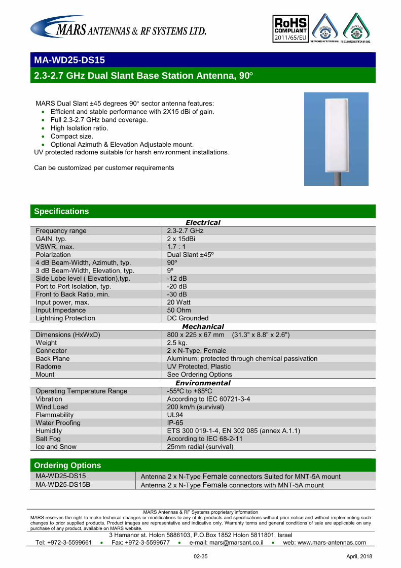
MARS Antennas & RF Systems proprietary information MARS reserves the right to make technical changes or modifications to any of its products and specifications without prior notice and without implementing such changes to prior supplied products. Product images are representative and indicative only. Warranty terms and general conditions of sale are applicable on any purchase of any product, available on MARS website.
3 Hamanor st. Holon 5886103, P.O.Box 1852 Holon 5811801, Israel Tel: +972-3-5599661 Fax: +972-3-5599677 e-mail: [email protected] web: www.mars-antennas.com
MA-WD25-DS15
2.2-2.2 GHz Dual Slant Base Station Antenna, 90
MARS Dual Slant ±45 degrees 90 sector antenna features: Efficient and stable performance with 2X15 dBi of gain. Full 2.3-2.7 GHz band coverage. High Isolation ratio. Compact size. Optional Azimuth & Elevation Adjustable mount.
UV protected radome suitable for harsh environment installations. Can be customized per customer requirements
Specifications
Electrical Frequency range 2.3-2.7 GHz GAIN, typ. 2 x 15dBi VSWR, max. 1.7 : 1 Polarization Dual Slant ±45º 4 dB Beam-Width, Azimuth, typ. 90º 3 dB Beam-Width, Elevation, typ. 9º Side Lobe level ( Elevation),typ. -12 dB Port to Port Isolation, typ. -20 dB Front to Back Ratio, min. -30 dB Input power, max. 20 Watt Input Impedance 50 Ohm Lightning Protection DC Grounded
Mechanical Dimensions (HxWxD) 800 x 225 x 67 mm (31.3" x 8.8" x 2.6") Weight 2.5 kg. Connector 2 x N-Type, Female Back Plane Aluminum; protected through chemical passivation Radome UV Protected, Plastic Mount See Ordering Options
Environmental Operating Temperature Range -55ºC to +65ºC Vibration According to IEC 60721-3-4 Wind Load 200 km/h (survival) Flammability UL94 Water Proofing IP-65 Humidity ETS 300 019-1-4, EN 302 085 (annex A.1.1) Salt Fog According to IEC 68-2-11 Ice and Snow 25mm radial (survival) Ordering Options
MA-WD25-DS15 Antenna 2 x N-Type Female connectors Suited for MNT-5A mount MA-WD25-DS15B Antenna 2 x N-Type Female connectors with MNT-5A mount
April, 201802-35
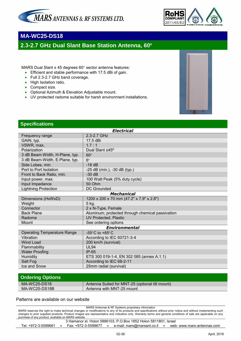
MARS Antennas & RF Systems proprietary information MARS reserves the right to make technical changes or modifications to any of its products and specifications without prior notice and without implementing such changes to prior supplied products. Product images are representative and indicative only. Warranty terms and general conditions of sale are applicable on any purchase of any product, available on MARS website.
3 Hamanor st. Holon 5886103, P.O.Box 1852 Holon 5811801, Israel Tel: +972-3-5599661 Fax: +972-3-5599677 e-mail: [email protected] web: www.mars-antennas.com
MA-WC25-DS18
2.2-2.2 GHz Dual Slant Base Station Antenna, 60
MARS Dual Slant ± 45 degrees 60 sector antenna features: Efficient and stable performance with 17.5 dBi of gain. Full 2.3-2.7 GHz band coverage. High Isolation ratio. Compact size. Optional Azimuth & Elevation Adjustable mount. UV protected radome suitable for harsh environment installations.
Specifications
Electrical Frequency range 2.3-2.7 GHz GAIN, typ. 17.5 dBi VSWR, max. 1.7 : 1 Polarization Dual Slant ±45º 3 dB Beam-Width, H-Plane, typ. 60 3 dB Beam-Width, E-Plane, typ. 6 Side Lobes, min. -18 dB Port to Port Isolation -25 dB (min.), -30 dB (typ.) Front to Back Ratio, min. -30 dB Input power, max. 100 Watt Peak (5% duty cycle) Input Impedance 50 Ohm Lightning Protection DC Grounded
Mechanical Dimensions (HxWxD) 1200 x 200 x 70 mm (47.2" x 7.9" x 2.8") Weight 5 kg. Connector 2 x N-Type, Female Back Plane Aluminum; protected through chemical passivation Radome UV Protected, Plastic Mount See ordering options
Environmental Operating Temperature Range -55C to +65C Vibration According to IEC 60721-3-4 Wind Load 200 km/h (survival) Flammability UL94 Water Proofing IP-65 Humidity ETS 300 019-1-4, EN 302 085 (annex A.1.1) Salt Fog According to IEC 68-2-11 Ice and Snow 25mm radial (survival) Ordering Options
MA-WC25-DS18 Antenna Suited for MNT-25 (optional tilt mount) MA-WC25-DS18B Antenna with MNT-25 mount
Patterns are available on our website
April, 201802-36
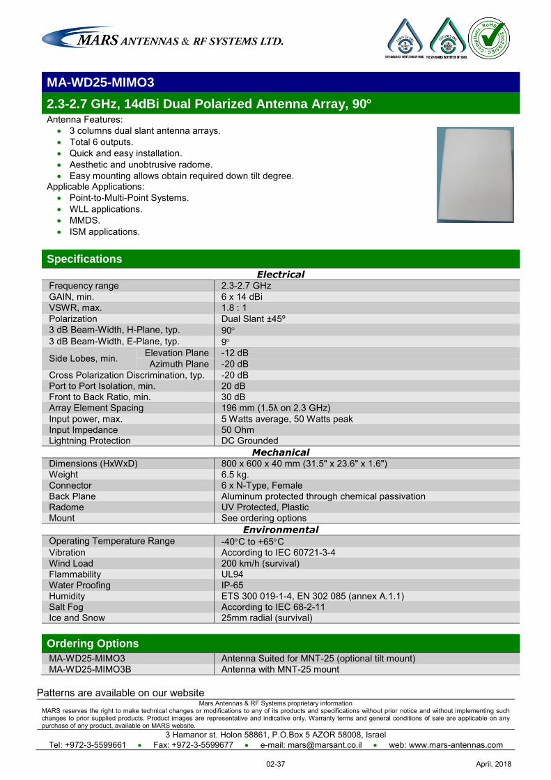
Mars Antennas & RF Systems proprietary information MARS reserves the right to make technical changes or modifications to any of its products and specifications without prior notice and without implementing such changes to prior supplied products. Product images are representative and indicative only. Warranty terms and general conditions of sale are applicable on any purchase of any product, available on MARS website.
3 Hamanor st. Holon 58861, P.O.Box 5 AZOR 58008, Israel Tel: +972-3-5599661 Fax: +972-3-5599677 e-mail: [email protected] web: www.mars-antennas.com
MA-WD25-MIMO3
2.3-2.7 GHz, 14dBi Dual Polarized Antenna Array, 90 Antenna Features:
3 columns dual slant antenna arrays. Total 6 outputs. Quick and easy installation. Aesthetic and unobtrusive radome. Easy mounting allows obtain required down tilt degree.
Applicable Applications: Point-to-Multi-Point Systems. WLL applications. MMDS. ISM applications.
Specifications
Electrical Frequency range 2.3-2.7 GHz GAIN, min. 6 x 14 dBi VSWR, max. 1.8 : 1 Polarization Dual Slant ±45º 3 dB Beam-Width, H-Plane, typ. 90 3 dB Beam-Width, E-Plane, typ. 9
Side Lobes, min. Elevation Plane -12 dB Azimuth Plane -20 dB
Cross Polarization Discrimination, typ. -20 dB Port to Port Isolation, min. 20 dB Front to Back Ratio, min. 30 dB Array Element Spacing 196 mm (1.5λ on 2.3 GHz) Input power, max. 5 Watts average, 50 Watts peak Input Impedance 50 Ohm Lightning Protection DC Grounded
Mechanical Dimensions (HxWxD) 800 x 600 x 40 mm (31.5" x 23.6" x 1.6") Weight 6.5 kg. Connector 6 x N-Type, Female Back Plane Aluminum protected through chemical passivation Radome UV Protected, Plastic Mount See ordering options
Environmental Operating Temperature Range -40C to +65C Vibration According to IEC 60721-3-4 Wind Load 200 km/h (survival) Flammability UL94 Water Proofing IP-65 Humidity ETS 300 019-1-4, EN 302 085 (annex A.1.1) Salt Fog According to IEC 68-2-11 Ice and Snow 25mm radial (survival) Ordering Options
MA-WD25-MIMO3 Antenna Suited for MNT-25 (optional tilt mount) MA-WD25-MIMO3B Antenna with MNT-25 mount
Patterns are available on our website
April, 201802-37
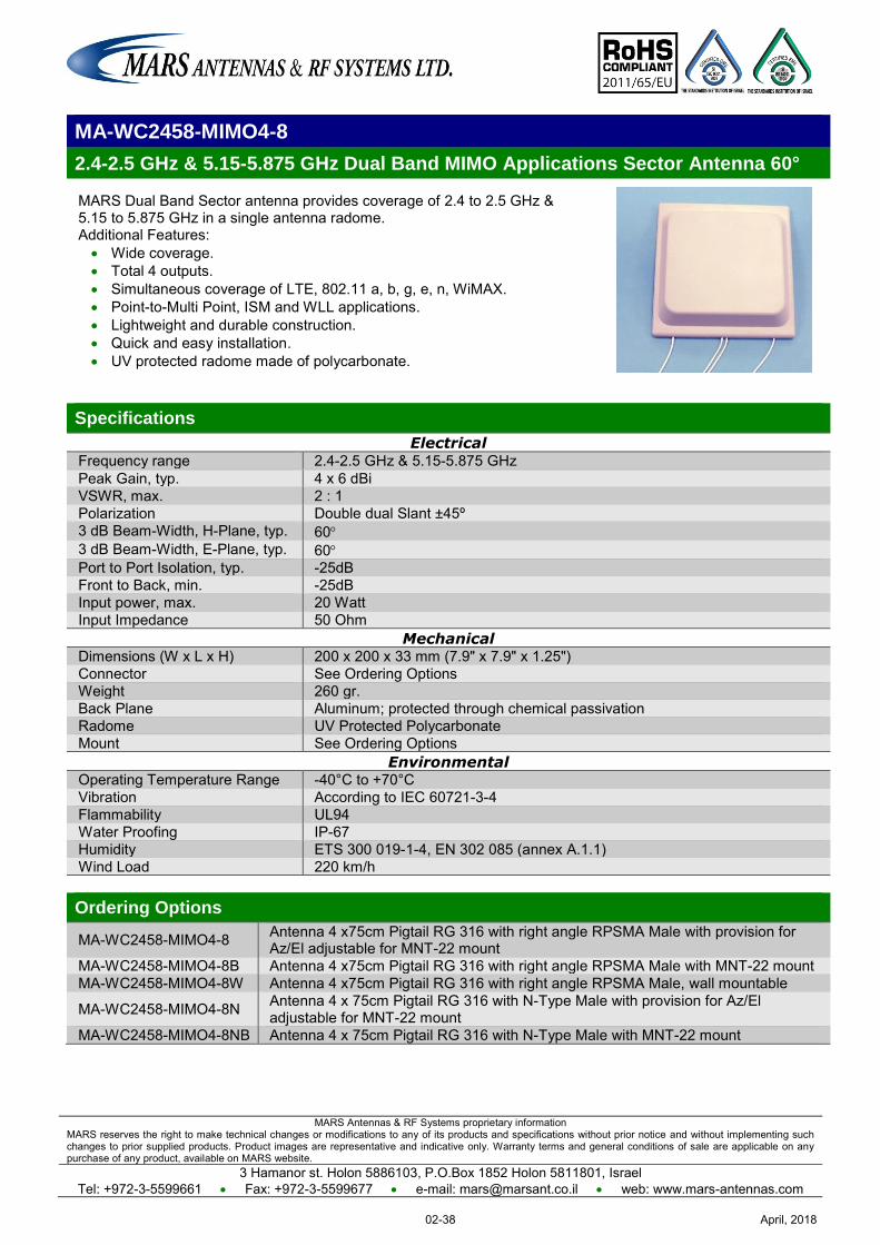
MARS Antennas & RF Systems proprietary information MARS reserves the right to make technical changes or modifications to any of its products and specifications without prior notice and without implementing such changes to prior supplied products. Product images are representative and indicative only. Warranty terms and general conditions of sale are applicable on any purchase of any product, available on MARS website.
3 Hamanor st. Holon 5886103, P.O.Box 1852 Holon 5811801, Israel Tel: +972-3-5599661 Fax: +972-3-5599677 e-mail: [email protected] web: www.mars-antennas.com
MA-WC2458-MIMO4-8
2.4-2.5 GHz & 5.15-5.875 GHz Dual Band MIMO Applications Sector Antenna 60°
MARS Dual Band Sector antenna provides coverage of 2.4 to 2.5 GHz & 5.15 to 5.875 GHz in a single antenna radome. Additional Features: Wide coverage. Total 4 outputs. Simultaneous coverage of LTE, 802.11 a, b, g, e, n, WiMAX. Point-to-Multi Point, ISM and WLL applications. Lightweight and durable construction. Quick and easy installation. UV protected radome made of polycarbonate.
Specifications
Electrical Frequency range 2.4-2.5 GHz & 5.15-5.875 GHz Peak Gain, typ. 4 x 6 dBi VSWR, max. 2 : 1 Polarization Double dual Slant ±45º 3 dB Beam-Width, H-Plane, typ. 60 3 dB Beam-Width, E-Plane, typ. 60 Port to Port Isolation, typ. -25dB Front to Back, min. -25dB Input power, max. 20 Watt Input Impedance 50 Ohm
Mechanical Dimensions (W x L x H) 200 x 200 x 33 mm (7.9" x 7.9" x 1.25") Connector See Ordering Options Weight 260 gr. Back Plane Aluminum; protected through chemical passivation Radome UV Protected Polycarbonate Mount See Ordering Options
Environmental Operating Temperature Range -40°C to +70°C Vibration According to IEC 60721-3-4 Flammability UL94 Water Proofing IP-67 Humidity ETS 300 019-1-4, EN 302 085 (annex A.1.1) Wind Load 220 km/h Ordering Options
MA-WC2458-MIMO4-8 Antenna 4 x75cm Pigtail RG 316 with right angle RPSMA Male with provision for Az/El adjustable for MNT-22 mount
MA-WC2458-MIMO4-8B Antenna 4 x75cm Pigtail RG 316 with right angle RPSMA Male with MNT-22 mount MA-WC2458-MIMO4-8W Antenna 4 x75cm Pigtail RG 316 with right angle RPSMA Male, wall mountable
MA-WC2458-MIMO4-8N Antenna 4 x 75cm Pigtail RG 316 with N-Type Male with provision for Az/El adjustable for MNT-22 mount
MA-WC2458-MIMO4-8NB Antenna 4 x 75cm Pigtail RG 316 with N-Type Male with MNT-22 mount
April, 201802-38
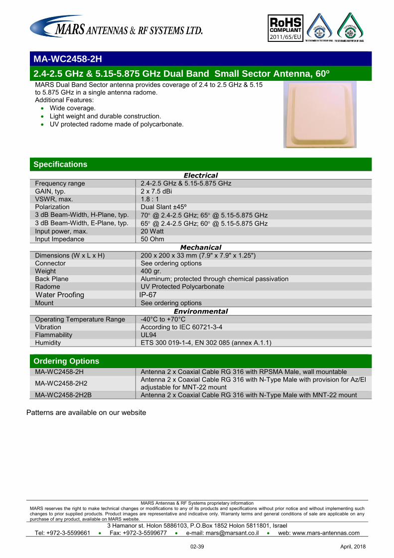
MARS Antennas & RF Systems proprietary information MARS reserves the right to make technical changes or modifications to any of its products and specifications without prior notice and without implementing such changes to prior supplied products. Product images are representative and indicative only. Warranty terms and general conditions of sale are applicable on any purchase of any product, available on MARS website.
3 Hamanor st. Holon 5886103, P.O.Box 1852 Holon 5811801, Israel Tel: +972-3-5599661 Fax: +972-3-5599677 e-mail: [email protected] web: www.mars-antennas.com
MA-WC2458-2H
2.4-2.5 GHz & 5.15-5.875 GHz Dual Band Small Sector Antenna, 60o MARS Dual Band Sector antenna provides coverage of 2.4 to 2.5 GHz & 5.15 to 5.875 GHz in a single antenna radome. Additional Features: Wide coverage. Light weight and durable construction. UV protected radome made of polycarbonate.
Specifications
Electrical Frequency range 2.4-2.5 GHz & 5.15-5.875 GHz GAIN, typ. 2 x 7.5 dBi VSWR, max. 1.8 : 1 Polarization Dual Slant ±45º 3 dB Beam-Width, H-Plane, typ. 70 @ 2.4-2.5 GHz; 65 @ 5.15-5.875 GHz 3 dB Beam-Width, E-Plane, typ. 65 @ 2.4-2.5 GHz; 60 @ 5.15-5.875 GHz Input power, max. 20 Watt Input Impedance 50 Ohm
Mechanical Dimensions (W x L x H) 200 x 200 x 33 mm (7.9" x 7.9" x 1.25") Connector See ordering options Weight 400 gr. Back Plane Aluminum; protected through chemical passivation Radome UV Protected Polycarbonate Water Proofing IP-67 Mount See ordering options
Environmental Operating Temperature Range -40°C to +70°C Vibration According to IEC 60721-3-4 Flammability UL94 Humidity ETS 300 019-1-4, EN 302 085 (annex A.1.1) Ordering Options
MA-WC2458-2H Antenna 2 x Coaxial Cable RG 316 with RPSMA Male, wall mountable
MA-WC2458-2H2 Antenna 2 x Coaxial Cable RG 316 with N-Type Male with provision for Az/El adjustable for MNT-22 mount
MA-WC2458-2H2B Antenna 2 x Coaxial Cable RG 316 with N-Type Male with MNT-22 mount
Patterns are available on our website
April, 201802-39
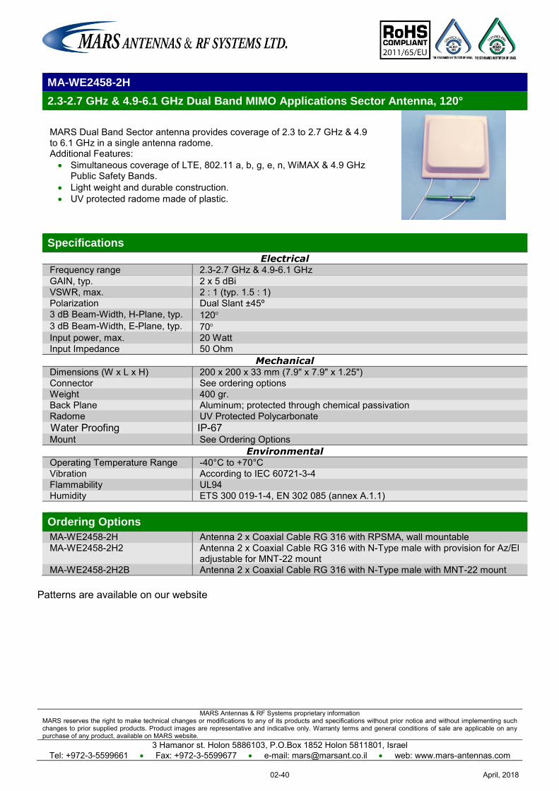
MARS Antennas & RF Systems proprietary information MARS reserves the right to make technical changes or modifications to any of its products and specifications without prior notice and without implementing such changes to prior supplied products. Product images are representative and indicative only. Warranty terms and general conditions of sale are applicable on any purchase of any product, available on MARS website.
3 Hamanor st. Holon 5886103, P.O.Box 1852 Holon 5811801, Israel Tel: +972-3-5599661 Fax: +972-3-5599677 e-mail: [email protected] web: www.mars-antennas.com
MA-WE2458-2H
2.3-2.7 GHz & 4.9-6.1 GHz Dual Band MIMO Applications Sector Antenna, 120°
MARS Dual Band Sector antenna provides coverage of 2.3 to 2.7 GHz & 4.9 to 6.1 GHz in a single antenna radome. Additional Features: Simultaneous coverage of LTE, 802.11 a, b, g, e, n, WiMAX & 4.9 GHz
Public Safety Bands. Light weight and durable construction. UV protected radome made of plastic.
Specifications
Electrical Frequency range 2.3-2.7 GHz & 4.9-6.1 GHz GAIN, typ. 2 x 5 dBi VSWR, max. 2 : 1 (typ. 1.5 : 1) Polarization Dual Slant ±45º 3 dB Beam-Width, H-Plane, typ. 120 3 dB Beam-Width, E-Plane, typ. 70 Input power, max. 20 Watt Input Impedance 50 Ohm
Mechanical Dimensions (W x L x H) 200 x 200 x 33 mm (7.9" x 7.9" x 1.25") Connector See ordering options Weight 400 gr. Back Plane Aluminum; protected through chemical passivation Radome UV Protected Polycarbonate Water Proofing IP-67 Mount See Ordering Options
Environmental Operating Temperature Range -40°C to +70°C Vibration According to IEC 60721-3-4 Flammability UL94 Humidity ETS 300 019-1-4, EN 302 085 (annex A.1.1) Ordering Options
MA-WE2458-2H Antenna 2 x Coaxial Cable RG 316 with RPSMA, wall mountable MA-WE2458-2H2 Antenna 2 x Coaxial Cable RG 316 with N-Type male with provision for Az/El
adjustable for MNT-22 mount MA-WE2458-2H2B Antenna 2 x Coaxial Cable RG 316 with N-Type male with MNT-22 mount
Patterns are available on our website
April, 201802-40
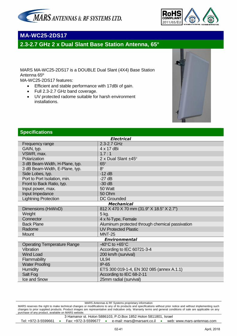
MARS Antennas & RF Systems proprietary information MARS reserves the right to make technical changes or modifications to any of its products and specifications without prior notice and without implementing such changes to prior supplied products. Product images are representative and indicative only. Warranty terms and general conditions of sale are applicable on any purchase of any product, available on MARS website.
3 Hamanor st. Holon 5886103, P.O.Box 1852 Holon 5811801, Israel
Tel: +972-3-5599661 Fax: +972-3-5599677 e-mail: [email protected] web: www.mars-antennas.com
MA-WC25-2DS17
2.3-2.7 GHz 2 x Dual Slant Base Station Antenna, 65°
MARS MA-WC25-2DS17 is a DOUBLE Dual Slant (4X4) Base Station Antenna 65º
MA-WC25-2DS17 features:
Efficient and stable performance with 17dBi of gain.
Full 2.3-2.7 GHz band coverage.
UV protected radome suitable for harsh environment installations.
Specifications
Electrical
Frequency range 2.3-2.7 GHz GAIN, typ. 4 x 17 dBi VSWR, max. 1.7 : 1 Polarization 2 x Dual Slant ±45 3 dB Beam-Width, H-Plane, typ. 65 3 dB Beam-Width, E-Plane, typ. 8 Side Lobes, typ. -12 dB Port to Port Isolation, min. -27 dB Front to Back Ratio, typ. -30 dB Input power, max. 50 Watt Input Impedance 50 Ohm Lightning Protection DC Grounded
Mechanical
Dimensions (HxWxD) 812 X 470 X 70 mm (31.9" X 18.5" X 2.7") Weight 5 kg. Connector 4 x N-Type, Female Back Plane Aluminum protected through chemical passivation Radome UV Protected Plastic Mount MNT-25
Environmental
Operating Temperature Range -40C to +65C Vibration According to IEC 60721-3-4 Wind Load 200 km/h (survival) Flammability UL94 Water Proofing IP-65 Humidity ETS 300 019-1-4, EN 302 085 (annex A.1.1) Salt Fog According to IEC 68-2-11 Ice and Snow 25mm radial (survival)
April, 201802-41
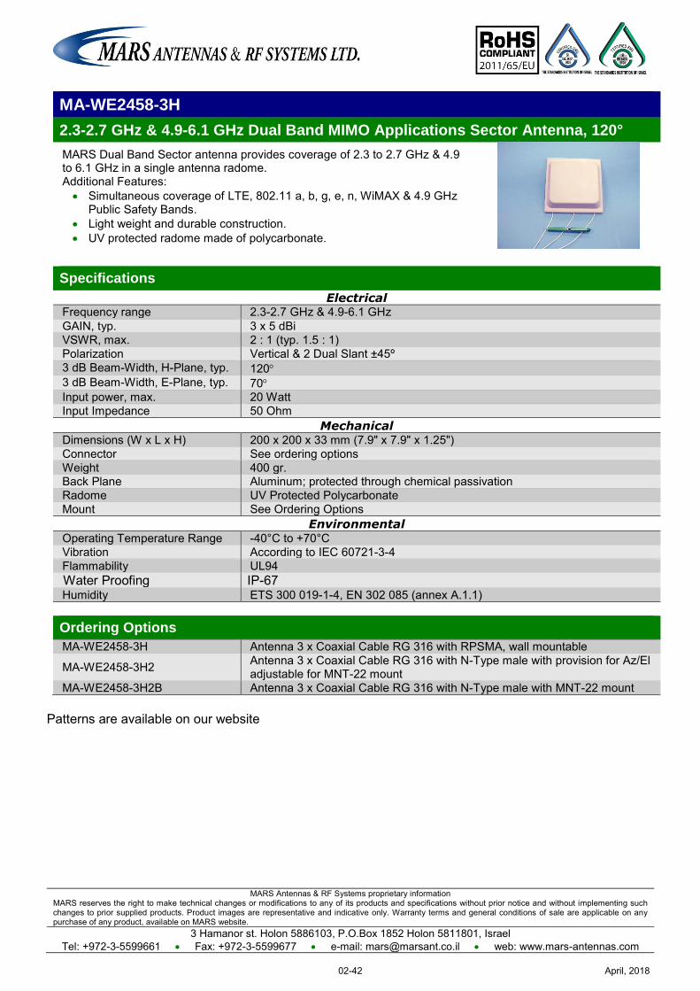
MARS Antennas & RF Systems proprietary information MARS reserves the right to make technical changes or modifications to any of its products and specifications without prior notice and without implementing such changes to prior supplied products. Product images are representative and indicative only. Warranty terms and general conditions of sale are applicable on any purchase of any product, available on MARS website.
3 Hamanor st. Holon 5886103, P.O.Box 1852 Holon 5811801, Israel Tel: +972-3-5599661 Fax: +972-3-5599677 e-mail: [email protected] web: www.mars-antennas.com
MA-WE2458-3H
2.3-2.7 GHz & 4.9-6.1 GHz Dual Band MIMO Applications Sector Antenna, 120°
MARS Dual Band Sector antenna provides coverage of 2.3 to 2.7 GHz & 4.9 to 6.1 GHz in a single antenna radome. Additional Features: Simultaneous coverage of LTE, 802.11 a, b, g, e, n, WiMAX & 4.9 GHz
Public Safety Bands. Light weight and durable construction. UV protected radome made of polycarbonate.
Specifications
Electrical Frequency range 2.3-2.7 GHz & 4.9-6.1 GHz GAIN, typ. 3 x 5 dBi VSWR, max. 2 : 1 (typ. 1.5 : 1) Polarization Vertical & 2 Dual Slant ±45º 3 dB Beam-Width, H-Plane, typ. 120 3 dB Beam-Width, E-Plane, typ. 70 Input power, max. 20 Watt Input Impedance 50 Ohm
Mechanical Dimensions (W x L x H) 200 x 200 x 33 mm (7.9" x 7.9" x 1.25") Connector See ordering options Weight 400 gr. Back Plane Aluminum; protected through chemical passivation Radome UV Protected Polycarbonate Mount See Ordering Options
Environmental Operating Temperature Range -40°C to +70°C Vibration According to IEC 60721-3-4 Flammability UL94 Water Proofing IP-67 Humidity ETS 300 019-1-4, EN 302 085 (annex A.1.1) Ordering Options
MA-WE2458-3H Antenna 3 x Coaxial Cable RG 316 with RPSMA, wall mountable
MA-WE2458-3H2 Antenna 3 x Coaxial Cable RG 316 with N-Type male with provision for Az/El adjustable for MNT-22 mount
MA-WE2458-3H2B Antenna 3 x Coaxial Cable RG 316 with N-Type male with MNT-22 mount
Patterns are available on our website
April, 201802-42
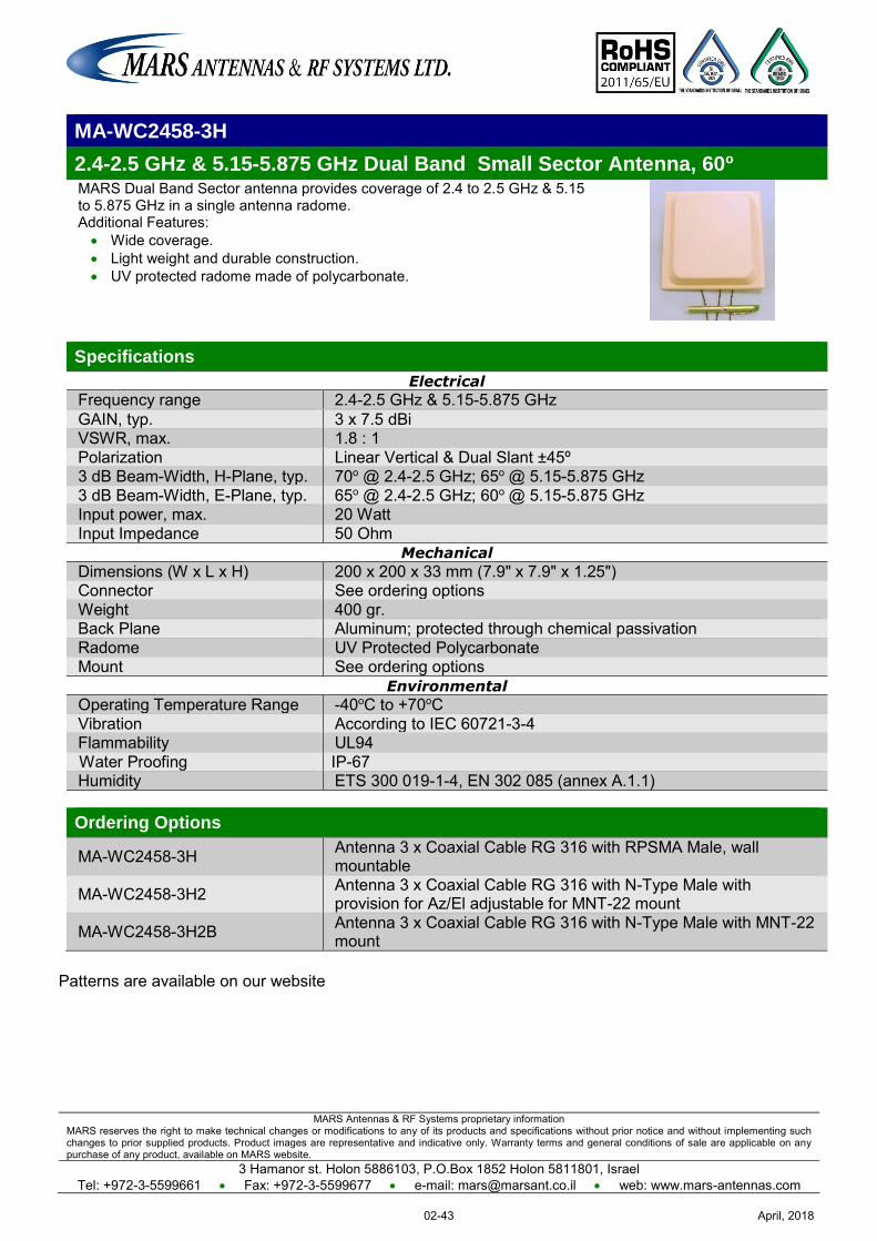
MARS Antennas & RF Systems proprietary information MARS reserves the right to make technical changes or modifications to any of its products and specifications without prior notice and without implementing such changes to prior supplied products. Product images are representative and indicative only. Warranty terms and general conditions of sale are applicable on any purchase of any product, available on MARS website.
3 Hamanor st. Holon 5886103, P.O.Box 1852 Holon 5811801, Israel Tel: +972-3-5599661 Fax: +972-3-5599677 e-mail: [email protected] web: www.mars-antennas.com
MA-WC2458-3H
2.4-2.5 GHz & 5.15-5.875 GHz Dual Band Small Sector Antenna, 60o MARS Dual Band Sector antenna provides coverage of 2.4 to 2.5 GHz & 5.15 to 5.875 GHz in a single antenna radome. Additional Features: Wide coverage. Light weight and durable construction. UV protected radome made of polycarbonate.
Specifications
Electrical
Frequency range 2.4-2.5 GHz & 5.15-5.875 GHz GAIN, typ. 3 x 7.5 dBi VSWR, max. 1.8 : 1 Polarization Linear Vertical & Dual Slant ±45º 3 dB Beam-Width, H-Plane, typ. 70o @ 2.4-2.5 GHz; 65o @ 5.15-5.875 GHz 3 dB Beam-Width, E-Plane, typ. 65o @ 2.4-2.5 GHz; 60o @ 5.15-5.875 GHz Input power, max. 20 Watt Input Impedance 50 Ohm
Mechanical
Dimensions (W x L x H) 200 x 200 x 33 mm (7.9" x 7.9" x 1.25") Connector See ordering options Weight 400 gr. Back Plane Aluminum; protected through chemical passivation Radome UV Protected Polycarbonate Mount See ordering options
Environmental
Operating Temperature Range -40oC to +70oC Vibration According to IEC 60721-3-4 Flammability UL94 Water Proofing IP-67 Humidity ETS 300 019-1-4, EN 302 085 (annex A.1.1) Ordering Options
MA-WC2458-3H Antenna 3 x Coaxial Cable RG 316 with RPSMA Male, wall mountable
MA-WC2458-3H2 Antenna 3 x Coaxial Cable RG 316 with N-Type Male with provision for Az/El adjustable for MNT-22 mount
MA-WC2458-3H2B Antenna 3 x Coaxial Cable RG 316 with N-Type Male with MNT-22 mount
Patterns are available on our website
April, 201802-43
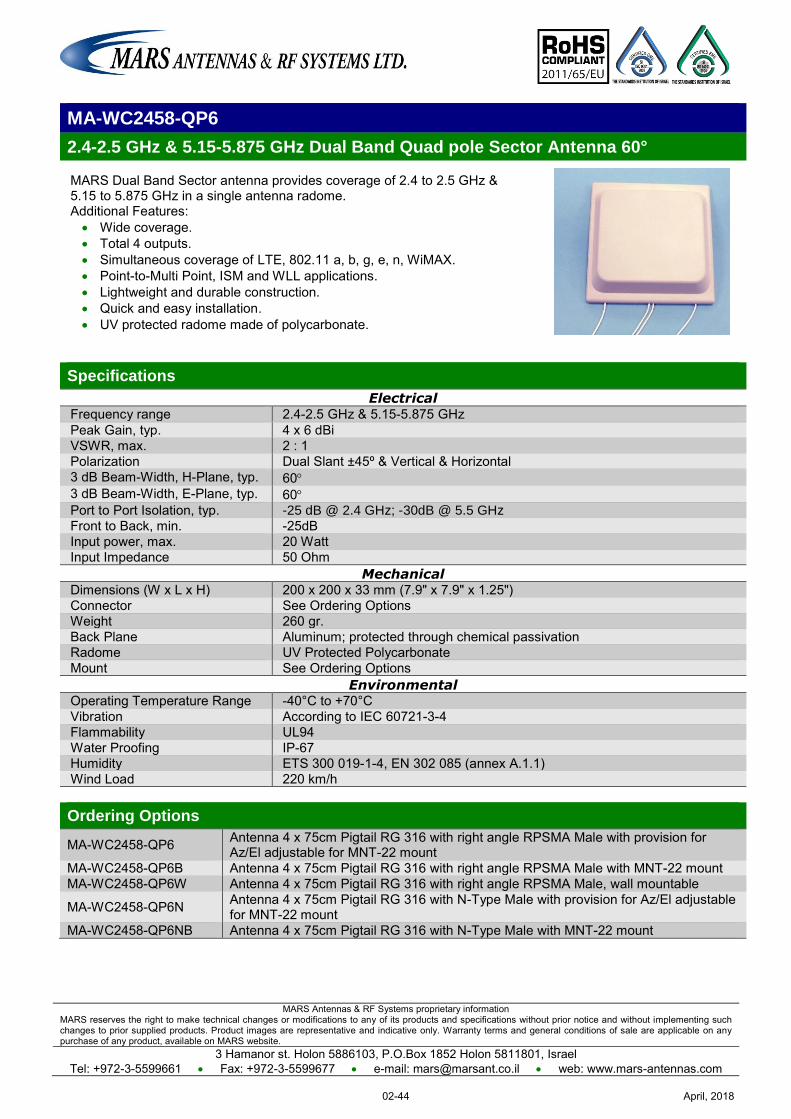
MARS Antennas & RF Systems proprietary information MARS reserves the right to make technical changes or modifications to any of its products and specifications without prior notice and without implementing such changes to prior supplied products. Product images are representative and indicative only. Warranty terms and general conditions of sale are applicable on any purchase of any product, available on MARS website.
3 Hamanor st. Holon 5886103, P.O.Box 1852 Holon 5811801, Israel Tel: +972-3-5599661 Fax: +972-3-5599677 e-mail: [email protected] web: www.mars-antennas.com
MA-WC2458-QP6
2.4-2.5 GHz & 5.15-5.875 GHz Dual Band Quad pole Sector Antenna 60°
MARS Dual Band Sector antenna provides coverage of 2.4 to 2.5 GHz & 5.15 to 5.875 GHz in a single antenna radome. Additional Features: Wide coverage. Total 4 outputs. Simultaneous coverage of LTE, 802.11 a, b, g, e, n, WiMAX. Point-to-Multi Point, ISM and WLL applications. Lightweight and durable construction. Quick and easy installation. UV protected radome made of polycarbonate.
Specifications
Electrical Frequency range 2.4-2.5 GHz & 5.15-5.875 GHz Peak Gain, typ. 4 x 6 dBi VSWR, max. 2 : 1 Polarization Dual Slant ±45º & Vertical & Horizontal 3 dB Beam-Width, H-Plane, typ. 60 3 dB Beam-Width, E-Plane, typ. 60 Port to Port Isolation, typ. -25 dB @ 2.4 GHz; -30dB @ 5.5 GHz Front to Back, min. -25dB Input power, max. 20 Watt Input Impedance 50 Ohm
Mechanical Dimensions (W x L x H) 200 x 200 x 33 mm (7.9" x 7.9" x 1.25") Connector See Ordering Options Weight 260 gr. Back Plane Aluminum; protected through chemical passivation Radome UV Protected Polycarbonate Mount See Ordering Options
Environmental Operating Temperature Range -40°C to +70°C Vibration According to IEC 60721-3-4 Flammability UL94 Water Proofing IP-67 Humidity ETS 300 019-1-4, EN 302 085 (annex A.1.1) Wind Load 220 km/h Ordering Options
MA-WC2458-QP6 Antenna 4 x 75cm Pigtail RG 316 with right angle RPSMA Male with provision for Az/El adjustable for MNT-22 mount
MA-WC2458-QP6B Antenna 4 x 75cm Pigtail RG 316 with right angle RPSMA Male with MNT-22 mount MA-WC2458-QP6W Antenna 4 x 75cm Pigtail RG 316 with right angle RPSMA Male, wall mountable
MA-WC2458-QP6N Antenna 4 x 75cm Pigtail RG 316 with N-Type Male with provision for Az/El adjustable for MNT-22 mount
MA-WC2458-QP6NB Antenna 4 x 75cm Pigtail RG 316 with N-Type Male with MNT-22 mount
April, 201802-44
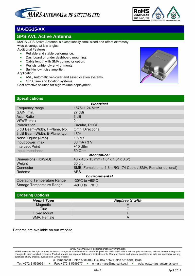
MARS Antennas & RF Systems proprietary information MARS reserves the right to make technical changes or modifications to any of its products and specifications without prior notice and without implementing such changes to prior supplied products. Product images are representative and indicative only. Warranty terms and general conditions of sale are applicable on any purchase of any product, available on MARS website.
3 Hamanor st. Holon 5886103, P.O.Box 1852 Holon 5811801, Israel Tel: +972-3-5599661 Fax: +972-3-5599677 e-mail: [email protected] web: www.mars-antennas.com
MA-EG15-XX
GPS AVL Active Antenna MARS GPS Active Antenna is exceptionally small sized and offers extremely wide coverage at low angles. Additional Features: Reliable and stable performance. Dashboard or under dashboard mounting. Cable length with SMA connector option. Resists unfriendly environments. Built-in low noise amplifier.
Application: AVL, Automatic vehicular and asset location systems. GPS, time and location systems.
Cost effective solution for high volume deployment.
Specifications
Electrical
Frequency range 1575±1.24 MHz GAIN, min. 27 dBi Axial Ratio 3 dB VSWR, max. 2 : 1 Polarization Circular, RHCP 3 dB Beam-Width, H-Plane, typ. Omni Directional 3 dB Beam-Width, E-Plane, typ. 150 Noise Figure (Amp) 1.6 dB Input power, max 30 mA / 3 V Intercept Point +10 dBm Input Impedance 50 Ohm
Mechanical
Dimensions (HxWxD) 40 x 45 x 15 mm (1.6" x 1.8" x 0.6") Weight 60 gr. Connector SMB, Female on a 1.8m RG 174 Cable / SMA, Female( optional) Radome ABS
Environmental
Operating Temperature Range -30C to +60C Storage Temperature Range -40C to +70C
Ordering Options
Mount Type Replace X with
Magnetic M Glue G
Fixed Mount F SMA, Female A
Patterns are available on our website
April, 201802-45
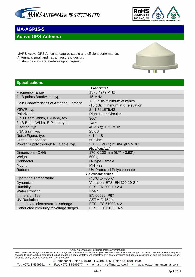
MARS Antennas & RF Systems proprietary information MARS reserves the right to make technical changes or modifications to any of its products and specifications without prior notice and without implementing such changes to prior supplied products. Product images are representative and indicative only. Warranty terms and general conditions of sale are applicable on any purchase of any product, available on MARS website.
3 Hamanor st. Holon 5886103, P.O.Box 1852 Holon 5811801, Israel
Tel: +972-3-5599661 Fax: +972-3-5599677 e-mail: [email protected] web: www.mars-antennas.com
MA-AGP15-5
Active GPS Antenna
MARS Active GPS Antenna features stable and efficient performance. Antenna is small and has an aesthetic design. Custom designs are available upon request.
Specifications
Electrical
Frequency range 1575.42±2 MHz
1 dB points Bandwidth, typ. 15 MHz
Gain Characteristics of Antenna Element +5.0 dBic minimum at zenith
-10 dBic minimum at 0 elevation VSWR, typ. 2 : 1 @ 1575.42
Polarization Right Hand Circular 3 dB Beam-Width, H-Plane, typ. 360
3 dB Beam-Width, E-Plane, typ. ±40 Filtering, typ. 40 dB @ ± 50 MHz
LNA Gain, typ. 25 dB Noise Figure, typ. < 1.4 dB
Output Impedance 50 Ohm Power Supply through RF Cable, typ. 5±0.25 VDC ; 21 mA @ 5 VDC
Mechanical
Dimensions (ØxH) 170 X 100 mm (6.7" x 3.93") Weight 500 gr.
Connector N-Type Female Mount MNT-22
Radome UV Protected Polycarbonate
Environmental
Operating Temperature -40C to +85C Dynamics Vibration: ETSI EN 300-19-2-4
Humidity ETSI EN 300-19-2-4 Water Proofing IP-67
Immersion Test EN 60529-IP67 UV Radiation ASTM G-154-4
Immunity to electrostatic discharge ETSI IEC 61000-4-2 Conducted immunity to voltage surges ETSI IEC 61000-4-5
April, 201802-46
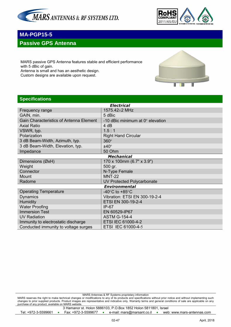
MARS Antennas & RF Systems proprietary information MARS reserves the right to make technical changes or modifications to any of its products and specifications without prior notice and without implementing such changes to prior supplied products. Product images are representative and indicative only. Warranty terms and general conditions of sale are applicable on any purchase of any product, available on MARS website.
3 Hamanor st. Holon 5886103, P.O.Box 1852 Holon 5811801, Israel Tel: +972-3-5599661 Fax: +972-3-5599677 e-mail: [email protected] web: www.mars-antennas.com
MA-PGP15-5
Passive GPS Antenna
MARS passive GPS Antenna features stable and efficient performance with 5 dBic of gain. Antenna is small and has an aesthetic design. Custom designs are available upon request.
Specifications
Electrical
Frequency range 1575.42±2 MHz GAIN, min. 5 dBic Gain Characteristics of Antenna Element -10 dBic minimum at 0 elevation Axial Ratio 4 dB VSWR, typ. 1.5 : 1 Polarization Right Hand Circular 3 dB Beam-Width, Azimuth, typ. 360 3 dB Beam-Width, Elevation, typ. ±40 Impedance 50 Ohm
Mechanical
Dimensions (ØxH) 170 x 100mm (6.7" x 3.9") Weight 500 gr. Connector N-Type Female Mount MNT-22 Radome UV Protected Polycarbonate
Environmental
Operating Temperature -40C to +85C Dynamics Vibration: ETSI EN 300-19-2-4 Humidity ETSI EN 300-19-2-4 Water Proofing IP-67 Immersion Test EN 60529-IP67 UV Radiation ASTM G-154-4 Immunity to electrostatic discharge ETSI IEC 61000-4-2 Conducted immunity to voltage surges ETSI IEC 61000-4-5
April, 201802-47
MARS Antennas & RF Systems proprietary information MARS reserves the right to make technical changes or modifications to any of its products and specifications without prior notice and without implementing such changes to prior supplied products. Product images are representative and indicative only. Warranty terms and general conditions of sale are applicable on any purchase of any product, available on MARS website.
3 Hamanor st. Holon 5886103, P.O.Box 1852 Holon 5811801, Israel
Tel: +972-3-5599661 Fax: +972-3-5599677 e-mail: [email protected] web: www.mars-antennas.com
3.2 GHz – 4.1 GHz Subscriber - Single Pol Subscriber - Dual Pol
Sector- Single Pol Sector – Dual Pol
Sector - Double Dual Slant DAS - Single Pol DAS - Dual Pol
Part Number Description Frequency
band Gain Polarization Dimension
Antenna type
Page
MA-WA35-12 3.5GHz Small Size Subscriber 3.3-3.8 GHz 12 dBi
Linear, Vertical or Horizontal
155 x 155 x 28 mm
Subscriber Single Pol
03-1
MA-WA35-2X-D
Subscriber for WiMAX Applications
3.3-3.8 GHz 18 dBi (min.)
Linear, Vertical
305 x 305 x 15 mm
(Diamond shape)
Subscriber Single Pol
03-2
MA-WA36-26 3.5 GHz Subscriber 3.3-3.8 GHz 26 dBi Linear, Vertical
600 x 600 x 30 mm
Subscriber Single Pol
03-3
MA-WA36-DP11
Dual Pol / Dual Slant Subscriber
3.3-4.01 GHz 11 dBi Dual Pole V & H Dual Slant
±45°
112 x 112 x 33.5 mm
Subscriber Dual Pol
03-4
MA-WA36-DP14
Dual Pol / Dual Slant Subscriber
3.3-3.8 GHz 14 dBi Dual Pole V & H Dual Slant
±45°
200 x 200 x 33 mm
Subscriber Dual Pol
03-5
MA-WA36-DP19
Dual Pol / Dual Slant Subscriber
3.3-4.1 GHz 19.5 dBi Dual Pole V & H Dual Slant
±45°
305 x 305 x 25 mm
Subscriber Dual Pol
03-6
MA-WA36-DP21
Dual Pol / Dual Slant Subscriber
3.3-3.8 GHz 22 dBi Dual Pole V & H Dual Slant
±45°
370 x 370 x 40 mm
Subscriber Dual Pol
03-7
MA-WA36-DP25
Dual Pol / Dual Slant Subscriber
3.3-3.8 GHz 25 dBi Dual Pole V & H Dual Slant
±45°
600 x 600 x 22 mm
Subscriber Dual Pol
03-8
MA-WC36-17 Base Station, 70° 3.3-3.8 GHz 16.5 dBi Linear, Vertical
573 x 95 x 53 mm Sector
Single Pol 03-9
MA-WD36-16 Base Station,90° 3.3-3.8 GHz 15.5 dBi Linear, Vertical
573 x 95 x 53 mm Sector
Single Pol 03-10
MA-WE36-15 Base Station,120° 3.3-3.8 GHz 14.5 dBi Linear, Vertical
573 x 95 x 53 mm Sector
Single Pol 03-11
MA-WC35-DS17
Dual Slant WiMAX Base Station, 65°
3.3-3.8 GHz 16.5 dBi
(typ.) Dual Slant
±45° 600 x 225 x 40
mm Sector
Dual Slant 03-12
MA-WD35-DS15
Dual Slant WiMAX Base Station, 90°
3.3-3.8 GHz 15 dBi (typ.)
Dual Slant ±45°
600 x 225 x 40 mm
Sector Dual Slant
03-13
MA-WC36-DP15
Dual Polarization Base Station, 60º
3.3-4.01 GHz 15 dBi Linear,
Vertical & Horizontal
370 x 370 x 40 mm
Sector Dual Pol
03-14
MA-WC36-2H15
2 x Horizontal Polarization Base Station, 60º
3.3-4.01 GHz 15 dBi 2 x Horizontal 370 x 370 x 40
mm Sector
Dual Pol 03-15
MA-WC36-2V15
2 x Vertical Polarization Base Station, 60º
3.3-4.01 GHz 15 dBi 2 x Vertical 370 x 370 x 40
mm Sector
Dual Pol 03-16
MA-WD36-DP14N
Dual Polarization Base Station, 90°
3.3-4.01 GHz 14 dBi (typ.)
Dual, Vertical & Horizontal
370 x 370 x 40 mm
Sector Dual Pol
03-17
MA-WC35-2DS17
2 x Dual Slant Base Station Antenna, 65°
3.2-4.1 GHz 4 x 17 dBi
2 x Dual Polarized
±45
573 X 360 X 60 mm
Sector Dual Slant
03-18
MA-WD36-MIMO3
Dual Polarization Array 90°
3.3-3.8 GHz 6 x 15 dBi Dual Slant ±
45º 800 x 600 x 40
mm
Sector Double
Dual Slant 03-19
April, 201803-I
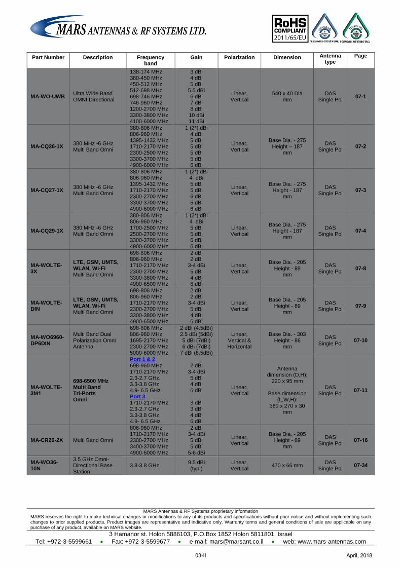
MARS Antennas & RF Systems proprietary information MARS reserves the right to make technical changes or modifications to any of its products and specifications without prior notice and without implementing such changes to prior supplied products. Product images are representative and indicative only. Warranty terms and general conditions of sale are applicable on any purchase of any product, available on MARS website.
3 Hamanor st. Holon 5886103, P.O.Box 1852 Holon 5811801, Israel
Tel: +972-3-5599661 Fax: +972-3-5599677 e-mail: [email protected] web: www.mars-antennas.com
Part Number Description Frequency band
Gain Polarization Dimension Antenna type
Page
MA-WO-UWB Ultra Wide Band OMNI Directional
138-174 MHz 380-450 MHz 450-512 MHz 512-698 MHz 698-746 MHz 746-960 MHz 1200-2700 MHz 3300-3800 MHz 4100-6000 MHz
3 dBi 4 dBi 5 dBi
5.5 dBi 6 dBi 7 dBi 8 dBi 10 dBi 11 dBi
Linear, Vertical
540 x 40 Dia mm
DAS Single Pol
07-1
MA-CQ26-1X 380 MHz -6 GHz Multi Band Omni
380-806 MHz 806-960 MHz 1395-1432 MHz 1710-2170 MHz 2300-2500 MHz 3300-3700 MHz 4900-6000 MHz
1 (2*) dBi 4 dBi 5 dBi 5 dBi 5 dBi 5 dBi 6 dBi
Linear, Vertical
Base Dia. - 275 Height – 187
mm
DAS Single Pol
07-2
MA-CQ27-1X 380 MHz -6 GHz Multi Band Omni
380-806 MHz 806-960 MHz 1395-1432 MHz 1710-2170 MHz 2300-2700 MHz 3300-3700 MHz 4900-6000 MHz
1 (2*) dBi 4 dBi 5 dBi 5 dBi 6 dBi 6 dBi 6 dBi
Linear, Vertical
Base Dia. - 275 Height - 187
mm
DAS Single Pol
07-3
MA-CQ29-1X 380 MHz -6 GHz Multi Band Omni
380-806 MHz 806-960 MHz 1700-2500 MHz 2500-2700 MHz 3300-3700 MHz 4900-6000 MHz
1 (2*) dBi 4 dBi 5 dBi 5 dBi 6 dBi 6 dBi
Linear, Vertical
Base Dia. - 275 Height - 187
mm
DAS Single Pol
07-4
MA-WOLTE-3X
LTE, GSM, UMTS, WLAN, Wi-Fi Multi Band Omni
698-806 MHz 806-960 MHz 1710-2170 MHz 2300-2700 MHz 3300-3800 MHz 4900-6500 MHz
2 dBi 2 dBi
3-4 dBi 5 dBi 4 dBi 6 dBi
Linear, Vertical
Base Dia. - 205 Height - 89
mm
DAS Single Pol
07-8
MA-WOLTE-DIN
LTE, GSM, UMTS, WLAN, Wi-Fi Multi Band Omni
698-806 MHz 806-960 MHz 1710-2170 MHz 2300-2700 MHz 3300-3800 MHz 4900-6500 MHz
2 dBi 2 dBi
3-4 dBi 5 dBi 4 dBi 6 dBi
Linear, Vertical
Base Dia. - 205 Height - 89
mm
DAS Single Pol
07-9
MA-WO6960-DP6DIN
Multi Band Dual Polarization Omni Antenna
698-806 MHz 806-960 MHz 1695-2170 MHz 2300-2700 MHz 5000-6000 MHz
2 dBi (4.5dBi) 2.5 dBi (5dBi) 5 dBi (7dBi) 6 dBi (7dBi)
7 dBi (8.5dBi)
Linear, Vertical & Horizontal
Base Dia. - 303 Height - 86
mm
DAS Single Pol
07-10
MA-WOLTE-3M1
698-6500 MHz Multi Band Tri-Ports Omni
Port 1 & 2 698-960 MHz 1710-2170 MHz 2.3-2.7 GHz. 3.3-3.8 GHz 4.9- 6.5 GHz Port 3 1710-2170 MHz 2.3-2.7 GHz 3.3-3.8 GHz 4.9- 6.5 GHz
2 dBi
3-4 dBi 5 dBi 4 dBi 6 dBi
3 dBi 3 dBi 4 dBi 6 dBi
Linear, Vertical
Antenna dimension (D,H):
220 x 95 mm
Base dimension (L,W,H):
369 x 270 x 30 mm
DAS Single Pol
07-11
MA-CR26-2X Multi Band Omni
806-960 MHz 1710-2170 MHz 2300-2700 MHz 3400-3700 MHz 4900-6000 MHz
2 dBi 3-4 dBi 5 dBi 5 dBi
5-6 dBi
Linear, Vertical
Base Dia. - 205 Height - 89
mm
DAS Single Pol
07-16
MA-WO36-10N
3.5 GHz Omni-Directional Base Station
3.3-3.8 GHz 9.5 dBi (typ.)
Linear, Vertical
470 x 66 mm DAS
Single Pol 07-34
April, 201803-II
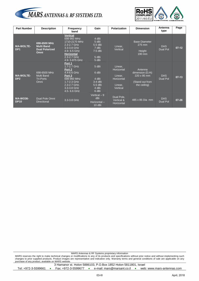
MARS Antennas & RF Systems proprietary information MARS reserves the right to make technical changes or modifications to any of its products and specifications without prior notice and without implementing such changes to prior supplied products. Product images are representative and indicative only. Warranty terms and general conditions of sale are applicable on any purchase of any product, available on MARS website.
3 Hamanor st. Holon 5886103, P.O.Box 1852 Holon 5811801, Israel
Tel: +972-3-5599661 Fax: +972-3-5599677 e-mail: [email protected] web: www.mars-antennas.com
Part Number Description Frequency band
Gain Polarization Dimension Antenna type
Page
MA-WOLTE-DP1
698-6500 MHz Multi Band Dual Polarized Omni
Vertical 698-960 MHz 1710-2170 MHz 2.3-2.7 GHz 3.3-3.8 GHz 4.9- 6.5 GHz Horizontal 2.3-2.7 GHz 4.9- 5.875 GHz
4 dBi 5 dBi
5.5 dBi 7 dBi
7.5 dBi
5 dBi 5 dBi
Linear, Vertical
Base Diameter 275 mm
Height
190 mm
DAS Dual Pol
07-12
MA-WOLTE-DP2
698-6500 MHz Multi Band Tri-Ports Omni
Port 1 1.7-2.7 GHz Port 2 4.4-6.6 GHz Port 3 698-960 MHz 1.7-2.3 GHz 2.3-2.7 GHz. 3.3-3.8 GHz 4.5- 6.6 GHz
5 dBi
6 dBi
4 dBi
3-4 dBi 5.5 dBi 4 dBi 6 dBi
Linear, Horizontal
Linear,
Horizontal
Linear, Vertical
Antenna dimension (D,H):
220 x 95 mm
(Stand out from the ceiling)
DAS Dual Pol
07-13
MA-WO36-DP10
Dual Pole Omni Directional 3.3-3.8 GHz
Vertical – 9 dBi
Horizontal – 10 dBi
Dual Pole, Vertical & Horizontal
485 x 85 Dia mm DAS
Dual Pol 07-26
April, 201803-III
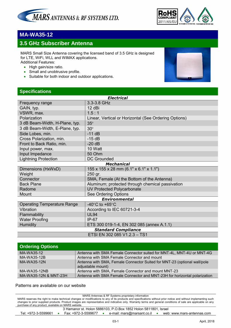
MARS Antennas & RF Systems proprietary information MARS reserves the right to make technical changes or modifications to any of its products and specifications without prior notice and without implementing such changes to prior supplied products. Product images are representative and indicative only. Warranty terms and general conditions of sale are applicable on any purchase of any product, available on MARS website.
3 Hamanor st. Holon 5886103, P.O.Box 1852 Holon 5811801, Israel Tel: +972-3-5599661 Fax: +972-3-5599677 e-mail: [email protected] web: www.mars-antennas.com
MA-WA35-12
3.5 GHz Subscriber Antenna
MARS Small Size Antenna covering the licensed band of 3.5 GHz is designed for LTE, WiFi, WLL and WiMAX applications. Additional Features: High gain/size ratio. Small and unobtrusive profile. Suitable for both indoor and outdoor applications.
Specifications
Electrical
Frequency range 3.3-3.8 GHz GAIN, typ. 12 dBi VSWR, max. 1.5 : 1 Polarization Linear, Vertical or Horizontal (See Ordering Options) 3 dB Beam-Width, H-Plane, typ. 35 3 dB Beam-Width, E-Plane, typ. 30 Side Lobes, min. -11 dB
Cross Polarization, min. -15 dB Front to Back Ratio, min. -20 dB
Input power, max. 10 Watt Input Impedance 50 Ohm Lightning Protection DC Grounded
Mechanical
Dimensions (HxWxD) 155 x 155 x 28 mm (6.1" x 6.1" x 1.1") Weight 250 gr. Connector SMA, Female (At the Bottom of the Antenna) Back Plane Aluminum; protected through chemical passivation Radome UV Protected Polycarbonate Mount See Ordering Options
Environmental
Operating Temperature Range -40C to +65C Vibration According to IEC 60721-3-4 Flammability UL94 Water Proofing IP-67 Humidity ETS 300 019-1-4, EN 302 085 (annex A.1.1)
Standard Compliance
ETSI EN 302 085 V1.2.3 – TS1
Ordering Options
MA-WA35-12 Antenna with SMA Female Connector suited for MNT-4L, MNT-4U or MNT-4G MA-WA35-12B Antenna with SMA Female Connector and mount MA-WA35-12N Antenna with SMA, Female Connector Suited for MNT-23 (optional wall/pole
adjustable mount) MA-WA35-12NB Antenna with SMA, Female Connector and mount MNT-23 MA-WA35-12N & MNT-23H Antenna with SMA Female Connector and MNT-23H for horizontal polarization
Patterns are available on our website
April, 201803-1
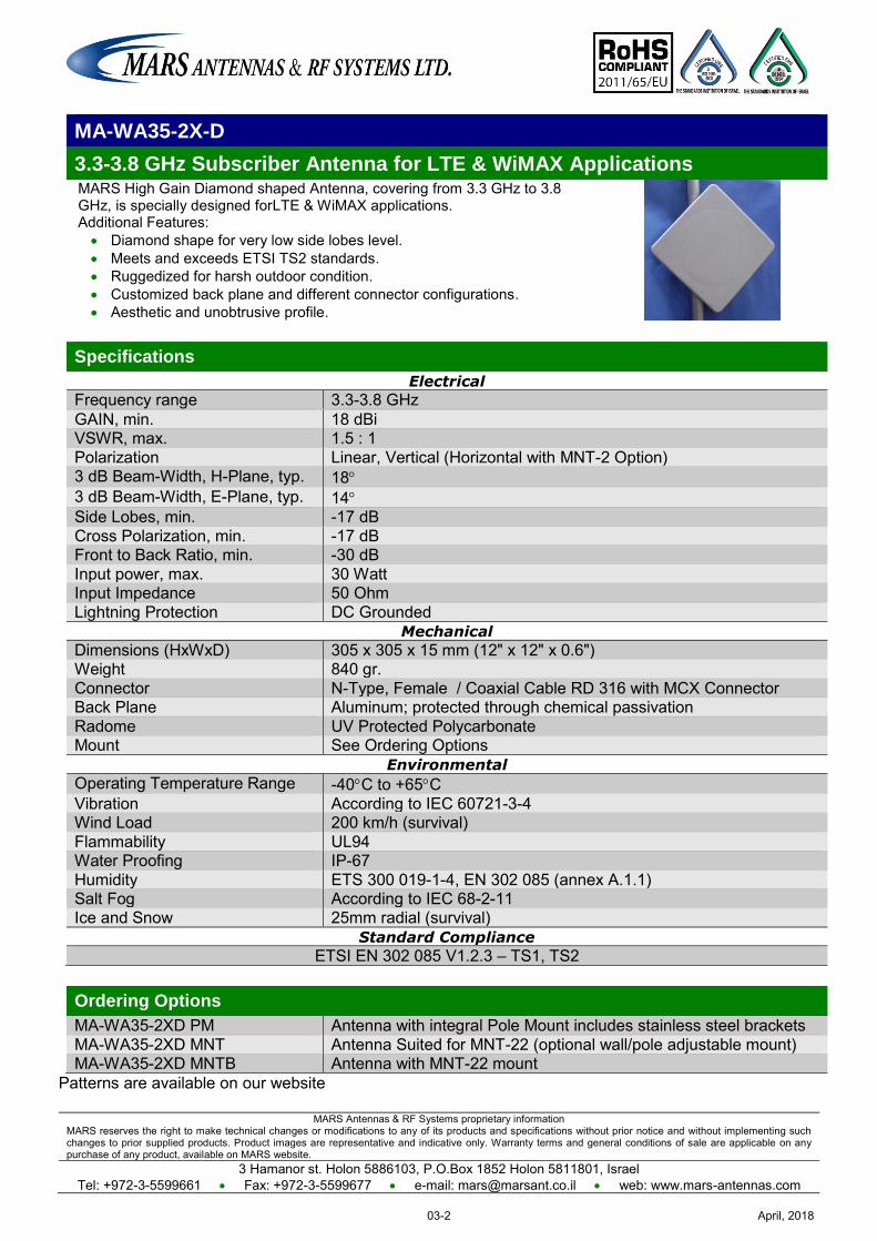
MARS Antennas & RF Systems proprietary information MARS reserves the right to make technical changes or modifications to any of its products and specifications without prior notice and without implementing such changes to prior supplied products. Product images are representative and indicative only. Warranty terms and general conditions of sale are applicable on any purchase of any product, available on MARS website.
3 Hamanor st. Holon 5886103, P.O.Box 1852 Holon 5811801, Israel Tel: +972-3-5599661 Fax: +972-3-5599677 e-mail: [email protected] web: www.mars-antennas.com
MA-WA35-2X-D
3.3-3.8 GHz Subscriber Antenna for LTE & WiMAX Applications MARS High Gain Diamond shaped Antenna, covering from 3.3 GHz to 3.8 GHz, is specially designed forLTE & WiMAX applications. Additional Features: Diamond shape for very low side lobes level. Meets and exceeds ETSI TS2 standards. Ruggedized for harsh outdoor condition. Customized back plane and different connector configurations. Aesthetic and unobtrusive profile.
Specifications
Electrical
Frequency range 3.3-3.8 GHz GAIN, min. 18 dBi VSWR, max. 1.5 : 1 Polarization Linear, Vertical (Horizontal with MNT-2 Option) 3 dB Beam-Width, H-Plane, typ. 18 3 dB Beam-Width, E-Plane, typ. 14 Side Lobes, min. -17 dB
Cross Polarization, min. -17 dB Front to Back Ratio, min. -30 dB
Input power, max. 30 Watt Input Impedance 50 Ohm Lightning Protection DC Grounded
Mechanical
Dimensions (HxWxD) 305 x 305 x 15 mm (12" x 12" x 0.6") Weight 840 gr. Connector N-Type, Female / Coaxial Cable RD 316 with MCX Connector Back Plane Aluminum; protected through chemical passivation Radome UV Protected Polycarbonate Mount See Ordering Options
Environmental
Operating Temperature Range -40C to +65C Vibration According to IEC 60721-3-4 Wind Load 200 km/h (survival) Flammability UL94 Water Proofing IP-67 Humidity ETS 300 019-1-4, EN 302 085 (annex A.1.1) Salt Fog According to IEC 68-2-11 Ice and Snow 25mm radial (survival)
Standard Compliance
ETSI EN 302 085 V1.2.3 – TS1, TS2
Ordering Options
MA-WA35-2XD PM Antenna with integral Pole Mount includes stainless steel brackets MA-WA35-2XD MNT Antenna Suited for MNT-22 (optional wall/pole adjustable mount) MA-WA35-2XD MNTB Antenna with MNT-22 mount
Patterns are available on our website
April, 201803-2
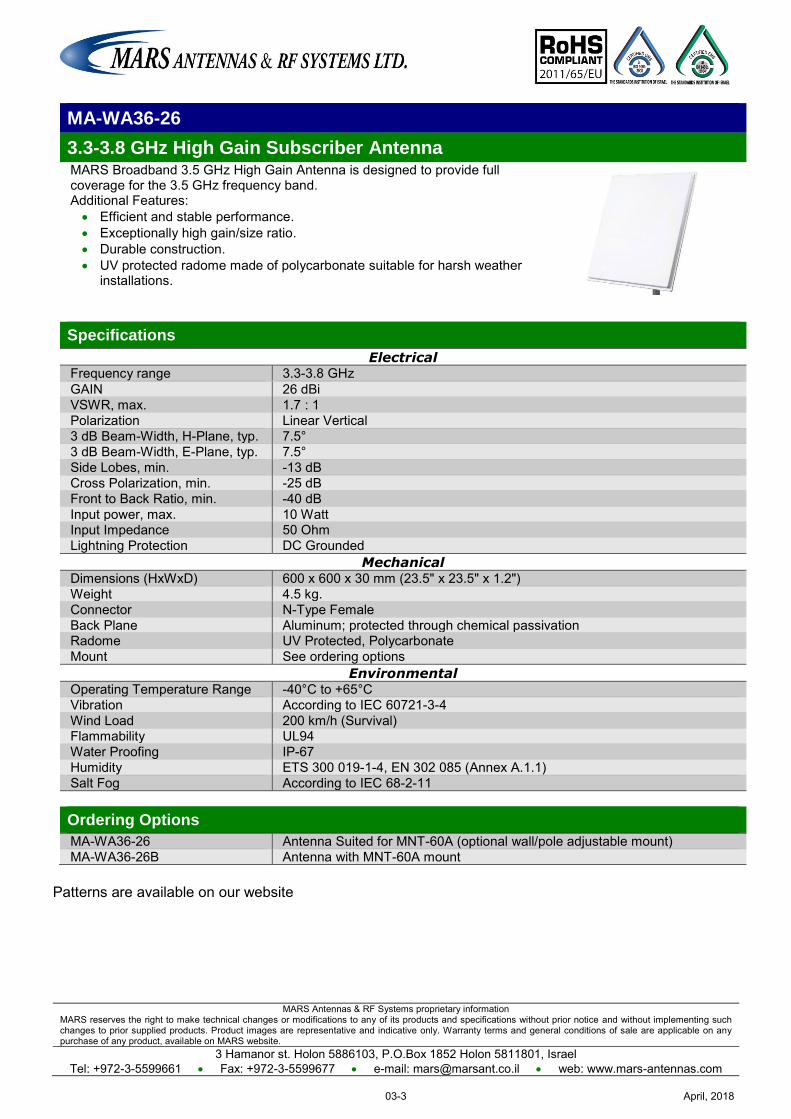
MARS Antennas & RF Systems proprietary information MARS reserves the right to make technical changes or modifications to any of its products and specifications without prior notice and without implementing such changes to prior supplied products. Product images are representative and indicative only. Warranty terms and general conditions of sale are applicable on any purchase of any product, available on MARS website.
3 Hamanor st. Holon 5886103, P.O.Box 1852 Holon 5811801, Israel Tel: +972-3-5599661 Fax: +972-3-5599677 e-mail: [email protected] web: www.mars-antennas.com
MA-WA36-26
3.3-3.8 GHz High Gain Subscriber Antenna MARS Broadband 3.5 GHz High Gain Antenna is designed to provide full coverage for the 3.5 GHz frequency band. Additional Features: Efficient and stable performance. Exceptionally high gain/size ratio. Durable construction. UV protected radome made of polycarbonate suitable for harsh weather
installations.
Specifications
Electrical Frequency range 3.3-3.8 GHz GAIN 26 dBi VSWR, max. 1.7 : 1 Polarization Linear Vertical 3 dB Beam-Width, H-Plane, typ. 7.5° 3 dB Beam-Width, E-Plane, typ. 7.5° Side Lobes, min. -13 dB Cross Polarization, min. -25 dB Front to Back Ratio, min. -40 dB Input power, max. 10 Watt Input Impedance 50 Ohm Lightning Protection DC Grounded
Mechanical Dimensions (HxWxD) 600 x 600 x 30 mm (23.5" x 23.5" x 1.2") Weight 4.5 kg. Connector N-Type Female Back Plane Aluminum; protected through chemical passivation Radome UV Protected, Polycarbonate Mount See ordering options
Environmental Operating Temperature Range -40°C to +65°C Vibration According to IEC 60721-3-4 Wind Load 200 km/h (Survival) Flammability UL94 Water Proofing IP-67 Humidity ETS 300 019-1-4, EN 302 085 (Annex A.1.1) Salt Fog According to IEC 68-2-11 Ordering Options
MA-WA36-26 Antenna Suited for MNT-60A (optional wall/pole adjustable mount) MA-WA36-26B Antenna with MNT-60A mount
Patterns are available on our website
April, 201803-3
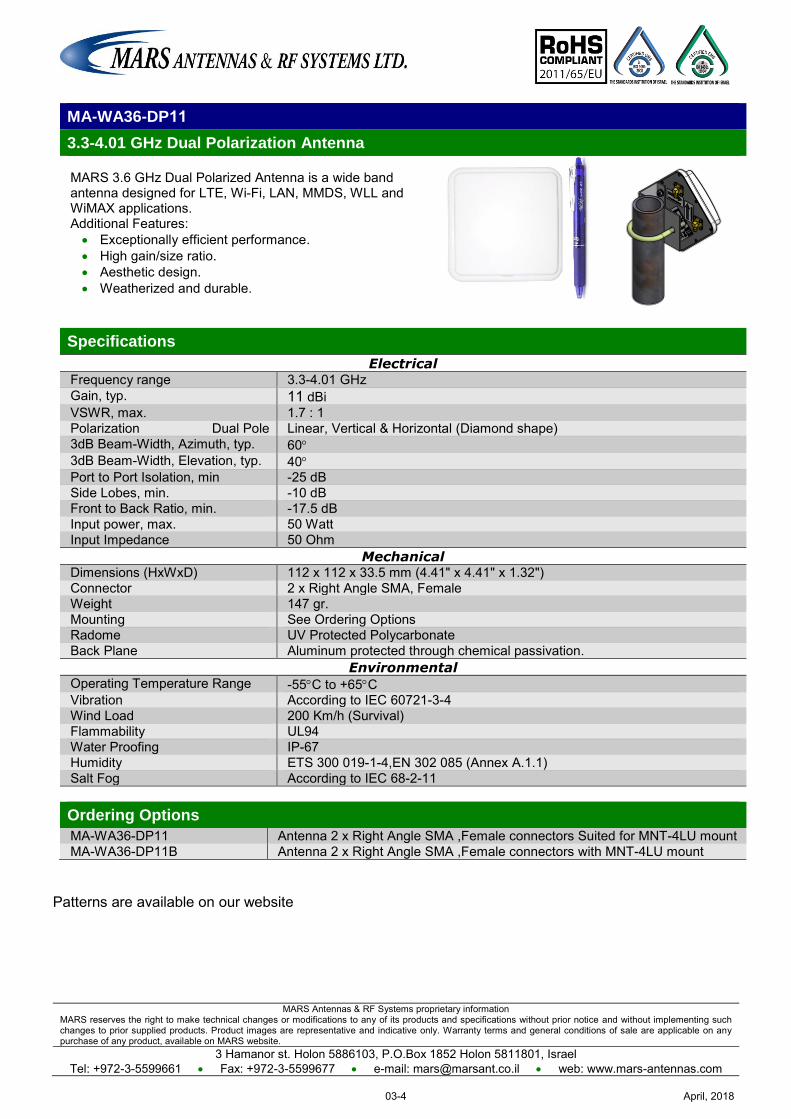
MARS Antennas & RF Systems proprietary information MARS reserves the right to make technical changes or modifications to any of its products and specifications without prior notice and without implementing such changes to prior supplied products. Product images are representative and indicative only. Warranty terms and general conditions of sale are applicable on any purchase of any product, available on MARS website.
3 Hamanor st. Holon 5886103, P.O.Box 1852 Holon 5811801, Israel Tel: +972-3-5599661 Fax: +972-3-5599677 e-mail: [email protected] web: www.mars-antennas.com
MA-WA36-DP11
3.3-4.01 GHz Dual Polarization Antenna
MARS 3.6 GHz Dual Polarized Antenna is a wide band antenna designed for LTE, Wi-Fi, LAN, MMDS, WLL and WiMAX applications. Additional Features: Exceptionally efficient performance. High gain/size ratio. Aesthetic design. Weatherized and durable.
Specifications
Electrical Frequency range 3.3-4.01 GHz Gain, typ. 11 dBi VSWR, max. 1.7 : 1 Polarization Dual Pole Linear, Vertical & Horizontal (Diamond shape) 3dB Beam-Width, Azimuth, typ. 60 3dB Beam-Width, Elevation, typ. 40 Port to Port Isolation, min -25 dB Side Lobes, min. -10 dB Front to Back Ratio, min. -17.5 dB Input power, max. 50 Watt Input Impedance 50 Ohm
Mechanical Dimensions (HxWxD) 112 x 112 x 33.5 mm (4.41" x 4.41" x 1.32") Connector 2 x Right Angle SMA, Female Weight 147 gr. Mounting See Ordering Options Radome UV Protected Polycarbonate Back Plane Aluminum protected through chemical passivation.
Environmental Operating Temperature Range -55C to +65C Vibration According to IEC 60721-3-4 Wind Load 200 Km/h (Survival) Flammability UL94 Water Proofing IP-67 Humidity ETS 300 019-1-4,EN 302 085 (Annex A.1.1) Salt Fog According to IEC 68-2-11 Ordering Options
MA-WA36-DP11 Antenna 2 x Right Angle SMA ,Female connectors Suited for MNT-4LU mount MA-WA36-DP11B Antenna 2 x Right Angle SMA ,Female connectors with MNT-4LU mount
Patterns are available on our website
April, 201803-4
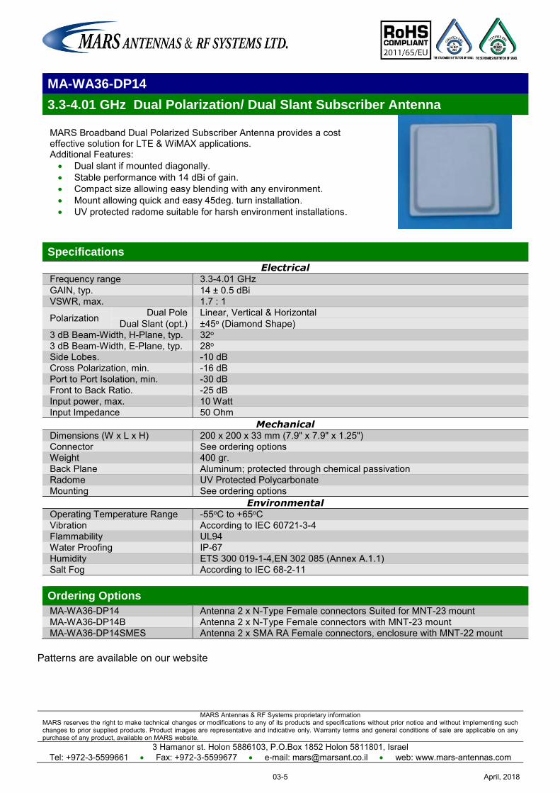
MARS Antennas & RF Systems proprietary information MARS reserves the right to make technical changes or modifications to any of its products and specifications without prior notice and without implementing such changes to prior supplied products. Product images are representative and indicative only. Warranty terms and general conditions of sale are applicable on any purchase of any product, available on MARS website.
3 Hamanor st. Holon 5886103, P.O.Box 1852 Holon 5811801, Israel Tel: +972-3-5599661 Fax: +972-3-5599677 e-mail: [email protected] web: www.mars-antennas.com
MA-WA36-DP14
3.3-4.01 GHz Dual Polarization/ Dual Slant Subscriber Antenna
MARS Broadband Dual Polarized Subscriber Antenna provides a cost effective solution for LTE & WiMAX applications. Additional Features: Dual slant if mounted diagonally. Stable performance with 14 dBi of gain. Compact size allowing easy blending with any environment. Mount allowing quick and easy 45deg. turn installation. UV protected radome suitable for harsh environment installations.
Specifications
Electrical Frequency range 3.3-4.01 GHz GAIN, typ. 14 ± 0.5 dBi VSWR, max. 1.7 : 1
Polarization Dual Pole Linear, Vertical & Horizontal Dual Slant (opt.) ±45o (Diamond Shape)
3 dB Beam-Width, H-Plane, typ. 32o 3 dB Beam-Width, E-Plane, typ. 28o Side Lobes. -10 dB Cross Polarization, min. -16 dB Port to Port Isolation, min. -30 dB Front to Back Ratio. -25 dB Input power, max. 10 Watt Input Impedance 50 Ohm
Mechanical Dimensions (W x L x H) 200 x 200 x 33 mm (7.9" x 7.9" x 1.25") Connector See ordering options Weight 400 gr. Back Plane Aluminum; protected through chemical passivation Radome UV Protected Polycarbonate Mounting See ordering options
Environmental Operating Temperature Range -55oC to +65oC Vibration According to IEC 60721-3-4 Flammability UL94 Water Proofing IP-67 Humidity ETS 300 019-1-4,EN 302 085 (Annex A.1.1) Salt Fog According to IEC 68-2-11 Ordering Options
MA-WA36-DP14 Antenna 2 x N-Type Female connectors Suited for MNT-23 mount MA-WA36-DP14B Antenna 2 x N-Type Female connectors with MNT-23 mount MA-WA36-DP14SMES Antenna 2 x SMA RA Female connectors, enclosure with MNT-22 mount
Patterns are available on our website
April, 201803-5

MARS Antennas & RF Systems proprietary information MARS reserves the right to make technical changes or modifications to any of its products and specifications without prior notice and without implementing such changes to prior supplied products. Product images are representative and indicative only. Warranty terms and general conditions of sale are applicable on any purchase of any product, available on MARS website.
3 Hamanor st. Holon 5886103, P.O.Box 1852 Holon 5811801, Israel Tel: +972-3-5599661 Fax: +972-3-5599677 e-mail: [email protected] web: www.mars-antennas.com
MA-WA36-DP91
3.3-4.01 GHz Dual Polarization/ Dual Slant Subscriber Antenna MARS Broadband Dual Polarized Subscriber Antenna provides a cost effective solution for LTE & WiMAX applications. Additional Features: Dual slant if mounted diagonally. Stable performance with 19.5 dBi of gain. Compact size allowing easy blending with any environment. Mount suitable for quick and easy 45deg. turn installation. UV protected radome suitable for harsh environment installations.
Specifications
Electrical Frequency range 3.3-4.01 GHz GAIN, typ. 19.5 ± 0.5 dBi VSWR, max. 1.7 : 1
Polarization Dual Pole Linear, Vertical & Horizontal Dual Slant (opt.) ±45o
3 dB Beam-Width, H-Plane, typ. 17o 3 dB Beam-Width, E-Plane, typ. 17o Cross Polarization, min. -23 dB Front to Back Ratio, min. -35 dB
Side Lobes, min. -12 dB @ 3.3-3.8 GHz -11 dB @ 3.8-4.01 GHz
Port to Port Isolation, min. -30 dB Input power, max. 50 Watt Input Impedance 50 Ohm Lightning Protection DC Grounded
Mechanical Dimensions (HxWxD) 305 x 305 x 25 mm (12" x 12" x 1") Weight 1.3 kg. Connector 2 x N-Type, Female Back Plane Aluminum; protected through chemical passivation Radome UV Protected Polycarbonate Mount See ordering options
Environmental Operating Temperature Range -55oC to +65oC Vibration According to IEC 60721-3-4 Wind Load 200 km/h (survival) Flammability UL94 Water Proofing IP-67 Humidity ETS 300 019-1-4, EN 302 085 (annex A.1.1) Salt Fog According to IEC 68-2-11 Ice and Snow 25mm radial (survival)
Standard Compliance ESTI TS3
Ordering Options
MA-WA36-DP19 Antenna with 2xN-Type, Female Connector Suited for MNT-22 MA-WA36-DP19B Antenna with 2xN-Type, Female Connector and MNT-22 mount
Patterns are available on our website
April, 201803-6
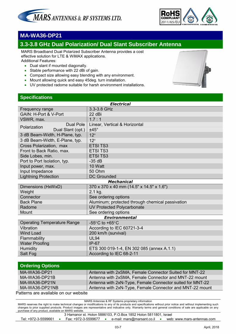
MARS Antennas & RF Systems proprietary information MARS reserves the right to make technical changes or modifications to any of its products and specifications without prior notice and without implementing such changes to prior supplied products. Product images are representative and indicative only. Warranty terms and general conditions of sale are applicable on any purchase of any product, available on MARS website.
3 Hamanor st. Holon 5886103, P.O.Box 1852 Holon 5811801, Israel Tel: +972-3-5599661 Fax: +972-3-5599677 e-mail: [email protected] web: www.mars-antennas.com
MA-WA36-DP21
3.3-3.8 GHz Dual Polarization/ Dual Slant Subscriber Antenna
MARS Broadband Dual Polarized Subscriber Antenna provides a cost effective solution for LTE & WiMAX applications. Additional Features: Dual slant if mounted diagonally. Stable performance with 22 dBi of gain. Compact size allowing easy blending with any environment. Mount allowing quick and easy 45deg. turn installation. UV protected radome suitable for harsh environment installations.
Specifications
Electrical
Frequency range 3.3-3.8 GHz GAIN: H-Port & V-Port 22 dBi VSWR, max. 1.7 : 1
Polarization Dual Pole Linear, Vertical & Horizontal Dual Slant (opt.) ±45°
3 dB Beam-Width, H-Plane, typ. 12 3 dB Beam-Width, E-Plane, typ. 12 Cross Polarization, max ETSI TS3 Front to Back Ratio, max. ETSI TS3 Side Lobes, min. ETSI TS3 Port to Port Isolation, typ. -35 dB Input power, max. 10 Watt Input Impedance 50 Ohm Lightning Protection DC Grounded
Mechanical
Dimensions (HxWxD) 370 x 370 x 40 mm (14.5" x 14.5" x 1.6") Weight 2.1 kg. Connector See ordering options Back Plane Aluminum; protected through chemical passivation Radome UV Protected Polycarbonate Mount See ordering options
Environmental
Operating Temperature Range -55C to +65C Vibration According to IEC 60721-3-4 Wind Load 200 km/h (survival) Flammability UL94 Water Proofing IP-67 Humidity ETS 300 019-1-4, EN 302 085 (annex A.1.1) Salt Fog According to IEC 68-2-11
Ordering Options
MA-WA36-DP21 Antenna with 2xSMA, Female Connector Suited for MNT-22 MA-WA36-DP21B Antenna with 2xSMA, Female Connector and MNT-22 mount MA-WA36-DP21N Antenna with 2xN-Type, Female Connector suited for MNT-22 MA-WA36-DP21NB Antenna with 2xN-Type, Female Connector and MNT-22 mount
Patterns are available on our website
April, 201803-7
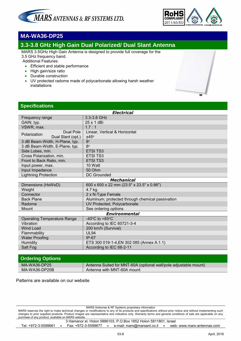
MARS Antennas & RF Systems proprietary information MARS reserves the right to make technical changes or modifications to any of its products and specifications without prior notice and without implementing such changes to prior supplied products. Product images are representative and indicative only. Warranty terms and general conditions of sale are applicable on any purchase of any product, available on MARS website.
3 Hamanor st. Holon 5886103, P.O.Box 1852 Holon 5811801, Israel Tel: +972-3-5599661 Fax: +972-3-5599677 e-mail: [email protected] web: www.mars-antennas.com
MA-WA36-DP25
3.3-3.8 GHz High Gain Dual Polarized/ Dual Slant Antenna MARS 3.5GHz High Gain Antenna is designed to provide full coverage for the 3.5 GHz frequency band. Additional Features: Efficient and stable performance High gain/size ratio Durable construction UV protected radome made of polycarbonate allowing harsh weather
installations
Specifications
Electrical Frequency range 3.3-3.8 GHz GAIN, typ. 25 ± 1 dBi VSWR, max. 1.7 : 1
Polarization Dual Pole Linear, Vertical & Horizontal Dual Slant (opt.) ±45o
3 dB Beam-Width, H-Plane, typ. 8o 3 dB Beam-Width, E-Plane, typ. 8o Side Lobes, min. ETSI TS3 Cross Polarization, min. ETSI TS3 Front to Back Ratio, min. ETSI TS3 Input power, max. 10 Watt Input Impedance 50 Ohm Lightning Protection DC Grounded
Mechanical Dimensions (HxWxD) 600 x 600 x 22 mm (23.5" x 23.5" x 0.86") Weight 4.7 kg. Connector 2 x N-Type Female Back Plane Aluminum; protected through chemical passivation Radome UV Protected, Polycarbonate Mount See ordering options
Environmental Operating Temperature Range -40oC to +65oC Vibration According to IEC 60721-3-4 Wind Load 200 km/h (Survival) Flammability UL94 Water Proofing IP-67 Humidity ETS 300 019-1-4,EN 302 085 (Annex A.1.1) Salt Fog According to IEC 68-2-11 Ordering Options
MA-WA36-DP25 Antenna Suited for MNT-60A (optional wall/pole adjustable mount) MA-WA36-DP25B Antenna with MNT-60A mount
Patterns are available on our website
April, 201803-8
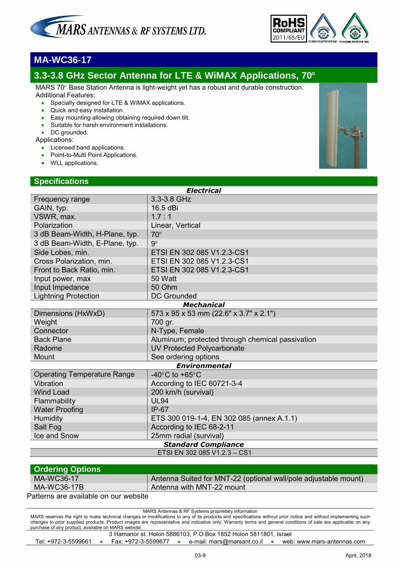
MARS Antennas & RF Systems proprietary information MARS reserves the right to make technical changes or modifications to any of its products and specifications without prior notice and without implementing such changes to prior supplied products. Product images are representative and indicative only. Warranty terms and general conditions of sale are applicable on any purchase of any product, available on MARS website.
3 Hamanor st. Holon 5886103, P.O.Box 1852 Holon 5811801, Israel Tel: +972-3-5599661 Fax: +972-3-5599677 e-mail: [email protected] web: www.mars-antennas.com
MA-WC36-17
3.3-3.8 GHz Sector Antenna for LTE & WiMAX Applications, 70 MARS 70 Base Station Antenna is light-weight yet has a robust and durable construction. Additional Features:
Specially designed for LTE & WiMAX applications. Quick and easy installation. Easy mounting allowing obtaining required down tilt. Suitable for harsh environment installations. DC grounded.
Applications: Licensed band applications. Point-to-Multi Point Applications. WLL applications.
Specifications Electrical
Frequency range 3.3-3.8 GHz GAIN, typ. 16.5 dBi VSWR, max. 1.7 : 1 Polarization Linear, Vertical 3 dB Beam-Width, H-Plane, typ. 70 3 dB Beam-Width, E-Plane, typ. 9 Side Lobes, min. ETSI EN 302 085 V1.2.3-CS1 Cross Polarization, min. ETSI EN 302 085 V1.2.3-CS1 Front to Back Ratio, min. ETSI EN 302 085 V1.2.3-CS1 Input power, max 50 Watt Input Impedance 50 Ohm Lightning Protection DC Grounded
Mechanical
Dimensions (HxWxD) 573 x 95 x 53 mm (22.6" x 3.7" x 2.1") Weight 700 gr. Connector N-Type, Female Back Plane Aluminum; protected through chemical passivation Radome UV Protected Polycarbonate Mount See ordering options
Environmental
Operating Temperature Range -40C to +65C Vibration According to IEC 60721-3-4 Wind Load 200 km/h (survival) Flammability UL94 Water Proofing IP-67 Humidity ETS 300 019-1-4, EN 302 085 (annex A.1.1) Salt Fog According to IEC 68-2-11 Ice and Snow 25mm radial (survival)
Standard Compliance ETSI EN 302 085 V1.2.3 – CS1
Ordering Options MA-WC36-17 Antenna Suited for MNT-22 (optional wall/pole adjustable mount) MA-WC36-17B Antenna with MNT-22 mount
Patterns are available on our website
April, 201803-9
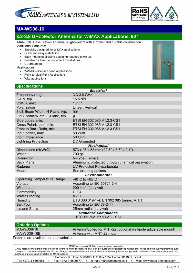
MARS Antennas & RF Systems proprietary information MARS reserves the right to make technical changes or modifications to any of its products and specifications without prior notice and without implementing such changes to prior supplied products. Product images are representative and indicative only. Warranty terms and general conditions of sale are applicable on any purchase of any product, available on MARS website.
3 Hamanor st. Holon 5886103, P.O.Box 1852 Holon 5811801, Israel Tel: +972-3-5599661 Fax: +972-3-5599677 e-mail: [email protected] web: www.mars-antennas.com
MA-WD36-16
3.3-3.8 GHz Sector Antenna for WiMAX Applications, 90 MARS 90 Base Station Antenna is light-weight with a robust and durable construction. Additional Features:
Specially designed for WiMAX applications. Quick and easy installation. Easy mounting allowing obtaining required down tilt. Suitable for harsh environment installations. DC grounded.
Applications: WiMAX – licensed band applications. Point-to-Multi Point Applications. WLL applications.
Specifications Electrical
Frequency range 3.3-3.8 GHz GAIN, typ. 15.5 dBi VSWR, max. 1.7 : 1 Polarization Linear, Vertical 3 dB Beam-Width, H-Plane, typ. 90 3 dB Beam-Width, E-Plane, typ. 9 Side Lobes, min. ETSI EN 302 085 V1.2.3-CS1 Cross Polarization, min. ETSI EN 302 085 V1.2.3-CS1 Front to Back Ratio, min. ETSI EN 302 085 V1.2.3-CS1 Input power, max. 50 Watt Input Impedance 50 Ohm Lightning Protection DC Grounded
Mechanical
Dimensions (HxWxD) 573 x 95 x 53 mm (22.6" x 3.7" x 2.1") Weight 700 gr. Connector N-Type, Female Back Plane Aluminum; protected through chemical passivation Radome UV Protected Polycarbonate Mount See ordering options
Environmental
Operating Temperature Range -40C to +65C Vibration According to IEC 60721-3-4 Wind Load 200 km/h (survival) Flammability UL94 Water Proofing IP-67 Humidity ETS 300 019-1-4, EN 302 085 (annex A.1.1) Salt Fog According to IEC 68-2-11 Ice and Snow 25mm radial (survival)
Standard Compliance ETSI EN 302 085 V1.2.3 – CS1
Ordering Options MA-WD36-16 Antenna Suited for MNT-22 (optional wall/pole adjustable mount) MA-WD36-16B Antenna with MNT-22 mount
Patterns are available on our website
April, 201803-10
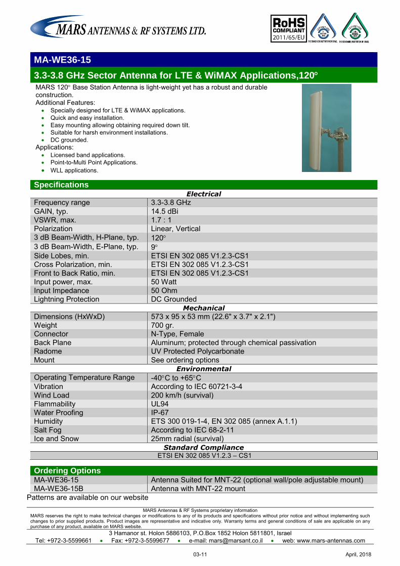
MARS Antennas & RF Systems proprietary information MARS reserves the right to make technical changes or modifications to any of its products and specifications without prior notice and without implementing such changes to prior supplied products. Product images are representative and indicative only. Warranty terms and general conditions of sale are applicable on any purchase of any product, available on MARS website.
3 Hamanor st. Holon 5886103, P.O.Box 1852 Holon 5811801, Israel Tel: +972-3-5599661 Fax: +972-3-5599677 e-mail: [email protected] web: www.mars-antennas.com
MA-WE36-15
3.3-3.8 GHz Sector Antenna for LTE & WiMAX Applications,120 MARS 120 Base Station Antenna is light-weight yet has a robust and durable construction. Additional Features:
Specially designed for LTE & WiMAX applications. Quick and easy installation. Easy mounting allowing obtaining required down tilt. Suitable for harsh environment installations. DC grounded.
Applications: Licensed band applications. Point-to-Multi Point Applications. WLL applications.
Specifications Electrical
Frequency range 3.3-3.8 GHz GAIN, typ. 14.5 dBi VSWR, max. 1.7 : 1 Polarization Linear, Vertical 3 dB Beam-Width, H-Plane, typ. 120 3 dB Beam-Width, E-Plane, typ. 9 Side Lobes, min. ETSI EN 302 085 V1.2.3-CS1 Cross Polarization, min. ETSI EN 302 085 V1.2.3-CS1 Front to Back Ratio, min. ETSI EN 302 085 V1.2.3-CS1 Input power, max. 50 Watt Input Impedance 50 Ohm Lightning Protection DC Grounded
Mechanical
Dimensions (HxWxD) 573 x 95 x 53 mm (22.6" x 3.7" x 2.1") Weight 700 gr. Connector N-Type, Female Back Plane Aluminum; protected through chemical passivation Radome UV Protected Polycarbonate Mount See ordering options
Environmental
Operating Temperature Range -40C to +65C Vibration According to IEC 60721-3-4 Wind Load 200 km/h (survival) Flammability UL94 Water Proofing IP-67 Humidity ETS 300 019-1-4, EN 302 085 (annex A.1.1) Salt Fog According to IEC 68-2-11 Ice and Snow 25mm radial (survival)
Standard Compliance ETSI EN 302 085 V1.2.3 – CS1
Ordering Options MA-WE36-15 Antenna Suited for MNT-22 (optional wall/pole adjustable mount) MA-WE36-15B Antenna with MNT-22 mount
Patterns are available on our website
April, 201803-11
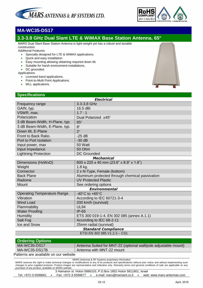
MARS Antennas & RF Systems proprietary information MARS reserves the right to make technical changes or modifications to any of its products and specifications without prior notice and without implementing such changes to prior supplied products. Product images are representative and indicative only. Warranty terms and general conditions of sale are applicable on any purchase of any product, available on MARS website.
3 Hamanor st. Holon 5886103, P.O.Box 1852 Holon 5811801, Israel
Tel: +972-3-5599661 Fax: +972-3-5599677 e-mail: [email protected] web: www.mars-antennas.com
MA-WC35-DS17
3.3-3.8 GHz Dual Slant LTE & WiMAX Base Station Antenna, 65° MARS Dual Slant Base Station Antenna is light-weight yet has a robust and durable construction. Additional Features:
Specially designed for LTE & WiMAX applications.
Quick and easy installation.
Easy mounting allowing obtaining required down tilt.
Suitable for harsh environment installations.
DC grounded. Applications:
Licensed band applications.
Point-to-Multi Point Applications.
WLL applications.
Specifications Electrical
Frequency range 3.3-3.8 GHz
GAIN, typ. 16.5 dBi
VSWR, max. 1.7 : 1 Polarization Dual Polarized ±45
3 dB Beam-Width, H-Plane, typ. 65 3 dB Beam-Width, E-Plane, typ. 8 Down tilt, E-Plane 2
Front to Back Ratio. -25 dB Port to Port Isolation -30 dB
Input power, max 50 Watt Input Impedance 50 Ohm
Lightning Protection DC Grounded
Mechanical
Dimensions (HxWxD) 600 x 225 x 40 mm (23.6” x 8.9” x 1.6”) Weight 1.8 kg.
Connector 2 x N-Type, Female (bottom) Back Plane Aluminum protected through chemical passivation
Radome UV Protected Plastic Mount See ordering options
Environmental
Operating Temperature Range -40C to +65C
Vibration According to IEC 60721-3-4 Wind Load 200 km/h (survival)
Flammability UL94 Water Proofing IP-65
Humidity ETS 300 019-1-4, EN 302 085 (annex A.1.1) Salt Fog According to IEC 68-2-11
Ice and Snow 25mm radial (survival)
Standard Compliance ETSI EN 302 085 V1.2.3 – CS1
Ordering Options MA-WC35-DS17 Antenna Suited for MNT-22 (optional wall/pole adjustable mount)
MA-WC35-DS17B Antenna with MNT-22 mount
Patterns are available on our website
April, 201803-12
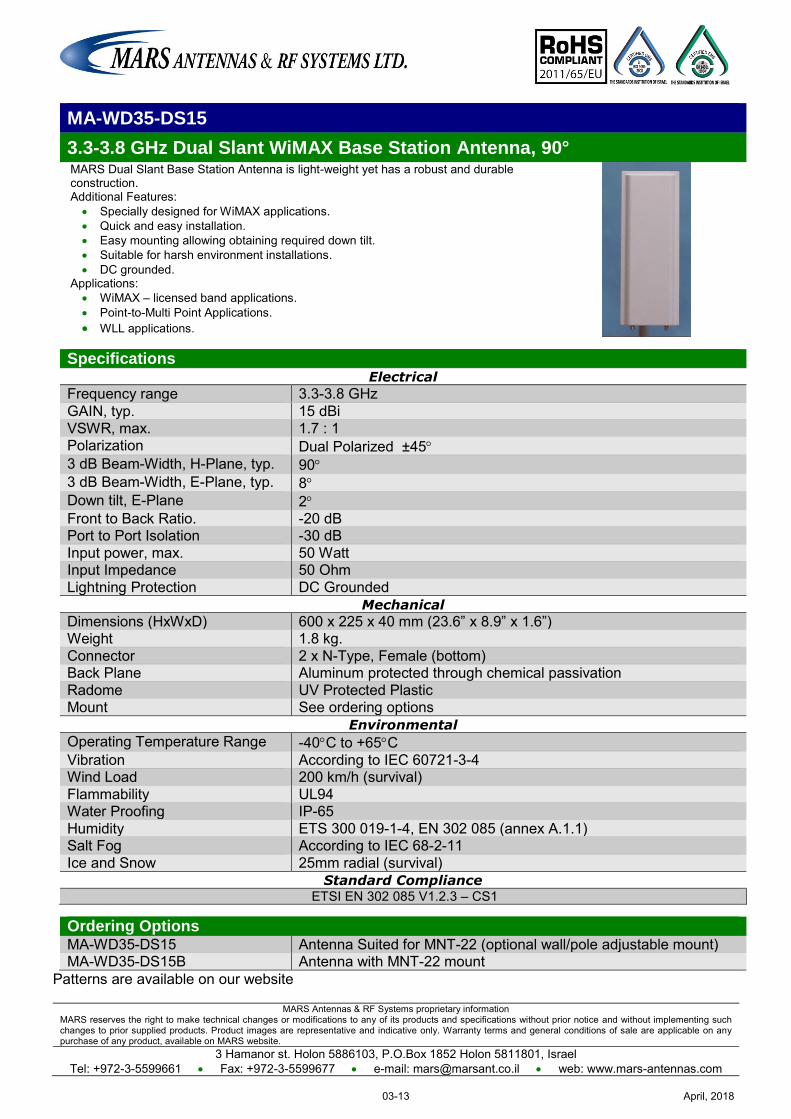
MARS Antennas & RF Systems proprietary information MARS reserves the right to make technical changes or modifications to any of its products and specifications without prior notice and without implementing such changes to prior supplied products. Product images are representative and indicative only. Warranty terms and general conditions of sale are applicable on any purchase of any product, available on MARS website.
3 Hamanor st. Holon 5886103, P.O.Box 1852 Holon 5811801, Israel Tel: +972-3-5599661 Fax: +972-3-5599677 e-mail: [email protected] web: www.mars-antennas.com
MA-WD35-DS15
3.3-3.8 GHz Dual Slant WiMAX Base Station Antenna, 90° MARS Dual Slant Base Station Antenna is light-weight yet has a robust and durable construction. Additional Features:
Specially designed for WiMAX applications. Quick and easy installation. Easy mounting allowing obtaining required down tilt. Suitable for harsh environment installations. DC grounded.
Applications: WiMAX – licensed band applications. Point-to-Multi Point Applications. WLL applications.
Specifications Electrical
Frequency range 3.3-3.8 GHz GAIN, typ. 15 dBi VSWR, max. 1.7 : 1 Polarization Dual Polarized ±45 3 dB Beam-Width, H-Plane, typ. 90 3 dB Beam-Width, E-Plane, typ. 8 Down tilt, E-Plane 2 Front to Back Ratio. -20 dB Port to Port Isolation -30 dB Input power, max. 50 Watt Input Impedance 50 Ohm Lightning Protection DC Grounded
Mechanical
Dimensions (HxWxD) 600 x 225 x 40 mm (23.6” x 8.9” x 1.6”) Weight 1.8 kg. Connector 2 x N-Type, Female (bottom) Back Plane Aluminum protected through chemical passivation Radome UV Protected Plastic Mount See ordering options
Environmental
Operating Temperature Range -40C to +65C Vibration According to IEC 60721-3-4 Wind Load 200 km/h (survival) Flammability UL94 Water Proofing IP-65 Humidity ETS 300 019-1-4, EN 302 085 (annex A.1.1) Salt Fog According to IEC 68-2-11 Ice and Snow 25mm radial (survival)
Standard Compliance ETSI EN 302 085 V1.2.3 – CS1
Ordering Options MA-WD35-DS15 Antenna Suited for MNT-22 (optional wall/pole adjustable mount) MA-WD35-DS15B Antenna with MNT-22 mount
Patterns are available on our website
April, 201803-13

MARS Antennas & RF Systems proprietary information MARS reserves the right to make technical changes or modifications to any of its products and specifications without prior notice and without implementing such changes to prior supplied products. Product images are representative and indicative only. Warranty terms and general conditions of sale are applicable on any purchase of any product, available on MARS website.
3 Hamanor st. Holon 5886103, P.O.Box 1852 Holon 5811801, Israel Tel: +972-3-5599661 Fax: +972-3-5599677 e-mail: [email protected] web: www.mars-antennas.com
MA-WC36-DP15
3.3-4.01 GHz Dual Polarization Base Station Antenna, 60º
MARS 60o Broadband Dual Polarized Sector Antenna provides a cost effective solution for LTE & WiMAX applications. Additional Features: Stable performance with 15dBi of gain. Compact size allowing for easy blending with any environment. Tilt mount allowing quick and easy installation. UV protected radome suitable for harsh environment installations.
Specifications
Electrical Frequency range -3.3 4.01 GHz GAIN, typ. 15 dBi VSWR, max. 1.7 : 1 Polarization Linear, Vertical & Horizontal 3 dB Beam-Width, Az-Plane, typ. 60 3 dB Beam-Width, El-Plane, typ. 12 Side Lobes, typ. -12 dB Cross Polarization, min. -15 dB Port to Port Isolation, min. -30 dB Front to Back Ratio, min. -35 dB Input power, max. 10 Watt Input Impedance 50 Ohm Lightning Protection DC Grounded
Mechanical Dimensions (HxWxD) 370 x 370 x 40 mm (14.5" x14.5" x1.6") Connector 2 x N-Type, Female Weight 2 Kg. Back Plane Aluminum; protected through chemical passivation Radome UV Protected Polycarbonate Mounting See Ordering Options
Environmental Operating Temperature Range -55°C to +65°C Vibration According to IEC 60721-3-4 Wind Load 200 Km/h (Survival) Flammability UL94 Water Proofing IP-65 Humidity ETS 300 019-1-4,EN 302 085 (Annex A.1.1) Salt Fog According to IEC 68-2-11 Ice and Snow 25mm radial (survival) Ordering Options
MA-WC36-DP15 Antenna Suited for MNT-22 (optional wall/pole adjustable mount) MA-WC36-DP15B Antenna with MNT-22 mount
April, 201803-14
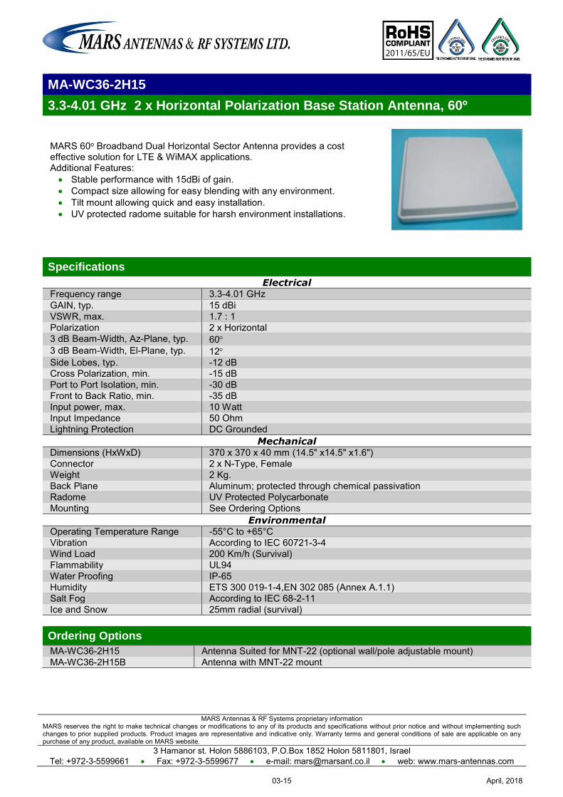
MARS Antennas & RF Systems proprietary information MARS reserves the right to make technical changes or modifications to any of its products and specifications without prior notice and without implementing such changes to prior supplied products. Product images are representative and indicative only. Warranty terms and general conditions of sale are applicable on any purchase of any product, available on MARS website.
3 Hamanor st. Holon 5886103, P.O.Box 1852 Holon 5811801, Israel Tel: +972-3-5599661 Fax: +972-3-5599677 e-mail: [email protected] web: www.mars-antennas.com
MA-WC36-2H15
3.3-4.01 GHz 2 x Horizontal Polarization Base Station Antenna, 60º
MARS 60o Broadband Dual Horizontal Sector Antenna provides a cost effective solution for LTE & WiMAX applications. Additional Features: Stable performance with 15dBi of gain. Compact size allowing for easy blending with any environment. Tilt mount allowing quick and easy installation. UV protected radome suitable for harsh environment installations.
Specifications
Electrical Frequency range -3.3 4.01 GHz GAIN, typ. 15 dBi VSWR, max. 1.7 : 1 Polarization 2 x Horizontal 3 dB Beam-Width, Az-Plane, typ. 60 3 dB Beam-Width, El-Plane, typ. 12 Side Lobes, typ. -12 dB Cross Polarization, min. -15 dB Port to Port Isolation, min. -30 dB Front to Back Ratio, min. -35 dB Input power, max. 10 Watt Input Impedance 50 Ohm Lightning Protection DC Grounded
Mechanical Dimensions (HxWxD) 370 x 370 x 40 mm (14.5" x14.5" x1.6") Connector 2 x N-Type, Female Weight 2 Kg. Back Plane Aluminum; protected through chemical passivation Radome UV Protected Polycarbonate Mounting See Ordering Options
Environmental Operating Temperature Range -55°C to +65°C Vibration According to IEC 60721-3-4 Wind Load 200 Km/h (Survival) Flammability UL94 Water Proofing IP-65 Humidity ETS 300 019-1-4,EN 302 085 (Annex A.1.1) Salt Fog According to IEC 68-2-11 Ice and Snow 25mm radial (survival) Ordering Options
MA-WC36-2H15 Antenna Suited for MNT-22 (optional wall/pole adjustable mount) MA-WC36-2H15B Antenna with MNT-22 mount
April, 201803-15
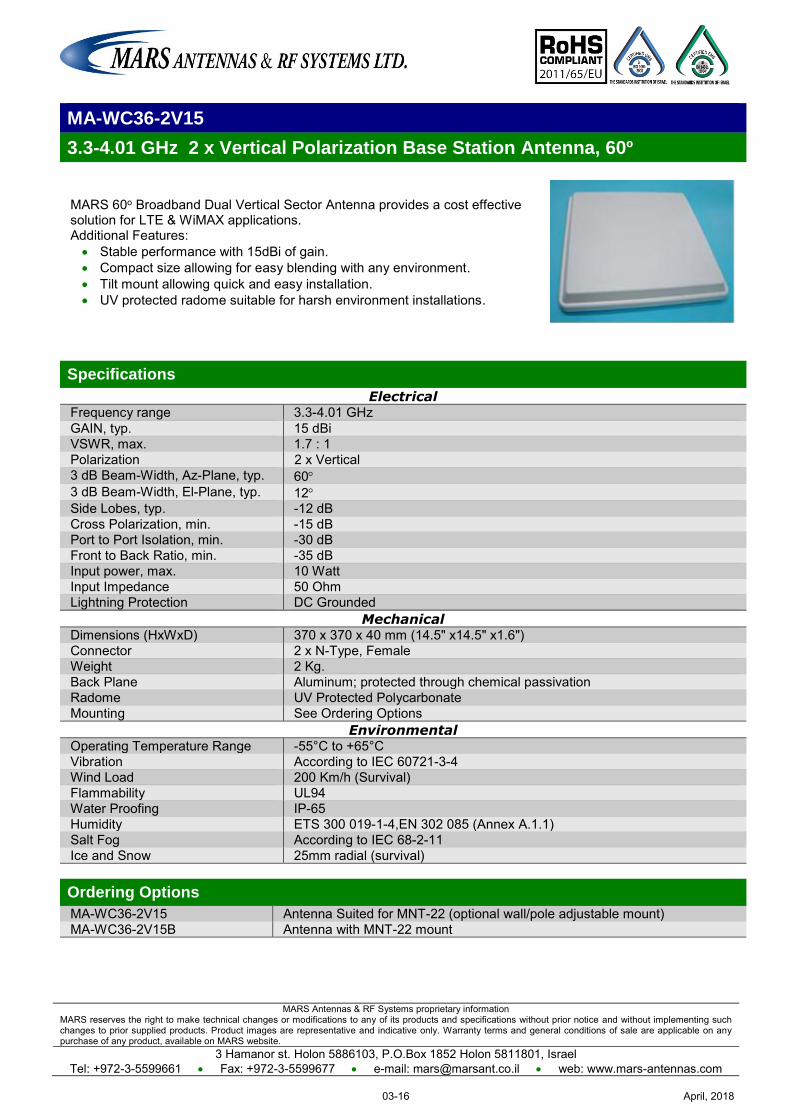
MARS Antennas & RF Systems proprietary information MARS reserves the right to make technical changes or modifications to any of its products and specifications without prior notice and without implementing such changes to prior supplied products. Product images are representative and indicative only. Warranty terms and general conditions of sale are applicable on any purchase of any product, available on MARS website.
3 Hamanor st. Holon 5886103, P.O.Box 1852 Holon 5811801, Israel Tel: +972-3-5599661 Fax: +972-3-5599677 e-mail: [email protected] web: www.mars-antennas.com
MA-WC36-2V15
3.3-4.01 GHz 2 x Vertical Polarization Base Station Antenna, 60º
MARS 60o Broadband Dual Vertical Sector Antenna provides a cost effective solution for LTE & WiMAX applications. Additional Features: Stable performance with 15dBi of gain. Compact size allowing for easy blending with any environment. Tilt mount allowing quick and easy installation. UV protected radome suitable for harsh environment installations.
Specifications
Electrical Frequency range -3.3 4.01 GHz GAIN, typ. 15 dBi VSWR, max. 1.7 : 1 Polarization 2 x Vertical 3 dB Beam-Width, Az-Plane, typ. 60 3 dB Beam-Width, El-Plane, typ. 12 Side Lobes, typ. -12 dB Cross Polarization, min. -15 dB Port to Port Isolation, min. -30 dB Front to Back Ratio, min. -35 dB Input power, max. 10 Watt Input Impedance 50 Ohm Lightning Protection DC Grounded
Mechanical Dimensions (HxWxD) 370 x 370 x 40 mm (14.5" x14.5" x1.6") Connector 2 x N-Type, Female Weight 2 Kg. Back Plane Aluminum; protected through chemical passivation Radome UV Protected Polycarbonate Mounting See Ordering Options
Environmental Operating Temperature Range -55°C to +65°C Vibration According to IEC 60721-3-4 Wind Load 200 Km/h (Survival) Flammability UL94 Water Proofing IP-65 Humidity ETS 300 019-1-4,EN 302 085 (Annex A.1.1) Salt Fog According to IEC 68-2-11 Ice and Snow 25mm radial (survival) Ordering Options
MA-WC36-2V15 Antenna Suited for MNT-22 (optional wall/pole adjustable mount) MA-WC36-2V15B Antenna with MNT-22 mount
April, 201803-16
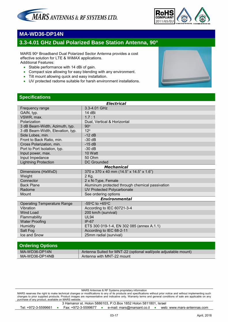
MARS Antennas & RF Systems proprietary information MARS reserves the right to make technical changes or modifications to any of its products and specifications without prior notice and without implementing such changes to prior supplied products. Product images are representative and indicative only. Warranty terms and general conditions of sale are applicable on any purchase of any product, available on MARS website.
3 Hamanor st. Holon 5886103, P.O.Box 1852 Holon 5811801, Israel Tel: +972-3-5599661 Fax: +972-3-5599677 e-mail: [email protected] web: www.mars-antennas.com
MA-WD36-DP14N
3.3-4.01 GHz Dual Polarized Base Station Antenna, 90o
MARS 90o Broadband Dual Polarized Sector Antenna provides a cost effective solution for LTE & WiMAX applications. Additional Features: Stable performance with 14 dBi of gain. Compact size allowing for easy blending with any environment. Tilt mount allowing quick and easy installation. UV protected radome suitable for harsh environment installations.
Specifications
Electrical Frequency range 3.3-4.01 GHz GAIN, typ. 14 dBi VSWR, max. 1.7 : 1 Polarization Dual, Vertical & Horizontal 3 dB Beam-Width, Azimuth, typ. 90o 3 dB Beam-Width, Elevation, typ. 12o Side Lobes, min. -12 dB Front to Back Ratio, min. -30 dB Cross Polarization, min. -15 dB Port to Port Isolation, typ. -30 dB Input power, max. 10 Watt Input Impedance 50 Ohm Lightning Protection DC Grounded
Mechanical Dimensions (HxWxD) 370 x 370 x 40 mm (14.5” x 14.5” x 1.6”) Weight 2 Kg. Connector 2 x N-Type, Female Back Plane Aluminum protected through chemical passivation Radome UV Protected Polycarbonate Mount See ordering options
Environmental Operating Temperature Range -55oC to +65oC Vibration According to IEC 60721-3-4 Wind Load 200 km/h (survival) Flammability UL94 Water Proofing IP-67 Humidity ETS 300 019-1-4, EN 302 085 (annex A.1.1) Salt Fog According to IEC 68-2-11 Ice and Snow 25mm radial (survival) Ordering Options
MA-WD36-DP14N Antenna Suited for MNT-22 (optional wall/pole adjustable mount) MA-WD36-DP14NB Antenna with MNT-22 mount
April, 201803-17
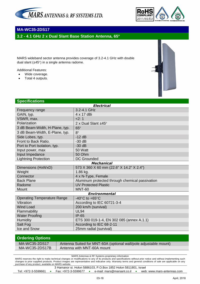
MARS Antennas & RF Systems proprietary information MARS reserves the right to make technical changes or modifications to any of its products and specifications without prior notice and without implementing such changes to prior supplied products. Product images are representative and indicative only. Warranty terms and general conditions of sale are applicable on any purchase of any product, available on MARS website.
3 Hamanor st. Holon 5886103, P.O.Box 1852 Holon 5811801, Israel
Tel: +972-3-5599661 Fax: +972-3-5599677 e-mail: [email protected] web: www.mars-antennas.com
MA-WC35-2DS17
3.2 - .4 1 GHz 2 x Dual Slant Base Station Antenna, 65°
MARS wideband sector antenna provides coverage of 3.2-4.1 GHz with double
dual slant (±45) in a single antenna radome. Additional Features:
Wide coverage.
Total 4 outputs.
Specifications Electrical
Frequency range 3.2-4.1 GHz
GAIN, typ. 4 x 17 dBi VSWR, max. <2: 1
Polarization 2 x Dual Slant ±45 3 dB Beam-Width, H-Plane, typ. 65
3 dB Beam-Width, E-Plane, typ. 8 Side Lobes, typ. -12 dB
Front to Back Ratio. -30 dB Port to Port Isolation, typ. -30 dB
Input power, max 50 Watt Input Impedance 50 Ohm
Lightning Protection DC Grounded
Mechanical
Dimensions (HxWxD) 573 X 360 X 60 mm (22.6" X 14.2" X 2.4") Weight 1.86 kg.
Connector 4 x N-Type, Female Back Plane Aluminum protected through chemical passivation
Radome UV Protected Plastic Mount MNT-60
Environmental
Operating Temperature Range -40C to +65C Vibration According to IEC 60721-3-4
Wind Load 200 km/h (survival) Flammability UL94
Water Proofing IP-65 Humidity ETS 300 019-1-4, EN 302 085 (annex A.1.1)
Salt Fog According to IEC 68-2-11 Ice and Snow 25mm radial (survival)
Ordering Options
MA-WC35-2DS17 Antenna Suited for MNT-60A (optional wall/pole adjustable mount) MA-WC35-2DS17B Antenna with MNT-60A mount
April, 201803-18
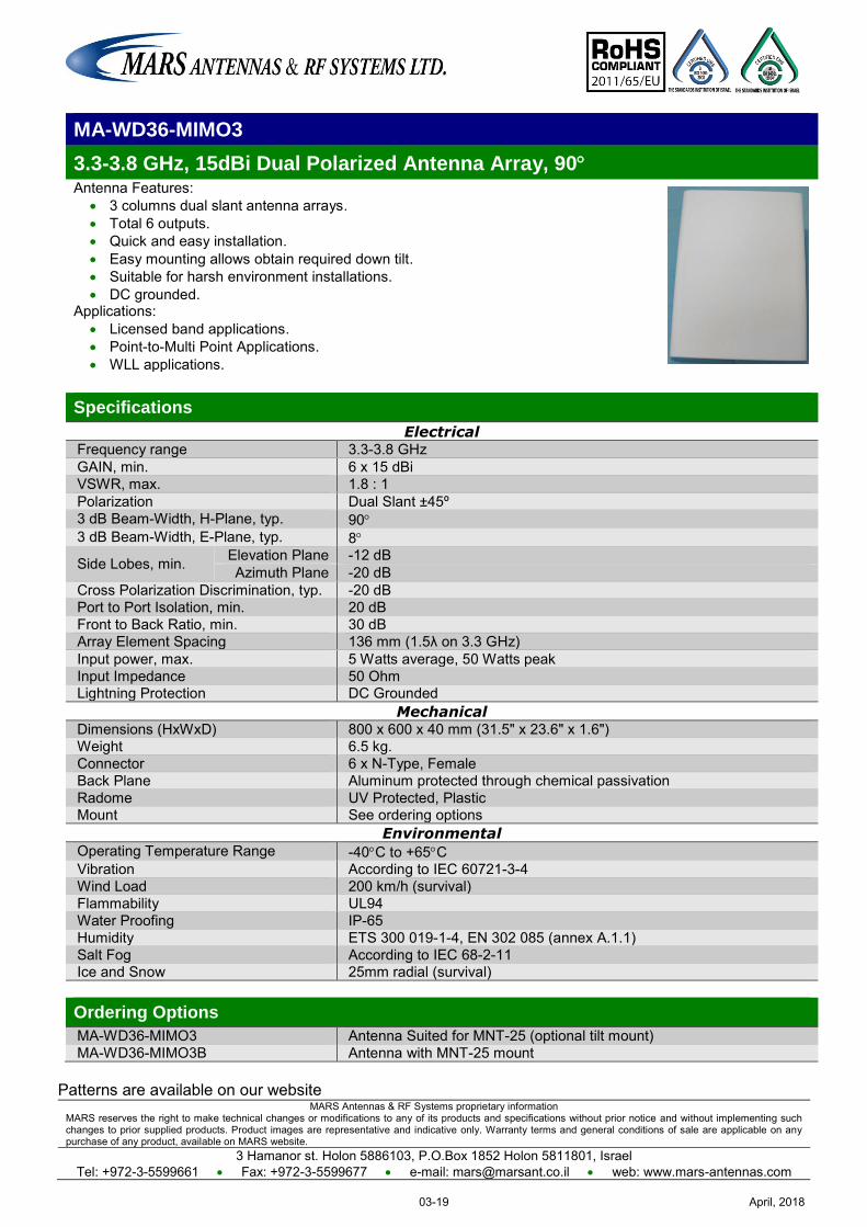
MARS Antennas & RF Systems proprietary information MARS reserves the right to make technical changes or modifications to any of its products and specifications without prior notice and without implementing such changes to prior supplied products. Product images are representative and indicative only. Warranty terms and general conditions of sale are applicable on any purchase of any product, available on MARS website.
3 Hamanor st. Holon 5886103, P.O.Box 1852 Holon 5811801, Israel Tel: +972-3-5599661 Fax: +972-3-5599677 e-mail: [email protected] web: www.mars-antennas.com
MA-WD36-MIMO3
3.3-3.8 GHz, 15dBi Dual Polarized Antenna Array, 90 Antenna Features:
3 columns dual slant antenna arrays. Total 6 outputs. Quick and easy installation. Easy mounting allows obtain required down tilt. Suitable for harsh environment installations. DC grounded.
Applications: Licensed band applications. Point-to-Multi Point Applications. WLL applications.
Specifications
Electrical Frequency range 3.3-3.8 GHz GAIN, min. 6 x 15 dBi VSWR, max. 1.8 : 1 Polarization Dual Slant ±45º 3 dB Beam-Width, H-Plane, typ. 90 3 dB Beam-Width, E-Plane, typ. 8
Side Lobes, min. Elevation Plane -12 dB Azimuth Plane -20 dB
Cross Polarization Discrimination, typ. -20 dB Port to Port Isolation, min. 20 dB Front to Back Ratio, min. 30 dB Array Element Spacing 136 mm (1.5λ on 3.3 GHz) Input power, max. 5 Watts average, 50 Watts peak Input Impedance 50 Ohm Lightning Protection DC Grounded
Mechanical Dimensions (HxWxD) 800 x 600 x 40 mm (31.5" x 23.6" x 1.6") Weight 6.5 kg. Connector 6 x N-Type, Female Back Plane Aluminum protected through chemical passivation Radome UV Protected, Plastic Mount See ordering options
Environmental Operating Temperature Range -40C to +65C Vibration According to IEC 60721-3-4 Wind Load 200 km/h (survival) Flammability UL94 Water Proofing IP-65 Humidity ETS 300 019-1-4, EN 302 085 (annex A.1.1) Salt Fog According to IEC 68-2-11 Ice and Snow 25mm radial (survival) Ordering Options
MA-WD36-MIMO3 Antenna Suited for MNT-25 (optional tilt mount) MA-WD36-MIMO3B Antenna with MNT-25 mount
Patterns are available on our website
April, 201803-19
MARS Antennas & RF Systems proprietary information MARS reserves the right to make technical changes or modifications to any of its products and specifications without prior notice and without implementing such changes to prior supplied products. Product images are representative and indicative only. Warranty terms and general conditions of sale are applicable on any purchase of any product, available on MARS website.
3 Hamanor st. Holon 5886103, P.O.Box 1852 Holon 5811801, Israel
Tel: +972-3-5599661 Fax: +972-3-5599677 e-mail: [email protected] web: www.mars-antennas.com
4.4 GHz – 5.1 GHz
4.9 GHz – 6.1 GHz 5.4 GHz – 6.5 GHz
Subscriber - Single Pol Subscriber - Dual Pol Subscriber - Triple Pol Subscriber - Quad Pol
Subscriber - 5 Pol Sector - Single Pol Sector -Dual Pol
Sector - Double Dual Slant Sector - Triple Pol Sector - Quad Pol DAS - Single Pol DAS - Dual Pol
Part Number Description Frequency
band Gain
Polarization
Dimension Antenna type Page
MA-WA48-23 High Gain, 4.8 GHz Subscriber
4.4-5.1 GHz 23 dBi Linear, Vertical
370 x 370 x 40 mm
Subscriber
Single Pol 04-1
MA-WA47-20 4.5 GHz Subscriber 4.4-5.1 GHz 20 dBi Linear, Vertical
305 x 305 x 15 mm
Subscriber
Single Pol 04-2
MA-WS2455-1X
Dual Band Subscriber, High Gain
2.4-2.5 GHz 4.9-5.875 GHz
18 dBi
12 dBi (typ.)
Linear, Vertical or Horizontal
305 x 305 x 25 mm
Subscriber
Single Pol 02-7
MA-WA57-3HG1
Small S ize Subscriber, High Gain
4.9-6.5 GHz 19 dBi (min.)
Linear, Vertical
155 x 155 x 28 mm
Subscriber
Single Pol 04-3
MA-WA58-1X Broadband Subscriber
4.9-5.875 GHz 23 dBi (typ.)
Linear, Vertical
305 x 305 x 15 mm
(Diamond Shape)
Subscriber
Single Pol 04-4
MA-WA58-1XMMES
Integrated Antenna & Enclosure Solution
4.9-5.875 GHz 23 dBi (typ.)
Linear, Vertical
305 x 305 x 15 mm
(Diamond Shape)
Subscriber
Single Pol 04-5
MA-WA55-27 5 GHz Broadband Subscriber
4.9-6.1 GHz 26 dBi
(typ.)
Linear, Vertical or Horizontal
370 x 370 x 40 mm
Subscriber
Single Pol 04-6
MA-WA55-30 High Gain Subscriber 4.9-6.1 GHz
30 dBi
(typ.)
Linear, Vertical
600 x 600 x 30 mm
Subscriber
Single Pol 04-7
MA-WA62-30 4.9-6.5 GHz High Gain Subscriber
4.9-6.5 GHz 30 dBi
(Typ.)
Linear, Vertical
600 x 600 x 30 mm
Subscriber
Single Pol 04-8
MA-WA61-25 6 GHz Broadband Subscriber
5.4-6.5 GHz 25 dBi Linear, Vertical
305 x 305 x 15 mm
Subscriber
Single Pol 04-9
MA-WA48-DP23
Dual Polarized / Dual Slant Subscriber
4.4-5.1 GHz 23 dBi
Dual Pole V & H
Dual Slant ±45°
370 x 370 x 40 mm
Subscriber
Dual Pol 04-10
MA-WA52-DP24
Dual Polarized / Dual Slant Subscriber
4.4-6.1 GHz 24 ± 1 dBi Linear,
Vertical & Horizontal
112 x 112 x 33.5 mm
Subscriber
Dual Pol 04-11
MA-WA2458-2DP18
Dual Band Dual Pol Subscriber
2.3-2.7 GHz 4.9-5.95 GHz
13 dBi 18 dBi
Linear, Vertical & Horizontal
370 x 370 x 40 mm
Subscriber
Double Dual Pol
02-13
April, 201804-I
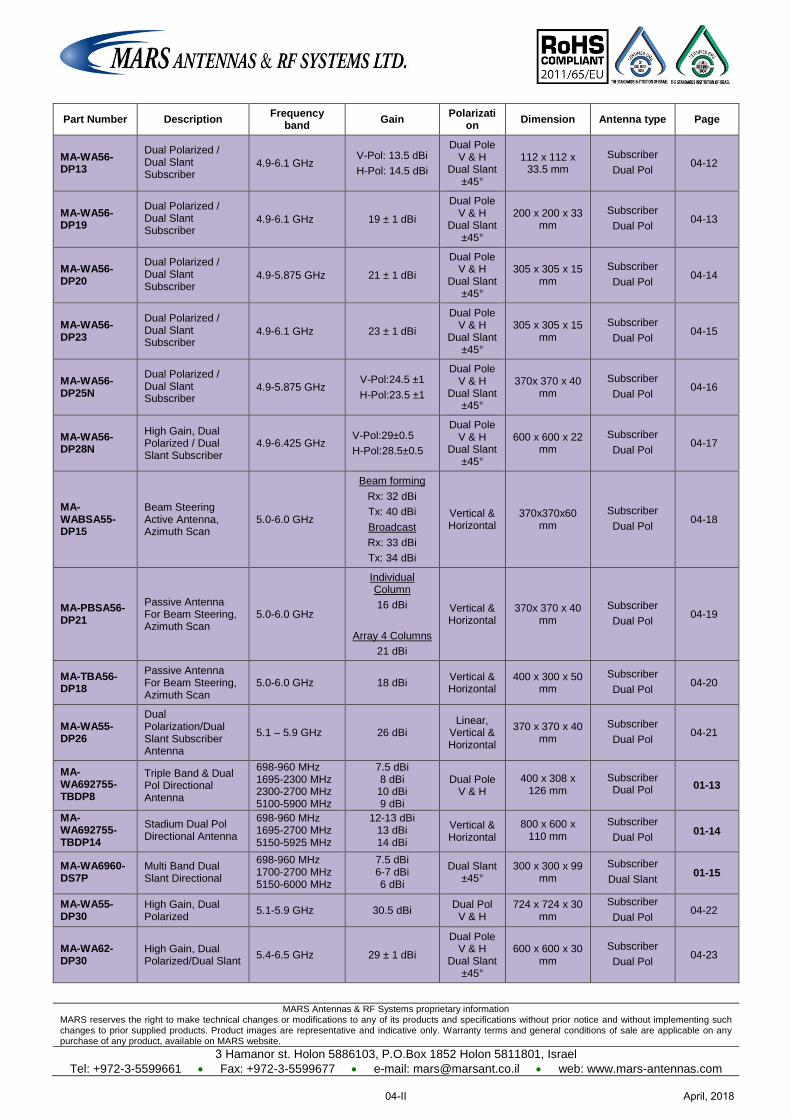
MARS Antennas & RF Systems proprietary information MARS reserves the right to make technical changes or modifications to any of its products and specifications without prior notice and without implementing such changes to prior supplied products. Product images are representative and indicative only. Warranty terms and general conditions of sale are applicable on any purchase of any product, available on MARS website.
3 Hamanor st. Holon 5886103, P.O.Box 1852 Holon 5811801, Israel
Tel: +972-3-5599661 Fax: +972-3-5599677 e-mail: [email protected] web: www.mars-antennas.com
Part Number Description Frequency
band Gain
Polarization
Dimension Antenna type Page
MA-WA56-DP13
Dual Polarized / Dual Slant Subscriber
4.9-6.1 GHz V-Pol: 13.5 dBi
H-Pol: 14.5 dBi
Dual Pole V & H
Dual Slant ±45°
112 x 112 x 33.5 mm
Subscriber
Dual Pol 04-12
MA-WA56-DP19
Dual Polarized / Dual Slant Subscriber
4.9-6.1 GHz 19 ± 1 dBi Dual Pole
V & H Dual Slant
±45°
200 x 200 x 33 mm
Subscriber
Dual Pol 04-13
MA-WA56-DP20
Dual Polarized / Dual Slant Subscriber
4.9-5.875 GHz 21 ± 1 dBi Dual Pole
V & H Dual Slant
±45°
305 x 305 x 15 mm
Subscriber
Dual Pol 04-14
MA-WA56-DP23
Dual Polarized / Dual Slant Subscriber
4.9-6.1 GHz 23 ± 1 dBi Dual Pole
V & H Dual Slant
±45°
305 x 305 x 15 mm
Subscriber
Dual Pol 04-15
MA-WA56-DP25N
Dual Polarized / Dual Slant Subscriber
4.9-5.875 GHz V-Pol:24.5 ±1
H-Pol:23.5 ±1
Dual Pole V & H
Dual Slant ±45°
370x 370 x 40 mm
Subscriber
Dual Pol 04-16
MA-WA56-DP28N
High Gain, Dual Polarized / Dual Slant Subscriber
4.9-6.425 GHz V-Pol:29±0.5
H-Pol:28.5±0.5
Dual Pole V & H
Dual Slant ±45°
600 x 600 x 22 mm
Subscriber
Dual Pol 04-17
MA-WABSA55-DP15
Beam Steering Active Antenna, Azimuth Scan
5.0-6.0 GHz
Beam forming
Rx: 32 dBi
Tx: 40 dBi
Broadcast
Rx: 33 dBi
Tx: 34 dBi
Vertical & Horizontal
370x370x60 mm
Subscriber
Dual Pol 04-18
MA-PBSA56-DP21
Passive Antenna For Beam Steering, Azimuth Scan
5.0-6.0 GHz
Individual Column
16 dBi
Array 4 Columns
21 dBi
Vertical & Horizontal
370x 370 x 40 mm
Subscriber
Dual Pol 04-19
MA-TBA56-DP18
Passive Antenna For Beam Steering, Azimuth Scan
5.0-6.0 GHz 18 dBi Vertical & Horizontal
400 x 300 x 50 mm
Subscriber
Dual Pol 04-20
MA-WA55-DP26
Dual Polarization/Dual Slant Subscriber Antenna
5.1 – 5.9 GHz 26 dBi Linear,
Vertical & Horizontal
370 x 370 x 40 mm
Subscriber
Dual Pol 04-21
MA-WA692755-TBDP8
Triple Band & Dual Pol Directional Antenna
698-960 MHz 1695-2300 MHz 2300-2700 MHz 5100-5900 MHz
7.5 dBi 8 dBi
10 dBi 9 dBi
Dual Pole V & H
400 x 308 x 126 mm
Subscriber Dual Pol 01-13
MA-WA692755-TBDP14
Stadium Dual Pol Directional Antenna
698-960 MHz 1695-2700 MHz 5150-5925 MHz
12-13 dBi 13 dBi 14 dBi
Vertical & Horizontal
800 x 600 x 110 mm
Subscriber
Dual Pol 01-14
MA-WA6960-DS7P
Multi Band Dual Slant Directional
698-960 MHz 1700-2700 MHz 5150-6000 MHz
7.5 dBi 6-7 dBi 6 dBi
Dual Slant ±45°
300 x 300 x 99 mm
Subscriber
Dual Slant 01-15
MA-WA55-DP30
High Gain, Dual Polarized
5.1-5.9 GHz 30.5 dBi Dual Pol
V & H 724 x 724 x 30
mm
Subscriber
Dual Pol 04-22
MA-WA62-DP30
High Gain, Dual Polarized/Dual Slant
5.4-6.5 GHz 29 ± 1 dBi
Dual Pole V & H
Dual Slant ±45°
600 x 600 x 30 mm
Subscriber
Dual Pol 04-23
April, 201804-II
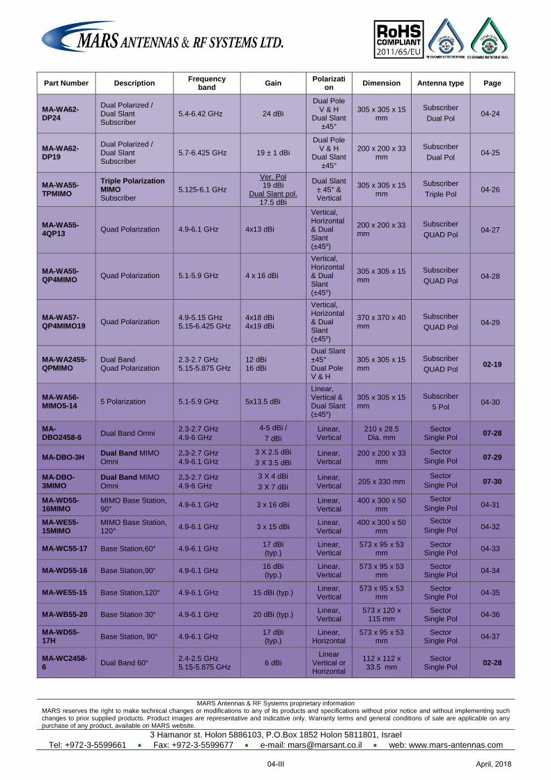
MARS Antennas & RF Systems proprietary information MARS reserves the right to make technical changes or modifications to any of its products and specifications without prior notice and without implementing such changes to prior supplied products. Product images are representative and indicative only. Warranty terms and general conditions of sale are applicable on any purchase of any product, available on MARS website.
3 Hamanor st. Holon 5886103, P.O.Box 1852 Holon 5811801, Israel
Tel: +972-3-5599661 Fax: +972-3-5599677 e-mail: [email protected] web: www.mars-antennas.com
Part Number Description Frequency
band Gain
Polarization
Dimension Antenna type Page
MA-WA62-DP24
Dual Polarized / Dual Slant Subscriber
5.4-6.42 GHz 24 dBi
Dual Pole V & H
Dual Slant ±45°
305 x 305 x 15 mm
Subscriber
Dual Pol 04-24
MA-WA62-DP19
Dual Polarized / Dual Slant Subscriber
5.7-6.425 GHz 19 ± 1 dBi
Dual Pole V & H
Dual Slant ±45°
200 x 200 x 33 mm
Subscriber
Dual Pol 04-25
MA-WA55-TPMIMO
Triple Polarization MIMO Subscriber
5.125-6.1 GHz
Ver. Pol 19 dBi
Dual Slant pol. 17.5 dBi
Dual Slant ± 45° & Vertical
305 x 305 x 15 mm
Subscriber
Triple Pol 04-26
MA-WA55-4QP13
Quad Polarization 4.9-6.1 GHz 4x13 dBi
Vertical, Horizontal & Dual Slant (±45o)
200 x 200 x 33 mm
Subscriber
QUAD Pol 04-27
MA-WA55-QP4MIMO Quad Polarization 5.1-5.9 GHz 4 x 16 dBi
Vertical, Horizontal & Dual Slant (±45o)
305 x 305 x 15 mm
Subscriber
QUAD Pol 04-28
MA-WA57-QP4MIMO19
Quad Polarization 4.9-5.15 GHz 5.15-6.425 GHz
4x18 dBi 4x19 dBi
Vertical, Horizontal & Dual Slant (±45o)
370 x 370 x 40 mm
Subscriber
QUAD Pol 04-29
MA-WA2455-QPMIMO
Dual Band Quad Polarization
2.3-2.7 GHz 5.15-5.875 GHz
12 dBi 16 dBi
Dual Slant ±45° Dual Pole V & H
305 x 305 x 15 mm
Subscriber
QUAD Pol 02-19
MA-WA56-MIMO5-14
5 Polarization 5.1-5.9 GHz 5x13.5 dBi
Linear, Vertical & Dual Slant (±45o)
305 x 305 x 15 mm
Subscriber
5 Pol 04-30
MA-DBO2458-6 Dual Band Omni 2.3-2.7 GHz
4.9-6 GHz
4-5 dBi /
7 dBi
Linear, Vertical
210 x 28.5 Dia. mm
Sector Single Pol
07-28
MA-DBO-3H Dual Band MIMO Omni
2.3-2.7 GHz 4.9-6.1 GHz
3 X 2.5 dBi
3 X 3.5 dBi
Linear, Vertical
200 x 200 x 33 mm
Sector
Single Pol 07-29
MA-DBO-3MIMO
Dual Band MIMO Omni
2.3-2.7 GHz 4.9-6 GHz
3 X 4 dBi
3 X 7 dBi
Linear, Vertical
205 x 330 mm Sector
Single Pol 07-30
MA-WD55-16MIMO
MIMO Base Station, 90° 4.9-6.1 GHz 3 x 16 dBi
Linear, Vertical
400 x 300 x 50 mm
Sector
Single Pol 04-31
MA-WE55-15MIMO
MIMO Base Station, 120° 4.9-6.1 GHz 3 x 15 dBi
Linear, Vertical
400 x 300 x 50 mm
Sector
Single Pol 04-32
MA-WC55-17 Base Station,60° 4.9-6.1 GHz 17 dBi (typ.)
Linear, Vertical
573 x 95 x 53 mm
Sector Single Pol
04-33
MA-WD55-16 Base Station,90° 4.9-6.1 GHz 16 dBi (typ.)
Linear, Vertical
573 x 95 x 53 mm
Sector Single Pol
04-34
MA-WE55-15 Base Station,120° 4.9-6.1 GHz 15 dBi (typ.) Linear, Vertical
573 x 95 x 53 mm
Sector Single Pol
04-35
MA-WB55-20 Base Station 30° 4.9-6.1 GHz 20 dBi (typ.) Linear, Vertical
573 x 120 x 115 mm
Sector Single Pol
04-36
MA-WD55-17H Base Station, 90° 4.9-6.1 GHz
17 dBi (typ.)
Linear, Horizontal
573 x 95 x 53 mm
Sector Single Pol
04-37
MA-WC2458-6 Dual Band 60° 2.4-2.5 GHz
5.15-5.875 GHz 6 dBi
Linear Vertical or Horizontal
112 x 112 x 33.5 mm
Sector Single Pol
02-28
April, 201804-III
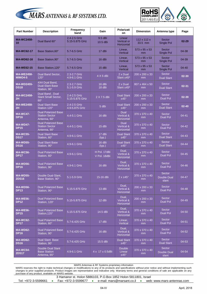
MARS Antennas & RF Systems proprietary information MARS reserves the right to make technical changes or modifications to any of its products and specifications without prior notice and without implementing such changes to prior supplied products. Product images are representative and indicative only. Warranty terms and general conditions of sale are applicable on any purchase of any product, available on MARS website.
3 Hamanor st. Holon 5886103, P.O.Box 1852 Holon 5811801, Israel
Tel: +972-3-5599661 Fax: +972-3-5599677 e-mail: [email protected] web: www.mars-antennas.com
Part Number Description Frequency
band Gain
Polarization
Dimension Antenna type Page
MA-WC2458-10
Dual Band 60° 2.4-2.5 GHz 5.15-5.875 GHz
9.5 dBi
10.5 dBi
Linear Vertical or Horizontal
112 x 112 x 33.5 mm
Sector Single Pol
02-29
MA-WC62-17 Base Station,60° 5.7-6.5 GHz 17 dBi Linear, Vertical
573 x 95 x 53 mm
Sector Single Pol
04-38
MA-WD62-16 Base Station,90° 5.7-6.5 GHz 16 dBi Linear, Vertical
573 x 95 x 53 mm
Sector Single Pol
04-39
MA-WE62-15 Base Station,120° 5.7-6.5 GHz 15 dBi Linear, Vertical
573 x 95 x 53 mm
Sector Single Pol
04-40
MA-WE2458-MIMO4-5
Dual Band Sector, 120°
2.3-2.7 GHz 4.9-6.1 GHz
4 X 5 dBi 2 x Dual
Slant ±45º 200 x 200 x 33
mm
Sector
Dual Slant 02-30
MA-WD2455-DS18
4X4 Dual Band, Dual-Slant Base
Station, 90
2.3-2.7 GHz 5.1-5.9 GHz
16 dBi 18 dBi
2 x Dual Slant ±45º
807 x 464 x 50 mm
Sector
Dual Slant 02-31
MA-WC2458-2H
Dual Band , Dual Slant Small Sector,
60
2.4-2.5 GHz 5.15-5.875 GHz
2 X 7.5 dBi Dual Slant
±45° 200 x 200 x 33
mm
Sector
Dual Pol 02-39
MA-WE2458-2H
Dual Slant Base Station 120°
2.4-2.5 GHz 4.9-5.875 GHz
5 dBi Dual Slant
±45° 200 x 200 x 33
mm
Sector
Dual Slant 02-40
MA-WC47-DP16
Dual Polarized Base Station Sector
Antenna, 60
4.4-5.1 GHz 16 dBi Dual
Vertical & Horizontal
370 x 370 x 40 mm
Sector Dual Pol
04-41
MA-WD47-DP15
Dual Polarized Base Station Sector
Antenna, 90
4.4-5.1 GHz 15 dBi Dual
Vertical & Horizontal
370 x 370 x 40 mm
Sector Dual Pol
04-42
MA-WC55-DS17
Dual Slant Base Station, 60° 4.9-6.1 GHz
17 dBi (typ.)
Dual Slant ±45°
370 x 370 x 40 mm
Sector
Dual Slant 04-43
MA-WD55-DS16
Dual Slant Base Station, 90° 4.9-6.1 GHz
16 dBi (typ.)
Dual Slant ±45°
370 x 370 x 40 mm
Sector
Dual Slant 04-44
MA-WC56-DP17
Dual Polarized Base
Station, 60 4.9-6.1 GHz H Pol. 17dBi
V Pol. 18dBi
Dual, Vertical & Horizontal
370 x 370 x 40 mm
Sector
Dual Pol 04-45
MA-WD56-DP16
Dual Polarized Base
Station, 90 4.9-6.1 GHz 16 dBi Dual,
Vertical & Horizontal
370 x 370 x 40 mm
Sector
Dual Pol 04-46
MA-WD55-2DS16
Double Dual-Slant, Base Station, 90°
5.1-5.9 GHz 15-16 dBi 2 x ±45° 370 x 370 x 40
mm
Sector
Double Dual slant
04-47
MA-WD56-DP13
Dual Polarized Base
Station, 90 5.15-5.875 GHz 13 dBi
Dual, Vertical & Horizontal
200 x 200 x 33 mm
Sector
Dual Pol 04-48
MA-WE56-DP12
Dual Polarized Base
Station, 120 5.15-5.875 GHz 12 dBi Dual,
Vertical & Horizontal
200 x 200 x 33 mm
Sector
Dual Pol 04-49
MA-WE56-DP15
Dual Polarized Base Station,120° 5.15-5.875 GHz 14.5 dBi
Dual, Vertical & Horizontal
370 x 370 x 40 mm
Sector
Dual Pol 04-50
MA-WC62-DP17
Dual Polarized Base Station, 60° 5.7-6.425 GHz 17 dBi
Linear, Vertical
370 x 370 x 40 mm
Sector
Dual Pol 04-51
MA-WD62-DP16
Dual Polarized Base
Station, 90 5.7-6.425 GHz 16 dBi Dual,
Vertical & Horizontal
370 x 370 x 40 mm
Sector
Dual Pol 04-52
MA-WD62-DS16
Dual Slant Base
Station, 90 5.7-6.425 GHz 15.5 dBi Dual Slant
±45° 370 x 370 x 40
mm
Sector
Dual Slant 04-53
MA-WC54-2DS17
Double Dual Slant Base Station Antenna, 65°
4.9-6.1 GHz 4 x 17 ± 0.5dBi Double Linear ±45°
370 x 370 x 40 mm
Sector
Double Dual slant
04-54
April, 201804-IV
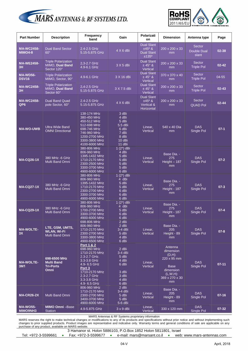
MARS Antennas & RF Systems proprietary information MARS reserves the right to make technical changes or modifications to any of its products and specifications without prior notice and without implementing such changes to prior supplied products. Product images are representative and indicative only. Warranty terms and general conditions of sale are applicable on any purchase of any product, available on MARS website.
3 Hamanor st. Holon 5886103, P.O.Box 1852 Holon 5811801, Israel
Tel: +972-3-5599661 Fax: +972-3-5599677 e-mail: [email protected] web: www.mars-antennas.com
Part Number Description Frequency
band Gain
Polarization
Dimension Antenna type Page
MA-WC2458-MIMO4-8
Dual Band Sector 60°
2.4-2.5 GHz 5.15-5.875 GHz
4 X 6 dBi
Dual Slant ±45º &
Dual Slant ±135º
200 x 200 x 33 mm
Sector
Double Dual slant
02-38
MA-WE2458-3H
Triple Polarization MIMO, Dual Band Sector 120°
2.3-2.7 GHz 4.9-6.1 GHz
3 X 5 dBi Dual Slant
± 45° & Vertical
200 x 200 x 33 mm
Sector
Triple Pol 02-42
MA-WD56-DSV16
Triple Polarization MIMO, Sector, 90°
4.9-6.1 GHz 3 X 16 dBi Dual Slant
± 45° & Vertical
370 x 370 x 40 mm
Sector
Triple Pol 04-55
MA-WC2458-3H
Triple Polarization MIMO, Dual Band Sector 60°
2.4-2.5 GHz 5.15-5.875 GHz
3 X 7.5 dBi Dual Slant
± 45° & Vertical
200 x 200 x 33 mm
Sector
Triple Pol 02-43
MA-WC2458-QP6
Dual Band Quad pole Sector, 60°
2.4-2.5 GHz 5.15-5.875 GHz
4 X 6 dBi
Dual Slant ±45º &
Vertical & Horizontal
200 x 200 x 33 mm
Sector
QUAD Pol 02-44
MA-WO-UWB Ultra Wide Band OMNI Directional
138-174 MHz 380-450 MHz 450-512 MHz 512-698 MHz 698-746 MHz 746-960 MHz 1200-2700 MHz 3300-3800 MHz 4100-6000 MHz
3 dBi 4 dBi 5 dBi
5.5 dBi 6 dBi 7 dBi 8 dBi
10 dBi 11 dBi
Linear, Vertical
540 x 40 Dia mm
DAS Single Pol
07-1
MA-CQ26-1X 380 MHz -6 GHz Multi Band Omni
380-806 MHz 806-960 MHz 1395-1432 MHz 1710-2170 MHz 2300-2500 MHz 3300-3700 MHz 4900-6000 MHz
1 (2*) dBi 4 dBi 5 dBi 5 dBi 5 dBi 5 dBi 6 dBi
Linear, Vertical
Base Dia. - 275
Height – 187 mm
DAS Single Pol
07-2
MA-CQ27-1X 380 MHz -6 GHz Multi Band Omni
380-806 MHz 806-960 MHz 1395-1432 MHz 1710-2170 MHz 2300-2700 MHz 3300-3700 MHz 4900-6000 MHz
1 (2*) dBi 4 dBi 5 dBi 5 dBi 6 dBi 6 dBi 6 dBi
Linear, Vertical
Base Dia. - 275
Height - 187 mm
DAS Single Pol
07-3
MA-CQ29-1X 380 MHz -6 GHz Multi Band Omni
380-806 MHz 806-960 MHz 1700-2700 MHz 3300-3700 MHz 4900-6000 MHz
1 (2*) dBi 4 dBi 5 dBi 6 dBi 6 dBi
Linear, Vertical
Base Dia. - 275
Height - 187 mm
DAS Single Pol
07-4
MA-WOLTE-3X
LTE, GSM, UMTS, WLAN, Wi-Fi Multi Band Omni
698-806 MHz 806-960 MHz 1710-2170 MHz 2300-2700 MHz 3300-3800 MHz 4900-6500 MHz
2 dBi 2 dBi
3-4 dBi 5 dBi 4 dBi 6 dBi
Linear, Vertical
Base Dia. - 205
Height - 89 mm
DAS Single Pol
07-8
MA-WOLTE-3M1
698-6500 MHz Multi Band Tri-Ports Omni
Port 1 & 2 698-960 MHz 1710-2170 MHz 2.3-2.7 GHz. 3.3-3.8 GHz 4.9- 6.5 GHz Port 3 1710-2170 MHz 2.3-2.7 GHz 3.3-3.8 GHz 4.9- 6.5 GHz
2 dBi
3-4 dBi 5 dBi 4 dBi 6 dBi
3 dBi 3 dBi 4 dBi 6 dBi
Linear, Vertical
Antenna dimension
(D,H): 220 x 95 mm
Base
dimension (L,W,H):
369 x 270 x 30 mm
DAS Single Pol
07-11
MA-CR26-2X Multi Band Omni
806-960 MHz 1710-2170 MHz 2300-2700 MHz 3400-3700 MHz 4900-6000 MHz
2 dBi 3-4 dBi 5 dBi 5 dBi
5-6 dBi
Linear, Vertical
Base Dia. - 205
Height - 89 mm
DAS Single Pol
07-16
MA-WO55-MIMO9NH3
MIMO Omni –Base Station 4.9-5.875 GHz 3 x 9 dBi
Linear, Vertical
330 x 120 mm DAS
Single Pol 07-32
April, 201804-V
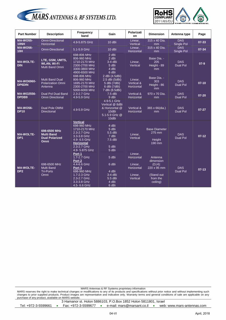
MARS Antennas & RF Systems proprietary information MARS reserves the right to make technical changes or modifications to any of its products and specifications without prior notice and without implementing such changes to prior supplied products. Product images are representative and indicative only. Warranty terms and general conditions of sale are applicable on any purchase of any product, available on MARS website.
3 Hamanor st. Holon 5886103, P.O.Box 1852 Holon 5811801, Israel
Tel: +972-3-5599661 Fax: +972-3-5599677 e-mail: [email protected] web: www.mars-antennas.com
Part Number Description Frequency
band Gain
Polarization
Dimension Antenna type Page
MA-WO55-10NH
Omni-Directional Horizontal 4.9-5.875 GHz 10 dBi
Linear, Vertical
315 x 40 Dia. mm
DAS Single Pol
07-33
MA-WO56-10H
Omni-Directional 5.1-5.9 GHz 10 dBi Linear,
Horizontal 315 x 40 Dia.
mm DAS
Single Pol 07-34
MA-WOLTE-DIN
LTE, GSM, UMTS, WLAN, Wi-Fi Multi Band Omni
698-806 MHz 806-960 MHz 1710-2170 MHz 2300-2700 MHz 3300-3800 MHz 4900-6500 MHz
2 dBi 2 dBi
3-4 dBi 5 dBi 4 dBi 6 dBi
Linear, Vertical
Base Dia. - 205
Height - 89 mm
DAS Dual Pol
07-9
MA-WO6960-DP6DIN
Multi Band Dual Polarization Omni Antenna
698-806 MHz 806-960 MHz 1695-2170 MHz 2300-2700 MHz 5000-6000 MHz
2 dBi (4.5dBi) 2.5 dBi (5dBi) 5 dBi (7dBi) 6 dBi (7dBi)
7 dBi (8.5dBi)
Linear, Vertical & Horizontal
Base Dia. - 303
Height - 86 mm
DAS Dual Pol
07-10
MA-WO2556-DPDB9
Dual Pol Dual Band Omni Directional
2.3-2.7 GHz 4.9-5.9 GHz
7.5 dBi 9 dBi
Vertical & Horizontal
970 x 70 Dia. mm
DAS Dual Pol
07-20
MA-WO56-DP10
Dual Pole OMNI Directional
4.9-5.9 GHz
4.9-5.1 GHz Vertical @ 8dBi & Horizontal @
10dBi 5.1-5.9 GHz @
10dBi
Vertical & Horizontal
365 x 66(dia.) mm
DAS Dual Pol
07-27
MA-WOLTE-DP1
698-6500 MHz Multi Band Dual Polarized Omni
Vertical 698-960 MHz 1710-2170 MHz 2.3-2.7 GHz 3.3-3.8 GHz 4.9- 6.5 GHz Horizontal 2.3-2.7 GHz 4.9- 5.875 GHz
4 dBi 5 dBi
5.5 dBi 7 dBi
7.5 dBi
5 dBi 5 dBi
Linear, Vertical
Base Diameter 275 mm
Height
190 mm
DAS Dual Pol
07-12
MA-WOLTE-DP2
698-6500 MHz Multi Band Tri-Ports Omni
Port 1 1.7-2.7 GHz Port 2 4.4-6.6 GHz Port 3 698-960 MHz 1.7-2.3 GHz 2.3-2.7 GHz. 3.3-3.8 GHz 4.5- 6.6 GHz
5 dBi
6 dBi
4 dBi
3-4 dBi 5.5 dBi 4 dBi 6 dBi
Linear, Horizontal
Linear,
Horizontal
Linear, Vertical
Antenna dimension
(D,H): 220 x 95 mm
(Stand out from the ceiling)
DAS Dual Pol
07-13
April, 201804-VI
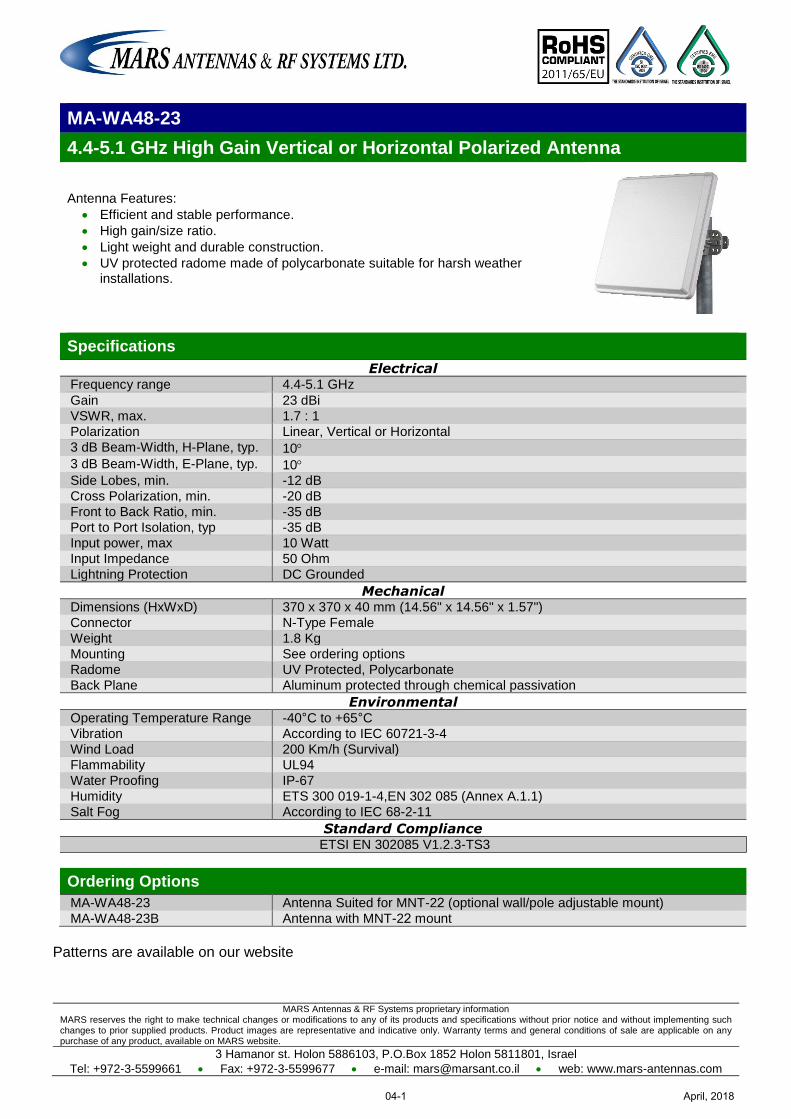
MARS Antennas & RF Systems proprietary information MARS reserves the right to make technical changes or modifications to any of its products and specifications without prior notice and without implementing such changes to prior supplied products. Product images are representative and indicative only. Warranty terms and general conditions of sale are applicable on any purchase of any product, available on MARS website.
3 Hamanor st. Holon 5886103, P.O.Box 1852 Holon 5811801, Israel
Tel: +972-3-5599661 Fax: +972-3-5599677 e-mail: [email protected] web: www.mars-antennas.com
MA-WA48-23
4.4-5.1 GHz High Gain Vertical or Horizontal Polarized Antenna
Antenna Features:
Efficient and stable performance.
High gain/size ratio.
Light weight and durable construction.
UV protected radome made of polycarbonate suitable for harsh weather installations.
Specifications
Electrical Frequency range 4.4-5.1 GHz
Gain 23 dBi
VSWR, max. 1.7 : 1
Polarization Linear, Vertical or Horizontal
3 dB Beam-Width, H-Plane, typ. 10 3 dB Beam-Width, E-Plane, typ. 10 Side Lobes, min. -12 dB
Cross Polarization, min. -20 dB
Front to Back Ratio, min. -35 dB
Port to Port Isolation, typ -35 dB
Input power, max 10 Watt
Input Impedance 50 Ohm
Lightning Protection DC Grounded
Mechanical Dimensions (HxWxD) 370 x 370 x 40 mm (14.56" x 14.56" x 1.57")
Connector N-Type Female
Weight 1.8 Kg
Mounting See ordering options
Radome UV Protected, Polycarbonate
Back Plane Aluminum protected through chemical passivation
Environmental Operating Temperature Range -40°C to +65°C
Vibration According to IEC 60721-3-4
Wind Load 200 Km/h (Survival)
Flammability UL94
Water Proofing IP-67
Humidity ETS 300 019-1-4,EN 302 085 (Annex A.1.1)
Salt Fog According to IEC 68-2-11
Standard Compliance ETSI EN 302085 V1.2.3-TS3
Ordering Options
MA-WA48-23 Antenna Suited for MNT-22 (optional wall/pole adjustable mount)
MA-WA48-23B Antenna with MNT-22 mount
Patterns are available on our website
April, 201804-1
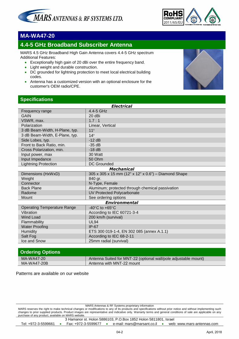
MARS Antennas & RF Systems proprietary information MARS reserves the right to make technical changes or modifications to any of its products and specifications without prior notice and without implementing such changes to prior supplied products. Product images are representative and indicative only. Warranty terms and general conditions of sale are applicable on any purchase of any product, available on MARS website.
3 Hamanor st. Holon 5886103, P.O.Box 1852 Holon 5811801, Israel
Tel: +972-3-5599661 Fax: +972-3-5599677 e-mail: [email protected] web: www.mars-antennas.com
MA-WA47-20
4.4-5 GHz Broadband Subscriber Antenna
MARS 4.5 GHz Broadband High Gain Antenna covers 4.4-5 GHz spectrum Additional Features:
Exceptionally high gain of 20 dBi over the entire frequency band.
Light weight and durable construction.
DC grounded for lightning protection to meet local electrical building codes.
Antenna has a customized version with an optional enclosure for the customer's OEM radio/CPE.
Specifications
Electrical Frequency range 4.4-5 GHz
GAIN 20 dBi
VSWR, max. 1.7 : 1
Polarization Linear, Vertical
3 dB Beam-Width, H-Plane, typ. 11 3 dB Beam-Width, E-Plane, typ. 14 Side Lobes, typ. -12 dB
Front to Back Ratio, min. -35 dB
Cross Polarization, min. -18 dB
Input power, max 30 Watt
Input Impedance 50 Ohm
Lightning Protection DC Grounded
Mechanical Dimensions (HxWxD) 305 x 305 x 15 mm (12" x 12" x 0.6") – Diamond Shape
Weight 840 gr.
Connector N-Type, Female
Back Plane Aluminum; protected through chemical passivation
Radome UV Protected Polycarbonate
Mount See ordering options
Environmental Operating Temperature Range -40C to +65C Vibration According to IEC 60721-3-4
Wind Load 200 km/h (survival)
Flammability UL94
Water Proofing IP-67
Humidity ETS 300 019-1-4, EN 302 085 (annex A.1.1)
Salt Fog According to IEC 68-2-11
Ice and Snow 25mm radial (survival)
Ordering Options
MA-WA47-20 Antenna Suited for MNT-22 (optional wall/pole adjustable mount)
MA-WA47-20B Antenna with MNT-22 mount
Patterns are available on our website
April, 201804-2
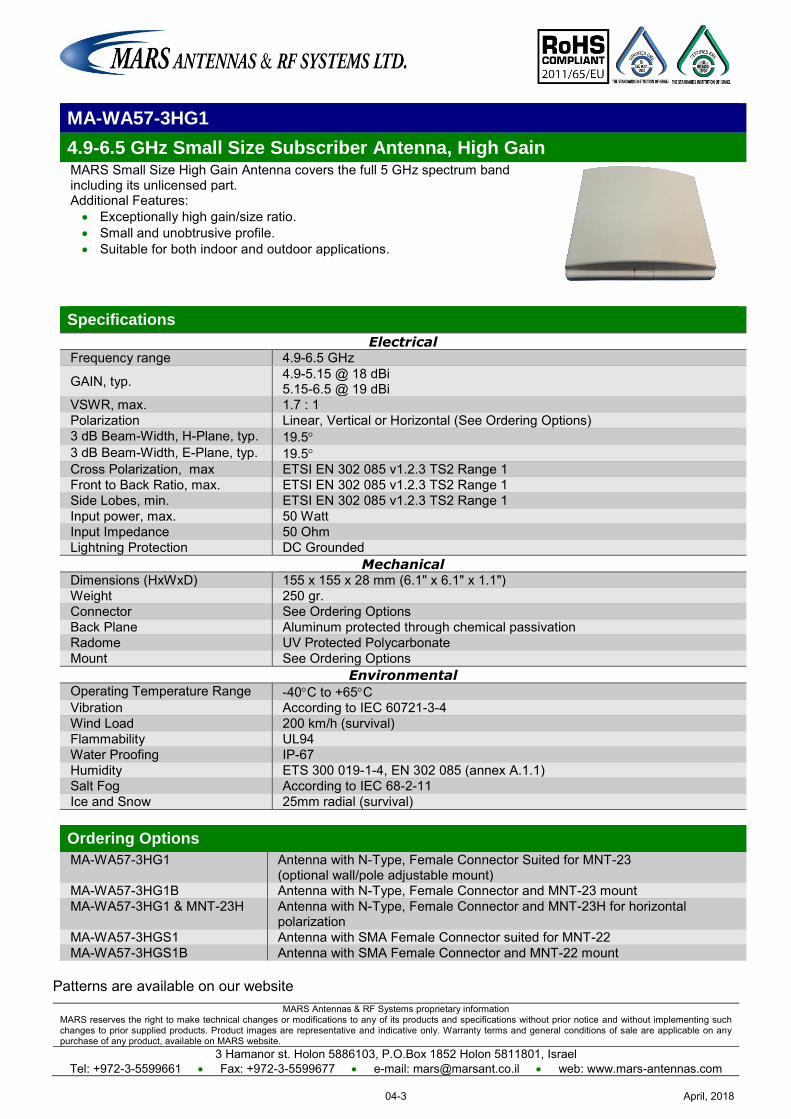
MARS Antennas & RF Systems proprietary information MARS reserves the right to make technical changes or modifications to any of its products and specifications without prior notice and without implementing such changes to prior supplied products. Product images are representative and indicative only. Warranty terms and general conditions of sale are applicable on any purchase of any product, available on MARS website.
3 Hamanor st. Holon 5886103, P.O.Box 1852 Holon 5811801, Israel Tel: +972-3-5599661 Fax: +972-3-5599677 e-mail: [email protected] web: www.mars-antennas.com
MA-WA57-3HG1
4.9-6.5 GHz Small Size Subscriber Antenna, High Gain MARS Small Size High Gain Antenna covers the full 5 GHz spectrum band including its unlicensed part. Additional Features: Exceptionally high gain/size ratio. Small and unobtrusive profile. Suitable for both indoor and outdoor applications.
Specifications
Electrical Frequency range 4.9-6.5 GHz
GAIN, typ. 4.9-5.15 @ 18 dBi 5.15-6.5 @ 19 dBi
VSWR, max. 1.7 : 1 Polarization Linear, Vertical or Horizontal (See Ordering Options) 3 dB Beam-Width, H-Plane, typ. 19.5 3 dB Beam-Width, E-Plane, typ. 19.5 Cross Polarization, max ETSI EN 302 085 v1.2.3 TS2 Range 1 Front to Back Ratio, max. ETSI EN 302 085 v1.2.3 TS2 Range 1 Side Lobes, min. ETSI EN 302 085 v1.2.3 TS2 Range 1 Input power, max. 50 Watt Input Impedance 50 Ohm Lightning Protection DC Grounded
Mechanical Dimensions (HxWxD) 155 x 155 x 28 mm (6.1" x 6.1" x 1.1") Weight 250 gr. Connector See Ordering Options Back Plane Aluminum protected through chemical passivation Radome UV Protected Polycarbonate Mount See Ordering Options
Environmental Operating Temperature Range -40C to +65C Vibration According to IEC 60721-3-4 Wind Load 200 km/h (survival) Flammability UL94 Water Proofing IP-67 Humidity ETS 300 019-1-4, EN 302 085 (annex A.1.1) Salt Fog According to IEC 68-2-11 Ice and Snow 25mm radial (survival) Ordering Options
MA-WA57-3HG1 Antenna with N-Type, Female Connector Suited for MNT-23 (optional wall/pole adjustable mount)
MA-WA57-3HG1B Antenna with N-Type, Female Connector and MNT-23 mount MA-WA57-3HG1 & MNT-23H Antenna with N-Type, Female Connector and MNT-23H for horizontal
polarization MA-WA57-3HGS1 Antenna with SMA Female Connector suited for MNT-22 MA-WA57-3HGS1B Antenna with SMA Female Connector and MNT-22 mount
Patterns are available on our website
April, 201804-3
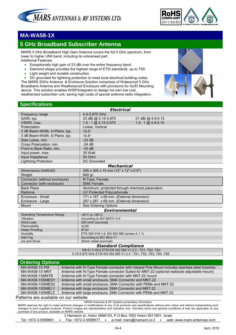
MARS Antennas & RF Systems proprietary information MARS reserves the right to make technical changes or modifications to any of its products and specifications without prior notice and without implementing such changes to prior supplied products. Product images are representative and indicative only. Warranty terms and general conditions of sale are applicable on any purchase of any product, available on MARS website.
3 Hamanor st. Holon 5886103, P.O.Box 1852 Holon 5811801, Israel Tel: +972-3-5599661 Fax: +972-3-5599677 e-mail: [email protected] web: www.mars-antennas.com
MA-WA58-1X
5 GHz Broadband Subscriber Antenna
MARS 5 GHz Broadband High Gain Antenna covers the full 5 GHz spectrum, from lower to higher UNII band, including its unlicensed part. Additional Features:
Exceptionally high gain of 23 dBi over the entire frequency band. Diamond shape provides the highest range of ETSI standards, up to TS5. Light weight and durable construction. DC grounded for lightning protection to meet local electrical building codes.
The MARS 5GHz Antenna & Enclosure Solution comprises of Waterproof 5 GHz Broadband Antenna and Weatherproof Enclosure with provisions for Az/El Mounting device. This solution enables WISP/Integrator to design his own low cost, weatherized subscriber unit, saving high costs of special antenna-radio integration.
Specifications Electrical
Frequency range 4.9-5.875 GHz GAIN, typ. 23 dBi @ 5.15-5.875 21 dBi @ 4.9-5.15 VSWR, max. 1.5 : 1 @ 5.15-5.875 1.9 : 1 @ 4.9-5.15 Polarization Linear, Vertical 3 dB Beam-Width, H-Plane, typ. 10.5 3 dB Beam-Width, E-Plane, typ. 10.5 Side Lobes, min. -23 dB Cross Polarization, min. -24 dB Front to Back Ratio, min. -30 dB Input power, max. 30 Watt Input Impedance 50 Ohm Lightning Protection DC Grounded
Mechanical Dimensions (HxWxD) 305 x 305 x 15 mm (12" x 12" x 0.6") Weight 840 gr. Connector (without enclosure) N-Type, Female Connector (with enclosure) SMA Female Back Plane Aluminum; protected through chemical passivation Radome UV Protected Polycarbonate Enclosure - Small 171 x 167 x 68 mm. (External dimension) Enclosure - Large 287 x 287 x 68 mm. (External dimension) Mount See Ordering Options
Environmental Operating Temperature Range -40C to +65C Vibration According to IEC 60721-3-4 Wind Load 200 km/h (survival) Flammability UL94 Water Proofing IP-67 Humidity ETS 300 019-1-4, EN 302 085 (annex A.1.1) Salt Fog According to IEC 68-2-11 Ice and Snow 25mm radial (survival)
Standard Compliance 51. 5-914 GHz ETSI EN 302 085 V1.2.3 - TS1, TS2, TS3
5.15-5.875 GHz ETSI EN 302 085 V1.2.3 - TS1, TS2, TS3, TS4, TS5
Ordering Options MA-WA58-1X PM Antenna with N-Type Female connector with integral Pole Mount includes stainless steel brackets MA-WA58-1X MNT Antenna with N-Type Female connector Suited for MNT-22 (optional wall/pole adjustable mount) MA-WA58-1XMNTB Antenna with N-Type Female connector with MNT-22 mount MA-WA58-1XSMESY Antenna with small enclosure, SMA Connector and MNT-22 MA-WA58-1XSMESZ Antenna with small enclosure, SMA Connector with PEMs and MNT-22 MA-WA58-1XSMELY Antenna with large enclosure, SMA Connector and MNT-22 MA-WA58-1XSMELZ Antenna with large enclosure, SMA Connector with PEMs and MNT-22
Patterns are available on our website
April, 201804-4
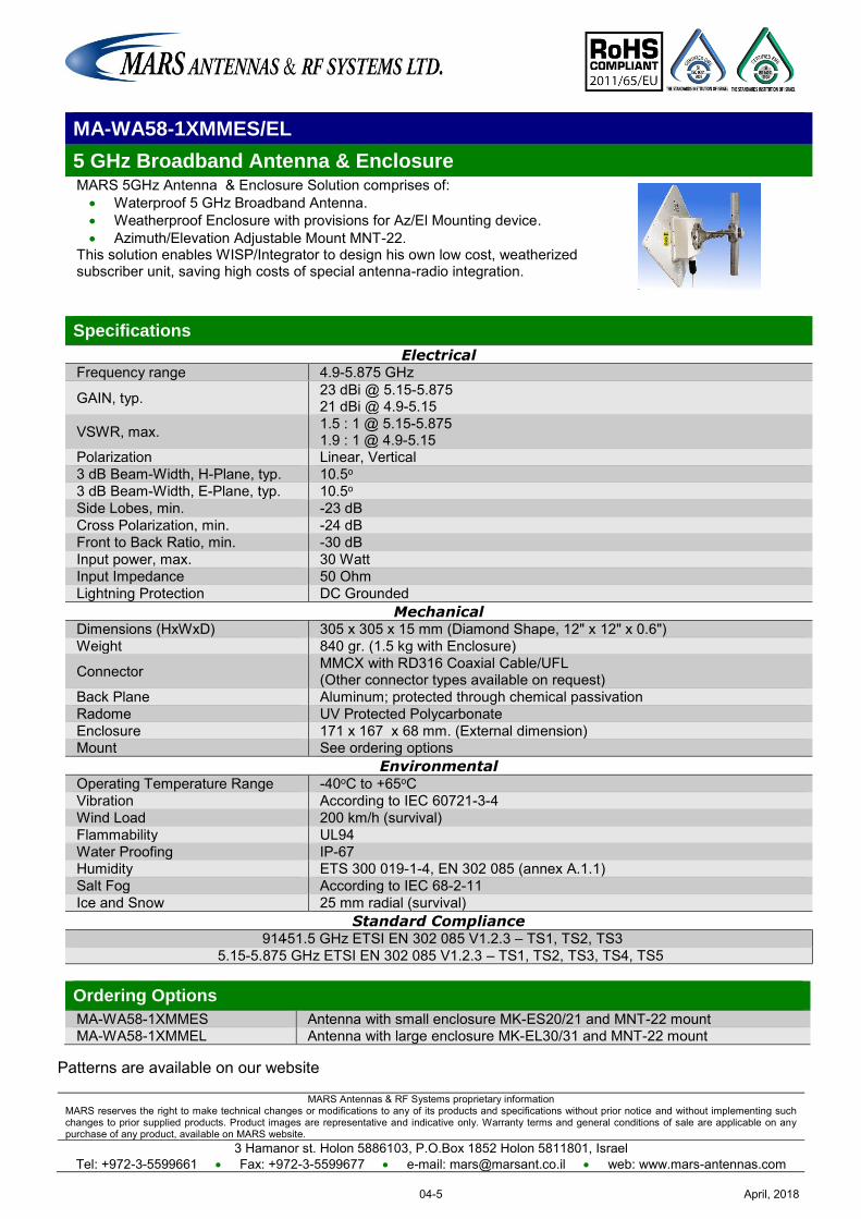
MARS Antennas & RF Systems proprietary information MARS reserves the right to make technical changes or modifications to any of its products and specifications without prior notice and without implementing such changes to prior supplied products. Product images are representative and indicative only. Warranty terms and general conditions of sale are applicable on any purchase of any product, available on MARS website.
3 Hamanor st. Holon 5886103, P.O.Box 1852 Holon 5811801, Israel Tel: +972-3-5599661 Fax: +972-3-5599677 e-mail: [email protected] web: www.mars-antennas.com
MA-WA58-1XMMES/EL
5 GHz Broadband Antenna & Enclosure MARS 5GHz Antenna & Enclosure Solution comprises of: Waterproof 5 GHz Broadband Antenna. Weatherproof Enclosure with provisions for Az/El Mounting device. Azimuth/Elevation Adjustable Mount MNT-22.
This solution enables WISP/Integrator to design his own low cost, weatherized subscriber unit, saving high costs of special antenna-radio integration.
Specifications
Electrical Frequency range 4.9-5.875 GHz
GAIN, typ. 23 dBi @ 5.15-5.875 21 dBi @ 4.9-5.15
VSWR, max. 1.5 : 1 @ 5.15-5.875 1.9 : 1 @ 4.9-5.15
Polarization Linear, Vertical 3 dB Beam-Width, H-Plane, typ. 10.5o 3 dB Beam-Width, E-Plane, typ. 10.5o Side Lobes, min. -23 dB Cross Polarization, min. -24 dB Front to Back Ratio, min. -30 dB Input power, max. 30 Watt Input Impedance 50 Ohm Lightning Protection DC Grounded
Mechanical Dimensions (HxWxD) 305 x 305 x 15 mm (Diamond Shape, 12" x 12" x 0.6") Weight 840 gr. (1.5 kg with Enclosure)
Connector MMCX with RD316 Coaxial Cable/UFL (Other connector types available on request)
Back Plane Aluminum; protected through chemical passivation Radome UV Protected Polycarbonate Enclosure 171 x 167 x 68 mm. (External dimension) Mount See ordering options
Environmental Operating Temperature Range -40oC to +65oC Vibration According to IEC 60721-3-4 Wind Load 200 km/h (survival) Flammability UL94 Water Proofing IP-67 Humidity ETS 300 019-1-4, EN 302 085 (annex A.1.1) Salt Fog According to IEC 68-2-11 Ice and Snow 25 mm radial (survival)
Standard Compliance 51.5-914 GHz ETSI EN 302 085 V1.2.3 – TS1, TS2, TS3
5.15-5.875 GHz ETSI EN 302 085 V1.2.3 – TS1, TS2, TS3, TS4, TS5 Ordering Options
MA-WA58-1XMMES Antenna with small enclosure MK-ES20/21 and MNT-22 mount MA-WA58-1XMMEL Antenna with large enclosure MK-EL30/31 and MNT-22 mount
Patterns are available on our website
April, 201804-5
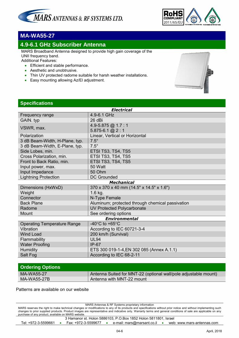
MARS Antennas & RF Systems proprietary information MARS reserves the right to make technical changes or modifications to any of its products and specifications without prior notice and without implementing such changes to prior supplied products. Product images are representative and indicative only. Warranty terms and general conditions of sale are applicable on any purchase of any product, available on MARS website.
3 Hamanor st. Holon 5886103, P.O.Box 1852 Holon 5811801, Israel Tel: +972-3-5599661 Fax: +972-3-5599677 e-mail: [email protected] web: www.mars-antennas.com
MA-WA55-27
4.9-6.1 GHz Subscriber Antenna MARS Broadband Antenna designed to provide high gain coverage of the UNII frequency band. Additional Features: Efficient and stable performance. Aesthetic and unobtrusive. Thin UV protected radome suitable for harsh weather installations. Easy mounting allowing Az/El adjustment.
Specifications
Electrical
Frequency range 4.9-6.1 GHz GAIN. typ 26 dBi
VSWR, max. 4.9-5.875 @ 1.7 : 1 5.875-6.1 @ 2 : 1
Polarization Linear, Vertical or Horizontal 3 dB Beam-Width, H-Plane, typ. 7.5° 3 dB Beam-Width, E-Plane, typ. 7.5° Side Lobes, min. ETSI TS3, TS4, TS5 Cross Polarization, min. ETSI TS3, TS4, TS5 Front to Back Ratio, min. ETSI TS3, TS4, TS5 Input power, max. 50 Watt Input Impedance 50 Ohm Lightning Protection DC Grounded
Mechanical
Dimensions (HxWxD) 370 x 370 x 40 mm (14.5" x 14.5" x 1.6") Weight 1.6 kg. Connector N-Type Female Back Plane Aluminum; protected through chemical passivation Radome UV Protected Polycarbonate Mount See ordering options
Environmental
Operating Temperature Range -40°C to +65°C Vibration According to IEC 60721-3-4 Wind Load 200 km/h (Survival) Flammability UL94 Water Proofing IP-67 Humidity ETS 300 019-1-4,EN 302 085 (Annex A.1.1) Salt Fog According to IEC 68-2-11
Ordering Options
MA-WA55-27 Antenna Suited for MNT-22 (optional wall/pole adjustable mount) MA-WA55-27B Antenna with MNT-22 mount
Patterns are available on our website
April, 201804-6
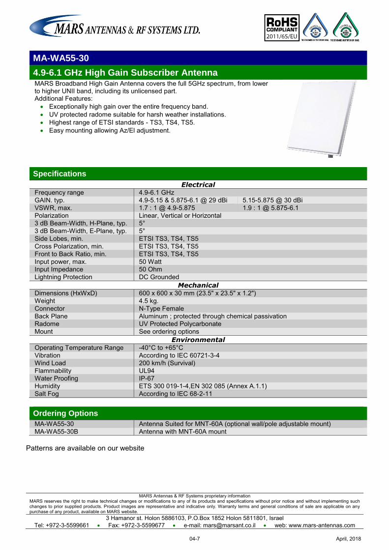
MARS Antennas & RF Systems proprietary information MARS reserves the right to make technical changes or modifications to any of its products and specifications without prior notice and without implementing such changes to prior supplied products. Product images are representative and indicative only. Warranty terms and general conditions of sale are applicable on any purchase of any product, available on MARS website.
3 Hamanor st. Holon 5886103, P.O.Box 1852 Holon 5811801, Israel Tel: +972-3-5599661 Fax: +972-3-5599677 e-mail: [email protected] web: www.mars-antennas.com
MA-WA55-30
4.9-6.1 GHz High Gain Subscriber Antenna MARS Broadband High Gain Antenna covers the full 5GHz spectrum, from lower to higher UNII band, including its unlicensed part. Additional Features: Exceptionally high gain over the entire frequency band. UV protected radome suitable for harsh weather installations. Highest range of ETSI standards - TS3, TS4, TS5. Easy mounting allowing Az/El adjustment.
Specifications
Electrical Frequency range 4.9-6.1 GHz GAIN. typ. 4.9-5.15 & 5.875-6.1 @ 29 dBi 5.15-5.875 @ 30 dBi VSWR, max. 1.7 : 1 @ 4.9-5.875 1.9 : 1 @ 5.875-6.1 Polarization Linear, Vertical or Horizontal 3 dB Beam-Width, H-Plane, typ. 5° 3 dB Beam-Width, E-Plane, typ. 5° Side Lobes, min. ETSI TS3, TS4, TS5 Cross Polarization, min. ETSI TS3, TS4, TS5 Front to Back Ratio, min. ETSI TS3, TS4, TS5 Input power, max. 50 Watt Input Impedance 50 Ohm Lightning Protection DC Grounded
Mechanical Dimensions (HxWxD) 600 x 600 x 30 mm (23.5" x 23.5" x 1.2") Weight 4.5 kg. Connector N-Type Female Back Plane Aluminum ; protected through chemical passivation Radome UV Protected Polycarbonate Mount See ordering options
Environmental Operating Temperature Range -40°C to +65°C Vibration According to IEC 60721-3-4 Wind Load 200 km/h (Survival) Flammability UL94 Water Proofing IP-67 Humidity ETS 300 019-1-4,EN 302 085 (Annex A.1.1) Salt Fog According to IEC 68-2-11
Ordering Options
MA-WA55-30 Antenna Suited for MNT-60A (optional wall/pole adjustable mount) MA-WA55-30B Antenna with MNT-60A mount
Patterns are available on our website
April, 201804-7
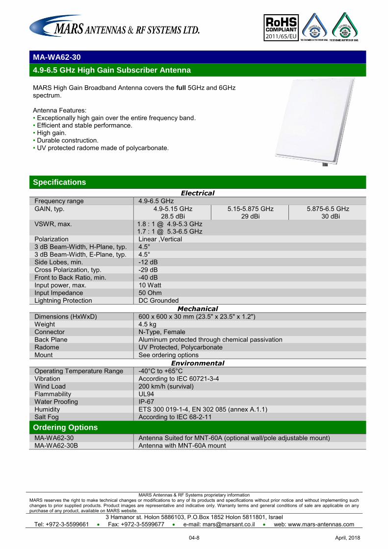
MARS Antennas & RF Systems proprietary information MARS reserves the right to make technical changes or modifications to any of its products and specifications without prior notice and without implementing such changes to prior supplied products. Product images are representative and indicative only. Warranty terms and general conditions of sale are applicable on any purchase of any product, available on MARS website.
3 Hamanor st. Holon 5886103, P.O.Box 1852 Holon 5811801, Israel Tel: +972-3-5599661 Fax: +972-3-5599677 e-mail: [email protected] web: www.mars-antennas.com
MA-WA62-30
4.9-6.5 GHz High Gain Subscriber Antenna
MARS High Gain Broadband Antenna covers the full 5GHz and 6GHz spectrum. Antenna Features: • Exceptionally high gain over the entire frequency band. • Efficient and stable performance. • High gain. • Durable construction. • UV protected radome made of polycarbonate.
Specifications
Electrical Frequency range 4.9-6.5 GHz GAIN, typ. 4.9-5.15 GHz
28.5 dBi 5.15-5.875 GHz
29 dBi 5.875-6.5 GHz
30 dBi VSWR, max. 1.8 : 1 @ 4.9-5.3 GHz
1.7 : 1 @ 5.3-6.5 GHz Polarization Linear ,Vertical 3 dB Beam-Width, H-Plane, typ. 4.5° 3 dB Beam-Width, E-Plane, typ. 4.5° Side Lobes, min. -12 dB Cross Polarization, typ. -29 dB Front to Back Ratio, min. -40 dB Input power, max. 10 Watt Input Impedance 50 Ohm Lightning Protection DC Grounded
Mechanical Dimensions (HxWxD) 600 x 600 x 30 mm (23.5" x 23.5" x 1.2") Weight 4.5 kg Connector N-Type, Female Back Plane Aluminum protected through chemical passivation Radome UV Protected, Polycarbonate Mount See ordering options
Environmental Operating Temperature Range -40°C to +65°C Vibration According to IEC 60721-3-4 Wind Load 200 km/h (survival) Flammability UL94 Water Proofing IP-67 Humidity ETS 300 019-1-4, EN 302 085 (annex A.1.1) Salt Fog According to IEC 68-2-11 Ordering Options
MA-WA62-30 Antenna Suited for MNT-60A (optional wall/pole adjustable mount) MA-WA62-30B Antenna with MNT-60A mount
April, 201804-8
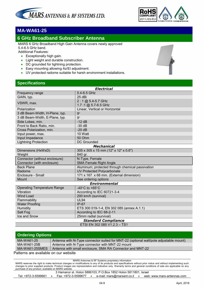
MARS Antennas & RF Systems proprietary information MARS reserves the right to make technical changes or modifications to any of its products and specifications without prior notice and without implementing such changes to prior supplied products. Product images are representative and indicative only. Warranty terms and general conditions of sale are applicable on any purchase of any product, available on MARS website.
3 Hamanor st. Holon 5886103, P.O.Box 1852 Holon 5811801, Israel Tel: +972-3-5599661 Fax: +972-3-5599677 e-mail: [email protected] web: www.mars-antennas.com
MA-WA61-25
6 GHz Broadband Subscriber Antenna MARS 6 GHz Broadband High Gain Antenna covers newly approved 5.4-6.5 GHz band. Additional Features: Exceptionally high gain. Light weight and durable construction. DC grounded for lightning protection. Easy mounting allowing Az/El adjustment. UV protected radome suitable for harsh environment installations.
Specifications
Electrical Frequency range 5.4-6.5 GHz GAIN, typ. 25 dBi
VSWR, max. 2 : 1 @ 5.4-5.7 GHz 1.7 :1 @ 5.7-6.5 GHz
Polarization Linear, Vertical or Horizontal 3 dB Beam-Width, H-Plane, typ. 9 3 dB Beam-Width, E-Plane, typ. 9 Side Lobes, min. -12 dB Front to Back Ratio, min. -30 dB Cross Polarization, min. -20 dB Input power, max. 10 Watt Input Impedance 50 Ohm Lightning Protection DC Grounded
Mechanical Dimensions (HxWxD) 305 x 305 x 15 mm (12" x 12" x 0.6") Weight 840 gr. Connector (without enclosure) N-Type, Female Connector (with enclosure) SMA Female Right Angle Back Plane Aluminum; protected through chemical passivation Radome UV Protected Polycarbonate Enclosure - Small 171 x 167 x 68 mm. (External dimension) Mount See ordering options
Environmental Operating Temperature Range -40C to +65C Vibration According to IEC 60721-3-4 Wind Load 200 km/h (survival) Flammability UL94 Water Proofing IP-67 Humidity ETS 300 019-1-4, EN 302 085 (annex A.1.1) Salt Fog According to IEC 68-2-11 Ice and Snow 25mm radial (survival)
Standard Compliance ETSI EN 302 085 V1.2.3 – TS1
Ordering Options
MA-WA61-25 Antenna with N-Type connector suited for MNT-22 (optional wall/pole adjustable mount) MA-WA61-25B Antenna with N-Type connector with MNT-22 mount MA-WA61-25SMES Antenna with small enclosure, SMA RA Connector and MNT-22
Patterns are available on our website
April, 201804-9
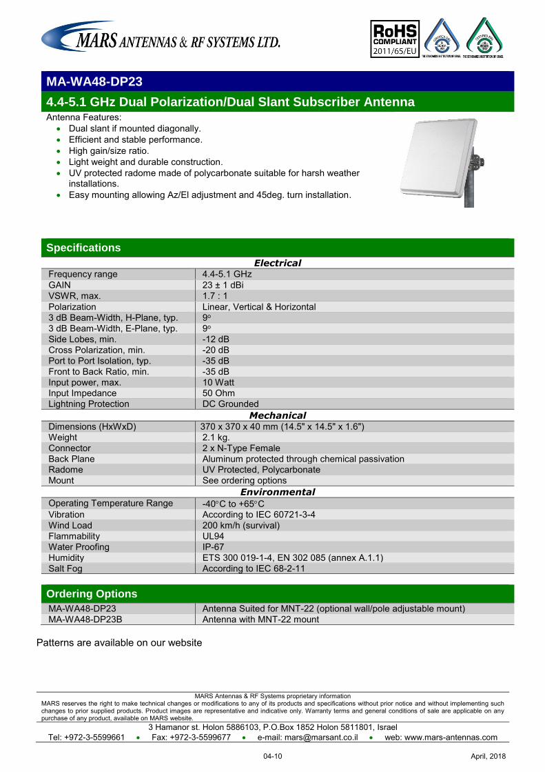
MARS Antennas & RF Systems proprietary information MARS reserves the right to make technical changes or modifications to any of its products and specifications without prior notice and without implementing such changes to prior supplied products. Product images are representative and indicative only. Warranty terms and general conditions of sale are applicable on any purchase of any product, available on MARS website.
3 Hamanor st. Holon 5886103, P.O.Box 1852 Holon 5811801, Israel Tel: +972-3-5599661 Fax: +972-3-5599677 e-mail: [email protected] web: www.mars-antennas.com
MA-WA48-DP23
4.4-5.1 GHz Dual Polarization/Dual Slant Subscriber Antenna Antenna Features:
Dual slant if mounted diagonally. Efficient and stable performance. High gain/size ratio. Light weight and durable construction. UV protected radome made of polycarbonate suitable for harsh weather
installations. Easy mounting allowing Az/El adjustment and 45deg. turn installation.
Specifications
Electrical Frequency range 4.4-5.1 GHz GAIN 23 ± 1 dBi VSWR, max. 1.7 : 1 Polarization Linear, Vertical & Horizontal 3 dB Beam-Width, H-Plane, typ. 9o 3 dB Beam-Width, E-Plane, typ. 9o Side Lobes, min. -12 dB Cross Polarization, min. -20 dB Port to Port Isolation, typ. -35 dB Front to Back Ratio, min. -35 dB Input power, max. 10 Watt Input Impedance 50 Ohm Lightning Protection DC Grounded
Mechanical Dimensions (HxWxD) 370 x 370 x 40 mm (14.5" x 14.5" x 1.6") Weight 2.1 kg. Connector 2 x N-Type Female Back Plane Aluminum protected through chemical passivation Radome UV Protected, Polycarbonate Mount See ordering options
Environmental Operating Temperature Range -40C to +65C Vibration According to IEC 60721-3-4 Wind Load 200 km/h (survival) Flammability UL94 Water Proofing IP-67 Humidity ETS 300 019-1-4, EN 302 085 (annex A.1.1) Salt Fog According to IEC 68-2-11 Ordering Options
MA-WA48-DP23 Antenna Suited for MNT-22 (optional wall/pole adjustable mount) MA-WA48-DP23B Antenna with MNT-22 mount
Patterns are available on our website
April, 201804-10
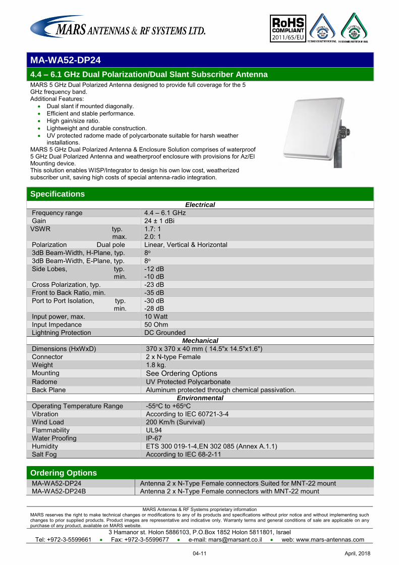
MARS Antennas & RF Systems proprietary information MARS reserves the right to make technical changes or modifications to any of its products and specifications without prior notice and without implementing such changes to prior supplied products. Product images are representative and indicative only. Warranty terms and general conditions of sale are applicable on any purchase of any product, available on MARS website.
3 Hamanor st. Holon 5886103, P.O.Box 1852 Holon 5811801, Israel Tel: +972-3-5599661 Fax: +972-3-5599677 e-mail: [email protected] web: www.mars-antennas.com
MA-WA52-DP24
4.4 – 6.1 GHz Dual Polarization/Dual Slant Subscriber Antenna
MARS 5 GHz Dual Polarized Antenna designed to provide full coverage for the 5 GHz frequency band. Additional Features:
Dual slant if mounted diagonally. Efficient and stable performance. High gain/size ratio. Lightweight and durable construction. UV protected radome made of polycarbonate suitable for harsh weather
installations. MARS 5 GHz Dual Polarized Antenna & Enclosure Solution comprises of waterproof 5 GHz Dual Polarized Antenna and weatherproof enclosure with provisions for Az/El Mounting device. This solution enables WISP/Integrator to design his own low cost, weatherized subscriber unit, saving high costs of special antenna-radio integration.
Specifications
Electrical
Frequency range 4.4 – 6.1 GHz Gain 24 ± 1 dBi VSWR typ. max.
1.7: 1 2.0: 1
Polarization Dual pole Linear, Vertical & Horizontal 3dB Beam-Width, H-Plane, typ. 8o 3dB Beam-Width, E-Plane, typ. 8o Side Lobes, typ. min.
-12 dB -10 dB
Cross Polarization, typ. -23 dB Front to Back Ratio, min. -35 dB Port to Port Isolation, typ. min.
-30 dB -28 dB
Input power, max. 10 Watt Input Impedance 50 Ohm Lightning Protection DC Grounded
Mechanical
Dimensions (HxWxD) 370 x 370 x 40 mm ( 14.5"x 14.5"x1.6") Connector 2 x N-type Female Weight 1.8 kg. Mounting See Ordering Options Radome UV Protected Polycarbonate Back Plane Aluminum protected through chemical passivation.
Environmental
Operating Temperature Range -55oC to +65oC Vibration According to IEC 60721-3-4 Wind Load 200 Km/h (Survival) Flammability UL94 Water Proofing IP-67 Humidity ETS 300 019-1-4,EN 302 085 (Annex A.1.1) Salt Fog According to IEC 68-2-11 Ordering Options
MA-WA52-DP24 Antenna 2 x N-Type Female connectors Suited for MNT-22 mount MA-WA52-DP24B Antenna 2 x N-Type Female connectors with MNT-22 mount
April, 201804-11
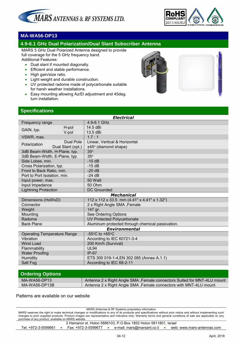
MARS Antennas & RF Systems proprietary information MARS reserves the right to make technical changes or modifications to any of its products and specifications without prior notice and without implementing such changes to prior supplied products. Product images are representative and indicative only. Warranty terms and general conditions of sale are applicable on any purchase of any product, available on MARS website.
3 Hamanor st. Holon 5886103, P.O.Box 1852 Holon 5811801, Israel Tel: +972-3-5599661 Fax: +972-3-5599677 e-mail: [email protected] web: www.mars-antennas.com
MA-WA56-DP13
4.9-6.1 GHz Dual Polarization/Dual Slant Subscriber Antenna
MARS 5 GHz Dual Polarized Antenna designed to provide full coverage for the 5 GHz frequency band. Additional Features: Dual slant if mounted diagonally. Efficient and stable performance. High gain/size ratio. Light weight and durable construction. UV protected radome made of polycarbonate suitable
for harsh weather installations. Easy mounting allowing Az/El adjustment and 45deg.
turn installation.
Specifications
Electrical Frequency range 4.9-6.1 GHz
GAIN, typ. H-pol 14.5 dBi V-pol 13.5 dBi
VSWR, max. 1.7 : 1
Polarization Dual Pole Linear, Vertical & Horizontal Dual Slant (opt.) ±45o (diamond shape)
3dB Beam-Width, H-Plane, typ. 35o 3dB Beam-Width, E-Plane, typ. 35o Side Lobes, min. -10 dB Cross Polarization, typ. -15 dB Front to Back Ratio, min. -20 dB Port to Port Isolation, min. -24 dB Input power, max. 50 Watt Input Impedance 50 Ohm Lightning Protection DC Grounded
Mechanical Dimensions (HxWxD) 112 x 112 x 33.5 mm (4.41" x 4.41" x 1.32") Connector 2 x Right Angle SMA ,Female Weight 147 gr. Mounting See Ordering Options Radome UV Protected Polycarbonate Back Plane Aluminum protected through chemical passivation.
Environmental Operating Temperature Range -55oC to +65oC Vibration According to IEC 60721-3-4 Wind Load 200 Km/h (Survival) Flammability UL94 Water Proofing IP-67 Humidity ETS 300 019-1-4,EN 302 085 (Annex A.1.1) Salt Fog According to IEC 68-2-11 Ordering Options
MA-WA56-DP13 Antenna 2 x Right Angle SMA ,Female connectors Suited for MNT-4LU mount MA-WA56-DP13B Antenna 2 x Right Angle SMA ,Female connectors with MNT-4LU mount
Patterns are available on our website
April, 201804-12
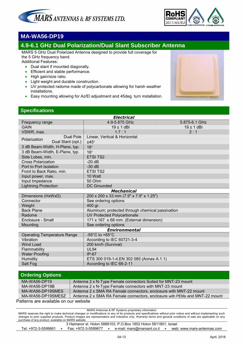
MARS Antennas & RF Systems proprietary information MARS reserves the right to make technical changes or modifications to any of its products and specifications without prior notice and without implementing such changes to prior supplied products. Product images are representative and indicative only. Warranty terms and general conditions of sale are applicable on any purchase of any product, available on MARS website.
3 Hamanor st. Holon 5886103, P.O.Box 1852 Holon 5811801, Israel Tel: +972-3-5599661 Fax: +972-3-5599677 e-mail: [email protected] web: www.mars-antennas.com
MA-WA56-DP19
4.9-6.1 GHz Dual Polarization/Dual Slant Subscriber Antenna MARS 5 GHz Dual Polarized Antenna designed to provide full coverage for the 5 GHz frequency band. Additional Features: Dual slant if mounted diagonally. Efficient and stable performance. High gain/size ratio. Light weight and durable construction. UV protected radome made of polycarbonate allowing for harsh weather
installations. Easy mounting allowing for Az/El adjustment and 45deg. turn installation.
Specifications
Electrical Frequency range 4.9-5.875 GHz 5.875-6.1 GHz GAIN 19 ± 1 dBi 19 ± 1 dBi VSWR, max. 1.7 : 1 2 : 1
Polarization Dual Pole Linear, Vertical & Horizontal Dual Slant (opt.) ±45
3 dB Beam-Width, H-Plane, typ. 16 3 dB Beam-Width, E-Plane, typ. 16 Side Lobes, min. ETSI TS2 Cross Polarization -20 dB Port to Port Isolation -30 dB Front to Back Ratio, min. ETSI TS2 Input power, max. 10 Watt Input Impedance 50 Ohm Lightning Protection DC Grounded
Mechanical Dimensions (HxWxD) 200 x 200 x 33 mm (7.9" x 7.9" x 1.25") Connector See ordering options Weight 400 gr. Back Plane Aluminum; protected through chemical passivation Radome UV Protected Polycarbonate Enclosure - Small 171 x 167 x 68 mm. (External dimension) Mounting See ordering options
Environmental Operating Temperature Range -55°C to +65°C Vibration According to IEC 60721-3-4 Wind Load 200 km/h (Survival) Flammability UL94 Water Proofing IP-67 Humidity ETS 300 019-1-4,EN 302 085 (Annex A.1.1) Salt Fog According to IEC 68-2-11 Ordering Options
MA-WA56-DP19 Antenna 2 x N-Type Female connectors Suited for MNT-23 mount MA-WA56-DP19B Antenna 2 x N-Type Female connectors with MNT-23 mount MA-WA56-DP19SMES Antenna 2 x SMA RA Female connectors, enclosure with MNT-22 mount MA-WA56-DP19SMESZ Antenna 2 x SMA RA Female connectors, enclosure with PEMs and MNT-22 mount
Patterns are available on our website
April, 201804-13
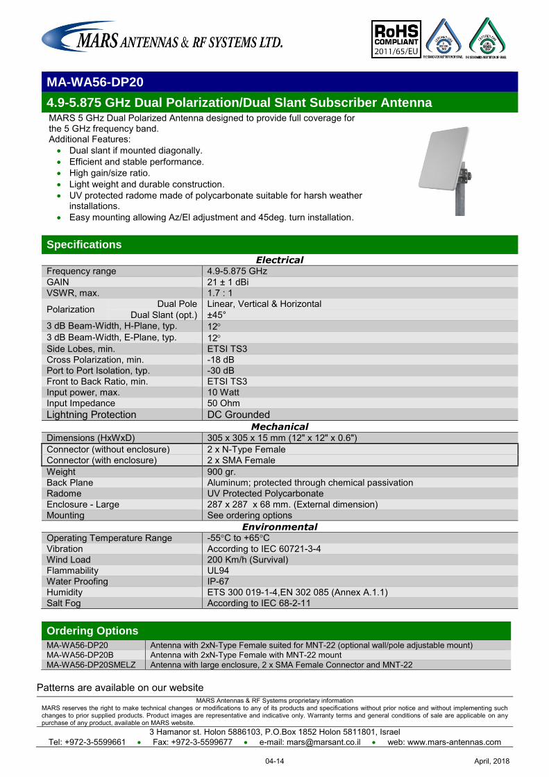
MARS Antennas & RF Systems proprietary information MARS reserves the right to make technical changes or modifications to any of its products and specifications without prior notice and without implementing such changes to prior supplied products. Product images are representative and indicative only. Warranty terms and general conditions of sale are applicable on any purchase of any product, available on MARS website.
3 Hamanor st. Holon 5886103, P.O.Box 1852 Holon 5811801, Israel Tel: +972-3-5599661 Fax: +972-3-5599677 e-mail: [email protected] web: www.mars-antennas.com
MA-WA56-DP20
4.9-5.875 GHz Dual Polarization/Dual Slant Subscriber Antenna MARS 5 GHz Dual Polarized Antenna designed to provide full coverage for the 5 GHz frequency band. Additional Features: Dual slant if mounted diagonally. Efficient and stable performance. High gain/size ratio. Light weight and durable construction. UV protected radome made of polycarbonate suitable for harsh weather
installations. Easy mounting allowing Az/El adjustment and 45deg. turn installation.
Specifications
Electrical Frequency range 4.9-5.875 GHz GAIN 21 ± 1 dBi VSWR, max. 1.7 : 1
Polarization Dual Pole Linear, Vertical & Horizontal Dual Slant (opt.) ±45°
3 dB Beam-Width, H-Plane, typ. 12 3 dB Beam-Width, E-Plane, typ. 12 Side Lobes, min. ETSI TS3 Cross Polarization, min. -18 dB Port to Port Isolation, typ. -30 dB Front to Back Ratio, min. ETSI TS3 Input power, max. 10 Watt Input Impedance 50 Ohm Lightning Protection DC Grounded
Mechanical Dimensions (HxWxD) 305 x 305 x 15 mm (12" x 12" x 0.6") Connector (without enclosure) 2 x N-Type Female Connector (with enclosure) 2 x SMA Female Weight 900 gr. Back Plane Aluminum; protected through chemical passivation Radome UV Protected Polycarbonate Enclosure - Large 287 x 287 x 68 mm. (External dimension) Mounting See ordering options
Environmental Operating Temperature Range -55°C to +65°C Vibration According to IEC 60721-3-4 Wind Load 200 Km/h (Survival) Flammability UL94 Water Proofing IP-67 Humidity ETS 300 019-1-4,EN 302 085 (Annex A.1.1) Salt Fog According to IEC 68-2-11
Ordering Options
MA-WA56-DP20 Antenna with 2xN-Type Female suited for MNT-22 (optional wall/pole adjustable mount) MA-WA56-DP20B Antenna with 2xN-Type Female with MNT-22 mount MA-WA56-DP20SMELZ Antenna with large enclosure, 2 x SMA Female Connector and MNT-22
Patterns are available on our website
April, 201804-14
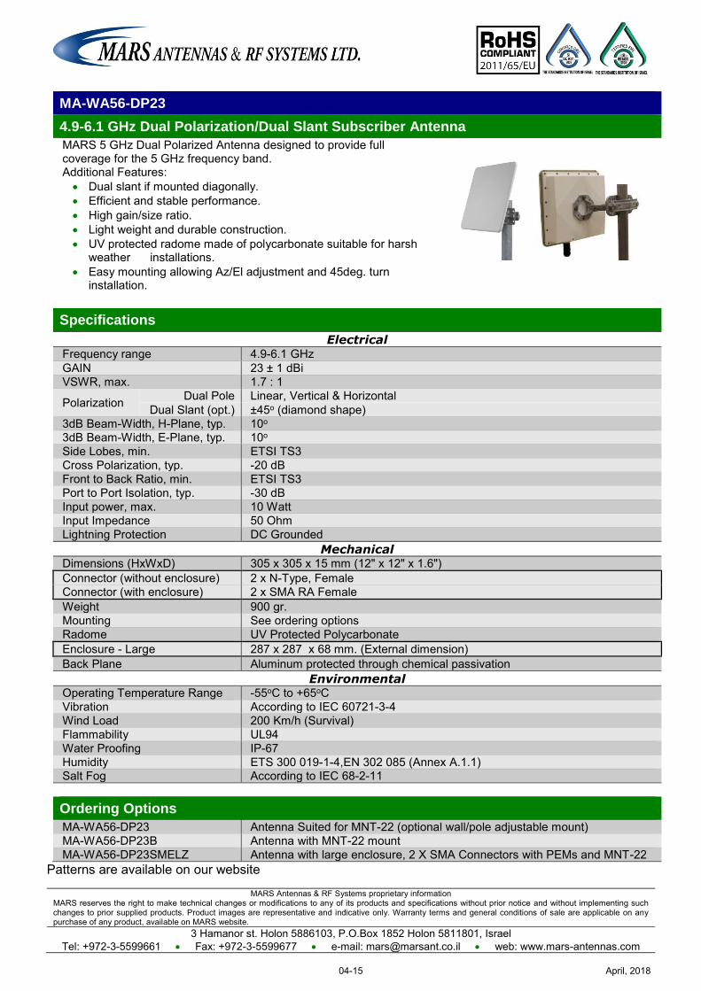
MARS Antennas & RF Systems proprietary information MARS reserves the right to make technical changes or modifications to any of its products and specifications without prior notice and without implementing such changes to prior supplied products. Product images are representative and indicative only. Warranty terms and general conditions of sale are applicable on any purchase of any product, available on MARS website.
3 Hamanor st. Holon 5886103, P.O.Box 1852 Holon 5811801, Israel Tel: +972-3-5599661 Fax: +972-3-5599677 e-mail: [email protected] web: www.mars-antennas.com
MA-WA56-DP23
4.9-6.1 GHz Dual Polarization/Dual Slant Subscriber Antenna
MARS 5 GHz Dual Polarized Antenna designed to provide full coverage for the 5 GHz frequency band. Additional Features: Dual slant if mounted diagonally. Efficient and stable performance. High gain/size ratio. Light weight and durable construction. UV protected radome made of polycarbonate suitable for harsh
weather installations. Easy mounting allowing Az/El adjustment and 45deg. turn
installation.
Specifications
Electrical Frequency range 4.9-6.1 GHz GAIN 23 ± 1 dBi VSWR, max. 1.7 : 1
Polarization Dual Pole Linear, Vertical & Horizontal Dual Slant (opt.) ±45o (diamond shape)
3dB Beam-Width, H-Plane, typ. 10o 3dB Beam-Width, E-Plane, typ. 10o Side Lobes, min. ETSI TS3 Cross Polarization, typ. -20 dB Front to Back Ratio, min. ETSI TS3 Port to Port Isolation, typ. -30 dB Input power, max. 10 Watt Input Impedance 50 Ohm Lightning Protection DC Grounded
Mechanical Dimensions (HxWxD) 305 x 305 x 15 mm (12" x 12" x 1.6") Connector (without enclosure) 2 x N-Type, Female Connector (with enclosure) 2 x SMA RA Female Weight 900 gr. Mounting See ordering options Radome UV Protected Polycarbonate Enclosure - Large 287 x 287 x 68 mm. (External dimension) Back Plane Aluminum protected through chemical passivation
Environmental Operating Temperature Range -55oC to +65oC Vibration According to IEC 60721-3-4 Wind Load 200 Km/h (Survival) Flammability UL94 Water Proofing IP-67 Humidity ETS 300 019-1-4,EN 302 085 (Annex A.1.1) Salt Fog According to IEC 68-2-11 Ordering Options
MA-WA56-DP23 Antenna Suited for MNT-22 (optional wall/pole adjustable mount) MA-WA56-DP23B Antenna with MNT-22 mount MA-WA56-DP23SMELZ Antenna with large enclosure, 2 X SMA Connectors with PEMs and MNT-22
Patterns are available on our website
April, 201804-15
MARS Antennas & RF Systems proprietary information MARS reserves the right to make technical changes or modifications to any of its products and specifications without prior notice and without implementing such changes to prior supplied products. Product images are representative and indicative only. Warranty terms and general conditions of sale are applicable on any purchase of any product, available on MARS website.
3 Hamanor st. Holon 5886103, P.O.Box 1852 Holon 5811801, Israel Tel: +972-3-5599661 Fax: +972-3-5599677 e-mail: [email protected] web: www.mars-antennas.com
MA-WA56-DP25N
4.9-5.875 GHz Dual Polarized/ Dual Slant Antenna MARS 5 GHz Dual Polarized Antenna designed to provide full coverage for the 5 GHz frequency band. Additional Features:
Dual slant if mounted diagonally. Efficient and stable performance. High gain/size ratio. Light weight and durable construction. UV protected radome made of polycarbonate suitable for
harsh weather installations. MARS 5 GHz Dual Polarized Antenna & Enclosure Solution comprises of waterproof 5 GHz Dual Polarized Antenna and weatherproof enclosure with provisions for Az/El Mounting device. This solution enables WISP/Integrator to design his own low cost, weatherized subscriber unit, saving high costs of special antenna-radio integration.
Specifications Electrical
Frequency range 4.9-5.875 GHz
GAIN V-Pol 23.5 ± 1 dBi H-Pol 24.5 ± 1dBi
VSWR, max. 1.7 : 1
Polarization Dual Pole Linear, Vertical & Horizontal Dual Slant (opt.) ±45
3 dB Beam-Width, H-Plane, typ. 7°-9 3 dB Beam-Width, E-Plane, typ. 7°-9 Side Lobes, min. ETSI TS3, TS4, TS5 Cross Polarization, typ. -25 dB Port to Port Isolation,typ. -30 dB Front to Back Ratio, min. ETSI TS3, TS4, TS5 Input power, max. 5 Watt Input Impedance 50 Ohm Lightning Protection DC Grounded
Mechanical Dimensions (HxWxD) 370 x 370 x 40 mm (14.5" x 14.5" x 1.6") Connector (without enclosure) 2 x N-Type, Female Connector (with enclosure) 2 x SMA Female Weight 1.8 kg. Back Plane Aluminum; protected through chemical passivation Radome UV Protected Polycarbonate Enclosure dimensions (external) 287 x 287 x 68 mm. Enclosure dimensions (internal) 260 x 260 x 45 mm (10.2" x 10.2" x 1.8") Enclosure internal plate dimensions 245 x 245 mm, height of PCB (from Base for RF to backplane) - 55 mm Mounting See ordering options
Environmental Operating Temperature Range -40°C to +65°C Vibration According to IEC 60721-3-4 Wind Load 200 Km/h (Survival) Flammability UL94 Water Proofing IP-67 Humidity ETS 300 019-1-4,EN 302 085 (Annex A.1.1) Salt Fog According to IEC 68-2-11
Ordering Options MA-WA56-DP25N Antenna Suited for MNT-22 (optional wall/pole adjustable mount) MA-WA56-DP25NB Antenna with MNT-22 mount MA-WA56-DP25SMELY Antenna with large enclosure, 2 x SMA Female Connector and MNT-22 MA-WA56-DP25SMELZ Antenna with large enclosure, 2 x SMA Female Connector with PEMs and MNT-22
Patterns are available on our website
April, 201804-16
MARS Antennas & RF Systems proprietary information MARS reserves the right to make technical changes or modifications to any of its products and specifications without prior notice and without implementing such changes to prior supplied products. Product images are representative and indicative only. Warranty terms and general conditions of sale are applicable on any purchase of any product, available on MARS website.
3 Hamanor st. Holon 5886103, P.O.Box 1852 Holon 5811801, Israel
Tel: +972-3-5599661 Fax: +972-3-5599677 e-mail: [email protected] web: www.mars-antennas.com
MA-WA56-DP28N
4.7-6.425 GHz High Gain, Wideband, Dual Polarized/Dual Slant Antenna
MARS 5 GHz Dual Polarized Antenna designed to provide full coverage for the 5 GHz frequency band. Additional Features:
Efficient and stable performance.
High gain/size ratio.
Durable construction.
UV protected radome made of polycarbonate allowing harsh weather installations.
Specifications
Electrical Frequency range 4.7-4.9 GHz 4.9-5.15 GHz 5.15-5.875 GHz 5.875-6.1GHz 6.1-6.425 GHz
GAIN V-Pol: 28 ± 1dBi 28.5 ± 0.5 dBi 29 ± 0.5 dBi 28.5 ± 0.5 dBi 27.5 ± 1 dBi
H-Pol: 27 ± 1 dBi 28 ± 0.5 dBi 28.5±0.5 dBi 28 ± 1 dBi 27 ± 1 dBi
VSWR, max. 2.7: 1 2 : 1 1.9 : 1 2 : 1 2.6 :1
Polarization Dual Pole Dual Polarization V&H
Dual Slant (opt.) ±45º
3dB Beam-Width, H-Plane, typ. 5.5o 5.2o 4.7o 4.4o 5o
3dB Beam-Width, E-Plane, typ. 5.5o 5.2o 4.7o 4.4o 5o
Side Lobes, min. ETSI TS3 ETSI TS 2
Cross Polarization, min.
V-Pol: -26 dB -26 dB -23 dB -23 dB -23 dB
H-Pol: -23 dB -25 dB -23 dB -20 dB -15 dB
Front to Back Ratio, min. ETSI TS3
Port to Port Isolation, typ. -30 dB
Input power, max. 10 Watt
Input Impedance 50 Ohm
Lightning Protection DC Grounded
Mechanical Dimensions (HxWxD) 600 x 600 x 22 mm (23.5" x 23.5" x 0.86")
Weight 4.7 kg.
Connector (without enclosure) 2 x N-Type Female
Connector (with enclosure) 2 x SMA
Back Plane Aluminum; Protected through chemical passivation Radome UV Protected, Polycarbonate
Enclosure - Small 171 x 167 x 68 mm. (External dimension)
Mount See ordering options
Environmental Operating Temperature Range -40oC to +65oC
Vibration According to IEC 60721-3-4 Wind Load 200 km/h (Survival)
Flammability UL94
Water Proofing IP-67
Humidity ETS 300 019-1-4,EN 302 085 (Annex A.1.1)
Salt Fog According to IEC 68-2-11
Ordering Options
MA-WA56-DP28N Antenna Suited for MNT-60A (optional wall/pole adjustable mount)
MA-WA56-DP28NB Antenna with MNT-60A mount
MA-WA56-DP28NSMESY Antenna Suited for MNT-60A (2 x SMA with Small Enclosure)
April, 201804-17
MARS Antennas & RF Systems proprietary information MARS reserves the right to make technical changes or modifications to any of its products and specifications without prior notice and without implementing such changes to prior supplied products. Product images are representative and indicative only. Warranty terms and general conditions of sale are applicable on any purchase of any product, available on MARS website.
3 Hamanor st. Holon 5886103, P.O.Box 1852 Holon 5811801, Israel Tel: +972-3-5599661 Fax: +972-3-5599677 e-mail: [email protected] web: www.mars-antennas.com
MA-WABSA55-DP15_g Preliminary
5.0-6.0 GHz Beam Steering Active Antenna, Azimuth Scan
Dual polarized Beamforming antenna for beam steering applications : 100 Deg coverage by 20 Deg Beamwidth. 15 options for beam directions with 5 Deg step. Reduces co-channel interferences and pointing independent beams
toward various clients. Specifications
Electrical Frequency range 5.0-6.0 GHz Polarization Dual Pol Vertical & Horizontal Elevation 3dB beam width 8 - 10 Azimuth 3dB Beam width 15°- 20 Azimuth scan step (3-7) Azimuth beam control range * +/-45 * Side lobes, typ. -10 dB Modes (External control) Rx or Tx, Beamforming or Broadcast
Beamforming (V & H polarization): Gain of passive antenna part, typ. 21dBi
Rx Mode: Gain with LNA's (Broadside), typ. 32dBi Noise figure (Rx channel), typ. 5-6 dB
Tx Mode: Output Operating RF Power (Output PA), typ. 19-23dBm Gain with PA (Broadside), typ. 40dBi
Broadcast (V & H polarization): Gain of passive antenna part, typ. 15dBi
Azimuth 3dB Beam width 60-70 Azimuth 5dB Beam width 90-100
Rx Mode: Gain with LNA's, typ. 33dBi
Tx Mode: Output Operating RF Power (Output PA), typ. 19-23dBm Gain with PA, typ. 34dBi
Max Input RF Power (damage) 18dBm VSWR 2 : 1 Impedance 50 Ohm Front to Back Ratio, min. -30 dB Cross Polarization, typ. -20 dB Port-Port Isolation, typ. -25 dB Beam and Modes selection time, typ. 1-2 us External Power supply +5V ; PoE (+48 В) External control interface GPIO (7 wires) Lighting protection DC grounded * - For Azimuth beam control range +/- (30-45) : Gain = Gain, typ. – (~3) dB; Side Lobes < -(1-3)dB.
Mechanical Dimensions (HxWxD) 370x370x60mm (TBD) Weight TBD Connectors RF SMA Type Female DC connectors TBD Radome UV Protected Polycarbonate, white
Environmental Operating Temperature -20C to +60C Dynamics IEC 60721-3-4 Humidity ETS 300 019-1-4, EN 302 085 (annex A.1.1) Salt Fog IEC 68-2-11 Water Proofing IP-67
April, 201804-18
MARS Antennas & RF Systems proprietary information MARS reserves the right to make technical changes or modifications to any of its products and specifications without prior notice and without implementing such changes to prior supplied products. Product images are representative and indicative only. Warranty terms and general conditions of sale are applicable on any purchase of any product, available on MARS website.
3 Hamanor st. Holon 5886103, P.O.Box 1852 Holon 5811801, Israel
Tel: +972-3-5599661 Fax: +972-3-5599677 e-mail: [email protected] web: www.mars-antennas.com
MA-PBSA56-DP21 Preliminary
5-6 GHz Passive Antenna For Beam Steering, Azimuth Scan
Array antenna for Beam Steering Applications
Dual polarized antenna four columns each.
Distance 0.5 λ between columns in the center frequency.
Specifications
Electrical
Frequency range 5 - 6 GHz
Polarization Dual Pol V&H Individual Column
Gain, typ. 16 dBi 3 dB Beam-Width, Azimuth Plane 90°±10° Cross Polarization, typ. -20 dB Front to Back Ratio , min. -30 dB Array 4 Columns (Equal Amp & Phase Boresight) Gain, typ. 21 dBi 3 dB Beam-Width, Azimuth Plane, typ. 25°
Cross Polarization, typ. -20 dB
Front to Back Ratio, min. -30 dB General 3 dB Beam-Width, Elevation Plane, typ. 8° Side Lobes, Elevation Plane, typ. -12 dB Input power, max 10W Input Impedance 50 Ohm Lightning Protection DC Ground
Mechanical
Dimensions (HxWxD) 370 x 370 x 40 mm (14.5”x 14.5”x 1.6”) Weight 2 kg Connector 8 x N-Type , Female Back Plane Aluminum protected through chemical passivation Radome UV Protected, Plastic Mount See Ordering Options
Environmental
Operating Temperature Range - 40°C to + 65°C Vibration According to IEC 60721-3-4 Wind Load 200 km/h (survival) Flammability UL94 Water Proofing IP-67 Humidity ETS 300 019-1-4, EN 302 085 (annex A.1.1) Salt Fog According to IEC 68-2-11 Ice and Snow 25mm radial (survival)
Ordering Options MA-PBSA56-DP21 Antenna Suited for MNT-22 (optional wall/pole adjustable mount) MA-PBSA56-DP21 Antenna with MNT-22 mount
April, 201804-19
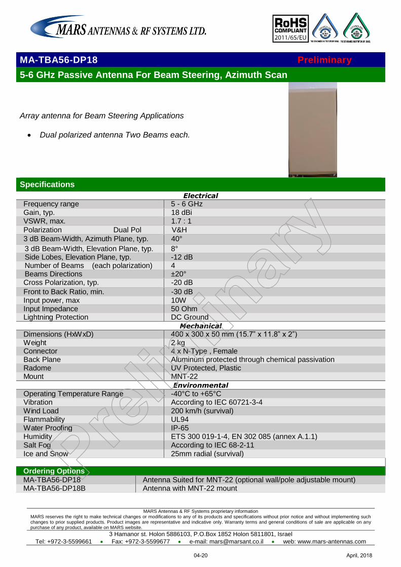
MARS Antennas & RF Systems proprietary information MARS reserves the right to make technical changes or modifications to any of its products and specifications without prior notice and without implementing such changes to prior supplied products. Product images are representative and indicative only. Warranty terms and general conditions of sale are applicable on any purchase of any product, available on MARS website.
3 Hamanor st. Holon 5886103, P.O.Box 1852 Holon 5811801, Israel
Tel: +972-3-5599661 Fax: +972-3-5599677 e-mail: [email protected] web: www.mars-antennas.com
MA-TBA56-DP18 Preliminary
5-6 GHz Passive Antenna For Beam Steering, Azimuth Scan
Array antenna for Beam Steering Applications
Dual polarized antenna Two Beams each.
Specifications
Electrical
Frequency range 5 - 6 GHz Gain, typ. 18 dBi VSWR, max. 1.7 : 1
Polarization Dual Pol V&H
3 dB Beam-Width, Azimuth Plane, typ. 40°
3 dB Beam-Width, Elevation Plane, typ. 8° Side Lobes, Elevation Plane, typ. -12 dB Number of Beams (each polarization) 4 Beams Directions ±20° Cross Polarization, typ. -20 dB
Front to Back Ratio, min. -30 dB Input power, max 10W Input Impedance 50 Ohm Lightning Protection DC Ground
Mechanical
Dimensions (HxWxD) 400 x 300 x 50 mm (15.7” x 11.8” x 2”) Weight 2 kg Connector 4 x N-Type , Female Back Plane Aluminum protected through chemical passivation Radome UV Protected, Plastic Mount MNT-22
Environmental
Operating Temperature Range -40°C to +65°C Vibration According to IEC 60721-3-4 Wind Load 200 km/h (survival) Flammability UL94 Water Proofing IP-65 Humidity ETS 300 019-1-4, EN 302 085 (annex A.1.1) Salt Fog According to IEC 68-2-11 Ice and Snow 25mm radial (survival)
Ordering Options
MA-TBA56-DP18 Antenna Suited for MNT-22 (optional wall/pole adjustable mount) MA-TBA56-DP18B Antenna with MNT-22 mount
April, 201804-20
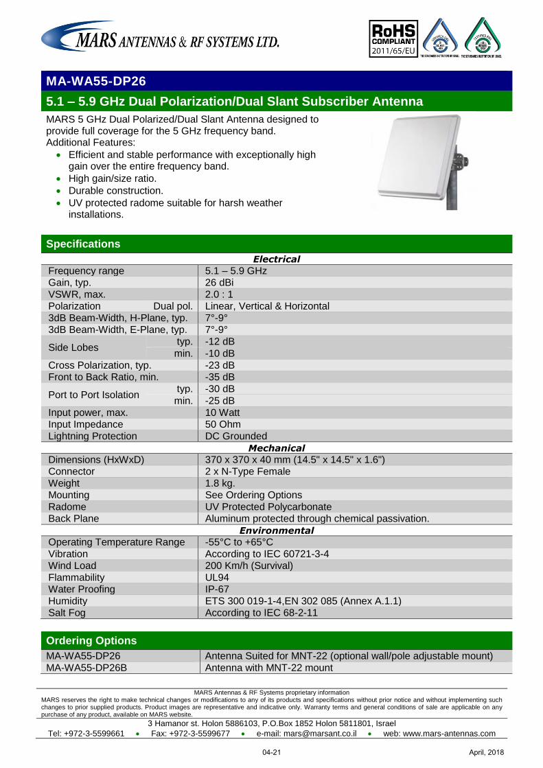
MARS Antennas & RF Systems proprietary information MARS reserves the right to make technical changes or modifications to any of its products and specifications without prior notice and without implementing such changes to prior supplied products. Product images are representative and indicative only. Warranty terms and general conditions of sale are applicable on any purchase of any product, available on MARS website.
3 Hamanor st. Holon 5886103, P.O.Box 1852 Holon 5811801, Israel
Tel: +972-3-5599661 Fax: +972-3-5599677 e-mail: [email protected] web: www.mars-antennas.com
MA-WA55-DP26
5.1 – 5.9 GHz Dual Polarization/Dual Slant Subscriber Antenna
MARS 5 GHz Dual Polarized/Dual Slant Antenna designed to provide full coverage for the 5 GHz frequency band. Additional Features:
Efficient and stable performance with exceptionally high gain over the entire frequency band.
High gain/size ratio.
Durable construction.
UV protected radome suitable for harsh weather installations.
Specifications
Electrical
Frequency range 5.1 – 5.9 GHz Gain, typ. 26 dBi
VSWR, max. 2.0 : 1 Polarization Dual pol. Linear, Vertical & Horizontal
3dB Beam-Width, H-Plane, typ. 7°-9° 3dB Beam-Width, E-Plane, typ. 7°-9°
Side Lobes typ. -12 dB
min. -10 dB
Cross Polarization, typ. -23 dB Front to Back Ratio, min. -35 dB
Port to Port Isolation typ. -30 dB
min. -25 dB
Input power, max. 10 Watt Input Impedance 50 Ohm
Lightning Protection DC Grounded
Mechanical
Dimensions (HxWxD) 370 x 370 x 40 mm (14.5" x 14.5" x 1.6") Connector 2 x N-Type Female
Weight 1.8 kg. Mounting See Ordering Options
Radome UV Protected Polycarbonate Back Plane Aluminum protected through chemical passivation.
Environmental
Operating Temperature Range -55°C to +65°C
Vibration According to IEC 60721-3-4 Wind Load 200 Km/h (Survival)
Flammability UL94 Water Proofing IP-67
Humidity ETS 300 019-1-4,EN 302 085 (Annex A.1.1) Salt Fog According to IEC 68-2-11
Ordering Options
MA-WA55-DP26 Antenna Suited for MNT-22 (optional wall/pole adjustable mount)
MA-WA55-DP26B Antenna with MNT-22 mount
April, 201804-21
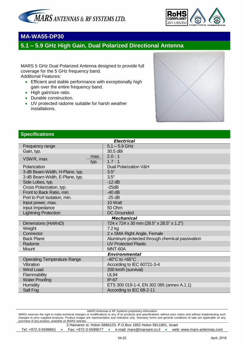
MARS Antennas & RF Systems proprietary information MARS reserves the right to make technical changes or modifications to any of its products and specifications without prior notice and without implementing such changes to prior supplied products. Product images are representative and indicative only. Warranty terms and general conditions of sale are applicable on any purchase of any product, available on MARS website.
3 Hamanor st. Holon 5886103, P.O.Box 1852 Holon 5811801, Israel
Tel: +972-3-5599661 Fax: +972-3-5599677 e-mail: [email protected] web: www.mars-antennas.com
MA-WA55-DP30
5.1 – 5.9 GHz High Gain, Dual Polarized Directional Antenna
MARS 5 GHz Dual Polarized Antenna designed to provide full coverage for the 5 GHz frequency band. Additional Features:
Efficient and stable performance with exceptionally high gain over the entire frequency band.
High gain/size ratio.
Durable construction.
UV protected radome suitable for harsh weather installations.
Specifications
Electrical
Frequency range 5.1 – 5.9 GHz Gain, typ. 30.5 dBi
VSWR, max. max. 2.0 : 1 typ. 1.7 : 1
Polarization Dual Polarization V&H 3 dB Beam-Width, H-Plane, typ. 3.5° 3 dB Beam-Width, E-Plane, typ. 3.5° Side Lobes, typ. -12 dB Cross Polarization, typ. -25dB Front to Back Ratio, min. -40 dB Port to Port Isolation, min. -25 dB Input power, max. 10 Watt Input Impedance 50 Ohm Lightning Protection DC Grounded
Mechanical
Dimensions (HxWxD) 724 x 724 x 30 mm (28.5" x 28.5" x 1.2") Weight 7.2 kg Connector 2 x SMA Right Angle, Female Back Plane Aluminum protected through chemical passivation Radome UV Protected Plastic Mount MNT-60A
Environmental
Operating Temperature Range -40°C to +65°C Vibration According to IEC 60721-3-4 Wind Load 200 km/h (survival) Flammability UL94 Water Proofing IP-67 Humidity ETS 300 019-1-4, EN 302 085 (annex A.1.1) Salt Fog According to IEC 68-2-11
April, 201804-22
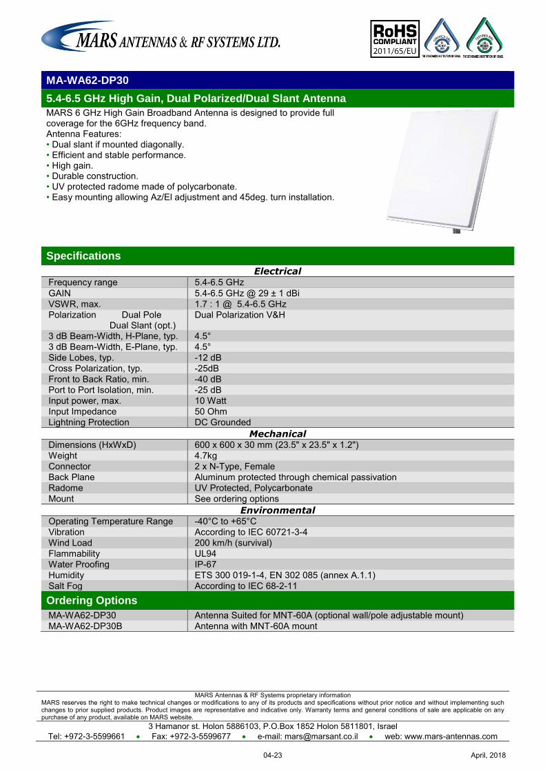
MARS Antennas & RF Systems proprietary information MARS reserves the right to make technical changes or modifications to any of its products and specifications without prior notice and without implementing such changes to prior supplied products. Product images are representative and indicative only. Warranty terms and general conditions of sale are applicable on any purchase of any product, available on MARS website.
3 Hamanor st. Holon 5886103, P.O.Box 1852 Holon 5811801, Israel Tel: +972-3-5599661 Fax: +972-3-5599677 e-mail: [email protected] web: www.mars-antennas.com
MA-WA62-DP30
5.4-6.5 GHz High Gain, Dual Polarized/Dual Slant Antenna
MARS 6 GHz High Gain Broadband Antenna is designed to provide full coverage for the 6GHz frequency band. Antenna Features: • Dual slant if mounted diagonally. • Efficient and stable performance. • High gain. • Durable construction. • UV protected radome made of polycarbonate. • Easy mounting allowing Az/El adjustment and 45deg. turn installation.
Specifications
Electrical Frequency range 5.4-6.5 GHz GAIN 5.4-6.5 GHz @ 29 ± 1 dBi VSWR, max. 1.7 : 1 @ 5.4-6.5 GHz Polarization Dual Pole Dual Slant (opt.)
Dual Polarization V&H
3 dB Beam-Width, H-Plane, typ. 4.5° 3 dB Beam-Width, E-Plane, typ. 4.5° Side Lobes, typ. -12 dB Cross Polarization, typ. -25dB Front to Back Ratio, min. -40 dB Port to Port Isolation, min. -25 dB Input power, max. 10 Watt Input Impedance 50 Ohm Lightning Protection DC Grounded
Mechanical Dimensions (HxWxD) 600 x 600 x 30 mm (23.5" x 23.5" x 1.2") Weight 4.7kg Connector 2 x N-Type, Female Back Plane Aluminum protected through chemical passivation Radome UV Protected, Polycarbonate Mount See ordering options
Environmental Operating Temperature Range -40°C to +65°C Vibration According to IEC 60721-3-4 Wind Load 200 km/h (survival) Flammability UL94 Water Proofing IP-67 Humidity ETS 300 019-1-4, EN 302 085 (annex A.1.1) Salt Fog According to IEC 68-2-11 Ordering Options
MA-WA62-DP30 Antenna Suited for MNT-60A (optional wall/pole adjustable mount) MA-WA62-DP30B Antenna with MNT-60A mount
April, 201804-23
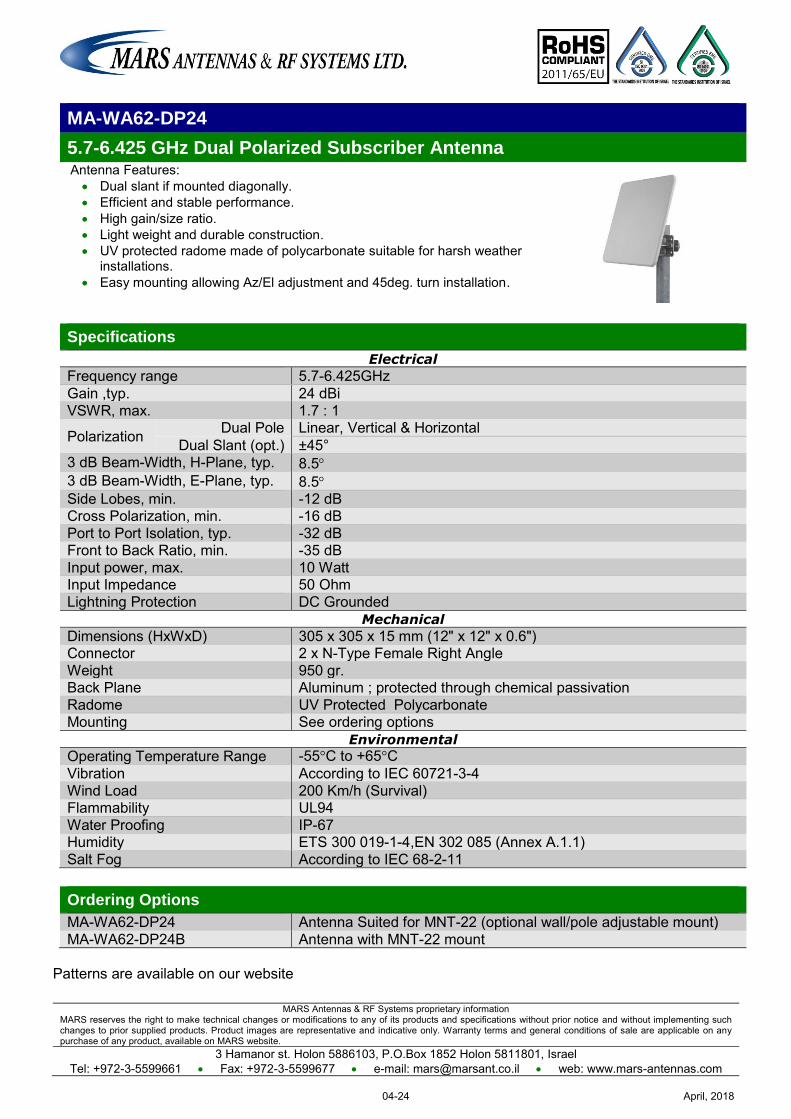
MARS Antennas & RF Systems proprietary information MARS reserves the right to make technical changes or modifications to any of its products and specifications without prior notice and without implementing such changes to prior supplied products. Product images are representative and indicative only. Warranty terms and general conditions of sale are applicable on any purchase of any product, available on MARS website.
3 Hamanor st. Holon 5886103, P.O.Box 1852 Holon 5811801, Israel Tel: +972-3-5599661 Fax: +972-3-5599677 e-mail: [email protected] web: www.mars-antennas.com
MA-WA62-DP24
5.7-6.425 GHz Dual Polarized Subscriber Antenna Antenna Features: Dual slant if mounted diagonally. Efficient and stable performance. High gain/size ratio. Light weight and durable construction. UV protected radome made of polycarbonate suitable for harsh weather
installations. Easy mounting allowing Az/El adjustment and 45deg. turn installation.
Specifications
Electrical
Frequency range 5.7-6.425GHz Gain ,typ. 24 dBi VSWR, max. 1.7 : 1
Polarization Dual Pole Linear, Vertical & Horizontal Dual Slant (opt.) ±45°
3 dB Beam-Width, H-Plane, typ. 8.5 3 dB Beam-Width, E-Plane, typ. 8.5 Side Lobes, min. -12 dB Cross Polarization, min. -16 dB Port to Port Isolation, typ. -32 dB Front to Back Ratio, min. -35 dB Input power, max. 10 Watt Input Impedance 50 Ohm Lightning Protection DC Grounded
Mechanical
Dimensions (HxWxD) 305 x 305 x 15 mm (12" x 12" x 0.6") Connector 2 x N-Type Female Right Angle Weight 950 gr. Back Plane Aluminum ; protected through chemical passivation Radome UV Protected Polycarbonate Mounting See ordering options
Environmental
Operating Temperature Range -55°C to +65°C Vibration According to IEC 60721-3-4 Wind Load 200 Km/h (Survival) Flammability UL94 Water Proofing IP-67 Humidity ETS 300 019-1-4,EN 302 085 (Annex A.1.1) Salt Fog According to IEC 68-2-11
Ordering Options
MA-WA62-DP24 Antenna Suited for MNT-22 (optional wall/pole adjustable mount) MA-WA62-DP24B Antenna with MNT-22 mount
Patterns are available on our website
April, 201804-24
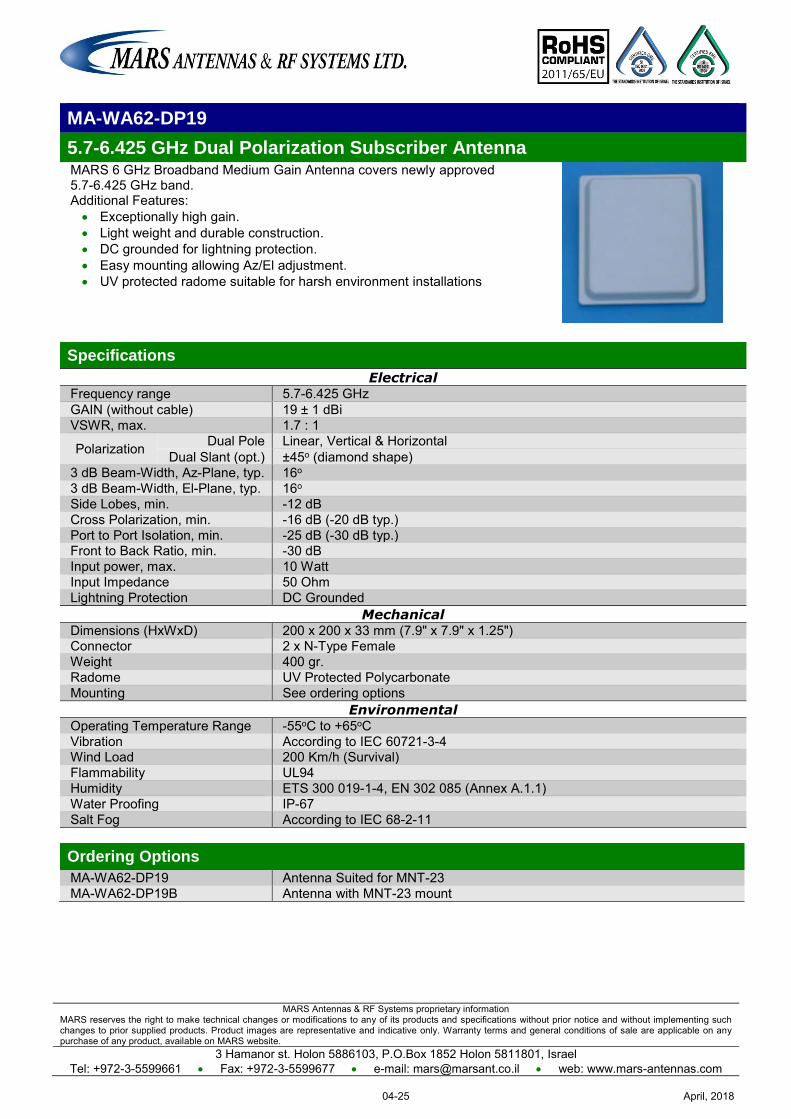
MARS Antennas & RF Systems proprietary information MARS reserves the right to make technical changes or modifications to any of its products and specifications without prior notice and without implementing such changes to prior supplied products. Product images are representative and indicative only. Warranty terms and general conditions of sale are applicable on any purchase of any product, available on MARS website.
3 Hamanor st. Holon 5886103, P.O.Box 1852 Holon 5811801, Israel Tel: +972-3-5599661 Fax: +972-3-5599677 e-mail: [email protected] web: www.mars-antennas.com
MA-WA62-DP19
5.7-6.425 GHz Dual Polarization Subscriber Antenna MARS 6 GHz Broadband Medium Gain Antenna covers newly approved 5.7-6.425 GHz band. Additional Features: Exceptionally high gain. Light weight and durable construction. DC grounded for lightning protection. Easy mounting allowing Az/El adjustment. UV protected radome suitable for harsh environment installations
Specifications
Electrical Frequency range 5.7-6.425 GHz GAIN (without cable) 19 ± 1 dBi VSWR, max. 1.7 : 1
Polarization Dual Pole Linear, Vertical & Horizontal Dual Slant (opt.) ±45o (diamond shape)
3 dB Beam-Width, Az-Plane, typ. 16o 3 dB Beam-Width, El-Plane, typ. 16o Side Lobes, min. -12 dB Cross Polarization, min. -16 dB (-20 dB typ.) Port to Port Isolation, min. -25 dB (-30 dB typ.) Front to Back Ratio, min. -30 dB Input power, max. 10 Watt Input Impedance 50 Ohm Lightning Protection DC Grounded
Mechanical Dimensions (HxWxD) 200 x 200 x 33 mm (7.9" x 7.9" x 1.25") Connector 2 x N-Type Female Weight 400 gr. Radome UV Protected Polycarbonate Mounting See ordering options
Environmental Operating Temperature Range -55oC to +65oC Vibration According to IEC 60721-3-4 Wind Load 200 Km/h (Survival) Flammability UL94 Humidity ETS 300 019-1-4, EN 302 085 (Annex A.1.1) Water Proofing IP-67 Salt Fog According to IEC 68-2-11 Ordering Options
MA-WA62-DP19 Antenna Suited for MNT-23 MA-WA62-DP19B Antenna with MNT-23 mount
April, 201804-25
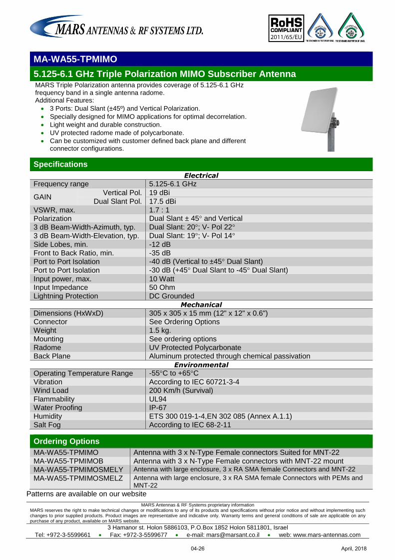
MARS Antennas & RF Systems proprietary information MARS reserves the right to make technical changes or modifications to any of its products and specifications without prior notice and without implementing such changes to prior supplied products. Product images are representative and indicative only. Warranty terms and general conditions of sale are applicable on any purchase of any product, available on MARS website.
3 Hamanor st. Holon 5886103, P.O.Box 1852 Holon 5811801, Israel
Tel: +972-3-5599661 Fax: +972-3-5599677 e-mail: [email protected] web: www.mars-antennas.com
MA-WA55-TPMIMO
5.125-6.1 GHz Triple Polarization MIMO Subscriber Antenna MARS Triple Polarization antenna provides coverage of 5.125-6.1 GHz frequency band in a single antenna radome. Additional Features:
3 Ports: Dual Slant (±45º) and Vertical Polarization.
Specially designed for MIMO applications for optimal decorrelation.
Light weight and durable construction.
UV protected radome made of polycarbonate.
Can be customized with customer defined back plane and different connector configurations.
Specifications
Electrical
Frequency range 5.125-6.1 GHz
GAIN Vertical Pol. 19 dBi
Dual Slant Pol. 17.5 dBi
VSWR, max. 1.7 : 1 Polarization Dual Slant ± 45° and Vertical
3 dB Beam-Width-Azimuth, typ. Dual Slant: 20°; V- Pol 22°
3 dB Beam-Width-Elevation, typ. Dual Slant: 19°; V- Pol 14°
Side Lobes, min. -12 dB Front to Back Ratio, min. -35 dB
Port to Port Isolation -40 dB (Vertical to ±45° Dual Slant)
Port to Port Isolation -30 dB (+45° Dual Slant to -45° Dual Slant)
Input power, max. 10 Watt Input Impedance 50 Ohm
Lightning Protection DC Grounded
Mechanical
Dimensions (HxWxD) 305 x 305 x 15 mm (12" x 12" x 0.6") Connector See Ordering Options
Weight 1.5 kg. Mounting See ordering options
Radome UV Protected Polycarbonate Back Plane Aluminum protected through chemical passivation
Environmental
Operating Temperature Range -55°C to +65°C
Vibration According to IEC 60721-3-4 Wind Load 200 Km/h (Survival)
Flammability UL94 Water Proofing IP-67
Humidity ETS 300 019-1-4,EN 302 085 (Annex A.1.1) Salt Fog According to IEC 68-2-11
Ordering Options
MA-WA55-TPMIMO Antenna with 3 x N-Type Female connectors Suited for MNT-22
MA-WA55-TPMIMOB Antenna with 3 x N-Type Female connectors with MNT-22 mount MA-WA55-TPMIMOSMELY Antenna with large enclosure, 3 x RA SMA female Connectors and MNT-22
MA-WA55-TPMIMOSMELZ Antenna with large enclosure, 3 x RA SMA female Connectors with PEMs and MNT-22
Patterns are available on our website
April, 201804-26
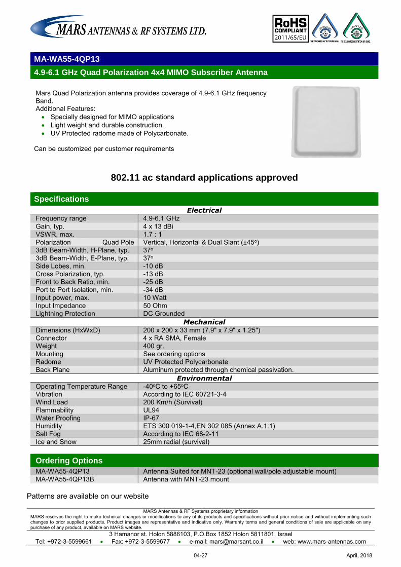
MARS Antennas & RF Systems proprietary information MARS reserves the right to make technical changes or modifications to any of its products and specifications without prior notice and without implementing such changes to prior supplied products. Product images are representative and indicative only. Warranty terms and general conditions of sale are applicable on any purchase of any product, available on MARS website.
3 Hamanor st. Holon 5886103, P.O.Box 1852 Holon 5811801, Israel Tel: +972-3-5599661 Fax: +972-3-5599677 e-mail: [email protected] web: www.mars-antennas.com
MA-WA55-4QP13
4.9-6.1 GHz Quad Polarization 4x4 MIMO Subscriber Antenna
Mars Quad Polarization antenna provides coverage of 4.9-6.1 GHz frequency Band. Additional Features: Specially designed for MIMO applications Light weight and durable construction. UV Protected radome made of Polycarbonate.
Can be customized per customer requirements
802.11 ac standard applications approved
Specifications
Electrical Frequency range 4.9-6.1 GHz Gain, typ. 4 x 13 dBi VSWR, max. 1.7 : 1 Polarization Quad Pole Vertical, Horizontal & Dual Slant (±45o) 3dB Beam-Width, H-Plane, typ. 37o 3dB Beam-Width, E-Plane, typ. 37o Side Lobes, min. -10 dB Cross Polarization, typ. -13 dB Front to Back Ratio, min. -25 dB Port to Port Isolation, min. -34 dB Input power, max. 10 Watt Input Impedance 50 Ohm Lightning Protection DC Grounded
Mechanical Dimensions (HxWxD) 200 x 200 x 33 mm (7.9" x 7.9" x 1.25") Connector 4 x RA SMA, Female Weight 400 gr. Mounting See ordering options Radome UV Protected Polycarbonate Back Plane Aluminum protected through chemical passivation.
Environmental Operating Temperature Range -40oC to +65oC Vibration According to IEC 60721-3-4 Wind Load 200 Km/h (Survival) Flammability UL94 Water Proofing IP-67 Humidity ETS 300 019-1-4,EN 302 085 (Annex A.1.1) Salt Fog According to IEC 68-2-11 Ice and Snow 25mm radial (survival) Ordering Options
MA-WA55-4QP13 Antenna Suited for MNT-23 (optional wall/pole adjustable mount) MA-WA55-4QP13B Antenna with MNT-23 mount
Patterns are available on our website
April, 201804-27
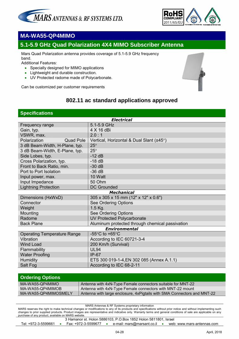
MARS Antennas & RF Systems proprietary information MARS reserves the right to make technical changes or modifications to any of its products and specifications without prior notice and without implementing such changes to prior supplied products. Product images are representative and indicative only. Warranty terms and general conditions of sale are applicable on any purchase of any product, available on MARS website.
3 Hamanor st. Holon 5886103, P.O.Box 1852 Holon 5811801, Israel Tel: +972-3-5599661 Fax: +972-3-5599677 e-mail: [email protected] web: www.mars-antennas.com
MA-WA55-QP4MIMO
5.1-5.9 GHz Quad Polarization 4X4 MIMO Subscriber Antenna
Mars Quad Polarization antenna provides coverage of 5.1-5.9 GHz frequency band. Additional Features: Specially designed for MIMO applications Lightweight and durable construction. UV Protected radome made of Polycarbonate.
Can be customized per customer requirements
802.11 ac standard applications approved
Specifications
Electrical
Frequency range 5.1-5.9 GHz Gain, typ. 4 X 16 dBi VSWR, max. 2.0 : 1 Polarization Quad Pole Vertical, Horizontal & Dual Slant (±45°) 3 dB Beam-Width, H-Plane, typ. 25° 3 dB Beam-Width, E-Plane, typ. 25°
Side Lobes, typ. -12 dB Cross Polarization, typ. -18 dB Front to Back Ratio, min. -30 dB Port to Port Isolation -36 dB Input power, max. 10 Watt Input Impedance 50 Ohm Lightning Protection DC Grounded
Mechanical
Dimensions (HxWxD) 305 x 305 x 15 mm (12" x 12" x 0.6") Connector See Ordering Options Weight 1.5 Kg. Mounting See Ordering Options Radome UV Protected Polycarbonate Back Plane Aluminum protected through chemical passivation
Environmental
Operating Temperature Range -55°C to +65°C Vibration According to IEC 60721-3-4 Wind Load 200 Km/h (Survival) Flammability UL94 Water Proofing IP-67 Humidity ETS 300 019-1-4,EN 302 085 (Annex A.1.1) Salt Fog According to IEC 68-2-11
Ordering Options
MA-WA55-QP4MIMO Antenna with 4xN-Type Female connectors suitable for MNT-22 MA-WA55-QP4MIMOB Antenna with 4xN-Type Female connectors with MNT-22 mount MA-WA55-QP4MIMOSMELY Antenna with large enclosure, 4xPigtails with SMA Connectors and MNT-22
April, 201804-28
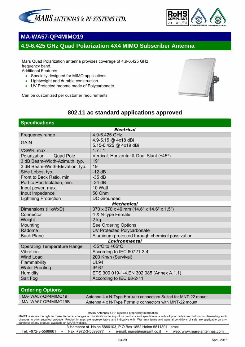
MARS Antennas & RF Systems proprietary information MARS reserves the right to make technical changes or modifications to any of its products and specifications without prior notice and without implementing such changes to prior supplied products. Product images are representative and indicative only. Warranty terms and general conditions of sale are applicable on any purchase of any product, available on MARS website.
3 Hamanor st. Holon 5886103, P.O.Box 1852 Holon 5811801, Israel Tel: +972-3-5599661 Fax: +972-3-5599677 e-mail: [email protected] web: www.mars-antennas.com
MA-WA57-QP4MIMO19
4.9-6.425 GHz Quad Polarization 4X4 MIMO Subscriber Antenna
Mars Quad Polarization antenna provides coverage of 4.9-6.425 GHz frequency band. Additional Features: Specially designed for MIMO applications Lightweight and durable construction. UV Protected radome made of Polycarbonate.
Can be customized per customer requirements
802.11 ac standard applications approved
Specifications
Electrical
Frequency range 4.9-6.425 GHz
GAIN 4.9-5.15 @ 4x18 dBi 5.15-6.425 @ 4x19 dBi
VSWR, max. 1.7 : 1 Polarization Quad Pole Vertical, Horizontal & Dual Slant (±45°) 3 dB Beam-Width-Azimuth, typ. 19° 3 dB Beam-Width-Elevation, typ. 19° Side Lobes, typ. -12 dB Front to Back Ratio, min. -35 dB Port to Port Isolation, min. -34 dB Input power, max. 10 Watt Input Impedance 50 Ohm Lightning Protection DC Grounded
Mechanical
Dimensions (HxWxD) 370 x 370 x 40 mm (14.6" x 14.6" x 1.5") Connector 4 X N-type Female Weight 2 kg. Mounting See Ordering Options Radome UV Protected Polycarbonate Back Plane Aluminum protected through chemical passivation
Environmental
Operating Temperature Range -55°C to +65°C Vibration According to IEC 60721-3-4 Wind Load 200 Km/h (Survival) Flammability UL94 Water Proofing IP-67 Humidity ETS 300 019-1-4,EN 302 085 (Annex A.1.1) Salt Fog According to IEC 68-2-11 Ordering Options
MA- WA57-QP4MIMO19 Antenna 4 x N-Type Female connectors Suited for MNT-22 mount MA- WA57-QP4MIMO19B Antenna 4 x N-Type Female connectors with MNT-22 mount
April, 201804-29
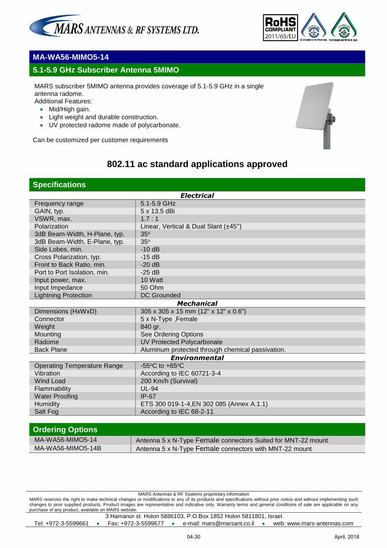
MARS Antennas & RF Systems proprietary information MARS reserves the right to make technical changes or modifications to any of its products and specifications without prior notice and without implementing such changes to prior supplied products. Product images are representative and indicative only. Warranty terms and general conditions of sale are applicable on any purchase of any product, available on MARS website.
3 Hamanor st. Holon 5886103, P.O.Box 1852 Holon 5811801, Israel
Tel: +972-3-5599661 Fax: +972-3-5599677 e-mail: [email protected] web: www.mars-antennas.com
MA-WA56-MIMO5-14
5.1-5.9 GHz Subscriber Antenna 5MIMO
MARS subscriber 5MIMO antenna provides coverage of 5.1-5.9 GHz in a single antenna radome. Additional Features:
Mid/High gain.
Light weight and durable construction.
UV protected radome made of polycarbonate.
Can be customized per customer requirements
802.11 ac standard applications approved
Specifications
Electrical Frequency range 5.1-5.9 GHz
GAIN, typ. 5 x 13.5 dBi
VSWR, max. 1.7 : 1 Polarization Linear, Vertical & Dual Slant (±45°)
3dB Beam-Width, H-Plane, typ. 35o
3dB Beam-Width, E-Plane, typ. 35o
Side Lobes, min. -10 dB
Cross Polarization, typ. -15 dB
Front to Back Ratio, min. -20 dB
Port to Port Isolation, min. -25 dB
Input power, max. 10 Watt
Input Impedance 50 Ohm
Lightning Protection DC Grounded
Mechanical Dimensions (HxWxD) 305 x 305 x 15 mm (12" x 12" x 0.6")
Connector 5 x N-Type ,Female
Weight 840 gr.
Mounting See Ordering Options
Radome UV Protected Polycarbonate
Back Plane Aluminum protected through chemical passivation.
Environmental Operating Temperature Range -55oC to +65oC
Vibration According to IEC 60721-3-4
Wind Load 200 Km/h (Survival)
Flammability UL-94
Water Proofing IP-67
Humidity ETS 300 019-1-4,EN 302 085 (Annex A.1.1) Salt Fog According to IEC 68-2-11
Ordering Options
MA-WA56-MIMO5-14 Antenna 5 x N-Type Female connectors Suited for MNT-22 mount
MA-WA56-MIMO5-14B Antenna 5 x N-Type Female connectors with MNT-22 mount
April, 201804-30
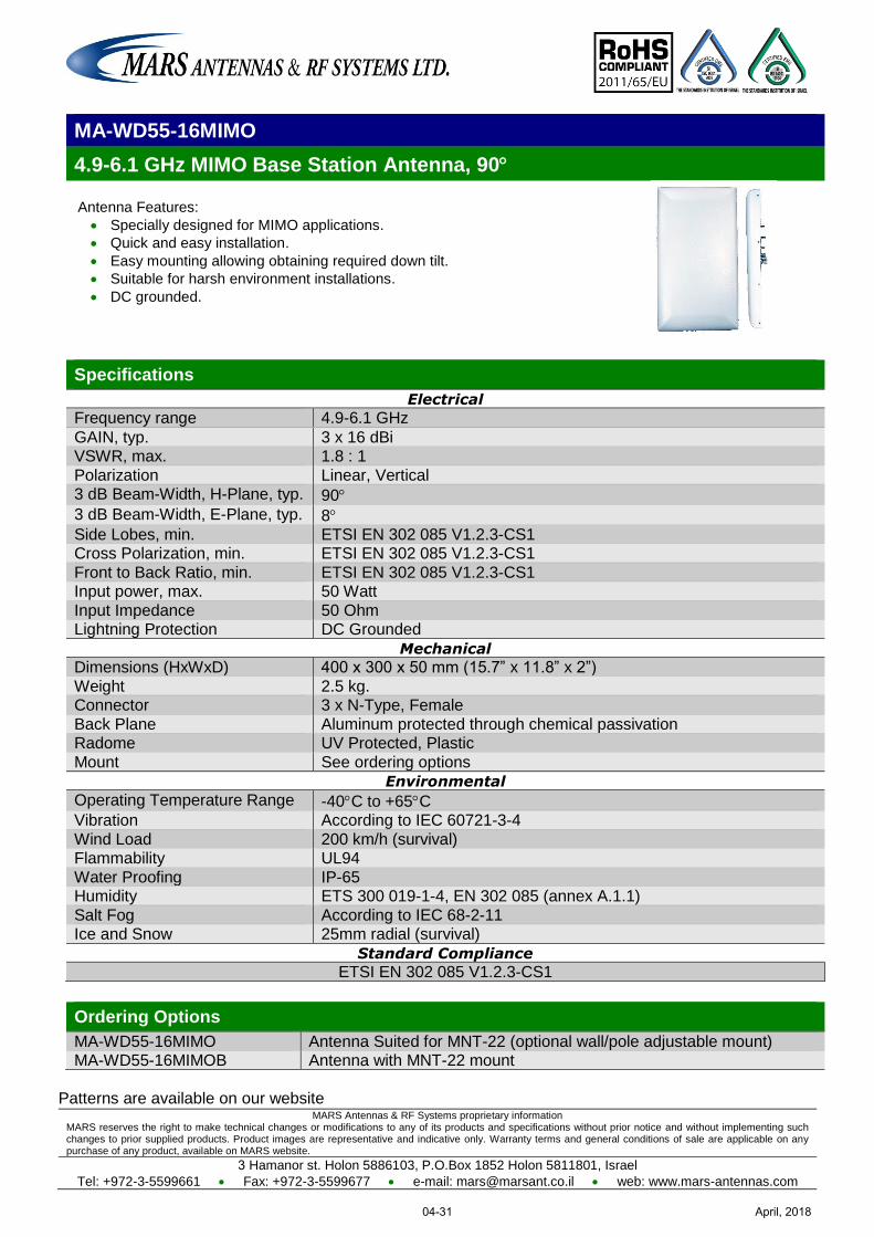
MARS Antennas & RF Systems proprietary information MARS reserves the right to make technical changes or modifications to any of its products and specifications without prior notice and without implementing such changes to prior supplied products. Product images are representative and indicative only. Warranty terms and general conditions of sale are applicable on any purchase of any product, available on MARS website.
3 Hamanor st. Holon 5886103, P.O.Box 1852 Holon 5811801, Israel
Tel: +972-3-5599661 Fax: +972-3-5599677 e-mail: [email protected] web: www.mars-antennas.com
MA-WD55-16MIMO
4.9-6.1 GHz MIMO Base Station Antenna, 90
Antenna Features:
Specially designed for MIMO applications.
Quick and easy installation.
Easy mounting allowing obtaining required down tilt.
Suitable for harsh environment installations.
DC grounded.
Specifications
Electrical
Frequency range 4.9-6.1 GHz
GAIN, typ. 3 x 16 dBi VSWR, max. 1.8 : 1
Polarization Linear, Vertical 3 dB Beam-Width, H-Plane, typ. 90
3 dB Beam-Width, E-Plane, typ. 8 Side Lobes, min. ETSI EN 302 085 V1.2.3-CS1 Cross Polarization, min. ETSI EN 302 085 V1.2.3-CS1
Front to Back Ratio, min. ETSI EN 302 085 V1.2.3-CS1 Input power, max. 50 Watt
Input Impedance 50 Ohm Lightning Protection DC Grounded
Mechanical
Dimensions (HxWxD) 400 x 300 x 50 mm (15.7” x 11.8” x 2”)
Weight 2.5 kg. Connector 3 x N-Type, Female
Back Plane Aluminum protected through chemical passivation Radome UV Protected, Plastic
Mount See ordering options
Environmental
Operating Temperature Range -40C to +65C Vibration According to IEC 60721-3-4
Wind Load 200 km/h (survival) Flammability UL94
Water Proofing IP-65 Humidity ETS 300 019-1-4, EN 302 085 (annex A.1.1)
Salt Fog According to IEC 68-2-11 Ice and Snow 25mm radial (survival)
Standard Compliance
ETSI EN 302 085 V1.2.3-CS1
Ordering Options
MA-WD55-16MIMO Antenna Suited for MNT-22 (optional wall/pole adjustable mount) MA-WD55-16MIMOB Antenna with MNT-22 mount
Patterns are available on our website
April, 201804-31
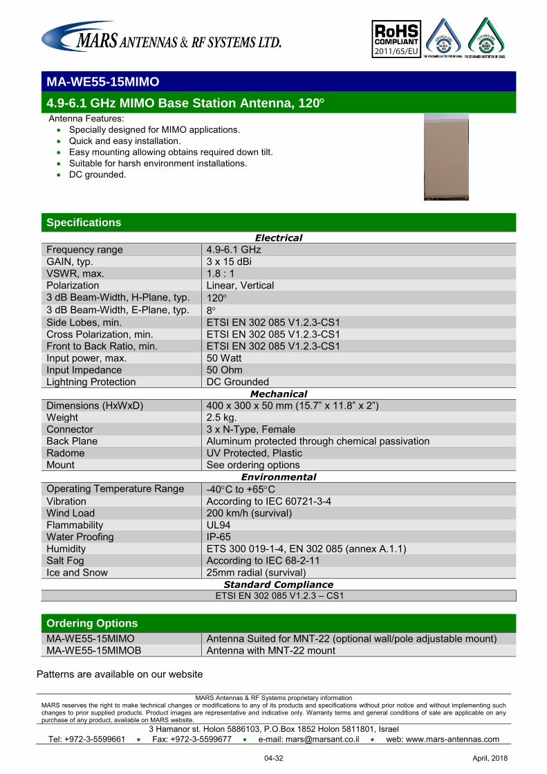
MARS Antennas & RF Systems proprietary information MARS reserves the right to make technical changes or modifications to any of its products and specifications without prior notice and without implementing such changes to prior supplied products. Product images are representative and indicative only. Warranty terms and general conditions of sale are applicable on any purchase of any product, available on MARS website.
3 Hamanor st. Holon 5886103, P.O.Box 1852 Holon 5811801, Israel Tel: +972-3-5599661 Fax: +972-3-5599677 e-mail: [email protected] web: www.mars-antennas.com
MA-WE55-15MIMO
4.9-6.1 GHz MIMO Base Station Antenna, 120 Antenna Features: Specially designed for MIMO applications. Quick and easy installation. Easy mounting allowing obtains required down tilt. Suitable for harsh environment installations. DC grounded.
Specifications
Electrical
Frequency range 4.9-6.1 GHz GAIN, typ. 3 x 15 dBi VSWR, max. 1.8 : 1 Polarization Linear, Vertical 3 dB Beam-Width, H-Plane, typ. 120 3 dB Beam-Width, E-Plane, typ. 8 Side Lobes, min. ETSI EN 302 085 V1.2.3-CS1 Cross Polarization, min. ETSI EN 302 085 V1.2.3-CS1 Front to Back Ratio, min. ETSI EN 302 085 V1.2.3-CS1 Input power, max. 50 Watt Input Impedance 50 Ohm Lightning Protection DC Grounded
Mechanical
Dimensions (HxWxD) 400 x 300 x 50 mm (15.7” x 11.8” x 2”) Weight 2.5 kg. Connector 3 x N-Type, Female Back Plane Aluminum protected through chemical passivation Radome UV Protected, Plastic Mount See ordering options
Environmental
Operating Temperature Range -40C to +65C Vibration According to IEC 60721-3-4 Wind Load 200 km/h (survival) Flammability UL94 Water Proofing IP-65 Humidity ETS 300 019-1-4, EN 302 085 (annex A.1.1) Salt Fog According to IEC 68-2-11 Ice and Snow 25mm radial (survival)
Standard Compliance ETSI EN 302 085 V1.2.3 – CS1
Ordering Options
MA-WE55-15MIMO Antenna Suited for MNT-22 (optional wall/pole adjustable mount) MA-WE55-15MIMOB Antenna with MNT-22 mount
Patterns are available on our website
April, 201804-32
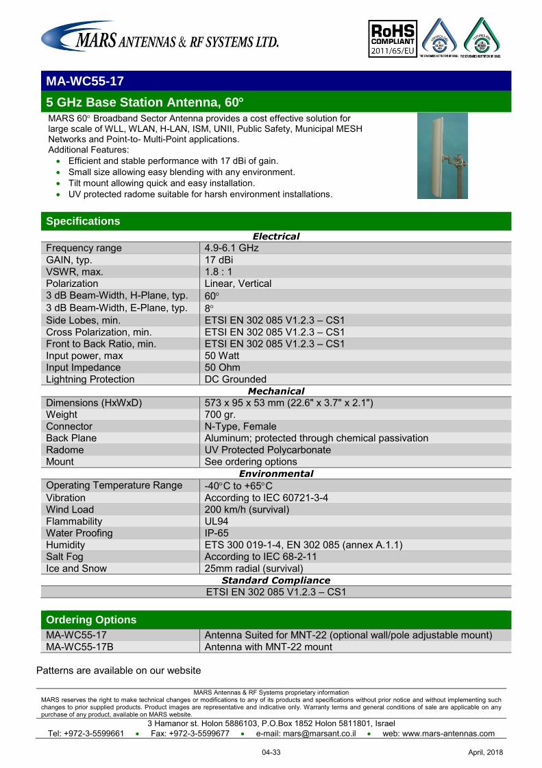
MARS Antennas & RF Systems proprietary information MARS reserves the right to make technical changes or modifications to any of its products and specifications without prior notice and without implementing such changes to prior supplied products. Product images are representative and indicative only. Warranty terms and general conditions of sale are applicable on any purchase of any product, available on MARS website.
3 Hamanor st. Holon 5886103, P.O.Box 1852 Holon 5811801, Israel Tel: +972-3-5599661 Fax: +972-3-5599677 e-mail: [email protected] web: www.mars-antennas.com
MA-WC55-17
5 GHz Base Station Antenna, 60 MARS 60 Broadband Sector Antenna provides a cost effective solution for large scale of WLL, WLAN, H-LAN, ISM, UNII, Public Safety, Municipal MESH Networks and Point-to- Multi-Point applications. Additional Features: Efficient and stable performance with 17 dBi of gain. Small size allowing easy blending with any environment. Tilt mount allowing quick and easy installation. UV protected radome suitable for harsh environment installations.
Specifications
Electrical
Frequency range 4.9-6.1 GHz GAIN, typ. 17 dBi VSWR, max. 1.8 : 1 Polarization Linear, Vertical 3 dB Beam-Width, H-Plane, typ. 60 3 dB Beam-Width, E-Plane, typ. 8 Side Lobes, min. ETSI EN 302 085 V1.2.3 – CS1
Cross Polarization, min. ETSI EN 302 085 V1.2.3 – CS1 Front to Back Ratio, min. ETSI EN 302 085 V1.2.3 – CS1
Input power, max 50 Watt Input Impedance 50 Ohm Lightning Protection DC Grounded
Mechanical
Dimensions (HxWxD) 573 x 95 x 53 mm (22.6" x 3.7" x 2.1") Weight 700 gr. Connector N-Type, Female Back Plane Aluminum; protected through chemical passivation Radome UV Protected Polycarbonate Mount See ordering options
Environmental
Operating Temperature Range -40C to +65C Vibration According to IEC 60721-3-4 Wind Load 200 km/h (survival) Flammability UL94 Water Proofing IP-65 Humidity ETS 300 019-1-4, EN 302 085 (annex A.1.1) Salt Fog According to IEC 68-2-11 Ice and Snow 25mm radial (survival)
Standard Compliance
ETSI EN 302 085 V1.2.3 – CS1
Ordering Options
MA-WC55-17 Antenna Suited for MNT-22 (optional wall/pole adjustable mount) MA-WC55-17B Antenna with MNT-22 mount
Patterns are available on our website
April, 201804-33
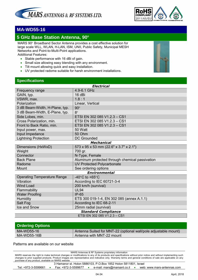
MARS Antennas & RF Systems proprietary information MARS reserves the right to make technical changes or modifications to any of its products and specifications without prior notice and without implementing such changes to prior supplied products. Product images are representative and indicative only. Warranty terms and general conditions of sale are applicable on any purchase of any product, available on MARS website.
3 Hamanor st. Holon 5886103, P.O.Box 1852 Holon 5811801, Israel Tel: +972-3-5599661 Fax: +972-3-5599677 e-mail: [email protected] web: www.mars-antennas.com
MA-WD55-16
5 GHz Base Station Antenna, 90 MARS 90 Broadband Sector Antenna provides a cost effective solution for large scale WLL, WLAN, H-LAN, ISM, UNII, Public Safety, Municipal MESH Networks and Point-to-Multi-Point applications. Additional Features: Stable performance with 16 dBi of gain. Small size allowing easy blending with any environment. Tilt mount allowing quick and easy installation. UV protected radome suitable for harsh environment installations.
Specifications
Electrical
Frequency range 4.9-6.1 GHz GAIN, typ. 16 dBi VSWR, max. 1.8 : 1 Polarization Linear, Vertical 3 dB Beam-Width, H-Plane, typ. 90 3 dB Beam-Width, E-Plane, typ. 8 Side Lobes, min. ETSI EN 302 085 V1.2.3 – CS1
Cross Polarization, min. ETSI EN 302 085 V1.2.3 – CS1 Front to Back Ratio, min. ETSI EN 302 085 V1.2.3 – CS1
Input power, max. 50 Watt Input Impedance 50 Ohm Lightning Protection DC Grounded
Mechanical
Dimensions (HxWxD) 573 x 95 x 53 mm (22.6" x 3.7" x 2.1") Weight 700 gr. Connector N-Type, Female Back Plane Aluminum protected through chemical passivation Radome UV Protected Polycarbonate Mount See ordering options
Environmental
Operating Temperature Range -40C to +65C Vibration According to IEC 60721-3-4 Wind Load 200 km/h (survival) Flammability UL94 Water Proofing IP-65 Humidity ETS 300 019-1-4, EN 302 085 (annex A.1.1) Salt Fog According to IEC 68-2-11 Ice and Snow 25mm radial (survival)
Standard Compliance ETSI EN 302 085 V1.2.3 – CS1
Ordering Options
MA-WD55-16 Antenna Suited for MNT-22 (optional wall/pole adjustable mount) MA-WD55-16B Antenna with MNT-22 mount
Patterns are available on our website
April, 201804-34
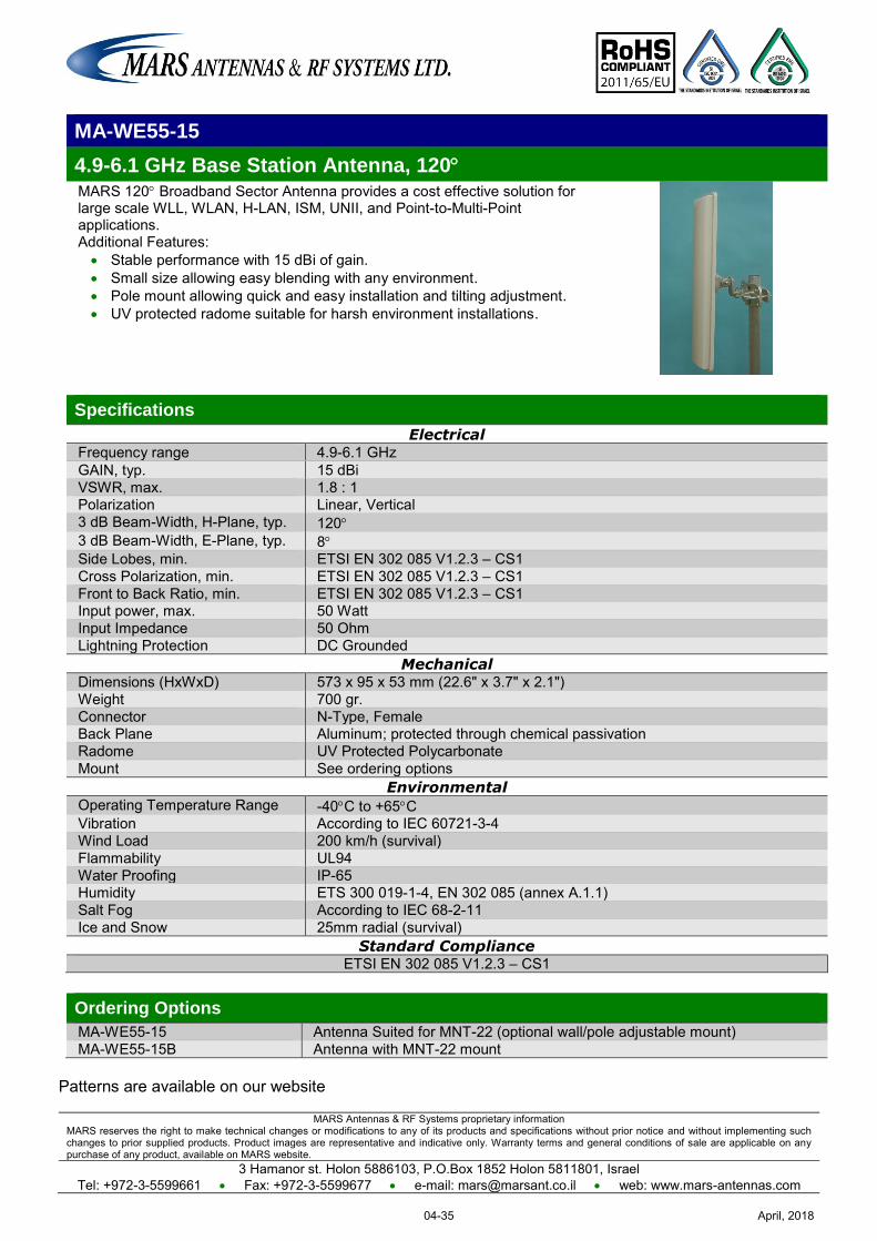
MARS Antennas & RF Systems proprietary information MARS reserves the right to make technical changes or modifications to any of its products and specifications without prior notice and without implementing such changes to prior supplied products. Product images are representative and indicative only. Warranty terms and general conditions of sale are applicable on any purchase of any product, available on MARS website.
3 Hamanor st. Holon 5886103, P.O.Box 1852 Holon 5811801, Israel Tel: +972-3-5599661 Fax: +972-3-5599677 e-mail: [email protected] web: www.mars-antennas.com
MA-WE55-15
4.9-6.1 GHz Base Station Antenna, 120 MARS 120 Broadband Sector Antenna provides a cost effective solution for large scale WLL, WLAN, H-LAN, ISM, UNII, and Point-to-Multi-Point applications. Additional Features: Stable performance with 15 dBi of gain. Small size allowing easy blending with any environment. Pole mount allowing quick and easy installation and tilting adjustment. UV protected radome suitable for harsh environment installations.
Specifications
Electrical Frequency range 4.9-6.1 GHz GAIN, typ. 15 dBi VSWR, max. 1.8 : 1 Polarization Linear, Vertical 3 dB Beam-Width, H-Plane, typ. 120 3 dB Beam-Width, E-Plane, typ. 8 Side Lobes, min. ETSI EN 302 085 V1.2.3 – CS1 Cross Polarization, min. ETSI EN 302 085 V1.2.3 – CS1 Front to Back Ratio, min. ETSI EN 302 085 V1.2.3 – CS1 Input power, max. 50 Watt Input Impedance 50 Ohm Lightning Protection DC Grounded
Mechanical Dimensions (HxWxD) 573 x 95 x 53 mm (22.6" x 3.7" x 2.1") Weight 700 gr. Connector N-Type, Female Back Plane Aluminum; protected through chemical passivation Radome UV Protected Polycarbonate Mount See ordering options
Environmental Operating Temperature Range -40C to +65C Vibration According to IEC 60721-3-4 Wind Load 200 km/h (survival) Flammability UL94 Water Proofing IP-65 Humidity ETS 300 019-1-4, EN 302 085 (annex A.1.1) Salt Fog According to IEC 68-2-11 Ice and Snow 25mm radial (survival)
Standard Compliance ETSI EN 302 085 V1.2.3 – CS1
Ordering Options
MA-WE55-15 Antenna Suited for MNT-22 (optional wall/pole adjustable mount) MA-WE55-15B Antenna with MNT-22 mount
Patterns are available on our website
April, 201804-35
MARS Antennas & RF Systems proprietary information MARS reserves the right to make technical changes or modifications to any of its products and specifications without prior notice and without implementing such changes to prior supplied products. Product images are representative and indicative only. Warranty terms and general conditions of sale are applicable on any purchase of any product, available on MARS website.
3 Hamanor st. Holon 5886103, P.O.Box 1852 Holon 5811801, Israel
Tel: +972-3-5599661 Fax: +972-3-5599677 e-mail: [email protected] web: www.mars-antennas.com
MA-WB55-20
5 GHz Base Station Antenna, 30
MARS 30° Broadband Sector Antenna provides a cost effective solution for large scale WLL, WLAN, H-LAN, ISM, UNII, Public Safety, Municipal MESH Networks and Point-to-Multi-Point applications. Additional Features:
Stable performance with 20 dBi of gain.
Small size allowing easy blending with any environment.
Tilt mount allowing quick and easy installation.
UV protected radome suitable for harsh environment installations.
Specifications Electrical
Frequency range 4.9-6.1 GHz
GAIN, typ. 20 dBi
VSWR, max. 1.8 : 1 Polarization Linear, Vertical
3 dB Beam-Width, H-Plane, typ. 30 3 dB Beam-Width, E-Plane, typ. 8 Side Lobes, min. ETSI EN 302 085 V1.2.3 – CS1
Cross Polarization, min. ETSI EN 302 085 V1.2.3 – CS1 Front to Back Ratio, min. ETSI EN 302 085 V1.2.3 – CS1
Input power, max. 50 Watt Input Impedance 50 Ohm
Lightning Protection DC Grounded
Mechanical
Dimensions (HxWxL) 573 x 120 x 115 mm (22.6" x 4.7" x 4.5") Weight 1 kg.
Connector N-Type, Female Back Plane Aluminum protected through chemical passivation
Radome UV Protected, Polycarbonate Mount See ordering options
Environmental
Operating Temperature Range -40C to +65C
Vibration According to IEC 60721-3-4 Wind Load 200 km/h (survival)
Flammability UL94 Water Proofing IP-67
Humidity ETS 300 019-1-4, EN 302 085 (annex A.1.1) Salt Fog According to IEC 68-2-11
Ice and Snow 25mm radial (survival)
Standard Compliance ETSI EN 302 085 V1.2.3 – CS1
Ordering Options MA-WB55-20 Antenna Suited for MNT-22 (optional wall/pole adjustable mount) MA-WB55-20B Antenna with MNT-22 mount
Patterns are available on our website
April, 201804-36
MARS Antennas & RF Systems proprietary information MARS reserves the right to make technical changes or modifications to any of its products and specifications without prior notice and without implementing such changes to prior supplied products. Product images are representative and indicative only. Warranty terms and general conditions of sale are applicable on any purchase of any product, available on MARS website.
3 Hamanor st. Holon 5886103, P.O.Box 1852 Holon 5811801, Israel Tel: +972-3-5599661 Fax: +972-3-5599677 e-mail: [email protected] web: www.mars-antennas.com
MA-WD55-17H
5.5 GHz Horizontal Polarization Base Station Antenna, 90 MARS 90° Broadband Sector Antenna provides a cost effective solution for large scale WLL, WLAN, H-LAN, ISM, UNII, Public Safety, Municipal MESH Networks and Point-to-Multi-Point applications. Additional Features: Stable performance with 17 dBi of gain. Small size allowing for easy blending with any environment. Tilt mount allowing quick and easy installation. UV protected radome suitable for harsh environment installations.
Specifications
Electrical Frequency range 4.9-6.1 GHz GAIN, typ. 17 dBi VSWR, max. 1.7 : 1 Polarization Linear, Horizontal 3 dB Beam-Width, H-Plane, typ. 90 3 dB Beam-Width, E-Plane, typ. 5 Side Lobes, min. ETSI EN 302 085 V1.2.3 – CS2 Cross Polarization, min. ETSI EN 302 085 V1.2.3 – CS1 Front to Back Ratio, min. ETSI EN 302 085 V1.2.3 – CS2 Input power, max. 20 Watt Input Impedance 50 Ohm Lightning Protection DC Grounded
Mechanical Dimensions (HxWxD) 573 x 95 x 53 mm (22.6" x 3.7" x 2.1") Weight 600 gr. Connector N-Type, Female Back Plane Aluminum protected through chemical passivation Radome UV Protected, Polycarbonate Mount See ordering options
Environmental Operating Temperature Range -40C to +65C Vibration According to IEC 60721-3-4 Wind Load 200 km/h (survival) Flammability UL94 Water Proofing IP-67 Humidity ETS 300 019-1-4, EN 302 085 (annex A.1.1) Salt Fog According to IEC 68-2-11 Ice and Snow 25mm radial (survival)
Standard Compliance ETSI EN 302 085 V1.2.3 – CS1 / CS2
Ordering Options
MA-WD55-17H Antenna Suited for MNT-22 (optional wall/pole adjustable mount) MA-WD55-17HB Antenna with MNT-22 mount
Patterns are available on our website
April, 201804-37
MARS Antennas & RF Systems proprietary information MARS reserves the right to make technical changes or modifications to any of its products and specifications without prior notice and without implementing such changes to prior supplied products. Product images are representative and indicative only. Warranty terms and general conditions of sale are applicable on any purchase of any product, available on MARS website.
3 Hamanor st. Holon 5886103, P.O.Box 1852 Holon 5811801, Israel Tel: +972-3-5599661 Fax: +972-3-5599677 e-mail: [email protected] web: www.mars-antennas.com
MA-WC62-17
6 GHz Base Station Antenna, 60 MARS 60° Broadband Sector Antenna provides a cost effective solution for large scale WLL, WLAN, H-LAN, ISM, UNII, Public Safety, Municipal MESH Networks and Point-to-Multi-Point applications. Additional Features: Stable performance with 17 dBi of gain. Small size allowing easy blending with any environment. Tilt mount allowing quick and easy installation. UV protected radome suitable for harsh environment installations.
Specifications
Electrical
Frequency range 5.7-6.5 GHz GAIN, typ. 17 dBi VSWR, max. 1.7 : 1 Polarization Linear, Vertical 3 dB Beam-Width, H-Plane, typ. 60 3 dB Beam-Width, E-Plane, typ. 8 Side Lobes, min. ETSI EN 302 085 V1.2.3 – CS1
Cross Polarization, min. ETSI EN 302 085 V1.2.3 – CS1 Front to Back Ratio, min. ETSI EN 302 085 V1.2.3 – CS1
Input power, max. 50 Watt Input Impedance 50 Ohm Lightning Protection DC Grounded
Mechanical
Dimensions (HxWxD) 573 x 95 x 53 mm (22.6" x 3.7" x 2.1") Weight 700 gr. Connector N-Type, Female Back Plane Aluminum protected through chemical passivation Radome UV Protected, Polycarbonate Mount See ordering options
Environmental
Operating Temperature Range -40C to +65C Vibration According to IEC 60721-3-4 Wind Load 200 km/h (survival) Flammability UL94 Water Proofing IP-67 Humidity ETS 300 019-1-4, EN 302 085 (annex A.1.1) Salt Fog According to IEC 68-2-11 Ice and Snow 25mm radial (survival)
Standard Compliance ETSI EN 302 085 V1.2.3 – CS1
Ordering Options
MA-WC62-17 Antenna Suited for MNT-22 (optional wall/pole adjustable mount) MA-WC62-17B Antenna with MNT-22 mount
Patterns are available on our website
April, 201804-38
MARS Antennas & RF Systems proprietary information MARS reserves the right to make technical changes or modifications to any of its products and specifications without prior notice and without implementing such changes to prior supplied products. Product images are representative and indicative only. Warranty terms and general conditions of sale are applicable on any purchase of any product, available on MARS website.
3 Hamanor st. Holon 5886103, P.O.Box 1852 Holon 5811801, Israel Tel: +972-3-5599661 Fax: +972-3-5599677 e-mail: [email protected] web: www.mars-antennas.com
MA-WD62-16
5.7-6.5 GHz Base Station Antenna, 90 MARS 90° Broadband Sector Antenna provides a cost effective solution for large scale WLL, WLAN, H-LAN, ISM, UNII, Public Safety, Municipal MESH Networks and Point-to-Multi-Point applications. Additional Features: Stable performance with 16 dBi of gain. Small size allowing easy blending with any environment. Tilt mount allowing quick and easy installation. UV protected radome suitable for harsh environment installations.
Specifications Electrical
Frequency range 5.7-6.5 GHz GAIN, typ. 16 dBi VSWR, max. 1.7 : 1 Polarization Linear, Vertical 3 dB Beam-Width, H-Plane, typ. 90 3 dB Beam-Width, E-Plane, typ. 8 Side Lobes, min. ETSI EN 302 085 V1.2.3 – CS1
Cross Polarization, min. ETSI EN 302 085 V1.2.3 – CS1 Front to Back Ratio, min. ETSI EN 302 085 V1.2.3 – CS1
Input power, max. 50 Watt Input Impedance 50 Ohm Lightning Protection DC Grounded
Mechanical
Dimensions (HxWxD) 573 x 95 x 53 mm (22.6" x 3.7" x 2.1") Weight 700 gr. Connector N-Type, Female Back Plane Aluminum protected through chemical passivation Radome UV Protected, Polycarbonate Mount See ordering options
Environmental
Operating Temperature Range -40C to +65C Vibration According to IEC 60721-3-4 Wind Load 200 km/h (survival) Flammability UL94 Water Proofing IP-67 Humidity ETS 300 019-1-4, EN 302 085 (annex A.1.1) Salt Fog According to IEC 68-2-11 Ice and Snow 25mm radial (survival)
Standard Compliance
ETSI EN 302 085 V1.2.3 – CS1
Ordering Options MA-WD62-16 Antenna Suited for MNT-22 (optional wall/pole adjustable mount) MA-WD62-16B Antenna with MNT-22 mount
Patterns are available on our website
April, 201804-39
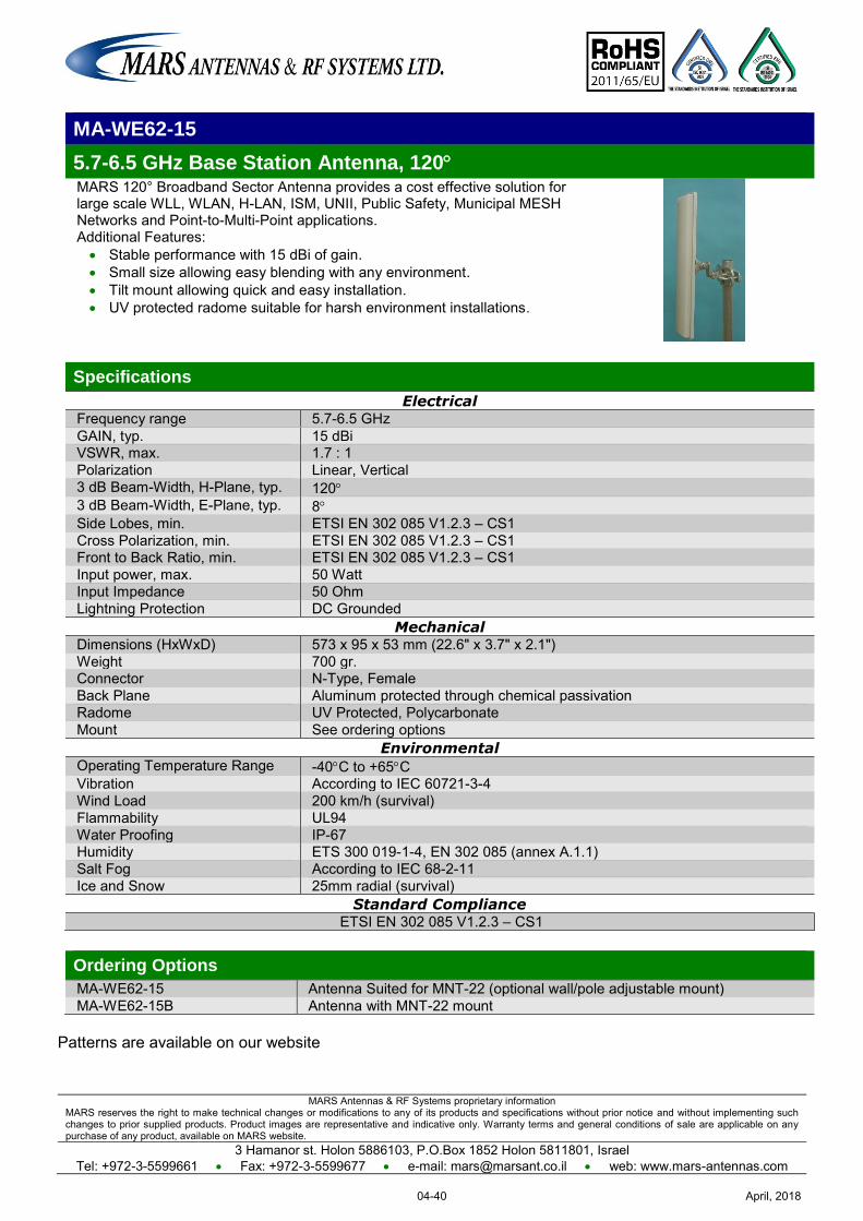
MARS Antennas & RF Systems proprietary information MARS reserves the right to make technical changes or modifications to any of its products and specifications without prior notice and without implementing such changes to prior supplied products. Product images are representative and indicative only. Warranty terms and general conditions of sale are applicable on any purchase of any product, available on MARS website.
3 Hamanor st. Holon 5886103, P.O.Box 1852 Holon 5811801, Israel Tel: +972-3-5599661 Fax: +972-3-5599677 e-mail: [email protected] web: www.mars-antennas.com
MA-WE62-15
5.7-6.5 GHz Base Station Antenna, 120 MARS 120° Broadband Sector Antenna provides a cost effective solution for large scale WLL, WLAN, H-LAN, ISM, UNII, Public Safety, Municipal MESH Networks and Point-to-Multi-Point applications. Additional Features: Stable performance with 15 dBi of gain. Small size allowing easy blending with any environment. Tilt mount allowing quick and easy installation. UV protected radome suitable for harsh environment installations.
Specifications
Electrical Frequency range 5.7-6.5 GHz GAIN, typ. 15 dBi VSWR, max. 1.7 : 1 Polarization Linear, Vertical 3 dB Beam-Width, H-Plane, typ. 120 3 dB Beam-Width, E-Plane, typ. 8 Side Lobes, min. ETSI EN 302 085 V1.2.3 – CS1 Cross Polarization, min. ETSI EN 302 085 V1.2.3 – CS1 Front to Back Ratio, min. ETSI EN 302 085 V1.2.3 – CS1 Input power, max. 50 Watt Input Impedance 50 Ohm Lightning Protection DC Grounded
Mechanical Dimensions (HxWxD) 573 x 95 x 53 mm (22.6" x 3.7" x 2.1") Weight 700 gr. Connector N-Type, Female Back Plane Aluminum protected through chemical passivation Radome UV Protected, Polycarbonate Mount See ordering options
Environmental Operating Temperature Range -40C to +65C Vibration According to IEC 60721-3-4 Wind Load 200 km/h (survival) Flammability UL94 Water Proofing IP-67 Humidity ETS 300 019-1-4, EN 302 085 (annex A.1.1) Salt Fog According to IEC 68-2-11 Ice and Snow 25mm radial (survival)
Standard Compliance ETSI EN 302 085 V1.2.3 – CS1
Ordering Options
MA-WE62-15 Antenna Suited for MNT-22 (optional wall/pole adjustable mount) MA-WE62-15B Antenna with MNT-22 mount
Patterns are available on our website
April, 201804-40

MARS Antennas & RF Systems proprietary information MARS reserves the right to make technical changes or modifications to any of its products and specifications without prior notice and without implementing such changes to prior supplied products. Product images are representative and indicative only. Warranty terms and general conditions of sale are applicable on any purchase of any product, available on MARS website.
3 Hamanor st. Holon 5886103, P.O.Box 1852 Holon 5811801, Israel
Tel: +972-3-5599661 Fax: +972-3-5599677 e-mail: [email protected] web: www.mars-antennas.com
MA-WC47-DP16
4.4-5.1 GHz Dual Polarized Base Station Sector Antenna, 60
MARS 60 Broadband Dual Polarized Base Station Sector Antenna provides a cost effective solution for large scale of applications.
Additional Features:
Stable performance with 16 dBi of gain.
Tilt mount allowing quick and easy installation.
UV protected radome suitable for harsh environment installations.
Specifications
Electrical
Frequency range 4.4-5.1 GHz GAIN, typ. 16 dBi VSWR, max. 1.7 : 1 Polarization Dual Vertical & Horizontal 3 dB Beam-Width, H-Plane, typ. 60 3 dB Beam-Width, E-Plane, typ. 9 Side Lobes, typ. -12 dB Cross Polarization, min. -20 dB Front to Back Ratio, min. -30 dB Port to Port Isolation, min. -35 dB Input power, max. 10 Watt Input Impedance 50 Ohm Lightning Protection DC Grounded
Mechanical
Dimensions (HxWxD) 370 x 370 x 40 mm (14.5" x 14.5" x 1.6") Weight 2 kg. Connector 2 x N-Type, Female Back Plane Aluminum protected through chemical passivation Radome UV Protected, Polycarbonate Mount See ordering options
Environmental
Operating Temperature Range -40C to +65C Vibration According to IEC 60721-3-4 Wind Load 200 km/h (survival) Flammability UL94 Water Proofing IP-67 Humidity ETS 300 019-1-4, EN 302 085 (annex A.1.1) Salt Fog According to IEC 68-2-11 Ice and Snow 25mm radial (survival)
Ordering Options
MA-WC47-DP16 Antenna Suited for MNT-22 (optional wall/pole adjustable mount) MA-WC47-DP16B Antenna with MNT-22 mount
April, 201804-41
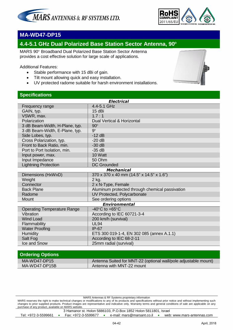
MARS Antennas & RF Systems proprietary information MARS reserves the right to make technical changes or modifications to any of its products and specifications without prior notice and without implementing such changes to prior supplied products. Product images are representative and indicative only. Warranty terms and general conditions of sale are applicable on any purchase of any product, available on MARS website.
3 Hamanor st. Holon 5886103, P.O.Box 1852 Holon 5811801, Israel
Tel: +972-3-5599661 Fax: +972-3-5599677 e-mail: [email protected] web: www.mars-antennas.com
MA-WD47-DP15
4.4-5.1 GHz Dual Polarized Base Station Sector Antenna, 90
MARS 90 Broadband Dual Polarized Base Station Sector Antenna provides a cost effective solution for large scale of applications.
Additional Features:
Stable performance with 15 dBi of gain.
Tilt mount allowing quick and easy installation.
UV protected radome suitable for harsh environment installations.
Specifications
Electrical
Frequency range 4.4-5.1 GHz GAIN, typ. 15 dBi VSWR, max. 1.7 : 1 Polarization Dual Vertical & Horizontal 3 dB Beam-Width, H-Plane, typ. 90 3 dB Beam-Width, E-Plane, typ. 9 Side Lobes, typ. -12 dB Cross Polarization, typ. -20 dB Front to Back Ratio, min. -30 dB Port to Port Isolation, min. -35 dB Input power, max. 10 Watt Input Impedance 50 Ohm Lightning Protection DC Grounded
Mechanical
Dimensions (HxWxD) 370 x 370 x 40 mm (14.5" x 14.5" x 1.6") Weight 2 kg. Connector 2 x N-Type, Female Back Plane Aluminum protected through chemical passivation Radome UV Protected, Polycarbonate Mount See ordering options
Environmental
Operating Temperature Range -40C to +65C Vibration According to IEC 60721-3-4 Wind Load 200 km/h (survival) Flammability UL94 Water Proofing IP-67 Humidity ETS 300 019-1-4, EN 302 085 (annex A.1.1) Salt Fog According to IEC 68-2-11 Ice and Snow 25mm radial (survival)
Ordering Options
MA-WD47-DP15 Antenna Suited for MNT-22 (optional wall/pole adjustable mount) MA-WD47-DP15B Antenna with MNT-22 mount
April, 201804-42
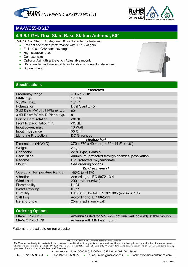
MARS Antennas & RF Systems proprietary information MARS reserves the right to make technical changes or modifications to any of its products and specifications without prior notice and without implementing such changes to prior supplied products. Product images are representative and indicative only. Warranty terms and general conditions of sale are applicable on any purchase of any product, available on MARS website.
3 Hamanor st. Holon 5886103, P.O.Box 1852 Holon 5811801, Israel Tel: +972-3-5599661 Fax: +972-3-5599677 e-mail: [email protected] web: www.mars-antennas.com
MA-WC55-DS17
4.9-6.1 GHz Dual Slant Base Station Antenna, 60 MARS Dual Slant ± 45 degrees 60 sector antenna features: Efficient and stable performance with 17 dBi of gain. Full 4.9-6.1 GHz band coverage. High Isolation ratio. Compact size. Optional Azimuth & Elevation Adjustable mount. UV protected radome suitable for harsh environment installations. Square shape.
Specifications
Electrical
Frequency range 4.9-6.1 GHz GAIN, typ. 17 dBi VSWR, max. 1.7 : 1 Polarization Dual Slant ± 45º 3 dB Beam-Width, H-Plane, typ. 60 3 dB Beam-Width, E-Plane, typ. 8 Port to Port Isolation -30 dB Front to Back Ratio, min. -35 dB
Input power, max. 10 Watt Input Impedance 50 Ohm Lightning Protection DC Grounded
Mechanical
Dimensions (HxWxD) 370 x 370 x 40 mm (14.5" x 14.5" x 1.6") Weight 2 kg. Connector 2x N-Type, Female Back Plane Aluminum; protected through chemical passivation Radome UV Protected Polycarbonate Mount See ordering options
Environmental
Operating Temperature Range -40C to +65C Vibration According to IEC 60721-3-4 Wind Load 200 km/h (survival) Flammability UL94 Water Proofing IP-67 Humidity ETS 300 019-1-4, EN 302 085 (annex A.1.1) Salt Fog According to IEC 68-2-11 Ice and Snow 25mm radial (survival)
Ordering Options
MA-WC55-DS17 Antenna Suited for MNT-22 (optional wall/pole adjustable mount) MA-WC55-DS17B Antenna with MNT-22 mount
Patterns are available on our website
April, 201804-43
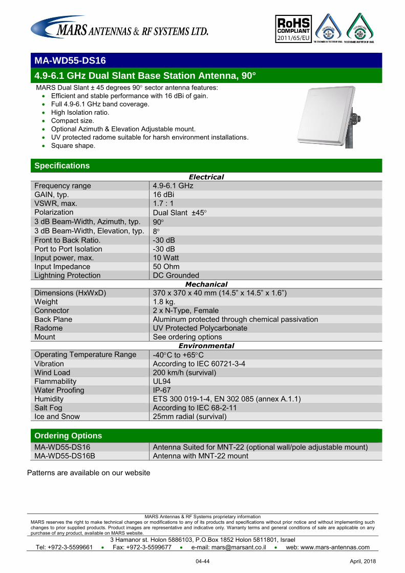
MARS Antennas & RF Systems proprietary information MARS reserves the right to make technical changes or modifications to any of its products and specifications without prior notice and without implementing such changes to prior supplied products. Product images are representative and indicative only. Warranty terms and general conditions of sale are applicable on any purchase of any product, available on MARS website.
3 Hamanor st. Holon 5886103, P.O.Box 1852 Holon 5811801, Israel Tel: +972-3-5599661 Fax: +972-3-5599677 e-mail: [email protected] web: www.mars-antennas.com
MA-WD55-DS16
4.9-6.1 GHz Dual Slant Base Station Antenna, 90° MARS Dual Slant ± 45 degrees 90 sector antenna features: Efficient and stable performance with 16 dBi of gain. Full 4.9-6.1 GHz band coverage. High Isolation ratio. Compact size. Optional Azimuth & Elevation Adjustable mount. UV protected radome suitable for harsh environment installations. Square shape.
Specifications
Electrical
Frequency range 4.9-6.1 GHz GAIN, typ. 16 dBi VSWR, max. 1.7 : 1 Polarization Dual Slant ±45 3 dB Beam-Width, Azimuth, typ. 90 3 dB Beam-Width, Elevation, typ. 8 Front to Back Ratio. -30 dB Port to Port Isolation -30 dB Input power, max. 10 Watt Input Impedance 50 Ohm Lightning Protection DC Grounded
Mechanical
Dimensions (HxWxD) 370 x 370 x 40 mm (14.5” x 14.5” x 1.6”) Weight 1.8 kg. Connector 2 x N-Type, Female Back Plane Aluminum protected through chemical passivation Radome UV Protected Polycarbonate Mount See ordering options
Environmental
Operating Temperature Range -40C to +65C Vibration According to IEC 60721-3-4 Wind Load 200 km/h (survival) Flammability UL94 Water Proofing IP-67 Humidity ETS 300 019-1-4, EN 302 085 (annex A.1.1) Salt Fog According to IEC 68-2-11 Ice and Snow 25mm radial (survival) Ordering Options
MA-WD55-DS16 Antenna Suited for MNT-22 (optional wall/pole adjustable mount) MA-WD55-DS16B Antenna with MNT-22 mount
Patterns are available on our website
April, 201804-44
MARS Antennas & RF Systems proprietary information MARS reserves the right to make technical changes or modifications to any of its products and specifications without prior notice and without implementing such changes to prior supplied products. Product images are representative and indicative only. Warranty terms and general conditions of sale are applicable on any purchase of any product, available on MARS website.
3 Hamanor st. Holon 5886103, P.O.Box 1852 Holon 5811801, Israel Tel: +972-3-5599661 Fax: +972-3-5599677 e-mail: [email protected] web: www.mars-antennas.com
MA-WC56-DP17
1.6-9.4 GHz Dual Polarized Base Station Antenna, 60 MARS 60 Broadband Dual Polarized Sector Antenna provides a cost effective solution for large scale WLL, WLAN, H-LAN, ISM, UNII, Public Safety, Municipal MESH Networks and Point-to-Multi-Point applications. Additional Features: Stable performance with 17/18 dBi of gain. Compact size allowing easy blending with any environment. Tilt mount allowing quick and easy installation. UV protected radome suitable for harsh environment
installations.
Specifications
Electrical Frequency range 4.9-6.1 GHz
GAIN, typ. V-pol: 18 dBi H-pol: 17 dBi
VSWR, max. 1.7 : 1 Polarization Dual, Vertical & Horizontal 3 dB Beam-Width, H-Plane, typ. 60 3 dB Beam-Width, E-Plane, typ. 8
Side Lobes, min. H-pol: ETSI EN 302 085 V1.2.3 – CS2 V-pol: ETSI EN 302 085 V1.2.3 – CS3
Cross Polarization, min. -16 dB Front to Back Ratio, min. -30 dB
Port to Port Isolation, typ. -40 dB Input power, max. 10 Watt Input Impedance 50 Ohm Lightning Protection DC Grounded
Mechanical Dimensions (HxWxD) 370 x 370 x 40 mm (14.5" x 14.5" x 1.6") Weight 1.8 kg. Connector (without enclosure) 2 x N-Type, Female Connector (with enclosure) 2 x SMA Back Plane Aluminum protected through chemical passivation Radome UV Protected Polycarbonate Enclosure - Large 287 x 287 x 68 mm. (External dimension) Mount See ordering options
Environmental Operating Temperature Range -55C to +65C Vibration According to IEC 60721-3-4 Wind Load 200 km/h (survival) Flammability UL94 Water Proofing IP-67 Humidity ETS 300 019-1-4, EN 302 085 (annex A.1.1) Salt Fog According to IEC 68-2-11 Ice and Snow 25mm radial (survival)
Ordering Options MA-WC56-DP17 Antenna Suited for MNT-22 (optional wall/pole adjustable mount) MA-WC56-DP17B Antenna with MNT-22 mount MA-WC56-DP17SMEL Antenna with large enclosure, 2 x SMA Connectors and MNT-22 MA-WC56-DP17SMELZ Antenna with large enclosure, 2 x SMA Connectors with PEMs and MNT-22
Patterns are available on our website
April, 201804-45
MARS Antennas & RF Systems proprietary information MARS reserves the right to make technical changes or modifications to any of its products and specifications without prior notice and without implementing such changes to prior supplied products. Product images are representative and indicative only. Warranty terms and general conditions of sale are applicable on any purchase of any product, available on MARS website.
3 Hamanor st. Holon 5886103, P.O.Box 1852 Holon 5811801, Israel Tel: +972-3-5599661 Fax: +972-3-5599677 e-mail: [email protected] web: www.mars-antennas.com
MA-WD56-DP16
4.9-6.1 GHz Dual Polarized Base Station Antenna, 90 MARS 90 Broadband Dual Polarized Sector Antenna provides a cost effective solution for large scale WLL, WLAN, H-LAN, ISM, UNII, Public Safety, Municipal MESH Networks and Point-to-Multi-Point applications. Additional Features: Stable performance with 16 dBi of gain. Compact size allowing easy blending with any environment. Tilt mount allowing quick and easy installation. UV protected radome suitable for harsh environment
installations.
Specifications
Electrical Frequency range 4.9-6.1 GHz GAIN, typ. 16 dBi VSWR, max. 1.7 : 1 Polarization Dual Vertical & Horizontal 3 dB Beam-Width, H-Plane, typ. 90 3 dB Beam-Width, E-Plane, typ. 8
Side Lobes, min. V-Pol. ETSI EN 302 085 V1.2.3 – CS2
H-Pol. ETSI EN 302 085 V1.2.3 – CS3
Cross Polarization, min. -15 dB Front to Back Ratio, min. -30 dB
Port to Port Isolation, typ. -30 dB Input power, max. 10 Watt Input Impedance 50 Ohm Lightning Protection DC Grounded
Mechanical Dimensions (HxWxD) 370 x 370 x 40 mm (14.5" x 14.5" x 1.6") Weight 2 kg. Connector (without enclosure) 2 x N-Type, Female Connector (with enclosure) 2 x SMA Back Plane Aluminum protected through chemical passivation Radome UV Protected Polycarbonate Enclosure - Large 287 x 287 x 68 mm. (External dimension) Mount See ordering options
Environmental Operating Temperature Range -55C to +65C Vibration According to IEC 60721-3-4 Wind Load 200 km/h (survival) Flammability UL94 Water Proofing IP-67 Humidity ETS 300 019-1-4, EN 302 085 (annex A.1.1) Salt Fog According to IEC 68-2-11 Ice and Snow 25mm radial (survival) Ordering Options MA-WD56-DP16 Antenna Suited for MNT-22 (optional wall/pole adjustable mount) MA-WD56-DP16B Antenna with MNT-22 mount MA-WD56-DP16SMEL Antenna with large enclosure, 2xSMA Connectors and MNT-22 MA-WD56-DP16SMELZ Antenna with large enclosure, 2xSMA Connectors with PEMs and MNT-22
Patterns are available on our website
April, 201804-46
MARS Antennas & RF Systems proprietary information MARS reserves the right to make technical changes or modifications to any of its products and specifications without prior notice and without implementing such changes to prior supplied products. Product images are representative and indicative only. Warranty terms and general conditions of sale are applicable on any purchase of any product, available on MARS website.
3 Hamanor st. Holon 5886103, P.O.Box 1852 Holon 5811801, Israel
Tel: +972-3-5599661 Fax: +972-3-5599677 e-mail: [email protected] web: www.mars-antennas.com
MA-WD55-2DS16
5.1 – 5.9 GHz, 2 x Dual Slant (2 x ±45°), Base Station Antenna, 90°
MARS wideband 90° sector antenna provides coverage for
5.1-5.9 GHz band with double dual slant (±45) in a single antenna radome with high aperture efficiency. Additional Features: Wide coverage Total 4 outputs Pole or wall mounting A possibility of mounting Access Point upon antenna
Specifications
Electrical
Frequency range 5.1 – 5.3 GHz 5.3 – 5.9 GHz Gain, typ. 15 dBi 16 dBi VSWR, max. 1.7 : 1 Polarization 2 x Dual Slant ±45 3 dB Beam-Width, Azimuth, typ. 90 3 dB Beam-Width, Elevation, typ. 8 Side Lobe Level (Elevation), min. -10 dB Front to Back Ratio, min. -32 dB Port to Port Isolation, min. -25 dB Input power, max 10 Watt Input Impedance 50 Ohm Lightning Protection DC Grounded
Mechanical
Dimensions (HxWxD) 370 x 370 x 40 mm (14.5” x 14.5” x 1.6”) Weight 1.8 Kg. Connector 4 x N-Type, Female Back Plane Aluminum protected through chemical passivation Radome UV Protected Polycarbonate Mount MNT-22
Environmental
Operating Temperature Range -55C to +65C Vibration According to IEC 60721-3-4
Wind Load 200 km/h (survival) Flammability UL94
Water Proofing IP-67 Humidity ETS 300 019-1-4, EN 302 085 (annex A.1.1)
Salt Fog According to IEC 68-2-11 Ice and Snow 25mm radial (survival)
Ordering Options
MA-WD55-2DS16 Antenna Suited for MNT-22 (optional wall/pole adjustable mount) MA-WD55-2DS16B Antenna with MNT-22 mount
April, 201804-47
Mars Antennas & RF Systems proprietary information MARS reserves the right to make technical changes or modifications to any of its products and specifications without prior notice and without implementing such changes to prior supplied products. Product images are representative and indicative only. Warranty terms and general conditions of sale are applicable on any purchase of any product, available on MARS website.
3 Hamanor st. Holon 58861, P.O.Box 5 AZOR 58008, Israel Tel: +972-3-5599661 Fax: +972-3-5599677 e-mail: [email protected] web: www.mars-antennas.com
MA-WD56-DP13
5.15-5.875 GHz Dual Polarized Base Station Antenna, 90o MARS 90o Broadband Dual Polarized Sector Antenna. Additional Features: Stable performance with 13 dBi of gain. Compact size allowing easy blending with any environment. Tilt mount allowing quick and easy installation. UV protected radome suitable for harsh environment installations.
Specifications
Electrical Frequency range 5.15-5.875 GHz GAIN, typ. 13 dBi VSWR, max. 1.7 : 1 Polarization Dual, Vertical & Horizontal 3 dB Beam-Width, H-Plane, typ. 90o 3 dB Beam-Width, E-Plane, typ. 15o Cross Polarization, typ. -15 dB Front to Back Ratio, min. -30 dB Port to Port Isolation, typ. -20 dB Input power, max. 10 Watt Input Impedance 50 Ohm Lightning Protection DC Grounded
Mechanical Dimensions (HxWxD) 200 x 200 x 33 mm (7.9" x 7.9" x 1.25") Weight 400 gr. Connector 2 x N-Type, Female Back Plane Aluminum protected through chemical passivation Radome UV Protected Polycarbonate Mount See Ordering options
Environmental Operating Temperature Range -55oC to +65oC Vibration According to IEC 60721-3-4 Wind Load 200 km/h (survival) Flammability UL94 Water Proofing IP-67 Humidity ETS 300 019-1-4, EN 302 085 (annex A.1.1) Salt Fog According to IEC 68-2-11 Ice and Snow 25mm radial (survival) Ordering Options
MA-WD56-DP13 Antenna Suited for MNT-23 (optional wall/pole adjustable mount) MA-WD56-DP13B Antenna with MNT-23 mount
Patterns are available on our website
April, 201804-48
MARS Antennas & RF Systems proprietary information MARS reserves the right to make technical changes or modifications to any of its products and specifications without prior notice and without implementing such changes to prior supplied products. Product images are representative and indicative only. Warranty terms and general conditions of sale are applicable on any purchase of any product, available on MARS website.
3 Hamanor st. Holon 5886103, P.O.Box 1852 Holon 5811801, Israel Tel: +972-3-5599661 Fax: +972-3-5599677 e-mail: [email protected] web: www.mars-antennas.com
MA-WE56-DP12
5.15-5.875 GHz Dual Polarized Base Station Antenna, 120 MARS 120 Broadband Dual Polarized Sector Antenna. Additional Features: Stable performance with 12 dBi of gain. Compact size allowing easy blending with any environment. Tilt mount allowing quick and easy installation. UV protected radome suitable for harsh environment installations.
Specifications
Electrical Frequency range 5.15-5.875 GHz GAIN, typ. 12 dBi VSWR, max. 1.7 : 1 Polarization Dual, Vertical & Horizontal 3 dB Beam-Width, H-Plane, typ. 120 3 dB Beam-Width, E-Plane, typ. 15 Cross Polarization, typ. -15 dB Front to Back Ratio, min. -30 dB Port to Port Isolation, typ. -20 dB Input power, max. 10 Watt Input Impedance 50 Ohm Lightning Protection DC Grounded
Mechanical Dimensions (HxWxD) 200 x 200 x 33 mm (7.9" x 7.9" x 1.25") Weight 400 gr. Connector 2 x N-Type, Female Back Plane Aluminum protected through chemical passivation Radome UV Protected Polycarbonate Mount See ordering options
Environmental Operating Temperature Range -55C to +65C Vibration According to IEC 60721-3-4 Wind Load 200 km/h (survival) Flammability UL94 Water Proofing IP-67 Humidity ETS 300 019-1-4, EN 302 085 (annex A.1.1) Salt Fog According to IEC 68-2-11 Ice and Snow 25mm radial (survival) Ordering Options
MA-WE56-DP12 Antenna Suited for MNT-23 (optional wall/pole adjustable mount) MA-WE56-DP12B Antenna with MNT-23 mount
Patterns are available on our website
April, 201804-49
MARS Antennas & RF Systems proprietary information MARS reserves the right to make technical changes or modifications to any of its products and specifications without prior notice and without implementing such changes to prior supplied products. Product images are representative and indicative only. Warranty terms and general conditions of sale are applicable on any purchase of any product, available on MARS website.
3 Hamanor st. Holon 5886103, P.O.Box 1852 Holon 5811801, Israel Tel: +972-3-5599661 Fax: +972-3-5599677 e-mail: [email protected] web: www.mars-antennas.com
MA-WE56-DP15
5.15-5.875 GHz Dual Polarized Base Station Antenna, 120
MARS 120 Broadband Dual Polarized Base station Antenna. Additional Features: Stable performance with 15 dBi of gain. Compact size allowing easy blending with any environment. Tilt mount allowing quick and easy installation. UV protected radome suitable for harsh environment installations.
Specifications Electrical
Frequency range 5.15-5.875 GHz GAIN, typ. 14.5 dBi VSWR, max. 1.7 : 1 Polarization Dual, Vertical & Horizontal 3 dB Beam-Width, H-Plane, typ. 120 3 dB Beam-Width, E-Plane, typ. 8 Cross Polarization, typ. -15 dB Front to Back Ratio, min. -30 dB Port to Port Isolation, typ. -25 dB Input power, max. 10 Watt Input Impedance 50 Ohm Lightning Protection DC Grounded
Mechanical
Dimensions (HxWxD) 370 x 370 x 40 mm (14.5" x 14.5" x 1.6") Weight 2 kg. Connector (without enclosure) 2 x N-Type, Female Connector (with enclosure) 2 x SMA Back Plane Aluminum protected through chemical passivation Radome UV Protected Polycarbonate Enclosure - Large 287 x 287 x 68 mm. (External dimension) Mount See ordering options
Environmental
Operating Temperature Range -55C to +65C Vibration According to IEC 60721-3-4 Wind Load 200 km/h (survival) Flammability UL94 Water Proofing IP-67 Humidity ETS 300 019-1-4, EN 302 085 (annex A.1.1) Salt Fog According to IEC 68-2-11 Ice and Snow 25mm radial (survival)
Ordering Options MA-WE56-DP15 Antenna Suited for MNT-22 (optional wall/pole adjustable mount) MA-WE56-DP15B Antenna with MNT-22 mount MA-WE56-DP15SMELZ Antenna with large enclosure, 2 x SMA Connectors with PEMs and MNT-22
April, 201804-50
MARS Antennas & RF Systems proprietary information MARS reserves the right to make technical changes or modifications to any of its products and specifications without prior notice and without implementing such changes to prior supplied products. Product images are representative and indicative only. Warranty terms and general conditions of sale are applicable on any purchase of any product, available on MARS website.
3 Hamanor st. Holon 5886103, P.O.Box 1852 Holon 5811801, Israel Tel: +972-3-5599661 Fax: +972-3-5599677 e-mail: [email protected] web: www.mars-antennas.com
MA-WC62-DP17
5.7-6.425 GHz Dual Polarized Base Station Antenna, 60 MARS 60 Broadband Dual Polarized Sector Antenna provides a cost effective solution for large scale WLL, WLAN, H-LAN, ISM, UNII, Public Safety, Municipal MESH Networks and Point-to-Multi-Point applications. Additional Features:
Stable performance with 17 dBi of gain. Compact size allowing easy blending with any environment. Tilt mount allowing quick and easy installation. UV protected radome suitable for harsh environment installations.
Specifications
Electrical Frequency range 5.7-6.425 GHz GAIN, typ. 17 dBi VSWR, max. 1.7 : 1 Polarization Dual Vertical & Horizontal 3 dB Beam-Width, H-Plane, typ. 60 3 dB Beam-Width, E-Plane, typ. 8.5 Side Lobes, min. (azimuth) -25 dB Cross Polarization, min. -18 dB Front to Back Ratio, min. -40 dB Port to Port Isolation, typ. -45 dB Input power, max. 10 Watt Input Impedance 50 Ohm Lightning Protection DC Grounded
Mechanical Dimensions (HxWxD) 370 x 370 x 40 mm (14.5" x 14.5" x 1.6") Weight 2 kg. Connector 2 x N-Type, Female Back Plane Aluminum protected through chemical passivation Radome UV Protected Polycarbonate Mount See ordering information
Environmental Operating Temperature Range -55C to +65C Vibration According to IEC 60721-3-4 Wind Load 200 km/h (survival) Flammability UL94 Water Proofing IP-67 Humidity ETS 300 019-1-4, EN 302 085 (annex A.1.1) Salt Fog According to IEC 68-2-11 Ice and Snow 25mm radial (survival) Ordering Options
MA-WC62-DP17 Antenna Suited for MNT-22 (optional wall/pole adjustable mount) MA-WC62-DP17B Antenna with MNT-22 mount
Patterns are available on our website
April, 201804-51
MARS Antennas & RF Systems proprietary information MARS reserves the right to make technical changes or modifications to any of its products and specifications without prior notice and without implementing such changes to prior supplied products. Product images are representative and indicative only. Warranty terms and general conditions of sale are applicable on any purchase of any product, available on MARS website.
3 Hamanor st. Holon 5886103, P.O.Box 1852 Holon 5811801, Israel Tel: +972-3-5599661 Fax: +972-3-5599677 e-mail: [email protected] web: www.mars-antennas.com
MA-WD62-DP16
5.7-6.425 GHz Dual Polarized Base Station Antenna, 90 MARS 90 Broadband Dual Polarized Sector Antenna provides a cost effective solution for large scale WLL, WLAN, H-LAN, ISM, UNII, Public Safety, Municipal MESH Networks and Point-to-Multi-Point applications. Additional Features: Stable performance with 16 dBi of gain. Compact size allowing easy blending with any environment. Tilt mount allowing quick and easy installation. UV protected radome suitable for harsh environment installations.
Specifications
Electrical
Frequency range 5.7-6.425 GHz GAIN, typ. 16 dBi VSWR, max. 1.7 : 1 Polarization Dual Vertical & Horizontal 3 dB Beam-Width, H-Plane, typ. 90 3 dB Beam-Width, E-Plane, typ. 8.5 Side Lobes, min. (azimuth) -25 dB
Cross Polarization, min. -18 dB Front to Back Ratio, min. -40 dB
Port to Port Isolation, typ. -45 dB Input power, max. 10 Watt Input Impedance 50 Ohm Lightning Protection DC Grounded
Mechanical
Dimensions (HxWxD) 370 x 370 x 40 mm (14.5" x 14.5" x 1.6") Weight 2 kg. Connector 2 x N-Type, Female Back Plane Aluminum protected through chemical passivation Radome UV Protected Polycarbonate Mount See ordering options
Environmental
Operating Temperature Range -55C to +65C Vibration According to IEC 60721-3-4 Wind Load 200 km/h (survival) Flammability UL94 Water Proofing IP-67 Humidity ETS 300 019-1-4, EN 302 085 (annex A.1.1) Salt Fog According to IEC 68-2-11 Ice and Snow 25mm radial (survival) Ordering Options
MA-WD62-DP16 Antenna Suited for MNT-22 (optional wall/pole adjustable mount) MA-WD62-DP16B Antenna with MNT-22 mount
Patterns are available on our website
April, 201804-52
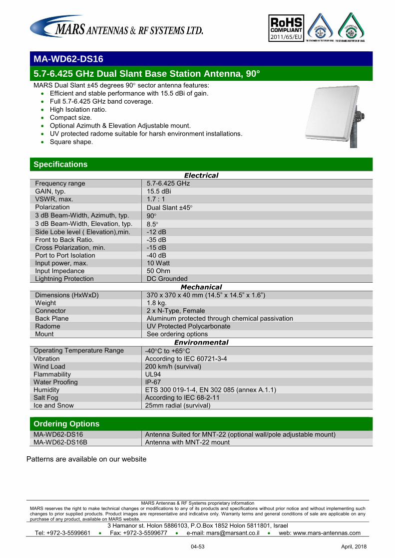
MARS Antennas & RF Systems proprietary information MARS reserves the right to make technical changes or modifications to any of its products and specifications without prior notice and without implementing such changes to prior supplied products. Product images are representative and indicative only. Warranty terms and general conditions of sale are applicable on any purchase of any product, available on MARS website.
3 Hamanor st. Holon 5886103, P.O.Box 1852 Holon 5811801, Israel Tel: +972-3-5599661 Fax: +972-3-5599677 e-mail: [email protected] web: www.mars-antennas.com
MA-WD62-DS16
5.7-6.425 GHz Dual Slant Base Station Antenna, 90° MARS Dual Slant ±45 degrees 90 sector antenna features:
Efficient and stable performance with 15.5 dBi of gain. Full 5.7-6.425 GHz band coverage. High Isolation ratio. Compact size. Optional Azimuth & Elevation Adjustable mount. UV protected radome suitable for harsh environment installations. Square shape.
Specifications
Electrical Frequency range 5.7-6.425 GHz GAIN, typ. 15.5 dBi VSWR, max. 1.7 : 1 Polarization Dual Slant ±45 3 dB Beam-Width, Azimuth, typ. 90 3 dB Beam-Width, Elevation, typ. 8.5 Side Lobe level ( Elevation),min. -12 dB Front to Back Ratio. -35 dB Cross Polarization, min. -15 dB Port to Port Isolation -40 dB Input power, max. 10 Watt Input Impedance 50 Ohm Lightning Protection DC Grounded
Mechanical Dimensions (HxWxD) 370 x 370 x 40 mm (14.5” x 14.5” x 1.6”) Weight 1.8 kg. Connector 2 x N-Type, Female Back Plane Aluminum protected through chemical passivation Radome UV Protected Polycarbonate Mount See ordering options
Environmental Operating Temperature Range -40C to +65C Vibration According to IEC 60721-3-4 Wind Load 200 km/h (survival) Flammability UL94 Water Proofing IP-67 Humidity ETS 300 019-1-4, EN 302 085 (annex A.1.1) Salt Fog According to IEC 68-2-11 Ice and Snow 25mm radial (survival) Ordering Options
MA-WD62-DS16 Antenna Suited for MNT-22 (optional wall/pole adjustable mount) MA-WD62-DS16B Antenna with MNT-22 mount
Patterns are available on our website
April, 201804-53

MARS Antennas & RF Systems proprietary information MARS reserves the right to make technical changes or modifications to any of its products and specifications without prior notice and without implementing such changes to prior supplied products. Product images are representative and indicative only. Warranty terms and general conditions of sale are applicable on any purchase of any product, available on MARS website.
3 Hamanor st. Holon 5886103, P.O.Box 1852 Holon 5811801, Israel
Tel: +972-3-5599661 Fax: +972-3-5599677 e-mail: [email protected] web: www.mars-antennas.com
MA-WC54-2DS17
4.9 – 6.1 GHz 2 x Dual Slant (2 x ±45°) Base Station Antenna, 65°
MARS wideband 65° sector antenna provides coverage for 4.9-6.1 GHz
band with double dual-slant (±45) in a single antenna radome with high aperture efficiency. Additional Features: Wide coverage Total 4 outputs Pole or wall mounting A possibility of mounting Access Point upon antenna
Specifications
Electrical
Frequency range 4.9 – 6.1 GHz Gain 4 x 17 ± 0.5 dBi VSWR, max. 1.7 : 1 Polarization 2 x Dual Slant ±45 3dB Beam-Width, Azimuth, typ. 65° 3dB Beam-Width, Elevation, typ. 8° Side Lobes, min. -10 dB Cross Polarization, typ. -15 dB Port to Port Isolation, typ. -28 dB Front to Back Ratio, min. -35 dB Input power, max. 10 Watt Input Impedance 50 Ohm Lightning Protection DC Grounded
Mechanical
Dimensions (HxWxD) 370 x 370 x 40 mm (14.5" x 14.5" x 1.6") Weight 2 Kg. Connector 4 x N-Type, Female Back Plane Aluminum protected through chemical passivation Radome UV Protected, Polycarbonate Mount See Ordering Options
Environmental
Operating Temperature Range -40°C to +65°C
Vibration According to IEC 60721-3-4
Wind Load 200 km/h (Survival)
Flammability UL94
Water Proofing IP-67
Humidity ETS 300 019-1-4,EN 302 085 (Annex A.1.1)
Salt Fog According to IEC 68-2-11
Ordering Options
MA-WC54-2DS17 Antenna Suited for MNT-22 (optional wall/pole adjustable mount) MA-WC54-2DS17B Antenna with MNT-22 mount
April, 201804-54
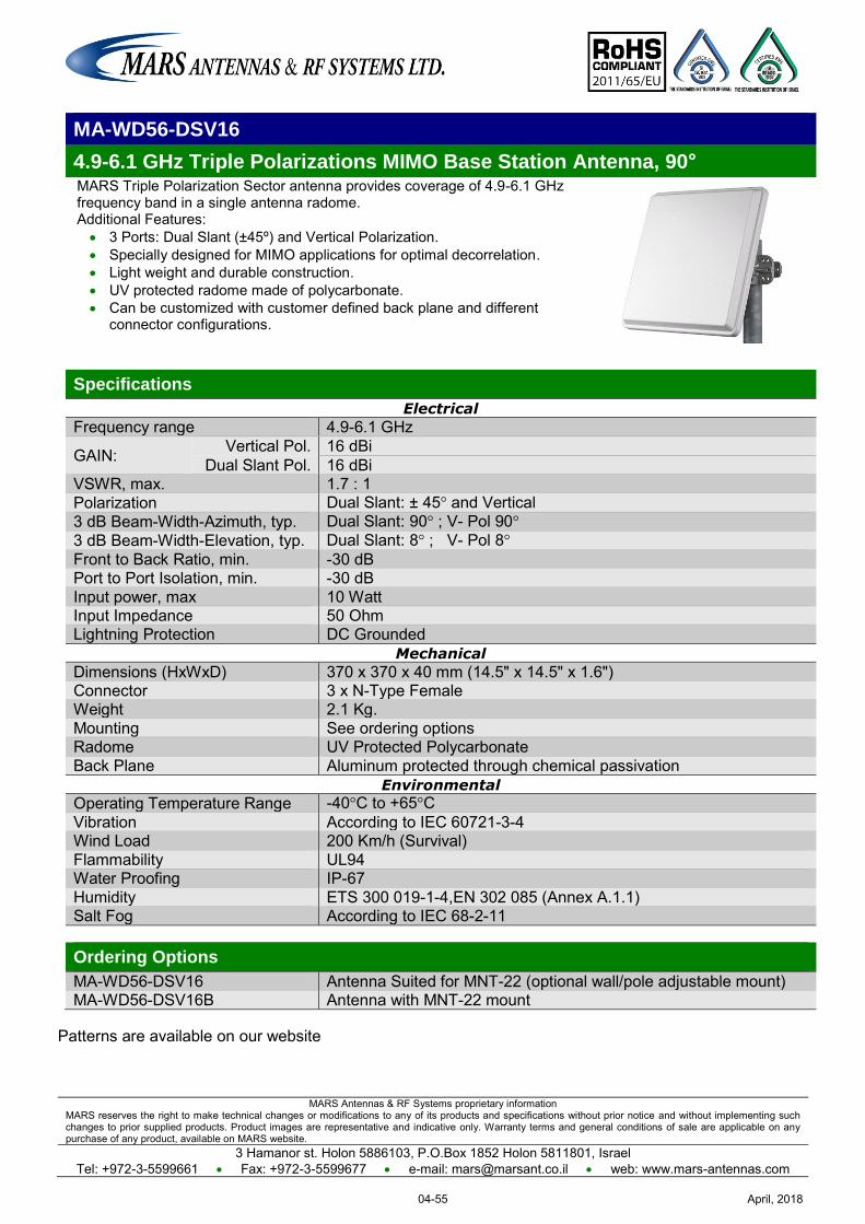
MARS Antennas & RF Systems proprietary information MARS reserves the right to make technical changes or modifications to any of its products and specifications without prior notice and without implementing such changes to prior supplied products. Product images are representative and indicative only. Warranty terms and general conditions of sale are applicable on any purchase of any product, available on MARS website.
3 Hamanor st. Holon 5886103, P.O.Box 1852 Holon 5811801, Israel Tel: +972-3-5599661 Fax: +972-3-5599677 e-mail: [email protected] web: www.mars-antennas.com
MA-WD56-DSV16
4.9-6.1 GHz Triple Polarizations MIMO Base Station Antenna, 90° MARS Triple Polarization Sector antenna provides coverage of 4.9-6.1 GHz frequency band in a single antenna radome. Additional Features: 3 Ports: Dual Slant (±45º) and Vertical Polarization. Specially designed for MIMO applications for optimal decorrelation. Light weight and durable construction. UV protected radome made of polycarbonate. Can be customized with customer defined back plane and different
connector configurations.
Specifications
Electrical
Frequency range 4.9-6.1 GHz
GAIN: Vertical Pol. 16 dBi Dual Slant Pol. 16 dBi
VSWR, max. 1.7 : 1 Polarization Dual Slant: ± 45° and Vertical 3 dB Beam-Width-Azimuth, typ. Dual Slant: 90° ; V- Pol 90° 3 dB Beam-Width-Elevation, typ. Dual Slant: 8° ; V- Pol 8° Front to Back Ratio, min. -30 dB Port to Port Isolation, min. -30 dB Input power, max 10 Watt Input Impedance 50 Ohm Lightning Protection DC Grounded
Mechanical
Dimensions (HxWxD) 370 x 370 x 40 mm (14.5" x 14.5" x 1.6") Connector 3 x N-Type Female Weight 2.1 Kg. Mounting See ordering options Radome UV Protected Polycarbonate Back Plane Aluminum protected through chemical passivation
Environmental
Operating Temperature Range -40°C to +65°C Vibration According to IEC 60721-3-4 Wind Load 200 Km/h (Survival) Flammability UL94 Water Proofing IP-67 Humidity ETS 300 019-1-4,EN 302 085 (Annex A.1.1) Salt Fog According to IEC 68-2-11 Ordering Options
MA-WD56-DSV16 Antenna Suited for MNT-22 (optional wall/pole adjustable mount) MA-WD56-DSV16B Antenna with MNT-22 mount
Patterns are available on our website
April, 201804-55

MARS Antennas & RF Systems proprietary information MARS reserves the right to make technical changes or modifications to any of its products and specifications without prior notice and without implementing such changes to prior supplied products. Product images are representative and indicative only. Warranty terms and general conditions of sale are applicable on any purchase of any product, available on MARS website.
3 Hamanor st. Holon 5886103, P.O.Box 1852 Holon 5811801, Israel
Tel: +972-3-5599661 Fax: +972-3-5599677 e-mail: [email protected] web: www.mars-antennas.com
6 GHz – 8 GHz
Subscriber - Dual Pol Sector - Dual Pol
Part Number Description Frequency
band Gain Polarization Dimension
Antenna type
Page
MA-WA65-DP19
Dual Polarized / Dual Slant Subscriber
6-7 GHz 19 ± 1 dBi Dual Pole V & H Dual Slant ±45°
200 x 200 x 33 mm
Subscriber
Dual Pol 05-1
MA-WA78-DP19N
Dual Polarized Subscriber
7-8 GHz 19 ± 1 dBi Dual Pole V & H 155 x 155 x 28
mm
Subscriber
Dual Pol 05-2
MA-WA78-DP24
Dual Polarization/Dual Slant Subscriber Antenna
7.125-8.5 GHz 24 dBi Dual Pole V & H
Dual Slant (OPT.) ±45°
305 x 305 x 15 mm ( 12"x 12"x1.6")
Subscriber
Dual Pol 05-3
MA-WD78-DP12
Dual Polarized Base
Station 90 7.75-7.9 GHz 12 dBi Linear, Vertical &
Horizontal 155 x 155 x 28
mm
Sector
Dual Pol 05-4
April, 201805-I
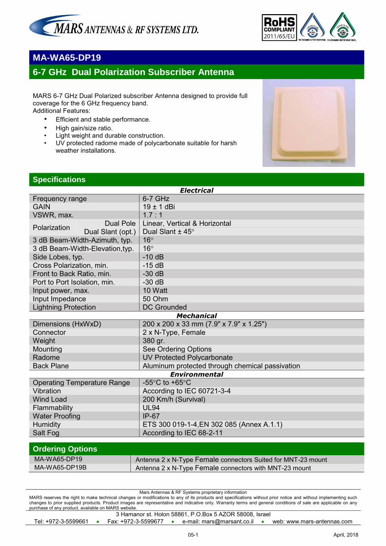
Mars Antennas & RF Systems proprietary information MARS reserves the right to make technical changes or modifications to any of its products and specifications without prior notice and without implementing such changes to prior supplied products. Product images are representative and indicative only. Warranty terms and general conditions of sale are applicable on any purchase of any product, available on MARS website.
3 Hamanor st. Holon 58861, P.O.Box 5 AZOR 58008, Israel Tel: +972-3-5599661 Fax: +972-3-5599677 e-mail: [email protected] web: www.mars-antennas.com
MA-WA65-DP19
6-7 GHz Dual Polarization Subscriber Antenna
MARS 6-7 GHz Dual Polarized subscriber Antenna designed to provide full coverage for the 6 GHz frequency band. Additional Features:
• Efficient and stable performance. • High gain/size ratio. • Light weight and durable construction. • UV protected radome made of polycarbonate suitable for harsh
weather installations.
Specifications
Electrical
Frequency range 6-7 GHz GAIN 19 ± 1 dBi VSWR, max. 1.7 : 1
Polarization Dual Pole Linear, Vertical & Horizontal Dual Slant (opt.) Dual Slant ± 45°
3 dB Beam-Width-Azimuth, typ. 16° 3 dB Beam-Width-Elevation,typ. 16° Side Lobes, typ. -10 dB Cross Polarization, min. -15 dB Front to Back Ratio, min. -30 dB Port to Port Isolation, min. -30 dB Input power, max. 10 Watt Input Impedance 50 Ohm Lightning Protection DC Grounded
Mechanical
Dimensions (HxWxD) 200 x 200 x 33 mm (7.9" x 7.9" x 1.25") Connector 2 x N-Type, Female Weight 380 gr. Mounting See Ordering Options Radome UV Protected Polycarbonate Back Plane Aluminum protected through chemical passivation
Environmental
Operating Temperature Range -55°C to +65°C Vibration According to IEC 60721-3-4 Wind Load 200 Km/h (Survival) Flammability UL94 Water Proofing IP-67 Humidity ETS 300 019-1-4,EN 302 085 (Annex A.1.1) Salt Fog According to IEC 68-2-11
Ordering Options
MA-WA65-DP19 Antenna 2 x N-Type Female connectors Suited for MNT-23 mount MA-WA65-DP19B Antenna 2 x N-Type Female connectors with MNT-23 mount
April, 201805-1
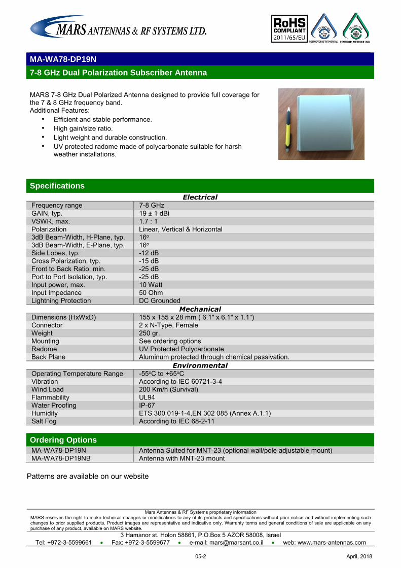
Mars Antennas & RF Systems proprietary information MARS reserves the right to make technical changes or modifications to any of its products and specifications without prior notice and without implementing such changes to prior supplied products. Product images are representative and indicative only. Warranty terms and general conditions of sale are applicable on any purchase of any product, available on MARS website.
3 Hamanor st. Holon 58861, P.O.Box 5 AZOR 58008, Israel Tel: +972-3-5599661 Fax: +972-3-5599677 e-mail: [email protected] web: www.mars-antennas.com
Patterns are available on our website
MA-WA78-DP19N
7-8 GHz Dual Polarization Subscriber Antenna
MARS 7-8 GHz Dual Polarized Antenna designed to provide full coverage for the 7 & 8 GHz frequency band. Additional Features:
• Efficient and stable performance. • High gain/size ratio. • Light weight and durable construction. • UV protected radome made of polycarbonate suitable for harsh
weather installations.
Specifications
Electrical Frequency range 7-8 GHz GAIN, typ. 19 ± 1 dBi VSWR, max. 1.7 : 1 Polarization Linear, Vertical & Horizontal 3dB Beam-Width, H-Plane, typ. 16o 3dB Beam-Width, E-Plane, typ. 16o Side Lobes, typ. -12 dB Cross Polarization, typ. -15 dB Front to Back Ratio, min. -25 dB Port to Port Isolation, typ. -25 dB Input power, max. 10 Watt Input Impedance 50 Ohm Lightning Protection DC Grounded
Mechanical Dimensions (HxWxD) 155 x 155 x 28 mm ( 6.1" x 6.1" x 1.1") Connector 2 x N-Type, Female Weight 250 gr. Mounting See ordering options Radome UV Protected Polycarbonate Back Plane Aluminum protected through chemical passivation.
Environmental Operating Temperature Range -55oC to +65oC Vibration According to IEC 60721-3-4 Wind Load 200 Km/h (Survival) Flammability UL94 Water Proofing IP-67 Humidity ETS 300 019-1-4,EN 302 085 (Annex A.1.1) Salt Fog According to IEC 68-2-11 Ordering Options
MA-WA78-DP19N Antenna Suited for MNT-23 (optional wall/pole adjustable mount) MA-WA78-DP19NB Antenna with MNT-23 mount
April, 201805-2
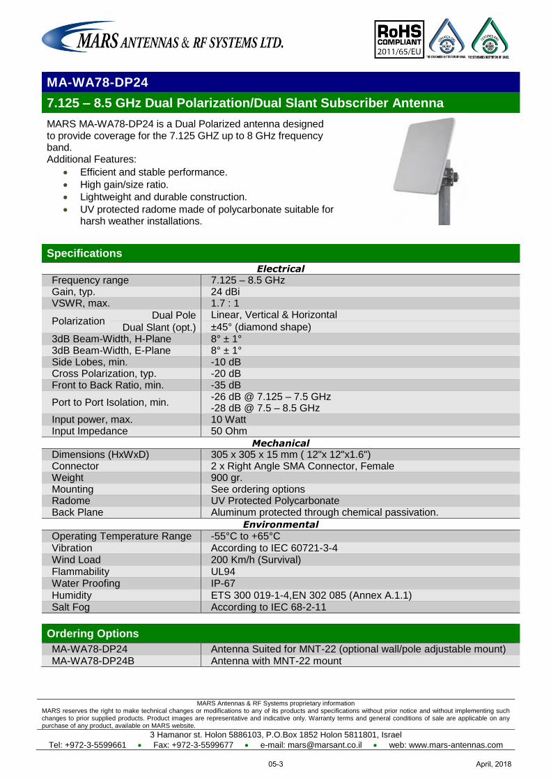
MARS Antennas & RF Systems proprietary information MARS reserves the right to make technical changes or modifications to any of its products and specifications without prior notice and without implementing such changes to prior supplied products. Product images are representative and indicative only. Warranty terms and general conditions of sale are applicable on any purchase of any product, available on MARS website.
3 Hamanor st. Holon 5886103, P.O.Box 1852 Holon 5811801, Israel
Tel: +972-3-5599661 Fax: +972-3-5599677 e-mail: [email protected] web: www.mars-antennas.com
MA-WA78-DP24
7.125 – 8.5 GHz Dual Polarization/Dual Slant Subscriber Antenna
MARS MA-WA78-DP24 is a Dual Polarized antenna designed to provide coverage for the 7.125 GHZ up to 8 GHz frequency band. Additional Features:
Efficient and stable performance.
High gain/size ratio.
Lightweight and durable construction.
UV protected radome made of polycarbonate suitable for harsh weather installations.
Specifications
Electrical
Frequency range 7.125 – 8.5 GHz Gain, typ. 24 dBi VSWR, max. 1.7 : 1
Polarization Dual Pole Linear, Vertical & Horizontal
Dual Slant (opt.) ±45° (diamond shape) 3dB Beam-Width, H-Plane 8° ± 1° 3dB Beam-Width, E-Plane 8° ± 1° Side Lobes, min. -10 dB Cross Polarization, typ. -20 dB Front to Back Ratio, min. -35 dB
Port to Port Isolation, min. -26 dB @ 7.125 – 7.5 GHz -28 dB @ 7.5 – 8.5 GHz
Input power, max. 10 Watt Input Impedance 50 Ohm
Mechanical
Dimensions (HxWxD) 305 x 305 x 15 mm ( 12"x 12"x1.6") Connector 2 x Right Angle SMA Connector, Female Weight 900 gr. Mounting See ordering options Radome UV Protected Polycarbonate Back Plane Aluminum protected through chemical passivation.
Environmental
Operating Temperature Range -55°C to +65°C Vibration According to IEC 60721-3-4 Wind Load 200 Km/h (Survival) Flammability UL94 Water Proofing IP-67 Humidity ETS 300 019-1-4,EN 302 085 (Annex A.1.1) Salt Fog According to IEC 68-2-11
Ordering Options
MA-WA78-DP24 Antenna Suited for MNT-22 (optional wall/pole adjustable mount) MA-WA78-DP24B Antenna with MNT-22 mount
April, 201805-3
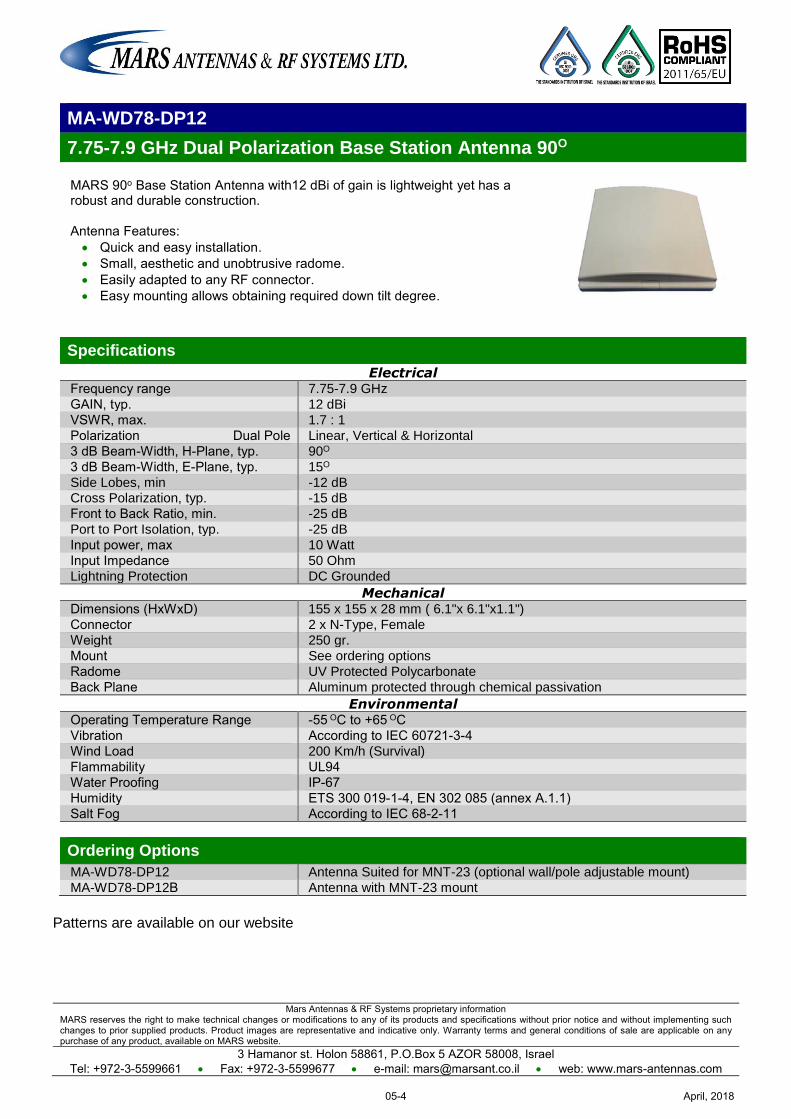
Mars Antennas & RF Systems proprietary information MARS reserves the right to make technical changes or modifications to any of its products and specifications without prior notice and without implementing such changes to prior supplied products. Product images are representative and indicative only. Warranty terms and general conditions of sale are applicable on any purchase of any product, available on MARS website.
3 Hamanor st. Holon 58861, P.O.Box 5 AZOR 58008, Israel Tel: +972-3-5599661 Fax: +972-3-5599677 e-mail: [email protected] web: www.mars-antennas.com
MA-WD78-DP12
7.75-7.9 GHz Dual Polarization Base Station Antenna 90O MARS 90o Base Station Antenna with12 dBi of gain is lightweight yet has a robust and durable construction. Antenna Features: Quick and easy installation. Small, aesthetic and unobtrusive radome. Easily adapted to any RF connector. Easy mounting allows obtaining required down tilt degree.
Specifications
Electrical Frequency range 7.75-7.9 GHz GAIN, typ. 12 dBi VSWR, max. 1.7 : 1 Polarization Dual Pole Linear, Vertical & Horizontal 3 dB Beam-Width, H-Plane, typ. 90O 3 dB Beam-Width, E-Plane, typ. 15O Side Lobes, min -12 dB Cross Polarization, typ. -15 dB Front to Back Ratio, min. -25 dB Port to Port Isolation, typ. -25 dB Input power, max 10 Watt Input Impedance 50 Ohm Lightning Protection DC Grounded
Mechanical Dimensions (HxWxD) 155 x 155 x 28 mm ( 6.1"x 6.1"x1.1") Connector 2 x N-Type, Female Weight 250 gr. Mount See ordering options Radome UV Protected Polycarbonate Back Plane Aluminum protected through chemical passivation
Environmental Operating Temperature Range -55 OC to +65 OC Vibration According to IEC 60721-3-4 Wind Load 200 Km/h (Survival) Flammability UL94 Water Proofing IP-67 Humidity ETS 300 019-1-4, EN 302 085 (annex A.1.1) Salt Fog According to IEC 68-2-11 Ordering Options
MA-WD78-DP12 Antenna Suited for MNT-23 (optional wall/pole adjustable mount) MA-WD78-DP12B Antenna with MNT-23 mount
Patterns are available on our website
April, 201805-4

MARS Antennas & RF Systems proprietary information MARS reserves the right to make technical changes or modifications to any of its products and specifications without prior notice and without implementing such changes to prior supplied products. Product images are representative and indicative only. Warranty terms and general conditions of sale are applicable on any purchase of any product, available on MARS website.
3 Hamanor st. Holon 5886103, P.O.Box 1852 Holon 5811801, Israel
Tel: +972-3-5599661 Fax: +972-3-5599677 e-mail: [email protected] web: www.mars-antennas.com
10 GHz and Ka
Subscriber - Dual Pol Sector - Single Pol
Part Number Description Frequency
band Gain Polarization Dimension
Antenna type
Page
MA-WA10-DP23
Dual Polarized Subscriber 10.15-11 GHz 23 dBi Dual Pole V & H 200 x 200 x 33
mm
Subscriber
Dual Pol 06-1
MA-WD10-DP14
Dual Slant Base
Station, 90 10.15-10.7 GHz 14 dBi Dual Vertical &
Horizontal 200 x 200 x 33
mm
Sector
Dual Pol 06-2
MA-WA28-30 Ka Subscriber Antenna 26-31 GHz 30 dBi Linear, Vertical
175 x 175 x 10 mm
Subscriber 06-3
April, 201806-I
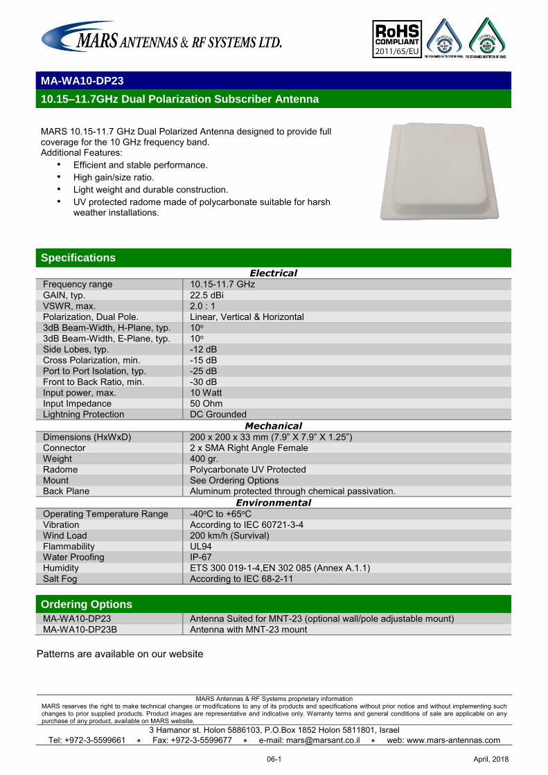
MARS Antennas & RF Systems proprietary information MARS reserves the right to make technical changes or modifications to any of its products and specifications without prior notice and without implementing such changes to prior supplied products. Product images are representative and indicative only. Warranty terms and general conditions of sale are applicable on any purchase of any product, available on MARS website.
3 Hamanor st. Holon 5886103, P.O.Box 1852 Holon 5811801, Israel Tel: +972-3-5599661 Fax: +972-3-5599677 e-mail: [email protected] web: www.mars-antennas.com
Patterns are available on our website
MA-WA10-DP23
10.15–11.7GHz Dual Polarization Subscriber Antenna
MARS 10.15-11.7 GHz Dual Polarized Antenna designed to provide full coverage for the 10 GHz frequency band. Additional Features:
• Efficient and stable performance. • High gain/size ratio. • Light weight and durable construction. • UV protected radome made of polycarbonate suitable for harsh
weather installations.
Specifications
Electrical Frequency range 10.15-11.7 GHz GAIN, typ. 22.5 dBi VSWR, max. 2.0 : 1 Polarization, Dual Pole. Linear, Vertical & Horizontal 3dB Beam-Width, H-Plane, typ. 10o 3dB Beam-Width, E-Plane, typ. 10o Side Lobes, typ. -12 dB Cross Polarization, min. -15 dB Port to Port Isolation, typ. -25 dB Front to Back Ratio, min. -30 dB Input power, max. 10 Watt Input Impedance 50 Ohm Lightning Protection DC Grounded
Mechanical Dimensions (HxWxD) 200 x 200 x 33 mm (7.9” X 7.9” X 1.25”) Connector 2 x SMA Right Angle Female Weight 400 gr. Radome Polycarbonate UV Protected Mount See Ordering Options Back Plane Aluminum protected through chemical passivation.
Environmental Operating Temperature Range -40oC to +65oC Vibration According to IEC 60721-3-4 Wind Load 200 km/h (Survival) Flammability UL94 Water Proofing IP-67 Humidity ETS 300 019-1-4,EN 302 085 (Annex A.1.1) Salt Fog According to IEC 68-2-11 Ordering Options
MA-WA10-DP23 Antenna Suited for MNT-23 (optional wall/pole adjustable mount) MA-WA10-DP23B Antenna with MNT-23 mount
April, 201806-1
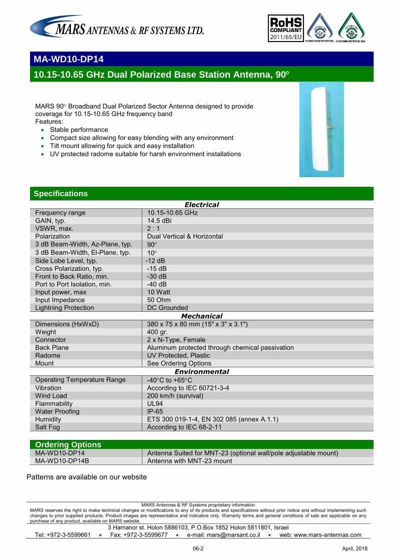
MARS Antennas & RF Systems proprietary information MARS reserves the right to make technical changes or modifications to any of its products and specifications without prior notice and without implementing such changes to prior supplied products. Product images are representative and indicative only. Warranty terms and general conditions of sale are applicable on any purchase of any product, available on MARS website.
3 Hamanor st. Holon 5886103, P.O.Box 1852 Holon 5811801, Israel Tel: +972-3-5599661 Fax: +972-3-5599677 e-mail: [email protected] web: www.mars-antennas.com
MA-WD10-DP14
10.15-10.65 GHz Dual Polarized Base Station Antenna, 90
MARS 90 Broadband Dual Polarized Sector Antenna designed to provide coverage for 10.15-10.65 GHz frequency band Features: Stable performance Compact size allowing for easy blending with any environment Tilt mount allowing for quick and easy installation UV protected radome suitable for harsh environment installations
Specifications
Electrical Frequency range 10.15-10.65 GHz GAIN, typ. 14.5 dBi VSWR, max. 2 : 1 Polarization Dual Vertical & Horizontal 3 dB Beam-Width, Az-Plane, typ. 90 3 dB Beam-Width, El-Plane, typ. 10 Side Lobe Level, typ. -12 dB Cross Polarization, typ. -15 dB Front to Back Ratio, min. -30 dB Port to Port Isolation, min. -40 dB Input power, max 10 Watt Input Impedance 50 Ohm Lightning Protection DC Grounded
Mechanical Dimensions (HxWxD) 380 x 75 x 80 mm (15" x 3" x 3.1") Weight 400 gr. Connector 2 x N-Type, Female Back Plane Aluminum protected through chemical passivation Radome UV Protected, Plastic Mount See Ordering Options
Environmental Operating Temperature Range -40C to +65C Vibration According to IEC 60721-3-4 Wind Load 200 km/h (survival) Flammability UL94 Water Proofing IP-65 Humidity ETS 300 019-1-4, EN 302 085 (annex A.1.1) Salt Fog According to IEC 68-2-11
Patterns are available on our website
Ordering Options MA-WD10-DP14 Antenna Suited for MNT-23 (optional wall/pole adjustable mount) MA-WD10-DP14B Antenna with MNT-23 mount
April, 201806-2
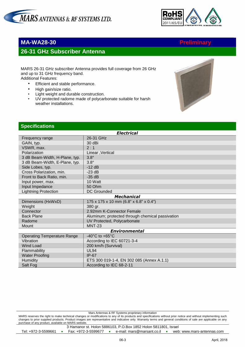
Mars Antennas & RF Systems proprietary information MARS reserves the right to make technical changes or modifications to any of its products and specifications without prior notice and without implementing such changes to prior supplied products. Product images are representative and indicative only. Warranty terms and general conditions of sale are applicable on any purchase of any product, available on MARS website.
3 Hamanor st. Holon 5886103, P.O.Box 1852 Holon 5811801, Israel
Tel: +972-3-5599661 Fax: +972-3-5599677 e-mail: [email protected] web: www.mars-antennas.com
MA-WA28-30 Preliminary
26-31 GHz Subscriber Antenna
MARS 26-31 GHz subscriber Antenna provides full coverage from 26 GHz and up to 31 GHz frequency band. Additional Features:
• Efficient and stable performance. • High gain/size ratio. • Light weight and durable construction. • UV protected radome made of polycarbonate suitable for harsh
weather installations.
Specifications
Electrical Frequency range 26-31 GHz
GAIN, typ. 30 dBi VSWR, max. 2 : 1
Polarization Linear ,Vertical
3 dB Beam-Width, H-Plane, typ. 3.8°
3 dB Beam-Width, E-Plane, typ. 3.8°
Side Lobes, typ. -12 dB
Cross Polarization, min. -23 dB
Front to Back Ratio, min. -35 dB
Input power, max. 10 Watt
Input Impedance 50 Ohm
Lightning Protection DC Grounded
Mechanical Dimensions (HxWxD) 175 x 175 x 10 mm (6.8" x 6.8" x 0.4")
Weight 380 gr.
Connector 2.92mm K-Connector Female
Back Plane Aluminum; protected through chemical passivation
Radome UV Protected, Polycarbonate
Mount MNT-23
Environmental Operating Temperature Range -40°C to +65°C
Vibration According to IEC 60721-3-4
Wind Load 200 km/h (Survival)
Flammability UL94
Water Proofing IP-67
Humidity ETS 300 019-1-4, EN 302 085 (Annex A.1.1) Salt Fog According to IEC 68-2-11
April, 201806-3
MARS Antennas & RF Systems proprietary information MARS reserves the right to make technical changes or modifications to any of its products and specifications without prior notice and without implementing such changes to prior supplied products. Product images are representative and indicative only. Warranty terms and general conditions of sale are applicable on any purchase of any product, available on MARS website.
3 Hamanor st. Holon 5886103, P.O.Box 1852 Holon 5811801, Israel
Tel: +972-3-5599661 Fax: +972-3-5599677 e-mail: [email protected] web: www.mars-antennas.com
OMNI
Part Number Description Frequency
band Gain Polarization Dimension
Antenna type
Page
MA-WO-UWB Ultra Wide Band OMNI Directional
138-174 MHz 380-450 MHz 450-512 MHz 512-698 MHz 698-746 MHz 746-806 MHz 806-960 MHz 1200-2700 MHz 3300-3800 MHz 4100-6000 MHz
3 dBi 4 dBi 5 dBi
5.5 dBi 6 dBi 7 dBi 7 dBi 8 dBi
10 dBi 11 dBi
Linear, Vertical
540 x 40 Dia
mm OMNI 07-1
MA-CQ26-1X 380 MHz -6 GHz Multi Band Omni
380-806 MHz 806-960 MHz 1395-1432 MHz 1710-2170 MHz 2300-2500 MHz 3300-3700 MHz 4900-6000 MHz
1 (2*) dBi 4 dBi 5 dBi 5 dBi 5 dBi 5 dBi 6 dBi
Linear, Vertical
Base Dia. - 275 Height – 187
mm OMNI 07-2
MA-CQ27-1X 380 MHz -6 GHz Multi Band Omni
380-806 MHz 806-960 MHz 1395-1432 MHz 1710-2170 MHz 2300-2700 MHz 3300-3700 MHz 4900-6000 MHz
1 (2*) dBi 4 dBi 5 dBi 5 dBi 6 dBi 6 dBi 6 dBi
Linear, Vertical
Base Dia. - 275 Height - 187
mm OMNI 07-3
MA-CQ29-1X 380 MHz -6 GHz Multi Band Omni
380-806 MHz 806-960 MHz 1700-2500 MHz 2500-2700 MHz 3300-3700 MHz 4900-6000 MHz
1 (2*) dBi 4 dBi 5 dBi 5 dBi 6 dBi 6 dBi
Linear, Vertical
Base Dia. - 275 Height - 187
mm OMNI 07-4
MA-WO440-5 OMNI Directional Antenna
406-470 MHz 5 dBi Linear, Vertical
Base Dia. - 60 Height - 900 mm
OMNI 07-5
MA-WO46-2 450-470 MHz OMNI
450-470 MHz 2 dBi Linear, Vertical
360 x 26 Dia mm OMNI 07-6
MA-WO530-5 480-580 MHz OMNI
480-580 MHz 5 dBi Linear, Vertical
760 x 60 Dia mm OMNI 07-7
MA-WOLTE-3X
LTE, GSM, UMTS, WLAN, Wi-Fi Multi Band Omni
698-806 MHz 806-960 MHz 1710-2170 MHz 2300-2700 MHz 3300-3800 MHz 4900-6500 MHz
2 dBi 2 dBi
3-4 dBi 5 dBi 4 dBi 6 dBi
Linear, Vertical
Base Dia. - 205 Height - 89
mm OMNI 07-8
MA-WOLTE-DIN
LTE, GSM, UMTS, WLAN, Wi-Fi Multi Band Omni
698-806 MHz 806-960 MHz 1710-2170 MHz 2300-2700 MHz 3300-3800 MHz 4900-6500 MHz
2 dBi 2 dBi
3-4 dBi 5 dBi 4 dBi 6 dBi
Linear, Vertical
Base Dia. - 205 Height - 89
mm OMNI 07-9
MA-WO6960-DP6DIN
Multi Band Dual Polarization Omni Antenna
698-806 MHz 806-960 MHz 1695-2170 MHz 2300-2700 MHz 5000-6000 MHz
2 dBi (4.5dBi) 2.5 dBi (5dBi) 5 dBi (7dBi) 6 dBi (7dBi)
7 dBi (8.5dBi)
Linear, Vertical & Horizontal
Base Dia. - 303 Height - 86
mm OMNI 07-10
April, 201807-I
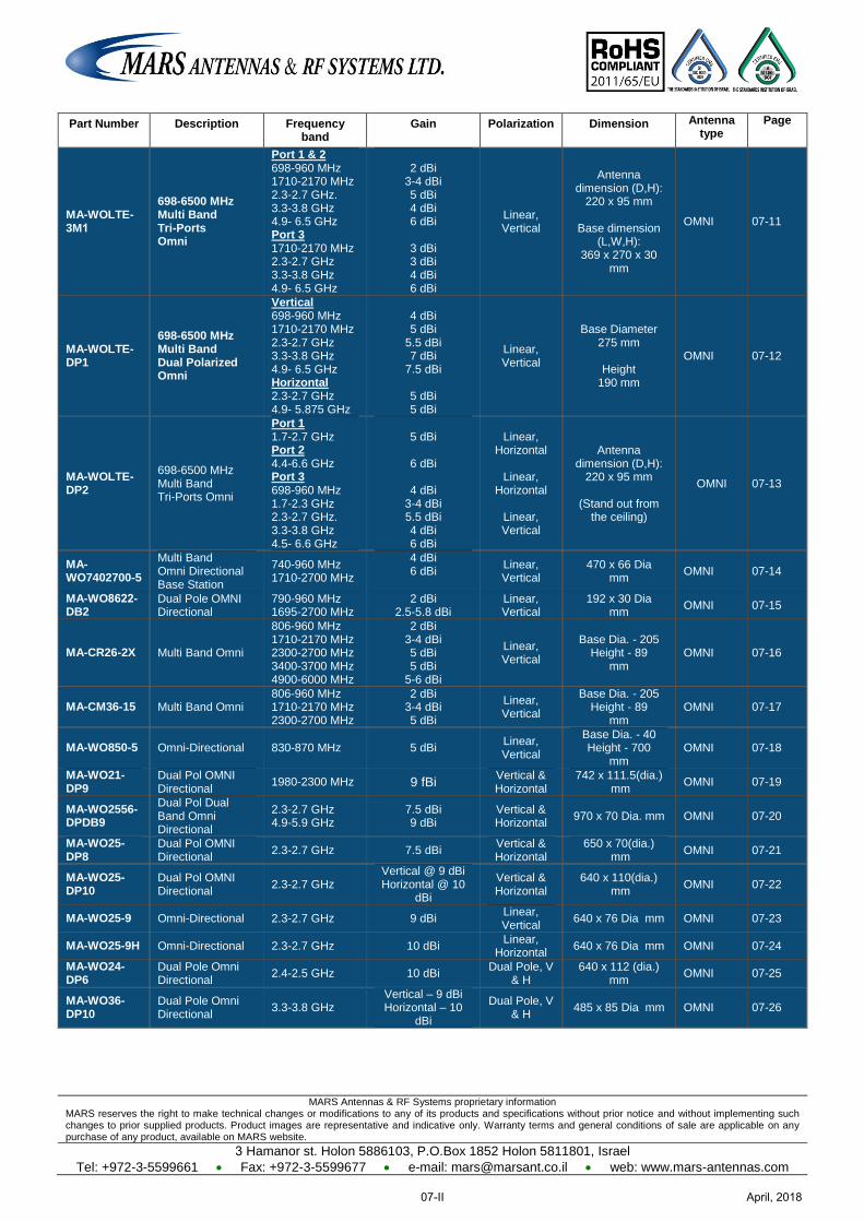
MARS Antennas & RF Systems proprietary information MARS reserves the right to make technical changes or modifications to any of its products and specifications without prior notice and without implementing such changes to prior supplied products. Product images are representative and indicative only. Warranty terms and general conditions of sale are applicable on any purchase of any product, available on MARS website.
3 Hamanor st. Holon 5886103, P.O.Box 1852 Holon 5811801, Israel
Tel: +972-3-5599661 Fax: +972-3-5599677 e-mail: [email protected] web: www.mars-antennas.com
Part Number Description Frequency band
Gain Polarization Dimension Antenna type
Page
MA-WOLTE-3M1
698-6500 MHz Multi Band Tri-Ports Omni
Port 1 & 2 698-960 MHz 1710-2170 MHz 2.3-2.7 GHz. 3.3-3.8 GHz 4.9- 6.5 GHz Port 3 1710-2170 MHz 2.3-2.7 GHz 3.3-3.8 GHz 4.9- 6.5 GHz
2 dBi
3-4 dBi 5 dBi 4 dBi 6 dBi
3 dBi 3 dBi 4 dBi 6 dBi
Linear, Vertical
Antenna dimension (D,H):
220 x 95 mm
Base dimension (L,W,H):
369 x 270 x 30 mm
OMNI 07-11
MA-WOLTE-DP1
698-6500 MHz Multi Band Dual Polarized Omni
Vertical 698-960 MHz 1710-2170 MHz 2.3-2.7 GHz 3.3-3.8 GHz 4.9- 6.5 GHz Horizontal 2.3-2.7 GHz 4.9- 5.875 GHz
4 dBi 5 dBi
5.5 dBi 7 dBi
7.5 dBi
5 dBi 5 dBi
Linear, Vertical
Base Diameter 275 mm
Height
190 mm
OMNI 07-12
MA-WOLTE-DP2
698-6500 MHz Multi Band Tri-Ports Omni
Port 1 1.7-2.7 GHz Port 2 4.4-6.6 GHz Port 3 698-960 MHz 1.7-2.3 GHz 2.3-2.7 GHz. 3.3-3.8 GHz 4.5- 6.6 GHz
5 dBi
6 dBi
4 dBi
3-4 dBi 5.5 dBi 4 dBi 6 dBi
Linear, Horizontal
Linear,
Horizontal
Linear, Vertical
Antenna dimension (D,H):
220 x 95 mm
(Stand out from the ceiling)
OMNI 07-13
MA-WO7402700-5
Multi Band Omni Directional Base Station
740-960 MHz 1710-2700 MHz
4 dBi 6 dBi
Linear, Vertical
470 x 66 Dia mm
OMNI 07-14
MA-WO8622-DB2
Dual Pole OMNI Directional
790-960 MHz 1695-2700 MHz
2 dBi 2.5-5.8 dBi
Linear, Vertical
192 x 30 Dia mm
OMNI 07-15
MA-CR26-2X Multi Band Omni
806-960 MHz 1710-2170 MHz 2300-2700 MHz 3400-3700 MHz 4900-6000 MHz
2 dBi 3-4 dBi 5 dBi 5 dBi
5-6 dBi
Linear, Vertical
Base Dia. - 205 Height - 89
mm OMNI 07-16
MA-CM36-15 Multi Band Omni 806-960 MHz 1710-2170 MHz 2300-2700 MHz
2 dBi 3-4 dBi 5 dBi
Linear, Vertical
Base Dia. - 205 Height - 89
mm OMNI 07-17
MA-WO850-5 Omni-Directional 830-870 MHz 5 dBi Linear, Vertical
Base Dia. - 40 Height - 700
mm OMNI 07-18
MA-WO21-DP9
Dual Pol OMNI Directional
1980-2300 MHz 9 fBi Vertical & Horizontal
742 x 111.5(dia.) mm
OMNI 07-19
MA-WO2556-DPDB9
Dual Pol Dual Band Omni Directional
2.3-2.7 GHz 4.9-5.9 GHz
7.5 dBi 9 dBi
Vertical & Horizontal
970 x 70 Dia. mm OMNI 07-20
MA-WO25-DP8
Dual Pol OMNI Directional 2.3-2.7 GHz 7.5 dBi
Vertical & Horizontal
650 x 70(dia.) mm
OMNI 07-21
MA-WO25-DP10
Dual Pol OMNI Directional 2.3-2.7 GHz
Vertical @ 9 dBi Horizontal @ 10
dBi
Vertical & Horizontal
640 x 110(dia.) mm
OMNI 07-22
MA-WO25-9 Omni-Directional 2.3-2.7 GHz 9 dBi Linear, Vertical
640 x 76 Dia mm OMNI 07-23
MA-WO25-9H Omni-Directional 2.3-2.7 GHz 10 dBi Linear,
Horizontal 640 x 76 Dia mm OMNI 07-24
MA-WO24-DP6
Dual Pole Omni Directional
2.4-2.5 GHz 10 dBi Dual Pole, V
& H 640 x 112 (dia.)
mm OMNI 07-25
MA-WO36-DP10
Dual Pole Omni Directional
3.3-3.8 GHz Vertical – 9 dBi Horizontal – 10
dBi
Dual Pole, V & H
485 x 85 Dia mm OMNI 07-26
April, 201807-II
MARS Antennas & RF Systems proprietary information MARS reserves the right to make technical changes or modifications to any of its products and specifications without prior notice and without implementing such changes to prior supplied products. Product images are representative and indicative only. Warranty terms and general conditions of sale are applicable on any purchase of any product, available on MARS website.
3 Hamanor st. Holon 5886103, P.O.Box 1852 Holon 5811801, Israel
Tel: +972-3-5599661 Fax: +972-3-5599677 e-mail: [email protected] web: www.mars-antennas.com
Part Number Description Frequency band
Gain Polarization Dimension Antenna type
Page
MA-WO56-DP10
Dual Pole OMNI Directional
4.9-5.9 GHz
4.9-5.1 GHz Vertical @ 8dBi &
Horizontal @ 10dBi
5.1-5.9 GHz @ 10dBi
Vertical & Horizontal
365 x 66(dia.) mm
OMNI 07-27
MA-DBO2458-6 Dual Band Omni 2.3-2.7 GHz
4.9-6 GHz 4-5 dBi /
7 dBi Linear, Vertical
210 x 28.5 Dia. mm
OMNI 07-28
MA-DBO-3H Dual Band MIMO Omni
2.3-2.7 GHz 4.9-6.1 GHz
3 X 2.5 dBi 3 X 3.5 dBi
Linear, Vertical
200 x 200 x 33 mm
OMNI 07-29
MA-DBO-3MIMO
Dual Band MIMO Omni
2.3-2.7 GHz 4.9-6 GHz
3 X 4 dBi 3 X 7 dBi
Linear, Vertical
205 x 330 mm OMNI 07-30
MA-WO36-10N
3.5 GHz Omni-Directional Base Station
3.3-3.8 GHz 9.5 dBi (typ.)
Linear, Vertical
470 x 66 mm OMNI 07-31
MA-WO55-MIMO9NH3
MIMO Omni –Base Station 4.9-5.875 GHz 3 x 9 dBi
Linear, Vertical
330 x 120 mm OMNI 07-32
MA-WO55-10NH
Omni-Directional Horizontal 4.9-5.875 GHz 10 dBi
Linear, Vertical
315 x 40 Dia. mm OMNI 07-33
MA-WO56-10H
Omni-Directional 5.1-5.9 GHz 10 dBi Linear,
Horizontal 315 x 40 Dia. mm OMNI 07-34
April, 201807-III
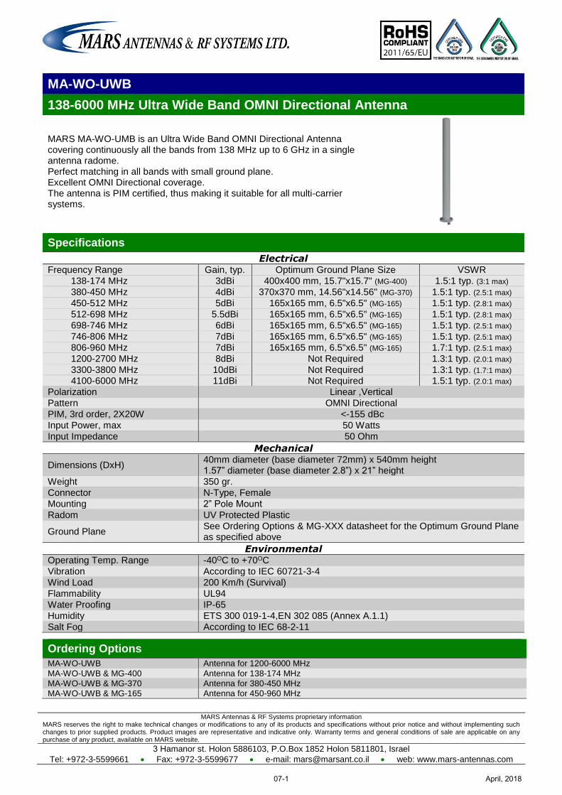
MARS Antennas & RF Systems proprietary information MARS reserves the right to make technical changes or modifications to any of its products and specifications without prior notice and without implementing such changes to prior supplied products. Product images are representative and indicative only. Warranty terms and general conditions of sale are applicable on any purchase of any product, available on MARS website.
3 Hamanor st. Holon 5886103, P.O.Box 1852 Holon 5811801, Israel
Tel: +972-3-5599661 Fax: +972-3-5599677 e-mail: [email protected] web: www.mars-antennas.com
MA-WO-UWB
138-6000 MHz Ultra Wide Band OMNI Directional Antenna
MARS MA-WO-UMB is an Ultra Wide Band OMNI Directional Antenna covering continuously all the bands from 138 MHz up to 6 GHz in a single antenna radome. Perfect matching in all bands with small ground plane. Excellent OMNI Directional coverage. The antenna is PIM certified, thus making it suitable for all multi-carrier systems.
Specifications
Electrical Frequency Range Gain, typ. Optimum Ground Plane Size VSWR
138-174 MHz 3dBi 400x400 mm, 15.7"x15.7" (MG-400) 1.5:1 typ. (3:1 max)
380-450 MHz 4dBi 370x370 mm, 14.56"x14.56" (MG-370) 1.5:1 typ. (2.5:1 max)
450-512 MHz 5dBi 165x165 mm, 6.5"x6.5" (MG-165) 1.5:1 typ. (2.8:1 max)
512-698 MHz 5.5dBi 165x165 mm, 6.5"x6.5" (MG-165) 1.5:1 typ. (2.8:1 max)
698-746 MHz 6dBi 165x165 mm, 6.5"x6.5" (MG-165) 1.5:1 typ. (2.5:1 max)
746-806 MHz 7dBi 165x165 mm, 6.5"x6.5" (MG-165) 1.5:1 typ. (2.5:1 max)
806-960 MHz 7dBi 165x165 mm, 6.5"x6.5" (MG-165) 1.7:1 typ. (2.5:1 max)
1200-2700 MHz 8dBi Not Required 1.3:1 typ. (2.0:1 max)
3300-3800 MHz 10dBi Not Required 1.3:1 typ. (1.7:1 max) 4100-6000 MHz 11dBi Not Required 1.5:1 typ. (2.0:1 max)
Polarization Linear ,Vertical
Pattern OMNI Directional
PIM, 3rd order, 2X20W <-155 dBc
Input Power, max 50 Watts
Input Impedance 50 Ohm
Mechanical
Dimensions (DxH) 40mm diameter (base diameter 72mm) x 540mm height 1.57” diameter (base diameter 2.8”) x 21” height
Weight 350 gr.
Connector N-Type, Female
Mounting 2” Pole Mount
Radom UV Protected Plastic
Ground Plane See Ordering Options & MG-XXX datasheet for the Optimum Ground Plane as specified above
Environmental Operating Temp. Range -40OC to +70OC
Vibration According to IEC 60721-3-4
Wind Load 200 Km/h (Survival)
Flammability UL94
Water Proofing IP-65
Humidity ETS 300 019-1-4,EN 302 085 (Annex A.1.1)
Salt Fog According to IEC 68-2-11
Ordering Options
MA-WO-UWB Antenna for 1200-6000 MHz
MA-WO-UWB & MG-400 Antenna for 138-174 MHz
MA-WO-UWB & MG-370 Antenna for 380-450 MHz
MA-WO-UWB & MG-165 Antenna for 450-960 MHz
April, 201807-1
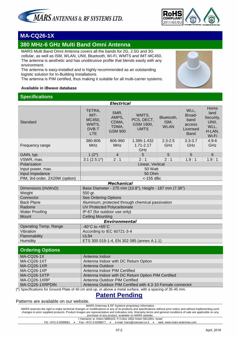
MARS Antennas & RF Systems proprietary information MARS reserves the right to make technical changes or modifications to any of its products and specifications without prior notice and without implementing such changes to prior supplied products. Product images are representative and indicative only. Warranty terms and general conditions of sale are applicable on any
purchase of any product, available on MARS website.
3 Hamanor st. Holon 5886103, P.O.Box 1852 Holon 5811801, Israel
Tel: +972-3-5599661 Fax: +972-3-5599677 e-mail: [email protected] web: www.mars-antennas.com
MA-CQ26-1X
380 MHz-6 GHz Multi Band Omni Antenna MARS Multi Band Omni Antenna covers all the bands for 2G, 2.5G and 3G cellular, as well as ISM, WLAN, UNII, Bluetooth, Wi-Fi, WMTS and IMT-MC450. The antenna is aesthetic and has unobtrusive profile that blends easily with any environment. The antenna is easy-installed and is highly recommended as an outstanding logistic solution for In-Building Installations. The antenna is PIM certified, thus making it suitable for all multi-carrier systems. Available in iBwave database
Specifications
Electrical
Standard
TETRA, IMT-
MC450, WMTS, DVB-T
LTE
SMR, AMPS, CDMA, TDMA,
GSM 900
WMTS, PCS, DECT, GSM 1900,
UMTS
Bluetooth, ISM,
WLAN
WLL, Broad-band
access Licensed
Band
Home land
Security, UNII, WLL,
H-LAN, Wi-Fi
Frequency range 380-806
MHz 806-960
MHz 1.395-1.432
1.71-2.17 GHz
2.3-2.5 GHz
3.3-3.7 GHz
4.9-6 GHz
GAIN, typ. 1 (2*) 4 5 5 5 6
VSWR, max. 3:1 (2.5:1*) 2 : 1 2 : 1 2 : 1 1.9 : 1 1.9 : 1
Polarization Linear, Vertical
Input power, max. 50 Watt
Input Impedance 50 Ohm
PIM, 3rd order, 2X20W (option) <-155 dBc
Mechanical Dimensions (HxWxD) Base Diameter - 275 mm (10.8"), Height - 187 mm (7.36")
Weight 550 gr.
Connector See Ordering Options
Back Plane Aluminum; protected through chemical passivation
Radome UV Protected Polycarbonate
Water Proofing IP-67 (for outdoor use only)
Mount Ceiling Mounting
Environmental Operating Temp. Range -40C to +65C
Vibration According to IEC 60721-3-4 Flammability UL94
Humidity ETS 300 019-1-4, EN 302 085 (annex A.1.1)
Ordering Options
MA-CQ26-1X Antenna Indoor
MA-CQ26-1XT Antenna Indoor with DC Return Option
MA-CQ26-1XR Antenna Outdoor
MA-CQ26-1XP Antenna Indoor PIM Certified
MA-CQ26-1XTP Antenna Indoor with DC Return Option PIM Certified
MA-CQ26-1XRP Antenna Outdoor PIM Certified MA-CQ26-1XRPDIN Antenna Outdoor PIM Certified with 4.3-10 Female connector
(*) Specifications for Ground Plate of 40 cm and up, or above a metal surface, with a spacing of 35-45 mm.
Patent Pending Patterns are available on our website.
April, 201807-2
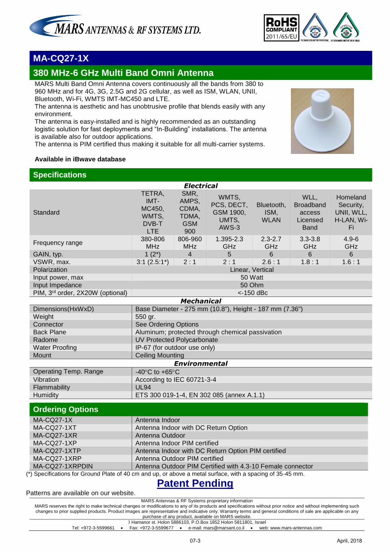
MARS Antennas & RF Systems proprietary information MARS reserves the right to make technical changes or modifications to any of its products and specifications without prior notice and without implementing such changes to prior supplied products. Product images are representative and indicative only. Warranty terms and general conditions of sale are applicable on any
purchase of any product, available on MARS website.
3 Hamanor st. Holon 5886103, P.O.Box 1852 Holon 5811801, Israel
Tel: +972-3-5599661 Fax: +972-3-5599677 e-mail: [email protected] web: www.mars-antennas.com
MA-CQ27-1X
380 MHz-6 GHz Multi Band Omni Antenna MARS Multi Band Omni Antenna covers continuously all the bands from 380 to 960 MHz and for 4G, 3G, 2.5G and 2G cellular, as well as ISM, WLAN, UNII, Bluetooth, Wi-Fi, WMTS IMT-MC450 and LTE. The antenna is aesthetic and has unobtrusive profile that blends easily with any environment. The antenna is easy-installed and is highly recommended as an outstanding logistic solution for fast deployments and “In-Building” installations. The antenna is available also for outdoor applications. The antenna is PIM certified thus making it suitable for all multi-carrier systems. Available in iBwave database
Specifications
Electrical
Standard
TETRA, IMT-
MC450, WMTS, DVB-T
LTE
SMR, AMPS, CDMA, TDMA, GSM 900
WMTS, PCS, DECT, GSM 1900,
UMTS, AWS-3
Bluetooth, ISM,
WLAN
WLL, Broadband
access Licensed
Band
Homeland Security,
UNII, WLL, H-LAN, Wi-
Fi
Frequency range 380-806
MHz 806-960
MHz 1.395-2.3
GHz 2.3-2.7 GHz
3.3-3.8 GHz
4.9-6 GHz
GAIN, typ. 1 (2*) 4 5 6 6 6
VSWR, max. 3:1 (2.5:1*) 2 : 1 2 : 1 2.6 : 1 1.8 : 1 1.6 : 1
Polarization Linear, Vertical
Input power, max 50 Watt
Input Impedance 50 Ohm
PIM, 3rd order, 2X20W (optional) <-150 dBc
Mechanical Dimensions(HxWxD) Base Diameter - 275 mm (10.8"), Height - 187 mm (7.36")
Weight 550 gr.
Connector See Ordering Options
Back Plane Aluminum; protected through chemical passivation
Radome UV Protected Polycarbonate
Water Proofing IP-67 (for outdoor use only)
Mount Ceiling Mounting
Environmental Operating Temp. Range -40C to +65C Vibration According to IEC 60721-3-4
Flammability UL94
Humidity ETS 300 019-1-4, EN 302 085 (annex A.1.1)
Ordering Options
MA-CQ27-1X Antenna Indoor
MA-CQ27-1XT Antenna Indoor with DC Return Option
MA-CQ27-1XR Antenna Outdoor
MA-CQ27-1XP Antenna Indoor PIM certified
MA-CQ27-1XTP Antenna Indoor with DC Return Option PIM certified
MA-CQ27-1XRP Antenna Outdoor PIM certified
MA-CQ27-1XRPDIN Antenna Outdoor PIM Certified with 4.3-10 Female connector (*) Specifications for Ground Plate of 40 cm and up, or above a metal surface, with a spacing of 35-45 mm.
Patent Pending Patterns are available on our website.
April, 201807-3
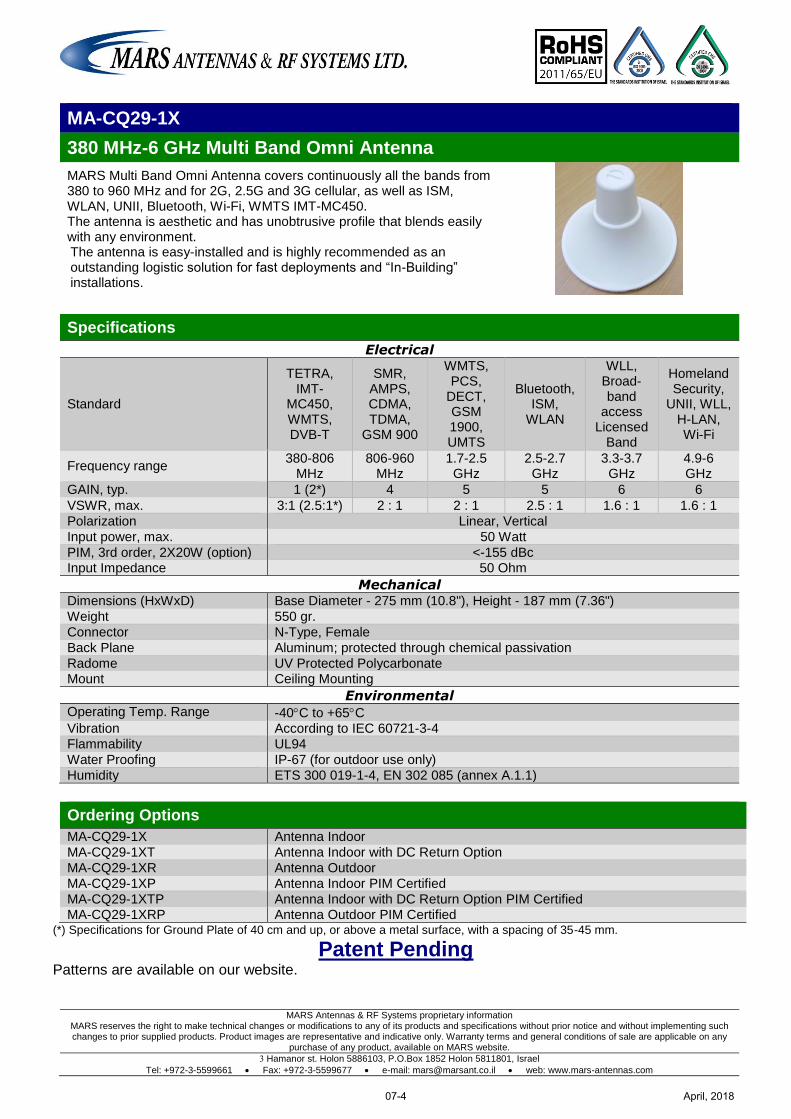
MARS Antennas & RF Systems proprietary information MARS reserves the right to make technical changes or modifications to any of its products and specifications without prior notice and without implementing such changes to prior supplied products. Product images are representative and indicative only. Warranty terms and general conditions of sale are applicable on any
purchase of any product, available on MARS website.
3 Hamanor st. Holon 5886103, P.O.Box 1852 Holon 5811801, Israel
Tel: +972-3-5599661 Fax: +972-3-5599677 e-mail: [email protected] web: www.mars-antennas.com
MA-CQ29-1X
380 MHz-6 GHz Multi Band Omni Antenna
MARS Multi Band Omni Antenna covers continuously all the bands from 380 to 960 MHz and for 2G, 2.5G and 3G cellular, as well as ISM, WLAN, UNII, Bluetooth, Wi-Fi, WMTS IMT-MC450. The antenna is aesthetic and has unobtrusive profile that blends easily with any environment. The antenna is easy-installed and is highly recommended as an outstanding logistic solution for fast deployments and “In-Building” installations.
Specifications
Electrical
Standard
TETRA, IMT-
MC450, WMTS, DVB-T
SMR, AMPS, CDMA, TDMA,
GSM 900
WMTS, PCS,
DECT, GSM 1900, UMTS
Bluetooth, ISM,
WLAN
WLL, Broad-band
access Licensed
Band
Homeland Security,
UNII, WLL, H-LAN, Wi-Fi
Frequency range 380-806
MHz 806-960
MHz 1.7-2.5 GHz
2.5-2.7 GHz
3.3-3.7 GHz
4.9-6 GHz
GAIN, typ. 1 (2*) 4 5 5 6 6
VSWR, max. 3:1 (2.5:1*) 2 : 1 2 : 1 2.5 : 1 1.6 : 1 1.6 : 1
Polarization Linear, Vertical
Input power, max. 50 Watt
PIM, 3rd order, 2X20W (option) <-155 dBc Input Impedance 50 Ohm
Mechanical Dimensions (HxWxD) Base Diameter - 275 mm (10.8"), Height - 187 mm (7.36")
Weight 550 gr.
Connector N-Type, Female
Back Plane Aluminum; protected through chemical passivation
Radome UV Protected Polycarbonate Mount Ceiling Mounting
Environmental Operating Temp. Range -40C to +65C Vibration According to IEC 60721-3-4
Flammability UL94
Water Proofing IP-67 (for outdoor use only)
Humidity ETS 300 019-1-4, EN 302 085 (annex A.1.1)
Ordering Options
MA-CQ29-1X Antenna Indoor
MA-CQ29-1XT Antenna Indoor with DC Return Option
MA-CQ29-1XR Antenna Outdoor
MA-CQ29-1XP Antenna Indoor PIM Certified
MA-CQ29-1XTP Antenna Indoor with DC Return Option PIM Certified MA-CQ29-1XRP Antenna Outdoor PIM Certified
(*) Specifications for Ground Plate of 40 cm and up, or above a metal surface, with a spacing of 35-45 mm.
Patent Pending Patterns are available on our website.
April, 201807-4
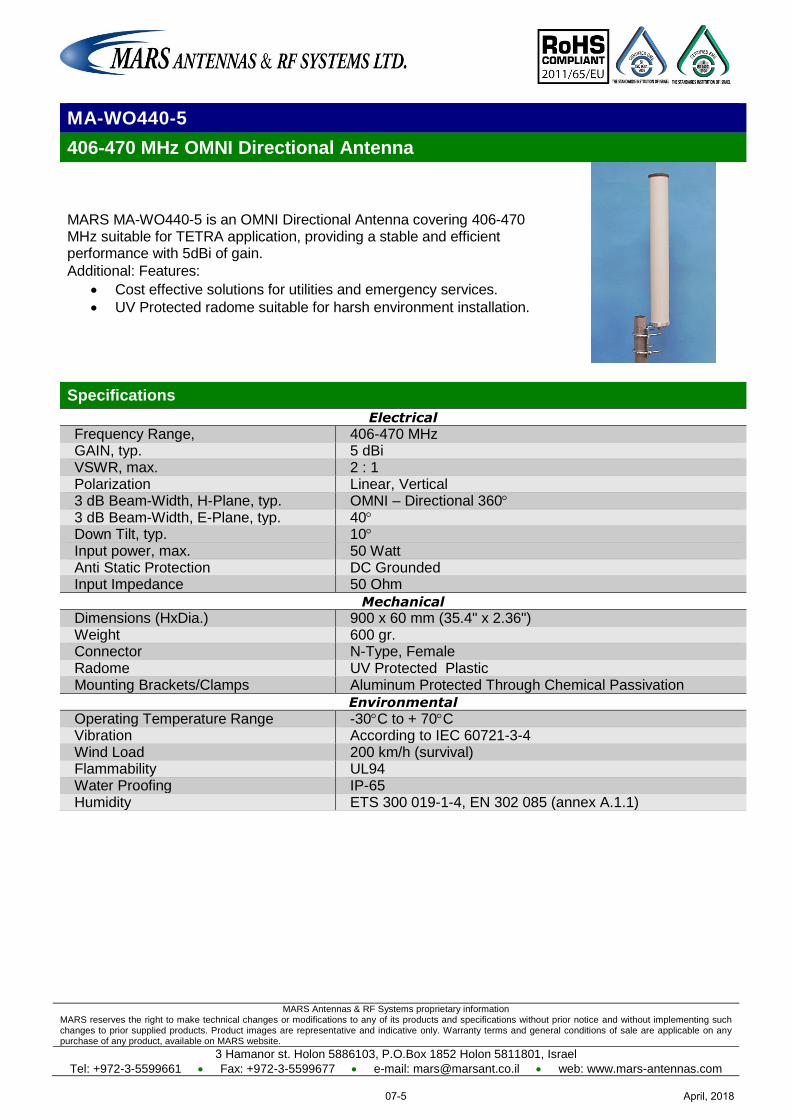
MARS Antennas & RF Systems proprietary information MARS reserves the right to make technical changes or modifications to any of its products and specifications without prior notice and without implementing such changes to prior supplied products. Product images are representative and indicative only. Warranty terms and general conditions of sale are applicable on any purchase of any product, available on MARS website.
3 Hamanor st. Holon 5886103, P.O.Box 1852 Holon 5811801, Israel
Tel: +972-3-5599661 Fax: +972-3-5599677 e-mail: [email protected] web: www.mars-antennas.com
MA-WO440-5
406-470 MHz OMNI Directional Antenna
MARS MA-WO440-5 is an OMNI Directional Antenna covering 406-470 MHz suitable for TETRA application, providing a stable and efficient performance with 5dBi of gain.
Additional: Features:
Cost effective solutions for utilities and emergency services.
UV Protected radome suitable for harsh environment installation.
Specifications
Electrical
Frequency Range, 406-470 MHz GAIN, typ. 5 dBi VSWR, max. 2 : 1 Polarization Linear, Vertical 3 dB Beam-Width, H-Plane, typ. OMNI – Directional 360 3 dB Beam-Width, E-Plane, typ. 40 Down Tilt, typ. 10 Input power, max. 50 Watt Anti Static Protection DC Grounded Input Impedance 50 Ohm
Mechanical
Dimensions (HxDia.) 900 x 60 mm (35.4" x 2.36") Weight 600 gr. Connector N-Type, Female Radome UV Protected Plastic Mounting Brackets/Clamps Aluminum Protected Through Chemical Passivation
Environmental
Operating Temperature Range -30C to + 70C Vibration According to IEC 60721-3-4 Wind Load 200 km/h (survival) Flammability UL94 Water Proofing IP-65 Humidity ETS 300 019-1-4, EN 302 085 (annex A.1.1)
April, 201807-5
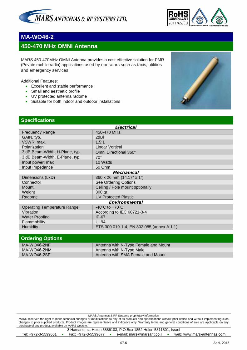
MARS Antennas & RF Systems proprietary information MARS reserves the right to make technical changes or modifications to any of its products and specifications without prior notice and without implementing such changes to prior supplied products. Product images are representative and indicative only. Warranty terms and general conditions of sale are applicable on any purchase of any product, available on MARS website.
3 Hamanor st. Holon 5886103, P.O.Box 1852 Holon 5811801, Israel
Tel: +972-3-5599661 Fax: +972-3-5599677 e-mail: [email protected] web: www.mars-antennas.com
MA-WO 2-46
450-470 MHz OMNI Antenna
MARS 450-470MHz OMNI Antenna provides a cost effective solution for PMR
(Private mobile radio) applications used by operators such as taxis, utilities
and emergency services. Additional Features:
Excellent and stable performance
Small and aesthetic profile
UV protected antenna radome
Suitable for both indoor and outdoor installations
Specifications
Electrical Frequency Range 450-470 MHz
GAIN, typ. 2dBi
VSWR, max. 1.5:1
Polarization Linear Vertical
3 dB Beam-Width, H-Plane, typ. Omni Directional 360 3 dB Beam-Width, E-Plane, typ. 70 Input power, max 10 Watts
Input Impedance 50 Ohm
Mechanical Dimensions (LxD) 360 x 26 mm (14.17" x 1")
Connector See Ordering Options
Mount Celling / Pole mount optionally
Weight 300 gr.
Radome UV Protected Plastic
Environmental Operating Temperature Range -40ºC to +70ºC
Vibration According to IEC 60721-3-4
Water Proofing IP-67
Flammability UL94
Humidity ETS 300 019-1-4, EN 302 085 (annex A.1.1)
Ordering Options
MA-WO 2-46 NF Antenna with N-Type Female and Mount
MA-WO 2-46 NM Antenna with N-Type Male
MA-WO 2-46 SF Antenna with SMA Female and Mount
April, 201807-6
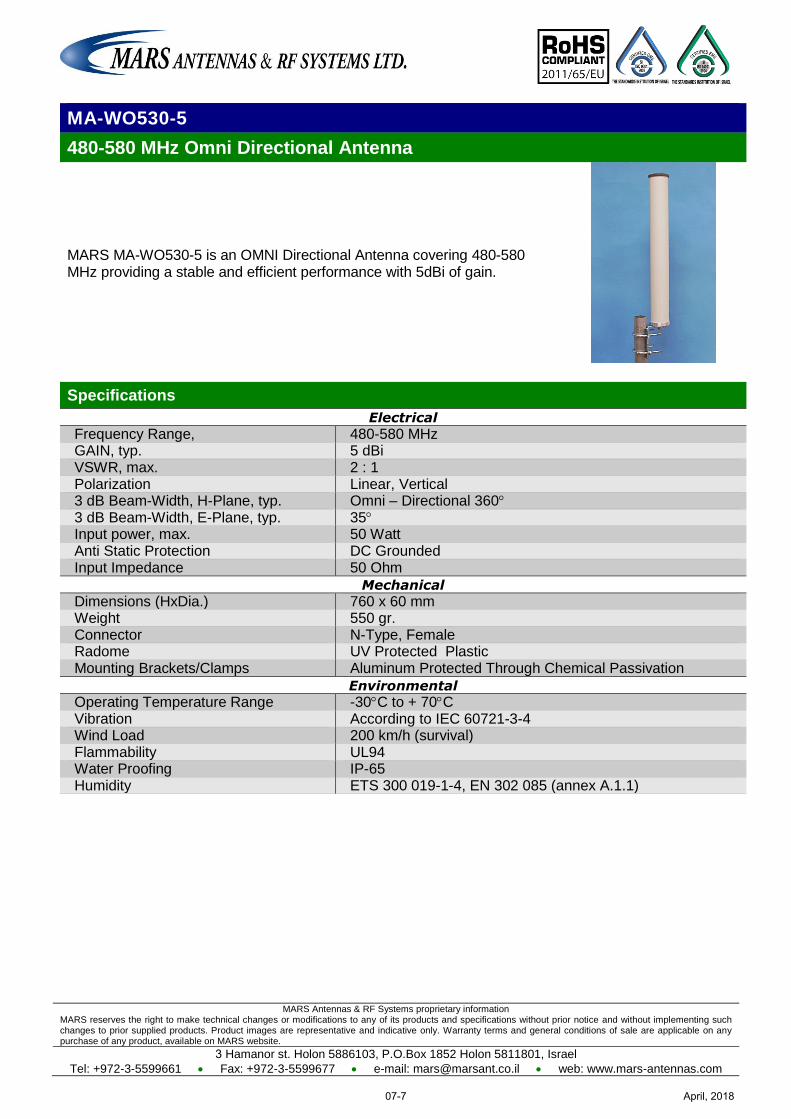
MARS Antennas & RF Systems proprietary information MARS reserves the right to make technical changes or modifications to any of its products and specifications without prior notice and without implementing such changes to prior supplied products. Product images are representative and indicative only. Warranty terms and general conditions of sale are applicable on any purchase of any product, available on MARS website.
3 Hamanor st. Holon 5886103, P.O.Box 1852 Holon 5811801, Israel
Tel: +972-3-5599661 Fax: +972-3-5599677 e-mail: [email protected] web: www.mars-antennas.com
MA-WO530-5
480-580 MHz Omni Directional Antenna
MARS MA-WO530-5 is an OMNI Directional Antenna covering 480-580 MHz providing a stable and efficient performance with 5dBi of gain.
Specifications
Electrical
Frequency Range, 480-580 MHz GAIN, typ. 5 dBi VSWR, max. 2 : 1 Polarization Linear, Vertical 3 dB Beam-Width, H-Plane, typ. Omni – Directional 360 3 dB Beam-Width, E-Plane, typ. 35 Input power, max. 50 Watt Anti Static Protection DC Grounded Input Impedance 50 Ohm
Mechanical
Dimensions (HxDia.) 760 x 60 mm Weight 550 gr. Connector N-Type, Female Radome UV Protected Plastic Mounting Brackets/Clamps Aluminum Protected Through Chemical Passivation
Environmental
Operating Temperature Range -30C to + 70C Vibration According to IEC 60721-3-4 Wind Load 200 km/h (survival) Flammability UL94 Water Proofing IP-65 Humidity ETS 300 019-1-4, EN 302 085 (annex A.1.1)
April, 201807-7
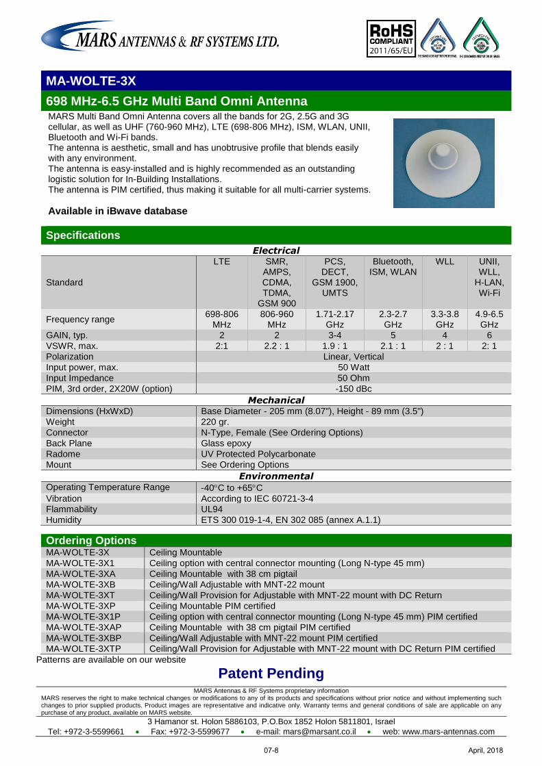
MARS Antennas & RF Systems proprietary information MARS reserves the right to make technical changes or modifications to any of its products and specifications without prior notice and without implementing such changes to prior supplied products. Product images are representative and indicative only. Warranty terms and general conditions of sale are applicable on any purchase of any product, available on MARS website.
3 Hamanor st. Holon 5886103, P.O.Box 1852 Holon 5811801, Israel
Tel: +972-3-5599661 Fax: +972-3-5599677 e-mail: [email protected] web: www.mars-antennas.com
MA-WOLTE-3X
698 MHz-6.5 GHz Multi Band Omni Antenna MARS Multi Band Omni Antenna covers all the bands for 2G, 2.5G and 3G cellular, as well as UHF (760-960 MHz), LTE (698-806 MHz), ISM, WLAN, UNII, Bluetooth and Wi-Fi bands. The antenna is aesthetic, small and has unobtrusive profile that blends easily with any environment. The antenna is easy-installed and is highly recommended as an outstanding logistic solution for In-Building Installations. The antenna is PIM certified, thus making it suitable for all multi-carrier systems.
Available in iBwave database
Specifications
Electrical
Standard
LTE SMR, AMPS, CDMA, TDMA,
GSM 900
PCS, DECT,
GSM 1900, UMTS
Bluetooth, ISM, WLAN
WLL UNII, WLL,
H-LAN, Wi-Fi
Frequency range 698-806
MHz 806-960
MHz 1.71-2.17
GHz 2.3-2.7 GHz
3.3-3.8 GHz
4.9-6.5 GHz
GAIN, typ. 2 2 3-4 5 4 6
VSWR, max. 2:1 2.2 : 1 1.9 : 1 2.1 : 1 2 : 1 2: 1
Polarization Linear, Vertical
Input power, max. 50 Watt
Input Impedance 50 Ohm
PIM, 3rd order, 2X20W (option) -150 dBc
Mechanical Dimensions (HxWxD) Base Diameter - 205 mm (8.07"), Height - 89 mm (3.5")
Weight 220 gr.
Connector N-Type, Female (See Ordering Options)
Back Plane Glass epoxy
Radome UV Protected Polycarbonate
Mount See Ordering Options
Environmental Operating Temperature Range -40C to +65C
Vibration According to IEC 60721-3-4 Flammability UL94
Humidity ETS 300 019-1-4, EN 302 085 (annex A.1.1)
Ordering Options MA-WOLTE-3X Ceiling Mountable
MA-WOLTE-3X1 Ceiling option with central connector mounting (Long N-type 45 mm)
MA-WOLTE-3XA Ceiling Mountable with 38 cm pigtail
MA-WOLTE-3XB Ceiling/Wall Adjustable with MNT-22 mount
MA-WOLTE-3XT Ceiling/Wall Provision for Adjustable with MNT-22 mount with DC Return
MA-WOLTE-3XP Ceiling Mountable PIM certified
MA-WOLTE-3X1P Ceiling option with central connector mounting (Long N-type 45 mm) PIM certified
MA-WOLTE-3XAP Ceiling Mountable with 38 cm pigtail PIM certified
MA-WOLTE-3XBP Ceiling/Wall Adjustable with MNT-22 mount PIM certified MA-WOLTE-3XTP Ceiling/Wall Provision for Adjustable with MNT-22 mount with DC Return PIM certified
Patterns are available on our website
Patent Pending
April, 201807-8
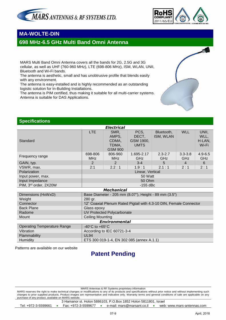
MARS Antennas & RF Systems proprietary information MARS reserves the right to make technical changes or modifications to any of its products and specifications without prior notice and without implementing such changes to prior supplied products. Product images are representative and indicative only. Warranty terms and general conditions of sale are applicable on any purchase of any product, available on MARS website.
3 Hamanor st. Holon 5886103, P.O.Box 1852 Holon 5811801, Israel
Tel: +972-3-5599661 Fax: +972-3-5599677 e-mail: [email protected] web: www.mars-antennas.com
MA-WOLTE-DIN
698 MHz-6.5 GHz Multi Band Omni Antenna
MARS Multi Band Omni Antenna covers all the bands for 2G, 2.5G and 3G cellular, as well as UHF (760-960 MHz), LTE (698-806 MHz), ISM, WLAN, UNII, Bluetooth and Wi-Fi bands. The antenna is aesthetic, small and has unobtrusive profile that blends easily with any environment. The antenna is easy-installed and is highly recommended as an outstanding logistic solution for In-Building Installations. The antenna is PIM certified, thus making it suitable for all multi-carrier systems. Antenna is suitable for DAS Applications.
Specifications
Electrical
Standard
LTE SMR, AMPS, CDMA, TDMA,
GSM 900
PCS, DECT,
GSM 1900, UMTS
Bluetooth, ISM, WLAN
WLL UNII, WLL,
H-LAN, Wi-Fi
Frequency range 698-806
MHz 806-960
MHz 1.695-2.17
GHz 2.3-2.7 GHz
3.3-3.8 GHz
4.9-6.5 GHz
GAIN, typ. 2 2 3-4 5 4 6
VSWR, max. 2:1 2.2 : 1 1.9 : 1 2.1 : 1 2 : 1 2 : 1 Polarization Linear, Vertical
Input power, max. 50 Watt
Input Impedance 50 Ohm
PIM, 3rd order, 2X20W -155 dBc
Mechanical Dimensions (HxWxD) Base Diameter - 205 mm (8.07"), Height - 89 mm (3.5")
Weight 280 gr. Connector 12” Coaxial Plenum Rated Pigtail with 4.3-10 DIN, Female Connector
Back Plane Glass epoxy
Radome UV Protected Polycarbonate
Mount Ceiling Mounting
Environmental Operating Temperature Range -40C to +65C Vibration According to IEC 60721-3-4
Flammability UL94
Humidity ETS 300 019-1-4, EN 302 085 (annex A.1.1)
Patterns are available on our website
Patent Pending
April, 201807-9
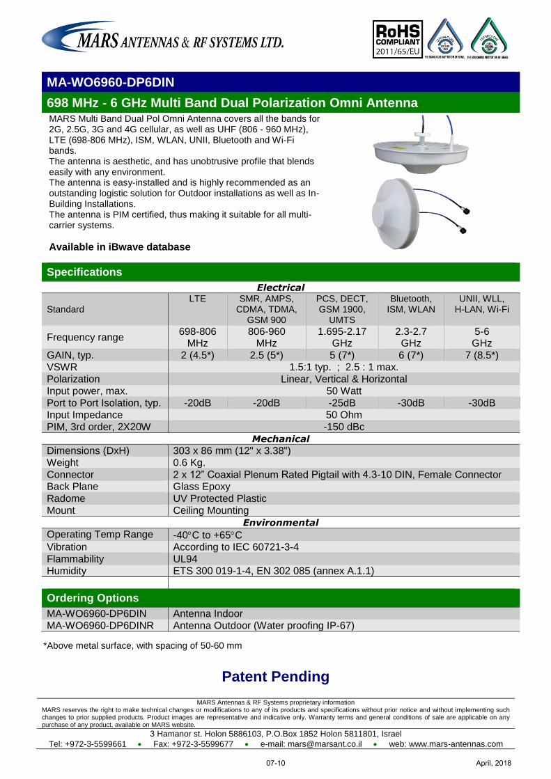
MARS Antennas & RF Systems proprietary information MARS reserves the right to make technical changes or modifications to any of its products and specifications without prior notice and without implementing such changes to prior supplied products. Product images are representative and indicative only. Warranty terms and general conditions of sale are applicable on any purchase of any product, available on MARS website.
3 Hamanor st. Holon 5886103, P.O.Box 1852 Holon 5811801, Israel
Tel: +972-3-5599661 Fax: +972-3-5599677 e-mail: [email protected] web: www.mars-antennas.com
MA-WO6960-DP6DIN
698 MHz - 6 GHz Multi Band Dual Polarization Omni Antenna MARS Multi Band Dual Pol Omni Antenna covers all the bands for 2G, 2.5G, 3G and 4G cellular, as well as UHF (806 - 960 MHz), LTE (698-806 MHz), ISM, WLAN, UNII, Bluetooth and Wi-Fi bands. The antenna is aesthetic, and has unobtrusive profile that blends easily with any environment. The antenna is easy-installed and is highly recommended as an outstanding logistic solution for Outdoor installations as well as In-Building Installations. The antenna is PIM certified, thus making it suitable for all multi-carrier systems.
Available in iBwave database
Specifications
Electrical
Standard LTE SMR, AMPS,
CDMA, TDMA, GSM 900
PCS, DECT, GSM 1900,
UMTS
Bluetooth, ISM, WLAN
UNII, WLL, H-LAN, Wi-Fi
Frequency range 698-806
MHz 806-960
MHz 1.695-2.17
GHz 2.3-2.7
GHz 5-6 GHz
GAIN, typ. 2 (4.5*) 2.5 (5*) 5 (7*) 6 (7*) 7 (8.5*) VSWR 1.5:1 typ. ; 2.5 : 1 max.
Polarization Linear, Vertical & Horizontal Input power, max. 50 Watt
Port to Port Isolation, typ. -20dB -20dB -25dB -30dB -30dB Input Impedance 50 Ohm
PIM, 3rd order, 2X20W -150 dBc
Mechanical
Dimensions (DxH) 303 x 86 mm (12" x 3.38") Weight 0.6 Kg.
Connector 2 x 12” Coaxial Plenum Rated Pigtail with 4.3-10 DIN, Female Connector Back Plane Glass Epoxy
Radome UV Protected Plastic Mount Ceiling Mounting
Environmental
Operating Temp Range -40C to +65C Vibration According to IEC 60721-3-4
Flammability UL94 Humidity ETS 300 019-1-4, EN 302 085 (annex A.1.1)
Ordering Options
MA-WO6960-DP6DIN Antenna Indoor MA-WO6960-DP6DINR Antenna Outdoor (Water proofing IP-67)
*Above metal surface, with spacing of 50-60 mm
Patent Pending
April, 201807-10
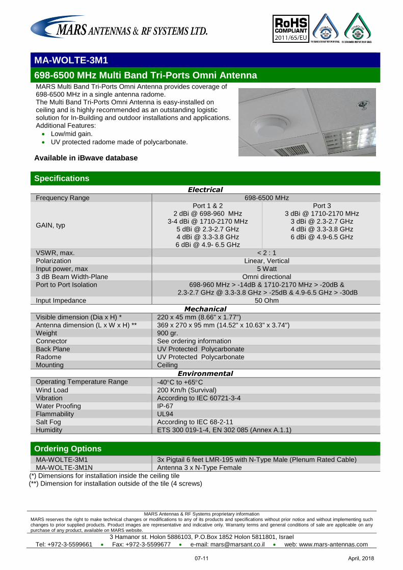
MARS Antennas & RF Systems proprietary information MARS reserves the right to make technical changes or modifications to any of its products and specifications without prior notice and without implementing such changes to prior supplied products. Product images are representative and indicative only. Warranty terms and general conditions of sale are applicable on any purchase of any product, available on MARS website.
3 Hamanor st. Holon 5886103, P.O.Box 1852 Holon 5811801, Israel
Tel: +972-3-5599661 Fax: +972-3-5599677 e-mail: [email protected] web: www.mars-antennas.com
MA-WOLTE-3M1
698-6500 MHz Multi Band Tri-Ports Omni Antenna MARS Multi Band Tri-Ports Omni Antenna provides coverage of 698-6500 MHz in a single antenna radome. The Multi Band Tri-Ports Omni Antenna is easy-installed on ceiling and is highly recommended as an outstanding logistic solution for In-Building and outdoor installations and applications. Additional Features:
Low/mid gain.
UV protected radome made of polycarbonate.
Available in iBwave database
Specifications
Electrical Frequency Range 698-6500 MHz
GAIN, typ
Port 1 & 2 2 dBi @ 698-960 MHz
3-4 dBi @ 1710-2170 MHz 5 dBi @ 2.3-2.7 GHz 4 dBi @ 3.3-3.8 GHz 6 dBi @ 4.9- 6.5 GHz
Port 3 3 dBi @ 1710-2170 MHz
3 dBi @ 2.3-2.7 GHz 4 dBi @ 3.3-3.8 GHz 6 dBi @ 4.9-6.5 GHz
VSWR, max. < 2 : 1
Polarization Linear, Vertical
Input power, max 5 Watt
3 dB Beam Width-Plane Omni directional
Port to Port Isolation
698-960 MHz > -14dB & 1710-2170 MHz > -20dB & 2.3-2.7 GHz @ 3.3-3.8 GHz > -25dB & 4.9-6.5 GHz > -30dB
Input Impedance 50 Ohm
Mechanical Visible dimension (Dia x H) * 220 x 45 mm (8.66" x 1.77")
Antenna dimension (L x W x H) ** 369 x 270 x 95 mm (14.52" x 10.63" x 3.74")
Weight 900 gr.
Connector See ordering information
Back Plane UV Protected Polycarbonate
Radome UV Protected Polycarbonate
Mounting Ceiling
Environmental Operating Temperature Range -40C to +65C Wind Load 200 Km/h (Survival)
Vibration According to IEC 60721-3-4
Water Proofing IP-67
Flammability UL94
Salt Fog According to IEC 68-2-11
Humidity ETS 300 019-1-4, EN 302 085 (Annex A.1.1)
Ordering Options
MA-WOLTE-3M1 3x Pigtail 6 feet LMR-195 with N-Type Male (Plenum Rated Cable)
MA-WOLTE-3M1N Antenna 3 x N-Type Female
(*) Dimensions for installation inside the ceiling tile (**) Dimension for installation outside of the tile (4 screws)
April, 201807-11
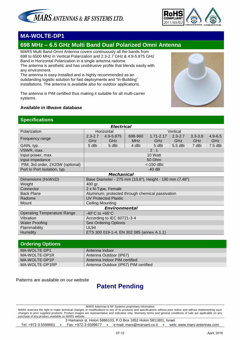
MARS Antennas & RF Systems proprietary information MARS reserves the right to make technical changes or modifications to any of its products and specifications without prior notice and without implementing such changes to prior supplied products. Product images are representative and indicative only. Warranty terms and general conditions of sale are applicable on any purchase of any product, available on MARS website.
3 Hamanor st. Holon 5886103, P.O.Box 1852 Holon 5811801, Israel
Tel: +972-3-5599661 Fax: +972-3-5599677 e-mail: [email protected] web: www.mars-antennas.com
MA-WOLTE-DP1
698 MHz – 6.5 GHz Multi Band Dual Polarized Omni Antenna MARS Multi Band Omni Antenna covers continuously all the bands from 698 to 6500 MHz in Vertical Polarization and 2.3-2.7 GHz & 4.9-5.875 GHz Band in Horizontal Polarization in a single antenna radome. The antenna is aesthetic and has unobtrusive profile that blends easily with any environment. The antenna is easy-installed and is highly recommended as an outstanding logistic solution for fast deployments and “In-Building” installations. The antenna is available also for outdoor applications. The antenna is PIM certified thus making it suitable for all multi-carrier systems.
Available in iBwave database
Specifications
Electrical Polarization Horizontal Vertical
Frequency range 2.3-2.7 GHz
4.9-5.875 GHz
698-960 MHz
1.71-2.17 GHz
2.3-2.7 GHz
3.3-3.8 GHz
4.9-6.5 GHz
GAIN, typ. 5 dBi 5 dBi 4 dBi 5 dBi 5.5 dBi 7 dBi 7.5 dBi
VSWR, max. 2 : 1
Input power, max. 10 Watt Input Impedance 50 Ohm
PIM, 3rd order, 2X20W (optional) <-150 dBc
Port to Port Isolation, typ. -40 dB
Mechanical Dimensions (HxWxD) Base Diameter - 275 mm (10.8"), Height - 190 mm (7.48")
Weight 400 gr.
Connector 2 x N-Type, Female Back Plane Aluminum; protected through chemical passivation
Radome UV Protected Plastic
Mount Ceiling Mounting
Environmental Operating Temperature Range -40C to +65C Vibration According to IEC 60721-3-4
Water Proofing See Ordering Options
Flammability UL94
Humidity ETS 300 019-1-4, EN 302 085 (annex A.1.1)
Ordering Options
MA-WOLTE-DP1 Antenna Indoor
MA-WOLTE-DP1R Antenna Outdoor (IP67)
MA-WOLTE-DP1P Antenna Indoor PIM certified
MA-WOLTE-DP1RP Antenna Outdoor (IP67) PIM certified
Patterns are available on our website
Patent Pending
April, 201807-12
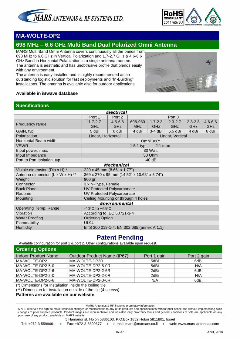
MARS Antennas & RF Systems proprietary information MARS reserves the right to make technical changes or modifications to any of its products and specifications without prior notice and without implementing such changes to prior supplied products. Product images are representative and indicative only. Warranty terms and general conditions of sale are applicable on any purchase of any product, available on MARS website.
3 Hamanor st. Holon 5886103, P.O.Box 1852 Holon 5811801, Israel
Tel: +972-3-5599661 Fax: +972-3-5599677 e-mail: [email protected] web: www.mars-antennas.com
MA-WOLTE-DP2
698 MHz – 6.6 GHz Multi Band Dual Polarized Omni Antenna MARS Multi Band Omni Antenna covers continuously all the bands from 698 MHz to 6.6 GHz in Vertical Polarization and 1.7-2.7 GHz & 4.6-6.6 GHz Band in Horizontal Polarization in a single antenna radome. The antenna is aesthetic and has unobtrusive profile that blends easily with any environment. The antenna is easy-installed and is highly recommended as an outstanding logistic solution for fast deployments and “In-Building” installations. The antenna is available also for outdoor applications.
Available in iBwave database
Specifications
Electrical Port 1 Port 2 Port 3
Frequency range 1.7-2.7 GHz
4.5-6.6 GHz
698-960 MHz
1.7-2.3 GHz
2.3-2.7 GHz
3.3-3.8 GHz
4.6-6.6 GHz
GAIN, typ. 5 dBi 6 dBi 4 dBi 3-4 dBi 5.5 dBi 4 dBi 6 dBi
Polarization. Linear, Horizontal Linear, Vertical
Horizontal Beam width Omni 360 VSWR 1.5:1 typ. 2:1 max.
Input power, max. 30 Watt
Input Impedance 50 Ohm
Port to Port Isolation, typ -40 dB
Mechanical Visible dimension (Dia x H) * 220 x 45 mm (8.66" x 1.77")
Antenna dimension (L x W x H) ** 369 x 270 x 95 mm (14.52" x 10.63" x 3.74")
Weight 900 gr.
Connector 3 x N-Type, Female
Back Plane UV Protected Polycarbonate
Radome UV Protected Polycarbonate
Mounting Ceiling Mounting or through 4 holes
Environmental Operating Temp. Range -40C to +65C Vibration According to IEC 60721-3-4
Water Proofing Ordering Option
Flammability UL94
Humidity ETS 300 019-1-4, EN 302 085 (annex A.1.1)
Patent Pending Avalable configuration for port 1 & port 2. Other configurations available upon request.
Ordering Options
Indoor Product Name Outdoor Product Name (IP67) Port 1 gain Port 2 gain MA-WOLTE-DP2 MA-WOLTE-DP2R 5dBi 6dBi
MA-WOLTE-DP2-5-0 MA-WOLTE-DP2-5-0R 5dBi N/A
MA-WOLTE-DP2-2-6 MA-WOLTE-DP2-2-6R 2dBi 6dBi
MA-WOLTE-DP2-2-0 MA-WOLTE-DP2-2-0R 2dBi N/A
MA-WOLTE-DP2-0-6 MA-WOLTE-DP2-0-6R N/A 6dBi
(*) Dimensions for installation inside the ceiling tile (**) Dimension for installation outside of the tile (4 screws)
Patterns are available on our website
April, 201807-13
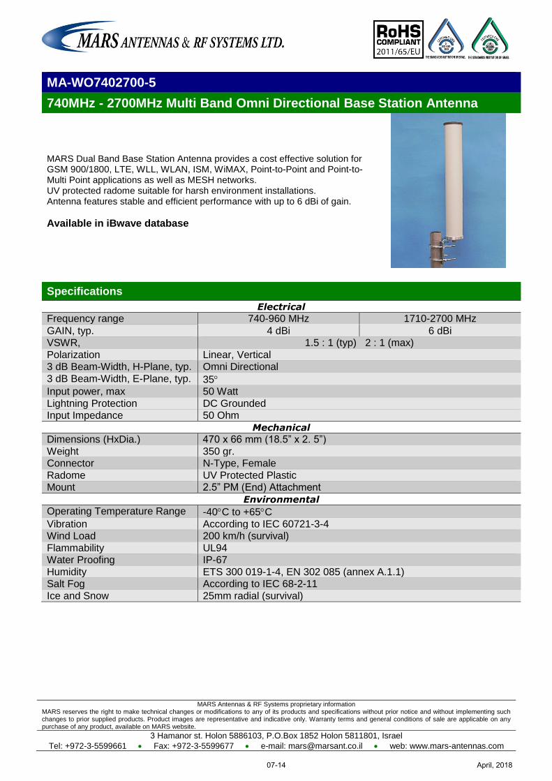
MARS Antennas & RF Systems proprietary information MARS reserves the right to make technical changes or modifications to any of its products and specifications without prior notice and without implementing such changes to prior supplied products. Product images are representative and indicative only. Warranty terms and general conditions of sale are applicable on any purchase of any product, available on MARS website.
3 Hamanor st. Holon 5886103, P.O.Box 1852 Holon 5811801, Israel
Tel: +972-3-5599661 Fax: +972-3-5599677 e-mail: [email protected] web: www.mars-antennas.com
MA-WO7402700-5
740MHz - 2700MHz Multi Band Omni Directional Base Station Antenna
MARS Dual Band Base Station Antenna provides a cost effective solution for GSM 900/1800, LTE, WLL, WLAN, ISM, WiMAX, Point-to-Point and Point-to-Multi Point applications as well as MESH networks. UV protected radome suitable for harsh environment installations. Antenna features stable and efficient performance with up to 6 dBi of gain.
Available in iBwave database
Specifications
Electrical
Frequency range 740-960 MHz 1710-2700 MHz
GAIN, typ. 4 dBi 6 dBi VSWR, 1.5 : 1 (typ) 2 : 1 (max)
Polarization Linear, Vertical 3 dB Beam-Width, H-Plane, typ. Omni Directional
3 dB Beam-Width, E-Plane, typ. 35 Input power, max 50 Watt
Lightning Protection DC Grounded Input Impedance 50 Ohm
Mechanical
Dimensions (HxDia.) 470 x 66 mm (18.5” x 2. 5”)
Weight 350 gr. Connector N-Type, Female
Radome UV Protected Plastic Mount 2.5” PM (End) Attachment
Environmental
Operating Temperature Range -40C to +65C
Vibration According to IEC 60721-3-4 Wind Load 200 km/h (survival)
Flammability UL94 Water Proofing IP-67
Humidity ETS 300 019-1-4, EN 302 085 (annex A.1.1) Salt Fog According to IEC 68-2-11
Ice and Snow 25mm radial (survival)
April, 201807-14
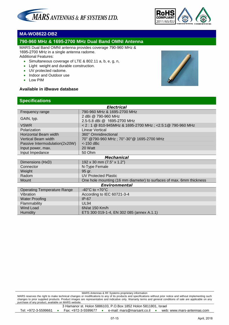
MARS Antennas & RF Systems proprietary information MARS reserves the right to make technical changes or modifications to any of its products and specifications without prior notice and without implementing such changes to prior supplied products. Product images are representative and indicative only. Warranty terms and general conditions of sale are applicable on any purchase of any product, available on MARS website.
3 Hamanor st. Holon 5886103, P.O.Box 1852 Holon 5811801, Israel
Tel: +972-3-5599661 Fax: +972-3-5599677 e-mail: [email protected] web: www.mars-antennas.com
MA-WO8622-DB2
960-790 MHz & 2700-1695 MHz Dual Band OMNI Antenna
MARS Dual Band OMNI antenna provides coverage 960-790 MHz & 2700-1695 MHz in a single antenna radome.
Additional Features:
Simultaneous coverage of LTE & 802.11 a, b, e, g, n,
Light weight and durable construction.
UV protected radome.
Indoor and Outdoor use
Low PIM
Available in iBwave database
Specifications
Electrical Frequency range 790-960 MHz & 1695-2700 MHz
GAIN, typ. 2 dBi @ 960-790 MHz 2.5-5.8 dBi @ 2700-1695 MHz
VSWR < 2 : 1 @ 810-945MHz & 1695-2700 MHz ; <2.5:1@ 790-960 MHz
Polarization Linear Vertical Horizontal Beam width 360° Omnidirectional
Vertical Beam width 70° @790-960 MHz ; 70°-30°@ 1695-2700 MHz
Passive Intermodulation(2x20W) <-150 dBc
Input power, max. 20 Watt
Input Impedance 50 Ohm
Mechanical Dimensions (HxD) 192 x 30 mm (7.5" x 1.2") Connector N-Type Female
Weight 95 gr.
Radom UV Protected Plastic
Mount One hole mounting (16 mm diameter) to surfaces of max. 6mm thickness
Environmental Operating Temperature Range -40°C to +70°C Vibration According to IEC 60721-3-4
Water Proofing IP-67
Flammability UL94
Wind Load 6N/at 150 Km/h
Humidity ETS 300 019-1-4, EN 302 085 (annex A.1.1)
April, 201807-15
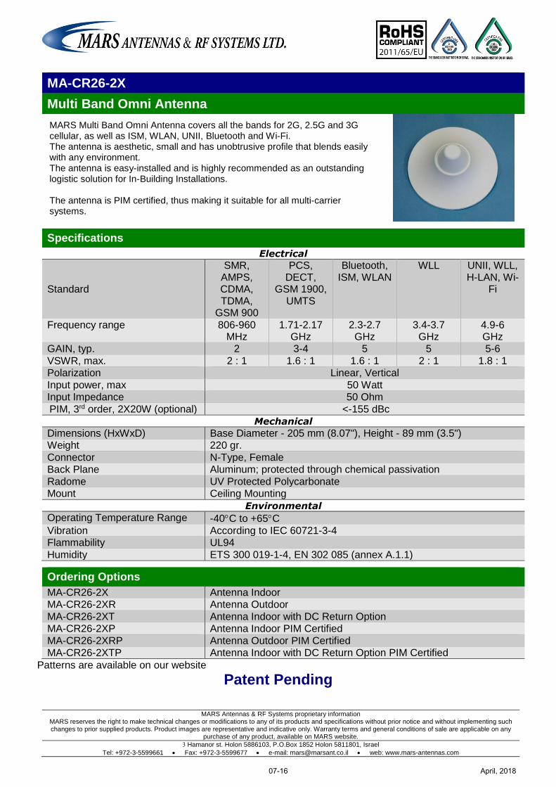
MARS Antennas & RF Systems proprietary information MARS reserves the right to make technical changes or modifications to any of its products and specifications without prior notice and without implementing such changes to prior supplied products. Product images are representative and indicative only. Warranty terms and general conditions of sale are applicable on any
purchase of any product, available on MARS website.
3 Hamanor st. Holon 5886103, P.O.Box 1852 Holon 5811801, Israel
Tel: +972-3-5599661 Fax: +972-3-5599677 e-mail: [email protected] web: www.mars-antennas.com
MA-CR26-2X
Multi Band Omni Antenna
MARS Multi Band Omni Antenna covers all the bands for 2G, 2.5G and 3G cellular, as well as ISM, WLAN, UNII, Bluetooth and Wi-Fi. The antenna is aesthetic, small and has unobtrusive profile that blends easily with any environment. The antenna is easy-installed and is highly recommended as an outstanding logistic solution for In-Building Installations. The antenna is PIM certified, thus making it suitable for all multi-carrier systems.
Specifications
Electrical
Standard
SMR, AMPS, CDMA, TDMA,
GSM 900
PCS, DECT,
GSM 1900, UMTS
Bluetooth, ISM, WLAN
WLL UNII, WLL, H-LAN, Wi-
Fi
Frequency range 806-960 MHz
1.71-2.17 GHz
2.3-2.7 GHz
3.4-3.7 GHz
4.9-6 GHz
GAIN, typ. 2 3-4 5 5 5-6
VSWR, max. 2 : 1 1.6 : 1 1.6 : 1 2 : 1 1.8 : 1 Polarization Linear, Vertical
Input power, max 50 Watt Input Impedance 50 Ohm
PIM, 3rd order, 2X20W (optional) <-155 dBc
Mechanical
Dimensions (HxWxD) Base Diameter - 205 mm (8.07"), Height - 89 mm (3.5") Weight 220 gr.
Connector N-Type, Female Back Plane Aluminum; protected through chemical passivation
Radome UV Protected Polycarbonate Mount Ceiling Mounting
Environmental
Operating Temperature Range -40C to +65C
Vibration According to IEC 60721-3-4 Flammability UL94
Humidity ETS 300 019-1-4, EN 302 085 (annex A.1.1)
Ordering Options
MA-CR26-2X Antenna Indoor MA-CR26-2XR Antenna Outdoor
MA-CR26-2XT Antenna Indoor with DC Return Option MA-CR26-2XP Antenna Indoor PIM Certified
MA-CR26-2XRP Antenna Outdoor PIM Certified MA-CR26-2XTP Antenna Indoor with DC Return Option PIM Certified
Patterns are available on our website
Patent Pending
April, 201807-16
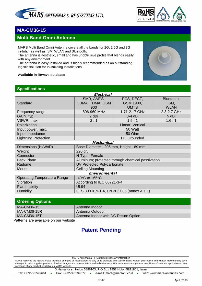
MARS Antennas & RF Systems proprietary information MARS reserves the right to make technical changes or modifications to any of its products and specifications without prior notice and without implementing such changes to prior supplied products. Product images are representative and indicative only. Warranty terms and general conditions of sale are applicable on any purchase of any product, available on MARS website.
3 Hamanor st. Holon 5886103, P.O.Box 1852 Holon 5811801, Israel
Tel: +972-3-5599661 Fax: +972-3-5599677 e-mail: [email protected] web: www.mars-antennas.com
MA-CM36-15
Multi Band Omni Antenna
MARS Multi Band Omni Antenna covers all the bands for 2G, 2.5G and 3G cellular, as well as ISM, WLAN and Bluetooth. The antenna is aesthetic, small and has unobtrusive profile that blends easily with any environment. The antenna is easy-installed and is highly recommended as an outstanding logistic solution for In-Building Installations. Available in iBwave database
Specifications
Electrical
Standard SMR, AMPS,
CDMA, TDMA, GSM 900
PCS, DECT, GSM 1900,
UMTS
Bluetooth, ISM,
WLAN Frequency range 806-960 MHz 1.71-2.17 GHz 2.3-2.7 GHz
GAIN, typ. 2 dBi 3-4 dBi 5 dBi VSWR, max. 2 : 1 1.5 : 1 1.6 : 1
Polarization Linear, Vertical Input power, max. 50 Watt
Input Impedance 50 Ohm Lightning Protection DC Grounded
Mechanical
Dimensions (HxWxD) Base Diameter - 205 mm, Height - 89 mm
Weight 220 gr. Connector N-Type, Female
Back Plane Aluminum; protected through chemical passivation Radome UV Protected Polycarbonate
Mount Ceiling Mounting
Environmental
Operating Temperature Range -40C to +65C Vibration According to IEC 60721-3-4
Flammability UL94 Humidity ETS 300 019-1-4, EN 302 085 (annex A.1.1)
Ordering Options
MA-CM36-15 Antenna Indoor MA-CM36-15R Antenna Outdoor
MA-CM36-15T Antenna Indoor with DC Return Option
Patterns are available on our website
Patent Pending
April, 201807-17
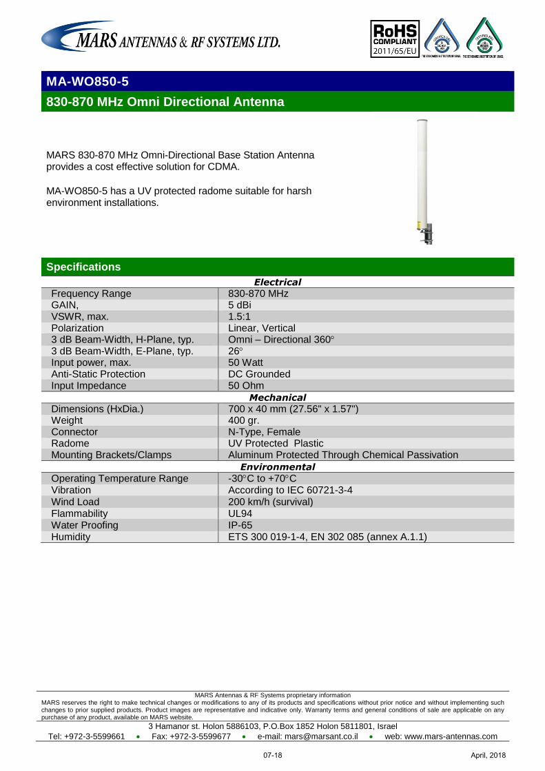
MARS Antennas & RF Systems proprietary information MARS reserves the right to make technical changes or modifications to any of its products and specifications without prior notice and without implementing such changes to prior supplied products. Product images are representative and indicative only. Warranty terms and general conditions of sale are applicable on any purchase of any product, available on MARS website.
3 Hamanor st. Holon 5886103, P.O.Box 1852 Holon 5811801, Israel
Tel: +972-3-5599661 Fax: +972-3-5599677 e-mail: [email protected] web: www.mars-antennas.com
MA-WO850-5
830-870 MHz Omni Directional Antenna
MARS 830-870 MHz Omni-Directional Base Station Antenna provides a cost effective solution for CDMA.
MA-WO850-5 has a UV protected radome suitable for harsh environment installations.
Specifications
Electrical
Frequency Range 830-870 MHz GAIN, 5 dBi VSWR, max. 1.5:1 Polarization Linear, Vertical 3 dB Beam-Width, H-Plane, typ. Omni – Directional 360 3 dB Beam-Width, E-Plane, typ. 26 Input power, max. 50 Watt Anti-Static Protection DC Grounded Input Impedance 50 Ohm
Mechanical
Dimensions (HxDia.) 700 x 40 mm (27.56" x 1.57") Weight 400 gr. Connector N-Type, Female Radome UV Protected Plastic Mounting Brackets/Clamps Aluminum Protected Through Chemical Passivation
Environmental
Operating Temperature Range -30C to +70C Vibration According to IEC 60721-3-4 Wind Load 200 km/h (survival) Flammability UL94 Water Proofing IP-65 Humidity ETS 300 019-1-4, EN 302 085 (annex A.1.1)
April, 201807-18
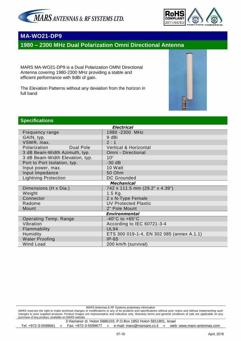
MARS Antennas & RF Systems proprietary information MARS reserves the right to make technical changes or modifications to any of its products and specifications without prior notice and without implementing such changes to prior supplied products. Product images are representative and indicative only. Warranty terms and general conditions of sale are applicable on any purchase of any product, available on MARS website.
3 Hamanor st. Holon 5886103, P.O.Box 1852 Holon 5811801, Israel
Tel: +972-3-5599661 Fax: +972-3-5599677 e-mail: [email protected] web: www.mars-antennas.com
MA-WO21-DP9
1980 – 2300 MHz Dual Polarization Omni Directional Antenna
MARS MA-WO21-DP9 is a Dual Polarization OMNI Directional Antenna covering 1980-2300 MHz providing a stable and efficient performance with 9dBi of gain.
The Elevation Patterns without any deviation from the horizon in full band
Specifications
Electrical
Frequency range 1980 -2300 MHz GAIN, typ. 9 dBi VSWR, max. 2 : 1 Polarization Dual Pole Vertical & Horizontal 3 dB Beam-Width Azimuth, typ. Omni - Directional 3 dB Beam-Width Elevation, typ. 10 Port to Port Isolation, typ. -30 dB Input power, max. 10 Watt Input Impedance 50 Ohm Lightning Protection DC Grounded
Mechanical
Dimensions (H x Dia.) 742 x 111.5 mm (29.2" x 4.39") Weight 1.5 Kg. Connector 2 x N-Type Female Radome UV Protected Plastic Mount 2" Pole Mount
Environmental
Operating Temp. Range -40C to +65C Vibration According to IEC 60721-3-4 Flammability UL94 Humidity ETS 300 019-1-4, EN 302 085 (annex A.1.1) Water Proofing IP-65 Wind Load 200 km/h (survival)
April, 201807-19
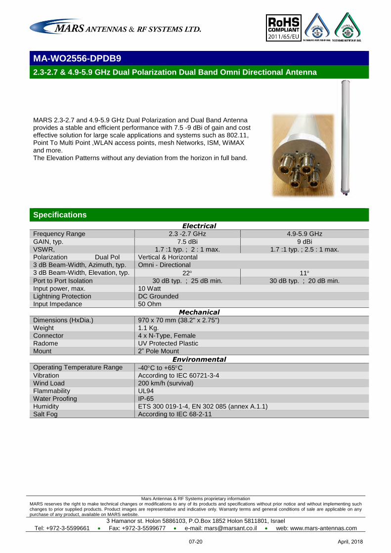
Mars Antennas & RF Systems proprietary information MARS reserves the right to make technical changes or modifications to any of its products and specifications without prior notice and without implementing such changes to prior supplied products. Product images are representative and indicative only. Warranty terms and general conditions of sale are applicable on any purchase of any product, available on MARS website.
3 Hamanor st. Holon 5886103, P.O.Box 1852 Holon 5811801, Israel
Tel: +972-3-5599661 Fax: +972-3-5599677 e-mail: [email protected] web: www.mars-antennas.com
MA-WO2556-DPDB9
2.3-2.7 & 4.9-5.9 GHz Dual Polarization Dual Band Omni Directional Antenna
MARS 2.3-2.7 and 4.9-5.9 GHz Dual Polarization and Dual Band Antenna provides a stable and efficient performance with 7.5 -9 dBi of gain and cost effective solution for large scale applications and systems such as 802.11, Point To Multi Point ,WLAN access points, mesh Networks, ISM, WiMAX and more. The Elevation Patterns without any deviation from the horizon in full band.
Specifications
Electrical Frequency Range 2.3 -2.7 GHz 4.9-5.9 GHz
GAIN, typ. 7.5 dBi 9 dBi
VSWR, 1.7 :1 typ. ; 2 : 1 max. 1.7 :1 typ. ; 2.5 : 1 max.
Polarization Dual Pol Vertical & Horizontal
3 dB Beam-Width, Azimuth, typ. Omni - Directional
3 dB Beam-Width, Elevation, typ. 22 11 Port to Port Isolation 30 dB typ. ; 25 dB min. 30 dB typ. ; 20 dB min.
Input power, max. 10 Watt
Lightning Protection DC Grounded
Input Impedance 50 Ohm
Mechanical Dimensions (HxDia.) 970 x 70 mm (38.2" x 2.75")
Weight 1.1 Kg.
Connector 4 x N-Type, Female
Radome UV Protected Plastic
Mount 2” Pole Mount
Environmental Operating Temperature Range -40C to +65C Vibration According to IEC 60721-3-4
Wind Load 200 km/h (survival)
Flammability UL94
Water Proofing IP-65
Humidity ETS 300 019-1-4, EN 302 085 (annex A.1.1)
Salt Fog According to IEC 68-2-11
April, 201807-20
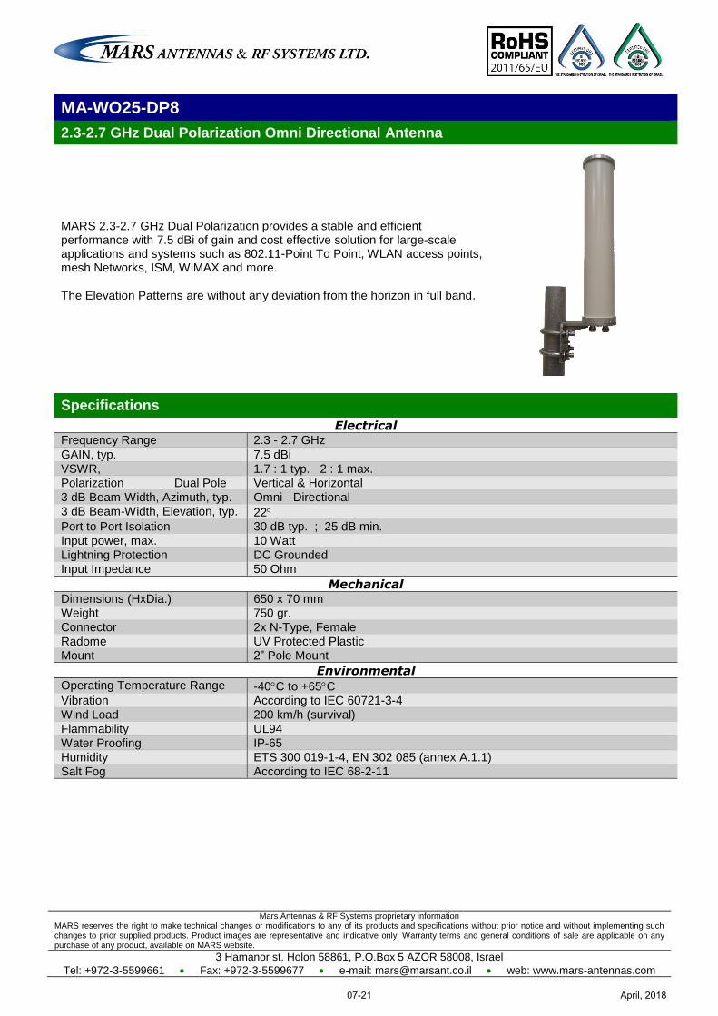
Mars Antennas & RF Systems proprietary information MARS reserves the right to make technical changes or modifications to any of its products and specifications without prior notice and without implementing such changes to prior supplied products. Product images are representative and indicative only. Warranty terms and general conditions of sale are applicable on any purchase of any product, available on MARS website.
3 Hamanor st. Holon 58861, P.O.Box 5 AZOR 58008, Israel
Tel: +972-3-5599661 Fax: +972-3-5599677 e-mail: [email protected] web: www.mars-antennas.com
MA-WO25-DP8
2.3-2.7 GHz Dual Polarization Omni Directional Antenna
MARS 2.3-2.7 GHz Dual Polarization provides a stable and efficient performance with 7.5 dBi of gain and cost effective solution for large-scale applications and systems such as 802.11-Point To Point, WLAN access points, mesh Networks, ISM, WiMAX and more. The Elevation Patterns are without any deviation from the horizon in full band.
Specifications
Electrical Frequency Range 2.3 - 2.7 GHz
GAIN, typ. 7.5 dBi
VSWR, 1.7 : 1 typ. 2 : 1 max.
Polarization Dual Pole Vertical & Horizontal
3 dB Beam-Width, Azimuth, typ. Omni - Directional
3 dB Beam-Width, Elevation, typ. 22 Port to Port Isolation 30 dB typ. ; 25 dB min.
Input power, max. 10 Watt
Lightning Protection DC Grounded Input Impedance 50 Ohm
Mechanical Dimensions (HxDia.) 650 x 70 mm
Weight 750 gr.
Connector 2x N-Type, Female
Radome UV Protected Plastic Mount 2” Pole Mount
Environmental Operating Temperature Range -40C to +65C Vibration According to IEC 60721-3-4
Wind Load 200 km/h (survival)
Flammability UL94
Water Proofing IP-65
Humidity ETS 300 019-1-4, EN 302 085 (annex A.1.1)
Salt Fog According to IEC 68-2-11
April, 201807-21
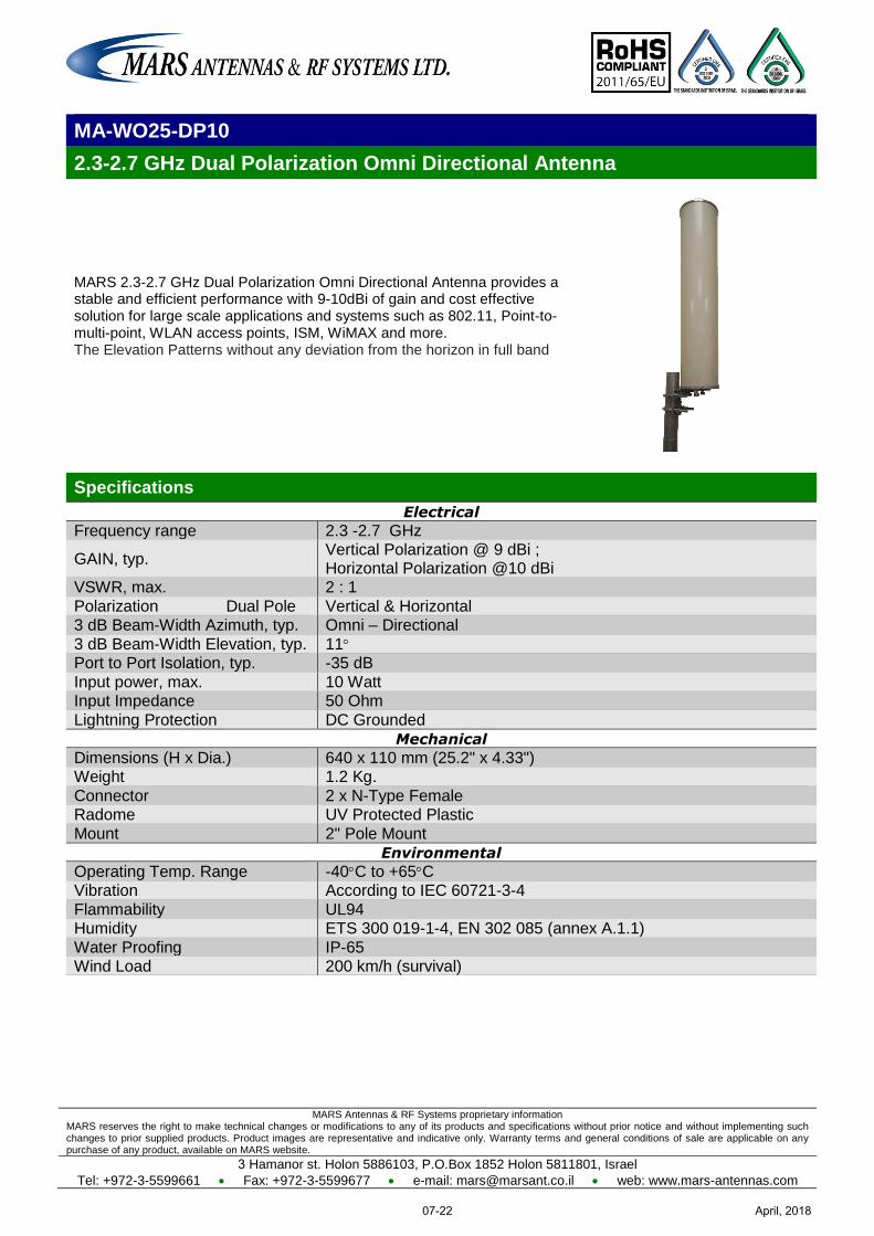
MARS Antennas & RF Systems proprietary information MARS reserves the right to make technical changes or modifications to any of its products and specifications without prior notice and without implementing such changes to prior supplied products. Product images are representative and indicative only. Warranty terms and general conditions of sale are applicable on any purchase of any product, available on MARS website.
3 Hamanor st. Holon 5886103, P.O.Box 1852 Holon 5811801, Israel
Tel: +972-3-5599661 Fax: +972-3-5599677 e-mail: [email protected] web: www.mars-antennas.com
MA-WO25-DP10
2.3-2.7 GHz Dual Polarization Omni Directional Antenna
MARS 2.3-2.7 GHz Dual Polarization Omni Directional Antenna provides a stable and efficient performance with 9-10dBi of gain and cost effective solution for large scale applications and systems such as 802.11, Point-to-multi-point, WLAN access points, ISM, WiMAX and more. The Elevation Patterns without any deviation from the horizon in full band
Specifications
Electrical
Frequency range 2.3 -2.7 GHz
GAIN, typ. Vertical Polarization @ 9 dBi ; Horizontal Polarization @10 dBi
VSWR, max. 2 : 1
Polarization Dual Pole Vertical & Horizontal 3 dB Beam-Width Azimuth, typ. Omni – Directional
3 dB Beam-Width Elevation, typ. 11 Port to Port Isolation, typ. -35 dB
Input power, max. 10 Watt Input Impedance 50 Ohm
Lightning Protection DC Grounded
Mechanical
Dimensions (H x Dia.) 640 x 110 mm (25.2" x 4.33") Weight 1.2 Kg.
Connector 2 x N-Type Female Radome UV Protected Plastic
Mount 2" Pole Mount
Environmental
Operating Temp. Range -40C to +65C Vibration According to IEC 60721-3-4
Flammability UL94 Humidity ETS 300 019-1-4, EN 302 085 (annex A.1.1)
Water Proofing IP-65 Wind Load 200 km/h (survival)
April, 201807-22
MARS Antennas & RF Systems proprietary information MARS reserves the right to make technical changes or modifications to any of its products and specifications without prior notice and without implementing such changes to prior supplied products. Product images are representative and indicative only. Warranty terms and general conditions of sale are applicable on any purchase of any product, available on MARS website.
3 Hamanor st. Holon 5886103, P.O.Box 1852 Holon 5811801, Israel
Tel: +972-3-5599661 Fax: +972-3-5599677 e-mail: [email protected] web: www.mars-antennas.com
MA-WO25-9
2.3-2.7 GHz Omni – Directional Base Station Antenna
MARS 2.4 GHz Base Station Antenna provides a cost effective solution for large scale WLL, WLAN, ISM and Point-to-Multi Point applications. UV protected radome suitable for harsh environment installations. Antenna features stable and efficient performance with 9 dBi of gain.
Specifications
Electrical Frequency range 2.3-2.7 GHz
GAIN, typ. 9 dBi
VSWR, max. 2 : 1
Polarization Linear, Vertical
3 dB Beam-Width, H-Plane, typ. Omni - Directional
3 dB Beam-Width, E-Plane, typ. 10 Input power, max. 50 Watt
Input Impedance 50 Ohm
Mechanical Dimensions (HxDia.) 640 x 76mm (25” x 3”)
Weight 660 gr.
Connector N-Type, Female
Radome UV Protected Plastic
Mount Pole Mount
Environmental Operating Temperature Range -40C to +65C Vibration According to IEC 60721-3-4
Wind Load 200 km/h (survival)
Flammability UL94
Water Proofing IP-67
Humidity ETS 300 019-1-4, EN 302 085 (annex A.1.1)
Salt Fog According to IEC 68-2-11
Ice and Snow 25mm radial (survival)
Ordering Options MA-WO25-9 Antenna with pole mount
MA-WO25-9S Antenna heavy duty with pole mount
Patterns are available on our website
April, 201807-23
Mars Antennas & RF Systems proprietary information MARS reserves the right to make technical changes or modifications to any of its products and specifications without prior notice and without implementing such changes to prior supplied products. Product images are representative and indicative only. Warranty terms and general conditions of sale are applicable on any purchase of any product, available on MARS website.
3 Hamanor st. Holon 58861, P.O.Box 5 AZOR 58008, Israel
Tel: +972-3-5599661 Fax: +972-3-5599677 e-mail: [email protected] web: www.mars-antennas.com
MA-WO25-9H
2.3 – 2.7 GHz Horizontal Omni Directional
MARS Horizontal polarized Omni Directional antenna provides coverage of 2.3-2.7 GHz with a stable and efficient performance of 10dBi gain.
MARS MA-WO25-9H provides a cost effective solution for large-scale applications and systems such as 802.11b/g, Point-to-multi-point, WLAN access points, WiMAX and more.
MARS Horizontal Omni Directional polarized antenna offers polarization rejection of interference of vertically polarized signals, as used in most WLAN systems.
Main Features:
Horizontally polarized
High gain.
Lightweight and durable construction.
UV protected radome suitable for harsh environment installations.
Specifications
Electrical
Frequency range 2.3 - 2.7 GHz GAIN, typ. 10 dBi
VSWR 2 : 1 max. 1.7 : 1 typ. Polarization Linear, Horizontal
3 dB Beam-Width Azimuth, typ. Omni - Directional 3 dB Beam-Width Elevation, typ. 11
Input power, max. 10 Watt Input Impedance 50 Ohm
Lightning Protection DC Grounded
Mechanical
Dimensions (L x Ø) 640 x 76 mm (25.2" x 3") Weight 750 gr.
Connector N-Type Female Radome UV Protected Plastic
Mount 2" Pole Mount
Environmental
Operating Temp. Range -40C to +65C Vibration According to IEC 60721-3-4
Flammability UL94 Humidity ETS 300 019-1-4, EN 302 085 (annex A.1.1)
Water Proofing IP-65 Wind Load 200 km/h (survival)
April, 201807-24
MARS Antennas & RF Systems proprietary information MARS reserves the right to make technical changes or modifications to any of its products and specifications without prior notice and without implementing such changes to prior supplied products. Product images are representative and indicative only. Warranty terms and general conditions of sale are applicable on any purchase of any product, available on MARS website.
3 Hamanor st. Holon 5886103, P.O.Box 1852 Holon 5811801, Israel
Tel: +972-3-5599661 Fax: +972-3-5599677 e-mail: [email protected] web: www.mars-antennas.com
MA-WO24-DP6
2.4 – 2.5 GHz Dual Pole Omni Directional Antenna
MARS 2.4-2.5 GHz Dual Polarization Omni Directional Antenna provides a stable and efficient performance with 10dBi of gain and cost effective solution for large scale applications and systems such as 802.11, Point-to-multi-point, WLAN access points, ISM, WiMAX and more. The Elevation Patterns without any deviation from the horizon in full band Very high Isolation between 2 or more antennas when installed Horizontally.
Specifications
Electrical
Frequency range 2.4 -2.5 GHz
GAIN, typ. 10 dBi VSWR, max. 1.8:1
Polarization Dual Pole, Vertical & Horizontal 3 dB Beam-Width Azimuth, typ. Omni - Directional
3 dB Beam-Width Elevation, typ. 13 Down Tilt, typ. 12
Horizon Isolation, typ. -30 dB Port to Port Isolation, typ. -30 dB
Input power, max. 10 Watt Input Impedance 50 Ohm
Lightning Protection DC Grounded
Mechanical
Dimensions (H x Dia.) 640 x 112 mm (25.2" x 4.4") Weight 1.2 kg
Connector 2 x N-Type Female Radome UV Protected Plastic
Mount 2" Pole Mount
Environmental
Operating Temp. Range -40C to +65C Vibration According to IEC 60721-3-4
Flammability UL94 Humidity ETS 300 019-1-4, EN 302 085 (annex A.1.1)
Water Proofing IP-65 Wind Load 200 km/h (survival)
April, 201807-25
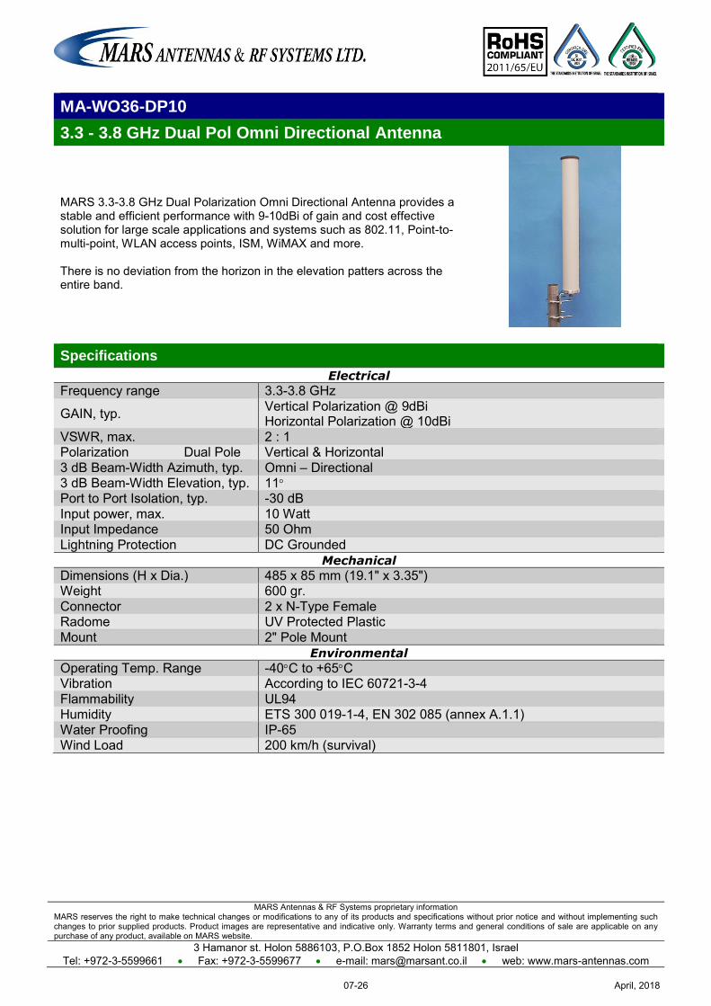
MARS Antennas & RF Systems proprietary information MARS reserves the right to make technical changes or modifications to any of its products and specifications without prior notice and without implementing such changes to prior supplied products. Product images are representative and indicative only. Warranty terms and general conditions of sale are applicable on any purchase of any product, available on MARS website.
3 Hamanor st. Holon 5886103, P.O.Box 1852 Holon 5811801, Israel Tel: +972-3-5599661 Fax: +972-3-5599677 e-mail: [email protected] web: www.mars-antennas.com
MA-WO36-DP10
3.3 - 3.8 GHz Dual Pol Omni Directional Antenna
MARS 3.3-3.8 GHz Dual Polarization Omni Directional Antenna provides a stable and efficient performance with 9-10dBi of gain and cost effective solution for large scale applications and systems such as 802.11, Point-to-multi-point, WLAN access points, ISM, WiMAX and more. There is no deviation from the horizon in the elevation patters across the entire band.
Specifications
Electrical
Frequency range 3.3-3.8 GHz
GAIN, typ. Vertical Polarization @ 9dBi Horizontal Polarization @ 10dBi
VSWR, max. 2 : 1 Polarization Dual Pole Vertical & Horizontal 3 dB Beam-Width Azimuth, typ. Omni – Directional 3 dB Beam-Width Elevation, typ. 11 Port to Port Isolation, typ. -30 dB Input power, max. 10 Watt Input Impedance 50 Ohm Lightning Protection DC Grounded
Mechanical
Dimensions (H x Dia.) 485 x 85 mm (19.1" x 3.35") Weight 600 gr. Connector 2 x N-Type Female Radome UV Protected Plastic Mount 2" Pole Mount
Environmental
Operating Temp. Range -40C to +65C Vibration According to IEC 60721-3-4 Flammability UL94 Humidity ETS 300 019-1-4, EN 302 085 (annex A.1.1) Water Proofing IP-65 Wind Load 200 km/h (survival)
April, 201807-26
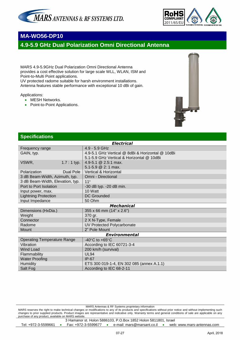
MARS Antennas & RF Systems proprietary information MARS reserves the right to make technical changes or modifications to any of its products and specifications without prior notice and without implementing such changes to prior supplied products. Product images are representative and indicative only. Warranty terms and general conditions of sale are applicable on any purchase of any product, available on MARS website.
3 Hamanor st. Holon 5886103, P.O.Box 1852 Holon 5811801, Israel
Tel: +972-3-5599661 Fax: +972-3-5599677 e-mail: [email protected] web: www.mars-antennas.com
MA-WO56-DP10
4.9-5.9 GHz Dual Polarization Omni Directional Antenna
MARS 4.9-5.9GHz Dual Polarization Omni Directional Antenna provides a cost effective solution for large scale WLL, WLAN, ISM and Point-to-Multi Point applications. UV protected radome suitable for harsh environment installations. Antenna features stable performance with exceptional 10 dBi of gain. Applications:
MESH Networks.
Point-to-Point Applications.
Specifications
Electrical Frequency range 4.9 - 5.9 GHz
GAIN, typ. 4.9-5.1 GHz Vertical @ 8dBi & Horizontal @ 10dBi 5.1-5.9 GHz Vertical & Horizontal @ 10dBi
VSWR, 1.7 : 1 typ. 4.9-5.1 @ 2.5:1 max. 5.1-5.9 @ 2: 1 max.
Polarization Dual Pole Vertical & Horizontal
3 dB Beam-Width, Azimuth, typ. Omni - Directional
3 dB Beam-Width, Elevation, typ. 11 Port to Port Isolation -30 dB typ. -20 dB min.
Input power, max. 10 Watt
Lightning Protection DC Grounded
Input Impedance 50 Ohm
Mechanical Dimensions (HxDia.) 355 x 66 mm (14" x 2.6")
Weight 370 gr.
Connector 2 X N-Type, Female
Radome UV Protected Polycarbonate
Mount 2” Pole Mount
Environmental Operating Temperature Range -40C to +65C Vibration According to IEC 60721-3-4
Wind Load 200 km/h (survival)
Flammability UL94
Water Proofing IP-67
Humidity ETS 300 019-1-4, EN 302 085 (annex A.1.1)
Salt Fog According to IEC 68-2-11
April, 201807-27
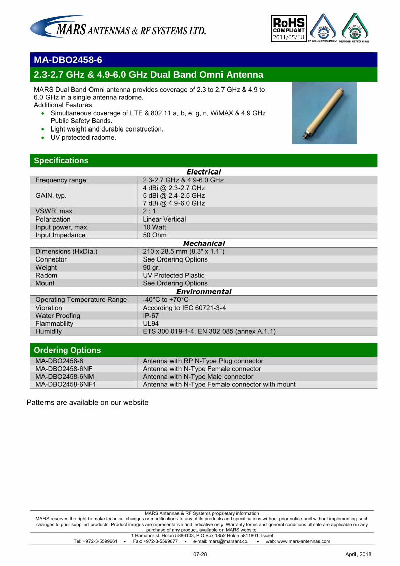
MARS Antennas & RF Systems proprietary information MARS reserves the right to make technical changes or modifications to any of its products and specifications without prior notice and without implementing such changes to prior supplied products. Product images are representative and indicative only. Warranty terms and general conditions of sale are applicable on any
purchase of any product, available on MARS website. 3 Hamanor st. Holon 5886103, P.O.Box 1852 Holon 5811801, Israel
Tel: +972-3-5599661 Fax: +972-3-5599677 e-mail: [email protected] web: www.mars-antennas.com
MA-DBO2458-6
2.3-2.7 GHz & 4.9-6.0 GHz Dual Band Omni Antenna
MARS Dual Band Omni antenna provides coverage of 2.3 to 2.7 GHz & 4.9 to 6.0 GHz in a single antenna radome. Additional Features:
Simultaneous coverage of LTE & 802.11 a, b, e, g, n, WiMAX & 4.9 GHz Public Safety Bands.
Light weight and durable construction. UV protected radome.
Specifications
Electrical Frequency range 2.3-2.7 GHz & 4.9-6.0 GHz
GAIN, typ. 4 dBi @ 2.3-2.7 GHz 5 dBi @ 2.4-2.5 GHz 7 dBi @ 4.9-6.0 GHz
VSWR, max. 2 : 1 Polarization Linear Vertical Input power, max. 10 Watt Input Impedance 50 Ohm
Mechanical Dimensions (HxDia.) 210 x 28.5 mm (8.3" x 1.1") Connector See Ordering Options Weight 90 gr. Radom UV Protected Plastic Mount See Ordering Options
Environmental Operating Temperature Range -40°C to +70°C Vibration According to IEC 60721-3-4 Water Proofing IP-67 Flammability UL94 Humidity ETS 300 019-1-4, EN 302 085 (annex A.1.1) Ordering Options
MA-DBO2458-6 Antenna with RP N-Type Plug connector MA-DBO2458-6NF Antenna with N-Type Female connector MA-DBO2458-6NM Antenna with N-Type Male connector MA-DBO2458-6NF1 Antenna with N-Type Female connector with mount
Patterns are available on our website
April, 201807-28
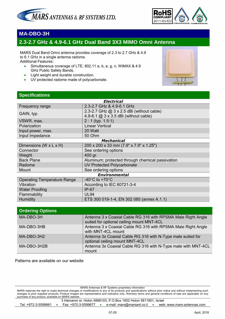
MARS Antennas & RF Systems proprietary information MARS reserves the right to make technical changes or modifications to any of its products and specifications without prior notice and without implementing such changes to prior supplied products. Product images are representative and indicative only. Warranty terms and general conditions of sale are applicable on any purchase of any product, available on MARS website.
3 Hamanor st. Holon 5886103, P.O.Box 1852 Holon 5811801, Israel Tel: +972-3-5599661 Fax: +972-3-5599677 e-mail: [email protected] web: www.mars-antennas.com
MA-DBO-3H
2.3-2.7 GHz & 4.9-6.1 GHz Dual Band 3X3 MIMO Omni Antenna
MARS Dual Band Omni antenna provides coverage of 2.3 to 2.7 GHz & 4.9 to 6.1 GHz in a single antenna radome. Additional Features:
Simultaneous coverage of LTE, 802.11 a, b, e, g, n, WiMAX & 4.9 GHz Public Safety Bands.
Light weight and durable construction. UV protected radome made of polycarbonate.
Specifications
Electrical
Frequency range 2.3-2.7 GHz & 4.9-6.1 GHz
GAIN, typ. 2.3-2.7 GHz @ 3 x 2.5 dBi (without cable) 4.9-6.1 @ 3 x 3.5 dBi (without cable)
VSWR, max. 2 : 1 (typ. 1.5:1) Polarization Linear Vertical Input power, max. 20 Watt Input Impedance 50 Ohm
Mechanical
Dimensions (W x L x H) 200 x 200 x 33 mm (7.9" x 7.9" x 1.25") Connector See ordering options Weight 400 gr. Back Plane Aluminum; protected through chemical passivation Radome UV Protected Polycarbonate Mount See ordering options
Environmental
Operating Temperature Range -40°C to +70°C Vibration According to IEC 60721-3-4 Water Proofing IP-67 Flammability UL94 Humidity ETS 300 019-1-4, EN 302 085 (annex A.1.1)
Ordering Options
MA-DBO-3H Antenna 3 x Coaxial Cable RG 316 with RPSMA Male Right Angle suited for optional ceiling mount MNT-4CL
MA-DBO-3HB Antenna 3 x Coaxial Cable RG 316 with RPSMA Male Right Angle with MNT-4CL mount
MA-DBO-3H2 Antenna 3x Coaxial Cable RG 316 with N-Type male suited for optional ceiling mount MNT-4CL
MA-DBO-3H2B Antenna 3x Coaxial Cable RG 316 with N-Type male with MNT-4CL mount
Patterns are available on our website
April, 201807-29
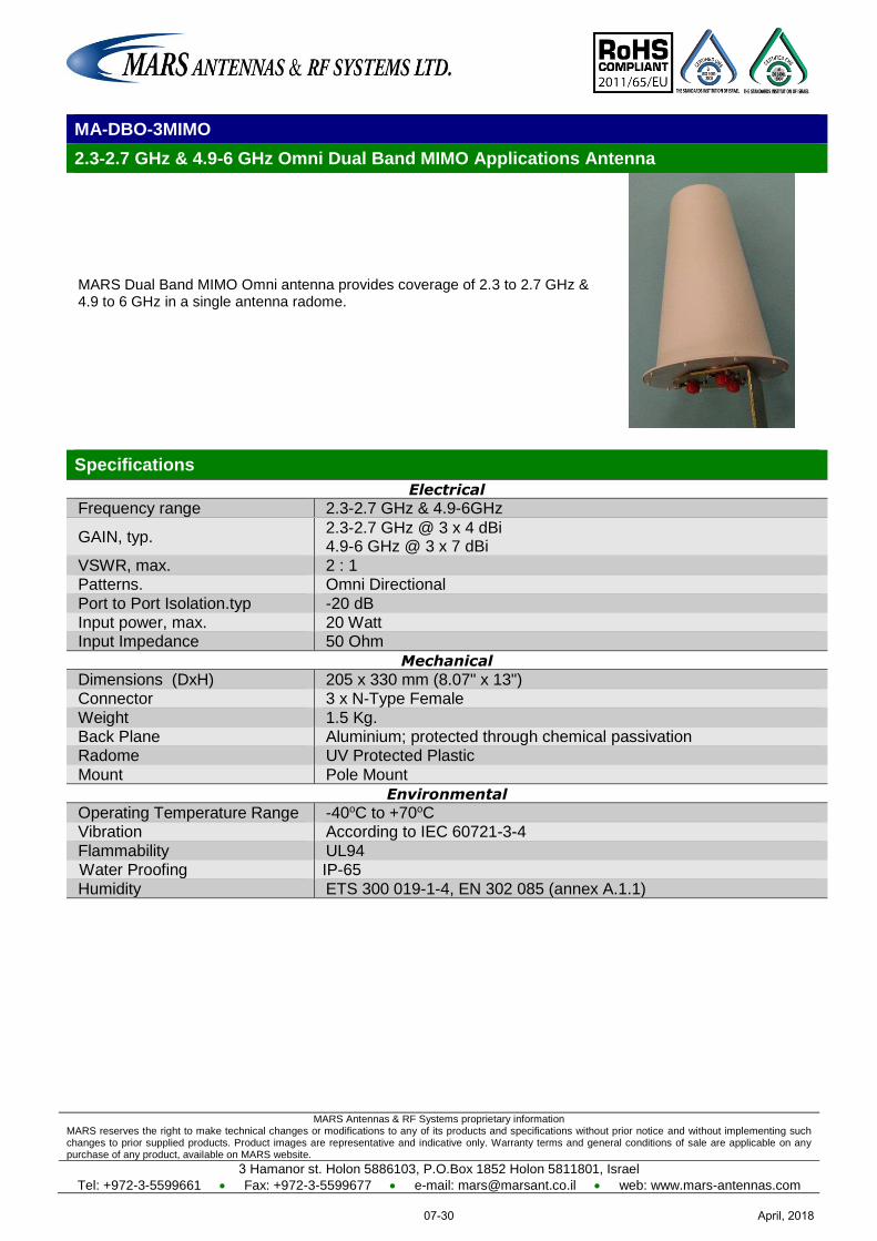
MARS Antennas & RF Systems proprietary information MARS reserves the right to make technical changes or modifications to any of its products and specifications without prior notice and without implementing such changes to prior supplied products. Product images are representative and indicative only. Warranty terms and general conditions of sale are applicable on any purchase of any product, available on MARS website.
3 Hamanor st. Holon 5886103, P.O.Box 1852 Holon 5811801, Israel
Tel: +972-3-5599661 Fax: +972-3-5599677 e-mail: [email protected] web: www.mars-antennas.com
MA-DBO-3MIMO
2.3-2.7 GHz & 4.9-6 GHz Omni Dual Band MIMO Applications Antenna
MARS Dual Band MIMO Omni antenna provides coverage of 2.3 to 2.7 GHz & 4.9 to 6 GHz in a single antenna radome.
Specifications
Electrical
Frequency range 2.3-2.7 GHz & 4.9-6GHz
GAIN, typ. 2.3-2.7 GHz @ 3 x 4 dBi 4.9-6 GHz @ 3 x 7 dBi
VSWR, max. 2 : 1 Patterns. Omni Directional
Port to Port Isolation.typ -20 dB Input power, max. 20 Watt Input Impedance 50 Ohm
Mechanical
Dimensions (DxH) 205 x 330 mm (8.07" x 13") Connector 3 x N-Type Female
Weight 1.5 Kg. Back Plane Aluminium; protected through chemical passivation Radome UV Protected Plastic
Mount Pole Mount
Environmental
Operating Temperature Range -40oC to +70oC Vibration According to IEC 60721-3-4
Flammability UL94 Water Proofing IP-65
Humidity ETS 300 019-1-4, EN 302 085 (annex A.1.1)
April, 201807-30
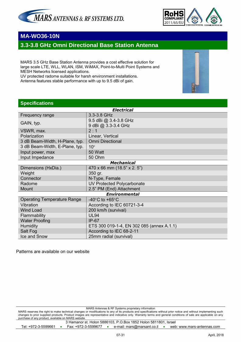
MARS Antennas & RF Systems proprietary information MARS reserves the right to make technical changes or modifications to any of its products and specifications without prior notice and without implementing such changes to prior supplied products. Product images are representative and indicative only. Warranty terms and general conditions of sale are applicable on any purchase of any product, available on MARS website.
3 Hamanor st. Holon 5886103, P.O.Box 1852 Holon 5811801, Israel Tel: +972-3-5599661 Fax: +972-3-5599677 e-mail: [email protected] web: www.mars-antennas.com
MA-WO36-10N
3.3-3.8 GHz Omni Directional Base Station Antenna
MARS 3.5 GHz Base Station Antenna provides a cost effective solution for large scale LTE, WLL, WLAN, ISM, WiMAX, Point-to-Multi Point Systems and MESH Networks licensed applications. UV protected radome suitable for harsh environment installations. Antenna features stable performance with up to 9.5 dBi of gain.
Specifications
Electrical
Frequency range 3.3-3.8 GHz
GAIN, typ. 9.5 dBi @ 3.4-3.8 GHz 9 dBi @ 3.3-3.4 GHz
VSWR, max. 2 : 1 Polarization Linear, Vertical 3 dB Beam-Width, H-Plane, typ. Omni Directional 3 dB Beam-Width, E-Plane, typ. 10 Input power, max 50 Watt Input Impedance 50 Ohm
Mechanical
Dimensions (HxDia.) 470 x 66 mm (18.5” x 2. 5”) Weight 350 gr. Connector N-Type, Female Radome UV Protected Polycarbonate Mount 2.5” PM (End) Attachment
Environmental
Operating Temperature Range -40C to +65C Vibration According to IEC 60721-3-4 Wind Load 200 km/h (survival) Flammability UL94 Water Proofing IP-67 Humidity ETS 300 019-1-4, EN 302 085 (annex A.1.1) Salt Fog According to IEC 68-2-11 Ice and Snow 25mm radial (survival)
Patterns are available on our website
April, 201807-31
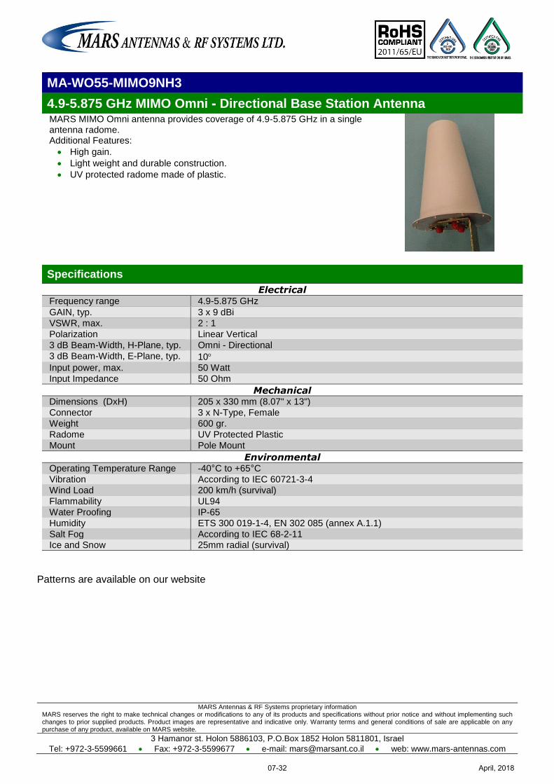
MARS Antennas & RF Systems proprietary information MARS reserves the right to make technical changes or modifications to any of its products and specifications without prior notice and without implementing such changes to prior supplied products. Product images are representative and indicative only. Warranty terms and general conditions of sale are applicable on any purchase of any product, available on MARS website.
3 Hamanor st. Holon 5886103, P.O.Box 1852 Holon 5811801, Israel
Tel: +972-3-5599661 Fax: +972-3-5599677 e-mail: [email protected] web: www.mars-antennas.com
MA-WO55-MIMO9NH3
4.9-5.875 GHz MIMO Omni - Directional Base Station Antenna MARS MIMO Omni antenna provides coverage of 4.9-5.875 GHz in a single antenna radome. Additional Features:
High gain.
Light weight and durable construction.
UV protected radome made of plastic.
Specifications
Electrical Frequency range 4.9-5.875 GHz
GAIN, typ. 3 x 9 dBi
VSWR, max. 2 : 1
Polarization Linear Vertical
3 dB Beam-Width, H-Plane, typ. Omni - Directional
3 dB Beam-Width, E-Plane, typ. 10 Input power, max. 50 Watt
Input Impedance 50 Ohm
Mechanical Dimensions (DxH) 205 x 330 mm (8.07" x 13")
Connector 3 x N-Type, Female
Weight 600 gr.
Radome UV Protected Plastic
Mount Pole Mount
Environmental Operating Temperature Range -40°C to +65°C
Vibration According to IEC 60721-3-4
Wind Load 200 km/h (survival)
Flammability UL94
Water Proofing IP-65
Humidity ETS 300 019-1-4, EN 302 085 (annex A.1.1)
Salt Fog According to IEC 68-2-11 Ice and Snow 25mm radial (survival)
Patterns are available on our website
April, 201807-32
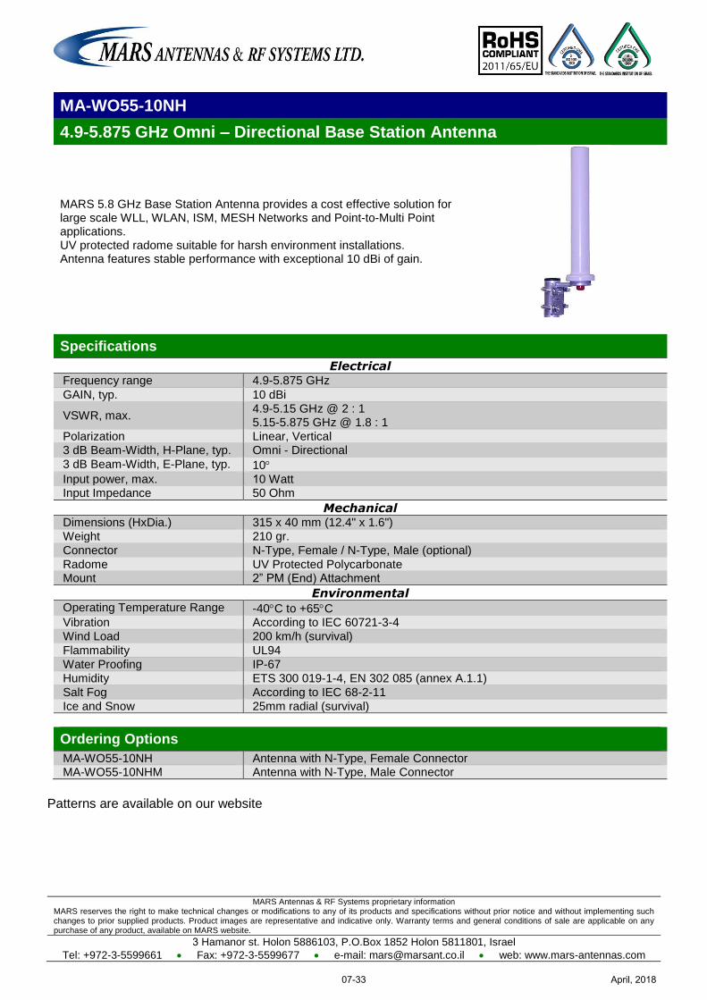
MARS Antennas & RF Systems proprietary information MARS reserves the right to make technical changes or modifications to any of its products and specifications without prior notice and without implementing such changes to prior supplied products. Product images are representative and indicative only. Warranty terms and general conditions of sale are applicable on any purchase of any product, available on MARS website.
3 Hamanor st. Holon 5886103, P.O.Box 1852 Holon 5811801, Israel
Tel: +972-3-5599661 Fax: +972-3-5599677 e-mail: [email protected] web: www.mars-antennas.com
MA-WO55-10NH
4.9-5.875 GHz Omni – Directional Base Station Antenna
MARS 5.8 GHz Base Station Antenna provides a cost effective solution for large scale WLL, WLAN, ISM, MESH Networks and Point-to-Multi Point applications. UV protected radome suitable for harsh environment installations. Antenna features stable performance with exceptional 10 dBi of gain.
Specifications
Electrical Frequency range 4.9-5.875 GHz
GAIN, typ. 10 dBi
VSWR, max. 4.9-5.15 GHz @ 2 : 1 5.15-5.875 GHz @ 1.8 : 1
Polarization Linear, Vertical 3 dB Beam-Width, H-Plane, typ. Omni - Directional
3 dB Beam-Width, E-Plane, typ. 10
Input power, max. 10 Watt Input Impedance 50 Ohm
Mechanical Dimensions (HxDia.) 315 x 40 mm (12.4" x 1.6")
Weight 210 gr.
Connector N-Type, Female / N-Type, Male (optional)
Radome UV Protected Polycarbonate Mount 2” PM (End) Attachment
Environmental Operating Temperature Range -40C to +65C Vibration According to IEC 60721-3-4
Wind Load 200 km/h (survival)
Flammability UL94
Water Proofing IP-67
Humidity ETS 300 019-1-4, EN 302 085 (annex A.1.1)
Salt Fog According to IEC 68-2-11
Ice and Snow 25mm radial (survival)
Ordering Options
MA-WO55-10NH Antenna with N-Type, Female Connector MA-WO55-10NHM Antenna with N-Type, Male Connector
Patterns are available on our website
April, 201807-33
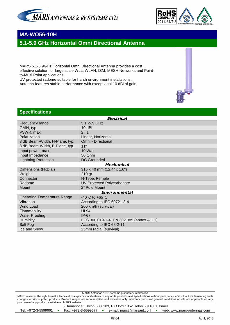
MARS Antennas & RF Systems proprietary information MARS reserves the right to make technical changes or modifications to any of its products and specifications without prior notice and without implementing such changes to prior supplied products. Product images are representative and indicative only. Warranty terms and general conditions of sale are applicable on any purchase of any product, available on MARS website.
3 Hamanor st. Holon 5886103, P.O.Box 1852 Holon 5811801, Israel
Tel: +972-3-5599661 Fax: +972-3-5599677 e-mail: [email protected] web: www.mars-antennas.com
MA-WO56-10H
5.1-5.9 GHz Horizontal Omni Directional Antenna
MARS 5.1-5.9GHz Horizontal Omni Directional Antenna provides a cost effective solution for large scale WLL, WLAN, ISM, MESH Networks and Point-to-Multi Point applications. UV protected radome suitable for harsh environment installations. Antenna features stable performance with exceptional 10 dBi of gain.
Specifications
Electrical Frequency range 5.1 -5.9 GHz
GAIN, typ. 10 dBi
VSWR, max. 2 : 1
Polarization Linear, Horizontal
3 dB Beam-Width, H-Plane, typ. Omni - Directional
3 dB Beam-Width, E-Plane, typ. 11 Input power, max. 10 Watt
Input Impedance 50 Ohm
Lightning Protection DC Grounded
Mechanical Dimensions (HxDia.) 315 x 40 mm (12.4" x 1.6")
Weight 210 gr.
Connector N-Type, Female
Radome UV Protected Polycarbonate
Mount 2” Pole Mount
Environmental Operating Temperature Range -40C to +65C Vibration According to IEC 60721-3-4
Wind Load 200 km/h (survival)
Flammability UL94
Water Proofing IP-67
Humidity ETS 300 019-1-4, EN 302 085 (annex A.1.1)
Salt Fog According to IEC 68-2-11
Ice and Snow 25mm radial (survival)
April, 201807-34

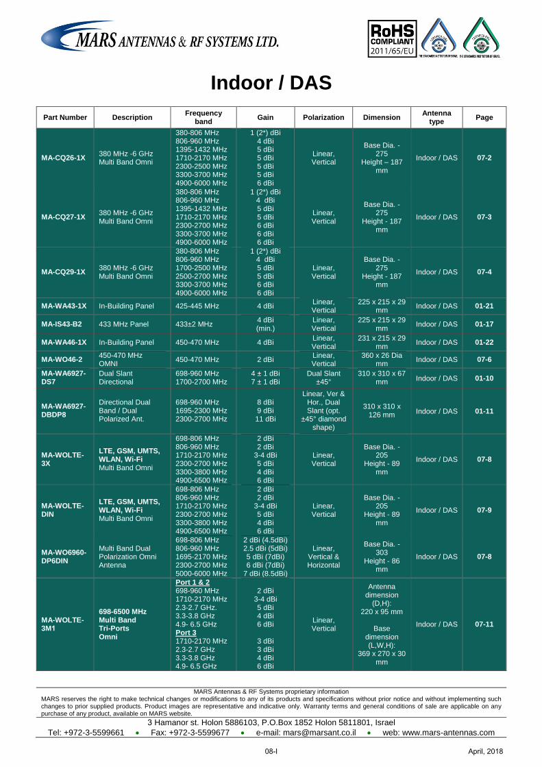
MARS Antennas & RF Systems proprietary information MARS reserves the right to make technical changes or modifications to any of its products and specifications without prior notice and without implementing such changes to prior supplied products. Product images are representative and indicative only. Warranty terms and general conditions of sale are applicable on any purchase of any product, available on MARS website.
3 Hamanor st. Holon 5886103, P.O.Box 1852 Holon 5811801, Israel
Tel: +972-3-5599661 Fax: +972-3-5599677 e-mail: [email protected] web: www.mars-antennas.com
Indoor / DAS
Part Number Description Frequency
band Gain Polarization Dimension
Antenna type
Page
MA-CQ26-1X 380 MHz -6 GHz Multi Band Omni
380-806 MHz 806-960 MHz 1395-1432 MHz 1710-2170 MHz 2300-2500 MHz 3300-3700 MHz 4900-6000 MHz
1 (2*) dBi 4 dBi 5 dBi 5 dBi 5 dBi 5 dBi 6 dBi
Linear, Vertical
Base Dia. - 275
Height – 187 mm
Indoor / DAS 07-2
MA-CQ27-1X 380 MHz -6 GHz Multi Band Omni
380-806 MHz 806-960 MHz 1395-1432 MHz 1710-2170 MHz 2300-2700 MHz 3300-3700 MHz 4900-6000 MHz
1 (2*) dBi 4 dBi 5 dBi 5 dBi 6 dBi 6 dBi 6 dBi
Linear, Vertical
Base Dia. - 275
Height - 187 mm
Indoor / DAS 07-3
MA-CQ29-1X 380 MHz -6 GHz Multi Band Omni
380-806 MHz 806-960 MHz 1700-2500 MHz 2500-2700 MHz 3300-3700 MHz 4900-6000 MHz
1 (2*) dBi 4 dBi 5 dBi 5 dBi 6 dBi 6 dBi
Linear, Vertical
Base Dia. - 275
Height - 187 mm
Indoor / DAS 07-4
MA-WA43-1X In-Building Panel 425-445 MHz 4 dBi Linear, Vertical
225 x 215 x 29 mm
Indoor / DAS 01-21
MA-IS43-B2 433 MHz Panel 433±2 MHz 4 dBi (min.)
Linear, Vertical
225 x 215 x 29 mm
Indoor / DAS 01-17
MA-WA46-1X In-Building Panel 450-470 MHz 4 dBi Linear, Vertical
231 x 215 x 29 mm
Indoor / DAS 01-22
MA-WO46-2 450-470 MHz OMNI
450-470 MHz 2 dBi Linear, Vertical
360 x 26 Dia mm
Indoor / DAS 07-6
MA-WA6927-DS7
Dual Slant Directional
698-960 MHz 1700-2700 MHz
4 ± 1 dBi 7 ± 1 dBi
Dual Slant ±45°
310 x 310 x 67 mm
Indoor / DAS 01-10
MA-WA6927-DBDP8
Directional Dual Band / Dual Polarized Ant.
698-960 MHz 1695-2300 MHz 2300-2700 MHz
8 dBi 9 dBi 11 dBi
Linear, Ver & Hor., Dual Slant (opt.
±45° diamond shape)
310 x 310 x 126 mm
Indoor / DAS 01-11
MA-WOLTE-3X
LTE, GSM, UMTS, WLAN, Wi-Fi Multi Band Omni
698-806 MHz 806-960 MHz 1710-2170 MHz 2300-2700 MHz 3300-3800 MHz 4900-6500 MHz
2 dBi 2 dBi
3-4 dBi 5 dBi 4 dBi 6 dBi
Linear, Vertical
Base Dia. - 205
Height - 89 mm
Indoor / DAS 07-8
MA-WOLTE-DIN
LTE, GSM, UMTS, WLAN, Wi-Fi Multi Band Omni
698-806 MHz 806-960 MHz 1710-2170 MHz 2300-2700 MHz 3300-3800 MHz 4900-6500 MHz
2 dBi 2 dBi
3-4 dBi 5 dBi 4 dBi 6 dBi
Linear, Vertical
Base Dia. - 205
Height - 89 mm
Indoor / DAS 07-9
MA-WO6960-DP6DIN
Multi Band Dual Polarization Omni Antenna
698-806 MHz 806-960 MHz 1695-2170 MHz 2300-2700 MHz 5000-6000 MHz
2 dBi (4.5dBi) 2.5 dBi (5dBi) 5 dBi (7dBi) 6 dBi (7dBi)
7 dBi (8.5dBi)
Linear, Vertical & Horizontal
Base Dia. - 303
Height - 86 mm
Indoor / DAS 07-8
MA-WOLTE-3M1
698-6500 MHz Multi Band Tri-Ports Omni
Port 1 & 2 698-960 MHz 1710-2170 MHz 2.3-2.7 GHz. 3.3-3.8 GHz 4.9- 6.5 GHz Port 3 1710-2170 MHz 2.3-2.7 GHz 3.3-3.8 GHz 4.9- 6.5 GHz
2 dBi
3-4 dBi 5 dBi 4 dBi 6 dBi
3 dBi 3 dBi 4 dBi 6 dBi
Linear, Vertical
Antenna dimension
(D,H): 220 x 95 mm
Base
dimension (L,W,H):
369 x 270 x 30 mm
Indoor / DAS 07-11
April, 201808-I
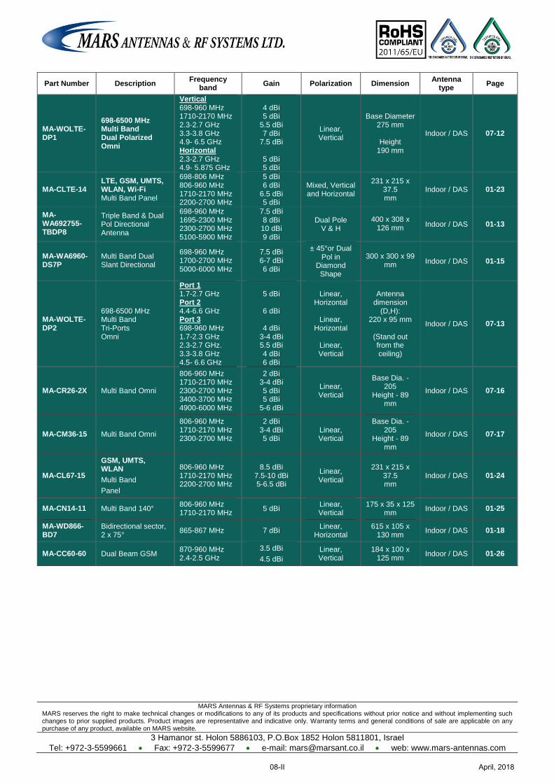
MARS Antennas & RF Systems proprietary information MARS reserves the right to make technical changes or modifications to any of its products and specifications without prior notice and without implementing such changes to prior supplied products. Product images are representative and indicative only. Warranty terms and general conditions of sale are applicable on any purchase of any product, available on MARS website.
3 Hamanor st. Holon 5886103, P.O.Box 1852 Holon 5811801, Israel
Tel: +972-3-5599661 Fax: +972-3-5599677 e-mail: [email protected] web: www.mars-antennas.com
Part Number Description Frequency
band Gain Polarization Dimension
Antenna type
Page
MA-WOLTE-DP1
698-6500 MHz Multi Band Dual Polarized Omni
Vertical 698-960 MHz 1710-2170 MHz 2.3-2.7 GHz 3.3-3.8 GHz 4.9- 6.5 GHz Horizontal 2.3-2.7 GHz 4.9- 5.875 GHz
4 dBi 5 dBi
5.5 dBi 7 dBi
7.5 dBi
5 dBi 5 dBi
Linear, Vertical
Base Diameter 275 mm
Height
190 mm
Indoor / DAS 07-12
MA-CLTE-14 LTE, GSM, UMTS, WLAN, Wi-Fi Multi Band Panel
698-806 MHz 806-960 MHz 1710-2170 MHz 2200-2700 MHz
5 dBi 6 dBi
6.5 dBi 5 dBi
Mixed, Vertical and Horizontal
231 x 215 x 37.5 mm
Indoor / DAS 01-23
MA-WA692755-TBDP8
Triple Band & Dual Pol Directional Antenna
698-960 MHz 1695-2300 MHz 2300-2700 MHz 5100-5900 MHz
7.5 dBi 8 dBi 10 dBi 9 dBi
Dual Pole V & H
400 x 308 x 126 mm
Indoor / DAS 01-13
MA-WA6960-DS7P
Multi Band Dual Slant Directional
698-960 MHz 1700-2700 MHz 5000-6000 MHz
7.5 dBi 6-7 dBi 6 dBi
± 45°or Dual Pol in
Diamond Shape
300 x 300 x 99 mm
Indoor / DAS 01-15
MA-WOLTE-DP2
698-6500 MHz Multi Band Tri-Ports Omni
Port 1 1.7-2.7 GHz Port 2 4.4-6.6 GHz Port 3 698-960 MHz 1.7-2.3 GHz 2.3-2.7 GHz. 3.3-3.8 GHz 4.5- 6.6 GHz
5 dBi
6 dBi
4 dBi
3-4 dBi 5.5 dBi 4 dBi 6 dBi
Linear, Horizontal
Linear,
Horizontal
Linear, Vertical
Antenna dimension
(D,H): 220 x 95 mm
(Stand out from the ceiling)
Indoor / DAS 07-13
MA-CR26-2X Multi Band Omni
806-960 MHz 1710-2170 MHz 2300-2700 MHz 3400-3700 MHz 4900-6000 MHz
2 dBi 3-4 dBi 5 dBi 5 dBi
5-6 dBi
Linear, Vertical
Base Dia. - 205
Height - 89 mm
Indoor / DAS 07-16
MA-CM36-15 Multi Band Omni
806-960 MHz 1710-2170 MHz 2300-2700 MHz
2 dBi 3-4 dBi 5 dBi
Linear, Vertical
Base Dia. - 205
Height - 89 mm
Indoor / DAS 07-17
MA-CL67-15
GSM, UMTS, WLAN
Multi Band
Panel
806-960 MHz 1710-2170 MHz 2200-2700 MHz
8.5 dBi 7.5-10 dBi 5-6.5 dBi
Linear, Vertical
231 x 215 x 37.5 mm
Indoor / DAS 01-24
MA-CN14-11 Multi Band 140° 806-960 MHz 1710-2170 MHz
5 dBi Linear, Vertical
175 x 35 x 125 mm
Indoor / DAS 01-25
MA-WD866-BD7
Bidirectional sector, 2 x 75°
865-867 MHz 7 dBi Linear,
Horizontal 615 x 105 x
130 mm Indoor / DAS 01-18
MA-CC60-60 Dual Beam GSM 870-960 MHz 2.4-2.5 GHz
3.5 dBi
4.5 dBi
Linear, Vertical
184 x 100 x 125 mm
Indoor / DAS 01-26
April, 201808-II
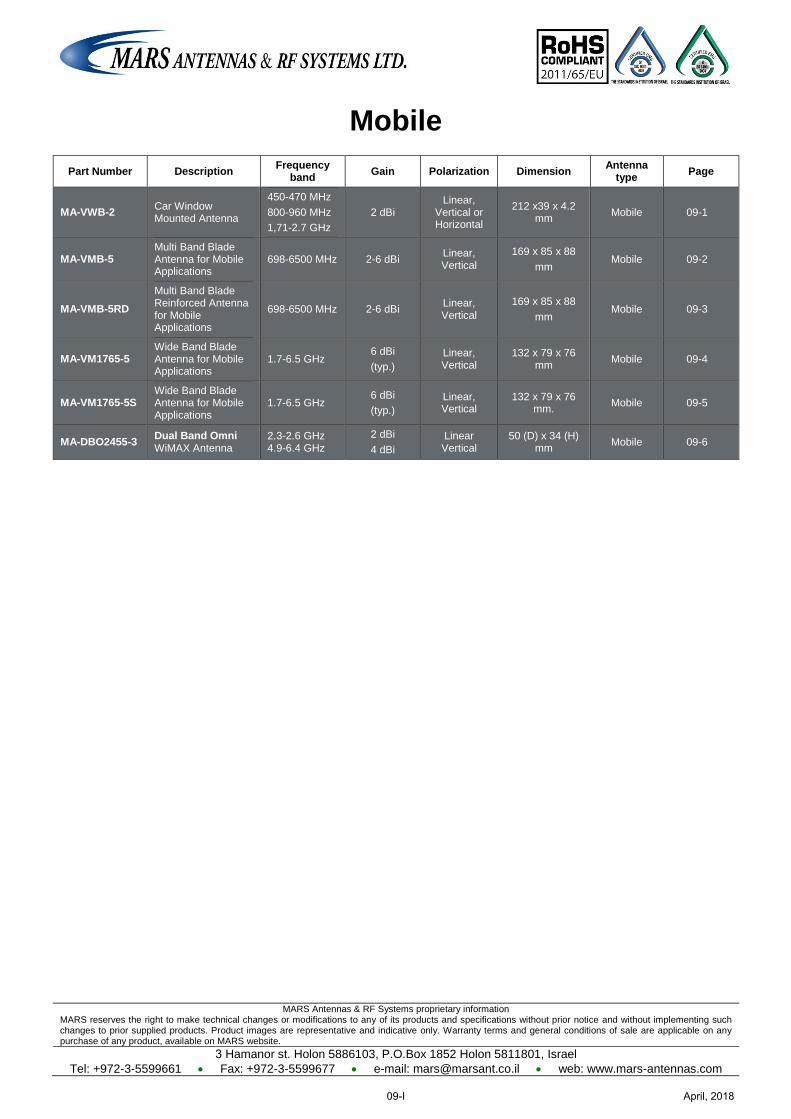
MARS Antennas & RF Systems proprietary information MARS reserves the right to make technical changes or modifications to any of its products and specifications without prior notice and without implementing such changes to prior supplied products. Product images are representative and indicative only. Warranty terms and general conditions of sale are applicable on any purchase of any product, available on MARS website.
3 Hamanor st. Holon 5886103, P.O.Box 1852 Holon 5811801, Israel
Tel: +972-3-5599661 Fax: +972-3-5599677 e-mail: [email protected] web: www.mars-antennas.com
Mobile
Part Number Description Frequency
band Gain Polarization Dimension
Antenna type
Page
MA-VWB-2 Car Window Mounted Antenna
450-470 MHz
800-960 MHz
1,71-2.7 GHz
2 dBi Linear,
Vertical or Horizontal
212 x39 x 4.2 mm
Mobile 09-1
MA-VMB-5 Multi Band Blade Antenna for Mobile Applications
698-6500 MHz 2-6 dBi Linear, Vertical
169 x 85 x 88
mm Mobile 09-2
MA-VMB-5RD
Multi Band Blade Reinforced Antenna for Mobile Applications
698-6500 MHz 2-6 dBi Linear, Vertical
169 x 85 x 88
mm Mobile 09-3
MA-VM1765-5 Wide Band Blade Antenna for Mobile Applications
1.7-6.5 GHz 6 dBi
(typ.)
Linear, Vertical
132 x 79 x 76 mm
Mobile 09-4
MA-VM1765-5S Wide Band Blade Antenna for Mobile Applications
1.7-6.5 GHz 6 dBi
(typ.)
Linear, Vertical
132 x 79 x 76 mm.
Mobile 09-5
MA-DBO2455-3 Dual Band Omni WiMAX Antenna
2.3-2.6 GHz 4.9-6.4 GHz
2 dBi
4 dBi
Linear Vertical
50 (D) x 34 (H) mm
Mobile 09-6
April, 201809-I
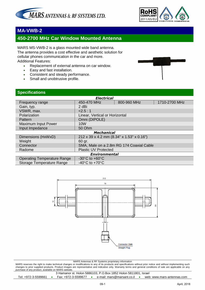
MARS Antennas & RF Systems proprietary information MARS reserves the right to make technical changes or modifications to any of its products and specifications without prior notice and without implementing such changes to prior supplied products. Product images are representative and indicative only. Warranty terms and general conditions of sale are applicable on any purchase of any product, available on MARS website.
3 Hamanor st. Holon 5886103, P.O.Box 1852 Holon 5811801, Israel
Tel: +972-3-5599661 Fax: +972-3-5599677 e-mail: [email protected] web: www.mars-antennas.com
MA-VWB-2
450-2700 MHz Car Window Mounted Antenna
MARS MS-VWB-2 is a glass mounted wide band antenna.
The antenna provides a cost effective and aesthetic solution for cellular phones communication in the car and more.
Additional Features:
Replacement of external antenna on car window. Easy and fast installation. Consistent and steady performance. Small and unobtrusive profile.
Specifications
Electrical
Frequency range 450-470 MHz 800-960 MHz 1710-2700 MHz Gain, typ. 2 dBi VSWR, max. <2.5 : 1 Polarization Linear, Vertical or Horizontal Pattern Omni (DIPOLE) Maximum Input Power 10W Input Impedance 50 Ohm
Mechanical
Dimensions (HxWxD) 212 x 39 x 4.2 mm (8.34" x 1.53" x 0.16") Weight 60 gr. Connector SMA, Male on a 2.8m RG 174 Coaxial Cable Radome Plastic UV Protected
Environmental
Operating Temperature Range -30C to +60C Storage Temperature Range -40C to +70C
April, 201809-1
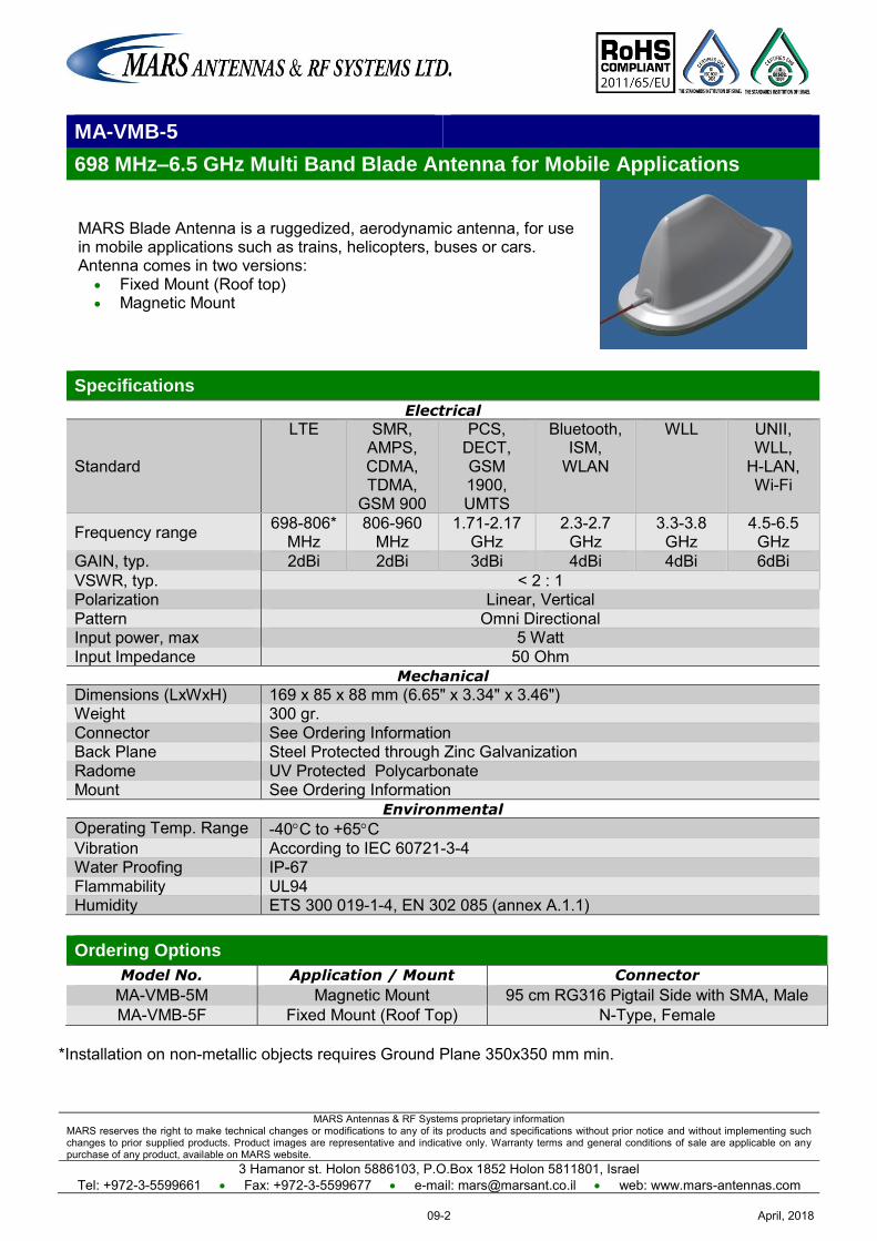
MARS Antennas & RF Systems proprietary information MARS reserves the right to make technical changes or modifications to any of its products and specifications without prior notice and without implementing such changes to prior supplied products. Product images are representative and indicative only. Warranty terms and general conditions of sale are applicable on any purchase of any product, available on MARS website.
3 Hamanor st. Holon 5886103, P.O.Box 1852 Holon 5811801, Israel Tel: +972-3-5599661 Fax: +972-3-5599677 e-mail: [email protected] web: www.mars-antennas.com
MA-VMB-5
698 MHz–6.5 GHz Multi Band Blade Antenna for Mobile Applications
MARS Blade Antenna is a ruggedized, aerodynamic antenna, for use in mobile applications such as trains, helicopters, buses or cars. Antenna comes in two versions:
Fixed Mount (Roof top) Magnetic Mount
Specifications
Electrical
Standard
LTE SMR, AMPS, CDMA, TDMA,
GSM 900
PCS, DECT, GSM 1900, UMTS
Bluetooth, ISM,
WLAN
WLL UNII, WLL,
H-LAN, Wi-Fi
Frequency range 698-806* MHz
806-960 MHz
1.71-2.17 GHz
2.3-2.7 GHz
3.3-3.8 GHz
4.5-6.5 GHz
GAIN, typ. 2dBi 2dBi 3dBi 4dBi 4dBi 6dBi VSWR, typ. < 2 : 1 Polarization Linear, Vertical Pattern Omni Directional Input power, max 5 Watt Input Impedance 50 Ohm
Mechanical
Dimensions (LxWxH) 169 x 85 x 88 mm (6.65" x 3.34" x 3.46") Weight 300 gr. Connector See Ordering Information Back Plane Steel Protected through Zinc Galvanization Radome UV Protected Polycarbonate Mount See Ordering Information
Environmental
Operating Temp. Range -40C to +65C Vibration According to IEC 60721-3-4 Water Proofing IP-67 Flammability UL94 Humidity ETS 300 019-1-4, EN 302 085 (annex A.1.1)
Ordering Options
Model No. Application / Mount Connector
MA-VMB-5M Magnetic Mount 95 cm RG316 Pigtail Side with SMA, Male MA-VMB-5F Fixed Mount (Roof Top) N-Type, Female
*Installation on non-metallic objects requires Ground Plane 350x350 mm min.
April, 201809-2
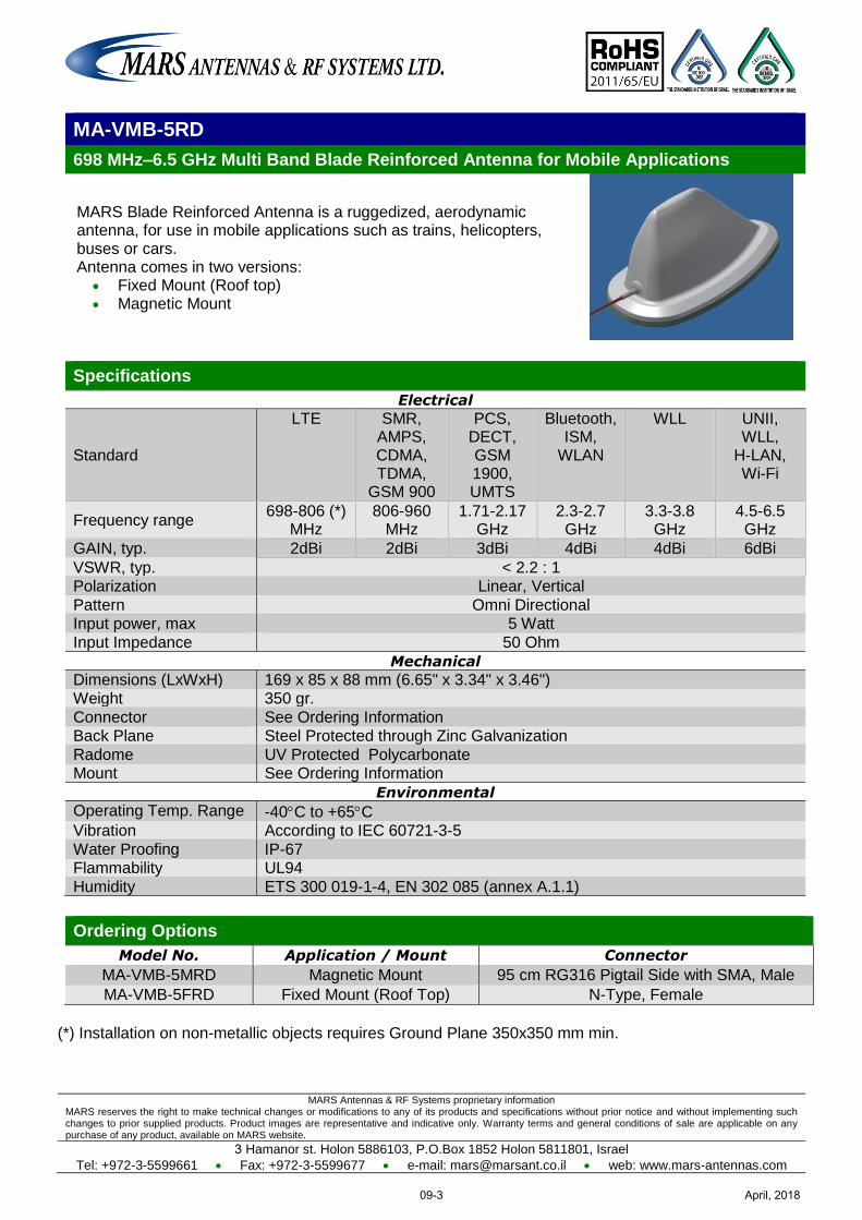
MARS Antennas & RF Systems proprietary information MARS reserves the right to make technical changes or modifications to any of its products and specifications without prior notice and without implementing such changes to prior supplied products. Product images are representative and indicative only. Warranty terms and general conditions of sale are applicable on any purchase of any product, available on MARS website.
3 Hamanor st. Holon 5886103, P.O.Box 1852 Holon 5811801, Israel
Tel: +972-3-5599661 Fax: +972-3-5599677 e-mail: [email protected] web: www.mars-antennas.com
MA-VMB-5RD
698 MHz–6.5 GHz Multi Band Blade Reinforced Antenna for Mobile Applications
MARS Blade Reinforced Antenna is a ruggedized, aerodynamic antenna, for use in mobile applications such as trains, helicopters, buses or cars. Antenna comes in two versions:
Fixed Mount (Roof top) Magnetic Mount
Specifications
Electrical
Standard
LTE SMR, AMPS, CDMA, TDMA,
GSM 900
PCS, DECT, GSM 1900, UMTS
Bluetooth, ISM,
WLAN
WLL UNII, WLL,
H-LAN, Wi-Fi
Frequency range 698-806 (*)
MHz 806-960
MHz 1.71-2.17
GHz 2.3-2.7
GHz 3.3-3.8 GHz
4.5-6.5 GHz
GAIN, typ. 2dBi 2dBi 3dBi 4dBi 4dBi 6dBi
VSWR, typ. < 2.2 : 1 Polarization Linear, Vertical
Pattern Omni Directional Input power, max 5 Watt
Input Impedance 50 Ohm
Mechanical
Dimensions (LxWxH) 169 x 85 x 88 mm (6.65" x 3.34" x 3.46") Weight 350 gr.
Connector See Ordering Information Back Plane Steel Protected through Zinc Galvanization
Radome UV Protected Polycarbonate Mount See Ordering Information
Environmental
Operating Temp. Range -40C to +65C Vibration According to IEC 60721-3-5
Water Proofing IP-67 Flammability UL94
Humidity ETS 300 019-1-4, EN 302 085 (annex A.1.1)
Ordering Options
Model No. Application / Mount Connector
MA-VMB-5MRD Magnetic Mount 95 cm RG316 Pigtail Side with SMA, Male MA-VMB-5FRD Fixed Mount (Roof Top) N-Type, Female
(*) Installation on non-metallic objects requires Ground Plane 350x350 mm min.
April, 201809-3
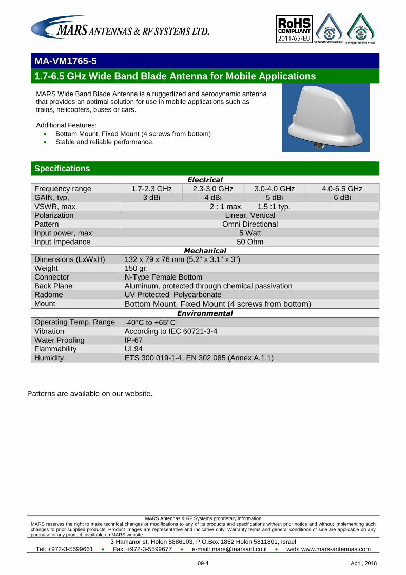
MARS Antennas & RF Systems proprietary information MARS reserves the right to make technical changes or modifications to any of its products and specifications without prior notice and without implementing such changes to prior supplied products. Product images are representative and indicative only. Warranty terms and general conditions of sale are applicable on any purchase of any product, available on MARS website.
3 Hamanor st. Holon 5886103, P.O.Box 1852 Holon 5811801, Israel
Tel: +972-3-5599661 Fax: +972-3-5599677 e-mail: [email protected] web: www.mars-antennas.com
MA-VM1765-5
1.7-6.5 GHz Wide Band Blade Antenna for Mobile Applications
MARS Wide Band Blade Antenna is a ruggedized and aerodynamic antenna that provides an optimal solution for use in mobile applications such as trains, helicopters, buses or cars. Additional Features:
Bottom Mount, Fixed Mount (4 screws from bottom)
Stable and reliable performance.
Specifications
Electrical
Frequency range 1.7-2.3 GHz 2.3-3.0 GHz 3.0-4.0 GHz 4.0-6.5 GHz
GAIN, typ. 3 dBi 4 dBi 5 dBi 6 dBi
VSWR, max. 2 : 1 max. 1.5 :1 typ.
Polarization Linear, Vertical Pattern Omni Directional
Input power, max 5 Watt Input Impedance 50 Ohm
Mechanical
Dimensions (LxWxH) 132 x 79 x 76 mm (5.2" x 3.1" x 3")
Weight 150 gr. Connector N-Type Female Bottom
Back Plane Aluminum, protected through chemical passivation Radome UV Protected Polycarbonate
Mount Bottom Mount, Fixed Mount (4 screws from bottom) Environmental
Operating Temp. Range -40C to +65C
Vibration According to IEC 60721-3-4 Water Proofing IP-67
Flammability UL94 Humidity ETS 300 019-1-4, EN 302 085 (Annex A.1.1)
Patterns are available on our website.
April, 201809-4

MARS Antennas & RF Systems proprietary information MARS reserves the right to make technical changes or modifications to any of its products and specifications without prior notice and without implementing such changes to prior supplied products. Product images are representative and indicative only. Warranty terms and general conditions of sale are applicable on any purchase of any product, available on MARS website.
3 Hamanor st. Holon 5886103, P.O.Box 1852 Holon 5811801, Israel
Tel: +972-3-5599661 Fax: +972-3-5599677 e-mail: [email protected] web: www.mars-antennas.com
MA-VM1765-5S
1.7-6.5 GHz Wide Band Blade Antenna for Mobile Applications
MARS Wide Band Blade Antenna is a ruggedized and aerodynamic antenna that provides an optimal solution for use in mobile applications such as trains, helicopters, buses or cars. Additional Features:
Magnetic Mount
Fixed Mount (4 screws from bottom)
Stable and reliable performance.
Specifications
Electrical
Frequency range 1.7-2.3 GHz 2.3-3.0 GHz 3.0-4.0 GHz 4.0-6.5 GHz
GAIN, typ. 3 dBi 4 dBi 5 dBi 6 dBi
VSWR, max. 2 : 1 max. 1.5 :1 typ. Polarization Linear, Vertical
Pattern Omni Directional Input power, max 5 Watt
Input Impedance 50 Ohm
Mechanical
Dimensions (LxWxH) 132 x 79 x 76 mm (5.2" x 3.1" x 3") Weight 150 gr.
Connector SMA Female side Back Plane Steel with galvanic protection
Radome UV Protected Polycarbonate Mount Ordering Options
Environmental
Operating Temp. Range -40C to +65C Vibration According to IEC 60721-3-4
Water Proofing IP-67 Flammability UL94
Humidity ETS 300 019-1-4, EN 302 085 (Annex A.1.1)
Ordering Options
Model No. Application / Mount
MA-VM1765-5SM Magnetic Mount Patterns are available on our website.
April, 201809-5
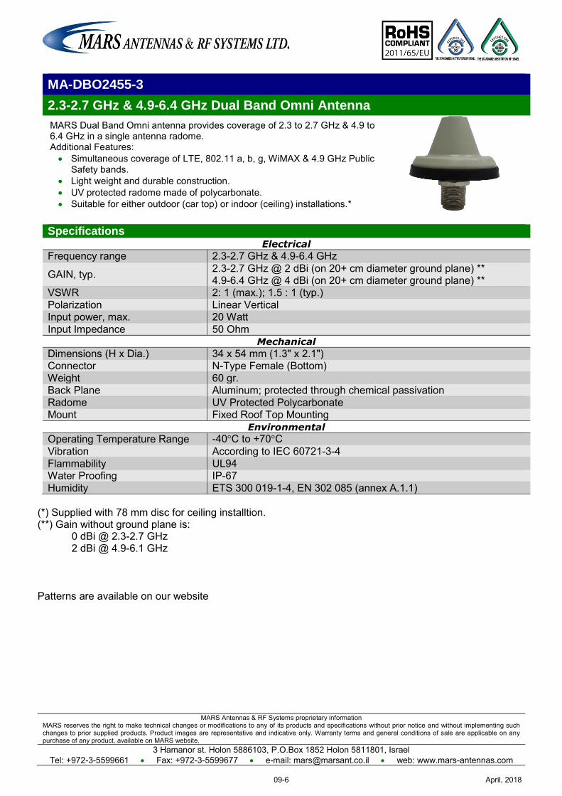
MARS Antennas & RF Systems proprietary information MARS reserves the right to make technical changes or modifications to any of its products and specifications without prior notice and without implementing such changes to prior supplied products. Product images are representative and indicative only. Warranty terms and general conditions of sale are applicable on any purchase of any product, available on MARS website.
3 Hamanor st. Holon 5886103, P.O.Box 1852 Holon 5811801, Israel Tel: +972-3-5599661 Fax: +972-3-5599677 e-mail: [email protected] web: www.mars-antennas.com
MA-DBO2455-3
2.3-2.7 GHz & 4.9-6.4 GHz Dual Band Omni Antenna
MARS Dual Band Omni antenna provides coverage of 2.3 to 2.7 GHz & 4.9 to 6.4 GHz in a single antenna radome. Additional Features: Simultaneous coverage of LTE, 802.11 a, b, g, WiMAX & 4.9 GHz Public
Safety bands. Light weight and durable construction. UV protected radome made of polycarbonate. Suitable for either outdoor (car top) or indoor (ceiling) installations.*
Specifications Electrical
Frequency range 2.3-2.7 GHz & 4.9-6.4 GHz
GAIN, typ. 2.3-2.7 GHz @ 2 dBi (on 20+ cm diameter ground plane) ** 4.9-6.4 GHz @ 4 dBi (on 20+ cm diameter ground plane) **
VSWR 2: 1 (max.); 1.5 : 1 (typ.) Polarization Linear Vertical Input power, max. 20 Watt Input Impedance 50 Ohm
Mechanical
Dimensions (H x Dia.) 34 x 54 mm (1.3" x 2.1") Connector N-Type Female (Bottom) Weight 60 gr. Back Plane Aluminum; protected through chemical passivation Radome UV Protected Polycarbonate Mount Fixed Roof Top Mounting
Environmental
Operating Temperature Range -40°C to +70°C Vibration According to IEC 60721-3-4 Flammability UL94 Water Proofing IP-67 Humidity ETS 300 019-1-4, EN 302 085 (annex A.1.1)
(*) Supplied with 78 mm disc for ceiling installtion. (**) Gain without ground plane is:
0 dBi @ 2.3-2.7 GHz 2 dBi @ 4.9-6.1 GHz
Patterns are available on our website
April, 201809-6

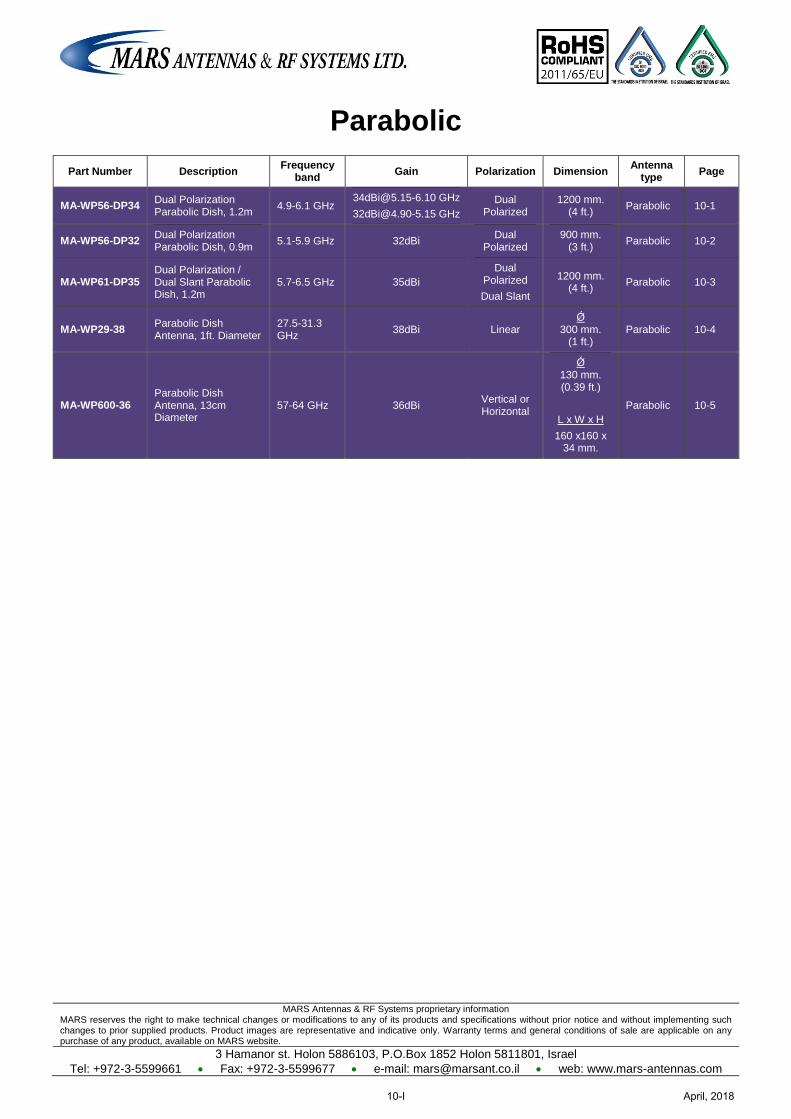
MARS Antennas & RF Systems proprietary information MARS reserves the right to make technical changes or modifications to any of its products and specifications without prior notice and without implementing such changes to prior supplied products. Product images are representative and indicative only. Warranty terms and general conditions of sale are applicable on any purchase of any product, available on MARS website.
3 Hamanor st. Holon 5886103, P.O.Box 1852 Holon 5811801, Israel
Tel: +972-3-5599661 Fax: +972-3-5599677 e-mail: [email protected] web: www.mars-antennas.com
Parabolic
Part Number Description Frequency
band Gain Polarization Dimension
Antenna type
Page
MA-WP56-DP34 Dual Polarization Parabolic Dish, 1.2m 4.9-6.1 GHz
Dual Polarized
1200 mm. (4 ft.)
Parabolic 10-1
MA-WP56-DP32 Dual Polarization Parabolic Dish, 0.9m 5.1-5.9 GHz 32dBi
Dual Polarized
900 mm. (3 ft.)
Parabolic 10-2
MA-WP61-DP35 Dual Polarization / Dual Slant Parabolic Dish, 1.2m
5.7-6.5 GHz 35dBi
Dual Polarized
Dual Slant
1200 mm. (4 ft.)
Parabolic 10-3
MA-WP29-38 Parabolic Dish Antenna, 1ft. Diameter
27.5-31.3 GHz
38dBi Linear Ǿ
300 mm. (1 ft.)
Parabolic 10-4
MA-WP600-36 Parabolic Dish Antenna, 13cm Diameter
57-64 GHz 36dBi Vertical or Horizontal
Ǿ 130 mm. (0.39 ft.)
L x W x H
160 x160 x 34 mm.
Parabolic 10-5
April, 201810-I
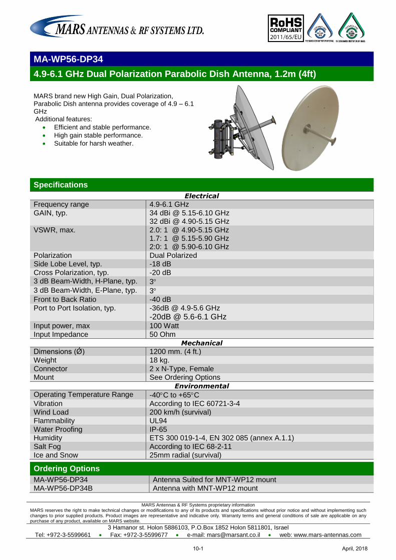
MARS Antennas & RF Systems proprietary information MARS reserves the right to make technical changes or modifications to any of its products and specifications without prior notice and without implementing such changes to prior supplied products. Product images are representative and indicative only. Warranty terms and general conditions of sale are applicable on any purchase of any product, available on MARS website.
3 Hamanor st. Holon 5886103, P.O.Box 1852 Holon 5811801, Israel
Tel: +972-3-5599661 Fax: +972-3-5599677 e-mail: [email protected] web: www.mars-antennas.com
MA-WP56-DP34
4.9-6.1 GHz Dual Polarization Parabolic Dish Antenna, 1.2m (4ft)
MARS brand new High Gain, Dual Polarization, Parabolic Dish antenna provides coverage of 4.9 – 6.1 GHz Additional features:
Efficient and stable performance.
High gain stable performance.
Suitable for harsh weather.
Specifications
Electrical
Frequency range 4.9-6.1 GHz
GAIN, typ. 34 dBi @ 5.15-6.10 GHz 32 dBi @ 4.90-5.15 GHz
VSWR, max. 2.0: 1 @ 4.90-5.15 GHz 1.7: 1 @ 5.15-5.90 GHz 2:0: 1 @ 5.90-6.10 GHz
Polarization Dual Polarized Side Lobe Level, typ. -18 dB
Cross Polarization, typ. -20 dB 3 dB Beam-Width, H-Plane, typ. 3
3 dB Beam-Width, E-Plane, typ. 3 Front to Back Ratio -40 dB
Port to Port Isolation, typ. -36dB @ 4.9-5.6 GHz
-20dB @ 5.6-6.1 GHz Input power, max 100 Watt
Input Impedance 50 Ohm
Mechanical
Dimensions (Ǿ) 1200 mm. (4 ft.) Weight 18 kg.
Connector 2 x N-Type, Female Mount See Ordering Options
Environmental
Operating Temperature Range -40C to +65C Vibration According to IEC 60721-3-4
Wind Load 200 km/h (survival) Flammability UL94
Water Proofing IP-65 Humidity ETS 300 019-1-4, EN 302 085 (annex A.1.1)
Salt Fog According to IEC 68-2-11 Ice and Snow 25mm radial (survival)
Ordering Options
MA-WP56-DP34 Antenna Suited for MNT-WP12 mount MA-WP56-DP34B Antenna with MNT-WP12 mount
April, 201810-1
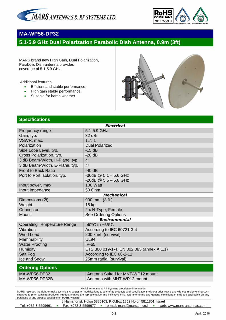
MARS Antennas & RF Systems proprietary information MARS reserves the right to make technical changes or modifications to any of its products and specifications without prior notice and without implementing such changes to prior supplied products. Product images are representative and indicative only. Warranty terms and general conditions of sale are applicable on any purchase of any product, available on MARS website.
3 Hamanor st. Holon 5886103, P.O.Box 1852 Holon 5811801, Israel
Tel: +972-3-5599661 Fax: +972-3-5599677 e-mail: [email protected] web: www.mars-antennas.com
MA-WP56-DP32
5.1-5.9 GHz Dual Polarization Parabolic Dish Antenna, 0.9m (3ft)
MARS brand new High Gain, Dual Polarization, Parabolic Dish antenna provides coverage of 5.1-5.9 GHz Additional features:
Efficient and stable performance.
High gain stable performance.
Suitable for harsh weather.
Specifications
Electrical
Frequency range 5.1-5.9 GHz Gain, typ. 32 dBi
VSWR, max. 1.7: 1 Polarization Dual Polarized
Side Lobe Level, typ. -15 dB Cross Polarization, typ. -20 dB
3 dB Beam-Width, H-Plane, typ. 4 3 dB Beam-Width, E-Plane, typ. 4
Front to Back Ratio -40 dB Port to Port Isolation, typ. -36dB @ 5.1 – 5.6 GHz
-20dB @ 5.6 – 5.8 GHz
Input power, max 100 Watt Input Impedance 50 Ohm
Mechanical
Dimensions (Ǿ) 900 mm. (3 ft.)
Weight 18 kg. Connector 2 x N-Type, Female
Mount See Ordering Options
Environmental
Operating Temperature Range -40C to +65C Vibration According to IEC 60721-3-4
Wind Load 200 km/h (survival) Flammability UL94
Water Proofing IP-65 Humidity ETS 300 019-1-4, EN 302 085 (annex A.1.1)
Salt Fog According to IEC 68-2-11 Ice and Snow 25mm radial (survival)
Ordering Options
MA-WP56-DP32 Antenna Suited for MNT-WP12 mount MA-WP56-DP32B Antenna with MNT-WP12 mount
April, 201810-2
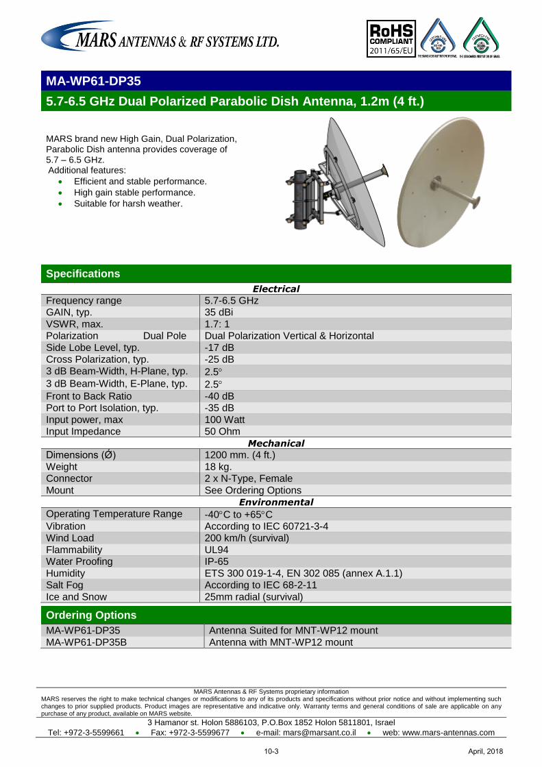
MARS Antennas & RF Systems proprietary information MARS reserves the right to make technical changes or modifications to any of its products and specifications without prior notice and without implementing such changes to prior supplied products. Product images are representative and indicative only. Warranty terms and general conditions of sale are applicable on any purchase of any product, available on MARS website.
3 Hamanor st. Holon 5886103, P.O.Box 1852 Holon 5811801, Israel
Tel: +972-3-5599661 Fax: +972-3-5599677 e-mail: [email protected] web: www.mars-antennas.com
MA-WP61-DP35
5.7-6.5 GHz Dual Polarized Parabolic Dish Antenna, 1.2m (4 ft.)
MARS brand new High Gain, Dual Polarization, Parabolic Dish antenna provides coverage of 5.7 – 6.5 GHz. Additional features:
Efficient and stable performance.
High gain stable performance.
Suitable for harsh weather.
Specifications
Electrical
Frequency range 5.7-6.5 GHz GAIN, typ. 35 dBi
VSWR, max. 1.7: 1 Polarization Dual Pole Dual Polarization Vertical & Horizontal
Side Lobe Level, typ. -17 dB Cross Polarization, typ. -25 dB
3 dB Beam-Width, H-Plane, typ. 2.5 3 dB Beam-Width, E-Plane, typ. 2.5
Front to Back Ratio -40 dB Port to Port Isolation, typ. -35 dB
Input power, max 100 Watt Input Impedance 50 Ohm
Mechanical
Dimensions (Ǿ) 1200 mm. (4 ft.)
Weight 18 kg. Connector 2 x N-Type, Female
Mount See Ordering Options
Environmental
Operating Temperature Range -40C to +65C Vibration According to IEC 60721-3-4 Wind Load 200 km/h (survival)
Flammability UL94 Water Proofing IP-65
Humidity ETS 300 019-1-4, EN 302 085 (annex A.1.1) Salt Fog According to IEC 68-2-11
Ice and Snow 25mm radial (survival)
Ordering Options
MA-WP61-DP35 Antenna Suited for MNT-WP12 mount
MA-WP61-DP35B Antenna with MNT-WP12 mount
April, 201810-3
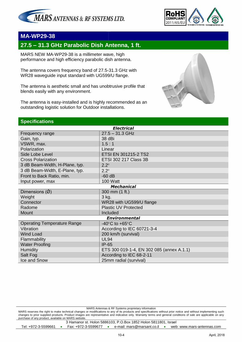
MARS Antennas & RF Systems proprietary information MARS reserves the right to make technical changes or modifications to any of its products and specifications without prior notice and without implementing such changes to prior supplied products. Product images are representative and indicative only. Warranty terms and general conditions of sale are applicable on any purchase of any product, available on MARS website.
3 Hamanor st. Holon 5886103, P.O.Box 1852 Holon 5811801, Israel
Tel: +972-3-5599661 Fax: +972-3-5599677 e-mail: [email protected] web: www.mars-antennas.com
MA-WP29-38
27.5 – 31.3 GHz Parabolic Dish Antenna, 1 ft.
MARS NEW MA-WP29-38 is a millimeter wave, high performance and high efficiency parabolic dish antenna.
The antenna covers frequency band of 27.5-31.3 GHz with WR28 waveguide input standard with UG599/U flange.
The antenna is aesthetic small and has unobtrusive profile that blends easily with any environment.
The antenna is easy-installed and is highly recommended as an outstanding logistic solution for Outdoor installations.
Specifications
Electrical
Frequency range 27.5 – 31.3 GHz
Gain, typ. 38 dBi VSWR, max. 1.5 : 1
Polarization Linear Side Lobe Level ETSI EN 301215-2 TS2
Cross Polarization ETSI 302 217 Class 3B 3 dB Beam-Width, H-Plane, typ. 2.2
3 dB Beam-Width, E-Plane, typ. 2.2 Front to Back Ratio, min. -60 dB
Input power, max 100 Watt Mechanical
Dimensions (Ǿ) 300 mm (1 ft.) Weight 3 kg.
Connector WR28 with UG599/U flange Radome Plastic UV Protected
Mount Included
Environmental
Operating Temperature Range -40C to +65C Vibration According to IEC 60721-3-4 Wind Load 200 km/h (survival)
Flammability UL94 Water Proofing IP-65
Humidity ETS 300 019-1-4, EN 302 085 (annex A.1.1) Salt Fog According to IEC 68-2-11
Ice and Snow 25mm radial (survival)
April, 201810-4
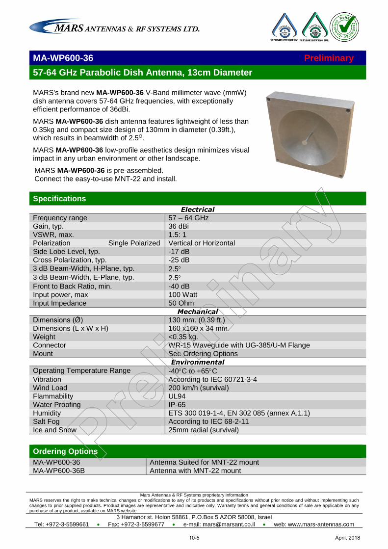
Mars Antennas & RF Systems proprietary information MARS reserves the right to make technical changes or modifications to any of its products and specifications without prior notice and without implementing such changes to prior supplied products. Product images are representative and indicative only. Warranty terms and general conditions of sale are applicable on any purchase of any product, available on MARS website.
3 Hamanor st. Holon 58861, P.O.Box 5 AZOR 58008, Israel
Tel: +972-3-5599661 Fax: +972-3-5599677 e-mail: [email protected] web: www.mars-antennas.com
MA-WP600-36 Preliminary
57-64 GHz Parabolic Dish Antenna, 13cm Diameter
MARS's brand new MA-WP600-36 V-Band millimeter wave (mmW) dish antenna covers 57-64 GHz frequencies, with exceptionally efficient performance of 36dBi.
MARS MA-WP600-36 dish antenna features lightweight of less than 0.35kg and compact size design of 130mm in diameter (0.39ft.), which results in beamwidth of 2.5O.
MARS MA-WP600-36 low-profile aesthetics design minimizes visual impact in any urban environment or other landscape.
MARS MA-WP600-36 is pre-assembled. Connect the easy-to-use MNT-22 and install.
Specifications
Electrical
Frequency range 57 – 64 GHz Gain, typ. 36 dBi
VSWR, max. 1.5: 1 Polarization Single Polarized Vertical or Horizontal
Side Lobe Level, typ. -17 dB Cross Polarization, typ. -25 dB
3 dB Beam-Width, H-Plane, typ. 2.5 3 dB Beam-Width, E-Plane, typ. 2.5
Front to Back Ratio, min. -40 dB Input power, max 100 Watt Input Impedance 50 Ohm
Mechanical
Dimensions (Ǿ) 130 mm. (0.39 ft.) Dimensions (L x W x H) 160 x160 x 34 mm.
Weight <0.35 kg. Connector WR-15 Waveguide with UG-385/U-M Flange
Mount See Ordering Options
Environmental
Operating Temperature Range -40C to +65C Vibration According to IEC 60721-3-4 Wind Load 200 km/h (survival)
Flammability UL94 Water Proofing IP-65
Humidity ETS 300 019-1-4, EN 302 085 (annex A.1.1) Salt Fog According to IEC 68-2-11
Ice and Snow 25mm radial (survival)
Ordering Options
MA-WP600-36 Antenna Suited for MNT-22 mount MA-WP600-36B Antenna with MNT-22 mount
April, 201810-5
MARS Antennas & RF Systems proprietary information MARS reserves the right to make technical changes or modifications to any of its products and specifications without prior notice and without implementing such changes to prior supplied products. Product images are representative and indicative only. Warranty terms and general conditions of sale are applicable on any purchase of any product, available on MARS website.
3 Hamanor st. Holon 5886103, P.O.Box 1852 Holon 5811801, Israel
Tel: +972-3-5599661 Fax: +972-3-5599677 e-mail: [email protected] web: www.mars-antennas.com
RF Products
Part Number Description Frequency Band (Up/Down
Link) Gain
Dimensions (LxWxD)
Page
MR-PBSMR55-X SMR/IDEN Personal Bi-Directional Amplifier
Down Link 851-866 MHz Up Link 806-821 MHz
55 dB (min.) 55 dB (min.)
120 x 70 x 35 mm 11-1
MR-BIDEN60-X1W SMR/IDEN Bi-Directional amplifier
Down Link 851-866 MHz Up Link 806-821 MHz
60 dB (min.) 60 dB (min.)
243 x 160 x 57 mm
11-2
MR-BSMR60-A1W SMR/IDEN Automatic Control Repeater
Down Link 851-866 MHz Up Link 806-821 MHz
60 dB (min.) 60 dB (min.)
243 x 163 x 57 mm
11-3
MR-BSMR80-XA SMR/IDEN High Gain Automatic Control Repeater
Down Link 851-866 MHz Up Link 806-821 MHz
80 dB (min.) 80 dB (min.)
280 x 250 x 65 mm
11-4
MR-HSBDA60-X CDMA High Selective Repeater
Down Link 864-894 MHz Up Link 824-849 MHz
63 dB (min.) 60 dB (min.)
280 x 250 x 65 mm
11-5
MR-PBCT55-X CMDA/TDMA Personal BDA
Down Link 864-894 MHz Up Link 824-849 MHz
55 dB (min.) 55 dB (min.)
120 x 70 x 35 mm 11-6
MR-PBCT55-A CMDA/TDMA Personal BDA Automatic Gain Control
Down Link 864-894 MHz Up Link 824-849 MHz
55 dB (min.) 55 dB (min.)
120 x 70 x 35 mm 11-7
MR-BDA60-X1W CDMA Bi-Directional Amplifier
Down Link 869-879 MHz Up Link 824-834 MHz
60 dB (min.) 243 x 160 x 57
mm 11-8
MR-BGSM60-X1W GSM Bi-Directional Amplifier
Down Link 947-960 MHz Up Link 902-915 MHz
60 dB (min.) 60 dB (min.)
243 x 160 x 57 mm
11-9
MR-PBGS55-FA Full Band GSM Automatic Gain Control Repeater
Down Link 935-960 MHz Up Link 890-915 MHz
55 dB (min.) 55 dB (min.)
120 x 70 x 35 mm 11-10
MR-PBGS55-X GSM Personal Bi-Directional Amplifier
Down Link 947-960 MHz Up Link 824-834 MHz
55 dB (min.) 55 dB (min.)
120 x 70 x 35 mm 11-11
MR-HGSM50-X GSM1800 Bi-Directional Amplifier
Down Link 1805-1880 MHz Up Link 1710-1785 MHz
45 dB (min.) 45 dB (min.)
310 x 150 x 63 mm
11-12
MR-HSBGSM60 GSM High Selective Repeater
Down Link 935-960 MHz Up Link 890-915 MHz
63 dB (min.) 60 dB (min.)
280 x 250 x 65 mm
11-13
MR-BGSM80-XA GSM High Gain Automatic Control Repeater
Down Link 935-960 MHz Up Link 890-915 MHz
80 dB (min.) 70 dB (min.)
260 x 250 x 65 mm
11-14
MR-DBHSDG-70YY Dual Band GSM 900 &1800 MHz Repeater
Down Link 935-960 MHz Up Link 890-915 MHz
Down Link 1805-1880 MHz
Up Link 1710-1785 MHz
70 dB (min.) 70 dB (min.)
70 dB (min.) 70 dB (min.)
310 x 200 x 60 mm
11-15
MR-HSUMTS70-X UMTS High Selective Bi – Directional Amplifier 1Watt
Down Link 2110-2170 MHz Up Link 1920-1980 MHz
75 dB (min) 72 dB (min)
440 x 325 x 180 mm
11-16
MR-UMTS70-20F UMTS Bi – Directional Amplifier (WCDMA)
Down Link 2110-2170 MHz Up Link 1920-1980 MHz
70 dB (min) 70 dB (min)
280 x 250 x 65 mm
11-17
MR-HSUMTS70-20 UMTS HS Bi – Directional Amplifier
Down Link 2110-2170 MHz Up Link 1920-1980 MHz
73 dB (min) 73 dB (min)
280 x 250 x 65 mm
11-18
MR-HSUMTS70-18 UMTS HS Bi – Directional Amp. (WCDMA)
Down Link 2110-2170 MHz Up Link 1920-1980 MHz
73 dB (min) 70 dB (min)
420 x 250 x 65 mm
11-19
MR-PUMTS50-FA Full Band UMTS (2GHz) Automatic Gain Control Repeater
Down Link 2110-2170 MHz Up Link 1920-1980 MHz
50 dB (min) 50 dB (min)
120 x 70 x 35 mm
11-20
April, 201811-I
MARS Antennas & RF Systems proprietary information MARS reserves the right to make technical changes or modifications to any of its products and specifications without prior notice and without implementing such changes to prior supplied products. Product images are representative and indicative only. Warranty terms and general conditions of sale are applicable on any purchase of any product, available on MARS website.
3 Hamanor st. Holon 5886103, P.O.Box 1852 Holon 5811801, Israel
Tel: +972-3-5599661 Fax: +972-3-5599677 e-mail: [email protected] web: www.mars-antennas.com
Part Number Description Frequency Band (Up/Down
Link) Gain
Dimensions (LxWxD)
Page
MR-DBHSUC-80
CDMA/UMTS 1Watt Dual Band 850MHz & 2000MHz Repeater
Down Link 869-879 MHz Up Link 824-834 MHz
Down Link 2140-2150 MHz
Up Link 1950-1690 MHz
75 dB (min.) 72 dB (min.)
80 dB (min.) 77 dB (min.)
350 x 270 x 100 mm
11-21
MR-DBHSUC-70YY
Dual Band CDMA/UMTS 850 & 2000 MHz Repeater
Down Link 869-879 MHz Up Link 824-834 MHz
Down Link 2140-2150 MHz
Up Link 1950-1690 MHz
68 dB (min.) 65 dB (min.)
75 dB (min.) 72 dB (min.)
260 x 200 x 60 mm
11-22
MR-AM800-X Power Amplifier Cellular Bands
800-960 MHz 30±1 dB 60 x 50 x 20 mm W/O Heat Sink
11-23
MR-AM1800-X MR-AM1900-X
Power Amplifiers –Cellular Bands
PCS1800 GSM1800 1800-1900 MHz
PCS1900 GSM1900 1900-2000 MHz
30±1 dB 60 x 50 x 20 mm W/O Heat Sink
11-24
MR-AM2100-X Power Amplifiers – Cellular Bands
2110-2170 MHz IMT2000, UMTS
11 dB 260 x 250 x 65
mm 11-25
MR-AM1200-2100 Power Amplifiers RF 1200-2100 MHz 20-28 dB 44 x 9 x 25 mm 11-26
MR-RRA30-1 GPS Re-Radiating System
1575.42±2.0 MHz 35 dB 11-27
MR-RRA30-2 GPS Re-Radiating System
1575.42±2.0 MHz 35 dB 11-28
MR-DARF-XX Dual Active Reject Filter 825-835
MHz 3 dB (min) to 7 dB
(max) 19" Box 11-29
MR-PD02-X 2 Way Splitter 800-2500
MHz 0.7dB/1.5 dB
typ. / max. 120 x 95 x 30 mm 11-30
MR-PD03-X 3 Way Splitter 800-2000
MHz 1.3 dB 140 x 95 x 30 mm 11-31
MR-PD04-X 4 Way Splitter 800-2200
MHz 1.5 dB
120 x 110 x 30 mm
11-32
MR-PD04-X1 4 Way Splitter 2.3-2.6 GHz
1.5 dB 197 x 136 x 82
mm 11-33
April, 201811-II

Mars Antennas & RF Systems proprietary information MARS reserves the right to make technical changes or modifications to any of its products and specifications without prior notice and without implementing such changes to prior supplied products. Product images are representative and indicative only. Warranty terms and general conditions of sale are applicable on any purchase of any product, available on MARS website.
3 Hamanor st. Holon 58861, P.O.Box 5 AZOR 58008, Israel Tel: +972-3-5599661 Fax: +972-3-5599677 e-mail: [email protected] web: www.mars-antennas.com
MR-PBSMR55-X
SMR / IDEN Bi - Directional Amplifier MARS Personal BDA provides a cost effective solution for enhancing radio communication in offices and other small area spaces. Amplifier features small size and is easy to install.
Specifications
Electrical
Down Link Up Link Frequency range 851-866 MHz 806-821 MHz Operational Frequency Band, (Other Available on Request) 851-866 MHz 806-821 MHz
Gain at, min. Attenuation 55 dB Pass Band Ripple ±2 dB Output Power @ 1 dB Compression 18 dBm Noise Figure max. 6.5 dB Step Attenuator (2 dB Step) 2 to 30 dB Impedance 50 Ohm VSWR, max. 2 : 1 Output IP3, min. 28 dBm Input Power, max. -20 dBm
Biasing (Through Separate DC Connector) 6V / 400mA (Adaptor MR-PS13 should be Ordered Separately)
Mechanical
Dimensions 120 x 70 x 35 mm Weight 200 gr. Connectors SMA, Female Housing Aluminum, Anodized, Black Mount Wall / Ceiling Mounting
Environmental
Operating Temperature Range -10C to +50C Humidity, min. 95%
April, 201811-1
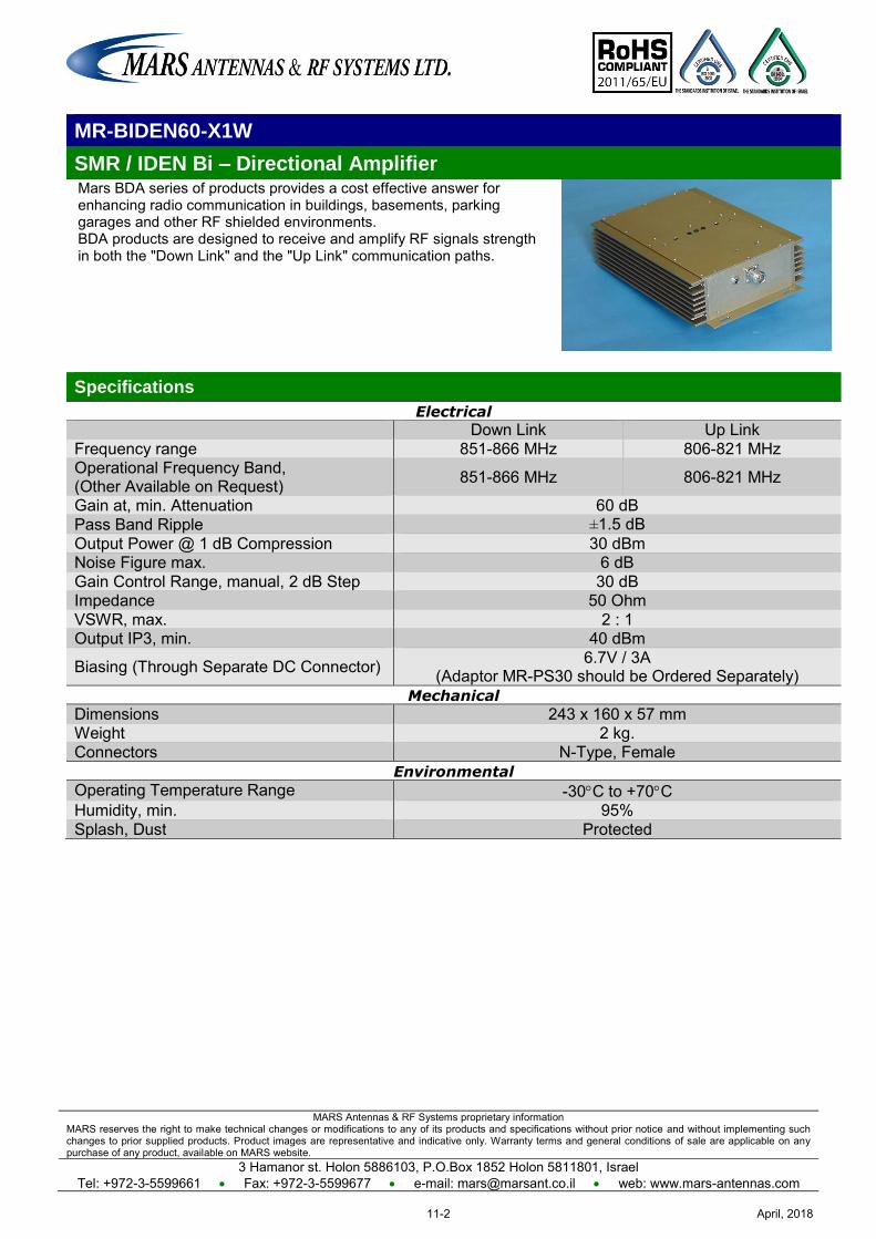
MARS Antennas & RF Systems proprietary information MARS reserves the right to make technical changes or modifications to any of its products and specifications without prior notice and without implementing such changes to prior supplied products. Product images are representative and indicative only. Warranty terms and general conditions of sale are applicable on any purchase of any product, available on MARS website.
3 Hamanor st. Holon 5886103, P.O.Box 1852 Holon 5811801, Israel Tel: +972-3-5599661 Fax: +972-3-5599677 e-mail: [email protected] web: www.mars-antennas.com
MR-BIDEN60-X1W
SMR / IDEN Bi – Directional Amplifier Mars BDA series of products provides a cost effective answer for enhancing radio communication in buildings, basements, parking garages and other RF shielded environments. BDA products are designed to receive and amplify RF signals strength in both the "Down Link" and the "Up Link" communication paths.
Specifications
Electrical
Down Link Up Link Frequency range 851-866 MHz 806-821 MHz Operational Frequency Band, (Other Available on Request) 851-866 MHz 806-821 MHz
Gain at, min. Attenuation 60 dB Pass Band Ripple ±1.5 dB Output Power @ 1 dB Compression 30 dBm Noise Figure max. 6 dB Gain Control Range, manual, 2 dB Step 30 dB Impedance 50 Ohm VSWR, max. 2 : 1 Output IP3, min. 40 dBm
Biasing (Through Separate DC Connector) 6.7V / 3A (Adaptor MR-PS30 should be Ordered Separately)
Mechanical
Dimensions 243 x 160 x 57 mm Weight 2 kg. Connectors N-Type, Female
Environmental
Operating Temperature Range -30C to +70C Humidity, min. 95% Splash, Dust Protected
April, 201811-2
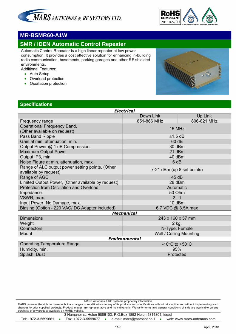
MARS Antennas & RF Systems proprietary information MARS reserves the right to make technical changes or modifications to any of its products and specifications without prior notice and without implementing such changes to prior supplied products. Product images are representative and indicative only. Warranty terms and general conditions of sale are applicable on any purchase of any product, available on MARS website.
3 Hamanor st. Holon 5886103, P.O.Box 1852 Holon 5811801, Israel Tel: +972-3-5599661 Fax: +972-3-5599677 e-mail: [email protected] web: www.mars-antennas.com
MR-BSMR60-A1W
SMR / IDEN Automatic Control Repeater Automatic Control Repeater is a high linear repeater at low power consumption. It provides a cost effective solution for enhancing in-building radio communication, basements, parking garages and other RF shielded environments. Additional Features: Auto Setup Overload protection Oscillation protection
Specifications
Electrical
Down Link Up Link Frequency range 851-866 MHz 806-821 MHz Operational Frequency Band, (Other available on request) 15 MHz
Pass Band Ripple ±1.5 dB Gain at min. attenuation, min. 60 dB Output Power @ 1 dB Compression 30 dBm Maximum Output Power 21 dBm Output IP3, min. 40 dBm Noise Figure at min. attenuation, max. 6 dB Range of ALC output power setting points, (Other available by request) 7-21 dBm (up 8 set points)
Range of AGC 45 dB Limited Output Power, (Other available by request) 28 dBm Protection from Oscillation and Overload Automatic Impedance 50 Ohm VSWR, max. 2 : 1 Input Power, No Damage, max. 10 dBm Biasing (Option - 220 VAC/ DC Adapter included) 6.7 VDC @ 3.5A max
Mechanical
Dimensions 243 x 160 x 57 mm Weight 2 kg. Connectors N-Type, Female Mount Wall / Ceiling Mounting
Environmental
Operating Temperature Range -10C to +50C Humidity, min. 95% Splash, Dust Protected
April, 201811-3
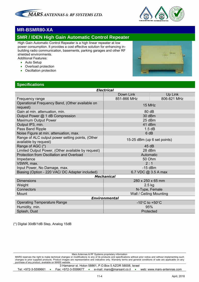
Mars Antennas & RF Systems proprietary information MARS reserves the right to make technical changes or modifications to any of its products and specifications without prior notice and without implementing such changes to prior supplied products. Product images are representative and indicative only. Warranty terms and general conditions of sale are applicable on any purchase of any product, available on MARS website.
3 Hamanor st. Holon 58861, P.O.Box 5 AZOR 58008, Israel Tel: +972-3-5599661 Fax: +972-3-5599677 e-mail: [email protected] web: www.mars-antennas.com
MR-BSMR80-XA
SMR / IDEN High Gain Automatic Control Repeater High Gain Automatic Control Repeater is a high linear repeater at low power consumption. It provides a cost effective solution for enhancing in-building radio communication, basements, parking garages and other RF shielded environments. Additional Features: Auto Setup Overload protection Oscillation protection
Specifications
Electrical
Down Link Up Link Frequency range 851-866 MHz 806-821 MHz Operational Frequency Band, (Other available on request) 15 MHz
Gain at min. attenuation, min. 80 dB Output Power @ 1 dB Compression 30 dBm Maximum Output Power 25 dBm Output IP3, min. 41 dBm Pass Band Ripple 1.5 dB Noise Figure at min. attenuation, max. 6 dB Range of ALC output power setting points, (Other available by request) 15-25 dBm (up 6 set points)
Range of AGC (*) 45 dB Limited Output Power, (Other available by request) 28 dBm Protection from Oscillation and Overload Automatic Impedance 50 Ohm VSWR, max. 2 : 1 Input Power, No Damage, max. -15 dBm Biasing (Option - 220 VAC/ DC Adapter included) 6.7 VDC @ 3.5 A max
Mechanical
Dimensions 280 x 250 x 65 mm Weight 2.5 kg Connectors N-Type, Female Mount Wall / Ceiling Mounting
Environmental
Operating Temperature Range -10C to +50C Humidity, min. 95% Splash, Dust Protected
(*) Digital 30dB/1dB Step, Analog 15dB
April, 201811-4
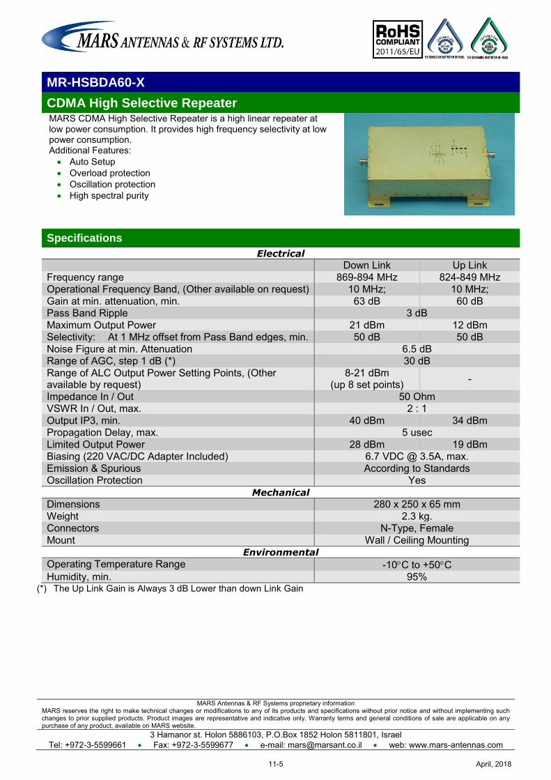
MARS Antennas & RF Systems proprietary information MARS reserves the right to make technical changes or modifications to any of its products and specifications without prior notice and without implementing such changes to prior supplied products. Product images are representative and indicative only. Warranty terms and general conditions of sale are applicable on any purchase of any product, available on MARS website.
3 Hamanor st. Holon 5886103, P.O.Box 1852 Holon 5811801, Israel Tel: +972-3-5599661 Fax: +972-3-5599677 e-mail: [email protected] web: www.mars-antennas.com
MR-HSBDA60-X
CDMA High Selective Repeater MARS CDMA High Selective Repeater is a high linear repeater at low power consumption. It provides high frequency selectivity at low power consumption. Additional Features: Auto Setup Overload protection Oscillation protection High spectral purity
Specifications
Electrical
Down Link Up Link Frequency range 869-894 MHz 824-849 MHz Operational Frequency Band, (Other available on request) 10 MHz; 10 MHz; Gain at min. attenuation, min. 63 dB 60 dB Pass Band Ripple 3 dB Maximum Output Power 21 dBm 12 dBm Selectivity: At 1 MHz offset from Pass Band edges, min. 50 dB 50 dB Noise Figure at min. Attenuation 6.5 dB Range of AGC, step 1 dB (*) 30 dB Range of ALC Output Power Setting Points, (Other available by request)
8-21 dBm (up 8 set points) -
Impedance In / Out 50 Ohm VSWR In / Out, max. 2 : 1 Output IP3, min. 40 dBm 34 dBm Propagation Delay, max. 5 usec Limited Output Power 28 dBm 19 dBm Biasing (220 VAC/DC Adapter Included) 6.7 VDC @ 3.5A, max. Emission & Spurious According to Standards Oscillation Protection Yes
Mechanical
Dimensions 280 x 250 x 65 mm Weight 2.3 kg. Connectors N-Type, Female Mount Wall / Ceiling Mounting
Environmental
Operating Temperature Range -10C to +50C Humidity, min. 95%
(*) The Up Link Gain is Always 3 dB Lower than down Link Gain
April, 201811-5
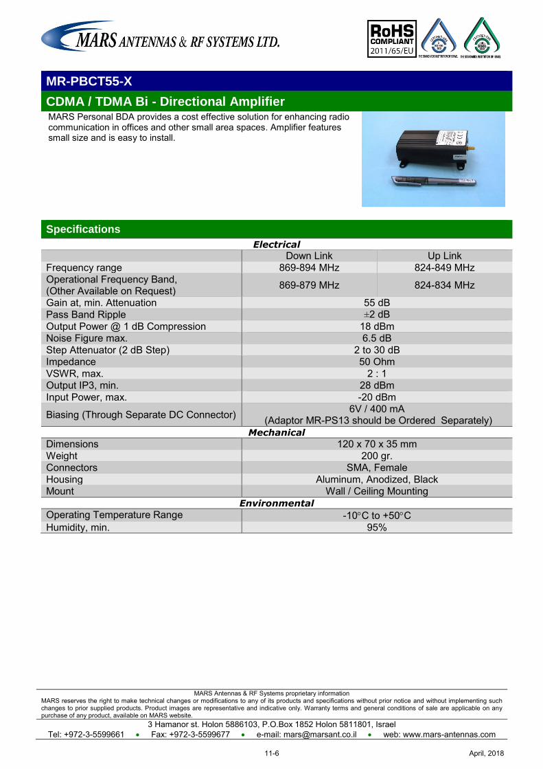
MARS Antennas & RF Systems proprietary information MARS reserves the right to make technical changes or modifications to any of its products and specifications without prior notice and without implementing such changes to prior supplied products. Product images are representative and indicative only. Warranty terms and general conditions of sale are applicable on any purchase of any product, available on MARS website.
3 Hamanor st. Holon 5886103, P.O.Box 1852 Holon 5811801, Israel Tel: +972-3-5599661 Fax: +972-3-5599677 e-mail: [email protected] web: www.mars-antennas.com
MR-PBCT55-X
CDMA / TDMA Bi - Directional Amplifier MARS Personal BDA provides a cost effective solution for enhancing radio communication in offices and other small area spaces. Amplifier features small size and is easy to install.
Specifications
Electrical
Down Link Up Link Frequency range 869-894 MHz 824-849 MHz Operational Frequency Band, (Other Available on Request) 869-879 MHz 824-834 MHz
Gain at, min. Attenuation 55 dB Pass Band Ripple ±2 dB Output Power @ 1 dB Compression 18 dBm Noise Figure max. 6.5 dB Step Attenuator (2 dB Step) 2 to 30 dB Impedance 50 Ohm VSWR, max. 2 : 1 Output IP3, min. 28 dBm Input Power, max. -20 dBm
Biasing (Through Separate DC Connector) 6V / 400 mA (Adaptor MR-PS13 should be Ordered Separately)
Mechanical
Dimensions 120 x 70 x 35 mm Weight 200 gr. Connectors SMA, Female Housing Aluminum, Anodized, Black Mount Wall / Ceiling Mounting
Environmental
Operating Temperature Range -10C to +50C Humidity, min. 95%
April, 201811-6
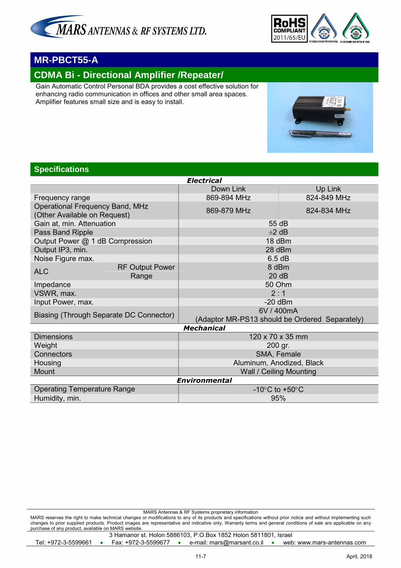
MARS Antennas & RF Systems proprietary information MARS reserves the right to make technical changes or modifications to any of its products and specifications without prior notice and without implementing such changes to prior supplied products. Product images are representative and indicative only. Warranty terms and general conditions of sale are applicable on any purchase of any product, available on MARS website.
3 Hamanor st. Holon 5886103, P.O.Box 1852 Holon 5811801, Israel Tel: +972-3-5599661 Fax: +972-3-5599677 e-mail: [email protected] web: www.mars-antennas.com
MR-PBCT55-A
CDMA Bi - Directional Amplifier /Repeater/ Gain Automatic Control Personal BDA provides a cost effective solution for enhancing radio communication in offices and other small area spaces. Amplifier features small size and is easy to install.
Specifications
Electrical
Down Link Up Link Frequency range 869-894 MHz 824-849 MHz Operational Frequency Band, MHz (Other Available on Request) 869-879 MHz 824-834 MHz
Gain at, min. Attenuation 55 dB Pass Band Ripple ±2 dB Output Power @ 1 dB Compression 18 dBm Output IP3, min. 28 dBm Noise Figure max. 6.5 dB
ALC RF Output Power 8 dBm Range 20 dB
Impedance 50 Ohm VSWR, max. 2 : 1 Input Power, max. -20 dBm
Biasing (Through Separate DC Connector) 6V / 400mA (Adaptor MR-PS13 should be Ordered Separately)
Mechanical
Dimensions 120 x 70 x 35 mm Weight 200 gr. Connectors SMA, Female Housing Aluminum, Anodized, Black Mount Wall / Ceiling Mounting
Environmental
Operating Temperature Range -10C to +50C Humidity, min. 95%
April, 201811-7

MARS Antennas & RF Systems proprietary information MARS reserves the right to make technical changes or modifications to any of its products and specifications without prior notice and without implementing such changes to prior supplied products. Product images are representative and indicative only. Warranty terms and general conditions of sale are applicable on any purchase of any product, available on MARS website.
3 Hamanor st. Holon 5886103, P.O.Box 1852 Holon 5811801, Israel Tel: +972-3-5599661 Fax: +972-3-5599677 e-mail: [email protected] web: www.mars-antennas.com
MR-BDA60-X1W
Bi-Directional Amplifier MARS BDA series of products provides a cost effective answer for enhancing radio communication in buildings, basements, parking garages and other RF shielded environments. BDA products are designed to receive and amplify RF signals strength in both the "Down Link" and the "Up Link" communication paths.
Specifications
Electrical
Down Link Up Link Frequency range 869-894 MHz 824-849 MHz Operational Frequency Band, MHz (Other Available on Request) 869-879 MHz 824-834 MHz
Gain at, min. Attenuation 60 dB Pass Band Ripple ±1.5 dB Output Power @ 1 dB Compression 30 dBm Noise Figure max. 6 dB Gain Control Range, manual, 2 dB Step 30 dB Impedance 50 Ohm VSWR, max. 2 : 1 Output IP3, min. 40 dBm
Biasing (Through Separate DC Connector) 6.7VDC / 3A (Adaptor MR-PS30 should be Ordered Separately)
Mechanical
Dimensions 243 x 160 x 57 mm Weight 2 kg. Connectors N-Type, Female
Environmental
Operating Temperature Range -30C to +70C Humidity, min. 95% Splash, Dust Protected
April, 201811-8
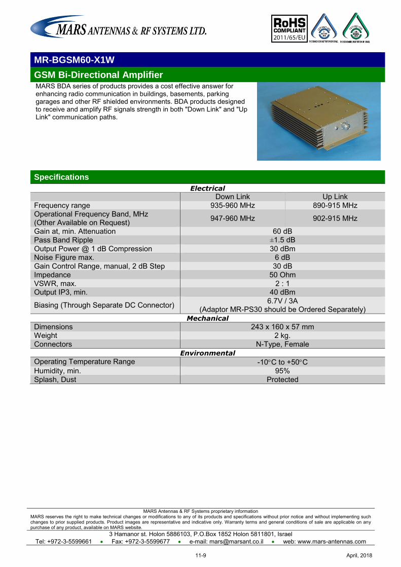
MARS Antennas & RF Systems proprietary information MARS reserves the right to make technical changes or modifications to any of its products and specifications without prior notice and without implementing such changes to prior supplied products. Product images are representative and indicative only. Warranty terms and general conditions of sale are applicable on any purchase of any product, available on MARS website.
3 Hamanor st. Holon 5886103, P.O.Box 1852 Holon 5811801, Israel Tel: +972-3-5599661 Fax: +972-3-5599677 e-mail: [email protected] web: www.mars-antennas.com
MR-BGSM60-X1W
GSM Bi-Directional Amplifier MARS BDA series of products provides a cost effective answer for enhancing radio communication in buildings, basements, parking garages and other RF shielded environments. BDA products designed to receive and amplify RF signals strength in both "Down Link" and "Up Link" communication paths.
Specifications
Electrical
Down Link Up Link Frequency range 935-960 MHz 890-915 MHz Operational Frequency Band, MHz (Other Available on Request) 947-960 MHz 902-915 MHz
Gain at, min. Attenuation 60 dB Pass Band Ripple ±1.5 dB Output Power @ 1 dB Compression 30 dBm Noise Figure max. 6 dB Gain Control Range, manual, 2 dB Step 30 dB Impedance 50 Ohm VSWR, max. 2 : 1 Output IP3, min. 40 dBm
Biasing (Through Separate DC Connector) 6.7V / 3A (Adaptor MR-PS30 should be Ordered Separately)
Mechanical
Dimensions 243 x 160 x 57 mm Weight 2 kg. Connectors N-Type, Female
Environmental
Operating Temperature Range -10C to +50C Humidity, min. 95% Splash, Dust Protected
April, 201811-9
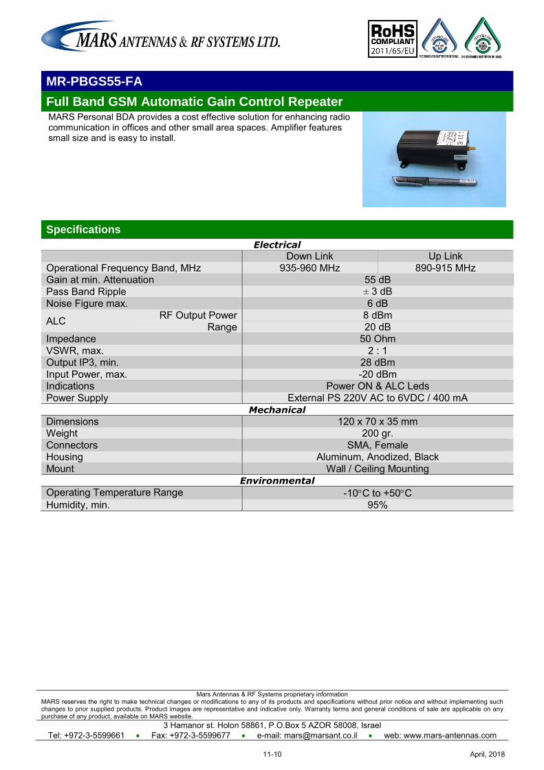
Mars Antennas & RF Systems proprietary information MARS reserves the right to make technical changes or modifications to any of its products and specifications without prior notice and without implementing such changes to prior supplied products. Product images are representative and indicative only. Warranty terms and general conditions of sale are applicable on any purchase of any product, available on MARS website.
3 Hamanor st. Holon 58861, P.O.Box 5 AZOR 58008, Israel Tel: +972-3-5599661 Fax: +972-3-5599677 e-mail: [email protected] web: www.mars-antennas.com
MR-PBGS55-FA
Full Band GSM Automatic Gain Control Repeater MARS Personal BDA provides a cost effective solution for enhancing radio communication in offices and other small area spaces. Amplifier features small size and is easy to install.
Specifications
Electrical
Down Link Up Link Operational Frequency Band, MHz 935-960 MHz 890-915 MHz Gain at min. Attenuation 55 dB Pass Band Ripple ± 3 dB Noise Figure max. 6 dB
ALC RF Output Power 8 dBm Range 20 dB
Impedance 50 Ohm VSWR, max. 2 : 1 Output IP3, min. 28 dBm Input Power, max. -20 dBm Indications Power ON & ALC Leds Power Supply External PS 220V AC to 6VDC / 400 mA
Mechanical
Dimensions 120 x 70 x 35 mm Weight 200 gr. Connectors SMA, Female Housing Aluminum, Anodized, Black Mount Wall / Ceiling Mounting
Environmental
Operating Temperature Range -10C to +50C Humidity, min. 95%
April, 201811-10
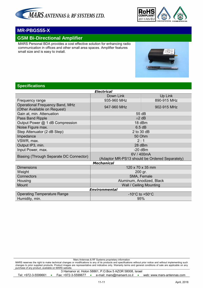
Mars Antennas & RF Systems proprietary information MARS reserves the right to make technical changes or modifications to any of its products and specifications without prior notice and without implementing such changes to prior supplied products. Product images are representative and indicative only. Warranty terms and general conditions of sale are applicable on any purchase of any product, available on MARS website.
3 Hamanor st. Holon 58861, P.O.Box 5 AZOR 58008, Israel Tel: +972-3-5599661 Fax: +972-3-5599677 e-mail: [email protected] web: www.mars-antennas.com
MR-PBGS55-X
GSM Bi-Directional Amplifier MARS Personal BDA provides a cost effective solution for enhancing radio communication in offices and other small area spaces. Amplifier features small size and is easy to install.
Specifications
Electrical
Down Link Up Link Frequency range 935-960 MHz 890-915 MHz Operational Frequency Band, MHz (Other Available on Request) 947-960 MHz 902-915 MHz
Gain at, min. Attenuation 55 dB Pass Band Ripple ±2 dB Output Power @ 1 dB Compression 18 dBm Noise Figure max. 6.5 dB Step Attenuator (2 dB Step) 2 to 30 dB Impedance 50 Ohm VSWR, max. 2 : 1 Output IP3, min. 28 dBm Input Power, max. -20 dBm
Biasing (Through Separate DC Connector) 6V / 400mA (Adaptor MR-PS13 should be Ordered Separately)
Mechanical
Dimensions 120 x 70 x 35 mm Weight 200 gr. Connectors SMA, Female Housing Aluminum, Anodized, Black Mount Wall / Ceiling Mounting
Environmental
Operating Temperature Range -10C to +50C Humidity, min. 95%
April, 201811-11
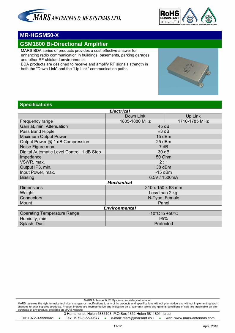
MARS Antennas & RF Systems proprietary information MARS reserves the right to make technical changes or modifications to any of its products and specifications without prior notice and without implementing such changes to prior supplied products. Product images are representative and indicative only. Warranty terms and general conditions of sale are applicable on any purchase of any product, available on MARS website.
3 Hamanor st. Holon 5886103, P.O.Box 1852 Holon 5811801, Israel Tel: +972-3-5599661 Fax: +972-3-5599677 e-mail: [email protected] web: www.mars-antennas.com
MR-HGSM50-X
GSM1800 Bi-Directional Amplifier MARS BDA series of products provides a cost effective answer for enhancing radio communication in buildings, basements, parking garages and other RF shielded environments. BDA products are designed to receive and amplify RF signals strength in both the "Down Link" and the "Up Link" communication paths.
Specifications
Electrical
Down Link Up Link Frequency range 1805-1880 MHz 1710-1785 MHz Gain at, min. Attenuation 45 dB Pass Band Ripple ±3 dB Maximum Output Power 15 dBm Output Power @ 1 dB Compression 25 dBm Noise Figure max. 7 dB Digital Automatic Level Control, 1 dB Step 30 dB Impedance 50 Ohm VSWR, max. 2 : 1 Output IP3, min. 38 dBm Input Power, max. -15 dBm Biasing 6.5V / 1500mA
Mechanical
Dimensions 310 x 150 x 63 mm Weight Less than 2 kg. Connectors N-Type, Female Mount Panel
Environmental
Operating Temperature Range -10C to +50C Humidity, min. 95% Splash, Dust Protected
April, 201811-12
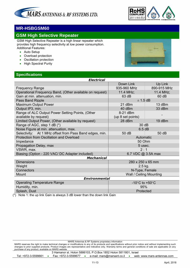
MARS Antennas & RF Systems proprietary information MARS reserves the right to make technical changes or modifications to any of its products and specifications without prior notice and without implementing such changes to prior supplied products. Product images are representative and indicative only. Warranty terms and general conditions of sale are applicable on any purchase of any product, available on MARS website.
3 Hamanor st. Holon 5886103, P.O.Box 1852 Holon 5811801, Israel Tel: +972-3-5599661 Fax: +972-3-5599677 e-mail: [email protected] web: www.mars-antennas.com
MR-HSBGSM60
GSM High Selective Repeater GSM High Selective Repeater is a high linear repeater which provides high frequency selectivity at low power consumption. Additional Features: Auto Setup Overload protection Oscillation protection High Spectral Purity
Specifications
Electrical
Down Link Up Link Frequency Range 935-960 MHz 890-915 MHz Operational Frequency Band, (Other available on request) 11.4 MHz; 11.4 MHz; Gain at min. attenuation, min. 63 dB 60 dB Pass Band Ripple ± 1.5 dB
Maximum Output Power 21 dBm 13 dBm Output IP3, min. 40 dBm 33 dBm Range of ALC Output Power Setting Points, (Other available by request)
8-21 dBm (up 8 set points) -
Limited Output Power, (Other available by request) 28 dBm 19 dBm Range of AGC, step 1 dB (*) 30 dB Noise Figure at min. attenuation, max. 6.5 dB Selectivity: At 1 MHz offset from Pass Band edges, min. 50 dB 50 dB Protection from Oscillation and Overload Automatic Impedance 50 Ohm Propagation Delay, max 5 usec. VSWR, max. 2 : 1 Biasing (Option - 220 VAC/ DC Adapter included) 6.7 VDC @ 3.5A max
Mechanical
Dimensions 280 x 250 x 65 mm Weight 2.5 kg. Connectors N-Type, Female Mount Wall / Ceiling Mounting
Environmental
Operating Temperature Range -10C to +50C Humidity, min. 95% Splash, Dust Protected
(*) Note 1: the up link Gain is always 3 dB lower than the down link Gain
April, 201811-13
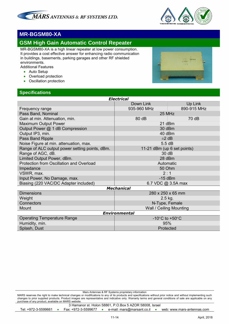
Mars Antennas & RF Systems proprietary information MARS reserves the right to make technical changes or modifications to any of its products and specifications without prior notice and without implementing such changes to prior supplied products. Product images are representative and indicative only. Warranty terms and general conditions of sale are applicable on any purchase of any product, available on MARS website.
3 Hamanor st. Holon 58861, P.O.Box 5 AZOR 58008, Israel Tel: +972-3-5599661 Fax: +972-3-5599677 e-mail: [email protected] web: www.mars-antennas.com
MR-BGSM80-XA
GSM High Gain Automatic Control Repeater MR-BGSM80-XA is a high linear repeater at low power consumption. It provides a cost effective answer for enhancing radio communication in buildings, basements, parking garages and other RF shielded environments. Additional Features Auto Setup Overload protection Oscillation protection
Specifications
Electrical
Down Link Up Link Frequency range 935-960 MHz 890-915 MHz Pass Band, Nominal 25 MHz Gain at min. Attenuation, min. 80 dB 70 dB Maximum Output Power 21 dBm Output Power @ 1 dB Compression 30 dBm Output IP3, min. 40 dBm Pass Band Ripple ±2 dB Noise Figure at min. attenuation, max. 5.5 dB Range of ALC output power setting points, dBm. 11-21 dBm (up 6 set points) Range of AGC, dB. 30 dB Limited Output Power, dBm. 28 dBm Protection from Oscillation and Overload Automatic Impedance 50 Ohm VSWR, max. 2 : 1 Input Power, No Damage, max. -15 dBm Biasing (220 VAC/DC Adapter included) 6.7 VDC @ 3.5A max
Mechanical
Dimensions 280 x 250 x 65 mm Weight 2.5 kg. Connectors N-Type, Female Mount Wall / Ceiling Mounting
Environmental
Operating Temperature Range -10C to +50C Humidity, min. 95% Splash, Dust Protected
April, 201811-14
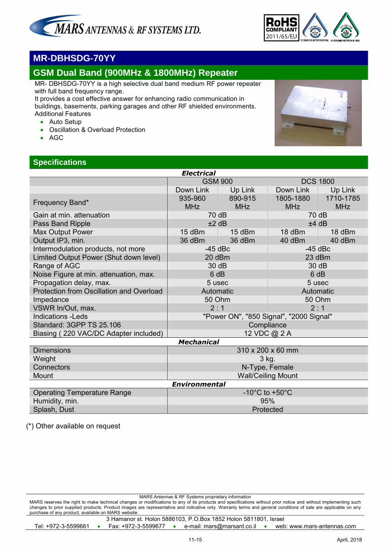
MARS Antennas & RF Systems proprietary information MARS reserves the right to make technical changes or modifications to any of its products and specifications without prior notice and without implementing such changes to prior supplied products. Product images are representative and indicative only. Warranty terms and general conditions of sale are applicable on any purchase of any product, available on MARS website.
3 Hamanor st. Holon 5886103, P.O.Box 1852 Holon 5811801, Israel Tel: +972-3-5599661 Fax: +972-3-5599677 e-mail: [email protected] web: www.mars-antennas.com
MR-DBHSDG-70YY
GSM Dual Band (900MHz & 1800MHz) Repeater MR- DBHSDG-70YY is a high selective dual band medium RF power repeater with full band frequency range. It provides a cost effective answer for enhancing radio communication in buildings, basements, parking garages and other RF shielded environments. Additional Features Auto Setup Oscillation & Overload Protection AGC
Specifications
Electrical
GSM 900 DCS 1800 Down Link Up Link Down Link Up Link
Frequency Band* 935-960 MHz
890-915 MHz
1805-1880 MHz
1710-1785 MHz
Gain at min. attenuation 70 dB 70 dB Pass Band Ripple ±2 dB ±4 dB Max Output Power 15 dBm 15 dBm 18 dBm 18 dBm Output IP3, min. 36 dBm 36 dBm 40 dBm 40 dBm Intermodulation products, not more -45 dBc -45 dBc Limited Output Power (Shut down level) 20 dBm 23 dBm Range of AGC 30 dB 30 dB Noise Figure at min. attenuation, max. 6 dB 6 dB Propagation delay, max. 5 usec 5 usec Protection from Oscillation and Overload Automatic Automatic Impedance 50 Ohm 50 Ohm VSWR In/Out, max. 2 : 1 2 : 1 Indications -Leds "Power ON", "850 Signal", "2000 Signal'' Standard: 3GPP TS 25.106 Compliance Biasing ( 220 VAC/DC Adapter included) 12 VDC @ 2 A
Mechanical
Dimensions 310 x 200 x 60 mm Weight 3 kg. Connectors N-Type, Female Mount Wall/Ceiling Mount
Environmental
Operating Temperature Range -10°C to +50°C Humidity, min. 95% Splash, Dust Protected
(*) Other available on request
April, 201811-15
MARS Antennas & RF Systems proprietary information MARS reserves the right to make technical changes or modifications to any of its products and specifications without prior notice and without implementing such changes to prior supplied products. Product images are representative and indicative only. Warranty terms and general conditions of sale are applicable on any purchase of any product, available on MARS website.
3 Hamanor st. Holon 5886103, P.O.Box 1852 Holon 5811801, Israel Tel: +972-3-5599661 Fax: +972-3-5599677 e-mail: [email protected] web: www.mars-antennas.com
MR-HSUMTS70-X
UMTS HS Bi-Directional Amplifier 1Watt UMTS High Selective Repeater provides a cost effective answer for enhancing radio communication in buildings, basements, parking garages and other RF shielded environments. BDA products are designed to receive and amplify RF signals strength in both the "Down Link" and the "Up Link" communication paths.
Specifications
Electrical
Down Link Up Link Frequency Range 2110-2170 MHz 1920-1980 MHz Pass Band (*) 2140-2150 MHz 1950-1960 MHz Gain at min. Attenuation, min. 75 dB 72 dB Pass Band Ripple ±1.5 dB ±1.5 dB
Rejection / 1 MHz from Pass Band, min. 45 dB 45 dB Maximum Output Power 30 dBm 12 dBm
Range of ALC output power setting points (up 8) 30-16 dBm (*) (*) & (**) Range of ALC, min. 30 dB Output IP3, min. 48 dB 38 dB Propagation delay, max. 5 usec Noise Figure, max. 6 dB 4.5 dB Impedance 50 Ohm VSWR In/Out, max. 2 : 1 Protection from Oscillation and Overload Automatic Local control & monitoring / RS-232/ Yes Current & temperature protection Yes Down RF Power indication Yes Power Supply 220V AC Power consumption, max. 50 W
Mechanical
Dimensions 440 x 325 x 180 mm Weight Less than 11 kg. Connectors N-Type, Female Mount Wall / Ceiling Mounting
Environmental
Operating Temperature Range -10C to +50C Humidity, min. 95% Splash, Dust Protected
(*) Other available on request (**) Up Link Gain is setting 3 dB less than Down Link Gain
April, 201811-16
Mars Antennas & RF Systems proprietary information MARS reserves the right to make technical changes or modifications to any of its products and specifications without prior notice and without implementing such changes to prior supplied products. Product images are representative and indicative only. Warranty terms and general conditions of sale are applicable on any purchase of any product, available on MARS website.
3 Hamanor st. Holon 58861, P.O.Box 5 AZOR 58008, Israel Tel: +972-3-5599661 Fax: +972-3-5599677 e-mail: [email protected] web: www.mars-antennas.com
MR-UMTS70-20F
UMTS Bi-Directional Amplifier (WCDMA) MR-UMTS70-20F is a full band UMTS linear repeater at low power consumption. It provides a cost effective answer for enhancing radio communication in buildings, basements, parking garages and other RF shielded environments. Additional Features Auto Setup. Overload & Oscillation protection. "Down Link" RF Power indication.
Specifications
Electrical
Down Link Up Link Frequency Band 2110-2170 MHz 1920-1980 MHz Pass Band - nominal 60 MHz Gain at min. attenuation, min. 70 dB Pass Band Ripple ± 3 dB
Maximum Output Power 20 dBm Range of ALC output power setting points, dBm 20-6 dBm (up to 8 set points) Range of AGC, dB 30 dB Output IP3, min. 40 dBm Output Power @ 1 dB Compression 30 dBm Noise Figure at min. attenuation, max. 5 dB Impedance 50 Ohm VSWR, max. 2 : 1 Protection from Oscillation and Overload Automatic Biasing (220 VAC/DC Adapter included) 6.7 VDC @ 2.5A max
Mechanical
Dimensions 280 x 250 x 65 mm Weight 2.5 kg. Connectors N-Type, Female Mount Wall / Ceiling Mounting
Environmental
Operating Temperature Range -10C to +50C Humidity, min. 95% Splash, Dust Protected
April, 201811-17
MARS Antennas & RF Systems proprietary information MARS reserves the right to make technical changes or modifications to any of its products and specifications without prior notice and without implementing such changes to prior supplied products. Product images are representative and indicative only. Warranty terms and general conditions of sale are applicable on any purchase of any product, available on MARS website.
3 Hamanor st. Holon 5886103, P.O.Box 1852 Holon 5811801, Israel Tel: +972-3-5599661 Fax: +972-3-5599677 e-mail: [email protected] web: www.mars-antennas.com
MR-HSUMTS70-20
UMTS HS Bi-Directional Amplifier MR-HSUMTS70-20 is a high selective linear repeater at low power consumption. It provides a cost effective answer for enhancing radio communication in buildings, basements, parking garages and other RF shielded environments. Additional Features Auto Setup. Overload & Oscillation protection. "Down Link" RF Power indication.
Specifications
Electrical
Down Link Up Link Frequency Band 2110-2170 MHz 1920-1980 MHz Pass Band (*) 2140-2150 MHz 1950-1960 MHz Gain at min. Attenuation, min. 73 dB Pass Band Ripple ±1.5 dB
Rejection / 1 MHz from Pass Band, min. 45 dB Maximum Output Power 20dBm Range of ALC output power setting points, dBm 20-6 dBm (up to 8 set points) Range of AGC, dB 30 dB Output IP3, min. 40 dBm Output Power @ 1 dB Compression 30 dBm Propagation delay, max. 5 usec Noise Figure at min. attenuation, max. 6 dB Limited Output Power, dBm 28 dBm Impedance 50 Ohm VSWR, max. 2:1 Protection from Oscillation and Overload Automatic Biasing (220 VAC/DC Adapter included) 6.7 VDC@ 3.5 A max
Mechanical
Dimensions 280 x 250 x 65 mm Weight 2.5 kg. Connectors N-Type, Female Mount Wall / Ceiling Mounting
Environmental
Operating Temperature Range -10C to +50C Humidity, min. 95% Splash, Dust Protected
(*) Other available on request
April, 201811-18
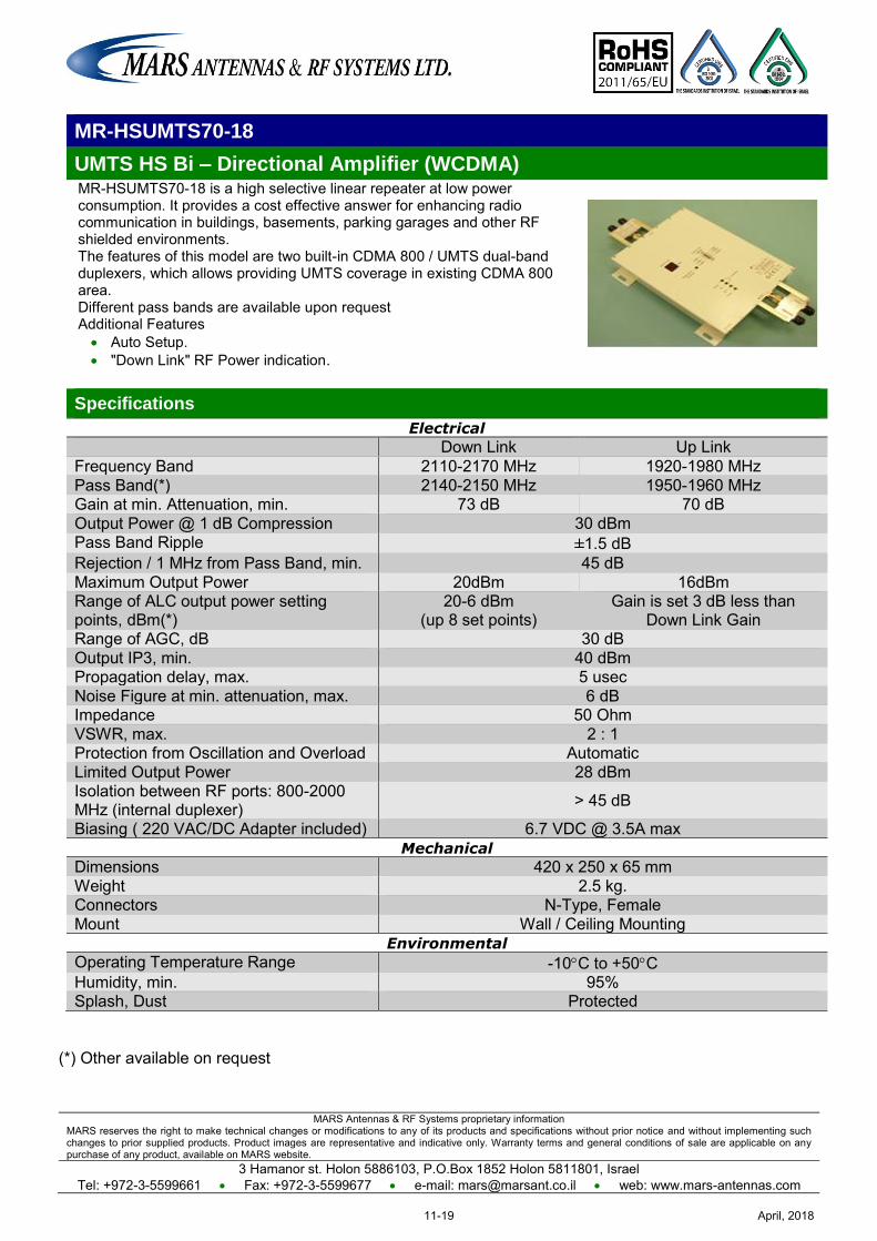
MARS Antennas & RF Systems proprietary information MARS reserves the right to make technical changes or modifications to any of its products and specifications without prior notice and without implementing such changes to prior supplied products. Product images are representative and indicative only. Warranty terms and general conditions of sale are applicable on any purchase of any product, available on MARS website.
3 Hamanor st. Holon 5886103, P.O.Box 1852 Holon 5811801, Israel Tel: +972-3-5599661 Fax: +972-3-5599677 e-mail: [email protected] web: www.mars-antennas.com
MR-HSUMTS70-18
UMTS HS Bi – Directional Amplifier (WCDMA) MR-HSUMTS70-18 is a high selective linear repeater at low power consumption. It provides a cost effective answer for enhancing radio communication in buildings, basements, parking garages and other RF shielded environments. The features of this model are two built-in CDMA 800 / UMTS dual-band duplexers, which allows providing UMTS coverage in existing CDMA 800 area. Different pass bands are available upon request Additional Features Auto Setup. "Down Link" RF Power indication.
Specifications
Electrical
Down Link Up Link Frequency Band 2110-2170 MHz 1920-1980 MHz Pass Band(*) 2140-2150 MHz 1950-1960 MHz Gain at min. Attenuation, min. 73 dB 70 dB Output Power @ 1 dB Compression 30 dBm Pass Band Ripple ±1.5 dB
Rejection / 1 MHz from Pass Band, min. 45 dB Maximum Output Power 20dBm 16dBm Range of ALC output power setting points, dBm(*)
20-6 dBm (up 8 set points)
Gain is set 3 dB less than Down Link Gain
Range of AGC, dB 30 dB Output IP3, min. 40 dBm Propagation delay, max. 5 usec Noise Figure at min. attenuation, max. 6 dB Impedance 50 Ohm VSWR, max. 2 : 1 Protection from Oscillation and Overload Automatic Limited Output Power 28 dBm Isolation between RF ports: 800-2000 MHz (internal duplexer) > 45 dB
Biasing ( 220 VAC/DC Adapter included) 6.7 VDC @ 3.5A max Mechanical
Dimensions 420 x 250 x 65 mm Weight 2.5 kg. Connectors N-Type, Female Mount Wall / Ceiling Mounting
Environmental
Operating Temperature Range -10C to +50C Humidity, min. 95% Splash, Dust Protected
(*) Other available on request
April, 201811-19
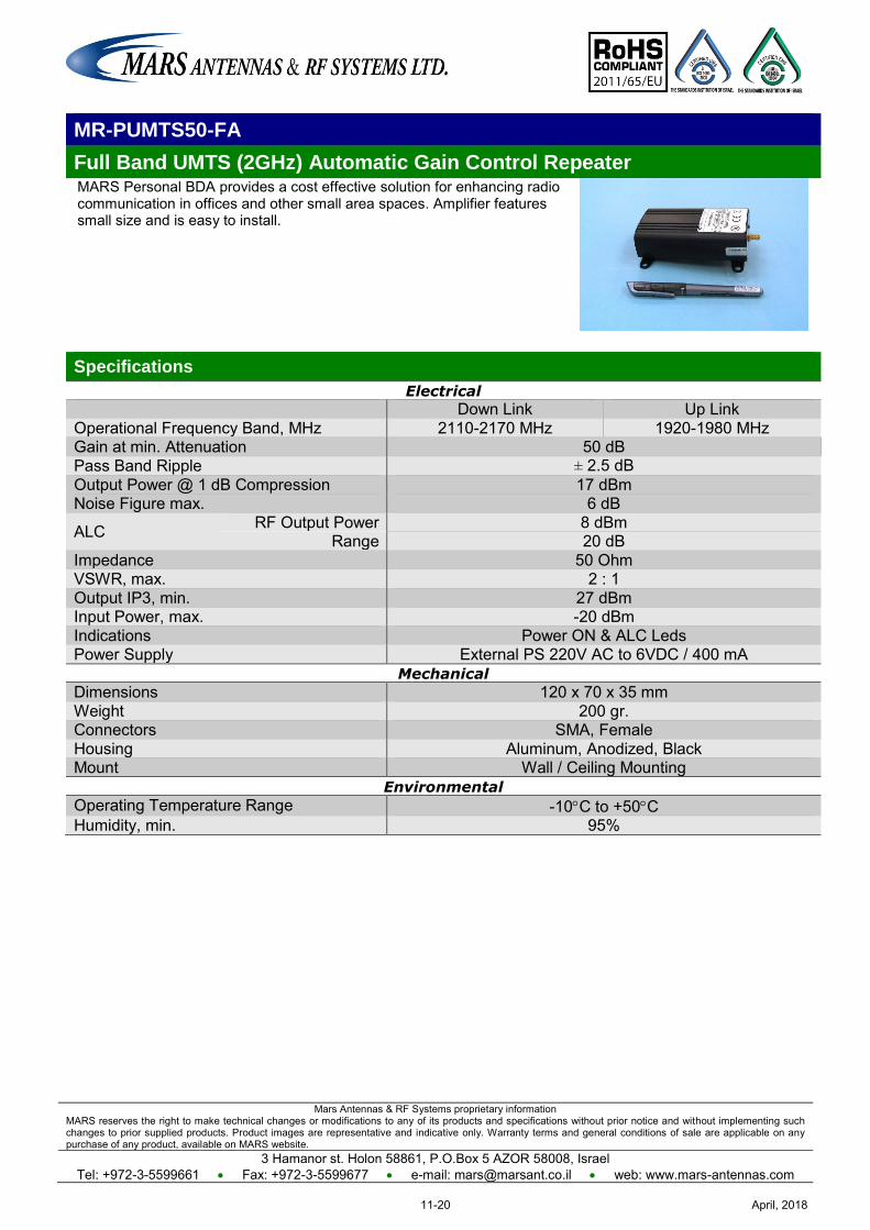
Mars Antennas & RF Systems proprietary information MARS reserves the right to make technical changes or modifications to any of its products and specifications without prior notice and without implementing such changes to prior supplied products. Product images are representative and indicative only. Warranty terms and general conditions of sale are applicable on any purchase of any product, available on MARS website.
3 Hamanor st. Holon 58861, P.O.Box 5 AZOR 58008, Israel Tel: +972-3-5599661 Fax: +972-3-5599677 e-mail: [email protected] web: www.mars-antennas.com
MR-PUMTS50-FA
Full Band UMTS (2GHz) Automatic Gain Control Repeater MARS Personal BDA provides a cost effective solution for enhancing radio communication in offices and other small area spaces. Amplifier features small size and is easy to install.
Specifications
Electrical
Down Link Up Link Operational Frequency Band, MHz 2110-2170 MHz 1920-1980 MHz Gain at min. Attenuation 50 dB Pass Band Ripple ± 2.5 dB Output Power @ 1 dB Compression 17 dBm Noise Figure max. 6 dB
ALC RF Output Power 8 dBm Range 20 dB
Impedance 50 Ohm VSWR, max. 2 : 1 Output IP3, min. 27 dBm Input Power, max. -20 dBm Indications Power ON & ALC Leds Power Supply External PS 220V AC to 6VDC / 400 mA
Mechanical
Dimensions 120 x 70 x 35 mm Weight 200 gr. Connectors SMA, Female Housing Aluminum, Anodized, Black Mount Wall / Ceiling Mounting
Environmental
Operating Temperature Range -10C to +50C Humidity, min. 95%
April, 201811-20
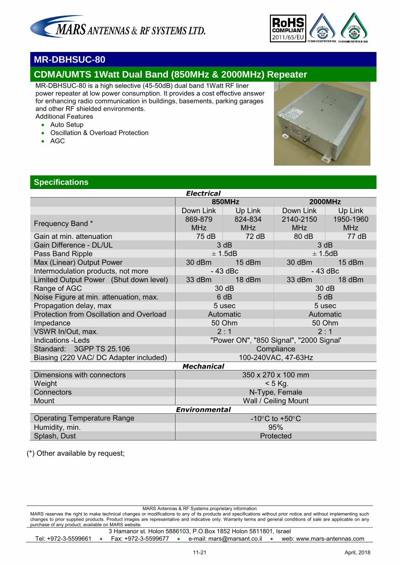
MARS Antennas & RF Systems proprietary information MARS reserves the right to make technical changes or modifications to any of its products and specifications without prior notice and without implementing such changes to prior supplied products. Product images are representative and indicative only. Warranty terms and general conditions of sale are applicable on any purchase of any product, available on MARS website.
3 Hamanor st. Holon 5886103, P.O.Box 1852 Holon 5811801, Israel Tel: +972-3-5599661 Fax: +972-3-5599677 e-mail: [email protected] web: www.mars-antennas.com
MR-DBHSUC-80
CDMA/UMTS 1Watt Dual Band (850MHz & 2000MHz) Repeater MR-DBHSUC-80 is a high selective (45-50dB) dual band 1Watt RF liner power repeater at low power consumption. It provides a cost effective answer for enhancing radio communication in buildings, basements, parking garages and other RF shielded environments. Additional Features Auto Setup Oscillation & Overload Protection AGC
Specifications
Electrical
850MHz 2000MHz
Down Link Up Link Down Link Up Link
Frequency Band * 869-879 MHz
824-834 MHz
2140-2150 MHz
1950-1960 MHz
Gain at min. attenuation 75 dB 72 dB 80 dB 77 dB Gain Difference - DL/UL 3 dB 3 dB
Pass Band Ripple ± 1.5dB ± 1.5dB Max (Linear) Output Power 30 dBm 15 dBm 30 dBm 15 dBm Intermodulation products, not more - 43 dBc - 43 dBc Limited Output Power (Shut down level) 33 dBm 18 dBm 33 dBm 18 dBm Range of AGC 30 dB 30 dB Noise Figure at min. attenuation, max. 6 dB 5 dB Propagation delay, max 5 usec 5 usec Protection from Oscillation and Overload Automatic Automatic Impedance 50 Ohm 50 Ohm VSWR In/Out, max. 2 : 1 2 : 1 Indications -Leds "Power ON", "850 Signal", "2000 Signal' Standard: 3GPP TS 25.106 Compliance Biasing (220 VAC/ DC Adapter included) 100-240VAC, 47-63Hz
Mechanical
Dimensions with connectors 350 x 270 x 100 mm Weight < 5 Kg. Connectors N-Type, Female Mount Wall / Ceiling Mount
Environmental
Operating Temperature Range -10C to +50C Humidity, min. 95% Splash, Dust Protected
(*) Other available by request;
April, 201811-21
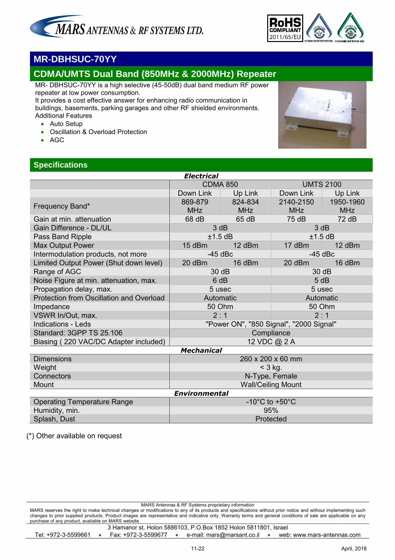
MARS Antennas & RF Systems proprietary information MARS reserves the right to make technical changes or modifications to any of its products and specifications without prior notice and without implementing such changes to prior supplied products. Product images are representative and indicative only. Warranty terms and general conditions of sale are applicable on any purchase of any product, available on MARS website.
3 Hamanor st. Holon 5886103, P.O.Box 1852 Holon 5811801, Israel Tel: +972-3-5599661 Fax: +972-3-5599677 e-mail: [email protected] web: www.mars-antennas.com
MR-DBHSUC-70YY
CDMA/UMTS Dual Band (850MHz & 2000MHz) Repeater MR- DBHSUC-70YY is a high selective (45-50dB) dual band medium RF power repeater at low power consumption. It provides a cost effective answer for enhancing radio communication in buildings, basements, parking garages and other RF shielded environments. Additional Features Auto Setup Oscillation & Overload Protection AGC
Specifications
Electrical
CDMA 850 UMTS 2100 Down Link Up Link Down Link Up Link
Frequency Band* 869-879 MHz
824-834 MHz
2140-2150 MHz
1950-1960 MHz
Gain at min. attenuation 68 dB 65 dB 75 dB 72 dB Gain Difference - DL/UL 3 dB 3 dB Pass Band Ripple ±1.5 dB ±1.5 dB Max Output Power 15 dBm 12 dBm 17 dBm 12 dBm Intermodulation products, not more -45 dBc -45 dBc Limited Output Power (Shut down level) 20 dBm 16 dBm 20 dBm 16 dBm Range of AGC 30 dB 30 dB Noise Figure at min. attenuation, max. 6 dB 5 dB Propagation delay, max. 5 usec 5 usec Protection from Oscillation and Overload Automatic Automatic Impedance 50 Ohm 50 Ohm VSWR In/Out, max. 2 : 1 2 : 1 Indications - Leds "Power ON", "850 Signal", "2000 Signal'' Standard: 3GPP TS 25.106 Compliance Biasing ( 220 VAC/DC Adapter included) 12 VDC @ 2 A
Mechanical
Dimensions 260 x 200 x 60 mm Weight < 3 kg. Connectors N-Type, Female Mount Wall/Ceiling Mount
Environmental
Operating Temperature Range -10°C to +50°C Humidity, min. 95% Splash, Dust Protected
(*) Other available on request
April, 201811-22
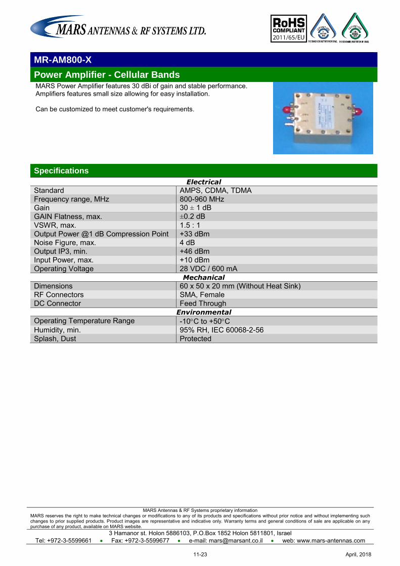
MARS Antennas & RF Systems proprietary information MARS reserves the right to make technical changes or modifications to any of its products and specifications without prior notice and without implementing such changes to prior supplied products. Product images are representative and indicative only. Warranty terms and general conditions of sale are applicable on any purchase of any product, available on MARS website.
3 Hamanor st. Holon 5886103, P.O.Box 1852 Holon 5811801, Israel Tel: +972-3-5599661 Fax: +972-3-5599677 e-mail: [email protected] web: www.mars-antennas.com
MR-AM800-X
Power Amplifier - Cellular Bands MARS Power Amplifier features 30 dBi of gain and stable performance. Amplifiers features small size allowing for easy installation. Can be customized to meet customer's requirements.
Specifications
Electrical
Standard AMPS, CDMA, TDMA Frequency range, MHz 800-960 MHz Gain 30 ± 1 dB GAIN Flatness, max. ±0.2 dB VSWR, max. 1.5 : 1 Output Power @1 dB Compression Point +33 dBm Noise Figure, max. 4 dB Output IP3, min. +46 dBm Input Power, max. +10 dBm Operating Voltage 28 VDC / 600 mA
Mechanical
Dimensions 60 x 50 x 20 mm (Without Heat Sink) RF Connectors SMA, Female DC Connector Feed Through
Environmental
Operating Temperature Range -10C to +50C Humidity, min. 95% RH, IEC 60068-2-56 Splash, Dust Protected
April, 201811-23
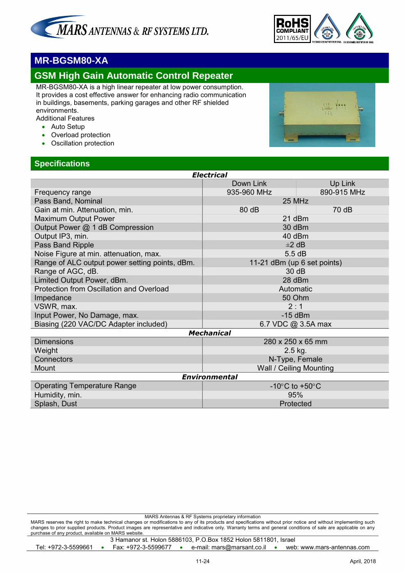
MARS Antennas & RF Systems proprietary information MARS reserves the right to make technical changes or modifications to any of its products and specifications without prior notice and without implementing such changes to prior supplied products. Product images are representative and indicative only. Warranty terms and general conditions of sale are applicable on any purchase of any product, available on MARS website.
3 Hamanor st. Holon 5886103, P.O.Box 1852 Holon 5811801, Israel Tel: +972-3-5599661 Fax: +972-3-5599677 e-mail: [email protected] web: www.mars-antennas.com
MR-BGSM80-XA
GSM High Gain Automatic Control Repeater MR-BGSM80-XA is a high linear repeater at low power consumption. It provides a cost effective answer for enhancing radio communication in buildings, basements, parking garages and other RF shielded environments. Additional Features Auto Setup Overload protection Oscillation protection
Specifications
Electrical
Down Link Up Link Frequency range 935-960 MHz 890-915 MHz Pass Band, Nominal 25 MHz Gain at min. Attenuation, min. 80 dB 70 dB Maximum Output Power 21 dBm Output Power @ 1 dB Compression 30 dBm Output IP3, min. 40 dBm Pass Band Ripple ±2 dB Noise Figure at min. attenuation, max. 5.5 dB Range of ALC output power setting points, dBm. 11-21 dBm (up 6 set points) Range of AGC, dB. 30 dB Limited Output Power, dBm. 28 dBm Protection from Oscillation and Overload Automatic Impedance 50 Ohm VSWR, max. 2 : 1 Input Power, No Damage, max. -15 dBm Biasing (220 VAC/DC Adapter included) 6.7 VDC @ 3.5A max
Mechanical
Dimensions 280 x 250 x 65 mm Weight 2.5 kg. Connectors N-Type, Female Mount Wall / Ceiling Mounting
Environmental
Operating Temperature Range -10C to +50C Humidity, min. 95% Splash, Dust Protected
April, 201811-24
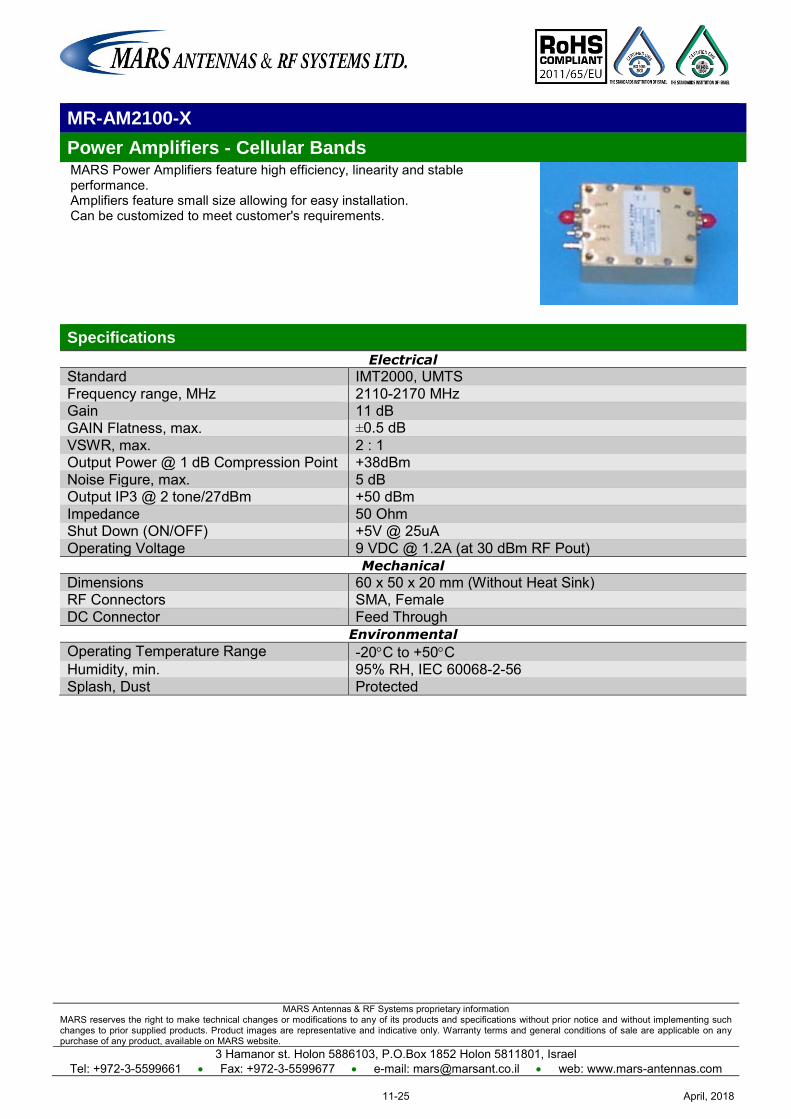
MARS Antennas & RF Systems proprietary information MARS reserves the right to make technical changes or modifications to any of its products and specifications without prior notice and without implementing such changes to prior supplied products. Product images are representative and indicative only. Warranty terms and general conditions of sale are applicable on any purchase of any product, available on MARS website.
3 Hamanor st. Holon 5886103, P.O.Box 1852 Holon 5811801, Israel Tel: +972-3-5599661 Fax: +972-3-5599677 e-mail: [email protected] web: www.mars-antennas.com
MR-AM2100-X
Power Amplifiers - Cellular Bands MARS Power Amplifiers feature high efficiency, linearity and stable performance. Amplifiers feature small size allowing for easy installation. Can be customized to meet customer's requirements.
Specifications
Electrical
Standard IMT2000, UMTS Frequency range, MHz 2110-2170 MHz Gain 11 dB GAIN Flatness, max. ±0.5 dB VSWR, max. 2 : 1 Output Power @ 1 dB Compression Point +38dBm Noise Figure, max. 5 dB Output IP3 @ 2 tone/27dBm +50 dBm Impedance 50 Ohm Shut Down (ON/OFF) +5V @ 25uA Operating Voltage 9 VDC @ 1.2A (at 30 dBm RF Pout)
Mechanical
Dimensions 60 x 50 x 20 mm (Without Heat Sink) RF Connectors SMA, Female DC Connector Feed Through
Environmental
Operating Temperature Range -20C to +50C Humidity, min. 95% RH, IEC 60068-2-56 Splash, Dust Protected
April, 201811-25
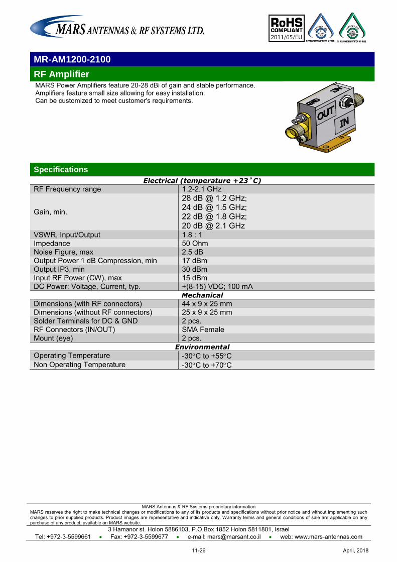
MARS Antennas & RF Systems proprietary information MARS reserves the right to make technical changes or modifications to any of its products and specifications without prior notice and without implementing such changes to prior supplied products. Product images are representative and indicative only. Warranty terms and general conditions of sale are applicable on any purchase of any product, available on MARS website.
3 Hamanor st. Holon 5886103, P.O.Box 1852 Holon 5811801, Israel Tel: +972-3-5599661 Fax: +972-3-5599677 e-mail: [email protected] web: www.mars-antennas.com
MR-AM1200-2100
RF Amplifier MARS Power Amplifiers feature 20-28 dBi of gain and stable performance. Amplifiers feature small size allowing for easy installation. Can be customized to meet customer's requirements.
Specifications
Electrical (temperature +23˚C)
RF Frequency range 1.2-2.1 GHz
Gain, min.
28 dB @ 1.2 GHz; 24 dB @ 1.5 GHz; 22 dB @ 1.8 GHz; 20 dB @ 2.1 GHz
VSWR, Input/Output 1.8 : 1 Impedance 50 Ohm Noise Figure, max 2.5 dB Output Power 1 dB Compression, min 17 dBm Output IP3, min 30 dBm Input RF Power (CW), max 15 dBm DC Power: Voltage, Current, typ. +(8-15) VDC; 100 mA
Mechanical
Dimensions (with RF connectors) 44 x 9 x 25 mm Dimensions (without RF connectors) 25 x 9 x 25 mm Solder Terminals for DC & GND 2 pcs. RF Connectors (IN/OUT) SMA Female Mount (eye) 2 pcs.
Environmental
Operating Temperature -30C to +55C Non Operating Temperature -30C to +70C
April, 201811-26
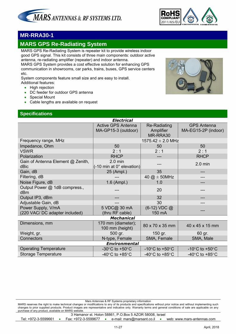
Mars Antennas & RF Systems proprietary information MARS reserves the right to make technical changes or modifications to any of its products and specifications without prior notice and without implementing such changes to prior supplied products. Product images are representative and indicative only. Warranty terms and general conditions of sale are applicable on any purchase of any product, available on MARS website.
3 Hamanor st. Holon 58861, P.O.Box 5 AZOR 58008, Israel Tel: +972-3-5599661 Fax: +972-3-5599677 e-mail: [email protected] web: www.mars-antennas.com
MR-RRA30-1
MARS GPS Re-Radiating System MARS GPS Re-Radiating System is repeater kit to provide wireless indoor good GPS signal. This kit consists of three main components: outdoor active antenna, re-radiating amplifier (repeater) and indoor antenna. MARS GPS System provides a cost effective solution for enhancing GPS communication in showrooms, car parks, trains, buses, GPS service centers etc. System components feature small size and are easy to install. Additional features: High rejection DC feeder for outdoor GPS antenna Special Mount Cable lengths are available on request
Specifications
Electrical
Active GPS Antenna MA-GP15-3 (outdoor)
Re-Radiating Amplifier
MR-RRA30
GPS Antenna MA-EG15-2P (indoor)
Frequency range, MHz 1575.42 ± 2.0 MHz Impedance, Ohm 50 50 50 VSWR 2 : 1 2 : 1 2 : 1 Polarization RHCP --- RHCP Gain of Antenna Element @ Zenith, dBic
2.0 min (-10 min at 0° elevation) --- 2.0 min
Gain, dB 25 (Ampl.) 35 --- Filtering, dB --- 40 @ ± 50MHz --- Noise Figure, dB 1.6 (Ampl.) 1.0 --- Output Power @ 1dB compress., dBm --- 20 ---
Output IP3, dBm --- 32 --- Adjustable Gain, dB --- 30 --- Power Supply, V/mA (220 VAC/ DC adapter included)
5 VDC@ 30 mA (thru RF cable)
(6-12) VDC @ 150 mA ---
Mechanical
Dimensions, mm 170 mm (diameter); 100 mm (height) 80 x 70 x 35 mm 40 x 45 x 15 mm
Weight, gr. 500 gr. 150 gr. 60 gr. Connectors N-type, Female SMA, Female SMA, Male
Environmental
Operating Temperature -30C to +50C -10C to +50C -10C to +50C Storage Temperature -40C to +85C -40C to +85C -40C to +85C
April, 201811-27
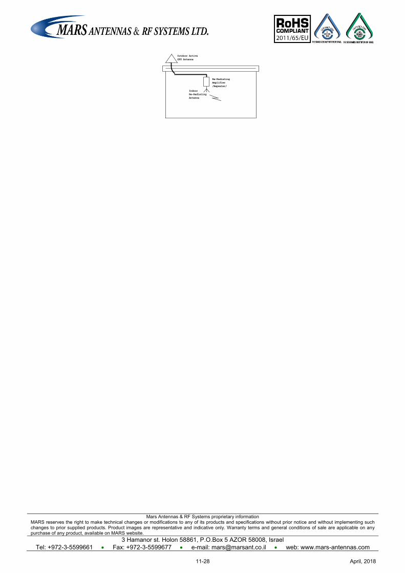
Mars Antennas & RF Systems proprietary information MARS reserves the right to make technical changes or modifications to any of its products and specifications without prior notice and without implementing such changes to prior supplied products. Product images are representative and indicative only. Warranty terms and general conditions of sale are applicable on any purchase of any product, available on MARS website.
3 Hamanor st. Holon 58861, P.O.Box 5 AZOR 58008, Israel Tel: +972-3-5599661 Fax: +972-3-5599677 e-mail: [email protected] web: www.mars-antennas.com
Re-Radiating
Amplifier
/Repeater/
Outdoor Active
GPS Antenna
Indoor
Re-Radiating
Antenna
April, 201811-28
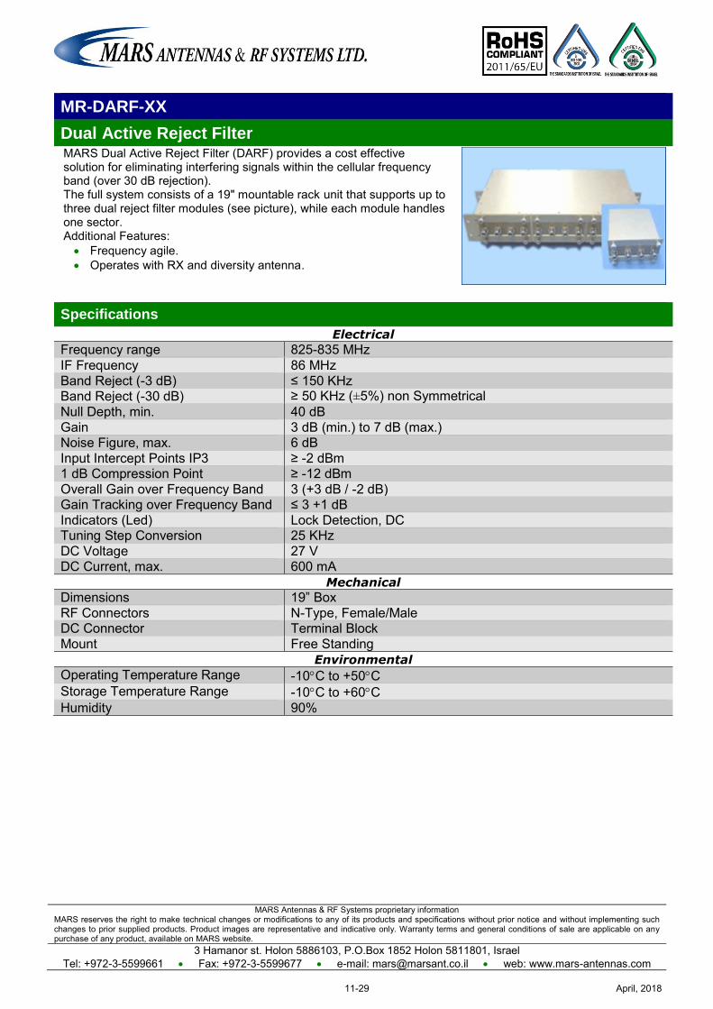
MARS Antennas & RF Systems proprietary information MARS reserves the right to make technical changes or modifications to any of its products and specifications without prior notice and without implementing such changes to prior supplied products. Product images are representative and indicative only. Warranty terms and general conditions of sale are applicable on any purchase of any product, available on MARS website.
3 Hamanor st. Holon 5886103, P.O.Box 1852 Holon 5811801, Israel Tel: +972-3-5599661 Fax: +972-3-5599677 e-mail: [email protected] web: www.mars-antennas.com
MR-DARF-XX
Dual Active Reject Filter MARS Dual Active Reject Filter (DARF) provides a cost effective solution for eliminating interfering signals within the cellular frequency band (over 30 dB rejection). The full system consists of a 19" mountable rack unit that supports up to three dual reject filter modules (see picture), while each module handles one sector. Additional Features: Frequency agile. Operates with RX and diversity antenna.
Specifications
Electrical
Frequency range 825-835 MHz IF Frequency 86 MHz Band Reject (-3 dB) ≤ 150 KHz
Band Reject (-30 dB) ≥ 50 KHz (±5%) non Symmetrical Null Depth, min. 40 dB Gain 3 dB (min.) to 7 dB (max.) Noise Figure, max. 6 dB Input Intercept Points IP3 ≥ -2 dBm 1 dB Compression Point ≥ -12 dBm Overall Gain over Frequency Band 3 (+3 dB / -2 dB) Gain Tracking over Frequency Band ≤ 3 +1 dB Indicators (Led) Lock Detection, DC Tuning Step Conversion 25 KHz DC Voltage 27 V DC Current, max. 600 mA
Mechanical
Dimensions 19” Box RF Connectors N-Type, Female/Male DC Connector Terminal Block Mount Free Standing
Environmental
Operating Temperature Range -10C to +50C Storage Temperature Range -10C to +60C Humidity 90%
April, 201811-29
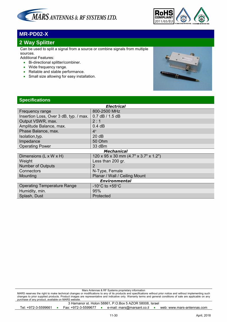
Mars Antennas & RF Systems proprietary information MARS reserves the right to make technical changes or modifications to any of its products and specifications without prior notice and without implementing such changes to prior supplied products. Product images are representative and indicative only. Warranty terms and general conditions of sale are applicable on any purchase of any product, available on MARS website.
3 Hamanor st. Holon 58861, P.O.Box 5 AZOR 58008, Israel Tel: +972-3-5599661 Fax: +972-3-5599677 e-mail: [email protected] web: www.mars-antennas.com
MR-PD02-X
2 Way Splitter Can be used to split a signal from a source or combine signals from multiple sources. Additional Features: Bi-directional splitter/combiner. Wide frequency range. Reliable and stable performance. Small size allowing for easy installation.
Specifications
Electrical
Frequency range 800-2500 MHz Insertion Loss, Over 3 dB, typ. / max. 0.7 dB / 1.5 dB Output VSWR, max. 2 : 1 Amplitude Balance, max. 0.4 dB Phase Balance, max. 4 Isolation,typ. 20 dB Impedance 50 Ohm Operating Power 33 dBm
Mechanical
Dimensions (L x W x H) 120 x 95 x 30 mm (4.7" x 3.7" x 1.2") Weight Less than 200 gr. Number of Outputs 2 Connectors N-Type, Female Mounting Planar / Wall / Ceiling Mount
Environmental
Operating Temperature Range -10C to +55C Humidity, min. 95% Splash, Dust Protected
April, 201811-30

Mars Antennas & RF Systems proprietary information MARS reserves the right to make technical changes or modifications to any of its products and specifications without prior notice and without implementing such changes to prior supplied products. Product images are representative and indicative only. Warranty terms and general conditions of sale are applicable on any purchase of any product, available on MARS website.
3 Hamanor st. Holon 58861, P.O.Box 5 AZOR 58008, Israel Tel: +972-3-5599661 Fax: +972-3-5599677 e-mail: [email protected] web: www.mars-antennas.com
MR-PD03-X
3 Way Splitter Can be used to split a signal from a source or combine signals from multiple sources. Additional Features: Bi-directional splitter/combiner Wide frequency range Reliable and stable performance Small size allowing for easy installation
Specifications
Electrical
Frequency range 800-2000 MHz Insertion Loss, Over 4.8 dB 1.3 dB Output VSWR, max. 1.8 : 1 Amplitude Balance, max. 0.8 dB Phase Balance, max. 8 Isolation, typ. 18 dB Impedance 50 Ohm Input Power (Load VSWR <1.2) 60 Watt
Mechanical
Dimensions (L x W x H) 140 x 95 x 30 (5.5" x 3.7" x 1.2") Weight Less than 200 gr. Number of Outputs 3 Connectors N-Type, Female Mounting Planar / Wall / Ceiling Mount
Environmental
Operating Temperature Range -40C to +70C Humidity, min. 95% Splash, Dust Protected
April, 201811-31
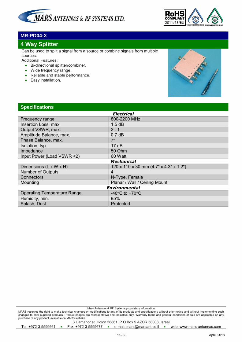
Mars Antennas & RF Systems proprietary information MARS reserves the right to make technical changes or modifications to any of its products and specifications without prior notice and without implementing such changes to prior supplied products. Product images are representative and indicative only. Warranty terms and general conditions of sale are applicable on any purchase of any product, available on MARS website.
3 Hamanor st. Holon 58861, P.O.Box 5 AZOR 58008, Israel Tel: +972-3-5599661 Fax: +972-3-5599677 e-mail: [email protected] web: www.mars-antennas.com
MR-PD04-X
4 Way Splitter Can be used to split a signal from a source or combine signals from multiple sources. Additional Features: Bi-directional splitter/combiner. Wide frequency range. Reliable and stable performance. Easy installation.
Specifications
Electrical
Frequency range 800-2200 MHz Insertion Loss, max. 1.5 dB Output VSWR, max. 2 : 1 Amplitude Balance, max. 0.7 dB Phase Balance, max. 7 Isolation, typ. 17 dB Impedance 50 Ohm Input Power (Load VSWR <2) 60 Watt
Mechanical
Dimensions (L x W x H) 120 x 110 x 30 mm (4.7" x 4.3" x 1.2") Number of Outputs 4 Connectors N-Type, Female Mounting Planar / Wall / Ceiling Mount
Environmental
Operating Temperature Range -40C to +70C Humidity, min. 95% Splash, Dust Protected
April, 201811-32
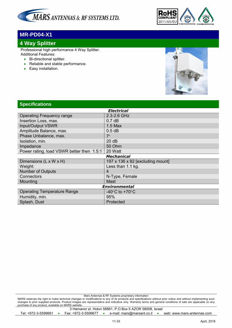
Mars Antennas & RF Systems proprietary information MARS reserves the right to make technical changes or modifications to any of its products and specifications without prior notice and without implementing such changes to prior supplied products. Product images are representative and indicative only. Warranty terms and general conditions of sale are applicable on any purchase of any product, available on MARS website.
3 Hamanor st. Holon 58861, P.O.Box 5 AZOR 58008, Israel Tel: +972-3-5599661 Fax: +972-3-5599677 e-mail: [email protected] web: www.mars-antennas.com
MR-PD04-X1
4 Way Splitter Professional high performance 4 Way Splitter. Additional Features: Bi-directional splitter. Reliable and stable performance. Easy installation.
Specifications
Electrical
Operating Frequency range 2.3-2.6 GHz Insertion Loss, max. 0.7 dB Input/Output VSWR 1.5 Max Amplitude Balance, max. 0.5 dB Phase Unbalance, max. 7 Isolation, min. 20 dB Impedance 50 Ohm Power rating, load VSWR better then 1.5:1 20 Watt
Mechanical
Dimensions (L x W x H) 197 x 136 x 82 [excluding mount] Weight: Less than 1.1 kg. Number of Outputs 4 Connectors N-Type, Female Mounting Mast
Environmental
Operating Temperature Range -40C to +70C Humidity, min. 95% Splash, Dust Protected
April, 201811-33

MARS Antennas & RF Systems proprietary information MARS reserves the right to make technical changes or modifications to any of its products and specifications without prior notice and without implementing such changes to prior supplied products. Product images are representative and indicative only. Warranty terms and general conditions of sale are applicable on any purchase of any product, available on MARS website.
3 Hamanor st. Holon 5886103, P.O.Box 1852 Holon 5811801, Israel
Tel: +972-3-5599661 Fax: +972-3-5599677 e-mail: [email protected] web: www.mars-antennas.com
Antenna mounts & Enclosure Kits
Part Number Description Page
MNT-22 Heavy Duty, Az/El Adjustable Mount for CPE / Subscriber and Small Base Station Antennas
12-1
MNT-23 Az/El Adjustable Mount for CPE / Subscriber Antennas 12-2
MNT-1A Mount for CPE / Subscriber and Small Base Station Antennas 12-3
MNT-5A Mount for CPE / Subscriber and Small Base Station Antennas 12-4
MNT-25 Mount for CPE / Subscriber and Small Base Station Antennas 12-5
MNT-4X Az/El Adjustable Mount for Small Size Antennas 12-6
MNT-60A Mount for CPE / Subscriber Large Size Antennas 12-7
MK-ES20 Small Enclosure kit 12-8
MK-EL30 Large Enclosure kit 12-9
MG-XXX Ground Plane for MA-WO-UMB 12-10
April, 201812-I
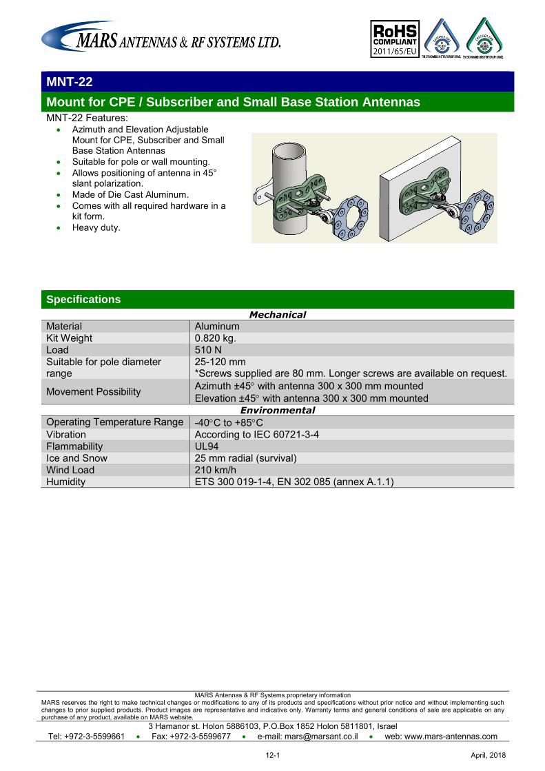
MARS Antennas & RF Systems proprietary information MARS reserves the right to make technical changes or modifications to any of its products and specifications without prior notice and without implementing such changes to prior supplied products. Product images are representative and indicative only. Warranty terms and general conditions of sale are applicable on any purchase of any product, available on MARS website.
3 Hamanor st. Holon 5886103, P.O.Box 1852 Holon 5811801, Israel Tel: +972-3-5599661 Fax: +972-3-5599677 e-mail: [email protected] web: www.mars-antennas.com
MNT-22
Mount for CPE / Subscriber and Small Base Station Antennas MNT-22 Features:
Azimuth and Elevation Adjustable Mount for CPE, Subscriber and Small Base Station Antennas
Suitable for pole or wall mounting. Allows positioning of antenna in 45°
slant polarization. Made of Die Cast Aluminum. Comes with all required hardware in a
kit form. Heavy duty.
Specifications
Mechanical
Material Aluminum Kit Weight 0.820 kg. Load 510 N Suitable for pole diameter range
25-120 mm *Screws supplied are 80 mm. Longer screws are available on request.
Movement Possibility Azimuth ±45 with antenna 300 x 300 mm mounted Elevation ±45 with antenna 300 x 300 mm mounted
Environmental
Operating Temperature Range -40C to +85C Vibration According to IEC 60721-3-4 Flammability UL94 Ice and Snow 25 mm radial (survival) Wind Load 210 km/h Humidity ETS 300 019-1-4, EN 302 085 (annex A.1.1)
April, 201812-1
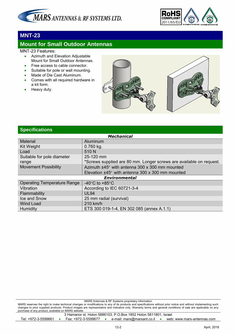
MARS Antennas & RF Systems proprietary information MARS reserves the right to make technical changes or modifications to any of its products and specifications without prior notice and without implementing such changes to prior supplied products. Product images are representative and indicative only. Warranty terms and general conditions of sale are applicable on any purchase of any product, available on MARS website.
3 Hamanor st. Holon 5886103, P.O.Box 1852 Holon 5811801, Israel Tel: +972-3-5599661 Fax: +972-3-5599677 e-mail: [email protected] web: www.mars-antennas.com
MNT-23
Mount for Small Outdoor Antennas MNT-23 Features:
Azimuth and Elevation Adjustable Mount for Small Outdoor Antennas.
Free access to cable connector. Suitable for pole or wall mounting. Made of Die Cast Aluminum. Comes with all required hardware in
a kit form. Heavy duty.
Specifications
Mechanical
Material Aluminum Kit Weight 0.760 kg. Load 510 N Suitable for pole diameter range
25-120 mm *Screws supplied are 80 mm. Longer screws are available on request.
Movement Possibility Azimuth ±45 with antenna 300 x 300 mm mounted Elevation ±45 with antenna 300 x 300 mm mounted
Environmental
Operating Temperature Range -40C to +85C Vibration According to IEC 60721-3-4 Flammability UL94 Ice and Snow 25 mm radial (survival) Wind Load 210 km/h Humidity ETS 300 019-1-4, EN 302 085 (annex A.1.1)
April, 201812-2
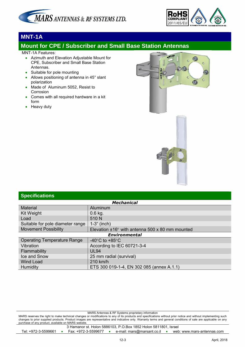
MARS Antennas & RF Systems proprietary information MARS reserves the right to make technical changes or modifications to any of its products and specifications without prior notice and without implementing such changes to prior supplied products. Product images are representative and indicative only. Warranty terms and general conditions of sale are applicable on any purchase of any product, available on MARS website.
3 Hamanor st. Holon 5886103, P.O.Box 1852 Holon 5811801, Israel Tel: +972-3-5599661 Fax: +972-3-5599677 e-mail: [email protected] web: www.mars-antennas.com
MNT-1A
Mount for CPE / Subscriber and Small Base Station Antennas MNT-1A Features: Azimuth and Elevation Adjustable Mount for
CPE, Subscriber and Small Base Station Antennas.
Suitable for pole mounting Allows positioning of antenna in 45° slant
polarization Made of Aluminum 5052, Resist to
Corrosion Comes with all required hardware in a kit
form Heavy duty
Specifications
Mechanical
Material Aluminum Kit Weight 0.6 kg. Load 510 N Suitable for pole diameter range 1-3“ (inch) Movement Possibility Elevation ±16 with antenna 500 x 80 mm mounted
Environmental
Operating Temperature Range -40C to +85C Vibration According to IEC 60721-3-4 Flammability UL94 Ice and Snow 25 mm radial (survival) Wind Load 210 km/h Humidity ETS 300 019-1-4, EN 302 085 (annex A.1.1)
April, 201812-3
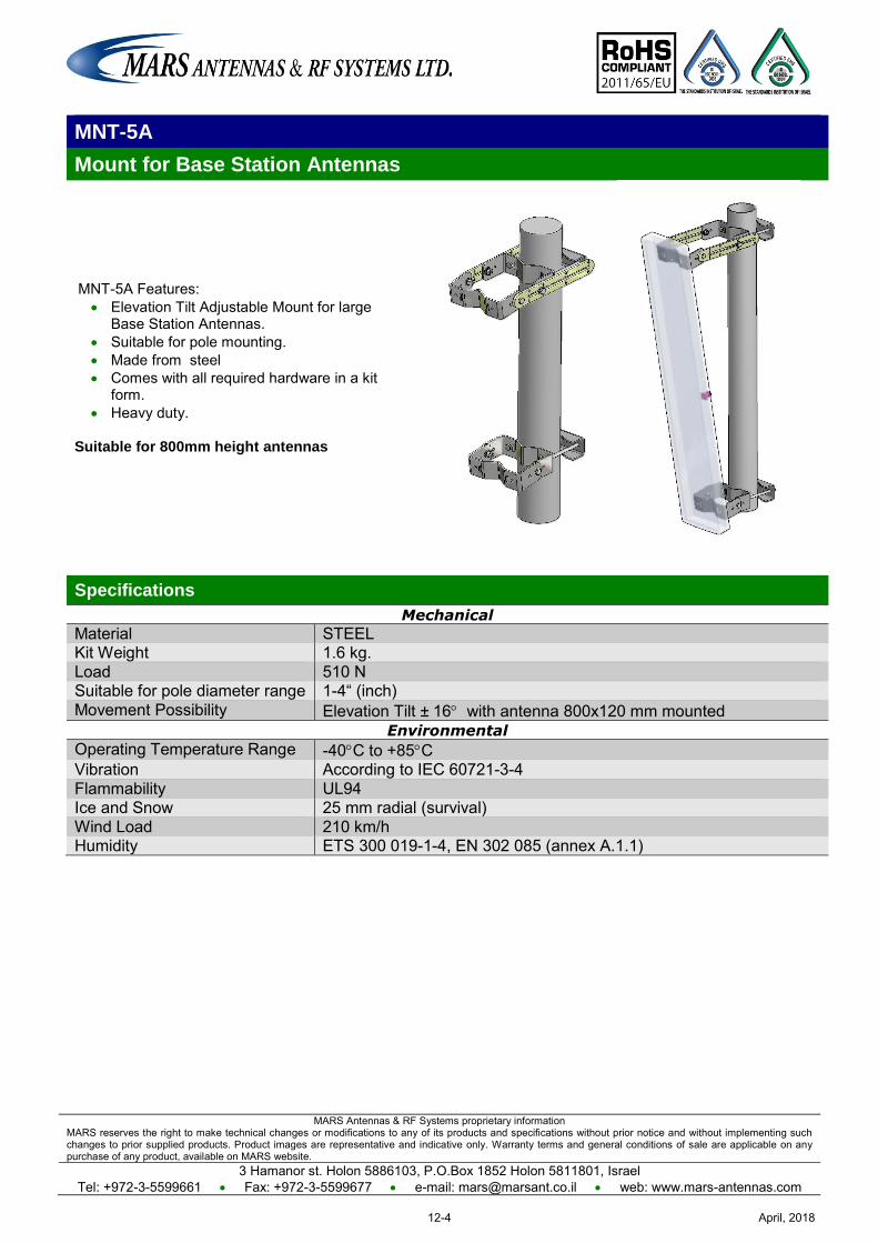
MARS Antennas & RF Systems proprietary information MARS reserves the right to make technical changes or modifications to any of its products and specifications without prior notice and without implementing such changes to prior supplied products. Product images are representative and indicative only. Warranty terms and general conditions of sale are applicable on any purchase of any product, available on MARS website.
3 Hamanor st. Holon 5886103, P.O.Box 1852 Holon 5811801, Israel Tel: +972-3-5599661 Fax: +972-3-5599677 e-mail: [email protected] web: www.mars-antennas.com
MNT-5A
Mount for Base Station Antennas
MNT-5A Features: Elevation Tilt Adjustable Mount for large
Base Station Antennas. Suitable for pole mounting. Made from steel Comes with all required hardware in a kit
form. Heavy duty.
Suitable for 800mm height antennas
Specifications
Mechanical
Material STEEL Kit Weight 1.6 kg. Load 510 N Suitable for pole diameter range 1-4“ (inch) Movement Possibility Elevation Tilt ± 16 with antenna 800x120 mm mounted
Environmental
Operating Temperature Range -40C to +85C Vibration According to IEC 60721-3-4 Flammability UL94 Ice and Snow 25 mm radial (survival) Wind Load 210 km/h Humidity ETS 300 019-1-4, EN 302 085 (annex A.1.1)
April, 201812-4
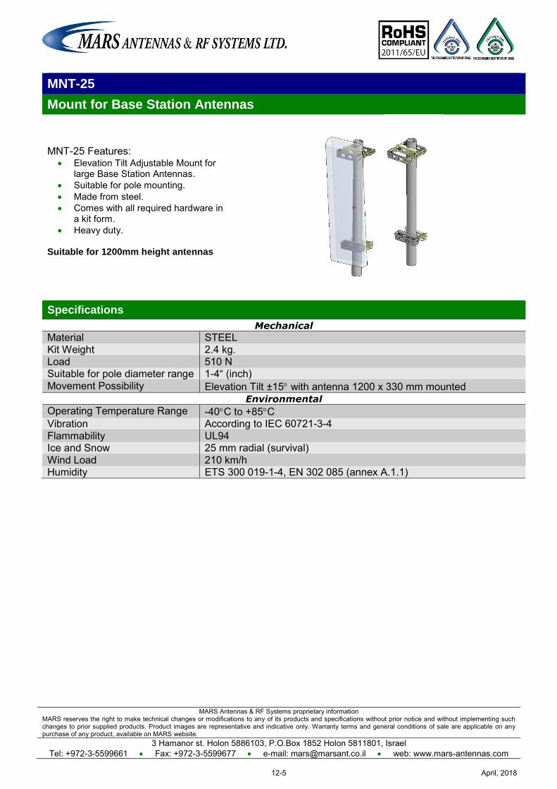
MARS Antennas & RF Systems proprietary information MARS reserves the right to make technical changes or modifications to any of its products and specifications without prior notice and without implementing such changes to prior supplied products. Product images are representative and indicative only. Warranty terms and general conditions of sale are applicable on any purchase of any product, available on MARS website.
3 Hamanor st. Holon 5886103, P.O.Box 1852 Holon 5811801, Israel Tel: +972-3-5599661 Fax: +972-3-5599677 e-mail: [email protected] web: www.mars-antennas.com
MNT-25
Mount for Base Station Antennas
MNT-25 Features: Elevation Tilt Adjustable Mount for
large Base Station Antennas. Suitable for pole mounting. Made from steel. Comes with all required hardware in
a kit form. Heavy duty.
Suitable for 1200mm height antennas
Specifications
Mechanical
Material STEEL Kit Weight 2.4 kg. Load 510 N Suitable for pole diameter range 1-4“ (inch) Movement Possibility Elevation Tilt ±15 with antenna 1200 x 330 mm mounted
Environmental
Operating Temperature Range -40C to +85C Vibration According to IEC 60721-3-4 Flammability UL94 Ice and Snow 25 mm radial (survival) Wind Load 210 km/h Humidity ETS 300 019-1-4, EN 302 085 (annex A.1.1)
April, 201812-5
MARS Antennas & RF Systems proprietary information MARS reserves the right to make technical changes or modifications to any of its products and specifications without prior notice and without implementing such changes to prior supplied products. Product images are representative and indicative only. Warranty terms and general conditions of sale are applicable on any purchase of any product, available on MARS website.
3 Hamanor st. Holon 5886103, P.O.Box 1852 Holon 5811801, Israel
Tel: +972-3-5599661 Fax: +972-3-5599677 e-mail: [email protected] web: www.mars-antennas.com
MNT-4 Series
For Small Size Antennas
MNT-4U (Wall mount)
MNT-4L (Ceiling/Stand mount)
MNT-4LU (Wall/Pole mount)
April, 201812-6
MARS Antennas & RF Systems proprietary information MARS reserves the right to make technical changes or modifications to any of its products and specifications without prior notice and without implementing such changes to prior supplied products. Product images are representative and indicative only. Warranty terms and general conditions of sale are applicable on any purchase of any product, available on MARS website.
3 Hamanor st. Holon 5886103, P.O.Box 1852 Holon 5811801, Israel Tel: +972-3-5599661 Fax: +972-3-5599677 e-mail: [email protected] web: www.mars-antennas.com
MNT-60A
Mount for CPE / Subscriber Large Size Antennas MNT-60A Features:
Elevation Adjustable Mount for Subscriber Large Size Antennas.
Suitable for pole or wall mounting. Allowing angle inclination of 16°. Made of Steel SAE1020, Resist to
Corrosion. Comes with all required hardware in
a kit form. Heavy duty.
Specifications
Mechanical
Material STEEL, GALVANIZED Kit Weight 2 kg. Load 700 N Suitable for pole diameter range 1-4“ (inch) Movement Possibility Elevation ±16 (with antenna 600 x 600 mm mounted)
Environmental
Operating Temperature Range -40C to +85C Vibration According to IEC 60721-3-4 Flammability UL94 Ice and Snow 25 mm radial (survival) Wind Load 210 km/h Humidity ETS 300 019-1-4, EN 302 085 (annex A.1.1)
April, 201812-7
MARS Antennas & RF Systems proprietary information MARS reserves the right to make technical changes or modifications to any of its products and specifications without prior notice and without implementing such changes to prior supplied products. Product images are representative and indicative only. Warranty terms and general conditions of sale are applicable on any purchase of any product, available on MARS website.
3 Hamanor st. Holon 5886103, P.O.Box 1852 Holon 5811801, Israel Tel: +972-3-5599661 Fax: +972-3-5599677 e-mail: [email protected] web: www.mars-antennas.com
MK-ES20/MK-ES21
Small Enclosure Kit
Mars enclosure kit designed for integration of RF PCB from different manufactures with Mars antennas. Enclosure kit includes: Enclosure Die Cast Aluminum. Base for RF PCB (See ordering options). RJ45 Ethernet Waterproof Connector.
Enclosure Kit Features: Suitable for integration with 200x200, 305x305, 370x370 and
600x600 mm Mars antennas*. Suitable for pole or wall azimuth and elevation adjustable
mounting. Heavy duty.
Suitable for Mount MNT-22 or MNT-60A*. (*) MNT-22 suitable for 200x200, 305x305, 370x370 mm Mars antennas. MNT-60A suitable for 600x600 mm Mars Antennas.
Specifications
Mechanical
Enclosure Material Aluminum A380 Enclosure dimensions (external) 180 x 167 (242 with RJ45) x 68 mm Base for RF plate material Aluminum Base for RF dimensions 150 x 138 mm, height of PCB (max) - 55 mm Enclosure Finish White electrostatic powder coating Connector RJ45 Ethernet Waterproof Connector Weight (without MNT) 0.7 kg.
Suitable for pole diameter range 25-120 mm (Screws supplied are 80 mm. Longer screws are available on request)
Environmental
Operating Temperature Range -40C to +65C Vibration According to IEC 60721-3-4 Flammability UL94 Ice and Snow 25 mm radial (survival) Water proofing IP-67 Humidity ETS 300 019-1-4, EN 302 085 (annex A.1.1)
Ordering Options
MK-ES20 Base for RF PCB MK-ES21 Base for RF PCB with embedded PEMs suitable for RB-411/RB-711
April, 201812-8
MARS Antennas & RF Systems proprietary information MARS reserves the right to make technical changes or modifications to any of its products and specifications without prior notice and without implementing such changes to prior supplied products. Product images are representative and indicative only. Warranty terms and general conditions of sale are applicable on any purchase of any product, available on MARS website.
3 Hamanor st. Holon 5886103, P.O.Box 1852 Holon 5811801, Israel Tel: +972-3-5599661 Fax: +972-3-5599677 e-mail: [email protected] web: www.mars-antennas.com
MK-EL30/MK-EL31
Large Enclosure Kit
Mars enclosure kit designed for integration of RF PCB from different manufactures with Mars antennas. Enclosure kit includes: Enclosure Die Cast Aluminum. Base for RF PCB (See ordering options). RJ45 Ethernet Waterproof Connector.
Enclosure Kit Features: Suitable for integration with 305x305, 370x370 mm
Mars antennas. Suitable for pole or wall azimuth and elevation
adjustable mounting. Heavy duty.
Suitable for Mount MNT-22.
Specifications
Mechanical
Enclosure Material Aluminum A380 Enclosure dimensions (external) 287 x 287 (347 with RJ45) x 68 mm Base for RF plate material Aluminum Base for RF dimensions 245 x 245 mm, height of PCB (from Base for RF to backplane) - 55
mm Enclosure Finish White electrostatic powder coating Connector RJ45 Ethernet Waterproof Connector Weight (without MNT-22) 1.35 kg.
Suitable for pole diameter range 25-120 mm (Screws supplied are 80 mm. Longer screws are available on request)
Environmental
Operating Temperature Range -40C to +65C Vibration According to IEC 60721-3-4 Flammability UL94 Ice and Snow 25 mm radial (survival) Water proofing IP-67 Humidity ETS 300 019-1-4, EN 302 085 (annex A.1.1)
Ordering Options
MK-EL30 Base for RF PCB MK-EL31 Base for RF PCB with embedded PEMs suitable for RB-411/RB-711
and RB-433/RB-733
April, 201812-9
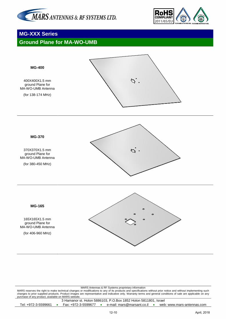
MARS Antennas & RF Systems proprietary information MARS reserves the right to make technical changes or modifications to any of its products and specifications without prior notice and without implementing such changes to prior supplied products. Product images are representative and indicative only. Warranty terms and general conditions of sale are applicable on any purchase of any product, available on MARS website.
3 Hamanor st. Holon 5886103, P.O.Box 1852 Holon 5811801, Israel
Tel: +972-3-5599661 Fax: +972-3-5599677 e-mail: [email protected] web: www.mars-antennas.com
MG-XXX Series
Ground Plane for MA-WO-UMB
MG-400
400X400X1.5 mm ground Plane for
MA-WO-UMB Antenna
(for 138-174 MHz)
MG-370
370X370X1.5 mm ground Plane for
MA-WO-UMB Antenna
(for 380-450 MHz)
MG-165
165X165X1.5 mm ground Plane for
MA-WO-UMB Antenna
(for 406-960 MHz)
April, 201812-10
Ver 16.02
www.mars-antennas.com
3 Hamanor st. Holon 5886103, IsraelP.O.B 1852 Holon 5811801, Israel
Tel: +972-3-5599661Fax: +972-3-5599677
E-mail: [email protected]


