Embed Size (px)
Citation preview
Fiber-Reinforced Concrete – High Fiber Slabs: Extending Joint Spacing
FORTA Corporation
March 2020
TR.1.03.03.20
TECHNICAL REPORT
© 2020 FORTA Corporation No part of this publication may be reproduced in any form, in an electronic retrieval system or otherwise, without the prior written permission of the publisher.

Fiber-Reinforced Concrete – High Fiber Slabs: Extending Joint Spacing
ii
THIS PAGE LEFT BLANK INTENTIONALLY
Fiber-Reinforced Concrete – High Fiber Slabs: Extending Joint Spacing
iii
AUTHORS Daniel Biddle Vice President of Sales
FORTA CORPORATION FORTA personnel are available to assist with fiber selection and use, as well as the explanation of reasonable expectations of the fiber. FORTA representatives do not engage in the practice of engineering or architecture as licensed by government agencies, nor are they licensed to act in a role of overall project supervision where FORTA products are used. FORTA personnel are available solely for the support of our customers - those that purchase and specify our products.
100 Forta Drive, Grove City, PA 16127-6399 U.S.A.
1-800-245-0306 or 1-724-458-5221
Fax: 1-724-458-8331
www.forta-ferro.com
FORTA® and FORTA-FERRO® are
registered trademarks of FORTA Corporation.
KEYWORDS FORTA-FERRO®, FRC, Macro Synthetic Fiber, High Fiber Slabs, Extended Joints
Fiber-Reinforced Concrete – High Fiber Slabs: Extending Joint Spacing
iv
CONTENTS 1. INTRODUCTION ....................................................................................................... 1
2. BACKGROUND ......................................................................................................... 1
3. EXTENDED JOINT-SPACE HISTORY ...................................................................... 2
4. THE MACRO FIBER FLOOR PHILOSOPHY ............................................................ 3
5. THE FIBER – FORTA-FERRO® ................................................................................ 5
5.1 Fiber Dosage .................................................................................................... 5
5.2 Fiber Length ..................................................................................................... 6
5.3 Fiber Contribution to Reductions in Shrinkage and Curling ............................... 6
5.4 Fiber Addition Point .......................................................................................... 7
5.5 Mixing Time and Speed .................................................................................... 8
5.6 Fiber Slump ...................................................................................................... 9
5.7 Pumping ......................................................................................................... 10
5.8 Bleeding.......................................................................................................... 10
5.9 Finishing ......................................................................................................... 11
6. THE CONCRETE .................................................................................................... 12
6.1 Mix Design: Cement, MSA, and Strength ....................................................... 12
6.2 Water: Too Much or Too Little ........................................................................ 14
6.3 Air ................................................................................................................... 15
6.4 Temperature, Sunlight, and Humidity .............................................................. 15
6.5 Wind ............................................................................................................... 15
6.6 Curing ............................................................................................................. 15
7. THE PRACTICE ...................................................................................................... 16
7.1 Panel Size ...................................................................................................... 16
7.2 Panel Shape ................................................................................................... 17
7.3 Load Transfer ................................................................................................. 18
7.4 Sawcut Timing and Depth ............................................................................... 19
7.5 Sub-grade Drag .............................................................................................. 19
7.6 Sub-Grade Compaction and Levelness with Regards to Slab Thickness ........ 20
7.7 Perimeter Restraint ......................................................................................... 21
7.8 Internal Restraint ............................................................................................ 21
7.9 Column Isolation and Re-Entrant Corners ....................................................... 21
8. SAFEGUARD SUMMARY ....................................................................................... 22

Fiber-Reinforced Concrete – High Fiber Slabs: Extending Joint Spacing
v
THIS PAGE LEFT BLANK INTENTIONALLY
Fiber-Reinforced Concrete – High Fiber Slabs: Extending Joint Spacing
1
1. INTRODUCTION
The concrete industry has had a long-time obsession with cracks in concrete, based on the perception that floor and pavement owners are most troubled by cracking issues. And while cracks and methods to control them are certainly an important consideration in any concrete project, the vast majority of problems faced by facility owners are, in reality, more often caused by joints than random cracks. As a result, owners continue to investigate and search for methods and materials that can reduce the number of joints in floors and pavements, and thereby avoid the costly repairs and down-time associated with joint failures. To-date, those reduced-joint or joint-free methods of slab construction have centered on the use of post-tensioned slabs or shrinkage-compensating cement, both of which are very effective, yet represent a considerable up-front cost. The use of three-dimensional fiber reinforcement over the past several decades has allowed designers to effectively replace conventional non-structural temperature steel reinforcement in a wide variety of slab-on-ground applications. With the advent of higher possible dosages of fiber per cubic yard or meter of concrete, traditional joint-spacing practice and design can now be reconsidered as well and can play an important role in reducing both the short-term and long-term joint-related costs for owners.
2. BACKGROUND
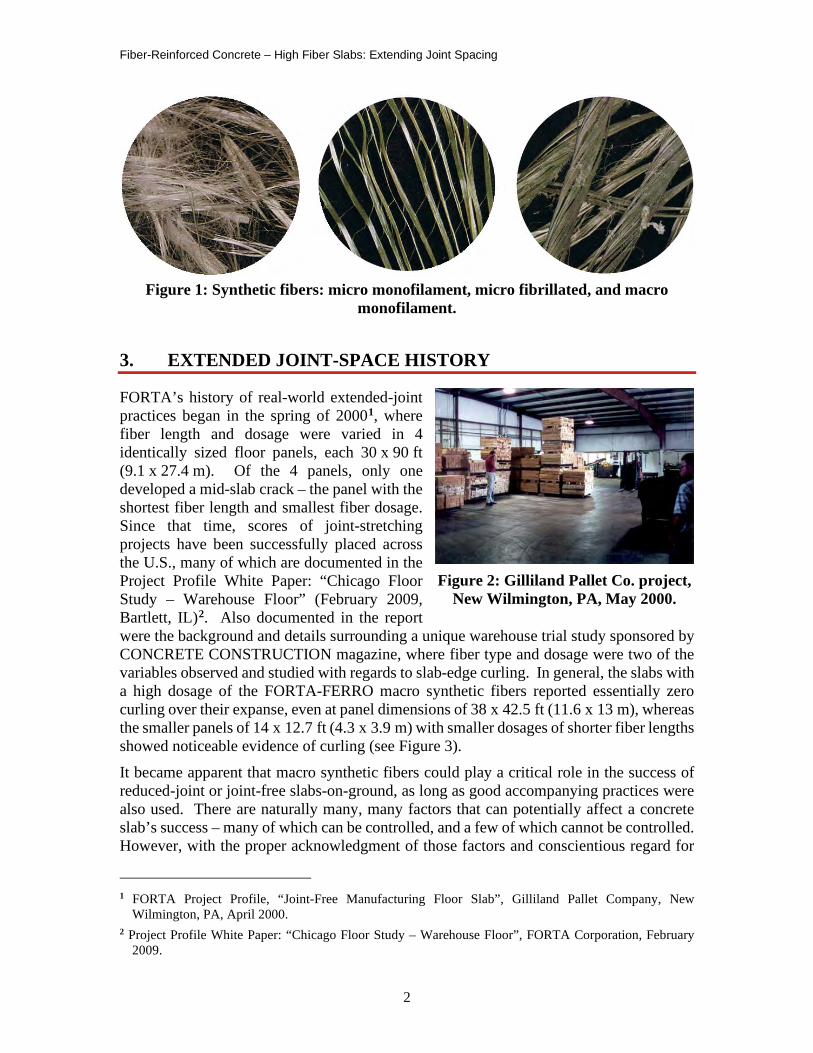
FORTA Corporation introduced micro synthetic fibers to the U.S. market in 1978, which were designed to reduce plastic shrinkage cracking and add an element of shrinkage/temperature crack control. These products generally took the form of very fine single-filament polypropylene or nylon fibers (monofilaments) used at a low dosage of 1.0 lb/cu yd (0.6 kg/cu m), and deformed net-shaped polypropylene fibers (fibrillated) typically used at 1.5 to 3.0 lb/cu yd (0.9 to 1.8 kg/cu m). Though it was well recognized in the laboratory that adding higher dosages would lead to considerably higher levels of shrinkage reduction, these fine-filament fibers created mixing and placing challenges due to their high surface-area characteristic. After years of research and trials, FORTA introduced the first of its kind macro synthetic fiber in late 1999 to solve the user-friendly issues at higher dosages. The solution keys became a twisted-bundle shape to eliminate balling, a polypropylene/copolymer chemistry and long lengths to enhance strength, and a concrete-gray color and special fibril shape to accommodate finishability. For over a decade, the result has made FORTA-FERRO the most user-friendly macro synthetic fiber in the industry, with scores of successful flatwork projects all over the world. And with these higher fiber dosages came considerable evidence of other important benefits – the dramatic reduction in shrinkage, and a resulting reduction in slab-edge curling.
Fiber-Reinforced Concrete – High Fiber Slabs: Extending Joint Spacing
2
Figure 1: Synthetic fibers: micro monofilament, micro fibrillated, and macro
monofilament.
3. EXTENDED JOINT-SPACE HISTORY
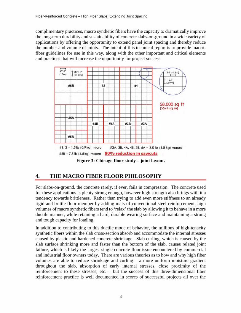
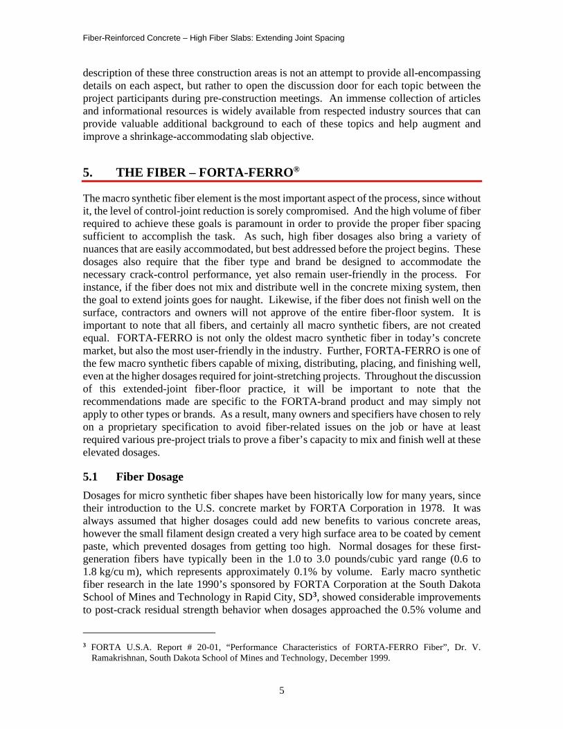
FORTA’s history of real-world extended-joint practices began in the spring of 20001, where fiber length and dosage were varied in 4 identically sized floor panels, each 30 x 90 ft (9.1 x 27.4 m). Of the 4 panels, only one developed a mid-slab crack – the panel with the shortest fiber length and smallest fiber dosage. Since that time, scores of joint-stretching projects have been successfully placed across the U.S., many of which are documented in the Project Profile White Paper: “Chicago Floor Study – Warehouse Floor” (February 2009, Bartlett, IL)2. Also documented in the report were the background and details surrounding a unique warehouse trial study sponsored by CONCRETE CONSTRUCTION magazine, where fiber type and dosage were two of the variables observed and studied with regards to slab-edge curling. In general, the slabs with a high dosage of the FORTA-FERRO macro synthetic fibers reported essentially zero curling over their expanse, even at panel dimensions of 38 x 42.5 ft (11.6 x 13 m), whereas the smaller panels of 14 x 12.7 ft (4.3 x 3.9 m) with smaller dosages of shorter fiber lengths showed noticeable evidence of curling (see Figure 3). It became apparent that macro synthetic fibers could play a critical role in the success of reduced-joint or joint-free slabs-on-ground, as long as good accompanying practices were also used. There are naturally many, many factors that can potentially affect a concrete slab’s success – many of which can be controlled, and a few of which cannot be controlled. However, with the proper acknowledgment of those factors and conscientious regard for
1 FORTA Project Profile, “Joint-Free Manufacturing Floor Slab”, Gilliland Pallet Company, New
Wilmington, PA, April 2000. 2 Project Profile White Paper: “Chicago Floor Study – Warehouse Floor”, FORTA Corporation, February
2009.
Figure 2: Gilliland Pallet Co. project, New Wilmington, PA, May 2000.
Fiber-Reinforced Concrete – High Fiber Slabs: Extending Joint Spacing
3
complimentary practices, macro synthetic fibers have the capacity to dramatically improve the long-term durability and sustainability of concrete slabs-on-ground in a wide variety of applications by offering the opportunity to extend panel joint spacing and thereby reduce the number and volume of joints. The intent of this technical report is to provide macro-fiber guidelines for use in this way, along with the other important and critical elements and practices that will increase the opportunity for project success.
Figure 3: Chicago floor study – joint layout.
4. THE MACRO FIBER FLOOR PHILOSOPHY
For slabs-on-ground, the concrete rarely, if ever, fails in compression. The concrete used for these applications is plenty strong enough, however high strength also brings with it a tendency towards brittleness. Rather than trying to add even more stiffness to an already rigid and brittle floor member by adding mats of conventional steel reinforcement, high volumes of macro synthetic fibers tend to ‘relax’ the slab by allowing it to behave in a more ductile manner, while retaining a hard, durable wearing surface and maintaining a strong and tough capacity for loading. In addition to contributing to this ductile mode of behavior, the millions of high-tenacity synthetic fibers within the slab cross-section absorb and accommodate the internal stresses caused by plastic and hardened concrete shrinkage. Slab curling, which is caused by the slab surface shrinking more and faster than the bottom of the slab, causes related joint failure, which is likely the largest single concrete floor issue encountered by commercial and industrial floor owners today. There are various theories as to how and why high fiber volumes are able to reduce shrinkage and curling – a more uniform moisture gradient throughout the slab, absorption of early internal stresses, close proximity of the reinforcement to these stresses, etc. – but the success of this three-dimensional fiber reinforcement practice is well documented in scores of successful projects all over the

Fiber-Reinforced Concrete – High Fiber Slabs: Extending Joint Spacing
4
world and is likely a combination of all of the benefit characteristics. This historic success coupled with the phenomenon of reduced shrinkage and slab relaxation led FORTA and others to begin re-considering the conventional joint-space practices for slabs-on-ground, and to develop guidelines and complimentary practices to continually improve the opportunity for success in this application.
This fiber-floor process requires a fundamental change in basic philosophy with regards to slabs-on-ground, one that focuses on shrinkage rather than strength. Once all involved parties – the owner, architect, engineer, concrete supplier, and concrete contractor – buy in to a shrinkage-related focus, then each aspect of the slab construction can be adjusted accordingly. The basic premise is the acknowledgement that concrete will shrink as it dries and cures, and all efforts should be made to reduce the shrinkage as much as possible, and then accommodate the shrinkage that remains. Though high volumes of macro synthetic fibers play a large and critical role in the shrinkage-reducing goal and extended joint-space objective, it would be foolhardy to ignore other shrinkage-related aspects of the process. Similarly, it wouldn’t make sense to create a healthy lifestyle program involving only vitamins, while ignoring the ramifications of smoking, excessive drinking, or eating a basketful of candy each day. To reduce the number and volume of joints in slab-on-ground applications, high volumes of macro synthetic fibers will provide the reinforcement
vitamins to help the concrete reduce the effects of shrinkage, and by following complimentary practices in several related areas, the odds for success can be improved dramatically. This regimen acknowledges and respects the phenomenon of shrinkage, and therefore dictates materials and practices accordingly. As the construction team adds more and more elements of shrinkage-accommodating behavior to the plus column, the opportunity for success increases dramatically. A healthy concrete floor or slab should contain a shrinkage-reducing diet and high-fiber content, along with a well-rounded project behavior regimen that compliments the goal. The uniform three-dimensional distribution of a high-fiber dosage provides a considerable level of reinforcement ‘forgiveness’, many times covering for shrinkage transgressions in other related areas, however all attempts to follow shrinkage-reducing practices in addition to the fiber usage will pay long-term sustainable dividends to the slab owner and user. This ‘high-fiber, reduced-joint’ slab objective requires attention to three basic topic areas: The Fiber, the Concrete itself, and the related Practice, creating a F-C-P formula and guideline checklist. Diligent attention to each area is important in order for each element to remain in harmony and not negate the other. Each of these areas is important, and the collection will provide designers and contractors a valuable road map and guideline to achieve their goal of better and more serviceable concrete floors and slabs. The following
Fiber-Reinforced Concrete – High Fiber Slabs: Extending Joint Spacing
5
description of these three construction areas is not an attempt to provide all-encompassing details on each aspect, but rather to open the discussion door for each topic between the project participants during pre-construction meetings. An immense collection of articles and informational resources is widely available from respected industry sources that can provide valuable additional background to each of these topics and help augment and improve a shrinkage-accommodating slab objective.
5. THE FIBER – FORTA-FERRO®
The macro synthetic fiber element is the most important aspect of the process, since without it, the level of control-joint reduction is sorely compromised. And the high volume of fiber required to achieve these goals is paramount in order to provide the proper fiber spacing sufficient to accomplish the task. As such, high fiber dosages also bring a variety of nuances that are easily accommodated, but best addressed before the project begins. These dosages also require that the fiber type and brand be designed to accommodate the necessary crack-control performance, yet also remain user-friendly in the process. For instance, if the fiber does not mix and distribute well in the concrete mixing system, then the goal to extend joints goes for naught. Likewise, if the fiber does not finish well on the surface, contractors and owners will not approve of the entire fiber-floor system. It is important to note that all fibers, and certainly all macro synthetic fibers, are not created equal. FORTA-FERRO is not only the oldest macro synthetic fiber in today’s concrete market, but also the most user-friendly in the industry. Further, FORTA-FERRO is one of the few macro synthetic fibers capable of mixing, distributing, placing, and finishing well, even at the higher dosages required for joint-stretching projects. Throughout the discussion of this extended-joint fiber-floor practice, it will be important to note that the recommendations made are specific to the FORTA-brand product and may simply not apply to other types or brands. As a result, many owners and specifiers have chosen to rely on a proprietary specification to avoid fiber-related issues on the job or have at least required various pre-project trials to prove a fiber’s capacity to mix and finish well at these elevated dosages.
5.1 Fiber Dosage Dosages for micro synthetic fiber shapes have been historically low for many years, since their introduction to the U.S. concrete market by FORTA Corporation in 1978. It was always assumed that higher dosages could add new benefits to various concrete areas, however the small filament design created a very high surface area to be coated by cement paste, which prevented dosages from getting too high. Normal dosages for these first-generation fibers have typically been in the 1.0 to 3.0 pounds/cubic yard range (0.6 to 1.8 kg/cu m), which represents approximately 0.1% by volume. Early macro synthetic fiber research in the late 1990’s sponsored by FORTA Corporation at the South Dakota School of Mines and Technology in Rapid City, SD3, showed considerable improvements to post-crack residual strength behavior when dosages approached the 0.5% volume and
3 FORTA U.S.A. Report # 20-01, “Performance Characteristics of FORTA-FERRO Fiber”, Dr. V.
Ramakrishnan, South Dakota School of Mines and Technology, December 1999.
Fiber-Reinforced Concrete – High Fiber Slabs: Extending Joint Spacing
6
higher addition rates, and dramatic reductions in plastic shrinkage crack area from 0.5% to 2.0% by volume rates. Based on these early laboratory results and a life-time of study and practice, Mr. Jerry Holland of Atlanta, GA, a world-renowned concrete and floor expert, began to experiment with macro synthetic fibers per his desire to determine the proper dosage to accommodate the goal of increasing floor-panel size and minimizing the need for control joints used as a crack-control practice. From his trials and experimental projects, Mr. Holland also arrived at the 0.5% volume dosage of 7.5 lb/cu yd (4.5 kg/cu m) as the minimum macro fiber dosage needed to consider extending slab panel size to any great degree, often claiming that ‘…it’s not the first 2.5 lb of fiber nor the second 2.5 lb that is the shrinkage-controlling tipping point, but the third critical 2.5 lb that allows the process to work effectively. What might represent only 50% in additional fiber dosage could easily result in a 500% improvement in performance.’ Certainly, lesser degrees of shrinkage and crack control are possible with lesser fiber dosages and could be considered, but the ‘magical’ 7.5 lb/cu yd (4.5 kg/cu m) dosage has been proven by scores of successful extended-joint projects for over 20 years. If macro synthetic fibers are used as a simple alternate to conventional matt-steel as non-structural temperature reinforcement for slabs while maintaining conventional panel sizes, certainly lower calculated dosages are viable and proper. However, when the goal is to increase panel size and minimize control joints, the 0.5% by volume dosage level represents a trusted and often-practiced addition level for consideration.
5.2 Fiber Length The length of the fiber is typically called out in the project specifications by the project engineer and should be acknowledged and confirmed by the project team. It is universally acknowledged that longer fibers offer improved post-crack values than shorter fibers at similar dosages by adding to the mechanical gripping capacity along their length. However, not all fiber types and shapes offer the same capability to be uniformly mixed and distributed when used in long lengths, and manufacturers may recommend short fiber lengths due to this deficiency. The unique FORTA-FERRO bundle configuration allows long fiber lengths – such as 2.25 in (54 mm) – to mix and distribute extremely well, even at the high-fiber dosages required to achieve joint-stretching goals and performance. If, in fact, project conditions require a small-aggregate mix such as 3/8 in (9.5 mm) or smaller to be used, then a shorter-length fiber could be considered, such as 1.5 in (38 mm). Fiber length may impact other facets to some degree, such as pumping or finishing, and should be pre-trialed if there are concerns in that regard (see “Pumping” on page 10 and “Finishing” on page 11 for additional information).
5.3 Fiber Contribution to Reductions in Shrinkage and Curling The well-documented Chicago Warehouse Trial Study project in 2009 certainly added validity to the presumption that high dosages of macro synthetic fibers reduce surface shrinkage and the resulting slab-edge curling. A series of six articles in CONCRETE
Fiber-Reinforced Concrete – High Fiber Slabs: Extending Joint Spacing
7
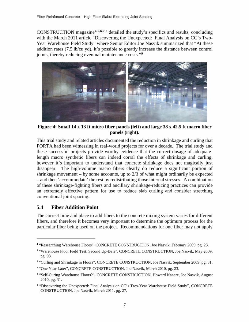
CONSTRUCTION magazine4,5,6,7,8 detailed the study’s specifics and results, concluding with the March 2011 article “Discovering the Unexpected: Final Analysis on CC’s Two-Year Warehouse Field Study” where Senior Editor Joe Nasvik summarized that “At these addition rates (7.5 lb/cu yd), it’s possible to greatly increase the distance between control joints, thereby reducing eventual maintenance costs.”9
Figure 4: Small 14 x 13 ft micro fiber panels (left) and large 38 x 42.5 ft macro fiber
panels (right). This trial study and related articles documented the reduction in shrinkage and curling that FORTA had been witnessing in real-world projects for over a decade. The trial study and these successful projects provide worthy evidence that the correct dosage of adequate-length macro synthetic fibers can indeed corral the effects of shrinkage and curling, however it’s important to understand that concrete shrinkage does not magically just disappear. The high-volume macro fibers clearly do reduce a significant portion of shrinkage movement – by some accounts, up to 2/3 of what might ordinarily be expected – and then ‘accommodate’ the rest by redistributing those internal stresses. A combination of these shrinkage-fighting fibers and ancillary shrinkage-reducing practices can provide an extremely effective pattern for use to reduce slab curling and consider stretching conventional joint spacing.
5.4 Fiber Addition Point The correct time and place to add fibers to the concrete mixing system varies for different fibers, and therefore it becomes very important to determine the optimum process for the particular fiber being used on the project. Recommendations for one fiber may not apply
4 “Researching Warehouse Floors”, CONCRETE CONSTRUCTION, Joe Nasvik, February 2009, pg. 23. 5 “Warehouse Floor Field Test: Second Up-Date”, CONCRETE CONSTRUCTION, Joe Nasvik, May 2009,
pg. 93. 6 “Curling and Shrinkage in Floors”, CONCRETE CONSTRUCTION, Joe Nasvik, September 2009, pg. 31. 7 “One Year Later”, CONCRETE CONSTRUCTION, Joe Nasvik, March 2010, pg. 23. 8 “Self-Curing Warehouse Floors?”, CONCRETE CONSTRUCTION, Howard Kanare, Joe Nasvik, August
2010, pg. 31. 9 “Discovering the Unexpected: Final Analysis on CC’s Two-Year Warehouse Field Study”, CONCRETE
CONSTRUCTION, Joe Nasvik, March 2011, pg. 27.
Fiber-Reinforced Concrete – High Fiber Slabs: Extending Joint Spacing
8
to another, and therefore the correct addition point and practice should not be assumed as normal, especially with high dosages of macro synthetic fibers. To affect the high demand for shrinkage reduction in joint-stretching projects, it is especially critical to have uniform fiber distribution without clumping or balling. A reasonable litmus test to pre-determine a particular fiber’s ability to mix without clumping is to inspect the fiber in its original package – it’s safe to assume that if the fiber is tangled in the bag it comes in, it’s not likely to un-tangle in 4,000 pounds of wet concrete! If the fibers do not gravity-feed well when dry, then special addition tactics will be required, such as feathering them slowly into the mixing system which would require extra time and patience on the part of the ready-mix supplier.
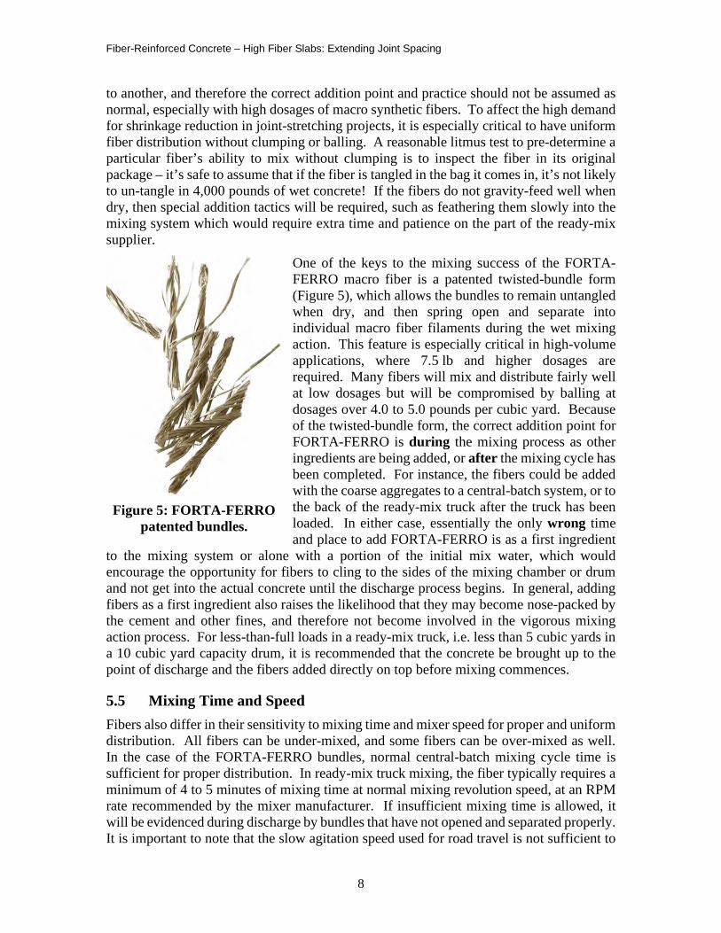
One of the keys to the mixing success of the FORTA-FERRO macro fiber is a patented twisted-bundle form (Figure 5), which allows the bundles to remain untangled when dry, and then spring open and separate into individual macro fiber filaments during the wet mixing action. This feature is especially critical in high-volume applications, where 7.5 lb and higher dosages are required. Many fibers will mix and distribute fairly well at low dosages but will be compromised by balling at dosages over 4.0 to 5.0 pounds per cubic yard. Because of the twisted-bundle form, the correct addition point for FORTA-FERRO is during the mixing process as other ingredients are being added, or after the mixing cycle has been completed. For instance, the fibers could be added with the coarse aggregates to a central-batch system, or to the back of the ready-mix truck after the truck has been loaded. In either case, essentially the only wrong time and place to add FORTA-FERRO is as a first ingredient
to the mixing system or alone with a portion of the initial mix water, which would encourage the opportunity for fibers to cling to the sides of the mixing chamber or drum and not get into the actual concrete until the discharge process begins. In general, adding fibers as a first ingredient also raises the likelihood that they may become nose-packed by the cement and other fines, and therefore not become involved in the vigorous mixing action process. For less-than-full loads in a ready-mix truck, i.e. less than 5 cubic yards in a 10 cubic yard capacity drum, it is recommended that the concrete be brought up to the point of discharge and the fibers added directly on top before mixing commences.
5.5 Mixing Time and Speed Fibers also differ in their sensitivity to mixing time and mixer speed for proper and uniform distribution. All fibers can be under-mixed, and some fibers can be over-mixed as well. In the case of the FORTA-FERRO bundles, normal central-batch mixing cycle time is sufficient for proper distribution. In ready-mix truck mixing, the fiber typically requires a minimum of 4 to 5 minutes of mixing time at normal mixing revolution speed, at an RPM rate recommended by the mixer manufacturer. If insufficient mixing time is allowed, it will be evidenced during discharge by bundles that have not opened and separated properly. It is important to note that the slow agitation speed used for road travel is not sufficient to
Figure 5: FORTA-FERRO patented bundles.
Fiber-Reinforced Concrete – High Fiber Slabs: Extending Joint Spacing
9
properly mix the fibers and should not be added into the minimum fiber mixing time allotted. This same mixing time and speed recommendation would also apply if fibers are added to the truck on-site rather than at the batch plant, and mixing time should not be shortened even under rushed project conditions. Further, excessive agitation-speed revolution time will not negate or ruin the uniform fiber distribution, in the event of project placement delays. Excessive mixer speed can be just as problematic as slow mixing speed, causing the concrete to hang onto the drum wall rather than be subject to the normal blending and folding action required for uniform mixing of all the ingredients – including fibers. Using an RPM speed that is too high in an attempt to shorten the required mixing time will also result in unopened fiber bundles during discharge. When concrete including FORTA-FERRO is mixed at the proper time and speed, the extremely uniform fiber distribution is readily evident even to the untrained eye during discharge.
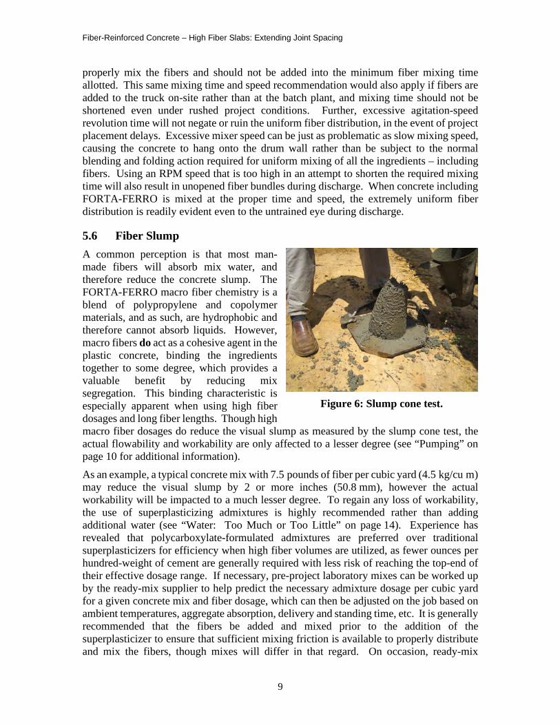
5.6 Fiber Slump A common perception is that most man-made fibers will absorb mix water, and therefore reduce the concrete slump. The FORTA-FERRO macro fiber chemistry is a blend of polypropylene and copolymer materials, and as such, are hydrophobic and therefore cannot absorb liquids. However, macro fibers do act as a cohesive agent in the plastic concrete, binding the ingredients together to some degree, which provides a valuable benefit by reducing mix segregation. This binding characteristic is especially apparent when using high fiber dosages and long fiber lengths. Though high macro fiber dosages do reduce the visual slump as measured by the slump cone test, the actual flowability and workability are only affected to a lesser degree (see “Pumping” on page 10 for additional information). As an example, a typical concrete mix with 7.5 pounds of fiber per cubic yard (4.5 kg/cu m) may reduce the visual slump by 2 or more inches (50.8 mm), however the actual workability will be impacted to a much lesser degree. To regain any loss of workability, the use of superplasticizing admixtures is highly recommended rather than adding additional water (see “Water: Too Much or Too Little” on page 14). Experience has revealed that polycarboxylate-formulated admixtures are preferred over traditional superplasticizers for efficiency when high fiber volumes are utilized, as fewer ounces per hundred-weight of cement are generally required with less risk of reaching the top-end of their effective dosage range. If necessary, pre-project laboratory mixes can be worked up by the ready-mix supplier to help predict the necessary admixture dosage per cubic yard for a given concrete mix and fiber dosage, which can then be adjusted on the job based on ambient temperatures, aggregate absorption, delivery and standing time, etc. It is generally recommended that the fibers be added and mixed prior to the addition of the superplasticizer to ensure that sufficient mixing friction is available to properly distribute and mix the fibers, though mixes will differ in that regard. On occasion, ready-mix
Figure 6: Slump cone test.
Fiber-Reinforced Concrete – High Fiber Slabs: Extending Joint Spacing
10
suppliers have also reported success by adding a projected base amount of superplasticizer to the mix before fiber addition and mixing, and then adding a final admixture adjustment based on need and contractor preferences, once the fiber has been added and mixed.
5.7 Pumping Fibers also differ greatly in their capacity to be pumped. First-generation micro synthetic fibers at low dosages rarely impact any normal pumping procedures. On the other hand, steel fibers often pose pumping challenges due to their rigidity, especially at high dosages. Some macro fiber versions, packaged in cylindrically-shaped pucks, offer a high probability of line blockage if the fiber-wrap remains intact. Any fiber that does not mix well will increase the chances for line blockage caused by fiber clumps or balls, even if the pump grate successfully catches a majority of these clumps. Again, due to the advantage of the unique FORTA-FERRO twisted-bundle form and the resulting uniform fiber distribution, pumping has not been a problem, even at high dosages. In fact, the uniform binding ability of the fiber often results in much more uniform and slightly lower pump pressures that would normally be required for non-fibered mixes, likely due to the reduction in mix segregation courtesy of the fiber. However, issues will arise at the pump-hopper grate, if pre-project precautions are not taken. The primary high-fiber issue at the grate is quite simply the shape of the grate slats – the narrow, thin, rectangular-shaped slats beg for fiber hang-over and build-up – and essentially, the cohesive tendency of the fibers begins to work too soon and makes fiber-concrete flow-through very difficult and slow. Once the high-fiber concrete passes the protective grate, no actual pumping issues will occur, but the grate slats must be accommodated to avoid project issues and delays. There are several grate-fix options available – some of which require only a few minutes to prepare – but all deserve forethought before the first ready-mix truck arrives at the pump hopper. The FORTA Technical Report: “Pumping High-Volume Fibers”10 provides extensive details regarding all aspects of pumping macro synthetic fibers, such as chute location and height, critical grate and hopper vibration, and both permanent and temporary grate rehabs. Essentially, the grate change simply involves changing the shape of the slats – from thin and square to thick and round – to allow the high-fiber concrete to easily flow through rather than hang up or drape over. For whatever reason, the pump-grate fiber-flow issue is the most often ignored pre-construction warning, and the most time-consuming and costly when not addressed. Determining if the concrete placement will be pumped, and if so, addressing these pump-grate issues, is one of the most important fiber facets that should be included in high-fiber specifications and pre-construction project meetings.
5.8 Bleeding As mentioned previously, the FORTA-FERRO is hydrophobic, and therefore will not affect the free water content within the plastic concrete. Further, unlike fiberglass, nylon, or some other fiber chemistries, the polypropylene/copolymer fibers will not wick water to the surface. However, because of their random, three-dimensional location throughout the slab cross-section, these fibers will mechanically block or divert the normal water bleed channels to the surface. As a result, concrete reinforced with high volumes of macro
10 Technical Report: “Pumping High-Volume Fibers”, FORTA Corporation, December 2011.
Fiber-Reinforced Concrete – High Fiber Slabs: Extending Joint Spacing
11
synthetic fiber will bleed slightly slower and slightly less than non-fibered concrete. This phenomenon should be acknowledged by the concrete finisher to help them properly time the finishing operations. As with plain concrete, the historic finish-timing indicators remain the same for high-volume synthetic fiber reinforced concrete. For example, when a footprint leaves only a slight indention in the screeded slab surface, timely finishing procedures may commence. Naturally, if the concrete has not finished bleeding of excess or unused mix water, then finishing should be delayed to avoid prematurely sealing the surface which would add to the risk of future delamination and scaling. And obviously at the other extreme, if surface indicators are misread and the slab has gotten away from the finisher, then it will naturally represent a challenge to reopen the surface to allow for a suitable finish. In either case, ‘blessing’ the young concrete slab with water as a regular practice is just as harmful to fiber-reinforced slabs as it is for unreinforced slabs. Like all slabs, fiber-reinforced slabs must be monitored closely to allow for the correct time – not too early and not too late – for a suitable surface finish.
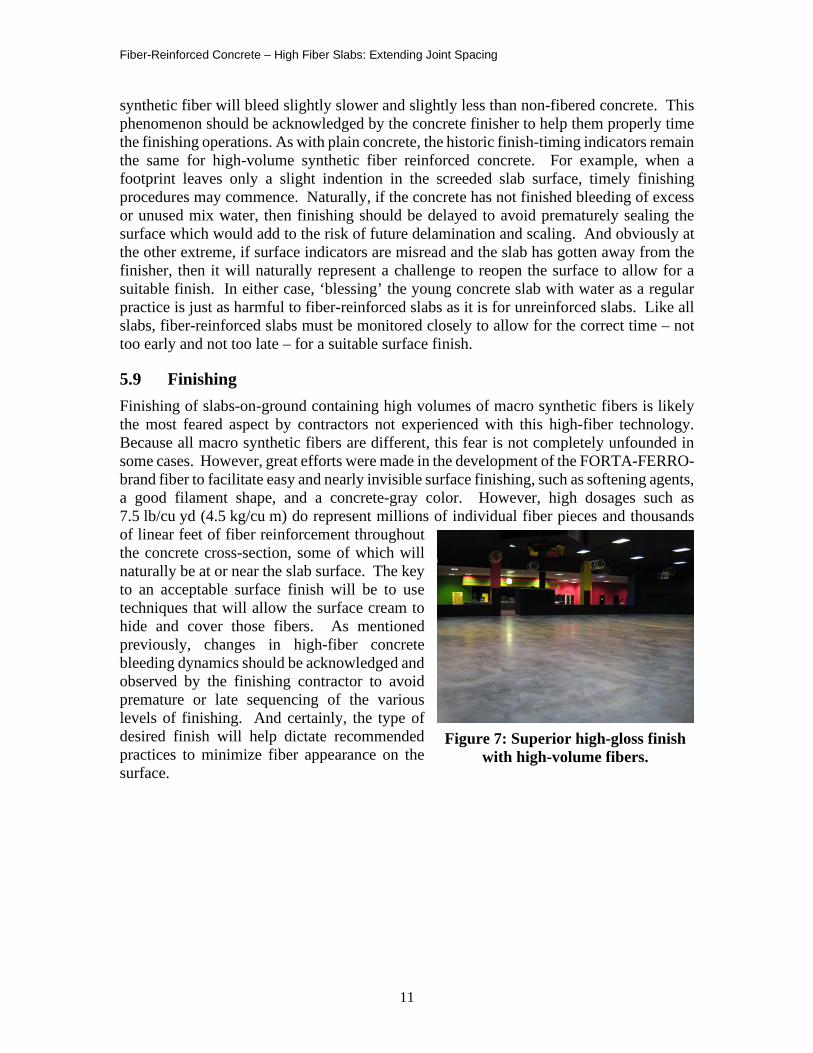
5.9 Finishing Finishing of slabs-on-ground containing high volumes of macro synthetic fibers is likely the most feared aspect by contractors not experienced with this high-fiber technology. Because all macro synthetic fibers are different, this fear is not completely unfounded in some cases. However, great efforts were made in the development of the FORTA-FERRO-brand fiber to facilitate easy and nearly invisible surface finishing, such as softening agents, a good filament shape, and a concrete-gray color. However, high dosages such as 7.5 lb/cu yd (4.5 kg/cu m) do represent millions of individual fiber pieces and thousands of linear feet of fiber reinforcement throughout the concrete cross-section, some of which will naturally be at or near the slab surface. The key to an acceptable surface finish will be to use techniques that will allow the surface cream to hide and cover those fibers. As mentioned previously, changes in high-fiber concrete bleeding dynamics should be acknowledged and observed by the finishing contractor to avoid premature or late sequencing of the various levels of finishing. And certainly, the type of desired finish will help dictate recommended practices to minimize fiber appearance on the surface.
Figure 7: Superior high-gloss finish with high-volume fibers.
Fiber-Reinforced Concrete – High Fiber Slabs: Extending Joint Spacing
12
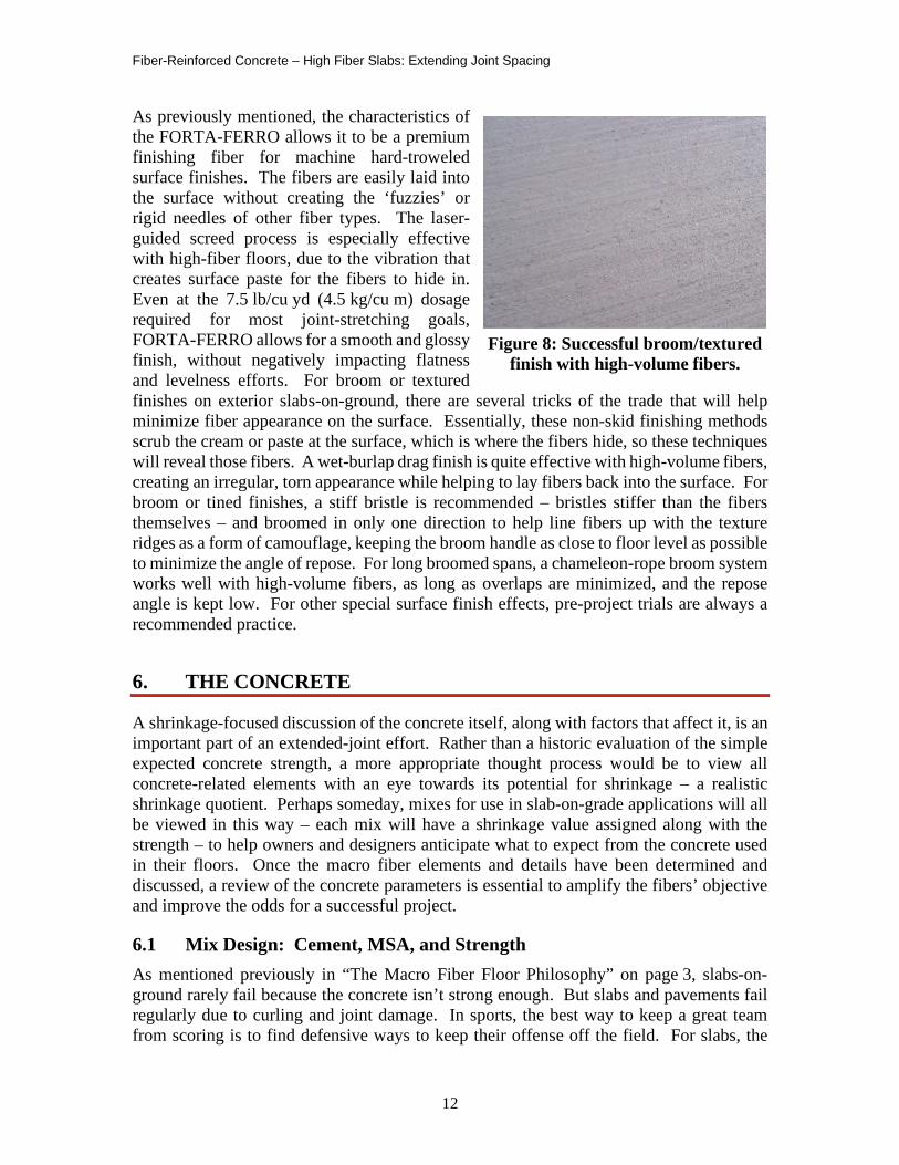
As previously mentioned, the characteristics of the FORTA-FERRO allows it to be a premium finishing fiber for machine hard-troweled surface finishes. The fibers are easily laid into the surface without creating the ‘fuzzies’ or rigid needles of other fiber types. The laser-guided screed process is especially effective with high-fiber floors, due to the vibration that creates surface paste for the fibers to hide in. Even at the 7.5 lb/cu yd (4.5 kg/cu m) dosage required for most joint-stretching goals, FORTA-FERRO allows for a smooth and glossy finish, without negatively impacting flatness and levelness efforts. For broom or textured finishes on exterior slabs-on-ground, there are several tricks of the trade that will help minimize fiber appearance on the surface. Essentially, these non-skid finishing methods scrub the cream or paste at the surface, which is where the fibers hide, so these techniques will reveal those fibers. A wet-burlap drag finish is quite effective with high-volume fibers, creating an irregular, torn appearance while helping to lay fibers back into the surface. For broom or tined finishes, a stiff bristle is recommended – bristles stiffer than the fibers themselves – and broomed in only one direction to help line fibers up with the texture ridges as a form of camouflage, keeping the broom handle as close to floor level as possible to minimize the angle of repose. For long broomed spans, a chameleon-rope broom system works well with high-volume fibers, as long as overlaps are minimized, and the repose angle is kept low. For other special surface finish effects, pre-project trials are always a recommended practice.
6. THE CONCRETE
A shrinkage-focused discussion of the concrete itself, along with factors that affect it, is an important part of an extended-joint effort. Rather than a historic evaluation of the simple expected concrete strength, a more appropriate thought process would be to view all concrete-related elements with an eye towards its potential for shrinkage – a realistic shrinkage quotient. Perhaps someday, mixes for use in slab-on-grade applications will all be viewed in this way – each mix will have a shrinkage value assigned along with the strength – to help owners and designers anticipate what to expect from the concrete used in their floors. Once the macro fiber elements and details have been determined and discussed, a review of the concrete parameters is essential to amplify the fibers’ objective and improve the odds for a successful project.
6.1 Mix Design: Cement, MSA, and Strength As mentioned previously in “The Macro Fiber Floor Philosophy” on page 3, slabs-on-ground rarely fail because the concrete isn’t strong enough. But slabs and pavements fail regularly due to curling and joint damage. In sports, the best way to keep a great team from scoring is to find defensive ways to keep their offense off the field. For slabs, the
Figure 8: Successful broom/textured finish with high-volume fibers.
Fiber-Reinforced Concrete – High Fiber Slabs: Extending Joint Spacing
13
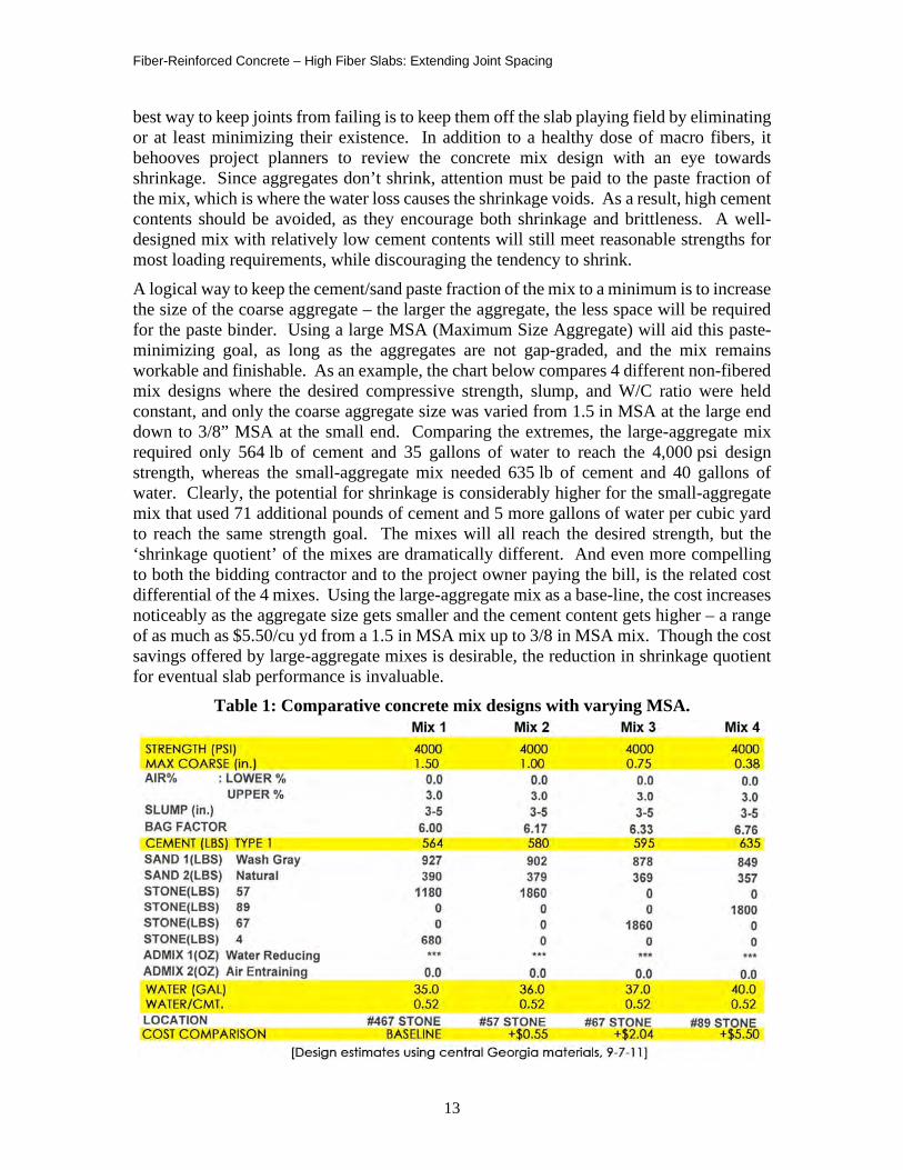
best way to keep joints from failing is to keep them off the slab playing field by eliminating or at least minimizing their existence. In addition to a healthy dose of macro fibers, it behooves project planners to review the concrete mix design with an eye towards shrinkage. Since aggregates don’t shrink, attention must be paid to the paste fraction of the mix, which is where the water loss causes the shrinkage voids. As a result, high cement contents should be avoided, as they encourage both shrinkage and brittleness. A well-designed mix with relatively low cement contents will still meet reasonable strengths for most loading requirements, while discouraging the tendency to shrink. A logical way to keep the cement/sand paste fraction of the mix to a minimum is to increase the size of the coarse aggregate – the larger the aggregate, the less space will be required for the paste binder. Using a large MSA (Maximum Size Aggregate) will aid this paste-minimizing goal, as long as the aggregates are not gap-graded, and the mix remains workable and finishable. As an example, the chart below compares 4 different non-fibered mix designs where the desired compressive strength, slump, and W/C ratio were held constant, and only the coarse aggregate size was varied from 1.5 in MSA at the large end down to 3/8” MSA at the small end. Comparing the extremes, the large-aggregate mix required only 564 lb of cement and 35 gallons of water to reach the 4,000 psi design strength, whereas the small-aggregate mix needed 635 lb of cement and 40 gallons of water. Clearly, the potential for shrinkage is considerably higher for the small-aggregate mix that used 71 additional pounds of cement and 5 more gallons of water per cubic yard to reach the same strength goal. The mixes will all reach the desired strength, but the ‘shrinkage quotient’ of the mixes are dramatically different. And even more compelling to both the bidding contractor and to the project owner paying the bill, is the related cost differential of the 4 mixes. Using the large-aggregate mix as a base-line, the cost increases noticeably as the aggregate size gets smaller and the cement content gets higher – a range of as much as $5.50/cu yd from a 1.5 in MSA mix up to 3/8 in MSA mix. Though the cost savings offered by large-aggregate mixes is desirable, the reduction in shrinkage quotient for eventual slab performance is invaluable.
Table 1: Comparative concrete mix designs with varying MSA.
Fiber-Reinforced Concrete – High Fiber Slabs: Extending Joint Spacing
14
Certainly, a high dosage of macro fibers will require sufficient paste to properly coat the fiber surface area involved, however many successful FORTA-FERRO projects have used relatively low cement contents – from 517 to 564 lb/cu yd – while still offering a comfortable balance between workability, strength, and the potential for shrinkage. Often times, ready-mix suppliers will bid on a 4,000 psi design mix, only to deliver concrete that far exceeds that design strength. Though this result may have been considered ‘free strength’ in the past, it does not improve the shrinkage-reducing goals required of a joint-reduction practice. As with other concrete-related facets of this shrinkage-reducing regimen, laboratory work-ups and small field trials will add to the comfort level of all participants and allow for mix adjustments prior to the project start-up.
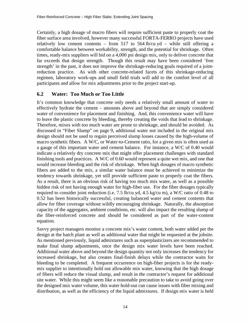
6.2 Water: Too Much or Too Little It’s common knowledge that concrete only needs a relatively small amount of water to effectively hydrate the cement – amounts above and beyond that are simply considered water of convenience for placement and finishing. And, this convenience water will have to leave the plastic concrete by bleeding, thereby creating the voids that lead to shrinkage. Therefore, mixes with too much water are prone to shrinkage, and should be avoided. As discussed in “Fiber Slump” on page 9, additional water not included in the original mix design should not be used to regain perceived slump losses caused by the high-volume of macro synthetic fibers. A W/C, or Water-to-Cement ratio, for a given mix is often used as a gauge of this important water and cement balance. For instance, a W/C of 0.40 would indicate a relatively dry concrete mix that might offer placement challenges with standard finishing tools and practices. A W/C of 0.60 would represent a quite wet mix, and one that would increase bleeding and the risk of shrinkage. When high dosages of macro synthetic fibers are added to the mix, a similar water balance must be achieved to minimize the tendency towards shrinkage, yet still provide sufficient paste to properly coat the fibers. As a result, there is an obvious risk of having too much mix water, as well as a possible hidden risk of not having enough water for high-fiber use. For the fiber dosages typically required to consider joint reduction (i.e. 7.5 lb/cu yd, 4.5 kg/cu m), a W/C ratio of 0.48 to 0.52 has been historically successful, creating balanced water and cement contents that allow for fiber coverage without wildly encouraging shrinkage. Naturally, the absorption capacity of the aggregates, ambient conditions, etc. will also impact the resulting slump of the fiber-reinforced concrete and should be considered as part of the water-content equation. Savvy project managers monitor a concrete mix’s water content, both water added per the design at the batch plant as well as additional water that might be requested at the jobsite. As mentioned previously, liquid admixtures such as superplasticizers are recommended to make final slump adjustments, once the design mix water levels have been reached. Additional water above and beyond the design quantity not only increases the tendency for increased shrinkage, but also creates final-finish delays while the contractor waits for bleeding to be completed. A frequent occurrence on high-fiber projects is for the ready-mix supplier to intentionally hold out allowable mix water, knowing that the high dosage of fibers will reduce the visual slump, and result in the contractor’s request for additional site water. While this might seem like a reasonable precaution to take to avoid going over the designed mix water volume, this water hold-out can cause issues with fiber mixing and distribution, as well as the efficiency of the liquid admixtures. If design mix water is held
Fiber-Reinforced Concrete – High Fiber Slabs: Extending Joint Spacing
15
out, the volume should be kept to a bare minimum, and that held-back quantity should be relayed to the contractor to allow them some amount of job-site latitude.
6.3 Air The air content of the concrete will affect freeze/thaw resistance for outside slabs, and can impact flowability, placement, and finishing on both exterior and interior slabs. Similar effects concerning air also apply to high-fiber mixes. A common perception is that fibers – of any type and at any dosage – will change the amount of entrapped or entrained air in concrete mixes. Except for some brands of micro-monofilament fibers, this is rarely the case. If a producer believes that the fiber used is impacting their air contents, then they would be well-served to seek out another fiber source, or search for other reasons that might be causing the air. Even at the high dosage levels required for joint-stretching applications, the FORTA-FERRO macro synthetic fiber will not increase nor decrease the air content of the mix.
6.4 Temperature, Sunlight, and Humidity Ambient temperature and relative humidity fall into the category of items that are difficult to control, however both should be closely observed and monitored with regards to a shrinkage-reducing project mind-set. Naturally, freezing temperatures are detrimental to plain concrete, and similarly, to fiber-reinforced concrete. High temperatures certainly lead to hot concrete, which is also detrimental to shrinkage-reducing efforts. Any efforts to provide cover or protection from direct sunlight and high temperatures will pay dividends on joint-stretching projects. For interior floor slabs, projects that are under roof provide a great advantage to these efforts. Though this is naturally impossible for exterior jobs, selecting a day when the weather (sun and temperature) are not extreme will reward the eventual slab outcome. If the local humidity is very low, extra care must be observed to minimize the effect of the fresh concrete drying too quickly and raising the shrinkage quotient as a result.
6.5 Wind One of the most detrimental causes of premature drying and therefore shrinkage is wind across the slab surface. More joint-stretching project pours are cancelled or delayed because of high wind conditions than any other single cause. If the wind or air movement across the top of the slab dries out the skin before the concrete beneath, the surface will dry and shrink much quicker and lead to slab-edge curling. Enclosed building structures or exterior wind breaks are highly encouraged to reduce the impact of wind for these projects in order to swing the scale towards shrinkage reduction.
6.6 Curing Curing measures are naturally important to any slab-on-ground, and especially important to high-fiber slabs where joint-space extension is being practiced. Early joint-free projects using high volumes of macro synthetic fibers often used a 7-day curing-blanket process, though most projects since have used less costly and less time-consuming curing methods. If a curing-blanket or water-flood cure is used, consideration should be given to the water temperature vs. the slab surface temperature – a large temperature differential could result
Fiber-Reinforced Concrete – High Fiber Slabs: Extending Joint Spacing
16
in thermal shock to the slab and possibly lead to cracking or crazing. A variety of post-finish surface treatments are available, and most are quite effective as long as used properly and in a timely manner. The curing goal is to slow down the process of the concrete transitioning from wet to dry, and therefore allow the concrete to gain internal strength to fight the shrinkage stresses. If the moisture gradient is allowed to be uniform throughout the slab, the differential shrinkage stresses can be better minimized. The use of high dosages of macro fibers will improve the uniformity of the moisture level within the slab, by simply acting as a three-dimensional cohesive agent and reducing mix segregation and aggregate settlement, as well as reducing the bleeding dynamics as mentioned previously. This fiber contribution to a more uniform moisture gradient from the top of the slab to the bottom is likely one of the most important benefits offered by macro synthetic fibers, and one that is especially critical to projects where the amount of control joints is being considerably reduced.
7. THE PRACTICE
The third segment of the F-C-P joint-stretching formula is just as critical as the Fiber and Concrete portions, as it contains the elements involved in putting the practice into play. It will do little good to acknowledge shrinkage-fighting tactics in the fiber and concrete segments yet ignore how shrinkage should be accommodated in actual construction practices. Though many of the topics represent good practice for any slab-on-ground application, several are unique to high-fiber slabs, and should be carefully considered. Some of the practice items pertain to job-site actions and procedures that can be reviewed and discussed during pre-constriction meetings, however most of them will need to be addressed during the design and specification processes. The design-related elements will help guide and explain the subsequent job-site practices that follow. In both cases, an eye towards an accommodation of shrinkage will be the driving force behind the recommendations.
7.1 Panel Size The entire joint-reduction or joint-stretching process revolves ultimately around the owner’s desires and goals for their floor or slab, and the resulting decisions will help guide many of the practice stipulations and guidelines. The practice-related decisions must also acknowledge the owner’s tolerance for a limited amount of cracking vs. a substantial number of joints and their subsequent repair over the life of the structure. In the extremes, if an owner has zero tolerance for irregular cracks, then slab panels should be cut into very small sizes so that shrinkage-related cracks are more likely to occur within the joints rather than at mid-panel locations. However, if the owner has a major aversion to joint repair based on their past history, then the panel-size will increase to reflect that desire. To an owner, a joint is simply a straight crack, and one that must be contended with for the life of the floor. If the owner goal is to reduce or eliminate these ‘straight cracks’, then guidelines can be established, and practices can be followed to increase the opportunity for success. Historically, most slab designers and contractors have followed ACI –American Concrete Institute – recommendations with regards to panel size, following a formula based on slab
Fiber-Reinforced Concrete – High Fiber Slabs: Extending Joint Spacing
17
thickness. As detailed in the “Chicago Floor Study – Warehouse Floor”11 report (see ACI 360 Background on page 8 of the report), these recommendations have become more conservative over time for a variety of reasons, to arrive at the most recent formula of 24 to 30 times the thickness in inches, or 2 to 2.5 times the thickness in feet. For instance, a 6 in thick floor would require a panel size of 144 to 180 in (12 to 15 ft). Though these ACI suggestions are not derived from engineering calculations, they do represent industry consensus based on the historical collection of both successful and unsuccessful project data. For the FORTA-FERRO macro synthetic fiber, that same type of historical data collection over a 20-year period has also offered a joint-spacing formula based on slab thickness – 60 to 120 times the thickness in inches, or 5 to 10 times the thickness in feet. For example, the same 6 in thick slab might consider a panel size of 360 to 720 in (30 to 60 ft) when using a sufficient fiber dosage (i.e. 0.5% by volume, 7.5 lb/cu yd, 4.5 kg/cu m) along with many of the recommended practices to augment the fiber. Though many previous projects have used smaller, as well as considerably large panels, than the 5-10 formula suggests, the calculation provides a sound starting point for discussions with owners and designers, while taking into account the project specifics, such as column lines, anticipated traffic patterns, etc. Given the 5-10 spacing formula, the correct fiber type and dosage, and a clear vision of shrinkage-reducing practices, an owner and slab designer can develop a high comfort level towards achieving reduced-joint slabs-on-ground.
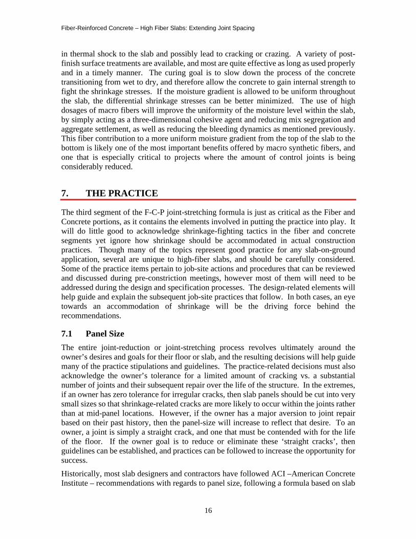
7.2 Panel Shape Conventional concrete wisdom suggests that floor and slab panels be kept as close to square as possible to help accommodate differential shrinkage. This wisdom is based on the philosophy that concrete shrinks in both panel directions and maintaining close-to-square shapes will equalize the directional shrinkage stresses. Unless restrained, slab-on-grade panels typically shrink towards their mid-point, and therefore square panels provide center points that are equidistant from the corners. This same uniform shrinkage theory applies to high-volume macro-fiber slabs as well, and every attempt should be made to accommodate square-shaped panels. Having said that, project history does include many projects that have disregarded the square-panel theorem yet have been very successful just the same. For example, several large oval-shaped skating rinks (i.e. 81 ft x 167 ft x 4 in thick, Figure 9) have been placed using high-fiber, joint-free technology, and have remained crack-free for many years. Long narrow heavy-duty pavement traffic pads (i.e. 20 ft x 70 ft x 6 in thick), residential sidewalks12 (i.e. 3 ft x 62 ft x 4 in thick), and residential driveways (10 ft x 155 ft x 5 in thick, Figure 9) have been placed successfully joint-free, and report little if any cracking to-date. Though attention to differential shrinkage dynamics and therefore panel shapes are important, a focus on slab restraint of all kinds is likely the more important consideration.
11 Project Profile White Paper: “Chicago Floor Study – Warehouse Floor”, ACI 360 Background, pg. 8,
February 2009. 12 “A Jointless, Crack-Free Walkway”, E. Bentley Sr., Wayne Walker, Jerry Holland, CONCRETE
CONSTRUCTION, June 2008.
Fiber-Reinforced Concrete – High Fiber Slabs: Extending Joint Spacing
18
Figure 9: An 81’x167’x4” joint free topping slab for roller skating rink (left) and
a 10’x155’x5” joint free residential driveway pavement (right).
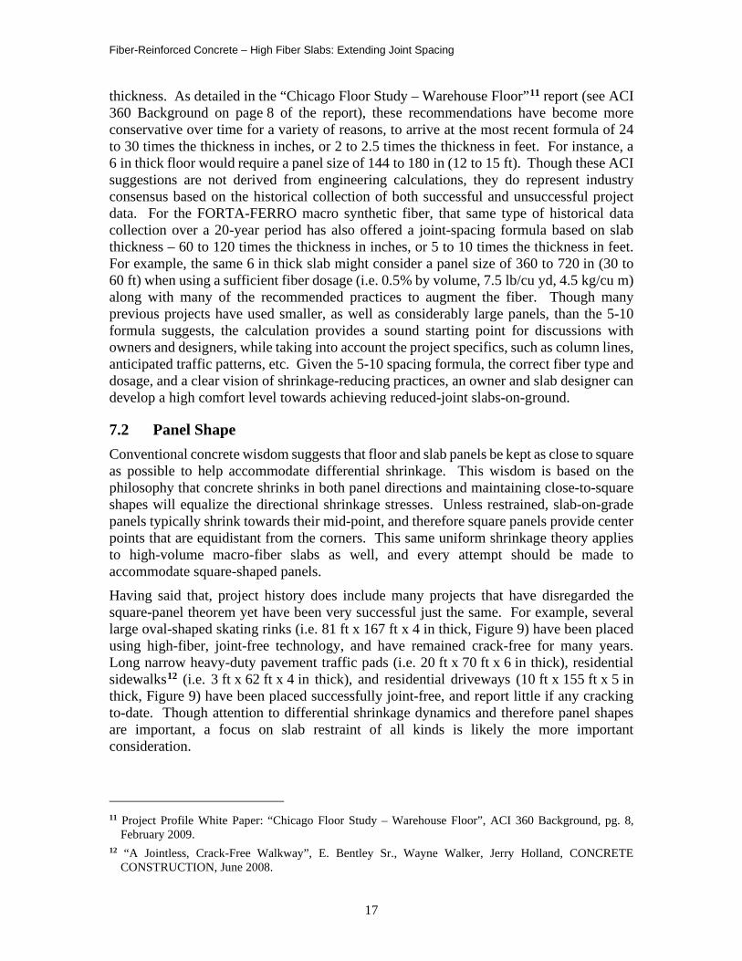
7.3 Load Transfer Maintaining sufficient load transfer from one slab panel to the next is very important in any concrete slab application, and naturally just as important in high-fiber projects. Even if conventional control joints are reduced dramatically – sometimes by 80% or more13 – the remaining joints must preserve load transfer across the joint to prevent panel rocking and joint damage from traffic loads. Even though high volumes of macro synthetic fiber offer substantial post-crack improvements, they should not be considered as a replacement or alternative to adequate dowel or plate baskets for load transfer (Figure 10). Though high dosages of macro fibers have certainly shown dramatic reductions in shrinkage crack area, more study is needed to determine the actual overall reduction in dimensional change over wide or long expanses. As such, consideration should be allowed for the potential of dominant joints, or those that activate to a higher degree than others. Consideration should also be given to the potential for restraint created by the dowel system. Care should be taken that the load-transfer devices used will provide sufficient slab-to-slab loading capacity, without restricting lateral slab movement caused by shrinkage.
Figure 10: Load transfer devices – dowels (left) and plate baskets (right).
13 “Chicago Floor Study – Warehouse Floor”, Chicago Project Joint Layout, pg. 11, February 2009.
Fiber-Reinforced Concrete – High Fiber Slabs: Extending Joint Spacing
19
7.4 Sawcut Timing and Depth The installation timing of sawcut control joints and the depth of those joints are very important in any slab-on-ground project to minimize mid-panel cracking. If the timing is too late, the concrete will likely relieve those shrinkage stresses at its convenience and at its weakest point by cracking. And if the sawcut depth is not enough to create a sufficient plane of weakness within the joint, the shrinkage-related crack may not occur within the joint as planned. For extended-joint projects, these two sawcut-related issues are especially important if we hope to guide the new concrete to relieve the stresses in the planned locations for these larger panels. A common perception is that slabs may be cut up to 24 hours after placement (and sometimes longer), and still fall within specifications and successfully encourage shrinkage cracks to fall within the joints. However, the concrete will have a mind of its own – it will relieve those shrinkage losses at a time most convenient to itself, with little regard to the construction schedule or agenda! In hot weather, even 4 hours after finishing might prove to be too late. Therefore, best practice calls for cutting new slabs as soon as humanly possible, as long as the cuts do not ravel in the process. Early-entry saws may facilitate this early process, though conventional cutting systems are also effective given the proper timing. The control joint depth is also particularly critical to large-panel slabs. ACI Committee 360 “Guide to Design of Slabs-on-Ground” Section 6.3 – Sawcut contraction joints14 recommends a sawcut depth minimum of 1/4 of the slab thickness, but a deeper cut of 1/3 the slab thickness minimum for macro-fiber reinforced slabs. For a 6 in thick FRC (Fiber Reinforced Concrete) slab, recommended sawcut depth would therefore be a minimum of 2 in to provide a sufficient plane of weakness within the joint. Similarly, early entry saws should also increase cut depth for high-volume fiber slabs, and a reasonable amount of increase might be a similar 30% depth increase as recommended for conventionally cut slabs. In any event, both sawcut depth and timing will be especially important for high-volume fiber projects that require joint-space extension above the norm, creating large slab panels.
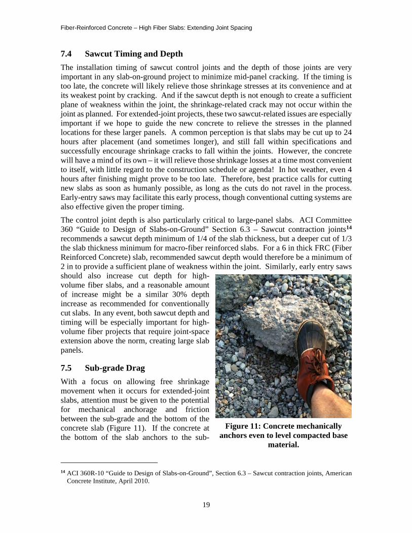
7.5 Sub-grade Drag With a focus on allowing free shrinkage movement when it occurs for extended-joint slabs, attention must be given to the potential for mechanical anchorage and friction between the sub-grade and the bottom of the concrete slab (Figure 11). If the concrete at the bottom of the slab anchors to the sub-
14 ACI 360R-10 “Guide to Design of Slabs-on-Ground”, Section 6.3 – Sawcut contraction joints, American
Concrete Institute, April 2010.
Figure 11: Concrete mechanically anchors even to level compacted base
material.
Fiber-Reinforced Concrete – High Fiber Slabs: Extending Joint Spacing
20
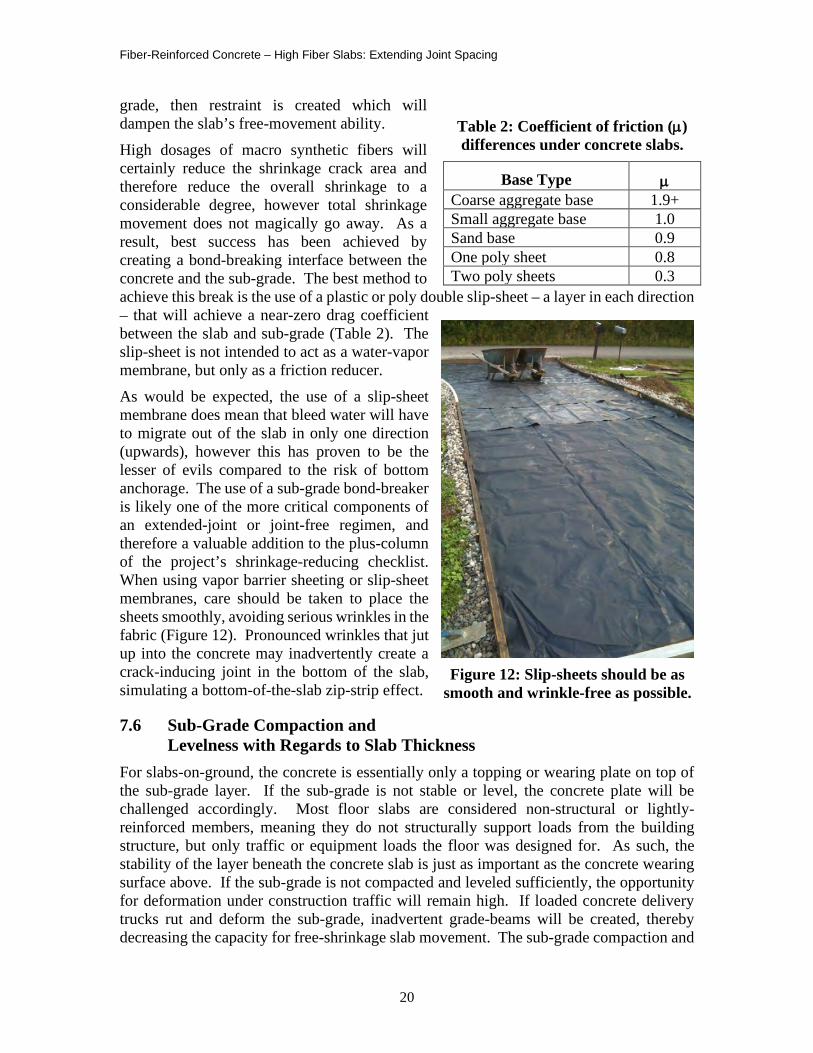
grade, then restraint is created which will dampen the slab’s free-movement ability. High dosages of macro synthetic fibers will certainly reduce the shrinkage crack area and therefore reduce the overall shrinkage to a considerable degree, however total shrinkage movement does not magically go away. As a result, best success has been achieved by creating a bond-breaking interface between the concrete and the sub-grade. The best method to achieve this break is the use of a plastic or poly double slip-sheet – a layer in each direction – that will achieve a near-zero drag coefficient between the slab and sub-grade (Table 2). The slip-sheet is not intended to act as a water-vapor membrane, but only as a friction reducer. As would be expected, the use of a slip-sheet membrane does mean that bleed water will have to migrate out of the slab in only one direction (upwards), however this has proven to be the lesser of evils compared to the risk of bottom anchorage. The use of a sub-grade bond-breaker is likely one of the more critical components of an extended-joint or joint-free regimen, and therefore a valuable addition to the plus-column of the project’s shrinkage-reducing checklist. When using vapor barrier sheeting or slip-sheet membranes, care should be taken to place the sheets smoothly, avoiding serious wrinkles in the fabric (Figure 12). Pronounced wrinkles that jut up into the concrete may inadvertently create a crack-inducing joint in the bottom of the slab, simulating a bottom-of-the-slab zip-strip effect.
7.6 Sub-Grade Compaction and Levelness with Regards to Slab Thickness
For slabs-on-ground, the concrete is essentially only a topping or wearing plate on top of the sub-grade layer. If the sub-grade is not stable or level, the concrete plate will be challenged accordingly. Most floor slabs are considered non-structural or lightly-reinforced members, meaning they do not structurally support loads from the building structure, but only traffic or equipment loads the floor was designed for. As such, the stability of the layer beneath the concrete slab is just as important as the concrete wearing surface above. If the sub-grade is not compacted and leveled sufficiently, the opportunity for deformation under construction traffic will remain high. If loaded concrete delivery trucks rut and deform the sub-grade, inadvertent grade-beams will be created, thereby decreasing the capacity for free-shrinkage slab movement. The sub-grade compaction and
Table 2: Coefficient of friction (µ) differences under concrete slabs.
Base Type µ Coarse aggregate base 1.9+ Small aggregate base 1.0 Sand base 0.9 One poly sheet 0.8 Two poly sheets 0.3
Figure 12: Slip-sheets should be as smooth and wrinkle-free as possible.
Fiber-Reinforced Concrete – High Fiber Slabs: Extending Joint Spacing
21
levelness have much to do with constructing a uniform slab thickness, which is critical to equalizing shrinkage stresses and shrinkage movement. For instance, if slab edges are allowed to be thicker than the rest of the slab, shrinkage will be restrained in that area, and the effected panels will be free to move in only one direction. An uneven, wavy, or loose sub-grade will create mechanical anchor points along the bottom of the concrete slab, thereby restricting its movement due to shrinkage stresses. To complement a joint-stretching agenda, slab thickness must be very uniform, and a level and stable sub-grade is the best way to reach that goal. Special care must be observed around columns and slab perimeters to prevent the slab thicknesses from changing to any large degree. To prevent deformations in the sub-grade prior to and during concrete placement, anti-rutting measures may need to be considered to help minimize the risk of slab thickness variances.
7.7 Perimeter Restraint For various reasons, some floor designs call for conventional reinforcement tying the footers into the floor slab, adding continuity between the two. This type of perimeter restraint would not be conducive to a joint-stretching regimen, at least not for the slab panels closest to the perimeter. If wall, footer, or slab-perimeter reinforcement restraint is called for in the overall design, then a plan to reduce or eliminate control joints should be reconsidered, at least on the perimeter panels. Such slab-edge restraint will curtail the panels’ ability to move in at least one direction and will not allow the floor or pavement panels to shrink-to-middle as they are inclined.
7.8 Internal Restraint Other forms of restraint might also come from within the slab itself and should be avoided if joint stretching is the goal. Those types of anchored, internal restraints might include plumbing lines, drainage systems, electrical conduit, or other types of harness that might come up through the sub-grade and into the concrete slab. Something as simple as grade stakes, used to eyeball the proper slab surface location, that are intentionally or inadvertently left in place within the slab will offer restraint by connecting the sub-grade to the slab. If grade stakes are used, they should be completely submerged in the sub-grade or completely removed once the desired grade is achieved, prior to placing the surrounding concrete. If internal restraint items cannot be avoided, then care should be taken to locate them near the approximate center of the slab panel, to minimize their capacity to restrain slab movement.
7.9 Column Isolation and Re-Entrant Corners Support columns that are located within a floor slab must also be accommodated in a reduced-joint directive. These columns must naturally be isolated from the floor slab itself by a variety of ACI-recommended practices15, and the isolation material used should be thick enough to accommodate the anticipated amount of shrinkage and should be used in a full-depth of the slab manner. Re-entrant corners or corners that may appear within a slab panel due to machine bases, floor layout, etc., should also be detailed and accommodated,
15 ACI 360R-10 “Guide to Design of Slabs-on-Ground”, Section 6.1.1 – Isolation joints, American Concrete
Institute, April 2010.
Fiber-Reinforced Concrete – High Fiber Slabs: Extending Joint Spacing
22
to avoid cracking from those interior corners. Recommendations for protecting these re-entrant corners might include the use of reinforcing bars at a 45-degree angle in one or two levels, in an attempt to reduce the tendency for cracking in these troublesome areas.
8. SAFEGUARD SUMMARY
Over the past 20+ years, FORTA has participated in scores of joint-free and extended-joint space projects all over the United States. Along with an ample collection of shrinkage-related and post-crack performance laboratory testing programs, these projects have helped to create a comfort level with this technology and compliment a macro fiber slab-on-ground philosophy. This study of the art and successful project history will play an important role in assisting owners, specifiers, and contractors who strive to build better and more serviceable floors in the future. There are two ways to use macro synthetic fiber reinforcement in slab-on-ground applications:
1. As a simple alternate to conventional temperature-steel reinforcement, while maintaining conventional joint spacing and panel sizes, and
2. As a viable reinforcement to consider the reduction of control joints and increasing panel size, when sufficient dosages of fibers are used.
Despite the successes and project history in the past, it is also very clear that macro synthetic fibers are only a part, albeit an important one, of a complete recipe to control shrinkage and curling in slabs-on-ground. Many additional facets of this joint-stretching agenda should be carefully considered when embarking on a reduced-joint or joint-free path, many of which are noted in this report. These additional topics warrant serious consideration, including, but not limited to, the fiber parameters, the concrete design and tendencies, and the many construction practices that encourage shrinkage-accommodating measures on the project. Both the short-term and long-term costs associated with cutting, filling, and maintaining control joints over the life of the slab are considerable, and methods to avoid those costs and slab failure have long been sought by owners around the world. As such, the use of FORTA-FERRO macro synthetic fiber to reduce control joints becomes a balancing act on the scale of practicality, cost, and ease of use. And the path to success in reducing these joints and reducing the likelihood of mid-panel cracking becomes an exercise in using as many of the shrinkage-reducing tactics as possible to augment the fiber performance. The design and construction objective for reduced-joint projects should be to put as many of the shrinkage-fighting recommendations as possible into the project’s plus column, along with a sufficient dosage of the FORTA-FERRO macro fiber. To that end, FORTA’s “Pre-Con F-C-P Checklist for High-Volume Macro-Synthetic Fiber Extended-Joint or Joint-Free Projects” (attached) serves as a valuable guide to designers and contractors alike, to help gauge and record those measures that will assist their reduced-joint efforts. Though this report and the F-C-P checklist are admittedly not intended to be portrayed as an all-inclusive recipe for joint-free slabs, the focus, direction, and intent will hopefully be a valuable resource to construction teams committed to the process and serve to instigate pre-construction conversation and dialogue to help improve the opportunity for a successful project.
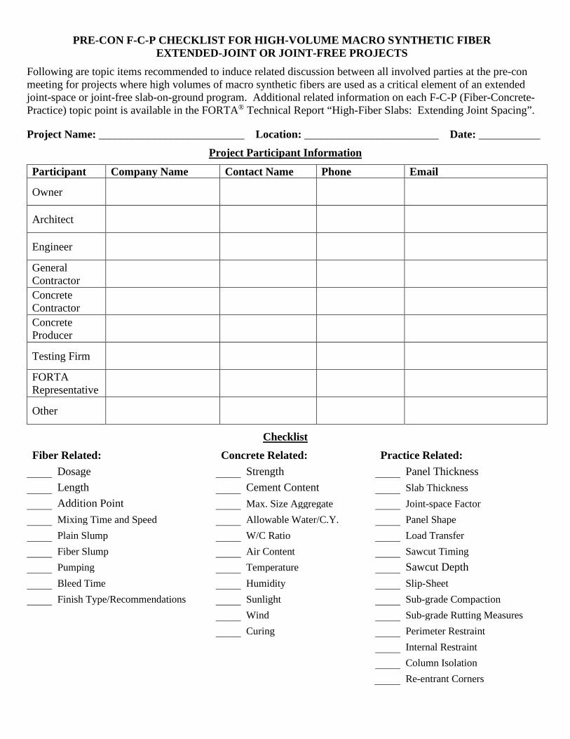
PRE-CON F-C-P CHECKLIST FOR HIGH-VOLUME MACRO SYNTHETIC FIBER EXTENDED-JOINT OR JOINT-FREE PROJECTS
Following are topic items recommended to induce related discussion between all involved parties at the pre-con meeting for projects where high volumes of macro synthetic fibers are used as a critical element of an extended joint-space or joint-free slab-on-ground program. Additional related information on each F-C-P (Fiber-Concrete-Practice) topic point is available in the FORTA® Technical Report “High-Fiber Slabs: Extending Joint Spacing”.
Project Name: __________________________ Location: ________________________ Date: ___________ Project Participant Information
Participant Company Name Contact Name Phone Email
Owner
Architect
Engineer
General Contractor
Concrete Contractor
Concrete Producer
Testing Firm
FORTA Representative
Other
Checklist Fiber Related: Concrete Related: Practice Related: Dosage Strength Panel Thickness Length Cement Content Slab Thickness Addition Point Max. Size Aggregate Joint-space Factor Mixing Time and Speed Allowable Water/C.Y. Panel Shape Plain Slump W/C Ratio Load Transfer Fiber Slump Air Content Sawcut Timing Pumping Temperature Sawcut Depth Bleed Time Humidity Slip-Sheet Finish Type/Recommendations Sunlight Sub-grade Compaction Wind Sub-grade Rutting Measures Curing Perimeter Restraint Internal Restraint Column Isolation Re-entrant Corners


