Embed Size (px)
Citation preview
High-function General-purpose Inverter
RX2 Series
User’s Manual
I620-E1-02
3G3RX2-

All rights reserved. No part of this publication may be reproduced, stored in a retrieval system, or transmitted, in any form, or by any means, mechanical, electronic, photocopying, recording, or otherwise, without the prior written permission of OMRON.
No patent liability is assumed with respect to the use of the information contained herein. Moreover, because OMRON is constantly striving to improve its high-quality products, the information contained in this manual is subject to change without notice. Every precaution has been taken in the preparation of this manual. Neverthe-less, OMRON assumes no responsibility for errors or omissions. Neither is any liability assumed for damages resulting from the use of the information contained in this publication.
• Sysmac and SYSMAC are trademarks or registered trademarks of OMRON Corporation in Japan and other countries for OMRON factory automation products.
• EtherCAT® is registered trademark and patented technology, licensed by Beckhoff Automation GmbH, Germany.
• Safety over EtherCAT® is registered trademark and patented technology, licensed by Beckhoff Automation GmbH, Germany.
• ODVA, CIP, CompoNet, DeviceNet, and EtherNet/IP are trademarks of ODVA.
Other company names and product names in this document are the trademarks or registered trademarks of their respective companies.
Trademarks
NOTE
IntroductionThank you for purchasing the High-function General-purpose Inverter (Model: 3G3RX2).This manual describes the installation and wiring methods of the 3G3RX2 Series Inverter, and param-eter setting methods which are required for the operation, as well as troubleshooting and inspectionmethods.
Intended ReadersThis manual is intended for the following individuals.Those who have electrical knowledge (certified electricians or individuals who have equivalent knowl-edge) and also are qualified for one of the following:• Introducing control equipment• Designing control system• Installing and connecting control systems• Managing control systems and facilities
NoticeThis manual contains information you need to know to correctly use the High-function General-pur-pose Inverter (Model: 3G3RX2).Before using the inverter, read this manual and gain a full understanding of the information providedherein.After you finished reading this manual, keep it in a convenient place so that it can be referenced at anytime.Make sure this manual is delivered to the end user.
Introduction
1RX2 Series User’s Manual (I620)
Manual Structure
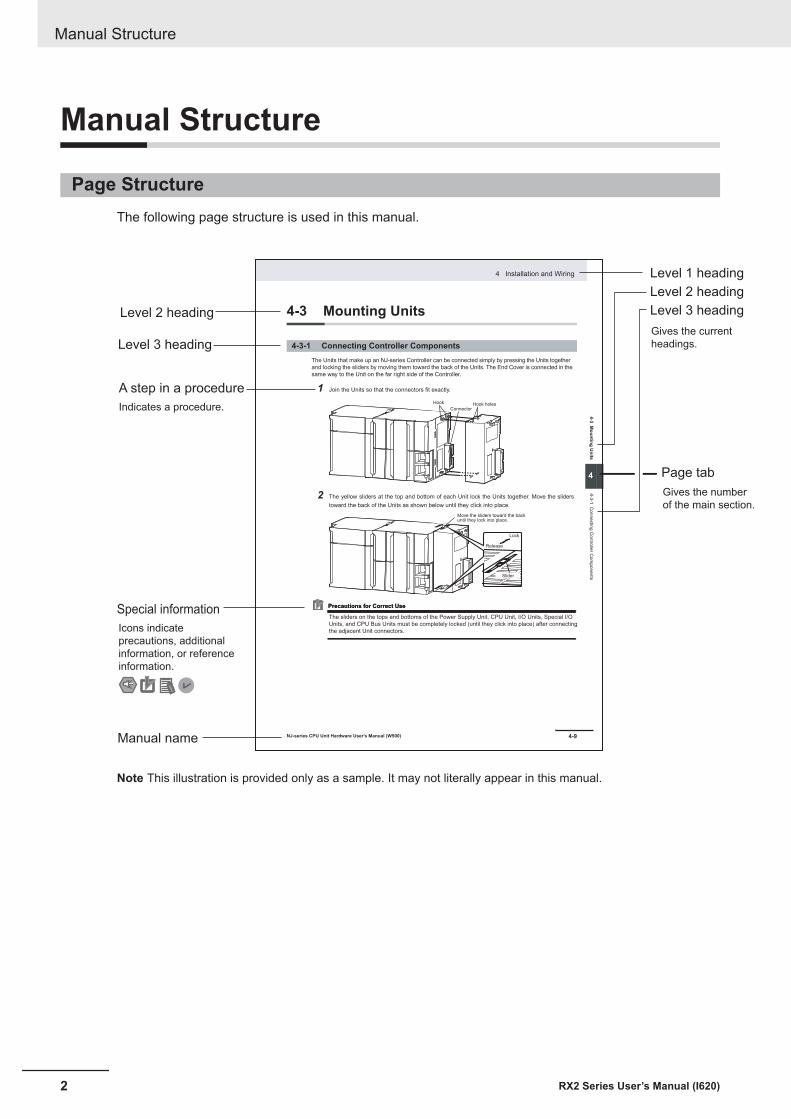
Page StructureThe following page structure is used in this manual.
4-9
4 Installation and Wiring
NJ-series CPU Unit Hardware User’s Manual (W500)
sti
nU
gni
tn
uo
M
3-4
4
s tn
en
op
mo
C r
ellor
tn
oC
gni
tc
en
no
C
1-3-
4
4-3 Mounting Units
The Units that make up an NJ-series Controller can be connected simply by pressing the Units together
and locking the sliders by moving them toward the back of the Units. The End Cover is connected in the
same way to the Unit on the far right side of the Controller.
1 Join the Units so that the connectors fit exactly.
2 The yellow sliders at the top and bottom of each Unit lock the Units together. Move the sliders
toward the back of the Units as shown below until they click into place.
Precautions for Correct UsePrecautions for Correct Use
4-3-1 Connecting Controller Components
Connector
Hook Hook holes
Slider
Lock
Release
Move the sliders toward the back until they lock into place.
Level 1 heading
Level 2 heading
Level 3 headingLevel 2 heading
A step in a procedure
Manual name
Special information
Level 3 heading
Page tab
Gives the current
headings.
Indicates a procedure.
Icons indicate
precautions, additional
information, or reference
information.
Gives the number
of the main section.
The sliders on the tops and bottoms of the Power Supply Unit, CPU Unit, I/O Units, Special I/O
Units, and CPU Bus Units must be completely locked (until they click into place) after connecting
the adjacent Unit connectors.
Note This illustration is provided only as a sample. It may not literally appear in this manual.
Manual Structure
2 RX2 Series User’s Manual (I620)
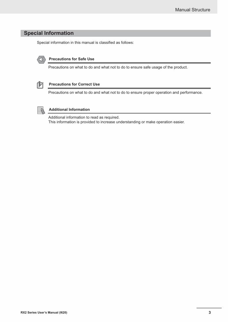
Special InformationSpecial information in this manual is classified as follows:
Precautions for Safe Use
Precautions on what to do and what not to do to ensure safe usage of the product.
Precautions for Correct Use
Precautions on what to do and what not to do to ensure proper operation and performance.
Additional Information
Additional information to read as required.This information is provided to increase understanding or make operation easier.
Manual Structure
3RX2 Series User’s Manual (I620)

Manual Structure
4 RX2 Series User’s Manual (I620)
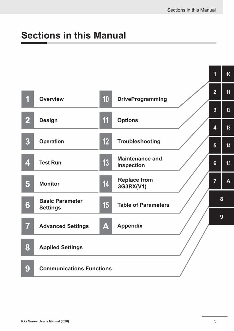
Sections in this Manual
Sections in this Manual
5RX2 Series User’s Manual (I620)
1 10
2 11
3
4
5
6
7
8
9
1 10
2 11
3 12
4
15
5
6
7
8
9
Overview DriveProgramming
Design Options
Operation 12 Troubleshooting
Test Run
14Replace from
3G3RX(V1)Monitor
Basic Parameter
Settings
Advanced Settings
Applied Settings
Communications Functions
14
13
A
15 Table of Parameters
A Appendix
13Maintenance and
Inspection
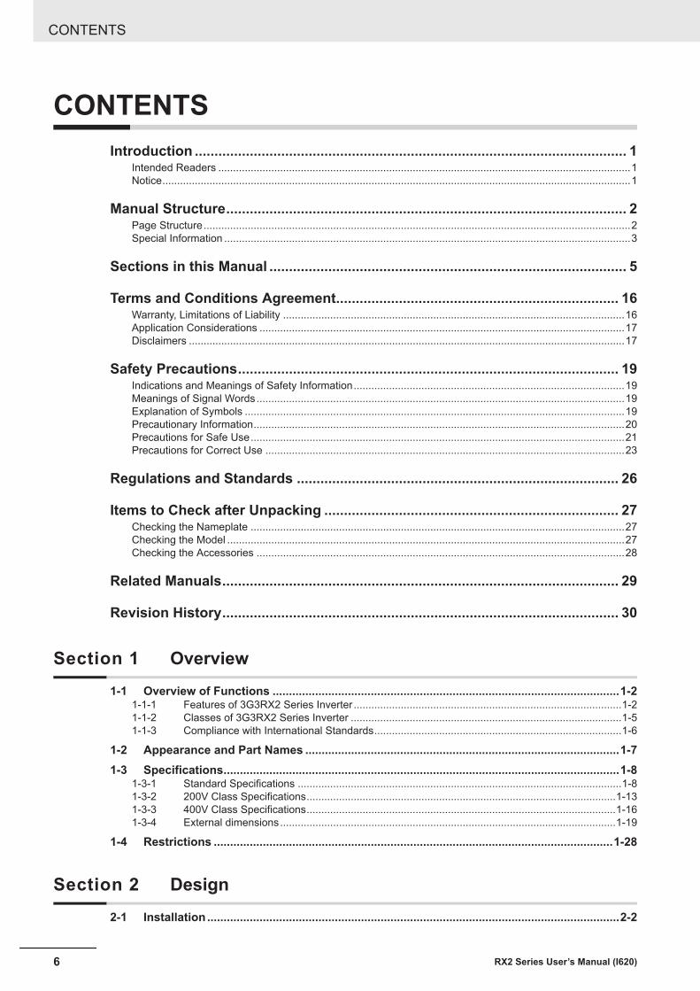
CONTENTSIntroduction .............................................................................................................. 1
Intended Readers ............................................................................................................................................1Notice...............................................................................................................................................................1
Manual Structure...................................................................................................... 2Page Structure.................................................................................................................................................2Special Information ..........................................................................................................................................3
Sections in this Manual ........................................................................................... 5
Terms and Conditions Agreement........................................................................ 16Warranty, Limitations of Liability ....................................................................................................................16Application Considerations ............................................................................................................................17Disclaimers ....................................................................................................................................................17
Safety Precautions................................................................................................. 19Indications and Meanings of Safety Information............................................................................................19Meanings of Signal Words.............................................................................................................................19Explanation of Symbols .................................................................................................................................19Precautionary Information..............................................................................................................................20Precautions for Safe Use...............................................................................................................................21Precautions for Correct Use ..........................................................................................................................23
Regulations and Standards .................................................................................. 26
Items to Check after Unpacking ........................................................................... 27Checking the Nameplate ...............................................................................................................................27Checking the Model .......................................................................................................................................27Checking the Accessories .............................................................................................................................28
Related Manuals..................................................................................................... 29
Revision History..................................................................................................... 30
Section 1 Overview1-1 Overview of Functions ..........................................................................................................1-2
1-1-1 Features of 3G3RX2 Series Inverter ...........................................................................................1-21-1-2 Classes of 3G3RX2 Series Inverter ............................................................................................1-51-1-3 Compliance with International Standards....................................................................................1-6
1-2 Appearance and Part Names ................................................................................................1-71-3 Specifications.........................................................................................................................1-8
1-3-1 Standard Specifications ..............................................................................................................1-81-3-2 200V Class Specifications.........................................................................................................1-131-3-3 400V Class Specifications.........................................................................................................1-161-3-4 External dimensions..................................................................................................................1-19
1-4 Restrictions ..........................................................................................................................1-28
Section 2 Design2-1 Installation ..............................................................................................................................2-2
CONTENTS
6 RX2 Series User’s Manual (I620)
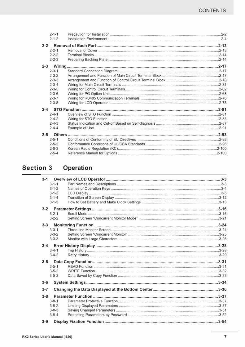
2-1-1 Precaution for Installation............................................................................................................2-22-1-2 Installation Environment..............................................................................................................2-4
2-2 Removal of Each Part ..........................................................................................................2-132-2-1 Removal of Cover .....................................................................................................................2-132-2-2 Terminal Blocks .........................................................................................................................2-142-2-3 Preparing Backing Plate............................................................................................................2-14
2-3 Wiring....................................................................................................................................2-172-3-1 Standard Connection Diagram..................................................................................................2-172-3-2 Arrangement and Function of Main Circuit Terminal Block .......................................................2-172-3-3 Arrangement and Function of Control Circuit Terminal Block ...................................................2-182-3-4 Wiring for Main Circuit Terminals ..............................................................................................2-312-3-5 Wiring for Control Circuit Terminals...........................................................................................2-622-3-6 Wiring for PG Option Unit..........................................................................................................2-682-3-7 Wiring for RS485 Communication Terminals ............................................................................2-762-3-8 Wiring for LCD Operator ...........................................................................................................2-78
2-4 STO Function .......................................................................................................................2-812-4-1 Overview of STO Function ........................................................................................................2-812-4-2 Wiring for STO Function............................................................................................................2-832-4-3 Status Indication and Cut-off Based on Self-diagnosis .............................................................2-872-4-4 Example of Use.........................................................................................................................2-91
2-5 Others ...................................................................................................................................2-932-5-1 Conditions of Conformity of EU Directives ................................................................................2-932-5-2 Conformance Conditions of UL/CSA Standards .......................................................................2-962-5-3 Korean Radio Regulation (KC)................................................................................................2-1002-5-4 Reference Manual for Options ................................................................................................2-100
Section 3 Operation3-1 Overview of LCD Operator ....................................................................................................3-3
3-1-1 Part Names and Descriptions .....................................................................................................3-33-1-2 Names of Operation Keys ...........................................................................................................3-43-1-3 LCD Display ................................................................................................................................3-53-1-4 Transition of Screen Display .....................................................................................................3-123-1-5 How to Set Battery and Make Clock Settings ...........................................................................3-13
3-2 Parameter Settings ..............................................................................................................3-163-2-1 Scroll Mode ...............................................................................................................................3-163-2-2 Setting Screen “Concurrent Monitor Mode” ..............................................................................3-21
3-3 Monitoring Function ............................................................................................................3-243-3-1 Three-line Monitor Screen.........................................................................................................3-243-3-2 Setting Screen “Concurrent Monitor” ........................................................................................3-253-3-3 Monitor with Large Characters ..................................................................................................3-26
3-4 Error History Display ...........................................................................................................3-283-4-1 Trip History ................................................................................................................................3-283-4-2 Retry History .............................................................................................................................3-29
3-5 Data Copy Function .............................................................................................................3-313-5-1 READ Function .........................................................................................................................3-313-5-2 WRITE Function........................................................................................................................3-323-5-3 Data Saved by Copy Function ..................................................................................................3-33
3-6 System Settings ...................................................................................................................3-343-7 Changing the Data Displayed at the Bottom Center.........................................................3-363-8 Parameter Function .............................................................................................................3-37
3-8-1 Parameter Protective Function..................................................................................................3-373-8-2 Limiting Displayed Parameters .................................................................................................3-373-8-3 Saving Changed Parameters ....................................................................................................3-513-8-4 Protecting Parameters by Password.........................................................................................3-52
3-9 Display Fixation Function ...................................................................................................3-54
CONTENTS
7RX2 Series User’s Manual (I620)
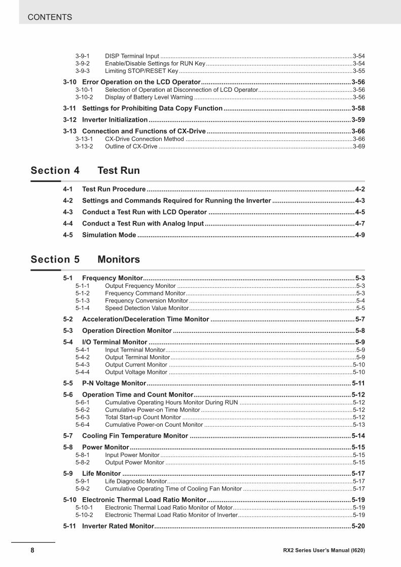
3-9-1 DISP Terminal Input ..................................................................................................................3-543-9-2 Enable/Disable Settings for RUN Key.......................................................................................3-543-9-3 Limiting STOP/RESET Key .......................................................................................................3-55
3-10 Error Operation on the LCD Operator................................................................................3-563-10-1 Selection of Operation at Disconnection of LCD Operator........................................................3-563-10-2 Display of Battery Level Warning ..............................................................................................3-56
3-11 Settings for Prohibiting Data Copy Function ....................................................................3-583-12 Inverter Initialization ............................................................................................................3-593-13 Connection and Functions of CX-Drive .............................................................................3-66
3-13-1 CX-Drive Connection Method ...................................................................................................3-663-13-2 Outline of CX-Drive ...................................................................................................................3-69
Section 4 Test Run4-1 Test Run Procedure ...............................................................................................................4-24-2 Settings and Commands Required for Running the Inverter ............................................4-34-3 Conduct a Test Run with LCD Operator ..............................................................................4-54-4 Conduct a Test Run with Analog Input ................................................................................4-74-5 Simulation Mode ....................................................................................................................4-9
Section 5 Monitors5-1 Frequency Monitor.................................................................................................................5-3
5-1-1 Output Frequency Monitor ..........................................................................................................5-35-1-2 Frequency Command Monitor.....................................................................................................5-35-1-3 Frequency Conversion Monitor ...................................................................................................5-45-1-4 Speed Detection Value Monitor...................................................................................................5-5
5-2 Acceleration/Deceleration Time Monitor .............................................................................5-75-3 Operation Direction Monitor .................................................................................................5-85-4 I/O Terminal Monitor ..............................................................................................................5-9
5-4-1 Input Terminal Monitor.................................................................................................................5-95-4-2 Output Terminal Monitor ..............................................................................................................5-95-4-3 Output Current Monitor .............................................................................................................5-105-4-4 Output Voltage Monitor .............................................................................................................5-10
5-5 P-N Voltage Monitor............................................................................................................. 5-115-6 Operation Time and Count Monitor....................................................................................5-12
5-6-1 Cumulative Operating Hours Monitor During RUN ...................................................................5-125-6-2 Cumulative Power-on Time Monitor ..........................................................................................5-125-6-3 Total Start-up Count Monitor .....................................................................................................5-125-6-4 Cumulative Power-on Count Monitor ........................................................................................5-13
5-7 Cooling Fin Temperature Monitor ......................................................................................5-145-8 Power Monitor ......................................................................................................................5-15
5-8-1 Input Power Monitor ..................................................................................................................5-155-8-2 Output Power Monitor ...............................................................................................................5-15
5-9 Life Monitor ..........................................................................................................................5-175-9-1 Life Diagnostic Monitor..............................................................................................................5-175-9-2 Cumulative Operating Time of Cooling Fan Monitor .................................................................5-17
5-10 Electronic Thermal Load Ratio Monitor.............................................................................5-195-10-1 Electronic Thermal Load Ratio Monitor of Motor.......................................................................5-195-10-2 Electronic Thermal Load Ratio Monitor of Inverter....................................................................5-19
5-11 Inverter Rated Monitor.........................................................................................................5-20
CONTENTS
8 RX2 Series User’s Manual (I620)
5-11-1 Load Rated Monitor...................................................................................................................5-205-11-2 Rated Current Monitor...............................................................................................................5-20
5-12 Braking Resistor Load Ratio Monitor ................................................................................5-215-13 Inverter Status Monitor........................................................................................................5-22
5-13-1 Detailed Monitor for Icon 2 LIM (dC-37)....................................................................................5-225-13-2 Detailed Monitor for Icon 2 ALT (dC-38)....................................................................................5-225-13-3 Detailed Monitor for Icon 2 RETRY (dC-39)..............................................................................5-225-13-4 Detailed Monitor for Icon 2 NRDY (dC-40)................................................................................5-23
5-14 Analog Input Value Monitor ................................................................................................5-245-15 Analog Terminal Setting Monitor........................................................................................5-255-16 Terminal Block Type Monitor ..............................................................................................5-265-17 Operation Command / Frequency Command Source Monitor ........................................5-275-18 Option Monitor .....................................................................................................................5-28
Section 6 Basic Parameter Settings6-1 Basic Parameter Settings......................................................................................................6-3
6-1-1 Inverter Load Rating Settings......................................................................................................6-36-1-2 Inverter Initialization ....................................................................................................................6-4
6-2 Settings for Motor Related Parameter .................................................................................6-86-2-1 Motor Basic Settings ...................................................................................................................6-86-2-2 Motor Constant Settings............................................................................................................6-126-2-3 Auto-tuning of Motor..................................................................................................................6-13
6-3 Operation Command Settings ............................................................................................6-186-3-1 Types of Operation Commands ................................................................................................6-186-3-2 Operation with LCD Operator....................................................................................................6-186-3-3 Operation with Forward and Reverse Rotation Terminals.........................................................6-196-3-4 Operation with 3 Wire Function of Terminal Block ....................................................................6-206-3-5 Operation with RS485 Communication .....................................................................................6-216-3-6 Operation from Optional Unit ....................................................................................................6-226-3-7 Disabling Keys on LCD Operator ..............................................................................................6-226-3-8 Temporary Change of Operation Command Destination ..........................................................6-22
6-4 Frequency Command Settings ...........................................................................................6-256-4-1 Frequency Command Selection................................................................................................6-256-4-2 When Command Is Given from LCD Operator .........................................................................6-266-4-3 When Command Is Given from Terminal Block Analog Signals ...............................................6-276-4-4 When Command Is Given through R485 Communication ........................................................6-286-4-5 When Command Is Given from Pulse Train Input.....................................................................6-286-4-6 When Command Is Given through DriveProgramming.............................................................6-346-4-7 When Command Is Given with PID Control ..............................................................................6-346-4-8 When Command Is Given with Main Speed Command and Auxiliary Speed Command .........6-356-4-9 When Command Is Given with Multi-step Speed......................................................................6-376-4-10 Temporary Addition of Frequency Command............................................................................6-416-4-11 Up/Down Function (FUP, FDN) .................................................................................................6-426-4-12 Analog Command Hold Function (AHD) ...................................................................................6-446-4-13 Temporary Change of Frequency Command Destination .........................................................6-45
6-5 Limiting Frequency and Operation Commands................................................................6-476-5-1 Limiting Frequency Command ..................................................................................................6-476-5-2 Limiting Operation Command Direction ....................................................................................6-486-5-3 Limiting Output Direction...........................................................................................................6-496-5-4 Operation Permission................................................................................................................6-50
6-6 Thermal Protection ..............................................................................................................6-516-6-1 Motor Electronic Thermal ..........................................................................................................6-526-6-2 Inverter Electronic Thermal .......................................................................................................6-596-6-3 Motor Thermal Protection with a Thermistor .............................................................................6-61
6-7 Acceleration/Deceleration Settings....................................................................................6-63
CONTENTS
9RX2 Series User’s Manual (I620)
6-7-1 Change of Acceleration/Deceleration Time...............................................................................6-636-7-2 Switching of Acceleration/Deceleration Time in Two Stages ....................................................6-646-7-3 Switching of Acceleration/Deceleration Time with Multistep Speed..........................................6-676-7-4 Holding Acceleration/Deceleration ............................................................................................6-736-7-5 Change of Acceleration/Deceleration Pattern ...........................................................................6-746-7-6 Control for Following Frequency Command..............................................................................6-77
Section 7 Advanced Settings7-1 Selection of Motor Control Methods ....................................................................................7-3
7-1-1 Procedure for Control Method Selection .....................................................................................7-37-1-2 Vector Control .............................................................................................................................7-57-1-3 V/f Control ...................................................................................................................................7-5
7-2 Details of Motor Control Methods ........................................................................................7-77-2-1 V/f Control Constant Torque Characteristics ...............................................................................7-77-2-2 V/f Control Reduced Torque Characteristics ...............................................................................7-87-2-3 V/f Control Free V/f Characteristics.............................................................................................7-97-2-4 Automatic Torque Boost ............................................................................................................7-127-2-5 V/f Control with Sensor .............................................................................................................7-147-2-6 Sensorless Vector Control.........................................................................................................7-157-2-7 Zero-speed Range (Zero-Hz Range) Sensorless Vector Control..............................................7-177-2-8 Vector Control with Sensor........................................................................................................7-197-2-9 Synchronous Motor (Permanent Magnet Motor) Control ..........................................................7-21
7-3 Torque Control .....................................................................................................................7-337-3-1 Speed Control and Torque Control............................................................................................7-337-3-2 Control Gain Switching..............................................................................................................7-337-3-3 P/PI Switching function .............................................................................................................7-367-3-4 Torque Limit Function................................................................................................................7-387-3-5 High-torque Multi-operation Control ..........................................................................................7-437-3-6 Torque Bias Function ................................................................................................................7-447-3-7 Torque Control/Speed Control Switching Function (ATR) .........................................................7-467-3-8 Torque Command......................................................................................................................7-47
7-4 DC Braking ...........................................................................................................................7-507-4-1 External DC Braking..................................................................................................................7-517-4-2 Internal DC Braking...................................................................................................................7-52
7-5 Start Conditions ...................................................................................................................7-577-5-1 Reduced Voltage Start ..............................................................................................................7-577-5-2 Forcing Function .......................................................................................................................7-587-5-3 Restart.......................................................................................................................................7-597-5-4 Start After Power-on..................................................................................................................7-637-5-5 Restart After Reset Release .....................................................................................................7-647-5-6 Restart After Releasing Free-run ..............................................................................................7-65
7-6 Stop Conditions ...................................................................................................................7-687-6-1 Stop by Operation Command....................................................................................................7-687-6-2 Stop by Free Run Stop (FRS) ...................................................................................................7-69
7-7 Reduction of Motor Noise, Noise and Inverter Heat Generation .....................................7-707-7-1 Carrier Frequency .....................................................................................................................7-707-7-2 Automatic Carrier Reduction .....................................................................................................7-717-7-3 Motor Electromagnetic Noise Reduction...................................................................................7-73
7-8 Manual Torque Boost ..........................................................................................................7-747-9 Energy-saving Operation Function ....................................................................................7-767-10 Encoder Feedback...............................................................................................................7-77
7-10-1 Encoder Feedback Input Wiring................................................................................................7-787-10-2 Encoder Feedback Input Settings .............................................................................................7-787-10-3 Encoder Feedback Function Selection .....................................................................................7-797-10-4 Check of Pulse Train Input Setting............................................................................................7-80
7-11 Motor Hunting Measures.....................................................................................................7-83
CONTENTS
10 RX2 Series User’s Manual (I620)
7-11-1 Stabilization Constant ...............................................................................................................7-837-11-2 Output Voltage Gain..................................................................................................................7-83
Section 8 Applied Settings8-1 PID Control .............................................................................................................................8-4
8-1-1 Function Overview ......................................................................................................................8-48-1-2 PID Parameters and Block Diagram ...........................................................................................8-78-1-3 PID Soft-start Function..............................................................................................................8-228-1-4 PID Sleep Function ...................................................................................................................8-248-1-5 PID2 / PID3 / PID4 Control........................................................................................................8-288-1-6 PID Signal Output .....................................................................................................................8-388-1-7 PID Unit Change .......................................................................................................................8-41
8-2 Tripless Functions ...............................................................................................................8-458-2-1 Overload Limit Level Function...................................................................................................8-458-2-2 Overcurrent Suppression Function ...........................................................................................8-478-2-3 Overvoltage Suppression During Deceleration .........................................................................8-488-2-4 Over Magnetization Deceleration Function ...............................................................................8-518-2-5 Regenerative Braking Function.................................................................................................8-548-2-6 Restart during Power Interruption / Undervoltage.....................................................................8-568-2-7 Over-Current Restart.................................................................................................................8-608-2-8 Over-Voltage Restart.................................................................................................................8-628-2-9 Deceleration-Stop at Power Failure ..........................................................................................8-63
8-3 Protective Functions ...........................................................................................................8-708-3-1 Input Power Supply Phase Loss Protection ..............................................................................8-708-3-2 Output Phase Loss Protection ..................................................................................................8-708-3-3 External Trip (EXT) Function.....................................................................................................8-718-3-4 Power Recovery Restart Prevention Function (USP) ...............................................................8-728-3-5 Over-Current Detection .............................................................................................................8-738-3-6 Under-Voltage Detection ...........................................................................................................8-748-3-7 Instantaneous Power Failure Detection ....................................................................................8-748-3-8 Frequency Jump Function.........................................................................................................8-748-3-9 Speed Deviation Error Detection...............................................................................................8-758-3-10 Over-speed Error Detection ......................................................................................................8-76
8-4 Control Function ..................................................................................................................8-788-4-1 Second Control (SET) ...............................................................................................................8-788-4-2 Commercial Switch (CS) ...........................................................................................................8-798-4-3 Jogging Operation Function (JG) ..............................................................................................8-818-4-4 Brake Control Function (BRK)...................................................................................................8-838-4-5 Contactor Control (CON)...........................................................................................................8-898-4-6 Forced Operation ......................................................................................................................8-948-4-7 Pulse String Position Control ....................................................................................................8-988-4-8 Orientation Control ..................................................................................................................8-1048-4-9 Absolute Position Control Mode..............................................................................................8-1078-4-10 Servo-ON [65: SON] ...............................................................................................................8-1218-4-11 Adjustment of Position Control ................................................................................................8-122
8-5 Cooling Fan Control ..........................................................................................................8-1258-6 Alarm Signal .......................................................................................................................8-126
8-6-1 Alarm Signal (AL) ....................................................................................................................8-1268-6-2 Severe Failure Signal (MJA) ...................................................................................................8-1288-6-3 Alarm Code .............................................................................................................................8-1288-6-4 Overload Warning Function (OL / OL2)...................................................................................8-1308-6-5 Low Current Signal (LOC).......................................................................................................8-1318-6-6 Momentary Power Interruption Signal (IP) ..............................................................................8-1338-6-7 Under Insufficient Voltage Signal (UV) ....................................................................................8-1348-6-8 Motor Thermal Warning Signal (THM) ....................................................................................8-1358-6-9 Inverter Thermal Warning Signal (THC)..................................................................................8-1368-6-10 Cooling Fin Heating Advance Notice (OHF) ...........................................................................8-1378-6-11 Capacitor Life Advance Notice Signal (WAC) .........................................................................8-1388-6-12 Fan Life Advance Notice Signal (WAF)...................................................................................8-139
CONTENTS
11RX2 Series User’s Manual (I620)
8-6-13 RUN Time Elapsed Signal (RNT)............................................................................................8-1398-6-14 Power ON Time Elapsed Signal..............................................................................................8-1408-6-15 Excessive Voltage of Accepted Power (OVS).........................................................................8-141
8-7 Terminal Output During Run.............................................................................................8-1428-7-1 Operation Command Signal (RUN).........................................................................................8-1428-7-2 During Forward / Reverse Operation Signals (FWR / RVR) ...................................................8-1428-7-3 Operation Command Signal (FR)............................................................................................8-1448-7-4 Operation Ready Completion Signal (IRDY)...........................................................................8-144
8-8 Frequency Attained Signals..............................................................................................8-1468-8-1 When Constant Speed is Attained Signal (FA1) .....................................................................8-1468-8-2 Equal to or Above the Set Frequency Signal (FA2 / FA4) .......................................................8-1478-8-3 Set Frequency Match Signal (FA3 / FA5)................................................................................8-1488-8-4 0 Hz Detection Signal (ZS)......................................................................................................8-150
8-9 Applied Output ...................................................................................................................8-1518-9-1 Window Comparator Signal (WCAi1 / WCAi2 / WCAi3) .........................................................8-1518-9-2 Analog Abnormality .................................................................................................................8-1528-9-3 Logical Operation Output Signal (LOG1) to (LOG7) ...............................................................8-156
8-10 Input Terminal Function ....................................................................................................8-1608-10-1 Overview .................................................................................................................................8-1608-10-2 Input Terminal Active State .....................................................................................................8-1638-10-3 Input Terminal Response Time................................................................................................8-1638-10-4 Reset .......................................................................................................................................8-1648-10-5 Automatic Reset Function .......................................................................................................8-1658-10-6 Pulse Count Function..............................................................................................................8-169
8-11 Output Terminal Function .................................................................................................8-1708-11-1 Overview .................................................................................................................................8-1708-11-2 Output Terminal Active State...................................................................................................8-1748-11-3 Output Terminal ON Delay/OFF Delay....................................................................................8-175
8-12 Analog Input Terminal Function .......................................................................................8-1768-12-1 Switch Setting .........................................................................................................................8-1778-12-2 Bias Adjustment ......................................................................................................................8-1778-12-3 Gain Adjustment......................................................................................................................8-1788-12-4 Filter Settings ..........................................................................................................................8-1798-12-5 Start Value and End Value of Volume on LCD Operator .........................................................8-1808-12-6 Adding Analog Input Ai3 to Analog Inputs Ai1 and Ai2 ...........................................................8-183
8-13 Analog Output Terminal Function ....................................................................................8-1858-13-1 Overview .................................................................................................................................8-1858-13-2 Switch setting ..........................................................................................................................8-1898-13-3 Bias Adjustment ......................................................................................................................8-1898-13-4 Gain Adjustment......................................................................................................................8-1908-13-5 Filter settings...........................................................................................................................8-1918-13-6 Analog Monitor Adjust Mode ...................................................................................................8-192
8-14 Pulse String Input Terminal Function ..............................................................................8-1958-14-1 Overview .................................................................................................................................8-1958-14-2 Pulse Input Method .................................................................................................................8-1958-14-3 Pulse String Input Commands ................................................................................................8-1988-14-4 Speed Feedback .....................................................................................................................8-1988-14-5 Pulse Count Function..............................................................................................................8-199
8-15 Digital Pulse Output Terminal Function...........................................................................8-2018-15-1 Overview .................................................................................................................................8-2018-15-2 Pulse Form..............................................................................................................................8-2058-15-3 Bias Adjustment ......................................................................................................................8-2068-15-4 Gain Adjustment......................................................................................................................8-2078-15-5 Digital Pulse Output Filter Settings .........................................................................................8-2088-15-6 Analog monitor adjust mode ...................................................................................................8-208
CONTENTS
12 RX2 Series User’s Manual (I620)
Section 9 Communication function9-1 Communication Specifications ............................................................................................9-2
9-1-1 Specifications of RS485 Communication Terminal Block............................................................9-29-1-2 Communication Parameter Settings ...........................................................................................9-5
9-2 Modbus Method .....................................................................................................................9-79-3 Explanation of Each Function Code ..................................................................................9-129-4 Saving a Change to Holding Register (Enter Instruction)................................................9-219-5 Modbus Communication Register Number List................................................................9-23
9-5-1 Coil Number List........................................................................................................................9-239-5-2 Group d Register List ................................................................................................................9-259-5-3 Group F Register List ................................................................................................................9-569-5-4 Group A Register List ................................................................................................................9-579-5-5 Group b Register List ................................................................................................................9-899-5-6 Group C Register List................................................................................................................9-999-5-7 Group H Register List..............................................................................................................9-1129-5-8 Group P Register List ..............................................................................................................9-1229-5-9 Group U Register List..............................................................................................................9-1249-5-10 Group o Register List ..............................................................................................................9-132
9-6 Inter-inverter Communication...........................................................................................9-1349-6-1 Inter-inverter Communication Parameters ..............................................................................9-1359-6-2 Communication Settings .........................................................................................................9-137
Section 10 DriveProgramming10-1 Overview of DriveProgramming .........................................................................................10-2
Section 11 Options11-1 Overview of Optional Equipment ....................................................................................... 11-3
11-1-1 Part Names and Descriptions ...................................................................................................11-3
11-2 Regenerative Braking Unit (Model: 3G3AX-RBU)........................................................ 11-511-2-1 Specifications ............................................................................................................................11-511-2-2 External Dimensions .................................................................................................................11-811-2-3 Connection Examples .............................................................................................................11-12
11-3 Braking Resistor (Model: 3G3AX-RBA / RBB / RBC) ........................................... 11-1411-3-1 Specifications ..........................................................................................................................11-1411-3-2 External Dimensions ...............................................................................................................11-1511-3-3 Connection Example ...............................................................................................................11-17
11-4 Regenerative Braking Unit and Braking Resistor Combination Selection Table......... 11-1811-4-1 200-V class Specifications ......................................................................................................11-1811-4-2 400-V class Specifications ......................................................................................................11-2011-4-3 Connection Form Table ...........................................................................................................11-22
11-5 DC Reactor (Model: 3G3AX-DL)............................................................................. 11-2511-5-1 200-V class Specifications ......................................................................................................11-2511-5-2 400-V class Specifications ......................................................................................................11-2611-5-3 External Dimensions ...............................................................................................................11-2811-5-4 Connection Examples .............................................................................................................11-31
11-6 AC Reactor (Model: 3G3AX-AL)............................................................................. 11-3211-6-1 200-V class Specifications ......................................................................................................11-3211-6-2 400-V class Specifications ......................................................................................................11-3311-6-3 External Dimensions ...............................................................................................................11-3511-6-4 Connection Examples .............................................................................................................11-37
11-7 Input Noise Filter (Model: 3G3AX-NFI) ....................................................................... 11-38
CONTENTS
13RX2 Series User’s Manual (I620)
11-7-1 200-V class Specifications ......................................................................................................11-3811-7-2 400-V class Specifications ......................................................................................................11-3911-7-3 External Dimensions ...............................................................................................................11-4111-7-4 Connection Examples .............................................................................................................11-46
11-8 Output Noise Filter (Model: 3G3AX-NFO)................................................................... 11-4711-8-1 200-V class Specifications ......................................................................................................11-4711-8-2 400-V class Specifications ......................................................................................................11-4811-8-3 External Dimensions ...............................................................................................................11-5011-8-4 Connection Example ...............................................................................................................11-51
11-9 Radio Noise Filter (Model: 3G3AX-ZCL)........................................................................ 11-5211-9-1 Specifications ..........................................................................................................................11-5211-9-2 External Dimensions ...............................................................................................................11-5411-9-3 Connection Example ...............................................................................................................11-55
11-10 EMC Noise Filter (Model: 3G3AX-EFI).......................................................................... 11-5611-10-1 200-V class Specifications ......................................................................................................11-5611-10-2 400-V class Specifications ......................................................................................................11-5711-10-3 External Dimensions ...............................................................................................................11-6011-10-4 Connection Example ...............................................................................................................11-62
11-11 LCD Operator Cable (Model: 3G3AX-OPCN).................................................................. 11-6311-11-1 Specifications ..........................................................................................................................11-6311-11-2 External Dimensions ...............................................................................................................11-63
11-12 EtherCAT Communications Unit (Model: 3G3AX-RX2-ECT) ........................................... 11-6411-12-1 Specifications ..........................................................................................................................11-6411-12-2 External Dimensions ...............................................................................................................11-65
Section 12 Troubleshooting12-1 Checking the Alarm Display ...............................................................................................12-2
12-1-1 Checking Trip Information .........................................................................................................12-212-1-2 Checking the Retry Information.................................................................................................12-312-1-3 Procedure for Resetting a Trip State.........................................................................................12-4
12-2 Error Numbers and Corresponding Measures..................................................................12-512-2-1 Error Number List ......................................................................................................................12-512-2-2 Details about Errors ..................................................................................................................12-7
12-3 Alarm Display and Measures ............................................................................................12-2312-3-1 Checking the Alarm Display ....................................................................................................12-2312-3-2 Checking Inconsistent Settings ...............................................................................................12-2912-3-3 Checking Messages................................................................................................................12-30
12-4 Troubleshooting.................................................................................................................12-33
Section 13 Maintenance and Inspection13-1 Daily Inspection ...................................................................................................................13-213-2 Periodic Inspection..............................................................................................................13-313-3 Inspection Items...................................................................................................................13-413-4 Cleaning................................................................................................................................13-913-5 Test Methods ......................................................................................................................13-10
13-5-1 Megger Test ............................................................................................................................13-1013-5-2 Pressure Test ..........................................................................................................................13-1013-5-3 Method of Checking Inverter and Converter Condition ...........................................................13-1013-5-4 Measurement Method of I/O Voltage, Current and Power ......................................................13-1213-5-5 Smoothing Capacitor Life Curve .............................................................................................13-1413-5-6 Life Alarming Output ...............................................................................................................13-15
CONTENTS
14 RX2 Series User’s Manual (I620)
Section 14 Upgrading from 3G3RX (V1)14-1 Comparison of External Dimensions.................................................................................14-2
14-1-1 3G3RX-series V1 and 3G3RX2-series......................................................................................14-2
14-2 Parameter Comparison ..................................................................................................... 14-11
Section 15 Table of Parameters15-1 Parameter Notation..............................................................................................................15-215-2 Monitor List ..........................................................................................................................15-4
15-2-1 Monitors Related to Output .......................................................................................................15-415-2-2 Monitors Related to Control Circuit ...........................................................................................15-515-2-3 Option Slot Monitors..................................................................................................................15-515-2-4 Monitors Related to Program Function EzSQ ...........................................................................15-615-2-5 Monitors Related to PID Function .............................................................................................15-615-2-6 Monitors for Checking Internal Condition ..................................................................................15-715-2-7 Trip State Monitors ..................................................................................................................15-1015-2-8 Retry State Monitors ...............................................................................................................15-1615-2-9 Monitors and Parameters for Changing the Current Commands............................................15-22
15-3 Parameter List ....................................................................................................................15-2415-3-1 Parameter (Code A) ................................................................................................................15-2415-3-2 Parameter (Code B) ................................................................................................................15-5415-3-3 Parameter (Code C)................................................................................................................15-6715-3-4 Parameter (Code H)................................................................................................................15-8615-3-5 Parameter (Code o) ..............................................................................................................15-10215-3-6 Parameter (Code P) ..............................................................................................................15-10515-3-7 Parameter (Code U)..............................................................................................................15-107
AppendixA-1 Overview of Inverter Selection ............................................................................................ A-2
A-1-1 Motor Capacity Selection ........................................................................................................... A-2A-1-2 Inverter Capacity Selection ........................................................................................................ A-6A-1-3 Overview of Braking Resistor Selection ..................................................................................... A-6
Index
CONTENTS
15RX2 Series User’s Manual (I620)
Terms and Conditions Agreement
Warranty, Limitations of Liability
Warranties
l Exclusive WarrantyOmron’s exclusive warranty is that the Products will be free from defects in materials and work-manship for a period of twelve months from the date of sale by Omron (or such other period ex-pressed in writing by Omron). Omron disclaims all other warranties, express or implied.
l LimitationsOMRON MAKES NO WARRANTY OR REPRESENTATION, EXPRESS OR IMPLIED, ABOUTNON-INFRINGEMENT, MERCHANTABILITY OR FITNESS FOR A PARTICULAR PURPOSE OFTHE PRODUCTS. BUYER ACKNOWLEDGES THAT IT ALONE HAS DETERMINED THAT THEPRODUCTS WILL SUITABLY MEET THE REQUIREMENTS OF THEIR INTENDED USE.
Omron further disclaims all warranties and responsibility of any type for claims or expenses basedon infringement by the Products or otherwise of any intellectual property right.
l Buyer RemedyOmron’s sole obligation hereunder shall be, at Omron’s election, to (i) replace (in the form originallyshipped with Buyer responsible for labor charges for removal or replacement thereof) the non-com-plying Product, (ii) repair the non-complying Product, or (iii) repay or credit Buyer an amount equalto the purchase price of the non-complying Product; provided that in no event shall Omron be re-sponsible for warranty, repair, indemnity or any other claims or expenses regarding the Productsunless Omron’s analysis confirms that the Products were properly handled, stored, installed andmaintained and not subject to contamination, abuse, misuse or inappropriate modification. Returnof any Products by Buyer must be approved in writing by Omron before shipment. Omron Compa-nies shall not be liable for the suitability or unsuitability or the results from the use of Products incombination with any electrical or electronic components, circuits, system assemblies or any othermaterials or substances or environments. Any advice, recommendations or information given orallyor in writing, are not to be construed as an amendment or addition to the above warranty.
See http://www.omron.com/global/ or contact your Omron representative for published information.
Limitation on Liability; EtcOMRON COMPANIES SHALL NOT BE LIABLE FOR SPECIAL, INDIRECT, INCIDENTAL, OR CON-SEQUENTIAL DAMAGES, LOSS OF PROFITS OR PRODUCTION OR COMMERCIAL LOSS IN ANY
Terms and Conditions Agreement
16 RX2 Series User’s Manual (I620)

WAY CONNECTED WITH THE PRODUCTS, WHETHER SUCH CLAIM IS BASED IN CONTRACT,WARRANTY, NEGLIGENCE OR STRICT LIABILITY.
Further, in no event shall liability of Omron Companies exceed the individual price of the Product onwhich liability is asserted.
Application Considerations
Suitability of UseOmron Companies shall not be responsible for conformity with any standards, codes or regulationswhich apply to the combination of the Product in the Buyer’s application or use of the Product. At Buy-er’s request, Omron will provide applicable third party certification documents identifying ratings andlimitations of use which apply to the Product. This information by itself is not sufficient for a completedetermination of the suitability of the Product in combination with the end product, machine, system, orother application or use. Buyer shall be solely responsible for determining appropriateness of the par-ticular Product with respect to Buyer’s application, product or system. Buyer shall take application re-sponsibility in all cases.
NEVER USE THE PRODUCT FOR AN APPLICATION INVOLVING SERIOUS RISK TO LIFE ORPROPERTY OR IN LARGE QUANTITIES WITHOUT ENSURING THAT THE SYSTEM AS A WHOLEHAS BEEN DESIGNED TO ADDRESS THE RISKS, AND THAT THE OMRON PRODUCT(S) ISPROPERLY RATED AND INSTALLED FOR THE INTENDED USE WITHIN THE OVERALL EQUIP-MENT OR SYSTEM.
Programmable ProductsOmron Companies shall not be responsible for the user’s programming of a programmable Product, orany consequence thereof.
Disclaimers
Performance DataData presented in Omron Company websites, catalogs and other materials is provided as a guide forthe user in determining suitability and does not constitute a warranty. It may represent the result ofOmron’s test conditions, and the user must correlate it to actual application requirements. Actual per-formance is subject to the Omron’s Warranty and Limitations of Liability.
Change in SpecificationsProduct specifications and accessories may be changed at any time based on improvements and oth-er reasons. It is our practice to change part numbers when published ratings or features are changed,or when significant construction changes are made. However, some specifications of the Product may
Terms and Conditions Agreement
17RX2 Series User’s Manual (I620)

be changed without any notice. When in doubt, special part numbers may be assigned to fix or estab-lish key specifications for your application. Please consult with your Omron’s representative at anytime to confirm actual specifications of purchased Product.
Errors and OmissionsInformation presented by Omron Companies has been checked and is believed to be accurate; how-ever, no responsibility is assumed for clerical, typographical or proofreading errors or omissions.
Terms and Conditions Agreement
18 RX2 Series User’s Manual (I620)

Safety PrecautionsTo ensure that the High-function General-purpose Inverter (Model: 3G3RX2) is used safely and cor-rectly, be sure to read this Safety Precautions section and the main text before using the product.Learn all items you should know before use, regarding the equipment as well as required safety infor-mation and precautions.Make an arrangement so that this manual also gets to the end user of this product.After reading this manual, keep it in a convenient place so that it can be referenced at any time.
Indications and Meanings of Safety InformationIn this user’s manual, the following precautions and signal words are used to provide information toensure the safe use of the High-function General-purpose Inverter (Model: 3G3RX2).The information provided here is vital to safety. Strictly observe the precautions provided.
Meanings of Signal Words
Indicates an imminently hazardous situation which, if
not avoided, is likely to result in serious injury or may
result in death. Additionally there may be severe
property damage.
Indicates a potentially hazardous situation which, if not
avoided, will result in minor or moderate injury, or may
result in serious injury or death. Additionally there may
be significant property damage.
DANGER
WARNING
Indicates a potentially hazardous situation which,
if not avoided, may result in minor or moderate
injury or in property damage.Caution
Explanation of Symbols
This symbol indicates a prohibited item (an item you must not do).
The specific instruction is indicated using an illustration or text inside or near .
The symbol shown to the left indicates “disassembly prohibited.”
This symbol indicates danger and caution (including warning).
The specific instruction is indicated using an illustration or text inside or near .
The symbol shown to the left indicates “beware of electric shock.”
This symbol indicates danger and caution (including warning).
The specific instruction is indicated using an illustration or text inside or near .
The symbol shown to the left indicates “non-specific general danger.”
Safety Precautions
19RX2 Series User’s Manual (I620)
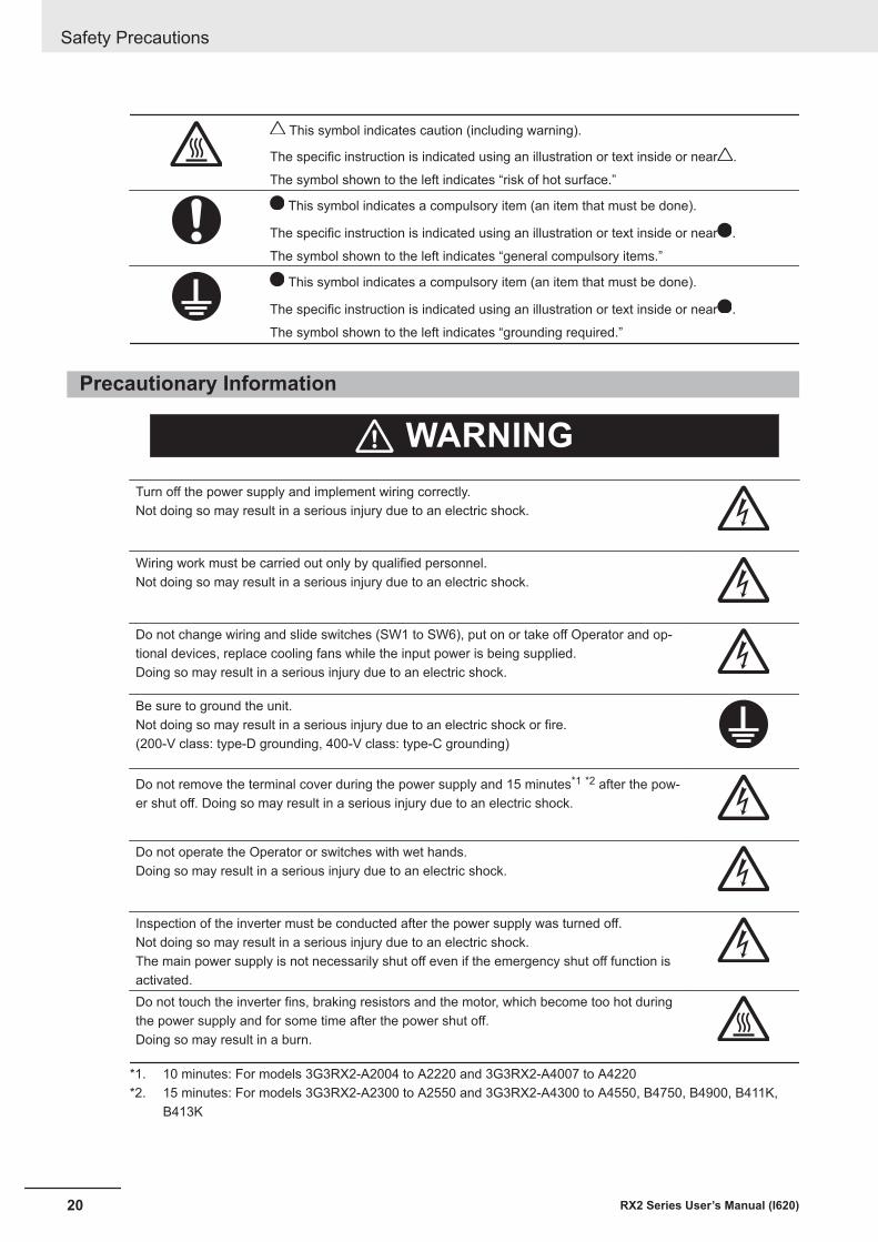
This symbol indicates caution (including warning).
The specific instruction is indicated using an illustration or text inside or near .
The symbol shown to the left indicates “risk of hot surface.”
This symbol indicates a compulsory item (an item that must be done).
The specific instruction is indicated using an illustration or text inside or near .
The symbol shown to the left indicates “general compulsory items.”
This symbol indicates a compulsory item (an item that must be done).
The specific instruction is indicated using an illustration or text inside or near .
The symbol shown to the left indicates “grounding required.”
Precautionary Information
WARNING
Turn off the power supply and implement wiring correctly.Not doing so may result in a serious injury due to an electric shock.
Wiring work must be carried out only by qualified personnel.Not doing so may result in a serious injury due to an electric shock.
Do not change wiring and slide switches (SW1 to SW6), put on or take off Operator and op-tional devices, replace cooling fans while the input power is being supplied.Doing so may result in a serious injury due to an electric shock.
Be sure to ground the unit.Not doing so may result in a serious injury due to an electric shock or fire.(200-V class: type-D grounding, 400-V class: type-C grounding)
Do not remove the terminal cover during the power supply and 15 minutes*1 *2 after the pow-er shut off. Doing so may result in a serious injury due to an electric shock.
Do not operate the Operator or switches with wet hands.Doing so may result in a serious injury due to an electric shock.
Inspection of the inverter must be conducted after the power supply was turned off.Not doing so may result in a serious injury due to an electric shock.The main power supply is not necessarily shut off even if the emergency shut off function isactivated.Do not touch the inverter fins, braking resistors and the motor, which become too hot duringthe power supply and for some time after the power shut off.Doing so may result in a burn.
*1. 10 minutes: For models 3G3RX2-A2004 to A2220 and 3G3RX2-A4007 to A4220*2. 15 minutes: For models 3G3RX2-A2300 to A2550 and 3G3RX2-A4300 to A4550, B4750, B4900, B411K,
B413K
Safety Precautions
20 RX2 Series User’s Manual (I620)
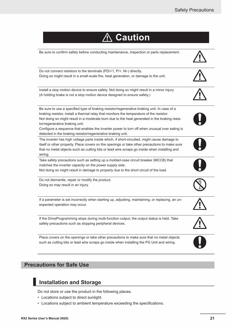
Caution
Be sure to confirm safety before conducting maintenance, inspection or parts replacement.
Do not connect resistors to the terminals (PD/+1, P/+, N/-) directly.Doing so might result in a small-scale fire, heat generation, or damage to the unit.
Install a stop motion device to ensure safety. Not doing so might result in a minor injury.(A holding brake is not a stop motion device designed to ensure safety.)
Be sure to use a specified type of braking resistor/regenerative braking unit. In case of abraking resistor, install a thermal relay that monitors the temperature of the resistor.Not doing so might result in a moderate burn due to the heat generated in the braking resis-tor/regenerative braking unit.Configure a sequence that enables the inverter power to turn off when unusual over eating isdetected in the braking resistor/regenerative braking unit.The inverter has high voltage parts inside which, if short-circuited, might cause damage toitself or other property. Place covers on the openings or take other precautions to make surethat no metal objects such as cutting bits or lead wire scraps go inside when installing andwiring.Take safety precautions such as setting up a molded-case circuit breaker (MCCB) thatmatches the inverter capacity on the power supply side.Not doing so might result in damage to property due to the short circuit of the load.
Do not dismantle, repair or modify the product.Doing so may result in an injury.
If a parameter is set incorrectly when starting up, adjusting, maintaining, or replacing, an un-expected operation may occur.
If the DriveProgramming stops during multi-function output, the output status is held. Takesafety precautions such as stopping peripheral devices.
Place covers on the openings or take other precautions to make sure that no metal objectssuch as cutting bits or lead wire scraps go inside when installing the PG Unit and wiring.
Precautions for Safe Use
Installation and StorageDo not store or use the product in the following places.• Locations subject to direct sunlight.• Locations subject to ambient temperature exceeding the specifications.
Safety Precautions
21RX2 Series User’s Manual (I620)
• Locations subject to relative humidity exceeding the specifications.• Locations subject to condensation due to severe temperature fluctuations.• Locations subject to corrosive or flammable gases.• Locations subject to exposure to combustibles.• Locations subject to dust (especially iron dust) or salts.• Locations subject to exposure to water, oil, or chemicals.• Locations subject to shock or vibration.
Transportation, Installation, and Wiring• Do not drop or apply strong impact on the product. Doing so may result in damaged parts or mal-
function.• Do not hold by the front cover and terminal cover, but hold by the fins during transportation.• Confirm that the rated input voltage of the inverter is the same as AC power supply voltage.• Do not connect an AC power supply voltage to the control input/output terminals. Doing so may re-
sult in damage to the product.• Be sure to tighten the screws on the terminal block securely. Wiring work must be done after instal-
ling the unit body.• Do not connect any load other than a three-phase inductive motor to the U, V, and W output termi-
nals.• Take sufficient shielding measures when using the product in the following locations. Not doing so
may result in damage to the product.• Locations subject to static electricity or other forms of noise.• Locations subject to strong magnetic fields.• Locations close to power lines.
• When using DriveProgramming, confirm that the program data is downloaded normally before start-ing operation.
• Connect the PG Unit to the Inverter tightly with fixing screws. In addition, be sure to connect terminalwires on the PG Unit securely.
Operation and Adjustment• Be sure to confirm the permissible range of motors and machines before operation because the in-
verter speed can be changed easily from low to high.• Provide a separate holding brake if necessary.• If the clock command is used in DriveProgramming, an unexpected operation may occur due to
weak battery. Take measures such as detecting a weak battery by [E042] RTC Error and stoppingthe inverter or programs. When the LCD Operator is removed or disconnected, DriveProgrammingis in a waiting status by the clock command.
• (bA-30), (bb-20), or The number of retries after under voltage• Take careful note that if you set Deceleration-stop at power failure (bA-30), 、The number of
retries after instantaneous power failure(bb-20), or The number of retries after under voltage(bb-21), to restart after a momentary power failure, under-voltage deceleration stop or reset, thepower will restart suddenly after the power is restored.
• Provide a separate emergency stop switch because the STOP Key on the Operator is valid onlywhen function settings are performed.
Safety Precautions
22 RX2 Series User’s Manual (I620)
• Be sure to confirm the RUN signal is turned off before resetting the alarm because the machine mayabruptly start.
• If checking a signal while the power supply and the voltage is erroneously applied to the control in-put terminals, the motor may start abruptly. Be sure to confirm safety before checking a signal.
• Check whether the motor rotation direction is correct and whether any unusual sound or vibrationoccurs during operation.
Maintenance and Inspection• The capacitor service life is affected by the ambient temperature. Refer to “Smoothing Capacitor Life
Curve” described in the manual. When a capacitor reaches the end of its service life and does notwork in the product, you need to replace the capacitor.
• When disposing of LCD operators and depleted batteries, follow the applicable ordinances of yourlocal government. When disposing of the battery, insulate it using tape.
The following display must be indicated when products using lithium primary batteries (with morethan 6 ppb of perchlorate) are transport to or through the State of California, USA.
Perchlorate Material - special handling may apply.
See https://dtsc.ca.gov/perchlorate/
When exporting your product containing a lithium primary battery to California, USA, please indicatethe above labeling on the packing box or shipping box of your product.
• Do not short + and –, charge, disassemble, heat, put into the fire, or apply strong impact on the bat-tery. The battery may leak, explode, produce heat or fire. Never use the battery which was appliedstrong impact due to such as fall on the floor, it may leak.
• UL standards establish that the battery shall be replaced by an expert engineer. The expert engineermust be in charge of the replacement and also replace the battery according to the method descri-bed in this manual.
• When the display of LCD Operator can not be recognized due to the service life, replace the LCDOperator.
Precautions for Correct Use
InstallationMount the product vertically on a wall with the product’s longer sides upright.The material of the wall must be noninflammable such as a metal plate.
Safety Precautions
23RX2 Series User’s Manual (I620)
Installation and WiringConfirm that the power voltage for the encoder is the same as the rated voltage (+12 VDC or +5 VDC)of the product.
Restart Selection FunctionDo not come close to the machine when using Instantaneous power failure/under-voltage trip(bb-24) or over-current (bb-28) because the machine may abruptly start after the alarm is cleared.
Maintenance and Parts Replacement• Generally speaking, inverters contain components and will operate properly only when each compo-
nent operates normally.Some of the electrical components require maintenance depending on application conditions.Periodic inspection and replacement are necessary to ensure proper long-term operation of Inver-ters.
• When a cooling fan reaches the end of its service life, replace it.
Product DisposalComply with the local ordinance and regulations when disposing of the product.
Dispose of in accordance with WEEE Directive
Warning Label• This product bears a warning label at the following location to provide handling warnings.• Be sure to follow the instructions.
The appearance differs depending on the capacity of the inverter.
Safety Precautions
24 RX2 Series User’s Manual (I620)
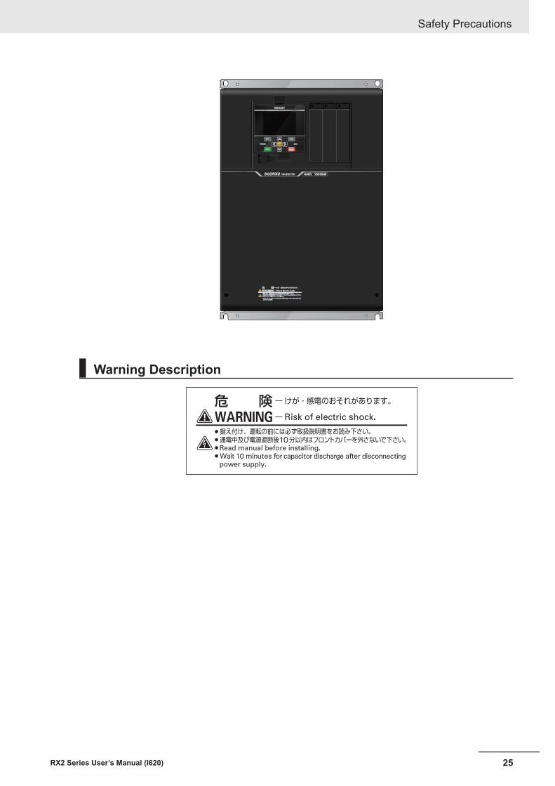
Warning Description
Safety Precautions
25RX2 Series User’s Manual (I620)
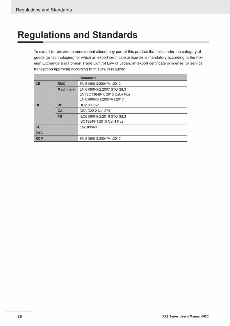
Regulations and StandardsTo export (or provide to nonresident aliens) any part of this product that falls under the category ofgoods (or technologies) for which an export certificate or license is mandatory according to the For-eign Exchange and Foreign Trade Control Law of Japan, an export certificate or license (or servicetransaction approval) according to this law is required.
StandardsCE EMC EN 61800-3:2004/A1:2012
Machinery EN 61800-5-2:2007 STO SIL3EN ISO13849-1: 2015 Cat.4 PLeEN 61800-5-1:2007/A1:2017
UL US UL61800-5-1CA CSA C22.2 No. 274FS IEC61800-5-2:2016 STO SIL3
ISO13849-1:2015 Cat.4 PLeKC KN61800-3EAC -RCM EN 61800-3:2004/A1:2012
Regulations and Standards
26 RX2 Series User’s Manual (I620)
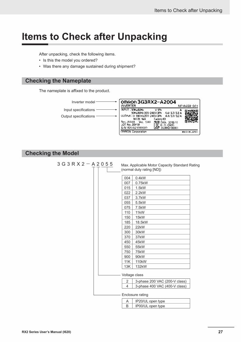
Items to Check after UnpackingAfter unpacking, check the following items.• Is this the model you ordered?• Was there any damage sustained during shipment?
Checking the NameplateThe nameplate is affixed to the product.
Inverter model
Input specifications
Output specifications
Checking the Model
3 G 3 R X 2- A 2 0 5 5 Max. Applicable Motor Capacity Standard Rating
(normal duty rating [ND])
004
007
015
022
037
055
075
110
150
185
220
300
370
450
550
750
900
11K
13K
0.4kW
0.75kW
1.5kW
2.2kW
3.7kW
5.5kW
7.5kW
11kW
15kW
18.5kW
22kW
30kW
37kW
45kW
55kW
75kW
90kW
110kW
132kW
Voltage class
2
4
3-phase 200 VAC (200-V class)
3-phase 400 VAC (400-V class)
Enclosure rating
A IP20/UL open type
B IP00/UL open type
Items to Check after Unpacking
27RX2 Series User’s Manual (I620)
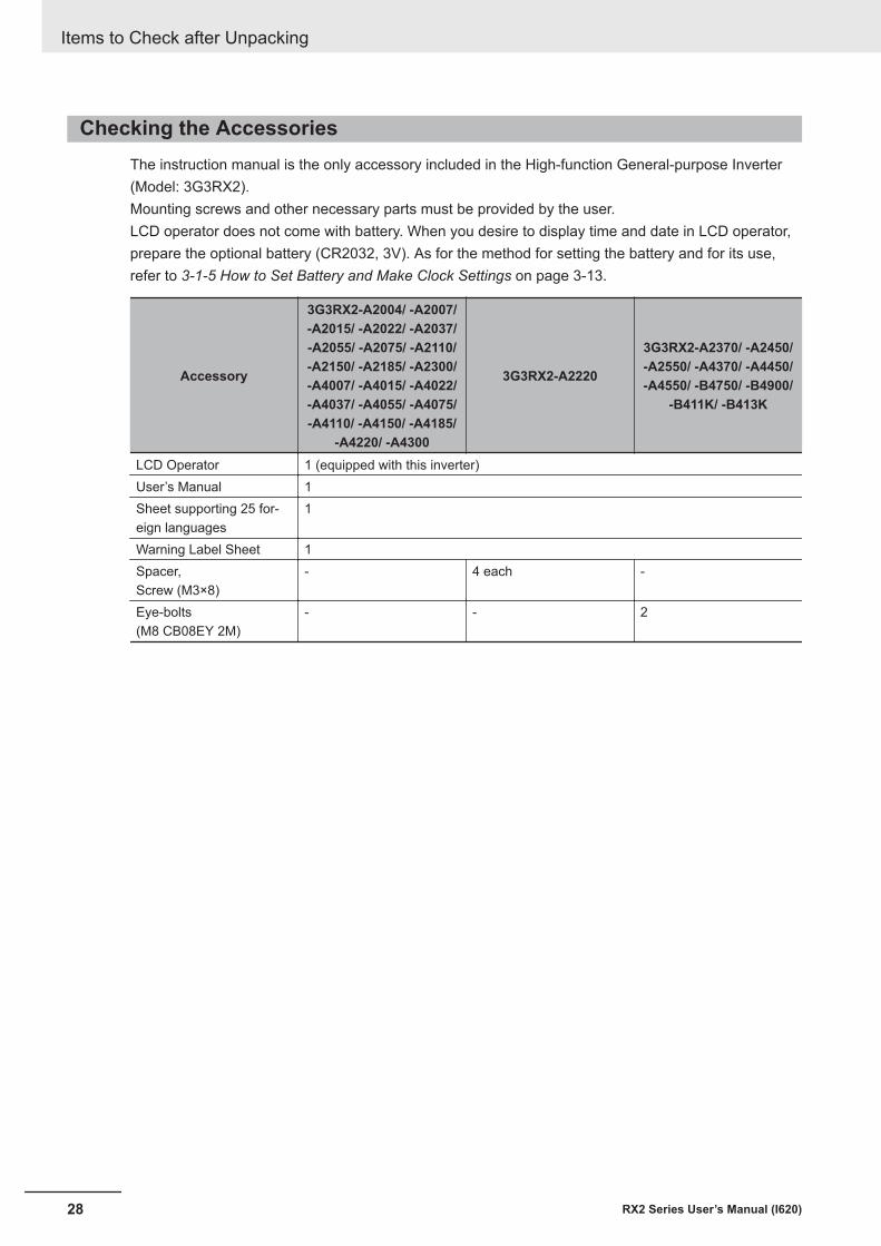
Checking the AccessoriesThe instruction manual is the only accessory included in the High-function General-purpose Inverter(Model: 3G3RX2).Mounting screws and other necessary parts must be provided by the user.LCD operator does not come with battery. When you desire to display time and date in LCD operator,prepare the optional battery (CR2032, 3V). As for the method for setting the battery and for its use,refer to 3-1-5 How to Set Battery and Make Clock Settings on page 3-13.
Accessory
3G3RX2-A2004/ -A2007/-A2015/ -A2022/ -A2037/-A2055/ -A2075/ -A2110/-A2150/ -A2185/ -A2300/-A4007/ -A4015/ -A4022/-A4037/ -A4055/ -A4075/-A4110/ -A4150/ -A4185/
-A4220/ -A4300
3G3RX2-A2220
3G3RX2-A2370/ -A2450/-A2550/ -A4370/ -A4450/-A4550/ -B4750/ -B4900/
-B411K/ -B413K
LCD Operator 1 (equipped with this inverter)User’s Manual 1Sheet supporting 25 for-eign languages
1
Warning Label Sheet 1Spacer,Screw (M3×8)
- 4 each -
Eye-bolts(M8 CB08EY 2M)
- - 2
Items to Check after Unpacking
28 RX2 Series User’s Manual (I620)
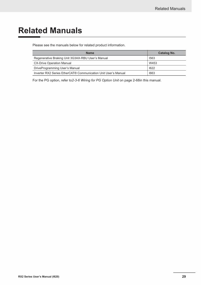
Related ManualsPlease see the manuals below for related product information.
Name Catalog No.Regenerative Braking Unit 3G3AX-RBU User’s Manual I563CX-Drive Operation Manual W453DriveProgramming User’s Manual I622Inverter RX2 Series EtherCAT® Communication Unit User’s Manual I663
For the PG option, refer to2-3-6 Wiring for PG Option Unit on page 2-68in this manual.
Related Manuals
29RX2 Series User’s Manual (I620)
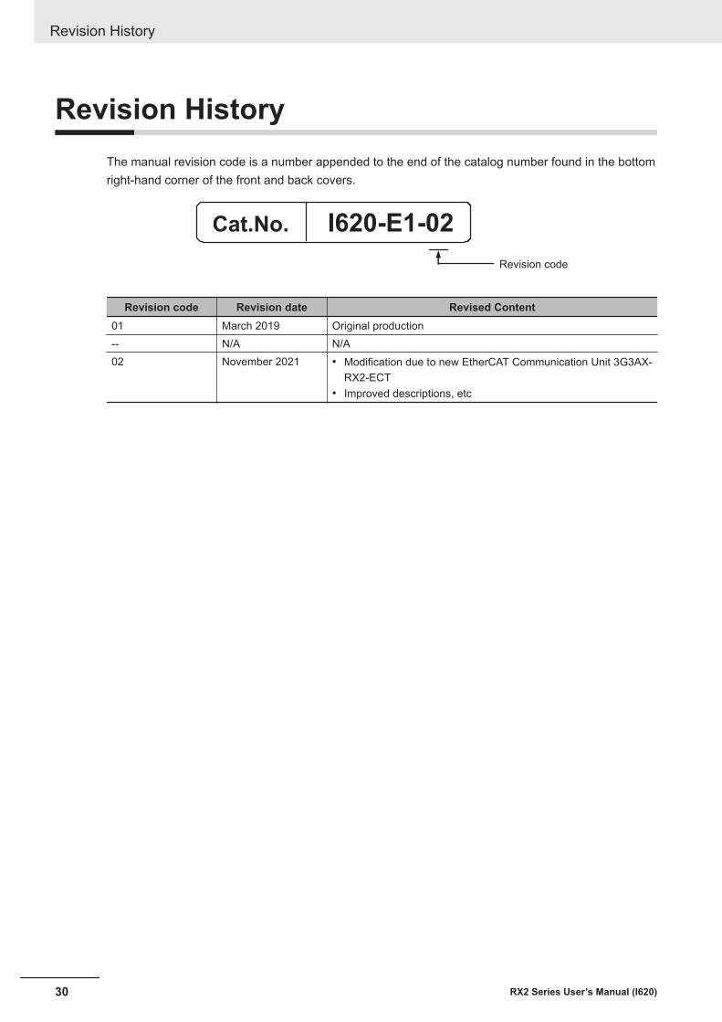
Revision HistoryThe manual revision code is a number appended to the end of the catalog number found in the bottomright-hand corner of the front and back covers.
Cat.No. I620-E1-02
Revision code
Revision code Revision date Revised Content01 March 2019 Original production-- N/A N/A02 November 2021 • Modification due to new EtherCAT Communication Unit 3G3AX-
RX2-ECT• Improved descriptions, etc
Revision History
30 RX2 Series User’s Manual (I620)
1Overview
This section provides an overview of the 3G3RX2 Series features, standard specifica-tions, and external dimensions by inverter model
1-1 Overview of Functions................................................................................... 1-21-1-1 Features of 3G3RX2 Series Inverter ............................................................... 1-21-1-2 Classes of 3G3RX2 Series Inverter ................................................................ 1-51-1-3 Compliance with International Standards........................................................ 1-6
1-2 Appearance and Part Names ........................................................................ 1-71-3 Specifications................................................................................................. 1-8
1-3-1 Standard Specifications................................................................................... 1-81-3-2 200V Class Specifications............................................................................. 1-131-3-3 400V Class Specifications............................................................................. 1-161-3-4 External dimensions ...................................................................................... 1-19
1-4 Restrictions .................................................................................................. 1-28
1-1RX2 Series User’s Manual (I620)
1
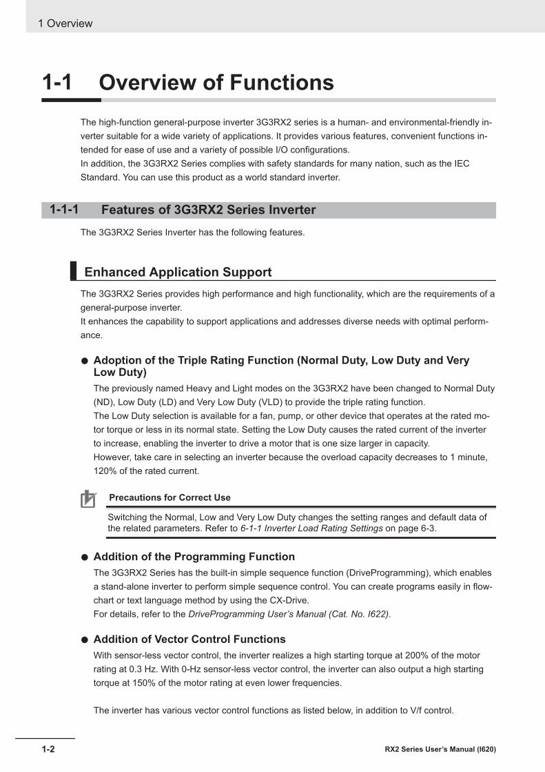
1-1 Overview of FunctionsThe high-function general-purpose inverter 3G3RX2 series is a human- and environmental-friendly in-verter suitable for a wide variety of applications. It provides various features, convenient functions in-tended for ease of use and a variety of possible I/O configurations.In addition, the 3G3RX2 Series complies with safety standards for many nation, such as the IECStandard. You can use this product as a world standard inverter.
1-1-1 Features of 3G3RX2 Series InverterThe 3G3RX2 Series Inverter has the following features.
Enhanced Application SupportThe 3G3RX2 Series provides high performance and high functionality, which are the requirements of ageneral-purpose inverter.It enhances the capability to support applications and addresses diverse needs with optimal perform-ance.
l Adoption of the Triple Rating Function (Normal Duty, Low Duty and VeryLow Duty)The previously named Heavy and Light modes on the 3G3RX2 have been changed to Normal Duty(ND), Low Duty (LD) and Very Low Duty (VLD) to provide the triple rating function.The Low Duty selection is available for a fan, pump, or other device that operates at the rated mo-tor torque or less in its normal state. Setting the Low Duty causes the rated current of the inverterto increase, enabling the inverter to drive a motor that is one size larger in capacity.However, take care in selecting an inverter because the overload capacity decreases to 1 minute,120% of the rated current.
Precautions for Correct Use
Switching the Normal, Low and Very Low Duty changes the setting ranges and default data ofthe related parameters. Refer to 6-1-1 Inverter Load Rating Settings on page 6-3.
l Addition of the Programming FunctionThe 3G3RX2 Series has the built-in simple sequence function (DriveProgramming), which enablesa stand-alone inverter to perform simple sequence control. You can create programs easily in flow-chart or text language method by using the CX-Drive.For details, refer to the DriveProgramming User’s Manual (Cat. No. I622).
l Addition of Vector Control FunctionsWith sensor-less vector control, the inverter realizes a high starting torque at 200% of the motorrating at 0.3 Hz. With 0-Hz sensor-less vector control, the inverter can also output a high startingtorque at 150% of the motor rating at even lower frequencies.
The inverter has various vector control functions as listed below, in addition to V/f control.
1 Overview
1-2 RX2 Series User’s Manual (I620)
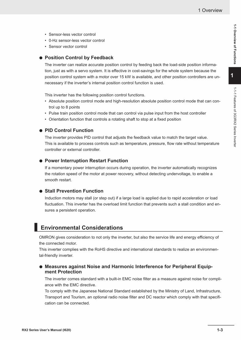
• Sensor-less vector control• 0-Hz sensor-less vector control• Sensor vector control
l Position Control by FeedbackThe inverter can realize accurate position control by feeding back the load-side position informa-tion, just as with a servo system. It is effective in cost-savings for the whole system because theposition control system with a motor over 15 kW is available, and other position controllers are un-necessary if the inverter’s internal position control function is used.
This inverter has the following position control functions.• Absolute position control mode and high-resolution absolute position control mode that can con-
trol up to 8 points• Pulse train position control mode that can control via pulse input from the host controller• Orientation function that controls a rotating shaft to stop at a fixed position
l PID Control FunctionThe inverter provides PID control that adjusts the feedback value to match the target value.This is available to process controls such as temperature, pressure, flow rate without temperaturecontroller or external controller.
l Power Interruption Restart FunctionIf a momentary power interruption occurs during operation, the inverter automatically recognizesthe rotation speed of the motor at power recovery, without detecting undervoltage, to enable asmooth restart.
l Stall Prevention FunctionInduction motors may stall (or step out) if a large load is applied due to rapid acceleration or loadfluctuation. This inverter has the overload limit function that prevents such a stall condition and en-sures a persistent operation.
Environmental ConsiderationsOMRON gives consideration to not only the inverter, but also the service life and energy efficiency ofthe connected motor.This inverter complies with the RoHS directive and international standards to realize an environmen-tal-friendly inverter.
l Measures against Noise and Harmonic Interference for Peripheral Equip-ment ProtectionThe inverter comes standard with a built-in EMC noise filter as a measure against noise for compli-ance with the EMC directive.To comply with the Japanese National Standard established by the Ministry of Land, Infrastructure,Transport and Tourism, an optional radio noise filter and DC reactor which comply with that specifi-cation can be connected.
1 Overview
1-3RX2 Series User’s Manual (I620)
1-1 Overview
of Functions
1
1-1-1 Features of 3G3R
X2 Series Inverter

l Long Life DesignThe inverter has a design life of 10 years, achieved through the use of long-life parts for its capaci-tors, fan, and other consumables. Using an inverter for a longer period than ever before has an ad-vantage in extending the life of your facility.
l Automatic Energy-saving FunctionThe automatic energy-saving function automatically adjusts the output power of the inverter operat-ing at a constant speed to the minimum. It has an energy-saving effect in applications such as afan or a pump.
l Compliance with Safety StandardsThe inverter complies with international safety standards adopted by many nations such as the IECStandard.
l Complies with RoHS DirectiveThis inverter complies with the RoHS Directive that restricts the use of 10 hazardous substances.
Ease of UseThe 3G3R2 Series Inverter has features to help reduce the man-hours needed in all phases of inver-ter-related work: from wiring, parameter setting, operation to maintenance.
l Removable Color LCD Operator PanelThis inverter comes standard with a removable LCD operator panel.The Color LCD Display is to provide easier viewing when monitoring or setting parameters.You can save inverter data to the LCD operator panel and it can be used as a copy unit.By connecting the optional cable (3G3AX-OPCN□), it is possible to operate the operator panelwhile holding it, or install it to the front face of the control panel. This is convenient during setup ormaintenance operations.When the optional battery (CR2032, 3V) is installed in the LCD operator panel, date and time canbe displayed in the error history. This display is useful in troubleshooting when an error occurs.
l Safe Torque OFF (STO) FunctionSafe Torque OFF (STO) function complying with IEC61800-5-2 is equipped. With the use of a sig-nal from a safety devices such as an emergency shutoff button, the motor current can be shutoff tostop the motor safely.
l Modbus Communication Function as StandardThe inverter is equipped standard with an RS485 communications circuit and the Modbus commu-nication protocol.You can use Modbus communications to control and monitor the inverter status, or read and writevarious parameter settings.
l Simplified Parameter Setting by User ParametersThis inverter provides User Selection (UA-31 to UA-62) as user parameters.
1 Overview
1-4 RX2 Series User’s Manual (I620)
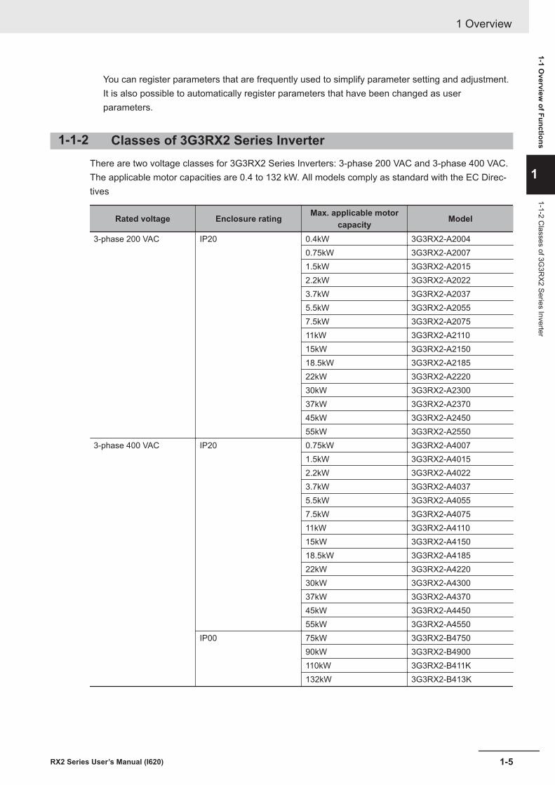
You can register parameters that are frequently used to simplify parameter setting and adjustment.It is also possible to automatically register parameters that have been changed as userparameters.
1-1-2 Classes of 3G3RX2 Series InverterThere are two voltage classes for 3G3RX2 Series Inverters: 3-phase 200 VAC and 3-phase 400 VAC.The applicable motor capacities are 0.4 to 132 kW. All models comply as standard with the EC Direc-tives
Rated voltage Enclosure rating Max. applicable motorcapacity Model
3-phase 200 VAC IP20 0.4kW 3G3RX2-A20040.75kW 3G3RX2-A20071.5kW 3G3RX2-A20152.2kW 3G3RX2-A20223.7kW 3G3RX2-A20375.5kW 3G3RX2-A20557.5kW 3G3RX2-A207511kW 3G3RX2-A211015kW 3G3RX2-A215018.5kW 3G3RX2-A218522kW 3G3RX2-A222030kW 3G3RX2-A230037kW 3G3RX2-A237045kW 3G3RX2-A245055kW 3G3RX2-A2550
3-phase 400 VAC IP20 0.75kW 3G3RX2-A40071.5kW 3G3RX2-A40152.2kW 3G3RX2-A40223.7kW 3G3RX2-A40375.5kW 3G3RX2-A40557.5kW 3G3RX2-A407511kW 3G3RX2-A411015kW 3G3RX2-A415018.5kW 3G3RX2-A418522kW 3G3RX2-A422030kW 3G3RX2-A430037kW 3G3RX2-A437045kW 3G3RX2-A445055kW 3G3RX2-A4550
IP00 75kW 3G3RX2-B475090kW 3G3RX2-B4900110kW 3G3RX2-B411K132kW 3G3RX2-B413K
1 Overview
1-5RX2 Series User’s Manual (I620)
1-1 Overview
of Functions
1
1-1-2 Classes of 3G
3RX2 Series Inverter
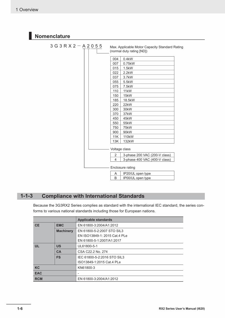
Nomenclature3 G 3 R X 2- A 2 0 5 5 Max. Applicable Motor Capacity Standard Rating
(normal duty rating [ND])
004
007
015
022
037
055
075
110
150
185
220
300
370
450
550
750
900
11K
13K
0.4kW
0.75kW
1.5kW
2.2kW
3.7kW
5.5kW
7.5kW
11kW
15kW
18.5kW
22kW
30kW
37kW
45kW
55kW
75kW
90kW
110kW
132kW
Voltage class
2
4
3-phase 200 VAC (200-V class)
3-phase 400 VAC (400-V class)
Enclosure rating
A IP20/UL open type
B IP00/UL open type
1-1-3 Compliance with International StandardsBecause the 3G3RX2 Series complies as standard with the international IEC standard, the series con-forms to various national standards including those for European nations.
Applicable standardsCE EMC EN 61800-3:2004/A1:2012
Machinery EN 61800-5-2:2007 STO SIL3EN ISO13849-1: 2015 Cat.4 PLeEN 61800-5-1:2007/A1:2017
UL US UL61800-5-1CA CSA C22.2 No. 274FS IEC 61800-5-2:2016 STO SIL3
ISO13849-1:2015 Cat.4 PLeKC KN61800-3EAC -RCM EN 61800-3:2004/A1:2012
1 Overview
1-6 RX2 Series User’s Manual (I620)
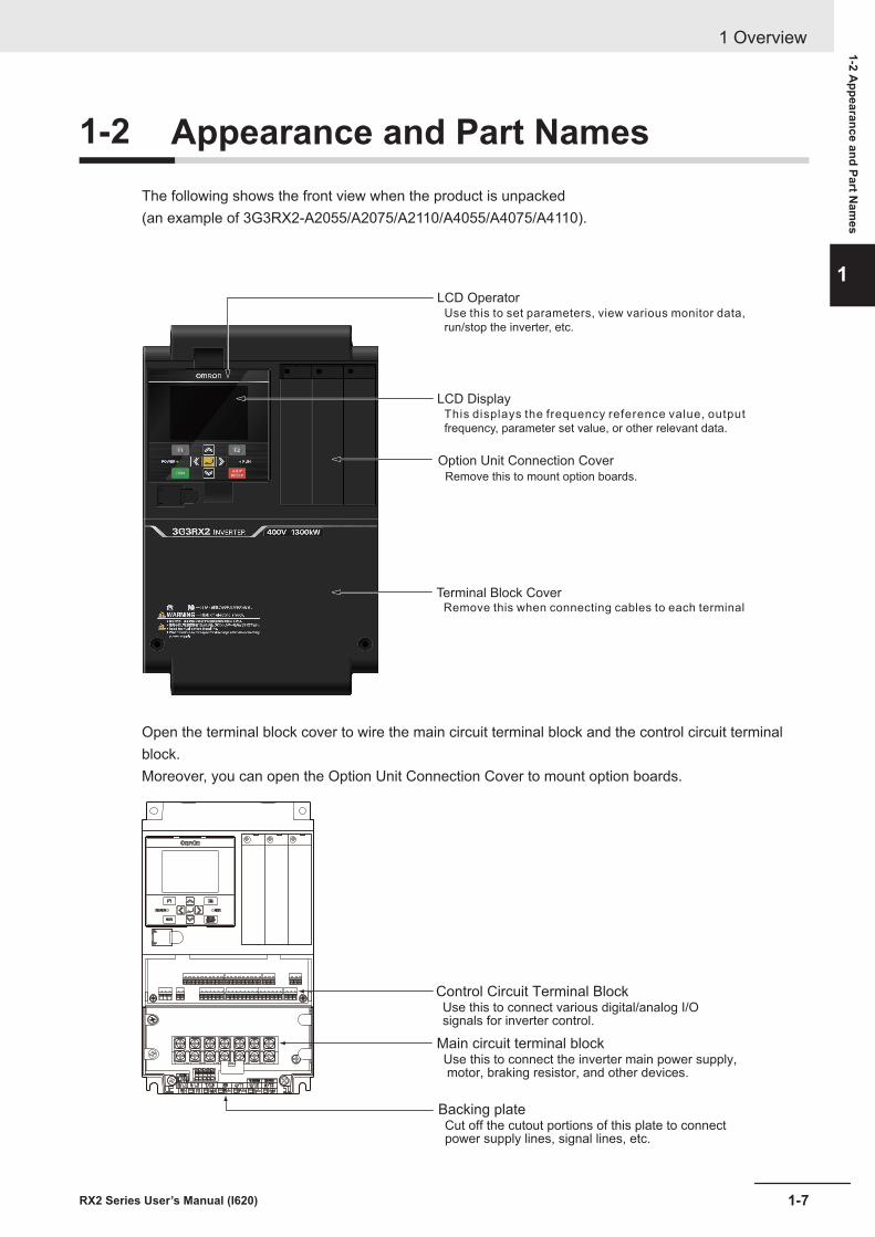
1-2 Appearance and Part NamesThe following shows the front view when the product is unpacked(an example of 3G3RX2-A2055/A2075/A2110/A4055/A4075/A4110).
LCD Operator
LCD Display
Option Unit Connection Cover
Terminal Block Cover
Use this to set parameters, view various monitor data,
run/stop the inverter, etc.
This displays the frequency reference value, output
frequency, parameter set value, or other relevant data.
Remove this to mount option boards.
Remove this when connecting cables to each terminal
Open the terminal block cover to wire the main circuit terminal block and the control circuit terminalblock.Moreover, you can open the Option Unit Connection Cover to mount option boards.
Control Circuit Terminal BlockUse this to connect various digital/analog I/O signals for inverter control.
Backing plateCut off the cutout portions of this plate to connectpower supply lines, signal lines, etc.
Main circuit terminal blockUse this to connect the inverter main power supply, motor, braking resistor, and other devices.
1 Overview
1-7RX2 Series User’s Manual (I620)
1-2 Appearance and Part N
ames
1
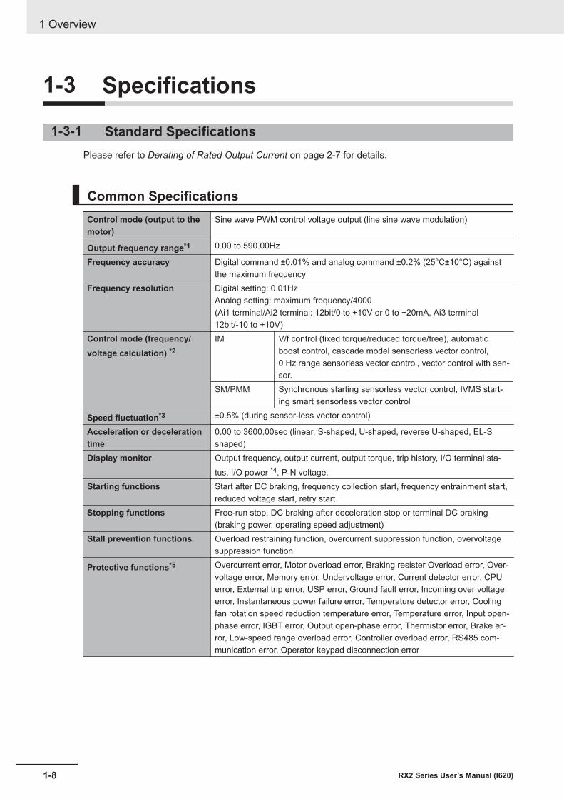
1-3 Specifications
1-3-1 Standard SpecificationsPlease refer to Derating of Rated Output Current on page 2-7 for details.
Common SpecificationsControl mode (output to themotor)
Sine wave PWM control voltage output (line sine wave modulation)
Output frequency range*1 0.00 to 590.00Hz
Frequency accuracy Digital command ±0.01% and analog command ±0.2% (25°C±10°C) againstthe maximum frequency
Frequency resolution Digital setting: 0.01HzAnalog setting: maximum frequency/4000(Ai1 terminal/Ai2 terminal: 12bit/0 to +10V or 0 to +20mA, Ai3 terminal12bit/-10 to +10V)
Control mode (frequency/voltage calculation) *2
IM V/f control (fixed torque/reduced torque/free), automaticboost control, cascade model sensorless vector control,0 Hz range sensorless vector control, vector control with sen-sor.
SM/PMM Synchronous starting sensorless vector control, IVMS start-ing smart sensorless vector control
Speed fluctuation*3 ±0.5% (during sensor-less vector control)
Acceleration or decelerationtime
0.00 to 3600.00sec (linear, S-shaped, U-shaped, reverse U-shaped, EL-Sshaped)
Display monitor Output frequency, output current, output torque, trip history, I/O terminal sta-tus, I/O power *4, P-N voltage.
Starting functions Start after DC braking, frequency collection start, frequency entrainment start,reduced voltage start, retry start
Stopping functions Free-run stop, DC braking after deceleration stop or terminal DC braking(braking power, operating speed adjustment)
Stall prevention functions Overload restraining function, overcurrent suppression function, overvoltagesuppression function
Protective functions*5 Overcurrent error, Motor overload error, Braking resister Overload error, Over-voltage error, Memory error, Undervoltage error, Current detector error, CPUerror, External trip error, USP error, Ground fault error, Incoming over voltageerror, Instantaneous power failure error, Temperature detector error, Coolingfan rotation speed reduction temperature error, Temperature error, Input open-phase error, IGBT error, Output open-phase error, Thermistor error, Brake er-ror, Low-speed range overload error, Controller overload error, RS485 com-munication error, Operator keypad disconnection error
1 Overview
1-8 RX2 Series User’s Manual (I620)

Other functions V/f free settings (7 points), Upper/lower limit frequency limiter, Frequencyjump, Curve acceleration/deceleration, Manual torque boost, Energy-savingoperation, Analog output adjustment function, Minimum frequency, Carrier fre-quency adjustment, Motor electronic thermal function (free setting is also pos-sible), Inverter electronic thermal function, External start/end (volume/ratio),Frequency input selection, Trip retry, Restart after instantaneous stop, Outputof signals, Initialization settings, PID control, Automatic deceleration at powershut-off, Brake control function, and Auto-tuning for commercial switchingfunction (online/offline).
1 Overview
1-9RX2 Series User’s Manual (I620)
1-3 Specifications
1
1-3-1 Standard Specifications
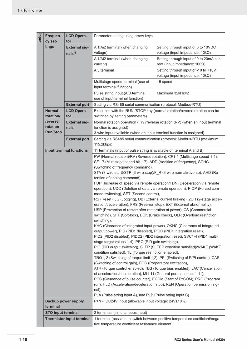
Input
Frequen-cy set-tings
LCD Opera-tor
Parameter setting using arrow keys
External sig-nals*6
Ai1/Ai2 terminal (when changingvoltage)
Setting through input of 0 to 10VDCvoltage (input impedance: 10kΩ)
Ai1/Ai2 terminal (when changingcurrent)
Setting through input of 0 to 20mA cur-rent (input impedance: 100Ω)
Ai3 terminal Setting through input of -10 to +10Vvoltage (input impedance: 10kΩ)
Multistage speed terminal (use ofinput terminal function)
15 speed
Pulse string input (A/B terminal,use of input terminal function)
Maximum 32kHz×2
External port Setting via RS485 serial communication (protocol: Modbus-RTU)Normalrotation/reverserotationRun/Stop
LCD Opera-tor
Execution with the RUN /STOP key (normal rotation/reverse rotation can beswitched by setting parameters)
External sig-nals
Normal rotation operation (FW)/reverse rotation (RV) (when an input terminalfunction is assigned)3-wire input available (when an input terminal function is assigned)
External port Setting via RS485 serial communication (protocol: Modbus-RTU (maximum:115.2kbps)
Input terminal functions 11 terminals (input of pulse string is available on terminal A and B)FW (Normal rotation)/RV (Reverse rotation), CF1-4 (Multistage speed 1-4),SF1-7 (Multistage speed bit 1-7), ADD (Addition of frequency), SCHG(Switching of frequency command),STA (3-wire start)/STP (3-wire stop)/F_R (3-wire normal/reverse), AHD (Re-tention of analog command),FUP (Increase of speed via remote operation/FDN (Deceleration via remoteoperation), UDC (Deletion of data via remote operation), F-OP (Forced com-mand switching), SET (Second control),RS (Reset), JG (Jogging), DB (External current braking), 2CH (2-stage accel-eration/deceleration), FRS (Free-run stop), EXT (External abnormality),USP (Prevention of restart after restoration of power), CS (Commercialswitching), SFT (Soft-lock), BOK (Brake check), OLR (Overload restrictionswitching),KHC (Clearance of integrated input power), OKHC (Clearance of integratedoutput power), PID (PID1 disabled), PIDC (PID1 integration reset),PID2 (PID2 disabled), PIDC2 (PID2 integration reset), SVC1-4 (PID1 multi-stage target values 1-4), PRO (PID gain switching),PIO (PID output switching), SLEP (SLEEP condition satisfied)/WAKE (WAKEcondition satisfied), TL (Torque restriction enabled),TRQ1, 2 (Switching of torque limit 1,2), PPI (Switching of P/PI control), CAS(Switching of control gain), FOC (Preparatory excitation),ATR (Torque control enabled), TBS (Torque bias enabled), LAC (Cancellationof acceleration/deceleration), Mi1-11 (General-purpose input 1-11),PCC (Clearance of pulse counter), ECOM (Start of EzCOM), PRG (Programrun), HLD (Acceleration/deceleration stop), REN (Operation permission sig-nal),PLA (Pulse string input A), and PLB (Pulse string input B)
Backup power supplyterminal
P+/P-: DC24V input (allowable input voltage: 24V±10%)
STO input terminal 2 terminals (simultaneous input)Thermistor input terminal 1 terminal (possible to switch between positive temperature coefficient/nega-
tive temperature coefficient resistance element)
1 Overview
1-10 RX2 Series User’s Manual (I620)
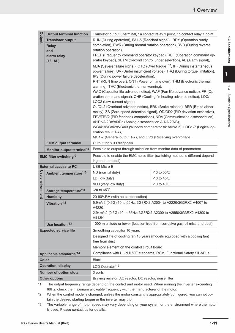
Output
Output terminal function Transistor output 5 terminal, 1a contact relay 1 point, 1c contact relay 1 pointTransistor output RUN (During operation), FA1-5 (Reached signal), IRDY (Operation ready
completion), FWR (During normal rotation operation), RVR (During reverserotation operation),FREF (Frequency command operator keypad), REF (Operation command op-erator keypad), SETM (Second control under selection), AL (Alarm signal),MJA (Severe failure signal), OTQ (Over torque) *7, IP (During instantaneouspower failure), UV (Under insufficient voltage), TRQ (During torque limitation),IPS (During power failure deceleration),RNT (RUN time over), ONT (Power on time over), THM (Electronic thermalwarning), THC (Electronic thermal warning),WAC (Capacitor life advance notice), WAF (Fan life advance notice), FR (Op-eration command signal), OHF (Cooling fin heating advance notice), LOC/LOC2 (Low-current signal),OL/OL2 (Overload advance notice), BRK (Brake release), BER (Brake abnor-mality), ZS (Zero-speed detection signal), OD/OD2 (PID deviation excessive),FBV/FBV2 (PID feedback comparison), NDc (Communication disconnection),Ai1Dc/Ai2Dc/Ai3Dc (Analog disconnection Ai1/Ai2/Ai3),WCAi1/WCAi2/WCAi3 (Window comparator Ai1/Ai2/Ai3), LOG1-7 (Logical op-eration result 1-7),MO1-7 (General output 1-7), and OVS (Receiving overvoltage).
Relayandalarm relay(16, AL)
EDM output terminal Output for STO diagnosis
Monitor output terminal*8 Possible to output through selection from monitor data of parameters
EMC filter switching*9 Possible to enable the EMC noise filter (switching method is different depend-ing on the model)
External access to PC USB Micro-BUse environm
ent
Ambient temperature*10 ND (normal duty) -10 to 50℃LD (low duty) -10 to 45℃VLD (very low duty) -10 to 40℃
Storage temperature*11 -20 to 65℃Humidity 20-90%RH (with no condensation)
Vibration*12 5.9m/s2 (0.6G) 10 to 55Hz: 3G3RX2-A2004 to A2220/3G3RX2-A4007 toA42202.94m/s2 (0.3G) 10 to 55Hz: 3G3RX2-A2300 to A2550/3G3RX2-A4300 toA413K
Use location*13 1000 m altitude or lower (location free from corrosive gas, oil mist, and dust)
Expected service life Smoothing capacitor 10 yearsDesigned life of cooling fan 10 years (models equipped with a cooling fan)free from dustMemory element on the control circuit board
Applicable standards*14 Compliance with UL/cUL/CE standards, RCM, Functional Safety SIL3/PLe
Color BlackOperation, display LCD Operator*15
Number of option slots 3 portsOther options Braking resistor, AC reactor, DC reactor, noise filter
*1. The output frequency range depend on the control and motor used. When running the inverter exceeding60Hz, check the maximum allowable frequency with the manufacturer of the motor.
*2. When the control mode is changed, unless the motor constant is appropriately configured, you cannot ob-tain the desired starting torque or the inverter may trip.
*3. The variable range of motor speed may vary depending on your system or the environment where the motoris used. Please contact us for details.
1 Overview
1-11RX2 Series User’s Manual (I620)
1-3 Specifications
1
1-3-1 Standard Specifications
*4. Both the input power and output power are reference values, which are not appropriate for use in calculationof efficiency values, etc. To obtain an accurate value, use an external device.
*5. The IGBT error [E030] is generated by the protective function not only for short circuit protection but alsowhen IGBT is damaged. Depending on the operating conditions of the inverter, the overcurrent error [E001]may occur, instead of the IGBT error.
*6. At the factory default setting, when voltage and current on Ai1/Ai2 terminal is changed using a switch, withinput of voltage at 9.8V and current at 19.8mA, the command is recognized as being 100%. To change char-acteristics, make adjustments using the analog start/end function.
*7. The threshold for signal output varies depending on the motor to be combined with the inverter, parameteradjustment, etc.
*8. The output data of analog voltage monitor and analog current monitor are reference values for connectingan analog meter. Due to the meter to be connected and variation in analog output circuit, the maximum out-put value may slightly vary from 10V or 20mA. To change characteristics, make adjustments using the Ao1adjustment and Ao2 adjustment functions. Some monitor data cannot be output.
*9. To enable the EMC filter, connect with a power supply grounded at a neutral point. Otherwise, the leakagecurrent may increase.
*10. Use the 400V class inverter at an input voltage of 500VAC or below. If input voltage exceeds 500VAC due tofluctuation of power, use the inverter at 40°C or lower ambient temperature.
*11. The storage temperature is the temperature during transport.*12. To be in accordance with the testing method specified in JIS C 60068-2-6: 2010 (IEC 60068-2-6:2007)*13. When the inverter is used in a location at 1000m or higher altitude, air pressure reduces approximately 1%
every 100m elevation. Perform 1% current derating and conduct evaluation for every 100m elevation.*14. For insulation distance, comply with UL and CE standards*15. When a clock function is used, the optional battery (CR2032, 3V) is required. When you purchase, this LCD
operator does not come with the battery.
1 Overview
1-12 RX2 Series User’s Manual (I620)
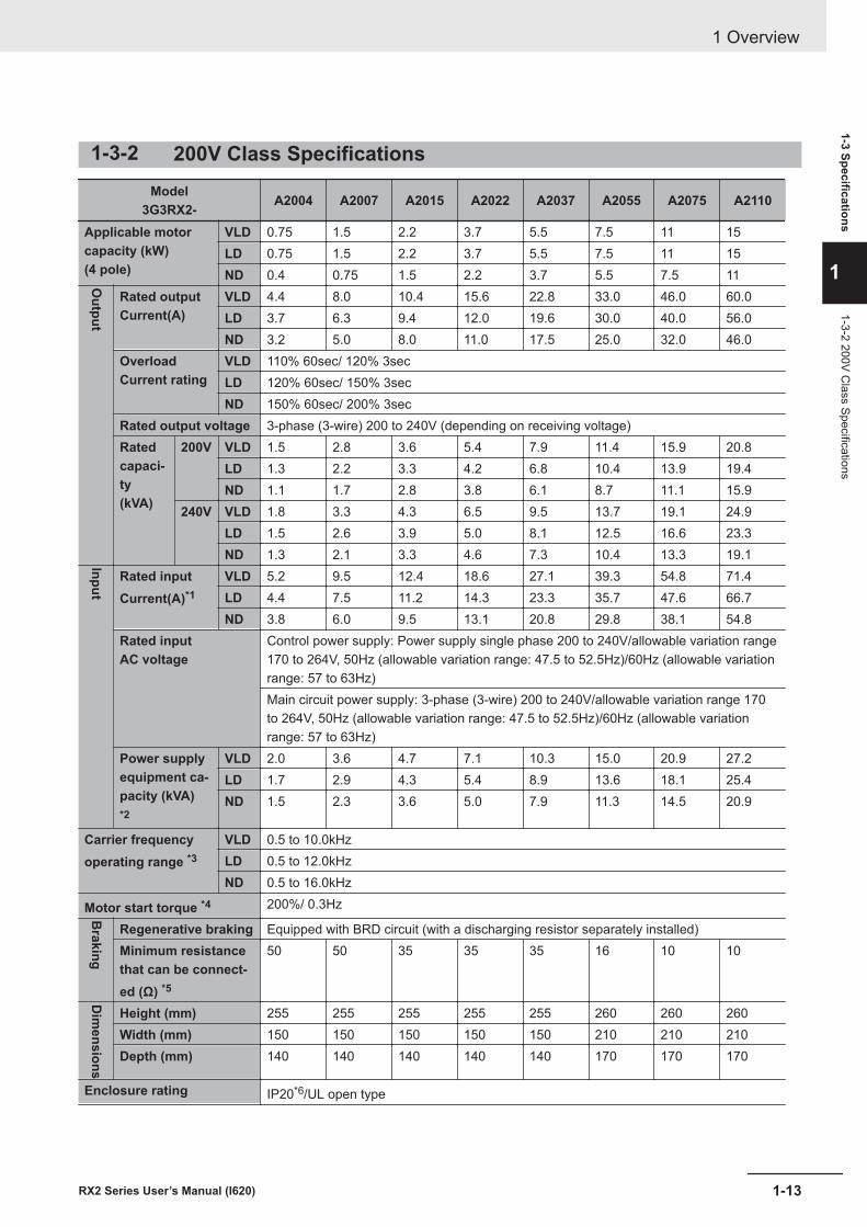
1-3-2 200V Class SpecificationsModel
3G3RX2- A2004 A2007 A2015 A2022 A2037 A2055 A2075 A2110
Applicable motorcapacity (kW)(4 pole)
VLD 0.75 1.5 2.2 3.7 5.5 7.5 11 15LD 0.75 1.5 2.2 3.7 5.5 7.5 11 15ND 0.4 0.75 1.5 2.2 3.7 5.5 7.5 11O
utput
Rated outputCurrent(A)
VLD 4.4 8.0 10.4 15.6 22.8 33.0 46.0 60.0LD 3.7 6.3 9.4 12.0 19.6 30.0 40.0 56.0ND 3.2 5.0 8.0 11.0 17.5 25.0 32.0 46.0
OverloadCurrent rating
VLD 110% 60sec/ 120% 3secLD 120% 60sec/ 150% 3secND 150% 60sec/ 200% 3sec
Rated output voltage 3-phase (3-wire) 200 to 240V (depending on receiving voltage)Ratedcapaci-ty(kVA)
200V VLD 1.5 2.8 3.6 5.4 7.9 11.4 15.9 20.8LD 1.3 2.2 3.3 4.2 6.8 10.4 13.9 19.4ND 1.1 1.7 2.8 3.8 6.1 8.7 11.1 15.9
240V VLD 1.8 3.3 4.3 6.5 9.5 13.7 19.1 24.9LD 1.5 2.6 3.9 5.0 8.1 12.5 16.6 23.3ND 1.3 2.1 3.3 4.6 7.3 10.4 13.3 19.1Input
Rated inputCurrent(A)*1
VLD 5.2 9.5 12.4 18.6 27.1 39.3 54.8 71.4LD 4.4 7.5 11.2 14.3 23.3 35.7 47.6 66.7ND 3.8 6.0 9.5 13.1 20.8 29.8 38.1 54.8
Rated inputAC voltage
Control power supply: Power supply single phase 200 to 240V/allowable variation range170 to 264V, 50Hz (allowable variation range: 47.5 to 52.5Hz)/60Hz (allowable variationrange: 57 to 63Hz)Main circuit power supply: 3-phase (3-wire) 200 to 240V/allowable variation range 170to 264V, 50Hz (allowable variation range: 47.5 to 52.5Hz)/60Hz (allowable variationrange: 57 to 63Hz)
Power supplyequipment ca-pacity (kVA)*2
VLD 2.0 3.6 4.7 7.1 10.3 15.0 20.9 27.2LD 1.7 2.9 4.3 5.4 8.9 13.6 18.1 25.4ND 1.5 2.3 3.6 5.0 7.9 11.3 14.5 20.9
Carrier frequencyoperating range *3
VLD 0.5 to 10.0kHzLD 0.5 to 12.0kHzND 0.5 to 16.0kHz
Motor start torque *4 200%/ 0.3Hz
Braking
Regenerative braking Equipped with BRD circuit (with a discharging resistor separately installed)Minimum resistancethat can be connect-ed (Ω) *5
50 50 35 35 35 16 10 10
Dim
ensions
Height (mm) 255 255 255 255 255 260 260 260Width (mm) 150 150 150 150 150 210 210 210Depth (mm) 140 140 140 140 140 170 170 170
Enclosure rating IP20*6/UL open type
1 Overview
1-13RX2 Series User’s Manual (I620)
1-3 Specifications
1
1-3-2 200V Class Specifications
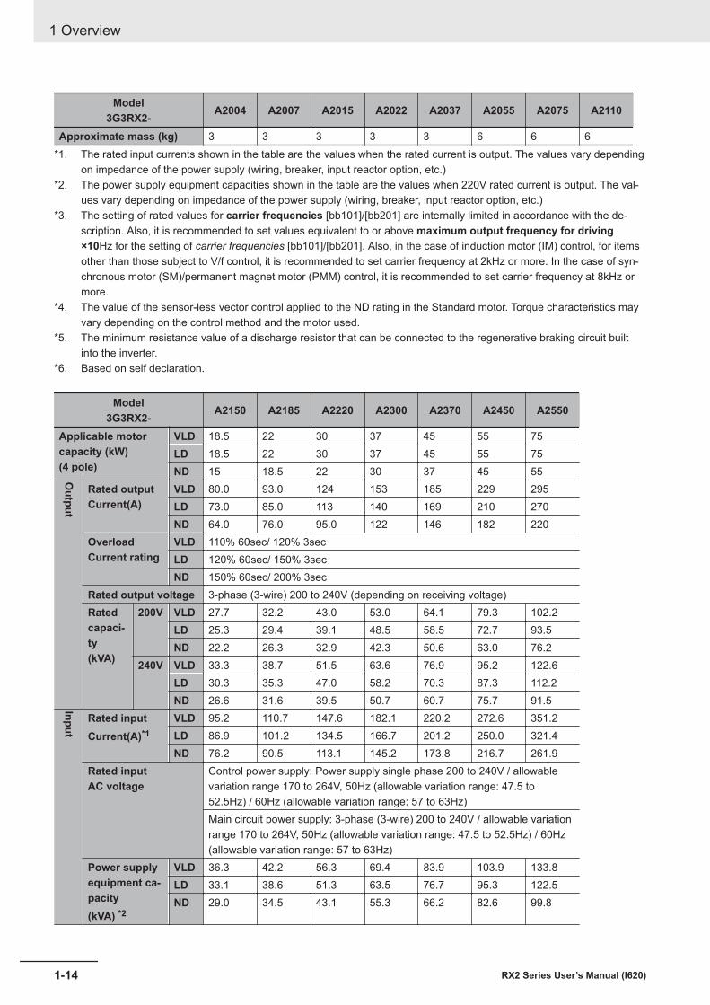
Model3G3RX2- A2004 A2007 A2015 A2022 A2037 A2055 A2075 A2110
Approximate mass (kg) 3 3 3 3 3 6 6 6*1. The rated input currents shown in the table are the values when the rated current is output. The values vary depending
on impedance of the power supply (wiring, breaker, input reactor option, etc.)*2. The power supply equipment capacities shown in the table are the values when 220V rated current is output. The val-
ues vary depending on impedance of the power supply (wiring, breaker, input reactor option, etc.)*3. The setting of rated values for carrier frequencies [bb101]/[bb201] are internally limited in accordance with the de-
scription. Also, it is recommended to set values equivalent to or above maximum output frequency for driving×10Hz for the setting of carrier frequencies [bb101]/[bb201]. Also, in the case of induction motor (IM) control, for itemsother than those subject to V/f control, it is recommended to set carrier frequency at 2kHz or more. In the case of syn-chronous motor (SM)/permanent magnet motor (PMM) control, it is recommended to set carrier frequency at 8kHz ormore.
*4. The value of the sensor-less vector control applied to the ND rating in the Standard motor. Torque characteristics mayvary depending on the control method and the motor used.
*5. The minimum resistance value of a discharge resistor that can be connected to the regenerative braking circuit builtinto the inverter.
*6. Based on self declaration.
Model3G3RX2- A2150 A2185 A2220 A2300 A2370 A2450 A2550
Applicable motorcapacity (kW)(4 pole)
VLD 18.5 22 30 37 45 55 75LD 18.5 22 30 37 45 55 75ND 15 18.5 22 30 37 45 55O
utput
Rated outputCurrent(A)
VLD 80.0 93.0 124 153 185 229 295LD 73.0 85.0 113 140 169 210 270ND 64.0 76.0 95.0 122 146 182 220
OverloadCurrent rating
VLD 110% 60sec/ 120% 3secLD 120% 60sec/ 150% 3secND 150% 60sec/ 200% 3sec
Rated output voltage 3-phase (3-wire) 200 to 240V (depending on receiving voltage)Ratedcapaci-ty(kVA)
200V VLD 27.7 32.2 43.0 53.0 64.1 79.3 102.2LD 25.3 29.4 39.1 48.5 58.5 72.7 93.5ND 22.2 26.3 32.9 42.3 50.6 63.0 76.2
240V VLD 33.3 38.7 51.5 63.6 76.9 95.2 122.6LD 30.3 35.3 47.0 58.2 70.3 87.3 112.2ND 26.6 31.6 39.5 50.7 60.7 75.7 91.5Input
Rated inputCurrent(A)*1
VLD 95.2 110.7 147.6 182.1 220.2 272.6 351.2LD 86.9 101.2 134.5 166.7 201.2 250.0 321.4ND 76.2 90.5 113.1 145.2 173.8 216.7 261.9
Rated inputAC voltage
Control power supply: Power supply single phase 200 to 240V / allowablevariation range 170 to 264V, 50Hz (allowable variation range: 47.5 to52.5Hz) / 60Hz (allowable variation range: 57 to 63Hz)Main circuit power supply: 3-phase (3-wire) 200 to 240V / allowable variationrange 170 to 264V, 50Hz (allowable variation range: 47.5 to 52.5Hz) / 60Hz(allowable variation range: 57 to 63Hz)
Power supplyequipment ca-pacity(kVA) *2
VLD 36.3 42.2 56.3 69.4 83.9 103.9 133.8LD 33.1 38.6 51.3 63.5 76.7 95.3 122.5ND 29.0 34.5 43.1 55.3 66.2 82.6 99.8
1 Overview
1-14 RX2 Series User’s Manual (I620)
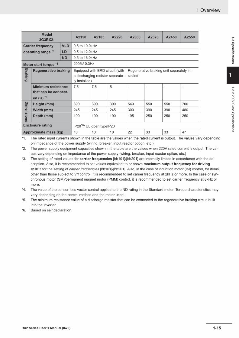
Model3G3RX2- A2150 A2185 A2220 A2300 A2370 A2450 A2550
Carrier frequencyoperating range *3
VLD 0.5 to 10.0kHzLD 0.5 to 12.0kHzND 0.5 to 16.0kHz
Motor start torque *4 200%/ 0.3Hz
Braking
Regenerative braking Equipped with BRD circuit (witha discharging resistor separate-ly installed)
Regenerative braking unit separately in-stalled
Minimum resistancethat can be connect-ed (Ω) *5
7.5 7.5 5 - - - -
Dim
ensions
Height (mm) 390 390 390 540 550 550 700Width (mm) 245 245 245 300 390 390 480Depth (mm) 190 190 190 195 250 250 250
Enclosure rating IP20*6/ UL open typeIP20Approximate mass (kg) 10 10 10 22 33 33 47
*1. The rated input currents shown in the table are the values when the rated current is output. The values vary dependingon impedance of the power supply (wiring, breaker, input reactor option, etc.)
*2. The power supply equipment capacities shown in the table are the values when 220V rated current is output. The val-ues vary depending on impedance of the power supply (wiring, breaker, input reactor option, etc.)
*3. The setting of rated values for carrier frequencies [bb101]/[bb201] are internally limited in accordance with the de-scription. Also, it is recommended to set values equivalent to or above maximum output frequency for driving×10Hz for the setting of carrier frequencies [bb101]/[bb201]. Also, in the case of induction motor (IM) control, for itemsother than those subject to V/f control, it is recommended to set carrier frequency at 2kHz or more. In the case of syn-chronous motor (SM)/permanent magnet motor (PMM) control, it is recommended to set carrier frequency at 8kHz ormore.
*4. The value of the sensor-less vector control applied to the ND rating in the Standard motor. Torque characteristics mayvary depending on the control method and the motor used.
*5. The minimum resistance value of a discharge resistor that can be connected to the regenerative braking circuit builtinto the inverter.
*6. Based on self declaration.
1 Overview
1-15RX2 Series User’s Manual (I620)
1-3 Specifications
1
1-3-2 200V Class Specifications
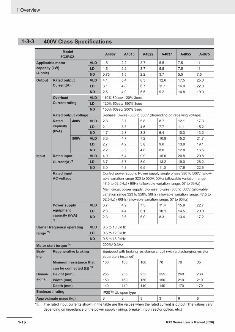
1-3-3 400V Class SpecificationsModel
3G3RX2- A4007 A4015 A4022 A4037 A4055 A4075
Applicable motorcapacity (kW)(4 pole)
VLD 1.5 2.2 3.7 5.5 7.5 11LD 1.5 2.2 3.7 5.5 7.5 11ND 0.75 1.5 2.2 3.7 5.5 7.5
Output Rated outputCurrent(A)
VLD 4.1 5.4 8.3 12.6 17.5 25.0LD 3.1 4.8 6.7 11.1 16.0 22.0ND 2.5 4.0 5.5 9.2 14.8 19.0
OverloadCurrent rating
VLD 110% 60sec/ 120% 3secLD 120% 60sec/ 150% 3secND 150% 60sec/ 200% 3sec
Rated output voltage 3-phase (3-wire) 380 to 500V (depending on receiving voltage)Ratedcapacity(kVA)
400V VLD 2.8 3.7 5.8 8.7 12.1 17.3LD 2.1 3.3 4.6 7.7 11.1 15.2ND 1.7 2.8 3.8 6.4 10.3 13.2
500V VLD 3.6 4.7 7.2 10.9 15.2 21.7LD 2.7 4.2 5.8 9.6 13.9 19.1ND 2.2 3.5 4.8 8.0 12.8 16.5
Input Rated inputCurrent(A)*1
VLD 4.9 6.4 9.9 15.0 20.8 29.8LD 3.7 5.7 8.0 13.2 19.0 26.2ND 3.0 4.8 6.5 11.0 17.6 22.6
Rated inputAC voltage
Control power supply: Power supply single phase 380 to 500V (allow-able variation range 323 to 550V, 50Hz (allowable variation range:47.5 to 52.5Hz) / 60Hz (allowable variation range: 57 to 63Hz)Main circuit power supply: 3-phase (3-wire) 380 to 500V (allowablevariation range 323 to 550V, 50Hz (allowable variation range: 47.5 to52.5Hz) / 60Hz (allowable variation range: 57 to 63Hz)
Power supplyequipmentcapacity (kVA)*2
VLD 3.7 4.9 7.5 11.4 15.9 22.7LD 2.8 4.4 6.1 10.1 14.5 20.0ND 2.3 3.6 5.0 8.3 13.4 17.2
Carrier frequency operatingrange *3
VLD 0.5 to 10.0kHzLD 0.5 to 12.0kHzND 0.5 to 16.0kHz
Motor start torque *4 200%/ 0.3Hz
Brak-ing
Regenerative braking Equipped with braking resistance circuit (with a discharging resistorseparately installed)
Minimum resistance thatcan be connected (Ω) *5
100 100 100 70 70 35
Dimen-sions
Height (mm) 255 255 255 255 260 260Width (mm) 150 150 150 150 210 210Depth (mm) 140 140 140 140 170 170
Enclosure rating IP20*6/ UL open typeApproximate mass (kg) 3 3 3 3 6 6
*1. The rated input currents shown in the table are the values when the rated current is output. The values varydepending on impedance of the power supply (wiring, breaker, input reactor option, etc.)
1 Overview
1-16 RX2 Series User’s Manual (I620)
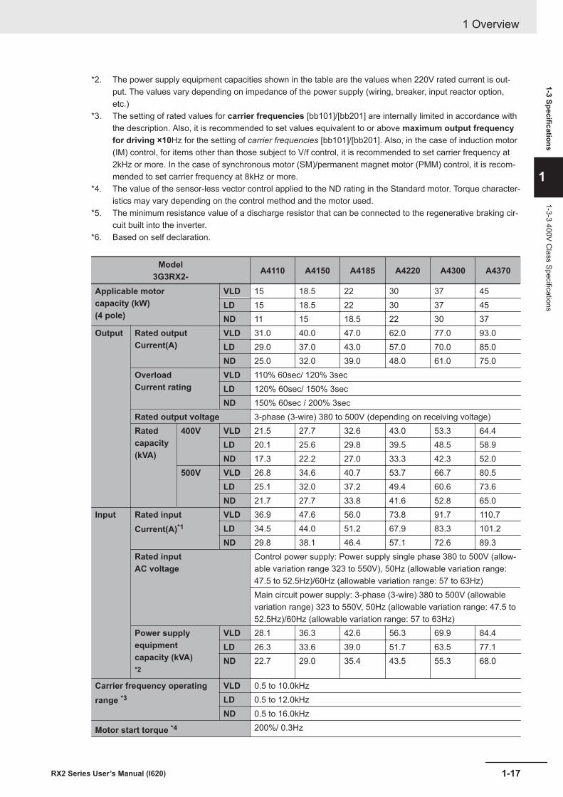
*2. The power supply equipment capacities shown in the table are the values when 220V rated current is out-put. The values vary depending on impedance of the power supply (wiring, breaker, input reactor option,etc.)
*3. The setting of rated values for carrier frequencies [bb101]/[bb201] are internally limited in accordance withthe description. Also, it is recommended to set values equivalent to or above maximum output frequencyfor driving ×10Hz for the setting of carrier frequencies [bb101]/[bb201]. Also, in the case of induction motor(IM) control, for items other than those subject to V/f control, it is recommended to set carrier frequency at2kHz or more. In the case of synchronous motor (SM)/permanent magnet motor (PMM) control, it is recom-mended to set carrier frequency at 8kHz or more.
*4. The value of the sensor-less vector control applied to the ND rating in the Standard motor. Torque character-istics may vary depending on the control method and the motor used.
*5. The minimum resistance value of a discharge resistor that can be connected to the regenerative braking cir-cuit built into the inverter.
*6. Based on self declaration.
Model3G3RX2- A4110 A4150 A4185 A4220 A4300 A4370
Applicable motorcapacity (kW)(4 pole)
VLD 15 18.5 22 30 37 45LD 15 18.5 22 30 37 45ND 11 15 18.5 22 30 37
Output Rated outputCurrent(A)
VLD 31.0 40.0 47.0 62.0 77.0 93.0LD 29.0 37.0 43.0 57.0 70.0 85.0ND 25.0 32.0 39.0 48.0 61.0 75.0
OverloadCurrent rating
VLD 110% 60sec/ 120% 3secLD 120% 60sec/ 150% 3secND 150% 60sec / 200% 3sec
Rated output voltage 3-phase (3-wire) 380 to 500V (depending on receiving voltage)Ratedcapacity(kVA)
400V VLD 21.5 27.7 32.6 43.0 53.3 64.4LD 20.1 25.6 29.8 39.5 48.5 58.9ND 17.3 22.2 27.0 33.3 42.3 52.0
500V VLD 26.8 34.6 40.7 53.7 66.7 80.5LD 25.1 32.0 37.2 49.4 60.6 73.6ND 21.7 27.7 33.8 41.6 52.8 65.0
Input Rated inputCurrent(A)*1
VLD 36.9 47.6 56.0 73.8 91.7 110.7LD 34.5 44.0 51.2 67.9 83.3 101.2ND 29.8 38.1 46.4 57.1 72.6 89.3
Rated inputAC voltage
Control power supply: Power supply single phase 380 to 500V (allow-able variation range 323 to 550V), 50Hz (allowable variation range:47.5 to 52.5Hz)/60Hz (allowable variation range: 57 to 63Hz)Main circuit power supply: 3-phase (3-wire) 380 to 500V (allowablevariation range) 323 to 550V, 50Hz (allowable variation range: 47.5 to52.5Hz)/60Hz (allowable variation range: 57 to 63Hz)
Power supplyequipmentcapacity (kVA)*2
VLD 28.1 36.3 42.6 56.3 69.9 84.4LD 26.3 33.6 39.0 51.7 63.5 77.1ND 22.7 29.0 35.4 43.5 55.3 68.0
Carrier frequency operatingrange *3
VLD 0.5 to 10.0kHzLD 0.5 to 12.0kHzND 0.5 to 16.0kHz
Motor start torque *4 200%/ 0.3Hz
1 Overview
1-17RX2 Series User’s Manual (I620)
1-3 Specifications
1
1-3-3 400V Class Specifications
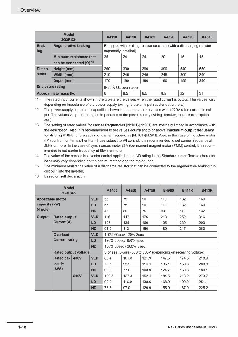
Model3G3RX2- A4110 A4150 A4185 A4220 A4300 A4370
Brak-ing
Regenerative braking Equipped with braking resistance circuit (with a discharging resistorseparately installed)
Minimum resistance thatcan be connected (Ω) *5
35 24 24 20 15 15
Dimen-sions
Height (mm) 260 390 390 390 540 550Width (mm) 210 245 245 245 300 390Depth (mm) 170 190 190 190 195 250
Enclosure rating IP20*6/ UL open typeApproximate mass (kg) 6 8.5 8.5 8.5 22 31
*1. The rated input currents shown in the table are the values when the rated current is output. The values varydepending on impedance of the power supply (wiring, breaker, input reactor option, etc.)
*2. The power supply equipment capacities shown in the table are the values when 220V rated current is out-put. The values vary depending on impedance of the power supply (wiring, breaker, input reactor option,etc.)
*3. The setting of rated values for carrier frequencies [bb101]/[bb201] are internally limited in accordance withthe description. Also, it is recommended to set values equivalent to or above maximum output frequencyfor driving ×10Hz for the setting of carrier frequencies [bb101]/[bb201]. Also, in the case of induction motor(IM) control, for items other than those subject to V/f control, it is recommended to set carrier frequency at2kHz or more. In the case of synchronous motor (SM)/permanent magnet motor (PMM) control, it is recom-mended to set carrier frequency at 8kHz or more.
*4. The value of the sensor-less vector control applied to the ND rating in the Standard motor. Torque character-istics may vary depending on the control method and the motor used.
*5. The minimum resistance value of a discharge resistor that can be connected to the regenerative braking cir-cuit built into the inverter.
*6. Based on self declaration.
Model3G3RX2- A4450 A4550 A4750 B4900 B411K B413K
Applicable motorcapacity (kW)(4 pole)
VLD 55 75 90 110 132 160LD 55 75 90 110 132 160ND 45 55 75 90 110 132
Output Rated outputCurrent(A)
VLD 116 147 176 213 252 316LD 105 135 160 195 230 290ND 91.0 112 150 180 217 260
OverloadCurrent rating
VLD 110% 60sec/ 120% 3secLD 120% 60sec/ 150% 3secND 150% 60sec / 200% 3sec
Rated output voltage 3-phase (3-wire) 380 to 500V (depending on receiving voltage)Rated ca-pacity(kVA)
400V VLD 80.4 101.8 121.9 147.6 174.6 218.9LD 72.7 93.5 110.9 135.1 159.3 200.9ND 63.0 77.6 103.9 124.7 150.3 180.1
500V VLD 100.5 127.3 152.4 184.5 218.2 273.7LD 90.9 116.9 138.6 168.9 199.2 251.1ND 78.8 97.0 129.9 155.9 187.9 225.2
1 Overview
1-18 RX2 Series User’s Manual (I620)
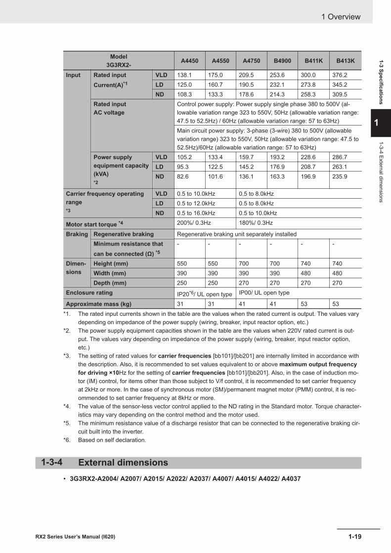
Model3G3RX2- A4450 A4550 A4750 B4900 B411K B413K
Input Rated inputCurrent(A)*1
VLD 138.1 175.0 209.5 253.6 300.0 376.2LD 125.0 160.7 190.5 232.1 273.8 345.2ND 108.3 133.3 178.6 214.3 258.3 309.5
Rated inputAC voltage
Control power supply: Power supply single phase 380 to 500V (al-lowable variation range 323 to 550V, 50Hz (allowable variation range:47.5 to 52.5Hz) / 60Hz (allowable variation range: 57 to 63Hz)Main circuit power supply: 3-phase (3-wire) 380 to 500V (allowablevariation range) 323 to 550V, 50Hz (allowable variation range: 47.5 to52.5Hz)/60Hz (allowable variation range: 57 to 63Hz)
Power supplyequipment capacity(kVA)*2
VLD 105.2 133.4 159.7 193.2 228.6 286.7LD 95.3 122.5 145.2 176.9 208.7 263.1ND 82.6 101.6 136.1 163.3 196.9 235.9
Carrier frequency operatingrange*3
VLD 0.5 to 10.0kHz 0.5 to 8.0kHzLD 0.5 to 12.0kHz 0.5 to 8.0kHzND 0.5 to 16.0kHz 0.5 to 10.0kHz
Motor start torque *4 200%/ 0.3Hz 180%/ 0.3Hz
Braking Regenerative braking Regenerative braking unit separately installedMinimum resistance thatcan be connected (Ω) *5
- - - - - -
Dimen-sions
Height (mm) 550 550 700 700 740 740Width (mm) 390 390 390 390 480 480Depth (mm) 250 250 270 270 270 270
Enclosure rating IP20*6/ UL open type IP00/ UL open type
Approximate mass (kg) 31 31 41 41 53 53*1. The rated input currents shown in the table are the values when the rated current is output. The values vary
depending on impedance of the power supply (wiring, breaker, input reactor option, etc.)*2. The power supply equipment capacities shown in the table are the values when 220V rated current is out-
put. The values vary depending on impedance of the power supply (wiring, breaker, input reactor option,etc.)
*3. The setting of rated values for carrier frequencies [bb101]/[bb201] are internally limited in accordance withthe description. Also, it is recommended to set values equivalent to or above maximum output frequencyfor driving ×10Hz for the setting of carrier frequencies [bb101]/[bb201]. Also, in the case of induction mo-tor (IM) control, for items other than those subject to V/f control, it is recommended to set carrier frequencyat 2kHz or more. In the case of synchronous motor (SM)/permanent magnet motor (PMM) control, it is rec-ommended to set carrier frequency at 8kHz or more.
*4. The value of the sensor-less vector control applied to the ND rating in the Standard motor. Torque character-istics may vary depending on the control method and the motor used.
*5. The minimum resistance value of a discharge resistor that can be connected to the regenerative braking cir-cuit built into the inverter.
*6. Based on self declaration.
1-3-4 External dimensions• 3G3RX2-A2004/ A2007/ A2015/ A2022/ A2037/ A4007/ A4015/ A4022/ A4037
1 Overview
1-19RX2 Series User’s Manual (I620)
1-3 Specifications
1
1-3-4 External dimensions
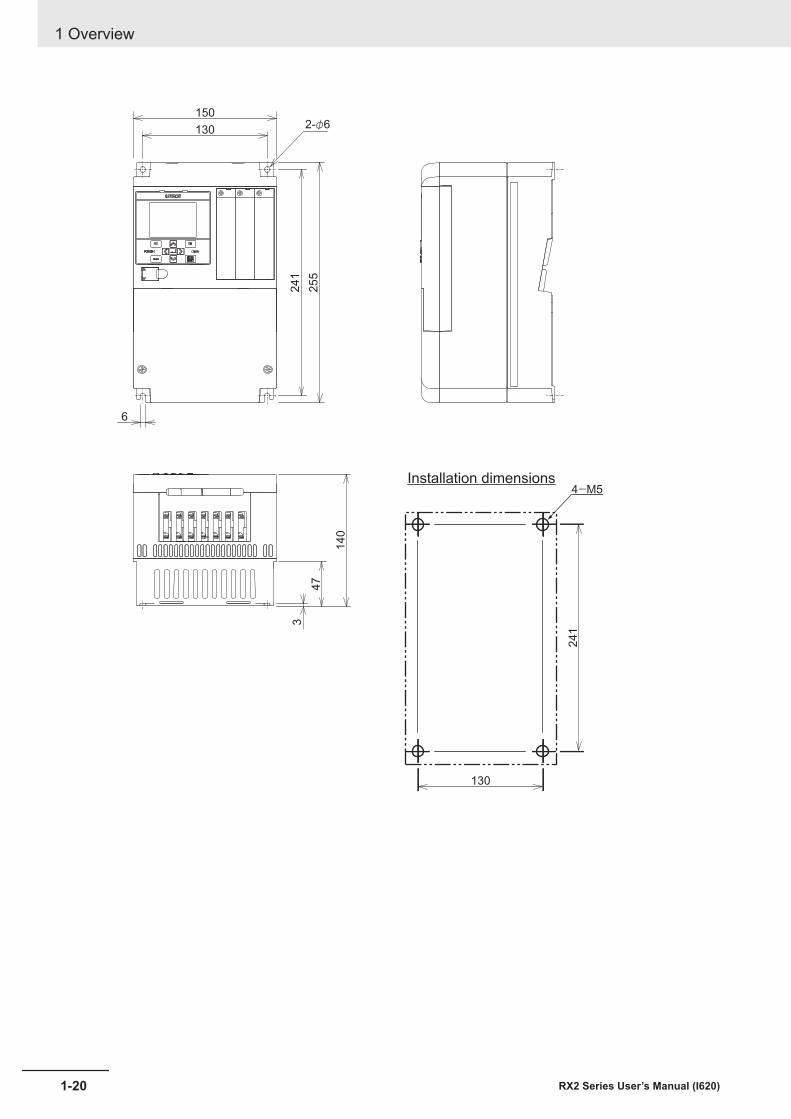
1302-φ6
24
1
25
5
6
150
3
47
14
0
Installation dimensions4-M5
130
24
1
1 Overview
1-20 RX2 Series User’s Manual (I620)
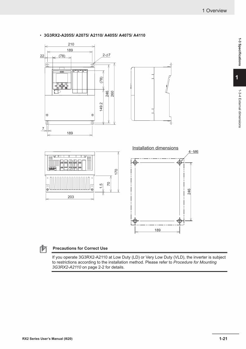
• 3G3RX2-A2055/ A2075/ A2110/ A4055/ A4075/ A4110
189
246
Installation dimensions4-M6
203
70
1.5
170
2-φ7
149.2
189
22 (78)
189
7
246
(78)
260
210
Precautions for Correct Use
If you operate 3G3RX2-A2110 at Low Duty (LD) or Very Low Duty (VLD), the inverter is subjectto restrictions according to the installation method. Please refer to Procedure for Mounting3G3RX2-A2110 on page 2-2 for details.
1 Overview
1-21RX2 Series User’s Manual (I620)
1-3 Specifications
1
1-3-4 External dimensions
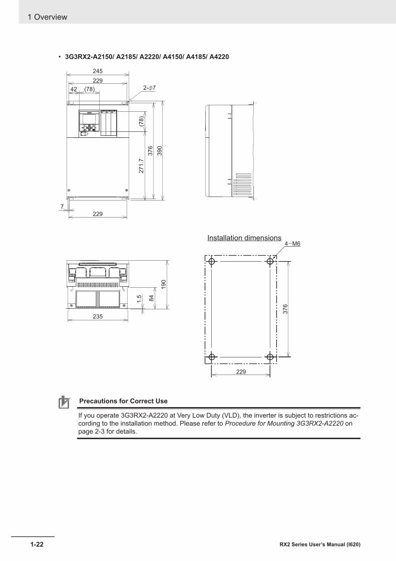
• 3G3RX2-A2150/ A2185/ A2220/ A4150/ A4185/ A4220
229
376
Installation dimensions4-M6
235
84
1.5
190
2-φ7
271.7
229
42 (78)
229
7
376
(78)
390
245
Precautions for Correct Use
If you operate 3G3RX2-A2220 at Very Low Duty (VLD), the inverter is subject to restrictions ac-cording to the installation method. Please refer to Procedure for Mounting 3G3RX2-A2220 onpage 2-3 for details.
1 Overview
1-22 RX2 Series User’s Manual (I620)
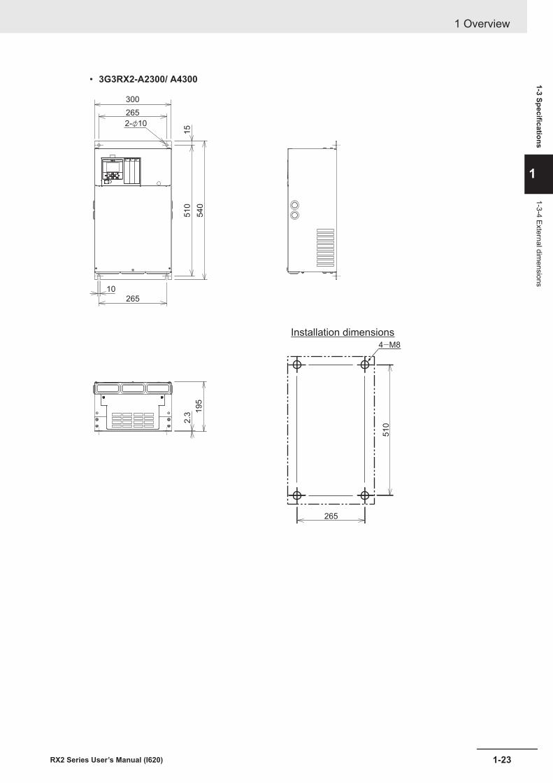
• 3G3RX2-A2300/ A4300
265
51
0
Installation dimensions4-M8
2.3
19
5
265
265
10
51
0
54
0
300
2-φ10
15
1 Overview
1-23RX2 Series User’s Manual (I620)
1-3 Specifications
1
1-3-4 External dimensions
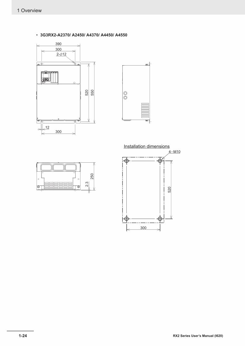
• 3G3RX2-A2370/ A2450/ A4370/ A4450/ A4550
300
52
0
Installation dimensions4-M10
2.3
25
0
300
300
12
52
0
55
0
390
2-φ12
1 Overview
1-24 RX2 Series User’s Manual (I620)
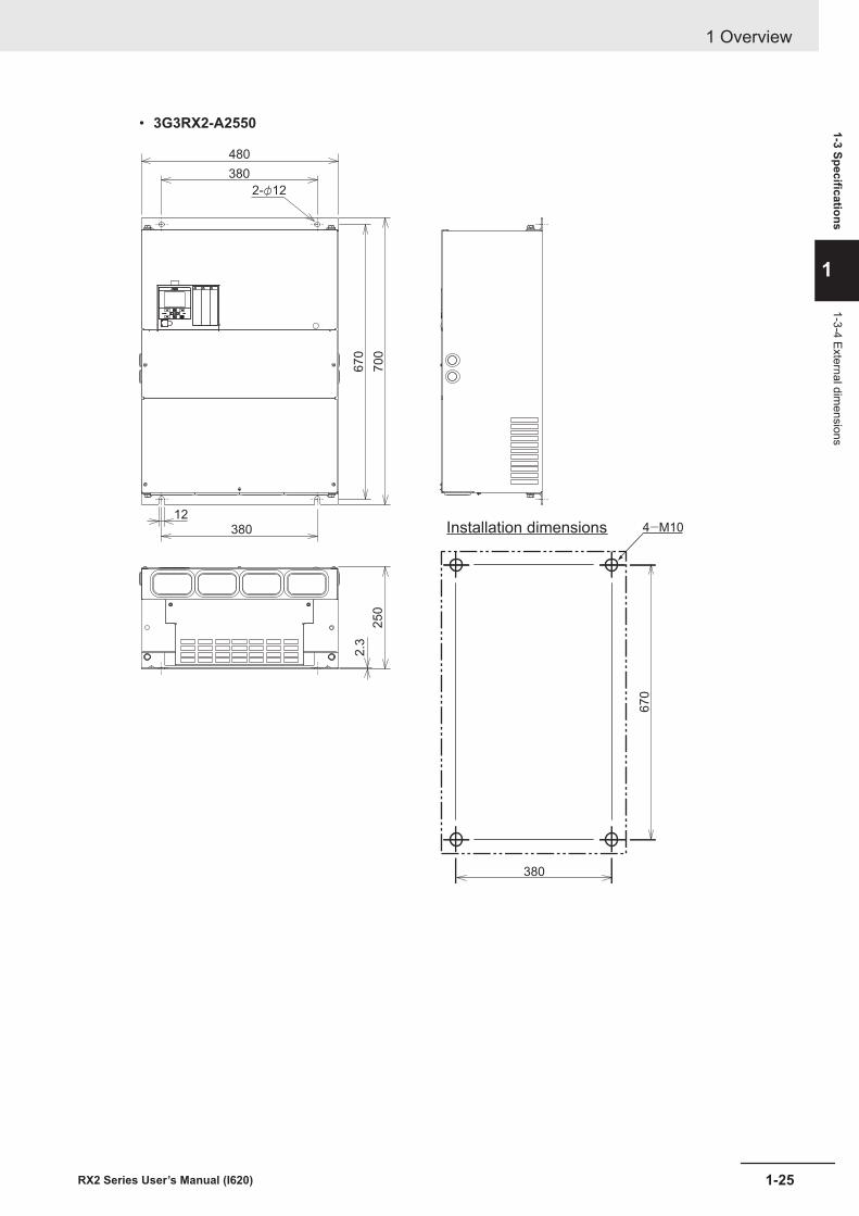
• 3G3RX2-A2550
380
670
Installation dimensions 4-M10
2.3
250
380
380
12
670
700
480
2-φ12
1 Overview
1-25RX2 Series User’s Manual (I620)
1-3 Specifications
1
1-3-4 External dimensions
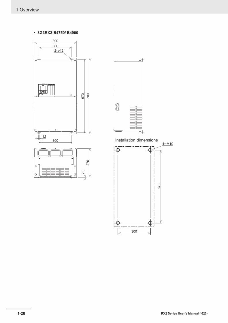
• 3G3RX2-B4750/ B4900
300
670
Installation dimensions4-M10
2.3
270
300
300
12
670
700
390
2-φ12
1 Overview
1-26 RX2 Series User’s Manual (I620)
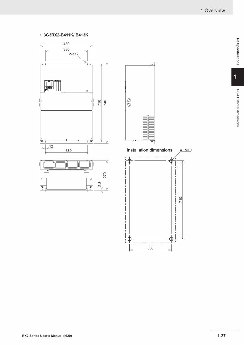
• 3G3RX2-B411K/ B413K
380
710
Installation dimensions 4-M10
2.3
270
380
380
12
710
740
480
2-φ12
1 Overview
1-27RX2 Series User’s Manual (I620)
1-3 Specifications
1
1-3-4 External dimensions

1-4 Restrictions
Limitation on 0-Hz Sensor-less Vector ControlWhen 0-Hz sensor-less vector control is used, a large current flows at low frequencies.To protect the inverter against overload, select and use an inverter whose rated capacity is one sizelarger than the rated capacity of the motor.
1 Overview
1-28 RX2 Series User’s Manual (I620)
2Design
2-1 Installation ...................................................................................................... 2-22-1-1 Precaution for Installation................................................................................ 2-22-1-2 Installation Environment .................................................................................. 2-4
2-2 Removal of Each Part .................................................................................. 2-132-2-1 Removal of Cover.......................................................................................... 2-132-2-2 Terminal Blocks ............................................................................................. 2-142-2-3 Preparing Backing Plate................................................................................ 2-14
2-3 Wiring ............................................................................................................ 2-172-3-1 Standard Connection Diagram ...................................................................... 2-172-3-2 Arrangement and Function of Main Circuit Terminal Block ........................... 2-172-3-3 Arrangement and Function of Control Circuit Terminal Block........................ 2-182-3-4 Wiring for Main Circuit Terminals................................................................... 2-312-3-5 Wiring for Control Circuit Terminals............................................................... 2-622-3-6 Wiring for PG Option Unit.............................................................................. 2-682-3-7 Wiring for RS485 Communication Terminals................................................. 2-762-3-8 Wiring for LCD Operator................................................................................ 2-78
2-4 STO Function................................................................................................ 2-812-4-1 Overview of STO Function ............................................................................ 2-812-4-2 Wiring for STO Function................................................................................ 2-832-4-3 Status Indication and Cut-off Based on Self-diagnosis ................................. 2-872-4-4 Example of Use ............................................................................................. 2-91
2-5 Others............................................................................................................ 2-932-5-1 Conditions of Conformity of EU Directives .................................................... 2-932-5-2 Conformance Conditions of UL/CSA Standards ........................................... 2-962-5-3 Korean Radio Regulation (KC).................................................................... 2-1002-5-4 Reference Manual for Options .................................................................... 2-100
2-1RX2 Series User’s Manual (I620)
2
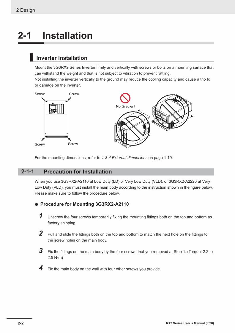
2-1 Installation
Inverter InstallationMount the 3G3RX2 Series Inverter firmly and vertically with screws or bolts on a mounting surface thatcan withstand the weight and that is not subject to vibration to prevent rattling.Not installing the inverter vertically to the ground may reduce the cooling capacity and cause a trip toor damage on the inverter.
ScrewScrew
ScrewScrew
No Gradient
For the mounting dimensions, refer to 1-3-4 External dimensions on page 1-19.
2-1-1 Precaution for InstallationWhen you use 3G3RX2-A2110 at Low Duty (LD) or Very Low Duty (VLD), or 3G3RX2-A2220 at VeryLow Duty (VLD), you must install the main body according to the instruction shown in the figure below.Please make sure to follow the procedure below.
l Procedure for Mounting 3G3RX2-A2110
1 Unscrew the four screws temporarily fixing the mounting fittings both on the top and bottom asfactory shipping.
2 Pull and slide the fittings both on the top and bottom to match the next hole on the fittings tothe screw holes on the main body.
3 Fix the fittings on the main body by the four screws that you removed at Step 1. (Torque: 2.2 to2.5 N·m)
4 Fix the main body on the wall with four other screws you provide.
2 Design
2-2 RX2 Series User’s Manual (I620)
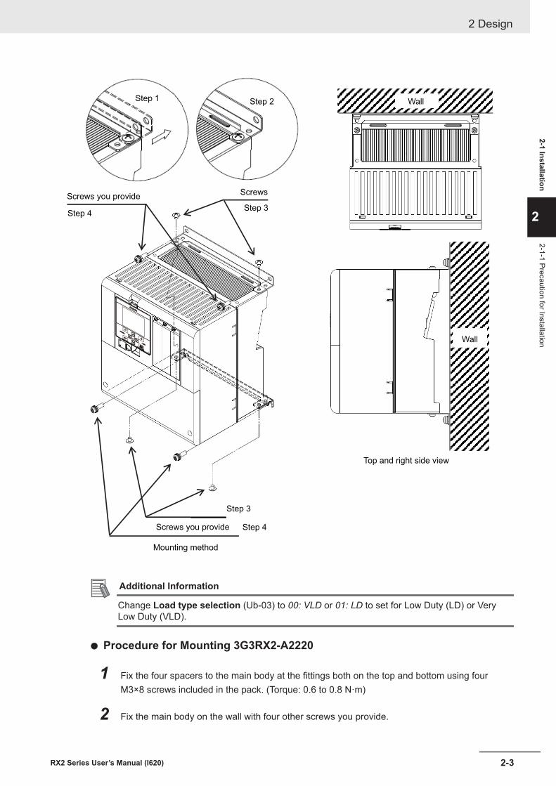
Mounting method
Top and right side view
Screws you provide
Step 1 Step 2
Step 3Step 4
Screws you provide
Step 3
Step 4
Screws
Wall
Wall
Additional Information
Change Load type selection (Ub-03) to 00: VLD or 01: LD to set for Low Duty (LD) or VeryLow Duty (VLD).
l Procedure for Mounting 3G3RX2-A2220
1 Fix the four spacers to the main body at the fittings both on the top and bottom using fourM3×8 screws included in the pack. (Torque: 0.6 to 0.8 N·m)
2 Fix the main body on the wall with four other screws you provide.
2 Design
2-3RX2 Series User’s Manual (I620)
2-1 Installation
2
2-1-1 Precaution for Installation
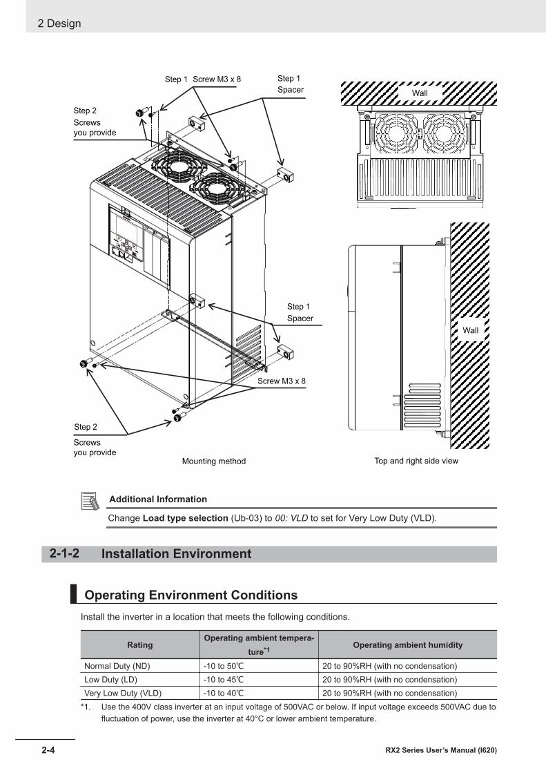
Wall
Step 1
Step 2
Screws
you provide
Wall
Step 1
Screws
you provide
Step 2
Step 1
Spacer
Spacer
Mounting method Top and right side view
Screw M3 x 8
Screw M3 x 8
Additional Information
Change Load type selection (Ub-03) to 00: VLD to set for Very Low Duty (VLD).
2-1-2 Installation Environment
Operating Environment ConditionsInstall the inverter in a location that meets the following conditions.
RatingOperating ambient tempera-
ture*1 Operating ambient humidity
Normal Duty (ND) -10 to 50℃ 20 to 90%RH (with no condensation)Low Duty (LD) -10 to 45℃ 20 to 90%RH (with no condensation)Very Low Duty (VLD) -10 to 40℃ 20 to 90%RH (with no condensation)
*1. Use the 400V class inverter at an input voltage of 500VAC or below. If input voltage exceeds 500VAC due tofluctuation of power, use the inverter at 40°C or lower ambient temperature.
2 Design
2-4 RX2 Series User’s Manual (I620)
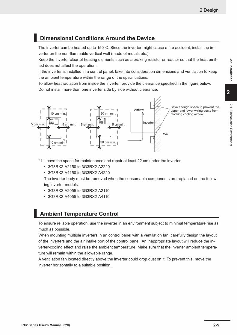
Dimensional Conditions Around the DeviceThe inverter can be heated up to 150°C. Since the inverter might cause a fire accident, install the in-verter on the non-flammable vertical wall (made of metals etc.).Keep the inverter clear of heating elements such as a braking resistor or reactor so that the heat emit-ted does not affect the operation.If the inverter is installed in a control panel, take into consideration dimensions and ventilation to keepthe ambient temperature within the range of the specifications.To allow heat radiation from inside the inverter, provide the clearance specified in the figure below.Do not install more than one inverter side by side without clearance.
Inverter
AirflowSave enough space to prevent theupper and lower wiring ducts fromblocking cooling airflow.
Wall
10 cm min.
10 cm min.
5 cm min. 5 cm min.5 cm min.
30 cm min.
*1
5 cm min.
30 cm min.
*1. Leave the space for maintenance and repair at least 22 cm under the inverter.• 3G3RX2-A2150 to 3G3RX2-A2220• 3G3RX2-A4150 to 3G3RX2-A4220The inverter body must be removed when the consumable components are replaced on the follow-ing inverter models.• 3G3RX2-A2055 to 3G3RX2-A2110• 3G3RX2-A4055 to 3G3RX2-A4110
Ambient Temperature ControlTo ensure reliable operation, use the inverter in an environment subject to minimal temperature rise asmuch as possible.When mounting multiple inverters in an control panel with a ventilation fan, carefully design the layoutof the inverters and the air intake port of the control panel. An inappropriate layout will reduce the in-verter-cooling effect and raise the ambient temperature. Make sure that the inverter ambient tempera-ture will remain within the allowable range.A ventilation fan located directly above the inverter could drop dust on it. To prevent this, move theinverter horizontally to a suitable position.
2 Design
2-5RX2 Series User’s Manual (I620)
2-1 Installation
2
2-1-2 Installation Environment
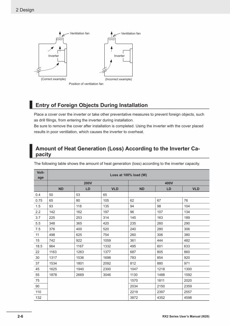
Ventilation fan Ventilation fan
Position of ventilation fan
Inverter Inverter
(Correct example) (Incorrect example)
Entry of Foreign Objects During InstallationPlace a cover over the inverter or take other preventative measures to prevent foreign objects, suchas drill filings, from entering the inverter during installation.Be sure to remove the cover after installation is completed. Using the inverter with the cover placedresults in poor ventilation, which causes the inverter to overheat.
Amount of Heat Generation (Loss) According to the Inverter Ca-pacity
The following table shows the amount of heat generation (loss) according to the inverter capacity.
Volt-age Loss at 100% load (W)
200V 400VND LD VLD ND LD VLD
0.4 50 53 650.75 65 80 105 62 67 761.5 93 118 135 94 98 1042.2 142 162 197 96 107 1343.7 225 253 314 145 163 1895.5 348 365 420 235 260 2907.5 376 400 520 240 280 30611 498 625 754 260 306 38015 742 922 1059 361 444 48218.5 964 1167 1332 495 601 63322 1163 1263 1377 687 805 86030 1317 1536 1698 783 854 92037 1534 1801 2092 812 880 97145 1625 1940 2300 1047 1218 130055 1878 2669 3046 1130 1488 159275 1570 1811 202090 2034 2150 2359110 2219 2397 2557132 3872 4352 4598
2 Design
2-6 RX2 Series User’s Manual (I620)
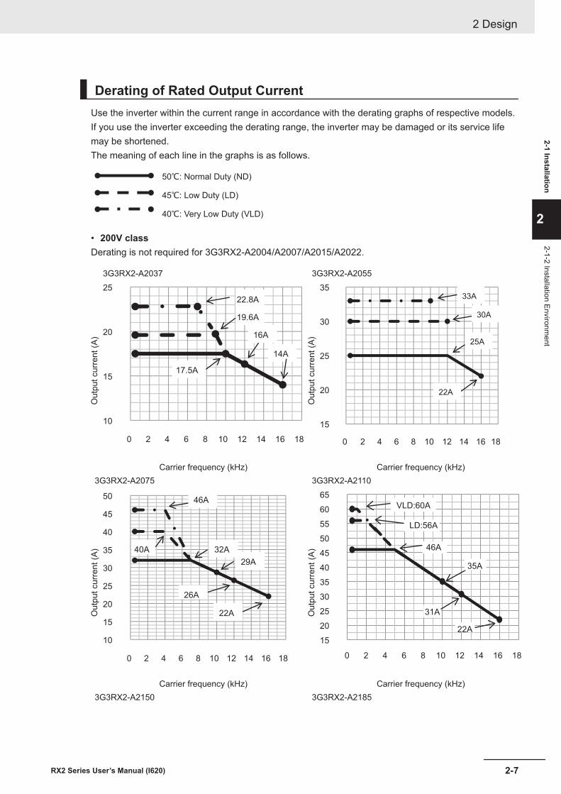
Derating of Rated Output CurrentUse the inverter within the current range in accordance with the derating graphs of respective models.If you use the inverter exceeding the derating range, the inverter may be damaged or its service lifemay be shortened.The meaning of each line in the graphs is as follows.
50℃: Normal Duty (ND)
45℃: Low Duty (LD)
40℃: Very Low Duty (VLD)
• 200V classDerating is not required for 3G3RX2-A2004/A2007/A2015/A2022.
Out
put c
urre
nt (A
)
3G3RX2-A2037 3G3RX2-A2055
10
15
20
25
0 2 4 6 8 10 12 14 16 18
14A
16A
17.5A
19.6A
22.8A
Out
put c
urre
nt (A
)
15
20
25
30
35
0 2 4 6 8 10 12 14 16 18
33A
30A
25A
22A
Carrier frequency (kHz) Carrier frequency (kHz)3G3RX2-A2075 3G3RX2-A2110
Out
put c
urre
nt (A
)
10
15
20
25
30
35
40
45
50
0 2 4 6 8 10 12 14 16 18
22A
26A
29A
32A
46A
40A
Out
put c
urre
nt (A
)
15
20
25
30
35
40
45
50
55
60
65
0 2 4 6 8 10 12 14 16 18
VLD:60A
LD:56A
46A
35A
31A
22A
Carrier frequency (kHz) Carrier frequency (kHz)3G3RX2-A2150 3G3RX2-A2185
2 Design
2-7RX2 Series User’s Manual (I620)
2-1 Installation
2
2-1-2 Installation Environment
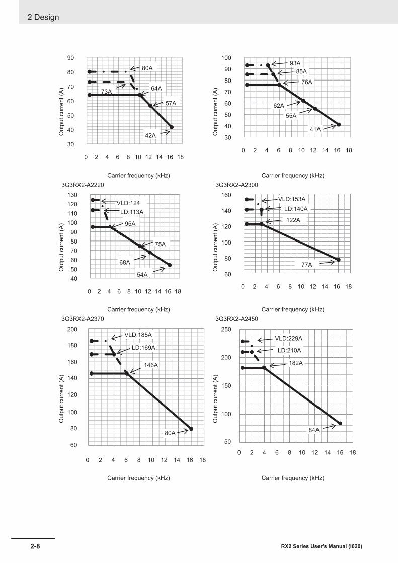
Out
put c
urre
nt (A
)
30
40
50
60
70
80
90
0 2 4 6 8 10 12 14 16 18
80A
73A64A
57A
42A Out
put c
urre
nt (A
)
30
40
50
60
70
80
90
100
0 2 4 6 8 10 12 14 16 18
93A
85A
76A
62A
55A
41A
Carrier frequency (kHz) Carrier frequency (kHz)3G3RX2-A2220 3G3RX2-A2300
Out
put c
urre
nt (A
)
40
50
60
70
80
90
100
110
120
130
0 2 4 6 8 10 12 14 16 18
VLD:124
LD:113A
95A
75A
68A
54A
Out
put c
urre
nt (A
)
60
80
100
120
140
160
0 2 4 6 8 10 12 14 16 18
VLD:153A
LD:140A
122A
77A
Carrier frequency (kHz) Carrier frequency (kHz)3G3RX2-A2370 3G3RX2-A2450
Out
put c
urre
nt (A
)
60
80
100
120
140
160
180
200
0 2 4 6 8 10 12 14 16 18
VLD:185A
LD:169A
80A
146A
Out
put c
urre
nt (A
)
50
100
150
200
250
0 2 4 6 8 10 12 14 16 18
VLD:229A
LD:210A
182A
84A
Carrier frequency (kHz) Carrier frequency (kHz)
2 Design
2-8 RX2 Series User’s Manual (I620)
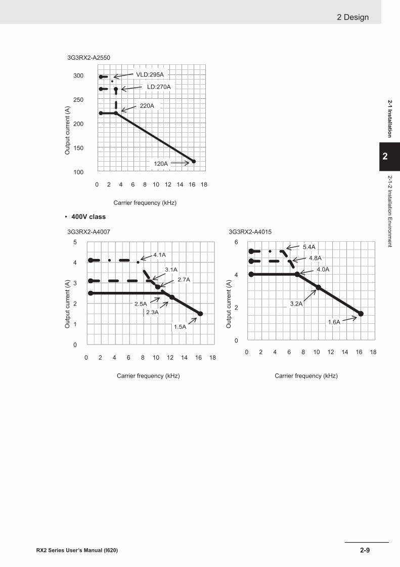
3G3RX2-A2550O
utpu
t cur
rent
(A)
100
150
200
250
300
0 2 4 6 8 10 12 14 16 18
VLD:295A
LD:270A
220A
120A
Carrier frequency (kHz)
• 400V class
3G3RX2-A4007 3G3RX2-A4015
Out
put c
urre
nt (A
)
0
1
2
3
4
5
0 2 4 6 8 10 12 14 16 18
4.1A
3.1A
2.7A
2.5A
2.3A
1.5A Out
put c
urre
nt (A
)
0
2
4
6
0 2 4 6 8 10 12 14 16 18
5.4A
4.8A
4.0A
3.2A
1.6A
Carrier frequency (kHz) Carrier frequency (kHz)
2 Design
2-9RX2 Series User’s Manual (I620)
2-1 Installation
2
2-1-2 Installation Environment
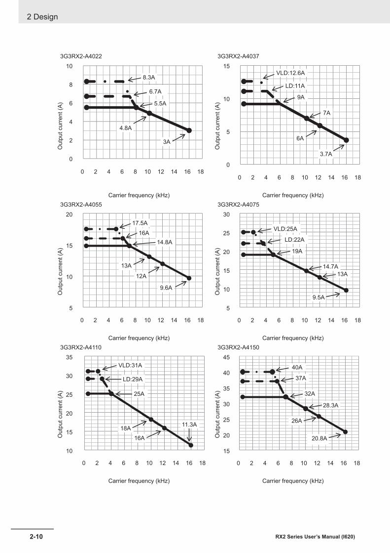
3G3RX2-A4022 3G3RX2-A4037O
utpu
t cur
rent
(A)
0
2
4
6
8
10
0 2 4 6 8 10 12 14 16 18
8.3A
6.7A
5.5A
4.8A
3A
Out
put c
urre
nt (A
)
0
5
10
15
0 2 4 6 8 10 12 14 16 18
VLD:12.6A
LD:11A
9A
7A
6A
3.7A
Carrier frequency (kHz) Carrier frequency (kHz)3G3RX2-A4055 3G3RX2-A4075
Out
put c
urre
nt (A
)
5
10
15
20
0 2 4 6 8 10 12 14 16 18
17.5A
16A
14.8A
13A
12A
9.6A
Out
put c
urre
nt (A
)
5
10
15
20
25
30
0 2 4 6 8 10 12 14 16 18
VLD:25A
LD:22A
19A
14.7A
13A
9.5A
Carrier frequency (kHz) Carrier frequency (kHz)3G3RX2-A4110 3G3RX2-A4150
Out
put c
urre
nt (A
)
10
15
20
25
30
35
0 2 4 6 8 10 12 14 16 18
VLD:31A
LD:29A
25A
18A
16A
11.3A
Out
put c
urre
nt (A
)
15
20
25
30
35
40
45
0 2 4 6 8 10 12 14 16 18
40A
37A
32A
28.3A
26A
20.8A
Carrier frequency (kHz) Carrier frequency (kHz)
2 Design
2-10 RX2 Series User’s Manual (I620)
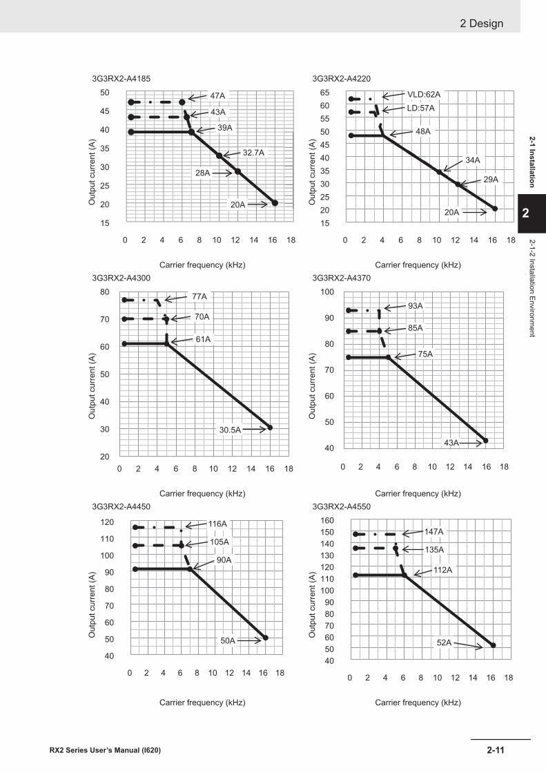
3G3RX2-A4185 3G3RX2-A4220O
utpu
t cur
rent
(A)
15
20
25
30
35
40
45
50
0 2 4 6 8 10 12 14 16 18
47A
43A
39A
32.7A
28A
20A Out
put c
urre
nt (A
)
15
20
25
30
35
40
45
50
55
60
65
0 2 4 6 8 10 12 14 16 18
VLD:62A
LD:57A
48A
34A
29A
20A
Carrier frequency (kHz) Carrier frequency (kHz)3G3RX2-A4300 3G3RX2-A4370
Out
put c
urre
nt (A
)
20
30
40
50
60
70
80
0 2 4 6 8 10 12 14 16 18
77A
70A
61A
30.5A
Out
put c
urre
nt (A
)
40
50
60
70
80
90
100
0 2 4 6 8 10 12 14 16 18
93A
85A
75A
43A
Carrier frequency (kHz) Carrier frequency (kHz)3G3RX2-A4450 3G3RX2-A4550
Out
put c
urre
nt (A
)
40
50
60
70
80
90
100
110
120
0 2 4 6 8 10 12 14 16 18
116A
105A
90A
50A
Out
put c
urre
nt (A
)
40
50
60
70
80
90
100
110
120
130
140
150
160
0 2 4 6 8 10 12 14 16 18
147A
135A
112A
52A
Carrier frequency (kHz) Carrier frequency (kHz)
2 Design
2-11RX2 Series User’s Manual (I620)
2-1 Installation
2
2-1-2 Installation Environment
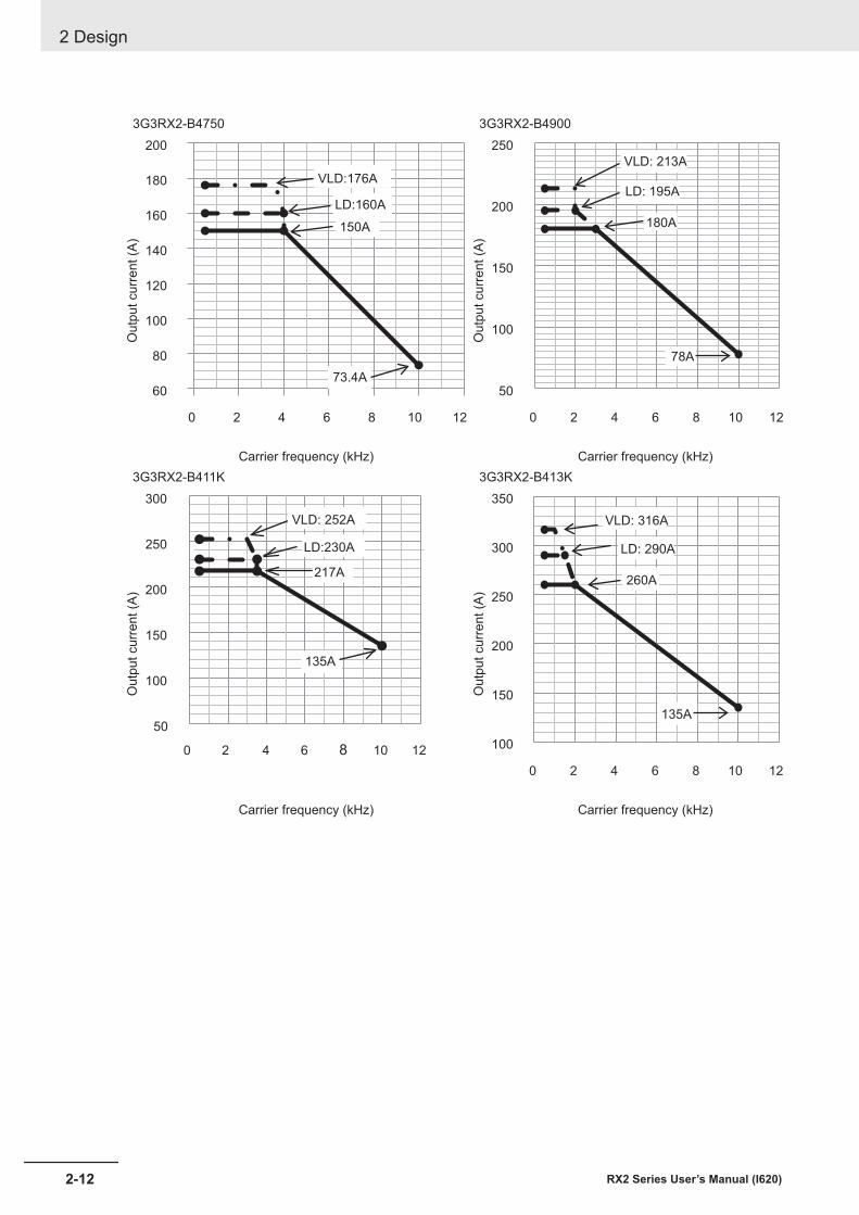
3G3RX2-B4750 3G3RX2-B4900O
utpu
t cur
rent
(A)
60
80
100
120
140
160
180
200
0 2 4 6 8 10 12
VLD:176A
LD:160A
150A
73.4A
Out
put c
urre
nt (A
)
50
100
150
200
250
0 2 4 6 8 10 12
VLD: 213A
LD: 195A
180A
78A
Carrier frequency (kHz) Carrier frequency (kHz)3G3RX2-B411K 3G3RX2-B413K
Out
put c
urre
nt (A
)
50
100
150
200
250
300
0 2 4 6 8 10 12
VLD: 252A
LD:230A
217A
135A
Out
put c
urre
nt (A
)
100
150
200
250
300
350
0 2 4 6 8 10 12
LD: 290A
260A
135A
VLD: 316A
Carrier frequency (kHz) Carrier frequency (kHz)
2 Design
2-12 RX2 Series User’s Manual (I620)
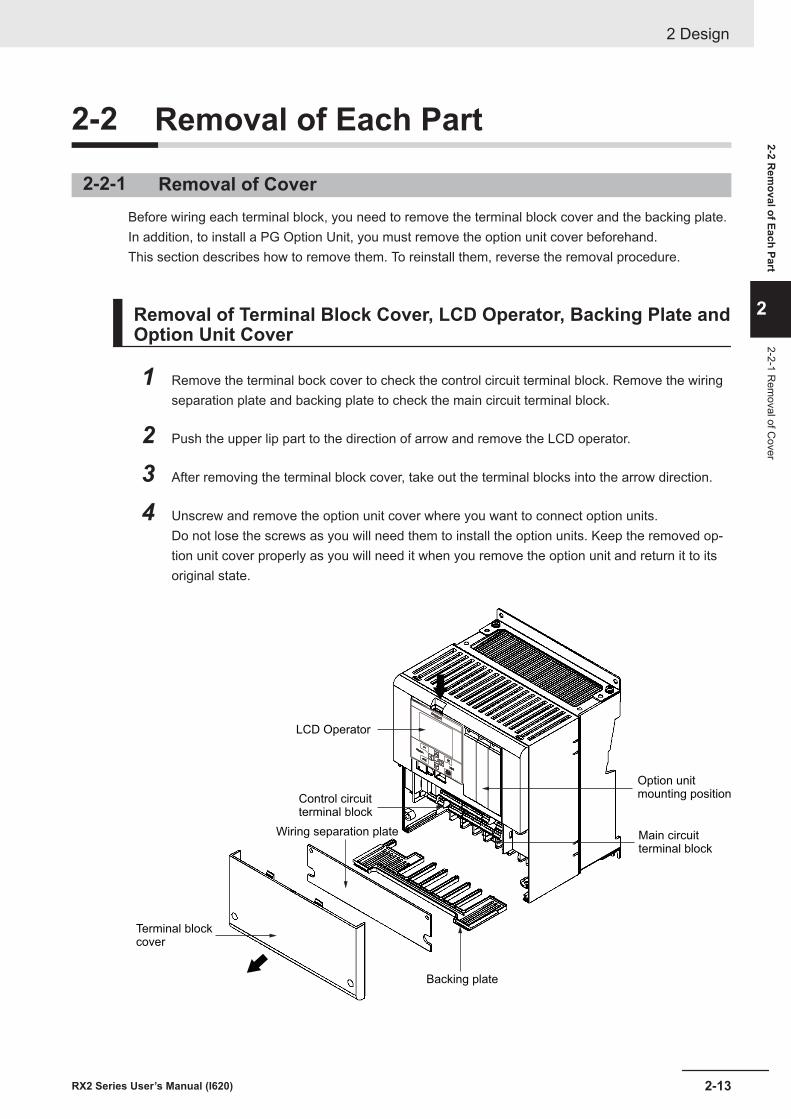
2-2 Removal of Each Part
2-2-1 Removal of CoverBefore wiring each terminal block, you need to remove the terminal block cover and the backing plate.In addition, to install a PG Option Unit, you must remove the option unit cover beforehand.This section describes how to remove them. To reinstall them, reverse the removal procedure.
Removal of Terminal Block Cover, LCD Operator, Backing Plate andOption Unit Cover
1 Remove the terminal bock cover to check the control circuit terminal block. Remove the wiringseparation plate and backing plate to check the main circuit terminal block.
2 Push the upper lip part to the direction of arrow and remove the LCD operator.
3 After removing the terminal block cover, take out the terminal blocks into the arrow direction.
4 Unscrew and remove the option unit cover where you want to connect option units.Do not lose the screws as you will need them to install the option units. Keep the removed op-tion unit cover properly as you will need it when you remove the option unit and return it to itsoriginal state.
LCD Operator
Option unitmounting position
Main circuitterminal block
Control circuitterminal block
Terminal blockcover
Wiring separation plate
Backing plate
2 Design
2-13RX2 Series User’s Manual (I620)
2-2 Rem
oval of Each Part
2
2-2-1 Rem
oval of Cover
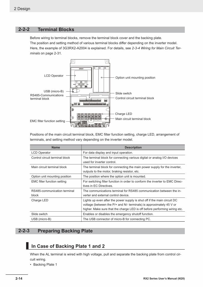
2-2-2 Terminal BlocksBefore wiring to terminal blocks, remove the terminal block cover and the backing plate.The position and setting method of various terminal blocks differ depending on the inverter model.Here, the example of 3G3RX2-A2004 is explained. For details, see 2-3-4 Wiring for Main Circuit Ter-minals on page 2-31.
Option unit mounting position
Slide switch
Control circuit terminal block
Main circuit terminal block
Charge LED
LCD Operator
USB (micro-B)
RS485-Communicationsterminal block
EMC filter function setting
Positions of the main circuit terminal block, EMC filter function setting, charge LED, arrangement ofterminals, and setting method vary depending on the inverter model.
Name DescriptionLCD Operator For data display and input operation.Control circuit terminal block The terminal block for connecting various digital or analog I/O devices
used for inverter control.Main circuit terminal block The terminal block for connecting the main power supply for the inverter,
outputs to the motor, braking resistor, etc.Option unit mounting position The position where the option unit is mounted.EMC filter function setting For switching filter function in order to conform the inverter to EMC Direc-
tives in EC Directives.RS485-communication terminalblock
The communications terminal for RS485 communication between the in-verter and external control device.
Charge LED Lights up even after the power supply is shut off if the main circuit DCvoltage (between the P/+ and N/- terminals) is approximately 45 V orhigher. Make sure that the charge LED is off before performing wiring etc.
Slide switch Enables or disables the emergency shutoff function.USB (micro-B) The USB connector of micro-B for connecting PC.
2-2-3 Preparing Backing Plate
In Case of Backing Plate 1 and 2When the AL terminal is wired with high voltage, pull and separate the backing plate from control cir-cuit wiring.• Backing Plate 1
2 Design
2-14 RX2 Series User’s Manual (I620)
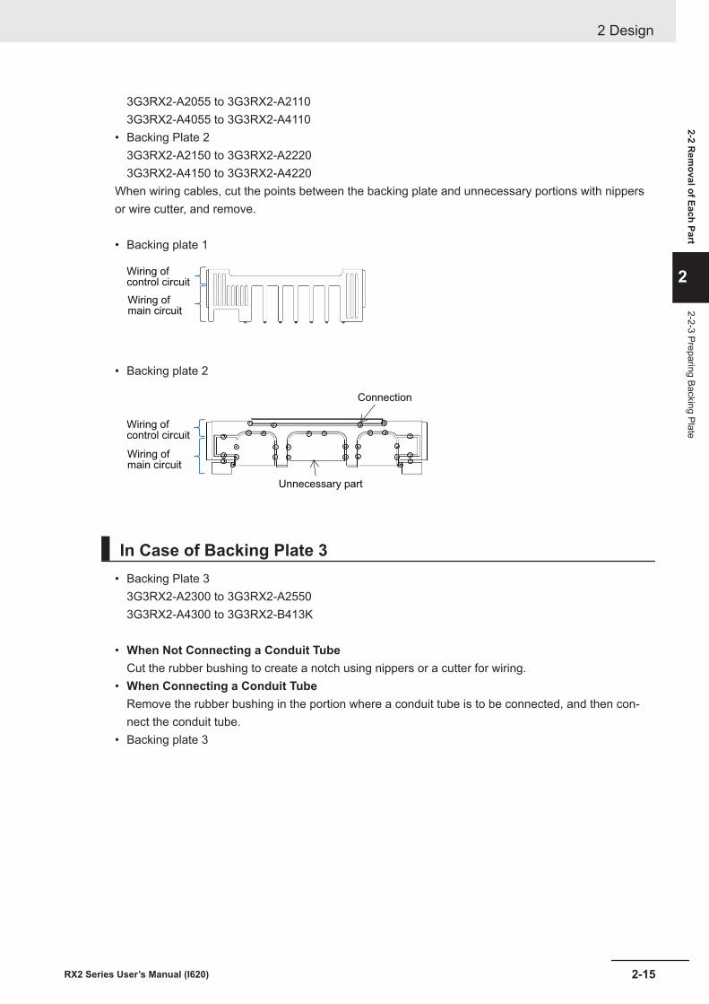
3G3RX2-A2055 to 3G3RX2-A21103G3RX2-A4055 to 3G3RX2-A4110
• Backing Plate 23G3RX2-A2150 to 3G3RX2-A22203G3RX2-A4150 to 3G3RX2-A4220
When wiring cables, cut the points between the backing plate and unnecessary portions with nippersor wire cutter, and remove.
• Backing plate 1
Wiring ofcontrol circuit
Wiring ofmain circuit
• Backing plate 2
Wiring ofcontrol circuit
Wiring ofmain circuit
Unnecessary part
Connection
In Case of Backing Plate 3• Backing Plate 3
3G3RX2-A2300 to 3G3RX2-A25503G3RX2-A4300 to 3G3RX2-B413K
• When Not Connecting a Conduit TubeCut the rubber bushing to create a notch using nippers or a cutter for wiring.
• When Connecting a Conduit TubeRemove the rubber bushing in the portion where a conduit tube is to be connected, and then con-nect the conduit tube.
• Backing plate 3
2 Design
2-15RX2 Series User’s Manual (I620)
2-2 Rem
oval of Each Part
2
2-2-3 Preparing Backing Plate
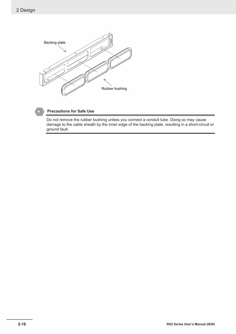
Backing plate
Rubber bushing
Precautions for Safe Use
Do not remove the rubber bushing unless you connect a conduit tube. Doing so may causedamage to the cable sheath by the inner edge of the backing plate, resulting in a short-circuit orground fault.
2 Design
2-16 RX2 Series User’s Manual (I620)
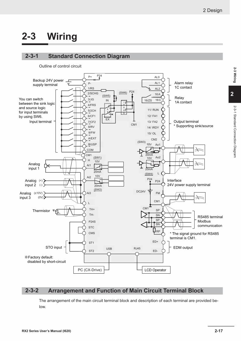
2-3 Wiring
2-3-1 Standard Connection DiagramOutline of control circuit
Backup 24V power
supply terminal
You can switch
between the sink logic
and source logic
for input terminals
by using SW6.
Input terminal
Analog
input 1
Analog
input 2
Analog
input 3
Thermistor
STO input
LCD Operator
EDM output
* The signal ground for RS485
terminal is CM1.
RS485 terminal
Modbus
communication
Interface
24V power supply terminal
Output terminal
* Supporting sink/source
Relay
1A contact
Alarm relay
1C contact
PC (CX-Drive)
※Factory default:
disabled by short-circuit
P+
P-
1/RS
2/SCHG
3/JG
4/FRS
5/2CH
6/CF1
7/CF2
8/RV
9/FW
A/EXT
B/USP
COM
CM1
P24
H
Ai1
Ai2
Ai3
L
(+)
(-)
(±10V)
(0V)
TH+
AL2
AL1
AL0
16 A
16 C
11/ RUN
12/ FA1
13/ FA2
14/ IRDY
15/ OL
CM2
FM
CM1
Ao1
Ao2
SP
SN
SP
SN
RP
P24S
STC
CMS
ST1
ST2
ED+
ED-
TH-
L
10V
20mA
10V
20mA
10V
10V
20mA
20mA
P24
CM1
DC24V
P24
CM1
P24
IN
EX
(SW5)(SW6)
(SW1)
(SW2)
10V(SW3)
(SW4)
16/ZS
USB RJ45
2-3-2 Arrangement and Function of Main Circuit Terminal BlockThe arrangement of the main circuit terminal block and description of each terminal are provided be-low.
2 Design
2-17RX2 Series User’s Manual (I620)
2-3 Wiring
2
2-3-1 Standard Connection D
iagram
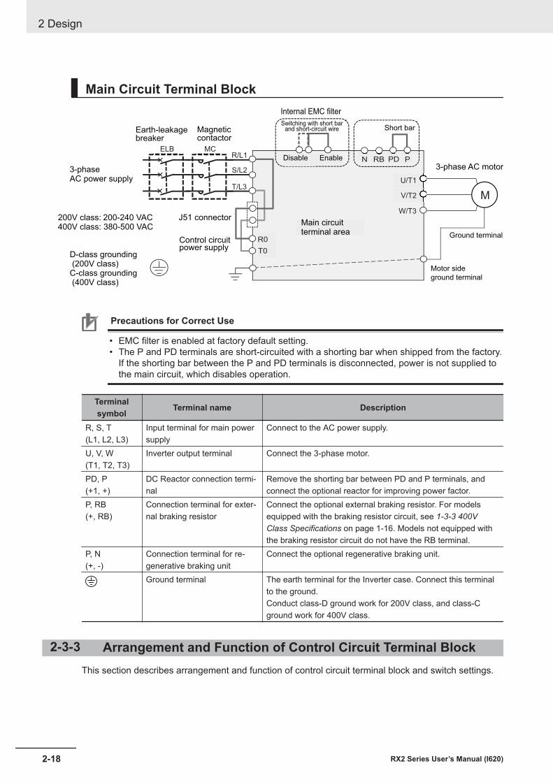
Main Circuit Terminal Block
ELB MCR/L1
S/L2
T/L3
R0
T0
U/T1
V/T2
W/T3
PPDRBN
Earth-leakagebreaker
Magneticcontactor
3-phaseAC power supply
200V class: 200-240 VAC400V class: 380-500 VAC
J51 connector
Internal EMC filter
Switching with short barand short-circuit wire
Disable Enable
Short bar
3-phase AC motor
D-class grounding (200V class)C-class grounding (400V class)
Main circuitterminal area
Control circuitpower supply
Motor side
ground terminal
Ground terminal
M
Precautions for Correct Use
• EMC filter is enabled at factory default setting.• The P and PD terminals are short-circuited with a shorting bar when shipped from the factory.
If the shorting bar between the P and PD terminals is disconnected, power is not supplied tothe main circuit, which disables operation.
Terminalsymbol Terminal name Description
R, S, T(L1, L2, L3)
Input terminal for main powersupply
Connect to the AC power supply.
U, V, W(T1, T2, T3)
Inverter output terminal Connect the 3-phase motor.
PD, P(+1, +)
DC Reactor connection termi-nal
Remove the shorting bar between PD and P terminals, andconnect the optional reactor for improving power factor.
P, RB(+, RB)
Connection terminal for exter-nal braking resistor
Connect the optional external braking resistor. For modelsequipped with the braking resistor circuit, see 1-3-3 400VClass Specifications on page 1-16. Models not equipped withthe braking resistor circuit do not have the RB terminal.
P, N(+, -)
Connection terminal for re-generative braking unit
Connect the optional regenerative braking unit.
Ground terminal The earth terminal for the Inverter case. Connect this terminalto the ground.Conduct class-D ground work for 200V class, and class-Cground work for 400V class.
2-3-3 Arrangement and Function of Control Circuit Terminal BlockThis section describes arrangement and function of control circuit terminal block and switch settings.
2 Design
2-18 RX2 Series User’s Manual (I620)
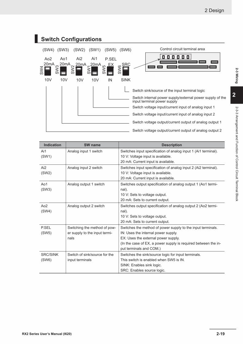
Switch ConfigurationsS
W4
SW
3
SW
2
SW
1
SW
5
SW
6
10V
20mA
10V
20mA
10V
W2 20mA
10V
20mA
IN
W5 EX
SINK
SRC
Ao2 Ao1 Ai2 Ai1 P.SEL
(SW4) (SW3) (SW2) (SW1) (SW5) (SW6)
Switch sink/source of the input terminal logic
Switch internal power supply/external power supply of theinput terminal power supply
Switch voltage input/current input of analog input 1
Switch voltage input/current input of analog input 2
Switch voltage output/current output of analog output 1
Switch voltage output/current output of analog output 2
Control circuit terminal area
Indication SW name DescriptionAi1(SW1)
Analog input 1 switch Switches input specification of analog input 1 (Ai1 terminal).10 V: Voltage input is available.20 mA: Current input is available.
Ai2(SW2)
Analog input 2 switch Switches input specification of analog input 2 (Ai2 terminal).10 V: Voltage input is available.20 mA: Current input is available.
Ao1(SW3)
Analog output 1 switch Switches output specification of analog output 1 (Ao1 termi-nal).10 V: Sets to voltage output.20 mA: Sets to current output.
Ao2(SW4)
Analog output 2 switch Switches output specification of analog output 2 (Ao2 termi-nal).10 V: Sets to voltage output.20 mA: Sets to current output.
P.SEL(SW5)
Switching the method of pow-er supply to the input termi-nals
Switches the method of power supply to the input terminals.IN: Uses the internal power supply.EX: Uses the external power supply.(In the case of EX, a power supply is required between the in-put terminals and COM.)
SRC/SINK(SW6)
Switch of sink/source for theinput terminals
Switches the sink/source logic for input terminals.This switch is enabled when SW5 is IN.SINK: Enables sink logic.SRC: Enables source logic.
2 Design
2-19RX2 Series User’s Manual (I620)
2-3 Wiring
2
2-3-3 Arrangement and Function of C
ontrol Circuit Term
inal Block
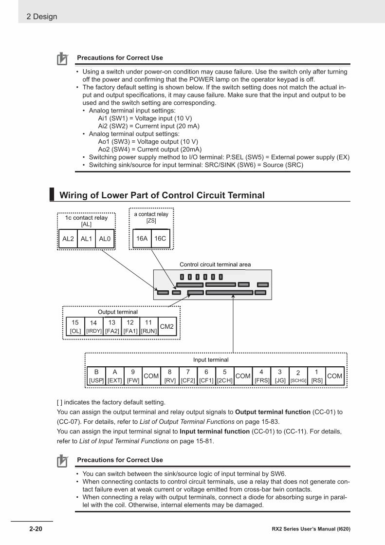
Precautions for Correct Use
• Using a switch under power-on condition may cause failure. Use the switch only after turningoff the power and confirming that the POWER lamp on the operator keypad is off.
• The factory default setting is shown below. If the switch setting does not match the actual in-put and output specifications, it may cause failure. Make sure that the input and output to beused and the switch setting are corresponding.• Analog terminal input settings:
Ai1 (SW1) = Voltage input (10 V)Ai2 (SW2) = Currernt input (20 mA)
• Analog terminal output settings:Ao1 (SW3) = Voltage output (10 V)Ao2 (SW4) = Current output (20mA)
• Switching power supply method to I/O terminal: P.SEL (SW5) = External power supply (EX)• Switching sink/source for input terminal: SRC/SINK (SW6) = Source (SRC)
Wiring of Lower Part of Control Circuit Terminal
1
[RS]
2[SCHG]
3
[JG]
4
[FRS]
5
[2CH]
6
[CF1]
7
[CF2]
8
[RV]
9
[FW]
A
[EXT]
B
[USP]COMCOMCOM
16A 16C
11
[RUN]
12
[FA1]
13
[FA2]
14
[IRDY]
15
[OL]CM2
AL2 AL1 AL0
Input terminal
Output terminal
a contact relay[ZS]
1c contact relay[AL]
Control circuit terminal area
[ ] indicates the factory default setting.You can assign the output terminal and relay output signals to Output terminal function (CC-01) to(CC-07). For details, refer to List of Output Terminal Functions on page 15-83.You can assign the input terminal signal to Input terminal function (CC-01) to (CC-11). For details,refer to List of Input Terminal Functions on page 15-81.
Precautions for Correct Use
• You can switch between the sink/source logic of input terminal by SW6.• When connecting contacts to control circuit terminals, use a relay that does not generate con-
tact failure even at weak current or voltage emitted from cross-bar twin contacts.• When connecting a relay with output terminals, connect a diode for absorbing surge in paral-
lel with the coil. Otherwise, internal elements may be damaged.
2 Design
2-20 RX2 Series User’s Manual (I620)
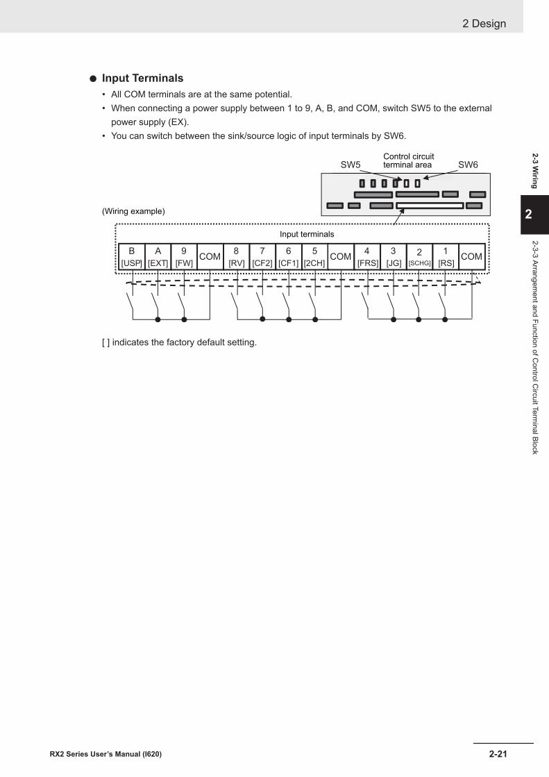
l Input Terminals• All COM terminals are at the same potential.• When connecting a power supply between 1 to 9, A, B, and COM, switch SW5 to the external
power supply (EX).• You can switch between the sink/source logic of input terminals by SW6.
1
[RS]
2[SCHG]
3
[JG]
4
[FRS]
5
[2CH]
6
[CF1]
7
[CF2]
8
[RV]
9
[FW]
A
[EXT]
B
[USP]COMCOMCOM
SW6SW5Control circuitterminal area
Input terminals
(Wiring example)
[ ] indicates the factory default setting.
2 Design
2-21RX2 Series User’s Manual (I620)
2-3 Wiring
2
2-3-3 Arrangement and Function of C
ontrol Circuit Term
inal Block
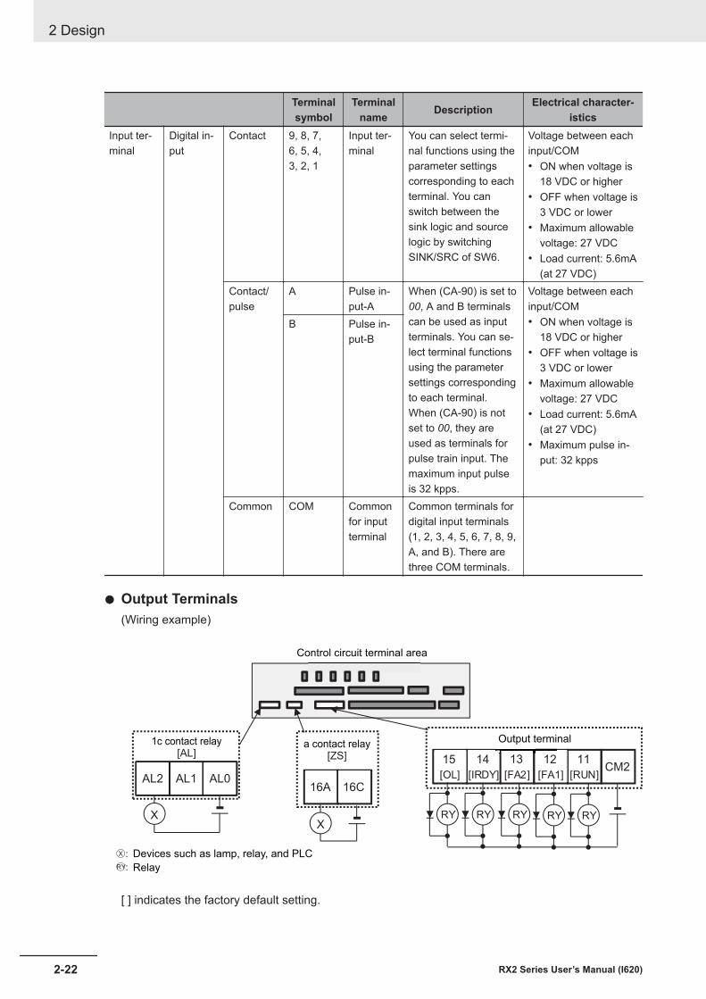
Terminalsymbol
Terminalname Description Electrical character-
isticsInput ter-minal
Digital in-put
Contact 9, 8, 7,6, 5, 4,3, 2, 1
Input ter-minal
You can select termi-nal functions using theparameter settingscorresponding to eachterminal. You canswitch between thesink logic and sourcelogic by switchingSINK/SRC of SW6.
Voltage between eachinput/COM• ON when voltage is
18 VDC or higher• OFF when voltage is
3 VDC or lower• Maximum allowable
voltage: 27 VDC• Load current: 5.6mA
(at 27 VDC)Contact/pulse
A Pulse in-put-A
When (CA-90) is set to00, A and B terminalscan be used as inputterminals. You can se-lect terminal functionsusing the parametersettings correspondingto each terminal.When (CA-90) is notset to 00, they areused as terminals forpulse train input. Themaximum input pulseis 32 kpps.
Voltage between eachinput/COM• ON when voltage is
18 VDC or higher• OFF when voltage is
3 VDC or lower• Maximum allowable
voltage: 27 VDC• Load current: 5.6mA
(at 27 VDC)• Maximum pulse in-
put: 32 kpps
B Pulse in-put-B
Common COM Commonfor inputterminal
Common terminals fordigital input terminals(1, 2, 3, 4, 5, 6, 7, 8, 9,A, and B). There arethree COM terminals.
l Output Terminals(Wiring example)
○X :
○RY:
11
[RUN]
12
[FA1]
13
[FA2]
14
[IRDY]
15
[OL]CM2
RY RY RY RY RY
16A 16C
X
AL2 AL1 AL0
X
1c contact relay[AL]
a contact relay[ZS]
Control circuit terminal area
Output terminal
Devices such as lamp, relay, and PLC
Relay
[ ] indicates the factory default setting.
2 Design
2-22 RX2 Series User’s Manual (I620)
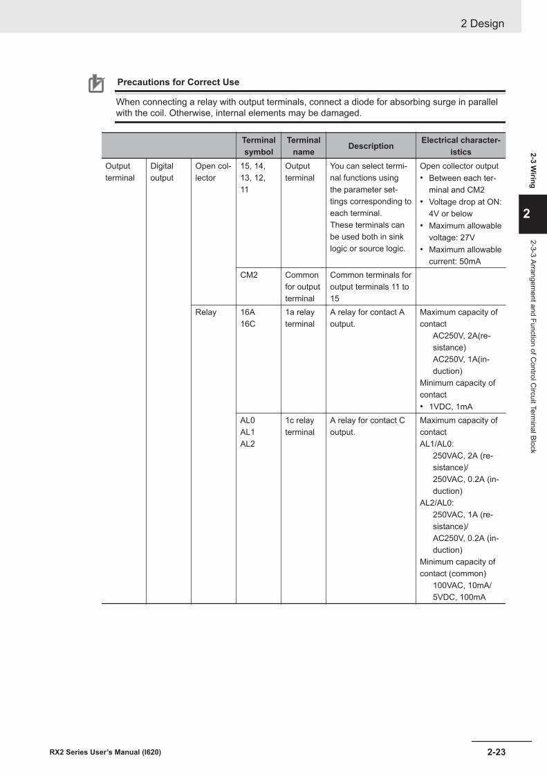
Precautions for Correct Use
When connecting a relay with output terminals, connect a diode for absorbing surge in parallelwith the coil. Otherwise, internal elements may be damaged.
Terminalsymbol
Terminalname Description Electrical character-
isticsOutputterminal
Digitaloutput
Open col-lector
15, 14,13, 12,11
Outputterminal
You can select termi-nal functions usingthe parameter set-tings corresponding toeach terminal.These terminals canbe used both in sinklogic or source logic.
Open collector output• Between each ter-
minal and CM2• Voltage drop at ON:
4V or below• Maximum allowable
voltage: 27V• Maximum allowable
current: 50mACM2 Common
for outputterminal
Common terminals foroutput terminals 11 to15
Relay 16A16C
1a relayterminal
A relay for contact Aoutput.
Maximum capacity ofcontact
AC250V, 2A(re-sistance)AC250V, 1A(in-duction)
Minimum capacity ofcontact• 1VDC, 1mA
AL0AL1AL2
1c relayterminal
A relay for contact Coutput.
Maximum capacity ofcontactAL1/AL0:
250VAC, 2A (re-sistance)/250VAC, 0.2A (in-duction)
AL2/AL0:250VAC, 1A (re-sistance)/AC250V, 0.2A (in-duction)
Minimum capacity ofcontact (common)
100VAC, 10mA/5VDC, 100mA
2 Design
2-23RX2 Series User’s Manual (I620)
2-3 Wiring
2
2-3-3 Arrangement and Function of C
ontrol Circuit Term
inal Block
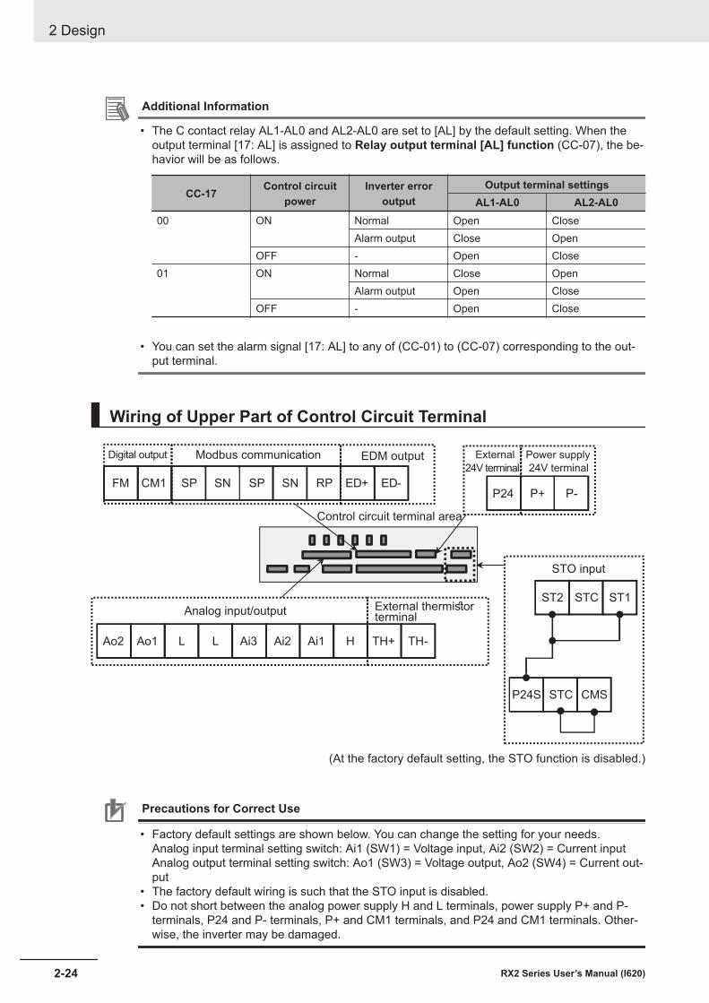
Additional Information
• The C contact relay AL1-AL0 and AL2-AL0 are set to [AL] by the default setting. When theoutput terminal [17: AL] is assigned to Relay output terminal [AL] function (CC-07), the be-havior will be as follows.
CC-17 Control circuitpower
Inverter erroroutput
Output terminal settingsAL1-AL0 AL2-AL0
00 ON Normal Open CloseAlarm output Close Open
OFF - Open Close01 ON Normal Close Open
Alarm output Open CloseOFF - Open Close
• You can set the alarm signal [17: AL] to any of (CC-01) to (CC-07) corresponding to the out-
put terminal.
Wiring of Upper Part of Control Circuit Terminal
Power supply
24V terminal
External
24V terminal
Digital output Modbus communication EDM output
Analog input/output External thermistorterminal
Control circuit terminal area
STO input
(At the factory default setting, the STO function is disabled.)
P+P24 P-FM RPSNSPSNSPCM1 ED-ED+
Ao2 Ao1 HAi1Ai2Ai3LL TH-TH+
P24S STC CMS
ST1ST2 STC
Precautions for Correct Use
• Factory default settings are shown below. You can change the setting for your needs.Analog input terminal setting switch: Ai1 (SW1) = Voltage input, Ai2 (SW2) = Current inputAnalog output terminal setting switch: Ao1 (SW3) = Voltage output, Ao2 (SW4) = Current out-put
• The factory default wiring is such that the STO input is disabled.• Do not short between the analog power supply H and L terminals, power supply P+ and P-
terminals, P24 and P- terminals, P+ and CM1 terminals, and P24 and CM1 terminals. Other-wise, the inverter may be damaged.
2 Design
2-24 RX2 Series User’s Manual (I620)
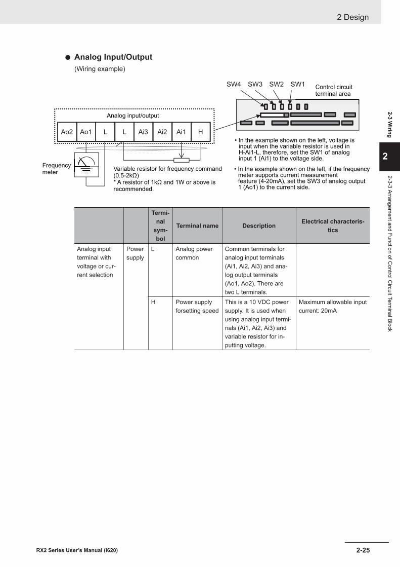
l Analog Input/Output(Wiring example)
Ao2 Ao1 HAi1Ai2Ai3LL
SW4 SW3 SW2 SW1
Analog input/output
Variable resistor for frequency command(0.5-2kΩ)* A resistor of 1kΩ and 1W or above isrecommended.
Frequencymeter
• In the example shown on the left, voltage isinput when the variable resistor is used inH-Ai1-L, therefore, set the SW1 of analoginput 1 (Ai1) to the voltage side.
Control circuitterminal area
• In the example shown on the left, if the frequencymeter supports current measurementfeature (4-20mA), set the SW3 of analog output1 (Ao1) to the current side.
Termi-nal
sym-bol
Terminal name Description Electrical characteris-tics
Analog inputterminal withvoltage or cur-rent selection
Powersupply
L Analog powercommon
Common terminals foranalog input terminals(Ai1, Ai2, Ai3) and ana-log output terminals(Ao1, Ao2). There aretwo L terminals.
H Power supplyforsetting speed
This is a 10 VDC powersupply. It is used whenusing analog input termi-nals (Ai1, Ai2, Ai3) andvariable resistor for in-putting voltage.
Maximum allowable inputcurrent: 20mA
2 Design
2-25RX2 Series User’s Manual (I620)
2-3 Wiring
2
2-3-3 Arrangement and Function of C
ontrol Circuit Term
inal Block
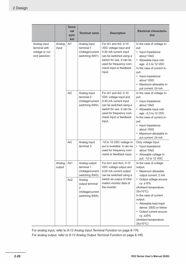
Termi-nal
sym-bol
Terminal name Description Electrical characteris-tics
Analog inputterminal withvoltage or cur-rent selection
Analoginput
Ai1 Analog inputterminal 1(Voltage/currentswitching SW1)
For Ai1 and Ai2, 0-10VDC voltage input and0-20 mA current inputcan be switched using aswitch for use. It can beused for frequency com-mand input or feedbackinput.
In the case of voltage in-put:• Input impedance:
about 10kΩ• Allowable input volt-
age: -0.3 to 12 VDCIn the case of current in-put:• Input impedance:
about 100Ω• Maximum allowable in-
put current: 24 mAAi2 Analog input
terminal 2(Voltage/currentswitching SW2)
For Ai1 and Ai2, 0-10VDC voltage input and0-20 mA current inputcan be switched using aswitch for use. It can beused for frequency com-mand input or feedbackinput.
In the case of voltage in-put:• Input impedance:
about 10kΩ• Allowable input volt-
age: -0.3 to 12 VDCIn the case of current in-put:• Input impedance:
about 100Ω• Maximum allowable in-
put current: 24 mAAi3 Analog input
terminal 3-10 to 10 VDC voltage in-put is available. It can beused for frequency com-mand or feedback input.
Only voltage input:• Input impedance:
about 10kΩ• Allowable voltage in-
put: -12 to 12 VDCAnalogoutput
Ao1 Analog outputterminal 1(Voltage/currentswitching SW3)
For Ao1 and Ao2, 0-10VDC voltage output and0-20 mA current outputcan be switched using aswitch as output of infor-mation monitor data ofthe inverter.
In the case of voltageoutput:• Maximum allowable
output current: 2 mA• Output voltage accura-
cy: ±10%(Ambient temperature:25±10°C)In the case of currentoutput:• Allowable load impe-
dance: 250Ω or below• Output current accura-
cy: ±20%(Ambient temperature:25±10°C)
Ao2 Analogoutput terminal2(Voltage/currentswitching SW4)
For analog input, refer to 8-12 Analog Input Terminal Function on page 8-176.For analog output, refer to 8-13 Analog Output Terminal Function on page 8-185.
2 Design
2-26 RX2 Series User’s Manual (I620)
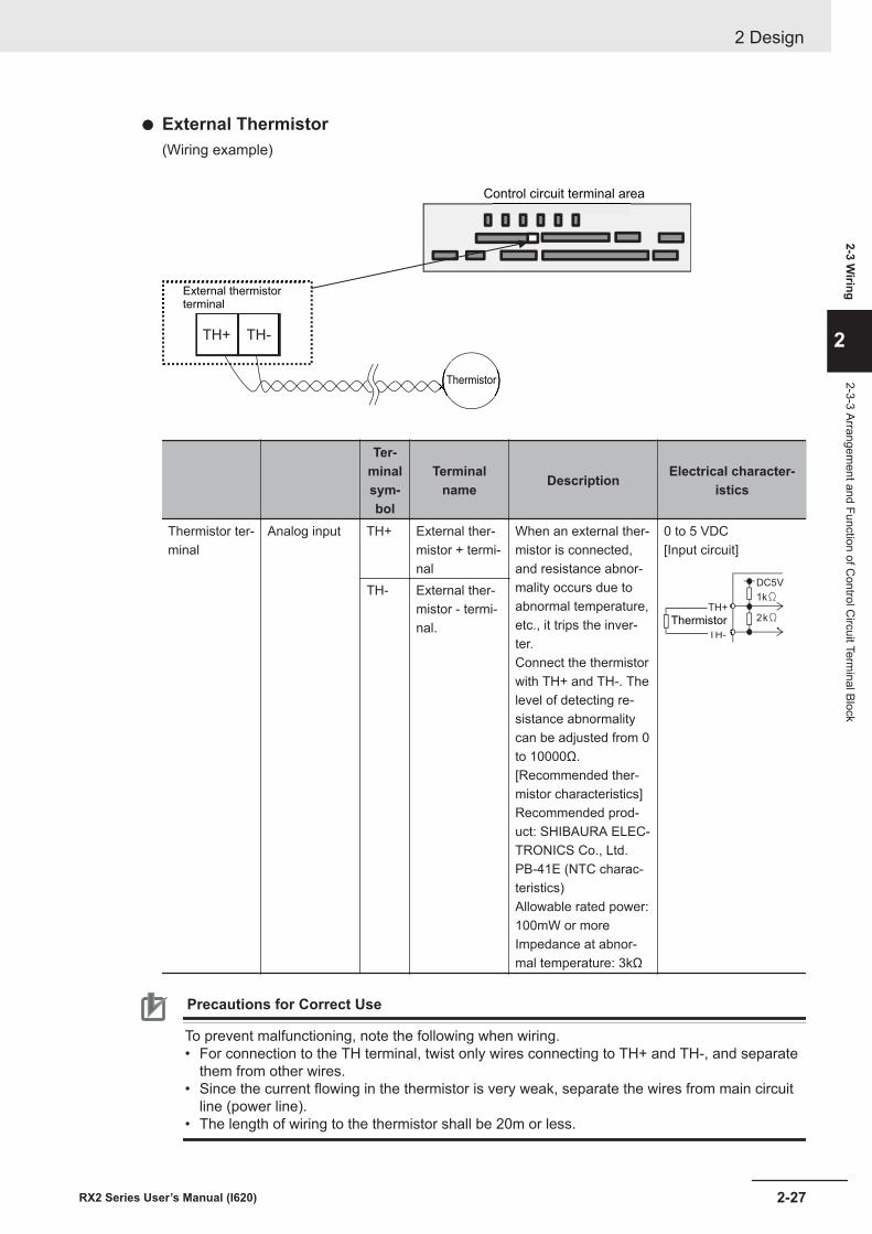
l External Thermistor(Wiring example)
TH-TH+
External thermistor
terminal
Control circuit terminal area
Thermistor
Ter-minalsym-bol
Terminalname Description Electrical character-
istics
Thermistor ter-minal
Analog input TH+ External ther-mistor + termi-nal
When an external ther-mistor is connected,and resistance abnor-mality occurs due toabnormal temperature,etc., it trips the inver-ter.Connect the thermistorwith TH+ and TH-. Thelevel of detecting re-sistance abnormalitycan be adjusted from 0to 10000Ω.[Recommended ther-mistor characteristics]Recommended prod-uct: SHIBAURA ELEC-TRONICS Co., Ltd.PB-41E (NTC charac-teristics)Allowable rated power:100mW or moreImpedance at abnor-mal temperature: 3kΩ
0 to 5 VDC[Input circuit]
DC5V
1kΩ
2kΩTH-
TH+
TH
Thermistor
TH- External ther-mistor - termi-nal.
Precautions for Correct Use
To prevent malfunctioning, note the following when wiring.• For connection to the TH terminal, twist only wires connecting to TH+ and TH-, and separate
them from other wires.• Since the current flowing in the thermistor is very weak, separate the wires from main circuit
line (power line).• The length of wiring to the thermistor shall be 20m or less.
2 Design
2-27RX2 Series User’s Manual (I620)
2-3 Wiring
2
2-3-3 Arrangement and Function of C
ontrol Circuit Term
inal Block
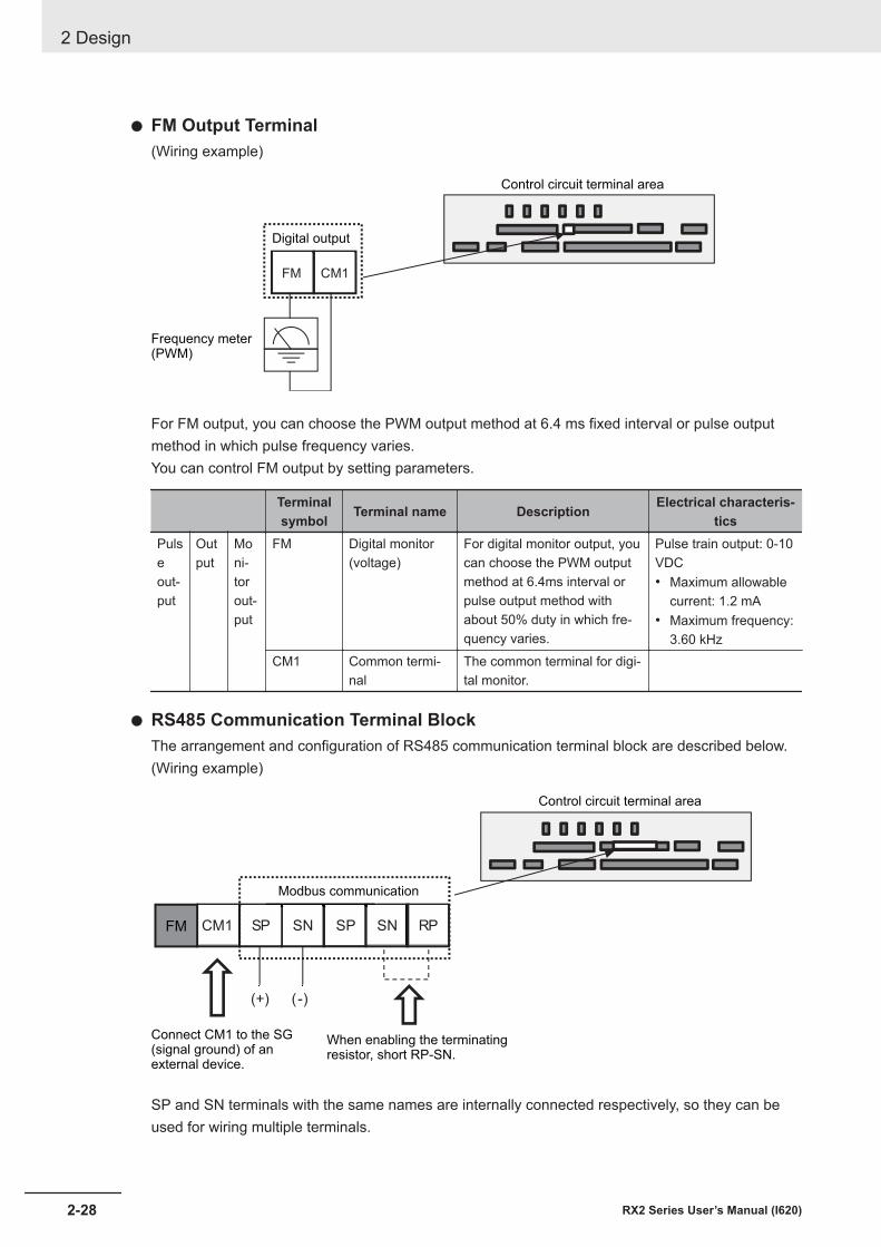
l FM Output Terminal(Wiring example)
FM CM1
Control circuit terminal area
Frequency meter(PWM)
Digital output
For FM output, you can choose the PWM output method at 6.4 ms fixed interval or pulse outputmethod in which pulse frequency varies.You can control FM output by setting parameters.
Terminalsymbol Terminal name Description Electrical characteris-
ticsPulseout-put
Output
Moni-torout-put
FM Digital monitor(voltage)
For digital monitor output, youcan choose the PWM outputmethod at 6.4ms interval orpulse output method withabout 50% duty in which fre-quency varies.
Pulse train output: 0-10VDC• Maximum allowable
current: 1.2 mA• Maximum frequency:
3.60 kHzCM1 Common termi-
nalThe common terminal for digi-tal monitor.
l RS485 Communication Terminal BlockThe arrangement and configuration of RS485 communication terminal block are described below.(Wiring example)
RPSNSPSNSPCM1
(+) (-)
Control circuit terminal area
Modbus communication
Connect CM1 to the SG(signal ground) of anexternal device.
When enabling the terminatingresistor, short RP-SN.
FM
SP and SN terminals with the same names are internally connected respectively, so they can beused for wiring multiple terminals.
2 Design
2-28 RX2 Series User’s Manual (I620)
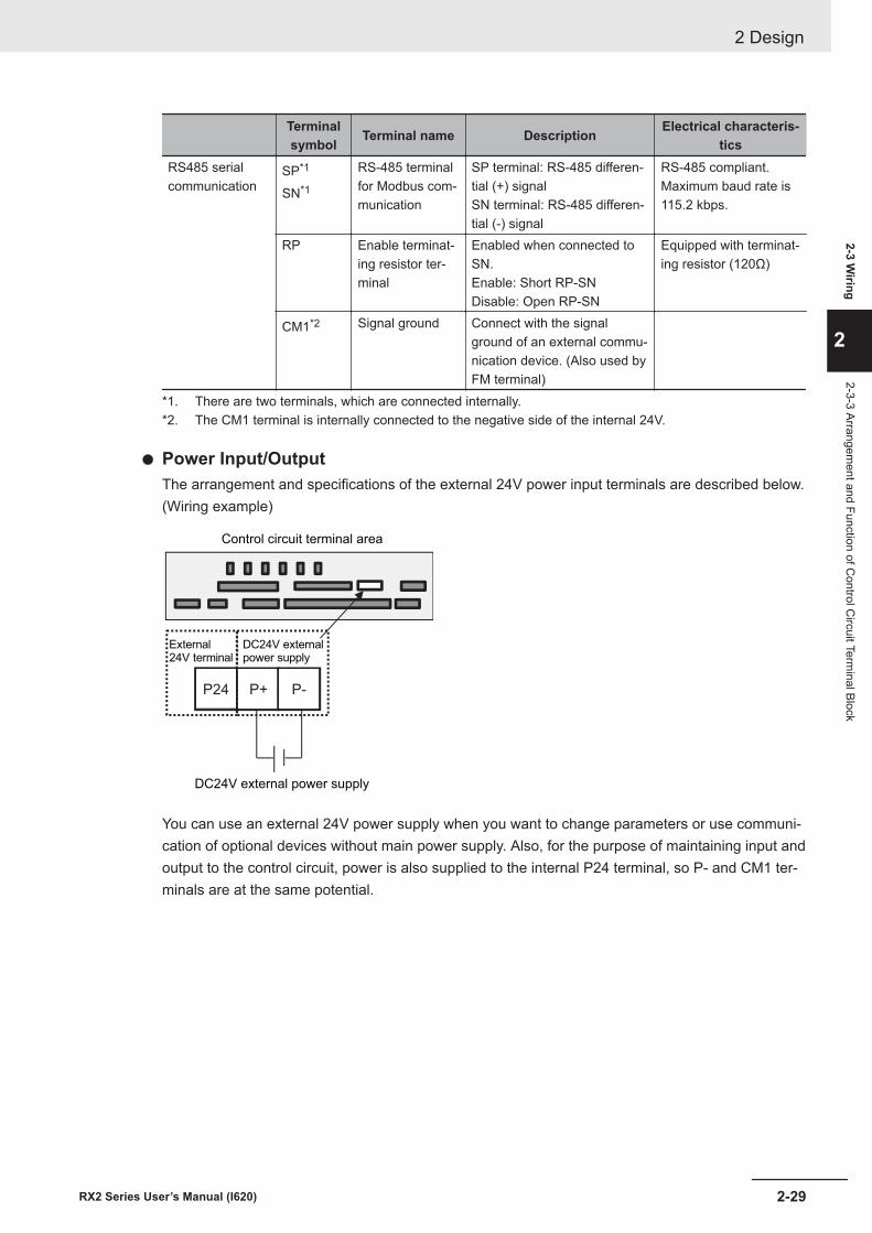
Terminalsymbol Terminal name Description Electrical characteris-
ticsRS485 serialcommunication
SP*1
SN*1
RS-485 terminalfor Modbus com-munication
SP terminal: RS-485 differen-tial (+) signalSN terminal: RS-485 differen-tial (-) signal
RS-485 compliant.Maximum baud rate is115.2 kbps.
RP Enable terminat-ing resistor ter-minal
Enabled when connected toSN.Enable: Short RP-SNDisable: Open RP-SN
Equipped with terminat-ing resistor (120Ω)
CM1*2 Signal ground Connect with the signalground of an external commu-nication device. (Also used byFM terminal)
*1. There are two terminals, which are connected internally.*2. The CM1 terminal is internally connected to the negative side of the internal 24V.
l Power Input/OutputThe arrangement and specifications of the external 24V power input terminals are described below.(Wiring example)
P+P24 P-
Control circuit terminal area
DC24V externalpower supply
External24V terminal
DC24V external power supply
You can use an external 24V power supply when you want to change parameters or use communi-cation of optional devices without main power supply. Also, for the purpose of maintaining input andoutput to the control circuit, power is also supplied to the internal P24 terminal, so P- and CM1 ter-minals are at the same potential.
2 Design
2-29RX2 Series User’s Manual (I620)
2-3 Wiring
2
2-3-3 Arrangement and Function of C
ontrol Circuit Term
inal Block
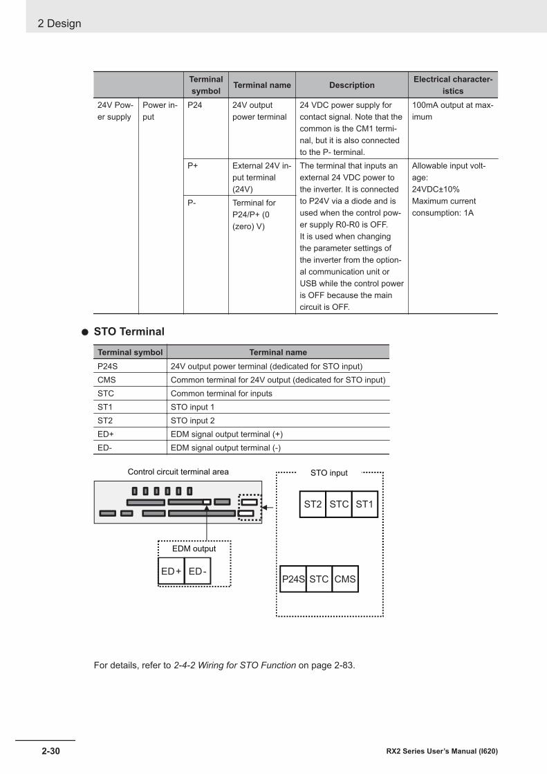
Terminalsymbol Terminal name Description Electrical character-
istics24V Pow-er supply
Power in-put
P24 24V outputpower terminal
24 VDC power supply forcontact signal. Note that thecommon is the CM1 termi-nal, but it is also connectedto the P- terminal.
100mA output at max-imum
P+ External 24V in-put terminal(24V)
The terminal that inputs anexternal 24 VDC power tothe inverter. It is connectedto P24V via a diode and isused when the control pow-er supply R0-R0 is OFF.It is used when changingthe parameter settings ofthe inverter from the option-al communication unit orUSB while the control poweris OFF because the maincircuit is OFF.
Allowable input volt-age:24VDC±10%Maximum currentconsumption: 1A
P- Terminal forP24/P+ (0(zero) V)
l STO Terminal
Terminal symbol Terminal nameP24S 24V output power terminal (dedicated for STO input)CMS Common terminal for 24V output (dedicated for STO input)STC Common terminal for inputsST1 STO input 1ST2 STO input 2ED+ EDM signal output terminal (+)ED- EDM signal output terminal (-)
ED-ED+
STCST2 ST1
P24S STC CMS
EDM output
STO inputControl circuit terminal area
For details, refer to 2-4-2 Wiring for STO Function on page 2-83.
2 Design
2-30 RX2 Series User’s Manual (I620)
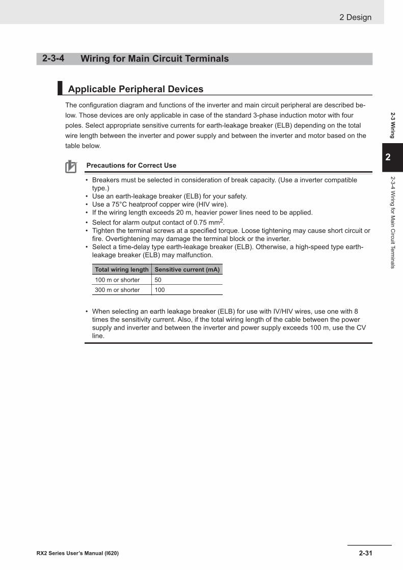
2-3-4 Wiring for Main Circuit Terminals
Applicable Peripheral DevicesThe configuration diagram and functions of the inverter and main circuit peripheral are described be-low. Those devices are only applicable in case of the standard 3-phase induction motor with fourpoles. Select appropriate sensitive currents for earth-leakage breaker (ELB) depending on the totalwire length between the inverter and power supply and between the inverter and motor based on thetable below.
Precautions for Correct Use
• Breakers must be selected in consideration of break capacity. (Use a inverter compatibletype.)
• Use an earth-leakage breaker (ELB) for your safety.• Use a 75°C heatproof copper wire (HIV wire).• If the wiring length exceeds 20 m, heavier power lines need to be applied.• Select for alarm output contact of 0.75 mm2.• Tighten the terminal screws at a specified torque. Loose tightening may cause short circuit or
fire. Overtightening may damage the terminal block or the inverter.• Select a time-delay type earth-leakage breaker (ELB). Otherwise, a high-speed type earth-
leakage breaker (ELB) may malfunction.
Total wiring length Sensitive current (mA)100 m or shorter 50300 m or shorter 100
• When selecting an earth leakage breaker (ELB) for use with IV/HIV wires, use one with 8
times the sensitivity current. Also, if the total wiring length of the cable between the powersupply and inverter and between the inverter and power supply exceeds 100 m, use the CVline.
2 Design
2-31RX2 Series User’s Manual (I620)
2-3 Wiring
2
2-3-4 Wiring for M
ain Circuit Term
inals
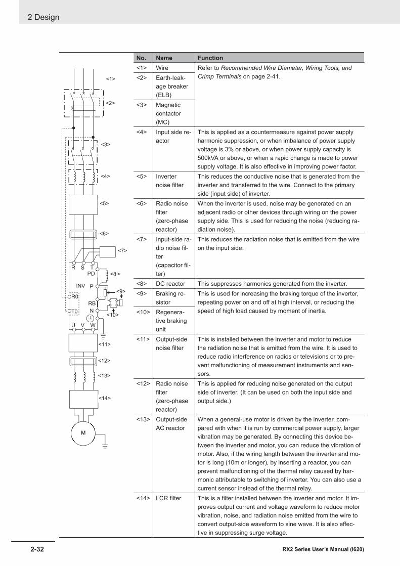
R S T
R0
T0
U V W
PD
P
N
M
RB
<1>
<2>
<3>
INV
<4>
<5>
<6>
<7>
<8 >
<9>
<10>
<11>
<12>
<13>
<14>
No. Name Function<1> Wire Refer to Recommended Wire Diameter, Wiring Tools, and
Crimp Terminals on page 2-41.<2> Earth-leak-age breaker(ELB)
<3> Magneticcontactor(MC)
<4> Input side re-actor
This is applied as a countermeasure against power supplyharmonic suppression, or when imbalance of power supplyvoltage is 3% or above, or when power supply capacity is500kVA or above, or when a rapid change is made to powersupply voltage. It is also effective in improving power factor.
<5> Inverternoise filter
This reduces the conductive noise that is generated from theinverter and transferred to the wire. Connect to the primaryside (input side) of inverter.
<6> Radio noisefilter(zero-phasereactor)
When the inverter is used, noise may be generated on anadjacent radio or other devices through wiring on the powersupply side. This is used for reducing the noise (reducing ra-diation noise).
<7> Input-side ra-dio noise fil-ter(capacitor fil-ter)
This reduces the radiation noise that is emitted from the wireon the input side.
<8> DC reactor This suppresses harmonics generated from the inverter.<9> Braking re-
sistorThis is used for increasing the braking torque of the inverter,repeating power on and off at high interval, or reducing thespeed of high load caused by moment of inertia.<10> Regenera-
tive brakingunit
<11> Output-sidenoise filter
This is installed between the inverter and motor to reducethe radiation noise that is emitted from the wire. It is used toreduce radio interference on radios or televisions or to pre-vent malfunctioning of measurement instruments and sen-sors.
<12> Radio noisefilter(zero-phasereactor)
This is applied for reducing noise generated on the outputside of inverter. (It can be used on both the input side andoutput side.)
<13> Output-sideAC reactor
When a general-use motor is driven by the inverter, com-pared with when it is run by commercial power supply, largervibration may be generated. By connecting this device be-tween the inverter and motor, you can reduce the vibration ofmotor. Also, if the wiring length between the inverter and mo-tor is long (10m or longer), by inserting a reactor, you canprevent malfunctioning of the thermal relay caused by har-monic attributable to switching of inverter. You can also use acurrent sensor instead of the thermal relay.
<14> LCR filter This is a filter installed between the inverter and motor. It im-proves output current and voltage waveform to reduce motorvibration, noise, and radiation noise emitted from the wire toconvert output-side waveform to sine wave. It is also effec-tive in suppressing surge voltage.
2 Design
2-32 RX2 Series User’s Manual (I620)
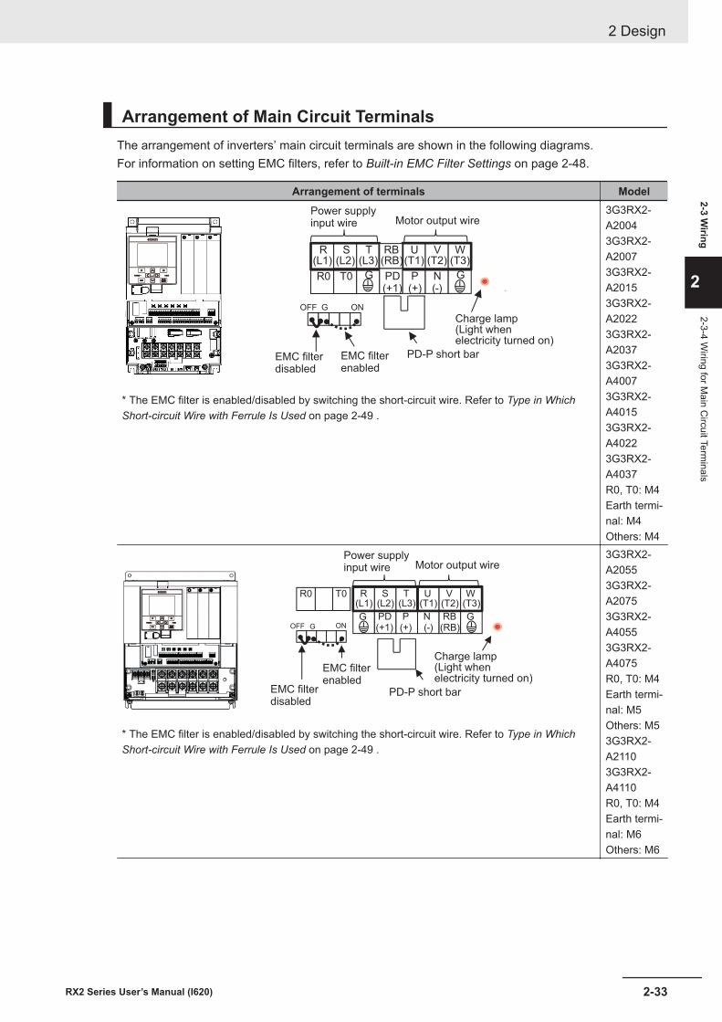
Arrangement of Main Circuit TerminalsThe arrangement of inverters’ main circuit terminals are shown in the following diagrams.For information on setting EMC filters, refer to Built-in EMC Filter Settings on page 2-48.
Arrangement of terminals Model
R0
R(L1)
S(L2)
T(L3)
U(T1)
V(T2)
W(T3)
T0 G P(+)
N(-)
G
G
RB(RB)
PD(+1)
OFF ON
Charge lamp(Light whenelectricity turned on)
Motor output wire
EMC filterdisabled
EMC filterenabled
PD-P short bar
Power supplyinput wire
* The EMC filter is enabled/disabled by switching the short-circuit wire. Refer to Type in WhichShort-circuit Wire with Ferrule Is Used on page 2-49 .
3G3RX2-A20043G3RX2-A20073G3RX2-A20153G3RX2-A20223G3RX2-A20373G3RX2-A40073G3RX2-A40153G3RX2-A40223G3RX2-A4037R0, T0: M4Earth termi-nal: M4Others: M4
G
R(L1)
S(L2)
T(L3)
U(T1)
V(T2)
W(T3)
R0
PD(+1)
P(+)
N(-)
RB(RB)
G
T0
OFF ONG
Charge lamp(Light whenelectricity turned on)
Motor output wire
EMC filterdisabled
EMC filterenabled
PD-P short bar
Power supplyinput wire
* The EMC filter is enabled/disabled by switching the short-circuit wire. Refer to Type in WhichShort-circuit Wire with Ferrule Is Used on page 2-49 .
3G3RX2-A20553G3RX2-A20753G3RX2-A40553G3RX2-A4075R0, T0: M4Earth termi-nal: M5Others: M53G3RX2-A21103G3RX2-A4110R0, T0: M4Earth termi-nal: M6Others: M6
2 Design
2-33RX2 Series User’s Manual (I620)
2-3 Wiring
2
2-3-4 Wiring for M
ain Circuit Term
inals
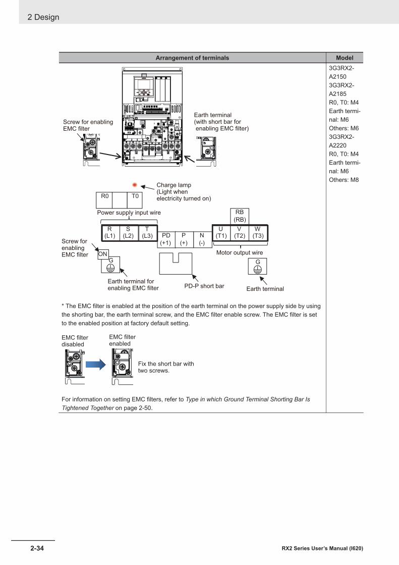
Arrangement of terminals Model
R(L1)
S(L2)
T(L3)
U(T1)
V(T2)
W(T3)
R0
PD
(+1)
P
(+)
N
(-)
RB
(RB)
G
T0
GON
Charge lamp(Light whenelectricity turned on)
Motor output wire
Earth terminal(with short bar for enabling EMC filter)
Earth terminal forenabling EMC filter PD-P short bar
Power supply input wire
Earth terminal
Screw for enablingEMC filter
Screw for enablingEMC filter
* The EMC filter is enabled at the position of the earth terminal on the power supply side by usingthe shorting bar, the earth terminal screw, and the EMC filter enable screw. The EMC filter is setto the enabled position at factory default setting.
EMC filter
disabled
EMC filter
enabled
Fix the short bar with
two screws.
For information on setting EMC filters, refer to Type in which Ground Terminal Shorting Bar IsTightened Together on page 2-50.
3G3RX2-A21503G3RX2-A2185R0, T0: M4Earth termi-nal: M6Others: M63G3RX2-A2220R0, T0: M4Earth termi-nal: M6Others: M8
2 Design
2-34 RX2 Series User’s Manual (I620)
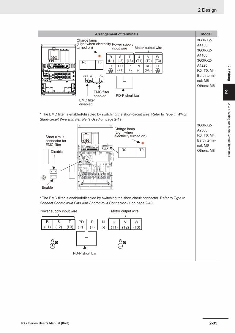
Arrangement of terminals Model
G
R
(L1)
S
(L2)
T
(L3)
U
(T1)
V
(T2)
W
(T3)R0PD
(+1)
P
(+)
N
(-)
RB
(RB)
GT0
OFF G ON
Charge lamp(Light when electricityturned on) Motor output wire
EMC filterenabled PD-P short bar
Power supplyinput wire
EMC filterdisabled
* The EMC filter is enabled/disabled by switching the short-circuit wire. Refer to Type in WhichShort-circuit Wire with Ferrule Is Used on page 2-49 .
3G3RX2-A41503G3RX2-A41803G3RX2-A4220R0, T0: M4Earth termi-nal: M6Others: M6
R0 T0
Charge lamp(Light whenelectricity turned on)
Disable
Short circuitconnector forEMC filter
Enable
* The EMC filter is enabled/disabled by switching the short circuit connector. Refer to Type toConnect Short-circuit Pins with Short-circuit Connector - 1 on page 2-49 .
R
(L1)
S
(L2)
T
(L3)
U
(T1)
V
(T2)
W
(T3)
PD
(+1)
P
(+)
N
(-)
G G
Motor output wire
PD-P short bar
Power supply input wire
3G3RX2-A2300R0, T0: M4Earth termi-nal: M6Others: M8
2 Design
2-35RX2 Series User’s Manual (I620)
2-3 Wiring
2
2-3-4 Wiring for M
ain Circuit Term
inals
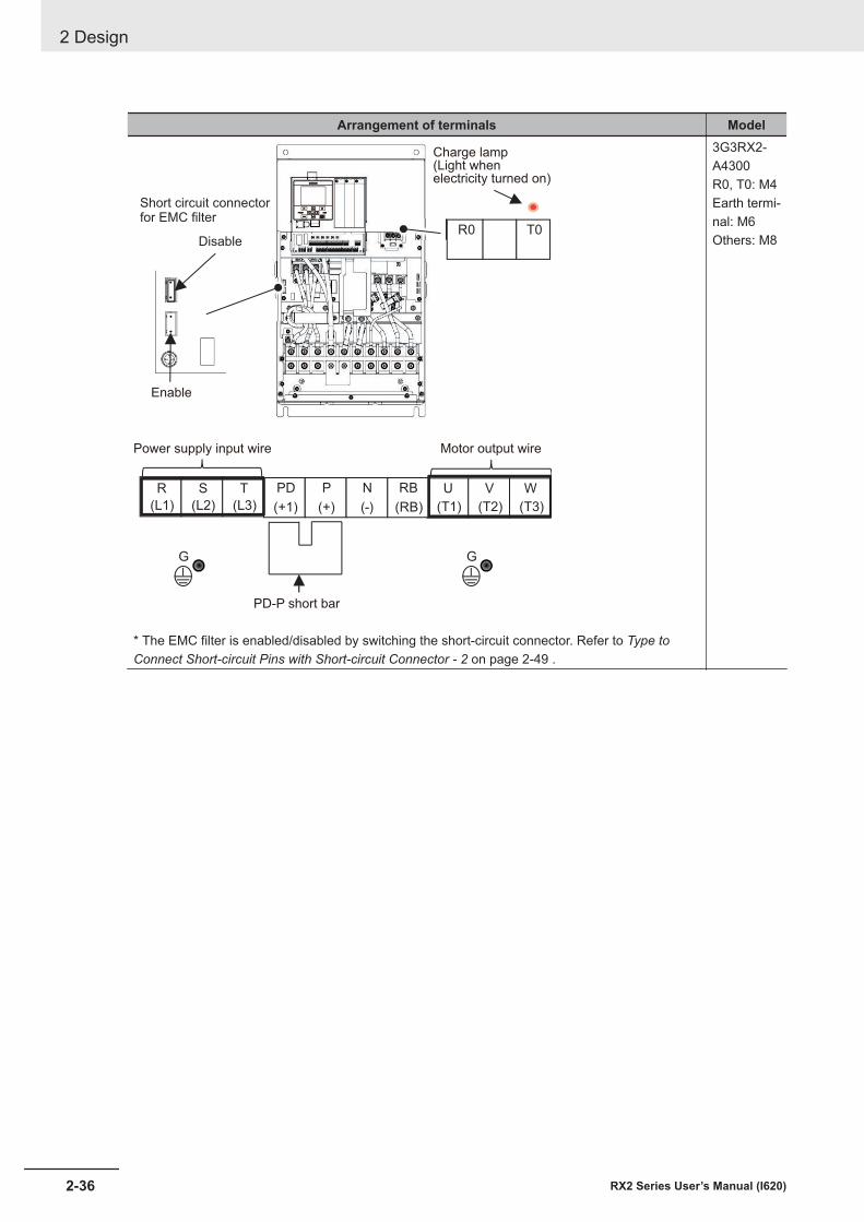
Arrangement of terminals Model
R0 T0
R
(L1)
S
(L2)
T
(L3)
U
(T1)
V
(T2)
W
(T3)
PD
(+1)
P
(+)
N
(-)
RB
(RB)
G G
Charge lamp(Light whenelectricity turned on)
Motor output wire
Enable
PD-P short bar
Power supply input wire
Short circuit connectorfor EMC filter
Disable
* The EMC filter is enabled/disabled by switching the short-circuit connector. Refer to Type toConnect Short-circuit Pins with Short-circuit Connector - 2 on page 2-49 .
3G3RX2-A4300R0, T0: M4Earth termi-nal: M6Others: M8
2 Design
2-36 RX2 Series User’s Manual (I620)
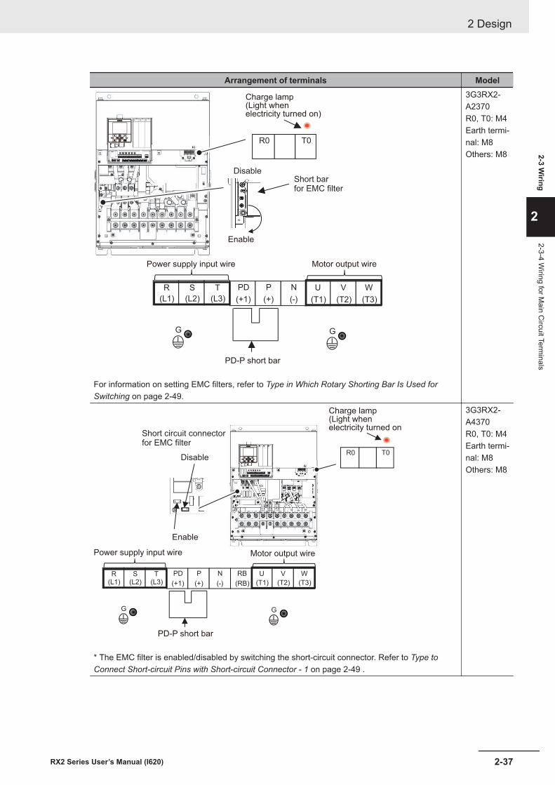
Arrangement of terminals Model
R0 T0
R
(L1)
S
(L2)
T
(L3)
U
(T1)
V
(T2)
W
(T3)
PD
(+1)
P
(+)
N
(-)
G G
Charge lamp(Light whenelectricity turned on)
Motor output wire
Enable
PD-P short bar
Power supply input wire
Short barfor EMC filter
Disable
For information on setting EMC filters, refer to Type in Which Rotary Shorting Bar Is Used forSwitching on page 2-49.
3G3RX2-A2370R0, T0: M4Earth termi-nal: M8Others: M8
R0 T0
R
(L1)
S
(L2)
T
(L3)
U
(T1)
V
(T2)
W
(T3)
PD
(+1)
P
(+)
N
(-)
RB
(RB)
G G
Charge lamp(Light whenelectricity turned on
Motor output wire
Enable
PD-P short bar
Power supply input wire
Short circuit connectorfor EMC filter
Disable
* The EMC filter is enabled/disabled by switching the short-circuit connector. Refer to Type toConnect Short-circuit Pins with Short-circuit Connector - 1 on page 2-49 .
3G3RX2-A4370R0, T0: M4Earth termi-nal: M8Others: M8
2 Design
2-37RX2 Series User’s Manual (I620)
2-3 Wiring
2
2-3-4 Wiring for M
ain Circuit Term
inals
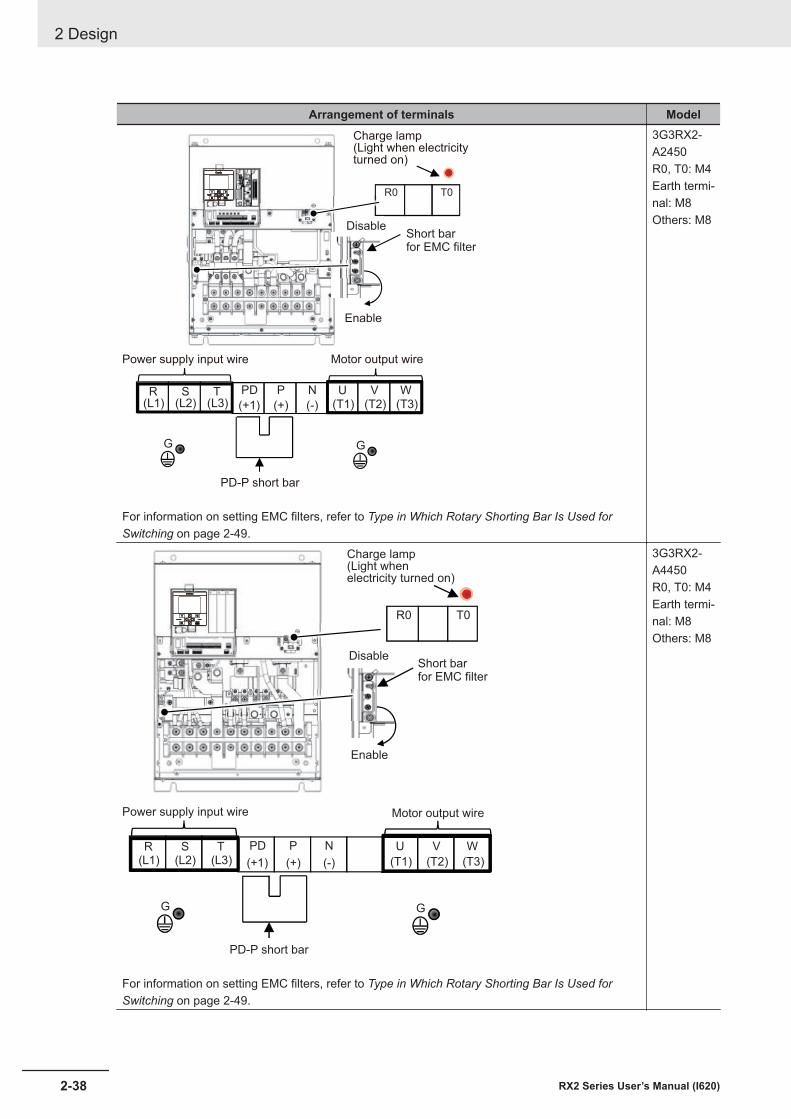
Arrangement of terminals Model
R0 T0
R(L1)
S(L2)
T(L3)
U
(T1)
V
(T2)
W
(T3)
PD
(+1)
P
(+)
N
(-)
G G
Charge lamp(Light when electricityturned on)
Motor output wire
Enable
PD-P short bar
Power supply input wire
Short barfor EMC filter
Disable
For information on setting EMC filters, refer to Type in Which Rotary Shorting Bar Is Used forSwitching on page 2-49.
3G3RX2-A2450R0, T0: M4Earth termi-nal: M8Others: M8
R0 T0
R(L1)
S(L2)
T(L3)
U
(T1)
V
(T2)
W
(T3)
PD
(+1)
P
(+)
N
(-)
G G
Charge lamp(Light whenelectricity turned on)
Enable
DisableShort barfor EMC filter
Power supply input wire Motor output wire
PD-P short bar
For information on setting EMC filters, refer to Type in Which Rotary Shorting Bar Is Used forSwitching on page 2-49.
3G3RX2-A4450R0, T0: M4Earth termi-nal: M8Others: M8
2 Design
2-38 RX2 Series User’s Manual (I620)
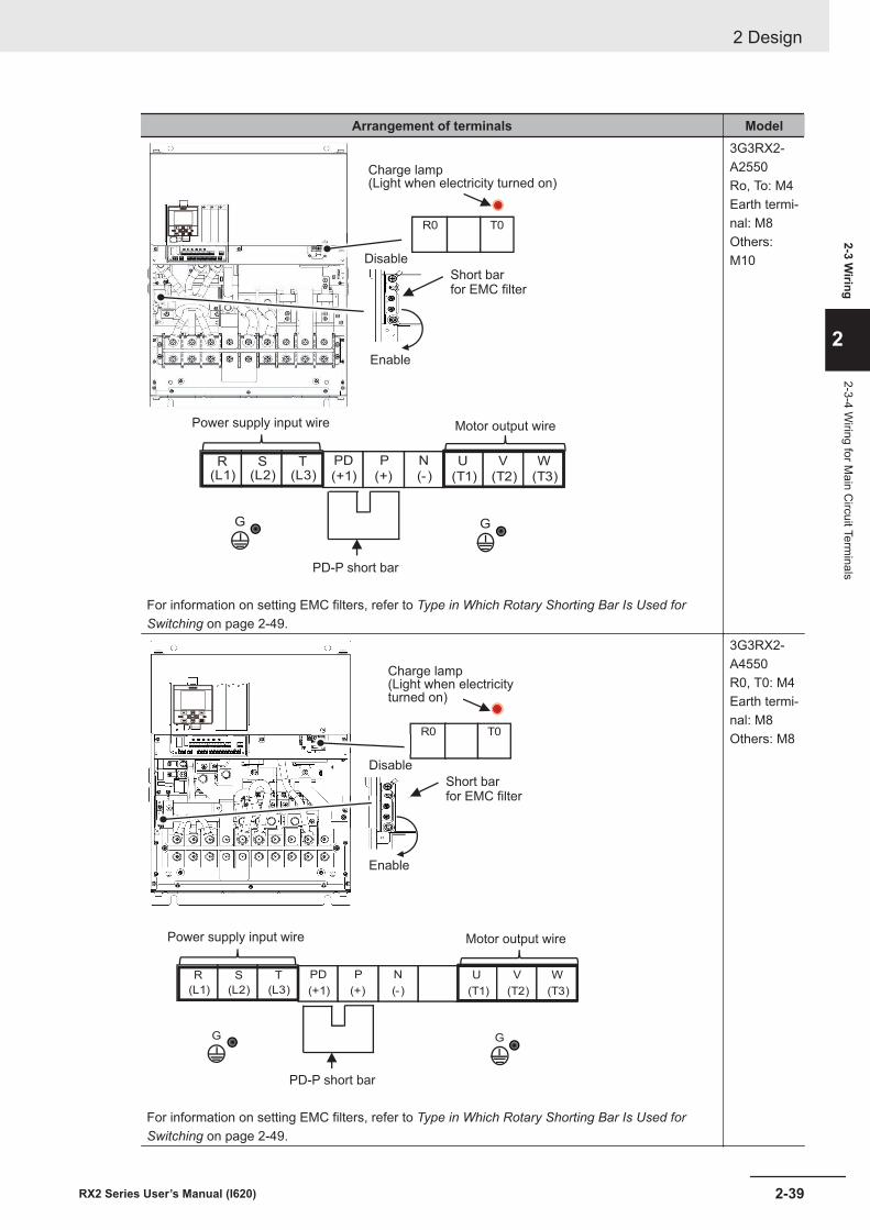
Arrangement of terminals Model
R0 T0
R(L1)
S(L2)
T(L3)
U
(T1)
V
(T2)
W
(T3)
PD
(+1)
P
(+)
N
(-)
G G
Charge lamp(Light when electricity turned on)
Enable
Disable
Short barfor EMC filter
Power supply input wire Motor output wire
PD-P short bar
For information on setting EMC filters, refer to Type in Which Rotary Shorting Bar Is Used forSwitching on page 2-49.
3G3RX2-A2550Ro, To: M4Earth termi-nal: M8Others:M10
R0 T0
R
(L1)
S
(L2)
T
(L3)
U
(T1)
V
(T2)
W
(T3)
PD
(+1)
P
(+)
N
(-)
G G
Charge lamp(Light when electricityturned on)
Enable
Disable
Short barfor EMC filter
Power supply input wire Motor output wire
PD-P short bar
For information on setting EMC filters, refer to Type in Which Rotary Shorting Bar Is Used forSwitching on page 2-49.
3G3RX2-A4550R0, T0: M4Earth termi-nal: M8Others: M8
2 Design
2-39RX2 Series User’s Manual (I620)
2-3 Wiring
2
2-3-4 Wiring for M
ain Circuit Term
inals
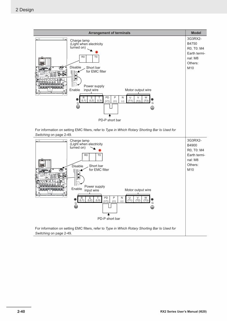
Arrangement of terminals Model
R0 T0
無効
R(L1)
S(L2)
T(L3)
U
(T1)
V
(T2)
W
(T3)
PD
(+1)
P
(+)
N
(-)G G
Charge lamp(Light when electricityturned on)
Enable
Disable Short barfor EMC filter
Power supplyinput wire Motor output wire
PD-P short bar
For information on setting EMC filters, refer to Type in Which Rotary Shorting Bar Is Used forSwitching on page 2-49.
3G3RX2-B4750R0, T0: M4Earth termi-nal: M8Others:M10
R0 T0
無効
R(L1)
S(L2)
T(L3)
U(T1)
V(T2)
W(T3)
PD
(+1)
P
(+)
N
(-)G G
Charge lamp(Light when electricityturned on)
Enable
Disable Short barfor EMC filter
Power supplyinput wire Motor output wire
PD-P short bar
For information on setting EMC filters, refer to Type in Which Rotary Shorting Bar Is Used forSwitching on page 2-49.
3G3RX2-B4900R0, T0: M4Earth termi-nal: M8Others:M10
2 Design
2-40 RX2 Series User’s Manual (I620)
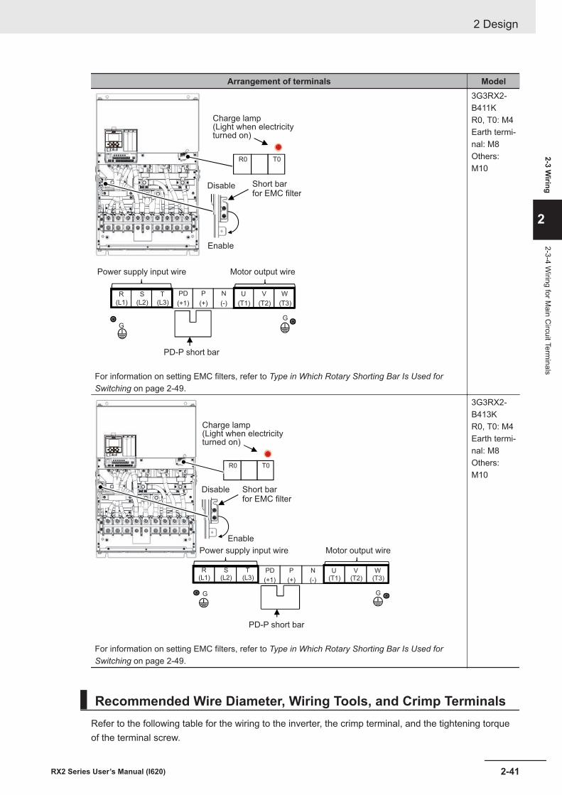
Arrangement of terminals Model
R
(L1)
S
(L2)
T
(L3)
U
(T1)
V
(T2)
W
(T3)
PD
(+1)
P
(+)
N
(-)
GG
R0 T0
Charge lamp(Light when electricityturned on)
Enable
Disable Short barfor EMC filter
Power supply input wire Motor output wire
PD-P short bar
For information on setting EMC filters, refer to Type in Which Rotary Shorting Bar Is Used forSwitching on page 2-49.
3G3RX2-B411KR0, T0: M4Earth termi-nal: M8Others:M10
R0 T0
R(L1)
S(L2)
T(L3)
U(T1)
V(T2)
W(T3)
PD
(+1)
P
(+)
N
(-)
G G
Charge lamp(Light when electricityturned on)
Enable
Disable Short barfor EMC filter
Power supply input wire Motor output wire
PD-P short bar
For information on setting EMC filters, refer to Type in Which Rotary Shorting Bar Is Used forSwitching on page 2-49.
3G3RX2-B413KR0, T0: M4Earth termi-nal: M8Others:M10
Recommended Wire Diameter, Wiring Tools, and Crimp TerminalsRefer to the following table for the wiring to the inverter, the crimp terminal, and the tightening torqueof the terminal screw.
2 Design
2-41RX2 Series User’s Manual (I620)
2-3 Wiring
2
2-3-4 Wiring for M
ain Circuit Term
inals
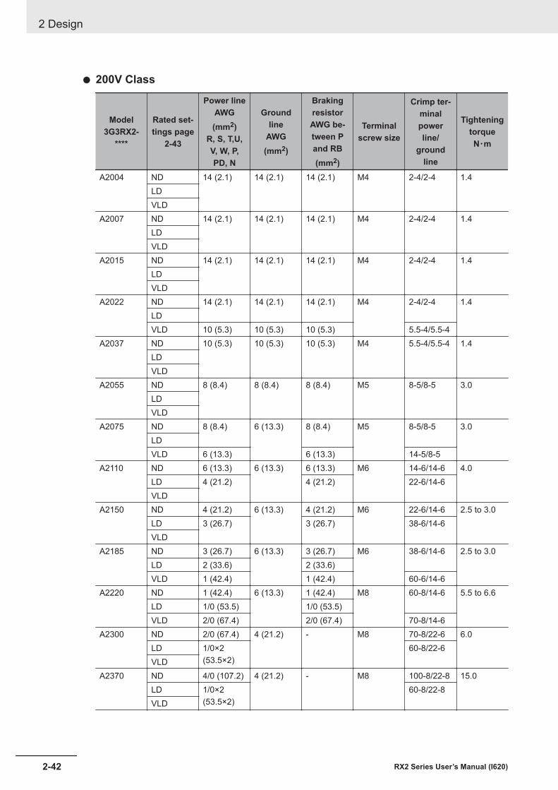
l 200V Class
Model3G3RX2-
****
Rated set-tings page
2-43
Power lineAWG(mm2)
R, S, T,U,V, W, P,PD, N
Groundline
AWG(mm2)
BrakingresistorAWG be-tween Pand RB(mm2)
Terminalscrew size
Crimp ter-minalpowerline/
groundline
TighteningtorqueN・m
A2004 ND 14 (2.1) 14 (2.1) 14 (2.1) M4 2-4/2-4 1.4LDVLD
A2007 ND 14 (2.1) 14 (2.1) 14 (2.1) M4 2-4/2-4 1.4LDVLD
A2015 ND 14 (2.1) 14 (2.1) 14 (2.1) M4 2-4/2-4 1.4LDVLD
A2022 ND 14 (2.1) 14 (2.1) 14 (2.1) M4 2-4/2-4 1.4LDVLD 10 (5.3) 10 (5.3) 10 (5.3) 5.5-4/5.5-4
A2037 ND 10 (5.3) 10 (5.3) 10 (5.3) M4 5.5-4/5.5-4 1.4LDVLD
A2055 ND 8 (8.4) 8 (8.4) 8 (8.4) M5 8-5/8-5 3.0LDVLD
A2075 ND 8 (8.4) 6 (13.3) 8 (8.4) M5 8-5/8-5 3.0LDVLD 6 (13.3) 6 (13.3) 14-5/8-5
A2110 ND 6 (13.3) 6 (13.3) 6 (13.3) M6 14-6/14-6 4.0LD 4 (21.2) 4 (21.2) 22-6/14-6VLD
A2150 ND 4 (21.2) 6 (13.3) 4 (21.2) M6 22-6/14-6 2.5 to 3.0LD 3 (26.7) 3 (26.7) 38-6/14-6VLD
A2185 ND 3 (26.7) 6 (13.3) 3 (26.7) M6 38-6/14-6 2.5 to 3.0LD 2 (33.6) 2 (33.6)VLD 1 (42.4) 1 (42.4) 60-6/14-6
A2220 ND 1 (42.4) 6 (13.3) 1 (42.4) M8 60-8/14-6 5.5 to 6.6LD 1/0 (53.5) 1/0 (53.5)VLD 2/0 (67.4) 2/0 (67.4) 70-8/14-6
A2300 ND 2/0 (67.4) 4 (21.2) - M8 70-8/22-6 6.0LD 1/0×2
(53.5×2)60-8/22-6
VLDA2370 ND 4/0 (107.2) 4 (21.2) - M8 100-8/22-8 15.0
LD 1/0×2(53.5×2)
60-8/22-8VLD
2 Design
2-42 RX2 Series User’s Manual (I620)
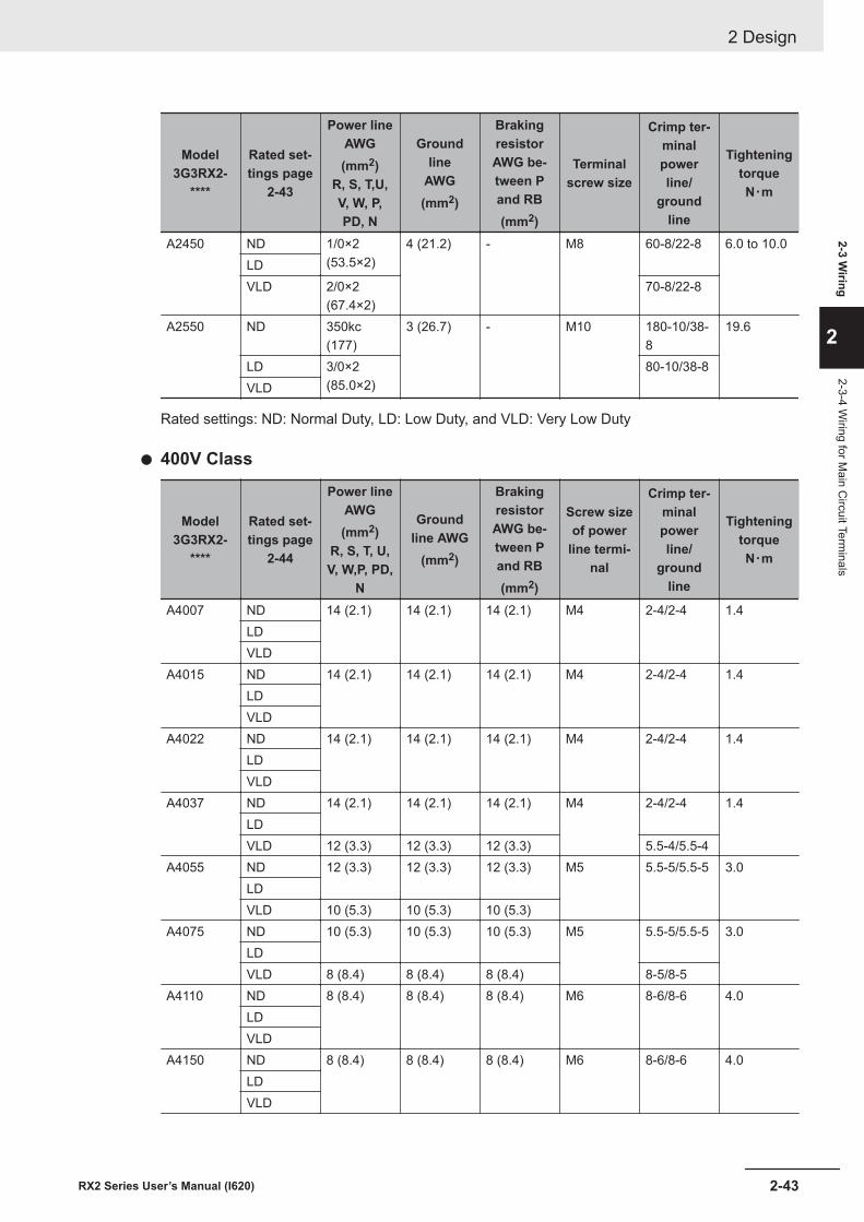
Model3G3RX2-
****
Rated set-tings page
2-43
Power lineAWG(mm2)
R, S, T,U,V, W, P,PD, N
Groundline
AWG(mm2)
BrakingresistorAWG be-tween Pand RB(mm2)
Terminalscrew size
Crimp ter-minalpowerline/
groundline
TighteningtorqueN・m
A2450 ND 1/0×2(53.5×2)
4 (21.2) - M8 60-8/22-8 6.0 to 10.0LDVLD 2/0×2
(67.4×2)70-8/22-8
A2550 ND 350kc(177)
3 (26.7) - M10 180-10/38-8
19.6
LD 3/0×2(85.0×2)
80-10/38-8VLD
Rated settings: ND: Normal Duty, LD: Low Duty, and VLD: Very Low Duty
l 400V Class
Model3G3RX2-
****
Rated set-tings page
2-44
Power lineAWG(mm2)
R, S, T, U,V, W,P, PD,
N
Groundline AWG
(mm2)
BrakingresistorAWG be-tween Pand RB(mm2)
Screw sizeof power
line termi-nal
Crimp ter-minalpowerline/
groundline
TighteningtorqueN・m
A4007 ND 14 (2.1) 14 (2.1) 14 (2.1) M4 2-4/2-4 1.4LDVLD
A4015 ND 14 (2.1) 14 (2.1) 14 (2.1) M4 2-4/2-4 1.4LDVLD
A4022 ND 14 (2.1) 14 (2.1) 14 (2.1) M4 2-4/2-4 1.4LDVLD
A4037 ND 14 (2.1) 14 (2.1) 14 (2.1) M4 2-4/2-4 1.4LDVLD 12 (3.3) 12 (3.3) 12 (3.3) 5.5-4/5.5-4
A4055 ND 12 (3.3) 12 (3.3) 12 (3.3) M5 5.5-5/5.5-5 3.0LDVLD 10 (5.3) 10 (5.3) 10 (5.3)
A4075 ND 10 (5.3) 10 (5.3) 10 (5.3) M5 5.5-5/5.5-5 3.0LDVLD 8 (8.4) 8 (8.4) 8 (8.4) 8-5/8-5
A4110 ND 8 (8.4) 8 (8.4) 8 (8.4) M6 8-6/8-6 4.0LDVLD
A4150 ND 8 (8.4) 8 (8.4) 8 (8.4) M6 8-6/8-6 4.0LDVLD
2 Design
2-43RX2 Series User’s Manual (I620)
2-3 Wiring
2
2-3-4 Wiring for M
ain Circuit Term
inals
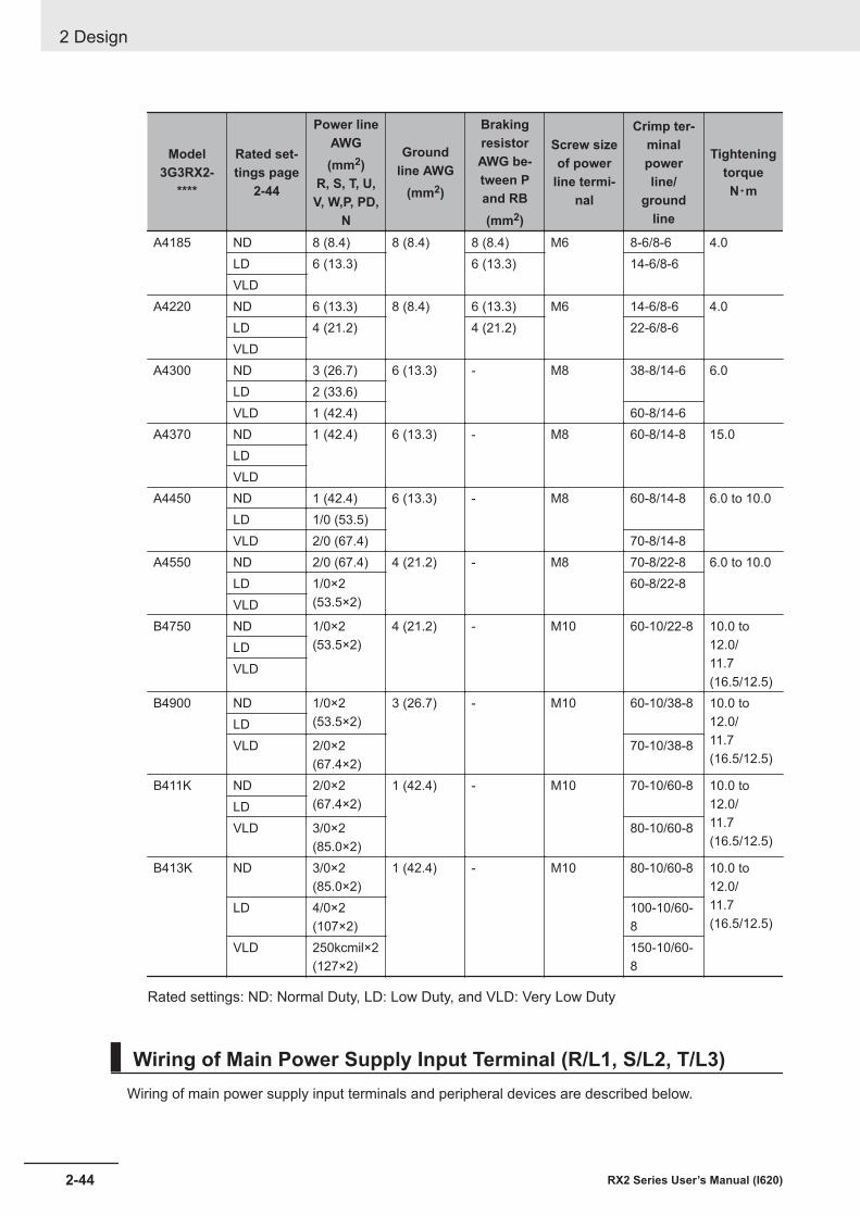
Model3G3RX2-
****
Rated set-tings page
2-44
Power lineAWG(mm2)
R, S, T, U,V, W,P, PD,
N
Groundline AWG
(mm2)
BrakingresistorAWG be-tween Pand RB(mm2)
Screw sizeof power
line termi-nal
Crimp ter-minalpowerline/
groundline
TighteningtorqueN・m
A4185 ND 8 (8.4) 8 (8.4) 8 (8.4) M6 8-6/8-6 4.0LD 6 (13.3) 6 (13.3) 14-6/8-6VLD
A4220 ND 6 (13.3) 8 (8.4) 6 (13.3) M6 14-6/8-6 4.0LD 4 (21.2) 4 (21.2) 22-6/8-6VLD
A4300 ND 3 (26.7) 6 (13.3) - M8 38-8/14-6 6.0LD 2 (33.6)VLD 1 (42.4) 60-8/14-6
A4370 ND 1 (42.4) 6 (13.3) - M8 60-8/14-8 15.0LDVLD
A4450 ND 1 (42.4) 6 (13.3) - M8 60-8/14-8 6.0 to 10.0LD 1/0 (53.5)VLD 2/0 (67.4) 70-8/14-8
A4550 ND 2/0 (67.4) 4 (21.2) - M8 70-8/22-8 6.0 to 10.0LD 1/0×2
(53.5×2)60-8/22-8
VLDB4750 ND 1/0×2
(53.5×2)4 (21.2) - M10 60-10/22-8 10.0 to
12.0/11.7(16.5/12.5)
LDVLD
B4900 ND 1/0×2(53.5×2)
3 (26.7) - M10 60-10/38-8 10.0 to12.0/11.7(16.5/12.5)
LDVLD 2/0×2
(67.4×2)70-10/38-8
B411K ND 2/0×2(67.4×2)
1 (42.4) - M10 70-10/60-8 10.0 to12.0/11.7(16.5/12.5)
LDVLD 3/0×2
(85.0×2)80-10/60-8
B413K ND 3/0×2(85.0×2)
1 (42.4) - M10 80-10/60-8 10.0 to12.0/11.7(16.5/12.5)
LD 4/0×2(107×2)
100-10/60-8
VLD 250kcmil×2(127×2)
150-10/60-8
Rated settings: ND: Normal Duty, LD: Low Duty, and VLD: Very Low Duty
Wiring of Main Power Supply Input Terminal (R/L1, S/L2, T/L3)Wiring of main power supply input terminals and peripheral devices are described below.
2 Design
2-44 RX2 Series User’s Manual (I620)
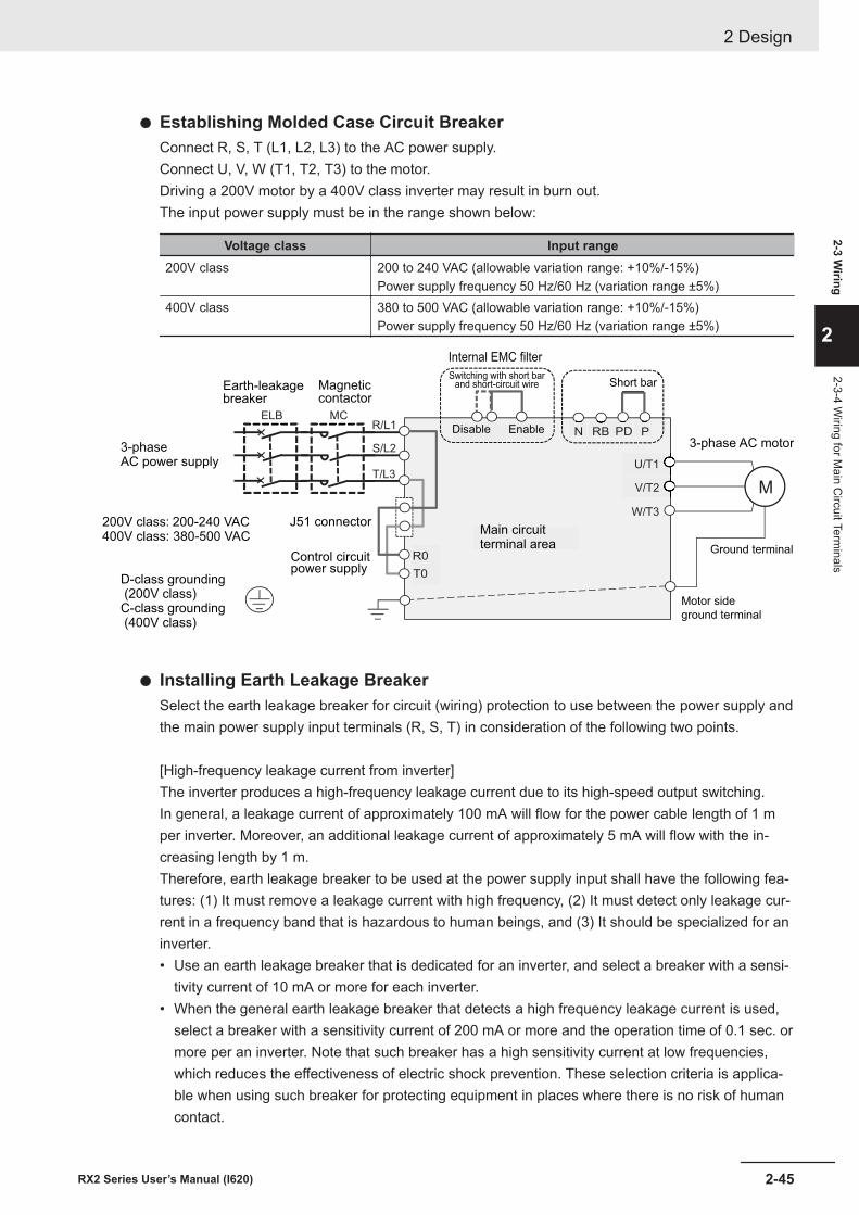
l Establishing Molded Case Circuit BreakerConnect R, S, T (L1, L2, L3) to the AC power supply.Connect U, V, W (T1, T2, T3) to the motor.Driving a 200V motor by a 400V class inverter may result in burn out.The input power supply must be in the range shown below:
Voltage class Input range200V class 200 to 240 VAC (allowable variation range: +10%/-15%)
Power supply frequency 50 Hz/60 Hz (variation range ±5%)400V class 380 to 500 VAC (allowable variation range: +10%/-15%)
Power supply frequency 50 Hz/60 Hz (variation range ±5%)
ELB MCR/L1
S/L2
T/L3
R0
T0
U/T1
V/T2
W/T3
PPDRBN
Earth-leakagebreaker
Magneticcontactor
3-phaseAC power supply
200V class: 200-240 VAC400V class: 380-500 VAC
J51 connector
Internal EMC filter
Switching with short barand short-circuit wire
Disable Enable
Short bar
3-phase AC motor
D-class grounding (200V class)C-class grounding (400V class)
Main circuitterminal area
Control circuitpower supply
Motor side
ground terminal
Ground terminal
M
l Installing Earth Leakage BreakerSelect the earth leakage breaker for circuit (wiring) protection to use between the power supply andthe main power supply input terminals (R, S, T) in consideration of the following two points.
[High-frequency leakage current from inverter]The inverter produces a high-frequency leakage current due to its high-speed output switching.In general, a leakage current of approximately 100 mA will flow for the power cable length of 1 mper inverter. Moreover, an additional leakage current of approximately 5 mA will flow with the in-creasing length by 1 m.Therefore, earth leakage breaker to be used at the power supply input shall have the following fea-tures: (1) It must remove a leakage current with high frequency, (2) It must detect only leakage cur-rent in a frequency band that is hazardous to human beings, and (3) It should be specialized for aninverter.• Use an earth leakage breaker that is dedicated for an inverter, and select a breaker with a sensi-
tivity current of 10 mA or more for each inverter.• When the general earth leakage breaker that detects a high frequency leakage current is used,
select a breaker with a sensitivity current of 200 mA or more and the operation time of 0.1 sec. ormore per an inverter. Note that such breaker has a high sensitivity current at low frequencies,which reduces the effectiveness of electric shock prevention. These selection criteria is applica-ble when using such breaker for protecting equipment in places where there is no risk of humancontact.
2 Design
2-45RX2 Series User’s Manual (I620)
2-3 Wiring
2
2-3-4 Wiring for M
ain Circuit Term
inals
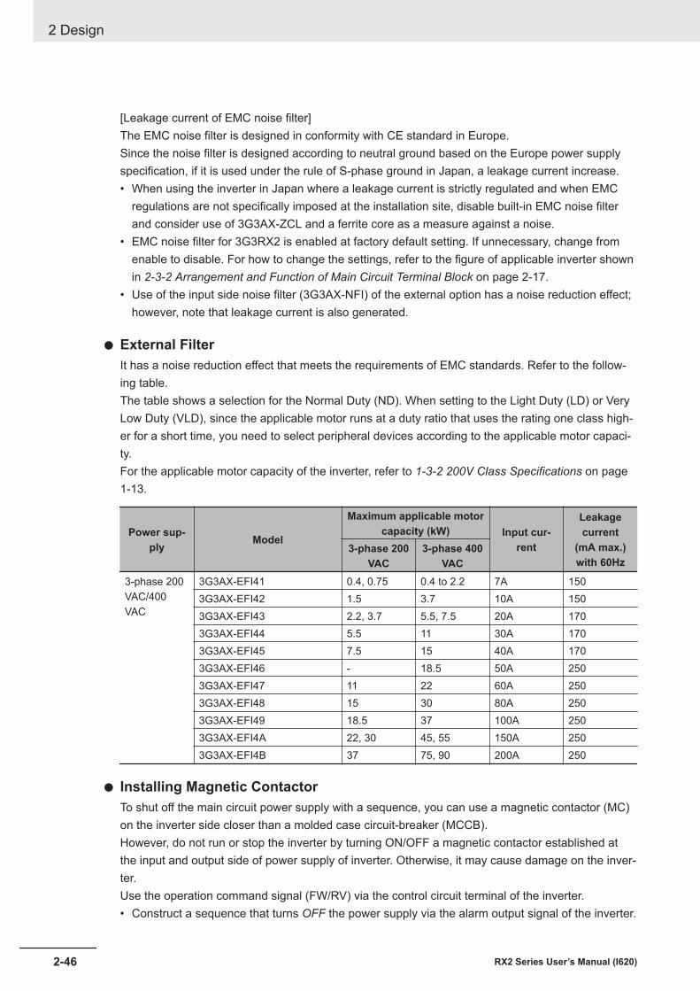
[Leakage current of EMC noise filter]The EMC noise filter is designed in conformity with CE standard in Europe.Since the noise filter is designed according to neutral ground based on the Europe power supplyspecification, if it is used under the rule of S-phase ground in Japan, a leakage current increase.• When using the inverter in Japan where a leakage current is strictly regulated and when EMC
regulations are not specifically imposed at the installation site, disable built-in EMC noise filterand consider use of 3G3AX-ZCL and a ferrite core as a measure against a noise.
• EMC noise filter for 3G3RX2 is enabled at factory default setting. If unnecessary, change fromenable to disable. For how to change the settings, refer to the figure of applicable inverter shownin 2-3-2 Arrangement and Function of Main Circuit Terminal Block on page 2-17.
• Use of the input side noise filter (3G3AX-NFI) of the external option has a noise reduction effect;however, note that leakage current is also generated.
l External FilterIt has a noise reduction effect that meets the requirements of EMC standards. Refer to the follow-ing table.The table shows a selection for the Normal Duty (ND). When setting to the Light Duty (LD) or VeryLow Duty (VLD), since the applicable motor runs at a duty ratio that uses the rating one class high-er for a short time, you need to select peripheral devices according to the applicable motor capaci-ty.For the applicable motor capacity of the inverter, refer to 1-3-2 200V Class Specifications on page1-13.
Power sup-ply Model
Maximum applicable motorcapacity (kW) Input cur-
rent
Leakagecurrent
(mA max.)with 60Hz
3-phase 200VAC
3-phase 400VAC
3-phase 200VAC/400VAC
3G3AX-EFI41 0.4, 0.75 0.4 to 2.2 7A 1503G3AX-EFI42 1.5 3.7 10A 1503G3AX-EFI43 2.2, 3.7 5.5, 7.5 20A 1703G3AX-EFI44 5.5 11 30A 1703G3AX-EFI45 7.5 15 40A 1703G3AX-EFI46 - 18.5 50A 2503G3AX-EFI47 11 22 60A 2503G3AX-EFI48 15 30 80A 2503G3AX-EFI49 18.5 37 100A 2503G3AX-EFI4A 22, 30 45, 55 150A 2503G3AX-EFI4B 37 75, 90 200A 250
l Installing Magnetic ContactorTo shut off the main circuit power supply with a sequence, you can use a magnetic contactor (MC)on the inverter side closer than a molded case circuit-breaker (MCCB).However, do not run or stop the inverter by turning ON/OFF a magnetic contactor established atthe input and output side of power supply of inverter. Otherwise, it may cause damage on the inver-ter.Use the operation command signal (FW/RV) via the control circuit terminal of the inverter.• Construct a sequence that turns OFF the power supply via the alarm output signal of the inverter.
2 Design
2-46 RX2 Series User’s Manual (I620)
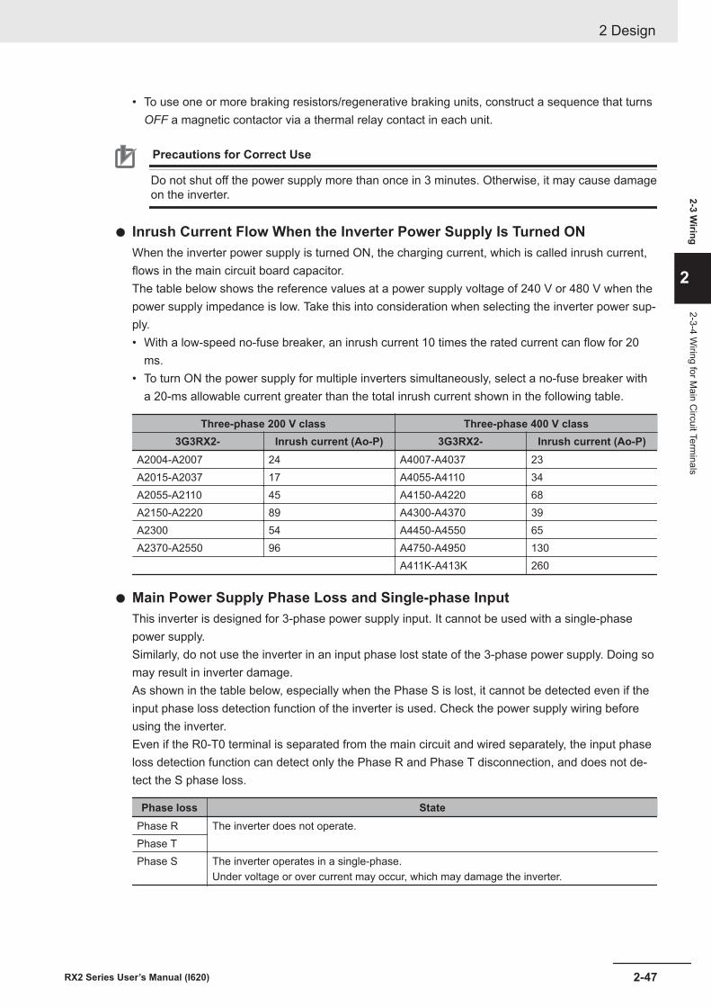
• To use one or more braking resistors/regenerative braking units, construct a sequence that turnsOFF a magnetic contactor via a thermal relay contact in each unit.
Precautions for Correct Use
Do not shut off the power supply more than once in 3 minutes. Otherwise, it may cause damageon the inverter.
l Inrush Current Flow When the Inverter Power Supply Is Turned ONWhen the inverter power supply is turned ON, the charging current, which is called inrush current,flows in the main circuit board capacitor.The table below shows the reference values at a power supply voltage of 240 V or 480 V when thepower supply impedance is low. Take this into consideration when selecting the inverter power sup-ply.• With a low-speed no-fuse breaker, an inrush current 10 times the rated current can flow for 20
ms.• To turn ON the power supply for multiple inverters simultaneously, select a no-fuse breaker with
a 20-ms allowable current greater than the total inrush current shown in the following table.
Three-phase 200 V class Three-phase 400 V class3G3RX2- Inrush current (Ao-P) 3G3RX2- Inrush current (Ao-P)
A2004-A2007 24 A4007-A4037 23A2015-A2037 17 A4055-A4110 34A2055-A2110 45 A4150-A4220 68A2150-A2220 89 A4300-A4370 39A2300 54 A4450-A4550 65A2370-A2550 96 A4750-A4950 130
A411K-A413K 260
l Main Power Supply Phase Loss and Single-phase InputThis inverter is designed for 3-phase power supply input. It cannot be used with a single-phasepower supply.Similarly, do not use the inverter in an input phase lost state of the 3-phase power supply. Doing somay result in inverter damage.As shown in the table below, especially when the Phase S is lost, it cannot be detected even if theinput phase loss detection function of the inverter is used. Check the power supply wiring beforeusing the inverter.Even if the R0-T0 terminal is separated from the main circuit and wired separately, the input phaseloss detection function can detect only the Phase R and Phase T disconnection, and does not de-tect the S phase loss.
Phase loss StatePhase R The inverter does not operate.Phase TPhase S The inverter operates in a single-phase.
Under voltage or over current may occur, which may damage the inverter.
2 Design
2-47RX2 Series User’s Manual (I620)
2-3 Wiring
2
2-3-4 Wiring for M
ain Circuit Term
inals
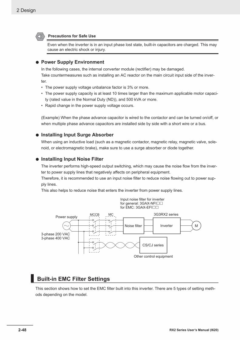
Precautions for Safe Use
Even when the inverter is in an input phase lost state, built-in capacitors are charged. This maycause an electric shock or injury.
l Power Supply EnvironmentIn the following cases, the internal converter module (rectifier) may be damaged.Take countermeasures such as installing an AC reactor on the main circuit input side of the inver-ter.• The power supply voltage unbalance factor is 3% or more.• The power supply capacity is at least 10 times larger than the maximum applicable motor capaci-
ty (rated value in the Normal Duty (ND)), and 500 kVA or more.• Rapid change in the power supply voltage occurs.
(Example) When the phase advance capacitor is wired to the contactor and can be turned on/off, orwhen multiple phase advance capacitors are installed side by side with a short wire or a bus.
l Installing Input Surge AbsorberWhen using an inductive load (such as a magnetic contactor, magnetic relay, magnetic valve, sole-noid, or electromagnetic brake), make sure to use a surge absorber or diode together.
l Installing Input Noise FilterThe inverter performs high-speed output switching, which may cause the noise flow from the inver-ter to power supply lines that negatively affects on peripheral equipment.Therefore, it is recommended to use an input noise filter to reduce noise flowing out to power sup-ply lines.This also helps to reduce noise that enters the inverter from power supply lines.
MNoise filter
3G3RX2 series
Inverter
CS/CJ series
Other control equipment
Input noise filter for inverterfor general: 3GAX-NFI££
for EMC: 3GAX-EFI££
3-phase 200 VAC3-phase 400 VAC
Power supplyMCMCCB
Built-in EMC Filter SettingsThis section shows how to set the EMC filter built into this inverter. There are 5 types of setting meth-ods depending on the model.
2 Design
2-48 RX2 Series User’s Manual (I620)
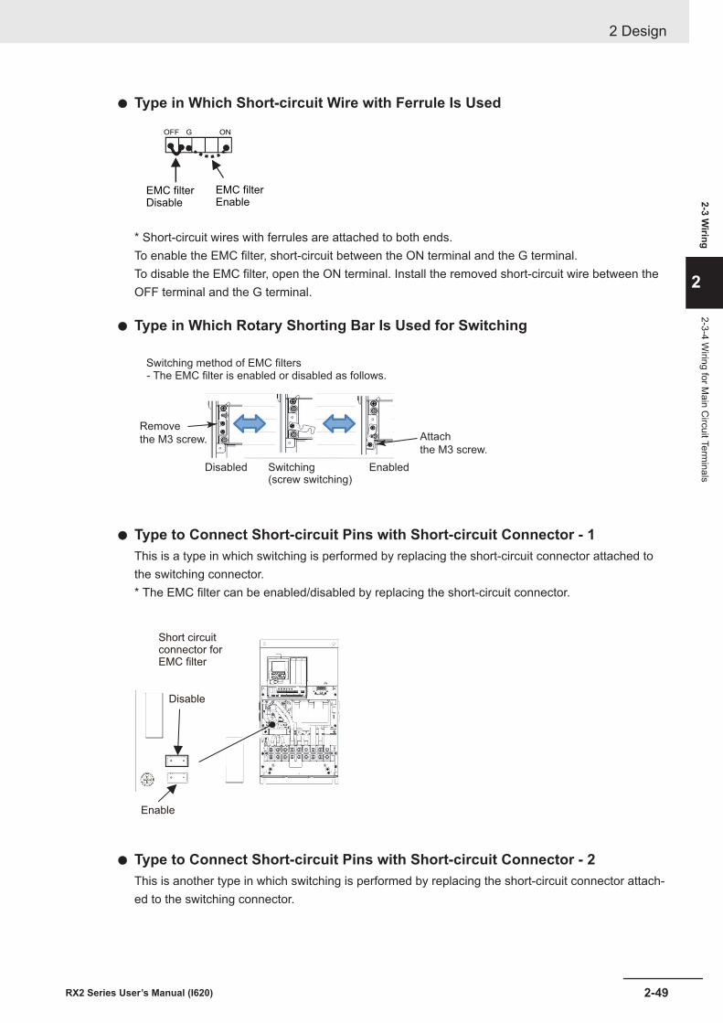
l Type in Which Short-circuit Wire with Ferrule Is Used
EMC filter
Enable
EMC filter
Disable
ONGOFF
* Short-circuit wires with ferrules are attached to both ends.To enable the EMC filter, short-circuit between the ON terminal and the G terminal.To disable the EMC filter, open the ON terminal. Install the removed short-circuit wire between theOFF terminal and the G terminal.
l Type in Which Rotary Shorting Bar Is Used for Switching
Switching method of EMC filters- The EMC filter is enabled or disabled as follows.
Disabled Switching(screw switching)
Enabled
Remove
the M3 screw. Attach
the M3 screw.
l Type to Connect Short-circuit Pins with Short-circuit Connector - 1This is a type in which switching is performed by replacing the short-circuit connector attached tothe switching connector.* The EMC filter can be enabled/disabled by replacing the short-circuit connector.
Disable
Short circuit
connector for
EMC filter
Enable
l Type to Connect Short-circuit Pins with Short-circuit Connector - 2This is another type in which switching is performed by replacing the short-circuit connector attach-ed to the switching connector.
2 Design
2-49RX2 Series User’s Manual (I620)
2-3 Wiring
2
2-3-4 Wiring for M
ain Circuit Term
inals
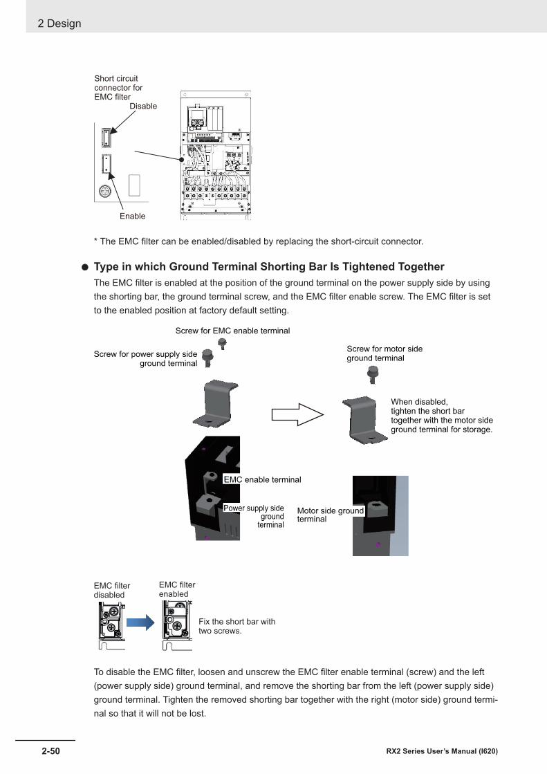
Enable
Short circuit
connector for
EMC filter
Disable
* The EMC filter can be enabled/disabled by replacing the short-circuit connector.
l Type in which Ground Terminal Shorting Bar Is Tightened TogetherThe EMC filter is enabled at the position of the ground terminal on the power supply side by usingthe shorting bar, the ground terminal screw, and the EMC filter enable screw. The EMC filter is setto the enabled position at factory default setting.
Screw for EMC enable terminal
Screw for power supply side ground terminal
Screw for motor sideground terminal
When disabled, tighten the short bar together with the motor sideground terminal for storage.
EMC enable terminal
Power supply sideground
terminal
Motor side groundterminal
EMC filter
disabled
EMC filter
enabled
Fix the short bar with
two screws.
To disable the EMC filter, loosen and unscrew the EMC filter enable terminal (screw) and the left(power supply side) ground terminal, and remove the shorting bar from the left (power supply side)ground terminal. Tighten the removed shorting bar together with the right (motor side) ground termi-nal so that it will not be lost.
2 Design
2-50 RX2 Series User’s Manual (I620)
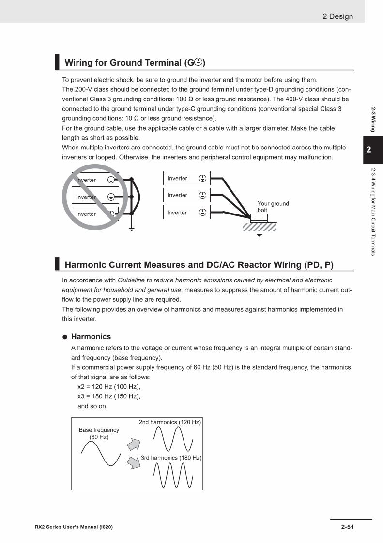
Wiring for Ground Terminal (G )
To prevent electric shock, be sure to ground the inverter and the motor before using them.The 200-V class should be connected to the ground terminal under type-D grounding conditions (con-ventional Class 3 grounding conditions: 100 Ω or less ground resistance). The 400-V class should beconnected to the ground terminal under type-C grounding conditions (conventional special Class 3grounding conditions: 10 Ω or less ground resistance).For the ground cable, use the applicable cable or a cable with a larger diameter. Make the cablelength as short as possible.When multiple inverters are connected, the ground cable must not be connected across the multipleinverters or looped. Otherwise, the inverters and peripheral control equipment may malfunction.
Inverter
Inverter
Inverter
Inverter
Inverter
Inverter
Your groundbolt
Harmonic Current Measures and DC/AC Reactor Wiring (PD, P)In accordance with Guideline to reduce harmonic emissions caused by electrical and electronicequipment for household and general use, measures to suppress the amount of harmonic current out-flow to the power supply line are required.The following provides an overview of harmonics and measures against harmonics implemented inthis inverter.
l HarmonicsA harmonic refers to the voltage or current whose frequency is an integral multiple of certain stand-ard frequency (base frequency).If a commercial power supply frequency of 60 Hz (50 Hz) is the standard frequency, the harmonicsof that signal are as follows: x2 = 120 Hz (100 Hz), x3 = 180 Hz (150 Hz), and so on.
Base frequency
(60 Hz)
2nd harmonics (120 Hz)
3rd harmonics (180 Hz)
2 Design
2-51RX2 Series User’s Manual (I620)
2-3 Wiring
2
2-3-4 Wiring for M
ain Circuit Term
inals
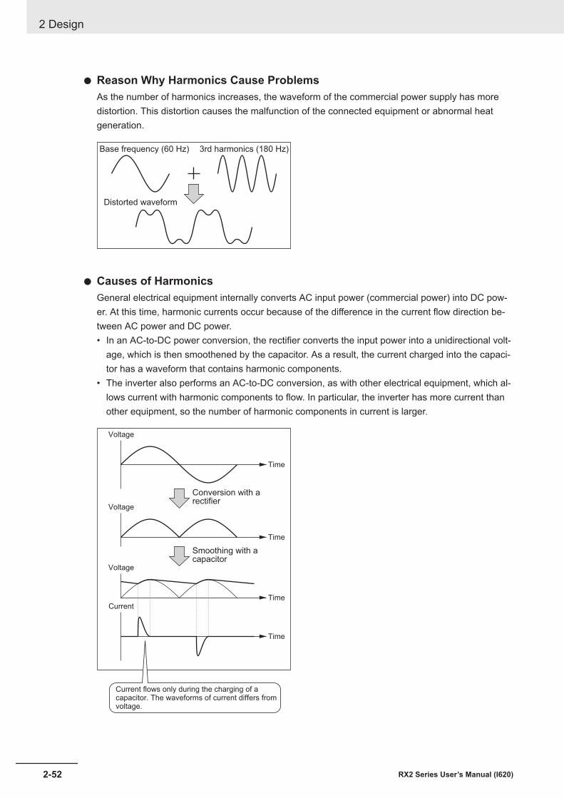
l Reason Why Harmonics Cause ProblemsAs the number of harmonics increases, the waveform of the commercial power supply has moredistortion. This distortion causes the malfunction of the connected equipment or abnormal heatgeneration.
Base frequency (60 Hz) 3rd harmonics (180 Hz)
Distorted waveform
l Causes of HarmonicsGeneral electrical equipment internally converts AC input power (commercial power) into DC pow-er. At this time, harmonic currents occur because of the difference in the current flow direction be-tween AC power and DC power.• In an AC-to-DC power conversion, the rectifier converts the input power into a unidirectional volt-
age, which is then smoothened by the capacitor. As a result, the current charged into the capaci-tor has a waveform that contains harmonic components.
• The inverter also performs an AC-to-DC conversion, as with other electrical equipment, which al-lows current with harmonic components to flow. In particular, the inverter has more current thanother equipment, so the number of harmonic components in current is larger.
Voltage
Time
Conversion with arectifier
Voltage
Time
Voltage
TimeCurrent
Time
Smoothing with acapacitor
Current flows only during the charging of acapacitor. The waveforms of current differs fromvoltage.
2 Design
2-52 RX2 Series User’s Manual (I620)
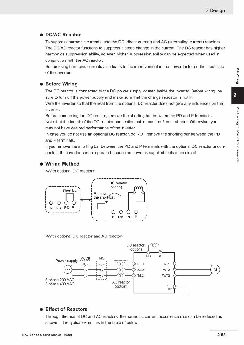
l DC/AC ReactorTo suppress harmonic currents, use the DC (direct current) and AC (alternating current) reactors.The DC/AC reactor functions to suppress a steep change in the current. The DC reactor has higherharmonics suppression ability, so even higher suppression ability can be expected when used inconjunction with the AC reactor.Suppressing harmonic currents also leads to the improvement in the power factor on the input sideof the inverter.
l Before WiringThe DC reactor is connected to the DC power supply located inside the inverter. Before wiring, besure to turn off the power supply and make sure that the charge indicator is not lit.Wire the inverter so that the heat from the optional DC reactor does not give any influences on theinverter.Before connecting the DC reactor, remove the shorting bar between the PD and P terminals.Note that the length of the DC reactor connection cable must be 5 m or shorter. Otherwise, youmay not have desired performance of the inverter.In case you do not use an optional DC reactor, do NOT remove the shorting bar between the PDand P terminals.If you remove the shorting bar between the PD and P terminals with the optional DC reactor uncon-nected, the inverter cannot operate because no power is supplied to its main circuit.
l Wiring Method<With optional DC reactor>
PPDRBN
PPDRBN
Short bar
DC reactor(option)
Remove the short bar.
<With optional DC reactor and AC reactor>
M
PD P
DC reactor(option)
AC reactor(option)
R/L1
S/L2
T/L3
U/T1
V/T2
W/T3
3-phase 200 VAC3-phase 400 VAC
Power supplyMCMCCB
l Effect of ReactorsThrough the use of DC and AC reactors, the harmonic current occurrence rate can be reduced asshown in the typical examples in the table of below.
2 Design
2-53RX2 Series User’s Manual (I620)
2-3 Wiring
2
2-3-4 Wiring for M
ain Circuit Term
inals
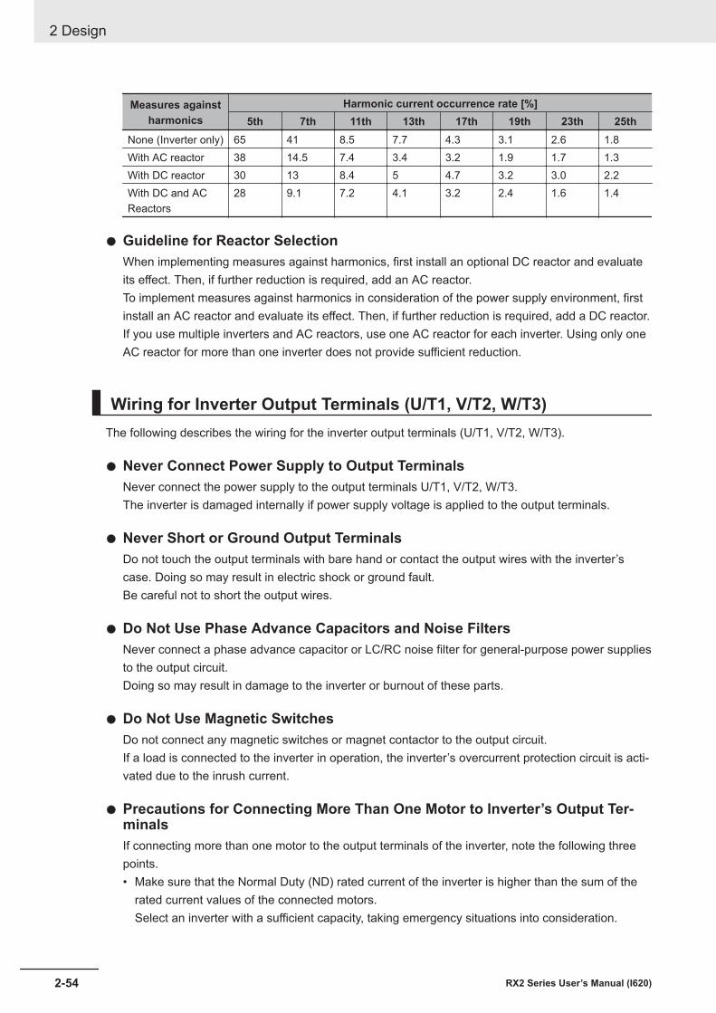
Measures againstharmonics
Harmonic current occurrence rate [%]5th 7th 11th 13th 17th 19th 23th 25th
None (Inverter only) 65 41 8.5 7.7 4.3 3.1 2.6 1.8With AC reactor 38 14.5 7.4 3.4 3.2 1.9 1.7 1.3With DC reactor 30 13 8.4 5 4.7 3.2 3.0 2.2With DC and ACReactors
28 9.1 7.2 4.1 3.2 2.4 1.6 1.4
l Guideline for Reactor SelectionWhen implementing measures against harmonics, first install an optional DC reactor and evaluateits effect. Then, if further reduction is required, add an AC reactor.To implement measures against harmonics in consideration of the power supply environment, firstinstall an AC reactor and evaluate its effect. Then, if further reduction is required, add a DC reactor.If you use multiple inverters and AC reactors, use one AC reactor for each inverter. Using only oneAC reactor for more than one inverter does not provide sufficient reduction.
Wiring for Inverter Output Terminals (U/T1, V/T2, W/T3)The following describes the wiring for the inverter output terminals (U/T1, V/T2, W/T3).
l Never Connect Power Supply to Output TerminalsNever connect the power supply to the output terminals U/T1, V/T2, W/T3.The inverter is damaged internally if power supply voltage is applied to the output terminals.
l Never Short or Ground Output TerminalsDo not touch the output terminals with bare hand or contact the output wires with the inverter’scase. Doing so may result in electric shock or ground fault.Be careful not to short the output wires.
l Do Not Use Phase Advance Capacitors and Noise FiltersNever connect a phase advance capacitor or LC/RC noise filter for general-purpose power suppliesto the output circuit.Doing so may result in damage to the inverter or burnout of these parts.
l Do Not Use Magnetic SwitchesDo not connect any magnetic switches or magnet contactor to the output circuit.If a load is connected to the inverter in operation, the inverter’s overcurrent protection circuit is acti-vated due to the inrush current.
l Precautions for Connecting More Than One Motor to Inverter’s Output Ter-minalsIf connecting more than one motor to the output terminals of the inverter, note the following threepoints.• Make sure that the Normal Duty (ND) rated current of the inverter is higher than the sum of the
rated current values of the connected motors.Select an inverter with a sufficient capacity, taking emergency situations into consideration.
2 Design
2-54 RX2 Series User’s Manual (I620)

• The inverter cannot provide overload protection for individual motors, because it only detects asum of the current values for all the connected motors.Install a thermal relay for each motor. The RC value of each thermal relay must be 1.1 times larg-er than the rated current of the motor.
• Set the inverter to detect only overloading that occurred in it by setting the inverter’s rated outputcurrent to the electronic thermal level of the inverter.
l Installing Output Noise FilterConnecting a noise filter to the output side of the inverter enables the reduction of radio noise andinductive noise.
3G3RX2 series
M
3G3AX-ZCL£3G3AX-NFO£
Controlequipment AM radio
Radio noiseInductive noiseSignal line
Inverter Noise filter
3-phase 200 VAC3-phase 400 VAC
Power supplyMCMCCB
Noise type DescriptionInductive noise Produced by electromagnetic induction, this noise causes malfunction of control equip-
ment due to noise in signal lines.Radio noise The electromagnetic waves emitted from the inverter body or cables cause noise in radio
receivers.
l Measures Against Inductive NoiseIn order to suppress the inductive noise generated from the output side, in addition to installing thenoise filter described above, you can connect a bundle of wires through a grounded metal conduit.Separate the metal conduit as far as possible from the signal line of the control equipment in orderto suppress the influence of inductive noise.
M
Metallic conduit3G3RX2 series
Inverter
Controlequipment
Signal line
Separate here as faras possible
3-phase 200 VAC3-phase 400 VAC
Power supplyMCMCCB
l Measures Against Radio NoiseRadio noise is radiated from the inverter itself, besides the I/O wires.This radio noise can be reduced by installing noise filters on both the input and output sides of theinverter and by installing and shielding the inverter body in a grounded iron enclosure etc.Keep the cables between the inverter and the motor as short as possible.
2 Design
2-55RX2 Series User’s Manual (I620)
2-3 Wiring
2
2-3-4 Wiring for M
ain Circuit Term
inals
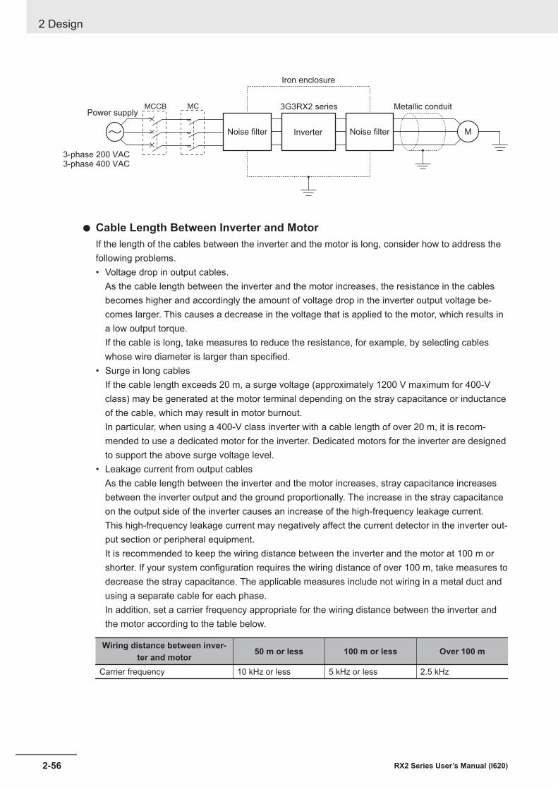
3G3RX2 series
MNoise filter Noise filter
Metallic conduit
Iron enclosure
Inverter
3-phase 200 VAC3-phase 400 VAC
Power supplyMCMCCB
l Cable Length Between Inverter and MotorIf the length of the cables between the inverter and the motor is long, consider how to address thefollowing problems.• Voltage drop in output cables.
As the cable length between the inverter and the motor increases, the resistance in the cablesbecomes higher and accordingly the amount of voltage drop in the inverter output voltage be-comes larger. This causes a decrease in the voltage that is applied to the motor, which results ina low output torque.If the cable is long, take measures to reduce the resistance, for example, by selecting cableswhose wire diameter is larger than specified.
• Surge in long cablesIf the cable length exceeds 20 m, a surge voltage (approximately 1200 V maximum for 400-Vclass) may be generated at the motor terminal depending on the stray capacitance or inductanceof the cable, which may result in motor burnout.In particular, when using a 400-V class inverter with a cable length of over 20 m, it is recom-mended to use a dedicated motor for the inverter. Dedicated motors for the inverter are designedto support the above surge voltage level.
• Leakage current from output cablesAs the cable length between the inverter and the motor increases, stray capacitance increasesbetween the inverter output and the ground proportionally. The increase in the stray capacitanceon the output side of the inverter causes an increase of the high-frequency leakage current.This high-frequency leakage current may negatively affect the current detector in the inverter out-put section or peripheral equipment.It is recommended to keep the wiring distance between the inverter and the motor at 100 m orshorter. If your system configuration requires the wiring distance of over 100 m, take measures todecrease the stray capacitance. The applicable measures include not wiring in a metal duct andusing a separate cable for each phase.In addition, set a carrier frequency appropriate for the wiring distance between the inverter andthe motor according to the table below.
Wiring distance between inver-ter and motor 50 m or less 100 m or less Over 100 m
Carrier frequency 10 kHz or less 5 kHz or less 2.5 kHz
2 Design
2-56 RX2 Series User’s Manual (I620)
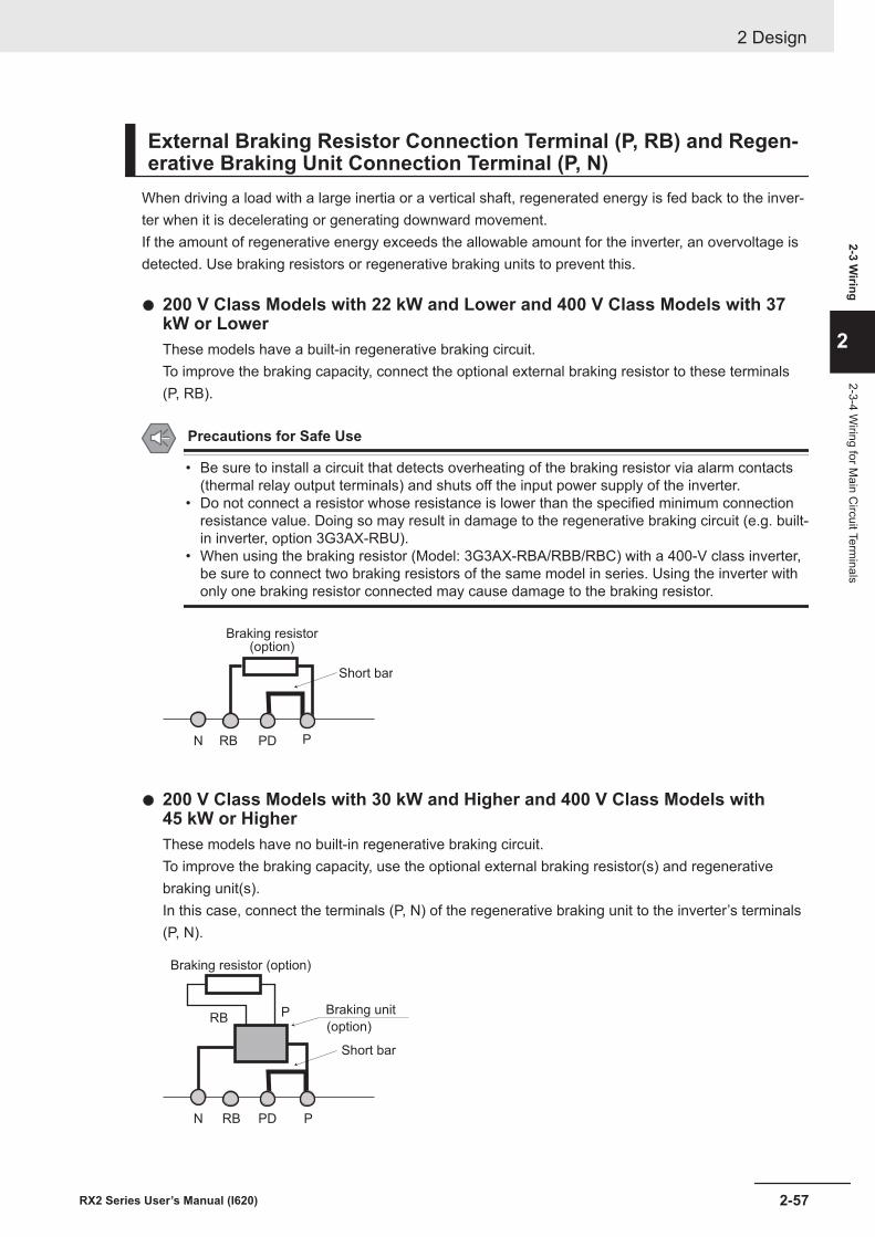
External Braking Resistor Connection Terminal (P, RB) and Regen-erative Braking Unit Connection Terminal (P, N)
When driving a load with a large inertia or a vertical shaft, regenerated energy is fed back to the inver-ter when it is decelerating or generating downward movement.If the amount of regenerative energy exceeds the allowable amount for the inverter, an overvoltage isdetected. Use braking resistors or regenerative braking units to prevent this.
l 200 V Class Models with 22 kW and Lower and 400 V Class Models with 37kW or LowerThese models have a built-in regenerative braking circuit.To improve the braking capacity, connect the optional external braking resistor to these terminals(P, RB).
Precautions for Safe Use
• Be sure to install a circuit that detects overheating of the braking resistor via alarm contacts(thermal relay output terminals) and shuts off the input power supply of the inverter.
• Do not connect a resistor whose resistance is lower than the specified minimum connectionresistance value. Doing so may result in damage to the regenerative braking circuit (e.g. built-in inverter, option 3G3AX-RBU).
• When using the braking resistor (Model: 3G3AX-RBA/RBB/RBC) with a 400-V class inverter,be sure to connect two braking resistors of the same model in series. Using the inverter withonly one braking resistor connected may cause damage to the braking resistor.
Braking resistor(option)
Short bar
N RB PD P
l 200 V Class Models with 30 kW and Higher and 400 V Class Models with45 kW or HigherThese models have no built-in regenerative braking circuit.To improve the braking capacity, use the optional external braking resistor(s) and regenerativebraking unit(s).In this case, connect the terminals (P, N) of the regenerative braking unit to the inverter’s terminals(P, N).
N RB PD P
PRBBraking unit
(option)
Braking resistor (option)
Short bar
2 Design
2-57RX2 Series User’s Manual (I620)
2-3 Wiring
2
2-3-4 Wiring for M
ain Circuit Term
inals
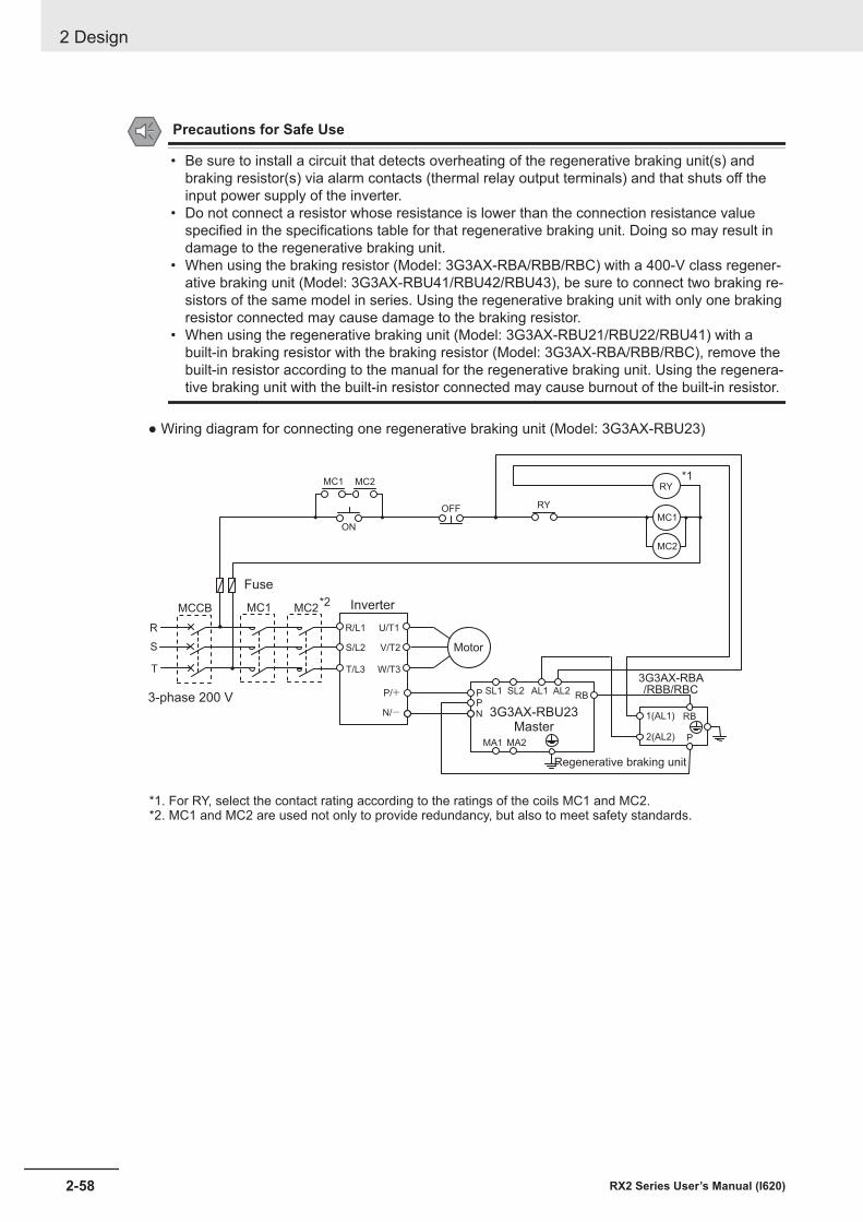
Precautions for Safe Use
• Be sure to install a circuit that detects overheating of the regenerative braking unit(s) andbraking resistor(s) via alarm contacts (thermal relay output terminals) and that shuts off theinput power supply of the inverter.
• Do not connect a resistor whose resistance is lower than the connection resistance valuespecified in the specifications table for that regenerative braking unit. Doing so may result indamage to the regenerative braking unit.
• When using the braking resistor (Model: 3G3AX-RBA/RBB/RBC) with a 400-V class regener-ative braking unit (Model: 3G3AX-RBU41/RBU42/RBU43), be sure to connect two braking re-sistors of the same model in series. Using the regenerative braking unit with only one brakingresistor connected may cause damage to the braking resistor.
• When using the regenerative braking unit (Model: 3G3AX-RBU21/RBU22/RBU41) with abuilt-in braking resistor with the braking resistor (Model: 3G3AX-RBA/RBB/RBC), remove thebuilt-in resistor according to the manual for the regenerative braking unit. Using the regenera-tive braking unit with the built-in resistor connected may cause burnout of the built-in resistor.
● Wiring diagram for connecting one regenerative braking unit (Model: 3G3AX-RBU23)
Inverter
Fuse
Motor
PPN
SL1 SL2 AL1 AL2RB
MA1 MA2
3G3AX-RBU23Master
ON
OFF RY
RY
MC1
*1
R/L1
S/L2
T/L3
U/T1
V/T2
W/T3
P/+
N/-3-phase 200 V
1(AL1)
2(AL2) P
RB
3G3AX-RBA/RBB/RBC
MC1 MC2
MC2
*1. For RY, select the contact rating according to the ratings of the coils MC1 and MC2.*2. MC1 and MC2 are used not only to provide redundancy, but also to meet safety standards.
MC1MCCB MC2
R
S
T
*2
Regenerative braking unit
2 Design
2-58 RX2 Series User’s Manual (I620)
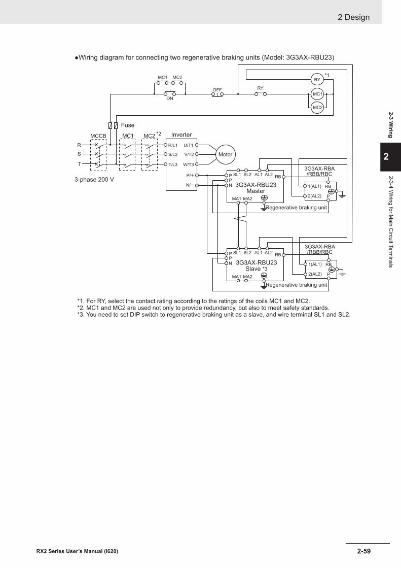
●Wiring diagram for connecting two regenerative braking units (Model: 3G3AX-RBU23)
Inverter
Fuse
Motor
PPN
SL1 SL2 AL1 AL2RB
MA1 MA2
3G3AX-RBU23Master
PPN
SL1 SL2 AL1 AL2RB
MA1 MA2
3G3AX-RBU23Slave *3
ON
OFF RY
RY
MC1
*1
R/L1
S/L2
T/L3
U/T1
V/T2
W/T3
P/+
N/- 1(AL1)
2(AL2) P
RB
3G3AX-RBA/RBB/RBC
1(AL1)
2(AL2) P
RB
3G3AX-RBA/RBB/RBC
MC1 MC2
MC2
Regenerative braking unit
Regenerative braking unit
*1. For RY, select the contact rating according to the ratings of the coils MC1 and MC2.*2. MC1 and MC2 are used not only to provide redundancy, but also to meet safety standards.*3. You need to set DIP switch to regenerative braking unit as a slave, and wire terminal SL1 and SL2.
3-phase 200 V
MC1MCCB MC2
R
S
T
*2
2 Design
2-59RX2 Series User’s Manual (I620)
2-3 Wiring
2
2-3-4 Wiring for M
ain Circuit Term
inals
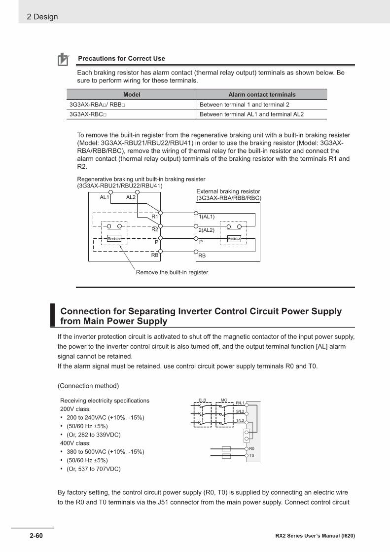
Precautions for Correct Use
Each braking resistor has alarm contact (thermal relay output) terminals as shown below. Besure to perform wiring for these terminals.
Model Alarm contact terminals3G3AX-RBA□/ RBB□ Between terminal 1 and terminal 23G3AX-RBC□ Between terminal AL1 and terminal AL2
To remove the built-in register from the regenerative braking unit with a built-in braking resister(Model: 3G3AX-RBU21/RBU22/RBU41) in order to use the braking resistor (Model: 3G3AX-RBA/RBB/RBC), remove the wiring of thermal relay for the built-in resistor and connect thealarm contact (thermal relay output) terminals of the braking resistor with the terminals R1 andR2.
AL1 AL2
R1
R2
Regenerative braking unit built-in braking resister(3G3AX-RBU21/RBU22/RBU41)
Remove the built-in register.
ResistorP
RB
Resistor
1(AL1)
2(AL2)
P
RB
External braking resistor(3G3AX-RBA/RBB/RBC)
Connection for Separating Inverter Control Circuit Power Supplyfrom Main Power Supply
If the inverter protection circuit is activated to shut off the magnetic contactor of the input power supply,the power to the inverter control circuit is also turned off, and the output terminal function [AL] alarmsignal cannot be retained.If the alarm signal must be retained, use control circuit power supply terminals R0 and T0.
(Connection method)
Receiving electricity specifications200V class:• 200 to 240VAC (+10%, -15%)• (50/60 Hz ±5%)• (Or, 282 to 339VDC)400V class:• 380 to 500VAC (+10%, -15%)• (50/60 Hz ±5%)• (Or, 537 to 707VDC)
ELB MCR/L1
S/L2
T/L3
R0
T0
By factory setting, the control circuit power supply (R0, T0) is supplied by connecting an electric wireto the R0 and T0 terminals via the J51 connector from the main power supply. Connect control circuit
2 Design
2-60 RX2 Series User’s Manual (I620)
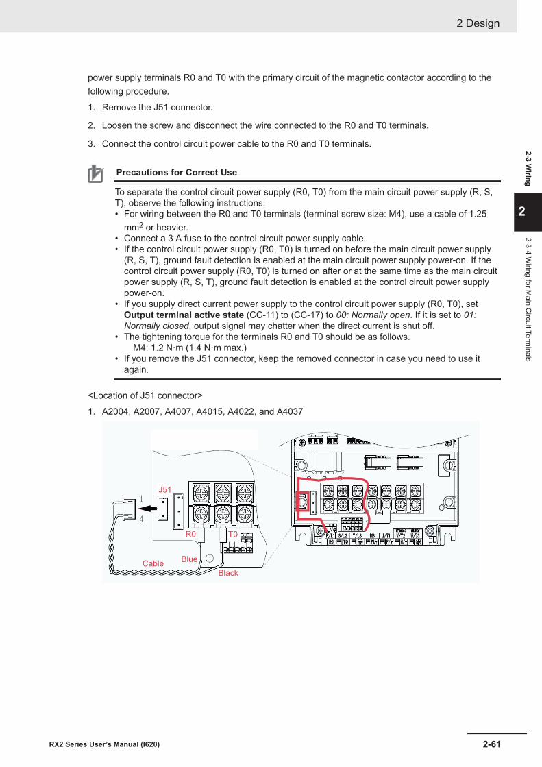
power supply terminals R0 and T0 with the primary circuit of the magnetic contactor according to thefollowing procedure.
1. Remove the J51 connector.
2. Loosen the screw and disconnect the wire connected to the R0 and T0 terminals.
3. Connect the control circuit power cable to the R0 and T0 terminals.
Precautions for Correct Use
To separate the control circuit power supply (R0, T0) from the main circuit power supply (R, S,T), observe the following instructions:• For wiring between the R0 and T0 terminals (terminal screw size: M4), use a cable of 1.25
mm2 or heavier.• Connect a 3 A fuse to the control circuit power supply cable.• If the control circuit power supply (R0, T0) is turned on before the main circuit power supply
(R, S, T), ground fault detection is enabled at the main circuit power supply power-on. If thecontrol circuit power supply (R0, T0) is turned on after or at the same time as the main circuitpower supply (R, S, T), ground fault detection is enabled at the control circuit power supplypower-on.
• If you supply direct current power supply to the control circuit power supply (R0, T0), setOutput terminal active state (CC-11) to (CC-17) to 00: Normally open. If it is set to 01:Normally closed, output signal may chatter when the direct current is shut off.
• The tightening torque for the terminals R0 and T0 should be as follows. M4: 1.2 N·m (1.4 N·m max.)
• If you remove the J51 connector, keep the removed connector in case you need to use itagain.
<Location of J51 connector>
1. A2004, A2007, A4007, A4015, A4022, and A4037
R0 T0
Black
BlueCable
J51
2 Design
2-61RX2 Series User’s Manual (I620)
2-3 Wiring
2
2-3-4 Wiring for M
ain Circuit Term
inals
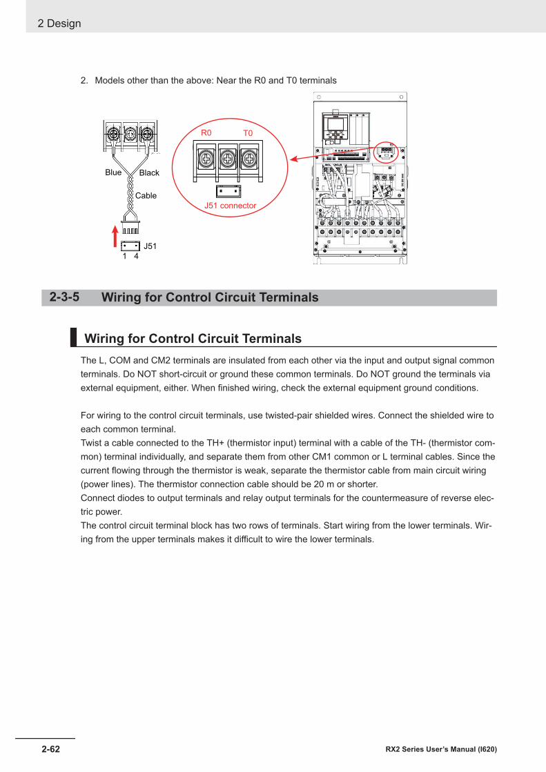
2. Models other than the above: Near the R0 and T0 terminals
1 4
J51
R0 T0
J51 connector
BlackBlue
Cable
2-3-5 Wiring for Control Circuit Terminals
Wiring for Control Circuit TerminalsThe L, COM and CM2 terminals are insulated from each other via the input and output signal commonterminals. Do NOT short-circuit or ground these common terminals. Do NOT ground the terminals viaexternal equipment, either. When finished wiring, check the external equipment ground conditions.
For wiring to the control circuit terminals, use twisted-pair shielded wires. Connect the shielded wire toeach common terminal.Twist a cable connected to the TH+ (thermistor input) terminal with a cable of the TH- (thermistor com-mon) terminal individually, and separate them from other CM1 common or L terminal cables. Since thecurrent flowing through the thermistor is weak, separate the thermistor cable from main circuit wiring(power lines). The thermistor connection cable should be 20 m or shorter.Connect diodes to output terminals and relay output terminals for the countermeasure of reverse elec-tric power.The control circuit terminal block has two rows of terminals. Start wiring from the lower terminals. Wir-ing from the upper terminals makes it difficult to wire the lower terminals.
2 Design
2-62 RX2 Series User’s Manual (I620)
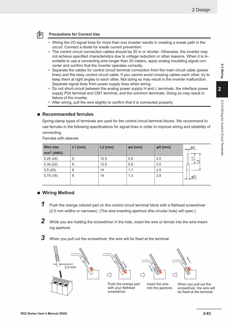
Precautions for Correct Use
• Wiring the I/O signal lines for more than one inverter results in creating a sneak path in thecircuit. Connect a diode for sneak current prevention.
• The control circuit connection cables should be 20 m or shorter. Otherwise, the inverter maynot achieve specified characteristics due to voltage reduction or other reasons. When it is in-evitable to use a connecting wire longer than 20 meters, apply analog insulating signal con-verter and confirm that the inverter operates correctly.
• Separate the cables for control circuit terminal connection from the main circuit cable (powerlines) and the relay control circuit cable. If you cannot avoid crossing cables each other, try tokeep them at right angles to each other. Not doing so may result in the inverter malfunction.Separate signal lines from power supply lines when wiring.
• Do not short-circuit between the analog power supply H and L terminals, the interface powersupply P24 terminal and CM1 terminal, and the common terminals. Doing so may result infailure of the inverter.
• After wiring, pull the wire slightly to confirm that it is connected properly.
l Recommended ferrulesSpring-clamp types of terminals are used for the control circuit terminal blocks. We recommend touse ferrules in the following specifications for signal lines in order to improve wiring and reliability ofconnecting.Ferrules with sleeves
Wire sizemm2 (AWG)
L1 [mm] L2 [mm] φd [mm] φD [mm] φd
φD
L2L10.25 (24) 8 12.5 0.8 2.0
0.34 (22) 8 12.5 0.8 2.00.5 (20) 8 14 1.1 2.50.75 (18) 8 14 1.3 2.8
l Wiring Method
1 Push the orange colored part on the control circuit terminal block with a flathead screwdriver(2.5 mm widths or narrower). (The wire-inserting aperture (the circular hole) will open.)
2 While you are holding the screwdriver in the hole, insert the wire or ferrule into the wire-insert-ing aperture.
3 When you pull out the screwdriver, the wire will be fixed at the terminal.
2.5 mm
When you pull out thescrewdriver, the wire willbe fixed at the terminal.
Insert the wireinto the aperture.
Push the orange partwith your flatheadscrewdriver.
2 Design
2-63RX2 Series User’s Manual (I620)
2-3 Wiring
2
2-3-5 Wiring for C
ontrol Circuit Term
inals
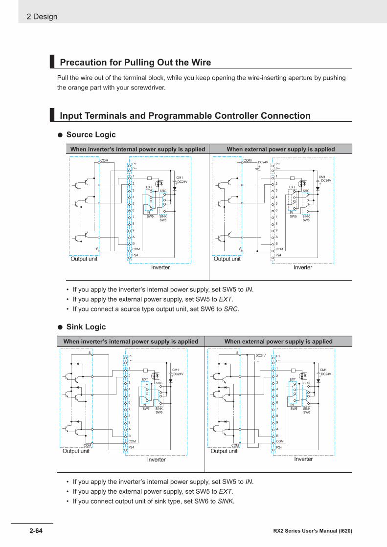
Precaution for Pulling Out the WirePull the wire out of the terminal block, while you keep opening the wire-inserting aperture by pushingthe orange part with your screwdriver.
Input Terminals and Programmable Controller Connection
l Source Logic
When inverter’s internal power supply is applied When external power supply is appliedCOM
S
Inverter
P+P-
1 CM1
DC24V2
3
4
5
6IN
EXTSRC
SW5 SINKSW6
7
8
9
A
B
COM
P24
Output unit
+
-+
COM
S
Inverter
P+P-
1 CM1DC24V
2
3
4
5
6IN
EXTSRC
SW5 SINKSW6
7
8
9
A
B
COM
P24
Output unit
+
DC24V
• If you apply the inverter’s internal power supply, set SW5 to IN.• If you apply the external power supply, set SW5 to EXT.• If you connect a source type output unit, set SW6 to SRC.
l Sink Logic
When inverter’s internal power supply is applied When external power supply is applied
Output unit
Inverter
P+
+
P-
1 CM1
DC24V2
3
4
5
6IN
EXTSRC
SW5 SINKSW6
7
8
9
A
B
COM
P24
S
COM
Output unit
Inverter
P+DC24V+- P-
1 CM1
DC24V2
3
4
5
6IN
EXTSRC
SW5 SINKSW6
7
8
9
A
B
COM
P24
S
COM
+
• If you apply the inverter’s internal power supply, set SW5 to IN.• If you apply the external power supply, set SW5 to EXT.• If you connect output unit of sink type, set SW6 to SINK.
2 Design
2-64 RX2 Series User’s Manual (I620)
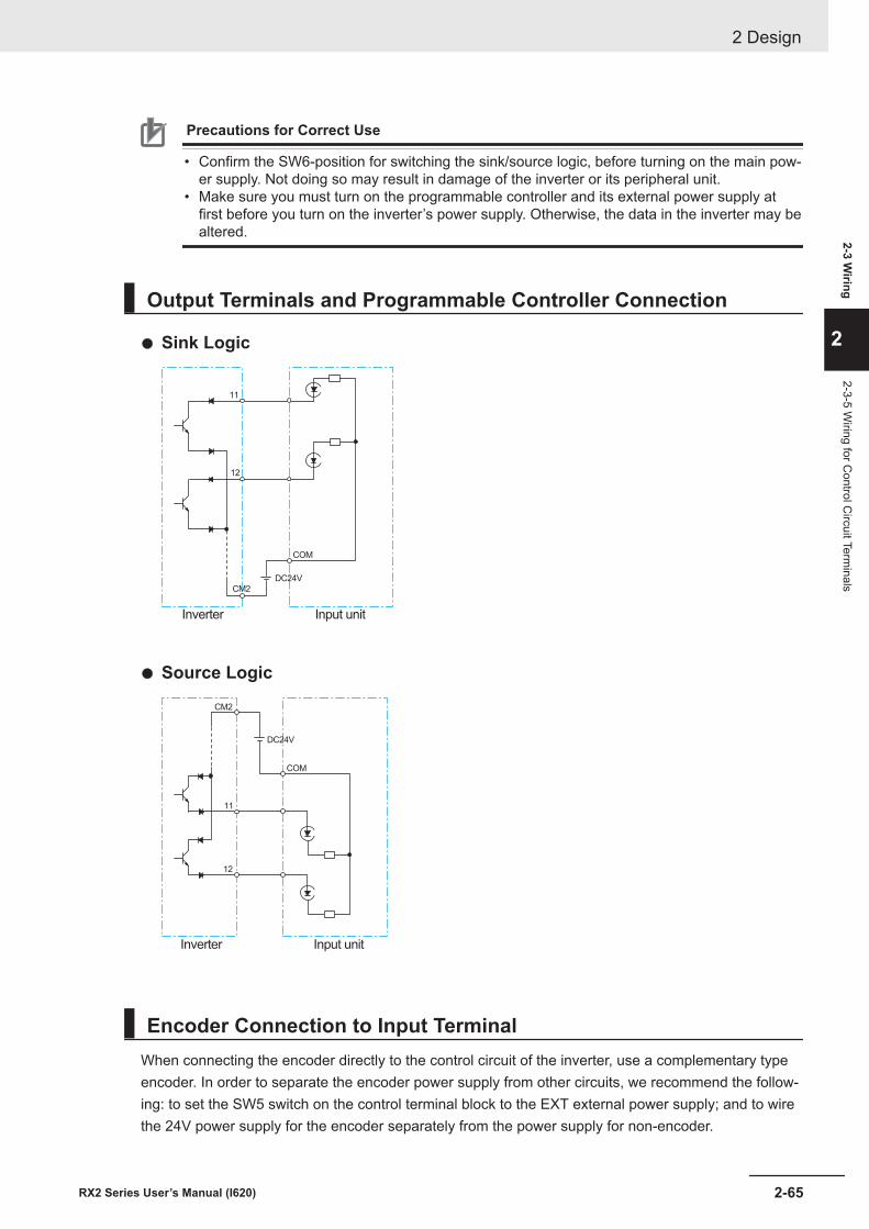
Precautions for Correct Use
• Confirm the SW6-position for switching the sink/source logic, before turning on the main pow-er supply. Not doing so may result in damage of the inverter or its peripheral unit.
• Make sure you must turn on the programmable controller and its external power supply atfirst before you turn on the inverter’s power supply. Otherwise, the data in the inverter may bealtered.
Output Terminals and Programmable Controller Connection
l Sink Logic
Inverter
DC24V
11
12
CM2
COM
Input unit
l Source Logic
Inverter
DC24V
11
12
Input unit
CM2
COM
Encoder Connection to Input TerminalWhen connecting the encoder directly to the control circuit of the inverter, use a complementary typeencoder. In order to separate the encoder power supply from other circuits, we recommend the follow-ing: to set the SW5 switch on the control terminal block to the EXT external power supply; and to wirethe 24V power supply for the encoder separately from the power supply for non-encoder.
2 Design
2-65RX2 Series User’s Manual (I620)
2-3 Wiring
2
2-3-5 Wiring for C
ontrol Circuit Term
inals
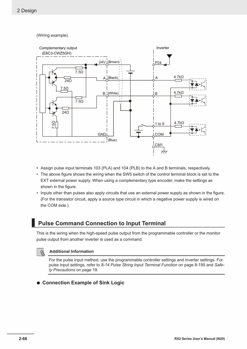
(Wiring example)
P24
B
1 to 9
COM
CM1
4.7kΩ
4.7kΩ
A
4.7kΩ
7.5Ω
24Ω
7.5Ω
24Ω
7.5Ω
7.5
Ω(E6C3-CWZ5GH)
24V
A
B
GND
(Brown)
(Black)
(White)
(Blue)
Complementary output Inverter
• Assign pulse input terminals 103 (PLA) and 104 (PLB) to the A and B terminals, respectively.• The above figure shows the wiring when the SW5 switch of the control terminal block is set to the
EXT external power supply. When using a complementary type encoder, make the settings asshown in the figure.
• Inputs other than pulses also apply circuits that use an external power supply as shown in the figure.(For the transistor circuit, apply a source type circuit in which a negative power supply is wired onthe COM side.)
Pulse Command Connection to Input TerminalThis is the wiring when the high-speed pulse output from the programmable controller or the monitorpulse output from another inverter is used as a command.
Additional Information
For the pulse input method, use the programmable controller settings and inverter settings. Forpulse input settings, refer to 8-14 Pulse String Input Terminal Function on page 8-195 and Safe-ty Precautions on page 19.
l Connection Example of Sink Logic
2 Design
2-66 RX2 Series User’s Manual (I620)
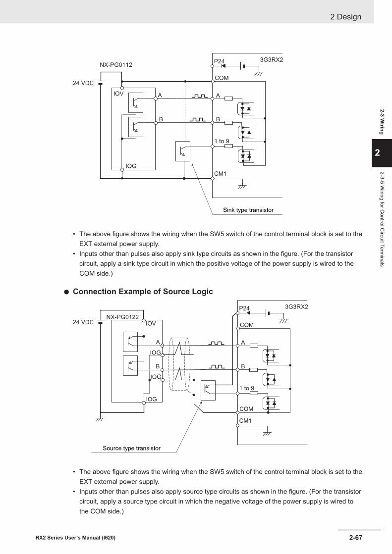
P24
A
B
A
3G3RX2
1 to 9
COM
CM1
IOG
24 VDC
IOV
B
NX-PG0112
Sink type transistor
• The above figure shows the wiring when the SW5 switch of the control terminal block is set to theEXT external power supply.
• Inputs other than pulses also apply sink type circuits as shown in the figure. (For the transistorcircuit, apply a sink type circuit in which the positive voltage of the power supply is wired to theCOM side.)
l Connection Example of Source Logic
P24
A
B
A
3G3RX2
1 to 9
COM
CM1
IOG
24 VDC IOV
B
NX-PG0122
COM
IOG
IOG
Source type transistor
• The above figure shows the wiring when the SW5 switch of the control terminal block is set to theEXT external power supply.
• Inputs other than pulses also apply source type circuits as shown in the figure. (For the transistorcircuit, apply a source type circuit in which the negative voltage of the power supply is wired tothe COM side.)
2 Design
2-67RX2 Series User’s Manual (I620)
2-3 Wiring
2
2-3-5 Wiring for C
ontrol Circuit Term
inals
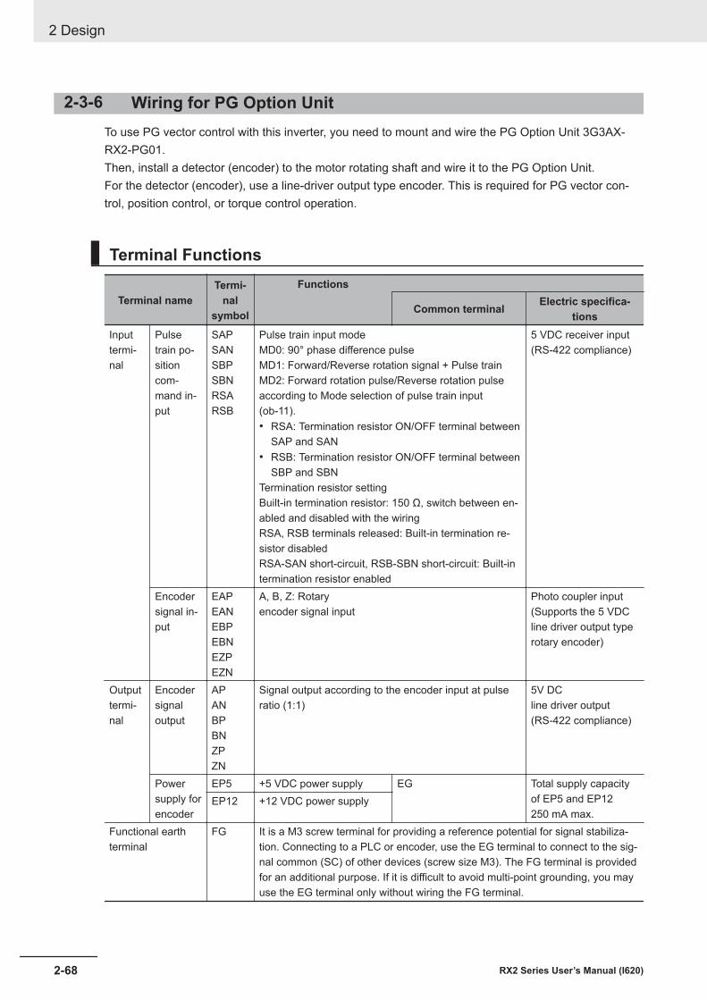
2-3-6 Wiring for PG Option UnitTo use PG vector control with this inverter, you need to mount and wire the PG Option Unit 3G3AX-RX2-PG01.Then, install a detector (encoder) to the motor rotating shaft and wire it to the PG Option Unit.For the detector (encoder), use a line-driver output type encoder. This is required for PG vector con-trol, position control, or torque control operation.
Terminal Functions
Terminal nameTermi-
nalsymbol
Functions
Common terminal Electric specifica-tions
Inputtermi-nal
Pulsetrain po-sitioncom-mand in-put
SAPSANSBPSBNRSARSB
Pulse train input modeMD0: 90° phase difference pulseMD1: Forward/Reverse rotation signal + Pulse trainMD2: Forward rotation pulse/Reverse rotation pulseaccording to Mode selection of pulse train input(ob-11).• RSA: Termination resistor ON/OFF terminal between
SAP and SAN• RSB: Termination resistor ON/OFF terminal between
SBP and SBNTermination resistor settingBuilt-in termination resistor: 150 Ω, switch between en-abled and disabled with the wiringRSA, RSB terminals released: Built-in termination re-sistor disabledRSA-SAN short-circuit, RSB-SBN short-circuit: Built-intermination resistor enabled
5 VDC receiver input(RS-422 compliance)
Encodersignal in-put
EAPEANEBPEBNEZPEZN
A, B, Z: Rotaryencoder signal input
Photo coupler input(Supports the 5 VDCline driver output typerotary encoder)
Outputtermi-nal
Encodersignaloutput
APANBPBNZPZN
Signal output according to the encoder input at pulseratio (1:1)
5V DCline driver output(RS-422 compliance)
Powersupply forencoder
EP5 +5 VDC power supply EG Total supply capacityof EP5 and EP12250 mA max.
EP12 +12 VDC power supply
Functional earthterminal
FG It is a M3 screw terminal for providing a reference potential for signal stabiliza-tion. Connecting to a PLC or encoder, use the EG terminal to connect to the sig-nal common (SC) of other devices (screw size M3). The FG terminal is providedfor an additional purpose. If it is difficult to avoid multi-point grounding, you mayuse the EG terminal only without wiring the FG terminal.
2 Design
2-68 RX2 Series User’s Manual (I620)
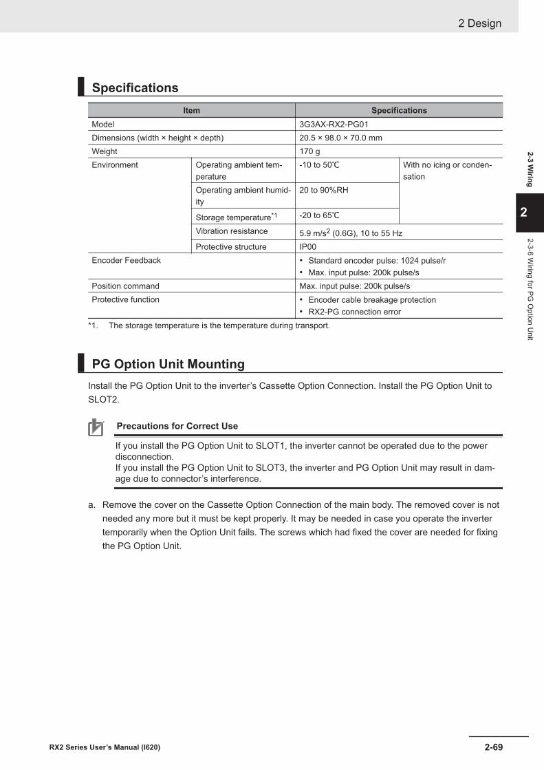
SpecificationsItem Specifications
Model 3G3AX-RX2-PG01Dimensions (width × height × depth) 20.5 × 98.0 × 70.0 mmWeight 170 gEnvironment Operating ambient tem-
perature-10 to 50℃ With no icing or conden-
sationOperating ambient humid-ity
20 to 90%RH
Storage temperature*1 -20 to 65℃Vibration resistance 5.9 m/s2 (0.6G), 10 to 55 HzProtective structure IP00
Encoder Feedback • Standard encoder pulse: 1024 pulse/r• Max. input pulse: 200k pulse/s
Position command Max. input pulse: 200k pulse/sProtective function • Encoder cable breakage protection
• RX2-PG connection error*1. The storage temperature is the temperature during transport.
PG Option Unit MountingInstall the PG Option Unit to the inverter’s Cassette Option Connection. Install the PG Option Unit toSLOT2.
Precautions for Correct Use
If you install the PG Option Unit to SLOT1, the inverter cannot be operated due to the powerdisconnection.If you install the PG Option Unit to SLOT3, the inverter and PG Option Unit may result in dam-age due to connector’s interference.
a. Remove the cover on the Cassette Option Connection of the main body. The removed cover is notneeded any more but it must be kept properly. It may be needed in case you operate the invertertemporarily when the Option Unit fails. The screws which had fixed the cover are needed for fixingthe PG Option Unit.
2 Design
2-69RX2 Series User’s Manual (I620)
2-3 Wiring
2
2-3-6 Wiring for PG
Option U
nit
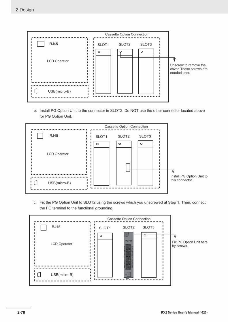
USB(micro-B)
RJ45 SLOT1 SLOT2 SLOT3
LCD Operator
Cassette Option Connection
Unscrew to remove thecover. Those screws areneeded later.
b. Install PG Option Unit to the connector in SLOT2. Do NOT use the other connector located abovefor PG Option Unit.
USB(micro-B)
SLOT1 SLOT2 SLOT3RJ45
LCD Operator
Cassette Option Connection
Install PG Option Unit tothis connector.
c. Fix the PG Option Unit to SLOT2 using the screws which you unscrewed at Step 1. Then, connectthe FG terminal to the functional grounding.
USB(micro-B)
RJ45 SLOT1 SLOT2 SLOT3
Cassette Option Connection
LCD OperatorFix PG Option Unit hereby screws.
2 Design
2-70 RX2 Series User’s Manual (I620)
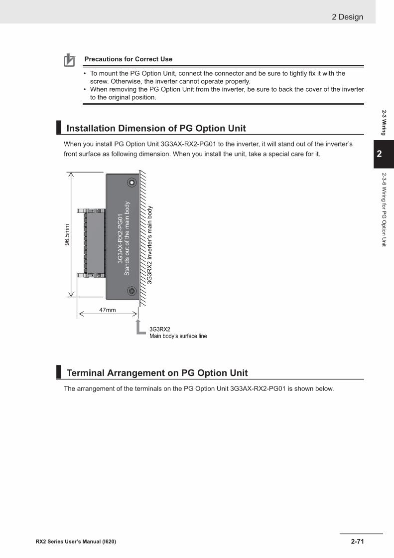
Precautions for Correct Use
• To mount the PG Option Unit, connect the connector and be sure to tightly fix it with thescrew. Otherwise, the inverter cannot operate properly.
• When removing the PG Option Unit from the inverter, be sure to back the cover of the inverterto the original position.
Installation Dimension of PG Option UnitWhen you install PG Option Unit 3G3AX-RX2-PG01 to the inverter, it will stand out of the inverter’sfront surface as following dimension. When you install the unit, take a special care for it.
47mm
96.5
mm
3G
3R
X2
In
ve
rte
r’s m
ain
bo
dy
3G
3A
X-R
X2
-PG
01
Sta
nd
s o
ut
of
the
ma
in b
od
y
3G3RX2Main body’s surface line
Terminal Arrangement on PG Option UnitThe arrangement of the terminals on the PG Option Unit 3G3AX-RX2-PG01 is shown below.
2 Design
2-71RX2 Series User’s Manual (I620)
2-3 Wiring
2
2-3-6 Wiring for PG
Option U
nit
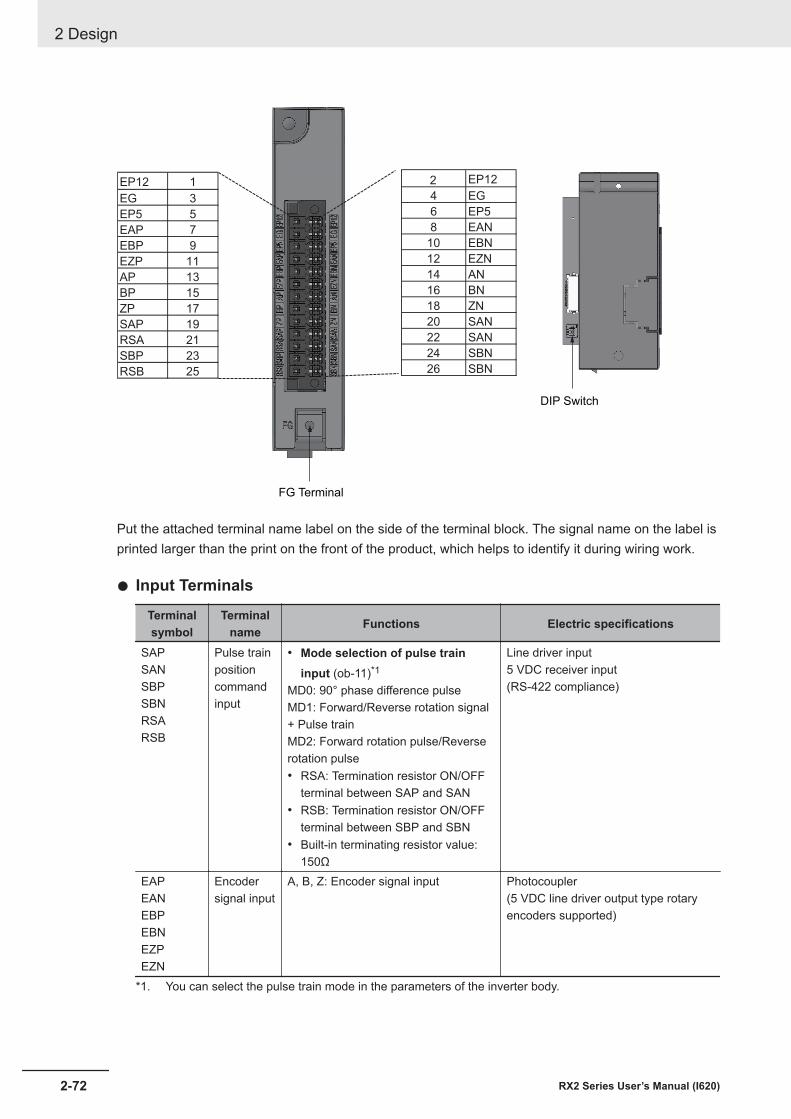
EP12 1 2 EP12
EG 3 4 EG
EP5 5 6 EP5
EAP 7 8 EAN
EBP 9 10 EBN
EZP 11 12 EZN
AP 13 14 AN
BP 15 16 BN
ZP 17 18 ZN
SAP 19 20 SAN
RSA 21 22 SAN
SBP 23 24 SBN
RSB 25 26 SBN
FG Terminal
DIP Switch
Put the attached terminal name label on the side of the terminal block. The signal name on the label isprinted larger than the print on the front of the product, which helps to identify it during wiring work.
l Input Terminals
Terminalsymbol
Terminalname Functions Electric specifications
SAPSANSBPSBNRSARSB
Pulse trainpositioncommandinput
• Mode selection of pulse traininput (ob-11)*1
MD0: 90° phase difference pulseMD1: Forward/Reverse rotation signal+ Pulse trainMD2: Forward rotation pulse/Reverserotation pulse• RSA: Termination resistor ON/OFF
terminal between SAP and SAN• RSB: Termination resistor ON/OFF
terminal between SBP and SBN• Built-in terminating resistor value:
150Ω
Line driver input5 VDC receiver input(RS-422 compliance)
EAPEANEBPEBNEZPEZN
Encodersignal input
A, B, Z: Encoder signal input Photocoupler(5 VDC line driver output type rotaryencoders supported)
*1. You can select the pulse train mode in the parameters of the inverter body.
2 Design
2-72 RX2 Series User’s Manual (I620)
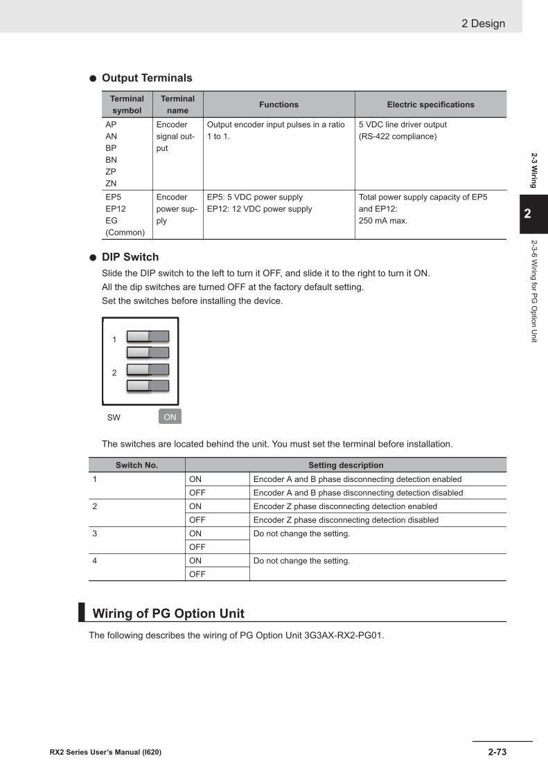
l Output Terminals
Terminalsymbol
Terminalname Functions Electric specifications
APANBPBNZPZN
Encodersignal out-put
Output encoder input pulses in a ratio1 to 1.
5 VDC line driver output(RS-422 compliance)
EP5EP12EG(Common)
Encoderpower sup-ply
EP5: 5 VDC power supplyEP12: 12 VDC power supply
Total power supply capacity of EP5and EP12:250 mA max.
l DIP SwitchSlide the DIP switch to the left to turn it OFF, and slide it to the right to turn it ON.All the dip switches are turned OFF at the factory default setting.Set the switches before installing the device.
1
2
SW ON
The switches are located behind the unit. You must set the terminal before installation.
Switch No. Setting description1 ON Encoder A and B phase disconnecting detection enabled
OFF Encoder A and B phase disconnecting detection disabled2 ON Encoder Z phase disconnecting detection enabled
OFF Encoder Z phase disconnecting detection disabled3 ON Do not change the setting.
OFF4 ON Do not change the setting.
OFF
Wiring of PG Option UnitThe following describes the wiring of PG Option Unit 3G3AX-RX2-PG01.
2 Design
2-73RX2 Series User’s Manual (I620)
2-3 Wiring
2
2-3-6 Wiring for PG
Option U
nit
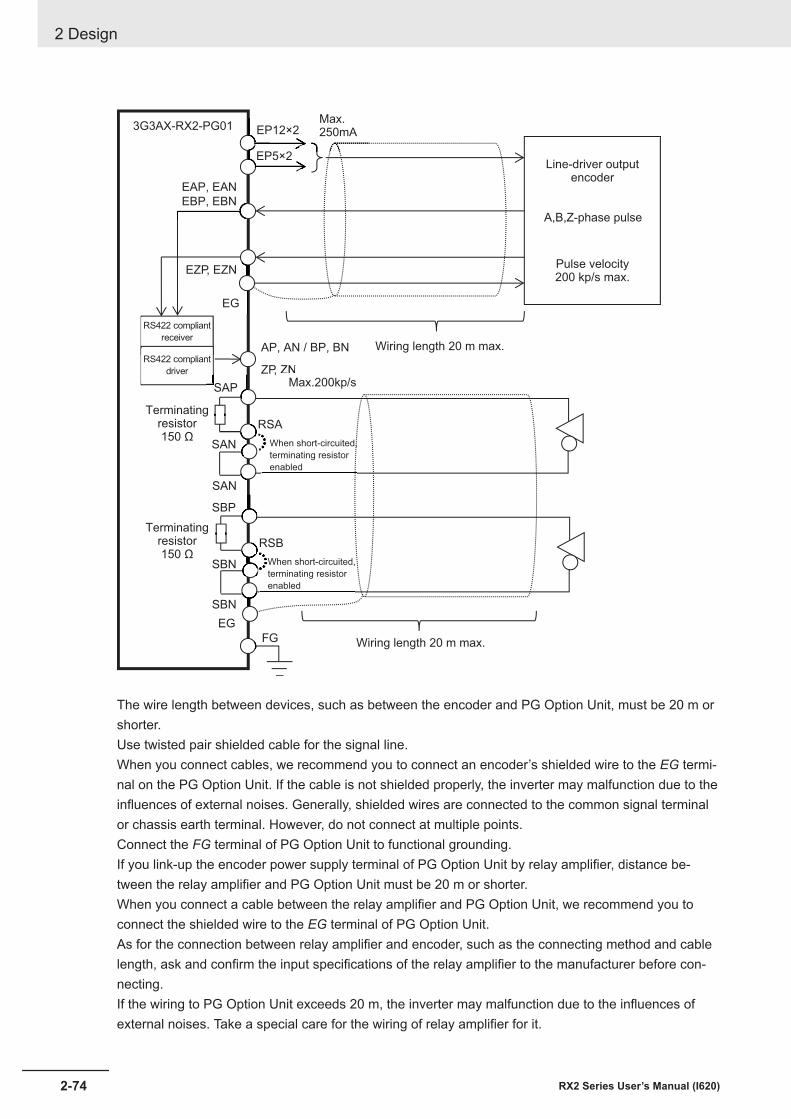
Line-driver outputencoder
A,B,Z-phase pulse
Pulse velocity200 kp/s max.
RS422 compliant
receiverAP, AN / BP, BN
ZP, ZN
EAP, EAN
EBP, EBN
EZP, EZN
EP12×2
EG
3G3AX-RX2-PG01
EP5×2
FG
Max.250mA
ZNMax.200kp/s
RS422 compliant
driver
Wiring length 20 m max.
Wiring length 20 m max.
SAP
RSA
SAN
Terminatingresistor150 Ω
Terminatingresistor150 Ω
SAN
When short-circuited,
terminating resistor
enabled
SBP
RSB
SBN
SBN
When short-circuited,
terminating resistor
enabled
EG
The wire length between devices, such as between the encoder and PG Option Unit, must be 20 m orshorter.Use twisted pair shielded cable for the signal line.When you connect cables, we recommend you to connect an encoder’s shielded wire to the EG termi-nal on the PG Option Unit. If the cable is not shielded properly, the inverter may malfunction due to theinfluences of external noises. Generally, shielded wires are connected to the common signal terminalor chassis earth terminal. However, do not connect at multiple points.Connect the FG terminal of PG Option Unit to functional grounding.If you link-up the encoder power supply terminal of PG Option Unit by relay amplifier, distance be-tween the relay amplifier and PG Option Unit must be 20 m or shorter.When you connect a cable between the relay amplifier and PG Option Unit, we recommend you toconnect the shielded wire to the EG terminal of PG Option Unit.As for the connection between relay amplifier and encoder, such as the connecting method and cablelength, ask and confirm the input specifications of the relay amplifier to the manufacturer before con-necting.If the wiring to PG Option Unit exceeds 20 m, the inverter may malfunction due to the influences ofexternal noises. Take a special care for the wiring of relay amplifier for it.
2 Design
2-74 RX2 Series User’s Manual (I620)
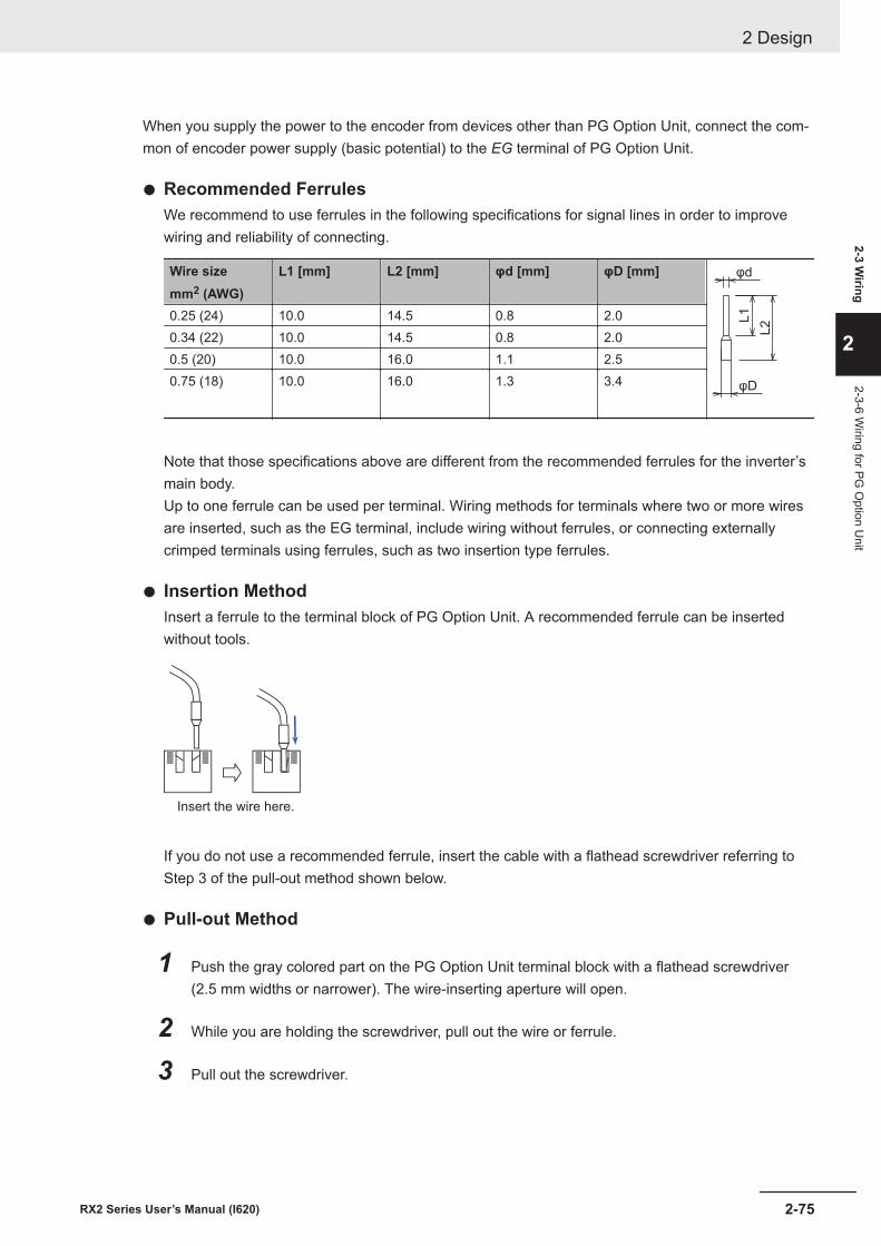
When you supply the power to the encoder from devices other than PG Option Unit, connect the com-mon of encoder power supply (basic potential) to the EG terminal of PG Option Unit.
l Recommended FerrulesWe recommend to use ferrules in the following specifications for signal lines in order to improvewiring and reliability of connecting.
Wire sizemm2 (AWG)
L1 [mm] L2 [mm] φd [mm] φD [mm] φd
φD
L2L10.25 (24) 10.0 14.5 0.8 2.0
0.34 (22) 10.0 14.5 0.8 2.00.5 (20) 10.0 16.0 1.1 2.50.75 (18) 10.0 16.0 1.3 3.4
Note that those specifications above are different from the recommended ferrules for the inverter’smain body.Up to one ferrule can be used per terminal. Wiring methods for terminals where two or more wiresare inserted, such as the EG terminal, include wiring without ferrules, or connecting externallycrimped terminals using ferrules, such as two insertion type ferrules.
l Insertion MethodInsert a ferrule to the terminal block of PG Option Unit. A recommended ferrule can be insertedwithout tools.
Insert the wire here.
If you do not use a recommended ferrule, insert the cable with a flathead screwdriver referring toStep 3 of the pull-out method shown below.
l Pull-out Method
1 Push the gray colored part on the PG Option Unit terminal block with a flathead screwdriver(2.5 mm widths or narrower). The wire-inserting aperture will open.
2 While you are holding the screwdriver, pull out the wire or ferrule.
3 Pull out the screwdriver.
2 Design
2-75RX2 Series User’s Manual (I620)
2-3 Wiring
2
2-3-6 Wiring for PG
Option U
nit
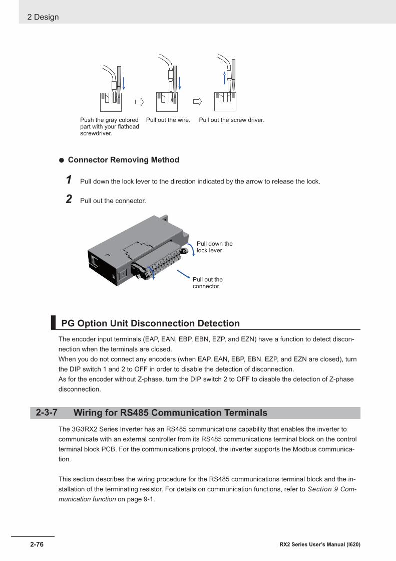
Push the gray coloredpart with your flatheadscrewdriver.
Pull out the wire. Pull out the screw driver.
l Connector Removing Method
1 Pull down the lock lever to the direction indicated by the arrow to release the lock.
2 Pull out the connector.
Pull out the
connector.
Pull down the
lock lever.
PG Option Unit Disconnection DetectionThe encoder input terminals (EAP, EAN, EBP, EBN, EZP, and EZN) have a function to detect discon-nection when the terminals are closed.When you do not connect any encoders (when EAP, EAN, EBP, EBN, EZP, and EZN are closed), turnthe DIP switch 1 and 2 to OFF in order to disable the detection of disconnection.As for the encoder without Z-phase, turn the DIP switch 2 to OFF to disable the detection of Z-phasedisconnection.
2-3-7 Wiring for RS485 Communication TerminalsThe 3G3RX2 Series Inverter has an RS485 communications capability that enables the inverter tocommunicate with an external controller from its RS485 communications terminal block on the controlterminal block PCB. For the communications protocol, the inverter supports the Modbus communica-tion.
This section describes the wiring procedure for the RS485 communications terminal block and the in-stallation of the terminating resistor. For details on communication functions, refer to Section 9 Com-munication function on page 9-1.
2 Design
2-76 RX2 Series User’s Manual (I620)
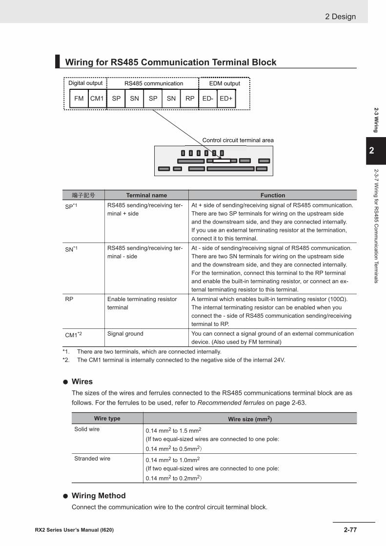
Wiring for RS485 Communication Terminal Block
FM CM1 RPSNSPSNSP ED+ED-
Digital output RS485 communication EDM output
Control circuit terminal area
端子記号 Terminal name Function
SP*1 RS485 sending/receiving ter-minal + side
At + side of sending/receiving signal of RS485 communication.There are two SP terminals for wiring on the upstream sideand the downstream side, and they are connected internally.If you use an external terminating resistor at the termination,connect it to this terminal.
SN*1 RS485 sending/receiving ter-minal - side
At - side of sending/receiving signal of RS485 communication.There are two SN terminals for wiring on the upstream sideand the downstream side, and they are connected internally.For the termination, connect this terminal to the RP terminaland enable the built-in terminating resistor, or connect an ex-ternal terminating resistor to this terminal.
RP Enable terminating resistorterminal
A terminal which enables built-in terminating resistor (100Ω).The internal terminating resistor can be enabled when youconnect the - side of RS485 communication sending/receivingterminal to RP.
CM1*2 Signal ground You can connect a signal ground of an external communicationdevice. (Also used by FM terminal)
*1. There are two terminals, which are connected internally.*2. The CM1 terminal is internally connected to the negative side of the internal 24V.
l WiresThe sizes of the wires and ferrules connected to the RS485 communications terminal block are asfollows. For the ferrules to be used, refer to Recommended ferrules on page 2-63.
Wire type Wire size (mm2)Solid wire 0.14 mm2 to 1.5 mm2
(If two equal-sized wires are connected to one pole:0.14 mm2 to 0.5mm2)
Stranded wire 0.14 mm2 to 1.0mm2
(If two equal-sized wires are connected to one pole:0.14 mm2 to 0.2mm2)
l Wiring MethodConnect the communication wire to the control circuit terminal block.
2 Design
2-77RX2 Series User’s Manual (I620)
2-3 Wiring
2
2-3-7 Wiring for R
S485 Com
munication Term
inals
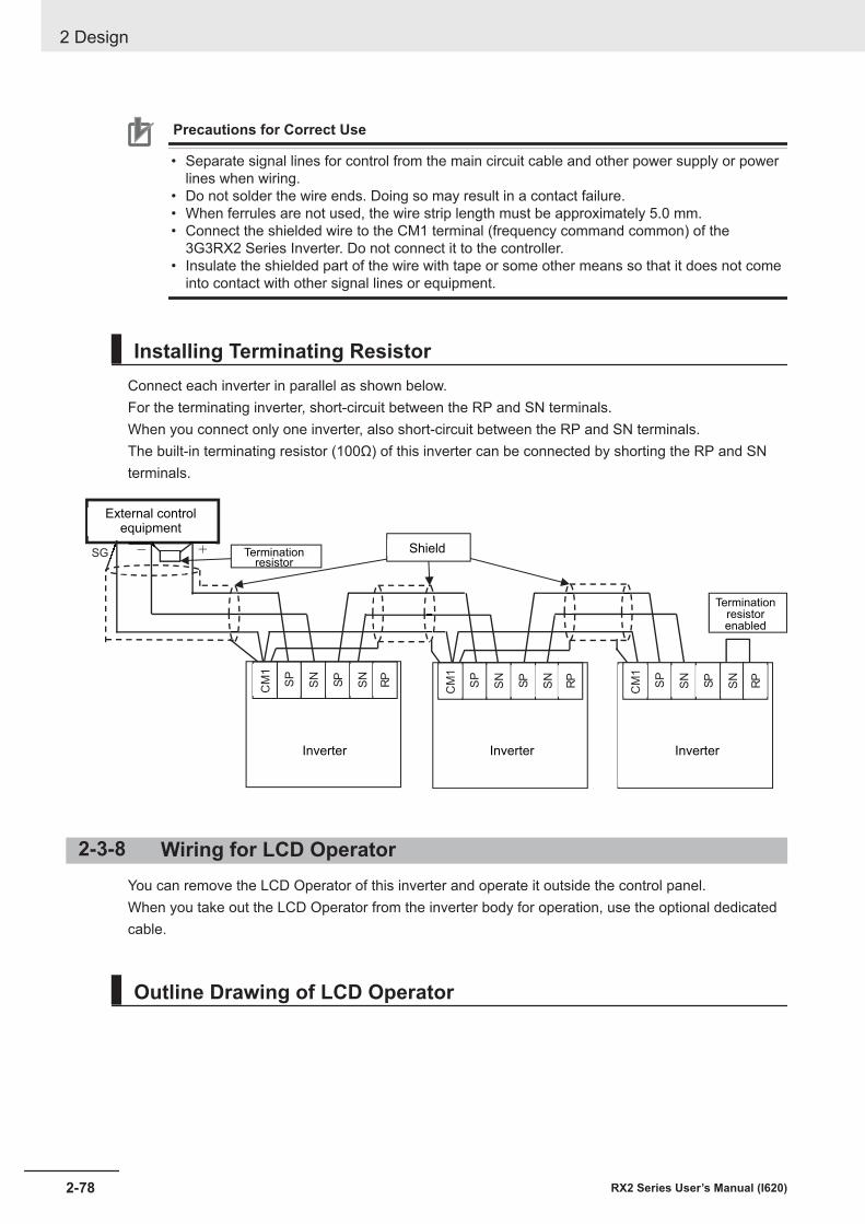
Precautions for Correct Use
• Separate signal lines for control from the main circuit cable and other power supply or powerlines when wiring.
• Do not solder the wire ends. Doing so may result in a contact failure.• When ferrules are not used, the wire strip length must be approximately 5.0 mm.• Connect the shielded wire to the CM1 terminal (frequency command common) of the
3G3RX2 Series Inverter. Do not connect it to the controller.• Insulate the shielded part of the wire with tape or some other means so that it does not come
into contact with other signal lines or equipment.
Installing Terminating ResistorConnect each inverter in parallel as shown below.For the terminating inverter, short-circuit between the RP and SN terminals.When you connect only one inverter, also short-circuit between the RP and SN terminals.The built-in terminating resistor (100Ω) of this inverter can be connected by shorting the RP and SNterminals.
SG - +
インバータ
SP
SN
SP
SN
CM
1
インバータタ
RP
SP
SN
SP
SN
CM
1
RP
SP
SN
SP
SN
CM
1
RP
External controlequipment
Terminationresistor
Shield
Terminationresistorenabled
InverterInverterInverter
2-3-8 Wiring for LCD OperatorYou can remove the LCD Operator of this inverter and operate it outside the control panel.When you take out the LCD Operator from the inverter body for operation, use the optional dedicatedcable.
Outline Drawing of LCD Operator
2 Design
2-78 RX2 Series User’s Manual (I620)
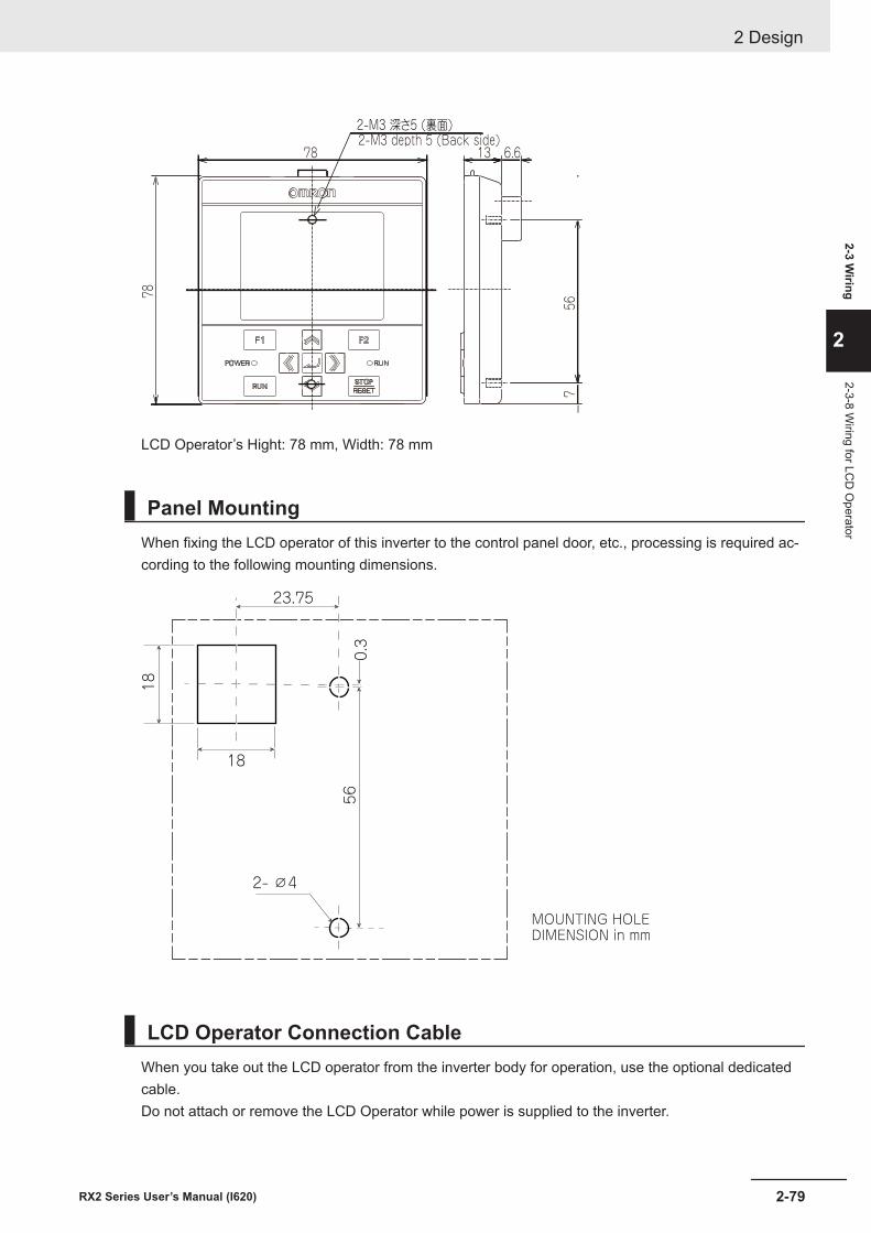
56
13 6.6
7
7878
2-M3 深さ5 (裏面) 2-M3 depth 5 (Back side)
LCD Operator’s Hight: 78 mm, Width: 78 mm
Panel MountingWhen fixing the LCD operator of this inverter to the control panel door, etc., processing is required ac-cording to the following mounting dimensions.
18
18
23.75
0.3
56
2- ∅4
MOUNTING HOLEDIMENSION in mm
LCD Operator Connection CableWhen you take out the LCD operator from the inverter body for operation, use the optional dedicatedcable.Do not attach or remove the LCD Operator while power is supplied to the inverter.
2 Design
2-79RX2 Series User’s Manual (I620)
2-3 Wiring
2
2-3-8 Wiring for LC
D O
perator
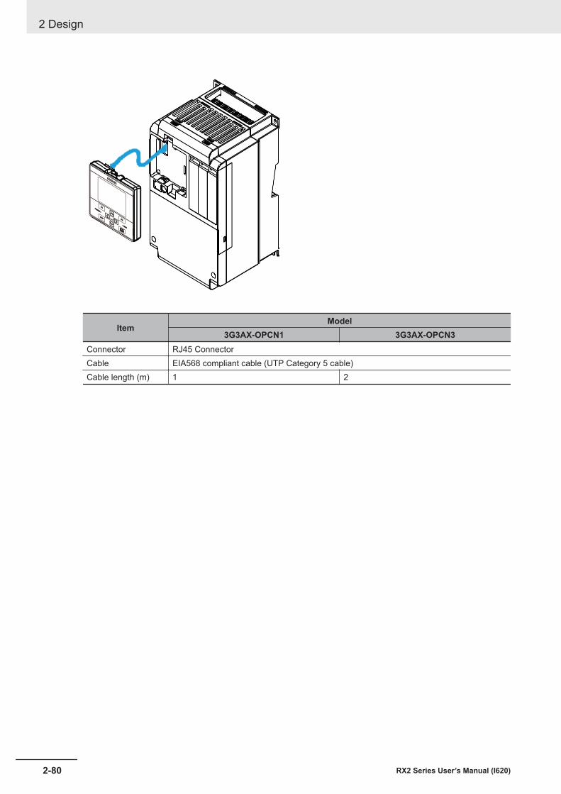
ItemModel
3G3AX-OPCN1 3G3AX-OPCN3Connector RJ45 ConnectorCable EIA568 compliant cable (UTP Category 5 cable)Cable length (m) 1 2
2 Design
2-80 RX2 Series User’s Manual (I620)
2-4 STO Function
2-4-1 Overview of STO FunctionThe 3G3RX2 Series Inverter is equipped with the STO (Safe Torque Off) function defined inIEC61800-5-2.The STO function is used to shut off the motor current with input signals from a safety controller and tostop the motor. This function is equivalent to stop category 0 defined in EN/IEC60204-1.
Precautions for Correct Use
Design• The 3G3RX2 Series Inverter does not feature a function to retain STO status. When STO in-
put is reset, the inverter goes into a state of operation enabled and starts the operation whenoperation command is input.
• Considering the above, configure the system so that the inverter disallows hazardous statuswhen STO input is reset.
• At the factory default setting, the STO function is disabled by short-circuit wires.Installment• Qualified engineers that have enough knowledge about the function safety must install the in-
verter.Wiring• The 3G3RX2 Series Inverter does not feature a function to carry out diagnosis of STO input
signals. Be sure to design the system that can provide 2 inputs normally. As necessary, carryout error diagnosis for input path with EDM signal output.
• STO input signals via two channels outside the inverter shall be separated and protected ap-propriately. No interruption should be made on each signal.
• The cable length for signals connected to ST1/ST2 or EDM terminal shall be each 20m orless.
Test Run• Be sure to conduct a test run to verify the safety system and check the validity. The safety
system without this check cannot be regarded as safe.Maintenance• STO function does not cut off the power supplies for the inverter main circuit and its peripher-
al circuit. When you make maintenance, be sure to separate the system away from the mainpower supply or devices like permanent magnet motors or capacitors to which voltage is like-ly supplied.
• Be sure to carry out the followings to discharge before the maintenance:1. Wait for 10 minutes or more*1 or 15 minutes or more*2 after cutting off power supply.2. Check that voltage between PN terminals is 45V or less after a charge LED goes out
• Be sure to conduct periodic function test every year.Others• Never modify the inverter. The modified inverter is out of conformity with criteria and product
guarantee.*1. In case of 3G3RX2-A2004 to -A2220 and -A4007 to -A4220*2. In case of 3G3RX2-A2300 to -A2550, -A4300 to -A4550, -B4750, -B4900, -B411K, and -B413K
Response TimeResponse time is defined as duration from input of an operation command for safety function to anactivation of the function. In the case of STO function, the response time is duration until the power tothe motor is shut off after STO signal is input.The STO response time of the 3G3RX2 Series Inverter is 10ms or less.
2 Design
2-81RX2 Series User’s Manual (I620)
2-4 STO Function
2
2-4-1 Overview
of STO Function
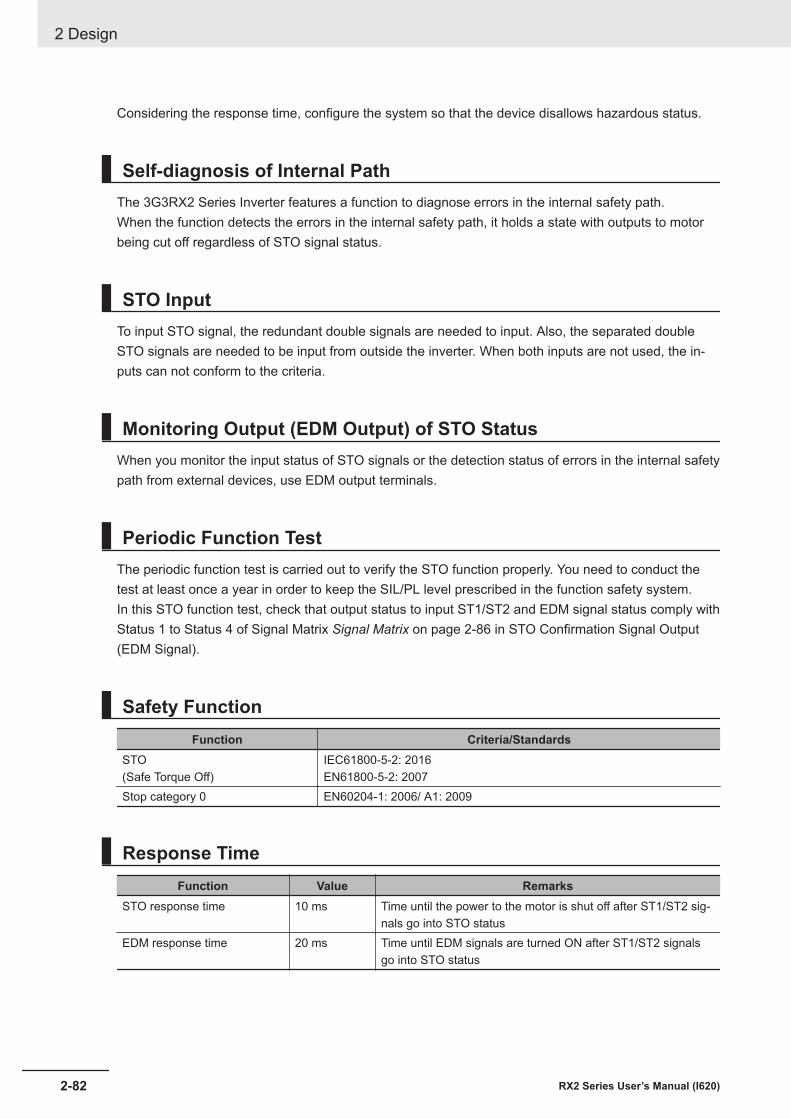
Considering the response time, configure the system so that the device disallows hazardous status.
Self-diagnosis of Internal PathThe 3G3RX2 Series Inverter features a function to diagnose errors in the internal safety path.When the function detects the errors in the internal safety path, it holds a state with outputs to motorbeing cut off regardless of STO signal status.
STO InputTo input STO signal, the redundant double signals are needed to input. Also, the separated doubleSTO signals are needed to be input from outside the inverter. When both inputs are not used, the in-puts can not conform to the criteria.
Monitoring Output (EDM Output) of STO StatusWhen you monitor the input status of STO signals or the detection status of errors in the internal safetypath from external devices, use EDM output terminals.
Periodic Function TestThe periodic function test is carried out to verify the STO function properly. You need to conduct thetest at least once a year in order to keep the SIL/PL level prescribed in the function safety system.In this STO function test, check that output status to input ST1/ST2 and EDM signal status comply withStatus 1 to Status 4 of Signal Matrix Signal Matrix on page 2-86 in STO Confirmation Signal Output(EDM Signal).
Safety FunctionFunction Criteria/Standards
STO(Safe Torque Off)
IEC61800-5-2: 2016EN61800-5-2: 2007
Stop category 0 EN60204-1: 2006/ A1: 2009
Response TimeFunction Value Remarks
STO response time 10 ms Time until the power to the motor is shut off after ST1/ST2 sig-nals go into STO status
EDM response time 20 ms Time until EDM signals are turned ON after ST1/ST2 signalsgo into STO status
2 Design
2-82 RX2 Series User’s Manual (I620)
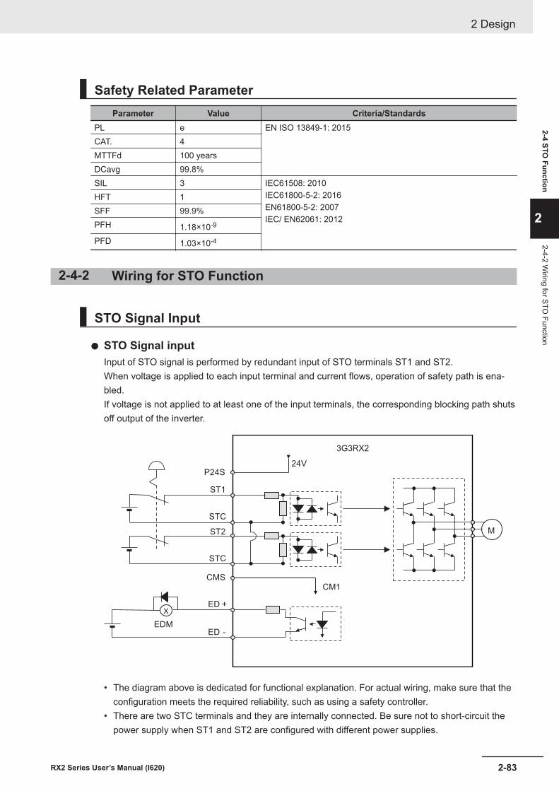
Safety Related ParameterParameter Value Criteria/Standards
PL e EN ISO 13849-1: 2015CAT. 4MTTFd 100 yearsDCavg 99.8%SIL 3 IEC61508: 2010
IEC61800-5-2: 2016EN61800-5-2: 2007IEC/ EN62061: 2012
HFT 1SFF 99.9%PFH 1.18×10⁻⁹
PFD 1.03×10⁻⁴
2-4-2 Wiring for STO Function
STO Signal Input
l STO Signal inputInput of STO signal is performed by redundant input of STO terminals ST1 and ST2.When voltage is applied to each input terminal and current flows, operation of safety path is ena-bled.If voltage is not applied to at least one of the input terminals, the corresponding blocking path shutsoff output of the inverter.
3G3RX2
M
ST1
ST2
STC
EDM
ED -
STC
ED +
24V
P24S
CMS
X
CM1
• The diagram above is dedicated for functional explanation. For actual wiring, make sure that theconfiguration meets the required reliability, such as using a safety controller.
• There are two STC terminals and they are internally connected. Be sure not to short-circuit thepower supply when ST1 and ST2 are configured with different power supplies.
2 Design
2-83RX2 Series User’s Manual (I620)
2-4 STO Function
2
2-4-2 Wiring for STO
Function
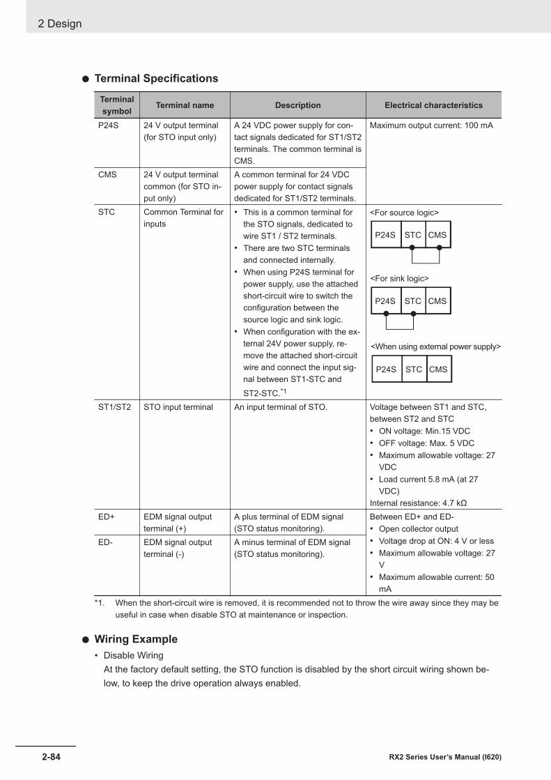
l Terminal Specifications
Terminalsymbol Terminal name Description Electrical characteristics
P24S 24 V output terminal(for STO input only)
A 24 VDC power supply for con-tact signals dedicated for ST1/ST2terminals. The common terminal isCMS.
Maximum output current: 100 mA
CMS 24 V output terminalcommon (for STO in-put only)
A common terminal for 24 VDCpower supply for contact signalsdedicated for ST1/ST2 terminals.
STC Common Terminal forinputs
• This is a common terminal forthe STO signals, dedicated towire ST1 / ST2 terminals.
• There are two STC terminalsand connected internally.
• When using P24S terminal forpower supply, use the attachedshort-circuit wire to switch theconfiguration between thesource logic and sink logic.
• When configuration with the ex-ternal 24V power supply, re-move the attached short-circuitwire and connect the input sig-nal between ST1-STC andST2-STC.*1
<For source logic>
<For sink logic>
<When using external power supply>
CMSSTCP24S
CMSSTCP24S
CMSSTCP24S
ST1/ST2 STO input terminal An input terminal of STO. Voltage between ST1 and STC,between ST2 and STC• ON voltage: Min.15 VDC• OFF voltage: Max. 5 VDC• Maximum allowable voltage: 27
VDC• Load current 5.8 mA (at 27
VDC)Internal resistance: 4.7 kΩ
ED+ EDM signal outputterminal (+)
A plus terminal of EDM signal(STO status monitoring).
Between ED+ and ED-• Open collector output• Voltage drop at ON: 4 V or less• Maximum allowable voltage: 27
V• Maximum allowable current: 50
mA
ED- EDM signal outputterminal (-)
A minus terminal of EDM signal(STO status monitoring).
*1. When the short-circuit wire is removed, it is recommended not to throw the wire away since they may beuseful in case when disable STO at maintenance or inspection.
l Wiring Example• Disable Wiring
At the factory default setting, the STO function is disabled by the short circuit wiring shown be-low, to keep the drive operation always enabled.
2 Design
2-84 RX2 Series User’s Manual (I620)
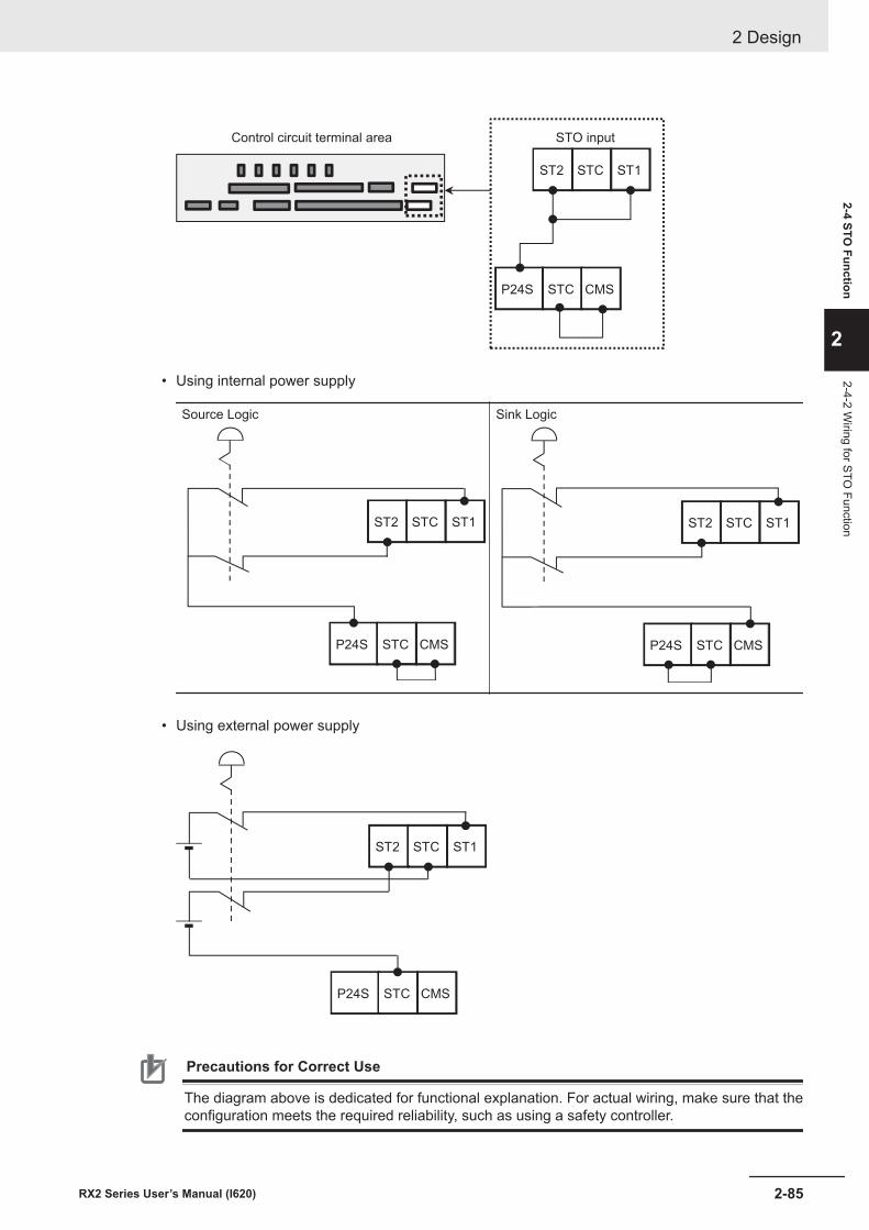
Control circuit terminal area STO input
STCST2 ST1
CMSSTCP24S
• Using internal power supply
Source Logic
STCST2 ST1
CMSSTCP24S
Sink Logic
STCST2 ST1
CMSSTCP24S
• Using external power supply
STCST2 ST1
CMSSTCP24S
Precautions for Correct Use
The diagram above is dedicated for functional explanation. For actual wiring, make sure that theconfiguration meets the required reliability, such as using a safety controller.
2 Design
2-85RX2 Series User’s Manual (I620)
2-4 STO Function
2
2-4-2 Wiring for STO
Function
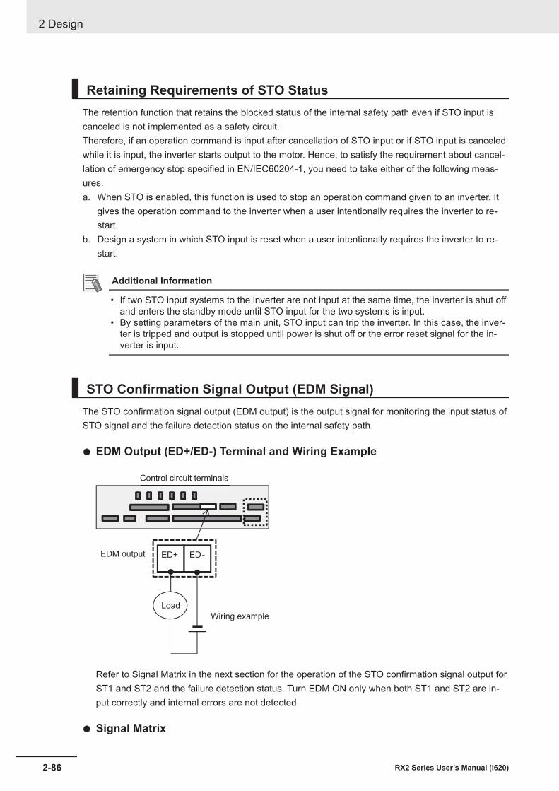
Retaining Requirements of STO StatusThe retention function that retains the blocked status of the internal safety path even if STO input iscanceled is not implemented as a safety circuit.Therefore, if an operation command is input after cancellation of STO input or if STO input is canceledwhile it is input, the inverter starts output to the motor. Hence, to satisfy the requirement about cancel-lation of emergency stop specified in EN/IEC60204-1, you need to take either of the following meas-ures.a. When STO is enabled, this function is used to stop an operation command given to an inverter. It
gives the operation command to the inverter when a user intentionally requires the inverter to re-start.
b. Design a system in which STO input is reset when a user intentionally requires the inverter to re-start.
Additional Information
• If two STO input systems to the inverter are not input at the same time, the inverter is shut offand enters the standby mode until STO input for the two systems is input.
• By setting parameters of the main unit, STO input can trip the inverter. In this case, the inver-ter is tripped and output is stopped until power is shut off or the error reset signal for the in-verter is input.
STO Confirmation Signal Output (EDM Signal)The STO confirmation signal output (EDM output) is the output signal for monitoring the input status ofSTO signal and the failure detection status on the internal safety path.
l EDM Output (ED+/ED-) Terminal and Wiring Example
ED-ED+
Control circuit terminals
Load
Wiring example
EDM output
Refer to Signal Matrix in the next section for the operation of the STO confirmation signal output forST1 and ST2 and the failure detection status. Turn EDM ON only when both ST1 and ST2 are in-put correctly and internal errors are not detected.
l Signal Matrix
2 Design
2-86 RX2 Series User’s Manual (I620)
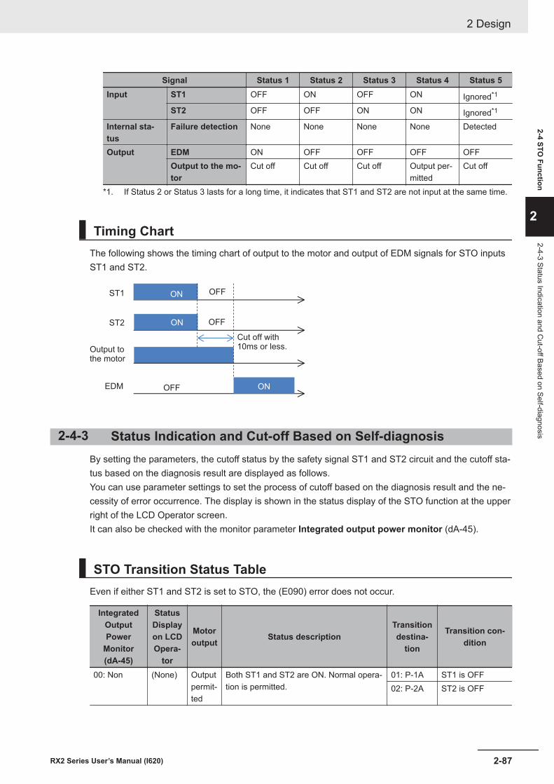
Signal Status 1 Status 2 Status 3 Status 4 Status 5Input ST1 OFF ON OFF ON Ignored*1
ST2 OFF OFF ON ON Ignored*1
Internal sta-tus
Failure detection None None None None Detected
Output EDM ON OFF OFF OFF OFFOutput to the mo-tor
Cut off Cut off Cut off Output per-mitted
Cut off
*1. If Status 2 or Status 3 lasts for a long time, it indicates that ST1 and ST2 are not input at the same time.
Timing ChartThe following shows the timing chart of output to the motor and output of EDM signals for STO inputsST1 and ST2.
ST1
ST2
EDM
ON
ON OFF
OFF
ONOFF
Output tothe motor
Cut off with10ms or less.
2-4-3 Status Indication and Cut-off Based on Self-diagnosisBy setting the parameters, the cutoff status by the safety signal ST1 and ST2 circuit and the cutoff sta-tus based on the diagnosis result are displayed as follows.You can use parameter settings to set the process of cutoff based on the diagnosis result and the ne-cessity of error occurrence. The display is shown in the status display of the STO function at the upperright of the LCD Operator screen.It can also be checked with the monitor parameter Integrated output power monitor (dA-45).
STO Transition Status TableEven if either ST1 and ST2 is set to STO, the (E090) error does not occur.
IntegratedOutputPower
Monitor(dA-45)
StatusDisplayon LCDOpera-
tor
Motoroutput Status description
Transitiondestina-
tion
Transition con-dition
00: Non (None) Outputpermit-ted
Both ST1 and ST2 are ON. Normal opera-tion is permitted.
01: P-1A ST1 is OFF02: P-2A ST2 is OFF
2 Design
2-87RX2 Series User’s Manual (I620)
2-4 STO Function
2
2-4-3 Status Indication and Cut-off Based on Self-diagnosis
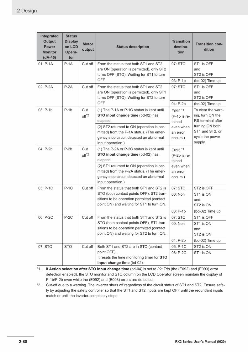
IntegratedOutputPower
Monitor(dA-45)
StatusDisplayon LCDOpera-
tor
Motoroutput Status description
Transitiondestina-
tion
Transition con-dition
01: P-1A P-1A Cut off From the status that both ST1 and ST2are ON (operation is permitted), only ST2turns OFF (STO). Waiting for ST1 to turnOFF.
07: STO ST1 is OFFandST2 is OFF
03: P-1b (bd-02) Time up02: P-2A P-2A Cut off From the status that both ST1 and ST2
are ON (operation is permitted), only ST1turns OFF (STO). Waiting for ST2 to turnOFF.
07: STO ST1 is OFFandST2 is OFF
04: P-2b (bd-02) Time up03: P-1b P-1b Cut
off*2(1) The P-1A or P-1C status is kept untilSTO input change time (bd-02) haselapsed.
E092 *1
(P-1b is re-tainedeven whenan erroroccurs.)
To clear the warn-ing, turn ON theRS terminal afterturning ON bothST1 and ST2, orcycle the powersupply.
(2) ST2 returned to ON (operation is per-mitted) from the P-1A status. (The emer-gency stop circuit detected an abnormalinput operation.)
04: P-2b P-2b Cutoff*2
(1) The P-2A or P-2C status is kept untilSTO input change time (bd-02) haselapsed.
E093 *1
(P-2b is re-tainedeven whenan erroroccurs.)
(2) ST1 returned to ON (operation is per-mitted) from the P-2A status. (The emer-gency stop circuit detected an abnormalinput operation.)
05: P-1C P-1C Cut off From the status that both ST1 and ST2 isSTO (both contact points OFF), ST2 tran-sitions to be operation permitted (contactpoint ON) and waiting for ST1 to turn ON.
07: STO ST2 is OFF00: Non ST1 is ON
andST2 is ON
03: P-1b (bd-02) Time up06: P-2C P-2C Cut off From the status that both ST1 and ST2 is
STO (both contact points OFF), ST1 tran-sitions to be operation permitted (contactpoint ON) and waiting for ST2 to turn ON.
07: STO ST1 is OFF00: Non ST1 is ON
andST2 is ON
04: P-2b (bd-02) Time up07: STO STO Cut off Both ST1 and ST2 are in STO (contact
point OFF).It resets the time monitoring timer for STOinput change time (bd-02).
05: P-1C ST2 is ON06: P-2C ST1 is ON
*1. If Action selection after STO input change time (bd-04) is set to 02: Trip (the (E092) and (E093) errordetection enabled), the STO monitor and STO column on the LCD Operator screen maintain the display ofP-1b/P-2b even while the (E092) and (E093) errors are detected.
*2. Cut-off due to a warning. The inverter shuts off regardless of the circuit status of ST1 and ST2. Ensure safe-ty by adjusting the safety controller so that the ST1 and ST2 inputs are kept OFF until the redundant inputsmatch or until the inverter completely stops.
2 Design
2-88 RX2 Series User’s Manual (I620)
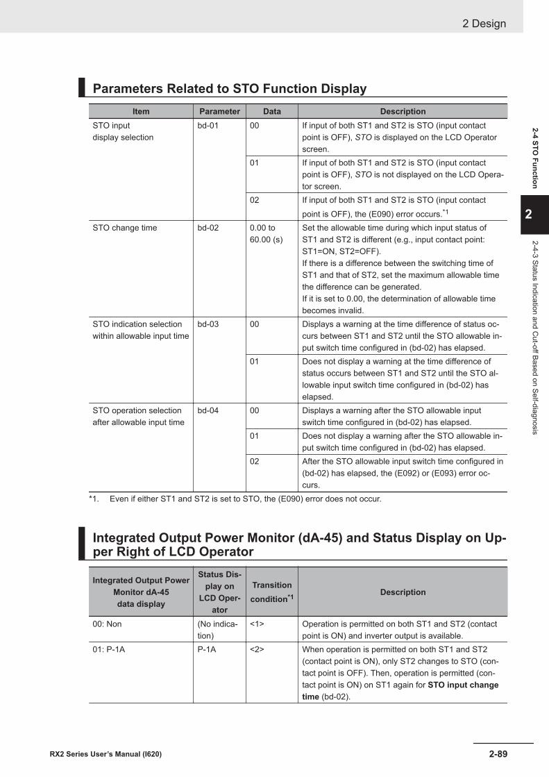
Parameters Related to STO Function DisplayItem Parameter Data Description
STO inputdisplay selection
bd-01 00 If input of both ST1 and ST2 is STO (input contactpoint is OFF), STO is displayed on the LCD Operatorscreen.
01 If input of both ST1 and ST2 is STO (input contactpoint is OFF), STO is not displayed on the LCD Opera-tor screen.
02 If input of both ST1 and ST2 is STO (input contactpoint is OFF), the (E090) error occurs.*1
STO change time bd-02 0.00 to60.00 (s)
Set the allowable time during which input status ofST1 and ST2 is different (e.g., input contact point:ST1=ON, ST2=OFF).If there is a difference between the switching time ofST1 and that of ST2, set the maximum allowable timethe difference can be generated.If it is set to 0.00, the determination of allowable timebecomes invalid.
STO indication selectionwithin allowable input time
bd-03 00 Displays a warning at the time difference of status oc-curs between ST1 and ST2 until the STO allowable in-put switch time configured in (bd-02) has elapsed.
01 Does not display a warning at the time difference ofstatus occurs between ST1 and ST2 until the STO al-lowable input switch time configured in (bd-02) haselapsed.
STO operation selectionafter allowable input time
bd-04 00 Displays a warning after the STO allowable inputswitch time configured in (bd-02) has elapsed.
01 Does not display a warning after the STO allowable in-put switch time configured in (bd-02) has elapsed.
02 After the STO allowable input switch time configured in(bd-02) has elapsed, the (E092) or (E093) error oc-curs.
*1. Even if either ST1 and ST2 is set to STO, the (E090) error does not occur.
Integrated Output Power Monitor (dA-45) and Status Display on Up-per Right of LCD Operator
Integrated Output PowerMonitor dA-45data display
Status Dis-play on
LCD Oper-ator
Transitioncondition*1 Description
00: Non (No indica-tion)
<1> Operation is permitted on both ST1 and ST2 (contactpoint is ON) and inverter output is available.
01: P-1A P-1A <2> When operation is permitted on both ST1 and ST2(contact point is ON), only ST2 changes to STO (con-tact point is OFF). Then, operation is permitted (con-tact point is ON) on ST1 again for STO input changetime (bd-02).
2 Design
2-89RX2 Series User’s Manual (I620)
2-4 STO Function
2
2-4-3 Status Indication and Cut-off Based on Self-diagnosis
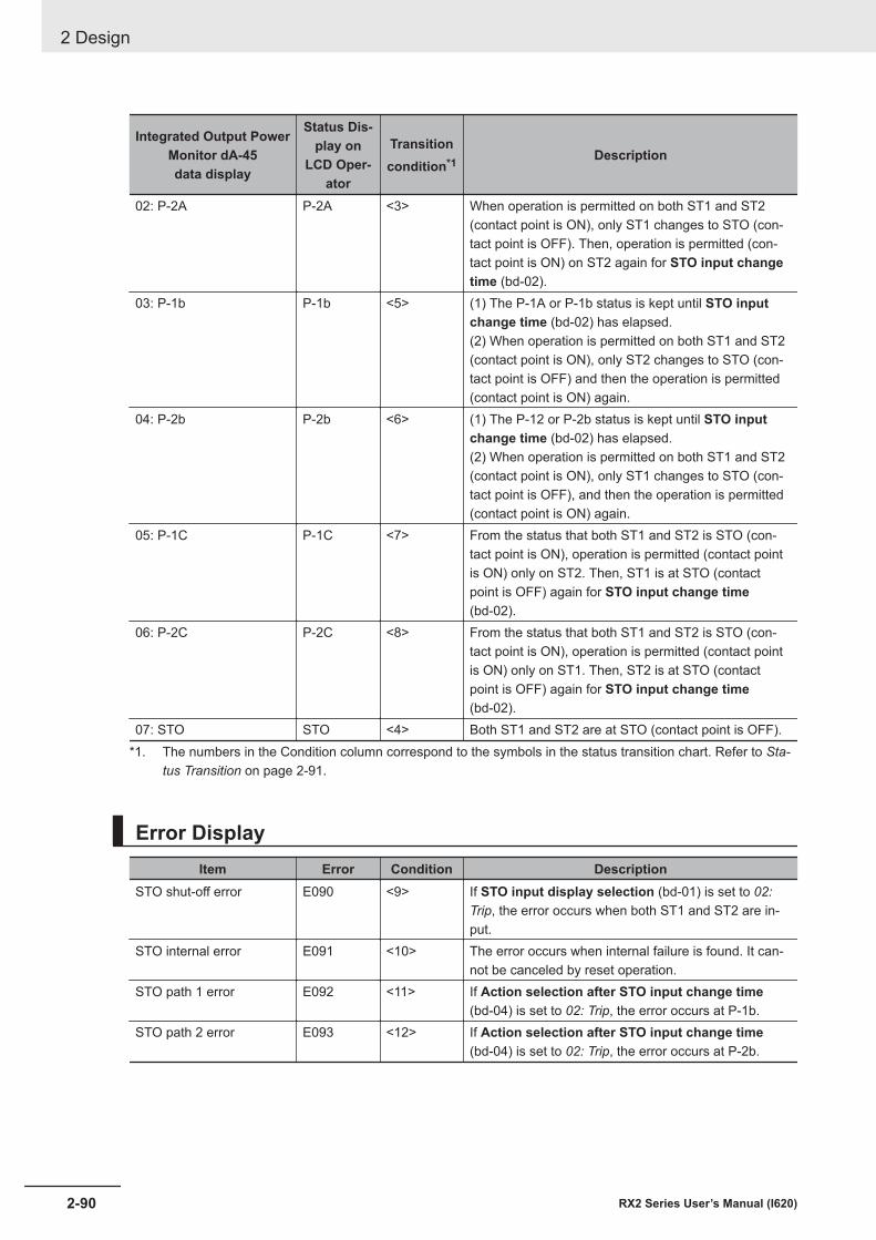
Integrated Output PowerMonitor dA-45data display
Status Dis-play on
LCD Oper-ator
Transitioncondition*1 Description
02: P-2A P-2A <3> When operation is permitted on both ST1 and ST2(contact point is ON), only ST1 changes to STO (con-tact point is OFF). Then, operation is permitted (con-tact point is ON) on ST2 again for STO input changetime (bd-02).
03: P-1b P-1b <5> (1) The P-1A or P-1b status is kept until STO inputchange time (bd-02) has elapsed.(2) When operation is permitted on both ST1 and ST2(contact point is ON), only ST2 changes to STO (con-tact point is OFF) and then the operation is permitted(contact point is ON) again.
04: P-2b P-2b <6> (1) The P-12 or P-2b status is kept until STO inputchange time (bd-02) has elapsed.(2) When operation is permitted on both ST1 and ST2(contact point is ON), only ST1 changes to STO (con-tact point is OFF), and then the operation is permitted(contact point is ON) again.
05: P-1C P-1C <7> From the status that both ST1 and ST2 is STO (con-tact point is ON), operation is permitted (contact pointis ON) only on ST2. Then, ST1 is at STO (contactpoint is OFF) again for STO input change time(bd-02).
06: P-2C P-2C <8> From the status that both ST1 and ST2 is STO (con-tact point is ON), operation is permitted (contact pointis ON) only on ST1. Then, ST2 is at STO (contactpoint is OFF) again for STO input change time(bd-02).
07: STO STO <4> Both ST1 and ST2 are at STO (contact point is OFF).*1. The numbers in the Condition column correspond to the symbols in the status transition chart. Refer to Sta-
tus Transition on page 2-91.
Error DisplayItem Error Condition Description
STO shut-off error E090 <9> If STO input display selection (bd-01) is set to 02:Trip, the error occurs when both ST1 and ST2 are in-put.
STO internal error E091 <10> The error occurs when internal failure is found. It can-not be canceled by reset operation.
STO path 1 error E092 <11> If Action selection after STO input change time(bd-04) is set to 02: Trip, the error occurs at P-1b.
STO path 2 error E093 <12> If Action selection after STO input change time(bd-04) is set to 02: Trip, the error occurs at P-2b.
2 Design
2-90 RX2 Series User’s Manual (I620)
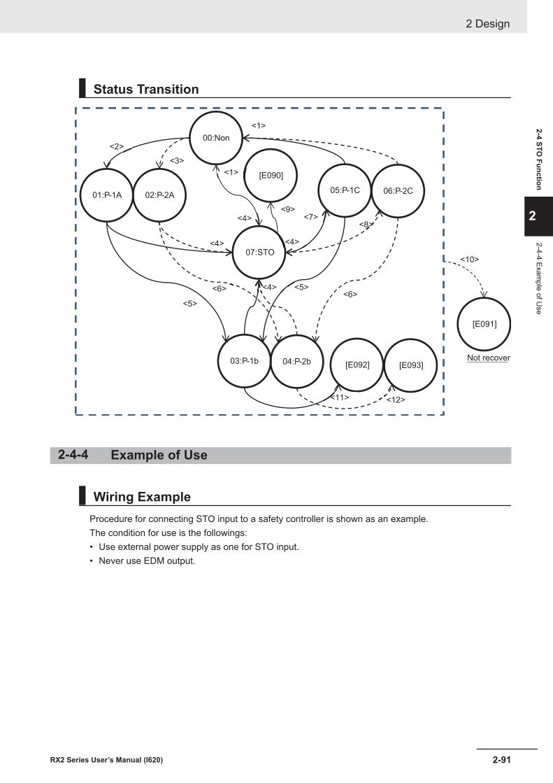
Status Transition
00:Non
03:P-1b
02:P-2A
04:P-2b
[E091]
Not recover
01:P-1A05:P-1C 06:P-2C
07:STO
[E090]
[E092] [E093]
<1>
<2>
<3>
<4>
<5>
<6>
<7><8>
<5><6>
<4>
<1>
<4>
<4>
<9>
<10>
<11> <12>
2-4-4 Example of Use
Wiring ExampleProcedure for connecting STO input to a safety controller is shown as an example.The condition for use is the followings:• Use external power supply as one for STO input.• Never use EDM output.
2 Design
2-91RX2 Series User’s Manual (I620)
2-4 STO Function
2
2-4-4 Example of U
se
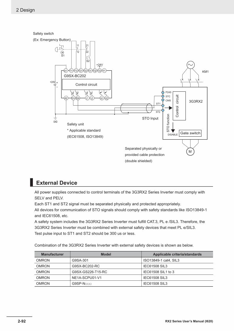
M
P24S
STC
CMS
ST1
ST2
KM1
Gate switch
Co
ntr
ol c
ircuit
ST
O function
DISABLE
S14A2 S24 L1 L2 X1
T11A1 T12 T21 T22 T31 T32 T33 Y1
S2
12
11 21
22
+24V
S1
GND
Control circuit
X2
STO Input
Safety switch
(Ex: Emergency Button)
Safety unit
* Applicable standard
(IEC61508, ISO13849)
Separated physically or
provided cable protection
(double shielded)
3G3RX2
+24V
G9SX-BC202
External DeviceAll power supplies connected to control terminals of the 3G3RX2 Series Inverter must comply withSELV and PELV.Each ST1 and ST2 signal must be separated physically and protected appropriately.All devices for communication of STO signals should comply with safety standards like ISO13849-1and IEC61508, etc.A safety system includes the 3G3RX2 Series Inverter must fulfill CAT.3, PL e /SIL3. Therefore, the3G3RX2 Series Inverter must be combined with external safety devices that meet PL e/SIL3.Test pulse input to ST1 and ST2 should be 300 us or less.
Combination of the 3G3RX2 Series Inverter with external safety devices is shown as below.
Manufacturer Model Applicable criteria/standardsOMRON G9SA-301 ISO13849-1 cat4, SIL3OMRON G9SX-BC202-RC IEC61508 SIL3OMRON G9SX-GS226-T15-RC IEC61508 SIL1 to 3OMRON NE1A-SCPU01-V1 IEC61508 SIL3OMRON G9SP-N□□□ IEC61508 SIL3
2 Design
2-92 RX2 Series User’s Manual (I620)
2-5 Others
2-5-1 Conditions of Conformity of EU DirectivesNote Note of European Directive, Caution for Electrical Safety (Low Voltage Directive (LVD)) on page 2-95, and
Caution for EMC (Electromagnetic Compatibility) on page 2-93 gives priority to the description written inEnglish. Other language description is provided as a reference. Refer to the instruction manual (2824133-4)for English description.
Criteria/StandardsEMC EN 61800-3:2004/A1:2012Machinery EN 61800-5-2:2007 STO SIL3
EN ISO 13849-1:2015 Cat.4 PLeEN 61800-5-1:2007/A1:2017
• This is a product designed for industrial environments.Use in residential area may cause radio wave interference. In that case, the user may be required totake adequate measures to reduce interference.
• This product is not intended to be connected to the power grid that supplies household facilities.
Manufacturer and EU RepresentativeManufacturer:
OMRON CorporationShiokoji Horikawa, Shimogyo-ku, Kyoto, 600-8530 Japan
Representative and Importer in EU:OMRON Europe B.VWegalaan 67-69, 2132 JD Hoofddorp, The Netherlands
GENERAL:The 3G3RX2 Series Inverter is an "open type" AC inverter with three phase input and three phase out-put. It is intended to be used in an enclosure. It is used to provide both an adjustable voltage and ad-justable frequency to the AC motor. The inverter automatically controls the required voltage and fre-quency for motor speed control. It is a multi-rated device, and the ratings are selectable according toload types by the operator with using the LCD Operator.
Caution for EMC (Electromagnetic Compatibility)The 3G3RX2 Series Inverter conforms to requirements of Electromagnetic Compatibility (EMC) Direc-tive (2014/30/EU). However, when using the inverter in Europe, you must comply with the followingspecifications and requirements to meet the EMC Directive and other standards in Europe:
This equipment must be installed, adjusted, and maintained by qualified engineers who have expert knowledge of electric work, inverter operation, and the hazard ouscircumstances thatcan occur. Otherwise, personal injury may result.
WARNING
2 Design
2-93RX2 Series User’s Manual (I620)
2-5 Others
2
2-5-1 Conditions of C
onformity of EU
Directives
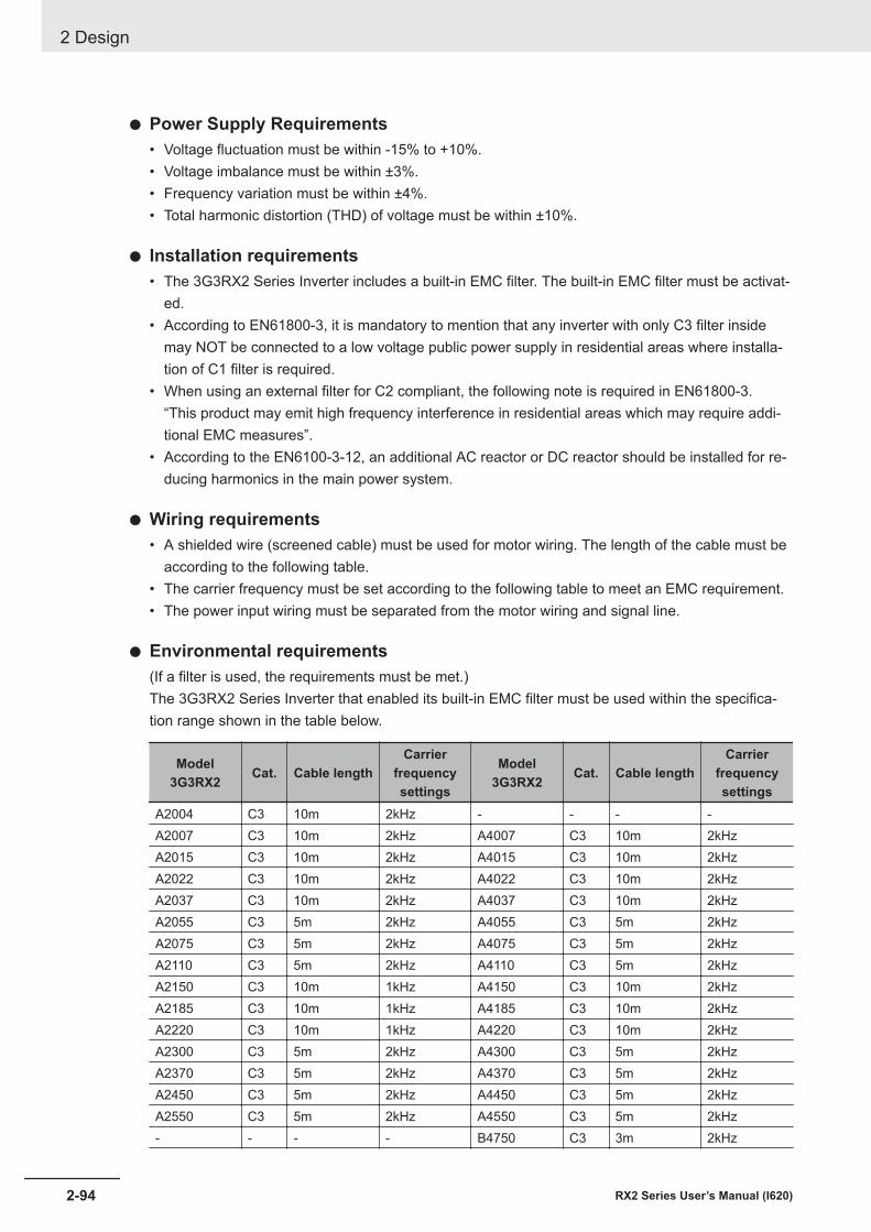
l Power Supply Requirements• Voltage fluctuation must be within -15% to +10%.• Voltage imbalance must be within ±3%.• Frequency variation must be within ±4%.• Total harmonic distortion (THD) of voltage must be within ±10%.
l Installation requirements• The 3G3RX2 Series Inverter includes a built-in EMC filter. The built-in EMC filter must be activat-
ed.• According to EN61800-3, it is mandatory to mention that any inverter with only C3 filter inside
may NOT be connected to a low voltage public power supply in residential areas where installa-tion of C1 filter is required.
• When using an external filter for C2 compliant, the following note is required in EN61800-3.“This product may emit high frequency interference in residential areas which may require addi-tional EMC measures”.
• According to the EN6100-3-12, an additional AC reactor or DC reactor should be installed for re-ducing harmonics in the main power system.
l Wiring requirements• A shielded wire (screened cable) must be used for motor wiring. The length of the cable must be
according to the following table.• The carrier frequency must be set according to the following table to meet an EMC requirement.• The power input wiring must be separated from the motor wiring and signal line.
l Environmental requirements(If a filter is used, the requirements must be met.)The 3G3RX2 Series Inverter that enabled its built-in EMC filter must be used within the specifica-tion range shown in the table below.
Model3G3RX2 Cat. Cable length
Carrierfrequencysettings
Model3G3RX2 Cat. Cable length
Carrierfrequencysettings
A2004 C3 10m 2kHz - - - -A2007 C3 10m 2kHz A4007 C3 10m 2kHzA2015 C3 10m 2kHz A4015 C3 10m 2kHzA2022 C3 10m 2kHz A4022 C3 10m 2kHzA2037 C3 10m 2kHz A4037 C3 10m 2kHzA2055 C3 5m 2kHz A4055 C3 5m 2kHzA2075 C3 5m 2kHz A4075 C3 5m 2kHzA2110 C3 5m 2kHz A4110 C3 5m 2kHzA2150 C3 10m 1kHz A4150 C3 10m 2kHzA2185 C3 10m 1kHz A4185 C3 10m 2kHzA2220 C3 10m 1kHz A4220 C3 10m 2kHzA2300 C3 5m 2kHz A4300 C3 5m 2kHzA2370 C3 5m 2kHz A4370 C3 5m 2kHzA2450 C3 5m 2kHz A4450 C3 5m 2kHzA2550 C3 5m 2kHz A4550 C3 5m 2kHz- - - - B4750 C3 3m 2kHz
2 Design
2-94 RX2 Series User’s Manual (I620)
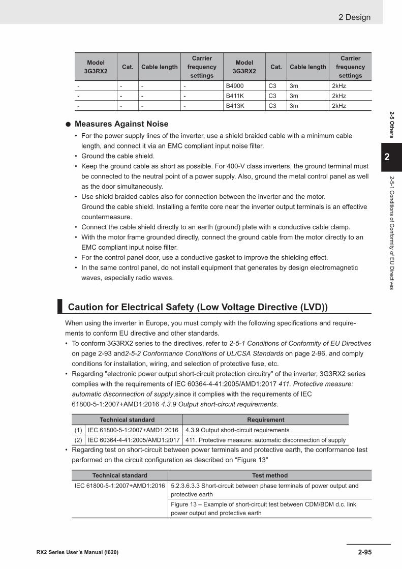
Model3G3RX2 Cat. Cable length
Carrierfrequencysettings
Model3G3RX2 Cat. Cable length
Carrierfrequencysettings
- - - - B4900 C3 3m 2kHz- - - - B411K C3 3m 2kHz- - - - B413K C3 3m 2kHz
l Measures Against Noise• For the power supply lines of the inverter, use a shield braided cable with a minimum cable
length, and connect it via an EMC compliant input noise filter.• Ground the cable shield.• Keep the ground cable as short as possible. For 400-V class inverters, the ground terminal must
be connected to the neutral point of a power supply. Also, ground the metal control panel as wellas the door simultaneously.
• Use shield braided cables also for connection between the inverter and the motor.Ground the cable shield. Installing a ferrite core near the inverter output terminals is an effectivecountermeasure.
• Connect the cable shield directly to an earth (ground) plate with a conductive cable clamp.• With the motor frame grounded directly, connect the ground cable from the motor directly to an
EMC compliant input noise filter.• For the control panel door, use a conductive gasket to improve the shielding effect.• In the same control panel, do not install equipment that generates by design electromagnetic
waves, especially radio waves.
Caution for Electrical Safety (Low Voltage Directive (LVD))When using the inverter in Europe, you must comply with the following specifications and require-ments to conform EU directive and other standards.• To conform 3G3RX2 series to the directives, refer to 2-5-1 Conditions of Conformity of EU Directives
on page 2-93 and2-5-2 Conformance Conditions of UL/CSA Standards on page 2-96, and complyconditions for installation, wiring, and selection of protective fuse, etc.
• Regarding "electronic power output short-circuit protection circuitry" of the inverter, 3G3RX2 seriescomplies with the requirements of IEC 60364-4-41:2005/AMD1:2017 411. Protective measure:automatic disconnection of supply,since it complies with the requirements of IEC61800-5-1:2007+AMD1:2016 4.3.9 Output short-circuit requirements.
Technical standard Requirement(1) IEC 61800-5-1:2007+AMD1:2016 4.3.9 Output short-circuit requirements(2) IEC 60364-4-41:2005/AMD1:2017 411. Protective measure: automatic disconnection of supply
• Regarding test on short-circuit between power terminals and protective earth, the conformance testperformed on the circuit configuration as described on “Figure 13"
Technical standard Test methodIEC 61800-5-1:2007+AMD1:2016 5.2.3.6.3.3 Short-circuit between phase terminals of power output and
protective earthFigure 13 – Example of short-circuit test between CDM/BDM d.c. linkpower output and protective earth
2 Design
2-95RX2 Series User’s Manual (I620)
2-5 Others
2
2-5-1 Conditions of C
onformity of EU
Directives
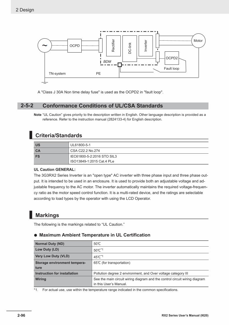
Re
ctifie
r Motor
TN-system
OCPD
Inve
rte
r
DC
-lin
k
PE
BDM
OCPD2
Fault loop
A "Class J 30A Non time delay fuse" is used as the OCPD2 in "fault loop".
2-5-2 Conformance Conditions of UL/CSA StandardsNote “UL Caution” gives priority to the description written in English. Other language description is provided as a
reference. Refer to the instruction manual (2824133-4) for English description.
Criteria/StandardsUS UL61800-5-1CA CSA C22.2 No.274FS IEC61800-5-2:2016 STO SIL3
ISO13849-1:2015 Cat.4 PLe
UL Caution GENERAL:The 3G3RX2 Series Inverter is an "open type" AC inverter with three phase input and three phase out-put. It is intended to be used in an enclosure. It is used to provide both an adjustable voltage and ad-justable frequency to the AC motor. The inverter automatically maintains the required voltage-frequen-cy ratio as the motor speed control function. It is a multi-rated device, and the ratings are selectableaccording to load types by the operator with using the LCD Operator.
MarkingsThe following is the markings related to “UL Caution.”
l Maximum Ambient Temperature in UL Certification
Normal Duty (ND) 50℃Low Duty (LD) 50℃*1
Very Low Duty (VLD) 45℃*1
Storage environment tempera-ture
65℃ (for transportation)
Instruction for installation Pollution degree 2 environment, and Over voltage category IIIWiring See the main circuit wiring diagram and the control circuit wiring diagram
in this User’s Manual.*1. For actual use, use within the temperature range indicated in the common specifications.
2 Design
2-96 RX2 Series User’s Manual (I620)
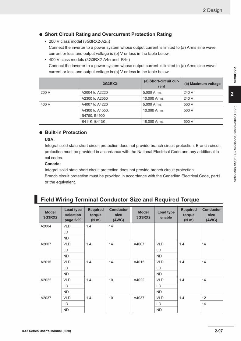
l Short Circuit Rating and Overcurrent Protection Rating• 200 V class model (3G3RX2-A2□)
Connect the inverter to a power system whose output current is limited to (a) Arms sine wavecurrent or less and output voltage is (b) V or less in the table below.
• 400 V class models (3G3RX2-A4□ and -B4□)Connect the inverter to a power system whose output current is limited to (a) Arms sine wavecurrent or less and output voltage is (b) V or less in the table below.
3G3RX2- (a) Short-circuit cur-rent (b) Maximum voltage
200 V A2004 to A2220 5,000 Arms 240 VA2300 to A2550 10,000 Arms 240 V
400 V A4007 to A4220 5,000 Arms 500 VA4300 to A4550,B4750, B4900
10,000 Arms 500 V
B411K, B413K 18,000 Arms 500 V
l Built-in ProtectionUSA:Integral solid state short circuit protection does not provide branch circuit protection. Branch circuitprotection must be provided in accordance with the National Electrical Code and any additional lo-cal codes.Canada:Integral solid state short circuit protection does not provide branch circuit protection.Branch circuit protection must be provided in accordance with the Canadian Electrical Code, part1or the equivalent.
Field Wiring Terminal Conductor Size and Required Torque
Model3G3RX2
Load typeselectionpage 2-99
Requiredtorque(N·m)
Conductorsize
(AWG)
Model3G3RX2
Load typeenable
Requiredtorque(N·m)
Conductorsize
(AWG)A2004 VLD 1.4 14
LDND
A2007 VLD 1.4 14 A4007 VLD 1.4 14LD LDND ND
A2015 VLD 1.4 14 A4015 VLD 1.4 14LD LDND ND
A2022 VLD 1.4 10 A4022 VLD 1.4 14LD LDND ND
A2037 VLD 1.4 10 A4037 VLD 1.4 12LD LD 14ND ND
2 Design
2-97RX2 Series User’s Manual (I620)
2-5 Others
2
2-5-2 Conform
ance Conditions of U
L/CSA Standards
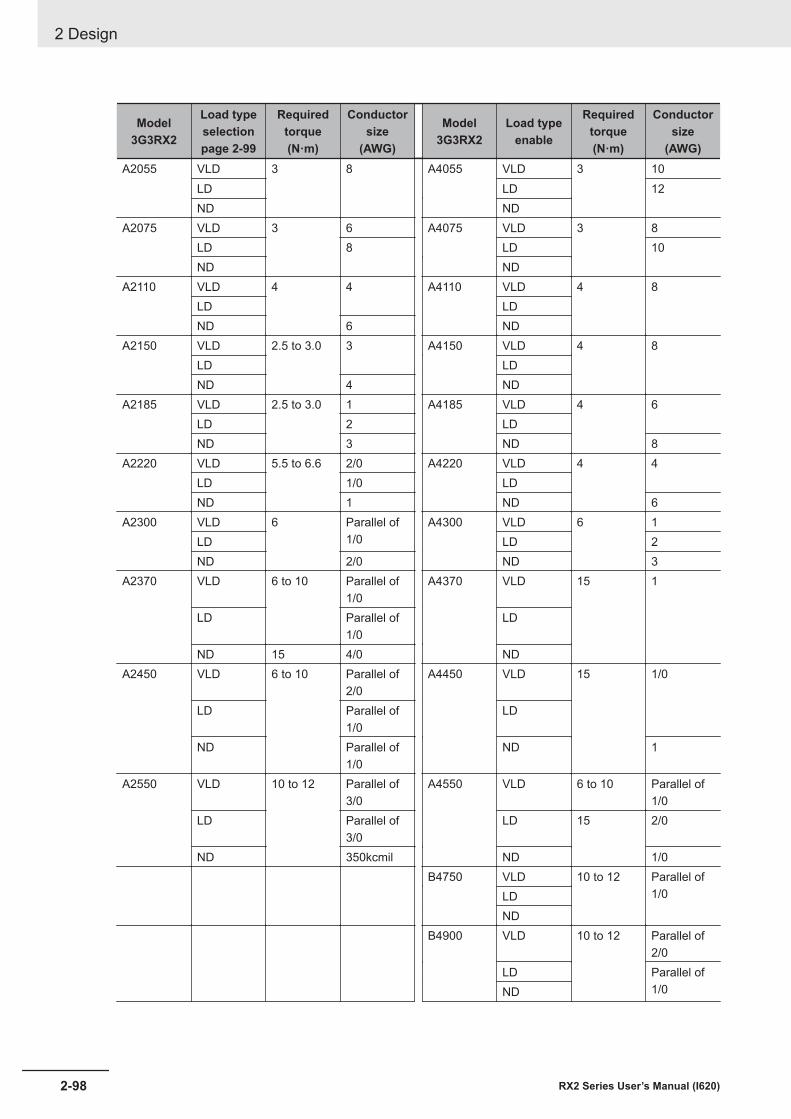
Model3G3RX2
Load typeselectionpage 2-99
Requiredtorque(N·m)
Conductorsize
(AWG)
Model3G3RX2
Load typeenable
Requiredtorque(N·m)
Conductorsize
(AWG)A2055 VLD 3 8 A4055 VLD 3 10
LD LD 12ND ND
A2075 VLD 3 6 A4075 VLD 3 8LD 8 LD 10ND ND
A2110 VLD 4 4 A4110 VLD 4 8LD LDND 6 ND
A2150 VLD 2.5 to 3.0 3 A4150 VLD 4 8LD LDND 4 ND
A2185 VLD 2.5 to 3.0 1 A4185 VLD 4 6LD 2 LDND 3 ND 8
A2220 VLD 5.5 to 6.6 2/0 A4220 VLD 4 4LD 1/0 LDND 1 ND 6
A2300 VLD 6 Parallel of1/0
A4300 VLD 6 1LD LD 2ND 2/0 ND 3
A2370 VLD 6 to 10 Parallel of1/0
A4370 VLD 15 1
LD Parallel of1/0
LD
ND 15 4/0 NDA2450 VLD 6 to 10 Parallel of
2/0A4450 VLD 15 1/0
LD Parallel of1/0
LD
ND Parallel of1/0
ND 1
A2550 VLD 10 to 12 Parallel of3/0
A4550 VLD 6 to 10 Parallel of1/0
LD Parallel of3/0
LD 15 2/0
ND 350kcmil ND 1/0B4750 VLD 10 to 12 Parallel of
1/0LDND
B4900 VLD 10 to 12 Parallel of2/0
LD Parallel of1/0ND
2 Design
2-98 RX2 Series User’s Manual (I620)
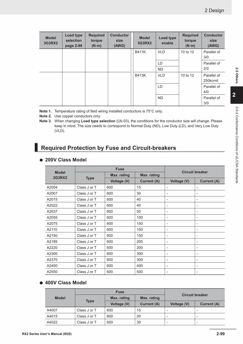
Model3G3RX2
Load typeselectionpage 2-99
Requiredtorque(N·m)
Conductorsize
(AWG)
Model3G3RX2
Load typeenable
Requiredtorque(N·m)
Conductorsize
(AWG)B411K VLD 10 to 12 Parallel of
3/0LD Parallel of
2/0NDB413K VLD 10 to 12 Parallel of
250kcmilLD Parallel of
4/0ND Parallel of
3/0
Note 1. Temperature rating of field wiring installed conductors is 75°C only.Note 2. Use copper conductors only.Note 3. When changing Load type selection (Ub-03), the conditions for the conductor size will change. Please
keep in mind. The size needs to correspond to Normal Duty (ND), Low Duty (LD), and Very Low Duty(VLD).
Required Protection by Fuse and Circuit-breakers
l 200V Class Model
Model3G3RX2
FuseCircuit breaker
TypeMax. rating Max. ratingVoltage (V) Current (A) Voltage (V) Current (A)
A2004 Class J or T 600 15 - -A2007 Class J or T 600 30 - -A2015 Class J or T 600 40 - -A2022 Class J or T 600 40 - -A2037 Class J or T 600 50 - -A2055 Class J or T 600 100 - -A2075 Class J or T 600 150 - -A2110 Class J or T 600 150 - -A2150 Class J or T 600 150 - -A2185 Class J or T 600 200 - -A2220 Class J or T 600 200 - -A2300 Class J or T 600 300 - -A2370 Class J or T 600 300 - -A2450 Class J or T 600 400 - -A2550 Class J or T 600 500 - -
l 400V Class Model
ModelFuse
Circuit breakerType
Max. rating Max. ratingVoltage (V) Current (A) Voltage (V) Current (A)
A4007 Class J or T 600 15 - -A4015 Class J or T 600 20 - -A4022 Class J or T 600 30 - -
2 Design
2-99RX2 Series User’s Manual (I620)
2-5 Others
2
2-5-2 Conform
ance Conditions of U
L/CSA Standards
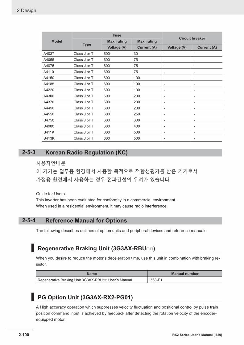
ModelFuse
Circuit breakerType
Max. rating Max. ratingVoltage (V) Current (A) Voltage (V) Current (A)
A4037 Class J or T 600 30 - -A4055 Class J or T 600 75 - -A4075 Class J or T 600 75 - -A4110 Class J or T 600 75 - -A4150 Class J or T 600 100 - -A4185 Class J or T 600 100 - -A4220 Class J or T 600 100 - -A4300 Class J or T 600 200 - -A4370 Class J or T 600 200 - -A4450 Class J or T 600 200 - -A4550 Class J or T 600 250 - -B4750 Class J or T 600 300 - -B4900 Class J or T 600 400 - -B411K Class J or T 600 500 - -B413K Class J or T 600 500 - -
2-5-3 Korean Radio Regulation (KC)
Guide for Users This inverter has been evaluated for conformity in a commercial environment.When used in a residential environment, it may cause radio interference.
2-5-4 Reference Manual for OptionsThe following describes outlines of option units and peripheral devices and reference manuals.
Regenerative Braking Unit (3G3AX-RBU□□)When you desire to reduce the motor’s deceleration time, use this unit in combination with braking re-sistor.
Name Manual numberRegenerative Braking Unit 3G3AX-RBU□□ User’s Manual I563-E1
PG Option Unit (3G3AX-RX2-PG01)A High accuracy operation which suppresses velocity fluctuation and positional control by pulse trainposition command input is achieved by feedback after detecting the rotation velocity of the encoder-equipped motor.
2 Design
2-100 RX2 Series User’s Manual (I620)
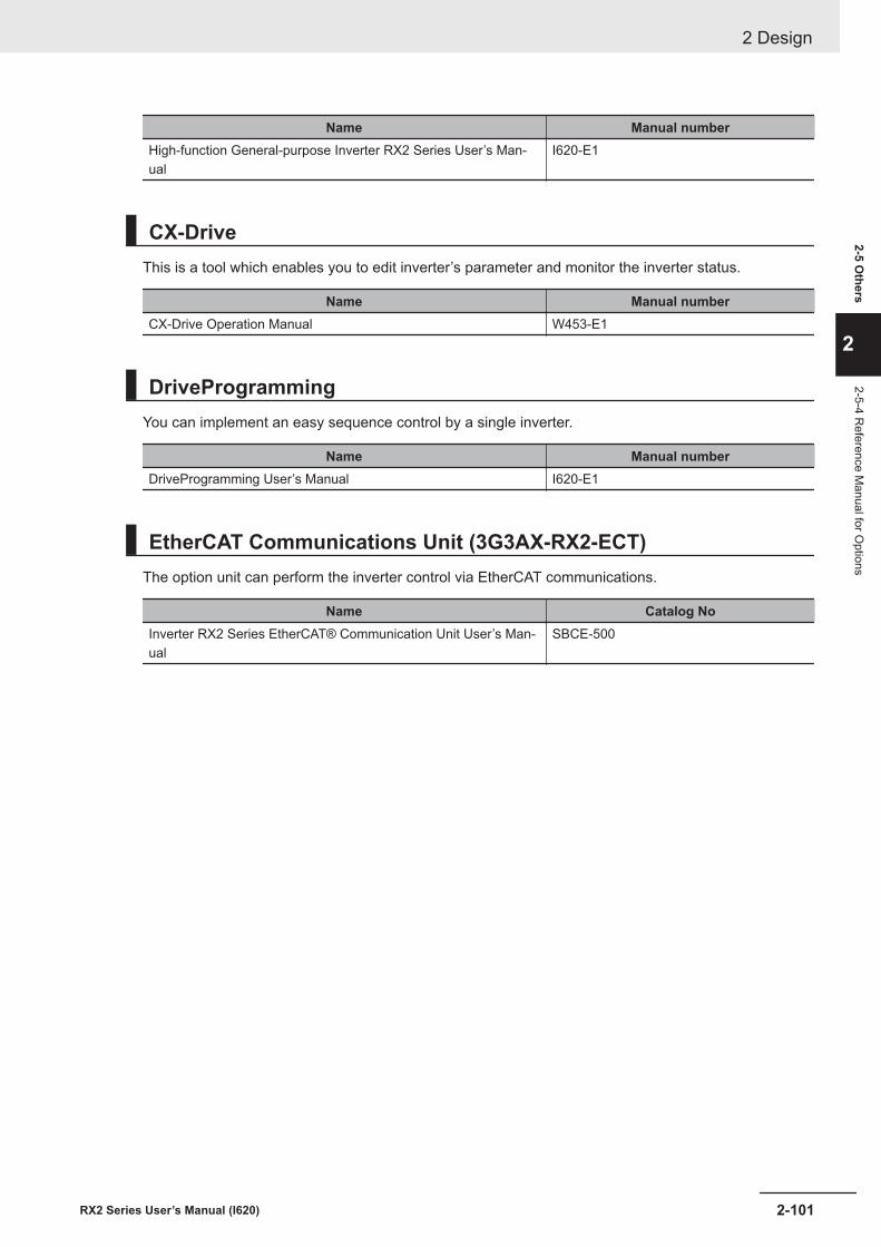
Name Manual numberHigh-function General-purpose Inverter RX2 Series User’s Man-ual
I620-E1
CX-DriveThis is a tool which enables you to edit inverter’s parameter and monitor the inverter status.
Name Manual numberCX-Drive Operation Manual W453-E1
DriveProgrammingYou can implement an easy sequence control by a single inverter.
Name Manual numberDriveProgramming User’s Manual I620-E1
EtherCAT Communications Unit (3G3AX-RX2-ECT)The option unit can perform the inverter control via EtherCAT communications.
Name Catalog NoInverter RX2 Series EtherCAT® Communication Unit User’s Man-ual
SBCE-500
2 Design
2-101RX2 Series User’s Manual (I620)
2-5 Others
2
2-5-4 Reference M
anual for Options

2 Design
2-102 RX2 Series User’s Manual (I620)
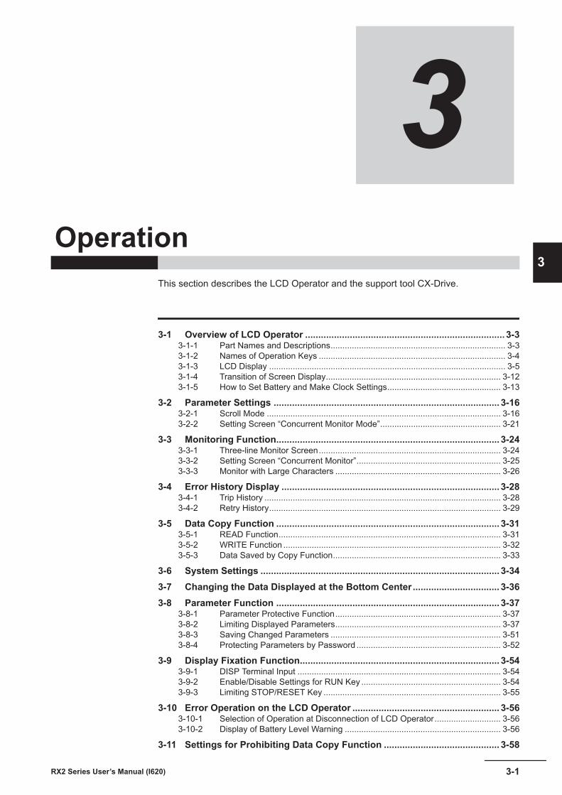
3Operation
This section describes the LCD Operator and the support tool CX-Drive.
3-1 Overview of LCD Operator ............................................................................ 3-33-1-1 Part Names and Descriptions.......................................................................... 3-33-1-2 Names of Operation Keys ............................................................................... 3-43-1-3 LCD Display .................................................................................................... 3-53-1-4 Transition of Screen Display.......................................................................... 3-123-1-5 How to Set Battery and Make Clock Settings................................................ 3-13
3-2 Parameter Settings ...................................................................................... 3-163-2-1 Scroll Mode ................................................................................................... 3-163-2-2 Setting Screen “Concurrent Monitor Mode”................................................... 3-21
3-3 Monitoring Function..................................................................................... 3-243-3-1 Three-line Monitor Screen............................................................................. 3-243-3-2 Setting Screen “Concurrent Monitor”............................................................. 3-253-3-3 Monitor with Large Characters ...................................................................... 3-26
3-4 Error History Display ................................................................................... 3-283-4-1 Trip History .................................................................................................... 3-283-4-2 Retry History.................................................................................................. 3-29
3-5 Data Copy Function ..................................................................................... 3-313-5-1 READ Function.............................................................................................. 3-313-5-2 WRITE Function ............................................................................................ 3-323-5-3 Data Saved by Copy Function....................................................................... 3-33
3-6 System Settings ........................................................................................... 3-343-7 Changing the Data Displayed at the Bottom Center ................................. 3-363-8 Parameter Function ..................................................................................... 3-37
3-8-1 Parameter Protective Function...................................................................... 3-373-8-2 Limiting Displayed Parameters...................................................................... 3-373-8-3 Saving Changed Parameters ........................................................................ 3-513-8-4 Protecting Parameters by Password ............................................................. 3-52
3-9 Display Fixation Function............................................................................ 3-543-9-1 DISP Terminal Input ...................................................................................... 3-543-9-2 Enable/Disable Settings for RUN Key ........................................................... 3-543-9-3 Limiting STOP/RESET Key ........................................................................... 3-55
3-10 Error Operation on the LCD Operator ........................................................ 3-563-10-1 Selection of Operation at Disconnection of LCD Operator............................ 3-563-10-2 Display of Battery Level Warning .................................................................. 3-56
3-11 Settings for Prohibiting Data Copy Function ............................................ 3-58
3-1RX2 Series User’s Manual (I620)
3
3-12 Inverter Initialization .................................................................................... 3-593-13 Connection and Functions of CX-Drive ..................................................... 3-66
3-13-1 CX-Drive Connection Method........................................................................ 3-663-13-2 Outline of CX-Drive ....................................................................................... 3-69
3 Operation
3-2 RX2 Series User’s Manual (I620)
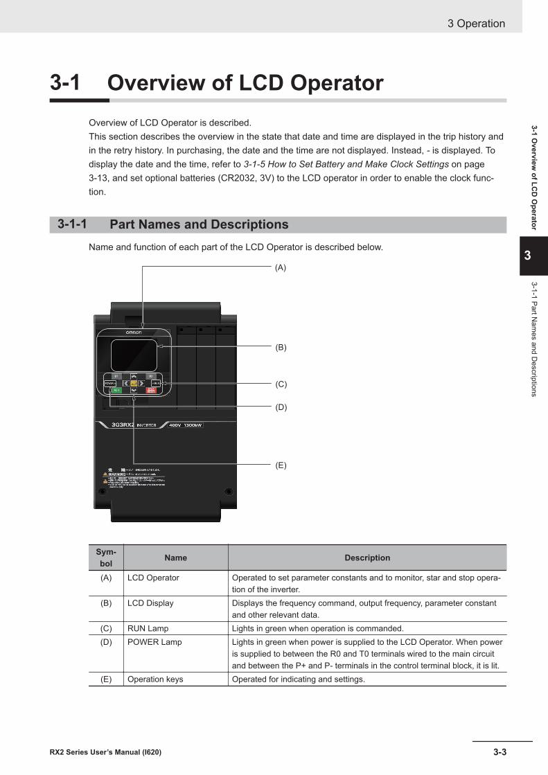
3-1 Overview of LCD OperatorOverview of LCD Operator is described.This section describes the overview in the state that date and time are displayed in the trip history andin the retry history. In purchasing, the date and the time are not displayed. Instead, - is displayed. Todisplay the date and the time, refer to 3-1-5 How to Set Battery and Make Clock Settings on page3-13, and set optional batteries (CR2032, 3V) to the LCD operator in order to enable the clock func-tion.
3-1-1 Part Names and DescriptionsName and function of each part of the LCD Operator is described below.
(A)
(B)
(C)
(D)
(E)
Sym-bol Name Description
(A) LCD Operator Operated to set parameter constants and to monitor, star and stop opera-tion of the inverter.
(B) LCD Display Displays the frequency command, output frequency, parameter constantand other relevant data.
(C) RUN Lamp Lights in green when operation is commanded.(D) POWER Lamp Lights in green when power is supplied to the LCD Operator. When power
is supplied to between the R0 and T0 terminals wired to the main circuitand between the P+ and P- terminals in the control terminal block, it is lit.
(E) Operation keys Operated for indicating and settings.
3 Operation
3-3RX2 Series User’s Manual (I620)
3-1 Overview
of LCD
Operator
3
3-1-1 Part Nam
es and Descriptions
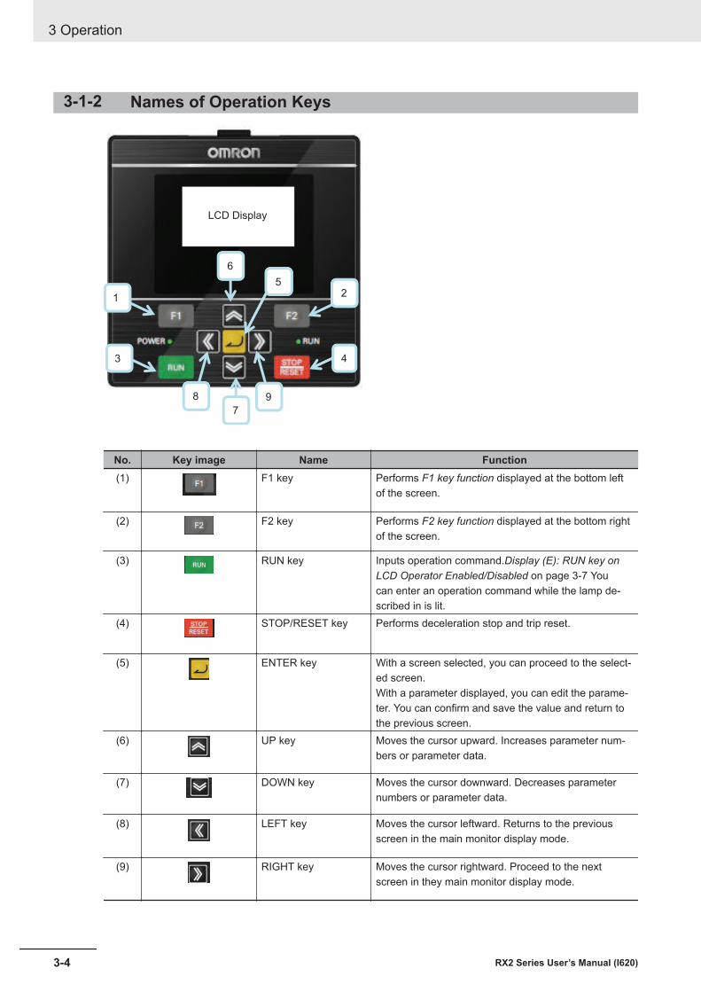
3-1-2 Names of Operation Keys
1
3 4
5
6
7
9
2
8
LCD Display
No. Key image Name Function(1) F1 key Performs F1 key function displayed at the bottom left
of the screen.
(2) F2 key Performs F2 key function displayed at the bottom rightof the screen.
(3) RUN key Inputs operation command.Display (E): RUN key onLCD Operator Enabled/Disabled on page 3-7 Youcan enter an operation command while the lamp de-scribed in is lit.
(4) STOP/RESET key Performs deceleration stop and trip reset.
(5) ENTER key With a screen selected, you can proceed to the select-ed screen.With a parameter displayed, you can edit the parame-ter. You can confirm and save the value and return tothe previous screen.
(6) UP key Moves the cursor upward. Increases parameter num-bers or parameter data.
(7) DOWN key Moves the cursor downward. Decreases parameternumbers or parameter data.
(8) LEFT key Moves the cursor leftward. Returns to the previousscreen in the main monitor display mode.
(9) RIGHT key Moves the cursor rightward. Proceed to the nextscreen in they main monitor display mode.
3 Operation
3-4 RX2 Series User’s Manual (I620)
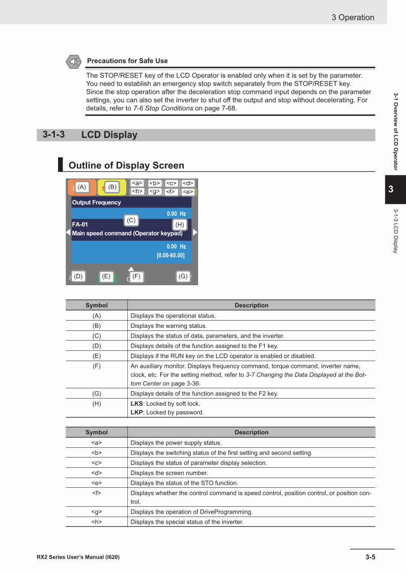
Precautions for Safe Use
The STOP/RESET key of the LCD Operator is enabled only when it is set by the parameter.You need to establish an emergency stop switch separately from the STOP/RESET key.Since the stop operation after the deceleration stop command input depends on the parametersettings, you can also set the inverter to shut off the output and stop without decelerating. Fordetails, refer to 7-6 Stop Conditions on page 7-68.
3-1-3 LCD Display
Outline of Display Screen
メニュー オプション0. 00HoFW
STO
Output Frequency
0.00 Hz
FA-01
Main speed command (Operator keypad)
0.00 Hz
[0.00-60.00]
NRD_
LKS
(A) (B)
(C)
(D) (E) (F) (G)
<a> <b> <c> <d>
<e><f><g><h>
(H)
Symbol Description(A) Displays the operational status.(B) Displays the warning status.(C) Displays the status of data, parameters, and the inverter.(D) Displays details of the function assigned to the F1 key.(E) Displays if the RUN key on the LCD operator is enabled or disabled.(F) An auxiliary monitor. Displays frequency command, torque command, inverter name,
clock, etc. For the setting method, refer to 3-7 Changing the Data Displayed at the Bot-tom Center on page 3-36.
(G) Displays details of the function assigned to the F2 key.(H) LKS: Locked by soft lock.
LKP: Locked by password.
Symbol Description<a> Displays the power supply status.<b> Displays the switching status of the first setting and second setting.<c> Displays the status of parameter display selection.<d> Displays the screen number.<e> Displays the status of the STO function.<f> Displays whether the control command is speed control, position control, or position con-
trol.<g> Displays the operation of DriveProgramming.<h> Displays the special status of the inverter.
3 Operation
3-5RX2 Series User’s Manual (I620)
3-1 Overview
of LCD
Operator
3
3-1-3 LCD
Display
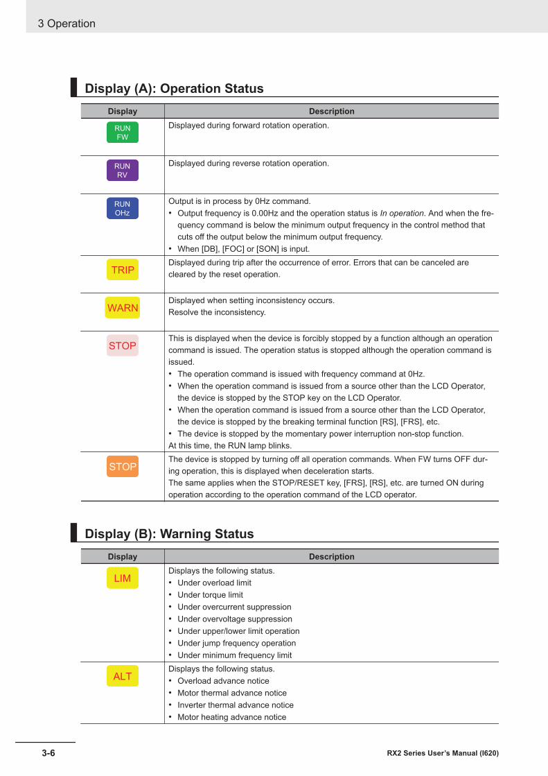
Display (A): Operation StatusDisplay Description
RUN
FW
Displayed during forward rotation operation.
RUN
RV
Displayed during reverse rotation operation.
RUN
OHz
Output is in process by 0Hz command.• Output frequency is 0.00Hz and the operation status is In operation. And when the fre-
quency command is below the minimum output frequency in the control method thatcuts off the output below the minimum output frequency.
• When [DB], [FOC] or [SON] is input.
TRIPDisplayed during trip after the occurrence of error. Errors that can be canceled arecleared by the reset operation.
WARNDisplayed when setting inconsistency occurs.Resolve the inconsistency.
STOPThis is displayed when the device is forcibly stopped by a function although an operationcommand is issued. The operation status is stopped although the operation command isissued.• The operation command is issued with frequency command at 0Hz.• When the operation command is issued from a source other than the LCD Operator,
the device is stopped by the STOP key on the LCD Operator.• When the operation command is issued from a source other than the LCD Operator,
the device is stopped by the breaking terminal function [RS], [FRS], etc.• The device is stopped by the momentary power interruption non-stop function.At this time, the RUN lamp blinks.
STOPThe device is stopped by turning off all operation commands. When FW turns OFF dur-ing operation, this is displayed when deceleration starts.The same applies when the STOP/RESET key, [FRS], [RS], etc. are turned ON duringoperation according to the operation command of the LCD operator.
Display (B): Warning StatusDisplay Description
LIMDisplays the following status.• Under overload limit• Under torque limit• Under overcurrent suppression• Under overvoltage suppression• Under upper/lower limit operation• Under jump frequency operation• Under minimum frequency limit
ALTDisplays the following status.• Overload advance notice• Motor thermal advance notice• Inverter thermal advance notice• Motor heating advance notice
3 Operation
3-6 RX2 Series User’s Manual (I620)
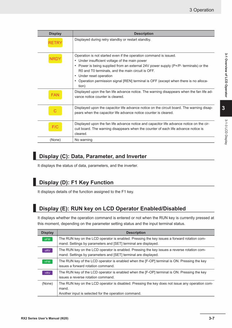
Display Description
RETRYDisplayed during retry standby or restart standby.
NRDYOperation is not started even if the operation command is issued.• Under insufficient voltage of the main power• Power is being supplied from an external 24V power supply (P+/P- terminals) or the
R0 and T0 terminals, and the main circuit is OFF.• Under reset operation• Operation permission signal [REN] terminal is OFF (except when there is no alloca-
tion)
FANDisplayed upon the fan life advance notice. The warning disappears when the fan life ad-vance notice counter is cleared.
CDisplayed upon the capacitor life advance notice on the circuit board. The warning disap-pears when the capacitor life advance notice counter is cleared.
F/CDisplayed upon the fan life advance notice and capacitor life advance notice on the cir-cuit board. The warning disappears when the counter of each life advance notice iscleared.
(None) No warning
Display (C): Data, Parameter, and InverterIt displays the status of data, parameters, and the inverter.
Display (D): F1 Key FunctionIt displays details of the function assigned to the F1 key.
Display (E): RUN key on LCD Operator Enabled/DisabledIt displays whether the operation command is entered or not when the RUN key is currently pressed atthis moment, depending on the parameter setting status and the input terminal status.
Display Description
oFW The RUN key on the LCD operator is enabled. Pressing the key issues a forward rotation com-mand. Settings by parameters and [SET] terminal are displayed.
oRV The RUN key on the LCD operator is enabled. Pressing the key issues a reverse rotation com-mand. Settings by parameters and [SET] terminal are displayed.
>FW The RUN key of the LCD operator is enabled when the [F-OP] terminal is ON. Pressing the keyissues a forward rotation command.
>RV The RUN key of the LCD operator is enabled when the [F-OP] terminal is ON. Pressing the keyissues a reverse rotation command.
(None) The RUN key on the LCD operator is disabled. Pressing the key does not issue any operation com-mand.Another input is selected for the operation command.
3 Operation
3-7RX2 Series User’s Manual (I620)
3-1 Overview
of LCD
Operator
3
3-1-3 LCD
Display
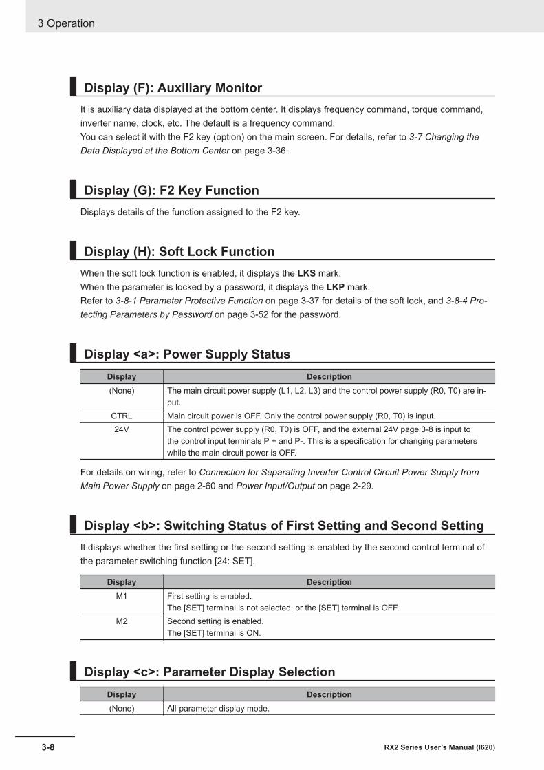
Display (F): Auxiliary MonitorIt is auxiliary data displayed at the bottom center. It displays frequency command, torque command,inverter name, clock, etc. The default is a frequency command.You can select it with the F2 key (option) on the main screen. For details, refer to 3-7 Changing theData Displayed at the Bottom Center on page 3-36.
Display (G): F2 Key FunctionDisplays details of the function assigned to the F2 key.
Display (H): Soft Lock FunctionWhen the soft lock function is enabled, it displays the LKS mark.When the parameter is locked by a password, it displays the LKP mark.Refer to 3-8-1 Parameter Protective Function on page 3-37 for details of the soft lock, and 3-8-4 Pro-tecting Parameters by Password on page 3-52 for the password.
Display <a>: Power Supply StatusDisplay Description(None) The main circuit power supply (L1, L2, L3) and the control power supply (R0, T0) are in-
put.CTRL Main circuit power is OFF. Only the control power supply (R0, T0) is input.24V The control power supply (R0, T0) is OFF, and the external 24V page 3-8 is input to
the control input terminals P + and P-. This is a specification for changing parameterswhile the main circuit power is OFF.
For details on wiring, refer to Connection for Separating Inverter Control Circuit Power Supply fromMain Power Supply on page 2-60 and Power Input/Output on page 2-29.
Display <b>: Switching Status of First Setting and Second SettingIt displays whether the first setting or the second setting is enabled by the second control terminal ofthe parameter switching function [24: SET].
Display DescriptionM1 First setting is enabled.
The [SET] terminal is not selected, or the [SET] terminal is OFF.M2 Second setting is enabled.
The [SET] terminal is ON.
Display <c>: Parameter Display SelectionDisplay Description(None) All-parameter display mode.
3 Operation
3-8 RX2 Series User’s Manual (I620)
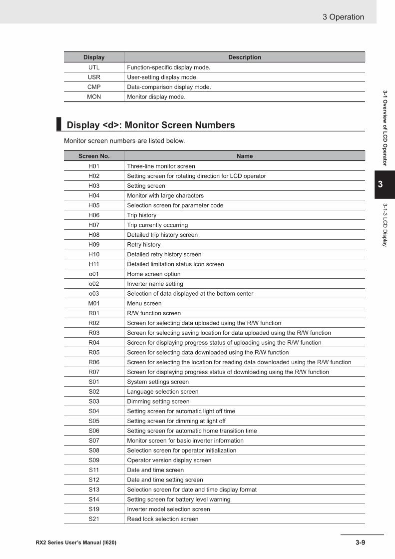
Display DescriptionUTL Function-specific display mode.USR User-setting display mode.CMP Data-comparison display mode.MON Monitor display mode.
Display <d>: Monitor Screen NumbersMonitor screen numbers are listed below.
Screen No. NameH01 Three-line monitor screenH02 Setting screen for rotating direction for LCD operatorH03 Setting screenH04 Monitor with large charactersH05 Selection screen for parameter codeH06 Trip historyH07 Trip currently occurringH08 Detailed trip history screenH09 Retry historyH10 Detailed retry history screenH11 Detailed limitation status icon screeno01 Home screen optiono02 Inverter name settingo03 Selection of data displayed at the bottom centerM01 Menu screenR01 R/W function screenR02 Screen for selecting data uploaded using the R/W functionR03 Screen for selecting saving location for data uploaded using the R/W functionR04 Screen for displaying progress status of uploading using the R/W functionR05 Screen for selecting data downloaded using the R/W functionR06 Screen for selecting the location for reading data downloaded using the R/W functionR07 Screen for displaying progress status of downloading using the R/W functionS01 System settings screenS02 Language selection screenS03 Dimming setting screenS04 Setting screen for automatic light off timeS05 Setting screen for dimming at light offS06 Setting screen for automatic home transition timeS07 Monitor screen for basic inverter informationS08 Selection screen for operator initializationS09 Operator version display screenS11 Date and time screenS12 Date and time setting screenS13 Selection screen for date and time display formatS14 Setting screen for battery level warningS19 Inverter model selection screenS21 Read lock selection screen
3 Operation
3-9RX2 Series User’s Manual (I620)
3-1 Overview
of LCD
Operator
3
3-1-3 LCD
Display
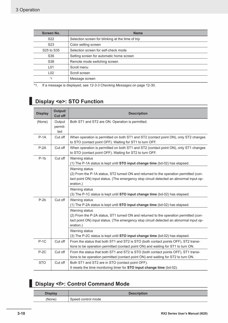
Screen No. NameS22 Selection screen for blinking at the time of tripS23 Color setting screen
S25 to S35 Selection screen for self-check modeS36 Setting screen for automatic home screenS38 Remote mode switching screenL01 Scroll menuL02 Scroll screen
*1 Message screen
*1. If a message is displayed, see 12-3-3 Checking Messages on page 12-30.
Display <e>: STO Function
Display Output/Cut off Description
(None) Outputpermit-
ted
Both ST1 and ST2 are ON. Operation is permitted.
P-1A Cut off When operation is permitted on both ST1 and ST2 (contact point ON), only ST2 changesto STO (contact point OFF). Waiting for ST1 to turn OFF.
P-2A Cut off When operation is permitted on both ST1 and ST2 (contact point ON), only ST1 changesto STO (contact point OFF). Waiting for ST2 to turn OFF.
P-1b Cut off Warning status(1) The P-1A status is kept until STO input change time (bd-02) has elapsed.Warning status(2) From the P-1A status, ST2 turned ON and returned to the operation permitted (con-tact point ON) input status. (The emergency stop circuit detected an abnormal input op-eration.)Warning status(3) The P-1C status is kept until STO input change time (bd-02) has elapsed.
P-2b Cut off Warning status(1) The P-2A status is kept until STO input change time (bd-02) has elapsed.Warning status(2) From the P-2A status, ST1 turned ON and returned to the operation permitted (con-tact point ON) input status. (The emergency stop circuit detected an abnormal input op-eration.)Warning status(3) The P-2C status is kept until STO input change time (bd-02) has elapsed.
P-1C Cut off From the status that both ST1 and ST2 is STO (both contact points OFF), ST2 transi-tions to be operation permitted (contact point ON) and waiting for ST1 to turn ON.
P-2C Cut off From the status that both ST1 and ST2 is STO (both contact points OFF), ST1 transi-tions to be operation permitted (contact point ON) and waiting for ST2 to turn ON.
STO Cut off Both ST1 and ST2 are in STO (contact point OFF).It resets the time monitoring timer for STO input change time (bd-02).
Display <f>: Control Command ModeDisplay Description(None) Speed control mode
3 Operation
3-10 RX2 Series User’s Manual (I620)
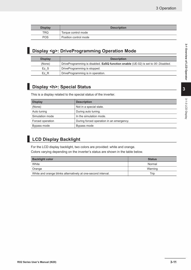
Display DescriptionTRQ Torque control modePOS Position control mode
Display <g>: DriveProgramming Operation ModeDisplay Description(None) DriveProgramming is disabled. EzSQ function enable (UE-02) is set to 00: Disabled.Ez_S DriveProgramming is stopped.Ez_R DriveProgramming is in operation.
Display <h>: Special StatusThis is a display related to the special status of the inverter.
Display Description(None) Not in a special state.Auto tuning During auto tuning.Simulation mode In the simulation mode.Forced operation During forced operation in an emergency.Bypass mode Bypass mode
LCD Display BacklightFor the LCD display backlight, two colors are provided: white and orange.Colors varying depending on the inverter’s status are shown in the table below.
Backlight color StatusWhite NormalOrange WarningWhite and orange blinks alternatively at one-second interval. Trip
3 Operation
3-11RX2 Series User’s Manual (I620)
3-1 Overview
of LCD
Operator
3
3-1-3 LCD
Display
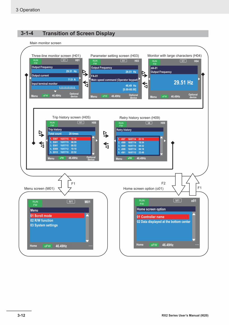
3-1-4 Transition of Screen Display
MenuOptionaldevice46.49HzoFW
RUN
FW
M1 H01
Output Frequency
29.51 Hz
Output current
11.9 A
Input terminal monitor
LLLLLLLLLLL
MenuOptionaldevice
46.49HzoFW
RUN
FW
M1 H03
Output Frequency
29.51 Hz
FA-01
Main speed command (Operator keypad)
46.49 Hz
[0.00-60.00]
MenuOptionaldevice46.49HzoFW
RUN
FW
M1 H04
dA-01
Output Frequency
29.51 Hz
Menu Optionaldevice
46.49HzoFW
RUN
FW
M1 H06
Trip history
Total count 20 times
1. E007 16/07/15 10:10
2. E001 16/07/15 08:55
3. E001 16/07/15 08:52
4. E009 16/07/12 10:10
5. E012 16/07/10 22:52
Home ----46.49HzoFW
RUN
FW
M1 M01
Menu
02 R/W function
03 System settings
Home ----46.49HzoFW
RUN
FW
M1 o01
Home screen option
01 Controller name
02 Data displayed at the bottom center
Menu 46.49HzoFW
M1 H09
Retry history
1. r007 16/07/14 20:10
2. r009 16/07/14 18:54
3. r009 16/07/14 08:32
4. r009 16/07/14 06:18
5. r001 16/07/12 22:49
RUN
FW
01 Scroll mode
Main monitor screen
Three-line monitor screen (H01) Parameter setting screen (H03) Monitor with large characters (H04)
Trip history screen (H05) Retry history screen (H09)
F1
F2F1
Menu screen (M01) Home screen option (o01)
3 Operation
3-12 RX2 Series User’s Manual (I620)
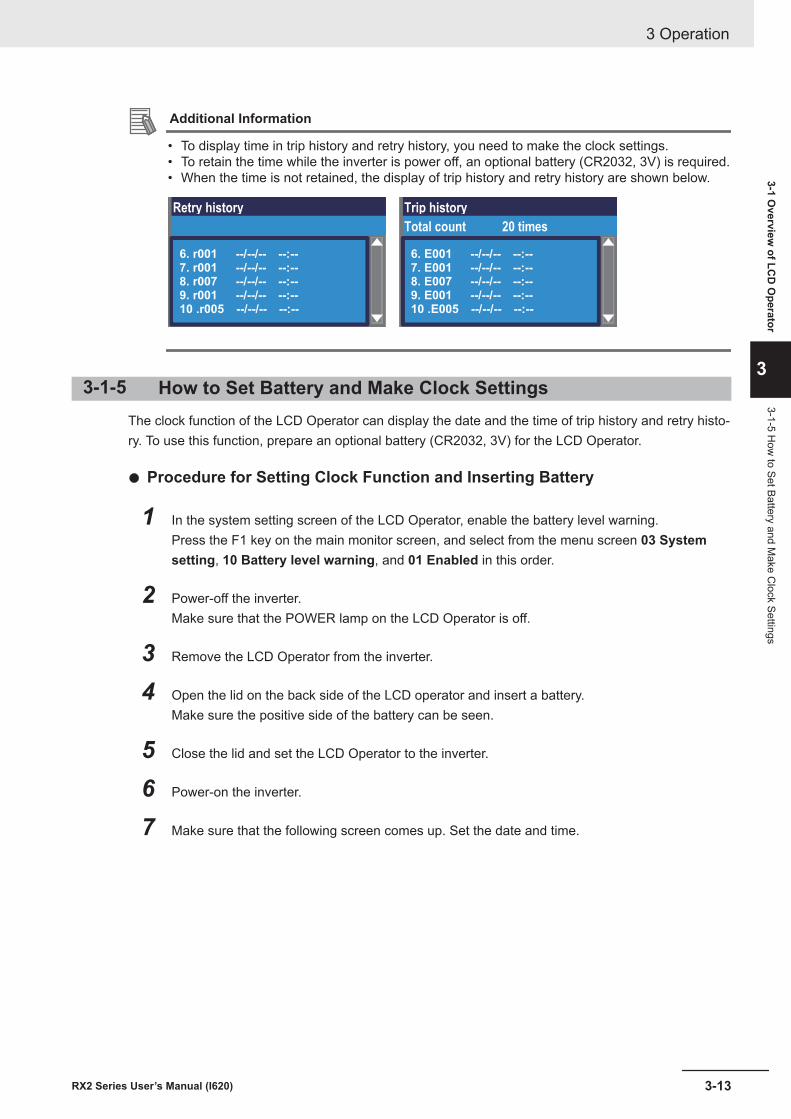
Additional Information
• To display time in trip history and retry history, you need to make the clock settings.• To retain the time while the inverter is power off, an optional battery (CR2032, 3V) is required.• When the time is not retained, the display of trip history and retry history are shown below.
Retry history
6. r001 --/--/-- --:--
7. r001 --/--/-- --:--
8. r007 --/--/-- --:--
9. r001 --/--/-- --:--
10 .r005 --/--/-- --:--
Trip history
Total count 20 times
6. E001 --/--/-- --:--
7. E001 --/--/-- --:--
8. E007 --/--/-- --:--
9. E001 --/--/-- --:--
10 .E005 --/--/-- --:--
3-1-5 How to Set Battery and Make Clock SettingsThe clock function of the LCD Operator can display the date and the time of trip history and retry histo-ry. To use this function, prepare an optional battery (CR2032, 3V) for the LCD Operator.
l Procedure for Setting Clock Function and Inserting Battery
1 In the system setting screen of the LCD Operator, enable the battery level warning.Press the F1 key on the main monitor screen, and select from the menu screen 03 Systemsetting, 10 Battery level warning, and 01 Enabled in this order.
2 Power-off the inverter.Make sure that the POWER lamp on the LCD Operator is off.
3 Remove the LCD Operator from the inverter.
4 Open the lid on the back side of the LCD operator and insert a battery.Make sure the positive side of the battery can be seen.
5 Close the lid and set the LCD Operator to the inverter.
6 Power-on the inverter.
7 Make sure that the following screen comes up. Set the date and time.
3 Operation
3-13RX2 Series User’s Manual (I620)
3-1 Overview
of LCD
Operator
3
3-1-5 How
to Set Battery and Make C
lock Settings
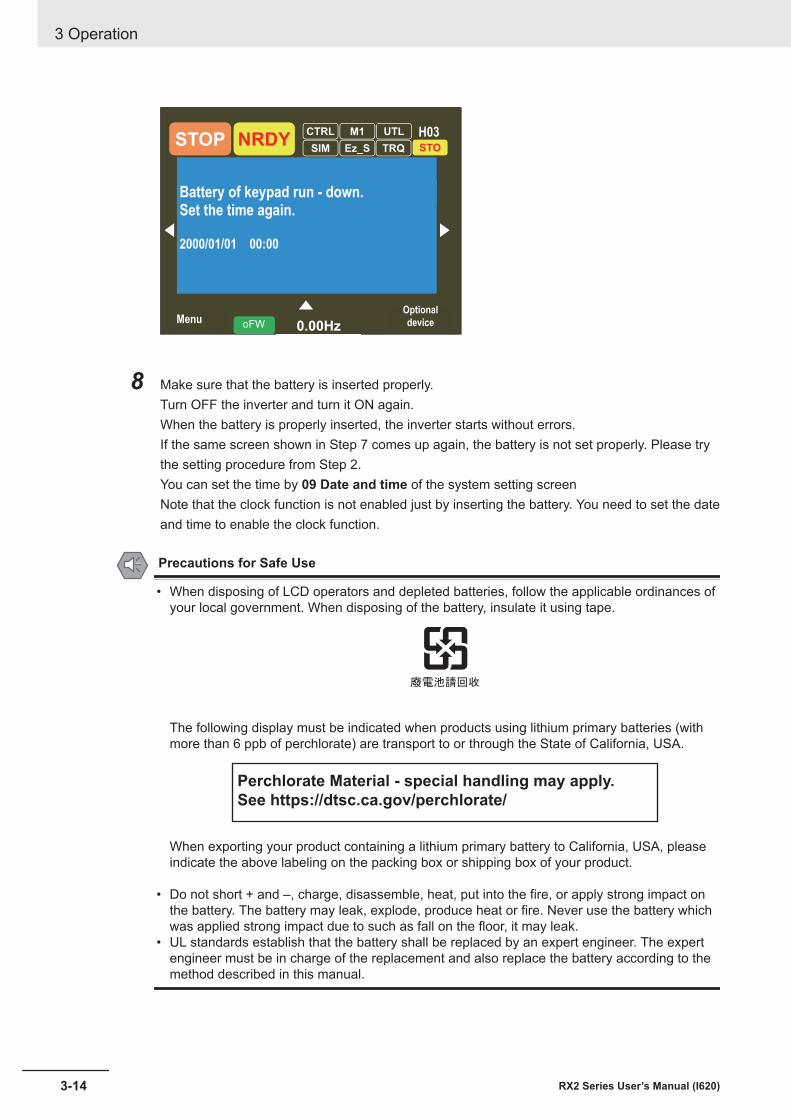
- 60.00]
Optional
device0.00HzoFW
STOPM1 H03
HzBattery of keypad run - down.Set the time again.
2000/01/01 00:00
NRDYCTRL
SIM Ez_S
UTL
TRQ STO
Menu
8 Make sure that the battery is inserted properly.Turn OFF the inverter and turn it ON again.When the battery is properly inserted, the inverter starts without errors.If the same screen shown in Step 7 comes up again, the battery is not set properly. Please trythe setting procedure from Step 2.You can set the time by 09 Date and time of the system setting screenNote that the clock function is not enabled just by inserting the battery. You need to set the dateand time to enable the clock function.
Precautions for Safe Use
• When disposing of LCD operators and depleted batteries, follow the applicable ordinances ofyour local government. When disposing of the battery, insulate it using tape.
The following display must be indicated when products using lithium primary batteries (withmore than 6 ppb of perchlorate) are transport to or through the State of California, USA.
Perchlorate Material - special handling may apply.
See https://dtsc.ca.gov/perchlorate/
When exporting your product containing a lithium primary battery to California, USA, pleaseindicate the above labeling on the packing box or shipping box of your product.
• Do not short + and –, charge, disassemble, heat, put into the fire, or apply strong impact onthe battery. The battery may leak, explode, produce heat or fire. Never use the battery whichwas applied strong impact due to such as fall on the floor, it may leak.
• UL standards establish that the battery shall be replaced by an expert engineer. The expertengineer must be in charge of the replacement and also replace the battery according to themethod described in this manual.
3 Operation
3-14 RX2 Series User’s Manual (I620)

Additional Information
• The parameters and DriveProgramming programs saved in the LCD Operator are retainedeven without batteries.
• If the LCD operator display becomes unrecognizable at the end of its life, replace the LCDOperator.
3 Operation
3-15RX2 Series User’s Manual (I620)
3-1 Overview
of LCD
Operator
3
3-1-5 How
to Set Battery and Make C
lock Settings
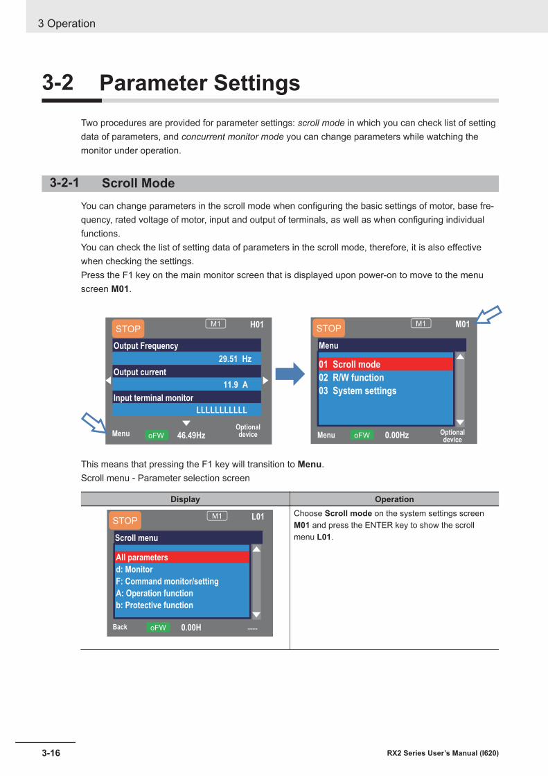
3-2 Parameter SettingsTwo procedures are provided for parameter settings: scroll mode in which you can check list of settingdata of parameters, and concurrent monitor mode you can change parameters while watching themonitor under operation.
3-2-1 Scroll ModeYou can change parameters in the scroll mode when configuring the basic settings of motor, base fre-quency, rated voltage of motor, input and output of terminals, as well as when configuring individualfunctions.You can check the list of setting data of parameters in the scroll mode, therefore, it is also effectivewhen checking the settings.Press the F1 key on the main monitor screen that is displayed upon power-on to move to the menuscreen M01.
Menu Optionaldevice
0.00HzoFW
M1 M01
Menu
01 Scroll mode
02 R/W function
03 System settings
STOP
MenuOptionaldevice46.49HzoFW
M1 H01
Output Frequency
29.51 Hz
Output current
11.9 A
Input terminal monitor
LLLLLLLLLLL
STOP
This means that pressing the F1 key will transition to Menu.Scroll menu - Parameter selection screen
Display Operation
Back ----0.00HoFW
M1 L01
Scroll menu
All parameters
d: Monitor
F: Command monitor/setting
A: Operation function
b: Protective function
STOPChoose Scroll mode on the system settings screenM01 and press the ENTER key to show the scrollmenu L01.
3 Operation
3-16 RX2 Series User’s Manual (I620)
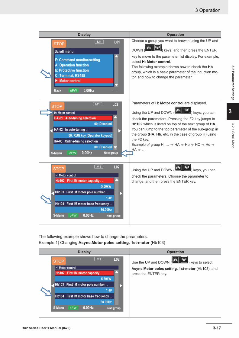
Display Operation
Back ----0.00HzoFW
M1 L01
Scroll menu
F: Command monitor/setting
A: Operation function
b: Protective function
C: Terminal, RS485
H: Motor control
STOPChoose a group you want to browse using the UP and
DOWN ( ) keys, and then press the ENTER
key to move to the parameter list display. For example,select H: Motor control.The following example shows how to check the Hbgroup, which is a basic parameter of the induction mo-tor, and how to change the parameter.
S-Menu Next group0.00HzoFW
M1 L02STOP
H: Motor control
00: Disabled
HA-01 Auto-tuning selection
00: RUN key (Operator keypad)
HA-02 In auto-tuning . .
00: Disabled
HA-03 Online-tuning selection
Parameters of H: Motor control are displayed.
Using the UP and DOWN ( ) keys, you can
check the parameters. Pressing the F2 key jumps toHb102 which is listed on top of the next group of HA.You can jump to the top parameter of the sub-group inthe group (HA, Hb, etc. in the case of group H) usingthe F2 key.Example of group H: … ⇒ HA ⇒ Hb ⇒ HC ⇒ Hd ⇒HA ⇒ …
S-Menu Next group0.00HzoFW
M1 L02STOP
H: Motor control
5.50kW
Hb102 First IM motor capacity . .
1:4P
Hb103 First IM motor pole number . .
60.00Hz
Hb104 First IM motor base frequency . .
Using the UP and DOWN ( ) keys, you can
check the parameters. Choose the parameter tochange, and then press the ENTER key.
The following example shows how to change the parameters.Example 1) Changing Async.Motor poles setting, 1st-motor (Hb103)
Display Operation
S-Menu Next group0.00HzoFW
M1 L02STOP
H: Motor control
5.50kW
Hb102 First IM motor capacity . .
1:4P
Hb103 First IM motor pole number . .
60.00Hz
Hb104 First IM motor base frequency . .
Use the UP and DOWN ( ) keys to select
Async.Motor poles setting, 1st-motor (Hb103), andpress the ENTER key.
3 Operation
3-17RX2 Series User’s Manual (I620)
3-2 Parameter Settings
3
3-2-1 Scroll Mode
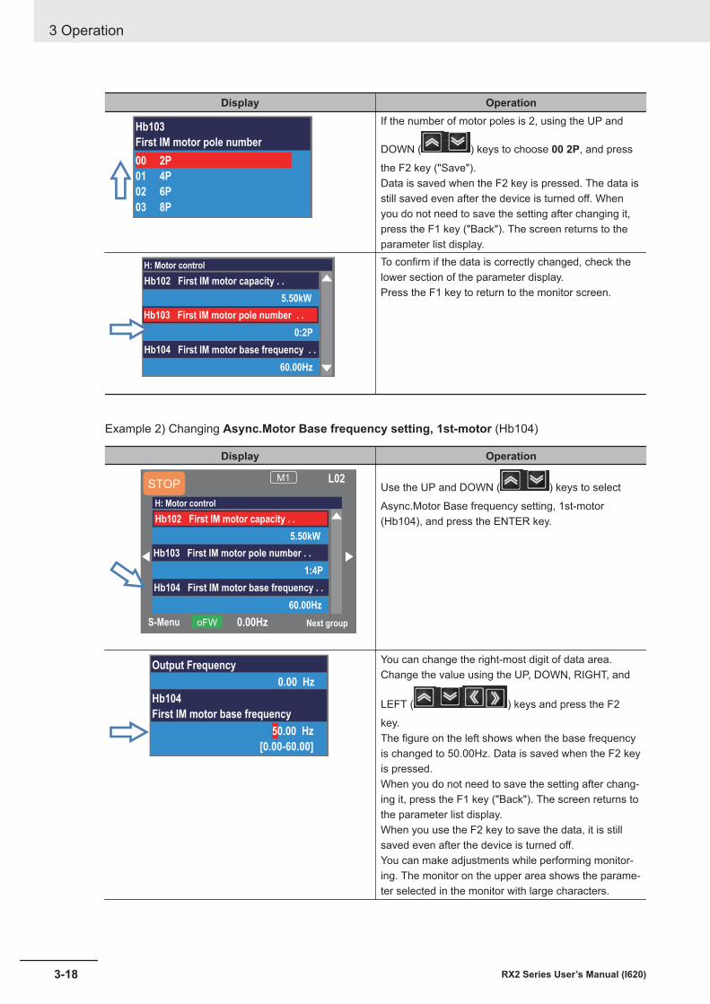
Display Operation
Hb103
First IM motor pole number
00 2P
01 4P
02 6P
03 8P
If the number of motor poles is 2, using the UP and
DOWN ( ) keys to choose 00 2P, and press
the F2 key ("Save").Data is saved when the F2 key is pressed. The data isstill saved even after the device is turned off. Whenyou do not need to save the setting after changing it,press the F1 key ("Back"). The screen returns to theparameter list display.
H: Motor control
5.50kW
Hb102 First IM motor capacity . .
0:2P
Hb103 First IM motor pole number . .
60.00Hz
Hb104 First IM motor base frequency . .
To confirm if the data is correctly changed, check thelower section of the parameter display.Press the F1 key to return to the monitor screen.
Example 2) Changing Async.Motor Base frequency setting, 1st-motor (Hb104)
Display Operation
S-Menu Next group0.00HzoFW
M1 L02STOP
H: Motor control
5.50kW
Hb102 First IM motor capacity . .
1:4P
Hb103 First IM motor pole number . .
60.00Hz
Hb104 First IM motor base frequency . .
Use the UP and DOWN ( ) keys to select
Async.Motor Base frequency setting, 1st-motor(Hb104), and press the ENTER key.
Output Frequency
0.00 Hz
Hb104
First IM motor base frequency
50.00 Hz
[0.00-60.00]
You can change the right-most digit of data area.Change the value using the UP, DOWN, RIGHT, and
LEFT ( ) keys and press the F2
key.The figure on the left shows when the base frequencyis changed to 50.00Hz. Data is saved when the F2 keyis pressed.When you do not need to save the setting after chang-ing it, press the F1 key ("Back"). The screen returns tothe parameter list display.When you use the F2 key to save the data, it is stillsaved even after the device is turned off.You can make adjustments while performing monitor-ing. The monitor on the upper area shows the parame-ter selected in the monitor with large characters.
3 Operation
3-18 RX2 Series User’s Manual (I620)
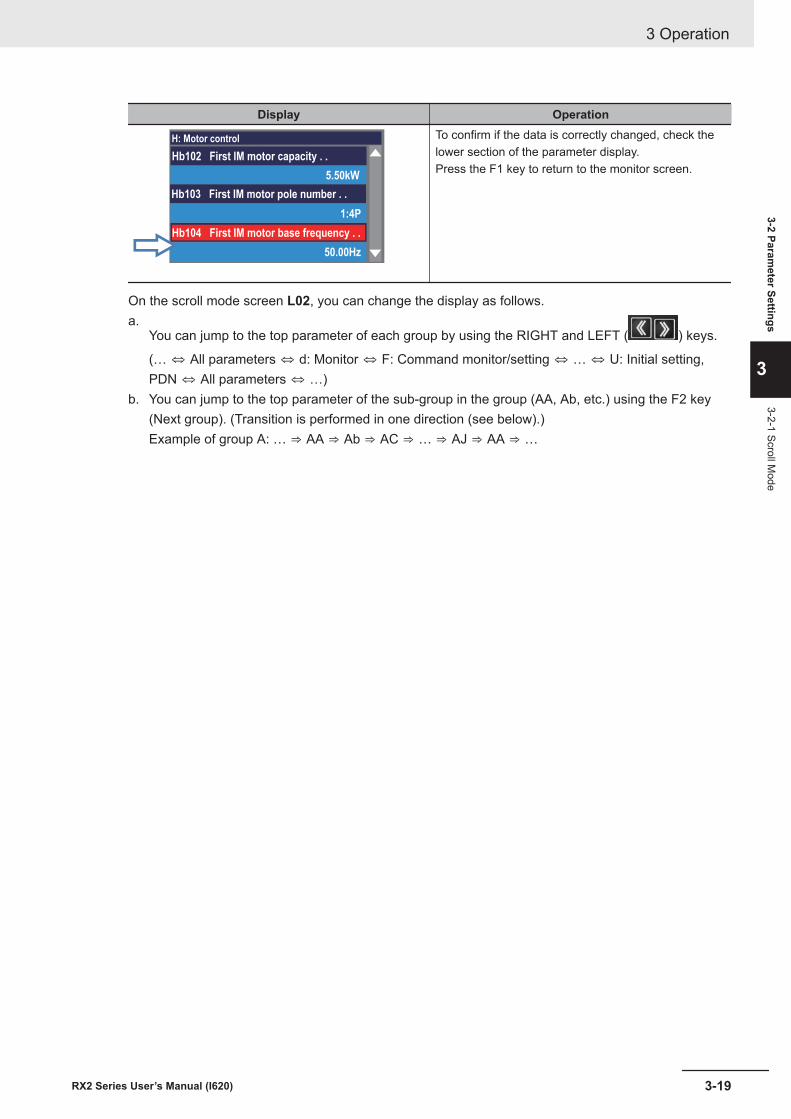
Display Operation
H: Motor control
5.50kW
Hb102 First IM motor capacity . .
1:4P
Hb103 First IM motor pole number . .
50.00Hz
Hb104 First IM motor base frequency . .
To confirm if the data is correctly changed, check thelower section of the parameter display.Press the F1 key to return to the monitor screen.
On the scroll mode screen L02, you can change the display as follows.a.
You can jump to the top parameter of each group by using the RIGHT and LEFT ( ) keys.
(… ⇔ All parameters ⇔ d: Monitor ⇔ F: Command monitor/setting ⇔ … ⇔ U: Initial setting,PDN ⇔ All parameters ⇔ …)
b. You can jump to the top parameter of the sub-group in the group (AA, Ab, etc.) using the F2 key(Next group). (Transition is performed in one direction (see below).)Example of group A: … ⇒ AA ⇒ Ab ⇒ AC ⇒ … ⇒ AJ ⇒ AA ⇒ …
3 Operation
3-19RX2 Series User’s Manual (I620)
3-2 Parameter Settings
3
3-2-1 Scroll Mode
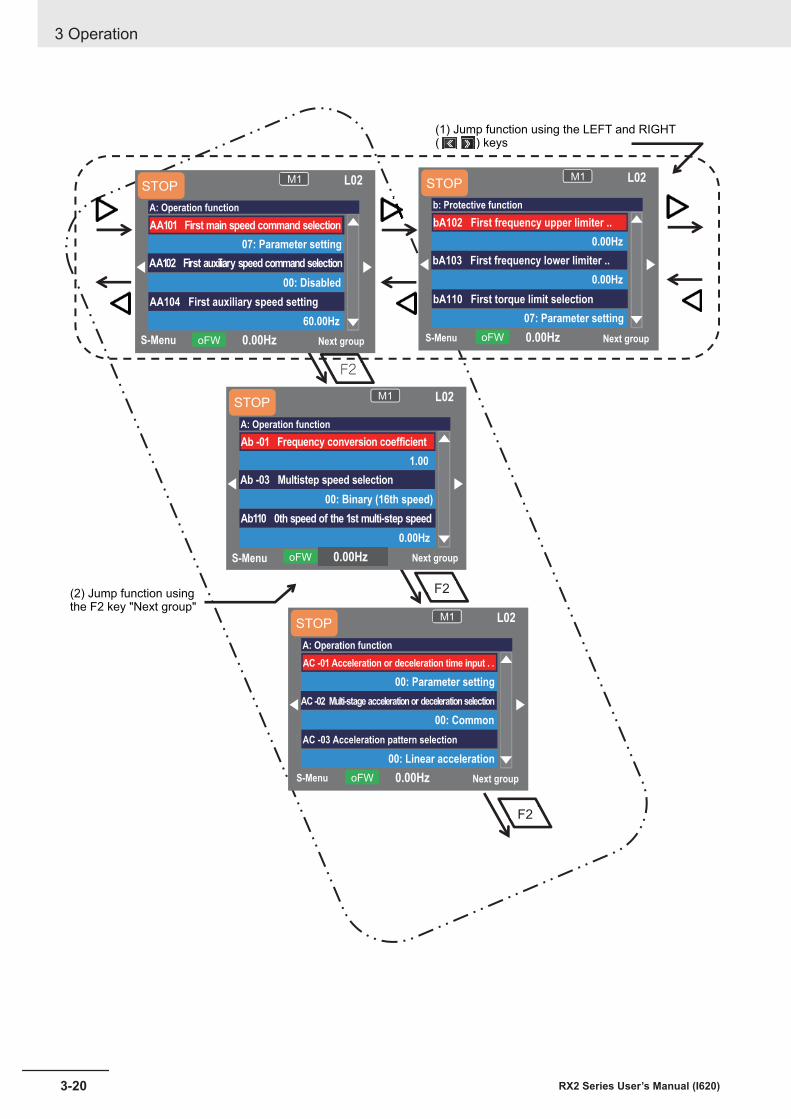
F2
F2
F2
S-Menu Next group0.00HzoFW
M1 L02STOP
A: Operation function
07: Parameter setting
AA101 First main speed command selection
00: Disabled
AA102 First auxiliary speed command selection
60.00Hz
AA104 First auxiliary speed setting
S-Menu Next group0.00HzoFW
M1 L02STOP
b: Protective function
0.00Hz
bA102 First frequency upper limiter ..
0.00Hz
bA103 First frequency lower limiter ..
07: Parameter setting
bA110 First torque limit selection
S-Menu Next group0.00HzoFW
M1 L02STOP
A: Operation function
1.00
Ab -01 Frequency conversion coefficient
00: Binary (16th speed)
Ab -03 Multistep speed selection
0.00Hz
Ab110 0th speed of the 1st multi-step speed
S-Menu Next group0.00HzoFW
M1 L02STOP
A: Operation function
00: Parameter setting
AC -01 Acceleration or deceleration time input . .
00: Common
AC -02 Multi-stage acceleration or deceleration selection
00: Linear acceleration
AC -03 Acceleration pattern selection
(1) Jump function using the LEFT and RIGHT( ) keys
(2) Jump function usingthe F2 key "Next group"
3 Operation
3-20 RX2 Series User’s Manual (I620)
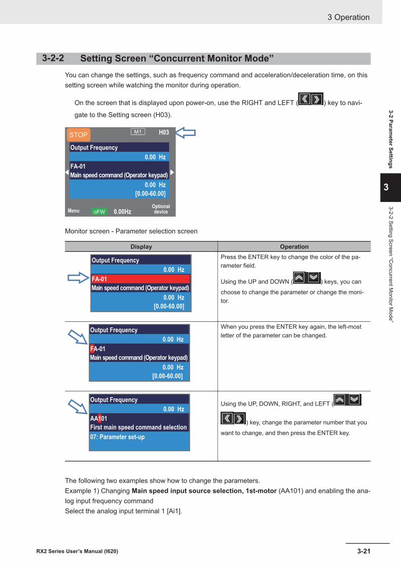
3-2-2 Setting Screen “Concurrent Monitor Mode”You can change the settings, such as frequency command and acceleration/deceleration time, on thissetting screen while watching the monitor during operation.
On the screen that is displayed upon power-on, use the RIGHT and LEFT ( ) key to navi-
gate to the Setting screen (H03).
MenuOptionaldevice0.00HzoFW
STOPM1 H03
Output Frequency
0.00 Hz
FA-01
Main speed command (Operator keypad)
0.00 Hz
[0.00-60.00]
Monitor screen - Parameter selection screen
Display Operation
Output Frequency
0.00 Hz
FA-01
Main speed command (Operator keypad)
0.00 Hz
[0.00-60.00]
Press the ENTER key to change the color of the pa-rameter field.
Using the UP and DOWN ( ) keys, you can
choose to change the parameter or change the moni-tor.
Output Frequency
0.00 Hz
FA-01
Main speed command (Operator keypad)
0.00 Hz
[0.00-60.00]
When you press the ENTER key again, the left-mostletter of the parameter can be changed.
Output Frequency
0.00 Hz
AA101
First main speed command selection
07: Parameter set-up
Using the UP, DOWN, RIGHT, and LEFT (
) key, change the parameter number that you
want to change, and then press the ENTER key.
The following two examples show how to change the parameters.Example 1) Changing Main speed input source selection, 1st-motor (AA101) and enabling the ana-log input frequency commandSelect the analog input terminal 1 [Ai1].
3 Operation
3-21RX2 Series User’s Manual (I620)
3-2 Parameter Settings
3
3-2-2 Setting Screen “Concurrent M
onitor Mode”
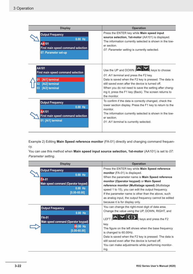
Display Operation
Output Frequency
0.00 Hz
AA101
First main speed command selection
07: Parameter set-up
Press the ENTER key while Main speed inputsource selection, 1st-motor (AA101) is displayed.The information currently selected is shown in the low-er section.07: Parameter setting is currently selected.
AA101
First main speed command selection
01 [Ai1] terminal
02 [Ai2] terminal
03 [Ai3] terminal
Use the UP and DOWN ( ) keys to choose
01: Ai1 terminal and press the F2 key.Data is saved when the F2 key is pressed. The data isstill saved even after the device is turned off.When you do not need to save the setting after chang-ing it, press the F1 key (Back). The screen returns tothe monitor.
Output Frequency
0.00 Hz
AA101
First main speed command selection
01: [Ai1] terminal
To confirm if the data is correctly changed, check thelower section display. Press the F1 key to return to themonitor.The information currently selected is shown in the low-er section.01: Ai1 terminal is currently selected.
Example 2) Editing Main Speed reference monitor (FA-01) directly and changing command frequen-cy.You can use this method when Main speed input source selection, 1st-motor (AA101) is set to 07:Parameter setting.
Display Operation
Output Frequency
0.00 Hz
FA-01
Main speed command (Operator keypad)
0.00 Hz
[0.00-60.00]
Press the ENTER key while Main Speed referencemonitor (FA-01) is displayed.When the parameter name is Main Speed referencemonitor (Operator keypad) or Main Speedreference monitor (Multistage speed) (Multistagespeed 1 to 15), you can edit the output frequency.If the parameter name is other than the above, suchas analog input, the output frequency cannot be editedbecause it is for display only.
Output Frequency
0.00 Hz
FA-01
Main speed command (Operator keypad)
60.00 Hz
[0.00-60.00]
You can change the right-most digit of data area.Change the value using the UP, DOWN, RIGHT, and
LEFT ( ) keys and press the F2
key.The figure on the left shows when the base frequencyis changed to 60.00Hz.Data is saved when the F2 key is pressed. The data isstill saved even after the device is turned off.You can make adjustments while performing monitor-ing.
3 Operation
3-22 RX2 Series User’s Manual (I620)
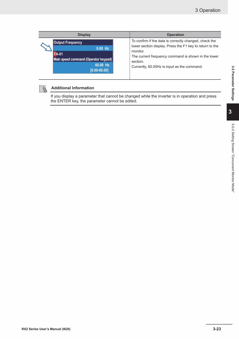
Display Operation
Output Frequency
0.00 Hz
FA-01
Main speed command (Operator keypad)
60.00 Hz
[0.00-60.00]
To confirm if the data is correctly changed, check thelower section display. Press the F1 key to return to themonitor.The current frequency command is shown in the lowersection.Currently, 60.00Hz is input as the command.
Additional Information
If you display a parameter that cannot be changed while the inverter is in operation and pressthe ENTER key, the parameter cannot be edited.
3 Operation
3-23RX2 Series User’s Manual (I620)
3-2 Parameter Settings
3
3-2-2 Setting Screen “Concurrent M
onitor Mode”
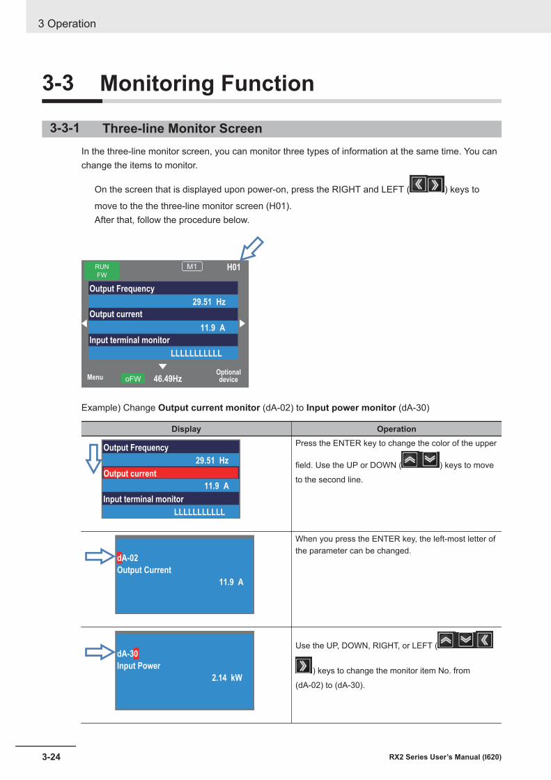
3-3 Monitoring Function
3-3-1 Three-line Monitor ScreenIn the three-line monitor screen, you can monitor three types of information at the same time. You canchange the items to monitor.
On the screen that is displayed upon power-on, press the RIGHT and LEFT ( ) keys to
move to the the three-line monitor screen (H01).After that, follow the procedure below.
MenuOptionaldevice46.49HzoFW
RUN
FW
M1 H01
Output Frequency
29.51 Hz
Output current
11.9 A
Input terminal monitor
LLLLLLLLLLL
Example) Change Output current monitor (dA-02) to Input power monitor (dA-30)
Display Operation
Output Frequency
29.51 Hz
Output current
11.9 A
Input terminal monitor
LLLLLLLLLLL
Press the ENTER key to change the color of the upper
field. Use the UP or DOWN ( ) keys to move
to the second line.
dA-02
Output Current
11.9 A
When you press the ENTER key, the left-most letter ofthe parameter can be changed.
dA-30
Input Power
2.14 kW
Use the UP, DOWN, RIGHT, or LEFT (
) keys to change the monitor item No. from
(dA-02) to (dA-30).
3 Operation
3-24 RX2 Series User’s Manual (I620)
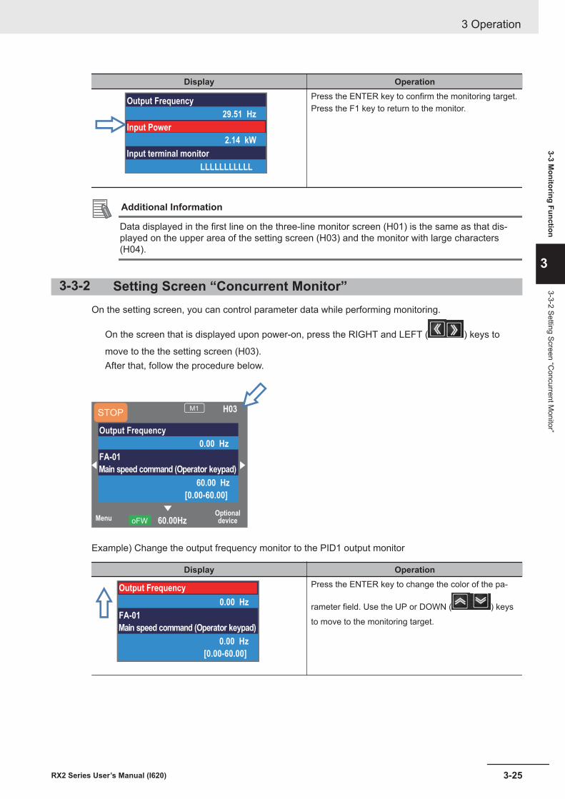
Display Operation
Output Frequency
29.51 Hz
Input Power
2.14 kW
Input terminal monitor
LLLLLLLLLLL
Press the ENTER key to confirm the monitoring target.Press the F1 key to return to the monitor.
Additional Information
Data displayed in the first line on the three-line monitor screen (H01) is the same as that dis-played on the upper area of the setting screen (H03) and the monitor with large characters(H04).
3-3-2 Setting Screen “Concurrent Monitor”On the setting screen, you can control parameter data while performing monitoring.
On the screen that is displayed upon power-on, press the RIGHT and LEFT ( ) keys to
move to the the setting screen (H03).After that, follow the procedure below.
MenuOptionaldevice60.00HzoFW
STOPM1 H03
Output Frequency
0.00 Hz
FA-01
Main speed command (Operator keypad)
60.00 Hz
[0.00-60.00]
Example) Change the output frequency monitor to the PID1 output monitor
Display Operation
Output Frequency
0.00 Hz
FA-01
Main speed command (Operator keypad)
0.00 Hz
[0.00-60.00]
Press the ENTER key to change the color of the pa-
rameter field. Use the UP or DOWN ( ) keys
to move to the monitoring target.
3 Operation
3-25RX2 Series User’s Manual (I620)
3-3 Monitoring Function
3
3-3-2 Setting Screen “Concurrent M
onitor”
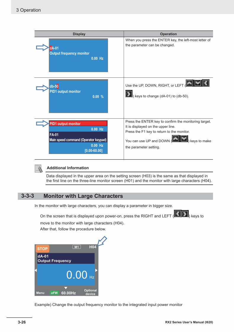
Display Operation
dA-01
Output frequency monitor
0.00 Hz
When you press the ENTER key, the left-most letter ofthe parameter can be changed.
db-50
PID1 output monitor
0.00 %
Use the UP, DOWN, RIGHT, or LEFT (
) keys to change (dA-01) to (db-50).
PID1 output monitor
0.00 Hz
FA-01
Main speed command (Operator keypad)
0.00 Hz
[0.00-60.00]
Press the ENTER key to confirm the monitoring target.It is displayed on the upper line.Press the F1 key to return to the monitor.
You can use UP and DOWN ( ) keys to make
the parameter setting.
Additional Information
Data displayed in the upper area on the setting screen (H03) is the same as that displayed inthe first line on the three-line monitor screen (H01) and the monitor with large characters (H04).
3-3-3 Monitor with Large CharactersIn the monitor with large characters, you can display a parameter in bigger size.
On the screen that is displayed upon power-on, press the RIGHT and LEFT ( ) keys to
move to the monitor with large characters (H04).After that, follow the procedure below.
Menu Optional device 60.00Hz oFW
STOPM1 H04
dA-01Output Frequency
0.00 Hz
Example) Change the output frequency monitor to the integrated input power monitor
3 Operation
3-26 RX2 Series User’s Manual (I620)
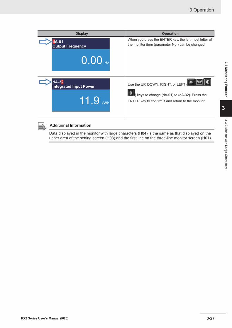
Display Operation
dA-01Output Frequency
0.00 Hz
When you press the ENTER key, the left-most letter ofthe monitor item (parameter No.) can be changed.
dA-32Integrated Input Power
11.9 kWh
Use the UP, DOWN, RIGHT, or LEFT (
) keys to change (dA-01) to (dA-32). Press the
ENTER key to confirm it and return to the monitor.
Additional Information
Data displayed in the monitor with large characters (H04) is the same as that displayed on theupper area of the setting screen (H03) and the first line on the three-line monitor screen (H01).
3 Operation
3-27RX2 Series User’s Manual (I620)
3-3 Monitoring Function
3
3-3-3 Monitor w
ith Large Characters
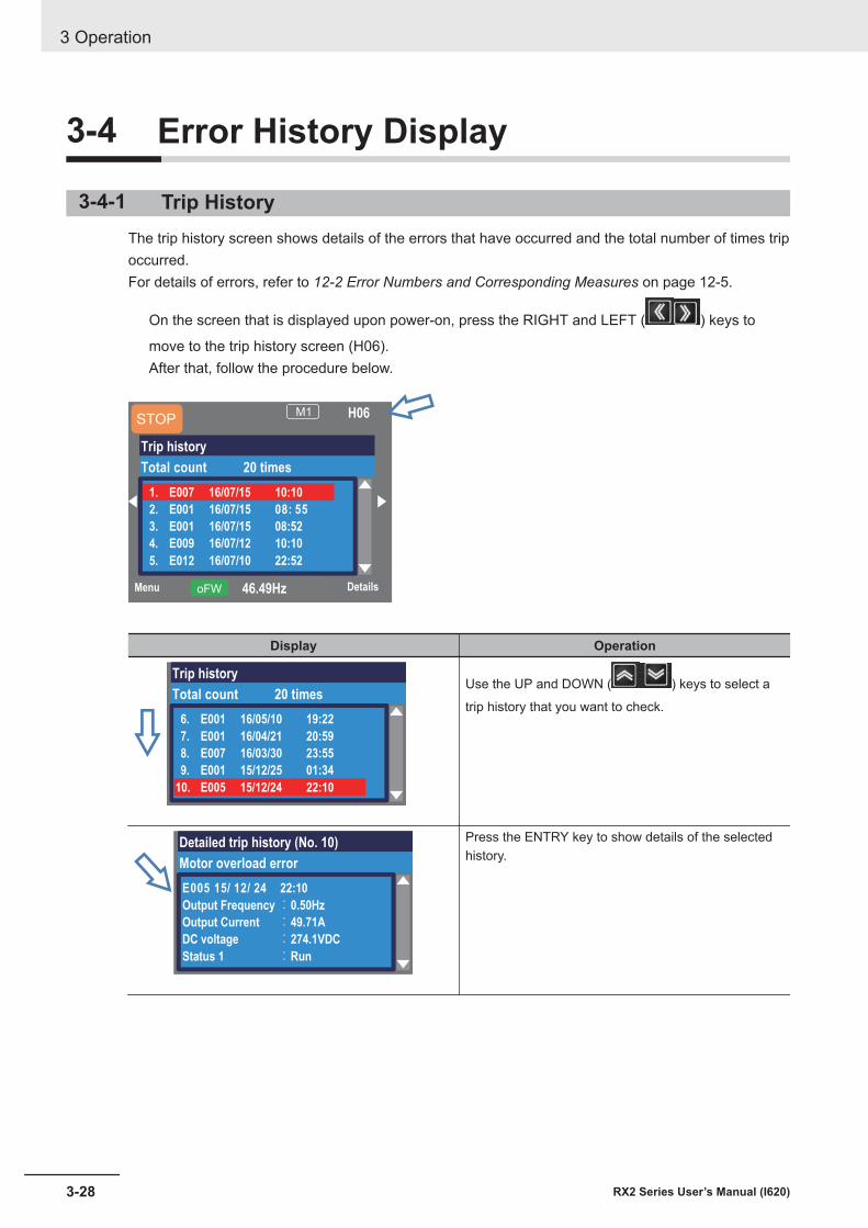
3-4 Error History Display
3-4-1 Trip HistoryThe trip history screen shows details of the errors that have occurred and the total number of times tripoccurred.For details of errors, refer to 12-2 Error Numbers and Corresponding Measures on page 12-5.
On the screen that is displayed upon power-on, press the RIGHT and LEFT ( ) keys to
move to the trip history screen (H06).After that, follow the procedure below.
Menu Details46.49HzoFW
M1 H06
Trip history
Total count 20 times
1. E007 16/07/15 10:10
2. E001 16/07/15 08: 55
3. E001 16/07/15 08:52
4. E009 16/07/12 10:10
5. E012 16/07/10 22:52
STOP
Display Operation
Trip history
Total count 20 times
6. E001 16/05/10 19:22
7. E001 16/04/21 20:59
8. E007 16/03/30 23:55
9. E001 15/12/25 01:34
10. E005 15/12/24 22:10
Use the UP and DOWN ( ) keys to select a
trip history that you want to check.
Detailed trip history (No. 10)
Motor overload error
E005 15/ 12/ 24 22:10
Output Frequency:0.50Hz
Output Current :49.71A
DC voltage :274.1VDC
Status 1 :Run
Press the ENTRY key to show details of the selectedhistory.
3 Operation
3-28 RX2 Series User’s Manual (I620)
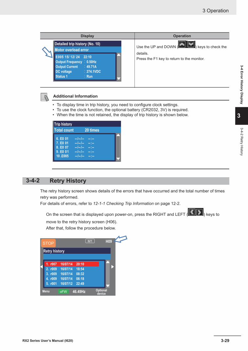
Display Operation
Detailed trip history (No. 10)
Motor overload error
E005 15/ 12/ 24 22:10
Output Frequency:0.50Hz
Output Current :49.71A
DC voltage :274.1VDC
Status 1 :Run
Use the UP and DOWN ( ) keys to check the
details.Press the F1 key to return to the monitor.
Additional Information
• To display time in trip history, you need to configure clock settings.• To use the clock function, the optional battery (CR2032, 3V) is required.• When the time is not retained, the display of trip history is shown below.
Trip history
Total count 20 times
6. E0 01 -- /-- /-- -- :--7 . E0 01 -- /-- /-- -- :--8 . E0 07 -- /-- /-- -- :--9 . E0 01 -- /-- /-- -- :--10 .E005 -- /-- /-- -- :--
3-4-2 Retry HistoryThe retry history screen shows details of the errors that have occurred and the total number of timesretry was performed.For details of errors, refer to 12-1-1 Checking Trip Information on page 12-2.
On the screen that is displayed upon power-on, press the RIGHT and LEFT ( ) keys to
move to the retry history screen (H06).After that, follow the procedure below.
Menu Optionaldevice
46.49HzoFW
M1 H09
1. r007 16/07/14 20:10
2. r009 16/07/14 18:54
3. r009 16/07/14 08:32
4. r009 16/07/14 06:18
5. r001 16/07/12 22:49
STOP
Retry history
3 Operation
3-29RX2 Series User’s Manual (I620)
3-4 Error History D
isplay
3
3-4-2 Retry H
istory
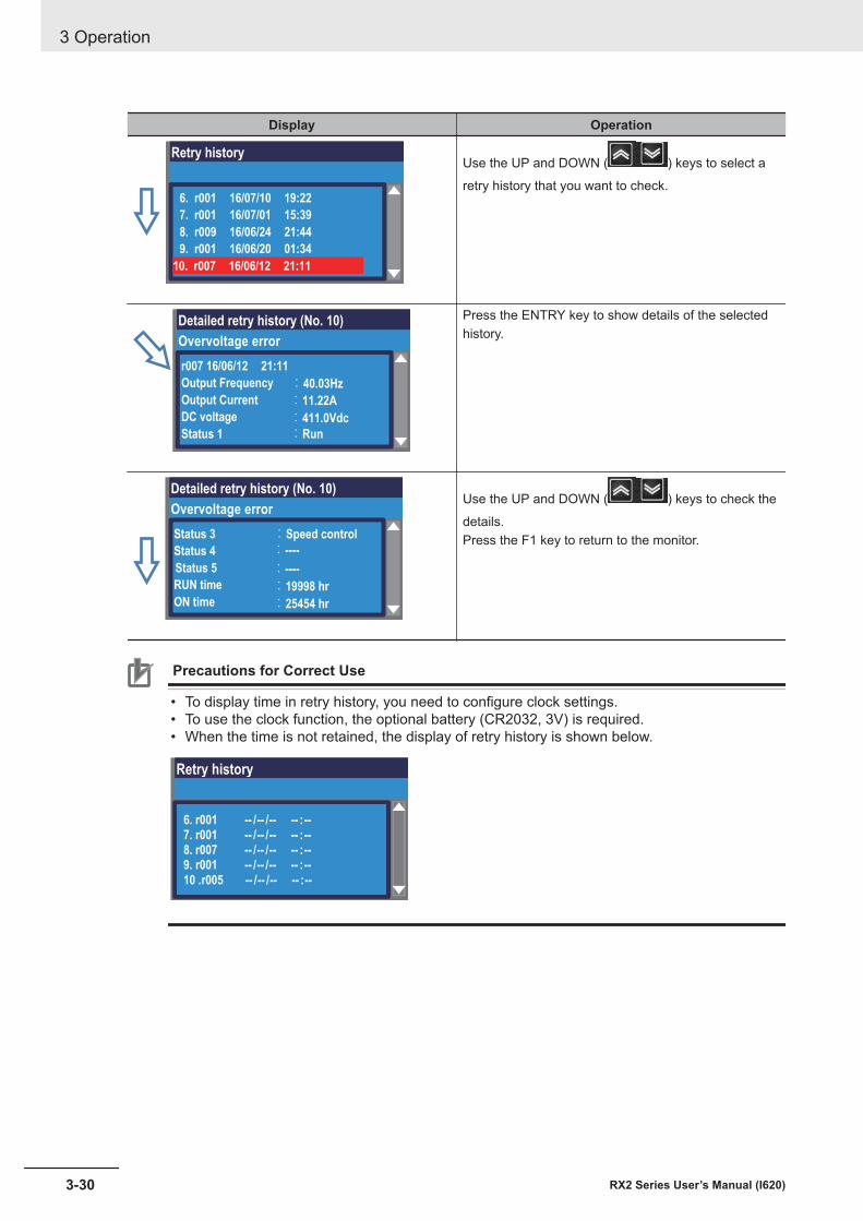
Display Operation
Retry history
6. r001 16/07/10 19:22
7. r001 16/07/01 15:39
8. r009 16/06/24 21:44
9. r001 16/06/20 01:34
10. r007 16/06/12 21:11
Use the UP and DOWN ( ) keys to select a
retry history that you want to check.
Detailed retry history (No. 10)
Overvoltage error
r007 16/06/12 21:11
Output Frequency
Output Current
DC voltage
Status 1
:40.03Hz
:11.22A
:411.0Vdc
:Run
Press the ENTRY key to show details of the selectedhistory.
Detailed retry history (No. 10)
Overvoltage error
Status 3
Status 4
Status 5
RUN time
ON time
:Speed control
:----
:19998 hr
:25454 hr
:----
Use the UP and DOWN ( ) keys to check the
details.Press the F1 key to return to the monitor.
Precautions for Correct Use
• To display time in retry history, you need to configure clock settings.• To use the clock function, the optional battery (CR2032, 3V) is required.• When the time is not retained, the display of retry history is shown below.
Retry history
6. r001 -- /-- /-- -- :--7. r001 -- /-- /-- -- :--8. r007 -- /-- /-- -- :--9. r001 -- /-- /-- -- :--10 .r005 -- /-- /-- -- :--
3 Operation
3-30 RX2 Series User’s Manual (I620)
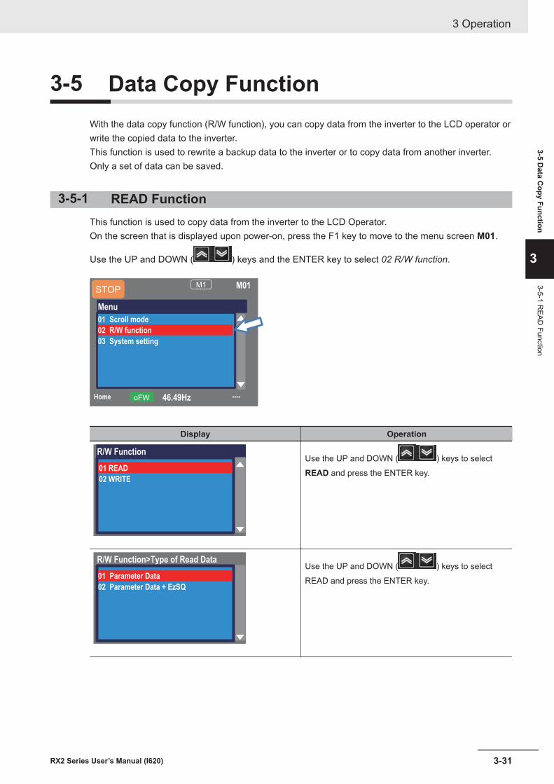
3-5 Data Copy FunctionWith the data copy function (R/W function), you can copy data from the inverter to the LCD operator orwrite the copied data to the inverter.This function is used to rewrite a backup data to the inverter or to copy data from another inverter.Only a set of data can be saved.
3-5-1 READ FunctionThis function is used to copy data from the inverter to the LCD Operator.On the screen that is displayed upon power-on, press the F1 key to move to the menu screen M01.
Use the UP and DOWN ( ) keys and the ENTER key to select 02 R/W function.
46.49HzoFW
M1 M01
Menu
01 Scroll mode
03 System setting
STOP
Home ----
02 R/W function
Display Operation
R/W Function
02 WRITE
01 READ
Use the UP and DOWN ( ) keys to select
READ and press the ENTER key.
R/W Function>Type of Read Data
01 Parameter Data
02 Parameter Data + EzSQ
Use the UP and DOWN ( ) keys to select
READ and press the ENTER key.
3 Operation
3-31RX2 Series User’s Manual (I620)
3-5 Data C
opy Function
3
3-5-1 READ
Function
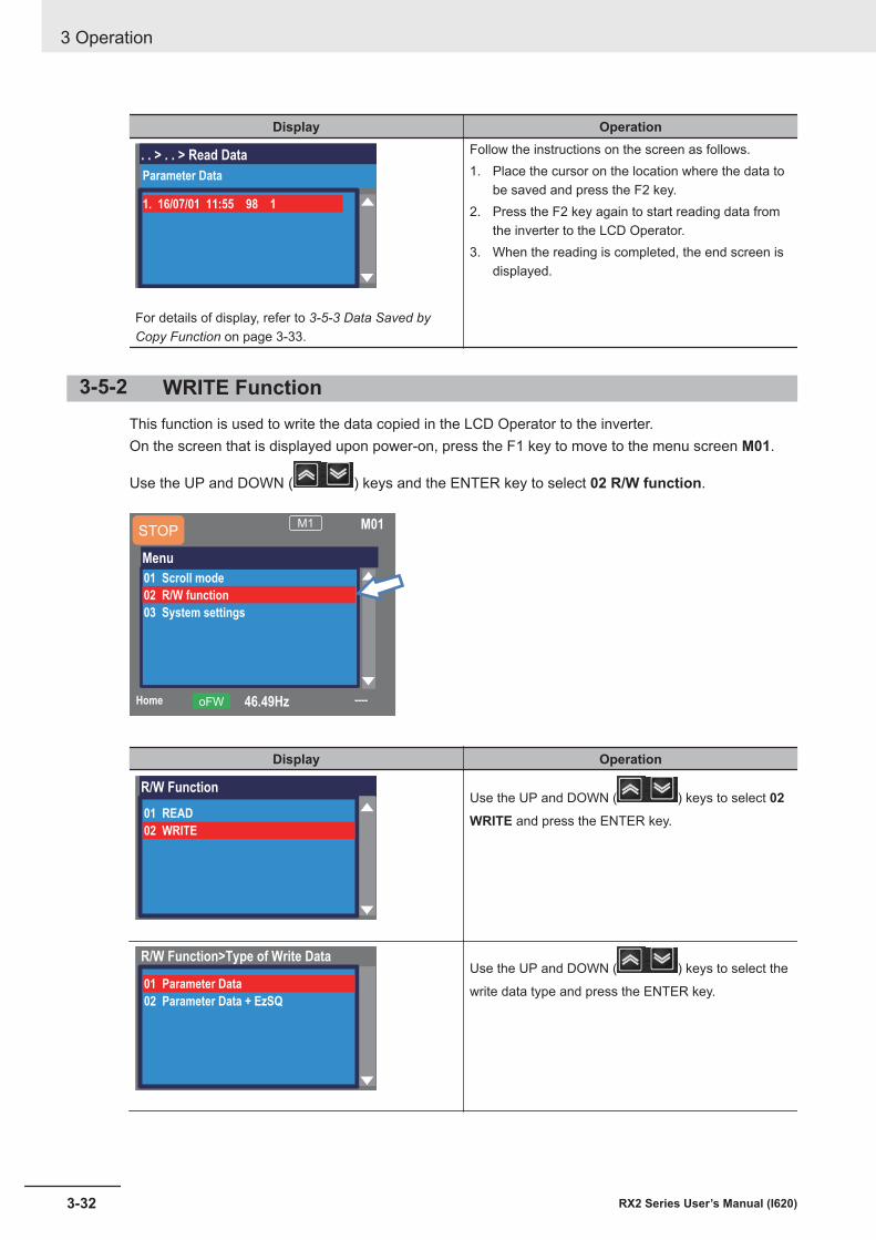
Display Operation
. . > . . > Read Data
Parameter Data
1. 16/07/01 11:55 98 1
For details of display, refer to 3-5-3 Data Saved byCopy Function on page 3-33.
Follow the instructions on the screen as follows.1. Place the cursor on the location where the data to
be saved and press the F2 key.2. Press the F2 key again to start reading data from
the inverter to the LCD Operator.3. When the reading is completed, the end screen is
displayed.
3-5-2 WRITE FunctionThis function is used to write the data copied in the LCD Operator to the inverter.On the screen that is displayed upon power-on, press the F1 key to move to the menu screen M01.
Use the UP and DOWN ( ) keys and the ENTER key to select 02 R/W function.
46.49HzoFW
M1 M01
Menu
01 Scroll mode
03 System settings
STOP
Home ----
02 R/W function
Display Operation
R/W Function
01 READ
02 WRITE
Use the UP and DOWN ( ) keys to select 02WRITE and press the ENTER key.
R/W Function>Type of Write Data
01 Parameter Data
02 Parameter Data + EzSQ
Use the UP and DOWN ( ) keys to select the
write data type and press the ENTER key.
3 Operation
3-32 RX2 Series User’s Manual (I620)
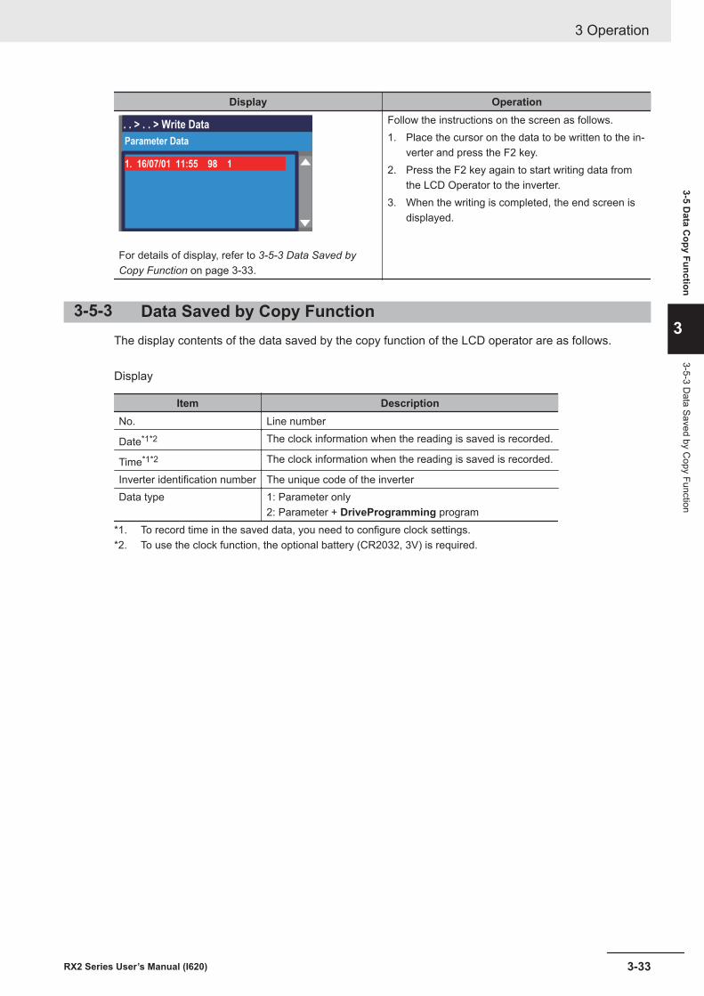
Display Operation
. . > . . > Write Data
Parameter Data
1. 16/07/01 11:55 98 1
For details of display, refer to 3-5-3 Data Saved byCopy Function on page 3-33.
Follow the instructions on the screen as follows.1. Place the cursor on the data to be written to the in-
verter and press the F2 key.2. Press the F2 key again to start writing data from
the LCD Operator to the inverter.3. When the writing is completed, the end screen is
displayed.
3-5-3 Data Saved by Copy FunctionThe display contents of the data saved by the copy function of the LCD operator are as follows.
Display
Item DescriptionNo. Line number
Date*1*2 The clock information when the reading is saved is recorded.
Time*1*2 The clock information when the reading is saved is recorded.
Inverter identification number The unique code of the inverterData type 1: Parameter only
2: Parameter + DriveProgramming program*1. To record time in the saved data, you need to configure clock settings.*2. To use the clock function, the optional battery (CR2032, 3V) is required.
3 Operation
3-33RX2 Series User’s Manual (I620)
3-5 Data C
opy Function
3
3-5-3 Data Saved by C
opy Function
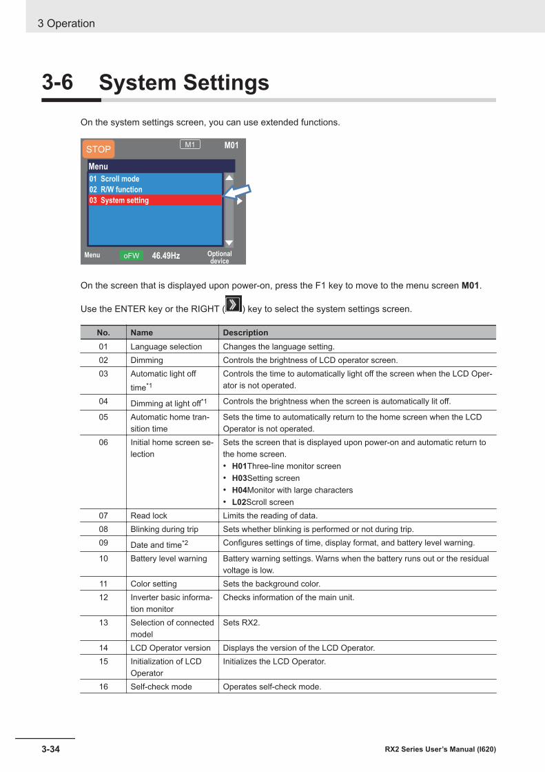
3-6 System SettingsOn the system settings screen, you can use extended functions.
Menu Optionaldevice
46.49HzoFW
M1 M01
Menu
01 Scroll mode
02 R/W function
03 System setting
STOP
On the screen that is displayed upon power-on, press the F1 key to move to the menu screen M01.
Use the ENTER key or the RIGHT ( ) key to select the system settings screen.
No. Name Description01 Language selection Changes the language setting.02 Dimming Controls the brightness of LCD operator screen.03 Automatic light off
time*1Controls the time to automatically light off the screen when the LCD Oper-ator is not operated.
04 Dimming at light off*1 Controls the brightness when the screen is automatically lit off.
05 Automatic home tran-sition time
Sets the time to automatically return to the home screen when the LCDOperator is not operated.
06 Initial home screen se-lection
Sets the screen that is displayed upon power-on and automatic return tothe home screen.• H01Three-line monitor screen• H03Setting screen• H04Monitor with large characters• L02Scroll screen
07 Read lock Limits the reading of data.08 Blinking during trip Sets whether blinking is performed or not during trip.09 Date and time*2 Configures settings of time, display format, and battery level warning.
10 Battery level warning Battery warning settings. Warns when the battery runs out or the residualvoltage is low.
11 Color setting Sets the background color.12 Inverter basic informa-
tion monitorChecks information of the main unit.
13 Selection of connectedmodel
Sets RX2.
14 LCD Operator version Displays the version of the LCD Operator.15 Initialization of LCD
OperatorInitializes the LCD Operator.
16 Self-check mode Operates self-check mode.
3 Operation
3-34 RX2 Series User’s Manual (I620)
No. Name Description17 Remote mode switch-
ingIf this setting is enabled, you can switch the frequency command and op-eration command to the commands issued from the LCD Operator bypressing the F1 key on the home screen 1 second or more.
18 Reserve Do NOT change the setting from OFF.*1. The light off function is disabled from the occurrence of trip until it is canceled.*2. To use the clock function, the optional battery (CR2032, 3V) is required. If no electricity is supplied to the
inverter, the battery need to be replaced every two years.
Precautions for Correct Use
If there is an error in the memory area in the LCD Operator, an error message is displayed onthe LCD Operator. In such a case, initialize the LCD Operator from the system settings, andconfirm the settings.If the error on the LCD Operator is not canceled, the internal memory may be damaged. Youneed to replace the LCD Operator.
3 Operation
3-35RX2 Series User’s Manual (I620)
3-6 System Settings
3
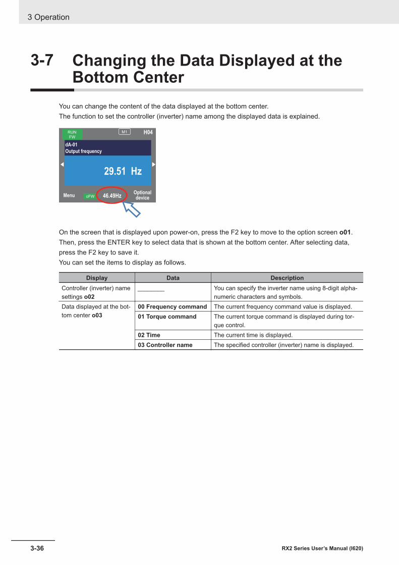
3-7 Changing the Data Displayed at theBottom Center
You can change the content of the data displayed at the bottom center.The function to set the controller (inverter) name among the displayed data is explained.
MenuOptionaldevice46.49HzoFW
RUN
FW
M1 H04
dA-01
Output frequency
29.51 Hz
On the screen that is displayed upon power-on, press the F2 key to move to the option screen o01.Then, press the ENTER key to select data that is shown at the bottom center. After selecting data,press the F2 key to save it.You can set the items to display as follows.
Display Data DescriptionController (inverter) namesettings o02
________ You can specify the inverter name using 8-digit alpha-numeric characters and symbols.
Data displayed at the bot-tom center o03
00 Frequency command The current frequency command value is displayed.01 Torque command The current torque command is displayed during tor-
que control.02 Time The current time is displayed.03 Controller name The specified controller (inverter) name is displayed.
3 Operation
3-36 RX2 Series User’s Manual (I620)
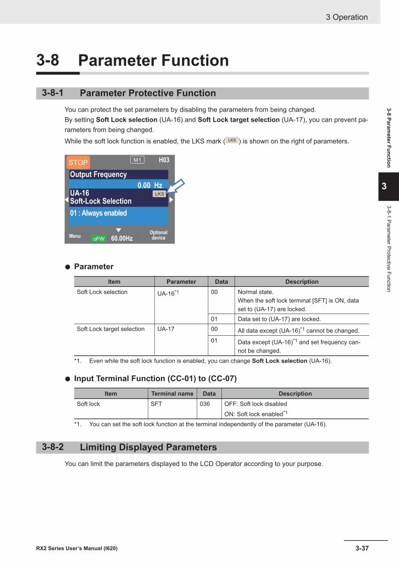
3-8 Parameter Function
3-8-1 Parameter Protective FunctionYou can protect the set parameters by disabling the parameters from being changed.By setting Soft Lock selection (UA-16) and Soft Lock target selection (UA-17), you can prevent pa-rameters from being changed.While the soft lock function is enabled, the LKS mark ( LKS ) is shown on the right of parameters.
MenuOptionaldevice60.00HzoFW
STOPM1 H03
Output Frequency
0.00 HzUA-16Soft-Lock Selection
01 : Always enabled
LKS
l Parameter
Item Parameter Data DescriptionSoft Lock selection UA-16*1 00 Normal state.
When the soft lock terminal [SFT] is ON, dataset to (UA-17) are locked.
01 Data set to (UA-17) are locked.Soft Lock target selection UA-17 00 All data except (UA-16)*1 cannot be changed.
01 Data except (UA-16)*1 and set frequency can-not be changed.
*1. Even while the soft lock function is enabled, you can change Soft Lock selection (UA-16).
l Input Terminal Function (CC-01) to (CC-07)
Item Terminal name Data DescriptionSoft lock SFT 036 OFF: Soft lock disabled
ON: Soft lock enabled*1
*1. You can set the soft lock function at the terminal independently of the parameter (UA-16).
3-8-2 Limiting Displayed ParametersYou can limit the parameters displayed to the LCD Operator according to your purpose.
3 Operation
3-37RX2 Series User’s Manual (I620)
3-8 Parameter Function
3
3-8-1 Parameter Protective Function
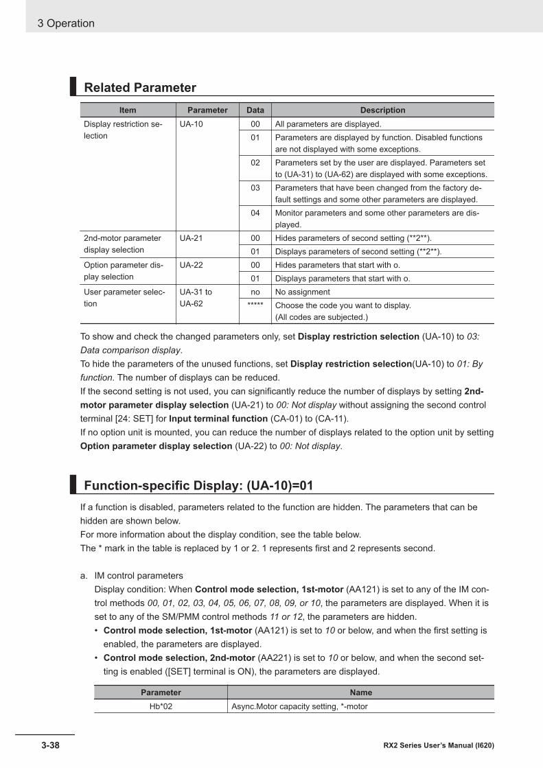
Related ParameterItem Parameter Data Description
Display restriction se-lection
UA-10 00 All parameters are displayed.01 Parameters are displayed by function. Disabled functions
are not displayed with some exceptions.02 Parameters set by the user are displayed. Parameters set
to (UA-31) to (UA-62) are displayed with some exceptions.03 Parameters that have been changed from the factory de-
fault settings and some other parameters are displayed.04 Monitor parameters and some other parameters are dis-
played.2nd-motor parameterdisplay selection
UA-21 00 Hides parameters of second setting (**2**).01 Displays parameters of second setting (**2**).
Option parameter dis-play selection
UA-22 00 Hides parameters that start with o.01 Displays parameters that start with o.
User parameter selec-tion
UA-31 toUA-62
no No assignment***** Choose the code you want to display.
(All codes are subjected.)
To show and check the changed parameters only, set Display restriction selection (UA-10) to 03:Data comparison display.To hide the parameters of the unused functions, set Display restriction selection(UA-10) to 01: Byfunction. The number of displays can be reduced.If the second setting is not used, you can significantly reduce the number of displays by setting 2nd-motor parameter display selection (UA-21) to 00: Not display without assigning the second controlterminal [24: SET] for Input terminal function (CA-01) to (CA-11).If no option unit is mounted, you can reduce the number of displays related to the option unit by settingOption parameter display selection (UA-22) to 00: Not display.
Function-specific Display: (UA-10)=01If a function is disabled, parameters related to the function are hidden. The parameters that can behidden are shown below.For more information about the display condition, see the table below.The * mark in the table is replaced by 1 or 2. 1 represents first and 2 represents second.
a. IM control parametersDisplay condition: When Control mode selection, 1st-motor (AA121) is set to any of the IM con-trol methods 00, 01, 02, 03, 04, 05, 06, 07, 08, 09, or 10, the parameters are displayed. When it isset to any of the SM/PMM control methods 11 or 12, the parameters are hidden.• Control mode selection, 1st-motor (AA121) is set to 10 or below, and when the first setting is
enabled, the parameters are displayed.• Control mode selection, 2nd-motor (AA221) is set to 10 or below, and when the second set-
ting is enabled ([SET] terminal is ON), the parameters are displayed.
Parameter NameHb*02 Async.Motor capacity setting, *-motor
3 Operation
3-38 RX2 Series User’s Manual (I620)
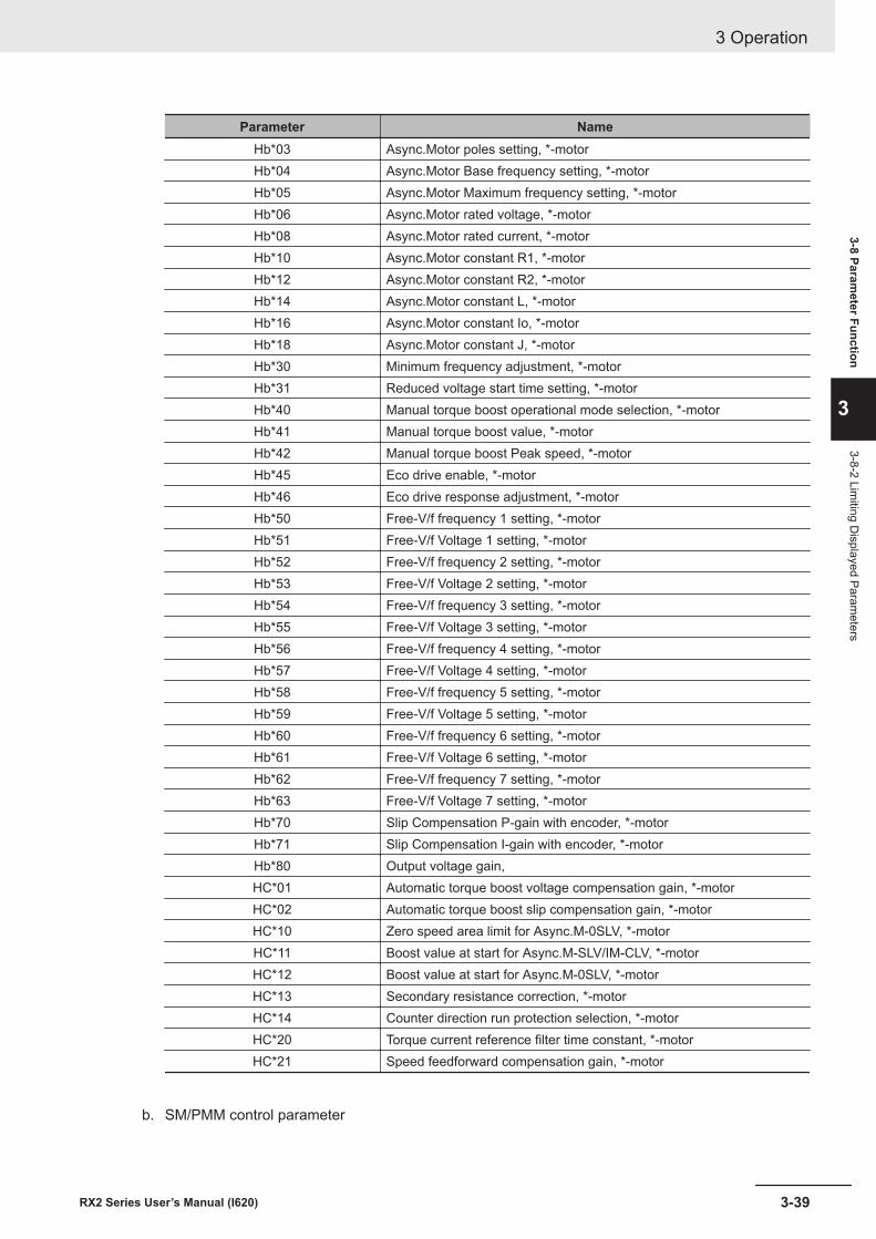
Parameter NameHb*03 Async.Motor poles setting, *-motorHb*04 Async.Motor Base frequency setting, *-motorHb*05 Async.Motor Maximum frequency setting, *-motorHb*06 Async.Motor rated voltage, *-motorHb*08 Async.Motor rated current, *-motorHb*10 Async.Motor constant R1, *-motorHb*12 Async.Motor constant R2, *-motorHb*14 Async.Motor constant L, *-motorHb*16 Async.Motor constant Io, *-motorHb*18 Async.Motor constant J, *-motorHb*30 Minimum frequency adjustment, *-motorHb*31 Reduced voltage start time setting, *-motorHb*40 Manual torque boost operational mode selection, *-motorHb*41 Manual torque boost value, *-motorHb*42 Manual torque boost Peak speed, *-motorHb*45 Eco drive enable, *-motorHb*46 Eco drive response adjustment, *-motorHb*50 Free-V/f frequency 1 setting, *-motorHb*51 Free-V/f Voltage 1 setting, *-motorHb*52 Free-V/f frequency 2 setting, *-motorHb*53 Free-V/f Voltage 2 setting, *-motorHb*54 Free-V/f frequency 3 setting, *-motorHb*55 Free-V/f Voltage 3 setting, *-motorHb*56 Free-V/f frequency 4 setting, *-motorHb*57 Free-V/f Voltage 4 setting, *-motorHb*58 Free-V/f frequency 5 setting, *-motorHb*59 Free-V/f Voltage 5 setting, *-motorHb*60 Free-V/f frequency 6 setting, *-motorHb*61 Free-V/f Voltage 6 setting, *-motorHb*62 Free-V/f frequency 7 setting, *-motorHb*63 Free-V/f Voltage 7 setting, *-motorHb*70 Slip Compensation P-gain with encoder, *-motorHb*71 Slip Compensation I-gain with encoder, *-motorHb*80 Output voltage gain,HC*01 Automatic torque boost voltage compensation gain, *-motorHC*02 Automatic torque boost slip compensation gain, *-motorHC*10 Zero speed area limit for Async.M-0SLV, *-motorHC*11 Boost value at start for Async.M-SLV/IM-CLV, *-motorHC*12 Boost value at start for Async.M-0SLV, *-motorHC*13 Secondary resistance correction, *-motorHC*14 Counter direction run protection selection, *-motorHC*20 Torque current reference filter time constant, *-motorHC*21 Speed feedforward compensation gain, *-motor
b. SM/PMM control parameter
3 Operation
3-39RX2 Series User’s Manual (I620)
3-8 Parameter Function
3
3-8-2 Limiting D
isplayed Parameters
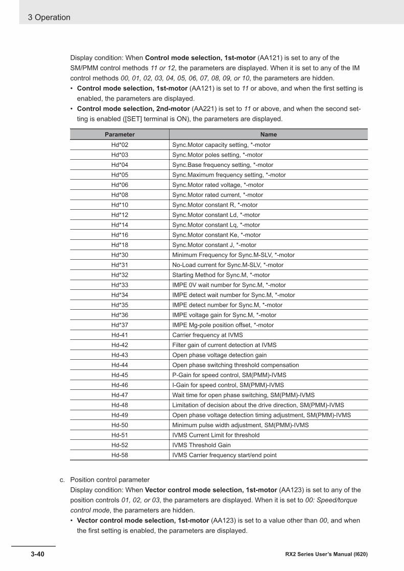
Display condition: When Control mode selection, 1st-motor (AA121) is set to any of theSM/PMM control methods 11 or 12, the parameters are displayed. When it is set to any of the IMcontrol methods 00, 01, 02, 03, 04, 05, 06, 07, 08, 09, or 10, the parameters are hidden.• Control mode selection, 1st-motor (AA121) is set to 11 or above, and when the first setting is
enabled, the parameters are displayed.• Control mode selection, 2nd-motor (AA221) is set to 11 or above, and when the second set-
ting is enabled ([SET] terminal is ON), the parameters are displayed.
Parameter NameHd*02 Sync.Motor capacity setting, *-motorHd*03 Sync.Motor poles setting, *-motorHd*04 Sync.Base frequency setting, *-motorHd*05 Sync.Maximum frequency setting, *-motorHd*06 Sync.Motor rated voltage, *-motorHd*08 Sync.Motor rated current, *-motorHd*10 Sync.Motor constant R, *-motorHd*12 Sync.Motor constant Ld, *-motorHd*14 Sync.Motor constant Lq, *-motorHd*16 Sync.Motor constant Ke, *-motorHd*18 Sync.Motor constant J, *-motorHd*30 Minimum Frequency for Sync.M-SLV, *-motorHd*31 No-Load current for Sync.M-SLV, *-motorHd*32 Starting Method for Sync.M, *-motorHd*33 IMPE 0V wait number for Sync.M, *-motorHd*34 IMPE detect wait number for Sync.M, *-motorHd*35 IMPE detect number for Sync.M, *-motorHd*36 IMPE voltage gain for Sync.M, *-motorHd*37 IMPE Mg-pole position offset, *-motorHd-41 Carrier frequency at IVMSHd-42 Filter gain of current detection at IVMSHd-43 Open phase voltage detection gainHd-44 Open phase switching threshold compensationHd-45 P-Gain for speed control, SM(PMM)-IVMSHd-46 I-Gain for speed control, SM(PMM)-IVMSHd-47 Wait time for open phase switching, SM(PMM)-IVMSHd-48 Limitation of decision about the drive direction, SM(PMM)-IVMSHd-49 Open phase voltage detection timing adjustment, SM(PMM)-IVMSHd-50 Minimum pulse width adjustment, SM(PMM)-IVMSHd-51 IVMS Current Limit for thresholdHd-52 IVMS Threshold GainHd-58 IVMS Carrier frequency start/end point
c. Position control parameterDisplay condition: When Vector control mode selection, 1st-motor (AA123) is set to any of theposition controls 01, 02, or 03, the parameters are displayed. When it is set to 00: Speed/torquecontrol mode, the parameters are hidden.• Vector control mode selection, 1st-motor (AA123) is set to a value other than 00, and when
the first setting is enabled, the parameters are displayed.
3 Operation
3-40 RX2 Series User’s Manual (I620)
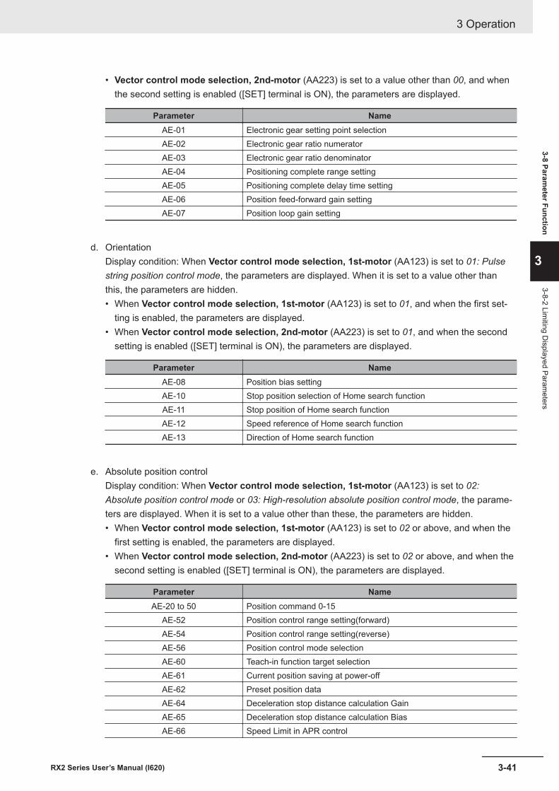
• Vector control mode selection, 2nd-motor (AA223) is set to a value other than 00, and whenthe second setting is enabled ([SET] terminal is ON), the parameters are displayed.
Parameter NameAE-01 Electronic gear setting point selectionAE-02 Electronic gear ratio numeratorAE-03 Electronic gear ratio denominatorAE-04 Positioning complete range settingAE-05 Positioning complete delay time settingAE-06 Position feed-forward gain settingAE-07 Position loop gain setting
d. OrientationDisplay condition: When Vector control mode selection, 1st-motor (AA123) is set to 01: Pulsestring position control mode, the parameters are displayed. When it is set to a value other thanthis, the parameters are hidden.• When Vector control mode selection, 1st-motor (AA123) is set to 01, and when the first set-
ting is enabled, the parameters are displayed.• When Vector control mode selection, 2nd-motor (AA223) is set to 01, and when the second
setting is enabled ([SET] terminal is ON), the parameters are displayed.
Parameter NameAE-08 Position bias settingAE-10 Stop position selection of Home search functionAE-11 Stop position of Home search functionAE-12 Speed reference of Home search functionAE-13 Direction of Home search function
e. Absolute position controlDisplay condition: When Vector control mode selection, 1st-motor (AA123) is set to 02:Absolute position control mode or 03: High-resolution absolute position control mode, the parame-ters are displayed. When it is set to a value other than these, the parameters are hidden.• When Vector control mode selection, 1st-motor (AA123) is set to 02 or above, and when the
first setting is enabled, the parameters are displayed.• When Vector control mode selection, 2nd-motor (AA223) is set to 02 or above, and when the
second setting is enabled ([SET] terminal is ON), the parameters are displayed.
Parameter NameAE-20 to 50 Position command 0-15
AE-52 Position control range setting(forward)AE-54 Position control range setting(reverse)AE-56 Position control mode selectionAE-60 Teach-in function target selectionAE-61 Current position saving at power-offAE-62 Preset position dataAE-64 Deceleration stop distance calculation GainAE-65 Deceleration stop distance calculation BiasAE-66 Speed Limit in APR control
3 Operation
3-41RX2 Series User’s Manual (I620)
3-8 Parameter Function
3
3-8-2 Limiting D
isplayed Parameters
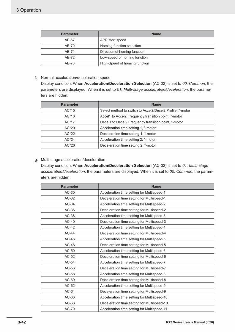
Parameter NameAE-67 APR start speedAE-70 Homing function selectionAE-71 Direction of homing functionAE-72 Low-speed of homing functionAE-73 High-Speed of homing function
f. Normal acceleration/deceleration speedDisplay condition: When Acceleration/Deceleration Selection (AC-02) is set to 00: Common, theparameters are displayed. When it is set to 01: Multi-stage acceleration/deceleration, the parame-ters are hidden.
Parameter NameAC*15 Select method to switch to Accel2/Decel2 Profile, *-motorAC*16 Accel1 to Accel2 Frequency transition point, *-motorAC*17 Decel1 to Decel2 Frequency transition point, *-motorAC*20 Acceleration time setting 1, *-motorAC*22 Deceleration time setting 1, *-motorAC*24 Acceleration time setting 2, *-motorAC*26 Deceleration time setting 2, *-motor
g. Multi-stage acceleration/decelerationDisplay condition: When Acceleration/Deceleration Selection (AC-02) is set to 01: Multi-stageacceleration/deceleration, the parameters are displayed. When it is set to 00: Common, the param-eters are hidden.
Parameter NameAC-30 Acceleration time setting for Multispeed-1AC-32 Deceleration time setting for Multispeed-1AC-34 Acceleration time setting for Multispeed-2AC-36 Deceleration time setting for Multispeed-2AC-38 Acceleration time setting for Multispeed-3AC-40 Deceleration time setting for Multispeed-3AC-42 Acceleration time setting for Multispeed-4AC-44 Deceleration time setting for Multispeed-4AC-46 Acceleration time setting for Multispeed-5AC-48 Deceleration time setting for Multispeed-5AC-50 Acceleration time setting for Multispeed-6AC-52 Deceleration time setting for Multispeed-6AC-54 Acceleration time setting for Multispeed-7AC-56 Deceleration time setting for Multispeed-7AC-58 Acceleration time setting for Multispeed-8AC-60 Deceleration time setting for Multispeed-8AC-62 Acceleration time setting for Multispeed-9AC-64 Deceleration time setting for Multispeed-9AC-66 Acceleration time setting for Multispeed-10AC-68 Deceleration time setting for Multispeed-10AC-70 Acceleration time setting for Multispeed-11
3 Operation
3-42 RX2 Series User’s Manual (I620)
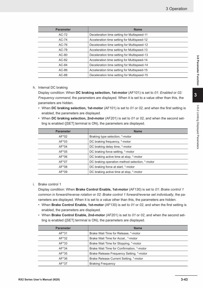
Parameter NameAC-72 Deceleration time setting for Multispeed-11AC-74 Acceleration time setting for Multispeed-12AC-76 Deceleration time setting for Multispeed-12AC-78 Acceleration time setting for Multispeed-13AC-80 Deceleration time setting for Multispeed-13AC-82 Acceleration time setting for Multispeed-14AC-84 Deceleration time setting for Multispeed-14AC-86 Acceleration time setting for Multispeed-15AC-88 Deceleration time setting for Multispeed-15
h. Internal DC brakingDisplay condition: When DC braking selection, 1st-motor (AF101) is set to 01: Enabled or 02:Frequency command, the parameters are displayed. When it is set to a value other than this, theparameters are hidden.• When DC braking selection, 1st-motor (AF101) is set to 01 or 02, and when the first setting is
enabled, the parameters are displayed.• When DC braking selection, 2nd-motor (AF201) is set to 01 or 02, and when the second set-
ting is enabled ([SET] terminal is ON), the parameters are displayed.
Parameter NameAF*02 Braking type selection, *-motorAF*03 DC braking frequency, *-motorAF*04 DC braking delay time, *-motorAF*05 DC braking force setting, *-motorAF*06 DC braking active time at stop, *-motorAF*07 DC braking operation method selection, *-motorAF*08 DC braking force at start, *-motorAF*09 DC braking active time at stop, *-motor
i. Brake control 1Display condition: When Brake Control Enable, 1st-motor (AF130) is set to 01: Brake control 1common in forward/reverse rotation or 02: Brake control 1 forward/reverse set individually, the pa-rameters are displayed. When it is set to a value other than this, the parameters are hidden.• When Brake Control Enable, 1st-motor (AF130) is set to 01 or 02, and when the first setting is
enabled, the parameters are displayed.• When Brake Control Enable, 2nd-motor (AF201) is set to 01 or 02, and when the second set-
ting is enabled ([SET] terminal is ON), the parameters are displayed.
Parameter NameAF*31 Brake Wait Time for Release, *-motorAF*32 Brake Wait Time for Accel., *-motorAF*33 Brake Wait Time for Stopping, *-motorAF*34 Brake Wait Time for Confirmation, *-motorAF*35 Brake Release Frequency Setting, *-motorAF*36 Brake Release Current Setting, *-motorAF*37 Braking Frequency
3 Operation
3-43RX2 Series User’s Manual (I620)
3-8 Parameter Function
3
3-8-2 Limiting D
isplayed Parameters
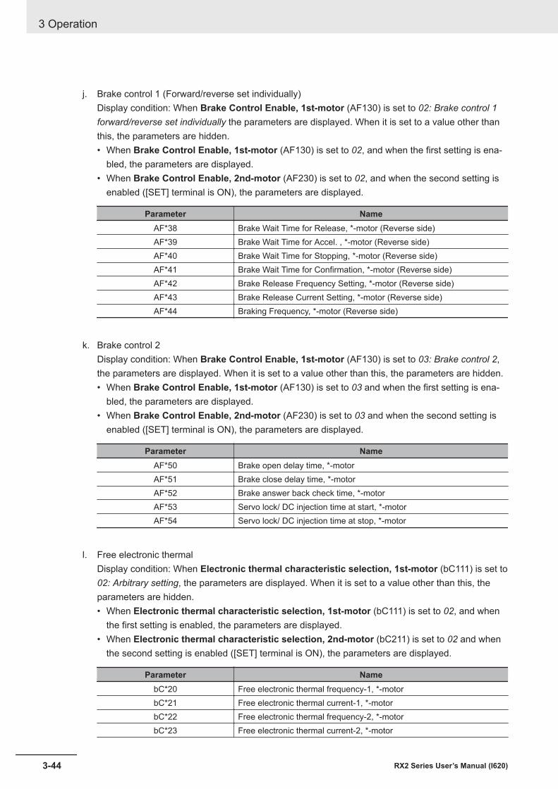
j. Brake control 1 (Forward/reverse set individually)Display condition: When Brake Control Enable, 1st-motor (AF130) is set to 02: Brake control 1forward/reverse set individually the parameters are displayed. When it is set to a value other thanthis, the parameters are hidden.• When Brake Control Enable, 1st-motor (AF130) is set to 02, and when the first setting is ena-
bled, the parameters are displayed.• When Brake Control Enable, 2nd-motor (AF230) is set to 02, and when the second setting is
enabled ([SET] terminal is ON), the parameters are displayed.
Parameter NameAF*38 Brake Wait Time for Release, *-motor (Reverse side)AF*39 Brake Wait Time for Accel. , *-motor (Reverse side)AF*40 Brake Wait Time for Stopping, *-motor (Reverse side)AF*41 Brake Wait Time for Confirmation, *-motor (Reverse side)AF*42 Brake Release Frequency Setting, *-motor (Reverse side)AF*43 Brake Release Current Setting, *-motor (Reverse side)AF*44 Braking Frequency, *-motor (Reverse side)
k. Brake control 2Display condition: When Brake Control Enable, 1st-motor (AF130) is set to 03: Brake control 2,the parameters are displayed. When it is set to a value other than this, the parameters are hidden.• When Brake Control Enable, 1st-motor (AF130) is set to 03 and when the first setting is ena-
bled, the parameters are displayed.• When Brake Control Enable, 2nd-motor (AF230) is set to 03 and when the second setting is
enabled ([SET] terminal is ON), the parameters are displayed.
Parameter NameAF*50 Brake open delay time, *-motorAF*51 Brake close delay time, *-motorAF*52 Brake answer back check time, *-motorAF*53 Servo lock/ DC injection time at start, *-motorAF*54 Servo lock/ DC injection time at stop, *-motor
l. Free electronic thermalDisplay condition: When Electronic thermal characteristic selection, 1st-motor (bC111) is set to02: Arbitrary setting, the parameters are displayed. When it is set to a value other than this, theparameters are hidden.• When Electronic thermal characteristic selection, 1st-motor (bC111) is set to 02, and when
the first setting is enabled, the parameters are displayed.• When Electronic thermal characteristic selection, 2nd-motor (bC211) is set to 02 and when
the second setting is enabled ([SET] terminal is ON), the parameters are displayed.
Parameter NamebC*20 Free electronic thermal frequency-1, *-motorbC*21 Free electronic thermal current-1, *-motorbC*22 Free electronic thermal frequency-2, *-motorbC*23 Free electronic thermal current-2, *-motor
3 Operation
3-44 RX2 Series User’s Manual (I620)
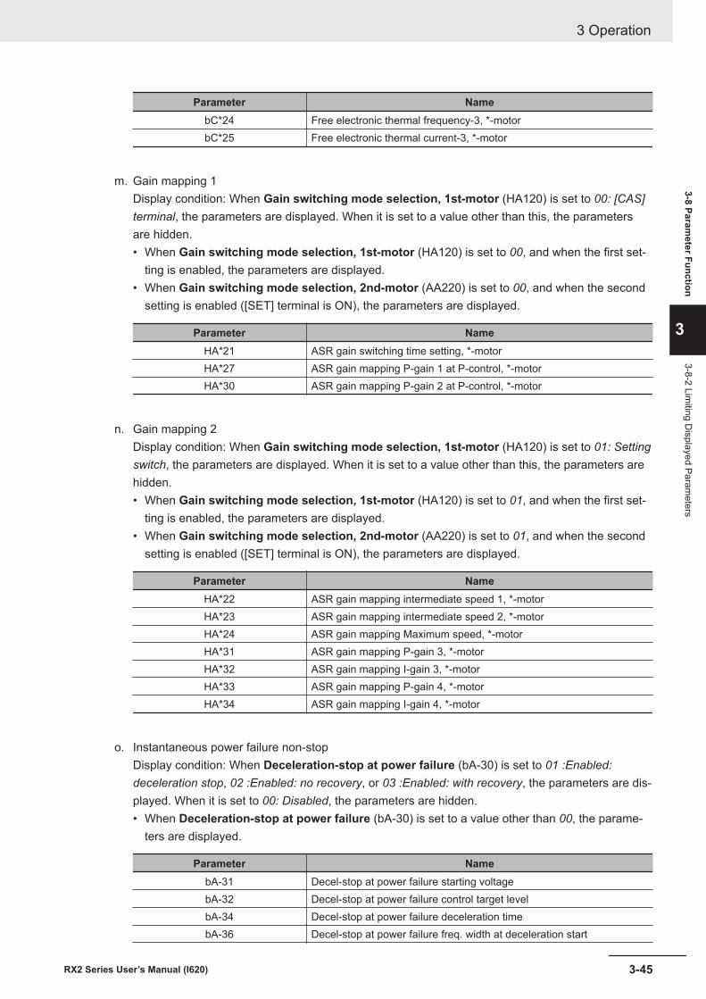
Parameter NamebC*24 Free electronic thermal frequency-3, *-motorbC*25 Free electronic thermal current-3, *-motor
m. Gain mapping 1Display condition: When Gain switching mode selection, 1st-motor (HA120) is set to 00: [CAS]terminal, the parameters are displayed. When it is set to a value other than this, the parametersare hidden.• When Gain switching mode selection, 1st-motor (HA120) is set to 00, and when the first set-
ting is enabled, the parameters are displayed.• When Gain switching mode selection, 2nd-motor (AA220) is set to 00, and when the second
setting is enabled ([SET] terminal is ON), the parameters are displayed.
Parameter NameHA*21 ASR gain switching time setting, *-motorHA*27 ASR gain mapping P-gain 1 at P-control, *-motorHA*30 ASR gain mapping P-gain 2 at P-control, *-motor
n. Gain mapping 2Display condition: When Gain switching mode selection, 1st-motor (HA120) is set to 01: Settingswitch, the parameters are displayed. When it is set to a value other than this, the parameters arehidden.• When Gain switching mode selection, 1st-motor (HA120) is set to 01, and when the first set-
ting is enabled, the parameters are displayed.• When Gain switching mode selection, 2nd-motor (AA220) is set to 01, and when the second
setting is enabled ([SET] terminal is ON), the parameters are displayed.
Parameter NameHA*22 ASR gain mapping intermediate speed 1, *-motorHA*23 ASR gain mapping intermediate speed 2, *-motorHA*24 ASR gain mapping Maximum speed, *-motorHA*31 ASR gain mapping P-gain 3, *-motorHA*32 ASR gain mapping I-gain 3, *-motorHA*33 ASR gain mapping P-gain 4, *-motorHA*34 ASR gain mapping I-gain 4, *-motor
o. Instantaneous power failure non-stopDisplay condition: When Deceleration-stop at power failure (bA-30) is set to 01 :Enabled:deceleration stop, 02 :Enabled: no recovery, or 03 :Enabled: with recovery, the parameters are dis-played. When it is set to 00: Disabled, the parameters are hidden.• When Deceleration-stop at power failure (bA-30) is set to a value other than 00, the parame-
ters are displayed.
Parameter NamebA-31 Decel-stop at power failure starting voltagebA-32 Decel-stop at power failure control target levelbA-34 Decel-stop at power failure deceleration timebA-36 Decel-stop at power failure freq. width at deceleration start
3 Operation
3-45RX2 Series User’s Manual (I620)
3-8 Parameter Function
3
3-8-2 Limiting D
isplayed Parameters
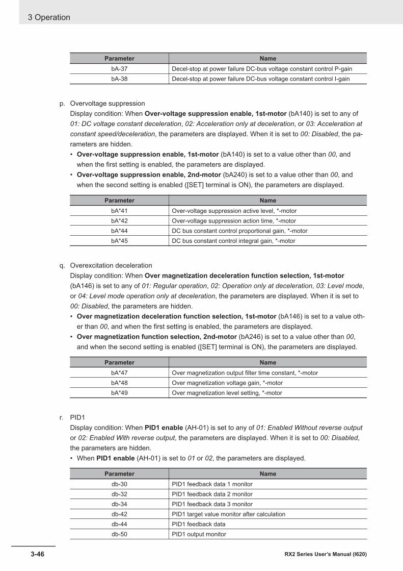
Parameter NamebA-37 Decel-stop at power failure DC-bus voltage constant control P-gainbA-38 Decel-stop at power failure DC-bus voltage constant control I-gain
p. Overvoltage suppressionDisplay condition: When Over-voltage suppression enable, 1st-motor (bA140) is set to any of01: DC voltage constant deceleration, 02: Acceleration only at deceleration, or 03: Acceleration atconstant speed/deceleration, the parameters are displayed. When it is set to 00: Disabled, the pa-rameters are hidden.• Over-voltage suppression enable, 1st-motor (bA140) is set to a value other than 00, and
when the first setting is enabled, the parameters are displayed.• Over-voltage suppression enable, 2nd-motor (bA240) is set to a value other than 00, and
when the second setting is enabled ([SET] terminal is ON), the parameters are displayed.
Parameter NamebA*41 Over-voltage suppression active level, *-motorbA*42 Over-voltage suppression action time, *-motorbA*44 DC bus constant control proportional gain, *-motorbA*45 DC bus constant control integral gain, *-motor
q. Overexcitation decelerationDisplay condition: When Over magnetization deceleration function selection, 1st-motor(bA146) is set to any of 01: Regular operation, 02: Operation only at deceleration, 03: Level mode,or 04: Level mode operation only at deceleration, the parameters are displayed. When it is set to00: Disabled, the parameters are hidden.• Over magnetization deceleration function selection, 1st-motor (bA146) is set to a value oth-
er than 00, and when the first setting is enabled, the parameters are displayed.• Over magnetization function selection, 2nd-motor (bA246) is set to a value other than 00,
and when the second setting is enabled ([SET] terminal is ON), the parameters are displayed.
Parameter NamebA*47 Over magnetization output filter time constant, *-motorbA*48 Over magnetization voltage gain, *-motorbA*49 Over magnetization level setting, *-motor
r. PID1Display condition: When PID1 enable (AH-01) is set to any of 01: Enabled Without reverse outputor 02: Enabled With reverse output, the parameters are displayed. When it is set to 00: Disabled,the parameters are hidden.• When PID1 enable (AH-01) is set to 01 or 02, the parameters are displayed.
Parameter Namedb-30 PID1 feedback data 1 monitordb-32 PID1 feedback data 2 monitordb-34 PID1 feedback data 3 monitordb-42 PID1 target value monitor after calculationdb-44 PID1 feedback datadb-50 PID1 output monitor
3 Operation
3-46 RX2 Series User’s Manual (I620)
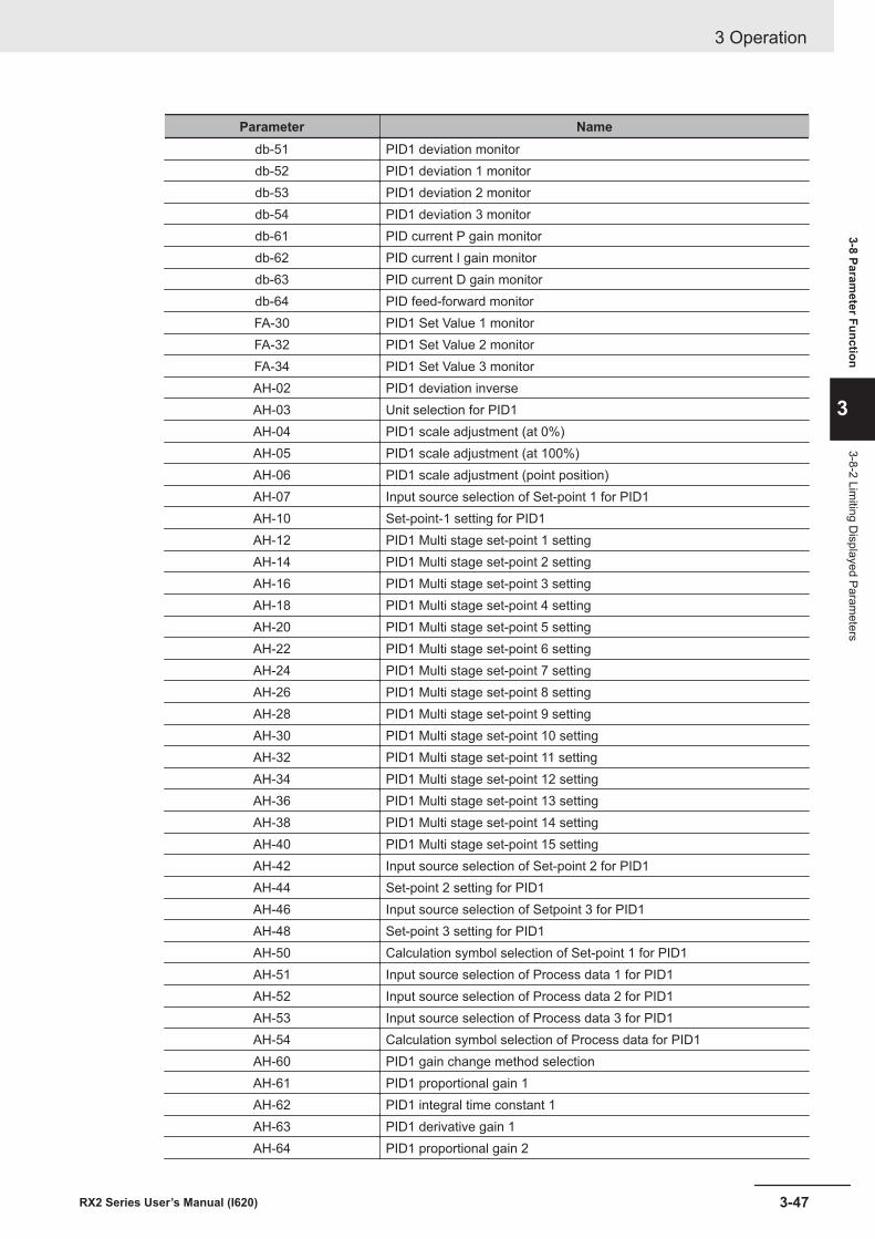
Parameter Namedb-51 PID1 deviation monitordb-52 PID1 deviation 1 monitordb-53 PID1 deviation 2 monitordb-54 PID1 deviation 3 monitordb-61 PID current P gain monitordb-62 PID current I gain monitordb-63 PID current D gain monitordb-64 PID feed-forward monitorFA-30 PID1 Set Value 1 monitorFA-32 PID1 Set Value 2 monitorFA-34 PID1 Set Value 3 monitorAH-02 PID1 deviation inverseAH-03 Unit selection for PID1AH-04 PID1 scale adjustment (at 0%)AH-05 PID1 scale adjustment (at 100%)AH-06 PID1 scale adjustment (point position)AH-07 Input source selection of Set-point 1 for PID1AH-10 Set-point-1 setting for PID1AH-12 PID1 Multi stage set-point 1 settingAH-14 PID1 Multi stage set-point 2 settingAH-16 PID1 Multi stage set-point 3 settingAH-18 PID1 Multi stage set-point 4 settingAH-20 PID1 Multi stage set-point 5 settingAH-22 PID1 Multi stage set-point 6 settingAH-24 PID1 Multi stage set-point 7 settingAH-26 PID1 Multi stage set-point 8 settingAH-28 PID1 Multi stage set-point 9 settingAH-30 PID1 Multi stage set-point 10 settingAH-32 PID1 Multi stage set-point 11 settingAH-34 PID1 Multi stage set-point 12 settingAH-36 PID1 Multi stage set-point 13 settingAH-38 PID1 Multi stage set-point 14 settingAH-40 PID1 Multi stage set-point 15 settingAH-42 Input source selection of Set-point 2 for PID1AH-44 Set-point 2 setting for PID1AH-46 Input source selection of Setpoint 3 for PID1AH-48 Set-point 3 setting for PID1AH-50 Calculation symbol selection of Set-point 1 for PID1AH-51 Input source selection of Process data 1 for PID1AH-52 Input source selection of Process data 2 for PID1AH-53 Input source selection of Process data 3 for PID1AH-54 Calculation symbol selection of Process data for PID1AH-60 PID1 gain change method selectionAH-61 PID1 proportional gain 1AH-62 PID1 integral time constant 1AH-63 PID1 derivative gain 1AH-64 PID1 proportional gain 2
3 Operation
3-47RX2 Series User’s Manual (I620)
3-8 Parameter Function
3
3-8-2 Limiting D
isplayed Parameters
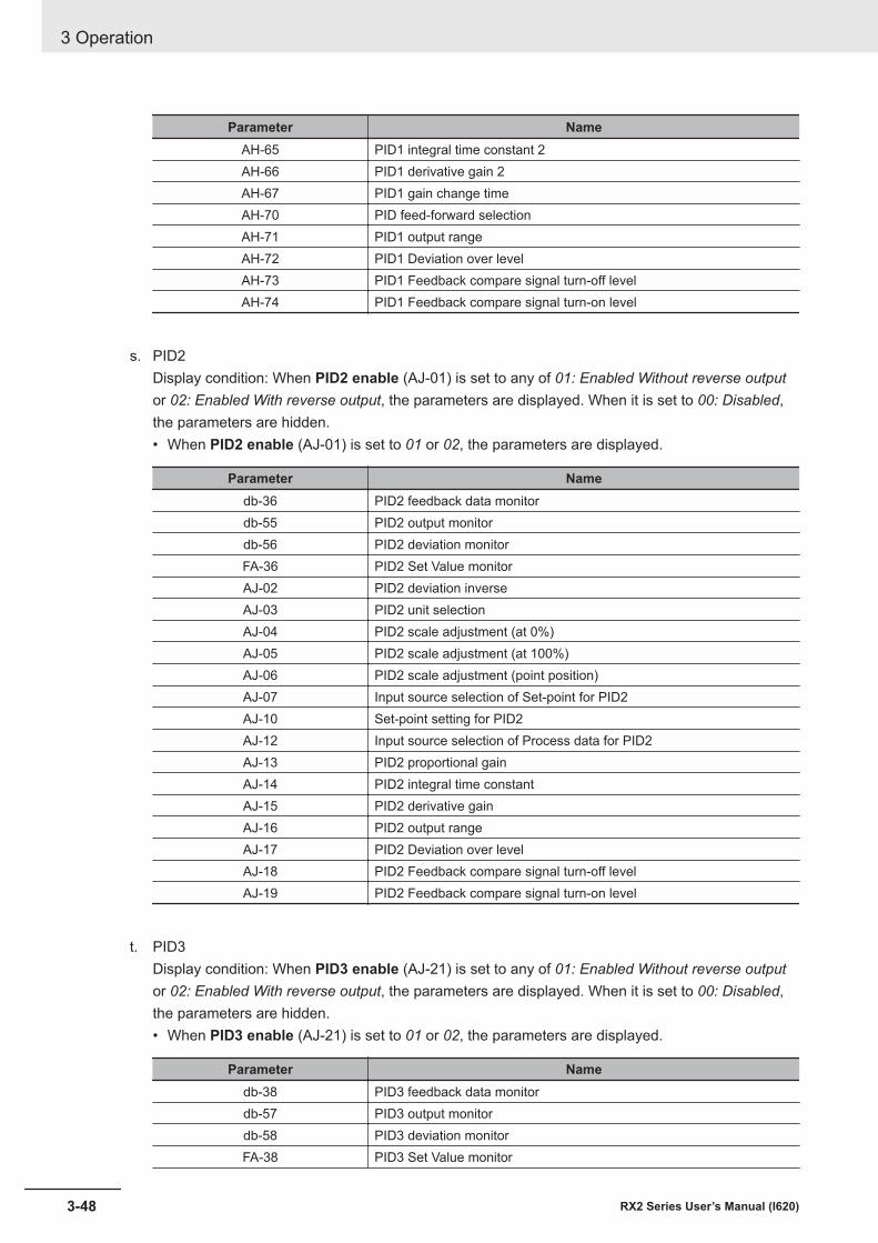
Parameter NameAH-65 PID1 integral time constant 2AH-66 PID1 derivative gain 2AH-67 PID1 gain change timeAH-70 PID feed-forward selectionAH-71 PID1 output rangeAH-72 PID1 Deviation over levelAH-73 PID1 Feedback compare signal turn-off levelAH-74 PID1 Feedback compare signal turn-on level
s. PID2Display condition: When PID2 enable (AJ-01) is set to any of 01: Enabled Without reverse outputor 02: Enabled With reverse output, the parameters are displayed. When it is set to 00: Disabled,the parameters are hidden.• When PID2 enable (AJ-01) is set to 01 or 02, the parameters are displayed.
Parameter Namedb-36 PID2 feedback data monitordb-55 PID2 output monitordb-56 PID2 deviation monitorFA-36 PID2 Set Value monitorAJ-02 PID2 deviation inverseAJ-03 PID2 unit selectionAJ-04 PID2 scale adjustment (at 0%)AJ-05 PID2 scale adjustment (at 100%)AJ-06 PID2 scale adjustment (point position)AJ-07 Input source selection of Set-point for PID2AJ-10 Set-point setting for PID2AJ-12 Input source selection of Process data for PID2AJ-13 PID2 proportional gainAJ-14 PID2 integral time constantAJ-15 PID2 derivative gainAJ-16 PID2 output rangeAJ-17 PID2 Deviation over levelAJ-18 PID2 Feedback compare signal turn-off levelAJ-19 PID2 Feedback compare signal turn-on level
t. PID3Display condition: When PID3 enable (AJ-21) is set to any of 01: Enabled Without reverse outputor 02: Enabled With reverse output, the parameters are displayed. When it is set to 00: Disabled,the parameters are hidden.• When PID3 enable (AJ-21) is set to 01 or 02, the parameters are displayed.
Parameter Namedb-38 PID3 feedback data monitordb-57 PID3 output monitordb-58 PID3 deviation monitorFA-38 PID3 Set Value monitor
3 Operation
3-48 RX2 Series User’s Manual (I620)
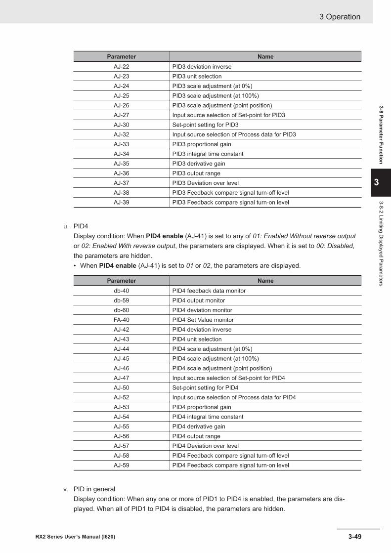
Parameter NameAJ-22 PID3 deviation inverseAJ-23 PID3 unit selectionAJ-24 PID3 scale adjustment (at 0%)AJ-25 PID3 scale adjustment (at 100%)AJ-26 PID3 scale adjustment (point position)AJ-27 Input source selection of Set-point for PID3AJ-30 Set-point setting for PID3AJ-32 Input source selection of Process data for PID3AJ-33 PID3 proportional gainAJ-34 PID3 integral time constantAJ-35 PID3 derivative gainAJ-36 PID3 output rangeAJ-37 PID3 Deviation over levelAJ-38 PID3 Feedback compare signal turn-off levelAJ-39 PID3 Feedback compare signal turn-on level
u. PID4Display condition: When PID4 enable (AJ-41) is set to any of 01: Enabled Without reverse outputor 02: Enabled With reverse output, the parameters are displayed. When it is set to 00: Disabled,the parameters are hidden.• When PID4 enable (AJ-41) is set to 01 or 02, the parameters are displayed.
Parameter Namedb-40 PID4 feedback data monitordb-59 PID4 output monitordb-60 PID4 deviation monitorFA-40 PID4 Set Value monitorAJ-42 PID4 deviation inverseAJ-43 PID4 unit selectionAJ-44 PID4 scale adjustment (at 0%)AJ-45 PID4 scale adjustment (at 100%)AJ-46 PID4 scale adjustment (point position)AJ-47 Input source selection of Set-point for PID4AJ-50 Set-point setting for PID4AJ-52 Input source selection of Process data for PID4AJ-53 PID4 proportional gainAJ-54 PID4 integral time constantAJ-55 PID4 derivative gainAJ-56 PID4 output rangeAJ-57 PID4 Deviation over levelAJ-58 PID4 Feedback compare signal turn-off levelAJ-59 PID4 Feedback compare signal turn-on level
v. PID in generalDisplay condition: When any one or more of PID1 to PID4 is enabled, the parameters are dis-played. When all of PID1 to PID4 is disabled, the parameters are hidden.
3 Operation
3-49RX2 Series User’s Manual (I620)
3-8 Parameter Function
3
3-8-2 Limiting D
isplayed Parameters
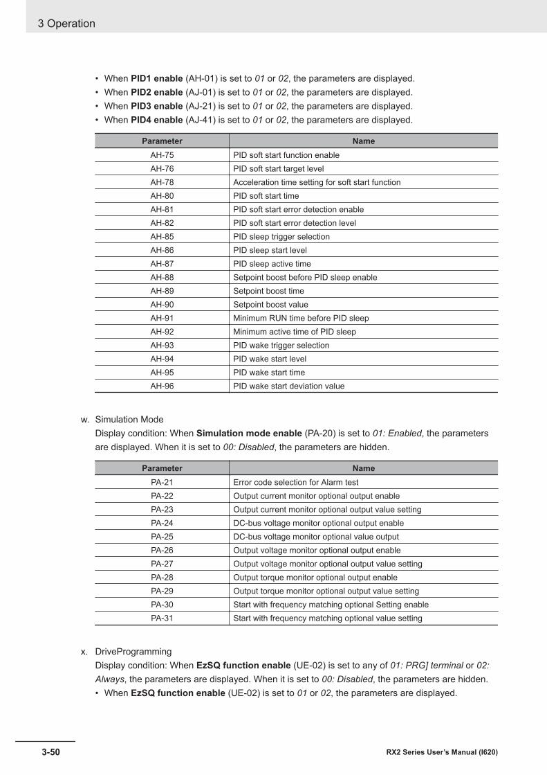
• When PID1 enable (AH-01) is set to 01 or 02, the parameters are displayed.• When PID2 enable (AJ-01) is set to 01 or 02, the parameters are displayed.• When PID3 enable (AJ-21) is set to 01 or 02, the parameters are displayed.• When PID4 enable (AJ-41) is set to 01 or 02, the parameters are displayed.
Parameter NameAH-75 PID soft start function enableAH-76 PID soft start target levelAH-78 Acceleration time setting for soft start functionAH-80 PID soft start timeAH-81 PID soft start error detection enableAH-82 PID soft start error detection levelAH-85 PID sleep trigger selectionAH-86 PID sleep start levelAH-87 PID sleep active timeAH-88 Setpoint boost before PID sleep enableAH-89 Setpoint boost timeAH-90 Setpoint boost valueAH-91 Minimum RUN time before PID sleepAH-92 Minimum active time of PID sleepAH-93 PID wake trigger selectionAH-94 PID wake start levelAH-95 PID wake start timeAH-96 PID wake start deviation value
w. Simulation ModeDisplay condition: When Simulation mode enable (PA-20) is set to 01: Enabled, the parametersare displayed. When it is set to 00: Disabled, the parameters are hidden.
Parameter NamePA-21 Error code selection for Alarm testPA-22 Output current monitor optional output enablePA-23 Output current monitor optional output value settingPA-24 DC-bus voltage monitor optional output enablePA-25 DC-bus voltage monitor optional value outputPA-26 Output voltage monitor optional output enablePA-27 Output voltage monitor optional output value settingPA-28 Output torque monitor optional output enablePA-29 Output torque monitor optional output value settingPA-30 Start with frequency matching optional Setting enablePA-31 Start with frequency matching optional value setting
x. DriveProgrammingDisplay condition: When EzSQ function enable (UE-02) is set to any of 01: PRG] terminal or 02:Always, the parameters are displayed. When it is set to 00: Disabled, the parameters are hidden.• When EzSQ function enable (UE-02) is set to 01 or 02, the parameters are displayed.
3 Operation
3-50 RX2 Series User’s Manual (I620)
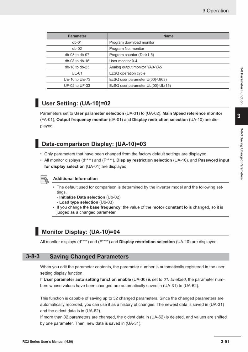
Parameter Namedb-01 Program download monitordb-02 Program No. monitor
db-03 to db-07 Program counter (Task1-5)db-08 to db-16 User monitor 0-4db-18 to db-23 Analog output monitor YA0-YA5
UE-01 EzSQ operation cycleUE-10 to UE-73 EzSQ user parameter U(00)-U(63)UF-02 to UF-33 EzSQ user parameter UL(00)-UL(15)
User Setting: (UA-10)=02Parameters set to User parameter selection (UA-31) to (UA-62), Main Speed reference monitor(FA-01), Output frequency monitor (dA-01) and Display restriction selection (UA-10) are dis-played.
Data-comparison Display: (UA-10)=03• Only parameters that have been changed from the factory default settings are displayed.• All monitor displays (d****) and (F****), Display restriction selection (UA-10), and Password input
for display selection (UA-01) are displayed.
Additional Information
• The default used for comparison is determined by the inverter model and the following set-tings.- Initialize Data selection (Ub-02)- Load type selection (Ub-03)
• If you change the base frequency, the value of the motor constant Io is changed, so it isjudged as a changed parameter.
Monitor Display: (UA-10)=04All monitor displays (d****) and (F****) and Display restriction selection (UA-10) are displayed.
3-8-3 Saving Changed ParametersWhen you edit the parameter contents, the parameter number is automatically registered in the usersetting display function.If User parameter auto setting function enable (UA-30) is set to 01: Enabled, the parameter num-bers whose values have been changed are automatically saved in (UA-31) to (UA-62).
This function is capable of saving up to 32 changed parameters. Since the changed parameters areautomatically recorded, you can use it as a history of changes. The newest data is saved in (UA-31)and the oldest data is in (UA-62).If more than 32 parameters are changed, the oldest data in (UA-62) is deleted, and values are shiftedby one parameter. Then, new data is saved in (UA-31).
3 Operation
3-51RX2 Series User’s Manual (I620)
3-8 Parameter Function
3
3-8-3 Saving Changed Param
eters
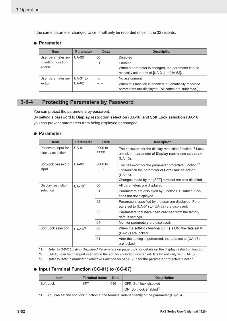
If the same parameter changed twice, it will only be recorded once in the 32 records.
l Parameter
Item Parameter Data DescriptionUser parameter au-to setting functionenable
UA-30 00 Disabled01 Enabled
When a parameter is changed, the parameter is auto-matically set to one of [UA-31] to [UA-62].
User parameter se-lection
UA-31 toUA-62
no No assignment***** When this function is enabled, automatically recorded
parameters are displayed. (All codes are subjected.)
3-8-4 Protecting Parameters by PasswordYou can protect the parameters by password.By setting a password to Display restriction selection (UA-10) and Soft Lock selection (UA-16),you can prevent parameters from being displayed or changed.
l Parameter
Item Parameter Data DescriptionPassword input fordisplay selection
UA-01 0000 toFFFF
The password for the display restriction function.*1 Lock/unlock the parameter of Display restriction selection(UA-10).
Soft-lock passwordinput
UA-02 0000 toFFFF
The password for the parameter protective function.*3
Lock/unlock the parameter of Soft Lock selection(UA-16).Changes made by the [SFT] terminal are also disabled.
Display restrictionselection
UA-10*1 00 All parameters are displayed.01 Parameters are displayed by functions. Disabled func-
tions are not displayed.02 Parameters specified by the user are displayed. Param-
eters set to (UA-31) to (UA-62) are displayed.03 Parameters that have been changed from the factory
default settings.04 Monitor parameters are displayed.
Soft Lock selection UA-16*2 00 When the soft-lock terminal [SFT] is ON, the data set to(UA-17) are locked.
01 After the setting is performed, the data set to (UA-17)are locked.
*1. Refer to 3-8-2 Limiting Displayed Parameters on page 3-37 for details on the display restriction function.*2. (UA-16) can be changed even while the soft lock function is enabled. It is locked only with (UA-02).*3. Refer to 3-8-1 Parameter Protective Function on page 3-37 for the parameter protective function.
l Input Terminal Function (CC-01) to (CC-07)
Item Terminal name Data DescriptionSoft Lock SFT 036 OFF: Soft lock disabled
ON: Soft lock enabled*1
*1. You can set the soft lock function at the terminal independently of the parameter (UA-16).
3 Operation
3-52 RX2 Series User’s Manual (I620)
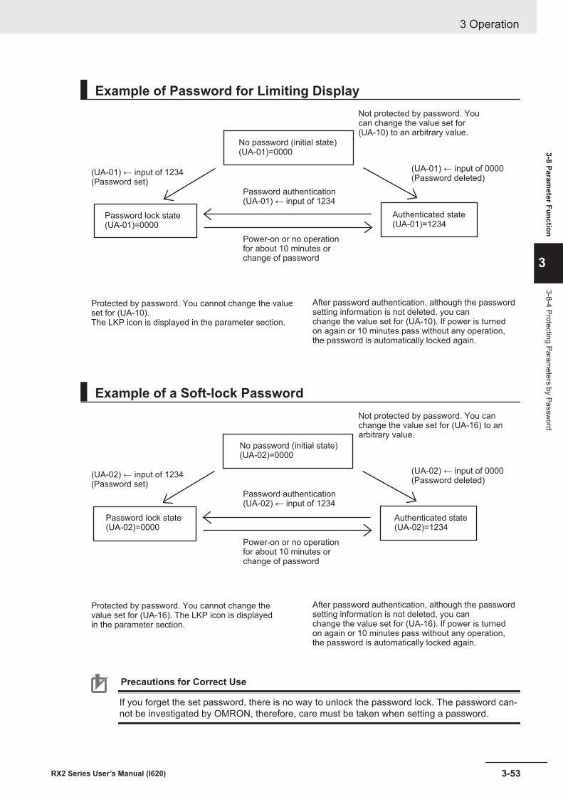
Example of Password for Limiting Display
No password (initial state)(UA-01)=0000
(UA-01) ← input of 1234(Password set)
Password authentication(UA-01) ← input of 1234
Password lock state(UA-01)=0000
Authenticated state(UA-01)=1234
Not protected by password. Youcan change the value set for(UA-10) to an arbitrary value.
(UA-01) ← input of 0000(Password deleted)
Power-on or no operationfor about 10 minutes orchange of password
Protected by password. You cannot change the valueset for (UA-10).The LKP icon is displayed in the parameter section.
After password authentication, although the passwordsetting information is not deleted, you canchange the value set for (UA-10). If power is turnedon again or 10 minutes pass without any operation,the password is automatically locked again.
Example of a Soft-lock Password
No password (initial state)(UA-02)=0000
(UA-02) ← input of 1234(Password set)
Password authentication(UA-02) ← input of 1234
Password lock state(UA-02)=0000
Authenticated state(UA-02)=1234
Not protected by password. You canchange the value set for (UA-16) to anarbitrary value.
(UA-02) ← input of 0000(Password deleted)
Power-on or no operationfor about 10 minutes orchange of password
Protected by password. You cannot change thevalue set for (UA-16). The LKP icon is displayedin the parameter section.
After password authentication, although the passwordsetting information is not deleted, you canchange the value set for (UA-16). If power is turnedon again or 10 minutes pass without any operation,the password is automatically locked again.
Precautions for Correct Use
If you forget the set password, there is no way to unlock the password lock. The password can-not be investigated by OMRON, therefore, care must be taken when setting a password.
3 Operation
3-53RX2 Series User’s Manual (I620)
3-8 Parameter Function
3
3-8-4 Protecting Parameters by Passw
ord
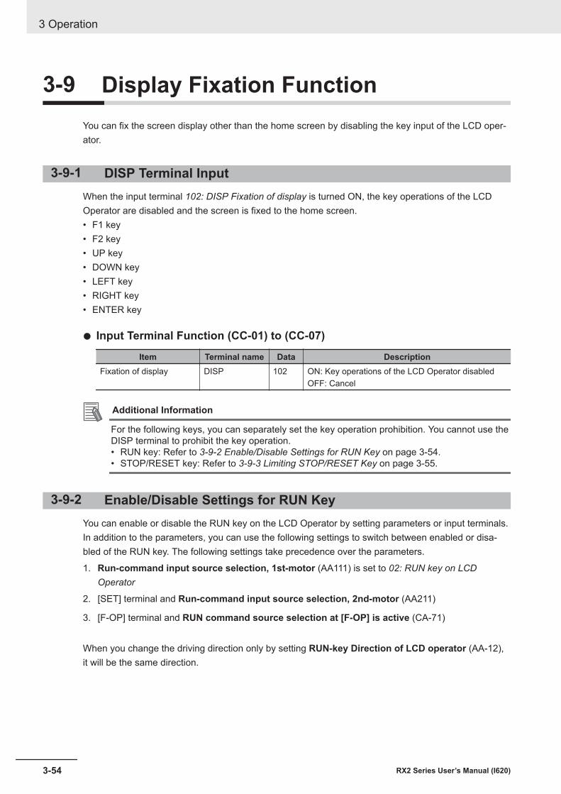
3-9 Display Fixation FunctionYou can fix the screen display other than the home screen by disabling the key input of the LCD oper-ator.
3-9-1 DISP Terminal InputWhen the input terminal 102: DISP Fixation of display is turned ON, the key operations of the LCDOperator are disabled and the screen is fixed to the home screen.• F1 key• F2 key• UP key• DOWN key• LEFT key• RIGHT key• ENTER key
l Input Terminal Function (CC-01) to (CC-07)
Item Terminal name Data DescriptionFixation of display DISP 102 ON: Key operations of the LCD Operator disabled
OFF: Cancel
Additional Information
For the following keys, you can separately set the key operation prohibition. You cannot use theDISP terminal to prohibit the key operation.• RUN key: Refer to 3-9-2 Enable/Disable Settings for RUN Key on page 3-54.• STOP/RESET key: Refer to 3-9-3 Limiting STOP/RESET Key on page 3-55.
3-9-2 Enable/Disable Settings for RUN KeyYou can enable or disable the RUN key on the LCD Operator by setting parameters or input terminals.In addition to the parameters, you can use the following settings to switch between enabled or disa-bled of the RUN key. The following settings take precedence over the parameters.
1. Run-command input source selection, 1st-motor (AA111) is set to 02: RUN key on LCDOperator
2. [SET] terminal and Run-command input source selection, 2nd-motor (AA211)
3. [F-OP] terminal and RUN command source selection at [F-OP] is active (CA-71)
When you change the driving direction only by setting RUN-key Direction of LCD operator (AA-12),it will be the same direction.
3 Operation
3-54 RX2 Series User’s Manual (I620)
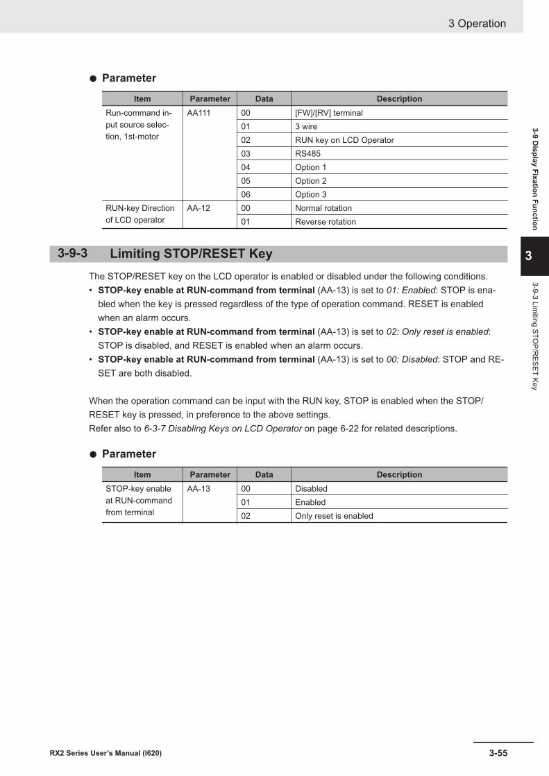
l Parameter
Item Parameter Data DescriptionRun-command in-put source selec-tion, 1st-motor
AA111 00 [FW]/[RV] terminal01 3 wire02 RUN key on LCD Operator03 RS48504 Option 105 Option 206 Option 3
RUN-key Directionof LCD operator
AA-12 00 Normal rotation01 Reverse rotation
3-9-3 Limiting STOP/RESET KeyThe STOP/RESET key on the LCD operator is enabled or disabled under the following conditions.• STOP-key enable at RUN-command from terminal (AA-13) is set to 01: Enabled: STOP is ena-
bled when the key is pressed regardless of the type of operation command. RESET is enabledwhen an alarm occurs.
• STOP-key enable at RUN-command from terminal (AA-13) is set to 02: Only reset is enabled:STOP is disabled, and RESET is enabled when an alarm occurs.
• STOP-key enable at RUN-command from terminal (AA-13) is set to 00: Disabled: STOP and RE-SET are both disabled.
When the operation command can be input with the RUN key, STOP is enabled when the STOP/RESET key is pressed, in preference to the above settings.Refer also to 6-3-7 Disabling Keys on LCD Operator on page 6-22 for related descriptions.
l Parameter
Item Parameter Data DescriptionSTOP-key enableat RUN-commandfrom terminal
AA-13 00 Disabled01 Enabled02 Only reset is enabled
3 Operation
3-55RX2 Series User’s Manual (I620)
3-9 Display Fixation Function
3
3-9-3 Limiting STO
P/RESET Key
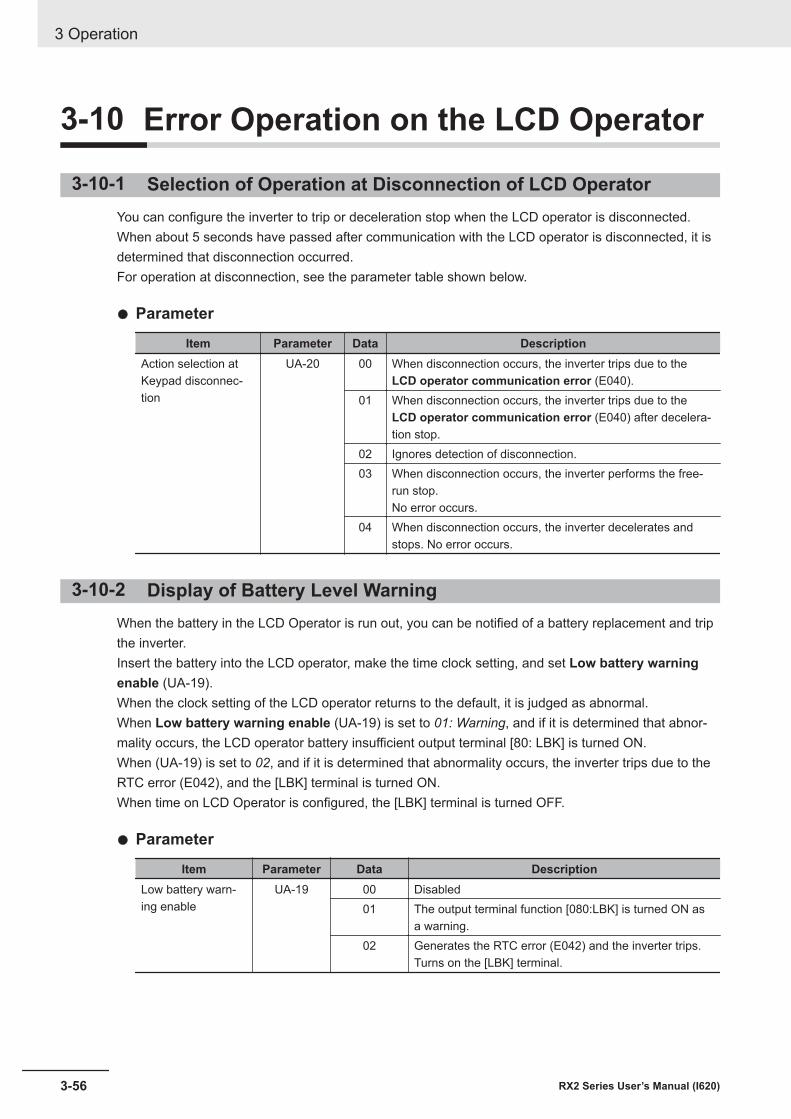
3-10 Error Operation on the LCD Operator
3-10-1 Selection of Operation at Disconnection of LCD OperatorYou can configure the inverter to trip or deceleration stop when the LCD operator is disconnected.When about 5 seconds have passed after communication with the LCD operator is disconnected, it isdetermined that disconnection occurred.For operation at disconnection, see the parameter table shown below.
l Parameter
Item Parameter Data DescriptionAction selection atKeypad disconnec-tion
UA-20 00 When disconnection occurs, the inverter trips due to theLCD operator communication error (E040).
01 When disconnection occurs, the inverter trips due to theLCD operator communication error (E040) after decelera-tion stop.
02 Ignores detection of disconnection.03 When disconnection occurs, the inverter performs the free-
run stop.No error occurs.
04 When disconnection occurs, the inverter decelerates andstops. No error occurs.
3-10-2 Display of Battery Level WarningWhen the battery in the LCD Operator is run out, you can be notified of a battery replacement and tripthe inverter.Insert the battery into the LCD operator, make the time clock setting, and set Low battery warningenable (UA-19).When the clock setting of the LCD operator returns to the default, it is judged as abnormal.When Low battery warning enable (UA-19) is set to 01: Warning, and if it is determined that abnor-mality occurs, the LCD operator battery insufficient output terminal [80: LBK] is turned ON.When (UA-19) is set to 02, and if it is determined that abnormality occurs, the inverter trips due to theRTC error (E042), and the [LBK] terminal is turned ON.When time on LCD Operator is configured, the [LBK] terminal is turned OFF.
l Parameter
Item Parameter Data DescriptionLow battery warn-ing enable
UA-19 00 Disabled01 The output terminal function [080:LBK] is turned ON as
a warning.02 Generates the RTC error (E042) and the inverter trips.
Turns on the [LBK] terminal.
3 Operation
3-56 RX2 Series User’s Manual (I620)
Additional Information
• You can cancel a trip due to the RTC error (E042) by performing the reset operation; howev-er, if time is not configured, the error occurs again. In this case, the output terminal function[080: LBK] is ON.
• If you do not need the time function and do not insert the battery in the LCD Operator, setLow battery warning enable (UA-19) to 00: Disabled.
3 Operation
3-57RX2 Series User’s Manual (I620)
3-10 Error Operation on the LC
D O
perator
3
3-10-2 Display of Battery Level W
arning
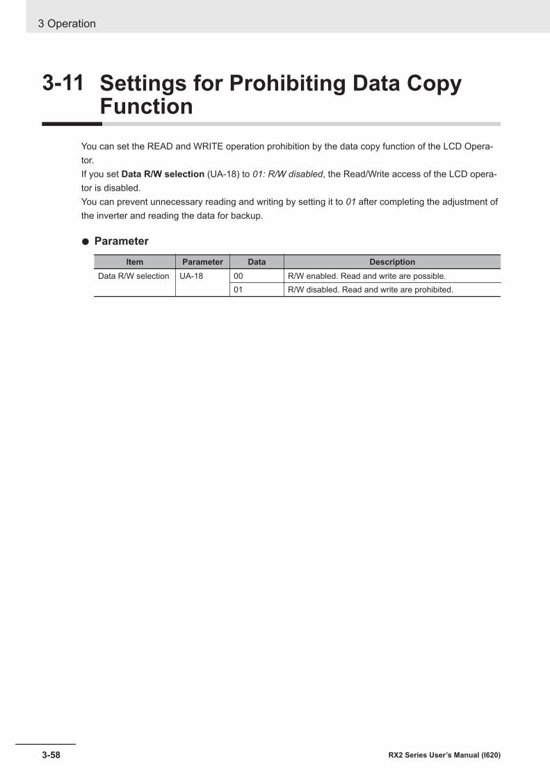
3-11 Settings for Prohibiting Data CopyFunction
You can set the READ and WRITE operation prohibition by the data copy function of the LCD Opera-tor.If you set Data R/W selection (UA-18) to 01: R/W disabled, the Read/Write access of the LCD opera-tor is disabled.You can prevent unnecessary reading and writing by setting it to 01 after completing the adjustment ofthe inverter and reading the data for backup.
l Parameter
Item Parameter Data DescriptionData R/W selection UA-18 00 R/W enabled. Read and write are possible.
01 R/W disabled. Read and write are prohibited.
3 Operation
3-58 RX2 Series User’s Manual (I620)
3-12 Inverter InitializationWhen Initialize Mode selection (Ub-01) is chosen and Initialize Enable (Ub-05) is set to 01: Startinitialization, the designated data can be initialized to the factory default.You can also clear only the trip history without initializing the stored parameter.
Precautions for Correct Use
After initializing the inverter, you need to reset the electronic thermal of the motor. If the inverteris used without the reset after initialization, the motor may burn out.
Additional Information
• The initialization begins when F2 key is pressed after Initialize Enable(Ub-05) set to 01.• The initialization sets the parameters to initial values. When you need the data before the ini-
tialization, read out it with the R/W function (Read) in the LCD operator, or use CX-Drive tostore it in a PC.
• The following data cannot be initialized:• EzSQ user parameter U(UE-10) to (UE-73)• Cumulative operating hours monitor during RUN(dC-22)、• Cumulative power-on time(dC-24)• Initialize Data selection(Ub-02)• Load type selection(Ub-03)• [Ai1] Voltage/Current zero-gain adjustment(Cb-30) to [Ai3] Voltage gain
adjustment(Cb-35)• Thermistor gain adjustment(Cb-41)
• The initialized parameters may not be displayed depending onDisplay restrictionselection(UA-10). Change the data to 00: Full displaybefore performing initialization.
• When the setting of Soft Lock selection(UA-16) bans on a change of parameter values, thedata can not be initialized. Be sure to reset the ban on a change of parameter values beforecarrying out the initialization.
• Initialization cannot be performed while the following symbols are displayed on the LCD oper-ator.
During operation (RUN)When the trip occurs (TRIP)During soft lock (LKS)
• Even when the operation command is input during initialization, the inverter ignores the com-mand. Input the operation command again after the initialization is finished.
l Parameter
3 Operation
3-59RX2 Series User’s Manual (I620)
3-12 Inverter Initialization
3
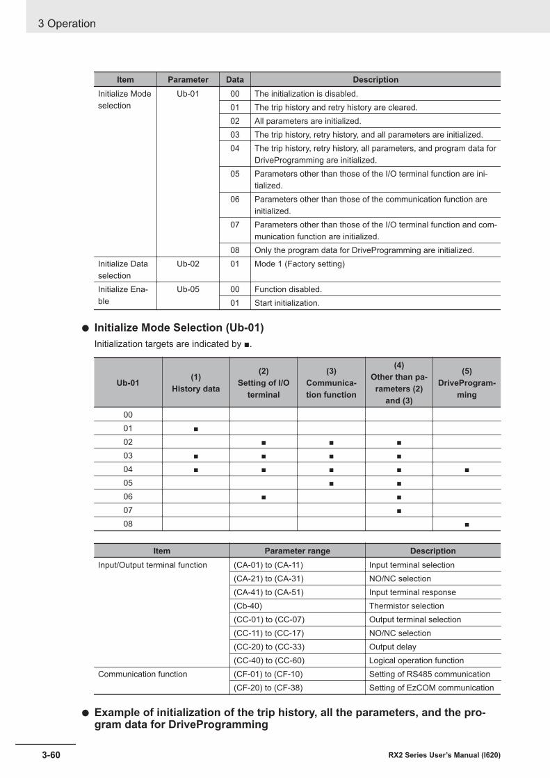
Item Parameter Data DescriptionInitialize Modeselection
Ub-01 00 The initialization is disabled.01 The trip history and retry history are cleared.02 All parameters are initialized.03 The trip history, retry history, and all parameters are initialized.04 The trip history, retry history, all parameters, and program data for
DriveProgramming are initialized.05 Parameters other than those of the I/O terminal function are ini-
tialized.06 Parameters other than those of the communication function are
initialized.07 Parameters other than those of the I/O terminal function and com-
munication function are initialized.08 Only the program data for DriveProgramming are initialized.
Initialize Dataselection
Ub-02 01 Mode 1 (Factory setting)
Initialize Ena-ble
Ub-05 00 Function disabled.01 Start initialization.
l Initialize Mode Selection (Ub-01)Initialization targets are indicated by ■.
Ub-01 (1)History data
(2)Setting of I/O
terminal
(3)Communica-tion function
(4)Other than pa-rameters (2)
and (3)
(5)DriveProgram-
ming
0001 ■02 ■ ■ ■03 ■ ■ ■ ■04 ■ ■ ■ ■ ■05 ■ ■06 ■ ■07 ■08 ■
Item Parameter range DescriptionInput/Output terminal function (CA-01) to (CA-11) Input terminal selection
(CA-21) to (CA-31) NO/NC selection(CA-41) to (CA-51) Input terminal response(Cb-40) Thermistor selection(CC-01) to (CC-07) Output terminal selection(CC-11) to (CC-17) NO/NC selection(CC-20) to (CC-33) Output delay(CC-40) to (CC-60) Logical operation function
Communication function (CF-01) to (CF-10) Setting of RS485 communication(CF-20) to (CF-38) Setting of EzCOM communication
l Example of initialization of the trip history, all the parameters, and the pro-gram data for DriveProgramming
3 Operation
3-60 RX2 Series User’s Manual (I620)
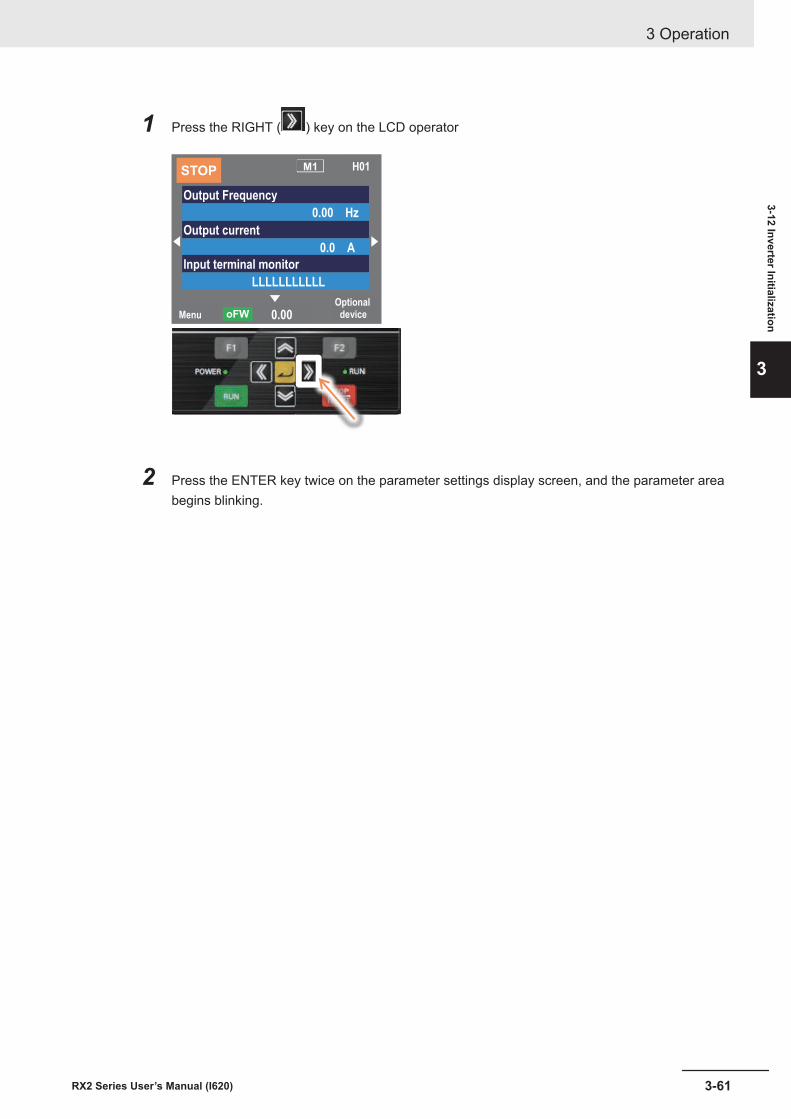
1 Press the RIGHT ( ) key on the LCD operator
Menu
Optional device0.00oFW
STOPM1 H01
Output Frequency
0.00 Hz
Output current
0.0 A
Input terminal monitor
LLLLLLLLLLL
2 Press the ENTER key twice on the parameter settings display screen, and the parameter areabegins blinking.
3 Operation
3-61RX2 Series User’s Manual (I620)
3-12 Inverter Initialization
3
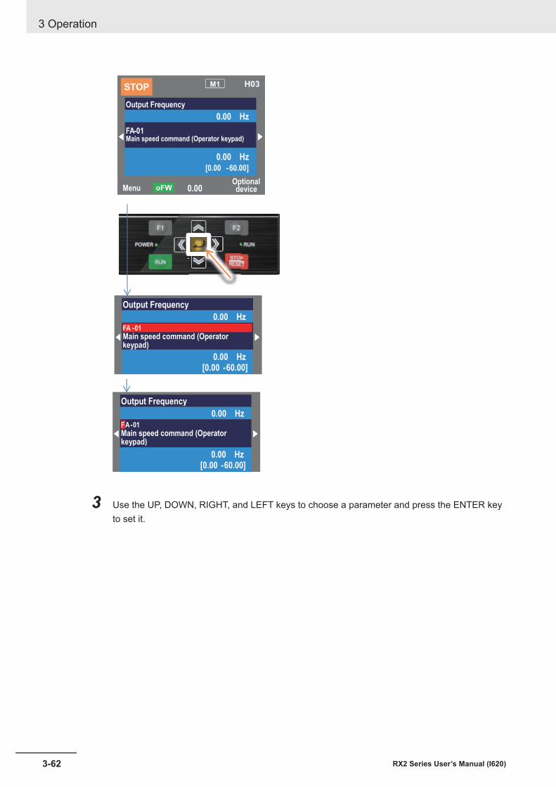
Output Frequency
0.00 HzFA -01 Main speed command (Operatorkeypad)
0.00 Hz[0.00 -60.00]
Output Frequency
0.00 HzFA-01Main speed command (Operatorkeypad)
0.00 Hz[0.00 -60.00]
MenuOptional device0.00oFW
STOPM1 H03
Output Frequency
0.00 Hz
FA-01Main speed command (Operator keypad)
0.00 Hz[0.00 -60.00]
3 Use the UP, DOWN, RIGHT, and LEFT keys to choose a parameter and press the ENTER keyto set it.
3 Operation
3-62 RX2 Series User’s Manual (I620)
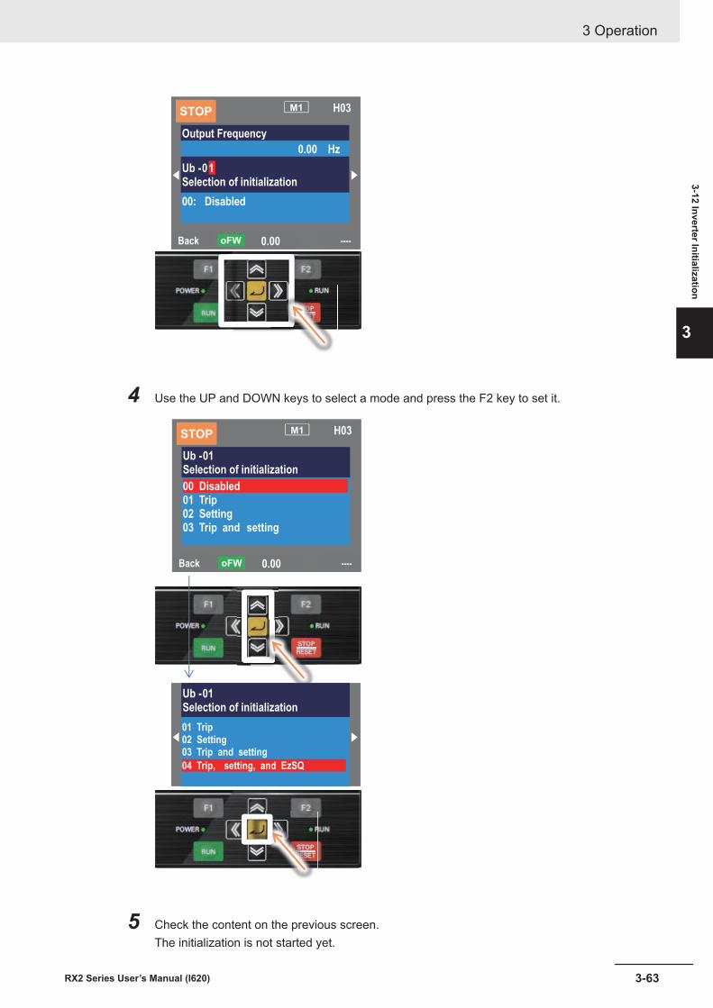
Back ----0.00oFW
STOPM1 H03
Output Frequency
0.00 Hz
Ub -01Selection of initialization
00: Disabled
4 Use the UP and DOWN keys to select a mode and press the F2 key to set it.
Back ----0.00oFW
STOPM1 H03
Ub -01Selection of initialization
00 Disabled 01 Trip02 Setting03 Trip and setting
Ub -01Selection of initialization
01 Trip02 Setting03 Trip and setting
04 Trip, setting, and EzSQ
5 Check the content on the previous screen.The initialization is not started yet.
3 Operation
3-63RX2 Series User’s Manual (I620)
3-12 Inverter Initialization
3
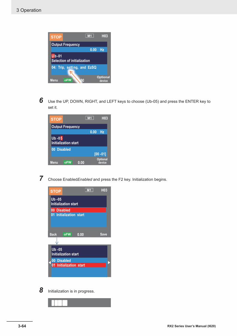
MenuOptional
device0.00oFW
STOP M1 H03
Output Frequency
0.00 Hz
U b-01Selection of initialization
04: Trip, setting, and EzSQ
0.00oFW
p, setting, and
6 Use the UP, DOWN, RIGHT, and LEFT keys to choose (Ub-05) and press the ENTER key toset it.
MenuOptional
device0.00oFW
STOPM1 H03
Output Frequency
0.00 Hz
Ub -05Initialization start
00 Disabled[00 -01]
7 Choose EnabledEnabled and press the F2 key. Initialization begins.
Back Save0.00oFW
STOPM1 H03
Ub -05
Initialization start
00 Disabled
01 Initialization start
Ub -05
Initialization start
00 Disabled
01 Initialization start
8 Initialization is in progress.
3 Operation
3-64 RX2 Series User’s Manual (I620)

9 Display showing message for initialization completed.
3 Operation
3-65RX2 Series User’s Manual (I620)
3-12 Inverter Initialization
3
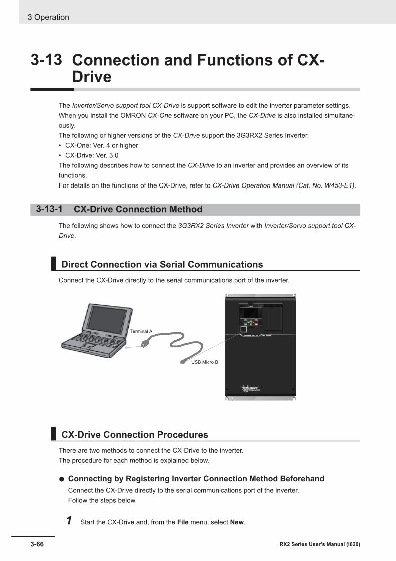
3-13 Connection and Functions of CX-Drive
The Inverter/Servo support tool CX-Drive is support software to edit the inverter parameter settings.When you install the OMRON CX-One software on your PC, the CX-Drive is also installed simultane-ously.The following or higher versions of the CX-Drive support the 3G3RX2 Series Inverter.• CX-One: Ver. 4 or higher• CX-Drive: Ver. 3.0The following describes how to connect the CX-Drive to an inverter and provides an overview of itsfunctions.For details on the functions of the CX-Drive, refer to CX-Drive Operation Manual (Cat. No. W453-E1).
3-13-1 CX-Drive Connection MethodThe following shows how to connect the 3G3RX2 Series Inverter with Inverter/Servo support tool CX-Drive.
Direct Connection via Serial CommunicationsConnect the CX-Drive directly to the serial communications port of the inverter.
Terminal A
USB Micro B
CX-Drive Connection ProceduresThere are two methods to connect the CX-Drive to the inverter.The procedure for each method is explained below.
l Connecting by Registering Inverter Connection Method BeforehandConnect the CX-Drive directly to the serial communications port of the inverter.Follow the steps below.
1 Start the CX-Drive and, from the File menu, select New.
3 Operation
3-66 RX2 Series User’s Manual (I620)
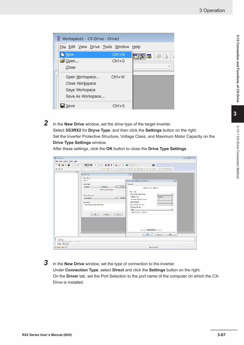
2 In the New Drive window, set the drive type of the target inverter.Select 3G3RX2 for Dryve Type, and then click the Settings button on the right.Set the Inverter Protective Structure, Voltage Class, and Maximum Motor Capacity on theDrive Type Settings window.After these settings, click the OK button to close the Drive Type Settings.
3 In the New Drive window, set the type of connection to the inverter.Under Connection Type, select Direct and click the Settings button on the right.On the Driver tab, set the Port Selection to the port name of the computer on which the CX-Drive is installed.
3 Operation
3-67RX2 Series User’s Manual (I620)
3-13 Connection and Functions of C
X-Drive
3
3-13-1 CX-D
rive Connection M
ethod
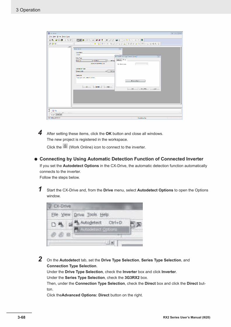
4 After setting these items, click the OK button and close all windows.The new project is registered in the workspace.
Click the (Work Online) icon to connect to the inverter.
l Connecting by Using Automatic Detection Function of Connected InverterIf you set the Autodetect Options in the CX-Drive, the automatic detection function automaticallyconnects to the inverter.Follow the steps below.
1 Start the CX-Drive and, from the Drive menu, select Autodetect Options to open the Optionswindow.
2 On the Autodetect tab, set the Drive Type Selection, Series Type Selection, andConnection Type Selection.Under the Drive Type Selection, check the Inverter box and click Inverter.Under the Series Type Selection, check the 3G3RX2 box.Then, under the Connection Type Selection, check the Direct box and click the Direct but-ton.Click theAdvanced Options: Direct button on the right.
3 Operation
3-68 RX2 Series User’s Manual (I620)
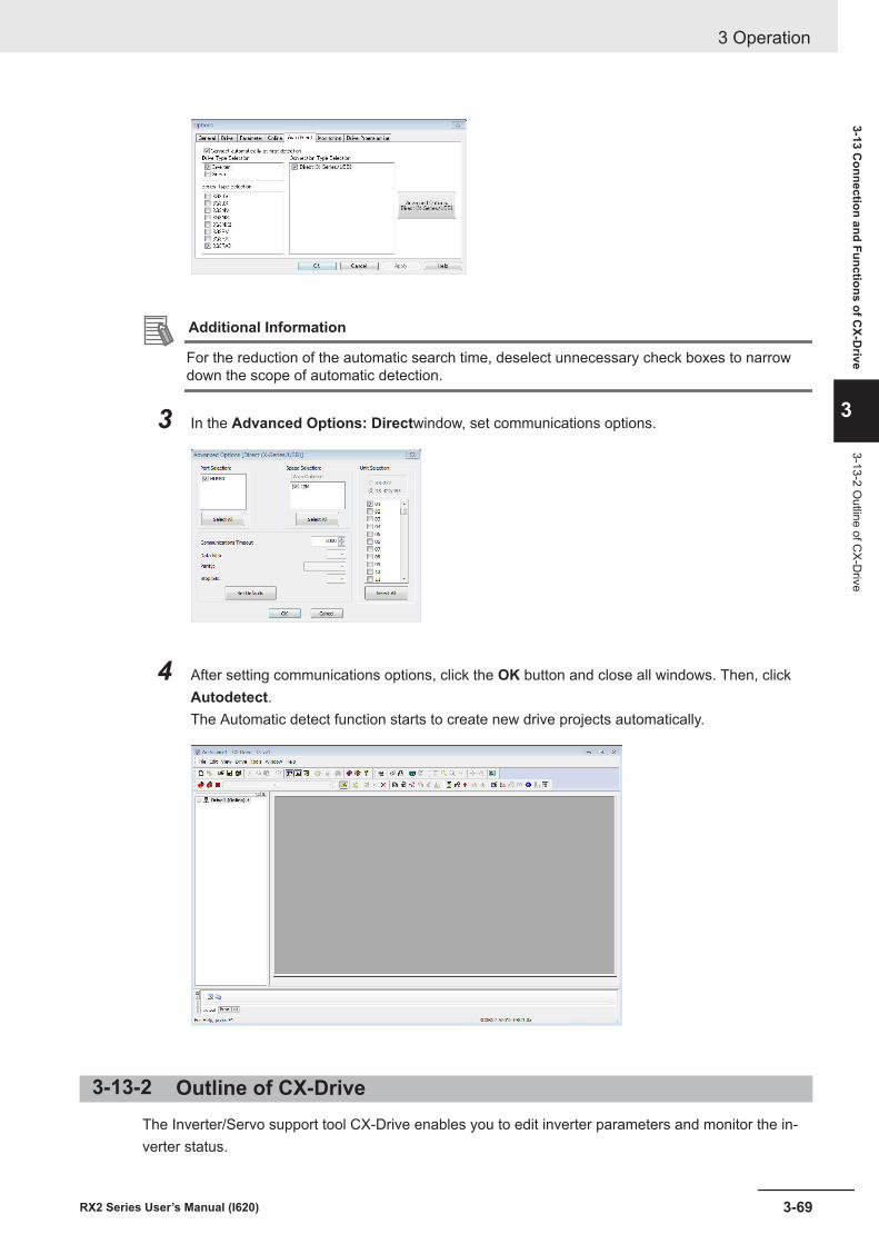
Additional Information
For the reduction of the automatic search time, deselect unnecessary check boxes to narrowdown the scope of automatic detection.
3 In the Advanced Options: Directwindow, set communications options.
4 After setting communications options, click the OK button and close all windows. Then, clickAutodetect.The Automatic detect function starts to create new drive projects automatically.
3-13-2 Outline of CX-DriveThe Inverter/Servo support tool CX-Drive enables you to edit inverter parameters and monitor the in-verter status.
3 Operation
3-69RX2 Series User’s Manual (I620)
3-13 Connection and Functions of C
X-Drive
3
3-13-2 Outline of C
X-Drive
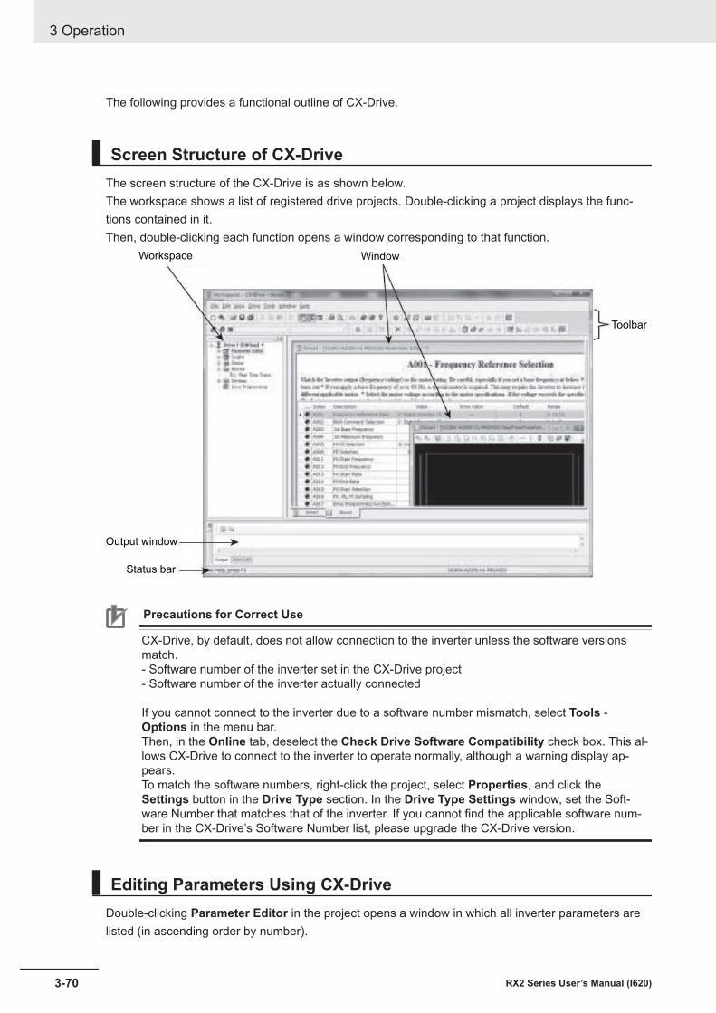
The following provides a functional outline of CX-Drive.
Screen Structure of CX-DriveThe screen structure of the CX-Drive is as shown below.The workspace shows a list of registered drive projects. Double-clicking a project displays the func-tions contained in it.Then, double-clicking each function opens a window corresponding to that function.
Workspace Window
Toolbar
Output window
Status bar
Precautions for Correct Use
CX-Drive, by default, does not allow connection to the inverter unless the software versionsmatch.- Software number of the inverter set in the CX-Drive project- Software number of the inverter actually connected If you cannot connect to the inverter due to a software number mismatch, select Tools -Options in the menu bar.Then, in the Online tab, deselect the Check Drive Software Compatibility check box. This al-lows CX-Drive to connect to the inverter to operate normally, although a warning display ap-pears.To match the software numbers, right-click the project, select Properties, and click theSettings button in the Drive Type section. In the Drive Type Settings window, set the Soft-ware Number that matches that of the inverter. If you cannot find the applicable software num-ber in the CX-Drive’s Software Number list, please upgrade the CX-Drive version.
Editing Parameters Using CX-DriveDouble-clicking Parameter Editor in the project opens a window in which all inverter parameters arelisted (in ascending order by number).
3 Operation
3-70 RX2 Series User’s Manual (I620)
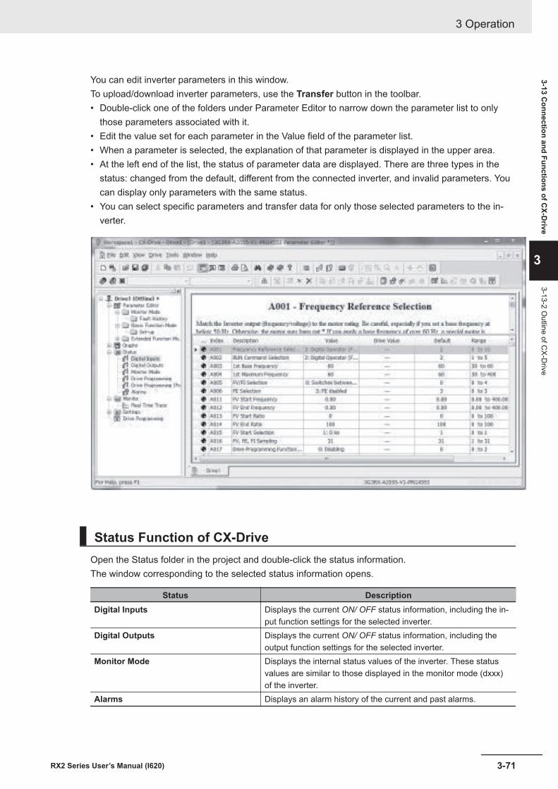
You can edit inverter parameters in this window.To upload/download inverter parameters, use the Transfer button in the toolbar.• Double-click one of the folders under Parameter Editor to narrow down the parameter list to only
those parameters associated with it.• Edit the value set for each parameter in the Value field of the parameter list.• When a parameter is selected, the explanation of that parameter is displayed in the upper area.• At the left end of the list, the status of parameter data are displayed. There are three types in the
status: changed from the default, different from the connected inverter, and invalid parameters. Youcan display only parameters with the same status.
• You can select specific parameters and transfer data for only those selected parameters to the in-verter.
Status Function of CX-DriveOpen the Status folder in the project and double-click the status information.The window corresponding to the selected status information opens.
Status DescriptionDigital Inputs Displays the current ON/ OFF status information, including the in-
put function settings for the selected inverter.Digital Outputs Displays the current ON/ OFF status information, including the
output function settings for the selected inverter.Monitor Mode Displays the internal status values of the inverter. These status
values are similar to those displayed in the monitor mode (dxxx)of the inverter.
Alarms Displays an alarm history of the current and past alarms.
3 Operation
3-71RX2 Series User’s Manual (I620)
3-13 Connection and Functions of C
X-Drive
3
3-13-2 Outline of C
X-Drive
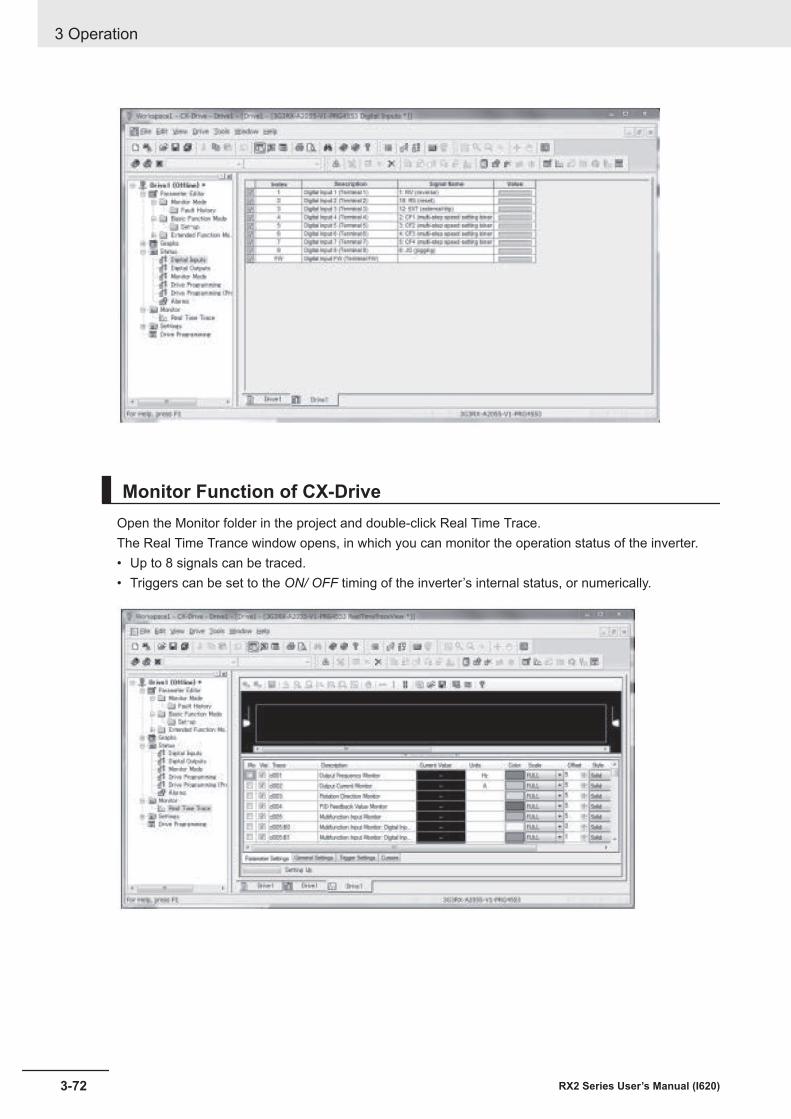
Monitor Function of CX-DriveOpen the Monitor folder in the project and double-click Real Time Trace.The Real Time Trance window opens, in which you can monitor the operation status of the inverter.• Up to 8 signals can be traced.• Triggers can be set to the ON/ OFF timing of the inverter’s internal status, or numerically.
3 Operation
3-72 RX2 Series User’s Manual (I620)
4Test Run
This section describes the test run procedure.
4-1 Test Run Procedure ....................................................................................... 4-24-2 Settings and Commands Required for Running the Inverter..................... 4-34-3 Conduct a Test Run with LCD Operator....................................................... 4-54-4 Conduct a Test Run with Analog Input ........................................................ 4-74-5 Simulation Mode............................................................................................. 4-9
4-1RX2 Series User’s Manual (I620)
4
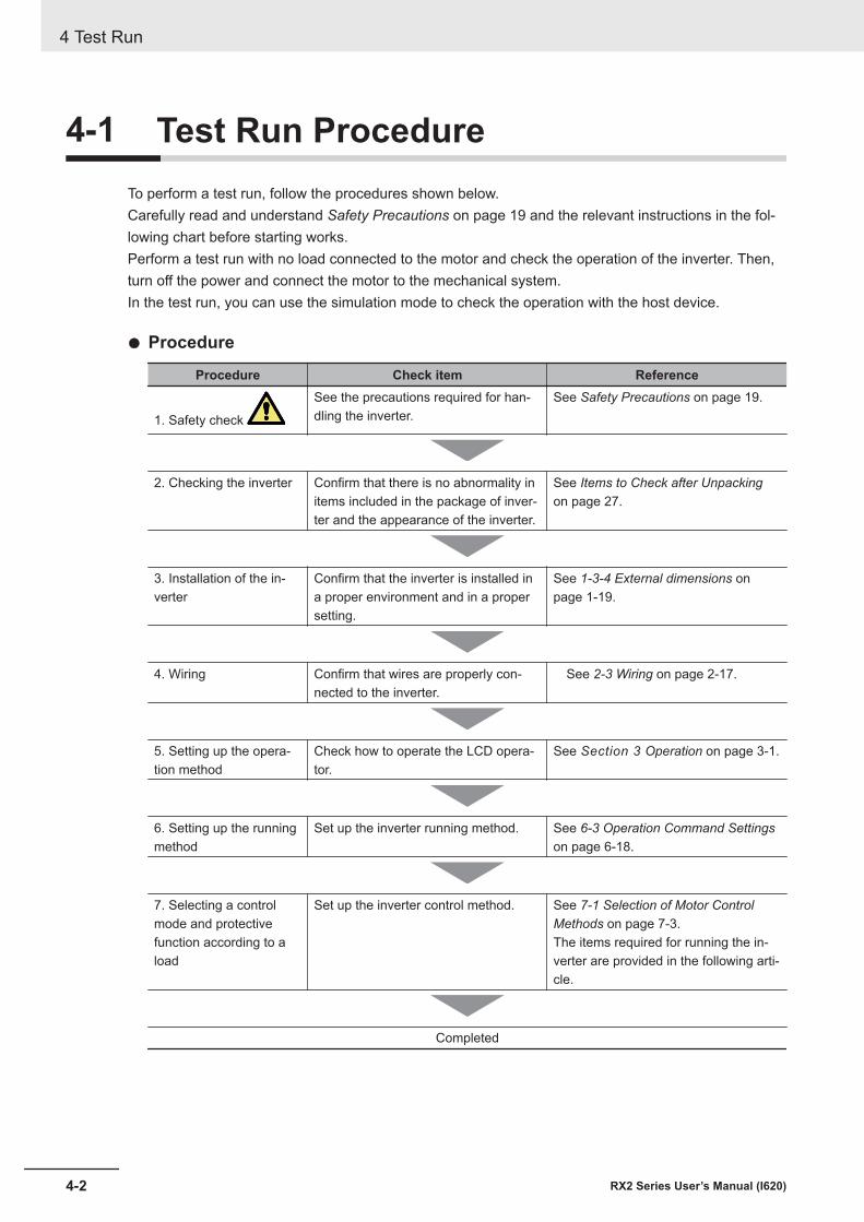
4-1 Test Run ProcedureTo perform a test run, follow the procedures shown below.Carefully read and understand Safety Precautions on page 19 and the relevant instructions in the fol-lowing chart before starting works.Perform a test run with no load connected to the motor and check the operation of the inverter. Then,turn off the power and connect the motor to the mechanical system.In the test run, you can use the simulation mode to check the operation with the host device.
l Procedure
Procedure Check item Reference
1. Safety check
See the precautions required for han-dling the inverter.
See Safety Precautions on page 19.
2. Checking the inverter Confirm that there is no abnormality initems included in the package of inver-ter and the appearance of the inverter.
See Items to Check after Unpackingon page 27.
3. Installation of the in-verter
Confirm that the inverter is installed ina proper environment and in a propersetting.
See 1-3-4 External dimensions onpage 1-19.
4. Wiring Confirm that wires are properly con-nected to the inverter.
See 2-3 Wiring on page 2-17.
5. Setting up the opera-tion method
Check how to operate the LCD opera-tor.
See Section 3 Operation on page 3-1.
6. Setting up the runningmethod
Set up the inverter running method. See 6-3 Operation Command Settingson page 6-18.
7. Selecting a controlmode and protectivefunction according to aload
Set up the inverter control method. See 7-1 Selection of Motor ControlMethods on page 7-3.The items required for running the in-verter are provided in the following arti-cle.
Completed
4 Test Run
4-2 RX2 Series User’s Manual (I620)
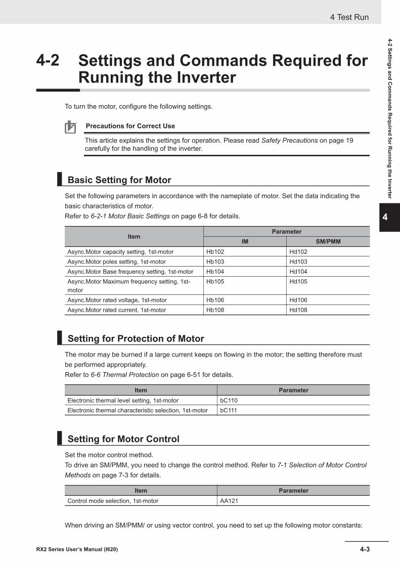
4-2 Settings and Commands Required forRunning the Inverter
To turn the motor, configure the following settings.
Precautions for Correct Use
This article explains the settings for operation. Please read Safety Precautions on page 19carefully for the handling of the inverter.
Basic Setting for MotorSet the following parameters in accordance with the nameplate of motor. Set the data indicating thebasic characteristics of motor.Refer to 6-2-1 Motor Basic Settings on page 6-8 for details.
ItemParameter
IM SM/PMMAsync.Motor capacity setting, 1st-motor Hb102 Hd102Async.Motor poles setting, 1st-motor Hb103 Hd103Async.Motor Base frequency setting, 1st-motor Hb104 Hd104Async.Motor Maximum frequency setting, 1st-motor
Hb105 Hd105
Async.Motor rated voltage, 1st-motor Hb106 Hd106Async.Motor rated current, 1st-motor Hb108 Hd108
Setting for Protection of MotorThe motor may be burned if a large current keeps on flowing in the motor; the setting therefore mustbe performed appropriately.Refer to 6-6 Thermal Protection on page 6-51 for details.
Item ParameterElectronic thermal level setting, 1st-motor bC110Electronic thermal characteristic selection, 1st-motor bC111
Setting for Motor ControlSet the motor control method.To drive an SM/PMM, you need to change the control method. Refer to 7-1 Selection of Motor ControlMethods on page 7-3 for details.
Item ParameterControl mode selection, 1st-motor AA121
When driving an SM/PMM/ or using vector control, you need to set up the following motor constants:
4 Test Run
4-3RX2 Series User’s Manual (I620)
4-2 Settings and Com
mands R
equired for Running the Inverter
4
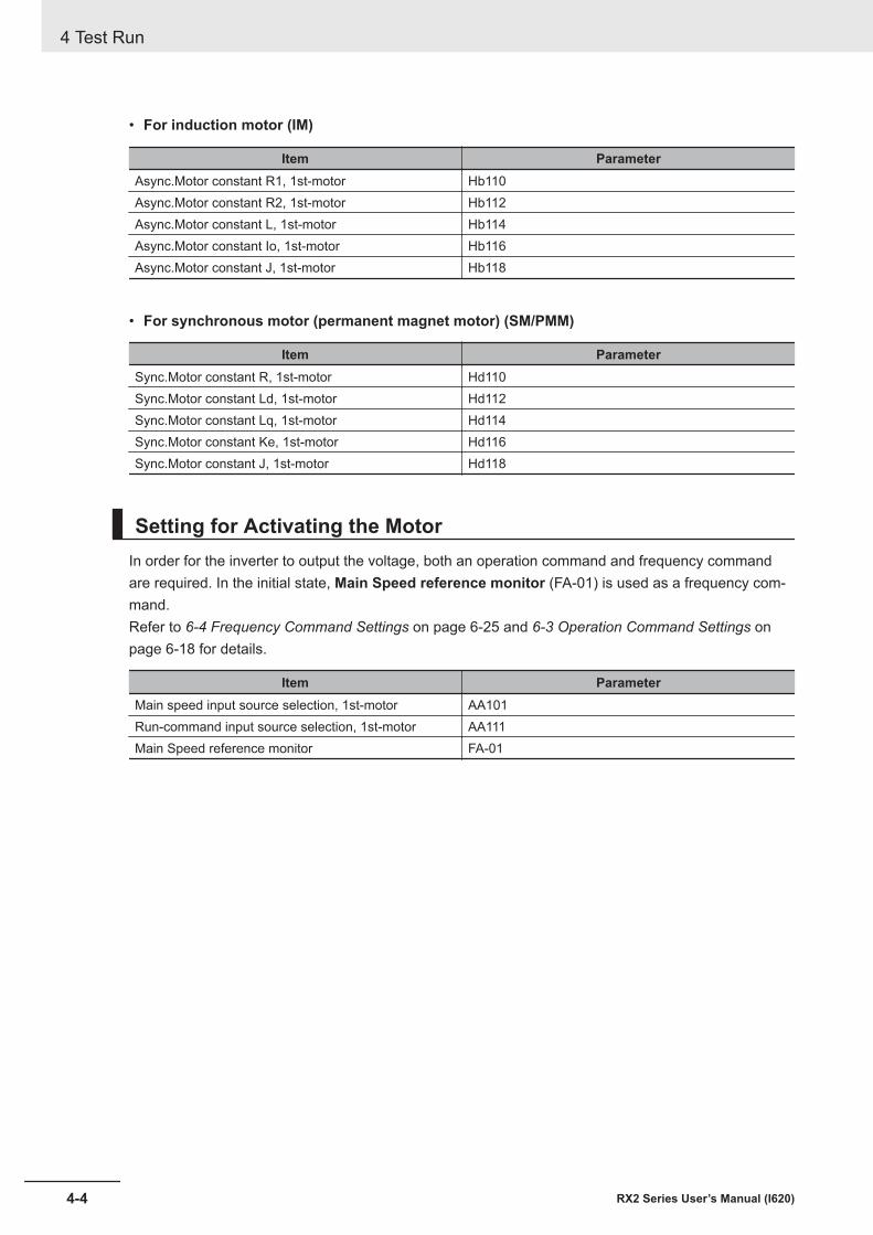
• For induction motor (IM)
Item ParameterAsync.Motor constant R1, 1st-motor Hb110Async.Motor constant R2, 1st-motor Hb112Async.Motor constant L, 1st-motor Hb114Async.Motor constant Io, 1st-motor Hb116Async.Motor constant J, 1st-motor Hb118
• For synchronous motor (permanent magnet motor) (SM/PMM)
Item ParameterSync.Motor constant R, 1st-motor Hd110Sync.Motor constant Ld, 1st-motor Hd112Sync.Motor constant Lq, 1st-motor Hd114Sync.Motor constant Ke, 1st-motor Hd116Sync.Motor constant J, 1st-motor Hd118
Setting for Activating the MotorIn order for the inverter to output the voltage, both an operation command and frequency commandare required. In the initial state, Main Speed reference monitor (FA-01) is used as a frequency com-mand.Refer to 6-4 Frequency Command Settings on page 6-25 and 6-3 Operation Command Settings onpage 6-18 for details.
Item ParameterMain speed input source selection, 1st-motor AA101Run-command input source selection, 1st-motor AA111Main Speed reference monitor FA-01
4 Test Run
4-4 RX2 Series User’s Manual (I620)
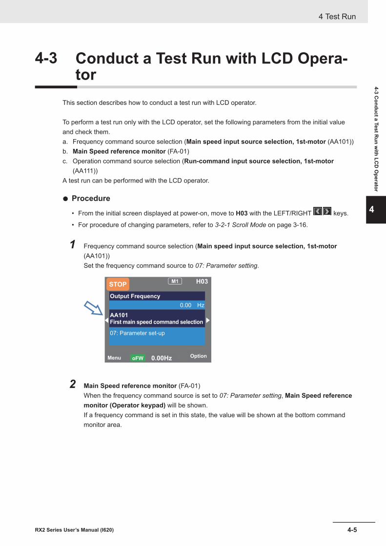
4-3 Conduct a Test Run with LCD Opera-tor
This section describes how to conduct a test run with LCD operator.
To perform a test run only with the LCD operator, set the following parameters from the initial valueand check them.a. Frequency command source selection (Main speed input source selection, 1st-motor (AA101))b. Main Speed reference monitor (FA-01)c. Operation command source selection (Run-command input source selection, 1st-motor
(AA111))A test run can be performed with the LCD operator.
l Procedure
• From the initial screen displayed at power-on, move to H03 with the LEFT/RIGHT keys.
• For procedure of changing parameters, refer to 3-2-1 Scroll Mode on page 3-16.
1 Frequency command source selection (Main speed input source selection, 1st-motor(AA101))Set the frequency command source to 07: Parameter setting.
Menu Option 0.00Hz oFW
STOP M1 H03
Output Frequency
0.00 Hz
AA101
07: Parameter set-up
2 Main Speed reference monitor (FA-01)When the frequency command source is set to 07: Parameter setting, Main Speed referencemonitor (Operator keypad) will be shown.If a frequency command is set in this state, the value will be shown at the bottom commandmonitor area.
4 Test Run
4-5RX2 Series User’s Manual (I620)
4-3 Conduct a Test R
un with LC
D O
perator
4
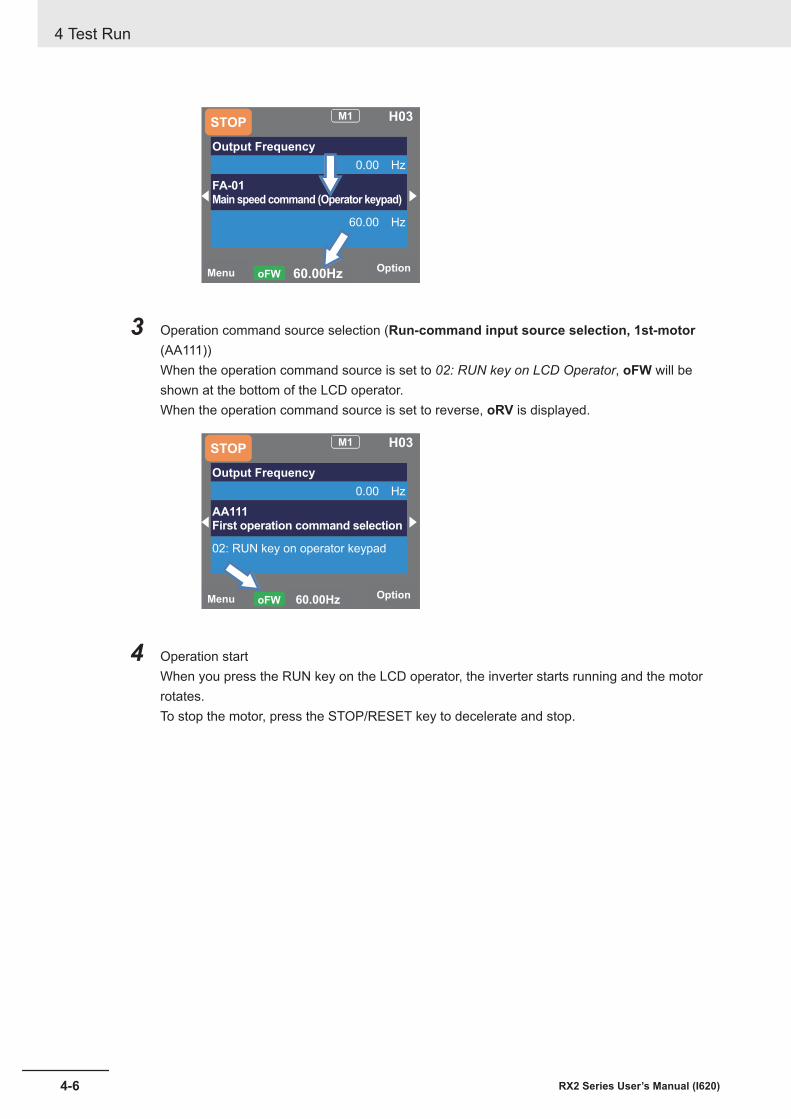
Menu Option60.00HzoFW
STOPM1 H03
Output Frequency
0.00 Hz
FA-01
60.00 Hz
3 Operation command source selection (Run-command input source selection, 1st-motor(AA111))When the operation command source is set to 02: RUN key on LCD Operator, oFW will beshown at the bottom of the LCD operator.When the operation command source is set to reverse, oRV is displayed.
Menu Option60.00HzoFW
STOPM1 H03
Output Frequency
0.00 Hz
AA111First operation command selection
02: RUN key on operator keypad
4 Operation startWhen you press the RUN key on the LCD operator, the inverter starts running and the motorrotates.To stop the motor, press the STOP/RESET key to decelerate and stop.
4 Test Run
4-6 RX2 Series User’s Manual (I620)
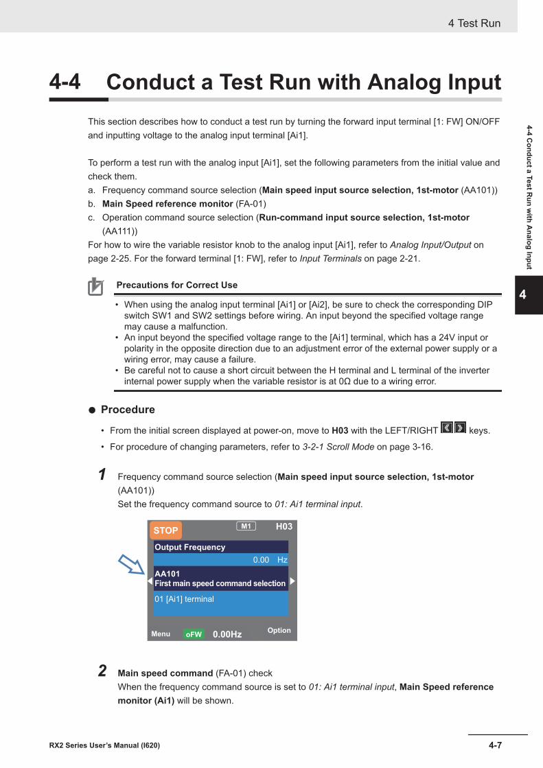
4-4 Conduct a Test Run with Analog InputThis section describes how to conduct a test run by turning the forward input terminal [1: FW] ON/OFFand inputting voltage to the analog input terminal [Ai1].
To perform a test run with the analog input [Ai1], set the following parameters from the initial value andcheck them.a. Frequency command source selection (Main speed input source selection, 1st-motor (AA101))b. Main Speed reference monitor (FA-01)c. Operation command source selection (Run-command input source selection, 1st-motor
(AA111))For how to wire the variable resistor knob to the analog input [Ai1], refer to Analog Input/Output onpage 2-25. For the forward terminal [1: FW], refer to Input Terminals on page 2-21.
Precautions for Correct Use
• When using the analog input terminal [Ai1] or [Ai2], be sure to check the corresponding DIPswitch SW1 and SW2 settings before wiring. An input beyond the specified voltage rangemay cause a malfunction.
• An input beyond the specified voltage range to the [Ai1] terminal, which has a 24V input orpolarity in the opposite direction due to an adjustment error of the external power supply or awiring error, may cause a failure.
• Be careful not to cause a short circuit between the H terminal and L terminal of the inverterinternal power supply when the variable resistor is at 0Ω due to a wiring error.
l Procedure
• From the initial screen displayed at power-on, move to H03 with the LEFT/RIGHT keys.
• For procedure of changing parameters, refer to 3-2-1 Scroll Mode on page 3-16.
1 Frequency command source selection (Main speed input source selection, 1st-motor(AA101))Set the frequency command source to 01: Ai1 terminal input.
Menu Option
0.00Hz oFW
STOP M1 H03
Output Frequency
0.00 Hz
AA101
01 [Ai1] terminal
2 Main speed command (FA-01) checkWhen the frequency command source is set to 01: Ai1 terminal input, Main Speed referencemonitor (Ai1) will be shown.
4 Test Run
4-7RX2 Series User’s Manual (I620)
4-4 Conduct a Test R
un with A
nalog Input
4
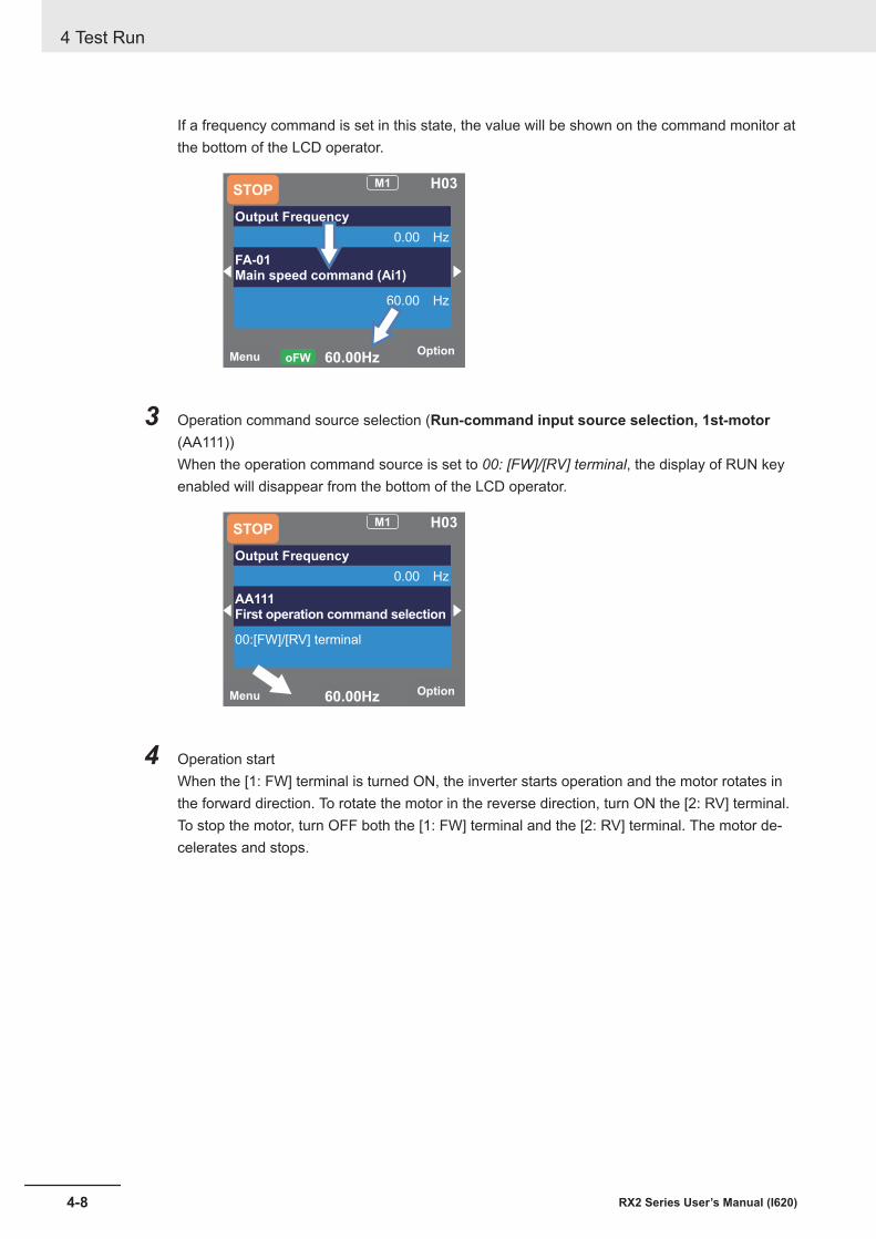
If a frequency command is set in this state, the value will be shown on the command monitor atthe bottom of the LCD operator.
Menu Option
60.00Hz oFW
STOP M1 H03
Output Frequency
0.00 Hz
FA-01
Main speed command (Ai1)
60.00 Hz
3 Operation command source selection (Run-command input source selection, 1st-motor(AA111))When the operation command source is set to 00: [FW]/[RV] terminal, the display of RUN keyenabled will disappear from the bottom of the LCD operator.
Menu Option60.00Hz
STOPM1 H03
Output Frequency
0.00 Hz
AA111First operation command selection
00:[FW]/[RV] terminal
4 Operation startWhen the [1: FW] terminal is turned ON, the inverter starts operation and the motor rotates inthe forward direction. To rotate the motor in the reverse direction, turn ON the [2: RV] terminal.To stop the motor, turn OFF both the [1: FW] terminal and the [2: RV] terminal. The motor de-celerates and stops.
4 Test Run
4-8 RX2 Series User’s Manual (I620)
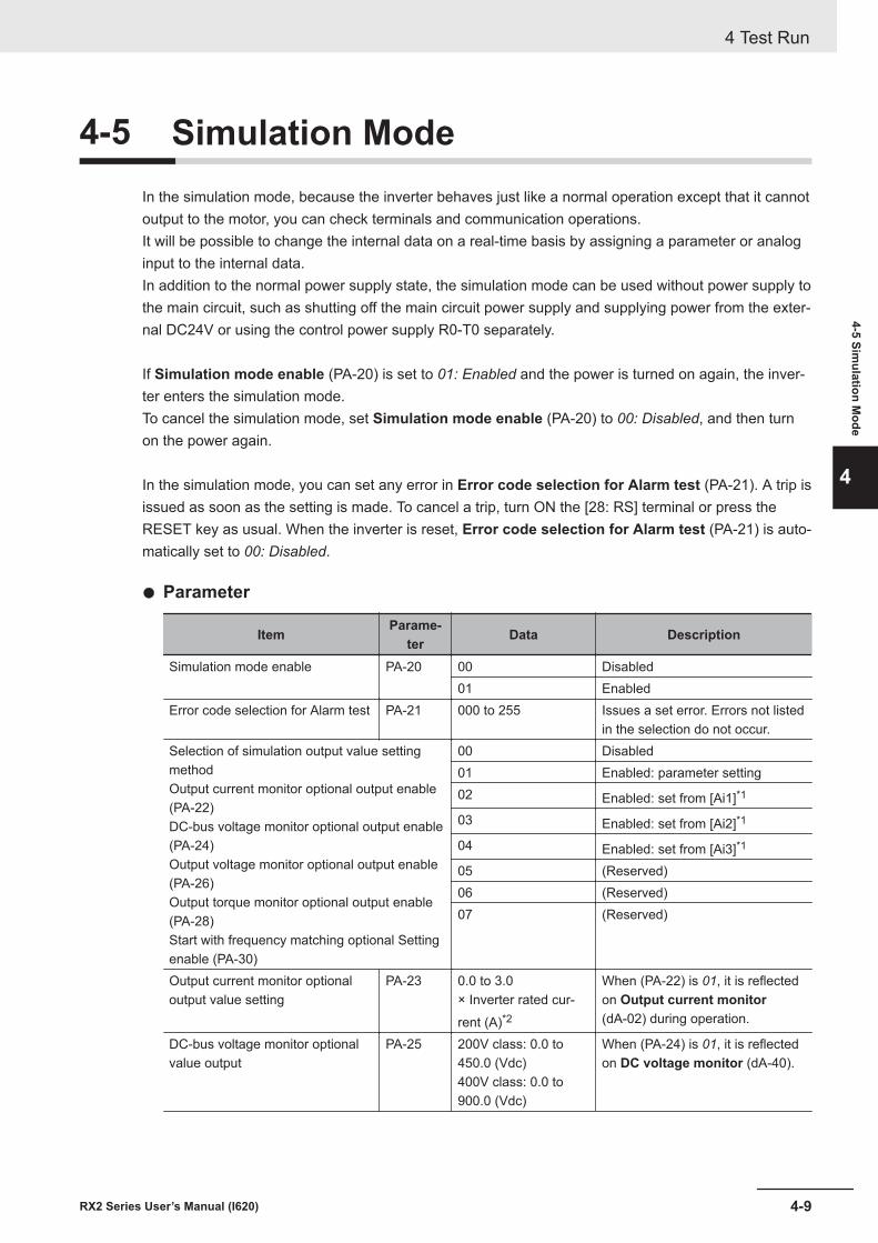
4-5 Simulation ModeIn the simulation mode, because the inverter behaves just like a normal operation except that it cannotoutput to the motor, you can check terminals and communication operations.It will be possible to change the internal data on a real-time basis by assigning a parameter or analoginput to the internal data.In addition to the normal power supply state, the simulation mode can be used without power supply tothe main circuit, such as shutting off the main circuit power supply and supplying power from the exter-nal DC24V or using the control power supply R0-T0 separately.
If Simulation mode enable (PA-20) is set to 01: Enabled and the power is turned on again, the inver-ter enters the simulation mode.To cancel the simulation mode, set Simulation mode enable (PA-20) to 00: Disabled, and then turnon the power again.
In the simulation mode, you can set any error in Error code selection for Alarm test (PA-21). A trip isissued as soon as the setting is made. To cancel a trip, turn ON the [28: RS] terminal or press theRESET key as usual. When the inverter is reset, Error code selection for Alarm test (PA-21) is auto-matically set to 00: Disabled.
l Parameter
Item Parame-ter Data Description
Simulation mode enable PA-20 00 Disabled01 Enabled
Error code selection for Alarm test PA-21 000 to 255 Issues a set error. Errors not listedin the selection do not occur.
Selection of simulation output value settingmethodOutput current monitor optional output enable(PA-22)DC-bus voltage monitor optional output enable(PA-24)Output voltage monitor optional output enable(PA-26)Output torque monitor optional output enable(PA-28)Start with frequency matching optional Settingenable (PA-30)
00 Disabled01 Enabled: parameter setting02 Enabled: set from [Ai1]*1
03 Enabled: set from [Ai2]*1
04 Enabled: set from [Ai3]*1
05 (Reserved)06 (Reserved)07 (Reserved)
Output current monitor optionaloutput value setting
PA-23 0.0 to 3.0× Inverter rated cur-rent (A)*2
When (PA-22) is 01, it is reflectedon Output current monitor(dA-02) during operation.
DC-bus voltage monitor optionalvalue output
PA-25 200V class: 0.0 to450.0 (Vdc)400V class: 0.0 to900.0 (Vdc)
When (PA-24) is 01, it is reflectedon DC voltage monitor (dA-40).
4 Test Run
4-9RX2 Series User’s Manual (I620)
4-5 Simulation M
ode
4
Item Parame-ter Data Description
Output voltage monitor optionaloutput value setting
PA-27 200V class: 0.0 to300.0 (V)400V class: 0.0 to600.0 (V)
When (PA-26) is 01, it is reflectedon Output voltage monitor(dA-18) during operation.
Output torque monitor optionaloutput value setting
PA-29 -500.0 to 500.0 (%) When (PA-28) is 01, it is reflectedon Output torque monitor(dA-17) during operation.
Start with frequency matching op-tional value setting
PA-31 0.00 to 590.00 (Hz) When (PA-30) is 01, it is used asthe detection value of the frequen-cy matching start operation.
*1. The input value of the analog terminal becomes the inverter output value during simulation operation.*2. On the current and voltage related parameters, the figures and the units to be handled vary in the setting
path.• When operating with the LCD operator and CX-Drive, set Resister data selection (CF-11) to 00: A, V.• As reference information, when Resister data selection (CF-11) is set to 01: %, the unit is 0.01% (rated
ratio).
Additional Information
• To check the actual motor behavior, cancel the simulation mode.• When using the simulation mode with only the external DC24V power supply, turn on the ex-
ternal DC24V after the main power supply (R, S, and T) and the control power supply (R0and T0) are completely shut off. Normal operation is performed until the power is turned onagain.
• Since the motor control does not operate in the simulation mode, the control cannot be con-firmed.
• If an error not listed in Error code selection for Alarm test (PA-21) is entered, the error willnot be generated.
• If a serious fault error is entered to Error code selection for Alarm test (PA-21), the errorcannot be canceled by resetting with the [28: RS] terminal or the RESET key. The powerneeds to be turned on again.(Serious fault errors: E008, E010, E011, E014, E019, and E020)
l Start the Simulation Mode
1 Set Simulation mode enable (PA-20) to 01: Enabled.
2 Turn off the power, and then turn it on again.Wait for the LCD operator to completely discharge, and then turn on the power again.
3 The simulation mode becomes active.
4 Test Run
4-10 RX2 Series User’s Manual (I620)
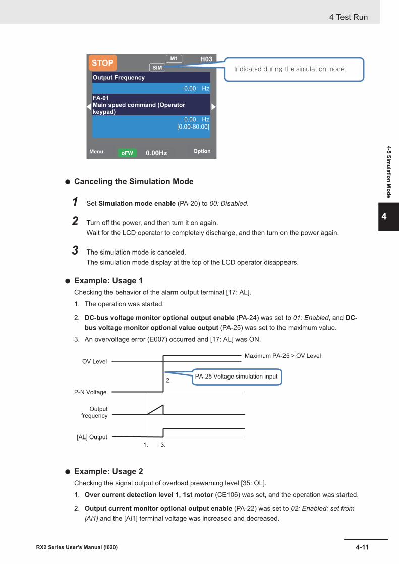
Menu Option0.00HzoFW
STOPM1 H03
Output Frequency
0.00 Hz
FA-01Main speed command (Operatorkeypad)
0.00 Hz
[0.00-60.00]
SIM Indicated during the simulation mode.
l Canceling the Simulation Mode
1 Set Simulation mode enable (PA-20) to 00: Disabled.
2 Turn off the power, and then turn it on again.Wait for the LCD operator to completely discharge, and then turn on the power again.
3 The simulation mode is canceled.The simulation mode display at the top of the LCD operator disappears.
l Example: Usage 1Checking the behavior of the alarm output terminal [17: AL].
1. The operation was started.
2. DC-bus voltage monitor optional output enable (PA-24) was set to 01: Enabled, and DC-bus voltage monitor optional value output (PA-25) was set to the maximum value.
3. An overvoltage error (E007) occurred and [17: AL] was ON.
PA-25 Voltage simulation input
OV Level
P-N Voltage
Outputfrequency
[AL] Output
Maximum PA-25 > OV Level
1.
2.
3.
l Example: Usage 2Checking the signal output of overload prewarning level [35: OL].
1. Over current detection level 1, 1st motor (CE106) was set, and the operation was started.
2. Output current monitor optional output enable (PA-22) was set to 02: Enabled: set from[Ai1] and the [Ai1] terminal voltage was increased and decreased.
4 Test Run
4-11RX2 Series User’s Manual (I620)
4-5 Simulation M
ode
4
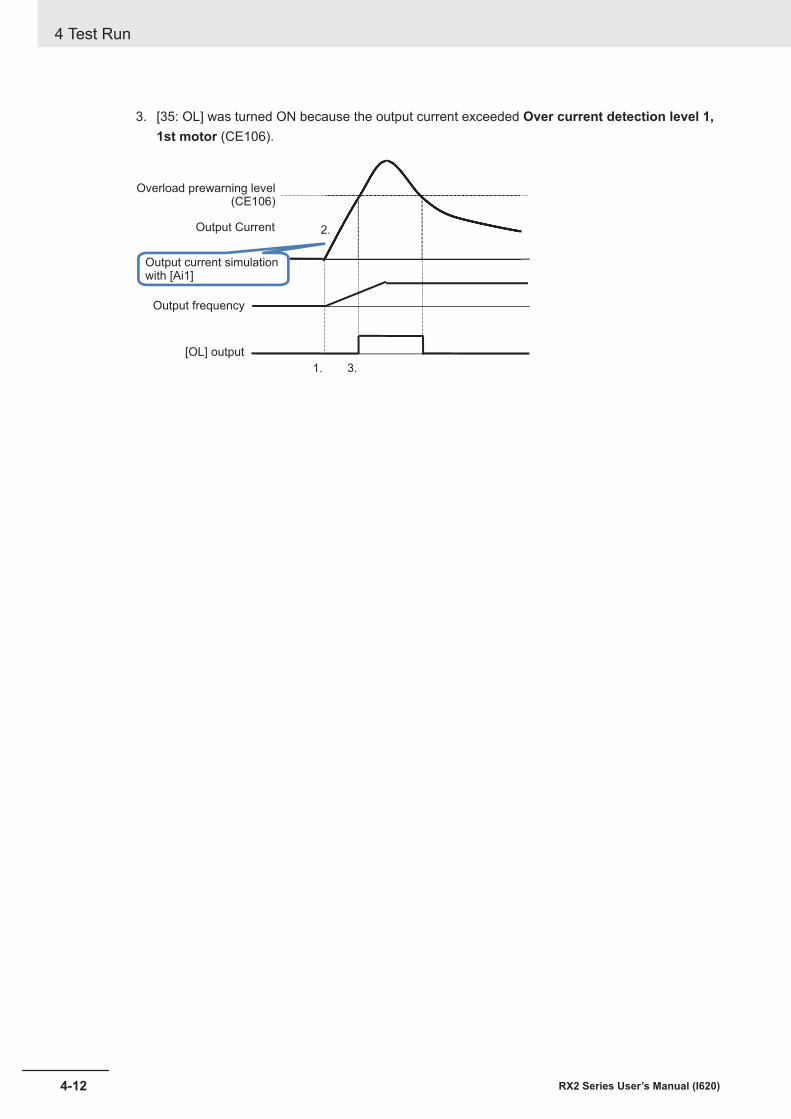
3. [35: OL] was turned ON because the output current exceeded Over current detection level 1,1st motor (CE106).
Output current simulationwith [Ai1]
Overload prewarning level(CE106)
Output frequency
Output Current
[OL] output
1.
2.
3.
4 Test Run
4-12 RX2 Series User’s Manual (I620)
5Monitors
This chapter describes the monitor functions of the inverter.
5-1 Frequency Monitor ......................................................................................... 5-35-1-1 Output Frequency Monitor............................................................................... 5-35-1-2 Frequency Command Monitor......................................................................... 5-35-1-3 Frequency Conversion Monitor ....................................................................... 5-45-1-4 Speed Detection Value Monitor ....................................................................... 5-5
5-2 Acceleration/Deceleration Time Monitor...................................................... 5-75-3 Operation Direction Monitor.......................................................................... 5-85-4 I/O Terminal Monitor....................................................................................... 5-9
5-4-1 Input Terminal Monitor..................................................................................... 5-95-4-2 Output Terminal Monitor .................................................................................. 5-95-4-3 Output Current Monitor.................................................................................. 5-105-4-4 Output Voltage Monitor.................................................................................. 5-10
5-5 P-N Voltage Monitor ..................................................................................... 5-115-6 Operation Time and Count Monitor ............................................................ 5-12
5-6-1 Cumulative Operating Hours Monitor During RUN........................................ 5-125-6-2 Cumulative Power-on Time Monitor .............................................................. 5-125-6-3 Total Start-up Count Monitor ......................................................................... 5-125-6-4 Cumulative Power-on Count Monitor ............................................................ 5-13
5-7 Cooling Fin Temperature Monitor............................................................... 5-145-8 Power Monitor .............................................................................................. 5-15
5-8-1 Input Power Monitor ...................................................................................... 5-155-8-2 Output Power Monitor ................................................................................... 5-15
5-9 Life Monitor................................................................................................... 5-175-9-1 Life Diagnostic Monitor.................................................................................. 5-175-9-2 Cumulative Operating Time of Cooling Fan Monitor ..................................... 5-17
5-10 Electronic Thermal Load Ratio Monitor ..................................................... 5-195-10-1 Electronic Thermal Load Ratio Monitor of Motor........................................... 5-195-10-2 Electronic Thermal Load Ratio Monitor of Inverter........................................ 5-19
5-11 Inverter Rated Monitor ................................................................................. 5-205-11-1 Load Rated Monitor....................................................................................... 5-205-11-2 Rated Current Monitor................................................................................... 5-20
5-12 Braking Resistor Load Ratio Monitor......................................................... 5-215-13 Inverter Status Monitor ................................................................................ 5-22
5-1RX2 Series User’s Manual (I620)
5
5-13-1 Detailed Monitor for Icon 2 LIM (dC-37) ........................................................ 5-225-13-2 Detailed Monitor for Icon 2 ALT (dC-38)........................................................ 5-225-13-3 Detailed Monitor for Icon 2 RETRY (dC-39) .................................................. 5-225-13-4 Detailed Monitor for Icon 2 NRDY (dC-40).................................................... 5-23
5-14 Analog Input Value Monitor......................................................................... 5-245-15 Analog Terminal Setting Monitor ................................................................ 5-255-16 Terminal Block Type Monitor ...................................................................... 5-265-17 Operation Command / Frequency Command Source Monitor................. 5-275-18 Option Monitor.............................................................................................. 5-28
5 Monitors
5-2 RX2 Series User’s Manual (I620)
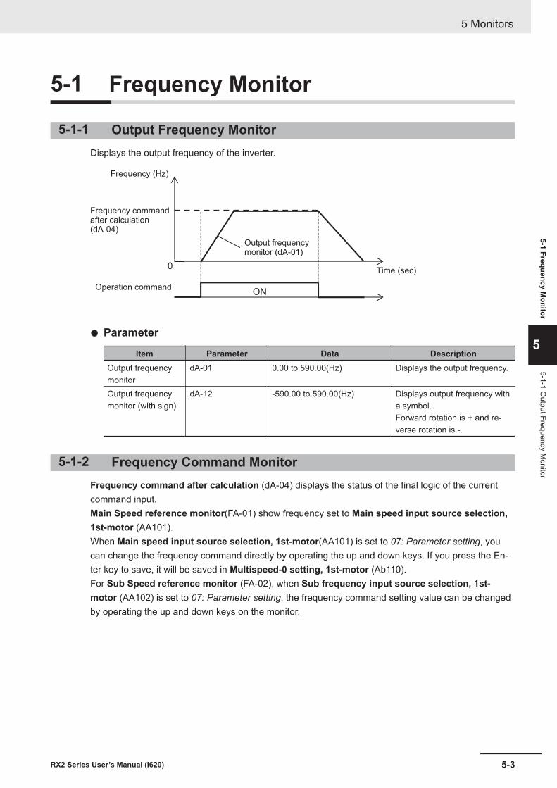
5-1 Frequency Monitor
5-1-1 Output Frequency MonitorDisplays the output frequency of the inverter.
ON
0
Frequency (Hz)
Frequency commandafter calculation(dA-04)
Operation command
Output frequencymonitor (dA-01)
Time (sec)
l Parameter
Item Parameter Data DescriptionOutput frequencymonitor
dA-01 0.00 to 590.00(Hz) Displays the output frequency.
Output frequencymonitor (with sign)
dA-12 -590.00 to 590.00(Hz) Displays output frequency witha symbol.Forward rotation is + and re-verse rotation is -.
5-1-2 Frequency Command MonitorFrequency command after calculation (dA-04) displays the status of the final logic of the currentcommand input.Main Speed reference monitor(FA-01) show frequency set to Main speed input source selection,1st-motor (AA101).When Main speed input source selection, 1st-motor(AA101) is set to 07: Parameter setting, youcan change the frequency command directly by operating the up and down keys. If you press the En-ter key to save, it will be saved in Multispeed-0 setting, 1st-motor (Ab110).For Sub Speed reference monitor (FA-02), when Sub frequency input source selection, 1st-motor (AA102) is set to 07: Parameter setting, the frequency command setting value can be changedby operating the up and down keys on the monitor.
5 Monitors
5-3RX2 Series User’s Manual (I620)
5-1 Frequency Monitor
5
5-1-1 Output Frequency M
onitor
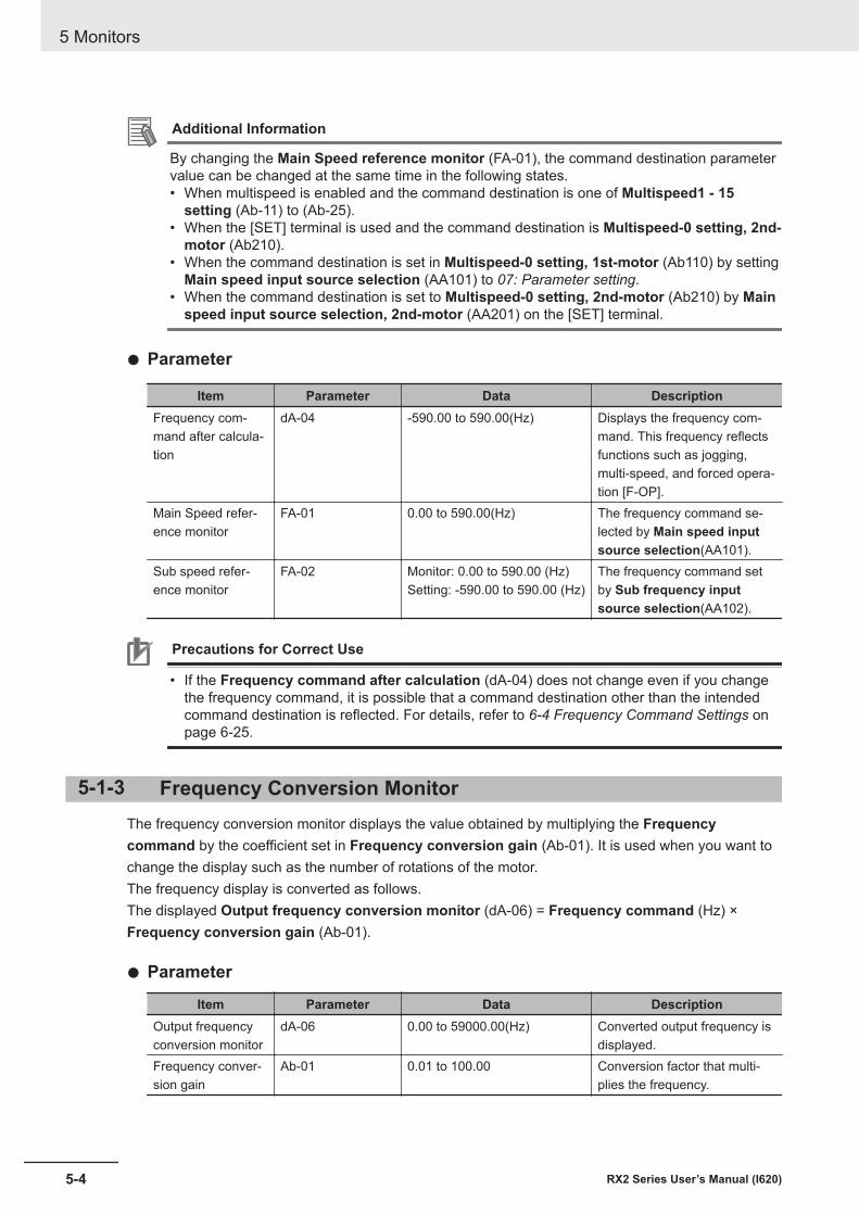
Additional Information
By changing the Main Speed reference monitor (FA-01), the command destination parametervalue can be changed at the same time in the following states.• When multispeed is enabled and the command destination is one of Multispeed1 - 15
setting (Ab-11) to (Ab-25).• When the [SET] terminal is used and the command destination is Multispeed-0 setting, 2nd-
motor (Ab210).• When the command destination is set in Multispeed-0 setting, 1st-motor (Ab110) by setting
Main speed input source selection (AA101) to 07: Parameter setting.• When the command destination is set to Multispeed-0 setting, 2nd-motor (Ab210) by Main
speed input source selection, 2nd-motor (AA201) on the [SET] terminal.
l Parameter
Item Parameter Data DescriptionFrequency com-mand after calcula-tion
dA-04 -590.00 to 590.00(Hz) Displays the frequency com-mand. This frequency reflectsfunctions such as jogging,multi-speed, and forced opera-tion [F-OP].
Main Speed refer-ence monitor
FA-01 0.00 to 590.00(Hz) The frequency command se-lected by Main speed inputsource selection(AA101).
Sub speed refer-ence monitor
FA-02 Monitor: 0.00 to 590.00 (Hz)Setting: -590.00 to 590.00 (Hz)
The frequency command setby Sub frequency inputsource selection(AA102).
Precautions for Correct Use
• If the Frequency command after calculation (dA-04) does not change even if you changethe frequency command, it is possible that a command destination other than the intendedcommand destination is reflected. For details, refer to 6-4 Frequency Command Settings onpage 6-25.
5-1-3 Frequency Conversion MonitorThe frequency conversion monitor displays the value obtained by multiplying the Frequencycommand by the coefficient set in Frequency conversion gain (Ab-01). It is used when you want tochange the display such as the number of rotations of the motor.The frequency display is converted as follows.The displayed Output frequency conversion monitor (dA-06) = Frequency command (Hz) ×Frequency conversion gain (Ab-01).
l Parameter
Item Parameter Data DescriptionOutput frequencyconversion monitor
dA-06 0.00 to 59000.00(Hz) Converted output frequency isdisplayed.
Frequency conver-sion gain
Ab-01 0.01 to 100.00 Conversion factor that multi-plies the frequency.
5 Monitors
5-4 RX2 Series User’s Manual (I620)
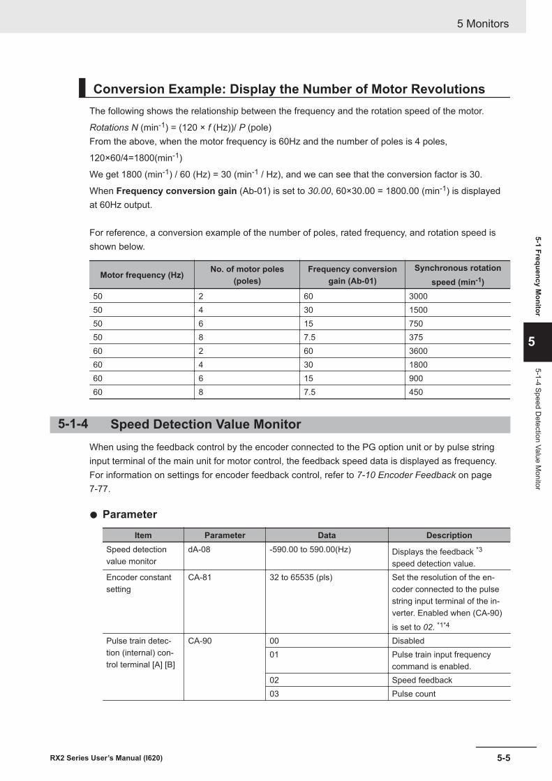
Conversion Example: Display the Number of Motor RevolutionsThe following shows the relationship between the frequency and the rotation speed of the motor.
Rotations N (min-1) = (120 × f (Hz))/ P (pole)From the above, when the motor frequency is 60Hz and the number of poles is 4 poles,
120×60/4=1800(min-1)
We get 1800 (min-1) / 60 (Hz) = 30 (min-1 / Hz), and we can see that the conversion factor is 30.
When Frequency conversion gain (Ab-01) is set to 30.00, 60×30.00 = 1800.00 (min-1) is displayedat 60Hz output.
For reference, a conversion example of the number of poles, rated frequency, and rotation speed isshown below.
Motor frequency (Hz) No. of motor poles(poles)
Frequency conversiongain (Ab-01)
Synchronous rotationspeed (min-1)
50 2 60 300050 4 30 150050 6 15 75050 8 7.5 37560 2 60 360060 4 30 180060 6 15 90060 8 7.5 450
5-1-4 Speed Detection Value MonitorWhen using the feedback control by the encoder connected to the PG option unit or by pulse stringinput terminal of the main unit for motor control, the feedback speed data is displayed as frequency.For information on settings for encoder feedback control, refer to 7-10 Encoder Feedback on page7-77.
l Parameter
Item Parameter Data DescriptionSpeed detectionvalue monitor
dA-08 -590.00 to 590.00(Hz) Displays the feedback *3
speed detection value.Encoder constantsetting
CA-81 32 to 65535 (pls) Set the resolution of the en-coder connected to the pulsestring input terminal of the in-verter. Enabled when (CA-90)is set to 02. *1*4
Pulse train detec-tion (internal) con-trol terminal [A] [B]
CA-90 00 Disabled01 Pulse train input frequency
command is enabled.02 Speed feedback03 Pulse count
5 Monitors
5-5RX2 Series User’s Manual (I620)
5-1 Frequency Monitor
5
5-1-4 Speed Detection Value M
onitor

Item Parameter Data DescriptionEncoder constantsetting(Option)
ob-01 32 to 65535 (pls) Set the resolution of the en-coder connected to the PG op-tion unit. *2*4
Async.Motor polessetting, 1st-motor
Hb103 2 to 48 (poles) Sets the number of motorpoles. *4
*1. When Pulse train detection (internal) control terminal [A] [B] (CA-90) is set to 02, the A / B terminalsof the inverter are used for feedback.
*2. When Pulse train detection (internal) control terminal [A] [B] (CA-90) is set to something other than02,the encoder of the PG option unit is used for feedback.
*3. If you are not using feedback, the frequency will not be displayed.*4. If the number of encoder pulses and the number of motor poles are not set correctly, it will not be dis-
played correctly.
5 Monitors
5-6 RX2 Series User’s Manual (I620)
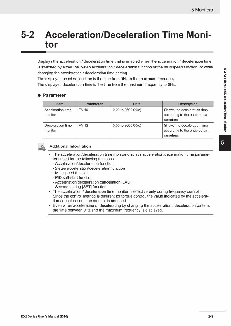
5-2 Acceleration/Deceleration Time Moni-tor
Displays the acceleration / deceleration time that is enabled when the acceleration / deceleration timeis switched by either the 2-step acceleration / deceleration function or the multispeed function, or whilechanging the acceleration / deceleration time setting.The displayed acceleration time is the time from 0Hz to the maximum frequency.The displayed deceleration time is the time from the maximum frequency to 0Hz.
l Parameter
Item Parameter Data DescriptionAcceleration timemonitor
FA-10 0.00 to 3600.00(s) Shows the acceleration timeaccording to the enabled pa-rameters.
Deceleration timemonitor
FA-12 0.00 to 3600.00(s) Shows the deceleration timeaccording to the enabled pa-rameters.
Additional Information
• The acceleration/deceleration time monitor displays acceleration/deceleration time parame-ters used for the following functions.- Acceleration/deceleration function- 2-step acceleration/deceleration function- Multispeed function- PID soft-start function- Acceleration/deceleration cancellation [LAC]- Second setting [SET] function
• The acceleration / deceleration time monitor is effective only during frequency control.Since the control method is different for torque control, the value indicated by the accelera-tion / deceleration time monitor is not used.
• Even when accelerating or decelerating by changing the acceleration / deceleration pattern,the time between 0Hz and the maximum frequency is displayed.
5 Monitors
5-7RX2 Series User’s Manual (I620)
5-2 Acceleration/D
eceleration Time M
onitor
5

5-3 Operation Direction MonitorThe operation direction monitor displays the status of the operation commands and the rotation direc-tion.The rotation direction is determined by the operation command method and the sign associated withthe frequency command.
l Parameter
Item Parameter Data DescriptionOperation directionmonitor
dA-03 00: o (Stopped) Inverter is stopped.01: d (0Hz output) Inverter is outputting 0 Hz.02: F (Normal rotation in proc-ess)
Inverter is running under for-ward rotation command.
03: r (Reverse rotation in proc-ess)
Inverter is running under re-verse rotation command.
Additional Information
• When in 01: d (0Hz output) mode, it is likely that the output under 0Hz frequency command isdue to DC injection braking function, the forcing function, or Zero-Hz range sensorless vectorcontrol, etc
• When there is no output to the motor, it is indicated by 00: o (Stopped).
5 Monitors
5-8 RX2 Series User’s Manual (I620)
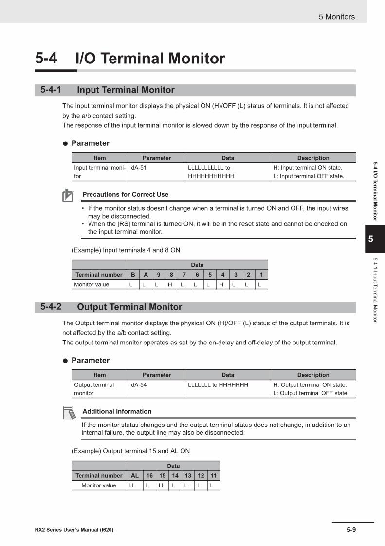
5-4 I/O Terminal Monitor
5-4-1 Input Terminal MonitorThe input terminal monitor displays the physical ON (H)/OFF (L) status of terminals. It is not affectedby the a/b contact setting.The response of the input terminal monitor is slowed down by the response of the input terminal.
l Parameter
Item Parameter Data DescriptionInput terminal moni-tor
dA-51 LLLLLLLLLLL toHHHHHHHHHHH
H: Input terminal ON state.L: Input terminal OFF state.
Precautions for Correct Use
• If the monitor status doesn’t change when a terminal is turned ON and OFF, the input wiresmay be disconnected.
• When the [RS] terminal is turned ON, it will be in the reset state and cannot be checked onthe input terminal monitor.
(Example) Input terminals 4 and 8 ON
DataTerminal number B A 9 8 7 6 5 4 3 2 1Monitor value L L L H L L L H L L L
5-4-2 Output Terminal MonitorThe Output terminal monitor displays the physical ON (H)/OFF (L) status of the output terminals. It isnot affected by the a/b contact setting.The output terminal monitor operates as set by the on-delay and off-delay of the output terminal.
l Parameter
Item Parameter Data DescriptionOutput terminalmonitor
dA-54 LLLLLLL to HHHHHHH H: Output terminal ON state.L: Output terminal OFF state.
Additional Information
If the monitor status changes and the output terminal status does not change, in addition to aninternal failure, the output line may also be disconnected.
(Example) Output terminal 15 and AL ON
DataTerminal number AL 16 15 14 13 12 11
Monitor value H L H L L L L
5 Monitors
5-9RX2 Series User’s Manual (I620)
5-4 I/O Term
inal Monitor
5
5-4-1 Input Terminal M
onitor
5-4-3 Output Current MonitorDisplays the current output to the motor.
l Parameter
Item Parameter Data DescriptionOutput currentmonitor
dA-02 0.00 to 655.35 (A) This is the effective value ofthe output current output to themotor.
Additional Information
The lower the carrier frequency, the more the inverter current fluctuates, which may cause themonitor value to fluctuate.
5-4-4 Output Voltage MonitorDisplays the voltage output to the motor.
l Parameter
Item Parameter Data DescriptionOutput voltagemonitor
dA-18 0.0 to 800.0 (V) Displays the voltage output tothe motor.
5 Monitors
5-10 RX2 Series User’s Manual (I620)
5-5 P-N Voltage MonitorDisplays the voltage charged in the capacitor built into the main circuit of the inverter. The P-N voltageis the DC voltage between the P and N terminals of the main circuit terminal.
l Parameter
Item Parameter Data DescriptionDC voltage monitor dA-40 0.0 to 1000.0 (V) This is the P-N voltage of the
main circuit capacitor.
Additional Information
An overvoltage error (E007) occurs when the P-N voltage exceeds approximately DC405V for a200V class inverter and approximately DC810V for a 400V class inverter.
5 Monitors
5-11RX2 Series User’s Manual (I620)
5-5 P-N Voltage M
onitor
5
5-6 Operation Time and Count Monitor
5-6-1 Cumulative Operating Hours Monitor During RUNThe cumulative operating hours monitor during RUN displays the duration of the time an inverter isgenerating output after it receives an operation command.
l Parameter
Item Parameter Data DescriptionCumulative operat-ing hours monitorduring RUN
dC-22 0 to 100000 (time) The inverter output time periodis recorded in memory and dis-played.
Additional Information
The cumulative operating hours monitor during RUN cannot be cleared by initialization or simi-lar method.
5-6-2 Cumulative Power-on Time MonitorThe cumulative power-on time monitor displays the total duration of power on time since the inverter’sfirst power on.
l Parameter
Item Parameter Data DescriptionCumulative power-on time
dC-24 0 to 100000 (time) The time from when the the in-verter was powered-on issaved in memory and dis-played.
Additional Information
The cumulative power ON time cannot be cleared by initialization or similar method.
5-6-3 Total Start-up Count MonitorThe total start-up count monitor displays the number of times there is output to a motor from the statewhere the inverter is stopped.
l Parameter
Item Parameter Data DescriptionTotal start-up count dC-20 0 to 65535 (times) Displays the number of times
the operation has changedfrom the cutoff state to the run-ning state.
5 Monitors
5-12 RX2 Series User’s Manual (I620)
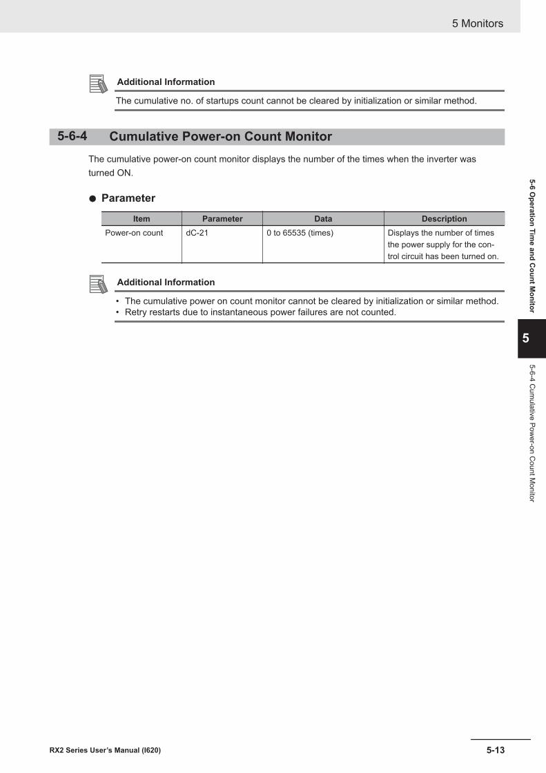
Additional Information
The cumulative no. of startups count cannot be cleared by initialization or similar method.
5-6-4 Cumulative Power-on Count MonitorThe cumulative power-on count monitor displays the number of the times when the inverter wasturned ON.
l Parameter
Item Parameter Data DescriptionPower-on count dC-21 0 to 65535 (times) Displays the number of times
the power supply for the con-trol circuit has been turned on.
Additional Information
• The cumulative power on count monitor cannot be cleared by initialization or similar method.• Retry restarts due to instantaneous power failures are not counted.
5 Monitors
5-13RX2 Series User’s Manual (I620)
5-6 Operation Tim
e and Count M
onitor
5
5-6-4 Cum
ulative Power-on C
ount Monitor
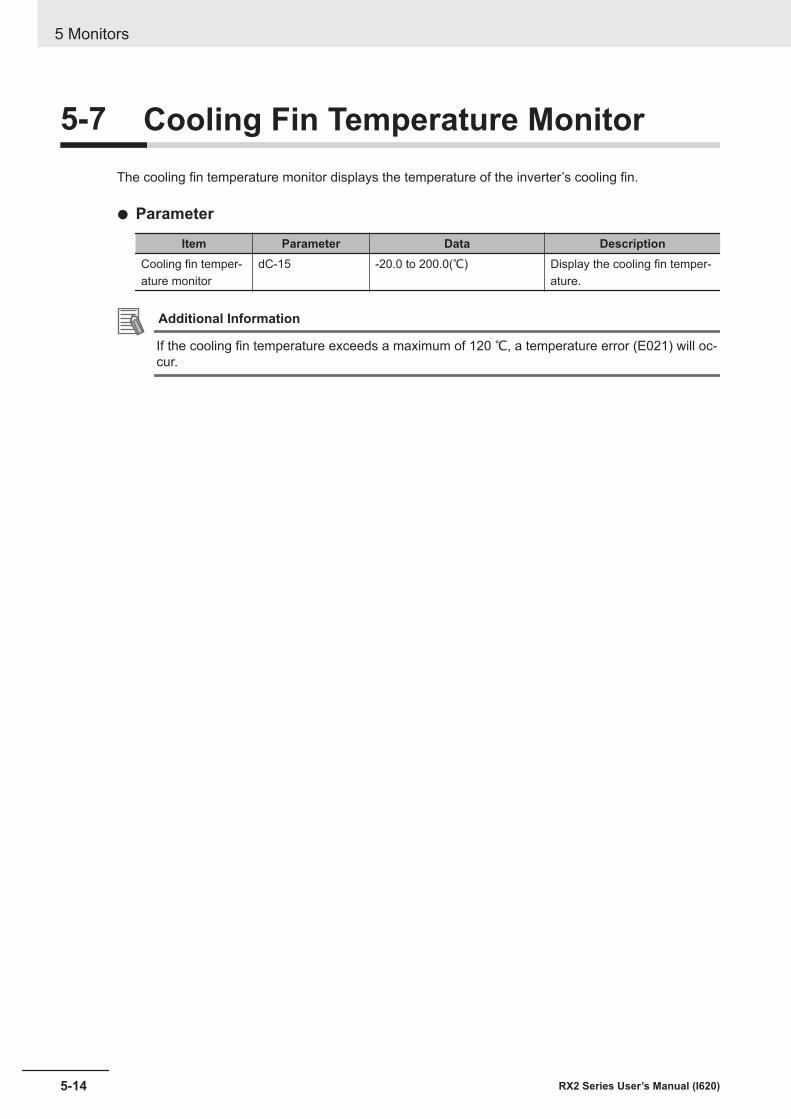
5-7 Cooling Fin Temperature MonitorThe cooling fin temperature monitor displays the temperature of the inverter’s cooling fin.
l Parameter
Item Parameter Data DescriptionCooling fin temper-ature monitor
dC-15 -20.0 to 200.0(℃) Display the cooling fin temper-ature.
Additional Information
If the cooling fin temperature exceeds a maximum of 120 ℃, a temperature error (E021) will oc-cur.
5 Monitors
5-14 RX2 Series User’s Manual (I620)
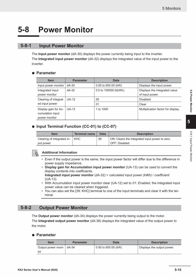
5-8 Power Monitor
5-8-1 Input Power MonitorThe Input power monitor (dA-30) displays the power currently being input to the inverter.The Integrated input power monitor (dA-32) displays the integrated value of the input power to theinverter.
l Parameter
Item Parameter Data DescriptionInput power monitor dA-30 0.00 to 600.00 (kW) Displays the input power.Integrated inputpower monitor
dA-32 0.0 to 100000.0(kWh) Displays the integrated valueof input power.
Clearing of integrat-ed input power
UA-12 00 Disabled01 Clear
Display gain for Ac-cumulation inputpower monitor
UA-13 1 to 1000 Multiplication factor for display.
l Input Terminal Function (CC-01) to (CC-07)
Item Terminal name Data DescriptionClearing of integrated in-put power
KHC 39 ON: Clears the integrated input power to zero.OFF: Disabled
Additional Information
• Even if the output power is the same, the input power factor will differ due to the difference inpower supply impedance.
• Display gain for Accumulation input power monitor (UA-13) can be used to convert thedisplay contents into coefficients.Integrated input power monitor (dA-32) = calculated input power (kWh) / coefficient(UA-13)
• With Accumulation input power monitor clear (UA-12) set to 01: Enabled, the integrated inputpower value can be cleared when triggered.
• You can also set the [39: KHC] terminal to one of the input terminals and clear it with the ter-minal.
5-8-2 Output Power MonitorThe Output power monitor (dA-34) displays the power currently being output to the motor.The Integrated output power monitor (dA-36) displays the integrated value of the output power tothe motor.
l Parameter
Item Parameter Data DescriptionOutput power moni-tor
dA-34 0.00 to 600.00 (kW) Displays the output power.
5 Monitors
5-15RX2 Series User’s Manual (I620)
5-8 Power M
onitor
5
5-8-1 Input Power M
onitor
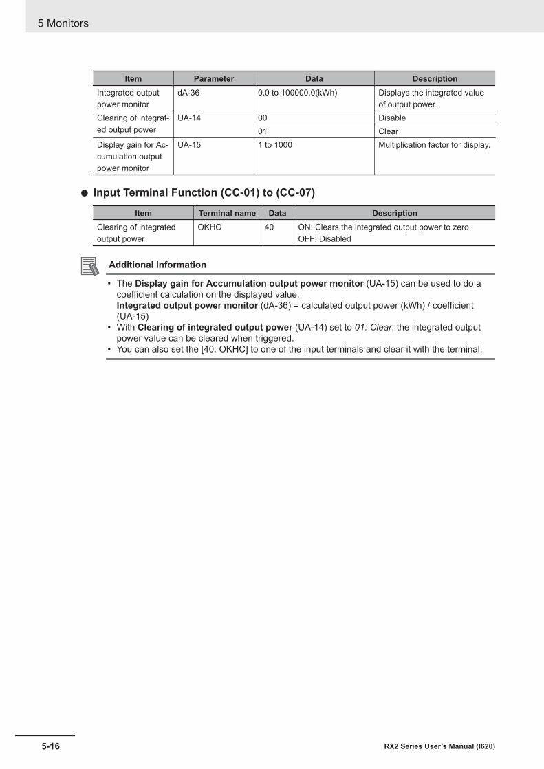
Item Parameter Data DescriptionIntegrated outputpower monitor
dA-36 0.0 to 100000.0(kWh) Displays the integrated valueof output power.
Clearing of integrat-ed output power
UA-14 00 Disable01 Clear
Display gain for Ac-cumulation outputpower monitor
UA-15 1 to 1000 Multiplication factor for display.
l Input Terminal Function (CC-01) to (CC-07)
Item Terminal name Data DescriptionClearing of integratedoutput power
OKHC 40 ON: Clears the integrated output power to zero.OFF: Disabled
Additional Information
• The Display gain for Accumulation output power monitor (UA-15) can be used to do acoefficient calculation on the displayed value.Integrated output power monitor (dA-36) = calculated output power (kWh) / coefficient(UA-15)
• With Clearing of integrated output power (UA-14) set to 01: Clear, the integrated outputpower value can be cleared when triggered.
• You can also set the [40: OKHC] to one of the input terminals and clear it with the terminal.
5 Monitors
5-16 RX2 Series User’s Manual (I620)
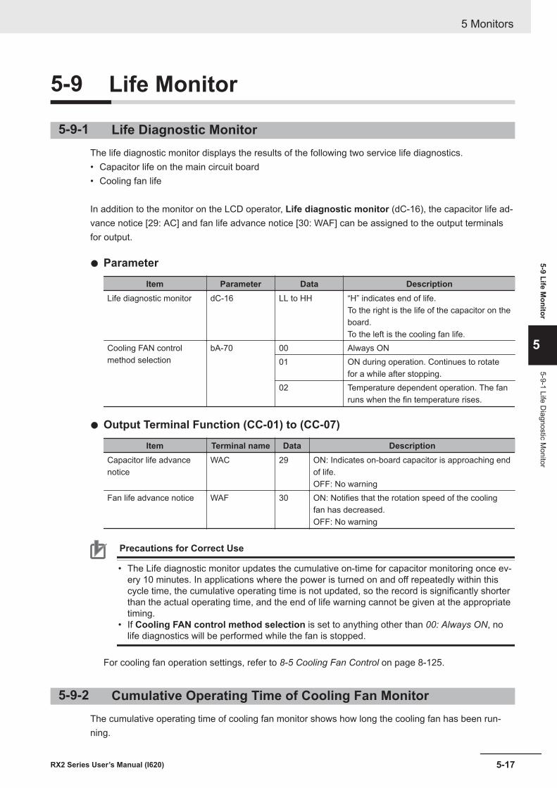
5-9 Life Monitor
5-9-1 Life Diagnostic MonitorThe life diagnostic monitor displays the results of the following two service life diagnostics.• Capacitor life on the main circuit board• Cooling fan life
In addition to the monitor on the LCD operator, Life diagnostic monitor (dC-16), the capacitor life ad-vance notice [29: AC] and fan life advance notice [30: WAF] can be assigned to the output terminalsfor output.
l Parameter
Item Parameter Data DescriptionLife diagnostic monitor dC-16 LL to HH “H” indicates end of life.
To the right is the life of the capacitor on theboard.To the left is the cooling fan life.
Cooling FAN controlmethod selection
bA-70 00 Always ON01 ON during operation. Continues to rotate
for a while after stopping.02 Temperature dependent operation. The fan
runs when the fin temperature rises.
l Output Terminal Function (CC-01) to (CC-07)
Item Terminal name Data DescriptionCapacitor life advancenotice
WAC 29 ON: Indicates on-board capacitor is approaching endof life.OFF: No warning
Fan life advance notice WAF 30 ON: Notifies that the rotation speed of the coolingfan has decreased.OFF: No warning
Precautions for Correct Use
• The Life diagnostic monitor updates the cumulative on-time for capacitor monitoring once ev-ery 10 minutes. In applications where the power is turned on and off repeatedly within thiscycle time, the cumulative operating time is not updated, so the record is significantly shorterthan the actual operating time, and the end of life warning cannot be given at the appropriatetiming.
• If Cooling FAN control method selection is set to anything other than 00: Always ON, nolife diagnostics will be performed while the fan is stopped.
For cooling fan operation settings, refer to 8-5 Cooling Fan Control on page 8-125.
5-9-2 Cumulative Operating Time of Cooling Fan MonitorThe cumulative operating time of cooling fan monitor shows how long the cooling fan has been run-ning.
5 Monitors
5-17RX2 Series User’s Manual (I620)
5-9 Life Monitor
5
5-9-1 Life Diagnostic M
onitor
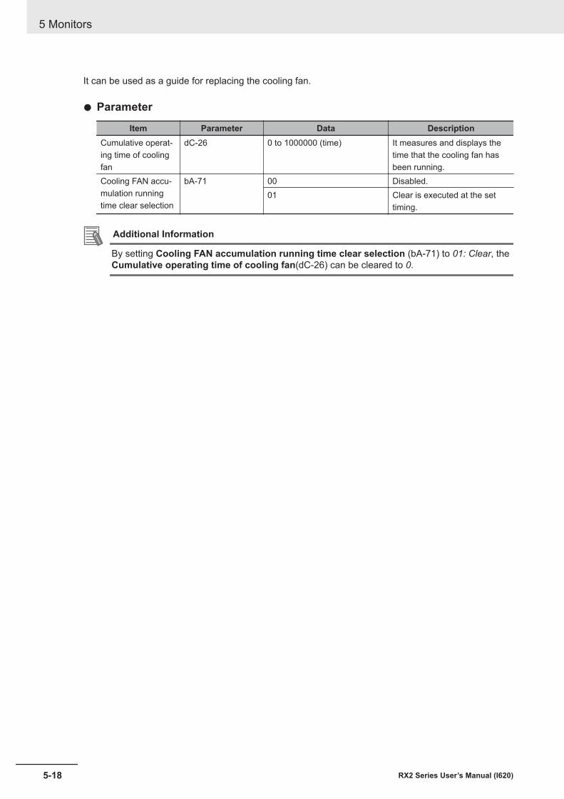
It can be used as a guide for replacing the cooling fan.
l Parameter
Item Parameter Data DescriptionCumulative operat-ing time of coolingfan
dC-26 0 to 1000000 (time) It measures and displays thetime that the cooling fan hasbeen running.
Cooling FAN accu-mulation runningtime clear selection
bA-71 00 Disabled.01 Clear is executed at the set
timing.
Additional Information
By setting Cooling FAN accumulation running time clear selection (bA-71) to 01: Clear, theCumulative operating time of cooling fan(dC-26) can be cleared to 0.
5 Monitors
5-18 RX2 Series User’s Manual (I620)
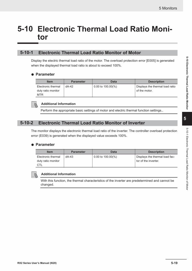
5-10 Electronic Thermal Load Ratio Moni-tor
5-10-1 Electronic Thermal Load Ratio Monitor of MotorDisplay the electric thermal load ratio of the motor. The overload protection error [E005] is generatedwhen the displayed thermal load ratio is about to exceed 100%.
l Parameter
Item Parameter Data DescriptionElectronic thermalduty ratio monitorMTR
dA-42 0.00 to 100.00(%) Displays the thermal load ratioof the motor.
Additional Information
Perform the appropriate basic settings of motor and electric thermal function settings.。
5-10-2 Electronic Thermal Load Ratio Monitor of InverterThe monitor displays the electronic thermal load ratio of the inverter. The controller overload protectionerror (E039) is generated when the displayed value exceeds 100%.
l Parameter
Item Parameter Data DescriptionElectronic thermalduty ratio monitorCTL
dA-43 0.00 to 100.00(%) Displays the thermal load fac-tor of the inverter.
Additional Information
With this function, the thermal characteristics of the inverter are predetermined and cannot bechanged.
5 Monitors
5-19RX2 Series User’s Manual (I620)
5-10 Electronic Thermal Load R
atio Monitor
5
5-10-1 Electronic Thermal Load R
atio Monitor of M
otor
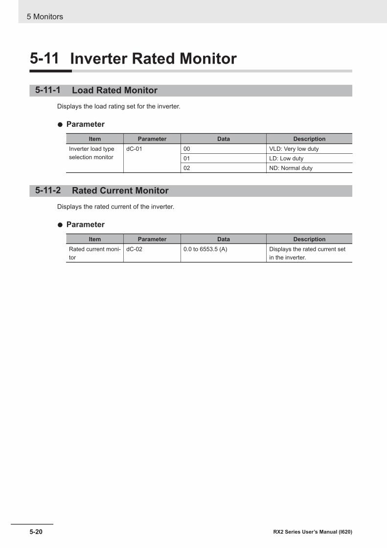
5-11 Inverter Rated Monitor
5-11-1 Load Rated MonitorDisplays the load rating set for the inverter.
l Parameter
Item Parameter Data DescriptionInverter load typeselection monitor
dC-01 00 VLD: Very low duty01 LD: Low duty02 ND: Normal duty
5-11-2 Rated Current MonitorDisplays the rated current of the inverter.
l Parameter
Item Parameter Data DescriptionRated current moni-tor
dC-02 0.0 to 6553.5 (A) Displays the rated current setin the inverter.
5 Monitors
5-20 RX2 Series User’s Manual (I620)
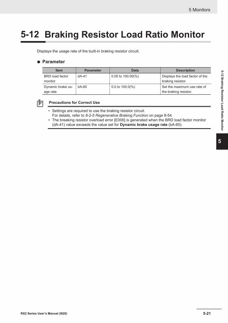
5-12 Braking Resistor Load Ratio MonitorDisplays the usage rate of the built-in braking resistor circuit.
l Parameter
Item Parameter Data DescriptionBRD load factormonitor
dA-41 0.00 to 100.00(%) Displays the load factor of thebraking resistor.
Dynamic brake us-age rate
bA-60 0.0 to 100.0(%) Set the maximum use rate ofthe braking resistor.
Precautions for Correct Use
• Settings are required to use the braking resistor circuit.For details, refer to 8-2-5 Regenerative Braking Function on page 8-54.
• The breaking resistor overload error [E006] is generated when the BRD load factor monitor(dA-41) value exceeds the value set for Dynamic brake usage rate (bA-60).
5 Monitors
5-21RX2 Series User’s Manual (I620)
5-12 Braking R
esistor Load Ratio M
onitor
5
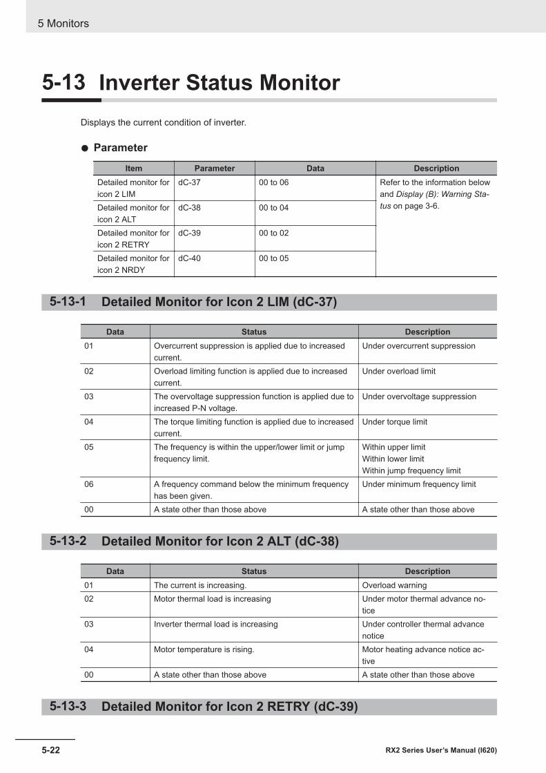
5-13 Inverter Status MonitorDisplays the current condition of inverter.
l Parameter
Item Parameter Data DescriptionDetailed monitor foricon 2 LIM
dC-37 00 to 06 Refer to the information belowand Display (B): Warning Sta-tus on page 3-6.Detailed monitor for
icon 2 ALTdC-38 00 to 04
Detailed monitor foricon 2 RETRY
dC-39 00 to 02
Detailed monitor foricon 2 NRDY
dC-40 00 to 05
5-13-1 Detailed Monitor for Icon 2 LIM (dC-37)
Data Status Description01 Overcurrent suppression is applied due to increased
current.Under overcurrent suppression
02 Overload limiting function is applied due to increasedcurrent.
Under overload limit
03 The overvoltage suppression function is applied due toincreased P-N voltage.
Under overvoltage suppression
04 The torque limiting function is applied due to increasedcurrent.
Under torque limit
05 The frequency is within the upper/lower limit or jumpfrequency limit.
Within upper limitWithin lower limitWithin jump frequency limit
06 A frequency command below the minimum frequencyhas been given.
Under minimum frequency limit
00 A state other than those above A state other than those above
5-13-2 Detailed Monitor for Icon 2 ALT (dC-38)
Data Status Description01 The current is increasing. Overload warning02 Motor thermal load is increasing Under motor thermal advance no-
tice03 Inverter thermal load is increasing Under controller thermal advance
notice04 Motor temperature is rising. Motor heating advance notice ac-
tive00 A state other than those above A state other than those above
5-13-3 Detailed Monitor for Icon 2 RETRY (dC-39)
5 Monitors
5-22 RX2 Series User’s Manual (I620)
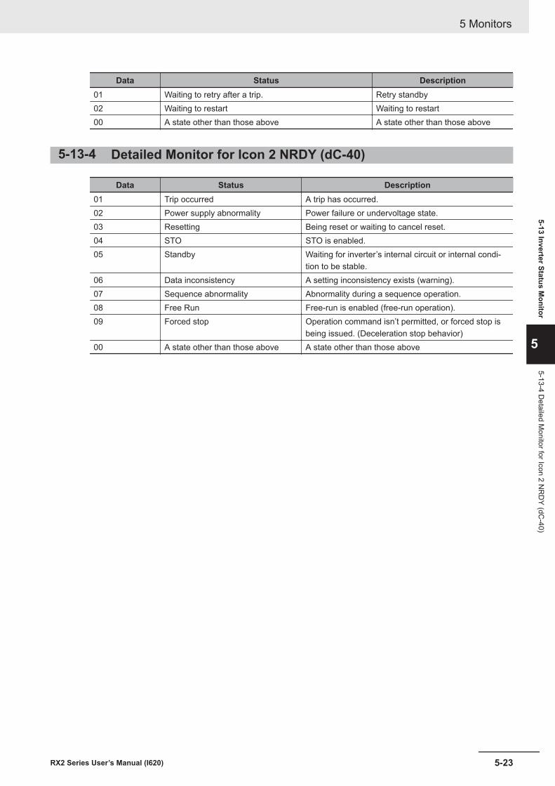
Data Status Description01 Waiting to retry after a trip. Retry standby02 Waiting to restart Waiting to restart00 A state other than those above A state other than those above
5-13-4 Detailed Monitor for Icon 2 NRDY (dC-40)
Data Status Description01 Trip occurred A trip has occurred.02 Power supply abnormality Power failure or undervoltage state.03 Resetting Being reset or waiting to cancel reset.04 STO STO is enabled.05 Standby Waiting for inverter’s internal circuit or internal condi-
tion to be stable.06 Data inconsistency A setting inconsistency exists (warning).07 Sequence abnormality Abnormality during a sequence operation.08 Free Run Free-run is enabled (free-run operation).09 Forced stop Operation command isn’t permitted, or forced stop is
being issued. (Deceleration stop behavior)00 A state other than those above A state other than those above
5 Monitors
5-23RX2 Series User’s Manual (I620)
5-13 Inverter Status Monitor
5
5-13-4 Detailed M
onitor for Icon 2 NR
DY (dC
-40)
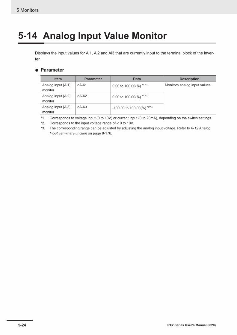
5-14 Analog Input Value MonitorDisplays the input values for Ai1, Ai2 and Ai3 that are currently input to the terminal block of the inver-ter.
l Parameter
Item Parameter Data DescriptionAnalog input [Ai1]monitor
dA-61 0.00 to 100.00(%) *1*3 Monitors analog input values.
Analog input [Ai2]monitor
dA-62 0.00 to 100.00(%) *1*3
Analog input [Ai3]monitor
dA-63 -100.00 to 100.00(%) *2*3
*1. Corresponds to voltage input (0 to 10V) or current input (0 to 20mA), depending on the switch settings.*2. Corresponds to the input voltage range of -10 to 10V.*3. The corresponding range can be adjusted by adjusting the analog input voltage. Refer to 8-12 Analog
Input Terminal Function on page 8-176.
5 Monitors
5-24 RX2 Series User’s Manual (I620)
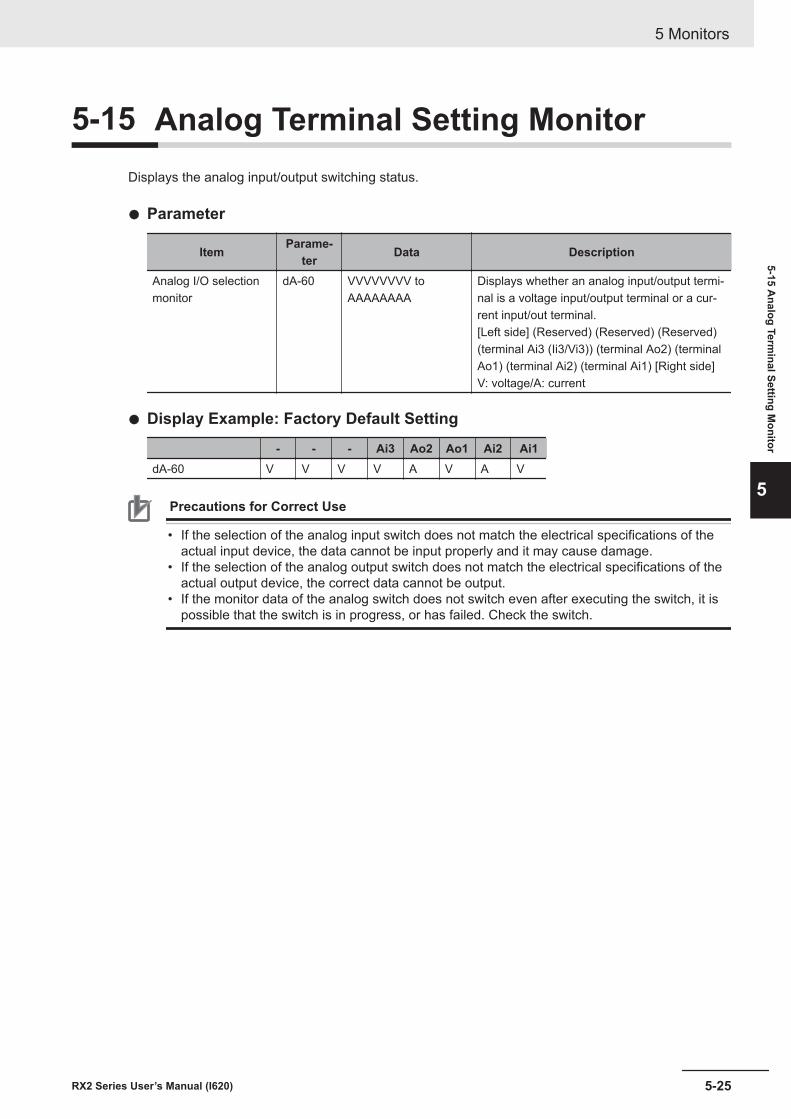
5-15 Analog Terminal Setting MonitorDisplays the analog input/output switching status.
l Parameter
Item Parame-ter Data Description
Analog I/O selectionmonitor
dA-60 VVVVVVVV toAAAAAAAA
Displays whether an analog input/output termi-nal is a voltage input/output terminal or a cur-rent input/out terminal.[Left side] (Reserved) (Reserved) (Reserved)(terminal Ai3 (Ii3/Vi3)) (terminal Ao2) (terminalAo1) (terminal Ai2) (terminal Ai1) [Right side]V: voltage/A: current
l Display Example: Factory Default Setting
- - - Ai3 Ao2 Ao1 Ai2 Ai1dA-60 V V V V A V A V
Precautions for Correct Use
• If the selection of the analog input switch does not match the electrical specifications of theactual input device, the data cannot be input properly and it may cause damage.
• If the selection of the analog output switch does not match the electrical specifications of theactual output device, the correct data cannot be output.
• If the monitor data of the analog switch does not switch even after executing the switch, it ispossible that the switch is in progress, or has failed. Check the switch.
5 Monitors
5-25RX2 Series User’s Manual (I620)
5-15 Analog Term
inal Setting Monitor
5
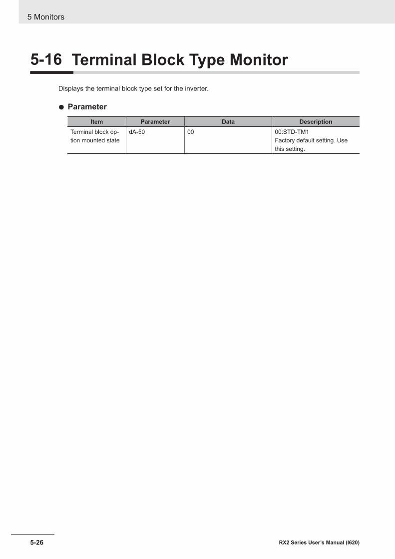
5-16 Terminal Block Type MonitorDisplays the terminal block type set for the inverter.
l Parameter
Item Parameter Data DescriptionTerminal block op-tion mounted state
dA-50 00 00:STD-TM1Factory default setting. Usethis setting.
5 Monitors
5-26 RX2 Series User’s Manual (I620)
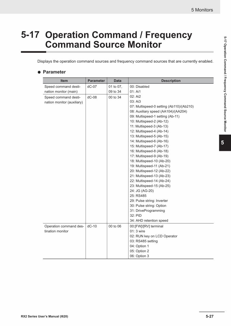
5-17 Operation Command / FrequencyCommand Source Monitor
Displays the operation command sources and frequency command sources that are currently enabled.
l Parameter
Item Parameter Data DescriptionSpeed command desti-nation monitor (main)
dC-07 01 to 07,09 to 34
00: Disabled01: Ai102: Ai203: Ai307: Multispeed-0 setting (Ab110)/(Ab210)08: Auxiliary speed (AA104)/(AA204)09: Multispeed-1 setting (Ab-11)10: Multispeed-2 (Ab-12)11: Multispeed-3 (Ab-13)12: Multispeed-4 (Ab-14)13: Multispeed-5 (Ab-15)14: Multispeed-6 (Ab-16)15: Multispeed-7 (Ab-17)16: Multispeed-8 (Ab-18)17: Multispeed-9 (Ab-19)18: Multispeed-10 (Ab-20)19: Multispeed-11 (Ab-21)20: Multispeed-12 (Ab-22)21: Multispeed-13 (Ab-23)22: Multispeed-14 (Ab-24)23: Multispeed-15 (Ab-25)24: JG (AG-20)25: RS48529: Pulse string: Inverter30: Pulse string: Option31: DriveProgramming32: PID34: AHD retention speed
Speed command desti-nation monitor (auxiliary)
dC-08 00 to 34
Operation command des-tination monitor
dC-10 00 to 06 00:[FW]/[RV] terminal01: 3 wire02: RUN key on LCD Operator03: RS485 setting04: Option 105: Option 206: Option 3
5 Monitors
5-27RX2 Series User’s Manual (I620)
5-17 Operation C
omm
and / Frequency Com
mand Source M
onitor
5
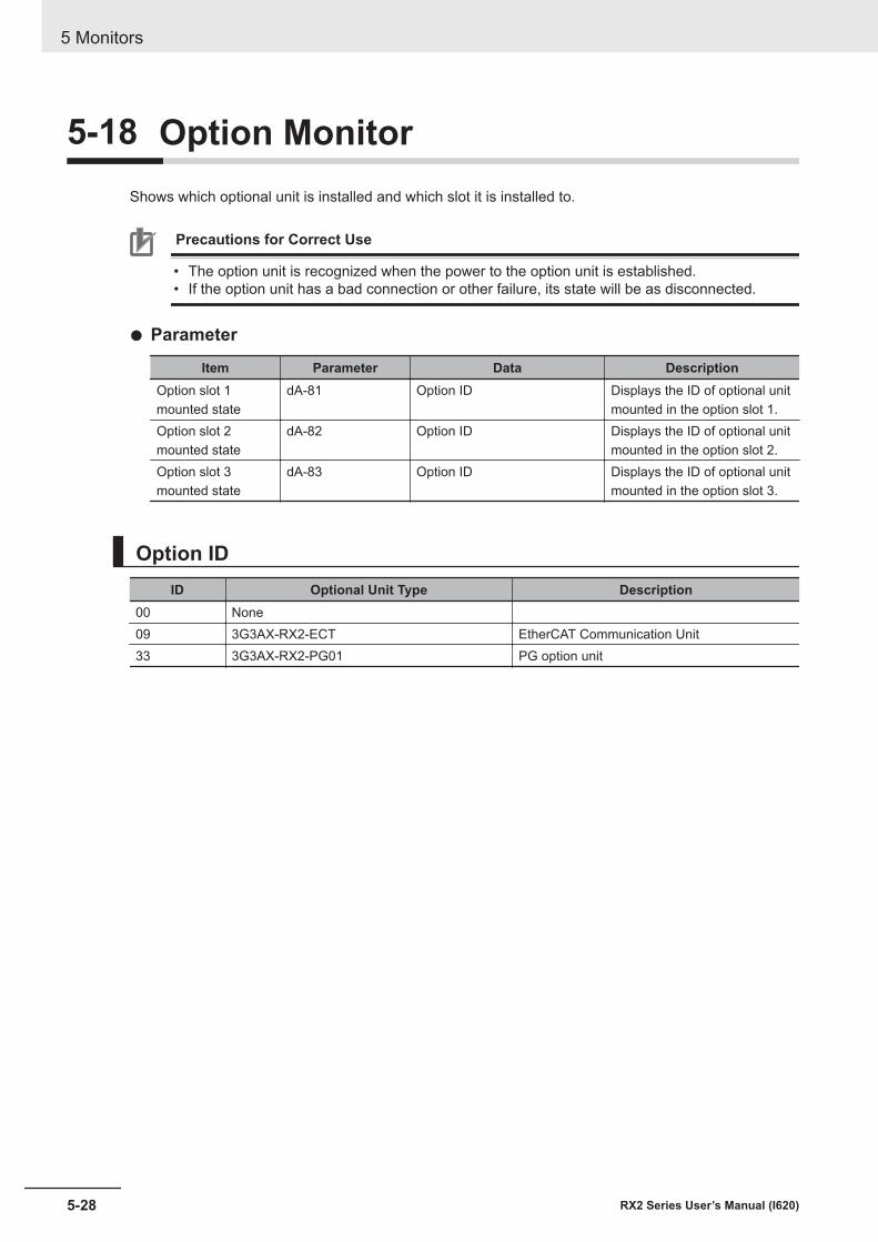
5-18 Option MonitorShows which optional unit is installed and which slot it is installed to.
Precautions for Correct Use
• The option unit is recognized when the power to the option unit is established.• If the option unit has a bad connection or other failure, its state will be as disconnected.
l Parameter
Item Parameter Data DescriptionOption slot 1mounted state
dA-81 Option ID Displays the ID of optional unitmounted in the option slot 1.
Option slot 2mounted state
dA-82 Option ID Displays the ID of optional unitmounted in the option slot 2.
Option slot 3mounted state
dA-83 Option ID Displays the ID of optional unitmounted in the option slot 3.
Option IDID Optional Unit Type Description
00 None09 3G3AX-RX2-ECT EtherCAT Communication Unit33 3G3AX-RX2-PG01 PG option unit
5 Monitors
5-28 RX2 Series User’s Manual (I620)
6Basic Parameter Settings
This section describes the basic parameter settings.
6-1 Basic Parameter Settings.............................................................................. 6-36-1-1 Inverter Load Rating Settings.......................................................................... 6-36-1-2 Inverter Initialization ........................................................................................ 6-4
6-2 Settings for Motor Related Parameter.......................................................... 6-86-2-1 Motor Basic Settings ....................................................................................... 6-86-2-2 Motor Constant Settings................................................................................ 6-126-2-3 Auto-tuning of Motor...................................................................................... 6-13
6-3 Operation Command Settings..................................................................... 6-186-3-1 Types of Operation Commands..................................................................... 6-186-3-2 Operation with LCD Operator........................................................................ 6-186-3-3 Operation with Forward and Reverse Rotation Terminals............................. 6-196-3-4 Operation with 3 Wire Function of Terminal Block......................................... 6-206-3-5 Operation with RS485 Communication ......................................................... 6-216-3-6 Operation from Optional Unit......................................................................... 6-226-3-7 Disabling Keys on LCD Operator .................................................................. 6-226-3-8 Temporary Change of Operation Command Destination .............................. 6-22
6-4 Frequency Command Settings ................................................................... 6-256-4-1 Frequency Command Selection .................................................................... 6-256-4-2 When Command Is Given from LCD Operator.............................................. 6-266-4-3 When Command Is Given from Terminal Block Analog Signals.................... 6-276-4-4 When Command Is Given through R485 Communication ............................ 6-286-4-5 When Command Is Given from Pulse Train Input ......................................... 6-286-4-6 When Command Is Given through DriveProgramming ................................. 6-346-4-7 When Command Is Given with PID Control .................................................. 6-346-4-8 When Command Is Given with Main Speed Command and Auxiliary
Speed Command .......................................................................................... 6-356-4-9 When Command Is Given with Multi-step Speed.......................................... 6-376-4-10 Temporary Addition of Frequency Command................................................ 6-416-4-11 Up/Down Function (FUP, FDN) ..................................................................... 6-426-4-12 Analog Command Hold Function (AHD) ....................................................... 6-446-4-13 Temporary Change of Frequency Command Destination ............................. 6-45
6-5 Limiting Frequency and Operation Commands ........................................ 6-476-5-1 Limiting Frequency Command ...................................................................... 6-476-5-2 Limiting Operation Command Direction ........................................................ 6-486-5-3 Limiting Output Direction ............................................................................... 6-496-5-4 Operation Permission.................................................................................... 6-50
6-6 Thermal Protection ...................................................................................... 6-51
6-1RX2 Series User’s Manual (I620)
6
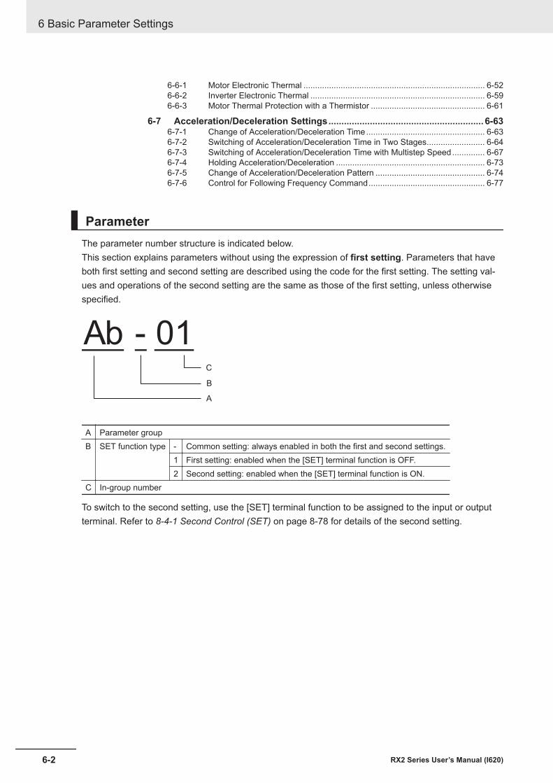
6-6-1 Motor Electronic Thermal .............................................................................. 6-526-6-2 Inverter Electronic Thermal ........................................................................... 6-596-6-3 Motor Thermal Protection with a Thermistor ................................................. 6-61
6-7 Acceleration/Deceleration Settings............................................................ 6-636-7-1 Change of Acceleration/Deceleration Time................................................... 6-636-7-2 Switching of Acceleration/Deceleration Time in Two Stages......................... 6-646-7-3 Switching of Acceleration/Deceleration Time with Multistep Speed.............. 6-676-7-4 Holding Acceleration/Deceleration ................................................................ 6-736-7-5 Change of Acceleration/Deceleration Pattern ............................................... 6-746-7-6 Control for Following Frequency Command.................................................. 6-77
ParameterThe parameter number structure is indicated below.This section explains parameters without using the expression of first setting. Parameters that haveboth first setting and second setting are described using the code for the first setting. The setting val-ues and operations of the second setting are the same as those of the first setting, unless otherwisespecified.
Ab - 01
A
B
C
A Parameter groupB SET function type - Common setting: always enabled in both the first and second settings.
1 First setting: enabled when the [SET] terminal function is OFF.2 Second setting: enabled when the [SET] terminal function is ON.
C In-group number
To switch to the second setting, use the [SET] terminal function to be assigned to the input or outputterminal. Refer to 8-4-1 Second Control (SET) on page 8-78 for details of the second setting.
6 Basic Parameter Settings
6-2 RX2 Series User’s Manual (I620)
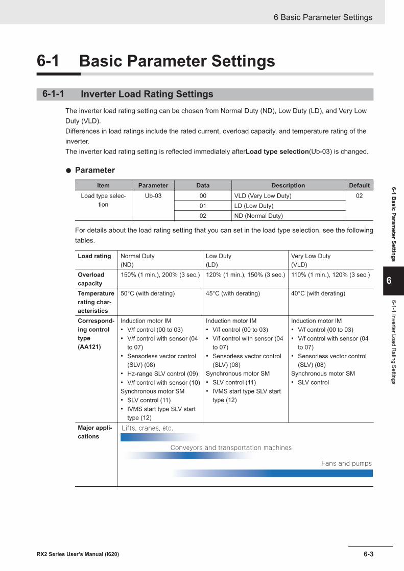
6-1 Basic Parameter Settings
6-1-1 Inverter Load Rating SettingsThe inverter load rating setting can be chosen from Normal Duty (ND), Low Duty (LD), and Very LowDuty (VLD).Differences in load ratings include the rated current, overload capacity, and temperature rating of theinverter.The inverter load rating setting is reflected immediately afterLoad type selection(Ub-03) is changed.
l Parameter
Item Parameter Data Description DefaultLoad type selec-
tionUb-03 00 VLD (Very Low Duty) 02
01 LD (Low Duty)02 ND (Normal Duty)
For details about the load rating setting that you can set in the load type selection, see the followingtables.
Load rating Normal Duty(ND)
Low Duty(LD)
Very Low Duty(VLD)
Overloadcapacity
150% (1 min.), 200% (3 sec.) 120% (1 min.), 150% (3 sec.) 110% (1 min.), 120% (3 sec.)
Temperaturerating char-acteristics
50°C (with derating) 45°C (with derating) 40°C (with derating)
Correspond-ing controltype(AA121)
Induction motor IM• V/f control (00 to 03)• V/f control with sensor (04
to 07)• Sensorless vector control
(SLV) (08)• Hz-range SLV control (09)• V/f control with sensor (10)Synchronous motor SM• SLV control (11)• IVMS start type SLV start
type (12)
Induction motor IM• V/f control (00 to 03)• V/f control with sensor (04
to 07)• Sensorless vector control
(SLV) (08)Synchronous motor SM• SLV control (11)• IVMS start type SLV start
type (12)
Induction motor IM• V/f control (00 to 03)• V/f control with sensor (04
to 07)• Sensorless vector control
(SLV) (08)Synchronous motor SM• SLV control
Major appli-cations
Lifts, cranes, etc.
Conveyors and transportation machines
Fans and pumps
6 Basic Parameter Settings
6-3RX2 Series User’s Manual (I620)
6-1 Basic Param
eter Settings
6
6-1-1 Inverter Load Rating Settings
Additional Information
• If Load type selection (Ub-03) is changed, the parameter setting values related to currentwill change inside the inverter, so they need to be configured again. This is because the inter-nal set value stored in the ratio (%) of the inverter rated current is interpreted in a unit ofcurrent (A); so all these parameters need to correspond to the new set value.
• The following functions related to the current setting need to be configured again after chang-ing Load type selection (Ub-03). Applicable parameters are those use current as a unit forthe overload limiting function, DC injection braking function, electronic thermal function, over-load warning function, and low current detection function.
• If the control mode set in Control mode selection (AA121) does not support the Low Duty(LD) or Very Low Duty (VLD), when Load type selection (Ub-03) is set, Control modeselection (AA121) is automatically changed to 00: VF control . When changing to the VeryLow Duty (VLD) or Low Duty (LD), change the setting of Load type selection (Ub-03) andthen check Control mode selection (AA121) again.
6-1-2 Inverter InitializationWhenInitialize Mode selection(Ub-01) is chosen andInitialize Enable(Ub-05) is set to01, the desig-nated data can be initialized to the default.This is convenient when you use the 3G3RX2 Series Inverter for the first time or when you want tomake the settings again after returning them to the factory default settings.
To initialize the inverter, setInitialize Mode selection(Ub-01) to04: Trip history + parameters +DriveProgrammingandInitialize Enable(Ub-05) to01.
You can also clear only the trip history without initializing the stored parameter.You do not need to changeInitialize Data selection(Ub-02), so use the default value01: Mode 1.
Precautions for Correct Use
After initializing the inverter, you need to reset the electronic thermal of the motor. If the inverteris used without the reset after initialization, the motor may burn out.
6 Basic Parameter Settings
6-4 RX2 Series User’s Manual (I620)
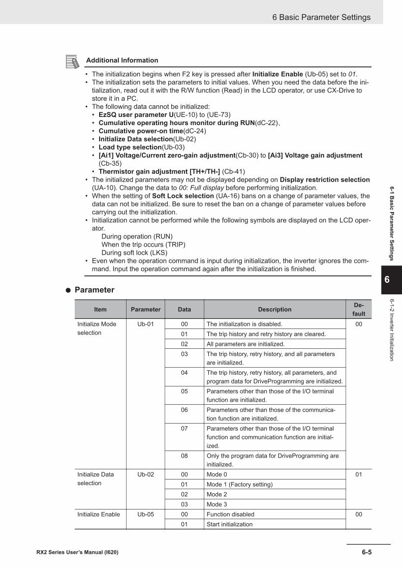
Additional Information
• The initialization begins when F2 key is pressed after Initialize Enable (Ub-05) set to 01.• The initialization sets the parameters to initial values. When you need the data before the ini-
tialization, read out it with the R/W function (Read) in the LCD operator, or use CX-Drive tostore it in a PC.
• The following data cannot be initialized:• EzSQ user parameter U(UE-10) to (UE-73)• Cumulative operating hours monitor during RUN(dC-22)、• Cumulative power-on time(dC-24)• Initialize Data selection(Ub-02)• Load type selection(Ub-03)• [Ai1] Voltage/Current zero-gain adjustment(Cb-30) to [Ai3] Voltage gain adjustment
(Cb-35)• Thermistor gain adjustment [TH+/TH-] (Cb-41)
• The initialized parameters may not be displayed depending on Display restriction selection(UA-10). Change the data to 00: Full display before performing initialization.
• When the setting of Soft Lock selection (UA-16) bans on a change of parameter values, thedata can not be initialized. Be sure to reset the ban on a change of parameter values beforecarrying out the initialization.
• Initialization cannot be performed while the following symbols are displayed on the LCD oper-ator.
During operation (RUN)When the trip occurs (TRIP)During soft lock (LKS)
• Even when the operation command is input during initialization, the inverter ignores the com-mand. Input the operation command again after the initialization is finished.
l Parameter
Item Parameter Data Description De-fault
Initialize Modeselection
Ub-01 00 The initialization is disabled. 0001 The trip history and retry history are cleared.02 All parameters are initialized.03 The trip history, retry history, and all parameters
are initialized.04 The trip history, retry history, all parameters, and
program data for DriveProgramming are initialized.05 Parameters other than those of the I/O terminal
function are initialized.06 Parameters other than those of the communica-
tion function are initialized.07 Parameters other than those of the I/O terminal
function and communication function are initial-ized.
08 Only the program data for DriveProgramming areinitialized.
Initialize Dataselection
Ub-02 00 Mode 0 0101 Mode 1 (Factory setting)02 Mode 203 Mode 3
Initialize Enable Ub-05 00 Function disabled 0001 Start initialization
6 Basic Parameter Settings
6-5RX2 Series User’s Manual (I620)
6-1 Basic Param
eter Settings
6
6-1-2 Inverter Initialization
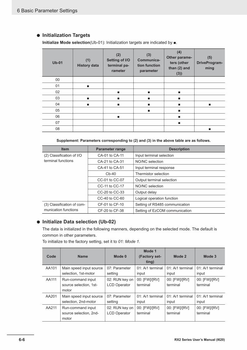
l Initialization TargetsInitialize Mode selection(Ub-01): Initialization targets are indicated by ■.
Ub-01 (1)History data
(2)Setting of I/Oterminal pa-
rameter
(3)Communica-tion function
parameter
(4)Other parame-
ters (otherthan (2) and
(3))
(5)DriveProgram-
ming
0001 ■02 ■ ■ ■03 ■ ■ ■ ■04 ■ ■ ■ ■ ■05 ■ ■06 ■ ■07 ■08 ■
Supplement: Parameters corresponding to (2) and (3) in the above table are as follows.
Item Parameter range Description(2) Classification of I/Oterminal functions
CA-01 to CA-11 Input terminal selectionCA-21 to CA-31 NO/NC selectionCA-41 to CA-51 Input terminal response
Cb-40 Thermistor selectionCC-01 to CC-07 Output terminal selectionCC-11 to CC-17 NO/NC selectionCC-20 to CC-33 Output delayCC-40 to CC-60 Logical operation function
(3) Classification of com-munication functions
CF-01 to CF-10 Setting of RS485 communicationCF-20 to CF-38 Setting of EzCOM communication
l Initialize Data selection (Ub-02)The data is initialized in the following manners, depending on the selected mode. The default iscommon in other parameters.To initialize to the factory setting, set it to 01: Mode 1.
Code Name Mode 0Mode 1
(Factory set-ting)
Mode 2 Mode 3
AA101 Main speed input sourceselection, 1st-motor
07: Parametersetting
01: Ai1 terminalinput
01: Ai1 terminalinput
01: Ai1 terminalinput
AA111 Run-command inputsource selection, 1st-motor
02: RUN key onLCD Operator
00: [FW]/[RV]terminal
00: [FW]/[RV]terminal
00: [FW]/[RV]terminal
AA201 Main speed input sourceselection, 2nd-motor
07: Parametersetting
01: Ai1 terminalinput
01: Ai1 terminalinput
01: Ai1 terminalinput
AA211 Run-command inputsource selection, 2nd-motor
02: RUN key onLCD Operator
00: [FW]/[RV]terminal
00: [FW]/[RV]terminal
00: [FW]/[RV]terminal
6 Basic Parameter Settings
6-6 RX2 Series User’s Manual (I620)
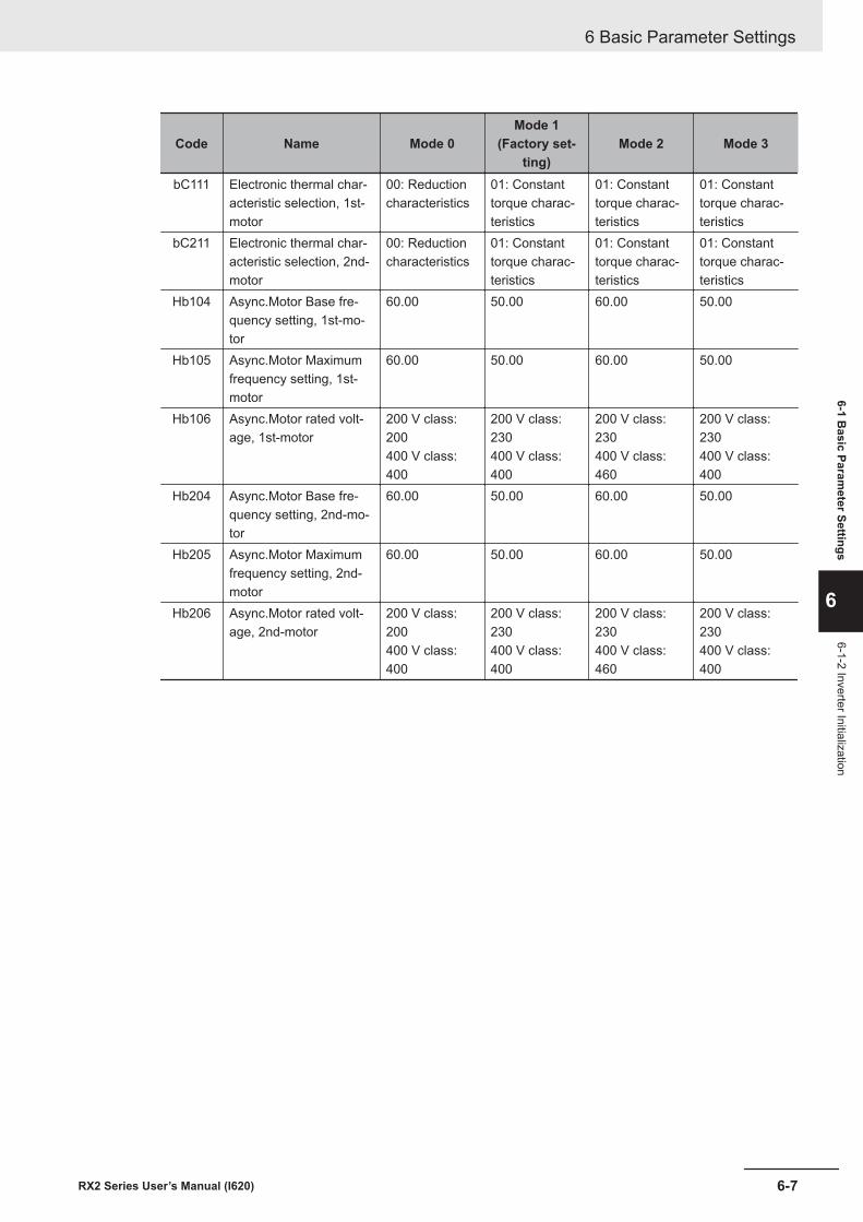
Code Name Mode 0Mode 1
(Factory set-ting)
Mode 2 Mode 3
bC111 Electronic thermal char-acteristic selection, 1st-motor
00: Reductioncharacteristics
01: Constanttorque charac-teristics
01: Constanttorque charac-teristics
01: Constanttorque charac-teristics
bC211 Electronic thermal char-acteristic selection, 2nd-motor
00: Reductioncharacteristics
01: Constanttorque charac-teristics
01: Constanttorque charac-teristics
01: Constanttorque charac-teristics
Hb104 Async.Motor Base fre-quency setting, 1st-mo-tor
60.00 50.00 60.00 50.00
Hb105 Async.Motor Maximumfrequency setting, 1st-motor
60.00 50.00 60.00 50.00
Hb106 Async.Motor rated volt-age, 1st-motor
200 V class:200400 V class:400
200 V class:230400 V class:400
200 V class:230400 V class:460
200 V class:230400 V class:400
Hb204 Async.Motor Base fre-quency setting, 2nd-mo-tor
60.00 50.00 60.00 50.00
Hb205 Async.Motor Maximumfrequency setting, 2nd-motor
60.00 50.00 60.00 50.00
Hb206 Async.Motor rated volt-age, 2nd-motor
200 V class:200400 V class:400
200 V class:230400 V class:400
200 V class:230400 V class:460
200 V class:230400 V class:400
6 Basic Parameter Settings
6-7RX2 Series User’s Manual (I620)
6-1 Basic Param
eter Settings
6
6-1-2 Inverter Initialization
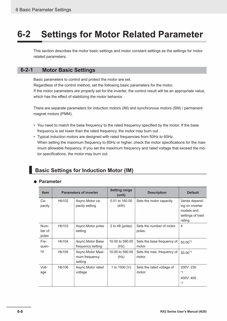
6-2 Settings for Motor Related ParameterThis section describes the motor basic settings and motor constant settings as the settings for motorrelated parameters.
6-2-1 Motor Basic SettingsBasic parameters to control and protect the motor are set.Regardless of the control method, set the following basic parameters for the motor.If the motor parameters are properly set for the inverter, the control result will be an appropriate value,which has the effect of stabilizing the motor behavior.
There are separate parameters for induction motors (IM) and synchronous motors (SM) / permanentmagnet motors (PMM).
• You need to match the base frequency to the rated frequency specified by the motor. If the basefrequency is set lower than the rated frequency, the motor may burn out.
• Typical induction motors are designed with rated frequencies from 50Hz to 60Hz.When setting the maximum frequency to 60Hz or higher, check the motor specifications for the max-imum allowable frequency. If you set the maximum frequency and rated voltage that exceed the mo-tor specifications, the motor may burn out.
Basic Settings for Induction Motor (IM)
l Parameter
Item Parameters of inverter Setting range(unit) Description Default
Ca-pacity
Hb102 Async.Motor ca-pacity setting
0.01 to 160.00(kW)
Sets the motor capacity. Varies depend-ing on invertermodels andsettings of loadrating.
Num-ber ofpoles
Hb103 Async.Motor polessetting
2 to 48 (poles) Sets the number of motorpoles.
4
Fre-quen-cy
Hb104 Async.Motor Basefrequency setting
10.00 to 590.00(Hz)
Sets the base frequency ofmotor.
50.00*1
Hb105 Async.Motor Maxi-mum frequencysetting
10.00 to 590.00(Hz)
Sets the max. frequency ofmotor.
50.00*1
Volt-age
Hb106 Async.Motor ratedvoltage
1 to 1000 (V) Sets the rated voltage ofmotor.
200V: 230*1
400V: 400*1
6 Basic Parameter Settings
6-8 RX2 Series User’s Manual (I620)
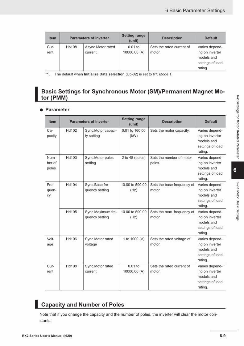
Item Parameters of inverter Setting range(unit) Description Default
Cur-rent
Hb108 Async.Motor ratedcurrent
0.01 to10000.00 (A)
Sets the rated current ofmotor.
Varies depend-ing on invertermodels andsettings of loadrating.
*1. The default when Initialize Data selection (Ub-02) is set to 01: Mode 1.
Basic Settings for Synchronous Motor (SM)/Permanent Magnet Mo-tor (PMM)
l Parameter
Item Parameters of inverter Setting range(unit) Description Default
Ca-pacity
Hd102 Sync.Motor capaci-ty setting
0.01 to 160.00(kW)
Sets the motor capacity. Varies depend-ing on invertermodels andsettings of loadrating.
Num-ber ofpoles
Hd103 Sync.Motor polessetting
2 to 48 (poles) Sets the number of motorpoles.
Varies depend-ing on invertermodels andsettings of loadrating.
Fre-quen-cy
Hd104 Sync.Base fre-quency setting
10.00 to 590.00(Hz)
Sets the base frequency ofmotor.
Varies depend-ing on invertermodels andsettings of loadrating.
Hd105 Sync.Maximum fre-quency setting
10.00 to 590.00(Hz)
Sets the max. frequency ofmotor.
Varies depend-ing on invertermodels andsettings of loadrating.
Volt-age
Hd106 Sync.Motor ratedvoltage
1 to 1000 (V) Sets the rated voltage ofmotor.
Varies depend-ing on invertermodels andsettings of loadrating.
Cur-rent
Hd108 Sync.Motor ratedcurrent
0.01 to10000.00 (A)
Sets the rated current ofmotor.
Varies depend-ing on invertermodels andsettings of loadrating.
Capacity and Number of PolesNote that if you change the capacity and the number of poles, the inverter will clear the motor con-stants.
6 Basic Parameter Settings
6-9RX2 Series User’s Manual (I620)
6-2 Settings for Motor R
elated Parameter
6
6-2-1 Motor Basic Settings
After setting the capacity and number of poles, you need to auto-tune or manually enter the preparedmotor constants. Setting the correct motor constant will optimize and stabilize the operation.The cleared initial value is for auto tuning, and if it is far from the actual motor constant, the motor maynot behave as expected, so set the motor constant correctly.
Base FrequencyMatch Async.Motor Base frequency setting (Hb104) to the rated frequency of the motor.The base (maximum) frequency is calculated from the rated rotation speed (min-1) and the number ofpoles of the motor as follows.• Base frequency (Hz) = Rated rotation speed (min-1) x Number of poles (pole) / 120
Precautions for Correct Use
If the induction motor can be used above 60Hz, it may be a special motor. Since the power con-sumption exceeds the maximum applicable motor capacity of the inverter, it may be necessaryto increase the inverter capacity.
Maximum FrequencySet the maximum frequency of motor.
Rated VoltageSet the rated voltage of motor according to the motor specifications.
Precautions for Correct Use
• If the motor rated voltage exceeds the receiving voltage or inverter rated voltage, the voltageexceeding the receiving voltage will not be output, so sufficient characteristics may not be ob-tained.
• When upgrading from the 3G3RX-V1 Series Inverter, set the rated voltage of the motor asfollows.3G3RX Series: Motor incoming voltage selection (A082) and Output voltage gain(A045)3G3RX2 Series: Async.Motor rated voltage (Hb106)Async.Motor rated voltage (Hb106) = A082 × A045 / 100
Rated CurrentSet the rated current of motor according to the motor specifications. If the setting is inappropriate, themotor protection may not work properly.If the motor rated current is not set correctly, the motor control may be unstable.
Precautions for Correct Use
If the motor rated current exceeds the inverter rated current, sufficient characteristics may notbe obtained. An inverter overcurrent error may be detected before the motor rated current isreached.
6 Basic Parameter Settings
6-10 RX2 Series User’s Manual (I620)
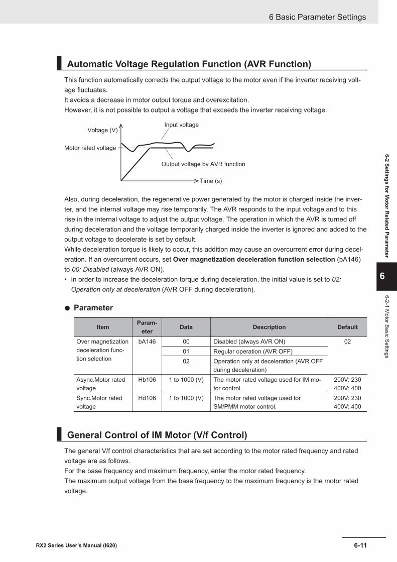
Automatic Voltage Regulation Function (AVR Function)This function automatically corrects the output voltage to the motor even if the inverter receiving volt-age fluctuates.It avoids a decrease in motor output torque and overexcitation.However, it is not possible to output a voltage that exceeds the inverter receiving voltage.
Input voltage
Output voltage by AVR function
Voltage (V)
Motor rated voltage
Time (s)
Also, during deceleration, the regenerative power generated by the motor is charged inside the inver-ter, and the internal voltage may rise temporarily. The AVR responds to the input voltage and to thisrise in the internal voltage to adjust the output voltage. The operation in which the AVR is turned offduring deceleration and the voltage temporarily charged inside the inverter is ignored and added to theoutput voltage to decelerate is set by default.While deceleration torque is likely to occur, this addition may cause an overcurrent error during decel-eration. If an overcurrent occurs, set Over magnetization deceleration function selection (bA146)to 00: Disabled (always AVR ON).• In order to increase the deceleration torque during deceleration, the initial value is set to 02:
Operation only at deceleration (AVR OFF during deceleration).
l Parameter
Item Param-eter Data Description Default
Over magnetizationdeceleration func-tion selection
bA146 00 Disabled (always AVR ON) 0201 Regular operation (AVR OFF)02 Operation only at deceleration (AVR OFF
during deceleration)Async.Motor ratedvoltage
Hb106 1 to 1000 (V) The motor rated voltage used for IM mo-tor control.
200V: 230400V: 400
Sync.Motor ratedvoltage
Hd106 1 to 1000 (V) The motor rated voltage used forSM/PMM motor control.
200V: 230400V: 400
General Control of IM Motor (V/f Control)The general V/f control characteristics that are set according to the motor rated frequency and ratedvoltage are as follows.For the base frequency and maximum frequency, enter the motor rated frequency.The maximum output voltage from the base frequency to the maximum frequency is the motor ratedvoltage.
6 Basic Parameter Settings
6-11RX2 Series User’s Manual (I620)
6-2 Settings for Motor R
elated Parameter
6
6-2-1 Motor Basic Settings
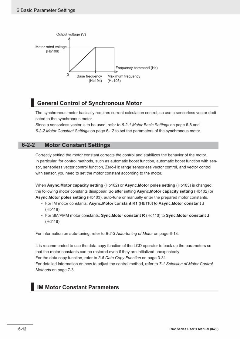
Output voltage (V)
Motor rated voltage
(Hb106)
Base frequency
(Hb194)
Maximum frequency
(Hb105)
Frequency command (Hz)
0
General Control of Synchronous MotorThe synchronous motor basically requires current calculation control, so use a sensorless vector dedi-cated to the synchronous motor.Since a sensorless vector is to be used, refer to 6-2-1 Motor Basic Settings on page 6-8 and 6-2-2 Motor Constant Settings on page 6-12 to set the parameters of the synchronous motor.
6-2-2 Motor Constant SettingsCorrectly setting the motor constant corrects the control and stabilizes the behavior of the motor.In particular, for control methods, such as automatic boost function, automatic boost function with sen-sor, sensorless vector control function, Zero-Hz range sensorless vector control, and vector controlwith sensor, you need to set the motor constant according to the motor.
When Async.Motor capacity setting (Hb102) or Async.Motor poles setting (Hb103) is changed,the following motor constants disappear. So after setting Async.Motor capacity setting (Hb102) orAsync.Motor poles setting (Hb103), auto-tune or manually enter the prepared motor constants.
• For IM motor constants: Async.Motor constant R1 (Hb110) to Async.Motor constant J(Hb118)
• For SM/PMM motor constants: Sync.Motor constant R (Hd110) to Sync.Motor constant J(Hd118)
For information on auto-tuning, refer to 6-2-3 Auto-tuning of Motor on page 6-13.
It is recommended to use the data copy function of the LCD operator to back up the parameters sothat the motor constants can be restored even if they are initialized unexpectedly.For the data copy function, refer to 3-5 Data Copy Function on page 3-31.For detailed information on how to adjust the control method, refer to 7-1 Selection of Motor ControlMethods on page 7-3.
IM Motor Constant Parameters
6 Basic Parameter Settings
6-12 RX2 Series User’s Manual (I620)
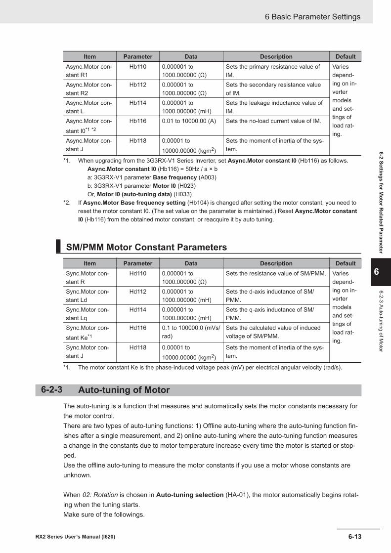
Item Parameter Data Description DefaultAsync.Motor con-stant R1
Hb110 0.000001 to1000.000000 (Ω)
Sets the primary resistance value ofIM.
Variesdepend-ing on in-vertermodelsand set-tings ofload rat-ing.
Async.Motor con-stant R2
Hb112 0.000001 to1000.000000 (Ω)
Sets the secondary resistance valueof IM.
Async.Motor con-stant L
Hb114 0.000001 to1000.000000 (mH)
Sets the leakage inductance value ofIM.
Async.Motor con-stant I0*1 *2
Hb116 0.01 to 10000.00 (A) Sets the no-load current value of IM.
Async.Motor con-stant J
Hb118 0.00001 to10000.00000 (kgm2)
Sets the moment of inertia of the sys-tem.
*1. When upgrading from the 3G3RX-V1 Series Inverter, set Async.Motor constant I0 (Hb116) as follows.Async.Motor constant I0 (Hb116) = 50Hz / a × ba: 3G3RX-V1 parameter Base frequency (A003)b: 3G3RX-V1 parameter Motor I0 (H023)Or, Motor I0 (auto-tuning data) (H033)
*2. If Async.Motor Base frequency setting (Hb104) is changed after setting the motor constant, you need toreset the motor constant I0. (The set value on the parameter is maintained.) Reset Async.Motor constantI0 (Hb116) from the obtained motor constant, or reacquire it by auto tuning.
SM/PMM Motor Constant ParametersItem Parameter Data Description Default
Sync.Motor con-stant R
Hd110 0.000001 to1000.000000 (Ω)
Sets the resistance value of SM/PMM. Variesdepend-ing on in-vertermodelsand set-tings ofload rat-ing.
Sync.Motor con-stant Ld
Hd112 0.000001 to1000.000000 (mH)
Sets the d-axis inductance of SM/PMM.
Sync.Motor con-stant Lq
Hd114 0.000001 to1000.000000 (mH)
Sets the q-axis inductance of SM/PMM.
Sync.Motor con-stant Ke*1
Hd116 0.1 to 100000.0 (mVs/rad)
Sets the calculated value of inducedvoltage of SM/PMM.
Sync.Motor con-stant J
Hd118 0.00001 to10000.00000 (kgm2)
Sets the moment of inertia of the sys-tem.
*1. The motor constant Ke is the phase-induced voltage peak (mV) per electrical angular velocity (rad/s).
6-2-3 Auto-tuning of MotorThe auto-tuning is a function that measures and automatically sets the motor constants necessary forthe motor control.There are two types of auto-tuning functions: 1) Offline auto-tuning where the auto-tuning function fin-ishes after a single measurement, and 2) online auto-tuning where the auto-tuning function measuresa change in the constants due to motor temperature increase every time the motor is started or stop-ped.Use the offline auto-tuning to measure the motor constants if you use a motor whose constants areunknown.
When 02: Rotation is chosen in Auto-tuning selection (HA-01), the motor automatically begins rotat-ing when the tuning starts.Make sure of the followings.
6 Basic Parameter Settings
6-13RX2 Series User’s Manual (I620)
6-2 Settings for Motor R
elated Parameter
6
6-2-3 Auto-tuning of Motor
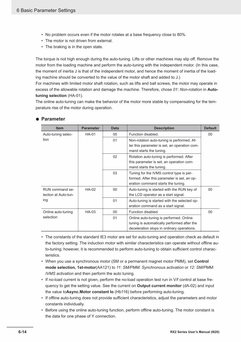
• No problem occurs even if the motor rotates at a base frequency close to 80%.• The motor is not driven from external.• The braking is in the open state.
The torque is not high enough during the auto-tuning. Lifts or other machines may slip off. Remove themotor from the loading machine and perform the auto-tuning with the independent motor. (In this case,the moment of inertia J is that of the independent motor, and hence the moment of inertia of the load-ing machine should be converted to the value of the motor shaft and added to J.)For machines with limited motor shaft rotation, such as lifts and ball screws, the motor may operate inexcess of the allowable rotation and damage the machine. Therefore, chose 01: Non-rotation in Auto-tuning selection (HA-01).The online auto-tuning can make the behavior of the motor more stable by compensating for the tem-perature rise of the motor during operation.
l Parameter
Item Parameter Data Description DefaultAuto-tuning selec-tion
HA-01 00 Function disabled. 0001 Non-rotation auto-tuning is performed. Af-
ter this parameter is set, an operation com-mand starts the tuning.
02 Rotation auto-tuning is performed. Afterthis parameter is set, an operation com-mand starts the tuning.
03 Tuning for the IVMS control type is per-formed. After this parameter is set, an op-eration command starts the tuning.
RUN command se-lection at Auto-tun-ing
HA-02 00 Auto-tuning is started with the RUN key ofthe LCD operator as a start signal.
00
01 Auto-tuning is started with the selected op-eration command as a start signal.
Online auto-tuningselection
HA-03 00 Function disabled. 0001 Online auto-tuning is performed. Online
tuning is automatically performed after thedeceleration stops in ordinary operations.
• The constants of the standard IE3 motor are set for auto-tuning and operation check as default inthe factory setting. The induction motor with similar characteristics can operate without offline au-to-tuning; however, it is recommended to perform auto-tuning to obtain sufficient control charac-teristics.
• When you use a synchronous motor (SM or a permanent magnet motor PMM), set Controlmode selection, 1st-motor(AA121) to 11: SM/PMM: Synchronous activation or 12: SM/PMM:IVMS activation and then perform the auto tuning.
• If no-load current is not given, perform the no-load operation test run in V/f control at base fre-quency to get the setting value. See the current on Output current monitor (dA-02) and inputthe value toAsync.Motor constant Io (Hb116) before performing auto-tuning.
• If offline auto-tuning does not provide sufficient characteristics, adjust the parameters and motorconstants individually.
• Before using the online auto-tuning function, perform offline auto-tuning. The motor constant isthe data for one phase of Υ connection.
6 Basic Parameter Settings
6-14 RX2 Series User’s Manual (I620)
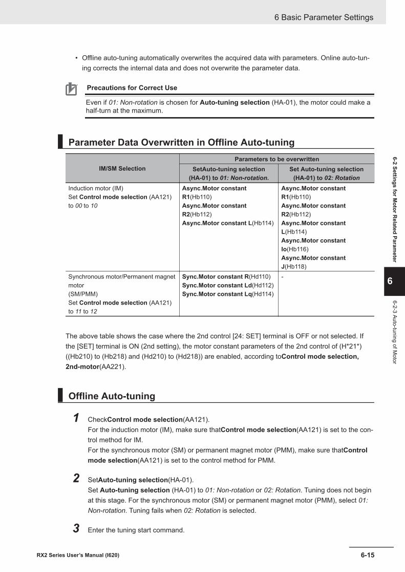
• Offline auto-tuning automatically overwrites the acquired data with parameters. Online auto-tun-ing corrects the internal data and does not overwrite the parameter data.
Precautions for Correct Use
Even if 01: Non-rotation is chosen for Auto-tuning selection (HA-01), the motor could make ahalf-turn at the maximum.
Parameter Data Overwritten in Offline Auto-tuning
IM/SM SelectionParameters to be overwritten
SetAuto-tuning selection(HA-01) to 01: Non-rotation.
Set Auto-tuning selection(HA-01) to 02: Rotation
Induction motor (IM)Set Control mode selection (AA121)to 00 to 10
Async.Motor constantR1(Hb110)Async.Motor constantR2(Hb112)Async.Motor constant L(Hb114)
Async.Motor constantR1(Hb110)Async.Motor constantR2(Hb112)Async.Motor constantL(Hb114)Async.Motor constantIo(Hb116)Async.Motor constantJ(Hb118)
Synchronous motor/Permanent magnetmotor(SM/PMM)Set Control mode selection (AA121)to 11 to 12
Sync.Motor constant R(Hd110)Sync.Motor constant Ld(Hd112)Sync.Motor constant Lq(Hd114)
-
The above table shows the case where the 2nd control [24: SET] terminal is OFF or not selected. Ifthe [SET] terminal is ON (2nd setting), the motor constant parameters of the 2nd control of (H*21*)((Hb210) to (Hb218) and (Hd210) to (Hd218)) are enabled, according toControl mode selection,2nd-motor(AA221).
Offline Auto-tuning
1 CheckControl mode selection(AA121).For the induction motor (IM), make sure thatControl mode selection(AA121) is set to the con-trol method for IM.For the synchronous motor (SM) or permanent magnet motor (PMM), make sure thatControlmode selection(AA121) is set to the control method for PMM.
2 SetAuto-tuning selection(HA-01).Set Auto-tuning selection (HA-01) to 01: Non-rotation or 02: Rotation. Tuning does not beginat this stage. For the synchronous motor (SM) or permanent magnet motor (PMM), select 01:Non-rotation. Tuning fails when 02: Rotation is selected.
3 Enter the tuning start command.
6 Basic Parameter Settings
6-15RX2 Series User’s Manual (I620)
6-2 Settings for Motor R
elated Parameter
6
6-2-3 Auto-tuning of Motor

Press the RUN key on the LCD Operator to start the offline auto-tuning. If you press the STOPbutton, the tuning stops in the middle. In this case, tuning data will not be stored.In auto-tuning, the output pattern for measurement is output to the motor as a voltage.IfAuto-tuning selection(HA-01) is set to01: Non-rotation, three patterns of non-rotation outputis given.IfAuto-tuning selection(HA-01) is set to02: Rotation, acceleration and deceleration are re-peated twice in addition to the three patterns of the non-rotation output. The frequency increas-es up to 80% of the base frequency.After the above operation finishes, the non-rotation output is made for final check.
4 Exit offline auto-tuning.When tuning is complete, the offline auto-tuning end display appears.At this time, the measured value is stored in the parameter.Press the STOP key to cancel the end display.
Measures to Take If Offline Auto-tuning FailsIf the auto-tuning ends with a trip or tuning failure, normal data cannot be acquired. See the followingtable for how to deal with the failure.
The online auto-tuning runs for up to 5 seconds each time the operation stops, and the result is auto-matically reflected. If the operation is restarted during tuning, the result will not be reflected.The factory default of the start signal for offline auto-tuning is the RUN key of the LCD operator. Bychanging RUN command selection at Auto-tuning (HA-02), you can change the setting to use theoperation command as the start signal.
With the following settings, online auto-tuning will not be performed until the motor is in the free-runstate.• DC braking when stopped (DC braking selection (AF101) is set to 01 or 02.)• Servo ON function [SON], Forcing function [FOC] (Input terminal function [65: SON], [66: FOC])• Brake control 2 (Brake Control Enable (AF130) is set to 03.)
l Measures to Take If Offline Auto-tuning Failure Occurs in the Middle
Assumed cause Example of measuresThe control method is not suitable for the motor. The tuning method is determined by whether
Control mode selection (AA121) is IM control orSM/PMM control, so set it according to the motor.
The base frequency, motor rated voltage, or motorrated current is not suitable for the motor specifica-tions.
Wrong basic parameters of the motor could causeovercurrent or trip, so check the basic parametersand set them appropriately.
STOP key was pressed. Pressing the STOP key on the LCD operator inter-rupts the auto-tuning. Start the tuning again.
External factors such as braking caused a trip. Factors that cause the trip need to be removed.The input terminal function worked. Inputs may interrupt the tuning during the auto-tun-
ing. Make sure that the signal to the terminals (inputterminals 1 to 9, A, and B) that caused the problemduring auto-tuning is not changed.
6 Basic Parameter Settings
6-16 RX2 Series User’s Manual (I620)
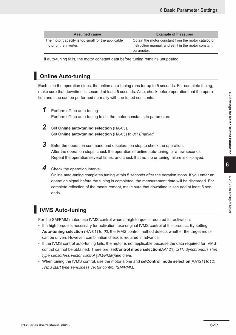
Assumed cause Example of measuresThe motor capacity is too small for the applicablemotor of the inverter.
Obtain the motor constant from the motor catalog orinstruction manual, and set it in the motor constantparameter.
If auto-tuning fails, the motor constant data before tuning remains unupdated.
Online Auto-tuningEach time the operation stops, the online auto-tuning runs for up to 5 seconds. For complete tuning,make sure that downtime is secured at least 5 seconds. Also, check before operation that the opera-tion and stop can be performed normally with the tuned constants.
1 Perform offline auto-tuning.Perform offline auto-tuning to set the motor constants to parameters.
2 Set Online auto-tuning selection (HA-03).Set Online auto-tuning selection (HA-03) to 01: Enabled.
3 Enter the operation command and deceleration stop to check the operation.After the operation stops, check the operation of online auto-tuning for a few seconds.Repeat the operation several times, and check that no trip or tuning failure is displayed.
4 Check the operation interval.Online auto-tuning completes tuning within 5 seconds after the oeration stops. If you enter anoperation signal before the tuning is completed, the measurement data will be discarded. Forcomplete reflection of the measurement, make sure that downtime is secured at least 5 sec-onds.
IVMS Auto-tuningFor the SM/PMM motor, use IVMS control when a high torque is required for activation.• If a high torque is necessary for activation, use original IVMS control of this product. By setting
Auto-tuning selection (HA-01) to 03, the IVMS control method detects whether the target motorcan be driven. However, combination check is required in advance.
• If the IVMS control auto-tuning fails, the motor is not applicable because the data required for IVMScontrol cannot be obtained. Therefore, setControl mode selection(AA121) to11: Synchronous starttype sensorless vector control (SM/PMM)and drive.
• When tuning the IVMS control, use the motor alone and setControl mode selection(AA121) to12:IVMS start type sensorless vector control (SM/PMM).
6 Basic Parameter Settings
6-17RX2 Series User’s Manual (I620)
6-2 Settings for Motor R
elated Parameter
6
6-2-3 Auto-tuning of Motor
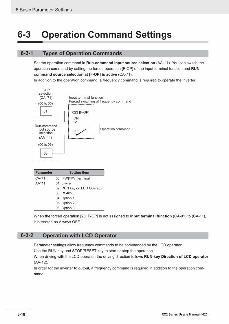
6-3 Operation Command Settings
6-3-1 Types of Operation CommandsSet the operation command in Run-command input source selection (AA111). You can switch theoperation command by setting the forced operation [F-OP] of the input terminal function and RUNcommand source selection at [F-OP] is active (CA-71).In addition to the operation command, a frequency command is required to operate the inverter.
023 [F-OP]
ON
OFF
(CA- 71)
(00 to 06)
01
(AA111)
(00 to 06)
03
F-OPselection
Input terminal functionForced switching of frequency command
Run-commandinput source
selectionOperation command
Parameter Setting itemCA-71AA111
00: [FW]/[RV] terminal01: 3 wire02: RUN key on LCD Operator03: RS48504: Option 105: Option 206: Option 3
When the forced operation [23: F-OP] is not assigned to Input terminal function (CA-01) to (CA-11),it is treated as Always OFF.
6-3-2 Operation with LCD OperatorParameter settings allow frequency commands to be commanded by the LCD operator.Use the RUN key and STOP/RESET key to start or stop the operation.When driving with the LCD operator, the driving direction follows RUN-key Direction of LCD operator(AA-12).In order for the inverter to output, a frequency command is required in addition to the operation com-mand.
6 Basic Parameter Settings
6-18 RX2 Series User’s Manual (I620)
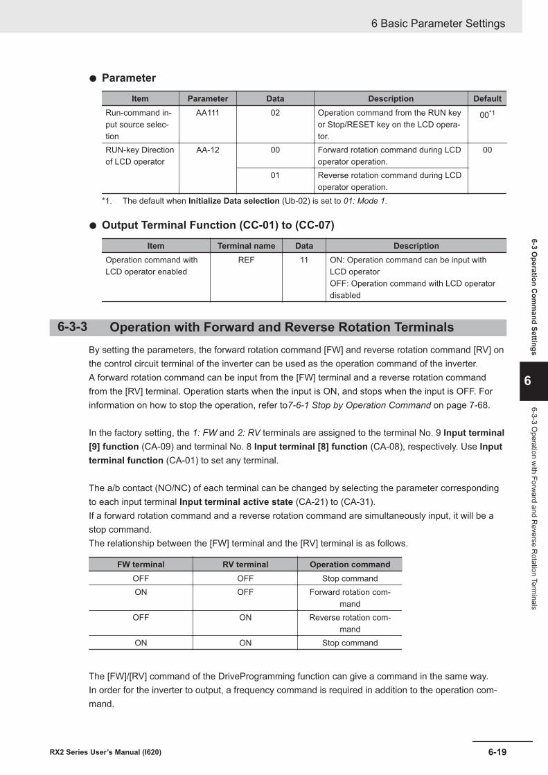
l Parameter
Item Parameter Data Description DefaultRun-command in-put source selec-tion
AA111 02 Operation command from the RUN keyor Stop/RESET key on the LCD opera-tor.
00*1
RUN-key Directionof LCD operator
AA-12 00 Forward rotation command during LCDoperator operation.
00
01 Reverse rotation command during LCDoperator operation.
*1. The default when Initialize Data selection (Ub-02) is set to 01: Mode 1.
l Output Terminal Function (CC-01) to (CC-07)
Item Terminal name Data DescriptionOperation command withLCD operator enabled
REF 11 ON: Operation command can be input withLCD operatorOFF: Operation command with LCD operatordisabled
6-3-3 Operation with Forward and Reverse Rotation TerminalsBy setting the parameters, the forward rotation command [FW] and reverse rotation command [RV] onthe control circuit terminal of the inverter can be used as the operation command of the inverter.A forward rotation command can be input from the [FW] terminal and a reverse rotation commandfrom the [RV] terminal. Operation starts when the input is ON, and stops when the input is OFF. Forinformation on how to stop the operation, refer to7-6-1 Stop by Operation Command on page 7-68.
In the factory setting, the 1: FW and 2: RV terminals are assigned to the terminal No. 9 Input terminal[9] function (CA-09) and terminal No. 8 Input terminal [8] function (CA-08), respectively. Use Inputterminal function (CA-01) to set any terminal.
The a/b contact (NO/NC) of each terminal can be changed by selecting the parameter correspondingto each input terminal Input terminal active state (CA-21) to (CA-31).If a forward rotation command and a reverse rotation command are simultaneously input, it will be astop command.The relationship between the [FW] terminal and the [RV] terminal is as follows.
FW terminal RV terminal Operation commandOFF OFF Stop commandON OFF Forward rotation com-
mandOFF ON Reverse rotation com-
mandON ON Stop command
The [FW]/[RV] command of the DriveProgramming function can give a command in the same way.In order for the inverter to output, a frequency command is required in addition to the operation com-mand.
6 Basic Parameter Settings
6-19RX2 Series User’s Manual (I620)
6-3 Operation C
omm
and Settings
6
6-3-3 Operation w
ith Forward and R
everse Rotation Term
inals
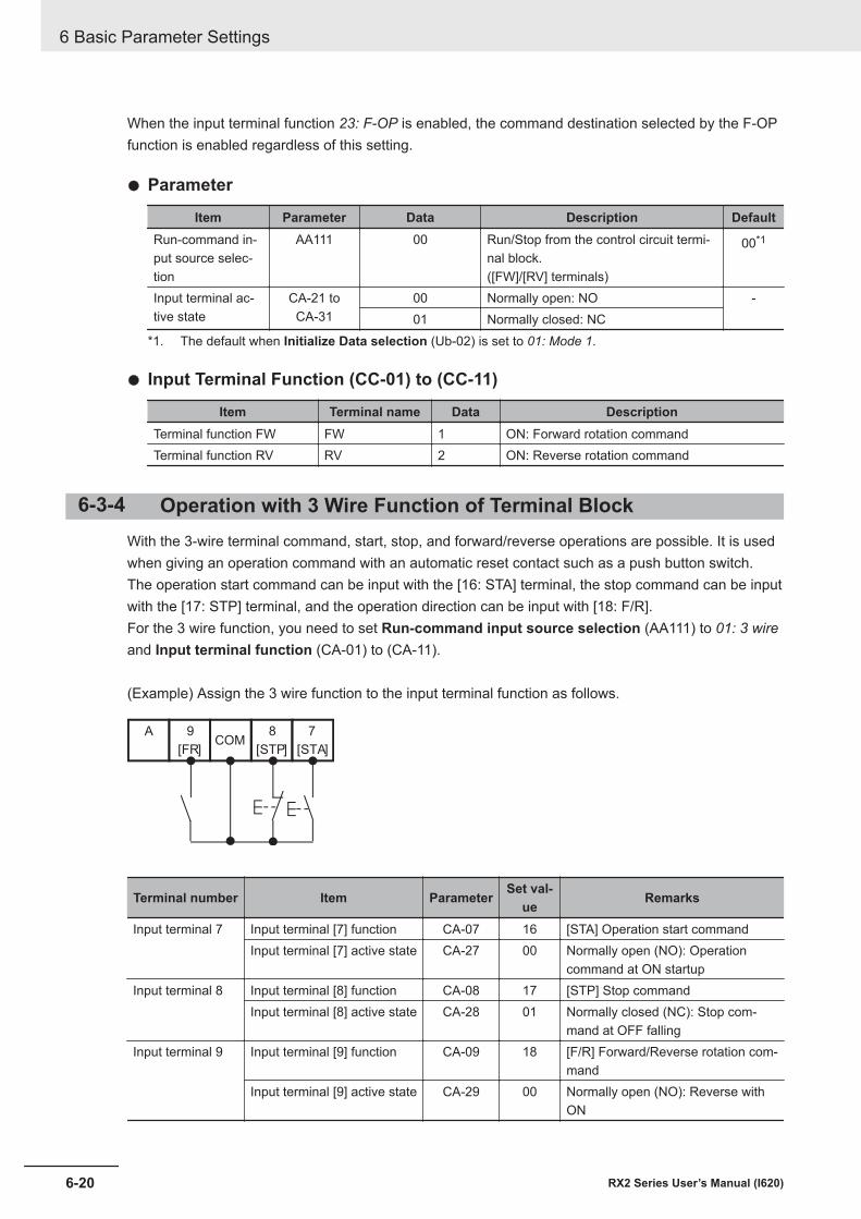
When the input terminal function 23: F-OP is enabled, the command destination selected by the F-OPfunction is enabled regardless of this setting.
l Parameter
Item Parameter Data Description DefaultRun-command in-put source selec-tion
AA111 00 Run/Stop from the control circuit termi-nal block.([FW]/[RV] terminals)
00*1
Input terminal ac-tive state
CA-21 toCA-31
00 Normally open: NO -01 Normally closed: NC
*1. The default when Initialize Data selection (Ub-02) is set to 01: Mode 1.
l Input Terminal Function (CC-01) to (CC-11)
Item Terminal name Data DescriptionTerminal function FW FW 1 ON: Forward rotation commandTerminal function RV RV 2 ON: Reverse rotation command
6-3-4 Operation with 3 Wire Function of Terminal BlockWith the 3-wire terminal command, start, stop, and forward/reverse operations are possible. It is usedwhen giving an operation command with an automatic reset contact such as a push button switch.The operation start command can be input with the [16: STA] terminal, the stop command can be inputwith the [17: STP] terminal, and the operation direction can be input with [18: F/R].For the 3 wire function, you need to set Run-command input source selection (AA111) to 01: 3 wireand Input terminal function (CA-01) to (CA-11).
(Example) Assign the 3 wire function to the input terminal function as follows.
7
[STA]
8
[STP]
9
[FR]
ACOM
Terminal number Item Parameter Set val-ue Remarks
Input terminal 7 Input terminal [7] function CA-07 16 [STA] Operation start commandInput terminal [7] active state CA-27 00 Normally open (NO): Operation
command at ON startupInput terminal 8 Input terminal [8] function CA-08 17 [STP] Stop command
Input terminal [8] active state CA-28 01 Normally closed (NC): Stop com-mand at OFF falling
Input terminal 9 Input terminal [9] function CA-09 18 [F/R] Forward/Reverse rotation com-mand
Input terminal [9] active state CA-29 00 Normally open (NO): Reverse withON
6 Basic Parameter Settings
6-20 RX2 Series User’s Manual (I620)
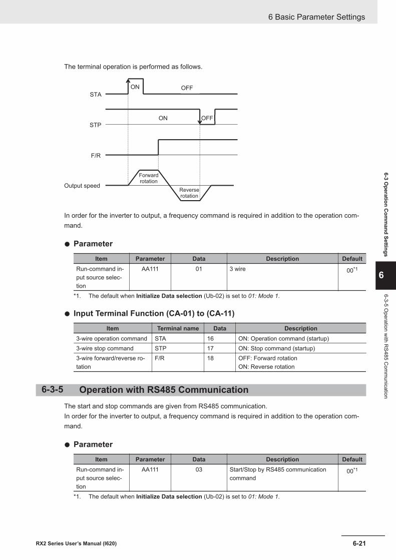
The terminal operation is performed as follows.
ON OFF
OFFON
STA
STP
F/R
Output speed
Forwardrotation
Reverserotation
In order for the inverter to output, a frequency command is required in addition to the operation com-mand.
l Parameter
Item Parameter Data Description DefaultRun-command in-put source selec-tion
AA111 01 3 wire 00*1
*1. The default when Initialize Data selection (Ub-02) is set to 01: Mode 1.
l Input Terminal Function (CA-01) to (CA-11)
Item Terminal name Data Description3-wire operation command STA 16 ON: Operation command (startup)3-wire stop command STP 17 ON: Stop command (startup)3-wire forward/reverse ro-tation
F/R 18 OFF: Forward rotationON: Reverse rotation
6-3-5 Operation with RS485 CommunicationThe start and stop commands are given from RS485 communication.In order for the inverter to output, a frequency command is required in addition to the operation com-mand.
l Parameter
Item Parameter Data Description DefaultRun-command in-put source selec-tion
AA111 03 Start/Stop by RS485 communicationcommand
00*1
*1. The default when Initialize Data selection (Ub-02) is set to 01: Mode 1.
6 Basic Parameter Settings
6-21RX2 Series User’s Manual (I620)
6-3 Operation C
omm
and Settings
6
6-3-5 Operation w
ith RS485 C
omm
unication
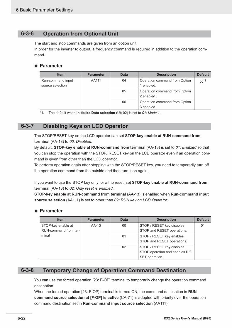
6-3-6 Operation from Optional UnitThe start and stop commands are given from an option unit.In order for the inverter to output, a frequency command is required in addition to the operation com-mand.
l Parameter
Item Parameter Data Description DefaultRun-command inputsource selection
AA111 04 Operation command from Option1 enabled.
00*1
05 Operation command from Option2 enabled.
06 Operation command from Option3 enabled
*1. The default when Initialize Data selection (Ub-02) is set to 01: Mode 1.
6-3-7 Disabling Keys on LCD OperatorThe STOP/RESET key on the LCD operator can set STOP-key enable at RUN-command fromterminal (AA-13) to 00: Disabled.By default, STOP-key enable at RUN-command from terminal (AA-13) is set to 01: Enabled so thatyou can stop the operation with the STOP/ RESET key on the LCD operator even if an operation com-mand is given from other than the LCD operator.To perform operation again after stopping with the STOP/RESET key, you need to temporarily turn offthe operation command from the outside and then turn it on again.
If you want to use the STOP key only for a trip reset, set STOP-key enable at RUN-command fromterminal (AA-13) to 02: Only reset is enabled.STOP-key enable at RUN-command from terminal (AA-13) is enabled when Run-command inputsource selection (AA111) is set to other than 02: RUN key on LCD Operator.
l Parameter
Item Parameter Data Description DefaultSTOP-key enable atRUN-command from ter-minal
AA-13 00 STOP / RESET key disablesSTOP and RESET operations.
01
01 STOP / RESET key enablesSTOP and RESET operations.
02 STOP / RESET key disablesSTOP operation and enables RE-SET operation.
6-3-8 Temporary Change of Operation Command DestinationYou can use the forced operation [23: F-OP] terminal to temporarily change the operation commanddestination.When the forced operation [23: F-OP] terminal is turned ON, the command destination in RUNcommand source selection at [F-OP] is active (CA-71) is adopted with priority over the operationcommand destination set in Run-command input source selection (AA111).
6 Basic Parameter Settings
6-22 RX2 Series User’s Manual (I620)
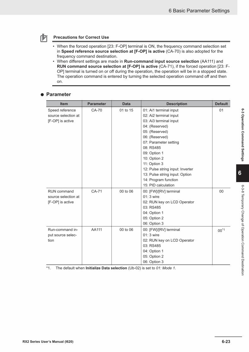
Precautions for Correct Use
• When the forced operation [23: F-OP] terminal is ON, the frequency command selection setin Speed reference source selection at [F-OP] is active (CA-70) is also adopted for thefrequency command destination.
• When different settings are made in Run-command input source selection (AA111) andRUN command source selection at [F-OP] is active (CA-71), if the forced operation [23: F-OP] terminal is turned on or off during the operation, the operation will be in a stopped state.The operation command is entered by turning the selected operation command off and thenon.
l Parameter
Item Parameter Data Description DefaultSpeed referencesource selection at[F-OP] is active
CA-70 01 to 15 01: Ai1 terminal input02: Ai2 terminal input03: Ai3 terminal input04: (Reserved)05: (Reserved)06: (Reserved)07: Parameter setting08: RS48509: Option 110: Option 211: Option 312: Pulse string input: Inverter13: Pulse string input: Option14: Program function15: PID calculation
01
RUN commandsource selection at[F-OP] is active
CA-71 00 to 06 00: [FW]/[RV] terminal01: 3 wire02: RUN key on LCD Operator03: RS48504: Option 105: Option 206: Option 3
00
Run-command in-put source selec-tion
AA111 00 to 06 00: [FW]/[RV] terminal01: 3 wire02: RUN key on LCD Operator03: RS48504: Option 105: Option 206: Option 3
00*1
*1. The default when Initialize Data selection (Ub-02) is set to 01: Mode 1.
6 Basic Parameter Settings
6-23RX2 Series User’s Manual (I620)
6-3 Operation C
omm
and Settings
6
6-3-8 Temporary C
hange of Operation C
omm
and Destination
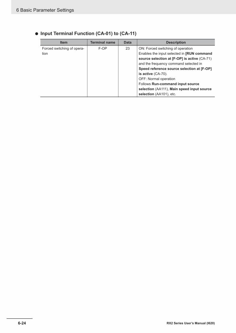
l Input Terminal Function (CA-01) to (CA-11)
Item Terminal name Data DescriptionForced switching of opera-tion
F-OP 23 ON: Forced switching of operationEnables the input selected in [RUN commandsource selection at [F-OP] is active (CA-71)and the frequency command selected inSpeed reference source selection at [F-OP]is active (CA-70).OFF: Normal operationFollows Run-command input sourceselection (AA111), Main speed input sourceselection (AA101), etc.
6 Basic Parameter Settings
6-24 RX2 Series User’s Manual (I620)
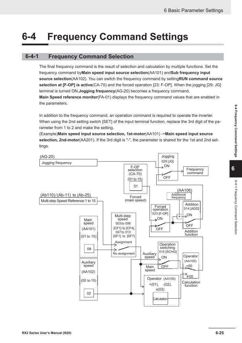
6-4 Frequency Command Settings
6-4-1 Frequency Command SelectionThe final frequency command is the result of selection and calculation by multiple functions. Set thefrequency command byMain speed input source selection(AA101) andSub frequency inputsource selection(AA102). You can switch the frequency command by settingRUN command sourceselection at [F-OP] is active(CA-70) and the forced operation [23: F-OP]. When the jogging [29: JG]terminal is turned ON,Jogging frequency(AG-20) becomes a frequency command.Main Speed reference monitor(FA-01) displays the frequency command values that are enabled inthe parameters.
In addition to the frequency command, an operation command is required to operate the inverter.When using the 2nd setting switch [SET] of the input terminal function, replace the 3rd digit of the pa-rameter from 1 to 2 and make the setting.(Example)Main speed input source selection, 1st-motor(AA101) ->Main speed input sourceselection, 2nd-motor(AA201). If the 3rd digit is "-", the parameter is shared for the 1st and 2nd set-tings.
+023 [F-OP]023 [F-OP]
ON
OFF
029 [JG]
ON
OFF
(AG-20)
(Ab110) / (Ab-11) to (Ab-25)
015 [SCHG]
ON
OFF
(AA105)(AAAA 105)
=00
≠00
014 [ADD]
OFF
ON
(AA106)
(AA101)
(01 to 15)
08
(AA102)
(00 to 15)
02
(CA-70)
(01 to 15)
01
003 to 006
[CF1] to [CF4],
007 to 013
[SF1] to [SF7]
+(01), -(02),
x(03)
(AA105)Calculation
function
Operator
Operationswitching
Multi-stepspeed
Assignment
No assignment
Auxiliaryspeed
Main speed
Operator
Multi-step Speed Reference 1 to 15
Jogging frequency
F-OPselection
Forced(main speed)
Forcedoperation
Additionalfrequency
Frequencycommand
Calculation
Auxiliaryspeed
Mainspeed
Jogging
Addition
Additionfunction
6 Basic Parameter Settings
6-25RX2 Series User’s Manual (I620)
6-4 Frequency Com
mand Settings
6
6-4-1 Frequency Com
mand Selection
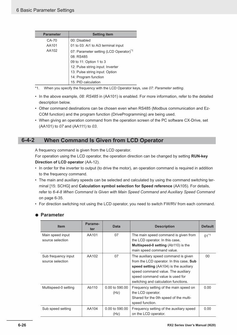
Parameter Setting itemCA-70AA101AA102
00: Disabled01 to 03: Ai1 to Ai3 terminal input07: Parameter setting (LCD Operator)*1
08: RS48509 to 11: Option 1 to 312: Pulse string input: Inverter13: Pulse string input: Option14: Program function15: PID calculation
*1. When you specify the frequency with the LCD Operator keys, use 07: Parameter setting.
• In the above example, 08: RS485 in (AA101) is enabled. For more information, refer to the detaileddescription below.
• Other command destinations can be chosen even when RS485 (Modbus communication and Ez-COM function) and the program function (DriveProgramming) are being used.
• When giving an operation command from the operation screen of the PC software CX-Drive, set(AA101) to 07 and (AA111) to 03.
6-4-2 When Command Is Given from LCD OperatorA frequency command is given from the LCD operator.For operation using the LCD operator, the operation direction can be changed by setting RUN-keyDirection of LCD operator (AA-12).• In order for the inverter to output (to drive the motor), an operation command is required in addition
to the frequency command.• The main and auxiliary speeds can be selected and calculated by using the command switching ter-
minal [15: SCHG] and Calculation symbol selection for Speed reference (AA105). For details,refer to 6-4-8 When Command Is Given with Main Speed Command and Auxiliary Speed Commandon page 6-35.
• For direction switching not using the LCD operator, you need to switch FW/RV from each command.
l Parameter
Item Parame-ter Data Description Default
Main speed inputsource selection
AA101 07 The main speed command is given fromthe LCD operator. In this case,Multispeed-0 setting (Ab110) is themain speed command value.
01*1
Sub frequency inputsource selection
AA102 07 The auxiliary speed command is givenfrom the LCD operator. In this case, Subspeed setting (AA104) is the auxiliaryspeed command value. The auxiliaryspeed command value is used forswitching and calculation functions.
00
Multispeed-0 setting Ab110 0.00 to 590.00(Hz)
Frequency setting of the main speed onthe LCD operator.Shared for the 0th speed of the multi-speed function.
0.00
Sub speed setting AA104 0.00 to 590.00(Hz)
Frequency setting of the auxiliary speedon the LCD operator.
0.00
6 Basic Parameter Settings
6-26 RX2 Series User’s Manual (I620)
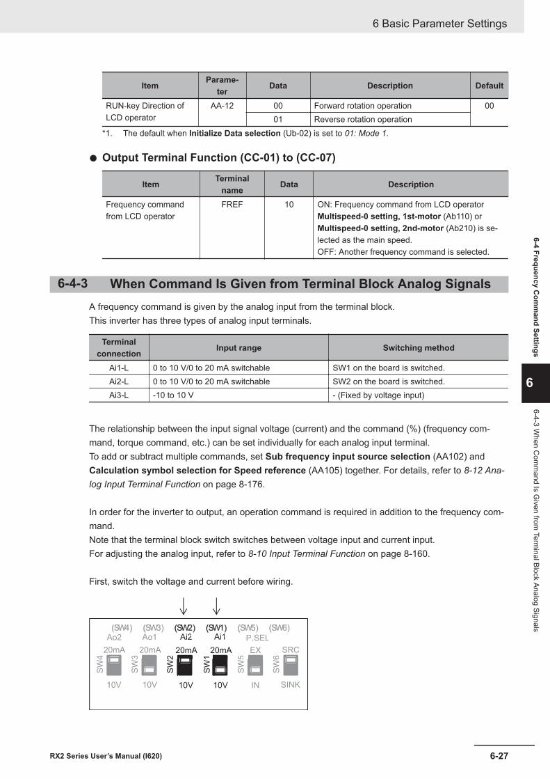
Item Parame-ter Data Description Default
RUN-key Direction ofLCD operator
AA-12 00 Forward rotation operation 0001 Reverse rotation operation
*1. The default when Initialize Data selection (Ub-02) is set to 01: Mode 1.
l Output Terminal Function (CC-01) to (CC-07)
Item Terminalname Data Description
Frequency commandfrom LCD operator
FREF 10 ON: Frequency command from LCD operatorMultispeed-0 setting, 1st-motor (Ab110) orMultispeed-0 setting, 2nd-motor (Ab210) is se-lected as the main speed.OFF: Another frequency command is selected.
6-4-3 When Command Is Given from Terminal Block Analog SignalsA frequency command is given by the analog input from the terminal block.This inverter has three types of analog input terminals.
Terminalconnection Input range Switching method
Ai1-L 0 to 10 V/0 to 20 mA switchable SW1 on the board is switched.Ai2-L 0 to 10 V/0 to 20 mA switchable SW2 on the board is switched.Ai3-L -10 to 10 V - (Fixed by voltage input)
The relationship between the input signal voltage (current) and the command (%) (frequency com-mand, torque command, etc.) can be set individually for each analog input terminal.To add or subtract multiple commands, set Sub frequency input source selection (AA102) andCalculation symbol selection for Speed reference (AA105) together. For details, refer to 8-12 Ana-log Input Terminal Function on page 8-176.
In order for the inverter to output, an operation command is required in addition to the frequency com-mand.Note that the terminal block switch switches between voltage input and current input.For adjusting the analog input, refer to 8-10 Input Terminal Function on page 8-160.
First, switch the voltage and current before wiring.
SW
4
SW
3
SW
2
SW
1
SW
5
SW
6
10V
20mA
10V
3
20mA
10V
2
20mA
10V
1
20mA
IN
5
EX
SINK
6
SRC
Ao2 Ao1 Ai2 Ai1 P.SELAo2 Ao1 Ai2 Ai1 P SEL
(SW4) (SW3) (SW2) (SW1) (SW5) (SW6)
6 Basic Parameter Settings
6-27RX2 Series User’s Manual (I620)
6-4 Frequency Com
mand Settings
6
6-4-3 When C
omm
and Is Given from
Terminal Block Analog Signals
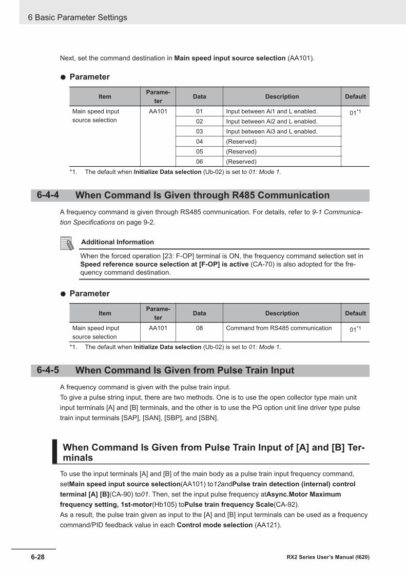
Next, set the command destination in Main speed input source selection (AA101).
l Parameter
Item Parame-ter Data Description Default
Main speed inputsource selection
AA101 01 Input between Ai1 and L enabled. 01*1
02 Input between Ai2 and L enabled.03 Input between Ai3 and L enabled.04 (Reserved)05 (Reserved)06 (Reserved)
*1. The default when Initialize Data selection (Ub-02) is set to 01: Mode 1.
6-4-4 When Command Is Given through R485 CommunicationA frequency command is given through RS485 communication. For details, refer to 9-1 Communica-tion Specifications on page 9-2.
Additional Information
When the forced operation [23: F-OP] terminal is ON, the frequency command selection set inSpeed reference source selection at [F-OP] is active (CA-70) is also adopted for the fre-quency command destination.
l Parameter
Item Parame-ter Data Description Default
Main speed inputsource selection
AA101 08 Command from RS485 communication 01*1
*1. The default when Initialize Data selection (Ub-02) is set to 01: Mode 1.
6-4-5 When Command Is Given from Pulse Train InputA frequency command is given with the pulse train input.To give a pulse string input, there are two methods. One is to use the open collector type main unitinput terminals [A] and [B] terminals, and the other is to use the PG option unit line driver type pulsetrain input terminals [SAP], [SAN], [SBP], and [SBN].
When Command Is Given from Pulse Train Input of [A] and [B] Ter-minals
To use the input terminals [A] and [B] of the main body as a pulse train input frequency command,setMain speed input source selection(AA101) to12andPulse train detection (internal) controlterminal [A] [B](CA-90) to01. Then, set the input pulse frequency atAsync.Motor Maximumfrequency setting, 1st-motor(Hb105) toPulse train frequency Scale(CA-92).As a result, the pulse train given as input to the [A] and [B] input terminals can be used as a frequencycommand/PID feedback value in each Control mode selection (AA121).
6 Basic Parameter Settings
6-28 RX2 Series User’s Manual (I620)
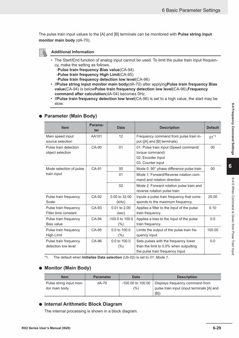
The pulse train input values to the [A] and [B] terminals can be monitored with Pulse string inputmonitor main body (dA-70).
Additional Information
• The Start/End function of analog input cannot be used. To limit the pulse train input frequen-cy, make the setting as follows.-Pulse train frequency Bias value(CA-94)-Pulse train frequency High Limit(CA-95)-Pulse train frequency detection low level(CA-96)
• IfPulse string input monitor main body(dA-70) after applyingPulse train frequency Biasvalue(CA-94) is belowPulse train frequency detection low level(CA-96),Frequencycommand after calculation(dA-04) becomes 0Hz.
• IfPulse train frequency detection low level(CA-96) is set to a high value, the start may beslow.
l Parameter (Main Body)
Item Parame-ter Data Description Default
Main speed inputsource selection
AA101 12 Frequency command from pulse train in-put ([A] and [B] terminals)
01*1
Pulse train detectionobject selection
CA-90 01 01: Pulse train input (Speed command/torque command)02: Encoder input03: Counter input
00
Mode selection of pulsetrain input
CA-91 00 Mode 0: 90° phase difference pulse train 0001 Mode 1: Forward/Reverse rotation com-
mand and rotation direction02 Mode 2: Forward rotation pulse train and
reverse rotation pulse trainPulse train frequencyScale
CA-92 0.05 to 32.00(kHz)
Inputs a pulse train frequency that corre-sponds to the maximum frequency.
25.00
Pulse train frequencyFilter time constant
CA-93 0.01 to 2.00(sec)
Applies a filter to the input of the pulsetrain frequency.
0.10
Pulse train frequencyBias value
CA-94 -100.0 to 100.0(%)
Applies a bias to the input of the pulsetrain frequency.
0.0
Pulse train frequencyHigh Limit
CA-95 0.0 to 100.0(%)
Limits the output of the pulse train fre-quency input.
100.00
Pulse train frequencydetection low level
CA-96 0.0 to 100.0(%)
Sets pulses with the frequency lowerthan the limit to 0.0% when outputtingthe pulse train frequency input.
0.0
*1. The default when Initialize Data selection (Ub-02) is set to 01: Mode 1.
l Monitor (Main Body)
Item Parameter Data DescriptionPulse string input mon-itor main body
dA-70 -100.00 to 100.00(%)
Displays frequency command frompulse train input (input terminals [A] and[B])
l Internal Arithmetic Block DiagramThe internal processing is shown in a block diagram.
6 Basic Parameter Settings
6-29RX2 Series User’s Manual (I620)
6-4 Frequency Com
mand Settings
6
6-4-5 When C
omm
and Is Given from
Pulse Train Input
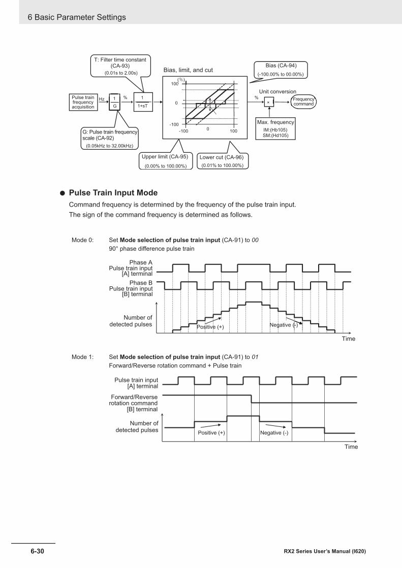
1+sT
1×
Hz %
G
1 %
0
100
-100 100
0
-100
0(%)
0 IM:(Hb105)
SM:(Hd105)
Unit conversion
Bias, limit, and cut
T: Filter time constant(CA-93)
G: Pulse train frequencyscale (CA-92)
Upper limit (CA-95) Lower cut (CA-96)
Max. frequency
Pulse trainfrequencyacquisition
Frequencycommand
Bias (CA-94)
(0.05kHz to 32.00kHz)
(0.01s to 2.00s)
(0.00% to 100.00%) (0.01% to 100.00%)
(-100.00% to 00.00%)
l Pulse Train Input ModeCommand frequency is determined by the frequency of the pulse train input.The sign of the command frequency is determined as follows.
Mode 0: Set Mode selection of pulse train input (CA-91) to 0090° phase difference pulse train
Positive (+) Negative (-)
Pulse train input[A] terminal
Pulse train input[B] terminal
Number ofdetected pulses
Time
Phase A
Phase B
Mode 1: Set Mode selection of pulse train input (CA-91) to 01Forward/Reverse rotation command + Pulse train
Pulse train input[A] terminal
Forward/Reverserotation command
[B] terminal
Number ofdetected pulses
Time
Positive (+) Negative (-)
6 Basic Parameter Settings
6-30 RX2 Series User’s Manual (I620)
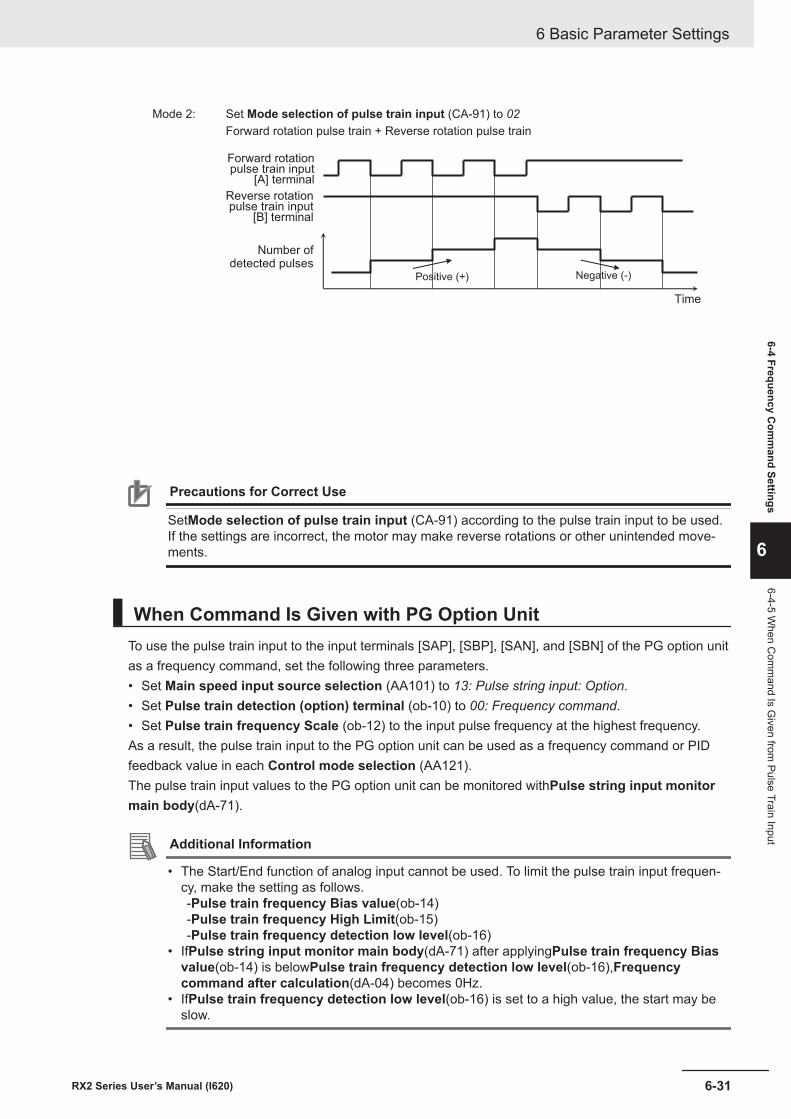
Mode 2: Set Mode selection of pulse train input (CA-91) to 02Forward rotation pulse train + Reverse rotation pulse train
Forward rotationpulse train input
[A] terminal
Reverse rotationpulse train input
[B] terminal
Number ofdetected pulses
Positive (+) Negative (-)
Time
Precautions for Correct Use
SetMode selection of pulse train input (CA-91) according to the pulse train input to be used.If the settings are incorrect, the motor may make reverse rotations or other unintended move-ments.
When Command Is Given with PG Option UnitTo use the pulse train input to the input terminals [SAP], [SBP], [SAN], and [SBN] of the PG option unitas a frequency command, set the following three parameters.• Set Main speed input source selection (AA101) to 13: Pulse string input: Option.• Set Pulse train detection (option) terminal (ob-10) to 00: Frequency command.• Set Pulse train frequency Scale (ob-12) to the input pulse frequency at the highest frequency.As a result, the pulse train input to the PG option unit can be used as a frequency command or PIDfeedback value in each Control mode selection (AA121).The pulse train input values to the PG option unit can be monitored withPulse string input monitormain body(dA-71).
Additional Information
• The Start/End function of analog input cannot be used. To limit the pulse train input frequen-cy, make the setting as follows.-Pulse train frequency Bias value(ob-14)-Pulse train frequency High Limit(ob-15)-Pulse train frequency detection low level(ob-16)
• IfPulse string input monitor main body(dA-71) after applyingPulse train frequency Biasvalue(ob-14) is belowPulse train frequency detection low level(ob-16),Frequencycommand after calculation(dA-04) becomes 0Hz.
• IfPulse train frequency detection low level(ob-16) is set to a high value, the start may beslow.
6 Basic Parameter Settings
6-31RX2 Series User’s Manual (I620)
6-4 Frequency Com
mand Settings
6
6-4-5 When C
omm
and Is Given from
Pulse Train Input
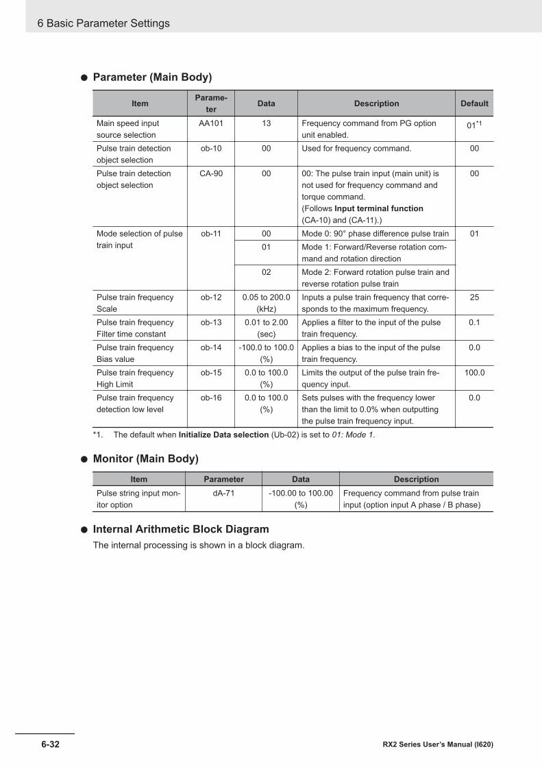
l Parameter (Main Body)
Item Parame-ter Data Description Default
Main speed inputsource selection
AA101 13 Frequency command from PG optionunit enabled.
01*1
Pulse train detectionobject selection
ob-10 00 Used for frequency command. 00
Pulse train detectionobject selection
CA-90 00 00: The pulse train input (main unit) isnot used for frequency command andtorque command.(Follows Input terminal function(CA-10) and (CA-11).)
00
Mode selection of pulsetrain input
ob-11 00 Mode 0: 90° phase difference pulse train 0101 Mode 1: Forward/Reverse rotation com-
mand and rotation direction02 Mode 2: Forward rotation pulse train and
reverse rotation pulse trainPulse train frequencyScale
ob-12 0.05 to 200.0(kHz)
Inputs a pulse train frequency that corre-sponds to the maximum frequency.
25
Pulse train frequencyFilter time constant
ob-13 0.01 to 2.00(sec)
Applies a filter to the input of the pulsetrain frequency.
0.1
Pulse train frequencyBias value
ob-14 -100.0 to 100.0(%)
Applies a bias to the input of the pulsetrain frequency.
0.0
Pulse train frequencyHigh Limit
ob-15 0.0 to 100.0(%)
Limits the output of the pulse train fre-quency input.
100.0
Pulse train frequencydetection low level
ob-16 0.0 to 100.0(%)
Sets pulses with the frequency lowerthan the limit to 0.0% when outputtingthe pulse train frequency input.
0.0
*1. The default when Initialize Data selection (Ub-02) is set to 01: Mode 1.
l Monitor (Main Body)
Item Parameter Data DescriptionPulse string input mon-itor option
dA-71 -100.00 to 100.00(%)
Frequency command from pulse traininput (option input A phase / B phase)
l Internal Arithmetic Block DiagramThe internal processing is shown in a block diagram.
6 Basic Parameter Settings
6-32 RX2 Series User’s Manual (I620)
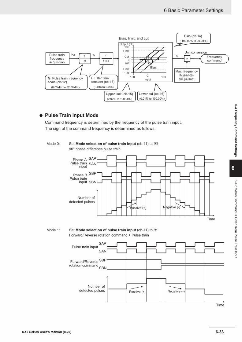
1+sT
1
1+sT
1×
Hz %
G
1 %
0
100
-100 100
-1000 IM:(Hb105)
SM:(Hd105)
(0.01% to 100.00%)
Bias (ob-14)
Pulse trainfrequencyacquisition
G: Pulse train frequencyscale (ob-12)
T: Filter timeconstant (ob-13)
Upper limit (ob-15) Lower cut (ob-16)
Max. frequency
Frequencycommand
Unit conversion
Bias, limit, and cut
BiasLimit
Cut
Limit
Cut
Output (%)
Input
(0.05kHz to 32.00kHz) (0.01s to 2.00s)
(0.00% to 100.00%)
(-100.00% to 00.00%)
l Pulse Train Input ModeCommand frequency is determined by the frequency of the pulse train input.The sign of the command frequency is determined as follows.
Mode 0: Set Mode selection of pulse train input (ob-11) to 0090° phase difference pulse train
SAP
SAN
SBP
SBN
Positive (+) Negative (-)
Time
Pulse traininput
Pulse traininput
Number ofdetected pulses
Phase A
Phase B
Mode 1: Set Mode selection of pulse train input (ob-11) to 01Forward/Reverse rotation command + Pulse train
SAP
SAN
SBP
SBN
Pulse train input
Forward/Reverserotation command
Number ofdetected pulses Positive (+) Negative (-)
Time
6 Basic Parameter Settings
6-33RX2 Series User’s Manual (I620)
6-4 Frequency Com
mand Settings
6
6-4-5 When C
omm
and Is Given from
Pulse Train Input
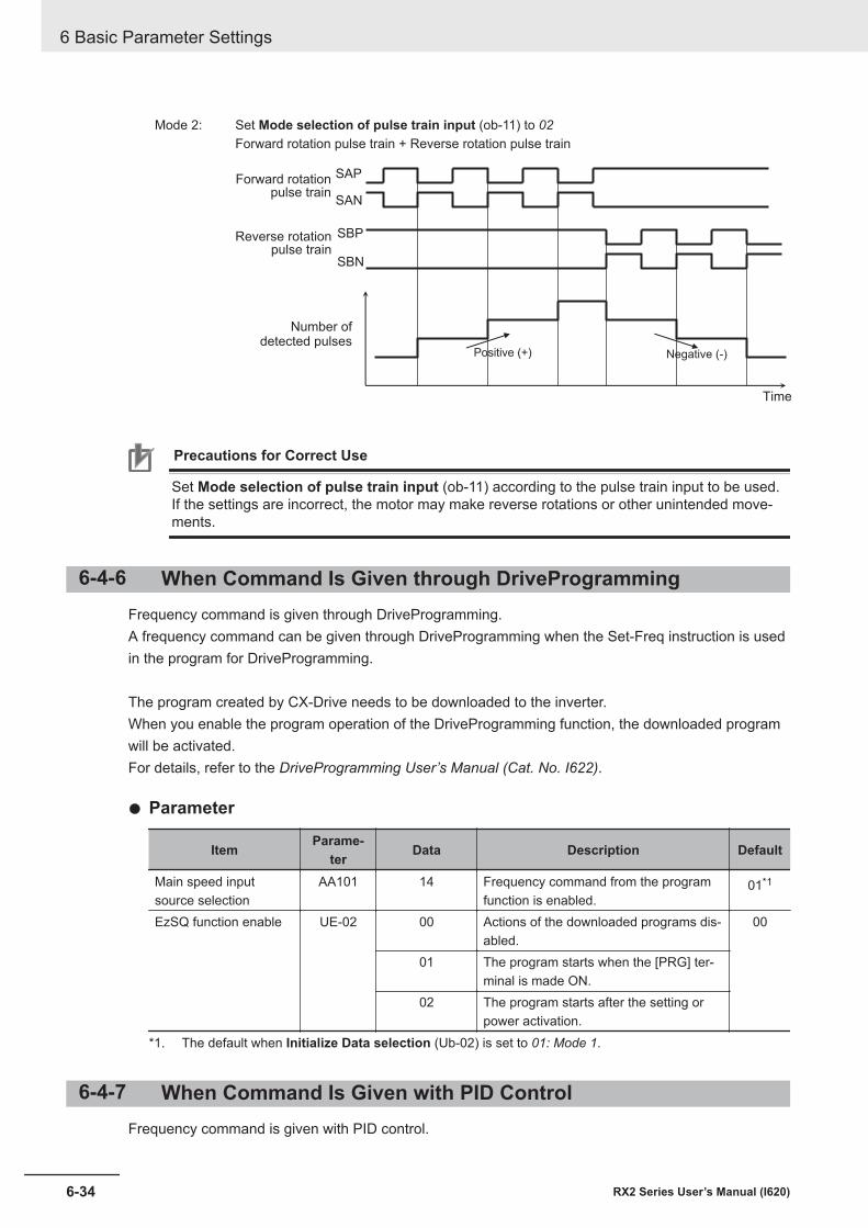
Mode 2: Set Mode selection of pulse train input (ob-11) to 02Forward rotation pulse train + Reverse rotation pulse train
SAP
SAN
SBP
SBN
Forward rotationpulse train
Reverse rotationpulse train
Number ofdetected pulses
Time
Positive (+) Negative (-)
Precautions for Correct Use
Set Mode selection of pulse train input (ob-11) according to the pulse train input to be used.If the settings are incorrect, the motor may make reverse rotations or other unintended move-ments.
6-4-6 When Command Is Given through DriveProgrammingFrequency command is given through DriveProgramming.A frequency command can be given through DriveProgramming when the Set-Freq instruction is usedin the program for DriveProgramming.
The program created by CX-Drive needs to be downloaded to the inverter.When you enable the program operation of the DriveProgramming function, the downloaded programwill be activated.For details, refer to the DriveProgramming User’s Manual (Cat. No. I622).
l Parameter
Item Parame-ter Data Description Default
Main speed inputsource selection
AA101 14 Frequency command from the programfunction is enabled.
01*1
EzSQ function enable UE-02 00 Actions of the downloaded programs dis-abled.
00
01 The program starts when the [PRG] ter-minal is made ON.
02 The program starts after the setting orpower activation.
*1. The default when Initialize Data selection (Ub-02) is set to 01: Mode 1.
6-4-7 When Command Is Given with PID ControlFrequency command is given with PID control.
6 Basic Parameter Settings
6-34 RX2 Series User’s Manual (I620)
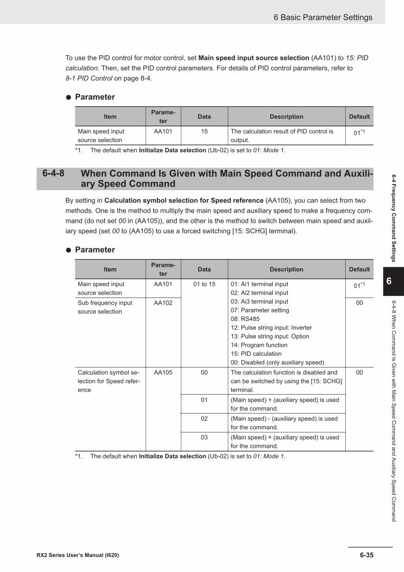
To use the PID control for motor control, set Main speed input source selection (AA101) to 15: PIDcalculation. Then, set the PID control parameters. For details of PID control parameters, refer to 8-1 PID Control on page 8-4.
l Parameter
Item Parame-ter Data Description Default
Main speed inputsource selection
AA101 15 The calculation result of PID control isoutput.
01*1
*1. The default when Initialize Data selection (Ub-02) is set to 01: Mode 1.
6-4-8 When Command Is Given with Main Speed Command and Auxili-ary Speed Command
By setting in Calculation symbol selection for Speed reference (AA105), you can select from twomethods. One is the method to multiply the main speed and auxiliary speed to make a frequency com-mand (do not set 00 in (AA105)), and the other is the method to switch between main speed and auxil-iary speed (set 00 to (AA105) to use a forced switching [15: SCHG] terminal).
l Parameter
Item Parame-ter Data Description Default
Main speed inputsource selection
AA101 01 to 15 01: Ai1 terminal input02: Ai2 terminal input03: Ai3 terminal input07: Parameter setting08: RS48512: Pulse string input: Inverter13: Pulse string input: Option14: Program function15: PID calculation00: Disabled (only auxiliary speed)
01*1
Sub frequency inputsource selection
AA102 00
Calculation symbol se-lection for Speed refer-ence
AA105 00 The calculation function is disabled andcan be switched by using the [15: SCHG]terminal.
00
01 (Main speed) + (auxiliary speed) is usedfor the command.
02 (Main speed) - (auxiliary speed) is usedfor the command.
03 (Main speed) × (auxiliary speed) is usedfor the command.
*1. The default when Initialize Data selection (Ub-02) is set to 01: Mode 1.
6 Basic Parameter Settings
6-35RX2 Series User’s Manual (I620)
6-4 Frequency Com
mand Settings
6
6-4-8 When C
omm
and Is Given w
ith Main Speed C
omm
and and Auxiliary Speed Com
mand
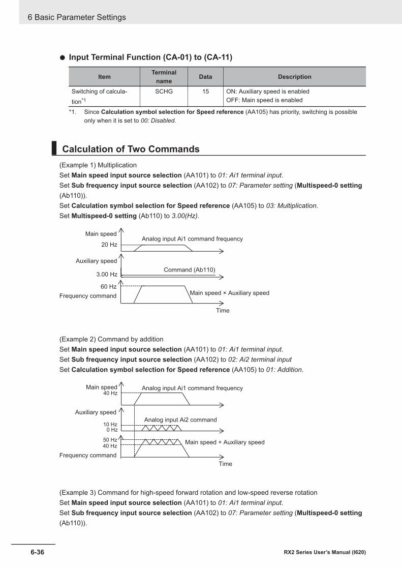
l Input Terminal Function (CA-01) to (CA-11)
Item Terminalname Data Description
Switching of calcula-tion*1
SCHG 15 ON: Auxiliary speed is enabledOFF: Main speed is enabled
*1. Since Calculation symbol selection for Speed reference (AA105) has priority, switching is possibleonly when it is set to 00: Disabled.
Calculation of Two Commands(Example 1) MultiplicationSet Main speed input source selection (AA101) to 01: Ai1 terminal input.Set Sub frequency input source selection (AA102) to 07: Parameter setting (Multispeed-0 setting(Ab110)).Set Calculation symbol selection for Speed reference (AA105) to 03: Multiplication.Set Multispeed-0 setting (Ab110) to 3.00(Hz).
3.00 Hz
20 Hz
60 Hz
Analog input Ai1 command frequencyMain speed
Auxiliary speed
Frequency commandMain speed × Auxiliary speed
Command (Ab110)
Time
(Example 2) Command by additionSet Main speed input source selection (AA101) to 01: Ai1 terminal input.Set Sub frequency input source selection (AA102) to 02: Ai2 terminal inputSet Calculation symbol selection for Speed reference (AA105) to 01: Addition.
40 Hz
40 Hz50 Hz
10 Hz0 Hz
Analog input Ai1 command frequencyMain speed
Auxiliary speed
Frequency command
Main speed + Auxiliary speed
Analog input Ai2 command
Time
(Example 3) Command for high-speed forward rotation and low-speed reverse rotationSet Main speed input source selection (AA101) to 01: Ai1 terminal input.Set Sub frequency input source selection (AA102) to 07: Parameter setting (Multispeed-0 setting(Ab110)).
6 Basic Parameter Settings
6-36 RX2 Series User’s Manual (I620)
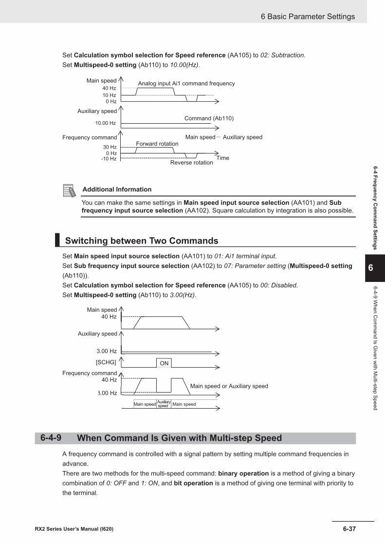
Set Calculation symbol selection for Speed reference (AA105) to 02: Subtraction.Set Multispeed-0 setting (Ab110) to 10.00(Hz).
10.00 Hz
40 Hz
30 Hz
-10 Hz
10 Hz
0 Hz
0 Hz
Analog input Ai1 command frequencyMain speed
Auxiliary speed
Frequency command Main speed- Auxiliary speed
Command (Ab110)
TimeReverse rotation
Forward rotation
Additional Information
You can make the same settings in Main speed input source selection (AA101) and Subfrequency input source selection (AA102). Square calculation by integration is also possible.
Switching between Two CommandsSet Main speed input source selection (AA101) to 01: Ai1 terminal input.Set Sub frequency input source selection (AA102) to 07: Parameter setting (Multispeed-0 setting(Ab110)).Set Calculation symbol selection for Speed reference (AA105) to 00: Disabled.Set Multispeed-0 setting (Ab110) to 3.00(Hz).
3.00 Hz
40 Hz
40 Hz
[SCHG]
3.00 Hz
ON
Main speed
Auxiliary speed
Frequency command
Main speed or Auxiliary speed
Auxiliaryspeed Main speed Main speed
6-4-9 When Command Is Given with Multi-step SpeedA frequency command is controlled with a signal pattern by setting multiple command frequencies inadvance.There are two methods for the multi-speed command: binary operation is a method of giving a binarycombination of 0: OFF and 1: ON, and bit operation is a method of giving one terminal with priority tothe terminal.
6 Basic Parameter Settings
6-37RX2 Series User’s Manual (I620)
6-4 Frequency Com
mand Settings
6
6-4-9 When C
omm
and Is Given w
ith Multi-step Speed
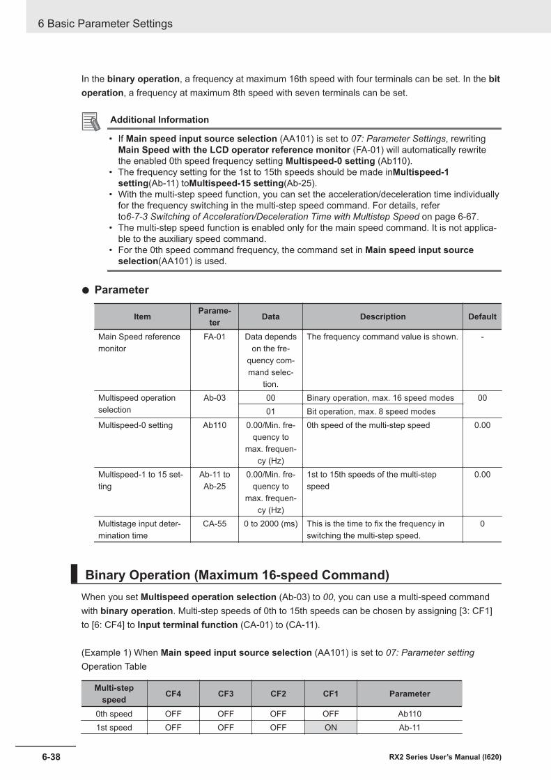
In the binary operation, a frequency at maximum 16th speed with four terminals can be set. In the bitoperation, a frequency at maximum 8th speed with seven terminals can be set.
Additional Information
• If Main speed input source selection (AA101) is set to 07: Parameter Settings, rewritingMain Speed with the LCD operator reference monitor (FA-01) will automatically rewritethe enabled 0th speed frequency setting Multispeed-0 setting (Ab110).
• The frequency setting for the 1st to 15th speeds should be made inMultispeed-1setting(Ab-11) toMultispeed-15 setting(Ab-25).
• With the multi-step speed function, you can set the acceleration/deceleration time individuallyfor the frequency switching in the multi-step speed command. For details, referto6-7-3 Switching of Acceleration/Deceleration Time with Multistep Speed on page 6-67.
• The multi-step speed function is enabled only for the main speed command. It is not applica-ble to the auxiliary speed command.
• For the 0th speed command frequency, the command set in Main speed input sourceselection(AA101) is used.
l Parameter
Item Parame-ter Data Description Default
Main Speed referencemonitor
FA-01 Data dependson the fre-
quency com-mand selec-
tion.
The frequency command value is shown. -
Multispeed operationselection
Ab-03 00 Binary operation, max. 16 speed modes 0001 Bit operation, max. 8 speed modes
Multispeed-0 setting Ab110 0.00/Min. fre-quency to
max. frequen-cy (Hz)
0th speed of the multi-step speed 0.00
Multispeed-1 to 15 set-ting
Ab-11 toAb-25
0.00/Min. fre-quency to
max. frequen-cy (Hz)
1st to 15th speeds of the multi-stepspeed
0.00
Multistage input deter-mination time
CA-55 0 to 2000 (ms) This is the time to fix the frequency inswitching the multi-step speed.
0
Binary Operation (Maximum 16-speed Command)When you set Multispeed operation selection (Ab-03) to 00, you can use a multi-speed commandwith binary operation. Multi-step speeds of 0th to 15th speeds can be chosen by assigning [3: CF1]to [6: CF4] to Input terminal function (CA-01) to (CA-11).
(Example 1) When Main speed input source selection (AA101) is set to 07: Parameter settingOperation Table
Multi-stepspeed CF4 CF3 CF2 CF1 Parameter
0th speed OFF OFF OFF OFF Ab1101st speed OFF OFF OFF ON Ab-11
6 Basic Parameter Settings
6-38 RX2 Series User’s Manual (I620)
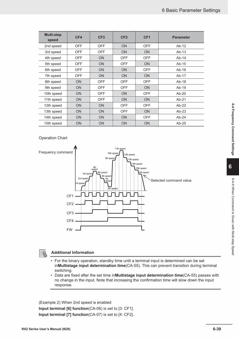
Multi-stepspeed CF4 CF3 CF2 CF1 Parameter
2nd speed OFF OFF ON OFF Ab-123rd speed OFF OFF ON ON Ab-134th speed OFF ON OFF OFF Ab-145th speed OFF ON OFF ON Ab-156th speed OFF ON ON OFF Ab-167th speed OFF ON ON ON Ab-178th speed ON OFF OFF OFF Ab-189th speed ON OFF OFF ON Ab-19
10th speed ON OFF ON OFF Ab-2011th speed ON OFF ON ON Ab-2112th speed ON ON OFF OFF Ab-2213th speed ON ON OFF ON Ab-2314th speed ON ON ON OFF Ab-2415th speed ON ON ON ON Ab-25
Operation Chart
CF4
FW
CF3
CF2
CF1
Selected command value
Frequency command
1st speed
2nd speed
3rd speed
4thspeed
5th speed
6th speed
7thspeed
8th speed
9th speed
10th speed
11th speed
12th speed
13th speed
14th speed
15th speed
0th speed
Additional Information
• For the binary operation, standby time until a terminal input is determined can be setinMultistage input determination time(CA-55). This can prevent transition during terminalswitching.
• Data are fixed after the set time inMultistage input determination time(CA-55) passes withno change in the input. Note that increasing the confirmation time will slow down the inputresponse.
(Example 2) When 2nd speed is enabledInput terminal [6] function(CA-06) is set to [3: CF1].Input terminal [7] function(CA-07) is set to [4: CF2].
6 Basic Parameter Settings
6-39RX2 Series User’s Manual (I620)
6-4 Frequency Com
mand Settings
6
6-4-9 When C
omm
and Is Given w
ith Multi-step Speed
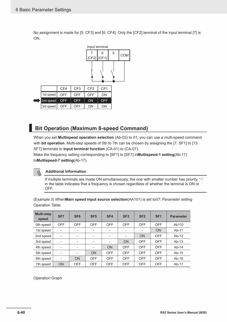
No assignment is made for [5: CF3] and [6: CF4]. Only the [CF2] terminal of the input terminal [7] isON.
CF4 CF3 CF2 CF1
OFF OFF OFF ON
OFF OFF ON OFF
OFF OFF ON ON
56
[CF1]
7
[CF2]COM
1st speed
2nd speed
3rd speed
Input terminal
Bit Operation (Maximum 8-speed Command)When you set Multispeed operation selection (Ab-03) to 01, you can use a multi-speed commandwith bit operation. Multi-step speeds of 0th to 7th can be chosen by assigning the [7: SF1] to [13:SF7] terminals to Input terminal function (CA-01) to (CA-07).Make the frequency setting corresponding to [SF1] to [SF7] inMultispeed-1 setting(Ab-11)toMultispeed-7 setting(Ab-17).
Additional Information
If multiple terminals are made ON simultaneously, the one with smaller number has priority. “-”in the table indicates that a frequency is chosen regardless of whether the terminal is ON orOFF.
(Example 3) WhenMain speed input source selection(AA101) is set to07: Parameter settingOperation Table
Multi-stepspeed SF7 SF6 SF5 SF4 SF3 SF2 SF1 Parameter
0th speed OFF OFF OFF OFF OFF OFF OFF Ab1101st speed - - - - - - ON Ab-112nd speed - - - - - ON OFF Ab-123rd speed - - - - ON OFF OFF Ab-134th speed - - - ON OFF OFF OFF Ab-145th speed - - ON OFF OFF OFF OFF Ab-156th speed - ON OFF OFF OFF OFF OFF Ab-167th speed ON OFF OFF OFF OFF OFF OFF Ab-17
Operation Graph
6 Basic Parameter Settings
6-40 RX2 Series User’s Manual (I620)
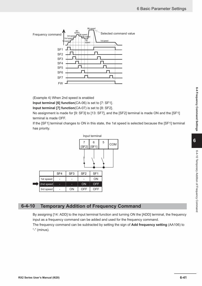
SF1
SF2
SF3
SF4
SF5
FW
SF6
SF7
Frequency command
1st speed
2nd speed
3rd speed
4thspeed
5th speed
7thspeed
8th speed
1st speed
Selected command value6th speed
(Example 4) When 2nd speed is enabledInput terminal [6] function(CA-06) is set to [7: SF1].Input terminal [7] function(CA-07) is set to [8: SF2].No assignment is made for [9: SF3] to [13: SF7], and the [SF2] terminal is made ON and the [SF1]terminal is made OFF.If the [SF1] terminal changes to ON in this state, the 1st speed is selected because the [SF1] terminalhas priority.
SF4 SF3 SF2 SF1
- - - ON
- - ON OFF
- ON OFF OFF
56
[SF1]
7
[SF2]COM
1st speed
2nd speed
3rd speed
Input terminal
6-4-10 Temporary Addition of Frequency CommandBy assigning [14: ADD] to the input terminal function and turning ON the [ADD] terminal, the frequencyinput as a frequency command can be added and used for the frequency command.The frequency command can be subtracted by setting the sign of Add frequency setting (AA106) to“-” (minus).
6 Basic Parameter Settings
6-41RX2 Series User’s Manual (I620)
6-4 Frequency Com
mand Settings
6
6-4-10 Temporary Addition of Frequency C
omm
and
Precautions for Correct Use
• The frequency addition of the input terminal function [14: ADD] is used as a frequency com-mand after rounding it within the effective range as a frequency command when the additionresult exceeds the upper and lower limits or the maximum frequency.
• If the sign of the frequency command changes (from (-) to (+) and from (+) to (-)) as a resultof the calculation, the rotation direction is reversed.
• The frequency addition is also effective for PID target value.
l Parameter
Item Parame-ter Data Description Default
Add frequency setting AA106 -590.00 to590.00 (Hz)
Sets the frequency to add. 0.00
l Input Terminal Function (CA-01) to (CA-11)
Item Terminalname Data Description
Addition of frequency ADD 14 ON: Main speed command + Add frequencysetting (AA106)OFF: The main speed command is used as thefrequency command.
6-4-11 Up/Down Function (FUP, FDN)The frequency command of the inverter can be changed by assigning the [20: FUP] terminal and [21:FDN] terminal to the input terminal function and turning the external signal ON/OFF.This function is effective whenMain speed input source selection(AA101) is set to07: Parametersettingor when a multi-step speed command is given. While the [20: FUP] terminal is ON, the frequen-cy command increases.While the [21: FDN] terminal is ON, the frequency command decreases.Acceleration/Deceleration followsAcceleration time setting for FUP/FDN function(CA-64)andDeceleration time setting for FUP/FDN function(CA-66).
• WhenMain speed input source selection(AA101) is set to other than07: Parameter setting(suchas analog input and command from optional communication unit), inputting the [20: FUP] terminaland [21: FDN] terminal to the speed command is invalid. The frequency command does not change.
• When operating with the multi-step speed command 1 to 15 using multi-speed switching, the fre-quency command increases or decreases with respect to the value of Multispeed-1 setting toMultispeed-15 setting (Ab-11 to Ab-25) regardless of the setting in Main speed input sourceselection (AA101).
• Frequency change made by the [20: FUP] terminal and [21: FDN] terminal is invalid for frequencycommands by functions other than multi-step speed (jog command speed, etc.).
• If 01: Save is chosen in FUP/FDN data save enable (CA-61), the frequency command datachanged with the [FUP] and [FDN] terminals is saved when the power supply is cut off. The opera-tion of an inverter can be resumed with the saved frequency command even after the power supplyis cycled.
• The frequency command value can be cleared by the up/down function. When the [22: UDC] termi-nal is assigned to the input terminal and the [22: UDC] terminal is changed from ON to OFF, the
6 Basic Parameter Settings
6-42 RX2 Series User’s Manual (I620)
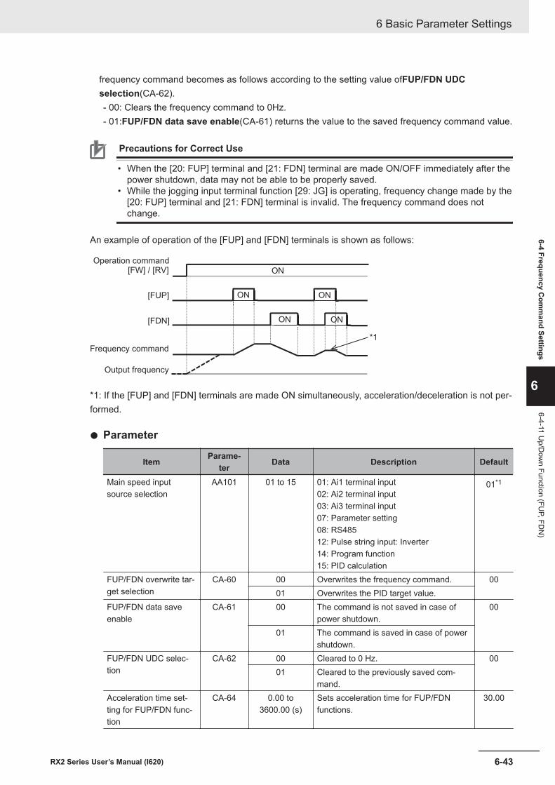
frequency command becomes as follows according to the setting value ofFUP/FDN UDCselection(CA-62).- 00: Clears the frequency command to 0Hz.- 01:FUP/FDN data save enable(CA-61) returns the value to the saved frequency command value.
Precautions for Correct Use
• When the [20: FUP] terminal and [21: FDN] terminal are made ON/OFF immediately after thepower shutdown, data may not be able to be properly saved.
• While the jogging input terminal function [29: JG] is operating, frequency change made by the[20: FUP] terminal and [21: FDN] terminal is invalid. The frequency command does notchange.
An example of operation of the [FUP] and [FDN] terminals is shown as follows:
[FW] / [RV]
[FUP]
[FDN] ON
ON ON
ON
ON
Output frequency
Operation command
Frequency command
*1
*1: If the [FUP] and [FDN] terminals are made ON simultaneously, acceleration/deceleration is not per-formed.
l Parameter
Item Parame-ter Data Description Default
Main speed inputsource selection
AA101 01 to 15 01: Ai1 terminal input02: Ai2 terminal input03: Ai3 terminal input07: Parameter setting08: RS48512: Pulse string input: Inverter14: Program function15: PID calculation
01*1
FUP/FDN overwrite tar-get selection
CA-60 00 Overwrites the frequency command. 0001 Overwrites the PID target value.
FUP/FDN data saveenable
CA-61 00 The command is not saved in case ofpower shutdown.
00
01 The command is saved in case of powershutdown.
FUP/FDN UDC selec-tion
CA-62 00 Cleared to 0 Hz. 0001 Cleared to the previously saved com-
mand.Acceleration time set-ting for FUP/FDN func-tion
CA-64 0.00 to3600.00 (s)
Sets acceleration time for FUP/FDNfunctions.
30.00
6 Basic Parameter Settings
6-43RX2 Series User’s Manual (I620)
6-4 Frequency Com
mand Settings
6
6-4-11 Up/D
own Function (FU
P, FDN
)
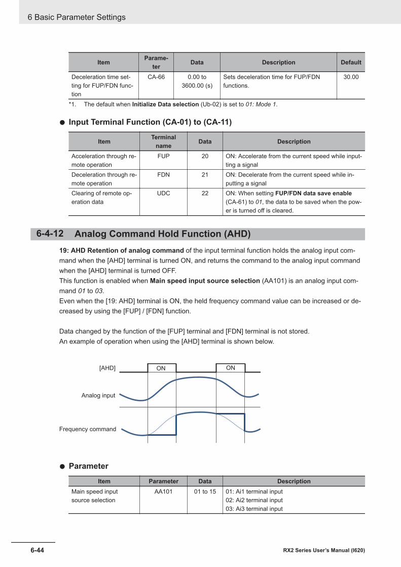
Item Parame-ter Data Description Default
Deceleration time set-ting for FUP/FDN func-tion
CA-66 0.00 to3600.00 (s)
Sets deceleration time for FUP/FDNfunctions.
30.00
*1. The default when Initialize Data selection (Ub-02) is set to 01: Mode 1.
l Input Terminal Function (CA-01) to (CA-11)
Item Terminalname Data Description
Acceleration through re-mote operation
FUP 20 ON: Accelerate from the current speed while input-ting a signal
Deceleration through re-mote operation
FDN 21 ON: Decelerate from the current speed while in-putting a signal
Clearing of remote op-eration data
UDC 22 ON: When setting FUP/FDN data save enable(CA-61) to 01, the data to be saved when the pow-er is turned off is cleared.
6-4-12 Analog Command Hold Function (AHD)19: AHD Retention of analog command of the input terminal function holds the analog input com-mand when the [AHD] terminal is turned ON, and returns the command to the analog input commandwhen the [AHD] terminal is turned OFF.This function is enabled when Main speed input source selection (AA101) is an analog input com-mand 01 to 03.Even when the [19: AHD] terminal is ON, the held frequency command value can be increased or de-creased by using the [FUP] / [FDN] function.
Data changed by the function of the [FUP] terminal and [FDN] terminal is not stored.An example of operation when using the [AHD] terminal is shown below.
ON ON[AHD]
Analog input
Frequency command
l Parameter
Item Parameter Data DescriptionMain speed inputsource selection
AA101 01 to 15 01: Ai1 terminal input02: Ai2 terminal input03: Ai3 terminal input
6 Basic Parameter Settings
6-44 RX2 Series User’s Manual (I620)
l Input Terminal Function (CA-01) to (CA-11)
Item Terminalname Data Description
Retention of analogcommand
AHD 19 ON: Holds the analog command value and doesnot reflect the change in the analog input value un-til it is released.OFF: Releases the holding of the analog com-mand value.
6-4-13 Temporary Change of Frequency Command DestinationYou can use the [23: F-OP] terminal to temporarily change the frequency command destination.When the [23: F-OP] terminal is turned ON, the command destination in Speed reference sourceselection at [F-OP] is active (CA-70) is adopted with priority over the frequency command destina-tion set in Main speed input source selection (AA101).
Precautions for Correct Use
When the [F-OP] terminal is ON while the input function 23: Forced switching of command isused, the operation command selection set in RUN command source selection at [F-OP] isactive (CA-71) is also adopted for the operation command destination.
l Parameter
Item Parame-ter Data Description Default
Speed referencesource selection at [F-OP] is active
CA-70 01 to 15 01: Ai1 terminal input02: Ai2 terminal input03: Ai3 terminal input04: (Reserved)05: (Reserved)06: (Reserved)07: Parameter setting08: RS48509: Option 110: Option 211: Option 312: Pulse string input: Inverter13: Pulse string input: Option14: Program function15: PID calculation
01
RUN command sourceselection at [F-OP] isactive
CA-71 00 to 06 00: [FW]/[RV] terminal01: 3 wire02: RUN key on LCD Operator03: RS48504: Option 105: Option 206: Option 3
00
6 Basic Parameter Settings
6-45RX2 Series User’s Manual (I620)
6-4 Frequency Com
mand Settings
6
6-4-13 Temporary C
hange of Frequency Com
mand D
estination
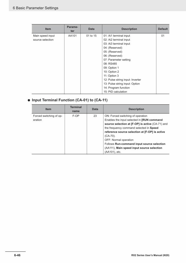
Item Parame-ter Data Description Default
Main speed inputsource selection
AA101 01 to 15 01: Ai1 terminal input02: Ai2 terminal input03: Ai3 terminal input04: (Reserved)05: (Reserved)06: (Reserved)07: Parameter setting08: RS48509: Option 110: Option 211: Option 312: Pulse string input: Inverter13: Pulse string input: Option14: Program function15: PID calculation
01
l Input Terminal Function (CA-01) to (CA-11)
Item Terminalname Data Description
Forced switching of op-eration
F-OP 23 ON: Forced switching of operationEnables the input selected in [RUN commandsource selection at [F-OP] is active (CA-71) andthe frequency command selected in Speedreference source selection at [F-OP] is active(CA-70).OFF: Normal operationFollows Run-command input source selection(AA111), Main speed input source selection(AA101), etc.
6 Basic Parameter Settings
6-46 RX2 Series User’s Manual (I620)
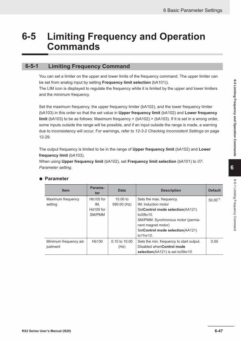
6-5 Limiting Frequency and OperationCommands
6-5-1 Limiting Frequency CommandYou can set a limiter on the upper and lower limits of the frequency command. The upper limiter canbe set from analog input by setting Frequency limit selection (bA101)).The LIM icon is displayed to regulate the frequency while it is limited by the upper and lower limitersand the minimum frequency.
Set the maximum frequency, the upper frequency limiter (bA102), and the lower frequency limiter(bA103) in this order so that the set value in Upper frequency limit (bA102) and Lower frequencylimit (bA103) to be as follows: Maximum frequency > (bA102) > (bA103). If it is set in a wrong order,some inputs outside the range will be possible, and if an input outside the range is made, a warningdue to inconsistency will occur. For warnings, refer to 12-3-2 Checking Inconsistent Settings on page12-29.
The output frequency is limited to be in the range of Upper frequency limit (bA102) and Lowerfrequency limit (bA103).When using Upper frequency limit (bA102), set Frequency limit selection (bA101) to 07:Parameter setting.
l Parameter
Item Parame-ter Data Description Default
Maximum frequencysetting
Hb105 forIM,
Hd105 forSM/PMM
10.00 to590.00 (Hz)
Sets the max. frequency.IM: Induction motorSetControl mode selection(AA121)to00to10.SM/PMM: Synchronous motor (perma-nent magnet motor)SetControl mode selection(AA121)to11or12.
50.00*1
Minimum frequency ad-justment
Hb130 0.10 to 10.00(Hz)
Sets the min. frequency to start output.Disabled whenControl modeselection(AA121) is set to09or10.
0.50
6 Basic Parameter Settings
6-47RX2 Series User’s Manual (I620)
6-5 Limiting Frequency and O
peration Com
mands
6
6-5-1 Limiting Frequency C
omm
and
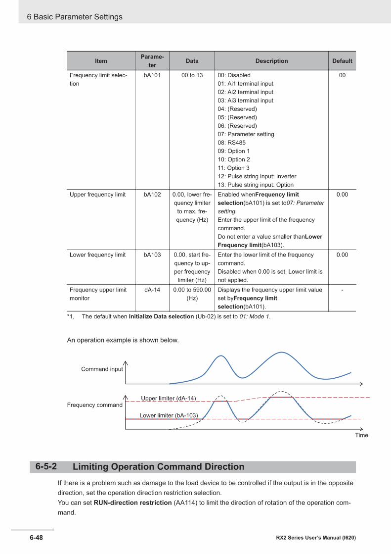
Item Parame-ter Data Description Default
Frequency limit selec-tion
bA101 00 to 13 00: Disabled01: Ai1 terminal input02: Ai2 terminal input03: Ai3 terminal input04: (Reserved)05: (Reserved)06: (Reserved)07: Parameter setting08: RS48509: Option 110: Option 211: Option 312: Pulse string input: Inverter13: Pulse string input: Option
00
Upper frequency limit bA102 0.00, lower fre-quency limiterto max. fre-quency (Hz)
Enabled whenFrequency limitselection(bA101) is set to07: Parametersetting.Enter the upper limit of the frequencycommand.Do not enter a value smaller thanLowerFrequency limit(bA103).
0.00
Lower frequency limit bA103 0.00, start fre-quency to up-per frequency
limiter (Hz)
Enter the lower limit of the frequencycommand.Disabled when 0.00 is set. Lower limit isnot applied.
0.00
Frequency upper limitmonitor
dA-14 0.00 to 590.00(Hz)
Displays the frequency upper limit valueset byFrequency limitselection(bA101).
-
*1. The default when Initialize Data selection (Ub-02) is set to 01: Mode 1.
An operation example is shown below.
Command input
Frequency commandUpper limiter (dA-14)
Lower limiter (bA-103)
Time
6-5-2 Limiting Operation Command DirectionIf there is a problem such as damage to the load device to be controlled if the output is in the oppositedirection, set the operation direction restriction selection.You can set RUN-direction restriction (AA114) to limit the direction of rotation of the operation com-mand.
6 Basic Parameter Settings
6-48 RX2 Series User’s Manual (I620)
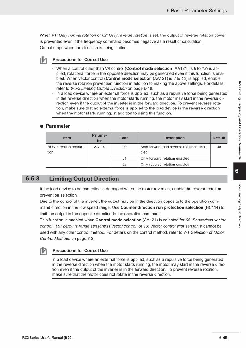
When 01: Only normal rotation or 02: Only reverse rotation is set, the output of reverse rotation poweris prevented even if the frequency command becomes negative as a result of calculation.Output stops when the direction is being limited.
Precautions for Correct Use
• When a control other than V/f control (Control mode selection (AA121) is 8 to 12) is ap-plied, rotational force in the opposite direction may be generated even if this function is ena-bled. When vector control (Control mode selection (AA121) is 8 to 10) is applied, enablethe reverse rotation prevention function in addition to making the above settings. For details,refer to 6-5-3 Limiting Output Direction on page 6-49.
• In a load device where an external force is applied, such as a repulsive force being generatedin the reverse direction when the motor starts running, the motor may start in the reverse di-rection even if the output of the inverter is in the forward direction. To prevent reverse rota-tion, make sure that no external force is applied to the load device in the reverse directionwhen the motor starts running, in addition to using this function.
l Parameter
Item Parame-ter Data Description Default
RUN-direction restric-tion
AA114 00 Both forward and reverse rotations ena-bled
00
01 Only forward rotation enabled02 Only reverse rotation enabled
6-5-3 Limiting Output DirectionIf the load device to be controlled is damaged when the motor reverses, enable the reverse rotationprevention selection.Due to the control of the inverter, the output may be in the direction opposite to the operation com-mand direction in the low speed range. Use Counter direction run protection selection (HC114) tolimit the output in the opposite direction to the operation command.This function is enabled when Control mode selection (AA121) is selected for 08: Sensorless vectorcontrol , 09: Zero-Hz range sensorless vector control, or 10: Vector control with sensor. It cannot beused with any other control method. For details on the control method, refer to 7-1 Selection of MotorControl Methods on page 7-3.
Precautions for Correct Use
In a load device where an external force is applied, such as a repulsive force being generatedin the reverse direction when the motor starts running, the motor may start in the reverse direc-tion even if the output of the inverter is in the forward direction. To prevent reverse rotation,make sure that the motor does not rotate in the reverse direction.
6 Basic Parameter Settings
6-49RX2 Series User’s Manual (I620)
6-5 Limiting Frequency and O
peration Com
mands
6
6-5-3 Limiting O
utput Direction
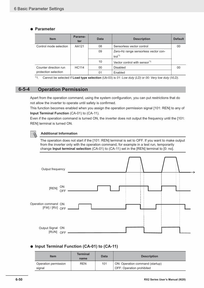
l Parameter
Item Parame-ter Data Description Default
Control mode selection AA121 08 Sensorless vector control 0009 Zero-Hz range sensorless vector con-
trol*1
10 Vector control with sensor*1
Counter direction runprotection selection
HC114 00 Disabled 0001 Enabled
*1. Cannot be selected if Load type selection (Ub-03) is 01: Low duty (LD) or 00: Very low duty (VLD).
6-5-4 Operation PermissionApart from the operation command, using the system configuration, you can put restrictions that donot allow the inverter to operate until safety is confirmed.This function becomes enabled when you assign the operation permission signal [101: REN] to any ofInput Terminal Function (CA-01) to (CA-11).Even if the operation command is turned ON, the inverter does not output the frequency until the [101:REN] terminal is turned ON.
Additional Information
The operation does not start if the [101: REN] terminal is set to OFF. If you want to make outputfrom the inverter only with the operation command, for example in a test run, temporarilychange Input terminal selection (CA-01) to (CA-11) set in the [REN] terminal to [0: no].
ON
OFF
ON
OFF
ON
OFF[RUN]
[FW] / [RV]
[REN]
Output frequency
Operation command
Output Signal
l Input Terminal Function (CA-01) to (CA-11)
Item Terminalname Data Description
Operation permissionsignal
REN 101 ON: Operation command (startup)OFF: Operation prohibited
6 Basic Parameter Settings
6-50 RX2 Series User’s Manual (I620)
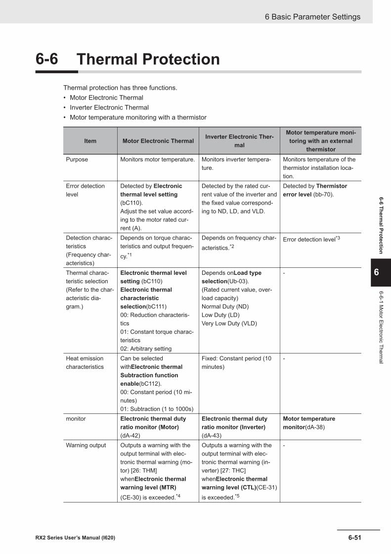
6-6 Thermal ProtectionThermal protection has three functions.• Motor Electronic Thermal• Inverter Electronic Thermal• Motor temperature monitoring with a thermistor
Item Motor Electronic Thermal Inverter Electronic Ther-mal
Motor temperature moni-toring with an external
thermistorPurpose Monitors motor temperature. Monitors inverter tempera-
ture.Monitors temperature of thethermistor installation loca-tion.
Error detectionlevel
Detected by Electronicthermal level setting(bC110).Adjust the set value accord-ing to the motor rated cur-rent (A).
Detected by the rated cur-rent value of the inverter andthe fixed value correspond-ing to ND, LD, and VLD.
Detected by Thermistorerror level (bb-70).
Detection charac-teristics(Frequency char-acteristics)
Depends on torque charac-teristics and output frequen-cy.*1
Depends on frequency char-acteristics.*2
Error detection level*3
Thermal charac-teristic selection(Refer to the char-acteristic dia-gram.)
Electronic thermal levelsetting (bC110)Electronic thermalcharacteristicselection(bC111)00: Reduction characteris-tics01: Constant torque charac-teristics02: Arbitrary setting
Depends onLoad typeselection(Ub-03).(Rated current value, over-load capacity)Normal Duty (ND)Low Duty (LD)Very Low Duty (VLD)
-
Heat emissioncharacteristics
Can be selectedwithElectronic thermalSubtraction functionenable(bC112).00: Constant period (10 mi-nutes)01: Subtraction (1 to 1000s)
Fixed: Constant period (10minutes)
-
monitor Electronic thermal dutyratio monitor (Motor)(dA-42)
Electronic thermal dutyratio monitor (Inverter)(dA-43)
Motor temperaturemonitor(dA-38)
Warning output Outputs a warning with theoutput terminal with elec-tronic thermal warning (mo-tor) [26: THM]whenElectronic thermalwarning level (MTR)(CE-30) is exceeded.*4
Outputs a warning with theoutput terminal with elec-tronic thermal warning (in-verter) [27: THC]whenElectronic thermalwarning level (CTL)(CE-31)is exceeded.*5
-
6 Basic Parameter Settings
6-51RX2 Series User’s Manual (I620)
6-6 Thermal Protection
6
6-6-1 Motor Electronic Therm
al
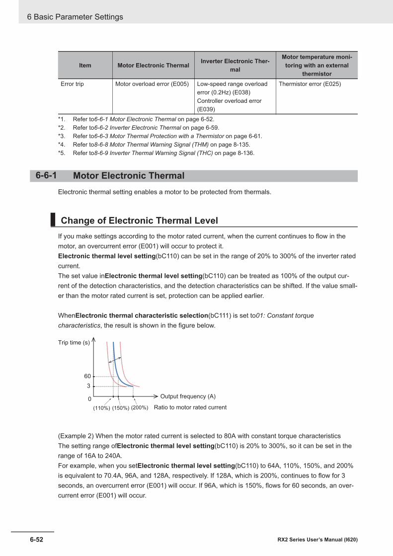
Item Motor Electronic Thermal Inverter Electronic Ther-mal
Motor temperature moni-toring with an external
thermistorError trip Motor overload error (E005) Low-speed range overload
error (0.2Hz) (E038)Controller overload error(E039)
Thermistor error (E025)
*1. Refer to6-6-1 Motor Electronic Thermal on page 6-52.*2. Refer to6-6-2 Inverter Electronic Thermal on page 6-59.*3. Refer to6-6-3 Motor Thermal Protection with a Thermistor on page 6-61.*4. Refer to8-6-8 Motor Thermal Warning Signal (THM) on page 8-135.*5. Refer to8-6-9 Inverter Thermal Warning Signal (THC) on page 8-136.
6-6-1 Motor Electronic ThermalElectronic thermal setting enables a motor to be protected from thermals.
Change of Electronic Thermal LevelIf you make settings according to the motor rated current, when the current continues to flow in themotor, an overcurrent error (E001) will occur to protect it.Electronic thermal level setting(bC110) can be set in the range of 20% to 300% of the inverter ratedcurrent.The set value inElectronic thermal level setting(bC110) can be treated as 100% of the output cur-rent of the detection characteristics, and the detection characteristics can be shifted. If the value small-er than the motor rated current is set, protection can be applied earlier.
WhenElectronic thermal characteristic selection(bC111) is set to01: Constant torquecharacteristics, the result is shown in the figure below.
60
3
0
(150%) (200%)(110%)
Trip time (s)
Output frequency (A)
Ratio to motor rated current
(Example 2) When the motor rated current is selected to 80A with constant torque characteristicsThe setting range ofElectronic thermal level setting(bC110) is 20% to 300%, so it can be set in therange of 16A to 240A.For example, when you setElectronic thermal level setting(bC110) to 64A, 110%, 150%, and 200%is equivalent to 70.4A, 96A, and 128A, respectively. If 128A, which is 200%, continues to flow for 3seconds, an overcurrent error (E001) will occur. If 96A, which is 150%, flows for 60 seconds, an over-current error (E001) will occur.
6 Basic Parameter Settings
6-52 RX2 Series User’s Manual (I620)
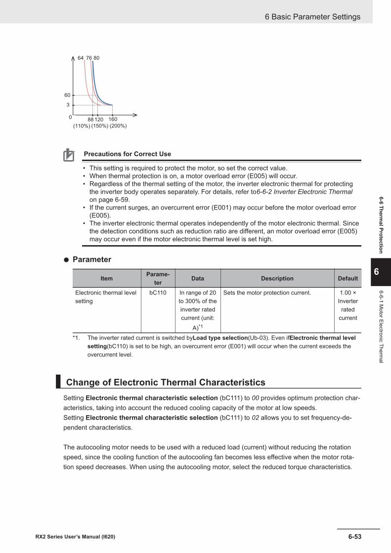
60
3
880
120 160
807664
(110%) (150%) (200%)
Precautions for Correct Use
• This setting is required to protect the motor, so set the correct value.• When thermal protection is on, a motor overload error (E005) will occur.• Regardless of the thermal setting of the motor, the inverter electronic thermal for protecting
the inverter body operates separately. For details, refer to6-6-2 Inverter Electronic Thermalon page 6-59.
• If the current surges, an overcurrent error (E001) may occur before the motor overload error(E005).
• The inverter electronic thermal operates independently of the motor electronic thermal. Sincethe detection conditions such as reduction ratio are different, an motor overload error (E005)may occur even if the motor electronic thermal level is set high.
l Parameter
Item Parame-ter Data Description Default
Electronic thermal levelsetting
bC110 In range of 20to 300% of theinverter ratedcurrent (unit:
A)*1
Sets the motor protection current. 1.00 ×Inverterrated
current
*1. The inverter rated current is switched byLoad type selection(Ub-03). Even ifElectronic thermal levelsetting(bC110) is set to be high, an overcurrent error (E001) will occur when the current exceeds theovercurrent level.
Change of Electronic Thermal CharacteristicsSetting Electronic thermal characteristic selection (bC111) to 00 provides optimum protection char-acteristics, taking into account the reduced cooling capacity of the motor at low speeds.Setting Electronic thermal characteristic selection (bC111) to 02 allows you to set frequency-de-pendent characteristics.
The autocooling motor needs to be used with a reduced load (current) without reducing the rotationspeed, since the cooling function of the autocooling fan becomes less effective when the motor rota-tion speed decreases. When using the autocooling motor, select the reduced torque characteristics.
6 Basic Parameter Settings
6-53RX2 Series User’s Manual (I620)
6-6 Thermal Protection
6
6-6-1 Motor Electronic Therm
al
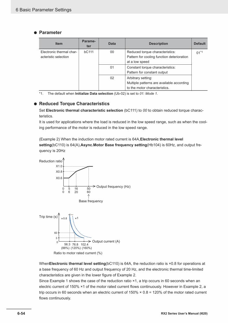
l Parameter
Item Parame-ter Data Description Default
Electronic thermal char-acteristic selection
bC111 00 Reduced torque characteristics:Pattern for cooling function deteriorationat a low speed
01*1
01 Constant torque characteristics:Pattern for constant output
02 Arbitrary setting:Multiple patterns are available accordingto the motor characteristics.
*1. The default when Initialize Data selection (Ub-02) is set to 01: Mode 1.
l Reduced Torque CharacteristicsSet Electronic thermal characteristic selection (bC111) to 00 to obtain reduced torque charac-teristics.It is used for applications where the load is reduced in the low speed range, such as when the cool-ing performance of the motor is reduced in the low speed range.
(Example 2) When the induction motor rated current is 64A,Electronic thermal levelsetting(bC110) is 64(A),Async.Motor Base frequency setting(Hb104) is 60Hz, and output fre-quency is 20Hz
X1.0
5 16 50
X0.8
X0.6
06 20 600
Base frequency
Output frequency (Hz)
Reduction ratio
0
60
3
×1×0.8Trip time (s)
Output current (A)
Ratio to motor rated current (%)
56.3 76.8 102.4(160%)(120%)(88%)
WhenElectronic thermal level setting(bC110) is 64A, the reduction ratio is ×0.8 for operations ata base frequency of 60 Hz and output frequency of 20 Hz, and the electronic thermal time-limitedcharacteristics are given in the lower figure of Example 2.Since Example 1 shows the case of the reduction ratio ×1, a trip occurs in 60 seconds when anelectric current of 150% ×1 of the motor rated current flows continuously. However in Example 2, atrip occurs in 60 seconds when an electric current of 150% × 0.8 = 120% of the motor rated currentflows continuously.
6 Basic Parameter Settings
6-54 RX2 Series User’s Manual (I620)
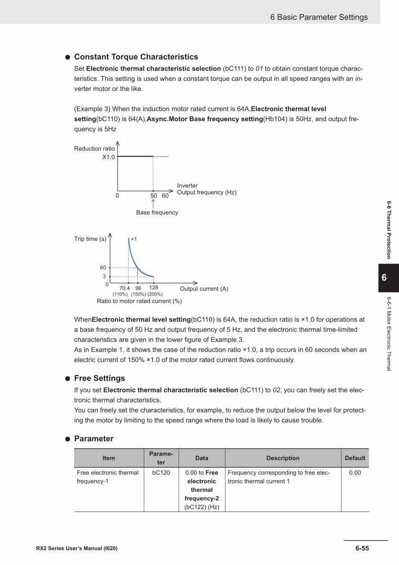
l Constant Torque CharacteristicsSet Electronic thermal characteristic selection (bC111) to 01 to obtain constant torque charac-teristics. This setting is used when a constant torque can be output in all speed ranges with an in-verter motor or the like.
(Example 3) When the induction motor rated current is 64A,Electronic thermal levelsetting(bC110) is 64(A),Async.Motor Base frequency setting(Hb104) is 50Hz, and output fre-quency is 5Hz
X1.0
0 50 60
Reduction ratio
Base frequency
InverterOutput frequency (Hz)
70.4(110%)
96(150%)
128
(200%)
60
3
0
×1Trip time (s)
Output current (A)
Ratio to motor rated current (%)
WhenElectronic thermal level setting(bC110) is 64A, the reduction ratio is ×1.0 for operations ata base frequency of 50 Hz and output frequency of 5 Hz, and the electronic thermal time-limitedcharacteristics are given in the lower figure of Example 3.As in Example 1, it shows the case of the reduction ratio ×1.0, a trip occurs in 60 seconds when anelectric current of 150% ×1.0 of the motor rated current flows continuously.
l Free SettingsIf you set Electronic thermal characteristic selection (bC111) to 02, you can freely set the elec-tronic thermal characteristics.You can freely set the characteristics, for example, to reduce the output below the level for protect-ing the motor by limiting to the speed range where the load is likely to cause trouble.
l Parameter
Item Parame-ter Data Description Default
Free electronic thermalfrequency-1
bC120 0.00 to Freeelectronicthermal
frequency-2(bC122) (Hz)
Frequency corresponding to free elec-tronic thermal current 1
0.00
6 Basic Parameter Settings
6-55RX2 Series User’s Manual (I620)
6-6 Thermal Protection
6
6-6-1 Motor Electronic Therm
al
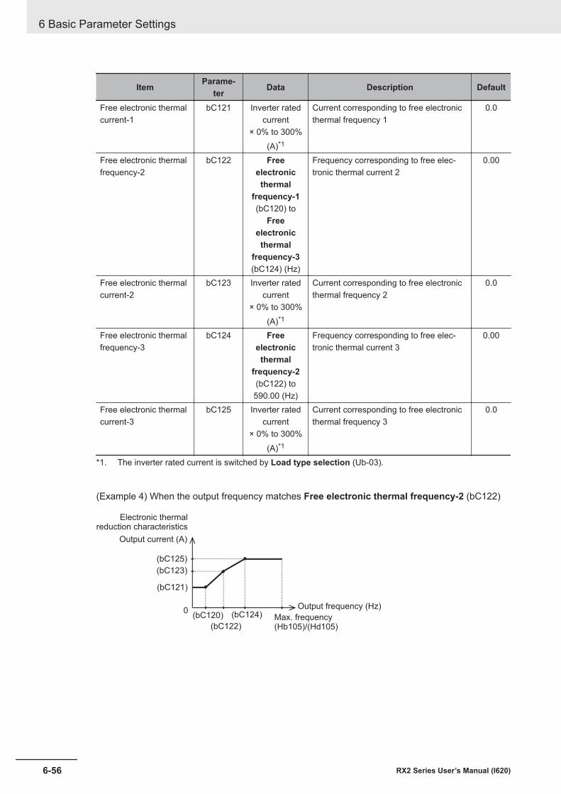
Item Parame-ter Data Description Default
Free electronic thermalcurrent-1
bC121 Inverter ratedcurrent
× 0% to 300%(A)*1
Current corresponding to free electronicthermal frequency 1
0.0
Free electronic thermalfrequency-2
bC122 Freeelectronicthermal
frequency-1(bC120) to
Freeelectronicthermal
frequency-3(bC124) (Hz)
Frequency corresponding to free elec-tronic thermal current 2
0.00
Free electronic thermalcurrent-2
bC123 Inverter ratedcurrent
× 0% to 300%(A)*1
Current corresponding to free electronicthermal frequency 2
0.0
Free electronic thermalfrequency-3
bC124 Freeelectronicthermal
frequency-2(bC122) to590.00 (Hz)
Frequency corresponding to free elec-tronic thermal current 3
0.00
Free electronic thermalcurrent-3
bC125 Inverter ratedcurrent
× 0% to 300%(A)*1
Current corresponding to free electronicthermal frequency 3
0.0
*1. The inverter rated current is switched by Load type selection (Ub-03).
(Example 4) When the output frequency matches Free electronic thermal frequency-2 (bC122)
(bC125)
(bC123)
(bC121)
(bC120)
(bC122)
(bC124)0
Max. frequency(Hb105)/(Hd105)
Output frequency (Hz)
Electronic thermalreduction characteristics
Output current (A)
6 Basic Parameter Settings
6-56 RX2 Series User’s Manual (I620)
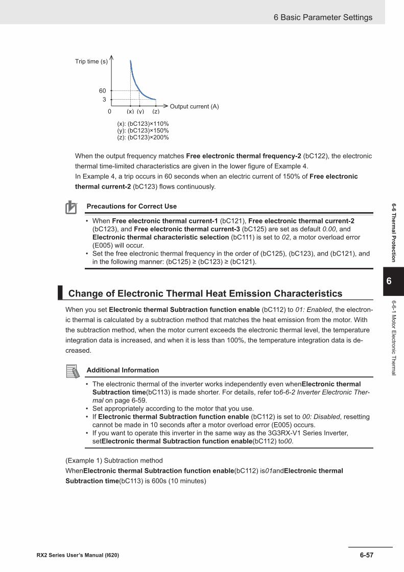
60
3
(x) (y) (z)0
Trip time (s)
Output current (A)
(x): (bC123)×110%(y): (bC123)×150%(z): (bC123)×200%
When the output frequency matches Free electronic thermal frequency-2 (bC122), the electronicthermal time-limited characteristics are given in the lower figure of Example 4.In Example 4, a trip occurs in 60 seconds when an electric current of 150% of Free electronicthermal current-2 (bC123) flows continuously.
Precautions for Correct Use
• When Free electronic thermal current-1 (bC121), Free electronic thermal current-2(bC123), and Free electronic thermal current-3 (bC125) are set as default 0.00, andElectronic thermal characteristic selection (bC111) is set to 02, a motor overload error(E005) will occur.
• Set the free electronic thermal frequency in the order of (bC125), (bC123), and (bC121), andin the following manner: (bC125) ≥ (bC123) ≥ (bC121).
Change of Electronic Thermal Heat Emission CharacteristicsWhen you set Electronic thermal Subtraction function enable (bC112) to 01: Enabled, the electron-ic thermal is calculated by a subtraction method that matches the heat emission from the motor. Withthe subtraction method, when the motor current exceeds the electronic thermal level, the temperatureintegration data is increased, and when it is less than 100%, the temperature integration data is de-creased.
Additional Information
• The electronic thermal of the inverter works independently even whenElectronic thermalSubtraction time(bC113) is made shorter. For details, refer to6-6-2 Inverter Electronic Ther-mal on page 6-59.
• Set appropriately according to the motor that you use.• If Electronic thermal Subtraction function enable (bC112) is set to 00: Disabled, resetting
cannot be made in 10 seconds after a motor overload error (E005) occurs.• If you want to operate this inverter in the same way as the 3G3RX-V1 Series Inverter,
setElectronic thermal Subtraction function enable(bC112) to00.
(Example 1) Subtraction methodWhenElectronic thermal Subtraction function enable(bC112) is01andElectronic thermalSubtraction time(bC113) is 600s (10 minutes)
6 Basic Parameter Settings
6-57RX2 Series User’s Manual (I620)
6-6 Thermal Protection
6
6-6-1 Motor Electronic Therm
al
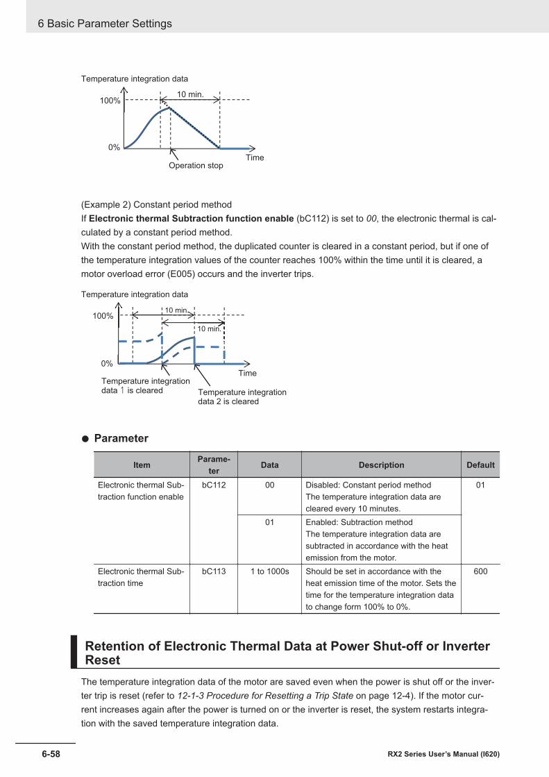
100%
0%
Time
Temperature integration data
10 min.
Operation stop
(Example 2) Constant period methodIf Electronic thermal Subtraction function enable (bC112) is set to 00, the electronic thermal is cal-culated by a constant period method.With the constant period method, the duplicated counter is cleared in a constant period, but if one ofthe temperature integration values of the counter reaches 100% within the time until it is cleared, amotor overload error (E005) occurs and the inverter trips.
100%
0%Time
Temperature integration data
10 min.
Temperature integrationdata 1 is cleared
10 min.
Temperature integrationdata 2 is cleared
l Parameter
Item Parame-ter Data Description Default
Electronic thermal Sub-traction function enable
bC112 00 Disabled: Constant period methodThe temperature integration data arecleared every 10 minutes.
01
01 Enabled: Subtraction methodThe temperature integration data aresubtracted in accordance with the heatemission from the motor.
Electronic thermal Sub-traction time
bC113 1 to 1000s Should be set in accordance with theheat emission time of the motor. Sets thetime for the temperature integration datato change form 100% to 0%.
600
Retention of Electronic Thermal Data at Power Shut-off or InverterReset
The temperature integration data of the motor are saved even when the power is shut off or the inver-ter trip is reset (refer to 12-1-3 Procedure for Resetting a Trip State on page 12-4). If the motor cur-rent increases again after the power is turned on or the inverter is reset, the system restarts integra-tion with the saved temperature integration data.
6 Basic Parameter Settings
6-58 RX2 Series User’s Manual (I620)
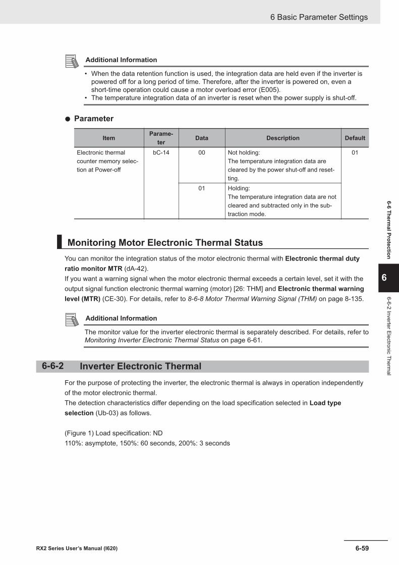
Additional Information
• When the data retention function is used, the integration data are held even if the inverter ispowered off for a long period of time. Therefore, after the inverter is powered on, even ashort-time operation could cause a motor overload error (E005).
• The temperature integration data of an inverter is reset when the power supply is shut-off.
l Parameter
Item Parame-ter Data Description Default
Electronic thermalcounter memory selec-tion at Power-off
bC-14 00 Not holding:The temperature integration data arecleared by the power shut-off and reset-ting.
01
01 Holding:The temperature integration data are notcleared and subtracted only in the sub-traction mode.
Monitoring Motor Electronic Thermal StatusYou can monitor the integration status of the motor electronic thermal with Electronic thermal dutyratio monitor MTR (dA-42).If you want a warning signal when the motor electronic thermal exceeds a certain level, set it with theoutput signal function electronic thermal warning (motor) [26: THM] and Electronic thermal warninglevel (MTR) (CE-30). For details, refer to 8-6-8 Motor Thermal Warning Signal (THM) on page 8-135.
Additional Information
The monitor value for the inverter electronic thermal is separately described. For details, refer to Monitoring Inverter Electronic Thermal Status on page 6-61.
6-6-2 Inverter Electronic ThermalFor the purpose of protecting the inverter, the electronic thermal is always in operation independentlyof the motor electronic thermal.The detection characteristics differ depending on the load specification selected in Load typeselection (Ub-03) as follows.
(Figure 1) Load specification: ND110%: asymptote, 150%: 60 seconds, 200%: 3 seconds
6 Basic Parameter Settings
6-59RX2 Series User’s Manual (I620)
6-6 Thermal Protection
6
6-6-2 Inverter Electronic Thermal
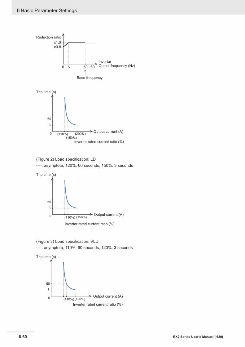
x1.0
0 50 605
x0.8
Reduction ratio
Base frequency
InverterOutput frequency (Hz)
60
3
0 (110%)(150%)
(200%)
Trip time (s)
Inverter rated current ratio (%)
Output current (A)
(Figure 2) Load specification: LD----: asymptote, 120%: 60 seconds, 150%: 3 seconds
60
3
0 (110%) (150%)
Trip time (s)
Inverter rated current ratio (%)
Output current (A)
(Figure 3) Load specification: VLD----: asymptote, 110%: 60 seconds, 120%: 3 seconds
60
3
0 (110%) (120%)
Trip time (s)
Inverter rated current ratio (%)
Output current (A)
6 Basic Parameter Settings
6-60 RX2 Series User’s Manual (I620)
Monitoring Inverter Electronic Thermal StatusYou can monitor the integration status of the the inverter electronic thermal with Electronic thermalduty ratio monitor CTL (dA-43).If you want a warning signal when the inverter electronic thermal exceeds a certain level, set it with theoutput signal function electronic thermal warning (inverter) [27: THC] and Electronic thermal warninglevel (CTL) (CE-31). For details, refer to 8-6-9 Inverter Thermal Warning Signal (THC) on page 8-136.
Additional Information
The monitor value for the motor electronic thermal is separately described. For details, refer to Monitoring Motor Electronic Thermal Status on page 6-59.
6-6-3 Motor Thermal Protection with a ThermistorYou can provide thermal protection for the external device by wiring the thermistor installed in the ex-ternal device such as a motor to the inverter and setting the function of the thermistor.Wire the external thermistor between the control terminals TH+ and TH-.Set Thermistor selection (Cb-40) and Thermistor error level (bb-70) (resistance value when an er-ror occurs) according to the thermistor specifications.
When the thermistor resistance value reaches Thermistor error level (bb-70) due to the temperatureof the external device, a thermistor error (E035) occurs.As an adjustment, if you want to make the inverter to trip with a value smaller than Thermistor errorlevel (bb-70), increase the value of Thermistor gain adjustment (Cb-41) to higher than 100%. If youwant to make the inverter to trip with a value larger than Thermistor error level (bb-70), decrease thevalue of Thermistor gain adjustment (Cb-41).
Using the characteristics of the installed thermistor, if you set Thermistor selection (Cb-40) to 02,Motor temperature monitor (dA-38) will display the detected motor temperature.If you set 01: PTC resistance value enabled that does not match the thermistor or 00: Disabled, Motortemperature monitor (dA-38) displays 0 (zero) C°.
Additional Information
• If the external thermistor is not connected, setting Thermistor selection (Cb-40) to 01 or 02will cause a trip.
• To use this function, the wiring distance between the motor and the inverter has to be 20 m orshorter. Since the current flowing in the thermistor is very weak, a measure such as wiringseparation should be taken to prevent noise from the motor current.
l Parameter
Item Parame-ter Data Description Default
Thermistor error level bb-70 0 to 10000 (Ω) Set the resistance value for the tempera-ture at which a trip occurs in accordancewith the thermistor resistance specifica-tions.Enabled whenThermistorselection(Cb-40) is01or02.
3000
6 Basic Parameter Settings
6-61RX2 Series User’s Manual (I620)
6-6 Thermal Protection
6
6-6-3 Motor Therm
al Protection with a Therm
istor
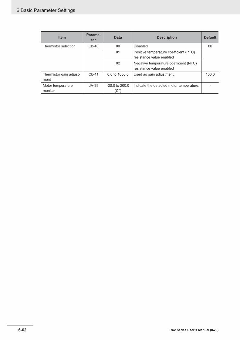
Item Parame-ter Data Description Default
Thermistor selection Cb-40 00 Disabled 0001 Positive temperature coefficient (PTC)
resistance value enabled02 Negative temperature coefficient (NTC)
resistance value enabledThermistor gain adjust-ment
Cb-41 0.0 to 1000.0 Used as gain adjustment. 100.0
Motor temperaturemonitor
dA-38 -20.0 to 200.0(C°)
Indicate the detected motor temperature. -
6 Basic Parameter Settings
6-62 RX2 Series User’s Manual (I620)
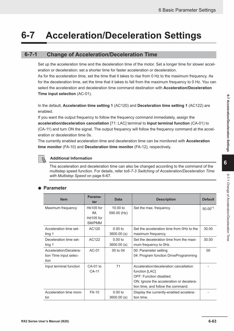
6-7 Acceleration/Deceleration Settings
6-7-1 Change of Acceleration/Deceleration TimeSet up the acceleration time and the deceleration time of the motor. Set a longer time for slower accel-eration or deceleration; set a shorter time for faster acceleration or deceleration.As for the acceleration time, set the time that it takes to rise from 0 Hz to the maximum frequency. Asfor the deceleration time, set the time that it takes to fall from the maximum frequency to 0 Hz. You canselect the acceleration and deceleration time command destination with Acceleration/DecelerationTime input selection (AC-01).
In the default, Acceleration time setting 1 (AC120) and Deceleration time setting 1 (AC122) areenabled.If you want the output frequency to follow the frequency command immediately, assign theacceleration/deceleration cancellation [71: LAC] terminal to Input terminal function (CA-01) to(CA-11) and turn ON the signal. The output frequency will follow the frequency command at the accel-eration or deceleration time 0s.The currently enabled acceleration time and deceleration time can be monitored with Accelerationtime monitor (FA-10) and Deceleration time monitor (FA-12), respectively.
Additional Information
The acceleration and deceleration time can also be changed according to the command of themultistep speed function. For details, refer to6-7-3 Switching of Acceleration/Deceleration Timewith Multistep Speed on page 6-67.
l Parameter
Item Parame-ter Data Description Default
Maximum frequency Hb105 forIM,
Hd105 forSM/PMM
10.00 to590.00 (Hz)
Set the max. frequency. 50.00*1
Acceleration time set-ting 1
AC120 0.00 to3600.00 (s)
Set the acceleration time from 0Hz to themaximum frequency.
30.00
Deceleration time set-ting 1
AC122 0.00 to3600.00 (s)
Set the deceleration time from the maxi-mum frequency to 0Hz.
30.00
Acceleration/Decelera-tion Time input selec-tion
AC-01 00 to 04 00: Parameter setting04: Program function DriveProgramming
00
Input terminal function CA-01 toCA-11
71 Acceleration/deceleration cancellationfunction [LAC]OFF: Function disabled.ON: Ignore the acceleration or decelera-tion time, and follow the command.
-
Acceleration time moni-tor
FA-10 0.00 to3600.00 (s)
Display the currently-enabled accelera-tion time.
-
6 Basic Parameter Settings
6-63RX2 Series User’s Manual (I620)
6-7 Acceleration/D
eceleration Settings
6
6-7-1 Change of Acceleration/D
eceleration Time
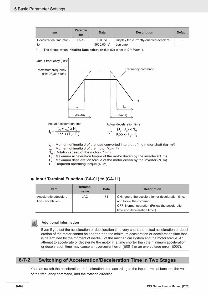
Item Parame-ter Data Description Default
Deceleration time moni-tor
FA-12 0.00 to3600.00 (s)
Display the currently-enabled decelera-tion time.
-
*1. The default when Initialize Data selection (Ub-02) is set to 01: Mode 1.
(FA-10) (FA-12)
st Bt
(JL+ J
M) ! N
M(J
L+ J
M) ! N
M
9.55 x (TB+ T
L) 9.55 x (T
S+ T
L)
tB =t
S =
Output frequency (Hz)
Maximum frequency
(Hb105)/(Hd105)
Frequency command
Actual acceleration time Actual deceleration time
: Moment of inertia J of the load converted into that of the motor shaft (kg・m2)
: Moment of inertia J of the motor (kg・m2)
: Rotation speed of the motor (r/min)
: Maximum acceleration torque of the motor driven by the inverter (N・m)
: Maximum deceleration torque of the motor driven by the inverter (N・m)
: Required operating torque (N・m)
JL
JM
NM
TS
TB
TL
l Input Terminal Function (CA-01) to (CA-11)
Item Terminalname Data Description
Acceleration/decelera-tion cancellation
LAC 71 ON: Ignore the acceleration or deceleration time,and follow the command.OFF: Normal operation (Follow the accelerationtime and deceleration time.)
Additional Information
Even if you set the acceleration or deceleration time very short, the actual acceleration or decel-eration of the motor cannot be shorter than the minimum acceleration or deceleration time thatis determined by the moment of inertia J of the mechanical system and the motor torque. Anattempt to accelerate or decelerate the motor in a time shorter than the minimum accelerationor deceleration time may cause an overcurrent error (E001) or an overvoltage error (E007).
6-7-2 Switching of Acceleration/Deceleration Time in Two StagesYou can switch the acceleration or deceleration time according to the input terminal function, the valueof the frequency command, and the rotation direction.
6 Basic Parameter Settings
6-64 RX2 Series User’s Manual (I620)
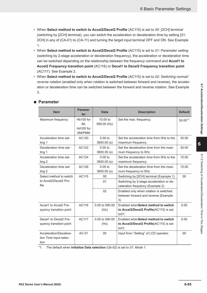
• When Select method to switch to Accel2/Decel2 Profile (AC115) is set to 00: [2CH] terminal(switching by [2CH] terminal), you can switch the acceleration or deceleration time by setting [31:2CH] in any of (CA-01) to (CA-11) and turning the target input terminal OFF and ON. See Example1.
• When Select method to switch to Accel2/Decel2 Profile (AC115) is set to 01: Parameter setting(switching by 2-stage acceleration or deceleration frequency), the acceleration or deceleration timecan be switched depending on the relationship between the frequency command and Accel1 toAccel2 Frequency transition point (AC116) or Decel1 to Decel2 Frequency transition point(AC117). See Example 2.
• When Select method to switch to Accel2/Decel2 Profile (AC115) is set to 02: Switching normal/reverse rotation (enabled only when rotation is switched between forward and reverse), the acceler-ation or deceleration time can be switched between the forward and reverse rotation. See Example3.
l Parameter
Item Parame-ter Data Description Default
Maximum frequency Hb105 forIM,
Hd105 forSM/PMM
10.00 to590.00 (Hz)
Set the max. frequency. 50.00*1
Acceleration time set-ting 1
AC120 0.00 to3600.00 (s)
Set the acceleration time from 0Hz to themaximum frequency.
30.00
Deceleration time set-ting 1
AC122 0.00 to3600.00 (s)
Set the deceleration time from the maxi-mum frequency to 0Hz.
30.00
Acceleration time set-ting 2
AC124 0.00 to3600.00 (s)
Set the acceleration time from 0Hz to themaximum frequency.
15.00
Deceleration time set-ting 2
AC126 0.00 to3600.00 (s)
Set the deceleration time from the maxi-mum frequency to 0Hz.
15.00
Select method to switchto Accel2/Decel2 Pro-file
AC115 00 Switching by [2CH] terminal (Example 1) 0001 Switching by 2-stage acceleration or de-
celeration frequency (Example 2)02 Enabled only when rotation is switched
between forward and reverse (Example3)
Accel1 to Accel2 Fre-quency transition point
AC116 0.00 to 590.00(Hz)
Enabled whenSelect method to switchto Accel2/Decel2 Profile(AC115) is setto01.
0.00
Decel1 to Decel2 Fre-quency transition point
AC117 0.00 to 590.00(Hz)
Enabled whenSelect method to switchto Accel2/Decel2 Profile(AC115) is setto01.
0.00
Acceleration/Decelera-tion Time input selec-tion
AC-01 00 Input from “Setting” of LCD operator. 00
*1. The default when Initialize Data selection (Ub-02) is set to 01: Mode 1.
6 Basic Parameter Settings
6-65RX2 Series User’s Manual (I620)
6-7 Acceleration/D
eceleration Settings
6
6-7-2 Switching of Acceleration/D
eceleration Time in Tw
o Stages
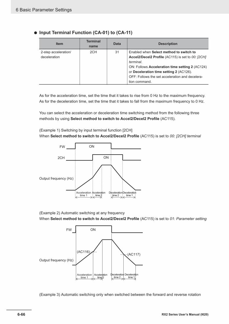
l Input Terminal Function (CA-01) to (CA-11)
Item Terminalname Data Description
2-step acceleration/deceleration
2CH 31 Enabled when Select method to switch toAccel2/Decel2 Profile (AC115) is set to 00: [2CH]terminal.ON: Follows Acceleration time setting 2 (AC124)or Deceleration time setting 2 (AC126).OFF: Follows the set acceleration and decelera-tion command.
As for the acceleration time, set the time that it takes to rise from 0 Hz to the maximum frequency.As for the deceleration time, set the time that it takes to fall from the maximum frequency to 0 Hz.
You can select the acceleration or deceleration time switching method from the following threemethods by using Select method to switch to Accel2/Decel2 Profile (AC115).
(Example 1) Switching by input terminal function [2CH]When Select method to switch to Accel2/Decel2 Profile (AC115) is set to 00: [2CH] terminal
2CH
FW ON
ON
Output frequency (Hz)
Accelerationtime 1
Accelerationtime 2
Decelerationtime 2
Decelerationtime 1
(Example 2) Automatic switching at any frequencyWhen Select method to switch to Accel2/Decel2 Profile (AC115) is set to 01: Parameter setting
FW
(AC117)(AC116)
ON
Accelerationtime 1
Output frequency (Hz)
Accelerationtime 2
Decelerationtime 2
Decelerationtime 1
(Example 3) Automatic switching only when switched between the forward and reverse rotation
6 Basic Parameter Settings
6-66 RX2 Series User’s Manual (I620)
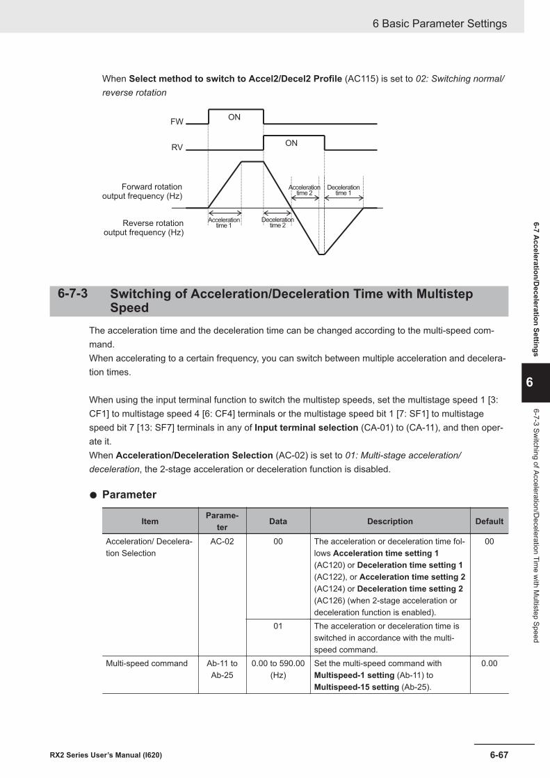
When Select method to switch to Accel2/Decel2 Profile (AC115) is set to 02: Switching normal/reverse rotation
FW
RV
ON
ON
Accelerationtime 1
Forward rotationoutput frequency (Hz)
Accelerationtime 2
Decelerationtime 2
Decelerationtime 1
Reverse rotationoutput frequency (Hz)
6-7-3 Switching of Acceleration/Deceleration Time with MultistepSpeed
The acceleration time and the deceleration time can be changed according to the multi-speed com-mand.When accelerating to a certain frequency, you can switch between multiple acceleration and decelera-tion times.
When using the input terminal function to switch the multistep speeds, set the multistage speed 1 [3:CF1] to multistage speed 4 [6: CF4] terminals or the multistage speed bit 1 [7: SF1] to multistagespeed bit 7 [13: SF7] terminals in any of Input terminal selection (CA-01) to (CA-11), and then oper-ate it.When Acceleration/Deceleration Selection (AC-02) is set to 01: Multi-stage acceleration/deceleration, the 2-stage acceleration or deceleration function is disabled.
l Parameter
Item Parame-ter Data Description Default
Acceleration/ Decelera-tion Selection
AC-02 00 The acceleration or deceleration time fol-lows Acceleration time setting 1(AC120) or Deceleration time setting 1(AC122), or Acceleration time setting 2(AC124) or Deceleration time setting 2(AC126) (when 2-stage acceleration ordeceleration function is enabled).
00
01 The acceleration or deceleration time isswitched in accordance with the multi-speed command.
Multi-speed command Ab-11 toAb-25
0.00 to 590.00(Hz)
Set the multi-speed command withMultispeed-1 setting (Ab-11) toMultispeed-15 setting (Ab-25).
0.00
6 Basic Parameter Settings
6-67RX2 Series User’s Manual (I620)
6-7 Acceleration/D
eceleration Settings
6
6-7-3 Switching of Acceleration/D
eceleration Time w
ith Multistep Speed
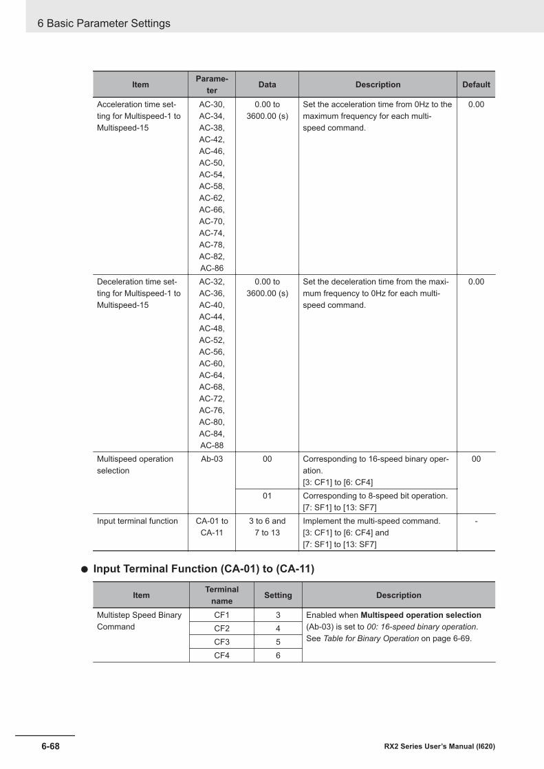
Item Parame-ter Data Description Default
Acceleration time set-ting for Multispeed-1 toMultispeed-15
AC-30,AC-34,AC-38,AC-42,AC-46,AC-50,AC-54,AC-58,AC-62,AC-66,AC-70,AC-74,AC-78,AC-82,AC-86
0.00 to3600.00 (s)
Set the acceleration time from 0Hz to themaximum frequency for each multi-speed command.
0.00
Deceleration time set-ting for Multispeed-1 toMultispeed-15
AC-32,AC-36,AC-40,AC-44,AC-48,AC-52,AC-56,AC-60,AC-64,AC-68,AC-72,AC-76,AC-80,AC-84,AC-88
0.00 to3600.00 (s)
Set the deceleration time from the maxi-mum frequency to 0Hz for each multi-speed command.
0.00
Multispeed operationselection
Ab-03 00 Corresponding to 16-speed binary oper-ation.[3: CF1] to [6: CF4]
00
01 Corresponding to 8-speed bit operation.[7: SF1] to [13: SF7]
Input terminal function CA-01 toCA-11
3 to 6 and7 to 13
Implement the multi-speed command.[3: CF1] to [6: CF4] and[7: SF1] to [13: SF7]
-
l Input Terminal Function (CA-01) to (CA-11)
Item Terminalname Setting Description
Multistep Speed BinaryCommand
CF1 3 Enabled when Multispeed operation selection(Ab-03) is set to 00: 16-speed binary operation.See Table for Binary Operation on page 6-69.
CF2 4CF3 5CF4 6
6 Basic Parameter Settings
6-68 RX2 Series User’s Manual (I620)
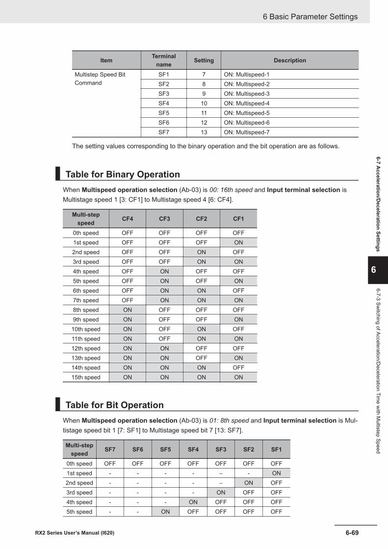
Item Terminalname Setting Description
Multistep Speed BitCommand
SF1 7 ON: Multispeed-1SF2 8 ON: Multispeed-2SF3 9 ON: Multispeed-3SF4 10 ON: Multispeed-4SF5 11 ON: Multispeed-5SF6 12 ON: Multispeed-6SF7 13 ON: Multispeed-7
The setting values corresponding to the binary operation and the bit operation are as follows.
Table for Binary OperationWhen Multispeed operation selection (Ab-03) is 00: 16th speed and Input terminal selection isMultistage speed 1 [3: CF1] to Multistage speed 4 [6: CF4].
Multi-stepspeed CF4 CF3 CF2 CF1
0th speed OFF OFF OFF OFF1st speed OFF OFF OFF ON2nd speed OFF OFF ON OFF3rd speed OFF OFF ON ON4th speed OFF ON OFF OFF5th speed OFF ON OFF ON6th speed OFF ON ON OFF7th speed OFF ON ON ON8th speed ON OFF OFF OFF9th speed ON OFF OFF ON10th speed ON OFF ON OFF11th speed ON OFF ON ON12th speed ON ON OFF OFF13th speed ON ON OFF ON14th speed ON ON ON OFF15th speed ON ON ON ON
Table for Bit OperationWhen Multispeed operation selection (Ab-03) is 01: 8th speed and Input terminal selection is Mul-tistage speed bit 1 [7: SF1] to Multistage speed bit 7 [13: SF7].
Multi-stepspeed SF7 SF6 SF5 SF4 SF3 SF2 SF1
0th speed OFF OFF OFF OFF OFF OFF OFF1st speed - - - - – - ON2nd speed - - - - – ON OFF3rd speed - - - - ON OFF OFF4th speed - - - ON OFF OFF OFF5th speed - - ON OFF OFF OFF OFF
6 Basic Parameter Settings
6-69RX2 Series User’s Manual (I620)
6-7 Acceleration/D
eceleration Settings
6
6-7-3 Switching of Acceleration/D
eceleration Time w
ith Multistep Speed
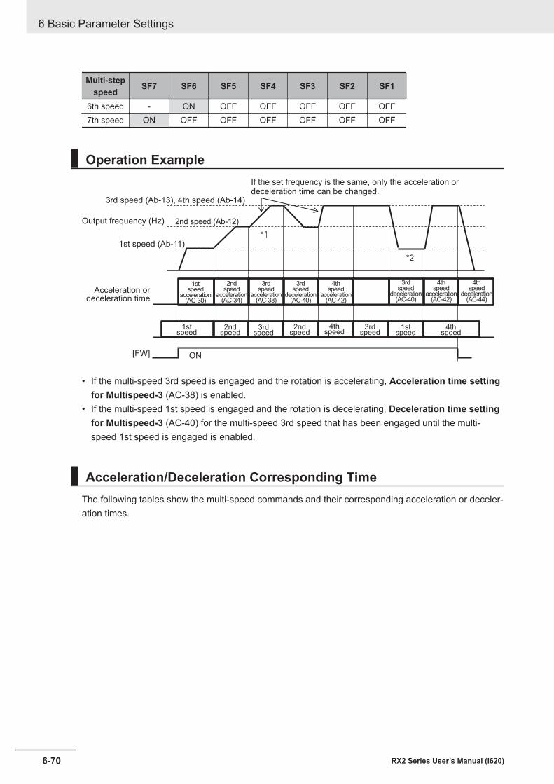
Multi-stepspeed SF7 SF6 SF5 SF4 SF3 SF2 SF1
6th speed - ON OFF OFF OFF OFF OFF7th speed ON OFF OFF OFF OFF OFF OFF
Operation Example
[FW] ON
3rd speed (Ab-13), 4th speed (Ab-14)
Output frequency (Hz) 2nd speed (Ab-12)
1st speed (Ab-11)
Acceleration ordeceleration time
1stspeed
2ndspeed
3rdspeed
2ndspeed
4thspeed
1stspeed
4thspeed
3rdspeed
*1
*2
If the set frequency is the same, only the acceleration ordeceleration time can be changed.
1stspeed
acceleration(AC-30)
2ndspeed
acceleration(AC-34)
3rdspeed
acceleration(AC-38)
3rdspeed
deceleration(AC-40)
4thspeed
acceleration(AC-42)
3rdspeed
deceleration(AC-40)
4thspeed
acceleration(AC-42)
4thspeed
deceleration(AC-44)
• If the multi-speed 3rd speed is engaged and the rotation is accelerating, Acceleration time settingfor Multispeed-3 (AC-38) is enabled.
• If the multi-speed 1st speed is engaged and the rotation is decelerating, Deceleration time settingfor Multispeed-3 (AC-40) for the multi-speed 3rd speed that has been engaged until the multi-speed 1st speed is engaged is enabled.
Acceleration/Deceleration Corresponding TimeThe following tables show the multi-speed commands and their corresponding acceleration or deceler-ation times.
6 Basic Parameter Settings
6-70 RX2 Series User’s Manual (I620)
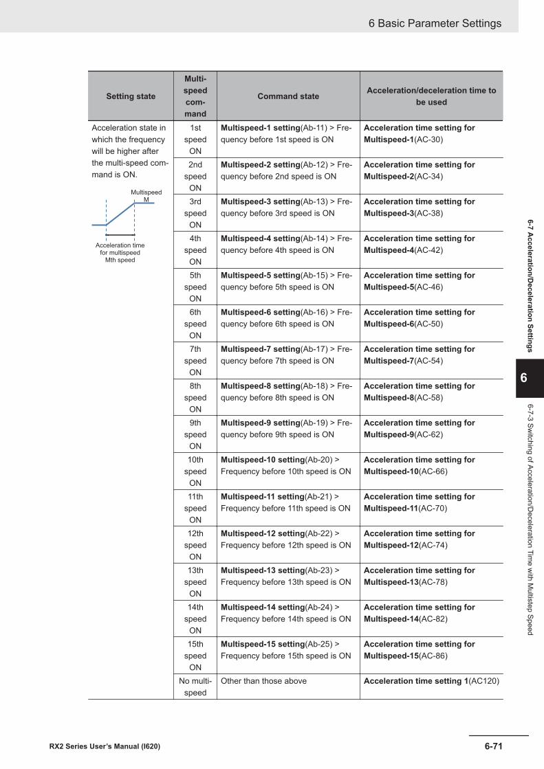
Setting state
Multi-speedcom-mand
Command state Acceleration/deceleration time tobe used
Acceleration state inwhich the frequencywill be higher afterthe multi-speed com-mand is ON.
Acceleration timefor multispeed
Mth speed
MultispeedM
1stspeed
ON
Multispeed-1 setting(Ab-11) > Fre-quency before 1st speed is ON
Acceleration time setting forMultispeed-1(AC-30)
2ndspeed
ON
Multispeed-2 setting(Ab-12) > Fre-quency before 2nd speed is ON
Acceleration time setting forMultispeed-2(AC-34)
3rdspeed
ON
Multispeed-3 setting(Ab-13) > Fre-quency before 3rd speed is ON
Acceleration time setting forMultispeed-3(AC-38)
4thspeed
ON
Multispeed-4 setting(Ab-14) > Fre-quency before 4th speed is ON
Acceleration time setting forMultispeed-4(AC-42)
5thspeed
ON
Multispeed-5 setting(Ab-15) > Fre-quency before 5th speed is ON
Acceleration time setting forMultispeed-5(AC-46)
6thspeed
ON
Multispeed-6 setting(Ab-16) > Fre-quency before 6th speed is ON
Acceleration time setting forMultispeed-6(AC-50)
7thspeed
ON
Multispeed-7 setting(Ab-17) > Fre-quency before 7th speed is ON
Acceleration time setting forMultispeed-7(AC-54)
8thspeed
ON
Multispeed-8 setting(Ab-18) > Fre-quency before 8th speed is ON
Acceleration time setting forMultispeed-8(AC-58)
9thspeed
ON
Multispeed-9 setting(Ab-19) > Fre-quency before 9th speed is ON
Acceleration time setting forMultispeed-9(AC-62)
10thspeed
ON
Multispeed-10 setting(Ab-20) >Frequency before 10th speed is ON
Acceleration time setting forMultispeed-10(AC-66)
11thspeed
ON
Multispeed-11 setting(Ab-21) >Frequency before 11th speed is ON
Acceleration time setting forMultispeed-11(AC-70)
12thspeed
ON
Multispeed-12 setting(Ab-22) >Frequency before 12th speed is ON
Acceleration time setting forMultispeed-12(AC-74)
13thspeed
ON
Multispeed-13 setting(Ab-23) >Frequency before 13th speed is ON
Acceleration time setting forMultispeed-13(AC-78)
14thspeed
ON
Multispeed-14 setting(Ab-24) >Frequency before 14th speed is ON
Acceleration time setting forMultispeed-14(AC-82)
15thspeed
ON
Multispeed-15 setting(Ab-25) >Frequency before 15th speed is ON
Acceleration time setting forMultispeed-15(AC-86)
No multi-speed
Other than those above Acceleration time setting 1(AC120)
6 Basic Parameter Settings
6-71RX2 Series User’s Manual (I620)
6-7 Acceleration/D
eceleration Settings
6
6-7-3 Switching of Acceleration/D
eceleration Time w
ith Multistep Speed
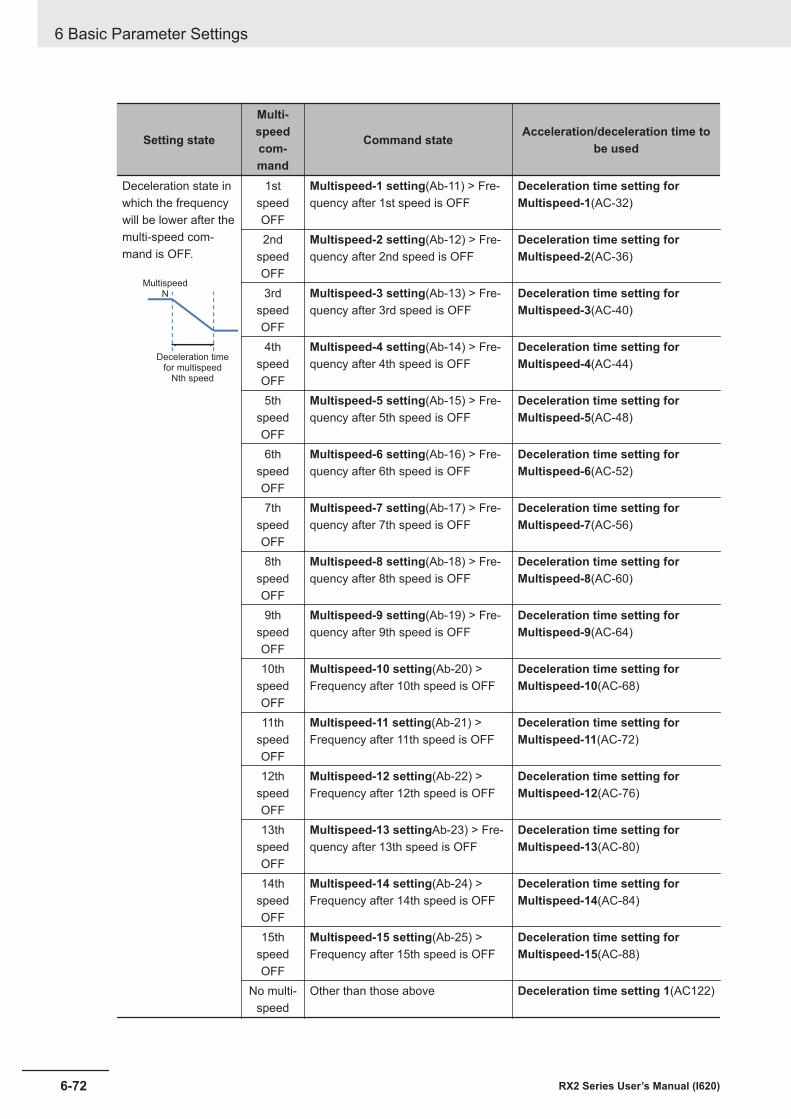
Setting state
Multi-speedcom-mand
Command state Acceleration/deceleration time tobe used
Deceleration state inwhich the frequencywill be lower after themulti-speed com-mand is OFF.
Deceleration timefor multispeed
Nth speed
MultispeedN
1stspeedOFF
Multispeed-1 setting(Ab-11) > Fre-quency after 1st speed is OFF
Deceleration time setting forMultispeed-1(AC-32)
2ndspeedOFF
Multispeed-2 setting(Ab-12) > Fre-quency after 2nd speed is OFF
Deceleration time setting forMultispeed-2(AC-36)
3rdspeedOFF
Multispeed-3 setting(Ab-13) > Fre-quency after 3rd speed is OFF
Deceleration time setting forMultispeed-3(AC-40)
4thspeedOFF
Multispeed-4 setting(Ab-14) > Fre-quency after 4th speed is OFF
Deceleration time setting forMultispeed-4(AC-44)
5thspeedOFF
Multispeed-5 setting(Ab-15) > Fre-quency after 5th speed is OFF
Deceleration time setting forMultispeed-5(AC-48)
6thspeedOFF
Multispeed-6 setting(Ab-16) > Fre-quency after 6th speed is OFF
Deceleration time setting forMultispeed-6(AC-52)
7thspeedOFF
Multispeed-7 setting(Ab-17) > Fre-quency after 7th speed is OFF
Deceleration time setting forMultispeed-7(AC-56)
8thspeedOFF
Multispeed-8 setting(Ab-18) > Fre-quency after 8th speed is OFF
Deceleration time setting forMultispeed-8(AC-60)
9thspeedOFF
Multispeed-9 setting(Ab-19) > Fre-quency after 9th speed is OFF
Deceleration time setting forMultispeed-9(AC-64)
10thspeedOFF
Multispeed-10 setting(Ab-20) >Frequency after 10th speed is OFF
Deceleration time setting forMultispeed-10(AC-68)
11thspeedOFF
Multispeed-11 setting(Ab-21) >Frequency after 11th speed is OFF
Deceleration time setting forMultispeed-11(AC-72)
12thspeedOFF
Multispeed-12 setting(Ab-22) >Frequency after 12th speed is OFF
Deceleration time setting forMultispeed-12(AC-76)
13thspeedOFF
Multispeed-13 settingAb-23) > Fre-quency after 13th speed is OFF
Deceleration time setting forMultispeed-13(AC-80)
14thspeedOFF
Multispeed-14 setting(Ab-24) >Frequency after 14th speed is OFF
Deceleration time setting forMultispeed-14(AC-84)
15thspeedOFF
Multispeed-15 setting(Ab-25) >Frequency after 15th speed is OFF
Deceleration time setting forMultispeed-15(AC-88)
No multi-speed
Other than those above Deceleration time setting 1(AC122)
6 Basic Parameter Settings
6-72 RX2 Series User’s Manual (I620)
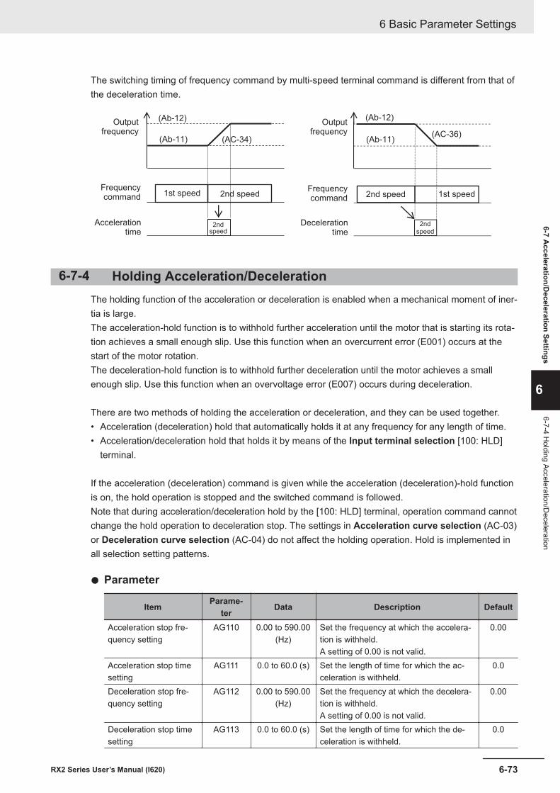
The switching timing of frequency command by multi-speed terminal command is different from that ofthe deceleration time.
(Ab-12)
(Ab-11) (AC-34)
Outputfrequency
Frequencycommand
Accelerationtime
1st speed 2nd speed
2ndspeed
(Ab-11)
(Ab-12)
(AC-36)
Outputfrequency
Frequencycommand
Decelerationtime
2nd speed 1st speed
2ndspeed
6-7-4 Holding Acceleration/DecelerationThe holding function of the acceleration or deceleration is enabled when a mechanical moment of iner-tia is large.The acceleration-hold function is to withhold further acceleration until the motor that is starting its rota-tion achieves a small enough slip. Use this function when an overcurrent error (E001) occurs at thestart of the motor rotation.The deceleration-hold function is to withhold further deceleration until the motor achieves a smallenough slip. Use this function when an overvoltage error (E007) occurs during deceleration.
There are two methods of holding the acceleration or deceleration, and they can be used together.• Acceleration (deceleration) hold that automatically holds it at any frequency for any length of time.• Acceleration/deceleration hold that holds it by means of the Input terminal selection [100: HLD]
terminal.
If the acceleration (deceleration) command is given while the acceleration (deceleration)-hold functionis on, the hold operation is stopped and the switched command is followed.Note that during acceleration/deceleration hold by the [100: HLD] terminal, operation command cannotchange the hold operation to deceleration stop. The settings in Acceleration curve selection (AC-03)or Deceleration curve selection (AC-04) do not affect the holding operation. Hold is implemented inall selection setting patterns.
l Parameter
Item Parame-ter Data Description Default
Acceleration stop fre-quency setting
AG110 0.00 to 590.00(Hz)
Set the frequency at which the accelera-tion is withheld.A setting of 0.00 is not valid.
0.00
Acceleration stop timesetting
AG111 0.0 to 60.0 (s) Set the length of time for which the ac-celeration is withheld.
0.0
Deceleration stop fre-quency setting
AG112 0.00 to 590.00(Hz)
Set the frequency at which the decelera-tion is withheld.A setting of 0.00 is not valid.
0.00
Deceleration stop timesetting
AG113 0.0 to 60.0 (s) Set the length of time for which the de-celeration is withheld.
0.0
6 Basic Parameter Settings
6-73RX2 Series User’s Manual (I620)
6-7 Acceleration/D
eceleration Settings
6
6-7-4 Holding Acceleration/D
eceleration
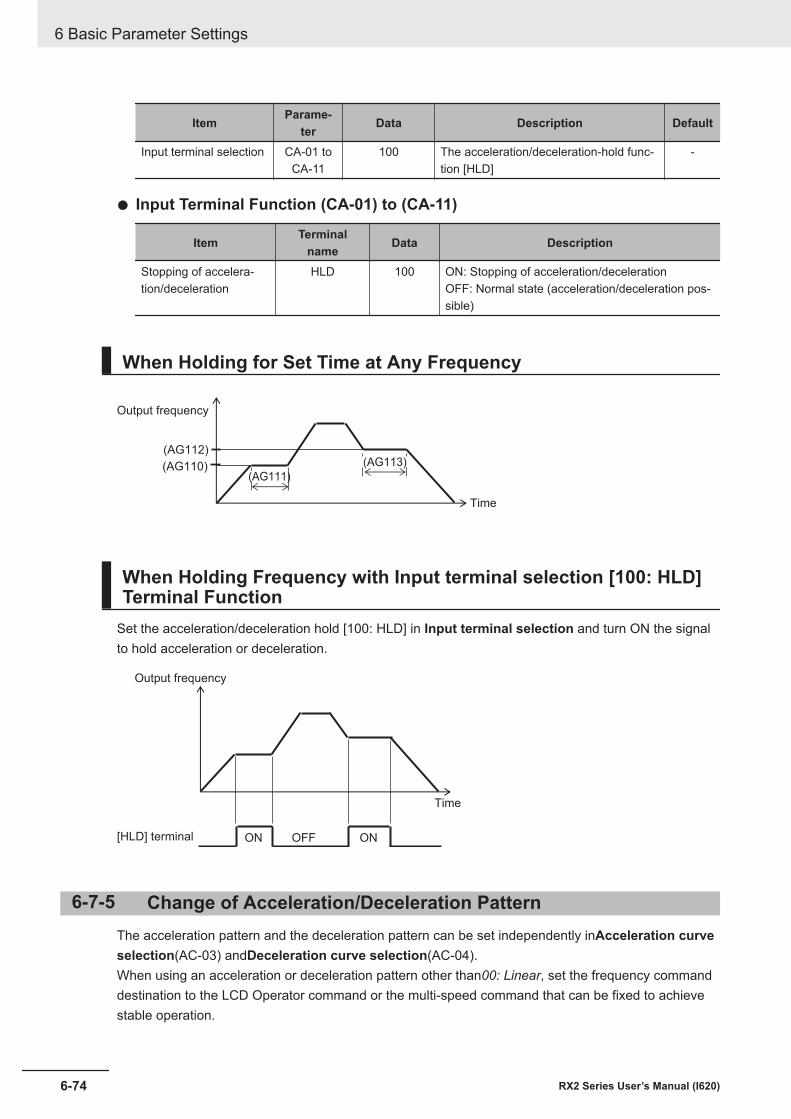
Item Parame-ter Data Description Default
Input terminal selection CA-01 toCA-11
100 The acceleration/deceleration-hold func-tion [HLD]
-
l Input Terminal Function (CA-01) to (CA-11)
Item Terminalname Data Description
Stopping of accelera-tion/deceleration
HLD 100 ON: Stopping of acceleration/decelerationOFF: Normal state (acceleration/deceleration pos-sible)
When Holding for Set Time at Any Frequency
(AG111)(AG110)
(AG112)(AG113)
Output frequency
Time
When Holding Frequency with Input terminal selection [100: HLD]Terminal Function
Set the acceleration/deceleration hold [100: HLD] in Input terminal selection and turn ON the signalto hold acceleration or deceleration.
[HLD] terminal OFFON ON
Output frequency
Time
6-7-5 Change of Acceleration/Deceleration PatternThe acceleration pattern and the deceleration pattern can be set independently inAcceleration curveselection(AC-03) andDeceleration curve selection(AC-04).When using an acceleration or deceleration pattern other than00: Linear, set the frequency commanddestination to the LCD Operator command or the multi-speed command that can be fixed to achievestable operation.
6 Basic Parameter Settings
6-74 RX2 Series User’s Manual (I620)
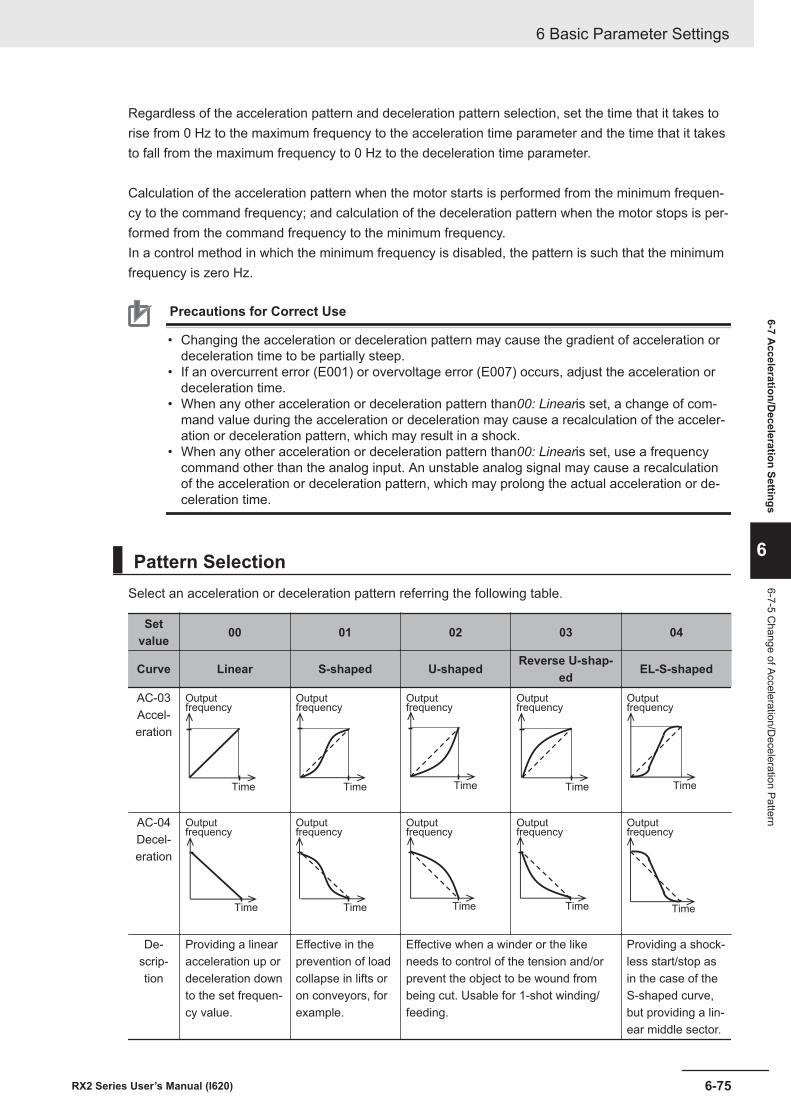
Regardless of the acceleration pattern and deceleration pattern selection, set the time that it takes torise from 0 Hz to the maximum frequency to the acceleration time parameter and the time that it takesto fall from the maximum frequency to 0 Hz to the deceleration time parameter.
Calculation of the acceleration pattern when the motor starts is performed from the minimum frequen-cy to the command frequency; and calculation of the deceleration pattern when the motor stops is per-formed from the command frequency to the minimum frequency.In a control method in which the minimum frequency is disabled, the pattern is such that the minimumfrequency is zero Hz.
Precautions for Correct Use
• Changing the acceleration or deceleration pattern may cause the gradient of acceleration ordeceleration time to be partially steep.
• If an overcurrent error (E001) or overvoltage error (E007) occurs, adjust the acceleration ordeceleration time.
• When any other acceleration or deceleration pattern than00: Linearis set, a change of com-mand value during the acceleration or deceleration may cause a recalculation of the acceler-ation or deceleration pattern, which may result in a shock.
• When any other acceleration or deceleration pattern than00: Linearis set, use a frequencycommand other than the analog input. An unstable analog signal may cause a recalculationof the acceleration or deceleration pattern, which may prolong the actual acceleration or de-celeration time.
Pattern SelectionSelect an acceleration or deceleration pattern referring the following table.
Setvalue 00 01 02 03 04
Curve Linear S-shaped U-shaped Reverse U-shap-ed EL-S-shaped
AC-03Accel-eration
Outputfrequency
Time
Outputfrequency
Time
Outputfrequency
Time
Outputfrequency
Time
Outputfrequency
Time
AC-04Decel-eration
Outputfrequency
Time
Outputfrequency
Time
Outputfrequency
Time
Outputfrequency
Time
Outputfrequency
Time
De-scrip-tion
Providing a linearacceleration up ordeceleration downto the set frequen-cy value.
Effective in theprevention of loadcollapse in lifts oron conveyors, forexample.
Effective when a winder or the likeneeds to control of the tension and/orprevent the object to be wound frombeing cut. Usable for 1-shot winding/feeding.
Providing a shock-less start/stop asin the case of theS-shaped curve,but providing a lin-ear middle sector.
6 Basic Parameter Settings
6-75RX2 Series User’s Manual (I620)
6-7 Acceleration/D
eceleration Settings
6
6-7-5 Change of Acceleration/D
eceleration Pattern
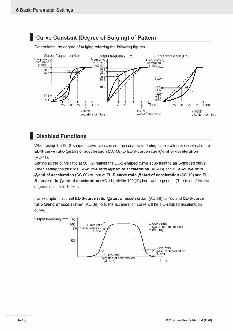
Curve Constant (Degree of Bulging) of PatternDetermining the degree of bulging referring the following figures.
(100%)
96.982.4
17.6
3.1 10
02
10 021010 0202
(100%)
99.693.8
35.0
25 50 75
0202
87.568.464.6 65.0
35.4
0.39
10
02
10
0235.431.6
12.512.56.25
25 50 75
(100%)
25 50 75
Output frequency (Hz)
Time
Output frequency (Hz)
Time
Frequencycommand
Output frequency (Hz)
Time
(100%)Acceleration time
(100%)Acceleration time
(100%)Acceleration time
Frequencycommand
Frequencycommand
Disabled FunctionsWhen using the EL-S-shaped curve, you can set the curve ratio during acceleration or deceleration toEL-S-curve ratio @start of acceleration (AC-08) to EL-S-curve ratio @end of deceleration(AC-11).Setting all the curve ratio at 50 (%) makes the EL-S-shaped curve equivalent to an S-shaped curve.When setting the pair of EL-S-curve ratio @start of acceleration (AC-08) and EL-S-curve ratio@end of acceleration (AC-09) or that of EL-S-curve ratio @start of deceleration (AC-10) and EL-S-curve ratio @end of deceleration (AC-11), divide 100 (%) into two segments. (The total of the twosegments is up to 100%.)
For example, if you set EL-S-curve ratio @start of acceleration (AC-08) to 100 and EL-S-curveratio @end of acceleration (AC-09) to 0, the acceleration curve will be a U-shaped accelerationcurve.
100
50
Curve ratio@end of acceleration
(AC-09)
Time
Output frequency rate (%)
Curve ratio@start of deceleration(AC-10)
Curve ratio@start of acceleration(AC-08)
Curve ratio@end of deceleration(AC-11)
6 Basic Parameter Settings
6-76 RX2 Series User’s Manual (I620)
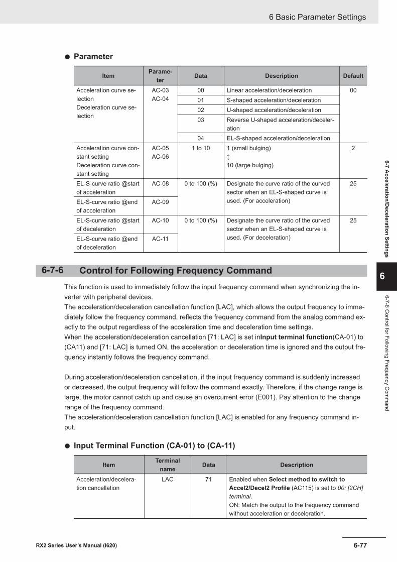
l Parameter
Item Parame-ter Data Description Default
Acceleration curve se-lectionDeceleration curve se-lection
AC-03AC-04
00 Linear acceleration/deceleration 0001 S-shaped acceleration/deceleration02 U-shaped acceleration/deceleration03 Reverse U-shaped acceleration/deceler-
ation04 EL-S-shaped acceleration/deceleration
Acceleration curve con-stant settingDeceleration curve con-stant setting
AC-05AC-06
1 to 10 1 (small bulging)↕10 (large bulging)
2
EL-S-curve ratio @startof acceleration
AC-08 0 to 100 (%) Designate the curve ratio of the curvedsector when an EL-S-shaped curve isused. (For acceleration)
25
EL-S-curve ratio @endof acceleration
AC-09
EL-S-curve ratio @startof deceleration
AC-10 0 to 100 (%) Designate the curve ratio of the curvedsector when an EL-S-shaped curve isused. (For deceleration)
25
EL-S-curve ratio @endof deceleration
AC-11
6-7-6 Control for Following Frequency CommandThis function is used to immediately follow the input frequency command when synchronizing the in-verter with peripheral devices.The acceleration/deceleration cancellation function [LAC], which allows the output frequency to imme-diately follow the frequency command, reflects the frequency command from the analog command ex-actly to the output regardless of the acceleration time and deceleration time settings.When the acceleration/deceleration cancellation [71: LAC] is set inInput terminal function(CA-01) to(CA11) and [71: LAC] is turned ON, the acceleration or deceleration time is ignored and the output fre-quency instantly follows the frequency command.
During acceleration/deceleration cancellation, if the input frequency command is suddenly increasedor decreased, the output frequency will follow the command exactly. Therefore, if the change range islarge, the motor cannot catch up and cause an overcurrent error (E001). Pay attention to the changerange of the frequency command.The acceleration/deceleration cancellation function [LAC] is enabled for any frequency command in-put.
l Input Terminal Function (CA-01) to (CA-11)
Item Terminalname Data Description
Acceleration/decelera-tion cancellation
LAC 71 Enabled when Select method to switch toAccel2/Decel2 Profile (AC115) is set to 00: [2CH]terminal.ON: Match the output to the frequency commandwithout acceleration or deceleration.
6 Basic Parameter Settings
6-77RX2 Series User’s Manual (I620)
6-7 Acceleration/D
eceleration Settings
6
6-7-6 Control for Follow
ing Frequency Com
mand
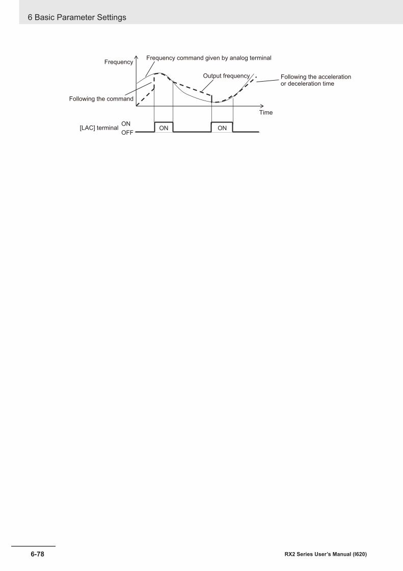
ON ONON
OFF[LAC] terminal
Frequency
Following the accelerationor deceleration time
Following the command
Output frequency
Frequency command given by analog terminal
Time
6 Basic Parameter Settings
6-78 RX2 Series User’s Manual (I620)
7Advanced Settings
This section explains the advanced settings of the motor control.
7-1 Selection of Motor Control Methods ............................................................ 7-37-1-1 Procedure for Control Method Selection ......................................................... 7-37-1-2 Vector Control.................................................................................................. 7-57-1-3 V/f Control ....................................................................................................... 7-5
7-2 Details of Motor Control Methods................................................................. 7-77-2-1 V/f Control Constant Torque Characteristics ................................................... 7-77-2-2 V/f Control Reduced Torque Characteristics ................................................... 7-87-2-3 V/f Control Free V/f Characteristics................................................................. 7-97-2-4 Automatic Torque Boost ................................................................................ 7-127-2-5 V/f Control with Sensor.................................................................................. 7-147-2-6 Sensorless Vector Control............................................................................. 7-157-2-7 Zero-speed Range (Zero-Hz Range) Sensorless Vector Control.................. 7-177-2-8 Vector Control with Sensor............................................................................ 7-197-2-9 Synchronous Motor (Permanent Magnet Motor) Control .............................. 7-21
7-3 Torque Control.............................................................................................. 7-337-3-1 Speed Control and Torque Control................................................................ 7-337-3-2 Control Gain Switching.................................................................................. 7-337-3-3 P/PI Switching function.................................................................................. 7-367-3-4 Torque Limit Function .................................................................................... 7-387-3-5 High-torque Multi-operation Control .............................................................. 7-437-3-6 Torque Bias Function..................................................................................... 7-447-3-7 Torque Control/Speed Control Switching Function (ATR) ............................. 7-467-3-8 Torque Command.......................................................................................... 7-47
7-4 DC Braking.................................................................................................... 7-507-4-1 External DC Braking...................................................................................... 7-517-4-2 Internal DC Braking ....................................................................................... 7-52
7-5 Start Conditions ........................................................................................... 7-577-5-1 Reduced Voltage Start .................................................................................. 7-577-5-2 Forcing Function............................................................................................ 7-587-5-3 Restart........................................................................................................... 7-597-5-4 Start After Power-on...................................................................................... 7-637-5-5 Restart After Reset Release.......................................................................... 7-647-5-6 Restart After Releasing Free-run .................................................................. 7-65
7-6 Stop Conditions............................................................................................ 7-687-6-1 Stop by Operation Command........................................................................ 7-687-6-2 Stop by Free Run Stop (FRS) ....................................................................... 7-69
7-7 Reduction of Motor Noise, Noise and Inverter Heat Generation ............. 7-70
7-1RX2 Series User’s Manual (I620)
7
7-7-1 Carrier Frequency ......................................................................................... 7-707-7-2 Automatic Carrier Reduction ......................................................................... 7-717-7-3 Motor Electromagnetic Noise Reduction ....................................................... 7-73
7-8 Manual Torque Boost................................................................................... 7-747-9 Energy-saving Operation Function ............................................................ 7-767-10 Encoder Feedback ....................................................................................... 7-77
7-10-1 Encoder Feedback Input Wiring .................................................................... 7-787-10-2 Encoder Feedback Input Settings ................................................................. 7-787-10-3 Encoder Feedback Function Selection.......................................................... 7-797-10-4 Check of Pulse Train Input Setting ................................................................ 7-80
7-11 Motor Hunting Measures ............................................................................. 7-837-11-1 Stabilization Constant.................................................................................... 7-837-11-2 Output Voltage Gain ...................................................................................... 7-83
ParameterThe parameter number structure is indicated below.This section explains parameters without using the expression of first setting. Parameters that haveboth first setting and second setting are described using the code for the first setting. The setting val-ues and operations of the second setting are the same as those of the first setting, unless otherwisespecified.
Ab - 01
A
B
C
A Parameter groupB SET function type - Common setting: always enabled in both the first and second settings.
1 First setting: enabled when the [SET] terminal function is OFF.2 Second setting: enabled when the [SET] terminal function is ON.
C In-group number
To switch to the second setting, use the [SET] terminal function to be assigned to the input or outputterminal. Refer to 8-4-1 Second Control (SET) on page 8-78 for details of the second setting.
7 Advanced Settings
7-2 RX2 Series User’s Manual (I620)
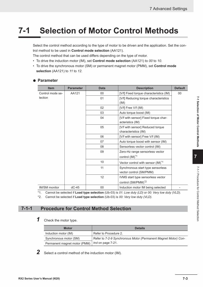
7-1 Selection of Motor Control MethodsSelect the control method according to the type of motor to be driven and the application. Set the con-trol method to be used in Control mode selection (AA121).The control method that can be used differs depending on the type of motor.• To drive the induction motor (IM), set Control mode selection (AA121) to 00 to 10.• To drive the synchronous motor (SM) or permanent magnet motor (PMM), set Control mode
selection (AA121) to 11 to 12.
l Parameter
Item Parameter Data Description DefaultControl mode se-lection
AA121 00 [V/f] Fixed torque characteristics (IM) 0001 [V/f] Reducing torque characteristics
(IM)02 [V/f] Free V/f (IM)03 Auto torque boost (IM)04 [V/f with sensor] Fixed torque char-
acteristics (IM)05 [V/f with sensor] Reduced torque
characteristics (IM)06 [V/f with sensor] Free V/f (IM)07 Auto torque boost with sensor (IM)08 Sensorless vector control (IM)09 Zero-Hz range sensorless vector
control (IM)*1
10 Vector control with sensor (IM)*1
11 Synchronous start type sensorlessvector control (SM/PMM)
12 IVMS start type sensorless vectorcontrol (SM/PMM)*2
IM/SM monitor dC-45 00 Induction motor IM being selected -*1. Cannot be selected if Load type selection (Ub-03) is 01: Low duty (LD) or 00: Very low duty (VLD).*2. Cannot be selected if Load type selection (Ub-03) is 00: Very low duty (VLD).
7-1-1 Procedure for Control Method Selection
1 Check the motor type.
Motor DetailsInduction motor (IM) Refer to Procedure 2.Synchronous motor (SM) Refer to 7-2-9 Synchronous Motor (Permanent Magnet Motor) Con-
trol on page 7-21.Permanent magnet motor (PMM)
2 Select a control method of the induction motor (IM).
7 Advanced Settings
7-3RX2 Series User’s Manual (I620)
7-1 Selection of Motor C
ontrol Methods
7
7-1-1 Procedure for Control M
ethod Selection
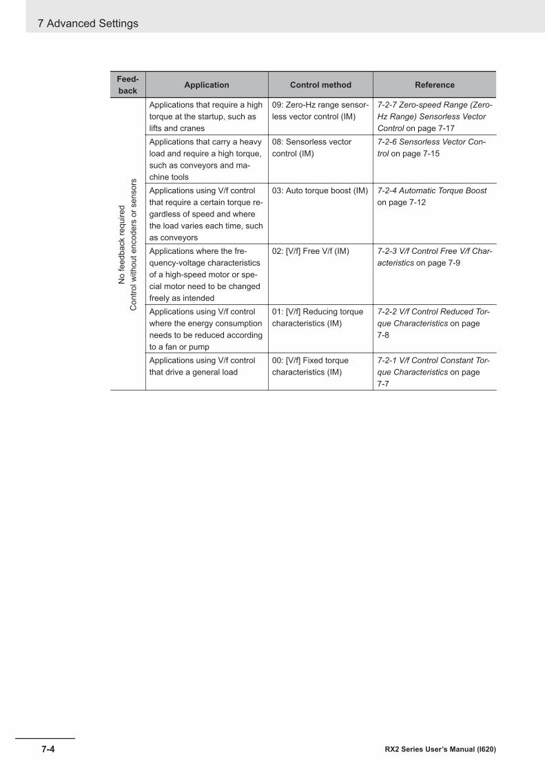
Feed-back Application Control method Reference
No
feed
back
requ
ired
Con
trol w
ithou
t enc
oder
s or
sen
sors
Applications that require a hightorque at the startup, such aslifts and cranes
09: Zero-Hz range sensor-less vector control (IM)
7-2-7 Zero-speed Range (Zero-Hz Range) Sensorless VectorControl on page 7-17
Applications that carry a heavyload and require a high torque,such as conveyors and ma-chine tools
08: Sensorless vectorcontrol (IM)
7-2-6 Sensorless Vector Con-trol on page 7-15
Applications using V/f controlthat require a certain torque re-gardless of speed and wherethe load varies each time, suchas conveyors
03: Auto torque boost (IM) 7-2-4 Automatic Torque Booston page 7-12
Applications where the fre-quency-voltage characteristicsof a high-speed motor or spe-cial motor need to be changedfreely as intended
02: [V/f] Free V/f (IM) 7-2-3 V/f Control Free V/f Char-acteristics on page 7-9
Applications using V/f controlwhere the energy consumptionneeds to be reduced accordingto a fan or pump
01: [V/f] Reducing torquecharacteristics (IM)
7-2-2 V/f Control Reduced Tor-que Characteristics on page7-8
Applications using V/f controlthat drive a general load
00: [V/f] Fixed torquecharacteristics (IM)
7-2-1 V/f Control Constant Tor-que Characteristics on page7-7
7 Advanced Settings
7-4 RX2 Series User’s Manual (I620)
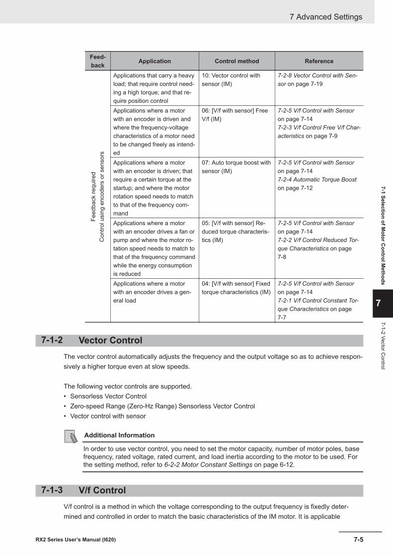
Feed-back Application Control method Reference
Feed
back
requ
ired
Con
trol u
sing
enc
oder
s or
sen
sors
Applications that carry a heavyload; that require control need-ing a high torque; and that re-quire position control
10: Vector control withsensor (IM)
7-2-8 Vector Control with Sen-sor on page 7-19
Applications where a motorwith an encoder is driven andwhere the frequency-voltagecharacteristics of a motor needto be changed freely as intend-ed
06: [V/f with sensor] FreeV/f (IM)
7-2-5 V/f Control with Sensoron page 7-147-2-3 V/f Control Free V/f Char-acteristics on page 7-9
Applications where a motorwith an encoder is driven; thatrequire a certain torque at thestartup; and where the motorrotation speed needs to matchto that of the frequency com-mand
07: Auto torque boost withsensor (IM)
7-2-5 V/f Control with Sensoron page 7-147-2-4 Automatic Torque Booston page 7-12
Applications where a motorwith an encoder drives a fan orpump and where the motor ro-tation speed needs to match tothat of the frequency commandwhile the energy consumptionis reduced
05: [V/f with sensor] Re-duced torque characteris-tics (IM)
7-2-5 V/f Control with Sensoron page 7-147-2-2 V/f Control Reduced Tor-que Characteristics on page7-8
Applications where a motorwith an encoder drives a gen-eral load
04: [V/f with sensor] Fixedtorque characteristics (IM)
7-2-5 V/f Control with Sensoron page 7-147-2-1 V/f Control Constant Tor-que Characteristics on page7-7
7-1-2 Vector ControlThe vector control automatically adjusts the frequency and the output voltage so as to achieve respon-sively a higher torque even at slow speeds.
The following vector controls are supported.• Sensorless Vector Control• Zero-speed Range (Zero-Hz Range) Sensorless Vector Control• Vector control with sensor
Additional Information
In order to use vector control, you need to set the motor capacity, number of motor poles, basefrequency, rated voltage, rated current, and load inertia according to the motor to be used. Forthe setting method, refer to 6-2-2 Motor Constant Settings on page 6-12.
7-1-3 V/f ControlV/f control is a method in which the voltage corresponding to the output frequency is fixedly deter-mined and controlled in order to match the basic characteristics of the IM motor. It is applicable
7 Advanced Settings
7-5RX2 Series User’s Manual (I620)
7-1 Selection of Motor C
ontrol Methods
7
7-1-2 Vector Control

toControl mode selection00,01, and02.Control mode selection03,04,05,06, and07are control meth-ods that combine the basic V/f control with other controls.
When using V/f control (Control mode selection 00, 01, and 02), if the tracking at the start of motorrotation is insufficient, first try manual torque boost. For information on manual torque boost, refer to 7-8 Manual Torque Boost on page 7-74.If you need feedback, see also7-10 Encoder Feedback on page 7-77.
7 Advanced Settings
7-6 RX2 Series User’s Manual (I620)
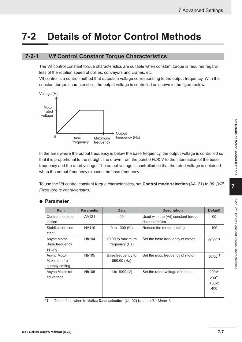
7-2 Details of Motor Control Methods
7-2-1 V/f Control Constant Torque CharacteristicsThe V/f control constant torque characteristics are suitable when constant torque is required regard-less of the rotation speed of dollies, conveyors and cranes, etc.V/f control is a control method that outputs a voltage corresponding to the output frequency. With theconstant torque characteristics, the output voltage is controlled as shown in the figure below.
0
Voltage (V)
Base frequency
Maximumfrequency
Outputfrequency (Hz)
Motorrated
voltage
In the area where the output frequency is below the base frequency, the output voltage is controlled sothat it is proportional to the straight line drawn from the point 0 Hz/0 V to the intersection of the basefrequency and the rated voltage. The output voltage is controlled so that the rated voltage is obtainedwhen the output frequency exceeds the base frequency.
To use the V/f control constant torque characteristics, set Control mode selection (AA121) to 00: [V/f]Fixed torque characteristics.
l Parameter
Item Parameter Data Description DefaultControl mode se-lection
AA121 00 Used with the [V/f] constant torquecharacteristics.
00
Stabilization con-stant
HA110 0 to 1000 (%) Reduce the motor hunting. 100
Async.MotorBase frequencysetting
Hb104 10.00 to maximumfrequency (Hz)
Set the base frequency of motor. 50.00*1
Async.MotorMaximum fre-quency setting
Hb105 Base frequency to590.00 (Hz)
Set the max. frequency of motor. 50.00*1
Async.Motor rat-ed voltage
Hb106 1 to 1000 (V) Set the rated voltage of motor. 200V:230*1
400V:400
*1
*1. The default when Initialize Data selection (Ub-02) is set to 01: Mode 1.
7 Advanced Settings
7-7RX2 Series User’s Manual (I620)
7-2 Details of M
otor Control M
ethods
7
7-2-1 V/f Control C
onstant Torque Characteristics
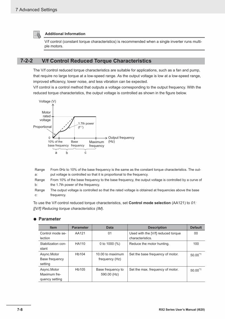
Additional Information
V/f control (constant torque characteristics) is recommended when a single inverter runs multi-ple motors.
7-2-2 V/f Control Reduced Torque CharacteristicsThe V/f control reduced torque characteristics are suitable for applications, such as a fan and pump,that require no large torque at a low-speed range. As the output voltage is low at a low-speed range,improved efficiency, lower noise, and less vibration can be expected.V/f control is a control method that outputs a voltage corresponding to the output frequency. With thereduced torque characteristics, the output voltage is controlled as shown in the figure below.
0
a b c
1.7th power
(f1.7)Proportional
10% of the
base frequency
Base
frequencyMaximumfrequency
Voltage (V)
Motorrated
voltage
Output frequency(Hz)
Rangea:
From 0Hz to 10% of the base frequency is the same as the constant torque characteristics. The out-put voltage is controlled so that it is proportional to the frequency.
Rangeb:
From 10% of the base frequency to the base frequency, the output voltage is controlled by a curve ofthe 1.7th power of the frequency.
Rangec:
The output voltage is controlled so that the rated voltage is obtained at frequencies above the basefrequency.
To use the V/f control reduced torque characteristics, set Control mode selection (AA121) to 01:[[V/f] Reducing torque characteristics (IM).
l Parameter
Item Parameter Data Description DefaultControl mode se-lection
AA121 01 Used with the [V/f] reduced torquecharacteristics.
00
Stabilization con-stant
HA110 0 to 1000 (%) Reduce the motor hunting. 100
Async.MotorBase frequencysetting
Hb104 10.00 to maximumfrequency (Hz)
Set the base frequency of motor. 50.00*1
Async.MotorMaximum fre-quency setting
Hb105 Base frequency to590.00 (Hz)
Set the max. frequency of motor. 50.00*1
7 Advanced Settings
7-8 RX2 Series User’s Manual (I620)
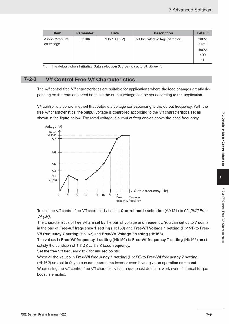
Item Parameter Data Description DefaultAsync.Motor rat-ed voltage
Hb106 1 to 1000 (V) Set the rated voltage of motor. 200V:230*1
400V:400
*1
*1. The default when Initialize Data selection (Ub-02) is set to 01: Mode 1.
7-2-3 V/f Control Free V/f CharacteristicsThe V/f control free V/f characteristics are suitable for applications where the load changes greatly de-pending on the rotation speed because the output voltage can be set according to the application.
V/f control is a control method that outputs a voltage corresponding to the output frequency. With thefree V/f characteristics, the output voltage is controlled according to the V/f characteristics set asshown in the figure below. The rated voltage is output at frequencies above the base frequency.
f1 f2 f3 f4 f5 f6 f70
V2,V3
V1
V5
V6
V7
V4
Voltage (V)
Output frequency (Hz)
Maximum
frequency
Base
frequency
Ratedvoltage
To use the V/f control free V/f characteristics, set Control mode selection (AA121) to 02: [[V/f] FreeV/f (IM).The characteristics of free V/f are set by the pair of voltage and frequency. You can set up to 7 pointsin the pair of Free-V/f frequency 1 setting (Hb150) and Free-V/f Voltage 1 setting (Hb151) to Free-V/f frequency 7 setting (Hb162) and Free-V/f Voltage 7 setting (Hb163).The values in Free-V/f frequency 1 setting (Hb150) to Free-V/f frequency 7 setting (Hb162) mustsatisfy the condition of 1 ≤ 2 ≤ ... ≤ 7 ≤ base frequency.Set the free V/f frequency to 0 for unused points.When all the values in Free-V/f frequency 1 setting (Hb150) to Free-V/f frequency 7 setting(Hb162) are set to 0, you can not operate the inverter even if you give an operation command.When using the V/f control free V/f characteristics, torque boost does not work even if manual torqueboost is enabled.
7 Advanced Settings
7-9RX2 Series User’s Manual (I620)
7-2 Details of M
otor Control M
ethods
7
7-2-3 V/f Control Free V/f C
haracteristics
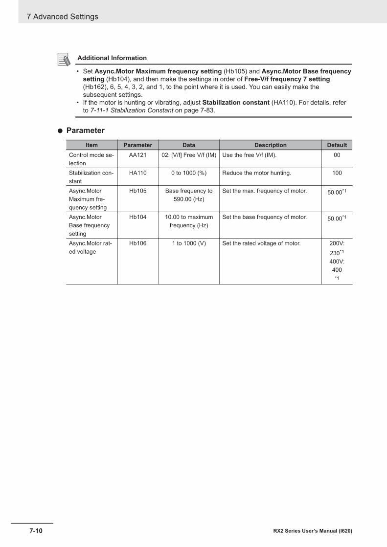
Additional Information
• Set Async.Motor Maximum frequency setting (Hb105) and Async.Motor Base frequencysetting (Hb104), and then make the settings in order of Free-V/f frequency 7 setting(Hb162), 6, 5, 4, 3, 2, and 1, to the point where it is used. You can easily make thesubsequent settings.
• If the motor is hunting or vibrating, adjust Stabilization constant (HA110). For details, referto 7-11-1 Stabilization Constant on page 7-83.
l Parameter
Item Parameter Data Description DefaultControl mode se-lection
AA121 02: [V/f] Free V/f (IM) Use the free V/f (IM). 00
Stabilization con-stant
HA110 0 to 1000 (%) Reduce the motor hunting. 100
Async.MotorMaximum fre-quency setting
Hb105 Base frequency to590.00 (Hz)
Set the max. frequency of motor. 50.00*1
Async.MotorBase frequencysetting
Hb104 10.00 to maximumfrequency (Hz)
Set the base frequency of motor. 50.00*1
Async.Motor rat-ed voltage
Hb106 1 to 1000 (V) Set the rated voltage of motor. 200V:230*1
400V:400
*1
7 Advanced Settings
7-10 RX2 Series User’s Manual (I620)
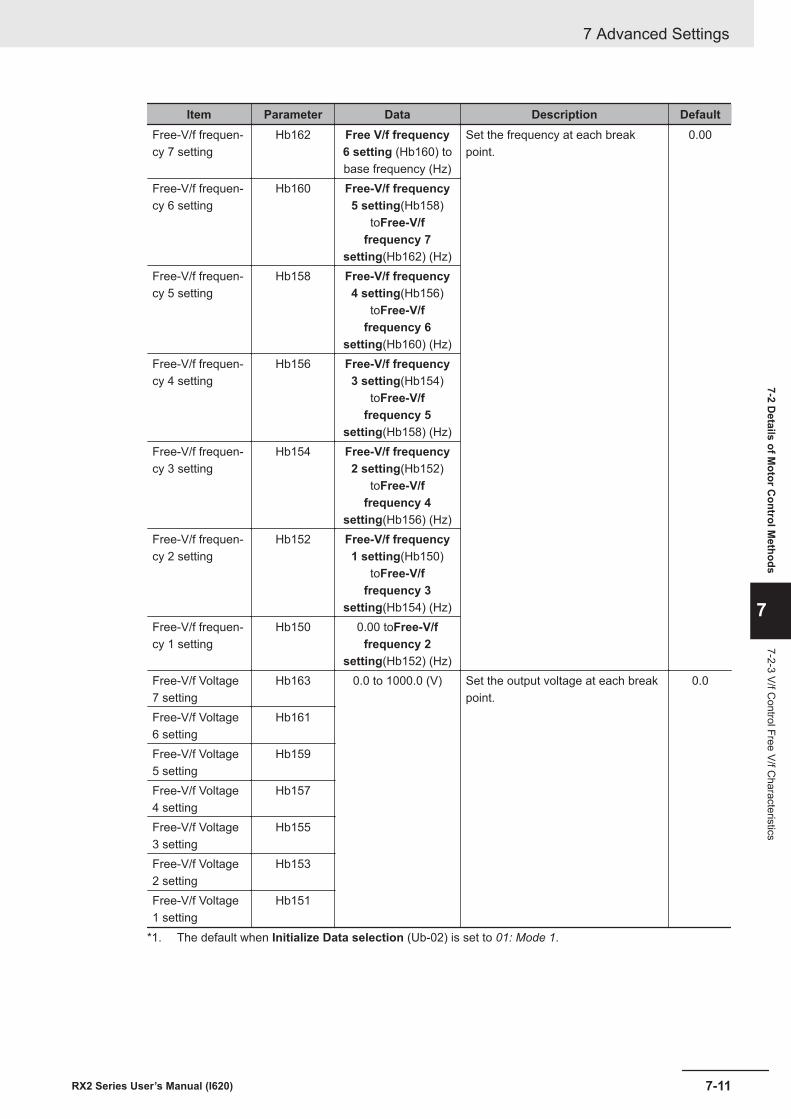
Item Parameter Data Description DefaultFree-V/f frequen-cy 7 setting
Hb162 Free V/f frequency6 setting (Hb160) tobase frequency (Hz)
Set the frequency at each breakpoint.
0.00
Free-V/f frequen-cy 6 setting
Hb160 Free-V/f frequency5 setting(Hb158)
toFree-V/ffrequency 7
setting(Hb162) (Hz)Free-V/f frequen-cy 5 setting
Hb158 Free-V/f frequency4 setting(Hb156)
toFree-V/ffrequency 6
setting(Hb160) (Hz)Free-V/f frequen-cy 4 setting
Hb156 Free-V/f frequency3 setting(Hb154)
toFree-V/ffrequency 5
setting(Hb158) (Hz)Free-V/f frequen-cy 3 setting
Hb154 Free-V/f frequency2 setting(Hb152)
toFree-V/ffrequency 4
setting(Hb156) (Hz)Free-V/f frequen-cy 2 setting
Hb152 Free-V/f frequency1 setting(Hb150)
toFree-V/ffrequency 3
setting(Hb154) (Hz)Free-V/f frequen-cy 1 setting
Hb150 0.00 toFree-V/ffrequency 2
setting(Hb152) (Hz)Free-V/f Voltage7 setting
Hb163 0.0 to 1000.0 (V) Set the output voltage at each breakpoint.
0.0
Free-V/f Voltage6 setting
Hb161
Free-V/f Voltage5 setting
Hb159
Free-V/f Voltage4 setting
Hb157
Free-V/f Voltage3 setting
Hb155
Free-V/f Voltage2 setting
Hb153
Free-V/f Voltage1 setting
Hb151
*1. The default when Initialize Data selection (Ub-02) is set to 01: Mode 1.
7 Advanced Settings
7-11RX2 Series User’s Manual (I620)
7-2 Details of M
otor Control M
ethods
7
7-2-3 V/f Control Free V/f C
haracteristics
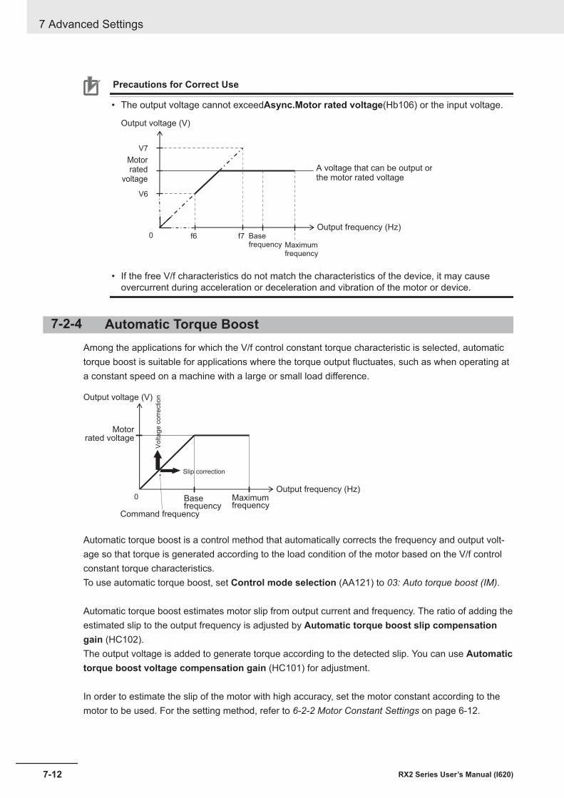
Precautions for Correct Use
• The output voltage cannot exceedAsync.Motor rated voltage(Hb106) or the input voltage.
0 f6 f7
V6
V7
Output frequency (Hz)
Output voltage (V)
Motorrated
voltage
A voltage that can be output orthe motor rated voltage
Basefrequency Maximum
frequency
• If the free V/f characteristics do not match the characteristics of the device, it may causeovercurrent during acceleration or deceleration and vibration of the motor or device.
7-2-4 Automatic Torque BoostAmong the applications for which the V/f control constant torque characteristic is selected, automatictorque boost is suitable for applications where the torque output fluctuates, such as when operating ata constant speed on a machine with a large or small load difference.
0
Output voltage (V)
Basefrequency
Maximumfrequency
Output frequency (Hz)
Motorrated voltage
Vo
lta
ge
co
rre
ctio
n
Slip correction
Command frequency
Automatic torque boost is a control method that automatically corrects the frequency and output volt-age so that torque is generated according to the load condition of the motor based on the V/f controlconstant torque characteristics.To use automatic torque boost, set Control mode selection (AA121) to 03: Auto torque boost (IM).
Automatic torque boost estimates motor slip from output current and frequency. The ratio of adding theestimated slip to the output frequency is adjusted by Automatic torque boost slip compensationgain (HC102).The output voltage is added to generate torque according to the detected slip. You can use Automatictorque boost voltage compensation gain (HC101) for adjustment.
In order to estimate the slip of the motor with high accuracy, set the motor constant according to themotor to be used. For the setting method, refer to 6-2-2 Motor Constant Settings on page 6-12.
7 Advanced Settings
7-12 RX2 Series User’s Manual (I620)
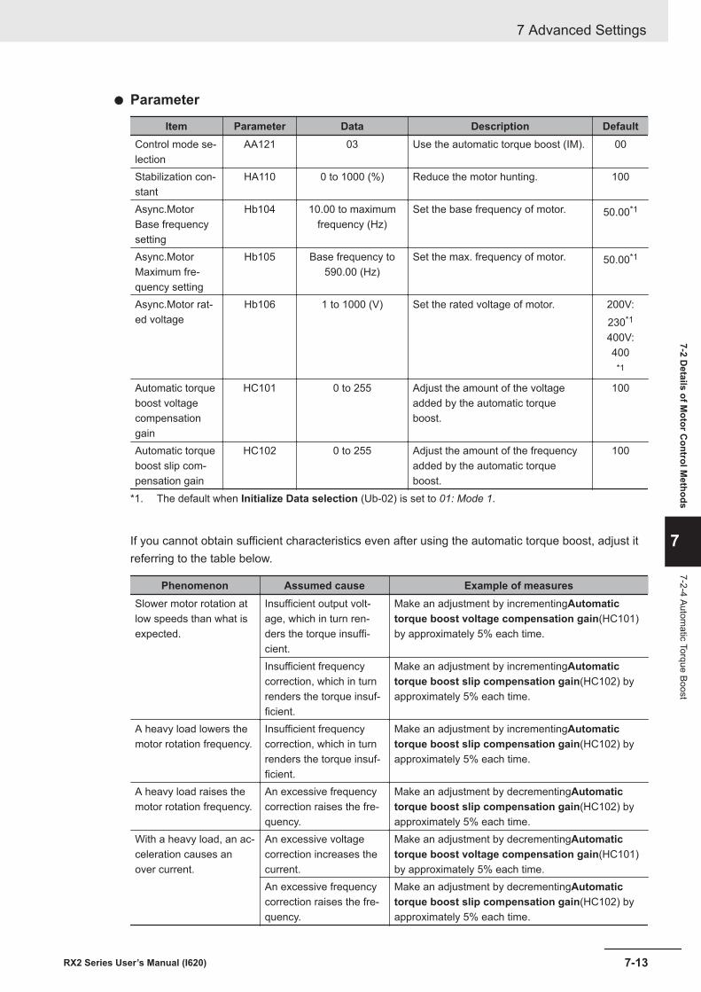
l Parameter
Item Parameter Data Description DefaultControl mode se-lection
AA121 03 Use the automatic torque boost (IM). 00
Stabilization con-stant
HA110 0 to 1000 (%) Reduce the motor hunting. 100
Async.MotorBase frequencysetting
Hb104 10.00 to maximumfrequency (Hz)
Set the base frequency of motor. 50.00*1
Async.MotorMaximum fre-quency setting
Hb105 Base frequency to590.00 (Hz)
Set the max. frequency of motor. 50.00*1
Async.Motor rat-ed voltage
Hb106 1 to 1000 (V) Set the rated voltage of motor. 200V:230*1
400V:400
*1
Automatic torqueboost voltagecompensationgain
HC101 0 to 255 Adjust the amount of the voltageadded by the automatic torqueboost.
100
Automatic torqueboost slip com-pensation gain
HC102 0 to 255 Adjust the amount of the frequencyadded by the automatic torqueboost.
100
*1. The default when Initialize Data selection (Ub-02) is set to 01: Mode 1.
If you cannot obtain sufficient characteristics even after using the automatic torque boost, adjust itreferring to the table below.
Phenomenon Assumed cause Example of measuresSlower motor rotation atlow speeds than what isexpected.
Insufficient output volt-age, which in turn ren-ders the torque insuffi-cient.
Make an adjustment by incrementingAutomatictorque boost voltage compensation gain(HC101)by approximately 5% each time.
Insufficient frequencycorrection, which in turnrenders the torque insuf-ficient.
Make an adjustment by incrementingAutomatictorque boost slip compensation gain(HC102) byapproximately 5% each time.
A heavy load lowers themotor rotation frequency.
Insufficient frequencycorrection, which in turnrenders the torque insuf-ficient.
Make an adjustment by incrementingAutomatictorque boost slip compensation gain(HC102) byapproximately 5% each time.
A heavy load raises themotor rotation frequency.
An excessive frequencycorrection raises the fre-quency.
Make an adjustment by decrementingAutomatictorque boost slip compensation gain(HC102) byapproximately 5% each time.
With a heavy load, an ac-celeration causes anover current.
An excessive voltagecorrection increases thecurrent.
Make an adjustment by decrementingAutomatictorque boost voltage compensation gain(HC101)by approximately 5% each time.
An excessive frequencycorrection raises the fre-quency.
Make an adjustment by decrementingAutomatictorque boost slip compensation gain(HC102) byapproximately 5% each time.
7 Advanced Settings
7-13RX2 Series User’s Manual (I620)
7-2 Details of M
otor Control M
ethods
7
7-2-4 Automatic Torque Boost
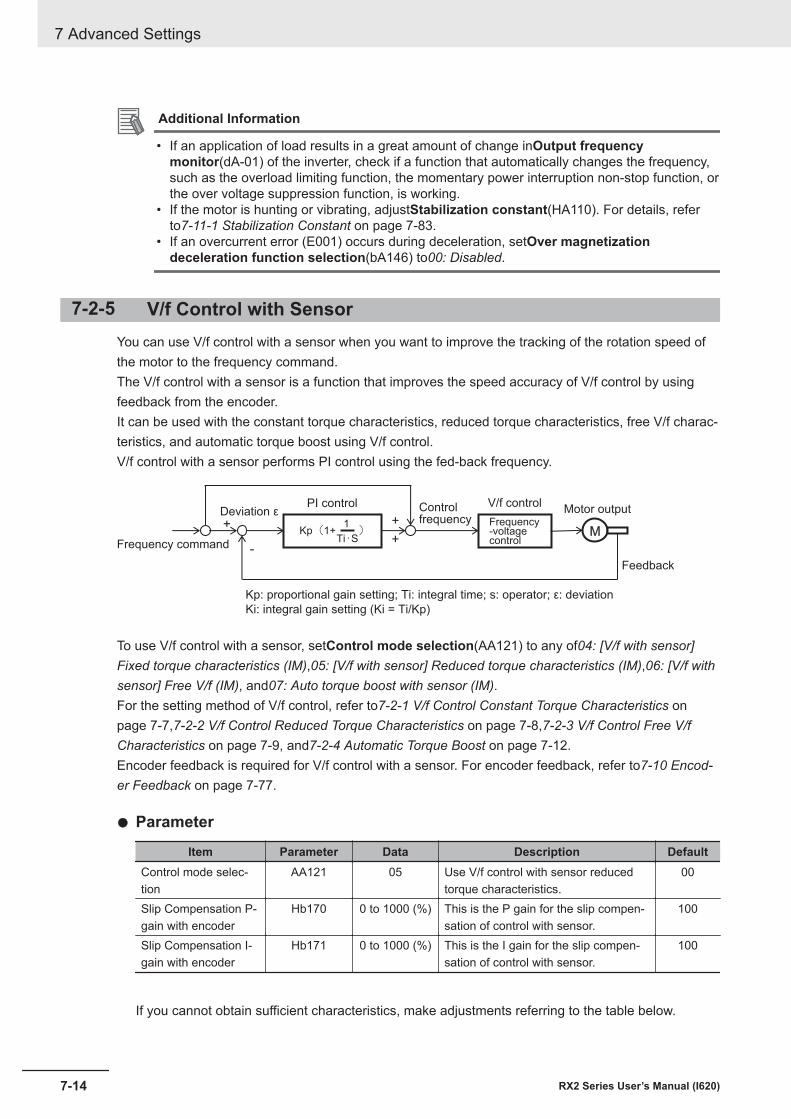
Additional Information
• If an application of load results in a great amount of change inOutput frequencymonitor(dA-01) of the inverter, check if a function that automatically changes the frequency,such as the overload limiting function, the momentary power interruption non-stop function, orthe over voltage suppression function, is working.
• If the motor is hunting or vibrating, adjustStabilization constant(HA110). For details, referto7-11-1 Stabilization Constant on page 7-83.
• If an overcurrent error (E001) occurs during deceleration, setOver magnetizationdeceleration function selection(bA146) to00: Disabled.
7-2-5 V/f Control with SensorYou can use V/f control with a sensor when you want to improve the tracking of the rotation speed ofthe motor to the frequency command.The V/f control with a sensor is a function that improves the speed accuracy of V/f control by usingfeedback from the encoder.It can be used with the constant torque characteristics, reduced torque characteristics, free V/f charac-teristics, and automatic torque boost using V/f control.V/f control with a sensor performs PI control using the fed-back frequency.
M+
Kp(1+ )1
Ti・S+
+-
Deviation ε
Frequency command
PI control Controlfrequency Frequency
-voltagecontrol
Feedback
Kp: proportional gain setting; Ti: integral time; s: operator; ε: deviation
Ki: integral gain setting (Ki = Ti/Kp)
Motor outputV/f control
To use V/f control with a sensor, setControl mode selection(AA121) to any of04: [V/f with sensor]Fixed torque characteristics (IM),05: [V/f with sensor] Reduced torque characteristics (IM),06: [V/f withsensor] Free V/f (IM), and07: Auto torque boost with sensor (IM).For the setting method of V/f control, refer to7-2-1 V/f Control Constant Torque Characteristics onpage 7-7,7-2-2 V/f Control Reduced Torque Characteristics on page 7-8,7-2-3 V/f Control Free V/fCharacteristics on page 7-9, and7-2-4 Automatic Torque Boost on page 7-12.Encoder feedback is required for V/f control with a sensor. For encoder feedback, refer to7-10 Encod-er Feedback on page 7-77.
l Parameter
Item Parameter Data Description DefaultControl mode selec-tion
AA121 05 Use V/f control with sensor reducedtorque characteristics.
00
Slip Compensation P-gain with encoder
Hb170 0 to 1000 (%) This is the P gain for the slip compen-sation of control with sensor.
100
Slip Compensation I-gain with encoder
Hb171 0 to 1000 (%) This is the I gain for the slip compen-sation of control with sensor.
100
If you cannot obtain sufficient characteristics, make adjustments referring to the table below.
7 Advanced Settings
7-14 RX2 Series User’s Manual (I620)
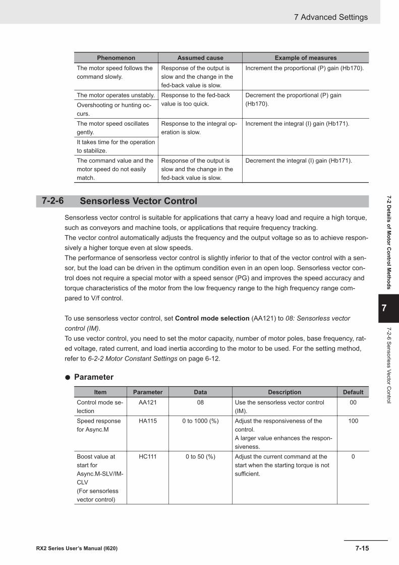
Phenomenon Assumed cause Example of measuresThe motor speed follows thecommand slowly.
Response of the output isslow and the change in thefed-back value is slow.
Increment the proportional (P) gain (Hb170).
The motor operates unstably. Response to the fed-backvalue is too quick.
Decrement the proportional (P) gain(Hb170).Overshooting or hunting oc-
curs.The motor speed oscillatesgently.
Response to the integral op-eration is slow.
Increment the integral (I) gain (Hb171).
It takes time for the operationto stabilize.The command value and themotor speed do not easilymatch.
Response of the output isslow and the change in thefed-back value is slow.
Decrement the integral (I) gain (Hb171).
7-2-6 Sensorless Vector ControlSensorless vector control is suitable for applications that carry a heavy load and require a high torque,such as conveyors and machine tools, or applications that require frequency tracking.The vector control automatically adjusts the frequency and the output voltage so as to achieve respon-sively a higher torque even at slow speeds.The performance of sensorless vector control is slightly inferior to that of the vector control with a sen-sor, but the load can be driven in the optimum condition even in an open loop. Sensorless vector con-trol does not require a special motor with a speed sensor (PG) and improves the speed accuracy andtorque characteristics of the motor from the low frequency range to the high frequency range com-pared to V/f control.
To use sensorless vector control, set Control mode selection (AA121) to 08: Sensorless vectorcontrol (IM).To use vector control, you need to set the motor capacity, number of motor poles, base frequency, rat-ed voltage, rated current, and load inertia according to the motor to be used. For the setting method,refer to 6-2-2 Motor Constant Settings on page 6-12.
l Parameter
Item Parameter Data Description DefaultControl mode se-lection
AA121 08 Use the sensorless vector control(IM).
00
Speed responsefor Async.M
HA115 0 to 1000 (%) Adjust the responsiveness of thecontrol.A larger value enhances the respon-siveness.
100
Boost value atstart forAsync.M-SLV/IM-CLV(For sensorlessvector control)
HC111 0 to 50 (%) Adjust the current command at thestart when the starting torque is notsufficient.
0
7 Advanced Settings
7-15RX2 Series User’s Manual (I620)
7-2 Details of M
otor Control M
ethods
7
7-2-6 Sensorless Vector Control
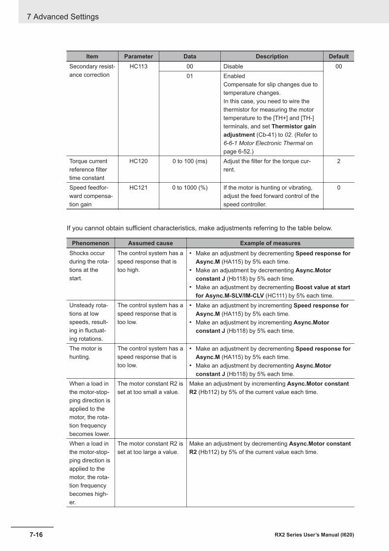
Item Parameter Data Description DefaultSecondary resist-ance correction
HC113 00 Disable 0001 Enabled
Compensate for slip changes due totemperature changes.In this case, you need to wire thethermistor for measuring the motortemperature to the [TH+] and [TH-]terminals, and set Thermistor gainadjustment (Cb-41) to 02. (Refer to 6-6-1 Motor Electronic Thermal onpage 6-52.)
Torque currentreference filtertime constant
HC120 0 to 100 (ms) Adjust the filter for the torque cur-rent.
2
Speed feedfor-ward compensa-tion gain
HC121 0 to 1000 (%) If the motor is hunting or vibrating,adjust the feed forward control of thespeed controller.
0
If you cannot obtain sufficient characteristics, make adjustments referring to the table below.
Phenomenon Assumed cause Example of measuresShocks occurduring the rota-tions at thestart.
The control system has aspeed response that istoo high.
• Make an adjustment by decrementing Speed response forAsync.M (HA115) by 5% each time.
• Make an adjustment by decrementing Async.Motorconstant J (Hb118) by 5% each time.
• Make an adjustment by decrementing Boost value at startfor Async.M-SLV/IM-CLV (HC111) by 5% each time.
Unsteady rota-tions at lowspeeds, result-ing in fluctuat-ing rotations.
The control system has aspeed response that istoo low.
• Make an adjustment by incrementing Speed response forAsync.M (HA115) by 5% each time.
• Make an adjustment by incrementing Async.Motorconstant J (Hb118) by 5% each time.
The motor ishunting.
The control system has aspeed response that istoo low.
• Make an adjustment by decrementing Speed response forAsync.M (HA115) by 5% each time.
• Make an adjustment by decrementing Async.Motorconstant J (Hb118) by 5% each time.
When a load inthe motor-stop-ping direction isapplied to themotor, the rota-tion frequencybecomes lower.
The motor constant R2 isset at too small a value.
Make an adjustment by incrementing Async.Motor constantR2 (Hb112) by 5% of the current value each time.
When a load inthe motor-stop-ping direction isapplied to themotor, the rota-tion frequencybecomes high-er.
The motor constant R2 isset at too large a value.
Make an adjustment by decrementing Async.Motor constantR2 (Hb112) by 5% of the current value each time.
7 Advanced Settings
7-16 RX2 Series User’s Manual (I620)
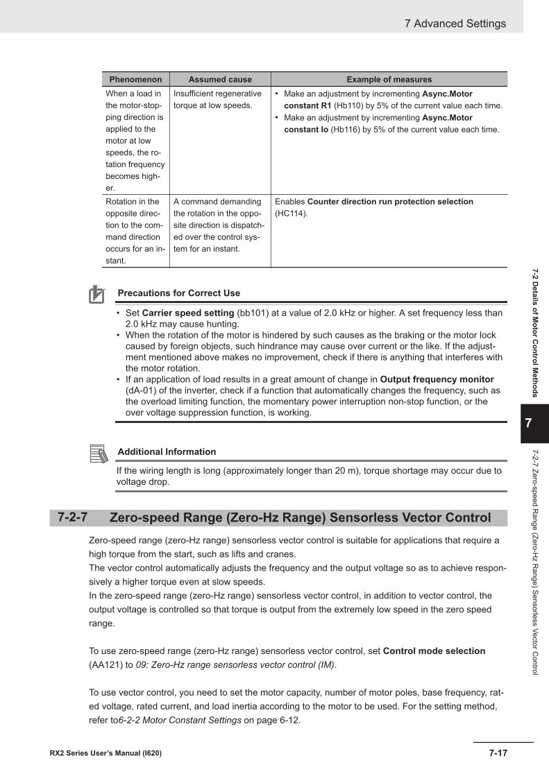
Phenomenon Assumed cause Example of measuresWhen a load inthe motor-stop-ping direction isapplied to themotor at lowspeeds, the ro-tation frequencybecomes high-er.
Insufficient regenerativetorque at low speeds.
• Make an adjustment by incrementing Async.Motorconstant R1 (Hb110) by 5% of the current value each time.
• Make an adjustment by incrementing Async.Motorconstant Io (Hb116) by 5% of the current value each time.
Rotation in theopposite direc-tion to the com-mand directionoccurs for an in-stant.
A command demandingthe rotation in the oppo-site direction is dispatch-ed over the control sys-tem for an instant.
Enables Counter direction run protection selection(HC114).
Precautions for Correct Use
• Set Carrier speed setting (bb101) at a value of 2.0 kHz or higher. A set frequency less than2.0 kHz may cause hunting.
• When the rotation of the motor is hindered by such causes as the braking or the motor lockcaused by foreign objects, such hindrance may cause over current or the like. If the adjust-ment mentioned above makes no improvement, check if there is anything that interferes withthe motor rotation.
• If an application of load results in a great amount of change in Output frequency monitor(dA-01) of the inverter, check if a function that automatically changes the frequency, such asthe overload limiting function, the momentary power interruption non-stop function, or theover voltage suppression function, is working.
Additional Information
If the wiring length is long (approximately longer than 20 m), torque shortage may occur due tovoltage drop.
7-2-7 Zero-speed Range (Zero-Hz Range) Sensorless Vector ControlZero-speed range (zero-Hz range) sensorless vector control is suitable for applications that require ahigh torque from the start, such as lifts and cranes.The vector control automatically adjusts the frequency and the output voltage so as to achieve respon-sively a higher torque even at slow speeds.In the zero-speed range (zero-Hz range) sensorless vector control, in addition to vector control, theoutput voltage is controlled so that torque is output from the extremely low speed in the zero speedrange.
To use zero-speed range (zero-Hz range) sensorless vector control, set Control mode selection(AA121) to 09: Zero-Hz range sensorless vector control (IM).
To use vector control, you need to set the motor capacity, number of motor poles, base frequency, rat-ed voltage, rated current, and load inertia according to the motor to be used. For the setting method,refer to6-2-2 Motor Constant Settings on page 6-12.
7 Advanced Settings
7-17RX2 Series User’s Manual (I620)
7-2 Details of M
otor Control M
ethods
7
7-2-7 Zero-speed Range (Zero-H
z Range) Sensorless Vector C
ontrol
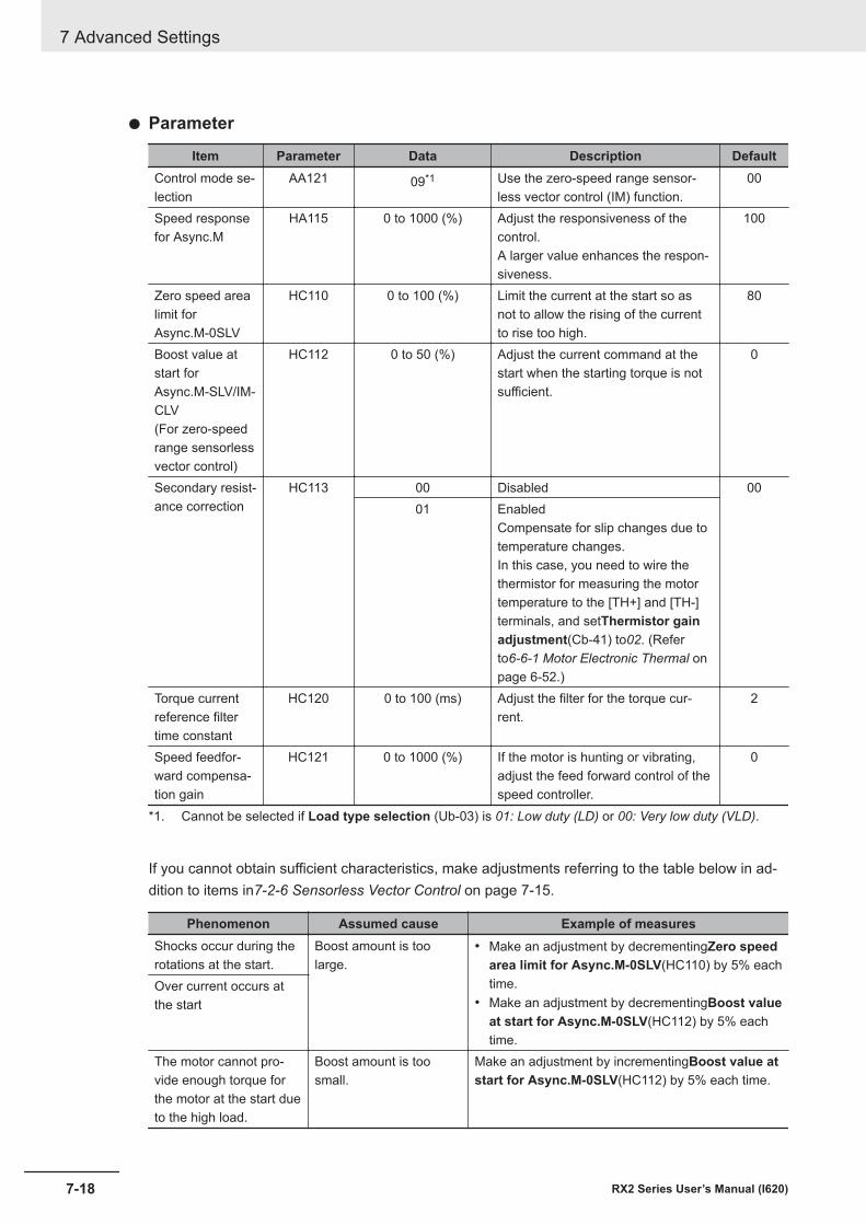
l Parameter
Item Parameter Data Description DefaultControl mode se-lection
AA121 09*1 Use the zero-speed range sensor-less vector control (IM) function.
00
Speed responsefor Async.M
HA115 0 to 1000 (%) Adjust the responsiveness of thecontrol.A larger value enhances the respon-siveness.
100
Zero speed arealimit forAsync.M-0SLV
HC110 0 to 100 (%) Limit the current at the start so asnot to allow the rising of the currentto rise too high.
80
Boost value atstart forAsync.M-SLV/IM-CLV(For zero-speedrange sensorlessvector control)
HC112 0 to 50 (%) Adjust the current command at thestart when the starting torque is notsufficient.
0
Secondary resist-ance correction
HC113 00 Disabled 0001 Enabled
Compensate for slip changes due totemperature changes.In this case, you need to wire thethermistor for measuring the motortemperature to the [TH+] and [TH-]terminals, and setThermistor gainadjustment(Cb-41) to02. (Referto6-6-1 Motor Electronic Thermal onpage 6-52.)
Torque currentreference filtertime constant
HC120 0 to 100 (ms) Adjust the filter for the torque cur-rent.
2
Speed feedfor-ward compensa-tion gain
HC121 0 to 1000 (%) If the motor is hunting or vibrating,adjust the feed forward control of thespeed controller.
0
*1. Cannot be selected if Load type selection (Ub-03) is 01: Low duty (LD) or 00: Very low duty (VLD).
If you cannot obtain sufficient characteristics, make adjustments referring to the table below in ad-dition to items in7-2-6 Sensorless Vector Control on page 7-15.
Phenomenon Assumed cause Example of measuresShocks occur during therotations at the start.
Boost amount is toolarge.
• Make an adjustment by decrementingZero speedarea limit for Async.M-0SLV(HC110) by 5% eachtime.
• Make an adjustment by decrementingBoost valueat start for Async.M-0SLV(HC112) by 5% eachtime.
Over current occurs atthe start
The motor cannot pro-vide enough torque forthe motor at the start dueto the high load.
Boost amount is toosmall.
Make an adjustment by incrementingBoost value atstart for Async.M-0SLV(HC112) by 5% each time.
7 Advanced Settings
7-18 RX2 Series User’s Manual (I620)
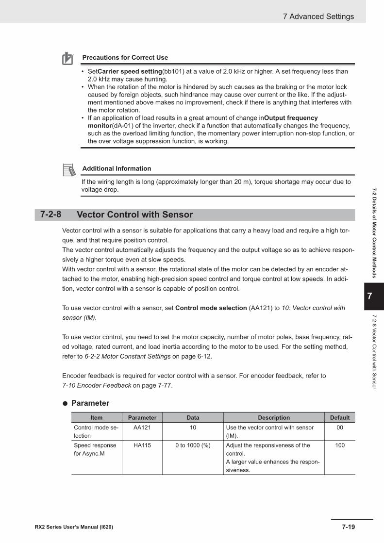
Precautions for Correct Use
• SetCarrier speed setting(bb101) at a value of 2.0 kHz or higher. A set frequency less than2.0 kHz may cause hunting.
• When the rotation of the motor is hindered by such causes as the braking or the motor lockcaused by foreign objects, such hindrance may cause over current or the like. If the adjust-ment mentioned above makes no improvement, check if there is anything that interferes withthe motor rotation.
• If an application of load results in a great amount of change inOutput frequencymonitor(dA-01) of the inverter, check if a function that automatically changes the frequency,such as the overload limiting function, the momentary power interruption non-stop function, orthe over voltage suppression function, is working.
Additional Information
If the wiring length is long (approximately longer than 20 m), torque shortage may occur due tovoltage drop.
7-2-8 Vector Control with SensorVector control with a sensor is suitable for applications that carry a heavy load and require a high tor-que, and that require position control.The vector control automatically adjusts the frequency and the output voltage so as to achieve respon-sively a higher torque even at slow speeds.With vector control with a sensor, the rotational state of the motor can be detected by an encoder at-tached to the motor, enabling high-precision speed control and torque control at low speeds. In addi-tion, vector control with a sensor is capable of position control.
To use vector control with a sensor, set Control mode selection (AA121) to 10: Vector control withsensor (IM).
To use vector control, you need to set the motor capacity, number of motor poles, base frequency, rat-ed voltage, rated current, and load inertia according to the motor to be used. For the setting method,refer to 6-2-2 Motor Constant Settings on page 6-12.
Encoder feedback is required for vector control with a sensor. For encoder feedback, refer to 7-10 Encoder Feedback on page 7-77.
l Parameter
Item Parameter Data Description DefaultControl mode se-lection
AA121 10 Use the vector control with sensor(IM).
00
Speed responsefor Async.M
HA115 0 to 1000 (%) Adjust the responsiveness of thecontrol.A larger value enhances the respon-siveness.
100
7 Advanced Settings
7-19RX2 Series User’s Manual (I620)
7-2 Details of M
otor Control M
ethods
7
7-2-8 Vector Control w
ith Sensor
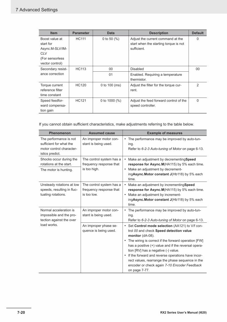
Item Parameter Data Description DefaultBoost value atstart forAsync.M-SLV/IM-CLV(For sensorlessvector control)
HC111 0 to 50 (%) Adjust the current command at thestart when the starting torque is notsufficient.
0
Secondary resist-ance correction
HC113 00 Disabled 0001 Enabled. Requiring a temperature
thermistor.Torque currentreference filtertime constant
HC120 0 to 100 (ms) Adjust the filter for the torque cur-rent.
2
Speed feedfor-ward compensa-tion gain
HC121 0 to 1000 (%) Adjust the feed forward control of thespeed controller.
0
If you cannot obtain sufficient characteristics, make adjustments referring to the table below.
Phenomenon Assumed cause Example of measuresThe performance is notsufficient for what themotor control character-istics predict.
An improper motor con-stant is being used.
• The performance may be improved by auto-tun-ing.Refer to 6-2-3 Auto-tuning of Motor on page 6-13.
Shocks occur during therotations at the start.
The control system has afrequency response thatis too high.
• Make an adjustment by decrementingSpeedresponse for Async.M(HA115) by 5% each time.
• Make an adjustment by decrement-ingAsync.Motor constant J(Hb118) by 5% eachtime.
The motor is hunting.
Unsteady rotations at lowspeeds, resulting in fluc-tuating rotations.
The control system has afrequency response thatis too low.
• Make an adjustment by incrementingSpeedresponse for Async.M(HA115) by 5% each time.
• Make an adjustment by increment-ingAsync.Motor constant J(Hb118) by 5% eachtime.
Normal acceleration isimpossible and the pro-tection against the overload works.
An improper motor con-stant is being used.
• The performance may be improved by auto-tun-ing.Refer to 6-2-3 Auto-tuning of Motor on page 6-13.
An improper phase se-quence is being used.
• Set Control mode selection (AA121) to V/f con-trol 00 and check Speed detection valuemonitor (dA-08).
• The wiring is correct if the forward operation [FW]has a positive (+) value and if the reversal opera-tion [RV] has a negative (-) value.
• If the forward and reverse operations have incor-rect values, rearrange the phase sequence in theencoder or check again 7-10 Encoder Feedbackon page 7-77.
7 Advanced Settings
7-20 RX2 Series User’s Manual (I620)
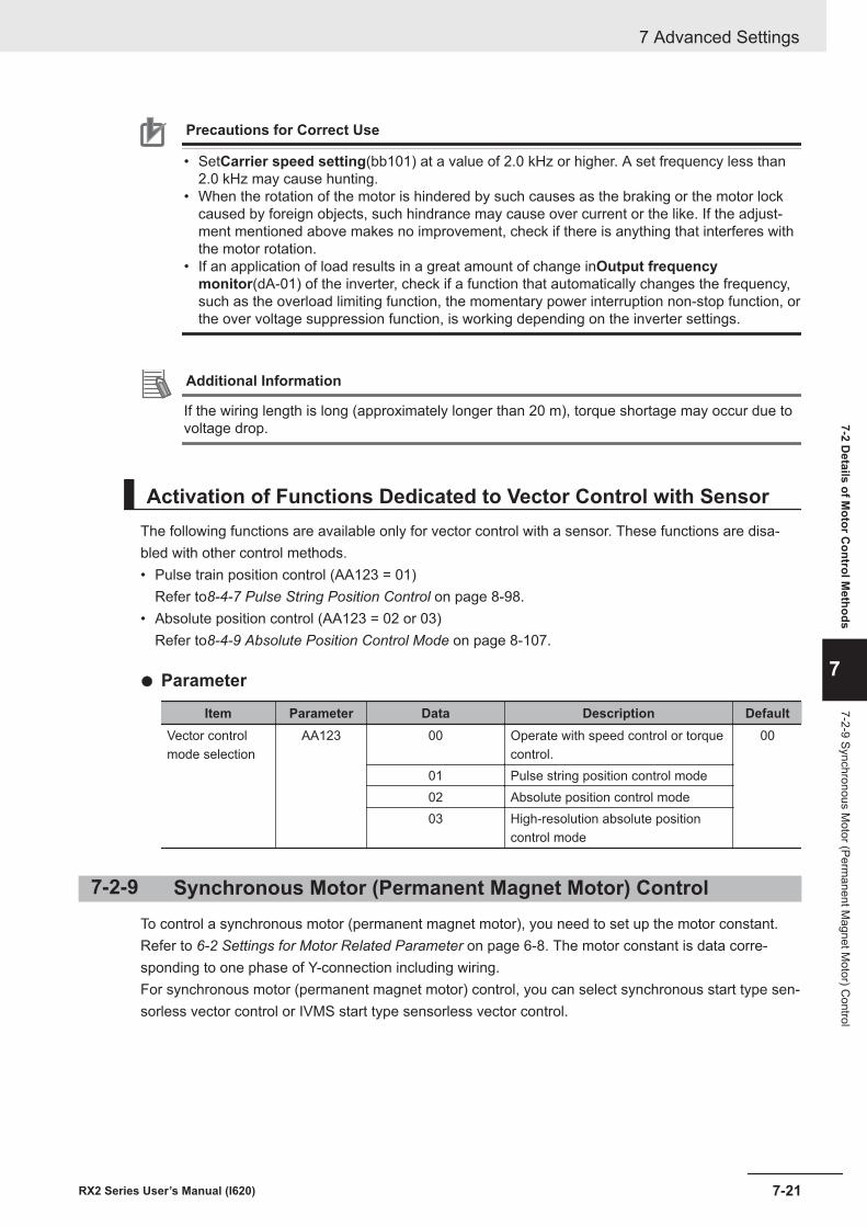
Precautions for Correct Use
• SetCarrier speed setting(bb101) at a value of 2.0 kHz or higher. A set frequency less than2.0 kHz may cause hunting.
• When the rotation of the motor is hindered by such causes as the braking or the motor lockcaused by foreign objects, such hindrance may cause over current or the like. If the adjust-ment mentioned above makes no improvement, check if there is anything that interferes withthe motor rotation.
• If an application of load results in a great amount of change inOutput frequencymonitor(dA-01) of the inverter, check if a function that automatically changes the frequency,such as the overload limiting function, the momentary power interruption non-stop function, orthe over voltage suppression function, is working depending on the inverter settings.
Additional Information
If the wiring length is long (approximately longer than 20 m), torque shortage may occur due tovoltage drop.
Activation of Functions Dedicated to Vector Control with SensorThe following functions are available only for vector control with a sensor. These functions are disa-bled with other control methods.• Pulse train position control (AA123 = 01)
Refer to8-4-7 Pulse String Position Control on page 8-98.• Absolute position control (AA123 = 02 or 03)
Refer to8-4-9 Absolute Position Control Mode on page 8-107.
l Parameter
Item Parameter Data Description DefaultVector controlmode selection
AA123 00 Operate with speed control or torquecontrol.
00
01 Pulse string position control mode02 Absolute position control mode03 High-resolution absolute position
control mode
7-2-9 Synchronous Motor (Permanent Magnet Motor) ControlTo control a synchronous motor (permanent magnet motor), you need to set up the motor constant.Refer to 6-2 Settings for Motor Related Parameter on page 6-8. The motor constant is data corre-sponding to one phase of Y-connection including wiring.For synchronous motor (permanent magnet motor) control, you can select synchronous start type sen-sorless vector control or IVMS start type sensorless vector control.
7 Advanced Settings
7-21RX2 Series User’s Manual (I620)
7-2 Details of M
otor Control M
ethods
7
7-2-9 Synchronous Motor (Perm
anent Magnet M
otor) Control
Precautions for Correct Use
• Check the current limit at which the motor does not demagnetize. The maximum current ofthe motor is 150% ofOver current detection level(bb160). You can protect the motor withthis setting. Note that the maximum current is the peak value, not the effective value. The rat-ed output current shown in the specification table is an effective value.
• This control method can be used for reduced torque applications where the motor that hasthe same frame number as the inverter’s rating needs a torque at the start that is 50% orsmaller. This method cannot be used for applications that require high torque from lowspeeds or for applications that involve rapid acceleration or deceleration. In particular, neveruse this method for applications involving a gravity load, such as lifts.
• Synchronous motors (permanent magnet motors) cannot be operated by a direct input fromthe commercial power supply.
• Multiple synchronous motors (permanent magnet motors) cannot be driven by a single inver-ter.
• Synchronous motors (permanent magnet motors) are more likely to cause an overvoltage er-ror (E007) than asynchronous motors (induction motors). If the rapid deceleration and/or theDC braking function need to be used, consider the possible use of an optional braking resis-tor or a regenerative braking unit.
• When a hold brake is used, release the brake before the motor starts operation. Otherwise,the motor may lose its synchronism.
• The motor may rotate in the reverse direction at the start of its rotation. UseStarting Methodfor Sync.M(Hd132) to prevent reverse rotation.
• SetCarrier speed setting(bb101) at a value of 8.0kHz or higher. Some low carrier frequen-cies may make the motor generate a lot of heat.
• The tolerable load moment of inertia is 50 times as large as the motor’s moment of inertia orsmaller. For some applications whose loads moment of inertia exceed the above mentionedrange, sufficient characteristics may not be obtained.
• When driving a motor whoseSync.Motor rated current(Hd108) exceeds the inverter ratedcurrent or a motor whose frame number is smaller than the maximum applicable motor by 2or more, sufficient characteristics may not be obtained.
• SetElectronic thermal level setting(bC110) in addition toSync.Motor ratedcurrent(Hd108).
• If the initial position estimation is enabled inStarting Method for Sync.M(Hd132), a shrillsound caused by the position detection action may be heard, but this sound has nothing to dowith any abnormality.
• If the initial position estimation is enabled inStarting Method for Sync.M(Hd132), start theoperation from the state in which the motor stopped. Failure to acquire the correct positionmay occur, which may result in unintended rotation, over current, or loss of synchronization.
Additional Information
• If the wiring length is long (approximately longer than 20 m), the motor may not exhibit suffi-cient characteristics.
• If the wiring length is long (approximately longer than 20 m), frequency-synchronized re-startmay cause an overcurrent error (E001).
Disabled FunctionsThe following functions cannot be used when the synchronous motor (permanent magnet motor) con-trol is applied.Even when these functions are enabled by parameter settings, they are actually disabled.
7 Advanced Settings
7-22 RX2 Series User’s Manual (I620)
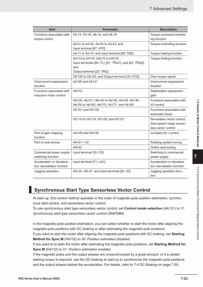
Item Parameter DescriptionFunctions associated withtorque control
FA-15, FA-16, dA-15, and dA-16 Torque command monitor-ing function
Ad-01 to Ad-04, Ad-40 to Ad-43, andInput terminal [67: ATR]
Torque controlling function
Ad-11 to Ad-14, and Input terminal [68: TBS] Torque biasing functionbA110 to bA116, bA210 to bA216,Input terminals [60: TL], [61: TRQ1], and [62: TRQ2],andOutput terminal [22: TRQ]
Torque limiting function
CE120 to CE123, and Output terminal [19: OTQ] Over torque signalOvercurrent suppressionfunction
bA120 and bA121 Overcurrent suppressionfunction
Functions associated withinduction motor control
HA110 Stabilization adjustmentgain
Hb130, Hb131, HB140 to Hb142, Hb145, Hb146,Hb150 to Hb163, Hb170, Hb171, and Hb180
Functions associated withV/f control
HC101 and HC102 Functions associated withautomatic boost
HC110 to HC114, HC120, and HC121 Sensorless vector control,Zero-speed range sensor-less vector control
Part of gain mappingfunction
HA126 and HA129 Constant for I control
Part of auto-tuning HA-01 = 02 Rotating system tuningHA-03 Online auto-tuning
Commercial power supplyswitching function
Input terminal [35: CS] Switching to commercialpower supply
Acceleration or decelera-tion cancellation function
Input terminal [71: LAC] Acceleration or decelera-tion cancellation function
Jogging operation AG-20, AG-21, and Input terminal [29: JG] Jogging operation func-tion
Synchronous Start Type Sensorless Vector ControlAt start-up, this control method operates in the order of magnetic-pole position estimation, synchro-nous start control, and sensorless vector control.To use synchronous start type sensorless vector control, set Control mode selection (AA121) to 11:Synchronous start type sensorless vector control (SM/PMM).
In the magnetic-pole position estimation, you can select whether to start the motor after aligning themagnetic-pole positions with DC braking or after estimating the magnetic-pole positions.If you want to start the motor after aligning the magnetic-pole positions with DC braking, set StartingMethod for Sync.M (Hd132) to 00: Position estimation disabled.If you want to to start the motor after estimating the magnetic-pole positions, set Starting Method forSync.M (Hd132) to 01: Position estimation enabled.If the magnetic poles and the output phases are unsynchronized by a great amount, or if a certainstarting torque is required, use the DC braking at start-up to synchronize the magnetic-pole positionsand the output phases before the acceleration. For details, refer to 7-4 DC Braking on page 7-50.
7 Advanced Settings
7-23RX2 Series User’s Manual (I620)
7-2 Details of M
otor Control M
ethods
7
7-2-9 Synchronous Motor (Perm
anent Magnet M
otor) Control
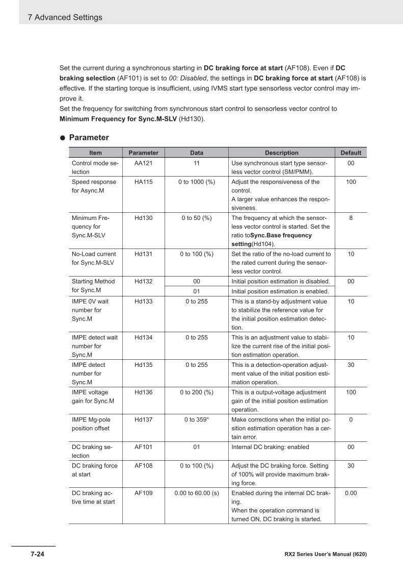
Set the current during a synchronous starting in DC braking force at start (AF108). Even if DCbraking selection (AF101) is set to 00: Disabled, the settings in DC braking force at start (AF108) iseffective. If the starting torque is insufficient, using IVMS start type sensorless vector control may im-prove it.Set the frequency for switching from synchronous start control to sensorless vector control toMinimum Frequency for Sync.M-SLV (Hd130).
l Parameter
Item Parameter Data Description DefaultControl mode se-lection
AA121 11 Use synchronous start type sensor-less vector control (SM/PMM).
00
Speed responsefor Async.M
HA115 0 to 1000 (%) Adjust the responsiveness of thecontrol.A larger value enhances the respon-siveness.
100
Minimum Fre-quency forSync.M-SLV
Hd130 0 to 50 (%) The frequency at which the sensor-less vector control is started. Set theratio toSync.Base frequencysetting(Hd104).
8
No-Load currentfor Sync.M-SLV
Hd131 0 to 100 (%) Set the ratio of the no-load current tothe rated current during the sensor-less vector control.
10
Starting Methodfor Sync.M
Hd132 00 Initial position estimation is disabled. 0001 Initial position estimation is enabled.
IMPE 0V waitnumber forSync.M
Hd133 0 to 255 This is a stand-by adjustment valueto stabilize the reference value forthe initial position estimation detec-tion.
10
IMPE detect waitnumber forSync.M
Hd134 0 to 255 This is an adjustment value to stabi-lize the current rise of the initial posi-tion estimation operation.
10
IMPE detectnumber forSync.M
Hd135 0 to 255 This is a detection-operation adjust-ment value of the initial position esti-mation operation.
30
IMPE voltagegain for Sync.M
Hd136 0 to 200 (%) This is a output-voltage adjustmentgain of the initial position estimationoperation.
100
IMPE Mg-poleposition offset
Hd137 0 to 359° Make corrections when the initial po-sition estimation operation has a cer-tain error.
0
DC braking se-lection
AF101 01 Internal DC braking: enabled 00
DC braking forceat start
AF108 0 to 100 (%) Adjust the DC braking force. Settingof 100% will provide maximum brak-ing force.
30
DC braking ac-tive time at start
AF109 0.00 to 60.00 (s) Enabled during the internal DC brak-ing.When the operation command isturned ON, DC braking is started.
0.00
7 Advanced Settings
7-24 RX2 Series User’s Manual (I620)
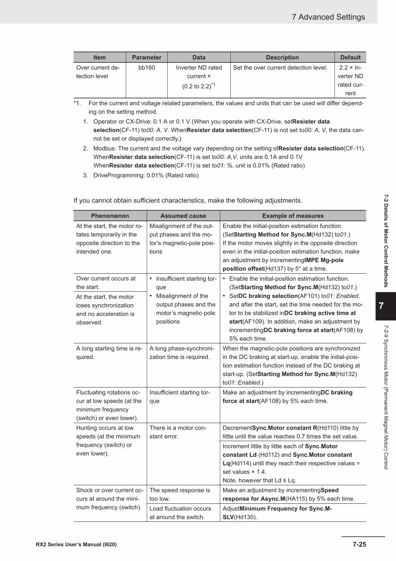
Item Parameter Data Description DefaultOver current de-tection level
bb160 Inverter ND ratedcurrent ×
(0.2 to 2.2)*1
Set the over current detection level. 2.2 × In-verter NDrated cur-
rent*1. For the current and voltage related parameters, the values and units that can be used will differ depend-
ing on the setting method.1. Operator or CX-Drive: 0.1 A or 0.1 V (When you operate with CX-Drive, setResister data
selection(CF-11) to00: A, V. WhenResister data selection(CF-11) is not set to00: A, V, the data can-not be set or displayed correctly.)
2. Modbus: The current and the voltage vary depending on the setting ofResister data selection(CF-11).WhenResister data selection(CF-11) is set to00: A,V, units are 0.1A and 0.1VWhenResister data selection(CF-11) is set to01: %, unit is 0.01% (Rated ratio)
3. DriveProgramming: 0.01% (Rated ratio)
If you cannot obtain sufficient characteristics, make the following adjustments.
Phenomenon Assumed cause Example of measuresAt the start, the motor ro-tates temporarily in theopposite direction to theintended one.
Misalignment of the out-put phases and the mo-tor’s magnetic-pole posi-tions
Enable the initial-position estimation function.(SetStarting Method for Sync.M(Hd132) to01.)If the motor moves slightly in the opposite directioneven in the initial-position estimation function, makean adjustment by incrementingIMPE Mg-poleposition offset(Hd137) by 5° at a time.
Over current occurs atthe start.
• Insufficient starting tor-que
• Misalignment of theoutput phases and themotor’s magnetic-polepositions
• Enable the initial-position estimation function.(SetStarting Method for Sync.M(Hd132) to01.)
• SetDC braking selection(AF101) to01: Enabled,and after the start, set the time needed for the mo-tor to be stabilized inDC braking active time atstart(AF109). In addition, make an adjustment byincrementingDC braking force at start(AF108) by5% each time.
At the start, the motorloses synchronizationand no acceleration isobserved.
A long starting time is re-quired.
A long phase-synchroni-zation time is required.
When the magnetic-pole positions are synchronizedin the DC braking at start-up, enable the initial-posi-tion estimation function instead of the DC braking atstart-up. (SetStarting Method for Sync.M(Hd132)to01: Enabled.)
Fluctuating rotations oc-cur at low speeds (at theminimum frequency(switch) or even lower).
Insufficient starting tor-que
Make an adjustment by incrementingDC brakingforce at start(AF108) by 5% each time.
Hunting occurs at lowspeeds (at the minimumfrequency (switch) oreven lower).
There is a motor con-stant error.
DecrementSync.Motor constant R(Hd110) little bylittle until the value reaches 0.7 times the set value.Increment little by little each of Sync.Motorconstant Ld (Hd112) and Sync.Motor constantLq(Hd114) until they reach their respective values =set values × 1.4.Note, however that Ld ≤ Lq.
Shock or over current oc-curs at around the mini-mum frequency (switch).
The speed response istoo low.
Make an adjustment by incrementingSpeedresponse for Async.M(HA115) by 5% each time.
Load fluctuation occursat around the switch.
AdjustMinimum Frequency for Sync.M-SLV(Hd130).
7 Advanced Settings
7-25RX2 Series User’s Manual (I620)
7-2 Details of M
otor Control M
ethods
7
7-2-9 Synchronous Motor (Perm
anent Magnet M
otor) Control
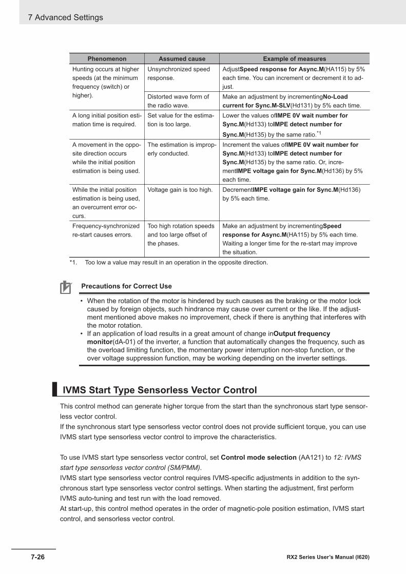
Phenomenon Assumed cause Example of measuresHunting occurs at higherspeeds (at the minimumfrequency (switch) orhigher).
Unsynchronized speedresponse.
AdjustSpeed response for Async.M(HA115) by 5%each time. You can increment or decrement it to ad-just.
Distorted wave form ofthe radio wave.
Make an adjustment by incrementingNo-Loadcurrent for Sync.M-SLV(Hd131) by 5% each time.
A long initial position esti-mation time is required.
Set value for the estima-tion is too large.
Lower the values ofIMPE 0V wait number forSync.M(Hd133) toIMPE detect number forSync.M(Hd135) by the same ratio.*1
A movement in the oppo-site direction occurswhile the initial positionestimation is being used.
The estimation is improp-erly conducted.
Increment the values ofIMPE 0V wait number forSync.M(Hd133) toIMPE detect number forSync.M(Hd135) by the same ratio. Or, incre-mentIMPE voltage gain for Sync.M(Hd136) by 5%each time.
While the initial positionestimation is being used,an overcurrent error oc-curs.
Voltage gain is too high. DecrementIMPE voltage gain for Sync.M(Hd136)by 5% each time.
Frequency-synchronizedre-start causes errors.
Too high rotation speedsand too large offset ofthe phases.
Make an adjustment by incrementingSpeedresponse for Async.M(HA115) by 5% each time.Waiting a longer time for the re-start may improvethe situation.
*1. Too low a value may result in an operation in the opposite direction.
Precautions for Correct Use
• When the rotation of the motor is hindered by such causes as the braking or the motor lockcaused by foreign objects, such hindrance may cause over current or the like. If the adjust-ment mentioned above makes no improvement, check if there is anything that interferes withthe motor rotation.
• If an application of load results in a great amount of change inOutput frequencymonitor(dA-01) of the inverter, a function that automatically changes the frequency, such asthe overload limiting function, the momentary power interruption non-stop function, or theover voltage suppression function, may be working depending on the inverter settings.
IVMS Start Type Sensorless Vector ControlThis control method can generate higher torque from the start than the synchronous start type sensor-less vector control.If the synchronous start type sensorless vector control does not provide sufficient torque, you can useIVMS start type sensorless vector control to improve the characteristics.
To use IVMS start type sensorless vector control, set Control mode selection (AA121) to 12: IVMSstart type sensorless vector control (SM/PMM).IVMS start type sensorless vector control requires IVMS-specific adjustments in addition to the syn-chronous start type sensorless vector control settings. When starting the adjustment, first performIVMS auto-tuning and test run with the load removed.At start-up, this control method operates in the order of magnetic-pole position estimation, IVMS startcontrol, and sensorless vector control.
7 Advanced Settings
7-26 RX2 Series User’s Manual (I620)
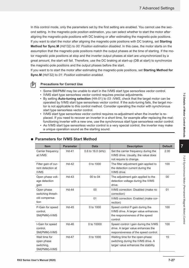
In this control mode, only the parameters set by the first setting are enabled. You cannot use the sec-ond setting. In the magnetic-pole position estimation, you can select whether to start the motor afteraligning the magnetic-pole positions with DC braking or after estimating the magnetic-pole positions.If you want to start the motor after aligning the magnetic-pole positions with DC braking, set StartingMethod for Sync.M (Hd132) to 00: Position estimation disabled. In this case, the motor starts on theassumption that the magnetic-pole positions match the output phases at the time of starting. If the mo-tor magnetic pole positions at stop and the inverter output phases at start are unsynchronized by agreat amount, the start will fail. Therefore, use the DC braking at start-up (DB at start) to synchronizethe magnetic-pole positions and the output phases before the start.If you want to to start the motor after estimating the magnetic-pole positions, set Starting Method forSync.M (Hd132) to 01: Position estimation enabled.
Precautions for Correct Use
• Some SM/PMM may be unable to start in the IVMS start type sensorless vector control.• IVMS start type sensorless vector control requires precise adjustments.• By setting Auto-tuning selection (HA-01) to 03: IVMS, check that the target motor can be
operated by IVMS start type sensorless vector control. If the auto-tuning fails, the target mo-tor is not applicable to this control method. Consider operating the motor with synchronousstart type sensorless vector control.
• IVMS start type sensorless vector control requires re-adjustment when the inverter is re-placed. If you need to recover an inverter in a short time, for example after replacing the mal-functioning inverter with a new one, use the synchronous start type sensorless vector control.
• As IVMS start type sensorless vector control is a very special control, the inverter may makea unique operation sound as the starting sound.
l Parameters for IVMS Start Method
Item Parameter Data Description DefaultCarrier frequencyat IVMS
Hd-41 0.6 to 16.0 (kHz) Set the carrier frequency during theIVMS drive. Usually, the value doesnot require to change.
2.00
Filter gain of cur-rent detection atIVMS
Hd-42 0 to 1000 The filter adjustment gain applied tothe detection current during theIVMS drive.
100
Open phase volt-age detectiongain
Hd-43 00 to 04 The adjustment gain applied to thedetection voltage during the IVMSdrive.
00
Open phaseswitching thresh-old compensa-tion
Hd-44 00 IVMS correction: Disabled (make nocorrection)
01
01 IVMS correction: Enabled (make cor-rection)
P-Gain for speedcontrol,SM(PMM)-IVMS
Hd-45 0 to 1000 Speed control P gain during theIVMS drive. A larger value enhancesthe responsiveness of the speedcontrol.
100
I-Gain for speedcontrol,SM(PMM)-IVMS
Hd-46 0 to 10000 Speed control I gain during the IVMSdrive. A larger value enhances theresponsiveness of the speed control.
100
Wait time foropen phaseswitching,SM(PMM)-IVMS
Hd-47 0 to 1000 Waiting time for the open-phaseswitching during the IVMS drive. Alarger value enhances the stability.
15
7 Advanced Settings
7-27RX2 Series User’s Manual (I620)
7-2 Details of M
otor Control M
ethods
7
7-2-9 Synchronous Motor (Perm
anent Magnet M
otor) Control
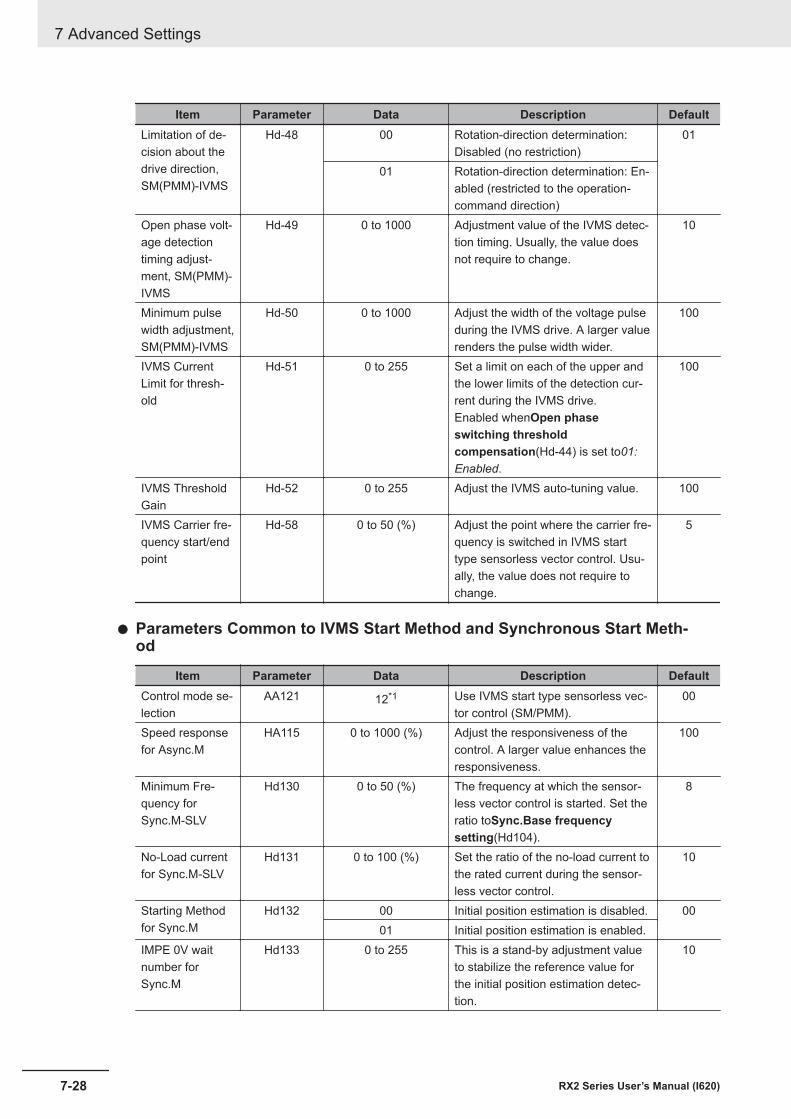
Item Parameter Data Description DefaultLimitation of de-cision about thedrive direction,SM(PMM)-IVMS
Hd-48 00 Rotation-direction determination:Disabled (no restriction)
01
01 Rotation-direction determination: En-abled (restricted to the operation-command direction)
Open phase volt-age detectiontiming adjust-ment, SM(PMM)-IVMS
Hd-49 0 to 1000 Adjustment value of the IVMS detec-tion timing. Usually, the value doesnot require to change.
10
Minimum pulsewidth adjustment,SM(PMM)-IVMS
Hd-50 0 to 1000 Adjust the width of the voltage pulseduring the IVMS drive. A larger valuerenders the pulse width wider.
100
IVMS CurrentLimit for thresh-old
Hd-51 0 to 255 Set a limit on each of the upper andthe lower limits of the detection cur-rent during the IVMS drive.Enabled whenOpen phaseswitching thresholdcompensation(Hd-44) is set to01:Enabled.
100
IVMS ThresholdGain
Hd-52 0 to 255 Adjust the IVMS auto-tuning value. 100
IVMS Carrier fre-quency start/endpoint
Hd-58 0 to 50 (%) Adjust the point where the carrier fre-quency is switched in IVMS starttype sensorless vector control. Usu-ally, the value does not require tochange.
5
l Parameters Common to IVMS Start Method and Synchronous Start Meth-od
Item Parameter Data Description DefaultControl mode se-lection
AA121 12*1 Use IVMS start type sensorless vec-tor control (SM/PMM).
00
Speed responsefor Async.M
HA115 0 to 1000 (%) Adjust the responsiveness of thecontrol. A larger value enhances theresponsiveness.
100
Minimum Fre-quency forSync.M-SLV
Hd130 0 to 50 (%) The frequency at which the sensor-less vector control is started. Set theratio toSync.Base frequencysetting(Hd104).
8
No-Load currentfor Sync.M-SLV
Hd131 0 to 100 (%) Set the ratio of the no-load current tothe rated current during the sensor-less vector control.
10
Starting Methodfor Sync.M
Hd132 00 Initial position estimation is disabled. 0001 Initial position estimation is enabled.
IMPE 0V waitnumber forSync.M
Hd133 0 to 255 This is a stand-by adjustment valueto stabilize the reference value forthe initial position estimation detec-tion.
10
7 Advanced Settings
7-28 RX2 Series User’s Manual (I620)
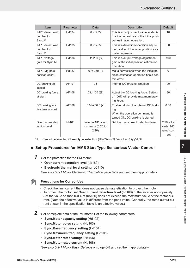
Item Parameter Data Description DefaultIMPE detect waitnumber forSync.M
Hd134 0 to 255 This is an adjustment value to stabi-lize the current rise of the initial posi-tion estimation operation.
10
IMPE detect waitnumber forSync.M
Hd135 0 to 255 This is a detection-operation adjust-ment value of the initial position esti-mation operation.
30
IMPE voltagegain for Sync.M
Hd136 0 to 200 (%) This is a output-voltage adjustmentgain of the initial position estimationoperation.
100
IMPE Mg-poleposition offset
Hd137 0 to 359 (°) Make corrections when the initial po-sition estimation operation has a cer-tain error.
0
DC braking se-lection
AF101 01 Internal DC braking: Enabled 00
DC braking forceat start
AF108 0 to 100 (%) Adjust the DC braking force. Settingof 100% will provide maximum brak-ing force.
30
DC braking ac-tive time at start
AF109 0.0 to 60.0 (s) Enabled during the internal DC brak-ing.When the operation command isturned ON, DC braking is started.
0.00
Over current de-tection level
bb160 Inverter ND ratedcurrent × (0.20 to
2.20)
Set the over current detection level. 2.20 × In-verter NDrated cur-
rent*1. Cannot be selected if Load type selection (Ub-03) is 00: Very low duty (VLD).
l Set-up Procedures for IVMS Start Type Sensorless Vector Control
1 Set the protection for the PM motor.• Over current detection level (bb160)• Electronic thermal level setting (bC110)See also 6-6-1 Motor Electronic Thermal on page 6-52 and set them appropriately.
Precautions for Correct Use
• Check the limit current that does not cause demagnetization to protect the motor.• To protect the motor, set Over current detection level (bb160) of the inverter appropriately.
Set the value so that 150% of (bb160) does not exceed the maximum value of the motor cur-rent. (Note the effective value is different from the peak value. Generally, the rated output cur-rent shown in the specification table is an effective value.)
2 Set nameplate data of the PM motor. Set the following parameters.• Sync.Motor capacity setting (Hd102)• Sync.Motor poles setting (Hd103)• Sync.Base frequency setting (Hd104)• Sync.Maximum frequency setting (Hd105)• Sync.Motor rated voltage (Hd106)• Sync.Motor rated current (Hd108)See also 6-2-1 Motor Basic Settings on page 6-8 and set them appropriately.
7 Advanced Settings
7-29RX2 Series User’s Manual (I620)
7-2 Details of M
otor Control M
ethods
7
7-2-9 Synchronous Motor (Perm
anent Magnet M
otor) Control
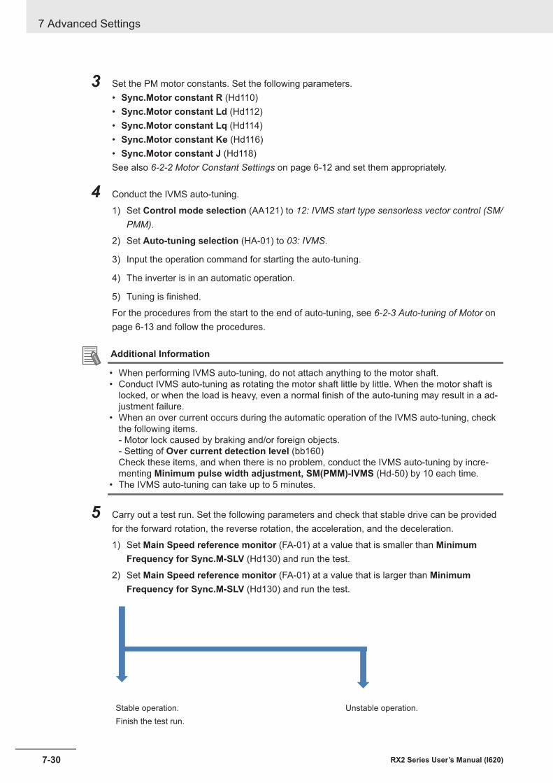
3 Set the PM motor constants. Set the following parameters.• Sync.Motor constant R (Hd110)• Sync.Motor constant Ld (Hd112)• Sync.Motor constant Lq (Hd114)• Sync.Motor constant Ke (Hd116)• Sync.Motor constant J (Hd118)See also 6-2-2 Motor Constant Settings on page 6-12 and set them appropriately.
4 Conduct the IVMS auto-tuning.
1) Set Control mode selection (AA121) to 12: IVMS start type sensorless vector control (SM/PMM).
2) Set Auto-tuning selection (HA-01) to 03: IVMS.
3) Input the operation command for starting the auto-tuning.
4) The inverter is in an automatic operation.
5) Tuning is finished.
For the procedures from the start to the end of auto-tuning, see 6-2-3 Auto-tuning of Motor onpage 6-13 and follow the procedures.
Additional Information
• When performing IVMS auto-tuning, do not attach anything to the motor shaft.• Conduct IVMS auto-tuning as rotating the motor shaft little by little. When the motor shaft is
locked, or when the load is heavy, even a normal finish of the auto-tuning may result in a ad-justment failure.
• When an over current occurs during the automatic operation of the IVMS auto-tuning, checkthe following items.- Motor lock caused by braking and/or foreign objects.- Setting of Over current detection level (bb160)Check these items, and when there is no problem, conduct the IVMS auto-tuning by incre-menting Minimum pulse width adjustment, SM(PMM)-IVMS (Hd-50) by 10 each time.
• The IVMS auto-tuning can take up to 5 minutes.
5 Carry out a test run. Set the following parameters and check that stable drive can be providedfor the forward rotation, the reverse rotation, the acceleration, and the deceleration.
1) Set Main Speed reference monitor (FA-01) at a value that is smaller than MinimumFrequency for Sync.M-SLV (Hd130) and run the test.
2) Set Main Speed reference monitor (FA-01) at a value that is larger than MinimumFrequency for Sync.M-SLV (Hd130) and run the test.
Stable operation. Unstable operation.Finish the test run.
7 Advanced Settings
7-30 RX2 Series User’s Manual (I620)
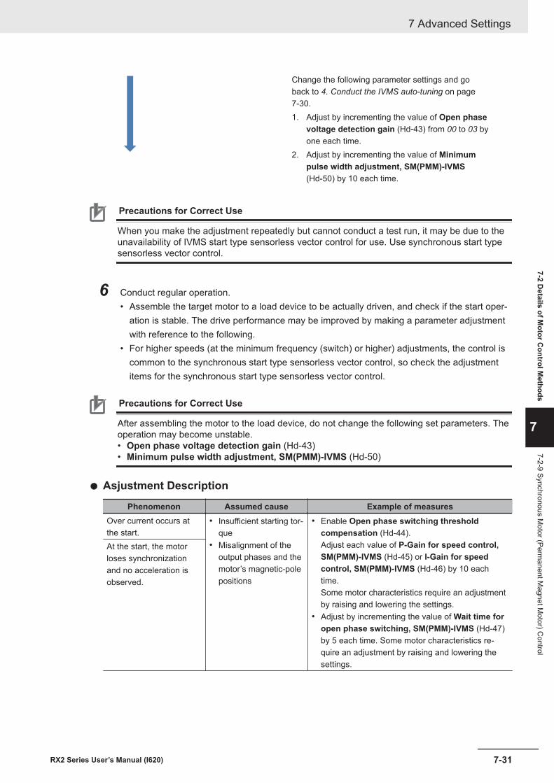
Change the following parameter settings and goback to 4. Conduct the IVMS auto-tuning on page7-30.1. Adjust by incrementing the value of Open phase
voltage detection gain (Hd-43) from 00 to 03 byone each time.
2. Adjust by incrementing the value of Minimumpulse width adjustment, SM(PMM)-IVMS(Hd-50) by 10 each time.
Precautions for Correct Use
When you make the adjustment repeatedly but cannot conduct a test run, it may be due to theunavailability of IVMS start type sensorless vector control for use. Use synchronous start typesensorless vector control.
6 Conduct regular operation.• Assemble the target motor to a load device to be actually driven, and check if the start oper-
ation is stable. The drive performance may be improved by making a parameter adjustmentwith reference to the following.
• For higher speeds (at the minimum frequency (switch) or higher) adjustments, the control iscommon to the synchronous start type sensorless vector control, so check the adjustmentitems for the synchronous start type sensorless vector control.
Precautions for Correct Use
After assembling the motor to the load device, do not change the following set parameters. Theoperation may become unstable.• Open phase voltage detection gain (Hd-43)• Minimum pulse width adjustment, SM(PMM)-IVMS (Hd-50)
l Asjustment Description
Phenomenon Assumed cause Example of measuresOver current occurs atthe start.
• Insufficient starting tor-que
• Misalignment of theoutput phases and themotor’s magnetic-polepositions
• Enable Open phase switching thresholdcompensation (Hd-44).Adjust each value of P-Gain for speed control,SM(PMM)-IVMS (Hd-45) or I-Gain for speedcontrol, SM(PMM)-IVMS (Hd-46) by 10 eachtime.Some motor characteristics require an adjustmentby raising and lowering the settings.
• Adjust by incrementing the value of Wait time foropen phase switching, SM(PMM)-IVMS (Hd-47)by 5 each time. Some motor characteristics re-quire an adjustment by raising and lowering thesettings.
At the start, the motorloses synchronizationand no acceleration isobserved.
7 Advanced Settings
7-31RX2 Series User’s Manual (I620)
7-2 Details of M
otor Control M
ethods
7
7-2-9 Synchronous Motor (Perm
anent Magnet M
otor) Control
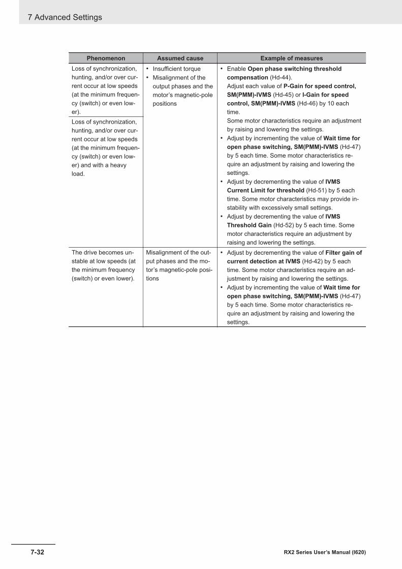
Phenomenon Assumed cause Example of measuresLoss of synchronization,hunting, and/or over cur-rent occur at low speeds(at the minimum frequen-cy (switch) or even low-er).
• Insufficient torque• Misalignment of the
output phases and themotor’s magnetic-polepositions
• Enable Open phase switching thresholdcompensation (Hd-44).Adjust each value of P-Gain for speed control,SM(PMM)-IVMS (Hd-45) or I-Gain for speedcontrol, SM(PMM)-IVMS (Hd-46) by 10 eachtime.Some motor characteristics require an adjustmentby raising and lowering the settings.
• Adjust by incrementing the value of Wait time foropen phase switching, SM(PMM)-IVMS (Hd-47)by 5 each time. Some motor characteristics re-quire an adjustment by raising and lowering thesettings.
• Adjust by decrementing the value of IVMSCurrent Limit for threshold (Hd-51) by 5 eachtime. Some motor characteristics may provide in-stability with excessively small settings.
• Adjust by decrementing the value of IVMSThreshold Gain (Hd-52) by 5 each time. Somemotor characteristics require an adjustment byraising and lowering the settings.
Loss of synchronization,hunting, and/or over cur-rent occur at low speeds(at the minimum frequen-cy (switch) or even low-er) and with a heavyload.
The drive becomes un-stable at low speeds (atthe minimum frequency(switch) or even lower).
Misalignment of the out-put phases and the mo-tor’s magnetic-pole posi-tions
• Adjust by decrementing the value of Filter gain ofcurrent detection at IVMS (Hd-42) by 5 eachtime. Some motor characteristics require an ad-justment by raising and lowering the settings.
• Adjust by incrementing the value of Wait time foropen phase switching, SM(PMM)-IVMS (Hd-47)by 5 each time. Some motor characteristics re-quire an adjustment by raising and lowering thesettings.
7 Advanced Settings
7-32 RX2 Series User’s Manual (I620)
7-3 Torque Control
7-3-1 Speed Control and Torque ControlThere are two methods to control the motor.• Speed control: Control to generate a torque that follows the motor speed according to the frequency
command.• Torque control: Control the motor output torque to follow the torque commandBoth control methods control the output frequency and output voltage in order to generate torque.
Speed control Torque controlControl Controlled to maintain the motor speed per
frequency command.Controlled to output the motor torque per tor-que command.
Operation When the load is changed, output will be con-trolled to maintain the speed.When the load increases, the torque is con-trolled to be higher, and when the load de-creases, the torque is controlled to be lower.
When the load is changed, output will be con-trolled to maintain the torque.By changing the rotation speed according tothe load and external force, the torque is con-trolled to follow the command.
Control modeselection(AA121)
All control methods 08: Sensorless vector control (IM)10: Vector control with sensor (IM)
Speed control with torque limitControl The control that maintains the motor speed according to the frequency command and the tor-
que limit function that limits the output torque not to exceed the upper limit operate at the sametime.
Operation When the load is changed, output will be controlled to maintain the speed.When the load increases, the torque is controlled to be higher, and when the load decreases,the torque is controlled to be lower. When the output torque exceeds the limit value, torque limitcontrol takes precedence over speed control.
Control modeselection(AA121)
08: Sensorless vector control (IM)09: Zero-Hz range sensorless vector control (IM)10: Vector control with sensor (IM)
7-3-2 Control Gain SwitchingWhen you want to switch the motor response depending on the conditions such as the rotation direc-tion of the machine and the high speed or low speed.There are two types of control gain switching functions, which can be selected with ASR gainswitching mode selection (HA120).• Control gain switching function: Two types of gain can be switched by turning the input terminal
function [CAS] ON/OFF.• Control gain mapping function: Four types of gain can be switched according to the speed.
To use this function, you need to set sensorless vector control, zero-speed range sensorless vectorcontrol, or vector control with sensor in Control mode selection (AA121).
7 Advanced Settings
7-33RX2 Series User’s Manual (I620)
7-3 Torque Control
7
7-3-1 Speed Control and Torque C
ontrol
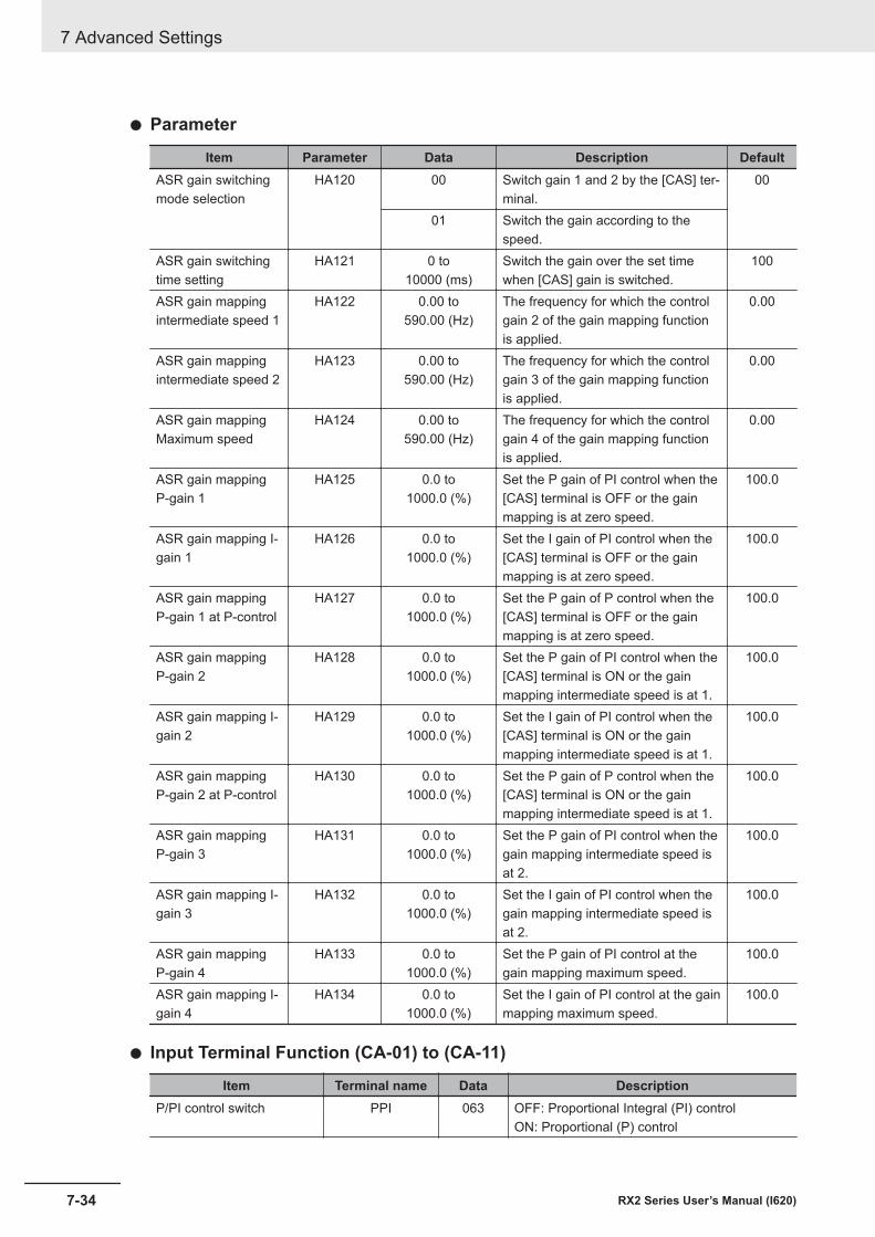
l Parameter
Item Parameter Data Description DefaultASR gain switchingmode selection
HA120 00 Switch gain 1 and 2 by the [CAS] ter-minal.
00
01 Switch the gain according to thespeed.
ASR gain switchingtime setting
HA121 0 to10000 (ms)
Switch the gain over the set timewhen [CAS] gain is switched.
100
ASR gain mappingintermediate speed 1
HA122 0.00 to590.00 (Hz)
The frequency for which the controlgain 2 of the gain mapping functionis applied.
0.00
ASR gain mappingintermediate speed 2
HA123 0.00 to590.00 (Hz)
The frequency for which the controlgain 3 of the gain mapping functionis applied.
0.00
ASR gain mappingMaximum speed
HA124 0.00 to590.00 (Hz)
The frequency for which the controlgain 4 of the gain mapping functionis applied.
0.00
ASR gain mappingP-gain 1
HA125 0.0 to1000.0 (%)
Set the P gain of PI control when the[CAS] terminal is OFF or the gainmapping is at zero speed.
100.0
ASR gain mapping I-gain 1
HA126 0.0 to1000.0 (%)
Set the I gain of PI control when the[CAS] terminal is OFF or the gainmapping is at zero speed.
100.0
ASR gain mappingP-gain 1 at P-control
HA127 0.0 to1000.0 (%)
Set the P gain of P control when the[CAS] terminal is OFF or the gainmapping is at zero speed.
100.0
ASR gain mappingP-gain 2
HA128 0.0 to1000.0 (%)
Set the P gain of PI control when the[CAS] terminal is ON or the gainmapping intermediate speed is at 1.
100.0
ASR gain mapping I-gain 2
HA129 0.0 to1000.0 (%)
Set the I gain of PI control when the[CAS] terminal is ON or the gainmapping intermediate speed is at 1.
100.0
ASR gain mappingP-gain 2 at P-control
HA130 0.0 to1000.0 (%)
Set the P gain of P control when the[CAS] terminal is ON or the gainmapping intermediate speed is at 1.
100.0
ASR gain mappingP-gain 3
HA131 0.0 to1000.0 (%)
Set the P gain of PI control when thegain mapping intermediate speed isat 2.
100.0
ASR gain mapping I-gain 3
HA132 0.0 to1000.0 (%)
Set the I gain of PI control when thegain mapping intermediate speed isat 2.
100.0
ASR gain mappingP-gain 4
HA133 0.0 to1000.0 (%)
Set the P gain of PI control at thegain mapping maximum speed.
100.0
ASR gain mapping I-gain 4
HA134 0.0 to1000.0 (%)
Set the I gain of PI control at the gainmapping maximum speed.
100.0
l Input Terminal Function (CA-01) to (CA-11)
Item Terminal name Data DescriptionP/PI control switch PPI 063 OFF: Proportional Integral (PI) control
ON: Proportional (P) control
7 Advanced Settings
7-34 RX2 Series User’s Manual (I620)
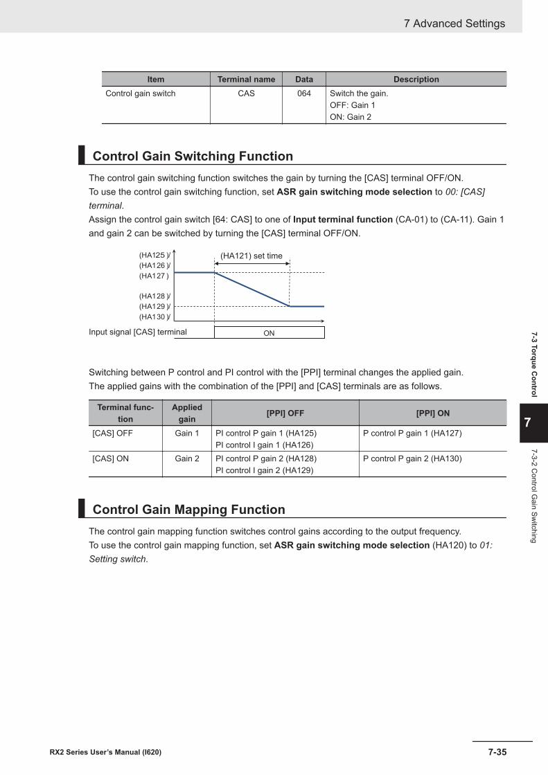
Item Terminal name Data DescriptionControl gain switch CAS 064 Switch the gain.
OFF: Gain 1ON: Gain 2
Control Gain Switching FunctionThe control gain switching function switches the gain by turning the [CAS] terminal OFF/ON.To use the control gain switching function, set ASR gain switching mode selection to 00: [CAS]terminal.Assign the control gain switch [64: CAS] to one of Input terminal function (CA-01) to (CA-11). Gain 1and gain 2 can be switched by turning the [CAS] terminal OFF/ON.
ON
(HA125 )/
(HA126 )/
(HA127 )
(HA128 )/
(HA129 )/
(HA130 )/
Input signal [CAS] terminal
(HA121) set time
Switching between P control and PI control with the [PPI] terminal changes the applied gain.The applied gains with the combination of the [PPI] and [CAS] terminals are as follows.
Terminal func-tion
Appliedgain [PPI] OFF [PPI] ON
[CAS] OFF Gain 1 PI control P gain 1 (HA125)PI control I gain 1 (HA126)
P control P gain 1 (HA127)
[CAS] ON Gain 2 PI control P gain 2 (HA128)PI control I gain 2 (HA129)
P control P gain 2 (HA130)
Control Gain Mapping FunctionThe control gain mapping function switches control gains according to the output frequency.To use the control gain mapping function, set ASR gain switching mode selection (HA120) to 01:Setting switch.
7 Advanced Settings
7-35RX2 Series User’s Manual (I620)
7-3 Torque Control
7
7-3-2 Control G
ain Switching
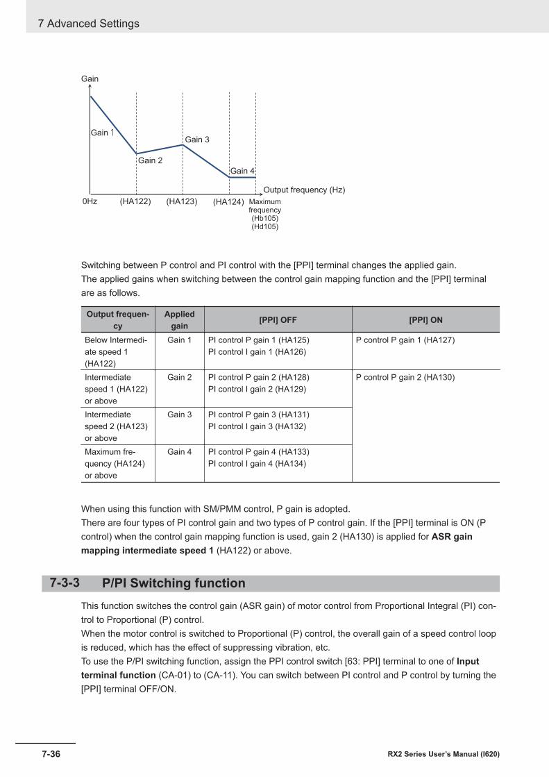
0Hz
Gain1Gain 3
Gain 2
Gain 4
(HA122) (HA123) (HA124) Maximumfrequency(Hb105)(Hd105)
Output frequency (Hz)
Gain
Switching between P control and PI control with the [PPI] terminal changes the applied gain.The applied gains when switching between the control gain mapping function and the [PPI] terminalare as follows.
Output frequen-cy
Appliedgain [PPI] OFF [PPI] ON
Below Intermedi-ate speed 1(HA122)
Gain 1 PI control P gain 1 (HA125)PI control I gain 1 (HA126)
P control P gain 1 (HA127)
Intermediatespeed 1 (HA122)or above
Gain 2 PI control P gain 2 (HA128)PI control I gain 2 (HA129)
P control P gain 2 (HA130)
Intermediatespeed 2 (HA123)or above
Gain 3 PI control P gain 3 (HA131)PI control I gain 3 (HA132)
Maximum fre-quency (HA124)or above
Gain 4 PI control P gain 4 (HA133)PI control I gain 4 (HA134)
When using this function with SM/PMM control, P gain is adopted.There are four types of PI control gain and two types of P control gain. If the [PPI] terminal is ON (Pcontrol) when the control gain mapping function is used, gain 2 (HA130) is applied for ASR gainmapping intermediate speed 1 (HA122) or above.
7-3-3 P/PI Switching functionThis function switches the control gain (ASR gain) of motor control from Proportional Integral (PI) con-trol to Proportional (P) control.When the motor control is switched to Proportional (P) control, the overall gain of a speed control loopis reduced, which has the effect of suppressing vibration, etc.To use the P/PI switching function, assign the PPI control switch [63: PPI] terminal to one of Inputterminal function (CA-01) to (CA-11). You can switch between PI control and P control by turning the[PPI] terminal OFF/ON.
7 Advanced Settings
7-36 RX2 Series User’s Manual (I620)
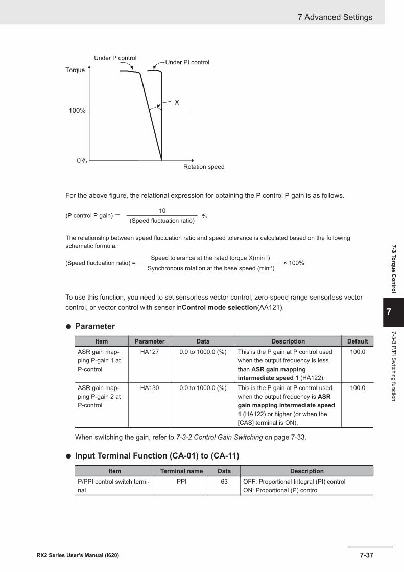
0%
100%
X
Under P controlUnder PI control
Torque
Rotation speed
For the above figure, the relational expression for obtaining the P control P gain is as follows.
(P control P gain) =
The relationship between speed fluctuation ratio and speed tolerance is calculated based on the following
schematic formula.
10
(Speed fluctuation ratio)%
(Speed fluctuation ratio) =Speed tolerance at the rated torque X(min-1)
Synchronous rotation at the base speed (min-1)× 100%
To use this function, you need to set sensorless vector control, zero-speed range sensorless vectorcontrol, or vector control with sensor inControl mode selection(AA121).
l Parameter
Item Parameter Data Description DefaultASR gain map-ping P-gain 1 atP-control
HA127 0.0 to 1000.0 (%) This is the P gain at P control usedwhen the output frequency is lessthan ASR gain mappingintermediate speed 1 (HA122).
100.0
ASR gain map-ping P-gain 2 atP-control
HA130 0.0 to 1000.0 (%) This is the P gain at P control usedwhen the output frequency is ASRgain mapping intermediate speed1 (HA122) or higher (or when the[CAS] terminal is ON).
100.0
When switching the gain, refer to 7-3-2 Control Gain Switching on page 7-33.
l Input Terminal Function (CA-01) to (CA-11)
Item Terminal name Data DescriptionP/PPI control switch termi-nal
PPI 63 OFF: Proportional Integral (PI) controlON: Proportional (P) control
7 Advanced Settings
7-37RX2 Series User’s Manual (I620)
7-3 Torque Control
7
7-3-3 P/PI Switching function
7-3-4 Torque Limit FunctionThis function limits the torque so that it does not become too high by using contact positioning control,etc.To use the torque limit function, you need to set sensorless vector control, zero-speed range sensor-less vector control, or vector control with sensor in Control mode selection (AA121). When zero-speed range sensorless vector control is used, the torque limit function does not work in the zero-speed range. The control to generate the torque is prioritized.The torque limit function is enabled in all of the speed control, position control, and torque control.
There are three types of torque limit functions.• Torque limit by analog input• Torque limit by quadrant-specific setting• Torque limit by terminal switching
The torque reference value (100%) for this function is calculated as follows.Torque reference value = 79.58 x motor capacity x number of poles / base frequency
(Example) Torque reference value = 79.58 x 5.5 (kW) x 4 (P) / 50 (Hz) ≒ 35Nm
Therefore, the output torque varies depending on the motor to be combined. Note that it is not the ab-solute value of torque.
l Parameter
Item Parameter Data Description DefaultTorque limit se-lection
bA110 00 to 11 00: Disabled01: Ai1 terminal input02: Ai2 terminal input03: Ai3 terminal input04: (Reserved)05: (Reserved)06: (Reserved)07: Parameter setting08: RS48509: Option 110: Option 211: Option 3
07
Torque limit pa-rameter modeselection
bA111 00 Four quadrant specific 0001 [TRQ] and [TRQ2] terminal switch
Torque limit 1Torque limit 2Torque limit 3Torque limit 4
bA112bA113bA114bA115
0.0 to 500.00 (%) The torque limit function will be onwhen the output torque exceeds thisset value.
150.0
l Input Terminal Function (CA-01) to (CA-11)
Item Terminal name Data DescriptionValidation of torque limit TL 60 Switch between enable and disable of the tor-
que limit function.Torque limit switchover 1 TRQ1 61 Switch terminal 1 of the torque limit command.
7 Advanced Settings
7-38 RX2 Series User’s Manual (I620)
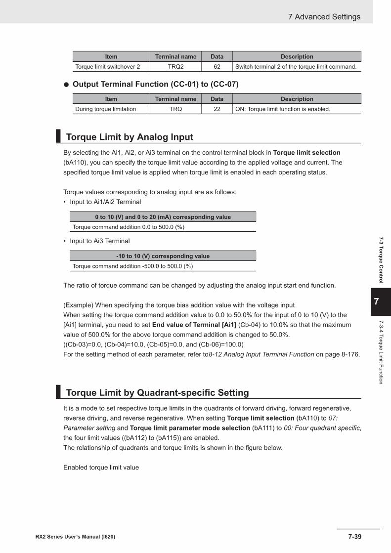
Item Terminal name Data DescriptionTorque limit switchover 2 TRQ2 62 Switch terminal 2 of the torque limit command.
l Output Terminal Function (CC-01) to (CC-07)
Item Terminal name Data DescriptionDuring torque limitation TRQ 22 ON: Torque limit function is enabled.
Torque Limit by Analog InputBy selecting the Ai1, Ai2, or Ai3 terminal on the control terminal block in Torque limit selection(bA110), you can specify the torque limit value according to the applied voltage and current. Thespecified torque limit value is applied when torque limit is enabled in each operating status.
Torque values corresponding to analog input are as follows.• Input to Ai1/Ai2 Terminal
0 to 10 (V) and 0 to 20 (mA) corresponding valueTorque command addition 0.0 to 500.0 (%)
• Input to Ai3 Terminal
-10 to 10 (V) corresponding valueTorque command addition -500.0 to 500.0 (%)
The ratio of torque command can be changed by adjusting the analog input start end function.
(Example) When specifying the torque bias addition value with the voltage inputWhen setting the torque command addition value to 0.0 to 50.0% for the input of 0 to 10 (V) to the[Ai1] terminal, you need to set End value of Terminal [Ai1] (Cb-04) to 10.0% so that the maximumvalue of 500.0% for the above torque command addition is changed to 50.0%.((Cb-03)=0.0, (Cb-04)=10.0, (Cb-05)=0.0, and (Cb-06)=100.0)For the setting method of each parameter, refer to8-12 Analog Input Terminal Function on page 8-176.
Torque Limit by Quadrant-specific SettingIt is a mode to set respective torque limits in the quadrants of forward driving, forward regenerative,reverse driving, and reverse regenerative. When setting Torque limit selection (bA110) to 07:Parameter setting and Torque limit parameter mode selection (bA111) to 00: Four quadrant specific,the four limit values ((bA112) to (bA115)) are enabled.The relationship of quadrants and torque limits is shown in the figure below.
Enabled torque limit value
7 Advanced Settings
7-39RX2 Series User’s Manual (I620)
7-3 Torque Control
7
7-3-4 Torque Limit Function
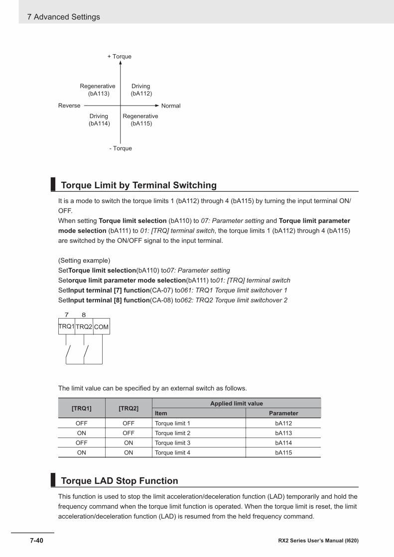
(bA112)
(bA115)(bA114)
(bA113)
NormalReverse
+ Torque
- Torque
DrivingRegenerative
RegenerativeDriving
Torque Limit by Terminal SwitchingIt is a mode to switch the torque limits 1 (bA112) through 4 (bA115) by turning the input terminal ON/OFF.When setting Torque limit selection (bA110) to 07: Parameter setting and Torque limit parametermode selection (bA111) to 01: [TRQ] terminal switch, the torque limits 1 (bA112) through 4 (bA115)are switched by the ON/OFF signal to the input terminal.
(Setting example)SetTorque limit selection(bA110) to07: Parameter settingSetorque limit parameter mode selection(bA111) to01: [TRQ] terminal switchSetInput terminal [7] function(CA-07) to061: TRQ1 Torque limit switchover 1SetInput terminal [8] function(CA-08) to062: TRQ2 Torque limit switchover 2
COMTRQ2TRQ1
7 8
The limit value can be specified by an external switch as follows.
[TRQ1] [TRQ2]Applied limit value
Item ParameterOFF OFF Torque limit 1 bA112ON OFF Torque limit 2 bA113OFF ON Torque limit 3 bA114ON ON Torque limit 4 bA115
Torque LAD Stop FunctionThis function is used to stop the limit acceleration/deceleration function (LAD) temporarily and hold thefrequency command when the torque limit function is operated. When the torque limit is reset, the limitacceleration/deceleration function (LAD) is resumed from the held frequency command.
7 Advanced Settings
7-40 RX2 Series User’s Manual (I620)
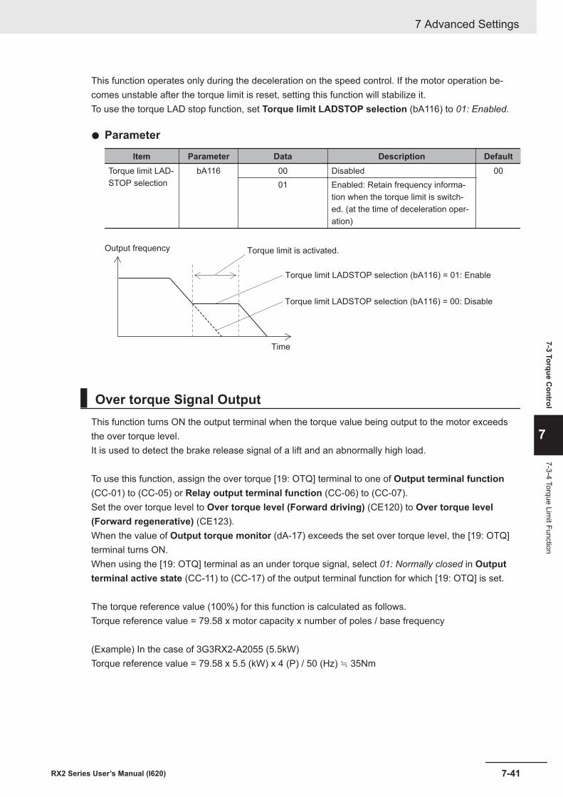
This function operates only during the deceleration on the speed control. If the motor operation be-comes unstable after the torque limit is reset, setting this function will stabilize it.To use the torque LAD stop function, set Torque limit LADSTOP selection (bA116) to 01: Enabled.
l Parameter
Item Parameter Data Description DefaultTorque limit LAD-STOP selection
bA116 00 Disabled 0001 Enabled: Retain frequency informa-
tion when the torque limit is switch-ed. (at the time of deceleration oper-ation)
Output frequency
Time
Torque limit is activated.
Torque limit LADSTOP selection (bA116) = 00: Disable
Torque limit LADSTOP selection (bA116) = 01: Enable
Over torque Signal OutputThis function turns ON the output terminal when the torque value being output to the motor exceedsthe over torque level.It is used to detect the brake release signal of a lift and an abnormally high load.
To use this function, assign the over torque [19: OTQ] terminal to one of Output terminal function(CC-01) to (CC-05) or Relay output terminal function (CC-06) to (CC-07).Set the over torque level to Over torque level (Forward driving) (CE120) to Over torque level(Forward regenerative) (CE123).When the value of Output torque monitor (dA-17) exceeds the set over torque level, the [19: OTQ]terminal turns ON.When using the [19: OTQ] terminal as an under torque signal, select 01: Normally closed in Outputterminal active state (CC-11) to (CC-17) of the output terminal function for which [19: OTQ] is set.
The torque reference value (100%) for this function is calculated as follows.Torque reference value = 79.58 x motor capacity x number of poles / base frequency
(Example) In the case of 3G3RX2-A2055 (5.5kW)Torque reference value = 79.58 x 5.5 (kW) x 4 (P) / 50 (Hz) ≒ 35Nm
7 Advanced Settings
7-41RX2 Series User’s Manual (I620)
7-3 Torque Control
7
7-3-4 Torque Limit Function
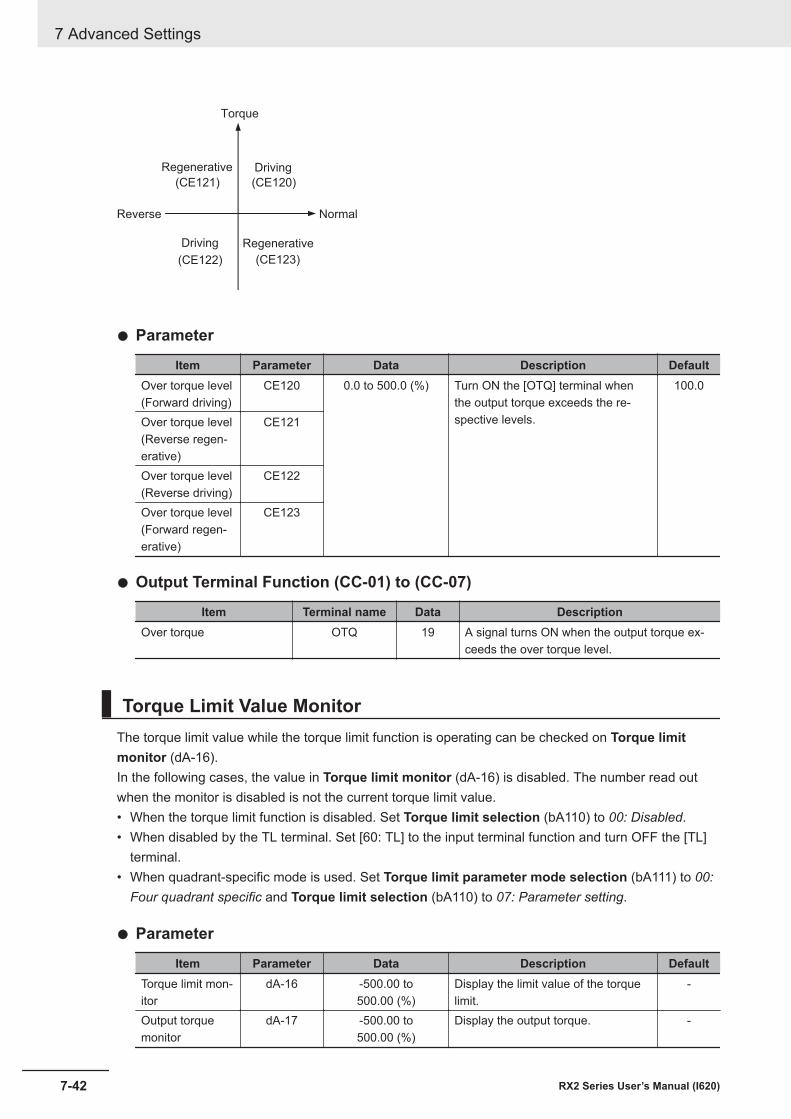
(CE120)
(CE123)(CE122)
(CE121)
Torque
NormalReverse
Driving
Driving Regenerative
Regenerative
l Parameter
Item Parameter Data Description DefaultOver torque level(Forward driving)
CE120 0.0 to 500.0 (%) Turn ON the [OTQ] terminal whenthe output torque exceeds the re-spective levels.
100.0
Over torque level(Reverse regen-erative)
CE121
Over torque level(Reverse driving)
CE122
Over torque level(Forward regen-erative)
CE123
l Output Terminal Function (CC-01) to (CC-07)
Item Terminal name Data DescriptionOver torque OTQ 19 A signal turns ON when the output torque ex-
ceeds the over torque level.
Torque Limit Value MonitorThe torque limit value while the torque limit function is operating can be checked on Torque limitmonitor (dA-16).In the following cases, the value in Torque limit monitor (dA-16) is disabled. The number read outwhen the monitor is disabled is not the current torque limit value.• When the torque limit function is disabled. Set Torque limit selection (bA110) to 00: Disabled.• When disabled by the TL terminal. Set [60: TL] to the input terminal function and turn OFF the [TL]
terminal.• When quadrant-specific mode is used. Set Torque limit parameter mode selection (bA111) to 00:
Four quadrant specific and Torque limit selection (bA110) to 07: Parameter setting.
l Parameter
Item Parameter Data Description DefaultTorque limit mon-itor
dA-16 -500.00 to500.00 (%)
Display the limit value of the torquelimit.
-
Output torquemonitor
dA-17 -500.00 to500.00 (%)
Display the output torque. -
7 Advanced Settings
7-42 RX2 Series User’s Manual (I620)
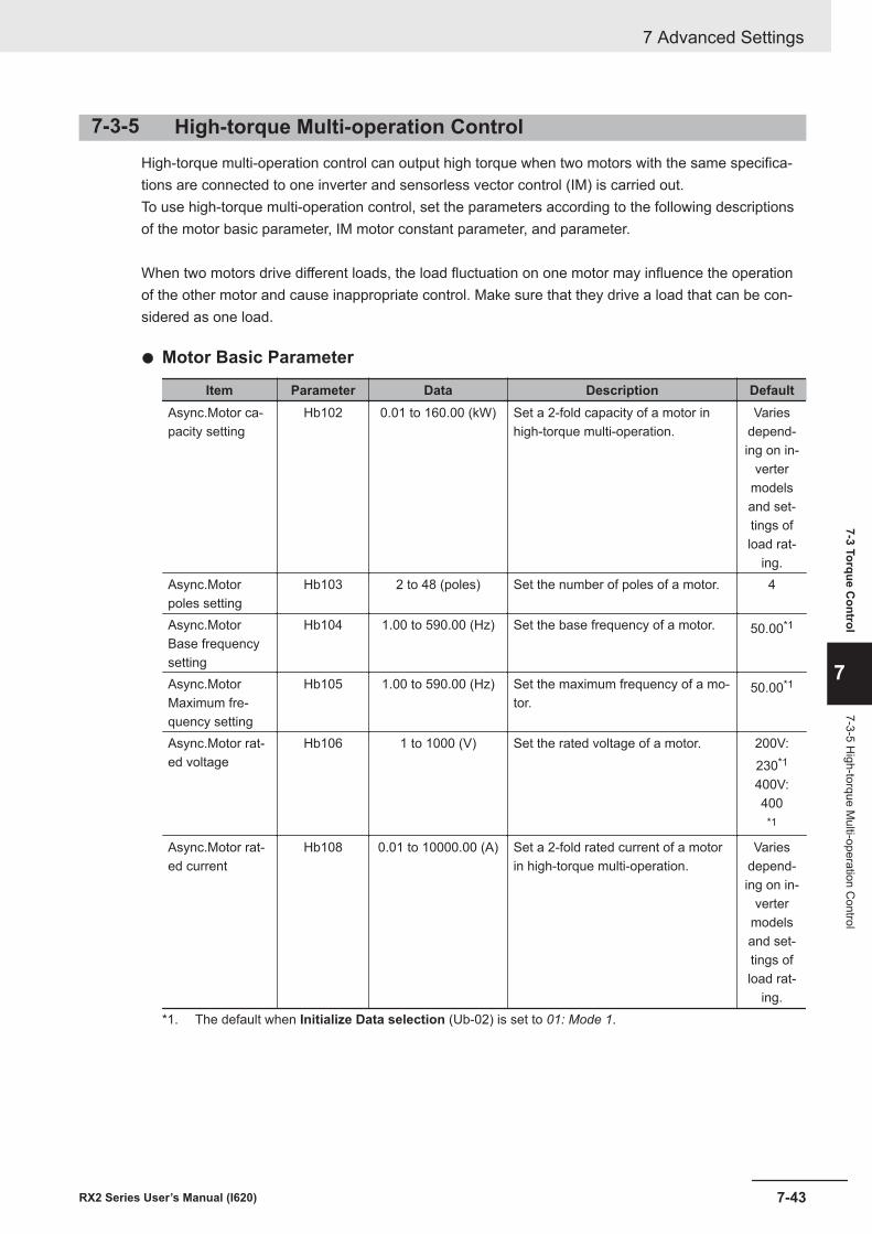
7-3-5 High-torque Multi-operation ControlHigh-torque multi-operation control can output high torque when two motors with the same specifica-tions are connected to one inverter and sensorless vector control (IM) is carried out.To use high-torque multi-operation control, set the parameters according to the following descriptionsof the motor basic parameter, IM motor constant parameter, and parameter.
When two motors drive different loads, the load fluctuation on one motor may influence the operationof the other motor and cause inappropriate control. Make sure that they drive a load that can be con-sidered as one load.
l Motor Basic Parameter
Item Parameter Data Description DefaultAsync.Motor ca-pacity setting
Hb102 0.01 to 160.00 (kW) Set a 2-fold capacity of a motor inhigh-torque multi-operation.
Variesdepend-ing on in-
vertermodelsand set-tings ofload rat-
ing.Async.Motorpoles setting
Hb103 2 to 48 (poles) Set the number of poles of a motor. 4
Async.MotorBase frequencysetting
Hb104 1.00 to 590.00 (Hz) Set the base frequency of a motor. 50.00*1
Async.MotorMaximum fre-quency setting
Hb105 1.00 to 590.00 (Hz) Set the maximum frequency of a mo-tor.
50.00*1
Async.Motor rat-ed voltage
Hb106 1 to 1000 (V) Set the rated voltage of a motor. 200V:230*1
400V:400
*1
Async.Motor rat-ed current
Hb108 0.01 to 10000.00 (A) Set a 2-fold rated current of a motorin high-torque multi-operation.
Variesdepend-ing on in-
vertermodelsand set-tings ofload rat-
ing.*1. The default when Initialize Data selection (Ub-02) is set to 01: Mode 1.
7 Advanced Settings
7-43RX2 Series User’s Manual (I620)
7-3 Torque Control
7
7-3-5 High-torque M
ulti-operation Control
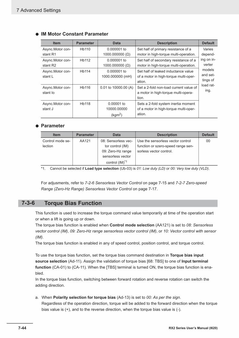
l IM Motor Constant Parameter
Item Parameter Data Description DefaultAsync.Motor con-stant R1
Hb110 0.000001 to1000.000000 (Ω)
Set half of primary resistance of amotor in high-torque multi-operation.
Variesdepend-ing on in-
vertermodelsand set-tings ofload rat-
ing.
Async.Motor con-stant R2
Hb112 0.000001 to1000.000000 (Ω)
Set half of secondary resistance of amotor in high-torque multi-operation.
Async.Motor con-stant L
Hb114 0.000001 to1000.000000 (mH)
Set half of leaked inductance valueof a motor in high-torque multi-oper-ation.
Async.Motor con-stant Io
Hb116 0.01 to 10000.00 (A) Set a 2-fold non-load current value ofa motor in high-torque multi-opera-tion.
Async.Motor con-stant J
Hb118 0.00001 to10000.00000
(kgm2)
Sets a 2-fold system inertia momentof a motor in high-torque multi-oper-ation.
l Parameter
Item Parameter Data Description DefaultControl mode se-lection
AA121 08: Sensorless vec-tor control (IM)
09: Zero-Hz rangesensorless vector
control (IM)*1
Use the sensorless vector controlfunction or szero-speed range sen-sorless vector control.
00
*1. Cannot be selected if Load type selection (Ub-03) is 01: Low duty (LD) or 00: Very low duty (VLD).
For adjusments, refer to 7-2-6 Sensorless Vector Control on page 7-15 and 7-2-7 Zero-speedRange (Zero-Hz Range) Sensorless Vector Control on page 7-17.
7-3-6 Torque Bias FunctionThis function is used to increase the torque command value temporarily at time of the operation startor when a lift is going up or down.The torque bias function is enabled when Control mode selection (AA121) is set to 08: Sensorlessvector control (IM), 09: Zero-Hz range sensorless vector control (IM), or 10: Vector control with sensor(IM).The torque bias function is enabled in any of speed control, position control, and torque control.
To use the torque bias function, set the torque bias command destination in Torque bias inputsource selection (Ad-11). Assign the validation of torque bias [68: TBS] to one of Input terminalfunction (CA-01) to (CA-11). When the [TBS] terminal is turned ON, the torque bias function is ena-bled.In the torque bias function, switching between forward rotation and reverse rotation can switch theadding direction.
a. When Polarity selection for torque bias (Ad-13) is set to 00: As per the sign.Regardless of the operation direction, torque will be added to the forward direction when the torquebias value is (+), and to the reverse direction, when the torque bias value is (-).
7 Advanced Settings
7-44 RX2 Series User’s Manual (I620)
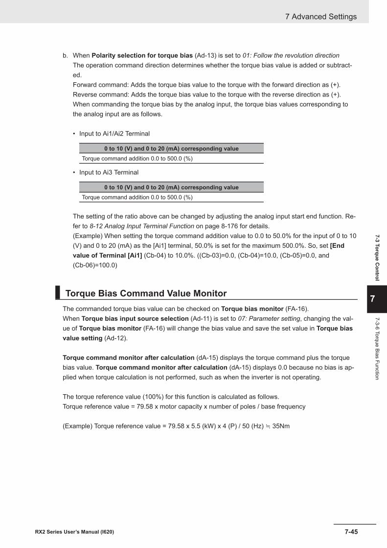
b. When Polarity selection for torque bias (Ad-13) is set to 01: Follow the revolution directionThe operation command direction determines whether the torque bias value is added or subtract-ed.Forward command: Adds the torque bias value to the torque with the forward direction as (+).Reverse command: Adds the torque bias value to the torque with the reverse direction as (+).When commanding the torque bias by the analog input, the torque bias values corresponding tothe analog input are as follows.
• Input to Ai1/Ai2 Terminal
0 to 10 (V) and 0 to 20 (mA) corresponding valueTorque command addition 0.0 to 500.0 (%)
• Input to Ai3 Terminal
0 to 10 (V) and 0 to 20 (mA) corresponding valueTorque command addition 0.0 to 500.0 (%)
The setting of the ratio above can be changed by adjusting the analog input start end function. Re-fer to 8-12 Analog Input Terminal Function on page 8-176 for details.(Example) When setting the torque command addition value to 0.0 to 50.0% for the input of 0 to 10(V) and 0 to 20 (mA) as the [Ai1] terminal, 50.0% is set for the maximum 500.0%. So, set [Endvalue of Terminal [Ai1] (Cb-04) to 10.0%. ((Cb-03)=0.0, (Cb-04)=10.0, (Cb-05)=0.0, and(Cb-06)=100.0)
Torque Bias Command Value MonitorThe commanded torque bias value can be checked on Torque bias monitor (FA-16).When Torque bias input source selection (Ad-11) is set to 07: Parameter setting, changing the val-ue of Torque bias monitor (FA-16) will change the bias value and save the set value in Torque biasvalue setting (Ad-12).
Torque command monitor after calculation (dA-15) displays the torque command plus the torquebias value. Torque command monitor after calculation (dA-15) displays 0.0 because no bias is ap-plied when torque calculation is not performed, such as when the inverter is not operating.
The torque reference value (100%) for this function is calculated as follows.Torque reference value = 79.58 x motor capacity x number of poles / base frequency
(Example) Torque reference value = 79.58 x 5.5 (kW) x 4 (P) / 50 (Hz) ≒ 35Nm
7 Advanced Settings
7-45RX2 Series User’s Manual (I620)
7-3 Torque Control
7
7-3-6 Torque Bias Function
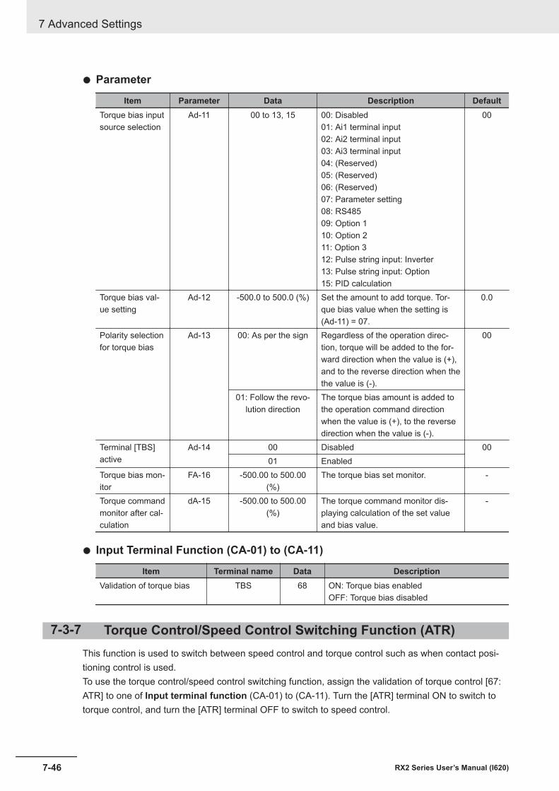
l Parameter
Item Parameter Data Description DefaultTorque bias inputsource selection
Ad-11 00 to 13, 15 00: Disabled01: Ai1 terminal input02: Ai2 terminal input03: Ai3 terminal input04: (Reserved)05: (Reserved)06: (Reserved)07: Parameter setting08: RS48509: Option 110: Option 211: Option 312: Pulse string input: Inverter13: Pulse string input: Option15: PID calculation
00
Torque bias val-ue setting
Ad-12 -500.0 to 500.0 (%) Set the amount to add torque. Tor-que bias value when the setting is(Ad-11) = 07.
0.0
Polarity selectionfor torque bias
Ad-13 00: As per the sign Regardless of the operation direc-tion, torque will be added to the for-ward direction when the value is (+),and to the reverse direction when thethe value is (-).
00
01: Follow the revo-lution direction
The torque bias amount is added tothe operation command directionwhen the value is (+), to the reversedirection when the value is (-).
Terminal [TBS]active
Ad-14 00 Disabled 0001 Enabled
Torque bias mon-itor
FA-16 -500.00 to 500.00(%)
The torque bias set monitor. -
Torque commandmonitor after cal-culation
dA-15 -500.00 to 500.00(%)
The torque command monitor dis-playing calculation of the set valueand bias value.
-
l Input Terminal Function (CA-01) to (CA-11)
Item Terminal name Data DescriptionValidation of torque bias TBS 68 ON: Torque bias enabled
OFF: Torque bias disabled
7-3-7 Torque Control/Speed Control Switching Function (ATR)This function is used to switch between speed control and torque control such as when contact posi-tioning control is used.To use the torque control/speed control switching function, assign the validation of torque control [67:ATR] to one of Input terminal function (CA-01) to (CA-11). Turn the [ATR] terminal ON to switch totorque control, and turn the [ATR] terminal OFF to switch to speed control.
7 Advanced Settings
7-46 RX2 Series User’s Manual (I620)
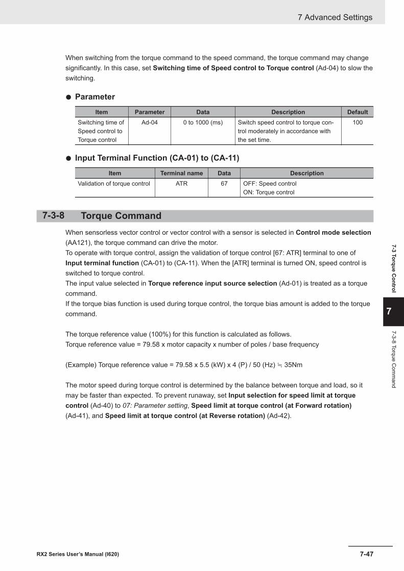
When switching from the torque command to the speed command, the torque command may changesignificantly. In this case, set Switching time of Speed control to Torque control (Ad-04) to slow theswitching.
l Parameter
Item Parameter Data Description DefaultSwitching time ofSpeed control toTorque control
Ad-04 0 to 1000 (ms) Switch speed control to torque con-trol moderately in accordance withthe set time.
100
l Input Terminal Function (CA-01) to (CA-11)
Item Terminal name Data DescriptionValidation of torque control ATR 67 OFF: Speed control
ON: Torque control
7-3-8 Torque CommandWhen sensorless vector control or vector control with a sensor is selected in Control mode selection(AA121), the torque command can drive the motor.To operate with torque control, assign the validation of torque control [67: ATR] terminal to one ofInput terminal function (CA-01) to (CA-11). When the [ATR] terminal is turned ON, speed control isswitched to torque control.The input value selected in Torque reference input source selection (Ad-01) is treated as a torquecommand.If the torque bias function is used during torque control, the torque bias amount is added to the torquecommand.
The torque reference value (100%) for this function is calculated as follows.Torque reference value = 79.58 x motor capacity x number of poles / base frequency
(Example) Torque reference value = 79.58 x 5.5 (kW) x 4 (P) / 50 (Hz) ≒ 35Nm
The motor speed during torque control is determined by the balance between torque and load, so itmay be faster than expected. To prevent runaway, set Input selection for speed limit at torquecontrol (Ad-40) to 07: Parameter setting, Speed limit at torque control (at Forward rotation)(Ad-41), and Speed limit at torque control (at Reverse rotation) (Ad-42).
7 Advanced Settings
7-47RX2 Series User’s Manual (I620)
7-3 Torque Control
7
7-3-8 Torque Com
mand
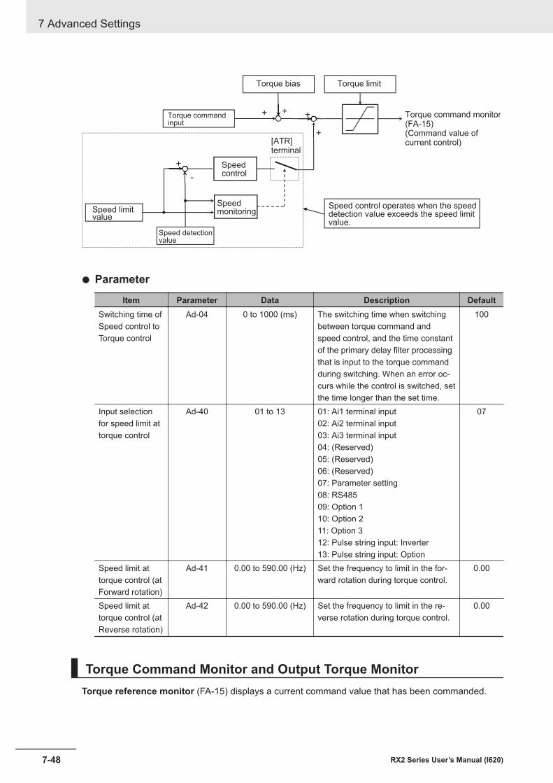
+
-
+ + +
+
Torque bias
Torque commandinput
Torque limit
Torque command monitor(FA-15)(Command value ofcurrent control)
Speed limitvalue
Speedmonitoring
Speedcontrol
[ATR]terminal
Speed detectionvalue
Speed control operates when the speeddetection value exceeds the speed limitvalue.
l Parameter
Item Parameter Data Description DefaultSwitching time ofSpeed control toTorque control
Ad-04 0 to 1000 (ms) The switching time when switchingbetween torque command andspeed control, and the time constantof the primary delay filter processingthat is input to the torque commandduring switching. When an error oc-curs while the control is switched, setthe time longer than the set time.
100
Input selectionfor speed limit attorque control
Ad-40 01 to 13 01: Ai1 terminal input02: Ai2 terminal input03: Ai3 terminal input04: (Reserved)05: (Reserved)06: (Reserved)07: Parameter setting08: RS48509: Option 110: Option 211: Option 312: Pulse string input: Inverter13: Pulse string input: Option
07
Speed limit attorque control (atForward rotation)
Ad-41 0.00 to 590.00 (Hz) Set the frequency to limit in the for-ward rotation during torque control.
0.00
Speed limit attorque control (atReverse rotation)
Ad-42 0.00 to 590.00 (Hz) Set the frequency to limit in the re-verse rotation during torque control.
0.00
Torque Command Monitor and Output Torque MonitorTorque reference monitor (FA-15) displays a current command value that has been commanded.
7 Advanced Settings
7-48 RX2 Series User’s Manual (I620)
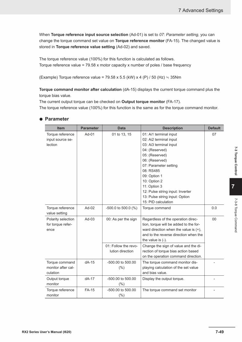
When Torque reference input source selection (Ad-01) is set to 07: Parameter setting, you canchange the torque command set value on Torque reference monitor (FA-15). The changed value isstored in Torque reference value setting (Ad-02) and saved.
The torque reference value (100%) for this function is calculated as follows.Torque reference value = 79.58 x motor capacity x number of poles / base frequency
(Example) Torque reference value = 79.58 x 5.5 (kW) x 4 (P) / 50 (Hz) ≒ 35Nm
Torque command monitor after calculation (dA-15) displays the current torque command plus thetorque bias value.The current output torque can be checked on Output torque monitor (FA-17).The torque reference value (100%) for this function is the same as for the torque command monitor.
l Parameter
Item Parameter Data Description DefaultTorque referenceinput source se-lection
Ad-01 01 to 13, 15 01: Ai1 terminal input02: Ai2 terminal input03: Ai3 terminal input04: (Reserved)05: (Reserved)06: (Reserved)07: Parameter setting08: RS48509: Option 110: Option 211: Option 312: Pulse string input: Inverter13: Pulse string input: Option15: PID calculation
07
Torque referencevalue setting
Ad-02 -500.0 to 500.0 (%) Torque command 0.0
Polarity selectionfor torque refer-ence
Ad-03 00: As per the sign Regardless of the operation direc-tion, torque will be added to the for-ward direction when the value is (+),and to the reverse direction when thethe value is (-).
00
01: Follow the revo-lution direction
Change the sign of value and the di-rection of torque bias action basedon the operation command direction.
Torque commandmonitor after cal-culation
dA-15 -500.00 to 500.00(%)
The torque command monitor dis-playing calculation of the set valueand bias value.
-
Output torquemonitor
dA-17 -500.00 to 500.00(%)
Display the output torque. -
Torque referencemonitor
FA-15 -500.00 to 500.00(%)
The torque command set monitor -
7 Advanced Settings
7-49RX2 Series User’s Manual (I620)
7-3 Torque Control
7
7-3-8 Torque Com
mand
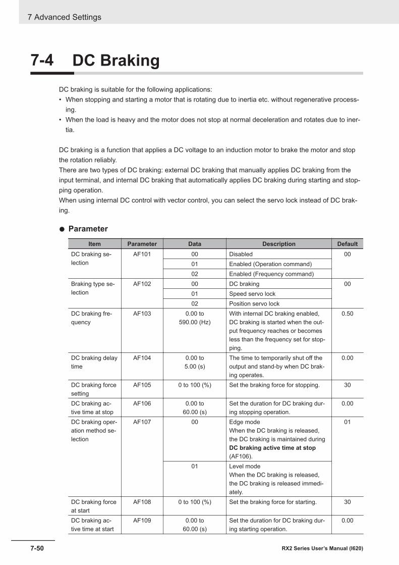
7-4 DC BrakingDC braking is suitable for the following applications:• When stopping and starting a motor that is rotating due to inertia etc. without regenerative process-
ing.• When the load is heavy and the motor does not stop at normal deceleration and rotates due to iner-
tia.
DC braking is a function that applies a DC voltage to an induction motor to brake the motor and stopthe rotation reliably.There are two types of DC braking: external DC braking that manually applies DC braking from theinput terminal, and internal DC braking that automatically applies DC braking during starting and stop-ping operation.When using internal DC control with vector control, you can select the servo lock instead of DC brak-ing.
l Parameter
Item Parameter Data Description DefaultDC braking se-lection
AF101 00 Disabled 0001 Enabled (Operation command)02 Enabled (Frequency command)
Braking type se-lection
AF102 00 DC braking 0001 Speed servo lock02 Position servo lock
DC braking fre-quency
AF103 0.00 to590.00 (Hz)
With internal DC braking enabled,DC braking is started when the out-put frequency reaches or becomesless than the frequency set for stop-ping.
0.50
DC braking delaytime
AF104 0.00 to5.00 (s)
The time to temporarily shut off theoutput and stand-by when DC brak-ing operates.
0.00
DC braking forcesetting
AF105 0 to 100 (%) Set the braking force for stopping. 30
DC braking ac-tive time at stop
AF106 0.00 to60.00 (s)
Set the duration for DC braking dur-ing stopping operation.
0.00
DC braking oper-ation method se-lection
AF107 00 Edge modeWhen the DC braking is released,the DC braking is maintained duringDC braking active time at stop(AF106).
01
01 Level modeWhen the DC braking is released,the DC braking is released immedi-ately.
DC braking forceat start
AF108 0 to 100 (%) Set the braking force for starting. 30
DC braking ac-tive time at start
AF109 0.00 to60.00 (s)
Set the duration for DC braking dur-ing starting operation.
0.00
7 Advanced Settings
7-50 RX2 Series User’s Manual (I620)
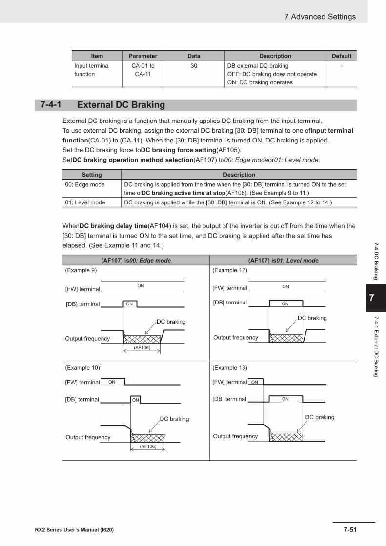
Item Parameter Data Description DefaultInput terminalfunction
CA-01 toCA-11
30 DB external DC brakingOFF: DC braking does not operateON: DC braking operates
-
7-4-1 External DC BrakingExternal DC braking is a function that manually applies DC braking from the input terminal.To use external DC braking, assign the external DC braking [30: DB] terminal to one ofInput terminalfunction(CA-01) to (CA-11). When the [30: DB] terminal is turned ON, DC braking is applied.Set the DC braking force toDC braking force setting(AF105).SetDC braking operation method selection(AF107) to00: Edge modeor01: Level mode.
Setting Description00: Edge mode DC braking is applied from the time when the [30: DB] terminal is turned ON to the set
time ofDC braking active time at stop(AF106). (See Example 9 to 11.)01: Level mode DC braking is applied while the [30: DB] terminal is ON. (See Example 12 to 14.)
WhenDC braking delay time(AF104) is set, the output of the inverter is cut off from the time when the[30: DB] terminal is turned ON to the set time, and DC braking is applied after the set time haselapsed. (See Example 11 and 14.)
(AF107) is00: Edge mode (AF107) is01: Level mode(Example 9)
[FW] terminal
[DB] terminal
(AF106)
ON
ON
DC braking
Output frequency
(Example 12)
[FW] terminal
[DB] terminal ON
ON
DC braking
Output frequency
(Example 10)
(AF106)
ON
ON[FW] terminal
[DB] terminal
DC braking
Output frequency
(Example 13)
ON
ON
[FW] terminal
[DB] terminal
DC braking
Output frequency
7 Advanced Settings
7-51RX2 Series User’s Manual (I620)
7-4 DC
Braking
7
7-4-1 External DC
Braking
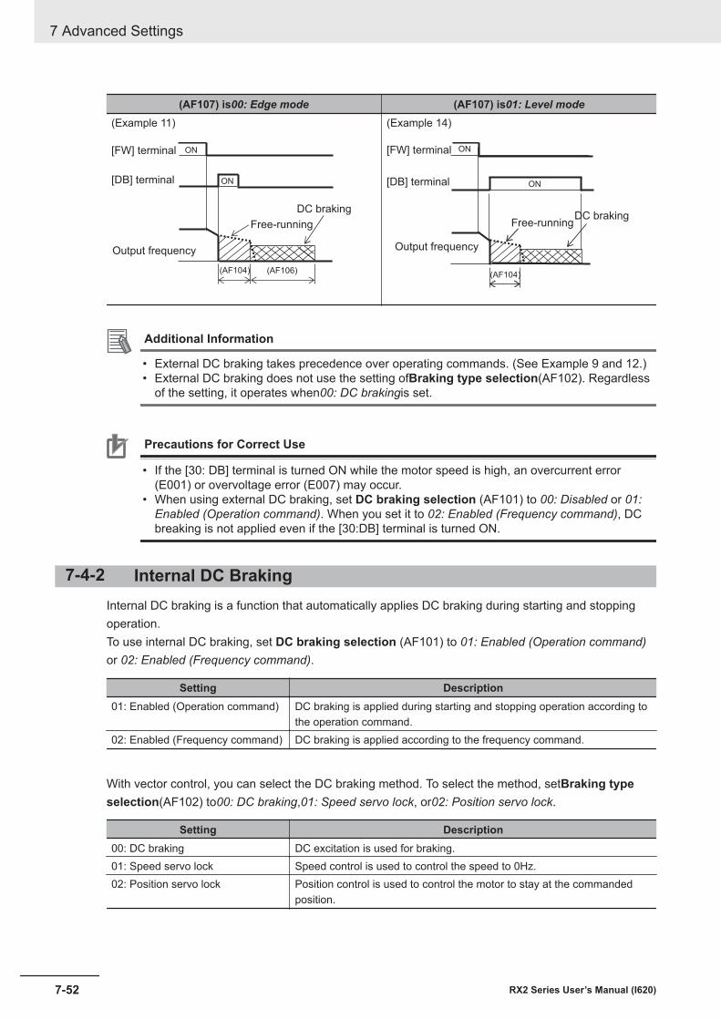
(AF107) is00: Edge mode (AF107) is01: Level mode(Example 11)
(AF104) (AF106)
[DB] terminal
ON[FW] terminal
ON
DC braking
Output frequency
Free-running
(Example 14)
(AF104)
ON
ON[DB] terminal
[FW] terminal
DC braking
Output frequency
Free-running
Additional Information
• External DC braking takes precedence over operating commands. (See Example 9 and 12.)• External DC braking does not use the setting ofBraking type selection(AF102). Regardless
of the setting, it operates when00: DC brakingis set.
Precautions for Correct Use
• If the [30: DB] terminal is turned ON while the motor speed is high, an overcurrent error(E001) or overvoltage error (E007) may occur.
• When using external DC braking, set DC braking selection (AF101) to 00: Disabled or 01:Enabled (Operation command). When you set it to 02: Enabled (Frequency command), DCbreaking is not applied even if the [30:DB] terminal is turned ON.
7-4-2 Internal DC BrakingInternal DC braking is a function that automatically applies DC braking during starting and stoppingoperation.To use internal DC braking, set DC braking selection (AF101) to 01: Enabled (Operation command)or 02: Enabled (Frequency command).
Setting Description01: Enabled (Operation command) DC braking is applied during starting and stopping operation according to
the operation command.02: Enabled (Frequency command) DC braking is applied according to the frequency command.
With vector control, you can select the DC braking method. To select the method, setBraking typeselection(AF102) to00: DC braking,01: Speed servo lock, or02: Position servo lock.
Setting Description00: DC braking DC excitation is used for braking.01: Speed servo lock Speed control is used to control the speed to 0Hz.02: Position servo lock Position control is used to control the motor to stay at the commanded
position.
7 Advanced Settings
7-52 RX2 Series User’s Manual (I620)
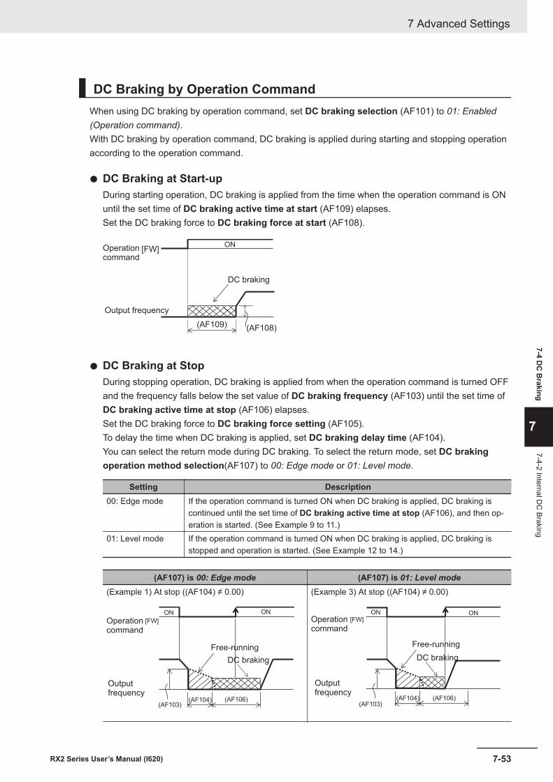
DC Braking by Operation CommandWhen using DC braking by operation command, set DC braking selection (AF101) to 01: Enabled(Operation command).With DC braking by operation command, DC braking is applied during starting and stopping operationaccording to the operation command.
l DC Braking at Start-upDuring starting operation, DC braking is applied from the time when the operation command is ONuntil the set time of DC braking active time at start (AF109) elapses.Set the DC braking force to DC braking force at start (AF108).
(AF109)
[FW]ON
(AF108)
Operationcommand
Output frequency
DC braking
l DC Braking at StopDuring stopping operation, DC braking is applied from when the operation command is turned OFFand the frequency falls below the set value of DC braking frequency (AF103) until the set time ofDC braking active time at stop (AF106) elapses.Set the DC braking force to DC braking force setting (AF105).To delay the time when DC braking is applied, set DC braking delay time (AF104).You can select the return mode during DC braking. To select the return mode, set DC brakingoperation method selection(AF107) to 00: Edge mode or 01: Level mode.
Setting Description00: Edge mode If the operation command is turned ON when DC braking is applied, DC braking is
continued until the set time of DC braking active time at stop (AF106), and then op-eration is started. (See Example 9 to 11.)
01: Level mode If the operation command is turned ON when DC braking is applied, DC braking isstopped and operation is started. (See Example 12 to 14.)
(AF107) is 00: Edge mode (AF107) is 01: Level mode(Example 1) At stop ((AF104) ≠ 0.00)
(AF104) (AF106)(AF103)
ON ON
[FW]Operationcommand
Free-running
DC braking
Outputfrequency
(Example 3) At stop ((AF104) ≠ 0.00)
(AF103)(AF104) (AF106)
ON ON[FW]Operation
command
Free-running
DC braking
Outputfrequency
7 Advanced Settings
7-53RX2 Series User’s Manual (I620)
7-4 DC
Braking
7
7-4-2 Internal DC
Braking
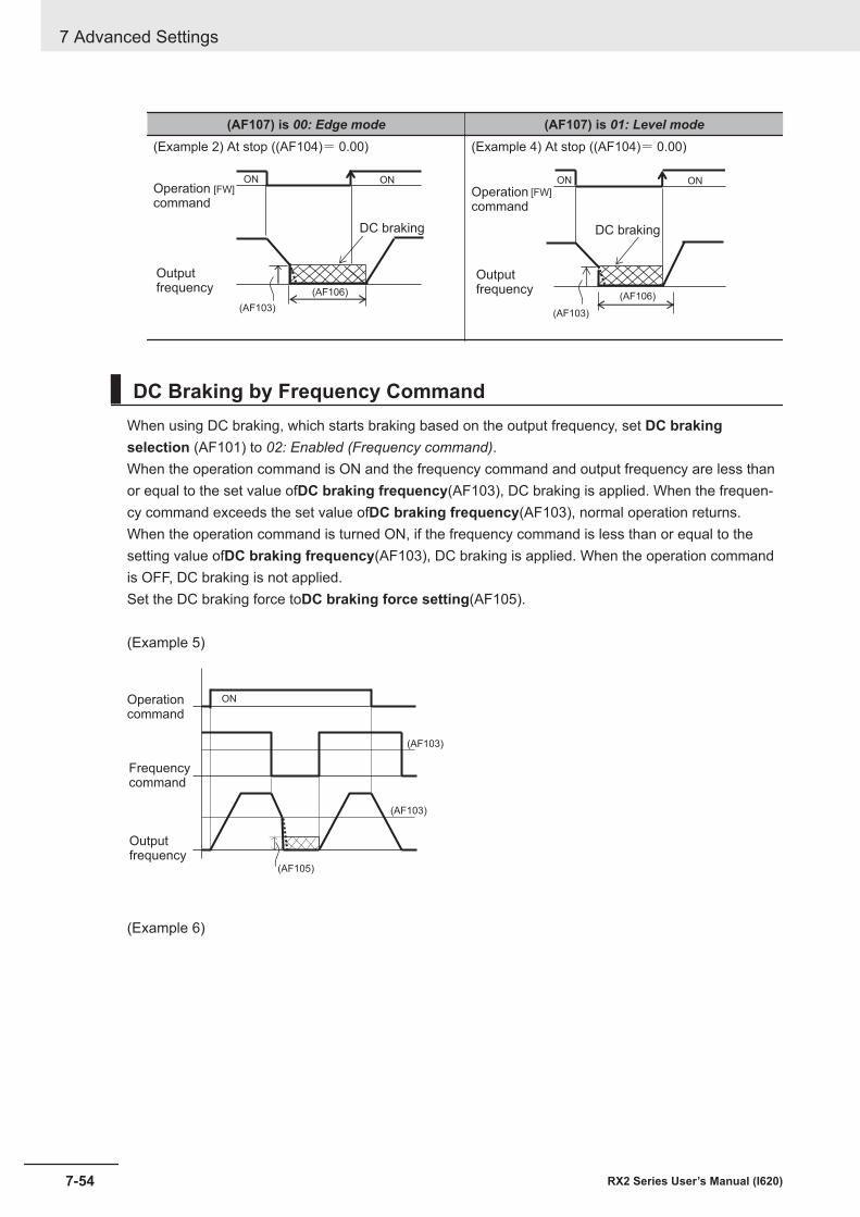
(AF107) is 00: Edge mode (AF107) is 01: Level mode(Example 2) At stop ((AF104)= 0.00)
(AF103)
(AF106)
ON ON[FW]Operation
command
DC braking
Outputfrequency
(Example 4) At stop ((AF104)= 0.00)
(AF103)
(AF106)
ON ON[FW]Operation
command
DC braking
Outputfrequency
DC Braking by Frequency CommandWhen using DC braking, which starts braking based on the output frequency, set DC brakingselection (AF101) to 02: Enabled (Frequency command).When the operation command is ON and the frequency command and output frequency are less thanor equal to the set value ofDC braking frequency(AF103), DC braking is applied. When the frequen-cy command exceeds the set value ofDC braking frequency(AF103), normal operation returns.When the operation command is turned ON, if the frequency command is less than or equal to thesetting value ofDC braking frequency(AF103), DC braking is applied. When the operation commandis OFF, DC braking is not applied.Set the DC braking force toDC braking force setting(AF105).
(Example 5)
(AF103)
ON
(AF103)
(AF105)
Operationcommand
Outputfrequency
Frequencycommand
(Example 6)
7 Advanced Settings
7-54 RX2 Series User’s Manual (I620)
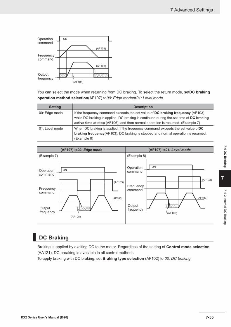
ON
(AF103)
(AF103)
(AF105)
Operationcommand
Outputfrequency
Frequencycommand
You can select the mode when returning from DC braking. To select the return mode, setDC brakingoperation method selection(AF107) to00: Edge modeor01: Level mode.
Setting Description00: Edge mode If the frequency command exceeds the set value of DC braking frequency (AF103)
while DC braking is applied, DC braking is continued during the set time of DC brakingactive time at stop (AF106), and then normal operation is resumed. (Example 7)
01: Level mode When DC braking is applied, if the frequency command exceeds the set value ofDCbraking frequency(AF103), DC braking is stopped and normal operation is resumed.(Example 8)
(AF107) is00: Edge mode (AF107) is01: Level mode(Example 7)
(AF103)
ON
(AF103)
(AF105)
Operationcommand
Outputfrequency
Frequencycommand
(Example 8)
(AF103)
ON
(AF103)
(AF105)
Operationcommand
Outputfrequency
Frequencycommand
DC BrakingBraking is applied by exciting DC to the motor. Regardless of the setting of Control mode selection(AA121), DC breaking is available in all control methods.To apply braking with DC braking, set Braking type selection (AF102) to 00: DC braking.
7 Advanced Settings
7-55RX2 Series User’s Manual (I620)
7-4 DC
Braking
7
7-4-2 Internal DC
Braking
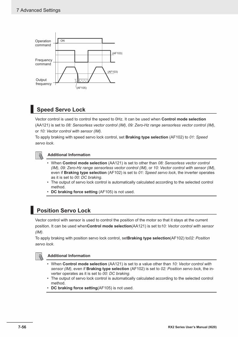
(AF103)
ON
(AF103)
(AF105)
Operationcommand
Outputfrequency
Frequencycommand
Speed Servo LockVector control is used to control the speed to 0Hz. It can be used when Control mode selection(AA121) is set to 08: Sensorless vector control (IM), 09: Zero-Hz range sensorless vector control (IM),or 10: Vector control with sensor (IM).To apply braking with speed servo lock control, set Braking type selection (AF102) to 01: Speedservo lock.
Additional Information
• When Control mode selection (AA121) is set to other than 08: Sensorless vector control(IM), 09: Zero-Hz range sensorless vector control (IM), or 10: Vector control with sensor (IM),even if Braking type selection (AF102) is set to 01: Speed servo lock, the inverter operatesas it is set to 00: DC braking.
• The output of servo lock control is automatically calculated according to the selected controlmethod.
• DC braking force setting (AF105) is not used.
Position Servo LockVector control with sensor is used to control the position of the motor so that it stays at the currentposition. It can be used whenControl mode selection(AA121) is set to10: Vector control with sensor(IM).To apply braking with position servo lock control, setBraking type selection(AF102) to02: Positionservo lock.
Additional Information
• When Control mode selection (AA121) is set to a value other than 10: Vector control withsensor (IM), even if Braking type selection (AF102) is set to 02: Position servo lock, the in-verter operates as it is set to 00: DC braking.
• The output of servo lock control is automatically calculated according to the selected controlmethod.
• DC braking force setting(AF105) is not used.
7 Advanced Settings
7-56 RX2 Series User’s Manual (I620)
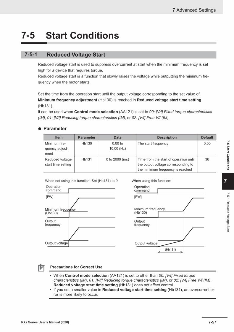
7-5 Start Conditions
7-5-1 Reduced Voltage StartReduced voltage start is used to suppress overcurrent at start when the minimum frequency is sethigh for a device that requires torque.Reduced voltage start is a function that slowly raises the voltage while outputting the minimum fre-quency when the motor starts.
Set the time from the operation start until the output voltage corresponding to the set value ofMinimum frequency adjustment (Hb130) is reached in Reduced voltage start time setting(Hb131).It can be used when Control mode selection (AA121) is set to 00: [V/f] Fixed torque characteristics(IM), 01: [V/f] Reducing torque characteristics (IM), or 02: [V/f] Free V/f (IM).
l Parameter
Item Parameter Data Description DefaultMinimum fre-quency adjust-ment
Hb130 0.00 to10.00 (Hz)
The start frequency 0.50
Reduced voltagestart time setting
Hb131 0 to 2000 (ms) Time from the start of operation untilthe output voltage corresponding tothe minimum frequency is reached
36
When not using this function: Set (Hb131) to 0. When using this function:
[FW]
(Hb131)
[FW]
Operationcommand
Outputfrequency
Operationcommand
Outputfrequency
Minimum frequency(Hb130)
Minimum frequency(Hb130)
Output voltage Output voltage
Precautions for Correct Use
• When Control mode selection (AA121) is set to other than 00: [V/f] Fixed torquecharacteristics (IM), 01: [V/f] Reducing torque characteristics (IM), or 02: [V/f] Free V/f (IM),Reduced voltage start time setting (Hb131) does not affect control.
• If you set a smaller value in Reduced voltage start time setting (Hb131), an overcurrent er-ror is more likely to occur.
7 Advanced Settings
7-57RX2 Series User’s Manual (I620)
7-5 Start Conditions
7
7-5-1 Reduced Voltage Start
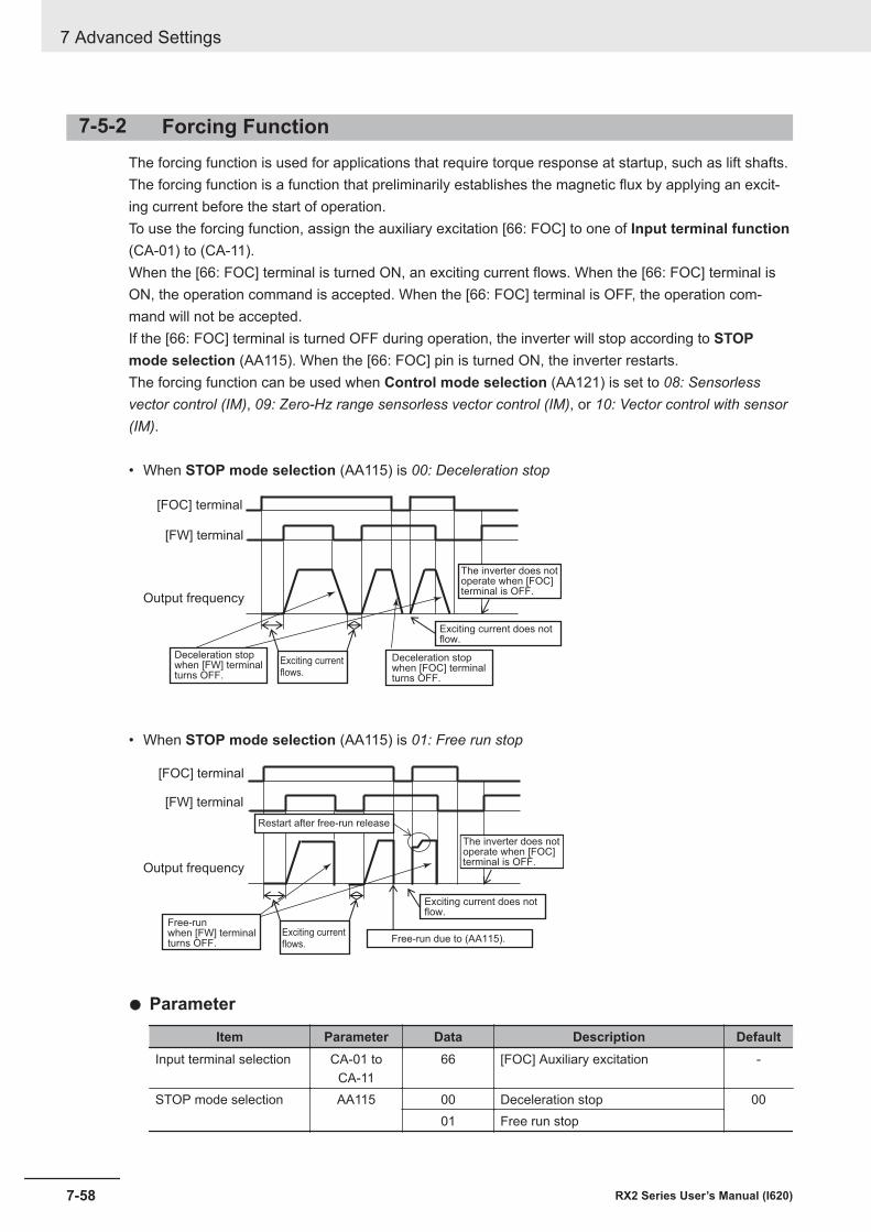
7-5-2 Forcing FunctionThe forcing function is used for applications that require torque response at startup, such as lift shafts.The forcing function is a function that preliminarily establishes the magnetic flux by applying an excit-ing current before the start of operation.To use the forcing function, assign the auxiliary excitation [66: FOC] to one of Input terminal function(CA-01) to (CA-11).When the [66: FOC] terminal is turned ON, an exciting current flows. When the [66: FOC] terminal isON, the operation command is accepted. When the [66: FOC] terminal is OFF, the operation com-mand will not be accepted.If the [66: FOC] terminal is turned OFF during operation, the inverter will stop according to STOPmode selection (AA115). When the [66: FOC] pin is turned ON, the inverter restarts.The forcing function can be used when Control mode selection (AA121) is set to 08: Sensorlessvector control (IM), 09: Zero-Hz range sensorless vector control (IM), or 10: Vector control with sensor(IM).
• When STOP mode selection (AA115) is 00: Deceleration stop
[FOC] terminal
[FW] terminal
Output frequency
Exciting current flows.
The inverter does notoperate when [FOC]terminal is OFF.
Exciting current does notflow.
Deceleration stopwhen [FOC] terminalturns OFF.
Deceleration stop when [FW] terminalturns OFF.
• When STOP mode selection (AA115) is 01: Free run stop
[FOC] terminal
[FW] terminal
Output frequency
Restart after free-run release
Exciting current flows.
Free-run due to (AA115).
The inverter does notoperate when [FOC]terminal is OFF.
Exciting current does notflow.
Free-runwhen [FW] terminalturns OFF.
l Parameter
Item Parameter Data Description DefaultInput terminal selection CA-01 to
CA-1166 [FOC] Auxiliary excitation -
STOP mode selection AA115 00 Deceleration stop 0001 Free run stop
7 Advanced Settings
7-58 RX2 Series User’s Manual (I620)
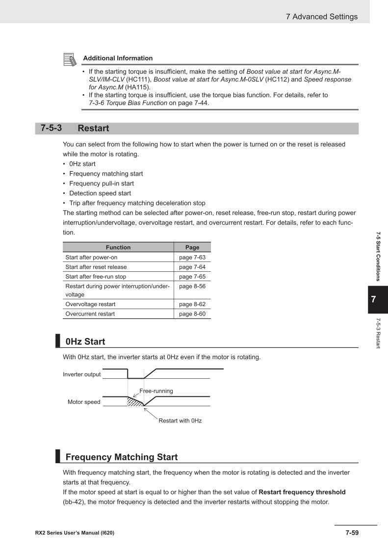
Additional Information
• If the starting torque is insufficient, make the setting of Boost value at start for Async.M-SLV/IM-CLV (HC111), Boost value at start for Async.M-0SLV (HC112) and Speed responsefor Async.M (HA115).
• If the starting torque is insufficient, use the torque bias function. For details, refer to 7-3-6 Torque Bias Function on page 7-44.
7-5-3 RestartYou can select from the following how to start when the power is turned on or the reset is releasedwhile the motor is rotating.• 0Hz start• Frequency matching start• Frequency pull-in start• Detection speed start• Trip after frequency matching deceleration stopThe starting method can be selected after power-on, reset release, free-run stop, restart during powerinterruption/undervoltage, overvoltage restart, and overcurrent restart. For details, refer to each func-tion.
Function PageStart after power-on page 7-63Start after reset release page 7-64Start after free-run stop page 7-65Restart during power interruption/under-voltage
page 8-56
Overvoltage restart page 8-62Overcurrent restart page 8-60
0Hz StartWith 0Hz start, the inverter starts at 0Hz even if the motor is rotating.
Inverter output
Motor speed
Restart with 0Hz
Free-running
Frequency Matching StartWith frequency matching start, the frequency when the motor is rotating is detected and the inverterstarts at that frequency.If the motor speed at start is equal to or higher than the set value of Restart frequency threshold(bb-42), the motor frequency is detected and the inverter restarts without stopping the motor.
7 Advanced Settings
7-59RX2 Series User’s Manual (I620)
7-5 Start Conditions
7
7-5-3 Restart
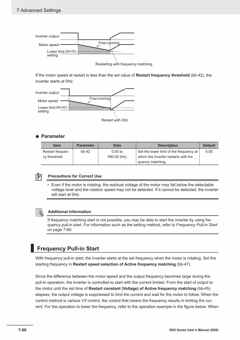
(bb-42)
Inverter output
Lower limitsetting
Motor speed
Restarting with frequency matching
Free-running
If the motor speed at restart is less than the set value of Restart frequency threshold (bb-42), theinverter starts at 0Hz.
(bb-42)
Inverter output
Lower limitsetting
Motor speed
Restart with 0Hz
Free-running
l Parameter
Item Parameter Data Description DefaultRestart frequen-cy threshold
bb-42 0.00 to590.00 (Hz)
Set the lower limit of the frequency atwhich the inverter restarts with fre-quency matching.
0.00
Precautions for Correct Use
• Even if the motor is rotating, the residual voltage of the motor may fall below the detectablevoltage level and the rotation speed may not be detected. If it cannot be detected, the inverterwill start at 0Hz.
Additional Information
If frequency matching start is not possible, you may be able to start the inverter by using fre-quency pull-in start. For information such as the setting method, refer to Frequency Pull-in Starton page 7-60.
Frequency Pull-in StartWith frequency pull-in start, the inverter starts at the set frequency when the motor is rotating. Set thestarting frequency in Restart speed selection of Active frequency matching (bb-47).
Since the difference between the motor speed and the output frequency becomes large during thepull-in operation, the inverter is controlled to start with the current limited. From the start of output tothe motor until the set time of Restart constant (Voltage) of Active frequency matching (bb-45)elapses, the output voltage is suppressed to limit the current and wait for the motor to follow. When thecontrol method is various V/f control, the control that lowers the frequency results in limiting the cur-rent. For the operation to lower the frequency, refer to the operation example in the figure below. When
7 Advanced Settings
7-60 RX2 Series User’s Manual (I620)
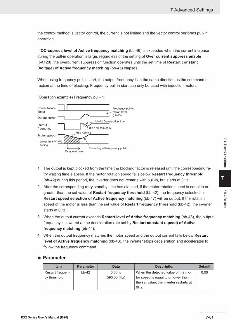
the control method is vector control, the current is not limited and the vector control performs pull-inoperation.
If OC-supress level of Active frequency matching (bb-46) is exceeded when the current increaseduring the pull-in operation is large, regardless of the setting of Over current suppress enable(bA120), the overcurrent suppression function operates until the set time of Restart constant(Voltage) of Active frequency matching (bb-45) elapses.
When using frequency pull-in start, the output frequency is in the same direction as the command di-rection at the time of blocking. Frequency pull-in start can only be used with induction motors.
(Operation example) Frequency pull-in
(bb-42)
(bb-43)
(bb-44)
(bb-47)Outputfrequency
Motor speed
Power failurefactor
Output current
Lower limit
setting
Frequency pull-in
restart level
Deceleration time
Frequency
Free-running
Restarting with frequency pull-inRetry wait time
1. The output is kept blocked from the time the blocking factor is released until the corresponding re-try waiting time elapses. If the motor rotation speed falls below Restart frequency threshold(bb-42) during this period, the inverter does not restarts with pull-in, but starts at 0Hz.
2. After the corresponding retry standby time has elapsed, if the motor rotation speed is equal to orgreater than the set value of Restart frequency threshold (bb-42), the frequency selected inRestart speed selection of Active frequency matching (bb-47) will be output. If the rotationspeed of the motor is less than the set value of Restart frequency threshold (bb-42), the inverterstarts at 0Hz.
3. When the output current exceeds Restart level of Active frequency matching (bb-43), the outputfrequency is lowered at the deceleration rate set by Restart constant (speed) of Activefrequency matching (bb-44).
4. When the output frequency matches the motor speed and the output current falls below Restartlevel of Active frequency matching (bb-43), the inverter stops deceleration and accelerates tofollow the frequency command.
l Parameter
Item Parameter Data Description DefaultRestart frequen-cy threshold
bb-42 0.00 to590.00 (Hz)
When the detected value of the mo-tor speed is equal to or lower thanthe set value, the inverter restarts at0Hz.
0.00
7 Advanced Settings
7-61RX2 Series User’s Manual (I620)
7-5 Start Conditions
7
7-5-3 Restart
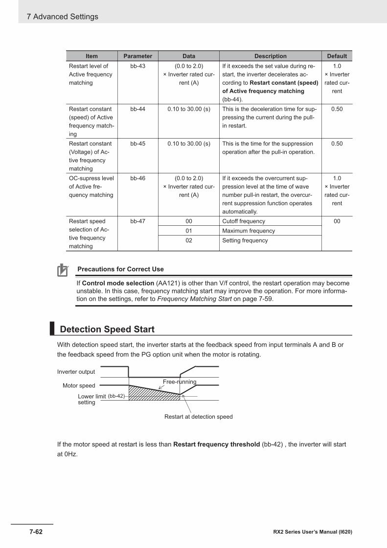
Item Parameter Data Description DefaultRestart level ofActive frequencymatching
bb-43 (0.0 to 2.0)× Inverter rated cur-
rent (A)
If it exceeds the set value during re-start, the inverter decelerates ac-cording to Restart constant (speed)of Active frequency matching(bb-44).
1.0× Inverterrated cur-
rent
Restart constant(speed) of Activefrequency match-ing
bb-44 0.10 to 30.00 (s) This is the deceleration time for sup-pressing the current during the pull-in restart.
0.50
Restart constant(Voltage) of Ac-tive frequencymatching
bb-45 0.10 to 30.00 (s) This is the time for the suppressionoperation after the pull-in operation.
0.50
OC-supress levelof Active fre-quency matching
bb-46 (0.0 to 2.0)× Inverter rated cur-
rent (A)
If it exceeds the overcurrent sup-pression level at the time of wavenumber pull-in restart, the overcur-rent suppression function operatesautomatically.
1.0× Inverterrated cur-
rent
Restart speedselection of Ac-tive frequencymatching
bb-47 00 Cutoff frequency 0001 Maximum frequency02 Setting frequency
Precautions for Correct Use
If Control mode selection (AA121) is other than V/f control, the restart operation may becomeunstable. In this case, frequency matching start may improve the operation. For more informa-tion on the settings, refer to Frequency Matching Start on page 7-59.
Detection Speed StartWith detection speed start, the inverter starts at the feedback speed from input terminals A and B orthe feedback speed from the PG option unit when the motor is rotating.
(bb-42)
Inverter output
Lower limitsetting
Motor speed
Restart at detection speed
Free-running
If the motor speed at restart is less than Restart frequency threshold (bb-42) , the inverter will startat 0Hz.
7 Advanced Settings
7-62 RX2 Series User’s Manual (I620)
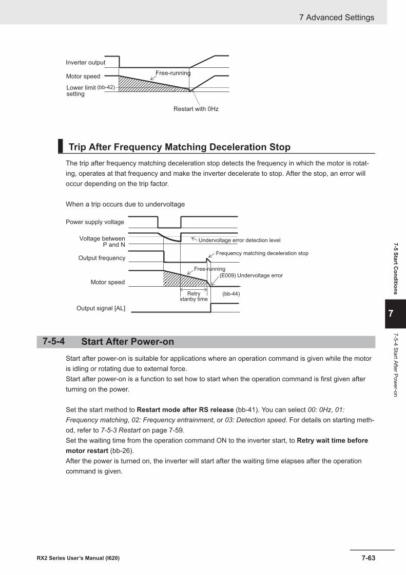
(bb-42)
Inverter output
Lower limitsetting
Motor speed
Restart with 0Hz
Free-running
Trip After Frequency Matching Deceleration StopThe trip after frequency matching deceleration stop detects the frequency in which the motor is rotat-ing, operates at that frequency and make the inverter decelerate to stop. After the stop, an error willoccur depending on the trip factor.
When a trip occurs due to undervoltage
(bb-44)
(E009) Undervoltage error
Power supply voltage
Voltage betweenP and N
Output frequency
Motor speed
Output signal [AL]
Retrystanby time
Frequency matching deceleration stop
Undervoltage error detection level
Free-running
7-5-4 Start After Power-onStart after power-on is suitable for applications where an operation command is given while the motoris idling or rotating due to external force.Start after power-on is a function to set how to start when the operation command is first given afterturning on the power.
Set the start method to Restart mode after RS release (bb-41). You can select 00: 0Hz, 01:Frequency matching, 02: Frequency entrainment, or 03: Detection speed. For details on starting meth-od, refer to 7-5-3 Restart on page 7-59.Set the waiting time from the operation command ON to the inverter start, to Retry wait time beforemotor restart (bb-26).After the power is turned on, the inverter will start after the waiting time elapses after the operationcommand is given.
7 Advanced Settings
7-63RX2 Series User’s Manual (I620)
7-5 Start Conditions
7
7-5-4 Start After Power-on
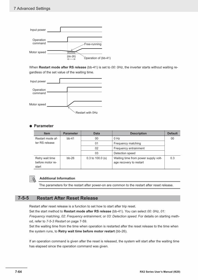
(bb-26)Operation of (bb-41)
Input power
Motor speed
Operationcommand Free-running
When Restart mode after RS release (bb-41) is set to 00: 0Hz, the inverter starts without waiting re-gardless of the set value of the waiting time.
Input power
Motor speed
Restart with 0Hz
Operationcommand
l Parameter
Item Parameter Data Description DefaultRestart mode af-ter RS release
bb-41 00 0 Hz 0001 Frequency matching02 Frequency entrainment03 Detection speed
Retry wait timebefore motor re-start
bb-26 0.3 to 100.0 (s) Waiting time from power supply volt-age recovery to restart
0.3
Additional Information
The parameters for the restart after power-on are common to the restart after reset release.
7-5-5 Restart After Reset ReleaseRestart after reset release is a function to set how to start after trip reset.Set the start method to Restart mode after RS release (bb-41). You can select 00: 0Hz, 01:Frequency matching, 02: Frequency entrainment, or 03: Detection speed. For details on starting meth-od, refer to 7-5-3 Restart on page 7-59.Set the waiting time from the time when operation is restarted after the reset release to the time whenthe system runs, to Retry wait time before motor restart (bb-26).
If an operation command is given after the reset is released, the system will start after the waiting timehas elapsed since the operation command was given.
7 Advanced Settings
7-64 RX2 Series User’s Manual (I620)
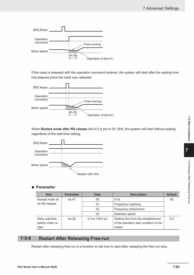
(bb-26)
[RS]
Operation of (bb-41)
Reset
Motor speed
Operationcommand
Free-running
If the reset is released with the operation command entered, the system will start after the waiting timehas elapsed since the reset was released.
(bb-26)
[RS]
Operation of (bb-41)
Reset
Motor speed
Operationcommand
Free-running
When Restart mode after RS release (bb-41) is set to 00: 0Hz, the system will start without waitingregardless of the wait time setting.
Motor speed
Restart with 0Hz
Operationcommand
[RS] Reset
l Parameter
Item Parameter Data Description DefaultRestart mode af-ter RS release
bb-41 00 0 Hz 0001 Frequency matching02 Frequency entrainment03 Detection speed
Retry wait timebefore motor re-start
bb-26 0.3 to 100.0 (s) Waiting time from the establishmentof the operation start condition to therestart
0.3
7-5-6 Restart After Releasing Free-runRestart after releasing free run is a function to set how to start after releasing the free run stop.
7 Advanced Settings
7-65RX2 Series User’s Manual (I620)
7-5 Start Conditions
7
7-5-6 Restart After R
eleasing Free-run
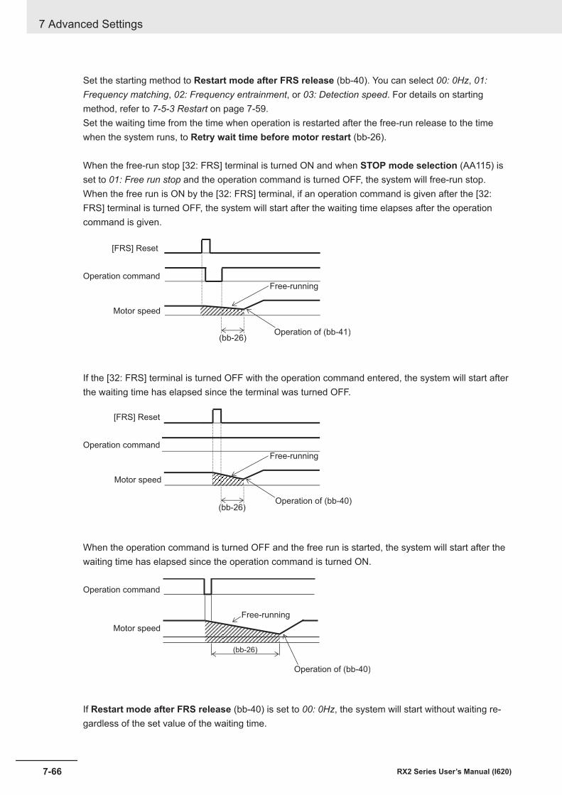
Set the starting method to Restart mode after FRS release (bb-40). You can select 00: 0Hz, 01:Frequency matching, 02: Frequency entrainment, or 03: Detection speed. For details on startingmethod, refer to 7-5-3 Restart on page 7-59.Set the waiting time from the time when operation is restarted after the free-run release to the timewhen the system runs, to Retry wait time before motor restart (bb-26).
When the free-run stop [32: FRS] terminal is turned ON and when STOP mode selection (AA115) isset to 01: Free run stop and the operation command is turned OFF, the system will free-run stop.When the free run is ON by the [32: FRS] terminal, if an operation command is given after the [32:FRS] terminal is turned OFF, the system will start after the waiting time elapses after the operationcommand is given.
(bb-26)
Motor speed
Free-running
Operation command
[FRS] Reset
Operation of (bb-41)
If the [32: FRS] terminal is turned OFF with the operation command entered, the system will start afterthe waiting time has elapsed since the terminal was turned OFF.
(bb-26)
Motor speed
Free-running
Operation command
[FRS] Reset
Operation of (bb-40)
When the operation command is turned OFF and the free run is started, the system will start after thewaiting time has elapsed since the operation command is turned ON.
(bb-26)
Motor speed
Free-running
Operation command
Operation of (bb-40)
If Restart mode after FRS release (bb-40) is set to 00: 0Hz, the system will start without waiting re-gardless of the set value of the waiting time.
7 Advanced Settings
7-66 RX2 Series User’s Manual (I620)
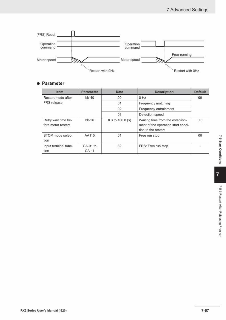
Motor speed
Restart with 0Hz
Operationcommand
[FRS] Reset
Restart with 0Hz
Motor speed
Free-running
Operationcommand
l Parameter
Item Parameter Data Description DefaultRestart mode afterFRS release
bb-40 00 0 Hz 0001 Frequency matching02 Frequency entrainment03 Detection speed
Retry wait time be-fore motor restart
bb-26 0.3 to 100.0 (s) Waiting time from the establish-ment of the operation start condi-tion to the restart
0.3
STOP mode selec-tion
AA115 01 Free run stop 00
Input terminal func-tion
CA-01 toCA-11
32 FRS: Free run stop -
7 Advanced Settings
7-67RX2 Series User’s Manual (I620)
7-5 Start Conditions
7
7-5-6 Restart After R
eleasing Free-run
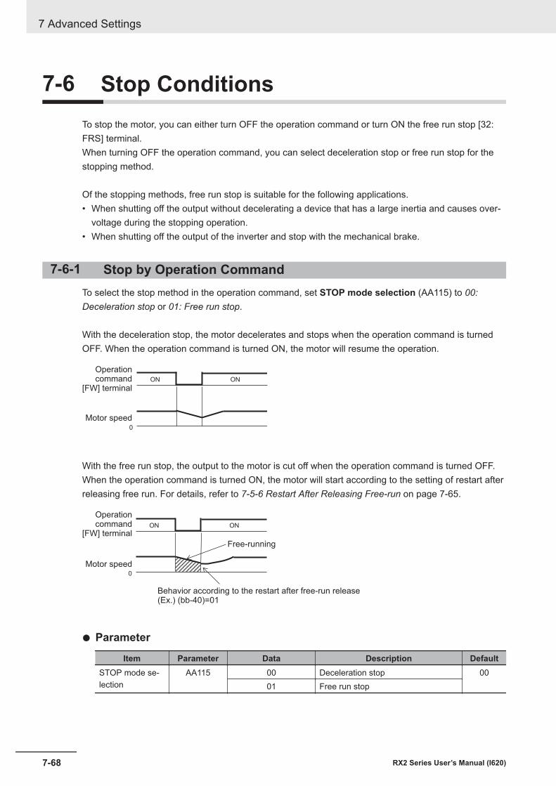
7-6 Stop ConditionsTo stop the motor, you can either turn OFF the operation command or turn ON the free run stop [32:FRS] terminal.When turning OFF the operation command, you can select deceleration stop or free run stop for thestopping method.
Of the stopping methods, free run stop is suitable for the following applications.• When shutting off the output without decelerating a device that has a large inertia and causes over-
voltage during the stopping operation.• When shutting off the output of the inverter and stop with the mechanical brake.
7-6-1 Stop by Operation CommandTo select the stop method in the operation command, set STOP mode selection (AA115) to 00:Deceleration stop or 01: Free run stop.
With the deceleration stop, the motor decelerates and stops when the operation command is turnedOFF. When the operation command is turned ON, the motor will resume the operation.
0
ON ON
Motor speed
Operationcommand
[FW] terminal
With the free run stop, the output to the motor is cut off when the operation command is turned OFF.When the operation command is turned ON, the motor will start according to the setting of restart afterreleasing free run. For details, refer to 7-5-6 Restart After Releasing Free-run on page 7-65.
0
ON ON
Motor speed
Operationcommand
[FW] terminal
Free-running
Behavior according to the restart after free-run release(Ex.) (bb-40)=01
l Parameter
Item Parameter Data Description DefaultSTOP mode se-lection
AA115 00 Deceleration stop 0001 Free run stop
7 Advanced Settings
7-68 RX2 Series User’s Manual (I620)
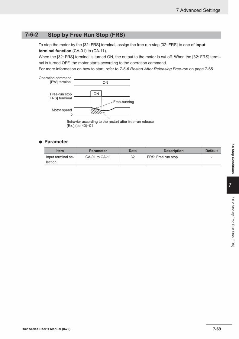
7-6-2 Stop by Free Run Stop (FRS)To stop the motor by the [32: FRS] terminal, assign the free run stop [32: FRS] to one of Inputterminal function (CA-01) to (CA-11).When the [32: FRS] terminal is turned ON, the output to the motor is cut off. When the [32: FRS] termi-nal is turned OFF, the motor starts according to the operation command.For more information on how to start, refer to 7-5-6 Restart After Releasing Free-run on page 7-65.
0
ON
ON
Motor speed
Operation command[FW] terminal
Free-running
Behavior according to the restart after free-run release(Ex.) (bb-40)=01
Free-run stop[FRS] terminal
l Parameter
Item Parameter Data Description DefaultInput terminal se-lection
CA-01 to CA-11 32 FRS: Free run stop -
7 Advanced Settings
7-69RX2 Series User’s Manual (I620)
7-6 Stop Conditions
7
7-6-2 Stop by Free Run Stop (FR
S)
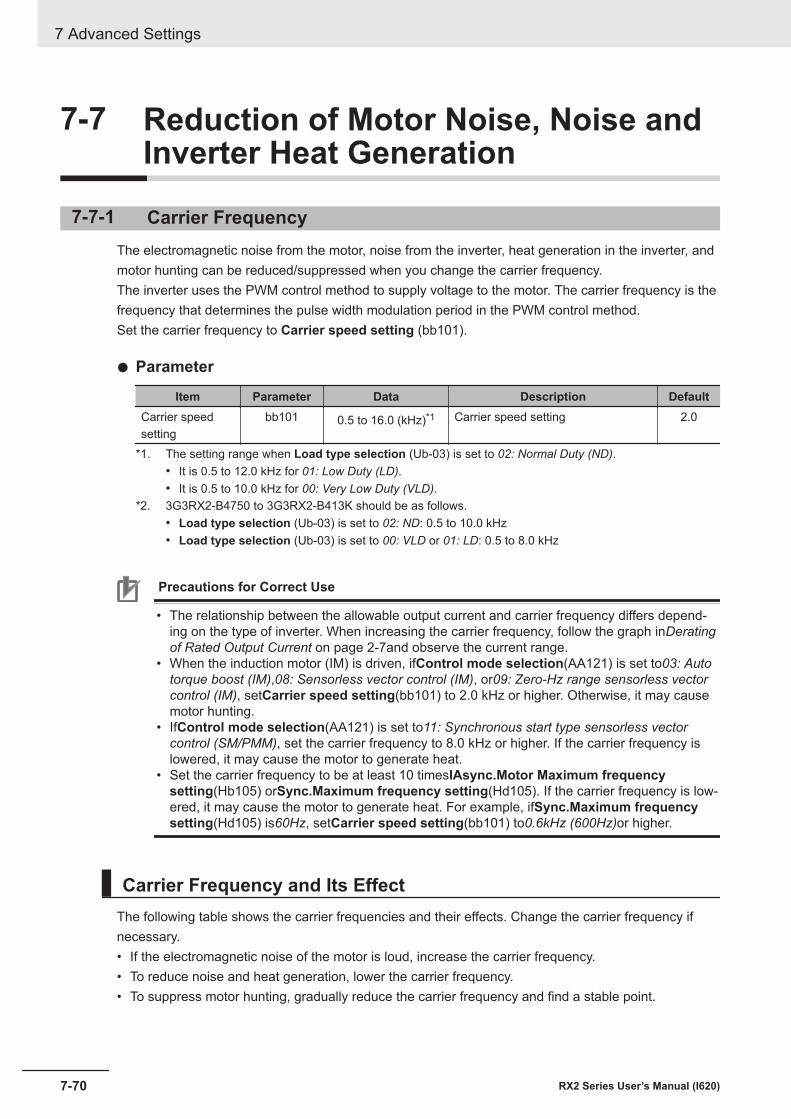
7-7 Reduction of Motor Noise, Noise andInverter Heat Generation
7-7-1 Carrier FrequencyThe electromagnetic noise from the motor, noise from the inverter, heat generation in the inverter, andmotor hunting can be reduced/suppressed when you change the carrier frequency.The inverter uses the PWM control method to supply voltage to the motor. The carrier frequency is thefrequency that determines the pulse width modulation period in the PWM control method.Set the carrier frequency to Carrier speed setting (bb101).
l Parameter
Item Parameter Data Description DefaultCarrier speedsetting
bb101 0.5 to 16.0 (kHz)*1 Carrier speed setting 2.0
*1. The setting range when Load type selection (Ub-03) is set to 02: Normal Duty (ND).• It is 0.5 to 12.0 kHz for 01: Low Duty (LD).• It is 0.5 to 10.0 kHz for 00: Very Low Duty (VLD).
*2. 3G3RX2-B4750 to 3G3RX2-B413K should be as follows.• Load type selection (Ub-03) is set to 02: ND: 0.5 to 10.0 kHz• Load type selection (Ub-03) is set to 00: VLD or 01: LD: 0.5 to 8.0 kHz
Precautions for Correct Use
• The relationship between the allowable output current and carrier frequency differs depend-ing on the type of inverter. When increasing the carrier frequency, follow the graph inDeratingof Rated Output Current on page 2-7and observe the current range.
• When the induction motor (IM) is driven, ifControl mode selection(AA121) is set to03: Autotorque boost (IM),08: Sensorless vector control (IM), or09: Zero-Hz range sensorless vectorcontrol (IM), setCarrier speed setting(bb101) to 2.0 kHz or higher. Otherwise, it may causemotor hunting.
• IfControl mode selection(AA121) is set to11: Synchronous start type sensorless vectorcontrol (SM/PMM), set the carrier frequency to 8.0 kHz or higher. If the carrier frequency islowered, it may cause the motor to generate heat.
• Set the carrier frequency to be at least 10 timesIAsync.Motor Maximum frequencysetting(Hb105) orSync.Maximum frequency setting(Hd105). If the carrier frequency is low-ered, it may cause the motor to generate heat. For example, ifSync.Maximum frequencysetting(Hd105) is60Hz, setCarrier speed setting(bb101) to0.6kHz (600Hz)or higher.
Carrier Frequency and Its EffectThe following table shows the carrier frequencies and their effects. Change the carrier frequency ifnecessary.• If the electromagnetic noise of the motor is loud, increase the carrier frequency.• To reduce noise and heat generation, lower the carrier frequency.• To suppress motor hunting, gradually reduce the carrier frequency and find a stable point.
7 Advanced Settings
7-70 RX2 Series User’s Manual (I620)

Effect of carrier frequency
When carrier frequency is low When carrier frequency is highMotor electro-magnetic noise
Loud Quiet
Noise Low HighInverter heatgeneration
Little Great
Leakage cur-rent
Low High
Example of in-verter outputvoltage wave-form(PWM output)
Carrier frequency: Low Carrier frequency: High
7-7-2 Automatic Carrier ReductionAutomatic carrier reduction has the effect of suppressing the temperature rise inside the inverter andextending the useful life of the internal elements.Automatic carrier reduction is a function that automatically reduces the carrier frequency as the outputcurrent value increases or the temperature of the inverter rises.
To use automatic carrier reduction, set Automatic-carrier reduction selection (bb103) to 01:Enabled: current or 02: Enabled: temperature. 01: Enabled: current lowers the carrier frequency ac-cording to the output current of the inverter. 02: Enabled: temperature lowers the carrier frequency ac-cording to the internal temperature of the inverter.If Carrier speed setting (bb101) is set to 2.0kHz or less, the carrier frequency will not be automatical-ly reduced.
Additional Information
• The rate of change that reduces the carrier frequency during operation is 2kHz per second.• When the automatic carrier reduction is activated, the electromagnetic noise of the motor
changes as the carrier frequency changes.• When using a synchronous motor (SM) or permanent magnet motor (PMM), set Automatic-
carrier reduction selection (bb103) to 00: Disabled. If the carrier frequency is lowered, itmay cause the motor to generate heat.
l Parameter
Item Parameter Data Description DefaultAutomatic-carrierreduction selec-tion
bb103 00 Disabled 0001 Enabled: current02 Enabled: temperature
7 Advanced Settings
7-71RX2 Series User’s Manual (I620)
7-7 Reduction of M
otor Noise, N
oise and Inverter Heat G
eneration
7
7-7-2 Automatic C
arrier Reduction
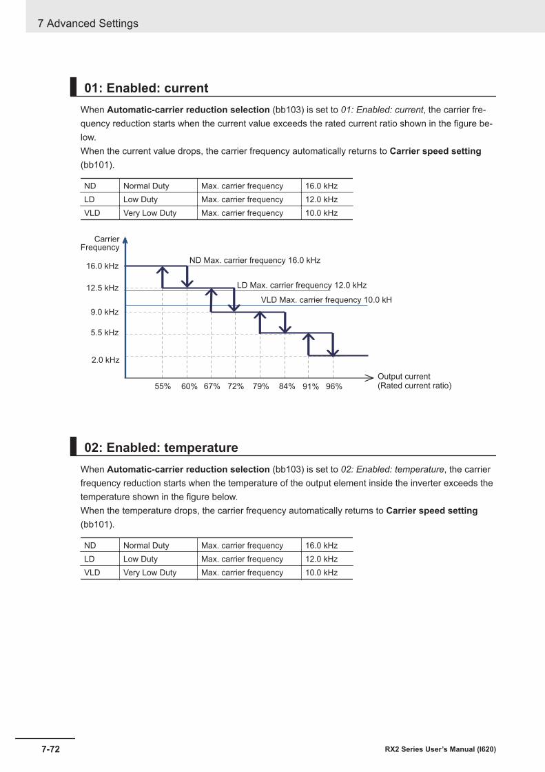
01: Enabled: currentWhen Automatic-carrier reduction selection (bb103) is set to 01: Enabled: current, the carrier fre-quency reduction starts when the current value exceeds the rated current ratio shown in the figure be-low.When the current value drops, the carrier frequency automatically returns to Carrier speed setting(bb101).
ND Normal Duty Max. carrier frequency 16.0 kHzLD Low Duty Max. carrier frequency 12.0 kHzVLD Very Low Duty Max. carrier frequency 10.0 kHz
12.5 kHz
9.0 kHz
5.5 kHz
2.0 kHz
16.0 kHz
55% 67%60%
96%72% 84%79% 91%
CarrierFrequency
ND Max. carrier frequency 16.0 kHz
LD Max. carrier frequency 12.0 kHz
VLD Max. carrier frequency 10.0 kH
Output current(Rated current ratio)
02: Enabled: temperatureWhen Automatic-carrier reduction selection (bb103) is set to 02: Enabled: temperature, the carrierfrequency reduction starts when the temperature of the output element inside the inverter exceeds thetemperature shown in the figure below.When the temperature drops, the carrier frequency automatically returns to Carrier speed setting(bb101).
ND Normal Duty Max. carrier frequency 16.0 kHzLD Low Duty Max. carrier frequency 12.0 kHzVLD Very Low Duty Max. carrier frequency 10.0 kHz
7 Advanced Settings
7-72 RX2 Series User’s Manual (I620)
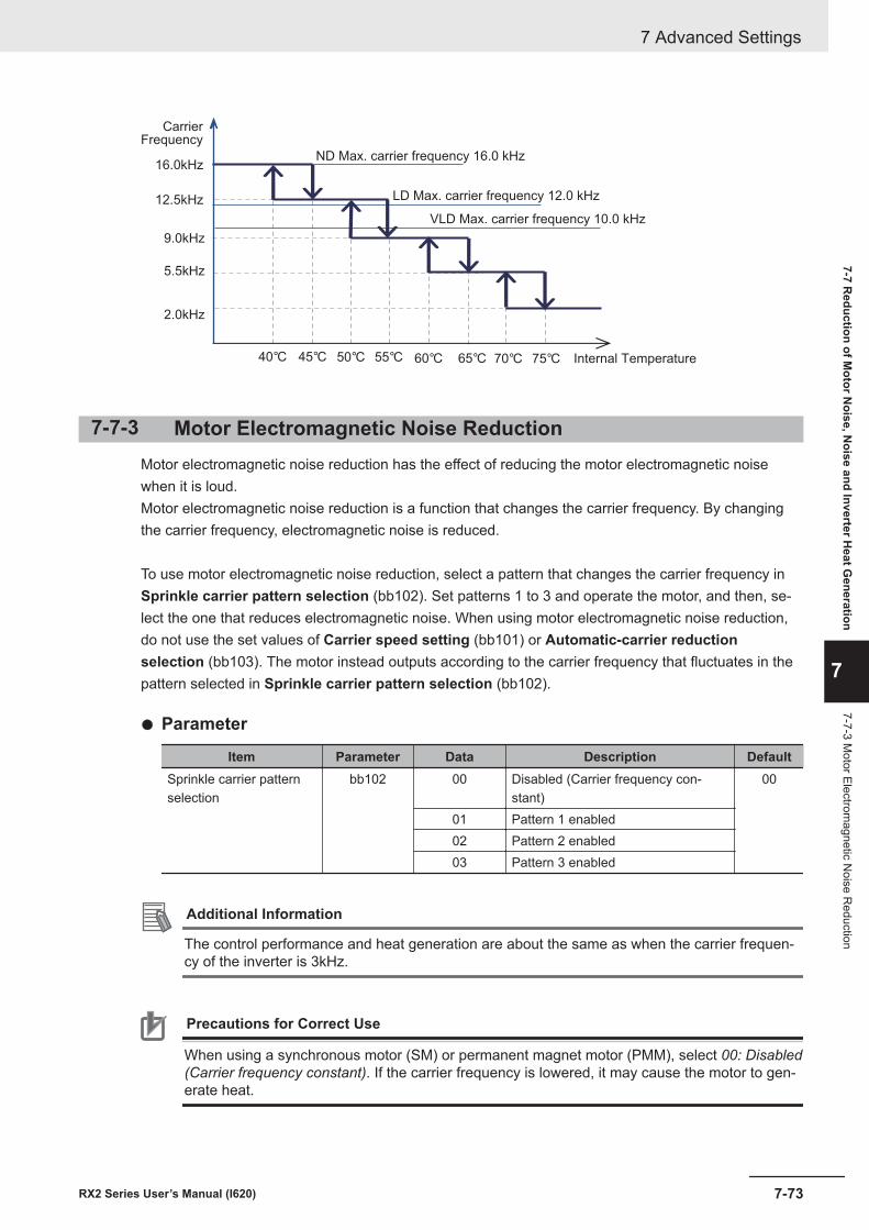
12.5kHz
9.0kHz
5.5kHz
2.0kHz
16.0kHz
40°C 45°C 50°C 55°C 60°C 65°C 70°C 75°C
CarrierFrequency
ND Max. carrier frequency 16.0 kHz
LD Max. carrier frequency 12.0 kHz
VLD Max. carrier frequency 10.0 kHz
Internal Temperature
7-7-3 Motor Electromagnetic Noise ReductionMotor electromagnetic noise reduction has the effect of reducing the motor electromagnetic noisewhen it is loud.Motor electromagnetic noise reduction is a function that changes the carrier frequency. By changingthe carrier frequency, electromagnetic noise is reduced.
To use motor electromagnetic noise reduction, select a pattern that changes the carrier frequency inSprinkle carrier pattern selection (bb102). Set patterns 1 to 3 and operate the motor, and then, se-lect the one that reduces electromagnetic noise. When using motor electromagnetic noise reduction,do not use the set values of Carrier speed setting (bb101) or Automatic-carrier reductionselection (bb103). The motor instead outputs according to the carrier frequency that fluctuates in thepattern selected in Sprinkle carrier pattern selection (bb102).
l Parameter
Item Parameter Data Description DefaultSprinkle carrier patternselection
bb102 00 Disabled (Carrier frequency con-stant)
00
01 Pattern 1 enabled02 Pattern 2 enabled03 Pattern 3 enabled
Additional Information
The control performance and heat generation are about the same as when the carrier frequen-cy of the inverter is 3kHz.
Precautions for Correct Use
When using a synchronous motor (SM) or permanent magnet motor (PMM), select 00: Disabled(Carrier frequency constant). If the carrier frequency is lowered, it may cause the motor to gen-erate heat.
7 Advanced Settings
7-73RX2 Series User’s Manual (I620)
7-7 Reduction of M
otor Noise, N
oise and Inverter Heat G
eneration
7
7-7-3 Motor Electrom
agnetic Noise R
eduction
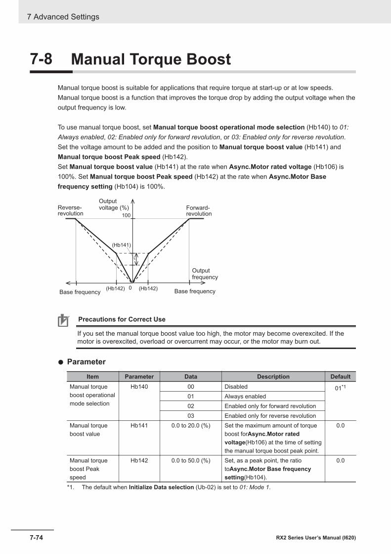
7-8 Manual Torque BoostManual torque boost is suitable for applications that require torque at start-up or at low speeds.Manual torque boost is a function that improves the torque drop by adding the output voltage when theoutput frequency is low.
To use manual torque boost, set Manual torque boost operational mode selection (Hb140) to 01:Always enabled, 02: Enabled only for forward revolution, or 03: Enabled only for reverse revolution.Set the voltage amount to be added and the position to Manual torque boost value (Hb141) andManual torque boost Peak speed (Hb142).Set Manual torque boost value (Hb141) at the rate when Async.Motor rated voltage (Hb106) is100%. Set Manual torque boost Peak speed (Hb142) at the rate when Async.Motor Basefrequency setting (Hb104) is 100%.
(Hb141)
100
0(Hb142) (Hb142)
Outputvoltage (%)Reverse-
revolutionForward-revolution
Outputfrequency
Base frequencyBase frequency
Precautions for Correct Use
If you set the manual torque boost value too high, the motor may become overexcited. If themotor is overexcited, overload or overcurrent may occur, or the motor may burn out.
l Parameter
Item Parameter Data Description DefaultManual torqueboost operationalmode selection
Hb140 00 Disabled 01*1
01 Always enabled02 Enabled only for forward revolution03 Enabled only for reverse revolution
Manual torqueboost value
Hb141 0.0 to 20.0 (%) Set the maximum amount of torqueboost forAsync.Motor ratedvoltage(Hb106) at the time of settingthe manual torque boost peak point.
0.0
Manual torqueboost Peakspeed
Hb142 0.0 to 50.0 (%) Set, as a peak point, the ratiotoAsync.Motor Base frequencysetting(Hb104).
0.0
*1. The default when Initialize Data selection (Ub-02) is set to 01: Mode 1.
7 Advanced Settings
7-74 RX2 Series User’s Manual (I620)
Additional Information
• To obtain torque and prevent overload, check the output current of the inverter and ad-justManual torque boost value(Hb141) so that it is about 150% of the motor rated current.150% is applicable when Load type selection (Ub-03) is set to 02: Normal Duty (ND). Apply120% and 110% when it is set to 01: Light Duty (LD) and 00: Very Light Duty (VLD), respec-tively.
• Use manual torque boost whenControl mode selection(AA121) is set to00: [V/f] Fixedtorque characteristics (IM),01 :[V/f] Reducing torque characteristics (IM),04: [V/f with sensor]Fixed torque characteristics (IM), or05: [V/f with sensor] Reduced torque characteristics (IM),and when the motor stalls at low speeds.
• IfControl mode selection(AA121) is set to03: Auto torque boost (IM)or07: Auto torque boostwith sensor (IM), automatic torque boost is enabled. Therefore, you do not need to use man-ual torque boost. If you enable both, the adjustment will be difficult.
7 Advanced Settings
7-75RX2 Series User’s Manual (I620)
7-8 Manual Torque B
oost
7
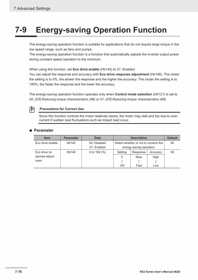
7-9 Energy-saving Operation FunctionThe energy-saving operation function is suitable for applications that do not require large torque in thelow speed range, such as fans and pumps.The energy-saving operation function is a function that automatically adjusts the inverter output powerduring constant speed operation to the minimum.
When using this function, set Eco drive enable (Hb145) to 01: Enabled.You can adjust the response and accuracy with Eco drive response adjustment (Hb146). The closerthe setting is to 0%, the slower the response and the higher the accuracy. The closer the setting is to100%, the faster the response and the lower the accuracy.
The energy-saving operation function operates only when Control mode selection (AA121) is set to00: [V/f] Reducing torque characteristics (IM) or 01: [V/f] Reducing torque characteristics (IM).
Precautions for Correct Use
Since this function controls the motor relatively slowly, the motor may stall and trip due to over-current if sudden load fluctuations such as impact load occur.
l Parameter
Item Parameter Data Description DefaultEco drive enable Hb145 00: Disabled
01: EnabledSelect whether or not to conduct the
energy-saving operation.00
Eco drive re-sponse adjust-ment
Hb146 0 to 100 (%) Setting Response Accuracy 500↕
100
Slow↕
Fast
High↕
Low
7 Advanced Settings
7-76 RX2 Series User’s Manual (I620)
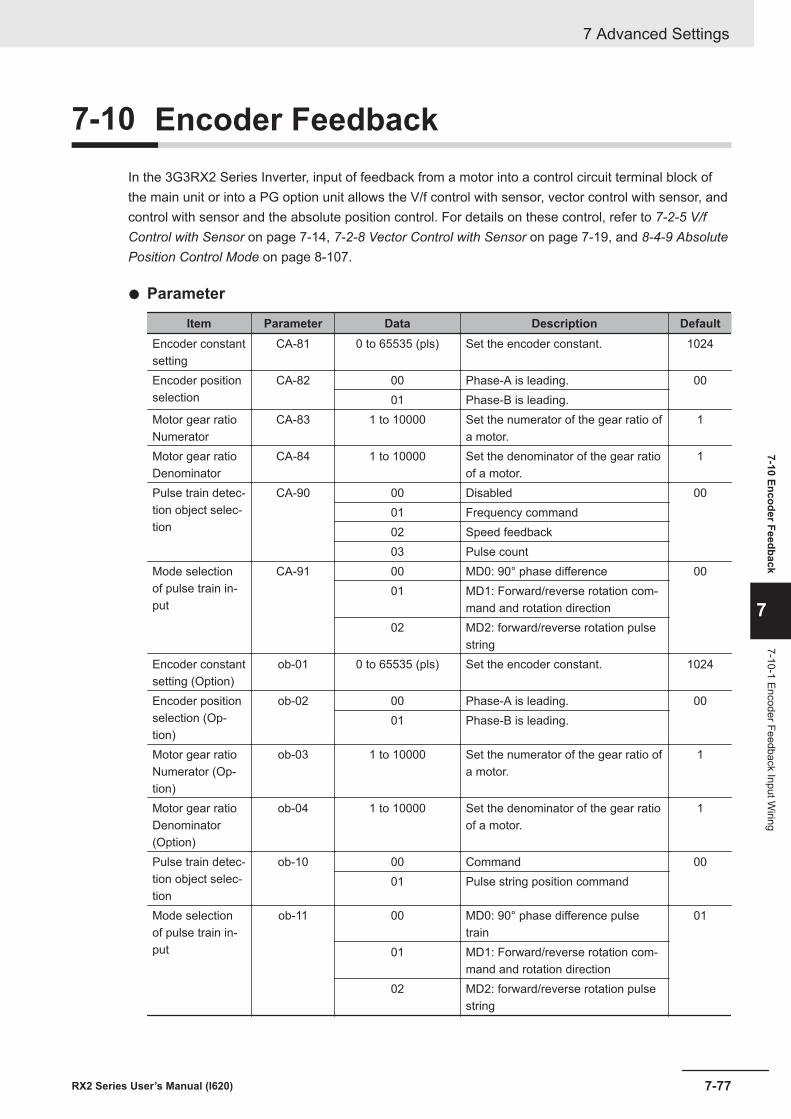
7-10 Encoder FeedbackIn the 3G3RX2 Series Inverter, input of feedback from a motor into a control circuit terminal block ofthe main unit or into a PG option unit allows the V/f control with sensor, vector control with sensor, andcontrol with sensor and the absolute position control. For details on these control, refer to 7-2-5 V/fControl with Sensor on page 7-14, 7-2-8 Vector Control with Sensor on page 7-19, and 8-4-9 AbsolutePosition Control Mode on page 8-107.
l Parameter
Item Parameter Data Description DefaultEncoder constantsetting
CA-81 0 to 65535 (pls) Set the encoder constant. 1024
Encoder positionselection
CA-82 00 Phase-A is leading. 0001 Phase-B is leading.
Motor gear ratioNumerator
CA-83 1 to 10000 Set the numerator of the gear ratio ofa motor.
1
Motor gear ratioDenominator
CA-84 1 to 10000 Set the denominator of the gear ratioof a motor.
1
Pulse train detec-tion object selec-tion
CA-90 00 Disabled 0001 Frequency command02 Speed feedback03 Pulse count
Mode selectionof pulse train in-put
CA-91 00 MD0: 90° phase difference 0001 MD1: Forward/reverse rotation com-
mand and rotation direction02 MD2: forward/reverse rotation pulse
stringEncoder constantsetting (Option)
ob-01 0 to 65535 (pls) Set the encoder constant. 1024
Encoder positionselection (Op-tion)
ob-02 00 Phase-A is leading. 0001 Phase-B is leading.
Motor gear ratioNumerator (Op-tion)
ob-03 1 to 10000 Set the numerator of the gear ratio ofa motor.
1
Motor gear ratioDenominator(Option)
ob-04 1 to 10000 Set the denominator of the gear ratioof a motor.
1
Pulse train detec-tion object selec-tion
ob-10 00 Command 0001 Pulse string position command
Mode selectionof pulse train in-put
ob-11 00 MD0: 90° phase difference pulsetrain
01
01 MD1: Forward/reverse rotation com-mand and rotation direction
02 MD2: forward/reverse rotation pulsestring
7 Advanced Settings
7-77RX2 Series User’s Manual (I620)
7-10 Encoder Feedback
7
7-10-1 Encoder Feedback Input Wiring
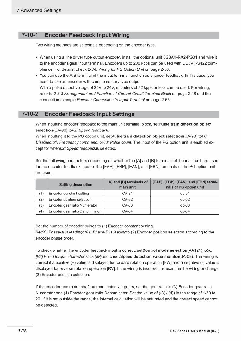
7-10-1 Encoder Feedback Input WiringTwo wiring methods are selectable depending on the encoder type.
• When using a line driver type output encoder, install the optional unit 3G3AX-RX2-PG01 and wire itto the encoder signal input terminal. Encoders up to 200 kpps can be used with DC5V RS422 com-pliance. For details, check 2-3-6 Wiring for PG Option Unit on page 2-68.
• You can use the A/B terminal of the input terminal function as encoder feedback. In this case, youneed to use an encoder with complementary type output.With a pulse output voltage of 20V to 24V, encoders of 32 kpps or less can be used. For wiring,refer to 2-3-3 Arrangement and Function of Control Circuit Terminal Block on page 2-18 and theconnection example Encoder Connection to Input Terminal on page 2-65.
7-10-2 Encoder Feedback Input SettingsWhen inputting encoder feedback to the main unit terminal block, setPulse train detection objectselection(CA-90) to02: Speed feedback.When inputting it to the PG option unit, setPulse train detection object selection(CA-90) to00:Disabled,01: Frequency command, or03: Pulse count. The input of the PG option unit is enabled ex-cept for when02: Speed feedbackis selected.
Set the following parameters depending on whether the [A] and [B] terminals of the main unit are usedfor the encoder feedback input or the [EAP], [EBP], [EAN], and [EBN] terminals of the PG option unitare used.
Setting description [A] and [B] terminals ofmain unit
[EAP], [EBP], [EAN], and [EBN] termi-nals of PG option unit
(1) Encoder constant setting CA-81 ob-01(2) Encoder position selection CA-82 ob-02(3) Encoder gear ratio Numerator CA-83 ob-03(4) Encoder gear ratio Denominator CA-84 ob-04
Set the number of encoder pulses to (1) Encoder constant setting.Set00: Phase-A is leadingor01: Phase-B is leadingto (2) Encoder position selection according to theencoder phase order.
To check whether the encoder feedback input is correct, setControl mode selection(AA121) to00:[V/f] Fixed torque characteristics (IM)and checkSpeed detection value monitor(dA-08). The wiring iscorrect if a positive (+) value is displayed for forward rotation operation [FW] and a negative (-) value isdisplayed for reverse rotation operation [RV]. If the wiring is incorrect, re-examine the wiring or change(2) Encoder position selection.
If the encoder and motor shaft are connected via gears, set the gear ratio to (3) Encoder gear ratioNumerator and (4) Encoder gear ratio Denominator. Set the value of ((3) / (4)) in the range of 1/50 to20. If it is set outside the range, the internal calculation will be saturated and the correct speed cannotbe detected.
7 Advanced Settings
7-78 RX2 Series User’s Manual (I620)
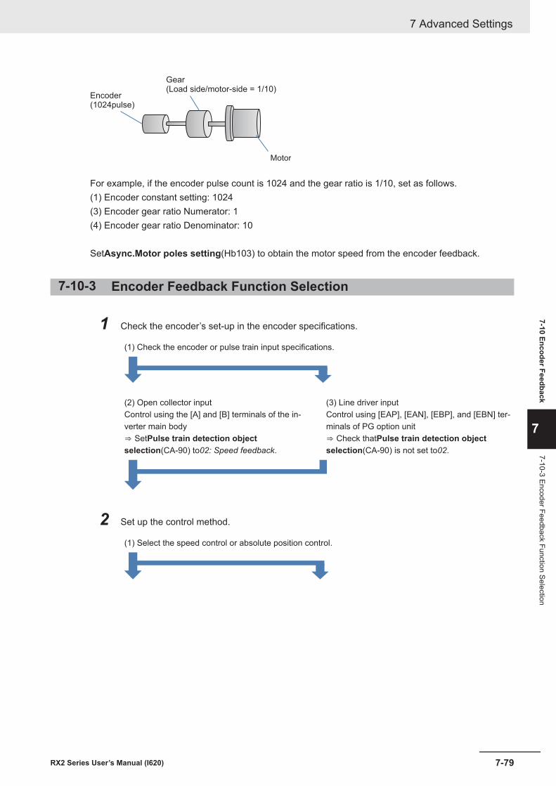
Gear(Load side/motor-side = 1/10)
Encoder(1024pulse)
Motor
For example, if the encoder pulse count is 1024 and the gear ratio is 1/10, set as follows.(1) Encoder constant setting: 1024(3) Encoder gear ratio Numerator: 1(4) Encoder gear ratio Denominator: 10
SetAsync.Motor poles setting(Hb103) to obtain the motor speed from the encoder feedback.
7-10-3 Encoder Feedback Function Selection
1 Check the encoder’s set-up in the encoder specifications.
(1) Check the encoder or pulse train input specifications.
(2) Open collector inputControl using the [A] and [B] terminals of the in-verter main body⇒ SetPulse train detection objectselection(CA-90) to02: Speed feedback.
(3) Line driver inputControl using [EAP], [EAN], [EBP], and [EBN] ter-minals of PG option unit⇒ Check thatPulse train detection objectselection(CA-90) is not set to02.
2 Set up the control method.
(1) Select the speed control or absolute position control.
7 Advanced Settings
7-79RX2 Series User’s Manual (I620)
7-10 Encoder Feedback
7
7-10-3 Encoder Feedback Function Selection

(2) Conduct the speed control.In Control mode selection (AA121), select onefrom the following settings for the speed controlwith sensor.• Set one of the following options for V/f control
with sensor04: [V/f with sensor] Fixed torquecharacteristics (IM)05: [V/f with sensor] Reduced torquecharacteristics (IM)06: [V/f with sensor] Free V/f (IM)
• Set auto torque boost with sensor07: Auto torque boost with sensor (IM)
• Set vector control with sensor10: Vector control with sensor (IM)When selecting this setting, you also needto set Vector control mode selection(AA123) to 00.
(Refer to7-1 Selection of Motor Control Methodson page 7-3.)
(3) Conduct the absolute position control.Set Control mode selection (AA121) to 10:Vector control with sensor (IM), and then selectone of the following modes in Vector controlmode selection (AA123).• 02: Absolute position control mode• 03: High-resolution absolute position control
mode(Refer to8-4-9 Absolute Position Control Modeon page 8-107.)
7-10-4 Check of Pulse Train Input SettingThe following table shows the relationship between the [A] and [B] terminals of the main unit and theset values, and between the [EAP], [EAN], [EBP], [EBN], [SAP], [SAN], [SBP], and [SBN] terminals ofthe PG Option Unit and the set values.
Function Setting check Encoder Pulse command inputSpeedcontrolwith sen-sor
Required setting• Set Control mode selection
(AA121) to 04 to 07.Or,• Set Control mode selection
(AA121) to 10 and Vector controlmode selection (AA123) to 00.
When wiring the encod-er to the PG option unit,set Pulse traindetection (internal)control terminal [A] [B](CA-90) to 00 or othervalues, where the A/Bterminal is not used forpulse input, referring tothe right column.*1
When using the A/B terminalfor pulse train speed com-mand, set Pulse traindetection (internal) controlterminal [A] [B] (CA-90) to 01.When using the SA/SB termi-nal on the PG option unit forpulse train speed command,set Pulse train detection(option) terminal (ob-10) to01.When connecting the
encoder to the A/B ter-minal, set Pulse traindetection (internal)control terminal [A] [B](CA-90) to 02.*2
7 Advanced Settings
7-80 RX2 Series User’s Manual (I620)
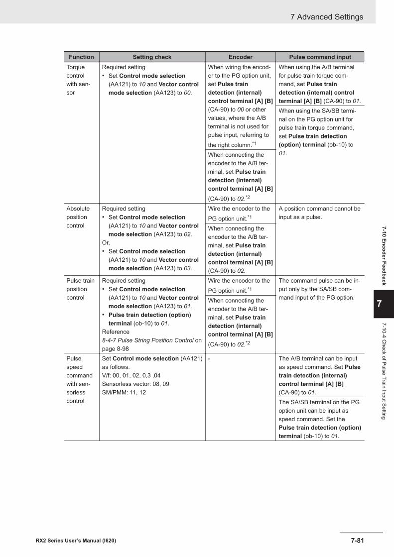
Function Setting check Encoder Pulse command inputTorquecontrolwith sen-sor
Required setting• Set Control mode selection
(AA121) to 10 and Vector controlmode selection (AA123) to 00.
When wiring the encod-er to the PG option unit,set Pulse traindetection (internal)control terminal [A] [B](CA-90) to 00 or othervalues, where the A/Bterminal is not used forpulse input, referring tothe right column.*1
When using the A/B terminalfor pulse train torque com-mand, set Pulse traindetection (internal) controlterminal [A] [B] (CA-90) to 01.When using the SA/SB termi-nal on the PG option unit forpulse train torque command,set Pulse train detection(option) terminal (ob-10) to01.When connecting the
encoder to the A/B ter-minal, set Pulse traindetection (internal)control terminal [A] [B](CA-90) to 02.*2
Absolutepositioncontrol
Required setting• Set Control mode selection
(AA121) to 10 and Vector controlmode selection (AA123) to 02.
Or,• Set Control mode selection
(AA121) to 10 and Vector controlmode selection (AA123) to 03.
Wire the encoder to thePG option unit.*1
A position command cannot beinput as a pulse.
When connecting theencoder to the A/B ter-minal, set Pulse traindetection (internal)control terminal [A] [B](CA-90) to 02.
Pulse trainpositioncontrol
Required setting• Set Control mode selection
(AA121) to 10 and Vector controlmode selection (AA123) to 01.
• Pulse train detection (option)terminal (ob-10) to 01.
Reference8-4-7 Pulse String Position Control onpage 8-98
Wire the encoder to thePG option unit.*1
The command pulse can be in-put only by the SA/SB com-mand input of the PG option.When connecting the
encoder to the A/B ter-minal, set Pulse traindetection (internal)control terminal [A] [B](CA-90) to 02.*2
Pulsespeedcommandwith sen-sorlesscontrol
Set Control mode selection (AA121)as follows.V/f: 00, 01, 02, 0,3 ,04Sensorless vector: 08, 09SM/PMM: 11, 12
- The A/B terminal can be inputas speed command. Set Pulsetrain detection (internal)control terminal [A] [B](CA-90) to 01.The SA/SB terminal on the PGoption unit can be input asspeed command. Set thePulse train detection (option)terminal (ob-10) to 01.
7 Advanced Settings
7-81RX2 Series User’s Manual (I620)
7-10 Encoder Feedback
7
7-10-4 Check of Pulse Train Input Setting
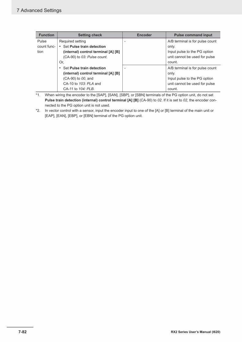
Function Setting check Encoder Pulse command inputPulsecount func-tion
Required setting• Set Pulse train detection
(internal) control terminal [A] [B](CA-90) to 03: Pulse count.
Or,
- A/B terminal is for pulse countonly.Input pulse to the PG optionunit cannot be used for pulsecount.
• Set Pulse train detection(internal) control terminal [A] [B](CA-90) to 00, andCA-10 to 103: PLA andCA-11 to 104: PLB.
- A/B terminal is for pulse countonly.Input pulse to the PG optionunit cannot be used for pulsecount.
*1. When wiring the encoder to the [SAP], [SAN], [SBP], or [SBN] terminals of the PG option unit, do not setPulse train detection (internal) control terminal [A] [B] (CA-90) to 02. If it is set to 02, the encoder con-nected to the PG option unit is not used.
*2. In vector control with a sensor, input the encoder input to one of the [A] or [B] terminal of the main unit or[EAP], [EAN], [EBP], or [EBN] terminal of the PG option unit.
7 Advanced Settings
7-82 RX2 Series User’s Manual (I620)
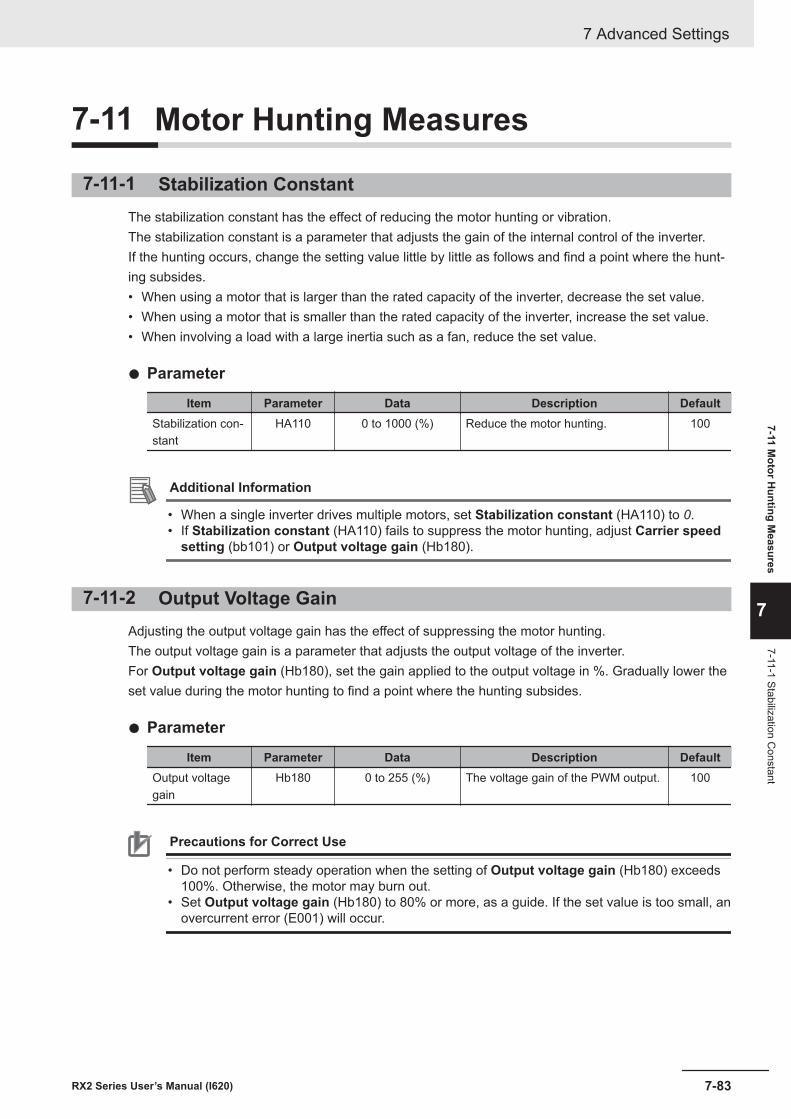
7-11 Motor Hunting Measures
7-11-1 Stabilization ConstantThe stabilization constant has the effect of reducing the motor hunting or vibration.The stabilization constant is a parameter that adjusts the gain of the internal control of the inverter.If the hunting occurs, change the setting value little by little as follows and find a point where the hunt-ing subsides.• When using a motor that is larger than the rated capacity of the inverter, decrease the set value.• When using a motor that is smaller than the rated capacity of the inverter, increase the set value.• When involving a load with a large inertia such as a fan, reduce the set value.
l Parameter
Item Parameter Data Description DefaultStabilization con-stant
HA110 0 to 1000 (%) Reduce the motor hunting. 100
Additional Information
• When a single inverter drives multiple motors, set Stabilization constant (HA110) to 0.• If Stabilization constant (HA110) fails to suppress the motor hunting, adjust Carrier speed
setting (bb101) or Output voltage gain (Hb180).
7-11-2 Output Voltage GainAdjusting the output voltage gain has the effect of suppressing the motor hunting.The output voltage gain is a parameter that adjusts the output voltage of the inverter.For Output voltage gain (Hb180), set the gain applied to the output voltage in %. Gradually lower theset value during the motor hunting to find a point where the hunting subsides.
l Parameter
Item Parameter Data Description DefaultOutput voltagegain
Hb180 0 to 255 (%) The voltage gain of the PWM output. 100
Precautions for Correct Use
• Do not perform steady operation when the setting of Output voltage gain (Hb180) exceeds100%. Otherwise, the motor may burn out.
• Set Output voltage gain (Hb180) to 80% or more, as a guide. If the set value is too small, anovercurrent error (E001) will occur.
7 Advanced Settings
7-83RX2 Series User’s Manual (I620)
7-11 Motor H
unting Measures
7
7-11-1 Stabilization Constant

7 Advanced Settings
7-84 RX2 Series User’s Manual (I620)
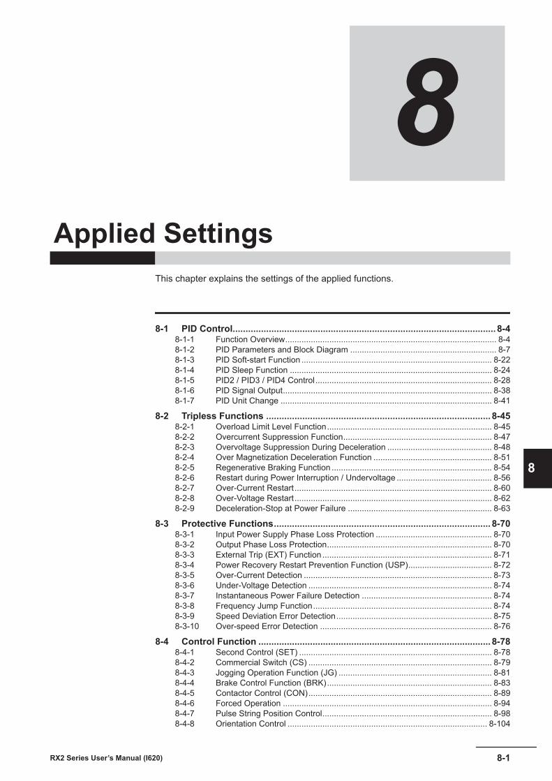
8Applied Settings
This chapter explains the settings of the applied functions.
8-1 PID Control...................................................................................................... 8-48-1-1 Function Overview........................................................................................... 8-48-1-2 PID Parameters and Block Diagram ............................................................... 8-78-1-3 PID Soft-start Function .................................................................................. 8-228-1-4 PID Sleep Function ....................................................................................... 8-248-1-5 PID2 / PID3 / PID4 Control............................................................................ 8-288-1-6 PID Signal Output.......................................................................................... 8-388-1-7 PID Unit Change ........................................................................................... 8-41
8-2 Tripless Functions ....................................................................................... 8-458-2-1 Overload Limit Level Function....................................................................... 8-458-2-2 Overcurrent Suppression Function................................................................ 8-478-2-3 Overvoltage Suppression During Deceleration ............................................. 8-488-2-4 Over Magnetization Deceleration Function ................................................... 8-518-2-5 Regenerative Braking Function ..................................................................... 8-548-2-6 Restart during Power Interruption / Undervoltage ......................................... 8-568-2-7 Over-Current Restart..................................................................................... 8-608-2-8 Over-Voltage Restart..................................................................................... 8-628-2-9 Deceleration-Stop at Power Failure .............................................................. 8-63
8-3 Protective Functions.................................................................................... 8-708-3-1 Input Power Supply Phase Loss Protection .................................................. 8-708-3-2 Output Phase Loss Protection....................................................................... 8-708-3-3 External Trip (EXT) Function ......................................................................... 8-718-3-4 Power Recovery Restart Prevention Function (USP).................................... 8-728-3-5 Over-Current Detection ................................................................................. 8-738-3-6 Under-Voltage Detection ............................................................................... 8-748-3-7 Instantaneous Power Failure Detection ........................................................ 8-748-3-8 Frequency Jump Function............................................................................. 8-748-3-9 Speed Deviation Error Detection................................................................... 8-758-3-10 Over-speed Error Detection .......................................................................... 8-76
8-4 Control Function .......................................................................................... 8-788-4-1 Second Control (SET) ................................................................................... 8-788-4-2 Commercial Switch (CS) ............................................................................... 8-798-4-3 Jogging Operation Function (JG) .................................................................. 8-818-4-4 Brake Control Function (BRK)....................................................................... 8-838-4-5 Contactor Control (CON)............................................................................... 8-898-4-6 Forced Operation .......................................................................................... 8-948-4-7 Pulse String Position Control......................................................................... 8-988-4-8 Orientation Control ...................................................................................... 8-104
8-1RX2 Series User’s Manual (I620)
8
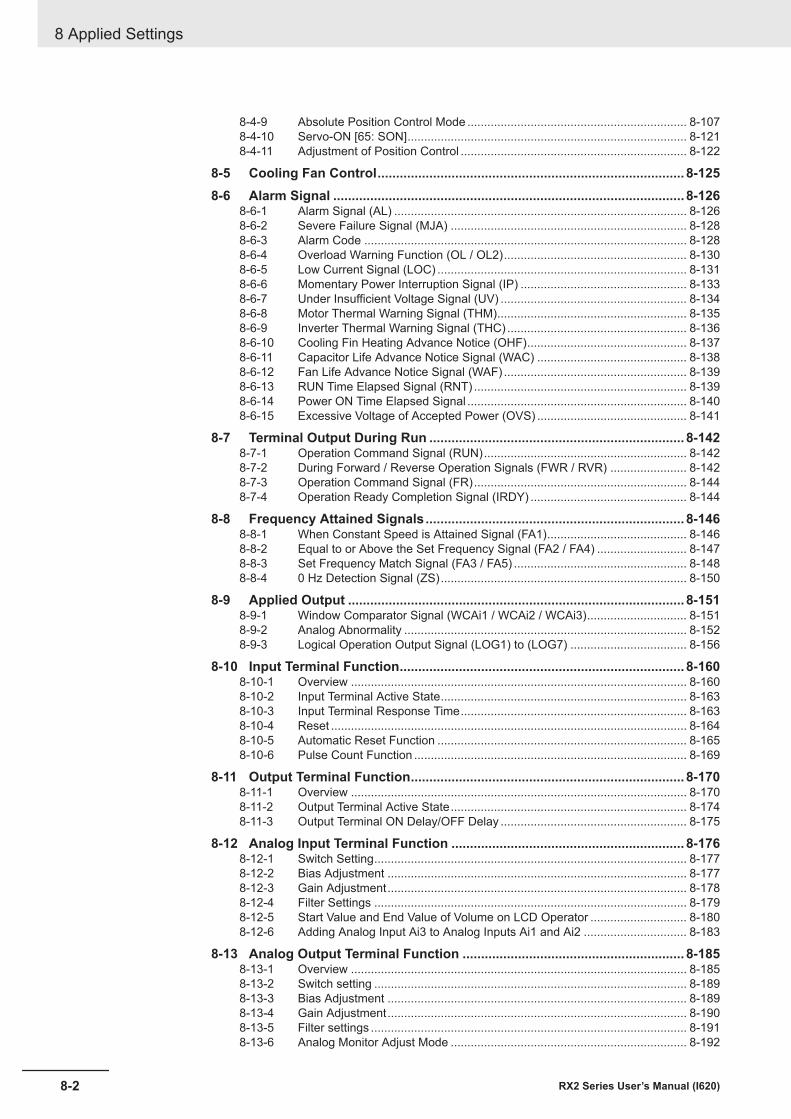
8-4-9 Absolute Position Control Mode .................................................................. 8-1078-4-10 Servo-ON [65: SON].................................................................................... 8-1218-4-11 Adjustment of Position Control .................................................................... 8-122
8-5 Cooling Fan Control................................................................................... 8-1258-6 Alarm Signal ............................................................................................... 8-126
8-6-1 Alarm Signal (AL) ........................................................................................ 8-1268-6-2 Severe Failure Signal (MJA) ....................................................................... 8-1288-6-3 Alarm Code ................................................................................................. 8-1288-6-4 Overload Warning Function (OL / OL2)....................................................... 8-1308-6-5 Low Current Signal (LOC) ........................................................................... 8-1318-6-6 Momentary Power Interruption Signal (IP) .................................................. 8-1338-6-7 Under Insufficient Voltage Signal (UV) ........................................................ 8-1348-6-8 Motor Thermal Warning Signal (THM)......................................................... 8-1358-6-9 Inverter Thermal Warning Signal (THC) ...................................................... 8-1368-6-10 Cooling Fin Heating Advance Notice (OHF)................................................ 8-1378-6-11 Capacitor Life Advance Notice Signal (WAC) ............................................. 8-1388-6-12 Fan Life Advance Notice Signal (WAF) ....................................................... 8-1398-6-13 RUN Time Elapsed Signal (RNT) ................................................................ 8-1398-6-14 Power ON Time Elapsed Signal .................................................................. 8-1408-6-15 Excessive Voltage of Accepted Power (OVS) ............................................. 8-141
8-7 Terminal Output During Run ..................................................................... 8-1428-7-1 Operation Command Signal (RUN)............................................................. 8-1428-7-2 During Forward / Reverse Operation Signals (FWR / RVR) ....................... 8-1428-7-3 Operation Command Signal (FR)................................................................ 8-1448-7-4 Operation Ready Completion Signal (IRDY) ............................................... 8-144
8-8 Frequency Attained Signals...................................................................... 8-1468-8-1 When Constant Speed is Attained Signal (FA1).......................................... 8-1468-8-2 Equal to or Above the Set Frequency Signal (FA2 / FA4) ........................... 8-1478-8-3 Set Frequency Match Signal (FA3 / FA5) .................................................... 8-1488-8-4 0 Hz Detection Signal (ZS).......................................................................... 8-150
8-9 Applied Output ........................................................................................... 8-1518-9-1 Window Comparator Signal (WCAi1 / WCAi2 / WCAi3).............................. 8-1518-9-2 Analog Abnormality ..................................................................................... 8-1528-9-3 Logical Operation Output Signal (LOG1) to (LOG7) ................................... 8-156
8-10 Input Terminal Function............................................................................. 8-1608-10-1 Overview ..................................................................................................... 8-1608-10-2 Input Terminal Active State.......................................................................... 8-1638-10-3 Input Terminal Response Time.................................................................... 8-1638-10-4 Reset ........................................................................................................... 8-1648-10-5 Automatic Reset Function ........................................................................... 8-1658-10-6 Pulse Count Function .................................................................................. 8-169
8-11 Output Terminal Function.......................................................................... 8-1708-11-1 Overview ..................................................................................................... 8-1708-11-2 Output Terminal Active State....................................................................... 8-1748-11-3 Output Terminal ON Delay/OFF Delay ........................................................ 8-175
8-12 Analog Input Terminal Function ............................................................... 8-1768-12-1 Switch Setting.............................................................................................. 8-1778-12-2 Bias Adjustment .......................................................................................... 8-1778-12-3 Gain Adjustment.......................................................................................... 8-1788-12-4 Filter Settings .............................................................................................. 8-1798-12-5 Start Value and End Value of Volume on LCD Operator ............................. 8-1808-12-6 Adding Analog Input Ai3 to Analog Inputs Ai1 and Ai2 ............................... 8-183
8-13 Analog Output Terminal Function ............................................................ 8-1858-13-1 Overview ..................................................................................................... 8-1858-13-2 Switch setting .............................................................................................. 8-1898-13-3 Bias Adjustment .......................................................................................... 8-1898-13-4 Gain Adjustment.......................................................................................... 8-1908-13-5 Filter settings ............................................................................................... 8-1918-13-6 Analog Monitor Adjust Mode ....................................................................... 8-192
8 Applied Settings
8-2 RX2 Series User’s Manual (I620)
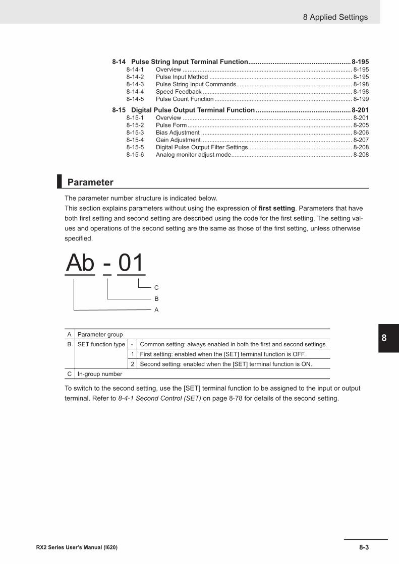
8-14 Pulse String Input Terminal Function....................................................... 8-1958-14-1 Overview ..................................................................................................... 8-1958-14-2 Pulse Input Method ..................................................................................... 8-1958-14-3 Pulse String Input Commands..................................................................... 8-1988-14-4 Speed Feedback ......................................................................................... 8-1988-14-5 Pulse Count Function .................................................................................. 8-199
8-15 Digital Pulse Output Terminal Function ................................................... 8-2018-15-1 Overview ..................................................................................................... 8-2018-15-2 Pulse Form .................................................................................................. 8-2058-15-3 Bias Adjustment .......................................................................................... 8-2068-15-4 Gain Adjustment.......................................................................................... 8-2078-15-5 Digital Pulse Output Filter Settings.............................................................. 8-2088-15-6 Analog monitor adjust mode........................................................................ 8-208
ParameterThe parameter number structure is indicated below.This section explains parameters without using the expression of first setting. Parameters that haveboth first setting and second setting are described using the code for the first setting. The setting val-ues and operations of the second setting are the same as those of the first setting, unless otherwisespecified.
Ab - 01
A
B
C
A Parameter groupB SET function type - Common setting: always enabled in both the first and second settings.
1 First setting: enabled when the [SET] terminal function is OFF.2 Second setting: enabled when the [SET] terminal function is ON.
C In-group number
To switch to the second setting, use the [SET] terminal function to be assigned to the input or outputterminal. Refer to 8-4-1 Second Control (SET) on page 8-78 for details of the second setting.
8 Applied Settings
8-3RX2 Series User’s Manual (I620)
8
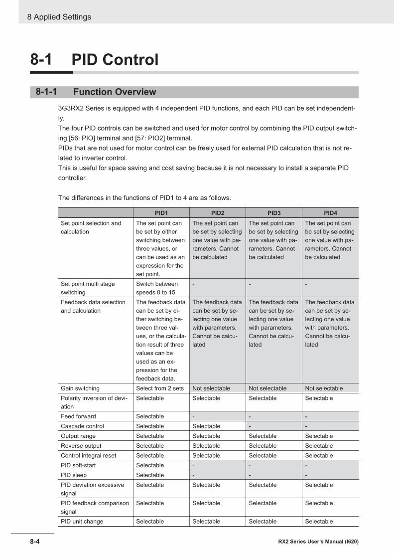
8-1 PID Control
8-1-1 Function Overview3G3RX2 Series is equipped with 4 independent PID functions, and each PID can be set independent-ly.The four PID controls can be switched and used for motor control by combining the PID output switch-ing [56: PIO] terminal and [57: PIO2] terminal.PIDs that are not used for motor control can be freely used for external PID calculation that is not re-lated to inverter control.This is useful for space saving and cost saving because it is not necessary to install a separate PIDcontroller.
The differences in the functions of PID1 to 4 are as follows.
PID1 PID2 PID3 PID4Set point selection andcalculation
The set point canbe set by eitherswitching betweenthree values, orcan be used as anexpression for theset point.
The set point canbe set by selectingone value with pa-rameters. Cannotbe calculated
The set point canbe set by selectingone value with pa-rameters. Cannotbe calculated
The set point canbe set by selectingone value with pa-rameters. Cannotbe calculated
Set point multi stageswitching
Switch betweenspeeds 0 to 15
- - -
Feedback data selectionand calculation
The feedback datacan be set by ei-ther switching be-tween three val-ues, or the calcula-tion result of threevalues can beused as an ex-pression for thefeedback data.
The feedback datacan be set by se-lecting one valuewith parameters.Cannot be calcu-lated
The feedback datacan be set by se-lecting one valuewith parameters.Cannot be calcu-lated
The feedback datacan be set by se-lecting one valuewith parameters.Cannot be calcu-lated
Gain switching Select from 2 sets Not selectable Not selectable Not selectablePolarity inversion of devi-ation
Selectable Selectable Selectable Selectable
Feed forward Selectable - - -Cascade control Selectable Selectable - -Output range Selectable Selectable Selectable SelectableReverse output Selectable Selectable Selectable SelectableControl integral reset Selectable Selectable Selectable SelectablePID soft-start Selectable - - -PID sleep Selectable - - -PID deviation excessivesignal
Selectable Selectable Selectable Selectable
PID feedback comparisonsignal
Selectable Selectable Selectable Selectable
PID unit change Selectable Selectable Selectable Selectable
8 Applied Settings
8-4 RX2 Series User’s Manual (I620)
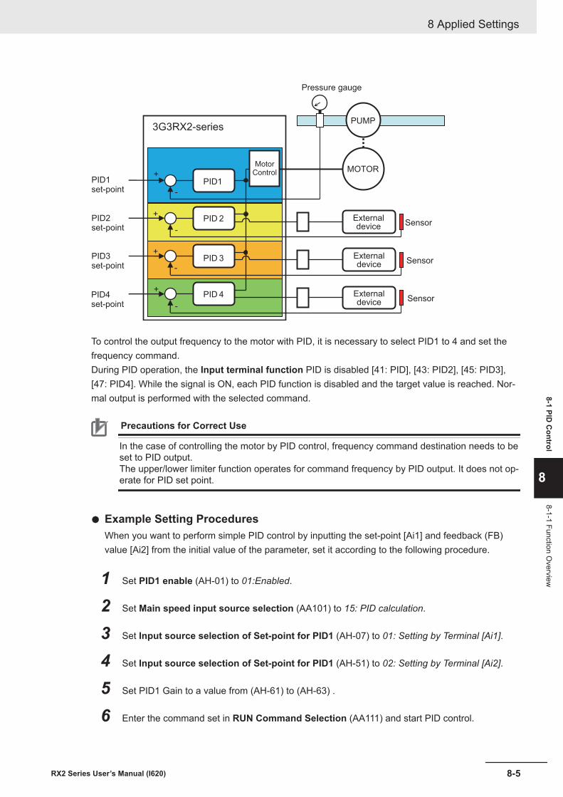
MOTOR
PUMP
PID1
PID 2
PID 3
PID 4+
-
-
-
-
+
+
+
Pressure gauge
MotorControl
PID1set-point
PID2set-point
PID3set-point
PID4set-point
Externaldevice
Externaldevice
Externaldevice
Sensor
Sensor
Sensor
3G3RX2-series
To control the output frequency to the motor with PID, it is necessary to select PID1 to 4 and set thefrequency command.During PID operation, the Input terminal function PID is disabled [41: PID], [43: PID2], [45: PID3],[47: PID4]. While the signal is ON, each PID function is disabled and the target value is reached. Nor-mal output is performed with the selected command.
Precautions for Correct Use
In the case of controlling the motor by PID control, frequency command destination needs to beset to PID output.The upper/lower limiter function operates for command frequency by PID output. It does not op-erate for PID set point.
l Example Setting ProceduresWhen you want to perform simple PID control by inputting the set-point [Ai1] and feedback (FB)value [Ai2] from the initial value of the parameter, set it according to the following procedure.
1 Set PID1 enable (AH-01) to 01:Enabled.
2 Set Main speed input source selection (AA101) to 15: PID calculation.
3 Set Input source selection of Set-point for PID1 (AH-07) to 01: Setting by Terminal [Ai1].
4 Set Input source selection of Set-point for PID1 (AH-51) to 02: Setting by Terminal [Ai2].
5 Set PID1 Gain to a value from (AH-61) to (AH-63) .
6 Enter the command set in RUN Command Selection (AA111) and start PID control.
8 Applied Settings
8-5RX2 Series User’s Manual (I620)
8-1 PID C
ontrol
8
8-1-1 Function Overview
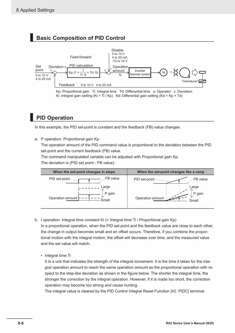
Basic Composition of PID Control
0 to 10 V4 to 20 mA
fsM =
+
-
+
+
0 to 10 V4 to 20 mA-10 to 10 V
Operationamount
Disable
Feed-forward
PID calculation
Feedback
Setpoint Inverter
Normal control
Deviation ε
Kp: Proportional gain Ti: Integral time Td: Differential time s: Operator ε: Deviation
Ki: Integral gain setting (Ki = Ti / Kp) Kd: Differential gain setting (Kd = Kp × Td)
Transducer
0 to 10 V 4 to 20 mA
Kp (1 + + Td・S)1
Ti・S
PID OperationIn this example, the PID set-point is constant and the feedback (FB) value changes.
a. P operation: Proportional gain KpThe operation amount of the PID command value is proportional to the deviation between the PIDset-point and the current feedback (FB) value.The command manipulated variable can be adjusted with Proportional gain Kp.The deviation is (PID set point - FB value).
When the set-point changes in steps When the set-point changes like a ramp
PID set-point
Operation amount
FB value
P gain
Large
Small
PID set-point
Operation amount
FB value
P gain
Large
Small
b. I operation: Integral time constant Ki (= Integral time Ti / Proportional gain Kp)In a proportional operation, when the PID set-point and the feedback value are close to each other,the change in output becomes small and an offset occurs. Therefore, if you combine the propor-tional motion with the integral motion, the offset will decrease over time, and the measured valueand the set value will match.
• Integral time TiIt is a unit that indicates the strength of the integral movement. It is the time it takes for the inte-gral operation amount to reach the same operation amount as the proportional operation with re-spect to the step-like deviation as shown in the figure below. The shorter the integral time, thestronger the correction by the integral operation. However, if it is made too short, the correctionoperation may become too strong and cause hunting.The integral value is cleared by the PID Control Integral Reset Function [42: PIDC] terminal.
8 Applied Settings
8-6 RX2 Series User’s Manual (I620)
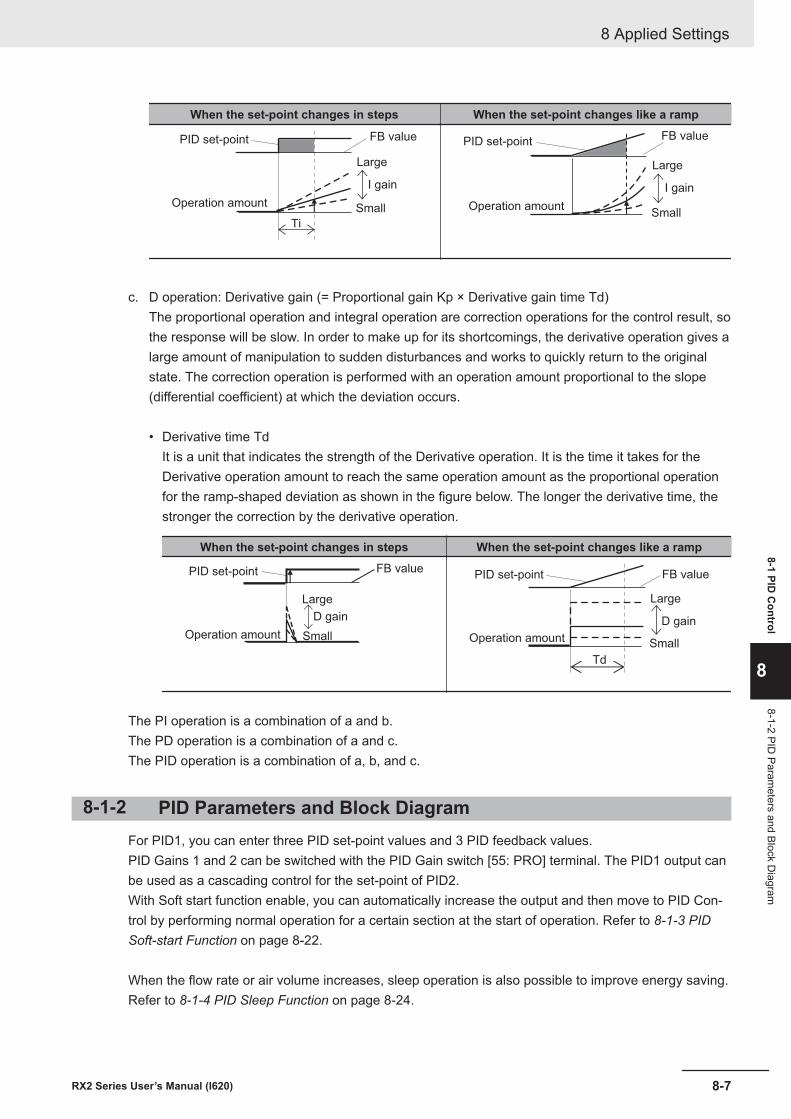
When the set-point changes in steps When the set-point changes like a ramp
PID set-point
Operation amount
FB value
I gain
Large
Small
Ti
PID set-point
Operation amount
FB value
I gain
Large
Small
c. D operation: Derivative gain (= Proportional gain Kp × Derivative gain time Td)The proportional operation and integral operation are correction operations for the control result, sothe response will be slow. In order to make up for its shortcomings, the derivative operation gives alarge amount of manipulation to sudden disturbances and works to quickly return to the originalstate. The correction operation is performed with an operation amount proportional to the slope(differential coefficient) at which the deviation occurs.
• Derivative time TdIt is a unit that indicates the strength of the Derivative operation. It is the time it takes for theDerivative operation amount to reach the same operation amount as the proportional operationfor the ramp-shaped deviation as shown in the figure below. The longer the derivative time, thestronger the correction by the derivative operation.
When the set-point changes in steps When the set-point changes like a ramp
PID set-point
Operation amount
FB value
D gain
Large
Small
Td
PID set-point
Operation amount
FB value
D gain
Large
Small
The PI operation is a combination of a and b.The PD operation is a combination of a and c.The PID operation is a combination of a, b, and c.
8-1-2 PID Parameters and Block DiagramFor PID1, you can enter three PID set-point values and 3 PID feedback values.PID Gains 1 and 2 can be switched with the PID Gain switch [55: PRO] terminal. The PID1 output canbe used as a cascading control for the set-point of PID2.With Soft start function enable, you can automatically increase the output and then move to PID Con-trol by performing normal operation for a certain section at the start of operation. Refer to 8-1-3 PIDSoft-start Function on page 8-22.
When the flow rate or air volume increases, sleep operation is also possible to improve energy saving.Refer to 8-1-4 PID Sleep Function on page 8-24.
8 Applied Settings
8-7RX2 Series User’s Manual (I620)
8-1 PID C
ontrol
8
8-1-2 PID Param
eters and Block Diagram
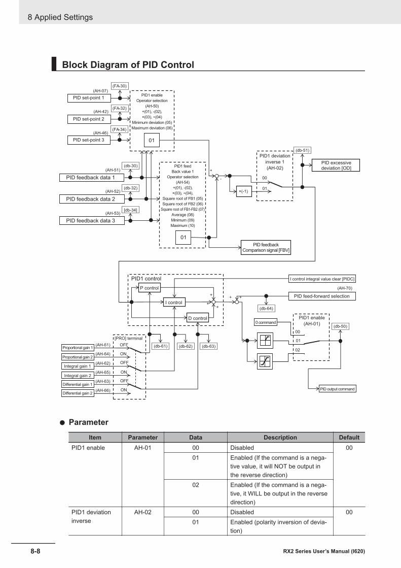
Block Diagram of PID Control
+
++
OFF
OFF
OFF
ON
ON
ON
+
00
01
-
00
01
02
+ +
01
01
(AH-07)
(AH-42)
(AH-51)
(AH-52)
(AH-61)
(AH-70)
×(-1)
(AH-64)
(AH-62)
(AH-65)
(AH-63)
(AH-66)
(FA-30)
(FA-32)
(db-30)
(db-32)
(db-51)
(db-64)
(db-62) (db-63)(db-61)
(db-50)
(AH-46)(FA-34)
(AH-53)[db-34]
PID excessivedeviation [OD]
PID set-point 1
PID set-point 2
PID set-point 3
PID feedback data 1
PID feedback data 2
PID feedback data 3
PID1 enable
Operator selection
(AH-50)
+(01), -(02),
×(03), ÷(04)
Minimum deviation (05)
Maximum deviation (06)
PID1 feed
Back value 1
Operator selection
(AH-54)
+(01), -(02),
×(03), ÷(04),
Square root of FB1 (05)
Square root of FB2 (06)
Square root of FB1-FB2 (07)
Average (08)
Minimum (09)
Maximum (10)
PID feedbackComparison signal [FBV]
I control integral value clear [PIDC]
PID feed-forward selection
PID1 control
P control
I control
D control0 command
PID1 enable
(AH-01)
PID output command
Proportional gain 1
Proportional gain 2
Integral gain 1
Integral gain 2
Differential gain 1
Differential gain 2
[PRO] terminal
PID1 deviation
inverse 1
(AH-02)
l Parameter
Item Parameter Data Description DefaultPID1 enable AH-01 00 Disabled 00
01 Enabled (If the command is a nega-tive value, it will NOT be output inthe reverse direction)
02 Enabled (If the command is a nega-tive, it WILL be output in the reversedirection)
PID1 deviationinverse
AH-02 00 Disabled 0001 Enabled (polarity inversion of devia-
tion)
8 Applied Settings
8-8 RX2 Series User’s Manual (I620)
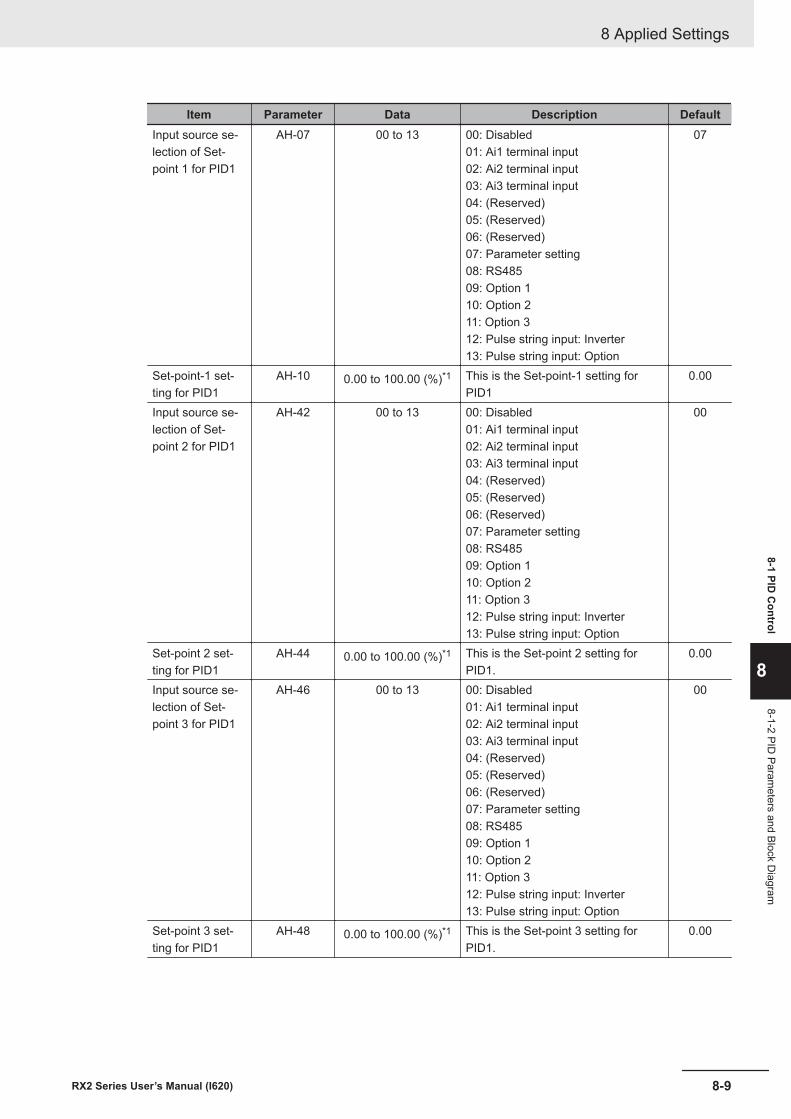
Item Parameter Data Description DefaultInput source se-lection of Set-point 1 for PID1
AH-07 00 to 13 00: Disabled01: Ai1 terminal input02: Ai2 terminal input03: Ai3 terminal input04: (Reserved)05: (Reserved)06: (Reserved)07: Parameter setting08: RS48509: Option 110: Option 211: Option 312: Pulse string input: Inverter13: Pulse string input: Option
07
Set-point-1 set-ting for PID1
AH-10 0.00 to 100.00 (%)*1 This is the Set-point-1 setting forPID1
0.00
Input source se-lection of Set-point 2 for PID1
AH-42 00 to 13 00: Disabled01: Ai1 terminal input02: Ai2 terminal input03: Ai3 terminal input04: (Reserved)05: (Reserved)06: (Reserved)07: Parameter setting08: RS48509: Option 110: Option 211: Option 312: Pulse string input: Inverter13: Pulse string input: Option
00
Set-point 2 set-ting for PID1
AH-44 0.00 to 100.00 (%)*1 This is the Set-point 2 setting forPID1.
0.00
Input source se-lection of Set-point 3 for PID1
AH-46 00 to 13 00: Disabled01: Ai1 terminal input02: Ai2 terminal input03: Ai3 terminal input04: (Reserved)05: (Reserved)06: (Reserved)07: Parameter setting08: RS48509: Option 110: Option 211: Option 312: Pulse string input: Inverter13: Pulse string input: Option
00
Set-point 3 set-ting for PID1
AH-48 0.00 to 100.00 (%)*1 This is the Set-point 3 setting forPID1.
0.00
8 Applied Settings
8-9RX2 Series User’s Manual (I620)
8-1 PID C
ontrol
8
8-1-2 PID Param
eters and Block Diagram
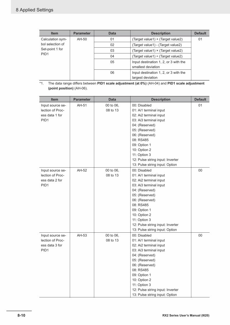
Item Parameter Data Description DefaultCalculation sym-bol selection ofSet-point 1 forPID1
AH-50 01 (Target value1) + (Target value2) 0102 (Target value1) - (Target value2)03 (Target value1) × (Target value2)04 (Target value1) ÷ (Target value2)05 Input destination 1, 2, or 3 with the
smallest deviation06 Input destination 1, 2, or 3 with the
largest deviation*1. The data range differs between PID1 scale adjustment (at 0%) (AH-04) and PID1 scale adjustment
(point position) (AH-06).
Item Parameter Data Description DefaultInput source se-lection of Proc-ess data 1 forPID1
AH-51 00 to 06,08 to 13
00: Disabled01: Ai1 terminal input02: Ai2 terminal input03: Ai3 terminal input04: (Reserved)05: (Reserved)06: (Reserved)08: RS48509: Option 110: Option 211: Option 312: Pulse string input: Inverter13: Pulse string input: Option
01
Input source se-lection of Proc-ess data 2 forPID1
AH-52 00 to 06,08 to 13
00: Disabled01: Ai1 terminal input02: Ai2 terminal input03: Ai3 terminal input04: (Reserved)05: (Reserved)06: (Reserved)08: RS48509: Option 110: Option 211: Option 312: Pulse string input: Inverter13: Pulse string input: Option
00
Input source se-lection of Proc-ess data 3 forPID1
AH-53 00 to 06,08 to 13
00: Disabled01: Ai1 terminal input02: Ai2 terminal input03: Ai3 terminal input04: (Reserved)05: (Reserved)06: (Reserved)08: RS48509: Option 110: Option 211: Option 312: Pulse string input: Inverter13: Pulse string input: Option
00
8 Applied Settings
8-10 RX2 Series User’s Manual (I620)
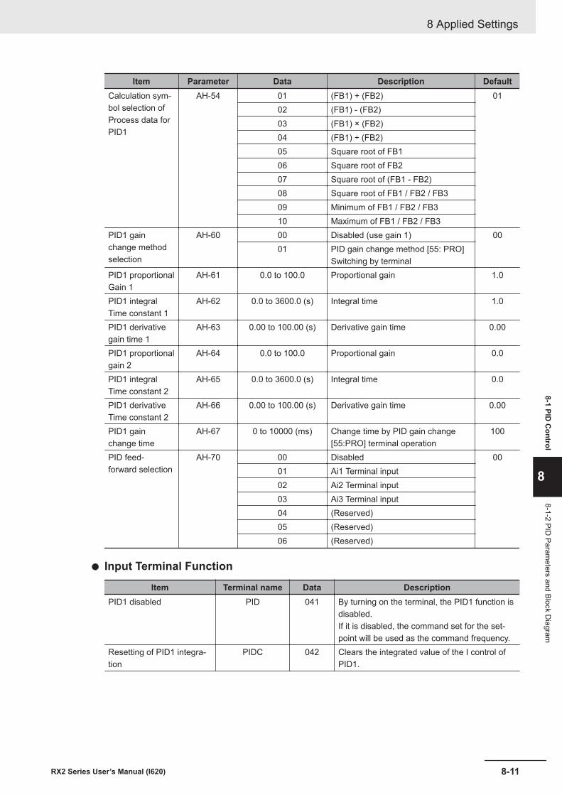
Item Parameter Data Description DefaultCalculation sym-bol selection ofProcess data forPID1
AH-54 01 (FB1) + (FB2) 0102 (FB1) - (FB2)03 (FB1) × (FB2)04 (FB1) ÷ (FB2)05 Square root of FB106 Square root of FB207 Square root of (FB1 - FB2)08 Square root of FB1 / FB2 / FB309 Minimum of FB1 / FB2 / FB310 Maximum of FB1 / FB2 / FB3
PID1 gainchange methodselection
AH-60 00 Disabled (use gain 1) 0001 PID gain change method [55: PRO]
Switching by terminalPID1 proportionalGain 1
AH-61 0.0 to 100.0 Proportional gain 1.0
PID1 integralTime constant 1
AH-62 0.0 to 3600.0 (s) Integral time 1.0
PID1 derivativegain time 1
AH-63 0.00 to 100.00 (s) Derivative gain time 0.00
PID1 proportionalgain 2
AH-64 0.0 to 100.0 Proportional gain 0.0
PID1 integralTime constant 2
AH-65 0.0 to 3600.0 (s) Integral time 0.0
PID1 derivativeTime constant 2
AH-66 0.00 to 100.00 (s) Derivative gain time 0.00
PID1 gainchange time
AH-67 0 to 10000 (ms) Change time by PID gain change[55:PRO] terminal operation
100
PID feed-forward selection
AH-70 00 Disabled 0001 Ai1 Terminal input02 Ai2 Terminal input03 Ai3 Terminal input04 (Reserved)05 (Reserved)06 (Reserved)
l Input Terminal Function
Item Terminal name Data DescriptionPID1 disabled PID 041 By turning on the terminal, the PID1 function is
disabled.If it is disabled, the command set for the set-point will be used as the command frequency.
Resetting of PID1 integra-tion
PIDC 042 Clears the integrated value of the I control ofPID1.
8 Applied Settings
8-11RX2 Series User’s Manual (I620)
8-1 PID C
ontrol
8
8-1-2 PID Param
eters and Block Diagram
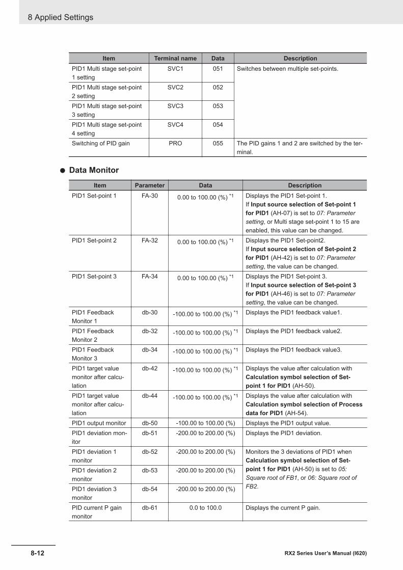
Item Terminal name Data DescriptionPID1 Multi stage set-point1 setting
SVC1 051 Switches between multiple set-points.
PID1 Multi stage set-point2 setting
SVC2 052
PID1 Multi stage set-point3 setting
SVC3 053
PID1 Multi stage set-point4 setting
SVC4 054
Switching of PID gain PRO 055 The PID gains 1 and 2 are switched by the ter-minal.
l Data Monitor
Item Parameter Data DescriptionPID1 Set-point 1 FA-30 0.00 to 100.00 (%) *1 Displays the PID1 Set-point 1.
If Input source selection of Set-point 1for PID1 (AH-07) is set to 07: Parametersetting, or Multi stage set-point 1 to 15 areenabled, this value can be changed.
PID1 Set-point 2 FA-32 0.00 to 100.00 (%) *1 Displays the PID1 Set-point2.If Input source selection of Set-point 2for PID1 (AH-42) is set to 07: Parametersetting, the value can be changed.
PID1 Set-point 3 FA-34 0.00 to 100.00 (%) *1 Displays the PID1 Set-point 3.If Input source selection of Set-point 3for PID1 (AH-46) is set to 07: Parametersetting, the value can be changed.
PID1 FeedbackMonitor 1
db-30 -100.00 to 100.00 (%) *1 Displays the PID1 feedback value1.
PID1 FeedbackMonitor 2
db-32 -100.00 to 100.00 (%) *1 Displays the PID1 feedback value2.
PID1 FeedbackMonitor 3
db-34 -100.00 to 100.00 (%) *1 Displays the PID1 feedback value3.
PID1 target valuemonitor after calcu-lation
db-42 -100.00 to 100.00 (%) *1 Displays the value after calculation withCalculation symbol selection of Set-point 1 for PID1 (AH-50).
PID1 target valuemonitor after calcu-lation
db-44 -100.00 to 100.00 (%) *1 Displays the value after calculation withCalculation symbol selection of Processdata for PID1 (AH-54).
PID1 output monitor db-50 -100.00 to 100.00 (%) Displays the PID1 output value.PID1 deviation mon-itor
db-51 -200.00 to 200.00 (%) Displays the PID1 deviation.
PID1 deviation 1monitor
db-52 -200.00 to 200.00 (%) Monitors the 3 deviations of PID1 whenCalculation symbol selection of Set-point 1 for PID1 (AH-50) is set to 05:Square root of FB1, or 06: Square root ofFB2.
PID1 deviation 2monitor
db-53 -200.00 to 200.00 (%)
PID1 deviation 3monitor
db-54 -200.00 to 200.00 (%)
PID current P gainmonitor
db-61 0.0 to 100.0 Displays the current P gain.
8 Applied Settings
8-12 RX2 Series User’s Manual (I620)
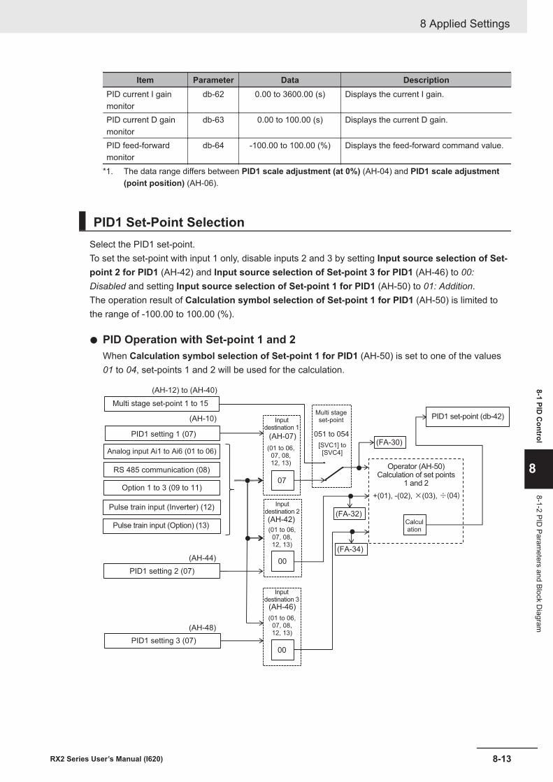
Item Parameter Data DescriptionPID current I gainmonitor
db-62 0.00 to 3600.00 (s) Displays the current I gain.
PID current D gainmonitor
db-63 0.00 to 100.00 (s) Displays the current D gain.
PID feed-forwardmonitor
db-64 -100.00 to 100.00 (%) Displays the feed-forward command value.
*1. The data range differs between PID1 scale adjustment (at 0%) (AH-04) and PID1 scale adjustment(point position) (AH-06).
PID1 Set-Point SelectionSelect the PID1 set-point.To set the set-point with input 1 only, disable inputs 2 and 3 by setting Input source selection of Set-point 2 for PID1 (AH-42) and Input source selection of Set-point 3 for PID1 (AH-46) to 00:Disabled and setting Input source selection of Set-point 1 for PID1 (AH-50) to 01: Addition.The operation result of Calculation symbol selection of Set-point 1 for PID1 (AH-50) is limited tothe range of -100.00 to 100.00 (%).
l PID Operation with Set-point 1 and 2When Calculation symbol selection of Set-point 1 for PID1 (AH-50) is set to one of the values01 to 04, set-points 1 and 2 will be used for the calculation.
+(01), -(02), ×(03), ÷(04)
(AH-12) to (AH-40)
07
00
00
(AH-10)
(AH-44)
(AH-48)
(FA-32)
(FA-34)
(FA-30)
PID1 set-point (db-42)
Operator (AH-50)Calculation of set points
1 and 2
Multi stageset-point
Multi stage set-point 1 to 15
PID1 setting 1 (07)
Analog input Ai1 to Ai6 (01 to 06)
RS 485 communication (08)
Option 1 to 3 (09 to 11)
Pulse train input (Inverter) (12)
Pulse train input (Option) (13)
PID1 setting 2 (07)
PID1 setting 3 (07)
(01 to 06,07, 08,12, 13)
Calculation
(AH-07)
Inputdestination 2
Inputdestination 3
Inputdestination 1
(AH-42)
(AH-46)
(01 to 06,07, 08,12, 13)
(01 to 06,07, 08,12, 13)
051 to 054
[SVC1] to[SVC4]
8 Applied Settings
8-13RX2 Series User’s Manual (I620)
8-1 PID C
ontrol
8
8-1-2 PID Param
eters and Block Diagram
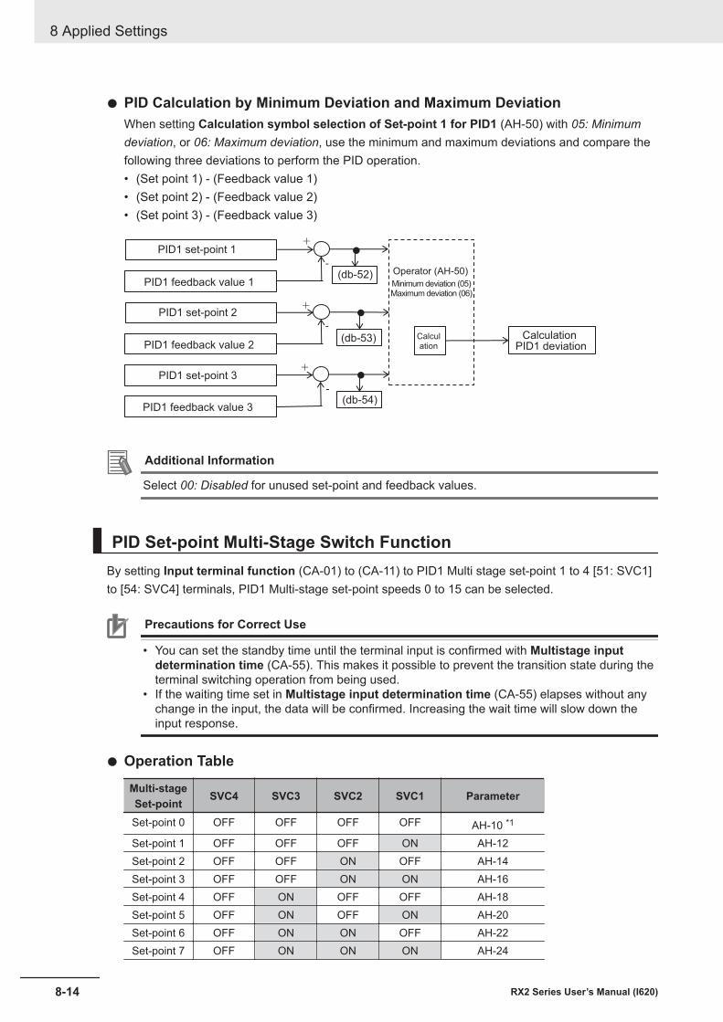
l PID Calculation by Minimum Deviation and Maximum DeviationWhen setting Calculation symbol selection of Set-point 1 for PID1 (AH-50) with 05: Minimumdeviation, or 06: Maximum deviation, use the minimum and maximum deviations and compare thefollowing three deviations to perform the PID operation.• (Set point 1) - (Feedback value 1)• (Set point 2) - (Feedback value 2)• (Set point 3) - (Feedback value 3)
+
+
+
-
-
-
(db-52)
(db-53)
(db-54)
PID1 set-point 1
PID1 feedback value 1
PID1 set-point 2
PID1 feedback value 2
PID1 set-point 3
PID1 feedback value 3
Minimum deviation (05)Maximum deviation (06)
Calculation
Calculation PID1 deviation
Operator (AH-50)
Additional Information
Select 00: Disabled for unused set-point and feedback values.
PID Set-point Multi-Stage Switch FunctionBy setting Input terminal function (CA-01) to (CA-11) to PID1 Multi stage set-point 1 to 4 [51: SVC1]to [54: SVC4] terminals, PID1 Multi-stage set-point speeds 0 to 15 can be selected.
Precautions for Correct Use
• You can set the standby time until the terminal input is confirmed with Multistage inputdetermination time (CA-55). This makes it possible to prevent the transition state during theterminal switching operation from being used.
• If the waiting time set in Multistage input determination time (CA-55) elapses without anychange in the input, the data will be confirmed. Increasing the wait time will slow down theinput response.
l Operation Table
Multi-stageSet-point SVC4 SVC3 SVC2 SVC1 Parameter
Set-point 0 OFF OFF OFF OFF AH-10 *1
Set-point 1 OFF OFF OFF ON AH-12Set-point 2 OFF OFF ON OFF AH-14Set-point 3 OFF OFF ON ON AH-16Set-point 4 OFF ON OFF OFF AH-18Set-point 5 OFF ON OFF ON AH-20Set-point 6 OFF ON ON OFF AH-22Set-point 7 OFF ON ON ON AH-24
8 Applied Settings
8-14 RX2 Series User’s Manual (I620)
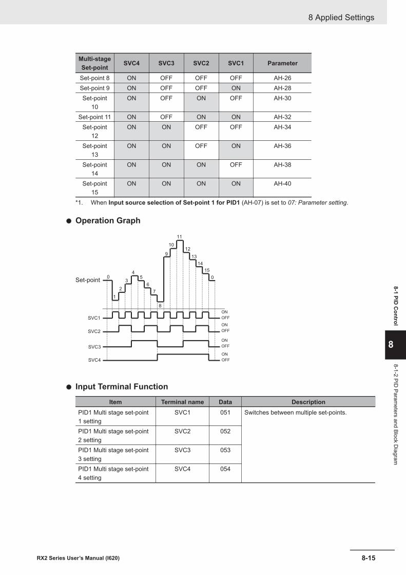
Multi-stageSet-point SVC4 SVC3 SVC2 SVC1 Parameter
Set-point 8 ON OFF OFF OFF AH-26Set-point 9 ON OFF OFF ON AH-28Set-point
10ON OFF ON OFF AH-30
Set-point 11 ON OFF ON ON AH-32Set-point
12ON ON OFF OFF AH-34
Set-point13
ON ON OFF ON AH-36
Set-point14
ON ON ON OFF AH-38
Set-point15
ON ON ON ON AH-40
*1. When Input source selection of Set-point 1 for PID1 (AH-07) is set to 07: Parameter setting.
l Operation Graph
2
35
6
7
4
8
9
10
11
12
13
14
15
0
1
SVC4
SVC3
SVC2
SVC1
0
ON
OFF
ON
OFF
ON
OFF
ON
OFF
Set-point
l Input Terminal Function
Item Terminal name Data DescriptionPID1 Multi stage set-point1 setting
SVC1 051 Switches between multiple set-points.
PID1 Multi stage set-point2 setting
SVC2 052
PID1 Multi stage set-point3 setting
SVC3 053
PID1 Multi stage set-point4 setting
SVC4 054
8 Applied Settings
8-15RX2 Series User’s Manual (I620)
8-1 PID C
ontrol
8
8-1-2 PID Param
eters and Block Diagram
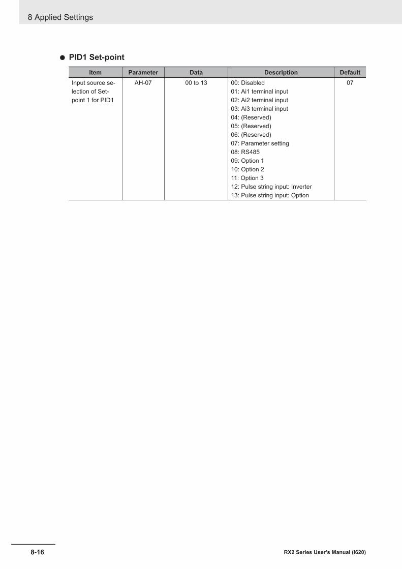
l PID1 Set-point
Item Parameter Data Description DefaultInput source se-lection of Set-point 1 for PID1
AH-07 00 to 13 00: Disabled01: Ai1 terminal input02: Ai2 terminal input03: Ai3 terminal input04: (Reserved)05: (Reserved)06: (Reserved)07: Parameter setting08: RS48509: Option 110: Option 211: Option 312: Pulse string input: Inverter13: Pulse string input: Option
07
8 Applied Settings
8-16 RX2 Series User’s Manual (I620)
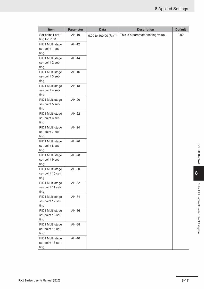
Item Parameter Data Description DefaultSet-point 1 set-ting for PID1
AH-10 0.00 to 100.00 (%) *1 This is a parameter setting value. 0.00
PID1 Multi stageset-point 1 set-ting
AH-12
PID1 Multi stageset-point 2 set-ting
AH-14
PID1 Multi stageset-point 3 set-ting
AH-16
PID1 Multi stageset-point 4 set-ting
AH-18
PID1 Multi stageset-point 5 set-ting
AH-20
PID1 Multi stageset-point 6 set-ting
AH-22
PID1 Multi stageset-point 7 set-ting
AH-24
PID1 Multi stageset-point 8 set-ting
AH-26
PID1 Multi stageset-point 9 set-ting
AH-28
PID1 Multi stageset-point 10 set-ting
AH-30
PID1 Multi stageset-point 11 set-ting
AH-32
PID1 Multi stageset-point 12 set-ting
AH-34
PID1 Multi stageset-point 13 set-ting
AH-36
PID1 Multi stageset-point 14 set-ting
AH-38
PID1 Multi stageset-point 15 set-ting
AH-40
8 Applied Settings
8-17RX2 Series User’s Manual (I620)
8-1 PID C
ontrol
8
8-1-2 PID Param
eters and Block Diagram
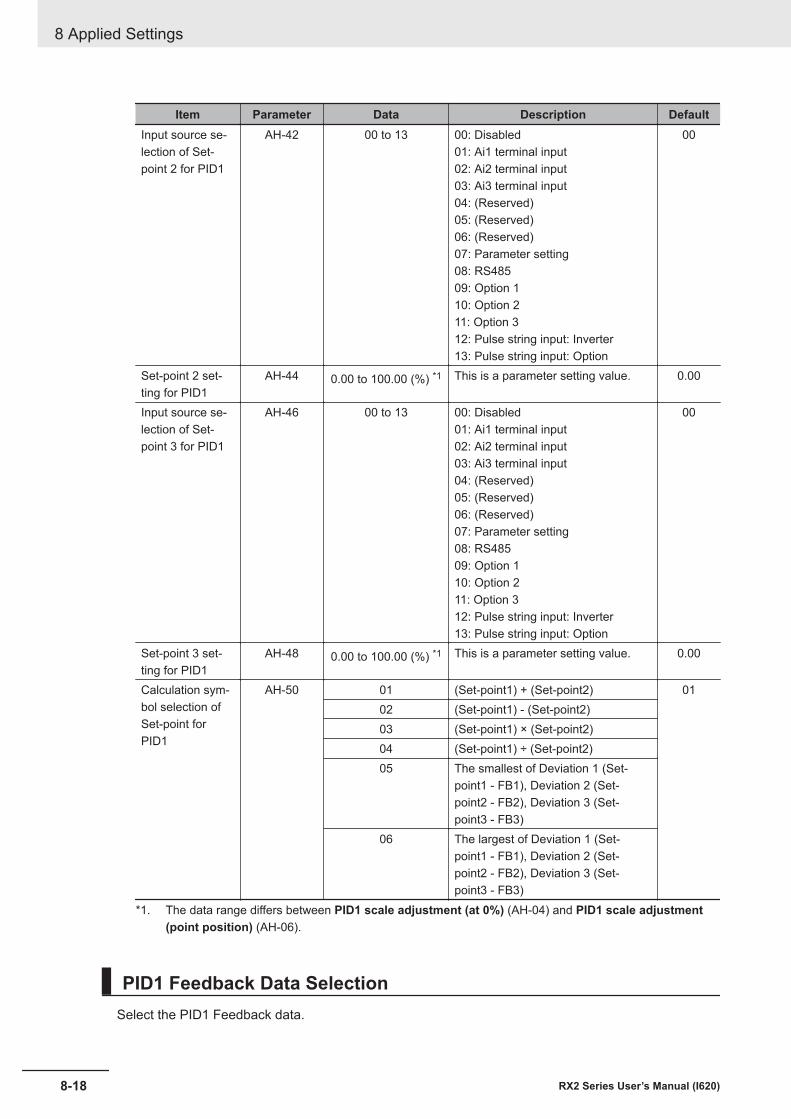
Item Parameter Data Description DefaultInput source se-lection of Set-point 2 for PID1
AH-42 00 to 13 00: Disabled01: Ai1 terminal input02: Ai2 terminal input03: Ai3 terminal input04: (Reserved)05: (Reserved)06: (Reserved)07: Parameter setting08: RS48509: Option 110: Option 211: Option 312: Pulse string input: Inverter13: Pulse string input: Option
00
Set-point 2 set-ting for PID1
AH-44 0.00 to 100.00 (%) *1 This is a parameter setting value. 0.00
Input source se-lection of Set-point 3 for PID1
AH-46 00 to 13 00: Disabled01: Ai1 terminal input02: Ai2 terminal input03: Ai3 terminal input04: (Reserved)05: (Reserved)06: (Reserved)07: Parameter setting08: RS48509: Option 110: Option 211: Option 312: Pulse string input: Inverter13: Pulse string input: Option
00
Set-point 3 set-ting for PID1
AH-48 0.00 to 100.00 (%) *1 This is a parameter setting value. 0.00
Calculation sym-bol selection ofSet-point forPID1
AH-50 01 (Set-point1) + (Set-point2) 0102 (Set-point1) - (Set-point2)03 (Set-point1) × (Set-point2)04 (Set-point1) ÷ (Set-point2)05 The smallest of Deviation 1 (Set-
point1 - FB1), Deviation 2 (Set-point2 - FB2), Deviation 3 (Set-point3 - FB3)
06 The largest of Deviation 1 (Set-point1 - FB1), Deviation 2 (Set-point2 - FB2), Deviation 3 (Set-point3 - FB3)
*1. The data range differs between PID1 scale adjustment (at 0%) (AH-04) and PID1 scale adjustment(point position) (AH-06).
PID1 Feedback Data SelectionSelect the PID1 Feedback data.
8 Applied Settings
8-18 RX2 Series User’s Manual (I620)
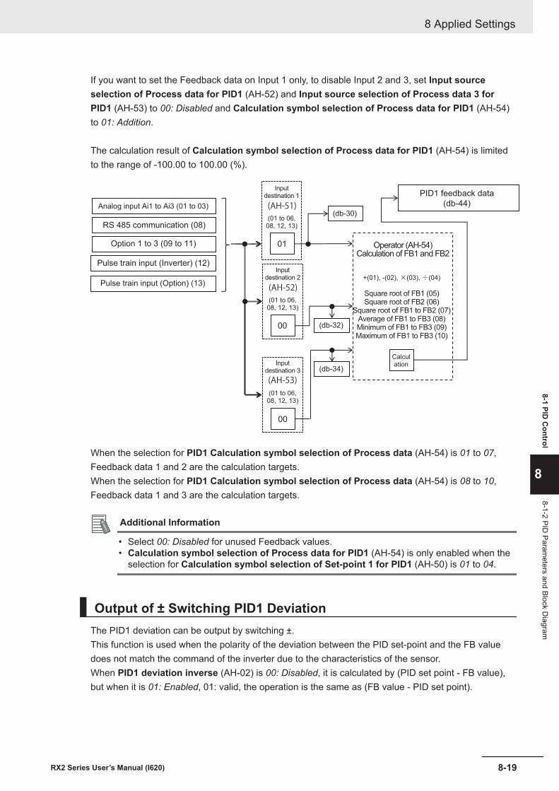
If you want to set the Feedback data on Input 1 only, to disable Input 2 and 3, set Input sourceselection of Process data for PID1 (AH-52) and Input source selection of Process data 3 forPID1 (AH-53) to 00: Disabled and Calculation symbol selection of Process data for PID1 (AH-54)to 01: Addition.
The calculation result of Calculation symbol selection of Process data for PID1 (AH-54) is limitedto the range of -100.00 to 100.00 (%).
01
00
(db-30)
(db-32)
00
(db-34)
Analog input Ai1 to Ai3 (01 to 03)
RS 485 communication (08)
Option 1 to 3 (09 to 11)
Pulse train input (Inverter) (12)
Pulse train input (Option) (13)
PID1 feedback data
(db-44)
Operator (AH-54)Calculation of FB1 and FB2
Calculation
+(01), -(02), ×(03), ÷(04)
Square root of FB1 (05)Square root of FB2 (06)
Square root of FB1 to FB2 (07)Average of FB1 to FB3 (08)Minimum of FB1 to FB3 (09)Maximum of FB1 to FB3 (10)
(AH-53)
(01 to 06,08, 12, 13)
Inputdestination 1
(01 to 06,08, 12, 13)
(01 to 06,08, 12, 13)
(AH-52)
(AH-51)
Inputdestination 2
Inputdestination 3
When the selection for PID1 Calculation symbol selection of Process data (AH-54) is 01 to 07,Feedback data 1 and 2 are the calculation targets.When the selection for PID1 Calculation symbol selection of Process data (AH-54) is 08 to 10,Feedback data 1 and 3 are the calculation targets.
Additional Information
• Select 00: Disabled for unused Feedback values.• Calculation symbol selection of Process data for PID1 (AH-54) is only enabled when the
selection for Calculation symbol selection of Set-point 1 for PID1 (AH-50) is 01 to 04.
Output of ± Switching PID1 DeviationThe PID1 deviation can be output by switching ±.This function is used when the polarity of the deviation between the PID set-point and the FB valuedoes not match the command of the inverter due to the characteristics of the sensor.When PID1 deviation inverse (AH-02) is 00: Disabled, it is calculated by (PID set point - FB value),but when it is 01: Enabled, 01: valid, the operation is the same as (FB value - PID set point).
8 Applied Settings
8-19RX2 Series User’s Manual (I620)
8-1 PID C
ontrol
8
8-1-2 PID Param
eters and Block Diagram
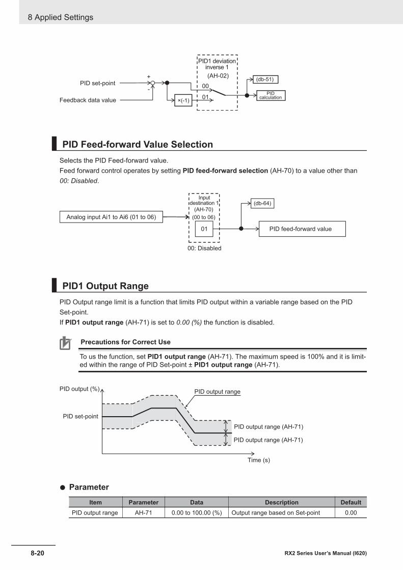
+
00
01
-
×(-1)
(db-51)
PIDcalculation
PID1 deviationinverse 1
PID set-point
Feedback data value
(AH-02)
PID Feed-forward Value SelectionSelects the PID Feed-forward value.Feed forward control operates by setting PID feed-forward selection (AH-70) to a value other than00: Disabled.
01
(db-64)
PID feed-forward value
Analog input Ai1 to Ai6 (01 to 06)
Inputdestination 1
00: Disabled
(AH-70)
(00 to 06)
PID1 Output RangePID Output range limit is a function that limits PID output within a variable range based on the PIDSet-point.If PID1 output range (AH-71) is set to 0.00 (%) the function is disabled.
Precautions for Correct Use
To us the function, set PID1 output range (AH-71). The maximum speed is 100% and it is limit-ed within the range of PID Set-point ± PID1 output range (AH-71).
PID output range
PID output range (AH-71)
PID output range (AH-71)
Time (s)
PID output (%)
PID set-point
l Parameter
Item Parameter Data Description DefaultPID output range AH-71 0.00 to 100.00 (%) Output range based on Set-point 0.00
8 Applied Settings
8-20 RX2 Series User’s Manual (I620)
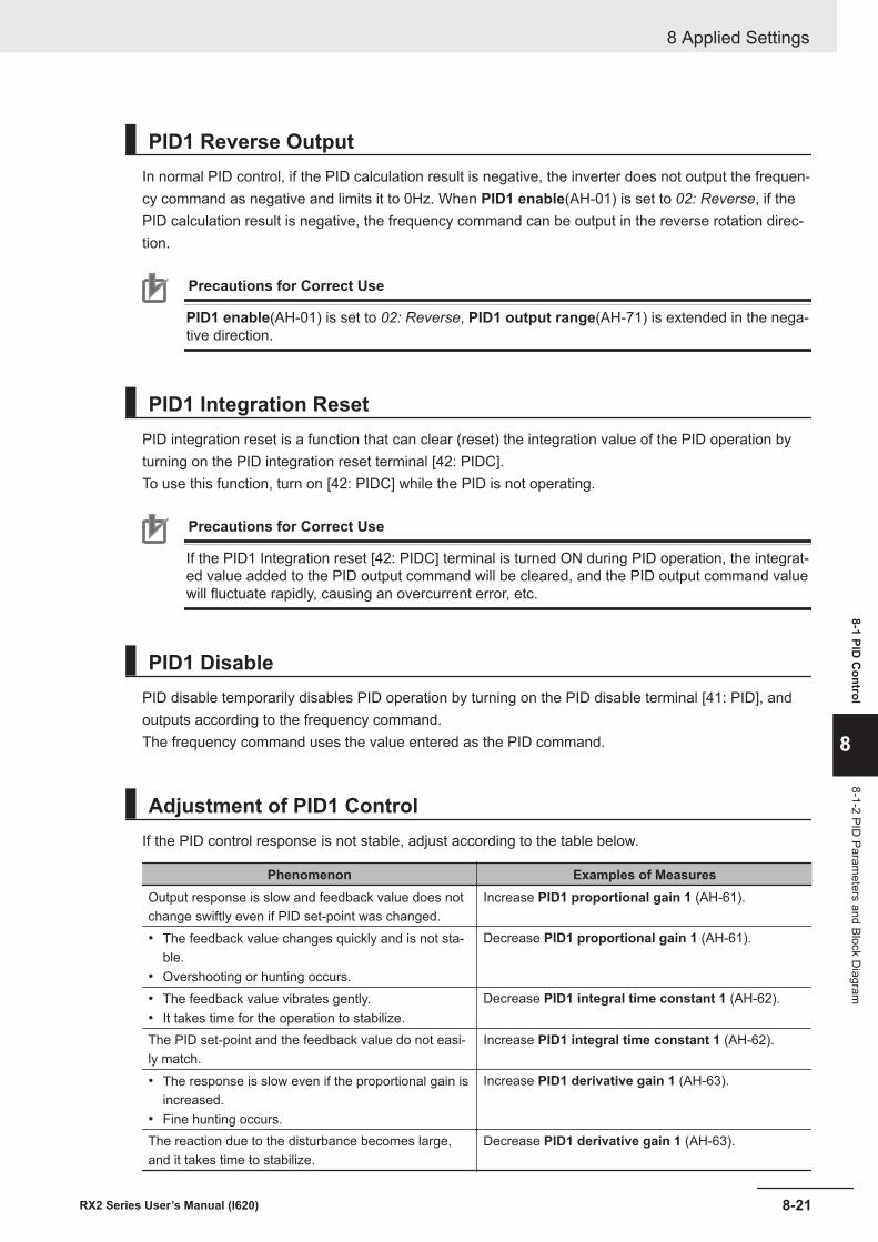
PID1 Reverse OutputIn normal PID control, if the PID calculation result is negative, the inverter does not output the frequen-cy command as negative and limits it to 0Hz. When PID1 enable(AH-01) is set to 02: Reverse, if thePID calculation result is negative, the frequency command can be output in the reverse rotation direc-tion.
Precautions for Correct Use
PID1 enable(AH-01) is set to 02: Reverse, PID1 output range(AH-71) is extended in the nega-tive direction.
PID1 Integration ResetPID integration reset is a function that can clear (reset) the integration value of the PID operation byturning on the PID integration reset terminal [42: PIDC].To use this function, turn on [42: PIDC] while the PID is not operating.
Precautions for Correct Use
If the PID1 Integration reset [42: PIDC] terminal is turned ON during PID operation, the integrat-ed value added to the PID output command will be cleared, and the PID output command valuewill fluctuate rapidly, causing an overcurrent error, etc.
PID1 DisablePID disable temporarily disables PID operation by turning on the PID disable terminal [41: PID], andoutputs according to the frequency command.The frequency command uses the value entered as the PID command.
Adjustment of PID1 ControlIf the PID control response is not stable, adjust according to the table below.
Phenomenon Examples of MeasuresOutput response is slow and feedback value does notchange swiftly even if PID set-point was changed.
Increase PID1 proportional gain 1 (AH-61).
• The feedback value changes quickly and is not sta-ble.
• Overshooting or hunting occurs.
Decrease PID1 proportional gain 1 (AH-61).
• The feedback value vibrates gently.• It takes time for the operation to stabilize.
Decrease PID1 integral time constant 1 (AH-62).
The PID set-point and the feedback value do not easi-ly match.
Increase PID1 integral time constant 1 (AH-62).
• The response is slow even if the proportional gain isincreased.
• Fine hunting occurs.
Increase PID1 derivative gain 1 (AH-63).
The reaction due to the disturbance becomes large,and it takes time to stabilize.
Decrease PID1 derivative gain 1 (AH-63).
8 Applied Settings
8-21RX2 Series User’s Manual (I620)
8-1 PID C
ontrol
8
8-1-2 PID Param
eters and Block Diagram
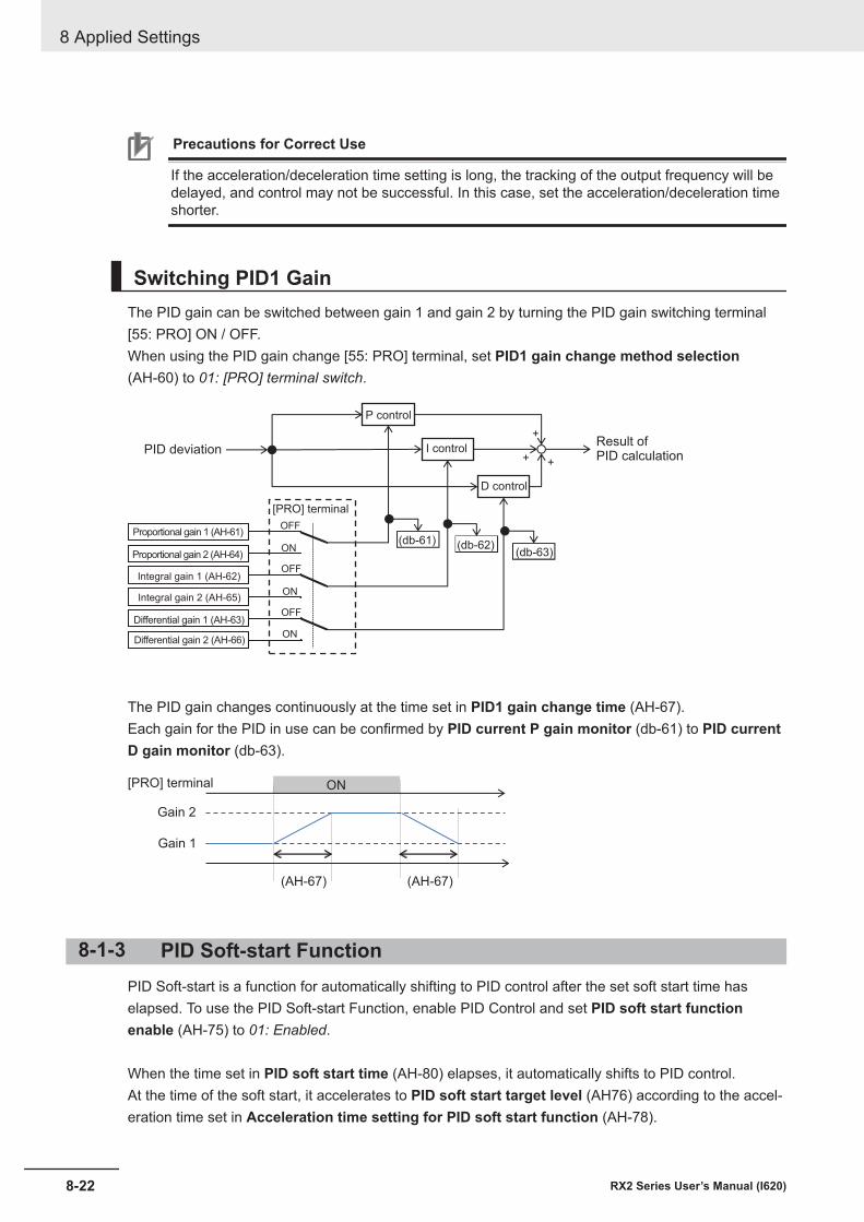
Precautions for Correct Use
If the acceleration/deceleration time setting is long, the tracking of the output frequency will bedelayed, and control may not be successful. In this case, set the acceleration/deceleration timeshorter.
Switching PID1 GainThe PID gain can be switched between gain 1 and gain 2 by turning the PID gain switching terminal[55: PRO] ON / OFF.When using the PID gain change [55: PRO] terminal, set PID1 gain change method selection(AH-60) to 01: [PRO] terminal switch.
+
+ +
OFF
OFF
OFF
ON
ON
ON(db-61) (db-62)
(db-63)
P control
I control
D control
PID deviationResult of PID calculation
Proportional gain 1 (AH-61)
Proportional gain 2 (AH-64)
Integral gain 1 (AH-62)
Integral gain 2 (AH-65)
Differential gain 1 (AH-63)
Differential gain 2 (AH-66)
[PRO] terminal
The PID gain changes continuously at the time set in PID1 gain change time (AH-67).Each gain for the PID in use can be confirmed by PID current P gain monitor (db-61) to PID currentD gain monitor (db-63).
ON
Gain 1
Gain 2
[PRO] terminal
(AH-67) (AH-67)
8-1-3 PID Soft-start FunctionPID Soft-start is a function for automatically shifting to PID control after the set soft start time haselapsed. To use the PID Soft-start Function, enable PID Control and set PID soft start functionenable (AH-75) to 01: Enabled.
When the time set in PID soft start time (AH-80) elapses, it automatically shifts to PID control.At the time of the soft start, it accelerates to PID soft start target level (AH76) according to the accel-eration time set in Acceleration time setting for PID soft start function (AH-78).
8 Applied Settings
8-22 RX2 Series User’s Manual (I620)
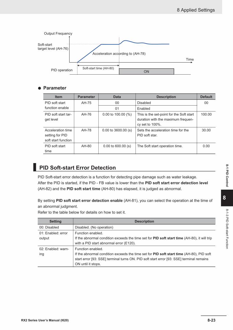
ON
Output Frequency
Soft-starttarget level (AH-76)
PID operation
Time
Soft-start time (AH-80)
Acceleration according to (AH-78)
l Parameter
Item Parameter Data Description DefaultPID soft startfunction enable
AH-75 00 Disabled 0001 Enabled
PID soft start tar-get level
AH-76 0.00 to 100.00 (%) This is the set-point for the Soft startduration with the maximum frequen-cy set to 100%.
100.00
Acceleration timesetting for PIDsoft start function
AH-78 0.00 to 3600.00 (s) Sets the acceleration time for thePID soft star.
30.00
PID soft starttime
AH-80 0.00 to 600.00 (s) The Soft start operation time. 0.00
PID Soft-start Error DetectionPID Soft-start error detection is a function for detecting pipe damage such as water leakage.After the PID is started, if the PID - FB value is lower than the PID soft start error detection level(AH-82) and the PID soft start time (AH-80) has elapsed, it is judged as abnormal.
By setting PID soft start error detection enable (AH-81), you can select the operation at the time ofan abnormal judgment.Refer to the table below for details on how to set it.
Setting Description00: Disabled Disabled. (No operation)01: Enabled: erroroutput
Function enabled.If the abnormal condition exceeds the time set for PID soft start time (AH-80), it will tripwith a PID start abnormal error (E120).
02: Enabled: warn-ing
Function enabled.If the abnormal condition exceeds the time set for PID soft start time (AH-80), PID softstart error [93: SSE] terminal turns ON. PID soft start error [93: SSE] terminal remainsON until it stops.
8 Applied Settings
8-23RX2 Series User’s Manual (I620)
8-1 PID C
ontrol
8
8-1-3 PID Soft-start Function
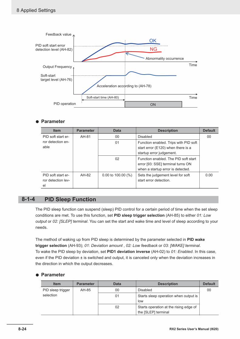
ON
OK
NG
Output Frequency
Soft-starttarget level (AH-76)
PID operation
TimeSoft-start time (AH-80)
Acceleration according to (AH-78)
Abnormality occurrence
Time
PID soft start errordetection level (AH-82)
Feedback value
l Parameter
Item Parameter Data Description DefaultPID soft start er-ror detection en-able
AH-81 00 Disabled 0001 Function enabled. Trips with PID soft
start error (E120) when there is astartup error judgement.
02 Function enabled. The PID soft starterror [93: SSE] terminal turns ONwhen a startup error is detected.
PID soft start er-ror detection lev-el
AH-82 0.00 to 100.00 (%) Sets the judgement level for softstart error detection.
0.00
8-1-4 PID Sleep FunctionThe PID sleep function can suspend (sleep) PID control for a certain period of time when the set sleepconditions are met. To use this function, set PID sleep trigger selection (AH-85) to either 01: Lowoutput or 02: [SLEP] terminal. You can set the start and wake time and level of sleep according to yourneeds.
The method of waking up from PID sleep is determined by the parameter selected in PID waketrigger selection (AH-93); 01: Deviation amount , 02: Low feedback or 03: [WAKE] terminal.To wake the PID sleep by deviation, set PID1 deviation inverse (AH-02) to 01: Enabled. In this case,even if the PID deviation ± is switched and output, it is canceled only when the deviation increases inthe direction in which the output decreases.
l Parameter
Item Parameter Data Description DefaultPID sleep triggerselection
AH-85 00 Disabled 0001 Starts sleep operation when output is
low02 Starts operation at the rising edge of
the [SLEP] terminal
8 Applied Settings
8-24 RX2 Series User’s Manual (I620)
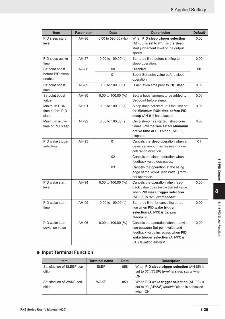
Item Parameter Data Description DefaultPID sleep startlevel
AH-86 0.00 to 590.00 (Hz) When PID sleep trigger selection(AH-85) is set to 01, it is the sleepstart judgement level of the outputspeed.
0.00
PID sleep activetime
AH-87 0.00 to 100.00 (s) Stand-by time before shifting tosleep operation.
0.00
Setpoint boostbefore PID sleepenable
AH-88 00 Disabled 0001 Boost Set-point value before sleep
operation.Setpoint boosttime
AH-89 0.00 to 100.00 (s) Is actuation time prior to PID sleep. 0.00
Setpoint boostvalue
AH-90 0.00 to 100.00 (%) Sets a boost amount to be added toSet-point before sleep.
0.00
Minimum RUNtime before PIDsleep
AH-91 0.00 to 100.00 (s) Sleep does not start until the time setfor Minimum RUN time before PIDsleep (AH-91) has elapsed.
0.00
Minimum activetime of PID sleep
AH-92 0.00 to 100.00 (s) Once sleep has started, sleep con-tinues until the time set for Minimumactive time of PID sleep (AH-92)elapses.
0.00
PID wake triggerselection
AH-93 01 Cancels the sleep operation when adeviation amount increases in a de-celeration direction.
01
02 Cancels the sleep operation whenfeedback value decreases.
03 Cancels the operation at the risingedge of the WAKE [59: WAKE] termi-nal operation.
PID wake startlevel
AH-94 0.00 to 100.00 (%) Cancels the operation when feed-back value goes below the set valuewhen PID wake trigger selection(AH-93) is 02: Low feedback.
0.00
PID wake starttime
AH-95 0.00 to 100.00 (s) Stand-by time for canceling opera-tion when PID wake triggerselection (AH-93) is 02: Lowfeedback.
0.00
PID wake startdeviation value
AH-96 0.00 to 100.00 (%) Cancels the operation when a devia-tion between Set-point value andfeedback value increases when PIDwake trigger selection (AH-93) is01: Deviation amount.
0.00
l Input Terminal Function
Item Terminal name Data DescriptionSatisfaction of SLEEP con-dition
SLEP 058 When PID sleep trigger selection (AH-85) isset to 02: [SLEP] terminal sleep starts whenON.
Satisfaction of WAKE con-dition
WAKE 059 When PID wake trigger selection (AH-93) isset to 03: [WAKE] terminal sleep is cancelledwhen ON.
8 Applied Settings
8-25RX2 Series User’s Manual (I620)
8-1 PID C
ontrol
8
8-1-4 PID Sleep Function
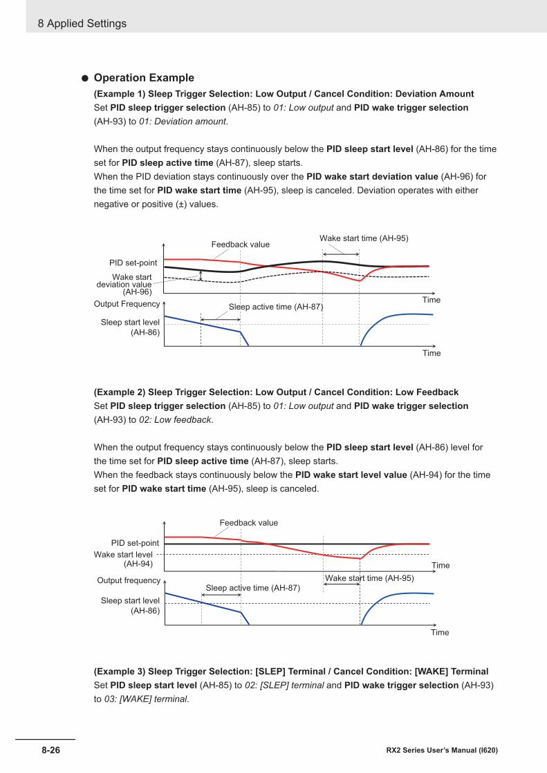
l Operation Example(Example 1) Sleep Trigger Selection: Low Output / Cancel Condition: Deviation AmountSet PID sleep trigger selection (AH-85) to 01: Low output and PID wake trigger selection(AH-93) to 01: Deviation amount.
When the output frequency stays continuously below the PID sleep start level (AH-86) for the timeset for PID sleep active time (AH-87), sleep starts.When the PID deviation stays continuously over the PID wake start deviation value (AH-96) forthe time set for PID wake start time (AH-95), sleep is canceled. Deviation operates with eithernegative or positive (±) values.
Output Frequency
Sleep start level
(AH-86)
Sleep active time (AH-87)
Time
Wake startdeviation value
(AH-96)Time
PID set-point
Feedback valueWake start time (AH-95)
(Example 2) Sleep Trigger Selection: Low Output / Cancel Condition: Low FeedbackSet PID sleep trigger selection (AH-85) to 01: Low output and PID wake trigger selection(AH-93) to 02: Low feedback.
When the output frequency stays continuously below the PID sleep start level (AH-86) level forthe time set for PID sleep active time (AH-87), sleep starts.When the feedback stays continuously below the PID wake start level value (AH-94) for the timeset for PID wake start time (AH-95), sleep is canceled.
Output frequency
Sleep start level
(AH-86)
Sleep active time (AH-87)
Time
Wake start level(AH-94) Time
PID set-point
Feedback value
Wake start time (AH-95)
(Example 3) Sleep Trigger Selection: [SLEP] Terminal / Cancel Condition: [WAKE] TerminalSet PID sleep start level (AH-85) to 02: [SLEP] terminal and PID wake trigger selection (AH-93)to 03: [WAKE] terminal.
8 Applied Settings
8-26 RX2 Series User’s Manual (I620)
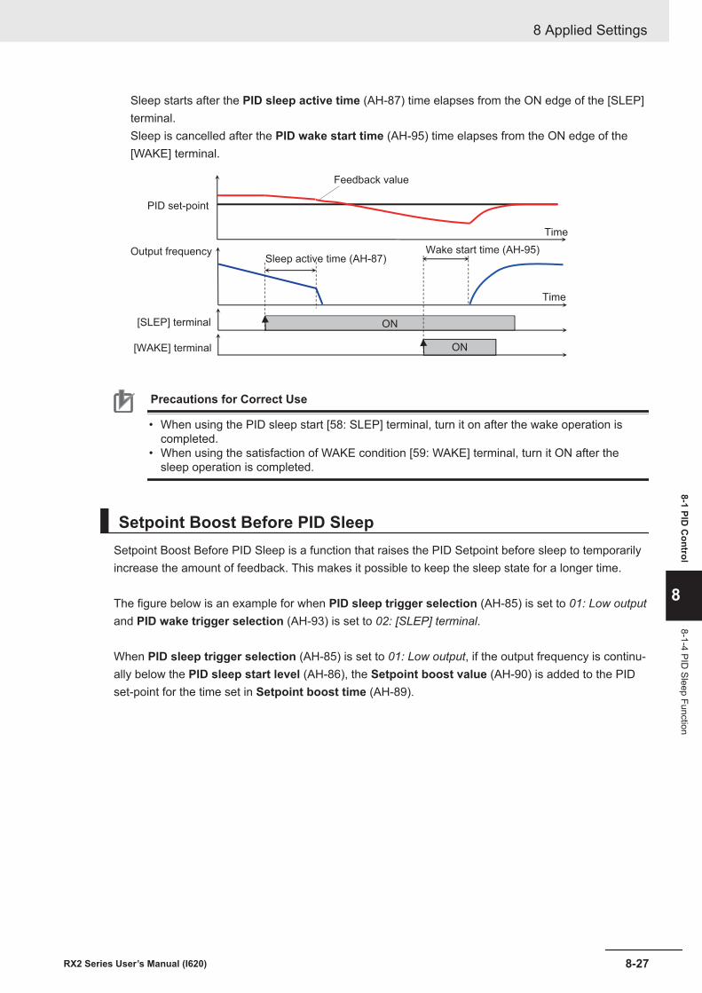
Sleep starts after the PID sleep active time (AH-87) time elapses from the ON edge of the [SLEP]terminal.Sleep is cancelled after the PID wake start time (AH-95) time elapses from the ON edge of the[WAKE] terminal.
ON
ON
Output frequency
[SLEP] terminal
Sleep active time (AH-87)
Time
[WAKE] terminal
Time
PID set-point
Feedback value
Wake start time (AH-95)
Precautions for Correct Use
• When using the PID sleep start [58: SLEP] terminal, turn it on after the wake operation iscompleted.
• When using the satisfaction of WAKE condition [59: WAKE] terminal, turn it ON after thesleep operation is completed.
Setpoint Boost Before PID SleepSetpoint Boost Before PID Sleep is a function that raises the PID Setpoint before sleep to temporarilyincrease the amount of feedback. This makes it possible to keep the sleep state for a longer time.
The figure below is an example for when PID sleep trigger selection (AH-85) is set to 01: Low outputand PID wake trigger selection (AH-93) is set to 02: [SLEP] terminal.
When PID sleep trigger selection (AH-85) is set to 01: Low output, if the output frequency is continu-ally below the PID sleep start level (AH-86), the Setpoint boost value (AH-90) is added to the PIDset-point for the time set in Setpoint boost time (AH-89).
8 Applied Settings
8-27RX2 Series User’s Manual (I620)
8-1 PID C
ontrol
8
8-1-4 PID Sleep Function
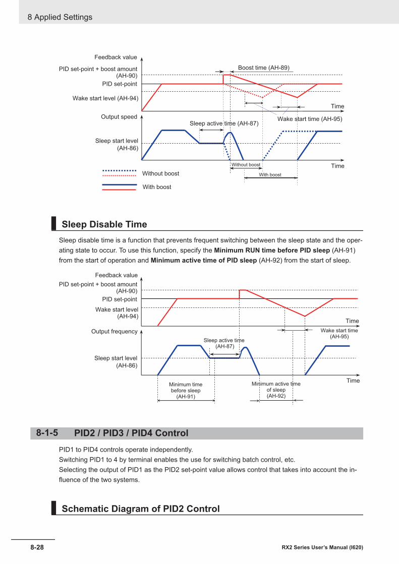
Sleep start level
(AH-86)
PID set-point + boost amount(AH-90)
Sleep active time (AH-87)
Time
Wake start level (AH-94)
Time
PID set-point
Output speed Wake start time (AH-95)
Boost time (AH-89)
Feedback value
Without boost
With boost
With boost
Without boost
Sleep Disable TimeSleep disable time is a function that prevents frequent switching between the sleep state and the oper-ating state to occur. To use this function, specify the Minimum RUN time before PID sleep (AH-91)from the start of operation and Minimum active time of PID sleep (AH-92) from the start of sleep.
Sleep start level
(AH-86)
PID set-point + boost amount(AH-90)
Sleep active time (AH-87)
Time
Wake start level(AH-94)
Time
PID set-point
Output frequency Wake start time(AH-95)
Feedback value
Minimum active timeof sleep(AH-92)
Minimum timebefore sleep
(AH-91)
8-1-5 PID2 / PID3 / PID4 ControlPID1 to PID4 controls operate independently.Switching PID1 to 4 by terminal enables the use for switching batch control, etc.Selecting the output of PID1 as the PID2 set-point value allows control that takes into account the in-fluence of the two systems.
Schematic Diagram of PID2 Control
8 Applied Settings
8-28 RX2 Series User’s Manual (I620)
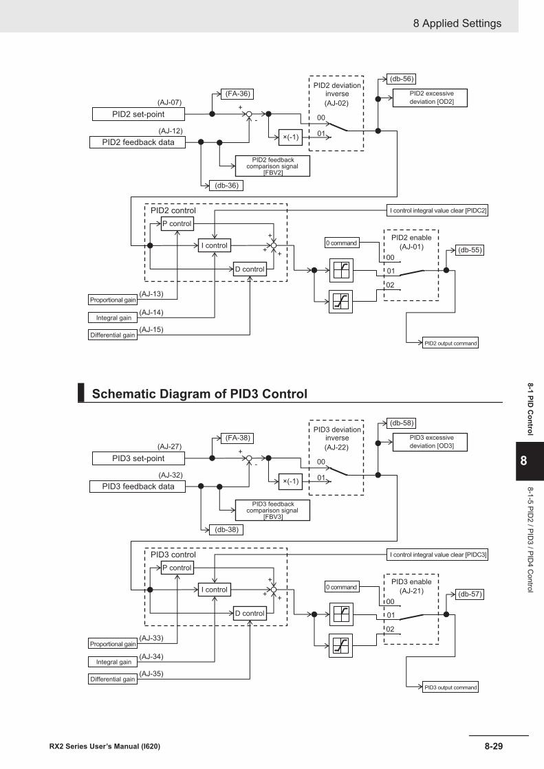
+
++
+
00
01
(AJ-02)
-
00
01
02
(AJ-07)
(AJ-12)
(AJ-13)
×(-1)
(AJ-14)
(AJ-15)
(FA-36)
(db-36)
(db-56)
(db-55)
PID2 control
P control
I control
D control
PID2 set-point
PID2 feedback data
PID2 deviationinverse
PID2 feedbackcomparison signal
[FBV2]
PID2 excessive
deviation [OD2]
I control integral value clear [PIDC2]
0 commandPID2 enable
(AJ-01)
PID2 output command
Proportional gain
Integral gain
Differential gain
Schematic Diagram of PID3 Control
+
++
+
00
01
(AJ-22)
-
00
01
02
(AJ-27)
(AJ-32)
(AJ-33)
×(-1)
(AJ-34)
(AJ-35)
(FA-38)
(db-38)
(db-58)
(db-57)
PID3 control
P control
I control
D control
PID3 set-point
PID3 feedback data
PID3 deviationinverse
PID3 feedbackcomparison signal
[FBV3]
PID3 excessive
deviation [OD3]
I control integral value clear [PIDC3]
0 commandPID3 enable
(AJ-21)
PID3 output command
Proportional gain
Integral gain
Differential gain
8 Applied Settings
8-29RX2 Series User’s Manual (I620)
8-1 PID C
ontrol
8
8-1-5 PID2 / PID
3 / PID4 C
ontrol
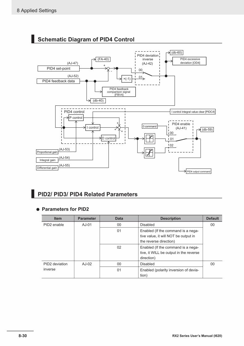
Schematic Diagram of PID4 Control
+
++
+
00
01
(AJ-42)
-
00
01
02
(AJ-47)
(AJ-52)
(AJ-53)
×(-1)
(AJ-54)
(AJ-55)
(FA-40)
(db-40)
(db-60)
(db-59)
PID4 control
P control
I control
D control
PID4 set-point
PID4 feedback data
PID4 deviationinverse
PID4 feedbackcomparison signal
[FBV4]
PID4 excessive
deviation [OD4]
I control integral value clear [PIDC4]
0 commandPID4 enable
(AJ-41)
PID4 output command
Proportional gain
Integral gain
Differential gain
PID2/ PID3/ PID4 Related Parameters
l Parameters for PID2
Item Parameter Data Description DefaultPID2 enable AJ-01 00 Disabled 00
01 Enabled (If the command is a nega-tive value, it will NOT be output inthe reverse direction)
02 Enabled (If the command is a nega-tive, it WILL be output in the reversedirection)
PID2 deviationinverse
AJ-02 00 Disabled 0001 Enabled (polarity inversion of devia-
tion)
8 Applied Settings
8-30 RX2 Series User’s Manual (I620)
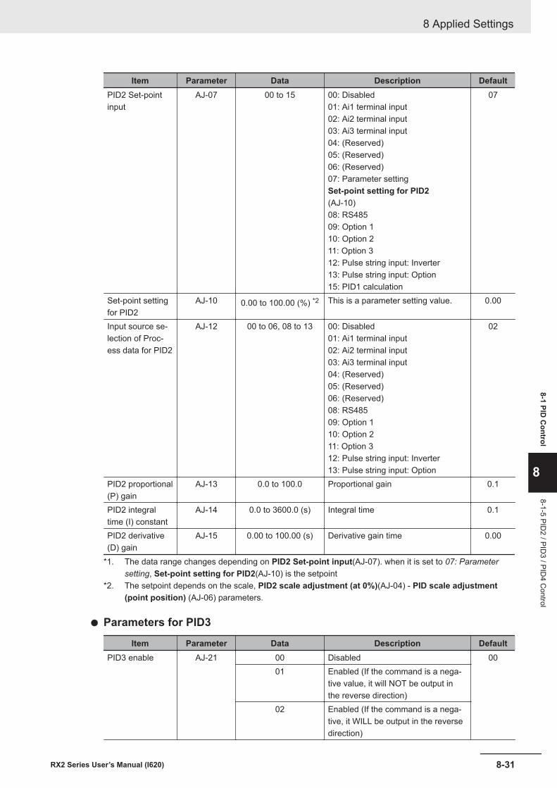
Item Parameter Data Description DefaultPID2 Set-pointinput
AJ-07 00 to 15 00: Disabled01: Ai1 terminal input02: Ai2 terminal input03: Ai3 terminal input04: (Reserved)05: (Reserved)06: (Reserved)07: Parameter settingSet-point setting for PID2(AJ-10)08: RS48509: Option 110: Option 211: Option 312: Pulse string input: Inverter13: Pulse string input: Option15: PID1 calculation
07
Set-point settingfor PID2
AJ-10 0.00 to 100.00 (%) *2 This is a parameter setting value. 0.00
Input source se-lection of Proc-ess data for PID2
AJ-12 00 to 06, 08 to 13 00: Disabled01: Ai1 terminal input02: Ai2 terminal input03: Ai3 terminal input04: (Reserved)05: (Reserved)06: (Reserved)08: RS48509: Option 110: Option 211: Option 312: Pulse string input: Inverter13: Pulse string input: Option
02
PID2 proportional(P) gain
AJ-13 0.0 to 100.0 Proportional gain 0.1
PID2 integraltime (I) constant
AJ-14 0.0 to 3600.0 (s) Integral time 0.1
PID2 derivative(D) gain
AJ-15 0.00 to 100.00 (s) Derivative gain time 0.00
*1. The data range changes depending on PID2 Set-point input(AJ-07). when it is set to 07: Parametersetting, Set-point setting for PID2(AJ-10) is the setpoint
*2. The setpoint depends on the scale, PID2 scale adjustment (at 0%)(AJ-04) - PID scale adjustment(point position) (AJ-06) parameters.
l Parameters for PID3
Item Parameter Data Description DefaultPID3 enable AJ-21 00 Disabled 00
01 Enabled (If the command is a nega-tive value, it will NOT be output inthe reverse direction)
02 Enabled (If the command is a nega-tive, it WILL be output in the reversedirection)
8 Applied Settings
8-31RX2 Series User’s Manual (I620)
8-1 PID C
ontrol
8
8-1-5 PID2 / PID
3 / PID4 C
ontrol
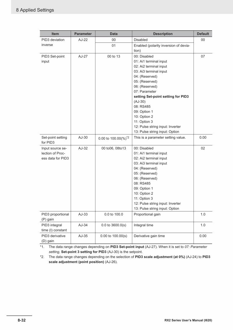
Item Parameter Data Description DefaultPID3 deviationinverse
AJ-22 00 Disabled 0001 Enabled (polarity inversion of devia-
tion)PID3 Set-pointinput
AJ-27 00 to 13 00: Disabled01: Ai1 terminal input02: Ai2 terminal input03: Ai3 terminal input04: (Reserved)05: (Reserved)06: (Reserved)07: Parametersetting Set-point setting for PID3(AJ-30)08: RS48509: Option 110: Option 211: Option 312: Pulse string input: Inverter13: Pulse string input: Option
07
Set-point settingfor PID3
AJ-30 0.00 to 100.00(%)*2 This is a parameter setting value. 0.00
Input source se-lection of Proc-ess data for PID3
AJ-32 00 to06, 08to13 00: Disabled01: Ai1 terminal input02: Ai2 terminal input03: Ai3 terminal input04: (Reserved)05: (Reserved)06: (Reserved)08: RS48509: Option 110: Option 211: Option 312: Pulse string input: Inverter13: Pulse string input: Option
02
PID3 proportional(P) gain
AJ-33 0.0 to 100.0 Proportional gain 1.0
PID3 integraltime (I) constant
AJ-34 0.0 to 3600.0(s) Integral time 1.0
PID3 derivative(D) gain
AJ-35 0.00 to 100.00(s) Derivative gain time 0.00
*1. The data range changes depending on PID3 Set-point input (AJ-27). When it is set to 07: Parametersetting, Set-point 3 setting for PID3 (AJ-30) is the setpoint.
*2. The data range changes depending on the selection of PID3 scale adjustment (at 0%) (AJ-24) to PID3scale adjustment (point position) (AJ-26).
8 Applied Settings
8-32 RX2 Series User’s Manual (I620)
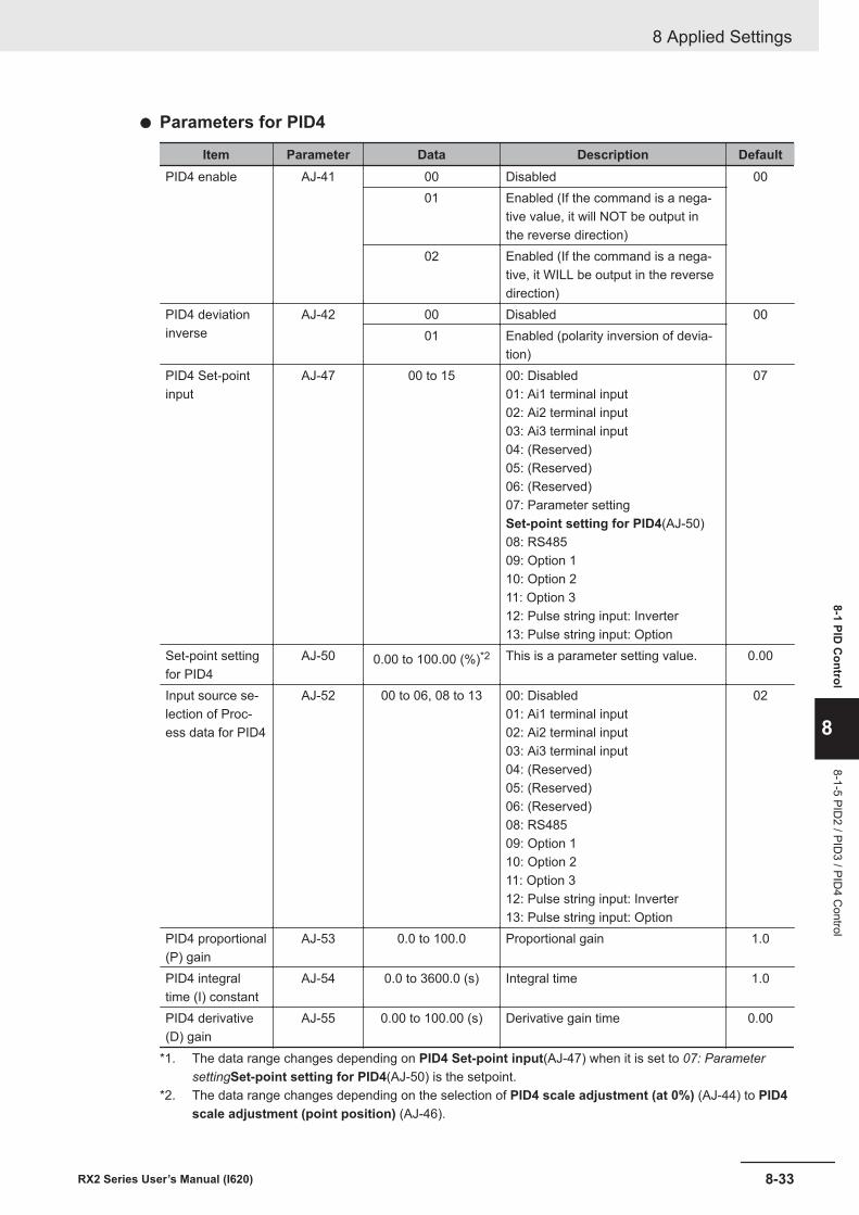
l Parameters for PID4
Item Parameter Data Description DefaultPID4 enable AJ-41 00 Disabled 00
01 Enabled (If the command is a nega-tive value, it will NOT be output inthe reverse direction)
02 Enabled (If the command is a nega-tive, it WILL be output in the reversedirection)
PID4 deviationinverse
AJ-42 00 Disabled 0001 Enabled (polarity inversion of devia-
tion)PID4 Set-pointinput
AJ-47 00 to 15 00: Disabled01: Ai1 terminal input02: Ai2 terminal input03: Ai3 terminal input04: (Reserved)05: (Reserved)06: (Reserved)07: Parameter settingSet-point setting for PID4(AJ-50)08: RS48509: Option 110: Option 211: Option 312: Pulse string input: Inverter13: Pulse string input: Option
07
Set-point settingfor PID4
AJ-50 0.00 to 100.00 (%)*2 This is a parameter setting value. 0.00
Input source se-lection of Proc-ess data for PID4
AJ-52 00 to 06, 08 to 13 00: Disabled01: Ai1 terminal input02: Ai2 terminal input03: Ai3 terminal input04: (Reserved)05: (Reserved)06: (Reserved)08: RS48509: Option 110: Option 211: Option 312: Pulse string input: Inverter13: Pulse string input: Option
02
PID4 proportional(P) gain
AJ-53 0.0 to 100.0 Proportional gain 1.0
PID4 integraltime (I) constant
AJ-54 0.0 to 3600.0 (s) Integral time 1.0
PID4 derivative(D) gain
AJ-55 0.00 to 100.00 (s) Derivative gain time 0.00
*1. The data range changes depending on PID4 Set-point input(AJ-47) when it is set to 07: ParametersettingSet-point setting for PID4(AJ-50) is the setpoint.
*2. The data range changes depending on the selection of PID4 scale adjustment (at 0%) (AJ-44) to PID4scale adjustment (point position) (AJ-46).
8 Applied Settings
8-33RX2 Series User’s Manual (I620)
8-1 PID C
ontrol
8
8-1-5 PID2 / PID
3 / PID4 C
ontrol
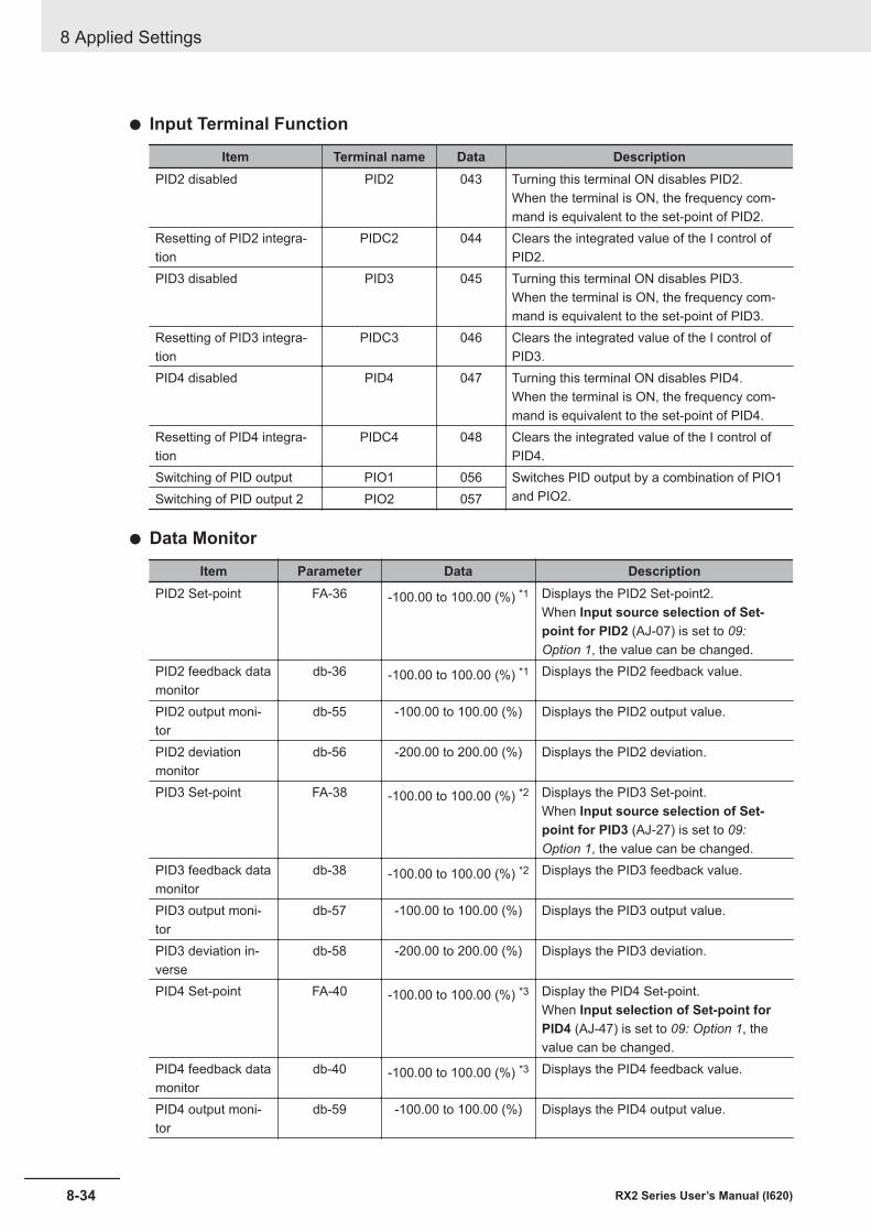
l Input Terminal Function
Item Terminal name Data DescriptionPID2 disabled PID2 043 Turning this terminal ON disables PID2.
When the terminal is ON, the frequency com-mand is equivalent to the set-point of PID2.
Resetting of PID2 integra-tion
PIDC2 044 Clears the integrated value of the I control ofPID2.
PID3 disabled PID3 045 Turning this terminal ON disables PID3.When the terminal is ON, the frequency com-mand is equivalent to the set-point of PID3.
Resetting of PID3 integra-tion
PIDC3 046 Clears the integrated value of the I control ofPID3.
PID4 disabled PID4 047 Turning this terminal ON disables PID4.When the terminal is ON, the frequency com-mand is equivalent to the set-point of PID4.
Resetting of PID4 integra-tion
PIDC4 048 Clears the integrated value of the I control ofPID4.
Switching of PID output PIO1 056 Switches PID output by a combination of PIO1and PIO2.Switching of PID output 2 PIO2 057
l Data Monitor
Item Parameter Data DescriptionPID2 Set-point FA-36 -100.00 to 100.00 (%) *1 Displays the PID2 Set-point2.
When Input source selection of Set-point for PID2 (AJ-07) is set to 09:Option 1, the value can be changed.
PID2 feedback datamonitor
db-36 -100.00 to 100.00 (%) *1 Displays the PID2 feedback value.
PID2 output moni-tor
db-55 -100.00 to 100.00 (%) Displays the PID2 output value.
PID2 deviationmonitor
db-56 -200.00 to 200.00 (%) Displays the PID2 deviation.
PID3 Set-point FA-38 -100.00 to 100.00 (%) *2 Displays the PID3 Set-point.When Input source selection of Set-point for PID3 (AJ-27) is set to 09:Option 1, the value can be changed.
PID3 feedback datamonitor
db-38 -100.00 to 100.00 (%) *2 Displays the PID3 feedback value.
PID3 output moni-tor
db-57 -100.00 to 100.00 (%) Displays the PID3 output value.
PID3 deviation in-verse
db-58 -200.00 to 200.00 (%) Displays the PID3 deviation.
PID4 Set-point FA-40 -100.00 to 100.00 (%) *3 Display the PID4 Set-point.When Input selection of Set-point forPID4 (AJ-47) is set to 09: Option 1, thevalue can be changed.
PID4 feedback datamonitor
db-40 -100.00 to 100.00 (%) *3 Displays the PID4 feedback value.
PID4 output moni-tor
db-59 -100.00 to 100.00 (%) Displays the PID4 output value.
8 Applied Settings
8-34 RX2 Series User’s Manual (I620)
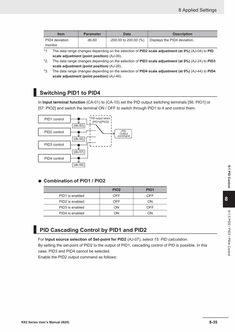
Item Parameter Data DescriptionPID4 deviationmonitor
db-60 -200.00 to 200.00 (%) Displays the PID4 deviation.
*1. The data range changes depending on the selection of PID2 scale adjustment (at 0%) (AJ-04) to PIDscale adjustment (point position) (AJ-06).
*2. The data range changes depending on the selection of PID3 scale adjustment (at 0%) (AJ-24) to PID3scale adjustment (point position) (AJ-26).
*3. The data range changes depending on the selection of PID4 scale adjustment (at 0%) (AJ-44) to PID4scale adjustment (point position) (AJ-46).
Switching PID1 to PID4In Input terminal function (CA-01) to (CA-10) set the PID output switching terminals [56: PIO1] or[57: PIO2] and switch the terminal ON / OFF to switch through PID1 to 4 and control them.
[PIO1]/[PIO2]
(db-50)
(db-55)
(db-57)
(db-59)
PID1 control
PID2 control
PID4 control
PID3 control
PID output switch
PIDOutput
command
l Combination of PIO1 / PIO2
PIO2 PIO1PID1 is enabled OFF OFFPID2 is enabled OFF ONPID3 is enabled ON OFFPID4 is enabled ON ON
PID Cascading Control by PID1 and PID2For Input source selection of Set-point for PID2 (AJ-07), select 15: PID calculation.By setting the set-point of PID2 to the output of PID1, cascading control of PID is possible. In thiscase, PID3 and PID4 cannot be selected.Enable the PID2 output command as follows:
8 Applied Settings
8-35RX2 Series User’s Manual (I620)
8-1 PID C
ontrol
8
8-1-5 PID2 / PID
3 / PID4 C
ontrol
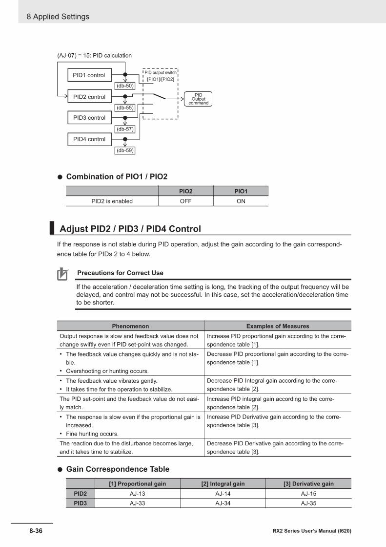
[PIO1]/[PIO2]
(db-50)
(db-55)
(db-57)
(db-59)
PID1 control
PID2 control
PID4 control
PID3 control
PID output switch
PIDOutput
command
(AJ-07) = 15: PID calculation
l Combination of PIO1 / PIO2
PIO2 PIO1PID2 is enabled OFF ON
Adjust PID2 / PID3 / PID4 ControlIf the response is not stable during PID operation, adjust the gain according to the gain correspond-ence table for PIDs 2 to 4 below.
Precautions for Correct Use
If the acceleration / deceleration time setting is long, the tracking of the output frequency will bedelayed, and control may not be successful. In this case, set the acceleration/deceleration timeto be shorter.
Phenomenon Examples of MeasuresOutput response is slow and feedback value does notchange swiftly even if PID set-point was changed.
Increase PID proportional gain according to the corre-spondence table [1].
• The feedback value changes quickly and is not sta-ble.
• Overshooting or hunting occurs.
Decrease PID proportional gain according to the corre-spondence table [1].
• The feedback value vibrates gently.• It takes time for the operation to stabilize.
Decrease PID Integral gain according to the corre-spondence table [2].
The PID set-point and the feedback value do not easi-ly match.
Increase PID integral gain according to the corre-spondence table [2].
• The response is slow even if the proportional gain isincreased.
• Fine hunting occurs.
Increase PID Derivative gain according to the corre-spondence table [3].
The reaction due to the disturbance becomes large,and it takes time to stabilize.
Decrease PID Derivative gain according to the corre-spondence table [3].
l Gain Correspondence Table
[1] Proportional gain [2] Integral gain [3] Derivative gainPID2 AJ-13 AJ-14 AJ-15PID3 AJ-33 AJ-34 AJ-35
8 Applied Settings
8-36 RX2 Series User’s Manual (I620)
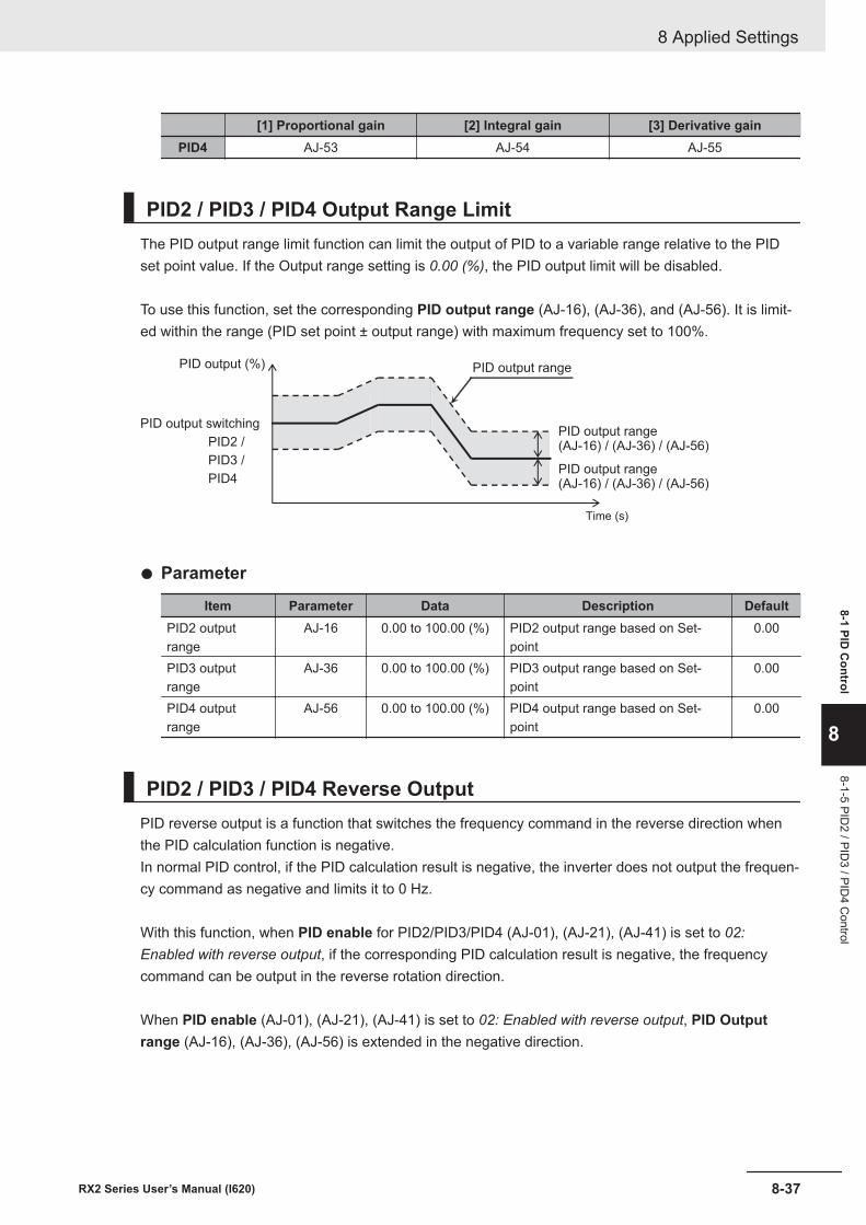
[1] Proportional gain [2] Integral gain [3] Derivative gainPID4 AJ-53 AJ-54 AJ-55
PID2 / PID3 / PID4 Output Range LimitThe PID output range limit function can limit the output of PID to a variable range relative to the PIDset point value. If the Output range setting is 0.00 (%), the PID output limit will be disabled.
To use this function, set the corresponding PID output range (AJ-16), (AJ-36), and (AJ-56). It is limit-ed within the range (PID set point ± output range) with maximum frequency set to 100%.
PID2 /
PID3 /
PID4
PID output range
PID output range(AJ-16) / (AJ-36) / (AJ-56)
Time (s)
PID output switching
PID output (%)
PID output range (AJ-16) / (AJ-36) / (AJ-56)
l Parameter
Item Parameter Data Description DefaultPID2 outputrange
AJ-16 0.00 to 100.00 (%) PID2 output range based on Set-point
0.00
PID3 outputrange
AJ-36 0.00 to 100.00 (%) PID3 output range based on Set-point
0.00
PID4 outputrange
AJ-56 0.00 to 100.00 (%) PID4 output range based on Set-point
0.00
PID2 / PID3 / PID4 Reverse OutputPID reverse output is a function that switches the frequency command in the reverse direction whenthe PID calculation function is negative.In normal PID control, if the PID calculation result is negative, the inverter does not output the frequen-cy command as negative and limits it to 0 Hz.
With this function, when PID enable for PID2/PID3/PID4 (AJ-01), (AJ-21), (AJ-41) is set to 02:Enabled with reverse output, if the corresponding PID calculation result is negative, the frequencycommand can be output in the reverse rotation direction.
When PID enable (AJ-01), (AJ-21), (AJ-41) is set to 02: Enabled with reverse output, PID Outputrange (AJ-16), (AJ-36), (AJ-56) is extended in the negative direction.
8 Applied Settings
8-37RX2 Series User’s Manual (I620)
8-1 PID C
ontrol
8
8-1-5 PID2 / PID
3 / PID4 C
ontrol
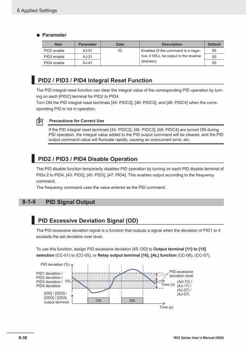
l Parameter
Item Parameter Data Description DefaultPID2 enable AJ-01 02 Enabled (If the command is a nega-
tive, it WILL be output in the reversedirection)
00PID3 enable AJ-21 00PID4 enable AJ-41 00
PID2 / PID3 / PID4 Integral Reset FunctionThe PID integral reset function can clear the integral value of the corresponding PID operation by turn-ing on each [PIDC] terminal for PID2 to PID4.Turn ON the PID integral reset terminals [44: PIDC2], [46: PIDC3], and [48: PIDC4] when the corre-sponding PID is not in operation.
Precautions for Correct Use
If the PID integral reset terminals [44: PIDC2], [46: PIDC3], [48: PIDC4] are turned ON duringPID operation, the integral value added to the PID output command will be cleared, and the PIDoutput command value will fluctuate rapidly, causing an overcurrent error, etc.
PID2 / PID3 / PID4 Disable OperationThe PID disable function temporarily disables PID operation by turning on each PID disable terminal ofPIDs 2 to PID4, [43: PID2], [45: PID3], [47: PID4]. This enables output according to the frequencycommand.The frequency command uses the value entered as the PID command.
8-1-6 PID Signal Output
PID Excessive Deviation Signal (OD)The PID excessive deviation signal is a function that outputs a signal when the deviation of PID1 to 4exceeds the set deviation over level.
To use this function, assign PID excessive deviation [45: OD] to Output terminal [11] to [15]selection (CC-01) to (CC-05), or Relay output terminal [16], [AL] function (CC-06), (CC-07).
0%
[OD] / [OD2] /
[OD3] / [OD4]ON ON
PID deviation (%)
PID1 deviation /PID2 deviation /PID3 deviation /PID4 deviation
PID excessivedeviation level
Time (s)
Time (s)
output terminal
(AH-72) /(AJ-17) /(AJ-37) /(AJ-57)
8 Applied Settings
8-38 RX2 Series User’s Manual (I620)
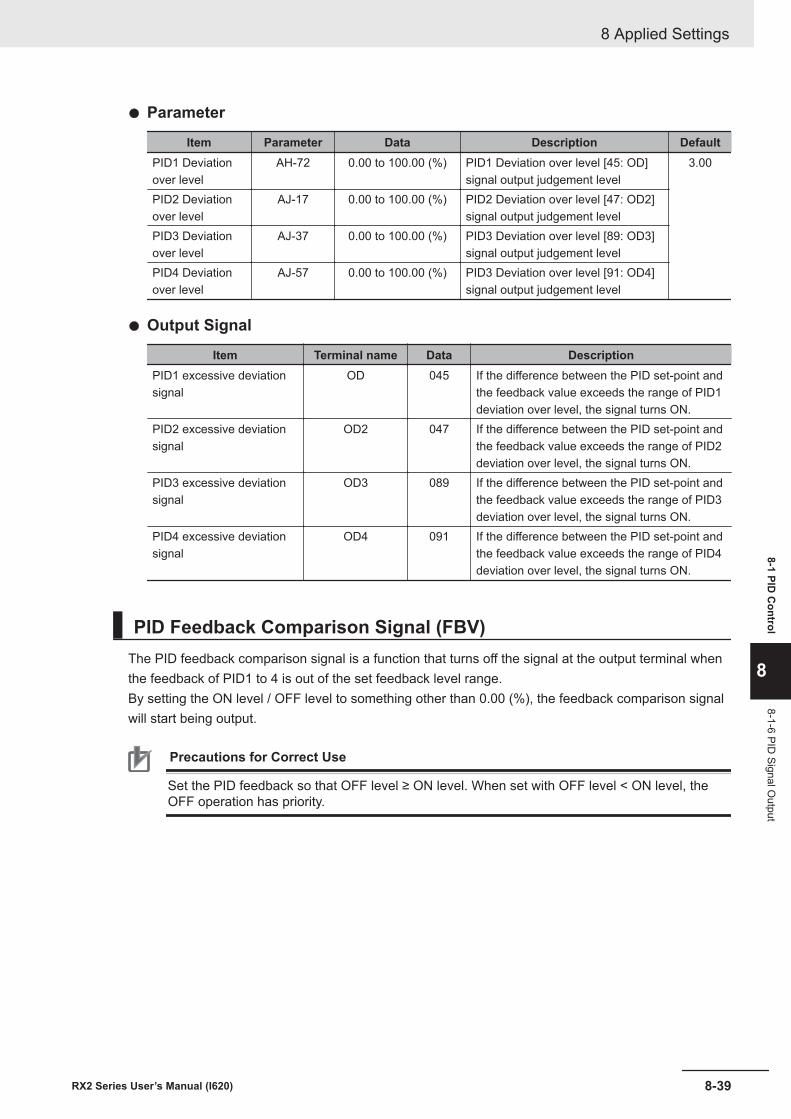
l Parameter
Item Parameter Data Description DefaultPID1 Deviationover level
AH-72 0.00 to 100.00 (%) PID1 Deviation over level [45: OD]signal output judgement level
3.00
PID2 Deviationover level
AJ-17 0.00 to 100.00 (%) PID2 Deviation over level [47: OD2]signal output judgement level
PID3 Deviationover level
AJ-37 0.00 to 100.00 (%) PID3 Deviation over level [89: OD3]signal output judgement level
PID4 Deviationover level
AJ-57 0.00 to 100.00 (%) PID3 Deviation over level [91: OD4]signal output judgement level
l Output Signal
Item Terminal name Data DescriptionPID1 excessive deviationsignal
OD 045 If the difference between the PID set-point andthe feedback value exceeds the range of PID1deviation over level, the signal turns ON.
PID2 excessive deviationsignal
OD2 047 If the difference between the PID set-point andthe feedback value exceeds the range of PID2deviation over level, the signal turns ON.
PID3 excessive deviationsignal
OD3 089 If the difference between the PID set-point andthe feedback value exceeds the range of PID3deviation over level, the signal turns ON.
PID4 excessive deviationsignal
OD4 091 If the difference between the PID set-point andthe feedback value exceeds the range of PID4deviation over level, the signal turns ON.
PID Feedback Comparison Signal (FBV)The PID feedback comparison signal is a function that turns off the signal at the output terminal whenthe feedback of PID1 to 4 is out of the set feedback level range.By setting the ON level / OFF level to something other than 0.00 (%), the feedback comparison signalwill start being output.
Precautions for Correct Use
Set the PID feedback so that OFF level ≥ ON level. When set with OFF level < ON level, theOFF operation has priority.
8 Applied Settings
8-39RX2 Series User’s Manual (I620)
8-1 PID C
ontrol
8
8-1-6 PID Signal O
utput
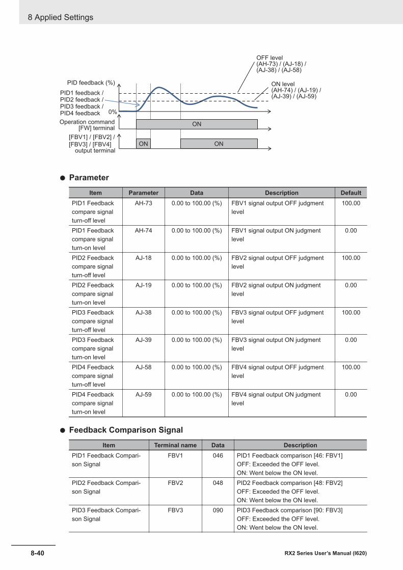
0%
[FBV1] / [FBV2] /
[FBV3] / [FBV4]
ON
ON ON
PID feedback (%)
PID1 feedback /PID2 feedback /PID3 feedback /PID4 feedback
OFF level(AH-73) / (AJ-18) /(AJ-38) / (AJ-58)
output terminal
ON level(AH-74) / (AJ-19) /(AJ-39) / (AJ-59)
Operation command[FW] terminal
l Parameter
Item Parameter Data Description DefaultPID1 Feedbackcompare signalturn-off level
AH-73 0.00 to 100.00 (%) FBV1 signal output OFF judgmentlevel
100.00
PID1 Feedbackcompare signalturn-on level
AH-74 0.00 to 100.00 (%) FBV1 signal output ON judgmentlevel
0.00
PID2 Feedbackcompare signalturn-off level
AJ-18 0.00 to 100.00 (%) FBV2 signal output OFF judgmentlevel
100.00
PID2 Feedbackcompare signalturn-on level
AJ-19 0.00 to 100.00 (%) FBV2 signal output ON judgmentlevel
0.00
PID3 Feedbackcompare signalturn-off level
AJ-38 0.00 to 100.00 (%) FBV3 signal output OFF judgmentlevel
100.00
PID3 Feedbackcompare signalturn-on level
AJ-39 0.00 to 100.00 (%) FBV3 signal output ON judgmentlevel
0.00
PID4 Feedbackcompare signalturn-off level
AJ-58 0.00 to 100.00 (%) FBV4 signal output OFF judgmentlevel
100.00
PID4 Feedbackcompare signalturn-on level
AJ-59 0.00 to 100.00 (%) FBV4 signal output ON judgmentlevel
0.00
l Feedback Comparison Signal
Item Terminal name Data DescriptionPID1 Feedback Compari-son Signal
FBV1 046 PID1 Feedback comparison [46: FBV1]OFF: Exceeded the OFF level.ON: Went below the ON level.
PID2 Feedback Compari-son Signal
FBV2 048 PID2 Feedback comparison [48: FBV2]OFF: Exceeded the OFF level.ON: Went below the ON level.
PID3 Feedback Compari-son Signal
FBV3 090 PID3 Feedback comparison [90: FBV3]OFF: Exceeded the OFF level.ON: Went below the ON level.
8 Applied Settings
8-40 RX2 Series User’s Manual (I620)
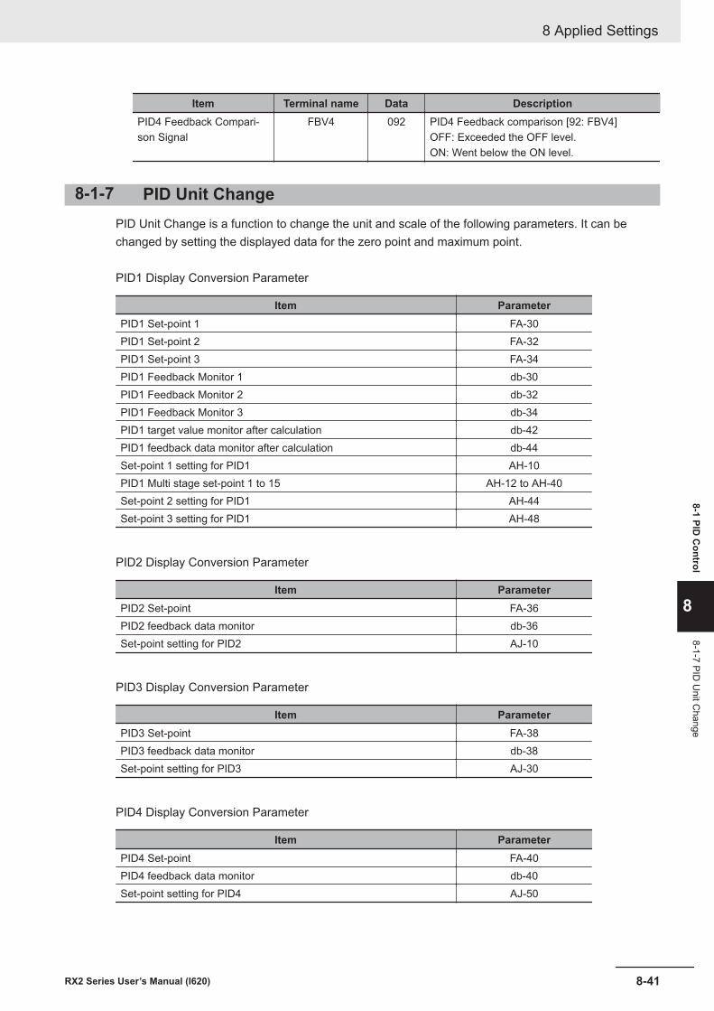
Item Terminal name Data DescriptionPID4 Feedback Compari-son Signal
FBV4 092 PID4 Feedback comparison [92: FBV4]OFF: Exceeded the OFF level.ON: Went below the ON level.
8-1-7 PID Unit ChangePID Unit Change is a function to change the unit and scale of the following parameters. It can bechanged by setting the displayed data for the zero point and maximum point.
PID1 Display Conversion Parameter
Item ParameterPID1 Set-point 1 FA-30PID1 Set-point 2 FA-32PID1 Set-point 3 FA-34PID1 Feedback Monitor 1 db-30PID1 Feedback Monitor 2 db-32PID1 Feedback Monitor 3 db-34PID1 target value monitor after calculation db-42PID1 feedback data monitor after calculation db-44Set-point 1 setting for PID1 AH-10PID1 Multi stage set-point 1 to 15 AH-12 to AH-40Set-point 2 setting for PID1 AH-44Set-point 3 setting for PID1 AH-48
PID2 Display Conversion Parameter
Item ParameterPID2 Set-point FA-36PID2 feedback data monitor db-36Set-point setting for PID2 AJ-10
PID3 Display Conversion Parameter
Item ParameterPID3 Set-point FA-38PID3 feedback data monitor db-38Set-point setting for PID3 AJ-30
PID4 Display Conversion Parameter
Item ParameterPID4 Set-point FA-40PID4 feedback data monitor db-40Set-point setting for PID4 AJ-50
8 Applied Settings
8-41RX2 Series User’s Manual (I620)
8-1 PID C
ontrol
8
8-1-7 PID U
nit Change
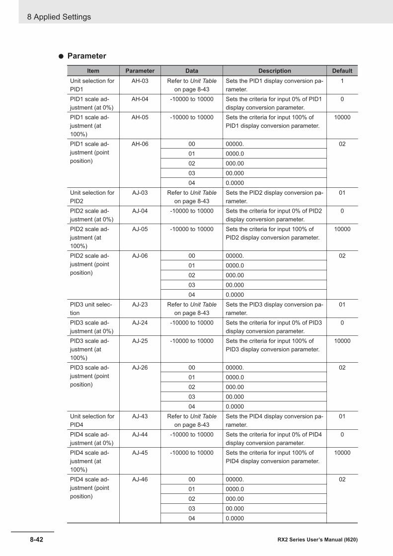
l Parameter
Item Parameter Data Description DefaultUnit selection forPID1
AH-03 Refer to Unit Tableon page 8-43
Sets the PID1 display conversion pa-rameter.
1
PID1 scale ad-justment (at 0%)
AH-04 -10000 to 10000 Sets the criteria for input 0% of PID1display conversion parameter.
0
PID1 scale ad-justment (at100%)
AH-05 -10000 to 10000 Sets the criteria for input 100% ofPID1 display conversion parameter.
10000
PID1 scale ad-justment (pointposition)
AH-06 00 00000. 0201 0000.002 000.0003 00.00004 0.0000
Unit selection forPID2
AJ-03 Refer to Unit Tableon page 8-43
Sets the PID2 display conversion pa-rameter.
01
PID2 scale ad-justment (at 0%)
AJ-04 -10000 to 10000 Sets the criteria for input 0% of PID2display conversion parameter.
0
PID2 scale ad-justment (at100%)
AJ-05 -10000 to 10000 Sets the criteria for input 100% ofPID2 display conversion parameter.
10000
PID2 scale ad-justment (pointposition)
AJ-06 00 00000. 0201 0000.002 000.0003 00.00004 0.0000
PID3 unit selec-tion
AJ-23 Refer to Unit Tableon page 8-43
Sets the PID3 display conversion pa-rameter.
01
PID3 scale ad-justment (at 0%)
AJ-24 -10000 to 10000 Sets the criteria for input 0% of PID3display conversion parameter.
0
PID3 scale ad-justment (at100%)
AJ-25 -10000 to 10000 Sets the criteria for input 100% ofPID3 display conversion parameter.
10000
PID3 scale ad-justment (pointposition)
AJ-26 00 00000. 0201 0000.002 000.0003 00.00004 0.0000
Unit selection forPID4
AJ-43 Refer to Unit Tableon page 8-43
Sets the PID4 display conversion pa-rameter.
01
PID4 scale ad-justment (at 0%)
AJ-44 -10000 to 10000 Sets the criteria for input 0% of PID4display conversion parameter.
0
PID4 scale ad-justment (at100%)
AJ-45 -10000 to 10000 Sets the criteria for input 100% ofPID4 display conversion parameter.
10000
PID4 scale ad-justment (pointposition)
AJ-46 00 00000. 0201 0000.002 000.0003 00.00004 0.0000
8 Applied Settings
8-42 RX2 Series User’s Manual (I620)
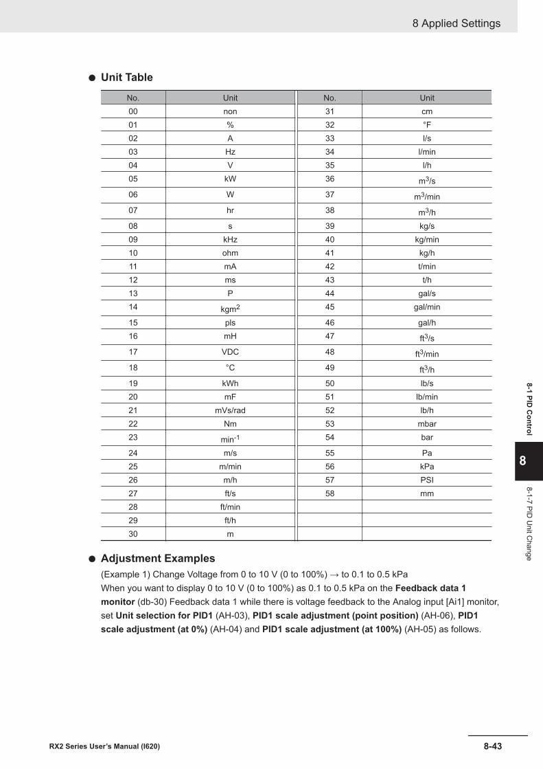
l Unit Table
No. Unit No. Unit00 non 31 cm01 % 32 °F02 A 33 l/s03 Hz 34 l/min04 V 35 l/h05 kW 36 m3/s06 W 37 m3/min07 hr 38 m3/h08 s 39 kg/s09 kHz 40 kg/min10 ohm 41 kg/h11 mA 42 t/min12 ms 43 t/h13 P 44 gal/s14 kgm2 45 gal/min
15 pls 46 gal/h16 mH 47 ft3/s17 VDC 48 ft3/min18 °C 49 ft3/h19 kWh 50 lb/s20 mF 51 lb/min21 mVs/rad 52 lb/h22 Nm 53 mbar23 min-1 54 bar
24 m/s 55 Pa25 m/min 56 kPa26 m/h 57 PSI27 ft/s 58 mm28 ft/min29 ft/h30 m
l Adjustment Examples(Example 1) Change Voltage from 0 to 10 V (0 to 100%) → to 0.1 to 0.5 kPaWhen you want to display 0 to 10 V (0 to 100%) as 0.1 to 0.5 kPa on the Feedback data 1monitor (db-30) Feedback data 1 while there is voltage feedback to the Analog input [Ai1] monitor,set Unit selection for PID1 (AH-03), PID1 scale adjustment (point position) (AH-06), PID1scale adjustment (at 0%) (AH-04) and PID1 scale adjustment (at 100%) (AH-05) as follows.
8 Applied Settings
8-43RX2 Series User’s Manual (I620)
8-1 PID C
ontrol
8
8-1-7 PID U
nit Change
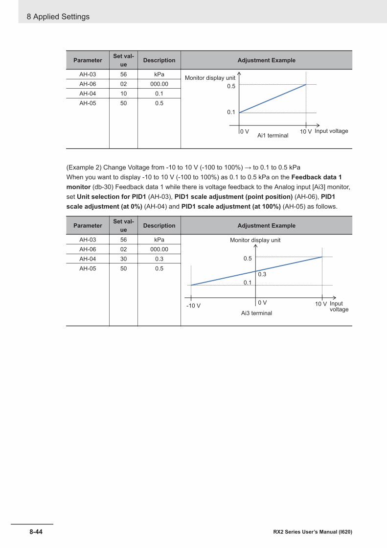
Parameter Set val-ue Description Adjustment Example
AH-03 56 kPa
0 V 10 V
0.1
0.5
Monitor display unit
Input voltageAi1 terminal
AH-06 02 000.00AH-04 10 0.1AH-05 50 0.5
(Example 2) Change Voltage from -10 to 10 V (-100 to 100%) → to 0.1 to 0.5 kPaWhen you want to display -10 to 10 V (-100 to 100%) as 0.1 to 0.5 kPa on the Feedback data 1monitor (db-30) Feedback data 1 while there is voltage feedback to the Analog input [Ai3] monitor,set Unit selection for PID1 (AH-03), PID1 scale adjustment (point position) (AH-06), PID1scale adjustment (at 0%) (AH-04) and PID1 scale adjustment (at 100%) (AH-05) as follows.
Parameter Set val-ue Description Adjustment Example
AH-03 56 kPa
0 V 10 V
0.1
0.5
0.3
-10 V
Monitor display unit
Inputvoltage
Ai3 terminal
AH-06 02 000.00AH-04 30 0.3AH-05 50 0.5
8 Applied Settings
8-44 RX2 Series User’s Manual (I620)
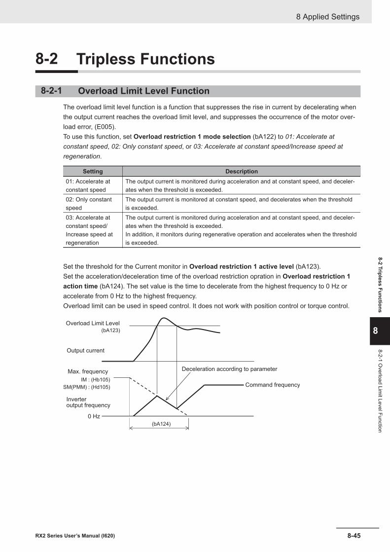
8-2 Tripless Functions
8-2-1 Overload Limit Level FunctionThe overload limit level function is a function that suppresses the rise in current by decelerating whenthe output current reaches the overload limit level, and suppresses the occurrence of the motor over-load error, (E005).To use this function, set Overload restriction 1 mode selection (bA122) to 01: Accelerate atconstant speed, 02: Only constant speed, or 03: Accelerate at constant speed/Increase speed atregeneration.
Setting Description01: Accelerate atconstant speed
The output current is monitored during acceleration and at constant speed, and deceler-ates when the threshold is exceeded.
02: Only constantspeed
The output current is monitored at constant speed, and decelerates when the thresholdis exceeded.
03: Accelerate atconstant speed/Increase speed atregeneration
The output current is monitored during acceleration and at constant speed, and deceler-ates when the threshold is exceeded.In addition, it monitors during regenerative operation and accelerates when the thresholdis exceeded.
Set the threshold for the Current monitor in Overload restriction 1 active level (bA123).Set the acceleration/deceleration time of the overload restriction opration in Overload restriction 1action time (bA124). The set value is the time to decelerate from the highest frequency to 0 Hz oraccelerate from 0 Hz to the highest frequency.Overload limit can be used in speed control. It does not work with position control or torque control.
(bA123)
(bA124)
IM : (Hb105)
SM(PMM) : (Hd105)
Overload Limit Level
Output current
Max. frequency
0 Hz
Command frequency
Deceleration according to parameter
Inverteroutput frequency
8 Applied Settings
8-45RX2 Series User’s Manual (I620)
8-2 Tripless Functions
8
8-2-1 Overload Lim
it Level Function
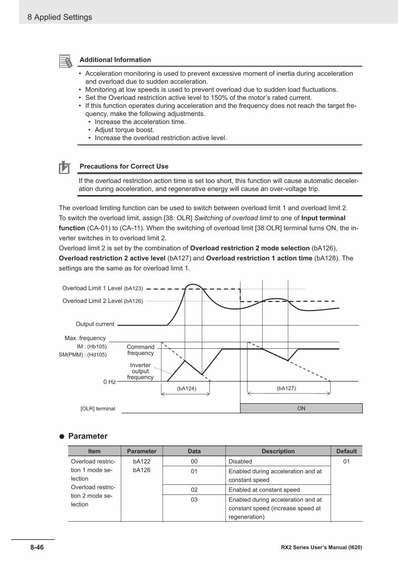
Additional Information
• Acceleration monitoring is used to prevent excessive moment of inertia during accelerationand overload due to sudden acceleration.
• Monitoring at low speeds is used to prevent overload due to sudden load fluctuations.• Set the Overload restriction active level to 150% of the motor’s rated current.• If this function operates during acceleration and the frequency does not reach the target fre-
quency, make the following adjustments.• Increase the acceleration time.• Adjust torque boost.• Increase the overload restriction active level.
Precautions for Correct Use
If the overload restriction action time is set too short, this function will cause automatic deceler-ation during acceleration, and regenerative energy will cause an over-voltage trip.
The overload limiting function can be used to switch between overload limit 1 and overload limit 2.To switch the overload limit, assign [38: OLR] Switching of overload limit to one of Input terminalfunction (CA-01) to (CA-11). When the switching of overload limit [38:OLR] terminal turns ON, the in-verter switches in to overload limit 2.Overload limit 2 is set by the combination of Overload restriction 2 mode selection (bA126),Overload restriction 2 active level (bA127) and Overload restriction 1 action time (bA128). Thesettings are the same as for overload limit 1.
(bA124)
IM : (Hb105)
SM(PMM) : (Hd105)
[OLR] terminal ON
(bA127)
(bA123)
Overload Limit 2 Level
Output current
0 Hz
Inverteroutput
frequency
Overload Limit 1 Level
(bA126)
Max. frequency
Commandfrequency
l Parameter
Item Parameter Data Description DefaultOverload restric-tion 1 mode se-lectionOverload restric-tion 2 mode se-lection
bA122bA126
00 Disabled 0101 Enabled during acceleration and at
constant speed02 Enabled at constant speed03 Enabled during acceleration and at
constant speed (increase speed atregeneration)
8 Applied Settings
8-46 RX2 Series User’s Manual (I620)
Item Parameter Data Description DefaultOverload restric-tion 1 active levelOverload restric-tion 2 active level
bA123bA127
Inverter rated current×(0.2 to 2.0) *1
The Overload limit function will oper-ate when the output torque exceedsthis set value.
1.5×Inverter
rated cur-rent
Overload restric-tion 1 action timeOverload restric-tion 2 action time
bA124bA128
0.10 to 3600.00 (s) The acceleration/deceleration timewhen overload restriction active levelis exceeded.
1.00
*1. For the current and voltage related parameters, the values and units that can be used will differ depend-ing on the setting method.
1. Operator, CX-Drive: For operation with CX-Drive 0.1 A, or 0.1 V, set Resister data selection (CF-11)to “00: A,V”. If Resister data selection (CF-11) is not set to 00: A,V, data cannot be set, or displayedcorrectly.
2. Modbus: Current and voltage vary, depending on the setting of Resister data selection (CF-11).When Resister data selection (CF-11) is set to 00: A,V, units are 0.1 A and 0.1 VWhen Resister data selection (CF-11) is set to 01: %, unit is 0.01% (Rated ratio)
3. Drive programming: 0.01% (Rated ratio)
l Input Terminal Function
Item Terminal name Data DescriptionInput terminal function CA-01 to CA-11 38 [38: OLR] Switching of overload limit
OFF: Overload limit 1 enabledON: Overload limit 2 enabled
8-2-2 Overcurrent Suppression FunctionOvercurrent suppression is a function that suppresses the rise in current by stopping accelerationwhen the output current reaches the overcurrent suppress level, and suppresses the occurrence ofovercurrent trips.To use this function, set Over current suppress enable (bA120) to 01: Enabled and set the monitorcurrent threshold to the Over current suppress level (bA121).
This function is automatically enabled during DC braking.This function is enabled during position/torque control.When using a synchronous motor or permanent magnet motor, overcurrent suppression is not per-formed even if the overcurrent suppression function is enabled.
Precautions for Correct Use
• Disable this function when using for elevators, etc. Suppressing the current causes insuffi-cient torque, which may result in the cargo or items being lifted falling off.
• Overcurrent tripping may occur even if this function is enabled if the current increases sharplydue to shock load, etc.
8 Applied Settings
8-47RX2 Series User’s Manual (I620)
8-2 Tripless Functions
8
8-2-2 Overcurrent Suppression Function
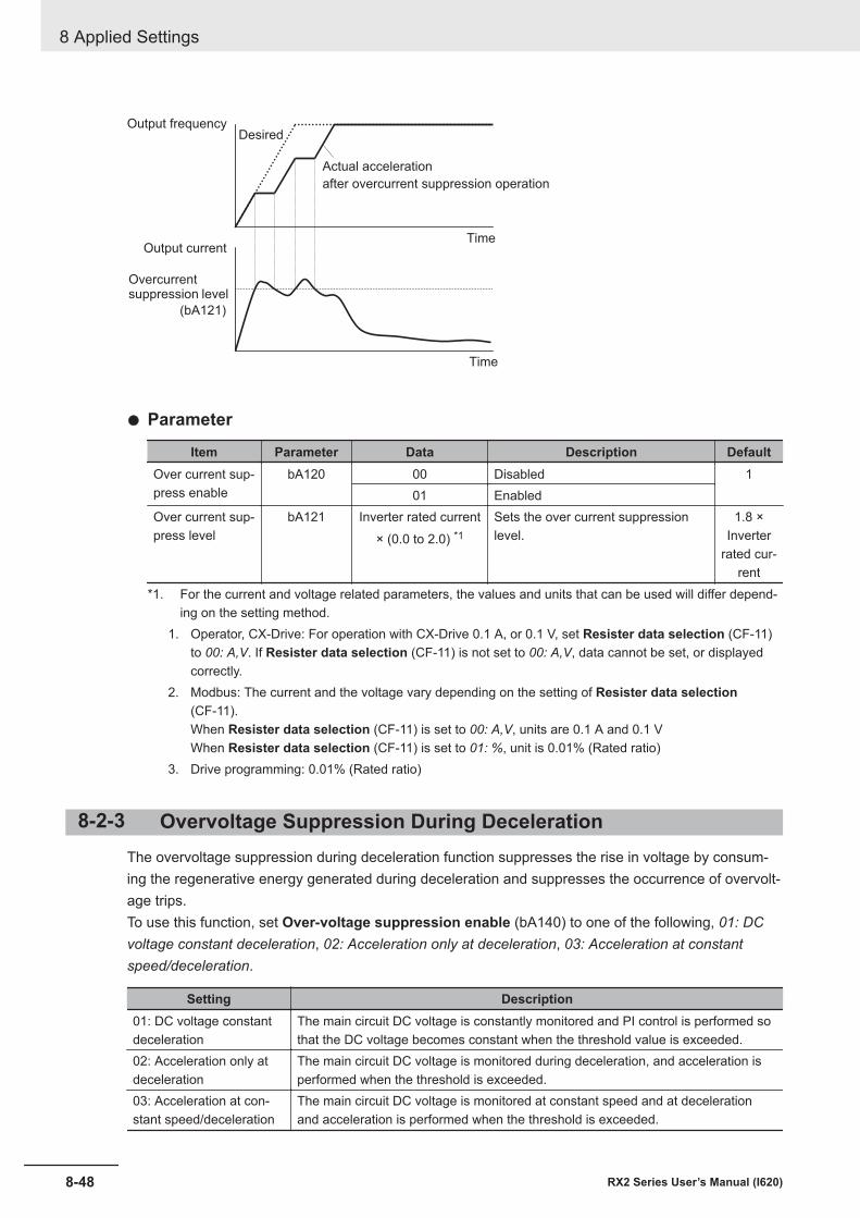
Output frequencyDesired
Actual acceleration
after overcurrent suppression operation
TimeOutput current
Overcurrentsuppression level
Time
(bA121)
l Parameter
Item Parameter Data Description DefaultOver current sup-press enable
bA120 00 Disabled 101 Enabled
Over current sup-press level
bA121 Inverter rated current× (0.0 to 2.0) *1
Sets the over current suppressionlevel.
1.8 ×Inverter
rated cur-rent
*1. For the current and voltage related parameters, the values and units that can be used will differ depend-ing on the setting method.
1. Operator, CX-Drive: For operation with CX-Drive 0.1 A, or 0.1 V, set Resister data selection (CF-11)to 00: A,V. If Resister data selection (CF-11) is not set to 00: A,V, data cannot be set, or displayedcorrectly.
2. Modbus: The current and the voltage vary depending on the setting of Resister data selection(CF-11).When Resister data selection (CF-11) is set to 00: A,V, units are 0.1 A and 0.1 VWhen Resister data selection (CF-11) is set to 01: %, unit is 0.01% (Rated ratio)
3. Drive programming: 0.01% (Rated ratio)
8-2-3 Overvoltage Suppression During DecelerationThe overvoltage suppression during deceleration function suppresses the rise in voltage by consum-ing the regenerative energy generated during deceleration and suppresses the occurrence of overvolt-age trips.To use this function, set Over-voltage suppression enable (bA140) to one of the following, 01: DCvoltage constant deceleration, 02: Acceleration only at deceleration, 03: Acceleration at constantspeed/deceleration.
Setting Description01: DC voltage constantdeceleration
The main circuit DC voltage is constantly monitored and PI control is performed sothat the DC voltage becomes constant when the threshold value is exceeded.
02: Acceleration only atdeceleration
The main circuit DC voltage is monitored during deceleration, and acceleration isperformed when the threshold is exceeded.
03: Acceleration at con-stant speed/deceleration
The main circuit DC voltage is monitored at constant speed and at decelerationand acceleration is performed when the threshold is exceeded.
8 Applied Settings
8-48 RX2 Series User’s Manual (I620)
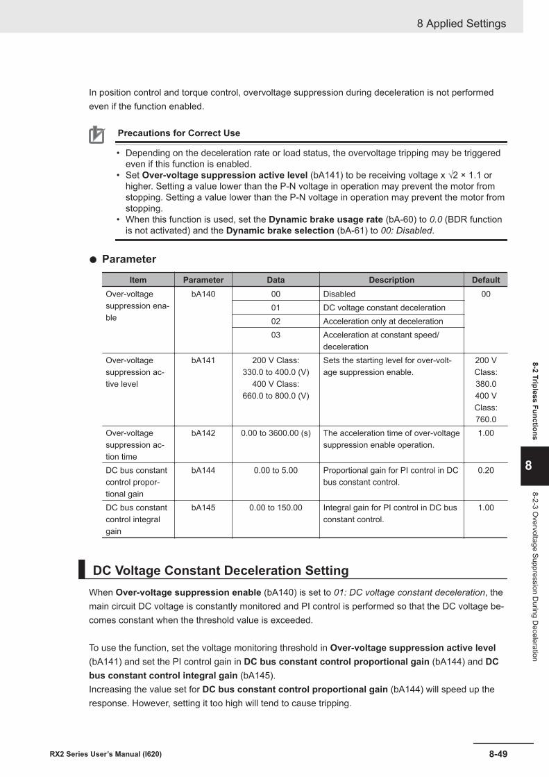
In position control and torque control, overvoltage suppression during deceleration is not performedeven if the function enabled.
Precautions for Correct Use
• Depending on the deceleration rate or load status, the overvoltage tripping may be triggeredeven if this function is enabled.
• Set Over-voltage suppression active level (bA141) to be receiving voltage x √2 × 1.1 orhigher. Setting a value lower than the P-N voltage in operation may prevent the motor fromstopping. Setting a value lower than the P-N voltage in operation may prevent the motor fromstopping.
• When this function is used, set the Dynamic brake usage rate (bA-60) to 0.0 (BDR functionis not activated) and the Dynamic brake selection (bA-61) to 00: Disabled.
l Parameter
Item Parameter Data Description DefaultOver-voltagesuppression ena-ble
bA140 00 Disabled 0001 DC voltage constant deceleration02 Acceleration only at deceleration03 Acceleration at constant speed/
decelerationOver-voltagesuppression ac-tive level
bA141 200 V Class:330.0 to 400.0 (V)
400 V Class:660.0 to 800.0 (V)
Sets the starting level for over-volt-age suppression enable.
200 VClass:380.0400 VClass:760.0
Over-voltagesuppression ac-tion time
bA142 0.00 to 3600.00 (s) The acceleration time of over-voltagesuppression enable operation.
1.00
DC bus constantcontrol propor-tional gain
bA144 0.00 to 5.00 Proportional gain for PI control in DCbus constant control.
0.20
DC bus constantcontrol integralgain
bA145 0.00 to 150.00 Integral gain for PI control in DC busconstant control.
1.00
DC Voltage Constant Deceleration SettingWhen Over-voltage suppression enable (bA140) is set to 01: DC voltage constant deceleration, themain circuit DC voltage is constantly monitored and PI control is performed so that the DC voltage be-comes constant when the threshold value is exceeded.
To use the function, set the voltage monitoring threshold in Over-voltage suppression active level(bA141) and set the PI control gain in DC bus constant control proportional gain (bA144) and DCbus constant control integral gain (bA145).Increasing the value set for DC bus constant control proportional gain (bA144) will speed up theresponse. However, setting it too high will tend to cause tripping.
8 Applied Settings
8-49RX2 Series User’s Manual (I620)
8-2 Tripless Functions
8
8-2-3 Overvoltage Suppression D
uring Deceleration
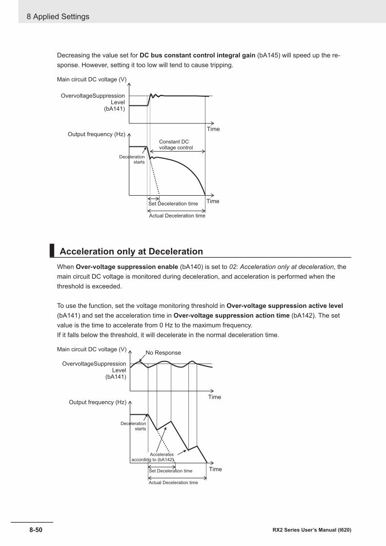
Decreasing the value set for DC bus constant control integral gain (bA145) will speed up the re-sponse. However, setting it too low will tend to cause tripping.
Main circuit DC voltage (V)
OvervoltageSuppressionLevel
(bA141)
Output frequency (Hz)Time
Decelerationstarts
Constant DCvoltage control
Set Deceleration time
Actual Deceleration time
Time
Acceleration only at DecelerationWhen Over-voltage suppression enable (bA140) is set to 02: Acceleration only at deceleration, themain circuit DC voltage is monitored during deceleration, and acceleration is performed when thethreshold is exceeded.
To use the function, set the voltage monitoring threshold in Over-voltage suppression active level(bA141) and set the acceleration time in Over-voltage suppression action time (bA142). The setvalue is the time to accelerate from 0 Hz to the maximum frequency.If it falls below the threshold, it will decelerate in the normal deceleration time.
Main circuit DC voltage (V)
OvervoltageSuppressionLevel
(bA141)
Output frequency (Hz)Time
Decelerationstarts
Actual Deceleration time
Time
No Response
Set Deceleration time
Acceleratesaccording to (bA142)
8 Applied Settings
8-50 RX2 Series User’s Manual (I620)
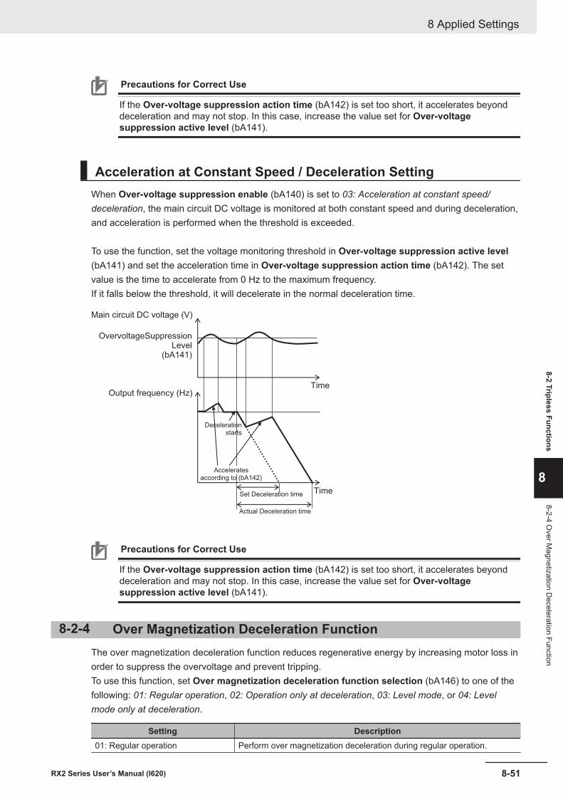
Precautions for Correct Use
If the Over-voltage suppression action time (bA142) is set too short, it accelerates beyonddeceleration and may not stop. In this case, increase the value set for Over-voltagesuppression active level (bA141).
Acceleration at Constant Speed / Deceleration SettingWhen Over-voltage suppression enable (bA140) is set to 03: Acceleration at constant speed/deceleration, the main circuit DC voltage is monitored at both constant speed and during deceleration,and acceleration is performed when the threshold is exceeded.
To use the function, set the voltage monitoring threshold in Over-voltage suppression active level(bA141) and set the acceleration time in Over-voltage suppression action time (bA142). The setvalue is the time to accelerate from 0 Hz to the maximum frequency.If it falls below the threshold, it will decelerate in the normal deceleration time.
Main circuit DC voltage (V)
OvervoltageSuppressionLevel
(bA141)
Output frequency (Hz)Time
Decelerationstarts
Actual Deceleration time
TimeSet Deceleration time
Acceleratesaccording to (bA142)
Precautions for Correct Use
If the Over-voltage suppression action time (bA142) is set too short, it accelerates beyonddeceleration and may not stop. In this case, increase the value set for Over-voltagesuppression active level (bA141).
8-2-4 Over Magnetization Deceleration FunctionThe over magnetization deceleration function reduces regenerative energy by increasing motor loss inorder to suppress the overvoltage and prevent tripping.To use this function, set Over magnetization deceleration function selection (bA146) to one of thefollowing: 01: Regular operation, 02: Operation only at deceleration, 03: Level mode, or 04: Levelmode only at deceleration.
Setting Description01: Regular operation Perform over magnetization deceleration during regular operation.
8 Applied Settings
8-51RX2 Series User’s Manual (I620)
8-2 Tripless Functions
8
8-2-4 Over M
agnetization Deceleration Function
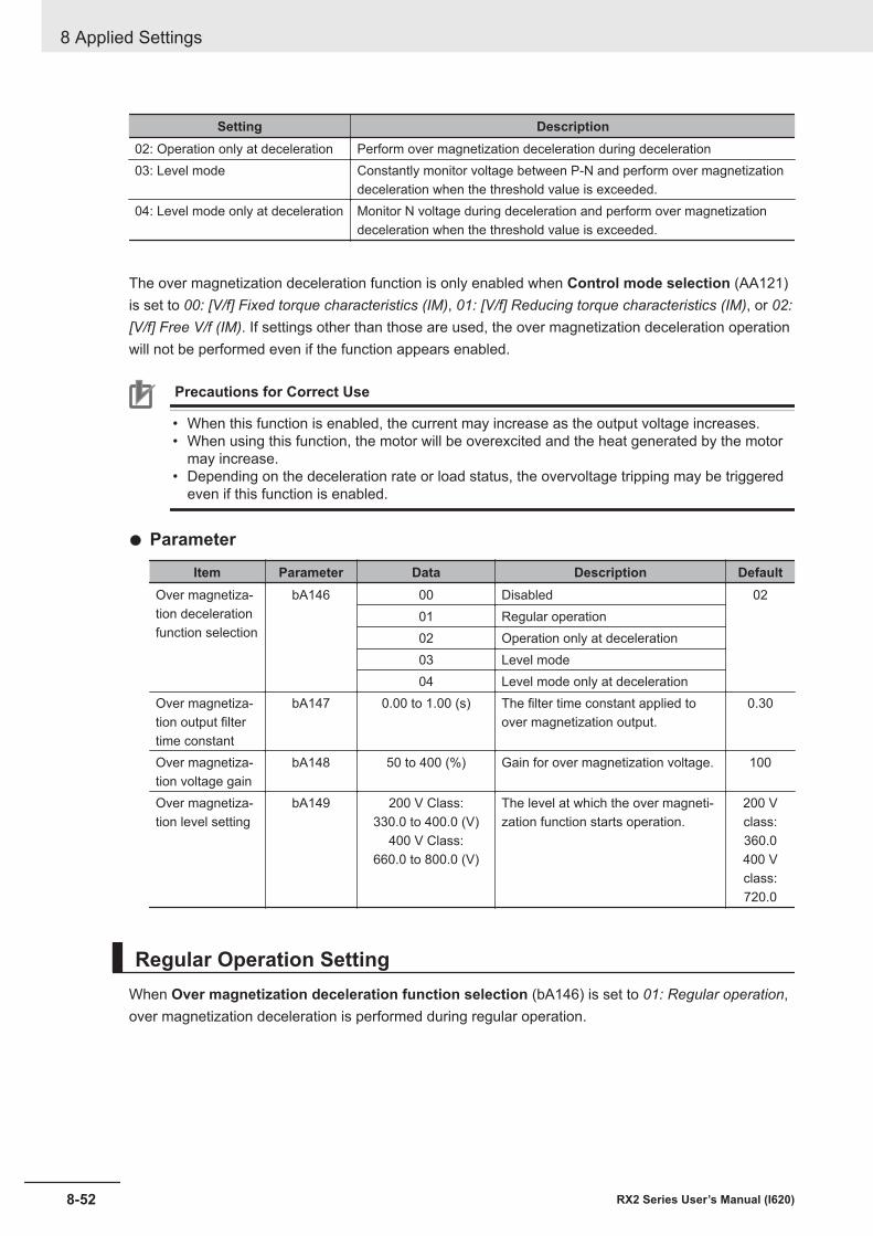
Setting Description02: Operation only at deceleration Perform over magnetization deceleration during deceleration03: Level mode Constantly monitor voltage between P-N and perform over magnetization
deceleration when the threshold value is exceeded.04: Level mode only at deceleration Monitor N voltage during deceleration and perform over magnetization
deceleration when the threshold value is exceeded.
The over magnetization deceleration function is only enabled when Control mode selection (AA121)is set to 00: [V/f] Fixed torque characteristics (IM), 01: [V/f] Reducing torque characteristics (IM), or 02:[V/f] Free V/f (IM). If settings other than those are used, the over magnetization deceleration operationwill not be performed even if the function appears enabled.
Precautions for Correct Use
• When this function is enabled, the current may increase as the output voltage increases.• When using this function, the motor will be overexcited and the heat generated by the motor
may increase.• Depending on the deceleration rate or load status, the overvoltage tripping may be triggered
even if this function is enabled.
l Parameter
Item Parameter Data Description DefaultOver magnetiza-tion decelerationfunction selection
bA146 00 Disabled 0201 Regular operation02 Operation only at deceleration03 Level mode04 Level mode only at deceleration
Over magnetiza-tion output filtertime constant
bA147 0.00 to 1.00 (s) The filter time constant applied toover magnetization output.
0.30
Over magnetiza-tion voltage gain
bA148 50 to 400 (%) Gain for over magnetization voltage. 100
Over magnetiza-tion level setting
bA149 200 V Class:330.0 to 400.0 (V)
400 V Class:660.0 to 800.0 (V)
The level at which the over magneti-zation function starts operation.
200 Vclass:360.0400 Vclass:720.0
Regular Operation SettingWhen Over magnetization deceleration function selection (bA146) is set to 01: Regular operation,over magnetization deceleration is performed during regular operation.
8 Applied Settings
8-52 RX2 Series User’s Manual (I620)
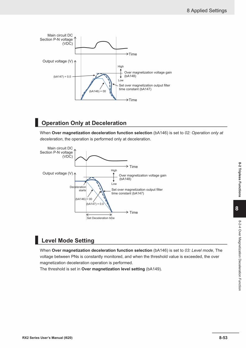
(bA147) = 0.0 (bA148)
(bA146) = 00
Main circuit DCSection P-N voltage
(VDC)
Time
Output voltage (V)
Over magnetization voltage gain
Time
Set over magnetization output filtertime constant (bA147)
High
Low
Operation Only at DecelerationWhen Over magnetization deceleration function selection (bA146) is set to 02: Operation only atdeceleration, the operation is performed only at deceleration.
(bA147) = 0.0
(bA148)
(bA146) = 00
Main circuit DCSection P-N voltage
(VDC)
Time
Output voltage (V)Over magnetization voltage gain
Time
Set over magnetization output filtertime constant (bA147)
Set Deceleration time
High
LowDeceleration
starts
Level Mode SettingWhen Over magnetization deceleration function selection (bA146) is set to 03: Level mode, Thevoltage between PNs is constantly monitored, and when the threshold value is exceeded, the overmagnetization deceleration operation is performed.The threshold is set in Over magnetization level setting (bA149).
8 Applied Settings
8-53RX2 Series User’s Manual (I620)
8-2 Tripless Functions
8
8-2-4 Over M
agnetization Deceleration Function
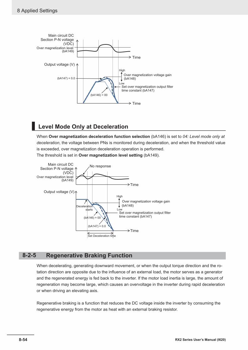
(bA147) = 0.0 (bA148)
(bA146) = 00
(bA149)
Main circuit DCSection P-N voltage
(VDC)
Time
Output voltage (V)
Over magnetization voltage gain
Time
Set over magnetization output filtertime constant (bA147)
High
Low
Over magnetization level
Level Mode Only at DecelerationWhen Over magnetization deceleration function selection (bA146) is set to 04: Level mode only atdeceleration, the voltage between PNs is monitored during deceleration, and when the threshold valueis exceeded, over magnetization deceleration operation is performed.The threshold is set in Over magnetization level setting (bA149).
(bA147) = 0.0
(bA148)
(bA146) = 00
(bA149)
Main circuit DCSection P-N voltage
(VDC)
Time
Output voltage (V)
Over magnetization voltage gain
Time
Set over magnetization output filtertime constant (bA147)
High
Low
Over magnetization level
No response
Set Deceleration time
Decelerationstarts
8-2-5 Regenerative Braking FunctionWhen decelerating, generating downward movement, or when the output torque direction and the ro-tation direction are opposite due to the influence of an external load, the motor serves as a generatorand the regenerated energy is fed back to the inverter. If the motor load inertia is large, the amount ofregeneration may become large, which causes an overvoltage in the inverter during rapid decelerationor when driving an elevating axis.
Regenerative braking is a function that reduces the DC voltage inside the inverter by consuming theregenerative energy from the motor as heat with an external braking resistor.
8 Applied Settings
8-54 RX2 Series User’s Manual (I620)
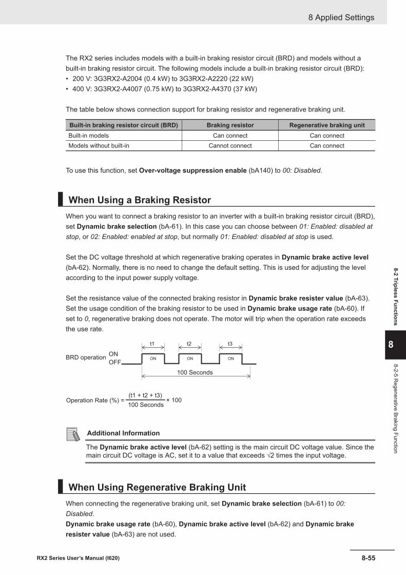
The RX2 series includes models with a built-in braking resistor circuit (BRD) and models without abuilt-in braking resistor circuit. The following models include a built-in braking resistor circuit (BRD):• 200 V: 3G3RX2-A2004 (0.4 kW) to 3G3RX2-A2220 (22 kW)• 400 V: 3G3RX2-A4007 (0.75 kW) to 3G3RX2-A4370 (37 kW)
The table below shows connection support for braking resistor and regenerative braking unit.
Built-in braking resistor circuit (BRD) Braking resistor Regenerative braking unitBuilt-in models Can connect Can connectModels without built-in Cannot connect Can connect
To use this function, set Over-voltage suppression enable (bA140) to 00: Disabled.
When Using a Braking ResistorWhen you want to connect a braking resistor to an inverter with a built-in braking resistor circuit (BRD),set Dynamic brake selection (bA-61). In this case you can choose between 01: Enabled: disabled atstop, or 02: Enabled: enabled at stop, but normally 01: Enabled: disabled at stop is used.
Set the DC voltage threshold at which regenerative braking operates in Dynamic brake active level(bA-62). Normally, there is no need to change the default setting. This is used for adjusting the levelaccording to the input power supply voltage.
Set the resistance value of the connected braking resistor in Dynamic brake resister value (bA-63).Set the usage condition of the braking resistor to be used in Dynamic brake usage rate (bA-60). Ifset to 0, regenerative braking does not operate. The motor will trip when the operation rate exceedsthe use rate.
t2
ON ONON
t1 t3
ON
OFF
(t1 + t2 + t3)× 100
BRD operation
100 Seconds
Operation Rate (%) =100 Seconds
Additional Information
The Dynamic brake active level (bA-62) setting is the main circuit DC voltage value. Since themain circuit DC voltage is AC, set it to a value that exceeds √2 times the input voltage.
When Using Regenerative Braking UnitWhen connecting the regenerative braking unit, set Dynamic brake selection (bA-61) to 00:Disabled.Dynamic brake usage rate (bA-60), Dynamic brake active level (bA-62) and Dynamic brakeresister value (bA-63) are not used.
8 Applied Settings
8-55RX2 Series User’s Manual (I620)
8-2 Tripless Functions
8
8-2-5 Regenerative Braking Function
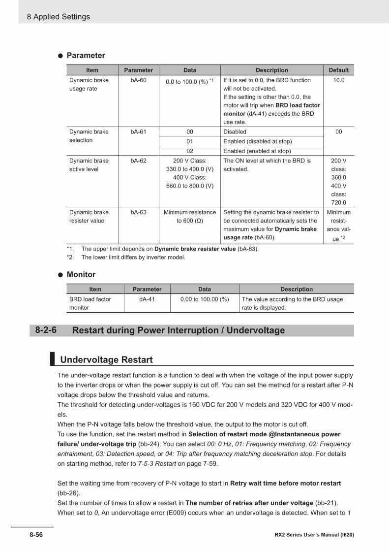
l Parameter
Item Parameter Data Description DefaultDynamic brakeusage rate
bA-60 0.0 to 100.0 (%) *1 If it is set to 0.0, the BRD functionwill not be activated.If the setting is other than 0.0, themotor will trip when BRD load factormonitor (dA-41) exceeds the BRDuse rate.
10.0
Dynamic brakeselection
bA-61 00 Disabled 0001 Enabled (disabled at stop)02 Enabled (enabled at stop)
Dynamic brakeactive level
bA-62 200 V Class:330.0 to 400.0 (V)
400 V Class:660.0 to 800.0 (V)
The ON level at which the BRD isactivated.
200 Vclass:360.0400 Vclass:720.0
Dynamic brakeresister value
bA-63 Minimum resistanceto 600 (Ω)
Setting the dynamic brake resister tobe connected automatically sets themaximum value for Dynamic brakeusage rate (bA-60).
Minimumresist-
ance val-ue *2
*1. The upper limit depends on Dynamic brake resister value (bA-63).*2. The lower limit differs by inverter model.
l Monitor
Item Parameter Data DescriptionBRD load factormonitor
dA-41 0.00 to 100.00 (%) The value according to the BRD usagerate is displayed.
8-2-6 Restart during Power Interruption / Undervoltage
Undervoltage RestartThe under-voltage restart function is a function to deal with when the voltage of the input power supplyto the inverter drops or when the power supply is cut off. You can set the method for a restart after P-Nvoltage drops below the threshold value and returns.The threshold for detecting under-voltages is 160 VDC for 200 V models and 320 VDC for 400 V mod-els.When the P-N voltage falls below the threshold value, the output to the motor is cut off.To use the function, set the restart method in Selection of restart mode @Instantaneous powerfailure/ under-voltage trip (bb-24). You can select 00: 0 Hz, 01: Frequency matching, 02: Frequencyentrainment, 03: Detection speed, or 04: Trip after frequency matching deceleration stop. For detailson starting method, refer to 7-5-3 Restart on page 7-59.
Set the waiting time from recovery of P-N voltage to start in Retry wait time before motor restart(bb-26).Set the number of times to allow a restart in The number of retries after under voltage (bb-21).When set to 0, An undervoltage error (E009) occurs when an undervoltage is detected. When set to 1
8 Applied Settings
8-56 RX2 Series User’s Manual (I620)
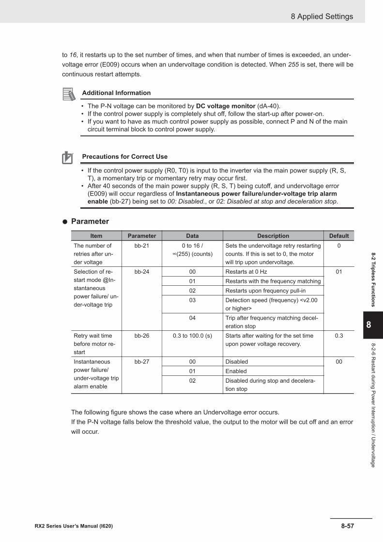
to 16, it restarts up to the set number of times, and when that number of times is exceeded, an under-voltage error (E009) occurs when an undervoltage condition is detected. When 255 is set, there will becontinuous restart attempts.
Additional Information
• The P-N voltage can be monitored by DC voltage monitor (dA-40).• If the control power supply is completely shut off, follow the start-up after power-on.• If you want to have as much control power supply as possible, connect P and N of the main
circuit terminal block to control power supply.
Precautions for Correct Use
• If the control power supply (R0, T0) is input to the inverter via the main power supply (R, S,T), a momentary trip or momentary retry may occur first.
• After 40 seconds of the main power supply (R, S, T) being cutoff, and undervoltage error(E009) will occur regardless of Instantaneous power failure/under-voltage trip alarmenable (bb-27) being set to 00: Disabled., or 02: Disabled at stop and deceleration stop.
l Parameter
Item Parameter Data Description DefaultThe number ofretries after un-der voltage
bb-21 0 to 16 /∞(255) (counts)
Sets the undervoltage retry restartingcounts. If this is set to 0, the motorwill trip upon undervoltage.
0
Selection of re-start mode @In-stantaneouspower failure/ un-der-voltage trip
bb-24 00 Restarts at 0 Hz 0101 Restarts with the frequency matching02 Restarts upon frequency pull-in03 Detection speed (frequency) <v2.00
or higher>04 Trip after frequency matching decel-
eration stopRetry wait timebefore motor re-start
bb-26 0.3 to 100.0 (s) Starts after waiting for the set timeupon power voltage recovery.
0.3
Instantaneouspower failure/under-voltage tripalarm enable
bb-27 00 Disabled 0001 Enabled02 Disabled during stop and decelera-
tion stop
The following figure shows the case where an Undervoltage error occurs.If the P-N voltage falls below the threshold value, the output to the motor will be cut off and an errorwill occur.
8 Applied Settings
8-57RX2 Series User’s Manual (I620)
8-2 Tripless Functions
8
8-2-6 Restart during Pow
er Interruption / Undervoltage
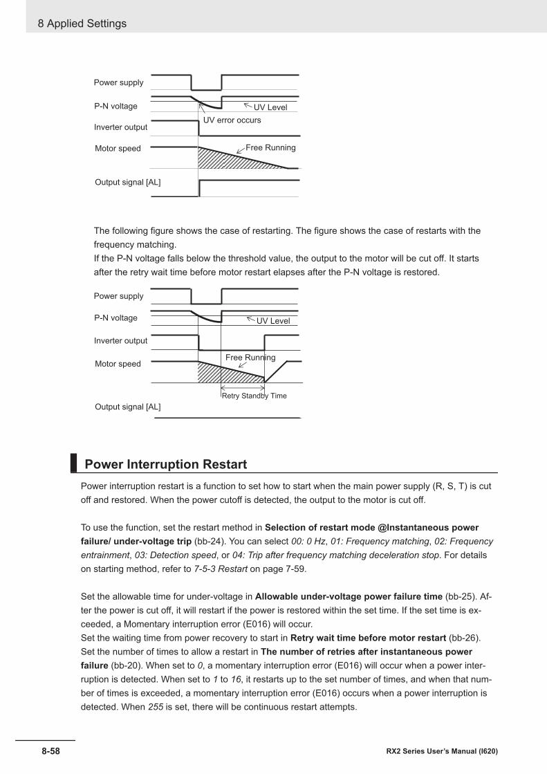
Power supply
P-N voltage
Inverter output
Motor speed
Output signal [AL]
UV Level
UV error occurs
Free Running
The following figure shows the case of restarting. The figure shows the case of restarts with thefrequency matching.If the P-N voltage falls below the threshold value, the output to the motor will be cut off. It startsafter the retry wait time before motor restart elapses after the P-N voltage is restored.
Power supply
P-N voltage
Inverter output
Motor speed
Output signal [AL]
UV Level
Free Running
Retry Standby Time
Power Interruption RestartPower interruption restart is a function to set how to start when the main power supply (R, S, T) is cutoff and restored. When the power cutoff is detected, the output to the motor is cut off.
To use the function, set the restart method in Selection of restart mode @Instantaneous powerfailure/ under-voltage trip (bb-24). You can select 00: 0 Hz, 01: Frequency matching, 02: Frequencyentrainment, 03: Detection speed, or 04: Trip after frequency matching deceleration stop. For detailson starting method, refer to 7-5-3 Restart on page 7-59.
Set the allowable time for under-voltage in Allowable under-voltage power failure time (bb-25). Af-ter the power is cut off, it will restart if the power is restored within the set time. If the set time is ex-ceeded, a Momentary interruption error (E016) will occur.Set the waiting time from power recovery to start in Retry wait time before motor restart (bb-26).Set the number of times to allow a restart in The number of retries after instantaneous powerfailure (bb-20). When set to 0, a momentary interruption error (E016) will occur when a power inter-ruption is detected. When set to 1 to 16, it restarts up to the set number of times, and when that num-ber of times is exceeded, a momentary interruption error (E016) occurs when a power interruption isdetected. When 255 is set, there will be continuous restart attempts.
8 Applied Settings
8-58 RX2 Series User’s Manual (I620)
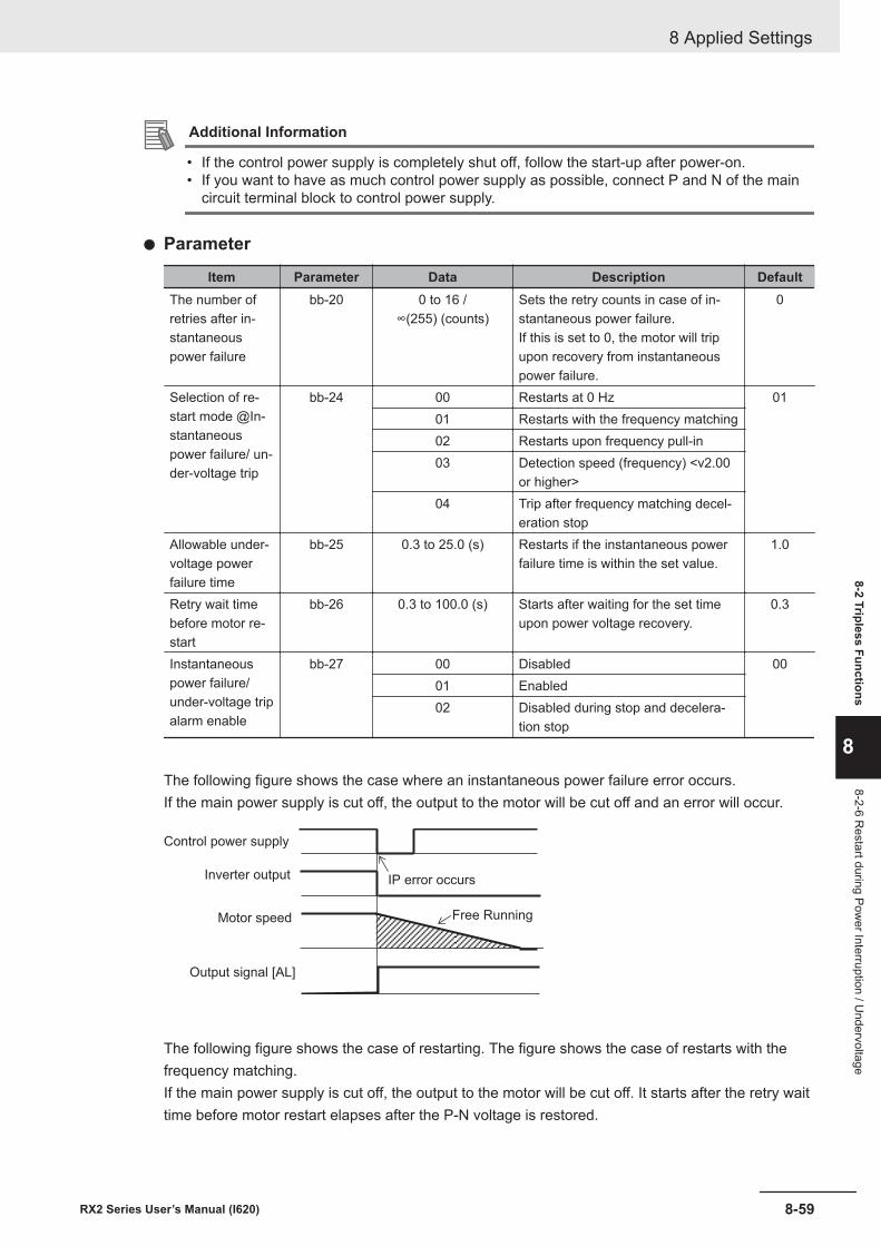
Additional Information
• If the control power supply is completely shut off, follow the start-up after power-on.• If you want to have as much control power supply as possible, connect P and N of the main
circuit terminal block to control power supply.
l Parameter
Item Parameter Data Description DefaultThe number ofretries after in-stantaneouspower failure
bb-20 0 to 16 /∞(255) (counts)
Sets the retry counts in case of in-stantaneous power failure.If this is set to 0, the motor will tripupon recovery from instantaneouspower failure.
0
Selection of re-start mode @In-stantaneouspower failure/ un-der-voltage trip
bb-24 00 Restarts at 0 Hz 0101 Restarts with the frequency matching02 Restarts upon frequency pull-in03 Detection speed (frequency) <v2.00
or higher>04 Trip after frequency matching decel-
eration stopAllowable under-voltage powerfailure time
bb-25 0.3 to 25.0 (s) Restarts if the instantaneous powerfailure time is within the set value.
1.0
Retry wait timebefore motor re-start
bb-26 0.3 to 100.0 (s) Starts after waiting for the set timeupon power voltage recovery.
0.3
Instantaneouspower failure/under-voltage tripalarm enable
bb-27 00 Disabled 0001 Enabled02 Disabled during stop and decelera-
tion stop
The following figure shows the case where an instantaneous power failure error occurs.If the main power supply is cut off, the output to the motor will be cut off and an error will occur.
Control power supply
Inverter output
Motor speed
Output signal [AL]
IP error occurs
Free Running
The following figure shows the case of restarting. The figure shows the case of restarts with thefrequency matching.If the main power supply is cut off, the output to the motor will be cut off. It starts after the retry waittime before motor restart elapses after the P-N voltage is restored.
8 Applied Settings
8-59RX2 Series User’s Manual (I620)
8-2 Tripless Functions
8
8-2-6 Restart during Pow
er Interruption / Undervoltage
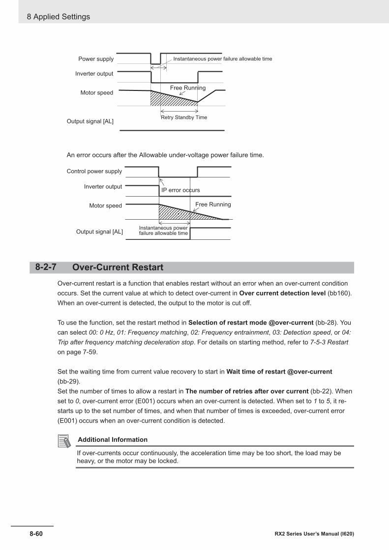
Power supply
Inverter output
Motor speed
Output signal [AL]
Free Running
Retry Standby Time
Instantaneous power failure allowable time
An error occurs after the Allowable under-voltage power failure time.
Control power supply
Inverter output
Motor speed
Output signal [AL]Instantaneous powerfailure allowable time
Free Running
IP error occurs
8-2-7 Over-Current RestartOver-current restart is a function that enables restart without an error when an over-current conditionoccurs. Set the current value at which to detect over-current in Over current detection level (bb160).When an over-current is detected, the output to the motor is cut off.
To use the function, set the restart method in Selection of restart mode @over-current (bb-28). Youcan select 00: 0 Hz, 01: Frequency matching, 02: Frequency entrainment, 03: Detection speed, or 04:Trip after frequency matching deceleration stop. For details on starting method, refer to 7-5-3 Restarton page 7-59.
Set the waiting time from current value recovery to start in Wait time of restart @over-current(bb-29).Set the number of times to allow a restart in The number of retries after over current (bb-22). Whenset to 0, over-current error (E001) occurs when an over-current is detected. When set to 1 to 5, it re-starts up to the set number of times, and when that number of times is exceeded, over-current error(E001) occurs when an over-current condition is detected.
Additional Information
If over-currents occur continuously, the acceleration time may be too short, the load may beheavy, or the motor may be locked.
8 Applied Settings
8-60 RX2 Series User’s Manual (I620)
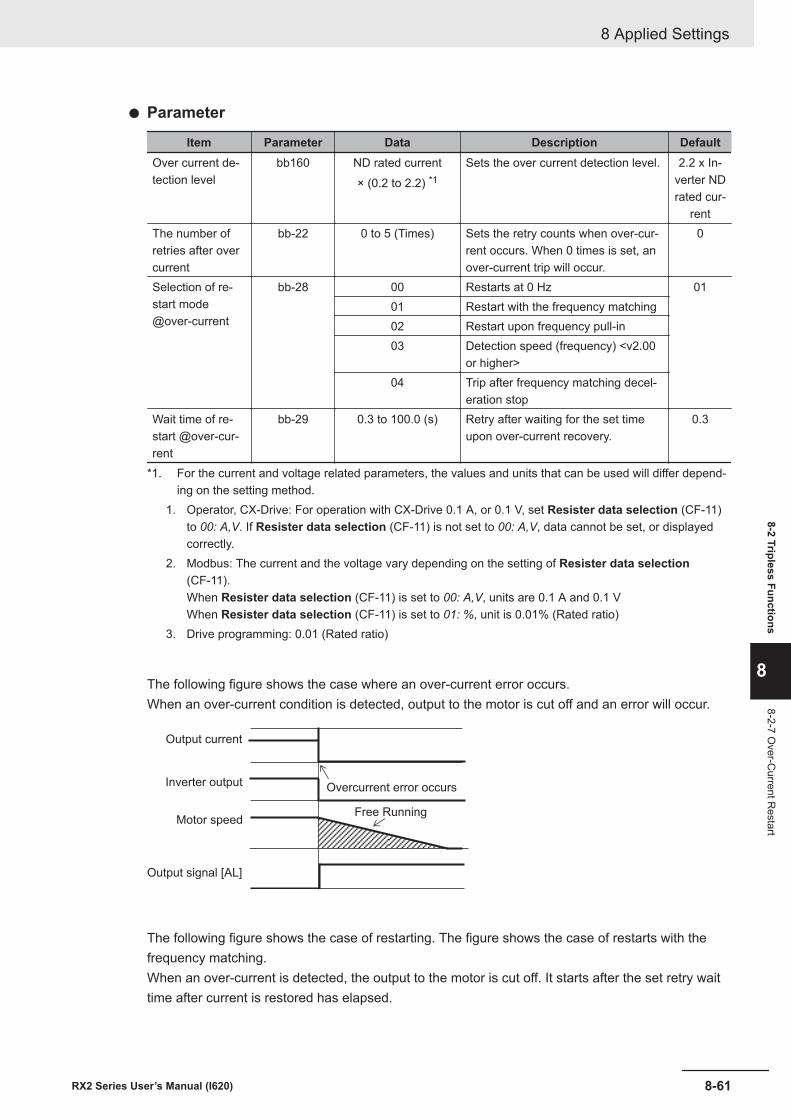
l Parameter
Item Parameter Data Description DefaultOver current de-tection level
bb160 ND rated current× (0.2 to 2.2) *1
Sets the over current detection level. 2.2 x In-verter NDrated cur-
rentThe number ofretries after overcurrent
bb-22 0 to 5 (Times) Sets the retry counts when over-cur-rent occurs. When 0 times is set, anover-current trip will occur.
0
Selection of re-start mode@over-current
bb-28 00 Restarts at 0 Hz 0101 Restart with the frequency matching02 Restart upon frequency pull-in03 Detection speed (frequency) <v2.00
or higher>04 Trip after frequency matching decel-
eration stopWait time of re-start @over-cur-rent
bb-29 0.3 to 100.0 (s) Retry after waiting for the set timeupon over-current recovery.
0.3
*1. For the current and voltage related parameters, the values and units that can be used will differ depend-ing on the setting method.
1. Operator, CX-Drive: For operation with CX-Drive 0.1 A, or 0.1 V, set Resister data selection (CF-11)to 00: A,V. If Resister data selection (CF-11) is not set to 00: A,V, data cannot be set, or displayedcorrectly.
2. Modbus: The current and the voltage vary depending on the setting of Resister data selection(CF-11).When Resister data selection (CF-11) is set to 00: A,V, units are 0.1 A and 0.1 VWhen Resister data selection (CF-11) is set to 01: %, unit is 0.01% (Rated ratio)
3. Drive programming: 0.01 (Rated ratio)
The following figure shows the case where an over-current error occurs.When an over-current condition is detected, output to the motor is cut off and an error will occur.
Output current
Overcurrent error occursInverter output
Motor speed
Output signal [AL]
Free Running
The following figure shows the case of restarting. The figure shows the case of restarts with thefrequency matching.When an over-current is detected, the output to the motor is cut off. It starts after the set retry waittime after current is restored has elapsed.
8 Applied Settings
8-61RX2 Series User’s Manual (I620)
8-2 Tripless Functions
8
8-2-7 Over-C
urrent Restart
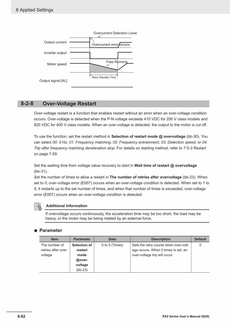
Output current
Inverter output
Motor speed
Output signal [AL]
Overcurrent error occurs
Free Running
Retry Standby Time
Overcurrent Detection Level
8-2-8 Over-Voltage RestartOver-voltage restart is a function that enables restart without an error when an over-voltage conditionoccurs. Over-voltage is detected when the P-N voltage exceeds 410 VDC for 200 V class models and820 VDC for 400 V class models. When an over-voltage is detected, the output to the motor is cut off.
To use the function, set the restart method in Selection of restart mode @ overvoltage (bb-30). Youcan select 00: 0 Hz, 01: Frequency matching, 02: Frequency entrainment, 03: Detection speed, or 04:Trip after frequency matching deceleration stop. For details on starting method, refer to 7-5-3 Restarton page 7-59.
Set the waiting time from voltage value recovery to start in Wait time of restart @ overvoltage(bb-31).Set the number of times to allow a restart in The number of retries after overvoltage (bb-23). Whenset to 0, over-voltage error (E007) occurs when an over-voltage condition is detected. When set to 1 to5, it restarts up to the set number of times, and when that number of times is exceeded, over-voltageerror (E007) occurs when an over-voltage condition is detected.
Additional Information
If overvoltage occurs continuously, the acceleration time may be too short, the load may beheavy, or the motor may be being rotated by an external force.
l Parameter
Item Parameter Data Description DefaultThe number ofretries after over-voltage
Selection ofrestartmode
@over-voltage(bb-23)
0 to 5 (Times) Sets the retry counts when over-volt-age occurs. When 0 times is set, anover-voltage trip will occur.
0
8 Applied Settings
8-62 RX2 Series User’s Manual (I620)
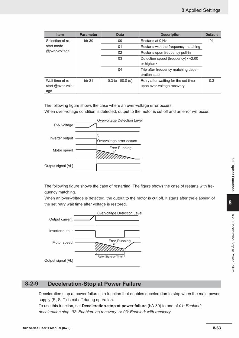
Item Parameter Data Description DefaultSelection of re-start mode@over-voltage
bb-30 00 Restarts at 0 Hz 0101 Restarts with the frequency matching02 Restarts upon frequency pull-in03 Detection speed (frequency) <v2.00
or higher>04 Trip after frequency matching decel-
eration stopWait time of re-start @over-volt-age
bb-31 0.3 to 100.0 (s) Retry after waiting for the set timeupon over-voltage recovery.
0.3
The following figure shows the case where an over-voltage error occurs.When over-voltage condition is detected, output to the motor is cut off and an error will occur.
P-N voltage
Inverter output
Motor speed
Output signal [AL]
Overvoltage error occurs
Free Running
Overvoltage Detection Level
The following figure shows the case of restarting. The figure shows the case of restarts with fre-quency matching.When an over-voltage is detected, the output to the motor is cut off. It starts after the elapsing ofthe set retry wait time after voltage is restored.
Output current
Inverter output
Motor speed
Output signal [AL]
Free Running
Retry Standby Time
Overvoltage Detection Level
8-2-9 Deceleration-Stop at Power FailureDeceleration stop at power failure is a function that enables deceleration to stop when the main powersupply (R, S, T) is cut off during operation.To use this function, set Deceleration-stop at power failure (bA-30) to one of 01: Enabled:deceleration stop, 02: Enabled: no recovery, or 03: Enabled: with recovery.
8 Applied Settings
8-63RX2 Series User’s Manual (I620)
8-2 Tripless Functions
8
8-2-9 Deceleration-Stop at Pow
er Failure
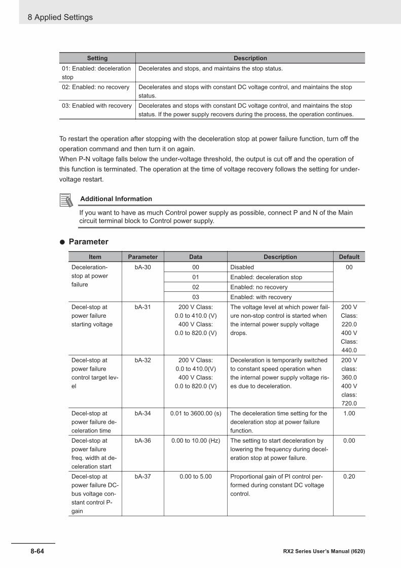
Setting Description01: Enabled: decelerationstop
Decelerates and stops, and maintains the stop status.
02: Enabled: no recovery Decelerates and stops with constant DC voltage control, and maintains the stopstatus.
03: Enabled with recovery Decelerates and stops with constant DC voltage control, and maintains the stopstatus. If the power supply recovers during the process, the operation continues.
To restart the operation after stopping with the deceleration stop at power failure function, turn off theoperation command and then turn it on again.When P-N voltage falls below the under-voltage threshold, the output is cut off and the operation ofthis function is terminated. The operation at the time of voltage recovery follows the setting for under-voltage restart.
Additional Information
If you want to have as much Control power supply as possible, connect P and N of the Maincircuit terminal block to Control power supply.
l Parameter
Item Parameter Data Description DefaultDeceleration-stop at powerfailure
bA-30 00 Disabled 0001 Enabled: deceleration stop02 Enabled: no recovery03 Enabled: with recovery
Decel-stop atpower failurestarting voltage
bA-31 200 V Class:0.0 to 410.0 (V)
400 V Class:0.0 to 820.0 (V)
The voltage level at which power fail-ure non-stop control is started whenthe internal power supply voltagedrops.
200 VClass:220.0400 VClass:440.0
Decel-stop atpower failurecontrol target lev-el
bA-32 200 V Class:0.0 to 410.0(V)400 V Class:
0.0 to 820.0 (V)
Deceleration is temporarily switchedto constant speed operation whenthe internal power supply voltage ris-es due to deceleration.
200 Vclass:360.0400 Vclass:720.0
Decel-stop atpower failure de-celeration time
bA-34 0.01 to 3600.00 (s) The deceleration time setting for thedeceleration stop at power failurefunction.
1.00
Decel-stop atpower failurefreq. width at de-celeration start
bA-36 0.00 to 10.00 (Hz) The setting to start deceleration bylowering the frequency during decel-eration stop at power failure.
0.00
Decel-stop atpower failure DC-bus voltage con-stant control P-gain
bA-37 0.00 to 5.00 Proportional gain of PI control per-formed during constant DC voltagecontrol.
0.20
8 Applied Settings
8-64 RX2 Series User’s Manual (I620)
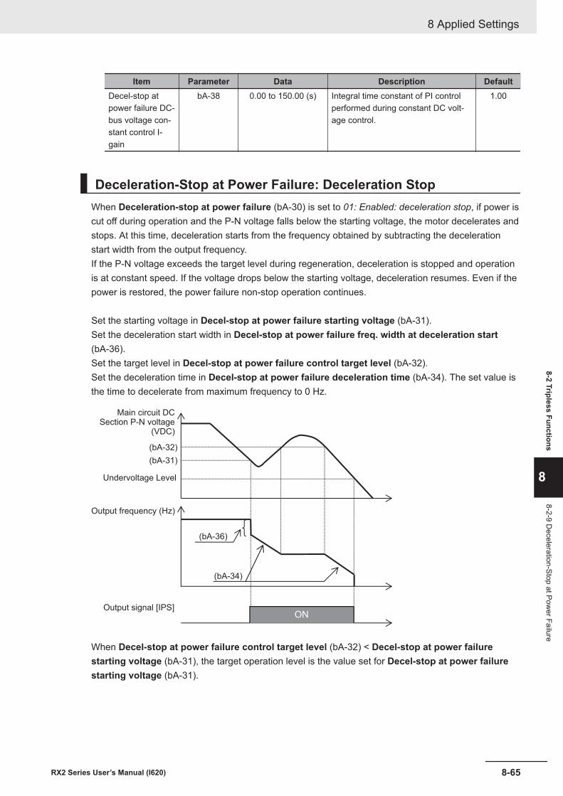
Item Parameter Data Description DefaultDecel-stop atpower failure DC-bus voltage con-stant control I-gain
bA-38 0.00 to 150.00 (s) Integral time constant of PI controlperformed during constant DC volt-age control.
1.00
Deceleration-Stop at Power Failure: Deceleration StopWhen Deceleration-stop at power failure (bA-30) is set to 01: Enabled: deceleration stop, if power iscut off during operation and the P-N voltage falls below the starting voltage, the motor decelerates andstops. At this time, deceleration starts from the frequency obtained by subtracting the decelerationstart width from the output frequency.If the P-N voltage exceeds the target level during regeneration, deceleration is stopped and operationis at constant speed. If the voltage drops below the starting voltage, deceleration resumes. Even if thepower is restored, the power failure non-stop operation continues.
Set the starting voltage in Decel-stop at power failure starting voltage (bA-31).Set the deceleration start width in Decel-stop at power failure freq. width at deceleration start(bA-36).Set the target level in Decel-stop at power failure control target level (bA-32).Set the deceleration time in Decel-stop at power failure deceleration time (bA-34). The set value isthe time to decelerate from maximum frequency to 0 Hz.
(bA-32)
(bA-31)
(bA-34)
(bA-36)
ON
Output frequency (Hz)
Output signal [IPS]
Undervoltage Level
Main circuit DCSection P-N voltage
(VDC)
When Decel-stop at power failure control target level (bA-32) < Decel-stop at power failurestarting voltage (bA-31), the target operation level is the value set for Decel-stop at power failurestarting voltage (bA-31).
8 Applied Settings
8-65RX2 Series User’s Manual (I620)
8-2 Tripless Functions
8
8-2-9 Deceleration-Stop at Pow
er Failure
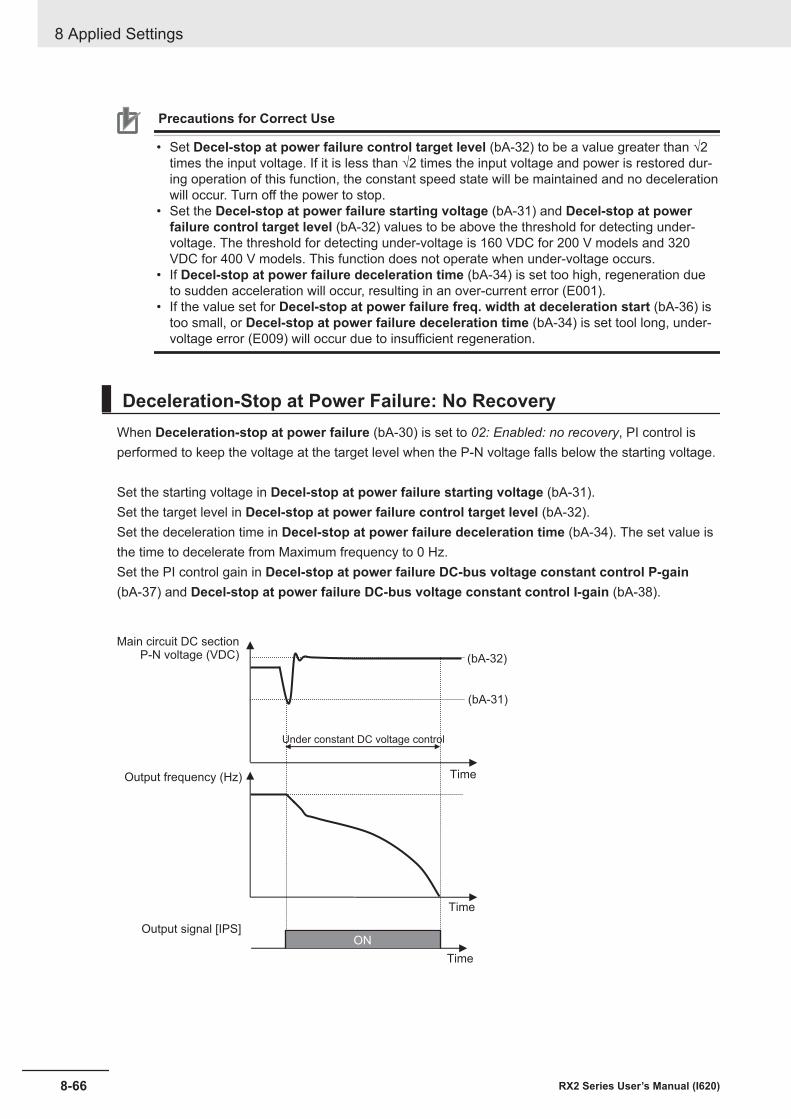
Precautions for Correct Use
• Set Decel-stop at power failure control target level (bA-32) to be a value greater than √2times the input voltage. If it is less than √2 times the input voltage and power is restored dur-ing operation of this function, the constant speed state will be maintained and no decelerationwill occur. Turn off the power to stop.
• Set the Decel-stop at power failure starting voltage (bA-31) and Decel-stop at powerfailure control target level (bA-32) values to be above the threshold for detecting under-voltage. The threshold for detecting under-voltage is 160 VDC for 200 V models and 320VDC for 400 V models. This function does not operate when under-voltage occurs.
• If Decel-stop at power failure deceleration time (bA-34) is set too high, regeneration dueto sudden acceleration will occur, resulting in an over-current error (E001).
• If the value set for Decel-stop at power failure freq. width at deceleration start (bA-36) istoo small, or Decel-stop at power failure deceleration time (bA-34) is set tool long, under-voltage error (E009) will occur due to insufficient regeneration.
Deceleration-Stop at Power Failure: No RecoveryWhen Deceleration-stop at power failure (bA-30) is set to 02: Enabled: no recovery, PI control isperformed to keep the voltage at the target level when the P-N voltage falls below the starting voltage.
Set the starting voltage in Decel-stop at power failure starting voltage (bA-31).Set the target level in Decel-stop at power failure control target level (bA-32).Set the deceleration time in Decel-stop at power failure deceleration time (bA-34). The set value isthe time to decelerate from Maximum frequency to 0 Hz.Set the PI control gain in Decel-stop at power failure DC-bus voltage constant control P-gain(bA-37) and Decel-stop at power failure DC-bus voltage constant control I-gain (bA-38).
(bA-32)
(bA-31)
ON
Output frequency (Hz)
Output signal [IPS]
Under constant DC voltage control
Main circuit DC sectionP-N voltage (VDC)
Time
Time
Time
8 Applied Settings
8-66 RX2 Series User’s Manual (I620)
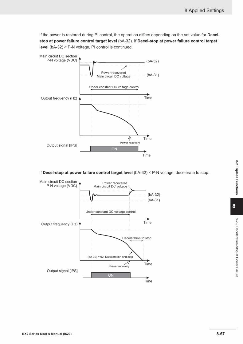
If the power is restored during PI control, the operation differs depending on the set value for Decel-stop at power failure control target level (bA-32). If Decel-stop at power failure control targetlevel (bA-32) ≥ P-N voltage, PI control is continued.
(bA-32)
(bA-31)
ON
Output frequency (Hz)
Output signal [IPS]
Under constant DC voltage control
Main circuit DC sectionP-N voltage (VDC)
Time
Time
Time
Power recoveredMain circuit DC voltage
Power recovery
If Decel-stop at power failure control target level (bA-32) < P-N voltage, decelerate to stop.
(bA-32)
(bA-31)
ON
Output frequency (Hz)
Output signal [IPS]
Under constant DC voltage control
Main circuit DC sectionP-N voltage (VDC)
Time
Time
Time
Power recoveredMain circuit DC voltage
Power recovery
Deceleration to stop
(bA-30) = 02: Deceleration and stop
8 Applied Settings
8-67RX2 Series User’s Manual (I620)
8-2 Tripless Functions
8
8-2-9 Deceleration-Stop at Pow
er Failure
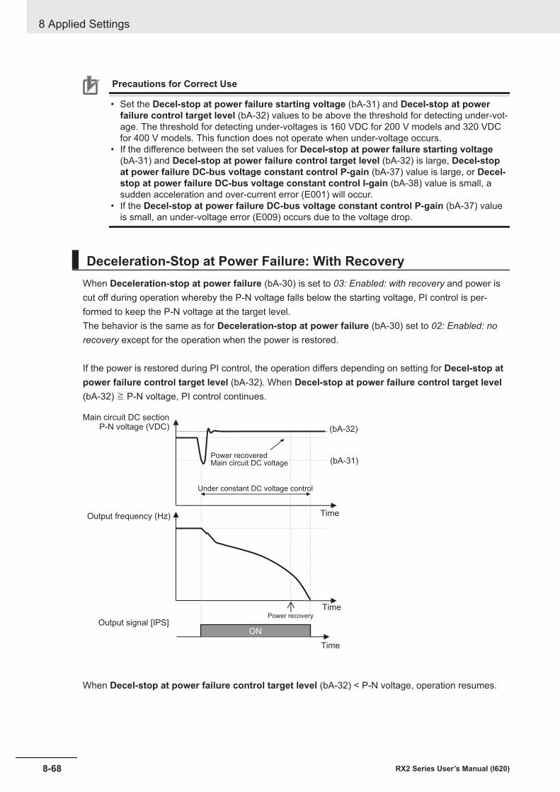
Precautions for Correct Use
• Set the Decel-stop at power failure starting voltage (bA-31) and Decel-stop at powerfailure control target level (bA-32) values to be above the threshold for detecting under-vot-age. The threshold for detecting under-voltages is 160 VDC for 200 V models and 320 VDCfor 400 V models. This function does not operate when under-voltage occurs.
• If the difference between the set values for Decel-stop at power failure starting voltage(bA-31) and Decel-stop at power failure control target level (bA-32) is large, Decel-stopat power failure DC-bus voltage constant control P-gain (bA-37) value is large, or Decel-stop at power failure DC-bus voltage constant control I-gain (bA-38) value is small, asudden acceleration and over-current error (E001) will occur.
• If the Decel-stop at power failure DC-bus voltage constant control P-gain (bA-37) valueis small, an under-voltage error (E009) occurs due to the voltage drop.
Deceleration-Stop at Power Failure: With RecoveryWhen Deceleration-stop at power failure (bA-30) is set to 03: Enabled: with recovery and power iscut off during operation whereby the P-N voltage falls below the starting voltage, PI control is per-formed to keep the P-N voltage at the target level.The behavior is the same as for Deceleration-stop at power failure (bA-30) set to 02: Enabled: norecovery except for the operation when the power is restored.
If the power is restored during PI control, the operation differs depending on setting for Decel-stop atpower failure control target level (bA-32). When Decel-stop at power failure control target level(bA-32) ≧ P-N voltage, PI control continues.
(bA-32)
(bA-31)
ON
Output frequency (Hz)
Output signal [IPS]
Under constant DC voltage control
Main circuit DC sectionP-N voltage (VDC)
Time
Time
Time
Power recoveredMain circuit DC voltage
Power recovery
When Decel-stop at power failure control target level (bA-32) < P-N voltage, operation resumes.
8 Applied Settings
8-68 RX2 Series User’s Manual (I620)
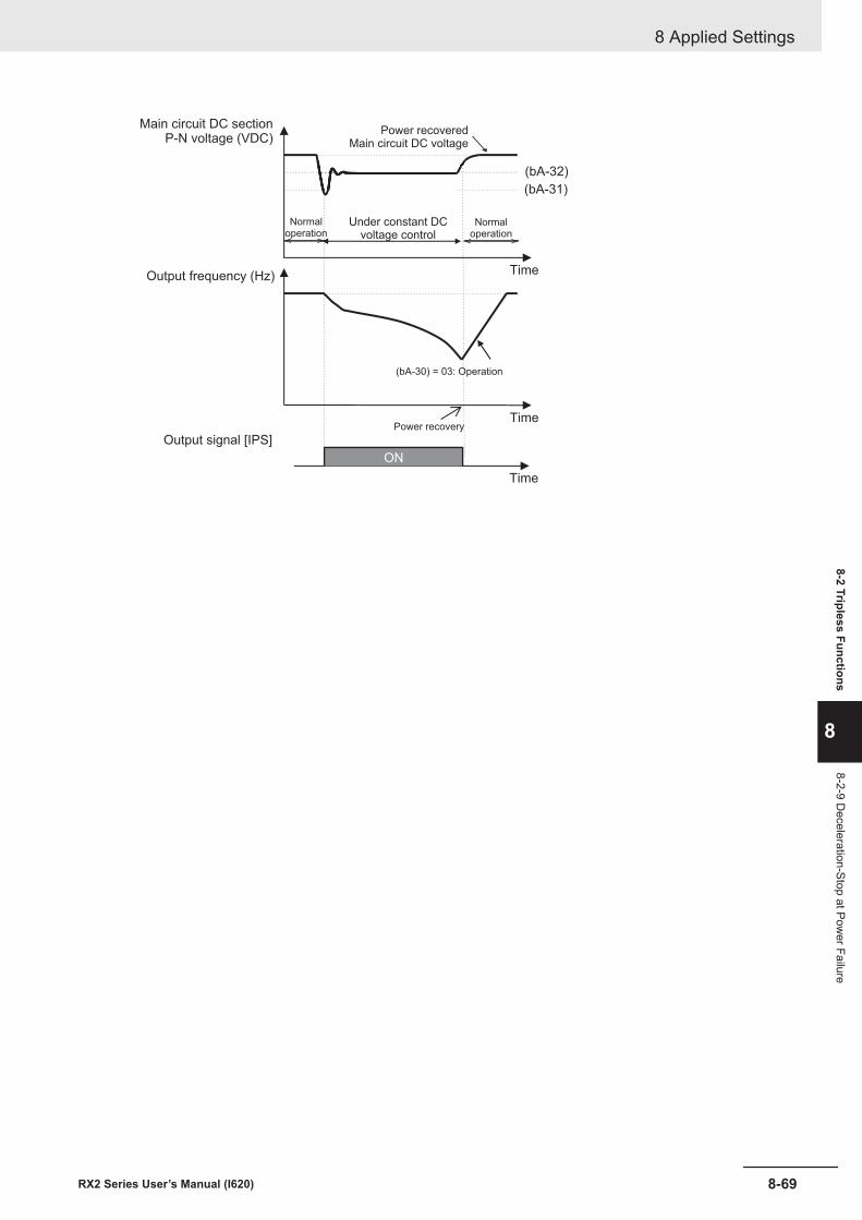
(bA-32)
(bA-31)
ON
Output frequency (Hz)
Output signal [IPS]
Under constant DCvoltage control
Main circuit DC sectionP-N voltage (VDC)
Time
Time
Time
Power recoveredMain circuit DC voltage
Power recovery
(bA-30) = 03: Operation
Normaloperation
Normaloperation
8 Applied Settings
8-69RX2 Series User’s Manual (I620)
8-2 Tripless Functions
8
8-2-9 Deceleration-Stop at Pow
er Failure
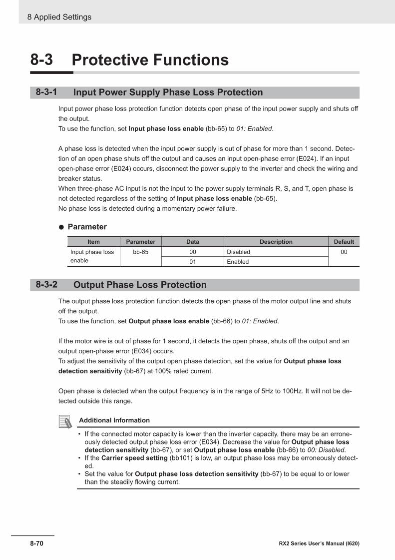
8-3 Protective Functions
8-3-1 Input Power Supply Phase Loss ProtectionInput power phase loss protection function detects open phase of the input power supply and shuts offthe output.To use the function, set Input phase loss enable (bb-65) to 01: Enabled.
A phase loss is detected when the input power supply is out of phase for more than 1 second. Detec-tion of an open phase shuts off the output and causes an input open-phase error (E024). If an inputopen-phase error (E024) occurs, disconnect the power supply to the inverter and check the wiring andbreaker status.When three-phase AC input is not the input to the power supply terminals R, S, and T, open phase isnot detected regardless of the setting of Input phase loss enable (bb-65).No phase loss is detected during a momentary power failure.
l Parameter
Item Parameter Data Description DefaultInput phase lossenable
bb-65 00 Disabled 0001 Enabled
8-3-2 Output Phase Loss ProtectionThe output phase loss protection function detects the open phase of the motor output line and shutsoff the output.To use the function, set Output phase loss enable (bb-66) to 01: Enabled.
If the motor wire is out of phase for 1 second, it detects the open phase, shuts off the output and anoutput open-phase error (E034) occurs.To adjust the sensitivity of the output open phase detection, set the value for Output phase lossdetection sensitivity (bb-67) at 100% rated current.
Open phase is detected when the output frequency is in the range of 5Hz to 100Hz. It will not be de-tected outside this range.
Additional Information
• If the connected motor capacity is lower than the inverter capacity, there may be an errone-ously detected output phase loss error (E034). Decrease the value for Output phase lossdetection sensitivity (bb-67), or set Output phase loss enable (bb-66) to 00: Disabled.
• If the Carrier speed setting (bb101) is low, an output phase loss may be erroneously detect-ed.
• Set the value for Output phase loss detection sensitivity (bb-67) to be equal to or lowerthan the steadily flowing current.
8 Applied Settings
8-70 RX2 Series User’s Manual (I620)
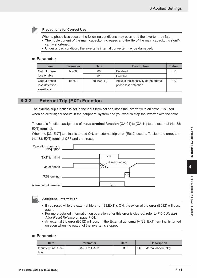
Precautions for Correct Use
When a phase loss occurs, the following conditions may occur and the inverter may fail.• The ripple current of the main capacitor increases and the life of the main capacitor is signifi-
cantly shortened.• Under a load condition, the inverter’s internal converter may be damaged.
l Parameter
Item Parameter Data Description DefaultOutput phaseloss enable
bb-66 00 Disabled 0001 Enabled
Output phaseloss detectionsensitivity
bb-67 1 to 100 (%) Adjusts the sensitivity of the outputphase loss detection.
10
8-3-3 External Trip (EXT) FunctionThe external trip function is set in the input terminal and stops the inverter with an error. It is usedwhen an error signal occurs in the peripheral system and you want to stop the inverter with the error.
To use this function, assign one of Input terminal function (CA-01) to (CA-11) to the external trip [33:EXT] terminal.When the [33: EXT] terminal is turned ON, an external trip error (E012) occurs. To clear the error, turnthe [33: EXT] terminal OFF and then reset.
ON
ON
ON[RS] terminal
[EXT] terminal
Motor speed
Operation command[FW] / [RV]
Alarm output terminal
Free-running
Additional Information
• If you reset while the external trip error [33:EXT]is ON, the external trip error (E012) will occuragain.
• For more detailed information on operation after this error is cleared, refer to 7-5-5 RestartAfter Reset Release on page 7-64.
• An external trip error (E012) will occur if the External abnormality [33: EXT] terminal is turnedon even when the output of the inverter is stopped.
l Parameter
Item Parameter Data DescriptionInput terminal func-tion
CA-01 to CA-11 033 EXT External abnormality
8 Applied Settings
8-71RX2 Series User’s Manual (I620)
8-3 Protective Functions
8
8-3-3 External Trip (EXT) Function
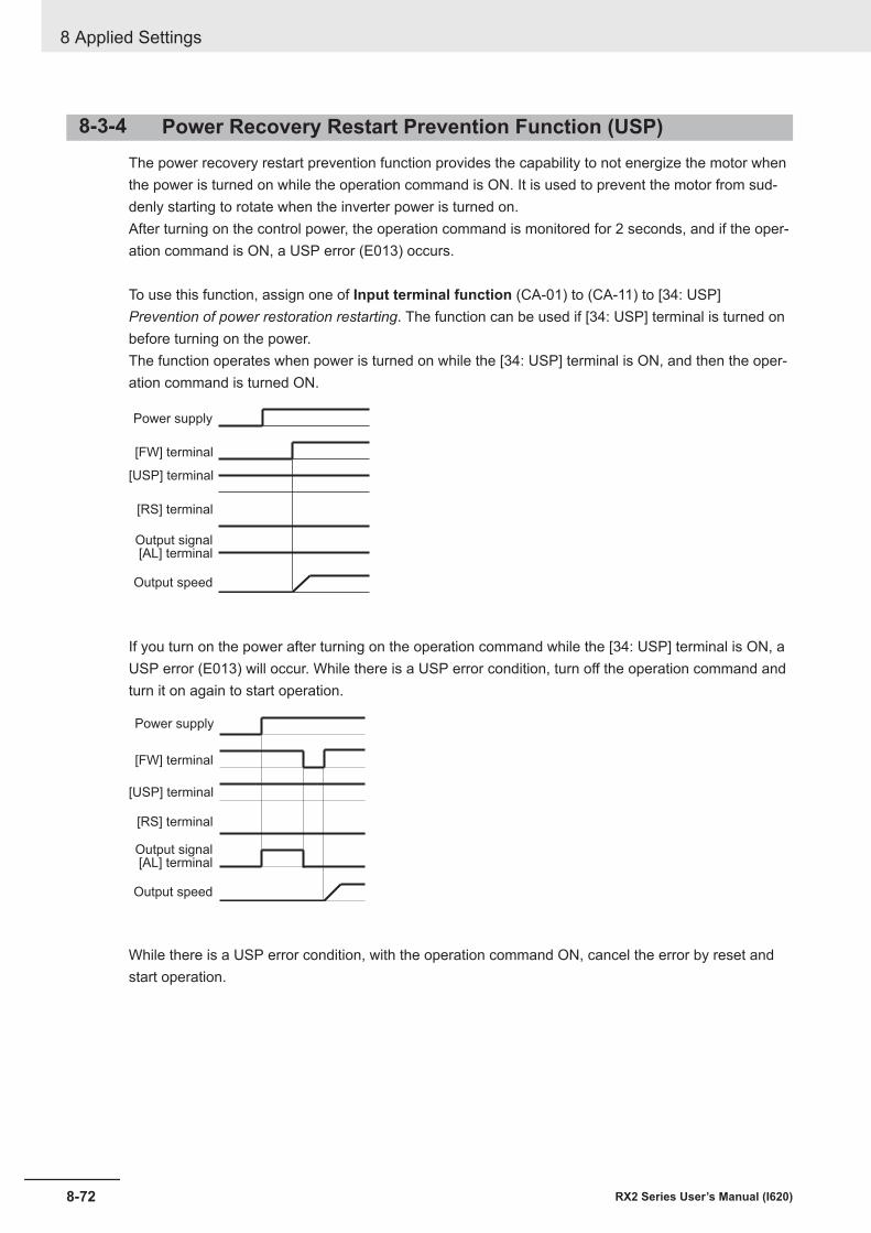
8-3-4 Power Recovery Restart Prevention Function (USP)The power recovery restart prevention function provides the capability to not energize the motor whenthe power is turned on while the operation command is ON. It is used to prevent the motor from sud-denly starting to rotate when the inverter power is turned on.After turning on the control power, the operation command is monitored for 2 seconds, and if the oper-ation command is ON, a USP error (E013) occurs.
To use this function, assign one of Input terminal function (CA-01) to (CA-11) to [34: USP]Prevention of power restoration restarting. The function can be used if [34: USP] terminal is turned onbefore turning on the power.The function operates when power is turned on while the [34: USP] terminal is ON, and then the oper-ation command is turned ON.
Power supply
[FW] terminal
[USP] terminal
[RS] terminal
Output signal[AL] terminal
Output speed
If you turn on the power after turning on the operation command while the [34: USP] terminal is ON, aUSP error (E013) will occur. While there is a USP error condition, turn off the operation command andturn it on again to start operation.
Power supply
[FW] terminal
[USP] terminal
[RS] terminal
Output signal[AL] terminal
Output speed
While there is a USP error condition, with the operation command ON, cancel the error by reset andstart operation.
8 Applied Settings
8-72 RX2 Series User’s Manual (I620)
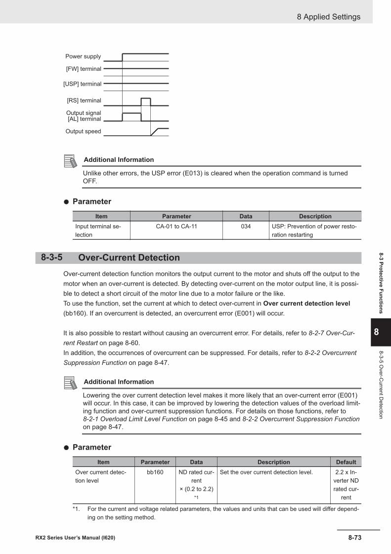
Power supply
[FW] terminal
[USP] terminal
[RS] terminal
Output signal[AL] terminal
Output speed
Additional Information
Unlike other errors, the USP error (E013) is cleared when the operation command is turnedOFF.
l Parameter
Item Parameter Data DescriptionInput terminal se-lection
CA-01 to CA-11 034 USP: Prevention of power resto-ration restarting
8-3-5 Over-Current DetectionOver-current detection function monitors the output current to the motor and shuts off the output to themotor when an over-current is detected. By detecting over-current on the motor output line, it is possi-ble to detect a short circuit of the motor line due to a motor failure or the like.To use the function, set the current at which to detect over-current in Over current detection level(bb160). If an overcurrent is detected, an overcurrent error (E001) will occur.
It is also possible to restart without causing an overcurrent error. For details, refer to 8-2-7 Over-Cur-rent Restart on page 8-60.In addition, the occurrences of overcurrent can be suppressed. For details, refer to 8-2-2 OvercurrentSuppression Function on page 8-47.
Additional Information
Lowering the over current detection level makes it more likely that an over-current error (E001)will occur. In this case, it can be improved by lowering the detection values of the overload limit-ing function and over-current suppression functions. For details on those functions, refer to 8-2-1 Overload Limit Level Function on page 8-45 and 8-2-2 Overcurrent Suppression Functionon page 8-47.
l Parameter
Item Parameter Data Description DefaultOver current detec-tion level
bb160 ND rated cur-rent
× (0.2 to 2.2)*1
Set the over current detection level. 2.2 x In-verter NDrated cur-
rent
*1. For the current and voltage related parameters, the values and units that can be used will differ depend-ing on the setting method.
8 Applied Settings
8-73RX2 Series User’s Manual (I620)
8-3 Protective Functions
8
8-3-5 Over-C
urrent Detection
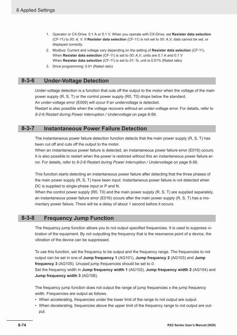
1. Operator or CX-Drive: 0.1 A or 0.1 V. When you operate with CX-Drive, set Resister data selection(CF-11) to 00: A, V. If Resister data selection (CF-11) is not set to 00: A,V, data cannot be set, ordisplayed correctly.
2. Modbus: Current and voltage vary depending on the setting of Resister data selection (CF-11).When Resister data selection (CF-11) is set to 00: A,V, units are 0.1 A and 0.1 VWhen Resister data selection (CF-11) is set to 01: %, unit is 0.01% (Rated ratio)
3. Drive programming: 0.01 (Rated ratio)
8-3-6 Under-Voltage DetectionUnder-voltage detection is a function that cuts off the output to the motor when the voltage of the mainpower supply (R, S, T) or the control power supply (R0, T0) drops below the standard.An under-voltage error (E009) will occur if an undervoltage is detected.Restart is also possible when the voltage recovers without an under-voltage error. For details, refer to 8-2-6 Restart during Power Interruption / Undervoltage on page 8-56.
8-3-7 Instantaneous Power Failure DetectionThe instantaneous power failure detection function detects that the main power supply (R, S, T) hasbeen cut off and cuts off the output to the motor.When an instantaneous power failure is detected, an instantaneous power failure error (E016) occurs.It is also possible to restart when the power is restored without this an instantaneous power failure er-ror. For details, refer to 8-2-6 Restart during Power Interruption / Undervoltage on page 8-56.
This function starts detecting an instantaneous power failure after detecting that the three phases ofthe main power supply (R, S, T) have been input. Instantaneous power failure is not detected whenDC is supplied to single-phase input or P and N.When the control power supply (R0, T0) and the main power supply (R, S, T) are supplied separately,an instantaneous power failure error (E016) occurs after the main power supply (R, S, T) has a mo-mentary power failure. There will be a delay of about 1 second before it occurs.
8-3-8 Frequency Jump FunctionThe frequency jump function allows you to not output specified frequencies. It is used to suppress vi-bration of the equipment. By not outputting the frequency that is the resonance point of a device, thevibration of the device can be suppressed.
To use this function, set the frequency to be output and the frequency range. The frequencies to notoutput can be set in one of Jump frequency 1 (AG101), Jump frequency 2 (AG103) and Jumpfrequency 3 (AG105). Unused jump frequencies should be set to 0.Set the frequency width in Jump frequency width 1 (AG102), Jump frequency width 2 (AG104) andJump frequency width 3 (AG106).
The frequency jump function does not output the range of jump frequencies ± the jump frequencywidth. Frequencies are output as follows.• When accelerating, frequencies under the lower limit of the range to not output are output.• When decelerating, frequencies above the upper limit of the frequency range to not output are out-
put.
8 Applied Settings
8-74 RX2 Series User’s Manual (I620)
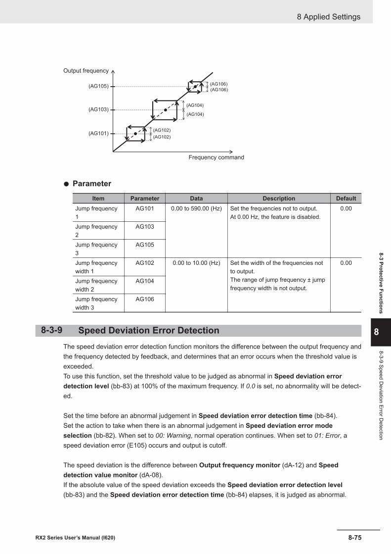
(AG101)
(AG103)
(AG105)
(AG102)
(AG102)
(AG106)
(AG106)
(AG104)
(AG104)
Frequency command
Output frequency
l Parameter
Item Parameter Data Description DefaultJump frequency1
AG101 0.00 to 590.00 (Hz) Set the frequencies not to output.At 0.00 Hz, the feature is disabled.
0.00
Jump frequency2
AG103
Jump frequency3
AG105
Jump frequencywidth 1
AG102 0.00 to 10.00 (Hz) Set the width of the frequencies notto output.The range of jump frequency ± jumpfrequency width is not output.
0.00
Jump frequencywidth 2
AG104
Jump frequencywidth 3
AG106
8-3-9 Speed Deviation Error DetectionThe speed deviation error detection function monitors the difference between the output frequency andthe frequency detected by feedback, and determines that an error occurs when the threshold value isexceeded.To use this function, set the threshold value to be judged as abnormal in Speed deviation errordetection level (bb-83) at 100% of the maximum frequency. If 0.0 is set, no abnormality will be detect-ed.
Set the time before an abnormal judgement in Speed deviation error detection time (bb-84).Set the action to take when there is an abnormal judgement in Speed deviation error modeselection (bb-82). When set to 00: Warning, normal operation continues. When set to 01: Error, aspeed deviation error (E105) occurs and output is cutoff.
The speed deviation is the difference between Output frequency monitor (dA-12) and Speeddetection value monitor (dA-08).If the absolute value of the speed deviation exceeds the Speed deviation error detection level(bb-83) and the Speed deviation error detection time (bb-84) elapses, it is judged as abnormal.
8 Applied Settings
8-75RX2 Series User’s Manual (I620)
8-3 Protective Functions
8
8-3-9 Speed Deviation Error D
etection
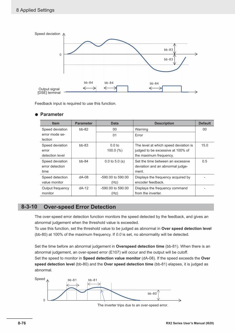
bb -83
0
bb -83
bb -84 bb -84 bb -84
Output signal[DSE] terminal
Speed deviation
Feedback input is required to use this function.
l Parameter
Item Parameter Data Description DefaultSpeed deviationerror mode se-lection
bb-82 00 Warning 0001 Error
Speed deviationerrordetection level
bb-83 0.0 to100.0 (%)
The level at which speed deviation isjudged to be excessive at 100% ofthe maximum frequency.
15.0
Speed deviationerror detectiontime
bb-84 0.0 to 5.0 (s) Set the time between an excessivedeviation and an abnormal judge-ment.
0.5
Speed detectionvalue monitor
dA-08 -590.00 to 590.00(Hz)
Displays the frequency acquired byencoder feedback.
-
Output frequencymonitor
dA-12 -590.00 to 590.00(Hz)
Displays the frequency commandfrom the inverter.
-
8-3-10 Over-speed Error DetectionThe over-speed error detection function monitors the speed detected by the feedback, and gives anabnormal judgement when the threshold value is exceeded.To use this function, set the threshold value to be judged as abnormal in Over speed detection level(bb-80) at 100% of the maximum frequency. If 0.0 is set, no abnormality will be detected.
Set the time before an abnormal judgement in Overspeed detection time (bb-81). When there is anabnormal judgement, an over-speed error (E107) will occur and the output will be cutoff.Set the speed to monitor in Speed detection value monitor (dA-08). If the speed exceeds the Overspeed detection level (bb-80) and the Over speed detection time (bb-81) elapses, it is judged asabnormal.
bb -80
0
bb -81 bb -81
The inverter trips due to an over-speed error.
Speed
8 Applied Settings
8-76 RX2 Series User’s Manual (I620)
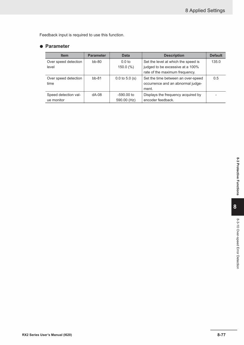
Feedback input is required to use this function.
l Parameter
Item Parameter Data Description DefaultOver speed detectionlevel
bb-80 0.0 to150.0 (%)
Set the level at which the speed isjudged to be excessive at a 100%rate of the maximum frequency.
135.0
Over speed detectiontime
bb-81 0.0 to 5.0 (s) Set the time between an over-speedoccurrence and an abnormal judge-ment.
0.5
Speed detection val-ue monitor
dA-08 -590.00 to590.00 (Hz)
Displays the frequency acquired byencoder feedback.
-
8 Applied Settings
8-77RX2 Series User’s Manual (I620)
8-3 Protective Functions
8
8-3-10 Over-speed Error D
etection
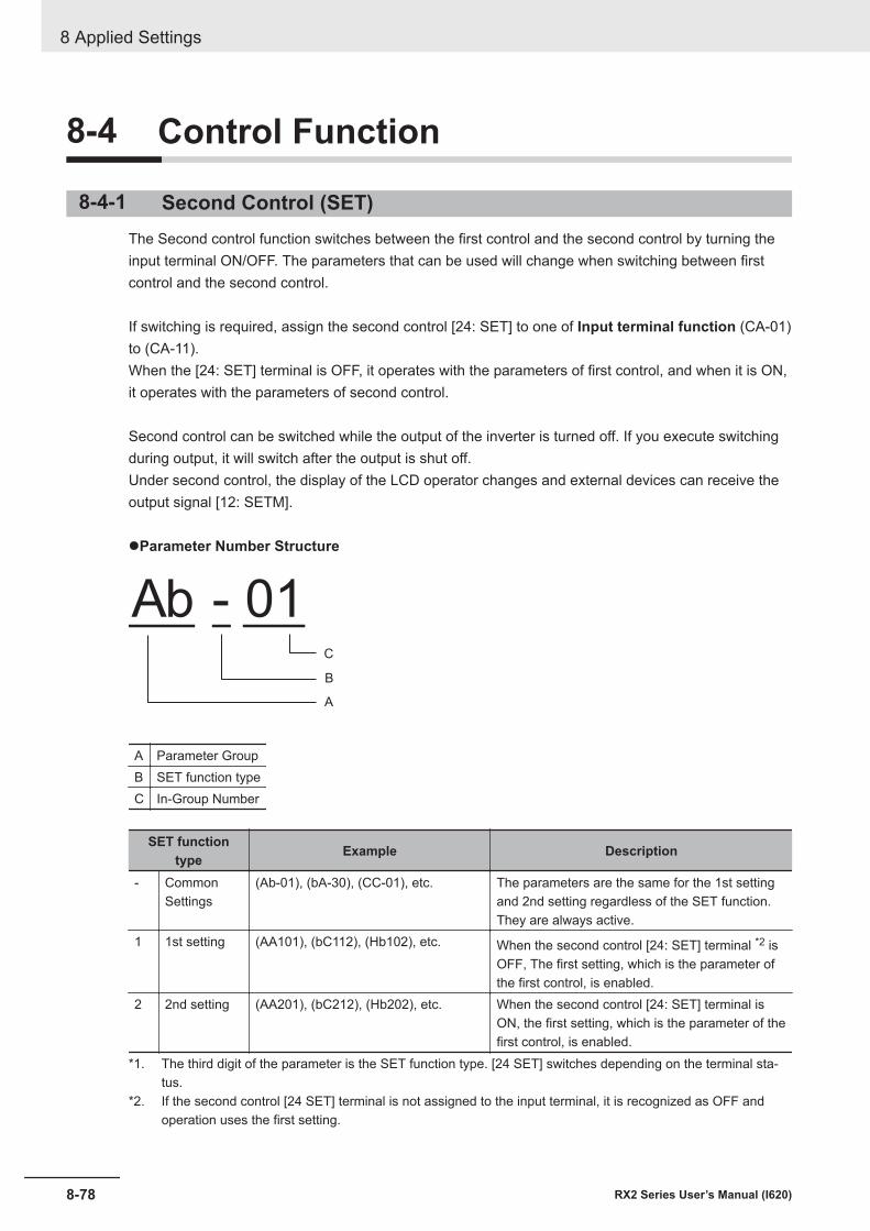
8-4 Control Function
8-4-1 Second Control (SET)The Second control function switches between the first control and the second control by turning theinput terminal ON/OFF. The parameters that can be used will change when switching between firstcontrol and the second control.
If switching is required, assign the second control [24: SET] to one of Input terminal function (CA-01)to (CA-11).When the [24: SET] terminal is OFF, it operates with the parameters of first control, and when it is ON,it operates with the parameters of second control.
Second control can be switched while the output of the inverter is turned off. If you execute switchingduring output, it will switch after the output is shut off.Under second control, the display of the LCD operator changes and external devices can receive theoutput signal [12: SETM].
lParameter Number Structure
Ab - 01
A
B
C
A Parameter GroupB SET function typeC In-Group Number
SET functiontype Example Description
- CommonSettings
(Ab-01), (bA-30), (CC-01), etc. The parameters are the same for the 1st settingand 2nd setting regardless of the SET function.They are always active.
1 1st setting (AA101), (bC112), (Hb102), etc. When the second control [24: SET] terminal *2 isOFF, The first setting, which is the parameter ofthe first control, is enabled.
2 2nd setting (AA201), (bC212), (Hb202), etc. When the second control [24: SET] terminal isON, the first setting, which is the parameter of thefirst control, is enabled.
*1. The third digit of the parameter is the SET function type. [24 SET] switches depending on the terminal sta-tus.
*2. If the second control [24 SET] terminal is not assigned to the input terminal, it is recognized as OFF andoperation uses the first setting.
8 Applied Settings
8-78 RX2 Series User’s Manual (I620)
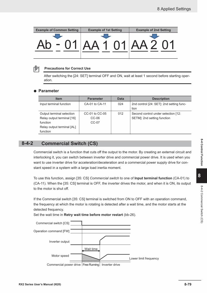
Example of Common Setting Example of 1st Setting Example of 2nd Setting
Ab - 01 AA 1 01 AA 2 01
Precautions for Correct Use
After switching the [24: SET] terminal OFF and ON, wait at least 1 second before starting oper-ation.
l Parameter
Item Parameter Data DescriptionInput terminal function CA-01 to CA-11 024 2nd control [24: SET]: 2nd setting func-
tionOutput terminal selectionRelay output terminal [16]functionRelay output terminal [AL]function
CC-01 to CC-05CC-06CC-07
012 Second control under selection [12:SETM]: 2nd setting function
8-4-2 Commercial Switch (CS)Commercial switch is a function that cuts off the output to the motor. By creating an external circuit andinterlocking it, you can switch between inverter drive and commercial power drive. It is used when youwant to use inverter drive for acceleration/deceleration and a commercial power supply drive for con-stant speed in a system with a large load inertia moment.
To use this function, assign [35: CS] Commercial switch to one of Input terminal function (CA-01) to(CA-11). When the [35: CS] terminal is OFF, the inverter drives the motor, and when it is ON, its outputto the motor is shut off.
If the Commercial switch [35: CS] terminal is switched from ON to OFF with an operation command,the frequency at which the motor is rotating is detected after a wait time, and the motor starts at thedetected frequency.Set the wait time in Retry wait time before motor restart (bb-26).
Wait time
Commercial switch [CS]
Operation command [FW]
Inverter output
Motor speedLower limit frequency
Inverter driveFree RunningCommercial power drive
8 Applied Settings
8-79RX2 Series User’s Manual (I620)
8-4 Control Function
8
8-4-2 Com
mercial Sw
itch (CS)
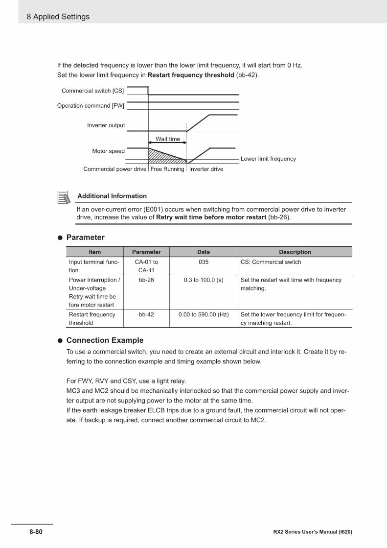
If the detected frequency is lower than the lower limit frequency, it will start from 0 Hz.Set the lower limit frequency in Restart frequency threshold (bb-42).
Wait time
Commercial switch [CS]
Operation command [FW]
Inverter output
Motor speed
Lower limit frequency
Inverter driveFree RunningCommercial power drive
Additional Information
If an over-current error (E001) occurs when switching from commercial power drive to inverterdrive, increase the value of Retry wait time before motor restart (bb-26).
l Parameter
Item Parameter Data DescriptionInput terminal func-tion
CA-01 toCA-11
035 CS: Commercial switch
Power Interruption /Under-voltageRetry wait time be-fore motor restart
bb-26 0.3 to 100.0 (s) Set the restart wait time with frequencymatching.
Restart frequencythreshold
bb-42 0.00 to 590.00 (Hz) Set the lower frequency limit for frequen-cy matching restart.
l Connection ExampleTo use a commercial switch, you need to create an external circuit and interlock it. Create it by re-ferring to the connection example and timing example shown below.
For FWY, RVY and CSY, use a light relay.MC3 and MC2 should be mechanically interlocked so that the commercial power supply and inver-ter output are not supplying power to the motor at the same time.If the earth leakage breaker ELCB trips due to a ground fault, the commercial circuit will not oper-ate. If backup is required, connect another commercial circuit to MC2.
8 Applied Settings
8-80 RX2 Series User’s Manual (I620)
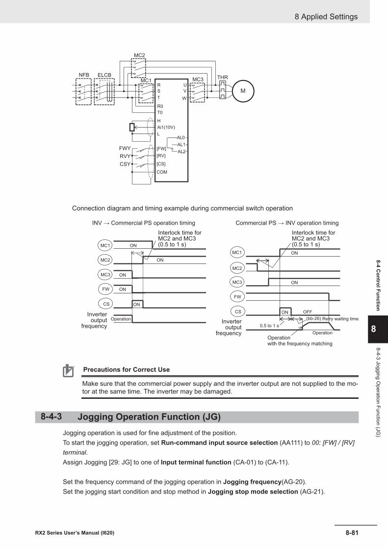
M
R
S
T
U
V
W
Ai1(10V)
L
[FW]
[RV]
[CS]
COM
AL1
AL0
AL2
THRMC1 MC3
ELCB
FWY
RVY
CSY
MC2
H
R0
T0
NFB
Connection diagram and timing example during commercial switch operation
INV → Commercial PS operation timing Commercial PS → INV operation timing
ON
ON
MC1
MC2
MC3
FW
CS ON
ON
ON
Interlock time forMC2 and MC3(0.5 to 1 s)
OperationInverter
outputfrequency 0.5 to 1 s
MC1
MC2
MC3
FW
CS
ON
ON
ON OFF
(bb-26)
Interlock time forMC2 and MC3(0.5 to 1 s)
Operation
Inverteroutput
frequency
Retry waiting time
Operationwith the frequency matching
Precautions for Correct Use
Make sure that the commercial power supply and the inverter output are not supplied to the mo-tor at the same time. The inverter may be damaged.
8-4-3 Jogging Operation Function (JG)Jogging operation is used for fine adjustment of the position.To start the jogging operation, set Run-command input source selection (AA111) to 00: [FW] / [RV]terminal.Assign Jogging [29: JG] to one of Input terminal function (CA-01) to (CA-11).
Set the frequency command of the jogging operation in Jogging frequency(AG-20).Set the jogging start condition and stop method in Jogging stop mode selection (AG-21).
8 Applied Settings
8-81RX2 Series User’s Manual (I620)
8-4 Control Function
8
8-4-3 Jogging Operation Function (JG
)
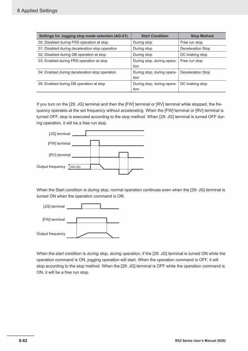
Settings for Jogging stop mode selection (AG-21). Start Condition Stop Method00: Disabled during FRS operation at stop During stop Free run stop01: Disabled during deceleration stop operation During stop Deceleration Stop02: Disabled during DB operation at stop During stop DC braking stop03: Enabled during FRS operation at stop During stop, during opera-
tionFree run stop
04: Enabled during deceleration stop operation During stop, during opera-tion
Deceleration Stop
05: Enabled during DB operation at stop During stop, during opera-tion
DC braking stop
If you turn on the [29: JG] terminal and then the [FW] terminal or [RV] terminal while stopped, the fre-quency operates at the set frequency without accelerating. When the [FW] terminal or [RV] terminal isturned OFF, stop is executed according to the stop method. When [29: JG] terminal is turned OFF dur-ing operation, it will be a free run stop.
(AG-20)
[JG] terminal
[FW] terminal
[RV] terminal
Output frequency
When the Start condition is during stop, normal operation continues even when the [29: JG] terminal isturned ON when the operation command is ON.
[JG] terminal
[FW] terminal
Output frequency
When the start condition is during stop, during operation, if the [29: JG] terminal is turned ON while theoperation command is ON, jogging operation will start. When the operation command is OFF, it willstop according to the stop method. When the [29: JG] terminal is OFF while the operation command isON, it will be a free run stop.
8 Applied Settings
8-82 RX2 Series User’s Manual (I620)
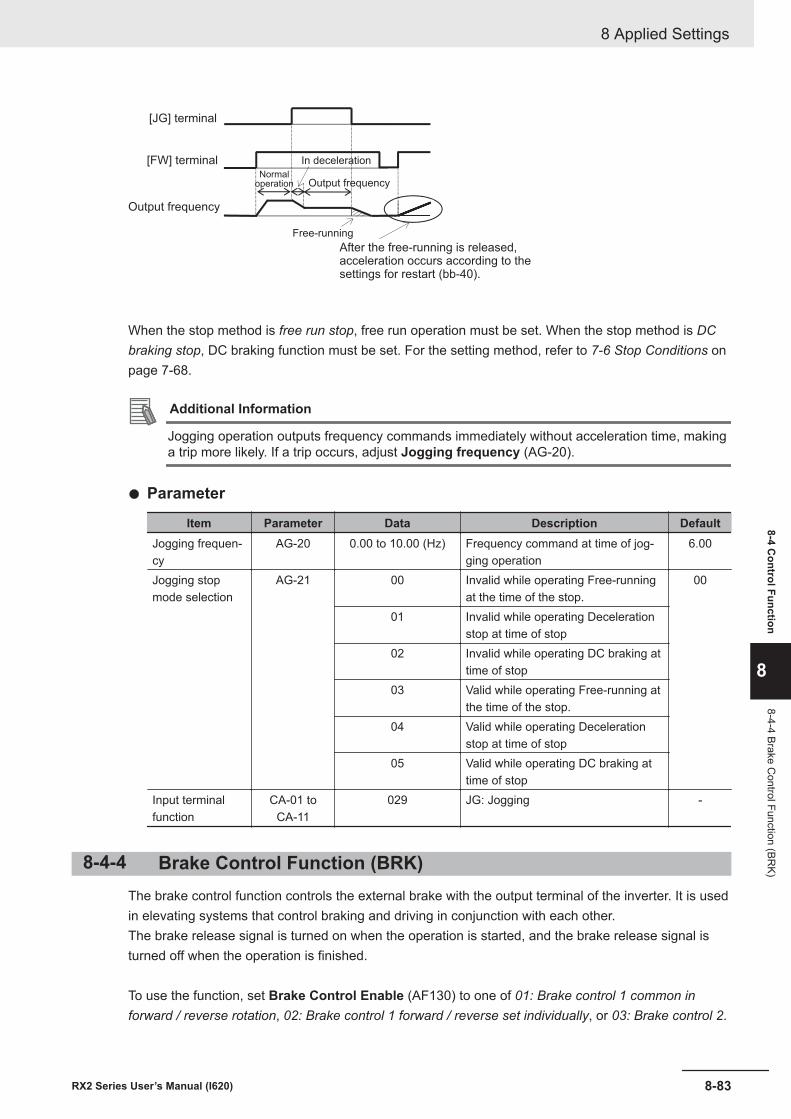
[JG] terminal
[FW] terminal
Output frequency
In deceleration
Output frequency
Free-running
After the free-running is released, acceleration occurs according to thesettings for restart (bb-40).
Normaloperation
When the stop method is free run stop, free run operation must be set. When the stop method is DCbraking stop, DC braking function must be set. For the setting method, refer to 7-6 Stop Conditions onpage 7-68.
Additional Information
Jogging operation outputs frequency commands immediately without acceleration time, makinga trip more likely. If a trip occurs, adjust Jogging frequency (AG-20).
l Parameter
Item Parameter Data Description DefaultJogging frequen-cy
AG-20 0.00 to 10.00 (Hz) Frequency command at time of jog-ging operation
6.00
Jogging stopmode selection
AG-21 00 Invalid while operating Free-runningat the time of the stop.
00
01 Invalid while operating Decelerationstop at time of stop
02 Invalid while operating DC braking attime of stop
03 Valid while operating Free-running atthe time of the stop.
04 Valid while operating Decelerationstop at time of stop
05 Valid while operating DC braking attime of stop
Input terminalfunction
CA-01 toCA-11
029 JG: Jogging -
8-4-4 Brake Control Function (BRK)The brake control function controls the external brake with the output terminal of the inverter. It is usedin elevating systems that control braking and driving in conjunction with each other.The brake release signal is turned on when the operation is started, and the brake release signal isturned off when the operation is finished.
To use the function, set Brake Control Enable (AF130) to one of 01: Brake control 1 common inforward / reverse rotation, 02: Brake control 1 forward / reverse set individually, or 03: Brake control 2.
8 Applied Settings
8-83RX2 Series User’s Manual (I620)
8-4 Control Function
8
8-4-4 Brake Control Function (BR
K)
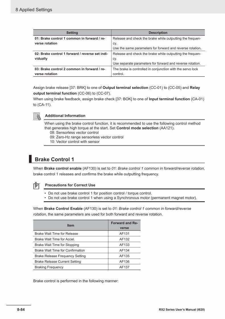
Setting Description01: Brake control 1 common in forward / re-verse rotation
Release and check the brake while outputting the frequen-cy.Use the same parameters for forward and reverse rotation.
02: Brake control 1 forward / reverse set indi-vidually
Release and check the brake while outputting the frequen-cy.Use separate parameters for forward and reverse rotation.
03: Brake control 2 common in forward / re-verse rotation
The brake is controlled in conjunction with the servo lockcontrol.
Assign brake release [37: BRK] to one of Output terminal selection (CC-01) to (CC-05) and Relayoutput terminal function (CC-06) to (CC-07).When using brake feedback, assign brake check [37: BOK] to one of Input terminal function (CA-01)to (CA-11).
Additional Information
When using the brake control function, it is recommended to use the following control methodthat generates high torque at the start. Set Control mode selection (AA121).
08: Sensorless vector control09: Zero-Hz range sensorless vector control10: Vector control with sensor
Brake Control 1 When Brake control enable (AF130) is set to 01: Brake control 1 common in forward/reverse rotation,brake control 1 releases and confirms the brake while outputting frequency.
Precautions for Correct Use
• Do not use brake control 1 for position control / torque control.• Do not use brake control 1 when using a Synchronous motor (permanent magnet motor).
When Brake Control Enable (AF130) is set to 01: Brake control 1 common in forward/reverserotation, the same parameters are used for both forward and reverse rotation.
Item Forward and Re-verse
Brake Wait Time for Release AF131Brake Wait Time for Accel. AF132Brake Wait Time for Stopping AF133Brake Wait Time for Confirmation AF134Brake Release Frequency Setting AF135Brake Release Current Setting AF136Braking Frequency AF137
Brake control is performed in the following manner:
8 Applied Settings
8-84 RX2 Series User’s Manual (I620)
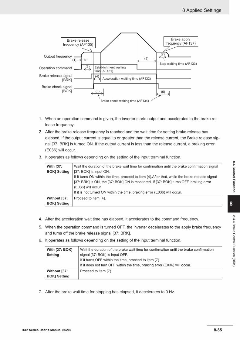
[BRK]
[BOK]
(2)
(3)
(4)
(6)
(7)
(1) (5)
Brake applyfrequency (AF137)
Brake releasefrequency (AF135)
Output frequency
Operation command
Brake release signal
Brake check signal
Establishment waitingtime (AF131)
Acceleration waiting time (AF132)
Brake check waiting time (AF134)
Stop waiting time (AF133)
1. When an operation command is given, the inverter starts output and accelerates to the brake re-lease frequency.
2. After the brake release frequency is reached and the wait time for setting brake release haselapsed, if the output current is equal to or greater than the release current, the Brake release sig-nal [37: BRK] is turned ON. If the output current is less than the release current, a braking error(E036) will occur.
3. It operates as follows depending on the setting of the input terminal function.
With [37:BOK] Setting
Wait the duration of the brake wait time for confirmation until the brake confirmation signal[37: BOK] is input ON.If it turns ON within the time, proceed to item (4).After that, while the brake release signal[37: BRK] is ON, the [37: BOK] ON is monitored. If [37: BOK] turns OFF, braking error(E036) will occur.If it is not turned ON within the time, braking error (E036) will occur.
Without [37:BOK] Setting
Proceed to item (4).
4. After the acceleration wait time has elapsed, it accelerates to the command frequency.
5. When the operation command is turned OFF, the inverter decelerates to the apply brake frequencyand turns off the brake release signal [37: BRK].
6. It operates as follows depending on the setting of the input terminal function.
With [37: BOK]Setting
Wait the duration of the brake wait time for confirmation until the brake confirmationsignal [37: BOK] is input OFF.If it turns OFF within the time, proceed to item (7).If it does not turn OFF within the time, braking error (E036) will occur.
Without [37:BOK] Setting
Proceed to item (7).
7. After the brake wait time for stopping has elapsed, it decelerates to 0 Hz.
8 Applied Settings
8-85RX2 Series User’s Manual (I620)
8-4 Control Function
8
8-4-4 Brake Control Function (BR
K)
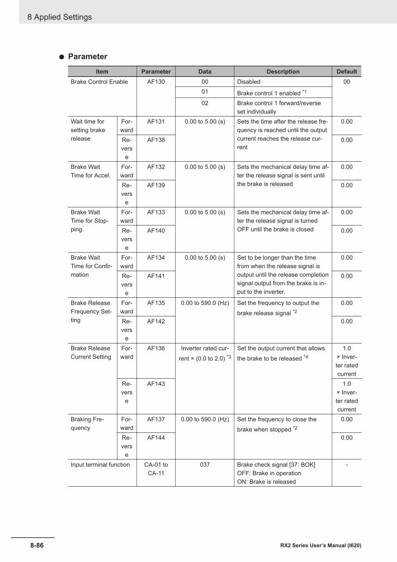
l Parameter
Item Parameter Data Description DefaultBrake Control Enable AF130 00 Disabled 00
01 Brake control 1 enabled *1
02 Brake control 1 forward/reverseset individually
Wait time forsetting brakerelease
For-ward
AF131 0.00 to 5.00 (s) Sets the time after the release fre-quency is reached until the outputcurrent reaches the release cur-rent
0.00
Re-vers
e
AF138 0.00
Brake WaitTime for Accel.
For-ward
AF132 0.00 to 5.00 (s) Sets the mechanical delay time af-ter the release signal is sent untilthe brake is released
0.00
Re-vers
e
AF139 0.00
Brake WaitTime for Stop-ping
For-ward
AF133 0.00 to 5.00 (s) Sets the mechanical delay time af-ter the release signal is turnedOFF until the brake is closed
0.00
Re-vers
e
AF140 0.00
Brake WaitTime for Confir-mation
For-ward
AF134 0.00 to 5.00 (s) Set to be longer than the timefrom when the release signal isoutput until the release completionsignal output from the brake is in-put to the inverter.
0.00
Re-vers
e
AF141 0.00
Brake ReleaseFrequency Set-ting
For-ward
AF135 0.00 to 590.0 (Hz) Set the frequency to output thebrake release signal *2
0.00
Re-vers
e
AF142 0.00
Brake ReleaseCurrent Setting
For-ward
AF136 Inverter rated cur-rent × (0.0 to 2.0) *3
Set the output current that allowsthe brake to be released *4
1.0× Inver-ter ratedcurrent
Re-vers
e
AF143 1.0× Inver-ter ratedcurrent
Braking Fre-quency
For-ward
AF137 0.00 to 590.0 (Hz) Set the frequency to close thebrake when stopped *2
0.00
Re-vers
e
AF144 0.00
Input terminal function CA-01 toCA-11
037 Brake check signal [37: BOK]OFF: Brake in operationON: Brake is released
-
8 Applied Settings
8-86 RX2 Series User’s Manual (I620)
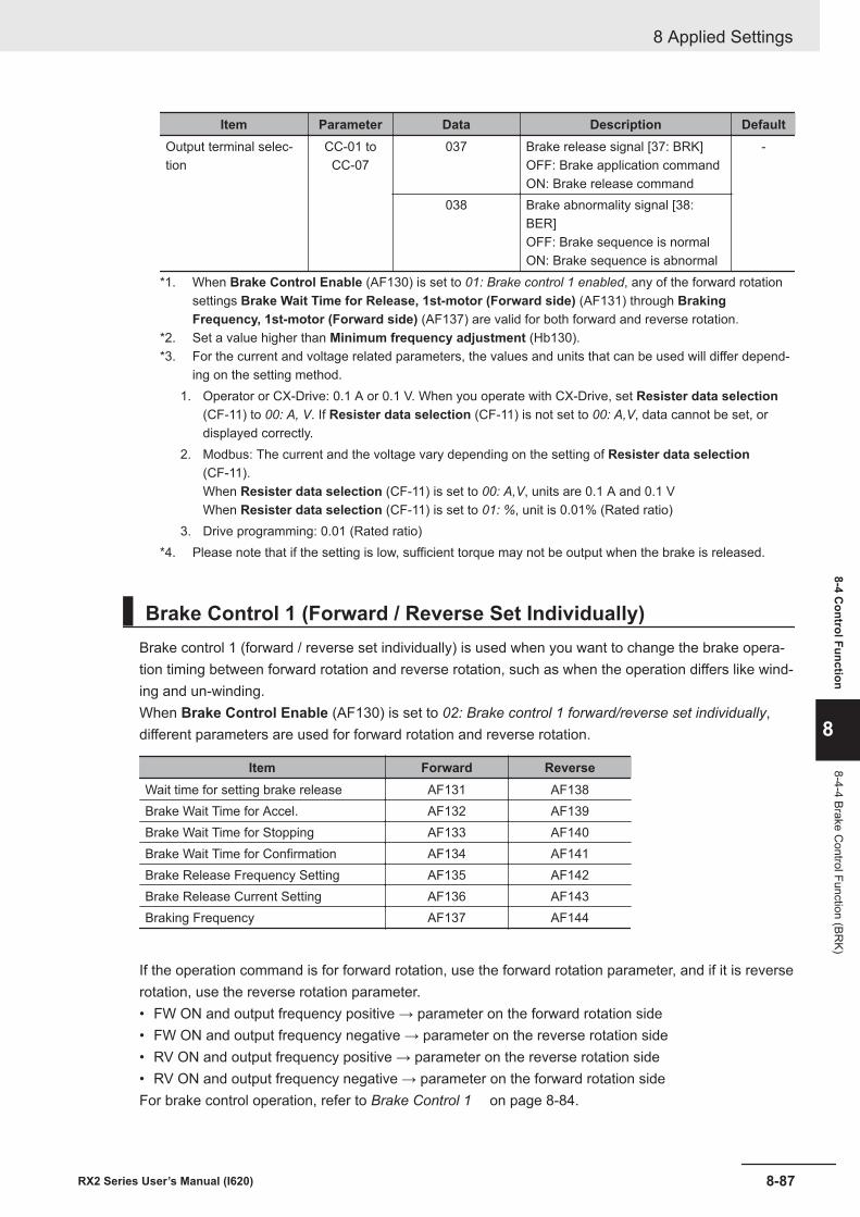
Item Parameter Data Description DefaultOutput terminal selec-tion
CC-01 toCC-07
037 Brake release signal [37: BRK]OFF: Brake application commandON: Brake release command
-
038 Brake abnormality signal [38:BER]OFF: Brake sequence is normalON: Brake sequence is abnormal
*1. When Brake Control Enable (AF130) is set to 01: Brake control 1 enabled, any of the forward rotationsettings Brake Wait Time for Release, 1st-motor (Forward side) (AF131) through BrakingFrequency, 1st-motor (Forward side) (AF137) are valid for both forward and reverse rotation.
*2. Set a value higher than Minimum frequency adjustment (Hb130).*3. For the current and voltage related parameters, the values and units that can be used will differ depend-
ing on the setting method.1. Operator or CX-Drive: 0.1 A or 0.1 V. When you operate with CX-Drive, set Resister data selection
(CF-11) to 00: A, V. If Resister data selection (CF-11) is not set to 00: A,V, data cannot be set, ordisplayed correctly.
2. Modbus: The current and the voltage vary depending on the setting of Resister data selection(CF-11).When Resister data selection (CF-11) is set to 00: A,V, units are 0.1 A and 0.1 VWhen Resister data selection (CF-11) is set to 01: %, unit is 0.01% (Rated ratio)
3. Drive programming: 0.01 (Rated ratio)*4. Please note that if the setting is low, sufficient torque may not be output when the brake is released.
Brake Control 1 (Forward / Reverse Set Individually)Brake control 1 (forward / reverse set individually) is used when you want to change the brake opera-tion timing between forward rotation and reverse rotation, such as when the operation differs like wind-ing and un-winding.When Brake Control Enable (AF130) is set to 02: Brake control 1 forward/reverse set individually,different parameters are used for forward rotation and reverse rotation.
Item Forward ReverseWait time for setting brake release AF131 AF138Brake Wait Time for Accel. AF132 AF139Brake Wait Time for Stopping AF133 AF140Brake Wait Time for Confirmation AF134 AF141Brake Release Frequency Setting AF135 AF142Brake Release Current Setting AF136 AF143Braking Frequency AF137 AF144
If the operation command is for forward rotation, use the forward rotation parameter, and if it is reverserotation, use the reverse rotation parameter.• FW ON and output frequency positive → parameter on the forward rotation side• FW ON and output frequency negative → parameter on the reverse rotation side• RV ON and output frequency positive → parameter on the reverse rotation side• RV ON and output frequency negative → parameter on the forward rotation sideFor brake control operation, refer to Brake Control 1 on page 8-84.
8 Applied Settings
8-87RX2 Series User’s Manual (I620)
8-4 Control Function
8
8-4-4 Brake Control Function (BR
K)
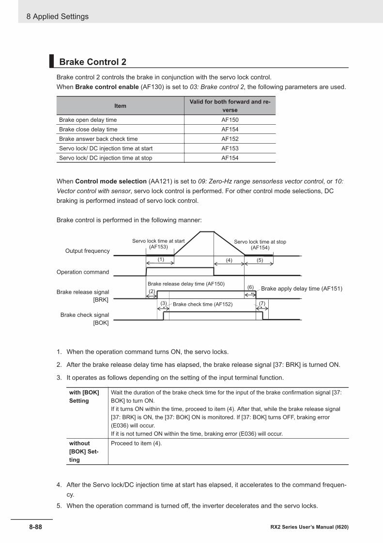
Brake Control 2Brake control 2 controls the brake in conjunction with the servo lock control.When Brake control enable (AF130) is set to 03: Brake control 2, the following parameters are used.
Item Valid for both forward and re-verse
Brake open delay time AF150Brake close delay time AF154Brake answer back check time AF152Servo lock/ DC injection time at start AF153Servo lock/ DC injection time at stop AF154
When Control mode selection (AA121) is set to 09: Zero-Hz range sensorless vector control, or 10:Vector control with sensor, servo lock control is performed. For other control mode selections, DCbraking is performed instead of servo lock control.
Brake control is performed in the following manner:
(1)
(6)
(7)
(4)
[BRK]
[BOK]
(2)
(3)
(5)
Servo lock time at stop(AF154)
Servo lock time at start(AF153)
Output frequency
Operation command
Brake release signal
Brake check signal
Brake release delay time (AF150)
Brake check time (AF152)
Brake apply delay time (AF151)
1. When the operation command turns ON, the servo locks.
2. After the brake release delay time has elapsed, the brake release signal [37: BRK] is turned ON.
3. It operates as follows depending on the setting of the input terminal function.
with [BOK]Setting
Wait the duration of the brake check time for the input of the brake confirmation signal [37:BOK] to turn ON.If it turns ON within the time, proceed to item (4). After that, while the brake release signal[37: BRK] is ON, the [37: BOK] ON is monitored. If [37: BOK] turns OFF, braking error(E036) will occur.If it is not turned ON within the time, braking error (E036) will occur.
without[BOK] Set-ting
Proceed to item (4).
4. After the Servo lock/DC injection time at start has elapsed, it accelerates to the command frequen-cy.
5. When the operation command is turned off, the inverter decelerates and the servo locks.
8 Applied Settings
8-88 RX2 Series User’s Manual (I620)
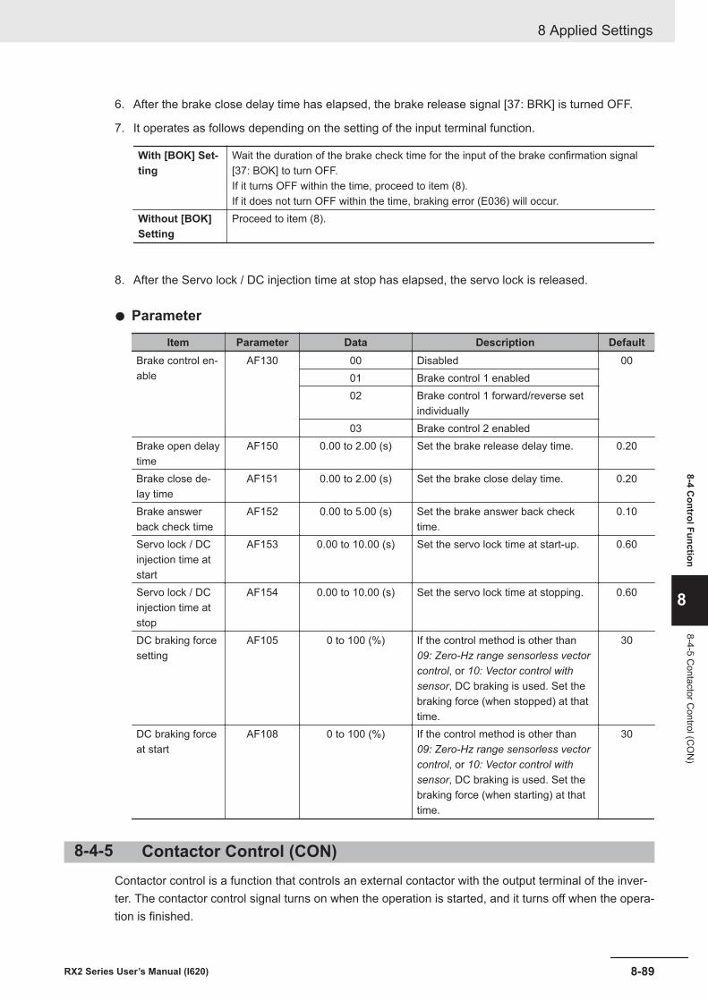
6. After the brake close delay time has elapsed, the brake release signal [37: BRK] is turned OFF.
7. It operates as follows depending on the setting of the input terminal function.
With [BOK] Set-ting
Wait the duration of the brake check time for the input of the brake confirmation signal[37: BOK] to turn OFF.If it turns OFF within the time, proceed to item (8).If it does not turn OFF within the time, braking error (E036) will occur.
Without [BOK]Setting
Proceed to item (8).
8. After the Servo lock / DC injection time at stop has elapsed, the servo lock is released.
l Parameter
Item Parameter Data Description DefaultBrake control en-able
AF130 00 Disabled 0001 Brake control 1 enabled02 Brake control 1 forward/reverse set
individually03 Brake control 2 enabled
Brake open delaytime
AF150 0.00 to 2.00 (s) Set the brake release delay time. 0.20
Brake close de-lay time
AF151 0.00 to 2.00 (s) Set the brake close delay time. 0.20
Brake answerback check time
AF152 0.00 to 5.00 (s) Set the brake answer back checktime.
0.10
Servo lock / DCinjection time atstart
AF153 0.00 to 10.00 (s) Set the servo lock time at start-up. 0.60
Servo lock / DCinjection time atstop
AF154 0.00 to 10.00 (s) Set the servo lock time at stopping. 0.60
DC braking forcesetting
AF105 0 to 100 (%) If the control method is other than09: Zero-Hz range sensorless vectorcontrol, or 10: Vector control withsensor, DC braking is used. Set thebraking force (when stopped) at thattime.
30
DC braking forceat start
AF108 0 to 100 (%) If the control method is other than09: Zero-Hz range sensorless vectorcontrol, or 10: Vector control withsensor, DC braking is used. Set thebraking force (when starting) at thattime.
30
8-4-5 Contactor Control (CON)Contactor control is a function that controls an external contactor with the output terminal of the inver-ter. The contactor control signal turns on when the operation is started, and it turns off when the opera-tion is finished.
8 Applied Settings
8-89RX2 Series User’s Manual (I620)
8-4 Control Function
8
8-4-5 Contactor C
ontrol (CO
N)
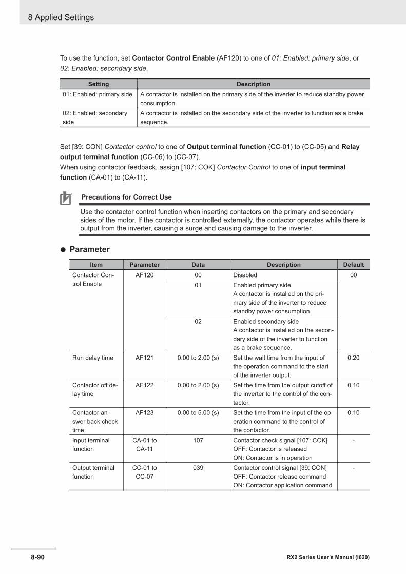
To use the function, set Contactor Control Enable (AF120) to one of 01: Enabled: primary side, or02: Enabled: secondary side.
Setting Description01: Enabled: primary side A contactor is installed on the primary side of the inverter to reduce standby power
consumption.02: Enabled: secondaryside
A contactor is installed on the secondary side of the inverter to function as a brakesequence.
Set [39: CON] Contactor control to one of Output terminal function (CC-01) to (CC-05) and Relayoutput terminal function (CC-06) to (CC-07).When using contactor feedback, assign [107: COK] Contactor Control to one of input terminalfunction (CA-01) to (CA-11).
Precautions for Correct Use
Use the contactor control function when inserting contactors on the primary and secondarysides of the motor. If the contactor is controlled externally, the contactor operates while there isoutput from the inverter, causing a surge and causing damage to the inverter.
l Parameter
Item Parameter Data Description DefaultContactor Con-trol Enable
AF120 00 Disabled 0001 Enabled primary side
A contactor is installed on the pri-mary side of the inverter to reducestandby power consumption.
02 Enabled secondary sideA contactor is installed on the secon-dary side of the inverter to functionas a brake sequence.
Run delay time AF121 0.00 to 2.00 (s) Set the wait time from the input ofthe operation command to the startof the inverter output.
0.20
Contactor off de-lay time
AF122 0.00 to 2.00 (s) Set the time from the output cutoff ofthe inverter to the control of the con-tactor.
0.10
Contactor an-swer back checktime
AF123 0.00 to 5.00 (s) Set the time from the input of the op-eration command to the control ofthe contactor.
0.10
Input terminalfunction
CA-01 toCA-11
107 Contactor check signal [107: COK]OFF: Contactor is releasedON: Contactor is in operation
-
Output terminalfunction
CC-01 toCC-07
039 Contactor control signal [39: CON]OFF: Contactor release commandON: Contactor application command
-
8 Applied Settings
8-90 RX2 Series User’s Manual (I620)
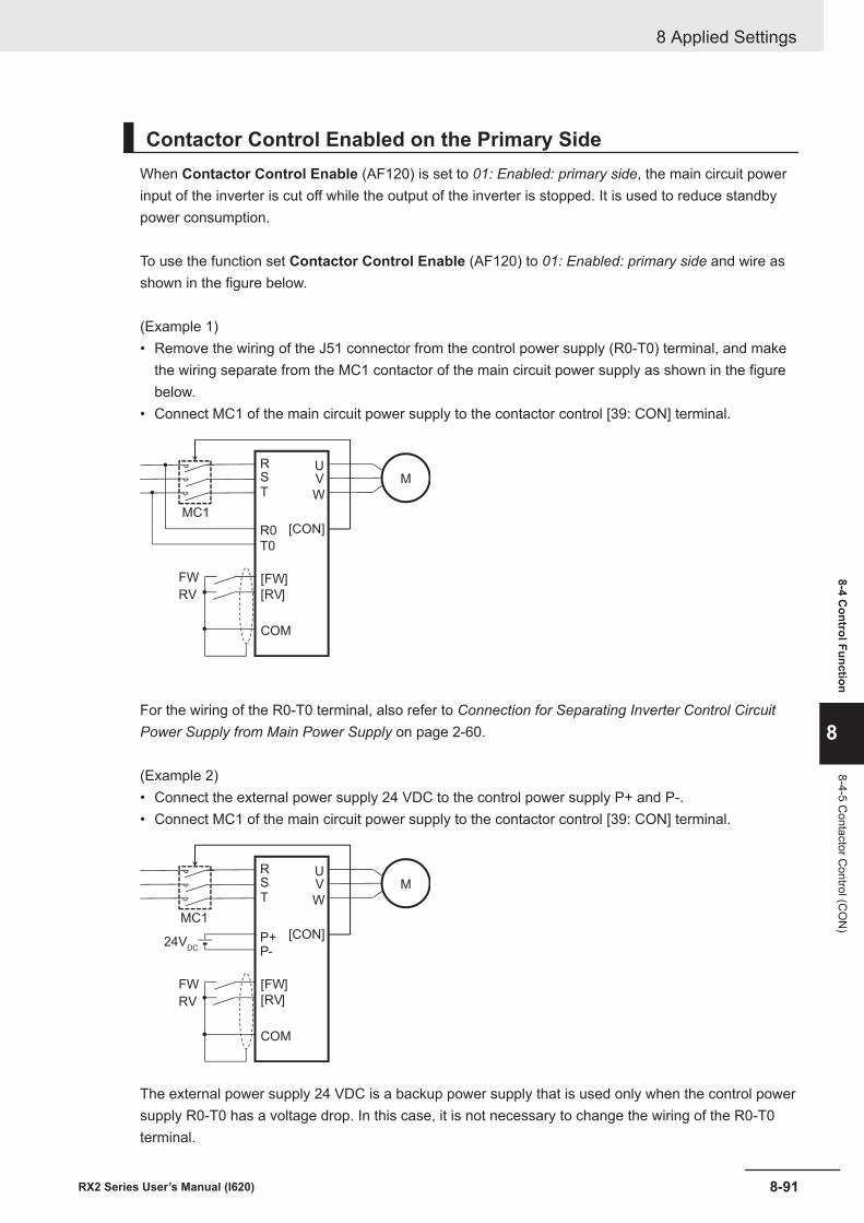
Contactor Control Enabled on the Primary SideWhen Contactor Control Enable (AF120) is set to 01: Enabled: primary side, the main circuit powerinput of the inverter is cut off while the output of the inverter is stopped. It is used to reduce standbypower consumption.
To use the function set Contactor Control Enable (AF120) to 01: Enabled: primary side and wire asshown in the figure below.
(Example 1)• Remove the wiring of the J51 connector from the control power supply (R0-T0) terminal, and make
the wiring separate from the MC1 contactor of the main circuit power supply as shown in the figurebelow.
• Connect MC1 of the main circuit power supply to the contactor control [39: CON] terminal.
M
R
S
T
U
V
W
[FW]
[RV]
COM
FW
RV
R0
T0
[CON]
MC1
For the wiring of the R0-T0 terminal, also refer to Connection for Separating Inverter Control CircuitPower Supply from Main Power Supply on page 2-60.
(Example 2)• Connect the external power supply 24 VDC to the control power supply P+ and P-.• Connect MC1 of the main circuit power supply to the contactor control [39: CON] terminal.
M
R
S
T
U
V
W
[FW]
[RV]
COM
FW
RV
P+
P-24V
DC
[CON]
MC1
The external power supply 24 VDC is a backup power supply that is used only when the control powersupply R0-T0 has a voltage drop. In this case, it is not necessary to change the wiring of the R0-T0terminal.
8 Applied Settings
8-91RX2 Series User’s Manual (I620)
8-4 Control Function
8
8-4-5 Contactor C
ontrol (CO
N)
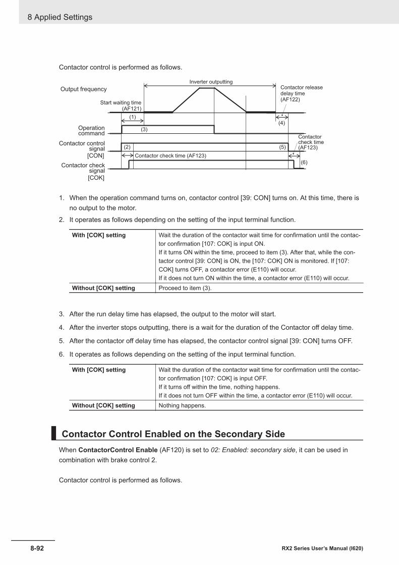
Contactor control is performed as follows.
[CON]
[COK]
(2)
(1)(4)
(5)
(3)
(6)
Inverter outputting
Output frequency
Operationcommand
Start waiting time(AF121)
Contactor releasedelay time(AF122)
Contactorcheck time(AF123)
Contactor check time (AF123)
Contactor controlsignal
Contactor checksignal
1. When the operation command turns on, contactor control [39: CON] turns on. At this time, there isno output to the motor.
2. It operates as follows depending on the setting of the input terminal function.
With [COK] setting Wait the duration of the contactor wait time for confirmation until the contac-tor confirmation [107: COK] is input ON.If it turns ON within the time, proceed to item (3). After that, while the con-tactor control [39: CON] is ON, the [107: COK] ON is monitored. If [107:COK] turns OFF, a contactor error (E110) will occur.If it does not turn ON within the time, a contactor error (E110) will occur.
Without [COK] setting Proceed to item (3).
3. After the run delay time has elapsed, the output to the motor will start.
4. After the inverter stops outputting, there is a wait for the duration of the Contactor off delay time.
5. After the contactor off delay time has elapsed, the contactor control signal [39: CON] turns OFF.
6. It operates as follows depending on the setting of the input terminal function.
With [COK] setting Wait the duration of the contactor wait time for confirmation until the contac-tor confirmation [107: COK] is input OFF.If it turns off within the time, nothing happens.If it does not turn OFF within the time, a contactor error (E110) will occur.
Without [COK] setting Nothing happens.
Contactor Control Enabled on the Secondary SideWhen ContactorControl Enable (AF120) is set to 02: Enabled: secondary side, it can be used incombination with brake control 2.
Contactor control is performed as follows.
8 Applied Settings
8-92 RX2 Series User’s Manual (I620)
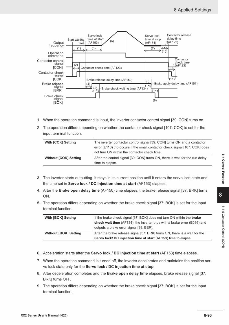
[CON]
[COK]
(2)
(3)
(8)
(9)
(1)
[BRK]
[BOK]
(4)
(10)
(5)
(11)
(7)
(6)
Servo locktime at stop(AF154)
Servo locktime at start(AF153)Output
frequency
Operationcommand
Brake releasesignal
Brake checksignal
Brake release delay time (AF150)
Brake check waiting time (AF134)
Brake apply delay time (AF151)
Start waitingtime
Contactor releasedelay time(AF122)
Contactorcheck time(AF123)
Contactor check time (AF123)
Contactor controlsignal
Contactor checksignal
1. When the operation command is input, the inverter contactor control signal [39: CON] turns on.
2. The operation differs depending on whether the contactor check signal [107: COK] is set for theinput terminal function.
With [COK] Setting The inverter contactor control signal [39: CON] turns ON and a contactorerror (E110) trip occurs if the small contactor check signal [107: COK] doesnot turn ON within the contactor check time.
Without [COK] Setting After the control signal [39: CON] turns ON, there is wait for the run delaytime to elapse.
3. The inverter starts outputting. It stays in its current position until it enters the servo lock state andthe time set in Servo lock / DC injection time at start (AF153) elapses.
4. After the Brake open delay time (AF150) time elapses, the brake release signal [37: BRK] turnsON.
5. The operation differs depending on whether the brake check signal [37: BOK] is set for the inputterminal function.
With [BOK] Setting If the brake check signal [37: BOK] does not turn ON within the brakecheck wait time (AF134), the inverter trips with a brake error (E036) andoutputs a brake error signal [38: BER].
Without [BOK] Setting After the brake release signal [37: BRK] turns ON, there is a wait for theServo lock/ DC injection time at start (AF153) time to elapse.
6. Acceleration starts after the Servo lock / DC injection time at start (AF153) time elapses.
7. When the operation command is turned off, the inverter decelerates and maintains the position ser-vo lock state only for the Servo lock / DC injection time at stop.
8. After deceleration completes and the Brake open delay time elapses, brake release signal [37:BRK] turns OFF.
9. The operation differs depending on whether the brake check signal [37: BOK] is set for the inputterminal function.
8 Applied Settings
8-93RX2 Series User’s Manual (I620)
8-4 Control Function
8
8-4-5 Contactor C
ontrol (CO
N)
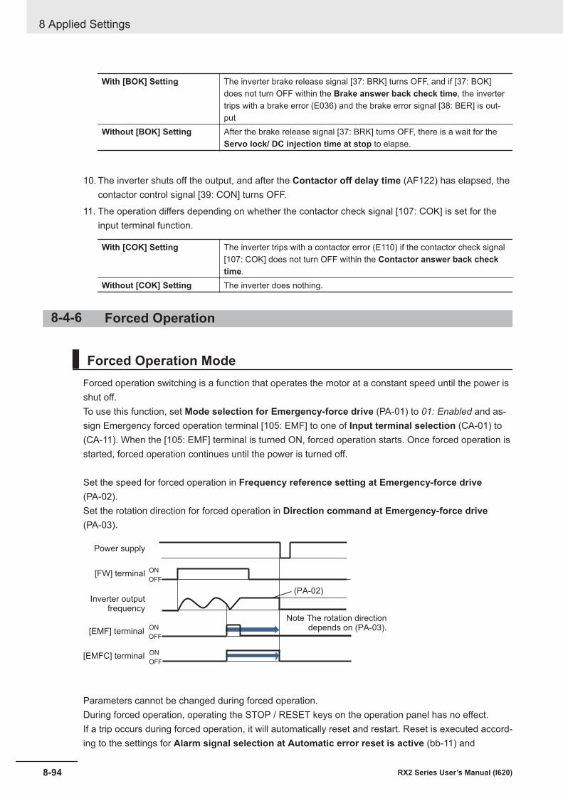
With [BOK] Setting The inverter brake release signal [37: BRK] turns OFF, and if [37: BOK]does not turn OFF within the Brake answer back check time, the invertertrips with a brake error (E036) and the brake error signal [38: BER] is out-put
Without [BOK] Setting After the brake release signal [37: BRK] turns OFF, there is a wait for theServo lock/ DC injection time at stop to elapse.
10. The inverter shuts off the output, and after the Contactor off delay time (AF122) has elapsed, thecontactor control signal [39: CON] turns OFF.
11. The operation differs depending on whether the contactor check signal [107: COK] is set for theinput terminal function.
With [COK] Setting The inverter trips with a contactor error (E110) if the contactor check signal[107: COK] does not turn OFF within the Contactor answer back checktime.
Without [COK] Setting The inverter does nothing.
8-4-6 Forced Operation
Forced Operation ModeForced operation switching is a function that operates the motor at a constant speed until the power isshut off.To use this function, set Mode selection for Emergency-force drive (PA-01) to 01: Enabled and as-sign Emergency forced operation terminal [105: EMF] to one of Input terminal selection (CA-01) to(CA-11). When the [105: EMF] terminal is turned ON, forced operation starts. Once forced operation isstarted, forced operation continues until the power is turned off.
Set the speed for forced operation in Frequency reference setting at Emergency-force drive(PA-02).Set the rotation direction for forced operation in Direction command at Emergency-force drive(PA-03).
ON
OFF
ON
OFF
(PA-02)
ON
OFF
Power supply
[FW] terminal
Inverter outputfrequency
[EMF] terminal
[EMFC] terminal
Note The rotation directiondepends on (PA-03).
Parameters cannot be changed during forced operation.During forced operation, operating the STOP / RESET keys on the operation panel has no effect.If a trip occurs during forced operation, it will automatically reset and restart. Reset is executed accord-ing to the settings for Alarm signal selection at Automatic error reset is active (bb-11) and
8 Applied Settings
8-94 RX2 Series User’s Manual (I620)
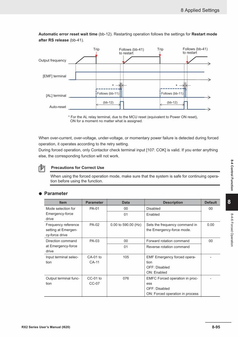
Automatic error reset wait time (bb-12). Restarting operation follows the settings for Restart modeafter RS release (bb-41).
(bb-12) (bb-12)
* *
* For the AL relay terminal, due to the MCU reset (equivalent to Power ON reset), ON for a moment no matter what is assigned.
[EMF] terminal
Output frequency
[AL] terminal
Auto-reset
Follows (bb-11) Follows (bb-11)
Follows (bb-41)to restart
TripFollows (bb-41)to restart
Trip
When over-current, over-voltage, under-voltage, or momentary power failure is detected during forcedoperation, it operates according to the retry setting.During forced operation, only Contactor check terminal input [107: COK] is valid. If you enter anythingelse, the corresponding function will not work.
Precautions for Correct Use
When using the forced operation mode, make sure that the system is safe for continuing opera-tion before using the function.
l Parameter
Item Parameter Data Description DefaultMode selection forEmergency-forcedrive
PA-01 00 Disabled 0001 Enabled
Frequency referencesetting at Emergen-cy-force drive
PA-02 0.00 to 590.00 (Hz) Sets the frequency command inthe Emergency-force mode.
0.00
Direction commandat Emergency-forcedrive
PA-03 00 Forward rotation command 0001 Reverse rotation command
Input terminal selec-tion
CA-01 toCA-11
105 EMF Emergency forced opera-tionOFF: DisabledON: Enabled
-
Output terminal func-tion
CC-01 toCC-07
076 EMFC Forced operation in proc-essOFF: DisabledON: Forced operation in process
-
8 Applied Settings
8-95RX2 Series User’s Manual (I620)
8-4 Control Function
8
8-4-6 Forced Operation
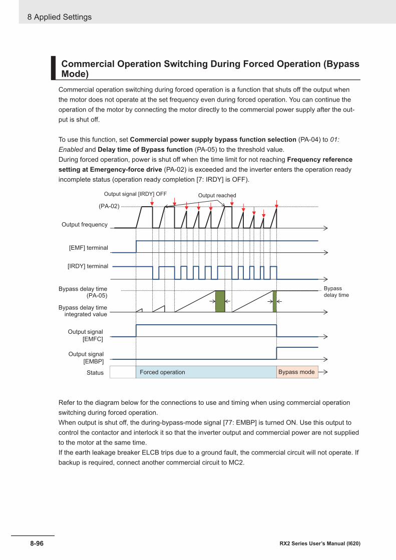
Commercial Operation Switching During Forced Operation (BypassMode)
Commercial operation switching during forced operation is a function that shuts off the output whenthe motor does not operate at the set frequency even during forced operation. You can continue theoperation of the motor by connecting the motor directly to the commercial power supply after the out-put is shut off.
To use this function, set Commercial power supply bypass function selection (PA-04) to 01:Enabled and Delay time of Bypass function (PA-05) to the threshold value.During forced operation, power is shut off when the time limit for not reaching Frequency referencesetting at Emergency-force drive (PA-02) is exceeded and the inverter enters the operation readyincomplete status (operation ready completion [7: IRDY] is OFF).
[EMF] terminal
Output frequency
Status
Bypass delay timeintegrated value
[IRDY] terminal
Output signal
[EMFC]
Bypass delay time(PA-05)
Output signal
[EMBP]
Forced operation Bypass mode
Bypass
delay time
Output reachedOutput signal [IRDY] OFF
(PA-02)
Refer to the diagram below for the connections to use and timing when using commercial operationswitching during forced operation.When output is shut off, the during-bypass-mode signal [77: EMBP] is turned ON. Use this output tocontrol the contactor and interlock it so that the inverter output and commercial power are not suppliedto the motor at the same time.If the earth leakage breaker ELCB trips due to a ground fault, the commercial circuit will not operate. Ifbackup is required, connect another commercial circuit to MC2.
8 Applied Settings
8-96 RX2 Series User’s Manual (I620)
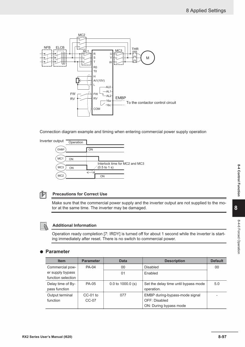
M
R
S
T
U
V
W
Ai1(10V)
L
FW
RV
COM
AL1
AL0
AL2
THRMC1 MC3
ELCB
FW
RV
MC2
H
R0
T0
NFB
16a
16c
EMBP
To the contactor control circuit
Connection diagram example and timing when entering commercial power supply operation
ON
MC2 ON
MC3
ONEMBP
ONMC1
Inverter output Operation
Interlock time for MC2 and MC3(0.5 to 1 s)
Precautions for Correct Use
Make sure that the commercial power supply and the inverter output are not supplied to the mo-tor at the same time. The inverter may be damaged.
Additional Information
Operation ready completion [7: IRDY] is turned off for about 1 second while the inverter is start-ing immediately after reset. There is no switch to commercial power.
l Parameter
Item Parameter Data Description DefaultCommercial pow-er supply bypassfunction selection
PA-04 00 Disabled 0001 Enabled
Delay time of By-pass function
PA-05 0.0 to 1000.0 (s) Set the delay time until bypass modeoperation.
5.0
Output terminalfunction
CC-01 toCC-07
077 EMBP during-bypass-mode signalOFF: DisabledON: During bypass mode
-
8 Applied Settings
8-97RX2 Series User’s Manual (I620)
8-4 Control Function
8
8-4-6 Forced Operation
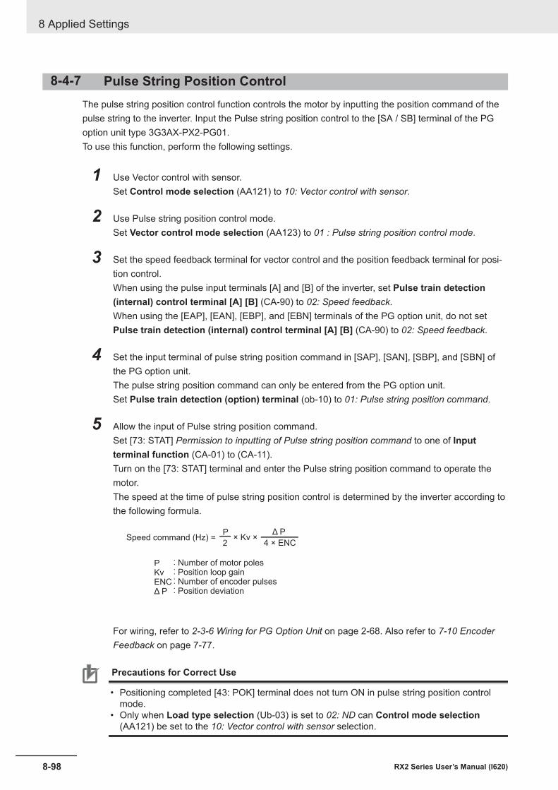
8-4-7 Pulse String Position ControlThe pulse string position control function controls the motor by inputting the position command of thepulse string to the inverter. Input the Pulse string position control to the [SA / SB] terminal of the PGoption unit type 3G3AX-PX2-PG01.To use this function, perform the following settings.
1 Use Vector control with sensor.Set Control mode selection (AA121) to 10: Vector control with sensor.
2 Use Pulse string position control mode.Set Vector control mode selection (AA123) to 01 : Pulse string position control mode.
3 Set the speed feedback terminal for vector control and the position feedback terminal for posi-tion control.When using the pulse input terminals [A] and [B] of the inverter, set Pulse train detection(internal) control terminal [A] [B] (CA-90) to 02: Speed feedback.When using the [EAP], [EAN], [EBP], and [EBN] terminals of the PG option unit, do not setPulse train detection (internal) control terminal [A] [B] (CA-90) to 02: Speed feedback.
4 Set the input terminal of pulse string position command in [SAP], [SAN], [SBP], and [SBN] ofthe PG option unit.The pulse string position command can only be entered from the PG option unit.Set Pulse train detection (option) terminal (ob-10) to 01: Pulse string position command.
5 Allow the input of Pulse string position command.Set [73: STAT] Permission to inputting of Pulse string position command to one of Inputterminal function (CA-01) to (CA-11).Turn on the [73: STAT] terminal and enter the Pulse string position command to operate themotor.The speed at the time of pulse string position control is determined by the inverter according tothe following formula.
PKvENCΔ P
Speed command (Hz) = × Kv × P
2
Δ P
4 × ENC
: Number of motor poles: Position loop gain: Number of encoder pulses: Position deviation
For wiring, refer to 2-3-6 Wiring for PG Option Unit on page 2-68. Also refer to 7-10 EncoderFeedback on page 7-77.
Precautions for Correct Use
• Positioning completed [43: POK] terminal does not turn ON in pulse string position controlmode.
• Only when Load type selection (Ub-03) is set to 02: ND can Control mode selection(AA121) be set to the 10: Vector control with sensor selection.
8 Applied Settings
8-98 RX2 Series User’s Manual (I620)
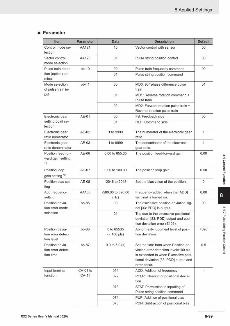
l Parameter
Item Parameter Data Description DefaultControl mode se-lection
AA121 10 Vector control with sensor 00
Vector controlmode selection
AA123 01 Pulse string position control 00
Pulse train detec-tion (option) ter-minal
ob-10 00 Pulse train frequency command 0001 Pulse string position command
Mode selectionof pulse train in-put
ob-11 00 MD0: 90° phase difference pulsetrain
01
01 MD1: Reverse rotation command +Pulse train
02 MD2: Forward rotation pulse train +Reverse rotation pulse train
Electronic gearsetting point se-lection
AE-01 00 FB: Feedback side 0001 REF: Command side
Electronic gearratio numerator
AE-02 1 to 9999 The numerator of the electronic gearratio.
1
Electronic gearratio denominator
AE-03 1 to 9999 The denominator of the electronicgear ratio.
1
Position feed-for-ward gain setting*1
AE-06 0.00 to 655.35 The position feed-forward gain. 0.00
Position loopgain setting *2
AE-07 0.00 to 100.00 The position loop gain. 0.50
Position bias set-ting
AE-08 -2048 to 2048 Set the bias value of the position. 0
Add frequencysetting
AA106 -590.00 to 590.00(Hz)
Frequency added when the [ADD]terminal is turned on.
0.00
Position devia-tion error modeselection
bb-85 00 The excessive position deviation sig-nal [33: PDD] is output.
00
01 Trip due to the excessive positionaldeviation [33: PDD] output and posi-tion deviation error (E106).
Position devia-tion error detec-tion level
bb-86 0 to 65535(× 100 pls)
Abnormality judgment level of posi-tion deviation.
4096
Position devia-tion error detec-tion time
bb-87 0.0 to 5.0 (s) Set the time from when Position de-viation error detection level×100 plsis exceeded to when Excessive posi-tional deviation [33: PDD] output anderror occur.
0.5
Input terminalfunction
CA-01 toCA-11
014 ADD: Addition of frequency -072 PCLR: Clearing of positional devia-
tion073 STAT: Permission to inputting of
Pulse string position command074 PUP: Addition of positional bias075 PDN: Subtraction of positional bias
8 Applied Settings
8-99RX2 Series User’s Manual (I620)
8-4 Control Function
8
8-4-7 Pulse String Position Control
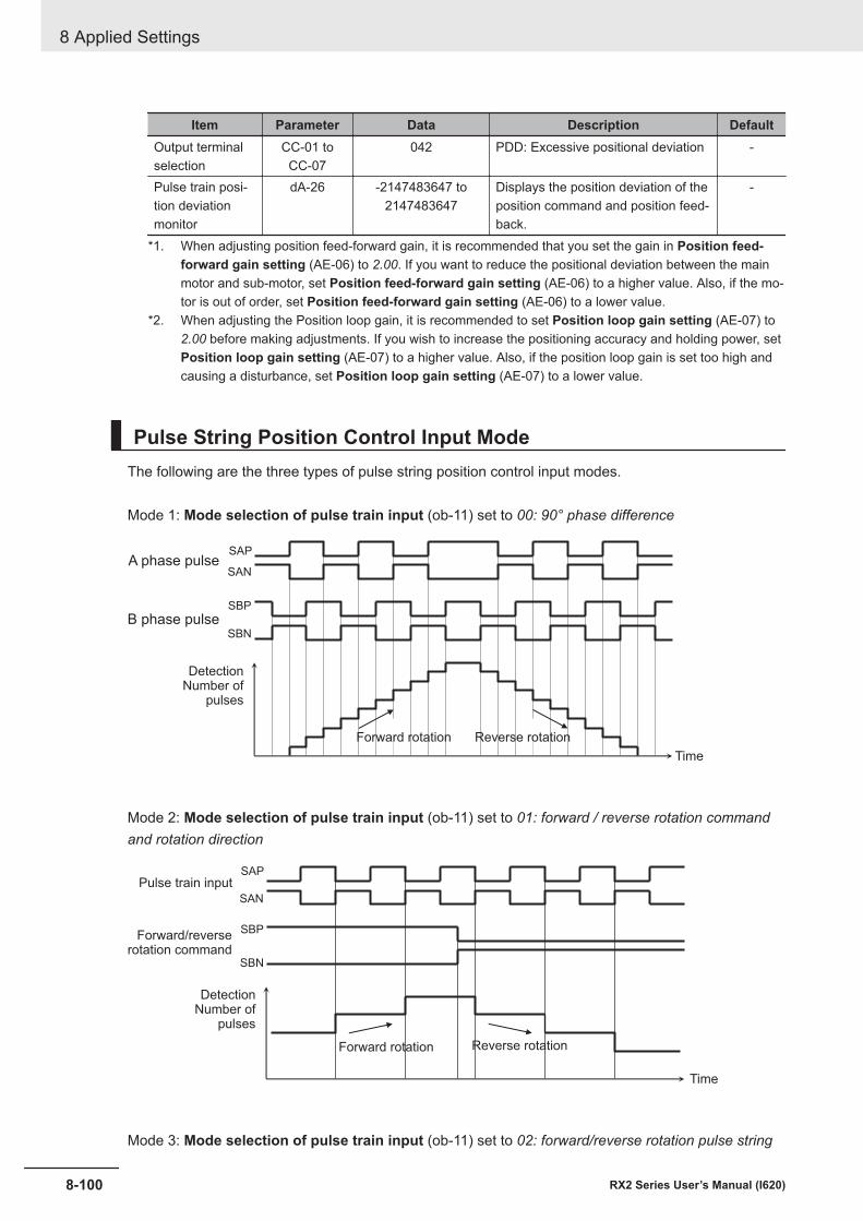
Item Parameter Data Description DefaultOutput terminalselection
CC-01 toCC-07
042 PDD: Excessive positional deviation -
Pulse train posi-tion deviationmonitor
dA-26 -2147483647 to2147483647
Displays the position deviation of theposition command and position feed-back.
-
*1. When adjusting position feed-forward gain, it is recommended that you set the gain in Position feed-forward gain setting (AE-06) to 2.00. If you want to reduce the positional deviation between the mainmotor and sub-motor, set Position feed-forward gain setting (AE-06) to a higher value. Also, if the mo-tor is out of order, set Position feed-forward gain setting (AE-06) to a lower value.
*2. When adjusting the Position loop gain, it is recommended to set Position loop gain setting (AE-07) to2.00 before making adjustments. If you wish to increase the positioning accuracy and holding power, setPosition loop gain setting (AE-07) to a higher value. Also, if the position loop gain is set too high andcausing a disturbance, set Position loop gain setting (AE-07) to a lower value.
Pulse String Position Control Input ModeThe following are the three types of pulse string position control input modes.
Mode 1: Mode selection of pulse train input (ob-11) set to 00: 90° phase difference
SAP
SAN
SBP
SBN
DetectionNumber of
pulses
Forward rotation Reverse rotation
Time
A phase pulse
B phase pulse
Mode 2: Mode selection of pulse train input (ob-11) set to 01: forward / reverse rotation commandand rotation direction
SAP
SAN
SBP
SBN
DetectionNumber of
pulses
Forward rotation Reverse rotation
Time
Pulse train input
Forward/reverserotation command
Mode 3: Mode selection of pulse train input (ob-11) set to 02: forward/reverse rotation pulse string
8 Applied Settings
8-100 RX2 Series User’s Manual (I620)
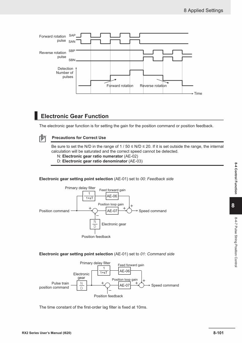
SAP
SAN
SBP
SBN
Forward rotation Reverse rotation
Time
DetectionNumber of
pulses
Forward rotationpulse
Reverse rotationpulse
Electronic Gear FunctionThe electronic gear function is for setting the gain for the position command or position feedback.
Precautions for Correct Use
Be sure to set the N/D in the range of 1 / 50 ≤ N/D ≤ 20. If it is set outside the range, the internalcalculation will be saturated and the correct speed cannot be detected.
N: Electronic gear ratio numerator (AE-02)D: Electronic gear ratio denominator (AE-03)
Electronic gear setting point selection (AE-01) set to 00: Feedback side
ND
1+sT
1
Speed command
Primary delay filterFeed forward gain
Position loop gain
Electronic gear
Position feedback
Position command
AE-06
AE-07
Electronic gear setting point selection (AE-01) set to 01: Command side
ND
1+sT
T
1
Speed command
Primary delay filterFeed forward gain
Position loop gain
Electronicgear
Position feedback
Pulse trainposition command
AE-06
AE-07
The time constant of the first-order lag filter is fixed at 10ms.
8 Applied Settings
8-101RX2 Series User’s Manual (I620)
8-4 Control Function
8
8-4-7 Pulse String Position Control
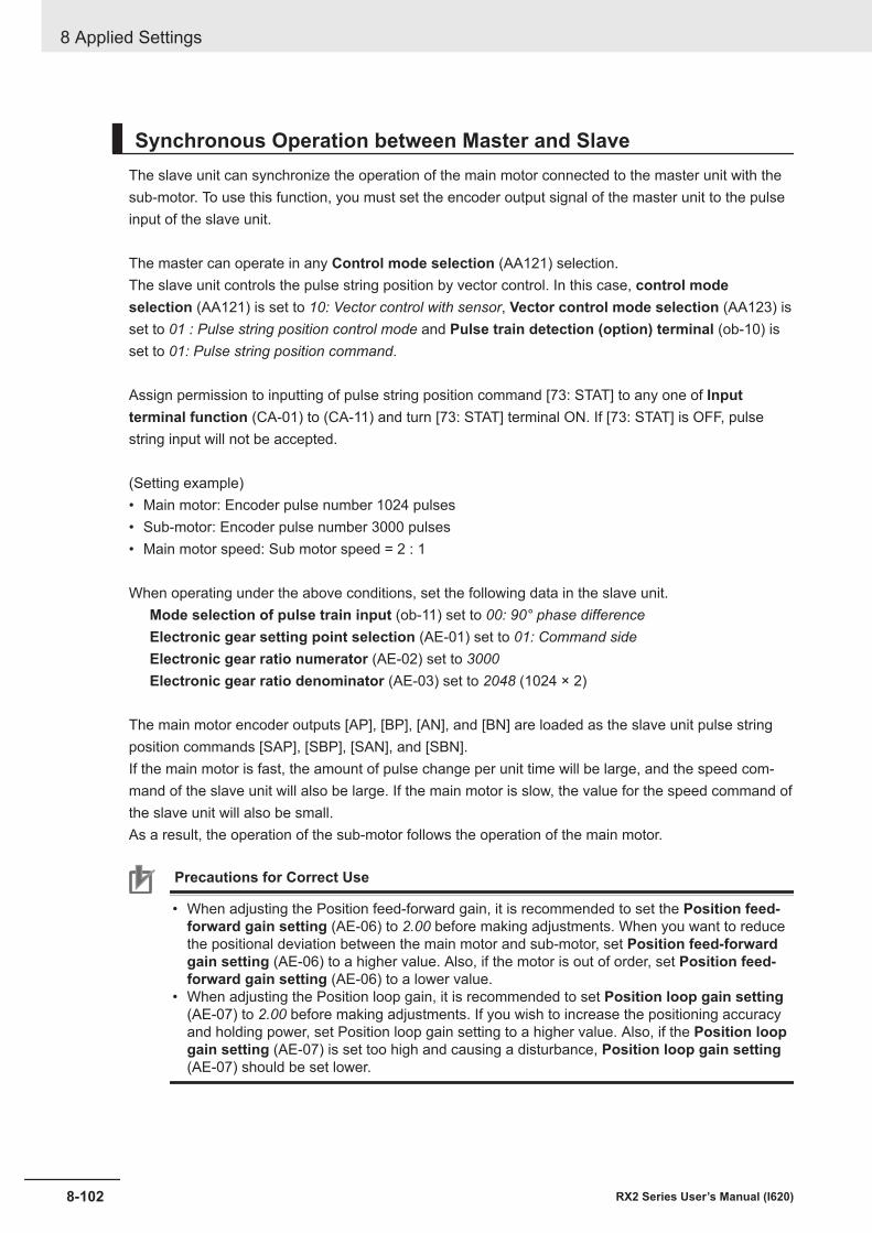
Synchronous Operation between Master and SlaveThe slave unit can synchronize the operation of the main motor connected to the master unit with thesub-motor. To use this function, you must set the encoder output signal of the master unit to the pulseinput of the slave unit.
The master can operate in any Control mode selection (AA121) selection.The slave unit controls the pulse string position by vector control. In this case, control modeselection (AA121) is set to 10: Vector control with sensor, Vector control mode selection (AA123) isset to 01 : Pulse string position control mode and Pulse train detection (option) terminal (ob-10) isset to 01: Pulse string position command.
Assign permission to inputting of pulse string position command [73: STAT] to any one of Inputterminal function (CA-01) to (CA-11) and turn [73: STAT] terminal ON. If [73: STAT] is OFF, pulsestring input will not be accepted.
(Setting example)• Main motor: Encoder pulse number 1024 pulses• Sub-motor: Encoder pulse number 3000 pulses• Main motor speed: Sub motor speed = 2 : 1
When operating under the above conditions, set the following data in the slave unit.Mode selection of pulse train input (ob-11) set to 00: 90° phase differenceElectronic gear setting point selection (AE-01) set to 01: Command sideElectronic gear ratio numerator (AE-02) set to 3000Electronic gear ratio denominator (AE-03) set to 2048 (1024 × 2)
The main motor encoder outputs [AP], [BP], [AN], and [BN] are loaded as the slave unit pulse stringposition commands [SAP], [SBP], [SAN], and [SBN].If the main motor is fast, the amount of pulse change per unit time will be large, and the speed com-mand of the slave unit will also be large. If the main motor is slow, the value for the speed command ofthe slave unit will also be small.As a result, the operation of the sub-motor follows the operation of the main motor.
Precautions for Correct Use
• When adjusting the Position feed-forward gain, it is recommended to set the Position feed-forward gain setting (AE-06) to 2.00 before making adjustments. When you want to reducethe positional deviation between the main motor and sub-motor, set Position feed-forwardgain setting (AE-06) to a higher value. Also, if the motor is out of order, set Position feed-forward gain setting (AE-06) to a lower value.
• When adjusting the Position loop gain, it is recommended to set Position loop gain setting(AE-07) to 2.00 before making adjustments. If you wish to increase the positioning accuracyand holding power, set Position loop gain setting to a higher value. Also, if the Position loopgain setting (AE-07) is set too high and causing a disturbance, Position loop gain setting(AE-07) should be set lower.
8 Applied Settings
8-102 RX2 Series User’s Manual (I620)
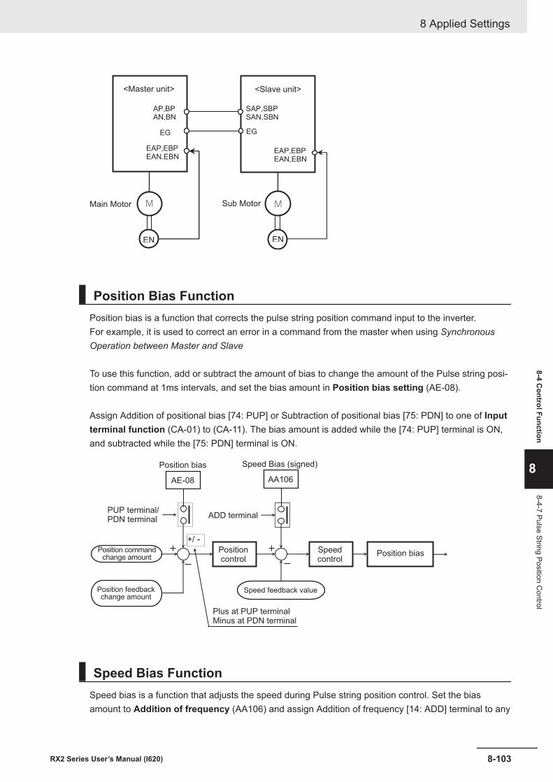
AP,BP
AN,BN
M
EN
M
EN
EG
EAP,EBP
EAN,EBN
SAP,SBP
SAN,SBN
EG
EAP,EBP
EAN,EBN
Main Motor Sub Motor
<Slave unit><Master unit>
Position Bias FunctionPosition bias is a function that corrects the pulse string position command input to the inverter.For example, it is used to correct an error in a command from the master when using SynchronousOperation between Master and Slave
To use this function, add or subtract the amount of bias to change the amount of the Pulse string posi-tion command at 1ms intervals, and set the bias amount in Position bias setting (AE-08).
Assign Addition of positional bias [74: PUP] or Subtraction of positional bias [75: PDN] to one of Inputterminal function (CA-01) to (CA-11). The bias amount is added while the [74: PUP] terminal is ON,and subtracted while the [75: PDN] terminal is ON.
+/ -
Speed Bias (signed)
PUP terminal/PDN terminal
ADD terminal
Position commandchange amount
Position feedbackchange amount
Positioncontrol
Speed feedback value
Plus at PUP terminalMinus at PDN terminal
Speedcontrol
Position bias
Position bias
AE-08 AA106
Speed Bias FunctionSpeed bias is a function that adjusts the speed during Pulse string position control. Set the biasamount to Addition of frequency (AA106) and assign Addition of frequency [14: ADD] terminal to any
8 Applied Settings
8-103RX2 Series User’s Manual (I620)
8-4 Control Function
8
8-4-7 Pulse String Position Control
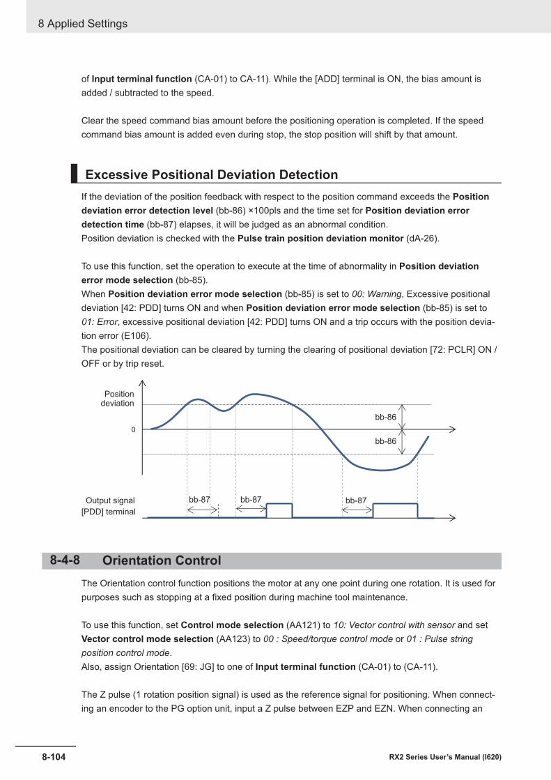
of Input terminal function (CA-01) to CA-11). While the [ADD] terminal is ON, the bias amount isadded / subtracted to the speed.
Clear the speed command bias amount before the positioning operation is completed. If the speedcommand bias amount is added even during stop, the stop position will shift by that amount.
Excessive Positional Deviation DetectionIf the deviation of the position feedback with respect to the position command exceeds the Positiondeviation error detection level (bb-86) ×100pls and the time set for Position deviation errordetection time (bb-87) elapses, it will be judged as an abnormal condition.Position deviation is checked with the Pulse train position deviation monitor (dA-26).
To use this function, set the operation to execute at the time of abnormality in Position deviationerror mode selection (bb-85).When Position deviation error mode selection (bb-85) is set to 00: Warning, Excessive positionaldeviation [42: PDD] turns ON and when Position deviation error mode selection (bb-85) is set to01: Error, excessive positional deviation [42: PDD] turns ON and a trip occurs with the position devia-tion error (E106).The positional deviation can be cleared by turning the clearing of positional deviation [72: PCLR] ON /OFF or by trip reset.
0
Positiondeviation
[PDD] terminal
Output signal bb-87
bb-86
bb-87 bb-87
bb-86
8-4-8 Orientation ControlThe Orientation control function positions the motor at any one point during one rotation. It is used forpurposes such as stopping at a fixed position during machine tool maintenance.
To use this function, set Control mode selection (AA121) to 10: Vector control with sensor and setVector control mode selection (AA123) to 00 : Speed/torque control mode or 01 : Pulse stringposition control mode.Also, assign Orientation [69: JG] to one of Input terminal function (CA-01) to (CA-11).
The Z pulse (1 rotation position signal) is used as the reference signal for positioning. When connect-ing an encoder to the PG option unit, input a Z pulse between EZP and EZN. When connecting an
8 Applied Settings
8-104 RX2 Series User’s Manual (I620)
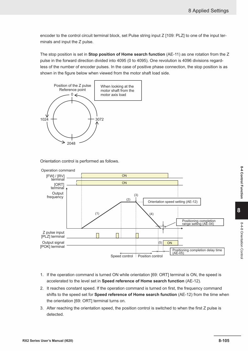
encoder to the control circuit terminal block, set Pulse string input Z [109: PLZ] to one of the input ter-minals and input the Z pulse.
The stop position is set in Stop position of Home search function (AE-11) as one rotation from the Zpulse in the forward direction divided into 4095 (0 to 4095). One revolution is 4096 divisions regard-less of the number of encoder pulses. In the case of positive phase connection, the stop position is asshown in the figure below when viewed from the motor shaft load side.
0
1024 3072
2048
When looking at themotor shaft from themotor axis load
Position of the Z pulseReference point
Orientation control is performed as follows.
ON
ON
ON
(1)
(2)
(3)
(5)
(4)
Operation command
[ORT]terminal
Outputfrequency
[FW] / [RV]terminal
Speed control Position control
Orientation speed setting (AE-12)
Positioning completionrange setting (AE-04)
Positioning completion delay time(AE-05)
[PLZ] terminal
[POK] terminal
Z pulse input
Output signal
1. If the operation command is turned ON while orientation [69: ORT] terminal is ON, the speed isaccelerated to the level set in Speed reference of Home search function (AE-12).
2. It reaches constant speed. If the operation command is turned on first, the frequency commandshifts to the speed set for Speed reference of Home search function (AE-12) from the time whenthe orientation [69: ORT] terminal turns on.
3. After reaching the orientation speed, the position control is switched to when the first Z pulse isdetected.
8 Applied Settings
8-105RX2 Series User’s Manual (I620)
8-4 Control Function
8
8-4-8 Orientation C
ontrol
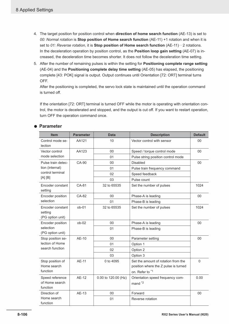
4. The target position for position control when direction of home search function (AE-13) is set to00: Normal rotation is Stop position of Home search function (AE-11) +1 rotation and when it isset to 01: Reverse rotation, it is Stop position of Home search function (AE-11)-2 rotations.In the deceleration operation by position control, as the Position loop gain setting (AE-07) is in-creased, the deceleration time becomes shorter. It does not follow the deceleration time setting.
5. After the number of remaining pulses is within the setting for Positioning complete range setting(AE-04) and the Positioning complete delay time setting (AE-05) has elapsed, the positioningcomplete [43: POK] signal is output. Output continues until Orientation [72: ORT] terminal turnsOFF.After the positioning is completed, the servo lock state is maintained until the operation commandis turned off.
If the orientation [72: ORT] terminal is turned OFF while the motor is operating with orientation con-trol, the motor is decelerated and stopped, and the output is cut off. If you want to restart operation,turn OFF the operation command once.
l Parameter
Item Parameter Data Description DefaultControl mode se-lection
AA121 10 Vector control with sensor 00
Vector controlmode selection
AA123 00 Speed / torque control mode 0001 Pulse string position control mode
Pulse train detec-tion (internal)control terminal[A] [B]
CA-90 00 Disabled 0001 Pulse train frequency command02 Speed feedback03 Pulse count
Encoder constantsetting
CA-81 32 to 65535 Set the number of pulses 1024
Encoder positionselection
CA-82 00 Phase-A is leading 0001 Phase-B is leading
Encoder constantsetting(PG option unit)
ob-01 32 to 65535 Set the number of pulses 1024
Encoder positionselection(PG option unit)
ob-02 00 Phase-A is leading 0001 Phase-B is leading
Stop position se-lection of Homesearch function
AE-10 00 Parameter setting 0001 Option 102 Option 203 Option 3
Stop position ofHome searchfunction
AE-11 0 to 4095 Set the amount of rotation from theposition where the Z pulse is turnedon. Refer to *1
0
Speed referenceof Home searchfunction
AE-12 0.00 to 120.00 (Hz) Orientation speed frequency com-mand *2
0.00
Direction ofHome searchfunction
AE-13 00 Forward 0001 Reverse rotation
8 Applied Settings
8-106 RX2 Series User’s Manual (I620)
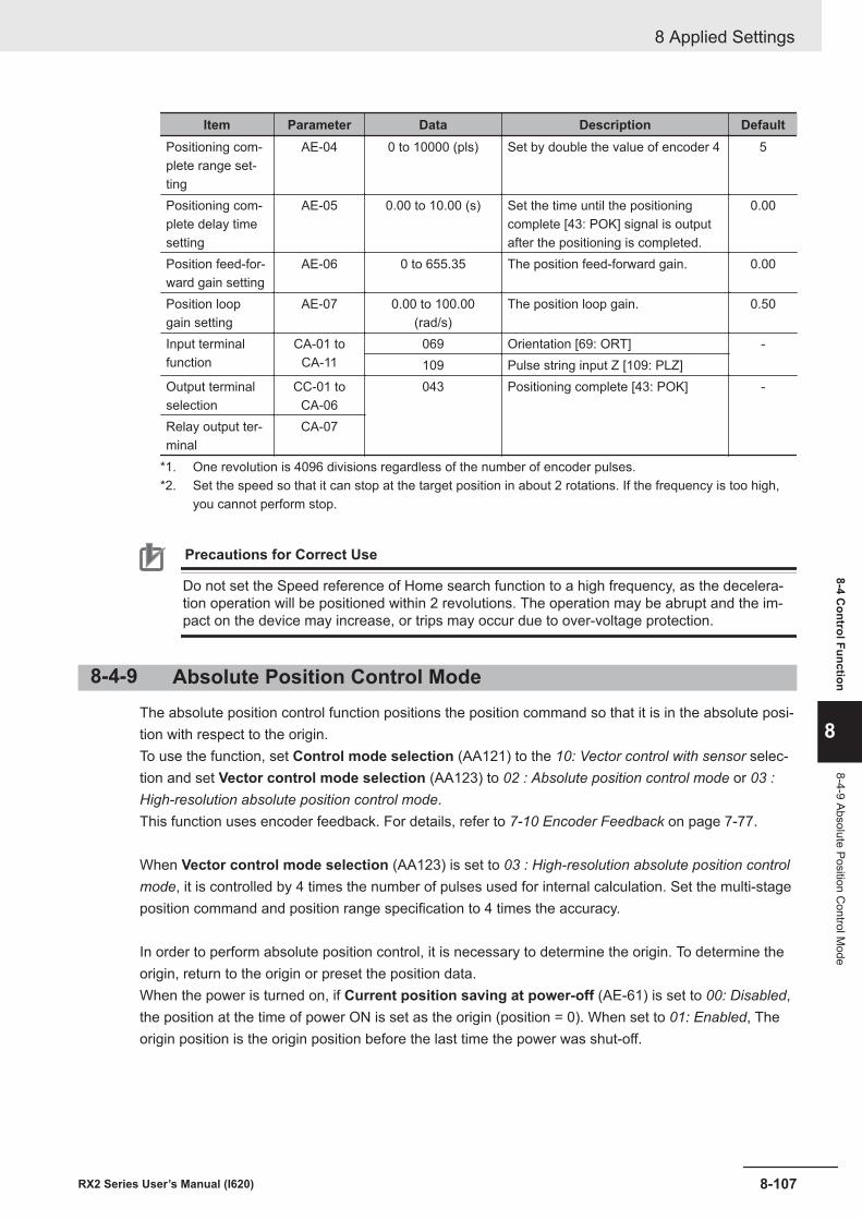
Item Parameter Data Description DefaultPositioning com-plete range set-ting
AE-04 0 to 10000 (pls) Set by double the value of encoder 4 5
Positioning com-plete delay timesetting
AE-05 0.00 to 10.00 (s) Set the time until the positioningcomplete [43: POK] signal is outputafter the positioning is completed.
0.00
Position feed-for-ward gain setting
AE-06 0 to 655.35 The position feed-forward gain. 0.00
Position loopgain setting
AE-07 0.00 to 100.00(rad/s)
The position loop gain. 0.50
Input terminalfunction
CA-01 toCA-11
069 Orientation [69: ORT] -109 Pulse string input Z [109: PLZ]
Output terminalselection
CC-01 toCA-06
043 Positioning complete [43: POK] -
Relay output ter-minal
CA-07
*1. One revolution is 4096 divisions regardless of the number of encoder pulses.*2. Set the speed so that it can stop at the target position in about 2 rotations. If the frequency is too high,
you cannot perform stop.
Precautions for Correct Use
Do not set the Speed reference of Home search function to a high frequency, as the decelera-tion operation will be positioned within 2 revolutions. The operation may be abrupt and the im-pact on the device may increase, or trips may occur due to over-voltage protection.
8-4-9 Absolute Position Control ModeThe absolute position control function positions the position command so that it is in the absolute posi-tion with respect to the origin.To use the function, set Control mode selection (AA121) to the 10: Vector control with sensor selec-tion and set Vector control mode selection (AA123) to 02 : Absolute position control mode or 03 :High-resolution absolute position control mode.This function uses encoder feedback. For details, refer to 7-10 Encoder Feedback on page 7-77.
When Vector control mode selection (AA123) is set to 03 : High-resolution absolute position controlmode, it is controlled by 4 times the number of pulses used for internal calculation. Set the multi-stageposition command and position range specification to 4 times the accuracy.
In order to perform absolute position control, it is necessary to determine the origin. To determine theorigin, return to the origin or preset the position data.When the power is turned on, if Current position saving at power-off (AE-61) is set to 00: Disabled,the position at the time of power ON is set as the origin (position = 0). When set to 01: Enabled, Theorigin position is the origin position before the last time the power was shut-off.
8 Applied Settings
8-107RX2 Series User’s Manual (I620)
8-4 Control Function
8
8-4-9 Absolute Position Control M
ode
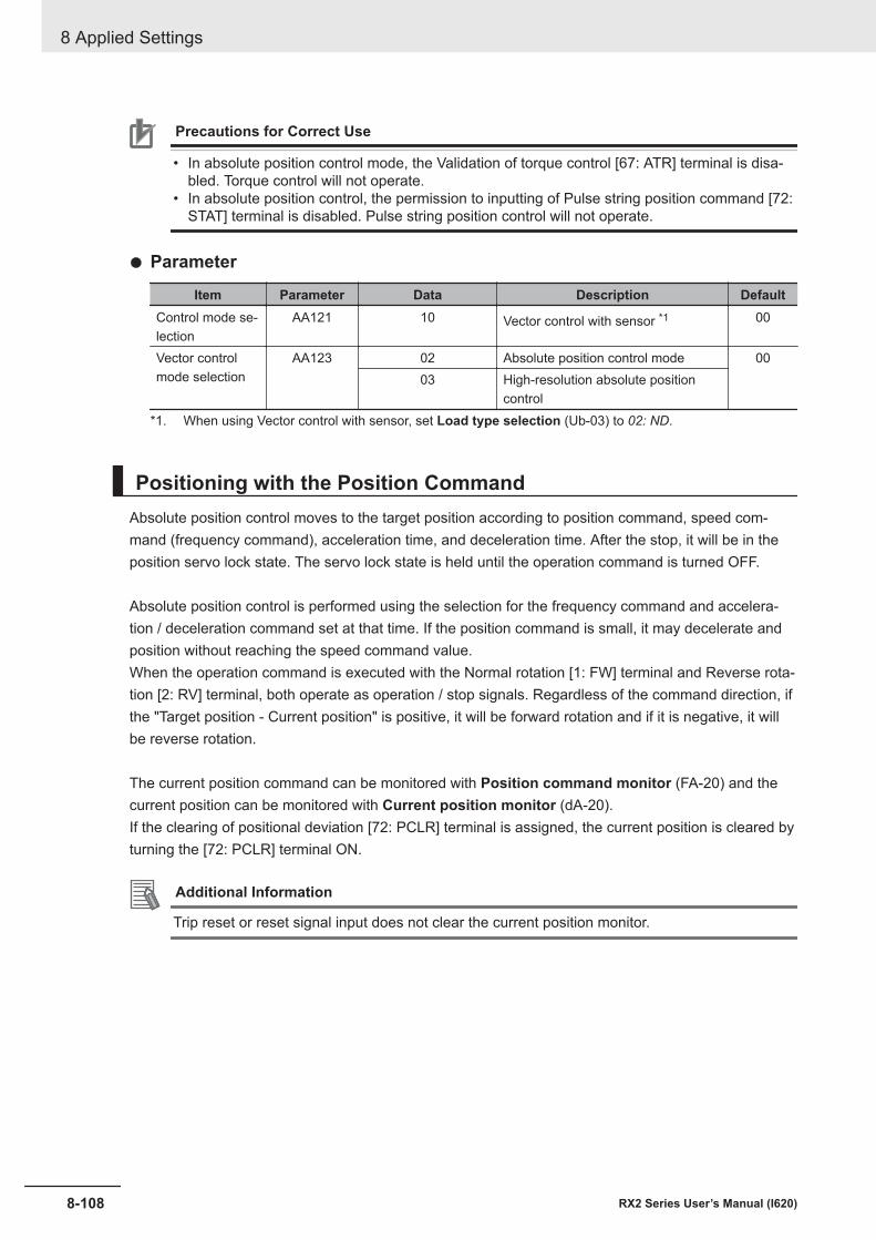
Precautions for Correct Use
• In absolute position control mode, the Validation of torque control [67: ATR] terminal is disa-bled. Torque control will not operate.
• In absolute position control, the permission to inputting of Pulse string position command [72:STAT] terminal is disabled. Pulse string position control will not operate.
l Parameter
Item Parameter Data Description DefaultControl mode se-lection
AA121 10 Vector control with sensor *1 00
Vector controlmode selection
AA123 02 Absolute position control mode 0003 High-resolution absolute position
control*1. When using Vector control with sensor, set Load type selection (Ub-03) to 02: ND.
Positioning with the Position CommandAbsolute position control moves to the target position according to position command, speed com-mand (frequency command), acceleration time, and deceleration time. After the stop, it will be in theposition servo lock state. The servo lock state is held until the operation command is turned OFF.
Absolute position control is performed using the selection for the frequency command and accelera-tion / deceleration command set at that time. If the position command is small, it may decelerate andposition without reaching the speed command value.When the operation command is executed with the Normal rotation [1: FW] terminal and Reverse rota-tion [2: RV] terminal, both operate as operation / stop signals. Regardless of the command direction, ifthe "Target position - Current position" is positive, it will be forward rotation and if it is negative, it willbe reverse rotation.
The current position command can be monitored with Position command monitor (FA-20) and thecurrent position can be monitored with Current position monitor (dA-20).If the clearing of positional deviation [72: PCLR] terminal is assigned, the current position is cleared byturning the [72: PCLR] terminal ON.
Additional Information
Trip reset or reset signal input does not clear the current position monitor.
8 Applied Settings
8-108 RX2 Series User’s Manual (I620)
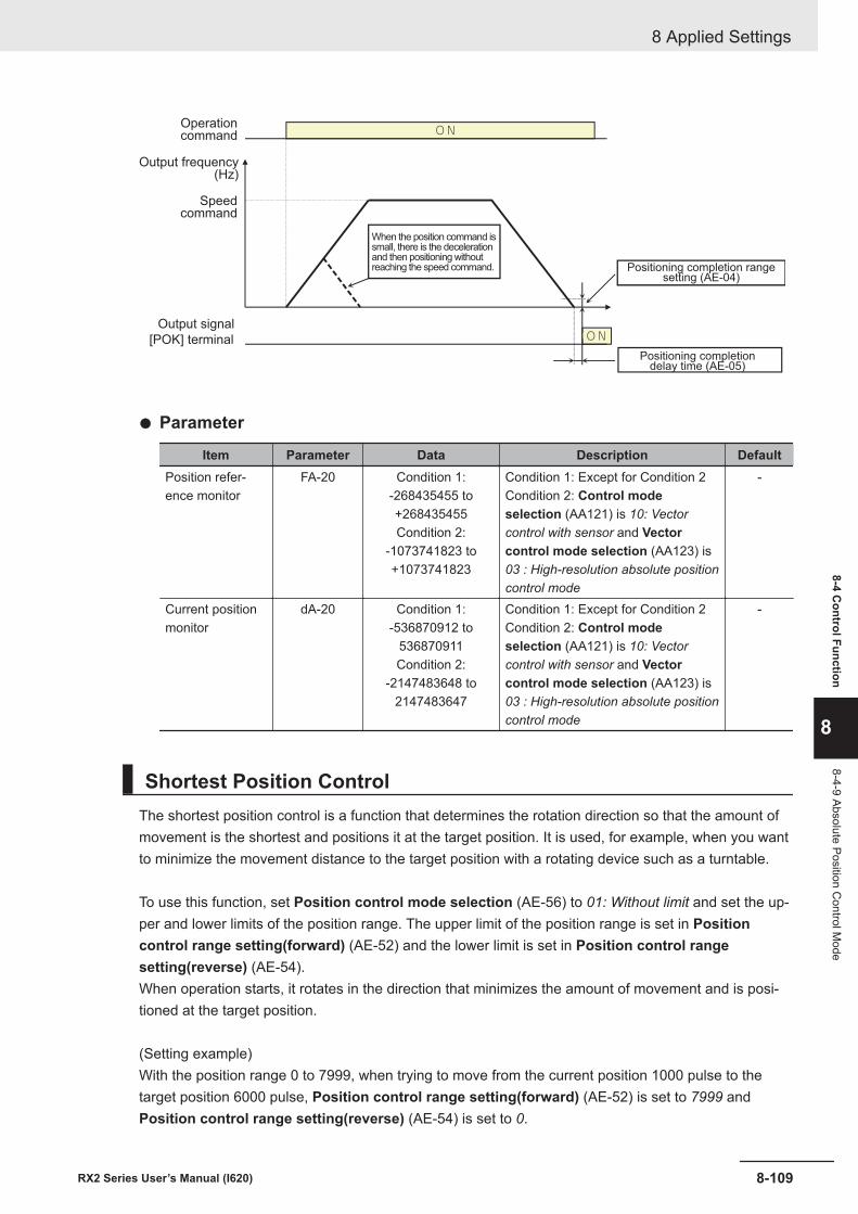
ON
ONOperationcommand
When the position command issmall, there is the decelerationand then positioning withoutreaching the speed command.
Output frequency(Hz)
Speedcommand
Positioning completion rangesetting (AE-04)
Positioning completiondelay time (AE-05)
[POK] terminal
Output signal
l Parameter
Item Parameter Data Description DefaultPosition refer-ence monitor
FA-20 Condition 1:-268435455 to+268435455Condition 2:
-1073741823 to+1073741823
Condition 1: Except for Condition 2Condition 2: Control modeselection (AA121) is 10: Vectorcontrol with sensor and Vectorcontrol mode selection (AA123) is03 : High-resolution absolute positioncontrol mode
-
Current positionmonitor
dA-20 Condition 1:-536870912 to
536870911Condition 2:
-2147483648 to2147483647
Condition 1: Except for Condition 2Condition 2: Control modeselection (AA121) is 10: Vectorcontrol with sensor and Vectorcontrol mode selection (AA123) is03 : High-resolution absolute positioncontrol mode
-
Shortest Position ControlThe shortest position control is a function that determines the rotation direction so that the amount ofmovement is the shortest and positions it at the target position. It is used, for example, when you wantto minimize the movement distance to the target position with a rotating device such as a turntable.
To use this function, set Position control mode selection (AE-56) to 01: Without limit and set the up-per and lower limits of the position range. The upper limit of the position range is set in Positioncontrol range setting(forward) (AE-52) and the lower limit is set in Position control rangesetting(reverse) (AE-54).When operation starts, it rotates in the direction that minimizes the amount of movement and is posi-tioned at the target position.
(Setting example)With the position range 0 to 7999, when trying to move from the current position 1000 pulse to thetarget position 6000 pulse, Position control range setting(forward) (AE-52) is set to 7999 andPosition control range setting(reverse) (AE-54) is set to 0.
8 Applied Settings
8-109RX2 Series User’s Manual (I620)
8-4 Control Function
8
8-4-9 Absolute Position Control M
ode
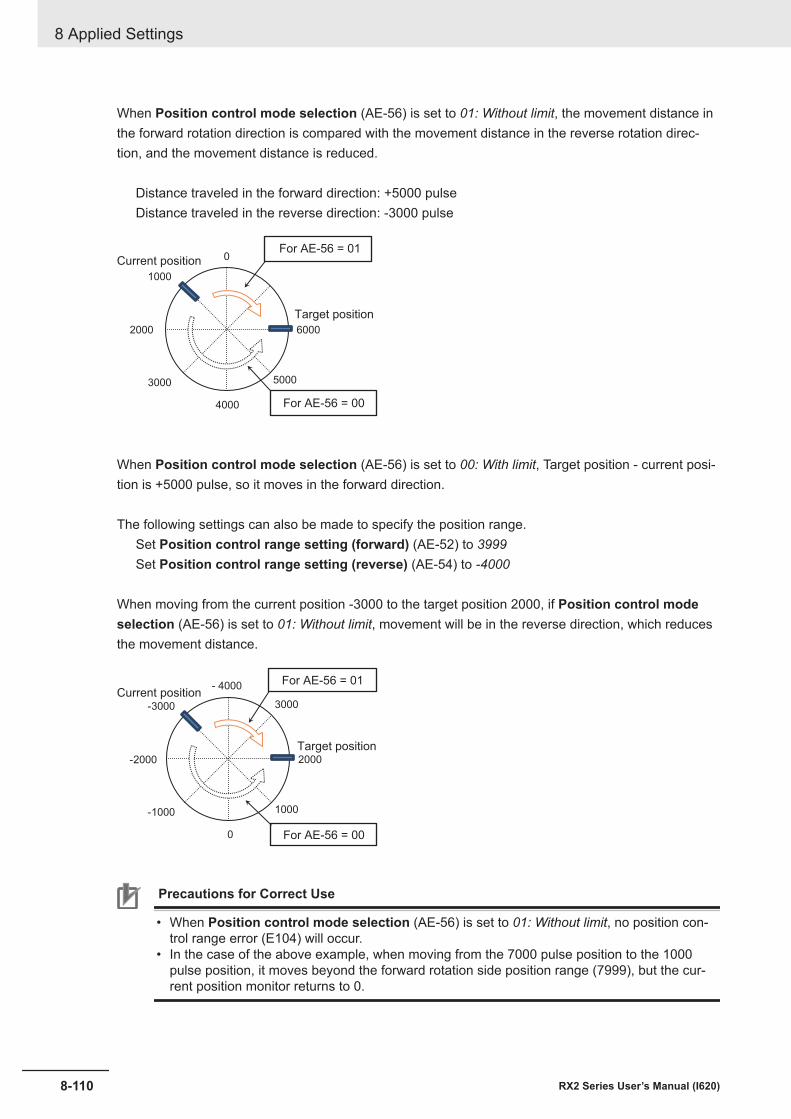
When Position control mode selection (AE-56) is set to 01: Without limit, the movement distance inthe forward rotation direction is compared with the movement distance in the reverse rotation direc-tion, and the movement distance is reduced.
Distance traveled in the forward direction: +5000 pulseDistance traveled in the reverse direction: -3000 pulse
2000
4000
6000
3000
1000
5000
0For AE-56 = 01
For AE-56 = 00
Target position
Current position
When Position control mode selection (AE-56) is set to 00: With limit, Target position - current posi-tion is +5000 pulse, so it moves in the forward direction.
The following settings can also be made to specify the position range.Set Position control range setting (forward) (AE-52) to 3999Set Position control range setting (reverse) (AE-54) to -4000
When moving from the current position -3000 to the target position 2000, if Position control modeselection (AE-56) is set to 01: Without limit, movement will be in the reverse direction, which reducesthe movement distance.
-2000
0
2000
-1000
-3000 3000
1000
- 4000 For AE-56 = 01
For AE-56 = 00
Target position
Current position
Precautions for Correct Use
• When Position control mode selection (AE-56) is set to 01: Without limit, no position con-trol range error (E104) will occur.
• In the case of the above example, when moving from the 7000 pulse position to the 1000pulse position, it moves beyond the forward rotation side position range (7999), but the cur-rent position monitor returns to 0.
8 Applied Settings
8-110 RX2 Series User’s Manual (I620)
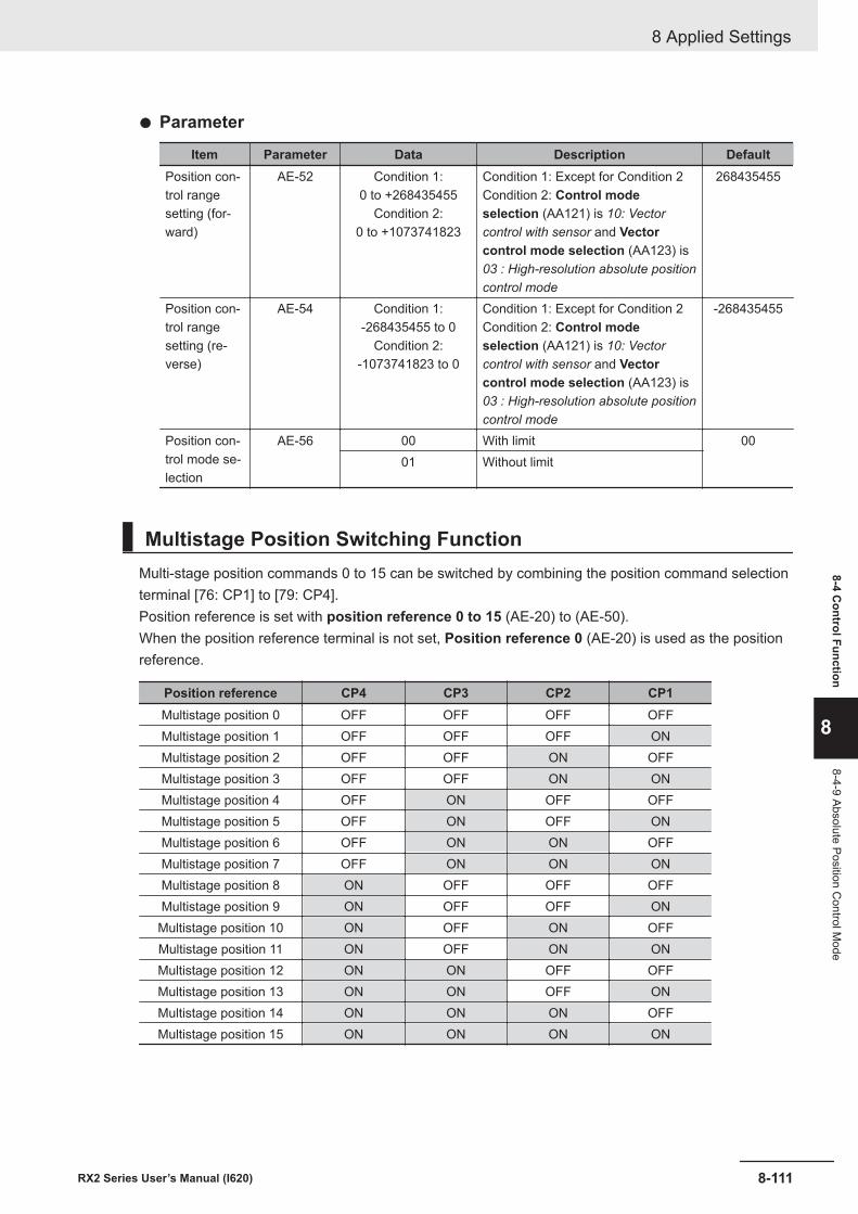
l Parameter
Item Parameter Data Description DefaultPosition con-trol rangesetting (for-ward)
AE-52 Condition 1:0 to +268435455
Condition 2:0 to +1073741823
Condition 1: Except for Condition 2Condition 2: Control modeselection (AA121) is 10: Vectorcontrol with sensor and Vectorcontrol mode selection (AA123) is03 : High-resolution absolute positioncontrol mode
268435455
Position con-trol rangesetting (re-verse)
AE-54 Condition 1:-268435455 to 0
Condition 2:-1073741823 to 0
Condition 1: Except for Condition 2Condition 2: Control modeselection (AA121) is 10: Vectorcontrol with sensor and Vectorcontrol mode selection (AA123) is03 : High-resolution absolute positioncontrol mode
-268435455
Position con-trol mode se-lection
AE-56 00 With limit 0001 Without limit
Multistage Position Switching FunctionMulti-stage position commands 0 to 15 can be switched by combining the position command selectionterminal [76: CP1] to [79: CP4].Position reference is set with position reference 0 to 15 (AE-20) to (AE-50).When the position reference terminal is not set, Position reference 0 (AE-20) is used as the positionreference.
Position reference CP4 CP3 CP2 CP1Multistage position 0 OFF OFF OFF OFFMultistage position 1 OFF OFF OFF ONMultistage position 2 OFF OFF ON OFFMultistage position 3 OFF OFF ON ONMultistage position 4 OFF ON OFF OFFMultistage position 5 OFF ON OFF ONMultistage position 6 OFF ON ON OFFMultistage position 7 OFF ON ON ONMultistage position 8 ON OFF OFF OFFMultistage position 9 ON OFF OFF ON
Multistage position 10 ON OFF ON OFFMultistage position 11 ON OFF ON ONMultistage position 12 ON ON OFF OFFMultistage position 13 ON ON OFF ONMultistage position 14 ON ON ON OFFMultistage position 15 ON ON ON ON
8 Applied Settings
8-111RX2 Series User’s Manual (I620)
8-4 Control Function
8
8-4-9 Absolute Position Control M
ode
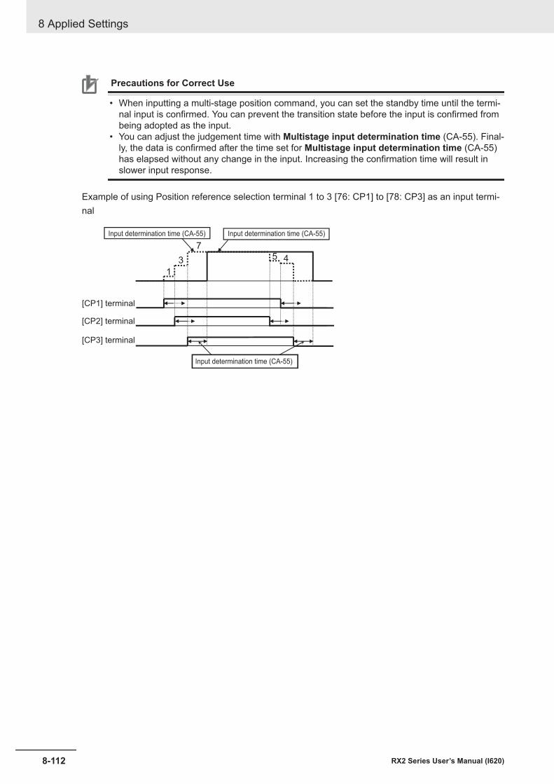
Precautions for Correct Use
• When inputting a multi-stage position command, you can set the standby time until the termi-nal input is confirmed. You can prevent the transition state before the input is confirmed frombeing adopted as the input.
• You can adjust the judgement time with Multistage input determination time (CA-55). Final-ly, the data is confirmed after the time set for Multistage input determination time (CA-55)has elapsed without any change in the input. Increasing the confirmation time will result inslower input response.
Example of using Position reference selection terminal 1 to 3 [76: CP1] to [78: CP3] as an input termi-nal
4
1
453
7
Input determination time (CA-55)Input determination time (CA-55)
[CP1] terminal
[CP2] terminal
[CP3] terminal
Input determination time (CA-55)
8 Applied Settings
8-112 RX2 Series User’s Manual (I620)
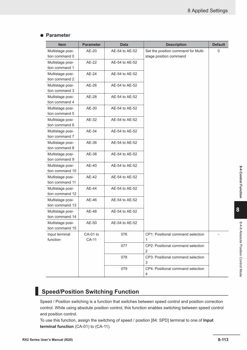
l Parameter
Item Parameter Data Description DefaultMultistage posi-tion command 0
AE-20 AE-54 to AE-52 Set the position command for Multi-stage position command
0
Multistage posi-tion command 1
AE-22 AE-54 to AE-52
Multistage posi-tion command 2
AE-24 AE-54 to AE-52
Multistage posi-tion command 3
AE-26 AE-54 to AE-52
Multistage posi-tion command 4
AE-28 AE-54 to AE-52
Multistage posi-tion command 5
AE-30 AE-54 to AE-52
Multistage posi-tion command 6
AE-32 AE-54 to AE-52
Multistage posi-tion command 7
AE-34 AE-54 to AE-52
Multistage posi-tion command 8
AE-36 AE-54 to AE-52
Multistage posi-tion command 9
AE-38 AE-54 to AE-52
Multistage posi-tion command 10
AE-40 AE-54 to AE-52
Multistage posi-tion command 11
AE-42 AE-54 to AE-52
Multistage posi-tion command 12
AE-44 AE-54 to AE-52
Multistage posi-tion command 13
AE-46 AE-54 to AE-52
Multistage posi-tion command 14
AE-48 AE-54 to AE-52
Multistage posi-tion command 15
AE-50 AE-54 to AE-52
Input terminalfunction
CA-01 toCA-11
076 CP1: Positional command selection1
-
077 CP2: Positional command selection2
078 CP3: Positional command selection3
079 CP4: Positional command selection4
Speed/Position Switching FunctionSpeed / Position switching is a function that switches between speed control and position correctioncontrol. While using absolute position control, this function enables switching between speed controland position control.To use this function, assign the switching of speed / position [84: SPD] terminal to one of Inputterminal function (CA-01) to (CA-11).
8 Applied Settings
8-113RX2 Series User’s Manual (I620)
8-4 Control Function
8
8-4-9 Absolute Position Control M
ode
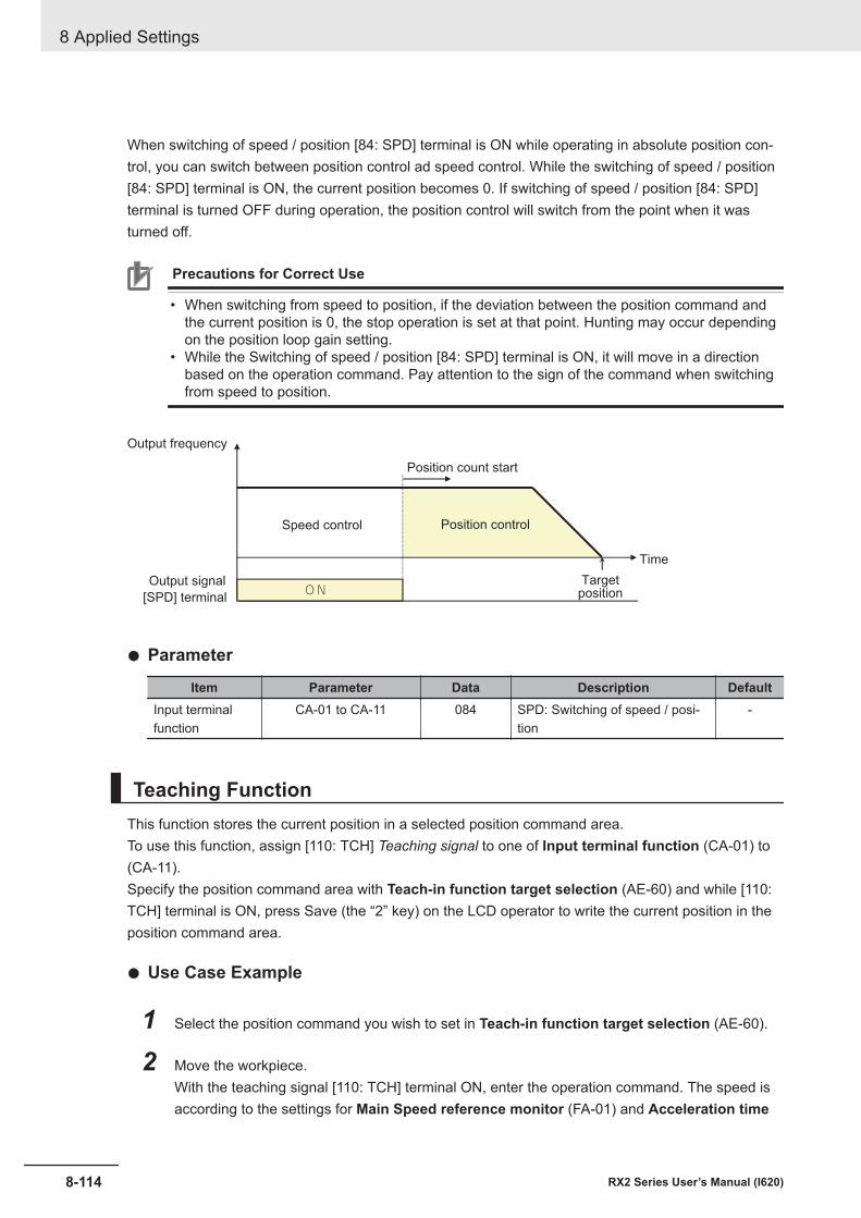
When switching of speed / position [84: SPD] terminal is ON while operating in absolute position con-trol, you can switch between position control ad speed control. While the switching of speed / position[84: SPD] terminal is ON, the current position becomes 0. If switching of speed / position [84: SPD]terminal is turned OFF during operation, the position control will switch from the point when it wasturned off.
Precautions for Correct Use
• When switching from speed to position, if the deviation between the position command andthe current position is 0, the stop operation is set at that point. Hunting may occur dependingon the position loop gain setting.
• While the Switching of speed / position [84: SPD] terminal is ON, it will move in a directionbased on the operation command. Pay attention to the sign of the command when switchingfrom speed to position.
ON
Position count start
Output frequency
Speed control
[SPD] terminal
Output signal
Time
Targetposition
Position control
l Parameter
Item Parameter Data Description DefaultInput terminalfunction
CA-01 to CA-11 084 SPD: Switching of speed / posi-tion
-
Teaching FunctionThis function stores the current position in a selected position command area.To use this function, assign [110: TCH] Teaching signal to one of Input terminal function (CA-01) to(CA-11).Specify the position command area with Teach-in function target selection (AE-60) and while [110:TCH] terminal is ON, press Save (the “2” key) on the LCD operator to write the current position in theposition command area.
l Use Case Example
1 Select the position command you wish to set in Teach-in function target selection (AE-60).
2 Move the workpiece.With the teaching signal [110: TCH] terminal ON, enter the operation command. The speed isaccording to the settings for Main Speed reference monitor (FA-01) and Acceleration time
8 Applied Settings
8-114 RX2 Series User’s Manual (I620)
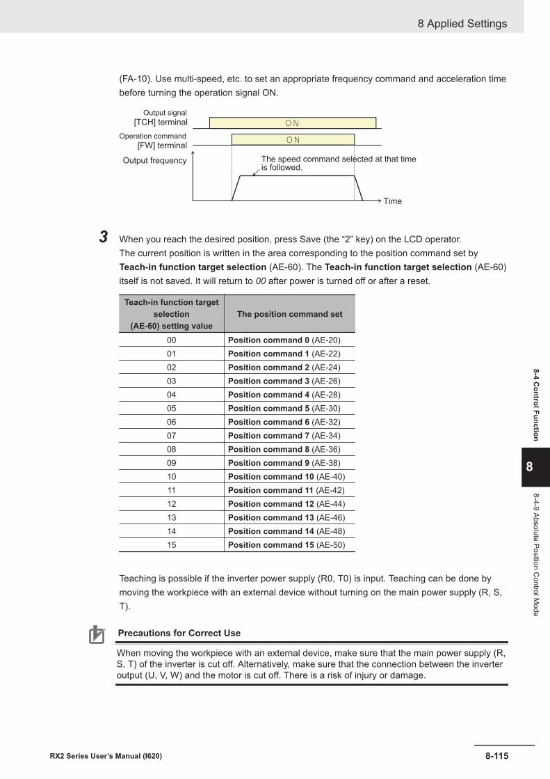
(FA-10). Use multi-speed, etc. to set an appropriate frequency command and acceleration timebefore turning the operation signal ON.
ON
ON
Output frequency
[FW] terminalOperation command
[TCH] terminalOutput signal
The speed command selected at that timeis followed.
Time
3 When you reach the desired position, press Save (the “2” key) on the LCD operator.The current position is written in the area corresponding to the position command set byTeach-in function target selection (AE-60). The Teach-in function target selection (AE-60)itself is not saved. It will return to 00 after power is turned off or after a reset.
Teach-in function targetselection
(AE-60) setting valueThe position command set
00 Position command 0 (AE-20)01 Position command 1 (AE-22)02 Position command 2 (AE-24)03 Position command 3 (AE-26)04 Position command 4 (AE-28)05 Position command 5 (AE-30)06 Position command 6 (AE-32)07 Position command 7 (AE-34)08 Position command 8 (AE-36)09 Position command 9 (AE-38)10 Position command 10 (AE-40)11 Position command 11 (AE-42)12 Position command 12 (AE-44)13 Position command 13 (AE-46)14 Position command 14 (AE-48)15 Position command 15 (AE-50)
Teaching is possible if the inverter power supply (R0, T0) is input. Teaching can be done bymoving the workpiece with an external device without turning on the main power supply (R, S,T).
Precautions for Correct Use
When moving the workpiece with an external device, make sure that the main power supply (R,S, T) of the inverter is cut off. Alternatively, make sure that the connection between the inverteroutput (U, V, W) and the motor is cut off. There is a risk of injury or damage.
8 Applied Settings
8-115RX2 Series User’s Manual (I620)
8-4 Control Function
8
8-4-9 Absolute Position Control M
ode
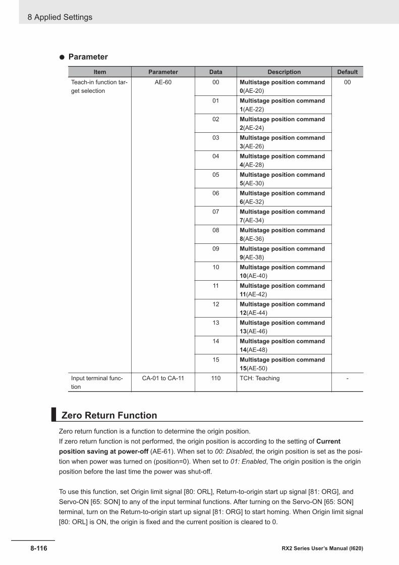
l Parameter
Item Parameter Data Description DefaultTeach-in function tar-get selection
AE-60 00 Multistage position command0(AE-20)
00
01 Multistage position command1(AE-22)
02 Multistage position command2(AE-24)
03 Multistage position command3(AE-26)
04 Multistage position command4(AE-28)
05 Multistage position command5(AE-30)
06 Multistage position command6(AE-32)
07 Multistage position command7(AE-34)
08 Multistage position command8(AE-36)
09 Multistage position command9(AE-38)
10 Multistage position command10(AE-40)
11 Multistage position command11(AE-42)
12 Multistage position command12(AE-44)
13 Multistage position command13(AE-46)
14 Multistage position command14(AE-48)
15 Multistage position command15(AE-50)
Input terminal func-tion
CA-01 to CA-11 110 TCH: Teaching -
Zero Return FunctionZero return function is a function to determine the origin position.If zero return function is not performed, the origin position is according to the setting of Currentposition saving at power-off (AE-61). When set to 00: Disabled, the origin position is set as the posi-tion when power was turned on (position=0). When set to 01: Enabled, The origin position is the originposition before the last time the power was shut-off.
To use this function, set Origin limit signal [80: ORL], Return-to-origin start up signal [81: ORG], andServo-ON [65: SON] to any of the input terminal functions. After turning on the Servo-ON [65: SON]terminal, turn on the Return-to-origin start up signal [81: ORG] to start homing. When Origin limit signal[80: ORL] is ON, the origin is fixed and the current position is cleared to 0.
8 Applied Settings
8-116 RX2 Series User’s Manual (I620)
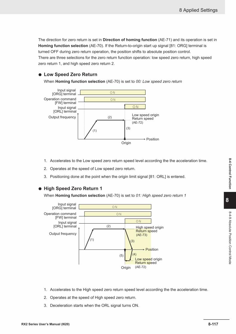
The direction for zero return is set in Direction of homing function (AE-71) and its operation is set inHoming function selection (AE-70). If the Return-to-origin start up signal [81: ORG] terminal isturned OFF during zero return operation, the position shifts to absolute position control.There are three selections for the zero return function operation: low speed zero return, high speedzero return 1, and high speed zero return 2.
l Low Speed Zero ReturnWhen Homing function selection (AE-70) is set to 00: Low speed zero return
ON
ON
(1)
(2)
(3)
(AE-72)
ON
Output frequency
[FW] terminalOperation command
[ORG] terminalInput signal
Low speed originReturn speed
PositionOrigin
[ORL] terminalInput signal
1. Accelerates to the Low speed zero return speed level according the the acceleration time.
2. Operates at the speed of Low speed zero return.
3. Positioning done at the point when the origin limit signal [81: ORL] is entered.
l High Speed Zero Return 1When Homing function selection (AE-70) is set to 01: High speed zero return 1
ON
ON
(1)
(2)
(3)
(4)(5)
(AE-73)
ON
(AE-72)
Output frequency
[ORG] terminalInput signal
Position
Origin
[ORL] terminalInput signal
[FW] terminalOperation command
High speed origin Return speed
Low speed originReturn speed
1. Accelerates to the High speed zero return speed level according the the acceleration time.
2. Operates at the speed of High speed zero return.
3. Deceleration starts when the ORL signal turns ON.
8 Applied Settings
8-117RX2 Series User’s Manual (I620)
8-4 Control Function
8
8-4-9 Absolute Position Control M
ode
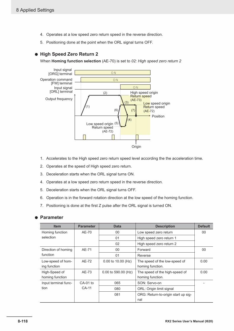
4. Operates at a low speed zero return speed in the reverse direction.
5. Positioning done at the point when the ORL signal turns OFF.
l High Speed Zero Return 2When Homing function selection (AE-70) is set to 02: High speed zero return 2
ON
ON
(1)
(2)
(3)
(4)(5)
(6) (7)
ON
(AE-73)
(AE-72)
(AE-72)
Output frequency
[ORG] terminalInput signal
Position
Origin
[ORL] terminalInput signal
[FW] terminalOperation command
High speed originReturn speed
Low speed originReturn speed
Low speed originReturn speed
1. Accelerates to the High speed zero return speed level according the the acceleration time.
2. Operates at the speed of High speed zero return.
3. Deceleration starts when the ORL signal turns ON.
4. Operates at a low speed zero return speed in the reverse direction.
5. Deceleration starts when the ORL signal turns OFF.
6. Operation is in the forward rotation direction at the low speed of the homing function.
7. Positioning is done at the first Z pulse after the ORL signal is turned ON.
l Parameter
Item Parameter Data Description DefaultHoming functionselection
AE-70 00 Low speed zero return 0001 High speed zero return 102 High speed zero return 2
Direction of homingfunction
AE-71 00 Forward 0001 Reverse
Low-speed of hom-ing function
AE-72 0.00 to 10.00 (Hz) The speed of the low-speed ofhoming function.
0.00
High-Speed ofhoming function
AE-73 0.00 to 590.00 (Hz) The speed of the high-speed ofhoming function.
0.00
Input terminal func-tion
CA-01 toCA-11
065 SON: Servo-on -080 ORL: Origin limit signal081 ORG: Return-to-origin start up sig-
nal
8 Applied Settings
8-118 RX2 Series User’s Manual (I620)
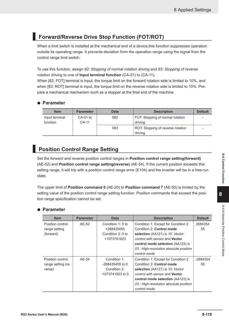
Forward/Reverse Drive Stop Function (FOT/ROT)When a limit switch is installed at the mechanical end of a device,this function suppresses operationoutside its operating range. It prevents deviation from the operation range using the signal from thecontrol range limit switch.
To use this function, assign 82: Stopping of normal rotation driving and 83: Stopping of reverserotation driving to one of Input terminal function (CA-01) to (CA-11).When [82: FOT] terminal is input, the torque limit on the forward rotation side is limited to 10%, andwhen [83: ROT] terminal is input, the torque limit on the reverse rotation side is limited to 10%. Pre-pare a mechanical mechanism such as a stopper at the final end of the machine.
l Parameter
Item Parameter Data Description DefaultInput terminalfunction
CA-01 toCA-11
082 FOT: Stopping of normal rotationdriving
-
083 ROT: Stopping of reverse rotationdriving
-
Position Control Range SettingSet the forward and reverse position control ranges in Position control range setting(forward)(AE-52) and Position control range setting(reverse) (AE-54). If the current position exceeds thissetting range, it will trip with a position control range error (E104) and the inverter will be in a free-runstate.
The upper limit of Position command 0 (AE-20) to Position command 7 (AE-50) is limited by thesetting value of the position control range setting function. Position commands that exceed the posi-tion range specification cannot be set.
l Parameter
Item Parameter Data Description DefaultPosition controlrange setting(forward)
AE-52 Condition 1: 0 to+268435455
Condition 2: 0 to+1073741823
Condition 1: Except for Condition 2Condition 2: Control modeselection (AA121) is 10: Vectorcontrol with sensor and Vectorcontrol mode selection (AA123) is03 : High-resolution absolute positioncontrol mode
268435455
Position controlrange setting (re-verse)
AE-54 Condition 1:-268435455 to 0
Condition 2:-1073741823 to 0
Condition 1: Except for Condition 2Condition 2: Control modeselection (AA121) is 10: Vectorcontrol with sensor and Vectorcontrol mode selection (AA123) is03 : High-resolution absolute positioncontrol mode
-268435455
8 Applied Settings
8-119RX2 Series User’s Manual (I620)
8-4 Control Function
8
8-4-9 Absolute Position Control M
ode
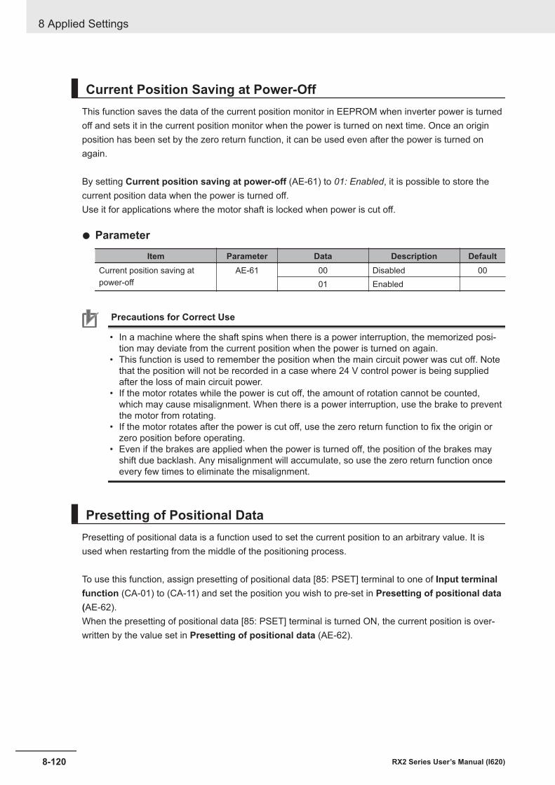
Current Position Saving at Power-OffThis function saves the data of the current position monitor in EEPROM when inverter power is turnedoff and sets it in the current position monitor when the power is turned on next time. Once an originposition has been set by the zero return function, it can be used even after the power is turned onagain.
By setting Current position saving at power-off (AE-61) to 01: Enabled, it is possible to store thecurrent position data when the power is turned off.Use it for applications where the motor shaft is locked when power is cut off.
l Parameter
Item Parameter Data Description DefaultCurrent position saving atpower-off
AE-61 00 Disabled 0001 Enabled
Precautions for Correct Use
• In a machine where the shaft spins when there is a power interruption, the memorized posi-tion may deviate from the current position when the power is turned on again.
• This function is used to remember the position when the main circuit power was cut off. Notethat the position will not be recorded in a case where 24 V control power is being suppliedafter the loss of main circuit power.
• If the motor rotates while the power is cut off, the amount of rotation cannot be counted,which may cause misalignment. When there is a power interruption, use the brake to preventthe motor from rotating.
• If the motor rotates after the power is cut off, use the zero return function to fix the origin orzero position before operating.
• Even if the brakes are applied when the power is turned off, the position of the brakes mayshift due backlash. Any misalignment will accumulate, so use the zero return function onceevery few times to eliminate the misalignment.
Presetting of Positional DataPresetting of positional data is a function used to set the current position to an arbitrary value. It isused when restarting from the middle of the positioning process.
To use this function, assign presetting of positional data [85: PSET] terminal to one of Input terminalfunction (CA-01) to (CA-11) and set the position you wish to pre-set in Presetting of positional data(AE-62).When the presetting of positional data [85: PSET] terminal is turned ON, the current position is over-written by the value set in Presetting of positional data (AE-62).
8 Applied Settings
8-120 RX2 Series User’s Manual (I620)
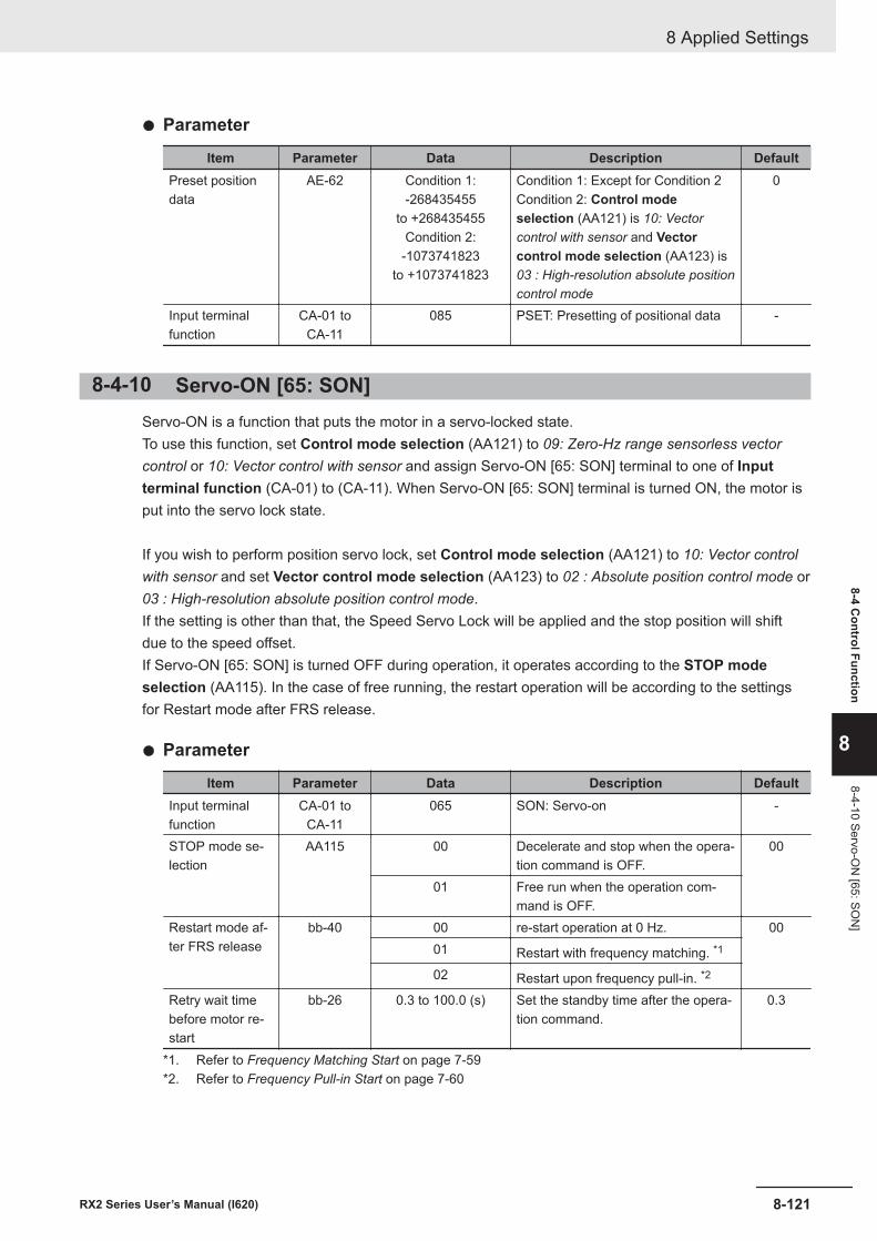
l Parameter
Item Parameter Data Description DefaultPreset positiondata
AE-62 Condition 1:-268435455
to +268435455Condition 2:
-1073741823to +1073741823
Condition 1: Except for Condition 2Condition 2: Control modeselection (AA121) is 10: Vectorcontrol with sensor and Vectorcontrol mode selection (AA123) is03 : High-resolution absolute positioncontrol mode
0
Input terminalfunction
CA-01 toCA-11
085 PSET: Presetting of positional data -
8-4-10 Servo-ON [65: SON]Servo-ON is a function that puts the motor in a servo-locked state.To use this function, set Control mode selection (AA121) to 09: Zero-Hz range sensorless vectorcontrol or 10: Vector control with sensor and assign Servo-ON [65: SON] terminal to one of Inputterminal function (CA-01) to (CA-11). When Servo-ON [65: SON] terminal is turned ON, the motor isput into the servo lock state.
If you wish to perform position servo lock, set Control mode selection (AA121) to 10: Vector controlwith sensor and set Vector control mode selection (AA123) to 02 : Absolute position control mode or03 : High-resolution absolute position control mode.If the setting is other than that, the Speed Servo Lock will be applied and the stop position will shiftdue to the speed offset.If Servo-ON [65: SON] is turned OFF during operation, it operates according to the STOP modeselection (AA115). In the case of free running, the restart operation will be according to the settingsfor Restart mode after FRS release.
l Parameter
Item Parameter Data Description DefaultInput terminalfunction
CA-01 toCA-11
065 SON: Servo-on -
STOP mode se-lection
AA115 00 Decelerate and stop when the opera-tion command is OFF.
00
01 Free run when the operation com-mand is OFF.
Restart mode af-ter FRS release
bb-40 00 re-start operation at 0 Hz. 0001 Restart with frequency matching. *1
02 Restart upon frequency pull-in. *2
Retry wait timebefore motor re-start
bb-26 0.3 to 100.0 (s) Set the standby time after the opera-tion command.
0.3
*1. Refer to Frequency Matching Start on page 7-59*2. Refer to Frequency Pull-in Start on page 7-60
8 Applied Settings
8-121RX2 Series User’s Manual (I620)
8-4 Control Function
8
8-4-10 Servo-ON
[65: SON
]
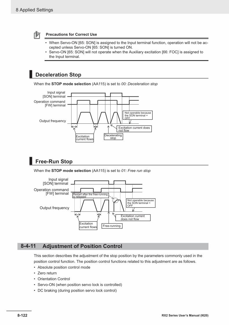
Precautions for Correct Use
• When Servo-ON [65: SON] is assigned to the Input terminal function, operation will not be ac-cepted unless Servo-ON [65: SON] is turned ON.
• Servo-ON [65: SON] will not operate when the Auxiliary excitation [66: FOC] is assigned tothe Input terminal.
Deceleration StopWhen the STOP mode selection (AA115) is set to 00: Deceleration stop
Output frequency
[SON] terminalInput signal
Deceleratingstop
Excitationcurrent flows
[FW] terminalOperation command
Excitation current doesnot flow
Not operable becausethe SON terminal =OFF
Free-Run StopWhen the STOP mode selection (AA115) is set to 01: Free run stop
Output frequency
[SON] terminalInput signal
Free-runningExcitationcurrent flows
[FW] terminalOperation command
Excitation currentdoes not flow
Not operable becausethe SON terminal =OFF
Restart after the free-runningis released
8-4-11 Adjustment of Position ControlThis section describes the adjustment of the stop position by the parameters commonly used in theposition control function. The position control functions related to this adjustment are as follows.• Absolute position control mode• Zero return• Orientation Control• Servo-ON (when position servo lock is controlled)• DC braking (during position servo lock control)
8 Applied Settings
8-122 RX2 Series User’s Manual (I620)
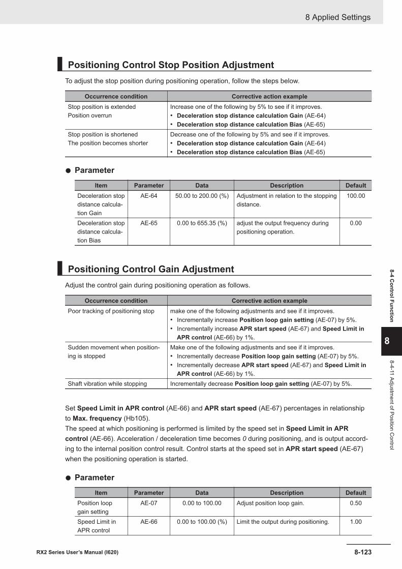
Positioning Control Stop Position AdjustmentTo adjust the stop position during positioning operation, follow the steps below.
Occurrence condition Corrective action exampleStop position is extendedPosition overrun
Increase one of the following by 5% to see if it improves.• Deceleration stop distance calculation Gain (AE-64)• Deceleration stop distance calculation Bias (AE-65)
Stop position is shortenedThe position becomes shorter
Decrease one of the following by 5% and see if it improves.• Deceleration stop distance calculation Gain (AE-64)• Deceleration stop distance calculation Bias (AE-65)
l Parameter
Item Parameter Data Description DefaultDeceleration stopdistance calcula-tion Gain
AE-64 50.00 to 200.00 (%) Adjustment in relation to the stoppingdistance.
100.00
Deceleration stopdistance calcula-tion Bias
AE-65 0.00 to 655.35 (%) adjust the output frequency duringpositioning operation.
0.00
Positioning Control Gain AdjustmentAdjust the control gain during positioning operation as follows.
Occurrence condition Corrective action examplePoor tracking of positioning stop make one of the following adjustments and see if it improves.
• Incrementally increase Position loop gain setting (AE-07) by 5%.• Incrementally increase APR start speed (AE-67) and Speed Limit in
APR control (AE-66) by 1%.Sudden movement when position-ing is stopped
Make one of the following adjustments and see if it improves.• Incrementally decrease Position loop gain setting (AE-07) by 5%.• Incrementally decrease APR start speed (AE-67) and Speed Limit in
APR control (AE-66) by 1%.Shaft vibration while stopping Incrementally decrease Position loop gain setting (AE-07) by 5%.
Set Speed Limit in APR control (AE-66) and APR start speed (AE-67) percentages in relationshipto Max. frequency (Hb105).The speed at which positioning is performed is limited by the speed set in Speed Limit in APRcontrol (AE-66). Acceleration / deceleration time becomes 0 during positioning, and is output accord-ing to the internal position control result. Control starts at the speed set in APR start speed (AE-67)when the positioning operation is started.
l Parameter
Item Parameter Data Description DefaultPosition loopgain setting
AE-07 0.00 to 100.00 Adjust position loop gain. 0.50
Speed Limit inAPR control
AE-66 0.00 to 100.00 (%) Limit the output during positioning. 1.00
8 Applied Settings
8-123RX2 Series User’s Manual (I620)
8-4 Control Function
8
8-4-11 Adjustment of Position C
ontrol

Item Parameter Data Description DefaultAPR start speed AE-67 0.00 to 100.00 (%) Set the speed at the start of position-
ing.0.20
8 Applied Settings
8-124 RX2 Series User’s Manual (I620)
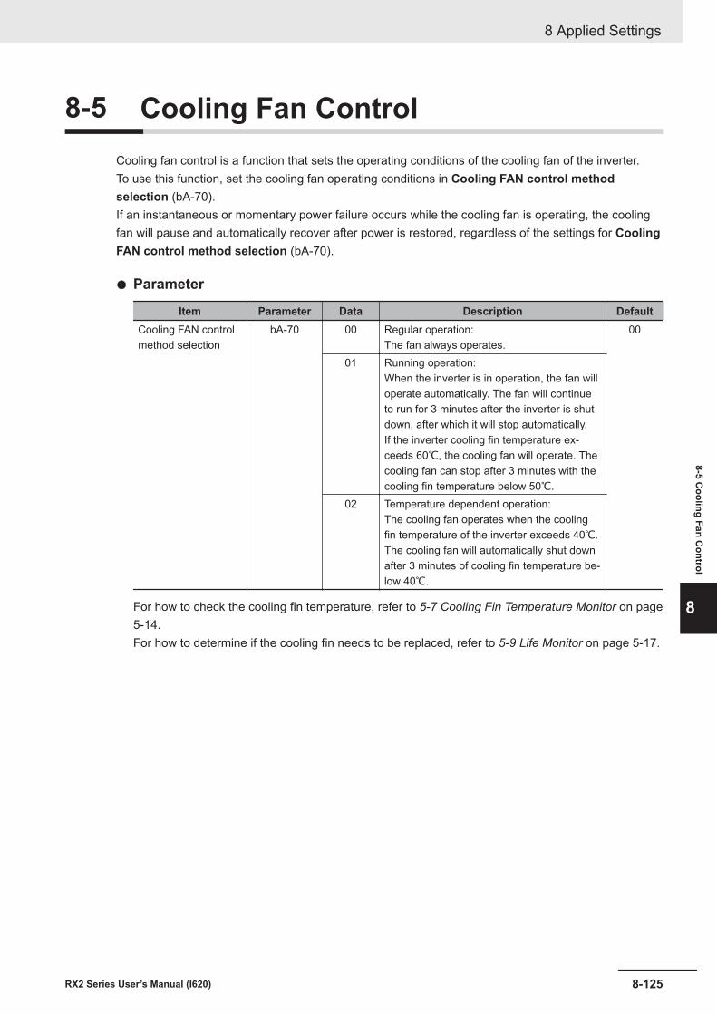
8-5 Cooling Fan ControlCooling fan control is a function that sets the operating conditions of the cooling fan of the inverter.To use this function, set the cooling fan operating conditions in Cooling FAN control methodselection (bA-70).If an instantaneous or momentary power failure occurs while the cooling fan is operating, the coolingfan will pause and automatically recover after power is restored, regardless of the settings for CoolingFAN control method selection (bA-70).
l Parameter
Item Parameter Data Description DefaultCooling FAN controlmethod selection
bA-70 00 Regular operation:The fan always operates.
00
01 Running operation:When the inverter is in operation, the fan willoperate automatically. The fan will continueto run for 3 minutes after the inverter is shutdown, after which it will stop automatically.If the inverter cooling fin temperature ex-ceeds 60℃, the cooling fan will operate. Thecooling fan can stop after 3 minutes with thecooling fin temperature below 50℃.
02 Temperature dependent operation:The cooling fan operates when the coolingfin temperature of the inverter exceeds 40℃.The cooling fan will automatically shut downafter 3 minutes of cooling fin temperature be-low 40℃.
For how to check the cooling fin temperature, refer to 5-7 Cooling Fin Temperature Monitor on page5-14.For how to determine if the cooling fin needs to be replaced, refer to 5-9 Life Monitor on page 5-17.
8 Applied Settings
8-125RX2 Series User’s Manual (I620)
8-5 Cooling Fan C
ontrol
8
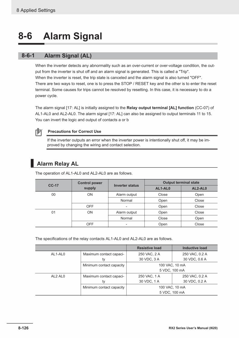
8-6 Alarm Signal
8-6-1 Alarm Signal (AL)When the inverter detects any abnormality such as an over-current or over-voltage condition, the out-put from the inverter is shut off and an alarm signal is generated. This is called a "Trip".When the inverter is reset, the trip state is canceled and the alarm signal is also turned "OFF".There are two ways to reset, one is to press the STOP / RESET key and the other is to enter the resetterminal. Some causes for trips cannot be resolved by resetting. In this case, it is necessary to do apower cycle.
The alarm signal [17: AL] is initially assigned to the Relay output terminal [AL] function (CC-07) ofAL1-AL0 and AL2-AL0. The alarm signal [17: AL] can also be assigned to output terminals 11 to 15.You can invert the logic and output of contacts a or b
Precautions for Correct Use
If the inverter outputs an error when the inverter power is intentionally shut off, it may be im-proved by changing the wiring and contact selection.
Alarm Relay ALThe operation of AL1-AL0 and AL2-AL0 are as follows.
CC-17 Control powersupply Inverter status
Output terminal stateAL1-AL0 AL2-AL0
00 ON Alarm output Close OpenNormal Open Close
OFF - Open Close01 ON Alarm output Open Close
Normal Close OpenOFF - Open Close
The specifications of the relay contacts AL1-AL0 and AL2-AL0 are as follows.
Resistive load Inductive loadAL1-AL0 Maximum contact capaci-
ty250 VAC, 2 A30 VDC, 3 A
250 VAC, 0.2 A30 VDC, 0.6 A
Minimum contact capacity 100 VAC, 10 mA5 VDC, 100 mA
AL2 AL0 Maximum contact capaci-ty
250 VAC, 1 A30 VDC, 1 A
250 VAC, 0.2 A30 VDC, 0.2 A
Minimum contact capacity 100 VAC, 10 mA5 VDC, 100 mA
8 Applied Settings
8-126 RX2 Series User’s Manual (I620)
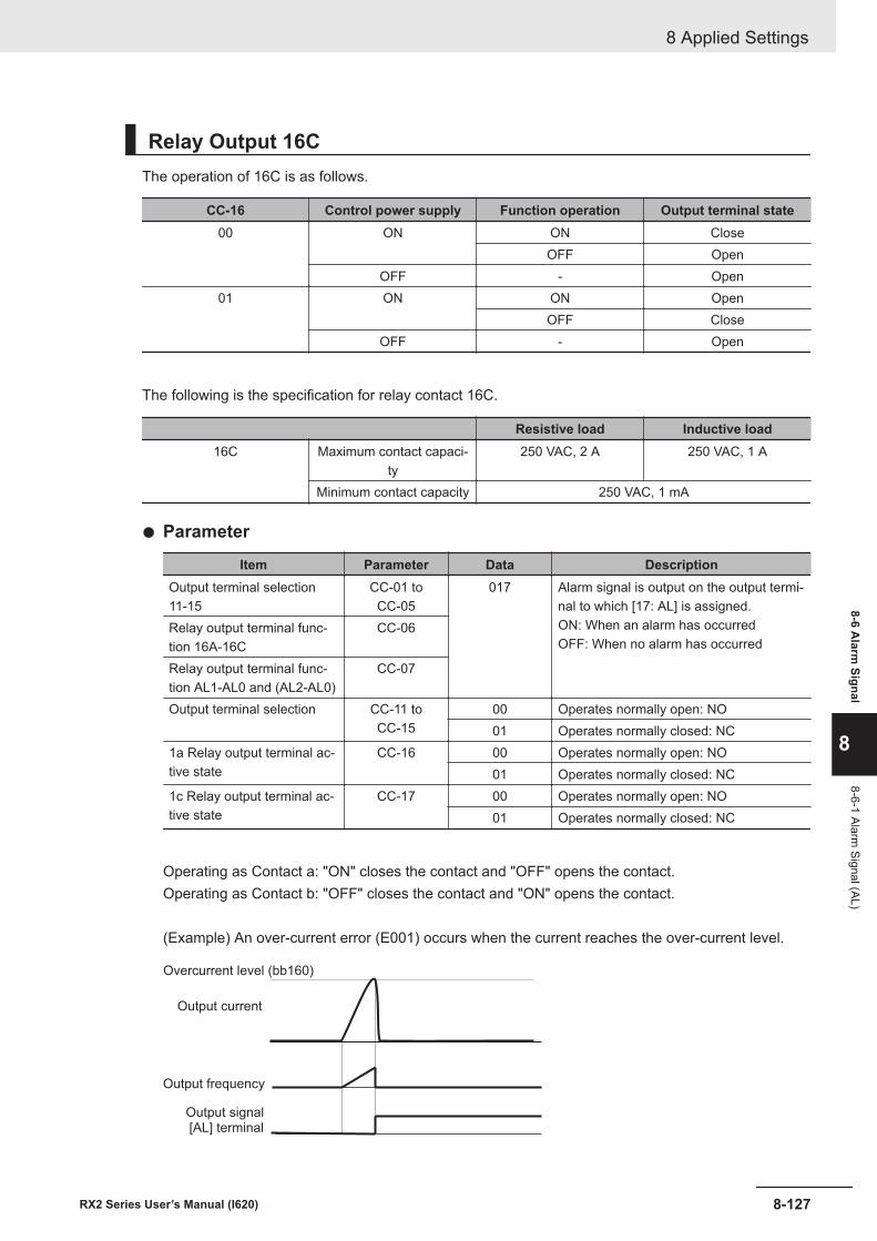
Relay Output 16CThe operation of 16C is as follows.
CC-16 Control power supply Function operation Output terminal state00 ON ON Close
OFF OpenOFF - Open
01 ON ON OpenOFF Close
OFF - Open
The following is the specification for relay contact 16C.
Resistive load Inductive load16C Maximum contact capaci-
ty250 VAC, 2 A 250 VAC, 1 A
Minimum contact capacity 250 VAC, 1 mA
l Parameter
Item Parameter Data DescriptionOutput terminal selection11-15
CC-01 toCC-05
017 Alarm signal is output on the output termi-nal to which [17: AL] is assigned.ON: When an alarm has occurredOFF: When no alarm has occurred
Relay output terminal func-tion 16A-16C
CC-06
Relay output terminal func-tion AL1-AL0 and (AL2-AL0)
CC-07
Output terminal selection CC-11 toCC-15
00 Operates normally open: NO01 Operates normally closed: NC
1a Relay output terminal ac-tive state
CC-16 00 Operates normally open: NO01 Operates normally closed: NC
1c Relay output terminal ac-tive state
CC-17 00 Operates normally open: NO01 Operates normally closed: NC
Operating as Contact a: "ON" closes the contact and "OFF" opens the contact.Operating as Contact b: "OFF" closes the contact and "ON" opens the contact.
(Example) An over-current error (E001) occurs when the current reaches the over-current level.
Output frequency
[AL] terminalOutput signal
Output current
Overcurrent level (bb160)
8 Applied Settings
8-127RX2 Series User’s Manual (I620)
8-6 Alarm
Signal
8
8-6-1 Alarm Signal (AL)
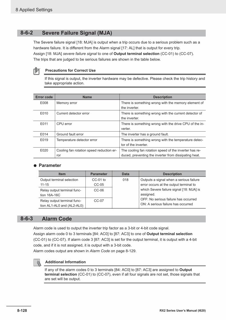
8-6-2 Severe Failure Signal (MJA)The Severe failure signal [18: MJA] is output when a trip occurs due to a serious problem such as ahardware failure. It is different from the Alarm signal [17: AL] that is output for every trip.Assign [18: MJA] severe failure signal to one of Output terminal selection (CC-01) to (CC-07).The trips that are judged to be serious failures are shown in the table below.
Precautions for Correct Use
If this signal is output, the inverter hardware may be defective. Please check the trip history andtake appropriate action.
Error code Name DescriptionE008 Memory error There is something wrong with the memory element of
the inverter.E010 Current detector error There is something wrong with the current detector of
the inverter.E011 CPU error There is something wrong with the drive CPU of the in-
verter.E014 Ground fault error The inverter has a ground fault.E019 Temperature detector error There is something wrong with the temperature detec-
tor of the inverter.E020 Cooling fan rotation speed reduction er-
rorThe cooling fan rotation speed of the inverter has re-duced, preventing the inverter from dissipating heat.
l Parameter
Item Parameter Data DescriptionOutput terminal selection11-15
CC-01 toCC-05
018 Outputs a signal when a serious failureerror occurs at the output terminal towhich Severe failure signal [18: MJA] isassigned.OFF: No serious failure has occurredON: A serious failure has occurred
Relay output terminal func-tion 16A-16C
CC-06
Relay output terminal func-tion AL1-AL0 and (AL2-AL0)
CC-07
8-6-3 Alarm CodeAlarm code is used to output the inverter trip factor as a 3-bit or 4-bit code signal.Assign alarm code 0 to 3 terminals [84: AC0] to [87: AC3] to one of Output terminal selection(CC-01) to (CC-07). If alarm code 3 [87: AC3] is set for the output terminal, it is output with a 4-bitcode, and if it is not assigned, it is output with a 3-bit code.Alarm codes output are shown in Alarm Code on page 8-129.
Additional Information
If any of the alarm codes 0 to 3 terminals [84: AC0] to [87: AC3] are assigned to Outputterminal selection (CC-01) to (CC-07), even if all four signals are not set, those signals thatare set will be output.
8 Applied Settings
8-128 RX2 Series User’s Manual (I620)
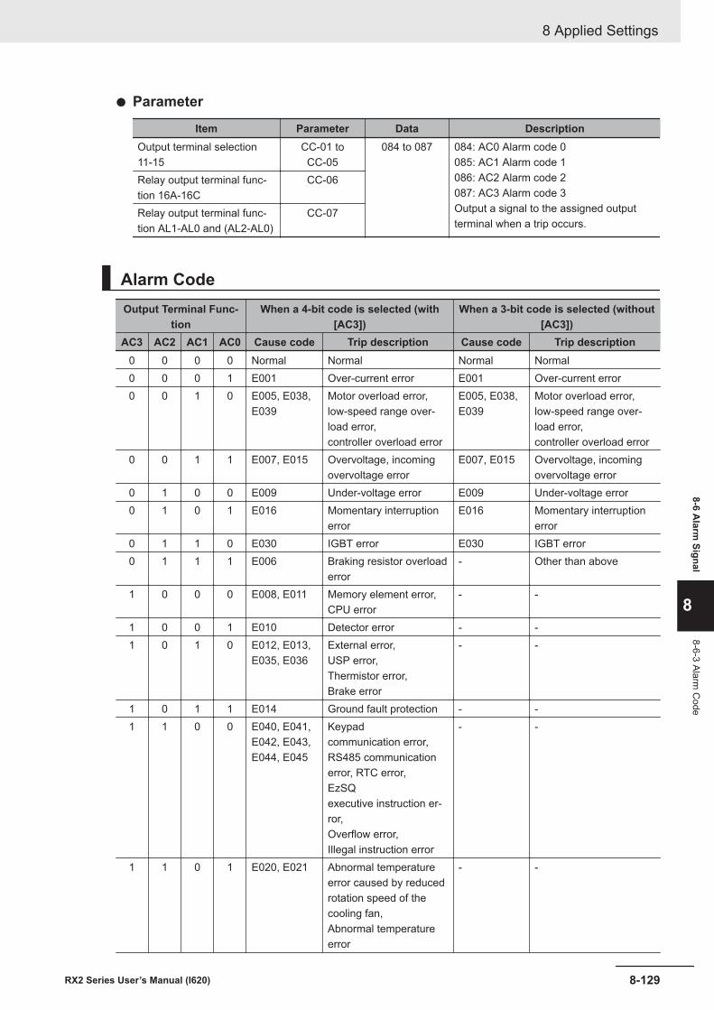
l Parameter
Item Parameter Data DescriptionOutput terminal selection11-15
CC-01 toCC-05
084 to 087 084: AC0 Alarm code 0085: AC1 Alarm code 1086: AC2 Alarm code 2087: AC3 Alarm code 3Output a signal to the assigned outputterminal when a trip occurs.
Relay output terminal func-tion 16A-16C
CC-06
Relay output terminal func-tion AL1-AL0 and (AL2-AL0)
CC-07
Alarm CodeOutput Terminal Func-
tionWhen a 4-bit code is selected (with
[AC3])When a 3-bit code is selected (without
[AC3])AC3 AC2 AC1 AC0 Cause code Trip description Cause code Trip description
0 0 0 0 Normal Normal Normal Normal0 0 0 1 E001 Over-current error E001 Over-current error0 0 1 0 E005, E038,
E039Motor overload error,low-speed range over-load error,controller overload error
E005, E038,E039
Motor overload error,low-speed range over-load error,controller overload error
0 0 1 1 E007, E015 Overvoltage, incomingovervoltage error
E007, E015 Overvoltage, incomingovervoltage error
0 1 0 0 E009 Under-voltage error E009 Under-voltage error0 1 0 1 E016 Momentary interruption
errorE016 Momentary interruption
error0 1 1 0 E030 IGBT error E030 IGBT error0 1 1 1 E006 Braking resistor overload
error- Other than above
1 0 0 0 E008, E011 Memory element error,CPU error
- -
1 0 0 1 E010 Detector error - -1 0 1 0 E012, E013,
E035, E036External error,USP error,Thermistor error,Brake error
- -
1 0 1 1 E014 Ground fault protection - -1 1 0 0 E040, E041,
E042, E043,E044, E045
Keypadcommunication error,RS485 communicationerror, RTC error,EzSQexecutive instruction er-ror,Overflow error,Illegal instruction error
- -
1 1 0 1 E020, E021 Abnormal temperatureerror caused by reducedrotation speed of thecooling fan,Abnormal temperatureerror
- -
8 Applied Settings
8-129RX2 Series User’s Manual (I620)
8-6 Alarm
Signal
8
8-6-3 Alarm C
ode
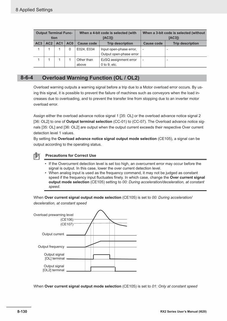
Output Terminal Func-tion
When a 4-bit code is selected (with[AC3])
When a 3-bit code is selected (without[AC3])
AC3 AC2 AC1 AC0 Cause code Trip description Cause code Trip description1 1 1 0 E024, E034 Input open-phase error,
Output open-phase error- -
1 1 1 1 Other thanabove
EzSQ assignment error0 to 9, etc.
- -
8-6-4 Overload Warning Function (OL / OL2)Overload warning outputs a warning signal before a trip due to a Motor overload error occurs. By us-ing this signal, it is possible to prevent the failure of machines such as conveyors when the load in-creases due to overloading, and to prevent the transfer line from stopping due to an inverter motoroverload error.
Assign either the overload advance notice signal 1 [35: OL] or the overload advance notice signal 2[36: OL2] to one of Output terminal selection (CC-01) to (CC-07). The Overload advance notice sig-nals [35: OL] and [36: OL2] are output when the output current exceeds their respective Over currentdetection level 1 values.By setting the Overload advance notice signal output mode selection (CE105), a signal can beoutput according to the operating status.
Precautions for Correct Use
• If the Overcurrent detection level is set too high, an overcurrent error may occur before thesignal is output. In this case, lower the over current detection level.
• When analog input is used as the frequency command, it may not be judged as constantspeed if the frequency input fluctuates finely. In which case, change the Over current signaloutput mode selection (CE105) setting to 00: During acceleration/deceleration, at constantspeed.
When Over current signal output mode selection (CE105) is set to 00: During acceleration/deceleration, at constant speed
(CE106)
(CE107)
Output frequency
[OL2] terminalOutput signal
Output current
Overload prewarning level
[OL] terminalOutput signal
When Over current signal output mode selection (CE105) is set to 01: Only at constant speed
8 Applied Settings
8-130 RX2 Series User’s Manual (I620)
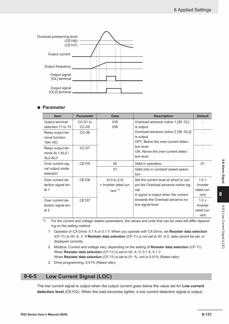
(CE106)
(CE107)
Output frequency
[OL2] terminalOutput signal
Output current
Overload prewarning level
[OL] terminalOutput signal
l Parameter
Item Parameter Data Description DefaultOutput terminalselection 11 to 15
CC-01 toCC-05
035036
Overload advance notice 1 [35: OL]is output.Overload advance notice 2 [36: OL2]is output.OFF: Below the over-current detec-tion levelON: Above the over-current detec-tion level
-
Relay output ter-minal function16A-16C
CC-06 -
Relay output ter-minal AL1-AL0 /AL2-AL0
CC-07 -
Over current sig-nal output modeselection
CE105 00 Valid in operation. 0101 Valid only in constant speed opera-
tionOver current de-tection signal lev-el 1
CE106 (0.0 to 2.0)× Inverter rated cur-
rent *1
Set the current level at which to out-put the Overload advance notice sig-nal.A signal is output when the currentexceeds the Overload advance no-tice signal level.
1.0 ×Inverter
rated cur-rent
Over current de-tection signal lev-el 2
CE107 1.0 ×Inverter
rated cur-rent
*1. For the current and voltage related parameters, the values and units that can be used will differ depend-ing on the setting method.
1. Operator or CX-Drive: 0.1 A or 0.1 V. When you operate with CX-Drive, set Resister data selection(CF-11) to 00: A, V. If Resister data selection (CF-11) is not set to 00: A,V, data cannot be set, ordisplayed correctly.
2. Modbus: Current and voltage vary, depending on the setting of Resister data selection (CF-11).When Resister data selection (CF-11) is set to 00: A, V, 0.1 A, 0.1 VWhen Resister data selection (CF-11) is set to 01: %, unit is 0.01% (Rated ratio)
3. Drive programming: 0.01% (Rated ratio)
8-6-5 Low Current Signal (LOC)The low current signal is output when the output current goes below the value set for Low currentdetection level (CE102). When the load becomes lighter, a low current detection signal is output.
8 Applied Settings
8-131RX2 Series User’s Manual (I620)
8-6 Alarm
Signal
8
8-6-5 Low C
urrent Signal (LOC
)
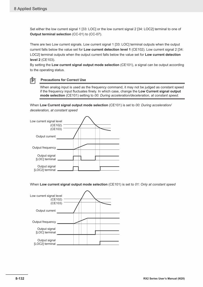
Set either the low current signal 1 [33: LOC] or the low current signal 2 [34: LOC2] terminal to one ofOutput terminal selection (CC-01) to (CC-07).
There are two Low current signals. Low current signal 1 [33: LOC] terminal outputs when the outputcurrent falls below the value set for Low current detection level 1 (CE102). Low current signal 2 [34:LOC2] terminal outputs when the output current falls below the value set for Low current detectionlevel 2 (CE103).By setting the Low current signal output mode selection (CE101), a signal can be output accordingto the operating status.
Precautions for Correct Use
When analog input is used as the frequency command, it may not be judged as constant speedif the frequency input fluctuates finely. In which case, change the Low Current signal outputmode selection (CE101) setting to 00: During acceleration/deceleration, at constant speed.
When Low Current signal output mode selection (CE101) is set to 00: During acceleration/deceleration, at constant speed
(CE102)
(CE103)
Output frequency
[LOC2] terminalOutput signal
Output current
Low current signal level
[LOC] terminalOutput signal
When Low current signal output mode selection (CE101) is set to 01: Only at constant speed
(CE102)
(CE103)
Output frequency
[LOC2] terminalOutput signal
Output current
Low current signal level
[LOC] terminalOutput signal
8 Applied Settings
8-132 RX2 Series User’s Manual (I620)
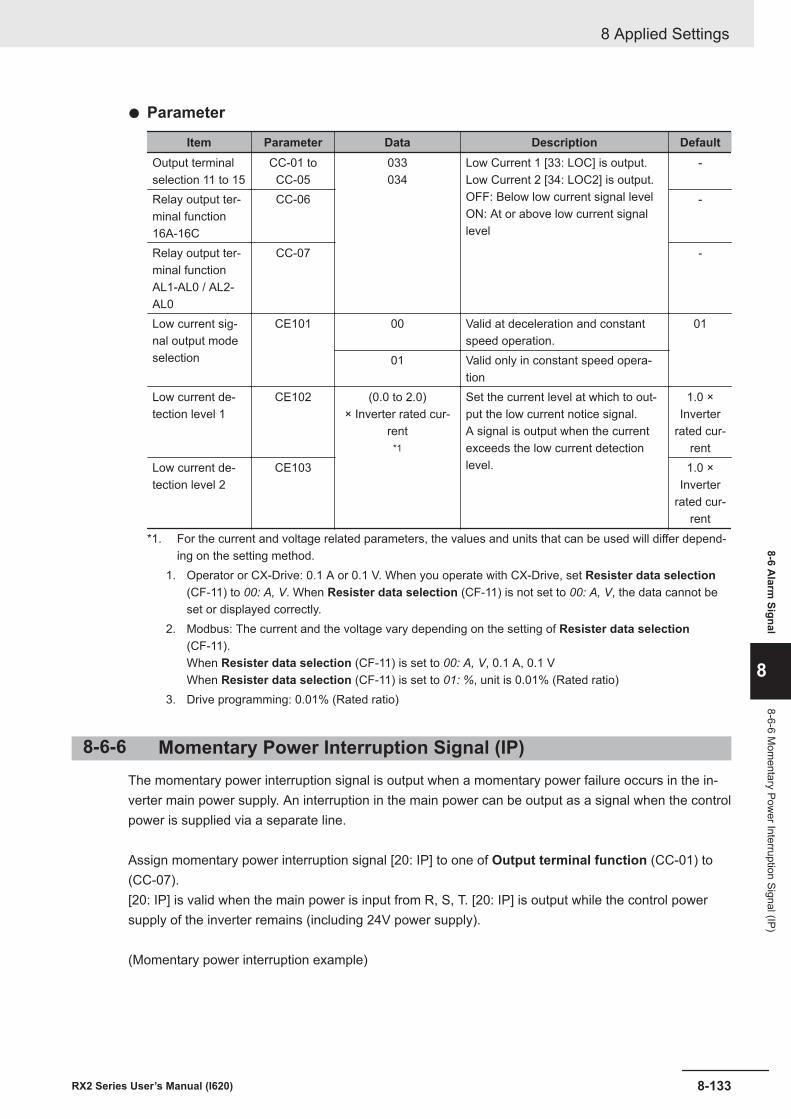
l Parameter
Item Parameter Data Description DefaultOutput terminalselection 11 to 15
CC-01 toCC-05
033034
Low Current 1 [33: LOC] is output.Low Current 2 [34: LOC2] is output.OFF: Below low current signal levelON: At or above low current signallevel
-
Relay output ter-minal function16A-16C
CC-06 -
Relay output ter-minal functionAL1-AL0 / AL2-AL0
CC-07 -
Low current sig-nal output modeselection
CE101 00 Valid at deceleration and constantspeed operation.
01
01 Valid only in constant speed opera-tion
Low current de-tection level 1
CE102 (0.0 to 2.0)× Inverter rated cur-
rent*1
Set the current level at which to out-put the low current notice signal.A signal is output when the currentexceeds the low current detectionlevel.
1.0 ×Inverter
rated cur-rent
Low current de-tection level 2
CE103 1.0 ×Inverter
rated cur-rent
*1. For the current and voltage related parameters, the values and units that can be used will differ depend-ing on the setting method.
1. Operator or CX-Drive: 0.1 A or 0.1 V. When you operate with CX-Drive, set Resister data selection(CF-11) to 00: A, V. When Resister data selection (CF-11) is not set to 00: A, V, the data cannot beset or displayed correctly.
2. Modbus: The current and the voltage vary depending on the setting of Resister data selection(CF-11).When Resister data selection (CF-11) is set to 00: A, V, 0.1 A, 0.1 VWhen Resister data selection (CF-11) is set to 01: %, unit is 0.01% (Rated ratio)
3. Drive programming: 0.01% (Rated ratio)
8-6-6 Momentary Power Interruption Signal (IP)The momentary power interruption signal is output when a momentary power failure occurs in the in-verter main power supply. An interruption in the main power can be output as a signal when the controlpower is supplied via a separate line.
Assign momentary power interruption signal [20: IP] to one of Output terminal function (CC-01) to(CC-07).[20: IP] is valid when the main power is input from R, S, T. [20: IP] is output while the control powersupply of the inverter remains (including 24V power supply).
(Momentary power interruption example)
8 Applied Settings
8-133RX2 Series User’s Manual (I620)
8-6 Alarm
Signal
8
8-6-6 Mom
entary Power Interruption Signal (IP)
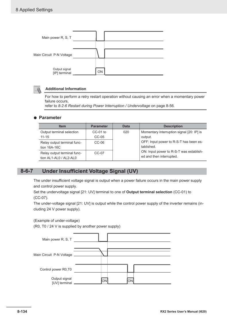
ON[IP] terminalOutput signal
Main Circuit P-N Voltage
Main power R, S, T
Additional Information
For how to perform a retry restart operation without causing an error when a momentary powerfailure occurs,refer to 8-2-6 Restart during Power Interruption / Undervoltage on page 8-56.
l Parameter
Item Parameter Data DescriptionOutput terminal selection11-15
CC-01 toCC-05
020 Momentary interruption signal [20: IP] isoutput.OFF: Input power to R-S-T has been es-tablished.ON: Input power to R-S-T was establish-ed and then interrupted.
Relay output terminal func-tion 16A-16C
CC-06
Relay output terminal func-tion AL1-AL0 / AL2-AL0
CC-07
8-6-7 Under Insufficient Voltage Signal (UV)The under insufficient voltage signal is output when a power failure occurs in the main power supplyand control power supply.Set the undervoltage signal [21: UV] terminal to one of Output terminal selection (CC-01) to(CC-07).The under-voltage signal [21: UV] is output while the control power supply of the inverter remains (in-cluding 24 V power supply).
(Example of under-voltage)(R0, T0 / 24 V is supplied by another power supply)
ON ON
Control power R0,T0
Main Circuit P-N Voltage
Main power R, S, T
[UV] terminal
Output signal
8 Applied Settings
8-134 RX2 Series User’s Manual (I620)
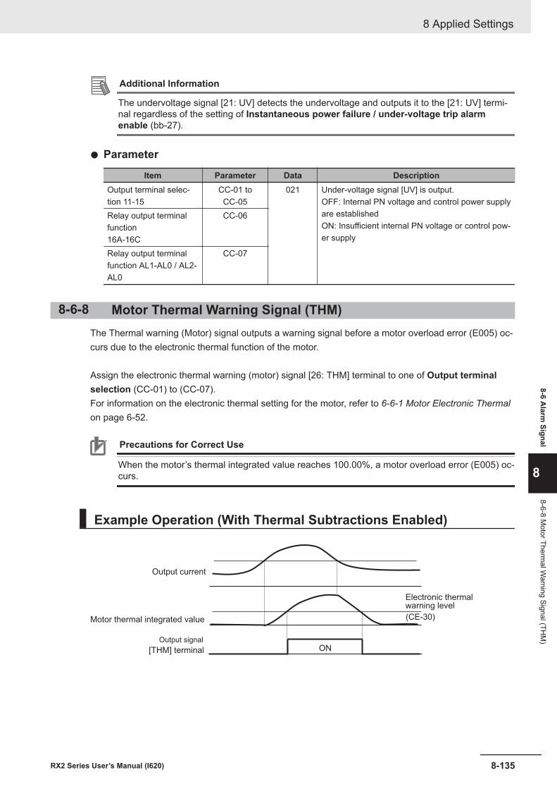
Additional Information
The undervoltage signal [21: UV] detects the undervoltage and outputs it to the [21: UV] termi-nal regardless of the setting of Instantaneous power failure / under-voltage trip alarmenable (bb-27).
l Parameter
Item Parameter Data DescriptionOutput terminal selec-tion 11-15
CC-01 toCC-05
021 Under-voltage signal [UV] is output.OFF: Internal PN voltage and control power supplyare establishedON: Insufficient internal PN voltage or control pow-er supply
Relay output terminalfunction16A-16C
CC-06
Relay output terminalfunction AL1-AL0 / AL2-AL0
CC-07
8-6-8 Motor Thermal Warning Signal (THM)The Thermal warning (Motor) signal outputs a warning signal before a motor overload error (E005) oc-curs due to the electronic thermal function of the motor.
Assign the electronic thermal warning (motor) signal [26: THM] terminal to one of Output terminalselection (CC-01) to (CC-07).For information on the electronic thermal setting for the motor, refer to 6-6-1 Motor Electronic Thermalon page 6-52.
Precautions for Correct Use
When the motor’s thermal integrated value reaches 100.00%, a motor overload error (E005) oc-curs.
Example Operation (With Thermal Subtractions Enabled)
(CE-30)
ON
Motor thermal integrated value
Electronic thermalwarning level
Output current
[THM] terminal
Output signal
8 Applied Settings
8-135RX2 Series User’s Manual (I620)
8-6 Alarm
Signal
8
8-6-8 Motor Therm
al Warning Signal (TH
M)
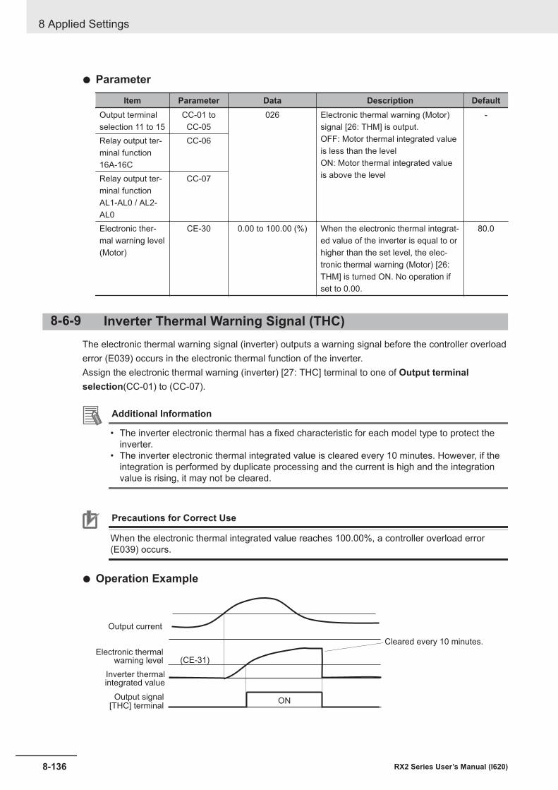
l Parameter
Item Parameter Data Description DefaultOutput terminalselection 11 to 15
CC-01 toCC-05
026 Electronic thermal warning (Motor)signal [26: THM] is output.OFF: Motor thermal integrated valueis less than the levelON: Motor thermal integrated valueis above the level
-
Relay output ter-minal function16A-16C
CC-06
Relay output ter-minal functionAL1-AL0 / AL2-AL0
CC-07
Electronic ther-mal warning level(Motor)
CE-30 0.00 to 100.00 (%) When the electronic thermal integrat-ed value of the inverter is equal to orhigher than the set level, the elec-tronic thermal warning (Motor) [26:THM] is turned ON. No operation ifset to 0.00.
80.0
8-6-9 Inverter Thermal Warning Signal (THC)The electronic thermal warning signal (inverter) outputs a warning signal before the controller overloaderror (E039) occurs in the electronic thermal function of the inverter.Assign the electronic thermal warning (inverter) [27: THC] terminal to one of Output terminalselection(CC-01) to (CC-07).
Additional Information
• The inverter electronic thermal has a fixed characteristic for each model type to protect theinverter.
• The inverter electronic thermal integrated value is cleared every 10 minutes. However, if theintegration is performed by duplicate processing and the current is high and the integrationvalue is rising, it may not be cleared.
Precautions for Correct Use
When the electronic thermal integrated value reaches 100.00%, a controller overload error(E039) occurs.
l Operation Example
ON
(CE-31)
Inverter thermalintegrated value
Electronic thermalwarning level
Output current
[THC] terminalOutput signal
Cleared every 10 minutes.
8 Applied Settings
8-136 RX2 Series User’s Manual (I620)
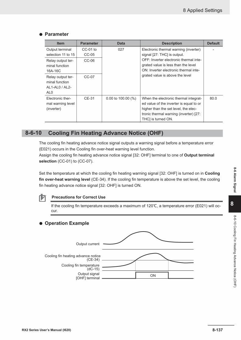
l Parameter
Item Parameter Data Description DefaultOutput terminalselection 11 to 15
CC-01 toCC-05
027 Electronic thermal warning (inverter)signal [27: THC] is output.OFF: Inverter electronic thermal inte-grated value is less than the levelON: Inverter electronic thermal inte-grated value is above the level
-
Relay output ter-minal function16A-16C
CC-06
Relay output ter-minal functionAL1-AL0 / AL2-AL0
CC-07
Electronic ther-mal warning level(inverter)
CE-31 0.00 to 100.00 (%) When the electronic thermal integrat-ed value of the inverter is equal to orhigher than the set level, the elec-tronic thermal warning (inverter) [27:THC] is turned ON.
80.0
8-6-10 Cooling Fin Heating Advance Notice (OHF)The cooling fin heating advance notice signal outputs a warning signal before a temperature error(E021) occurs in the Cooling fin over-heat warning level function.Assign the cooling fin heating advance notice signal [32: OHF] terminal to one of Output terminalselection (CC-01) to (CC-07).
Set the temperature at which the cooling fin heating warning signal [32: OHF] is turned on in Coolingfin over-heat warning level (CE-34). If the cooling fin temperature is above the set level, the coolingfin heating advance notice signal [32: OHF] is turned ON.
Precautions for Correct Use
If the cooling fin temperature exceeds a maximum of 120℃, a temperature error (E021) will oc-cur.
l Operation Example
ON
Cooling fin temperature(dC-15)
Cooling fin heating advance notice(CE-34)
Output current
[OHF] terminalOutput signal
山路を登りながら
8 Applied Settings
8-137RX2 Series User’s Manual (I620)
8-6 Alarm
Signal
8
8-6-10 Cooling Fin H
eating Advance Notice (O
HF)
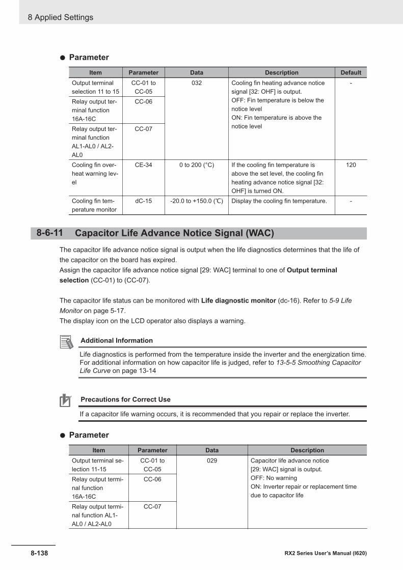
l Parameter
Item Parameter Data Description DefaultOutput terminalselection 11 to 15
CC-01 toCC-05
032 Cooling fin heating advance noticesignal [32: OHF] is output.OFF: Fin temperature is below thenotice levelON: Fin temperature is above thenotice level
-
Relay output ter-minal function16A-16C
CC-06
Relay output ter-minal functionAL1-AL0 / AL2-AL0
CC-07
Cooling fin over-heat warning lev-el
CE-34 0 to 200 (°C) If the cooling fin temperature isabove the set level, the cooling finheating advance notice signal [32:OHF] is turned ON.
120
Cooling fin tem-perature monitor
dC-15 -20.0 to +150.0 (℃) Display the cooling fin temperature. -
8-6-11 Capacitor Life Advance Notice Signal (WAC)The capacitor life advance notice signal is output when the life diagnostics determines that the life ofthe capacitor on the board has expired.Assign the capacitor life advance notice signal [29: WAC] terminal to one of Output terminalselection (CC-01) to (CC-07).
The capacitor life status can be monitored with Life diagnostic monitor (dc-16). Refer to 5-9 LifeMonitor on page 5-17.The display icon on the LCD operator also displays a warning.
Additional Information
Life diagnostics is performed from the temperature inside the inverter and the energization time.For additional information on how capacitor life is judged, refer to 13-5-5 Smoothing CapacitorLife Curve on page 13-14
Precautions for Correct Use
If a capacitor life warning occurs, it is recommended that you repair or replace the inverter.
l Parameter
Item Parameter Data DescriptionOutput terminal se-lection 11-15
CC-01 toCC-05
029 Capacitor life advance notice[29: WAC] signal is output.OFF: No warningON: Inverter repair or replacement timedue to capacitor life
Relay output termi-nal function16A-16C
CC-06
Relay output termi-nal function AL1-AL0 / AL2-AL0
CC-07
8 Applied Settings
8-138 RX2 Series User’s Manual (I620)
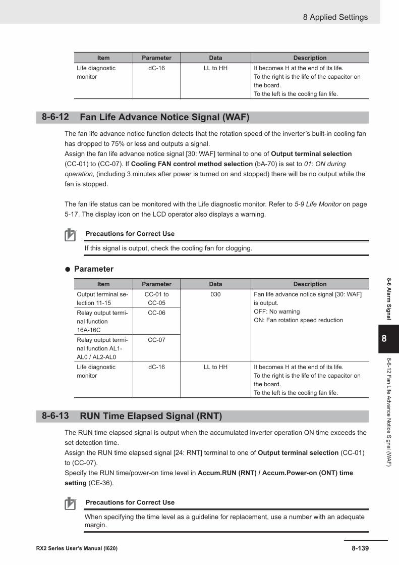
Item Parameter Data DescriptionLife diagnosticmonitor
dC-16 LL to HH It becomes H at the end of its life.To the right is the life of the capacitor onthe board.To the left is the cooling fan life.
8-6-12 Fan Life Advance Notice Signal (WAF)The fan life advance notice function detects that the rotation speed of the inverter’s built-in cooling fanhas dropped to 75% or less and outputs a signal.Assign the fan life advance notice signal [30: WAF] terminal to one of Output terminal selection(CC-01) to (CC-07). If Cooling FAN control method selection (bA-70) is set to 01: ON duringoperation, (including 3 minutes after power is turned on and stopped) there will be no output while thefan is stopped.
The fan life status can be monitored with the Life diagnostic monitor. Refer to 5-9 Life Monitor on page5-17. The display icon on the LCD operator also displays a warning.
Precautions for Correct Use
If this signal is output, check the cooling fan for clogging.
l Parameter
Item Parameter Data DescriptionOutput terminal se-lection 11-15
CC-01 toCC-05
030 Fan life advance notice signal [30: WAF]is output.OFF: No warningON: Fan rotation speed reduction
Relay output termi-nal function16A-16C
CC-06
Relay output termi-nal function AL1-AL0 / AL2-AL0
CC-07
Life diagnosticmonitor
dC-16 LL to HH It becomes H at the end of its life.To the right is the life of the capacitor onthe board.To the left is the cooling fan life.
8-6-13 RUN Time Elapsed Signal (RNT)The RUN time elapsed signal is output when the accumulated inverter operation ON time exceeds theset detection time.Assign the RUN time elapsed signal [24: RNT] terminal to one of Output terminal selection (CC-01)to (CC-07).Specify the RUN time/power-on time level in Accum.RUN (RNT) / Accum.Power-on (ONT) timesetting (CE-36).
Precautions for Correct Use
When specifying the time level as a guideline for replacement, use a number with an adequatemargin.
8 Applied Settings
8-139RX2 Series User’s Manual (I620)
8-6 Alarm
Signal
8
8-6-12 Fan Life Advance Notice Signal (W
AF)
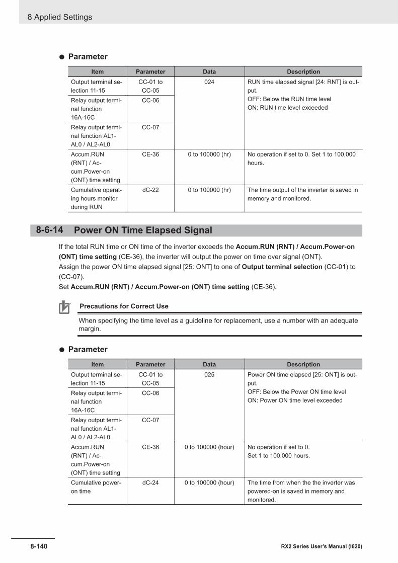
l Parameter
Item Parameter Data DescriptionOutput terminal se-lection 11-15
CC-01 toCC-05
024 RUN time elapsed signal [24: RNT] is out-put.OFF: Below the RUN time levelON: RUN time level exceeded
Relay output termi-nal function16A-16C
CC-06
Relay output termi-nal function AL1-AL0 / AL2-AL0
CC-07
Accum.RUN(RNT) / Ac-cum.Power-on(ONT) time setting
CE-36 0 to 100000 (hr) No operation if set to 0. Set 1 to 100,000hours.
Cumulative operat-ing hours monitorduring RUN
dC-22 0 to 100000 (hr) The time output of the inverter is saved inmemory and monitored.
8-6-14 Power ON Time Elapsed SignalIf the total RUN time or ON time of the inverter exceeds the Accum.RUN (RNT) / Accum.Power-on(ONT) time setting (CE-36), the inverter will output the power on time over signal (ONT).Assign the power ON time elapsed signal [25: ONT] to one of Output terminal selection (CC-01) to(CC-07).Set Accum.RUN (RNT) / Accum.Power-on (ONT) time setting (CE-36).
Precautions for Correct Use
When specifying the time level as a guideline for replacement, use a number with an adequatemargin.
l Parameter
Item Parameter Data DescriptionOutput terminal se-lection 11-15
CC-01 toCC-05
025 Power ON time elapsed [25: ONT] is out-put.OFF: Below the Power ON time levelON: Power ON time level exceeded
Relay output termi-nal function16A-16C
CC-06
Relay output termi-nal function AL1-AL0 / AL2-AL0
CC-07
Accum.RUN(RNT) / Ac-cum.Power-on(ONT) time setting
CE-36 0 to 100000 (hour) No operation if set to 0.Set 1 to 100,000 hours.
Cumulative power-on time
dC-24 0 to 100000 (hour) The time from when the the inverter waspowered-on is saved in memory andmonitored.
8 Applied Settings
8-140 RX2 Series User’s Manual (I620)
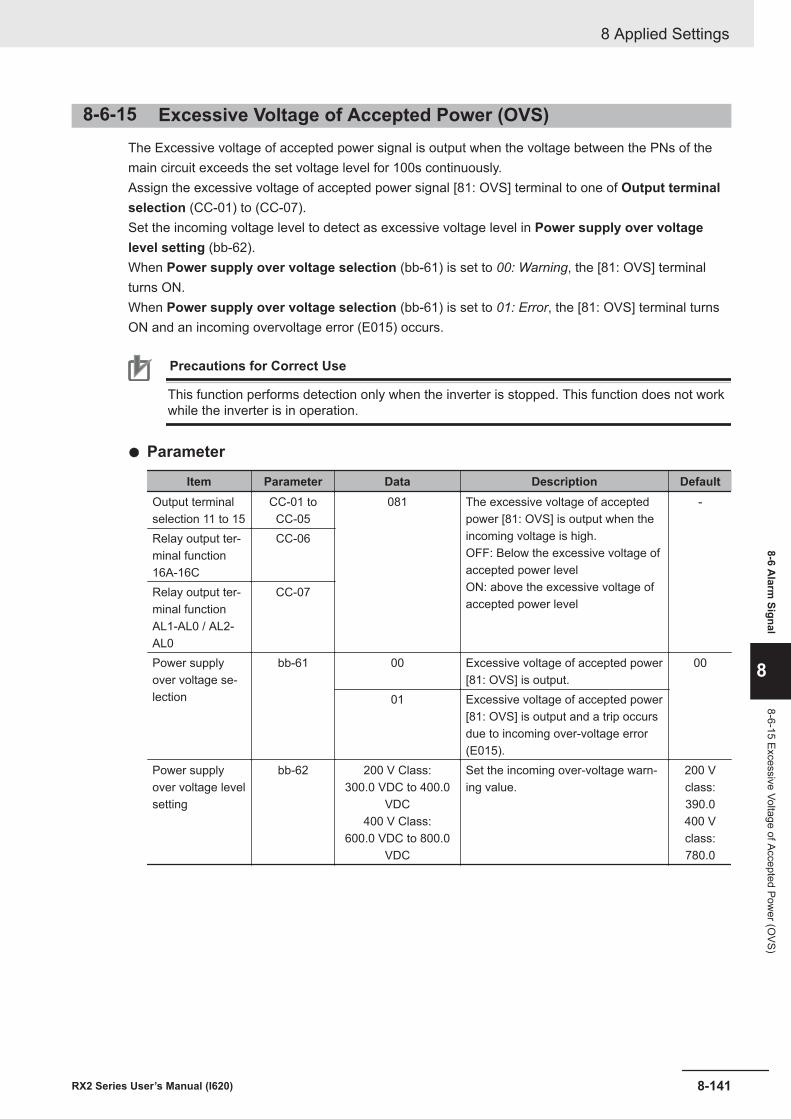
8-6-15 Excessive Voltage of Accepted Power (OVS)The Excessive voltage of accepted power signal is output when the voltage between the PNs of themain circuit exceeds the set voltage level for 100s continuously.Assign the excessive voltage of accepted power signal [81: OVS] terminal to one of Output terminalselection (CC-01) to (CC-07).Set the incoming voltage level to detect as excessive voltage level in Power supply over voltagelevel setting (bb-62).When Power supply over voltage selection (bb-61) is set to 00: Warning, the [81: OVS] terminalturns ON.When Power supply over voltage selection (bb-61) is set to 01: Error, the [81: OVS] terminal turnsON and an incoming overvoltage error (E015) occurs.
Precautions for Correct Use
This function performs detection only when the inverter is stopped. This function does not workwhile the inverter is in operation.
l Parameter
Item Parameter Data Description DefaultOutput terminalselection 11 to 15
CC-01 toCC-05
081 The excessive voltage of acceptedpower [81: OVS] is output when theincoming voltage is high.OFF: Below the excessive voltage ofaccepted power levelON: above the excessive voltage ofaccepted power level
-
Relay output ter-minal function16A-16C
CC-06
Relay output ter-minal functionAL1-AL0 / AL2-AL0
CC-07
Power supplyover voltage se-lection
bb-61 00 Excessive voltage of accepted power[81: OVS] is output.
00
01 Excessive voltage of accepted power[81: OVS] is output and a trip occursdue to incoming over-voltage error(E015).
Power supplyover voltage levelsetting
bb-62 200 V Class:300.0 VDC to 400.0
VDC400 V Class:
600.0 VDC to 800.0VDC
Set the incoming over-voltage warn-ing value.
200 Vclass:390.0400 Vclass:780.0
8 Applied Settings
8-141RX2 Series User’s Manual (I620)
8-6 Alarm
Signal
8
8-6-15 Excessive Voltage of Accepted Power (O
VS)
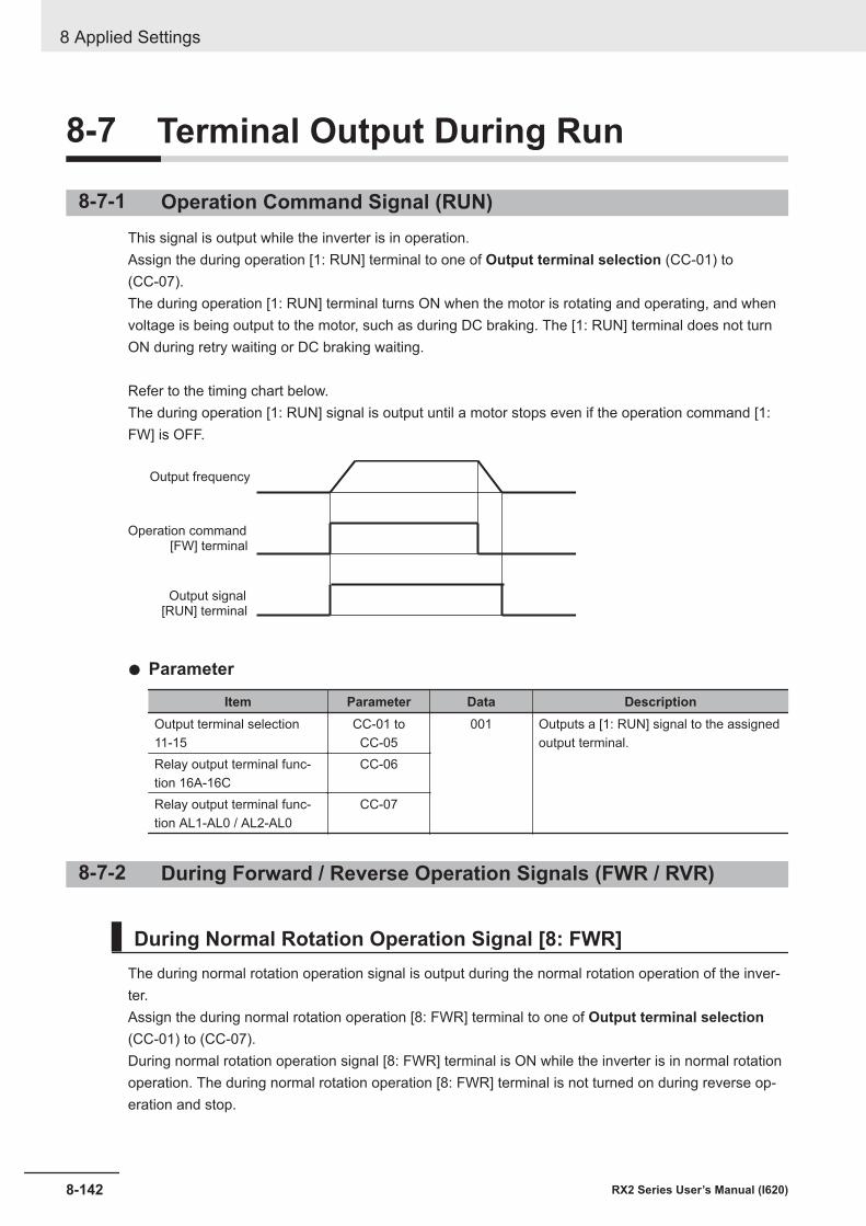
8-7 Terminal Output During Run
8-7-1 Operation Command Signal (RUN)This signal is output while the inverter is in operation.Assign the during operation [1: RUN] terminal to one of Output terminal selection (CC-01) to(CC-07).The during operation [1: RUN] terminal turns ON when the motor is rotating and operating, and whenvoltage is being output to the motor, such as during DC braking. The [1: RUN] terminal does not turnON during retry waiting or DC braking waiting.
Refer to the timing chart below.The during operation [1: RUN] signal is output until a motor stops even if the operation command [1:FW] is OFF.
[RUN] terminalOutput signal
[FW] terminalOperation command
Output frequency
l Parameter
Item Parameter Data DescriptionOutput terminal selection11-15
CC-01 toCC-05
001 Outputs a [1: RUN] signal to the assignedoutput terminal.
Relay output terminal func-tion 16A-16C
CC-06
Relay output terminal func-tion AL1-AL0 / AL2-AL0
CC-07
8-7-2 During Forward / Reverse Operation Signals (FWR / RVR)
During Normal Rotation Operation Signal [8: FWR]The during normal rotation operation signal is output during the normal rotation operation of the inver-ter.Assign the during normal rotation operation [8: FWR] terminal to one of Output terminal selection(CC-01) to (CC-07).During normal rotation operation signal [8: FWR] terminal is ON while the inverter is in normal rotationoperation. The during normal rotation operation [8: FWR] terminal is not turned on during reverse op-eration and stop.
8 Applied Settings
8-142 RX2 Series User’s Manual (I620)
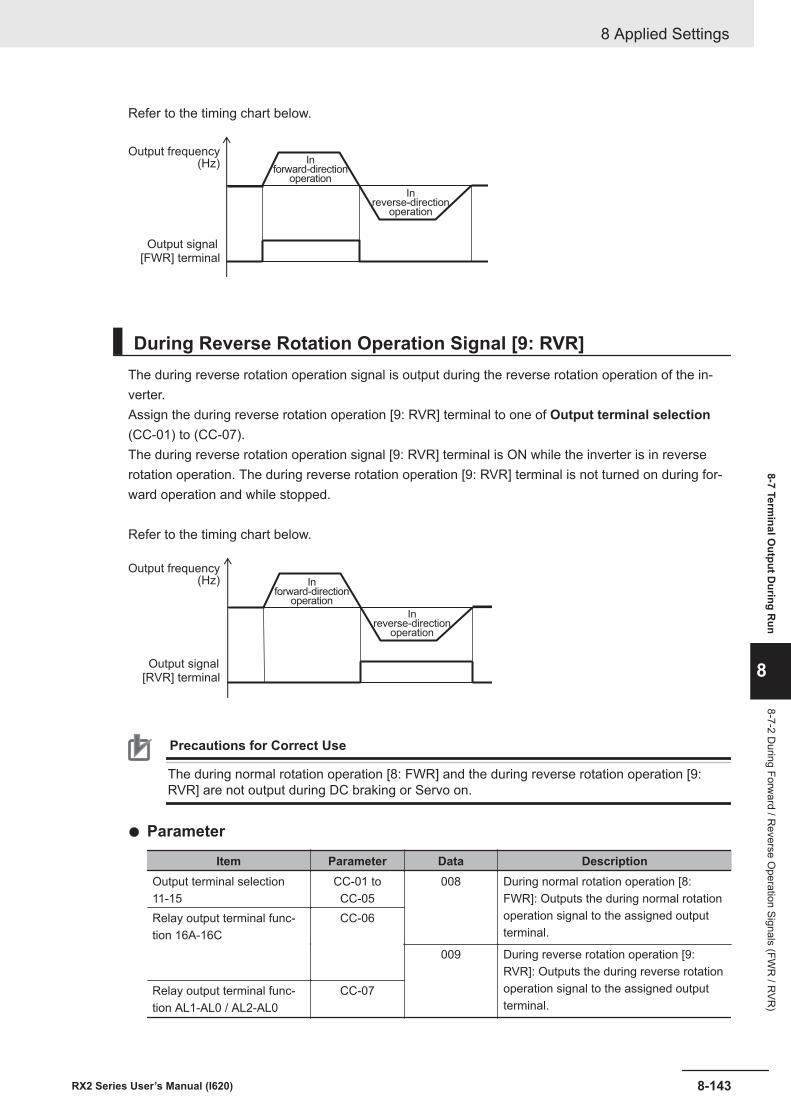
Refer to the timing chart below.
[FWR] terminalOutput signal
Output frequency(Hz) In
forward-directionoperation
Inreverse-direction
operation
During Reverse Rotation Operation Signal [9: RVR]The during reverse rotation operation signal is output during the reverse rotation operation of the in-verter.Assign the during reverse rotation operation [9: RVR] terminal to one of Output terminal selection(CC-01) to (CC-07).The during reverse rotation operation signal [9: RVR] terminal is ON while the inverter is in reverserotation operation. The during reverse rotation operation [9: RVR] terminal is not turned on during for-ward operation and while stopped.
Refer to the timing chart below.
[RVR] terminalOutput signal
Output frequency(Hz) In
forward-directionoperation
Inreverse-direction
operation
Precautions for Correct Use
The during normal rotation operation [8: FWR] and the during reverse rotation operation [9:RVR] are not output during DC braking or Servo on.
l Parameter
Item Parameter Data DescriptionOutput terminal selection11-15
CC-01 toCC-05
008 During normal rotation operation [8:FWR]: Outputs the during normal rotationoperation signal to the assigned outputterminal.
Relay output terminal func-tion 16A-16C
CC-06
009 During reverse rotation operation [9:RVR]: Outputs the during reverse rotationoperation signal to the assigned outputterminal.
Relay output terminal func-tion AL1-AL0 / AL2-AL0
CC-07
8 Applied Settings
8-143RX2 Series User’s Manual (I620)
8-7 Terminal O
utput During R
un
8
8-7-2 During Forw
ard / Reverse O
peration Signals (FWR
/ RVR
)
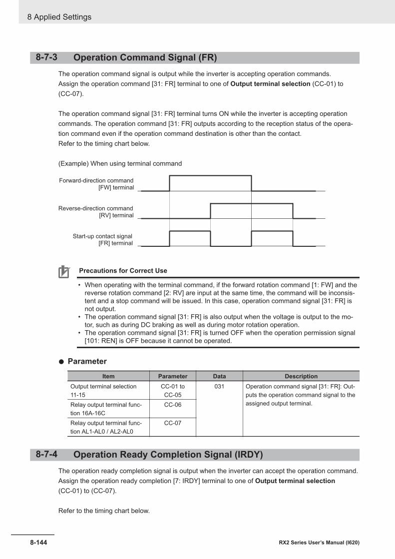
8-7-3 Operation Command Signal (FR)The operation command signal is output while the inverter is accepting operation commands.Assign the operation command [31: FR] terminal to one of Output terminal selection (CC-01) to(CC-07).
The operation command signal [31: FR] terminal turns ON while the inverter is accepting operationcommands. The operation command [31: FR] outputs according to the reception status of the opera-tion command even if the operation command destination is other than the contact.Refer to the timing chart below.
(Example) When using terminal command
[FR] terminalStart-up contact signal
[FW] terminalForward-direction command
[RV] terminalReverse-direction command
Precautions for Correct Use
• When operating with the terminal command, if the forward rotation command [1: FW] and thereverse rotation command [2: RV] are input at the same time, the command will be inconsis-tent and a stop command will be issued. In this case, operation command signal [31: FR] isnot output.
• The operation command signal [31: FR] is also output when the voltage is output to the mo-tor, such as during DC braking as well as during motor rotation operation.
• The operation command signal [31: FR] is turned OFF when the operation permission signal[101: REN] is OFF because it cannot be operated.
l Parameter
Item Parameter Data DescriptionOutput terminal selection11-15
CC-01 toCC-05
031 Operation command signal [31: FR]: Out-puts the operation command signal to theassigned output terminal.Relay output terminal func-
tion 16A-16CCC-06
Relay output terminal func-tion AL1-AL0 / AL2-AL0
CC-07
8-7-4 Operation Ready Completion Signal (IRDY)The operation ready completion signal is output when the inverter can accept the operation command.Assign the operation ready completion [7: IRDY] terminal to one of Output terminal selection(CC-01) to (CC-07).
Refer to the timing chart below.
8 Applied Settings
8-144 RX2 Series User’s Manual (I620)
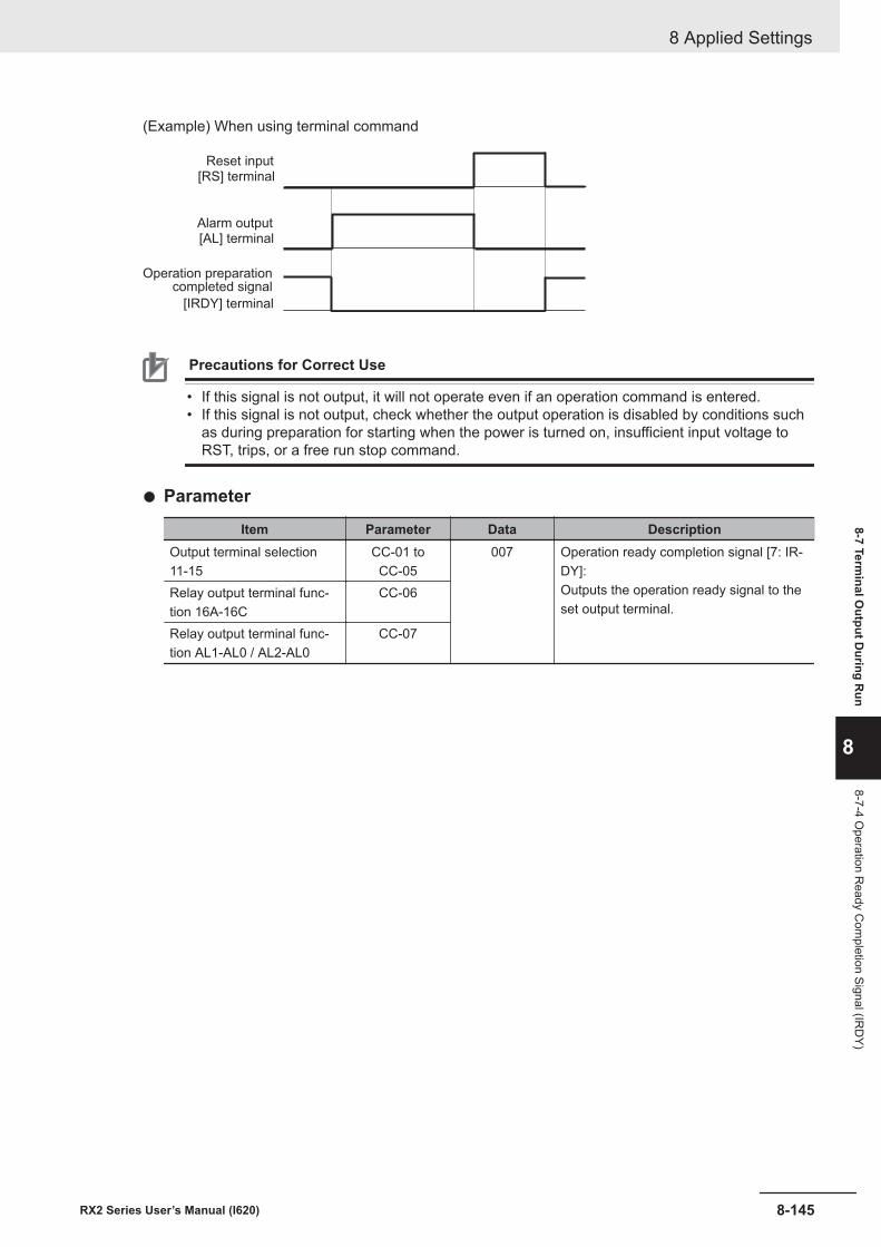
(Example) When using terminal command
[IRDY] terminal
Operation preparationcompleted signal
[RS] terminalReset input
[AL] terminalAlarm output
Precautions for Correct Use
• If this signal is not output, it will not operate even if an operation command is entered.• If this signal is not output, check whether the output operation is disabled by conditions such
as during preparation for starting when the power is turned on, insufficient input voltage toRST, trips, or a free run stop command.
l Parameter
Item Parameter Data DescriptionOutput terminal selection11-15
CC-01 toCC-05
007 Operation ready completion signal [7: IR-DY]:Outputs the operation ready signal to theset output terminal.
Relay output terminal func-tion 16A-16C
CC-06
Relay output terminal func-tion AL1-AL0 / AL2-AL0
CC-07
8 Applied Settings
8-145RX2 Series User’s Manual (I620)
8-7 Terminal O
utput During R
un
8
8-7-4 Operation R
eady Com
pletion Signal (IRD
Y)
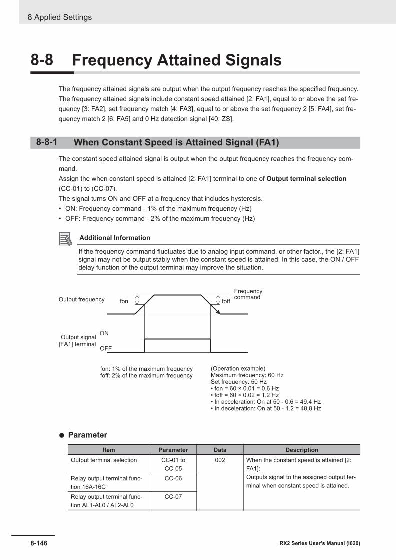
8-8 Frequency Attained SignalsThe frequency attained signals are output when the output frequency reaches the specified frequency.The frequency attained signals include constant speed attained [2: FA1], equal to or above the set fre-quency [3: FA2], set frequency match [4: FA3], equal to or above the set frequency 2 [5: FA4], set fre-quency match 2 [6: FA5] and 0 Hz detection signal [40: ZS].
8-8-1 When Constant Speed is Attained Signal (FA1)The constant speed attained signal is output when the output frequency reaches the frequency com-mand.Assign the when constant speed is attained [2: FA1] terminal to one of Output terminal selection(CC-01) to (CC-07).The signal turns ON and OFF at a frequency that includes hysteresis.• ON: Frequency command - 1% of the maximum frequency (Hz)• OFF: Frequency command - 2% of the maximum frequency (Hz)
Additional Information
If the frequency command fluctuates due to analog input command, or other factor., the [2: FA1]signal may not be output stably when the constant speed is attained. In this case, the ON / OFFdelay function of the output terminal may improve the situation.
foff fon
ON
OFF[FA1] terminalOutput signal
Output frequency
Frequencycommand
fon: 1% of the maximum frequencyfoff: 2% of the maximum frequency
(Operation example)Maximum frequency: 60 HzSet frequency: 50 Hz• fon = 60 × 0.01 = 0.6 Hz• foff = 60 × 0.02 = 1.2 Hz• In acceleration: On at 50 - 0.6 = 49.4 Hz• In deceleration: On at 50 - 1.2 = 48.8 Hz
l Parameter
Item Parameter Data DescriptionOutput terminal selection CC-01 to
CC-05002 When the constant speed is attained [2:
FA1]:Outputs signal to the assigned output ter-minal when constant speed is attained.
Relay output terminal func-tion 16A-16C
CC-06
Relay output terminal func-tion AL1-AL0 / AL2-AL0
CC-07
8 Applied Settings
8-146 RX2 Series User’s Manual (I620)
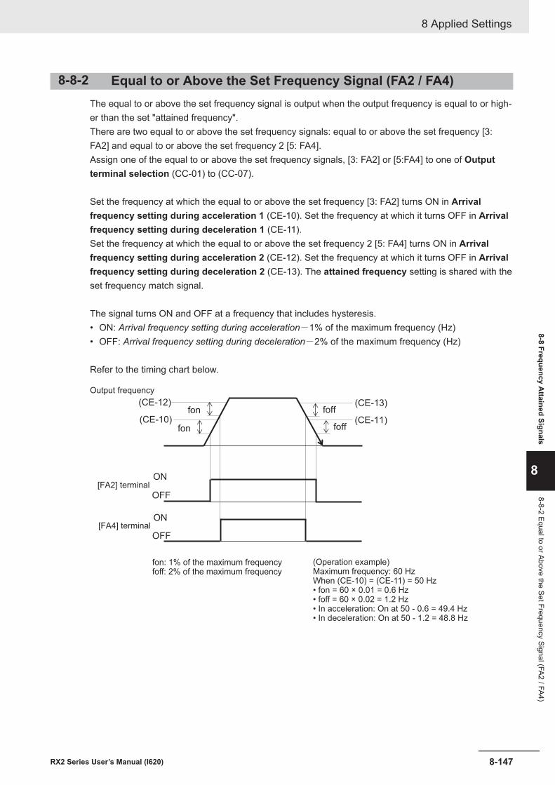
8-8-2 Equal to or Above the Set Frequency Signal (FA2 / FA4)The equal to or above the set frequency signal is output when the output frequency is equal to or high-er than the set "attained frequency".There are two equal to or above the set frequency signals: equal to or above the set frequency [3:FA2] and equal to or above the set frequency 2 [5: FA4].Assign one of the equal to or above the set frequency signals, [3: FA2] or [5:FA4] to one of Outputterminal selection (CC-01) to (CC-07).
Set the frequency at which the equal to or above the set frequency [3: FA2] turns ON in Arrivalfrequency setting during acceleration 1 (CE-10). Set the frequency at which it turns OFF in Arrivalfrequency setting during deceleration 1 (CE-11).Set the frequency at which the equal to or above the set frequency 2 [5: FA4] turns ON in Arrivalfrequency setting during acceleration 2 (CE-12). Set the frequency at which it turns OFF in Arrivalfrequency setting during deceleration 2 (CE-13). The attained frequency setting is shared with theset frequency match signal.
The signal turns ON and OFF at a frequency that includes hysteresis.• ON: Arrival frequency setting during acceleration-1% of the maximum frequency (Hz)• OFF: Arrival frequency setting during deceleration-2% of the maximum frequency (Hz)
Refer to the timing chart below.
(CE-10)fon foff
foff fon(CE-12)
ON
OFF
ON
OFF
(CE-11)
(CE-13)
Output frequency
[FA2] terminal
[FA4] terminal
fon: 1% of the maximum frequencyfoff: 2% of the maximum frequency
(Operation example)Maximum frequency: 60 HzWhen (CE-10) = (CE-11) = 50 Hz• fon = 60 × 0.01 = 0.6 Hz• foff = 60 × 0.02 = 1.2 Hz• In acceleration: On at 50 - 0.6 = 49.4 Hz• In deceleration: On at 50 - 1.2 = 48.8 Hz
8 Applied Settings
8-147RX2 Series User’s Manual (I620)
8-8 Frequency Attained Signals
8
8-8-2 Equal to or Above the Set Frequency Signal (FA2 / FA4)
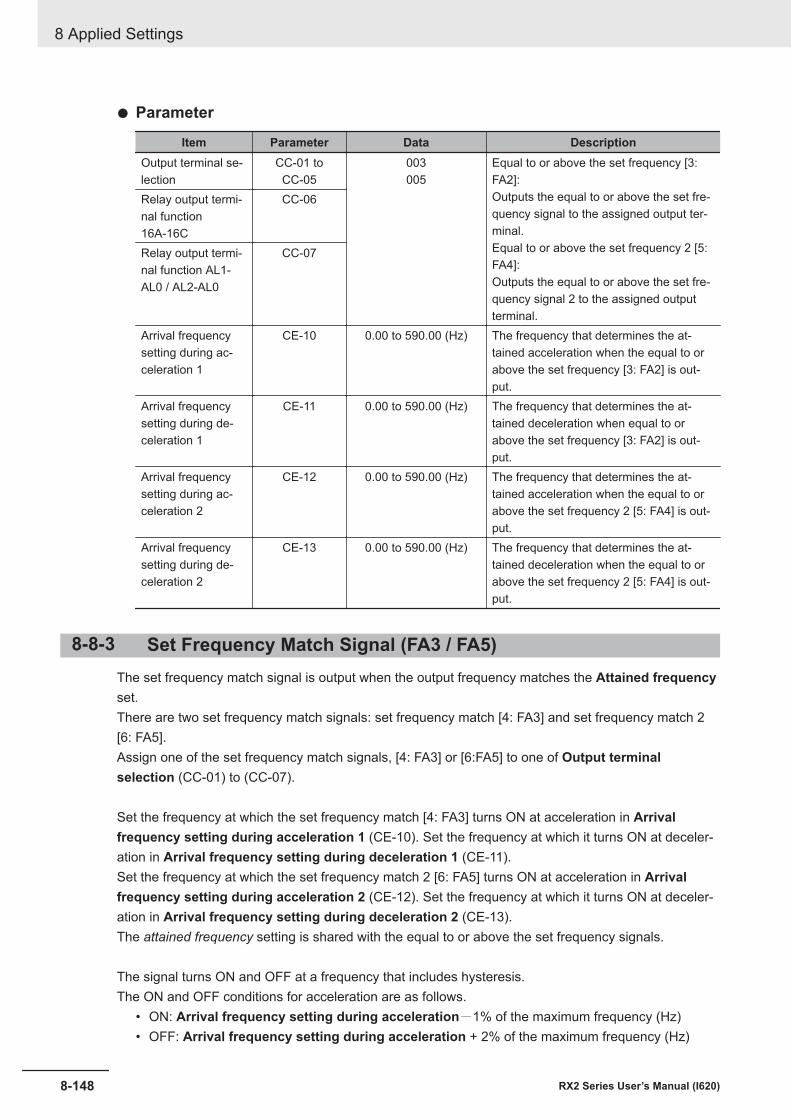
l Parameter
Item Parameter Data DescriptionOutput terminal se-lection
CC-01 toCC-05
003005
Equal to or above the set frequency [3:FA2]:Outputs the equal to or above the set fre-quency signal to the assigned output ter-minal.Equal to or above the set frequency 2 [5:FA4]:Outputs the equal to or above the set fre-quency signal 2 to the assigned outputterminal.
Relay output termi-nal function16A-16C
CC-06
Relay output termi-nal function AL1-AL0 / AL2-AL0
CC-07
Arrival frequencysetting during ac-celeration 1
CE-10 0.00 to 590.00 (Hz) The frequency that determines the at-tained acceleration when the equal to orabove the set frequency [3: FA2] is out-put.
Arrival frequencysetting during de-celeration 1
CE-11 0.00 to 590.00 (Hz) The frequency that determines the at-tained deceleration when equal to orabove the set frequency [3: FA2] is out-put.
Arrival frequencysetting during ac-celeration 2
CE-12 0.00 to 590.00 (Hz) The frequency that determines the at-tained acceleration when the equal to orabove the set frequency 2 [5: FA4] is out-put.
Arrival frequencysetting during de-celeration 2
CE-13 0.00 to 590.00 (Hz) The frequency that determines the at-tained deceleration when the equal to orabove the set frequency 2 [5: FA4] is out-put.
8-8-3 Set Frequency Match Signal (FA3 / FA5)The set frequency match signal is output when the output frequency matches the Attained frequencyset.There are two set frequency match signals: set frequency match [4: FA3] and set frequency match 2[6: FA5].Assign one of the set frequency match signals, [4: FA3] or [6:FA5] to one of Output terminalselection (CC-01) to (CC-07).
Set the frequency at which the set frequency match [4: FA3] turns ON at acceleration in Arrivalfrequency setting during acceleration 1 (CE-10). Set the frequency at which it turns ON at deceler-ation in Arrival frequency setting during deceleration 1 (CE-11).Set the frequency at which the set frequency match 2 [6: FA5] turns ON at acceleration in Arrivalfrequency setting during acceleration 2 (CE-12). Set the frequency at which it turns ON at deceler-ation in Arrival frequency setting during deceleration 2 (CE-13).The attained frequency setting is shared with the equal to or above the set frequency signals.
The signal turns ON and OFF at a frequency that includes hysteresis.The ON and OFF conditions for acceleration are as follows.
• ON: Arrival frequency setting during acceleration-1% of the maximum frequency (Hz)• OFF: Arrival frequency setting during acceleration + 2% of the maximum frequency (Hz)
8 Applied Settings
8-148 RX2 Series User’s Manual (I620)
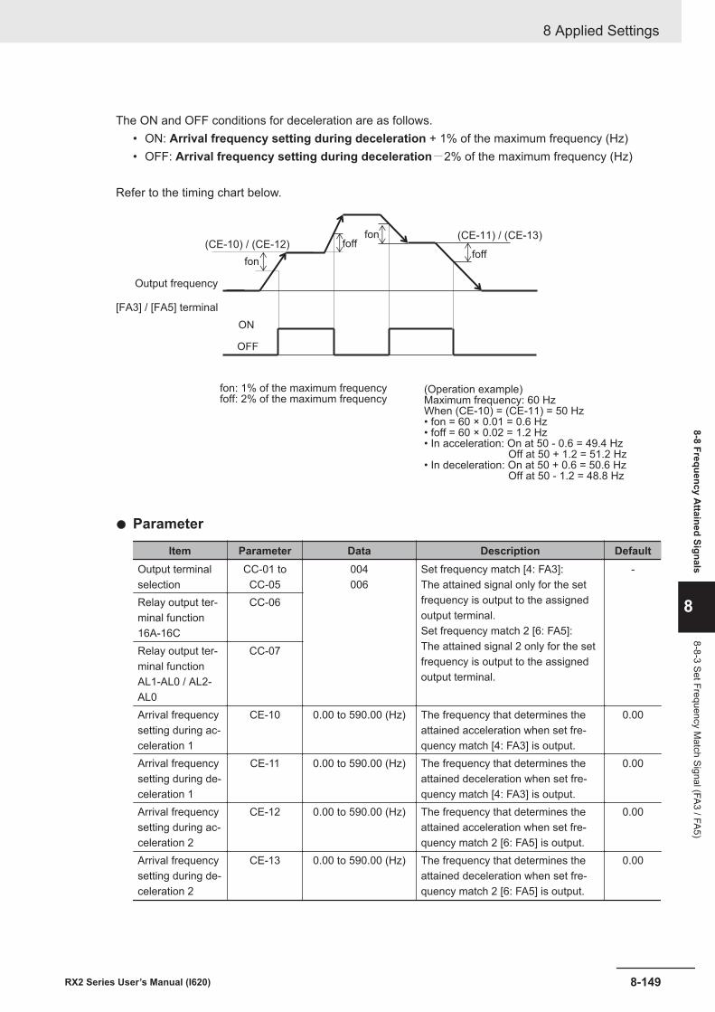
The ON and OFF conditions for deceleration are as follows.• ON: Arrival frequency setting during deceleration + 1% of the maximum frequency (Hz)• OFF: Arrival frequency setting during deceleration-2% of the maximum frequency (Hz)
Refer to the timing chart below.
fon
fon
fofffoff
(CE-11) / (CE-13)(CE-10) / (CE-12)
ON
OFF
Output frequency
fon: 1% of the maximum frequencyfoff: 2% of the maximum frequency
(Operation example)Maximum frequency: 60 HzWhen (CE-10) = (CE-11) = 50 Hz• fon = 60 × 0.01 = 0.6 Hz• foff = 60 × 0.02 = 1.2 Hz• In acceleration: On at 50 - 0.6 = 49.4 Hz Off at 50 + 1.2 = 51.2 Hz• In deceleration: On at 50 + 0.6 = 50.6 Hz Off at 50 - 1.2 = 48.8 Hz
[FA3] / [FA5] terminal
l Parameter
Item Parameter Data Description DefaultOutput terminalselection
CC-01 toCC-05
004006
Set frequency match [4: FA3]:The attained signal only for the setfrequency is output to the assignedoutput terminal.Set frequency match 2 [6: FA5]:The attained signal 2 only for the setfrequency is output to the assignedoutput terminal.
-
Relay output ter-minal function16A-16C
CC-06
Relay output ter-minal functionAL1-AL0 / AL2-AL0
CC-07
Arrival frequencysetting during ac-celeration 1
CE-10 0.00 to 590.00 (Hz) The frequency that determines theattained acceleration when set fre-quency match [4: FA3] is output.
0.00
Arrival frequencysetting during de-celeration 1
CE-11 0.00 to 590.00 (Hz) The frequency that determines theattained deceleration when set fre-quency match [4: FA3] is output.
0.00
Arrival frequencysetting during ac-celeration 2
CE-12 0.00 to 590.00 (Hz) The frequency that determines theattained acceleration when set fre-quency match 2 [6: FA5] is output.
0.00
Arrival frequencysetting during de-celeration 2
CE-13 0.00 to 590.00 (Hz) The frequency that determines theattained deceleration when set fre-quency match 2 [6: FA5] is output.
0.00
8 Applied Settings
8-149RX2 Series User’s Manual (I620)
8-8 Frequency Attained Signals
8
8-8-3 Set Frequency Match Signal (FA3 / FA5)
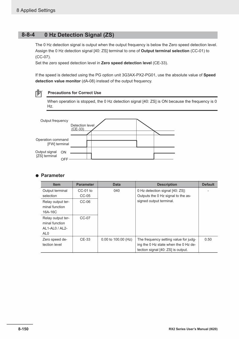
8-8-4 0 Hz Detection Signal (ZS)The 0 Hz detection signal is output when the output frequency is below the Zero speed detection level.Assign the 0 Hz detection signal [40: ZS] terminal to one of Output terminal selection (CC-01) to(CC-07).Set the zero speed detection level in Zero speed detection level (CE-33).
If the speed is detected using the PG option unit 3G3AX-PX2-PG01, use the absolute value of Speeddetection value monitor (dA-08) instead of the output frequency.
Precautions for Correct Use
When operation is stopped, the 0 Hz detection signal [40: ZS] is ON because the frequency is 0Hz.
(CE-33)
ON
OFF
[FW] terminal
Output frequency
Detection level
Operation command
[ZS] terminalOutput signal
l Parameter
Item Parameter Data Description DefaultOutput terminalselection
CC-01 toCC-05
040 0 Hz detection signal [40: ZS]:Outputs the 0 Hz signal to the as-signed output terminal.
-
Relay output ter-minal function16A-16C
CC-06
Relay output ter-minal functionAL1-AL0 / AL2-AL0
CC-07
Zero speed de-tection level
CE-33 0.00 to 100.00 (Hz) The frequency setting value for judg-ing the 0 Hz state when the 0 Hz de-tection signal [40: ZS] is output.
0.50
8 Applied Settings
8-150 RX2 Series User’s Manual (I620)
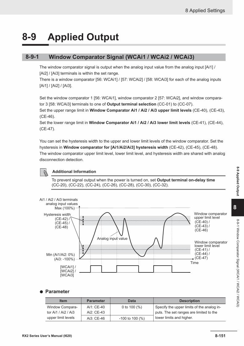
8-9 Applied Output
8-9-1 Window Comparator Signal (WCAi1 / WCAi2 / WCAi3)The window comparator signal is output when the analog input value from the analog input [Ai1] /[Ai2] / [Ai3] terminals is within the set range.There is a window comparator [56: WCAi1] / [57: WCAi2] / [58: WCAi3] for each of the analog inputs[Ai1] / [Ai2] / [Ai3].
Set the window comparator 1 [56: WCAi1], window comparator 2 [57: WCAi2], and window compara-tor 3 [58: WCAi3] terminals to one of Output terminal selection (CC-01) to (CC-07).Set the upper range limit in Window Comparator Ai1 / Ai2 / Ai3 upper limit levels (CE-40), (CE-43),(CE-46).Set the lower range limit in Window Comparator Ai1 / Ai2 / Ai3 lower limit levels (CE-41), (CE-44),(CE-47).
You can set the hysteresis width to the upper and lower limit levels of the window comparator. Set thehysteresis in Window comparator for [Ai1/Ai2/Ai3] hysteresis width (CE-42), (CE-45), (CE-48).The window comparator upper limit level, lower limit level, and hysteresis width are shared with analogdisconnection detection.
Additional Information
To prevent signal output when the power is turned on, set Output terminal on-delay time(CC-20), (CC-22), (CC-24), (CC-26), (CC-28), (CC-30), (CC-32).
[WCAi1] /[WCAi2] /[WCAi3]
Max (100%)
Min (Ai1/Ai2: 0%)
(Ai3: -100%)
(CE-40) /(CE-43) /(CE-46)
(CE-41) /(CE-44) /(CE-47)
(CE-42) /(CE-45) /(CE-48)
analog input valuesAi1 / Ai2 / Ai3 terminals
Hysteresis width
Analog input value
Window comparatorupper limit level
Window comparatorlower limit level
Time
l Parameter
Item Parameter Data DescriptionWindow Compara-tor Ai1 / Ai2 / Ai3upper limit levels
Ai1: CE-40Ai2: CE-43
0 to 100 (%) Specify the upper limits of the analog in-puts. The set ranges are limited to thelower limits and higher.Ai3: CE-46 -100 to 100 (%)
8 Applied Settings
8-151RX2 Series User’s Manual (I620)
8-9 Applied O
utput
8
8-9-1 Window
Com
parator Signal (WC
Ai1 / WC
Ai2 / WC
Ai3)
Item Parameter Data DescriptionWindow Compara-tor Ai1 / Ai2 / Ai3lower limit levels
Ai1: CE-41Ai2: CE-44
0 to 100 (%) Specify the lower limits of the analog in-puts. The set ranges are limited to the up-per limits and lower.Ai3: CE-47 -100 to 100 (%)
Window compara-tor Ai1 / Ai2 / Ai3hysteresis width
Ai1: CE-42Ai2: CE-45Ai3: CE-48
0 to 10 (%) The maximum hysteresis width is limitedby (upper limit level - lower limit level) / 2.
Output terminal se-lection 11 to 15
CC-01 toCC-05
056057058
Window comparator [56: WCAi1], [57:WCAi2], and [58: WCAi3] are output tothe set output terminal.Relay output termi-
nal function16A-16C
CC-06
Relay output termi-nal function AL1-AL0 / AL2-AL0
CC-07
8-9-2 Analog AbnormalityThis function is used when you want to change the operation when the value from the analog inputterminal is different from its normal state.The Analog disconnection signal is output when the analog input value from the analog input [Ai1] /[Ai2] / [Ai3] terminals are out of the set range.For each of the analog inputs [Ai1] / [Ai2] / [Ai3], there is a corresponding analog disconnection signal[50: Ai1Dc] / [51: Ai2Dc] / [52: Ai3Dc]. (Hereinafter referred to as [Ai * DC].)
Use the same parameters as those for window comparator for judging what is outside the normalrange.When you wish to output [Ai * DC] outside the range of the window comparator, set Operation levelselection at [Ai*] disconnection (CE-51), (CE-53), (CE-55) to 02: Enabled: out of range.Conversely, if you want to output [Ai * DC] within the range of the window comparator, set it to 01:Enabled: within the range.While the analog disconnection signal is ON, the adopted value of the analog input can be fixed to anyvalue.
Additional Information
• To prevent signal output when the power is turned on, set Output terminal on-delay time(CC-20), (CC-22), (CC-24), (CC-26), (CC-28), (CC-30), (CC-32).
• When the retention of analog command [19: AHD] is enabled, the held analog input value isadopted as the input value of the window comparator.
• Since the analog disconnection signal is not related errors or alarms, it can be used as nor-mal control even in the ON state.
l Parameter
Item Parameter Data DescriptionWindow ComparatorAi1 / Ai2 / Ai3 upperlimit levels
Ai1: CE-40Ai2: CE-43
0 to 100 (%) Specify the upper limits of the analog in-puts. The set ranges are limited to thelower limits and higher.Ai3: CE-46 -100 to 100 (%)
8 Applied Settings
8-152 RX2 Series User’s Manual (I620)
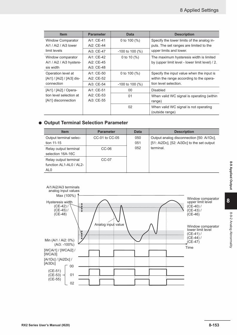
Item Parameter Data DescriptionWindow ComparatorAi1 / Ai2 / Ai3 lowerlimit levels
Ai1: CE-41Ai2: CE-44
0 to 100 (%) Specify the lower limits of the analog in-puts. The set ranges are limited to theupper limits and lower.Ai3: CE-47 -100 to 100 (%)
Window comparatorAi1 / Ai2 / Ai3 hystere-sis width
Ai1: CE-42Ai2: CE-45Ai3: CE-48
0 to 10 (%) The maximum hysteresis width is limitedby (upper limit level - lower limit level) / 2.
Operation level at[Ai1] / [Ai2] / [Ai3] dis-connection
Ai1: CE-50Ai2: CE-52
0 to 100 (%) Specify the input value when the input iswithin the range according to the opera-tion level selection.Ai3: CE-54 -100 to 100 (%)
[Ai1] / [Ai2] / Opera-tion level selection at[Ai1] disconnection
Ai1: CE-51Ai2: CE-53Ai3: CE-55
00 Disabled01 When valid WC signal is operating (within
range)02 When valid WC signal is not operating
(outside range)
l Output Terminal Selection Parameter
Item Parameter Data DescriptionOutput terminal selec-tion 11-15
CC-01 to CC-05 050051052
Output analog disconnection [50: Ai1Dc],[51: Ai2Dc], [52: Ai3Dc] to the set outputterminal.Relay output terminal
selection 16A-16CCC-06
Relay output terminalfunction AL1-AL0 / AL2-AL0
CC-07
[WCAi1] / [WCAi2] /[WCAi3]
Max (100%)
Min (Ai1 / Ai2: 0%)
(Ai3: -100%)
(CE-40) /(CE-43) /(CE-46)
(CE-41) /(CE-44) /(CE-47)
(CE-42) /(CE-45) /(CE-48)
[Ai1Dc] / [Ai2Dc] /[Ai3Dc]
00
01
02
(CE-51)(CE-53)
(CE-55)
analog input valuesAi1/Ai2/Ai3 terminals
Hysteresis width
Analog input value
Window comparatorupper limit level
Window comparatorlower limit level
Time
8 Applied Settings
8-153RX2 Series User’s Manual (I620)
8-9 Applied O
utput
8
8-9-2 Analog Abnormality
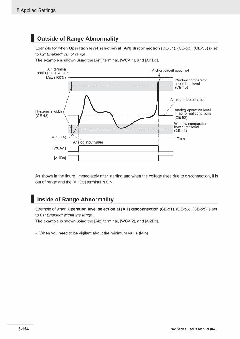
Outside of Range AbnormalityExample for when Operation level selection at [Ai1] disconnection (CE-51), (CE-53), (CE-55) is setto 02: Enabled: out of range.The example is shown using the [Ai1] terminal, [WCAi1], and [Ai1Dc].
Max (100%)
Min (0%)
(CE-50)(CE-42)
[Ai1Dc]
[WCAi1]
(CE-41)
(CE-40)
analog input valueAi1 terminal
Hysteresis width
Analog input value
Window comparatorupper limit level
Window comparatorlower limit level
A short circuit occurred
Analog adopted value
Analog operation levelin abnormal conditions
Time
As shown in the figure, immediately after starting and when the voltage rises due to disconnection, it isout of range and the [Ai1Dc] terminal is ON.
Inside of Range AbnormalityExample of when Operation level selection at [Ai1] disconnection (CE-51), (CE-53), (CE-55) is setto 01: Enabled: within the range.The example is shown using the [Ai2] terminal, [WCAi2], and [Ai2Dc].
• When you need to be vigilant about the minimum value (Min)
8 Applied Settings
8-154 RX2 Series User’s Manual (I620)
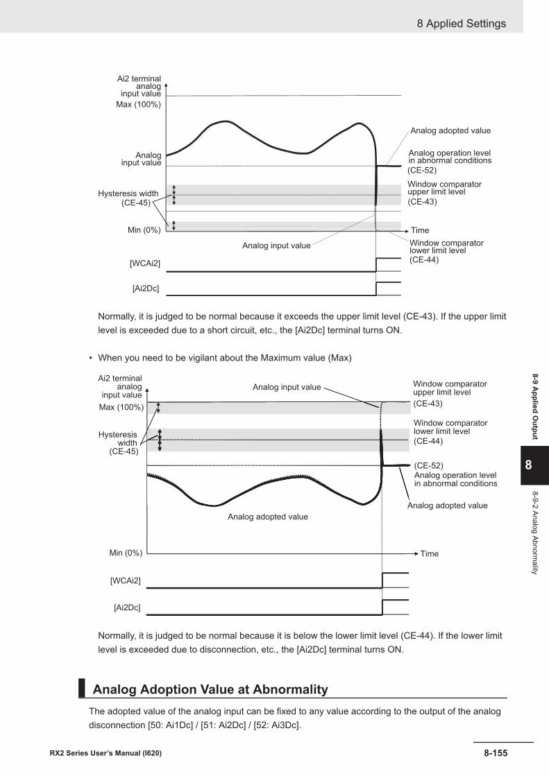
Max (100%)
Min (0%)
(CE-52)
(CE-43)
(CE-44)
(CE-45)
[WCAi2]
[Ai2Dc]
Ai2 terminalanalog
input value
Hysteresis width
Analoginput value
Window comparatorupper limit level
Window comparatorlower limit level
Time
Analog input value
Analog adopted value
Analog operation levelin abnormal conditions
Normally, it is judged to be normal because it exceeds the upper limit level (CE-43). If the upper limitlevel is exceeded due to a short circuit, etc., the [Ai2Dc] terminal turns ON.
• When you need to be vigilant about the Maximum value (Max)
Max (100%)
Min (0%)
(CE-52)
(CE-43)
(CE-44)
(CE-45)
[WCAi2]
[Ai2Dc]
Ai2 terminalanalog
input value
Hysteresiswidth
Analog adopted value
Window comparatorupper limit level
Window comparatorlower limit level
Time
Analog input value
Analog adopted value
Analog operation levelin abnormal conditions
Normally, it is judged to be normal because it is below the lower limit level (CE-44). If the lower limitlevel is exceeded due to disconnection, etc., the [Ai2Dc] terminal turns ON.
Analog Adoption Value at AbnormalityThe adopted value of the analog input can be fixed to any value according to the output of the analogdisconnection [50: Ai1Dc] / [51: Ai2Dc] / [52: Ai3Dc].
8 Applied Settings
8-155RX2 Series User’s Manual (I620)
8-9 Applied O
utput
8
8-9-2 Analog Abnormality
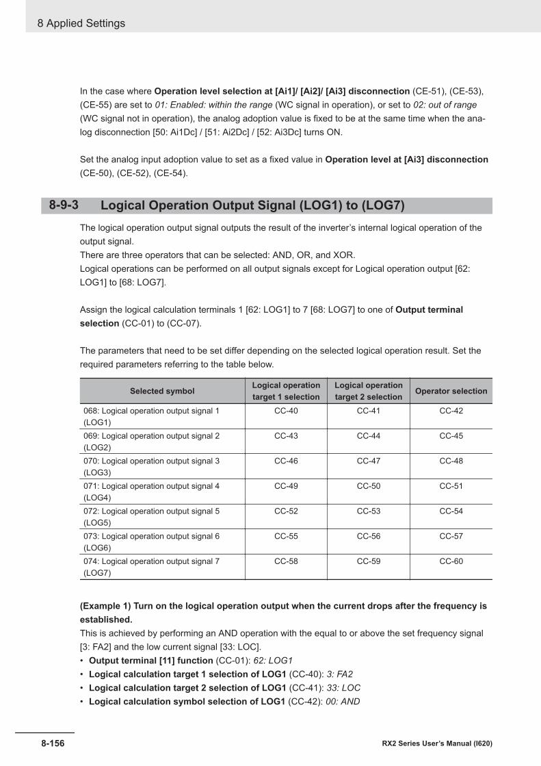
In the case where Operation level selection at [Ai1]/ [Ai2]/ [Ai3] disconnection (CE-51), (CE-53),(CE-55) are set to 01: Enabled: within the range (WC signal in operation), or set to 02: out of range(WC signal not in operation), the analog adoption value is fixed to be at the same time when the ana-log disconnection [50: Ai1Dc] / [51: Ai2Dc] / [52: Ai3Dc] turns ON.
Set the analog input adoption value to set as a fixed value in Operation level at [Ai3] disconnection(CE-50), (CE-52), (CE-54).
8-9-3 Logical Operation Output Signal (LOG1) to (LOG7)The logical operation output signal outputs the result of the inverter’s internal logical operation of theoutput signal.There are three operators that can be selected: AND, OR, and XOR.Logical operations can be performed on all output signals except for Logical operation output [62:LOG1] to [68: LOG7].
Assign the logical calculation terminals 1 [62: LOG1] to 7 [68: LOG7] to one of Output terminalselection (CC-01) to (CC-07).
The parameters that need to be set differ depending on the selected logical operation result. Set therequired parameters referring to the table below.
Selected symbol Logical operationtarget 1 selection
Logical operationtarget 2 selection Operator selection
068: Logical operation output signal 1(LOG1)
CC-40 CC-41 CC-42
069: Logical operation output signal 2(LOG2)
CC-43 CC-44 CC-45
070: Logical operation output signal 3(LOG3)
CC-46 CC-47 CC-48
071: Logical operation output signal 4(LOG4)
CC-49 CC-50 CC-51
072: Logical operation output signal 5(LOG5)
CC-52 CC-53 CC-54
073: Logical operation output signal 6(LOG6)
CC-55 CC-56 CC-57
074: Logical operation output signal 7(LOG7)
CC-58 CC-59 CC-60
(Example 1) Turn on the logical operation output when the current drops after the frequency isestablished.This is achieved by performing an AND operation with the equal to or above the set frequency signal[3: FA2] and the low current signal [33: LOC].• Output terminal [11] function (CC-01): 62: LOG1• Logical calculation target 1 selection of LOG1 (CC-40): 3: FA2• Logical calculation target 2 selection of LOG1 (CC-41): 33: LOC• Logical calculation symbol selection of LOG1 (CC-42): 00: AND
8 Applied Settings
8-156 RX2 Series User’s Manual (I620)
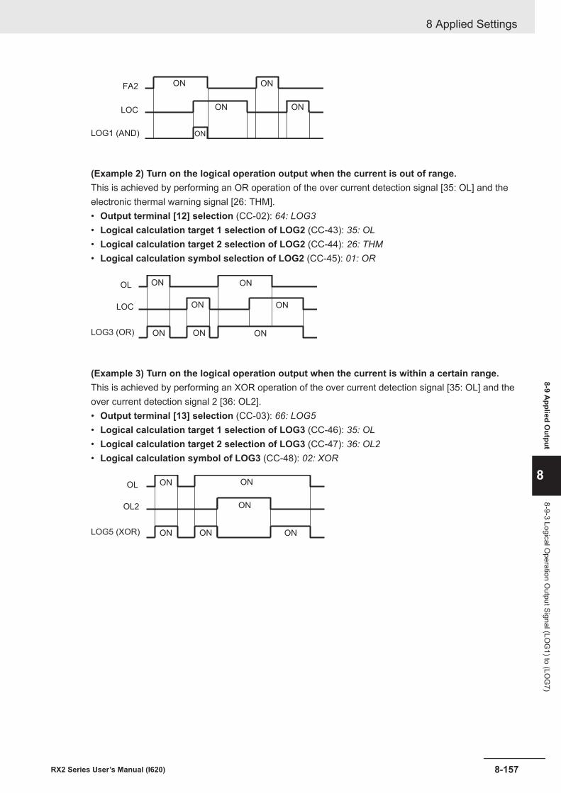
FA2
LOC
LOG1 (AND)
ON ON
ON ON
ON
(Example 2) Turn on the logical operation output when the current is out of range.This is achieved by performing an OR operation of the over current detection signal [35: OL] and theelectronic thermal warning signal [26: THM].• Output terminal [12] selection (CC-02): 64: LOG3• Logical calculation target 1 selection of LOG2 (CC-43): 35: OL• Logical calculation target 2 selection of LOG2 (CC-44): 26: THM• Logical calculation symbol selection of LOG2 (CC-45): 01: OR
OL
LOC
LOG3 (OR)
ON ON
ON ON
ONONON
(Example 3) Turn on the logical operation output when the current is within a certain range.This is achieved by performing an XOR operation of the over current detection signal [35: OL] and theover current detection signal 2 [36: OL2].• Output terminal [13] selection (CC-03): 66: LOG5• Logical calculation target 1 selection of LOG3 (CC-46): 35: OL• Logical calculation target 2 selection of LOG3 (CC-47): 36: OL2• Logical calculation symbol of LOG3 (CC-48): 02: XOR
OL
OL2
LOG5 (XOR)
ON ON
ON
ON ON ON
8 Applied Settings
8-157RX2 Series User’s Manual (I620)
8-9 Applied O
utput
8
8-9-3 Logical Operation O
utput Signal (LOG
1) to (LOG
7)
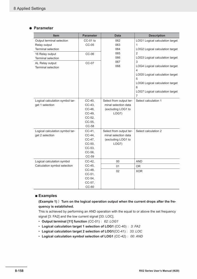
l Parameter
Item Parameter Data DescriptionOutput terminal selectionRelay outputTerminal selection
CC-01 toCC-05
062063064065066067068
LOG1 Logical calculation target1LOG2 Logical calculation target2LOG3 Logical calculation target3LOG4 Logical calculation target4LOG5 Logical calculation target5LOG6 Logical calculation target6LOG7 Logical calculation target7
16 Relay outputTerminal selection
CC-06
AL Relay outputTerminal selection
CC-07
Logical calculation symbol tar-get 1 selection
CC-40,CC-43,CC-46,CC-49,CC-52,CC-55,CC-58
Select from output ter-minal selection data(excluding LOG1 to
LOG7)
Select calculation 1
Logical calculation symbol tar-get 2 selection
CC-41,CC-44,CC-47,CC-50,CC-53,CC-56,CC-59
Select from output ter-minal selection data(excluding LOG1 to
LOG7)
Select calculation 2
Logical calculation symbolCalculation symbol selection
CC-42,CC-45,CC-48,CC-51,CC-54,CC-57,CC-60
00 AND01 OR02 XOR
¢ Examples(Example 1) )Turn on the logical operation output when the current drops after the fre-quency is established.This is achieved by performing an AND operation with the equal to or above the set frequencysignal [3: FA2] and the low current signal [33: LOC].• Output terminal [11] function (CC-01): 62: LOG1• Logical calculation target 1 selection of LOG1 (CC-40): 3: FA2• Logical calculation target 2 selection of LOG1(CC-41): 33: LOC• Logical calculation symbol selection of LOG1 (CC-42): 00: AND
8 Applied Settings
8-158 RX2 Series User’s Manual (I620)
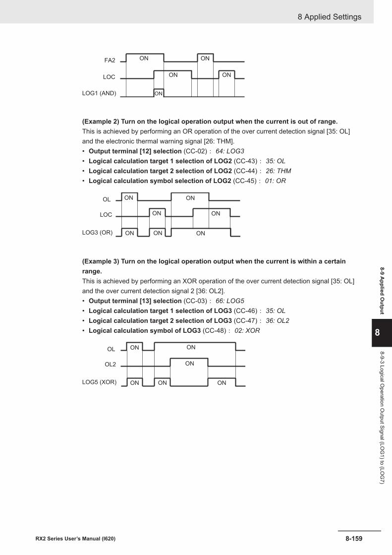
FA2
LOC
LOG1 (AND)
ON ON
ON ON
ON
(Example 2) Turn on the logical operation output when the current is out of range.This is achieved by performing an OR operation of the over current detection signal [35: OL]and the electronic thermal warning signal [26: THM].• Output terminal [12] selection (CC-02): 64: LOG3• Logical calculation target 1 selection of LOG2 (CC-43): 35: OL• Logical calculation target 2 selection of LOG2 (CC-44): 26: THM• Logical calculation symbol selection of LOG2 (CC-45): 01: OR
OL
LOC
LOG3 (OR)
ON ON
ON ON
ONONON
(Example 3) Turn on the logical operation output when the current is within a certainrange.This is achieved by performing an XOR operation of the over current detection signal [35: OL]and the over current detection signal 2 [36: OL2].• Output terminal [13] selection (CC-03): 66: LOG5• Logical calculation target 1 selection of LOG3 (CC-46): 35: OL• Logical calculation target 2 selection of LOG3 (CC-47): 36: OL2• Logical calculation symbol of LOG3 (CC-48): 02: XOR
OL
OL2
LOG5 (XOR)
ON ON
ON
ON ON ON
8 Applied Settings
8-159RX2 Series User’s Manual (I620)
8-9 Applied O
utput
8
8-9-3 Logical Operation O
utput Signal (LOG
1) to (LOG
7)
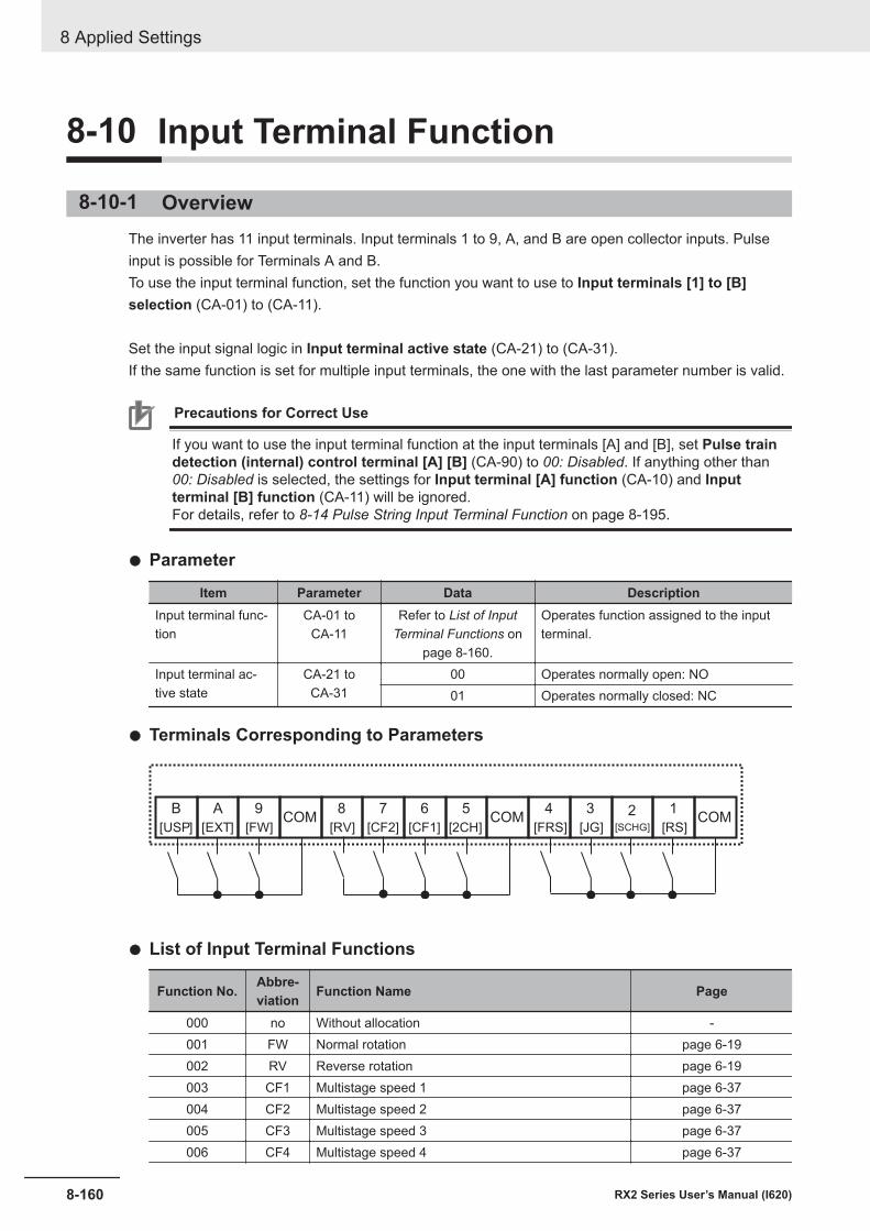
8-10 Input Terminal Function
8-10-1 OverviewThe inverter has 11 input terminals. Input terminals 1 to 9, A, and B are open collector inputs. Pulseinput is possible for Terminals A and B.To use the input terminal function, set the function you want to use to Input terminals [1] to [B]selection (CA-01) to (CA-11).
Set the input signal logic in Input terminal active state (CA-21) to (CA-31).If the same function is set for multiple input terminals, the one with the last parameter number is valid.
Precautions for Correct Use
If you want to use the input terminal function at the input terminals [A] and [B], set Pulse traindetection (internal) control terminal [A] [B] (CA-90) to 00: Disabled. If anything other than00: Disabled is selected, the settings for Input terminal [A] function (CA-10) and Inputterminal [B] function (CA-11) will be ignored.For details, refer to 8-14 Pulse String Input Terminal Function on page 8-195.
l Parameter
Item Parameter Data DescriptionInput terminal func-tion
CA-01 toCA-11
Refer to List of InputTerminal Functions on
page 8-160.
Operates function assigned to the inputterminal.
Input terminal ac-tive state
CA-21 toCA-31
00 Operates normally open: NO01 Operates normally closed: NC
l Terminals Corresponding to Parameters
1
[RS]
2
[SCHG]
3
[JG]
4
[FRS]
5
[2CH]
6
[CF1]
7
[CF2]
8
[RV]
9
[FW]
A
[EXT]
B
[USP]COMCOMCOM
l List of Input Terminal Functions
Function No. Abbre-viation Function Name Page
000 no Without allocation -001 FW Normal rotation page 6-19002 RV Reverse rotation page 6-19003 CF1 Multistage speed 1 page 6-37004 CF2 Multistage speed 2 page 6-37005 CF3 Multistage speed 3 page 6-37006 CF4 Multistage speed 4 page 6-37
8 Applied Settings
8-160 RX2 Series User’s Manual (I620)
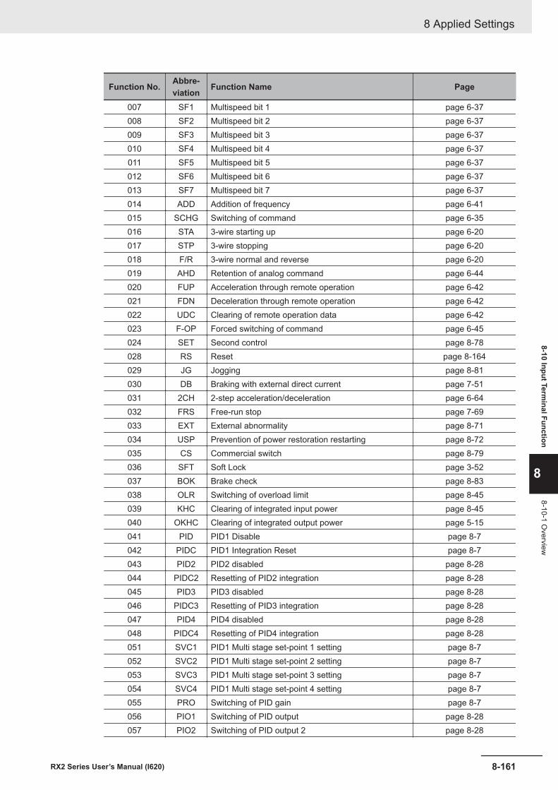
Function No. Abbre-viation Function Name Page
007 SF1 Multispeed bit 1 page 6-37008 SF2 Multispeed bit 2 page 6-37009 SF3 Multispeed bit 3 page 6-37010 SF4 Multispeed bit 4 page 6-37011 SF5 Multispeed bit 5 page 6-37012 SF6 Multispeed bit 6 page 6-37013 SF7 Multispeed bit 7 page 6-37014 ADD Addition of frequency page 6-41015 SCHG Switching of command page 6-35016 STA 3-wire starting up page 6-20017 STP 3-wire stopping page 6-20018 F/R 3-wire normal and reverse page 6-20019 AHD Retention of analog command page 6-44020 FUP Acceleration through remote operation page 6-42021 FDN Deceleration through remote operation page 6-42022 UDC Clearing of remote operation data page 6-42023 F-OP Forced switching of command page 6-45024 SET Second control page 8-78028 RS Reset page 8-164029 JG Jogging page 8-81030 DB Braking with external direct current page 7-51031 2CH 2-step acceleration/deceleration page 6-64032 FRS Free-run stop page 7-69033 EXT External abnormality page 8-71034 USP Prevention of power restoration restarting page 8-72035 CS Commercial switch page 8-79036 SFT Soft Lock page 3-52037 BOK Brake check page 8-83038 OLR Switching of overload limit page 8-45039 KHC Clearing of integrated input power page 8-45040 OKHC Clearing of integrated output power page 5-15041 PID PID1 Disable page 8-7042 PIDC PID1 Integration Reset page 8-7043 PID2 PID2 disabled page 8-28044 PIDC2 Resetting of PID2 integration page 8-28045 PID3 PID3 disabled page 8-28046 PIDC3 Resetting of PID3 integration page 8-28047 PID4 PID4 disabled page 8-28048 PIDC4 Resetting of PID4 integration page 8-28051 SVC1 PID1 Multi stage set-point 1 setting page 8-7052 SVC2 PID1 Multi stage set-point 2 setting page 8-7053 SVC3 PID1 Multi stage set-point 3 setting page 8-7054 SVC4 PID1 Multi stage set-point 4 setting page 8-7055 PRO Switching of PID gain page 8-7056 PIO1 Switching of PID output page 8-28057 PIO2 Switching of PID output 2 page 8-28
8 Applied Settings
8-161RX2 Series User’s Manual (I620)
8-10 Input Terminal Function
8
8-10-1 Overview
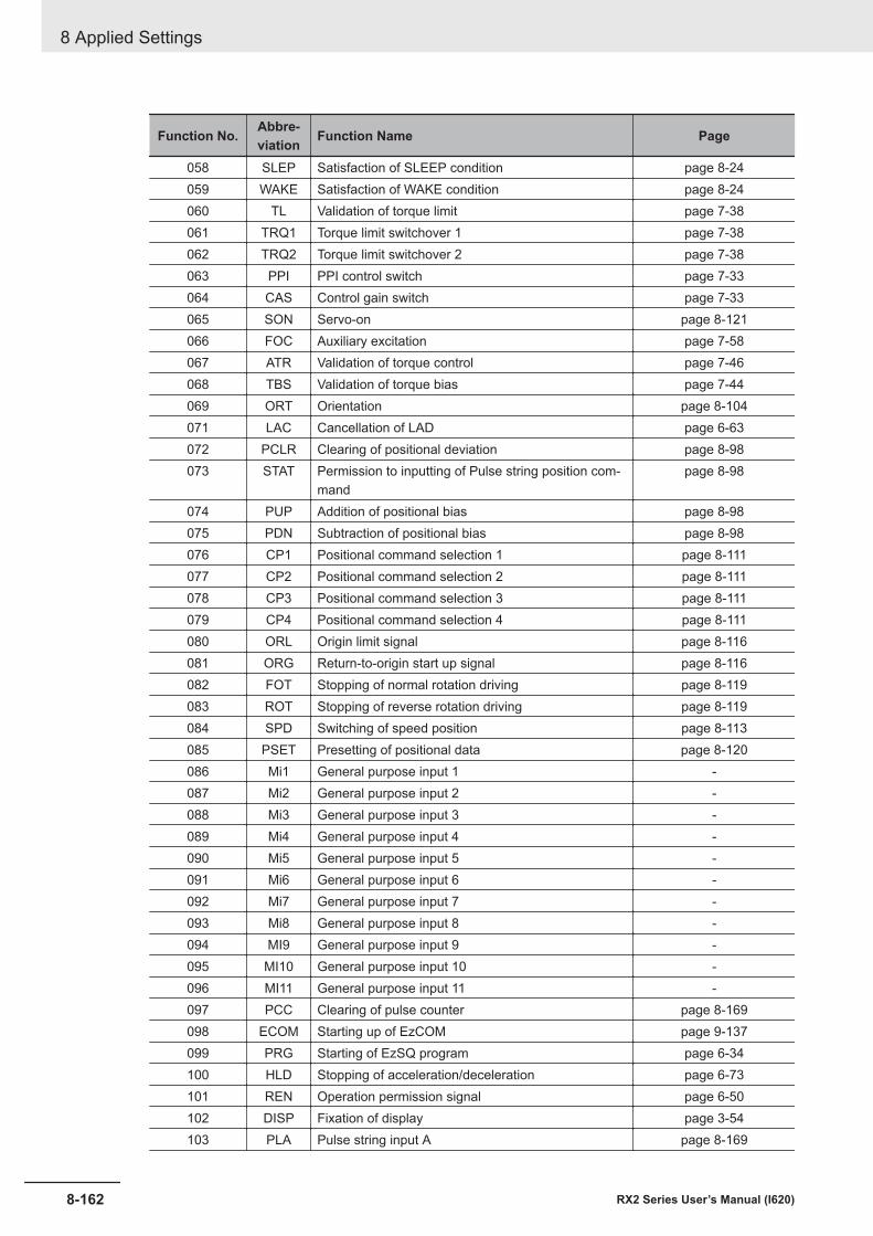
Function No. Abbre-viation Function Name Page
058 SLEP Satisfaction of SLEEP condition page 8-24059 WAKE Satisfaction of WAKE condition page 8-24060 TL Validation of torque limit page 7-38061 TRQ1 Torque limit switchover 1 page 7-38062 TRQ2 Torque limit switchover 2 page 7-38063 PPI PPI control switch page 7-33064 CAS Control gain switch page 7-33065 SON Servo-on page 8-121066 FOC Auxiliary excitation page 7-58067 ATR Validation of torque control page 7-46068 TBS Validation of torque bias page 7-44069 ORT Orientation page 8-104071 LAC Cancellation of LAD page 6-63072 PCLR Clearing of positional deviation page 8-98073 STAT Permission to inputting of Pulse string position com-
mandpage 8-98
074 PUP Addition of positional bias page 8-98075 PDN Subtraction of positional bias page 8-98076 CP1 Positional command selection 1 page 8-111077 CP2 Positional command selection 2 page 8-111078 CP3 Positional command selection 3 page 8-111079 CP4 Positional command selection 4 page 8-111080 ORL Origin limit signal page 8-116081 ORG Return-to-origin start up signal page 8-116082 FOT Stopping of normal rotation driving page 8-119083 ROT Stopping of reverse rotation driving page 8-119084 SPD Switching of speed position page 8-113085 PSET Presetting of positional data page 8-120086 Mi1 General purpose input 1 -087 Mi2 General purpose input 2 -088 Mi3 General purpose input 3 -089 Mi4 General purpose input 4 -090 Mi5 General purpose input 5 -091 Mi6 General purpose input 6 -092 Mi7 General purpose input 7 -093 Mi8 General purpose input 8 -094 MI9 General purpose input 9 -095 MI10 General purpose input 10 -096 MI11 General purpose input 11 -097 PCC Clearing of pulse counter page 8-169098 ECOM Starting up of EzCOM page 9-137099 PRG Starting of EzSQ program page 6-34100 HLD Stopping of acceleration/deceleration page 6-73101 REN Operation permission signal page 6-50102 DISP Fixation of display page 3-54103 PLA Pulse string input A page 8-169
8 Applied Settings
8-162 RX2 Series User’s Manual (I620)
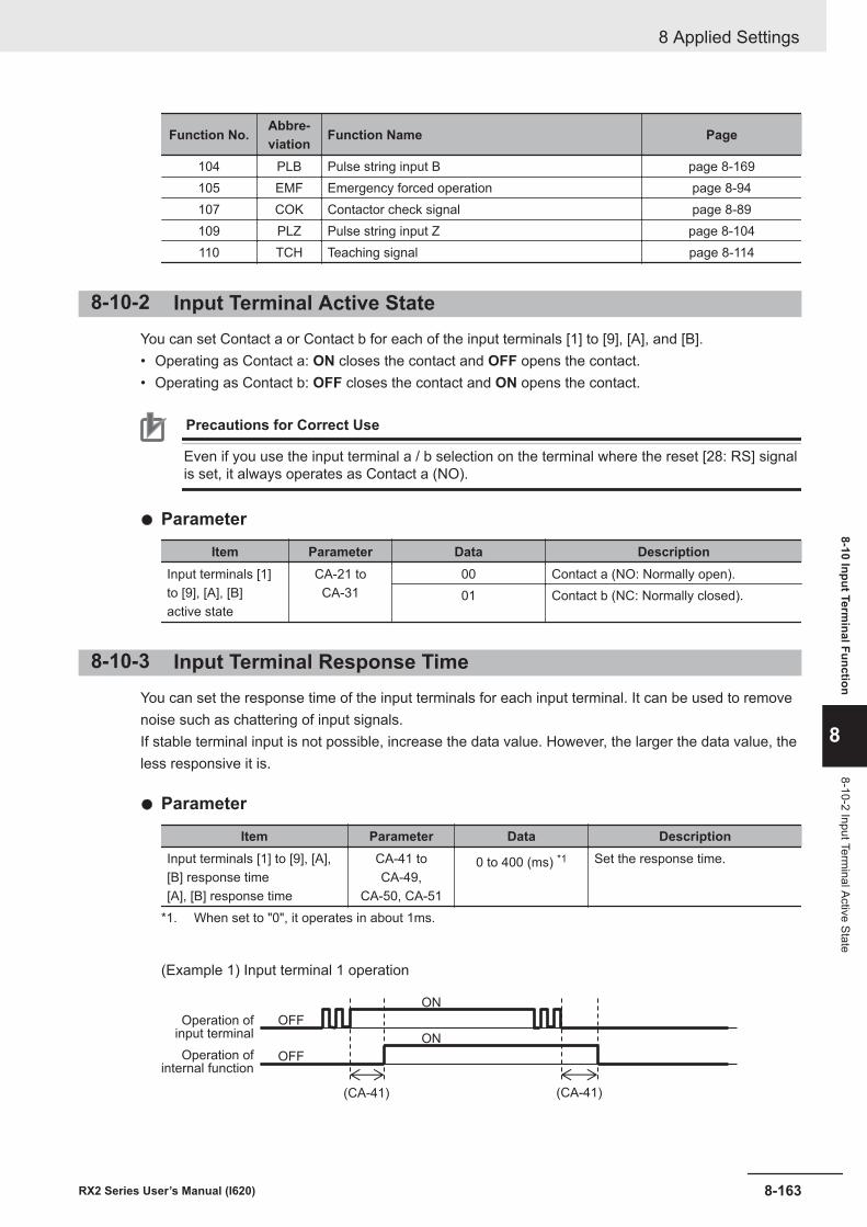
Function No. Abbre-viation Function Name Page
104 PLB Pulse string input B page 8-169105 EMF Emergency forced operation page 8-94107 COK Contactor check signal page 8-89109 PLZ Pulse string input Z page 8-104110 TCH Teaching signal page 8-114
8-10-2 Input Terminal Active StateYou can set Contact a or Contact b for each of the input terminals [1] to [9], [A], and [B].• Operating as Contact a: ON closes the contact and OFF opens the contact.• Operating as Contact b: OFF closes the contact and ON opens the contact.
Precautions for Correct Use
Even if you use the input terminal a / b selection on the terminal where the reset [28: RS] signalis set, it always operates as Contact a (NO).
l Parameter
Item Parameter Data DescriptionInput terminals [1]to [9], [A], [B]active state
CA-21 toCA-31
00 Contact a (NO: Normally open).01 Contact b (NC: Normally closed).
8-10-3 Input Terminal Response TimeYou can set the response time of the input terminals for each input terminal. It can be used to removenoise such as chattering of input signals.If stable terminal input is not possible, increase the data value. However, the larger the data value, theless responsive it is.
l Parameter
Item Parameter Data DescriptionInput terminals [1] to [9], [A],[B] response time[A], [B] response time
CA-41 toCA-49,
CA-50, CA-51
0 to 400 (ms) *1 Set the response time.
*1. When set to "0", it operates in about 1ms.
(Example 1) Input terminal 1 operation
(CA-41)
ON
OFF
OFF
ON
(CA-41)
Operation ofinput terminal
Operation ofinternal function
8 Applied Settings
8-163RX2 Series User’s Manual (I620)
8-10 Input Terminal Function
8
8-10-2 Input Terminal Active State
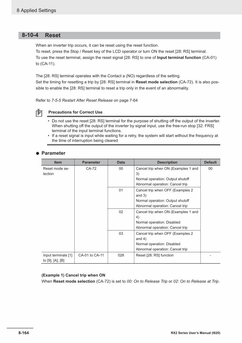
8-10-4 ResetWhen an inverter trip occurs, it can be reset using the reset function.To reset, press the Stop / Reset key of the LCD operator or turn ON the reset [28: RS] terminal.To use the reset terminal, assign the reset signal [28: RS] to one of Input terminal function (CA-01)to (CA-11).
The [28: RS] terminal operates with the Contact a (NO) regardless of the setting.Set the timing for resetting a trip by [28: RS] terminal in Reset mode selection (CA-72). It is also pos-sible to enable the [28: RS] terminal to reset a trip only in the event of an abnormality.
Refer to 7-5-5 Restart After Reset Release on page 7-64
Precautions for Correct Use
• Do not use the reset [28: RS] terminal for the purpose of shutting off the output of the inverter.When shutting off the output of the inverter by signal input, use the free-run stop [32: FRS]terminal of the input terminal functions.
• If a reset signal is input while waiting for a retry, the system will start without the frequency atthe time of interruption being cleared
l Parameter
Item Parameter Data Description DefaultReset mode se-lection
CA-72 00 Cancel trip when ON (Examples 1 and3)Normal operation: Output shutoffAbnormal operation: Cancel trip
00
01 Cancel trip when OFF (Examples 2and 3)Normal operation: Output shutoffAbnormal operation: Cancel trip
02 Cancel trip when ON (Examples 1 and4)Normal operation: DisabledAbnormal operation: Cancel trip
03 Cancel trip when OFF (Examples 2and 4)Normal operation: DisabledAbnormal operation: Cancel trip
Input terminals [1]to [9], [A], [B]
CA-01 to CA-11 028 Reset [28: RS] function -
(Example 1) Cancel trip when ONWhen Reset mode selection (CA-72) is set to 00: On to Release Trip or 02: On to Release at Trip.
8 Applied Settings
8-164 RX2 Series User’s Manual (I620)
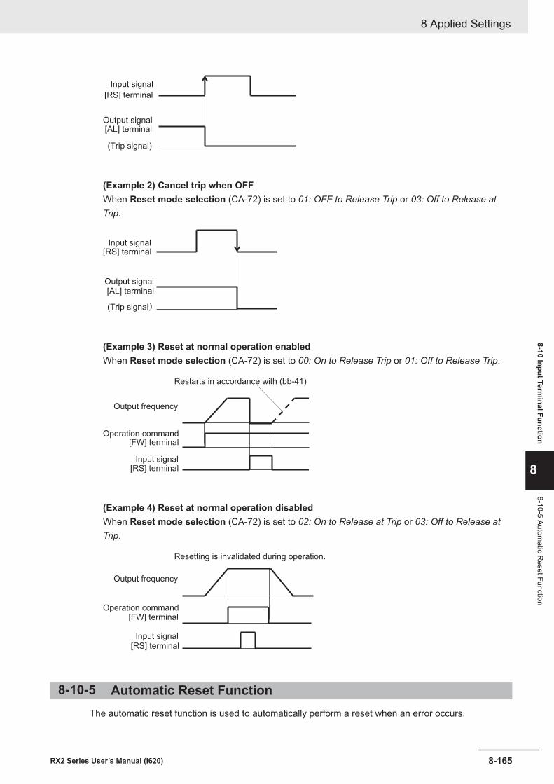
[RS] terminal
[AL] terminalOutput signal
Input signal
(Trip signal)
(Example 2) Cancel trip when OFFWhen Reset mode selection (CA-72) is set to 01: OFF to Release Trip or 03: Off to Release atTrip.
[RS] terminal
[AL] terminalOutput signal
Input signal
(Trip signal)
(Example 3) Reset at normal operation enabledWhen Reset mode selection (CA-72) is set to 00: On to Release Trip or 01: Off to Release Trip.
[FW] terminal
[RS] terminal
Operation command
Input signal
Restarts in accordance with (bb-41)
Output frequency
(Example 4) Reset at normal operation disabledWhen Reset mode selection (CA-72) is set to 02: On to Release at Trip or 03: Off to Release atTrip.
[FW] terminal
[RS] terminal
Operation command
Input signal
Resetting is invalidated during operation.
Output frequency
8-10-5 Automatic Reset FunctionThe automatic reset function is used to automatically perform a reset when an error occurs.
8 Applied Settings
8-165RX2 Series User’s Manual (I620)
8-10 Input Terminal Function
8
8-10-5 Automatic R
eset Function
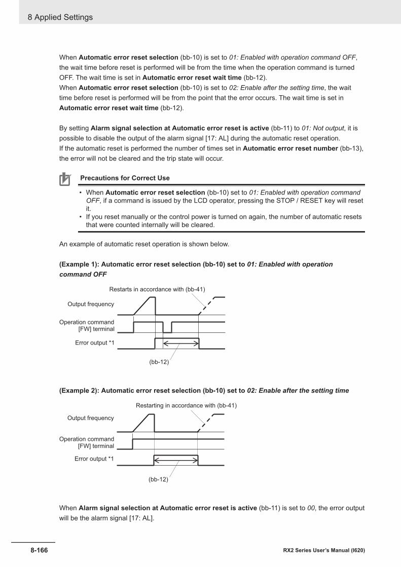
When Automatic error reset selection (bb-10) is set to 01: Enabled with operation command OFF,the wait time before reset is performed will be from the time when the operation command is turnedOFF. The wait time is set in Automatic error reset wait time (bb-12).When Automatic error reset selection (bb-10) is set to 02: Enable after the setting time, the waittime before reset is performed will be from the point that the error occurs. The wait time is set inAutomatic error reset wait time (bb-12).
By setting Alarm signal selection at Automatic error reset is active (bb-11) to 01: Not output, it ispossible to disable the output of the alarm signal [17: AL] during the automatic reset operation.If the automatic reset is performed the number of times set in Automatic error reset number (bb-13),the error will not be cleared and the trip state will occur.
Precautions for Correct Use
• When Automatic error reset selection (bb-10) set to 01: Enabled with operation commandOFF, if a command is issued by the LCD operator, pressing the STOP / RESET key will resetit.
• If you reset manually or the control power is turned on again, the number of automatic resetsthat were counted internally will be cleared.
An example of automatic reset operation is shown below.
(Example 1): Automatic error reset selection (bb-10) set to 01: Enabled with operationcommand OFF
(bb-12)
[FW] terminalOperation command
Error output *1
Output frequency
Restarts in accordance with (bb-41)
(Example 2): Automatic error reset selection (bb-10) set to 02: Enable after the setting time
(bb-12)
[FW] terminalOperation command
Error output *1
Output frequency
Restarting in accordance with (bb-41)
When Alarm signal selection at Automatic error reset is active (bb-11) is set to 00, the error outputwill be the alarm signal [17: AL].
8 Applied Settings
8-166 RX2 Series User’s Manual (I620)
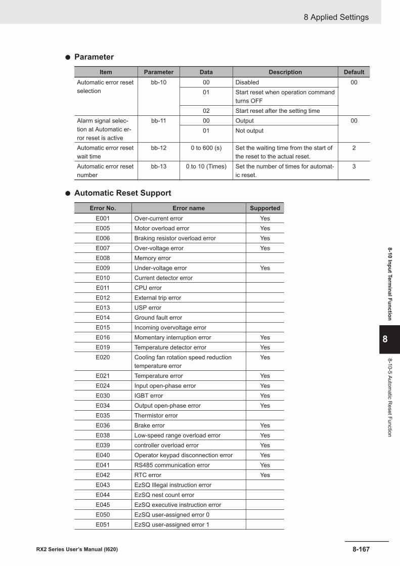
l Parameter
Item Parameter Data Description DefaultAutomatic error resetselection
bb-10 00 Disabled 0001 Start reset when operation command
turns OFF02 Start reset after the setting time
Alarm signal selec-tion at Automatic er-ror reset is active
bb-11 00 Output 0001 Not output
Automatic error resetwait time
bb-12 0 to 600 (s) Set the waiting time from the start ofthe reset to the actual reset.
2
Automatic error resetnumber
bb-13 0 to 10 (Times) Set the number of times for automat-ic reset.
3
l Automatic Reset Support
Error No. Error name SupportedE001 Over-current error YesE005 Motor overload error YesE006 Braking resistor overload error YesE007 Over-voltage error YesE008 Memory errorE009 Under-voltage error YesE010 Current detector errorE011 CPU errorE012 External trip errorE013 USP errorE014 Ground fault errorE015 Incoming overvoltage errorE016 Momentary interruption error YesE019 Temperature detector error YesE020 Cooling fan rotation speed reduction
temperature errorYes
E021 Temperature error YesE024 Input open-phase error YesE030 IGBT error YesE034 Output open-phase error YesE035 Thermistor errorE036 Brake error YesE038 Low-speed range overload error YesE039 controller overload error YesE040 Operator keypad disconnection error YesE041 RS485 communication error YesE042 RTC error YesE043 EzSQ Illegal instruction errorE044 EzSQ nest count errorE045 EzSQ executive instruction errorE050 EzSQ user-assigned error 0E051 EzSQ user-assigned error 1
8 Applied Settings
8-167RX2 Series User’s Manual (I620)
8-10 Input Terminal Function
8
8-10-5 Automatic R
eset Function
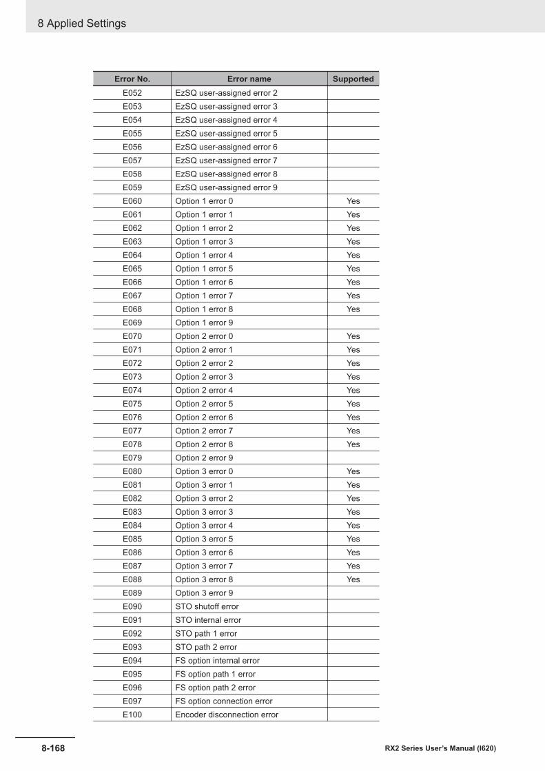
Error No. Error name SupportedE052 EzSQ user-assigned error 2E053 EzSQ user-assigned error 3E054 EzSQ user-assigned error 4E055 EzSQ user-assigned error 5E056 EzSQ user-assigned error 6E057 EzSQ user-assigned error 7E058 EzSQ user-assigned error 8E059 EzSQ user-assigned error 9E060 Option 1 error 0 YesE061 Option 1 error 1 YesE062 Option 1 error 2 YesE063 Option 1 error 3 YesE064 Option 1 error 4 YesE065 Option 1 error 5 YesE066 Option 1 error 6 YesE067 Option 1 error 7 YesE068 Option 1 error 8 YesE069 Option 1 error 9E070 Option 2 error 0 YesE071 Option 2 error 1 YesE072 Option 2 error 2 YesE073 Option 2 error 3 YesE074 Option 2 error 4 YesE075 Option 2 error 5 YesE076 Option 2 error 6 YesE077 Option 2 error 7 YesE078 Option 2 error 8 YesE079 Option 2 error 9E080 Option 3 error 0 YesE081 Option 3 error 1 YesE082 Option 3 error 2 YesE083 Option 3 error 3 YesE084 Option 3 error 4 YesE085 Option 3 error 5 YesE086 Option 3 error 6 YesE087 Option 3 error 7 YesE088 Option 3 error 8 YesE089 Option 3 error 9E090 STO shutoff errorE091 STO internal errorE092 STO path 1 errorE093 STO path 2 errorE094 FS option internal errorE095 FS option path 1 errorE096 FS option path 2 errorE097 FS option connection errorE100 Encoder disconnection error
8 Applied Settings
8-168 RX2 Series User’s Manual (I620)
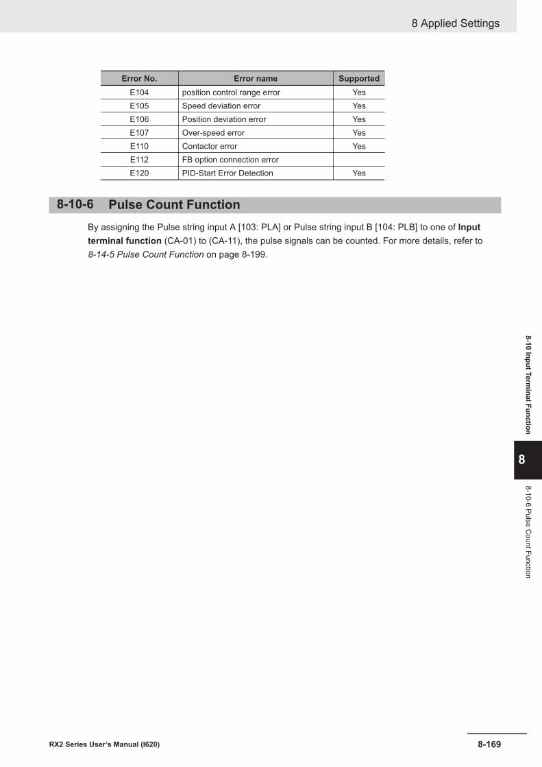
Error No. Error name SupportedE104 position control range error YesE105 Speed deviation error YesE106 Position deviation error YesE107 Over-speed error YesE110 Contactor error YesE112 FB option connection errorE120 PID-Start Error Detection Yes
8-10-6 Pulse Count FunctionBy assigning the Pulse string input A [103: PLA] or Pulse string input B [104: PLB] to one of Inputterminal function (CA-01) to (CA-11), the pulse signals can be counted. For more details, refer to 8-14-5 Pulse Count Function on page 8-199.
8 Applied Settings
8-169RX2 Series User’s Manual (I620)
8-10 Input Terminal Function
8
8-10-6 Pulse Count Function
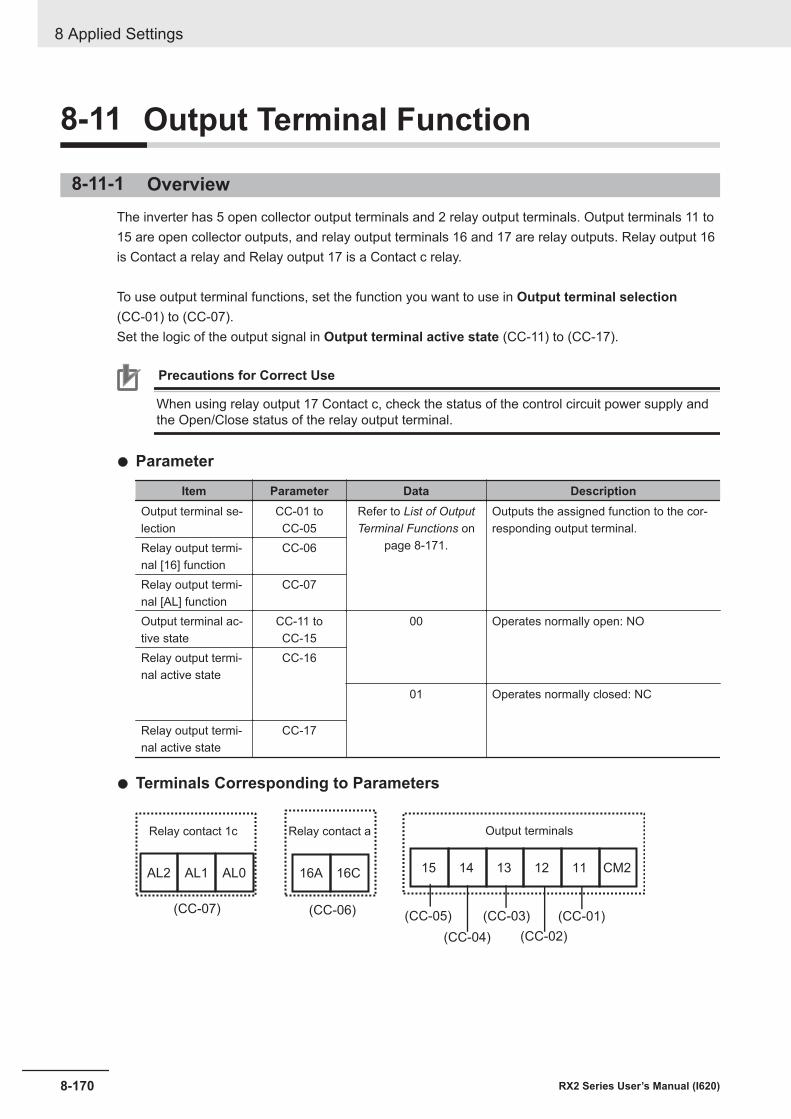
8-11 Output Terminal Function
8-11-1 OverviewThe inverter has 5 open collector output terminals and 2 relay output terminals. Output terminals 11 to15 are open collector outputs, and relay output terminals 16 and 17 are relay outputs. Relay output 16is Contact a relay and Relay output 17 is a Contact c relay.
To use output terminal functions, set the function you want to use in Output terminal selection(CC-01) to (CC-07).Set the logic of the output signal in Output terminal active state (CC-11) to (CC-17).
Precautions for Correct Use
When using relay output 17 Contact c, check the status of the control circuit power supply andthe Open/Close status of the relay output terminal.
l Parameter
Item Parameter Data DescriptionOutput terminal se-lection
CC-01 toCC-05
Refer to List of OutputTerminal Functions on
page 8-171.
Outputs the assigned function to the cor-responding output terminal.
Relay output termi-nal [16] function
CC-06
Relay output termi-nal [AL] function
CC-07
Output terminal ac-tive state
CC-11 toCC-15
00 Operates normally open: NO
Relay output termi-nal active state
CC-16
01 Operates normally closed: NC
Relay output termi-nal active state
CC-17
l Terminals Corresponding to Parameters
16A 16C 1112131415 CM2AL2 AL1 AL0
(CC-07) (CC-06) (CC-05)
(CC-04)
(CC-03)
(CC-02)
(CC-01)
Output terminalsRelay contact 1c Relay contact a
8 Applied Settings
8-170 RX2 Series User’s Manual (I620)
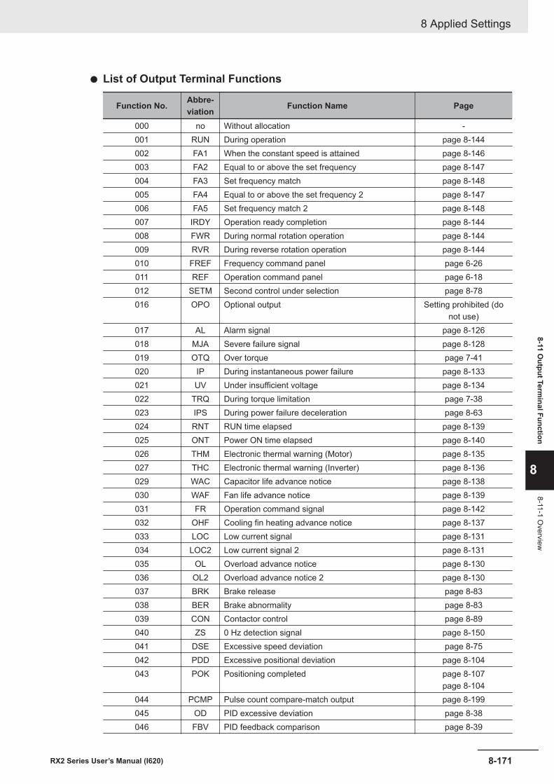
l List of Output Terminal Functions
Function No. Abbre-viation Function Name Page
000 no Without allocation -001 RUN During operation page 8-144002 FA1 When the constant speed is attained page 8-146003 FA2 Equal to or above the set frequency page 8-147004 FA3 Set frequency match page 8-148005 FA4 Equal to or above the set frequency 2 page 8-147006 FA5 Set frequency match 2 page 8-148007 IRDY Operation ready completion page 8-144008 FWR During normal rotation operation page 8-144009 RVR During reverse rotation operation page 8-144010 FREF Frequency command panel page 6-26011 REF Operation command panel page 6-18012 SETM Second control under selection page 8-78016 OPO Optional output Setting prohibited (do
not use)017 AL Alarm signal page 8-126018 MJA Severe failure signal page 8-128019 OTQ Over torque page 7-41020 IP During instantaneous power failure page 8-133021 UV Under insufficient voltage page 8-134022 TRQ During torque limitation page 7-38023 IPS During power failure deceleration page 8-63024 RNT RUN time elapsed page 8-139025 ONT Power ON time elapsed page 8-140026 THM Electronic thermal warning (Motor) page 8-135027 THC Electronic thermal warning (Inverter) page 8-136029 WAC Capacitor life advance notice page 8-138030 WAF Fan life advance notice page 8-139031 FR Operation command signal page 8-142032 OHF Cooling fin heating advance notice page 8-137033 LOC Low current signal page 8-131034 LOC2 Low current signal 2 page 8-131035 OL Overload advance notice page 8-130036 OL2 Overload advance notice 2 page 8-130037 BRK Brake release page 8-83038 BER Brake abnormality page 8-83039 CON Contactor control page 8-89040 ZS 0 Hz detection signal page 8-150041 DSE Excessive speed deviation page 8-75042 PDD Excessive positional deviation page 8-104043 POK Positioning completed page 8-107
page 8-104044 PCMP Pulse count compare-match output page 8-199045 OD PID excessive deviation page 8-38046 FBV PID feedback comparison page 8-39
8 Applied Settings
8-171RX2 Series User’s Manual (I620)
8-11 Output Term
inal Function
8
8-11-1 Overview
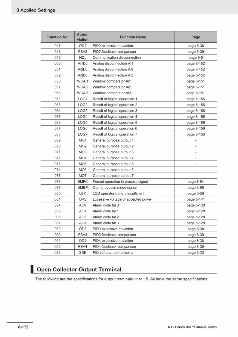
Function No. Abbre-viation Function Name Page
047 OD2 PID2 excessive deviation page 8-38048 FBV2 PID2 feedback comparison page 8-39049 NDc Communication disconnection page 9-5050 Ai1Dc Analog disconnection Ai1 page 8-152051 Ai2Dc Analog disconnection Ai2 page 8-152052 Ai3Dc Analog disconnection Ai3 page 8-152056 WCAi1 Window comparator Ai1 page 8-151057 WCAi2 Window comparator Ai2 page 8-151058 WCAi3 Window comparator Ai3 page 8-151062 LOG1 Result of logical operation 1 page 8-156063 LOG2 Result of logical operation 2 page 8-156064 LOG3 Result of logical operation 3 page 8-156065 LOG4 Result of logical operation 4 page 8-156066 LOG5 Result of logical operation 5 page 8-156067 LOG6 Result of logical operation 6 page 8-156068 LOG7 Result of logical operation 7 page 8-156069 MO1 General purpose output 1 -070 MO2 General purpose output 2 -071 MO3 General purpose output 3 -072 MO4 General purpose output 4 -073 MO5 General purpose output 5 -074 MO6 General purpose output 6 -075 MO7 General purpose output 7 -076 EMFC Forced operation in process signal page 8-94077 EMBP During-bypass-mode signal page 8-96080 LBK LCD operator battery insufficient page 3-56081 OVS Excessive voltage of accepted power page 8-141084 AC0 Alarm code bit 0 page 8-128085 AC1 Alarm code bit 1 page 8-128086 AC2 Alarm code bit 2 page 8-128087 AC3 Alarm code bit 3 page 8-128089 OD3 PID3 excessive deviation page 8-38090 FBV3 PID3 feedback comparison page 8-39091 OD4 PID4 excessive deviation page 8-38092 FBV4 PID4 feedback comparison page 8-39093 SSE PID soft start abnormality page 8-23
Open Collector Output TerminalThe following are the specifications for output terminals 11 to 15. All have the same specifications.
8 Applied Settings
8-172 RX2 Series User’s Manual (I620)
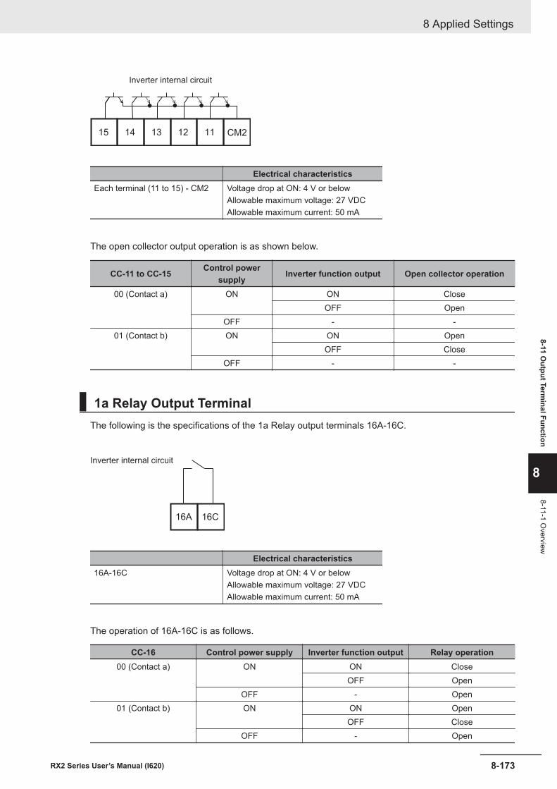
1112131415 CM2
Inverter internal circuit
Electrical characteristicsEach terminal (11 to 15) - CM2 Voltage drop at ON: 4 V or below
Allowable maximum voltage: 27 VDCAllowable maximum current: 50 mA
The open collector output operation is as shown below.
CC-11 to CC-15 Control powersupply Inverter function output Open collector operation
00 (Contact a) ON ON CloseOFF Open
OFF - -01 (Contact b) ON ON Open
OFF CloseOFF - -
1a Relay Output TerminalThe following is the specifications of the 1a Relay output terminals 16A-16C.
16A 16C
Inverter internal circuit
Electrical characteristics16A-16C Voltage drop at ON: 4 V or below
Allowable maximum voltage: 27 VDCAllowable maximum current: 50 mA
The operation of 16A-16C is as follows.
CC-16 Control power supply Inverter function output Relay operation00 (Contact a) ON ON Close
OFF OpenOFF - Open
01 (Contact b) ON ON OpenOFF Close
OFF - Open
8 Applied Settings
8-173RX2 Series User’s Manual (I620)
8-11 Output Term
inal Function
8
8-11-1 Overview
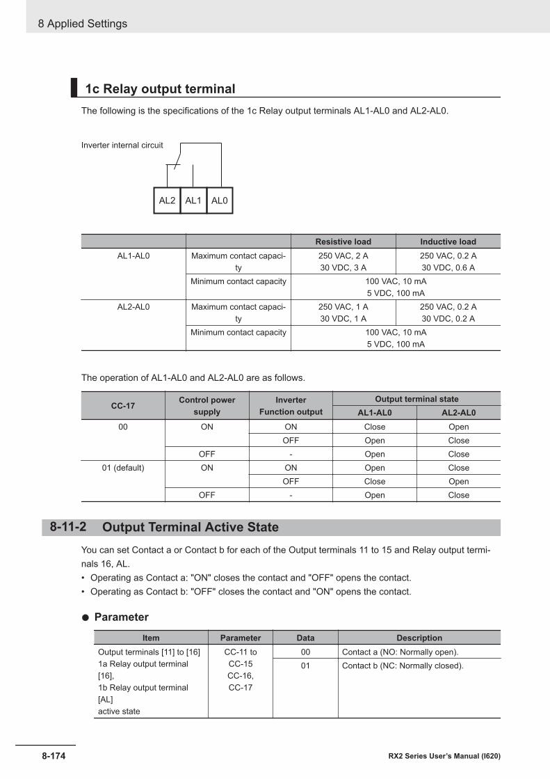
1c Relay output terminalThe following is the specifications of the 1c Relay output terminals AL1-AL0 and AL2-AL0.
AL1AL2 AL0
Inverter internal circuit
Resistive load Inductive loadAL1-AL0 Maximum contact capaci-
ty250 VAC, 2 A30 VDC, 3 A
250 VAC, 0.2 A30 VDC, 0.6 A
Minimum contact capacity 100 VAC, 10 mA5 VDC, 100 mA
AL2-AL0 Maximum contact capaci-ty
250 VAC, 1 A30 VDC, 1 A
250 VAC, 0.2 A30 VDC, 0.2 A
Minimum contact capacity 100 VAC, 10 mA5 VDC, 100 mA
The operation of AL1-AL0 and AL2-AL0 are as follows.
CC-17 Control powersupply
InverterFunction output
Output terminal stateAL1-AL0 AL2-AL0
00 ON ON Close OpenOFF Open Close
OFF - Open Close01 (default) ON ON Open Close
OFF Close OpenOFF - Open Close
8-11-2 Output Terminal Active StateYou can set Contact a or Contact b for each of the Output terminals 11 to 15 and Relay output termi-nals 16, AL.• Operating as Contact a: "ON" closes the contact and "OFF" opens the contact.• Operating as Contact b: "OFF" closes the contact and "ON" opens the contact.
l Parameter
Item Parameter Data DescriptionOutput terminals [11] to [16]1a Relay output terminal[16],1b Relay output terminal[AL]active state
CC-11 toCC-15CC-16,CC-17
00 Contact a (NO: Normally open).01 Contact b (NC: Normally closed).
8 Applied Settings
8-174 RX2 Series User’s Manual (I620)
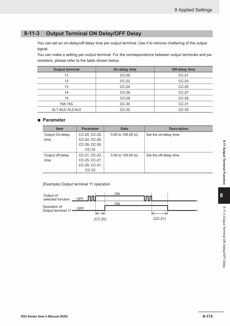
8-11-3 Output Terminal ON Delay/OFF DelayYou can set an on-delay/off-delay time per output terminal. Use it to remove chattering of the outputsignal.You can make a setting per output terminal. For the correspondence between output terminals and pa-rameters, please refer to the table shown below.
Output terminal On-delay time Off-delay time11 CC-20 CC-2112 CC-22 CC-2313 CC-24 CC-2514 CC-26 CC-2715 CC-28 CC-29
16A-16C CC-30 CC-31AL1-AL0/ AL2-AL0 CC-32 CC-33
l Parameter
Item Parameter Data DescriptionOutput On-delaytime
CC-20, CC-22,CC-24, CC-26,CC-28, CC-30,
CC-32
0.00 to 100.00 (s) Set the on-delay time.
Output off-delaytime
CC-21, CC-23,CC-25, CC-27,CC-29, CC-31,
CC-33
0.00 to 100.00 (s) Set the off-delay time.
(Example) Output terminal 11 operation
(CC-20)
ON
OFF
OFF
ON
(CC-21)
Operation ofOutput terminal 11
Output ofselected function
8 Applied Settings
8-175RX2 Series User’s Manual (I620)
8-11 Output Term
inal Function
8
8-11-3 Output Term
inal ON
Delay/O
FF Delay
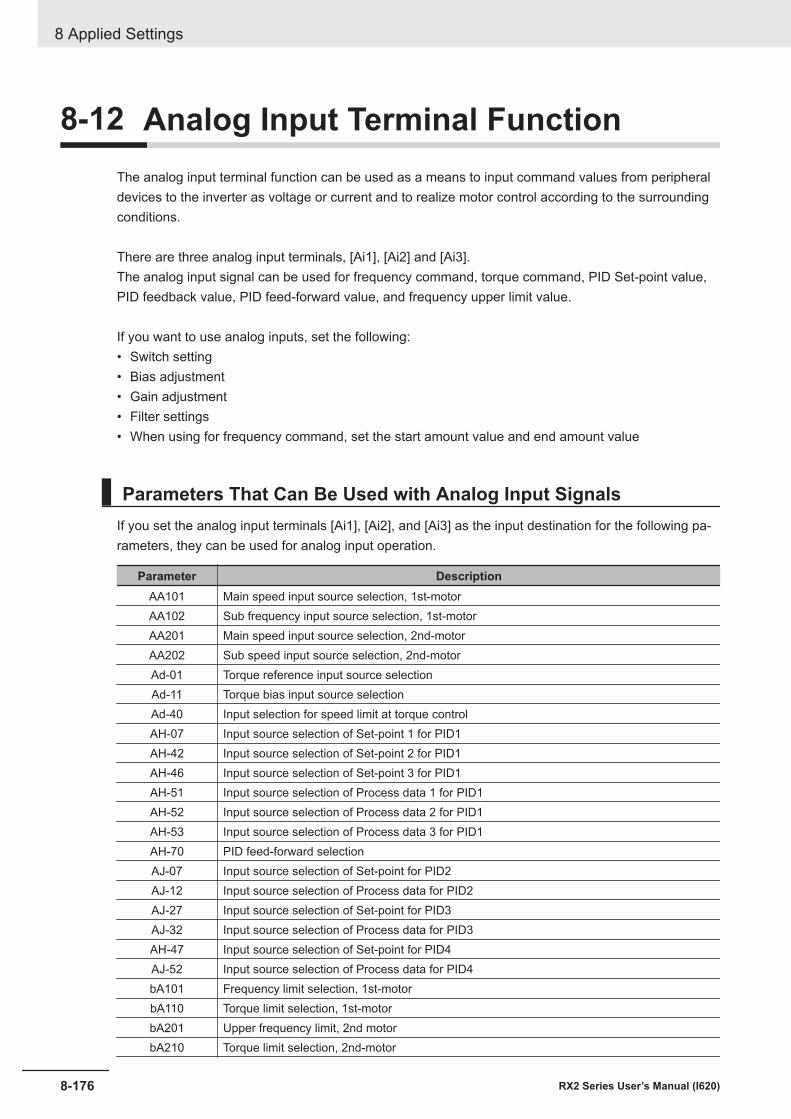
8-12 Analog Input Terminal FunctionThe analog input terminal function can be used as a means to input command values from peripheraldevices to the inverter as voltage or current and to realize motor control according to the surroundingconditions.
There are three analog input terminals, [Ai1], [Ai2] and [Ai3].The analog input signal can be used for frequency command, torque command, PID Set-point value,PID feedback value, PID feed-forward value, and frequency upper limit value.
If you want to use analog inputs, set the following:• Switch setting• Bias adjustment• Gain adjustment• Filter settings• When using for frequency command, set the start amount value and end amount value
Parameters That Can Be Used with Analog Input SignalsIf you set the analog input terminals [Ai1], [Ai2], and [Ai3] as the input destination for the following pa-rameters, they can be used for analog input operation.
Parameter DescriptionAA101 Main speed input source selection, 1st-motorAA102 Sub frequency input source selection, 1st-motorAA201 Main speed input source selection, 2nd-motorAA202 Sub speed input source selection, 2nd-motorAd-01 Torque reference input source selectionAd-11 Torque bias input source selectionAd-40 Input selection for speed limit at torque controlAH-07 Input source selection of Set-point 1 for PID1AH-42 Input source selection of Set-point 2 for PID1AH-46 Input source selection of Set-point 3 for PID1AH-51 Input source selection of Process data 1 for PID1AH-52 Input source selection of Process data 2 for PID1AH-53 Input source selection of Process data 3 for PID1AH-70 PID feed-forward selectionAJ-07 Input source selection of Set-point for PID2AJ-12 Input source selection of Process data for PID2AJ-27 Input source selection of Set-point for PID3AJ-32 Input source selection of Process data for PID3AH-47 Input source selection of Set-point for PID4AJ-52 Input source selection of Process data for PID4bA101 Frequency limit selection, 1st-motorbA110 Torque limit selection, 1st-motorbA201 Upper frequency limit, 2nd motorbA210 Torque limit selection, 2nd-motor
8 Applied Settings
8-176 RX2 Series User’s Manual (I620)
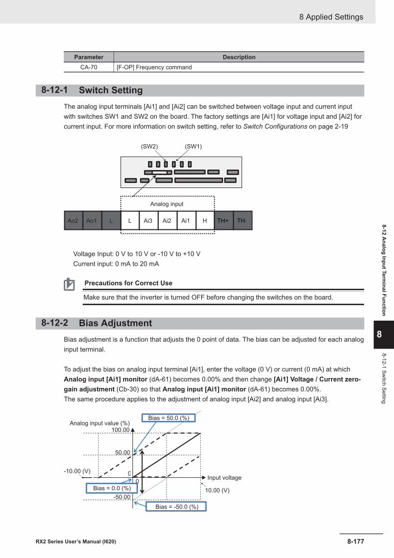
Parameter DescriptionCA-70 [F-OP] Frequency command
8-12-1 Switch SettingThe analog input terminals [Ai1] and [Ai2] can be switched between voltage input and current inputwith switches SW1 and SW2 on the board. The factory settings are [Ai1] for voltage input and [Ai2] forcurrent input. For more information on switch setting, refer to Switch Configurations on page 2-19
Ao2 Ao1
Analog input
HAi1Ai2Ai3LL TH--TH+
(SW2) (SW1)
Voltage Input: 0 V to 10 V or -10 V to +10 VCurrent input: 0 mA to 20 mA
Precautions for Correct Use
Make sure that the inverter is turned OFF before changing the switches on the board.
8-12-2 Bias AdjustmentBias adjustment is a function that adjusts the 0 point of data. The bias can be adjusted for each analoginput terminal.
To adjust the bias on analog input terminal [Ai1], enter the voltage (0 V) or current (0 mA) at whichAnalog input [Ai1] monitor (dA-61) becomes 0.00% and then change [Ai1] Voltage / Current zero-gain adjustment (Cb-30) so that Analog input [Ai1] monitor (dA-61) becomes 0.00%.The same procedure applies to the adjustment of analog input [Ai2] and analog input [Ai3].
0
0
Analog input value (%)100.00
Bias = 50.0 (%)
Input voltage
Bias = -50.0 (%)
Bias = 0.0 (%)
-10.00 (V)
-50.0010.00 (V)
50.00
8 Applied Settings
8-177RX2 Series User’s Manual (I620)
8-12 Analog Input Term
inal Function
8
8-12-1 Switch Setting
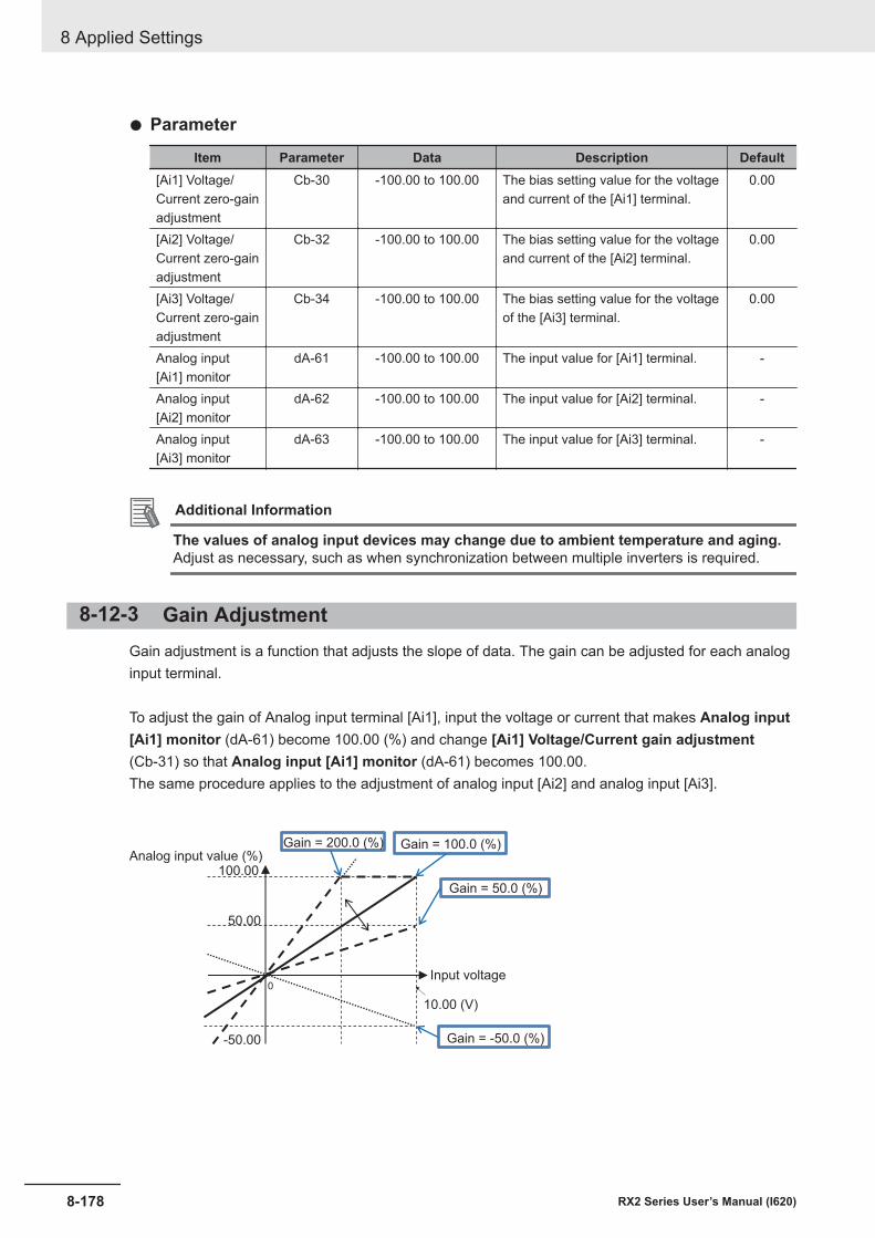
l Parameter
Item Parameter Data Description Default[Ai1] Voltage/Current zero-gainadjustment
Cb-30 -100.00 to 100.00 The bias setting value for the voltageand current of the [Ai1] terminal.
0.00
[Ai2] Voltage/Current zero-gainadjustment
Cb-32 -100.00 to 100.00 The bias setting value for the voltageand current of the [Ai2] terminal.
0.00
[Ai3] Voltage/Current zero-gainadjustment
Cb-34 -100.00 to 100.00 The bias setting value for the voltageof the [Ai3] terminal.
0.00
Analog input[Ai1] monitor
dA-61 -100.00 to 100.00 The input value for [Ai1] terminal. -
Analog input[Ai2] monitor
dA-62 -100.00 to 100.00 The input value for [Ai2] terminal. -
Analog input[Ai3] monitor
dA-63 -100.00 to 100.00 The input value for [Ai3] terminal. -
Additional Information
The values of analog input devices may change due to ambient temperature and aging.Adjust as necessary, such as when synchronization between multiple inverters is required.
8-12-3 Gain AdjustmentGain adjustment is a function that adjusts the slope of data. The gain can be adjusted for each analoginput terminal.
To adjust the gain of Analog input terminal [Ai1], input the voltage or current that makes Analog input[Ai1] monitor (dA-61) become 100.00 (%) and change [Ai1] Voltage/Current gain adjustment(Cb-31) so that Analog input [Ai1] monitor (dA-61) becomes 100.00.The same procedure applies to the adjustment of analog input [Ai2] and analog input [Ai3].
0
Analog input value (%)Gain = 200.0 (%) Gain = 100.0 (%)
Gain = 50.0 (%)
Gain = -50.0 (%)
Input voltage
100.00
50.00
-50.00
10.00 (V)
8 Applied Settings
8-178 RX2 Series User’s Manual (I620)
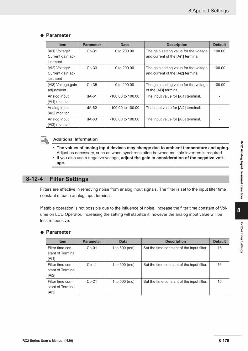
l Parameter
Item Parameter Data Description Default[Ai1] Voltage/Current gain ad-justment
Cb-31 0 to 200.00 The gain setting value for the voltageand current of the [Ai1] terminal.
100.00
[Ai2] Voltage/Current gain ad-justment
Cb-33 0 to 200.00 The gain setting value for the voltageand current of the [Ai2] terminal.
100.00
[Ai3] Voltage gainadjustment
Cb-35 0 to 200.00 The gain setting value for the voltageof the [Ai3] terminal.
100.00
Analog input[Ai1] monitor
dA-61 -100.00 to 100.00 The input value for [Ai1] terminal. -
Analog input[Ai2] monitor
dA-62 -100.00 to 100.00 The input value for [Ai2] terminal. -
Analog input[Ai3] monitor
dA-63 -100.00 to 100.00 The input value for [Ai3] terminal. -
Additional Information
• The values of analog input devices may change due to ambient temperature and aging.Adjust as necessary, such as when synchronization between multiple inverters is required.
• If you also use a negative voltage, adjust the gain in consideration of the negative volt-age.
8-12-4 Filter SettingsFilters are effective in removing noise from analog input signals. The filter is set to the input filter timeconstant of each analog input terminal.
If stable operation is not possible due to the influence of noise, increase the filter time constant of Vol-ume on LCD Operator. Increasing the setting will stabilize it, however the analog input value will beless responsive.
l Parameter
Item Parameter Data Description DefaultFilter time con-stant of Terminal[Ai1]
Cb-01 1 to 500 (ms) Set the time constant of the input filter. 16
Filter time con-stant of Terminal[Ai2]
Cb-11 1 to 500 (ms) Set the time constant of the input filter. 16
Filter time con-stant of Terminal[Ai3]
Cb-21 1 to 500 (ms) Set the time constant of the input filter. 16
8 Applied Settings
8-179RX2 Series User’s Manual (I620)
8-12 Analog Input Term
inal Function
8
8-12-4 Filter Settings
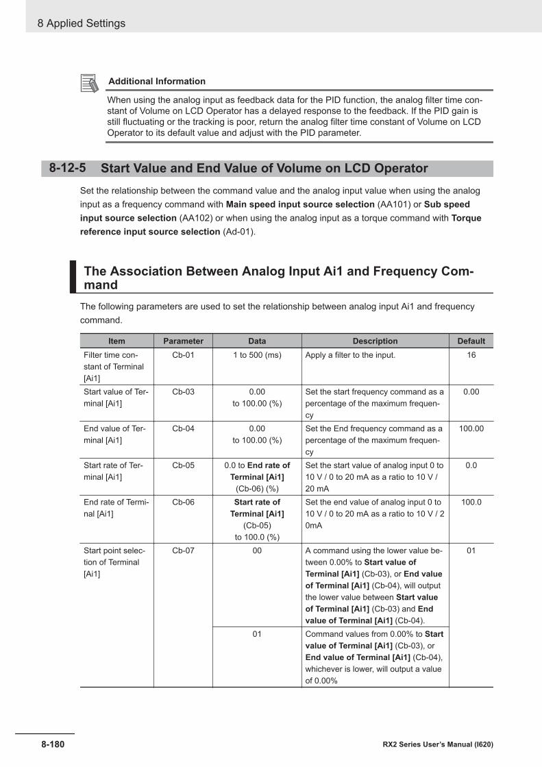
Additional Information
When using the analog input as feedback data for the PID function, the analog filter time con-stant of Volume on LCD Operator has a delayed response to the feedback. If the PID gain isstill fluctuating or the tracking is poor, return the analog filter time constant of Volume on LCDOperator to its default value and adjust with the PID parameter.
8-12-5 Start Value and End Value of Volume on LCD OperatorSet the relationship between the command value and the analog input value when using the analoginput as a frequency command with Main speed input source selection (AA101) or Sub speedinput source selection (AA102) or when using the analog input as a torque command with Torquereference input source selection (Ad-01).
The Association Between Analog Input Ai1 and Frequency Com-mand
The following parameters are used to set the relationship between analog input Ai1 and frequencycommand.
Item Parameter Data Description DefaultFilter time con-stant of Terminal[Ai1]
Cb-01 1 to 500 (ms) Apply a filter to the input. 16
Start value of Ter-minal [Ai1]
Cb-03 0.00to 100.00 (%)
Set the start frequency command as apercentage of the maximum frequen-cy
0.00
End value of Ter-minal [Ai1]
Cb-04 0.00to 100.00 (%)
Set the End frequency command as apercentage of the maximum frequen-cy
100.00
Start rate of Ter-minal [Ai1]
Cb-05 0.0 to End rate ofTerminal [Ai1]
(Cb-06) (%)
Set the start value of analog input 0 to10 V / 0 to 20 mA as a ratio to 10 V /20 mA
0.0
End rate of Termi-nal [Ai1]
Cb-06 Start rate ofTerminal [Ai1]
(Cb-05)to 100.0 (%)
Set the end value of analog input 0 to10 V / 0 to 20 mA as a ratio to 10 V / 20mA
100.0
Start point selec-tion of Terminal[Ai1]
Cb-07 00 A command using the lower value be-tween 0.00% to Start value ofTerminal [Ai1] (Cb-03), or End valueof Terminal [Ai1] (Cb-04), will outputthe lower value between Start valueof Terminal [Ai1] (Cb-03) and Endvalue of Terminal [Ai1] (Cb-04).
01
01 Command values from 0.00% to Startvalue of Terminal [Ai1] (Cb-03), orEnd value of Terminal [Ai1] (Cb-04),whichever is lower, will output a valueof 0.00%
8 Applied Settings
8-180 RX2 Series User’s Manual (I620)
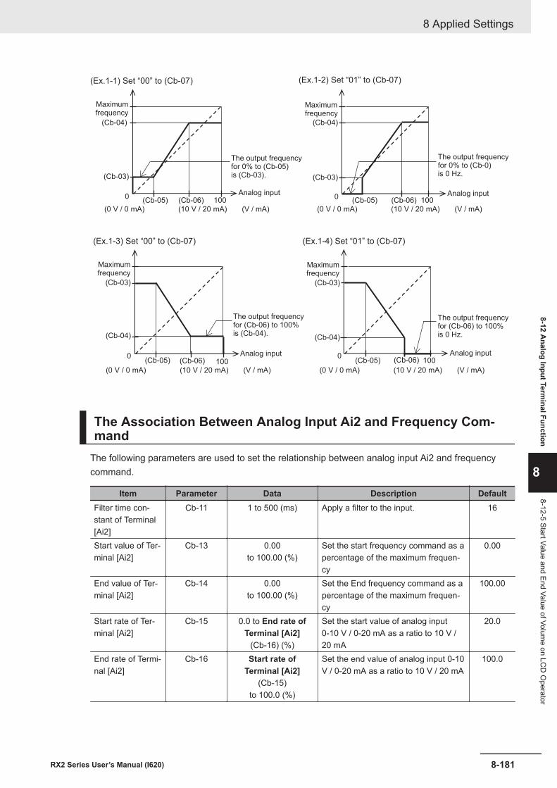
(Cb-04)
(Cb-03)
0(Cb-06)(Cb-05) 100
(Cb-03)
(Cb-04)
0(Cb-05) (Cb-06) 100
(Cb-04)
(Cb-03)
0(Cb-05) (Cb-06) 100
(0 V / 0 mA) (10 V / 20 mA) (V / mA)
(Cb-04)
(Cb-03)
0(Cb-05) (Cb-06) 100
(0 V / 0 mA) (10 V / 20 mA) (V / mA)
(0 V / 0 mA) (10 V / 20 mA) (V / mA) (0 V / 0 mA) (10 V / 20 mA) (V / mA)
(Ex.1-4) Set “01” to (Cb-07)
(Ex.1-2) Set “01” to (Cb-07)
(Ex.1-3) Set “00” to (Cb-07)
(Ex.1-1) Set “00” to (Cb-07)
Maximumfrequency
Maximumfrequency
Maximumfrequency
Maximumfrequency
The output frequencyfor 0% to (Cb-05)is (Cb-03).
The output frequencyfor (Cb-06) to 100%is (Cb-04).
The output frequencyfor 0% to (Cb-0)is 0 Hz.
The output frequencyfor (Cb-06) to 100%is 0 Hz.
Analog input
Analog input
Analog input
Analog input
The Association Between Analog Input Ai2 and Frequency Com-mand
The following parameters are used to set the relationship between analog input Ai2 and frequencycommand.
Item Parameter Data Description DefaultFilter time con-stant of Terminal[Ai2]
Cb-11 1 to 500 (ms) Apply a filter to the input. 16
Start value of Ter-minal [Ai2]
Cb-13 0.00to 100.00 (%)
Set the start frequency command as apercentage of the maximum frequen-cy
0.00
End value of Ter-minal [Ai2]
Cb-14 0.00to 100.00 (%)
Set the End frequency command as apercentage of the maximum frequen-cy
100.00
Start rate of Ter-minal [Ai2]
Cb-15 0.0 to End rate ofTerminal [Ai2]
(Cb-16) (%)
Set the start value of analog input0-10 V / 0-20 mA as a ratio to 10 V /20 mA
20.0
End rate of Termi-nal [Ai2]
Cb-16 Start rate ofTerminal [Ai2]
(Cb-15)to 100.0 (%)
Set the end value of analog input 0-10V / 0-20 mA as a ratio to 10 V / 20 mA
100.0
8 Applied Settings
8-181RX2 Series User’s Manual (I620)
8-12 Analog Input Term
inal Function
8
8-12-5 Start Value and End Value of Volume on LC
D O
perator
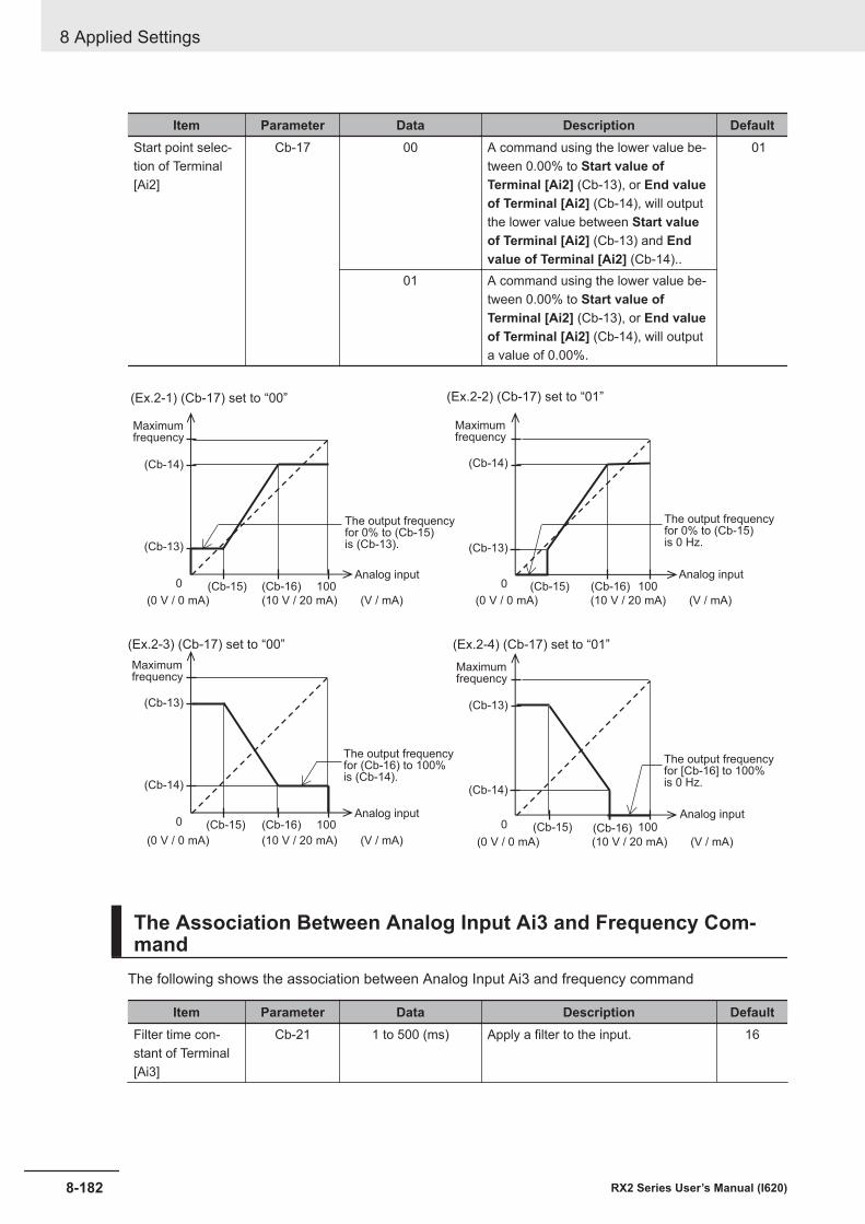
Item Parameter Data Description DefaultStart point selec-tion of Terminal[Ai2]
Cb-17 00 A command using the lower value be-tween 0.00% to Start value ofTerminal [Ai2] (Cb-13), or End valueof Terminal [Ai2] (Cb-14), will outputthe lower value between Start valueof Terminal [Ai2] (Cb-13) and Endvalue of Terminal [Ai2] (Cb-14)..
01
01 A command using the lower value be-tween 0.00% to Start value ofTerminal [Ai2] (Cb-13), or End valueof Terminal [Ai2] (Cb-14), will outputa value of 0.00%.
(Cb-14)
(Cb-13)
0 (Cb-15) (Cb-16) 100
(Cb-14)
(Cb-13)
0 (Cb-15) (Cb-16) 100
(Cb-13)
(Cb-14)
0 (Cb-15) (Cb-16) 100
(Cb-13)
(Cb-14)
0 (Cb-15) (Cb-16) 100
(0 V / 0 mA) (10 V / 20 mA) (V / mA)(0 V / 0 mA) (10 V / 20 mA) (V / mA)
(0 V / 0 mA) (10 V / 20 mA) (V / mA)(0 V / 0 mA) (10 V / 20 mA) (V / mA)
(Ex.2-4) (Cb-17) set to “01”
(Ex.2-2) (Cb-17) set to “01”
(Ex.2-3) (Cb-17) set to “00”
(Ex.2-1) (Cb-17) set to “00”
Maximumfrequency
Maximumfrequency
Maximumfrequency
Maximumfrequency
The output frequencyfor 0% to (Cb-15)is (Cb-13).
The output frequencyfor (Cb-16) to 100%is (Cb-14).
The output frequencyfor 0% to (Cb-15)is 0 Hz.
The output frequencyfor [Cb-16] to 100%is 0 Hz.
Analog input
Analog input
Analog input
Analog input
The Association Between Analog Input Ai3 and Frequency Com-mand
The following shows the association between Analog Input Ai3 and frequency command
Item Parameter Data Description DefaultFilter time con-stant of Terminal[Ai3]
Cb-21 1 to 500 (ms) Apply a filter to the input. 16
8 Applied Settings
8-182 RX2 Series User’s Manual (I620)
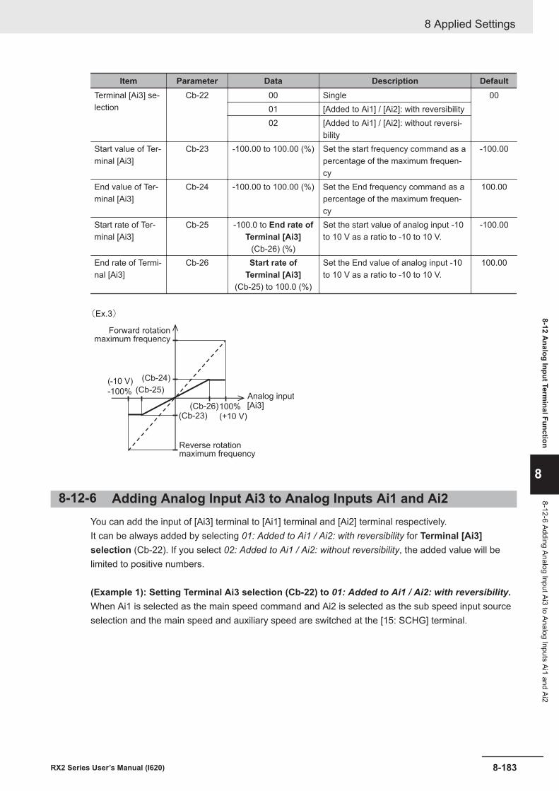
Item Parameter Data Description DefaultTerminal [Ai3] se-lection
Cb-22 00 Single 0001 [Added to Ai1] / [Ai2]: with reversibility02 [Added to Ai1] / [Ai2]: without reversi-
bilityStart value of Ter-minal [Ai3]
Cb-23 -100.00 to 100.00 (%) Set the start frequency command as apercentage of the maximum frequen-cy
-100.00
End value of Ter-minal [Ai3]
Cb-24 -100.00 to 100.00 (%) Set the End frequency command as apercentage of the maximum frequen-cy
100.00
Start rate of Ter-minal [Ai3]
Cb-25 -100.0 to End rate ofTerminal [Ai3]
(Cb-26) (%)
Set the start value of analog input -10to 10 V as a ratio to -10 to 10 V.
-100.00
End rate of Termi-nal [Ai3]
Cb-26 Start rate ofTerminal [Ai3]
(Cb-25) to 100.0 (%)
Set the End value of analog input -10to 10 V as a ratio to -10 to 10 V.
100.00
(Cb-23)(Cb-26)
(Cb-25)
(Cb-24) (-10 V)
-100%
100%(+10 V)
[Ai3]
(Ex.3)
Forward rotationmaximum frequency
Analog input
Reverse rotationmaximum frequency
8-12-6 Adding Analog Input Ai3 to Analog Inputs Ai1 and Ai2You can add the input of [Ai3] terminal to [Ai1] terminal and [Ai2] terminal respectively.It can be always added by selecting 01: Added to Ai1 / Ai2: with reversibility for Terminal [Ai3]selection (Cb-22). If you select 02: Added to Ai1 / Ai2: without reversibility, the added value will belimited to positive numbers.
(Example 1): Setting Terminal Ai3 selection (Cb-22) to 01: Added to Ai1 / Ai2: with reversibility.When Ai1 is selected as the main speed command and Ai2 is selected as the sub speed input sourceselection and the main speed and auxiliary speed are switched at the [15: SCHG] terminal.
8 Applied Settings
8-183RX2 Series User’s Manual (I620)
8-12 Analog Input Term
inal Function
8
8-12-6 Adding Analog Input Ai3 to Analog Inputs Ai1 and Ai2
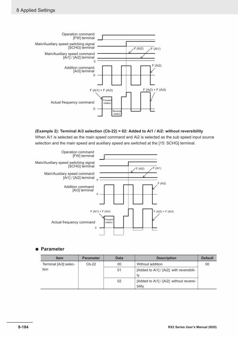
[FW] terminal
[SCHG] terminal F (Ai2)
0
0
0
F (Ai1)
F (Ai2)
F (Ai1) + F (Ai3) F (Ai2) + F (Ai3)
[Ai1] / [Ai2] terminal
Actual frequency commandForward
rotation
Reverse
rotation
Main/Auxiliary speed command
Addition command[Ai3] terminal
Operation command
Main/Auxiliary speed switching signal
(Example 2): Terminal Ai3 selection (Cb-22) = 02: Added to Ai1 / Ai2: without reversibilityWhen Ai1 is selected as the main speed command and Ai2 is selected as the sub speed input sourceselection and the main speed and auxiliary speed are switched at the [15: SCHG] terminal.
F (Ai1)
F (Ai2)
F (Ai2) + F (Ai3)
0
[SCHG] terminalF (Ai2)
0
0
F (Ai1) + F (Ai3)
[FW] terminal
[Ai1] / [Ai2] terminal
Actual frequency command
Main/Auxiliary speed command
Addition command[Ai3] terminal
Operation command
Main/Auxiliary speed switching signal
Forward
rotation
l Parameter
Item Parameter Data Description DefaultTerminal [Ai3] selec-tion
Cb-22 00 Without addition 0001 [Added to Ai1] / [Ai2]: with reversibili-
ty02 [Added to Ai1] / [Ai2]: without reversi-
bility
8 Applied Settings
8-184 RX2 Series User’s Manual (I620)
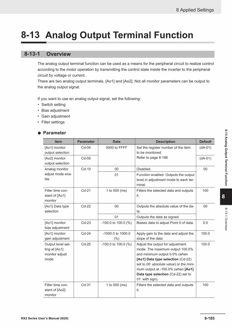
8-13 Analog Output Terminal Function
8-13-1 OverviewThe analog output terminal function can be used as a means for the peripheral circuit to realize controlaccording to the motor operation by transmitting the control state inside the inverter to the peripheralcircuit by voltage or current.There are two analog output terminals, [Ao1] and [Ao2]. Not all monitor parameters can be output tothe analog output signal.
If you want to use an analog output signal, set the following:• Switch setting• Bias adjustment• Gain adjustment• Filter settings
l Parameter
Item Parameter Data Description Default[Ao1] monitoroutput selection
Cd-04 0000 to FFFF Set the register number of the itemto be monitored.Refer to page 8-186
(dA-01)
[Ao2] monitoroutput selection
Cd-05 (dA-01)
Analog monitoradjust mode ena-ble
Cd-10 00 Disabled. 0001 Function enabled. Outputs the output
level in adjustment mode to each ter-minal.
Filter time con-stant of [Ao1]monitor
Cd-21 1 to 500 (ms) Filters the selected data and outputsit.
100
[Ao1] Data typeselection
Cd-22 00 Outputs the absolute value of the da-ta.
00
01 Outputs the data as signed.[Ao1] monitorbias adjustment
Cd-23 -100.0 to 100.0 (%) Biases data to adjust Point 0 of data. 0.0
[Ao1] monitorgain adjustment
Cd-24 -1000.0 to 1000.0(%)
Apply gain to the data and adjust theslope of the data
100.0
Output level set-ting at [Ao1]monitor adjustmode
Cd-25 -100.0 to 100.0 (%) Adjust the output for adjustmentmode. The maximum output 100.0%and minimum output 0.0% (when[Ao1] Data type selection (Cd-22)set to 00: absolute value) or the mini-mum output at -100.0% (when [Ao1]Data type selection (Cd-22) set to01: with sign).
100.0
Filter time con-stant of [Ao2]monitor
Cd-31 1 to 500 (ms) Filters the selected data and outputsit.
100
8 Applied Settings
8-185RX2 Series User’s Manual (I620)
8-13 Analog O
utput Terminal Function
8
8-13-1 Overview
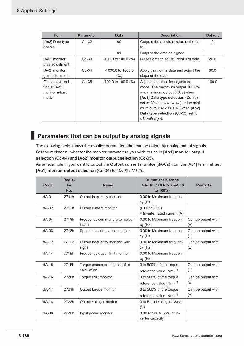
Item Parameter Data Description Default[Ao2] Data typeenable
Cd-32 00 Outputs the absolute value of the da-ta.
0
01 Outputs the data as signed.[Ao2] monitorbias adjustment
Cd-33 -100.0 to 100.0 (%) Biases data to adjust Point 0 of data. 20.0
[Ao2] monitorgain adjustment
Cd-34 -1000.0 to 1000.0(%)
Apply gain to the data and adjust theslope of the data
80.0
Output level set-ting at [Ao2]monitor adjustmode
Cd-35 -100.0 to 100.0 (%) Adjust the output for adjustmentmode. The maximum output 100.0%and minimum output 0.0% (when[Ao2] Data type selection (Cd-32)set to 00: absolute value) or the mini-mum output at -100.0% (when [Ao2]Data type selection (Cd-32) set to01: with sign).
100.0
Parameters that can be output by analog signalsThe following table shows the monitor parameters that can be output by analog output signals.Set the register number for the monitor parameters you wish to use in [Ao1] monitor outputselection (Cd-04) and [Ao2] monitor output selection (Cd-05).As an example, if you want to output the Output current monitor (dA-02) from the [Ao1] terminal, set[Ao1] monitor output selection (Cd-04) to 10002 (2712h).
CodeRegis-
terNo.
NameOutput scale range
(0 to 10 V / 0 to 20 mA / 0to 100%)
Remarks
dA-01 2711h Output frequency monitor 0.00 to Maximum frequen-cy (Hz)
dA-02 2712h Output current monitor (0.00 to 2.00)× Inverter rated current (A)
dA-04 2713h Frequency command after calcu-lation
0.00 to Maximum frequen-cy (Hz)
Can be output with(±)
dA-08 2718h Speed detection value monitor 0.00 to Maximum frequen-cy (Hz)
Can be output with(±)
dA-12 271Ch Output frequency monitor (withsign)
0.00 to Maximum frequen-cy (Hz)
Can be output with(±)
dA-14 271Eh Frequency upper limit monitor 0.00 to Maximum frequen-cy (Hz)
dA-15 271Fh Torque command monitor aftercalculation
0 to 500% of the torquereference value (Nm) *1
Can be output with(±)
dA-16 2720h Torque limit monitor 0 to 500% of the torquereference value (Nm) *1
Can be output with(±)
dA-17 2721h Output torque monitor 0 to 500% of the torquereference value (Nm) *1
Can be output with(±)
dA-18 2722h Output voltage monitor 0 to Rated voltage×133%(V)
dA-30 272Eh Input power monitor 0.00 to 200% (kW) of in-verter capacity
8 Applied Settings
8-186 RX2 Series User’s Manual (I620)
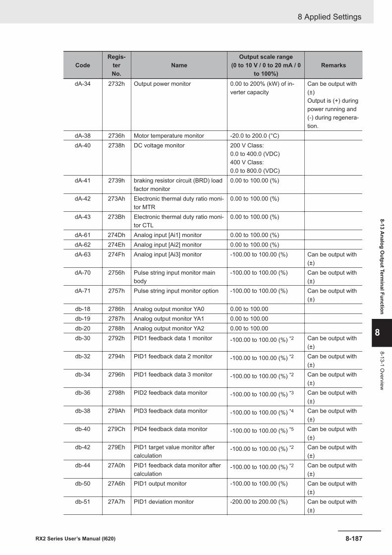
CodeRegis-
terNo.
NameOutput scale range
(0 to 10 V / 0 to 20 mA / 0to 100%)
Remarks
dA-34 2732h Output power monitor 0.00 to 200% (kW) of in-verter capacity
Can be output with(±)Output is (+) duringpower running and(-) during regenera-tion.
dA-38 2736h Motor temperature monitor -20.0 to 200.0 (°C)dA-40 2738h DC voltage monitor 200 V Class:
0.0 to 400.0 (VDC)400 V Class:0.0 to 800.0 (VDC)
dA-41 2739h braking resistor circuit (BRD) loadfactor monitor
0.00 to 100.00 (%)
dA-42 273Ah Electronic thermal duty ratio moni-tor MTR
0.00 to 100.00 (%)
dA-43 273Bh Electronic thermal duty ratio moni-tor CTL
0.00 to 100.00 (%)
dA-61 274Dh Analog input [Ai1] monitor 0.00 to 100.00 (%)dA-62 274Eh Analog input [Ai2] monitor 0.00 to 100.00 (%)dA-63 274Fh Analog input [Ai3] monitor -100.00 to 100.00 (%) Can be output with
(±)dA-70 2756h Pulse string input monitor main
body-100.00 to 100.00 (%) Can be output with
(±)dA-71 2757h Pulse string input monitor option -100.00 to 100.00 (%) Can be output with
(±)db-18 2786h Analog output monitor YA0 0.00 to 100.00db-19 2787h Analog output monitor YA1 0.00 to 100.00db-20 2788h Analog output monitor YA2 0.00 to 100.00db-30 2792h PID1 feedback data 1 monitor -100.00 to 100.00 (%) *2 Can be output with
(±)db-32 2794h PID1 feedback data 2 monitor -100.00 to 100.00 (%) *2 Can be output with
(±)db-34 2796h PID1 feedback data 3 monitor -100.00 to 100.00 (%) *2 Can be output with
(±)db-36 2798h PID2 feedback data monitor -100.00 to 100.00 (%) *3 Can be output with
(±)db-38 279Ah PID3 feedback data monitor -100.00 to 100.00 (%) *4 Can be output with
(±)db-40 279Ch PID4 feedback data monitor -100.00 to 100.00 (%) *5 Can be output with
(±)db-42 279Eh PID1 target value monitor after
calculation-100.00 to 100.00 (%) *2 Can be output with
(±)db-44 27A0h PID1 feedback data monitor after
calculation-100.00 to 100.00 (%) *2 Can be output with
(±)db-50 27A6h PID1 output monitor -100.00 to 100.00 (%) Can be output with
(±)db-51 27A7h PID1 deviation monitor -200.00 to 200.00 (%) Can be output with
(±)
8 Applied Settings
8-187RX2 Series User’s Manual (I620)
8-13 Analog O
utput Terminal Function
8
8-13-1 Overview
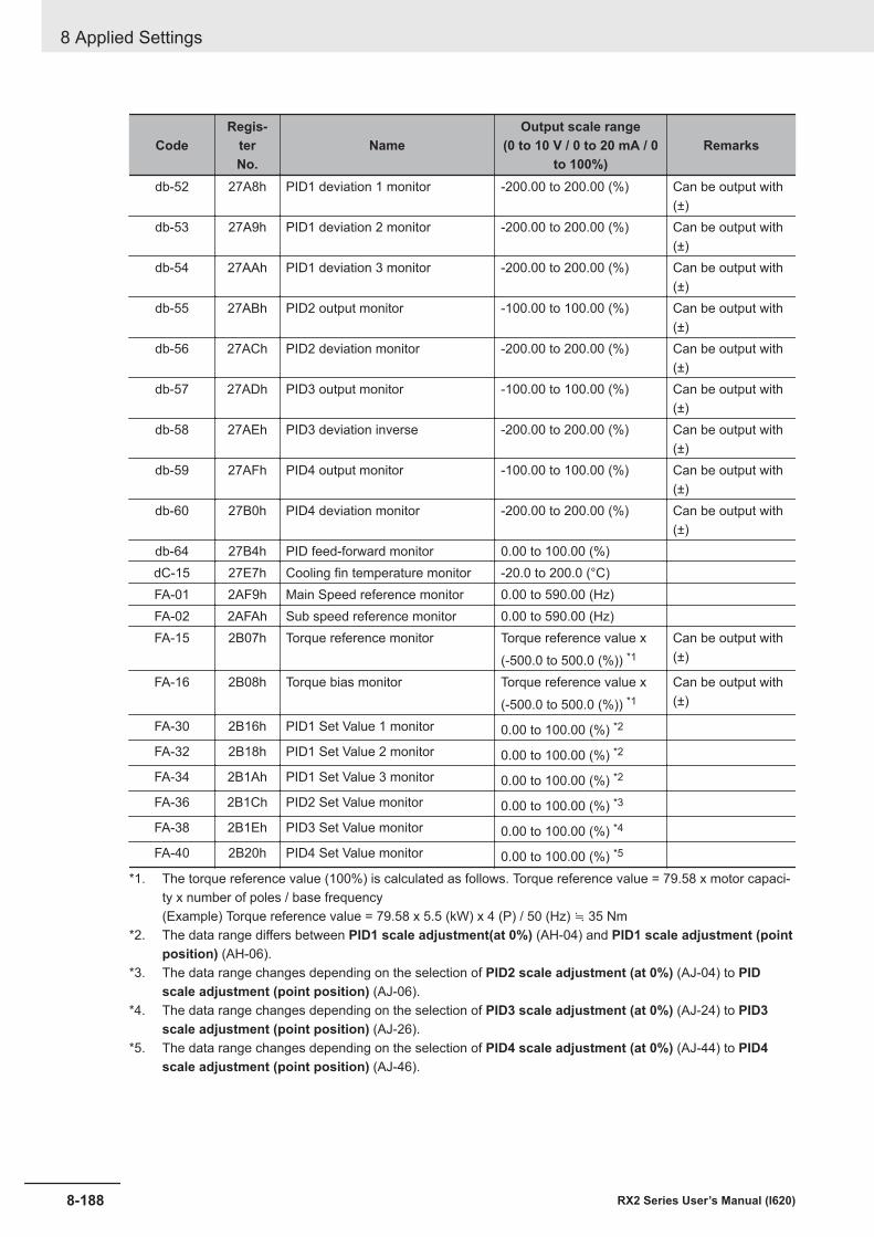
CodeRegis-
terNo.
NameOutput scale range
(0 to 10 V / 0 to 20 mA / 0to 100%)
Remarks
db-52 27A8h PID1 deviation 1 monitor -200.00 to 200.00 (%) Can be output with(±)
db-53 27A9h PID1 deviation 2 monitor -200.00 to 200.00 (%) Can be output with(±)
db-54 27AAh PID1 deviation 3 monitor -200.00 to 200.00 (%) Can be output with(±)
db-55 27ABh PID2 output monitor -100.00 to 100.00 (%) Can be output with(±)
db-56 27ACh PID2 deviation monitor -200.00 to 200.00 (%) Can be output with(±)
db-57 27ADh PID3 output monitor -100.00 to 100.00 (%) Can be output with(±)
db-58 27AEh PID3 deviation inverse -200.00 to 200.00 (%) Can be output with(±)
db-59 27AFh PID4 output monitor -100.00 to 100.00 (%) Can be output with(±)
db-60 27B0h PID4 deviation monitor -200.00 to 200.00 (%) Can be output with(±)
db-64 27B4h PID feed-forward monitor 0.00 to 100.00 (%)dC-15 27E7h Cooling fin temperature monitor -20.0 to 200.0 (°C)FA-01 2AF9h Main Speed reference monitor 0.00 to 590.00 (Hz)FA-02 2AFAh Sub speed reference monitor 0.00 to 590.00 (Hz)FA-15 2B07h Torque reference monitor Torque reference value x
(-500.0 to 500.0 (%)) *1Can be output with(±)
FA-16 2B08h Torque bias monitor Torque reference value x(-500.0 to 500.0 (%)) *1
Can be output with(±)
FA-30 2B16h PID1 Set Value 1 monitor 0.00 to 100.00 (%) *2
FA-32 2B18h PID1 Set Value 2 monitor 0.00 to 100.00 (%) *2
FA-34 2B1Ah PID1 Set Value 3 monitor 0.00 to 100.00 (%) *2
FA-36 2B1Ch PID2 Set Value monitor 0.00 to 100.00 (%) *3
FA-38 2B1Eh PID3 Set Value monitor 0.00 to 100.00 (%) *4
FA-40 2B20h PID4 Set Value monitor 0.00 to 100.00 (%) *5
*1. The torque reference value (100%) is calculated as follows. Torque reference value = 79.58 x motor capaci-ty x number of poles / base frequency(Example) Torque reference value = 79.58 x 5.5 (kW) x 4 (P) / 50 (Hz) ≒ 35 Nm
*2. The data range differs between PID1 scale adjustment(at 0%) (AH-04) and PID1 scale adjustment (pointposition) (AH-06).
*3. The data range changes depending on the selection of PID2 scale adjustment (at 0%) (AJ-04) to PIDscale adjustment (point position) (AJ-06).
*4. The data range changes depending on the selection of PID3 scale adjustment (at 0%) (AJ-24) to PID3scale adjustment (point position) (AJ-26).
*5. The data range changes depending on the selection of PID4 scale adjustment (at 0%) (AJ-44) to PID4scale adjustment (point position) (AJ-46).
8 Applied Settings
8-188 RX2 Series User’s Manual (I620)
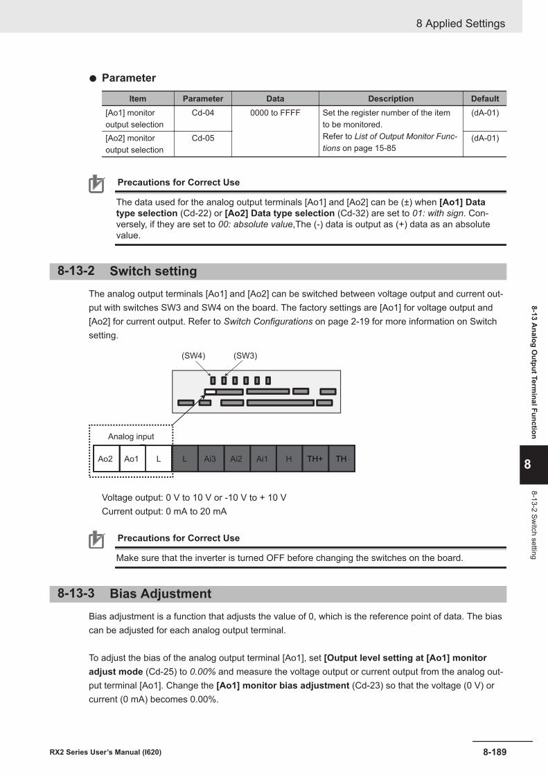
l Parameter
Item Parameter Data Description Default[Ao1] monitoroutput selection
Cd-04 0000 to FFFF Set the register number of the itemto be monitored.Refer to List of Output Monitor Func-tions on page 15-85
(dA-01)
[Ao2] monitoroutput selection
Cd-05 (dA-01)
Precautions for Correct Use
The data used for the analog output terminals [Ao1] and [Ao2] can be (±) when [Ao1] Datatype selection (Cd-22) or [Ao2] Data type selection (Cd-32) are set to 01: with sign. Con-versely, if they are set to 00: absolute value,The (-) data is output as (+) data as an absolutevalue.
8-13-2 Switch settingThe analog output terminals [Ao1] and [Ao2] can be switched between voltage output and current out-put with switches SW3 and SW4 on the board. The factory settings are [Ao1] for voltage output and[Ao2] for current output. Refer to Switch Configurations on page 2-19 for more information on Switchsetting.
Ao2 Ao1
Analog input
HAi1Ai2Ai3LL TH--TH+
(SW4) (SW3)
Voltage output: 0 V to 10 V or -10 V to + 10 VCurrent output: 0 mA to 20 mA
Precautions for Correct Use
Make sure that the inverter is turned OFF before changing the switches on the board.
8-13-3 Bias AdjustmentBias adjustment is a function that adjusts the value of 0, which is the reference point of data. The biascan be adjusted for each analog output terminal.
To adjust the bias of the analog output terminal [Ao1], set [Output level setting at [Ao1] monitoradjust mode (Cd-25) to 0.00% and measure the voltage output or current output from the analog out-put terminal [Ao1]. Change the [Ao1] monitor bias adjustment (Cd-23) so that the voltage (0 V) orcurrent (0 mA) becomes 0.00%.
8 Applied Settings
8-189RX2 Series User’s Manual (I620)
8-13 Analog O
utput Terminal Function
8
8-13-2 Switch setting
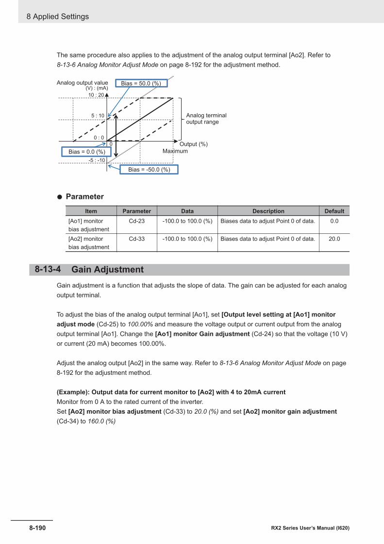
The same procedure also applies to the adjustment of the analog output terminal [Ao2]. Refer to 8-13-6 Analog Monitor Adjust Mode on page 8-192 for the adjustment method.
0
-5 : -10
Maximum
Output (%)
Analog terminaloutput range
Bias = 50.0 (%)
Bias = -50.0 (%)
Bias = 0.0 (%)
Analog output value(V) : (mA)
10 : 20
0 : 0
5 : 10
l Parameter
Item Parameter Data Description Default[Ao1] monitorbias adjustment
Cd-23 -100.0 to 100.0 (%) Biases data to adjust Point 0 of data. 0.0
[Ao2] monitorbias adjustment
Cd-33 -100.0 to 100.0 (%) Biases data to adjust Point 0 of data. 20.0
8-13-4 Gain AdjustmentGain adjustment is a function that adjusts the slope of data. The gain can be adjusted for each analogoutput terminal.
To adjust the bias of the analog output terminal [Ao1], set [Output level setting at [Ao1] monitoradjust mode (Cd-25) to 100.00% and measure the voltage output or current output from the analogoutput terminal [Ao1]. Change the [Ao1] monitor Gain adjustment (Cd-24) so that the voltage (10 V)or current (20 mA) becomes 100.00%.
Adjust the analog output [Ao2] in the same way. Refer to 8-13-6 Analog Monitor Adjust Mode on page8-192 for the adjustment method.
(Example): Output data for current monitor to [Ao2] with 4 to 20mA currentMonitor from 0 A to the rated current of the inverter.Set [Ao2] monitor bias adjustment (Cd-33) to 20.0 (%) and set [Ao2] monitor gain adjustment(Cd-34) to 160.0 (%)
8 Applied Settings
8-190 RX2 Series User’s Manual (I620)
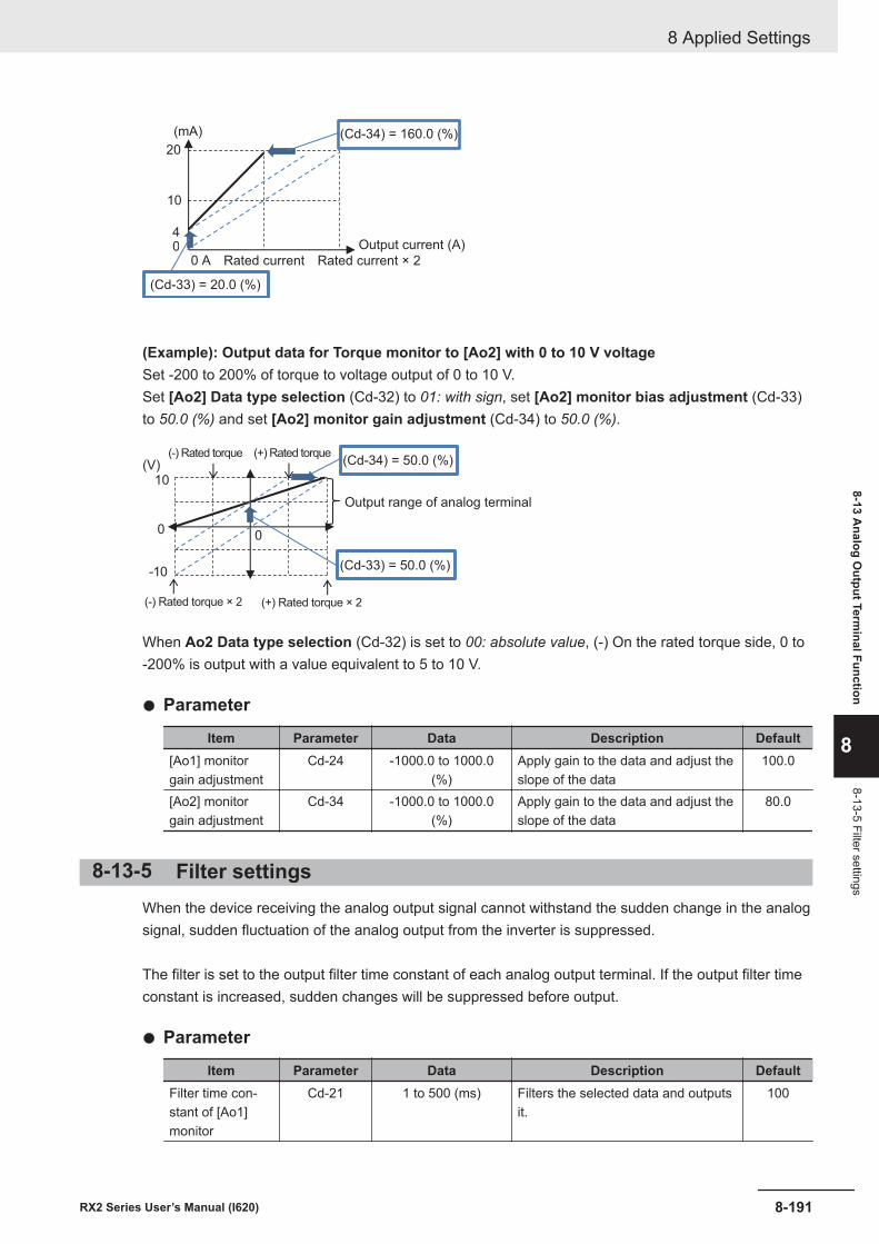
(mA)
20
00 A
10
4
Rated current Rated current × 2
Output current (A)
(Cd-33) = 20.0 (%)
(Cd-34) = 160.0 (%)
(Example): Output data for Torque monitor to [Ao2] with 0 to 10 V voltageSet -200 to 200% of torque to voltage output of 0 to 10 V.Set [Ao2] Data type selection (Cd-32) to 01: with sign, set [Ao2] monitor bias adjustment (Cd-33)to 50.0 (%) and set [Ao2] monitor gain adjustment (Cd-34) to 50.0 (%).
(V)
10
00
-10
(-) Rated torque × 2 (+) Rated torque × 2
Output range of analog terminal
(-) Rated torque (+) Rated torque
(Cd-33) = 50.0 (%)
(Cd-34) = 50.0 (%)
When Ao2 Data type selection (Cd-32) is set to 00: absolute value, (-) On the rated torque side, 0 to-200% is output with a value equivalent to 5 to 10 V.
l Parameter
Item Parameter Data Description Default[Ao1] monitorgain adjustment
Cd-24 -1000.0 to 1000.0(%)
Apply gain to the data and adjust theslope of the data
100.0
[Ao2] monitorgain adjustment
Cd-34 -1000.0 to 1000.0(%)
Apply gain to the data and adjust theslope of the data
80.0
8-13-5 Filter settingsWhen the device receiving the analog output signal cannot withstand the sudden change in the analogsignal, sudden fluctuation of the analog output from the inverter is suppressed.
The filter is set to the output filter time constant of each analog output terminal. If the output filter timeconstant is increased, sudden changes will be suppressed before output.
l Parameter
Item Parameter Data Description DefaultFilter time con-stant of [Ao1]monitor
Cd-21 1 to 500 (ms) Filters the selected data and outputsit.
100
8 Applied Settings
8-191RX2 Series User’s Manual (I620)
8-13 Analog O
utput Terminal Function
8
8-13-5 Filter settings
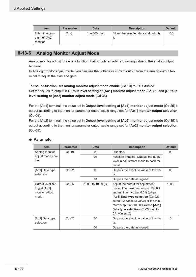
Item Parameter Data Description DefaultFilter time con-stant of [Ao2]monitor
Cd-31 1 to 500 (ms) Filters the selected data and outputsit.
100
8-13-6 Analog Monitor Adjust ModeAnalog monitor adjust mode is a function that outputs an arbitrary setting value to the analog outputterminal.In Analog monitor adjust mode, you can use the voltage or current output from the analog output ter-minal to adjust the bias and gain.
To use the function, set Analog monitor adjust mode enable (Cd-10) to 01: Enabled.Set the values to output in Output level setting at [Ao1] monitor adjust mode (Cd-25) and [Outputlevel setting at [Ao2] monitor adjust mode (Cd-35).
For the [Ao1] terminal, the value set in Output level setting at [Ao1] monitor adjust mode (Cd-25) isoutput according to the monitor parameter output scale range set for [Ao1] monitor output selection(Cd-04).For the [Ao2] terminal, the value set in Output level setting at [Ao2] monitor adjust mode (Cd-35) isoutput according to the monitor parameter output scale range set for [Ao2] monitor output selection(Cd-05).
l Parameter
Item Parameter Data Description DefaultAnalog monitoradjust mode ena-ble
Cd-10 00 Disabled. 0001 Function enabled. Outputs the output
level in adjustment mode to each ter-minal.
[Ao1] Data typeselection
Cd-22 00 Outputs the absolute value of the da-ta.
00
01 Outputs the data as signed.Output level set-ting at [Ao1]monitor adjustmode
Cd-25 -100.0 to 100.0 (%) Adjust the output for adjustmentmode. The maximum output 100.0%and minimum output 0.0% (when[Ao1] Data type selection (Cd-22)set to 00: absolute value) or the mini-mum output at -100.0% (when [Ao1]Data type selection (Cd-22) set to01: with sign).
100.0
[Ao2] Data typeselection
Cd-32 00 Outputs the absolute value of the da-ta.
0
01 Outputs the data as signed.
8 Applied Settings
8-192 RX2 Series User’s Manual (I620)
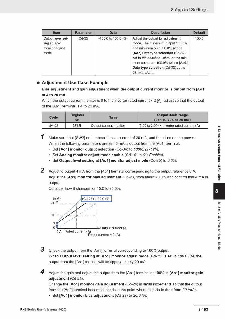
Item Parameter Data Description DefaultOutput level set-ting at [Ao2]monitor adjustmode
Cd-35 -100.0 to 100.0 (%) Adjust the output for adjustmentmode. The maximum output 100.0%and minimum output 0.0% (when[Ao2] Data type selection (Cd-32)set to 00: absolute value) or the mini-mum output at -100.0% (when [Ao2]Data type selection (Cd-32) set to01: with sign).
100.0
l Adjustment Use Case ExampleBias adjustment and gain adjustment when the output current monitor is output from [Ao1]at 4 to 20 mA.When the output current monitor is 0 to the inverter rated current x 2 [A], adjust so that the outputof the [Ao1] terminal is 4 to 20 mA.
Code RegisterNo. Name Output scale range
(0 to 10 V / 0 to 20 mA)dA-02 2712h Output current monitor (0.00 to 2.00) × Inverter rated current (A)
1 Make sure that [SW3] on the board has a current of 20 mA, and then turn on the power.When the following parameters are set, 0 mA is output from the [Ao1] terminal.• Set [Ao1] monitor output selection (Cd-04) to 10002 (2712h).• Set Analog monitor adjust mode enable (Cd-10) to 01: Enabled.• Set Output level setting at [Ao1] monitor adjust mode (Cd-25) to 0.0%.
2 Adjust to output 4 mA from the [Ao1] terminal corresponding to the output reference 0 A.Adjust the [Ao1] monitor bias adjustment (Cd-23) from about 20.0% and confirm that 4 mA isoutput.Consider how it changes for 15.0 to 25.0%.
20
0
0 A
10
4
(mA)
Rated current (A)Rated current × 2 (A)
Output current (A)
(Cd-23) = 20.0 (%)
3 Check the output from the [Ao1] terminal corresponding to 100% output.When Output level setting at [Ao1] monitor adjust mode (Cd-25) is set to 100.0 (%), theoutput from the [Ao1] teminal will be approximately 20 mA.
4 Adjust the gain and adjust the output from the [Ao1] terminal at 100% in [Ao1] monitor gainadjustment (Cd-24).Change the [Ao1] monitor gain adjustment (Cd-24) in small increments so that the outputfrom the [Ao2] terminal becomes less than the point where it starts to drop from 20 (mA).• Set [Ao1] monitor bias adjustment (Cd-23) to 20.0 (%)
8 Applied Settings
8-193RX2 Series User’s Manual (I620)
8-13 Analog O
utput Terminal Function
8
8-13-6 Analog Monitor Adjust M
ode
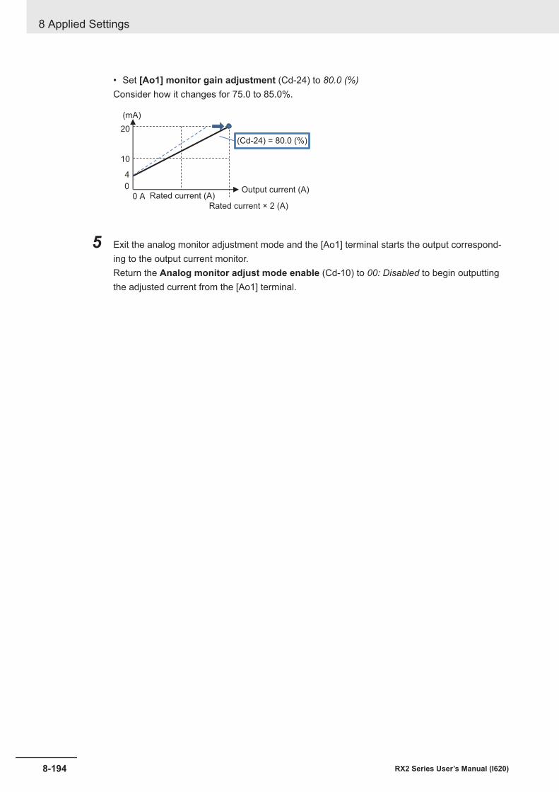
• Set [Ao1] monitor gain adjustment (Cd-24) to 80.0 (%)Consider how it changes for 75.0 to 85.0%.
20
0
0 A
10
4
(mA)
Rated current (A)
Rated current × 2 (A)
Output current (A)
(Cd-24) = 80.0 (%)
5 Exit the analog monitor adjustment mode and the [Ao1] terminal starts the output correspond-ing to the output current monitor.Return the Analog monitor adjust mode enable (Cd-10) to 00: Disabled to begin outputtingthe adjusted current from the [Ao1] terminal.
8 Applied Settings
8-194 RX2 Series User’s Manual (I620)
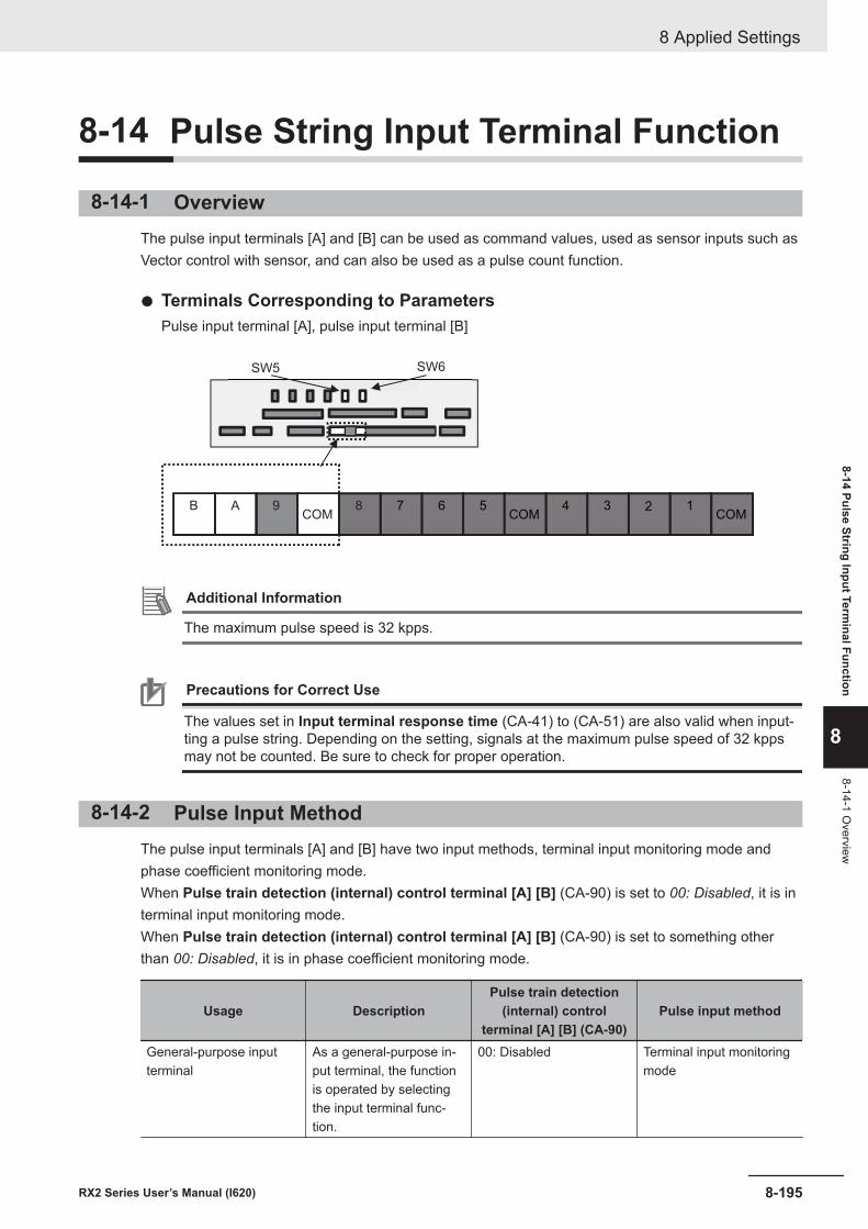
8-14 Pulse String Input Terminal Function
8-14-1 OverviewThe pulse input terminals [A] and [B] can be used as command values, used as sensor inputs such asVector control with sensor, and can also be used as a pulse count function.
l Terminals Corresponding to ParametersPulse input terminal [A], pulse input terminal [B]
123456789ABCOMCOMCOM
SW6SW5
Additional Information
The maximum pulse speed is 32 kpps.
Precautions for Correct Use
The values set in Input terminal response time (CA-41) to (CA-51) are also valid when input-ting a pulse string. Depending on the setting, signals at the maximum pulse speed of 32 kppsmay not be counted. Be sure to check for proper operation.
8-14-2 Pulse Input MethodThe pulse input terminals [A] and [B] have two input methods, terminal input monitoring mode andphase coefficient monitoring mode.When Pulse train detection (internal) control terminal [A] [B] (CA-90) is set to 00: Disabled, it is interminal input monitoring mode.When Pulse train detection (internal) control terminal [A] [B] (CA-90) is set to something otherthan 00: Disabled, it is in phase coefficient monitoring mode.
Usage DescriptionPulse train detection
(internal) controlterminal [A] [B] (CA-90)
Pulse input method
General-purpose inputterminal
As a general-purpose in-put terminal, the functionis operated by selectingthe input terminal func-tion.
00: Disabled Terminal input monitoringmode
8 Applied Settings
8-195RX2 Series User’s Manual (I620)
8-14 Pulse String Input Terminal Function
8
8-14-1 Overview
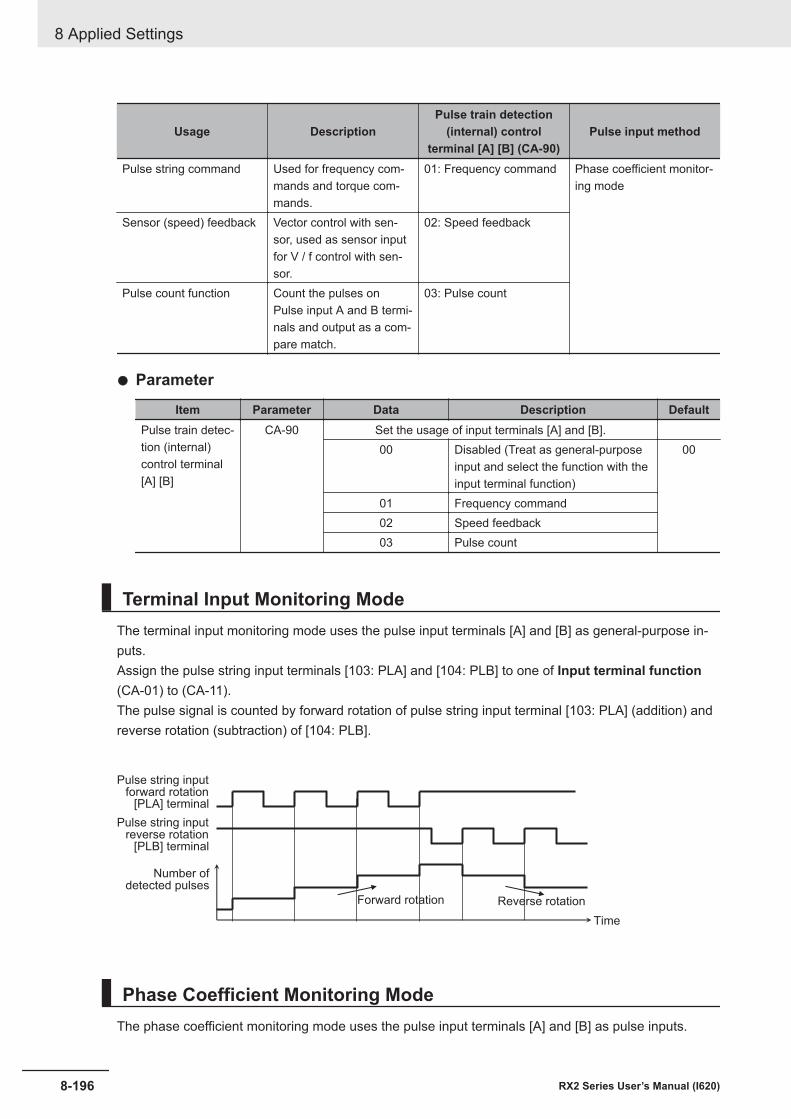
Usage DescriptionPulse train detection
(internal) controlterminal [A] [B] (CA-90)
Pulse input method
Pulse string command Used for frequency com-mands and torque com-mands.
01: Frequency command Phase coefficient monitor-ing mode
Sensor (speed) feedback Vector control with sen-sor, used as sensor inputfor V / f control with sen-sor.
02: Speed feedback
Pulse count function Count the pulses onPulse input A and B termi-nals and output as a com-pare match.
03: Pulse count
l Parameter
Item Parameter Data Description DefaultPulse train detec-tion (internal)control terminal[A] [B]
CA-90 Set the usage of input terminals [A] and [B].00 Disabled (Treat as general-purpose
input and select the function with theinput terminal function)
00
01 Frequency command02 Speed feedback03 Pulse count
Terminal Input Monitoring ModeThe terminal input monitoring mode uses the pulse input terminals [A] and [B] as general-purpose in-puts.Assign the pulse string input terminals [103: PLA] and [104: PLB] to one of Input terminal function(CA-01) to (CA-11).The pulse signal is counted by forward rotation of pulse string input terminal [103: PLA] (addition) andreverse rotation (subtraction) of [104: PLB].
[PLA] terminal
Pulse string inputforward rotation
Number ofdetected pulses
[PLB] terminal
Pulse string inputreverse rotation
Forward rotation Reverse rotation
Time
Phase Coefficient Monitoring ModeThe phase coefficient monitoring mode uses the pulse input terminals [A] and [B] as pulse inputs.
8 Applied Settings
8-196 RX2 Series User’s Manual (I620)
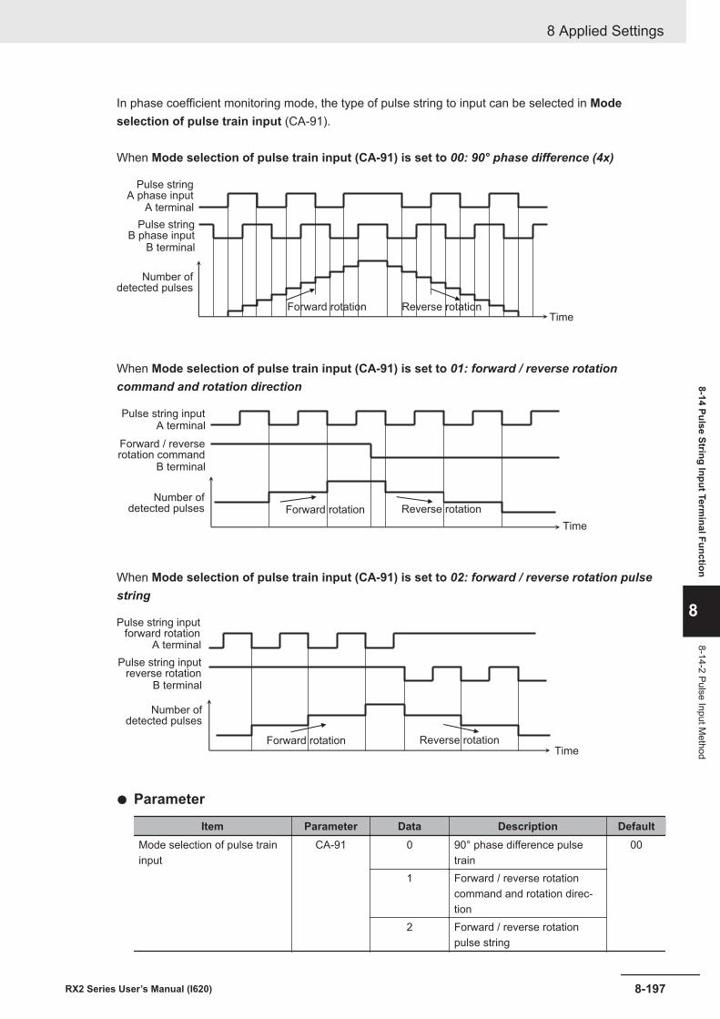
In phase coefficient monitoring mode, the type of pulse string to input can be selected in Modeselection of pulse train input (CA-91).
When Mode selection of pulse train input (CA-91) is set to 00: 90° phase difference (4x)
Pulse stringA phase input
Number ofdetected pulses
A terminal
Pulse stringB phase input
B terminal
Forward rotation Reverse rotationTime
When Mode selection of pulse train input (CA-91) is set to 01: forward / reverse rotationcommand and rotation direction
Forward rotation Reverse rotation
Time
A terminalPulse string input
Number ofdetected pulses
B terminal
Forward / reverserotation command
When Mode selection of pulse train input (CA-91) is set to 02: forward / reverse rotation pulsestring
A terminal
Pulse string inputforward rotation
Number ofdetected pulses
B terminal
Pulse string inputreverse rotation
Forward rotation Reverse rotationTime
l Parameter
Item Parameter Data Description DefaultMode selection of pulse traininput
CA-91 0 90° phase difference pulsetrain
00
1 Forward / reverse rotationcommand and rotation direc-tion
2 Forward / reverse rotationpulse string
8 Applied Settings
8-197RX2 Series User’s Manual (I620)
8-14 Pulse String Input Terminal Function
8
8-14-2 Pulse Input Method
8-14-3 Pulse String Input CommandsWhen Pulse train detection (internal) control terminal [A] [B] (CA-90) is set to 01: Frequencycommand, the pulse count value can be used for commands such as frequency command, torquecommand, PID set-point, PID feedback value, PID feed-forward, and frequency upper limit.Set the following command function parameters in 12: Pulse string: Inverter.
Code NameAA101 Main speed input source selection, 1st-motorAA102 Sub frequency input source selection, 1st-motorAA201 Main speed input source selection, 2nd-motorAA202 Sub speed input source selection, 2nd-motorAd-01 Torque reference input source selectionAd-11 Torque bias input source selectionAd-40 Input selection for speed limit at torque controlAH-07 Input source selection of Set-point 1 for PID1AH-42 Input source selection of Set-point 2 for PID1AH-46 Input source selection of Set-point 3 for PID1AH-51 Input source selection of Process data 1 for PID1AH-52 Input source selection of Process data 2 for PID1AH-53 Input source selection of Process data 3 for PID1AH-70 PID feed-forward selectionAJ-07 Input source selection of Set-point for PID2AJ-12 Input source selection of Process data for PID2AJ-27 Input source selection of Set-point for PID3AJ-32 Input source selection of Process data for PID3AJ-47 Input source selection of Set-point for PID4AJ-52 Input source selection of Process data for PID4bA101 Frequency limit selection, 1st-motorbA110 Torque limit selection, 1st-motorbA201 Frequency limit selection, 2nd motorbA210 Torque limit selection, 2nd-motorCA-70 Speed reference source selection at [F-OP] is active
8-14-4 Speed FeedbackWhen Pulse train detection (internal) control terminal [A] [B] (CA-90) is set to 02: Speedfeedback, the speed feedback value is calculated from the input pulse signal.Used as sensor input to Vector control with sensor and sensor input for V/f control.
The supported selections in Control mode selection (AA121) are as follows.04 : [V/f with sign] Fixed torque characteristics (IM)05 : [V/f with sign] Reduced torque characteristics (IM)06: [V/f with sign] Free V/f (IM)07: V/f with sensor] Auto torque boost (IM)08: Sensorless vector control (IM)
The speed feedback value can be monitored with Speed detection value monitor (dA-08).
8 Applied Settings
8-198 RX2 Series User’s Manual (I620)
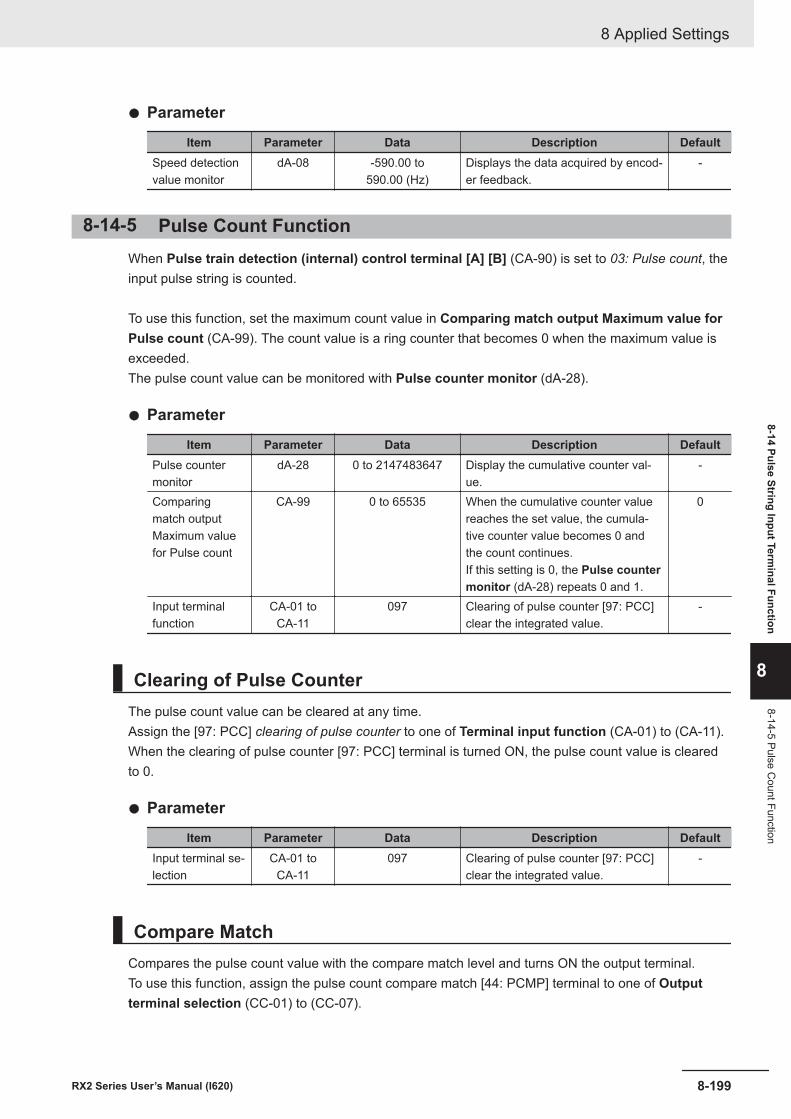
l Parameter
Item Parameter Data Description DefaultSpeed detectionvalue monitor
dA-08 -590.00 to590.00 (Hz)
Displays the data acquired by encod-er feedback.
-
8-14-5 Pulse Count FunctionWhen Pulse train detection (internal) control terminal [A] [B] (CA-90) is set to 03: Pulse count, theinput pulse string is counted.
To use this function, set the maximum count value in Comparing match output Maximum value forPulse count (CA-99). The count value is a ring counter that becomes 0 when the maximum value isexceeded.The pulse count value can be monitored with Pulse counter monitor (dA-28).
l Parameter
Item Parameter Data Description DefaultPulse countermonitor
dA-28 0 to 2147483647 Display the cumulative counter val-ue.
-
Comparingmatch outputMaximum valuefor Pulse count
CA-99 0 to 65535 When the cumulative counter valuereaches the set value, the cumula-tive counter value becomes 0 andthe count continues.If this setting is 0, the Pulse countermonitor (dA-28) repeats 0 and 1.
0
Input terminalfunction
CA-01 toCA-11
097 Clearing of pulse counter [97: PCC]clear the integrated value.
-
Clearing of Pulse CounterThe pulse count value can be cleared at any time.Assign the [97: PCC] clearing of pulse counter to one of Terminal input function (CA-01) to (CA-11).When the clearing of pulse counter [97: PCC] terminal is turned ON, the pulse count value is clearedto 0.
l Parameter
Item Parameter Data Description DefaultInput terminal se-lection
CA-01 toCA-11
097 Clearing of pulse counter [97: PCC]clear the integrated value.
-
Compare MatchCompares the pulse count value with the compare match level and turns ON the output terminal.To use this function, assign the pulse count compare match [44: PCMP] terminal to one of Outputterminal selection (CC-01) to (CC-07).
8 Applied Settings
8-199RX2 Series User’s Manual (I620)
8-14 Pulse String Input Terminal Function
8
8-14-5 Pulse Count Function
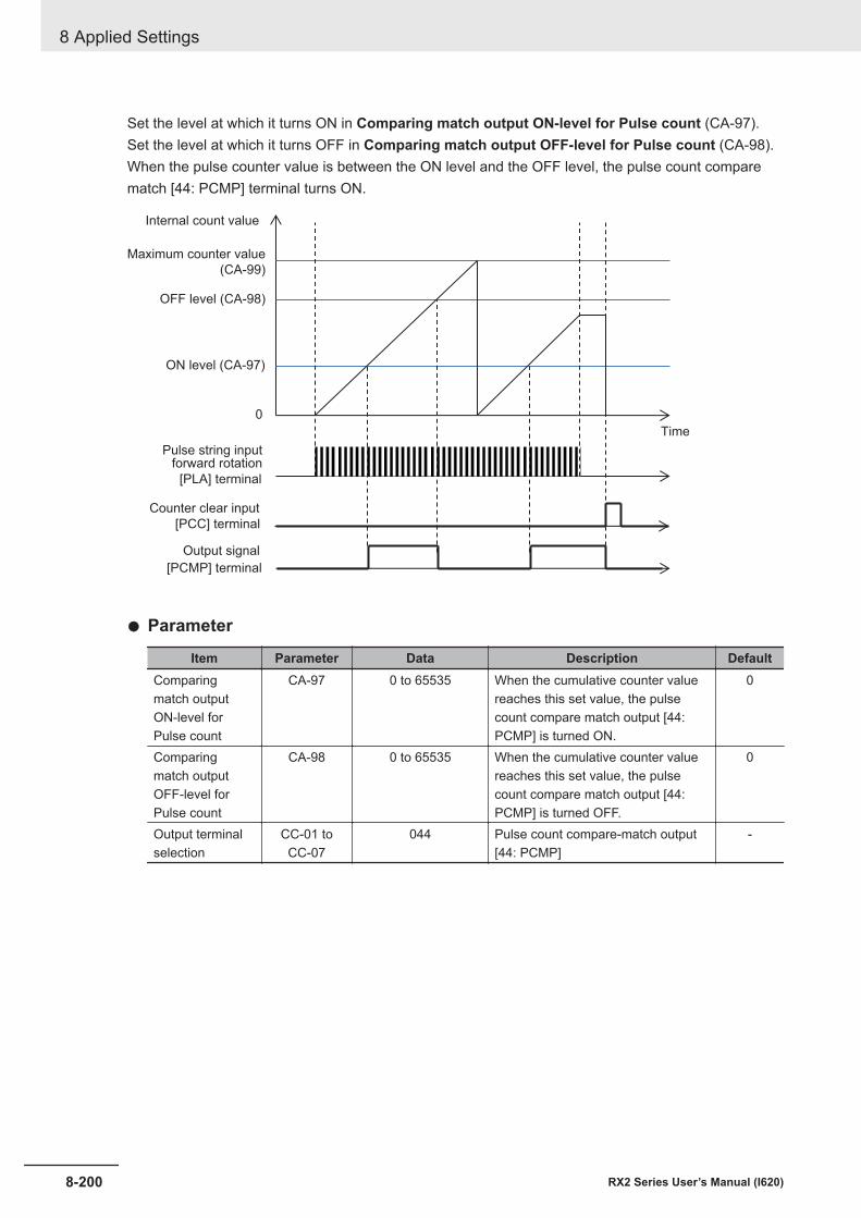
Set the level at which it turns ON in Comparing match output ON-level for Pulse count (CA-97).Set the level at which it turns OFF in Comparing match output OFF-level for Pulse count (CA-98).When the pulse counter value is between the ON level and the OFF level, the pulse count comparematch [44: PCMP] terminal turns ON.
0
[PLA] terminal
Pulse string inputforward rotation
[PCC] terminal
Counter clear input
Time
Internal count value
Maximum counter value
(CA-99)
OFF level (CA-98)
ON level (CA-97)
[PCMP] terminal
Output signal
l Parameter
Item Parameter Data Description DefaultComparingmatch outputON-level forPulse count
CA-97 0 to 65535 When the cumulative counter valuereaches this set value, the pulsecount compare match output [44:PCMP] is turned ON.
0
Comparingmatch outputOFF-level forPulse count
CA-98 0 to 65535 When the cumulative counter valuereaches this set value, the pulsecount compare match output [44:PCMP] is turned OFF.
0
Output terminalselection
CC-01 toCC-07
044 Pulse count compare-match output[44: PCMP]
-
8 Applied Settings
8-200 RX2 Series User’s Manual (I620)
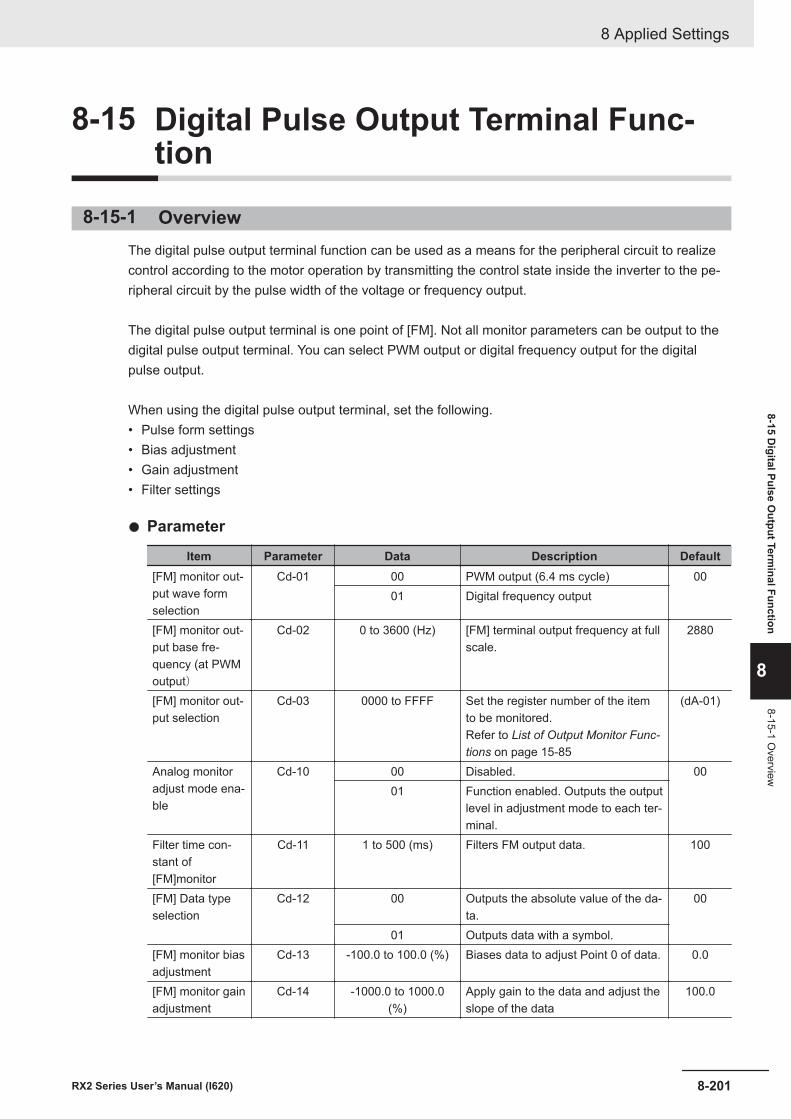
8-15 Digital Pulse Output Terminal Func-tion
8-15-1 OverviewThe digital pulse output terminal function can be used as a means for the peripheral circuit to realizecontrol according to the motor operation by transmitting the control state inside the inverter to the pe-ripheral circuit by the pulse width of the voltage or frequency output.
The digital pulse output terminal is one point of [FM]. Not all monitor parameters can be output to thedigital pulse output terminal. You can select PWM output or digital frequency output for the digitalpulse output.
When using the digital pulse output terminal, set the following.• Pulse form settings• Bias adjustment• Gain adjustment• Filter settings
l Parameter
Item Parameter Data Description Default[FM] monitor out-put wave formselection
Cd-01 00 PWM output (6.4 ms cycle) 0001 Digital frequency output
[FM] monitor out-put base fre-quency (at PWMoutput)
Cd-02 0 to 3600 (Hz) [FM] terminal output frequency at fullscale.
2880
[FM] monitor out-put selection
Cd-03 0000 to FFFF Set the register number of the itemto be monitored.Refer to List of Output Monitor Func-tions on page 15-85
(dA-01)
Analog monitoradjust mode ena-ble
Cd-10 00 Disabled. 0001 Function enabled. Outputs the output
level in adjustment mode to each ter-minal.
Filter time con-stant of[FM]monitor
Cd-11 1 to 500 (ms) Filters FM output data. 100
[FM] Data typeselection
Cd-12 00 Outputs the absolute value of the da-ta.
00
01 Outputs data with a symbol.[FM] monitor biasadjustment
Cd-13 -100.0 to 100.0 (%) Biases data to adjust Point 0 of data. 0.0
[FM] monitor gainadjustment
Cd-14 -1000.0 to 1000.0(%)
Apply gain to the data and adjust theslope of the data
100.0
8 Applied Settings
8-201RX2 Series User’s Manual (I620)
8-15 Digital Pulse O
utput Terminal Function
8
8-15-1 Overview
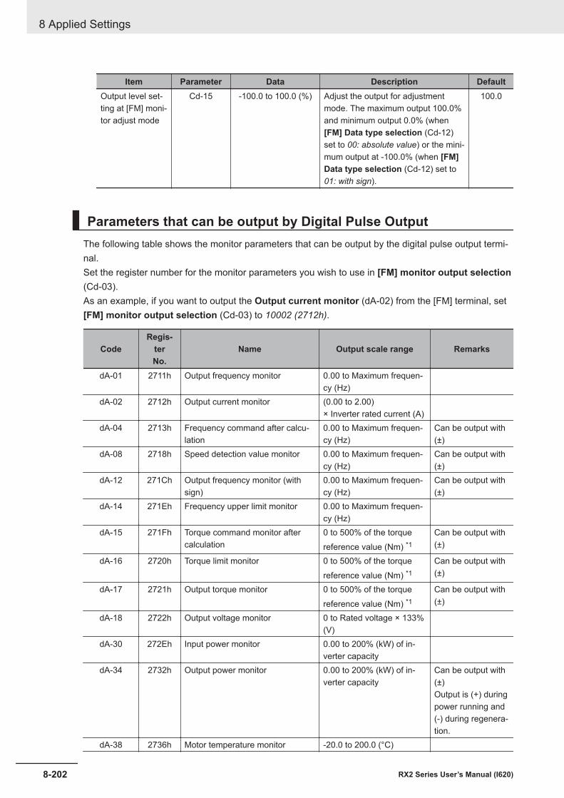
Item Parameter Data Description DefaultOutput level set-ting at [FM] moni-tor adjust mode
Cd-15 -100.0 to 100.0 (%) Adjust the output for adjustmentmode. The maximum output 100.0%and minimum output 0.0% (when[FM] Data type selection (Cd-12)set to 00: absolute value) or the mini-mum output at -100.0% (when [FM]Data type selection (Cd-12) set to01: with sign).
100.0
Parameters that can be output by Digital Pulse OutputThe following table shows the monitor parameters that can be output by the digital pulse output termi-nal.Set the register number for the monitor parameters you wish to use in [FM] monitor output selection(Cd-03).As an example, if you want to output the Output current monitor (dA-02) from the [FM] terminal, set[FM] monitor output selection (Cd-03) to 10002 (2712h).
CodeRegis-
terNo.
Name Output scale range Remarks
dA-01 2711h Output frequency monitor 0.00 to Maximum frequen-cy (Hz)
dA-02 2712h Output current monitor (0.00 to 2.00)× Inverter rated current (A)
dA-04 2713h Frequency command after calcu-lation
0.00 to Maximum frequen-cy (Hz)
Can be output with(±)
dA-08 2718h Speed detection value monitor 0.00 to Maximum frequen-cy (Hz)
Can be output with(±)
dA-12 271Ch Output frequency monitor (withsign)
0.00 to Maximum frequen-cy (Hz)
Can be output with(±)
dA-14 271Eh Frequency upper limit monitor 0.00 to Maximum frequen-cy (Hz)
dA-15 271Fh Torque command monitor aftercalculation
0 to 500% of the torquereference value (Nm) *1
Can be output with(±)
dA-16 2720h Torque limit monitor 0 to 500% of the torquereference value (Nm) *1
Can be output with(±)
dA-17 2721h Output torque monitor 0 to 500% of the torquereference value (Nm) *1
Can be output with(±)
dA-18 2722h Output voltage monitor 0 to Rated voltage × 133%(V)
dA-30 272Eh Input power monitor 0.00 to 200% (kW) of in-verter capacity
dA-34 2732h Output power monitor 0.00 to 200% (kW) of in-verter capacity
Can be output with(±)Output is (+) duringpower running and(-) during regenera-tion.
dA-38 2736h Motor temperature monitor -20.0 to 200.0 (°C)
8 Applied Settings
8-202 RX2 Series User’s Manual (I620)
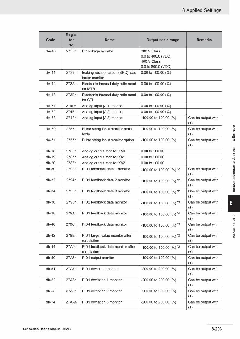
CodeRegis-
terNo.
Name Output scale range Remarks
dA-40 2738h DC voltage monitor 200 V Class:0.0 to 400.0 (VDC)400 V Class:0.0 to 800.0 (VDC)
dA-41 2739h braking resistor circuit (BRD) loadfactor monitor
0.00 to 100.00 (%)
dA-42 273Ah Electronic thermal duty ratio moni-tor MTR
0.00 to 100.00 (%)
dA-43 273Bh Electronic thermal duty ratio moni-tor CTL
0.00 to 100.00 (%)
dA-61 274Dh Analog input [Ai1] monitor 0.00 to 100.00 (%)dA-62 274Eh Analog input [Ai2] monitor 0.00 to 100.00 (%)dA-63 274Fh Analog input [Ai3] monitor -100.00 to 100.00 (%) Can be output with
(±)dA-70 2756h Pulse string input monitor main
body-100.00 to 100.00 (%) Can be output with
(±)dA-71 2757h Pulse string input monitor option -100.00 to 100.00 (%) Can be output with
(±)db-18 2786h Analog output monitor YA0 0.00 to 100.00db-19 2787h Analog output monitor YA1 0.00 to 100.00db-20 2788h Analog output monitor YA2 0.00 to 100.00db-30 2792h PID1 feedback data 1 monitor -100.00 to 100.00 (%) *2 Can be output with
(±)db-32 2794h PID1 feedback data 2 monitor -100.00 to 100.00 (%) *2 Can be output with
(±)db-34 2796h PID1 feedback data 3 monitor -100.00 to 100.00 (%) *2 Can be output with
(±)db-36 2798h PID2 feedback data monitor -100.00 to 100.00 (%) *3 Can be output with
(±)db-38 279Ah PID3 feedback data monitor -100.00 to 100.00 (%) *4 Can be output with
(±)db-40 279Ch PID4 feedback data monitor -100.00 to 100.00 (%) *5 Can be output with
(±)db-42 279Eh PID1 target value monitor after
calculation-100.00 to 100.00 (%) *2 Can be output with
(±)db-44 27A0h PID1 feedback data monitor after
calculation-100.00 to 100.00 (%) *2 Can be output with
(±)db-50 27A6h PID1 output monitor -100.00 to 100.00 (%) Can be output with
(±)db-51 27A7h PID1 deviation monitor -200.00 to 200.00 (%) Can be output with
(±)db-52 27A8h PID1 deviation 1 monitor -200.00 to 200.00 (%) Can be output with
(±)db-53 27A9h PID1 deviation 2 monitor -200.00 to 200.00 (%) Can be output with
(±)db-54 27AAh PID1 deviation 3 monitor -200.00 to 200.00 (%) Can be output with
(±)
8 Applied Settings
8-203RX2 Series User’s Manual (I620)
8-15 Digital Pulse O
utput Terminal Function
8
8-15-1 Overview
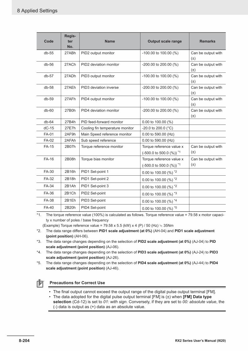
CodeRegis-
terNo.
Name Output scale range Remarks
db-55 27ABh PID2 output monitor -100.00 to 100.00 (%) Can be output with(±)
db-56 27ACh PID2 deviation monitor -200.00 to 200.00 (%) Can be output with(±)
db-57 27ADh PID3 output monitor -100.00 to 100.00 (%) Can be output with(±)
db-58 27AEh PID3 deviation inverse -200.00 to 200.00 (%) Can be output with(±)
db-59 27AFh PID4 output monitor -100.00 to 100.00 (%) Can be output with(±)
db-60 27B0h PID4 deviation monitor -200.00 to 200.00 (%) Can be output with(±)
db-64 27B4h PID feed-forward monitor 0.00 to 100.00 (%)dC-15 27E7h Cooling fin temperature monitor -20.0 to 200.0 (°C)FA-01 2AF9h Main Speed reference monitor 0.00 to 590.00 (Hz)FA-02 2AFAh Sub speed reference 0.00 to 590.00 (Hz)FA-15 2B07h Torque reference monitor Torque reference value x
(-500.0 to 500.0 (%)) *1Can be output with(±)
FA-16 2B08h Torque bias monitor Torque reference value x(-500.0 to 500.0 (%)) *1
Can be output with(±)
FA-30 2B16h PID1 Set-point 1 0.00 to 100.00 (%) *2
FA-32 2B18h PID1 Set-point 2 0.00 to 100.00 (%) *2
FA-34 2B1Ah PID1 Set-point 3 0.00 to 100.00 (%) *2
FA-36 2B1Ch PID2 Set-point 0.00 to 100.00 (%) *3
FA-38 2B1Eh PID3 Set-point 0.00 to 100.00 (%) *4
FA-40 2B20h PID4 Set-point 0.00 to 100.00 (%) *5
*1. The torque reference value (100%) is calculated as follows. Torque reference value = 79.58 x motor capaci-ty x number of poles / base frequency
(Example) Torque reference value = 79.58 x 5.5 (kW) x 4 (P) / 50 (Hz) ≒ 35Nm*2. The data range differs between PID1 scale adjustment (at 0%) (AH-04) and PID1 scale adjustment
(point position) (AH-06).*3. The data range changes depending on the selection of PID2 scale adjustment (at 0%) (AJ-04) to PID
scale adjustment (point position) (AJ-06).*4. The data range changes depending on the selection of PID3 scale adjustment (at 0%) (AJ-24) to PID3
scale adjustment (point position) (AJ-26).*5. The data range changes depending on the selection of PID4 scale adjustment (at 0%) (AJ-44) to PID4
scale adjustment (point position) (AJ-46).
Precautions for Correct Use
• The final output cannot exceed the output range of the digital pulse output terminal [FM].• The data adopted for the digital pulse output terminal [FM] is (±) when [FM] Data type
selection (Cd-12) is set to 01: with sign. Conversely, if they are set to 00: absolute value, the(-) data is output as (+) data as an absolute value.
8 Applied Settings
8-204 RX2 Series User’s Manual (I620)
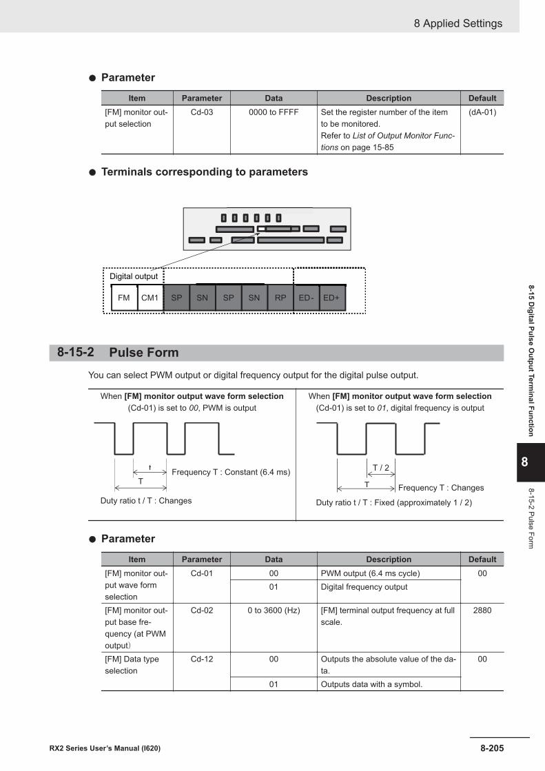
l Parameter
Item Parameter Data Description Default[FM] monitor out-put selection
Cd-03 0000 to FFFF Set the register number of the itemto be monitored.Refer to List of Output Monitor Func-tions on page 15-85
(dA-01)
l Terminals corresponding to parameters
FM CM1 RPSNSPSNSP ED+ED-
Digital output
8-15-2 Pulse FormYou can select PWM output or digital frequency output for the digital pulse output.
When [FM] monitor output wave form selection(Cd-01) is set to 00, PWM is output
t
TFrequency T : Constant (6.4 ms)
Duty ratio t / T : Changes
When [FM] monitor output wave form selection(Cd-01) is set to 01, digital frequency is output
T / 2
T
Duty ratio t / T : Fixed (approximately 1 / 2)
Frequency T : Changes
l Parameter
Item Parameter Data Description Default[FM] monitor out-put wave formselection
Cd-01 00 PWM output (6.4 ms cycle) 0001 Digital frequency output
[FM] monitor out-put base fre-quency (at PWMoutput)
Cd-02 0 to 3600 (Hz) [FM] terminal output frequency at fullscale.
2880
[FM] Data typeselection
Cd-12 00 Outputs the absolute value of the da-ta.
00
01 Outputs data with a symbol.
8 Applied Settings
8-205RX2 Series User’s Manual (I620)
8-15 Digital Pulse O
utput Terminal Function
8
8-15-2 Pulse Form
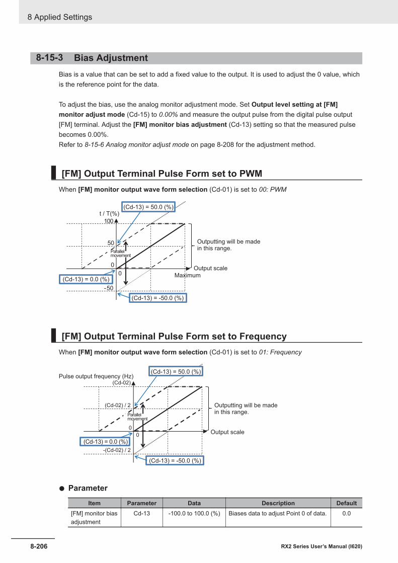
8-15-3 Bias AdjustmentBias is a value that can be set to add a fixed value to the output. It is used to adjust the 0 value, whichis the reference point for the data.
To adjust the bias, use the analog monitor adjustment mode. Set Output level setting at [FM]monitor adjust mode (Cd-15) to 0.00% and measure the output pulse from the digital pulse output[FM] terminal. Adjust the [FM] monitor bias adjustment (Cd-13) setting so that the measured pulsebecomes 0.00%.Refer to 8-15-6 Analog monitor adjust mode on page 8-208 for the adjustment method.
[FM] Output Terminal Pulse Form set to PWMWhen [FM] monitor output wave form selection (Cd-01) is set to 00: PWM
t / T(%)
0
0
50
-50
100
(Cd-13) = 50.0 (%)
(Cd-13) = -50.0 (%)
(Cd-13) = 0.0 (%)
Outputting will be madein this range.
Output scale
Maximum
Parallelmovement
[FM] Output Terminal Pulse Form set to FrequencyWhen [FM] monitor output wave form selection (Cd-01) is set to 01: Frequency
(Cd-02)
0
(Cd-13) = -50.0 (%)
(Cd-13) = 0.0 (%)0
(Cd-02) / 2
-(Cd-02) / 2
(Cd-13) = 50.0 (%)
Output scale
Outputting will be madein this range.
Pulse output frequency (Hz)
Parallelmovement
l Parameter
Item Parameter Data Description Default[FM] monitor biasadjustment
Cd-13 -100.0 to 100.0 (%) Biases data to adjust Point 0 of data. 0.0
8 Applied Settings
8-206 RX2 Series User’s Manual (I620)
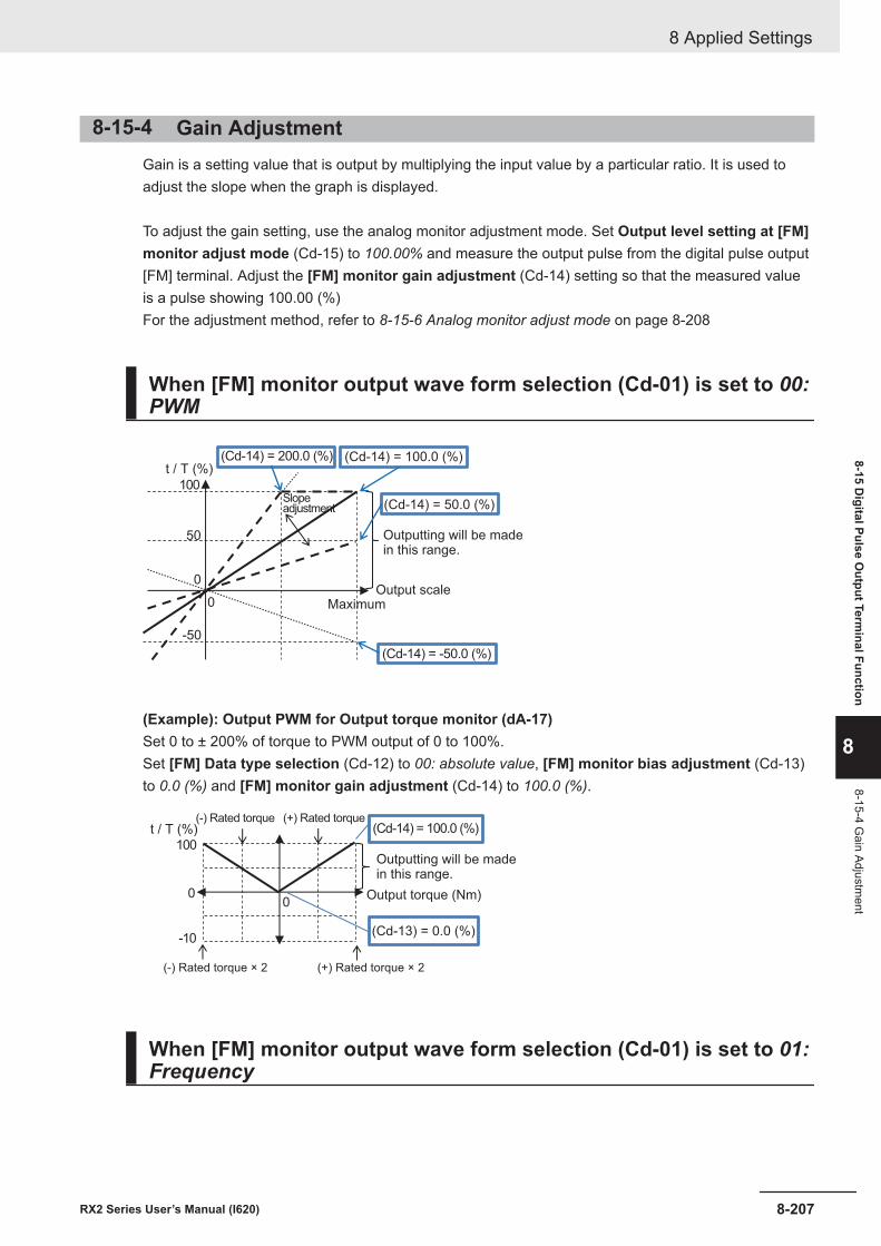
8-15-4 Gain AdjustmentGain is a setting value that is output by multiplying the input value by a particular ratio. It is used toadjust the slope when the graph is displayed.
To adjust the gain setting, use the analog monitor adjustment mode. Set Output level setting at [FM]monitor adjust mode (Cd-15) to 100.00% and measure the output pulse from the digital pulse output[FM] terminal. Adjust the [FM] monitor gain adjustment (Cd-14) setting so that the measured valueis a pulse showing 100.00 (%)For the adjustment method, refer to 8-15-6 Analog monitor adjust mode on page 8-208
When [FM] monitor output wave form selection (Cd-01) is set to 00:PWM
t / T (%)
0
(Cd-14) = 200.0 (%)
(Cd-14) = 50.0 (%)
(Cd-14) = 100.0 (%)
0
50
-50
(Cd-14) = -50.0 (%)
Output scale
Outputting will be madein this range.
Maximum
Slopeadjustment
100
(Example): Output PWM for Output torque monitor (dA-17)Set 0 to ± 200% of torque to PWM output of 0 to 100%.Set [FM] Data type selection (Cd-12) to 00: absolute value, [FM] monitor bias adjustment (Cd-13)to 0.0 (%) and [FM] monitor gain adjustment (Cd-14) to 100.0 (%).
t / T (%)
00
(Cd-14) = 100.0 (%)
100
(Cd-13) = 0.0 (%)-10
Output torque (Nm)
Outputting will be madein this range.
(+) Rated torque × 2(-) Rated torque × 2
(+) Rated torque(-) Rated torque
When [FM] monitor output wave form selection (Cd-01) is set to 01:Frequency
8 Applied Settings
8-207RX2 Series User’s Manual (I620)
8-15 Digital Pulse O
utput Terminal Function
8
8-15-4 Gain Adjustm
ent
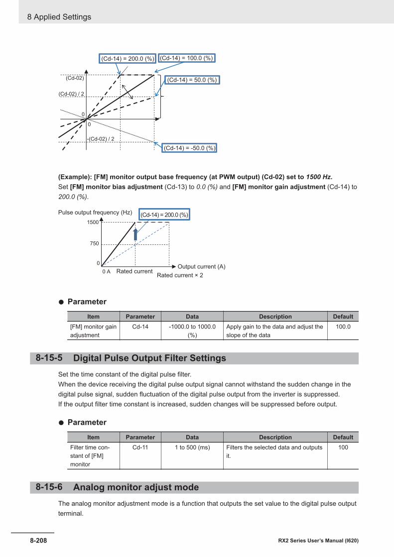
0
0
-(Cd-02) / 2
(Cd-14) = 200.0 (%)
(Cd-02) / 2
(Cd-02)
(Cd-14) = 100.0 (%)
(Cd-14) = -50.0 (%)
(Cd-14) = 50.0 (%)
(Example): [FM] monitor output base frequency (at PWM output) (Cd-02) set to 1500 Hz.Set [FM] monitor bias adjustment (Cd-13) to 0.0 (%) and [FM] monitor gain adjustment (Cd-14) to200.0 (%).
1500
0
0 A
750
(Cd-14) = 200.0 (%)
Rated currentRated current × 2
Output current (A)
Pulse output frequency (Hz)
l Parameter
Item Parameter Data Description Default[FM] monitor gainadjustment
Cd-14 -1000.0 to 1000.0(%)
Apply gain to the data and adjust theslope of the data
100.0
8-15-5 Digital Pulse Output Filter SettingsSet the time constant of the digital pulse filter.When the device receiving the digital pulse output signal cannot withstand the sudden change in thedigital pulse signal, sudden fluctuation of the digital pulse output from the inverter is suppressed.If the output filter time constant is increased, sudden changes will be suppressed before output.
l Parameter
Item Parameter Data Description DefaultFilter time con-stant of [FM]monitor
Cd-11 1 to 500 (ms) Filters the selected data and outputsit.
100
8-15-6 Analog monitor adjust modeThe analog monitor adjustment mode is a function that outputs the set value to the digital pulse outputterminal.
8 Applied Settings
8-208 RX2 Series User’s Manual (I620)

When adjusting the bias and gain, you can specify any output value in the analog monitor adjustmentmode, so you can check the adjustment status.
To use the function, set Analog monitor adjust mode enable (Cd-10) to 01: Enabled.Set the output value in Output level setting at [FM] monitor adjust mode (Cd-15).For the output value, the value set in Output level setting at [FM] monitor adjust mode (Cd-15) isoutput according to the monitor parameter output scale range set for [FM] monitor output selection(Cd-03).
l Parameter
Item Parameter Data Description DefaultAnalog monitoradjust mode ena-ble
Cd-10 00 Disabled 0001 Function enabled. Outputs the output
level in adjustment mode to each ter-minal.
[FM] Data typeselection
Cd-12 00 Outputs the absolute value of the da-ta.
00
01 Outputs data with a symbol.Output level set-ting at [FM] moni-tor adjust mode
Cd-15 -100.0 to 100.0 (%) Adjust the output for adjustmentmode. The maximum output 100.0%and minimum output 0.0% (when[FM] Data type selection (Cd-12)set to 00: absolute value) or the mini-mum output at -100.0% (when [FM]Data type selection (Cd-12) set to01: with sign).
100.0
l Adjustment Use Case Example(Example) Output PWM for Output Current MonitorThe value set for Output level setting at [FM] monitor adjust mode (Cd-15) is output accordingto the monitor parameter output scale range set for [FM] monitor output selection (Cd-03).Outputs at 100% PWM output when the current flowing is equivalent to the rated current of the in-verter.(The reference point is the rated current of the inverter)
Code Name Output scale rangedA-02 Output current monitor (0.00 to 2.00) × Inverter rated current (A)
1 Set the parameters of the [FM] terminal and enter the analog monitor adjustment mode.Set the following parameters.• Set [FM] monitor output wave form selection (Cd-01) to 00 to output PWM.• Set [FM] monitor output selection (Cd-03) to dA-02.• Set Analog monitor adjust mode enable (Cd-10) to 01: Enabled.• Set [FM] Data type selection (Cd-12) to 00.• Set Output level setting at [FM] monitor adjust mode (Cd-15) to 0.0 (%).
8 Applied Settings
8-209RX2 Series User’s Manual (I620)
8-15 Digital Pulse O
utput Terminal Function
8
8-15-6 Analog monitor adjust m
ode
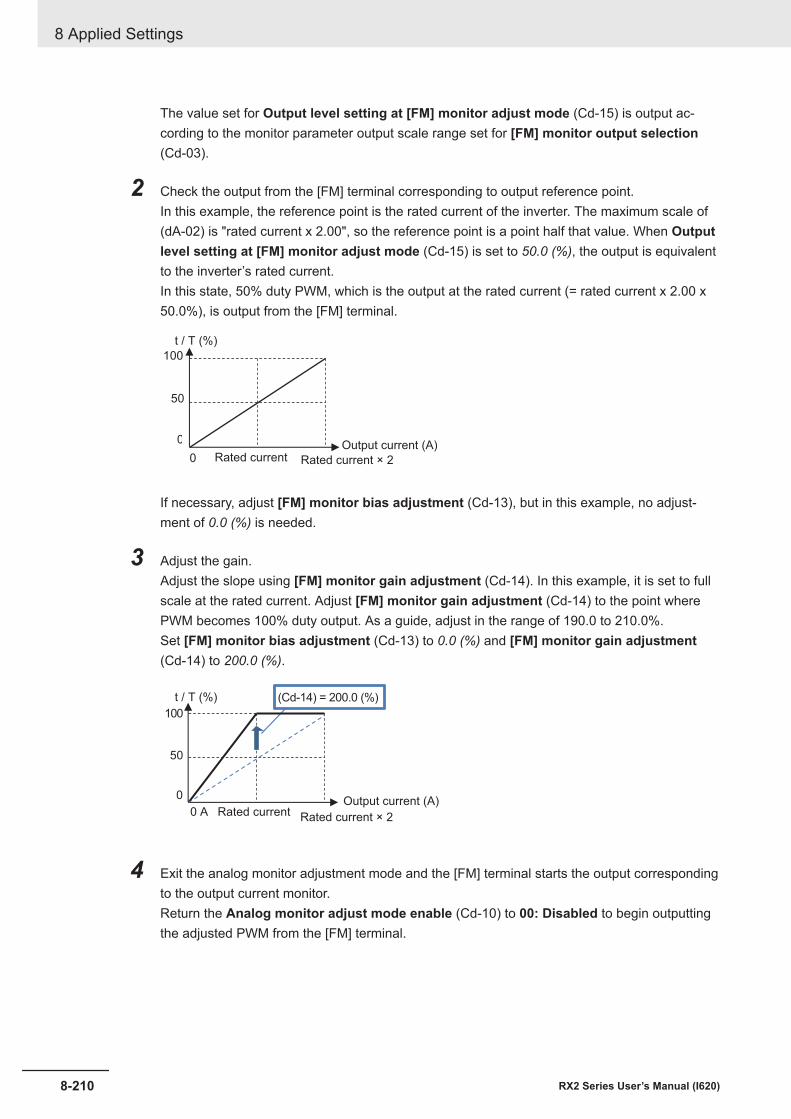
The value set for Output level setting at [FM] monitor adjust mode (Cd-15) is output ac-cording to the monitor parameter output scale range set for [FM] monitor output selection(Cd-03).
2 Check the output from the [FM] terminal corresponding to output reference point.In this example, the reference point is the rated current of the inverter. The maximum scale of(dA-02) is "rated current x 2.00", so the reference point is a point half that value. When Outputlevel setting at [FM] monitor adjust mode (Cd-15) is set to 50.0 (%), the output is equivalentto the inverter’s rated current.In this state, 50% duty PWM, which is the output at the rated current (= rated current x 2.00 x50.0%), is output from the [FM] terminal.
t / T (%)
100
0
0
50
Rated current Rated current × 2
Output current (A)
If necessary, adjust [FM] monitor bias adjustment (Cd-13), but in this example, no adjust-ment of 0.0 (%) is needed.
3 Adjust the gain.Adjust the slope using [FM] monitor gain adjustment (Cd-14). In this example, it is set to fullscale at the rated current. Adjust [FM] monitor gain adjustment (Cd-14) to the point wherePWM becomes 100% duty output. As a guide, adjust in the range of 190.0 to 210.0%.Set [FM] monitor bias adjustment (Cd-13) to 0.0 (%) and [FM] monitor gain adjustment(Cd-14) to 200.0 (%).
t / T (%)
0
0 A
50
(Cd-14) = 200.0 (%)
100
Rated current Rated current × 2
Output current (A)
4 Exit the analog monitor adjustment mode and the [FM] terminal starts the output correspondingto the output current monitor.Return the Analog monitor adjust mode enable (Cd-10) to 00: Disabled to begin outputtingthe adjusted PWM from the [FM] terminal.
8 Applied Settings
8-210 RX2 Series User’s Manual (I620)
9Communication function
This section describes the communication function.
9-1 Communication Specifications..................................................................... 9-29-1-1 Specifications of RS485 Communication Terminal Block................................ 9-29-1-2 Communication Parameter Settings................................................................ 9-5
9-2 Modbus Method.............................................................................................. 9-79-3 Explanation of Each Function Code........................................................... 9-129-4 Saving a Change to Holding Register (Enter Instruction) ........................ 9-219-5 Modbus Communication Register Number List ........................................ 9-23
9-5-1 Coil Number List............................................................................................ 9-239-5-2 Group d Register List .................................................................................... 9-259-5-3 Group F Register List .................................................................................... 9-569-5-4 Group A Register List .................................................................................... 9-579-5-5 Group b Register List .................................................................................... 9-899-5-6 Group C Register List.................................................................................... 9-999-5-7 Group H Register List...................................................................................9-1129-5-8 Group P Register List .................................................................................. 9-1229-5-9 Group U Register List.................................................................................. 9-1249-5-10 Group o Register List .................................................................................. 9-132
9-6 Inter-inverter Communication................................................................... 9-1349-6-1 Inter-inverter Communication Parameters .................................................. 9-1359-6-2 Communication Settings ............................................................................. 9-137
9-1RX2 Series User’s Manual (I620)
9
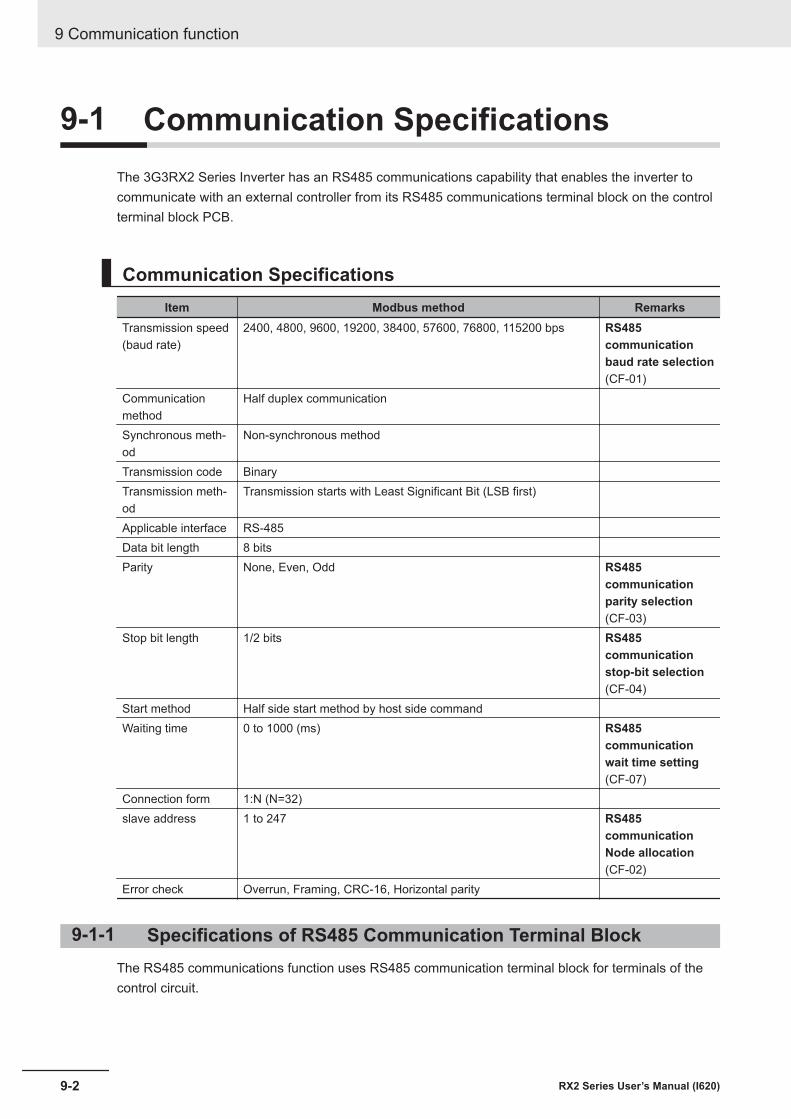
9-1 Communication SpecificationsThe 3G3RX2 Series Inverter has an RS485 communications capability that enables the inverter tocommunicate with an external controller from its RS485 communications terminal block on the controlterminal block PCB.
Communication SpecificationsItem Modbus method Remarks
Transmission speed(baud rate)
2400, 4800, 9600, 19200, 38400, 57600, 76800, 115200 bps RS485communicationbaud rate selection(CF-01)
Communicationmethod
Half duplex communication
Synchronous meth-od
Non-synchronous method
Transmission code BinaryTransmission meth-od
Transmission starts with Least Significant Bit (LSB first)
Applicable interface RS-485Data bit length 8 bitsParity None, Even, Odd RS485
communicationparity selection(CF-03)
Stop bit length 1/2 bits RS485communicationstop-bit selection(CF-04)
Start method Half side start method by host side commandWaiting time 0 to 1000 (ms) RS485
communicationwait time setting(CF-07)
Connection form 1:N (N=32)slave address 1 to 247 RS485
communicationNode allocation(CF-02)
Error check Overrun, Framing, CRC-16, Horizontal parity
9-1-1 Specifications of RS485 Communication Terminal BlockThe RS485 communications function uses RS485 communication terminal block for terminals of thecontrol circuit.
9 Communication function
9-2 RX2 Series User’s Manual (I620)
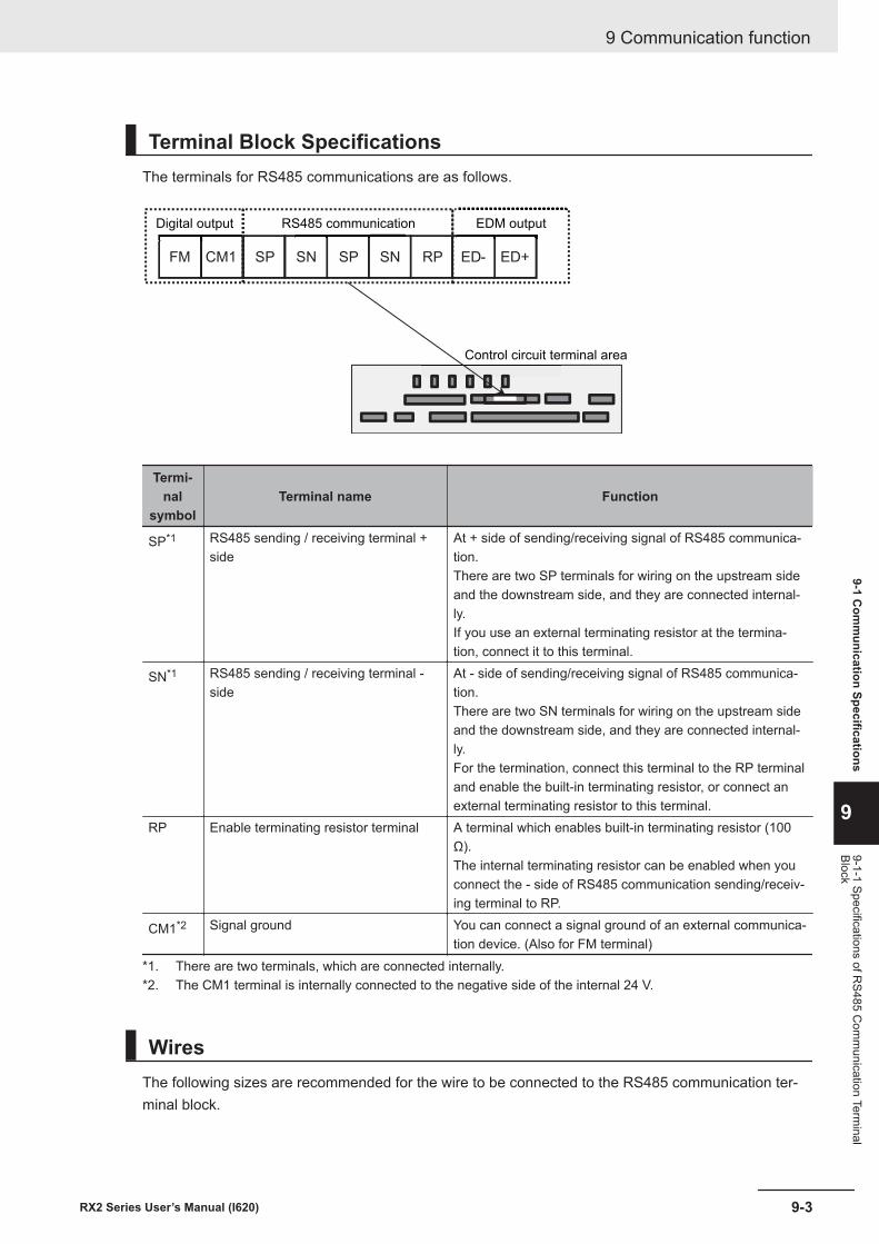
Terminal Block SpecificationsThe terminals for RS485 communications are as follows.
FM CM1 RPSNSPSNSP ED+ED-
Digital output RS485 communication EDM output
Control circuit terminal area
Termi-nal
symbolTerminal name Function
SP*1 RS485 sending / receiving terminal +side
At + side of sending/receiving signal of RS485 communica-tion.There are two SP terminals for wiring on the upstream sideand the downstream side, and they are connected internal-ly.If you use an external terminating resistor at the termina-tion, connect it to this terminal.
SN*1 RS485 sending / receiving terminal -side
At - side of sending/receiving signal of RS485 communica-tion.There are two SN terminals for wiring on the upstream sideand the downstream side, and they are connected internal-ly.For the termination, connect this terminal to the RP terminaland enable the built-in terminating resistor, or connect anexternal terminating resistor to this terminal.
RP Enable terminating resistor terminal A terminal which enables built-in terminating resistor (100Ω).The internal terminating resistor can be enabled when youconnect the - side of RS485 communication sending/receiv-ing terminal to RP.
CM1*2 Signal ground You can connect a signal ground of an external communica-tion device. (Also for FM terminal)
*1. There are two terminals, which are connected internally.*2. The CM1 terminal is internally connected to the negative side of the internal 24 V.
WiresThe following sizes are recommended for the wire to be connected to the RS485 communication ter-minal block.
9 Communication function
9-3RX2 Series User’s Manual (I620)
9-1 Com
munication Specifications
9
9-1-1 Specifications of RS485 C
omm
unication Terminal
Block
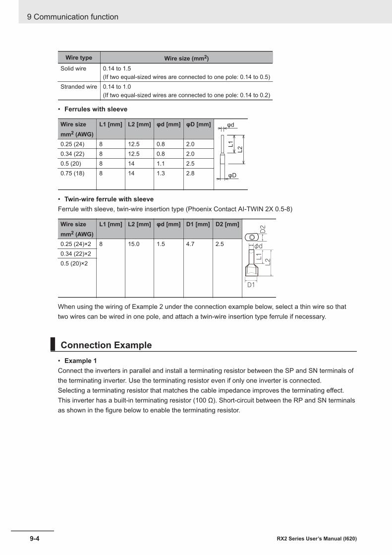
Wire type Wire size (mm2)Solid wire 0.14 to 1.5
(If two equal-sized wires are connected to one pole: 0.14 to 0.5)Stranded wire 0.14 to 1.0
(If two equal-sized wires are connected to one pole: 0.14 to 0.2)
• Ferrules with sleeve
Wire sizemm2 (AWG)
L1 [mm] L2 [mm] φd [mm] φD [mm] φd
φD
L2L10.25 (24) 8 12.5 0.8 2.0
0.34 (22) 8 12.5 0.8 2.00.5 (20) 8 14 1.1 2.50.75 (18) 8 14 1.3 2.8
• Twin-wire ferrule with sleeveFerrule with sleeve, twin-wire insertion type (Phoenix Contact AI-TWIN 2X 0.5-8)
Wire sizemm2 (AWG)
L1 [mm] L2 [mm] φd [mm] D1 [mm] D2 [mm]
D1
L2L1
D2
φd0.25 (24)×2 8 15.0 1.5 4.7 2.50.34 (22)×20.5 (20)×2
When using the wiring of Example 2 under the connection example below, select a thin wire so thattwo wires can be wired in one pole, and attach a twin-wire insertion type ferrule if necessary.
Connection Example• Example 1Connect the inverters in parallel and install a terminating resistor between the SP and SN terminals ofthe terminating inverter. Use the terminating resistor even if only one inverter is connected.Selecting a terminating resistor that matches the cable impedance improves the terminating effect.This inverter has a built-in terminating resistor (100 Ω). Short-circuit between the RP and SN terminalsas shown in the figure below to enable the terminating resistor.
9 Communication function
9-4 RX2 Series User’s Manual (I620)
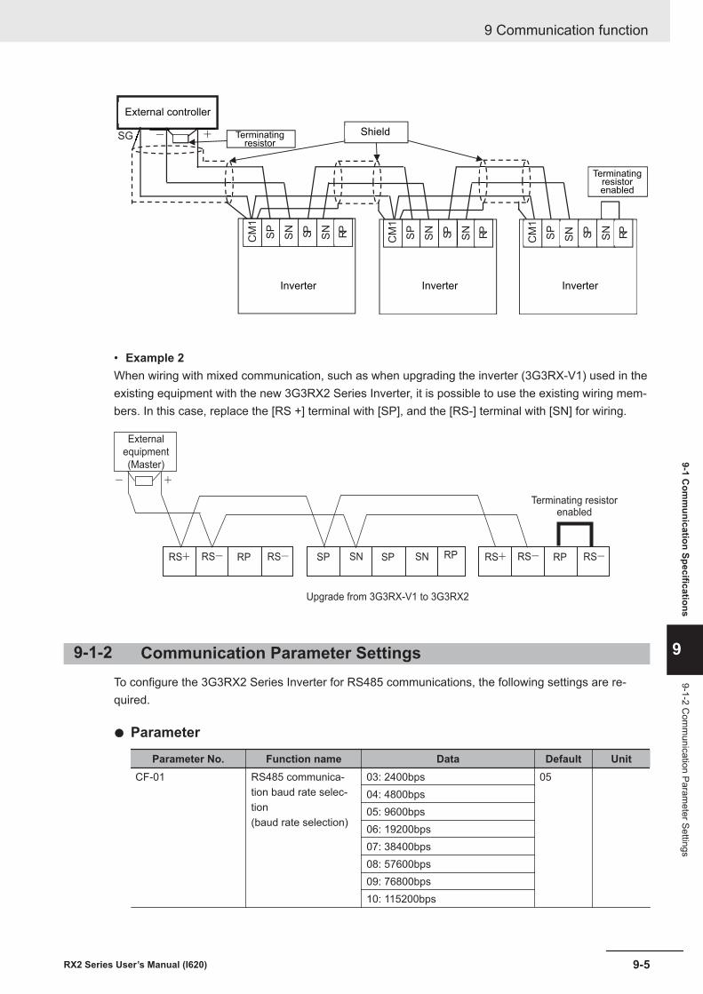
SG - +
インバータ
SP
SN
SP
SN
CM
1
インバータ
RP
SP
SN
SP
SN
CM
1
RP
SP
SN SP
SN
CM
1
RP
External controller
Terminatingresistor
Shield
InverterInverterInverter
Terminatingresistorenabled
• Example 2When wiring with mixed communication, such as when upgrading the inverter (3G3RX-V1) used in theexisting equipment with the new 3G3RX2 Series Inverter, it is possible to use the existing wiring mem-bers. In this case, replace the [RS +] terminal with [SP], and the [RS-] terminal with [SN] for wiring.
RS+ RS- RP RS-
Terminating resistorenabled
RS+ RS- RP RS-
External
equipment
(Master)
+-
SP SN SP SN RP
Upgrade from 3G3RX-V1 to 3G3RX2
9-1-2 Communication Parameter SettingsTo configure the 3G3RX2 Series Inverter for RS485 communications, the following settings are re-quired.
l Parameter
Parameter No. Function name Data Default UnitCF-01 RS485 communica-
tion baud rate selec-tion(baud rate selection)
03: 2400bps 0504: 4800bps05: 9600bps06: 19200bps07: 38400bps08: 57600bps09: 76800bps10: 115200bps
9 Communication function
9-5RX2 Series User’s Manual (I620)
9-1 Com
munication Specifications
9
9-1-2 Com
munication Param
eter Settings
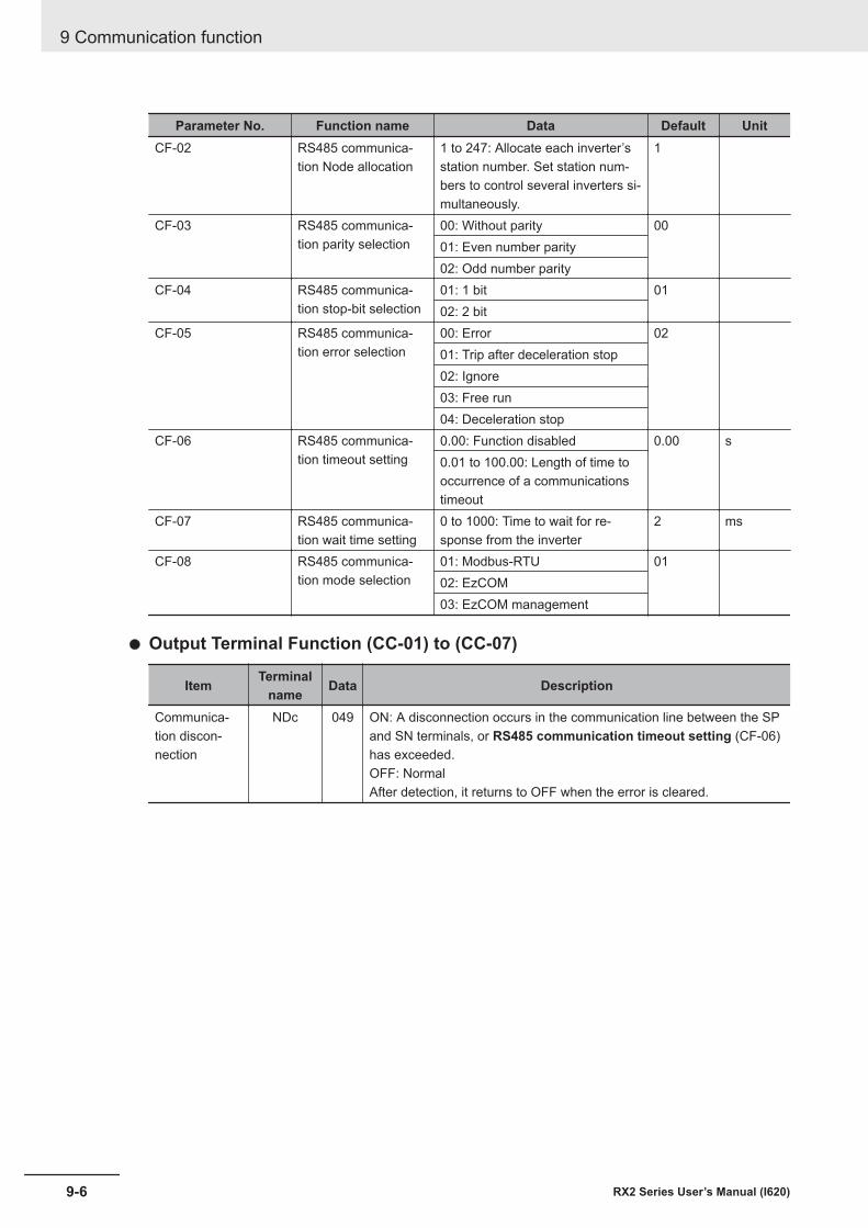
Parameter No. Function name Data Default UnitCF-02 RS485 communica-
tion Node allocation1 to 247: Allocate each inverter’sstation number. Set station num-bers to control several inverters si-multaneously.
1
CF-03 RS485 communica-tion parity selection
00: Without parity 0001: Even number parity02: Odd number parity
CF-04 RS485 communica-tion stop-bit selection
01: 1 bit 0102: 2 bit
CF-05 RS485 communica-tion error selection
00: Error 0201: Trip after deceleration stop02: Ignore03: Free run04: Deceleration stop
CF-06 RS485 communica-tion timeout setting
0.00: Function disabled 0.00 s0.01 to 100.00: Length of time tooccurrence of a communicationstimeout
CF-07 RS485 communica-tion wait time setting
0 to 1000: Time to wait for re-sponse from the inverter
2 ms
CF-08 RS485 communica-tion mode selection
01: Modbus-RTU 0102: EzCOM03: EzCOM management
l Output Terminal Function (CC-01) to (CC-07)
Item Terminalname Data Description
Communica-tion discon-nection
NDc 049 ON: A disconnection occurs in the communication line between the SPand SN terminals, or RS485 communication timeout setting (CF-06)has exceeded.OFF: NormalAfter detection, it returns to OFF when the error is cleared.
9 Communication function
9-6 RX2 Series User’s Manual (I620)
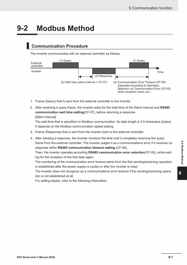
9-2 Modbus Method
Communication ProcedureThe inverter communicates with an external controller as follows.
Externalcontroller
Inverter
(1) Query
(3) Response
(2) Wait time (silent interval + CF-07) (4) Communication Error Timeout (CF-06)(Operates according to Operation Selection on Communication Error (CF-05)when reception times out.)
Time
(1) Query
1. Frame (Query) that is sent from the external controller to the inverter.
2. After receiving a query frame, the inverter waits for the total time of the Silent Interval and RS485communication wait time setting(CF-07), before returning a response.[Silent Interval]The wait time that is specified on Modbus communication. Its data length is 3.5 characters (bytes).It depends on the Modbus communication speed setting.
3. Frame (Response) that is sent from the inverter back to the external controller.
4. After sending a response, the inverter monitors the time until it completes receiving the queryframe from the external controller. The inverter judges it as a communications error if it receives noresponse within RS485 communication timeout setting (CF-06).Then, the inverter operates according RS485 communication error selection(CF-05), while wait-ing for the reception of the first data again.The monitoring of the communication error timeout starts from the first sending/receiving operationis established after the power supply is cycled or after the inverter is reset.The inverter does not recognize as a communications error timeout if the sending/receiving opera-tion is not established at all.For setting details, refer to the following information.
9 Communication function
9-7RX2 Series User’s Manual (I620)
9-2 Modbus M
ethod
9
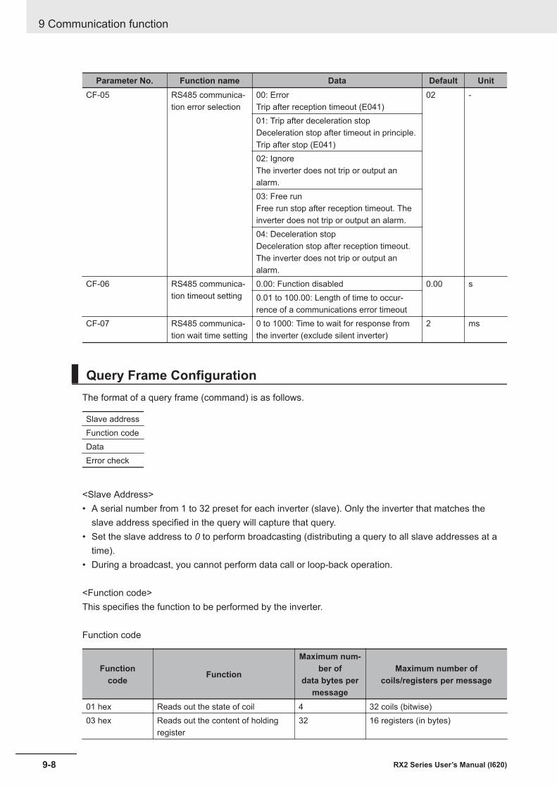
Parameter No. Function name Data Default UnitCF-05 RS485 communica-
tion error selection00: ErrorTrip after reception timeout (E041)
02 -
01: Trip after deceleration stopDeceleration stop after timeout in principle.Trip after stop (E041)02: IgnoreThe inverter does not trip or output analarm.03: Free runFree run stop after reception timeout. Theinverter does not trip or output an alarm.04: Deceleration stopDeceleration stop after reception timeout.The inverter does not trip or output analarm.
CF-06 RS485 communica-tion timeout setting
0.00: Function disabled 0.00 s0.01 to 100.00: Length of time to occur-rence of a communications error timeout
CF-07 RS485 communica-tion wait time setting
0 to 1000: Time to wait for response fromthe inverter (exclude silent inverter)
2 ms
Query Frame ConfigurationThe format of a query frame (command) is as follows.
Slave addressFunction codeDataError check
<Slave Address>• A serial number from 1 to 32 preset for each inverter (slave). Only the inverter that matches the
slave address specified in the query will capture that query.• Set the slave address to 0 to perform broadcasting (distributing a query to all slave addresses at a
time).• During a broadcast, you cannot perform data call or loop-back operation.
<Function code>This specifies the function to be performed by the inverter.
Function code
Functioncode Function
Maximum num-ber of
data bytes permessage
Maximum number ofcoils/registers per message
01 hex Reads out the state of coil 4 32 coils (bitwise)03 hex Reads out the content of holding
register32 16 registers (in bytes)
9 Communication function
9-8 RX2 Series User’s Manual (I620)
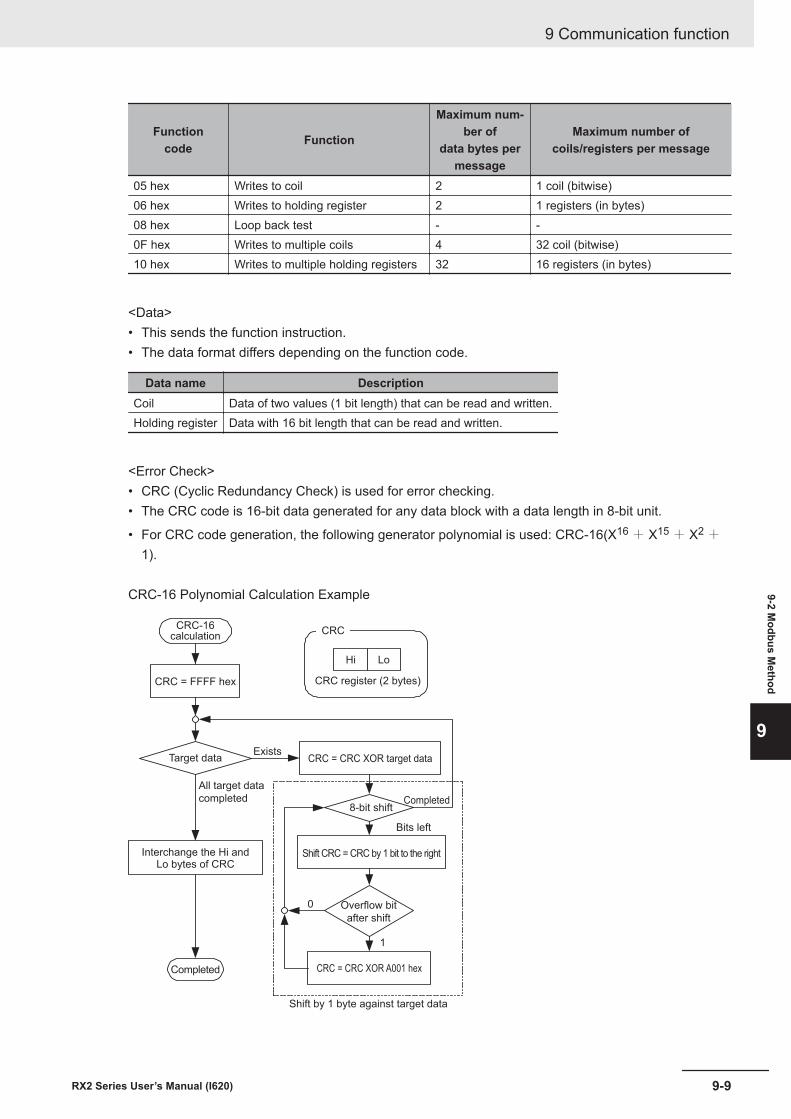
Functioncode Function
Maximum num-ber of
data bytes permessage
Maximum number ofcoils/registers per message
05 hex Writes to coil 2 1 coil (bitwise)06 hex Writes to holding register 2 1 registers (in bytes)08 hex Loop back test - -0F hex Writes to multiple coils 4 32 coil (bitwise)10 hex Writes to multiple holding registers 32 16 registers (in bytes)
<Data>• This sends the function instruction.• The data format differs depending on the function code.
Data name DescriptionCoil Data of two values (1 bit length) that can be read and written.Holding register Data with 16 bit length that can be read and written.
<Error Check>• CRC (Cyclic Redundancy Check) is used for error checking.• The CRC code is 16-bit data generated for any data block with a data length in 8-bit unit.
• For CRC code generation, the following generator polynomial is used: CRC-16(X16 + X15 + X2 +
1).
CRC-16 Polynomial Calculation Example
CRC-16calculation
CRC = FFFF hex
CRC
Hi Lo
CRC register (2 bytes)
Target dataExists
All target data
completed
Interchange the Hi andLo bytes of CRC
Completed
CRC = CRC XOR target data
8-bit shiftCompleted
Bits left
Shift CRC = CRC by 1 bit to the right
0
1
Overflow bit
after shift
CRC = CRC XOR A001 hex
Shift by 1 byte against target data
9 Communication function
9-9RX2 Series User’s Manual (I620)
9-2 Modbus M
ethod
9
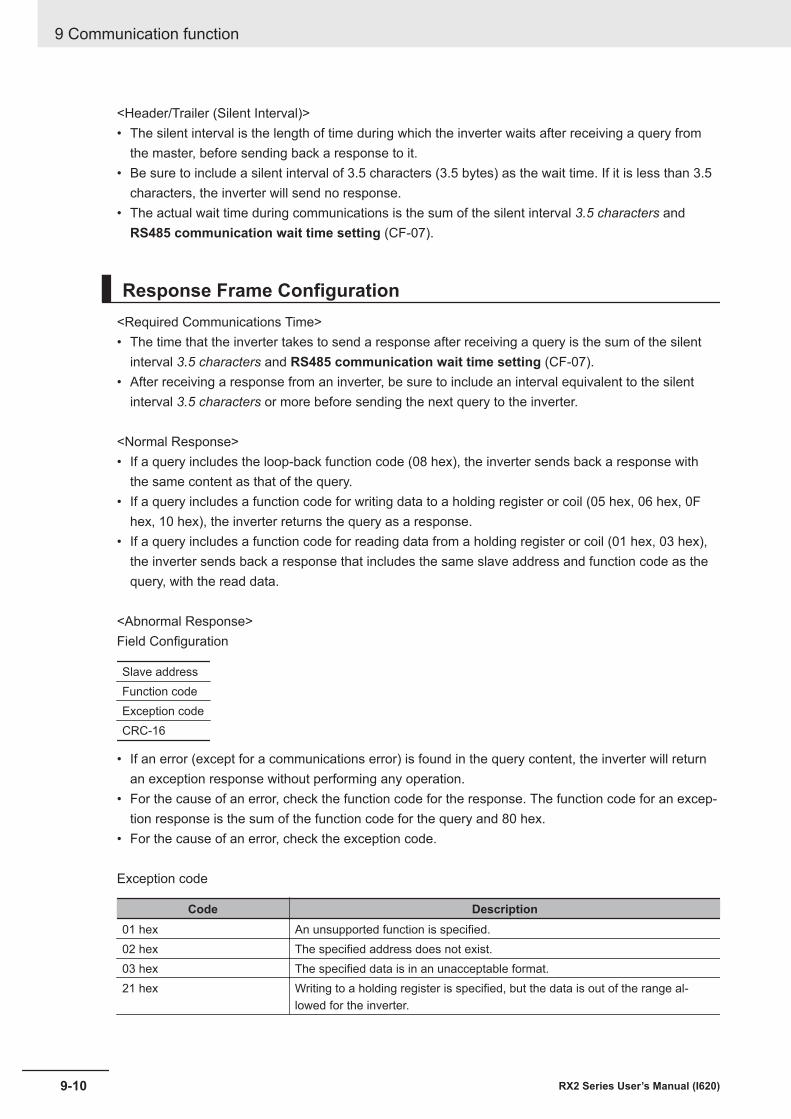
<Header/Trailer (Silent Interval)>• The silent interval is the length of time during which the inverter waits after receiving a query from
the master, before sending back a response to it.• Be sure to include a silent interval of 3.5 characters (3.5 bytes) as the wait time. If it is less than 3.5
characters, the inverter will send no response.• The actual wait time during communications is the sum of the silent interval 3.5 characters and
RS485 communication wait time setting (CF-07).
Response Frame Configuration<Required Communications Time>• The time that the inverter takes to send a response after receiving a query is the sum of the silent
interval 3.5 characters and RS485 communication wait time setting (CF-07).• After receiving a response from an inverter, be sure to include an interval equivalent to the silent
interval 3.5 characters or more before sending the next query to the inverter.
<Normal Response>• If a query includes the loop-back function code (08 hex), the inverter sends back a response with
the same content as that of the query.• If a query includes a function code for writing data to a holding register or coil (05 hex, 06 hex, 0F
hex, 10 hex), the inverter returns the query as a response.• If a query includes a function code for reading data from a holding register or coil (01 hex, 03 hex),
the inverter sends back a response that includes the same slave address and function code as thequery, with the read data.
<Abnormal Response>Field Configuration
Slave addressFunction codeException codeCRC-16
• If an error (except for a communications error) is found in the query content, the inverter will returnan exception response without performing any operation.
• For the cause of an error, check the function code for the response. The function code for an excep-tion response is the sum of the function code for the query and 80 hex.
• For the cause of an error, check the exception code.
Exception code
Code Description01 hex An unsupported function is specified.02 hex The specified address does not exist.03 hex The specified data is in an unacceptable format.21 hex Writing to a holding register is specified, but the data is out of the range al-
lowed for the inverter.
9 Communication function
9-10 RX2 Series User’s Manual (I620)
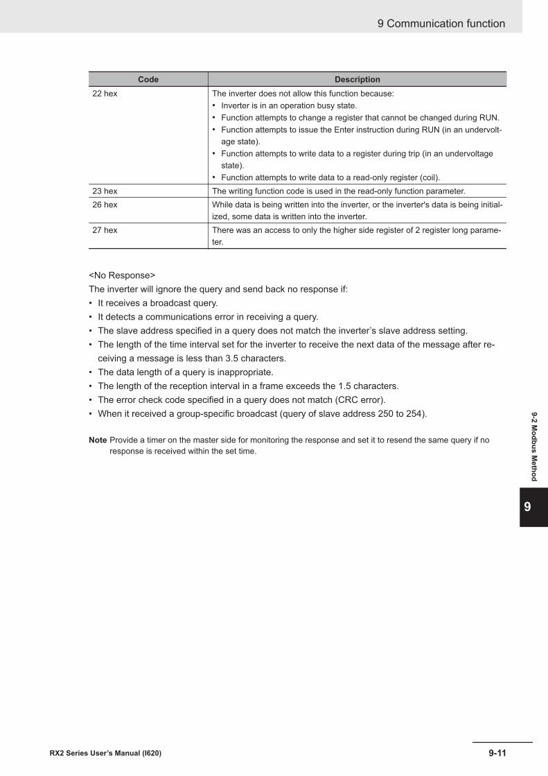
Code Description22 hex The inverter does not allow this function because:
• Inverter is in an operation busy state.• Function attempts to change a register that cannot be changed during RUN.• Function attempts to issue the Enter instruction during RUN (in an undervolt-
age state).• Function attempts to write data to a register during trip (in an undervoltage
state).• Function attempts to write data to a read-only register (coil).
23 hex The writing function code is used in the read-only function parameter.26 hex While data is being written into the inverter, or the inverter's data is being initial-
ized, some data is written into the inverter.27 hex There was an access to only the higher side register of 2 register long parame-
ter.
<No Response>The inverter will ignore the query and send back no response if:• It receives a broadcast query.• It detects a communications error in receiving a query.• The slave address specified in a query does not match the inverter’s slave address setting.• The length of the time interval set for the inverter to receive the next data of the message after re-
ceiving a message is less than 3.5 characters.• The data length of a query is inappropriate.• The length of the reception interval in a frame exceeds the 1.5 characters.• The error check code specified in a query does not match (CRC error).• When it received a group-specific broadcast (query of slave address 250 to 254).
Note Provide a timer on the master side for monitoring the response and set it to resend the same query if noresponse is received within the set time.
9 Communication function
9-11RX2 Series User’s Manual (I620)
9-2 Modbus M
ethod
9
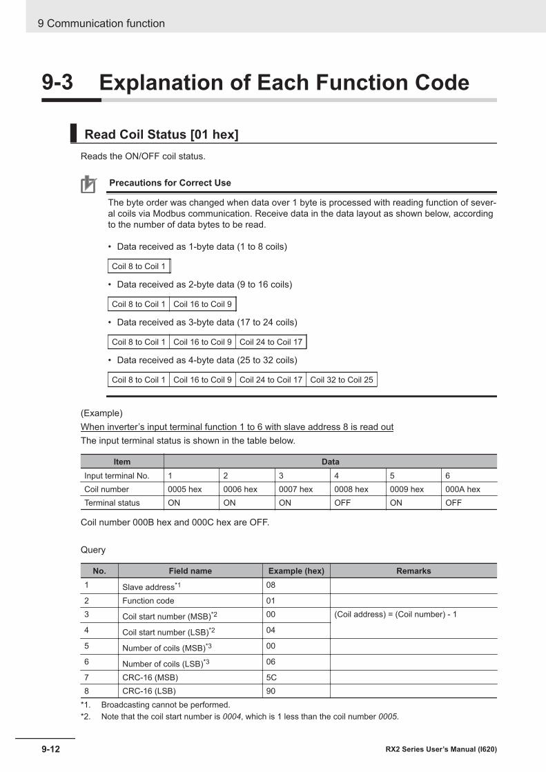
9-3 Explanation of Each Function Code
Read Coil Status [01 hex]Reads the ON/OFF coil status.
Precautions for Correct Use
The byte order was changed when data over 1 byte is processed with reading function of sever-al coils via Modbus communication. Receive data in the data layout as shown below, accordingto the number of data bytes to be read. • Data received as 1-byte data (1 to 8 coils)
Coil 8 to Coil 1
• Data received as 2-byte data (9 to 16 coils)
Coil 8 to Coil 1 Coil 16 to Coil 9
• Data received as 3-byte data (17 to 24 coils)
Coil 8 to Coil 1 Coil 16 to Coil 9 Coil 24 to Coil 17
• Data received as 4-byte data (25 to 32 coils)
Coil 8 to Coil 1 Coil 16 to Coil 9 Coil 24 to Coil 17 Coil 32 to Coil 25
(Example)When inverter’s input terminal function 1 to 6 with slave address 8 is read outThe input terminal status is shown in the table below.
Item DataInput terminal No. 1 2 3 4 5 6Coil number 0005 hex 0006 hex 0007 hex 0008 hex 0009 hex 000A hexTerminal status ON ON ON OFF ON OFF
Coil number 000B hex and 000C hex are OFF.
Query
No. Field name Example (hex) Remarks1 Slave address*1 08
2 Function code 013 Coil start number (MSB)*2 00 (Coil address) = (Coil number) - 1
4 Coil start number (LSB)*2 04
5 Number of coils (MSB)*3 00
6 Number of coils (LSB)*3 06
7 CRC-16 (MSB) 5C8 CRC-16 (LSB) 90
*1. Broadcasting cannot be performed.*2. Note that the coil start number is 0004, which is 1 less than the coil number 0005.
9 Communication function
9-12 RX2 Series User’s Manual (I620)
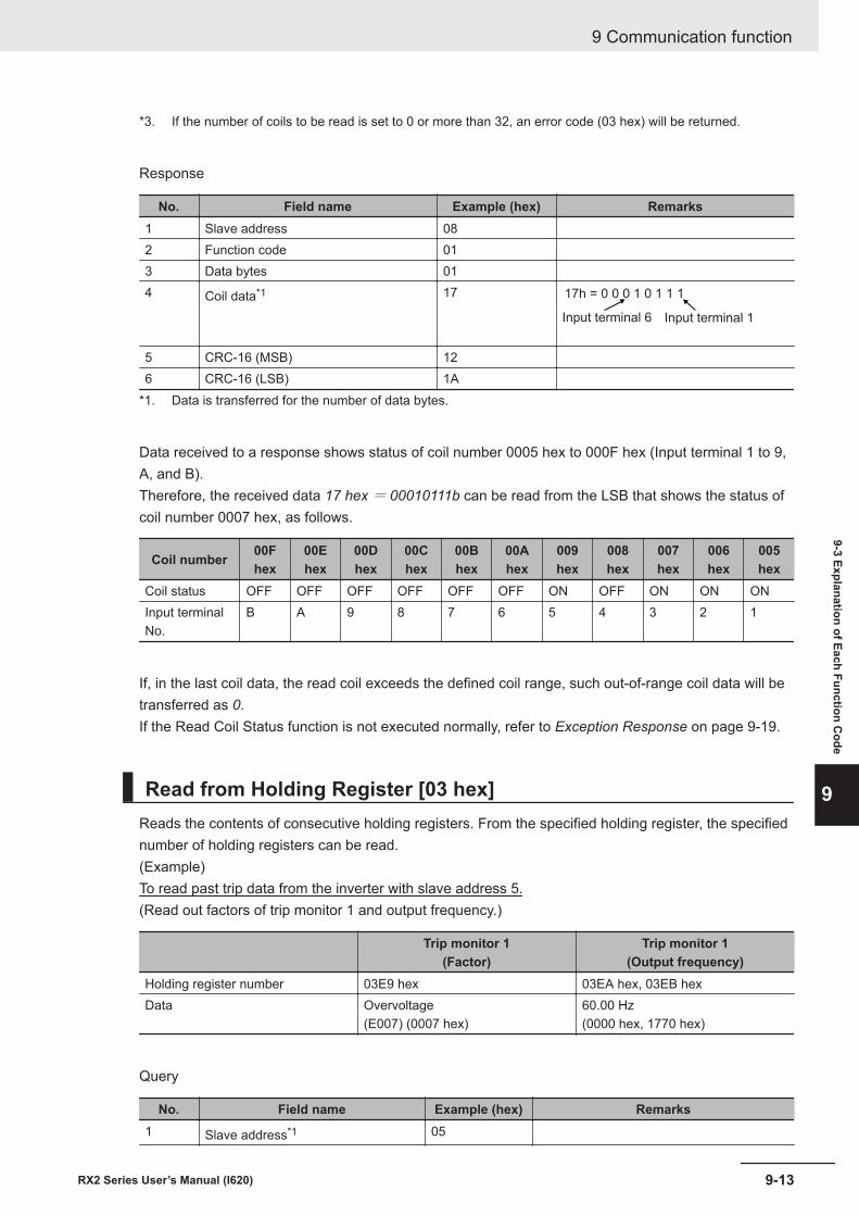
*3. If the number of coils to be read is set to 0 or more than 32, an error code (03 hex) will be returned.
Response
No. Field name Example (hex) Remarks1 Slave address 082 Function code 013 Data bytes 014 Coil data*1 17 17h = 0 0 0 1 0 1 1 1
Input terminal 6 Input terminal 1
5 CRC-16 (MSB) 126 CRC-16 (LSB) 1A
*1. Data is transferred for the number of data bytes.
Data received to a response shows status of coil number 0005 hex to 000F hex (Input terminal 1 to 9,A, and B).Therefore, the received data 17 hex = 00010111b can be read from the LSB that shows the status ofcoil number 0007 hex, as follows.
Coil number 00Fhex
00Ehex
00Dhex
00Chex
00Bhex
00Ahex
009hex
008hex
007hex
006hex
005hex
Coil status OFF OFF OFF OFF OFF OFF ON OFF ON ON ONInput terminalNo.
B A 9 8 7 6 5 4 3 2 1
If, in the last coil data, the read coil exceeds the defined coil range, such out-of-range coil data will betransferred as 0.If the Read Coil Status function is not executed normally, refer to Exception Response on page 9-19.
Read from Holding Register [03 hex]Reads the contents of consecutive holding registers. From the specified holding register, the specifiednumber of holding registers can be read.(Example)To read past trip data from the inverter with slave address 5.(Read out factors of trip monitor 1 and output frequency.)
Trip monitor 1(Factor)
Trip monitor 1(Output frequency)
Holding register number 03E9 hex 03EA hex, 03EB hexData Overvoltage
(E007) (0007 hex)60.00 Hz(0000 hex, 1770 hex)
Query
No. Field name Example (hex) Remarks1 Slave address*1 05
9 Communication function
9-13RX2 Series User’s Manual (I620)
9-3 Explanation of Each Function Code
9
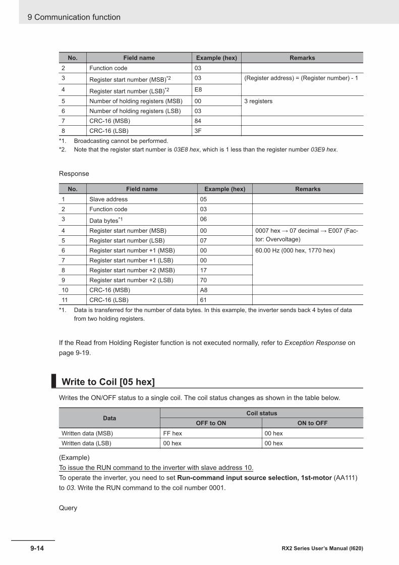
No. Field name Example (hex) Remarks2 Function code 033 Register start number (MSB)*2 03 (Register address) = (Register number) - 1
4 Register start number (LSB)*2 E8
5 Number of holding registers (MSB) 00 3 registers6 Number of holding registers (LSB) 037 CRC-16 (MSB) 848 CRC-16 (LSB) 3F
*1. Broadcasting cannot be performed.*2. Note that the register start number is 03E8 hex, which is 1 less than the register number 03E9 hex.
Response
No. Field name Example (hex) Remarks1 Slave address 052 Function code 033 Data bytes*1 06
4 Register start number (MSB) 00 0007 hex → 07 decimal → E007 (Fac-tor: Overvoltage)5 Register start number (LSB) 07
6 Register start number +1 (MSB) 00 60.00 Hz (000 hex, 1770 hex)7 Register start number +1 (LSB) 008 Register start number +2 (MSB) 179 Register start number +2 (LSB) 7010 CRC-16 (MSB) A811 CRC-16 (LSB) 61
*1. Data is transferred for the number of data bytes. In this example, the inverter sends back 4 bytes of datafrom two holding registers.
If the Read from Holding Register function is not executed normally, refer to Exception Response onpage 9-19.
Write to Coil [05 hex]Writes the ON/OFF status to a single coil. The coil status changes as shown in the table below.
DataCoil status
OFF to ON ON to OFFWritten data (MSB) FF hex 00 hexWritten data (LSB) 00 hex 00 hex
(Example)To issue the RUN command to the inverter with slave address 10.To operate the inverter, you need to set Run-command input source selection, 1st-motor (AA111)to 03. Write the RUN command to the coil number 0001.
Query
9 Communication function
9-14 RX2 Series User’s Manual (I620)
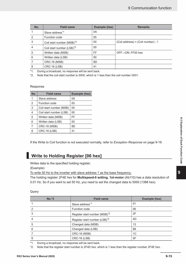
No. Field name Example (hex) Remarks1 Slave address*1 0A
2 Function code 053 Coil start number (MSB)*2 00 (Coil address) = (Coil number) - 1
4 Coil start number (LSB)*2 00
5 Written data (MSB) FF OFF→ON: FF00 hex6 Written data (LSB) 007 CRC-16 (MSB) 8D8 CRC-16 (LSB) 41
*1. During a broadcast, no response will be sent back.*2. Note that the coil start number is 0000, which is 1 less than the coil number 0001.
Response
No. Field name Example (hex)1 Slave address 0A2 Function code 053 Coil start number (MSB) 004 Coil start number (LSB) 005 Written data (MSB) FF6 Written data (LSB) 007 CRC-16 (MSB) 8D8 CRC-16 (LSB) 41
If the Write to Coil function is not executed normally, refer to Exception Response on page 9-19.
Write to Holding Register [06 hex]Writes data to the specified holding register.(Example)To write 50 Hz to the inverter with slave address 1 as the base frequency.The holding register 2F4E hex for Multispeed-0 setting, 1st-motor (Ab110) has a data resolution of0.01 Hz. So if you want to set 50 Hz, you need to set the changed data to 5000 (1388 hex).
Query
No.*3 Field name Example (hex)1 Slave address*1 01
2 Function code 063 Register start number (MSB)*2 2F
4 Register start number (LSB)*2 4D
5 Changed data (MSB) 136 Changed data (LSB) 887 CRC-16 (MSB) 1C8 CRC-16 (LSB) 5F
*1. During a broadcast, no response will be sent back.*2. Note that the register start number is 2F4D hex, which is 1 less than the register number 2F4E hex.
9 Communication function
9-15RX2 Series User’s Manual (I620)
9-3 Explanation of Each Function Code
9
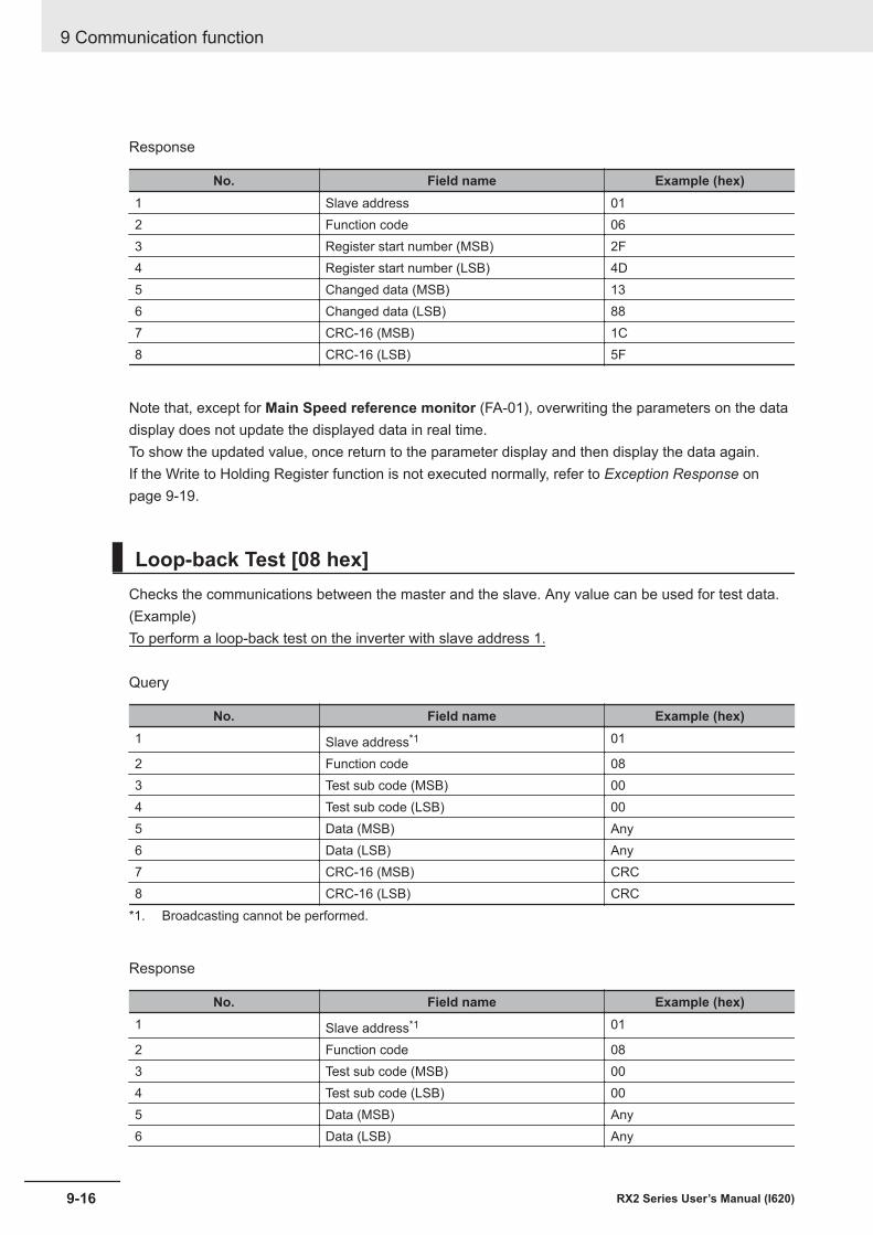
Response
No. Field name Example (hex)1 Slave address 012 Function code 063 Register start number (MSB) 2F4 Register start number (LSB) 4D5 Changed data (MSB) 136 Changed data (LSB) 887 CRC-16 (MSB) 1C8 CRC-16 (LSB) 5F
Note that, except for Main Speed reference monitor (FA-01), overwriting the parameters on the datadisplay does not update the displayed data in real time.To show the updated value, once return to the parameter display and then display the data again.If the Write to Holding Register function is not executed normally, refer to Exception Response onpage 9-19.
Loop-back Test [08 hex]Checks the communications between the master and the slave. Any value can be used for test data.(Example)To perform a loop-back test on the inverter with slave address 1.
Query
No. Field name Example (hex)1 Slave address*1 01
2 Function code 083 Test sub code (MSB) 004 Test sub code (LSB) 005 Data (MSB) Any6 Data (LSB) Any7 CRC-16 (MSB) CRC8 CRC-16 (LSB) CRC
*1. Broadcasting cannot be performed.
Response
No. Field name Example (hex)1 Slave address*1 01
2 Function code 083 Test sub code (MSB) 004 Test sub code (LSB) 005 Data (MSB) Any6 Data (LSB) Any
9 Communication function
9-16 RX2 Series User’s Manual (I620)
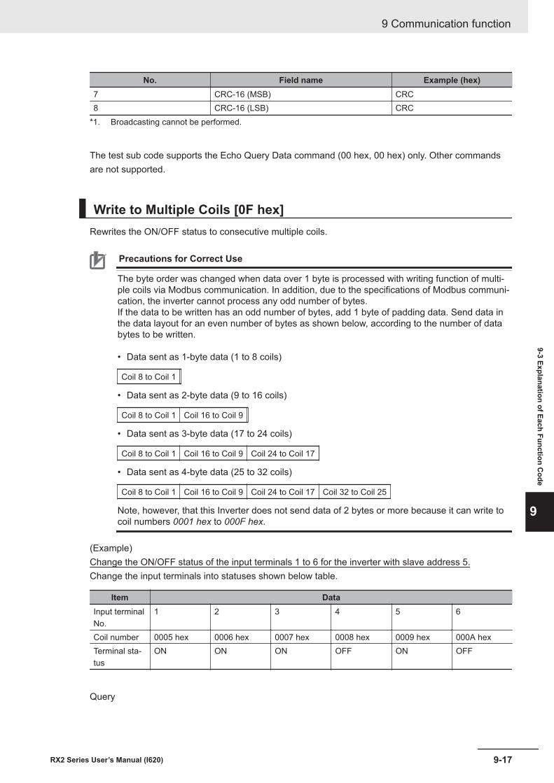
No. Field name Example (hex)7 CRC-16 (MSB) CRC8 CRC-16 (LSB) CRC
*1. Broadcasting cannot be performed.
The test sub code supports the Echo Query Data command (00 hex, 00 hex) only. Other commandsare not supported.
Write to Multiple Coils [0F hex]Rewrites the ON/OFF status to consecutive multiple coils.
Precautions for Correct Use
The byte order was changed when data over 1 byte is processed with writing function of multi-ple coils via Modbus communication. In addition, due to the specifications of Modbus communi-cation, the inverter cannot process any odd number of bytes.If the data to be written has an odd number of bytes, add 1 byte of padding data. Send data inthe data layout for an even number of bytes as shown below, according to the number of databytes to be written. • Data sent as 1-byte data (1 to 8 coils)
Coil 8 to Coil 1
• Data sent as 2-byte data (9 to 16 coils)
Coil 8 to Coil 1 Coil 16 to Coil 9
• Data sent as 3-byte data (17 to 24 coils)
Coil 8 to Coil 1 Coil 16 to Coil 9 Coil 24 to Coil 17
• Data sent as 4-byte data (25 to 32 coils)
Coil 8 to Coil 1 Coil 16 to Coil 9 Coil 24 to Coil 17 Coil 32 to Coil 25
Note, however, that this Inverter does not send data of 2 bytes or more because it can write tocoil numbers 0001 hex to 000F hex.
(Example)Change the ON/OFF status of the input terminals 1 to 6 for the inverter with slave address 5.Change the input terminals into statuses shown below table.
Item DataInput terminalNo.
1 2 3 4 5 6
Coil number 0005 hex 0006 hex 0007 hex 0008 hex 0009 hex 000A hexTerminal sta-tus
ON ON ON OFF ON OFF
Query
9 Communication function
9-17RX2 Series User’s Manual (I620)
9-3 Explanation of Each Function Code
9
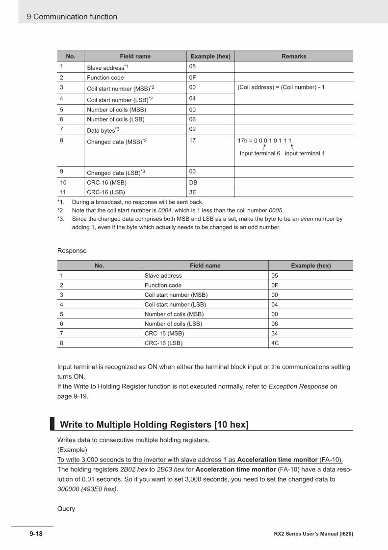
No. Field name Example (hex) Remarks1 Slave address*1 05
2 Function code 0F3 Coil start number (MSB)*2 00 (Coil address) = (Coil number) - 1
4 Coil start number (LSB)*2 04
5 Number of coils (MSB) 006 Number of coils (LSB) 067 Data bytes*3 02
8 Changed data (MSB)*3 17 17h = 0 0 0 1 0 1 1 1
Input terminal 6 Input terminal 1
9 Changed data (LSB)*3 00
10 CRC-16 (MSB) DB11 CRC-16 (LSB) 3E
*1. During a broadcast, no response will be sent back.*2. Note that the coil start number is 0004, which is 1 less than the coil number 0005.*3. Since the changed data comprises both MSB and LSB as a set, make the byte to be an even number by
adding 1, even if the byte which actually needs to be changed is an odd number.
Response
No. Field name Example (hex)1 Slave address 052 Function code 0F3 Coil start number (MSB) 004 Coil start number (LSB) 045 Number of coils (MSB) 006 Number of coils (LSB) 067 CRC-16 (MSB) 348 CRC-16 (LSB) 4C
Input terminal is recognized as ON when either the terminal block input or the communications settingturns ON.If the Write to Holding Register function is not executed normally, refer to Exception Response onpage 9-19.
Write to Multiple Holding Registers [10 hex]Writes data to consecutive multiple holding registers.(Example)To write 3,000 seconds to the inverter with slave address 1 as Acceleration time monitor (FA-10).The holding registers 2B02 hex to 2B03 hex for Acceleration time monitor (FA-10) have a data reso-lution of 0.01 seconds. So if you want to set 3,000 seconds, you need to set the changed data to300000 (493E0 hex).
Query
9 Communication function
9-18 RX2 Series User’s Manual (I620)
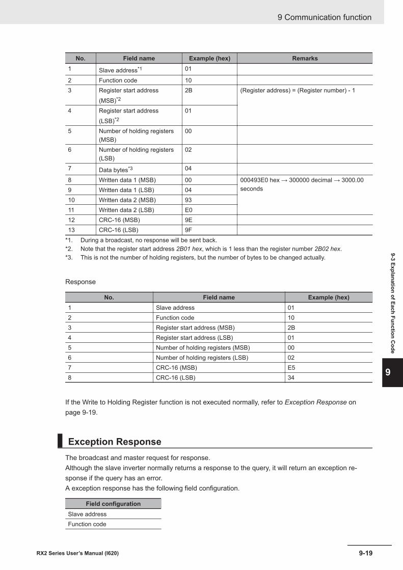
No. Field name Example (hex) Remarks1 Slave address*1 01
2 Function code 103 Register start address
(MSB)*22B (Register address) = (Register number) - 1
4 Register start address(LSB)*2
01
5 Number of holding registers(MSB)
00
6 Number of holding registers(LSB)
02
7 Data bytes*3 04
8 Written data 1 (MSB) 00 000493E0 hex → 300000 decimal → 3000.00seconds9 Written data 1 (LSB) 04
10 Written data 2 (MSB) 9311 Written data 2 (LSB) E012 CRC-16 (MSB) 9E13 CRC-16 (LSB) 9F
*1. During a broadcast, no response will be sent back.*2. Note that the register start address 2B01 hex, which is 1 less than the register number 2B02 hex.*3. This is not the number of holding registers, but the number of bytes to be changed actually.
Response
No. Field name Example (hex)1 Slave address 012 Function code 103 Register start address (MSB) 2B4 Register start address (LSB) 015 Number of holding registers (MSB) 006 Number of holding registers (LSB) 027 CRC-16 (MSB) E58 CRC-16 (LSB) 34
If the Write to Holding Register function is not executed normally, refer to Exception Response onpage 9-19.
Exception ResponseThe broadcast and master request for response.Although the slave inverter normally returns a response to the query, it will return an exception re-sponse if the query has an error.A exception response has the following field configuration.
Field configurationSlave addressFunction code
9 Communication function
9-19RX2 Series User’s Manual (I620)
9-3 Explanation of Each Function Code
9
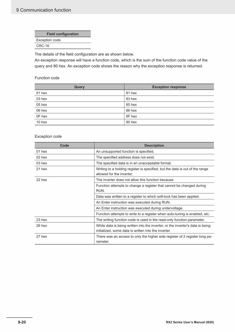
Field configurationException codeCRC-16
The details of the field configuration are as shown below.An exception response will have a function code, which is the sum of the function code value of thequery and 80 hex. An exception code shows the reason why the exception response is returned.
Function code
Query Exception response01 hex 81 hex03 hex 83 hex05 hex 85 hex06 hex 86 hex0F hex 8F hex10 hex 90 hex
Exception code
Code Description01 hex An unsupported function is specified.02 hex The specified address does not exist.03 hex The specified data is in an unacceptable format.21 hex Writing to a holding register is specified, but the data is out of the range
allowed for the inverter.22 hex The inverter does not allow this function because:
Function attempts to change a register that cannot be changed duringRUN.Data was written to a register to which soft-lock has been applied.An Enter instruction was executed during RUN.An Enter instruction was executed during undervoltage.Function attempts to write to a register when auto-tuning is enabled, etc.
23 hex The writing function code is used in the read-only function parameter.26 hex While data is being written into the inverter, or the inverter's data is being
initialized, some data is written into the inverter.27 hex There was an access to only the higher side register of 2 register long pa-
rameter.
9 Communication function
9-20 RX2 Series User’s Manual (I620)
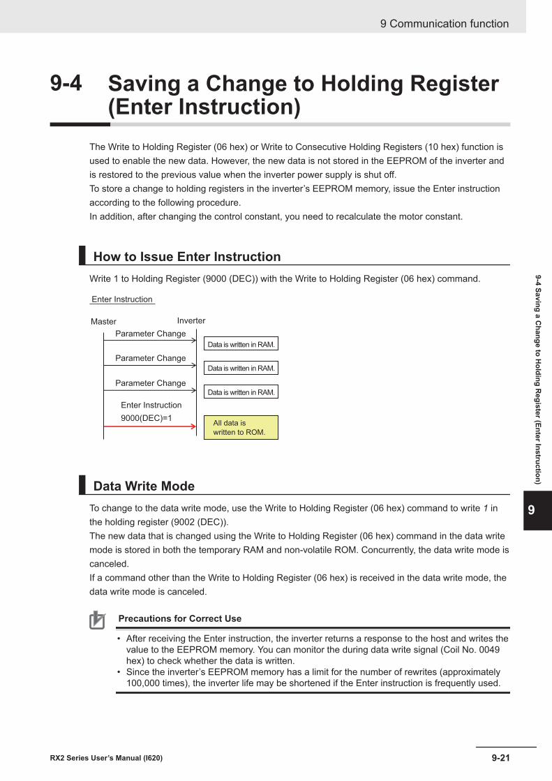
9-4 Saving a Change to Holding Register(Enter Instruction)
The Write to Holding Register (06 hex) or Write to Consecutive Holding Registers (10 hex) function isused to enable the new data. However, the new data is not stored in the EEPROM of the inverter andis restored to the previous value when the inverter power supply is shut off.To store a change to holding registers in the inverter’s EEPROM memory, issue the Enter instructionaccording to the following procedure.In addition, after changing the control constant, you need to recalculate the motor constant.
How to Issue Enter InstructionWrite 1 to Holding Register (9000 (DEC)) with the Write to Holding Register (06 hex) command.
Enter Instruction
Master Inverter
Enter Instruction
9000(DEC)=1All data is
written to ROM.
Parameter Change
Parameter Change
Parameter Change
Data is written in RAM.
Data is written in RAM.
Data is written in RAM.
Data Write ModeTo change to the data write mode, use the Write to Holding Register (06 hex) command to write 1 inthe holding register (9002 (DEC)).The new data that is changed using the Write to Holding Register (06 hex) command in the data writemode is stored in both the temporary RAM and non-volatile ROM. Concurrently, the data write mode iscanceled.If a command other than the Write to Holding Register (06 hex) is received in the data write mode, thedata write mode is canceled.
Precautions for Correct Use
• After receiving the Enter instruction, the inverter returns a response to the host and writes thevalue to the EEPROM memory. You can monitor the during data write signal (Coil No. 0049hex) to check whether the data is written.
• Since the inverter’s EEPROM memory has a limit for the number of rewrites (approximately100,000 times), the inverter life may be shortened if the Enter instruction is frequently used.
9 Communication function
9-21RX2 Series User’s Manual (I620)
9-4 Saving a Change to H
olding Register (Enter Instruction)
9
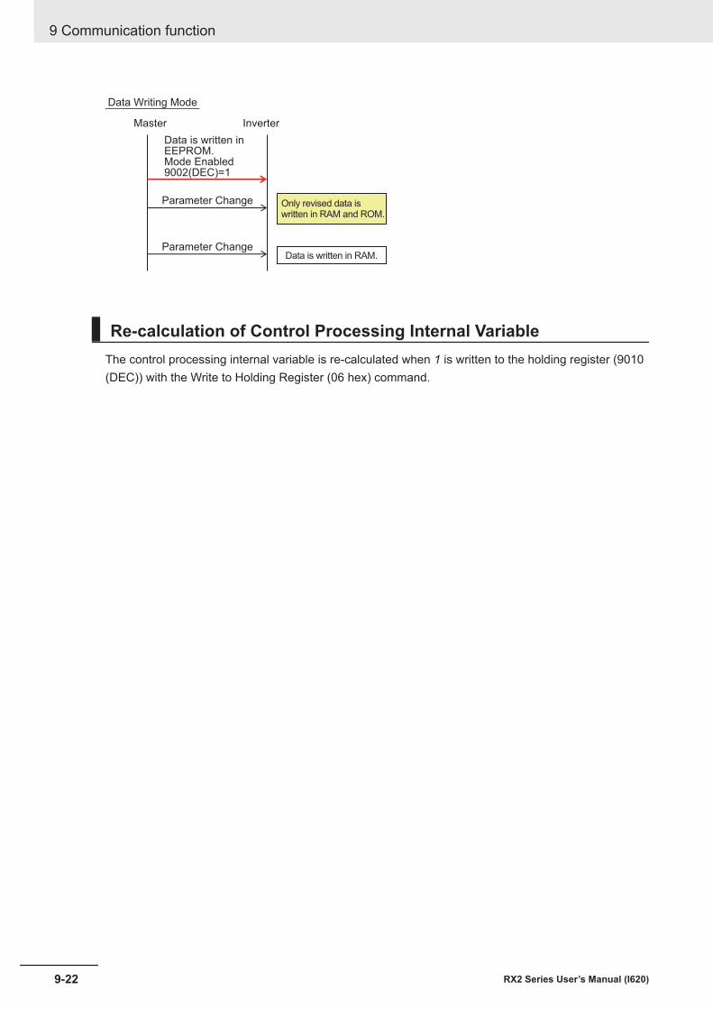
Data Writing Mode
Master Inverter
Parameter Change
Parameter ChangeData is written in RAM.
Only revised data is written in RAM and ROM.
Data is written inEEPROM.Mode Enabled9002(DEC)=1
Re-calculation of Control Processing Internal VariableThe control processing internal variable is re-calculated when 1 is written to the holding register (9010(DEC)) with the Write to Holding Register (06 hex) command.
9 Communication function
9-22 RX2 Series User’s Manual (I620)
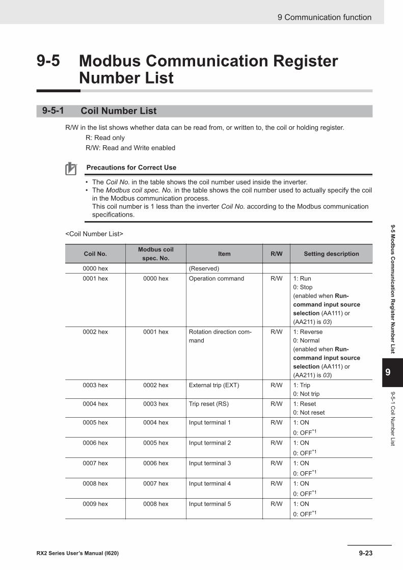
9-5 Modbus Communication RegisterNumber List
9-5-1 Coil Number ListR/W in the list shows whether data can be read from, or written to, the coil or holding register. R: Read only R/W: Read and Write enabled
Precautions for Correct Use
• The Coil No. in the table shows the coil number used inside the inverter.• The Modbus coil spec. No. in the table shows the coil number used to actually specify the coil
in the Modbus communication process.This coil number is 1 less than the inverter Coil No. according to the Modbus communicationspecifications.
<Coil Number List>
Coil No. Modbus coilspec. No. Item R/W Setting description
0000 hex (Reserved)0001 hex 0000 hex Operation command R/W 1: Run
0: Stop(enabled when Run-command input sourceselection (AA111) or(AA211) is 03)
0002 hex 0001 hex Rotation direction com-mand
R/W 1: Reverse0: Normal(enabled when Run-command input sourceselection (AA111) or(AA211) is 03)
0003 hex 0002 hex External trip (EXT) R/W 1: Trip0: Not trip
0004 hex 0003 hex Trip reset (RS) R/W 1: Reset0: Not reset
0005 hex 0004 hex Input terminal 1 R/W 1: ON0: OFF*1
0006 hex 0005 hex Input terminal 2 R/W 1: ON0: OFF*1
0007 hex 0006 hex Input terminal 3 R/W 1: ON0: OFF*1
0008 hex 0007 hex Input terminal 4 R/W 1: ON0: OFF*1
0009 hex 0008 hex Input terminal 5 R/W 1: ON0: OFF*1
9 Communication function
9-23RX2 Series User’s Manual (I620)
9-5 Modbus C
omm
unication Register N
umber List
9
9-5-1 Coil N
umber List
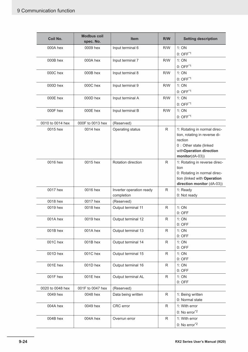
Coil No. Modbus coilspec. No. Item R/W Setting description
000A hex 0009 hex Input terminal 6 R/W 1: ON0: OFF*1
000B hex 000A hex Input terminal 7 R/W 1: ON0: OFF*1
000C hex 000B hex Input terminal 8 R/W 1: ON0: OFF*1
000D hex 000C hex Input terminal 9 R/W 1: ON0: OFF*1
000E hex 000D hex Input terminal A R/W 1: ON0: OFF*1
000F hex 000E hex Input terminal B R/W 1: ON0: OFF*1
0010 to 0014 hex 000F to 0013 hex (Reserved)0015 hex 0014 hex Operating status R 1: Rotating in normal direc-
tion, rotating in reverse di-rection0:Other state (linkedwithOperation directionmonitor(dA-03))
0016 hex 0015 hex Rotation direction R 1: Rotating in reverse direc-tion0: Rotating in normal direc-tion (linked with Operationdirection monitor (dA-03))
0017 hex 0016 hex Inverter operation readycompletion
R 1: Ready0: Not ready
0018 hex 0017 hex (Reserved)0019 hex 0018 hex Output terminal 11 R 1: ON
0: OFF001A hex 0019 hex Output terminal 12 R 1: ON
0: OFF001B hex 001A hex Output terminal 13 R 1: ON
0: OFF001C hex 001B hex Output terminal 14 R 1: ON
0: OFF001D hex 001C hex Output terminal 15 R 1: ON
0: OFF001E hex 001D hex Output terminal 16 R 1: ON
0: OFF001F hex 001E hex Output terminal AL R 1: ON
0: OFF0020 to 0048 hex 001F to 0047 hex (Reserved)
0049 hex 0048 hex Data being written R 1: Being written0: Normal state
004A hex 0049 hex CRC error R 1: With error0: No error*2
004B hex 004A hex Overrun error R 1: With error0: No error*2
9 Communication function
9-24 RX2 Series User’s Manual (I620)
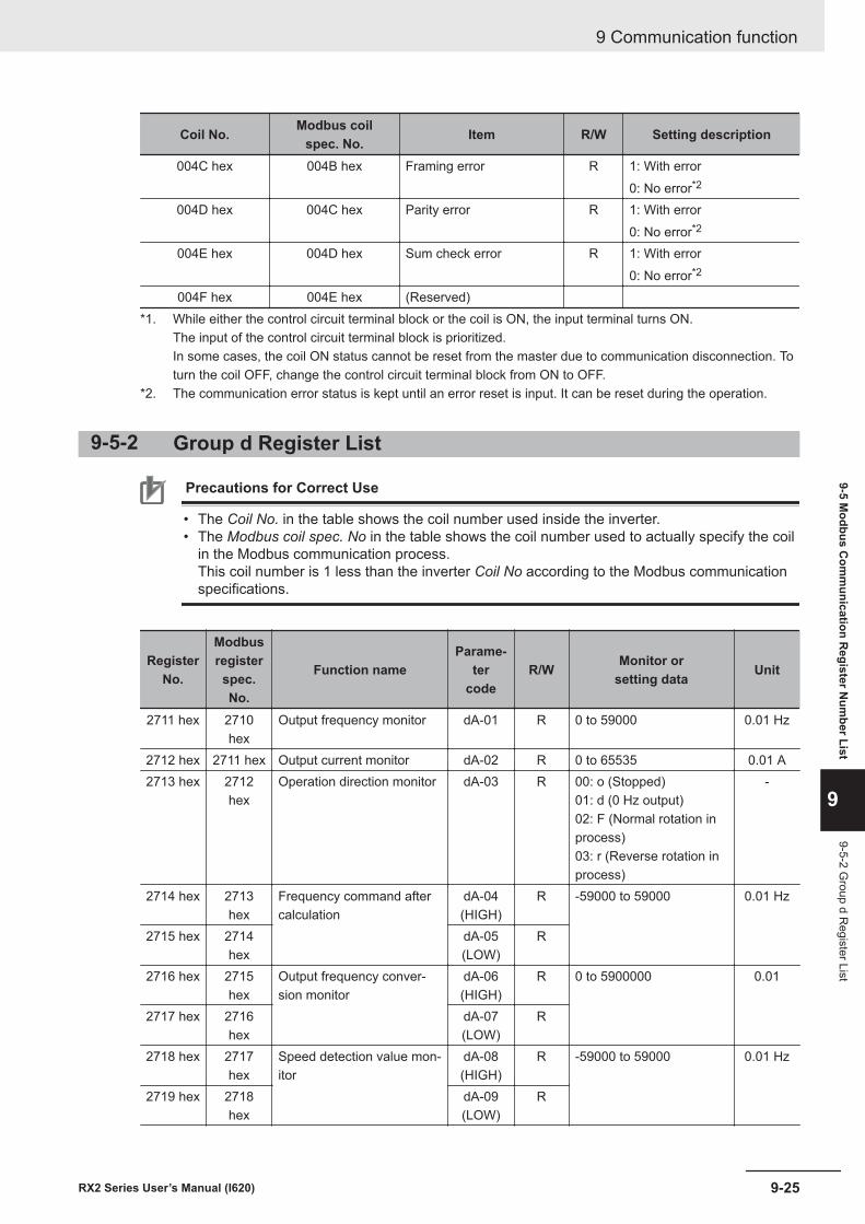
Coil No. Modbus coilspec. No. Item R/W Setting description
004C hex 004B hex Framing error R 1: With error0: No error*2
004D hex 004C hex Parity error R 1: With error0: No error*2
004E hex 004D hex Sum check error R 1: With error0: No error*2
004F hex 004E hex (Reserved)*1. While either the control circuit terminal block or the coil is ON, the input terminal turns ON.
The input of the control circuit terminal block is prioritized.In some cases, the coil ON status cannot be reset from the master due to communication disconnection. Toturn the coil OFF, change the control circuit terminal block from ON to OFF.
*2. The communication error status is kept until an error reset is input. It can be reset during the operation.
9-5-2 Group d Register List
Precautions for Correct Use
• The Coil No. in the table shows the coil number used inside the inverter.• The Modbus coil spec. No in the table shows the coil number used to actually specify the coil
in the Modbus communication process.This coil number is 1 less than the inverter Coil No according to the Modbus communicationspecifications.
RegisterNo.
Modbusregisterspec.No.
Function nameParame-
tercode
R/W Monitor orsetting data Unit
2711 hex 2710hex
Output frequency monitor dA-01 R 0 to 59000 0.01 Hz
2712 hex 2711 hex Output current monitor dA-02 R 0 to 65535 0.01 A2713 hex 2712
hexOperation direction monitor dA-03 R 00: o (Stopped)
01: d (0 Hz output)02: F (Normal rotation inprocess)03: r (Reverse rotation inprocess)
-
2714 hex 2713hex
Frequency command aftercalculation
dA-04(HIGH)
R -59000 to 59000 0.01 Hz
2715 hex 2714hex
dA-05(LOW)
R
2716 hex 2715hex
Output frequency conver-sion monitor
dA-06(HIGH)
R 0 to 5900000 0.01
2717 hex 2716hex
dA-07(LOW)
R
2718 hex 2717hex
Speed detection value mon-itor
dA-08(HIGH)
R -59000 to 59000 0.01 Hz
2719 hex 2718hex
dA-09(LOW)
R
9 Communication function
9-25RX2 Series User’s Manual (I620)
9-5 Modbus C
omm
unication Register N
umber List
9
9-5-2 Group d R
egister List
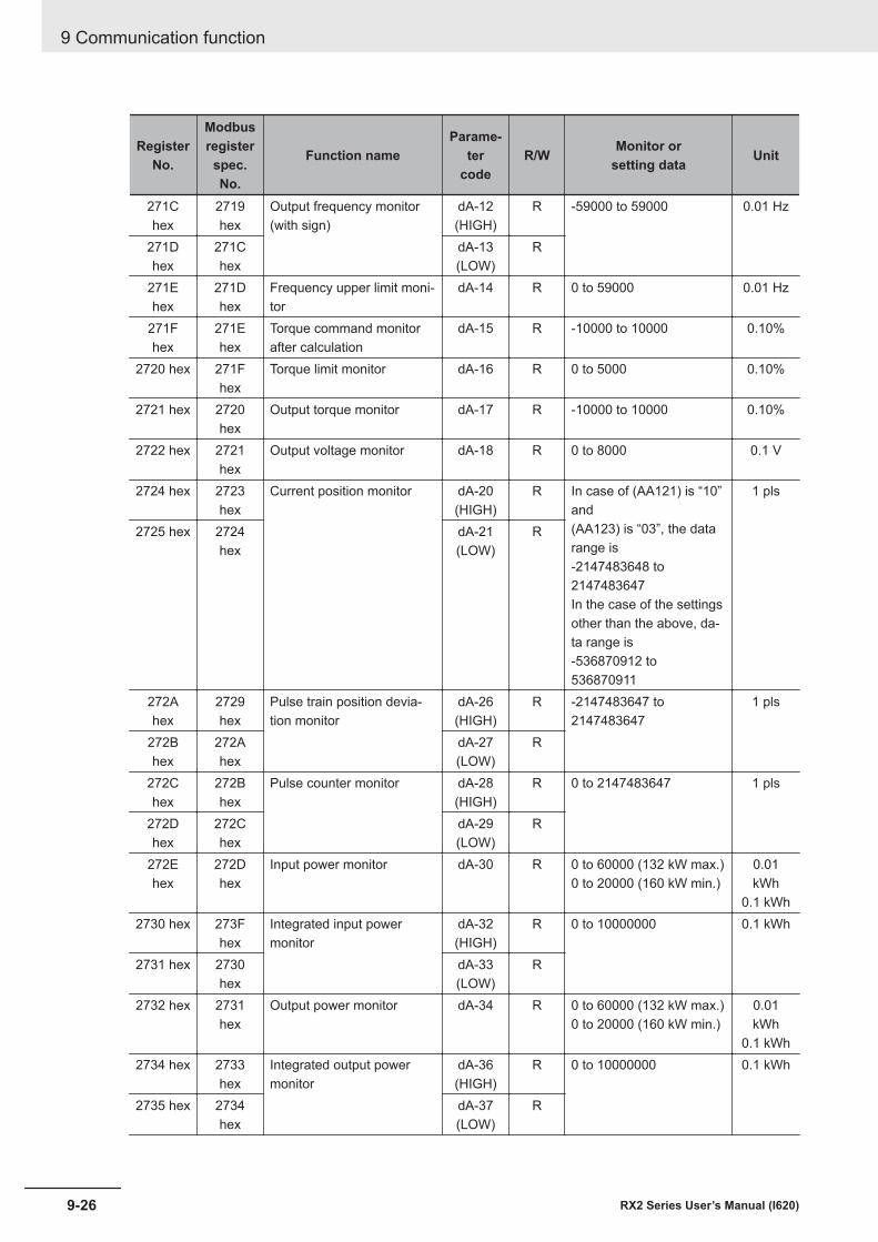
RegisterNo.
Modbusregisterspec.No.
Function nameParame-
tercode
R/W Monitor orsetting data Unit
271Chex
2719hex
Output frequency monitor(with sign)
dA-12(HIGH)
R -59000 to 59000 0.01 Hz
271Dhex
271Chex
dA-13(LOW)
R
271Ehex
271Dhex
Frequency upper limit moni-tor
dA-14 R 0 to 59000 0.01 Hz
271Fhex
271Ehex
Torque command monitorafter calculation
dA-15 R -10000 to 10000 0.10%
2720 hex 271Fhex
Torque limit monitor dA-16 R 0 to 5000 0.10%
2721 hex 2720hex
Output torque monitor dA-17 R -10000 to 10000 0.10%
2722 hex 2721hex
Output voltage monitor dA-18 R 0 to 8000 0.1 V
2724 hex 2723hex
Current position monitor dA-20(HIGH)
R In case of (AA121) is “10”and(AA123) is “03”, the datarange is-2147483648 to2147483647In the case of the settingsother than the above, da-ta range is-536870912 to536870911
1 pls
2725 hex 2724hex
dA-21(LOW)
R
272Ahex
2729hex
Pulse train position devia-tion monitor
dA-26(HIGH)
R -2147483647 to2147483647
1 pls
272Bhex
272Ahex
dA-27(LOW)
R
272Chex
272Bhex
Pulse counter monitor dA-28(HIGH)
R 0 to 2147483647 1 pls
272Dhex
272Chex
dA-29(LOW)
R
272Ehex
272Dhex
Input power monitor dA-30 R 0 to 60000 (132 kW max.)0 to 20000 (160 kW min.)
0.01kWh
0.1 kWh2730 hex 273F
hexIntegrated input powermonitor
dA-32(HIGH)
R 0 to 10000000 0.1 kWh
2731 hex 2730hex
dA-33(LOW)
R
2732 hex 2731hex
Output power monitor dA-34 R 0 to 60000 (132 kW max.)0 to 20000 (160 kW min.)
0.01kWh
0.1 kWh2734 hex 2733
hexIntegrated output powermonitor
dA-36(HIGH)
R 0 to 10000000 0.1 kWh
2735 hex 2734hex
dA-37(LOW)
R
9 Communication function
9-26 RX2 Series User’s Manual (I620)
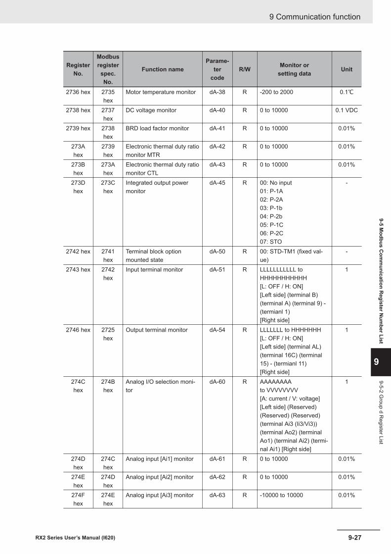
RegisterNo.
Modbusregisterspec.No.
Function nameParame-
tercode
R/W Monitor orsetting data Unit
2736 hex 2735hex
Motor temperature monitor dA-38 R -200 to 2000 0.1℃
2738 hex 2737hex
DC voltage monitor dA-40 R 0 to 10000 0.1 VDC
2739 hex 2738hex
BRD load factor monitor dA-41 R 0 to 10000 0.01%
273Ahex
2739hex
Electronic thermal duty ratiomonitor MTR
dA-42 R 0 to 10000 0.01%
273Bhex
273Ahex
Electronic thermal duty ratiomonitor CTL
dA-43 R 0 to 10000 0.01%
273Dhex
273Chex
Integrated output powermonitor
dA-45 R 00: No input01: P-1A02: P-2A03: P-1b04: P-2b05: P-1C06: P-2C07: STO
-
2742 hex 2741hex
Terminal block optionmounted state
dA-50 R 00: STD-TM1 (fixed val-ue)
-
2743 hex 2742hex
Input terminal monitor dA-51 R LLLLLLLLLLL toHHHHHHHHHHH[L: OFF / H: ON][Left side] (terminal B)(terminal A) (terminal 9) -(termianl 1)[Right side]
1
2746 hex 2725hex
Output terminal monitor dA-54 R LLLLLLL to HHHHHHH[L: OFF / H: ON][Left side] (terminal AL)(terminal 16C) (terminal15) - (termianl 11)[Right side]
1
274Chex
274Bhex
Analog I/O selection moni-tor
dA-60 R AAAAAAAAto VVVVVVVV[A: current / V: voltage][Left side] (Reserved)(Reserved) (Reserved)(terminal Ai3 (Ii3/Vi3))(terminal Ao2) (terminalAo1) (terminal Ai2) (termi-nal Ai1) [Right side]
1
274Dhex
274Chex
Analog input [Ai1] monitor dA-61 R 0 to 10000 0.01%
274Ehex
274Dhex
Analog input [Ai2] monitor dA-62 R 0 to 10000 0.01%
274Fhex
274Ehex
Analog input [Ai3] monitor dA-63 R -10000 to 10000 0.01%
9 Communication function
9-27RX2 Series User’s Manual (I620)
9-5 Modbus C
omm
unication Register N
umber List
9
9-5-2 Group d R
egister List
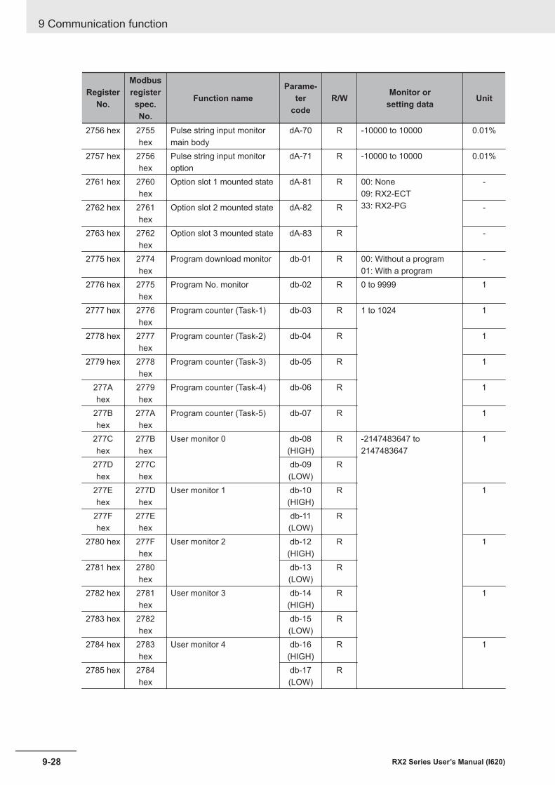
RegisterNo.
Modbusregisterspec.No.
Function nameParame-
tercode
R/W Monitor orsetting data Unit
2756 hex 2755hex
Pulse string input monitormain body
dA-70 R -10000 to 10000 0.01%
2757 hex 2756hex
Pulse string input monitoroption
dA-71 R -10000 to 10000 0.01%
2761 hex 2760hex
Option slot 1 mounted state dA-81 R 00: None09: RX2-ECT33: RX2-PG
-
2762 hex 2761hex
Option slot 2 mounted state dA-82 R -
2763 hex 2762hex
Option slot 3 mounted state dA-83 R -
2775 hex 2774hex
Program download monitor db-01 R 00: Without a program01: With a program
-
2776 hex 2775hex
Program No. monitor db-02 R 0 to 9999 1
2777 hex 2776hex
Program counter (Task-1) db-03 R 1 to 1024 1
2778 hex 2777hex
Program counter (Task-2) db-04 R 1
2779 hex 2778hex
Program counter (Task-3) db-05 R 1
277Ahex
2779hex
Program counter (Task-4) db-06 R 1
277Bhex
277Ahex
Program counter (Task-5) db-07 R 1
277Chex
277Bhex
User monitor 0 db-08(HIGH)
R -2147483647 to2147483647
1
277Dhex
277Chex
db-09(LOW)
R
277Ehex
277Dhex
User monitor 1 db-10(HIGH)
R 1
277Fhex
277Ehex
db-11(LOW)
R
2780 hex 277Fhex
User monitor 2 db-12(HIGH)
R 1
2781 hex 2780hex
db-13(LOW)
R
2782 hex 2781hex
User monitor 3 db-14(HIGH)
R 1
2783 hex 2782hex
db-15(LOW)
R
2784 hex 2783hex
User monitor 4 db-16(HIGH)
R 1
2785 hex 2784hex
db-17(LOW)
R
9 Communication function
9-28 RX2 Series User’s Manual (I620)
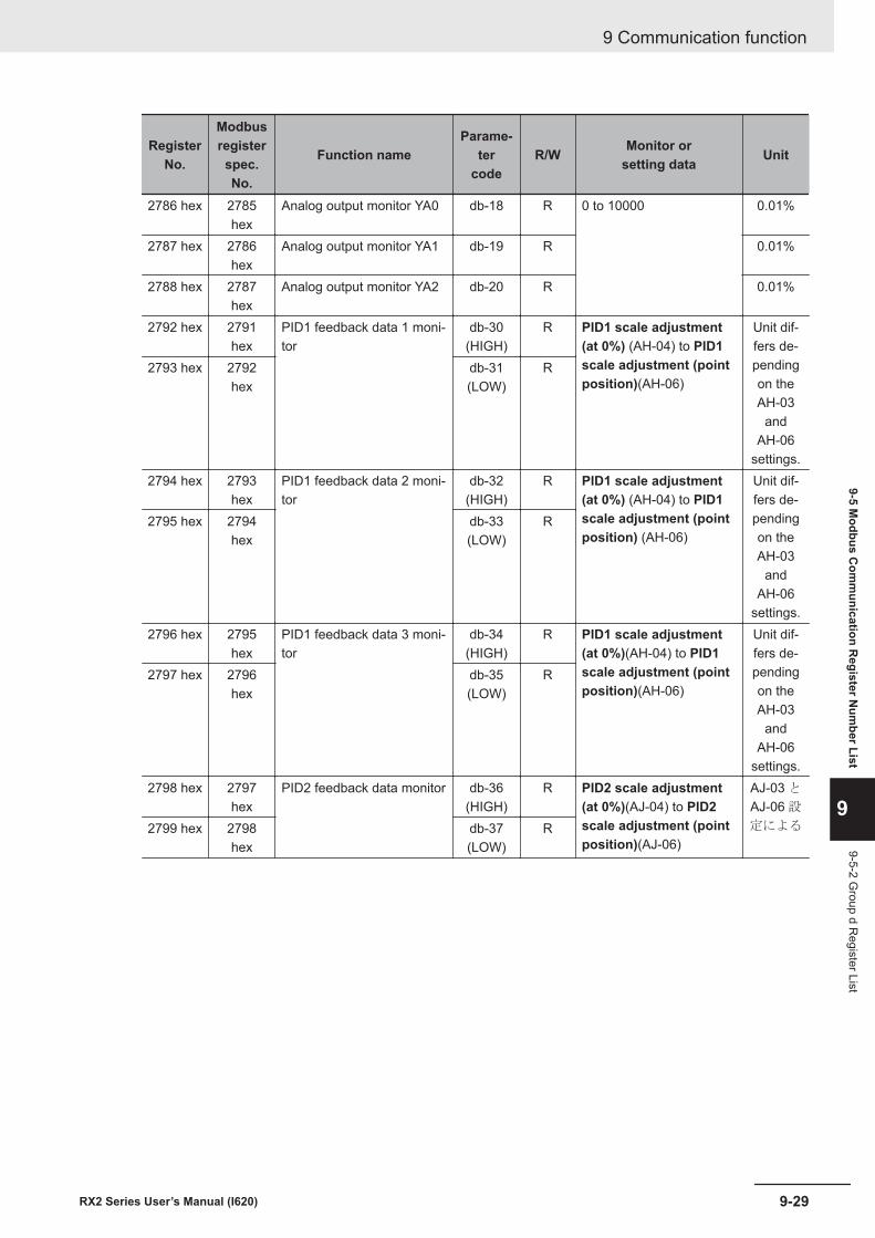
RegisterNo.
Modbusregisterspec.No.
Function nameParame-
tercode
R/W Monitor orsetting data Unit
2786 hex 2785hex
Analog output monitor YA0 db-18 R 0 to 10000 0.01%
2787 hex 2786hex
Analog output monitor YA1 db-19 R 0.01%
2788 hex 2787hex
Analog output monitor YA2 db-20 R 0.01%
2792 hex 2791hex
PID1 feedback data 1 moni-tor
db-30(HIGH)
R PID1 scale adjustment(at 0%) (AH-04) to PID1scale adjustment (pointposition)(AH-06)
Unit dif-fers de-pendingon theAH-03
andAH-06
settings.
2793 hex 2792hex
db-31(LOW)
R
2794 hex 2793hex
PID1 feedback data 2 moni-tor
db-32(HIGH)
R PID1 scale adjustment(at 0%) (AH-04) to PID1scale adjustment (pointposition) (AH-06)
Unit dif-fers de-pendingon theAH-03
andAH-06
settings.
2795 hex 2794hex
db-33(LOW)
R
2796 hex 2795hex
PID1 feedback data 3 moni-tor
db-34(HIGH)
R PID1 scale adjustment(at 0%)(AH-04) to PID1scale adjustment (pointposition)(AH-06)
Unit dif-fers de-pendingon theAH-03
andAH-06
settings.
2797 hex 2796hex
db-35(LOW)
R
2798 hex 2797hex
PID2 feedback data monitor db-36(HIGH)
R PID2 scale adjustment(at 0%)(AJ-04) to PID2scale adjustment (pointposition)(AJ-06)
AJ-03 と
AJ-06 設
定による2799 hex 2798hex
db-37(LOW)
R
9 Communication function
9-29RX2 Series User’s Manual (I620)
9-5 Modbus C
omm
unication Register N
umber List
9
9-5-2 Group d R
egister List
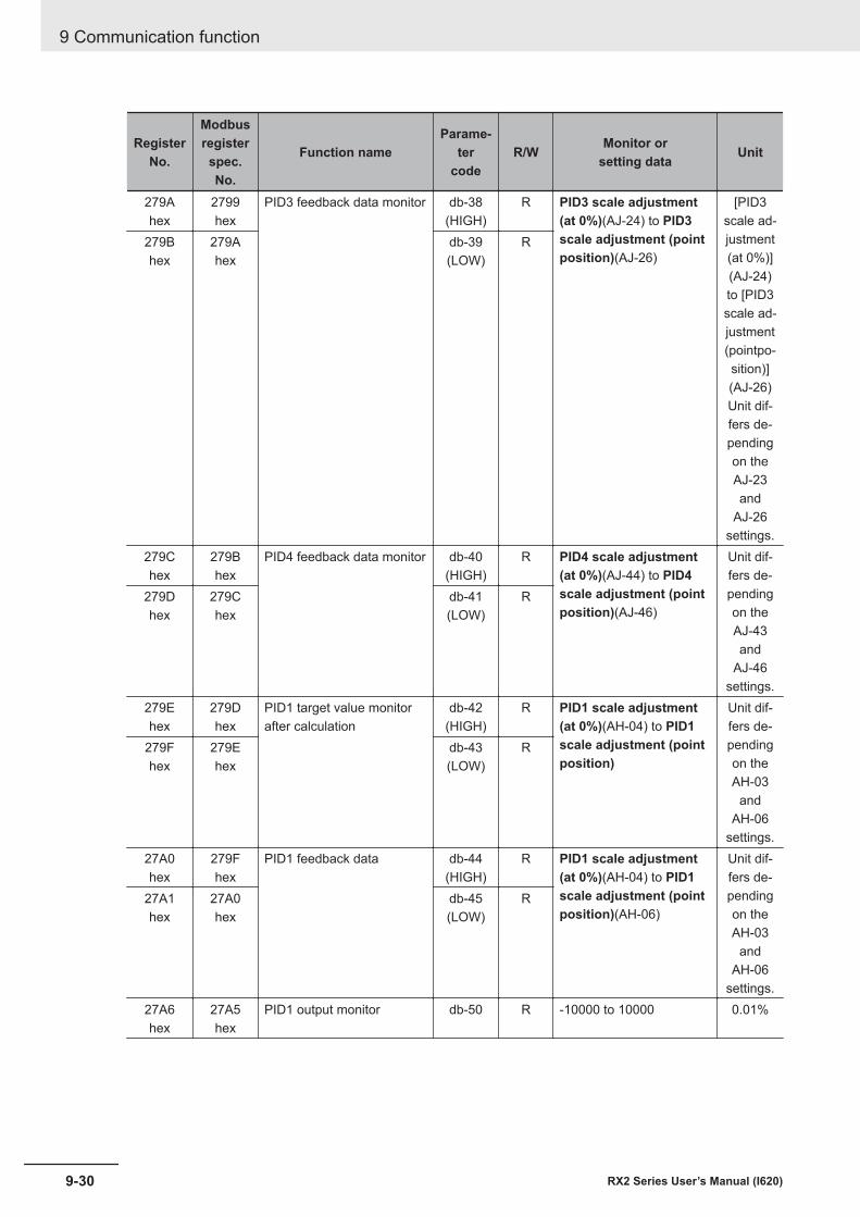
RegisterNo.
Modbusregisterspec.No.
Function nameParame-
tercode
R/W Monitor orsetting data Unit
279Ahex
2799hex
PID3 feedback data monitor db-38(HIGH)
R PID3 scale adjustment(at 0%)(AJ-24) to PID3scale adjustment (pointposition)(AJ-26)
[PID3scale ad-justment(at 0%)](AJ-24)to [PID3scale ad-justment(pointpo-sition)](AJ-26)Unit dif-fers de-pendingon theAJ-23and
AJ-26settings.
279Bhex
279Ahex
db-39(LOW)
R
279Chex
279Bhex
PID4 feedback data monitor db-40(HIGH)
R PID4 scale adjustment(at 0%)(AJ-44) to PID4scale adjustment (pointposition)(AJ-46)
Unit dif-fers de-pendingon theAJ-43and
AJ-46settings.
279Dhex
279Chex
db-41(LOW)
R
279Ehex
279Dhex
PID1 target value monitorafter calculation
db-42(HIGH)
R PID1 scale adjustment(at 0%)(AH-04) to PID1scale adjustment (pointposition)
Unit dif-fers de-pendingon theAH-03
andAH-06
settings.
279Fhex
279Ehex
db-43(LOW)
R
27A0hex
279Fhex
PID1 feedback data db-44(HIGH)
R PID1 scale adjustment(at 0%)(AH-04) to PID1scale adjustment (pointposition)(AH-06)
Unit dif-fers de-pendingon theAH-03
andAH-06
settings.
27A1hex
27A0hex
db-45(LOW)
R
27A6hex
27A5hex
PID1 output monitor db-50 R -10000 to 10000 0.01%
9 Communication function
9-30 RX2 Series User’s Manual (I620)
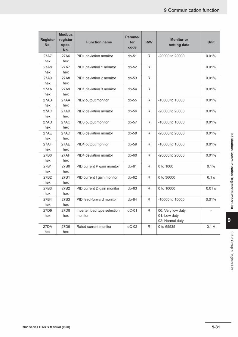
RegisterNo.
Modbusregisterspec.No.
Function nameParame-
tercode
R/W Monitor orsetting data Unit
27A7hex
27A6hex
PID1 deviation monitor db-51 R -20000 to 20000 0.01%
27A8hex
27A7hex
PID1 deviation 1 monitor db-52 R 0.01%
27A9hex
27A8hex
PID1 deviation 2 monitor db-53 R 0.01%
27AAhex
27A9hex
PID1 deviation 3 monitor db-54 R 0.01%
27ABhex
27AAhex
PID2 output monitor db-55 R -10000 to 10000 0.01%
27AChex
27ABhex
PID2 deviation monitor db-56 R -20000 to 20000 0.01%
27ADhex
27AChex
PID3 output monitor db-57 R -10000 to 10000 0.01%
27AEhex
27ADhex
PID3 deviation monitor db-58 R -20000 to 20000 0.01%
27AFhex
27AEhex
PID4 output monitor db-59 R -10000 to 10000 0.01%
27B0hex
27AFhex
PID4 deviation monitor db-60 R -20000 to 20000 0.01%
27B1hex
27B0hex
PID current P gain monitor db-61 R 0 to 1000 0.1%
27B2hex
27B1hex
PID current I gain monitor db-62 R 0 to 36000 0.1 s
27B3hex
27B2hex
PID current D gain monitor db-63 R 0 to 10000 0.01 s
27B4hex
27B3hex
PID feed-forward monitor db-64 R -10000 to 10000 0.01%
27D9hex
27D8hex
Inverter load type selectionmonitor
dC-01 R 00: Very low duty01: Low duty02: Normal duty
-
27DAhex
27D9hex
Rated current monitor dC-02 R 0 to 65535 0.1 A
9 Communication function
9-31RX2 Series User’s Manual (I620)
9-5 Modbus C
omm
unication Register N
umber List
9
9-5-2 Group d R
egister List
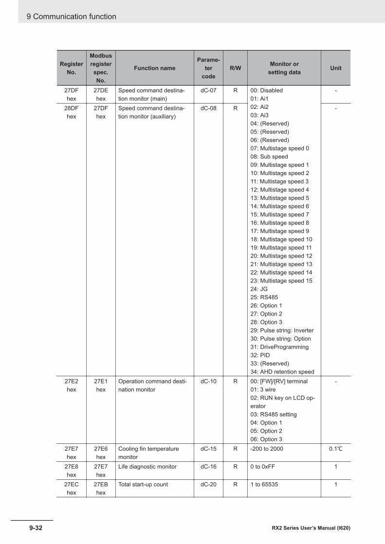
RegisterNo.
Modbusregisterspec.No.
Function nameParame-
tercode
R/W Monitor orsetting data Unit
27DFhex
27DEhex
Speed command destina-tion monitor (main)
dC-07 R 00: Disabled01: Ai102: Ai203: Ai304: (Reserved)05: (Reserved)06: (Reserved)07: Multistage speed 008: Sub speed09: Multistage speed 110: Multistage speed 211: Multistage speed 312: Multistage speed 413: Multistage speed 514: Multistage speed 615: Multistage speed 716: Multistage speed 817: Multistage speed 918: Multistage speed 1019: Multistage speed 1120: Multistage speed 1221: Multistage speed 1322: Multistage speed 1423: Multistage speed 1524: JG25: RS48526: Option 127: Option 228: Option 329: Pulse string: Inverter30: Pulse string: Option31: DriveProgramming32: PID33: (Reserved)34: AHD retention speed
-
28DFhex
27DFhex
Speed command destina-tion monitor (auxiliary)
dC-08 R -
27E2hex
27E1hex
Operation command desti-nation monitor
dC-10 R 00: [FW]/[RV] terminal01: 3 wire02: RUN key on LCD op-erator03: RS485 setting04: Option 105: Option 206: Option 3
-
27E7hex
27E6hex
Cooling fin temperaturemonitor
dC-15 R -200 to 2000 0.1℃
27E8hex
27E7hex
Life diagnostic monitor dC-16 R 0 to 0xFF 1
27EChex
27EBhex
Total start-up count dC-20 R 1 to 65535 1
9 Communication function
9-32 RX2 Series User’s Manual (I620)
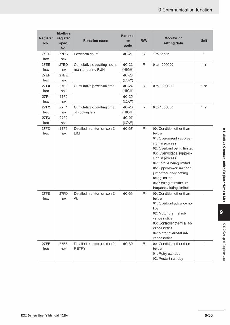
RegisterNo.
Modbusregisterspec.No.
Function nameParame-
tercode
R/W Monitor orsetting data Unit
27EDhex
27EChex
Power-on count dC-21 R 1 to 65535 1
27EEhex
27EDhex
Cumulative operating hoursmonitor during RUN
dC-22(HIGH)
R 0 to 1000000 1 hr
27EFhex
27EEhex
dC-23(LOW)
27F0hex
27EFhex
Cumulative power-on time dC-24(HIGH)
R 0 to 1000000 1 hr
27F1hex
27F0hex
dC-25(LOW)
27F2hex
27F1hex
Cumulative operating timeof cooling fan
dC-26(HIGH)
R 0 to 1000000 1 hr
27F3hex
27F2hex
dC-27(LOW)
27FDhex
27F3hex
Detailed monitor for icon 2LIM
dC-37 R 00: Condition other thanbelow01: Overcurrent suppres-sion in process02: Overload being limited03: Overvoltage suppres-sion in process04: Torque being limited05: Upper/lower limit andjump frequency settingbeing limited06: Setting of minimumfrequency being limited
-
27FEhex
27FDhex
Detailed monitor for icon 2ALT
dC-38 R 00: Condition other thanbelow01: Overload advance no-tice02: Motor thermal ad-vance notice03: Controller thermal ad-vance notice04: Motor overheat ad-vance notice
-
27FFhex
27FEhex
Detailed monitor for icon 2RETRY
dC-39 R 00: Condition other thanbelow01: Retry standby02: Restart standby
-
9 Communication function
9-33RX2 Series User’s Manual (I620)
9-5 Modbus C
omm
unication Register N
umber List
9
9-5-2 Group d R
egister List
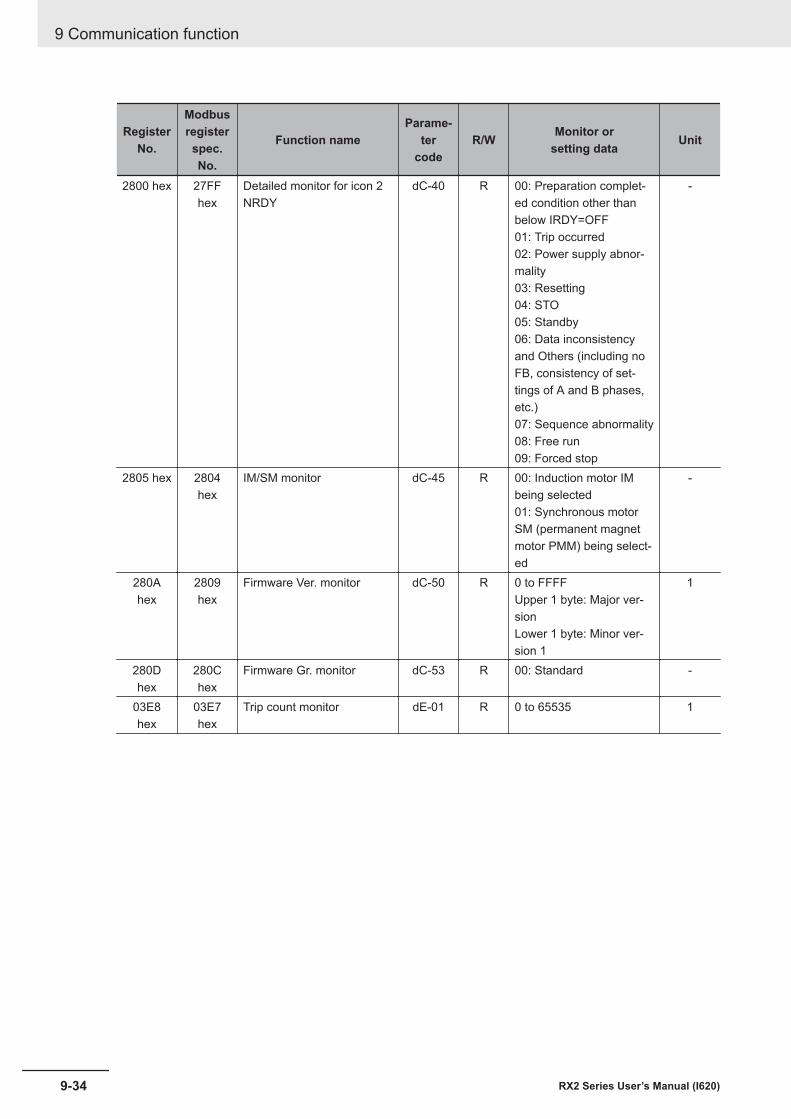
RegisterNo.
Modbusregisterspec.No.
Function nameParame-
tercode
R/W Monitor orsetting data Unit
2800 hex 27FFhex
Detailed monitor for icon 2NRDY
dC-40 R 00: Preparation complet-ed condition other thanbelow IRDY=OFF01: Trip occurred02: Power supply abnor-mality03: Resetting04: STO05: Standby06: Data inconsistencyand Others (including noFB, consistency of set-tings of A and B phases,etc.)07: Sequence abnormality08: Free run09: Forced stop
-
2805 hex 2804hex
IM/SM monitor dC-45 R 00: Induction motor IMbeing selected01: Synchronous motorSM (permanent magnetmotor PMM) being select-ed
-
280Ahex
2809hex
Firmware Ver. monitor dC-50 R 0 to FFFFUpper 1 byte: Major ver-sionLower 1 byte: Minor ver-sion 1
1
280Dhex
280Chex
Firmware Gr. monitor dC-53 R 00: Standard -
03E8hex
03E7hex
Trip count monitor dE-01 R 0 to 65535 1
9 Communication function
9-34 RX2 Series User’s Manual (I620)
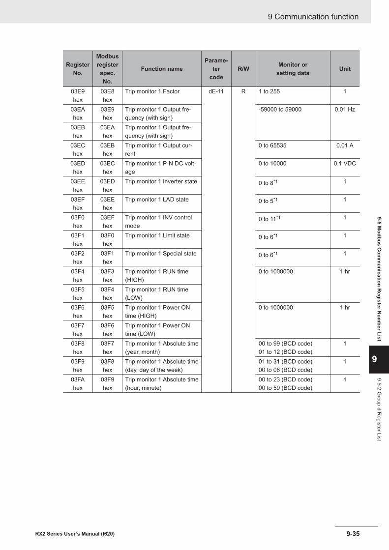
RegisterNo.
Modbusregisterspec.No.
Function nameParame-
tercode
R/W Monitor orsetting data Unit
03E9hex
03E8hex
Trip monitor 1 Factor dE-11 R 1 to 255 1
03EAhex
03E9hex
Trip monitor 1 Output fre-quency (with sign)
-59000 to 59000 0.01 Hz
03EBhex
03EAhex
Trip monitor 1 Output fre-quency (with sign)
03EChex
03EBhex
Trip monitor 1 Output cur-rent
0 to 65535 0.01 A
03EDhex
03EChex
Trip monitor 1 P-N DC volt-age
0 to 10000 0.1 VDC
03EEhex
03EDhex
Trip monitor 1 Inverter state 0 to 8*1 1
03EFhex
03EEhex
Trip monitor 1 LAD state 0 to 5*1 1
03F0hex
03EFhex
Trip monitor 1 INV controlmode
0 to 11*1 1
03F1hex
03F0hex
Trip monitor 1 Limit state 0 to 6*1 1
03F2hex
03F1hex
Trip monitor 1 Special state 0 to 6*1 1
03F4hex
03F3hex
Trip monitor 1 RUN time(HIGH)
0 to 1000000 1 hr
03F5hex
03F4hex
Trip monitor 1 RUN time(LOW)
03F6hex
03F5hex
Trip monitor 1 Power ONtime (HIGH)
0 to 1000000 1 hr
03F7hex
03F6hex
Trip monitor 1 Power ONtime (LOW)
03F8hex
03F7hex
Trip monitor 1 Absolute time(year, month)
00 to 99 (BCD code)01 to 12 (BCD code)
1
03F9hex
03F8hex
Trip monitor 1 Absolute time(day, day of the week)
01 to 31 (BCD code)00 to 06 (BCD code)
1
03FAhex
03F9hex
Trip monitor 1 Absolute time(hour, minute)
00 to 23 (BCD code)00 to 59 (BCD code)
1
9 Communication function
9-35RX2 Series User’s Manual (I620)
9-5 Modbus C
omm
unication Register N
umber List
9
9-5-2 Group d R
egister List

RegisterNo.
Modbusregisterspec.No.
Function nameParame-
tercode
R/W Monitor orsetting data Unit
03FDhex
03FChex
Trip monitor 2 Factor dE-12 R 1 to 255 1
03FEhex
03FDhex
Trip monitor 2 Output fre-quency (with sign) (HIGH)
-59000 to 59000 0.01 Hz
03FFhex
03FEhex
Trip monitor 2 Output fre-quency (with sign) (LOW)
0400 hex 03FFhex
Trip monitor 2 Output cur-rent
0 to 65535 0.01 A
0401 hex 0400hex
Trip monitor 2 P-N DC volt-age
0 to 10000 0.1 VDC
0402 hex 0401hex
Trip monitor 2 Inverter state 0 to 8*1 1
0403 hex 0402hex
Trip monitor 2 LAD state 0 to 5*1 1
0404 hex 0403hex
Trip monitor 2 INV controlmode
0 to 11*1 1
0405 hex 0404hex
Trip monitor 2 Limit state 0 to 6*1 1
0406 hex 0405hex
Trip monitor 2 Special state 0 to 6*1 1
0408 hex 0407hex
Trip monitor 2 RUN time(HIGH)
0 to 1000000 1 hr
0409 hex 0408hex
Trip monitor 2 RUN time(LOW)
040Ahex
0409hex
Trip monitor 2 Power ONtime (HIGH)
0 to 1000000 1 hr
040Bhex
040Ahex
Trip monitor 2 Power ONtime (LOW)
040Chex
040Bhex
Trip monitor 2 Absolute time(year, month)
00 to 99 (BCD code)01 to 12 (BCD code)
-
040Dhex
040Chex
Trip monitor 2 Absolute time(day, day of the week)
01 to 31 (BCD code)00 to 06 (BCD code)
-
040Ehex
040Dhex
Trip monitor 2 Absolute time(hour, minute)
00 to 23 (BCD code)00 to 59 (BCD code)
-
9 Communication function
9-36 RX2 Series User’s Manual (I620)

RegisterNo.
Modbusregisterspec.No.
Function nameParame-
tercode
R/W Monitor orsetting data Unit
0411 hex 0410hex
Trip monitor 3 Factor dE-13 R 1 to 255 -
0412 hex 0411 hex Trip monitor 3 Output fre-quency (with sign) (HIGH)
-59000 to 59000 0.01 Hz
0413 hex 0412hex
Trip monitor 3 Output fre-quency (with sign) (LOW)
0414 hex 0413hex
Trip monitor 3 Output cur-rent
0 to 65535 0.01 A
0415 hex 0414hex
Trip monitor 3 P-N DC volt-age
0 to 10000 0.1 VDC
0416 hex 0415hex
Trip monitor 3 Inverter state 0 to 8*1 1
0417 hex 0416hex
Trip monitor 3 LAD state 0 to 5*1 1
0418 hex 0417hex
Trip monitor 3 INV controlmode
0 to 11*1 1
0419 hex 0418hex
Trip monitor 3 Limit state 0 to 6*1 1
041Ahex
0419hex
Trip monitor 3 Special state 0 to 6*1 1
041Chex
041Bhex
Trip monitor 3 RUN time(HIGH)
0 to 1000000 1 hr
041Dhex
041Chex
Trip monitor 3 RUN time(LOW)
041Ehex
041Dhex
Trip monitor 3 Power ONtime (HIGH)
0 to 1000000 1 hr
041Fhex
041Ehex
Trip monitor 3 Power ONtime (LOW)
0420 hex 041Fhex
Trip monitor 3 Absolute time(year, month)
00 to 99 (BCD code)01 to 12 (BCD code)
-
0421 hex 0420hex
Trip monitor 3 Absolute time(day, day of the week)
01 to 31 (BCD code)00 to 06 (BCD code)
-
0422 hex 0421hex
Trip monitor 3 Absolute time(hour, minute)
00 to 23 (BCD code)00 to 59 (BCD code)
-
9 Communication function
9-37RX2 Series User’s Manual (I620)
9-5 Modbus C
omm
unication Register N
umber List
9
9-5-2 Group d R
egister List
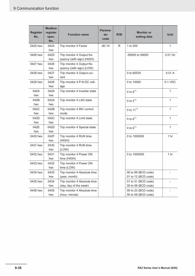
RegisterNo.
Modbusregisterspec.No.
Function nameParame-
tercode
R/W Monitor orsetting data Unit
0425 hex 0424hex
Trip monitor 4 Factor dE-14 R 1 to 255 1
0426 hex 0425hex
Trip monitor 4 Output fre-quency (with sign) (HIGH)
-59000 to 59000 0.01 Hz
0427 hex 0426hex
Trip monitor 4 Output fre-quency (with sign) (LOW)
0428 hex 0427hex
Trip monitor 4 Output cur-rent
0 to 65535 0.01 A
0429 hex 0428hex
Trip monitor 4 P-N DC volt-age
0 to 10000 0.1 VDC
042Ahex
0429hex
Trip monitor 4 Inverter state 0 to 8*1 1
042Bhex
042Ahex
Trip monitor 4 LAD state 0 to 5*1 1
042Chex
042Bhex
Trip monitor 4 INV controlmode
0 to 11*1 1
042Dhex
042Chex
Trip monitor 4 Limit state 0 to 6*1 1
042Ehex
042Dhex
Trip monitor 4 Special state 0 to 6*1 1
0430 hex 042Fhex
Trip monitor 4 RUN time(HIGH)
0 to 1000000 1 hr
0431 hex 0430hex
Trip monitor 4 RUN time(LOW)
0432 hex 0431hex
Trip monitor 4 Power ONtime (HIGH)
0 to 1000000 1 hr
0433 hex 0432hex
Trip monitor 4 Power ONtime (LOW)
0434 hex 0433hex
Trip monitor 4 Absolute time(year, month)
00 to 99 (BCD code)01 to 12 (BCD code)
-
0435 hex 0434hex
Trip monitor 4 Absolute time(day, day of the week)
01 to 31 (BCD code)00 to 06 (BCD code)
-
0436 hex 0435hex
Trip monitor 4 Absolute time(hour, minute)
00 to 23 (BCD code)00 to 59 (BCD code)
-
9 Communication function
9-38 RX2 Series User’s Manual (I620)

RegisterNo.
Modbusregisterspec.No.
Function nameParame-
tercode
R/W Monitor orsetting data Unit
0439 hex 0438hex
Trip monitor 5 Factor dE-15 R 1 to 255 1
043Ahex
0439hex
Trip monitor 5 Output fre-quency (with sign) (HIGH)
-59000 to 59000 0.01 Hz
043Bhex
043Ahex
Trip monitor 5 Output fre-quency (with sign) (LOW)
043Chex
043Bhex
Trip monitor 5 Output cur-rent
0 to 65535 0.01 A
043Dhex
043Chex
Trip monitor 5 P-N DC volt-age
0 to 10000 0.1 VDC
043Ehex
043Dhex
Trip monitor 5 Inverter state 0 to 8*1 1
043Fhex
043Ehex
Trip monitor 5 LAD state 0 to 5*1 1
0440 hex 043Fhex
Trip monitor 5 INV controlmode
0 to 11*1 1
0441 hex 0440hex
Trip monitor 5 Limit state 0 to 6*1 1
0442 hex 0441hex
Trip monitor 5 Special state 0 to 6*1 1
0444 hex 0443hex
Trip monitor 5 RUN time(HIGH)
0 to 1000000 1 hr
0445 hex 0444hex
Trip monitor 5 RUN time(LOW)
0446 hex 0445hex
Trip monitor 5 Power ONtime (HIGH)
0 to 1000000 1 hr
0447 hex 0446hex
Trip monitor 5 Power ONtime (LOW)
0448 hex 0447hex
Trip monitor 5 Absolute time(year, month)
00 to 99 (BCD code)01 to 12 (BCD code)
-
0449 hex 0448hex
Trip monitor 5 Absolute time(day, day of the week)
01 to 31 (BCD code)00 to 06 (BCD code)
-
044Ahex
0449hex
Trip monitor 5 Absolute time(hour, minute)
00 to 23 (BCD code)00 to 59 (BCD code)
-
9 Communication function
9-39RX2 Series User’s Manual (I620)
9-5 Modbus C
omm
unication Register N
umber List
9
9-5-2 Group d R
egister List
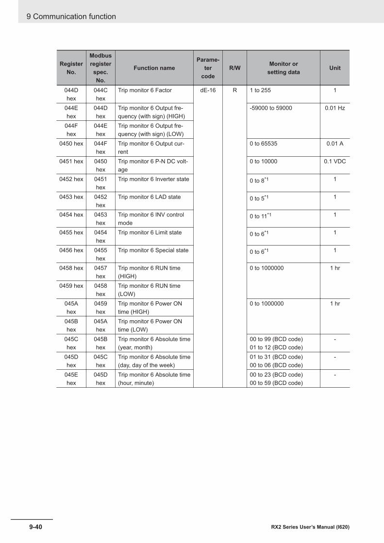
RegisterNo.
Modbusregisterspec.No.
Function nameParame-
tercode
R/W Monitor orsetting data Unit
044Dhex
044Chex
Trip monitor 6 Factor dE-16 R 1 to 255 1
044Ehex
044Dhex
Trip monitor 6 Output fre-quency (with sign) (HIGH)
-59000 to 59000 0.01 Hz
044Fhex
044Ehex
Trip monitor 6 Output fre-quency (with sign) (LOW)
0450 hex 044Fhex
Trip monitor 6 Output cur-rent
0 to 65535 0.01 A
0451 hex 0450hex
Trip monitor 6 P-N DC volt-age
0 to 10000 0.1 VDC
0452 hex 0451hex
Trip monitor 6 Inverter state 0 to 8*1 1
0453 hex 0452hex
Trip monitor 6 LAD state 0 to 5*1 1
0454 hex 0453hex
Trip monitor 6 INV controlmode
0 to 11*1 1
0455 hex 0454hex
Trip monitor 6 Limit state 0 to 6*1 1
0456 hex 0455hex
Trip monitor 6 Special state 0 to 6*1 1
0458 hex 0457hex
Trip monitor 6 RUN time(HIGH)
0 to 1000000 1 hr
0459 hex 0458hex
Trip monitor 6 RUN time(LOW)
045Ahex
0459hex
Trip monitor 6 Power ONtime (HIGH)
0 to 1000000 1 hr
045Bhex
045Ahex
Trip monitor 6 Power ONtime (LOW)
045Chex
045Bhex
Trip monitor 6 Absolute time(year, month)
00 to 99 (BCD code)01 to 12 (BCD code)
-
045Dhex
045Chex
Trip monitor 6 Absolute time(day, day of the week)
01 to 31 (BCD code)00 to 06 (BCD code)
-
045Ehex
045Dhex
Trip monitor 6 Absolute time(hour, minute)
00 to 23 (BCD code)00 to 59 (BCD code)
-
9 Communication function
9-40 RX2 Series User’s Manual (I620)
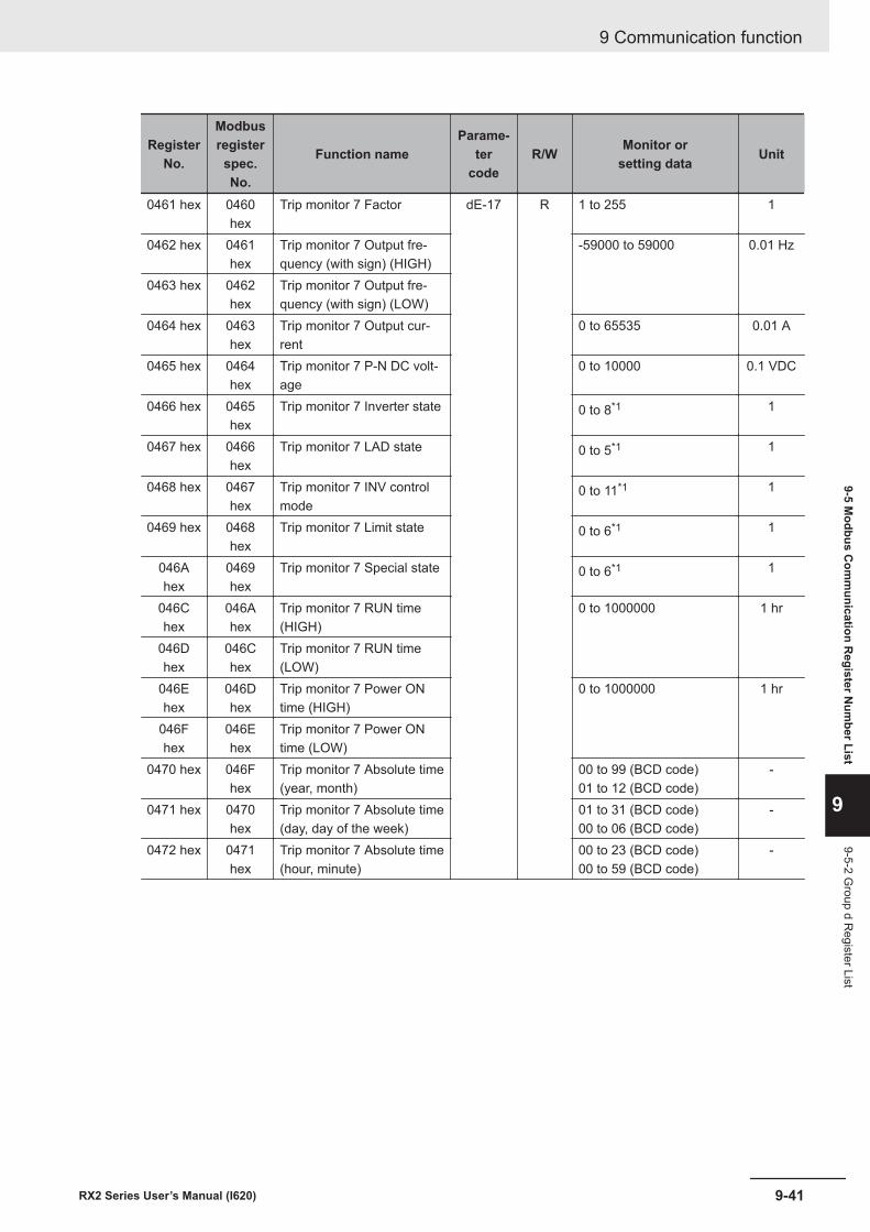
RegisterNo.
Modbusregisterspec.No.
Function nameParame-
tercode
R/W Monitor orsetting data Unit
0461 hex 0460hex
Trip monitor 7 Factor dE-17 R 1 to 255 1
0462 hex 0461hex
Trip monitor 7 Output fre-quency (with sign) (HIGH)
-59000 to 59000 0.01 Hz
0463 hex 0462hex
Trip monitor 7 Output fre-quency (with sign) (LOW)
0464 hex 0463hex
Trip monitor 7 Output cur-rent
0 to 65535 0.01 A
0465 hex 0464hex
Trip monitor 7 P-N DC volt-age
0 to 10000 0.1 VDC
0466 hex 0465hex
Trip monitor 7 Inverter state 0 to 8*1 1
0467 hex 0466hex
Trip monitor 7 LAD state 0 to 5*1 1
0468 hex 0467hex
Trip monitor 7 INV controlmode
0 to 11*1 1
0469 hex 0468hex
Trip monitor 7 Limit state 0 to 6*1 1
046Ahex
0469hex
Trip monitor 7 Special state 0 to 6*1 1
046Chex
046Ahex
Trip monitor 7 RUN time(HIGH)
0 to 1000000 1 hr
046Dhex
046Chex
Trip monitor 7 RUN time(LOW)
046Ehex
046Dhex
Trip monitor 7 Power ONtime (HIGH)
0 to 1000000 1 hr
046Fhex
046Ehex
Trip monitor 7 Power ONtime (LOW)
0470 hex 046Fhex
Trip monitor 7 Absolute time(year, month)
00 to 99 (BCD code)01 to 12 (BCD code)
-
0471 hex 0470hex
Trip monitor 7 Absolute time(day, day of the week)
01 to 31 (BCD code)00 to 06 (BCD code)
-
0472 hex 0471hex
Trip monitor 7 Absolute time(hour, minute)
00 to 23 (BCD code)00 to 59 (BCD code)
-
9 Communication function
9-41RX2 Series User’s Manual (I620)
9-5 Modbus C
omm
unication Register N
umber List
9
9-5-2 Group d R
egister List

RegisterNo.
Modbusregisterspec.No.
Function nameParame-
tercode
R/W Monitor orsetting data Unit
0475 hex 0474hex
Trip monitor 8 Factor dE-18 R 1 to 255 1
0476 hex 0475hex
Trip monitor 8 Output fre-quency (with sign) (HIGH)
-59000 to 59000 0.01 Hz
0477 hex 0476hex
Trip monitor 8 Output fre-quency (with sign) (LOW)
0478 hex 0477hex
Trip monitor 8 Output cur-rent
0 to 65535 0.01 A
0479 hex 0478hex
Trip monitor 8 P-N DC volt-age
0 to 10000 0.1 VDC
047Ahex
0479hex
Trip monitor 8 Inverter state 0 to 8*1 1
047Bhex
047Ahex
Trip monitor 8 LAD state 0 to 5*1 1
047Chex
047Bhex
Trip monitor 8 INV controlmode
0 to 11*1 1
047Dhex
047Chex
Trip monitor 8 Limit state 0 to 6*1 1
047Ehex
047Dhex
Trip monitor 8 Special state 0 to 6*1 1
0480 hex 047Ehex
Trip monitor 8 RUN time(HIGH)
0 to 1000000 1 hr
0481 hex 0480hex
Trip monitor 8 RUN time(LOW)
0482 hex 0481hex
Trip monitor 8 Power ONtime (HIGH)
0 to 1000000 1 hr
0483 hex 0482hex
Trip monitor 8 Power ONtime (LOW)
0484 hex 0483hex
Trip monitor 8 Absolute time(year, month)
00 to 99 (BCD code)01 to 12 (BCD code)
-
0485 hex 0484hex
Trip monitor 8 Absolute time(day, day of the week)
01 to 31 (BCD code)00 to 06 (BCD code)
-
0486 hex 0485hex
Trip monitor 8 Absolute time(hour, minute)
00 to 23 (BCD code)00 to 59 (BCD code)
-
9 Communication function
9-42 RX2 Series User’s Manual (I620)
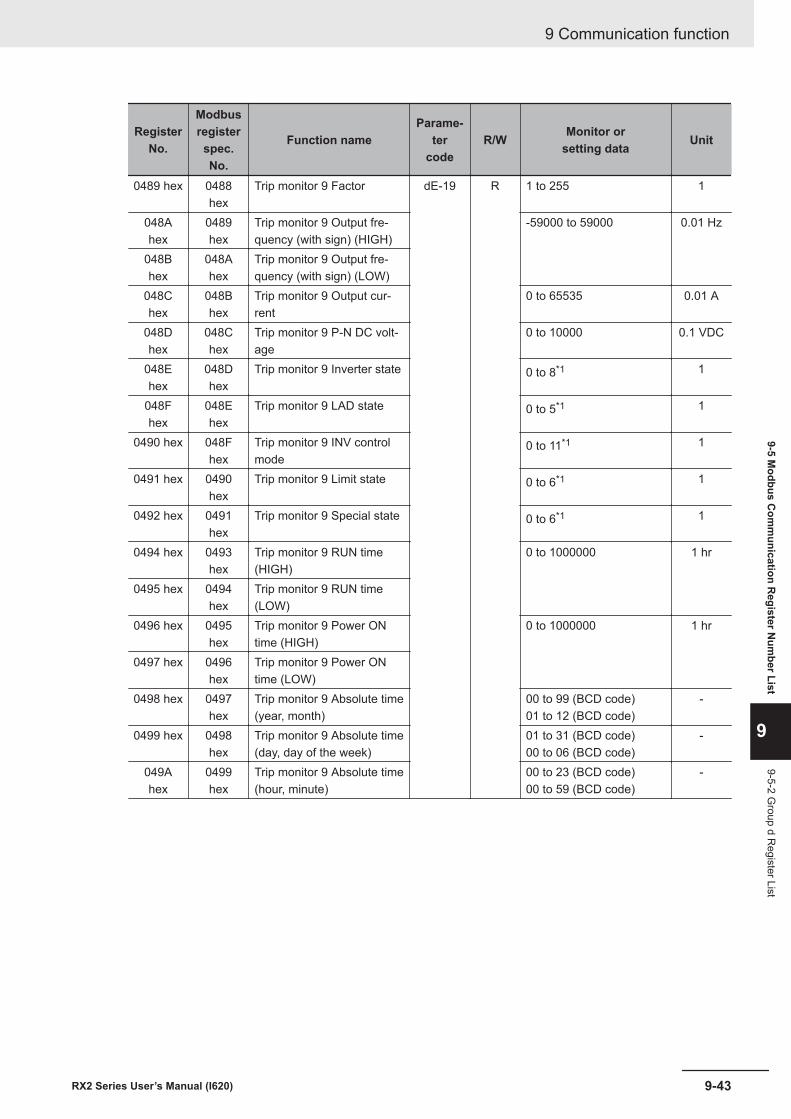
RegisterNo.
Modbusregisterspec.No.
Function nameParame-
tercode
R/W Monitor orsetting data Unit
0489 hex 0488hex
Trip monitor 9 Factor dE-19 R 1 to 255 1
048Ahex
0489hex
Trip monitor 9 Output fre-quency (with sign) (HIGH)
-59000 to 59000 0.01 Hz
048Bhex
048Ahex
Trip monitor 9 Output fre-quency (with sign) (LOW)
048Chex
048Bhex
Trip monitor 9 Output cur-rent
0 to 65535 0.01 A
048Dhex
048Chex
Trip monitor 9 P-N DC volt-age
0 to 10000 0.1 VDC
048Ehex
048Dhex
Trip monitor 9 Inverter state 0 to 8*1 1
048Fhex
048Ehex
Trip monitor 9 LAD state 0 to 5*1 1
0490 hex 048Fhex
Trip monitor 9 INV controlmode
0 to 11*1 1
0491 hex 0490hex
Trip monitor 9 Limit state 0 to 6*1 1
0492 hex 0491hex
Trip monitor 9 Special state 0 to 6*1 1
0494 hex 0493hex
Trip monitor 9 RUN time(HIGH)
0 to 1000000 1 hr
0495 hex 0494hex
Trip monitor 9 RUN time(LOW)
0496 hex 0495hex
Trip monitor 9 Power ONtime (HIGH)
0 to 1000000 1 hr
0497 hex 0496hex
Trip monitor 9 Power ONtime (LOW)
0498 hex 0497hex
Trip monitor 9 Absolute time(year, month)
00 to 99 (BCD code)01 to 12 (BCD code)
-
0499 hex 0498hex
Trip monitor 9 Absolute time(day, day of the week)
01 to 31 (BCD code)00 to 06 (BCD code)
-
049Ahex
0499hex
Trip monitor 9 Absolute time(hour, minute)
00 to 23 (BCD code)00 to 59 (BCD code)
-
9 Communication function
9-43RX2 Series User’s Manual (I620)
9-5 Modbus C
omm
unication Register N
umber List
9
9-5-2 Group d R
egister List

RegisterNo.
Modbusregisterspec.No.
Function nameParame-
tercode
R/W Monitor orsetting data Unit
049Dhex
049Chex
Trip monitor 10 Factor dE-20 R 1 to 255 1
049Ehex
049Dhex
Trip monitor 10 Output fre-quency (with sign) (HIGH)
-59000 to 59000 0.01 Hz
049Fhex
049Ehex
Trip monitor 10 Output fre-quency (with sign) (LOW)
04A0hex
049Fhex
Trip monitor 10 Output cur-rent
0 to 65535 0.01 A
04A1hex
04A0hex
Trip monitor 10 P-N DCvoltage
0 to 10000 0.1 VDC
04A2hex
04A1hex
Trip monitor 10 Inverterstate
0 to 8*1 1
04A3hex
04A2hex
Trip monitor 10 LAD state 0 to 5*1 1
04A4hex
04A3hex
Trip monitor 10 INV controlmode
0 to 11*1 1
04A5hex
04A4hex
Trip monitor 10 Limit state 0 to 6*1 1
04A6hex
04A5hex
Trip monitor 10 Specialstate
0 to 6*1 1
04A8hex
04A7hex
Trip monitor 10 RUN time(HIGH)
0 to 1000000 1 hr
04A9hex
04A8hex
Trip monitor 10 RUN time(LOW)
04AAhex
04A9hex
Trip monitor 10 Power ONtime (HIGH)
0 to 1000000 1 hr
04ABhex
04AAhex
Trip monitor 10 Power ONtime (LOW)
04AChex
04ABhex
Trip monitor 10 Absolutetime (year, month)
00 to 99 (BCD code)01 to 12 (BCD code)
-
04ADhex
04AChex
Trip monitor 10 Absolutetime (day, day of the week)
01 to 31 (BCD code)00 to 06 (BCD code)
-
04AEhex
04ADhex
Trip monitor 10 Absolutetime (hour, minute)
00 to 23 (BCD code)00 to 59 (BCD code)
-
9 Communication function
9-44 RX2 Series User’s Manual (I620)

RegisterNo.
Modbusregisterspec.No.
Function nameParame-
tercode
R/W Monitor orsetting data Unit
04B1hex
04B1hex
Retry monitor 1 Factor dE-31 R 1 to 255 1
04B2hex
04B1hex
Trip monitor 1 Output fre-quency (with sign) (HIGH)
-59000 to 59000 0.01 Hz
04B3hex
04B2hex
Trip monitor 1 Output fre-quency (with sign) (LOW)
04B4hex
04B3hex
Retry monitor 1 Output cur-rent
0 to 65535 0.01 A
04B5hex
04B4hex
Retry monitor 1 P-N DCvoltage
0 to 10000 0.1 VDC
04B6hex
04B5hex
Retry monitor 1 Inverterstate
0 to 8*1 1
04B7hex
04B6hex
Retry monitor 1 LAD state 0 to 5*1 1
04B8hex
04B7hex
Retry monitor 1 INV controlmode
0 to 11*1 1
04B9hex
04B8hex
Retry monitor 1 Limit state 0 to 6*1 1
04BAhex
04B9hex
Retry monitor 1 Specialstate
0 to 6*1 1
04BChex
04BBhex
Retry monitor 1 RUN time(HIGH)
0 to 1000000 1 hr
04BDhex
04BChex
Retry monitor 1 RUN time(LOW)
04BEhex
04BDhex
Retry monitor 1 Power ONtime (HIGH)
0 to 1000000 1 hr
04BFhex
04BEhex
Retry monitor 1 Power ONtime (LOW)
04C0hex
04BFhex
Retry monitor 1 Absolutetime (year, month)
00 to 99 (BCD code)01 to 12 (BCD code)
-
04C1hex
04C0hex
Retry monitor 1 Absolutetime (day, day of the week)
01 to 31 (BCD code)00 to 06 (BCD code)
-
04C2hex
04C1hex
Retry monitor 1 Absolutetime (hour, minute)
00 to 23 (BCD code)00 to 59 (BCD code)
-
9 Communication function
9-45RX2 Series User’s Manual (I620)
9-5 Modbus C
omm
unication Register N
umber List
9
9-5-2 Group d R
egister List
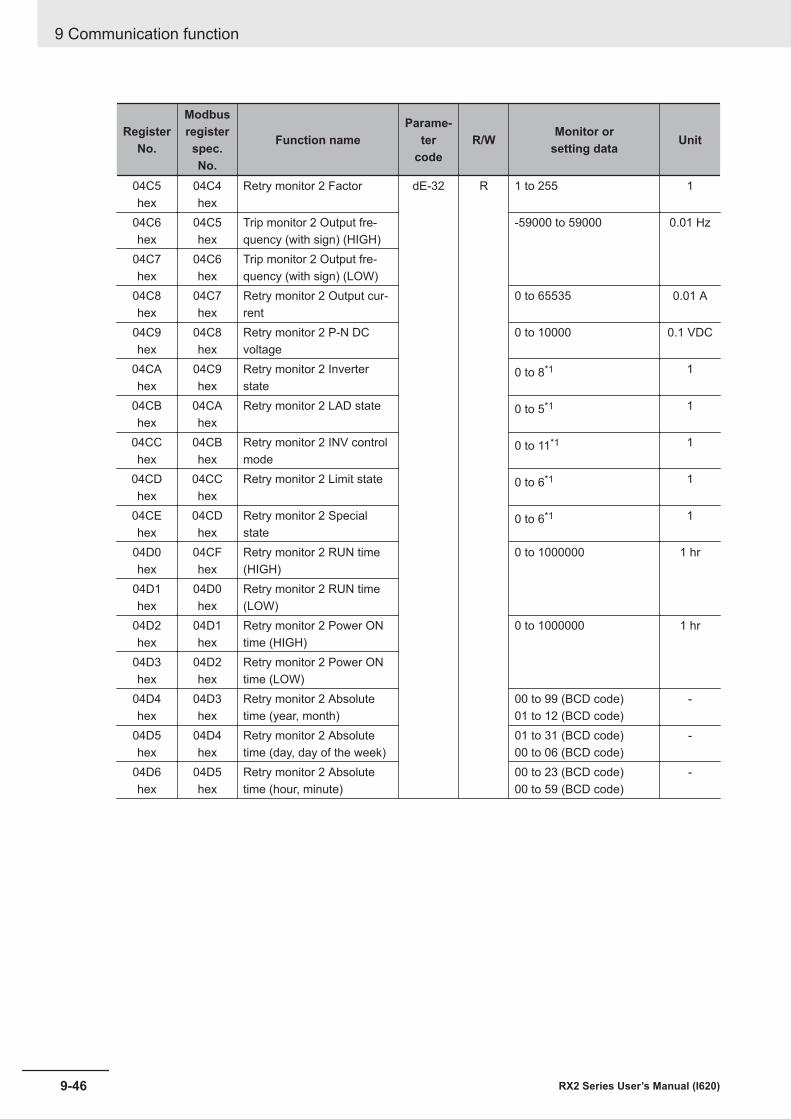
RegisterNo.
Modbusregisterspec.No.
Function nameParame-
tercode
R/W Monitor orsetting data Unit
04C5hex
04C4hex
Retry monitor 2 Factor dE-32 R 1 to 255 1
04C6hex
04C5hex
Trip monitor 2 Output fre-quency (with sign) (HIGH)
-59000 to 59000 0.01 Hz
04C7hex
04C6hex
Trip monitor 2 Output fre-quency (with sign) (LOW)
04C8hex
04C7hex
Retry monitor 2 Output cur-rent
0 to 65535 0.01 A
04C9hex
04C8hex
Retry monitor 2 P-N DCvoltage
0 to 10000 0.1 VDC
04CAhex
04C9hex
Retry monitor 2 Inverterstate
0 to 8*1 1
04CBhex
04CAhex
Retry monitor 2 LAD state 0 to 5*1 1
04CChex
04CBhex
Retry monitor 2 INV controlmode
0 to 11*1 1
04CDhex
04CChex
Retry monitor 2 Limit state 0 to 6*1 1
04CEhex
04CDhex
Retry monitor 2 Specialstate
0 to 6*1 1
04D0hex
04CFhex
Retry monitor 2 RUN time(HIGH)
0 to 1000000 1 hr
04D1hex
04D0hex
Retry monitor 2 RUN time(LOW)
04D2hex
04D1hex
Retry monitor 2 Power ONtime (HIGH)
0 to 1000000 1 hr
04D3hex
04D2hex
Retry monitor 2 Power ONtime (LOW)
04D4hex
04D3hex
Retry monitor 2 Absolutetime (year, month)
00 to 99 (BCD code)01 to 12 (BCD code)
-
04D5hex
04D4hex
Retry monitor 2 Absolutetime (day, day of the week)
01 to 31 (BCD code)00 to 06 (BCD code)
-
04D6hex
04D5hex
Retry monitor 2 Absolutetime (hour, minute)
00 to 23 (BCD code)00 to 59 (BCD code)
-
9 Communication function
9-46 RX2 Series User’s Manual (I620)

RegisterNo.
Modbusregisterspec.No.
Function nameParame-
tercode
R/W Monitor orsetting data Unit
04D9hex
04D8hex
Retry monitor 3 Factor dE-33 R 1 to 255 1
04DAhex
04D9hex
Trip monitor 3 Output fre-quency (with sign) (HIGH)
-59000 to 59000 0.01 Hz
04DBhex
04DAhex
Trip monitor 3 Output fre-quency (with sign) (LOW)
04DChex
04DBhex
Retry monitor 3 Output cur-rent
0 to 65535 0.01 A
04DDhex
04DChex
Retry monitor 3 P-N DCvoltage
0 to 10000 0.1 VDC
04DEhex
04DDhex
Retry monitor 3 Inverterstate
0 to 8*1 1
04DFhex
04DEhex
Retry monitor 3 LAD state 0 to 5*1 1
04E0hex
04DFhex
Retry monitor 3 INV controlmode
0 to 11*1 1
04E1hex
04E0hex
Retry monitor 3 Limit state 0 to 6*1 1
04E2hex
04E1hex
Retry monitor 3 Specialstate
0 to 6*1 1
04E4hex
04E3hex
Retry monitor 3 RUN time(HIGH)
0 to 1000000 1 hr
04E5hex
04E4hex
Retry monitor 3 RUN time(LOW)
04E6hex
04E5hex
Retry monitor 3 Power ONtime (HIGH)
0 to 1000000 1hr
04E7hex
04E6hex
Retry monitor 3 Power ONtime (LOW)
04E8hex
04E7hex
Retry monitor 3 Absolutetime (year, month)
00 to 99 (BCD code)01 to 12 (BCD code)
-
04E9hex
04E8hex
Retry monitor 3 Absolutetime (day, day of the week)
01 to 31 (BCD code)00 to 06 (BCD code)
-
04EAhex
04E9hex
Retry monitor 3 Absolutetime (hour, minute)
00 to 23 (BCD code)00 to 59 (BCD code)
-
9 Communication function
9-47RX2 Series User’s Manual (I620)
9-5 Modbus C
omm
unication Register N
umber List
9
9-5-2 Group d R
egister List

RegisterNo.
Modbusregisterspec.No.
Function nameParame-
tercode
R/W Monitor orsetting data Unit
04EDhex
04EChex
Retry monitor 4 Factor dE-34 R 1 to 255 1
04EEhex
04EDhex
Trip monitor 4 Output fre-quency (with sign) (HIGH)
-59000 to 59000 0.01 Hz
04EFhex
04EEhex
Trip monitor 4 Output fre-quency (with sign) (LOW)
04F0hex
04EFhex
Retry monitor 4 Output cur-rent
0 to 65535 0.01 A
04F1hex
04F0hex
Retry monitor 4 P-N DCvoltage
0 to 10000 0.1 VDC
04F2hex
04F1hex
Retry monitor 4 Inverterstate
0 to 8*1 1
04F3hex
04F2hex
Retry monitor 4 LAD state 0 to 5*1 1
04F4hex
04F3hex
Retry monitor 4 INV controlmode
0 to 11*1 1
04F5hex
04F4hex
Retry monitor 4 Limit state 0 to 6*1 1
04F6hex
04F5hex
Retry monitor 4 Specialstate
0 to 6*1 1
04F8hex
04F7hex
Retry monitor 4 RUN time(HIGH)
0 to 1000000 1 hr
04F9hex
04F8hex
Retry monitor 4 RUN time(LOW)
04FAhex
04F9hex
Retry monitor 4 Power ONtime (HIGH)
0 to 1000000 1 hr
04FBhex
04FAhex
Retry monitor 4 Power ONtime (LOW)
04FChex
04FBhex
Retry monitor 4 Absolutetime (year, month)
00 to 99 (BCD code)01 to 12 (BCD code)
-
04FDhex
04FChex
Retry monitor 4 Absolutetime (day, day of the week)
01 to 31 (BCD code)00 to 06 (BCD code)
-
04FEhex
04FDhex
Retry monitor 4 Absolutetime (hour, minute)
00 to 23 (BCD code)00 to 59 (BCD code)
-
9 Communication function
9-48 RX2 Series User’s Manual (I620)

RegisterNo.
Modbusregisterspec.No.
Function nameParame-
tercode
R/W Monitor orsetting data Unit
0501 hex 0500hex
Retry monitor 5 Factor dE-35 R 1 to 255 1
0502 hex 0501hex
Trip monitor 5 Output fre-quency (with sign) (HIGH)
-59000 to 59000 0.01 Hz
0503 hex 0502hex
Trip monitor 5 Output fre-quency (with sign) (LOW)
0504 hex 0503hex
Retry monitor 5 Output cur-rent
0 to 65535 0.01 A
0505 hex 0504hex
Retry monitor 5 P-N DCvoltage
0 to 10000 0.1 VDC
0506 hex 0505hex
Retry monitor 5 Inverterstate
0 to 8*1 1
0507 hex 0506hex
Retry monitor 5 LAD state 0 to 5*1 1
0508 hex 0507hex
Retry monitor 5 INV controlmode
0 to 11*1 1
0509 hex 0508hex
Retry monitor 5 Limit state 0 to 6*1 1
050Ahex
0509hex
Retry monitor 5 Specialstate
0 to 6*1 1
050Chex
050Bhex
Retry monitor 5 RUN time(HIGH)
0 to 1000000 1 hr
050Dhex
050Chex
Retry monitor 5 RUN time(LOW)
050Ehex
050Dhex
Retry monitor 5 Power ONtime (HIGH)
0 to 1000000 1 hr
050Fhex
050Ehex
Retry monitor 5 Power ONtime (LOW)
0510 hex 050Fhex
Retry monitor 5 Absolutetime (year, month)
00 to 99 (BCD code)01 to 12 (BCD code)
-
0511 hex 0510hex
Retry monitor 5 Absolutetime (day, day of the week)
01 to 31 (BCD code)00 to 06 (BCD code)
-
0512 hex 0511 hex Retry monitor 5 Absolutetime (hour, minute)
00 to 23 (BCD code)00 to 59 (BCD code)
-
9 Communication function
9-49RX2 Series User’s Manual (I620)
9-5 Modbus C
omm
unication Register N
umber List
9
9-5-2 Group d R
egister List

RegisterNo.
Modbusregisterspec.No.
Function nameParame-
tercode
R/W Monitor orsetting data Unit
0515 hex 0514hex
Retry monitor 6 Factor dE-36 R 1 to 255 1
0516 hex 0515hex
Trip monitor 6 Output fre-quency (with sign) (HIGH)
-59000 to 59000 0.01 Hz
0517 hex 0516hex
Trip monitor 6 Output fre-quency (with sign) (LOW)
0518 hex 0517hex
Retry monitor 6 Output cur-rent
0 to 65535 0.01 A
0519 hex 0518hex
Retry monitor 6 P-N DCvoltage
0 to 10000 0.1 VDC
051Ahex
0519hex
Retry monitor 6 Inverterstate
0 to 8*1 1
051Bhex
051Ahex
Retry monitor 6 LAD state 0 to 5*1 1
051Chex
051Bhex
Retry monitor 6 INV controlmode
0 to 11*1 1
051Dhex
051Chex
Retry monitor 6 Limit state 0 to 6*1 1
051Ehex
051Dhex
Retry monitor 6 Specialstate
0 to 6*1 1
0520 hex 051Fhex
Retry monitor 6 RUN time(HIGH)
0 to 1000000 1 hr
0521 hex 0520hex
Retry monitor 6 RUN time(LOW)
0522 hex 0521hex
Retry monitor 6 Power ONtime (HIGH)
0 to 1000000 1 hr
0523 hex 0522hex
Retry monitor 6 Power ONtime (LOW)
0524 hex 0523hex
Retry monitor 6 Absolutetime (year, month)
00 to 99 (BCD code)01 to 12 (BCD code)
-
0525 hex 0524hex
Retry monitor 6 Absolutetime (day, day of the week)
01 to 31 (BCD code)00 to 06 (BCD code)
-
0526 hex 0525hex
Retry monitor 6 Absolutetime (hour, minute)
00 to 23 (BCD code)00 to 59 (BCD code)
-
9 Communication function
9-50 RX2 Series User’s Manual (I620)

RegisterNo.
Modbusregisterspec.No.
Function nameParame-
tercode
R/W Monitor orsetting data Unit
0529 hex 0528hex
Retry monitor 7 Factor dE-37 R 1 to 255 1
052Ahex
0529hex
Trip monitor 7 Output fre-quency (with sign) (HIGH)
-59000 to 59000 0.01 Hz
052Bhex
052Ahex
Trip monitor 7 Output fre-quency (with sign) (LOW)
052Chex
052Bhex
Retry monitor 7 Output cur-rent
0 to 65535 0.01 A
052Dhex
052Chex
Retry monitor 7 P-N DCvoltage
0 to 10000 0.1 VDC
052Ehex
052Dhex
Retry monitor 7 Inverterstate
0 to 8*1 1
052Fhex
052Ehex
Retry monitor 7 LAD state 0 to 5*1 1
0530 hex 052Fhex
Retry monitor 7 INV controlmode
0 to 11*1 1
0531 hex 0530hex
Retry monitor 7 Limit state 0 to 6*1 1
0532 hex 0531hex
Retry monitor 7 Specialstate
0 to 6*1 1
0534 hex 0533hex
Retry monitor 7 RUN time(HIGH)
0 to 1000000 1 hr
0535 hex 0534hex
Retry monitor 7 RUN time(LOW)
0536 hex 0535hex
Retry monitor 7 Power ONtime (HIGH)
0 to 1000000 1 hr
0537 hex 0536hex
Retry monitor 7 Power ONtime (LOW)
0538 hex 0537hex
Retry monitor 7 Absolutetime (year, month)
00 to 99 (BCD code)01 to 12 (BCD code)
-
0539 hex 0538hex
Retry monitor 7 Absolutetime (day, day of the week)
01 to 31 (BCD code)00 to 06 (BCD code)
-
053Ahex
0539hex
Retry monitor 7 Absolutetime (hour, minute)
00 to 23 (BCD code)00 to 59 (BCD code)
-
9 Communication function
9-51RX2 Series User’s Manual (I620)
9-5 Modbus C
omm
unication Register N
umber List
9
9-5-2 Group d R
egister List

RegisterNo.
Modbusregisterspec.No.
Function nameParame-
tercode
R/W Monitor orsetting data Unit
053Dhex
053Chex
Retry monitor 8 Factor dE-38 R 1 to 255 1
053Ehex
053Dhex
Trip monitor 8 Output fre-quency (with sign) (HIGH)
-59000 to 59000 0.01 Hz
053Fhex
053Ehex
Trip monitor 8 Output fre-quency (with sign) (LOW)
0540 hex 053Fhex
Retry monitor 8 Output cur-rent
0 to 65535 0.01 A
0541 hex 0540hex
Retry monitor 8 P-N DCvoltage
0 to 10000 0.1 VDC
0542 hex 0541hex
Retry monitor 8 Inverterstate
0 to 8*1 1
0543 hex 0542hex
Retry monitor 8 LAD state 0 to 5*1 1
0544 hex 0543hex
Retry monitor 8 INV controlmode
0 to 11*1 1
0545 hex 0544hex
Retry monitor 8 Limit state 0 to 6*1 1
0546 hex 0545hex
Retry monitor 8 Specialstate
0 to 6*1 1
0548 hex 0547hex
Retry monitor 8 RUN time(HIGH)
0 to 1000000 1 hr
0549 hex 0548hex
Retry monitor 8 RUN time(LOW)
054Ahex
0549hex
Retry monitor 8 Power ONtime (HIGH)
0 to 1000000 1 hr
054Bhex
054Ahex
Retry monitor 8 Power ONtime (LOW)
054Chex
054Bhex
Retry monitor 8 Absolutetime (year, month)
00 to 99 (BCD code)01 to 12 (BCD code)
-
054Dhex
054Chex
Retry monitor 8 Absolutetime (day, day of the week)
01 to 31 (BCD code)00 to 06 (BCD code)
-
054Ehex
054Dhex
Retry monitor 8 Absolutetime (hour, minute)
00 to 23 (BCD code)00 to 59 (BCD code)
-
9 Communication function
9-52 RX2 Series User’s Manual (I620)

RegisterNo.
Modbusregisterspec.No.
Function nameParame-
tercode
R/W Monitor orsetting data Unit
0551 hex 0550hex
Retry monitor 9 Factor dE-39 R 1 to 255 1
0552 hex 0551hex
Trip monitor 9 Output fre-quency (with sign) (HIGH)
-59000 to 59000 0.01 Hz
0553 hex 0552hex
Trip monitor 9 Output fre-quency (with sign) (LOW)
0554 hex 0553hex
Retry monitor 9 Output cur-rent
0 to 65535 0.01 A
0555 hex 0554hex
Retry monitor 9 P-N DCvoltage
0 to 10000 0.1 VDC
0556 hex 0555hex
Retry monitor 9 Inverterstate
0 to 8*1 1
0557 hex 0556hex
Retry monitor 9 LAD state 0 to 5*1 1
0558 hex 0557hex
Retry monitor 9 INV controlmode
0 to 11*1 1
0559 hex 0558hex
Retry monitor 9 Limit state 0 to 6*1 1
055Ahex
0559hex
Retry monitor 9 Specialstate
0 to 6*1 1
055Chex
055Bhex
Retry monitor 9 RUN time(HIGH)
0 to 1000000 1 hr
055Dhex
055Chex
Retry monitor 9 RUN time(LOW)
055Ehex
055Dhex
Retry monitor 9 Power ONtime (HIGH)
0 to 1000000 1 hr
055Fhex
055Ehex
Retry monitor 9 Power ONtime (LOW)
0560 hex 055Fhex
Retry monitor 9 Absolutetime (year, month)
00 to 99 (BCD code)01 to 12 (BCD code)
-
0561 hex 0560hex
Retry monitor 9 Absolutetime (day, day of the week)
01 to 31 (BCD code)00 to 06 (BCD code)
-
0562 hex 0561hex
Retry monitor 9 Absolutetime (hour, minute)
00 to 23 (BCD code)00 to 59 (BCD code)
-
9 Communication function
9-53RX2 Series User’s Manual (I620)
9-5 Modbus C
omm
unication Register N
umber List
9
9-5-2 Group d R
egister List
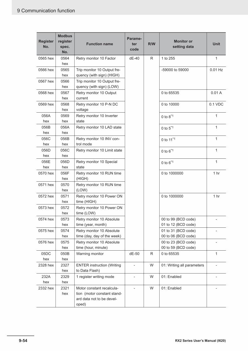
RegisterNo.
Modbusregisterspec.No.
Function nameParame-
tercode
R/W Monitor orsetting data Unit
0565 hex 0564hex
Retry monitor 10 Factor dE-40 R 1 to 255 1
0566 hex 0565hex
Trip monitor 10 Output fre-quency (with sign) (HIGH)
-59000 to 59000 0.01 Hz
0567 hex 0566hex
Trip monitor 10 Output fre-quency (with sign) (LOW)
0568 hex 0567hex
Retry monitor 10 Outputcurrent
0 to 65535 0.01 A
0569 hex 0568hex
Retry monitor 10 P-N DCvoltage
0 to 10000 0.1 VDC
056Ahex
0569hex
Retry monitor 10 Inverterstate
0 to 8*1 1
056Bhex
056Ahex
Retry monitor 10 LAD state 0 to 5*1 1
056Chex
056Bhex
Retry monitor 10 INV con-trol mode
0 to 11*1 1
056Dhex
056Chex
Retry monitor 10 Limit state 0 to 6*1 1
056Ehex
056Dhex
Retry monitor 10 Specialstate
0 to 6*1 1
0570 hex 056Fhex
Retry monitor 10 RUN time(HIGH)
0 to 1000000 1 hr
0571 hex 0570hex
Retry monitor 10 RUN time(LOW)
0572 hex 0571hex
Retry monitor 10 Power ONtime (HIGH)
0 to 1000000 1 hr
0573 hex 0572hex
Retry monitor 10 Power ONtime (LOW)
0574 hex 0573hex
Retry monitor 10 Absolutetime (year, month)
00 to 99 (BCD code)01 to 12 (BCD code)
-
0575 hex 0574hex
Retry monitor 10 Absolutetime (day, day of the week)
01 to 31 (BCD code)00 to 06 (BCD code)
-
0576 hex 0575hex
Retry monitor 10 Absolutetime (hour, minute)
00 to 23 (BCD code)00 to 59 (BCD code)
-
05DChex
050Bhex
Warning monitor dE-50 R 0 to 65535 1
2328 hex 2327hex
ENTER instruction (Writingto Data Flash)
- W 01: Writing all parameters -
232Ahex
2329hex
1 register writing mode - W 01: Enabled -
2332 hex 2321hex
Motor constant recalcula-tion (motor constant stand-ard data not to be devel-oped)
- W 01: Enabled -
9 Communication function
9-54 RX2 Series User’s Manual (I620)
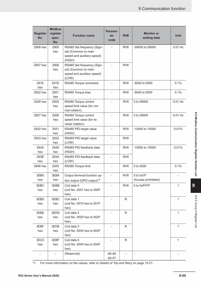
RegisterNo.
Modbusregisterspec.No.
Function nameParame-
tercode
R/W Monitor orsetting data Unit
2906 hex 2905hex
RS485 Set frequency (Sign-ed) (Common to mainspeed and auxiliary speed)(HIGH)
- R/W -59000 to 59000 0.01 Hz
2907 hex 2906hex
RS485 Set frequency (Sign-ed) (Common to mainspeed and auxiliary speed)(LOW)
- R/W
291Ehex
291Dhex
RS485 Torque command - R/W -5000 to 5000 0.1%
2922 hex 2921hex
RS485 Torque bias - R/W -5000 to 5000 0.1%
2926 hex 2925hex
RS485 Torque controlspeed limit value (for nor-mal rotation)
- R/W 0 to 59000 0.01 Hz
2927 hex 2926hex
RS485 Torque controlspeed limit value (for re-verse rotation)
- R/W 0 to 59000 0.01 Hz
2932 hex 2931hex
RS485 PID target value(HIGH)
- R/W -10000 to 10000 0.01%
2933 hex 2932hex
RS485 PID target value(LOW)
- R/W
293Ahex
2939hex
RS485 PID feedback data(HIGH)
- R/W -10000 to 10000 0.01%
293Bhex
293Ahex
RS485 PID feedback data(LOW)
- R/W
2946 hex 2945hex
RS485 Torque limit - R/W 0 to 5000 0.1%
3EB5hex
3EB4hex
Output terminal function op-tion output (OPO output)*2
- R/W 0 to 0x7F(Access prohibited)
-
3EBChex
3EBBhex
Coil data 0(coil No. 0001 hex to 000Fhex)
- R/W 0 to 0xFFFF 1
3EBDhex
3EBChex
Coil data 1(coil No. 0010 hex to 001Fhex)
- R 1
3EBEhex
3EDDhex
Coil data 2(coil No. 0020 hex to 002Fhex)
- R 1
3EBFhex
3EDEhex
Coil data 3(coil No. 0030 hex to 003Fhex)
- R 1
3EC0hex
3EBFhex
Coil data 4(coil No. 0040 hex to 004Fhex)
- R 1
- - (Reserved) dA-46dA-47
- - -
*1. For more information on the values, refer to Details of Trip and Retry on page 15-21.
9 Communication function
9-55RX2 Series User’s Manual (I620)
9-5 Modbus C
omm
unication Register N
umber List
9
9-5-2 Group d R
egister List
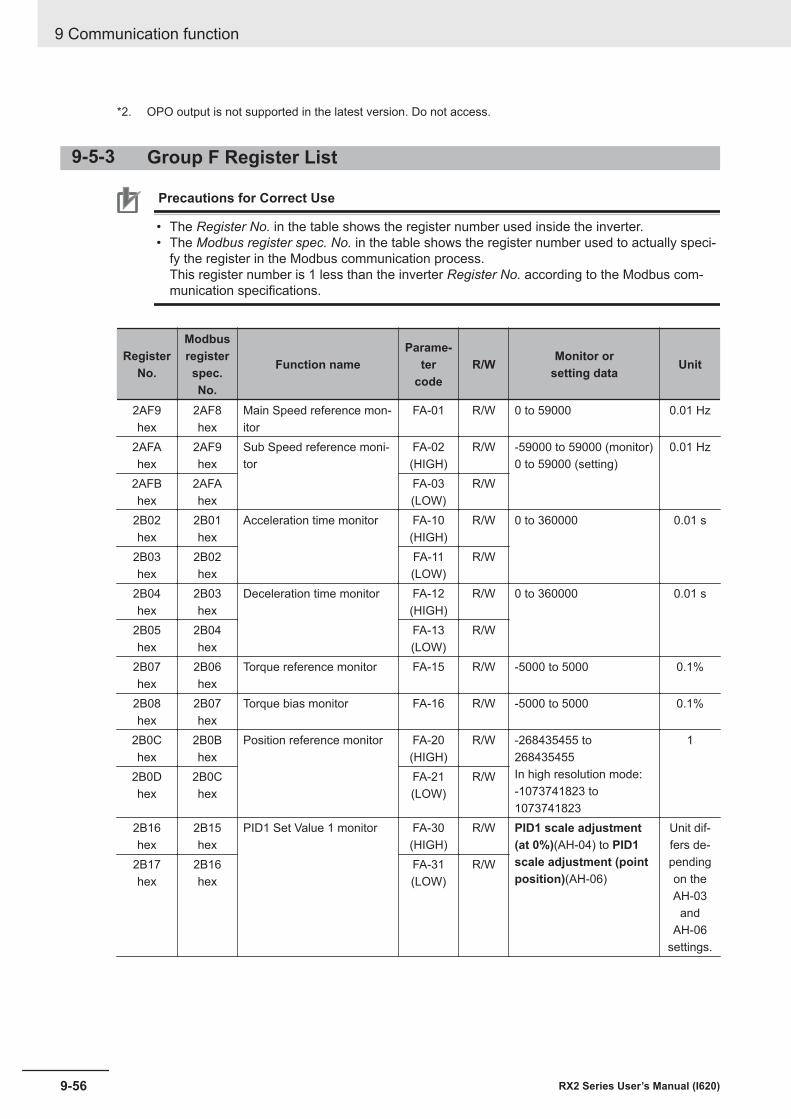
*2. OPO output is not supported in the latest version. Do not access.
9-5-3 Group F Register List
Precautions for Correct Use
• The Register No. in the table shows the register number used inside the inverter.• The Modbus register spec. No. in the table shows the register number used to actually speci-
fy the register in the Modbus communication process.This register number is 1 less than the inverter Register No. according to the Modbus com-munication specifications.
RegisterNo.
Modbusregisterspec.No.
Function nameParame-
tercode
R/W Monitor orsetting data Unit
2AF9hex
2AF8hex
Main Speed reference mon-itor
FA-01 R/W 0 to 59000 0.01 Hz
2AFAhex
2AF9hex
Sub Speed reference moni-tor
FA-02(HIGH)
R/W -59000 to 59000 (monitor)0 to 59000 (setting)
0.01 Hz
2AFBhex
2AFAhex
FA-03(LOW)
R/W
2B02hex
2B01hex
Acceleration time monitor FA-10(HIGH)
R/W 0 to 360000 0.01 s
2B03hex
2B02hex
FA-11(LOW)
R/W
2B04hex
2B03hex
Deceleration time monitor FA-12(HIGH)
R/W 0 to 360000 0.01 s
2B05hex
2B04hex
FA-13(LOW)
R/W
2B07hex
2B06hex
Torque reference monitor FA-15 R/W -5000 to 5000 0.1%
2B08hex
2B07hex
Torque bias monitor FA-16 R/W -5000 to 5000 0.1%
2B0Chex
2B0Bhex
Position reference monitor FA-20(HIGH)
R/W -268435455 to268435455In high resolution mode:-1073741823 to1073741823
1
2B0Dhex
2B0Chex
FA-21(LOW)
R/W
2B16hex
2B15hex
PID1 Set Value 1 monitor FA-30(HIGH)
R/W PID1 scale adjustment(at 0%)(AH-04) to PID1scale adjustment (pointposition)(AH-06)
Unit dif-fers de-pendingon theAH-03
andAH-06
settings.
2B17hex
2B16hex
FA-31(LOW)
R/W
9 Communication function
9-56 RX2 Series User’s Manual (I620)
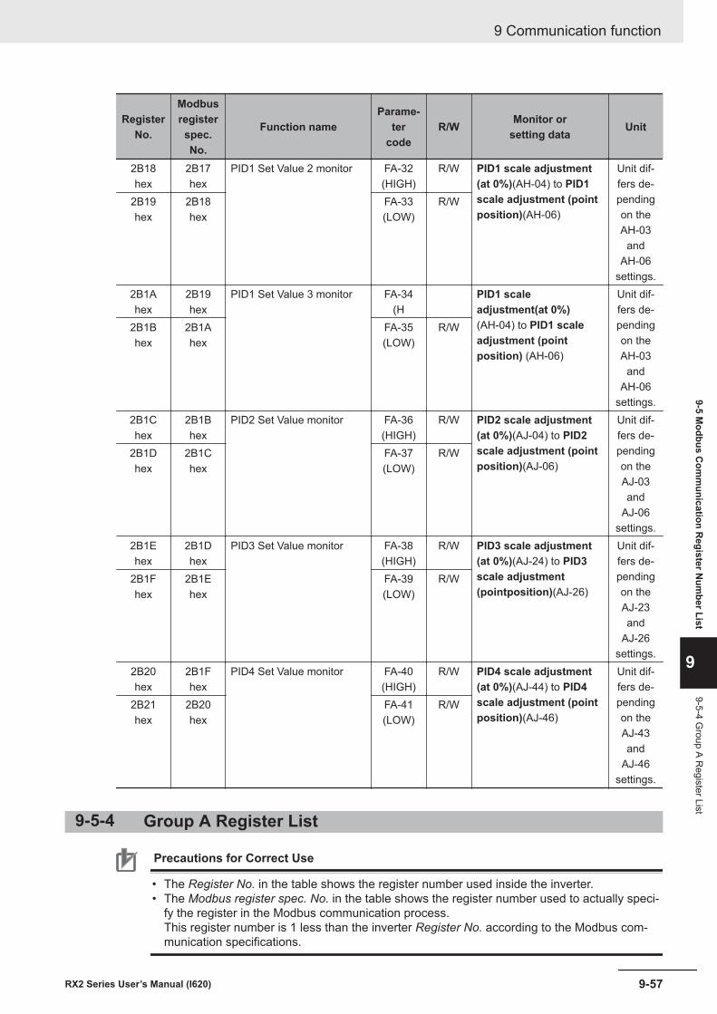
RegisterNo.
Modbusregisterspec.No.
Function nameParame-
tercode
R/W Monitor orsetting data Unit
2B18hex
2B17hex
PID1 Set Value 2 monitor FA-32(HIGH)
R/W PID1 scale adjustment(at 0%)(AH-04) to PID1scale adjustment (pointposition)(AH-06)
Unit dif-fers de-pendingon theAH-03
andAH-06
settings.
2B19hex
2B18hex
FA-33(LOW)
R/W
2B1Ahex
2B19hex
PID1 Set Value 3 monitor FA-34(H
PID1 scaleadjustment(at 0%)(AH-04) to PID1 scaleadjustment (pointposition) (AH-06)
Unit dif-fers de-pendingon theAH-03
andAH-06
settings.
2B1Bhex
2B1Ahex
FA-35(LOW)
R/W
2B1Chex
2B1Bhex
PID2 Set Value monitor FA-36(HIGH)
R/W PID2 scale adjustment(at 0%)(AJ-04) to PID2scale adjustment (pointposition)(AJ-06)
Unit dif-fers de-pendingon theAJ-03and
AJ-06settings.
2B1Dhex
2B1Chex
FA-37(LOW)
R/W
2B1Ehex
2B1Dhex
PID3 Set Value monitor FA-38(HIGH)
R/W PID3 scale adjustment(at 0%)(AJ-24) to PID3scale adjustment(pointposition)(AJ-26)
Unit dif-fers de-pendingon theAJ-23and
AJ-26settings.
2B1Fhex
2B1Ehex
FA-39(LOW)
R/W
2B20hex
2B1Fhex
PID4 Set Value monitor FA-40(HIGH)
R/W PID4 scale adjustment(at 0%)(AJ-44) to PID4scale adjustment (pointposition)(AJ-46)
Unit dif-fers de-pendingon theAJ-43and
AJ-46settings.
2B21hex
2B20hex
FA-41(LOW)
R/W
9-5-4 Group A Register List
Precautions for Correct Use
• The Register No. in the table shows the register number used inside the inverter.• The Modbus register spec. No. in the table shows the register number used to actually speci-
fy the register in the Modbus communication process.This register number is 1 less than the inverter Register No. according to the Modbus com-munication specifications.
9 Communication function
9-57RX2 Series User’s Manual (I620)
9-5 Modbus C
omm
unication Register N
umber List
9
9-5-4 Group A R
egister List
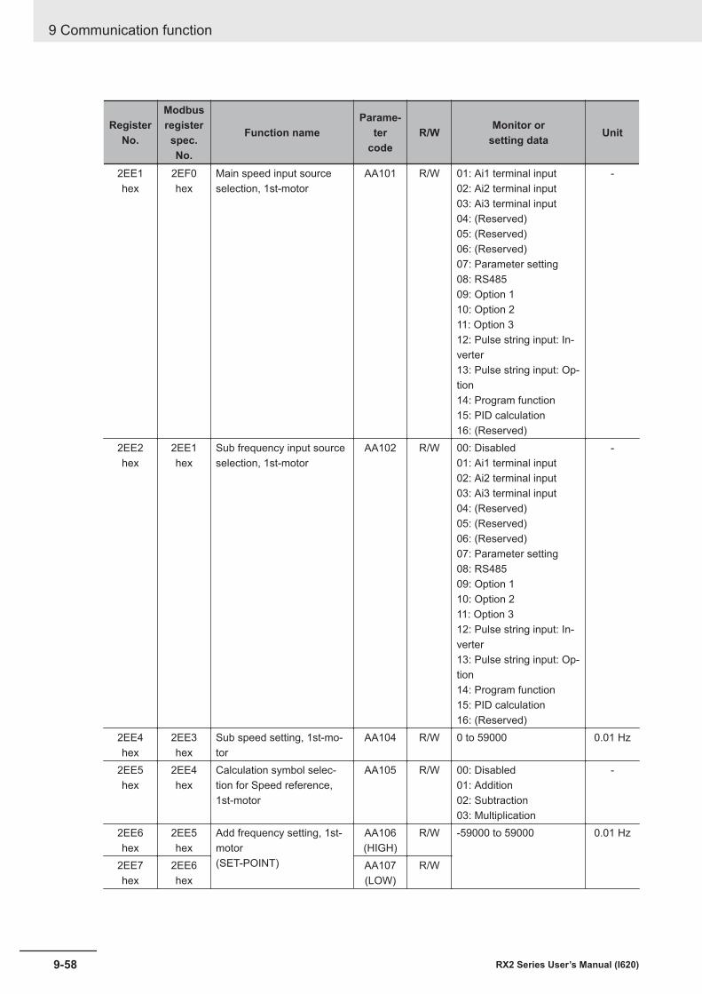
RegisterNo.
Modbusregisterspec.No.
Function nameParame-
tercode
R/W Monitor orsetting data Unit
2EE1hex
2EF0hex
Main speed input sourceselection, 1st-motor
AA101 R/W 01: Ai1 terminal input02: Ai2 terminal input03: Ai3 terminal input04: (Reserved)05: (Reserved)06: (Reserved)07: Parameter setting08: RS48509: Option 110: Option 211: Option 312: Pulse string input: In-verter13: Pulse string input: Op-tion14: Program function15: PID calculation16: (Reserved)
-
2EE2hex
2EE1hex
Sub frequency input sourceselection, 1st-motor
AA102 R/W 00: Disabled01: Ai1 terminal input02: Ai2 terminal input03: Ai3 terminal input04: (Reserved)05: (Reserved)06: (Reserved)07: Parameter setting08: RS48509: Option 110: Option 211: Option 312: Pulse string input: In-verter13: Pulse string input: Op-tion14: Program function15: PID calculation16: (Reserved)
-
2EE4hex
2EE3hex
Sub speed setting, 1st-mo-tor
AA104 R/W 0 to 59000 0.01 Hz
2EE5hex
2EE4hex
Calculation symbol selec-tion for Speed reference,1st-motor
AA105 R/W 00: Disabled01: Addition02: Subtraction03: Multiplication
-
2EE6hex
2EE5hex
Add frequency setting, 1st-motor(SET-POINT)
AA106(HIGH)
R/W -59000 to 59000 0.01 Hz
2EE7hex
2EE6hex
AA107(LOW)
R/W
9 Communication function
9-58 RX2 Series User’s Manual (I620)
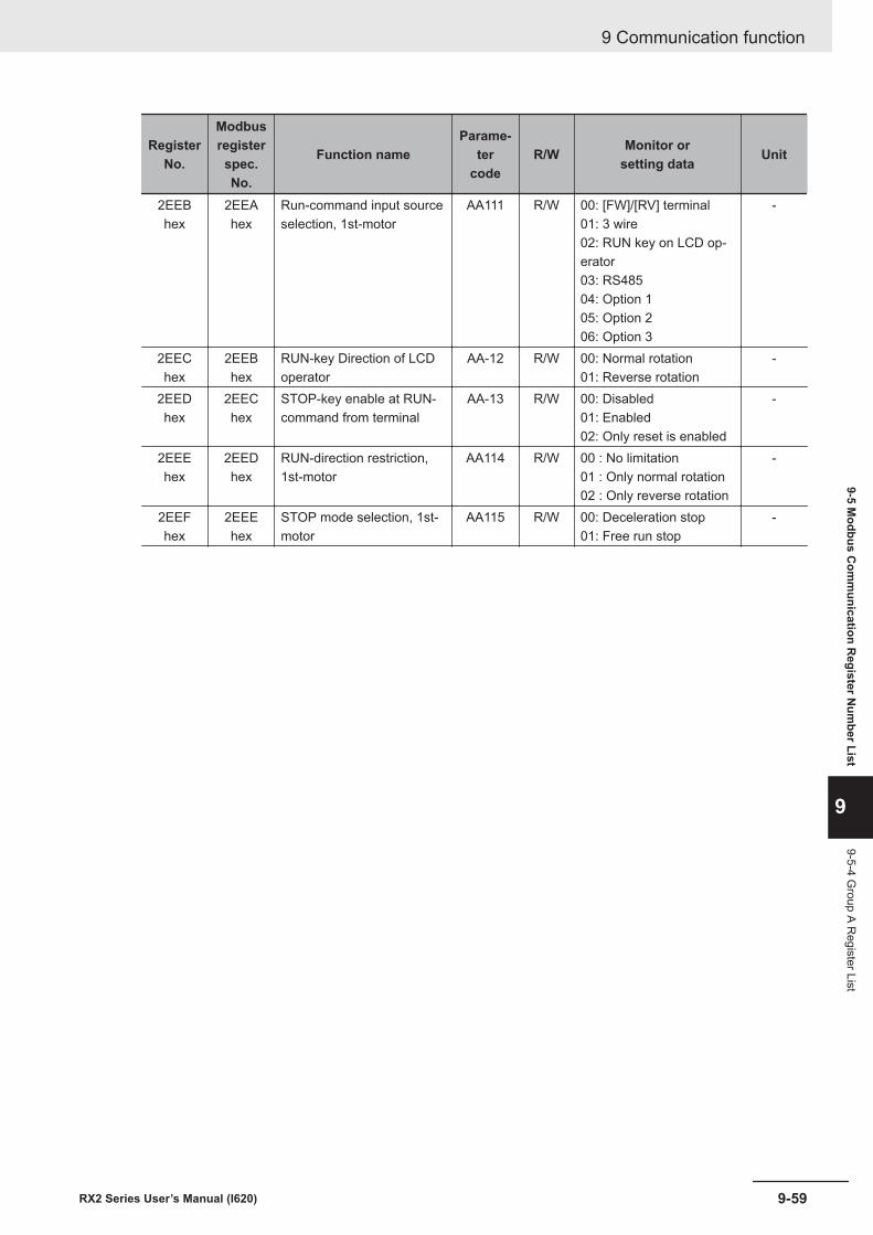
RegisterNo.
Modbusregisterspec.No.
Function nameParame-
tercode
R/W Monitor orsetting data Unit
2EEBhex
2EEAhex
Run-command input sourceselection, 1st-motor
AA111 R/W 00: [FW]/[RV] terminal01: 3 wire02: RUN key on LCD op-erator03: RS48504: Option 105: Option 206: Option 3
-
2EEChex
2EEBhex
RUN-key Direction of LCDoperator
AA-12 R/W 00: Normal rotation01: Reverse rotation
-
2EEDhex
2EEChex
STOP-key enable at RUN-command from terminal
AA-13 R/W 00: Disabled01: Enabled02: Only reset is enabled
-
2EEEhex
2EEDhex
RUN-direction restriction,1st-motor
AA114 R/W 00 : No limitation01 : Only normal rotation02 : Only reverse rotation
-
2EEFhex
2EEEhex
STOP mode selection, 1st-motor
AA115 R/W 00: Deceleration stop01: Free run stop
-
9 Communication function
9-59RX2 Series User’s Manual (I620)
9-5 Modbus C
omm
unication Register N
umber List
9
9-5-4 Group A R
egister List
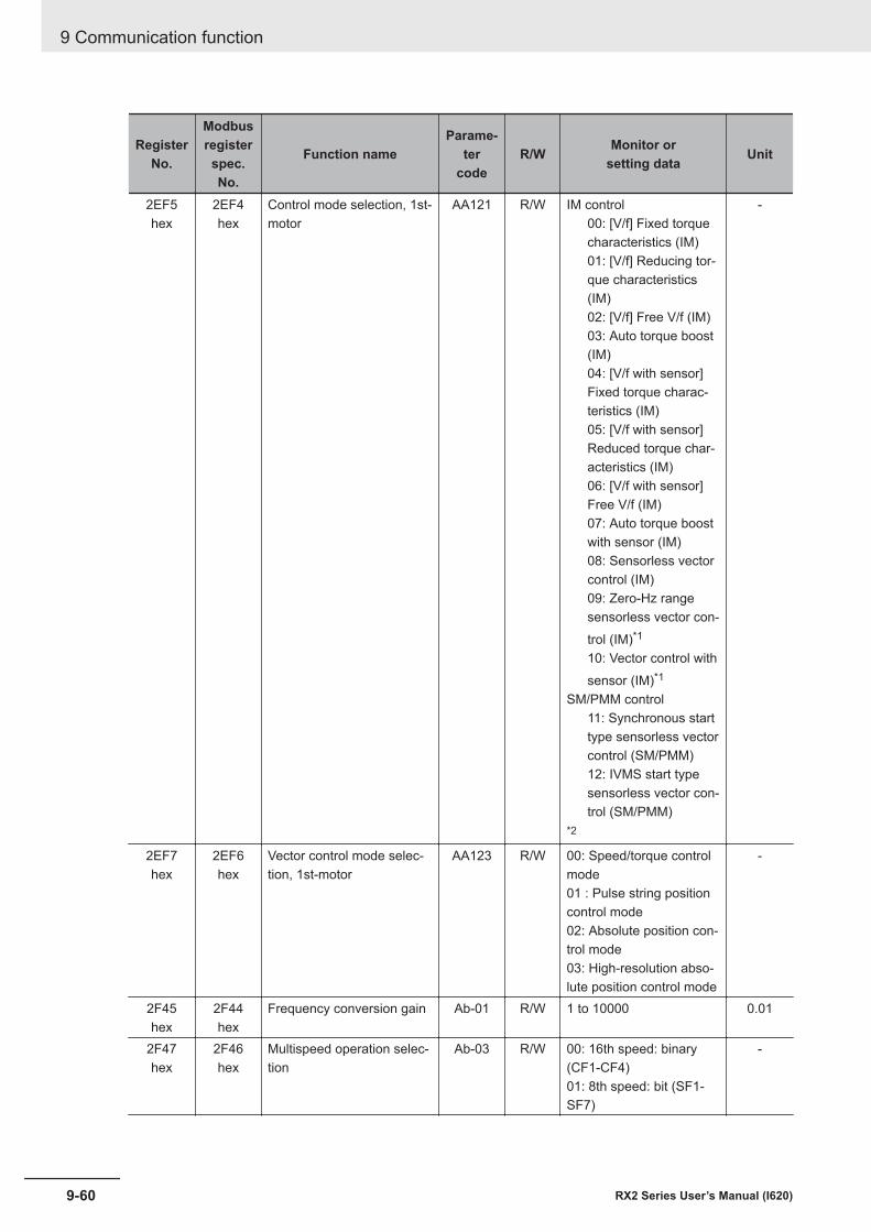
RegisterNo.
Modbusregisterspec.No.
Function nameParame-
tercode
R/W Monitor orsetting data Unit
2EF5hex
2EF4hex
Control mode selection, 1st-motor
AA121 R/W IM control00: [V/f] Fixed torquecharacteristics (IM)01: [V/f] Reducing tor-que characteristics(IM)02: [V/f] Free V/f (IM)03: Auto torque boost(IM)04: [V/f with sensor]Fixed torque charac-teristics (IM)05: [V/f with sensor]Reduced torque char-acteristics (IM)06: [V/f with sensor]Free V/f (IM)07: Auto torque boostwith sensor (IM)08: Sensorless vectorcontrol (IM)09: Zero-Hz rangesensorless vector con-trol (IM)*1
10: Vector control withsensor (IM)*1
SM/PMM control11: Synchronous starttype sensorless vectorcontrol (SM/PMM)12: IVMS start typesensorless vector con-trol (SM/PMM)
*2
-
2EF7hex
2EF6hex
Vector control mode selec-tion, 1st-motor
AA123 R/W 00: Speed/torque controlmode01 : Pulse string positioncontrol mode02: Absolute position con-trol mode03: High-resolution abso-lute position control mode
-
2F45hex
2F44hex
Frequency conversion gain Ab-01 R/W 1 to 10000 0.01
2F47hex
2F46hex
Multispeed operation selec-tion
Ab-03 R/W 00: 16th speed: binary(CF1-CF4)01: 8th speed: bit (SF1-SF7)
-
9 Communication function
9-60 RX2 Series User’s Manual (I620)
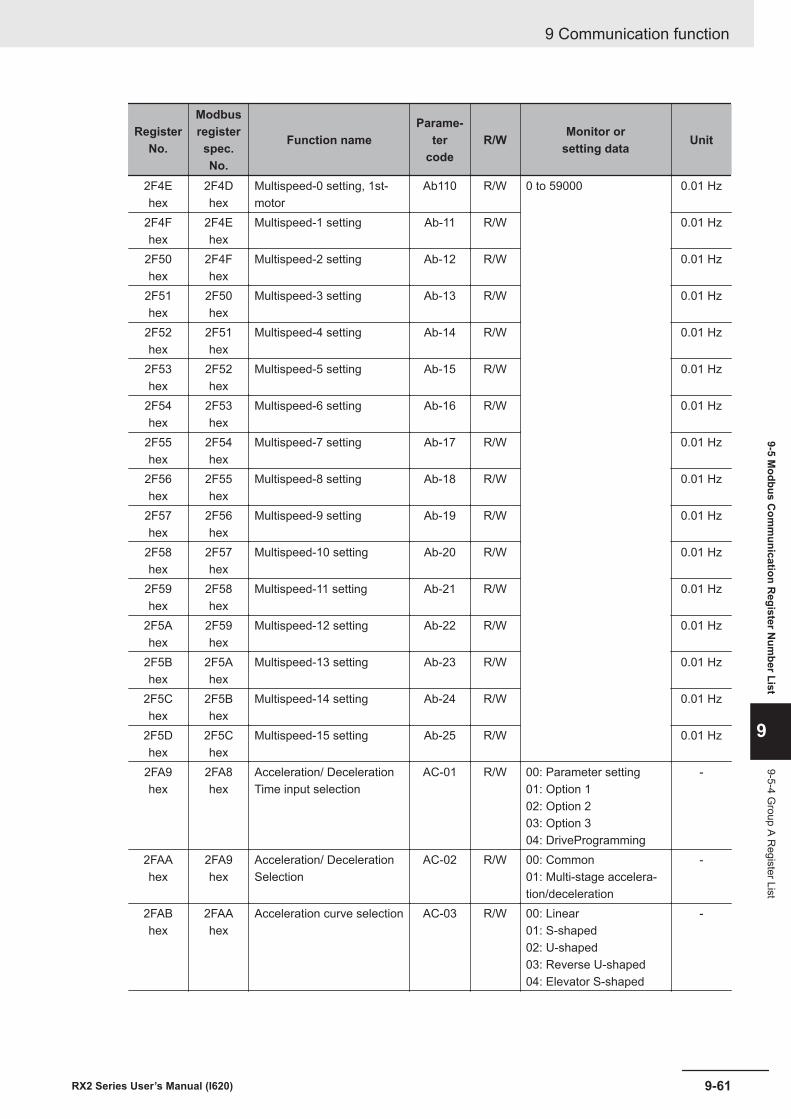
RegisterNo.
Modbusregisterspec.No.
Function nameParame-
tercode
R/W Monitor orsetting data Unit
2F4Ehex
2F4Dhex
Multispeed-0 setting, 1st-motor
Ab110 R/W 0 to 59000 0.01 Hz
2F4Fhex
2F4Ehex
Multispeed-1 setting Ab-11 R/W 0.01 Hz
2F50hex
2F4Fhex
Multispeed-2 setting Ab-12 R/W 0.01 Hz
2F51hex
2F50hex
Multispeed-3 setting Ab-13 R/W 0.01 Hz
2F52hex
2F51hex
Multispeed-4 setting Ab-14 R/W 0.01 Hz
2F53hex
2F52hex
Multispeed-5 setting Ab-15 R/W 0.01 Hz
2F54hex
2F53hex
Multispeed-6 setting Ab-16 R/W 0.01 Hz
2F55hex
2F54hex
Multispeed-7 setting Ab-17 R/W 0.01 Hz
2F56hex
2F55hex
Multispeed-8 setting Ab-18 R/W 0.01 Hz
2F57hex
2F56hex
Multispeed-9 setting Ab-19 R/W 0.01 Hz
2F58hex
2F57hex
Multispeed-10 setting Ab-20 R/W 0.01 Hz
2F59hex
2F58hex
Multispeed-11 setting Ab-21 R/W 0.01 Hz
2F5Ahex
2F59hex
Multispeed-12 setting Ab-22 R/W 0.01 Hz
2F5Bhex
2F5Ahex
Multispeed-13 setting Ab-23 R/W 0.01 Hz
2F5Chex
2F5Bhex
Multispeed-14 setting Ab-24 R/W 0.01 Hz
2F5Dhex
2F5Chex
Multispeed-15 setting Ab-25 R/W 0.01 Hz
2FA9hex
2FA8hex
Acceleration/ DecelerationTime input selection
AC-01 R/W 00: Parameter setting01: Option 102: Option 203: Option 304: DriveProgramming
-
2FAAhex
2FA9hex
Acceleration/ DecelerationSelection
AC-02 R/W 00: Common01: Multi-stage accelera-tion/deceleration
-
2FABhex
2FAAhex
Acceleration curve selection AC-03 R/W 00: Linear01: S-shaped02: U-shaped03: Reverse U-shaped04: Elevator S-shaped
-
9 Communication function
9-61RX2 Series User’s Manual (I620)
9-5 Modbus C
omm
unication Register N
umber List
9
9-5-4 Group A R
egister List
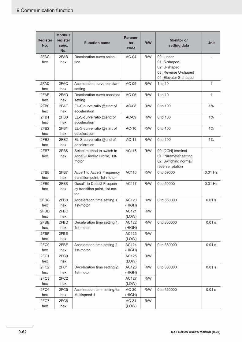
RegisterNo.
Modbusregisterspec.No.
Function nameParame-
tercode
R/W Monitor orsetting data Unit
2FAChex
2FABhex
Deceleration curve selec-tion
AC-04 R/W 00: Linear01: S-shaped02: U-shaped03: Reverse U-shaped04: Elevator S-shaped
-
2FADhex
2FAChex
Acceleration curve constantsetting
AC-05 R/W 1 to 10 1
2FAEhex
2FADhex
Deceleration curve constantsetting
AC-06 R/W 1 to 10 1
2FB0hex
2FAFhex
EL-S-curve ratio @start ofacceleration
AC-08 R/W 0 to 100 1%
2FB1hex
2FB0hex
EL-S-curve ratio @end ofacceleration
AC-09 R/W 0 to 100 1%
2FB2hex
2FB1hex
EL-S-curve ratio @start ofdeceleration
AC-10 R/W 0 to 100 1%
2FB3hex
2FB2hex
EL-S-curve ratio @end ofdeceleration
AC-11 R/W 0 to 100 1%
2FB7hex
2FB6hex
Select method to switch toAccel2/Decel2 Profile, 1st-motor
AC115 R/W 00: [2CH] terminal01: Parameter setting02: Switching normal/reverse rotation
-
2FB8hex
2FB7hex
Accel1 to Accel2 Frequencytransition point, 1st-motor
AC116 R/W 0 to 59000 0.01 Hz
2FB9hex
2FB8hex
Decel1 to Decel2 Frequen-cy transition point, 1st-mo-tor
AC117 R/W 0 to 59000 0.01 Hz
2FBChex
2FBBhex
Acceleration time setting 1,1st-motor
AC120(HIGH)
R/W 0 to 360000 0.01 s
2FBDhex
2FBChex
AC121(LOW)
R/W
2FBEhex
2FBDhex
Deceleration time setting 1,1st-motor
AC122(HIGH)
R/W 0 to 360000 0.01 s
2FBFhex
2FBEhex
AC123(LOW)
R/W
2FC0hex
2FBFhex
Acceleration time setting 2,1st-motor
AC124(HIGH)
R/W 0 to 360000 0.01 s
2FC1hex
2FC0hex
AC125(LOW)
R/W
2FC2hex
2FC1hex
Deceleration time setting 2,1st-motor
AC126(HIGH)
R/W 0 to 360000 0.01 s
2FC3hex
2FC2hex
AC127(LOW)
R/W
2FC6hex
2FC5hex
Acceleration time setting forMultispeed-1
AC-30(HIGH)
R/W 0 to 360000 0.01 s
2FC7hex
2FC6hex
AC-31(LOW)
R/W
9 Communication function
9-62 RX2 Series User’s Manual (I620)
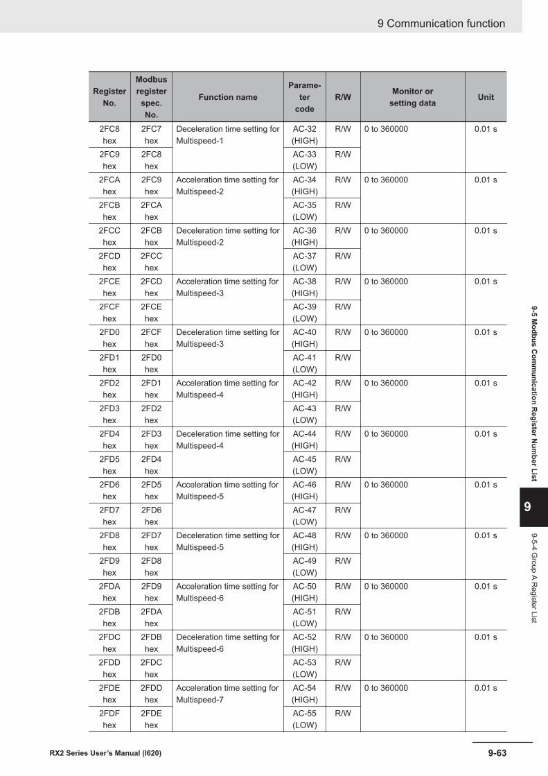
RegisterNo.
Modbusregisterspec.No.
Function nameParame-
tercode
R/W Monitor orsetting data Unit
2FC8hex
2FC7hex
Deceleration time setting forMultispeed-1
AC-32(HIGH)
R/W 0 to 360000 0.01 s
2FC9hex
2FC8hex
AC-33(LOW)
R/W
2FCAhex
2FC9hex
Acceleration time setting forMultispeed-2
AC-34(HIGH)
R/W 0 to 360000 0.01 s
2FCBhex
2FCAhex
AC-35(LOW)
R/W
2FCChex
2FCBhex
Deceleration time setting forMultispeed-2
AC-36(HIGH)
R/W 0 to 360000 0.01 s
2FCDhex
2FCChex
AC-37(LOW)
R/W
2FCEhex
2FCDhex
Acceleration time setting forMultispeed-3
AC-38(HIGH)
R/W 0 to 360000 0.01 s
2FCFhex
2FCEhex
AC-39(LOW)
R/W
2FD0hex
2FCFhex
Deceleration time setting forMultispeed-3
AC-40(HIGH)
R/W 0 to 360000 0.01 s
2FD1hex
2FD0hex
AC-41(LOW)
R/W
2FD2hex
2FD1hex
Acceleration time setting forMultispeed-4
AC-42(HIGH)
R/W 0 to 360000 0.01 s
2FD3hex
2FD2hex
AC-43(LOW)
R/W
2FD4hex
2FD3hex
Deceleration time setting forMultispeed-4
AC-44(HIGH)
R/W 0 to 360000 0.01 s
2FD5hex
2FD4hex
AC-45(LOW)
R/W
2FD6hex
2FD5hex
Acceleration time setting forMultispeed-5
AC-46(HIGH)
R/W 0 to 360000 0.01 s
2FD7hex
2FD6hex
AC-47(LOW)
R/W
2FD8hex
2FD7hex
Deceleration time setting forMultispeed-5
AC-48(HIGH)
R/W 0 to 360000 0.01 s
2FD9hex
2FD8hex
AC-49(LOW)
R/W
2FDAhex
2FD9hex
Acceleration time setting forMultispeed-6
AC-50(HIGH)
R/W 0 to 360000 0.01 s
2FDBhex
2FDAhex
AC-51(LOW)
R/W
2FDChex
2FDBhex
Deceleration time setting forMultispeed-6
AC-52(HIGH)
R/W 0 to 360000 0.01 s
2FDDhex
2FDChex
AC-53(LOW)
R/W
2FDEhex
2FDDhex
Acceleration time setting forMultispeed-7
AC-54(HIGH)
R/W 0 to 360000 0.01 s
2FDFhex
2FDEhex
AC-55(LOW)
R/W
9 Communication function
9-63RX2 Series User’s Manual (I620)
9-5 Modbus C
omm
unication Register N
umber List
9
9-5-4 Group A R
egister List
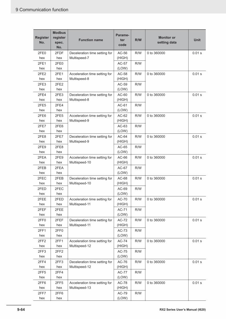
RegisterNo.
Modbusregisterspec.No.
Function nameParame-
tercode
R/W Monitor orsetting data Unit
2FE0hex
2FDFhex
Deceleration time setting forMultispeed-7
AC-56(HIGH)
R/W 0 to 360000 0.01 s
2FE1hex
2FE0hex
AC-57(LOW)
R/W
2FE2hex
2FE1hex
Acceleration time setting forMultispeed-8
AC-58(HIGH)
R/W 0 to 360000 0.01 s
2FE3hex
2FE2hex
AC-59(LOW)
R/W
2FE4hex
2FE3hex
Deceleration time setting forMultispeed-8
AC-60(HIGH)
R/W 0 to 360000 0.01 s
2FE5hex
2FE4hex
AC-61(LOW)
R/W
2FE6hex
2FE5hex
Acceleration time setting forMultispeed-9
AC-62(HIGH)
R/W 0 to 360000 0.01 s
2FE7hex
2FE6hex
AC-63(LOW)
R/W
2FE8hex
2FE7hex
Deceleration time setting forMultispeed-9
AC-64(HIGH)
R/W 0 to 360000 0.01 s
2FE9hex
2FE8hex
AC-65(LOW)
R/W
2FEAhex
2FE9hex
Acceleration time setting forMultispeed-10
AC-66(HIGH)
R/W 0 to 360000 0.01 s
2FEBhex
2FEAhex
AC-67(LOW)
R/W
2FEChex
2FEBhex
Deceleration time setting forMultispeed-10
AC-68(HIGH)
R/W 0 to 360000 0.01 s
2FEDhex
2FEChex
AC-69(LOW)
R/W
2FEEhex
2FEDhex
Acceleration time setting forMultispeed-11
AC-70(HIGH)
R/W 0 to 360000 0.01 s
2FEFhex
2FEEhex
AC-71(LOW)
R/W
2FF0hex
2FEFhex
Deceleration time setting forMultispeed-11
AC-72(HIGH)
R/W 0 to 360000 0.01 s
2FF1hex
2FF0hex
AC-73(LOW)
R/W
2FF2hex
2FF1hex
Acceleration time setting forMultispeed-12
AC-74(HIGH)
R/W 0 to 360000 0.01 s
2FF3hex
2FF2hex
AC-75(LOW)
R/W
2FF4hex
2FF3hex
Deceleration time setting forMultispeed-12
AC-76(HIGH)
R/W 0 to 360000 0.01 s
2FF5hex
2FF4hex
AC-77(LOW)
R/W
2FF6hex
2FF5hex
Acceleration time setting forMultispeed-13
AC-78(HIGH)
R/W 0 to 360000 0.01 s
2FF7hex
2FF6hex
AC-79(LOW)
R/W
9 Communication function
9-64 RX2 Series User’s Manual (I620)
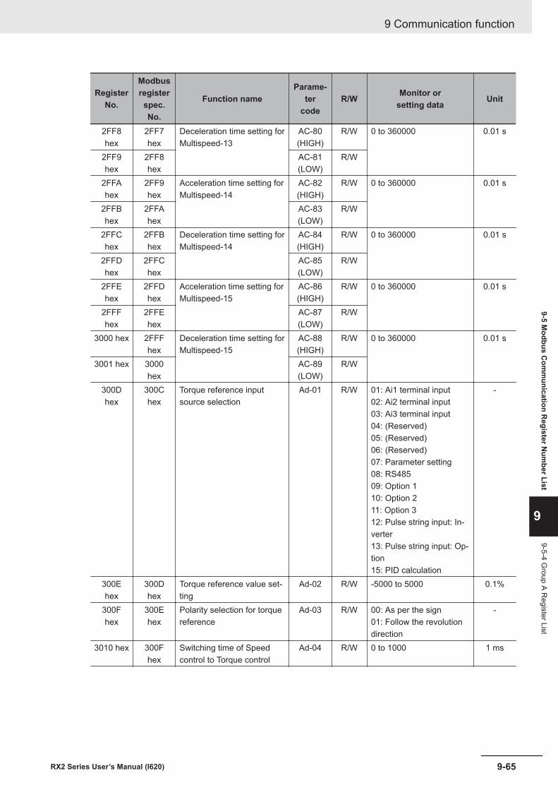
RegisterNo.
Modbusregisterspec.No.
Function nameParame-
tercode
R/W Monitor orsetting data Unit
2FF8hex
2FF7hex
Deceleration time setting forMultispeed-13
AC-80(HIGH)
R/W 0 to 360000 0.01 s
2FF9hex
2FF8hex
AC-81(LOW)
R/W
2FFAhex
2FF9hex
Acceleration time setting forMultispeed-14
AC-82(HIGH)
R/W 0 to 360000 0.01 s
2FFBhex
2FFAhex
AC-83(LOW)
R/W
2FFChex
2FFBhex
Deceleration time setting forMultispeed-14
AC-84(HIGH)
R/W 0 to 360000 0.01 s
2FFDhex
2FFChex
AC-85(LOW)
R/W
2FFEhex
2FFDhex
Acceleration time setting forMultispeed-15
AC-86(HIGH)
R/W 0 to 360000 0.01 s
2FFFhex
2FFEhex
AC-87(LOW)
R/W
3000 hex 2FFFhex
Deceleration time setting forMultispeed-15
AC-88(HIGH)
R/W 0 to 360000 0.01 s
3001 hex 3000hex
AC-89(LOW)
R/W
300Dhex
300Chex
Torque reference inputsource selection
Ad-01 R/W 01: Ai1 terminal input02: Ai2 terminal input03: Ai3 terminal input04: (Reserved)05: (Reserved)06: (Reserved)07: Parameter setting08: RS48509: Option 110: Option 211: Option 312: Pulse string input: In-verter13: Pulse string input: Op-tion15: PID calculation
-
300Ehex
300Dhex
Torque reference value set-ting
Ad-02 R/W -5000 to 5000 0.1%
300Fhex
300Ehex
Polarity selection for torquereference
Ad-03 R/W 00: As per the sign01: Follow the revolutiondirection
-
3010 hex 300Fhex
Switching time of Speedcontrol to Torque control
Ad-04 R/W 0 to 1000 1 ms
9 Communication function
9-65RX2 Series User’s Manual (I620)
9-5 Modbus C
omm
unication Register N
umber List
9
9-5-4 Group A R
egister List
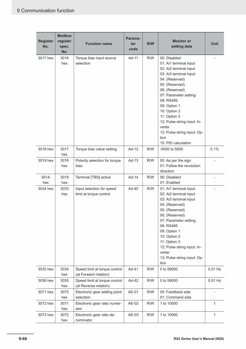
RegisterNo.
Modbusregisterspec.No.
Function nameParame-
tercode
R/W Monitor orsetting data Unit
3017 hex 3016hex
Torque bias input sourceselection
Ad-11 R/W 00: Disabled01: Ai1 terminal input02: Ai2 terminal input03: Ai3 terminal input04: (Reserved)05: (Reserved)06: (Reserved)07: Parameter setting08: RS48509: Option 110: Option 211: Option 312: Pulse string input: In-verter13: Pulse string input: Op-tion15: PID calculation
-
3018 hex 3017hex
Torque bias value setting Ad-12 R/W -5000 to 5000 0.1%
3019 hex 3018hex
Polarity selection for torquebias
Ad-13 R/W 00: As per the sign01: Follow the revolutiondirection
-
301Ahex
3019hex
Terminal [TBS] active Ad-14 R/W 00: Disabled01: Enabled
-
3034 hex 3033hex
Input selection for speedlimit at torque control
Ad-40 R/W 01: Ai1 terminal input02: Ai2 terminal input03: Ai3 terminal input04: (Reserved)05: (Reserved)06: (Reserved)07: Parameter setting08: RS48509: Option 110: Option 211: Option 312: Pulse string input: In-verter13: Pulse string input: Op-tion
-
3035 hex 3034hex
Speed limit at torque control(at Forward rotation)
Ad-41 R/W 0 to 59000 0.01 Hz
3036 hex 3035hex
Speed limit at torque control(at Reverse rotation)
Ad-42 R/W 0 to 59000 0.01 Hz
3071 hex 3070hex
Electronic gear setting pointselection
AE-01 R/W 00: Feedback side01: Command side
-
3072 hex 3071hex
Electronic gear ratio numer-ator
AE-02 R/W 1 to 10000 1
3073 hex 3072hex
Electronic gear ratio de-nominator
AE-03 R/W 1 to 10000 1
9 Communication function
9-66 RX2 Series User’s Manual (I620)
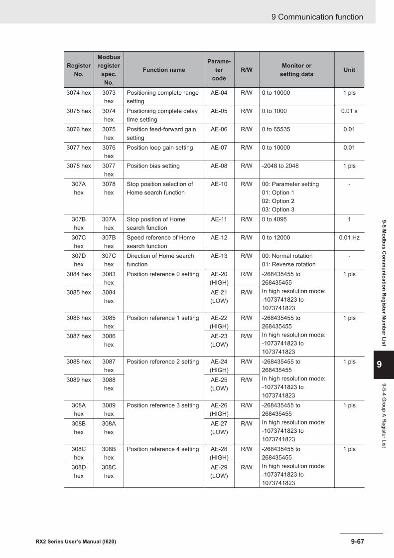
RegisterNo.
Modbusregisterspec.No.
Function nameParame-
tercode
R/W Monitor orsetting data Unit
3074 hex 3073hex
Positioning complete rangesetting
AE-04 R/W 0 to 10000 1 pls
3075 hex 3074hex
Positioning complete delaytime setting
AE-05 R/W 0 to 1000 0.01 s
3076 hex 3075hex
Position feed-forward gainsetting
AE-06 R/W 0 to 65535 0.01
3077 hex 3076hex
Position loop gain setting AE-07 R/W 0 to 10000 0.01
3078 hex 3077hex
Position bias setting AE-08 R/W -2048 to 2048 1 pls
307Ahex
3078hex
Stop position selection ofHome search function
AE-10 R/W 00: Parameter setting01: Option 102: Option 203: Option 3
-
307Bhex
307Ahex
Stop position of Homesearch function
AE-11 R/W 0 to 4095 1
307Chex
307Bhex
Speed reference of Homesearch function
AE-12 R/W 0 to 12000 0.01 Hz
307Dhex
307Chex
Direction of Home searchfunction
AE-13 R/W 00: Normal rotation01: Reverse rotation
-
3084 hex 3083hex
Position reference 0 setting AE-20(HIGH)
R/W -268435455 to268435455In high resolution mode:-1073741823 to1073741823
1 pls
3085 hex 3084hex
AE-21(LOW)
R/W
3086 hex 3085hex
Position reference 1 setting AE-22(HIGH)
R/W -268435455 to268435455In high resolution mode:-1073741823 to1073741823
1 pls
3087 hex 3086hex
AE-23(LOW)
R/W
3088 hex 3087hex
Position reference 2 setting AE-24(HIGH)
R/W -268435455 to268435455In high resolution mode:-1073741823 to1073741823
1 pls
3089 hex 3088hex
AE-25(LOW)
R/W
308Ahex
3089hex
Position reference 3 setting AE-26(HIGH)
R/W -268435455 to268435455In high resolution mode:-1073741823 to1073741823
1 pls
308Bhex
308Ahex
AE-27(LOW)
R/W
308Chex
308Bhex
Position reference 4 setting AE-28(HIGH)
R/W -268435455 to268435455In high resolution mode:-1073741823 to1073741823
1 pls
308Dhex
308Chex
AE-29(LOW)
R/W
9 Communication function
9-67RX2 Series User’s Manual (I620)
9-5 Modbus C
omm
unication Register N
umber List
9
9-5-4 Group A R
egister List
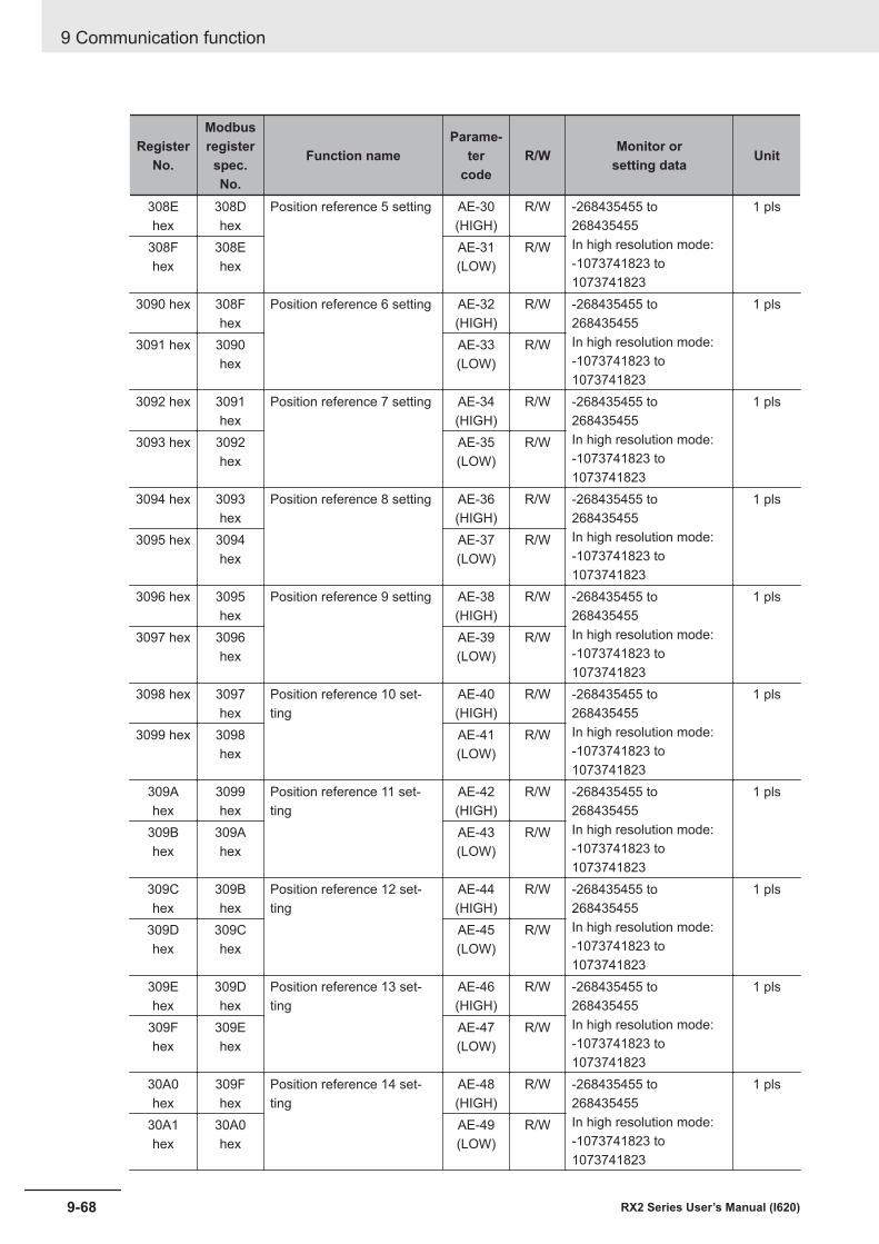
RegisterNo.
Modbusregisterspec.No.
Function nameParame-
tercode
R/W Monitor orsetting data Unit
308Ehex
308Dhex
Position reference 5 setting AE-30(HIGH)
R/W -268435455 to268435455In high resolution mode:-1073741823 to1073741823
1 pls
308Fhex
308Ehex
AE-31(LOW)
R/W
3090 hex 308Fhex
Position reference 6 setting AE-32(HIGH)
R/W -268435455 to268435455In high resolution mode:-1073741823 to1073741823
1 pls
3091 hex 3090hex
AE-33(LOW)
R/W
3092 hex 3091hex
Position reference 7 setting AE-34(HIGH)
R/W -268435455 to268435455In high resolution mode:-1073741823 to1073741823
1 pls
3093 hex 3092hex
AE-35(LOW)
R/W
3094 hex 3093hex
Position reference 8 setting AE-36(HIGH)
R/W -268435455 to268435455In high resolution mode:-1073741823 to1073741823
1 pls
3095 hex 3094hex
AE-37(LOW)
R/W
3096 hex 3095hex
Position reference 9 setting AE-38(HIGH)
R/W -268435455 to268435455In high resolution mode:-1073741823 to1073741823
1 pls
3097 hex 3096hex
AE-39(LOW)
R/W
3098 hex 3097hex
Position reference 10 set-ting
AE-40(HIGH)
R/W -268435455 to268435455In high resolution mode:-1073741823 to1073741823
1 pls
3099 hex 3098hex
AE-41(LOW)
R/W
309Ahex
3099hex
Position reference 11 set-ting
AE-42(HIGH)
R/W -268435455 to268435455In high resolution mode:-1073741823 to1073741823
1 pls
309Bhex
309Ahex
AE-43(LOW)
R/W
309Chex
309Bhex
Position reference 12 set-ting
AE-44(HIGH)
R/W -268435455 to268435455In high resolution mode:-1073741823 to1073741823
1 pls
309Dhex
309Chex
AE-45(LOW)
R/W
309Ehex
309Dhex
Position reference 13 set-ting
AE-46(HIGH)
R/W -268435455 to268435455In high resolution mode:-1073741823 to1073741823
1 pls
309Fhex
309Ehex
AE-47(LOW)
R/W
30A0hex
309Fhex
Position reference 14 set-ting
AE-48(HIGH)
R/W -268435455 to268435455In high resolution mode:-1073741823 to1073741823
1 pls
30A1hex
30A0hex
AE-49(LOW)
R/W
9 Communication function
9-68 RX2 Series User’s Manual (I620)
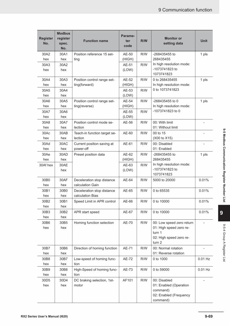
RegisterNo.
Modbusregisterspec.No.
Function nameParame-
tercode
R/W Monitor orsetting data Unit
30A2hex
30A1hex
Position reference 15 set-ting
AE-50(HIGH)
R/W -268435455 to268435455In high resolution mode:-1073741823 to1073741823
1 pls
30A3hex
30A2hex
AE-51(LOW)
R/W
30A4hex
30A3hex
Position control range set-ting(forward)
AE-52(HIGH)
R/W 0 to 268435455In high resolution mode:0 to 1073741823
1 pls
30A5hex
30A4hex
AE-53(LOW)
R/W
30A6hex
30A5hex
Position control range set-ting(reverse)
AE-54(HIGH)
R/W -268435455 to 0In high resolution mode:-1073741823 to 0
1 pls
30A7hex
30A6hex
AE-55(LOW)
R/W
30A8hex
30A7hex
Position control mode se-lection
AE-56 R/W 00: With limit01: Without limit
-
30Achex
30ABhex
Teach-in function target se-lection
AE-60 R/W 00 to 15(X00 to X15)
-
30Adhex
30AChex
Current position saving atpower-off
AE-61 R/W 00: Disabled01: Enabled
-
30Aehex
30ADhex
Preset position data AE-62(HIGH)
R/W -268435455 to268435455In high resolution mode:-1073741823 to1073741823
1 pls
30Af hex 30AEhex
AE-63(LOW)
R/W
30B0hex
30AFhex
Deceleration stop distancecalculation Gain
AE-64 R/W 5000 to 20000 0.01%
30B1hex
30B0hex
Deceleration stop distancecalculation Bias
AE-65 R/W 0 to 65535 0.01%
30B2hex
30B1hex
Speed Limit in APR control AE-66 R/W 0 to 10000 0.01%
30B3hex
30B2hex
APR start speed AE-67 R/W 0 to 10000 0.01%
30B6hex
30B5hex
Homing function selection AE-70 R/W 00: Low speed zero return01: High speed zero re-turn 102: High speed zero re-turn 2
-
30B7hex
30B6hex
Direction of homing function AE-71 R/W 00: Normal rotation01: Reverse rotation
-
30B8hex
30B7hex
Low-speed of homing func-tion
AE-72 R/W 0 to 1000 0.01 Hz
30B9hex
30B8hex
High-Speed of homing func-tion
AE-73 R/W 0 to 59000 0.01 Hz
30D5hex
30D4hex
DC braking selection, 1st-motor
AF101 R/W 00: Disabled01: Enabled (Operationcommand)02: Enabled (Frequencycommand)
-
9 Communication function
9-69RX2 Series User’s Manual (I620)
9-5 Modbus C
omm
unication Register N
umber List
9
9-5-4 Group A R
egister List
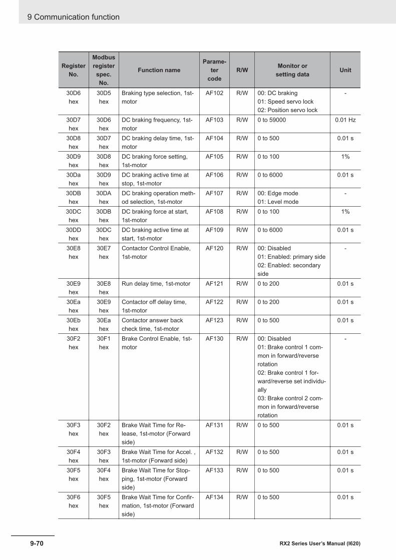
RegisterNo.
Modbusregisterspec.No.
Function nameParame-
tercode
R/W Monitor orsetting data Unit
30D6hex
30D5hex
Braking type selection, 1st-motor
AF102 R/W 00: DC braking01: Speed servo lock02: Position servo lock
-
30D7hex
30D6hex
DC braking frequency, 1st-motor
AF103 R/W 0 to 59000 0.01 Hz
30D8hex
30D7hex
DC braking delay time, 1st-motor
AF104 R/W 0 to 500 0.01 s
30D9hex
30D8hex
DC braking force setting,1st-motor
AF105 R/W 0 to 100 1%
30Dahex
30D9hex
DC braking active time atstop, 1st-motor
AF106 R/W 0 to 6000 0.01 s
30DBhex
30DAhex
DC braking operation meth-od selection, 1st-motor
AF107 R/W 00: Edge mode01: Level mode
-
30DChex
30DBhex
DC braking force at start,1st-motor
AF108 R/W 0 to 100 1%
30DDhex
30DChex
DC braking active time atstart, 1st-motor
AF109 R/W 0 to 6000 0.01 s
30E8hex
30E7hex
Contactor Control Enable,1st-motor
AF120 R/W 00: Disabled01: Enabled: primary side02: Enabled: secondaryside
-
30E9hex
30E8hex
Run delay time, 1st-motor AF121 R/W 0 to 200 0.01 s
30Eahex
30E9hex
Contactor off delay time,1st-motor
AF122 R/W 0 to 200 0.01 s
30Ebhex
30Eahex
Contactor answer backcheck time, 1st-motor
AF123 R/W 0 to 500 0.01 s
30F2hex
30F1hex
Brake Control Enable, 1st-motor
AF130 R/W 00: Disabled01: Brake control 1 com-mon in forward/reverserotation02: Brake control 1 for-ward/reverse set individu-ally03: Brake control 2 com-mon in forward/reverserotation
-
30F3hex
30F2hex
Brake Wait Time for Re-lease, 1st-motor (Forwardside)
AF131 R/W 0 to 500 0.01 s
30F4hex
30F3hex
Brake Wait Time for Accel. ,1st-motor (Forward side)
AF132 R/W 0 to 500 0.01 s
30F5hex
30F4hex
Brake Wait Time for Stop-ping, 1st-motor (Forwardside)
AF133 R/W 0 to 500 0.01 s
30F6hex
30F5hex
Brake Wait Time for Confir-mation, 1st-motor (Forwardside)
AF134 R/W 0 to 500 0.01 s
9 Communication function
9-70 RX2 Series User’s Manual (I620)
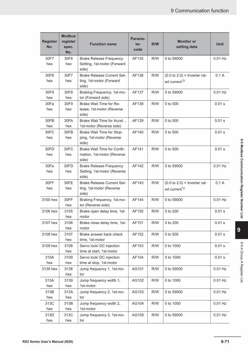
RegisterNo.
Modbusregisterspec.No.
Function nameParame-
tercode
R/W Monitor orsetting data Unit
30F7hex
30F6hex
Brake Release FrequencySetting, 1st-motor (Forwardside)
AF135 R/W 0 to 59000 0.01 Hz
30F8hex
30F7hex
Brake Release Current Set-ting, 1st-motor (Forwardside)
AF136 R/W (0.0 to 2.0) × Inverter rat-ed current*3
0.1 A
30F9hex
30F8hex
Braking Frequency, 1st-mo-tor (Forward side)
AF137 R/W 0 to 59000 0.01 Hz
30Fahex
30F9hex
Brake Wait Time for Re-lease, 1st-motor (Reverseside)
AF138 R/W 0 to 500 0.01 s
30FBhex
30FAhex
Brake Wait Time for Accel. ,1st-motor (Reverse side)
AF139 R/W 0 to 500 0.01 s
30FChex
30FBhex
Brake Wait Time for Stop-ping, 1st-motor (Reverseside)
AF140 R/W 0 to 500 0.01 s
30FDhex
30FChex
Brake Wait Time for Confir-mation, 1st-motor (Reverseside)
AF141 R/W 0 to 500 0.01 s
30Fehex
30FDhex
Brake Release FrequencySetting, 1st-motor (Reverseside)
AF142 R/W 0 to 59000 0.01 Hz
30FFhex
30FEhex
Brake Release Current Set-ting, 1st-motor (Reverseside)
AF143 R/W (0.0 to 2.0) × Inverter rat-ed current*3
0.1 A
3100 hex 30FFhex
Braking Frequency, 1st-mo-tor (Reverse side)
AF144 R/W 0 to 59000 0.01 Hz
3106 hex 3105hex
Brake open delay time, 1st-motor
AF150 R/W 0 to 200 0.01 s
3107 hex 3106hex
Brake close delay time, 1st-motor
AF151 R/W 0 to 200 0.01 s
3108 hex 3107hex
Brake answer back checktime, 1st-motor
AF152 R/W 0 to 500 0.01 s
3109 hex 3108hex
Servo lock/ DC injectiontime at start, 1st-motor
AF153 R/W 0 to 1000 0.01 s
310Ahex
3109hex
Servo lock/ DC injectiontime at stop, 1st-motor
AF154 R/W 0 to 1000 0.01 s
3139 hex 3138hex
Jump frequency 1, 1st-mo-tor
AG101 R/W 0 to 59000 0.01 Hz
313Ahex
3139hex
Jump frequency width 1,1st-motor
AG102 R/W 0 to 1000 0.01 Hz
313Bhex
313Ahex
Jump frequency 2, 1st-mo-tor
AG103 R/W 0 to 59000 0.01 Hz
313Chex
313Bhex
Jump frequency width 2,1st-motor
AG104 R/W 0 to 1000 0.01 Hz
313Dhex
313Chex
Jump frequency 3, 1st-mo-tor
AG105 R/W 0 to 59000 0.01 Hz
9 Communication function
9-71RX2 Series User’s Manual (I620)
9-5 Modbus C
omm
unication Register N
umber List
9
9-5-4 Group A R
egister List
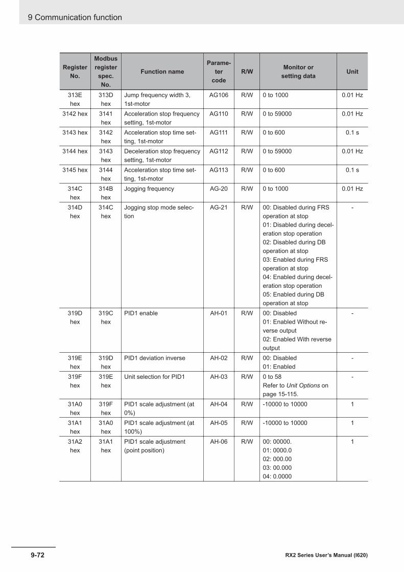
RegisterNo.
Modbusregisterspec.No.
Function nameParame-
tercode
R/W Monitor orsetting data Unit
313Ehex
313Dhex
Jump frequency width 3,1st-motor
AG106 R/W 0 to 1000 0.01 Hz
3142 hex 3141hex
Acceleration stop frequencysetting, 1st-motor
AG110 R/W 0 to 59000 0.01 Hz
3143 hex 3142hex
Acceleration stop time set-ting, 1st-motor
AG111 R/W 0 to 600 0.1 s
3144 hex 3143hex
Deceleration stop frequencysetting, 1st-motor
AG112 R/W 0 to 59000 0.01 Hz
3145 hex 3144hex
Acceleration stop time set-ting, 1st-motor
AG113 R/W 0 to 600 0.1 s
314Chex
314Bhex
Jogging frequency AG-20 R/W 0 to 1000 0.01 Hz
314Dhex
314Chex
Jogging stop mode selec-tion
AG-21 R/W 00: Disabled during FRSoperation at stop01: Disabled during decel-eration stop operation02: Disabled during DBoperation at stop03: Enabled during FRSoperation at stop04: Enabled during decel-eration stop operation05: Enabled during DBoperation at stop
-
319Dhex
319Chex
PID1 enable AH-01 R/W 00: Disabled01: Enabled Without re-verse output02: Enabled With reverseoutput
-
319Ehex
319Dhex
PID1 deviation inverse AH-02 R/W 00: Disabled01: Enabled
-
319Fhex
319Ehex
Unit selection for PID1 AH-03 R/W 0 to 58Refer to Unit Options onpage 15-115.
-
31A0hex
319Fhex
PID1 scale adjustment (at0%)
AH-04 R/W -10000 to 10000 1
31A1hex
31A0hex
PID1 scale adjustment (at100%)
AH-05 R/W -10000 to 10000 1
31A2hex
31A1hex
PID1 scale adjustment(point position)
AH-06 R/W 00: 00000.01: 0000.002: 000.0003: 00.00004: 0.0000
1
9 Communication function
9-72 RX2 Series User’s Manual (I620)
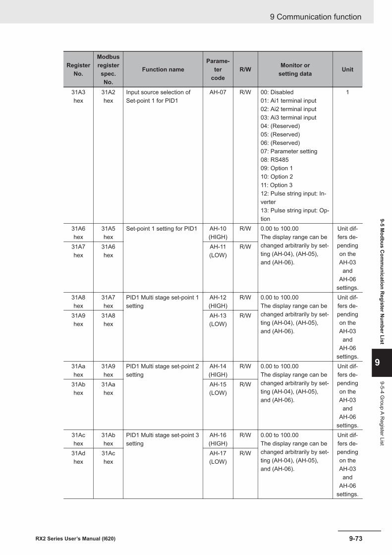
RegisterNo.
Modbusregisterspec.No.
Function nameParame-
tercode
R/W Monitor orsetting data Unit
31A3hex
31A2hex
Input source selection ofSet-point 1 for PID1
AH-07 R/W 00: Disabled01: Ai1 terminal input02: Ai2 terminal input03: Ai3 terminal input04: (Reserved)05: (Reserved)06: (Reserved)07: Parameter setting08: RS48509: Option 110: Option 211: Option 312: Pulse string input: In-verter13: Pulse string input: Op-tion
1
31A6hex
31A5hex
Set-point 1 setting for PID1 AH-10(HIGH)
R/W 0.00 to 100.00The display range can bechanged arbitrarily by set-ting (AH-04), (AH-05),and (AH-06).
Unit dif-fers de-pendingon theAH-03
andAH-06
settings.
31A7hex
31A6hex
AH-11(LOW)
R/W
31A8hex
31A7hex
PID1 Multi stage set-point 1setting
AH-12(HIGH)
R/W 0.00 to 100.00The display range can bechanged arbitrarily by set-ting (AH-04), (AH-05),and (AH-06).
Unit dif-fers de-pendingon theAH-03
andAH-06
settings.
31A9hex
31A8hex
AH-13(LOW)
R/W
31Aahex
31A9hex
PID1 Multi stage set-point 2setting
AH-14(HIGH)
R/W 0.00 to 100.00The display range can bechanged arbitrarily by set-ting (AH-04), (AH-05),and (AH-06).
Unit dif-fers de-pendingon theAH-03
andAH-06
settings.
31Abhex
31Aahex
AH-15(LOW)
R/W
31Achex
31Abhex
PID1 Multi stage set-point 3setting
AH-16(HIGH)
R/W 0.00 to 100.00The display range can bechanged arbitrarily by set-ting (AH-04), (AH-05),and (AH-06).
Unit dif-fers de-pendingon theAH-03
andAH-06
settings.
31Adhex
31Achex
AH-17(LOW)
R/W
9 Communication function
9-73RX2 Series User’s Manual (I620)
9-5 Modbus C
omm
unication Register N
umber List
9
9-5-4 Group A R
egister List
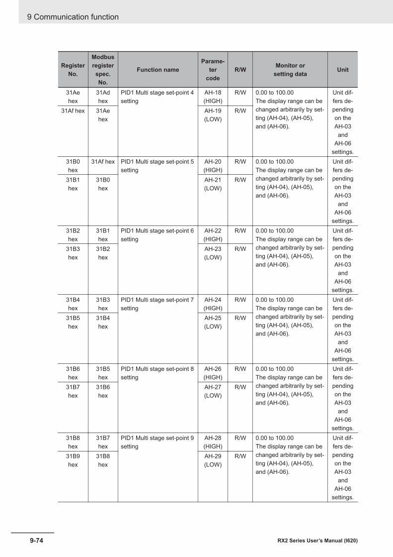
RegisterNo.
Modbusregisterspec.No.
Function nameParame-
tercode
R/W Monitor orsetting data Unit
31Aehex
31Adhex
PID1 Multi stage set-point 4setting
AH-18(HIGH)
R/W 0.00 to 100.00The display range can bechanged arbitrarily by set-ting (AH-04), (AH-05),and (AH-06).
Unit dif-fers de-pendingon theAH-03
andAH-06
settings.
31Af hex 31Aehex
AH-19(LOW)
R/W
31B0hex
31Af hex PID1 Multi stage set-point 5setting
AH-20(HIGH)
R/W 0.00 to 100.00The display range can bechanged arbitrarily by set-ting (AH-04), (AH-05),and (AH-06).
Unit dif-fers de-pendingon theAH-03
andAH-06
settings.
31B1hex
31B0hex
AH-21(LOW)
R/W
31B2hex
31B1hex
PID1 Multi stage set-point 6setting
AH-22(HIGH)
R/W 0.00 to 100.00The display range can bechanged arbitrarily by set-ting (AH-04), (AH-05),and (AH-06).
Unit dif-fers de-pendingon theAH-03
andAH-06
settings.
31B3hex
31B2hex
AH-23(LOW)
R/W
31B4hex
31B3hex
PID1 Multi stage set-point 7setting
AH-24(HIGH)
R/W 0.00 to 100.00The display range can bechanged arbitrarily by set-ting (AH-04), (AH-05),and (AH-06).
Unit dif-fers de-pendingon theAH-03
andAH-06
settings.
31B5hex
31B4hex
AH-25(LOW)
R/W
31B6hex
31B5hex
PID1 Multi stage set-point 8setting
AH-26(HIGH)
R/W 0.00 to 100.00The display range can bechanged arbitrarily by set-ting (AH-04), (AH-05),and (AH-06).
Unit dif-fers de-pendingon theAH-03
andAH-06
settings.
31B7hex
31B6hex
AH-27(LOW)
R/W
31B8hex
31B7hex
PID1 Multi stage set-point 9setting
AH-28(HIGH)
R/W 0.00 to 100.00The display range can bechanged arbitrarily by set-ting (AH-04), (AH-05),and (AH-06).
Unit dif-fers de-pendingon theAH-03
andAH-06
settings.
31B9hex
31B8hex
AH-29(LOW)
R/W
9 Communication function
9-74 RX2 Series User’s Manual (I620)
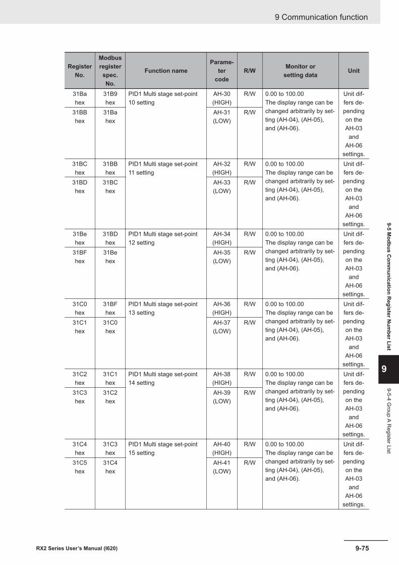
RegisterNo.
Modbusregisterspec.No.
Function nameParame-
tercode
R/W Monitor orsetting data Unit
31Bahex
31B9hex
PID1 Multi stage set-point10 setting
AH-30(HIGH)
R/W 0.00 to 100.00The display range can bechanged arbitrarily by set-ting (AH-04), (AH-05),and (AH-06).
Unit dif-fers de-pendingon theAH-03
andAH-06
settings.
31BBhex
31Bahex
AH-31(LOW)
R/W
31BChex
31BBhex
PID1 Multi stage set-point11 setting
AH-32(HIGH)
R/W 0.00 to 100.00The display range can bechanged arbitrarily by set-ting (AH-04), (AH-05),and (AH-06).
Unit dif-fers de-pendingon theAH-03
andAH-06
settings.
31BDhex
31BChex
AH-33(LOW)
R/W
31Behex
31BDhex
PID1 Multi stage set-point12 setting
AH-34(HIGH)
R/W 0.00 to 100.00The display range can bechanged arbitrarily by set-ting (AH-04), (AH-05),and (AH-06).
Unit dif-fers de-pendingon theAH-03
andAH-06
settings.
31BFhex
31Behex
AH-35(LOW)
R/W
31C0hex
31BFhex
PID1 Multi stage set-point13 setting
AH-36(HIGH)
R/W 0.00 to 100.00The display range can bechanged arbitrarily by set-ting (AH-04), (AH-05),and (AH-06).
Unit dif-fers de-pendingon theAH-03
andAH-06
settings.
31C1hex
31C0hex
AH-37(LOW)
R/W
31C2hex
31C1hex
PID1 Multi stage set-point14 setting
AH-38(HIGH)
R/W 0.00 to 100.00The display range can bechanged arbitrarily by set-ting (AH-04), (AH-05),and (AH-06).
Unit dif-fers de-pendingon theAH-03
andAH-06
settings.
31C3hex
31C2hex
AH-39(LOW)
R/W
31C4hex
31C3hex
PID1 Multi stage set-point15 setting
AH-40(HIGH)
R/W 0.00 to 100.00The display range can bechanged arbitrarily by set-ting (AH-04), (AH-05),and (AH-06).
Unit dif-fers de-pendingon theAH-03
andAH-06
settings.
31C5hex
31C4hex
AH-41(LOW)
R/W
9 Communication function
9-75RX2 Series User’s Manual (I620)
9-5 Modbus C
omm
unication Register N
umber List
9
9-5-4 Group A R
egister List
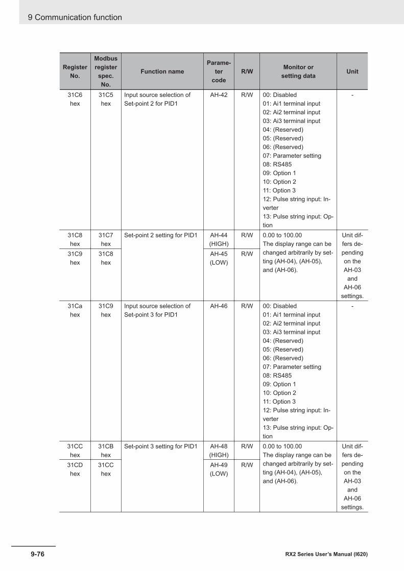
RegisterNo.
Modbusregisterspec.No.
Function nameParame-
tercode
R/W Monitor orsetting data Unit
31C6hex
31C5hex
Input source selection ofSet-point 2 for PID1
AH-42 R/W 00: Disabled01: Ai1 terminal input02: Ai2 terminal input03: Ai3 terminal input04: (Reserved)05: (Reserved)06: (Reserved)07: Parameter setting08: RS48509: Option 110: Option 211: Option 312: Pulse string input: In-verter13: Pulse string input: Op-tion
-
31C8hex
31C7hex
Set-point 2 setting for PID1 AH-44(HIGH)
R/W 0.00 to 100.00The display range can bechanged arbitrarily by set-ting (AH-04), (AH-05),and (AH-06).
Unit dif-fers de-pendingon theAH-03
andAH-06
settings.
31C9hex
31C8hex
AH-45(LOW)
R/W
31Cahex
31C9hex
Input source selection ofSet-point 3 for PID1
AH-46 R/W 00: Disabled01: Ai1 terminal input02: Ai2 terminal input03: Ai3 terminal input04: (Reserved)05: (Reserved)06: (Reserved)07: Parameter setting08: RS48509: Option 110: Option 211: Option 312: Pulse string input: In-verter13: Pulse string input: Op-tion
-
31CChex
31CBhex
Set-point 3 setting for PID1 AH-48(HIGH)
R/W 0.00 to 100.00The display range can bechanged arbitrarily by set-ting (AH-04), (AH-05),and (AH-06).
Unit dif-fers de-pendingon theAH-03
andAH-06
settings.
31CDhex
31CChex
AH-49(LOW)
R/W
9 Communication function
9-76 RX2 Series User’s Manual (I620)
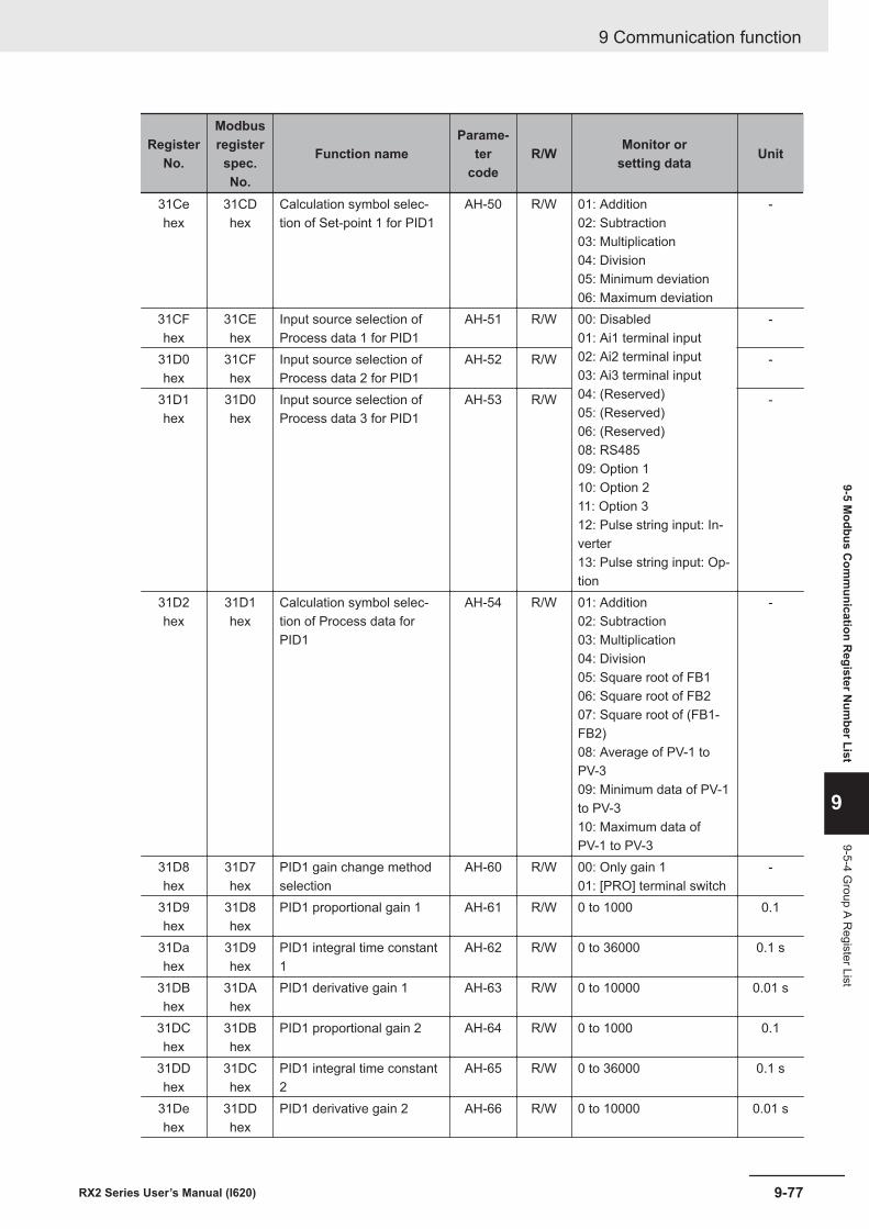
RegisterNo.
Modbusregisterspec.No.
Function nameParame-
tercode
R/W Monitor orsetting data Unit
31Cehex
31CDhex
Calculation symbol selec-tion of Set-point 1 for PID1
AH-50 R/W 01: Addition02: Subtraction03: Multiplication04: Division05: Minimum deviation06: Maximum deviation
-
31CFhex
31CEhex
Input source selection ofProcess data 1 for PID1
AH-51 R/W 00: Disabled01: Ai1 terminal input02: Ai2 terminal input03: Ai3 terminal input04: (Reserved)05: (Reserved)06: (Reserved)08: RS48509: Option 110: Option 211: Option 312: Pulse string input: In-verter13: Pulse string input: Op-tion
-
31D0hex
31CFhex
Input source selection ofProcess data 2 for PID1
AH-52 R/W -
31D1hex
31D0hex
Input source selection ofProcess data 3 for PID1
AH-53 R/W -
31D2hex
31D1hex
Calculation symbol selec-tion of Process data forPID1
AH-54 R/W 01: Addition02: Subtraction03: Multiplication04: Division05: Square root of FB106: Square root of FB207: Square root of (FB1-FB2)08: Average of PV-1 toPV-309: Minimum data of PV-1to PV-310: Maximum data ofPV-1 to PV-3
-
31D8hex
31D7hex
PID1 gain change methodselection
AH-60 R/W 00: Only gain 101: [PRO] terminal switch
-
31D9hex
31D8hex
PID1 proportional gain 1 AH-61 R/W 0 to 1000 0.1
31Dahex
31D9hex
PID1 integral time constant1
AH-62 R/W 0 to 36000 0.1 s
31DBhex
31DAhex
PID1 derivative gain 1 AH-63 R/W 0 to 10000 0.01 s
31DChex
31DBhex
PID1 proportional gain 2 AH-64 R/W 0 to 1000 0.1
31DDhex
31DChex
PID1 integral time constant2
AH-65 R/W 0 to 36000 0.1 s
31Dehex
31DDhex
PID1 derivative gain 2 AH-66 R/W 0 to 10000 0.01 s
9 Communication function
9-77RX2 Series User’s Manual (I620)
9-5 Modbus C
omm
unication Register N
umber List
9
9-5-4 Group A R
egister List
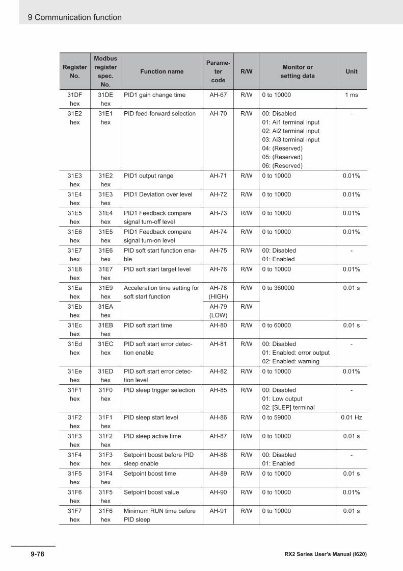
RegisterNo.
Modbusregisterspec.No.
Function nameParame-
tercode
R/W Monitor orsetting data Unit
31DFhex
31DEhex
PID1 gain change time AH-67 R/W 0 to 10000 1 ms
31E2hex
31E1hex
PID feed-forward selection AH-70 R/W 00: Disabled01: Ai1 terminal input02: Ai2 terminal input03: Ai3 terminal input04: (Reserved)05: (Reserved)06: (Reserved)
-
31E3hex
31E2hex
PID1 output range AH-71 R/W 0 to 10000 0.01%
31E4hex
31E3hex
PID1 Deviation over level AH-72 R/W 0 to 10000 0.01%
31E5hex
31E4hex
PID1 Feedback comparesignal turn-off level
AH-73 R/W 0 to 10000 0.01%
31E6hex
31E5hex
PID1 Feedback comparesignal turn-on level
AH-74 R/W 0 to 10000 0.01%
31E7hex
31E6hex
PID soft start function ena-ble
AH-75 R/W 00: Disabled01: Enabled
-
31E8hex
31E7hex
PID soft start target level AH-76 R/W 0 to 10000 0.01%
31Eahex
31E9hex
Acceleration time setting forsoft start function
AH-78(HIGH)
R/W 0 to 360000 0.01 s
31Ebhex
31EAhex
AH-79(LOW)
R/W
31Echex
31EBhex
PID soft start time AH-80 R/W 0 to 60000 0.01 s
31Edhex
31EChex
PID soft start error detec-tion enable
AH-81 R/W 00: Disabled01: Enabled: error output02: Enabled: warning
-
31Eehex
31EDhex
PID soft start error detec-tion level
AH-82 R/W 0 to 10000 0.01%
31F1hex
31F0hex
PID sleep trigger selection AH-85 R/W 00: Disabled01: Low output02: [SLEP] terminal
-
31F2hex
31F1hex
PID sleep start level AH-86 R/W 0 to 59000 0.01 Hz
31F3hex
31F2hex
PID sleep active time AH-87 R/W 0 to 10000 0.01 s
31F4hex
31F3hex
Setpoint boost before PIDsleep enable
AH-88 R/W 00: Disabled01: Enabled
-
31F5hex
31F4hex
Setpoint boost time AH-89 R/W 0 to 10000 0.01 s
31F6hex
31F5hex
Setpoint boost value AH-90 R/W 0 to 10000 0.01%
31F7hex
31F6hex
Minimum RUN time beforePID sleep
AH-91 R/W 0 to 10000 0.01 s
9 Communication function
9-78 RX2 Series User’s Manual (I620)
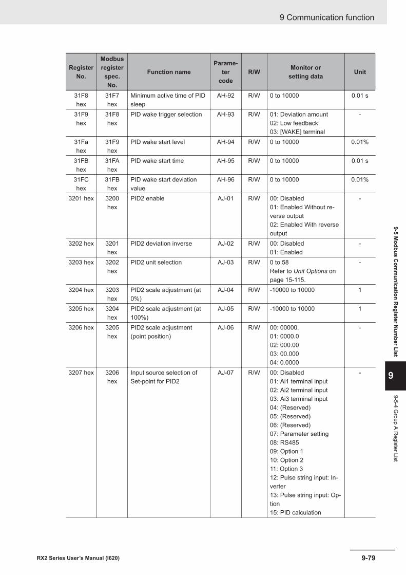
RegisterNo.
Modbusregisterspec.No.
Function nameParame-
tercode
R/W Monitor orsetting data Unit
31F8hex
31F7hex
Minimum active time of PIDsleep
AH-92 R/W 0 to 10000 0.01 s
31F9hex
31F8hex
PID wake trigger selection AH-93 R/W 01: Deviation amount02: Low feedback03: [WAKE] terminal
-
31Fahex
31F9hex
PID wake start level AH-94 R/W 0 to 10000 0.01%
31FBhex
31FAhex
PID wake start time AH-95 R/W 0 to 10000 0.01 s
31FChex
31FBhex
PID wake start deviationvalue
AH-96 R/W 0 to 10000 0.01%
3201 hex 3200hex
PID2 enable AJ-01 R/W 00: Disabled01: Enabled Without re-verse output02: Enabled With reverseoutput
-
3202 hex 3201hex
PID2 deviation inverse AJ-02 R/W 00: Disabled01: Enabled
-
3203 hex 3202hex
PID2 unit selection AJ-03 R/W 0 to 58Refer to Unit Options onpage 15-115.
-
3204 hex 3203hex
PID2 scale adjustment (at0%)
AJ-04 R/W -10000 to 10000 1
3205 hex 3204hex
PID2 scale adjustment (at100%)
AJ-05 R/W -10000 to 10000 1
3206 hex 3205hex
PID2 scale adjustment(point position)
AJ-06 R/W 00: 00000.01: 0000.002: 000.0003: 00.00004: 0.0000
-
3207 hex 3206hex
Input source selection ofSet-point for PID2
AJ-07 R/W 00: Disabled01: Ai1 terminal input02: Ai2 terminal input03: Ai3 terminal input04: (Reserved)05: (Reserved)06: (Reserved)07: Parameter setting08: RS48509: Option 110: Option 211: Option 312: Pulse string input: In-verter13: Pulse string input: Op-tion15: PID calculation
-
9 Communication function
9-79RX2 Series User’s Manual (I620)
9-5 Modbus C
omm
unication Register N
umber List
9
9-5-4 Group A R
egister List
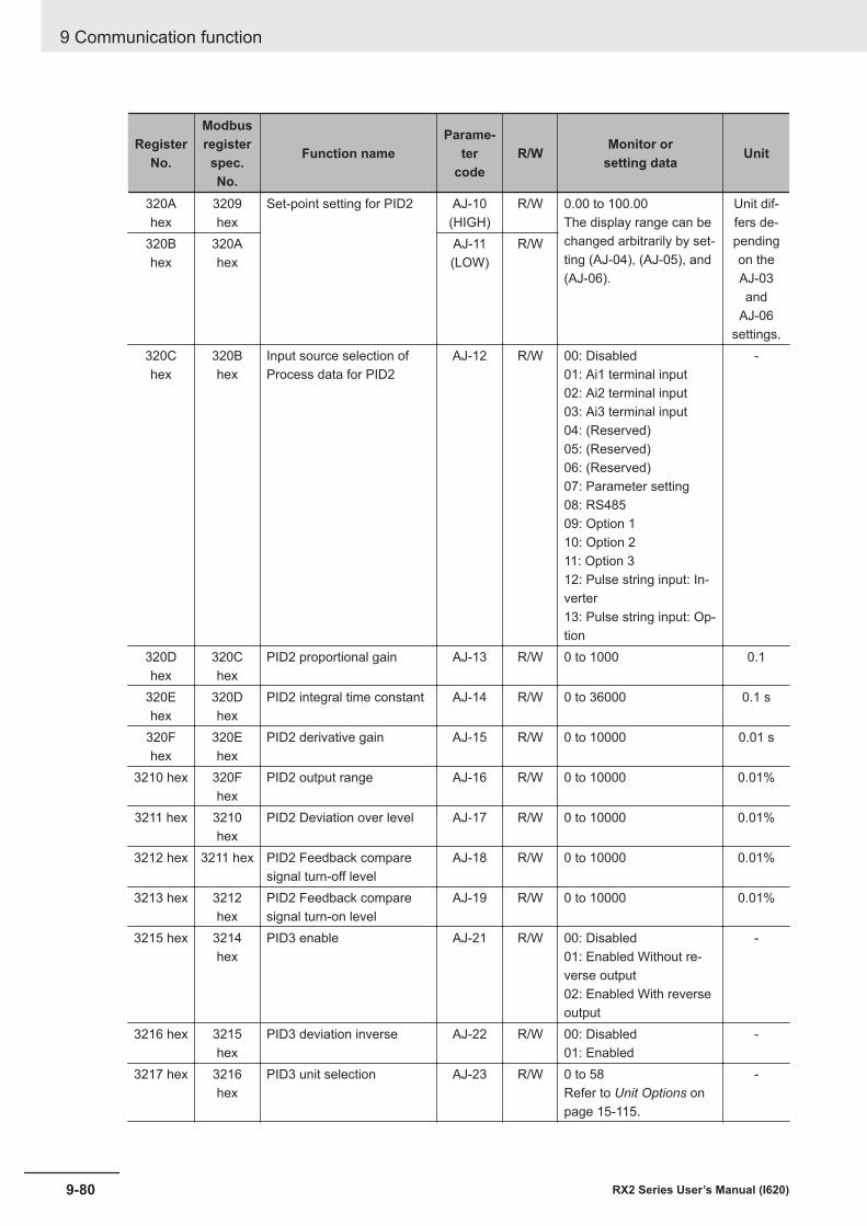
RegisterNo.
Modbusregisterspec.No.
Function nameParame-
tercode
R/W Monitor orsetting data Unit
320Ahex
3209hex
Set-point setting for PID2 AJ-10(HIGH)
R/W 0.00 to 100.00The display range can bechanged arbitrarily by set-ting (AJ-04), (AJ-05), and(AJ-06).
Unit dif-fers de-pendingon theAJ-03and
AJ-06settings.
320Bhex
320Ahex
AJ-11(LOW)
R/W
320Chex
320Bhex
Input source selection ofProcess data for PID2
AJ-12 R/W 00: Disabled01: Ai1 terminal input02: Ai2 terminal input03: Ai3 terminal input04: (Reserved)05: (Reserved)06: (Reserved)07: Parameter setting08: RS48509: Option 110: Option 211: Option 312: Pulse string input: In-verter13: Pulse string input: Op-tion
-
320Dhex
320Chex
PID2 proportional gain AJ-13 R/W 0 to 1000 0.1
320Ehex
320Dhex
PID2 integral time constant AJ-14 R/W 0 to 36000 0.1 s
320Fhex
320Ehex
PID2 derivative gain AJ-15 R/W 0 to 10000 0.01 s
3210 hex 320Fhex
PID2 output range AJ-16 R/W 0 to 10000 0.01%
3211 hex 3210hex
PID2 Deviation over level AJ-17 R/W 0 to 10000 0.01%
3212 hex 3211 hex PID2 Feedback comparesignal turn-off level
AJ-18 R/W 0 to 10000 0.01%
3213 hex 3212hex
PID2 Feedback comparesignal turn-on level
AJ-19 R/W 0 to 10000 0.01%
3215 hex 3214hex
PID3 enable AJ-21 R/W 00: Disabled01: Enabled Without re-verse output02: Enabled With reverseoutput
-
3216 hex 3215hex
PID3 deviation inverse AJ-22 R/W 00: Disabled01: Enabled
-
3217 hex 3216hex
PID3 unit selection AJ-23 R/W 0 to 58Refer to Unit Options onpage 15-115.
-
9 Communication function
9-80 RX2 Series User’s Manual (I620)
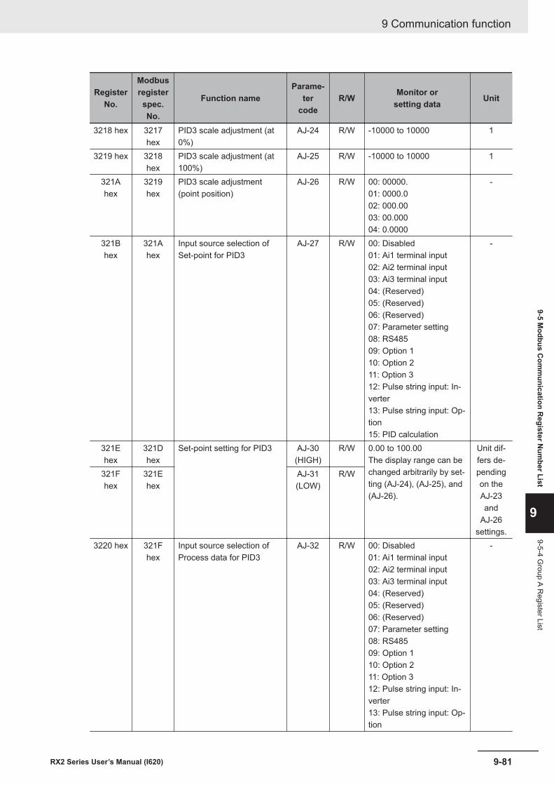
RegisterNo.
Modbusregisterspec.No.
Function nameParame-
tercode
R/W Monitor orsetting data Unit
3218 hex 3217hex
PID3 scale adjustment (at0%)
AJ-24 R/W -10000 to 10000 1
3219 hex 3218hex
PID3 scale adjustment (at100%)
AJ-25 R/W -10000 to 10000 1
321Ahex
3219hex
PID3 scale adjustment(point position)
AJ-26 R/W 00: 00000.01: 0000.002: 000.0003: 00.00004: 0.0000
-
321Bhex
321Ahex
Input source selection ofSet-point for PID3
AJ-27 R/W 00: Disabled01: Ai1 terminal input02: Ai2 terminal input03: Ai3 terminal input04: (Reserved)05: (Reserved)06: (Reserved)07: Parameter setting08: RS48509: Option 110: Option 211: Option 312: Pulse string input: In-verter13: Pulse string input: Op-tion15: PID calculation
-
321Ehex
321Dhex
Set-point setting for PID3 AJ-30(HIGH)
R/W 0.00 to 100.00The display range can bechanged arbitrarily by set-ting (AJ-24), (AJ-25), and(AJ-26).
Unit dif-fers de-pendingon theAJ-23and
AJ-26settings.
321Fhex
321Ehex
AJ-31(LOW)
R/W
3220 hex 321Fhex
Input source selection ofProcess data for PID3
AJ-32 R/W 00: Disabled01: Ai1 terminal input02: Ai2 terminal input03: Ai3 terminal input04: (Reserved)05: (Reserved)06: (Reserved)07: Parameter setting08: RS48509: Option 110: Option 211: Option 312: Pulse string input: In-verter13: Pulse string input: Op-tion
-
9 Communication function
9-81RX2 Series User’s Manual (I620)
9-5 Modbus C
omm
unication Register N
umber List
9
9-5-4 Group A R
egister List
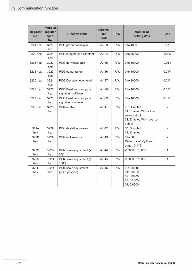
RegisterNo.
Modbusregisterspec.No.
Function nameParame-
tercode
R/W Monitor orsetting data Unit
3221 hex 3220hex
PID3 proportional gain AJ-33 R/W 0 to 1000 0.1
3222 hex 3221hex
PID3 integral time constant AJ-34 R/W 0 to 36000 0.1 s
3223 hex 3222hex
PID3 derivative gain AJ-35 R/W 0 to 10000 0.01 s
3224 hex 3223hex
PID3 output range AJ-36 R/W 0 to 10000 0.01%
3225 hex 3224hex
PID3 Deviation over level AJ-37 R/W 0 to 10000 0.01%
3226 hex 3225hex
PID3 Feedback comparesignal turn-off level
AJ-38 R/W 0 to 10000 0.01%
3227 hex 3226hex
PID3 Feedback comparesignal turn-on level
AJ-39 R/W 0 to 10000 0.01%
3229 hex 3228hex
PID4 enable AJ-41 R/W 00: Disabled01: Enabled Without re-verse output02: Enabled With reverseoutput
-
322Ahex
3229hex
PID4 deviation inverse AJ-42 R/W 00: Disabled01: Enabled
-
322Bhex
322Ahex
PID4 unit selection AJ-43 R/W 0 to 58Refer to Unit Options onpage 15-115.
-
322Chex
322Bhex
PID4 scale adjustment (at0%)
AJ-44 R/W -10000 to 10000 1
322Dhex
322Chex
PID4 scale adjustment (at100%)
AJ-45 R/W -10000 to 10000 1
322Ehex
322Dhex
PID4 scale adjustment(point position)
AJ-46 R/W 00: 00000.01: 0000.002: 000.0003: 00.00004: 0.0000
-
9 Communication function
9-82 RX2 Series User’s Manual (I620)
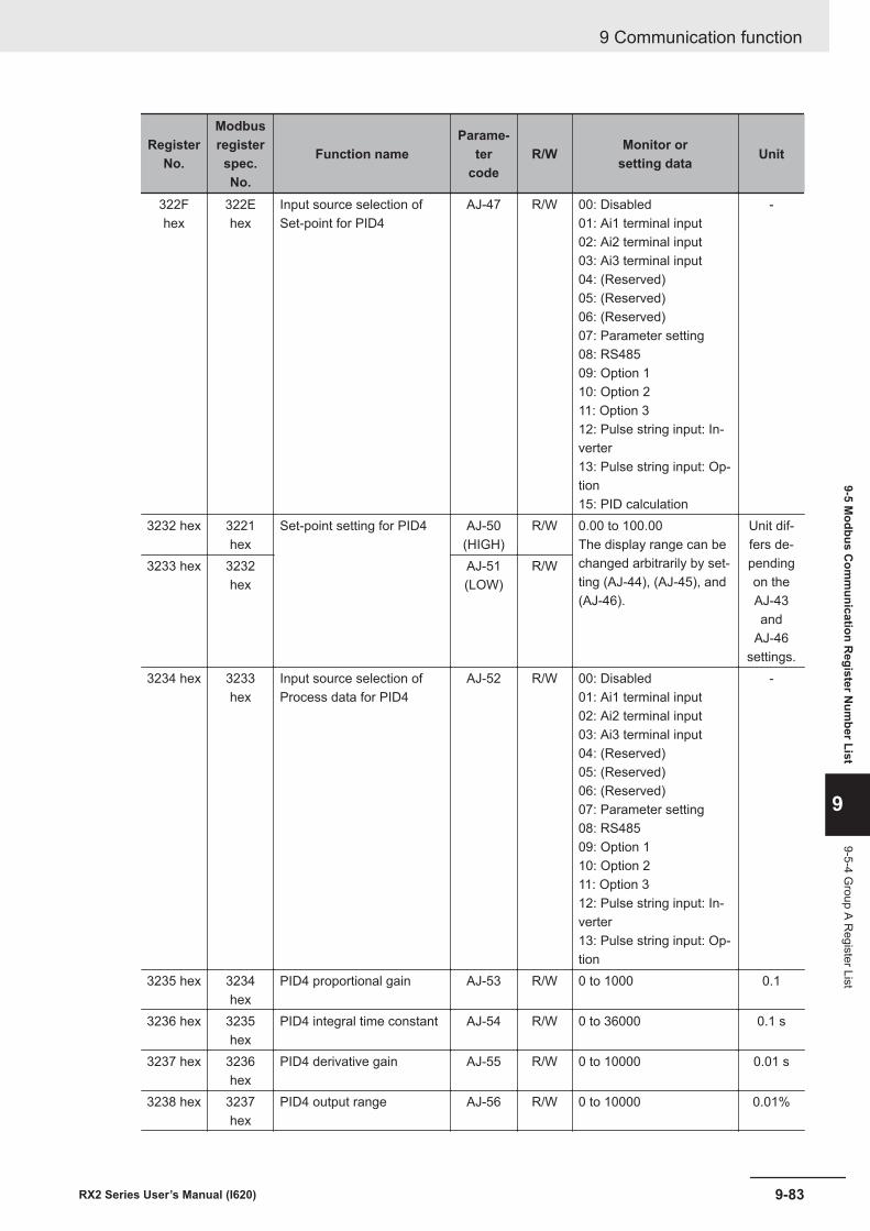
RegisterNo.
Modbusregisterspec.No.
Function nameParame-
tercode
R/W Monitor orsetting data Unit
322Fhex
322Ehex
Input source selection ofSet-point for PID4
AJ-47 R/W 00: Disabled01: Ai1 terminal input02: Ai2 terminal input03: Ai3 terminal input04: (Reserved)05: (Reserved)06: (Reserved)07: Parameter setting08: RS48509: Option 110: Option 211: Option 312: Pulse string input: In-verter13: Pulse string input: Op-tion15: PID calculation
-
3232 hex 3221hex
Set-point setting for PID4 AJ-50(HIGH)
R/W 0.00 to 100.00The display range can bechanged arbitrarily by set-ting (AJ-44), (AJ-45), and(AJ-46).
Unit dif-fers de-pendingon theAJ-43and
AJ-46settings.
3233 hex 3232hex
AJ-51(LOW)
R/W
3234 hex 3233hex
Input source selection ofProcess data for PID4
AJ-52 R/W 00: Disabled01: Ai1 terminal input02: Ai2 terminal input03: Ai3 terminal input04: (Reserved)05: (Reserved)06: (Reserved)07: Parameter setting08: RS48509: Option 110: Option 211: Option 312: Pulse string input: In-verter13: Pulse string input: Op-tion
-
3235 hex 3234hex
PID4 proportional gain AJ-53 R/W 0 to 1000 0.1
3236 hex 3235hex
PID4 integral time constant AJ-54 R/W 0 to 36000 0.1 s
3237 hex 3236hex
PID4 derivative gain AJ-55 R/W 0 to 10000 0.01 s
3238 hex 3237hex
PID4 output range AJ-56 R/W 0 to 10000 0.01%
9 Communication function
9-83RX2 Series User’s Manual (I620)
9-5 Modbus C
omm
unication Register N
umber List
9
9-5-4 Group A R
egister List
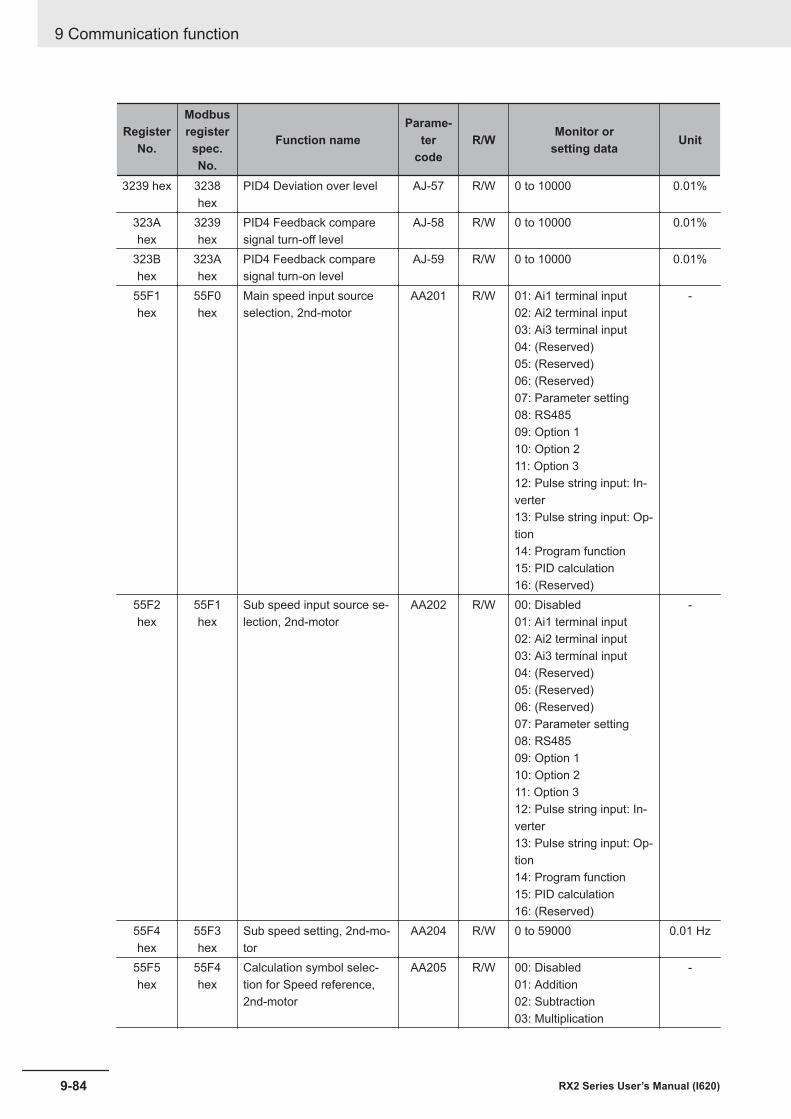
RegisterNo.
Modbusregisterspec.No.
Function nameParame-
tercode
R/W Monitor orsetting data Unit
3239 hex 3238hex
PID4 Deviation over level AJ-57 R/W 0 to 10000 0.01%
323Ahex
3239hex
PID4 Feedback comparesignal turn-off level
AJ-58 R/W 0 to 10000 0.01%
323Bhex
323Ahex
PID4 Feedback comparesignal turn-on level
AJ-59 R/W 0 to 10000 0.01%
55F1hex
55F0hex
Main speed input sourceselection, 2nd-motor
AA201 R/W 01: Ai1 terminal input02: Ai2 terminal input03: Ai3 terminal input04: (Reserved)05: (Reserved)06: (Reserved)07: Parameter setting08: RS48509: Option 110: Option 211: Option 312: Pulse string input: In-verter13: Pulse string input: Op-tion14: Program function15: PID calculation16: (Reserved)
-
55F2hex
55F1hex
Sub speed input source se-lection, 2nd-motor
AA202 R/W 00: Disabled01: Ai1 terminal input02: Ai2 terminal input03: Ai3 terminal input04: (Reserved)05: (Reserved)06: (Reserved)07: Parameter setting08: RS48509: Option 110: Option 211: Option 312: Pulse string input: In-verter13: Pulse string input: Op-tion14: Program function15: PID calculation16: (Reserved)
-
55F4hex
55F3hex
Sub speed setting, 2nd-mo-tor
AA204 R/W 0 to 59000 0.01 Hz
55F5hex
55F4hex
Calculation symbol selec-tion for Speed reference,2nd-motor
AA205 R/W 00: Disabled01: Addition02: Subtraction03: Multiplication
-
9 Communication function
9-84 RX2 Series User’s Manual (I620)
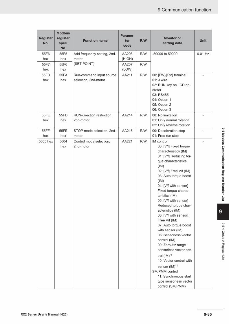
RegisterNo.
Modbusregisterspec.No.
Function nameParame-
tercode
R/W Monitor orsetting data Unit
55F6hex
55F5hex
Add frequency setting, 2nd-motor(SET-POINT)
AA206(HIGH)
R/W -59000 to 59000 0.01 Hz
55F7hex
55F6hex
AA207(LOW)
R/W
55FBhex
55FAhex
Run-command input sourceselection, 2nd-motor
AA211 R/W 00: [FW]/[RV] terminal01: 3 wire02: RUN key on LCD op-erator03: RS48504: Option 105: Option 206: Option 3
-
55FEhex
55FDhex
RUN-direction restriction,2nd-motor
AA214 R/W 00: No limitation01: Only normal rotation02: Only reverse rotation
-
55FFhex
55FEhex
STOP mode selection, 2nd-motor
AA215 R/W 00: Deceleration stop01: Free run stop
-
5605 hex 5604hex
Control mode selection,2nd-motor
AA221 R/W IM control00: [V/f] Fixed torquecharacteristics (IM)01: [V/f] Reducing tor-que characteristics(IM)02: [V/f] Free V/f (IM)03: Auto torque boost(IM)04: [V/f with sensor]Fixed torque charac-teristics (IM)05: [V/f with sensor]Reduced torque char-acteristics (IM)06: [V/f with sensor]Free V/f (IM)07: Auto torque boostwith sensor (IM)08: Sensorless vectorcontrol (IM)09: Zero-Hz rangesensorless vector con-trol (IM)*1
10: Vector control withsensor (IM)*1
SM/PMM control11: Synchronous starttype sensorless vectorcontrol (SM/PMM)
-
9 Communication function
9-85RX2 Series User’s Manual (I620)
9-5 Modbus C
omm
unication Register N
umber List
9
9-5-4 Group A R
egister List
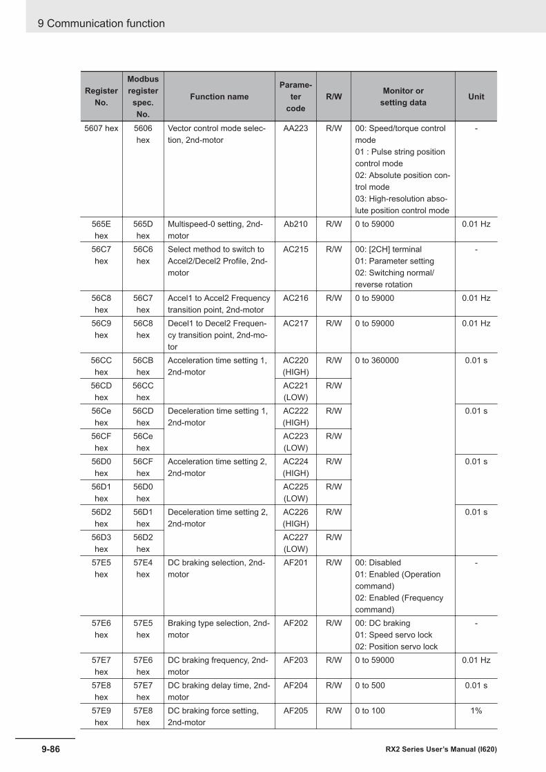
RegisterNo.
Modbusregisterspec.No.
Function nameParame-
tercode
R/W Monitor orsetting data Unit
5607 hex 5606hex
Vector control mode selec-tion, 2nd-motor
AA223 R/W 00: Speed/torque controlmode01 : Pulse string positioncontrol mode02: Absolute position con-trol mode03: High-resolution abso-lute position control mode
-
565Ehex
565Dhex
Multispeed-0 setting, 2nd-motor
Ab210 R/W 0 to 59000 0.01 Hz
56C7hex
56C6hex
Select method to switch toAccel2/Decel2 Profile, 2nd-motor
AC215 R/W 00: [2CH] terminal01: Parameter setting02: Switching normal/reverse rotation
-
56C8hex
56C7hex
Accel1 to Accel2 Frequencytransition point, 2nd-motor
AC216 R/W 0 to 59000 0.01 Hz
56C9hex
56C8hex
Decel1 to Decel2 Frequen-cy transition point, 2nd-mo-tor
AC217 R/W 0 to 59000 0.01 Hz
56CChex
56CBhex
Acceleration time setting 1,2nd-motor
AC220(HIGH)
R/W 0 to 360000 0.01 s
56CDhex
56CChex
AC221(LOW)
R/W
56Cehex
56CDhex
Deceleration time setting 1,2nd-motor
AC222(HIGH)
R/W 0.01 s
56CFhex
56Cehex
AC223(LOW)
R/W
56D0hex
56CFhex
Acceleration time setting 2,2nd-motor
AC224(HIGH)
R/W 0.01 s
56D1hex
56D0hex
AC225(LOW)
R/W
56D2hex
56D1hex
Deceleration time setting 2,2nd-motor
AC226(HIGH)
R/W 0.01 s
56D3hex
56D2hex
AC227(LOW)
R/W
57E5hex
57E4hex
DC braking selection, 2nd-motor
AF201 R/W 00: Disabled01: Enabled (Operationcommand)02: Enabled (Frequencycommand)
-
57E6hex
57E5hex
Braking type selection, 2nd-motor
AF202 R/W 00: DC braking01: Speed servo lock02: Position servo lock
-
57E7hex
57E6hex
DC braking frequency, 2nd-motor
AF203 R/W 0 to 59000 0.01 Hz
57E8hex
57E7hex
DC braking delay time, 2nd-motor
AF204 R/W 0 to 500 0.01 s
57E9hex
57E8hex
DC braking force setting,2nd-motor
AF205 R/W 0 to 100 1%
9 Communication function
9-86 RX2 Series User’s Manual (I620)
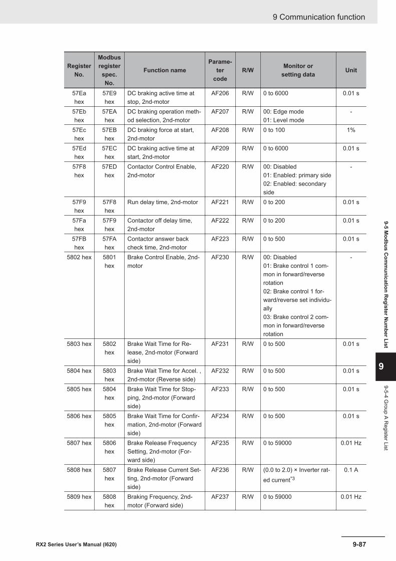
RegisterNo.
Modbusregisterspec.No.
Function nameParame-
tercode
R/W Monitor orsetting data Unit
57Eahex
57E9hex
DC braking active time atstop, 2nd-motor
AF206 R/W 0 to 6000 0.01 s
57Ebhex
57EAhex
DC braking operation meth-od selection, 2nd-motor
AF207 R/W 00: Edge mode01: Level mode
-
57Echex
57EBhex
DC braking force at start,2nd-motor
AF208 R/W 0 to 100 1%
57Edhex
57EChex
DC braking active time atstart, 2nd-motor
AF209 R/W 0 to 6000 0.01 s
57F8hex
57EDhex
Contactor Control Enable,2nd-motor
AF220 R/W 00: Disabled01: Enabled: primary side02: Enabled: secondaryside
-
57F9hex
57F8hex
Run delay time, 2nd-motor AF221 R/W 0 to 200 0.01 s
57Fahex
57F9hex
Contactor off delay time,2nd-motor
AF222 R/W 0 to 200 0.01 s
57FBhex
57FAhex
Contactor answer backcheck time, 2nd-motor
AF223 R/W 0 to 500 0.01 s
5802 hex 5801hex
Brake Control Enable, 2nd-motor
AF230 R/W 00: Disabled01: Brake control 1 com-mon in forward/reverserotation02: Brake control 1 for-ward/reverse set individu-ally03: Brake control 2 com-mon in forward/reverserotation
-
5803 hex 5802hex
Brake Wait Time for Re-lease, 2nd-motor (Forwardside)
AF231 R/W 0 to 500 0.01 s
5804 hex 5803hex
Brake Wait Time for Accel. ,2nd-motor (Reverse side)
AF232 R/W 0 to 500 0.01 s
5805 hex 5804hex
Brake Wait Time for Stop-ping, 2nd-motor (Forwardside)
AF233 R/W 0 to 500 0.01 s
5806 hex 5805hex
Brake Wait Time for Confir-mation, 2nd-motor (Forwardside)
AF234 R/W 0 to 500 0.01 s
5807 hex 5806hex
Brake Release FrequencySetting, 2nd-motor (For-ward side)
AF235 R/W 0 to 59000 0.01 Hz
5808 hex 5807hex
Brake Release Current Set-ting, 2nd-motor (Forwardside)
AF236 R/W (0.0 to 2.0) × Inverter rat-ed current*3
0.1 A
5809 hex 5808hex
Braking Frequency, 2nd-motor (Forward side)
AF237 R/W 0 to 59000 0.01 Hz
9 Communication function
9-87RX2 Series User’s Manual (I620)
9-5 Modbus C
omm
unication Register N
umber List
9
9-5-4 Group A R
egister List
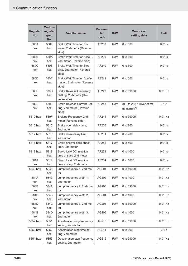
RegisterNo.
Modbusregisterspec.No.
Function nameParame-
tercode
R/W Monitor orsetting data Unit
580Ahex
5809hex
Brake Wait Time for Re-lease, 2nd-motor (Reverseside)
AF238 R/W 0 to 500 0.01 s
580Bhex
580Ahex
Brake Wait Time for Accel. ,2nd-motor (Reverse side)
AF239 R/W 0 to 500 0.01 s
580Chex
580Bhex
Brake Wait Time for Stop-ping, 2nd-motor (Reverseside)
AF240 R/W 0 to 500 0.01 s
580Dhex
580Chex
Brake Wait Time for Confir-mation, 2nd-motor (Reverseside)
AF241 R/W 0 to 500 0.01 s
580Ehex
580Dhex
Brake Release FrequencySetting, 2nd-motor (Re-verse side)
AF242 R/W 0 to 59000 0.01 Hz
580Fhex
580Ehex
Brake Release Current Set-ting, 2nd-motor (Reverseside)
AF243 R/W (0.0 to 2.0) × Inverter rat-ed current*3
0.1 A
5810 hex 580Fhex
Braking Frequency, 2nd-motor (Reverse side)
AF244 R/W 0 to 59000 0.01 Hz
5816 hex 5815hex
Brake open delay time,2nd-motor
AF250 R/W 0 to 200 0.01 s
5817 hex 5816hex
Brake close delay time,2nd-motor
AF251 R/W 0 to 200 0.01 s
5818 hex 5817hex
Brake answer back checktime, 2nd-motor
AF252 R/W 0 to 500 0.01 s
5819 hex 5818hex
Servo lock/ DC injectiontime at start, 2nd-motor
AF253 R/W 0 to 1000 0.01 s
581Ahex
5819hex
Servo lock/ DC injectiontime at stop, 2nd-motor
AF254 R/W 0 to 1000 0.01 s
5849 hex 5848hex
Jump frequency 1, 2nd-mo-tor
AG201 R/W 0 to 59000 0.01 Hz
584Ahex
5849hex
Jump frequency width 1,2nd-motor
AG202 R/W 0 to 1000 0.01 Hz
584Bhex
584Ahex
Jump frequency 2, 2nd-mo-tor
AG203 R/W 0 to 59000 0.01 Hz
584Chex
584Bhex
Jump frequency width 2,2nd-motor
AG204 R/W 0 to 1000 0.01 Hz
584Dhex
584Chex
Jump frequency 3, 2nd-mo-tor
AG205 R/W 0 to 59000 0.01 Hz
584Ehex
584Dhex
Jump frequency width 3,2nd-motor
AG206 R/W 0 to 1000 0.01 Hz
5852 hex 5851hex
Acceleration stop frequencysetting, 2nd-motor
AG210 R/W 0 to 59000 0.01 Hz
5853 hex 5852hex
Acceleration stop time set-ting, 2nd-motor
AG211 R/W 0 to 600 0.1 s
5854 hex 5853hex
Deceleration stop frequencysetting, 2nd-motor
AG212 R/W 0 to 59000 0.01 Hz
9 Communication function
9-88 RX2 Series User’s Manual (I620)
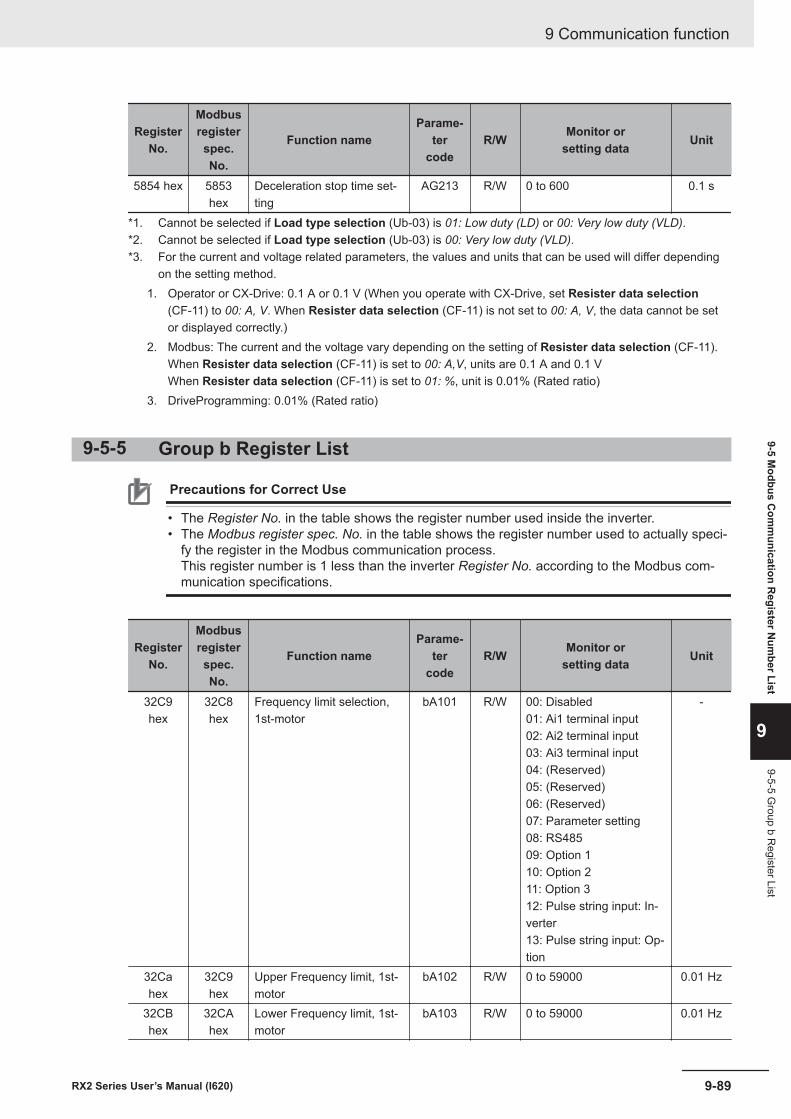
RegisterNo.
Modbusregisterspec.No.
Function nameParame-
tercode
R/W Monitor orsetting data Unit
5854 hex 5853hex
Deceleration stop time set-ting
AG213 R/W 0 to 600 0.1 s
*1. Cannot be selected if Load type selection (Ub-03) is 01: Low duty (LD) or 00: Very low duty (VLD).*2. Cannot be selected if Load type selection (Ub-03) is 00: Very low duty (VLD).*3. For the current and voltage related parameters, the values and units that can be used will differ depending
on the setting method.1. Operator or CX-Drive: 0.1 A or 0.1 V (When you operate with CX-Drive, set Resister data selection
(CF-11) to 00: A, V. When Resister data selection (CF-11) is not set to 00: A, V, the data cannot be setor displayed correctly.)
2. Modbus: The current and the voltage vary depending on the setting of Resister data selection (CF-11).When Resister data selection (CF-11) is set to 00: A,V, units are 0.1 A and 0.1 VWhen Resister data selection (CF-11) is set to 01: %, unit is 0.01% (Rated ratio)
3. DriveProgramming: 0.01% (Rated ratio)
9-5-5 Group b Register List
Precautions for Correct Use
• The Register No. in the table shows the register number used inside the inverter.• The Modbus register spec. No. in the table shows the register number used to actually speci-
fy the register in the Modbus communication process.This register number is 1 less than the inverter Register No. according to the Modbus com-munication specifications.
RegisterNo.
Modbusregisterspec.No.
Function nameParame-
tercode
R/W Monitor orsetting data Unit
32C9hex
32C8hex
Frequency limit selection,1st-motor
bA101 R/W 00: Disabled01: Ai1 terminal input02: Ai2 terminal input03: Ai3 terminal input04: (Reserved)05: (Reserved)06: (Reserved)07: Parameter setting08: RS48509: Option 110: Option 211: Option 312: Pulse string input: In-verter13: Pulse string input: Op-tion
-
32Cahex
32C9hex
Upper Frequency limit, 1st-motor
bA102 R/W 0 to 59000 0.01 Hz
32CBhex
32CAhex
Lower Frequency limit, 1st-motor
bA103 R/W 0 to 59000 0.01 Hz
9 Communication function
9-89RX2 Series User’s Manual (I620)
9-5 Modbus C
omm
unication Register N
umber List
9
9-5-5 Group b R
egister List
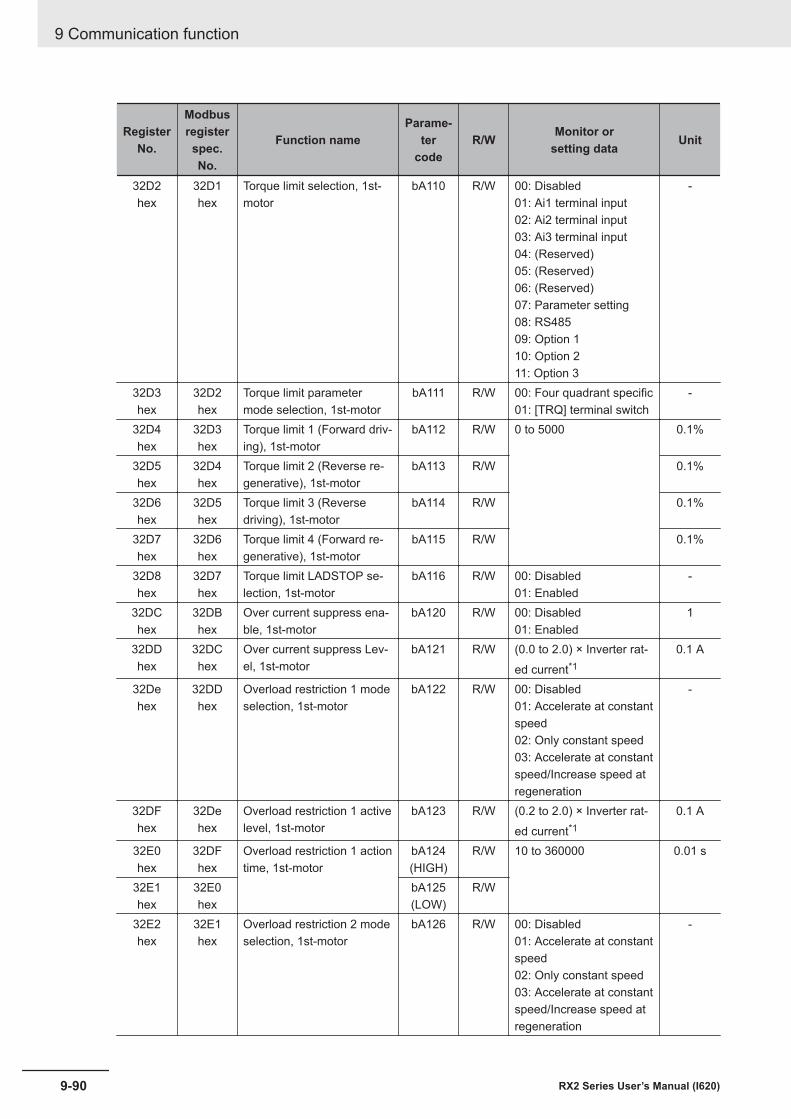
RegisterNo.
Modbusregisterspec.No.
Function nameParame-
tercode
R/W Monitor orsetting data Unit
32D2hex
32D1hex
Torque limit selection, 1st-motor
bA110 R/W 00: Disabled01: Ai1 terminal input02: Ai2 terminal input03: Ai3 terminal input04: (Reserved)05: (Reserved)06: (Reserved)07: Parameter setting08: RS48509: Option 110: Option 211: Option 3
-
32D3hex
32D2hex
Torque limit parametermode selection, 1st-motor
bA111 R/W 00: Four quadrant specific01: [TRQ] terminal switch
-
32D4hex
32D3hex
Torque limit 1 (Forward driv-ing), 1st-motor
bA112 R/W 0 to 5000 0.1%
32D5hex
32D4hex
Torque limit 2 (Reverse re-generative), 1st-motor
bA113 R/W 0.1%
32D6hex
32D5hex
Torque limit 3 (Reversedriving), 1st-motor
bA114 R/W 0.1%
32D7hex
32D6hex
Torque limit 4 (Forward re-generative), 1st-motor
bA115 R/W 0.1%
32D8hex
32D7hex
Torque limit LADSTOP se-lection, 1st-motor
bA116 R/W 00: Disabled01: Enabled
-
32DChex
32DBhex
Over current suppress ena-ble, 1st-motor
bA120 R/W 00: Disabled01: Enabled
1
32DDhex
32DChex
Over current suppress Lev-el, 1st-motor
bA121 R/W (0.0 to 2.0) × Inverter rat-ed current*1
0.1 A
32Dehex
32DDhex
Overload restriction 1 modeselection, 1st-motor
bA122 R/W 00: Disabled01: Accelerate at constantspeed02: Only constant speed03: Accelerate at constantspeed/Increase speed atregeneration
-
32DFhex
32Dehex
Overload restriction 1 activelevel, 1st-motor
bA123 R/W (0.2 to 2.0) × Inverter rat-ed current*1
0.1 A
32E0hex
32DFhex
Overload restriction 1 actiontime, 1st-motor
bA124(HIGH)
R/W 10 to 360000 0.01 s
32E1hex
32E0hex
bA125(LOW)
R/W
32E2hex
32E1hex
Overload restriction 2 modeselection, 1st-motor
bA126 R/W 00: Disabled01: Accelerate at constantspeed02: Only constant speed03: Accelerate at constantspeed/Increase speed atregeneration
-
9 Communication function
9-90 RX2 Series User’s Manual (I620)
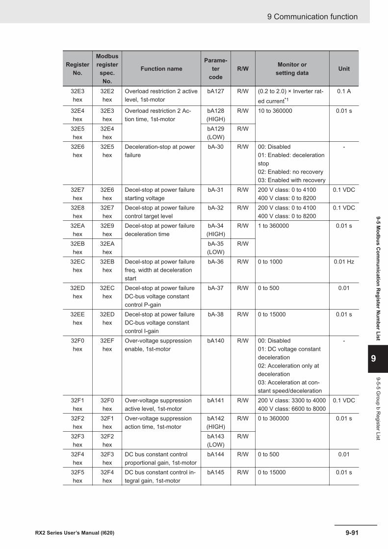
RegisterNo.
Modbusregisterspec.No.
Function nameParame-
tercode
R/W Monitor orsetting data Unit
32E3hex
32E2hex
Overload restriction 2 activelevel, 1st-motor
bA127 R/W (0.2 to 2.0) × Inverter rat-ed current*1
0.1 A
32E4hex
32E3hex
Overload restriction 2 Ac-tion time, 1st-motor
bA128(HIGH)
R/W 10 to 360000 0.01 s
32E5hex
32E4hex
bA129(LOW)
R/W
32E6hex
32E5hex
Deceleration-stop at powerfailure
bA-30 R/W 00: Disabled01: Enabled: decelerationstop02: Enabled: no recovery03: Enabled with recovery
-
32E7hex
32E6hex
Decel-stop at power failurestarting voltage
bA-31 R/W 200 V class: 0 to 4100400 V class: 0 to 8200
0.1 VDC
32E8hex
32E7hex
Decel-stop at power failurecontrol target level
bA-32 R/W 200 V class: 0 to 4100400 V class: 0 to 8200
0.1 VDC
32EAhex
32E9hex
Decel-stop at power failuredeceleration time
bA-34(HIGH)
R/W 1 to 360000 0.01 s
32EBhex
32EAhex
bA-35(LOW)
R/W
32EChex
32EBhex
Decel-stop at power failurefreq. width at decelerationstart
bA-36 R/W 0 to 1000 0.01 Hz
32EDhex
32EChex
Decel-stop at power failureDC-bus voltage constantcontrol P-gain
bA-37 R/W 0 to 500 0.01
32EEhex
32EDhex
Decel-stop at power failureDC-bus voltage constantcontrol I-gain
bA-38 R/W 0 to 15000 0.01 s
32F0hex
32EFhex
Over-voltage suppressionenable, 1st-motor
bA140 R/W 00: Disabled01: DC voltage constantdeceleration02: Acceleration only atdeceleration03: Acceleration at con-stant speed/deceleration
-
32F1hex
32F0hex
Over-voltage suppressionactive level, 1st-motor
bA141 R/W 200 V class: 3300 to 4000400 V class: 6600 to 8000
0.1 VDC
32F2hex
32F1hex
Over-voltage suppressionaction time, 1st-motor
bA142(HIGH)
R/W 0 to 360000 0.01 s
32F3hex
32F2hex
bA143(LOW)
R/W
32F4hex
32F3hex
DC bus constant controlproportional gain, 1st-motor
bA144 R/W 0 to 500 0.01
32F5hex
32F4hex
DC bus constant control in-tegral gain, 1st-motor
bA145 R/W 0 to 15000 0.01 s
9 Communication function
9-91RX2 Series User’s Manual (I620)
9-5 Modbus C
omm
unication Register N
umber List
9
9-5-5 Group b R
egister List
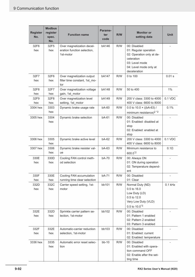
RegisterNo.
Modbusregisterspec.No.
Function nameParame-
tercode
R/W Monitor orsetting data Unit
32F6hex
32F5hex
Over magnetization decel-eration function selection,1st-motor
bA146 R/W 00: Disabled01: Regular operation02: Operation only at de-celeration03: Level mode04: Level mode only atdeceleration
-
32F7hex
32F6hex
Over magnetization outputfilter time constant, 1st_mo-tor
bA147 R/W 0 to 100 0.01 s
32F8hex
32F7hex
Over magnetization voltagegain, 1st_motor
bA148 R/W 50 to 400 1%
32F9hex
32F8hex
Over magnetization levelsetting, 1st_motor
bA149 R/W 200 V class: 3300 to 4000400 V class: 6600 to 8000
0.1 VDC
3304 hex 3303hex
Dynamic brake usage rate bA-60 R/W 0.0 to 10.0 × ((bA-63) /minimum resistance)2 *2
0.1%
3305 hex 3304hex
Dynamic brake selection bA-61 R/W 00: Disabled01: Enabled: disabled atstop02: Enabled: enabled atstop
-
3306 hex 3305hex
Dynamic brake active level bA-62 R/W 200 V class: 3300 to 4000400 V class: 6600 to 8000
0.1 VDC
3307 hex 3306hex
Dynamic brake resister val-ue
bA-63 R/W Minimum resistance to600.0*2
0.1Ω
330Ehex
330Dhex
Cooling FAN control meth-od selection
bA-70 R/W 00: Always ON01: ON during operation02: Temperature depend-ent
-
330Fhex
330Ehex
Cooling FAN accumulationrunning time clear selection
bA-71 R/W 00: Disabled01: Clear
-
332Dhex
332Chex
Carrier speed setting, 1st-motor
bb101 R/W Normal Duty (ND)0.5 to 16.0Low Duty (LD)0.5 to 12.0Very Low Duty (VLD)0.5 to 10.0*3
0.1 kHz
332Ehex
332Dhex
Sprinkle carrier pattern se-lection, 1st-motor
bb102 R/W 00: Disabled01: Pattern 1 enabled02: Pattern 2 enabled03: Pattern 3 enabled
-
332Fhex
332Ehex
Automatic-carrier reductionselection, 1st-motor
bb103 R/W 00: Disabled01: Enabled: current02: Enabled: temperature
-
3336 hex 3335hex
Automatic error reset selec-tion
bb-10 R/W 00: Disabled01: Enabled with opera-tion command OFF02: Enable after the set-ting time
-
9 Communication function
9-92 RX2 Series User’s Manual (I620)
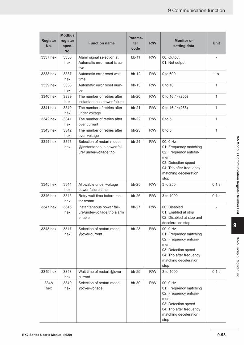
RegisterNo.
Modbusregisterspec.No.
Function nameParame-
tercode
R/W Monitor orsetting data Unit
3337 hex 3336hex
Alarm signal selection atAutomatic error reset is ac-tive
bb-11 R/W 00: Output01: Not output
-
3338 hex 3337hex
Automatic error reset waittime
bb-12 R/W 0 to 600 1 s
3339 hex 3338hex
Automatic error reset num-ber
bb-13 R/W 0 to 10 1
3340 hex 3339hex
The number of retries afterinstantaneous power failure
bb-20 R/W 0 to 16 / ∞(255) 1
3341 hex 3340hex
The number of retries afterunder voltage
bb-21 R/W 0 to 16 / ∞(255) 1
3342 hex 3341hex
The number of retries afterover current
bb-22 R/W 0 to 5 1
3343 hex 3342hex
The number of retries afterover-voltage
bb-23 R/W 0 to 5 1
3344 hex 3343hex
Selection of restart mode@Instantaneous power fail-ure/ under-voltage trip
bb-24 R/W 00: 0 Hz01: Frequency matching02: Frequency entrain-ment03: Detection speed04: Trip after frequencymatching decelerationstop
-
3345 hex 3344hex
Allowable under-voltagepower failure time
bb-25 R/W 3 to 250 0.1 s
3346 hex 3345hex
Retry wait time before mo-tor restart
bb-26 R/W 3 to 1000 0.1 s
3347 hex 3346hex
Instantaneous power fail-ure/under-voltage trip alarmenable
bb-27 R/W 00: Disabled01: Enabled at stop02: Disabled at stop anddeceleration stop
-
3348 hex 3347hex
Selection of restart mode@over-current
bb-28 R/W 00: 0 Hz01: Frequency matching02: Frequency entrain-ment03: Detection speed04: Trip after frequencymatching decelerationstop
-
3349 hex 3348hex
Wait time of restart @over-current
bb-29 R/W 3 to 1000 0.1 s
334Ahex
3349hex
Selection of restart mode@over-voltage
bb-30 R/W 00: 0 Hz01: Frequency matching02: Frequency entrain-ment03: Detection speed04: Trip after frequencymatching decelerationstop
-
9 Communication function
9-93RX2 Series User’s Manual (I620)
9-5 Modbus C
omm
unication Register N
umber List
9
9-5-5 Group b R
egister List
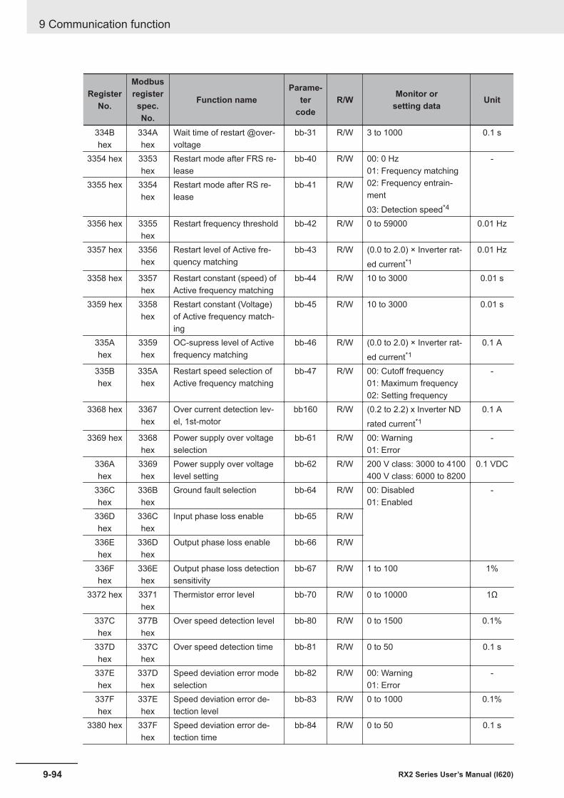
RegisterNo.
Modbusregisterspec.No.
Function nameParame-
tercode
R/W Monitor orsetting data Unit
334Bhex
334Ahex
Wait time of restart @over-voltage
bb-31 R/W 3 to 1000 0.1 s
3354 hex 3353hex
Restart mode after FRS re-lease
bb-40 R/W 00: 0 Hz01: Frequency matching02: Frequency entrain-ment03: Detection speed*4
-
3355 hex 3354hex
Restart mode after RS re-lease
bb-41 R/W
3356 hex 3355hex
Restart frequency threshold bb-42 R/W 0 to 59000 0.01 Hz
3357 hex 3356hex
Restart level of Active fre-quency matching
bb-43 R/W (0.0 to 2.0) × Inverter rat-ed current*1
0.01 Hz
3358 hex 3357hex
Restart constant (speed) ofActive frequency matching
bb-44 R/W 10 to 3000 0.01 s
3359 hex 3358hex
Restart constant (Voltage)of Active frequency match-ing
bb-45 R/W 10 to 3000 0.01 s
335Ahex
3359hex
OC-supress level of Activefrequency matching
bb-46 R/W (0.0 to 2.0) × Inverter rat-ed current*1
0.1 A
335Bhex
335Ahex
Restart speed selection ofActive frequency matching
bb-47 R/W 00: Cutoff frequency01: Maximum frequency02: Setting frequency
-
3368 hex 3367hex
Over current detection lev-el, 1st-motor
bb160 R/W (0.2 to 2.2) x Inverter NDrated current*1
0.1 A
3369 hex 3368hex
Power supply over voltageselection
bb-61 R/W 00: Warning01: Error
-
336Ahex
3369hex
Power supply over voltagelevel setting
bb-62 R/W 200 V class: 3000 to 4100400 V class: 6000 to 8200
0.1 VDC
336Chex
336Bhex
Ground fault selection bb-64 R/W 00: Disabled01: Enabled
-
336Dhex
336Chex
Input phase loss enable bb-65 R/W
336Ehex
336Dhex
Output phase loss enable bb-66 R/W
336Fhex
336Ehex
Output phase loss detectionsensitivity
bb-67 R/W 1 to 100 1%
3372 hex 3371hex
Thermistor error level bb-70 R/W 0 to 10000 1Ω
337Chex
377Bhex
Over speed detection level bb-80 R/W 0 to 1500 0.1%
337Dhex
337Chex
Over speed detection time bb-81 R/W 0 to 50 0.1 s
337Ehex
337Dhex
Speed deviation error modeselection
bb-82 R/W 00: Warning01: Error
-
337Fhex
337Ehex
Speed deviation error de-tection level
bb-83 R/W 0 to 1000 0.1%
3380 hex 337Fhex
Speed deviation error de-tection time
bb-84 R/W 0 to 50 0.1 s
9 Communication function
9-94 RX2 Series User’s Manual (I620)
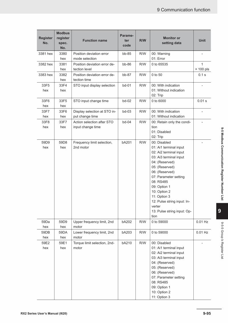
RegisterNo.
Modbusregisterspec.No.
Function nameParame-
tercode
R/W Monitor orsetting data Unit
3381 hex 3380hex
Position deviation errormode selection
bb-85 R/W 00: Warning01: Error
-
3382 hex 3381hex
Position deviation error de-tection level
bb-86 R/W 0 to 65535 1× 100 pls
3383 hex 3382hex
Position deviation error de-tection time
bb-87 R/W 0 to 50 0.1 s
33F5hex
33F4hex
STO input display selection bd-01 R/W 00: With indication01: Without indication02: Trip
-
33F6hex
33F5hex
STO input change time bd-02 R/W 0 to 6000 0.01 s
33F7hex
33F6hex
Display selection at STO in-put change time
bd-03 R/W 00: With indication01: Without indication
-
33F8hex
33F7hex
Action selection after STOinput change time
bd-04 R/W 00: Retain only the condi-tion01: Disabled02: Trip
-
59D9hex
59D8hex
Frequency limit selection,2nd motor
bA201 R/W 00: Disabled01: Ai1 terminal input02: Ai2 terminal input03: Ai3 terminal input04: (Reserved)05: (Reserved)06: (Reserved)07: Parameter setting08: RS48509: Option 110: Option 211: Option 312: Pulse string input: In-verter13: Pulse string input: Op-tion
-
59Dahex
59D9hex
Upper frequency limit, 2ndmotor
bA202 R/W 0 to 59000 0.01 Hz
59DBhex
59DAhex
Lower frequency limit, 2ndmotor
bA203 R/W 0 to 59000 0.01 Hz
59E2hex
59E1hex
Torque limit selection, 2nd-motor
bA210 R/W 00: Disabled01: Ai1 terminal input02: Ai2 terminal input03: Ai3 terminal input04: (Reserved)05: (Reserved)06: (Reserved)07: Parameter setting08: RS48509: Option 110: Option 211: Option 3
-
9 Communication function
9-95RX2 Series User’s Manual (I620)
9-5 Modbus C
omm
unication Register N
umber List
9
9-5-5 Group b R
egister List
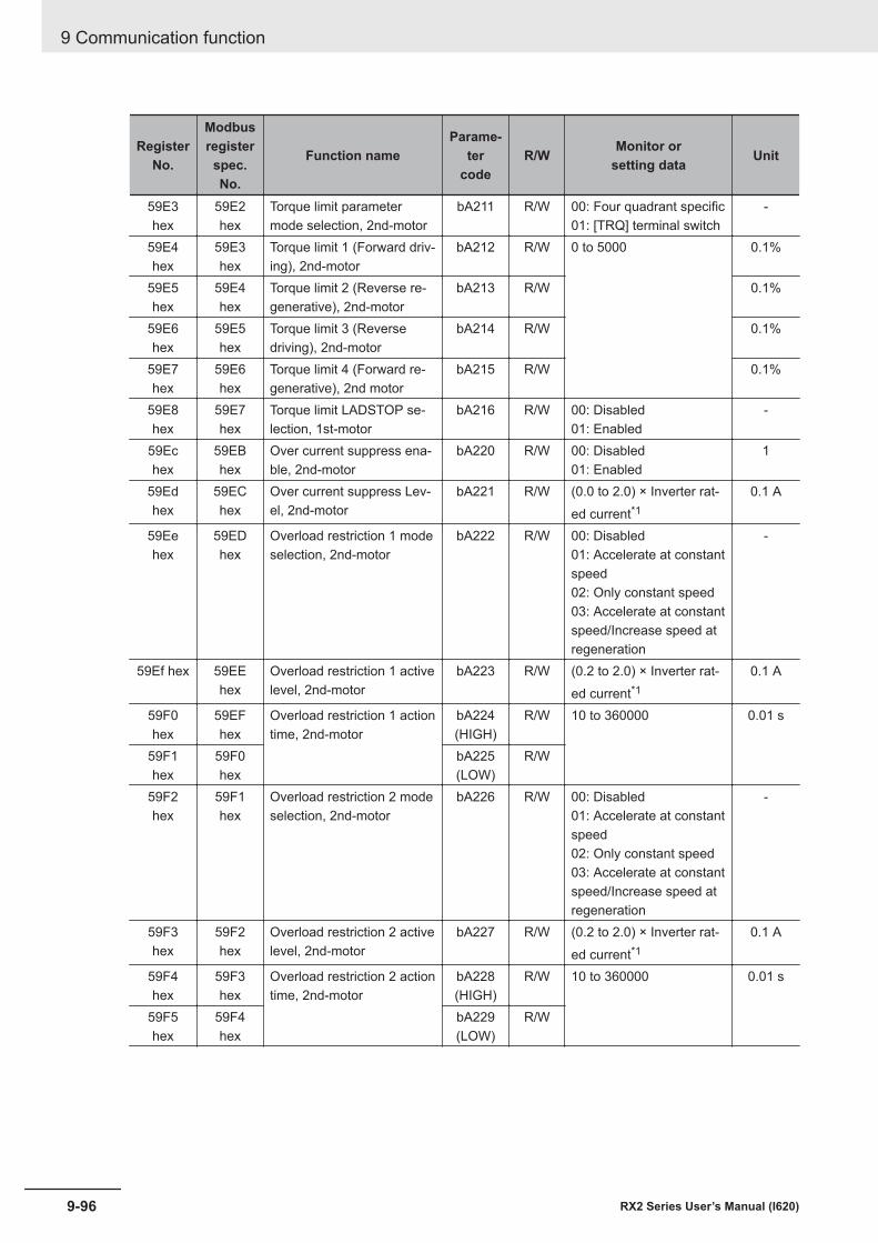
RegisterNo.
Modbusregisterspec.No.
Function nameParame-
tercode
R/W Monitor orsetting data Unit
59E3hex
59E2hex
Torque limit parametermode selection, 2nd-motor
bA211 R/W 00: Four quadrant specific01: [TRQ] terminal switch
-
59E4hex
59E3hex
Torque limit 1 (Forward driv-ing), 2nd-motor
bA212 R/W 0 to 5000 0.1%
59E5hex
59E4hex
Torque limit 2 (Reverse re-generative), 2nd-motor
bA213 R/W 0.1%
59E6hex
59E5hex
Torque limit 3 (Reversedriving), 2nd-motor
bA214 R/W 0.1%
59E7hex
59E6hex
Torque limit 4 (Forward re-generative), 2nd motor
bA215 R/W 0.1%
59E8hex
59E7hex
Torque limit LADSTOP se-lection, 1st-motor
bA216 R/W 00: Disabled01: Enabled
-
59Echex
59EBhex
Over current suppress ena-ble, 2nd-motor
bA220 R/W 00: Disabled01: Enabled
1
59Edhex
59EChex
Over current suppress Lev-el, 2nd-motor
bA221 R/W (0.0 to 2.0) × Inverter rat-ed current*1
0.1 A
59Eehex
59EDhex
Overload restriction 1 modeselection, 2nd-motor
bA222 R/W 00: Disabled01: Accelerate at constantspeed02: Only constant speed03: Accelerate at constantspeed/Increase speed atregeneration
-
59Ef hex 59EEhex
Overload restriction 1 activelevel, 2nd-motor
bA223 R/W (0.2 to 2.0) × Inverter rat-ed current*1
0.1 A
59F0hex
59EFhex
Overload restriction 1 actiontime, 2nd-motor
bA224(HIGH)
R/W 10 to 360000 0.01 s
59F1hex
59F0hex
bA225(LOW)
R/W
59F2hex
59F1hex
Overload restriction 2 modeselection, 2nd-motor
bA226 R/W 00: Disabled01: Accelerate at constantspeed02: Only constant speed03: Accelerate at constantspeed/Increase speed atregeneration
-
59F3hex
59F2hex
Overload restriction 2 activelevel, 2nd-motor
bA227 R/W (0.2 to 2.0) × Inverter rat-ed current*1
0.1 A
59F4hex
59F3hex
Overload restriction 2 actiontime, 2nd-motor
bA228(HIGH)
R/W 10 to 360000 0.01 s
59F5hex
59F4hex
bA229(LOW)
R/W
9 Communication function
9-96 RX2 Series User’s Manual (I620)
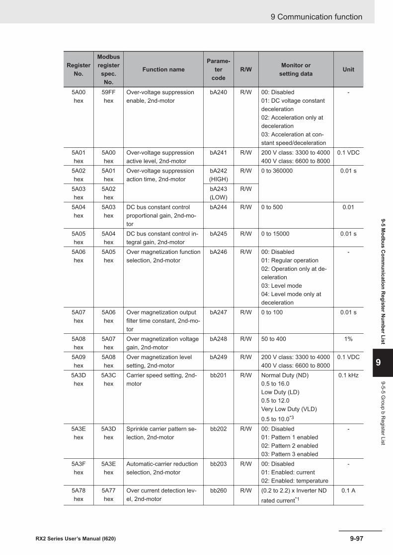
RegisterNo.
Modbusregisterspec.No.
Function nameParame-
tercode
R/W Monitor orsetting data Unit
5A00hex
59FFhex
Over-voltage suppressionenable, 2nd-motor
bA240 R/W 00: Disabled01: DC voltage constantdeceleration02: Acceleration only atdeceleration03: Acceleration at con-stant speed/deceleration
-
5A01hex
5A00hex
Over-voltage suppressionactive level, 2nd-motor
bA241 R/W 200 V class: 3300 to 4000400 V class: 6600 to 8000
0.1 VDC
5A02hex
5A01hex
Over-voltage suppressionaction time, 2nd-motor
bA242(HIGH)
R/W 0 to 360000 0.01 s
5A03hex
5A02hex
bA243(LOW)
R/W
5A04hex
5A03hex
DC bus constant controlproportional gain, 2nd-mo-tor
bA244 R/W 0 to 500 0.01
5A05hex
5A04hex
DC bus constant control in-tegral gain, 2nd-motor
bA245 R/W 0 to 15000 0.01 s
5A06hex
5A05hex
Over magnetization functionselection, 2nd-motor
bA246 R/W 00: Disabled01: Regular operation02: Operation only at de-celeration03: Level mode04: Level mode only atdeceleration
-
5A07hex
5A06hex
Over magnetization outputfilter time constant, 2nd-mo-tor
bA247 R/W 0 to 100 0.01 s
5A08hex
5A07hex
Over magnetization voltagegain, 2nd-motor
bA248 R/W 50 to 400 1%
5A09hex
5A08hex
Over magnetization levelsetting, 2nd-motor
bA249 R/W 200 V class: 3300 to 4000400 V class: 6600 to 8000
0.1 VDC
5A3Dhex
5A3Chex
Carrier speed setting, 2nd-motor
bb201 R/W Normal Duty (ND)0.5 to 16.0Low Duty (LD)0.5 to 12.0Very Low Duty (VLD)0.5 to 10.0*3
0.1 kHz
5A3Ehex
5A3Dhex
Sprinkle carrier pattern se-lection, 2nd-motor
bb202 R/W 00: Disabled01: Pattern 1 enabled02: Pattern 2 enabled03: Pattern 3 enabled
-
5A3Fhex
5A3Ehex
Automatic-carrier reductionselection, 2nd-motor
bb203 R/W 00: Disabled01: Enabled: current02: Enabled: temperature
-
5A78hex
5A77hex
Over current detection lev-el, 2nd-motor
bb260 R/W (0.2 to 2.2) x Inverter NDrated current*1
0.1 A
9 Communication function
9-97RX2 Series User’s Manual (I620)
9-5 Modbus C
omm
unication Register N
umber List
9
9-5-5 Group b R
egister List
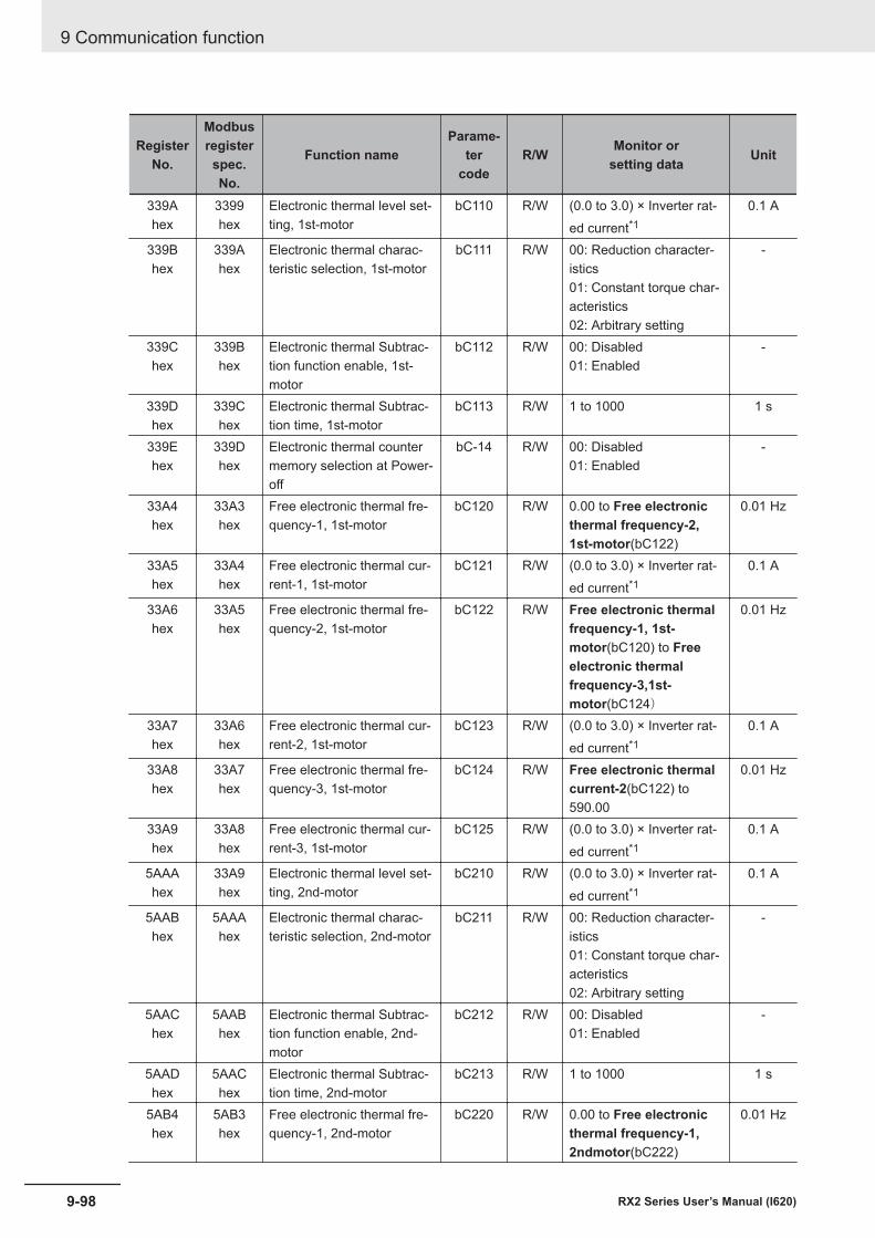
RegisterNo.
Modbusregisterspec.No.
Function nameParame-
tercode
R/W Monitor orsetting data Unit
339Ahex
3399hex
Electronic thermal level set-ting, 1st-motor
bC110 R/W (0.0 to 3.0) × Inverter rat-ed current*1
0.1 A
339Bhex
339Ahex
Electronic thermal charac-teristic selection, 1st-motor
bC111 R/W 00: Reduction character-istics01: Constant torque char-acteristics02: Arbitrary setting
-
339Chex
339Bhex
Electronic thermal Subtrac-tion function enable, 1st-motor
bC112 R/W 00: Disabled01: Enabled
-
339Dhex
339Chex
Electronic thermal Subtrac-tion time, 1st-motor
bC113 R/W 1 to 1000 1 s
339Ehex
339Dhex
Electronic thermal countermemory selection at Power-off
bC-14 R/W 00: Disabled01: Enabled
-
33A4hex
33A3hex
Free electronic thermal fre-quency-1, 1st-motor
bC120 R/W 0.00 to Free electronicthermal frequency-2,1st-motor(bC122)
0.01 Hz
33A5hex
33A4hex
Free electronic thermal cur-rent-1, 1st-motor
bC121 R/W (0.0 to 3.0) × Inverter rat-ed current*1
0.1 A
33A6hex
33A5hex
Free electronic thermal fre-quency-2, 1st-motor
bC122 R/W Free electronic thermalfrequency-1, 1st-motor(bC120) to Freeelectronic thermalfrequency-3,1st-motor(bC124)
0.01 Hz
33A7hex
33A6hex
Free electronic thermal cur-rent-2, 1st-motor
bC123 R/W (0.0 to 3.0) × Inverter rat-ed current*1
0.1 A
33A8hex
33A7hex
Free electronic thermal fre-quency-3, 1st-motor
bC124 R/W Free electronic thermalcurrent-2(bC122) to590.00
0.01 Hz
33A9hex
33A8hex
Free electronic thermal cur-rent-3, 1st-motor
bC125 R/W (0.0 to 3.0) × Inverter rat-ed current*1
0.1 A
5AAAhex
33A9hex
Electronic thermal level set-ting, 2nd-motor
bC210 R/W (0.0 to 3.0) × Inverter rat-ed current*1
0.1 A
5AABhex
5AAAhex
Electronic thermal charac-teristic selection, 2nd-motor
bC211 R/W 00: Reduction character-istics01: Constant torque char-acteristics02: Arbitrary setting
-
5AAChex
5AABhex
Electronic thermal Subtrac-tion function enable, 2nd-motor
bC212 R/W 00: Disabled01: Enabled
-
5AADhex
5AAChex
Electronic thermal Subtrac-tion time, 2nd-motor
bC213 R/W 1 to 1000 1 s
5AB4hex
5AB3hex
Free electronic thermal fre-quency-1, 2nd-motor
bC220 R/W 0.00 to Free electronicthermal frequency-1,2ndmotor(bC222)
0.01 Hz
9 Communication function
9-98 RX2 Series User’s Manual (I620)
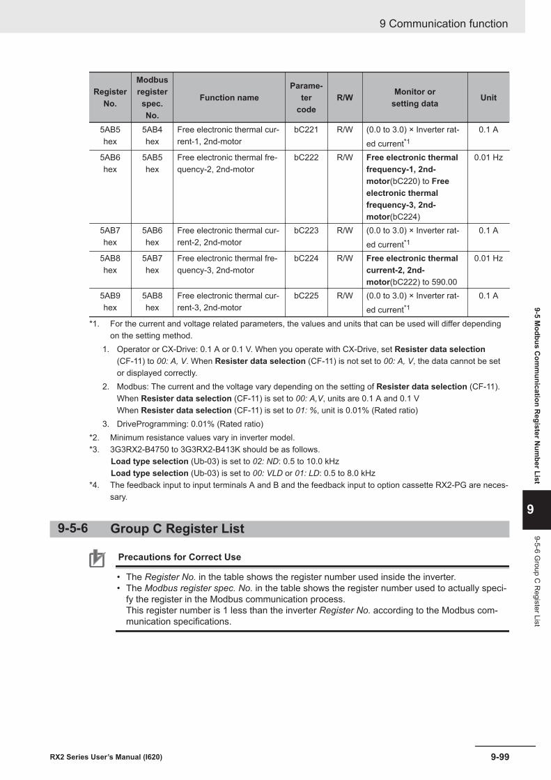
RegisterNo.
Modbusregisterspec.No.
Function nameParame-
tercode
R/W Monitor orsetting data Unit
5AB5hex
5AB4hex
Free electronic thermal cur-rent-1, 2nd-motor
bC221 R/W (0.0 to 3.0) × Inverter rat-ed current*1
0.1 A
5AB6hex
5AB5hex
Free electronic thermal fre-quency-2, 2nd-motor
bC222 R/W Free electronic thermalfrequency-1, 2nd-motor(bC220) to Freeelectronic thermalfrequency-3, 2nd-motor(bC224)
0.01 Hz
5AB7hex
5AB6hex
Free electronic thermal cur-rent-2, 2nd-motor
bC223 R/W (0.0 to 3.0) × Inverter rat-ed current*1
0.1 A
5AB8hex
5AB7hex
Free electronic thermal fre-quency-3, 2nd-motor
bC224 R/W Free electronic thermalcurrent-2, 2nd-motor(bC222) to 590.00
0.01 Hz
5AB9hex
5AB8hex
Free electronic thermal cur-rent-3, 2nd-motor
bC225 R/W (0.0 to 3.0) × Inverter rat-ed current*1
0.1 A
*1. For the current and voltage related parameters, the values and units that can be used will differ dependingon the setting method.
1. Operator or CX-Drive: 0.1 A or 0.1 V. When you operate with CX-Drive, set Resister data selection(CF-11) to 00: A, V. When Resister data selection (CF-11) is not set to 00: A, V, the data cannot be setor displayed correctly.
2. Modbus: The current and the voltage vary depending on the setting of Resister data selection (CF-11).When Resister data selection (CF-11) is set to 00: A,V, units are 0.1 A and 0.1 VWhen Resister data selection (CF-11) is set to 01: %, unit is 0.01% (Rated ratio)
3. DriveProgramming: 0.01% (Rated ratio)*2. Minimum resistance values vary in inverter model.*3. 3G3RX2-B4750 to 3G3RX2-B413K should be as follows.
Load type selection (Ub-03) is set to 02: ND: 0.5 to 10.0 kHz Load type selection (Ub-03) is set to 00: VLD or 01: LD: 0.5 to 8.0 kHz
*4. The feedback input to input terminals A and B and the feedback input to option cassette RX2-PG are neces-sary.
9-5-6 Group C Register List
Precautions for Correct Use
• The Register No. in the table shows the register number used inside the inverter.• The Modbus register spec. No. in the table shows the register number used to actually speci-
fy the register in the Modbus communication process.This register number is 1 less than the inverter Register No. according to the Modbus com-munication specifications.
9 Communication function
9-99RX2 Series User’s Manual (I620)
9-5 Modbus C
omm
unication Register N
umber List
9
9-5-6 Group C
Register List
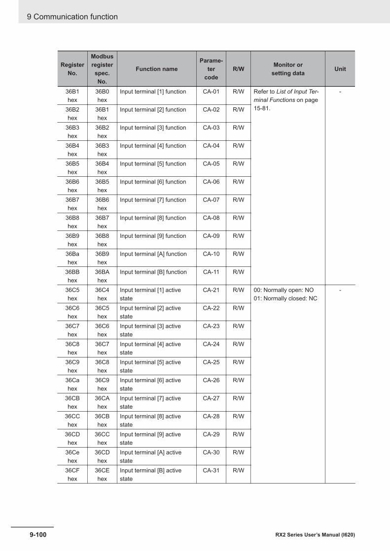
RegisterNo.
Modbusregisterspec.No.
Function nameParame-
tercode
R/W Monitor orsetting data Unit
36B1hex
36B0hex
Input terminal [1] function CA-01 R/W Refer to List of Input Ter-minal Functions on page15-81.
-
36B2hex
36B1hex
Input terminal [2] function CA-02 R/W
36B3hex
36B2hex
Input terminal [3] function CA-03 R/W
36B4hex
36B3hex
Input terminal [4] function CA-04 R/W
36B5hex
36B4hex
Input terminal [5] function CA-05 R/W
36B6hex
36B5hex
Input terminal [6] function CA-06 R/W
36B7hex
36B6hex
Input terminal [7] function CA-07 R/W
36B8hex
36B7hex
Input terminal [8] function CA-08 R/W
36B9hex
36B8hex
Input terminal [9] function CA-09 R/W
36Bahex
36B9hex
Input terminal [A] function CA-10 R/W
36BBhex
36BAhex
Input terminal [B] function CA-11 R/W
36C5hex
36C4hex
Input terminal [1] activestate
CA-21 R/W 00: Normally open: NO01: Normally closed: NC
-
36C6hex
36C5hex
Input terminal [2] activestate
CA-22 R/W
36C7hex
36C6hex
Input terminal [3] activestate
CA-23 R/W
36C8hex
36C7hex
Input terminal [4] activestate
CA-24 R/W
36C9hex
36C8hex
Input terminal [5] activestate
CA-25 R/W
36Cahex
36C9hex
Input terminal [6] activestate
CA-26 R/W
36CBhex
36CAhex
Input terminal [7] activestate
CA-27 R/W
36CChex
36CBhex
Input terminal [8] activestate
CA-28 R/W
36CDhex
36CChex
Input terminal [9] activestate
CA-29 R/W
36Cehex
36CDhex
Input terminal [A] activestate
CA-30 R/W
36CFhex
36CEhex
Input terminal [B] activestate
CA-31 R/W
9 Communication function
9-100 RX2 Series User’s Manual (I620)
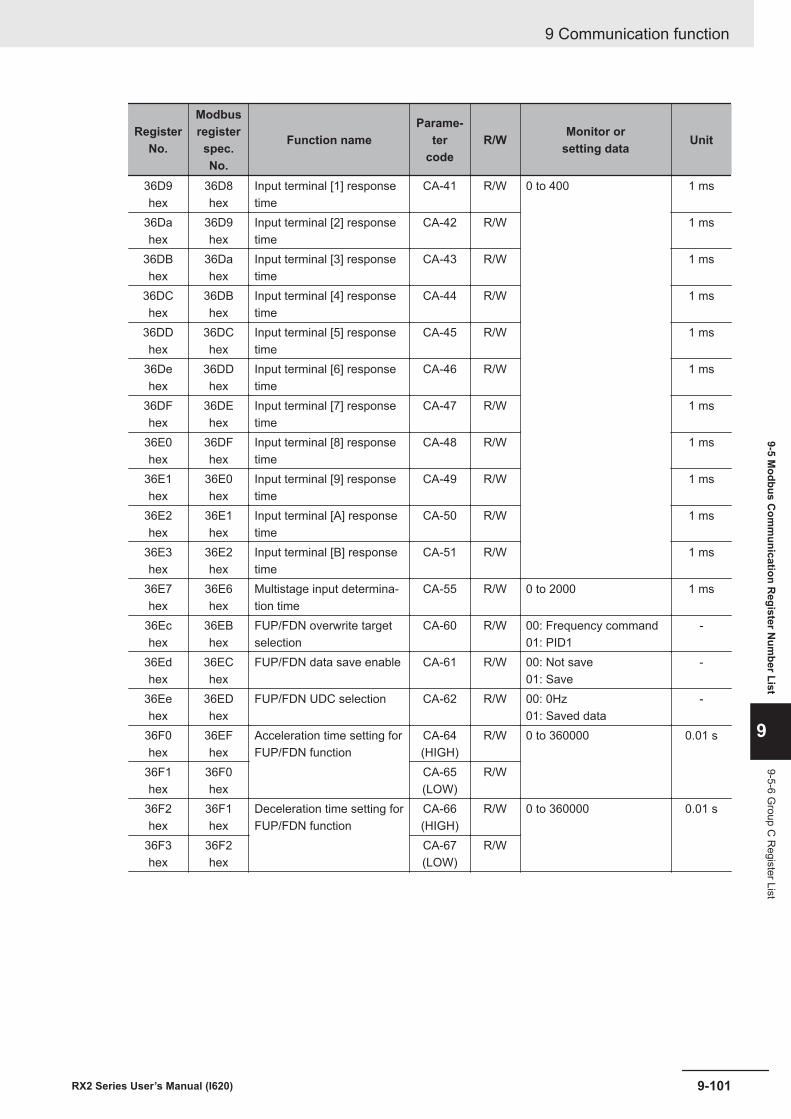
RegisterNo.
Modbusregisterspec.No.
Function nameParame-
tercode
R/W Monitor orsetting data Unit
36D9hex
36D8hex
Input terminal [1] responsetime
CA-41 R/W 0 to 400 1 ms
36Dahex
36D9hex
Input terminal [2] responsetime
CA-42 R/W 1 ms
36DBhex
36Dahex
Input terminal [3] responsetime
CA-43 R/W 1 ms
36DChex
36DBhex
Input terminal [4] responsetime
CA-44 R/W 1 ms
36DDhex
36DChex
Input terminal [5] responsetime
CA-45 R/W 1 ms
36Dehex
36DDhex
Input terminal [6] responsetime
CA-46 R/W 1 ms
36DFhex
36DEhex
Input terminal [7] responsetime
CA-47 R/W 1 ms
36E0hex
36DFhex
Input terminal [8] responsetime
CA-48 R/W 1 ms
36E1hex
36E0hex
Input terminal [9] responsetime
CA-49 R/W 1 ms
36E2hex
36E1hex
Input terminal [A] responsetime
CA-50 R/W 1 ms
36E3hex
36E2hex
Input terminal [B] responsetime
CA-51 R/W 1 ms
36E7hex
36E6hex
Multistage input determina-tion time
CA-55 R/W 0 to 2000 1 ms
36Echex
36EBhex
FUP/FDN overwrite targetselection
CA-60 R/W 00: Frequency command01: PID1
-
36Edhex
36EChex
FUP/FDN data save enable CA-61 R/W 00: Not save01: Save
-
36Eehex
36EDhex
FUP/FDN UDC selection CA-62 R/W 00: 0Hz01: Saved data
-
36F0hex
36EFhex
Acceleration time setting forFUP/FDN function
CA-64(HIGH)
R/W 0 to 360000 0.01 s
36F1hex
36F0hex
CA-65(LOW)
R/W
36F2hex
36F1hex
Deceleration time setting forFUP/FDN function
CA-66(HIGH)
R/W 0 to 360000 0.01 s
36F3hex
36F2hex
CA-67(LOW)
R/W
9 Communication function
9-101RX2 Series User’s Manual (I620)
9-5 Modbus C
omm
unication Register N
umber List
9
9-5-6 Group C
Register List
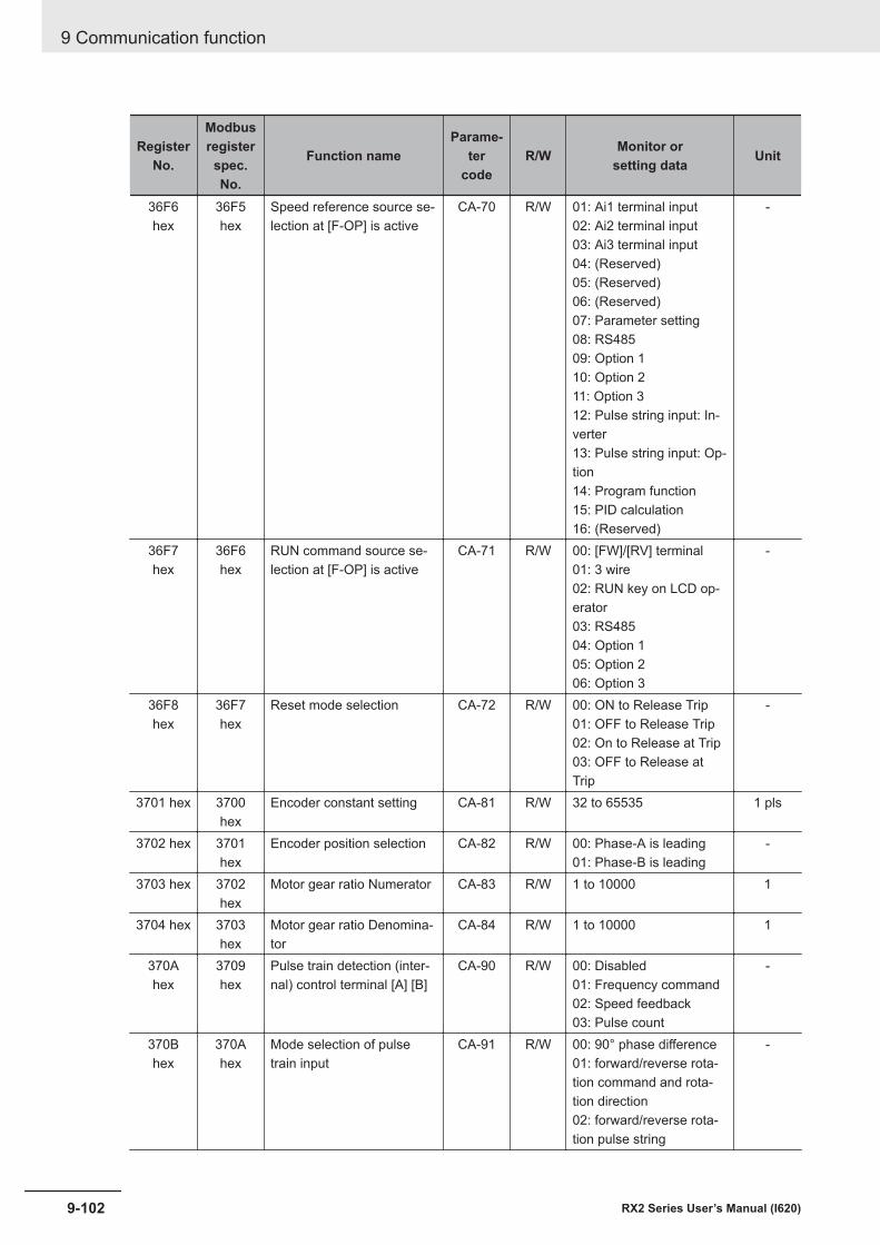
RegisterNo.
Modbusregisterspec.No.
Function nameParame-
tercode
R/W Monitor orsetting data Unit
36F6hex
36F5hex
Speed reference source se-lection at [F-OP] is active
CA-70 R/W 01: Ai1 terminal input02: Ai2 terminal input03: Ai3 terminal input04: (Reserved)05: (Reserved)06: (Reserved)07: Parameter setting08: RS48509: Option 110: Option 211: Option 312: Pulse string input: In-verter13: Pulse string input: Op-tion14: Program function15: PID calculation16: (Reserved)
-
36F7hex
36F6hex
RUN command source se-lection at [F-OP] is active
CA-71 R/W 00: [FW]/[RV] terminal01: 3 wire02: RUN key on LCD op-erator03: RS48504: Option 105: Option 206: Option 3
-
36F8hex
36F7hex
Reset mode selection CA-72 R/W 00: ON to Release Trip01: OFF to Release Trip02: On to Release at Trip03: OFF to Release atTrip
-
3701 hex 3700hex
Encoder constant setting CA-81 R/W 32 to 65535 1 pls
3702 hex 3701hex
Encoder position selection CA-82 R/W 00: Phase-A is leading01: Phase-B is leading
-
3703 hex 3702hex
Motor gear ratio Numerator CA-83 R/W 1 to 10000 1
3704 hex 3703hex
Motor gear ratio Denomina-tor
CA-84 R/W 1 to 10000 1
370Ahex
3709hex
Pulse train detection (inter-nal) control terminal [A] [B]
CA-90 R/W 00: Disabled01: Frequency command02: Speed feedback03: Pulse count
-
370Bhex
370Ahex
Mode selection of pulsetrain input
CA-91 R/W 00: 90° phase difference01: forward/reverse rota-tion command and rota-tion direction02: forward/reverse rota-tion pulse string
-
9 Communication function
9-102 RX2 Series User’s Manual (I620)
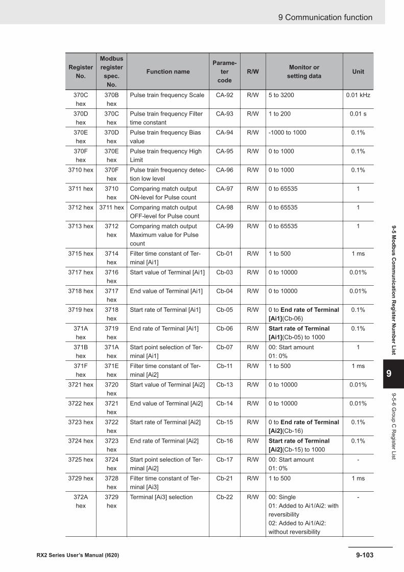
RegisterNo.
Modbusregisterspec.No.
Function nameParame-
tercode
R/W Monitor orsetting data Unit
370Chex
370Bhex
Pulse train frequency Scale CA-92 R/W 5 to 3200 0.01 kHz
370Dhex
370Chex
Pulse train frequency Filtertime constant
CA-93 R/W 1 to 200 0.01 s
370Ehex
370Dhex
Pulse train frequency Biasvalue
CA-94 R/W -1000 to 1000 0.1%
370Fhex
370Ehex
Pulse train frequency HighLimit
CA-95 R/W 0 to 1000 0.1%
3710 hex 370Fhex
Pulse train frequency detec-tion low level
CA-96 R/W 0 to 1000 0.1%
3711 hex 3710hex
Comparing match outputON-level for Pulse count
CA-97 R/W 0 to 65535 1
3712 hex 3711 hex Comparing match outputOFF-level for Pulse count
CA-98 R/W 0 to 65535 1
3713 hex 3712hex
Comparing match outputMaximum value for Pulsecount
CA-99 R/W 0 to 65535 1
3715 hex 3714hex
Filter time constant of Ter-minal [Ai1]
Cb-01 R/W 1 to 500 1 ms
3717 hex 3716hex
Start value of Terminal [Ai1] Cb-03 R/W 0 to 10000 0.01%
3718 hex 3717hex
End value of Terminal [Ai1] Cb-04 R/W 0 to 10000 0.01%
3719 hex 3718hex
Start rate of Terminal [Ai1] Cb-05 R/W 0 to End rate of Terminal[Ai1](Cb-06)
0.1%
371Ahex
3719hex
End rate of Terminal [Ai1] Cb-06 R/W Start rate of Terminal[Ai1](Cb-05) to 1000
0.1%
371Bhex
371Ahex
Start point selection of Ter-minal [Ai1]
Cb-07 R/W 00: Start amount01: 0%
1
371Fhex
371Ehex
Filter time constant of Ter-minal [Ai2]
Cb-11 R/W 1 to 500 1 ms
3721 hex 3720hex
Start value of Terminal [Ai2] Cb-13 R/W 0 to 10000 0.01%
3722 hex 3721hex
End value of Terminal [Ai2] Cb-14 R/W 0 to 10000 0.01%
3723 hex 3722hex
Start rate of Terminal [Ai2] Cb-15 R/W 0 to End rate of Terminal[Ai2](Cb-16)
0.1%
3724 hex 3723hex
End rate of Terminal [Ai2] Cb-16 R/W Start rate of Terminal[Ai2](Cb-15) to 1000
0.1%
3725 hex 3724hex
Start point selection of Ter-minal [Ai2]
Cb-17 R/W 00: Start amount01: 0%
-
3729 hex 3728hex
Filter time constant of Ter-minal [Ai3]
Cb-21 R/W 1 to 500 1 ms
372Ahex
3729hex
Terminal [Ai3] selection Cb-22 R/W 00: Single01: Added to Ai1/Ai2: withreversibility02: Added to Ai1/Ai2:without reversibility
-
9 Communication function
9-103RX2 Series User’s Manual (I620)
9-5 Modbus C
omm
unication Register N
umber List
9
9-5-6 Group C
Register List

RegisterNo.
Modbusregisterspec.No.
Function nameParame-
tercode
R/W Monitor orsetting data Unit
372Bhex
372Ahex
Start value of Terminal [Ai3] Cb-23 R/W -10000 to 10000 0.01%
372Chex
372Bhex
End value of Terminal [Ai3] Cb-24 R/W -10000 to 10000 0.01%
372Dhex
372Chex
Start rate of Terminal [Ai3] Cb-25 R/W -1000 to End rate ofTerminal [Ai3](Cb-26)
0.1%
372Ehex
372Dhex
End rate of Terminal [Ai3] Cb-26 R/W Start rate of Terminal[Ai3](Cb-25) to 1000
0.1%
3732 hex 3731hex
[Ai1] Voltage/Current zero-gain adjustment
Cb-30 R/W -10000 to 10000 0.01%
3733 hex 3732hex
[Ai1] Voltage/Current gainadjustment
Cb-31 R/W 0 to 20000 0.01%
3734 hex 3733hex
[Ai2] Voltage/Current zero-gain adjustment
Cb-32 R/W -10000 to 10000 0.01%
3735 hex 3734hex
[Ai2] Voltage/Current gainadjustment
Cb-33 R/W 0 to 20000 0.01%
3736 hex 3735hex
[Ai3] Voltage/Current zero-gain adjustment
Cb-34 R/W -10000 to 10000 0.01%
3737 hex 3736hex
[Ai3] Voltage gain adjust-ment
Cb-35 R/W 0 to 20000 0.01%
373Chex
373Bhex
Thermistor selection Cb-40 R/W 00: Disabled01: PTC resistance valueenabled02: NTC resistance valueenabled
-
373Dhex
373Chex
Thermistor gain adjustment Cb-41 R/W 0 to 10000 0.1
3779 hex 3778hex
Output terminal [11] function CC-01 R/W Refer to List of OutputTerminal Functions onpage 15-83.
--
377Ahex
3779hex
Output terminal [12] func-tion
CC-02 R/W
377Bhex
377Ahex
Output terminal [13] func-tion
CC-03 R/W
377Chex
377Bhex
Output terminal [14] func-tion
CC-04 R/W
377Dhex
377Chex
Output terminal [15] func-tion
CC-05 R/W
377Ehex
377Dhex
Relay output terminal [16]function
CC-06 R/W
377Fhex
377Ehex
Relay output terminal [AL]function
CC-07 R/W
9 Communication function
9-104 RX2 Series User’s Manual (I620)
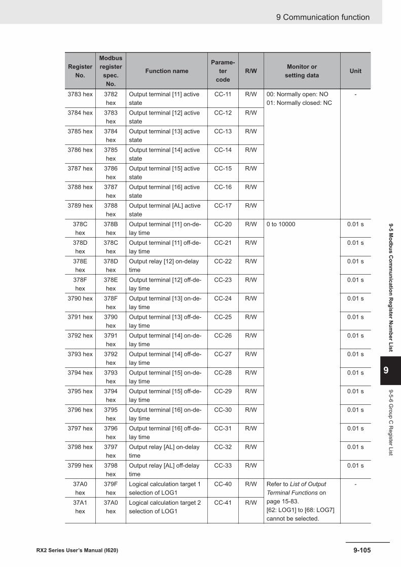
RegisterNo.
Modbusregisterspec.No.
Function nameParame-
tercode
R/W Monitor orsetting data Unit
3783 hex 3782hex
Output terminal [11] activestate
CC-11 R/W 00: Normally open: NO01: Normally closed: NC
-
3784 hex 3783hex
Output terminal [12] activestate
CC-12 R/W
3785 hex 3784hex
Output terminal [13] activestate
CC-13 R/W
3786 hex 3785hex
Output terminal [14] activestate
CC-14 R/W
3787 hex 3786hex
Output terminal [15] activestate
CC-15 R/W
3788 hex 3787hex
Output terminal [16] activestate
CC-16 R/W
3789 hex 3788hex
Output terminal [AL] activestate
CC-17 R/W
378Chex
378Bhex
Output terminal [11] on-de-lay time
CC-20 R/W 0 to 10000 0.01 s
378Dhex
378Chex
Output terminal [11] off-de-lay time
CC-21 R/W 0.01 s
378Ehex
378Dhex
Output relay [12] on-delaytime
CC-22 R/W 0.01 s
378Fhex
378Ehex
Output terminal [12] off-de-lay time
CC-23 R/W 0.01 s
3790 hex 378Fhex
Output terminal [13] on-de-lay time
CC-24 R/W 0.01 s
3791 hex 3790hex
Output terminal [13] off-de-lay time
CC-25 R/W 0.01 s
3792 hex 3791hex
Output terminal [14] on-de-lay time
CC-26 R/W 0.01 s
3793 hex 3792hex
Output terminal [14] off-de-lay time
CC-27 R/W 0.01 s
3794 hex 3793hex
Output terminal [15] on-de-lay time
CC-28 R/W 0.01 s
3795 hex 3794hex
Output terminal [15] off-de-lay time
CC-29 R/W 0.01 s
3796 hex 3795hex
Output terminal [16] on-de-lay time
CC-30 R/W 0.01 s
3797 hex 3796hex
Output terminal [16] off-de-lay time
CC-31 R/W 0.01 s
3798 hex 3797hex
Output relay [AL] on-delaytime
CC-32 R/W 0.01 s
3799 hex 3798hex
Output relay [AL] off-delaytime
CC-33 R/W 0.01 s
37A0hex
379Fhex
Logical calculation target 1selection of LOG1
CC-40 R/W Refer to List of OutputTerminal Functions onpage 15-83.[62: LOG1] to [68: LOG7]cannot be selected.
-
37A1hex
37A0hex
Logical calculation target 2selection of LOG1
CC-41 R/W
9 Communication function
9-105RX2 Series User’s Manual (I620)
9-5 Modbus C
omm
unication Register N
umber List
9
9-5-6 Group C
Register List
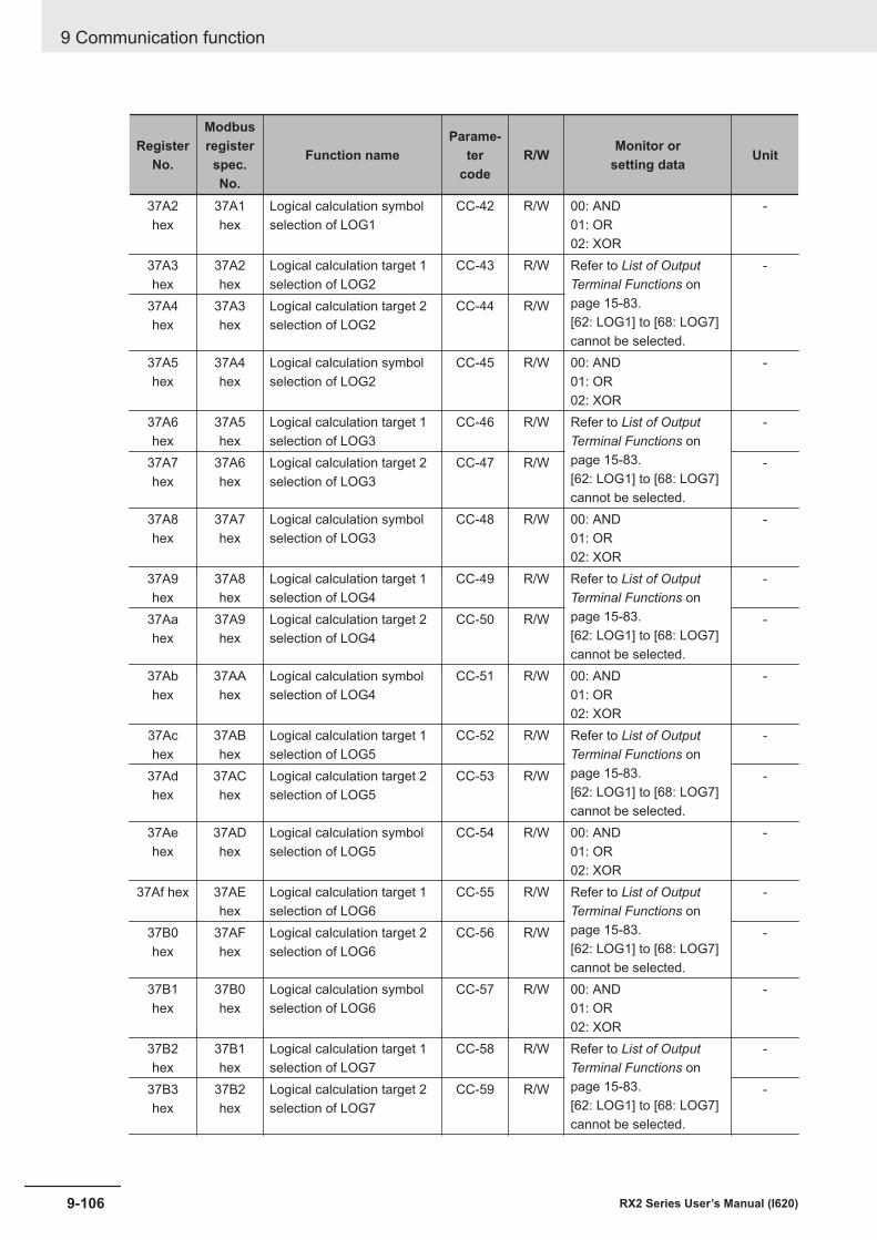
RegisterNo.
Modbusregisterspec.No.
Function nameParame-
tercode
R/W Monitor orsetting data Unit
37A2hex
37A1hex
Logical calculation symbolselection of LOG1
CC-42 R/W 00: AND01: OR02: XOR
-
37A3hex
37A2hex
Logical calculation target 1selection of LOG2
CC-43 R/W Refer to List of OutputTerminal Functions onpage 15-83.[62: LOG1] to [68: LOG7]cannot be selected.
-
37A4hex
37A3hex
Logical calculation target 2selection of LOG2
CC-44 R/W
37A5hex
37A4hex
Logical calculation symbolselection of LOG2
CC-45 R/W 00: AND01: OR02: XOR
-
37A6hex
37A5hex
Logical calculation target 1selection of LOG3
CC-46 R/W Refer to List of OutputTerminal Functions onpage 15-83.[62: LOG1] to [68: LOG7]cannot be selected.
-
37A7hex
37A6hex
Logical calculation target 2selection of LOG3
CC-47 R/W -
37A8hex
37A7hex
Logical calculation symbolselection of LOG3
CC-48 R/W 00: AND01: OR02: XOR
-
37A9hex
37A8hex
Logical calculation target 1selection of LOG4
CC-49 R/W Refer to List of OutputTerminal Functions onpage 15-83.[62: LOG1] to [68: LOG7]cannot be selected.
-
37Aahex
37A9hex
Logical calculation target 2selection of LOG4
CC-50 R/W -
37Abhex
37AAhex
Logical calculation symbolselection of LOG4
CC-51 R/W 00: AND01: OR02: XOR
-
37Achex
37ABhex
Logical calculation target 1selection of LOG5
CC-52 R/W Refer to List of OutputTerminal Functions onpage 15-83.[62: LOG1] to [68: LOG7]cannot be selected.
-
37Adhex
37AChex
Logical calculation target 2selection of LOG5
CC-53 R/W -
37Aehex
37ADhex
Logical calculation symbolselection of LOG5
CC-54 R/W 00: AND01: OR02: XOR
-
37Af hex 37AEhex
Logical calculation target 1selection of LOG6
CC-55 R/W Refer to List of OutputTerminal Functions onpage 15-83.[62: LOG1] to [68: LOG7]cannot be selected.
-
37B0hex
37AFhex
Logical calculation target 2selection of LOG6
CC-56 R/W -
37B1hex
37B0hex
Logical calculation symbolselection of LOG6
CC-57 R/W 00: AND01: OR02: XOR
-
37B2hex
37B1hex
Logical calculation target 1selection of LOG7
CC-58 R/W Refer to List of OutputTerminal Functions onpage 15-83.[62: LOG1] to [68: LOG7]cannot be selected.
-
37B3hex
37B2hex
Logical calculation target 2selection of LOG7
CC-59 R/W -
9 Communication function
9-106 RX2 Series User’s Manual (I620)
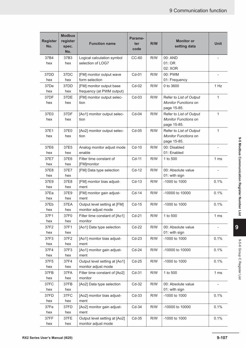
RegisterNo.
Modbusregisterspec.No.
Function nameParame-
tercode
R/W Monitor orsetting data Unit
37B4hex
37B3hex
Logical calculation symbolselection of LOG7
CC-60 R/W 00: AND01: OR02: XOR
-
37DDhex
37DChex
[FM] monitor output waveform selection
Cd-01 R/W 00: PWM01: Frequency
-
37Dehex
37DDhex
[FM] monitor output basefrequency (at PWM output)
Cd-02 R/W 0 to 3600 1 Hz
37DFhex
37DEhex
[FM] monitor output selec-tion
Cd-03 R/W Refer to List of OutputMonitor Functions onpage 15-85.
1
37E0hex
37DFhex
[Ao1] monitor output selec-tion
Cd-04 R/W Refer to List of OutputMonitor Functions onpage 15-85.
1
37E1hex
37E0hex
[Ao2] monitor output selec-tion
Cd-05 R/W Refer to List of OutputMonitor Functions onpage 15-85.
1
37E6hex
37E5hex
Analog monitor adjust modeenable
Cd-10 R/W 00: Disabled01: Enabled
-
37E7hex
37E6hex
Filter time constant of[FM]monitor
Cd-11 R/W 1 to 500 1 ms
37E8hex
37E7hex
[FM] Data type selection Cd-12 R/W 00: Absolute value01: with sign
-
37E9hex
37E8hex
[FM] monitor bias adjust-ment
Cd-13 R/W -1000 to 1000 0.1%
37Eahex
37E9hex
[FM] monitor gain adjust-ment
Cd-14 R/W -10000 to 10000 0.1%
37Ebhex
37EAhex
Output level setting at [FM]monitor adjust mode
Cd-15 R/W -1000 to 1000 0.1%
37F1hex
37F0hex
Filter time constant of [Ao1]monitor
Cd-21 R/W 1 to 500 1 ms
37F2hex
37F1hex
[Ao1] Data type selection Cd-22 R/W 00: Absolute value01: with sign
-
37F3hex
37F2hex
[Ao1] monitor bias adjust-ment
Cd-23 R/W -1000 to 1000 0.1%
37F4hex
37F3hex
[Ao1] monitor gain adjust-ment
Cd-24 R/W -10000 to 10000 0.1%
37F5hex
37F4hex
Output level setting at [Ao1]monitor adjust mode
Cd-25 R/W -1000 to 1000 0.1%
37FBhex
37FAhex
Filter time constant of [Ao2]monitor
Cd-31 R/W 1 to 500 1 ms
37FChex
37FBhex
[Ao2] Data type selection Cd-32 R/W 00: Absolute value01: with sign
-
37FDhex
37FChex
[Ao2] monitor bias adjust-ment
Cd-33 R/W -1000 to 1000 0.1%
37Fehex
37FDhex
[Ao2] monitor gain adjust-ment
Cd-34 R/W -10000 to 10000 0.1%
37FFhex
37FEhex
Output level setting at [Ao2]monitor adjust mode
Cd-35 R/W -1000 to 1000 0.1%
9 Communication function
9-107RX2 Series User’s Manual (I620)
9-5 Modbus C
omm
unication Register N
umber List
9
9-5-6 Group C
Register List
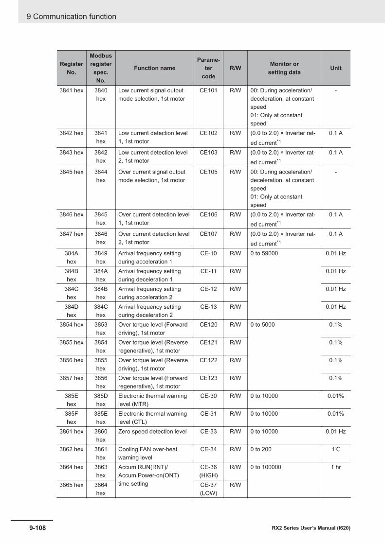
RegisterNo.
Modbusregisterspec.No.
Function nameParame-
tercode
R/W Monitor orsetting data Unit
3841 hex 3840hex
Low current signal outputmode selection, 1st motor
CE101 R/W 00: During acceleration/deceleration, at constantspeed01: Only at constantspeed
-
3842 hex 3841hex
Low current detection level1, 1st motor
CE102 R/W (0.0 to 2.0) × Inverter rat-ed current*1
0.1 A
3843 hex 3842hex
Low current detection level2, 1st motor
CE103 R/W (0.0 to 2.0) × Inverter rat-ed current*1
0.1 A
3845 hex 3844hex
Over current signal outputmode selection, 1st motor
CE105 R/W 00: During acceleration/deceleration, at constantspeed01: Only at constantspeed
-
3846 hex 3845hex
Over current detection level1, 1st motor
CE106 R/W (0.0 to 2.0) × Inverter rat-ed current*1
0.1 A
3847 hex 3846hex
Over current detection level2, 1st motor
CE107 R/W (0.0 to 2.0) × Inverter rat-ed current*1
0.1 A
384Ahex
3849hex
Arrival frequency settingduring acceleration 1
CE-10 R/W 0 to 59000 0.01 Hz
384Bhex
384Ahex
Arrival frequency settingduring deceleration 1
CE-11 R/W 0.01 Hz
384Chex
384Bhex
Arrival frequency settingduring acceleration 2
CE-12 R/W 0.01 Hz
384Dhex
384Chex
Arrival frequency settingduring deceleration 2
CE-13 R/W 0.01 Hz
3854 hex 3853hex
Over torque level (Forwarddriving), 1st motor
CE120 R/W 0 to 5000 0.1%
3855 hex 3854hex
Over torque level (Reverseregenerative), 1st motor
CE121 R/W 0.1%
3856 hex 3855hex
Over torque level (Reversedriving), 1st motor
CE122 R/W 0.1%
3857 hex 3856hex
Over torque level (Forwardregenerative), 1st motor
CE123 R/W 0.1%
385Ehex
385Dhex
Electronic thermal warninglevel (MTR)
CE-30 R/W 0 to 10000 0.01%
385Fhex
385Ehex
Electronic thermal warninglevel (CTL)
CE-31 R/W 0 to 10000 0.01%
3861 hex 3860hex
Zero speed detection level CE-33 R/W 0 to 10000 0.01 Hz
3862 hex 3861hex
Cooling FAN over-heatwarning level
CE-34 R/W 0 to 200 1℃
3864 hex 3863hex
Accum.RUN(RNT)/Accum.Power-on(ONT)time setting
CE-36(HIGH)
R/W 0 to 100000 1 hr
3865 hex 3864hex
CE-37(LOW)
R/W
9 Communication function
9-108 RX2 Series User’s Manual (I620)
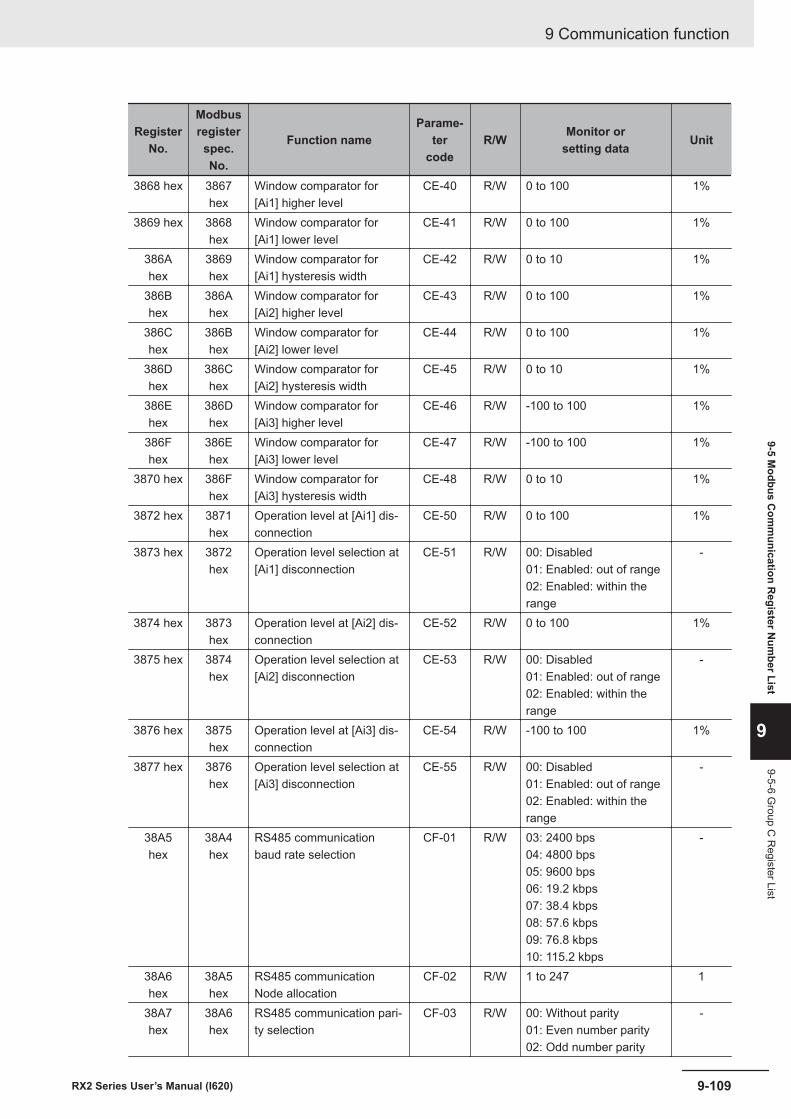
RegisterNo.
Modbusregisterspec.No.
Function nameParame-
tercode
R/W Monitor orsetting data Unit
3868 hex 3867hex
Window comparator for[Ai1] higher level
CE-40 R/W 0 to 100 1%
3869 hex 3868hex
Window comparator for[Ai1] lower level
CE-41 R/W 0 to 100 1%
386Ahex
3869hex
Window comparator for[Ai1] hysteresis width
CE-42 R/W 0 to 10 1%
386Bhex
386Ahex
Window comparator for[Ai2] higher level
CE-43 R/W 0 to 100 1%
386Chex
386Bhex
Window comparator for[Ai2] lower level
CE-44 R/W 0 to 100 1%
386Dhex
386Chex
Window comparator for[Ai2] hysteresis width
CE-45 R/W 0 to 10 1%
386Ehex
386Dhex
Window comparator for[Ai3] higher level
CE-46 R/W -100 to 100 1%
386Fhex
386Ehex
Window comparator for[Ai3] lower level
CE-47 R/W -100 to 100 1%
3870 hex 386Fhex
Window comparator for[Ai3] hysteresis width
CE-48 R/W 0 to 10 1%
3872 hex 3871hex
Operation level at [Ai1] dis-connection
CE-50 R/W 0 to 100 1%
3873 hex 3872hex
Operation level selection at[Ai1] disconnection
CE-51 R/W 00: Disabled01: Enabled: out of range02: Enabled: within therange
-
3874 hex 3873hex
Operation level at [Ai2] dis-connection
CE-52 R/W 0 to 100 1%
3875 hex 3874hex
Operation level selection at[Ai2] disconnection
CE-53 R/W 00: Disabled01: Enabled: out of range02: Enabled: within therange
-
3876 hex 3875hex
Operation level at [Ai3] dis-connection
CE-54 R/W -100 to 100 1%
3877 hex 3876hex
Operation level selection at[Ai3] disconnection
CE-55 R/W 00: Disabled01: Enabled: out of range02: Enabled: within therange
-
38A5hex
38A4hex
RS485 communicationbaud rate selection
CF-01 R/W 03: 2400 bps04: 4800 bps05: 9600 bps06: 19.2 kbps07: 38.4 kbps08: 57.6 kbps09: 76.8 kbps10: 115.2 kbps
-
38A6hex
38A5hex
RS485 communicationNode allocation
CF-02 R/W 1 to 247 1
38A7hex
38A6hex
RS485 communication pari-ty selection
CF-03 R/W 00: Without parity01: Even number parity02: Odd number parity
-
9 Communication function
9-109RX2 Series User’s Manual (I620)
9-5 Modbus C
omm
unication Register N
umber List
9
9-5-6 Group C
Register List
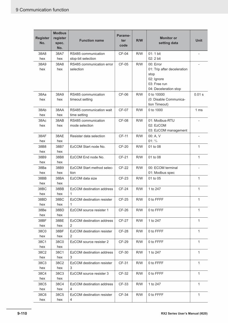
RegisterNo.
Modbusregisterspec.No.
Function nameParame-
tercode
R/W Monitor orsetting data Unit
38A8hex
38A7hex
RS485 communicationstop-bit selection
CF-04 R/W 01: 1 bit02: 2 bit
-
38A9hex
38A8hex
RS485 communication errorselection
CF-05 R/W 00: Error01: Trip after decelerationstop02: Ignore03: Free run04: Deceleration stop
-
38Aahex
38A9hex
RS485 communicationtimeout setting
CF-06 R/W 0 to 10000(0: Disable Communica-tion Timeout)
0.01 s
38Abhex
38AAhex
RS485 communication waittime setting
CF-07 R/W 0 to 1000 1 ms
38Achex
38ABhex
RS485 communicationmode selection
CF-08 R/W 01: Modbus-RTU02: EzCOM03: EzCOM management
-
38AFhex
38AEhex
Resister data selection CF-11 R/W 00: A, V01: %
-
38B8hex
38B7hex
EzCOM Start node No. CF-20 R/W 01 to 08 1
38B9hex
38B8hex
EzCOM End node No. CF-21 R/W 01 to 08 1
38Bahex
38B9hex
EzCOM Start method selec-tion
CF-22 R/W 00: ECOM terminal01: Modbus spec
-
38BBhex
38BAhex
EzCOM data size CF-23 R/W 01 to 05 1
38BChex
38BBhex
EzCOM destination address1
CF-24 R/W 1 to 247 1
38BDhex
38BChex
EzCOM destination resister1
CF-25 R/W 0 to FFFF 1
38Behex
38BDhex
EzCOM source resister 1 CF-26 R/W 0 to FFFF 1
38BFhex
38BEhex
EzCOM destination address2
CF-27 R/W 1 to 247 1
38C0hex
38BFhex
EzCOM destination resister2
CF-28 R/W 0 to FFFF 1
38C1hex
38C0hex
EzCOM source resister 2 CF-29 R/W 0 to FFFF 1
38C2hex
38C1hex
EzCOM destination address3
CF-30 R/W 1 to 247 1
38C3hex
38C2hex
EzCOM destination resister3
CF-31 R/W 0 to FFFF 1
38C4hex
38C3hex
EzCOM source resister 3 CF-32 R/W 0 to FFFF 1
38C5hex
38C4hex
EzCOM destination address4
CF-33 R/W 1 to 247 1
38C6hex
38C5hex
EzCOM destination resister4
CF-34 R/W 0 to FFFF 1
9 Communication function
9-110 RX2 Series User’s Manual (I620)
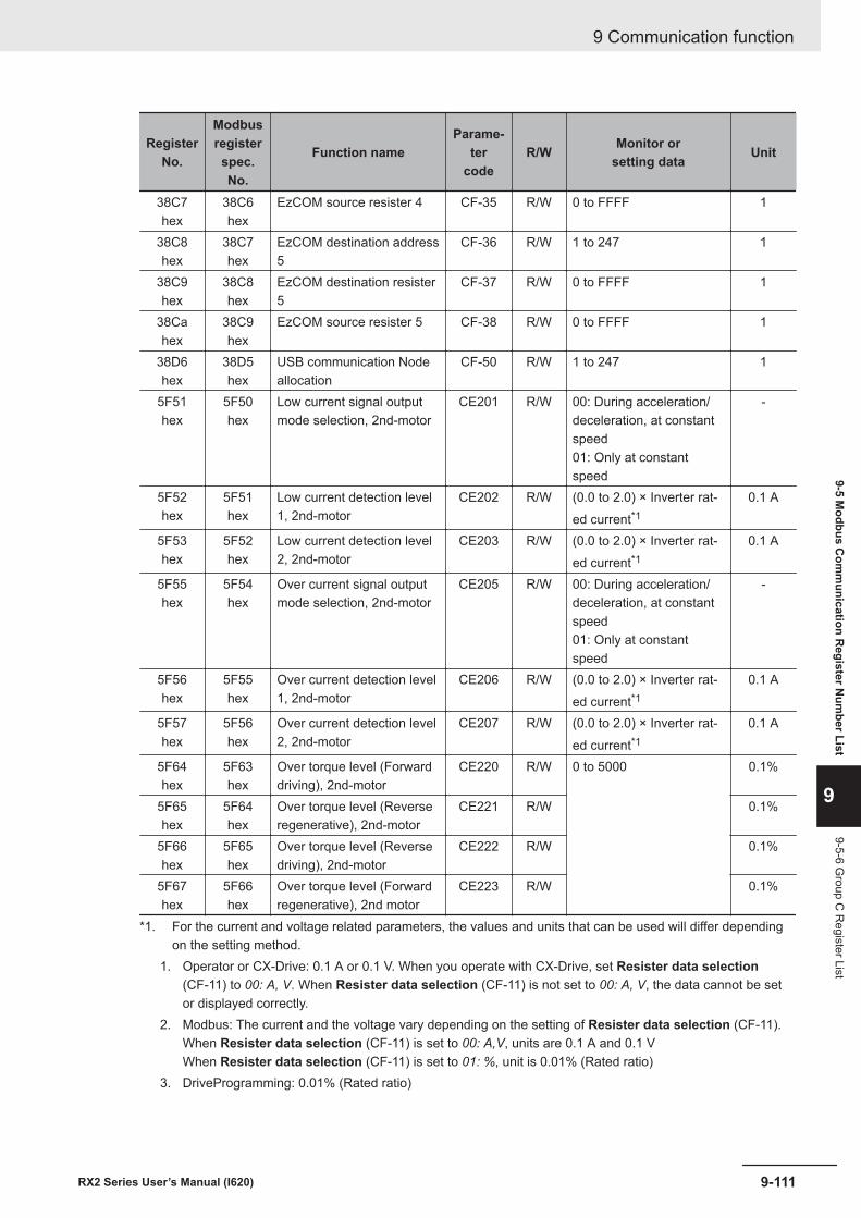
RegisterNo.
Modbusregisterspec.No.
Function nameParame-
tercode
R/W Monitor orsetting data Unit
38C7hex
38C6hex
EzCOM source resister 4 CF-35 R/W 0 to FFFF 1
38C8hex
38C7hex
EzCOM destination address5
CF-36 R/W 1 to 247 1
38C9hex
38C8hex
EzCOM destination resister5
CF-37 R/W 0 to FFFF 1
38Cahex
38C9hex
EzCOM source resister 5 CF-38 R/W 0 to FFFF 1
38D6hex
38D5hex
USB communication Nodeallocation
CF-50 R/W 1 to 247 1
5F51hex
5F50hex
Low current signal outputmode selection, 2nd-motor
CE201 R/W 00: During acceleration/deceleration, at constantspeed01: Only at constantspeed
-
5F52hex
5F51hex
Low current detection level1, 2nd-motor
CE202 R/W (0.0 to 2.0) × Inverter rat-ed current*1
0.1 A
5F53hex
5F52hex
Low current detection level2, 2nd-motor
CE203 R/W (0.0 to 2.0) × Inverter rat-ed current*1
0.1 A
5F55hex
5F54hex
Over current signal outputmode selection, 2nd-motor
CE205 R/W 00: During acceleration/deceleration, at constantspeed01: Only at constantspeed
-
5F56hex
5F55hex
Over current detection level1, 2nd-motor
CE206 R/W (0.0 to 2.0) × Inverter rat-ed current*1
0.1 A
5F57hex
5F56hex
Over current detection level2, 2nd-motor
CE207 R/W (0.0 to 2.0) × Inverter rat-ed current*1
0.1 A
5F64hex
5F63hex
Over torque level (Forwarddriving), 2nd-motor
CE220 R/W 0 to 5000 0.1%
5F65hex
5F64hex
Over torque level (Reverseregenerative), 2nd-motor
CE221 R/W 0.1%
5F66hex
5F65hex
Over torque level (Reversedriving), 2nd-motor
CE222 R/W 0.1%
5F67hex
5F66hex
Over torque level (Forwardregenerative), 2nd motor
CE223 R/W 0.1%
*1. For the current and voltage related parameters, the values and units that can be used will differ dependingon the setting method.
1. Operator or CX-Drive: 0.1 A or 0.1 V. When you operate with CX-Drive, set Resister data selection(CF-11) to 00: A, V. When Resister data selection (CF-11) is not set to 00: A, V, the data cannot be setor displayed correctly.
2. Modbus: The current and the voltage vary depending on the setting of Resister data selection (CF-11).When Resister data selection (CF-11) is set to 00: A,V, units are 0.1 A and 0.1 VWhen Resister data selection (CF-11) is set to 01: %, unit is 0.01% (Rated ratio)
3. DriveProgramming: 0.01% (Rated ratio)
9 Communication function
9-111RX2 Series User’s Manual (I620)
9-5 Modbus C
omm
unication Register N
umber List
9
9-5-6 Group C
Register List

9-5-7 Group H Register List
Precautions for Correct Use
• The Register No. in the table shows the register number used inside the inverter.• The Modbus register spec. No. in the table shows the register number used to actually speci-
fy the register in the Modbus communication process.This register number is 1 less than the inverter Register No. according to the Modbus com-munication specifications.
RegisterNo.
Modbusregisterspec.No.
Function nameParame-
tercode
R/W Monitor orsetting data Unit
3A99hex
3A98hex
Auto-tuning selection HA-01 R/W 00: Disabled01: Non-rotation02: Rotation03: IVMS
-
3A9Ahex
3A99hex
RUN command selection atAuto-tuning
HA-02 R/W 00: RUN key on LCD op-erator01: (AA111) / (AA211)
-
3A9Bhex
3A9Ahex
Online auto-tuning selection HA-03 R/W 00: Disabled01: Enabled
-
3AA2hex
3AA1hex
Stabilization constant, 1st-motor
HA110 R/W 0 to 1000 1%
3AA7hex
3AA6hex
Speed response forAsync.M, 1st-motor
HA115 R/W 0 to 1000 1%
3AAChex
3AABhex
ASR gain switching modeselection, 1st-motor
HA120 R/W 00: [CAS] terminal01: setting switch
-
3AADhex
3AAChex
ASR gain switching timesetting, 1st-motor
HA121 R/W 0 to 10000 1 ms
3AAEhex
3AADhex
ASR gain mapping inter-mediate speed 1, 1st-motor
HA122 R/W 0 to 59000 0.01 Hz
3AAFhex
3AAEhex
ASR gain mapping inter-mediate speed 2, 1st-motor
HA123 R/W 0 to 59000 0.01 Hz
3AB0hex
3AAFhex
ASR gain mapping Maxi-mum speed, 1st-motor
HA124 R/W 0 to 59000 0.01 Hz
9 Communication function
9-112 RX2 Series User’s Manual (I620)
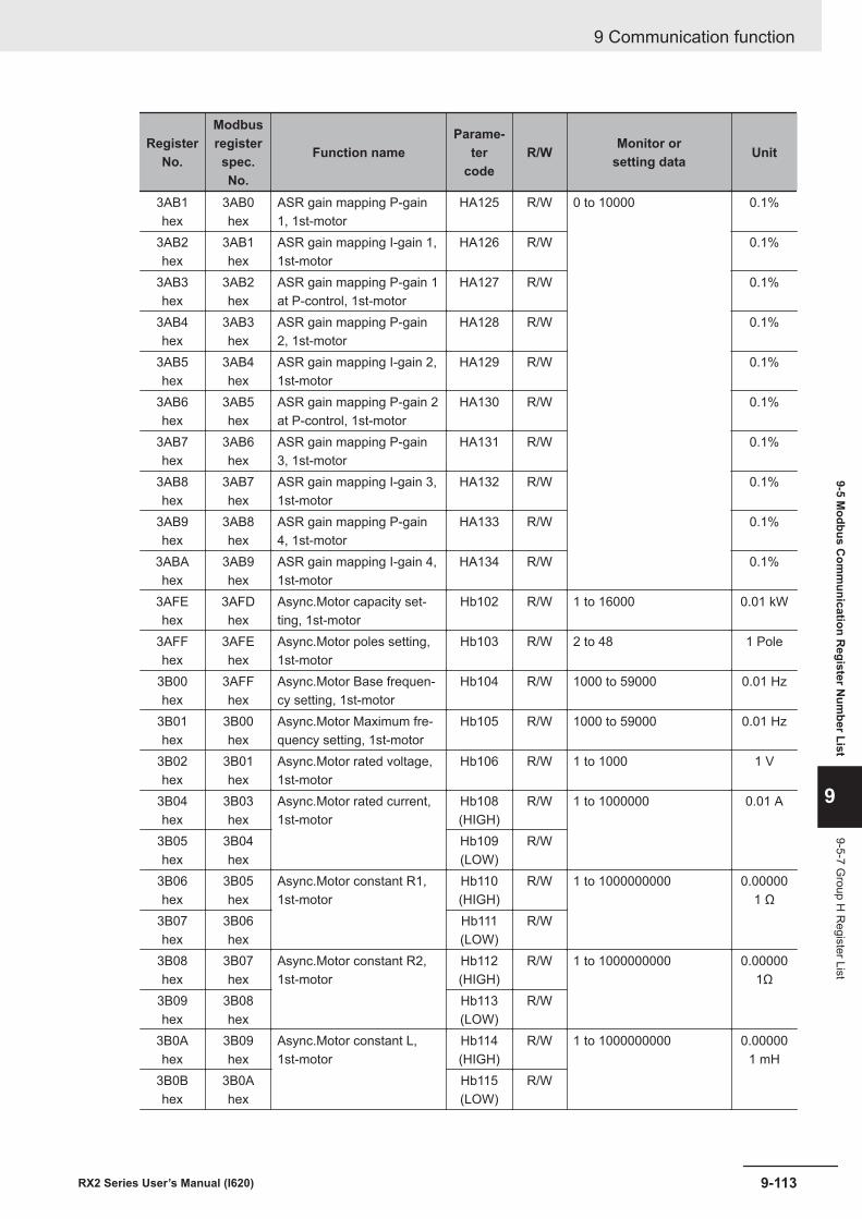
RegisterNo.
Modbusregisterspec.No.
Function nameParame-
tercode
R/W Monitor orsetting data Unit
3AB1hex
3AB0hex
ASR gain mapping P-gain1, 1st-motor
HA125 R/W 0 to 10000 0.1%
3AB2hex
3AB1hex
ASR gain mapping I-gain 1,1st-motor
HA126 R/W 0.1%
3AB3hex
3AB2hex
ASR gain mapping P-gain 1at P-control, 1st-motor
HA127 R/W 0.1%
3AB4hex
3AB3hex
ASR gain mapping P-gain2, 1st-motor
HA128 R/W 0.1%
3AB5hex
3AB4hex
ASR gain mapping I-gain 2,1st-motor
HA129 R/W 0.1%
3AB6hex
3AB5hex
ASR gain mapping P-gain 2at P-control, 1st-motor
HA130 R/W 0.1%
3AB7hex
3AB6hex
ASR gain mapping P-gain3, 1st-motor
HA131 R/W 0.1%
3AB8hex
3AB7hex
ASR gain mapping I-gain 3,1st-motor
HA132 R/W 0.1%
3AB9hex
3AB8hex
ASR gain mapping P-gain4, 1st-motor
HA133 R/W 0.1%
3ABAhex
3AB9hex
ASR gain mapping I-gain 4,1st-motor
HA134 R/W 0.1%
3AFEhex
3AFDhex
Async.Motor capacity set-ting, 1st-motor
Hb102 R/W 1 to 16000 0.01 kW
3AFFhex
3AFEhex
Async.Motor poles setting,1st-motor
Hb103 R/W 2 to 48 1 Pole
3B00hex
3AFFhex
Async.Motor Base frequen-cy setting, 1st-motor
Hb104 R/W 1000 to 59000 0.01 Hz
3B01hex
3B00hex
Async.Motor Maximum fre-quency setting, 1st-motor
Hb105 R/W 1000 to 59000 0.01 Hz
3B02hex
3B01hex
Async.Motor rated voltage,1st-motor
Hb106 R/W 1 to 1000 1 V
3B04hex
3B03hex
Async.Motor rated current,1st-motor
Hb108(HIGH)
R/W 1 to 1000000 0.01 A
3B05hex
3B04hex
Hb109(LOW)
R/W
3B06hex
3B05hex
Async.Motor constant R1,1st-motor
Hb110(HIGH)
R/W 1 to 1000000000 0.000001 Ω
3B07hex
3B06hex
Hb111(LOW)
R/W
3B08hex
3B07hex
Async.Motor constant R2,1st-motor
Hb112(HIGH)
R/W 1 to 1000000000 0.000001Ω
3B09hex
3B08hex
Hb113(LOW)
R/W
3B0Ahex
3B09hex
Async.Motor constant L,1st-motor
Hb114(HIGH)
R/W 1 to 1000000000 0.000001 mH
3B0Bhex
3B0Ahex
Hb115(LOW)
R/W
9 Communication function
9-113RX2 Series User’s Manual (I620)
9-5 Modbus C
omm
unication Register N
umber List
9
9-5-7 Group H
Register List
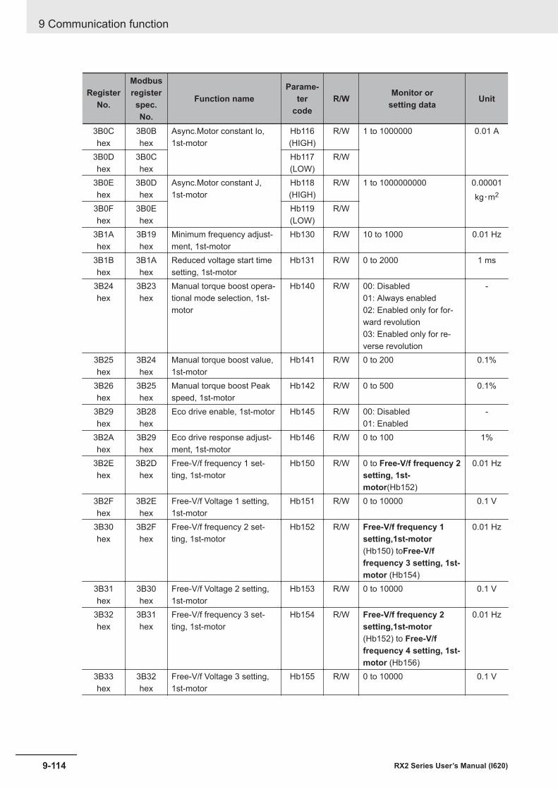
RegisterNo.
Modbusregisterspec.No.
Function nameParame-
tercode
R/W Monitor orsetting data Unit
3B0Chex
3B0Bhex
Async.Motor constant Io,1st-motor
Hb116(HIGH)
R/W 1 to 1000000 0.01 A
3B0Dhex
3B0Chex
Hb117(LOW)
R/W
3B0Ehex
3B0Dhex
Async.Motor constant J,1st-motor
Hb118(HIGH)
R/W 1 to 1000000000 0.00001kg・m2
3B0Fhex
3B0Ehex
Hb119(LOW)
R/W
3B1Ahex
3B19hex
Minimum frequency adjust-ment, 1st-motor
Hb130 R/W 10 to 1000 0.01 Hz
3B1Bhex
3B1Ahex
Reduced voltage start timesetting, 1st-motor
Hb131 R/W 0 to 2000 1 ms
3B24hex
3B23hex
Manual torque boost opera-tional mode selection, 1st-motor
Hb140 R/W 00: Disabled01: Always enabled02: Enabled only for for-ward revolution03: Enabled only for re-verse revolution
-
3B25hex
3B24hex
Manual torque boost value,1st-motor
Hb141 R/W 0 to 200 0.1%
3B26hex
3B25hex
Manual torque boost Peakspeed, 1st-motor
Hb142 R/W 0 to 500 0.1%
3B29hex
3B28hex
Eco drive enable, 1st-motor Hb145 R/W 00: Disabled01: Enabled
-
3B2Ahex
3B29hex
Eco drive response adjust-ment, 1st-motor
Hb146 R/W 0 to 100 1%
3B2Ehex
3B2Dhex
Free-V/f frequency 1 set-ting, 1st-motor
Hb150 R/W 0 to Free-V/f frequency 2setting, 1st-motor(Hb152)
0.01 Hz
3B2Fhex
3B2Ehex
Free-V/f Voltage 1 setting,1st-motor
Hb151 R/W 0 to 10000 0.1 V
3B30hex
3B2Fhex
Free-V/f frequency 2 set-ting, 1st-motor
Hb152 R/W Free-V/f frequency 1setting,1st-motor(Hb150) toFree-V/ffrequency 3 setting, 1st-motor (Hb154)
0.01 Hz
3B31hex
3B30hex
Free-V/f Voltage 2 setting,1st-motor
Hb153 R/W 0 to 10000 0.1 V
3B32hex
3B31hex
Free-V/f frequency 3 set-ting, 1st-motor
Hb154 R/W Free-V/f frequency 2setting,1st-motor(Hb152) to Free-V/ffrequency 4 setting, 1st-motor (Hb156)
0.01 Hz
3B33hex
3B32hex
Free-V/f Voltage 3 setting,1st-motor
Hb155 R/W 0 to 10000 0.1 V
9 Communication function
9-114 RX2 Series User’s Manual (I620)
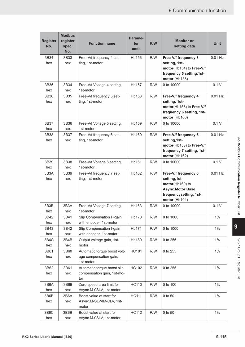
RegisterNo.
Modbusregisterspec.No.
Function nameParame-
tercode
R/W Monitor orsetting data Unit
3B34hex
3B33hex
Free-V/f frequency 4 set-ting, 1st-motor
Hb156 R/W Free-V/f frequency 3setting, 1st-motor(Hb154) to Free-V/ffrequency 5 setting,1st-motor (Hb158)
0.01 Hz
3B35hex
3B34hex
Free-V/f Voltage 4 setting,1st-motor
Hb157 R/W 0 to 10000 0.1 V
3B36hex
3B35hex
Free-V/f frequency 5 set-ting, 1st-motor
Hb158 R/W Free-V/f frequency 4setting, 1st-motor(Hb156) to Free-V/ffrequency 6 setting, 1st-motor (Hb160)
0.01 Hz
3B37hex
3B36hex
Free-V/f Voltage 5 setting,1st-motor
Hb159 R/W 0 to 10000 0.1 V
3B38hex
3B37hex
Free-V/f frequency 6 set-ting, 1st-motor
Hb160 R/W Free-V/f frequency 5setting,1st-motor(Hb158) to Free-V/ffrequency 7 setting, 1st-motor (Hb162)
0.01 Hz
3B39hex
3B38hex
Free-V/f Voltage 6 setting,1st-motor
Hb161 R/W 0 to 10000 0.1 V
3B3Ahex
3B39hex
Free-V/f frequency 7 set-ting, 1st-motor
Hb162 R/W Free-V/f frequency 6setting,1st-motor(Hb160) toAsync.Motor Basefrequencysetting, 1st-motor (Hb104)
0.01 Hz
3B3Bhex
3B3Ahex
Free-V/f Voltage 7 setting,1st-motor
Hb163 R/W 0 to 10000 0.1 V
3B42hex
3B41hex
Slip Compensation P-gainwith encoder, 1st-motor
Hb170 R/W 0 to 1000 1%
3B43hex
3B42hex
Slip Compensation I-gainwith encoder, 1st-motor
Hb171 R/W 0 to 1000 1%
3B4Chex
3B4Bhex
Output voltage gain, 1st-motor
Hb180 R/W 0 to 255 1%
3B61hex
3B60hex
Automatic torque boost volt-age compensation gain,1st-motor
HC101 R/W 0 to 255 1%
3B62hex
3B61hex
Automatic torque boost slipcompensation gain, 1st-mo-tor
HC102 R/W 0 to 255 1%
3B6Ahex
3B69hex
Zero speed area limit forAsync.M-0SLV, 1st-motor
HC110 R/W 0 to 100 1%
3B6Bhex
3B6Ahex
Boost value at start forAsync.M-SLV/IM-CLV, 1st-motor
HC111 R/W 0 to 50 1%
3B6Chex
3B6Bhex
Boost value at start forAsync.M-0SLV, 1st-motor
HC112 R/W 0 to 50 1%
9 Communication function
9-115RX2 Series User’s Manual (I620)
9-5 Modbus C
omm
unication Register N
umber List
9
9-5-7 Group H
Register List
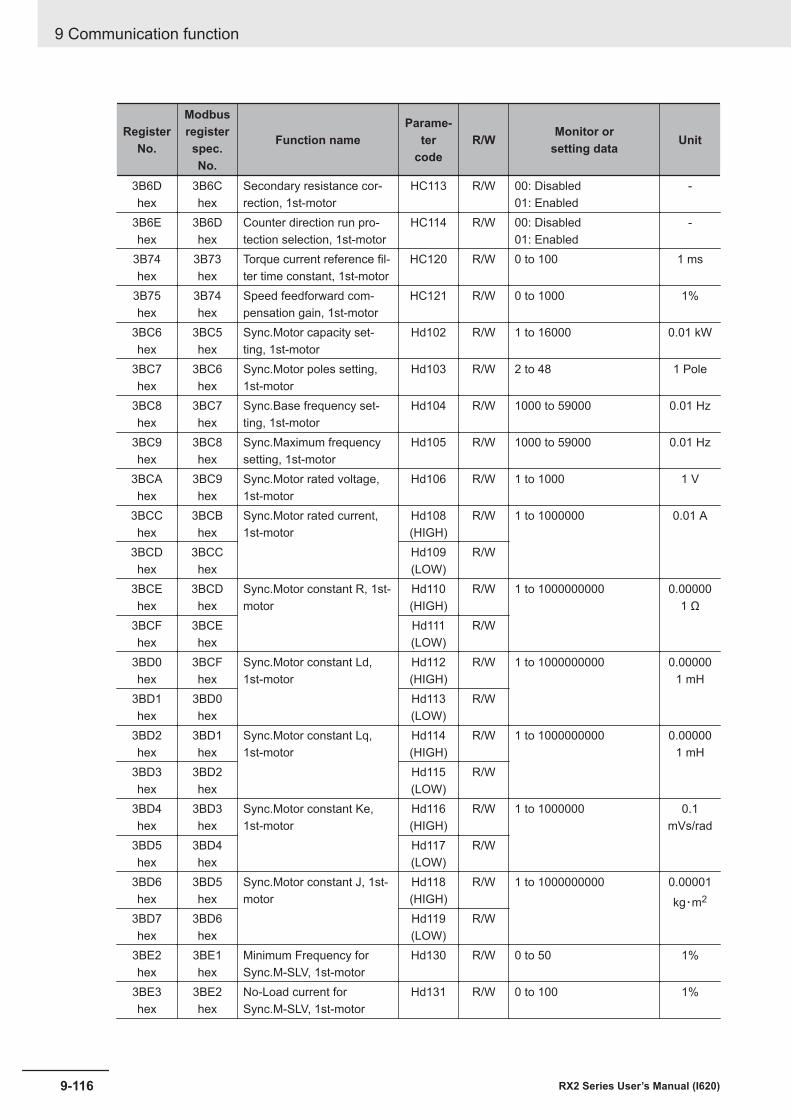
RegisterNo.
Modbusregisterspec.No.
Function nameParame-
tercode
R/W Monitor orsetting data Unit
3B6Dhex
3B6Chex
Secondary resistance cor-rection, 1st-motor
HC113 R/W 00: Disabled01: Enabled
-
3B6Ehex
3B6Dhex
Counter direction run pro-tection selection, 1st-motor
HC114 R/W 00: Disabled01: Enabled
-
3B74hex
3B73hex
Torque current reference fil-ter time constant, 1st-motor
HC120 R/W 0 to 100 1 ms
3B75hex
3B74hex
Speed feedforward com-pensation gain, 1st-motor
HC121 R/W 0 to 1000 1%
3BC6hex
3BC5hex
Sync.Motor capacity set-ting, 1st-motor
Hd102 R/W 1 to 16000 0.01 kW
3BC7hex
3BC6hex
Sync.Motor poles setting,1st-motor
Hd103 R/W 2 to 48 1 Pole
3BC8hex
3BC7hex
Sync.Base frequency set-ting, 1st-motor
Hd104 R/W 1000 to 59000 0.01 Hz
3BC9hex
3BC8hex
Sync.Maximum frequencysetting, 1st-motor
Hd105 R/W 1000 to 59000 0.01 Hz
3BCAhex
3BC9hex
Sync.Motor rated voltage,1st-motor
Hd106 R/W 1 to 1000 1 V
3BCChex
3BCBhex
Sync.Motor rated current,1st-motor
Hd108(HIGH)
R/W 1 to 1000000 0.01 A
3BCDhex
3BCChex
Hd109(LOW)
R/W
3BCEhex
3BCDhex
Sync.Motor constant R, 1st-motor
Hd110(HIGH)
R/W 1 to 1000000000 0.000001 Ω
3BCFhex
3BCEhex
Hd111(LOW)
R/W
3BD0hex
3BCFhex
Sync.Motor constant Ld,1st-motor
Hd112(HIGH)
R/W 1 to 1000000000 0.000001 mH
3BD1hex
3BD0hex
Hd113(LOW)
R/W
3BD2hex
3BD1hex
Sync.Motor constant Lq,1st-motor
Hd114(HIGH)
R/W 1 to 1000000000 0.000001 mH
3BD3hex
3BD2hex
Hd115(LOW)
R/W
3BD4hex
3BD3hex
Sync.Motor constant Ke,1st-motor
Hd116(HIGH)
R/W 1 to 1000000 0.1mVs/rad
3BD5hex
3BD4hex
Hd117(LOW)
R/W
3BD6hex
3BD5hex
Sync.Motor constant J, 1st-motor
Hd118(HIGH)
R/W 1 to 1000000000 0.00001kg・m2
3BD7hex
3BD6hex
Hd119(LOW)
R/W
3BE2hex
3BE1hex
Minimum Frequency forSync.M-SLV, 1st-motor
Hd130 R/W 0 to 50 1%
3BE3hex
3BE2hex
No-Load current forSync.M-SLV, 1st-motor
Hd131 R/W 0 to 100 1%
9 Communication function
9-116 RX2 Series User’s Manual (I620)
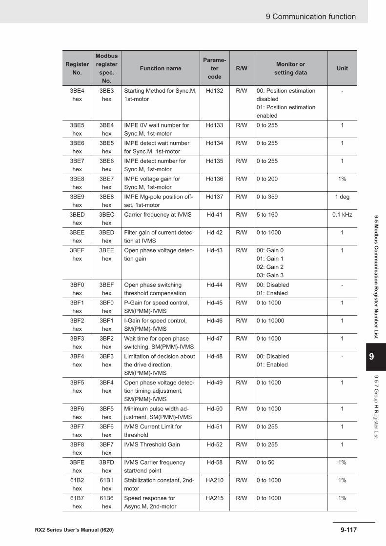
RegisterNo.
Modbusregisterspec.No.
Function nameParame-
tercode
R/W Monitor orsetting data Unit
3BE4hex
3BE3hex
Starting Method for Sync.M,1st-motor
Hd132 R/W 00: Position estimationdisabled01: Position estimationenabled
-
3BE5hex
3BE4hex
IMPE 0V wait number forSync.M, 1st-motor
Hd133 R/W 0 to 255 1
3BE6hex
3BE5hex
IMPE detect wait numberfor Sync.M, 1st-motor
Hd134 R/W 0 to 255 1
3BE7hex
3BE6hex
IMPE detect number forSync.M, 1st-motor
Hd135 R/W 0 to 255 1
3BE8hex
3BE7hex
IMPE voltage gain forSync.M, 1st-motor
Hd136 R/W 0 to 200 1%
3BE9hex
3BE8hex
IMPE Mg-pole position off-set, 1st-motor
Hd137 R/W 0 to 359 1 deg
3BEDhex
3BEChex
Carrier frequency at IVMS Hd-41 R/W 5 to 160 0.1 kHz
3BEEhex
3BEDhex
Filter gain of current detec-tion at IVMS
Hd-42 R/W 0 to 1000 1
3BEFhex
3BEEhex
Open phase voltage detec-tion gain
Hd-43 R/W 00: Gain 001: Gain 102: Gain 203: Gain 3
1
3BF0hex
3BEFhex
Open phase switchingthreshold compensation
Hd-44 R/W 00: Disabled01: Enabled
-
3BF1hex
3BF0hex
P-Gain for speed control,SM(PMM)-IVMS
Hd-45 R/W 0 to 1000 1
3BF2hex
3BF1hex
I-Gain for speed control,SM(PMM)-IVMS
Hd-46 R/W 0 to 10000 1
3BF3hex
3BF2hex
Wait time for open phaseswitching, SM(PMM)-IVMS
Hd-47 R/W 0 to 1000 1
3BF4hex
3BF3hex
Limitation of decision aboutthe drive direction,SM(PMM)-IVMS
Hd-48 R/W 00: Disabled01: Enabled
-
3BF5hex
3BF4hex
Open phase voltage detec-tion timing adjustment,SM(PMM)-IVMS
Hd-49 R/W 0 to 1000 1
3BF6hex
3BF5hex
Minimum pulse width ad-justment, SM(PMM)-IVMS
Hd-50 R/W 0 to 1000 1
3BF7hex
3BF6hex
IVMS Current Limit forthreshold
Hd-51 R/W 0 to 255 1
3BF8hex
3BF7hex
IVMS Threshold Gain Hd-52 R/W 0 to 255 1
3BFEhex
3BFDhex
IVMS Carrier frequencystart/end point
Hd-58 R/W 0 to 50 1%
61B2hex
61B1hex
Stabilization constant, 2nd-motor
HA210 R/W 0 to 1000 1%
61B7hex
61B6hex
Speed response forAsync.M, 2nd-motor
HA215 R/W 0 to 1000 1%
9 Communication function
9-117RX2 Series User’s Manual (I620)
9-5 Modbus C
omm
unication Register N
umber List
9
9-5-7 Group H
Register List
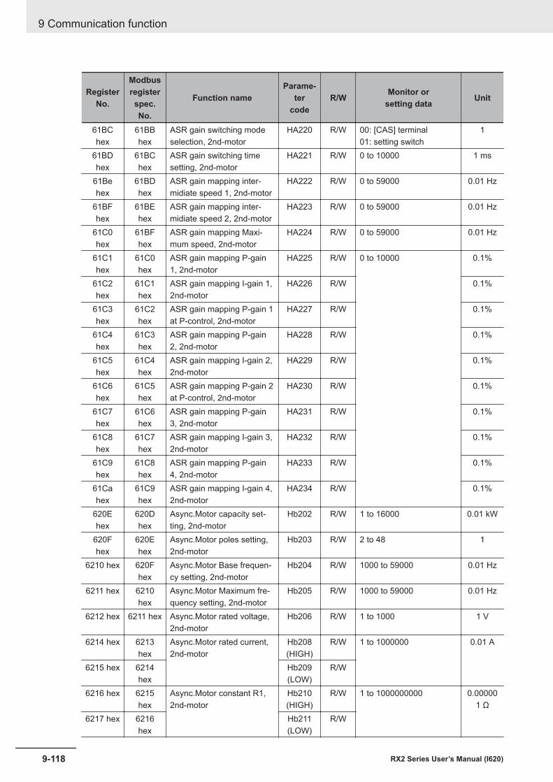
RegisterNo.
Modbusregisterspec.No.
Function nameParame-
tercode
R/W Monitor orsetting data Unit
61BChex
61BBhex
ASR gain switching modeselection, 2nd-motor
HA220 R/W 00: [CAS] terminal01: setting switch
1
61BDhex
61BChex
ASR gain switching timesetting, 2nd-motor
HA221 R/W 0 to 10000 1 ms
61Behex
61BDhex
ASR gain mapping inter-midiate speed 1, 2nd-motor
HA222 R/W 0 to 59000 0.01 Hz
61BFhex
61BEhex
ASR gain mapping inter-midiate speed 2, 2nd-motor
HA223 R/W 0 to 59000 0.01 Hz
61C0hex
61BFhex
ASR gain mapping Maxi-mum speed, 2nd-motor
HA224 R/W 0 to 59000 0.01 Hz
61C1hex
61C0hex
ASR gain mapping P-gain1, 2nd-motor
HA225 R/W 0 to 10000 0.1%
61C2hex
61C1hex
ASR gain mapping I-gain 1,2nd-motor
HA226 R/W 0.1%
61C3hex
61C2hex
ASR gain mapping P-gain 1at P-control, 2nd-motor
HA227 R/W 0.1%
61C4hex
61C3hex
ASR gain mapping P-gain2, 2nd-motor
HA228 R/W 0.1%
61C5hex
61C4hex
ASR gain mapping I-gain 2,2nd-motor
HA229 R/W 0.1%
61C6hex
61C5hex
ASR gain mapping P-gain 2at P-control, 2nd-motor
HA230 R/W 0.1%
61C7hex
61C6hex
ASR gain mapping P-gain3, 2nd-motor
HA231 R/W 0.1%
61C8hex
61C7hex
ASR gain mapping I-gain 3,2nd-motor
HA232 R/W 0.1%
61C9hex
61C8hex
ASR gain mapping P-gain4, 2nd-motor
HA233 R/W 0.1%
61Cahex
61C9hex
ASR gain mapping I-gain 4,2nd-motor
HA234 R/W 0.1%
620Ehex
620Dhex
Async.Motor capacity set-ting, 2nd-motor
Hb202 R/W 1 to 16000 0.01 kW
620Fhex
620Ehex
Async.Motor poles setting,2nd-motor
Hb203 R/W 2 to 48 1
6210 hex 620Fhex
Async.Motor Base frequen-cy setting, 2nd-motor
Hb204 R/W 1000 to 59000 0.01 Hz
6211 hex 6210hex
Async.Motor Maximum fre-quency setting, 2nd-motor
Hb205 R/W 1000 to 59000 0.01 Hz
6212 hex 6211 hex Async.Motor rated voltage,2nd-motor
Hb206 R/W 1 to 1000 1 V
6214 hex 6213hex
Async.Motor rated current,2nd-motor
Hb208(HIGH)
R/W 1 to 1000000 0.01 A
6215 hex 6214hex
Hb209(LOW)
R/W
6216 hex 6215hex
Async.Motor constant R1,2nd-motor
Hb210(HIGH)
R/W 1 to 1000000000 0.000001 Ω
6217 hex 6216hex
Hb211(LOW)
R/W
9 Communication function
9-118 RX2 Series User’s Manual (I620)
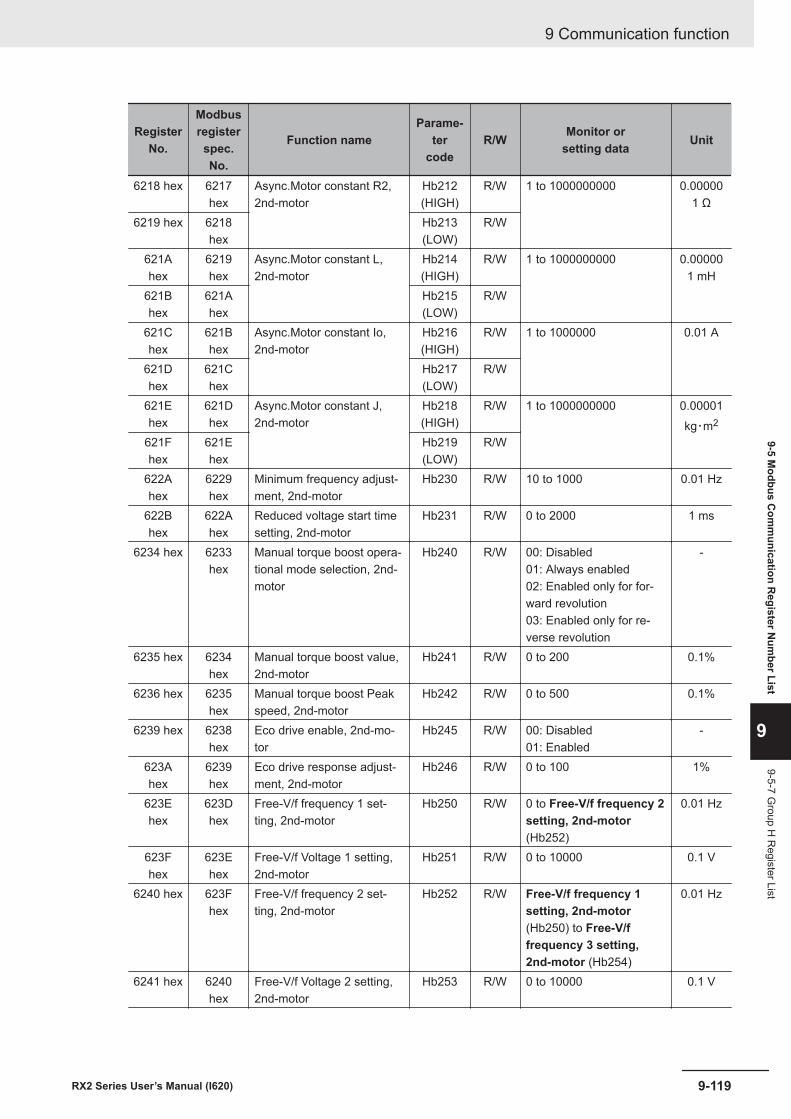
RegisterNo.
Modbusregisterspec.No.
Function nameParame-
tercode
R/W Monitor orsetting data Unit
6218 hex 6217hex
Async.Motor constant R2,2nd-motor
Hb212(HIGH)
R/W 1 to 1000000000 0.000001 Ω
6219 hex 6218hex
Hb213(LOW)
R/W
621Ahex
6219hex
Async.Motor constant L,2nd-motor
Hb214(HIGH)
R/W 1 to 1000000000 0.000001 mH
621Bhex
621Ahex
Hb215(LOW)
R/W
621Chex
621Bhex
Async.Motor constant Io,2nd-motor
Hb216(HIGH)
R/W 1 to 1000000 0.01 A
621Dhex
621Chex
Hb217(LOW)
R/W
621Ehex
621Dhex
Async.Motor constant J,2nd-motor
Hb218(HIGH)
R/W 1 to 1000000000 0.00001kg・m2
621Fhex
621Ehex
Hb219(LOW)
R/W
622Ahex
6229hex
Minimum frequency adjust-ment, 2nd-motor
Hb230 R/W 10 to 1000 0.01 Hz
622Bhex
622Ahex
Reduced voltage start timesetting, 2nd-motor
Hb231 R/W 0 to 2000 1 ms
6234 hex 6233hex
Manual torque boost opera-tional mode selection, 2nd-motor
Hb240 R/W 00: Disabled01: Always enabled02: Enabled only for for-ward revolution03: Enabled only for re-verse revolution
-
6235 hex 6234hex
Manual torque boost value,2nd-motor
Hb241 R/W 0 to 200 0.1%
6236 hex 6235hex
Manual torque boost Peakspeed, 2nd-motor
Hb242 R/W 0 to 500 0.1%
6239 hex 6238hex
Eco drive enable, 2nd-mo-tor
Hb245 R/W 00: Disabled01: Enabled
-
623Ahex
6239hex
Eco drive response adjust-ment, 2nd-motor
Hb246 R/W 0 to 100 1%
623Ehex
623Dhex
Free-V/f frequency 1 set-ting, 2nd-motor
Hb250 R/W 0 to Free-V/f frequency 2setting, 2nd-motor(Hb252)
0.01 Hz
623Fhex
623Ehex
Free-V/f Voltage 1 setting,2nd-motor
Hb251 R/W 0 to 10000 0.1 V
6240 hex 623Fhex
Free-V/f frequency 2 set-ting, 2nd-motor
Hb252 R/W Free-V/f frequency 1setting, 2nd-motor(Hb250) to Free-V/ffrequency 3 setting,2nd-motor (Hb254)
0.01 Hz
6241 hex 6240hex
Free-V/f Voltage 2 setting,2nd-motor
Hb253 R/W 0 to 10000 0.1 V
9 Communication function
9-119RX2 Series User’s Manual (I620)
9-5 Modbus C
omm
unication Register N
umber List
9
9-5-7 Group H
Register List
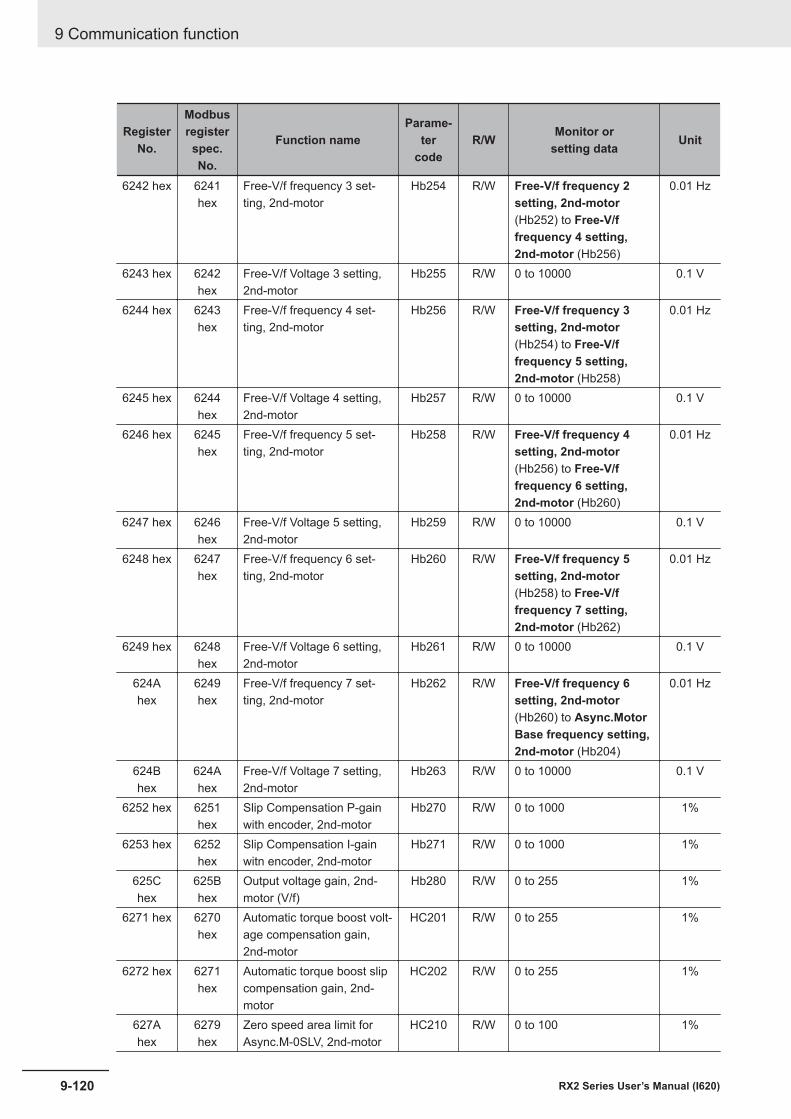
RegisterNo.
Modbusregisterspec.No.
Function nameParame-
tercode
R/W Monitor orsetting data Unit
6242 hex 6241hex
Free-V/f frequency 3 set-ting, 2nd-motor
Hb254 R/W Free-V/f frequency 2setting, 2nd-motor(Hb252) to Free-V/ffrequency 4 setting,2nd-motor (Hb256)
0.01 Hz
6243 hex 6242hex
Free-V/f Voltage 3 setting,2nd-motor
Hb255 R/W 0 to 10000 0.1 V
6244 hex 6243hex
Free-V/f frequency 4 set-ting, 2nd-motor
Hb256 R/W Free-V/f frequency 3setting, 2nd-motor(Hb254) to Free-V/ffrequency 5 setting,2nd-motor (Hb258)
0.01 Hz
6245 hex 6244hex
Free-V/f Voltage 4 setting,2nd-motor
Hb257 R/W 0 to 10000 0.1 V
6246 hex 6245hex
Free-V/f frequency 5 set-ting, 2nd-motor
Hb258 R/W Free-V/f frequency 4setting, 2nd-motor(Hb256) to Free-V/ffrequency 6 setting,2nd-motor (Hb260)
0.01 Hz
6247 hex 6246hex
Free-V/f Voltage 5 setting,2nd-motor
Hb259 R/W 0 to 10000 0.1 V
6248 hex 6247hex
Free-V/f frequency 6 set-ting, 2nd-motor
Hb260 R/W Free-V/f frequency 5setting, 2nd-motor(Hb258) to Free-V/ffrequency 7 setting,2nd-motor (Hb262)
0.01 Hz
6249 hex 6248hex
Free-V/f Voltage 6 setting,2nd-motor
Hb261 R/W 0 to 10000 0.1 V
624Ahex
6249hex
Free-V/f frequency 7 set-ting, 2nd-motor
Hb262 R/W Free-V/f frequency 6setting, 2nd-motor(Hb260) to Async.MotorBase frequency setting,2nd-motor (Hb204)
0.01 Hz
624Bhex
624Ahex
Free-V/f Voltage 7 setting,2nd-motor
Hb263 R/W 0 to 10000 0.1 V
6252 hex 6251hex
Slip Compensation P-gainwith encoder, 2nd-motor
Hb270 R/W 0 to 1000 1%
6253 hex 6252hex
Slip Compensation I-gainwitn encoder, 2nd-motor
Hb271 R/W 0 to 1000 1%
625Chex
625Bhex
Output voltage gain, 2nd-motor (V/f)
Hb280 R/W 0 to 255 1%
6271 hex 6270hex
Automatic torque boost volt-age compensation gain,2nd-motor
HC201 R/W 0 to 255 1%
6272 hex 6271hex
Automatic torque boost slipcompensation gain, 2nd-motor
HC202 R/W 0 to 255 1%
627Ahex
6279hex
Zero speed area limit forAsync.M-0SLV, 2nd-motor
HC210 R/W 0 to 100 1%
9 Communication function
9-120 RX2 Series User’s Manual (I620)
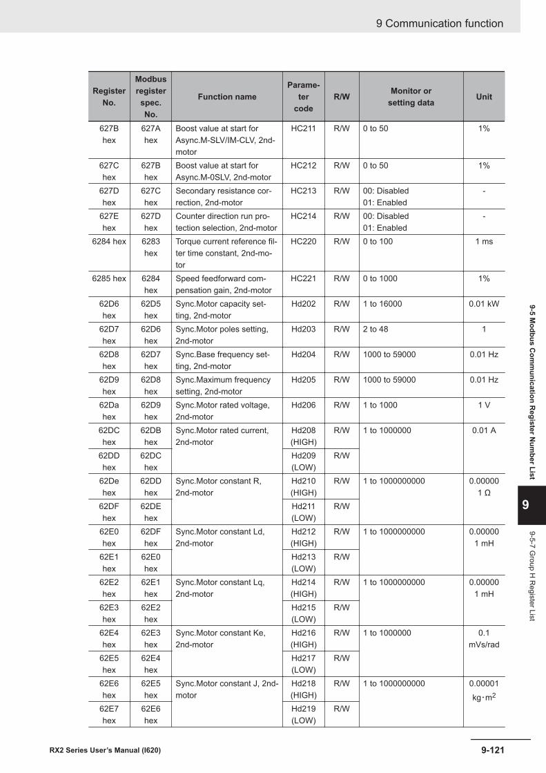
RegisterNo.
Modbusregisterspec.No.
Function nameParame-
tercode
R/W Monitor orsetting data Unit
627Bhex
627Ahex
Boost value at start forAsync.M-SLV/IM-CLV, 2nd-motor
HC211 R/W 0 to 50 1%
627Chex
627Bhex
Boost value at start forAsync.M-0SLV, 2nd-motor
HC212 R/W 0 to 50 1%
627Dhex
627Chex
Secondary resistance cor-rection, 2nd-motor
HC213 R/W 00: Disabled01: Enabled
-
627Ehex
627Dhex
Counter direction run pro-tection selection, 2nd-motor
HC214 R/W 00: Disabled01: Enabled
-
6284 hex 6283hex
Torque current reference fil-ter time constant, 2nd-mo-tor
HC220 R/W 0 to 100 1 ms
6285 hex 6284hex
Speed feedforward com-pensation gain, 2nd-motor
HC221 R/W 0 to 1000 1%
62D6hex
62D5hex
Sync.Motor capacity set-ting, 2nd-motor
Hd202 R/W 1 to 16000 0.01 kW
62D7hex
62D6hex
Sync.Motor poles setting,2nd-motor
Hd203 R/W 2 to 48 1
62D8hex
62D7hex
Sync.Base frequency set-ting, 2nd-motor
Hd204 R/W 1000 to 59000 0.01 Hz
62D9hex
62D8hex
Sync.Maximum frequencysetting, 2nd-motor
Hd205 R/W 1000 to 59000 0.01 Hz
62Dahex
62D9hex
Sync.Motor rated voltage,2nd-motor
Hd206 R/W 1 to 1000 1 V
62DChex
62DBhex
Sync.Motor rated current,2nd-motor
Hd208(HIGH)
R/W 1 to 1000000 0.01 A
62DDhex
62DChex
Hd209(LOW)
R/W
62Dehex
62DDhex
Sync.Motor constant R,2nd-motor
Hd210(HIGH)
R/W 1 to 1000000000 0.000001 Ω
62DFhex
62DEhex
Hd211(LOW)
R/W
62E0hex
62DFhex
Sync.Motor constant Ld,2nd-motor
Hd212(HIGH)
R/W 1 to 1000000000 0.000001 mH
62E1hex
62E0hex
Hd213(LOW)
R/W
62E2hex
62E1hex
Sync.Motor constant Lq,2nd-motor
Hd214(HIGH)
R/W 1 to 1000000000 0.000001 mH
62E3hex
62E2hex
Hd215(LOW)
R/W
62E4hex
62E3hex
Sync.Motor constant Ke,2nd-motor
Hd216(HIGH)
R/W 1 to 1000000 0.1mVs/rad
62E5hex
62E4hex
Hd217(LOW)
R/W
62E6hex
62E5hex
Sync.Motor constant J, 2nd-motor
Hd218(HIGH)
R/W 1 to 1000000000 0.00001kg・m2
62E7hex
62E6hex
Hd219(LOW)
R/W
9 Communication function
9-121RX2 Series User’s Manual (I620)
9-5 Modbus C
omm
unication Register N
umber List
9
9-5-7 Group H
Register List
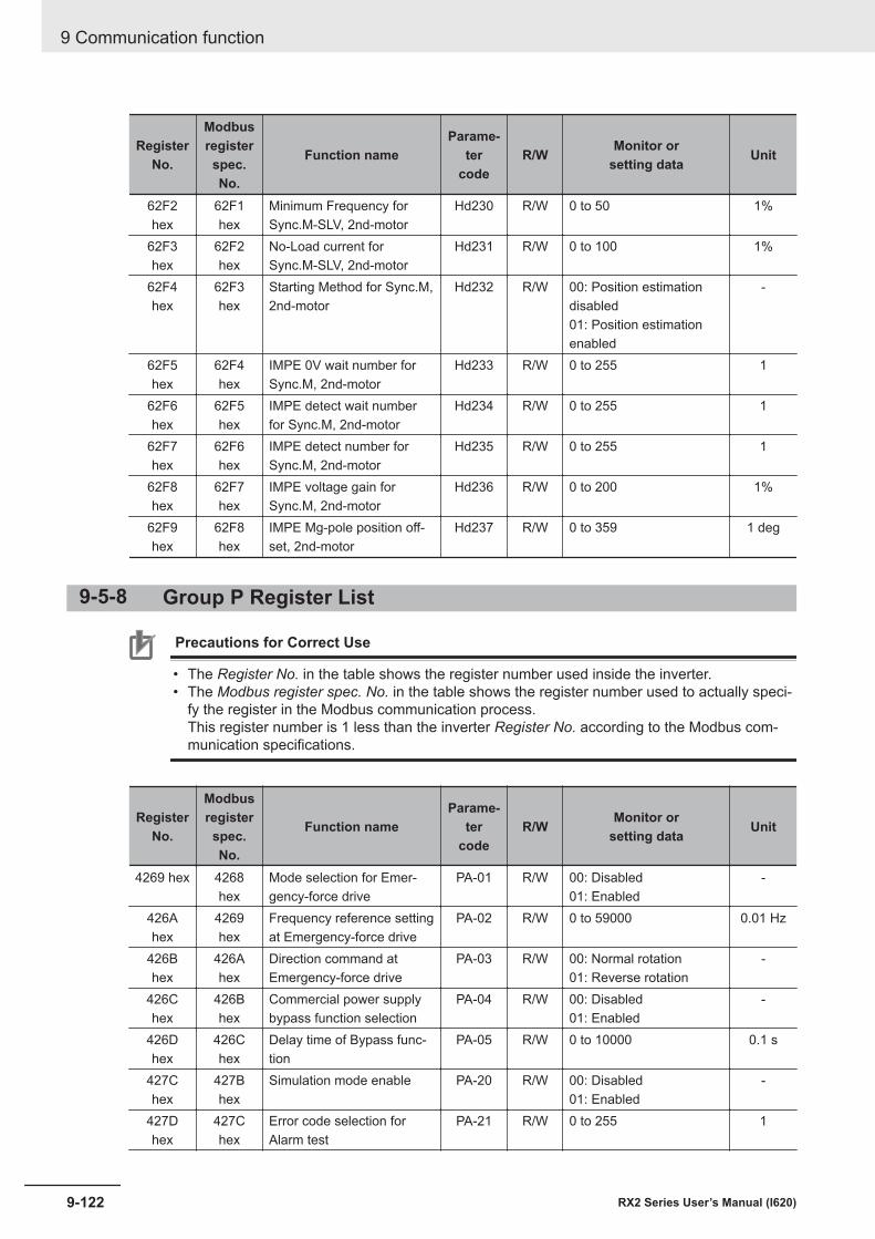
RegisterNo.
Modbusregisterspec.No.
Function nameParame-
tercode
R/W Monitor orsetting data Unit
62F2hex
62F1hex
Minimum Frequency forSync.M-SLV, 2nd-motor
Hd230 R/W 0 to 50 1%
62F3hex
62F2hex
No-Load current forSync.M-SLV, 2nd-motor
Hd231 R/W 0 to 100 1%
62F4hex
62F3hex
Starting Method for Sync.M,2nd-motor
Hd232 R/W 00: Position estimationdisabled01: Position estimationenabled
-
62F5hex
62F4hex
IMPE 0V wait number forSync.M, 2nd-motor
Hd233 R/W 0 to 255 1
62F6hex
62F5hex
IMPE detect wait numberfor Sync.M, 2nd-motor
Hd234 R/W 0 to 255 1
62F7hex
62F6hex
IMPE detect number forSync.M, 2nd-motor
Hd235 R/W 0 to 255 1
62F8hex
62F7hex
IMPE voltage gain forSync.M, 2nd-motor
Hd236 R/W 0 to 200 1%
62F9hex
62F8hex
IMPE Mg-pole position off-set, 2nd-motor
Hd237 R/W 0 to 359 1 deg
9-5-8 Group P Register List
Precautions for Correct Use
• The Register No. in the table shows the register number used inside the inverter.• The Modbus register spec. No. in the table shows the register number used to actually speci-
fy the register in the Modbus communication process.This register number is 1 less than the inverter Register No. according to the Modbus com-munication specifications.
RegisterNo.
Modbusregisterspec.No.
Function nameParame-
tercode
R/W Monitor orsetting data Unit
4269 hex 4268hex
Mode selection for Emer-gency-force drive
PA-01 R/W 00: Disabled01: Enabled
-
426Ahex
4269hex
Frequency reference settingat Emergency-force drive
PA-02 R/W 0 to 59000 0.01 Hz
426Bhex
426Ahex
Direction command atEmergency-force drive
PA-03 R/W 00: Normal rotation01: Reverse rotation
-
426Chex
426Bhex
Commercial power supplybypass function selection
PA-04 R/W 00: Disabled01: Enabled
-
426Dhex
426Chex
Delay time of Bypass func-tion
PA-05 R/W 0 to 10000 0.1 s
427Chex
427Bhex
Simulation mode enable PA-20 R/W 00: Disabled01: Enabled
-
427Dhex
427Chex
Error code selection forAlarm test
PA-21 R/W 0 to 255 1
9 Communication function
9-122 RX2 Series User’s Manual (I620)
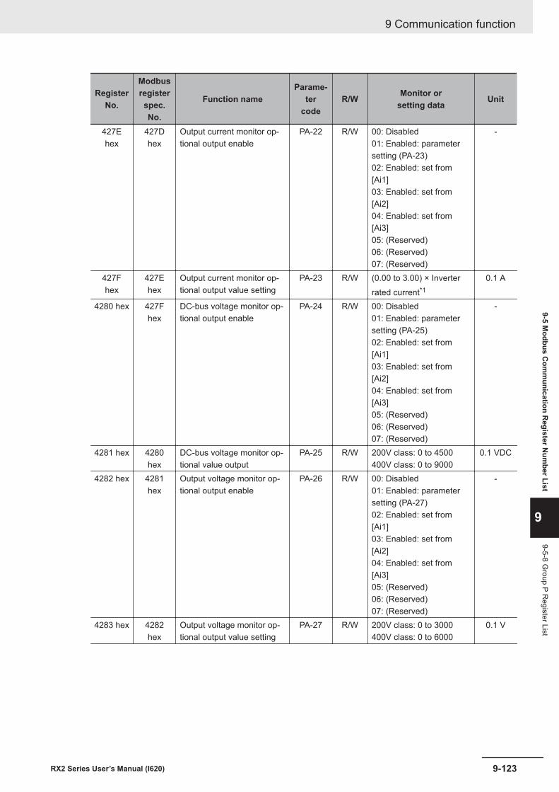
RegisterNo.
Modbusregisterspec.No.
Function nameParame-
tercode
R/W Monitor orsetting data Unit
427Ehex
427Dhex
Output current monitor op-tional output enable
PA-22 R/W 00: Disabled01: Enabled: parametersetting (PA-23)02: Enabled: set from[Ai1]03: Enabled: set from[Ai2]04: Enabled: set from[Ai3]05: (Reserved)06: (Reserved)07: (Reserved)
-
427Fhex
427Ehex
Output current monitor op-tional output value setting
PA-23 R/W (0.00 to 3.00) × Inverterrated current*1
0.1 A
4280 hex 427Fhex
DC-bus voltage monitor op-tional output enable
PA-24 R/W 00: Disabled01: Enabled: parametersetting (PA-25)02: Enabled: set from[Ai1]03: Enabled: set from[Ai2]04: Enabled: set from[Ai3]05: (Reserved)06: (Reserved)07: (Reserved)
-
4281 hex 4280hex
DC-bus voltage monitor op-tional value output
PA-25 R/W 200V class: 0 to 4500400V class: 0 to 9000
0.1 VDC
4282 hex 4281hex
Output voltage monitor op-tional output enable
PA-26 R/W 00: Disabled01: Enabled: parametersetting (PA-27)02: Enabled: set from[Ai1]03: Enabled: set from[Ai2]04: Enabled: set from[Ai3]05: (Reserved)06: (Reserved)07: (Reserved)
-
4283 hex 4282hex
Output voltage monitor op-tional output value setting
PA-27 R/W 200V class: 0 to 3000400V class: 0 to 6000
0.1 V
9 Communication function
9-123RX2 Series User’s Manual (I620)
9-5 Modbus C
omm
unication Register N
umber List
9
9-5-8 Group P R
egister List
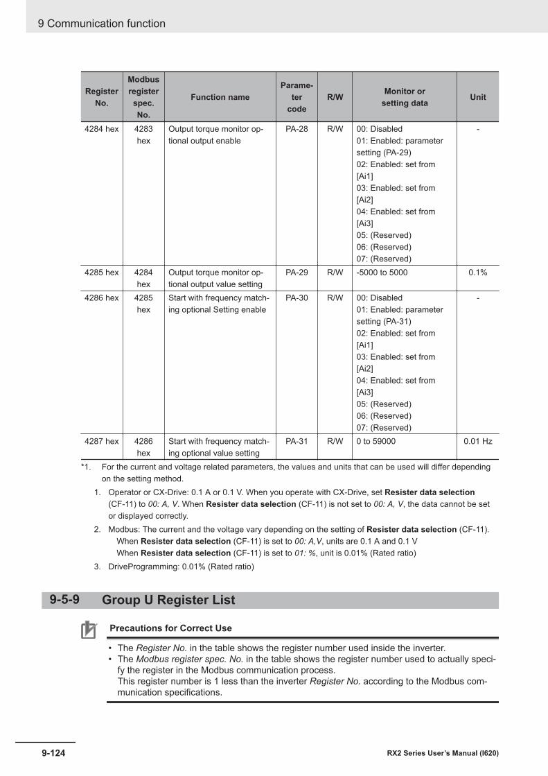
RegisterNo.
Modbusregisterspec.No.
Function nameParame-
tercode
R/W Monitor orsetting data Unit
4284 hex 4283hex
Output torque monitor op-tional output enable
PA-28 R/W 00: Disabled01: Enabled: parametersetting (PA-29)02: Enabled: set from[Ai1]03: Enabled: set from[Ai2]04: Enabled: set from[Ai3]05: (Reserved)06: (Reserved)07: (Reserved)
-
4285 hex 4284hex
Output torque monitor op-tional output value setting
PA-29 R/W -5000 to 5000 0.1%
4286 hex 4285hex
Start with frequency match-ing optional Setting enable
PA-30 R/W 00: Disabled01: Enabled: parametersetting (PA-31)02: Enabled: set from[Ai1]03: Enabled: set from[Ai2]04: Enabled: set from[Ai3]05: (Reserved)06: (Reserved)07: (Reserved)
-
4287 hex 4286hex
Start with frequency match-ing optional value setting
PA-31 R/W 0 to 59000 0.01 Hz
*1. For the current and voltage related parameters, the values and units that can be used will differ dependingon the setting method.
1. Operator or CX-Drive: 0.1 A or 0.1 V. When you operate with CX-Drive, set Resister data selection(CF-11) to 00: A, V. When Resister data selection (CF-11) is not set to 00: A, V, the data cannot be setor displayed correctly.
2. Modbus: The current and the voltage vary depending on the setting of Resister data selection (CF-11). When Resister data selection (CF-11) is set to 00: A,V, units are 0.1 A and 0.1 V When Resister data selection (CF-11) is set to 01: %, unit is 0.01% (Rated ratio)
3. DriveProgramming: 0.01% (Rated ratio)
9-5-9 Group U Register List
Precautions for Correct Use
• The Register No. in the table shows the register number used inside the inverter.• The Modbus register spec. No. in the table shows the register number used to actually speci-
fy the register in the Modbus communication process.This register number is 1 less than the inverter Register No. according to the Modbus com-munication specifications.
9 Communication function
9-124 RX2 Series User’s Manual (I620)
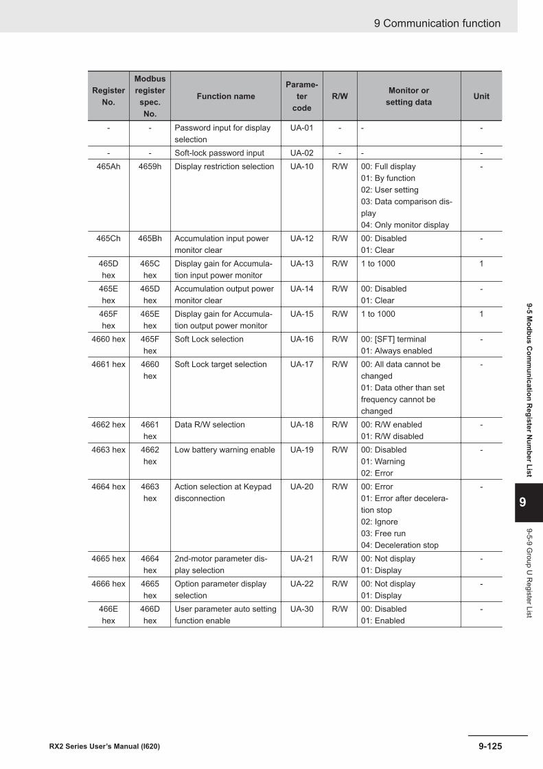
RegisterNo.
Modbusregisterspec.No.
Function nameParame-
tercode
R/W Monitor orsetting data Unit
- - Password input for displayselection
UA-01 - - -
- - Soft-lock password input UA-02 - - -465Ah 4659h Display restriction selection UA-10 R/W 00: Full display
01: By function02: User setting03: Data comparison dis-play04: Only monitor display
-
465Ch 465Bh Accumulation input powermonitor clear
UA-12 R/W 00: Disabled01: Clear
-
465Dhex
465Chex
Display gain for Accumula-tion input power monitor
UA-13 R/W 1 to 1000 1
465Ehex
465Dhex
Accumulation output powermonitor clear
UA-14 R/W 00: Disabled01: Clear
-
465Fhex
465Ehex
Display gain for Accumula-tion output power monitor
UA-15 R/W 1 to 1000 1
4660 hex 465Fhex
Soft Lock selection UA-16 R/W 00: [SFT] terminal01: Always enabled
-
4661 hex 4660hex
Soft Lock target selection UA-17 R/W 00: All data cannot bechanged01: Data other than setfrequency cannot bechanged
-
4662 hex 4661hex
Data R/W selection UA-18 R/W 00: R/W enabled01: R/W disabled
-
4663 hex 4662hex
Low battery warning enable UA-19 R/W 00: Disabled01: Warning02: Error
-
4664 hex 4663hex
Action selection at Keypaddisconnection
UA-20 R/W 00: Error01: Error after decelera-tion stop02: Ignore03: Free run04: Deceleration stop
-
4665 hex 4664hex
2nd-motor parameter dis-play selection
UA-21 R/W 00: Not display01: Display
-
4666 hex 4665hex
Option parameter displayselection
UA-22 R/W 00: Not display01: Display
-
466Ehex
466Dhex
User parameter auto settingfunction enable
UA-30 R/W 00: Disabled01: Enabled
-
9 Communication function
9-125RX2 Series User’s Manual (I620)
9-5 Modbus C
omm
unication Register N
umber List
9
9-5-9 Group U
Register List
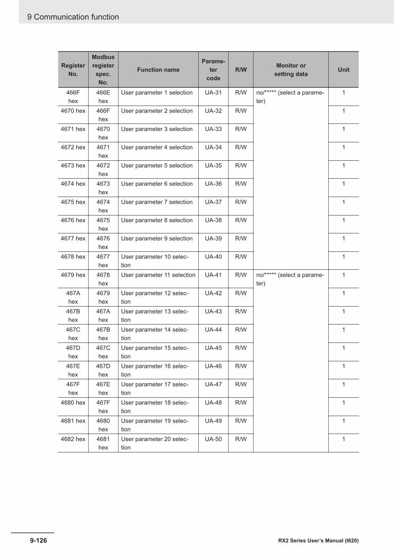
RegisterNo.
Modbusregisterspec.No.
Function nameParame-
tercode
R/W Monitor orsetting data Unit
466Fhex
466Ehex
User parameter 1 selection UA-31 R/W no/***** (select a parame-ter)
1
4670 hex 466Fhex
User parameter 2 selection UA-32 R/W 1
4671 hex 4670hex
User parameter 3 selection UA-33 R/W 1
4672 hex 4671hex
User parameter 4 selection UA-34 R/W 1
4673 hex 4672hex
User parameter 5 selection UA-35 R/W 1
4674 hex 4673hex
User parameter 6 selection UA-36 R/W 1
4675 hex 4674hex
User parameter 7 selection UA-37 R/W 1
4676 hex 4675hex
User parameter 8 selection UA-38 R/W 1
4677 hex 4676hex
User parameter 9 selection UA-39 R/W 1
4678 hex 4677hex
User parameter 10 selec-tion
UA-40 R/W 1
4679 hex 4678hex
User parameter 11 selection UA-41 R/W no/***** (select a parame-ter)
1
467Ahex
4679hex
User parameter 12 selec-tion
UA-42 R/W 1
467Bhex
467Ahex
User parameter 13 selec-tion
UA-43 R/W 1
467Chex
467Bhex
User parameter 14 selec-tion
UA-44 R/W 1
467Dhex
467Chex
User parameter 15 selec-tion
UA-45 R/W 1
467Ehex
467Dhex
User parameter 16 selec-tion
UA-46 R/W 1
467Fhex
467Ehex
User parameter 17 selec-tion
UA-47 R/W 1
4680 hex 467Fhex
User parameter 18 selec-tion
UA-48 R/W 1
4681 hex 4680hex
User parameter 19 selec-tion
UA-49 R/W 1
4682 hex 4681hex
User parameter 20 selec-tion
UA-50 R/W 1
9 Communication function
9-126 RX2 Series User’s Manual (I620)
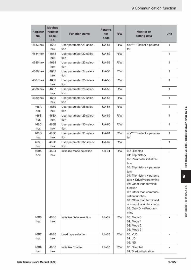
RegisterNo.
Modbusregisterspec.No.
Function nameParame-
tercode
R/W Monitor orsetting data Unit
4683 hex 4682hex
User parameter 21 selec-tion
UA-51 R/W no/***** (select a parame-ter)
1
4684 hex 4683hex
User parameter 22 selec-tion
UA-52 R/W 1
4685 hex 4684hex
User parameter 23 selec-tion
UA-53 R/W 1
4686 hex 4685hex
User parameter 24 selec-tion
UA-54 R/W 1
4687 hex 4686hex
User parameter 25 selec-tion
UA-55 R/W 1
4688 hex 4687hex
User parameter 26 selec-tion
UA-56 R/W 1
4689 hex 4688hex
User parameter 27 selec-tion
UA-57 R/W 1
468Ahex
4689hex
User parameter 28 selec-tion
UA-58 R/W 1
468Bhex
468Ahex
User parameter 29 selec-tion
UA-59 R/W 1
468Chex
468Bhex
User parameter 30 selec-tion
UA-60 R/W 1
468Dhex
468Chex
User parameter 31 selec-tion
UA-61 R/W no/***** (select a parame-ter)
1
468Ehex
468Dhex
User parameter 32 selec-tion
UA-62 R/W 1
46B5hex
46B4hex
Initialize Mode selection Ub-01 R/W 00: Disabled01: Trip history02: Parameter initializa-tion03: Trip history + parame-ters04: Trip history + parame-ters + DriveProgramming05: Other than terminalfunction06: Other than communi-cation function07: Other than terminal &communication functions08: Only DriveProgram-ming
-
46B6hex
46B5hex
Initialize Data selection Ub-02 R/W 00: Mode 001: Mode 102: Mode 203: Mode 3
-
46B7hex
46B6hex
Load type selection Ub-03 R/W 00: VLD01: LD02: ND
-
46B9hex
46B8hex
Initialize Enable Ub-05 R/W 00: Disabled01: Start initialization
-
9 Communication function
9-127RX2 Series User’s Manual (I620)
9-5 Modbus C
omm
unication Register N
umber List
9
9-5-9 Group U
Register List
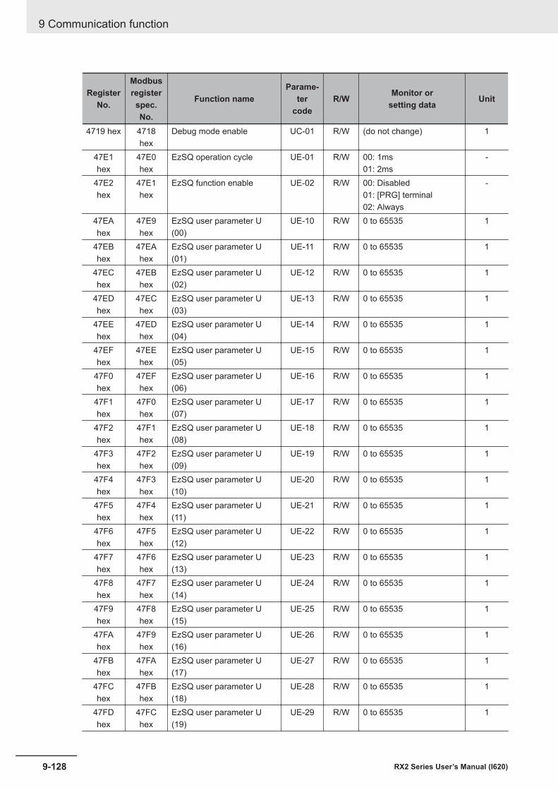
RegisterNo.
Modbusregisterspec.No.
Function nameParame-
tercode
R/W Monitor orsetting data Unit
4719 hex 4718hex
Debug mode enable UC-01 R/W (do not change) 1
47E1hex
47E0hex
EzSQ operation cycle UE-01 R/W 00: 1ms01: 2ms
-
47E2hex
47E1hex
EzSQ function enable UE-02 R/W 00: Disabled01: [PRG] terminal02: Always
-
47EAhex
47E9hex
EzSQ user parameter U(00)
UE-10 R/W 0 to 65535 1
47EBhex
47EAhex
EzSQ user parameter U(01)
UE-11 R/W 0 to 65535 1
47EChex
47EBhex
EzSQ user parameter U(02)
UE-12 R/W 0 to 65535 1
47EDhex
47EChex
EzSQ user parameter U(03)
UE-13 R/W 0 to 65535 1
47EEhex
47EDhex
EzSQ user parameter U(04)
UE-14 R/W 0 to 65535 1
47EFhex
47EEhex
EzSQ user parameter U(05)
UE-15 R/W 0 to 65535 1
47F0hex
47EFhex
EzSQ user parameter U(06)
UE-16 R/W 0 to 65535 1
47F1hex
47F0hex
EzSQ user parameter U(07)
UE-17 R/W 0 to 65535 1
47F2hex
47F1hex
EzSQ user parameter U(08)
UE-18 R/W 0 to 65535 1
47F3hex
47F2hex
EzSQ user parameter U(09)
UE-19 R/W 0 to 65535 1
47F4hex
47F3hex
EzSQ user parameter U(10)
UE-20 R/W 0 to 65535 1
47F5hex
47F4hex
EzSQ user parameter U(11)
UE-21 R/W 0 to 65535 1
47F6hex
47F5hex
EzSQ user parameter U(12)
UE-22 R/W 0 to 65535 1
47F7hex
47F6hex
EzSQ user parameter U(13)
UE-23 R/W 0 to 65535 1
47F8hex
47F7hex
EzSQ user parameter U(14)
UE-24 R/W 0 to 65535 1
47F9hex
47F8hex
EzSQ user parameter U(15)
UE-25 R/W 0 to 65535 1
47FAhex
47F9hex
EzSQ user parameter U(16)
UE-26 R/W 0 to 65535 1
47FBhex
47FAhex
EzSQ user parameter U(17)
UE-27 R/W 0 to 65535 1
47FChex
47FBhex
EzSQ user parameter U(18)
UE-28 R/W 0 to 65535 1
47FDhex
47FChex
EzSQ user parameter U(19)
UE-29 R/W 0 to 65535 1
9 Communication function
9-128 RX2 Series User’s Manual (I620)
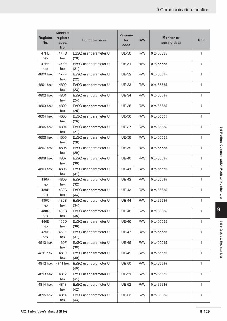
RegisterNo.
Modbusregisterspec.No.
Function nameParame-
tercode
R/W Monitor orsetting data Unit
47FEhex
47FDhex
EzSQ user parameter U(20)
UE-30 R/W 0 to 65535 1
47FFhex
47FEhex
EzSQ user parameter U(21)
UE-31 R/W 0 to 65535 1
4800 hex 47FFhex
EzSQ user parameter U(22)
UE-32 R/W 0 to 65535 1
4801 hex 4800hex
EzSQ user parameter U(23)
UE-33 R/W 0 to 65535 1
4802 hex 4801hex
EzSQ user parameter U(24)
UE-34 R/W 0 to 65535 1
4803 hex 4802hex
EzSQ user parameter U(25)
UE-35 R/W 0 to 65535 1
4804 hex 4803hex
EzSQ user parameter U(26)
UE-36 R/W 0 to 65535 1
4805 hex 4804hex
EzSQ user parameter U(27)
UE-37 R/W 0 to 65535 1
4806 hex 4805hex
EzSQ user parameter U(28)
UE-38 R/W 0 to 65535 1
4807 hex 4806hex
EzSQ user parameter U(29)
UE-39 R/W 0 to 65535 1
4808 hex 4807hex
EzSQ user parameter U(30)
UE-40 R/W 0 to 65535 1
4809 hex 4808hex
EzSQ user parameter U(31)
UE-41 R/W 0 to 65535 1
480Ahex
4809hex
EzSQ user parameter U(32)
UE-42 R/W 0 to 65535 1
480Bhex
480Ahex
EzSQ user parameter U(33)
UE-43 R/W 0 to 65535 1
480Chex
480Bhex
EzSQ user parameter U(34)
UE-44 R/W 0 to 65535 1
480Dhex
480Chex
EzSQ user parameter U(35)
UE-45 R/W 0 to 65535 1
480Ehex
480Dhex
EzSQ user parameter U(36)
UE-46 R/W 0 to 65535 1
480Fhex
480Ehex
EzSQ user parameter U(37)
UE-47 R/W 0 to 65535 1
4810 hex 480Fhex
EzSQ user parameter U(38)
UE-48 R/W 0 to 65535 1
4811 hex 4810hex
EzSQ user parameter U(39)
UE-49 R/W 0 to 65535 1
4812 hex 4811 hex EzSQ user parameter U(40)
UE-50 R/W 0 to 65535 1
4813 hex 4812hex
EzSQ user parameter U(41)
UE-51 R/W 0 to 65535 1
4814 hex 4813hex
EzSQ user parameter U(42)
UE-52 R/W 0 to 65535 1
4815 hex 4814hex
EzSQ user parameter U(43)
UE-53 R/W 0 to 65535 1
9 Communication function
9-129RX2 Series User’s Manual (I620)
9-5 Modbus C
omm
unication Register N
umber List
9
9-5-9 Group U
Register List
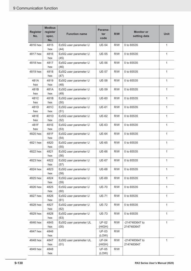
RegisterNo.
Modbusregisterspec.No.
Function nameParame-
tercode
R/W Monitor orsetting data Unit
4816 hex 4815hex
EzSQ user parameter U(44)
UE-54 R/W 0 to 65535 1
4817 hex 4816hex
EzSQ user parameter U(45)
UE-55 R/W 0 to 65535 1
4818 hex 4817hex
EzSQ user parameter U(46)
UE-56 R/W 0 to 65535 1
4819 hex 4818hex
EzSQ user parameter U(47)
UE-57 R/W 0 to 65535 1
481Ahex
4819hex
EzSQ user parameter U(48)
UE-58 R/W 0 to 65535 1
481Bhex
481Ahex
EzSQ user parameter U(49)
UE-59 R/W 0 to 65535 1
481Chex
481Bhex
EzSQ user parameter U(50)
UE-60 R/W 0 to 65535 1
481Dhex
481Chex
EzSQ user parameter U(51)
UE-61 R/W 0 to 65535 1
481Ehex
481Dhex
EzSQ user parameter U(52)
UE-62 R/W 0 to 65535 1
481Fhex
481Ehex
EzSQ user parameter U(53)
UE-63 R/W 0 to 65535 1
4820 hex 481Fhex
EzSQ user parameter U(54)
UE-64 R/W 0 to 65535 1
4821 hex 4820hex
EzSQ user parameter U(55)
UE-65 R/W 0 to 65535 1
4822 hex 4821hex
EzSQ user parameter U(56)
UE-66 R/W 0 to 65535 1
4823 hex 4822hex
EzSQ user parameter U(57)
UE-67 R/W 0 to 65535 1
4824 hex 4823hex
EzSQ user parameter U(58)
UE-68 R/W 0 to 65535 1
4825 hex 4824hex
EzSQ user parameter U(59)
UE-69 R/W 0 to 65535 1
4826 hex 4825hex
EzSQ user parameter U(60)
UE-70 R/W 0 to 65535 1
4827 hex 4826hex
EzSQ user parameter U(61)
UE-71 R/W 0 to 65535 1
4828 hex 4827hex
EzSQ user parameter U(62)
UE-72 R/W 0 to 65535 1
4829 hex 4828hex
EzSQ user parameter U(63)
UE-73 R/W 0 to 65535 1
4846 hex 4845hex
EzSQ user parameter UL(00)
UF-02(HIGH)
R/W -2147483647 to2147483647
1
4847 hex 4846hex
UF-03(LOW)
R/W
4848 hex 4847hex
EzSQ user parameter UL(01)
UF-04(HIGH)
R/W -2147483647 to2147483647
1
4849 hex 4848hex
UF-05(LOW)
R/W
9 Communication function
9-130 RX2 Series User’s Manual (I620)
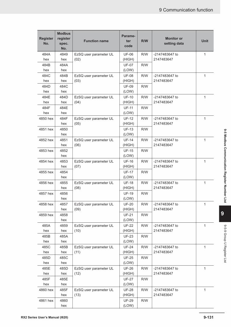
RegisterNo.
Modbusregisterspec.No.
Function nameParame-
tercode
R/W Monitor orsetting data Unit
484Ahex
4849hex
EzSQ user parameter UL(02)
UF-06(HIGH)
R/W -2147483647 to2147483647
1
484Bhex
484Ahex
UF-07(LOW)
R/W
484Chex
484Bhex
EzSQ user parameter UL(03)
UF-08(HIGH)
R/W -2147483647 to2147483647
1
484Dhex
484Chex
UF-09(LOW)
R/W
484Ehex
484Dhex
EzSQ user parameter UL(04)
UF-10(HIGH)
R/W -2147483647 to2147483647
1
484Fhex
484Ehex
UF-11(LOW)
R/W
4850 hex 484Fhex
EzSQ user parameter UL(05)
UF-12(HIGH)
R/W -2147483647 to2147483647
1
4851 hex 4850hex
UF-13(LOW)
R/W
4852 hex 4851hex
EzSQ user parameter UL(06)
UF-14(HIGH)
R/W -2147483647 to2147483647
1
4853 hex 4852hex
UF-15(LOW)
R/W
4854 hex 4853hex
EzSQ user parameter UL(07)
UF-16(HIGH)
R/W -2147483647 to2147483647
1
4855 hex 4854hex
UF-17(LOW)
R/W
4856 hex 4855hex
EzSQ user parameter UL(08)
UF-18(HIGH)
R/W -2147483647 to2147483647
1
4857 hex 4856hex
UF-19(LOW)
R/W
4858 hex 4857hex
EzSQ user parameter UL(09)
UF-20(HIGH)
R/W -2147483647 to2147483647
1
4859 hex 4858hex
UF-21(LOW)
R/W
485Ahex
4859hex
EzSQ user parameter UL(10)
UF-22(HIGH)
R/W -2147483647 to2147483647
1
485Bhex
485Ahex
UF-23(LOW)
R/W
485Chex
485Bhex
EzSQ user parameter UL(11)
UF-24(HIGH)
R/W -2147483647 to2147483647
1
485Dhex
485Chex
UF-25(LOW)
R/W
485Ehex
485Dhex
EzSQ user parameter UL(12)
UF-26(HIGH)
R/W -2147483647 to2147483647
1
485Fhex
485Ehex
UF-27(LOW)
R/W
4860 hex 485Fhex
EzSQ user parameter UL(13)
UF-28(HIGH)
R/W -2147483647 to2147483647
1
4861 hex 4860hex
UF-29(LOW)
R/W
9 Communication function
9-131RX2 Series User’s Manual (I620)
9-5 Modbus C
omm
unication Register N
umber List
9
9-5-9 Group U
Register List
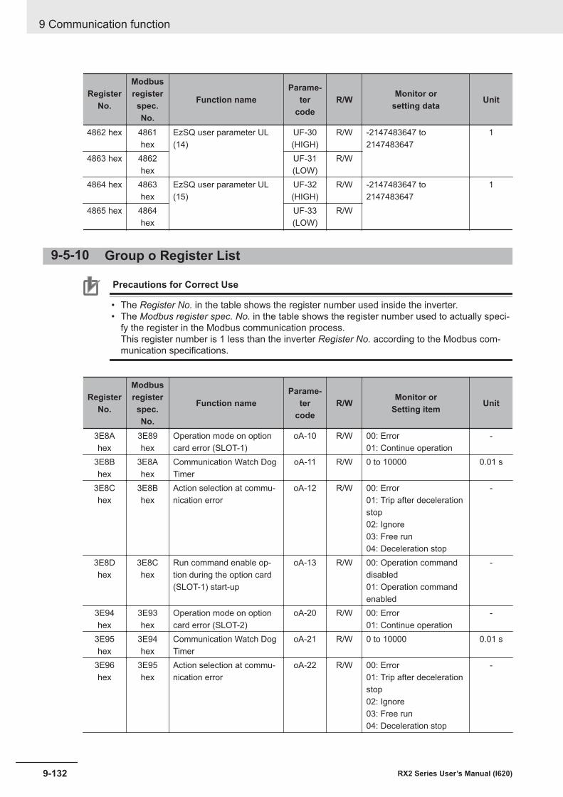
RegisterNo.
Modbusregisterspec.No.
Function nameParame-
tercode
R/W Monitor orsetting data Unit
4862 hex 4861hex
EzSQ user parameter UL(14)
UF-30(HIGH)
R/W -2147483647 to2147483647
1
4863 hex 4862hex
UF-31(LOW)
R/W
4864 hex 4863hex
EzSQ user parameter UL(15)
UF-32(HIGH)
R/W -2147483647 to2147483647
1
4865 hex 4864hex
UF-33(LOW)
R/W
9-5-10 Group o Register List
Precautions for Correct Use
• The Register No. in the table shows the register number used inside the inverter.• The Modbus register spec. No. in the table shows the register number used to actually speci-
fy the register in the Modbus communication process.This register number is 1 less than the inverter Register No. according to the Modbus com-munication specifications.
RegisterNo.
Modbusregisterspec.No.
Function nameParame-
tercode
R/W Monitor orSetting item Unit
3E8Ahex
3E89hex
Operation mode on optioncard error (SLOT-1)
oA-10 R/W 00: Error01: Continue operation
-
3E8Bhex
3E8Ahex
Communication Watch DogTimer
oA-11 R/W 0 to 10000 0.01 s
3E8Chex
3E8Bhex
Action selection at commu-nication error
oA-12 R/W 00: Error01: Trip after decelerationstop02: Ignore03: Free run04: Deceleration stop
-
3E8Dhex
3E8Chex
Run command enable op-tion during the option card(SLOT-1) start-up
oA-13 R/W 00: Operation commanddisabled01: Operation commandenabled
-
3E94hex
3E93hex
Operation mode on optioncard error (SLOT-2)
oA-20 R/W 00: Error01: Continue operation
-
3E95hex
3E94hex
Communication Watch DogTimer
oA-21 R/W 0 to 10000 0.01 s
3E96hex
3E95hex
Action selection at commu-nication error
oA-22 R/W 00: Error01: Trip after decelerationstop02: Ignore03: Free run04: Deceleration stop
-
9 Communication function
9-132 RX2 Series User’s Manual (I620)
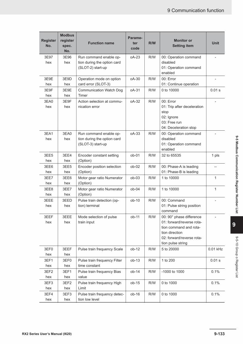
RegisterNo.
Modbusregisterspec.No.
Function nameParame-
tercode
R/W Monitor orSetting item Unit
3E97hex
3E96hex
Run command enable op-tion during the option card(SLOT-2) start-up
oA-23 R/W 00: Operation commanddisabled01: Operation commandenabled
-
3E9Ehex
3E9Dhex
Operation mode on optioncard error (SLOT-3)
oA-30 R/W 00: Error01: Continue operation
-
3E9Fhex
3E9Ehex
Communication Watch DogTimer
oA-31 R/W 0 to 10000 0.01 s
3EA0hex
3E9Fhex
Action selection at commu-nication error
oA-32 R/W 00: Error01: Trip after decelerationstop02: Ignore03: Free run04: Deceleration stop
-
3EA1hex
3EA0hex
Run command enable op-tion during the option card(SLOT-3) start-up
oA-33 R/W 00: Operation commanddisabled01: Operation commandenabled
-
3EE5hex
3EE4hex
Encoder constant setting(Option)
ob-01 R/W 32 to 65535 1 pls
3EE6hex
3EE5hex
Encoder position selection(Option)
ob-02 R/W 00: Phase-A is leading01: Phase-B is leading
--
3EE7hex
3EE6hex
Motor gear ratio Numerator(Option)
ob-03 R/W 1 to 10000 1
3EE8hex
3EE7hex
Motor gear ratio Numerator(Option)
ob-04 R/W 1 to 10000 1
3EEEhex
3EEDhex
Pulse train detection (op-tion) terminal
ob-10 R/W 00: Command01: Pulse string positioncommand
-
3EEFhex
3EEEhex
Mode selection of pulsetrain input
ob-11 R/W 00: 90° phase difference01: forward/reverse rota-tion command and rota-tion direction02: forward/reverse rota-tion pulse string
-
3EF0hex
3EEFhex
Pulse train frequency Scale ob-12 R/W 5 to 20000 0.01 kHz
3EF1hex
3EF0hex
Pulse train frequency Filtertime constant
ob-13 R/W 1 to 200 0.01 s
3EF2hex
3EF1hex
Pulse train frequency Biasvalue
ob-14 R/W -1000 to 1000 0.1%
3EF3hex
3EF2hex
Pulse train frequency HighLimit
ob-15 R/W 0 to 1000 0.1%
3EF4hex
3EF3hex
Pulse train frequency detec-tion low level
ob-16 R/W 0 to 1000 0.1%
9 Communication function
9-133RX2 Series User’s Manual (I620)
9-5 Modbus C
omm
unication Register N
umber List
9
9-5-10 Group o R
egister List
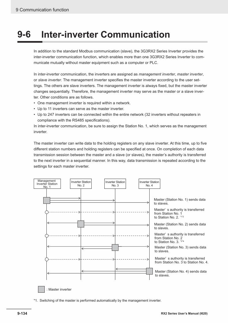
9-6 Inter-inverter CommunicationIn addition to the standard Modbus communication (slave), the 3G3RX2 Series Inverter provides theinter-inverter communication function, which enables more than one 3G3RX2 Series Inverter to com-municate mutually without master equipment such as a computer or PLC.
In inter-inverter communication, the inverters are assigned as management inverter, master inverter,or slave inverter. The management inverter specifies the master inverter according to the user set-tings. The others are slave inverters. The management inverter is always fixed, but the master inverterchanges sequentially. Therefore, the management inverter may serve as the master or a slave inver-ter. Other conditions are as follows.• One management inverter is required within a network.• Up to 11 inverters can serve as the master inverter.• Up to 247 inverters can be connected within the entire network (32 inverters without repeaters in
compliance with the RS485 specifications).In inter-inverter communication, be sure to assign the Station No. 1, which serves as the managementinverter.
The master inverter can write data to the holding registers on any slave inverter. At this time, up to fivedifferent station numbers and holding registers can be specified at once. On completion of each datatransmission session between the master and a slave (or slaves), the master’s authority is transferredto the next inverter in a sequential manner. In this way, data transmission is repeated according to thesettings for each master inverter.
Management Inverter Station
No. 1
Inverter StationNo. 2
: Master inverter
Inverter StationNo. 3
Inverter StationNo. 4
Master (Station No. 1) sends datato slaves.
Master (Station No. 2) sends datato slaves.
Master (Station No. 3) sends datato slaves.
Master’ s authority is transferred from Station No. 1 to Station No. 2. *1*2
Master’ s authority is transferred from Station No. 2 to Station No. 3. *3*4
Master (Station No. 4) sends datato slaves.
Master’ s authority is transferred from Station No. 3 to Station No. 4.
*1. Switching of the master is performed automatically by the management inverter.
9 Communication function
9-134 RX2 Series User’s Manual (I620)
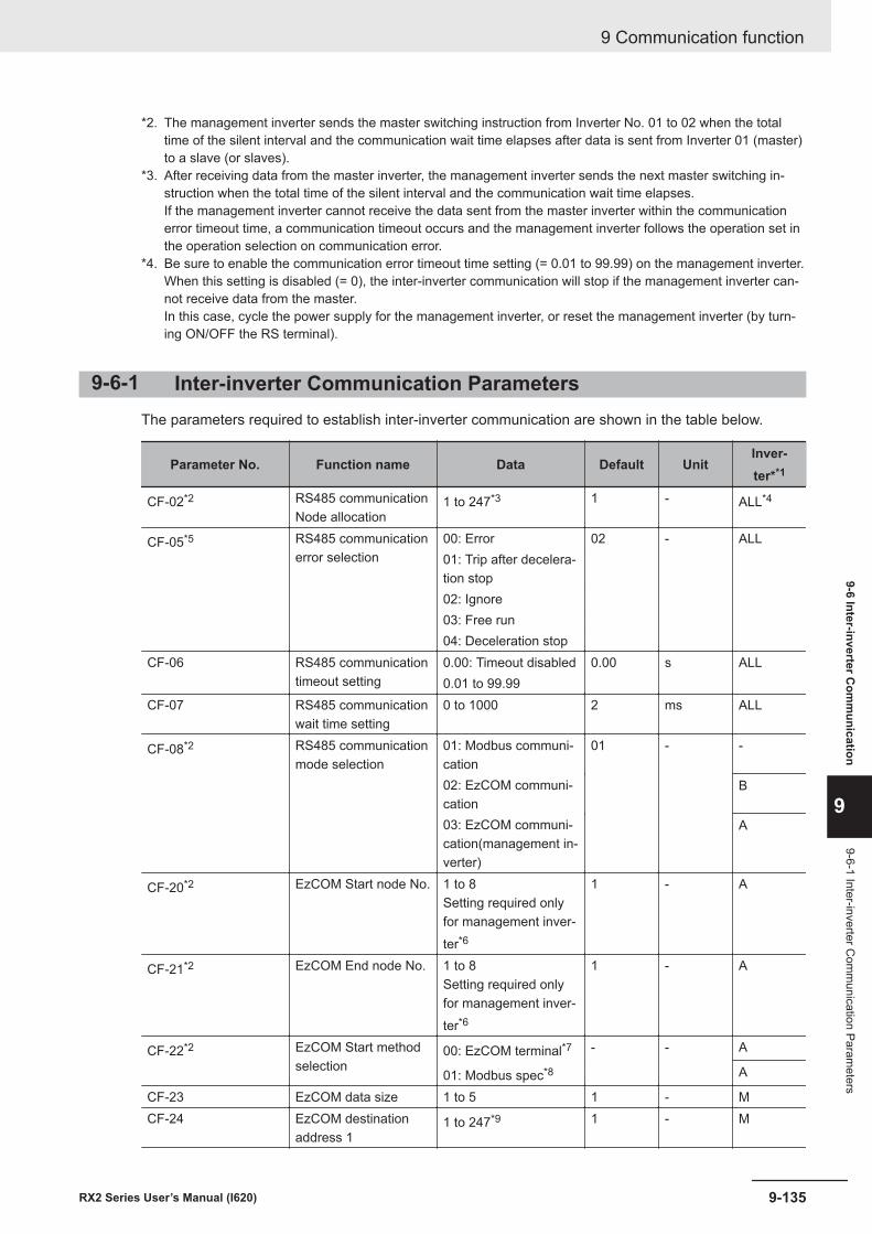
*2. The management inverter sends the master switching instruction from Inverter No. 01 to 02 when the totaltime of the silent interval and the communication wait time elapses after data is sent from Inverter 01 (master)to a slave (or slaves).
*3. After receiving data from the master inverter, the management inverter sends the next master switching in-struction when the total time of the silent interval and the communication wait time elapses.If the management inverter cannot receive the data sent from the master inverter within the communicationerror timeout time, a communication timeout occurs and the management inverter follows the operation set inthe operation selection on communication error.
*4. Be sure to enable the communication error timeout time setting (= 0.01 to 99.99) on the management inverter.When this setting is disabled (= 0), the inter-inverter communication will stop if the management inverter can-not receive data from the master.In this case, cycle the power supply for the management inverter, or reset the management inverter (by turn-ing ON/OFF the RS terminal).
9-6-1 Inter-inverter Communication ParametersThe parameters required to establish inter-inverter communication are shown in the table below.
Parameter No. Function name Data Default UnitInver-ter**1
CF-02*2 RS485 communicationNode allocation
1 to 247*3 1 - ALL*4
CF-05*5 RS485 communicationerror selection
00: Error 02 - ALL01: Trip after decelera-tion stop02: Ignore03: Free run04: Deceleration stop
CF-06 RS485 communicationtimeout setting
0.00: Timeout disabled 0.00 s ALL0.01 to 99.99
CF-07 RS485 communicationwait time setting
0 to 1000 2 ms ALL
CF-08*2 RS485 communicationmode selection
01: Modbus communi-cation
01 - -
02: EzCOM communi-cation
B
03: EzCOM communi-cation(management in-verter)
A
CF-20*2 EzCOM Start node No. 1 to 8Setting required onlyfor management inver-ter*6
1 - A
CF-21*2 EzCOM End node No. 1 to 8Setting required onlyfor management inver-ter*6
1 - A
CF-22*2 EzCOM Start methodselection
00: EzCOM terminal*7 - - A
01: Modbus spec*8 A
CF-23 EzCOM data size 1 to 5 1 - MCF-24 EzCOM destination
address 11 to 247*9 1 - M
9 Communication function
9-135RX2 Series User’s Manual (I620)
9-6 Inter-inverter Com
munication
9
9-6-1 Inter-inverter Com
munication Param
eters
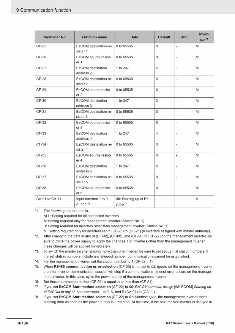
Parameter No. Function name Data Default UnitInver-ter**1
CF-25 EzCOM destination re-sister 1
0 to 65535 0 - M
CF-26 EzCOM source resist-er 1
0 to 65535 0 - M
CF-27 EzCOM destinationaddress 2
1 to 247 2 - M
CF-28 EzCOM destination re-sister 2
0 to 65535 0 - M
CF-29 EzCOM source resist-er 2
0 to 65535 0 - M
CF-30 EzCOM destinationaddress 3
1 to 247 3 - M
CF-31 EzCOM destination re-sister 3
0 to 65535 0 - M
CF-32 EzCOM source resist-er 3
0 to 65535 0 - M
CF-33 EzCOM destinationaddress 4
1 to 247 4 - M
CF-34 EzCOM destination re-sister 4
0 to 65535 0 - M
CF-35 EzCOM source resist-er 4
0 to 65535 0 - M
CF-36 EzCOM destinationaddress 5
1 to 247 5 - M
CF-37 EzCOM destination re-sister 5
0 to 65535 0 - M
CF-38 EzCOM source resist-er 5
0 to 65535 0 - M
CA-01 to CA-11 Input terminal 1 to 9,A, and B
98: Starting up of Ez-COM*7
- - A
*1. The following are the details.ALL: Setting required for all connected inverters.A: Setting required only for management inverter (Station No. 1).B: Setting required for inverters other than management inverter (Station No. 1).M: Setting required only for inverters set in (CF-20) to (CF-21) (= inverters assigned with master authority).
*2. After changing the data in any of (CF-02), (CF-08), and (CF-20) to (CF-22) on the management inverter, besure to cycle the power supply to apply the changes. For inverters other than the management inverter,these changes will be applied immediately.
*3. To switch the master inverter among more than one inverter, be sure to set sequential station numbers. Ifthe set station numbers include any skipped number, communications cannot be established.
*4. For the management inverter, set the station number to 1 (CF-02 = 1).*5. When RS485 communication error selection (CF-05) is not set to 02: Ignore on the management inverter,
the inter-inverter communication session will stop if a communications timeout error occurs on the manage-ment inverter. In this case, cycle the power supply of the management inverter.
*6. Set these parameters so that (CF-20) is equal to or less than (CF-21).*7. If you set EzCOM Start method selection (CF-22) to 00: EzCOM terminal, assign [98: ECOM] Starting up
of EzCOM to any of input terminals 1 to 9, A, and B (CA-01) to (CA-11).*8. If you set EzCOM Start method selection (CF-22) to 01: Modbus spec, the management inverter starts
sending data as soon as the power supply is turned on. At this time, if the next master inverter is delayed in
9 Communication function
9-136 RX2 Series User’s Manual (I620)

the startup and cannot receive the master switching instruction, the master inverter cannot send the data,which results in a communications timeout error on the management inverter.When you set (CF-22) to 01, check that the startup of the other inverters is completed, and then power onthe management inverter.
*9. Although, in master-to-slave communications, you set recipient slave’s station number, actually, data is sentto all stations via broadcast communications (Station No. 00). Slaves that are not specified as the recipienton the master side discard the received data.
9-6-2 Communication Settings• Set the station numbers for each inverter in inter-inverter communication so that they do not overlap
among the inverters. Do not forget to set the station No. 1. The inverter with the station No.1 servesas the management inverter.
• For the management inverter, set RS485 communication mode selection (CF-08) to 03: EzCOMmanagement. For inverters other than the management inverter, set RS485 communication modeselection (CF-08) to 02: EzCOM.
• Set a station number 1 to 8 on inverters that serve as the master inverter. To switch the master in-verter among more than one inverter, the station numbering must be sequential. On the manage-ment inverter, set the smallest master station number in EzCOM Start node No. (CF-20), and thelargest master station number in EzCOM End node No. (CF-21).
• Set the inverter communication start method on the management inverter. If you set RS485communication mode selection (CF-08) to 01: Modbus-RTU, assign 98: Starting up of EzCOM toone of Input terminal function (CA-01) to (CA-11).
• In (CF-23) to (CF-38), set the following parameters, which are required when the master inverterwrites data: the number of sent data, recipient station number, recipient register address, and send-er register address.
Inter-inverter Communication Operation
1 The master inverter sends data to one or more slave inverters according to the settings for thatmaster inverter.This data is also sent to the management inverter that does not serve as the master inverter.
2 The management inverter sends the master switching instruction and the master inverter isswitched accordingly.
3 The next master inverter sends data to one or more slave inverters in the same manner as ex-plained in Step 1.This data is also sent to the management inverter that does not serve as the master inverter.
4 Steps 2 and 3 are followed repeatedly.Note Because this inverter is designed to establish inter-inverter communication via broadcast communi-
cations (Station No. 00), communications data is sent to all stations. Therefore, slaves that are notspecified as the recipient on the master side receive the data once, but internally discard the data ifnot destined to them.
9 Communication function
9-137RX2 Series User’s Manual (I620)
9-6 Inter-inverter Com
munication
9
9-6-2 Com
munication Settings
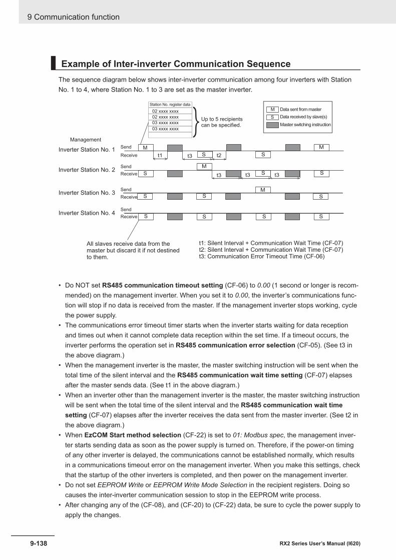
Example of Inter-inverter Communication SequenceThe sequence diagram below shows inter-inverter communication among four inverters with StationNo. 1 to 4, where Station No. 1 to 3 are set as the master inverter.
Management
Inverter Station No. 3Receive
M
S
All slaves receive data from themaster but discard it if not destinedto them.
t1: Silent Interval + Communication Wait Time (CF-07)t2: Silent Interval + Communication Wait Time (CF-07)t3: Communication Error Timeout Time (CF-06)
t1 t2
t3Inverter Station No. 2
Inverter Station No. 1
Inverter Station No. 4Send
Send
Send
Send
Receive
Receive
Receive
t3
t3
t3
S
S
S
S
S
S
S
S
S
S
S
M
M
M
M
S Data received by slave(s)
Data sent from master
Master switching instruction
Station No. register data
02 xxxx xxxx
02 xxxx xxxx
03 xxxx xxxx
03 xxxx xxxx
Up to 5 recipientscan be specified.}
• Do NOT set RS485 communication timeout setting (CF-06) to 0.00 (1 second or longer is recom-mended) on the management inverter. When you set it to 0.00, the inverter’s communications func-tion will stop if no data is received from the master. If the management inverter stops working, cyclethe power supply.
• The communications error timeout timer starts when the inverter starts waiting for data receptionand times out when it cannot complete data reception within the set time. If a timeout occurs, theinverter performs the operation set in RS485 communication error selection (CF-05). (See t3 inthe above diagram.)
• When the management inverter is the master, the master switching instruction will be sent when thetotal time of the silent interval and the RS485 communication wait time setting (CF-07) elapsesafter the master sends data. (See t1 in the above diagram.)
• When an inverter other than the management inverter is the master, the master switching instructionwill be sent when the total time of the silent interval and the RS485 communication wait timesetting (CF-07) elapses after the inverter receives the data sent from the master inverter. (See t2 inthe above diagram.)
• When EzCOM Start method selection (CF-22) is set to 01: Modbus spec, the management inver-ter starts sending data as soon as the power supply is turned on. Therefore, if the power-on timingof any other inverter is delayed, the communications cannot be established normally, which resultsin a communications timeout error on the management inverter. When you make this settings, checkthat the startup of the other inverters is completed, and then power on the management inverter.
• Do not set EEPROM Write or EEPROM Write Mode Selection in the recipient registers. Doing socauses the inter-inverter communication session to stop in the EEPROM write process.
• After changing any of the (CF-08), and (CF-20) to (CF-22) data, be sure to cycle the power supply toapply the changes.
9 Communication function
9-138 RX2 Series User’s Manual (I620)

10DriveProgramming
This section provides an overview of the DriveProgramming.
10-1 Overview of DriveProgramming ................................................................. 10-2
10-1RX2 Series User’s Manual (I620)
10

10-1 Overview of DriveProgrammingThe 3G3RX2 Series Inverter has the built-in simple sequence function (DriveProgramming), which en-ables a stand-alone inverter to perform simple sequence control.You can create programs easily by using the CX-Drive. The user programs you created can be down-loaded onto the inverter for programmed inverter operation.
Features of DriveProgramming• The DriveProgramming supports both flowchart and text language method programming.• Five tasks can be processed in parallel.• ON/OFF by input terminals enables a start of user programs.• The user programs enable the input terminals and output terminals to use reading and writing func-
tions.• The LCD Operator enables you to change the settings of the output frequency, acceleration/deceler-
ation time, and other parameters that require on-site adjustment by specifying the user parameters(UE-10) to (UE-73), without connecting the computer.
• Because user programs are stored in the internal EEPROM of the inverter, you can start a programimmediately after the inverter power supply is turned on.
• Connecting the optional LCD Operator enables the control of the inverter by using the LCD Opera-tor’s clock function.
Precautions for Safe Use
• If the clock function is used in DriveProgramming, an unexpected operation may occur due toweak battery.Take measures such as detecting a weak battery by the RTC error (E042) and stopping theinverter or programs.When the LCD Operator is removed or disconnected, DriveProgramming is in a waiting sta-tus by the clock function.
• If the DriveProgramming stops while the output terminal function is making output, the outputstatus is held. Take safety precautions such as stopping peripheral devices.
DriveProgramming FunctionThe details of the main DrvieProgramming function are as follows.
10 DriveProgramming
10-2 RX2 Series User’s Manual (I620)
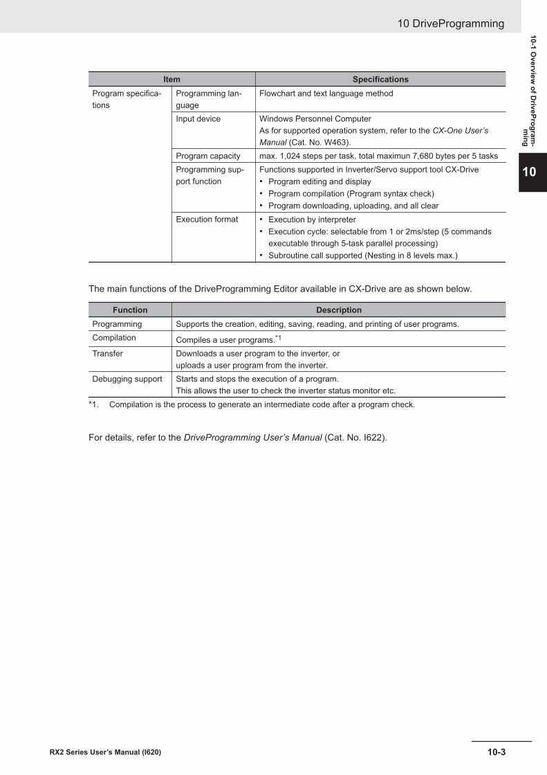
Item SpecificationsProgram specifica-tions
Programming lan-guage
Flowchart and text language method
Input device Windows Personnel ComputerAs for supported operation system, refer to the CX-One User’sManual (Cat. No. W463).
Program capacity max. 1,024 steps per task, total maximun 7,680 bytes per 5 tasksProgramming sup-port function
Functions supported in Inverter/Servo support tool CX-Drive• Program editing and display• Program compilation (Program syntax check)• Program downloading, uploading, and all clear
Execution format • Execution by interpreter• Execution cycle: selectable from 1 or 2ms/step (5 commands
executable through 5-task parallel processing)• Subroutine call supported (Nesting in 8 levels max.)
The main functions of the DriveProgramming Editor available in CX-Drive are as shown below.
Function DescriptionProgramming Supports the creation, editing, saving, reading, and printing of user programs.Compilation Compiles a user programs.*1
Transfer Downloads a user program to the inverter, oruploads a user program from the inverter.
Debugging support Starts and stops the execution of a program.This allows the user to check the inverter status monitor etc.
*1. Compilation is the process to generate an intermediate code after a program check.
For details, refer to the DriveProgramming User’s Manual (Cat. No. I622).
10 DriveProgramming
10-3RX2 Series User’s Manual (I620)
10-1 Overview
of DriveProgram
-m
ing
10
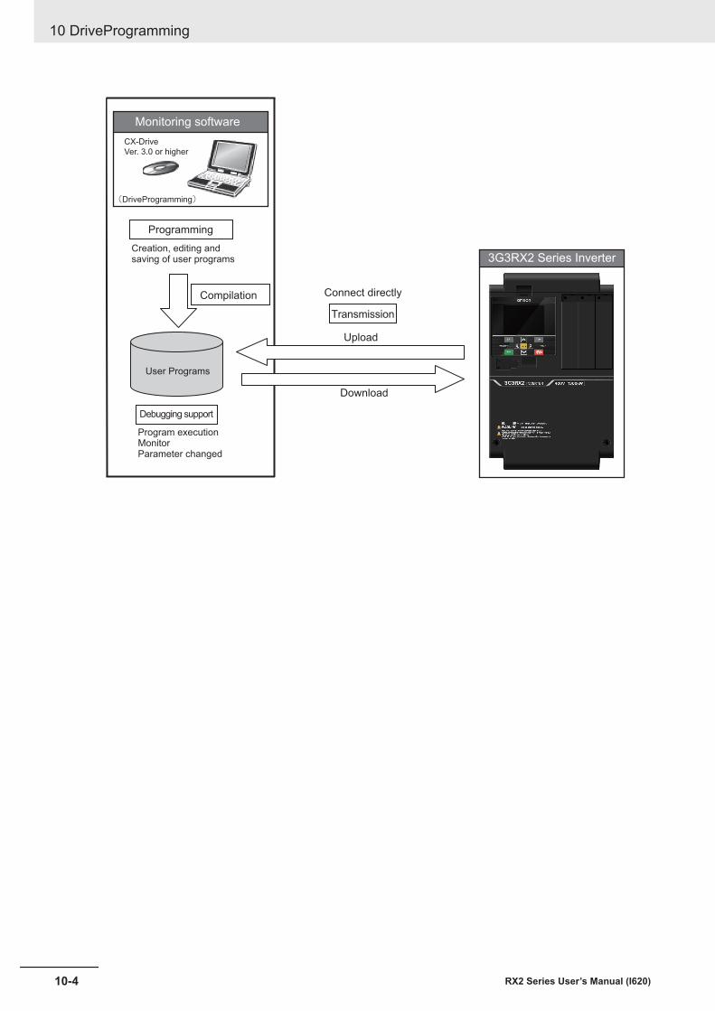
User Programs
Compilation
Download
Upload
(DriveProgramming)
Programming
Debugging support
Transmission
Creation, editing andsaving of user programs
Program executionMonitorParameter changed
Monitoring software
3G3RX2 Series Inverter
CX-Drive
Ver. 3.0 or higher
Connect directly
10 DriveProgramming
10-4 RX2 Series User’s Manual (I620)
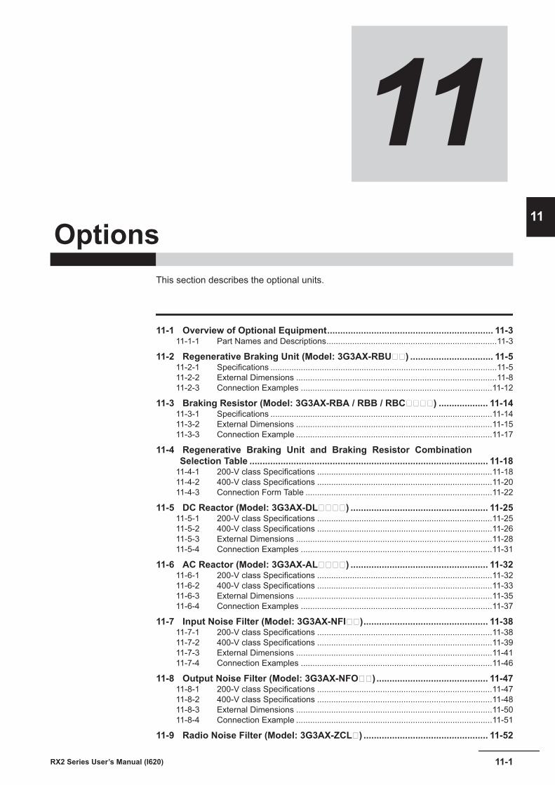
11Options
This section describes the optional units.
11-1 Overview of Optional Equipment................................................................ 11-311-1-1 Part Names and Descriptions.........................................................................11-3
11-2 Regenerative Braking Unit (Model: 3G3AX-RBU) ................................ 11-511-2-1 Specifications .................................................................................................11-511-2-2 External Dimensions ......................................................................................11-811-2-3 Connection Examples ..................................................................................11-12
11-3 Braking Resistor (Model: 3G3AX-RBA / RBB / RBC) ................... 11-1411-3-1 Specifications ...............................................................................................11-1411-3-2 External Dimensions ....................................................................................11-1511-3-3 Connection Example ....................................................................................11-17
11-4 Regenerative Braking Unit and Braking Resistor CombinationSelection Table ............................................................................................ 11-18
11-4-1 200-V class Specifications ...........................................................................11-1811-4-2 400-V class Specifications ...........................................................................11-2011-4-3 Connection Form Table ................................................................................11-22
11-5 DC Reactor (Model: 3G3AX-DL) ..................................................... 11-2511-5-1 200-V class Specifications ...........................................................................11-2511-5-2 400-V class Specifications ...........................................................................11-2611-5-3 External Dimensions ....................................................................................11-2811-5-4 Connection Examples ..................................................................................11-31
11-6 AC Reactor (Model: 3G3AX-AL) ..................................................... 11-3211-6-1 200-V class Specifications ...........................................................................11-3211-6-2 400-V class Specifications ...........................................................................11-3311-6-3 External Dimensions ....................................................................................11-3511-6-4 Connection Examples ..................................................................................11-37
11-7 Input Noise Filter (Model: 3G3AX-NFI)................................................ 11-3811-7-1 200-V class Specifications ...........................................................................11-3811-7-2 400-V class Specifications ...........................................................................11-3911-7-3 External Dimensions ....................................................................................11-4111-7-4 Connection Examples ..................................................................................11-46
11-8 Output Noise Filter (Model: 3G3AX-NFO)........................................... 11-4711-8-1 200-V class Specifications ...........................................................................11-4711-8-2 400-V class Specifications ...........................................................................11-4811-8-3 External Dimensions ....................................................................................11-5011-8-4 Connection Example ....................................................................................11-51
11-9 Radio Noise Filter (Model: 3G3AX-ZCL) ................................................ 11-52
11-1RX2 Series User’s Manual (I620)
11
11-9-1 Specifications ...............................................................................................11-5211-9-2 External Dimensions ....................................................................................11-5411-9-3 Connection Example ....................................................................................11-55
11-10 EMC Noise Filter (Model: 3G3AX-EFI) .................................................. 11-5611-10-1 200-V class Specifications ...........................................................................11-5611-10-2 400-V class Specifications ...........................................................................11-5711-10-3 External Dimensions ....................................................................................11-6011-10-4 Connection Example ....................................................................................11-62
11-11 LCD Operator Cable (Model: 3G3AX-OPCN) .......................................... 11-6311-11-1 Specifications ...............................................................................................11-6311-11-2 External Dimensions ....................................................................................11-63
11-12 EtherCAT Communications Unit (Model: 3G3AX-RX2-ECT).................... 11-6411-12-1 Specifications ...............................................................................................11-6411-12-2 External Dimensions ....................................................................................11-65
11 Options
11-2 RX2 Series User’s Manual (I620)
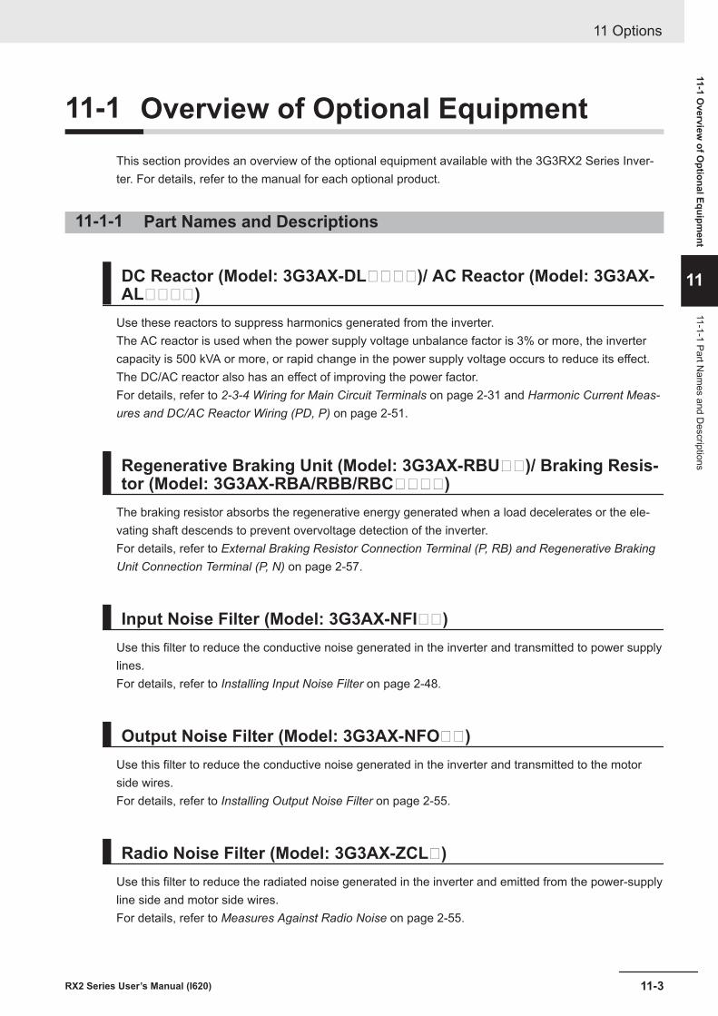
11-1 Overview of Optional EquipmentThis section provides an overview of the optional equipment available with the 3G3RX2 Series Inver-ter. For details, refer to the manual for each optional product.
11-1-1 Part Names and Descriptions
DC Reactor (Model: 3G3AX-DL)/ AC Reactor (Model: 3G3AX-AL)
Use these reactors to suppress harmonics generated from the inverter.The AC reactor is used when the power supply voltage unbalance factor is 3% or more, the invertercapacity is 500 kVA or more, or rapid change in the power supply voltage occurs to reduce its effect.The DC/AC reactor also has an effect of improving the power factor.For details, refer to 2-3-4 Wiring for Main Circuit Terminals on page 2-31 and Harmonic Current Meas-ures and DC/AC Reactor Wiring (PD, P) on page 2-51.
Regenerative Braking Unit (Model: 3G3AX-RBU)/ Braking Resis-tor (Model: 3G3AX-RBA/RBB/RBC)
The braking resistor absorbs the regenerative energy generated when a load decelerates or the ele-vating shaft descends to prevent overvoltage detection of the inverter.For details, refer to External Braking Resistor Connection Terminal (P, RB) and Regenerative BrakingUnit Connection Terminal (P, N) on page 2-57.
Input Noise Filter (Model: 3G3AX-NFI)Use this filter to reduce the conductive noise generated in the inverter and transmitted to power supplylines.For details, refer to Installing Input Noise Filter on page 2-48.
Output Noise Filter (Model: 3G3AX-NFO)Use this filter to reduce the conductive noise generated in the inverter and transmitted to the motorside wires.For details, refer to Installing Output Noise Filter on page 2-55.
Radio Noise Filter (Model: 3G3AX-ZCL)Use this filter to reduce the radiated noise generated in the inverter and emitted from the power-supplyline side and motor side wires.For details, refer to Measures Against Radio Noise on page 2-55.
11 Options
11-3RX2 Series User’s Manual (I620)
11-1 Overview
of Optional Equipm
ent
11
11-1-1 Part Nam
es and Descriptions
EMC Noise Filter (Model: 3G3AX-EFI)Use this filter to reduce the conductive noise generated in the inverter and transmitted to power supplylines for compliance with European EC Directives.For details, refer to 2-5-1 Conditions of Conformity of EU Directives on page 2-93.
PG Option Unit (Model: 3G3AX-RX2-PG01)This option detects the rotation speed of the motor with an encoder and feeds back the detected valueto enable high-accuracy operation with reduced speed variation, as well as position control via pulsetrain position command input.See 2-3-6 Wiring for PG Option Unit on page 2-68 for detail.
EtherCAT Communications unit (3G3AX-RX2-ECT)This option unit can control the inverter via EtherCAT communications.For details, refer to Inverter RX2 Series EtherCAT® Communication Unit User’s Manual (I663).
11 Options
11-4 RX2 Series User’s Manual (I620)
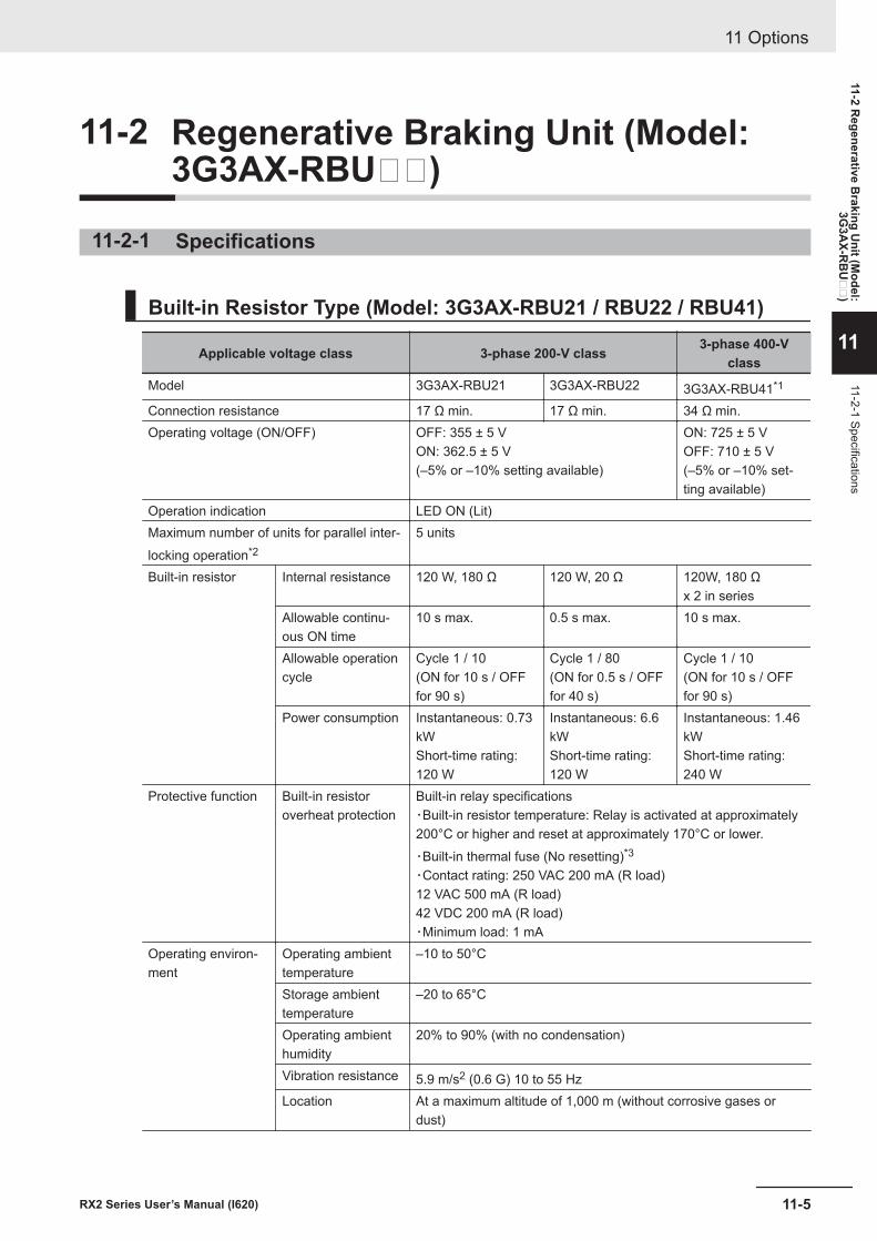
11-2 Regenerative Braking Unit (Model:3G3AX-RBU)
11-2-1 Specifications
Built-in Resistor Type (Model: 3G3AX-RBU21 / RBU22 / RBU41)
Applicable voltage class 3-phase 200-V class 3-phase 400-Vclass
Model 3G3AX-RBU21 3G3AX-RBU22 3G3AX-RBU41*1
Connection resistance 17 Ω min. 17 Ω min. 34 Ω min.Operating voltage (ON/OFF) OFF: 355 ± 5 V
ON: 362.5 ± 5 V(–5% or –10% setting available)
ON: 725 ± 5 VOFF: 710 ± 5 V(–5% or –10% set-ting available)
Operation indication LED ON (Lit)Maximum number of units for parallel inter-locking operation*2
5 units
Built-in resistor Internal resistance 120 W, 180 Ω 120 W, 20 Ω 120W, 180 Ωx 2 in series
Allowable continu-ous ON time
10 s max. 0.5 s max. 10 s max.
Allowable operationcycle
Cycle 1 / 10(ON for 10 s / OFFfor 90 s)
Cycle 1 / 80(ON for 0.5 s / OFFfor 40 s)
Cycle 1 / 10(ON for 10 s / OFFfor 90 s)
Power consumption Instantaneous: 0.73kWShort-time rating:120 W
Instantaneous: 6.6kWShort-time rating:120 W
Instantaneous: 1.46kWShort-time rating:240 W
Protective function Built-in resistoroverheat protection
Built-in relay specifications・Built-in resistor temperature: Relay is activated at approximately200°C or higher and reset at approximately 170°C or lower.・Built-in thermal fuse (No resetting)*3
・Contact rating: 250 VAC 200 mA (R load)12 VAC 500 mA (R load)42 VDC 200 mA (R load)・Minimum load: 1 mA
Operating environ-ment
Operating ambienttemperature
–10 to 50°C
Storage ambienttemperature
–20 to 65°C
Operating ambienthumidity
20% to 90% (with no condensation)
Vibration resistance 5.9 m/s2 (0.6 G) 10 to 55 HzLocation At a maximum altitude of 1,000 m (without corrosive gases or
dust)
11 Options
11-5RX2 Series User’s Manual (I620)
11-2 Regenerative B
raking Unit (M
odel:3G
3AX-R
BU
)
11
11-2-1 Specifications

Applicable voltage class 3-phase 200-V class 3-phase 400-Vclass
Paint color Munselle 5Y7/1 (except for cooling fan with aluminum base color)*1. To use the braking resistor (Model: 3G3AX-RAB / RBB / RBC) for the 400-V class regenerative braking unit,
be sure to remove the built-in resistor and connect two resistors of the same model in series. Using a 400-Vclass regenerative braking unit with only a single braking resistor connected may cause damage to the brak-ing resistor.
*2. Use DIP switches to set the number of connected units.*3. The built-in resistor has a thermal fuse. If the alarm terminals are not connected, the fuse may blow out in
order to prevent the resistor from burning due to overheating. If the fuse blows out, the built-in resistor mustbe replaced.
11 Options
11-6 RX2 Series User’s Manual (I620)
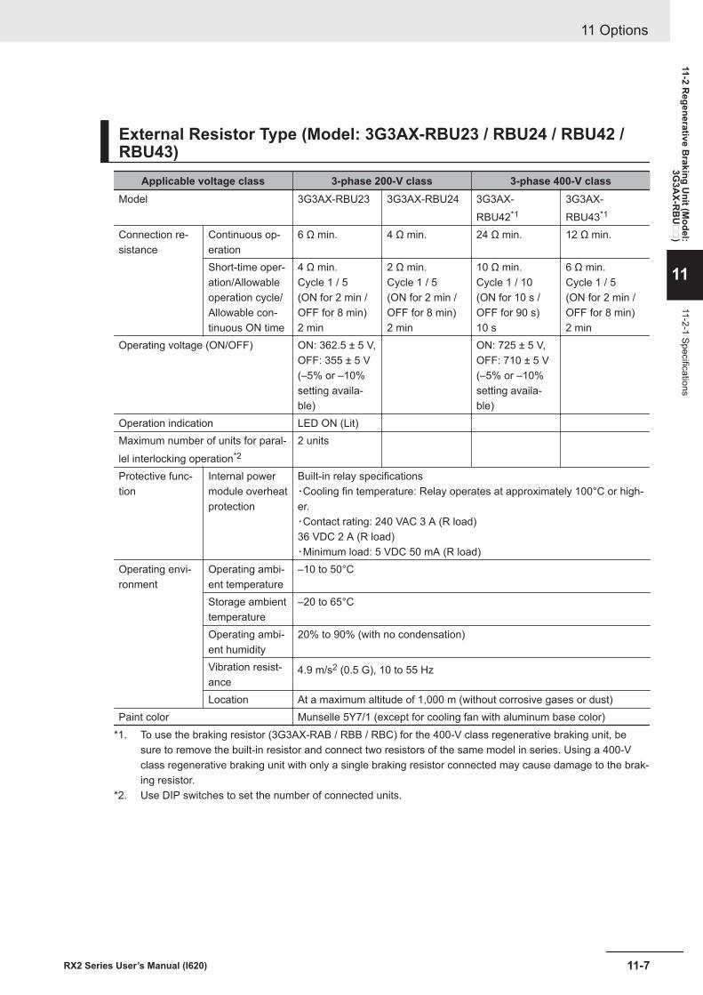
External Resistor Type (Model: 3G3AX-RBU23 / RBU24 / RBU42 /RBU43)
Applicable voltage class 3-phase 200-V class 3-phase 400-V classModel 3G3AX-RBU23 3G3AX-RBU24 3G3AX-
RBU42*13G3AX-RBU43*1
Connection re-sistance
Continuous op-eration
6 Ω min. 4 Ω min. 24 Ω min. 12 Ω min.
Short-time oper-ation/Allowableoperation cycle/Allowable con-tinuous ON time
4 Ω min.Cycle 1 / 5(ON for 2 min /OFF for 8 min)2 min
2 Ω min.Cycle 1 / 5(ON for 2 min /OFF for 8 min)2 min
10 Ω min.Cycle 1 / 10(ON for 10 s /OFF for 90 s)10 s
6 Ω min.Cycle 1 / 5(ON for 2 min /OFF for 8 min)2 min
Operating voltage (ON/OFF) ON: 362.5 ± 5 V,OFF: 355 ± 5 V(–5% or –10%setting availa-ble)
ON: 725 ± 5 V,OFF: 710 ± 5 V(–5% or –10%setting availa-ble)
Operation indication LED ON (Lit)Maximum number of units for paral-lel interlocking operation*2
2 units
Protective func-tion
Internal powermodule overheatprotection
Built-in relay specifications・Cooling fin temperature: Relay operates at approximately 100°C or high-er.・Contact rating: 240 VAC 3 A (R load)36 VDC 2 A (R load)・Minimum load: 5 VDC 50 mA (R load)
Operating envi-ronment
Operating ambi-ent temperature
–10 to 50°C
Storage ambienttemperature
–20 to 65°C
Operating ambi-ent humidity
20% to 90% (with no condensation)
Vibration resist-ance
4.9 m/s2 (0.5 G), 10 to 55 Hz
Location At a maximum altitude of 1,000 m (without corrosive gases or dust)Paint color Munselle 5Y7/1 (except for cooling fan with aluminum base color)
*1. To use the braking resistor (3G3AX-RAB / RBB / RBC) for the 400-V class regenerative braking unit, besure to remove the built-in resistor and connect two resistors of the same model in series. Using a 400-Vclass regenerative braking unit with only a single braking resistor connected may cause damage to the brak-ing resistor.
*2. Use DIP switches to set the number of connected units.
11 Options
11-7RX2 Series User’s Manual (I620)
11-2 Regenerative B
raking Unit (M
odel:3G
3AX-R
BU
)
11
11-2-1 Specifications
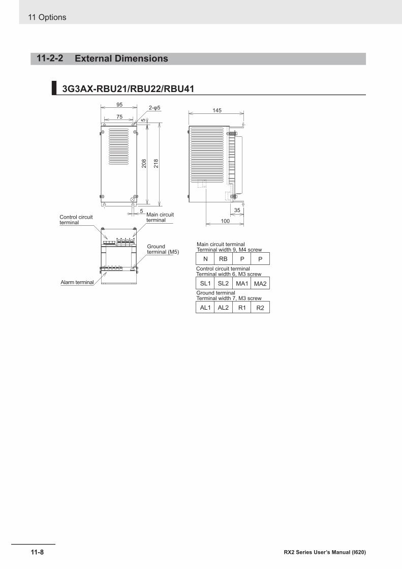
11-2-2 External Dimensions
3G3AX-RBU21/RBU22/RBU4195
5
100
35
145
5208
218
75
2-φ5
N RB P P
Main circuit terminalTerminal width 9, M4 screw
Control circuit terminalTerminal width 6, M3 screw
Ground terminalTerminal width 7, M3 screw
Groundterminal (M5)
Main circuitterminal
Control circuitterminal
SL1 SL2 MA1 MA2
AL1 AL2 R1 R2
Alarm terminal
11 Options
11-8 RX2 Series User’s Manual (I620)
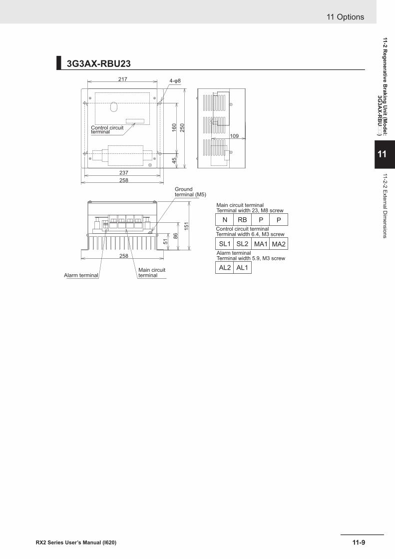
3G3AX-RBU23217
109
237
258
258
16
04
5
51
86
15
12
50
Groundterminal (M5)
4-φ8
N RB P P
Main circuit terminalTerminal width 23, M8 screw
Control circuit terminalTerminal width 6.4, M3 screw
Alarm terminalTerminal width 5.9, M3 screw
SL1 SL2 MA1 MA2
AL2 AL1
Control circuitterminal
Alarm terminalMain circuitterminal
11 Options
11-9RX2 Series User’s Manual (I620)
11-2 Regenerative B
raking Unit (M
odel:3G
3AX-R
BU
)
11
11-2-2 External Dim
ensions
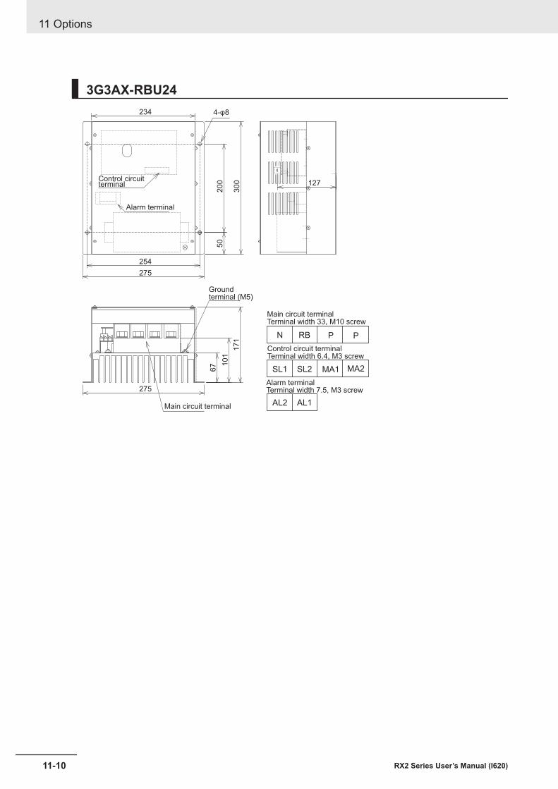
3G3AX-RBU24234
200
50
67 101
171
300
254
127
275
275
4-φ8
Groundterminal (M5)
N RB P P
Main circuit terminalTerminal width 33, M10 screw
Control circuit terminalTerminal width 6.4, M3 screw
Alarm terminalTerminal width 7.5, M3 screw
SL1 SL2 MA1 MA2
AL2 AL1
Control circuitterminal
Alarm terminal
Main circuit terminal
11 Options
11-10 RX2 Series User’s Manual (I620)
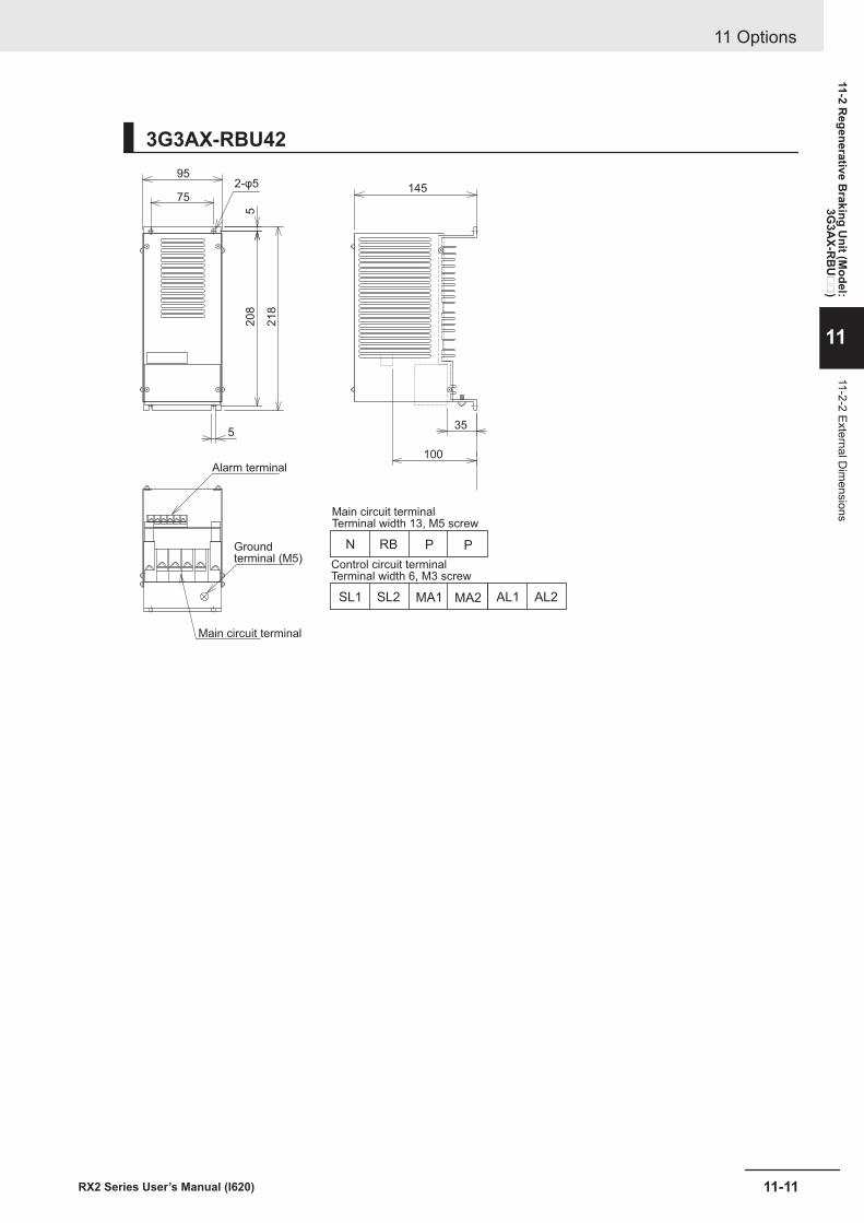
3G3AX-RBU4295
145
35
100
5
75
5208
218
2-φ5
Groundterminal (M5)
Alarm terminal
N RB P P
Main circuit terminalTerminal width 13, M5 screw
Control circuit terminalTerminal width 6, M3 screw
SL1 SL2 MA1 MA2 AL1 AL2
Main circuit terminal
11 Options
11-11RX2 Series User’s Manual (I620)
11-2 Regenerative B
raking Unit (M
odel:3G
3AX-R
BU
)
11
11-2-2 External Dim
ensions
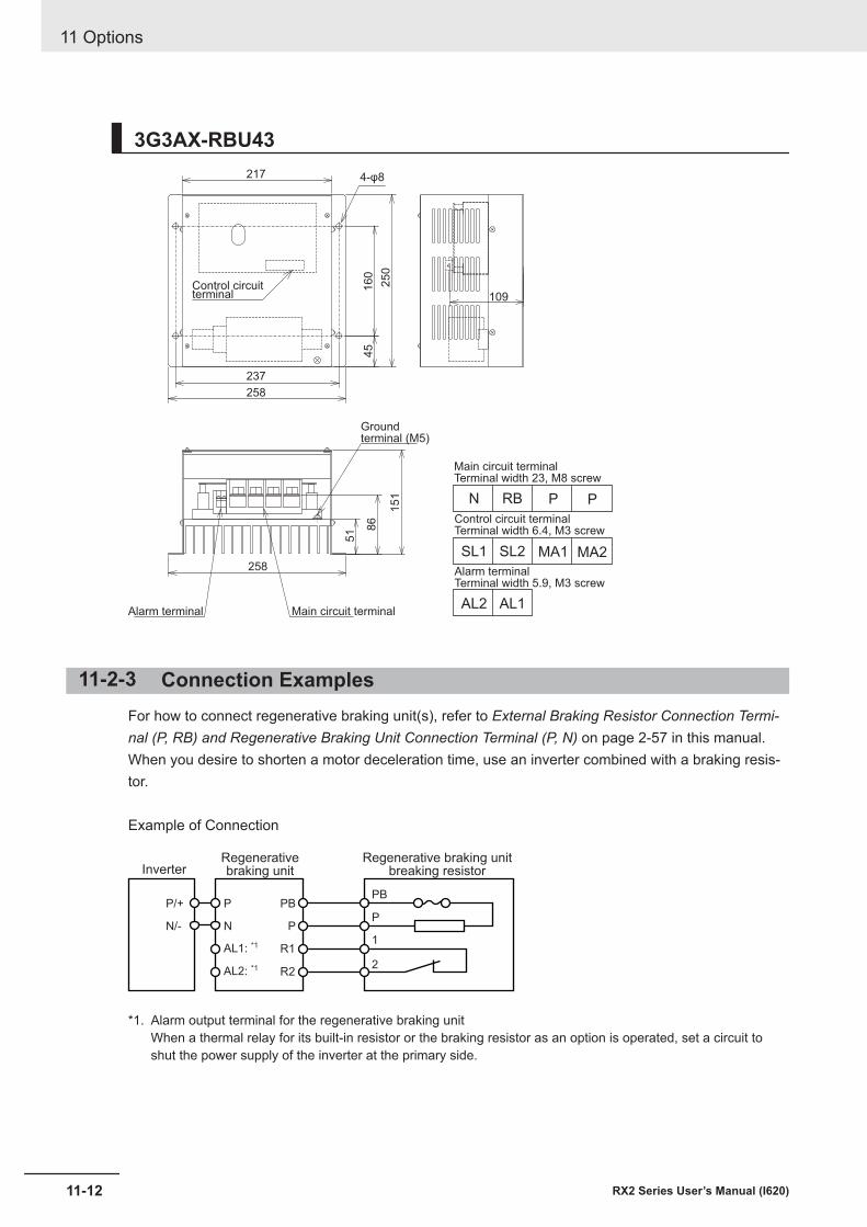
3G3AX-RBU43217
16
04
5
51 8
6
15
12
50
237
258
258
109
Groundterminal (M5)
4-φ8
N RB P P
Main circuit terminalTerminal width 23, M8 screw
Control circuit terminalTerminal width 6.4, M3 screw
Alarm terminalTerminal width 5.9, M3 screw
SL1 SL2 MA1 MA2
AL2 AL1
Control circuitterminal
Alarm terminal Main circuit terminal
11-2-3 Connection ExamplesFor how to connect regenerative braking unit(s), refer to External Braking Resistor Connection Termi-nal (P, RB) and Regenerative Braking Unit Connection Terminal (P, N) on page 2-57 in this manual.When you desire to shorten a motor deceleration time, use an inverter combined with a braking resis-tor.
Example of Connection
P
N
PBPB
R1
R2
PP
1
2
P/+
N/-
AL1: *1
AL2: *1
InverterRegenerativebraking unit
Regenerative braking unitbreaking resistor
*1. Alarm output terminal for the regenerative braking unitWhen a thermal relay for its built-in resistor or the braking resistor as an option is operated, set a circuit toshut the power supply of the inverter at the primary side.
11 Options
11-12 RX2 Series User’s Manual (I620)
Precautions for Correct Use
A thermal fuse is built in the braking resistor (RBA, RBB and RBC). After an alarm is issuedfrom the thermal relay between terminals 1 and 2, overheat may result in a breakage of thethermal fuse. If the fuse is broken, the braking resistor can’t be restored. Replace the brakingresistor with new one.Wire the alarm output terminals properly. When thermal abnormality is detected, stop the inver-ter operation and cool the braking resistor thoroughly. After that, start the inverter.
11 Options
11-13RX2 Series User’s Manual (I620)
11-2 Regenerative B
raking Unit (M
odel:3G
3AX-R
BU
)
11
11-2-3 Connection Exam
ples
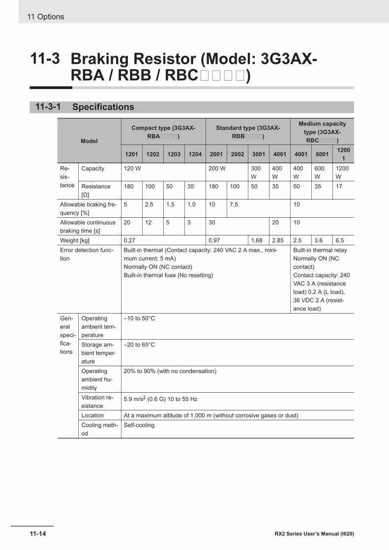
11-3 Braking Resistor (Model: 3G3AX-RBA / RBB / RBC)
11-3-1 Specifications
Model
Compact type (3G3AX-RBA)
Standard type (3G3AX-RBB)
Medium capacitytype (3G3AX-RBC)
1201 1202 1203 1204 2001 2002 3001 4001 4001 6001 12001
Re-sis-tance
Capacity 120 W 200 W 300W
400W
400W
600W
1200W
Resistance[Ω]
180 100 50 35 180 100 50 35 50 35 17
Allowable braking fre-quency [%]
5 2.5 1.5 1.0 10 7.5 10
Allowable continuousbraking time [s]
20 12 5 3 30 20 10
Weight [kg] 0.27 0.97 1.68 2.85 2.5 3.6 6.5Error detection func-tion
Built-in thermal (Contact capacity: 240 VAC 2 A max., mini-mum current: 5 mA)Normally ON (NC contact)Built-in thermal fuse (No resetting)
Built-in thermal relayNormally ON (NCcontact)Contact capacity: 240VAC 3 A (resistanceload) 0.2 A (L load),36 VDC 2 A (resist-ance load)
Gen-eralspeci-fica-tions
Operatingambient tem-perature
–10 to 50°C
Storage am-bient temper-ature
–20 to 65°C
Operatingambient hu-midity
20% to 90% (with no condensation)
Vibration re-sistance
5.9 m/s2 (0.6 G) 10 to 55 Hz
Location At a maximum altitude of 1,000 m (without corrosive gases or dust)Cooling meth-od
Self-cooling
11 Options
11-14 RX2 Series User’s Manual (I620)
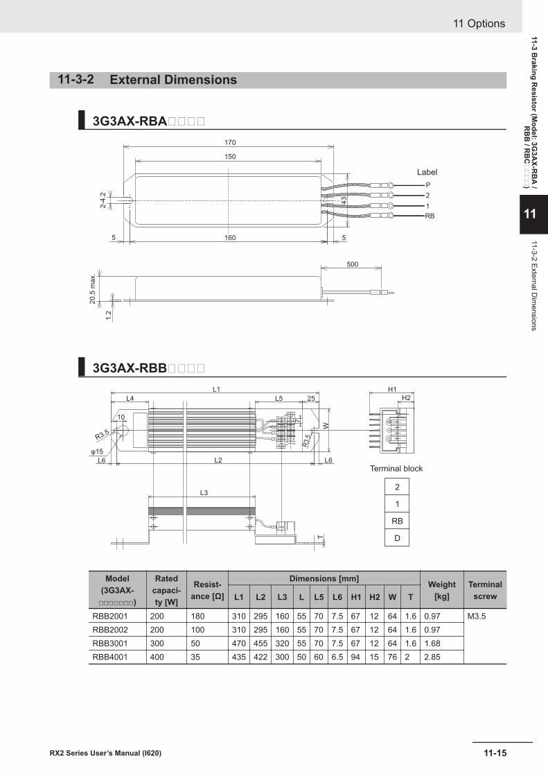
11-3-2 External Dimensions
3G3AX-RBA170
Label
2-4
.2
20.5
max.
1.2
43
150
160 5
P
2
1
RB
500
5
3G3AX-RBBL1
L4 L5 25
H1
H2
L6
7R
3.5R3.5
10
WT
L3
L2
φ15
L6
2
1
RB
D
Terminal block
Model(3G3AX-
□□□□□□□)
Ratedcapaci-ty [W]
Resist-ance [Ω]
Dimensions [mm] Weight[kg]
TerminalscrewL1 L2 L3 L L5 L6 H1 H2 W T
RBB2001 200 180 310 295 160 55 70 7.5 67 12 64 1.6 0.97 M3.5RBB2002 200 100 310 295 160 55 70 7.5 67 12 64 1.6 0.97RBB3001 300 50 470 455 320 55 70 7.5 67 12 64 1.6 1.68RBB4001 400 35 435 422 300 50 60 6.5 94 15 76 2 2.85
11 Options
11-15RX2 Series User’s Manual (I620)
11-3 Braking R
esistor (Model: 3G
3AX-R
BA
/R
BB
/ RB
C
)
11
11-3-2 External Dim
ensions
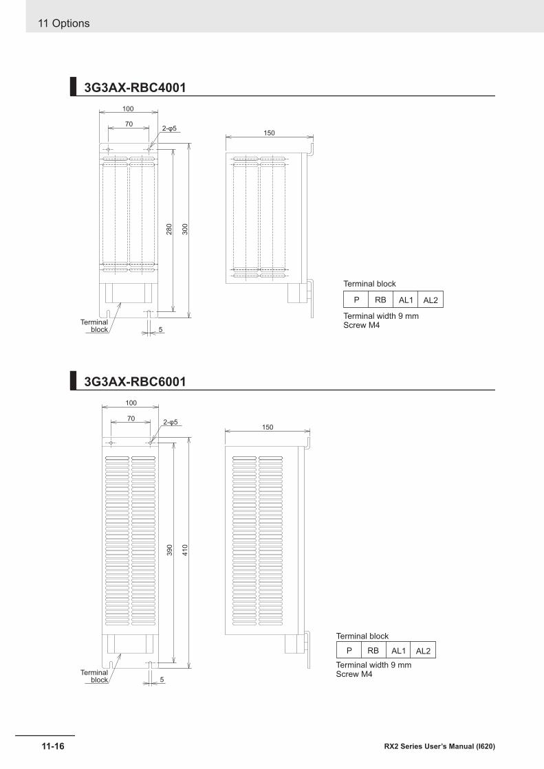
3G3AX-RBC4001100
150
28
0
30
0
5
70
P RB AL1 AL2
Terminal width 9 mmScrew M4
Terminal block
Terminalblock
2-φ5
3G3AX-RBC6001100
70
150
39
0
41
0
5
P RB AL1 AL2
Terminal width 9 mmScrew M4
Terminal block
Terminalblock
2-φ5
11 Options
11-16 RX2 Series User’s Manual (I620)
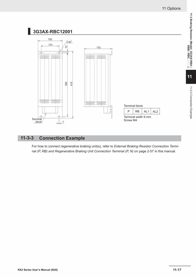
3G3AX-RBC12001150
170
7
110
10
39
0
41
0
P RB AL1 AL2
Terminal width 9 mmScrew M4
Terminal block
Terminalblock
2-φ7
11-3-3 Connection ExampleFor how to connect regenerative braking unit(s), refer to External Braking Resistor Connection Termi-nal (P, RB) and Regenerative Braking Unit Connection Terminal (P, N) on page 2-57 in this manual.
11 Options
11-17RX2 Series User’s Manual (I620)
11-3 Braking R
esistor (Model: 3G
3AX-R
BA
/R
BB
/ RB
C
)
11
11-3-3 Connection Exam
ple
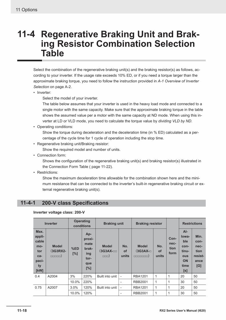
11-4 Regenerative Braking Unit and Brak-ing Resistor Combination SelectionTable
Select the combination of the regenerative braking unit(s) and the braking resistor(s) as follows, ac-cording to your inverter. If the usage rate exceeds 10% ED, or if you need a torque larger than theapproximate braking torque, you need to follow the instruction provided in A-1 Overview of InverterSelection on page A-2.• Inverter:
Select the model of your inverter.The table below assumes that your inverter is used in the heavy load mode and connected to asingle motor with the same capacity. Make sure that the approximate braking torque in the tableshows the assumed value per a motor with the same capacity at ND mode. When using this in-verter at LD or VLD mode, you need to calculate the torque value by dividing VLD by ND.
• Operating conditions:Show the torque during deceleration and the deceleration time (in % ED) calculated as a per-centage of the cycle time for 1 cycle of operation including the stop time.
• Regenerative braking unit/Braking resistor:Show the required model and number of units.
• Connection form:Shows the configuration of the regenerative braking unit(s) and braking resistor(s) illustrated inthe Connection Form Table ( page 11-22).
• Restrictions:Show the maximum deceleration time allowable for the combination shown here and the mini-mum resistance that can be connected to the inverter’s built-in regenerative braking circuit or ex-ternal regenerative braking unit(s).
11-4-1 200-V class SpecificationsInverter voltage class: 200-V
Inverter Operatingconditions Braking unit Braking resistor
Con-nec-tionform
Restrictions
Max.appli-cablemo-torca-
paci-ty
[kW]
Model(3G3RX2-
□□□□□)
%ED[%]
Ap-proxi-matebrak-ingtor-que[%]
Model(3G3AX-□□
□□□)
No.of
units
Model(3G3AX-□□□□□□□□)
No.of
units
Al-lowa-ble
con-tinu-ousON
time[s]
Min.con-nec-tion
resist-ance[Ω]
0.4 A2004 3% 220% Built into unit - RBA1201 1 1 20 5010.0% 220% - RBB2001 1 1 30 50
0.75 A2007 3.0% 120% Built into unit - RBA1201 1 1 20 5010.0% 120% - RBB2001 1 1 30 50
11 Options
11-18 RX2 Series User’s Manual (I620)
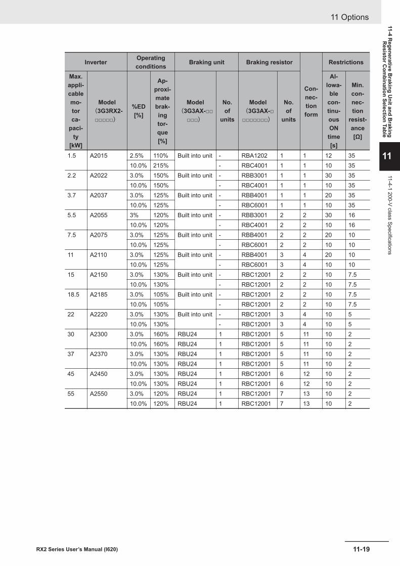
Inverter Operatingconditions Braking unit Braking resistor
Con-nec-tionform
Restrictions
Max.appli-cablemo-torca-
paci-ty
[kW]
Model(3G3RX2-
□□□□□)
%ED[%]
Ap-proxi-matebrak-ingtor-que[%]
Model(3G3AX-□□
□□□)
No.of
units
Model(3G3AX-□□□□□□□□)
No.of
units
Al-lowa-ble
con-tinu-ousON
time[s]
Min.con-nec-tion
resist-ance[Ω]
1.5 A2015 2.5% 110% Built into unit - RBA1202 1 1 12 3510.0% 215% - RBC4001 1 1 10 35
2.2 A2022 3.0% 150% Built into unit - RBB3001 1 1 30 3510.0% 150% - RBC4001 1 1 10 35
3.7 A2037 3.0% 125% Built into unit - RBB4001 1 1 20 3510.0% 125% - RBC6001 1 1 10 35
5.5 A2055 3% 120% Built into unit - RBB3001 2 2 30 1610.0% 120% - RBC4001 2 2 10 16
7.5 A2075 3.0% 125% Built into unit - RBB4001 2 2 20 1010.0% 125% - RBC6001 2 2 10 10
11 A2110 3.0% 125% Built into unit - RBB4001 3 4 20 1010.0% 125% - RBC6001 3 4 10 10
15 A2150 3.0% 130% Built into unit - RBC12001 2 2 10 7.510.0% 130% - RBC12001 2 2 10 7.5
18.5 A2185 3.0% 105% Built into unit - RBC12001 2 2 10 7.510.0% 105% - RBC12001 2 2 10 7.5
22 A2220 3.0% 130% Built into unit - RBC12001 3 4 10 510.0% 130% - RBC12001 3 4 10 5
30 A2300 3.0% 160% RBU24 1 RBC12001 5 11 10 210.0% 160% RBU24 1 RBC12001 5 11 10 2
37 A2370 3.0% 130% RBU24 1 RBC12001 5 11 10 210.0% 130% RBU24 1 RBC12001 5 11 10 2
45 A2450 3.0% 130% RBU24 1 RBC12001 6 12 10 210.0% 130% RBU24 1 RBC12001 6 12 10 2
55 A2550 3.0% 120% RBU24 1 RBC12001 7 13 10 210.0% 120% RBU24 1 RBC12001 7 13 10 2
11 Options
11-19RX2 Series User’s Manual (I620)
11-4 Regenerative B
raking Unit and B
rakingR
esistor Com
bination Selection Table
11
11-4-1 200-V class Specifications
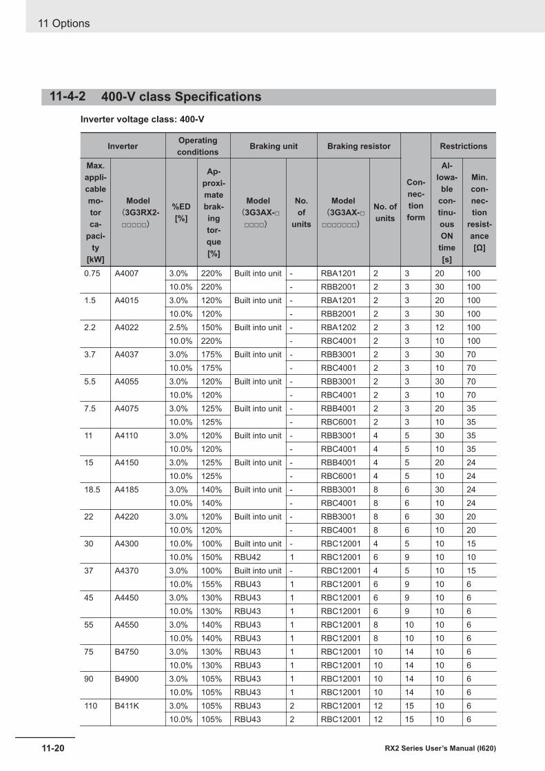
11-4-2 400-V class SpecificationsInverter voltage class: 400-V
Inverter Operatingconditions Braking unit Braking resistor
Con-nec-tionform
Restrictions
Max.appli-cablemo-torca-
paci-ty
[kW]
Model(3G3RX2-
□□□□□)
%ED[%]
Ap-proxi-matebrak-ingtor-que[%]
Model(3G3AX-□
□□□□)
No.of
units
Model(3G3AX-□□□□□□□□)
No. ofunits
Al-lowa-ble
con-tinu-ousON
time[s]
Min.con-nec-tion
resist-ance[Ω]
0.75 A4007 3.0% 220% Built into unit - RBA1201 2 3 20 10010.0% 220% - RBB2001 2 3 30 100
1.5 A4015 3.0% 120% Built into unit - RBA1201 2 3 20 10010.0% 120% - RBB2001 2 3 30 100
2.2 A4022 2.5% 150% Built into unit - RBA1202 2 3 12 10010.0% 220% - RBC4001 2 3 10 100
3.7 A4037 3.0% 175% Built into unit - RBB3001 2 3 30 7010.0% 175% - RBC4001 2 3 10 70
5.5 A4055 3.0% 120% Built into unit - RBB3001 2 3 30 7010.0% 120% - RBC4001 2 3 10 70
7.5 A4075 3.0% 125% Built into unit - RBB4001 2 3 20 3510.0% 125% - RBC6001 2 3 10 35
11 A4110 3.0% 120% Built into unit - RBB3001 4 5 30 3510.0% 120% - RBC4001 4 5 10 35
15 A4150 3.0% 125% Built into unit - RBB4001 4 5 20 2410.0% 125% - RBC6001 4 5 10 24
18.5 A4185 3.0% 140% Built into unit - RBB3001 8 6 30 2410.0% 140% - RBC4001 8 6 10 24
22 A4220 3.0% 120% Built into unit - RBB3001 8 6 30 2010.0% 120% - RBC4001 8 6 10 20
30 A4300 10.0% 100% Built into unit - RBC12001 4 5 10 1510.0% 150% RBU42 1 RBC12001 6 9 10 10
37 A4370 3.0% 100% Built into unit - RBC12001 4 5 10 1510.0% 155% RBU43 1 RBC12001 6 9 10 6
45 A4450 3.0% 130% RBU43 1 RBC12001 6 9 10 610.0% 130% RBU43 1 RBC12001 6 9 10 6
55 A4550 3.0% 140% RBU43 1 RBC12001 8 10 10 610.0% 140% RBU43 1 RBC12001 8 10 10 6
75 B4750 3.0% 130% RBU43 1 RBC12001 10 14 10 610.0% 130% RBU43 1 RBC12001 10 14 10 6
90 B4900 3.0% 105% RBU43 1 RBC12001 10 14 10 610.0% 105% RBU43 1 RBC12001 10 14 10 6
110 B411K 3.0% 105% RBU43 2 RBC12001 12 15 10 610.0% 105% RBU43 2 RBC12001 12 15 10 6
11 Options
11-20 RX2 Series User’s Manual (I620)
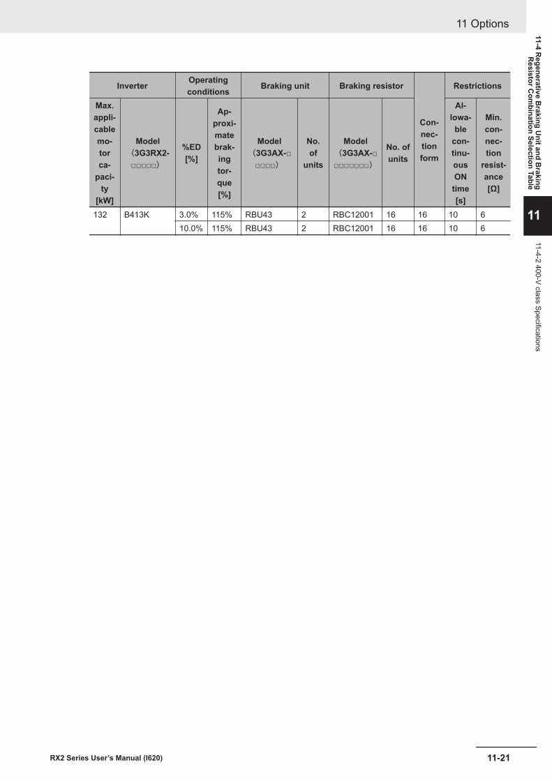
Inverter Operatingconditions Braking unit Braking resistor
Con-nec-tionform
Restrictions
Max.appli-cablemo-torca-
paci-ty
[kW]
Model(3G3RX2-
□□□□□)
%ED[%]
Ap-proxi-matebrak-ingtor-que[%]
Model(3G3AX-□
□□□□)
No.of
units
Model(3G3AX-□□□□□□□□)
No. ofunits
Al-lowa-ble
con-tinu-ousON
time[s]
Min.con-nec-tion
resist-ance[Ω]
132 B413K 3.0% 115% RBU43 2 RBC12001 16 16 10 610.0% 115% RBU43 2 RBC12001 16 16 10 6
11 Options
11-21RX2 Series User’s Manual (I620)
11-4 Regenerative B
raking Unit and B
rakingR
esistor Com
bination Selection Table
11
11-4-2 400-V class Specifications
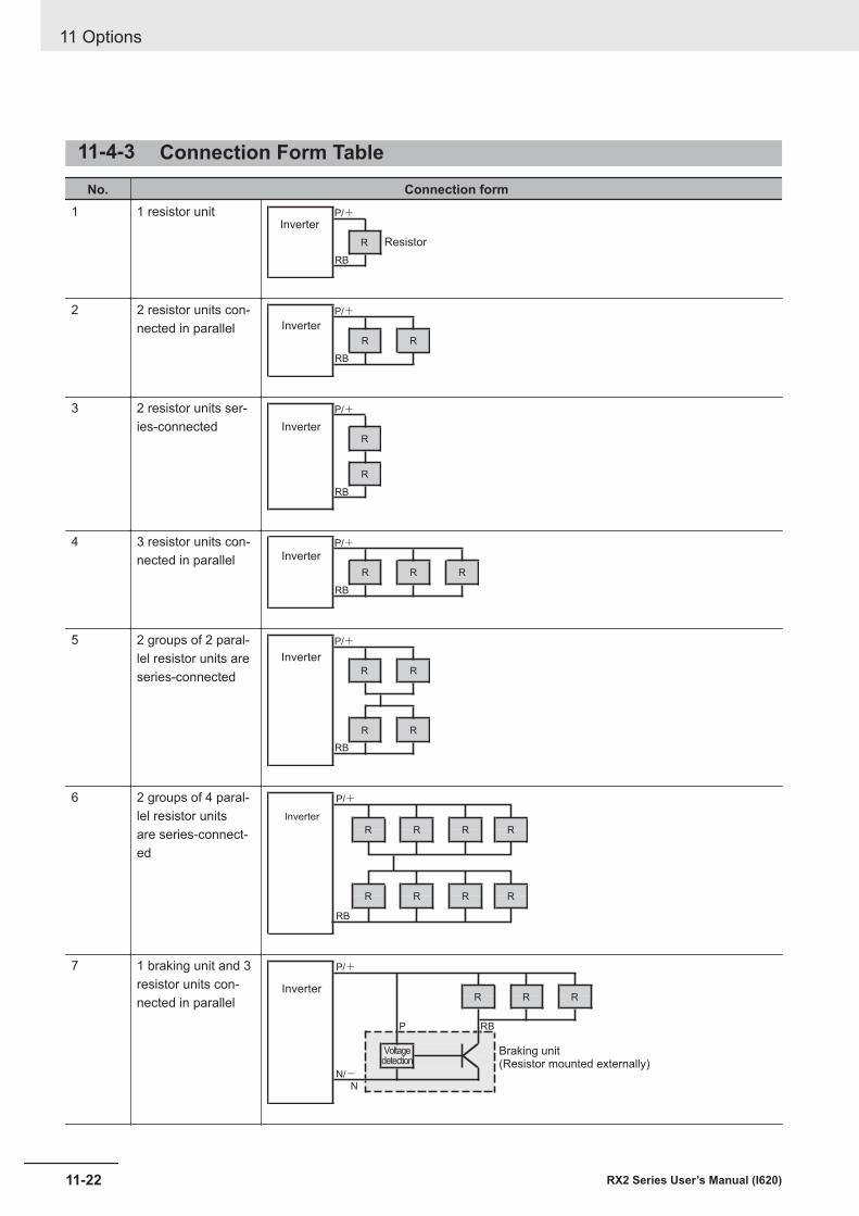
11-4-3 Connection Form TableNo. Connection form
1 1 resistor unit P/+Inverter
Resistor
RB
R
2 2 resistor units con-nected in parallel
P/+Inverter
RB
R R
3 2 resistor units ser-ies-connected
P/+
Inverter
RB
R
R
4 3 resistor units con-nected in parallel
P/+Inverter
RB
R R R
5 2 groups of 2 paral-lel resistor units areseries-connected
P/+Inverter
RB
R R
R R
6 2 groups of 4 paral-lel resistor unitsare series-connect-ed
P/+
Inverter
RB
R R R R
R R R R
7 1 braking unit and 3resistor units con-nected in parallel
P/+
Inverter
P RB
Braking unit(Resistor mounted externally)
N/-N
Voltagedetection
R R R
11 Options
11-22 RX2 Series User’s Manual (I620)
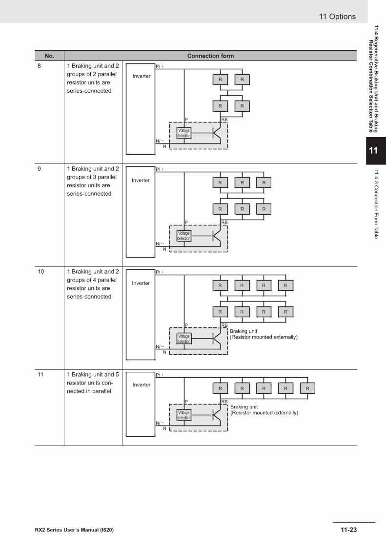
No. Connection form8 1 Braking unit and 2
groups of 2 parallelresistor units areseries-connected
P/+
Inverter
P RB
N/-N
R
R
R
R
Voltagedetection
9 1 Braking unit and 2groups of 3 parallelresistor units areseries-connected
P/+
Inverter
P RB
N/-N
R
R
R
R
R
R
Voltagedetection
10 1 Braking unit and 2groups of 4 parallelresistor units areseries-connected
P/+
Inverter
P RB
Braking unit(Resistor mounted externally)
N/-N
R RRR
R RRR
Voltagedetection
11 1 Braking unit and 5resistor units con-nected in parallel
P/+
Inverter
P RB
Braking unit(Resistor mounted externally)
N/-N
R R R R R
Voltagedetection
11 Options
11-23RX2 Series User’s Manual (I620)
11-4 Regenerative B
raking Unit and B
rakingR
esistor Com
bination Selection Table
11
11-4-3 Connection Form
Table
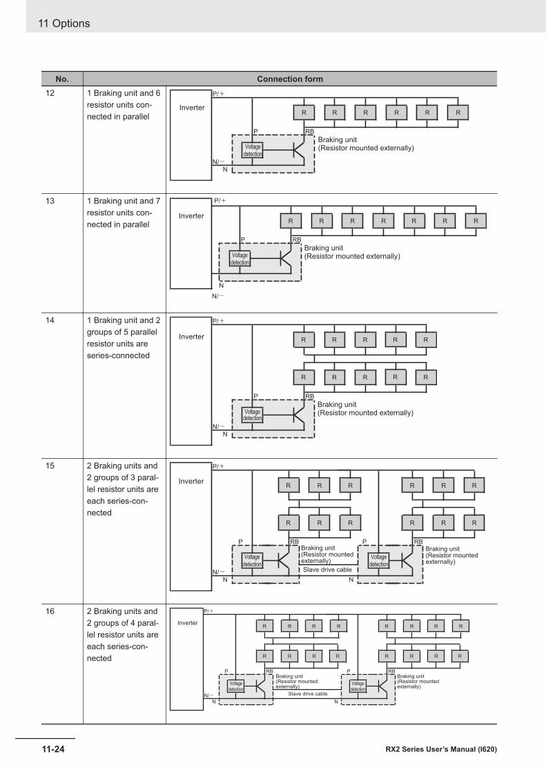
No. Connection form12 1 Braking unit and 6
resistor units con-nected in parallel
P/+
Inverter
P RB
Braking unit(Resistor mounted externally)
N/-N
R R R R R R
Voltagedetection
13 1 Braking unit and 7resistor units con-nected in parallel
P/+
Inverter
P RB
Braking unit(Resistor mounted externally)
N/-N
R R R R R R R
Voltagedetection
14 1 Braking unit and 2groups of 5 parallelresistor units areseries-connected
P/+
Inverter
P RB
Braking unit(Resistor mounted externally)
N/-N
R RRR
R RRR
Voltagedetection
R
R
15 2 Braking units and2 groups of 3 paral-lel resistor units areeach series-con-nected
P/+
Inverter
P RB
N/-N
R
R
R
R
R
R
Voltagedetection
P RB
N
R
R
R
R
R
R
Voltagedetection
Slave drive cable
Braking unit(Resistor mountedexternally)
Braking unit(Resistor mountedexternally)
16 2 Braking units and2 groups of 4 paral-lel resistor units areeach series-con-nected
P/+
Inverter
P RB
N/-N
R
R
R
R
R
R
Voltagedetection
Slave drive cable
R
R
P RB
N
R
R
R
R
R
R
Voltagedetection
R
R
Braking unit(Resistor mountedexternally)
Braking unit(Resistor mountedexternally)
11 Options
11-24 RX2 Series User’s Manual (I620)
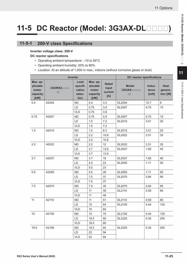
11-5 DC Reactor (Model: 3G3AX-DL)
11-5-1 200-V class SpecificationsInverter voltage class: 200-VDC reactor specifications
• Operating ambient temperature: –10 to 50°C• Operating ambient humidity: 20% to 90%• Location: At an altitude of 1,000 m max.; indoors (without corrosive gases or dust)
Inverter DC reactor specificationsMax. ap-plicablemotor
capacity[kW]
(3G3RX2-□□□□□)
Loadspecifi-cationselec-tion
Max. ap-plicablemotor
capacity[kW]
Ratedinput
current[A]
Model(3G3AX-□□□□□
□)
Induc-tance[mH]
Heatgenera-tion [W]
0.4 A2004 ND 0.4 3.3 DL2004 10.7 8LD 0.75 3.9 DL2007 6.75 15VLD 0.75 3.9
0.75 A2007 ND 0.75 5.5 DL2007 6.75 15LD 1.5 7.2 DL2015 3.51 25VLD 1.5 7.2
1.5 A2015 ND 1.5 8.3 DL2015 3.51 25LD 2.2 10.8 DL2022 2.51 35VLD 2.2 10.8
2.2 A2022 ND 2.2 12 DL2022 2.51 35LD 3.7 13.9 DL2037 1.60 45VLD 3.7 13.9
3.7 A2037 ND 3.7 18 DL2037 1.60 45LD 5.5 23 DL2055 1.11 55VLD 5.5 23
5.5 A2055 ND 5.5 26 DL2055 1.11 55LD 7.5 37 DL2075 0.84 95VLD 7.5 37
7.5 A2075 ND 7.5 35 DL2075 0.84 95LD 11 48 DL2110 0.59 80VLD 11 48
11 A2110 ND 11 51 DL2110 0.59 80LD 15 64 DL2150 0.44 135VLD 15 64
15 A2150 ND 15 70 DL2150 0.44 135LD 18.5 80 DL2220 0.30 200VLD 18.5 80
18.5 A2185 ND 18.5 84 DL2220 0.30 200LD 22 94VLD 22 94
11 Options
11-25RX2 Series User’s Manual (I620)
11-5 DC
Reactor (M
odel: 3G3A
X-DL
)
11
11-5-1 200-V class Specifications
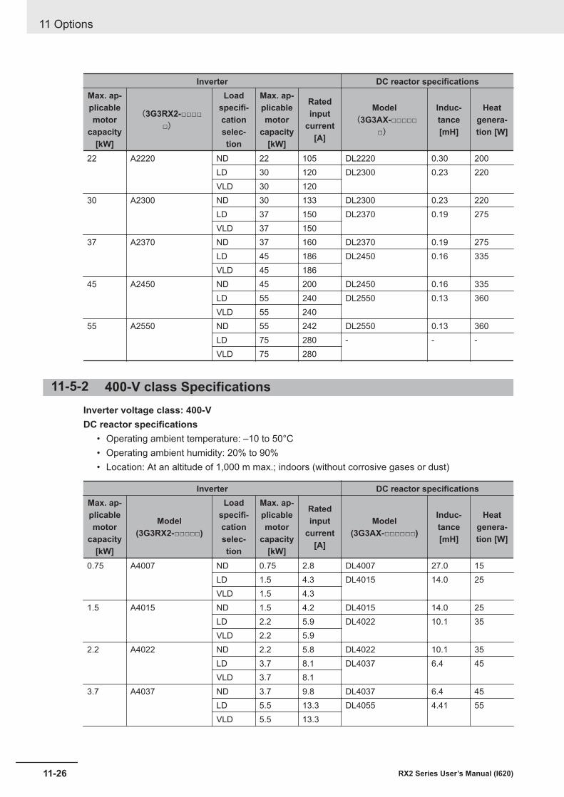
Inverter DC reactor specificationsMax. ap-plicablemotor
capacity[kW]
(3G3RX2-□□□□□)
Loadspecifi-cationselec-tion
Max. ap-plicablemotor
capacity[kW]
Ratedinput
current[A]
Model(3G3AX-□□□□□
□)
Induc-tance[mH]
Heatgenera-tion [W]
22 A2220 ND 22 105 DL2220 0.30 200LD 30 120 DL2300 0.23 220VLD 30 120
30 A2300 ND 30 133 DL2300 0.23 220LD 37 150 DL2370 0.19 275VLD 37 150
37 A2370 ND 37 160 DL2370 0.19 275LD 45 186 DL2450 0.16 335VLD 45 186
45 A2450 ND 45 200 DL2450 0.16 335LD 55 240 DL2550 0.13 360VLD 55 240
55 A2550 ND 55 242 DL2550 0.13 360LD 75 280 - - -VLD 75 280
11-5-2 400-V class SpecificationsInverter voltage class: 400-VDC reactor specifications
• Operating ambient temperature: –10 to 50°C• Operating ambient humidity: 20% to 90%• Location: At an altitude of 1,000 m max.; indoors (without corrosive gases or dust)
Inverter DC reactor specificationsMax. ap-plicablemotor
capacity[kW]
Model(3G3RX2-□□□□□)
Loadspecifi-cationselec-tion
Max. ap-plicablemotor
capacity[kW]
Ratedinput
current[A]
Model(3G3AX-□□□□□□)
Induc-tance[mH]
Heatgenera-tion [W]
0.75 A4007 ND 0.75 2.8 DL4007 27.0 15LD 1.5 4.3 DL4015 14.0 25VLD 1.5 4.3
1.5 A4015 ND 1.5 4.2 DL4015 14.0 25LD 2.2 5.9 DL4022 10.1 35VLD 2.2 5.9
2.2 A4022 ND 2.2 5.8 DL4022 10.1 35LD 3.7 8.1 DL4037 6.4 45VLD 3.7 8.1
3.7 A4037 ND 3.7 9.8 DL4037 6.4 45LD 5.5 13.3 DL4055 4.41 55VLD 5.5 13.3
11 Options
11-26 RX2 Series User’s Manual (I620)
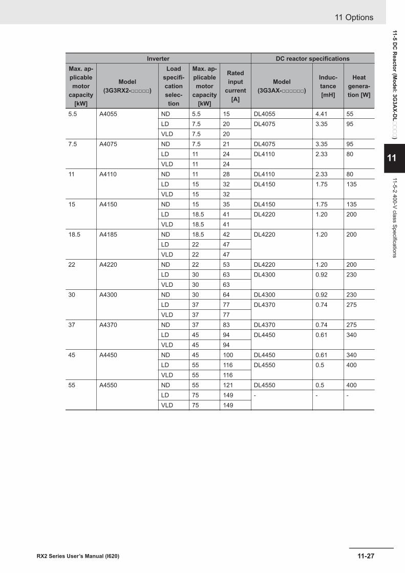
Inverter DC reactor specificationsMax. ap-plicablemotor
capacity[kW]
Model(3G3RX2-□□□□□)
Loadspecifi-cationselec-tion
Max. ap-plicablemotor
capacity[kW]
Ratedinput
current[A]
Model(3G3AX-□□□□□□)
Induc-tance[mH]
Heatgenera-tion [W]
5.5 A4055 ND 5.5 15 DL4055 4.41 55LD 7.5 20 DL4075 3.35 95VLD 7.5 20
7.5 A4075 ND 7.5 21 DL4075 3.35 95LD 11 24 DL4110 2.33 80VLD 11 24
11 A4110 ND 11 28 DL4110 2.33 80LD 15 32 DL4150 1.75 135VLD 15 32
15 A4150 ND 15 35 DL4150 1.75 135LD 18.5 41 DL4220 1.20 200VLD 18.5 41
18.5 A4185 ND 18.5 42 DL4220 1.20 200LD 22 47VLD 22 47
22 A4220 ND 22 53 DL4220 1.20 200LD 30 63 DL4300 0.92 230VLD 30 63
30 A4300 ND 30 64 DL4300 0.92 230LD 37 77 DL4370 0.74 275VLD 37 77
37 A4370 ND 37 83 DL4370 0.74 275LD 45 94 DL4450 0.61 340VLD 45 94
45 A4450 ND 45 100 DL4450 0.61 340LD 55 116 DL4550 0.5 400VLD 55 116
55 A4550 ND 55 121 DL4550 0.5 400LD 75 149 - - -VLD 75 149
11 Options
11-27RX2 Series User’s Manual (I620)
11-5 DC
Reactor (M
odel: 3G3A
X-DL
)
11
11-5-2 400-V class Specifications
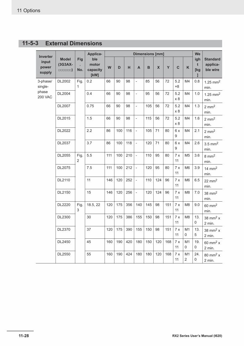
11-5-3 External Dimensions
Inverterinputpowersupply
Model(3G3AX-□□□□□□)
Fig.
No.
Applica-ble
motorcapacity
[kW]
Dimensions [mm] Weigh
t[kg
]
Standardapplica-ble wireW D H A B X Y C K
3-phase/single-phase200 VAC
DL2002 Fig.1
0.2 66 90 98 - 85 56 72 5.2×8
M4 0.8 1.25 mm2
min.DL2004 0.4 66 90 98 - 95 56 72 5.2
x 8M4 1.0 1.25 mm2
min.DL2007 0.75 66 90 98 - 105 56 72 5.2
x 8M4 1.3 2 mm2
min.DL2015 1.5 66 90 98 - 115 56 72 5.2
x 8M4 1.6 2 mm2
min.DL2022 2.2 86 100 116 - 105 71 80 6 x
9M4 2.1 2 mm2
min.DL2037 3.7 86 100 118 - 120 71 80 6 x
9M4 2.6 3.5 mm2
min.DL2055 Fig.
25.5 111 100 210 - 110 95 80 7 x
11M5 3.6 8 mm2
min.DL2075 7.5 111 100 212 - 120 95 80 7 x
11M6 3.9 14 mm2
min.DL2110 11 146 120 252 - 110 124 96 7 x
11M6 6.5 22 mm2
min.DL2150 15 146 120 256 - 120 124 96 7 x
11M8 7.0 38 mm2
min.DL2220 Fig.
318.5, 22 120 175 356 140 145 98 151 7 x
11M8 9.0 60 mm2
min.DL2300 30 120 175 386 155 150 98 151 7 x
11M8 13.
038 mm2 x2 min.
DL2370 37 120 175 390 155 150 98 151 7 x11
M10
13.5
38 mm2 x2 min.
DL2450 45 160 190 420 180 150 120 168 7 x11
M10
19.0
60 mm2 x2 min.
DL2550 55 160 190 424 180 180 120 168 7 x11
M12
24.0
80 mm2 x2 min.
11 Options
11-28 RX2 Series User’s Manual (I620)
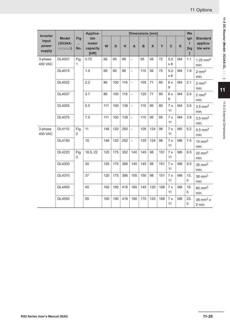
Inverterinputpowersupply
Model(3G3AX-□□□□□□)
Fig.
No.
Applica-ble
motorcapacity
[kW]
Dimensions [mm] Weigh
t[kg
]
Standardapplica-ble wireW D H A B X Y C K
3-phase400 VAC
DL4007 Fig.1
0.75 66 90 98 - 95 56 72 5.2x 8
M4 1.1 1.25 mm2
min.DL4015 1.5 66 90 98 - 115 56 72 5.2
x 8M4 1.6 2 mm2
min.DL4022 2.2 86 100 116 - 105 71 80 6 x
9M4 2.1 2 mm2
min.DL4037 3.7 86 100 116 - 120 71 80 6 x
9M4 2.6 2 mm2
min.DL4055 5.5 111 100 138 - 110 95 80 7 x
11M4 3.6 3.5 mm2
min.DL4075 7.5 111 100 138 - 115 95 80 7 x
11M4 3.9 3.5 mm2
min.3-phase400 VAC
DL4110 Fig.2
11 146 120 250 - 105 124 96 7 x11
M5 5.2 5.5 mm2
min.DL4150 15 146 120 252 - 120 124 96 7 x
11M6 7.0 14 mm2
min.DL4220 Fig.
318.5, 22 120 175 352 140 145 98 151 7 x
11M6 9.5 22 mm2
min.DL4300 30 120 175 356 140 145 98 151 7 x
11M8 9.5 30 mm2
min.DL4370 37 120 175 386 155 150 98 151 7 x
11M8 13.
538 mm2
min.DL4450 45 160 190 416 180 145 120 168 7 x
11M8 16.
560 mm2
min.DL4550 55 160 190 416 190 170 120 168 7 x
11M8 23.
038 mm2 x2 min.
11 Options
11-29RX2 Series User’s Manual (I620)
11-5 DC
Reactor (M
odel: 3G3A
X-DL
)
11
11-5-3 External Dim
ensions
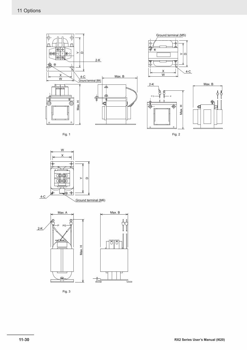
Fig. 1
Fig. 3
Fig. 2
Y Y D
Max. H
Ma
x. H
D
2-K
W
4-C
Max. A Max. B
Max. H
2-K
X
Y D
Max. B
Max. B2-K
W
X
Ground terminal (M5)
Ground terminal (M6)
4-C
X4-C
Ground terminal (M4)W
11 Options
11-30 RX2 Series User’s Manual (I620)
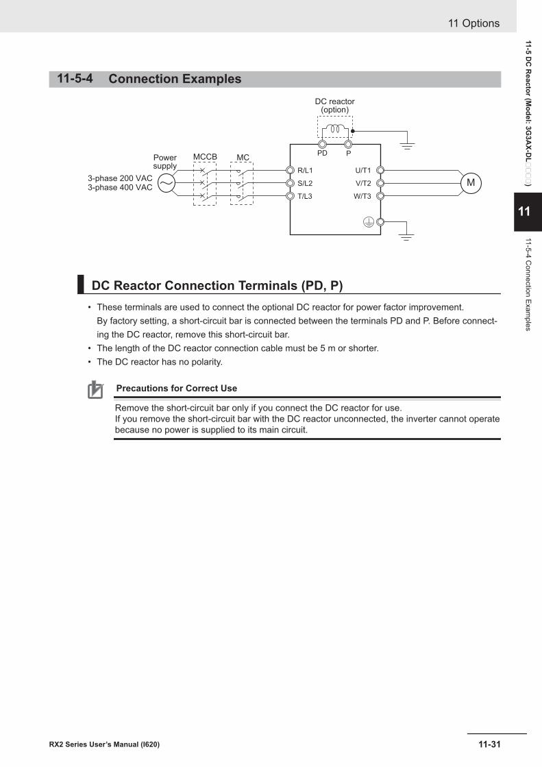
11-5-4 Connection Examples
P
M
PD
DC reactor(option)
R/L1
S/L2
T/L3
U/T1
V/T2
W/T3
3-phase 200 VAC3-phase 400 VAC
Powersupply
MCMCCB
DC Reactor Connection Terminals (PD, P)• These terminals are used to connect the optional DC reactor for power factor improvement.
By factory setting, a short-circuit bar is connected between the terminals PD and P. Before connect-ing the DC reactor, remove this short-circuit bar.
• The length of the DC reactor connection cable must be 5 m or shorter.• The DC reactor has no polarity.
Precautions for Correct Use
Remove the short-circuit bar only if you connect the DC reactor for use.If you remove the short-circuit bar with the DC reactor unconnected, the inverter cannot operatebecause no power is supplied to its main circuit.
11 Options
11-31RX2 Series User’s Manual (I620)
11-5 DC
Reactor (M
odel: 3G3A
X-DL
)
11
11-5-4 Connection Exam
ples
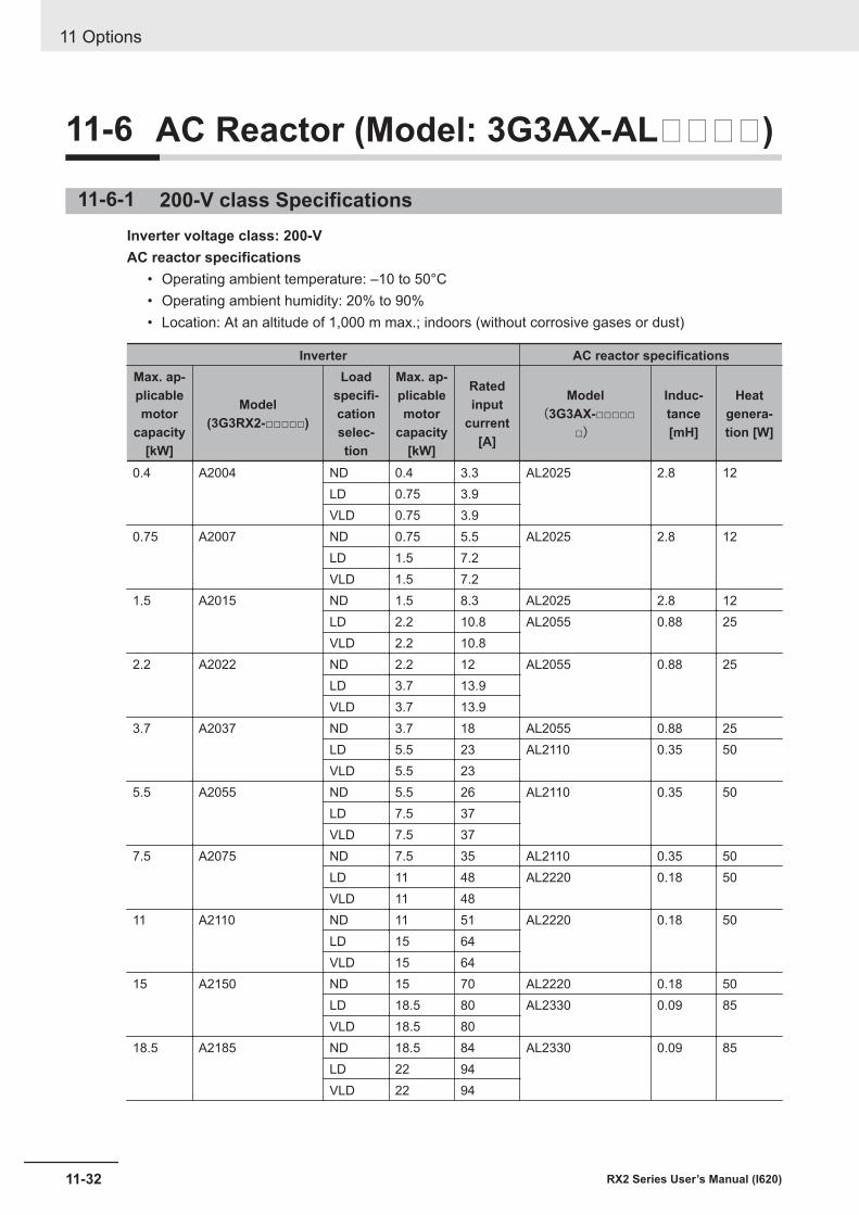
11-6 AC Reactor (Model: 3G3AX-AL)
11-6-1 200-V class SpecificationsInverter voltage class: 200-VAC reactor specifications
• Operating ambient temperature: –10 to 50°C• Operating ambient humidity: 20% to 90%• Location: At an altitude of 1,000 m max.; indoors (without corrosive gases or dust)
Inverter AC reactor specificationsMax. ap-plicablemotor
capacity[kW]
Model(3G3RX2-□□□□□)
Loadspecifi-cationselec-tion
Max. ap-plicablemotor
capacity[kW]
Ratedinput
current[A]
Model(3G3AX-□□□□□
□)
Induc-tance[mH]
Heatgenera-tion [W]
0.4 A2004 ND 0.4 3.3 AL2025 2.8 12LD 0.75 3.9VLD 0.75 3.9
0.75 A2007 ND 0.75 5.5 AL2025 2.8 12LD 1.5 7.2VLD 1.5 7.2
1.5 A2015 ND 1.5 8.3 AL2025 2.8 12LD 2.2 10.8 AL2055 0.88 25VLD 2.2 10.8
2.2 A2022 ND 2.2 12 AL2055 0.88 25LD 3.7 13.9VLD 3.7 13.9
3.7 A2037 ND 3.7 18 AL2055 0.88 25LD 5.5 23 AL2110 0.35 50VLD 5.5 23
5.5 A2055 ND 5.5 26 AL2110 0.35 50LD 7.5 37VLD 7.5 37
7.5 A2075 ND 7.5 35 AL2110 0.35 50LD 11 48 AL2220 0.18 50VLD 11 48
11 A2110 ND 11 51 AL2220 0.18 50LD 15 64VLD 15 64
15 A2150 ND 15 70 AL2220 0.18 50LD 18.5 80 AL2330 0.09 85VLD 18.5 80
18.5 A2185 ND 18.5 84 AL2330 0.09 85LD 22 94VLD 22 94
11 Options
11-32 RX2 Series User’s Manual (I620)
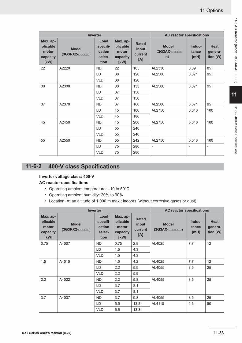
Inverter AC reactor specificationsMax. ap-plicablemotor
capacity[kW]
Model(3G3RX2-□□□□□)
Loadspecifi-cationselec-tion
Max. ap-plicablemotor
capacity[kW]
Ratedinput
current[A]
Model(3G3AX-□□□□□
□)
Induc-tance[mH]
Heatgenera-tion [W]
22 A2220 ND 22 105 AL2330 0.09 85LD 30 120 AL2500 0.071 95VLD 30 120
30 A2300 ND 30 133 AL2500 0.071 95LD 37 150VLD 37 150
37 A2370 ND 37 160 AL2500 0.071 95LD 45 186 AL2750 0.046 100VLD 45 186
45 A2450 ND 45 200 AL2750 0.046 100LD 55 240VLD 55 240
55 A2550 ND 55 242 AL2750 0.046 100LD 75 280 - - -VLD 75 280
11-6-2 400-V class SpecificationsInverter voltage class: 400-VAC reactor specifications
• Operating ambient temperature: –10 to 50°C• Operating ambient humidity: 20% to 90%• Location: At an altitude of 1,000 m max.; indoors (without corrosive gases or dust)
Inverter AC reactor specificationsMax. ap-plicablemotor
capacity[kW]
Model(3G3RX2-□□□□□)
Loadspecifi-cationselec-tion
Max. ap-plicablemotor
capacity[kW]
Ratedinput
current[A]
Model(3G3AX-□□□□□□)
Induc-tance[mH]
Heatgenera-tion [W]
0.75 A4007 ND 0.75 2.8 AL4025 7.7 12LD 1.5 4.3VLD 1.5 4.3
1.5 A4015 ND 1.5 4.2 AL4025 7.7 12LD 2.2 5.9 AL4055 3.5 25VLD 2.2 5.9
2.2 A4022 ND 2.2 5.8 AL4055 3.5 25LD 3.7 8.1VLD 3.7 8.1
3.7 A4037 ND 3.7 9.8 AL4055 3.5 25LD 5.5 13.3 AL4110 1.3 50VLD 5.5 13.3
11 Options
11-33RX2 Series User’s Manual (I620)
11-6 AC
Reactor (M
odel: 3G3A
X-AL
)
11
11-6-2 400-V class Specifications
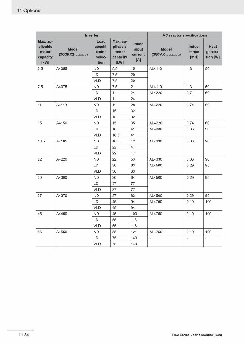
Inverter AC reactor specificationsMax. ap-plicablemotor
capacity[kW]
Model(3G3RX2-□□□□□)
Loadspecifi-cationselec-tion
Max. ap-plicablemotor
capacity[kW]
Ratedinput
current[A]
Model(3G3AX-□□□□□□)
Induc-tance[mH]
Heatgenera-tion [W]
5.5 A4055 ND 5.5 15 AL4110 1.3 50LD 7.5 20VLD 7.5 20
7.5 A4075 ND 7.5 21 AL4110 1.3 50LD 11 24 AL4220 0.74 60VLD 11 24
11 A4110 ND 11 28 AL4220 0.74 60LD 15 32VLD 15 32
15 A4150 ND 15 35 AL4220 0.74 60LD 18.5 41 AL4330 0.36 90VLD 18.5 41
18.5 A4185 ND 18.5 42 AL4330 0.36 90LD 22 47VLD 22 47
22 A4220 ND 22 53 AL4330 0.36 90LD 30 63 AL4500 0.29 95VLD 30 63
30 A4300 ND 30 64 AL4500 0.29 95LD 37 77VLD 37 77
37 A4370 ND 37 83 AL4500 0.29 95LD 45 94 AL4750 0.19 100VLD 45 94
45 A4450 ND 45 100 AL4750 0.19 100LD 55 116VLD 55 116
55 A4550 ND 55 121 AL4750 0.19 100LD 75 149 - - -VLD 75 149
11 Options
11-34 RX2 Series User’s Manual (I620)
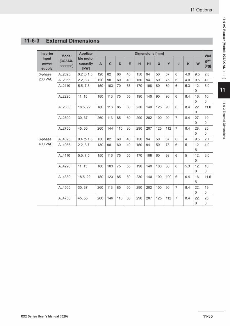
11-6-3 External Dimensions
Inverterinputpowersupply
Model(3G3AX-□□□□□□)
Applica-ble motorcapacity
[kW]
Dimensions [mm] Weight[kg]A C D E H H1 X Y J K W
3-phase200 VAC
AL2025 0.2 to 1.5 120 82 60 40 150 94 50 67 6 4.0 9.5 2.8AL2055 2.2, 3.7 120 98 60 40 150 94 50 75 6 4.0 9.5 4.0AL2110 5.5, 7.5 150 103 70 55 170 108 60 80 6 5.3 12.
05.0
AL2220 11, 15 180 113 75 55 190 140 90 90 6 8.4 16.5
10.0
AL2330 18.5, 22 180 113 85 60 230 140 125 90 6 8.4 22.0
11.0
AL2500 30, 37 260 113 85 60 290 202 100 90 7 8.4 27.0
19.0
AL2750 45, 55 260 144 110 80 290 207 125 112 7 8.4 28.5
25.0
3-phase400 VAC
AL4025 0.4 to 1.5 130 82 60 40 150 94 50 67 6 4 9.5 2.7AL4055 2.2, 3.7 130 98 60 40 150 94 50 75 6 5 12.
54.0
AL4110 5.5, 7.5 150 116 75 55 170 106 60 98 6 5 12.5
6.0
AL4220 11, 15 180 103 75 55 190 140 100 80 6 5.3 12.0
10.0
AL4330 18.5, 22 180 123 85 60 230 140 100 100 6 6.4 16.5
11.5
AL4500 30, 37 260 113 85 60 290 202 100 90 7 8.4 22.0
19.0
AL4750 45, 55 260 146 110 80 290 207 125 112 7 8.4 22.0
25.0
11 Options
11-35RX2 Series User’s Manual (I620)
11-6 AC
Reactor (M
odel: 3G3A
X-AL
)
11
11-6-3 External Dim
ensions
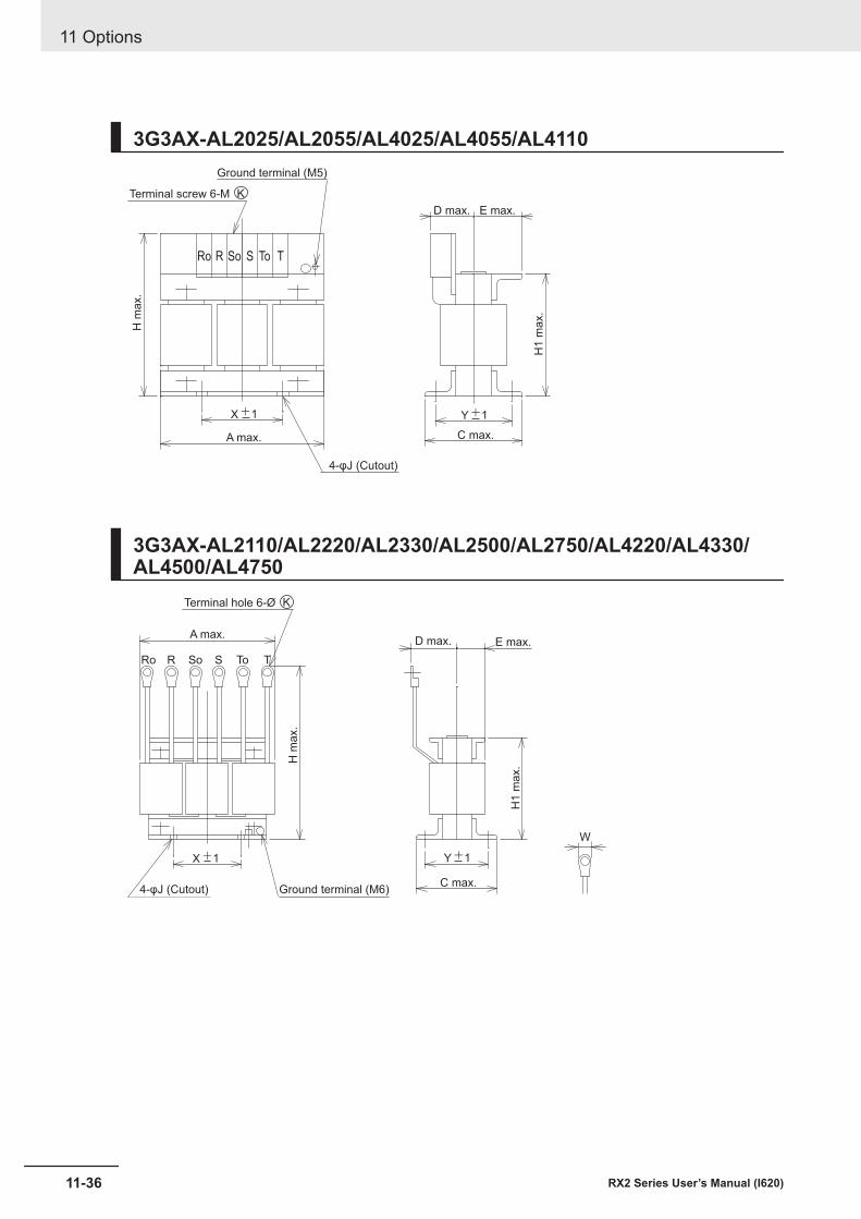
3G3AX-AL2025/AL2055/AL4025/AL4055/AL4110
Ro So ToR S T
H m
ax.
H1 m
ax.
A max.
D max. E max.
C max.
Y+1X+1
4-φJ (Cutout)
Terminal screw 6-M K
Ground terminal (M5)
3G3AX-AL2110/AL2220/AL2330/AL2500/AL2750/AL4220/AL4330/AL4500/AL4750
R So S To TRo
A max.D max. E max.
C max.
H m
ax.
H1 m
ax.
X+1
Terminal hole 6-Ø K
4-φJ (Cutout)
Y+1
Ground terminal (M6)
W
11 Options
11-36 RX2 Series User’s Manual (I620)
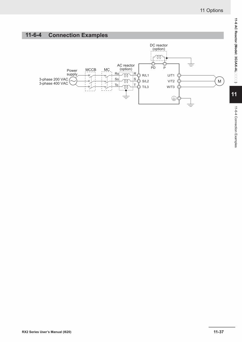
11-6-4 Connection Examples
M
PD PAC reactor
(option)
R/L1
S/L2
T/L3
U/T1
V/T2
W/T3
3-phase 200 VAC3-phase 400 VAC
Powersupply
MCMCCBRo
So
To
R
S
T
DC reactor(option)
11 Options
11-37RX2 Series User’s Manual (I620)
11-6 AC
Reactor (M
odel: 3G3A
X-AL
)
11
11-6-4 Connection Exam
ples
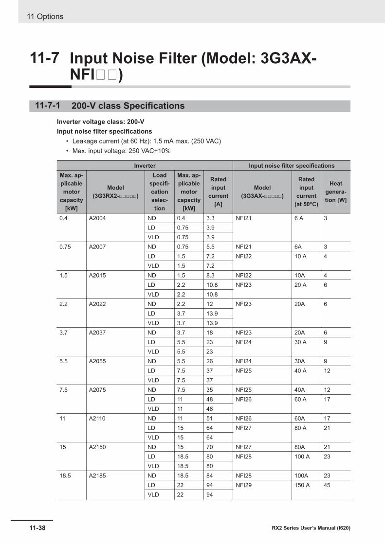
11-7 Input Noise Filter (Model: 3G3AX-NFI)
11-7-1 200-V class SpecificationsInverter voltage class: 200-VInput noise filter specifications
• Leakage current (at 60 Hz): 1.5 mA max. (250 VAC)• Max. input voltage: 250 VAC+10%
Inverter Input noise filter specificationsMax. ap-plicablemotor
capacity[kW]
Model(3G3RX2-□□□□□)
Loadspecifi-cationselec-tion
Max. ap-plicablemotor
capacity[kW]
Ratedinput
current[A]
Model(3G3AX-□□□□□)
Ratedinput
current(at 50°C)
Heatgenera-tion [W]
0.4 A2004 ND 0.4 3.3 NFI21 6 A 3LD 0.75 3.9VLD 0.75 3.9
0.75 A2007 ND 0.75 5.5 NFI21 6A 3LD 1.5 7.2 NFI22 10 A 4VLD 1.5 7.2
1.5 A2015 ND 1.5 8.3 NFI22 10A 4LD 2.2 10.8 NFI23 20 A 6VLD 2.2 10.8
2.2 A2022 ND 2.2 12 NFI23 20A 6LD 3.7 13.9VLD 3.7 13.9
3.7 A2037 ND 3.7 18 NFI23 20A 6LD 5.5 23 NFI24 30 A 9VLD 5.5 23
5.5 A2055 ND 5.5 26 NFI24 30A 9LD 7.5 37 NFI25 40 A 12VLD 7.5 37
7.5 A2075 ND 7.5 35 NFI25 40A 12LD 11 48 NFI26 60 A 17VLD 11 48
11 A2110 ND 11 51 NFI26 60A 17LD 15 64 NFI27 80 A 21VLD 15 64
15 A2150 ND 15 70 NFI27 80A 21LD 18.5 80 NFI28 100 A 23VLD 18.5 80
18.5 A2185 ND 18.5 84 NFI28 100A 23LD 22 94 NFI29 150 A 45VLD 22 94
11 Options
11-38 RX2 Series User’s Manual (I620)
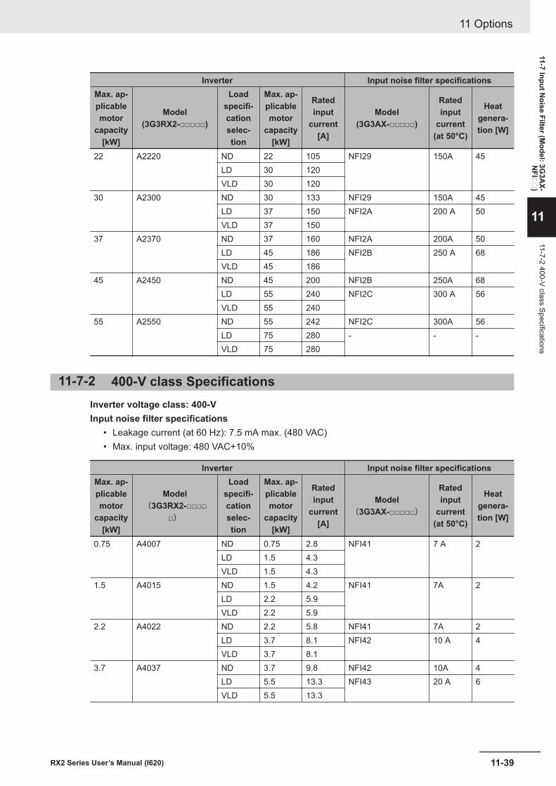
Inverter Input noise filter specificationsMax. ap-plicablemotor
capacity[kW]
Model(3G3RX2-□□□□□)
Loadspecifi-cationselec-tion
Max. ap-plicablemotor
capacity[kW]
Ratedinput
current[A]
Model(3G3AX-□□□□□)
Ratedinput
current(at 50°C)
Heatgenera-tion [W]
22 A2220 ND 22 105 NFI29 150A 45LD 30 120VLD 30 120
30 A2300 ND 30 133 NFI29 150A 45LD 37 150 NFI2A 200 A 50VLD 37 150
37 A2370 ND 37 160 NFI2A 200A 50LD 45 186 NFI2B 250 A 68VLD 45 186
45 A2450 ND 45 200 NFI2B 250A 68LD 55 240 NFI2C 300 A 56VLD 55 240
55 A2550 ND 55 242 NFI2C 300A 56LD 75 280 - - -VLD 75 280
11-7-2 400-V class SpecificationsInverter voltage class: 400-VInput noise filter specifications
• Leakage current (at 60 Hz): 7.5 mA max. (480 VAC)• Max. input voltage: 480 VAC+10%
Inverter Input noise filter specificationsMax. ap-plicablemotor
capacity[kW]
Model(3G3RX2-□□□□
□)
Loadspecifi-cationselec-tion
Max. ap-plicablemotor
capacity[kW]
Ratedinput
current[A]
Model(3G3AX-□□□□□)
Ratedinput
current(at 50°C)
Heatgenera-tion [W]
0.75 A4007 ND 0.75 2.8 NFI41 7 A 2LD 1.5 4.3VLD 1.5 4.3
1.5 A4015 ND 1.5 4.2 NFI41 7A 2LD 2.2 5.9VLD 2.2 5.9
2.2 A4022 ND 2.2 5.8 NFI41 7A 2LD 3.7 8.1 NFI42 10 A 4VLD 3.7 8.1
3.7 A4037 ND 3.7 9.8 NFI42 10A 4LD 5.5 13.3 NFI43 20 A 6VLD 5.5 13.3
11 Options
11-39RX2 Series User’s Manual (I620)
11-7 Input Noise Filter (M
odel: 3G3A
X-N
FI
)
11
11-7-2 400-V class Specifications
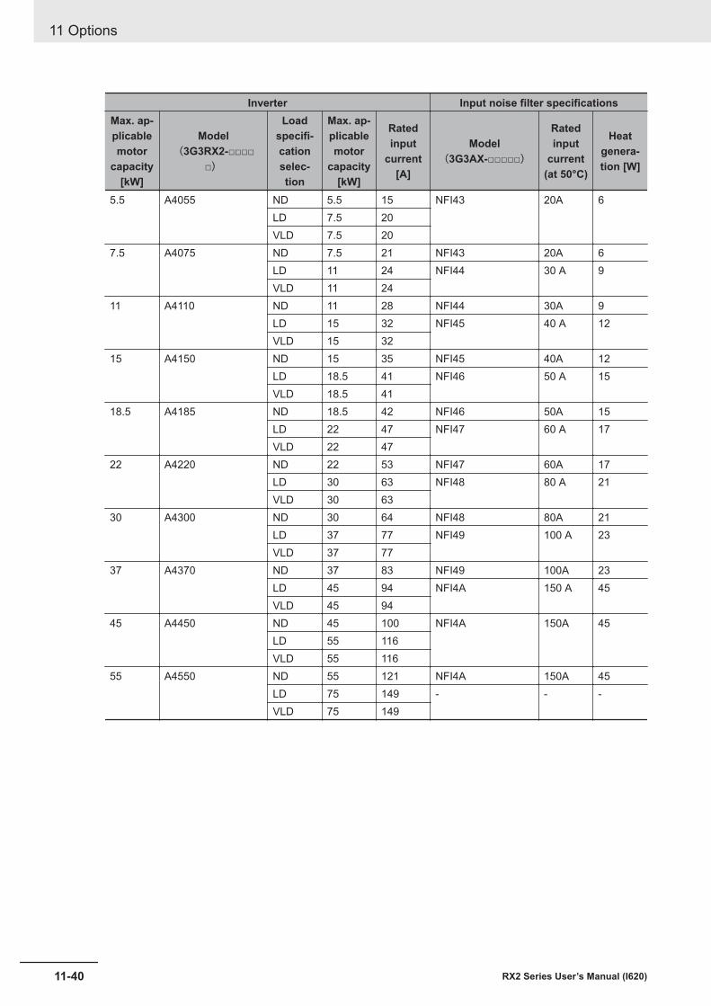
Inverter Input noise filter specificationsMax. ap-plicablemotor
capacity[kW]
Model(3G3RX2-□□□□
□)
Loadspecifi-cationselec-tion
Max. ap-plicablemotor
capacity[kW]
Ratedinput
current[A]
Model(3G3AX-□□□□□)
Ratedinput
current(at 50°C)
Heatgenera-tion [W]
5.5 A4055 ND 5.5 15 NFI43 20A 6LD 7.5 20VLD 7.5 20
7.5 A4075 ND 7.5 21 NFI43 20A 6LD 11 24 NFI44 30 A 9VLD 11 24
11 A4110 ND 11 28 NFI44 30A 9LD 15 32 NFI45 40 A 12VLD 15 32
15 A4150 ND 15 35 NFI45 40A 12LD 18.5 41 NFI46 50 A 15VLD 18.5 41
18.5 A4185 ND 18.5 42 NFI46 50A 15LD 22 47 NFI47 60 A 17VLD 22 47
22 A4220 ND 22 53 NFI47 60A 17LD 30 63 NFI48 80 A 21VLD 30 63
30 A4300 ND 30 64 NFI48 80A 21LD 37 77 NFI49 100 A 23VLD 37 77
37 A4370 ND 37 83 NFI49 100A 23LD 45 94 NFI4A 150 A 45VLD 45 94
45 A4450 ND 45 100 NFI4A 150A 45LD 55 116VLD 55 116
55 A4550 ND 55 121 NFI4A 150A 45LD 75 149 - - -VLD 75 149
11 Options
11-40 RX2 Series User’s Manual (I620)
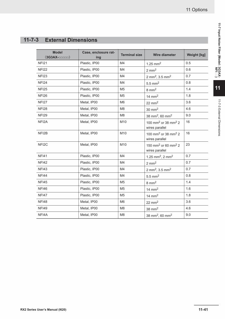
11-7-3 External Dimensions
Model(3G3AX-□□□□□)
Case, enclosure rat-ing Terminal size Wire diameter Weight [kg]
NFI21 Plastic, IP00 M4 1.25 mm2 0.5
NFI22 Plastic, IP00 M4 2 mm2 0.6
NFI23 Plastic, IP00 M4 2 mm2, 3.5 mm2 0.7
NFI24 Plastic, IP00 M4 5.5 mm2 0.8
NFI25 Plastic, IP00 M5 8 mm2 1.4
NFI26 Plastic, IP00 M5 14 mm2 1.8
NFI27 Metal, IP00 M6 22 mm2 3.6
NFI28 Metal, IP00 M8 30 mm2 4.6
NFI29 Metal, IP00 M8 38 mm2, 60 mm2 9.0
NFI2A Metal, IP00 M10 100 mm2 or 38 mm2 2wires parallel
16
NFI2B Metal, IP00 M10 100 mm2 or 38 mm2 2wires parallel
16
NFI2C Metal, IP00 M10 150 mm2 or 60 mm2 2wires parallel
23
NFI41 Plastic, IP00 M4 1.25 mm2, 2 mm2 0.7
NFI42 Plastic, IP00 M4 2 mm2 0.7
NFI43 Plastic, IP00 M4 2 mm2, 3.5 mm2 0.7
NFI44 Plastic, IP00 M4 5.5 mm2 0.8
NFI45 Plastic, IP00 M5 8 mm2 1.4
NFI46 Plastic, IP00 M5 14 mm2 1.6
NFI47 Plastic, IP00 M5 14 mm2 1.8
NFI48 Metal, IP00 M6 22 mm2 3.6
NFI49 Metal, IP00 M8 38 mm2 4.6
NFI4A Metal, IP00 M8 38 mm2, 60 mm2 9.0
11 Options
11-41RX2 Series User’s Manual (I620)
11-7 Input Noise Filter (M
odel: 3G3A
X-N
FI
)
11
11-7-3 External Dim
ensions
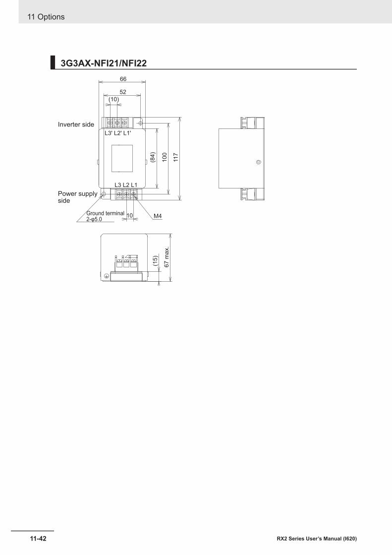
3G3AX-NFI21/NFI22
Inverter side
66
52
(10)
L3' L2' L1'
L3 L2 L1
(84
)
10
0
117
Ground terminal2-φ5.0
10 M4
67
ma
x.
(15)
Power supplyside
11 Options
11-42 RX2 Series User’s Manual (I620)
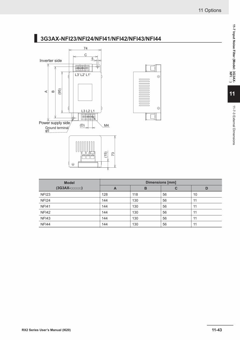
3G3AX-NFI23/NFI24/NFI41/NFI42/NFI43/NFI44
Inverter side
Power supply side
L3' L2' L1'
L3 L2 L1
A B
(95)
74
C
(D)
5
M4
(15)
73
Ground terminalφ5
Model(3G3AX-□□□□□)
Dimensions [mm]A B C D
NFI23 128 118 56 10NFI24 144 130 56 11NFI41 144 130 56 11NFI42 144 130 56 11NFI43 144 130 56 11NFI44 144 130 56 11
11 Options
11-43RX2 Series User’s Manual (I620)
11-7 Input Noise Filter (M
odel: 3G3A
X-N
FI
)
11
11-7-3 External Dim
ensions
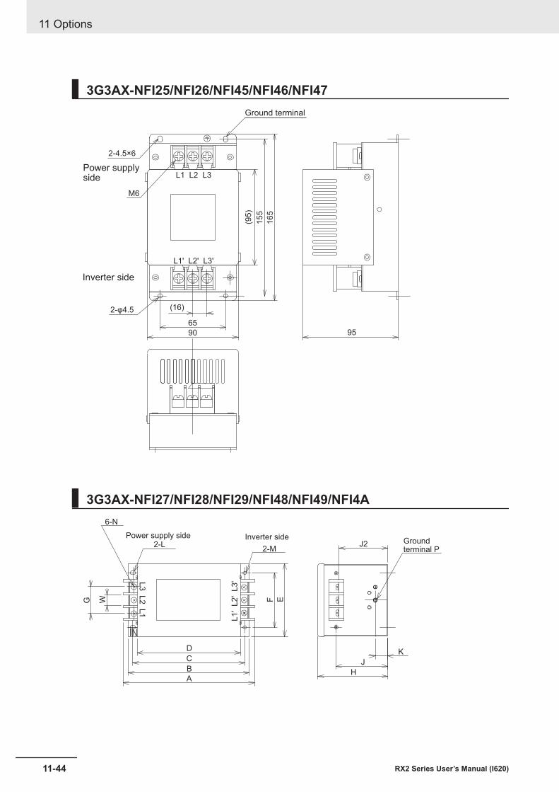
3G3AX-NFI25/NFI26/NFI45/NFI46/NFI47
Inverter side
65
90
(16)
155
165
2-φ4.5
M6
(95)
Power supplyside
2-4.5×6
95
L1 L2 L3
L1' L2' L3'
Ground terminal
3G3AX-NFI27/NFI28/NFI29/NFI48/NFI49/NFI4A
IN
Inverter side
A
6-N
G
Power supply side
L1
' L
2' L
3'
B
C
D
F EW
2-L2-M
J
H
J2
K
Groundterminal P
L3
L2
L1
11 Options
11-44 RX2 Series User’s Manual (I620)
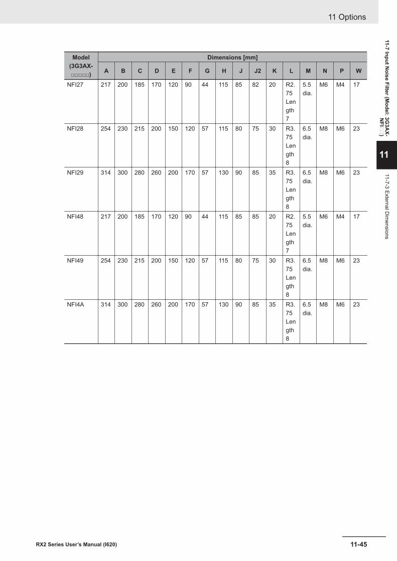
Model(3G3AX-□□□□□)
Dimensions [mm]
A B C D E F G H J J2 K L M N P W
NFI27 217 200 185 170 120 90 44 115 85 82 20 R2.75Length7
5.5dia.
M6 M4 17
NFI28 254 230 215 200 150 120 57 115 80 75 30 R3.75Length8
6.5dia.
M8 M6 23
NFI29 314 300 280 260 200 170 57 130 90 85 35 R3.75Length8
6.5dia.
M8 M6 23
NFI48 217 200 185 170 120 90 44 115 85 85 20 R2.75Length7
5.5dia.
M6 M4 17
NFI49 254 230 215 200 150 120 57 115 80 75 30 R3.75Length8
6.5dia.
M8 M6 23
NFI4A 314 300 280 260 200 170 57 130 90 85 35 R3.75Length8
6.5dia.
M8 M6 23
11 Options
11-45RX2 Series User’s Manual (I620)
11-7 Input Noise Filter (M
odel: 3G3A
X-N
FI
)
11
11-7-3 External Dim
ensions
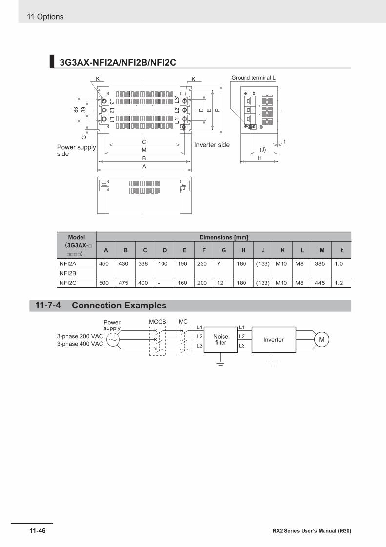
3G3AX-NFI2A/NFI2B/NFI2C
Inverter side
A
G
Power supplyside
L1' L
2' L
3'
B
C
FE
M
H
K K Ground terminal L
t
(J)
D86
39
L3 L
2 L
1
Model(3G3AX-□
□□□□)
Dimensions [mm]
A B C D E F G H J K L M t
NFI2A 450 430 338 100 190 230 7 180 (133) M10 M8 385 1.0NFI2BNFI2C 500 475 400 - 160 200 12 180 (133) M10 M8 445 1.2
11-7-4 Connection Examples
MNoisefilter
Inverter3-phase 200 VAC
3-phase 400 VAC
Powersupply
MCL1
L2
L3
L1’
L2’
L3’
MCCB
11 Options
11-46 RX2 Series User’s Manual (I620)
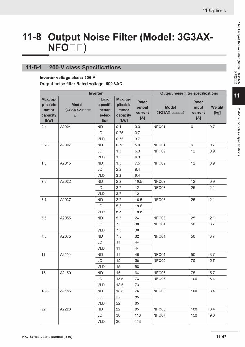
11-8 Output Noise Filter (Model: 3G3AX-NFO)
11-8-1 200-V class SpecificationsInverter voltage class: 200-VOutput noise filter Rated voltage: 500 VAC
Inverter Output noise filter specificationsMax. ap-plicablemotor
capacity[kW]
Model(3G3RX2-□□□□
□)
Loadspecifi-cationselec-tion
Max. ap-plicablemotor
capacity[kW]
Ratedoutputcurrent
[A]
Model(3G3AX-□□□□□)
Ratedinput
current[A]
Weight[kg]
0.4 A2004 ND 0.4 3.0 NFO01 6 0.7LD 0.75 3.7VLD 0.75 3.7
0.75 A2007 ND 0.75 5.0 NFO01 6 0.7LD 1.5 6.3 NFO02 12 0.9VLD 1.5 6.3
1.5 A2015 ND 1.5 7.5 NFO02 12 0.9LD 2.2 9.4VLD 2.2 9.4
2.2 A2022 ND 2.2 10.5 NFO02 12 0.9LD 3.7 12 NFO03 25 2.1VLD 3.7 12
3.7 A2037 ND 3.7 16.5 NFO03 25 2.1LD 5.5 19.6VLD 5.5 19.6
5.5 A2055 ND 5.5 24 NFO03 25 2.1LD 7.5 30 NFO04 50 3.7VLD 7.5 30
7.5 A2075 ND 7.5 32 NFO04 50 3.7LD 11 44VLD 11 44
11 A2110 ND 11 46 NFO04 50 3.7LD 15 58 NFO05 75 5.7VLD 15 58
15 A2150 ND 15 64 NFO05 75 5.7LD 18.5 73 NFO06 100 8.4VLD 18.5 73
18.5 A2185 ND 18.5 76 NFO06 100 8.4LD 22 85VLD 22 85
22 A2220 ND 22 95 NFO06 100 8.4LD 30 113 NFO07 150 9.0VLD 30 113
11 Options
11-47RX2 Series User’s Manual (I620)
11-8 Output N
oise Filter (Model: 3G
3AX-
NFO
)
11
11-8-1 200-V class Specifications
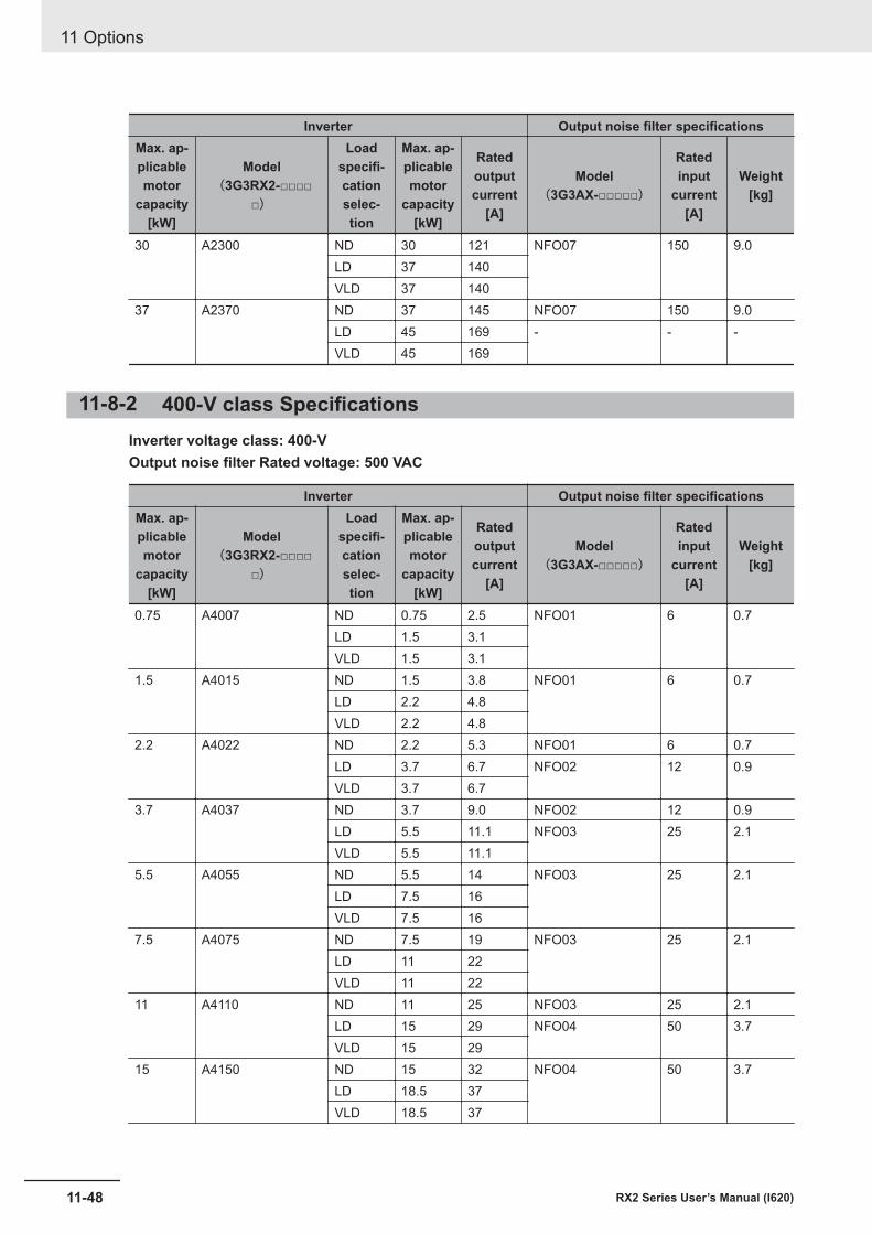
Inverter Output noise filter specificationsMax. ap-plicablemotor
capacity[kW]
Model(3G3RX2-□□□□
□)
Loadspecifi-cationselec-tion
Max. ap-plicablemotor
capacity[kW]
Ratedoutputcurrent
[A]
Model(3G3AX-□□□□□)
Ratedinput
current[A]
Weight[kg]
30 A2300 ND 30 121 NFO07 150 9.0LD 37 140VLD 37 140
37 A2370 ND 37 145 NFO07 150 9.0LD 45 169 - - -VLD 45 169
11-8-2 400-V class SpecificationsInverter voltage class: 400-VOutput noise filter Rated voltage: 500 VAC
Inverter Output noise filter specificationsMax. ap-plicablemotor
capacity[kW]
Model(3G3RX2-□□□□
□)
Loadspecifi-cationselec-tion
Max. ap-plicablemotor
capacity[kW]
Ratedoutputcurrent
[A]
Model(3G3AX-□□□□□)
Ratedinput
current[A]
Weight[kg]
0.75 A4007 ND 0.75 2.5 NFO01 6 0.7LD 1.5 3.1VLD 1.5 3.1
1.5 A4015 ND 1.5 3.8 NFO01 6 0.7LD 2.2 4.8VLD 2.2 4.8
2.2 A4022 ND 2.2 5.3 NFO01 6 0.7LD 3.7 6.7 NFO02 12 0.9VLD 3.7 6.7
3.7 A4037 ND 3.7 9.0 NFO02 12 0.9LD 5.5 11.1 NFO03 25 2.1VLD 5.5 11.1
5.5 A4055 ND 5.5 14 NFO03 25 2.1LD 7.5 16VLD 7.5 16
7.5 A4075 ND 7.5 19 NFO03 25 2.1LD 11 22VLD 11 22
11 A4110 ND 11 25 NFO03 25 2.1LD 15 29 NFO04 50 3.7VLD 15 29
15 A4150 ND 15 32 NFO04 50 3.7LD 18.5 37VLD 18.5 37
11 Options
11-48 RX2 Series User’s Manual (I620)
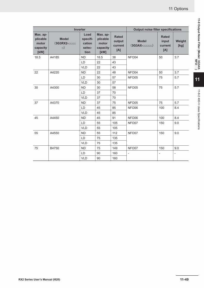
Inverter Output noise filter specificationsMax. ap-plicablemotor
capacity[kW]
Model(3G3RX2-□□□□
□)
Loadspecifi-cationselec-tion
Max. ap-plicablemotor
capacity[kW]
Ratedoutputcurrent
[A]
Model(3G3AX-□□□□□)
Ratedinput
current[A]
Weight[kg]
18.5 A4185 ND 18.5 38 NFO04 50 3.7LD 22 43VLD 22 43
22 A4220 ND 22 48 NFO04 50 3.7LD 30 57 NFO05 75 5.7VLD 30 57
30 A4300 ND 30 58 NFO05 75 5.7LD 37 70VLD 37 70
37 A4370 ND 37 75 NFO05 75 5.7LD 45 85 NFO06 100 8.4VLD 45 85
45 A4450 ND 45 91 NFO06 100 8.4LD 55 105 NFO07 150 9.0VLD 55 105
55 A4550 ND 55 112 NFO07 150 9.0LD 75 135VLD 75 135
75 B4750 ND 75 149 NFO07 150 9.0LD 90 160 - - -VLD 90 160
11 Options
11-49RX2 Series User’s Manual (I620)
11-8 Output N
oise Filter (Model: 3G
3AX-
NFO
)
11
11-8-2 400-V class Specifications
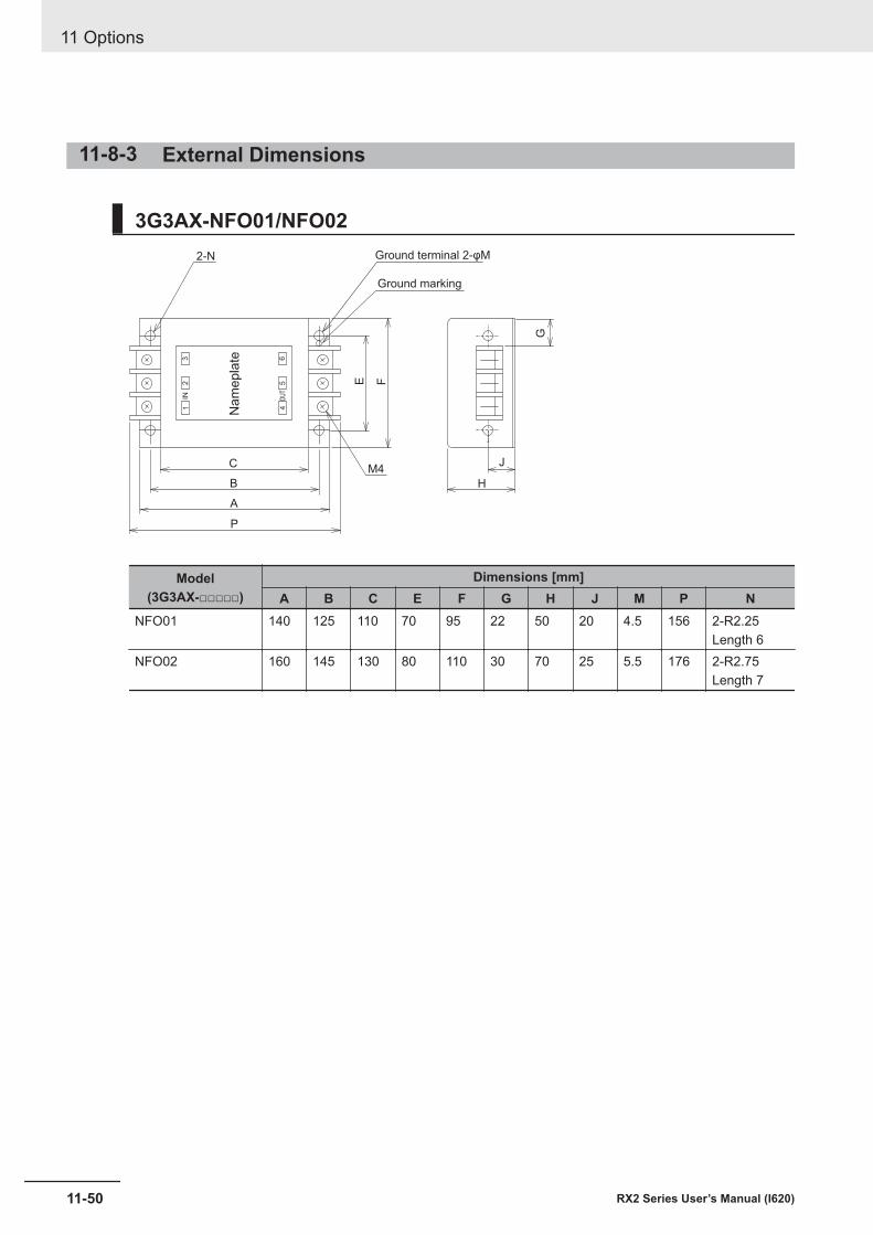
11-8-3 External Dimensions
3G3AX-NFO01/NFO02
H
F
P
C
B
A
E
J
G
M4
Ground marking
Ground terminal 2-φM2-N
Na
me
pla
te
12
3
4
IN OU
T5
6
Model(3G3AX-□□□□□)
Dimensions [mm]A B C E F G H J M P N
NFO01 140 125 110 70 95 22 50 20 4.5 156 2-R2.25Length 6
NFO02 160 145 130 80 110 30 70 25 5.5 176 2-R2.75Length 7
11 Options
11-50 RX2 Series User’s Manual (I620)
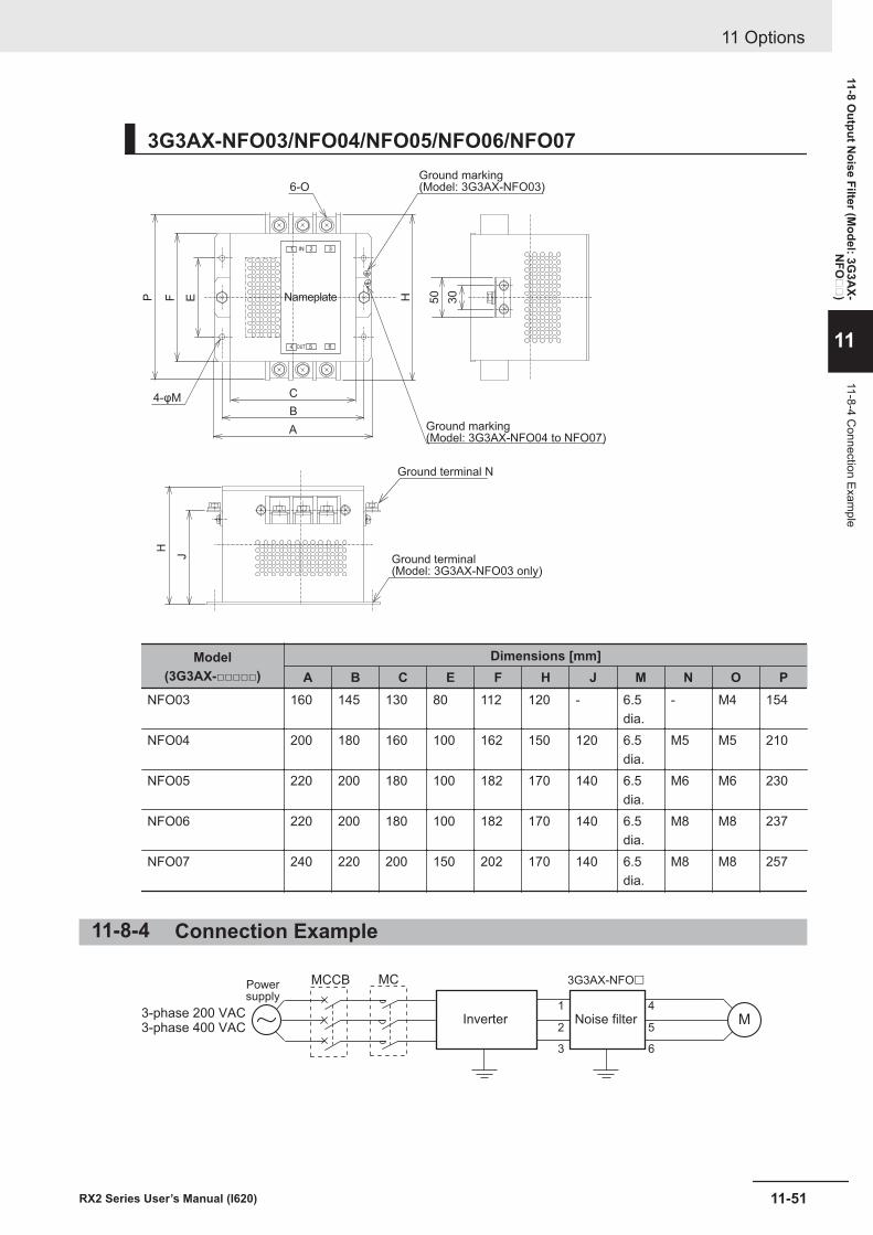
3G3AX-NFO03/NFO04/NFO05/NFO06/NFO07
HC
B
A
Ground marking(Model: 3G3AX-NFO03)
Ground marking(Model: 3G3AX-NFO04 to NFO07)
EFP
J
H
30
50
Ground terminal N
Ground terminal(Model: 3G3AX-NFO03 only)
4-φM
6-O
Nameplate
1 2 3
4
IN
OUT 5 6
Model(3G3AX-□□□□□)
Dimensions [mm]A B C E F H J M N O P
NFO03 160 145 130 80 112 120 - 6.5dia.
- M4 154
NFO04 200 180 160 100 162 150 120 6.5dia.
M5 M5 210
NFO05 220 200 180 100 182 170 140 6.5dia.
M6 M6 230
NFO06 220 200 180 100 182 170 140 6.5dia.
M8 M8 237
NFO07 240 220 200 150 202 170 140 6.5dia.
M8 M8 257
11-8-4 Connection Example
M
3G3AX-NFO£
1
2
3
4
5
6
Inverter Noise filter3-phase 200 VAC3-phase 400 VAC
Powersupply
MCMCCB
11 Options
11-51RX2 Series User’s Manual (I620)
11-8 Output N
oise Filter (Model: 3G
3AX-
NFO
)
11
11-8-4 Connection Exam
ple
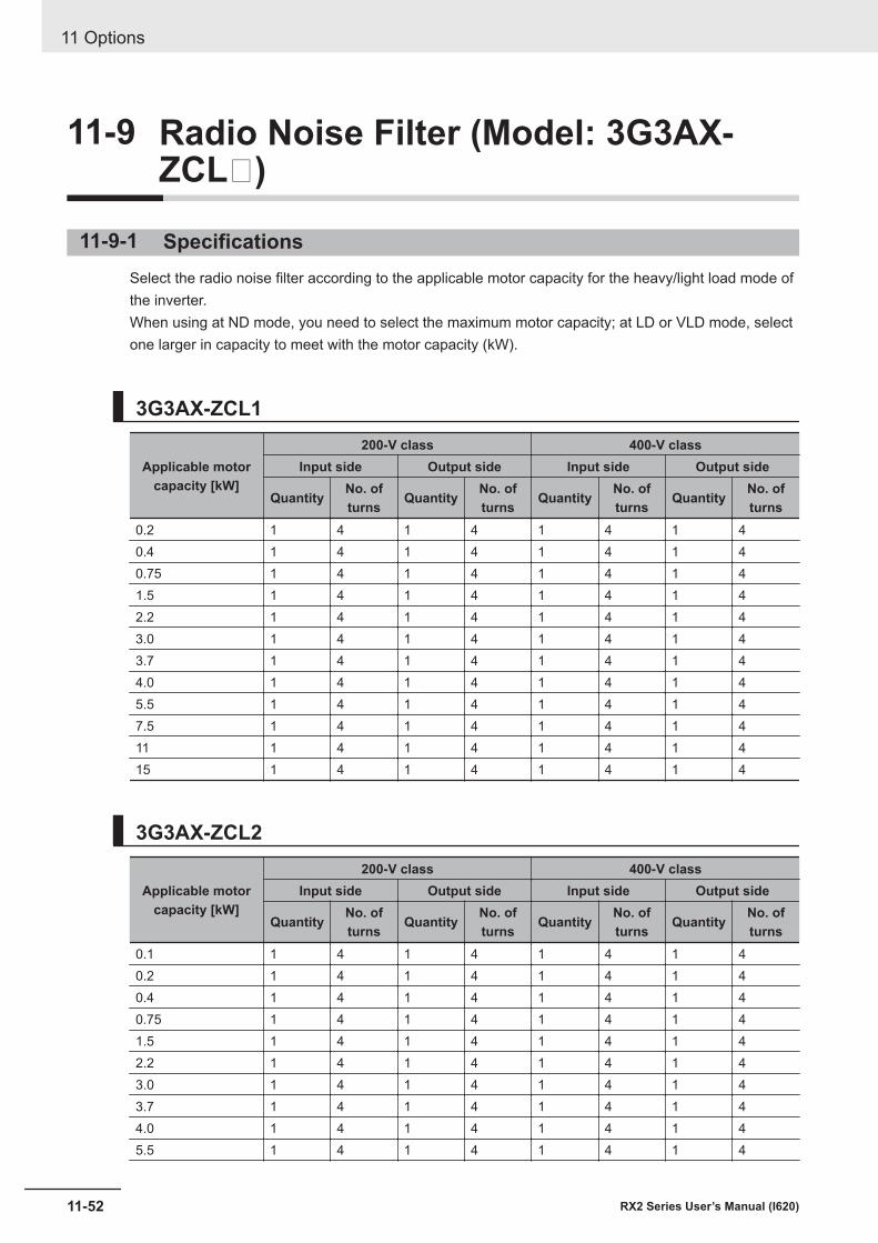
11-9 Radio Noise Filter (Model: 3G3AX-ZCL)
11-9-1 SpecificationsSelect the radio noise filter according to the applicable motor capacity for the heavy/light load mode ofthe inverter.When using at ND mode, you need to select the maximum motor capacity; at LD or VLD mode, selectone larger in capacity to meet with the motor capacity (kW).
3G3AX-ZCL1
Applicable motorcapacity [kW]
200-V class 400-V classInput side Output side Input side Output side
Quantity No. ofturns Quantity No. of
turns Quantity No. ofturns Quantity No. of
turns0.2 1 4 1 4 1 4 1 40.4 1 4 1 4 1 4 1 40.75 1 4 1 4 1 4 1 41.5 1 4 1 4 1 4 1 42.2 1 4 1 4 1 4 1 43.0 1 4 1 4 1 4 1 43.7 1 4 1 4 1 4 1 44.0 1 4 1 4 1 4 1 45.5 1 4 1 4 1 4 1 47.5 1 4 1 4 1 4 1 411 1 4 1 4 1 4 1 415 1 4 1 4 1 4 1 4
3G3AX-ZCL2
Applicable motorcapacity [kW]
200-V class 400-V classInput side Output side Input side Output side
Quantity No. ofturns Quantity No. of
turns Quantity No. ofturns Quantity No. of
turns0.1 1 4 1 4 1 4 1 40.2 1 4 1 4 1 4 1 40.4 1 4 1 4 1 4 1 40.75 1 4 1 4 1 4 1 41.5 1 4 1 4 1 4 1 42.2 1 4 1 4 1 4 1 43.0 1 4 1 4 1 4 1 43.7 1 4 1 4 1 4 1 44.0 1 4 1 4 1 4 1 45.5 1 4 1 4 1 4 1 4
11 Options
11-52 RX2 Series User’s Manual (I620)
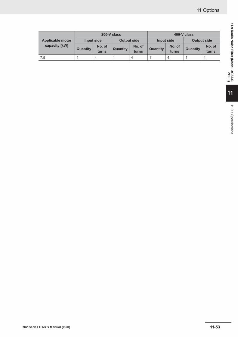
Applicable motorcapacity [kW]
200-V class 400-V classInput side Output side Input side Output side
Quantity No. ofturns Quantity No. of
turns Quantity No. ofturns Quantity No. of
turns7.5 1 4 1 4 1 4 1 4
11 Options
11-53RX2 Series User’s Manual (I620)
11-9 Radio N
oise Filter (Model: 3G
3AX-
ZCL
)
11
11-9-1 Specifications
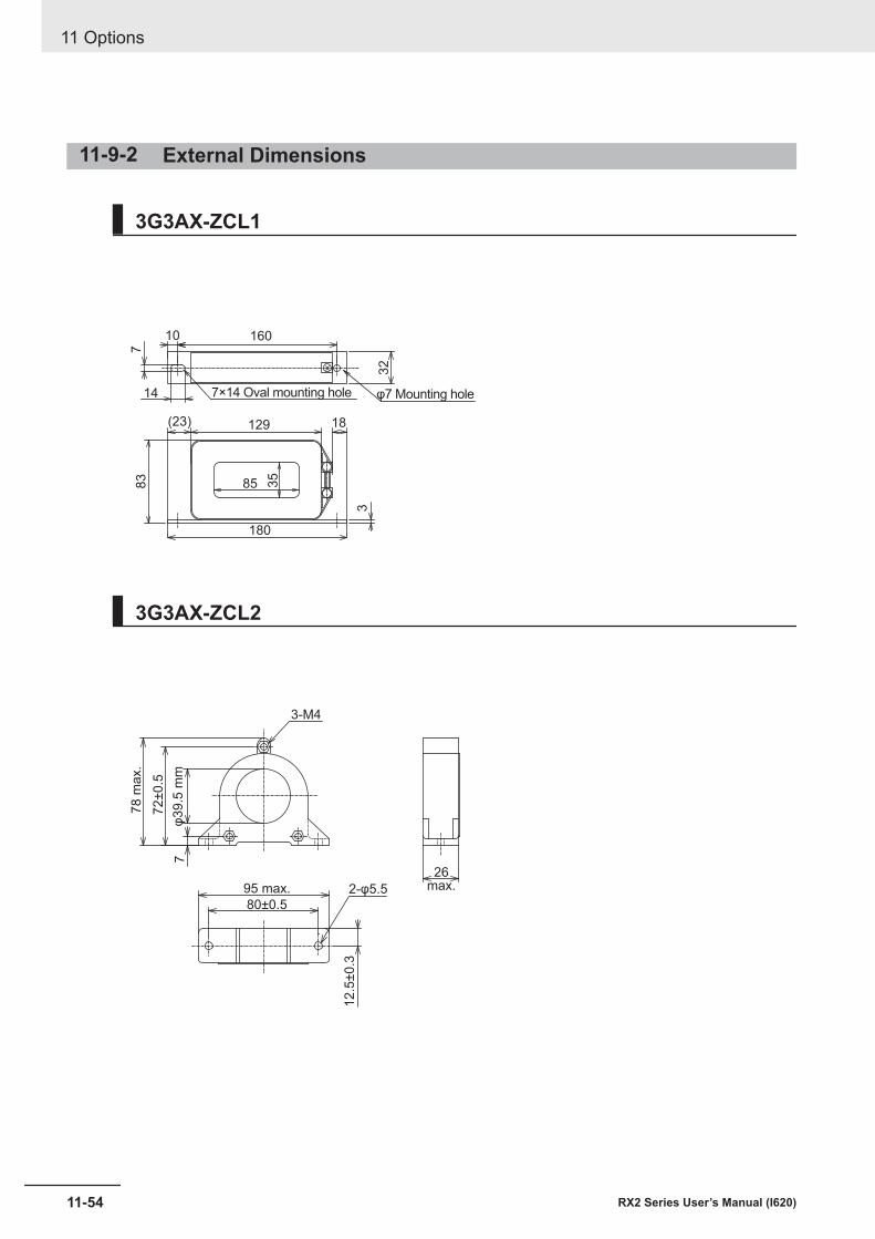
11-9-2 External Dimensions
3G3AX-ZCL1
160
18129
85
180
(23)
10
14 7×14 Oval mounting hole φ7 Mounting hole
783
35
32
3
3G3AX-ZCL2
3-M4
26max.95 max. 2-φ5.5
80±0.5
78
ma
x.
12
.5±0
.3
φ3
9.5
mm
7
72
±0
.5
11 Options
11-54 RX2 Series User’s Manual (I620)
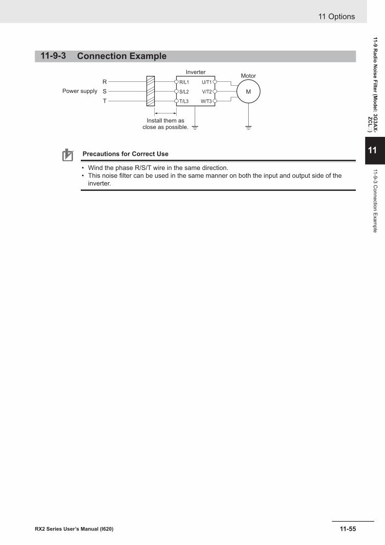
11-9-3 Connection Example
R
S
T
M
Motor
Power supply
Install them asclose as possible.
Inverter
U/T1
V/T2
W/T3
S/L2
T/L3
R/L1
Precautions for Correct Use
• Wind the phase R/S/T wire in the same direction.• This noise filter can be used in the same manner on both the input and output side of the
inverter.
11 Options
11-55RX2 Series User’s Manual (I620)
11-9 Radio N
oise Filter (Model: 3G
3AX-
ZCL
)
11
11-9-3 Connection Exam
ple
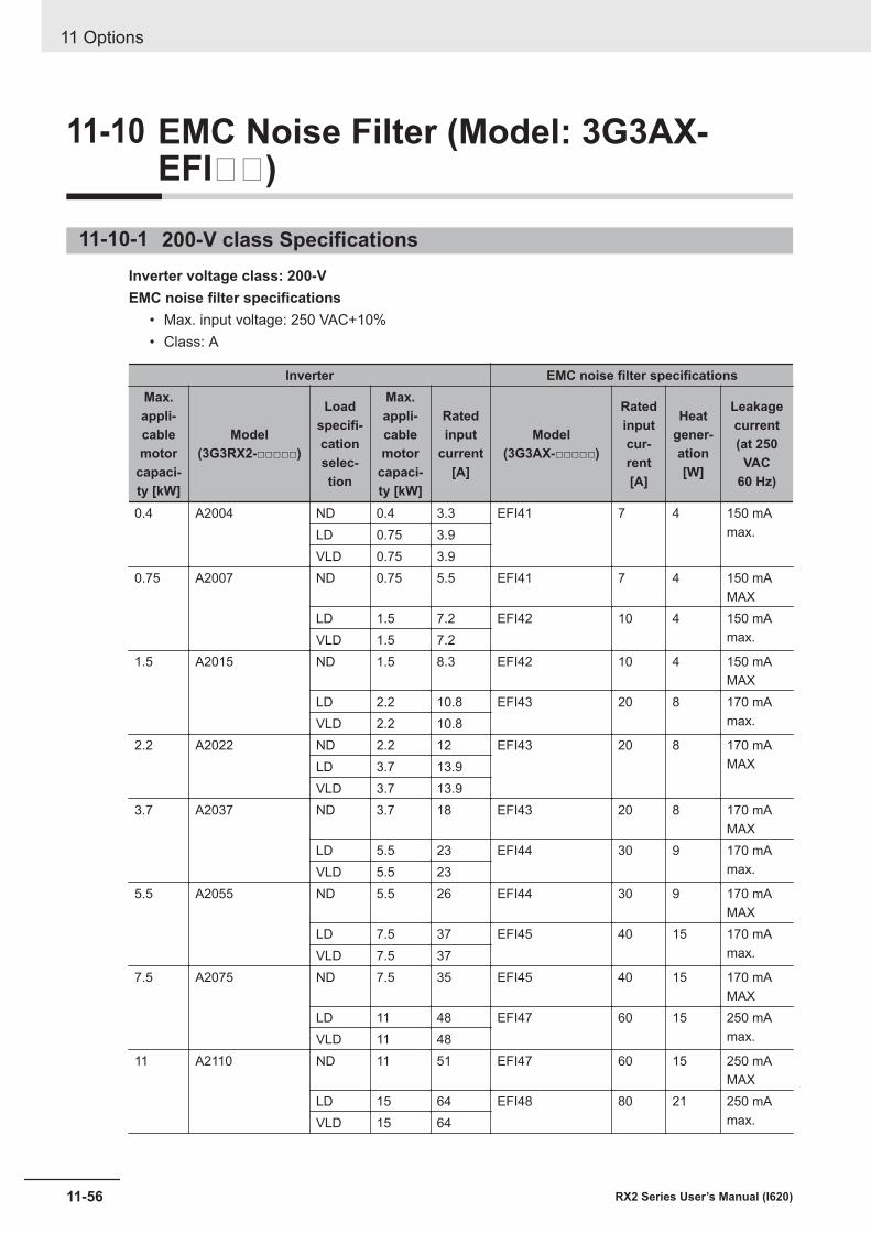
11-10 EMC Noise Filter (Model: 3G3AX-EFI)
11-10-1 200-V class SpecificationsInverter voltage class: 200-VEMC noise filter specifications
• Max. input voltage: 250 VAC+10%• Class: A
Inverter EMC noise filter specificationsMax.appli-cablemotor
capaci-ty [kW]
Model(3G3RX2-□□□□□)
Loadspecifi-cationselec-tion
Max.appli-cablemotor
capaci-ty [kW]
Ratedinput
current[A]
Model(3G3AX-□□□□□)
Ratedinputcur-rent[A]
Heatgener-ation[W]
Leakagecurrent(at 250
VAC60 Hz)
0.4 A2004 ND 0.4 3.3 EFI41 7 4 150 mAmax.LD 0.75 3.9
VLD 0.75 3.90.75 A2007 ND 0.75 5.5 EFI41 7 4 150 mA
MAXLD 1.5 7.2 EFI42 10 4 150 mA
max.VLD 1.5 7.21.5 A2015 ND 1.5 8.3 EFI42 10 4 150 mA
MAXLD 2.2 10.8 EFI43 20 8 170 mA
max.VLD 2.2 10.82.2 A2022 ND 2.2 12 EFI43 20 8 170 mA
MAXLD 3.7 13.9VLD 3.7 13.9
3.7 A2037 ND 3.7 18 EFI43 20 8 170 mAMAX
LD 5.5 23 EFI44 30 9 170 mAmax.VLD 5.5 23
5.5 A2055 ND 5.5 26 EFI44 30 9 170 mAMAX
LD 7.5 37 EFI45 40 15 170 mAmax.VLD 7.5 37
7.5 A2075 ND 7.5 35 EFI45 40 15 170 mAMAX
LD 11 48 EFI47 60 15 250 mAmax.VLD 11 48
11 A2110 ND 11 51 EFI47 60 15 250 mAMAX
LD 15 64 EFI48 80 21 250 mAmax.VLD 15 64
11 Options
11-56 RX2 Series User’s Manual (I620)
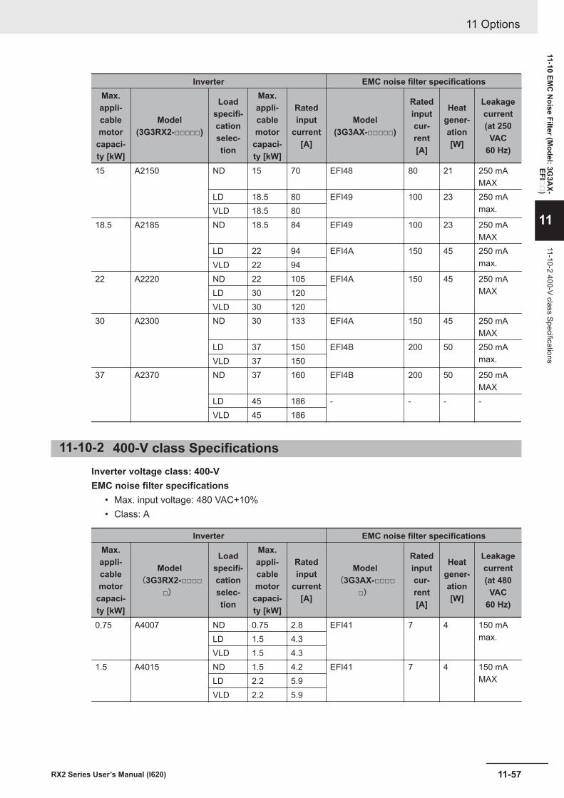
Inverter EMC noise filter specificationsMax.appli-cablemotor
capaci-ty [kW]
Model(3G3RX2-□□□□□)
Loadspecifi-cationselec-tion
Max.appli-cablemotor
capaci-ty [kW]
Ratedinput
current[A]
Model(3G3AX-□□□□□)
Ratedinputcur-rent[A]
Heatgener-ation[W]
Leakagecurrent(at 250
VAC60 Hz)
15 A2150 ND 15 70 EFI48 80 21 250 mAMAX
LD 18.5 80 EFI49 100 23 250 mAmax.VLD 18.5 80
18.5 A2185 ND 18.5 84 EFI49 100 23 250 mAMAX
LD 22 94 EFI4A 150 45 250 mAmax.VLD 22 94
22 A2220 ND 22 105 EFI4A 150 45 250 mAMAXLD 30 120
VLD 30 12030 A2300 ND 30 133 EFI4A 150 45 250 mA
MAXLD 37 150 EFI4B 200 50 250 mA
max.VLD 37 15037 A2370 ND 37 160 EFI4B 200 50 250 mA
MAXLD 45 186 - - - -VLD 45 186
11-10-2 400-V class SpecificationsInverter voltage class: 400-VEMC noise filter specifications
• Max. input voltage: 480 VAC+10%• Class: A
Inverter EMC noise filter specificationsMax.appli-cablemotor
capaci-ty [kW]
Model(3G3RX2-□□□□
□)
Loadspecifi-cationselec-tion
Max.appli-cablemotor
capaci-ty [kW]
Ratedinput
current[A]
Model(3G3AX-□□□□
□)
Ratedinputcur-rent[A]
Heatgener-ation[W]
Leakagecurrent(at 480
VAC60 Hz)
0.75 A4007 ND 0.75 2.8 EFI41 7 4 150 mAmax.LD 1.5 4.3
VLD 1.5 4.31.5 A4015 ND 1.5 4.2 EFI41 7 4 150 mA
MAXLD 2.2 5.9VLD 2.2 5.9
11 Options
11-57RX2 Series User’s Manual (I620)
11-10 EMC
Noise Filter (M
odel: 3G3A
X-EFI
)
11
11-10-2 400-V class Specifications
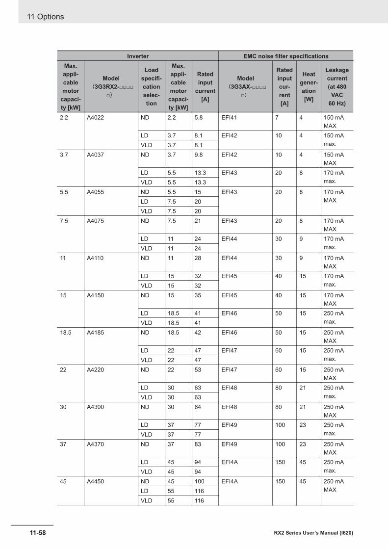
Inverter EMC noise filter specificationsMax.appli-cablemotor
capaci-ty [kW]
Model(3G3RX2-□□□□
□)
Loadspecifi-cationselec-tion
Max.appli-cablemotor
capaci-ty [kW]
Ratedinput
current[A]
Model(3G3AX-□□□□
□)
Ratedinputcur-rent[A]
Heatgener-ation[W]
Leakagecurrent(at 480
VAC60 Hz)
2.2 A4022 ND 2.2 5.8 EFI41 7 4 150 mAMAX
LD 3.7 8.1 EFI42 10 4 150 mAmax.VLD 3.7 8.1
3.7 A4037 ND 3.7 9.8 EFI42 10 4 150 mAMAX
LD 5.5 13.3 EFI43 20 8 170 mAmax.VLD 5.5 13.3
5.5 A4055 ND 5.5 15 EFI43 20 8 170 mAMAXLD 7.5 20
VLD 7.5 207.5 A4075 ND 7.5 21 EFI43 20 8 170 mA
MAXLD 11 24 EFI44 30 9 170 mA
max.VLD 11 2411 A4110 ND 11 28 EFI44 30 9 170 mA
MAXLD 15 32 EFI45 40 15 170 mA
max.VLD 15 3215 A4150 ND 15 35 EFI45 40 15 170 mA
MAXLD 18.5 41 EFI46 50 15 250 mA
max.VLD 18.5 4118.5 A4185 ND 18.5 42 EFI46 50 15 250 mA
MAXLD 22 47 EFI47 60 15 250 mA
max.VLD 22 4722 A4220 ND 22 53 EFI47 60 15 250 mA
MAXLD 30 63 EFI48 80 21 250 mA
max.VLD 30 6330 A4300 ND 30 64 EFI48 80 21 250 mA
MAXLD 37 77 EFI49 100 23 250 mA
max.VLD 37 7737 A4370 ND 37 83 EFI49 100 23 250 mA
MAXLD 45 94 EFI4A 150 45 250 mA
max.VLD 45 9445 A4450 ND 45 100 EFI4A 150 45 250 mA
MAXLD 55 116VLD 55 116
11 Options
11-58 RX2 Series User’s Manual (I620)
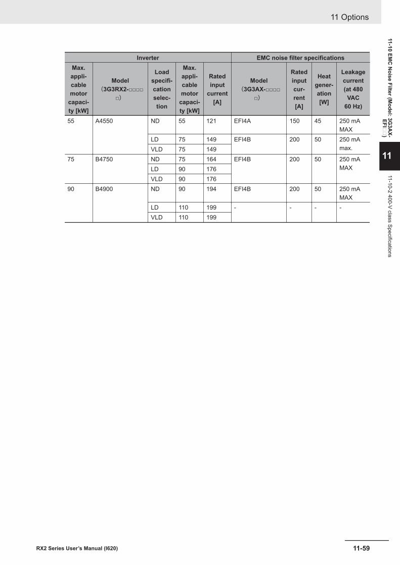
Inverter EMC noise filter specificationsMax.appli-cablemotor
capaci-ty [kW]
Model(3G3RX2-□□□□
□)
Loadspecifi-cationselec-tion
Max.appli-cablemotor
capaci-ty [kW]
Ratedinput
current[A]
Model(3G3AX-□□□□
□)
Ratedinputcur-rent[A]
Heatgener-ation[W]
Leakagecurrent(at 480
VAC60 Hz)
55 A4550 ND 55 121 EFI4A 150 45 250 mAMAX
LD 75 149 EFI4B 200 50 250 mAmax.VLD 75 149
75 B4750 ND 75 164 EFI4B 200 50 250 mAMAXLD 90 176
VLD 90 17690 B4900 ND 90 194 EFI4B 200 50 250 mA
MAXLD 110 199 - - - -VLD 110 199
11 Options
11-59RX2 Series User’s Manual (I620)
11-10 EMC
Noise Filter (M
odel: 3G3A
X-EFI
)
11
11-10-2 400-V class Specifications
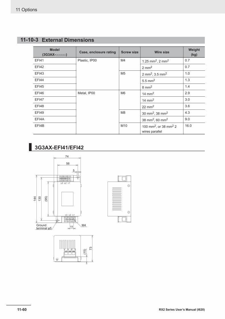
11-10-3 External DimensionsModel
(3G3AX-□□□□□) Case, enclosure rating Screw size Wire size Weight(kg)
EFI41 Plastic, IP00 M4 1.25 mm2, 2 mm2 0.7
EFI42 2 mm2 0.7
EFI43 M5 2 mm2, 3.5 mm2 1.0
EFI44 5.5 mm2 1.3
EFI45 8 mm2 1.4
EFI46 Metal, IP00 M6 14 mm2 2.9
EFI47 14 mm2 3.0
EFI48 22 mm2 3.6
EFI49 M8 30 mm2, 38 mm2 4.3
EFI4A 38 mm2, 60 mm2 9.0
EFI4B M10 100 mm2, or 38 mm2 2wires parallel
16.0
3G3AX-EFI41/EFI4274
56
144
73
(15)
130
(95)
5
M411
L3’ L2’ L1’
L3 L2 L1
Groundterminal φ5
11 Options
11-60 RX2 Series User’s Manual (I620)
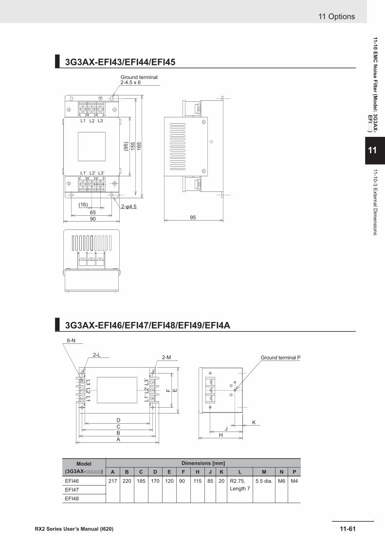
3G3AX-EFI43/EFI44/EFI45
(95)
155
165
(16)
659590
L3’L2’L1’
L3L2L1
Ground terminal2-4.5 x 6
2-φ4.5
3G3AX-EFI46/EFI47/EFI48/EFI49/EFI4A
F E
C
B
A
D
H
J
K
2-L2-M
6-N
Ground terminal P
L3
L2
L1
L3
’L
2’
L1
’
Model(3G3AX-□□□□□)
Dimensions [mm]A B C D E F H J K L M N P
EFI46 217 220 185 170 120 90 115 85 20 R2.75,Length 7
5.5 dia. M6 M4EFI47EFI48
11 Options
11-61RX2 Series User’s Manual (I620)
11-10 EMC
Noise Filter (M
odel: 3G3A
X-EFI
)
11
11-10-3 External Dim
ensions
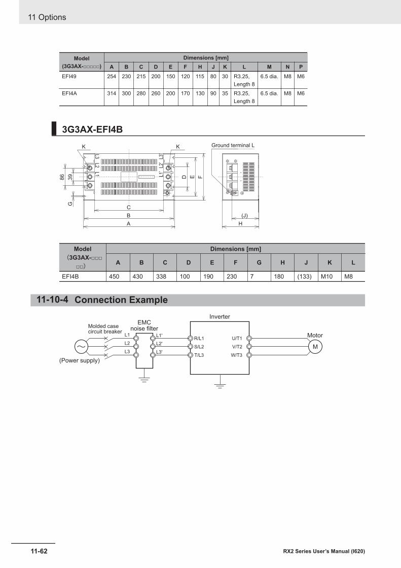
Model(3G3AX-□□□□□)
Dimensions [mm]A B C D E F H J K L M N P
EFI49 254 230 215 200 150 120 115 80 30 R3.25,Length 8
6.5 dia. M8 M6
EFI4A 314 300 280 260 200 170 130 90 35 R3.25,Length 8
6.5 dia. M8 M6
3G3AX-EFI4B
39
86
C
B
A
D E F
H
(J)
G
Ground terminal LKK
L3
L2
L1
L3
’L
2’
L1
’
Model(3G3AX-□□□
□□)
Dimensions [mm]
A B C D E F G H J K L
EFI4B 450 430 338 100 190 230 7 180 (133) M10 M8
11-10-4 Connection Example
L1 L1'
L2'
L3'
L2
L3
R/L1
S/L2
T/L3
U/T1
V/T2
W/T3
M~(Power supply)
EMCnoise filterMolded case
circuit breakerMotor
Inverter
11 Options
11-62 RX2 Series User’s Manual (I620)
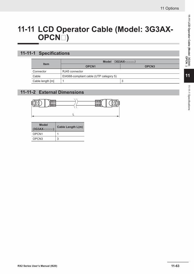
11-11 LCD Operator Cable (Model: 3G3AX-OPCN)
11-11-1 Specifications
ItemModel (3G3AX-□□□□□)
OPCN1 OPCN3Connector RJ45 connectorCable EIA568-compliant cable (UTP category 5)Cable length [m] 1 3
11-11-2 External Dimensions
L
Model(3G3AX-□□□□□) Cable Length L(m)
OPCN1 1OPCN3 3
11 Options
11-63RX2 Series User’s Manual (I620)
11-11 LCD
Operator C
able (Model: 3G
3AX-
OPC
N
)
11
11-11-1 Specifications
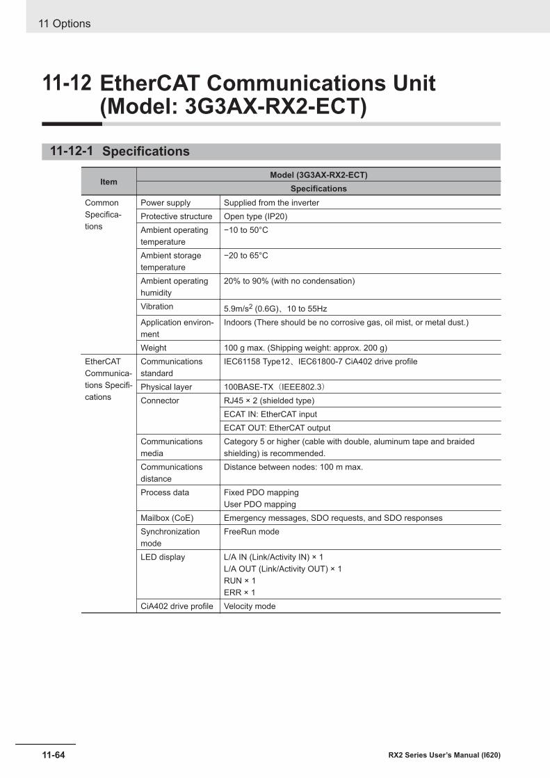
11-12 EtherCAT Communications Unit(Model: 3G3AX-RX2-ECT)
11-12-1 Specifications
ItemModel (3G3AX-RX2-ECT)
SpecificationsCommonSpecifica-tions
Power supply Supplied from the inverterProtective structure Open type (IP20)Ambient operatingtemperature
−10 to 50°C
Ambient storagetemperature
−20 to 65°C
Ambient operatinghumidity
20% to 90% (with no condensation)
Vibration 5.9m/s2 (0.6G)、10 to 55HzApplication environ-ment
Indoors (There should be no corrosive gas, oil mist, or metal dust.)
Weight 100 g max. (Shipping weight: approx. 200 g)EtherCATCommunica-tions Specifi-cations
Communicationsstandard
IEC61158 Type12、IEC61800-7 CiA402 drive profile
Physical layer 100BASE-TX(IEEE802.3)Connector RJ45 × 2 (shielded type)
ECAT IN: EtherCAT inputECAT OUT: EtherCAT output
Communicationsmedia
Category 5 or higher (cable with double, aluminum tape and braidedshielding) is recommended.
Communicationsdistance
Distance between nodes: 100 m max.
Process data Fixed PDO mappingUser PDO mapping
Mailbox (CoE) Emergency messages, SDO requests, and SDO responsesSynchronizationmode
FreeRun mode
LED display L/A IN (Link/Activity IN) × 1L/A OUT (Link/Activity OUT) × 1RUN × 1ERR × 1
CiA402 drive profile Velocity mode
11 Options
11-64 RX2 Series User’s Manual (I620)
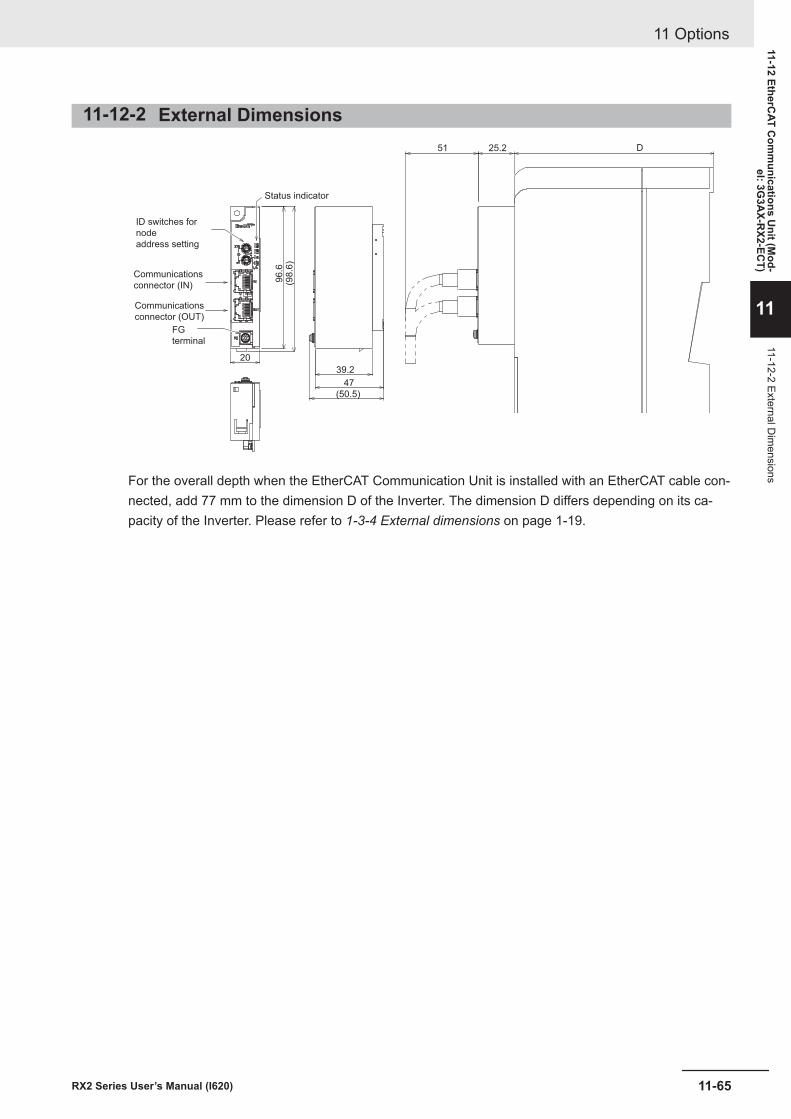
11-12-2 External Dimensions
39.2
47
(50.5)
(98
.6)
96
.6
20
ID switches for
node
address setting
Communications
connector (IN)
Communications
connector (OUT)
FG
terminal
Status indicator
51 25.2 D
For the overall depth when the EtherCAT Communication Unit is installed with an EtherCAT cable con-nected, add 77 mm to the dimension D of the Inverter. The dimension D differs depending on its ca-pacity of the Inverter. Please refer to 1-3-4 External dimensions on page 1-19.
11 Options
11-65RX2 Series User’s Manual (I620)
11-12 EtherCAT C
omm
unications Unit (M
od-el: 3G
3AX-R
X2-ECT)
11
11-12-2 External Dim
ensions

11 Options
11-66 RX2 Series User’s Manual (I620)
12Troubleshooting
This section describes how to check for abnormalities and how to deal with them.
12-1 Checking the Alarm Display........................................................................ 12-212-1-1 Checking Trip Information ............................................................................. 12-212-1-2 Checking the Retry Information..................................................................... 12-312-1-3 Procedure for Resetting a Trip State ............................................................. 12-4
12-2 Error Numbers and Corresponding Measures .......................................... 12-512-2-1 Error Number List .......................................................................................... 12-512-2-2 Details about Errors....................................................................................... 12-7
12-3 Alarm Display and Measures .................................................................... 12-2312-3-1 Checking the Alarm Display ........................................................................ 12-2312-3-2 Checking Inconsistent Settings ................................................................... 12-2912-3-3 Checking Messages .................................................................................... 12-30
12-4 Troubleshooting ......................................................................................... 12-33
12-1RX2 Series User’s Manual (I620)
12
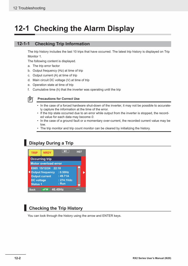
12-1 Checking the Alarm Display
12-1-1 Checking Trip InformationThe trip history includes the last 10 trips that have occurred. The latest trip history is displayed on TripMonitor 1.The following content is displayed.a. The trip error factorb. Output frequency (Hz) at time of tripc. Output current (A) at time of tripd. Main circuit DC voltage (V) at time of tripe. Operation state at time of tripf. Cumulative time (h) that the inverter was operating until the trip
Precautions for Correct Use
• In the case of a forced hardware shut-down of the inverter, it may not be possible to accurate-ly capture the information at the time of the error.
• If the trip state occurred due to an error while output from the inverter is stopped, the record-ed value for each data may become 0.
• In the case of a ground fault or a momentary over-current, the recorded current value may below.
• The trip monitor and trip count monitor can be cleared by initializing the history.
Display During a Trip
Back 46.49HzoFW
TRIPM1 H07
Occurring trip
Motor overload error
E005 15/12/24 22:10
Output frequency
Output current
DC voltage
Status 1
NRDY
----
: 0.50Hz
: 49.71A
: 274.1Vdc
: Run
Checking the Trip HistoryYou can look through the history using the arrow and ENTER keys.
12 Troubleshooting
12-2 RX2 Series User’s Manual (I620)
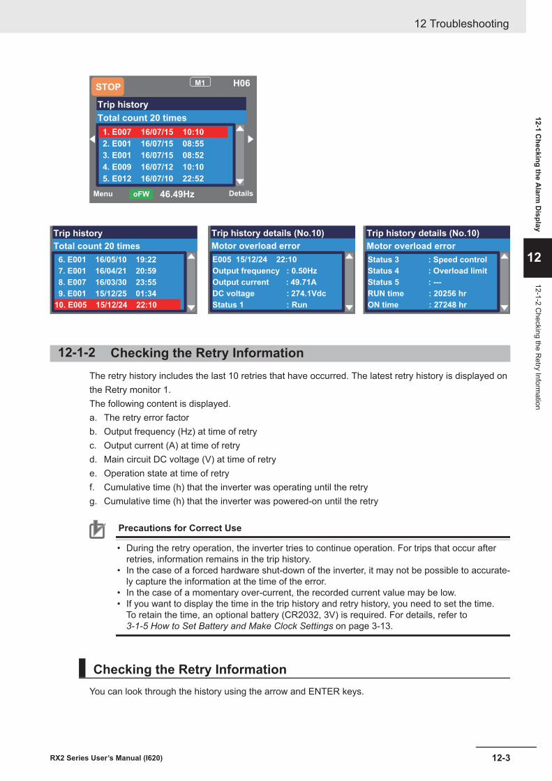
Menu Details46.49HzoFW
M1 H06
Trip history
Total count 20 times
1. E007 16/07/15 10:10
2. E001 16/07/15 08:55
3. E001 16/07/15 08:52
4. E009 16/07/12 10:10
5. E012 16/07/10 22:52
STOP
Trip history
Total count 20 times
6. E001 16/05/10 19:22
7. E001 16/04/21 20:59
8. E007 16/03/30 23:55
9. E001 15/12/25 01:34
10. E005 15/12/24 22:10
Trip history details (No.10)
Motor overload error
E005 15/12/24 22:10
Output frequency : 0.50Hz
Output current : 49.71A
DC voltage : 274.1Vdc
Status 1 : Run
Trip history details (No.10)
Motor overload error
Status 3 : Speed control
Status 4 : Overload limit
Status 5 : ---
RUN time : 20256 hr
ON time : 27248 hr
12-1-2 Checking the Retry InformationThe retry history includes the last 10 retries that have occurred. The latest retry history is displayed onthe Retry monitor 1.The following content is displayed.a. The retry error factorb. Output frequency (Hz) at time of retryc. Output current (A) at time of retryd. Main circuit DC voltage (V) at time of retrye. Operation state at time of retryf. Cumulative time (h) that the inverter was operating until the retryg. Cumulative time (h) that the inverter was powered-on until the retry
Precautions for Correct Use
• During the retry operation, the inverter tries to continue operation. For trips that occur afterretries, information remains in the trip history.
• In the case of a forced hardware shut-down of the inverter, it may not be possible to accurate-ly capture the information at the time of the error.
• In the case of a momentary over-current, the recorded current value may be low.• If you want to display the time in the trip history and retry history, you need to set the time.
To retain the time, an optional battery (CR2032, 3V) is required. For details, refer to 3-1-5 How to Set Battery and Make Clock Settings on page 3-13.
Checking the Retry InformationYou can look through the history using the arrow and ENTER keys.
12 Troubleshooting
12-3RX2 Series User’s Manual (I620)
12-1 Checking the A
larm D
isplay
12
12-1-2 Checking the R
etry Information
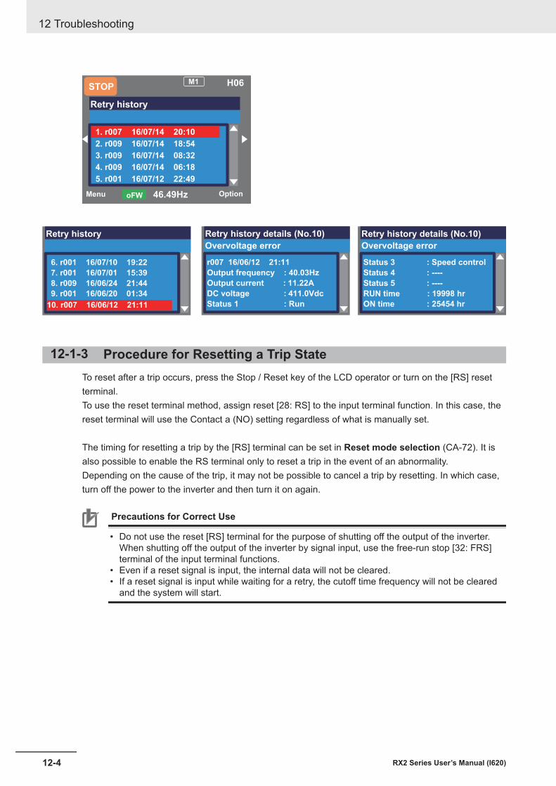
Menu Option46.49HzoFW
M1 H06
Retry history
1. r007 16/07/14 20:10
2. r009 16/07/14 18:54
3. r009 16/07/14 08:32
4. r009 16/07/14 06:18
5. r001 16/07/12 22:49
STOP
Retry history
6. r001 16/07/10 19:22
7. r001 16/07/01 15:39
8. r009 16/06/24 21:44
9. r001 16/06/20 01:34
10. r007 16/06/12 21:11
Retry history details (No.10)
Overvoltage error
r007 16/06/12 21:11
Output frequency : 40.03Hz
Output current : 11.22A
DC voltage : 411.0Vdc
Status 1 : Run
Retry history details (No.10)
Overvoltage error
Status 3 : Speed control
Status 4 : ----
Status 5 : ----
RUN time : 19998 hr
ON time : 25454 hr
12-1-3 Procedure for Resetting a Trip StateTo reset after a trip occurs, press the Stop / Reset key of the LCD operator or turn on the [RS] resetterminal.To use the reset terminal method, assign reset [28: RS] to the input terminal function. In this case, thereset terminal will use the Contact a (NO) setting regardless of what is manually set.
The timing for resetting a trip by the [RS] terminal can be set in Reset mode selection (CA-72). It isalso possible to enable the RS terminal only to reset a trip in the event of an abnormality.Depending on the cause of the trip, it may not be possible to cancel a trip by resetting. In which case,turn off the power to the inverter and then turn it on again.
Precautions for Correct Use
• Do not use the reset [RS] terminal for the purpose of shutting off the output of the inverter.When shutting off the output of the inverter by signal input, use the free-run stop [32: FRS]terminal of the input terminal functions.
• Even if a reset signal is input, the internal data will not be cleared.• If a reset signal is input while waiting for a retry, the cutoff time frequency will not be cleared
and the system will start.
12 Troubleshooting
12-4 RX2 Series User’s Manual (I620)
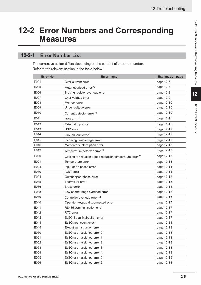
12-2 Error Numbers and CorrespondingMeasures
12-2-1 Error Number ListThe corrective action differs depending on the content of the error number.Refer to the relevant section in the table below.
Error No. Error name Explanation pageE001 Over-current error page 12-7E005 Motor overload error *2 page 12-8
E006 Braking resistor overload error page 12-8E007 Over-voltage error page 12-9E008 Memory error page 12-10E009 Under-voltage error page 12-10E010 Current detector error *1 page 12-10
E011 CPU error *1 page 12-11
E012 External trip error page 12-11E013 USP error page 12-12E014 Ground fault error *1 page 12-12
E015 Incoming overvoltage error page 12-12E016 Momentary interruption error page 12-13E019 Temperature detector error *1 page 12-13
E020 Cooling fan rotation speed reduction temperature error *1 page 12-13
E021 Temperature error page 12-13E024 Input open-phase error page 12-14E030 IGBT error page 12-14E034 Output open-phase error page 12-15E035 Thermistor error page 12-15E036 Brake error page 12-15E038 Low-speed range overload error page 12-16E039 Controller overload error *2 page 12-16
E040 Operator keypad disconnected error page 12-17E041 RS485 communication error page 12-17E042 RTC error page 12-17E043 EzSQ Illegal instruction error page 12-17E044 EzSQ nest count error page 12-18E045 Executive instruction error page 12-18E050 EzSQ user-assigned error 0 page 12-18E051 EzSQ user-assigned error 1 page 12-18E052 EzSQ user-assigned error 2 page 12-18E053 EzSQ user-assigned error 3 page 12-18E054 EzSQ user-assigned error 4 page 12-18E055 EzSQ user-assigned error 5 page 12-18E056 EzSQ user-assigned error 6 page 12-18
12 Troubleshooting
12-5RX2 Series User’s Manual (I620)
12-2 Error Num
bers and Corresponding M
easures
12
12-2-1 Error Num
ber List
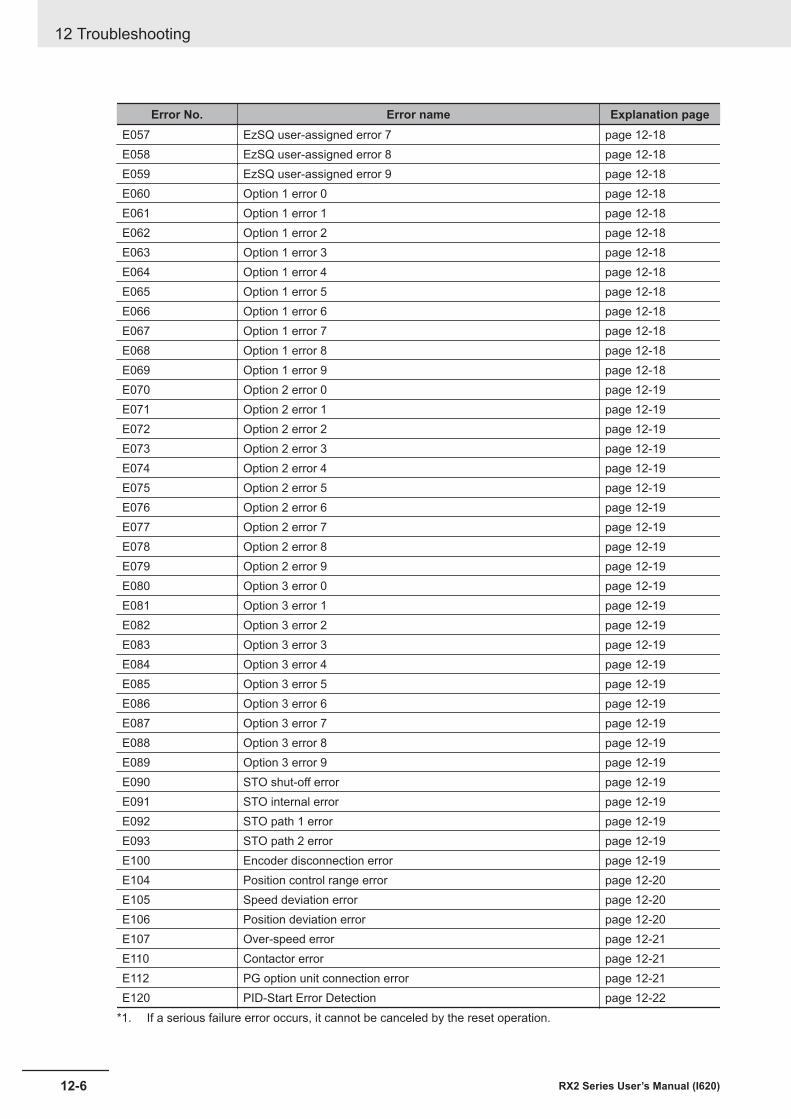
Error No. Error name Explanation pageE057 EzSQ user-assigned error 7 page 12-18E058 EzSQ user-assigned error 8 page 12-18E059 EzSQ user-assigned error 9 page 12-18E060 Option 1 error 0 page 12-18E061 Option 1 error 1 page 12-18E062 Option 1 error 2 page 12-18E063 Option 1 error 3 page 12-18E064 Option 1 error 4 page 12-18E065 Option 1 error 5 page 12-18E066 Option 1 error 6 page 12-18E067 Option 1 error 7 page 12-18E068 Option 1 error 8 page 12-18E069 Option 1 error 9 page 12-18E070 Option 2 error 0 page 12-19E071 Option 2 error 1 page 12-19E072 Option 2 error 2 page 12-19E073 Option 2 error 3 page 12-19E074 Option 2 error 4 page 12-19E075 Option 2 error 5 page 12-19E076 Option 2 error 6 page 12-19E077 Option 2 error 7 page 12-19E078 Option 2 error 8 page 12-19E079 Option 2 error 9 page 12-19E080 Option 3 error 0 page 12-19E081 Option 3 error 1 page 12-19E082 Option 3 error 2 page 12-19E083 Option 3 error 3 page 12-19E084 Option 3 error 4 page 12-19E085 Option 3 error 5 page 12-19E086 Option 3 error 6 page 12-19E087 Option 3 error 7 page 12-19E088 Option 3 error 8 page 12-19E089 Option 3 error 9 page 12-19E090 STO shut-off error page 12-19E091 STO internal error page 12-19E092 STO path 1 error page 12-19E093 STO path 2 error page 12-19E100 Encoder disconnection error page 12-19E104 Position control range error page 12-20E105 Speed deviation error page 12-20E106 Position deviation error page 12-20E107 Over-speed error page 12-21E110 Contactor error page 12-21E112 PG option unit connection error page 12-21E120 PID-Start Error Detection page 12-22
*1. If a serious failure error occurs, it cannot be canceled by the reset operation.
12 Troubleshooting
12-6 RX2 Series User’s Manual (I620)
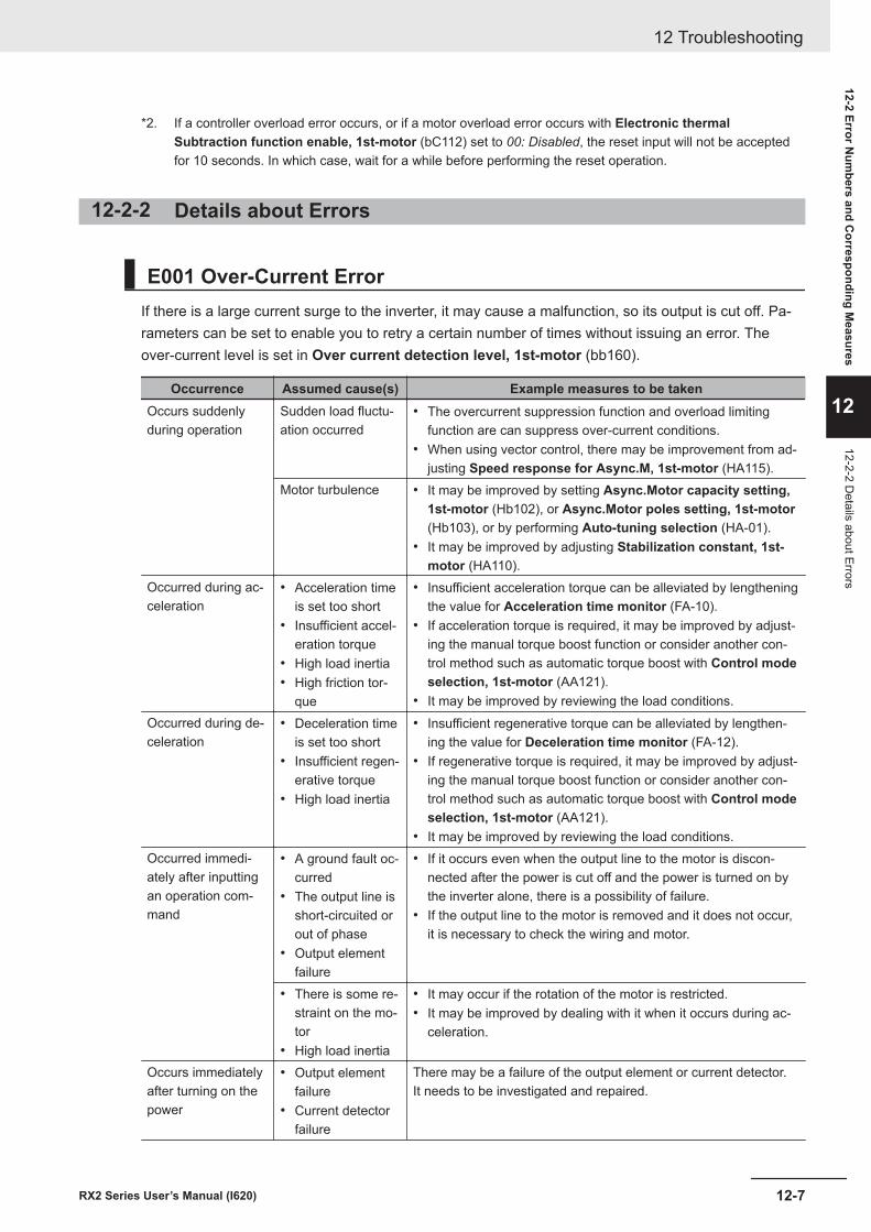
*2. If a controller overload error occurs, or if a motor overload error occurs with Electronic thermalSubtraction function enable, 1st-motor (bC112) set to 00: Disabled, the reset input will not be acceptedfor 10 seconds. In which case, wait for a while before performing the reset operation.
12-2-2 Details about Errors
E001 Over-Current ErrorIf there is a large current surge to the inverter, it may cause a malfunction, so its output is cut off. Pa-rameters can be set to enable you to retry a certain number of times without issuing an error. Theover-current level is set in Over current detection level, 1st-motor (bb160).
Occurrence Assumed cause(s) Example measures to be takenOccurs suddenlyduring operation
Sudden load fluctu-ation occurred
• The overcurrent suppression function and overload limitingfunction are can suppress over-current conditions.
• When using vector control, there may be improvement from ad-justing Speed response for Async.M, 1st-motor (HA115).
Motor turbulence • It may be improved by setting Async.Motor capacity setting,1st-motor (Hb102), or Async.Motor poles setting, 1st-motor(Hb103), or by performing Auto-tuning selection (HA-01).
• It may be improved by adjusting Stabilization constant, 1st-motor (HA110).
Occurred during ac-celeration
• Acceleration timeis set too short
• Insufficient accel-eration torque
• High load inertia• High friction tor-
que
• Insufficient acceleration torque can be alleviated by lengtheningthe value for Acceleration time monitor (FA-10).
• If acceleration torque is required, it may be improved by adjust-ing the manual torque boost function or consider another con-trol method such as automatic torque boost with Control modeselection, 1st-motor (AA121).
• It may be improved by reviewing the load conditions.Occurred during de-celeration
• Deceleration timeis set too short
• Insufficient regen-erative torque
• High load inertia
• Insufficient regenerative torque can be alleviated by lengthen-ing the value for Deceleration time monitor (FA-12).
• If regenerative torque is required, it may be improved by adjust-ing the manual torque boost function or consider another con-trol method such as automatic torque boost with Control modeselection, 1st-motor (AA121).
• It may be improved by reviewing the load conditions.Occurred immedi-ately after inputtingan operation com-mand
• A ground fault oc-curred
• The output line isshort-circuited orout of phase
• Output elementfailure
• If it occurs even when the output line to the motor is discon-nected after the power is cut off and the power is turned on bythe inverter alone, there is a possibility of failure.
• If the output line to the motor is removed and it does not occur,it is necessary to check the wiring and motor.
• There is some re-straint on the mo-tor
• High load inertia
• It may occur if the rotation of the motor is restricted.• It may be improved by dealing with it when it occurs during ac-
celeration.
Occurs immediatelyafter turning on thepower
• Output elementfailure
• Current detectorfailure
There may be a failure of the output element or current detector.It needs to be investigated and repaired.
12 Troubleshooting
12-7RX2 Series User’s Manual (I620)
12-2 Error Num
bers and Corresponding M
easures
12
12-2-2 Details about Errors
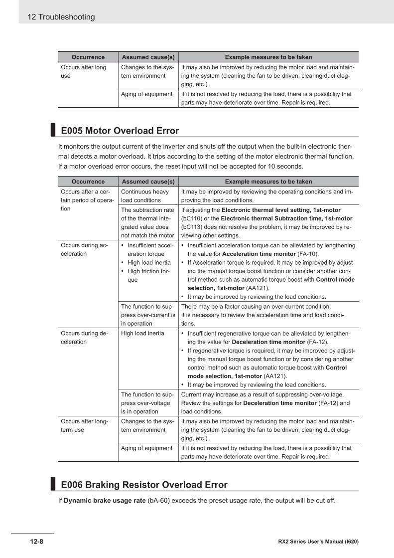
Occurrence Assumed cause(s) Example measures to be takenOccurs after longuse
Changes to the sys-tem environment
It may also be improved by reducing the motor load and maintain-ing the system (cleaning the fan to be driven, clearing duct clog-ging, etc.).
Aging of equipment If it is not resolved by reducing the load, there is a possibility thatparts may have deteriorate over time. Repair is required.
E005 Motor Overload ErrorIt monitors the output current of the inverter and shuts off the output when the built-in electronic ther-mal detects a motor overload. It trips according to the setting of the motor electronic thermal function.If a motor overload error occurs, the reset input will not be accepted for 10 seconds.
Occurrence Assumed cause(s) Example measures to be takenOccurs after a cer-tain period of opera-tion
Continuous heavyload conditions
It may be improved by reviewing the operating conditions and im-proving the load conditions.
The subtraction rateof the thermal inte-grated value doesnot match the motor
If adjusting the Electronic thermal level setting, 1st-motor(bC110) or the Electronic thermal Subtraction time, 1st-motor(bC113) does not resolve the problem, it may be improved by re-viewing other settings.
Occurs during ac-celeration
• Insufficient accel-eration torque
• High load inertia• High friction tor-
que
• Insufficient acceleration torque can be alleviated by lengtheningthe value for Acceleration time monitor (FA-10).
• If Acceleration torque is required, it may be improved by adjust-ing the manual torque boost function or consider another con-trol method such as automatic torque boost with Control modeselection, 1st-motor (AA121).
• It may be improved by reviewing the load conditions.The function to sup-press over-current isin operation
There may be a factor causing an over-current condition.It is necessary to review the acceleration time and load condi-tions.
Occurs during de-celeration
High load inertia • Insufficient regenerative torque can be alleviated by lengthen-ing the value for Deceleration time monitor (FA-12).
• If regenerative torque is required, it may be improved by adjust-ing the manual torque boost function or by considering anothercontrol method such as automatic torque boost with Controlmode selection, 1st-motor (AA121).
• It may be improved by reviewing the load conditions.The function to sup-press over-voltageis in operation
Current may increase as a result of suppressing over-voltage.Review the settings for Deceleration time monitor (FA-12) andload conditions.
Occurs after long-term use
Changes to the sys-tem environment
It may also be improved by reducing the motor load and maintain-ing the system (cleaning the fan to be driven, clearing duct clog-ging, etc.).
Aging of equipment If it is not resolved by reducing the load, there is a possibility thatparts may have deteriorate over time. Repair is required
E006 Braking Resistor Overload ErrorIf Dynamic brake usage rate (bA-60) exceeds the preset usage rate, the output will be cut off.
12 Troubleshooting
12-8 RX2 Series User’s Manual (I620)
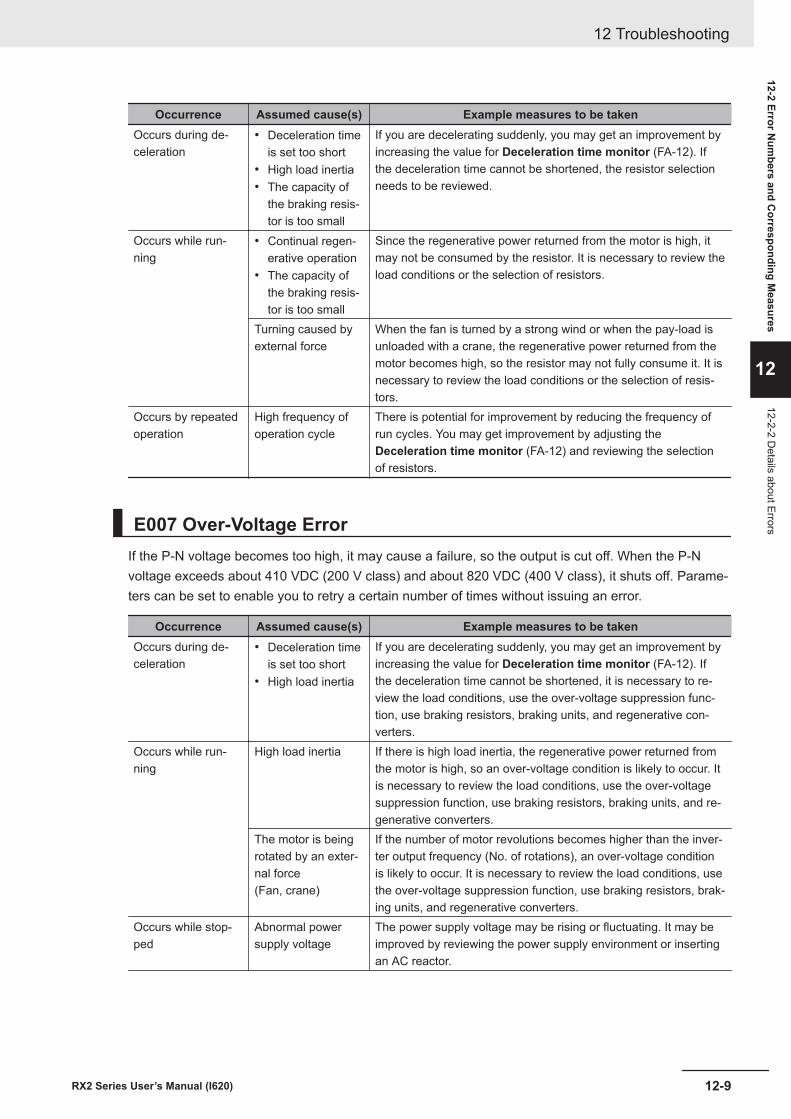
Occurrence Assumed cause(s) Example measures to be takenOccurs during de-celeration
• Deceleration timeis set too short
• High load inertia• The capacity of
the braking resis-tor is too small
If you are decelerating suddenly, you may get an improvement byincreasing the value for Deceleration time monitor (FA-12). Ifthe deceleration time cannot be shortened, the resistor selectionneeds to be reviewed.
Occurs while run-ning
• Continual regen-erative operation
• The capacity ofthe braking resis-tor is too small
Since the regenerative power returned from the motor is high, itmay not be consumed by the resistor. It is necessary to review theload conditions or the selection of resistors.
Turning caused byexternal force
When the fan is turned by a strong wind or when the pay-load isunloaded with a crane, the regenerative power returned from themotor becomes high, so the resistor may not fully consume it. It isnecessary to review the load conditions or the selection of resis-tors.
Occurs by repeatedoperation
High frequency ofoperation cycle
There is potential for improvement by reducing the frequency ofrun cycles. You may get improvement by adjusting theDeceleration time monitor (FA-12) and reviewing the selectionof resistors.
E007 Over-Voltage ErrorIf the P-N voltage becomes too high, it may cause a failure, so the output is cut off. When the P-Nvoltage exceeds about 410 VDC (200 V class) and about 820 VDC (400 V class), it shuts off. Parame-ters can be set to enable you to retry a certain number of times without issuing an error.
Occurrence Assumed cause(s) Example measures to be takenOccurs during de-celeration
• Deceleration timeis set too short
• High load inertia
If you are decelerating suddenly, you may get an improvement byincreasing the value for Deceleration time monitor (FA-12). Ifthe deceleration time cannot be shortened, it is necessary to re-view the load conditions, use the over-voltage suppression func-tion, use braking resistors, braking units, and regenerative con-verters.
Occurs while run-ning
High load inertia If there is high load inertia, the regenerative power returned fromthe motor is high, so an over-voltage condition is likely to occur. Itis necessary to review the load conditions, use the over-voltagesuppression function, use braking resistors, braking units, and re-generative converters.
The motor is beingrotated by an exter-nal force(Fan, crane)
If the number of motor revolutions becomes higher than the inver-ter output frequency (No. of rotations), an over-voltage conditionis likely to occur. It is necessary to review the load conditions, usethe over-voltage suppression function, use braking resistors, brak-ing units, and regenerative converters.
Occurs while stop-ped
Abnormal powersupply voltage
The power supply voltage may be rising or fluctuating. It may beimproved by reviewing the power supply environment or insertingan AC reactor.
12 Troubleshooting
12-9RX2 Series User’s Manual (I620)
12-2 Error Num
bers and Corresponding M
easures
12
12-2-2 Details about Errors
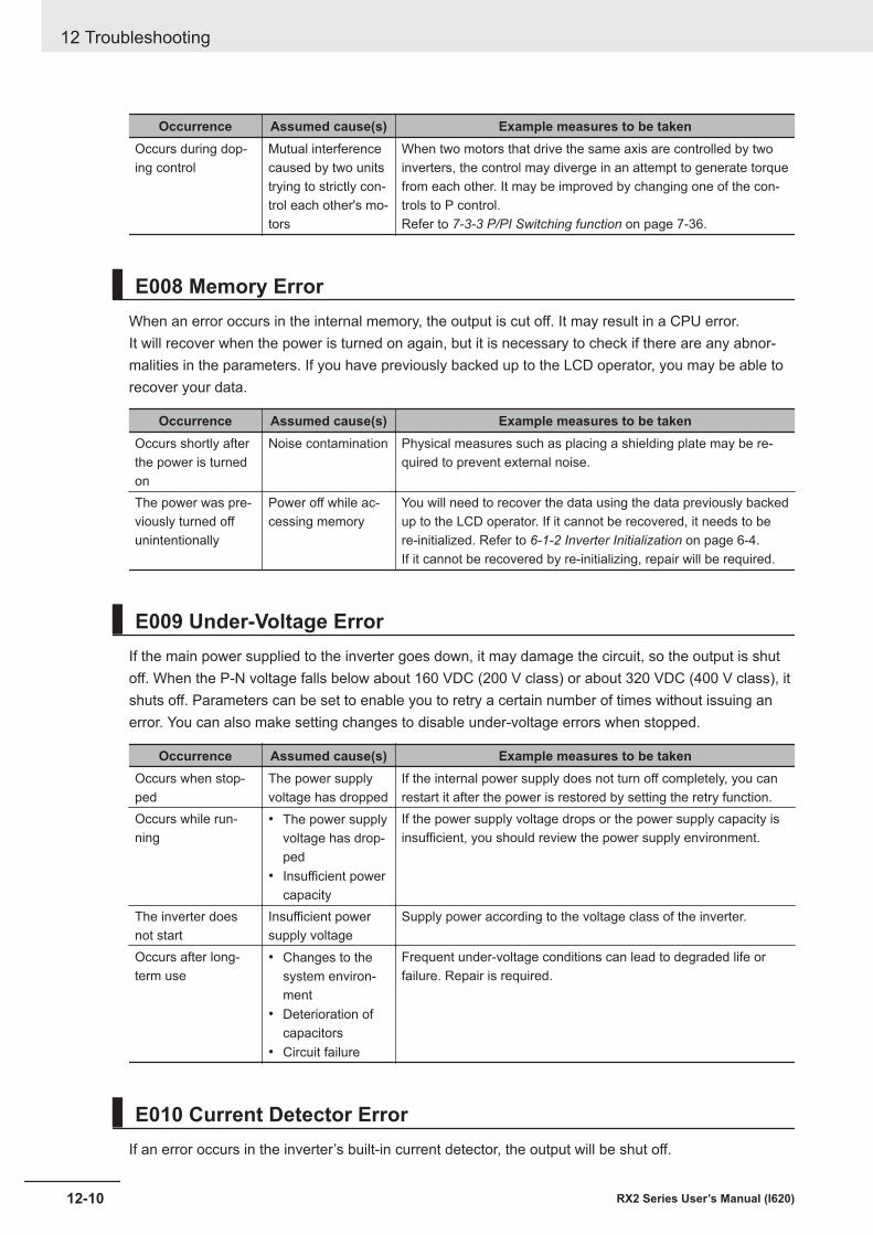
Occurrence Assumed cause(s) Example measures to be takenOccurs during dop-ing control
Mutual interferencecaused by two unitstrying to strictly con-trol each other's mo-tors
When two motors that drive the same axis are controlled by twoinverters, the control may diverge in an attempt to generate torquefrom each other. It may be improved by changing one of the con-trols to P control.Refer to 7-3-3 P/PI Switching function on page 7-36.
E008 Memory ErrorWhen an error occurs in the internal memory, the output is cut off. It may result in a CPU error.It will recover when the power is turned on again, but it is necessary to check if there are any abnor-malities in the parameters. If you have previously backed up to the LCD operator, you may be able torecover your data.
Occurrence Assumed cause(s) Example measures to be takenOccurs shortly afterthe power is turnedon
Noise contamination Physical measures such as placing a shielding plate may be re-quired to prevent external noise.
The power was pre-viously turned offunintentionally
Power off while ac-cessing memory
You will need to recover the data using the data previously backedup to the LCD operator. If it cannot be recovered, it needs to bere-initialized. Refer to 6-1-2 Inverter Initialization on page 6-4.If it cannot be recovered by re-initializing, repair will be required.
E009 Under-Voltage ErrorIf the main power supplied to the inverter goes down, it may damage the circuit, so the output is shutoff. When the P-N voltage falls below about 160 VDC (200 V class) or about 320 VDC (400 V class), itshuts off. Parameters can be set to enable you to retry a certain number of times without issuing anerror. You can also make setting changes to disable under-voltage errors when stopped.
Occurrence Assumed cause(s) Example measures to be takenOccurs when stop-ped
The power supplyvoltage has dropped
If the internal power supply does not turn off completely, you canrestart it after the power is restored by setting the retry function.
Occurs while run-ning
• The power supplyvoltage has drop-ped
• Insufficient powercapacity
If the power supply voltage drops or the power supply capacity isinsufficient, you should review the power supply environment.
The inverter doesnot start
Insufficient powersupply voltage
Supply power according to the voltage class of the inverter.
Occurs after long-term use
• Changes to thesystem environ-ment
• Deterioration ofcapacitors
• Circuit failure
Frequent under-voltage conditions can lead to degraded life orfailure. Repair is required.
E010 Current Detector ErrorIf an error occurs in the inverter’s built-in current detector, the output will be shut off.
12 Troubleshooting
12-10 RX2 Series User’s Manual (I620)
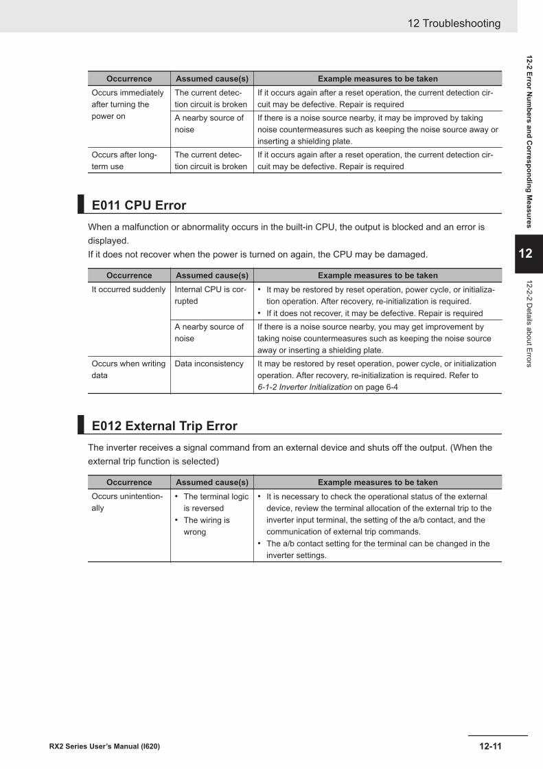
Occurrence Assumed cause(s) Example measures to be takenOccurs immediatelyafter turning thepower on
The current detec-tion circuit is broken
If it occurs again after a reset operation, the current detection cir-cuit may be defective. Repair is required
A nearby source ofnoise
If there is a noise source nearby, it may be improved by takingnoise countermeasures such as keeping the noise source away orinserting a shielding plate.
Occurs after long-term use
The current detec-tion circuit is broken
If it occurs again after a reset operation, the current detection cir-cuit may be defective. Repair is required
E011 CPU ErrorWhen a malfunction or abnormality occurs in the built-in CPU, the output is blocked and an error isdisplayed.If it does not recover when the power is turned on again, the CPU may be damaged.
Occurrence Assumed cause(s) Example measures to be takenIt occurred suddenly Internal CPU is cor-
rupted• It may be restored by reset operation, power cycle, or initializa-
tion operation. After recovery, re-initialization is required.• If it does not recover, it may be defective. Repair is required
A nearby source ofnoise
If there is a noise source nearby, you may get improvement bytaking noise countermeasures such as keeping the noise sourceaway or inserting a shielding plate.
Occurs when writingdata
Data inconsistency It may be restored by reset operation, power cycle, or initializationoperation. After recovery, re-initialization is required. Refer to 6-1-2 Inverter Initialization on page 6-4
E012 External Trip ErrorThe inverter receives a signal command from an external device and shuts off the output. (When theexternal trip function is selected)
Occurrence Assumed cause(s) Example measures to be takenOccurs unintention-ally
• The terminal logicis reversed
• The wiring iswrong
• It is necessary to check the operational status of the externaldevice, review the terminal allocation of the external trip to theinverter input terminal, the setting of the a/b contact, and thecommunication of external trip commands.
• The a/b contact setting for the terminal can be changed in theinverter settings.
12 Troubleshooting
12-11RX2 Series User’s Manual (I620)
12-2 Error Num
bers and Corresponding M
easures
12
12-2-2 Details about Errors
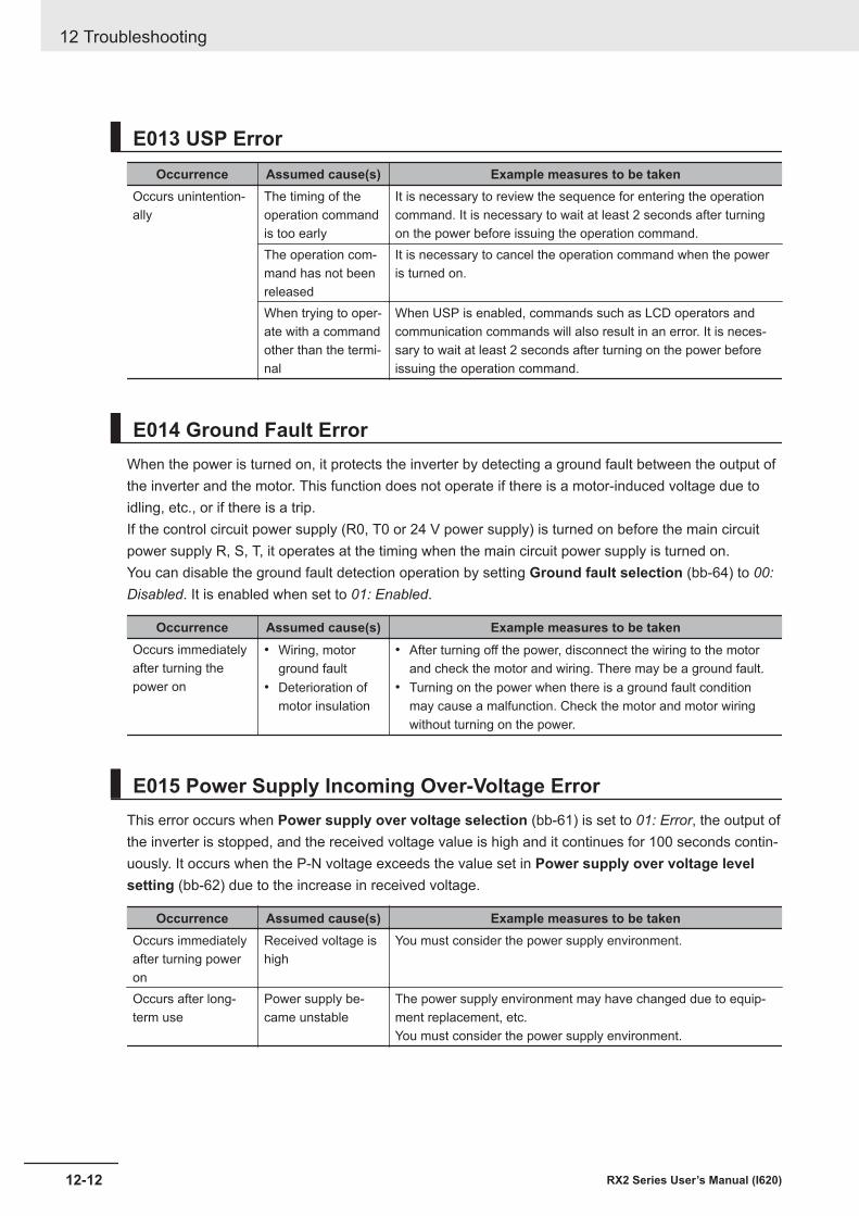
E013 USP ErrorOccurrence Assumed cause(s) Example measures to be taken
Occurs unintention-ally
The timing of theoperation commandis too early
It is necessary to review the sequence for entering the operationcommand. It is necessary to wait at least 2 seconds after turningon the power before issuing the operation command.
The operation com-mand has not beenreleased
It is necessary to cancel the operation command when the poweris turned on.
When trying to oper-ate with a commandother than the termi-nal
When USP is enabled, commands such as LCD operators andcommunication commands will also result in an error. It is neces-sary to wait at least 2 seconds after turning on the power beforeissuing the operation command.
E014 Ground Fault ErrorWhen the power is turned on, it protects the inverter by detecting a ground fault between the output ofthe inverter and the motor. This function does not operate if there is a motor-induced voltage due toidling, etc., or if there is a trip.If the control circuit power supply (R0, T0 or 24 V power supply) is turned on before the main circuitpower supply R, S, T, it operates at the timing when the main circuit power supply is turned on.You can disable the ground fault detection operation by setting Ground fault selection (bb-64) to 00:Disabled. It is enabled when set to 01: Enabled.
Occurrence Assumed cause(s) Example measures to be takenOccurs immediatelyafter turning thepower on
• Wiring, motorground fault
• Deterioration ofmotor insulation
• After turning off the power, disconnect the wiring to the motorand check the motor and wiring. There may be a ground fault.
• Turning on the power when there is a ground fault conditionmay cause a malfunction. Check the motor and motor wiringwithout turning on the power.
E015 Power Supply Incoming Over-Voltage ErrorThis error occurs when Power supply over voltage selection (bb-61) is set to 01: Error, the output ofthe inverter is stopped, and the received voltage value is high and it continues for 100 seconds contin-uously. It occurs when the P-N voltage exceeds the value set in Power supply over voltage levelsetting (bb-62) due to the increase in received voltage.
Occurrence Assumed cause(s) Example measures to be takenOccurs immediatelyafter turning poweron
Received voltage ishigh
You must consider the power supply environment.
Occurs after long-term use
Power supply be-came unstable
The power supply environment may have changed due to equip-ment replacement, etc.You must consider the power supply environment.
12 Troubleshooting
12-12 RX2 Series User’s Manual (I620)
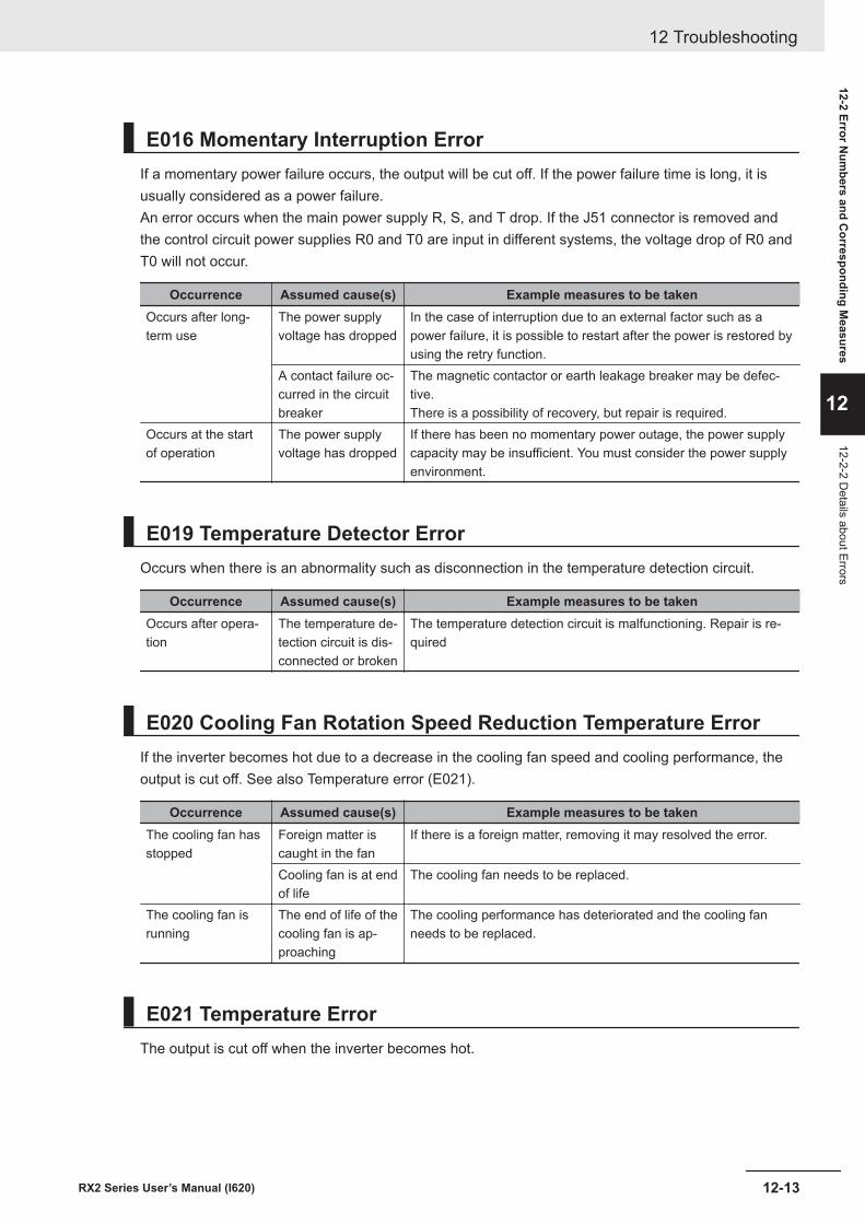
E016 Momentary Interruption ErrorIf a momentary power failure occurs, the output will be cut off. If the power failure time is long, it isusually considered as a power failure.An error occurs when the main power supply R, S, and T drop. If the J51 connector is removed andthe control circuit power supplies R0 and T0 are input in different systems, the voltage drop of R0 andT0 will not occur.
Occurrence Assumed cause(s) Example measures to be takenOccurs after long-term use
The power supplyvoltage has dropped
In the case of interruption due to an external factor such as apower failure, it is possible to restart after the power is restored byusing the retry function.
A contact failure oc-curred in the circuitbreaker
The magnetic contactor or earth leakage breaker may be defec-tive.There is a possibility of recovery, but repair is required.
Occurs at the startof operation
The power supplyvoltage has dropped
If there has been no momentary power outage, the power supplycapacity may be insufficient. You must consider the power supplyenvironment.
E019 Temperature Detector ErrorOccurs when there is an abnormality such as disconnection in the temperature detection circuit.
Occurrence Assumed cause(s) Example measures to be takenOccurs after opera-tion
The temperature de-tection circuit is dis-connected or broken
The temperature detection circuit is malfunctioning. Repair is re-quired
E020 Cooling Fan Rotation Speed Reduction Temperature ErrorIf the inverter becomes hot due to a decrease in the cooling fan speed and cooling performance, theoutput is cut off. See also Temperature error (E021).
Occurrence Assumed cause(s) Example measures to be takenThe cooling fan hasstopped
Foreign matter iscaught in the fan
If there is a foreign matter, removing it may resolved the error.
Cooling fan is at endof life
The cooling fan needs to be replaced.
The cooling fan isrunning
The end of life of thecooling fan is ap-proaching
The cooling performance has deteriorated and the cooling fanneeds to be replaced.
E021 Temperature ErrorThe output is cut off when the inverter becomes hot.
12 Troubleshooting
12-13RX2 Series User’s Manual (I620)
12-2 Error Num
bers and Corresponding M
easures
12
12-2-2 Details about Errors
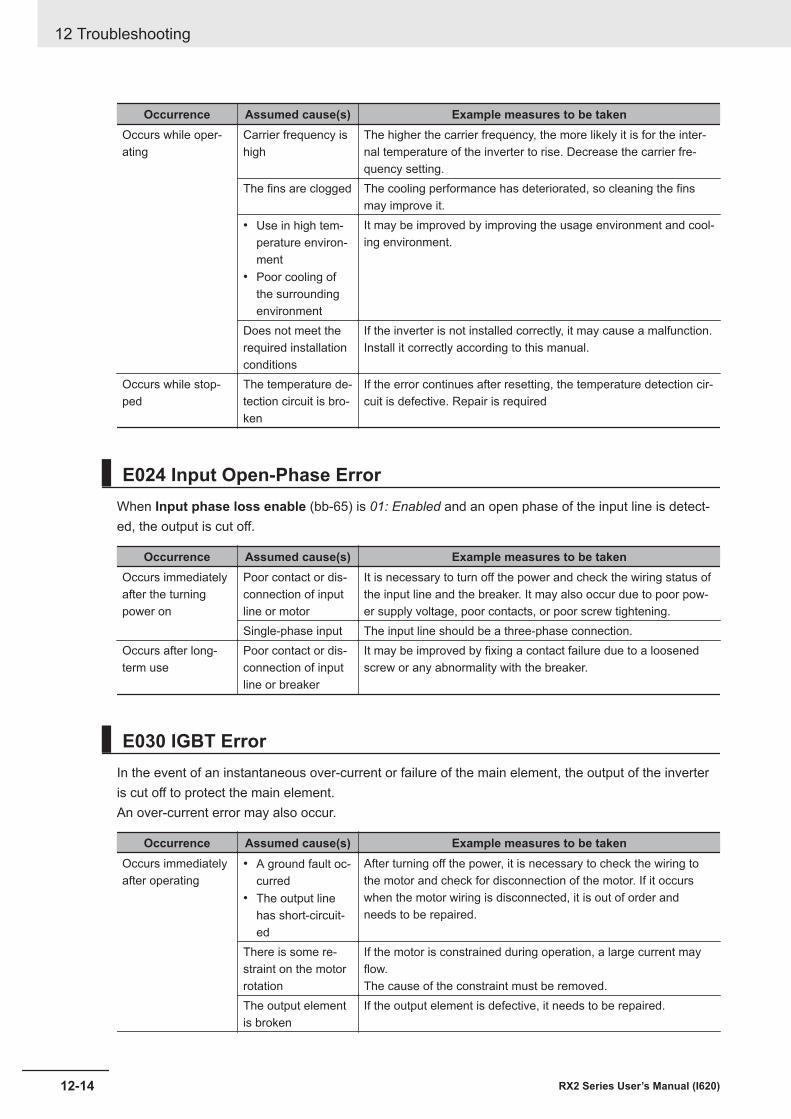
Occurrence Assumed cause(s) Example measures to be takenOccurs while oper-ating
Carrier frequency ishigh
The higher the carrier frequency, the more likely it is for the inter-nal temperature of the inverter to rise. Decrease the carrier fre-quency setting.
The fins are clogged The cooling performance has deteriorated, so cleaning the finsmay improve it.
• Use in high tem-perature environ-ment
• Poor cooling ofthe surroundingenvironment
It may be improved by improving the usage environment and cool-ing environment.
Does not meet therequired installationconditions
If the inverter is not installed correctly, it may cause a malfunction.Install it correctly according to this manual.
Occurs while stop-ped
The temperature de-tection circuit is bro-ken
If the error continues after resetting, the temperature detection cir-cuit is defective. Repair is required
E024 Input Open-Phase ErrorWhen Input phase loss enable (bb-65) is 01: Enabled and an open phase of the input line is detect-ed, the output is cut off.
Occurrence Assumed cause(s) Example measures to be takenOccurs immediatelyafter the turningpower on
Poor contact or dis-connection of inputline or motor
It is necessary to turn off the power and check the wiring status ofthe input line and the breaker. It may also occur due to poor pow-er supply voltage, poor contacts, or poor screw tightening.
Single-phase input The input line should be a three-phase connection.Occurs after long-term use
Poor contact or dis-connection of inputline or breaker
It may be improved by fixing a contact failure due to a loosenedscrew or any abnormality with the breaker.
E030 IGBT ErrorIn the event of an instantaneous over-current or failure of the main element, the output of the inverteris cut off to protect the main element.An over-current error may also occur.
Occurrence Assumed cause(s) Example measures to be takenOccurs immediatelyafter operating
• A ground fault oc-curred
• The output linehas short-circuit-ed
After turning off the power, it is necessary to check the wiring tothe motor and check for disconnection of the motor. If it occurswhen the motor wiring is disconnected, it is out of order andneeds to be repaired.
There is some re-straint on the motorrotation
If the motor is constrained during operation, a large current mayflow.The cause of the constraint must be removed.
The output elementis broken
If the output element is defective, it needs to be repaired.
12 Troubleshooting
12-14 RX2 Series User’s Manual (I620)
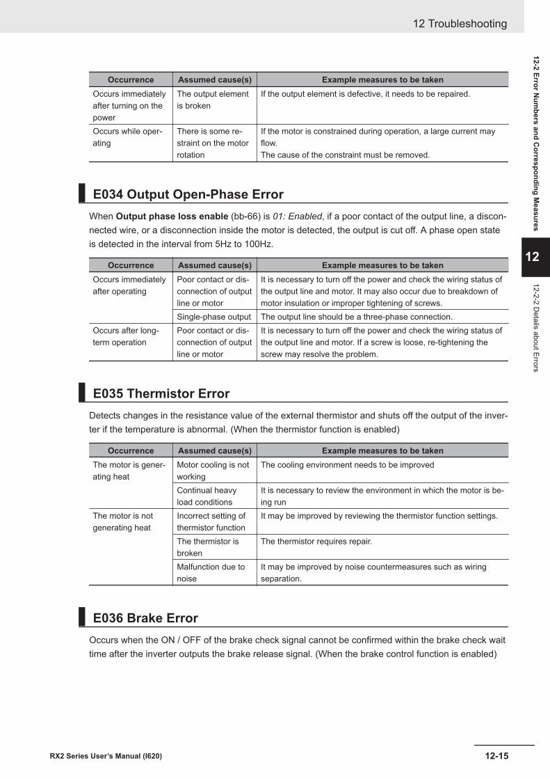
Occurrence Assumed cause(s) Example measures to be takenOccurs immediatelyafter turning on thepower
The output elementis broken
If the output element is defective, it needs to be repaired.
Occurs while oper-ating
There is some re-straint on the motorrotation
If the motor is constrained during operation, a large current mayflow.The cause of the constraint must be removed.
E034 Output Open-Phase ErrorWhen Output phase loss enable (bb-66) is 01: Enabled, if a poor contact of the output line, a discon-nected wire, or a disconnection inside the motor is detected, the output is cut off. A phase open stateis detected in the interval from 5Hz to 100Hz.
Occurrence Assumed cause(s) Example measures to be takenOccurs immediatelyafter operating
Poor contact or dis-connection of outputline or motor
It is necessary to turn off the power and check the wiring status ofthe output line and motor. It may also occur due to breakdown ofmotor insulation or improper tightening of screws.
Single-phase output The output line should be a three-phase connection.Occurs after long-term operation
Poor contact or dis-connection of outputline or motor
It is necessary to turn off the power and check the wiring status ofthe output line and motor. If a screw is loose, re-tightening thescrew may resolve the problem.
E035 Thermistor ErrorDetects changes in the resistance value of the external thermistor and shuts off the output of the inver-ter if the temperature is abnormal. (When the thermistor function is enabled)
Occurrence Assumed cause(s) Example measures to be takenThe motor is gener-ating heat
Motor cooling is notworking
The cooling environment needs to be improved
Continual heavyload conditions
It is necessary to review the environment in which the motor is be-ing run
The motor is notgenerating heat
Incorrect setting ofthermistor function
It may be improved by reviewing the thermistor function settings.
The thermistor isbroken
The thermistor requires repair.
Malfunction due tonoise
It may be improved by noise countermeasures such as wiringseparation.
E036 Brake ErrorOccurs when the ON / OFF of the brake check signal cannot be confirmed within the brake check waittime after the inverter outputs the brake release signal. (When the brake control function is enabled)
12 Troubleshooting
12-15RX2 Series User’s Manual (I620)
12-2 Error Num
bers and Corresponding M
easures
12
12-2-2 Details about Errors
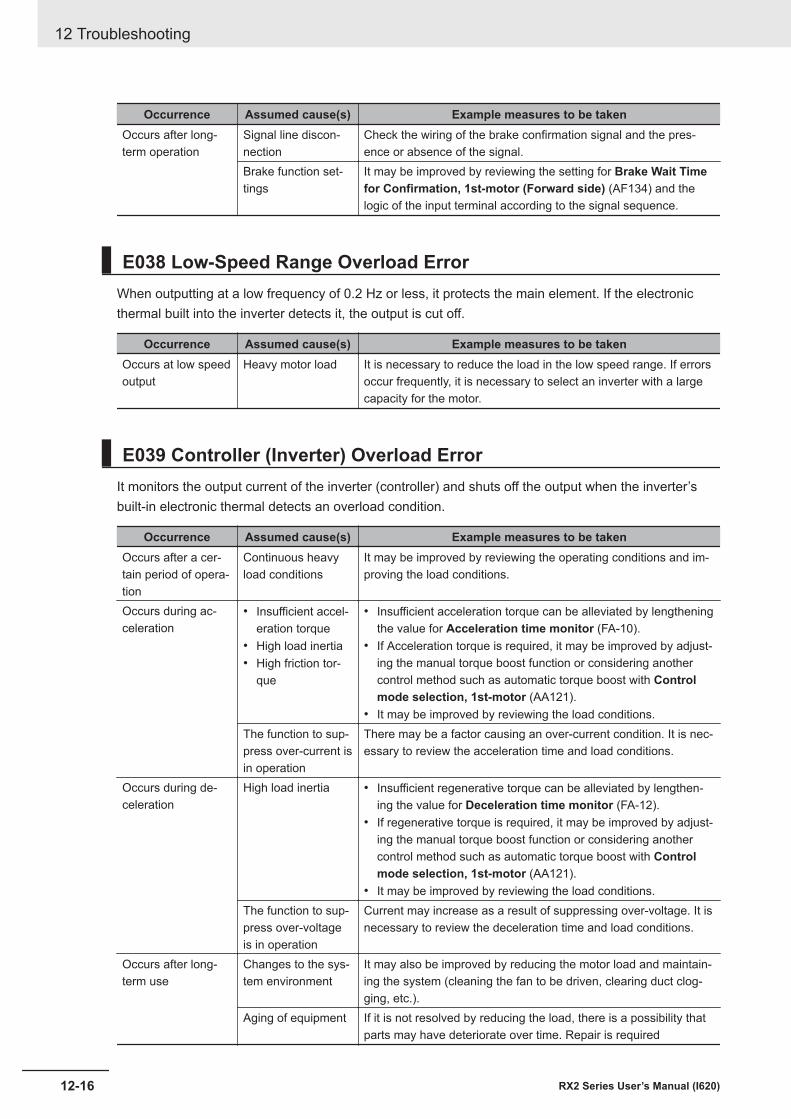
Occurrence Assumed cause(s) Example measures to be takenOccurs after long-term operation
Signal line discon-nection
Check the wiring of the brake confirmation signal and the pres-ence or absence of the signal.
Brake function set-tings
It may be improved by reviewing the setting for Brake Wait Timefor Confirmation, 1st-motor (Forward side) (AF134) and thelogic of the input terminal according to the signal sequence.
E038 Low-Speed Range Overload ErrorWhen outputting at a low frequency of 0.2 Hz or less, it protects the main element. If the electronicthermal built into the inverter detects it, the output is cut off.
Occurrence Assumed cause(s) Example measures to be takenOccurs at low speedoutput
Heavy motor load It is necessary to reduce the load in the low speed range. If errorsoccur frequently, it is necessary to select an inverter with a largecapacity for the motor.
E039 Controller (Inverter) Overload ErrorIt monitors the output current of the inverter (controller) and shuts off the output when the inverter’sbuilt-in electronic thermal detects an overload condition.
Occurrence Assumed cause(s) Example measures to be takenOccurs after a cer-tain period of opera-tion
Continuous heavyload conditions
It may be improved by reviewing the operating conditions and im-proving the load conditions.
Occurs during ac-celeration
• Insufficient accel-eration torque
• High load inertia• High friction tor-
que
• Insufficient acceleration torque can be alleviated by lengtheningthe value for Acceleration time monitor (FA-10).
• If Acceleration torque is required, it may be improved by adjust-ing the manual torque boost function or considering anothercontrol method such as automatic torque boost with Controlmode selection, 1st-motor (AA121).
• It may be improved by reviewing the load conditions.The function to sup-press over-current isin operation
There may be a factor causing an over-current condition. It is nec-essary to review the acceleration time and load conditions.
Occurs during de-celeration
High load inertia • Insufficient regenerative torque can be alleviated by lengthen-ing the value for Deceleration time monitor (FA-12).
• If regenerative torque is required, it may be improved by adjust-ing the manual torque boost function or considering anothercontrol method such as automatic torque boost with Controlmode selection, 1st-motor (AA121).
• It may be improved by reviewing the load conditions.The function to sup-press over-voltageis in operation
Current may increase as a result of suppressing over-voltage. It isnecessary to review the deceleration time and load conditions.
Occurs after long-term use
Changes to the sys-tem environment
It may also be improved by reducing the motor load and maintain-ing the system (cleaning the fan to be driven, clearing duct clog-ging, etc.).
Aging of equipment If it is not resolved by reducing the load, there is a possibility thatparts may have deteriorate over time. Repair is required
12 Troubleshooting
12-16 RX2 Series User’s Manual (I620)
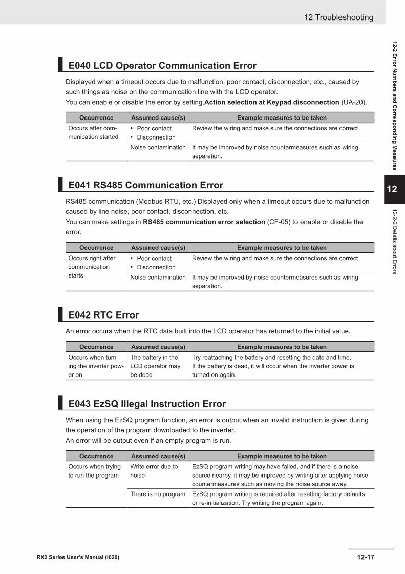
E040 LCD Operator Communication ErrorDisplayed when a timeout occurs due to malfunction, poor contact, disconnection, etc., caused bysuch things as noise on the communication line with the LCD operator.You can enable or disable the error by setting.Action selection at Keypad disconnection (UA-20).
Occurrence Assumed cause(s) Example measures to be takenOccurs after com-munication started
• Poor contact• Disconnection
Review the wiring and make sure the connections are correct.
Noise contamination It may be improved by noise countermeasures such as wiringseparation.
E041 RS485 Communication ErrorRS485 communication (Modbus-RTU, etc.) Displayed only when a timeout occurs due to malfunctioncaused by line noise, poor contact, disconnection, etc.You can make settings in RS485 communication error selection (CF-05) to enable or disable theerror.
Occurrence Assumed cause(s) Example measures to be takenOccurs right aftercommunicationstarts
• Poor contact• Disconnection
Review the wiring and make sure the connections are correct.
Noise contamination It may be improved by noise countermeasures such as wiringseparation.
E042 RTC ErrorAn error occurs when the RTC data built into the LCD operator has returned to the initial value.
Occurrence Assumed cause(s) Example measures to be takenOccurs when turn-ing the inverter pow-er on
The battery in theLCD operator maybe dead
Try reattaching the battery and resetting the date and time.If the battery is dead, it will occur when the inverter power isturned on again.
E043 EzSQ Illegal Instruction ErrorWhen using the EzSQ program function, an error is output when an invalid instruction is given duringthe operation of the program downloaded to the inverter.An error will be output even if an empty program is run.
Occurrence Assumed cause(s) Example measures to be takenOccurs when tryingto run the program
Write error due tonoise
EzSQ program writing may have failed, and if there is a noisesource nearby, it may be improved by writing after applying noisecountermeasures such as moving the noise source away.
There is no program EzSQ program writing is required after resetting factory defaultsor re-initialization. Try writing the program again.
12 Troubleshooting
12-17RX2 Series User’s Manual (I620)
12-2 Error Num
bers and Corresponding M
easures
12
12-2-2 Details about Errors
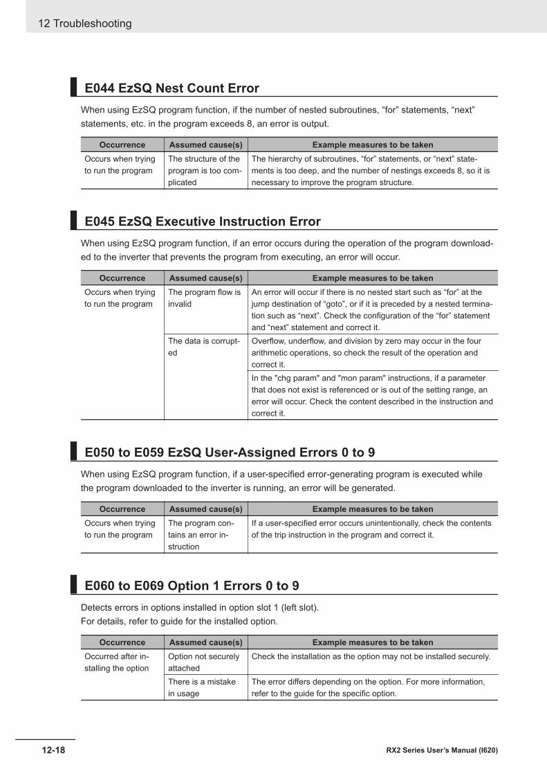
E044 EzSQ Nest Count ErrorWhen using EzSQ program function, if the number of nested subroutines, “for” statements, “next”statements, etc. in the program exceeds 8, an error is output.
Occurrence Assumed cause(s) Example measures to be takenOccurs when tryingto run the program
The structure of theprogram is too com-plicated
The hierarchy of subroutines, “for” statements, or “next” state-ments is too deep, and the number of nestings exceeds 8, so it isnecessary to improve the program structure.
E045 EzSQ Executive Instruction ErrorWhen using EzSQ program function, if an error occurs during the operation of the program download-ed to the inverter that prevents the program from executing, an error will occur.
Occurrence Assumed cause(s) Example measures to be takenOccurs when tryingto run the program
The program flow isinvalid
An error will occur if there is no nested start such as “for” at thejump destination of “goto”, or if it is preceded by a nested termina-tion such as “next”. Check the configuration of the “for” statementand “next” statement and correct it.
The data is corrupt-ed
Overflow, underflow, and division by zero may occur in the fourarithmetic operations, so check the result of the operation andcorrect it.In the "chg param" and "mon param" instructions, if a parameterthat does not exist is referenced or is out of the setting range, anerror will occur. Check the content described in the instruction andcorrect it.
E050 to E059 EzSQ User-Assigned Errors 0 to 9When using EzSQ program function, if a user-specified error-generating program is executed whilethe program downloaded to the inverter is running, an error will be generated.
Occurrence Assumed cause(s) Example measures to be takenOccurs when tryingto run the program
The program con-tains an error in-struction
If a user-specified error occurs unintentionally, check the contentsof the trip instruction in the program and correct it.
E060 to E069 Option 1 Errors 0 to 9Detects errors in options installed in option slot 1 (left slot).For details, refer to guide for the installed option.
Occurrence Assumed cause(s) Example measures to be takenOccurred after in-stalling the option
Option not securelyattached
Check the installation as the option may not be installed securely.
There is a mistakein usage
The error differs depending on the option. For more information,refer to the guide for the specific option.
12 Troubleshooting
12-18 RX2 Series User’s Manual (I620)
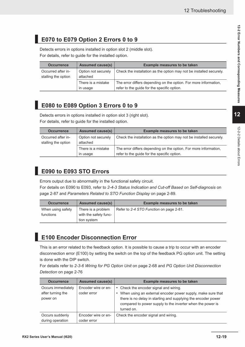
E070 to E079 Option 2 Errors 0 to 9Detects errors in options installed in option slot 2 (middle slot).For details, refer to guide for the installed option.
Occurrence Assumed cause(s) Example measures to be takenOccurred after in-stalling the option
Option not securelyattached
Check the installation as the option may not be installed securely.
There is a mistakein usage
The error differs depending on the option. For more information,refer to the guide for the specific option.
E080 to E089 Option 3 Errors 0 to 9Detects errors in options installed in option slot 3 (right slot).For details, refer to guide for the installed option.
Occurrence Assumed cause(s) Example measures to be takenOccurred after in-stalling the option
Option not securelyattached
Check the installation as the option may not be installed securely.
There is a mistakein usage
The error differs depending on the option. For more information,refer to the guide for the specific option.
E090 to E093 STO ErrorsErrors output due to abnormality in the functional safety circuit.For details on E090 to E093, refer to 2-4-3 Status Indication and Cut-off Based on Self-diagnosis onpage 2-87 and Parameters Related to STO Function Display on page 2-89.
Occurrence Assumed cause(s) Example measures to be takenWhen using safetyfunctions
There is a problemwith the safety func-tion system
Refer to 2-4 STO Function on page 2-81.
E100 Encoder Disconnection ErrorThis is an error related to the feedback option. It is possible to cause a trip to occur with an encoderdisconnection error (E100) by setting the switch on the top of the feedback PG option unit. The settingis done with the DIP switch.For details refer to 2-3-6 Wiring for PG Option Unit on page 2-68 and PG Option Unit DisconnectionDetection on page 2-76
Occurrence Assumed cause(s) Example measures to be takenOccurs immediatelyafter turning thepower on
Encoder wire or en-coder error
• Check the encoder signal and wiring.• When using an external encoder power supply, make sure that
there is no delay in starting and supplying the encoder powercompared to power supply to the inverter when the power isturned on.
Occurs suddenlyduring operation
Encoder wire or en-coder error
Check the encoder signal and wiring.
12 Troubleshooting
12-19RX2 Series User’s Manual (I620)
12-2 Error Num
bers and Corresponding M
easures
12
12-2-2 Details about Errors
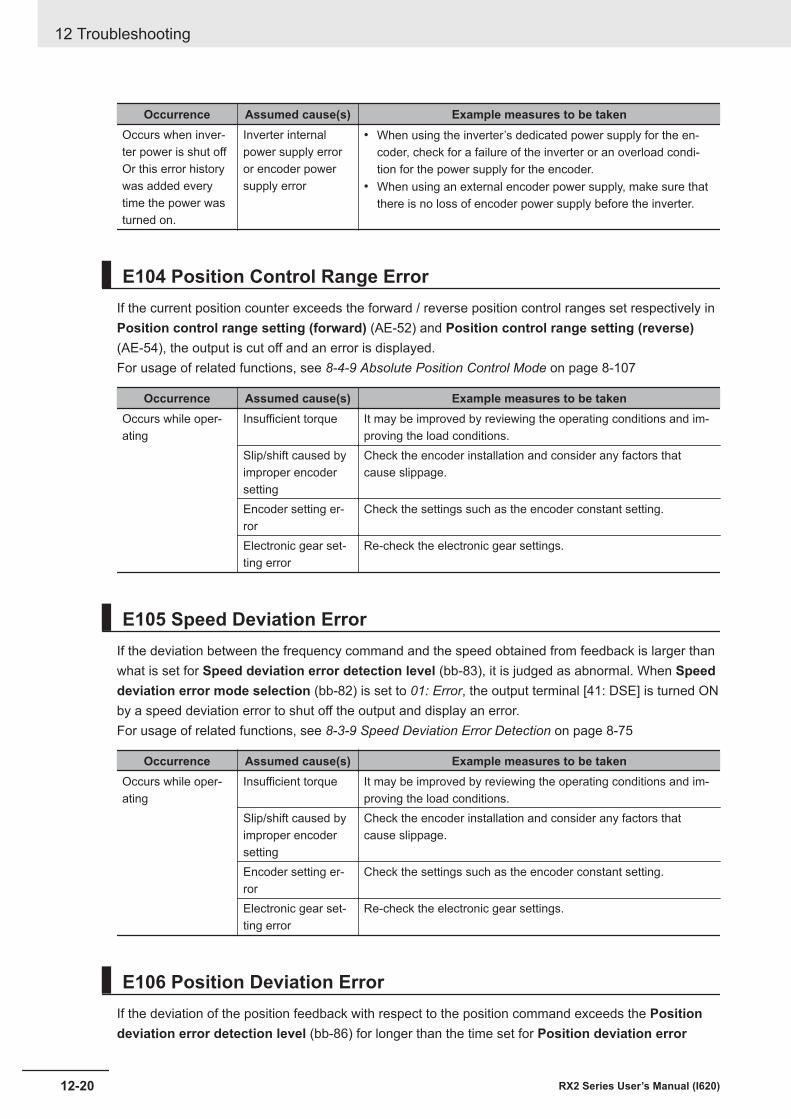
Occurrence Assumed cause(s) Example measures to be takenOccurs when inver-ter power is shut offOr this error historywas added everytime the power wasturned on.
Inverter internalpower supply erroror encoder powersupply error
• When using the inverter’s dedicated power supply for the en-coder, check for a failure of the inverter or an overload condi-tion for the power supply for the encoder.
• When using an external encoder power supply, make sure thatthere is no loss of encoder power supply before the inverter.
E104 Position Control Range ErrorIf the current position counter exceeds the forward / reverse position control ranges set respectively inPosition control range setting (forward) (AE-52) and Position control range setting (reverse)(AE-54), the output is cut off and an error is displayed.For usage of related functions, see 8-4-9 Absolute Position Control Mode on page 8-107
Occurrence Assumed cause(s) Example measures to be takenOccurs while oper-ating
Insufficient torque It may be improved by reviewing the operating conditions and im-proving the load conditions.
Slip/shift caused byimproper encodersetting
Check the encoder installation and consider any factors thatcause slippage.
Encoder setting er-ror
Check the settings such as the encoder constant setting.
Electronic gear set-ting error
Re-check the electronic gear settings.
E105 Speed Deviation ErrorIf the deviation between the frequency command and the speed obtained from feedback is larger thanwhat is set for Speed deviation error detection level (bb-83), it is judged as abnormal. When Speeddeviation error mode selection (bb-82) is set to 01: Error, the output terminal [41: DSE] is turned ONby a speed deviation error to shut off the output and display an error.For usage of related functions, see 8-3-9 Speed Deviation Error Detection on page 8-75
Occurrence Assumed cause(s) Example measures to be takenOccurs while oper-ating
Insufficient torque It may be improved by reviewing the operating conditions and im-proving the load conditions.
Slip/shift caused byimproper encodersetting
Check the encoder installation and consider any factors thatcause slippage.
Encoder setting er-ror
Check the settings such as the encoder constant setting.
Electronic gear set-ting error
Re-check the electronic gear settings.
E106 Position Deviation ErrorIf the deviation of the position feedback with respect to the position command exceeds the Positiondeviation error detection level (bb-86) for longer than the time set for Position deviation error
12 Troubleshooting
12-20 RX2 Series User’s Manual (I620)
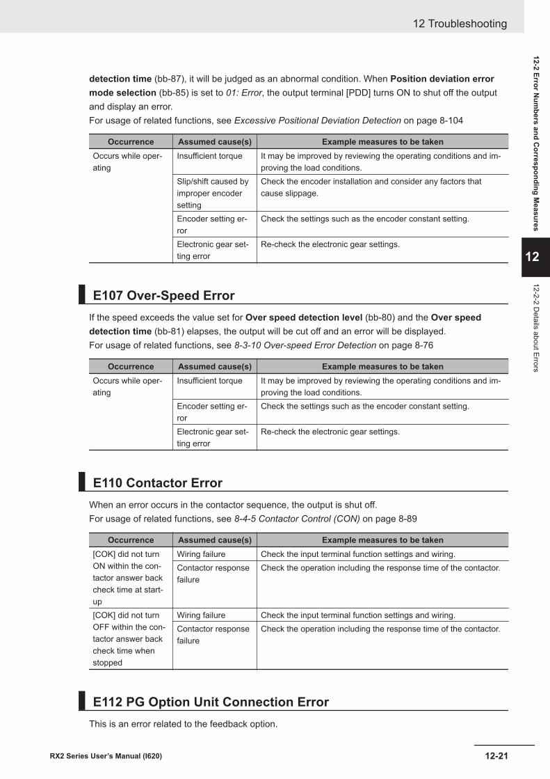
detection time (bb-87), it will be judged as an abnormal condition. When Position deviation errormode selection (bb-85) is set to 01: Error, the output terminal [PDD] turns ON to shut off the outputand display an error.For usage of related functions, see Excessive Positional Deviation Detection on page 8-104
Occurrence Assumed cause(s) Example measures to be takenOccurs while oper-ating
Insufficient torque It may be improved by reviewing the operating conditions and im-proving the load conditions.
Slip/shift caused byimproper encodersetting
Check the encoder installation and consider any factors thatcause slippage.
Encoder setting er-ror
Check the settings such as the encoder constant setting.
Electronic gear set-ting error
Re-check the electronic gear settings.
E107 Over-Speed ErrorIf the speed exceeds the value set for Over speed detection level (bb-80) and the Over speeddetection time (bb-81) elapses, the output will be cut off and an error will be displayed.For usage of related functions, see 8-3-10 Over-speed Error Detection on page 8-76
Occurrence Assumed cause(s) Example measures to be takenOccurs while oper-ating
Insufficient torque It may be improved by reviewing the operating conditions and im-proving the load conditions.
Encoder setting er-ror
Check the settings such as the encoder constant setting.
Electronic gear set-ting error
Re-check the electronic gear settings.
E110 Contactor ErrorWhen an error occurs in the contactor sequence, the output is shut off.For usage of related functions, see 8-4-5 Contactor Control (CON) on page 8-89
Occurrence Assumed cause(s) Example measures to be taken[COK] did not turnON within the con-tactor answer backcheck time at start-up
Wiring failure Check the input terminal function settings and wiring.Contactor responsefailure
Check the operation including the response time of the contactor.
[COK] did not turnOFF within the con-tactor answer backcheck time whenstopped
Wiring failure Check the input terminal function settings and wiring.Contactor responsefailure
Check the operation including the response time of the contactor.
E112 PG Option Unit Connection ErrorThis is an error related to the feedback option.
12 Troubleshooting
12-21RX2 Series User’s Manual (I620)
12-2 Error Num
bers and Corresponding M
easures
12
12-2-2 Details about Errors
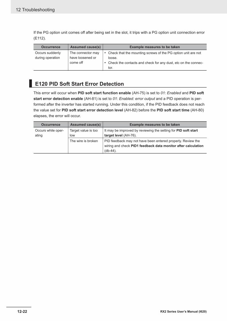
If the PG option unit comes off after being set in the slot, it trips with a PG option unit connection error(E112).
Occurrence Assumed cause(s) Example measures to be takenOccurs suddenlyduring operation
The connector mayhave loosened orcome off
• Check that the mounting screws of the PG option unit are notloose.
• Check the contacts and check for any dust, etc on the connec-tor.
E120 PID Soft Start Error DetectionThis error will occur when PID soft start function enable (AH-75) is set to 01: Enabled and PID softstart error detection enable (AH-81) is set to 01: Enabled: error output and a PID operation is per-formed after the inverter has started running. Under this condition, if the PID feedback does not reachthe value set for PID soft start error detection level (AH-82) before the PID soft start time (AH-80)elapses, the error will occur.
Occurrence Assumed cause(s) Example measures to be takenOccurs while oper-ating
Target value is toolow
It may be improved by reviewing the setting for PID soft starttarget level (AH-76).
The wire is broken PID feedback may not have been entered properly. Review thewiring and check PID1 feedback data monitor after calculation(db-44).
12 Troubleshooting
12-22 RX2 Series User’s Manual (I620)
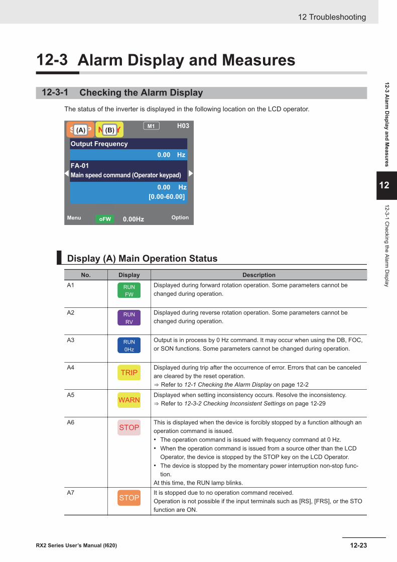
12-3 Alarm Display and Measures
12-3-1 Checking the Alarm DisplayThe status of the inverter is displayed in the following location on the LCD operator.
Menu Option0.00HzoFW
STOPM1 H03
Output Frequency
0.00 Hz
FA-01
Main speed command (Operator keypad)
0.00 Hz
[0.00-60.00]
NRDY(A) (B)
Display (A) Main Operation StatusNo. Display Description
A1 RUN
FW
Displayed during forward rotation operation. Some parameters cannot bechanged during operation.
A2 RUN
RV
Displayed during reverse rotation operation. Some parameters cannot bechanged during operation.
A3 RUN
0Hz
Output is in process by 0 Hz command. It may occur when using the DB, FOC,or SON functions. Some parameters cannot be changed during operation.
A4TRIP
Displayed during trip after the occurrence of error. Errors that can be canceledare cleared by the reset operation.⇒ Refer to 12-1 Checking the Alarm Display on page 12-2
A5WARN
Displayed when setting inconsistency occurs. Resolve the inconsistency.⇒ Refer to 12-3-2 Checking Inconsistent Settings on page 12-29
A6STOP
This is displayed when the device is forcibly stopped by a function although anoperation command is issued.• The operation command is issued with frequency command at 0 Hz.• When the operation command is issued from a source other than the LCD
Operator, the device is stopped by the STOP key on the LCD Operator.• The device is stopped by the momentary power interruption non-stop func-
tion.At this time, the RUN lamp blinks.
A7STOP
It is stopped due to no operation command received.Operation is not possible if the input terminals such as [RS], [FRS], or the STOfunction are ON.
12 Troubleshooting
12-23RX2 Series User’s Manual (I620)
12-3 Alarm
Display and M
easures
12
12-3-1 Checking the Alarm
Display
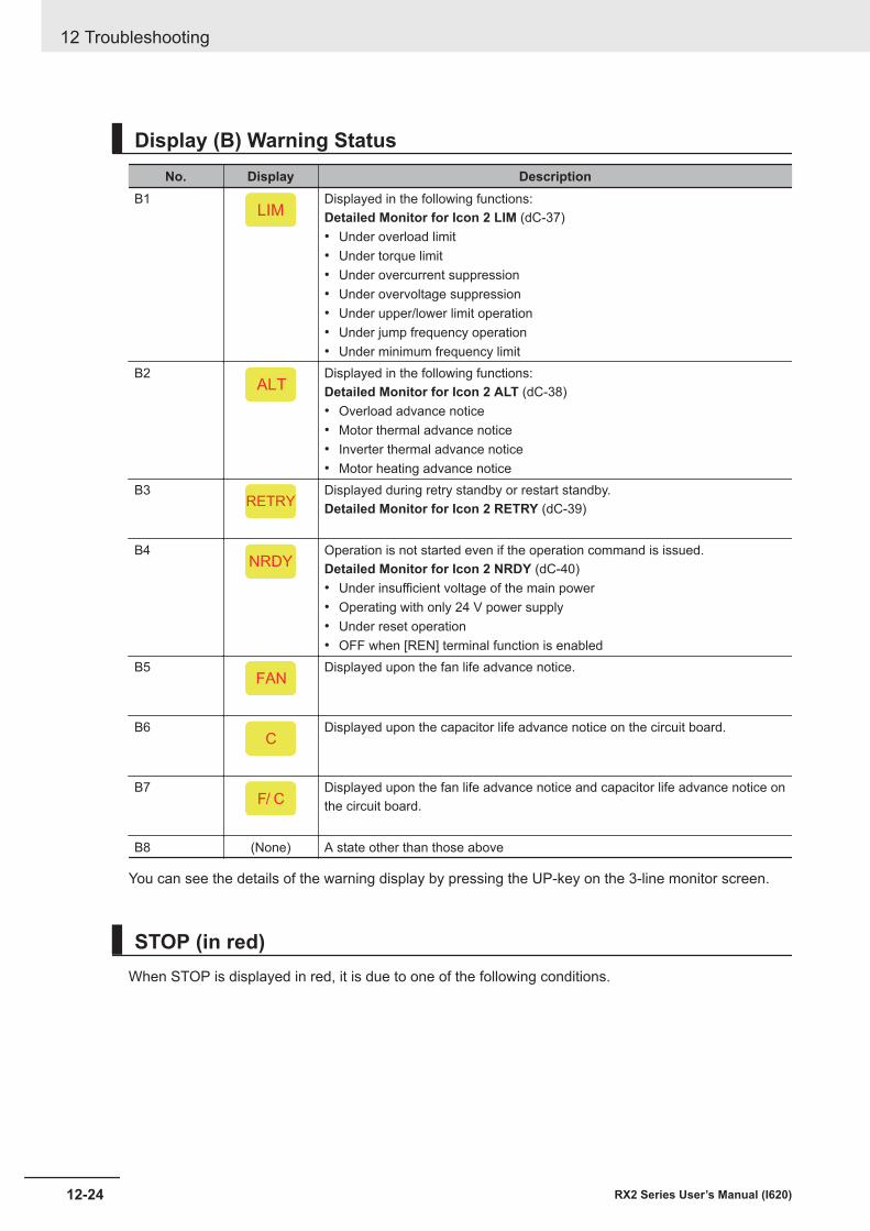
Display (B) Warning StatusNo. Display Description
B1LIM
Displayed in the following functions:Detailed Monitor for Icon 2 LIM (dC-37)• Under overload limit• Under torque limit• Under overcurrent suppression• Under overvoltage suppression• Under upper/lower limit operation• Under jump frequency operation• Under minimum frequency limit
B2ALT
Displayed in the following functions:Detailed Monitor for Icon 2 ALT (dC-38)• Overload advance notice• Motor thermal advance notice• Inverter thermal advance notice• Motor heating advance notice
B3RETRY
Displayed during retry standby or restart standby.Detailed Monitor for Icon 2 RETRY (dC-39)
B4NRDY
Operation is not started even if the operation command is issued.Detailed Monitor for Icon 2 NRDY (dC-40)• Under insufficient voltage of the main power• Operating with only 24 V power supply• Under reset operation• OFF when [REN] terminal function is enabled
B5FAN
Displayed upon the fan life advance notice.
B6C
Displayed upon the capacitor life advance notice on the circuit board.
B7F/ C
Displayed upon the fan life advance notice and capacitor life advance notice onthe circuit board.
B8 (None) A state other than those above
You can see the details of the warning display by pressing the UP-key on the 3-line monitor screen.
STOP (in red)When STOP is displayed in red, it is due to one of the following conditions.
12 Troubleshooting
12-24 RX2 Series User’s Manual (I620)

Occurrence Typical cause(s) Example measures to be takenRUN key on the op-erator was pressed
If the LIM is lit, the command is below theminimum frequency. Consider the followingcauses.• The operation command was entered,
but the frequency command was not.• Frequency command destination selec-
tion is wrong.
• Check that Main Speed referencemonitor (FA-01) is not set to 0.00Hz.
• Check whether the command is enteredfrom the command destination indicatedon the right of Main Speed referencemonitor (FA-01).
• Check Main speed input sourceselection, 1st-motor (AA101).
[FW] terminal wasturned ONOperation commandwas entered
After STOP key onoperator is pressed,inverter doesn’t op-erate with RUN key.
The STOP key on the LCD operator waspressed when the operation command wasentered from a source other than the LCDoperator.
Turn off the command at the operationcommand destination once.
Momentary powerfailure occurred
The device is stopped by the momentarypower interruption non-stop function.
To start operation, turn off the commandentered to the operation command destina-tion and turn on again.
WARNWhen WARN is displayed, it is due to one of the following conditions.
Occurrence Assumed cause(s) Example measures to be takenA setting is changed An invalid or inconsistent parameter Refer to 12-3-2 Checking Inconsistent Set-
tings on page 12-29.
Icon 2 LIMWhen LIM is shown, the inverter is in one of the following condition(s).You can see the status of LIM by pressing the UP key on the three-line monitor or on Detailedmonitor for icon 2 LIM (dC-37).
Occurrence Assumed cause(s) Example measures to be takenThe output currentis high and Detailedmonitor for icon 2LIM (dC-37) is set to“01”.
Over current suppress enable, 2nd-motor (bA120) is enabled and current in-creased due to load, or other factor.
Remove the factor for the increased load.(Cleaning the flow path, reviewing the load,etc.)
The current was increased by the high ratioof motor rotation during DC braking thatwas caused by the selection of [DB] termi-nal or DC braking selection, 1st-motor(AF101).
• Decrease the DC braking force setting,1st-motor (AF105) or DC braking forceat start, 1st-motor (AF108).
• If it occurs at stopping, set DC brakingactive time at stop, 1st-motor (AF106)to be longer.
• If it is a retry operation at start-up, in-crease the delay time depending on thecause factor. Retry wait time beforemotor restart (bb-26), Wait time ofrestart @over-current (bb-29), Waittime of restart @over-voltage (bb-31)
Acceleration time monitor (FA-10) is settoo short
Set a longer time in Acceleration timemonitor (FA-10).
12 Troubleshooting
12-25RX2 Series User’s Manual (I620)
12-3 Alarm
Display and M
easures
12
12-3-1 Checking the Alarm
Display
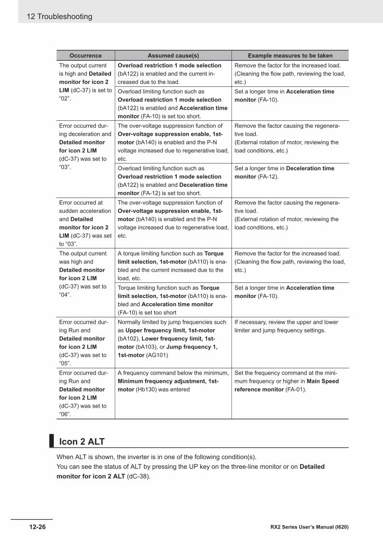
Occurrence Assumed cause(s) Example measures to be takenThe output currentis high and Detailedmonitor for icon 2LIM (dC-37) is set to“02”.
Overload restriction 1 mode selection(bA122) is enabled and the current in-creased due to the load.
Remove the factor for the increased load.(Cleaning the flow path, reviewing the load,etc.)
Overload limiting function such asOverload restriction 1 mode selection(bA122) is enabled and Acceleration timemonitor (FA-10) is set too short.
Set a longer time in Acceleration timemonitor (FA-10).
Error occurred dur-ing deceleration andDetailed monitorfor icon 2 LIM(dC-37) was set to“03”.
The over-voltage suppression function ofOver-voltage suppression enable, 1st-motor (bA140) is enabled and the P-Nvoltage increased due to regenerative load,etc.
Remove the factor causing the regenera-tive load.(External rotation of motor, reviewing theload conditions, etc.)
Overload limiting function such asOverload restriction 1 mode selection(bA122) is enabled and Deceleration timemonitor (FA-12) is set too short.
Set a longer time in Deceleration timemonitor (FA-12).
Error occurred atsudden accelerationand Detailedmonitor for icon 2LIM (dC-37) was setto “03”.
The over-voltage suppression function ofOver-voltage suppression enable, 1st-motor (bA140) is enabled and the P-Nvoltage increased due to regenerative load,etc.
Remove the factor causing the regenera-tive load.(External rotation of motor, reviewing theload conditions, etc.)
The output currentwas high andDetailed monitorfor icon 2 LIM(dC-37) was set to“04”.
A torque limiting function such as Torquelimit selection, 1st-motor (bA110) is ena-bled and the current increased due to theload, etc.
Remove the factor for the increased load.(Cleaning the flow path, reviewing the load,etc.)
Torque limiting function such as Torquelimit selection, 1st-motor (bA110) is ena-bled and Acceleration time monitor(FA-10) is set too short
Set a longer time in Acceleration timemonitor (FA-10).
Error occurred dur-ing Run andDetailed monitorfor icon 2 LIM(dC-37) was set to“05”.
Normally limited by jump frequencies suchas Upper frequency limit, 1st-motor(bA102), Lower frequency limit, 1st-motor (bA103), or Jump frequency 1,1st-motor (AG101)
If necessary, review the upper and lowerlimiter and jump frequency settings.
Error occurred dur-ing Run andDetailed monitorfor icon 2 LIM(dC-37) was set to“06”.
A frequency command below the minimum,Minimum frequency adjustment, 1st-motor (Hb130) was entered
Set the frequency command at the mini-mum frequency or higher in Main Speedreference monitor (FA-01).
Icon 2 ALTWhen ALT is shown, the inverter is in one of the following condition(s).You can see the status of ALT by pressing the UP key on the three-line monitor or on Detailedmonitor for icon 2 ALT (dC-38).
12 Troubleshooting
12-26 RX2 Series User’s Manual (I620)
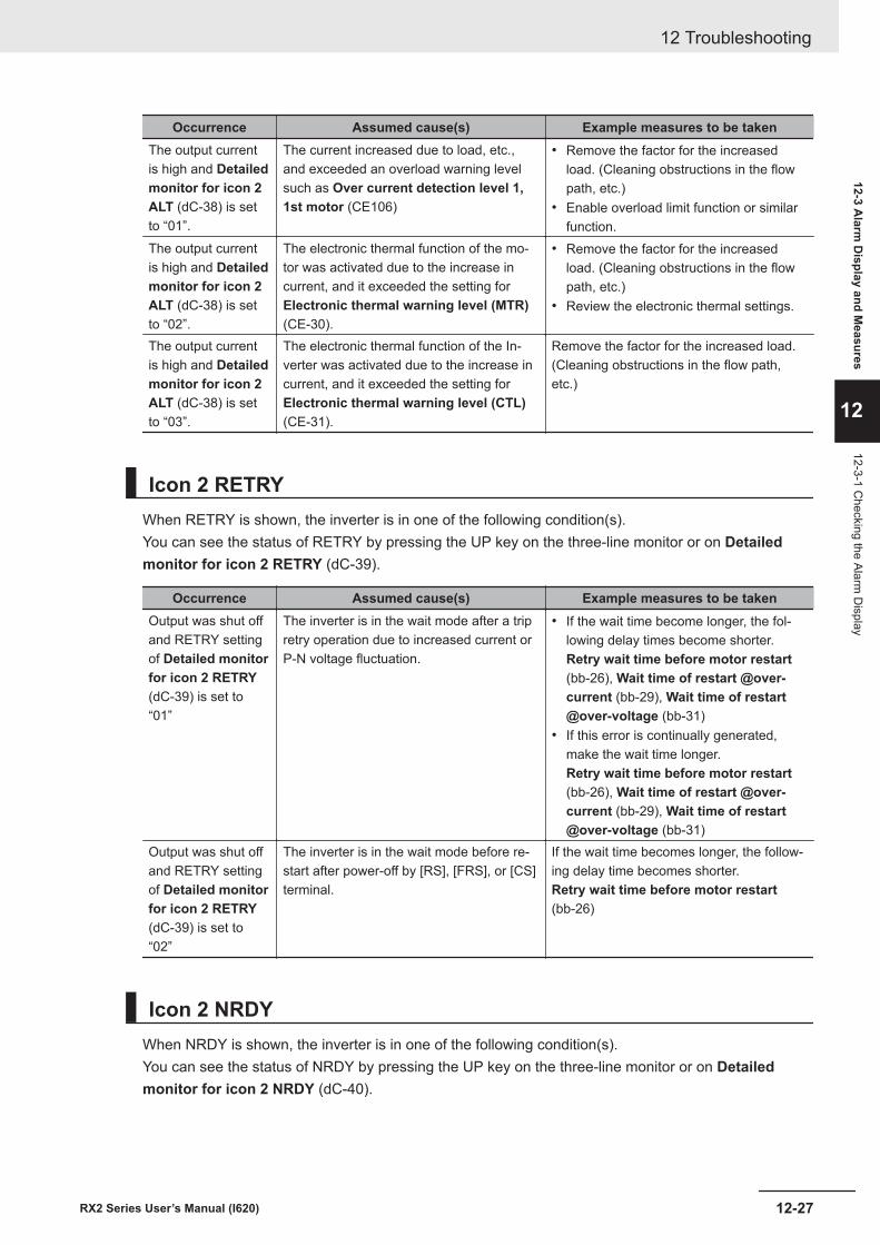
Occurrence Assumed cause(s) Example measures to be takenThe output currentis high and Detailedmonitor for icon 2ALT (dC-38) is setto “01”.
The current increased due to load, etc.,and exceeded an overload warning levelsuch as Over current detection level 1,1st motor (CE106)
• Remove the factor for the increasedload. (Cleaning obstructions in the flowpath, etc.)
• Enable overload limit function or similarfunction.
The output currentis high and Detailedmonitor for icon 2ALT (dC-38) is setto “02”.
The electronic thermal function of the mo-tor was activated due to the increase incurrent, and it exceeded the setting forElectronic thermal warning level (MTR)(CE-30).
• Remove the factor for the increasedload. (Cleaning obstructions in the flowpath, etc.)
• Review the electronic thermal settings.
The output currentis high and Detailedmonitor for icon 2ALT (dC-38) is setto “03”.
The electronic thermal function of the In-verter was activated due to the increase incurrent, and it exceeded the setting forElectronic thermal warning level (CTL)(CE-31).
Remove the factor for the increased load.(Cleaning obstructions in the flow path,etc.)
Icon 2 RETRYWhen RETRY is shown, the inverter is in one of the following condition(s).You can see the status of RETRY by pressing the UP key on the three-line monitor or on Detailedmonitor for icon 2 RETRY (dC-39).
Occurrence Assumed cause(s) Example measures to be takenOutput was shut offand RETRY settingof Detailed monitorfor icon 2 RETRY(dC-39) is set to“01”
The inverter is in the wait mode after a tripretry operation due to increased current orP-N voltage fluctuation.
• If the wait time become longer, the fol-lowing delay times become shorter.Retry wait time before motor restart(bb-26), Wait time of restart @over-current (bb-29), Wait time of restart@over-voltage (bb-31)
• If this error is continually generated,make the wait time longer.Retry wait time before motor restart(bb-26), Wait time of restart @over-current (bb-29), Wait time of restart@over-voltage (bb-31)
Output was shut offand RETRY settingof Detailed monitorfor icon 2 RETRY(dC-39) is set to“02”
The inverter is in the wait mode before re-start after power-off by [RS], [FRS], or [CS]terminal.
If the wait time becomes longer, the follow-ing delay time becomes shorter.Retry wait time before motor restart(bb-26)
Icon 2 NRDYWhen NRDY is shown, the inverter is in one of the following condition(s).You can see the status of NRDY by pressing the UP key on the three-line monitor or on Detailedmonitor for icon 2 NRDY (dC-40).
12 Troubleshooting
12-27RX2 Series User’s Manual (I620)
12-3 Alarm
Display and M
easures
12
12-3-1 Checking the Alarm
Display
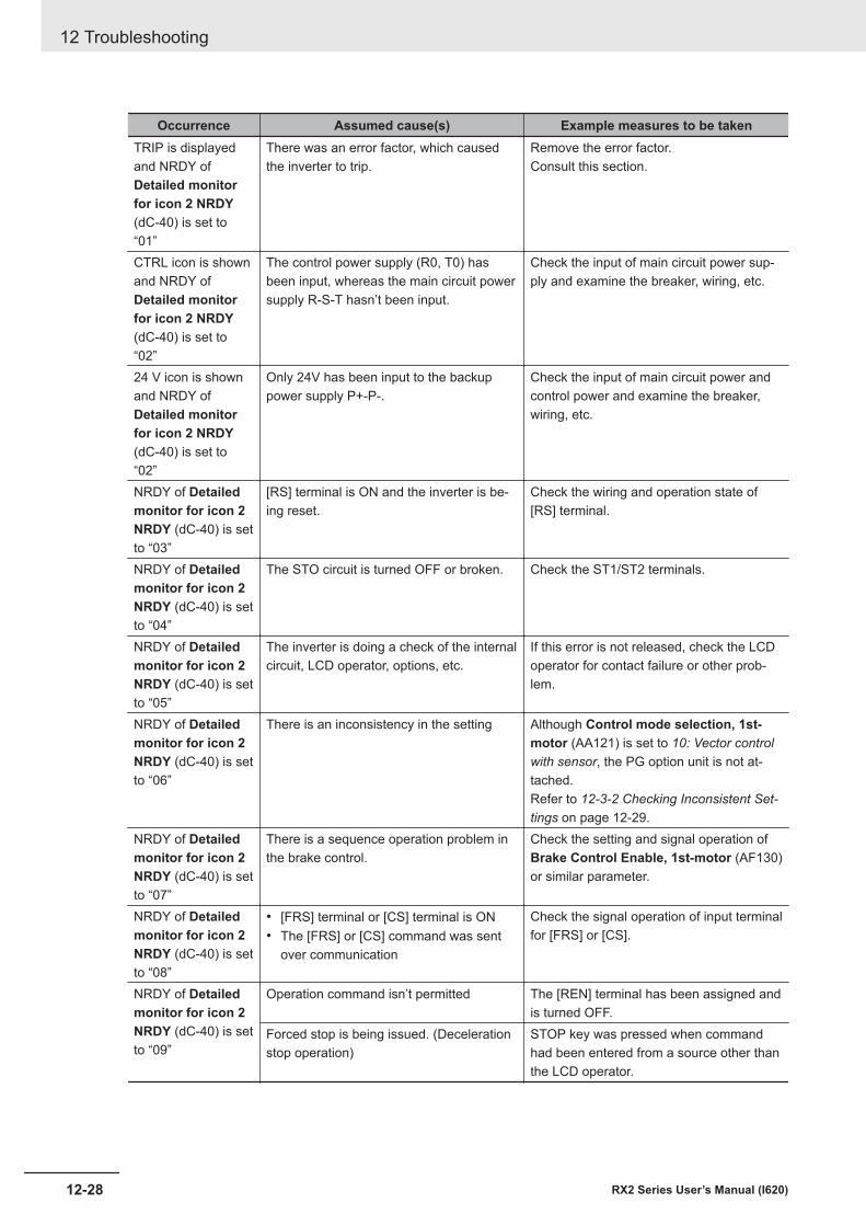
Occurrence Assumed cause(s) Example measures to be takenTRIP is displayedand NRDY ofDetailed monitorfor icon 2 NRDY(dC-40) is set to“01”
There was an error factor, which causedthe inverter to trip.
Remove the error factor.Consult this section.
CTRL icon is shownand NRDY ofDetailed monitorfor icon 2 NRDY(dC-40) is set to“02”
The control power supply (R0, T0) hasbeen input, whereas the main circuit powersupply R-S-T hasn’t been input.
Check the input of main circuit power sup-ply and examine the breaker, wiring, etc.
24 V icon is shownand NRDY ofDetailed monitorfor icon 2 NRDY(dC-40) is set to“02”
Only 24V has been input to the backuppower supply P+-P-.
Check the input of main circuit power andcontrol power and examine the breaker,wiring, etc.
NRDY of Detailedmonitor for icon 2NRDY (dC-40) is setto “03”
[RS] terminal is ON and the inverter is be-ing reset.
Check the wiring and operation state of[RS] terminal.
NRDY of Detailedmonitor for icon 2NRDY (dC-40) is setto “04”
The STO circuit is turned OFF or broken. Check the ST1/ST2 terminals.
NRDY of Detailedmonitor for icon 2NRDY (dC-40) is setto “05”
The inverter is doing a check of the internalcircuit, LCD operator, options, etc.
If this error is not released, check the LCDoperator for contact failure or other prob-lem.
NRDY of Detailedmonitor for icon 2NRDY (dC-40) is setto “06”
There is an inconsistency in the setting Although Control mode selection, 1st-motor (AA121) is set to 10: Vector controlwith sensor, the PG option unit is not at-tached.Refer to 12-3-2 Checking Inconsistent Set-tings on page 12-29.
NRDY of Detailedmonitor for icon 2NRDY (dC-40) is setto “07”
There is a sequence operation problem inthe brake control.
Check the setting and signal operation ofBrake Control Enable, 1st-motor (AF130)or similar parameter.
NRDY of Detailedmonitor for icon 2NRDY (dC-40) is setto “08”
• [FRS] terminal or [CS] terminal is ON• The [FRS] or [CS] command was sent
over communication
Check the signal operation of input terminalfor [FRS] or [CS].
NRDY of Detailedmonitor for icon 2NRDY (dC-40) is setto “09”
Operation command isn’t permitted The [REN] terminal has been assigned andis turned OFF.
Forced stop is being issued. (Decelerationstop operation)
STOP key was pressed when commandhad been entered from a source other thanthe LCD operator.
12 Troubleshooting
12-28 RX2 Series User’s Manual (I620)
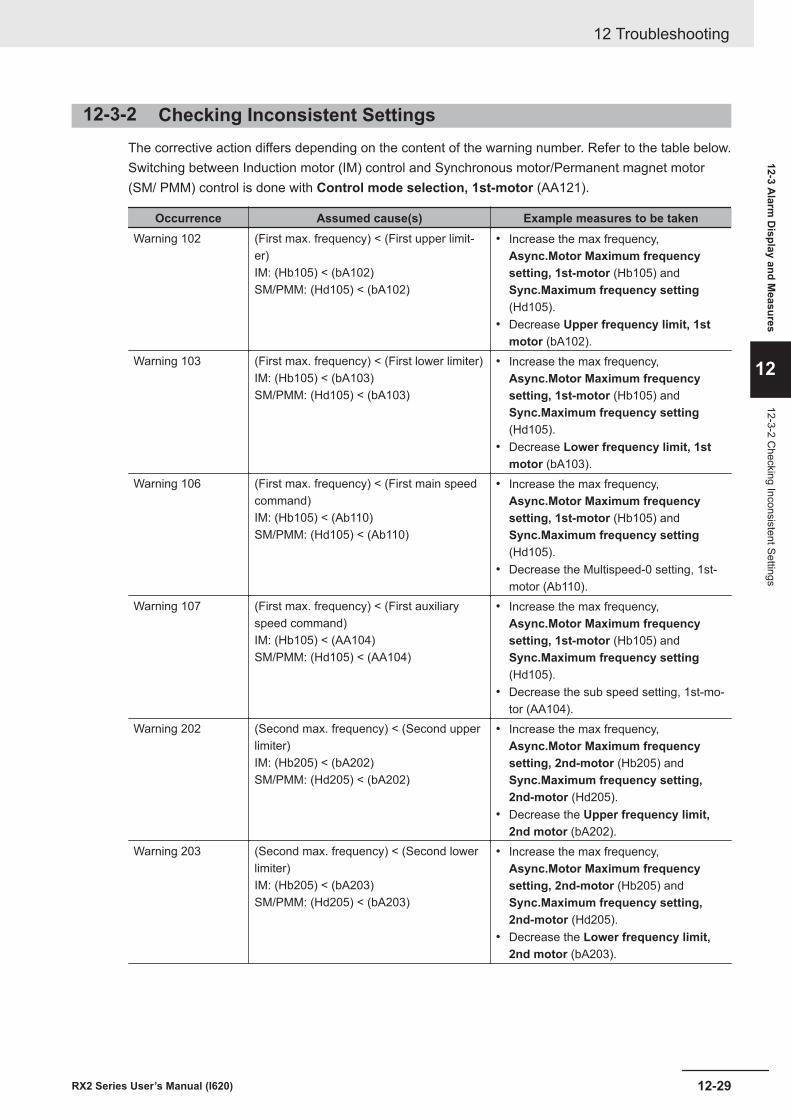
12-3-2 Checking Inconsistent SettingsThe corrective action differs depending on the content of the warning number. Refer to the table below.Switching between Induction motor (IM) control and Synchronous motor/Permanent magnet motor(SM/ PMM) control is done with Control mode selection, 1st-motor (AA121).
Occurrence Assumed cause(s) Example measures to be takenWarning 102 (First max. frequency) < (First upper limit-
er)IM: (Hb105) < (bA102)SM/PMM: (Hd105) < (bA102)
• Increase the max frequency,Async.Motor Maximum frequencysetting, 1st-motor (Hb105) andSync.Maximum frequency setting(Hd105).
• Decrease Upper frequency limit, 1stmotor (bA102).
Warning 103 (First max. frequency) < (First lower limiter)IM: (Hb105) < (bA103)SM/PMM: (Hd105) < (bA103)
• Increase the max frequency,Async.Motor Maximum frequencysetting, 1st-motor (Hb105) andSync.Maximum frequency setting(Hd105).
• Decrease Lower frequency limit, 1stmotor (bA103).
Warning 106 (First max. frequency) < (First main speedcommand)IM: (Hb105) < (Ab110)SM/PMM: (Hd105) < (Ab110)
• Increase the max frequency,Async.Motor Maximum frequencysetting, 1st-motor (Hb105) andSync.Maximum frequency setting(Hd105).
• Decrease the Multispeed-0 setting, 1st-motor (Ab110).
Warning 107 (First max. frequency) < (First auxiliaryspeed command)IM: (Hb105) < (AA104)SM/PMM: (Hd105) < (AA104)
• Increase the max frequency,Async.Motor Maximum frequencysetting, 1st-motor (Hb105) andSync.Maximum frequency setting(Hd105).
• Decrease the sub speed setting, 1st-mo-tor (AA104).
Warning 202 (Second max. frequency) < (Second upperlimiter)IM: (Hb205) < (bA202)SM/PMM: (Hd205) < (bA202)
• Increase the max frequency,Async.Motor Maximum frequencysetting, 2nd-motor (Hb205) andSync.Maximum frequency setting,2nd-motor (Hd205).
• Decrease the Upper frequency limit,2nd motor (bA202).
Warning 203 (Second max. frequency) < (Second lowerlimiter)IM: (Hb205) < (bA203)SM/PMM: (Hd205) < (bA203)
• Increase the max frequency,Async.Motor Maximum frequencysetting, 2nd-motor (Hb205) andSync.Maximum frequency setting,2nd-motor (Hd205).
• Decrease the Lower frequency limit,2nd motor (bA203).
12 Troubleshooting
12-29RX2 Series User’s Manual (I620)
12-3 Alarm
Display and M
easures
12
12-3-2 Checking Inconsistent Settings
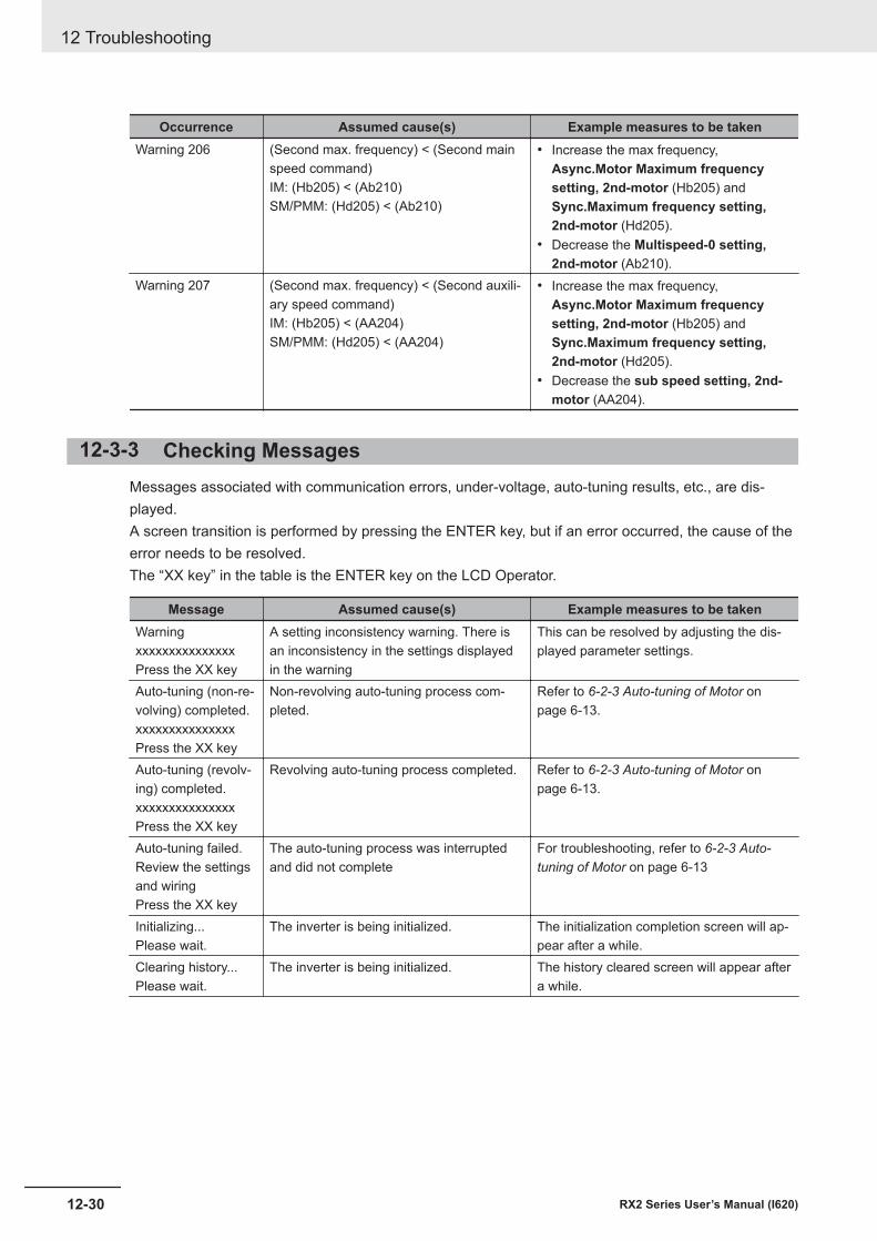
Occurrence Assumed cause(s) Example measures to be takenWarning 206 (Second max. frequency) < (Second main
speed command)IM: (Hb205) < (Ab210)SM/PMM: (Hd205) < (Ab210)
• Increase the max frequency,Async.Motor Maximum frequencysetting, 2nd-motor (Hb205) andSync.Maximum frequency setting,2nd-motor (Hd205).
• Decrease the Multispeed-0 setting,2nd-motor (Ab210).
Warning 207 (Second max. frequency) < (Second auxili-ary speed command)IM: (Hb205) < (AA204)SM/PMM: (Hd205) < (AA204)
• Increase the max frequency,Async.Motor Maximum frequencysetting, 2nd-motor (Hb205) andSync.Maximum frequency setting,2nd-motor (Hd205).
• Decrease the sub speed setting, 2nd-motor (AA204).
12-3-3 Checking MessagesMessages associated with communication errors, under-voltage, auto-tuning results, etc., are dis-played.A screen transition is performed by pressing the ENTER key, but if an error occurred, the cause of theerror needs to be resolved.The “XX key” in the table is the ENTER key on the LCD Operator.
Message Assumed cause(s) Example measures to be takenWarningxxxxxxxxxxxxxxxPress the XX key
A setting inconsistency warning. There isan inconsistency in the settings displayedin the warning
This can be resolved by adjusting the dis-played parameter settings.
Auto-tuning (non-re-volving) completed.xxxxxxxxxxxxxxxPress the XX key
Non-revolving auto-tuning process com-pleted.
Refer to 6-2-3 Auto-tuning of Motor onpage 6-13.
Auto-tuning (revolv-ing) completed.xxxxxxxxxxxxxxxPress the XX key
Revolving auto-tuning process completed. Refer to 6-2-3 Auto-tuning of Motor onpage 6-13.
Auto-tuning failed.Review the settingsand wiringPress the XX key
The auto-tuning process was interruptedand did not complete
For troubleshooting, refer to 6-2-3 Auto-tuning of Motor on page 6-13
Initializing...Please wait.
The inverter is being initialized. The initialization completion screen will ap-pear after a while.
Clearing history...Please wait.
The inverter is being initialized. The history cleared screen will appear aftera while.
12 Troubleshooting
12-30 RX2 Series User’s Manual (I620)
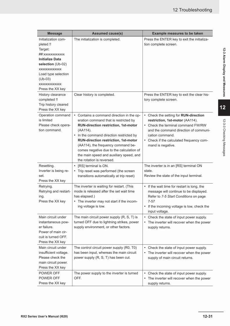
Message Assumed cause(s) Example measures to be takenInitialization com-pleted !!Target:##:xxxxxxxxxxxxInitialize Dataselection (Ub-02)xxxxxxxxxxxxxLoad type selection(Ub-03)xxxxxxxxxxxxxPress the XX key
The initialization is completed. Press the ENTER key to exit the initializa-tion complete screen.
History clearancecompleted !!Trip history clearedPress the XX key
Clear history is completed. Press the ENTER key to exit the clear his-tory complete screen.
Operation commandis limitedPlease check opera-tion command.
• Contains a command direction in the op-eration command that is restricted byRUN-direction restriction, 1st-motor(AA114).
• In the command direction restricted byRUN-direction restriction, 1st-motor(AA114), the frequency command be-comes negative due to the calculation ofthe main speed and auxiliary speed, andthe rotation is reversed.
• Check the setting for RUN-directionrestriction, 1st-motor (AA114).
• Check the terminal command FW/RWand the command direction of communi-cation command.
• Check if the calculated frequency com-mand is negative.
Resetting.Inverter is being re-set.Press the XX key
• [RS] terminal is ON.• Trip reset was performed (the screen
transitions automatically at trip reset)
The inverter is in an [RS] terminal ONstate.Review the state of the input terminal.
Retrying.Retrying and restart-ing.Press the XX key
The inverter is waiting for restart. (Thismode is released after the set wait timehas elapsed.)• The inverter may not start if the incom-
ing voltage is low.
• If the wait time for restart is long, themessage will continue to be displayed.Refer to 7-5 Start Conditions on page7-57
• If the incoming voltage is low, check theinput voltage.
Main circuit underinstantaneous pow-er failure.Power of main cir-cuit is turned OFF.Press the XX key
The main circuit power supply (R, S, T) isturned OFF due to lightning strikes, powersupply environment, or other factors.
• Check the state of input power supply.• The inverter will recover when the power
supply returns.
Main circuit underinsufficient voltage.Please check themain circuit power.Press the XX key
The control circuit power supply (R0, T0)has been input, whereas the main circuitpower supply (R, S, T) has been cut.
• Check the state of input power supply.• The inverter will recover when the power
supply of main circuit returns.
POWER OFFPOWER OFFPress the XX key
The power supply to the inverter is turnedOFF.
• Check the state of input power supply.• The inverter will recover when the power
supply returns.
12 Troubleshooting
12-31RX2 Series User’s Manual (I620)
12-3 Alarm
Display and M
easures
12
12-3-3 Checking M
essages
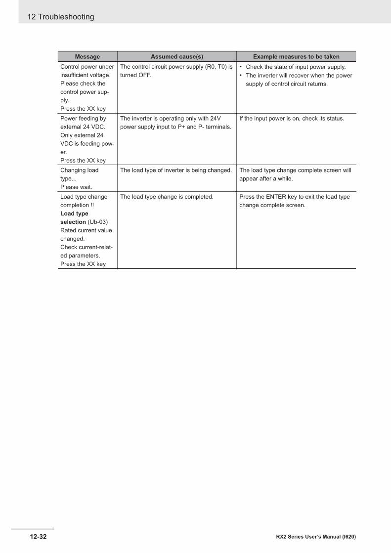
Message Assumed cause(s) Example measures to be takenControl power underinsufficient voltage.Please check thecontrol power sup-ply.Press the XX key
The control circuit power supply (R0, T0) isturned OFF.
• Check the state of input power supply.• The inverter will recover when the power
supply of control circuit returns.
Power feeding byexternal 24 VDC.Only external 24VDC is feeding pow-er.Press the XX key
The inverter is operating only with 24Vpower supply input to P+ and P- terminals.
If the input power is on, check its status.
Changing loadtype...Please wait.
The load type of inverter is being changed. The load type change complete screen willappear after a while.
Load type changecompletion !!Load typeselection (Ub-03)Rated current valuechanged.Check current-relat-ed parameters.Press the XX key
The load type change is completed. Press the ENTER key to exit the load typechange complete screen.
12 Troubleshooting
12-32 RX2 Series User’s Manual (I620)
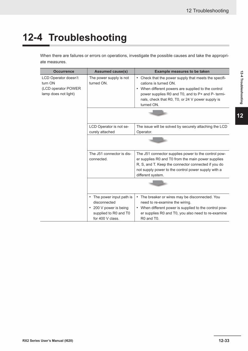
12-4 TroubleshootingWhen there are failures or errors on operations, investigate the possible causes and take the appropri-ate measures.
Occurrence Assumed cause(s) Example measures to be takenLCD Operator doesn’tturn ON(LCD operator POWERlamp does not light)
The power supply is notturned ON.
• Check that the power supply that meets the specifi-cations is turned ON.
• When different powers are supplied to the controlpower supplies R0 and T0, and to P+ and P- termi-nals, check that R0, T0, or 24 V power supply isturned ON.
LCD Operator is not se-curely attached
The issue will be solved by securely attaching the LCDOperator.
The J51 connector is dis-connected.
The J51 connector supplies power to the control pow-er supplies R0 and T0 from the main power suppliesR, S, and T. Keep the connector connected if you donot supply power to the control power supply with adifferent system.
• The power input path isdisconnected
• 200 V power is beingsupplied to R0 and T0for 400 V class.
• The breaker or wires may be disconnected. Youneed to re-examine the wiring.
• When different power is supplied to the control pow-er supplies R0 and T0, you also need to re-examineR0 and T0.
12 Troubleshooting
12-33RX2 Series User’s Manual (I620)
12-4 Troubleshooting
12
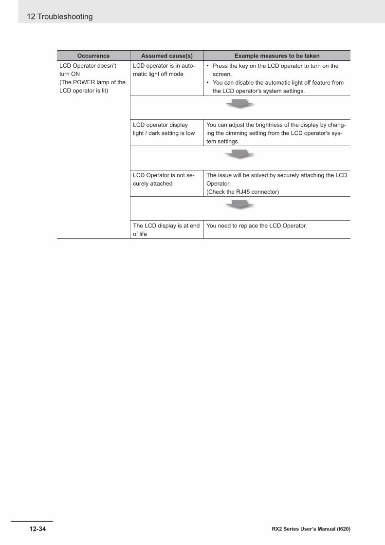
Occurrence Assumed cause(s) Example measures to be takenLCD Operator doesn’tturn ON(The POWER lamp of theLCD operator is lit)
LCD operator is in auto-matic light off mode
• Press the key on the LCD operator to turn on thescreen.
• You can disable the automatic light off feature fromthe LCD operator's system settings.
LCD operator displaylight / dark setting is low
You can adjust the brightness of the display by chang-ing the dimming setting from the LCD operator's sys-tem settings.
LCD Operator is not se-curely attached
The issue will be solved by securely attaching the LCDOperator.(Check the RJ45 connector)
The LCD display is at endof life
You need to replace the LCD Operator.
12 Troubleshooting
12-34 RX2 Series User’s Manual (I620)
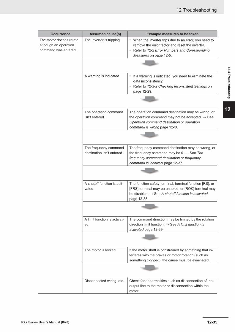
Occurrence Assumed cause(s) Example measures to be takenThe motor doesn’t rotatealthough an operationcommand was entered.
The inverter is tripping. • When the inverter trips due to an error, you need toremove the error factor and reset the inverter.
• Refer to 12-2 Error Numbers and CorrespondingMeasures on page 12-5.
A warning is indicated • If a warning is indicated, you need to eliminate thedata inconsistency.
• Refer to 12-3-2 Checking Inconsistent Settings onpage 12-29.
The operation commandisn’t entered.
The operation command destination may be wrong, orthe operation command may not be accepted. → SeeOperation command destination or operationcommand is wrong page 12-36
The frequency commanddestination isn’t entered.
The frequency command destination may be wrong, orthe frequency command may be 0. → See Thefrequency command destination or frequencycommand is incorrect page 12-37
A shutoff function is acti-vated
The function safety terminal, terminal function [RS], or[FRS] terminal may be enabled, or [ROK] terminal maybe disabled. → See A shutoff function is activatedpage 12-38
A limit function is activat-ed
The command direction may be limited by the rotationdirection limit function. → See A limit function isactivated page 12-39
The motor is locked. If the motor shaft is constrained by something that in-terferes with the brakes or motor rotation (such assomething clogged), the cause must be eliminated.
Disconnected wiring, etc. Check for abnormalities such as disconnection of theoutput line to the motor or disconnection within themotor.
12 Troubleshooting
12-35RX2 Series User’s Manual (I620)
12-4 Troubleshooting
12
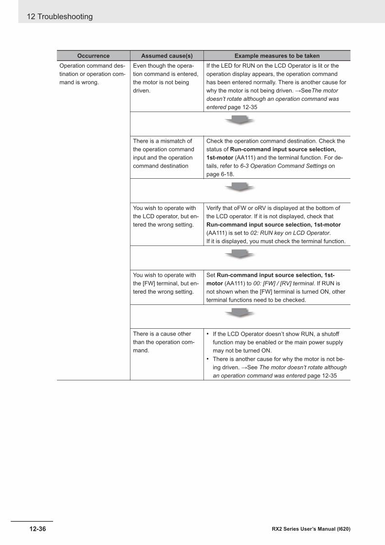
Occurrence Assumed cause(s) Example measures to be takenOperation command des-tination or operation com-mand is wrong.
Even though the opera-tion command is entered,the motor is not beingdriven.
If the LED for RUN on the LCD Operator is lit or theoperation display appears, the operation commandhas been entered normally. There is another cause forwhy the motor is not being driven. →SeeThe motordoesn’t rotate although an operation command wasentered page 12-35
There is a mismatch ofthe operation commandinput and the operationcommand destination
Check the operation command destination. Check thestatus of Run-command input source selection,1st-motor (AA111) and the terminal function. For de-tails, refer to 6-3 Operation Command Settings onpage 6-18.
You wish to operate withthe LCD operator, but en-tered the wrong setting.
Verify that oFW or oRV is displayed at the bottom ofthe LCD operator. If it is not displayed, check thatRun-command input source selection, 1st-motor(AA111) is set to 02: RUN key on LCD Operator.If it is displayed, you must check the terminal function.
You wish to operate withthe [FW] terminal, but en-tered the wrong setting.
Set Run-command input source selection, 1st-motor (AA111) to 00: [FW] / [RV] terminal. If RUN isnot shown when the [FW] terminal is turned ON, otherterminal functions need to be checked.
There is a cause otherthan the operation com-mand.
• If the LCD Operator doesn’t show RUN, a shutofffunction may be enabled or the main power supplymay not be turned ON.
• There is another cause for why the motor is not be-ing driven. →See The motor doesn’t rotate althoughan operation command was entered page 12-35
12 Troubleshooting
12-36 RX2 Series User’s Manual (I620)
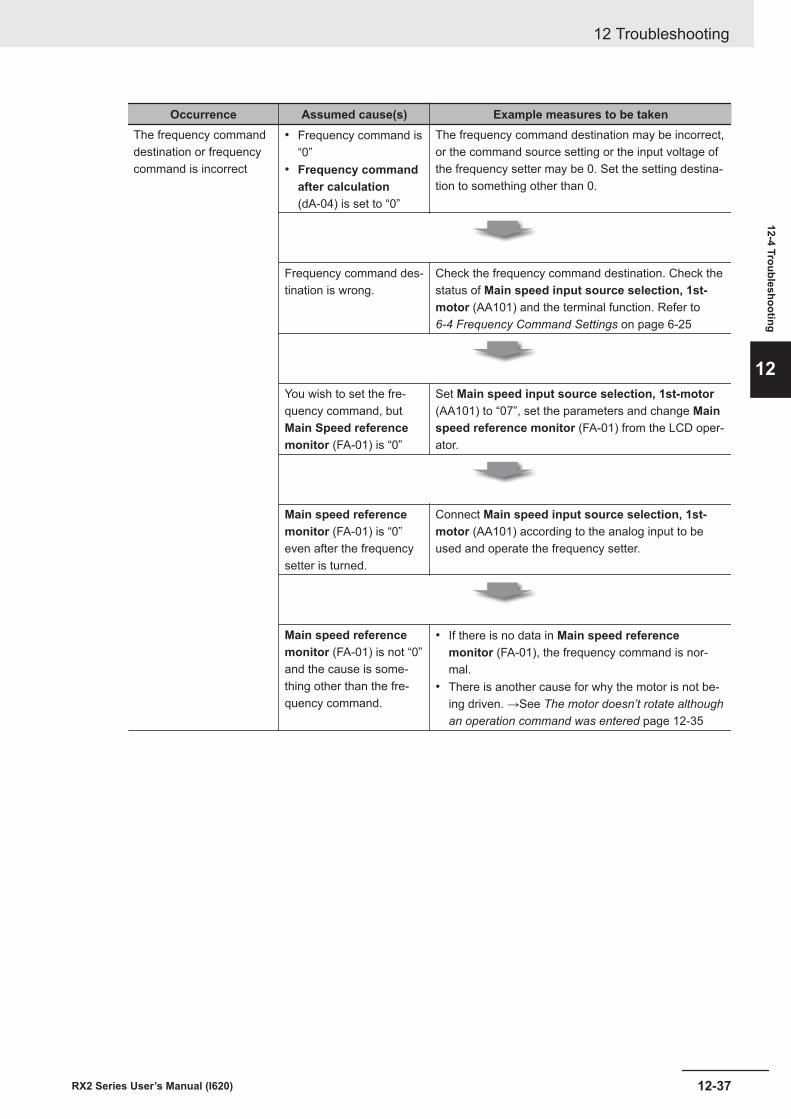
Occurrence Assumed cause(s) Example measures to be takenThe frequency commanddestination or frequencycommand is incorrect
• Frequency command is“0”
• Frequency commandafter calculation(dA-04) is set to “0”
The frequency command destination may be incorrect,or the command source setting or the input voltage ofthe frequency setter may be 0. Set the setting destina-tion to something other than 0.
Frequency command des-tination is wrong.
Check the frequency command destination. Check thestatus of Main speed input source selection, 1st-motor (AA101) and the terminal function. Refer to 6-4 Frequency Command Settings on page 6-25
You wish to set the fre-quency command, butMain Speed referencemonitor (FA-01) is “0”
Set Main speed input source selection, 1st-motor(AA101) to “07”, set the parameters and change Mainspeed reference monitor (FA-01) from the LCD oper-ator.
Main speed referencemonitor (FA-01) is “0”even after the frequencysetter is turned.
Connect Main speed input source selection, 1st-motor (AA101) according to the analog input to beused and operate the frequency setter.
Main speed referencemonitor (FA-01) is not “0”and the cause is some-thing other than the fre-quency command.
• If there is no data in Main speed referencemonitor (FA-01), the frequency command is nor-mal.
• There is another cause for why the motor is not be-ing driven. →See The motor doesn’t rotate althoughan operation command was entered page 12-35
12 Troubleshooting
12-37RX2 Series User’s Manual (I620)
12-4 Troubleshooting
12
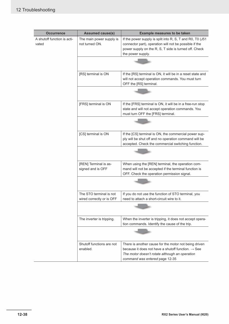
Occurrence Assumed cause(s) Example measures to be takenA shutoff function is acti-vated
The main power supply isnot turned ON.
If the power supply is split into R, S, T and R0, T0 (J51connector part), operation will not be possible if thepower supply on the R, S, T side is turned off. Checkthe power supply.
[RS] terminal is ON If the [RS] terminal is ON, it will be in a reset state andwill not accept operation commands. You must turnOFF the [RS] terminal.
[FRS] terminal is ON If the [FRS] terminal is ON, it will be in a free-run stopstate and will not accept operation commands. Youmust turn OFF the [FRS] terminal.
[CS] terminal is ON If the [CS] terminal is ON, the commercial power sup-ply will be shut off and no operation command will beaccepted. Check the commercial switching function.
[REN] Terminal is as-signed and is OFF
When using the [REN] terminal, the operation com-mand will not be accepted if the terminal function isOFF. Check the operation permission signal.
The STO terminal is notwired correctly or is OFF
If you do not use the function of STO terminal, youneed to attach a short-circuit wire to it.
The inverter is tripping. When the inverter is tripping, it does not accept opera-tion commands. Identify the cause of the trip.
Shutoff functions are notenabled.
There is another cause for the motor not being drivenbecause it does not have a shutoff function. → SeeThe motor doesn’t rotate although an operationcommand was entered page 12-35
12 Troubleshooting
12-38 RX2 Series User’s Manual (I620)
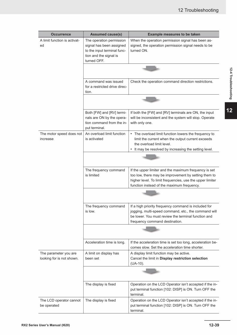
Occurrence Assumed cause(s) Example measures to be takenA limit function is activat-ed
The operation permissionsignal has been assignedto the input terminal func-tion and the signal isturned OFF.
When the operation permission signal has been as-signed, the operation permission signal needs to beturned ON.
A command was issuedfor a restricted drive direc-tion.
Check the operation command direction restrictions.
Both [FW] and [RV] termi-nals are ON by the opera-tion command from the in-put terminal.
If both the [FW] and [RV] terminals are ON, the inputwill be inconsistent and the system will stop. Operatewith only one.
The motor speed does notincrease
An overload limit functionis activated
• The overload limit function lowers the frequency tolimit the current when the output current exceedsthe overload limit level.
• It may be resolved by increasing the setting level.
The frequency commandis limited
If the upper limiter and the maximum frequency is settoo low, there may be improvement by setting them tohigher level. To limit frequencies, use the upper limiterfunction instead of the maximum frequency.
The frequency commandis low.
If a high priority frequency command is included forjogging, multi-speed command, etc., the command willbe lower. You must review the terminal function andfrequency command destination.
Acceleration time is long. If the acceleration time is set too long, acceleration be-comes slow. Set the acceleration time shorter.
The parameter you arelooking for is not shown.
A limit on display hasbeen set
A display limit function may be active.Cancel the limit in Display restriction selection(UA-10).
The display is fixed Operation on the LCD Operator isn’t accepted if the in-put terminal function [102: DISP] is ON. Turn OFF theterminal.
The LCD operator cannotbe operated
The display is fixed Operation on the LCD Operator isn’t accepted if the in-put terminal function [102: DISP] is ON. Turn OFF theterminal.
12 Troubleshooting
12-39RX2 Series User’s Manual (I620)
12-4 Troubleshooting
12
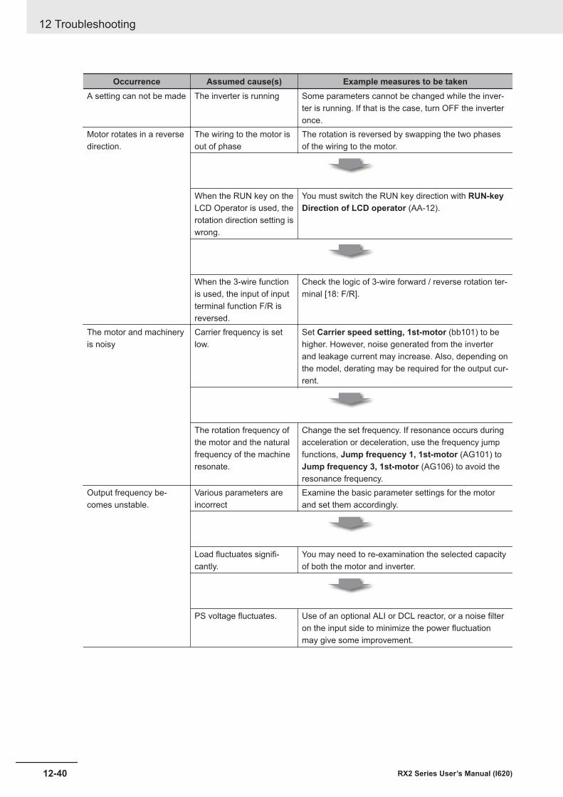
Occurrence Assumed cause(s) Example measures to be takenA setting can not be made The inverter is running Some parameters cannot be changed while the inver-
ter is running. If that is the case, turn OFF the inverteronce.
Motor rotates in a reversedirection.
The wiring to the motor isout of phase
The rotation is reversed by swapping the two phasesof the wiring to the motor.
When the RUN key on theLCD Operator is used, therotation direction setting iswrong.
You must switch the RUN key direction with RUN-keyDirection of LCD operator (AA-12).
When the 3-wire functionis used, the input of inputterminal function F/R isreversed.
Check the logic of 3-wire forward / reverse rotation ter-minal [18: F/R].
The motor and machineryis noisy
Carrier frequency is setlow.
Set Carrier speed setting, 1st-motor (bb101) to behigher. However, noise generated from the inverterand leakage current may increase. Also, depending onthe model, derating may be required for the output cur-rent.
The rotation frequency ofthe motor and the naturalfrequency of the machineresonate.
Change the set frequency. If resonance occurs duringacceleration or deceleration, use the frequency jumpfunctions, Jump frequency 1, 1st-motor (AG101) toJump frequency 3, 1st-motor (AG106) to avoid theresonance frequency.
Output frequency be-comes unstable.
Various parameters areincorrect
Examine the basic parameter settings for the motorand set them accordingly.
Load fluctuates signifi-cantly.
You may need to re-examination the selected capacityof both the motor and inverter.
PS voltage fluctuates. Use of an optional ALI or DCL reactor, or a noise filteron the input side to minimize the power fluctuationmay give some improvement.
12 Troubleshooting
12-40 RX2 Series User’s Manual (I620)
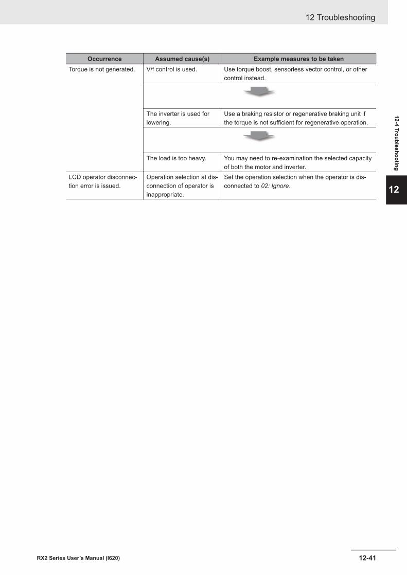
Occurrence Assumed cause(s) Example measures to be takenTorque is not generated. V/f control is used. Use torque boost, sensorless vector control, or other
control instead.
The inverter is used forlowering.
Use a braking resistor or regenerative braking unit ifthe torque is not sufficient for regenerative operation.
The load is too heavy. You may need to re-examination the selected capacityof both the motor and inverter.
LCD operator disconnec-tion error is issued.
Operation selection at dis-connection of operator isinappropriate.
Set the operation selection when the operator is dis-connected to 02: Ignore.
12 Troubleshooting
12-41RX2 Series User’s Manual (I620)
12-4 Troubleshooting
12
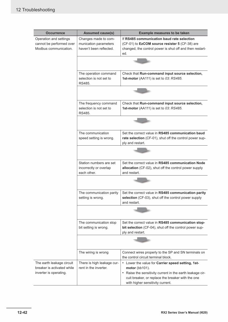
Occurrence Assumed cause(s) Example measures to be takenOperation and settingscannot be performed overModbus communication.
Changes made to com-munication parametershaven’t been reflected.
If RS485 communication baud rate selection(CF-01) to EzCOM source resister 5 (CF-38) arechanged, the control power is shut off and then restart-ed.
The operation commandselection is not set toRS485.
Check that Run-command input source selection,1st-motor (AA111) is set to 03: RS485.
The frequency commandselection is not set toRS485.
Check that Run-command input source selection,1st-motor (AA111) is set to 03: RS485.
The communicationspeed setting is wrong.
Set the correct value in RS485 communication baudrate selection (CF-01), shut off the control power sup-ply and restart.
Station numbers are setincorrectly or overlapeach other.
Set the correct value in RS485 communication Nodeallocation (CF-02), shut off the control power supplyand restart.
The communication paritysetting is wrong.
Set the correct value in RS485 communication parityselection (CF-03), shut off the control power supplyand restart.
The communication stopbit setting is wrong.
Set the correct value in RS485 communication stop-bit selection (CF-04), shut off the control power sup-ply and restart.
The wiring is wrong Connect wires properly to the SP and SN terminals onthe control circuit terminal block.
The earth leakage circuitbreaker is activated whileinverter is operating.
There is high leakage cur-rent in the inverter.
• Lower the value for Carrier speed setting, 1st-motor (bb101).
• Raise the sensitivity current in the earth leakage cir-cuit breaker, or replace the breaker with the onewith higher sensitivity current.
12 Troubleshooting
12-42 RX2 Series User’s Manual (I620)
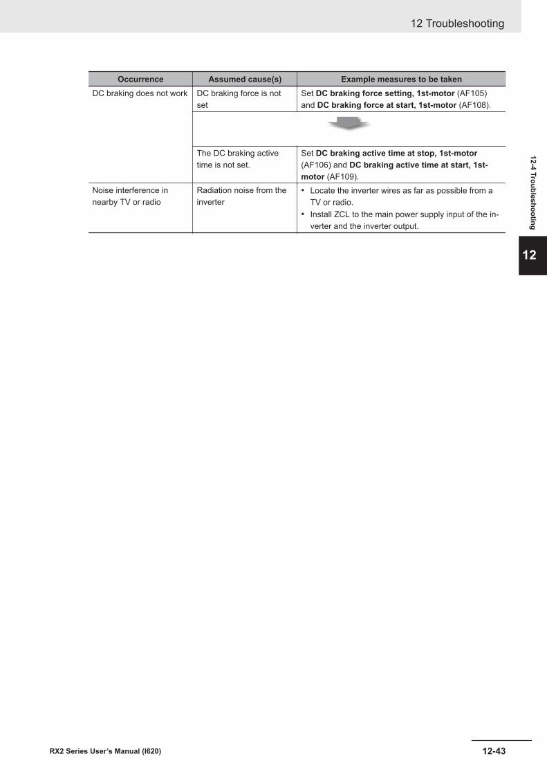
Occurrence Assumed cause(s) Example measures to be takenDC braking does not work DC braking force is not
setSet DC braking force setting, 1st-motor (AF105)and DC braking force at start, 1st-motor (AF108).
The DC braking activetime is not set.
Set DC braking active time at stop, 1st-motor(AF106) and DC braking active time at start, 1st-motor (AF109).
Noise interference innearby TV or radio
Radiation noise from theinverter
• Locate the inverter wires as far as possible from aTV or radio.
• Install ZCL to the main power supply input of the in-verter and the inverter output.
12 Troubleshooting
12-43RX2 Series User’s Manual (I620)
12-4 Troubleshooting
12

12 Troubleshooting
12-44 RX2 Series User’s Manual (I620)
13Maintenance and Inspection
This section describes the maintenance and inspection.
13-1 Daily Inspection............................................................................................ 13-213-2 Periodic Inspection ...................................................................................... 13-313-3 Inspection Items........................................................................................... 13-413-4 Cleaning ........................................................................................................ 13-913-5 Test Methods .............................................................................................. 13-10
13-5-1 Megger Test................................................................................................. 13-1013-5-2 Pressure Test .............................................................................................. 13-1013-5-3 Method of Checking Inverter and Converter Condition ............................... 13-1013-5-4 Measurement Method of I/O Voltage, Current and Power .......................... 13-1213-5-5 Smoothing Capacitor Life Curve ................................................................. 13-1413-5-6 Life Alarming Output.................................................................................... 13-15
13-1RX2 Series User’s Manual (I620)
13
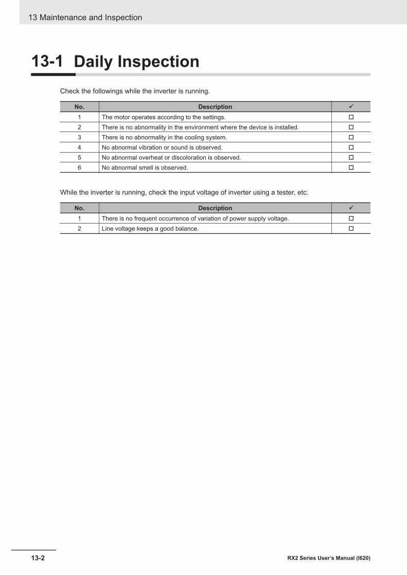
13-1 Daily InspectionCheck the followings while the inverter is running.
No. Description ü
1 The motor operates according to the settings. o
2 There is no abnormality in the environment where the device is installed. o
3 There is no abnormality in the cooling system. o
4 No abnormal vibration or sound is observed. o
5 No abnormal overheat or discoloration is observed. o
6 No abnormal smell is observed. o
While the inverter is running, check the input voltage of inverter using a tester, etc.
No. Description ü
1 There is no frequent occurrence of variation of power supply voltage. o
2 Line voltage keeps a good balance. o
13 Maintenance and Inspection
13-2 RX2 Series User’s Manual (I620)
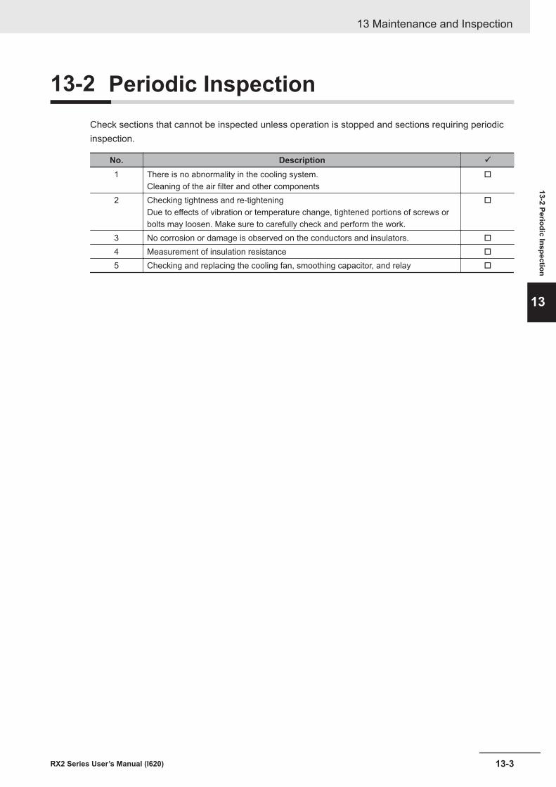
13-2 Periodic InspectionCheck sections that cannot be inspected unless operation is stopped and sections requiring periodicinspection.
No. Description ü
1 There is no abnormality in the cooling system.Cleaning of the air filter and other components
o
2 Checking tightness and re-tighteningDue to effects of vibration or temperature change, tightened portions of screws orbolts may loosen. Make sure to carefully check and perform the work.
o
3 No corrosion or damage is observed on the conductors and insulators. o
4 Measurement of insulation resistance o
5 Checking and replacing the cooling fan, smoothing capacitor, and relay o
13 Maintenance and Inspection
13-3RX2 Series User’s Manual (I620)
13-2 Periodic Inspection
13
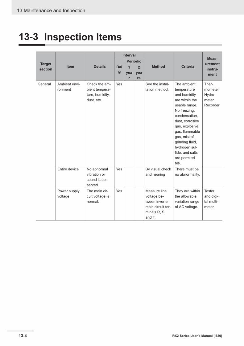
13-3 Inspection Items
Targetsection Item Details
Interval
Method Criteria
Meas-urementinstru-ment
Daily
Periodic1
year
2years
General Ambient envi-ronment
Check the am-bient tempera-ture, humidity,dust, etc.
Yes See the instal-lation method.
The ambienttemperatureand humidityare within theusable range.No freezing,condensation,dust, corrosivegas, explosivegas, flammablegas, mist ofgrinding fluid,hydrogen sul-fide, and saltsare permissi-ble.
Ther-mometerHydro-meterRecorder
Entire device No abnormalvibration orsound is ob-served.
Yes By visual checkand hearing
There must beno abnormality.
Power supplyvoltage
The main cir-cuit voltage isnormal.
Yes Measure linevoltage be-tween invertermain circuit ter-minals R, S,and T.
They are withinthe allowablevariation rangeof AC voltage.
Testerand digi-tal multi-meter
13 Maintenance and Inspection
13-4 RX2 Series User’s Manual (I620)
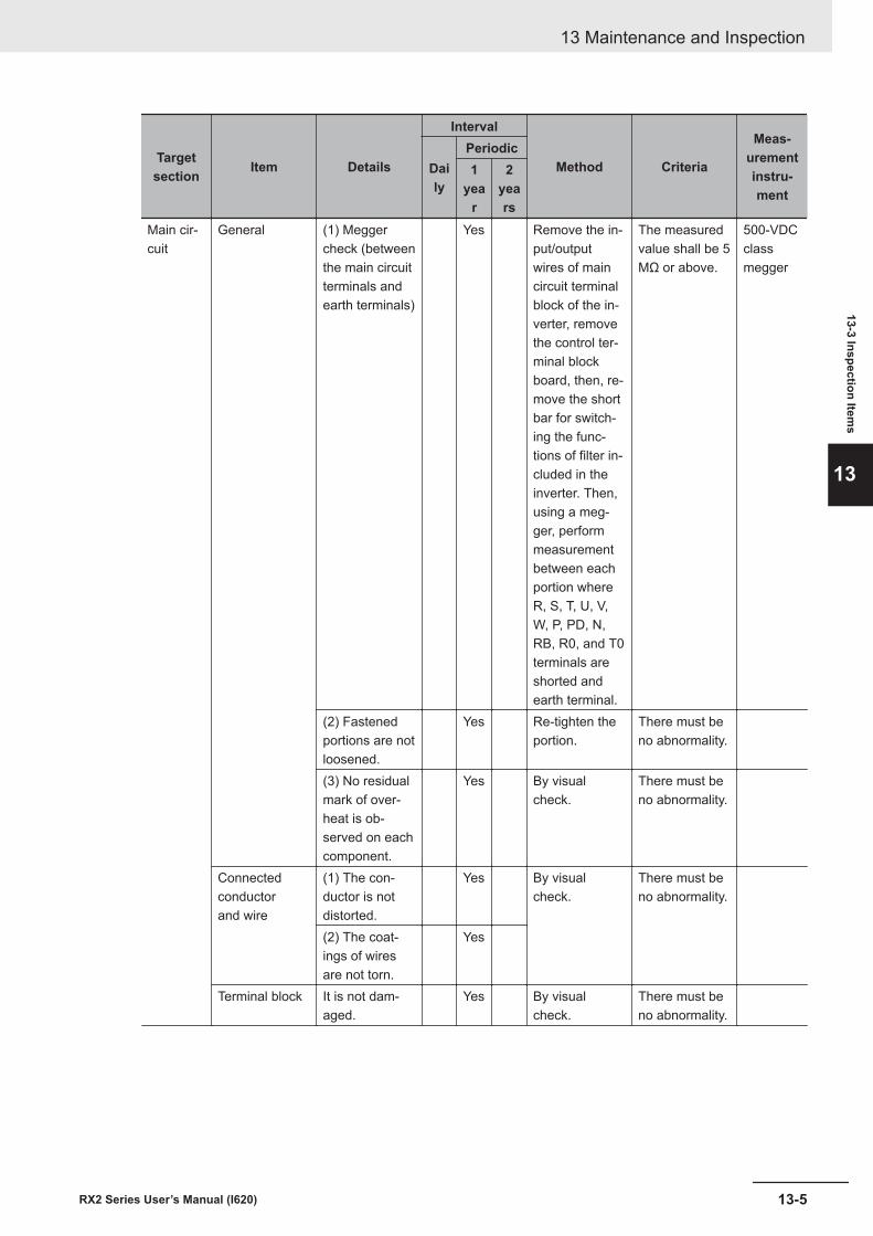
Targetsection Item Details
Interval
Method Criteria
Meas-urementinstru-ment
Daily
Periodic1
year
2years
Main cir-cuit
General (1) Meggercheck (betweenthe main circuitterminals andearth terminals)
Yes Remove the in-put/outputwires of maincircuit terminalblock of the in-verter, removethe control ter-minal blockboard, then, re-move the shortbar for switch-ing the func-tions of filter in-cluded in theinverter. Then,using a meg-ger, performmeasurementbetween eachportion whereR, S, T, U, V,W, P, PD, N,RB, R0, and T0terminals areshorted andearth terminal.
The measuredvalue shall be 5MΩ or above.
500-VDCclassmegger
(2) Fastenedportions are notloosened.
Yes Re-tighten theportion.
There must beno abnormality.
(3) No residualmark of over-heat is ob-served on eachcomponent.
Yes By visualcheck.
There must beno abnormality.
Connectedconductorand wire
(1) The con-ductor is notdistorted.
Yes By visualcheck.
There must beno abnormality.
(2) The coat-ings of wiresare not torn.
Yes
Terminal block It is not dam-aged.
Yes By visualcheck.
There must beno abnormality.
13 Maintenance and Inspection
13-5RX2 Series User’s Manual (I620)
13-3 Inspection Items
13
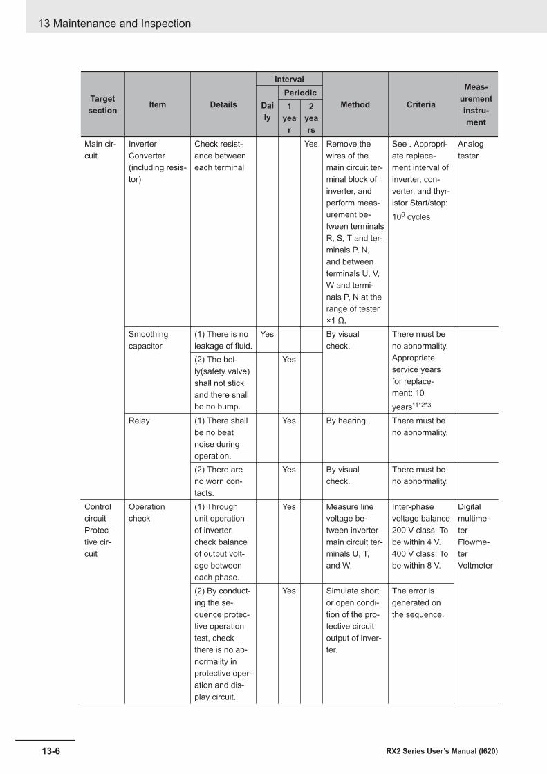
Targetsection Item Details
Interval
Method Criteria
Meas-urementinstru-ment
Daily
Periodic1
year
2years
Main cir-cuit
InverterConverter(including resis-tor)
Check resist-ance betweeneach terminal
Yes Remove thewires of themain circuit ter-minal block ofinverter, andperform meas-urement be-tween terminalsR, S, T and ter-minals P, N,and betweenterminals U, V,W and termi-nals P, N at therange of tester×1 Ω.
See . Appropri-ate replace-ment interval ofinverter, con-verter, and thyr-istor Start/stop:106 cycles
Analogtester
Smoothingcapacitor
(1) There is noleakage of fluid.
Yes By visualcheck.
There must beno abnormality.Appropriateservice yearsfor replace-ment: 10years*1*2*3
(2) The bel-ly(safety valve)shall not stickand there shallbe no bump.
Yes
Relay (1) There shallbe no beatnoise duringoperation.
Yes By hearing. There must beno abnormality.
(2) There areno worn con-tacts.
Yes By visualcheck.
There must beno abnormality.
ControlcircuitProtec-tive cir-cuit
Operationcheck
(1) Throughunit operationof inverter,check balanceof output volt-age betweeneach phase.
Yes Measure linevoltage be-tween invertermain circuit ter-minals U, T,and W.
Inter-phasevoltage balance200 V class: Tobe within 4 V.400 V class: Tobe within 8 V.
Digitalmultime-terFlowme-terVoltmeter
(2) By conduct-ing the se-quence protec-tive operationtest, checkthere is no ab-normality inprotective oper-ation and dis-play circuit.
Yes Simulate shortor open condi-tion of the pro-tective circuitoutput of inver-ter.
The error isgenerated onthe sequence.
13 Maintenance and Inspection
13-6 RX2 Series User’s Manual (I620)
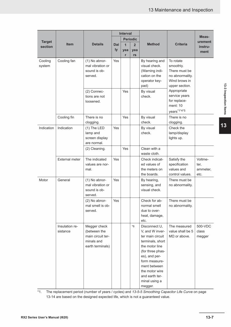
Targetsection Item Details
Interval
Method Criteria
Meas-urementinstru-ment
Daily
Periodic1
year
2years
Coolingsystem
Cooling fan (1) No abnor-mal vibration orsound is ob-served.
Yes By hearing andvisual check.(Warning indi-cation on theoperator key-pad)
To rotatesmoothly.There must beno abnormality.Wind brows inupper section.Appropriateservice yearsfor replace-ment: 10years*1*4*5
(2) Connec-tions are notloosened.
Yes By visualcheck.
Cooling fin There is noclogging.
Yes By visualcheck.
There is noclogging.
Indication Indication (1) The LEDlamp andscreen displayare normal.
Yes By visualcheck.
Check thelamp/displaylights up.
(2) Cleaning. Yes Clean with awaste cloth.
External meter The indicatedvalues are nor-mal.
Yes Check indicat-ed values ofthe meters onthe boards.
Satisfy thespecificationvalues andcontrol values.
Voltme-ter,ammeter,etc.
Motor General (1) No abnor-mal vibration orsound is ob-served.
Yes By hearing,sensing, andvisual check.
There must beno abnormality.
(2) No abnor-mal smell is ob-served.
Yes Check for ab-normal smelldue to over-heat, damage,etc.
There must beno abnormality.
Insulation re-sistance
Megger check(between themain circuit ter-minals andearth terminals)
*6 Disconnect U,V, and W inver-ter main circuitterminals, shortthe motor line(for three phas-es), and per-form measure-ment betweenthe motor wireand earth ter-minal using amegger.
The measuredvalue shall be 5MΩ or above.
500-VDCclassmegger
*1. The replacement period (number of years / cycles) and 13-5-5 Smoothing Capacitor Life Curve on page13-14 are based on the designed expected life, which is not a guaranteed value.
13 Maintenance and Inspection
13-7RX2 Series User’s Manual (I620)
13-3 Inspection Items
13
*2. The service life of smoothing capacitor is affected by the ambient temperature. See 13-5-5 Smoothing Ca-pacitor Life Curve on page 13-14 to determine replacement period.
*3. When you replace with a capacitor that has passed storage period more than three years, perform aging inthe following conditions before using it.• Initially apply 80% of rated voltage of capacitor for one hour in normal temperature• Then, increase the voltage to 90% and apply for one hour• Lastly, apply rated voltage for five hours in normal temperature
*4. The life of cooling fan varies depending on the environment conditions such as ambient temperature anddust. Check operating conditions by daily inspection.
*5. If the cooling fan is locked due to dust, etc., it takes about 5 to 10 seconds until re-rotation is enabled even ifdust is removed.
*6. Perform inspection in accordance with the instruction manual of motor.
13 Maintenance and Inspection
13-8 RX2 Series User’s Manual (I620)
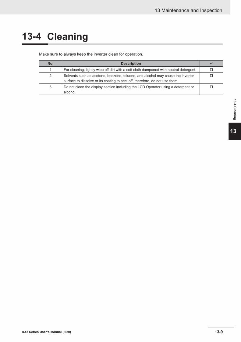
13-4 CleaningMake sure to always keep the inverter clean for operation.
No. Description ü
1 For cleaning, lightly wipe off dirt with a soft cloth dampened with neutral detergent. o
2 Solvents such as acetone, benzene, toluene, and alcohol may cause the invertersurface to dissolve or its coating to peel off, therefore, do not use them.
o
3 Do not clean the display section including the LCD Operator using a detergent oralcohol.
o
13 Maintenance and Inspection
13-9RX2 Series User’s Manual (I620)
13-4 Cleaning
13
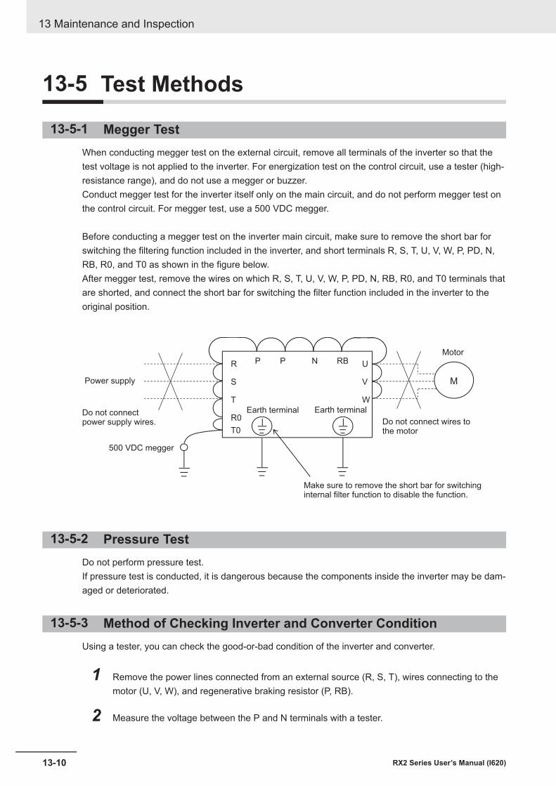
13-5 Test Methods
13-5-1 Megger TestWhen conducting megger test on the external circuit, remove all terminals of the inverter so that thetest voltage is not applied to the inverter. For energization test on the control circuit, use a tester (high-resistance range), and do not use a megger or buzzer.Conduct megger test for the inverter itself only on the main circuit, and do not perform megger test onthe control circuit. For megger test, use a 500 VDC megger.
Before conducting a megger test on the inverter main circuit, make sure to remove the short bar forswitching the filtering function included in the inverter, and short terminals R, S, T, U, V, W, P, PD, N,RB, R0, and T0 as shown in the figure below.After megger test, remove the wires on which R, S, T, U, V, W, P, PD, N, RB, R0, and T0 terminals thatare shorted, and connect the short bar for switching the filter function included in the inverter to theoriginal position.
M
R
S
T
U
V
W
P P N RB
R0
T0
Do not connectpower supply wires.
500 VDC megger
Power supply
Make sure to remove the short bar for switchinginternal filter function to disable the function.
Do not connect wires tothe motor
Motor
Earth terminalEarth terminal
13-5-2 Pressure TestDo not perform pressure test.If pressure test is conducted, it is dangerous because the components inside the inverter may be dam-aged or deteriorated.
13-5-3 Method of Checking Inverter and Converter ConditionUsing a tester, you can check the good-or-bad condition of the inverter and converter.
1 Remove the power lines connected from an external source (R, S, T), wires connecting to themotor (U, V, W), and regenerative braking resistor (P, RB).
2 Measure the voltage between the P and N terminals with a tester.
13 Maintenance and Inspection
13-10 RX2 Series User’s Manual (I620)
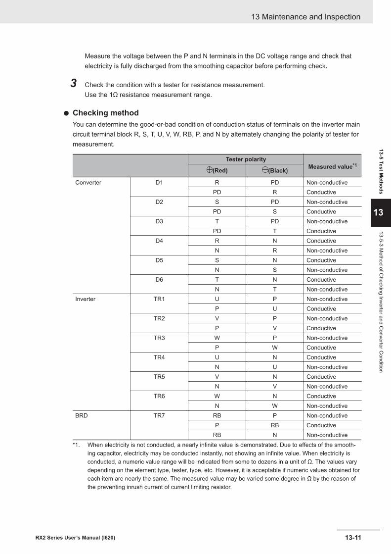
Measure the voltage between the P and N terminals in the DC voltage range and check thatelectricity is fully discharged from the smoothing capacitor before performing check.
3 Check the condition with a tester for resistance measurement.Use the 1Ω resistance measurement range.
l Checking methodYou can determine the good-or-bad condition of conduction status of terminals on the inverter maincircuit terminal block R, S, T, U, V, W, RB, P, and N by alternately changing the polarity of tester formeasurement.
Tester polarityMeasured value*1
(Red) (Black)
Converter D1 R PD Non-conductivePD R Conductive
D2 S PD Non-conductivePD S Conductive
D3 T PD Non-conductivePD T Conductive
D4 R N ConductiveN R Non-conductive
D5 S N ConductiveN S Non-conductive
D6 T N ConductiveN T Non-conductive
Inverter TR1 U P Non-conductiveP U Conductive
TR2 V P Non-conductiveP V Conductive
TR3 W P Non-conductiveP W Conductive
TR4 U N ConductiveN U Non-conductive
TR5 V N ConductiveN V Non-conductive
TR6 W N ConductiveN W Non-conductive
BRD TR7 RB P Non-conductiveP RB Conductive
RB N Non-conductive*1. When electricity is not conducted, a nearly infinite value is demonstrated. Due to effects of the smooth-
ing capacitor, electricity may be conducted instantly, not showing an infinite value. When electricity isconducted, a numeric value range will be indicated from some to dozens in a unit of Ω. The values varydepending on the element type, tester, type, etc. However, it is acceptable if numeric values obtained foreach item are nearly the same. The measured value may be varied some degree in Ω by the reason ofthe preventing inrush current of current limiting resistor.
13 Maintenance and Inspection
13-11RX2 Series User’s Manual (I620)
13-5 Test Methods
13
13-5-3 Method of C
hecking Inverter and Converter C
ondition
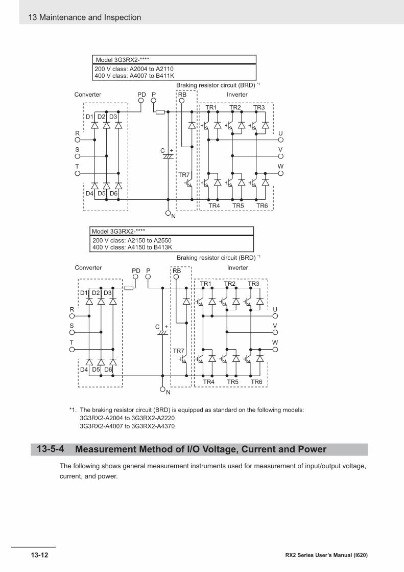
PD
D1
D4
D2
D5
D3
D6
R
S
T
TR4 TR5 TR6
TR1 TR2 TR3
C +
P
TR7
RB
U
V
W
PD
D1
D4
D2
D5
D3
D6
R
S
T
TR4 TR5 TR6
TR1 TR2 TR3
C +
P
N
N
TR7
RB
U
V
W
Model 3G3RX2-****
200 V class: A2004 to A2110400 V class: A4007 to B411K
Braking resistor circuit (BRD) *1
InverterConverter
Model 3G3RX2-****
200 V class: A2150 to A2550400 V class: A4150 to B413K
Braking resistor circuit (BRD) *1
InverterConverter
*1. The braking resistor circuit (BRD) is equipped as standard on the following models:3G3RX2-A2004 to 3G3RX2-A22203G3RX2-A4007 to 3G3RX2-A4370
13-5-4 Measurement Method of I/O Voltage, Current and PowerThe following shows general measurement instruments used for measurement of input/output voltage,current, and power.
13 Maintenance and Inspection
13-12 RX2 Series User’s Manual (I620)
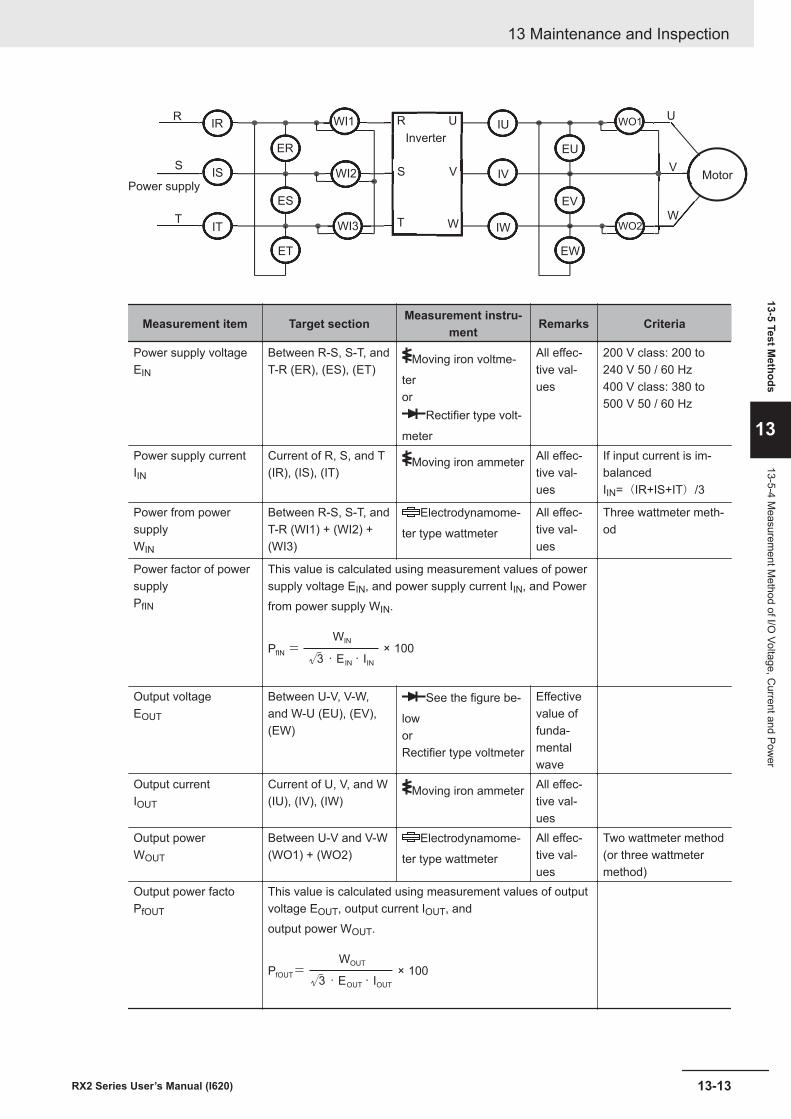
IR
IS
IT
ER
ET
ES
R
T
SS
U
V
W
IU
IV
IW
EU
EW
EV
W
V
UR
S
T
WO1
WO2
WI1
WI2
WI3
Power supply
Inverter
Motor
Measurement item Target section Measurement instru-ment Remarks Criteria
Power supply voltageEIN
Between R-S, S-T, andT-R (ER), (ES), (ET)
Moving iron voltme-
teror
Rectifier type volt-
meter
All effec-tive val-ues
200 V class: 200 to240 V 50 / 60 Hz400 V class: 380 to500 V 50 / 60 Hz
Power supply currentIIN
Current of R, S, and T(IR), (IS), (IT)
Moving iron ammeter All effec-tive val-ues
If input current is im-balancedIIN=(IR+IS+IT)/3
Power from powersupplyWIN
Between R-S, S-T, andT-R (WI1) + (WI2) +(WI3)
Electrodynamome-
ter type wattmeter
All effec-tive val-ues
Three wattmeter meth-od
Power factor of powersupplyPfIN
This value is calculated using measurement values of powersupply voltage EIN, and power supply current IIN, and Powerfrom power supply WIN.
PfIN=WIN
√3・EIN・IIN× 100
Output voltageEOUT
Between U-V, V-W,and W-U (EU), (EV),(EW)
See the figure be-
loworRectifier type voltmeter
Effectivevalue offunda-mentalwave
Output currentIOUT
Current of U, V, and W(IU), (IV), (IW)
Moving iron ammeter All effec-tive val-ues
Output powerWOUT
Between U-V and V-W(WO1) + (WO2)
Electrodynamome-
ter type wattmeter
All effec-tive val-ues
Two wattmeter method(or three wattmetermethod)
Output power factoPfOUT
This value is calculated using measurement values of outputvoltage EOUT, output current IOUT, andoutput power WOUT.
PfOUT=WOUT
√3・EOUT・IOUT× 100
13 Maintenance and Inspection
13-13RX2 Series User’s Manual (I620)
13-5 Test Methods
13
13-5-4 Measurem
ent Method of I/O
Voltage, Current and Pow
er
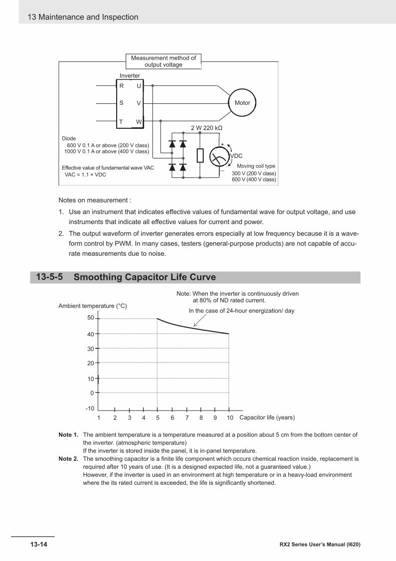
R
T
S
RR
T
S
U
V
W
+
-
VDC
2 W 220 kΩ
Measurement method ofoutput voltage
Inverter
Motor
Diode
600 V 0.1 A or above (200 V class)1000 V 0.1 A or above (400 V class)
VAC = 1.1 × VDC
Effective value of fundamental wave VAC300 V (200 V class)600 V (400 V class)
Moving coil type
Notes on measurement :
1. Use an instrument that indicates effective values of fundamental wave for output voltage, and useinstruments that indicate all effective values for current and power.
2. The output waveform of inverter generates errors especially at low frequency because it is a wave-form control by PWM. In many cases, testers (general-purpose products) are not capable of accu-rate measurements due to noise.
13-5-5 Smoothing Capacitor Life Curve
10
20
30
40
50
0
1 2 3 4 5 6 7 8 9 10
-10
Ambient temperature (°C)
Note: When the inverter is continuously driven at 80% of ND rated current.
In the case of 24-hour energization/ day
Capacitor life (years)
Note 1. The ambient temperature is a temperature measured at a position about 5 cm from the bottom center ofthe inverter. (atmospheric temperature)If the inverter is stored inside the panel, it is in-panel temperature.
Note 2. The smoothing capacitor is a finite life component which occurs chemical reaction inside, replacement isrequired after 10 years of use. (It is a designed expected life, not a guaranteed value.)However, if the inverter is used in an environment at high temperature or in a heavy-load environmentwhere the its rated current is exceeded, the life is significantly shortened.
13 Maintenance and Inspection
13-14 RX2 Series User’s Manual (I620)

13-5-6 Life Alarming OutputWhen the life a component (smoothing capacitor or cooling fan on the board, excluding the main cir-cuit smoothing capacitor) is near its end, an alarm can be generated based on self-diagnosis. Use thisalarm as a sign of part replacement period. For details, see the life diagnosis monitor (dC-16) andoutput terminal function selection (CC-01) to (CC-07). Note that alarms are generated based on di-agnosis of designed expected life (not a guaranteed value). There will be differences due to use envi-ronments, operating conditions, etc. Please conduct maintenance in advance.
13 Maintenance and Inspection
13-15RX2 Series User’s Manual (I620)
13-5 Test Methods
13
13-5-6 Life Alarming O
utput

13 Maintenance and Inspection
13-16 RX2 Series User’s Manual (I620)
14Upgrading from 3G3RX (V1)
This section provides precautions when replacing the 3G3RX Series V1 Inverter withthe 3G3RX2 Series Inverter.
14-1 Comparison of External Dimensions ......................................................... 14-214-1-1 3G3RX-series V1 and 3G3RX2-series.......................................................... 14-2
14-2 Parameter Comparison.............................................................................. 14-11
14-1RX2 Series User’s Manual (I620)
14
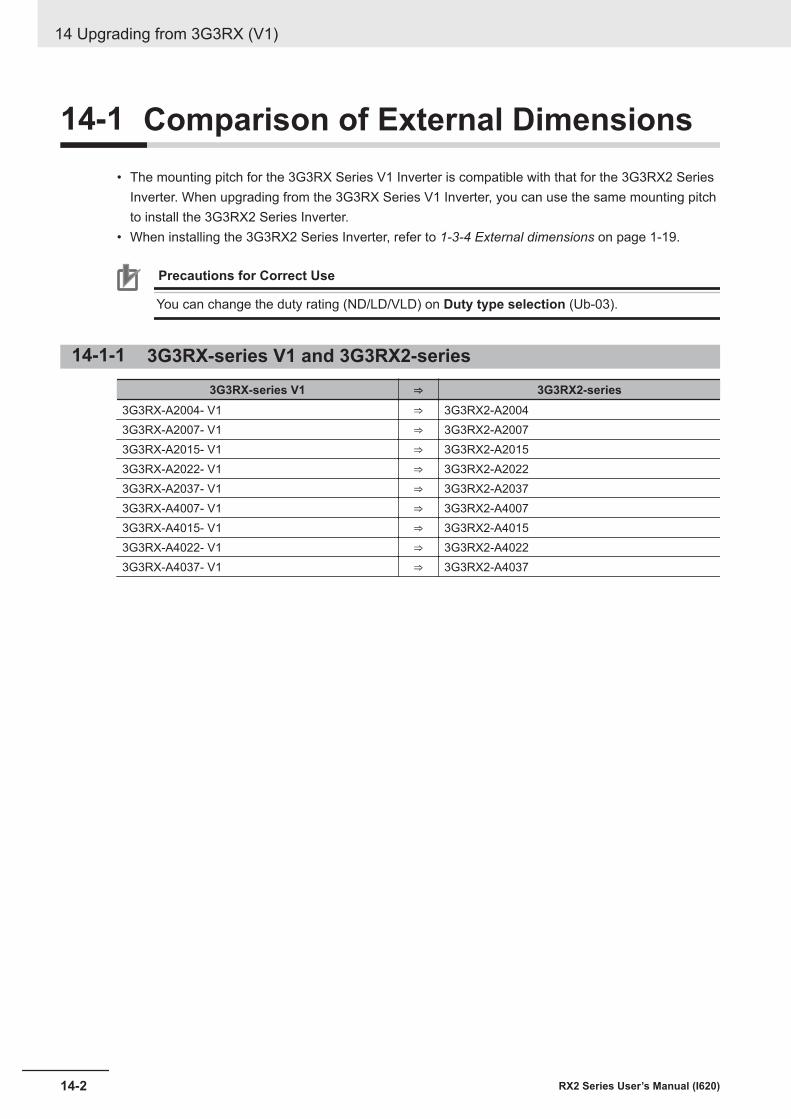
14-1 Comparison of External Dimensions• The mounting pitch for the 3G3RX Series V1 Inverter is compatible with that for the 3G3RX2 Series
Inverter. When upgrading from the 3G3RX Series V1 Inverter, you can use the same mounting pitchto install the 3G3RX2 Series Inverter.
• When installing the 3G3RX2 Series Inverter, refer to 1-3-4 External dimensions on page 1-19.
Precautions for Correct Use
You can change the duty rating (ND/LD/VLD) on Duty type selection (Ub-03).
14-1-1 3G3RX-series V1 and 3G3RX2-series3G3RX-series V1 ⇒ 3G3RX2-series
3G3RX-A2004- V1 ⇒ 3G3RX2-A20043G3RX-A2007- V1 ⇒ 3G3RX2-A20073G3RX-A2015- V1 ⇒ 3G3RX2-A20153G3RX-A2022- V1 ⇒ 3G3RX2-A20223G3RX-A2037- V1 ⇒ 3G3RX2-A20373G3RX-A4007- V1 ⇒ 3G3RX2-A40073G3RX-A4015- V1 ⇒ 3G3RX2-A40153G3RX-A4022- V1 ⇒ 3G3RX2-A40223G3RX-A4037- V1 ⇒ 3G3RX2-A4037
14 Upgrading from 3G3RX (V1)
14-2 RX2 Series User’s Manual (I620)
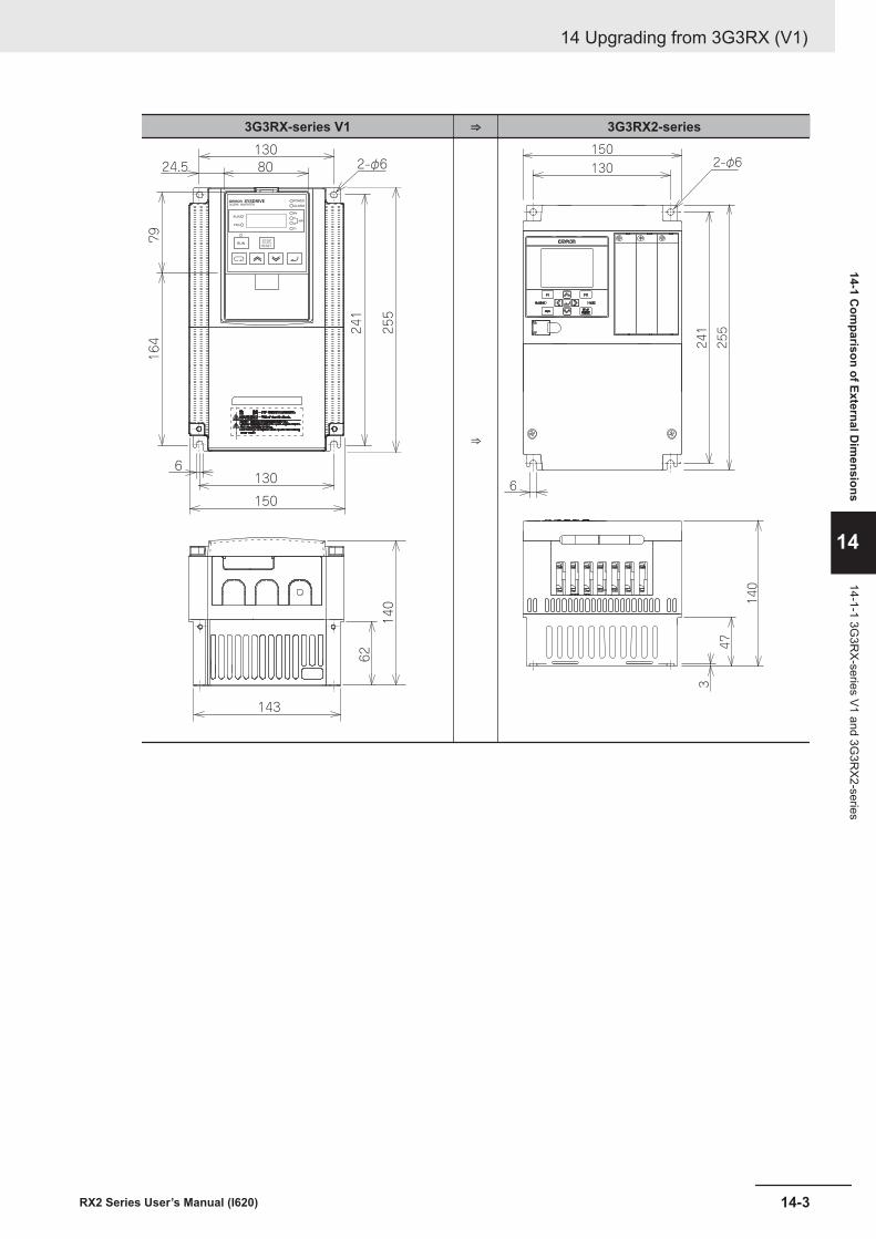
3G3RX-series V1 ⇒ 3G3RX2-series
2-φ6130
24.5
130
150
143
80
6
79164
140
62241
255
⇒
130 2-φ6
241
255
6
150
3
47
140
14 Upgrading from 3G3RX (V1)
14-3RX2 Series User’s Manual (I620)
14-1 Com
parison of External Dim
ensions
14
14-1-1 3G3R
X-series V1 and 3G3R
X2-series
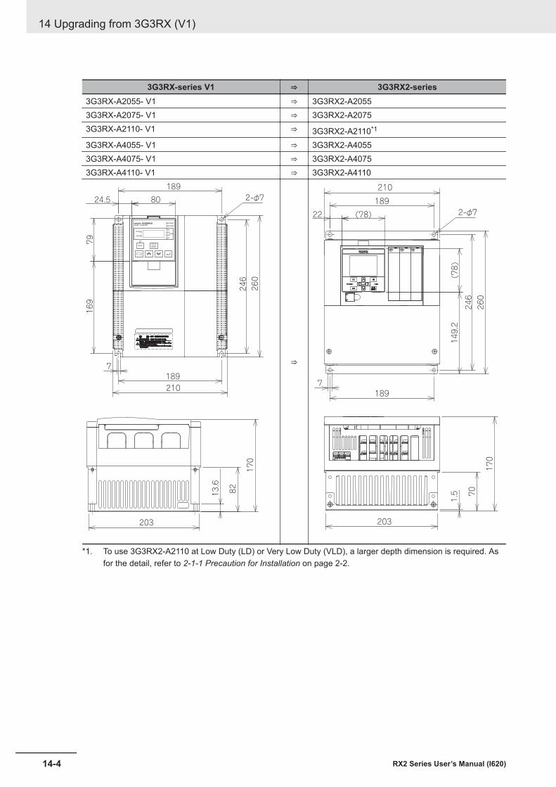
3G3RX-series V1 ⇒ 3G3RX2-series3G3RX-A2055- V1 ⇒ 3G3RX2-A20553G3RX-A2075- V1 ⇒ 3G3RX2-A20753G3RX-A2110- V1 ⇒ 3G3RX2-A2110*1
3G3RX-A4055- V1 ⇒ 3G3RX2-A40553G3RX-A4075- V1 ⇒ 3G3RX2-A40753G3RX-A4110- V1 ⇒ 3G3RX2-A4110
203
8213.6
2-φ7
169
189
24.5 80
1897
246
79
260
210
170
⇒
203
70
1.5
170
2-φ7
149.2
189
22 (78)
1897
246
(78)
260
210
*1. To use 3G3RX2-A2110 at Low Duty (LD) or Very Low Duty (VLD), a larger depth dimension is required. Asfor the detail, refer to 2-1-1 Precaution for Installation on page 2-2.
14 Upgrading from 3G3RX (V1)
14-4 RX2 Series User’s Manual (I620)
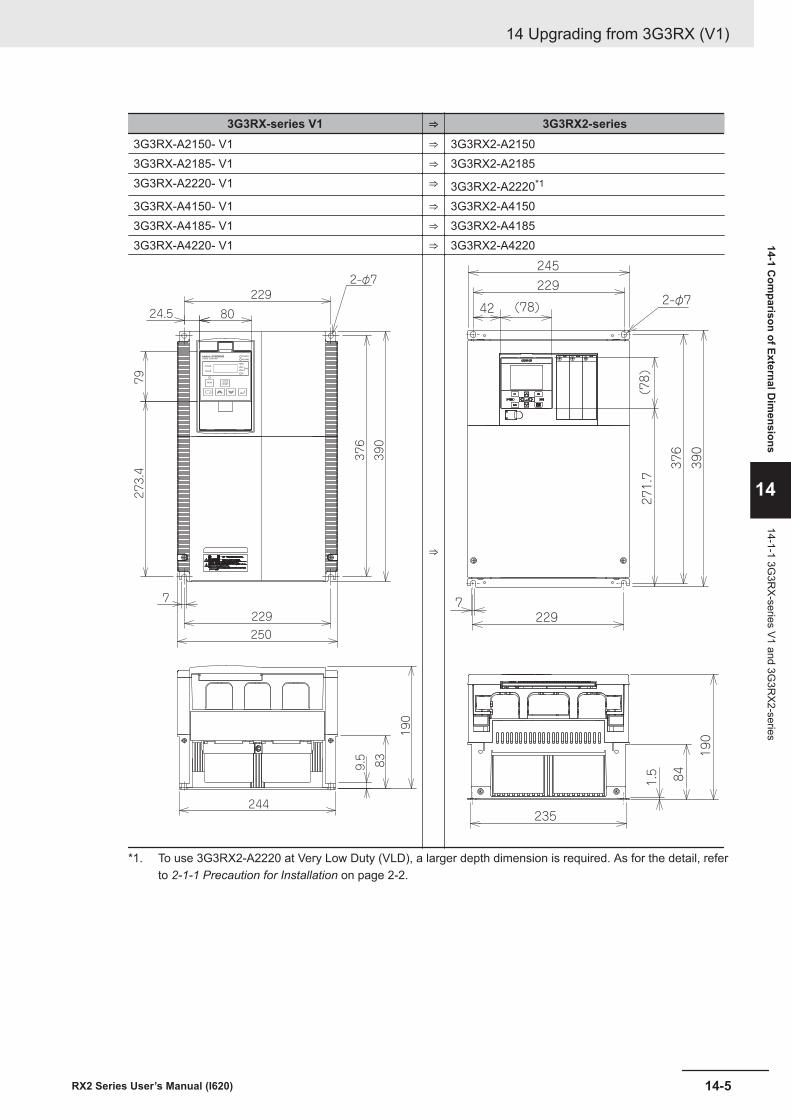
3G3RX-series V1 ⇒ 3G3RX2-series3G3RX-A2150- V1 ⇒ 3G3RX2-A21503G3RX-A2185- V1 ⇒ 3G3RX2-A21853G3RX-A2220- V1 ⇒ 3G3RX2-A2220*1
3G3RX-A4150- V1 ⇒ 3G3RX2-A41503G3RX-A4185- V1 ⇒ 3G3RX2-A41853G3RX-A4220- V1 ⇒ 3G3RX2-A4220
229
24.5 80
79273.4
7229
244
9.5 83
376
390
2-φ7
250
190
⇒
235
841.5
190
2-φ7
271.7
229
42 (78)
2297
376
(78)
390
245
*1. To use 3G3RX2-A2220 at Very Low Duty (VLD), a larger depth dimension is required. As for the detail, referto 2-1-1 Precaution for Installation on page 2-2.
14 Upgrading from 3G3RX (V1)
14-5RX2 Series User’s Manual (I620)
14-1 Com
parison of External Dim
ensions
14
14-1-1 3G3R
X-series V1 and 3G3R
X2-series
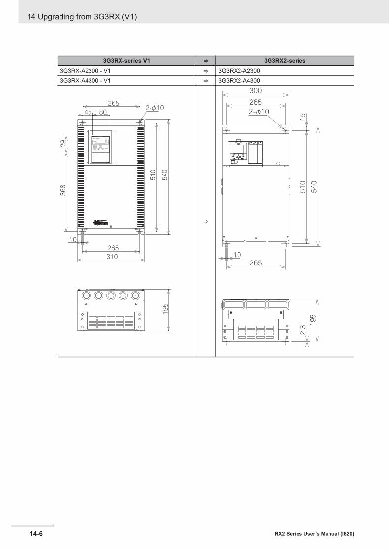
3G3RX-series V1 ⇒ 3G3RX2-series3G3RX-A2300 - V1 ⇒ 3G3RX2-A23003G3RX-A4300 - V1 ⇒ 3G3RX2-A4300
368
79
510
540
2-φ1045 80
265
265310
10
195
⇒
2.3 19
5
265
26510
510
540
300
2-φ10
15
14 Upgrading from 3G3RX (V1)
14-6 RX2 Series User’s Manual (I620)
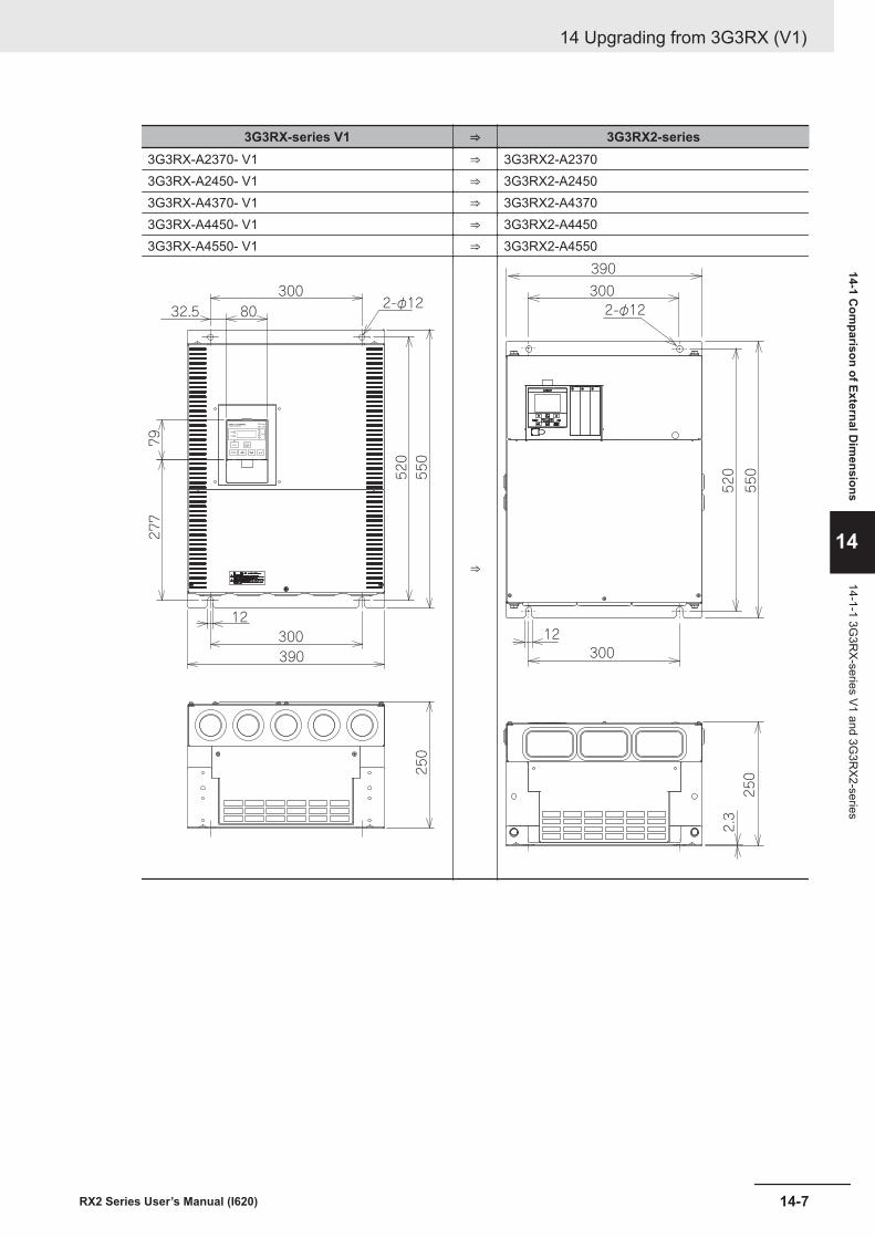
3G3RX-series V1 ⇒ 3G3RX2-series3G3RX-A2370- V1 ⇒ 3G3RX2-A23703G3RX-A2450- V1 ⇒ 3G3RX2-A24503G3RX-A4370- V1 ⇒ 3G3RX2-A43703G3RX-A4450- V1 ⇒ 3G3RX2-A44503G3RX-A4550- V1 ⇒ 3G3RX2-A4550
390
12300
277
79
520
550
250
2-φ12300
8032.5
⇒
2.3
250
300
30012
520
550
390
2-φ12
14 Upgrading from 3G3RX (V1)
14-7RX2 Series User’s Manual (I620)
14-1 Com
parison of External Dim
ensions
14
14-1-1 3G3R
X-series V1 and 3G3R
X2-series
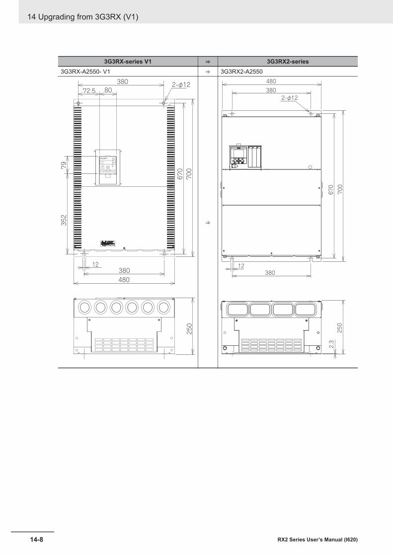
3G3RX-series V1 ⇒ 3G3RX2-series3G3RX-A2550- V1 ⇒ 3G3RX2-A2550
380
670
700
12380480
250
352
79
8072.52-φ12
⇒
2.3
250
380
38012
670
700
480
2-φ12
14 Upgrading from 3G3RX (V1)
14-8 RX2 Series User’s Manual (I620)
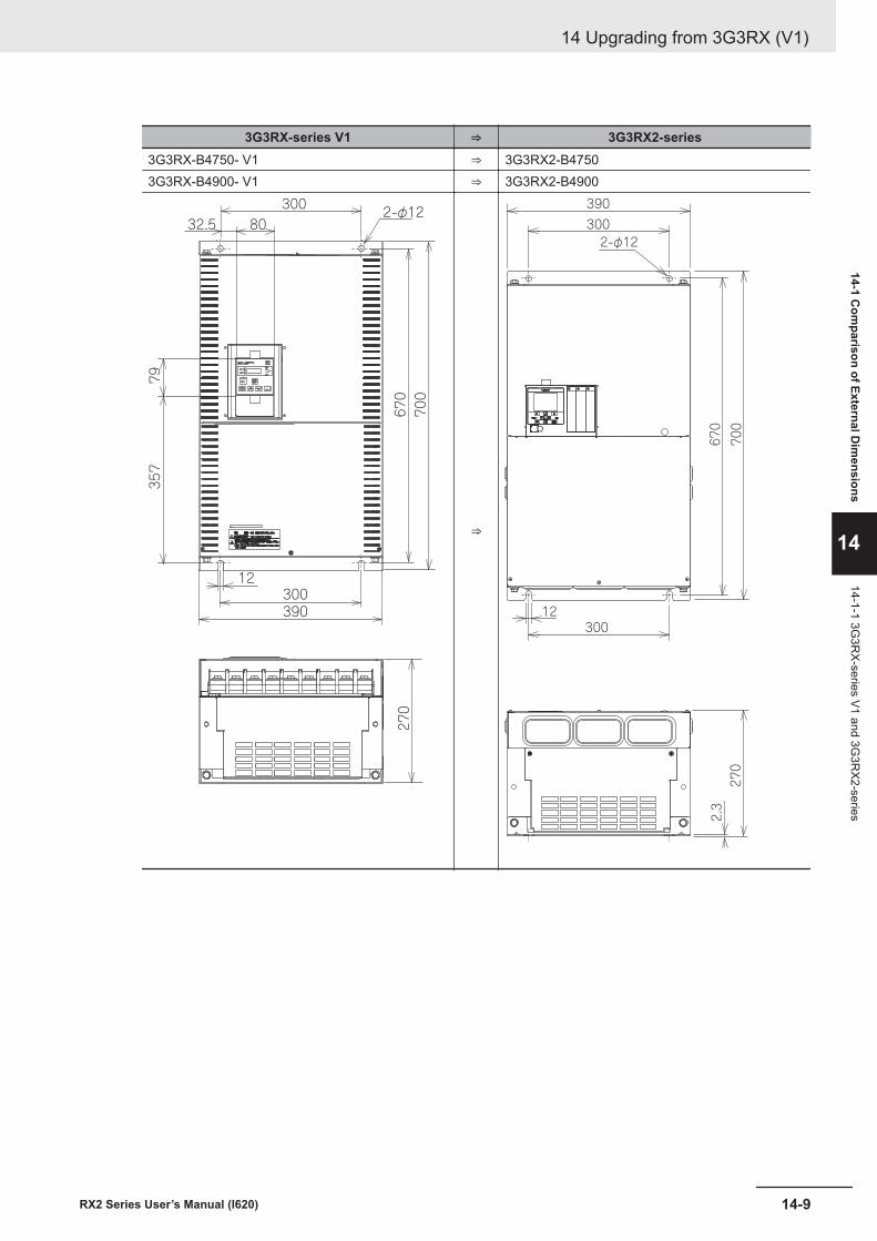
3G3RX-series V1 ⇒ 3G3RX2-series3G3RX-B4750- V1 ⇒ 3G3RX2-B47503G3RX-B4900- V1 ⇒ 3G3RX2-B4900
270
670
700
2-φ12
7935
7
3008032.5
12300390
⇒
2.3
270
300
30012
670
700
390
2-φ12
14 Upgrading from 3G3RX (V1)
14-9RX2 Series User’s Manual (I620)
14-1 Com
parison of External Dim
ensions
14
14-1-1 3G3R
X-series V1 and 3G3R
X2-series
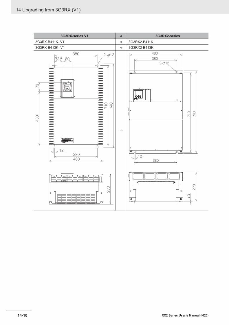
3G3RX-series V1 ⇒ 3G3RX2-series3G3RX-B411K- V1 ⇒ 3G3RX2-B411K3G3RX-B413K- V1 ⇒ 3G3RX2-B413K
3808072.5
79480
12380480
740
710
2-φ12
270
⇒
2.3
270
380
38012
710
740
480
2-φ12
14 Upgrading from 3G3RX (V1)
14-10 RX2 Series User’s Manual (I620)
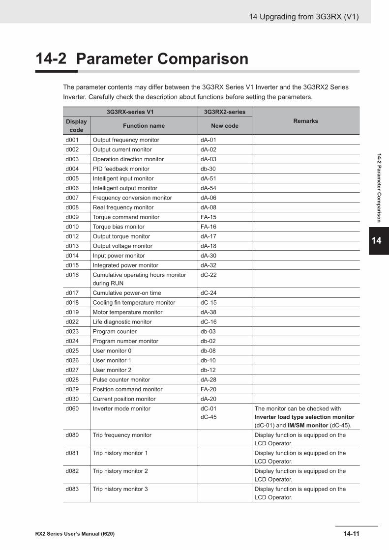
14-2 Parameter ComparisonThe parameter contents may differ between the 3G3RX Series V1 Inverter and the 3G3RX2 SeriesInverter. Carefully check the description about functions before setting the parameters.
3G3RX-series V1 3G3RX2-seriesRemarksDisplay
code Function name New code
d001 Output frequency monitor dA-01d002 Output current monitor dA-02d003 Operation direction monitor dA-03d004 PID feedback monitor db-30d005 Intelligent input monitor dA-51d006 Intelligent output monitor dA-54d007 Frequency conversion monitor dA-06d008 Real frequency monitor dA-08d009 Torque command monitor FA-15d010 Torque bias monitor FA-16d012 Output torque monitor dA-17d013 Output voltage monitor dA-18d014 Input power monitor dA-30d015 Integrated power monitor dA-32d016 Cumulative operating hours monitor
during RUNdC-22
d017 Cumulative power-on time dC-24d018 Cooling fin temperature monitor dC-15d019 Motor temperature monitor dA-38d022 Life diagnostic monitor dC-16d023 Program counter db-03d024 Program number monitor db-02d025 User monitor 0 db-08d026 User monitor 1 db-10d027 User monitor 2 db-12d028 Pulse counter monitor dA-28d029 Position command monitor FA-20d030 Current position monitor dA-20d060 Inverter mode monitor dC-01
dC-45The monitor can be checked withInverter load type selection monitor(dC-01) and IM/SM monitor (dC-45).
d080 Trip frequency monitor Display function is equipped on theLCD Operator.
d081 Trip history monitor 1 Display function is equipped on theLCD Operator.
d082 Trip history monitor 2 Display function is equipped on theLCD Operator.
d083 Trip history monitor 3 Display function is equipped on theLCD Operator.
14 Upgrading from 3G3RX (V1)
14-11RX2 Series User’s Manual (I620)
14-2 Parameter C
omparison
14
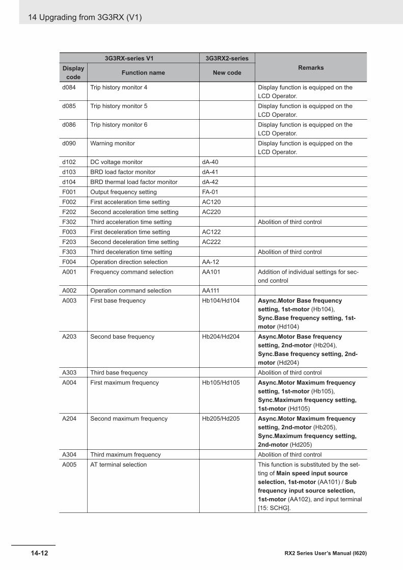
3G3RX-series V1 3G3RX2-seriesRemarksDisplay
code Function name New code
d084 Trip history monitor 4 Display function is equipped on theLCD Operator.
d085 Trip history monitor 5 Display function is equipped on theLCD Operator.
d086 Trip history monitor 6 Display function is equipped on theLCD Operator.
d090 Warning monitor Display function is equipped on theLCD Operator.
d102 DC voltage monitor dA-40d103 BRD load factor monitor dA-41d104 BRD thermal load factor monitor dA-42F001 Output frequency setting FA-01F002 First acceleration time setting AC120F202 Second acceleration time setting AC220F302 Third acceleration time setting Abolition of third controlF003 First deceleration time setting AC122F203 Second deceleration time setting AC222F303 Third deceleration time setting Abolition of third controlF004 Operation direction selection AA-12A001 Frequency command selection AA101 Addition of individual settings for sec-
ond controlA002 Operation command selection AA111A003 First base frequency Hb104/Hd104 Async.Motor Base frequency
setting, 1st-motor (Hb104),Sync.Base frequency setting, 1st-motor (Hd104)
A203 Second base frequency Hb204/Hd204 Async.Motor Base frequencysetting, 2nd-motor (Hb204),Sync.Base frequency setting, 2nd-motor (Hd204)
A303 Third base frequency Abolition of third controlA004 First maximum frequency Hb105/Hd105 Async.Motor Maximum frequency
setting, 1st-motor (Hb105),Sync.Maximum frequency setting,1st-motor (Hd105)
A204 Second maximum frequency Hb205/Hd205 Async.Motor Maximum frequencysetting, 2nd-motor (Hb205),Sync.Maximum frequency setting,2nd-motor (Hd205)
A304 Third maximum frequency Abolition of third controlA005 AT terminal selection This function is substituted by the set-
ting of Main speed input sourceselection, 1st-motor (AA101) / Subfrequency input source selection,1st-motor (AA102), and input terminal[15: SCHG].
14 Upgrading from 3G3RX (V1)
14-12 RX2 Series User’s Manual (I620)
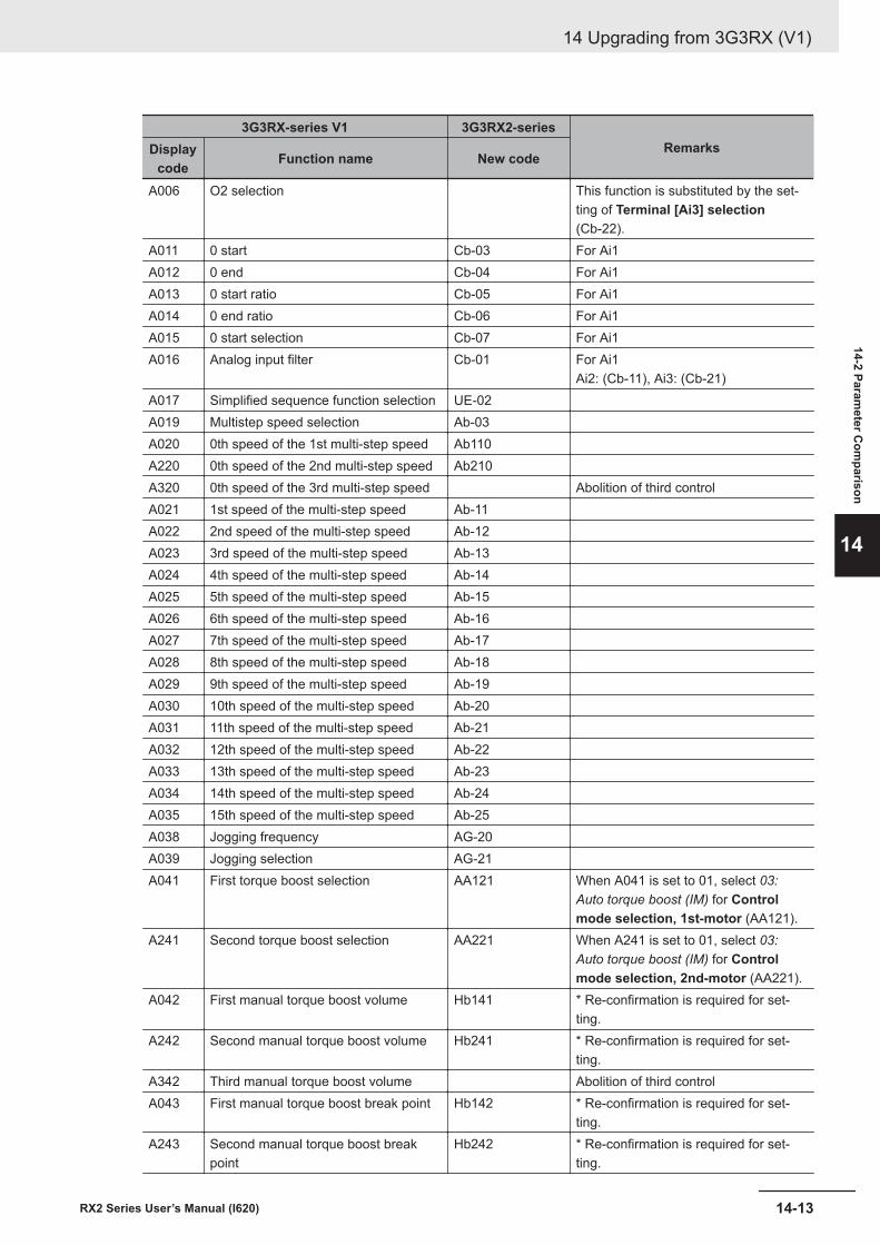
3G3RX-series V1 3G3RX2-seriesRemarksDisplay
code Function name New code
A006 O2 selection This function is substituted by the set-ting of Terminal [Ai3] selection(Cb-22).
A011 0 start Cb-03 For Ai1A012 0 end Cb-04 For Ai1A013 0 start ratio Cb-05 For Ai1A014 0 end ratio Cb-06 For Ai1A015 0 start selection Cb-07 For Ai1A016 Analog input filter Cb-01 For Ai1
Ai2: (Cb-11), Ai3: (Cb-21)A017 Simplified sequence function selection UE-02A019 Multistep speed selection Ab-03A020 0th speed of the 1st multi-step speed Ab110A220 0th speed of the 2nd multi-step speed Ab210A320 0th speed of the 3rd multi-step speed Abolition of third controlA021 1st speed of the multi-step speed Ab-11A022 2nd speed of the multi-step speed Ab-12A023 3rd speed of the multi-step speed Ab-13A024 4th speed of the multi-step speed Ab-14A025 5th speed of the multi-step speed Ab-15A026 6th speed of the multi-step speed Ab-16A027 7th speed of the multi-step speed Ab-17A028 8th speed of the multi-step speed Ab-18A029 9th speed of the multi-step speed Ab-19A030 10th speed of the multi-step speed Ab-20A031 11th speed of the multi-step speed Ab-21A032 12th speed of the multi-step speed Ab-22A033 13th speed of the multi-step speed Ab-23A034 14th speed of the multi-step speed Ab-24A035 15th speed of the multi-step speed Ab-25A038 Jogging frequency AG-20A039 Jogging selection AG-21A041 First torque boost selection AA121 When A041 is set to 01, select 03:
Auto torque boost (IM) for Controlmode selection, 1st-motor (AA121).
A241 Second torque boost selection AA221 When A241 is set to 01, select 03:Auto torque boost (IM) for Controlmode selection, 2nd-motor (AA221).
A042 First manual torque boost volume Hb141 * Re-confirmation is required for set-ting.
A242 Second manual torque boost volume Hb241 * Re-confirmation is required for set-ting.
A342 Third manual torque boost volume Abolition of third controlA043 First manual torque boost break point Hb142 * Re-confirmation is required for set-
ting.A243 Second manual torque boost break
pointHb242 * Re-confirmation is required for set-
ting.
14 Upgrading from 3G3RX (V1)
14-13RX2 Series User’s Manual (I620)
14-2 Parameter C
omparison
14
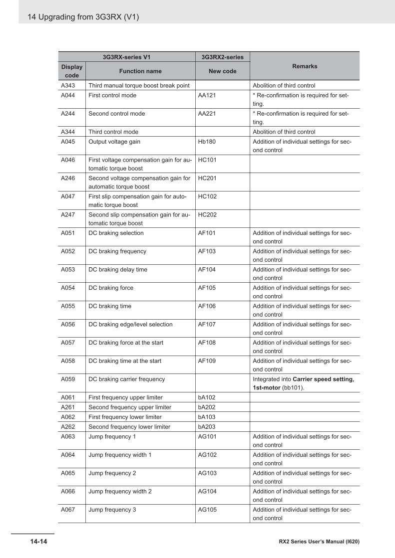
3G3RX-series V1 3G3RX2-seriesRemarksDisplay
code Function name New code
A343 Third manual torque boost break point Abolition of third controlA044 First control mode AA121 * Re-confirmation is required for set-
ting.A244 Second control mode AA221 * Re-confirmation is required for set-
ting.A344 Third control mode Abolition of third controlA045 Output voltage gain Hb180 Addition of individual settings for sec-
ond controlA046 First voltage compensation gain for au-
tomatic torque boostHC101
A246 Second voltage compensation gain forautomatic torque boost
HC201
A047 First slip compensation gain for auto-matic torque boost
HC102
A247 Second slip compensation gain for au-tomatic torque boost
HC202
A051 DC braking selection AF101 Addition of individual settings for sec-ond control
A052 DC braking frequency AF103 Addition of individual settings for sec-ond control
A053 DC braking delay time AF104 Addition of individual settings for sec-ond control
A054 DC braking force AF105 Addition of individual settings for sec-ond control
A055 DC braking time AF106 Addition of individual settings for sec-ond control
A056 DC braking edge/level selection AF107 Addition of individual settings for sec-ond control
A057 DC braking force at the start AF108 Addition of individual settings for sec-ond control
A058 DC braking time at the start AF109 Addition of individual settings for sec-ond control
A059 DC braking carrier frequency Integrated into Carrier speed setting,1st-motor (bb101).
A061 First frequency upper limiter bA102A261 Second frequency upper limiter bA202A062 First frequency lower limiter bA103A262 Second frequency lower limiter bA203A063 Jump frequency 1 AG101 Addition of individual settings for sec-
ond controlA064 Jump frequency width 1 AG102 Addition of individual settings for sec-
ond controlA065 Jump frequency 2 AG103 Addition of individual settings for sec-
ond controlA066 Jump frequency width 2 AG104 Addition of individual settings for sec-
ond controlA067 Jump frequency 3 AG105 Addition of individual settings for sec-
ond control
14 Upgrading from 3G3RX (V1)
14-14 RX2 Series User’s Manual (I620)
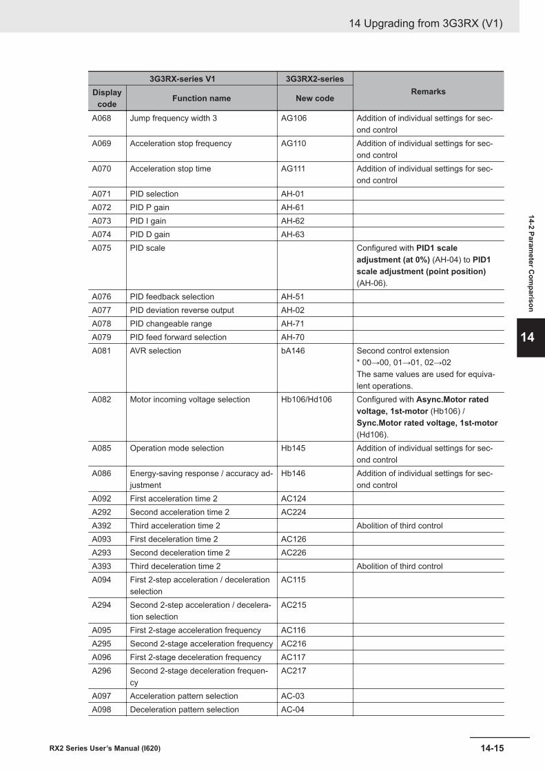
3G3RX-series V1 3G3RX2-seriesRemarksDisplay
code Function name New code
A068 Jump frequency width 3 AG106 Addition of individual settings for sec-ond control
A069 Acceleration stop frequency AG110 Addition of individual settings for sec-ond control
A070 Acceleration stop time AG111 Addition of individual settings for sec-ond control
A071 PID selection AH-01A072 PID P gain AH-61A073 PID I gain AH-62A074 PID D gain AH-63A075 PID scale Configured with PID1 scale
adjustment (at 0%) (AH-04) to PID1scale adjustment (point position)(AH-06).
A076 PID feedback selection AH-51A077 PID deviation reverse output AH-02A078 PID changeable range AH-71A079 PID feed forward selection AH-70A081 AVR selection bA146 Second control extension
* 00→00, 01→01, 02→02The same values are used for equiva-lent operations.
A082 Motor incoming voltage selection Hb106/Hd106 Configured with Async.Motor ratedvoltage, 1st-motor (Hb106) /Sync.Motor rated voltage, 1st-motor(Hd106).
A085 Operation mode selection Hb145 Addition of individual settings for sec-ond control
A086 Energy-saving response / accuracy ad-justment
Hb146 Addition of individual settings for sec-ond control
A092 First acceleration time 2 AC124A292 Second acceleration time 2 AC224A392 Third acceleration time 2 Abolition of third controlA093 First deceleration time 2 AC126A293 Second deceleration time 2 AC226A393 Third deceleration time 2 Abolition of third controlA094 First 2-step acceleration / deceleration
selectionAC115
A294 Second 2-step acceleration / decelera-tion selection
AC215
A095 First 2-stage acceleration frequency AC116A295 Second 2-stage acceleration frequency AC216A096 First 2-stage deceleration frequency AC117A296 Second 2-stage deceleration frequen-
cyAC217
A097 Acceleration pattern selection AC-03A098 Deceleration pattern selection AC-04
14 Upgrading from 3G3RX (V1)
14-15RX2 Series User’s Manual (I620)
14-2 Parameter C
omparison
14
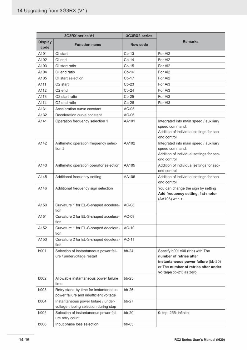
3G3RX-series V1 3G3RX2-seriesRemarksDisplay
code Function name New code
A101 OI start Cb-13 For Ai2A102 OI end Cb-14 For Ai2A103 OI start ratio Cb-15 For Ai2A104 OI end ratio Cb-16 For Ai2A105 OI start selection Cb-17 For Ai2A111 O2 start Cb-23 For Ai3A112 O2 end Cb-24 For Ai3A113 O2 start ratio Cb-25 For Ai3A114 O2 end ratio Cb-26 For Ai3A131 Acceleration curve constant AC-05A132 Deceleration curve constant AC-06A141 Operation frequency selection 1 AA101 Integrated into main speed / auxiliary
speed command.Addition of individual settings for sec-ond control
A142 Arithmetic operation frequency selec-tion 2
AA102 Integrated into main speed / auxiliaryspeed command.Addition of individual settings for sec-ond control
A143 Arithmetic operation operator selection AA105 Addition of individual settings for sec-ond control
A145 Additional frequency setting AA106 Addition of individual settings for sec-ond control
A146 Additional frequency sign selection You can change the sign by settingAdd frequency setting, 1st-motor(AA106) with ±.
A150 Curvature 1 for EL-S-shaped accelera-tion
AC-08
A151 Curvature 2 for EL-S-shaped accelera-tion
AC-09
A152 Curvature 1 for EL-S-shaped decelera-tion
AC-10
A153 Curvature 2 for EL-S-shaped decelera-tion
AC-11
b001 Selection of instantaneous power fail-ure / undervoltage restart
bb-24 Specify b001=00 (trip) with Thenumber of retries afterinstantaneous power failure (bb-20)or The number of retries after undervoltage(bb-21) as zero.
b002 Allowable instantaneous power failuretime
bb-25
b003 Retry stand-by time for instantaneouspower failure and insufficient voltage
bb-26
b004 Instantaneous power failure / under-voltage tripping selection during stop
bb-27
b005 Selection of instantaneous power fail-ure retry count
bb-20 0: trip, 255: infinite
b006 Input phase loss selection bb-65
14 Upgrading from 3G3RX (V1)
14-16 RX2 Series User’s Manual (I620)
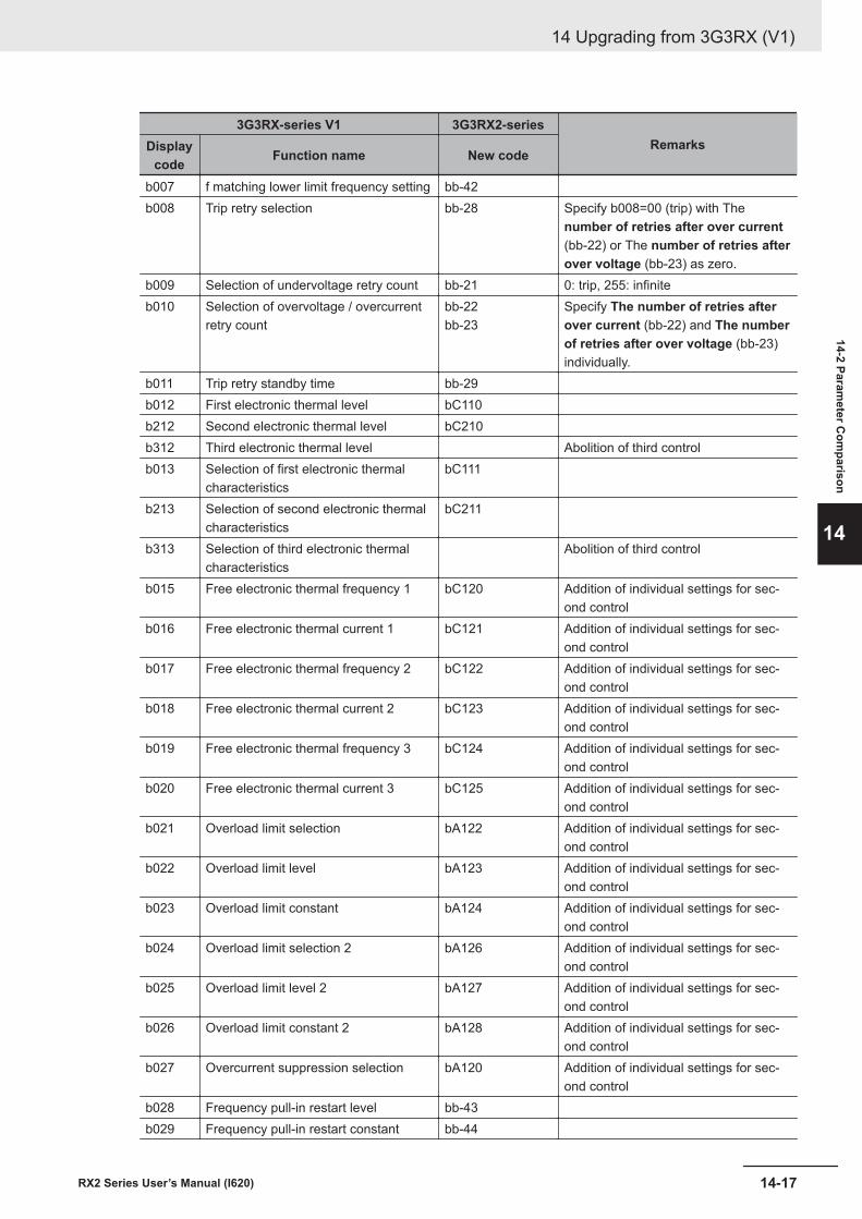
3G3RX-series V1 3G3RX2-seriesRemarksDisplay
code Function name New code
b007 f matching lower limit frequency setting bb-42b008 Trip retry selection bb-28 Specify b008=00 (trip) with The
number of retries after over current(bb-22) or The number of retries afterover voltage (bb-23) as zero.
b009 Selection of undervoltage retry count bb-21 0: trip, 255: infiniteb010 Selection of overvoltage / overcurrent
retry countbb-22bb-23
Specify The number of retries afterover current (bb-22) and The numberof retries after over voltage (bb-23)individually.
b011 Trip retry standby time bb-29b012 First electronic thermal level bC110b212 Second electronic thermal level bC210b312 Third electronic thermal level Abolition of third controlb013 Selection of first electronic thermal
characteristicsbC111
b213 Selection of second electronic thermalcharacteristics
bC211
b313 Selection of third electronic thermalcharacteristics
Abolition of third control
b015 Free electronic thermal frequency 1 bC120 Addition of individual settings for sec-ond control
b016 Free electronic thermal current 1 bC121 Addition of individual settings for sec-ond control
b017 Free electronic thermal frequency 2 bC122 Addition of individual settings for sec-ond control
b018 Free electronic thermal current 2 bC123 Addition of individual settings for sec-ond control
b019 Free electronic thermal frequency 3 bC124 Addition of individual settings for sec-ond control
b020 Free electronic thermal current 3 bC125 Addition of individual settings for sec-ond control
b021 Overload limit selection bA122 Addition of individual settings for sec-ond control
b022 Overload limit level bA123 Addition of individual settings for sec-ond control
b023 Overload limit constant bA124 Addition of individual settings for sec-ond control
b024 Overload limit selection 2 bA126 Addition of individual settings for sec-ond control
b025 Overload limit level 2 bA127 Addition of individual settings for sec-ond control
b026 Overload limit constant 2 bA128 Addition of individual settings for sec-ond control
b027 Overcurrent suppression selection bA120 Addition of individual settings for sec-ond control
b028 Frequency pull-in restart level bb-43b029 Frequency pull-in restart constant bb-44
14 Upgrading from 3G3RX (V1)
14-17RX2 Series User’s Manual (I620)
14-2 Parameter C
omparison
14
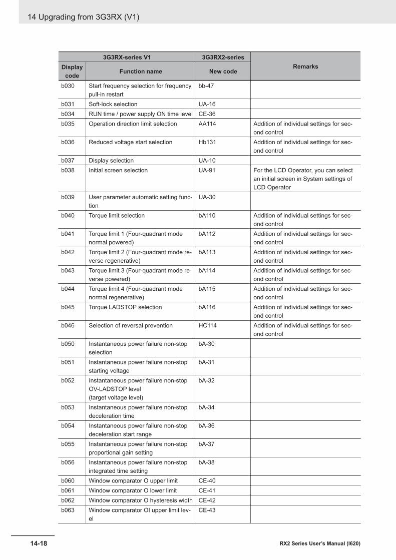
3G3RX-series V1 3G3RX2-seriesRemarksDisplay
code Function name New code
b030 Start frequency selection for frequencypull-in restart
bb-47
b031 Soft-lock selection UA-16b034 RUN time / power supply ON time level CE-36b035 Operation direction limit selection AA114 Addition of individual settings for sec-
ond controlb036 Reduced voltage start selection Hb131 Addition of individual settings for sec-
ond controlb037 Display selection UA-10b038 Initial screen selection UA-91 For the LCD Operator, you can select
an initial screen in System settings ofLCD Operator
b039 User parameter automatic setting func-tion
UA-30
b040 Torque limit selection bA110 Addition of individual settings for sec-ond control
b041 Torque limit 1 (Four-quadrant modenormal powered)
bA112 Addition of individual settings for sec-ond control
b042 Torque limit 2 (Four-quadrant mode re-verse regenerative)
bA113 Addition of individual settings for sec-ond control
b043 Torque limit 3 (Four-quadrant mode re-verse powered)
bA114 Addition of individual settings for sec-ond control
b044 Torque limit 4 (Four-quadrant modenormal regenerative)
bA115 Addition of individual settings for sec-ond control
b045 Torque LADSTOP selection bA116 Addition of individual settings for sec-ond control
b046 Selection of reversal prevention HC114 Addition of individual settings for sec-ond control
b050 Instantaneous power failure non-stopselection
bA-30
b051 Instantaneous power failure non-stopstarting voltage
bA-31
b052 Instantaneous power failure non-stopOV-LADSTOP level(target voltage level)
bA-32
b053 Instantaneous power failure non-stopdeceleration time
bA-34
b054 Instantaneous power failure non-stopdeceleration start range
bA-36
b055 Instantaneous power failure non-stopproportional gain setting
bA-37
b056 Instantaneous power failure non-stopintegrated time setting
bA-38
b060 Window comparator O upper limit CE-40b061 Window comparator O lower limit CE-41b062 Window comparator O hysteresis width CE-42b063 Window comparator OI upper limit lev-
elCE-43
14 Upgrading from 3G3RX (V1)
14-18 RX2 Series User’s Manual (I620)
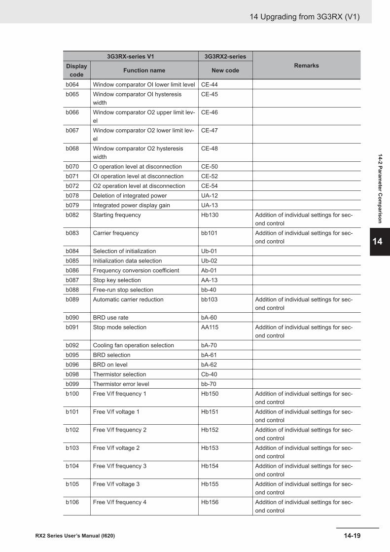
3G3RX-series V1 3G3RX2-seriesRemarksDisplay
code Function name New code
b064 Window comparator OI lower limit level CE-44b065 Window comparator OI hysteresis
widthCE-45
b066 Window comparator O2 upper limit lev-el
CE-46
b067 Window comparator O2 lower limit lev-el
CE-47
b068 Window comparator O2 hysteresiswidth
CE-48
b070 O operation level at disconnection CE-50b071 OI operation level at disconnection CE-52b072 O2 operation level at disconnection CE-54b078 Deletion of integrated power UA-12b079 Integrated power display gain UA-13b082 Starting frequency Hb130 Addition of individual settings for sec-
ond controlb083 Carrier frequency bb101 Addition of individual settings for sec-
ond controlb084 Selection of initialization Ub-01b085 Initialization data selection Ub-02b086 Frequency conversion coefficient Ab-01b087 Stop key selection AA-13b088 Free-run stop selection bb-40b089 Automatic carrier reduction bb103 Addition of individual settings for sec-
ond controlb090 BRD use rate bA-60b091 Stop mode selection AA115 Addition of individual settings for sec-
ond controlb092 Cooling fan operation selection bA-70b095 BRD selection bA-61b096 BRD on level bA-62b098 Thermistor selection Cb-40b099 Thermistor error level bb-70b100 Free V/f frequency 1 Hb150 Addition of individual settings for sec-
ond controlb101 Free V/f voltage 1 Hb151 Addition of individual settings for sec-
ond controlb102 Free V/f frequency 2 Hb152 Addition of individual settings for sec-
ond controlb103 Free V/f voltage 2 Hb153 Addition of individual settings for sec-
ond controlb104 Free V/f frequency 3 Hb154 Addition of individual settings for sec-
ond controlb105 Free V/f voltage 3 Hb155 Addition of individual settings for sec-
ond controlb106 Free V/f frequency 4 Hb156 Addition of individual settings for sec-
ond control
14 Upgrading from 3G3RX (V1)
14-19RX2 Series User’s Manual (I620)
14-2 Parameter C
omparison
14
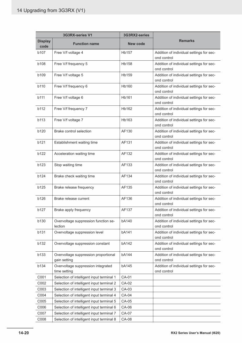
3G3RX-series V1 3G3RX2-seriesRemarksDisplay
code Function name New code
b107 Free V/f voltage 4 Hb157 Addition of individual settings for sec-ond control
b108 Free V/f frequency 5 Hb158 Addition of individual settings for sec-ond control
b109 Free V/f voltage 5 Hb159 Addition of individual settings for sec-ond control
b110 Free V/f frequency 6 Hb160 Addition of individual settings for sec-ond control
b111 Free V/f voltage 6 Hb161 Addition of individual settings for sec-ond control
b112 Free V/f frequency 7 Hb162 Addition of individual settings for sec-ond control
b113 Free V/f voltage 7 Hb163 Addition of individual settings for sec-ond control
b120 Brake control selection AF130 Addition of individual settings for sec-ond control
b121 Establishment waiting time AF131 Addition of individual settings for sec-ond control
b122 Acceleration waiting time AF132 Addition of individual settings for sec-ond control
b123 Stop waiting time AF133 Addition of individual settings for sec-ond control
b124 Brake check waiting time AF134 Addition of individual settings for sec-ond control
b125 Brake release frequency AF135 Addition of individual settings for sec-ond control
b126 Brake release current AF136 Addition of individual settings for sec-ond control
b127 Brake apply frequency AF137 Addition of individual settings for sec-ond control
b130 Overvoltage suppression function se-lection
bA140 Addition of individual settings for sec-ond control
b131 Overvoltage suppression level bA141 Addition of individual settings for sec-ond control
b132 Overvoltage suppression constant bA142 Addition of individual settings for sec-ond control
b133 Overvoltage suppression proportionalgain setting
bA144 Addition of individual settings for sec-ond control
b134 Overvoltage suppression integratedtime setting
bA145 Addition of individual settings for sec-ond control
C001 Selection of intelligent input terminal 1 CA-01C002 Selection of intelligent input terminal 2 CA-02C003 Selection of intelligent input terminal 3 CA-03C004 Selection of intelligent input terminal 4 CA-04C005 Selection of intelligent input terminal 5 CA-05C006 Selection of intelligent input terminal 6 CA-06C007 Selection of intelligent input terminal 7 CA-07C008 Selection of intelligent input terminal 8 CA-08
14 Upgrading from 3G3RX (V1)
14-20 RX2 Series User’s Manual (I620)
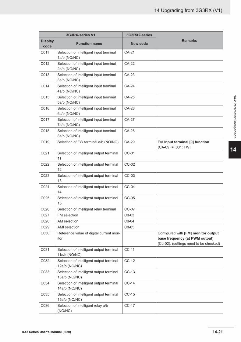
3G3RX-series V1 3G3RX2-seriesRemarksDisplay
code Function name New code
C011 Selection of intelligent input terminal1a/b (NO/NC)
CA-21
C012 Selection of intelligent input terminal2a/b (NO/NC)
CA-22
C013 Selection of intelligent input terminal3a/b (NO/NC)
CA-23
C014 Selection of intelligent input terminal4a/b (NO/NC)
CA-24
C015 Selection of intelligent input terminal5a/b (NO/NC)
CA-25
C016 Selection of intelligent input terminal6a/b (NO/NC)
CA-26
C017 Selection of intelligent input terminal7a/b (NO/NC)
CA-27
C018 Selection of intelligent input terminal8a/b (NO/NC)
CA-28
C019 Selection of FW terminal a/b (NO/NC) CA-29 For Input terminal [9] function(CA-09) = [001: FW]
C021 Selection of intelligent output terminal11
CC-01
C022 Selection of intelligent output terminal12
CC-02
C023 Selection of intelligent output terminal13
CC-03
C024 Selection of intelligent output terminal14
CC-04
C025 Selection of intelligent output terminal15
CC-05
C026 Selection of intelligent relay terminal CC-07C027 FM selection Cd-03C028 AM selection Cd-04C029 AMI selection Cd-05C030 Reference value of digital current mon-
itorConfigured with [FM] monitor outputbase frequency (at PWM output)(Cd-02). (settings need to be checked)
C031 Selection of intelligent output terminal11a/b (NO/NC)
CC-11
C032 Selection of intelligent output terminal12a/b (NO/NC)
CC-12
C033 Selection of intelligent output terminal13a/b (NO/NC)
CC-13
C034 Selection of intelligent output terminal14a/b (NO/NC)
CC-14
C035 Selection of intelligent output terminal15a/b (NO/NC)
CC-15
C036 Selection of intelligent relay a/b(NO/NC)
CC-17
14 Upgrading from 3G3RX (V1)
14-21RX2 Series User’s Manual (I620)
14-2 Parameter C
omparison
14
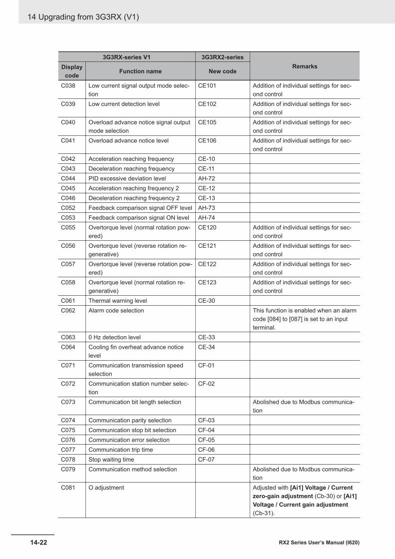
3G3RX-series V1 3G3RX2-seriesRemarksDisplay
code Function name New code
C038 Low current signal output mode selec-tion
CE101 Addition of individual settings for sec-ond control
C039 Low current detection level CE102 Addition of individual settings for sec-ond control
C040 Overload advance notice signal outputmode selection
CE105 Addition of individual settings for sec-ond control
C041 Overload advance notice level CE106 Addition of individual settings for sec-ond control
C042 Acceleration reaching frequency CE-10C043 Deceleration reaching frequency CE-11C044 PID excessive deviation level AH-72C045 Acceleration reaching frequency 2 CE-12C046 Deceleration reaching frequency 2 CE-13C052 Feedback comparison signal OFF level AH-73C053 Feedback comparison signal ON level AH-74C055 Overtorque level (normal rotation pow-
ered)CE120 Addition of individual settings for sec-
ond controlC056 Overtorque level (reverse rotation re-
generative)CE121 Addition of individual settings for sec-
ond controlC057 Overtorque level (reverse rotation pow-
ered)CE122 Addition of individual settings for sec-
ond controlC058 Overtorque level (normal rotation re-
generative)CE123 Addition of individual settings for sec-
ond controlC061 Thermal warning level CE-30C062 Alarm code selection This function is enabled when an alarm
code [084] to [087] is set to an inputterminal.
C063 0 Hz detection level CE-33C064 Cooling fin overheat advance notice
levelCE-34
C071 Communication transmission speedselection
CF-01
C072 Communication station number selec-tion
CF-02
C073 Communication bit length selection Abolished due to Modbus communica-tion
C074 Communication parity selection CF-03C075 Communication stop bit selection CF-04C076 Communication error selection CF-05C077 Communication trip time CF-06C078 Stop waiting time CF-07C079 Communication method selection Abolished due to Modbus communica-
tionC081 O adjustment Adjusted with [Ai1] Voltage / Current
zero-gain adjustment (Cb-30) or [Ai1]Voltage / Current gain adjustment(Cb-31).
14 Upgrading from 3G3RX (V1)
14-22 RX2 Series User’s Manual (I620)
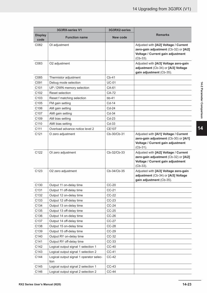
3G3RX-series V1 3G3RX2-seriesRemarksDisplay
code Function name New code
C082 OI adjustment Adjusted with [Ai2] Voltage / Currentzero-gain adjustment (Cb-32) or [Ai2]Voltage / Current gain adjustment(Cb-33).
C083 O2 adjustment Adjusted with [Ai3] Voltage zero-gainadjustment (Cb-34) or [Ai3] Voltagegain adjustment (Cb-35).
C085 Thermistor adjustment Cb-41C091 Debug mode selection UC-01C101 UP / DWN memory selection CA-61C102 Reset selection CA-72C103 Reset f matching selection bb-41C105 FM gain setting Cd-14C106 AM gain setting Cd-24C107 AMI gain setting Cd-34C109 AM bias setting Cd-23C110 AMI bias setting Cd-33C111 Overload advance notice level 2 CE107C121 O zero adjustment Cb-30/Cb-31 Adjusted with [Ai1] Voltage / Current
zero-gain adjustment (Cb-30) or [Ai1]Voltage / Current gain adjustment(Cb-31).
C122 OI zero adjustment Cb-32/Cb-33 Adjusted with [Ai2] Voltage / Currentzero-gain adjustment (Cb-32) or [Ai2]Voltage / Current gain adjustment(Cb-33).
C123 O2 zero adjustment Cb-34/Cb-35 Adjusted with [Ai3] Voltage zero-gainadjustment (Cb-34) or [Ai3] Voltagegain adjustment (Cb-35).
C130 Output 11 on-delay time CC-20C131 Output 11 off-delay time CC-21C132 Output 12 on-delay time CC-22C133 Output 12 off-delay time CC-23C134 Output 13 on-delay time CC-24C135 Output 13 off-delay time CC-25C136 Output 14 on-delay time CC-26C137 Output 14 off-delay time CC-27C138 Output 15 on-delay time CC-28C139 Output 15 off-delay time CC-29C140 Output RY on-delay time CC-32C141 Output RY off-delay time CC-33C142 Logical output signal 1 selection 1 CC-40C143 Logical output signal 1 selection 2 CC-41C144 Logical output signal 1 operator selec-
tionCC-42
C145 Logical output signal 2 selection 1 CC-43C146 Logical output signal 2 selection 2 CC-44
14 Upgrading from 3G3RX (V1)
14-23RX2 Series User’s Manual (I620)
14-2 Parameter C
omparison
14
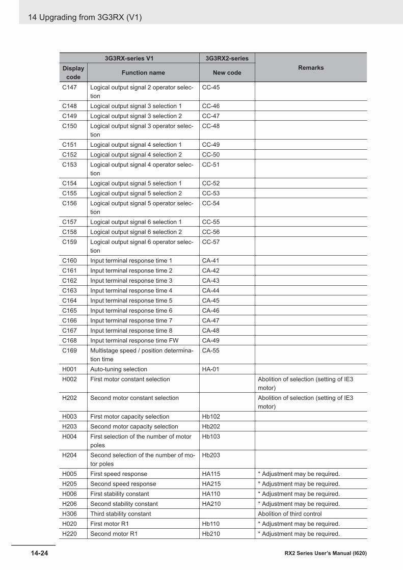
3G3RX-series V1 3G3RX2-seriesRemarksDisplay
code Function name New code
C147 Logical output signal 2 operator selec-tion
CC-45
C148 Logical output signal 3 selection 1 CC-46C149 Logical output signal 3 selection 2 CC-47C150 Logical output signal 3 operator selec-
tionCC-48
C151 Logical output signal 4 selection 1 CC-49C152 Logical output signal 4 selection 2 CC-50C153 Logical output signal 4 operator selec-
tionCC-51
C154 Logical output signal 5 selection 1 CC-52C155 Logical output signal 5 selection 2 CC-53C156 Logical output signal 5 operator selec-
tionCC-54
C157 Logical output signal 6 selection 1 CC-55C158 Logical output signal 6 selection 2 CC-56C159 Logical output signal 6 operator selec-
tionCC-57
C160 Input terminal response time 1 CA-41C161 Input terminal response time 2 CA-42C162 Input terminal response time 3 CA-43C163 Input terminal response time 4 CA-44C164 Input terminal response time 5 CA-45C165 Input terminal response time 6 CA-46C166 Input terminal response time 7 CA-47C167 Input terminal response time 8 CA-48C168 Input terminal response time FW CA-49C169 Multistage speed / position determina-
tion timeCA-55
H001 Auto-tuning selection HA-01H002 First motor constant selection Abolition of selection (setting of IE3
motor)H202 Second motor constant selection Abolition of selection (setting of IE3
motor)H003 First motor capacity selection Hb102H203 Second motor capacity selection Hb202H004 First selection of the number of motor
polesHb103
H204 Second selection of the number of mo-tor poles
Hb203
H005 First speed response HA115 * Adjustment may be required.H205 Second speed response HA215 * Adjustment may be required.H006 First stability constant HA110 * Adjustment may be required.H206 Second stability constant HA210 * Adjustment may be required.H306 Third stability constant Abolition of third controlH020 First motor R1 Hb110 * Adjustment may be required.H220 Second motor R1 Hb210 * Adjustment may be required.
14 Upgrading from 3G3RX (V1)
14-24 RX2 Series User’s Manual (I620)
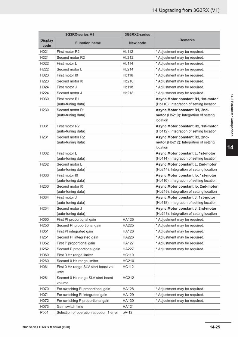
3G3RX-series V1 3G3RX2-seriesRemarksDisplay
code Function name New code
H021 First motor R2 Hb112 * Adjustment may be required.H221 Second motor R2 Hb212 * Adjustment may be required.H022 First motor L Hb114 * Adjustment may be required.H222 Second motor L Hb214 * Adjustment may be required.H023 First motor I0 Hb116 * Adjustment may be required.H223 Second motor I0 Hb216 * Adjustment may be required.H024 First motor J Hb118 * Adjustment may be required.H224 Second motor J Hb218 * Adjustment may be required.H030 First motor R1
(auto-tuning data)Async.Motor constant R1, 1st-motor(Hb110): Integration of setting location
H230 Second motor R1(auto-tuning data)
Async.Motor constant R1, 2nd-motor (Hb210): Integration of settinglocation
H031 First motor R2(auto-tuning data)
Async.Motor constant R2, 1st-motor(Hb112): Integration of setting location
H231 Second motor R2(auto-tuning data)
Async.Motor constant R2, 2nd-motor (Hb212): Integration of settinglocation
H032 First motor L(auto-tuning data)
Async.Motor constant L, 1st-motor(Hb114): Integration of setting location
H232 Second motor L(auto-tuning data)
Async.Motor constant L, 2nd-motor(Hb214): Integration of setting location
H033 First motor I0(auto-tuning data)
Async.Motor constant Io, 1st-motor(Hb116): Integration of setting location
H233 Second motor I0(auto-tuning data)
Async.Motor constant Io, 2nd-motor(Hb216): Integration of setting location
H034 First motor J(auto-tuning data)
Async.Motor constant J, 1st-motor(Hb118): Integration of setting location
H234 Second motor J(auto-tuning data)
Async.Motor constant J, 2nd-motor(Hb218): Integration of setting location
H050 First PI proportional gain HA125 * Adjustment may be required.H250 Second PI proportional gain HA225 * Adjustment may be required.H051 First PI integrated gain HA126 * Adjustment may be required.H251 Second PI integrated gain HA226 * Adjustment may be required.H052 First P proportional gain HA127 * Adjustment may be required.H252 Second P proportional gain HA227 * Adjustment may be required.H060 First 0 Hz range limiter HC110H260 Second 0 Hz range limiter HC210H061 First 0 Hz range SLV start boost vol-
umeHC112
H261 Second 0 Hz range SLV start boostvolume
HC212
H070 For switching PI proportional gain HA128 * Adjustment may be required.H071 For switching PI integrated gain HA129 * Adjustment may be required.H072 For switching P proportional gain HA130 * Adjustment may be required.H073 Gain switch time HA121P001 Selection of operation at option 1 error oA-12
14 Upgrading from 3G3RX (V1)
14-25RX2 Series User’s Manual (I620)
14-2 Parameter C
omparison
14
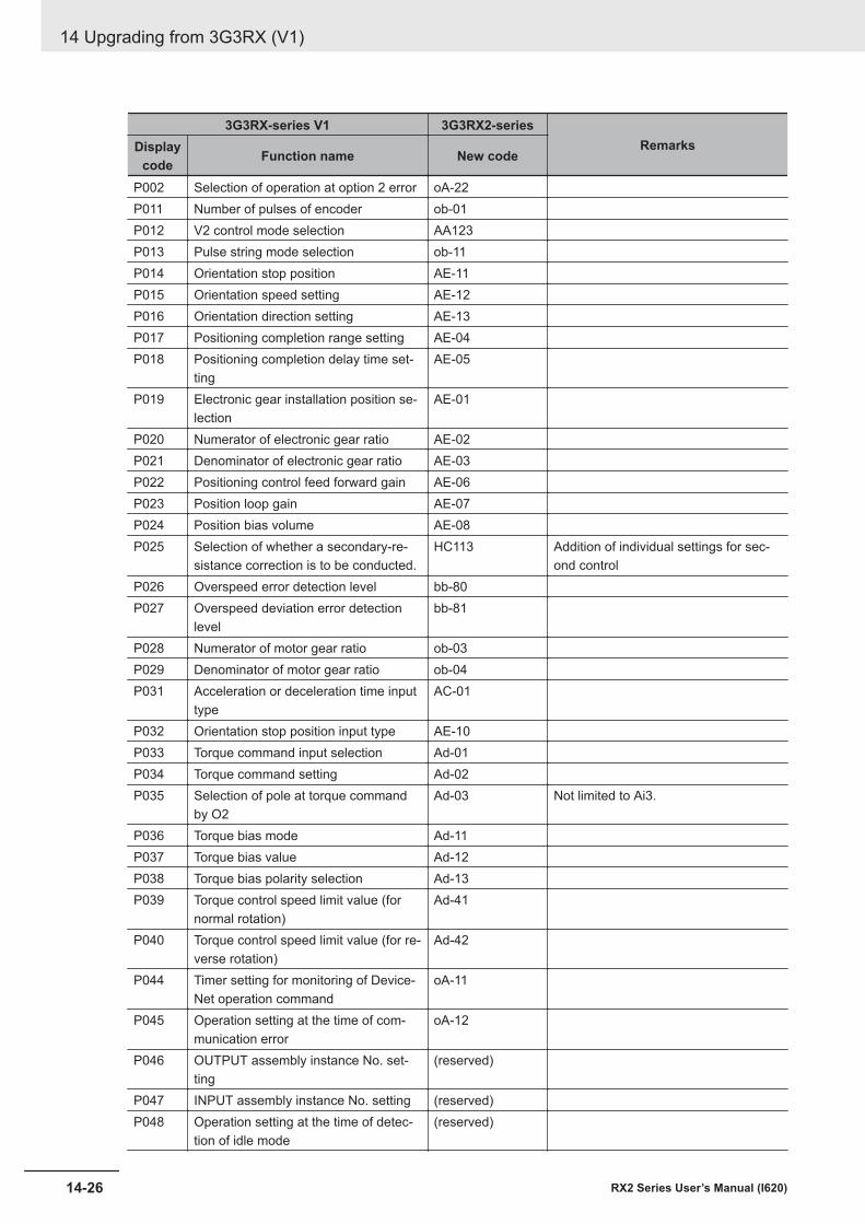
3G3RX-series V1 3G3RX2-seriesRemarksDisplay
code Function name New code
P002 Selection of operation at option 2 error oA-22P011 Number of pulses of encoder ob-01P012 V2 control mode selection AA123P013 Pulse string mode selection ob-11P014 Orientation stop position AE-11P015 Orientation speed setting AE-12P016 Orientation direction setting AE-13P017 Positioning completion range setting AE-04P018 Positioning completion delay time set-
tingAE-05
P019 Electronic gear installation position se-lection
AE-01
P020 Numerator of electronic gear ratio AE-02P021 Denominator of electronic gear ratio AE-03P022 Positioning control feed forward gain AE-06P023 Position loop gain AE-07P024 Position bias volume AE-08P025 Selection of whether a secondary-re-
sistance correction is to be conducted.HC113 Addition of individual settings for sec-
ond controlP026 Overspeed error detection level bb-80P027 Overspeed deviation error detection
levelbb-81
P028 Numerator of motor gear ratio ob-03P029 Denominator of motor gear ratio ob-04P031 Acceleration or deceleration time input
typeAC-01
P032 Orientation stop position input type AE-10P033 Torque command input selection Ad-01P034 Torque command setting Ad-02P035 Selection of pole at torque command
by O2Ad-03 Not limited to Ai3.
P036 Torque bias mode Ad-11P037 Torque bias value Ad-12P038 Torque bias polarity selection Ad-13P039 Torque control speed limit value (for
normal rotation)Ad-41
P040 Torque control speed limit value (for re-verse rotation)
Ad-42
P044 Timer setting for monitoring of Device-Net operation command
oA-11
P045 Operation setting at the time of com-munication error
oA-12
P046 OUTPUT assembly instance No. set-ting
(reserved)
P047 INPUT assembly instance No. setting (reserved)P048 Operation setting at the time of detec-
tion of idle mode(reserved)
14 Upgrading from 3G3RX (V1)
14-26 RX2 Series User’s Manual (I620)
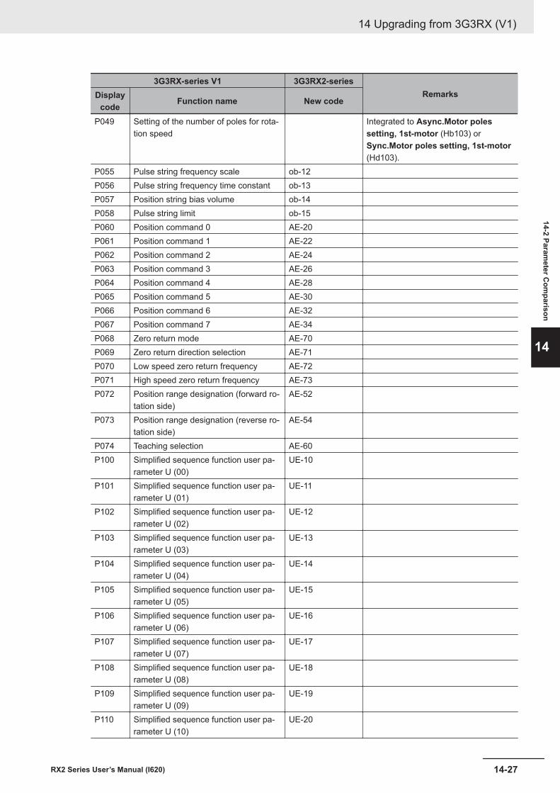
3G3RX-series V1 3G3RX2-seriesRemarksDisplay
code Function name New code
P049 Setting of the number of poles for rota-tion speed
Integrated to Async.Motor polessetting, 1st-motor (Hb103) orSync.Motor poles setting, 1st-motor(Hd103).
P055 Pulse string frequency scale ob-12P056 Pulse string frequency time constant ob-13P057 Position string bias volume ob-14P058 Pulse string limit ob-15P060 Position command 0 AE-20P061 Position command 1 AE-22P062 Position command 2 AE-24P063 Position command 3 AE-26P064 Position command 4 AE-28P065 Position command 5 AE-30P066 Position command 6 AE-32P067 Position command 7 AE-34P068 Zero return mode AE-70P069 Zero return direction selection AE-71P070 Low speed zero return frequency AE-72P071 High speed zero return frequency AE-73P072 Position range designation (forward ro-
tation side)AE-52
P073 Position range designation (reverse ro-tation side)
AE-54
P074 Teaching selection AE-60P100 Simplified sequence function user pa-
rameter U (00)UE-10
P101 Simplified sequence function user pa-rameter U (01)
UE-11
P102 Simplified sequence function user pa-rameter U (02)
UE-12
P103 Simplified sequence function user pa-rameter U (03)
UE-13
P104 Simplified sequence function user pa-rameter U (04)
UE-14
P105 Simplified sequence function user pa-rameter U (05)
UE-15
P106 Simplified sequence function user pa-rameter U (06)
UE-16
P107 Simplified sequence function user pa-rameter U (07)
UE-17
P108 Simplified sequence function user pa-rameter U (08)
UE-18
P109 Simplified sequence function user pa-rameter U (09)
UE-19
P110 Simplified sequence function user pa-rameter U (10)
UE-20
14 Upgrading from 3G3RX (V1)
14-27RX2 Series User’s Manual (I620)
14-2 Parameter C
omparison
14
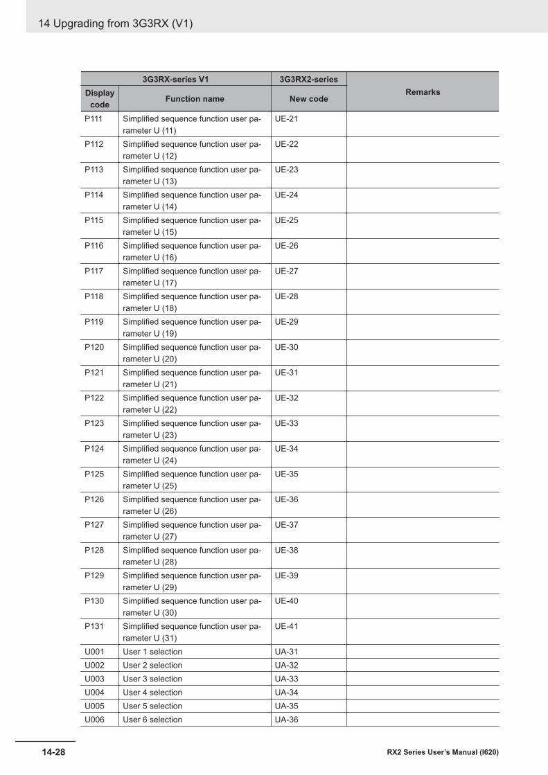
3G3RX-series V1 3G3RX2-seriesRemarksDisplay
code Function name New code
P111 Simplified sequence function user pa-rameter U (11)
UE-21
P112 Simplified sequence function user pa-rameter U (12)
UE-22
P113 Simplified sequence function user pa-rameter U (13)
UE-23
P114 Simplified sequence function user pa-rameter U (14)
UE-24
P115 Simplified sequence function user pa-rameter U (15)
UE-25
P116 Simplified sequence function user pa-rameter U (16)
UE-26
P117 Simplified sequence function user pa-rameter U (17)
UE-27
P118 Simplified sequence function user pa-rameter U (18)
UE-28
P119 Simplified sequence function user pa-rameter U (19)
UE-29
P120 Simplified sequence function user pa-rameter U (20)
UE-30
P121 Simplified sequence function user pa-rameter U (21)
UE-31
P122 Simplified sequence function user pa-rameter U (22)
UE-32
P123 Simplified sequence function user pa-rameter U (23)
UE-33
P124 Simplified sequence function user pa-rameter U (24)
UE-34
P125 Simplified sequence function user pa-rameter U (25)
UE-35
P126 Simplified sequence function user pa-rameter U (26)
UE-36
P127 Simplified sequence function user pa-rameter U (27)
UE-37
P128 Simplified sequence function user pa-rameter U (28)
UE-38
P129 Simplified sequence function user pa-rameter U (29)
UE-39
P130 Simplified sequence function user pa-rameter U (30)
UE-40
P131 Simplified sequence function user pa-rameter U (31)
UE-41
U001 User 1 selection UA-31U002 User 2 selection UA-32U003 User 3 selection UA-33U004 User 4 selection UA-34U005 User 5 selection UA-35U006 User 6 selection UA-36
14 Upgrading from 3G3RX (V1)
14-28 RX2 Series User’s Manual (I620)
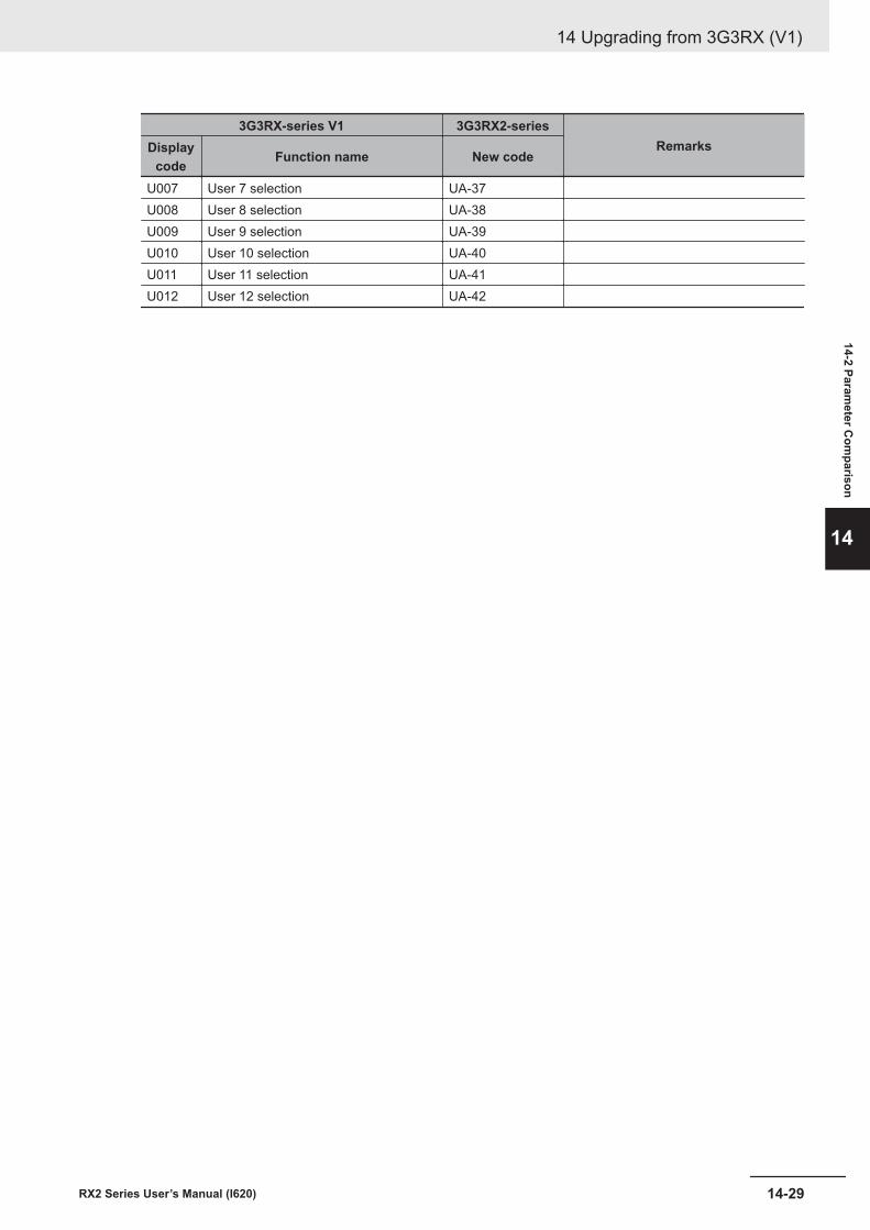
3G3RX-series V1 3G3RX2-seriesRemarksDisplay
code Function name New code
U007 User 7 selection UA-37U008 User 8 selection UA-38U009 User 9 selection UA-39U010 User 10 selection UA-40U011 User 11 selection UA-41U012 User 12 selection UA-42
14 Upgrading from 3G3RX (V1)
14-29RX2 Series User’s Manual (I620)
14-2 Parameter C
omparison
14

14 Upgrading from 3G3RX (V1)
14-30 RX2 Series User’s Manual (I620)
15Table of Parameters
This section describes the monitor list and parameter list as well as the setting rangeand default of each parameter.
15-1 Parameter Notation ...................................................................................... 15-215-2 Monitor List................................................................................................... 15-4
15-2-1 Monitors Related to Output ........................................................................... 15-415-2-2 Monitors Related to Control Circuit ............................................................... 15-515-2-3 Option Slot Monitors...................................................................................... 15-515-2-4 Monitors Related to Program Function EzSQ ............................................... 15-615-2-5 Monitors Related to PID Function ................................................................. 15-615-2-6 Monitors for Checking Internal Condition ...................................................... 15-715-2-7 Trip State Monitors ...................................................................................... 15-1015-2-8 Retry State Monitors.................................................................................... 15-1615-2-9 Monitors and Parameters for Changing the Current Commands ................ 15-22
15-3 Parameter List ............................................................................................ 15-2415-3-1 Parameter (Code A) .................................................................................... 15-2415-3-2 Parameter (Code B) .................................................................................... 15-5415-3-3 Parameter (Code C) .................................................................................... 15-6715-3-4 Parameter (Code H) .................................................................................... 15-8615-3-5 Parameter (Code o)................................................................................... 15-10215-3-6 Parameter (Code P) .................................................................................. 15-10515-3-7 Parameter (Code U) .................................................................................. 15-107
15-1RX2 Series User’s Manual (I620)
15
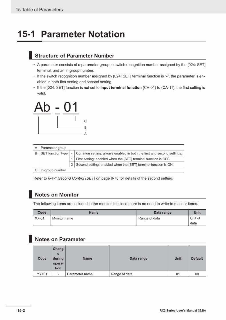
15-1 Parameter Notation
Structure of Parameter Number• A parameter consists of a parameter group, a switch recognition number assigned by the [024: SET]
terminal, and an in-group number.• If the switch recognition number assigned by [024: SET] terminal function is “-”, the parameter is en-
abled in both first setting and second setting.• If the [024: SET] function is not set to Input terminal function (CA-01) to (CA-11), the first setting is
valid.
Ab - 01
A
B
C
A Parameter groupB SET function type - Common setting: always enabled in both the first and second settings.
1 First setting: enabled when the [SET] terminal function is OFF.2 Second setting: enabled when the [SET] terminal function is ON.
C In-group number
Refer to 8-4-1 Second Control (SET) on page 8-78 for details of the second setting.
Notes on MonitorThe following items are included in the monitor list since there is no need to write to monitor items.
Code Name Data range UnitXX-01 Monitor name Range of data Unit of
data
Notes on Parameter
Code
Change
duringopera-
tion
Name Data range Unit Default
YY101 - Parameter name Range of data 01 00
15 Table of Parameters
15-2 RX2 Series User’s Manual (I620)
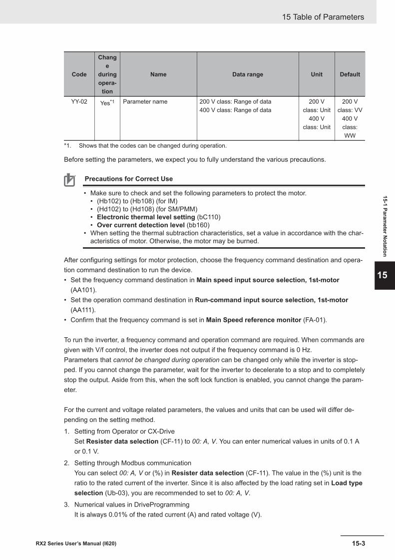
Code
Change
duringopera-
tion
Name Data range Unit Default
YY-02 Yes*1 Parameter name 200 V class: Range of data400 V class: Range of data
200 Vclass: Unit
400 Vclass: Unit
200 Vclass: VV
400 Vclass:WW
*1. Shows that the codes can be changed during operation.
Before setting the parameters, we expect you to fully understand the various precautions.
Precautions for Correct Use
• Make sure to check and set the following parameters to protect the motor.• (Hb102) to (Hb108) (for IM)• (Hd102) to (Hd108) (for SM/PMM)• Electronic thermal level setting (bC110)• Over current detection level (bb160)
• When setting the thermal subtraction characteristics, set a value in accordance with the char-acteristics of motor. Otherwise, the motor may be burned.
After configuring settings for motor protection, choose the frequency command destination and opera-tion command destination to run the device.• Set the frequency command destination in Main speed input source selection, 1st-motor
(AA101).• Set the operation command destination in Run-command input source selection, 1st-motor
(AA111).• Confirm that the frequency command is set in Main Speed reference monitor (FA-01).
To run the inverter, a frequency command and operation command are required. When commands aregiven with V/f control, the inverter does not output if the frequency command is 0 Hz.Parameters that cannot be changed during operation can be changed only while the inverter is stop-ped. If you cannot change the parameter, wait for the inverter to decelerate to a stop and to completelystop the output. Aside from this, when the soft lock function is enabled, you cannot change the param-eter.
For the current and voltage related parameters, the values and units that can be used will differ de-pending on the setting method.
1. Setting from Operator or CX-DriveSet Resister data selection (CF-11) to 00: A, V. You can enter numerical values in units of 0.1 Aor 0.1 V.
2. Setting through Modbus communicationYou can select 00: A, V or (%) in Resister data selection (CF-11). The value in the (%) unit is theratio to the rated current of the inverter. Since it is also affected by the load rating set in Load typeselection (Ub-03), you are recommended to set to 00: A, V.
3. Numerical values in DriveProgrammingIt is always 0.01% of the rated current (A) and rated voltage (V).
15 Table of Parameters
15-3RX2 Series User’s Manual (I620)
15-1 Parameter N
otation
15
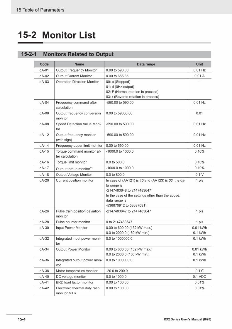
15-2 Monitor List
15-2-1 Monitors Related to OutputCode Name Data range UnitdA-01 Output Frequency Monitor 0.00 to 590.00 0.01 HzdA-02 Output Current Monitor 0.00 to 655.35 0.01 AdA-03 Operation Direction Monitor 00: o (Stopped)
01: d (0Hz output)02: F (Normal rotation in process)03: r (Reverse rotation in process)
-
dA-04 Frequency command aftercalculation
-590.00 to 590.00 0.01 Hz
dA-06 Output frequency conversionmonitor
0.00 to 59000.00 0.01
dA-08 Speed Detection Value Moni-tor
-590.00 to 590.00 0.01 Hz
dA-12 Output frequency monitor(with sign)
-590.00 to 590.00 0.01 Hz
dA-14 Frequency upper limit monitor 0.00 to 590.00 0.01 HzdA-15 Torque command monitor af-
ter calculation-1000.0 to 1000.0 0.10%
dA-16 Torque limit monitor 0.0 to 500.0 0.10%dA-17 Output torque monitor*1 -1000.0 to 1000.0 0.10%
dA-18 Output Voltage Monitor 0.0 to 800.0 0.1 VdA-20 Current position monitor In case of (AA121) is 10 and (AA123) is 03, the da-
ta range is-2147483648 to 2147483647In the case of the settings other than the above,data range is-536870912 to 536870911
1 pls
dA-26 Pulse train position deviationmonitor
-2147483647 to 2147483647 1 pls
dA-28 Pulse counter monitor 0 to 2147483647 1 plsdA-30 Input Power Monitor 0.00 to 600.00 (132 kW max.)
0.0 to 2000.0 (160 kW min.)0.01 kWh0.1 kWh
dA-32 Integrated input power moni-tor
0.0 to 1000000.0 0.1 kWh
dA-34 Output Power Monitor 0.00 to 600.00 (132 kW max.)0.0 to 2000.0 (160 kW min.)
0.01 kWh0.1 kWh
dA-36 Integrated output power mon-itor
0.0 to 1000000.0 0.1 kWh
dA-38 Motor temperature monitor -20.0 to 200.0 0.1℃dA-40 DC voltage monitor 0.0 to 1000.0 0.1 VDCdA-41 BRD load factor monitor 0.00 to 100.00 0.01%dA-42 Electronic thermal duty ratio
monitor MTR0.00 to 100.00 0.01%
15 Table of Parameters
15-4 RX2 Series User’s Manual (I620)
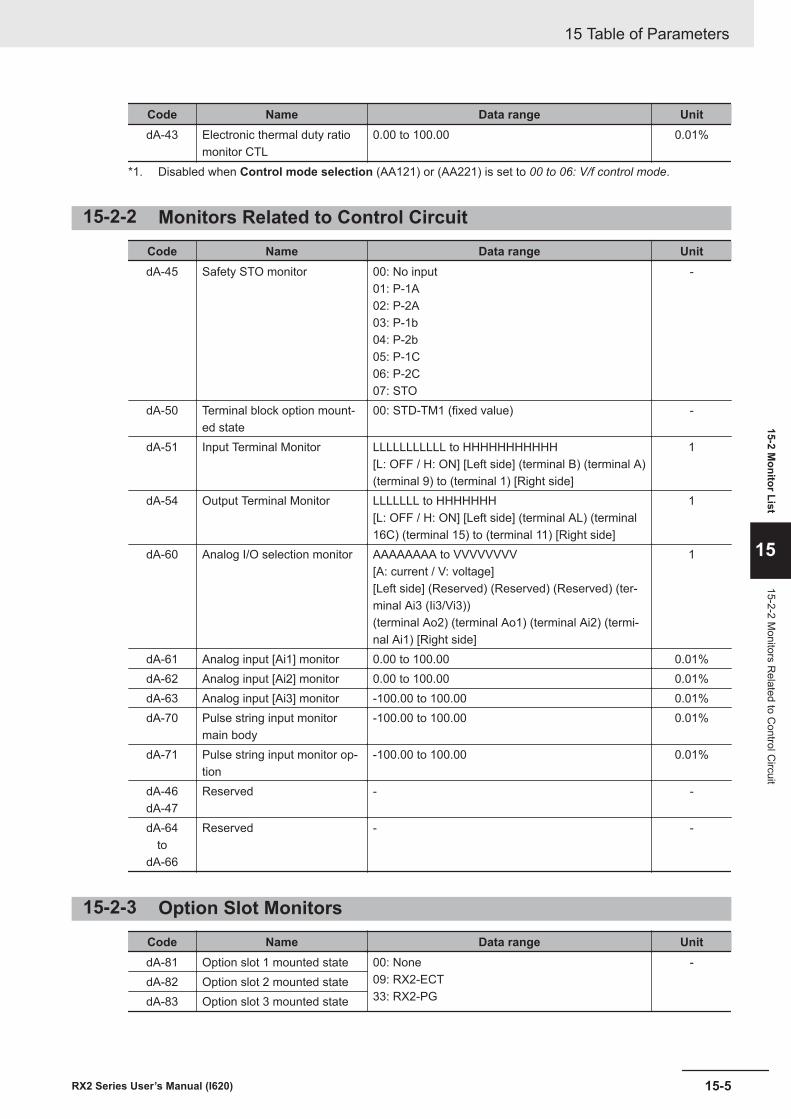
Code Name Data range UnitdA-43 Electronic thermal duty ratio
monitor CTL0.00 to 100.00 0.01%
*1. Disabled when Control mode selection (AA121) or (AA221) is set to 00 to 06: V/f control mode.
15-2-2 Monitors Related to Control CircuitCode Name Data range UnitdA-45 Safety STO monitor 00: No input
01: P-1A02: P-2A03: P-1b04: P-2b05: P-1C06: P-2C07: STO
-
dA-50 Terminal block option mount-ed state
00: STD-TM1 (fixed value) -
dA-51 Input Terminal Monitor LLLLLLLLLLL to HHHHHHHHHHH[L: OFF / H: ON] [Left side] (terminal B) (terminal A)(terminal 9) to (terminal 1) [Right side]
1
dA-54 Output Terminal Monitor LLLLLLL to HHHHHHH[L: OFF / H: ON] [Left side] (terminal AL) (terminal16C) (terminal 15) to (terminal 11) [Right side]
1
dA-60 Analog I/O selection monitor AAAAAAAA to VVVVVVVV[A: current / V: voltage][Left side] (Reserved) (Reserved) (Reserved) (ter-minal Ai3 (Ii3/Vi3))(terminal Ao2) (terminal Ao1) (terminal Ai2) (termi-nal Ai1) [Right side]
1
dA-61 Analog input [Ai1] monitor 0.00 to 100.00 0.01%dA-62 Analog input [Ai2] monitor 0.00 to 100.00 0.01%dA-63 Analog input [Ai3] monitor -100.00 to 100.00 0.01%dA-70 Pulse string input monitor
main body-100.00 to 100.00 0.01%
dA-71 Pulse string input monitor op-tion
-100.00 to 100.00 0.01%
dA-46dA-47
Reserved - -
dA-64to
dA-66
Reserved - -
15-2-3 Option Slot MonitorsCode Name Data range UnitdA-81 Option slot 1 mounted state 00: None
09: RX2-ECT33: RX2-PG
-dA-82 Option slot 2 mounted statedA-83 Option slot 3 mounted state
15 Table of Parameters
15-5RX2 Series User’s Manual (I620)
15-2 Monitor List
15
15-2-2 Monitors R
elated to Control C
ircuit
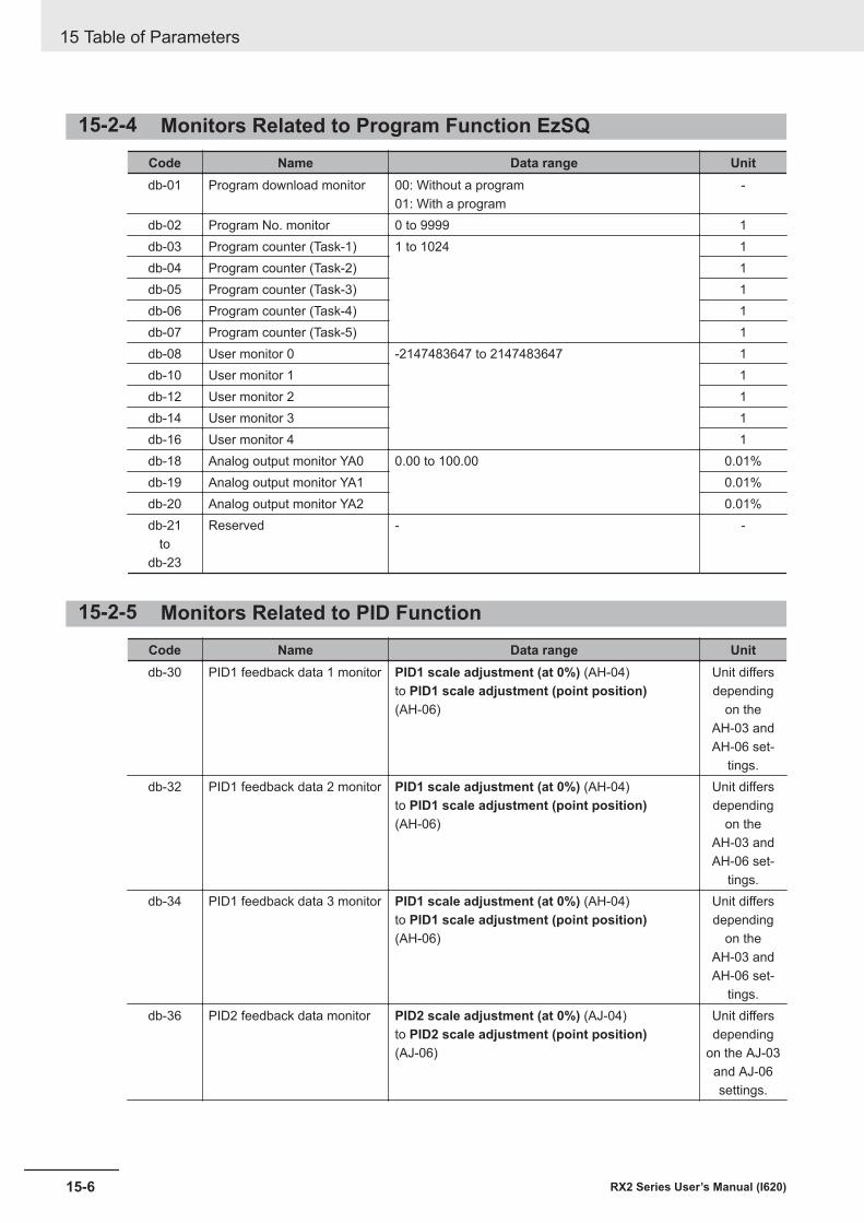
15-2-4 Monitors Related to Program Function EzSQCode Name Data range Unitdb-01 Program download monitor 00: Without a program
01: With a program-
db-02 Program No. monitor 0 to 9999 1db-03 Program counter (Task-1) 1 to 1024 1db-04 Program counter (Task-2) 1db-05 Program counter (Task-3) 1db-06 Program counter (Task-4) 1db-07 Program counter (Task-5) 1db-08 User monitor 0 -2147483647 to 2147483647 1db-10 User monitor 1 1db-12 User monitor 2 1db-14 User monitor 3 1db-16 User monitor 4 1db-18 Analog output monitor YA0 0.00 to 100.00 0.01%db-19 Analog output monitor YA1 0.01%db-20 Analog output monitor YA2 0.01%db-21
todb-23
Reserved - -
15-2-5 Monitors Related to PID FunctionCode Name Data range Unitdb-30 PID1 feedback data 1 monitor PID1 scale adjustment (at 0%) (AH-04)
to PID1 scale adjustment (point position)(AH-06)
Unit differsdepending
on theAH-03 andAH-06 set-
tings.db-32 PID1 feedback data 2 monitor PID1 scale adjustment (at 0%) (AH-04)
to PID1 scale adjustment (point position)(AH-06)
Unit differsdepending
on theAH-03 andAH-06 set-
tings.db-34 PID1 feedback data 3 monitor PID1 scale adjustment (at 0%) (AH-04)
to PID1 scale adjustment (point position)(AH-06)
Unit differsdepending
on theAH-03 andAH-06 set-
tings.db-36 PID2 feedback data monitor PID2 scale adjustment (at 0%) (AJ-04)
to PID2 scale adjustment (point position)(AJ-06)
Unit differsdepending
on the AJ-03and AJ-06settings.
15 Table of Parameters
15-6 RX2 Series User’s Manual (I620)
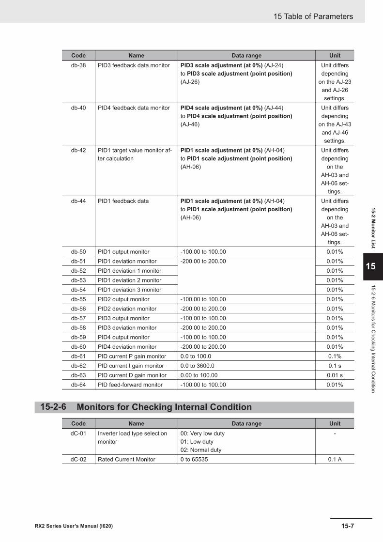
Code Name Data range Unitdb-38 PID3 feedback data monitor PID3 scale adjustment (at 0%) (AJ-24)
to PID3 scale adjustment (point position)(AJ-26)
Unit differsdepending
on the AJ-23and AJ-26settings.
db-40 PID4 feedback data monitor PID4 scale adjustment (at 0%) (AJ-44)to PID4 scale adjustment (point position)(AJ-46)
Unit differsdepending
on the AJ-43and AJ-46settings.
db-42 PID1 target value monitor af-ter calculation
PID1 scale adjustment (at 0%) (AH-04)to PID1 scale adjustment (point position)(AH-06)
Unit differsdepending
on theAH-03 andAH-06 set-
tings.db-44 PID1 feedback data PID1 scale adjustment (at 0%) (AH-04)
to PID1 scale adjustment (point position)(AH-06)
Unit differsdepending
on theAH-03 andAH-06 set-
tings.db-50 PID1 output monitor -100.00 to 100.00 0.01%db-51 PID1 deviation monitor -200.00 to 200.00 0.01%db-52 PID1 deviation 1 monitor 0.01%db-53 PID1 deviation 2 monitor 0.01%db-54 PID1 deviation 3 monitor 0.01%db-55 PID2 output monitor -100.00 to 100.00 0.01%db-56 PID2 deviation monitor -200.00 to 200.00 0.01%db-57 PID3 output monitor -100.00 to 100.00 0.01%db-58 PID3 deviation monitor -200.00 to 200.00 0.01%db-59 PID4 output monitor -100.00 to 100.00 0.01%db-60 PID4 deviation monitor -200.00 to 200.00 0.01%db-61 PID current P gain monitor 0.0 to 100.0 0.1%db-62 PID current I gain monitor 0.0 to 3600.0 0.1 sdb-63 PID current D gain monitor 0.00 to 100.00 0.01 sdb-64 PID feed-forward monitor -100.00 to 100.00 0.01%
15-2-6 Monitors for Checking Internal ConditionCode Name Data range UnitdC-01 Inverter load type selection
monitor00: Very low duty01: Low duty02: Normal duty
-
dC-02 Rated Current Monitor 0 to 65535 0.1 A
15 Table of Parameters
15-7RX2 Series User’s Manual (I620)
15-2 Monitor List
15
15-2-6 Monitors for C
hecking Internal Condition
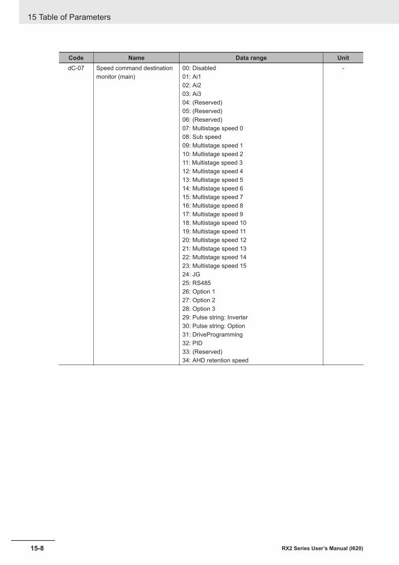
Code Name Data range UnitdC-07 Speed command destination
monitor (main)00: Disabled01: Ai102: Ai203: Ai304: (Reserved)05: (Reserved)06: (Reserved)07: Multistage speed 008: Sub speed09: Multistage speed 110: Multistage speed 211: Multistage speed 312: Multistage speed 413: Multistage speed 514: Multistage speed 615: Multistage speed 716: Multistage speed 817: Multistage speed 918: Multistage speed 1019: Multistage speed 1120: Multistage speed 1221: Multistage speed 1322: Multistage speed 1423: Multistage speed 1524: JG25: RS48526: Option 127: Option 228: Option 329: Pulse string: Inverter30: Pulse string: Option31: DriveProgramming32: PID33: (Reserved)34: AHD retention speed
-
15 Table of Parameters
15-8 RX2 Series User’s Manual (I620)
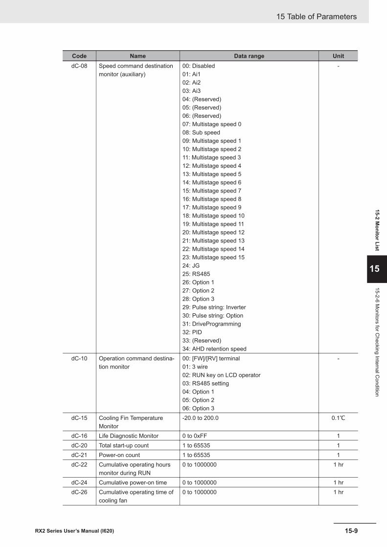
Code Name Data range UnitdC-08 Speed command destination
monitor (auxiliary)00: Disabled01: Ai102: Ai203: Ai304: (Reserved)05: (Reserved)06: (Reserved)07: Multistage speed 008: Sub speed09: Multistage speed 110: Multistage speed 211: Multistage speed 312: Multistage speed 413: Multistage speed 514: Multistage speed 615: Multistage speed 716: Multistage speed 817: Multistage speed 918: Multistage speed 1019: Multistage speed 1120: Multistage speed 1221: Multistage speed 1322: Multistage speed 1423: Multistage speed 1524: JG25: RS48526: Option 127: Option 228: Option 329: Pulse string: Inverter30: Pulse string: Option31: DriveProgramming32: PID33: (Reserved)34: AHD retention speed
-
dC-10 Operation command destina-tion monitor
00: [FW]/[RV] terminal01: 3 wire02: RUN key on LCD operator03: RS485 setting04: Option 105: Option 206: Option 3
-
dC-15 Cooling Fin TemperatureMonitor
-20.0 to 200.0 0.1℃
dC-16 Life Diagnostic Monitor 0 to 0xFF 1dC-20 Total start-up count 1 to 65535 1dC-21 Power-on count 1 to 65535 1dC-22 Cumulative operating hours
monitor during RUN0 to 1000000 1 hr
dC-24 Cumulative power-on time 0 to 1000000 1 hrdC-26 Cumulative operating time of
cooling fan0 to 1000000 1 hr
15 Table of Parameters
15-9RX2 Series User’s Manual (I620)
15-2 Monitor List
15
15-2-6 Monitors for C
hecking Internal Condition
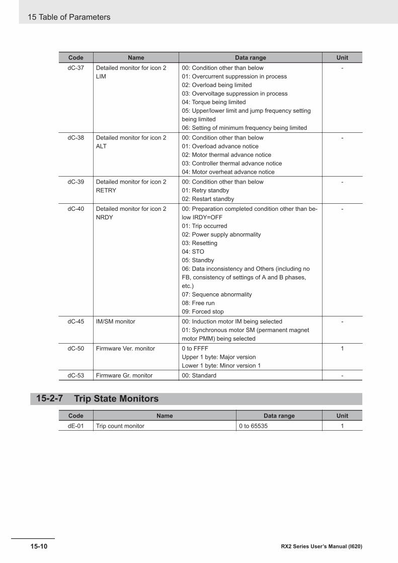
Code Name Data range UnitdC-37 Detailed monitor for icon 2
LIM00: Condition other than below01: Overcurrent suppression in process02: Overload being limited03: Overvoltage suppression in process04: Torque being limited05: Upper/lower limit and jump frequency settingbeing limited06: Setting of minimum frequency being limited
-
dC-38 Detailed monitor for icon 2ALT
00: Condition other than below01: Overload advance notice02: Motor thermal advance notice03: Controller thermal advance notice04: Motor overheat advance notice
-
dC-39 Detailed monitor for icon 2RETRY
00: Condition other than below01: Retry standby02: Restart standby
-
dC-40 Detailed monitor for icon 2NRDY
00: Preparation completed condition other than be-low IRDY=OFF01: Trip occurred02: Power supply abnormality03: Resetting04: STO05: Standby06: Data inconsistency and Others (including noFB, consistency of settings of A and B phases,etc.)07: Sequence abnormality08: Free run09: Forced stop
-
dC-45 IM/SM monitor 00: Induction motor IM being selected01: Synchronous motor SM (permanent magnetmotor PMM) being selected
-
dC-50 Firmware Ver. monitor 0 to FFFFUpper 1 byte: Major versionLower 1 byte: Minor version 1
1
dC-53 Firmware Gr. monitor 00: Standard -
15-2-7 Trip State MonitorsCode Name Data range UnitdE-01 Trip count monitor 0 to 65535 1
15 Table of Parameters
15-10 RX2 Series User’s Manual (I620)

Code Name Data range UnitdE-11 Trip monitor 1 Factor 1 to 255 1
Trip monitor 1 Output frequency (with sign) (HIGH) -590.00 to 590.00 0.01 HzTrip monitor 1 Output frequency (with sign) (LOW)Trip monitor 1 Output current 0.00 to 655.35 0.01 ATrip monitor 1 P-N DC voltage 0.0 to 1000.0 0.1 VDCTrip monitor 1 Inverter state 0 to 8*1 1
Trip monitor 1 LAD state 0 to 5*1 1
Trip monitor 1 INV control mode 0 to 11*1 1
Trip monitor 1 Limit state 0 to 6*1 1
Trip monitor 1 Special state 0 to 6*1 1
Trip monitor 1 RUN time (HIGH) 0 to 1000000 1 hrTrip monitor 1 RUN time (LOW)Trip monitor 1 Power ON time (HIGH) 0 to 1000000 1 hrTrip monitor 1 Power ON time (LOW)Trip monitor 1 Absolute time (year, month) 00 to 99 (BCD code)
01 to 12 (BCD code)1
Trip monitor 1 Absolute time (day, day of the week) 01 to 31 (BCD code)00 to 06 (BCD code)
1
Trip monitor 1 Absolute time (hour, minute) 00 to 23 (BCD code)00 to 59 (BCD code)
1
dE-12 Trip monitor 2 Factor 1 to 255 1Trip monitor 2 Output frequency (with sign) (HIGH) -590.00 to 590.00 0.01 HzTrip monitor 2 Output frequency (with sign) (LOW)Trip monitor 2 Output current 0.00 to 655.35 0.01 ATrip monitor 2 P-N DC voltage 0.0 to 1000.0 0.1 VDCTrip monitor 2 Inverter state 0 to 8*1 1
Trip monitor 2 LAD state 0 to 5*1 1
Trip monitor 2 INV control mode 0 to 11*1 1
Trip monitor 2 Limit state 0 to 6*1 1
Trip monitor 2 Special state 0 to 6*1 1
Trip monitor 2 RUN time (HIGH) 0 to 1000000 1 hrTrip monitor 2 RUN time (LOW)Trip monitor 2 Power ON time (HIGH) 0 to 1000000 1 hrTrip monitor 2 Power ON time (LOW)Trip monitor 2 Absolute time (year, month) 00 to 99 (BCD code)
01 to 12 (BCD code)-
Trip monitor 2 Absolute time (day, day of the week) 01 to 31 (BCD code)00 to 06 (BCD code)
-
Trip monitor 2 Absolute time (hour, minute) 00 to 23 (BCD code)00 to 59 (BCD code)
-
15 Table of Parameters
15-11RX2 Series User’s Manual (I620)
15-2 Monitor List
15
15-2-7 Trip State Monitors
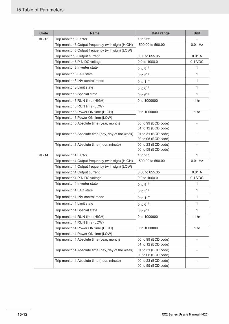
Code Name Data range UnitdE-13 Trip monitor 3 Factor 1 to 255 -
Trip monitor 3 Output frequency (with sign) (HIGH) -590.00 to 590.00 0.01 HzTrip monitor 3 Output frequency (with sign) (LOW)Trip monitor 3 Output current 0.00 to 655.35 0.01 ATrip monitor 3 P-N DC voltage 0.0 to 1000.0 0.1 VDCTrip monitor 3 Inverter state 0 to 8*1 1
Trip monitor 3 LAD state 0 to 5*1 1
Trip monitor 3 INV control mode 0 to 11*1 1
Trip monitor 3 Limit state 0 to 6*1 1
Trip monitor 3 Special state 0 to 6*1 1
Trip monitor 3 RUN time (HIGH) 0 to 1000000 1 hrTrip monitor 3 RUN time (LOW)Trip monitor 3 Power ON time (HIGH) 0 to 1000000 1 hrTrip monitor 3 Power ON time (LOW)Trip monitor 3 Absolute time (year, month) 00 to 99 (BCD code)
01 to 12 (BCD code)-
Trip monitor 3 Absolute time (day, day of the week) 01 to 31 (BCD code)00 to 06 (BCD code)
-
Trip monitor 3 Absolute time (hour, minute) 00 to 23 (BCD code)00 to 59 (BCD code)
-
dE-14 Trip monitor 4 Factor 1 to 255 1Trip monitor 4 Output frequency (with sign) (HIGH) -590.00 to 590.00 0.01 HzTrip monitor 4 Output frequency (with sign) (LOW)Trip monitor 4 Output current 0.00 to 655.35 0.01 ATrip monitor 4 P-N DC voltage 0.0 to 1000.0 0.1 VDCTrip monitor 4 Inverter state 0 to 8*1 1
Trip monitor 4 LAD state 0 to 5*1 1
Trip monitor 4 INV control mode 0 to 11*1 1
Trip monitor 4 Limit state 0 to 6*1 1
Trip monitor 4 Special state 0 to 6*1 1
Trip monitor 4 RUN time (HIGH) 0 to 1000000 1 hrTrip monitor 4 RUN time (LOW)Trip monitor 4 Power ON time (HIGH) 0 to 1000000 1 hrTrip monitor 4 Power ON time (LOW)Trip monitor 4 Absolute time (year, month) 00 to 99 (BCD code)
01 to 12 (BCD code)-
Trip monitor 4 Absolute time (day, day of the week) 01 to 31 (BCD code)00 to 06 (BCD code)
-
Trip monitor 4 Absolute time (hour, minute) 00 to 23 (BCD code)00 to 59 (BCD code)
-
15 Table of Parameters
15-12 RX2 Series User’s Manual (I620)
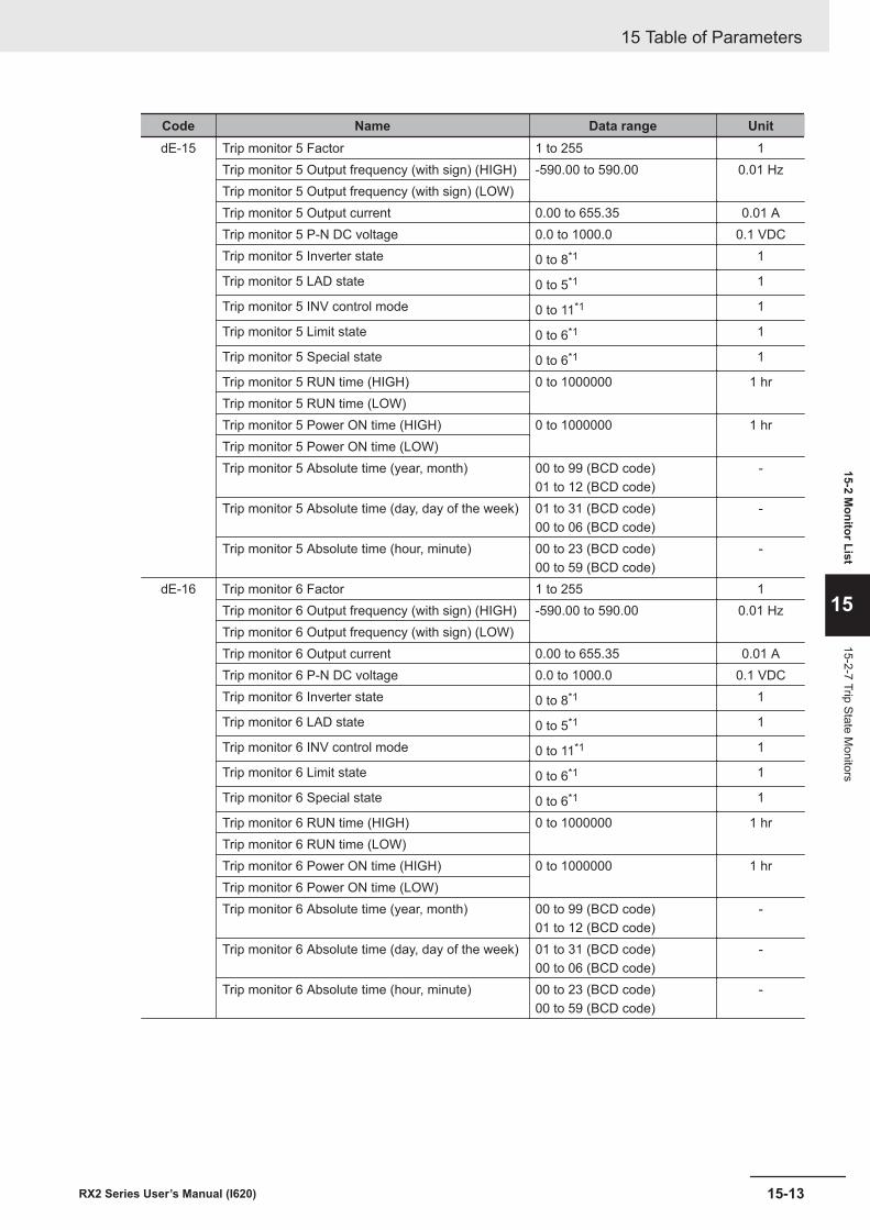
Code Name Data range UnitdE-15 Trip monitor 5 Factor 1 to 255 1
Trip monitor 5 Output frequency (with sign) (HIGH) -590.00 to 590.00 0.01 HzTrip monitor 5 Output frequency (with sign) (LOW)Trip monitor 5 Output current 0.00 to 655.35 0.01 ATrip monitor 5 P-N DC voltage 0.0 to 1000.0 0.1 VDCTrip monitor 5 Inverter state 0 to 8*1 1
Trip monitor 5 LAD state 0 to 5*1 1
Trip monitor 5 INV control mode 0 to 11*1 1
Trip monitor 5 Limit state 0 to 6*1 1
Trip monitor 5 Special state 0 to 6*1 1
Trip monitor 5 RUN time (HIGH) 0 to 1000000 1 hrTrip monitor 5 RUN time (LOW)Trip monitor 5 Power ON time (HIGH) 0 to 1000000 1 hrTrip monitor 5 Power ON time (LOW)Trip monitor 5 Absolute time (year, month) 00 to 99 (BCD code)
01 to 12 (BCD code)-
Trip monitor 5 Absolute time (day, day of the week) 01 to 31 (BCD code)00 to 06 (BCD code)
-
Trip monitor 5 Absolute time (hour, minute) 00 to 23 (BCD code)00 to 59 (BCD code)
-
dE-16 Trip monitor 6 Factor 1 to 255 1Trip monitor 6 Output frequency (with sign) (HIGH) -590.00 to 590.00 0.01 HzTrip monitor 6 Output frequency (with sign) (LOW)Trip monitor 6 Output current 0.00 to 655.35 0.01 ATrip monitor 6 P-N DC voltage 0.0 to 1000.0 0.1 VDCTrip monitor 6 Inverter state 0 to 8*1 1
Trip monitor 6 LAD state 0 to 5*1 1
Trip monitor 6 INV control mode 0 to 11*1 1
Trip monitor 6 Limit state 0 to 6*1 1
Trip monitor 6 Special state 0 to 6*1 1
Trip monitor 6 RUN time (HIGH) 0 to 1000000 1 hrTrip monitor 6 RUN time (LOW)Trip monitor 6 Power ON time (HIGH) 0 to 1000000 1 hrTrip monitor 6 Power ON time (LOW)Trip monitor 6 Absolute time (year, month) 00 to 99 (BCD code)
01 to 12 (BCD code)-
Trip monitor 6 Absolute time (day, day of the week) 01 to 31 (BCD code)00 to 06 (BCD code)
-
Trip monitor 6 Absolute time (hour, minute) 00 to 23 (BCD code)00 to 59 (BCD code)
-
15 Table of Parameters
15-13RX2 Series User’s Manual (I620)
15-2 Monitor List
15
15-2-7 Trip State Monitors
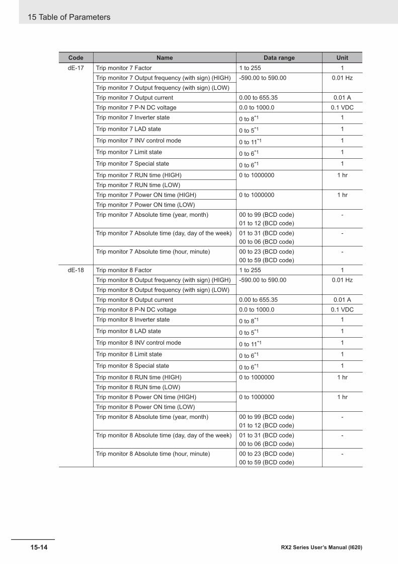
Code Name Data range UnitdE-17 Trip monitor 7 Factor 1 to 255 1
Trip monitor 7 Output frequency (with sign) (HIGH) -590.00 to 590.00 0.01 HzTrip monitor 7 Output frequency (with sign) (LOW)Trip monitor 7 Output current 0.00 to 655.35 0.01 ATrip monitor 7 P-N DC voltage 0.0 to 1000.0 0.1 VDCTrip monitor 7 Inverter state 0 to 8*1 1
Trip monitor 7 LAD state 0 to 5*1 1
Trip monitor 7 INV control mode 0 to 11*1 1
Trip monitor 7 Limit state 0 to 6*1 1
Trip monitor 7 Special state 0 to 6*1 1
Trip monitor 7 RUN time (HIGH) 0 to 1000000 1 hrTrip monitor 7 RUN time (LOW)Trip monitor 7 Power ON time (HIGH) 0 to 1000000 1 hrTrip monitor 7 Power ON time (LOW)Trip monitor 7 Absolute time (year, month) 00 to 99 (BCD code)
01 to 12 (BCD code)-
Trip monitor 7 Absolute time (day, day of the week) 01 to 31 (BCD code)00 to 06 (BCD code)
-
Trip monitor 7 Absolute time (hour, minute) 00 to 23 (BCD code)00 to 59 (BCD code)
-
dE-18 Trip monitor 8 Factor 1 to 255 1Trip monitor 8 Output frequency (with sign) (HIGH) -590.00 to 590.00 0.01 HzTrip monitor 8 Output frequency (with sign) (LOW)Trip monitor 8 Output current 0.00 to 655.35 0.01 ATrip monitor 8 P-N DC voltage 0.0 to 1000.0 0.1 VDCTrip monitor 8 Inverter state 0 to 8*1 1
Trip monitor 8 LAD state 0 to 5*1 1
Trip monitor 8 INV control mode 0 to 11*1 1
Trip monitor 8 Limit state 0 to 6*1 1
Trip monitor 8 Special state 0 to 6*1 1
Trip monitor 8 RUN time (HIGH) 0 to 1000000 1 hrTrip monitor 8 RUN time (LOW)Trip monitor 8 Power ON time (HIGH) 0 to 1000000 1 hrTrip monitor 8 Power ON time (LOW)Trip monitor 8 Absolute time (year, month) 00 to 99 (BCD code)
01 to 12 (BCD code)-
Trip monitor 8 Absolute time (day, day of the week) 01 to 31 (BCD code)00 to 06 (BCD code)
-
Trip monitor 8 Absolute time (hour, minute) 00 to 23 (BCD code)00 to 59 (BCD code)
-
15 Table of Parameters
15-14 RX2 Series User’s Manual (I620)
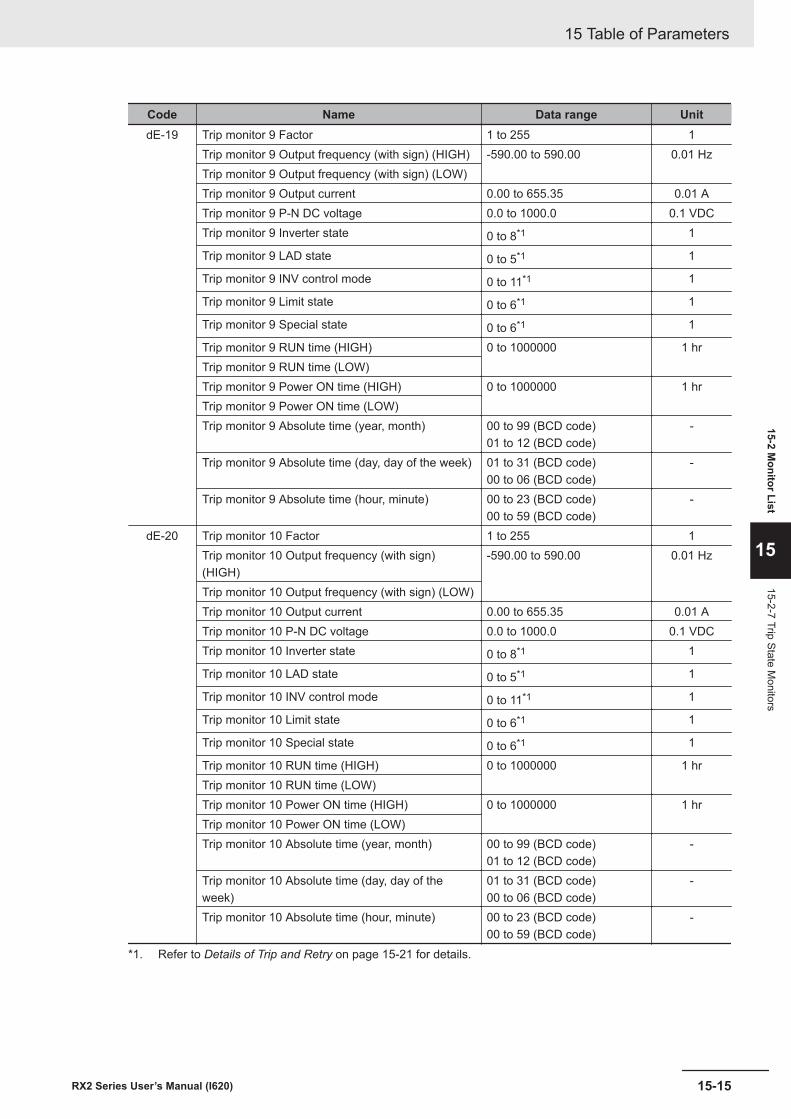
Code Name Data range UnitdE-19 Trip monitor 9 Factor 1 to 255 1
Trip monitor 9 Output frequency (with sign) (HIGH) -590.00 to 590.00 0.01 HzTrip monitor 9 Output frequency (with sign) (LOW)Trip monitor 9 Output current 0.00 to 655.35 0.01 ATrip monitor 9 P-N DC voltage 0.0 to 1000.0 0.1 VDCTrip monitor 9 Inverter state 0 to 8*1 1
Trip monitor 9 LAD state 0 to 5*1 1
Trip monitor 9 INV control mode 0 to 11*1 1
Trip monitor 9 Limit state 0 to 6*1 1
Trip monitor 9 Special state 0 to 6*1 1
Trip monitor 9 RUN time (HIGH) 0 to 1000000 1 hrTrip monitor 9 RUN time (LOW)Trip monitor 9 Power ON time (HIGH) 0 to 1000000 1 hrTrip monitor 9 Power ON time (LOW)Trip monitor 9 Absolute time (year, month) 00 to 99 (BCD code)
01 to 12 (BCD code)-
Trip monitor 9 Absolute time (day, day of the week) 01 to 31 (BCD code)00 to 06 (BCD code)
-
Trip monitor 9 Absolute time (hour, minute) 00 to 23 (BCD code)00 to 59 (BCD code)
-
dE-20 Trip monitor 10 Factor 1 to 255 1Trip monitor 10 Output frequency (with sign)(HIGH)
-590.00 to 590.00 0.01 Hz
Trip monitor 10 Output frequency (with sign) (LOW)Trip monitor 10 Output current 0.00 to 655.35 0.01 ATrip monitor 10 P-N DC voltage 0.0 to 1000.0 0.1 VDCTrip monitor 10 Inverter state 0 to 8*1 1
Trip monitor 10 LAD state 0 to 5*1 1
Trip monitor 10 INV control mode 0 to 11*1 1
Trip monitor 10 Limit state 0 to 6*1 1
Trip monitor 10 Special state 0 to 6*1 1
Trip monitor 10 RUN time (HIGH) 0 to 1000000 1 hrTrip monitor 10 RUN time (LOW)Trip monitor 10 Power ON time (HIGH) 0 to 1000000 1 hrTrip monitor 10 Power ON time (LOW)Trip monitor 10 Absolute time (year, month) 00 to 99 (BCD code)
01 to 12 (BCD code)-
Trip monitor 10 Absolute time (day, day of theweek)
01 to 31 (BCD code)00 to 06 (BCD code)
-
Trip monitor 10 Absolute time (hour, minute) 00 to 23 (BCD code)00 to 59 (BCD code)
-
*1. Refer to Details of Trip and Retry on page 15-21 for details.
15 Table of Parameters
15-15RX2 Series User’s Manual (I620)
15-2 Monitor List
15
15-2-7 Trip State Monitors
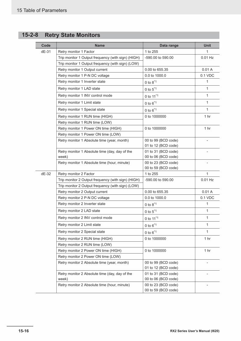
15-2-8 Retry State MonitorsCode Name Data range UnitdE-31 Retry monitor 1 Factor 1 to 255 1
Trip monitor 1 Output frequency (with sign) (HIGH) -590.00 to 590.00 0.01 HzTrip monitor 1 Output frequency (with sign) (LOW)Retry monitor 1 Output current 0.00 to 655.35 0.01 ARetry monitor 1 P-N DC voltage 0.0 to 1000.0 0.1 VDCRetry monitor 1 Inverter state 0 to 8*1 1
Retry monitor 1 LAD state 0 to 5*1 1
Retry monitor 1 INV control mode 0 to 11*1 1
Retry monitor 1 Limit state 0 to 6*1 1
Retry monitor 1 Special state 0 to 6*1 1
Retry monitor 1 RUN time (HIGH) 0 to 1000000 1 hrRetry monitor 1 RUN time (LOW)Retry monitor 1 Power ON time (HIGH) 0 to 1000000 1 hrRetry monitor 1 Power ON time (LOW)Retry monitor 1 Absolute time (year, month) 00 to 99 (BCD code)
01 to 12 (BCD code)-
Retry monitor 1 Absolute time (day, day of theweek)
01 to 31 (BCD code)00 to 06 (BCD code)
-
Retry monitor 1 Absolute time (hour, minute) 00 to 23 (BCD code)00 to 59 (BCD code)
-
dE-32 Retry monitor 2 Factor 1 to 255 1Trip monitor 2 Output frequency (with sign) (HIGH) -590.00 to 590.00 0.01 HzTrip monitor 2 Output frequency (with sign) (LOW)Retry monitor 2 Output current 0.00 to 655.35 0.01 ARetry monitor 2 P-N DC voltage 0.0 to 1000.0 0.1 VDCRetry monitor 2 Inverter state 0 to 8*1 1
Retry monitor 2 LAD state 0 to 5*1 1
Retry monitor 2 INV control mode 0 to 11*1 1
Retry monitor 2 Limit state 0 to 6*1 1
Retry monitor 2 Special state 0 to 6*1 1
Retry monitor 2 RUN time (HIGH) 0 to 1000000 1 hrRetry monitor 2 RUN time (LOW)Retry monitor 2 Power ON time (HIGH) 0 to 1000000 1 hrRetry monitor 2 Power ON time (LOW)Retry monitor 2 Absolute time (year, month) 00 to 99 (BCD code)
01 to 12 (BCD code)-
Retry monitor 2 Absolute time (day, day of theweek)
01 to 31 (BCD code)00 to 06 (BCD code)
-
Retry monitor 2 Absolute time (hour, minute) 00 to 23 (BCD code)00 to 59 (BCD code)
-
15 Table of Parameters
15-16 RX2 Series User’s Manual (I620)
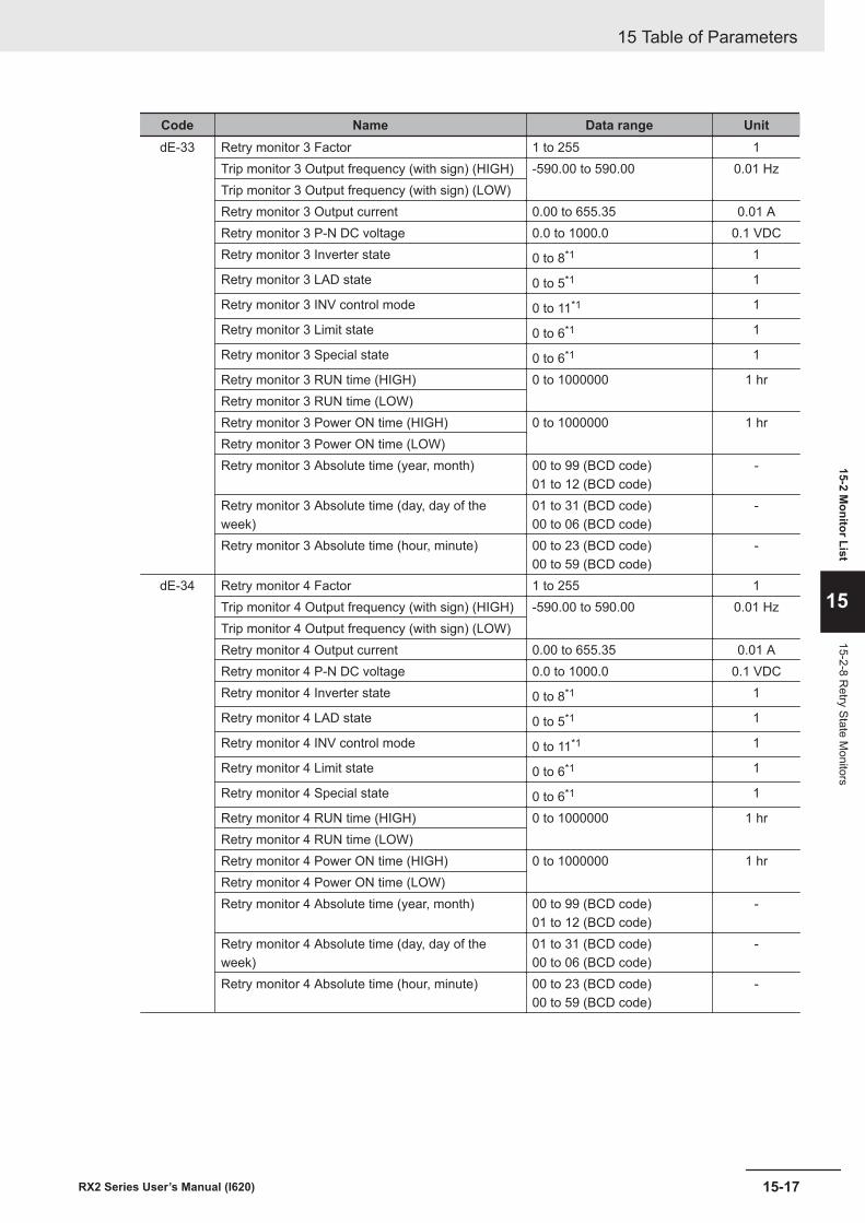
Code Name Data range UnitdE-33 Retry monitor 3 Factor 1 to 255 1
Trip monitor 3 Output frequency (with sign) (HIGH) -590.00 to 590.00 0.01 HzTrip monitor 3 Output frequency (with sign) (LOW)Retry monitor 3 Output current 0.00 to 655.35 0.01 ARetry monitor 3 P-N DC voltage 0.0 to 1000.0 0.1 VDCRetry monitor 3 Inverter state 0 to 8*1 1
Retry monitor 3 LAD state 0 to 5*1 1
Retry monitor 3 INV control mode 0 to 11*1 1
Retry monitor 3 Limit state 0 to 6*1 1
Retry monitor 3 Special state 0 to 6*1 1
Retry monitor 3 RUN time (HIGH) 0 to 1000000 1 hrRetry monitor 3 RUN time (LOW)Retry monitor 3 Power ON time (HIGH) 0 to 1000000 1 hrRetry monitor 3 Power ON time (LOW)Retry monitor 3 Absolute time (year, month) 00 to 99 (BCD code)
01 to 12 (BCD code)-
Retry monitor 3 Absolute time (day, day of theweek)
01 to 31 (BCD code)00 to 06 (BCD code)
-
Retry monitor 3 Absolute time (hour, minute) 00 to 23 (BCD code)00 to 59 (BCD code)
-
dE-34 Retry monitor 4 Factor 1 to 255 1Trip monitor 4 Output frequency (with sign) (HIGH) -590.00 to 590.00 0.01 HzTrip monitor 4 Output frequency (with sign) (LOW)Retry monitor 4 Output current 0.00 to 655.35 0.01 ARetry monitor 4 P-N DC voltage 0.0 to 1000.0 0.1 VDCRetry monitor 4 Inverter state 0 to 8*1 1
Retry monitor 4 LAD state 0 to 5*1 1
Retry monitor 4 INV control mode 0 to 11*1 1
Retry monitor 4 Limit state 0 to 6*1 1
Retry monitor 4 Special state 0 to 6*1 1
Retry monitor 4 RUN time (HIGH) 0 to 1000000 1 hrRetry monitor 4 RUN time (LOW)Retry monitor 4 Power ON time (HIGH) 0 to 1000000 1 hrRetry monitor 4 Power ON time (LOW)Retry monitor 4 Absolute time (year, month) 00 to 99 (BCD code)
01 to 12 (BCD code)-
Retry monitor 4 Absolute time (day, day of theweek)
01 to 31 (BCD code)00 to 06 (BCD code)
-
Retry monitor 4 Absolute time (hour, minute) 00 to 23 (BCD code)00 to 59 (BCD code)
-
15 Table of Parameters
15-17RX2 Series User’s Manual (I620)
15-2 Monitor List
15
15-2-8 Retry State M
onitors
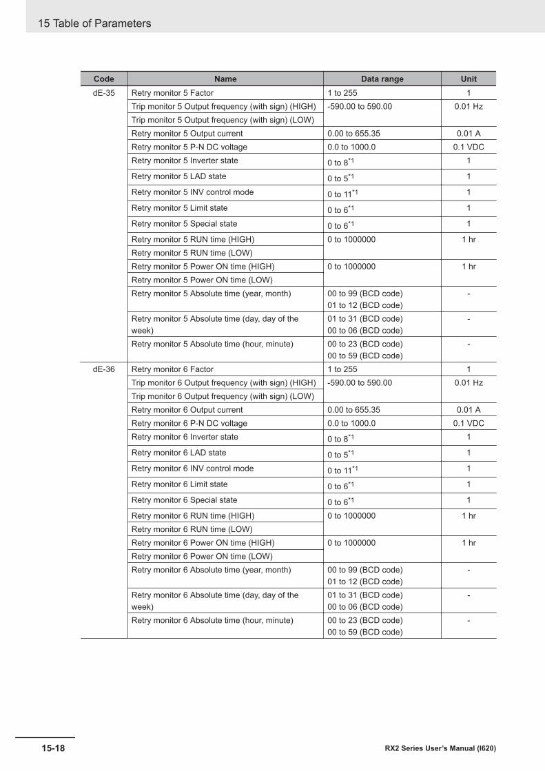
Code Name Data range UnitdE-35 Retry monitor 5 Factor 1 to 255 1
Trip monitor 5 Output frequency (with sign) (HIGH) -590.00 to 590.00 0.01 HzTrip monitor 5 Output frequency (with sign) (LOW)Retry monitor 5 Output current 0.00 to 655.35 0.01 ARetry monitor 5 P-N DC voltage 0.0 to 1000.0 0.1 VDCRetry monitor 5 Inverter state 0 to 8*1 1
Retry monitor 5 LAD state 0 to 5*1 1
Retry monitor 5 INV control mode 0 to 11*1 1
Retry monitor 5 Limit state 0 to 6*1 1
Retry monitor 5 Special state 0 to 6*1 1
Retry monitor 5 RUN time (HIGH) 0 to 1000000 1 hrRetry monitor 5 RUN time (LOW)Retry monitor 5 Power ON time (HIGH) 0 to 1000000 1 hrRetry monitor 5 Power ON time (LOW)Retry monitor 5 Absolute time (year, month) 00 to 99 (BCD code)
01 to 12 (BCD code)-
Retry monitor 5 Absolute time (day, day of theweek)
01 to 31 (BCD code)00 to 06 (BCD code)
-
Retry monitor 5 Absolute time (hour, minute) 00 to 23 (BCD code)00 to 59 (BCD code)
-
dE-36 Retry monitor 6 Factor 1 to 255 1Trip monitor 6 Output frequency (with sign) (HIGH) -590.00 to 590.00 0.01 HzTrip monitor 6 Output frequency (with sign) (LOW)Retry monitor 6 Output current 0.00 to 655.35 0.01 ARetry monitor 6 P-N DC voltage 0.0 to 1000.0 0.1 VDCRetry monitor 6 Inverter state 0 to 8*1 1
Retry monitor 6 LAD state 0 to 5*1 1
Retry monitor 6 INV control mode 0 to 11*1 1
Retry monitor 6 Limit state 0 to 6*1 1
Retry monitor 6 Special state 0 to 6*1 1
Retry monitor 6 RUN time (HIGH) 0 to 1000000 1 hrRetry monitor 6 RUN time (LOW)Retry monitor 6 Power ON time (HIGH) 0 to 1000000 1 hrRetry monitor 6 Power ON time (LOW)Retry monitor 6 Absolute time (year, month) 00 to 99 (BCD code)
01 to 12 (BCD code)-
Retry monitor 6 Absolute time (day, day of theweek)
01 to 31 (BCD code)00 to 06 (BCD code)
-
Retry monitor 6 Absolute time (hour, minute) 00 to 23 (BCD code)00 to 59 (BCD code)
-
15 Table of Parameters
15-18 RX2 Series User’s Manual (I620)
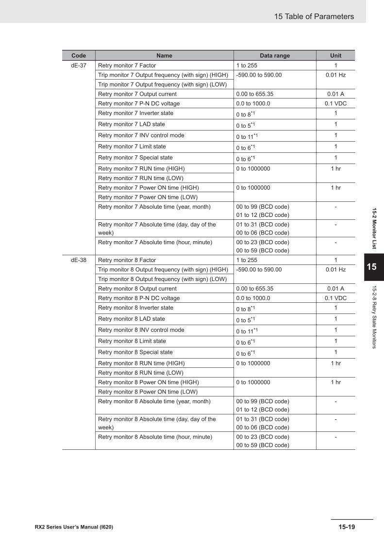
Code Name Data range UnitdE-37 Retry monitor 7 Factor 1 to 255 1
Trip monitor 7 Output frequency (with sign) (HIGH) -590.00 to 590.00 0.01 HzTrip monitor 7 Output frequency (with sign) (LOW)Retry monitor 7 Output current 0.00 to 655.35 0.01 ARetry monitor 7 P-N DC voltage 0.0 to 1000.0 0.1 VDCRetry monitor 7 Inverter state 0 to 8*1 1
Retry monitor 7 LAD state 0 to 5*1 1
Retry monitor 7 INV control mode 0 to 11*1 1
Retry monitor 7 Limit state 0 to 6*1 1
Retry monitor 7 Special state 0 to 6*1 1
Retry monitor 7 RUN time (HIGH) 0 to 1000000 1 hrRetry monitor 7 RUN time (LOW)Retry monitor 7 Power ON time (HIGH) 0 to 1000000 1 hrRetry monitor 7 Power ON time (LOW)Retry monitor 7 Absolute time (year, month) 00 to 99 (BCD code)
01 to 12 (BCD code)-
Retry monitor 7 Absolute time (day, day of theweek)
01 to 31 (BCD code)00 to 06 (BCD code)
-
Retry monitor 7 Absolute time (hour, minute) 00 to 23 (BCD code)00 to 59 (BCD code)
-
dE-38 Retry monitor 8 Factor 1 to 255 1Trip monitor 8 Output frequency (with sign) (HIGH) -590.00 to 590.00 0.01 HzTrip monitor 8 Output frequency (with sign) (LOW)Retry monitor 8 Output current 0.00 to 655.35 0.01 ARetry monitor 8 P-N DC voltage 0.0 to 1000.0 0.1 VDCRetry monitor 8 Inverter state 0 to 8*1 1
Retry monitor 8 LAD state 0 to 5*1 1
Retry monitor 8 INV control mode 0 to 11*1 1
Retry monitor 8 Limit state 0 to 6*1 1
Retry monitor 8 Special state 0 to 6*1 1
Retry monitor 8 RUN time (HIGH) 0 to 1000000 1 hrRetry monitor 8 RUN time (LOW)Retry monitor 8 Power ON time (HIGH) 0 to 1000000 1 hrRetry monitor 8 Power ON time (LOW)Retry monitor 8 Absolute time (year, month) 00 to 99 (BCD code)
01 to 12 (BCD code)-
Retry monitor 8 Absolute time (day, day of theweek)
01 to 31 (BCD code)00 to 06 (BCD code)
-
Retry monitor 8 Absolute time (hour, minute) 00 to 23 (BCD code)00 to 59 (BCD code)
-
15 Table of Parameters
15-19RX2 Series User’s Manual (I620)
15-2 Monitor List
15
15-2-8 Retry State M
onitors
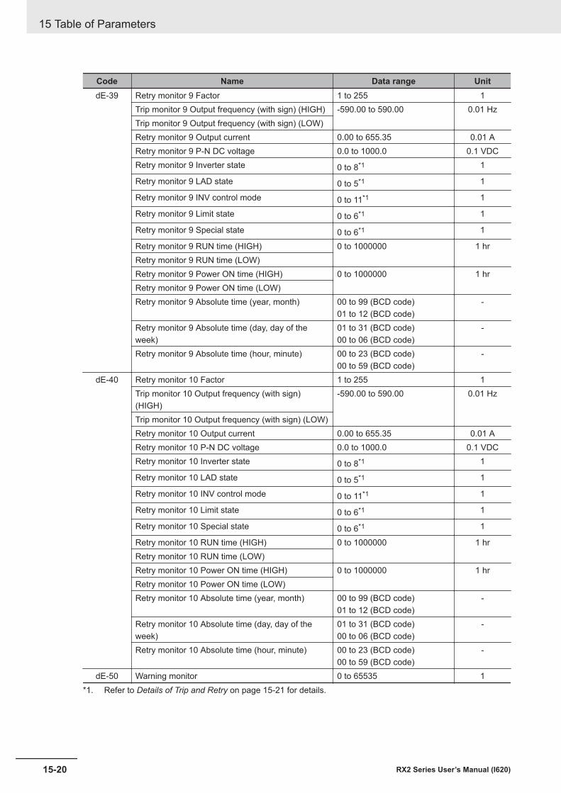
Code Name Data range UnitdE-39 Retry monitor 9 Factor 1 to 255 1
Trip monitor 9 Output frequency (with sign) (HIGH) -590.00 to 590.00 0.01 HzTrip monitor 9 Output frequency (with sign) (LOW)Retry monitor 9 Output current 0.00 to 655.35 0.01 ARetry monitor 9 P-N DC voltage 0.0 to 1000.0 0.1 VDCRetry monitor 9 Inverter state 0 to 8*1 1
Retry monitor 9 LAD state 0 to 5*1 1
Retry monitor 9 INV control mode 0 to 11*1 1
Retry monitor 9 Limit state 0 to 6*1 1
Retry monitor 9 Special state 0 to 6*1 1
Retry monitor 9 RUN time (HIGH) 0 to 1000000 1 hrRetry monitor 9 RUN time (LOW)Retry monitor 9 Power ON time (HIGH) 0 to 1000000 1 hrRetry monitor 9 Power ON time (LOW)Retry monitor 9 Absolute time (year, month) 00 to 99 (BCD code)
01 to 12 (BCD code)-
Retry monitor 9 Absolute time (day, day of theweek)
01 to 31 (BCD code)00 to 06 (BCD code)
-
Retry monitor 9 Absolute time (hour, minute) 00 to 23 (BCD code)00 to 59 (BCD code)
-
dE-40 Retry monitor 10 Factor 1 to 255 1Trip monitor 10 Output frequency (with sign)(HIGH)
-590.00 to 590.00 0.01 Hz
Trip monitor 10 Output frequency (with sign) (LOW)Retry monitor 10 Output current 0.00 to 655.35 0.01 ARetry monitor 10 P-N DC voltage 0.0 to 1000.0 0.1 VDCRetry monitor 10 Inverter state 0 to 8*1 1
Retry monitor 10 LAD state 0 to 5*1 1
Retry monitor 10 INV control mode 0 to 11*1 1
Retry monitor 10 Limit state 0 to 6*1 1
Retry monitor 10 Special state 0 to 6*1 1
Retry monitor 10 RUN time (HIGH) 0 to 1000000 1 hrRetry monitor 10 RUN time (LOW)Retry monitor 10 Power ON time (HIGH) 0 to 1000000 1 hrRetry monitor 10 Power ON time (LOW)Retry monitor 10 Absolute time (year, month) 00 to 99 (BCD code)
01 to 12 (BCD code)-
Retry monitor 10 Absolute time (day, day of theweek)
01 to 31 (BCD code)00 to 06 (BCD code)
-
Retry monitor 10 Absolute time (hour, minute) 00 to 23 (BCD code)00 to 59 (BCD code)
-
dE-50 Warning monitor 0 to 65535 1*1. Refer to Details of Trip and Retry on page 15-21 for details.
15 Table of Parameters
15-20 RX2 Series User’s Manual (I620)
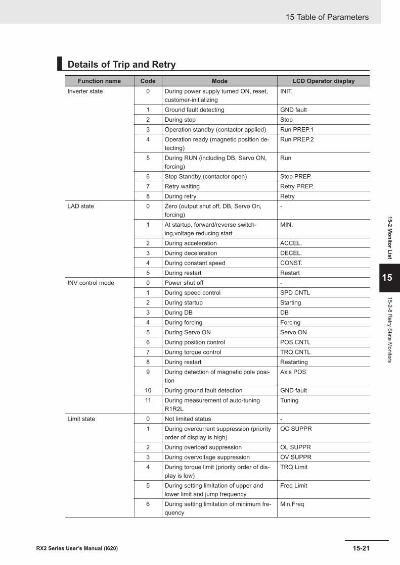
Details of Trip and RetryFunction name Code Mode LCD Operator display
Inverter state 0 During power supply turned ON, reset,customer-initializing
INIT.
1 Ground fault detecting GND fault2 During stop Stop3 Operation standby (contactor applied) Run PREP.14 Operation ready (magnetic position de-
tecting)Run PREP.2
5 During RUN (including DB, Servo ON,forcing)
Run
6 Stop Standby (contactor open) Stop PREP.7 Retry waiting Retry PREP.8 During retry Retry
LAD state 0 Zero (output shut off, DB, Servo On,forcing)
-
1 At startup, forward/reverse switch-ing,voltage reducing start
MIN.
2 During acceleration ACCEL.3 During deceleration DECEL.4 During constant speed CONST.5 During restart Restart
INV control mode 0 Power shut off -1 During speed control SPD CNTL2 During startup Starting3 During DB DB4 During forcing Forcing5 During Servo ON Servo ON6 During position control POS CNTL7 During torque control TRQ CNTL8 During restart Restarting9 During detection of magnetic pole posi-
tionAxis POS
10 During ground fault detection GND fault11 During measurement of auto-tuning
R1R2LTuning
Limit state 0 Not limited status -1 During overcurrent suppression (priority
order of display is high)OC SUPPR
2 During overload suppression OL SUPPR3 During overvoltage suppression OV SUPPR4 During torque limit (priority order of dis-
play is low)TRQ Limit
5 During setting limitation of upper andlower limit and jump frequency
Freq Limit
6 During setting limitation of minimum fre-quency
Min.Freq
15 Table of Parameters
15-21RX2 Series User’s Manual (I620)
15-2 Monitor List
15
15-2-8 Retry State M
onitors
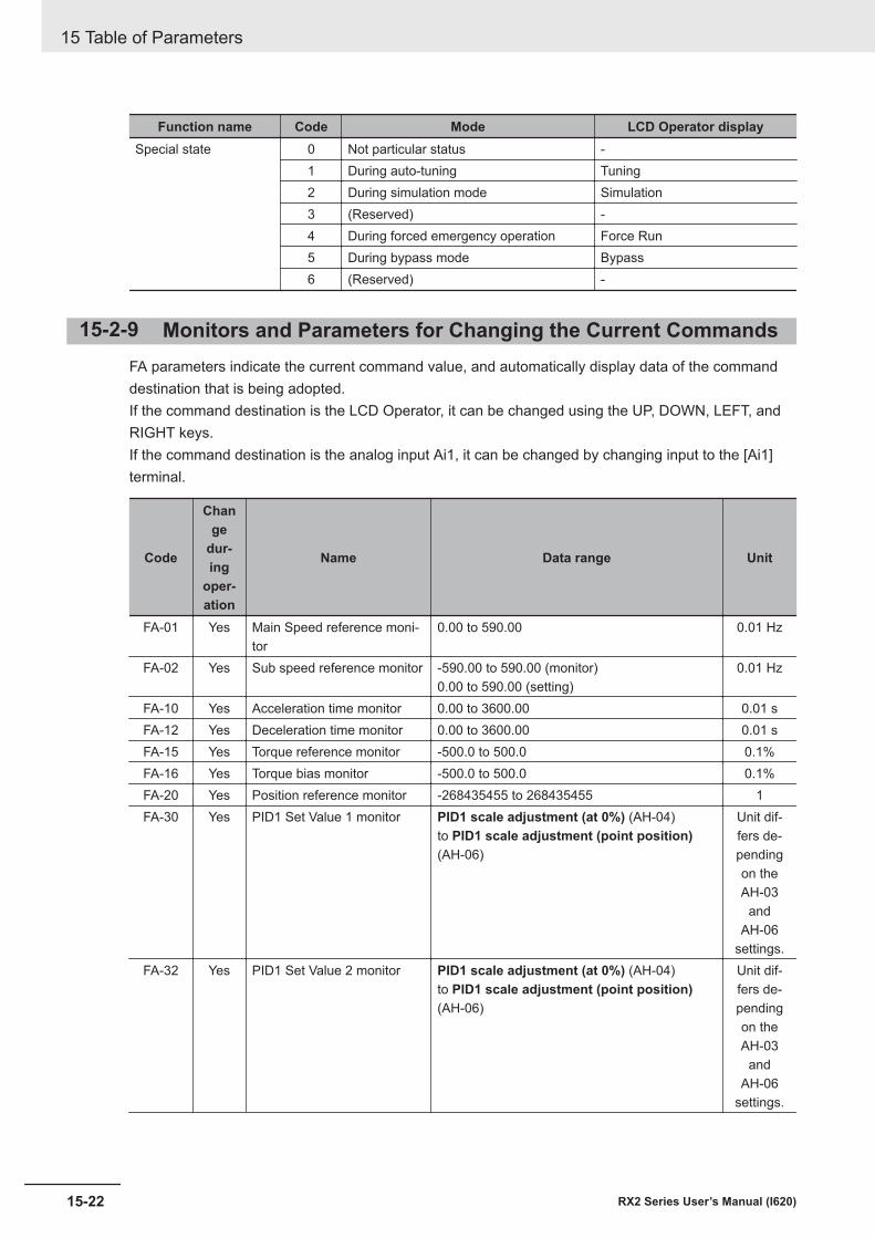
Function name Code Mode LCD Operator displaySpecial state 0 Not particular status -
1 During auto-tuning Tuning2 During simulation mode Simulation3 (Reserved) -4 During forced emergency operation Force Run5 During bypass mode Bypass6 (Reserved) -
15-2-9 Monitors and Parameters for Changing the Current CommandsFA parameters indicate the current command value, and automatically display data of the commanddestination that is being adopted.If the command destination is the LCD Operator, it can be changed using the UP, DOWN, LEFT, andRIGHT keys.If the command destination is the analog input Ai1, it can be changed by changing input to the [Ai1]terminal.
Code
Change
dur-ing
oper-ation
Name Data range Unit
FA-01 Yes Main Speed reference moni-tor
0.00 to 590.00 0.01 Hz
FA-02 Yes Sub speed reference monitor -590.00 to 590.00 (monitor)0.00 to 590.00 (setting)
0.01 Hz
FA-10 Yes Acceleration time monitor 0.00 to 3600.00 0.01 sFA-12 Yes Deceleration time monitor 0.00 to 3600.00 0.01 sFA-15 Yes Torque reference monitor -500.0 to 500.0 0.1%FA-16 Yes Torque bias monitor -500.0 to 500.0 0.1%FA-20 Yes Position reference monitor -268435455 to 268435455 1FA-30 Yes PID1 Set Value 1 monitor PID1 scale adjustment (at 0%) (AH-04)
to PID1 scale adjustment (point position)(AH-06)
Unit dif-fers de-pendingon theAH-03
andAH-06
settings.FA-32 Yes PID1 Set Value 2 monitor PID1 scale adjustment (at 0%) (AH-04)
to PID1 scale adjustment (point position)(AH-06)
Unit dif-fers de-pendingon theAH-03
andAH-06
settings.
15 Table of Parameters
15-22 RX2 Series User’s Manual (I620)
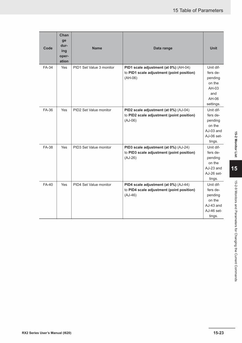
Code
Change
dur-ing
oper-ation
Name Data range Unit
FA-34 Yes PID1 Set Value 3 monitor PID1 scale adjustment (at 0%) (AH-04)to PID1 scale adjustment (point position)(AH-06)
Unit dif-fers de-pendingon theAH-03
andAH-06
settings.FA-36 Yes PID2 Set Value monitor PID2 scale adjustment (at 0%) (AJ-04)
to PID2 scale adjustment (point position)(AJ-06)
Unit dif-fers de-pendingon the
AJ-03 andAJ-06 set-
tings.FA-38 Yes PID3 Set Value monitor PID3 scale adjustment (at 0%) (AJ-24)
to PID3 scale adjustment (point position)(AJ-26)
Unit dif-fers de-pendingon the
AJ-23 andAJ-26 set-
tings.FA-40 Yes PID4 Set Value monitor PID4 scale adjustment (at 0%) (AJ-44)
to PID4 scale adjustment (point position)(AJ-46)
Unit dif-fers de-pendingon the
AJ-43 andAJ-46 set-
tings.
15 Table of Parameters
15-23RX2 Series User’s Manual (I620)
15-2 Monitor List
15
15-2-9 Monitors and Param
eters for Changing the C
urrent Com
mands
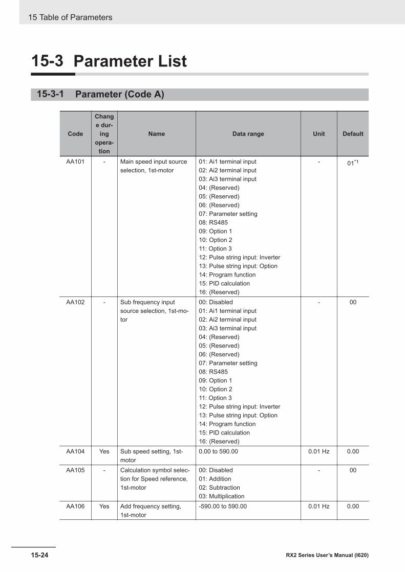
15-3 Parameter List
15-3-1 Parameter (Code A)
Code
Change dur-
ingopera-
tion
Name Data range Unit Default
AA101 - Main speed input sourceselection, 1st-motor
01: Ai1 terminal input02: Ai2 terminal input03: Ai3 terminal input04: (Reserved)05: (Reserved)06: (Reserved)07: Parameter setting08: RS48509: Option 110: Option 211: Option 312: Pulse string input: Inverter13: Pulse string input: Option14: Program function15: PID calculation16: (Reserved)
- 01*1
AA102 - Sub frequency inputsource selection, 1st-mo-tor
00: Disabled01: Ai1 terminal input02: Ai2 terminal input03: Ai3 terminal input04: (Reserved)05: (Reserved)06: (Reserved)07: Parameter setting08: RS48509: Option 110: Option 211: Option 312: Pulse string input: Inverter13: Pulse string input: Option14: Program function15: PID calculation16: (Reserved)
- 00
AA104 Yes Sub speed setting, 1st-motor
0.00 to 590.00 0.01 Hz 0.00
AA105 - Calculation symbol selec-tion for Speed reference,1st-motor
00: Disabled01: Addition02: Subtraction03: Multiplication
- 00
AA106 Yes Add frequency setting,1st-motor
-590.00 to 590.00 0.01 Hz 0.00
15 Table of Parameters
15-24 RX2 Series User’s Manual (I620)
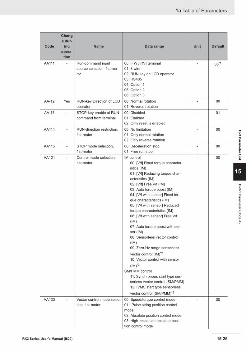
Code
Change dur-
ingopera-
tion
Name Data range Unit Default
AA111 - Run-command inputsource selection, 1st-mo-tor
00: [FW]/[RV] terminal01: 3 wire02: RUN key on LCD operator03: RS48504: Option 105: Option 206: Option 3
- 00*1
AA-12 Yes RUN-key Direction of LCDoperator
00: Normal rotation01: Reverse rotation
- 00
AA-13 - STOP-key enable at RUN-command from terminal
00: Disabled01: Enabled02: Only reset is enabled
- 01
AA114 - RUN-direction restriction,1st-motor
00: No limitation01: Only normal rotation02: Only reverse rotation
- 00
AA115 - STOP mode selection,1st-motor
00: Deceleration stop01: Free run stop
- 00
AA121 - Control mode selection,1st-motor
IM control00: [V/f] Fixed torque character-istics (IM)01: [V/f] Reducing torque char-acteristics (IM)02: [V/f] Free V/f (IM)03: Auto torque boost (IM)04: [V/f with sensor] Fixed tor-que characteristics (IM)05: [V/f with sensor] Reducedtorque characteristics (IM)06: [V/f with sensor] Free V/f(IM)07: Auto torque boost with sen-sor (IM)08: Sensorless vector control(IM)09: Zero-Hz range sensorlessvector control (IM)*2
10: Vector control with sensor(IM)*2
SM/PMM control11: Synchronous start type sen-sorless vector control (SM/PMM)12: IVMS start type sensorlessvector control (SM/PMM)*3
- 00
AA123 - Vector control mode selec-tion, 1st-motor
00: Speed/torque control mode01 : Pulse string position controlmode02: Absolute position control mode03: High-resolution absolute posi-tion control mode
- 00
15 Table of Parameters
15-25RX2 Series User’s Manual (I620)
15-3 Parameter List
15
15-3-1 Parameter (C
ode A)
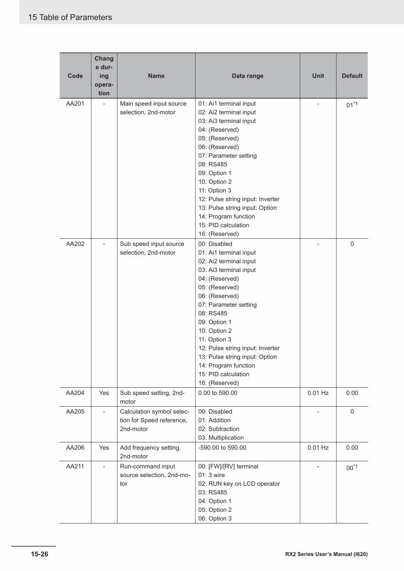
Code
Change dur-
ingopera-
tion
Name Data range Unit Default
AA201 - Main speed input sourceselection, 2nd-motor
01: Ai1 terminal input02: Ai2 terminal input03: Ai3 terminal input04: (Reserved)05: (Reserved)06: (Reserved)07: Parameter setting08: RS48509: Option 110: Option 211: Option 312: Pulse string input: Inverter13: Pulse string input: Option14: Program function15: PID calculation16: (Reserved)
- 01*1
AA202 - Sub speed input sourceselection, 2nd-motor
00: Disabled01: Ai1 terminal input02: Ai2 terminal input03: Ai3 terminal input04: (Reserved)05: (Reserved)06: (Reserved)07: Parameter setting08: RS48509: Option 110: Option 211: Option 312: Pulse string input: Inverter13: Pulse string input: Option14: Program function15: PID calculation16: (Reserved)
- 0
AA204 Yes Sub speed setting, 2nd-motor
0.00 to 590.00 0.01 Hz 0.00
AA205 - Calculation symbol selec-tion for Speed reference,2nd-motor
00: Disabled01: Addition02: Subtraction03: Multiplication
- 0
AA206 Yes Add frequency setting,2nd-motor
-590.00 to 590.00 0.01 Hz 0.00
AA211 - Run-command inputsource selection, 2nd-mo-tor
00: [FW]/[RV] terminal01: 3 wire02: RUN key on LCD operator03: RS48504: Option 105: Option 206: Option 3
- 00*1
15 Table of Parameters
15-26 RX2 Series User’s Manual (I620)
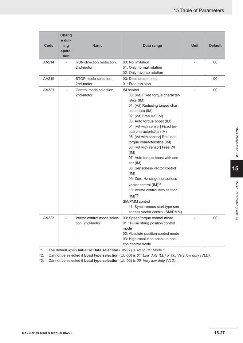
Code
Change dur-
ingopera-
tion
Name Data range Unit Default
AA214 - RUN-direction restriction,2nd-motor
00: No limitation01: Only normal rotation02: Only reverse rotation
- 00
AA215 - STOP mode selection,2nd-motor
00: Deceleration stop01: Free run stop
- 00
AA221 - Control mode selection,2nd-motor
IM control00: [V/f] Fixed torque character-istics (IM)01: [V/f] Reducing torque char-acteristics (IM)02: [V/f] Free V/f (IM)03: Auto torque boost (IM)04: [V/f with sensor] Fixed tor-que characteristics (IM)05: [V/f with sensor] Reducedtorque characteristics (IM)06: [V/f with sensor] Free V/f(IM)07: Auto torque boost with sen-sor (IM)08: Sensorless vector control(IM)09: Zero-Hz range sensorlessvector control (IM)*2
10: Vector control with sensor(IM)*2
SM/PMM control11: Synchronous start type sen-sorless vector control (SM/PMM)
- 00
AA223 - Vector control mode selec-tion, 2nd-motor
00: Speed/torque control mode01 : Pulse string position controlmode02: Absolute position control mode03: High-resolution absolute posi-tion control mode
- 00
*1. The default when Initialize Data selection (Ub-02) is set to 01: Mode 1.*2. Cannot be selected if Load type selection (Ub-03) is 01: Low duty (LD) or 00: Very low duty (VLD).*3. Cannot be selected if Load type selection (Ub-03) is 00: Very low duty (VLD).
15 Table of Parameters
15-27RX2 Series User’s Manual (I620)
15-3 Parameter List
15
15-3-1 Parameter (C
ode A)
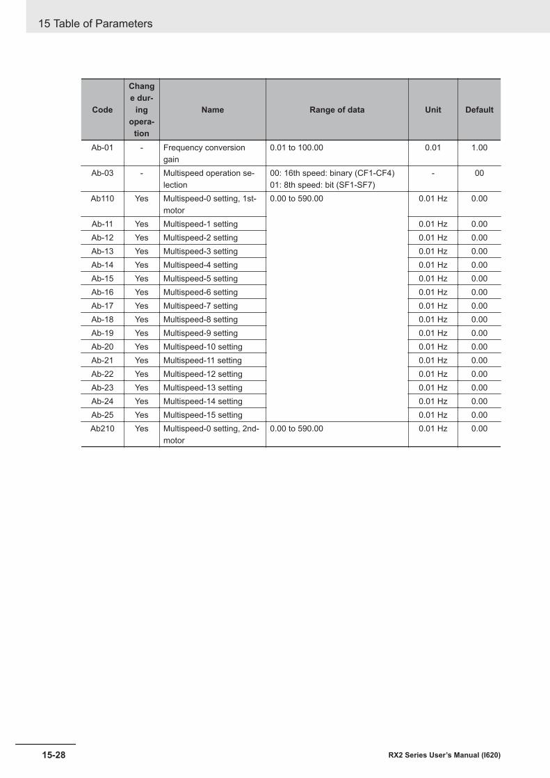
Code
Change dur-
ingopera-
tion
Name Range of data Unit Default
Ab-01 - Frequency conversiongain
0.01 to 100.00 0.01 1.00
Ab-03 - Multispeed operation se-lection
00: 16th speed: binary (CF1-CF4)01: 8th speed: bit (SF1-SF7)
- 00
Ab110 Yes Multispeed-0 setting, 1st-motor
0.00 to 590.00 0.01 Hz 0.00
Ab-11 Yes Multispeed-1 setting 0.01 Hz 0.00Ab-12 Yes Multispeed-2 setting 0.01 Hz 0.00Ab-13 Yes Multispeed-3 setting 0.01 Hz 0.00Ab-14 Yes Multispeed-4 setting 0.01 Hz 0.00Ab-15 Yes Multispeed-5 setting 0.01 Hz 0.00Ab-16 Yes Multispeed-6 setting 0.01 Hz 0.00Ab-17 Yes Multispeed-7 setting 0.01 Hz 0.00Ab-18 Yes Multispeed-8 setting 0.01 Hz 0.00Ab-19 Yes Multispeed-9 setting 0.01 Hz 0.00Ab-20 Yes Multispeed-10 setting 0.01 Hz 0.00Ab-21 Yes Multispeed-11 setting 0.01 Hz 0.00Ab-22 Yes Multispeed-12 setting 0.01 Hz 0.00Ab-23 Yes Multispeed-13 setting 0.01 Hz 0.00Ab-24 Yes Multispeed-14 setting 0.01 Hz 0.00Ab-25 Yes Multispeed-15 setting 0.01 Hz 0.00Ab210 Yes Multispeed-0 setting, 2nd-
motor0.00 to 590.00 0.01 Hz 0.00
15 Table of Parameters
15-28 RX2 Series User’s Manual (I620)
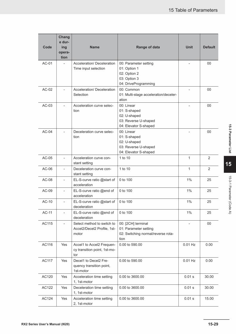
Code
Change dur-
ingopera-
tion
Name Range of data Unit Default
AC-01 - Acceleration/ DecelerationTime input selection
00: Parameter setting01: Option 102: Option 203: Option 304: DriveProgramming
- 00
AC-02 - Acceleration/ DecelerationSelection
00: Common01: Multi-stage acceleration/deceler-ation
- 00
AC-03 - Acceleration curve selec-tion
00: Linear01: S-shaped02: U-shaped03: Reverse U-shaped04: Elevator S-shaped
- 00
AC-04 - Deceleration curve selec-tion
00: Linear01: S-shaped02: U-shaped03: Reverse U-shaped04: Elevator S-shaped
- 00
AC-05 - Acceleration curve con-stant setting
1 to 10 1 2
AC-06 - Deceleration curve con-stant setting
1 to 10 1 2
AC-08 - EL-S-curve ratio @start ofacceleration
0 to 100 1% 25
AC-09 - EL-S-curve ratio @end ofacceleration
0 to 100 1% 25
AC-10 - EL-S-curve ratio @start ofdeceleration
0 to 100 1% 25
AC-11 - EL-S-curve ratio @end ofdeceleration
0 to 100 1% 25
AC115 - Select method to switch toAccel2/Decel2 Profile, 1st-motor
00: [2CH] terminal01: Parameter setting02: Switching normal/reverse rota-tion
- 00
AC116 Yes Accel1 to Accel2 Frequen-cy transition point, 1st-mo-tor
0.00 to 590.00 0.01 Hz 0.00
AC117 Yes Decel1 to Decel2 Fre-quency transition point,1st-motor
0.00 to 590.00 0.01 Hz 0.00
AC120 Yes Acceleration time setting1, 1st-motor
0.00 to 3600.00 0.01 s 30.00
AC122 Yes Deceleration time setting1, 1st-motor
0.00 to 3600.00 0.01 s 30.00
AC124 Yes Acceleration time setting2, 1st-motor
0.00 to 3600.00 0.01 s 15.00
15 Table of Parameters
15-29RX2 Series User’s Manual (I620)
15-3 Parameter List
15
15-3-1 Parameter (C
ode A)

Code
Change dur-
ingopera-
tion
Name Range of data Unit Default
AC126 Yes Deceleration time setting2, 1st-motor
0.00 to 3600.00 0.01 s 15.00
15 Table of Parameters
15-30 RX2 Series User’s Manual (I620)
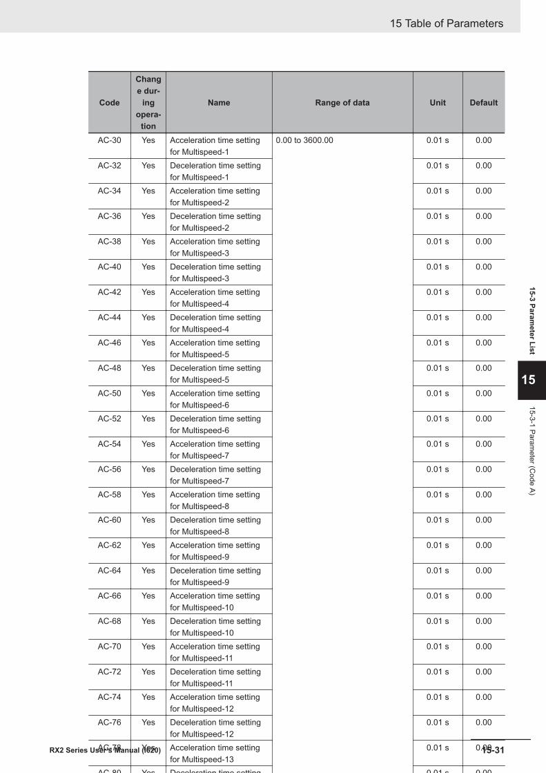
Code
Change dur-
ingopera-
tion
Name Range of data Unit Default
AC-30 Yes Acceleration time settingfor Multispeed-1
0.00 to 3600.00 0.01 s 0.00
AC-32 Yes Deceleration time settingfor Multispeed-1
0.01 s 0.00
AC-34 Yes Acceleration time settingfor Multispeed-2
0.01 s 0.00
AC-36 Yes Deceleration time settingfor Multispeed-2
0.01 s 0.00
AC-38 Yes Acceleration time settingfor Multispeed-3
0.01 s 0.00
AC-40 Yes Deceleration time settingfor Multispeed-3
0.01 s 0.00
AC-42 Yes Acceleration time settingfor Multispeed-4
0.01 s 0.00
AC-44 Yes Deceleration time settingfor Multispeed-4
0.01 s 0.00
AC-46 Yes Acceleration time settingfor Multispeed-5
0.01 s 0.00
AC-48 Yes Deceleration time settingfor Multispeed-5
0.01 s 0.00
AC-50 Yes Acceleration time settingfor Multispeed-6
0.01 s 0.00
AC-52 Yes Deceleration time settingfor Multispeed-6
0.01 s 0.00
AC-54 Yes Acceleration time settingfor Multispeed-7
0.01 s 0.00
AC-56 Yes Deceleration time settingfor Multispeed-7
0.01 s 0.00
AC-58 Yes Acceleration time settingfor Multispeed-8
0.01 s 0.00
AC-60 Yes Deceleration time settingfor Multispeed-8
0.01 s 0.00
AC-62 Yes Acceleration time settingfor Multispeed-9
0.01 s 0.00
AC-64 Yes Deceleration time settingfor Multispeed-9
0.01 s 0.00
AC-66 Yes Acceleration time settingfor Multispeed-10
0.01 s 0.00
AC-68 Yes Deceleration time settingfor Multispeed-10
0.01 s 0.00
AC-70 Yes Acceleration time settingfor Multispeed-11
0.01 s 0.00
AC-72 Yes Deceleration time settingfor Multispeed-11
0.01 s 0.00
AC-74 Yes Acceleration time settingfor Multispeed-12
0.01 s 0.00
AC-76 Yes Deceleration time settingfor Multispeed-12
0.01 s 0.00
AC-78 Yes Acceleration time settingfor Multispeed-13
0.01 s 0.00
AC-80 Yes Deceleration time settingfor Multispeed-13
0.01 s 0.00
AC-82 Yes Acceleration time settingfor Multispeed-14
0.01 s 0.00
AC-84 Yes Deceleration time settingfor Multispeed-14
0.01 s 0.00
AC-86 Yes Acceleration time settingfor Multispeed-15
0.01 s 0.00
AC-88 Yes Deceleration time settingfor Multispeed-15
0.01 s 0.00
15 Table of Parameters
15-31RX2 Series User’s Manual (I620)
15-3 Parameter List
15
15-3-1 Parameter (C
ode A)

Code
Change dur-
ingopera-
tion
Name Range of data Unit Default
AC215 - Select method to switch toAccel2/Decel2 Profile,2nd-motor
00: [2CH] terminal01: Parameter setting02: Switching normal/reverse rota-tion
- 00
AC216 Yes Accel1 to Accel2 Frequen-cy transition point, 2nd-motor
0.00 to 590.00 0.01 Hz 0.00
AC217 Yes Decel1 to Decel2 Fre-quency transition point,2nd-motor
0.00 to 590.00 0.01 Hz 0.00
AC220 Yes Acceleration time setting1, 2nd-motor
0.00 to 3600.00 0.01 s 30.00
AC222 Yes Deceleration time setting1, 2nd-motor
0.01 s 30.00
AC224 Yes Acceleration time setting2, 2nd-motor
0.01 s 15.00
AC226 Yes Deceleration time setting2, 2nd-motor
0.01 s 15.00
15 Table of Parameters
15-32 RX2 Series User’s Manual (I620)
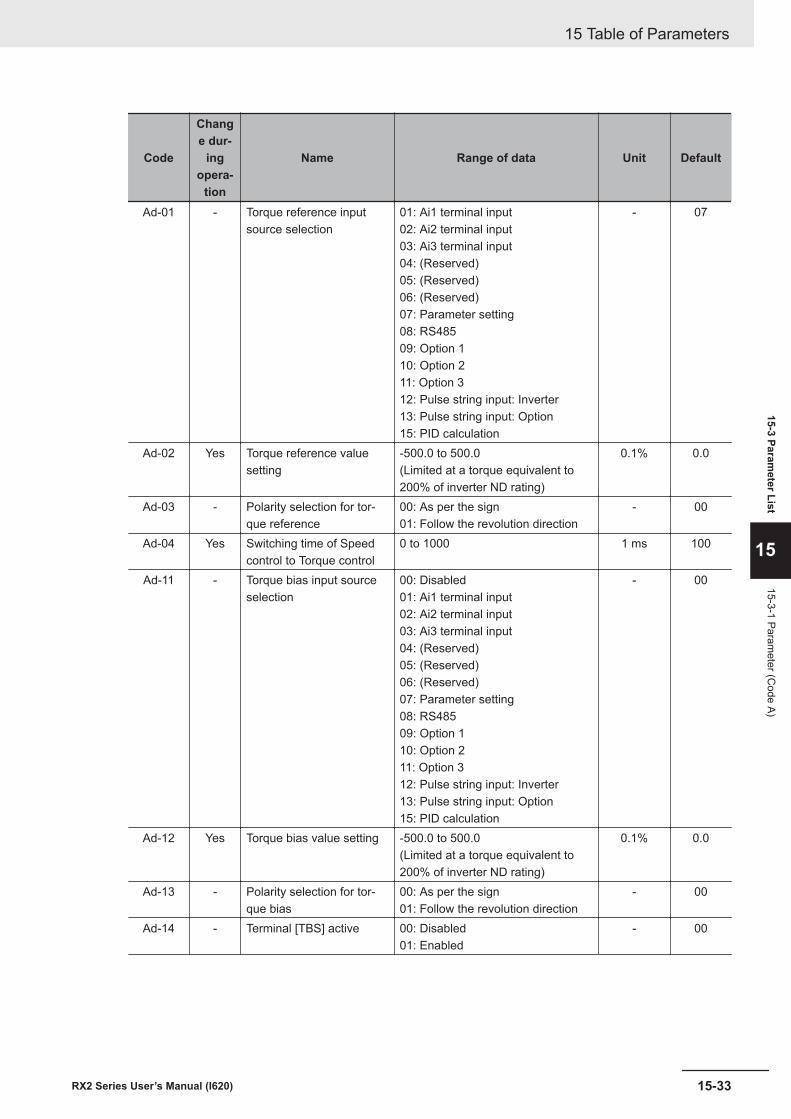
Code
Change dur-
ingopera-
tion
Name Range of data Unit Default
Ad-01 - Torque reference inputsource selection
01: Ai1 terminal input02: Ai2 terminal input03: Ai3 terminal input04: (Reserved)05: (Reserved)06: (Reserved)07: Parameter setting08: RS48509: Option 110: Option 211: Option 312: Pulse string input: Inverter13: Pulse string input: Option15: PID calculation
- 07
Ad-02 Yes Torque reference valuesetting
-500.0 to 500.0(Limited at a torque equivalent to200% of inverter ND rating)
0.1% 0.0
Ad-03 - Polarity selection for tor-que reference
00: As per the sign01: Follow the revolution direction
- 00
Ad-04 Yes Switching time of Speedcontrol to Torque control
0 to 1000 1 ms 100
Ad-11 - Torque bias input sourceselection
00: Disabled01: Ai1 terminal input02: Ai2 terminal input03: Ai3 terminal input04: (Reserved)05: (Reserved)06: (Reserved)07: Parameter setting08: RS48509: Option 110: Option 211: Option 312: Pulse string input: Inverter13: Pulse string input: Option15: PID calculation
- 00
Ad-12 Yes Torque bias value setting -500.0 to 500.0(Limited at a torque equivalent to200% of inverter ND rating)
0.1% 0.0
Ad-13 - Polarity selection for tor-que bias
00: As per the sign01: Follow the revolution direction
- 00
Ad-14 - Terminal [TBS] active 00: Disabled01: Enabled
- 00
15 Table of Parameters
15-33RX2 Series User’s Manual (I620)
15-3 Parameter List
15
15-3-1 Parameter (C
ode A)
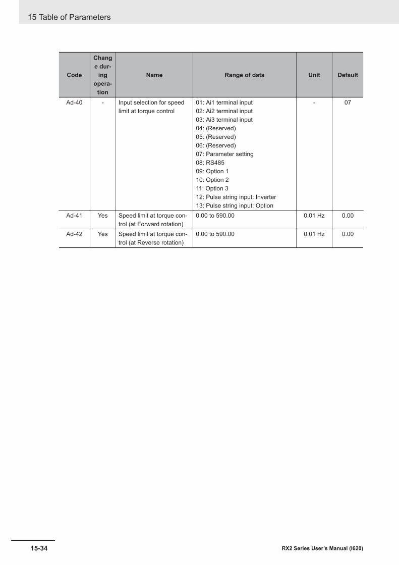
Code
Change dur-
ingopera-
tion
Name Range of data Unit Default
Ad-40 - Input selection for speedlimit at torque control
01: Ai1 terminal input02: Ai2 terminal input03: Ai3 terminal input04: (Reserved)05: (Reserved)06: (Reserved)07: Parameter setting08: RS48509: Option 110: Option 211: Option 312: Pulse string input: Inverter13: Pulse string input: Option
- 07
Ad-41 Yes Speed limit at torque con-trol (at Forward rotation)
0.00 to 590.00 0.01 Hz 0.00
Ad-42 Yes Speed limit at torque con-trol (at Reverse rotation)
0.00 to 590.00 0.01 Hz 0.00
15 Table of Parameters
15-34 RX2 Series User’s Manual (I620)
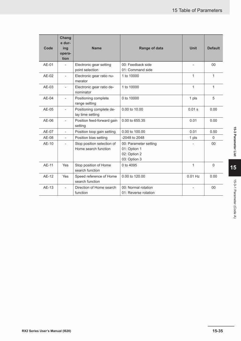
Code
Change dur-
ingopera-
tion
Name Range of data Unit Default
AE-01 - Electronic gear settingpoint selection
00: Feedback side01: Command side
- 00
AE-02 - Electronic gear ratio nu-merator
1 to 10000 1 1
AE-03 - Electronic gear ratio de-nominator
1 to 10000 1 1
AE-04 - Positioning completerange setting
0 to 10000 1 pls 5
AE-05 - Positioning complete de-lay time setting
0.00 to 10.00 0.01 s 0.00
AE-06 - Position feed-forward gainsetting
0.00 to 655.35 0.01 0.00
AE-07 - Position loop gain setting 0.00 to 100.00 0.01 0.50AE-08 - Position bias setting -2048 to 2048 1 pls 0AE-10 - Stop position selection of
Home search function00: Parameter setting01: Option 102: Option 203: Option 3
- 00
AE-11 Yes Stop position of Homesearch function
0 to 4095 1 0
AE-12 Yes Speed reference of Homesearch function
0.00 to 120.00 0.01 Hz 0.00
AE-13 - Direction of Home searchfunction
00: Normal rotation01: Reverse rotation
- 00
15 Table of Parameters
15-35RX2 Series User’s Manual (I620)
15-3 Parameter List
15
15-3-1 Parameter (C
ode A)
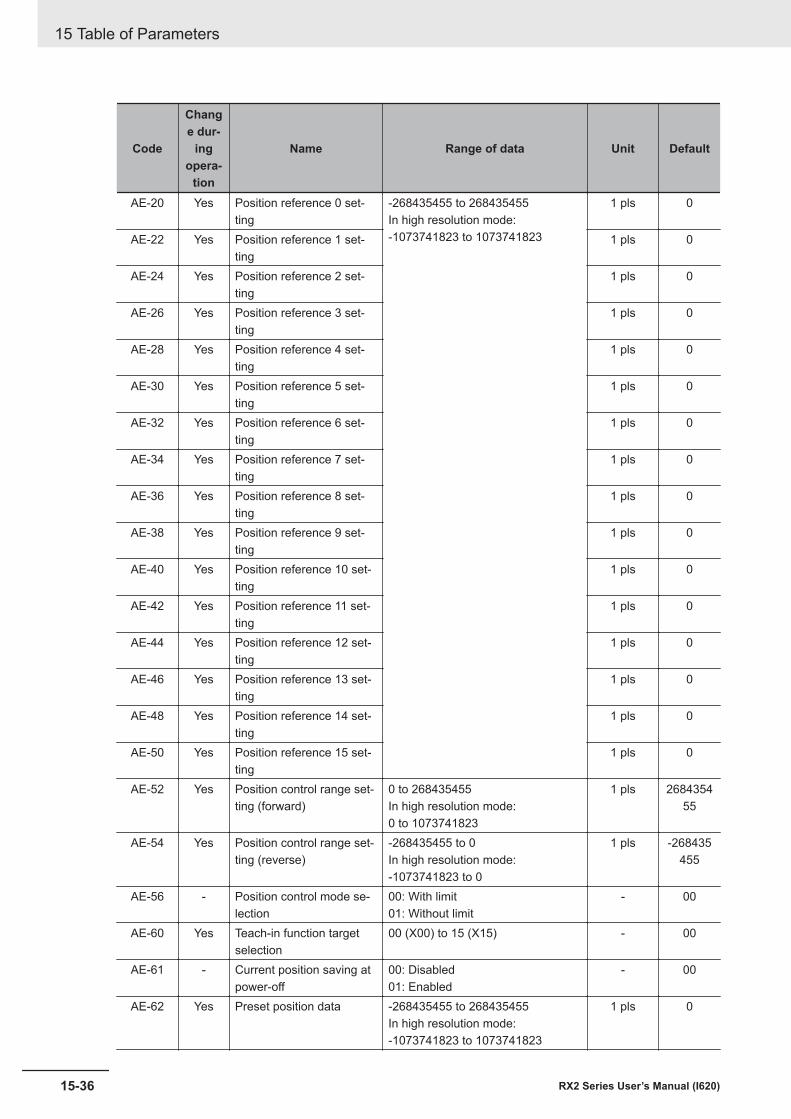
Code
Change dur-
ingopera-
tion
Name Range of data Unit Default
AE-20 Yes Position reference 0 set-ting
-268435455 to 268435455In high resolution mode:-1073741823 to 1073741823
1 pls 0
AE-22 Yes Position reference 1 set-ting
1 pls 0
AE-24 Yes Position reference 2 set-ting
1 pls 0
AE-26 Yes Position reference 3 set-ting
1 pls 0
AE-28 Yes Position reference 4 set-ting
1 pls 0
AE-30 Yes Position reference 5 set-ting
1 pls 0
AE-32 Yes Position reference 6 set-ting
1 pls 0
AE-34 Yes Position reference 7 set-ting
1 pls 0
AE-36 Yes Position reference 8 set-ting
1 pls 0
AE-38 Yes Position reference 9 set-ting
1 pls 0
AE-40 Yes Position reference 10 set-ting
1 pls 0
AE-42 Yes Position reference 11 set-ting
1 pls 0
AE-44 Yes Position reference 12 set-ting
1 pls 0
AE-46 Yes Position reference 13 set-ting
1 pls 0
AE-48 Yes Position reference 14 set-ting
1 pls 0
AE-50 Yes Position reference 15 set-ting
1 pls 0
AE-52 Yes Position control range set-ting (forward)
0 to 268435455In high resolution mode:0 to 1073741823
1 pls 268435455
AE-54 Yes Position control range set-ting (reverse)
-268435455 to 0In high resolution mode:-1073741823 to 0
1 pls -268435455
AE-56 - Position control mode se-lection
00: With limit01: Without limit
- 00
AE-60 Yes Teach-in function targetselection
00 (X00) to 15 (X15) - 00
AE-61 - Current position saving atpower-off
00: Disabled01: Enabled
- 00
AE-62 Yes Preset position data -268435455 to 268435455In high resolution mode:-1073741823 to 1073741823
1 pls 0
15 Table of Parameters
15-36 RX2 Series User’s Manual (I620)
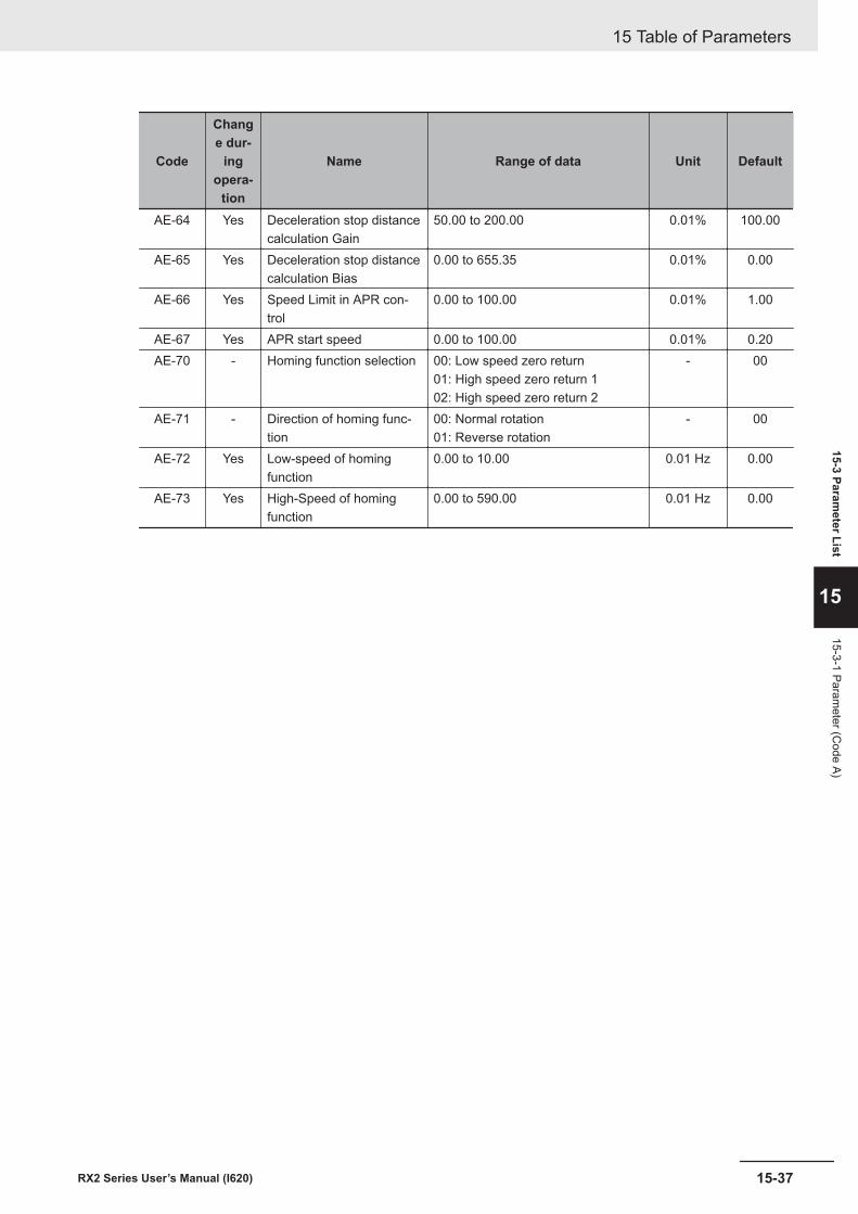
Code
Change dur-
ingopera-
tion
Name Range of data Unit Default
AE-64 Yes Deceleration stop distancecalculation Gain
50.00 to 200.00 0.01% 100.00
AE-65 Yes Deceleration stop distancecalculation Bias
0.00 to 655.35 0.01% 0.00
AE-66 Yes Speed Limit in APR con-trol
0.00 to 100.00 0.01% 1.00
AE-67 Yes APR start speed 0.00 to 100.00 0.01% 0.20AE-70 - Homing function selection 00: Low speed zero return
01: High speed zero return 102: High speed zero return 2
- 00
AE-71 - Direction of homing func-tion
00: Normal rotation01: Reverse rotation
- 00
AE-72 Yes Low-speed of homingfunction
0.00 to 10.00 0.01 Hz 0.00
AE-73 Yes High-Speed of homingfunction
0.00 to 590.00 0.01 Hz 0.00
15 Table of Parameters
15-37RX2 Series User’s Manual (I620)
15-3 Parameter List
15
15-3-1 Parameter (C
ode A)
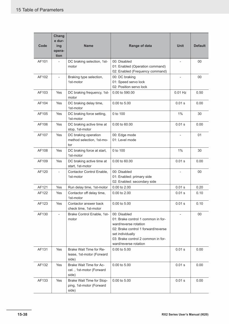
Code
Change dur-
ingopera-
tion
Name Range of data Unit Default
AF101 - DC braking selection, 1st-motor
00: Disabled01: Enabled (Operation command)02: Enabled (Frequency command)
- 00
AF102 - Braking type selection,1st-motor
00: DC braking01: Speed servo lock02: Position servo lock
- 00
AF103 Yes DC braking frequency, 1st-motor
0.00 to 590.00 0.01 Hz 0.50
AF104 Yes DC braking delay time,1st-motor
0.00 to 5.00 0.01 s 0.00
AF105 Yes DC braking force setting,1st-motor
0 to 100 1% 30
AF106 Yes DC braking active time atstop, 1st-motor
0.00 to 60.00 0.01 s 0.00
AF107 Yes DC braking operationmethod selection, 1st-mo-tor
00: Edge mode01: Level mode
- 01
AF108 Yes DC braking force at start,1st-motor
0 to 100 1% 30
AF109 Yes DC braking active time atstart, 1st-motor
0.00 to 60.00 0.01 s 0.00
AF120 - Contactor Control Enable,1st-motor
00: Disabled01: Enabled: primary side02: Enabled: secondary side
- 00
AF121 Yes Run delay time, 1st-motor 0.00 to 2.00 0.01 s 0.20AF122 Yes Contactor off delay time,
1st-motor0.00 to 2.00 0.01 s 0.10
AF123 Yes Contactor answer backcheck time, 1st-motor
0.00 to 5.00 0.01 s 0.10
AF130 - Brake Control Enable, 1st-motor
00: Disabled01: Brake control 1 common in for-ward/reverse rotation02: Brake control 1 forward/reverseset individually03: Brake control 2 common in for-ward/reverse rotation
- 00
AF131 Yes Brake Wait Time for Re-lease, 1st-motor (Forwardside)
0.00 to 5.00 0.01 s 0.00
AF132 Yes Brake Wait Time for Ac-cel. , 1st-motor (Forwardside)
0.00 to 5.00 0.01 s 0.00
AF133 Yes Brake Wait Time for Stop-ping, 1st-motor (Forwardside)
0.00 to 5.00 0.01 s 0.00
15 Table of Parameters
15-38 RX2 Series User’s Manual (I620)
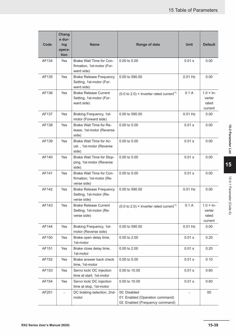
Code
Change dur-
ingopera-
tion
Name Range of data Unit Default
AF134 Yes Brake Wait Time for Con-firmation, 1st-motor (For-ward side)
0.00 to 5.00 0.01 s 0.00
AF135 Yes Brake Release FrequencySetting, 1st-motor (For-ward side)
0.00 to 590.00 0.01 Hz 0.00
AF136 Yes Brake Release CurrentSetting, 1st-motor (For-ward side)
(0.0 to 2.0) × Inverter rated current*1 0.1 A 1.0 × In-verterrated
currentAF137 Yes Braking Frequency, 1st-
motor (Forward side)0.00 to 590.00 0.01 Hz 0.00
AF138 Yes Brake Wait Time for Re-lease, 1st-motor (Reverseside)
0.00 to 5.00 0.01 s 0.00
AF139 Yes Brake Wait Time for Ac-cel. , 1st-motor (Reverseside)
0.00 to 5.00 0.01 s 0.00
AF140 Yes Brake Wait Time for Stop-ping, 1st-motor (Reverseside)
0.00 to 5.00 0.01 s 0.00
AF141 Yes Brake Wait Time for Con-firmation, 1st-motor (Re-verse side)
0.00 to 5.00 0.01 s 0.00
AF142 Yes Brake Release FrequencySetting, 1st-motor (Re-verse side)
0.00 to 590.00 0.01 Hz 0.00
AF143 Yes Brake Release CurrentSetting, 1st-motor (Re-verse side)
(0.0 to 2.0) × Inverter rated current*1 0.1 A 1.0 × In-verterrated
currentAF144 Yes Braking Frequency, 1st-
motor (Reverse side)0.00 to 590.00 0.01 Hz 0.00
AF150 Yes Brake open delay time,1st-motor
0.00 to 2.00 0.01 s 0.20
AF151 Yes Brake close delay time,1st-motor
0.00 to 2.00 0.01 s 0.20
AF152 Yes Brake answer back checktime, 1st-motor
0.00 to 5.00 0.01 s 0.10
AF153 Yes Servo lock/ DC injectiontime at start, 1st-motor
0.00 to 10.00 0.01 s 0.60
AF154 Yes Servo lock/ DC injectiontime at stop, 1st-motor
0.00 to 10.00 0.01 s 0.60
AF201 - DC braking selection, 2nd-motor
00: Disabled01: Enabled (Operation command)02: Enabled (Frequency command)
- 00
15 Table of Parameters
15-39RX2 Series User’s Manual (I620)
15-3 Parameter List
15
15-3-1 Parameter (C
ode A)
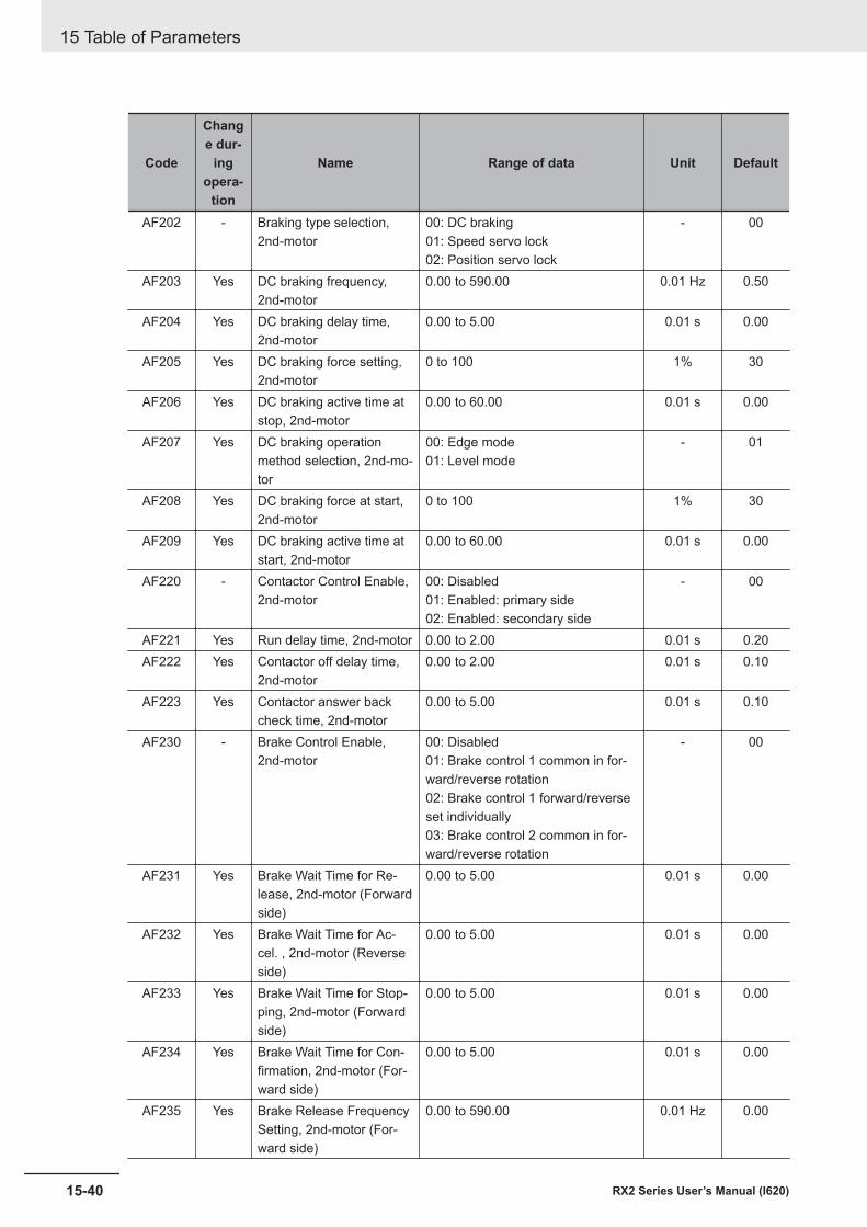
Code
Change dur-
ingopera-
tion
Name Range of data Unit Default
AF202 - Braking type selection,2nd-motor
00: DC braking01: Speed servo lock02: Position servo lock
- 00
AF203 Yes DC braking frequency,2nd-motor
0.00 to 590.00 0.01 Hz 0.50
AF204 Yes DC braking delay time,2nd-motor
0.00 to 5.00 0.01 s 0.00
AF205 Yes DC braking force setting,2nd-motor
0 to 100 1% 30
AF206 Yes DC braking active time atstop, 2nd-motor
0.00 to 60.00 0.01 s 0.00
AF207 Yes DC braking operationmethod selection, 2nd-mo-tor
00: Edge mode01: Level mode
- 01
AF208 Yes DC braking force at start,2nd-motor
0 to 100 1% 30
AF209 Yes DC braking active time atstart, 2nd-motor
0.00 to 60.00 0.01 s 0.00
AF220 - Contactor Control Enable,2nd-motor
00: Disabled01: Enabled: primary side02: Enabled: secondary side
- 00
AF221 Yes Run delay time, 2nd-motor 0.00 to 2.00 0.01 s 0.20AF222 Yes Contactor off delay time,
2nd-motor0.00 to 2.00 0.01 s 0.10
AF223 Yes Contactor answer backcheck time, 2nd-motor
0.00 to 5.00 0.01 s 0.10
AF230 - Brake Control Enable,2nd-motor
00: Disabled01: Brake control 1 common in for-ward/reverse rotation02: Brake control 1 forward/reverseset individually03: Brake control 2 common in for-ward/reverse rotation
- 00
AF231 Yes Brake Wait Time for Re-lease, 2nd-motor (Forwardside)
0.00 to 5.00 0.01 s 0.00
AF232 Yes Brake Wait Time for Ac-cel. , 2nd-motor (Reverseside)
0.00 to 5.00 0.01 s 0.00
AF233 Yes Brake Wait Time for Stop-ping, 2nd-motor (Forwardside)
0.00 to 5.00 0.01 s 0.00
AF234 Yes Brake Wait Time for Con-firmation, 2nd-motor (For-ward side)
0.00 to 5.00 0.01 s 0.00
AF235 Yes Brake Release FrequencySetting, 2nd-motor (For-ward side)
0.00 to 590.00 0.01 Hz 0.00
15 Table of Parameters
15-40 RX2 Series User’s Manual (I620)
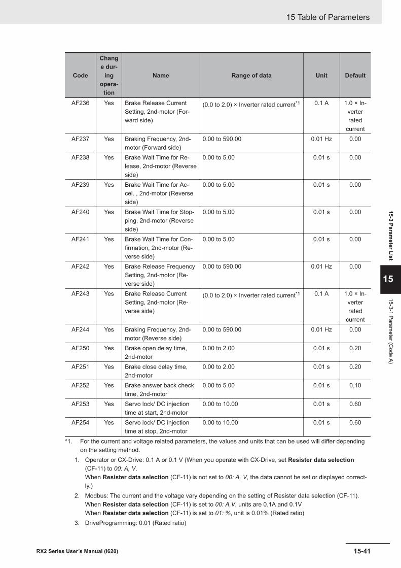
Code
Change dur-
ingopera-
tion
Name Range of data Unit Default
AF236 Yes Brake Release CurrentSetting, 2nd-motor (For-ward side)
(0.0 to 2.0) × Inverter rated current*1 0.1 A 1.0 × In-verterrated
currentAF237 Yes Braking Frequency, 2nd-
motor (Forward side)0.00 to 590.00 0.01 Hz 0.00
AF238 Yes Brake Wait Time for Re-lease, 2nd-motor (Reverseside)
0.00 to 5.00 0.01 s 0.00
AF239 Yes Brake Wait Time for Ac-cel. , 2nd-motor (Reverseside)
0.00 to 5.00 0.01 s 0.00
AF240 Yes Brake Wait Time for Stop-ping, 2nd-motor (Reverseside)
0.00 to 5.00 0.01 s 0.00
AF241 Yes Brake Wait Time for Con-firmation, 2nd-motor (Re-verse side)
0.00 to 5.00 0.01 s 0.00
AF242 Yes Brake Release FrequencySetting, 2nd-motor (Re-verse side)
0.00 to 590.00 0.01 Hz 0.00
AF243 Yes Brake Release CurrentSetting, 2nd-motor (Re-verse side)
(0.0 to 2.0) × Inverter rated current*1 0.1 A 1.0 × In-verterrated
currentAF244 Yes Braking Frequency, 2nd-
motor (Reverse side)0.00 to 590.00 0.01 Hz 0.00
AF250 Yes Brake open delay time,2nd-motor
0.00 to 2.00 0.01 s 0.20
AF251 Yes Brake close delay time,2nd-motor
0.00 to 2.00 0.01 s 0.20
AF252 Yes Brake answer back checktime, 2nd-motor
0.00 to 5.00 0.01 s 0.10
AF253 Yes Servo lock/ DC injectiontime at start, 2nd-motor
0.00 to 10.00 0.01 s 0.60
AF254 Yes Servo lock/ DC injectiontime at stop, 2nd-motor
0.00 to 10.00 0.01 s 0.60
*1. For the current and voltage related parameters, the values and units that can be used will differ dependingon the setting method.
1. Operator or CX-Drive: 0.1 A or 0.1 V (When you operate with CX-Drive, set Resister data selection(CF-11) to 00: A, V.When Resister data selection (CF-11) is not set to 00: A, V, the data cannot be set or displayed correct-ly.)
2. Modbus: The current and the voltage vary depending on the setting of Resister data selection (CF-11).When Resister data selection (CF-11) is set to 00: A,V, units are 0.1A and 0.1VWhen Resister data selection (CF-11) is set to 01: %, unit is 0.01% (Rated ratio)
3. DriveProgramming: 0.01 (Rated ratio)
15 Table of Parameters
15-41RX2 Series User’s Manual (I620)
15-3 Parameter List
15
15-3-1 Parameter (C
ode A)
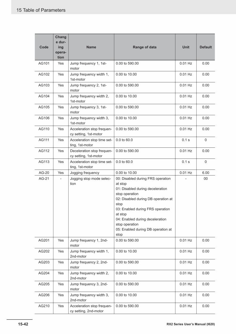
Code
Change dur-
ingopera-
tion
Name Range of data Unit Default
AG101 Yes Jump frequency 1, 1st-motor
0.00 to 590.00 0.01 Hz 0.00
AG102 Yes Jump frequency width 1,1st-motor
0.00 to 10.00 0.01 Hz 0.00
AG103 Yes Jump frequency 2, 1st-motor
0.00 to 590.00 0.01 Hz 0.00
AG104 Yes Jump frequency width 2,1st-motor
0.00 to 10.00 0.01 Hz 0.00
AG105 Yes Jump frequency 3, 1st-motor
0.00 to 590.00 0.01 Hz 0.00
AG106 Yes Jump frequency width 3,1st-motor
0.00 to 10.00 0.01 Hz 0.00
AG110 Yes Acceleration stop frequen-cy setting, 1st-motor
0.00 to 590.00 0.01 Hz 0.00
AG111 Yes Acceleration stop time set-ting, 1st-motor
0.0 to 60.0 0.1 s 0
AG112 Yes Deceleration stop frequen-cy setting, 1st-motor
0.00 to 590.00 0.01 Hz 0.00
AG113 Yes Acceleration stop time set-ting, 1st-motor
0.0 to 60.0 0.1 s 0
AG-20 Yes Jogging frequency 0.00 to 10.00 0.01 Hz 6.00AG-21 - Jogging stop mode selec-
tion00: Disabled during FRS operationat stop01: Disabled during decelerationstop operation02: Disabled during DB operation atstop03: Enabled during FRS operationat stop04: Enabled during decelerationstop operation05: Enabled during DB operation atstop
- 00
AG201 Yes Jump frequency 1, 2nd-motor
0.00 to 590.00 0.01 Hz 0.00
AG202 Yes Jump frequency width 1,2nd-motor
0.00 to 10.00 0.01 Hz 0.00
AG203 Yes Jump frequency 2, 2nd-motor
0.00 to 590.00 0.01 Hz 0.00
AG204 Yes Jump frequency width 2,2nd-motor
0.00 to 10.00 0.01 Hz 0.00
AG205 Yes Jump frequency 3, 2nd-motor
0.00 to 590.00 0.01 Hz 0.00
AG206 Yes Jump frequency width 3,2nd-motor
0.00 to 10.00 0.01 Hz 0.00
AG210 Yes Acceleration stop frequen-cy setting, 2nd-motor
0.00 to 590.00 0.01 Hz 0.00
15 Table of Parameters
15-42 RX2 Series User’s Manual (I620)
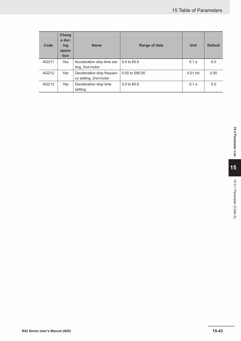
Code
Change dur-
ingopera-
tion
Name Range of data Unit Default
AG211 Yes Acceleration stop time set-ting, 2nd-motor
0.0 to 60.0 0.1 s 0.0
AG212 Yes Deceleration stop frequen-cy setting, 2nd-motor
0.00 to 590.00 0.01 Hz 0.00
AG213 Yes Deceleration stop timesetting
0.0 to 60.0 0.1 s 0.0
15 Table of Parameters
15-43RX2 Series User’s Manual (I620)
15-3 Parameter List
15
15-3-1 Parameter (C
ode A)
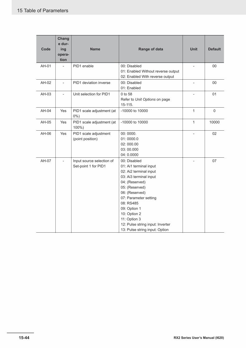
Code
Change dur-
ingopera-
tion
Name Range of data Unit Default
AH-01 - PID1 enable 00: Disabled01: Enabled Without reverse output02: Enabled With reverse output
- 00
AH-02 - PID1 deviation inverse 00: Disabled01: Enabled
- 00
AH-03 - Unit selection for PID1 0 to 58Refer to Unit Options on page15-115.
- 01
AH-04 Yes PID1 scale adjustment (at0%)
-10000 to 10000 1 0
AH-05 Yes PID1 scale adjustment (at100%)
-10000 to 10000 1 10000
AH-06 Yes PID1 scale adjustment(point position)
00: 0000.01: 0000.002: 000.0003: 00.00004: 0.0000
- 02
AH-07 - Input source selection ofSet-point 1 for PID1
00: Disabled01: Ai1 terminal input02: Ai2 terminal input03: Ai3 terminal input04: (Reserved)05: (Reserved)06: (Reserved)07: Parameter setting08: RS48509: Option 110: Option 211: Option 312: Pulse string input: Inverter13: Pulse string input: Option
- 07
15 Table of Parameters
15-44 RX2 Series User’s Manual (I620)
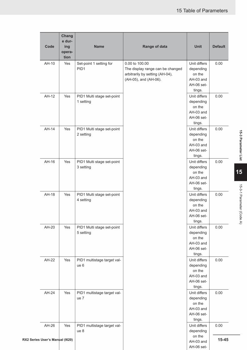
Code
Change dur-
ingopera-
tion
Name Range of data Unit Default
AH-10 Yes Set-point 1 setting forPID1
0.00 to 100.00The display range can be changedarbitrarily by setting (AH-04),(AH-05), and (AH-06).
Unit differsdepending
on theAH-03 andAH-06 set-
tings.
0.00
AH-12 Yes PID1 Multi stage set-point1 setting
Unit differsdepending
on theAH-03 andAH-06 set-
tings.
0.00
AH-14 Yes PID1 Multi stage set-point2 setting
Unit differsdepending
on theAH-03 andAH-06 set-
tings.
0.00
AH-16 Yes PID1 Multi stage set-point3 setting
Unit differsdepending
on theAH-03 andAH-06 set-
tings.
0.00
AH-18 Yes PID1 Multi stage set-point4 setting
Unit differsdepending
on theAH-03 andAH-06 set-
tings.
0.00
AH-20 Yes PID1 Multi stage set-point5 setting
Unit differsdepending
on theAH-03 andAH-06 set-
tings.
0.00
AH-22 Yes PID1 multistage target val-ue 6
Unit differsdepending
on theAH-03 andAH-06 set-
tings.
0.00
AH-24 Yes PID1 multistage target val-ue 7
Unit differsdepending
on theAH-03 andAH-06 set-
tings.
0.00
AH-26 Yes PID1 multistage target val-ue 8
Unit differsdepending
on theAH-03 andAH-06 set-
tings.
0.00
AH-28 Yes PID1 multistage target val-ue 9
Unit differsdepending
on theAH-03 andAH-06 set-
tings.
0.00
AH-30 Yes PID1 multistage target val-ue 10
Unit differsdepending
on theAH-03 andAH-06 set-
tings.
0.00
AH-32 Yes PID1 multistage target val-ue 11
Unit differsdepending
on theAH-03 andAH-06 set-
tings.
0.00
AH-34 Yes PID1 multistage target val-ue 12
Unit differsdepending
on theAH-03 andAH-06 set-
tings.
0.00
AH-36 Yes PID1 multistage target val-ue 13
Unit differsdepending
on theAH-03 andAH-06 set-
tings.
0.00
AH-38 Yes PID1 multistage target val-ue 14
Unit differsdepending
on theAH-03 andAH-06 set-
tings.
0.00
AH-40 Yes PID1 Multi stage set-point15 setting
Unit differsdepending
on theAH-03 andAH-06 set-
tings.
0.00
15 Table of Parameters
15-45RX2 Series User’s Manual (I620)
15-3 Parameter List
15
15-3-1 Parameter (C
ode A)
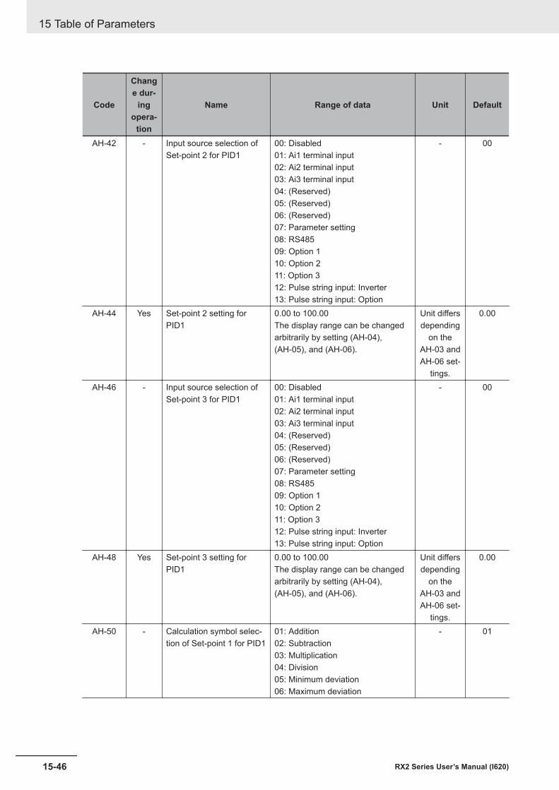
Code
Change dur-
ingopera-
tion
Name Range of data Unit Default
AH-42 - Input source selection ofSet-point 2 for PID1
00: Disabled01: Ai1 terminal input02: Ai2 terminal input03: Ai3 terminal input04: (Reserved)05: (Reserved)06: (Reserved)07: Parameter setting08: RS48509: Option 110: Option 211: Option 312: Pulse string input: Inverter13: Pulse string input: Option
- 00
AH-44 Yes Set-point 2 setting forPID1
0.00 to 100.00The display range can be changedarbitrarily by setting (AH-04),(AH-05), and (AH-06).
Unit differsdepending
on theAH-03 andAH-06 set-
tings.
0.00
AH-46 - Input source selection ofSet-point 3 for PID1
00: Disabled01: Ai1 terminal input02: Ai2 terminal input03: Ai3 terminal input04: (Reserved)05: (Reserved)06: (Reserved)07: Parameter setting08: RS48509: Option 110: Option 211: Option 312: Pulse string input: Inverter13: Pulse string input: Option
- 00
AH-48 Yes Set-point 3 setting forPID1
0.00 to 100.00The display range can be changedarbitrarily by setting (AH-04),(AH-05), and (AH-06).
Unit differsdepending
on theAH-03 andAH-06 set-
tings.
0.00
AH-50 - Calculation symbol selec-tion of Set-point 1 for PID1
01: Addition02: Subtraction03: Multiplication04: Division05: Minimum deviation06: Maximum deviation
- 01
15 Table of Parameters
15-46 RX2 Series User’s Manual (I620)
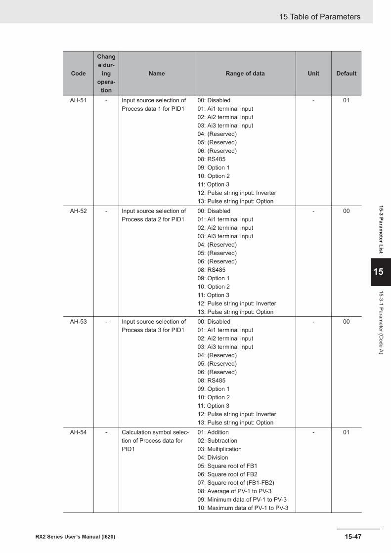
Code
Change dur-
ingopera-
tion
Name Range of data Unit Default
AH-51 - Input source selection ofProcess data 1 for PID1
00: Disabled01: Ai1 terminal input02: Ai2 terminal input03: Ai3 terminal input04: (Reserved)05: (Reserved)06: (Reserved)08: RS48509: Option 110: Option 211: Option 312: Pulse string input: Inverter13: Pulse string input: Option
- 01
AH-52 - Input source selection ofProcess data 2 for PID1
00: Disabled01: Ai1 terminal input02: Ai2 terminal input03: Ai3 terminal input04: (Reserved)05: (Reserved)06: (Reserved)08: RS48509: Option 110: Option 211: Option 312: Pulse string input: Inverter13: Pulse string input: Option
- 00
AH-53 - Input source selection ofProcess data 3 for PID1
00: Disabled01: Ai1 terminal input02: Ai2 terminal input03: Ai3 terminal input04: (Reserved)05: (Reserved)06: (Reserved)08: RS48509: Option 110: Option 211: Option 312: Pulse string input: Inverter13: Pulse string input: Option
- 00
AH-54 - Calculation symbol selec-tion of Process data forPID1
01: Addition02: Subtraction03: Multiplication04: Division05: Square root of FB106: Square root of FB207: Square root of (FB1-FB2)08: Average of PV-1 to PV-309: Minimum data of PV-1 to PV-310: Maximum data of PV-1 to PV-3
- 01
15 Table of Parameters
15-47RX2 Series User’s Manual (I620)
15-3 Parameter List
15
15-3-1 Parameter (C
ode A)
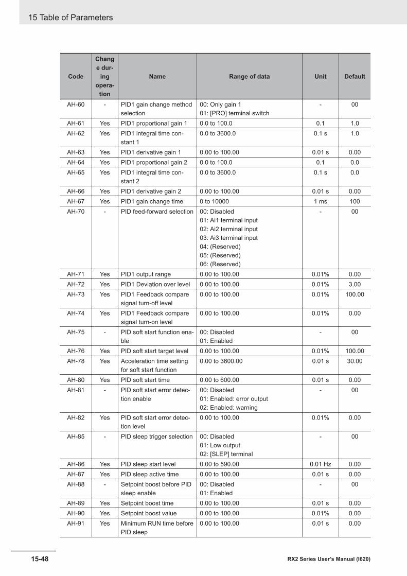
Code
Change dur-
ingopera-
tion
Name Range of data Unit Default
AH-60 - PID1 gain change methodselection
00: Only gain 101: [PRO] terminal switch
- 00
AH-61 Yes PID1 proportional gain 1 0.0 to 100.0 0.1 1.0AH-62 Yes PID1 integral time con-
stant 10.0 to 3600.0 0.1 s 1.0
AH-63 Yes PID1 derivative gain 1 0.00 to 100.00 0.01 s 0.00AH-64 Yes PID1 proportional gain 2 0.0 to 100.0 0.1 0.0AH-65 Yes PID1 integral time con-
stant 20.0 to 3600.0 0.1 s 0.0
AH-66 Yes PID1 derivative gain 2 0.00 to 100.00 0.01 s 0.00AH-67 Yes PID1 gain change time 0 to 10000 1 ms 100AH-70 - PID feed-forward selection 00: Disabled
01: Ai1 terminal input02: Ai2 terminal input03: Ai3 terminal input04: (Reserved)05: (Reserved)06: (Reserved)
- 00
AH-71 Yes PID1 output range 0.00 to 100.00 0.01% 0.00AH-72 Yes PID1 Deviation over level 0.00 to 100.00 0.01% 3.00AH-73 Yes PID1 Feedback compare
signal turn-off level0.00 to 100.00 0.01% 100.00
AH-74 Yes PID1 Feedback comparesignal turn-on level
0.00 to 100.00 0.01% 0.00
AH-75 - PID soft start function ena-ble
00: Disabled01: Enabled
- 00
AH-76 Yes PID soft start target level 0.00 to 100.00 0.01% 100.00AH-78 Yes Acceleration time setting
for soft start function0.00 to 3600.00 0.01 s 30.00
AH-80 Yes PID soft start time 0.00 to 600.00 0.01 s 0.00AH-81 - PID soft start error detec-
tion enable00: Disabled01: Enabled: error output02: Enabled: warning
- 00
AH-82 Yes PID soft start error detec-tion level
0.00 to 100.00 0.01% 0.00
AH-85 - PID sleep trigger selection 00: Disabled01: Low output02: [SLEP] terminal
- 00
AH-86 Yes PID sleep start level 0.00 to 590.00 0.01 Hz 0.00AH-87 Yes PID sleep active time 0.00 to 100.00 0.01 s 0.00AH-88 - Setpoint boost before PID
sleep enable00: Disabled01: Enabled
- 00
AH-89 Yes Setpoint boost time 0.00 to 100.00 0.01 s 0.00AH-90 Yes Setpoint boost value 0.00 to 100.00 0.01% 0.00AH-91 Yes Minimum RUN time before
PID sleep0.00 to 100.00 0.01 s 0.00
15 Table of Parameters
15-48 RX2 Series User’s Manual (I620)
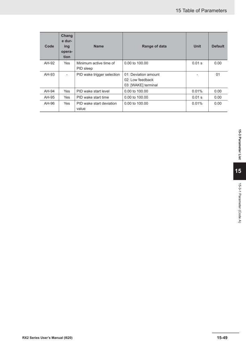
Code
Change dur-
ingopera-
tion
Name Range of data Unit Default
AH-92 Yes Minimum active time ofPID sleep
0.00 to 100.00 0.01 s 0.00
AH-93 - PID wake trigger selection 01: Deviation amount02: Low feedback03: [WAKE] terminal
- 01
AH-94 Yes PID wake start level 0.00 to 100.00 0.01% 0.00AH-95 Yes PID wake start time 0.00 to 100.00 0.01 s 0.00AH-96 Yes PID wake start deviation
value0.00 to 100.00 0.01% 0.00
15 Table of Parameters
15-49RX2 Series User’s Manual (I620)
15-3 Parameter List
15
15-3-1 Parameter (C
ode A)
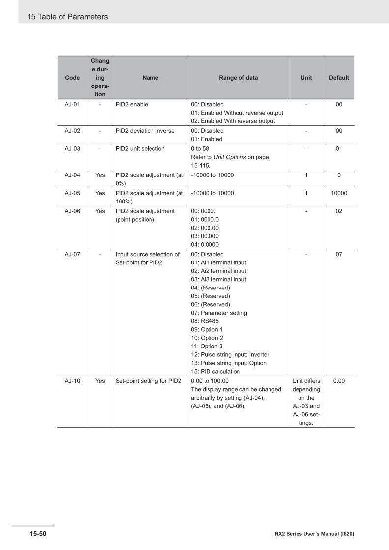
Code
Change dur-
ingopera-
tion
Name Range of data Unit Default
AJ-01 - PID2 enable 00: Disabled01: Enabled Without reverse output02: Enabled With reverse output
- 00
AJ-02 - PID2 deviation inverse 00: Disabled01: Enabled
- 00
AJ-03 - PID2 unit selection 0 to 58Refer to Unit Options on page15-115.
- 01
AJ-04 Yes PID2 scale adjustment (at0%)
-10000 to 10000 1 0
AJ-05 Yes PID2 scale adjustment (at100%)
-10000 to 10000 1 10000
AJ-06 Yes PID2 scale adjustment(point position)
00: 0000.01: 0000.002: 000.0003: 00.00004: 0.0000
- 02
AJ-07 - Input source selection ofSet-point for PID2
00: Disabled01: Ai1 terminal input02: Ai2 terminal input03: Ai3 terminal input04: (Reserved)05: (Reserved)06: (Reserved)07: Parameter setting08: RS48509: Option 110: Option 211: Option 312: Pulse string input: Inverter13: Pulse string input: Option15: PID calculation
- 07
AJ-10 Yes Set-point setting for PID2 0.00 to 100.00The display range can be changedarbitrarily by setting (AJ-04),(AJ-05), and (AJ-06).
Unit differsdepending
on theAJ-03 andAJ-06 set-
tings.
0.00
15 Table of Parameters
15-50 RX2 Series User’s Manual (I620)
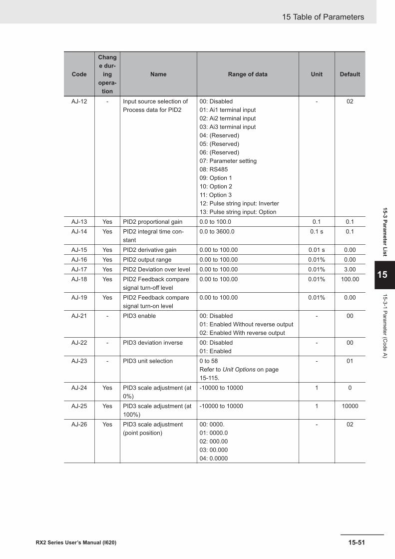
Code
Change dur-
ingopera-
tion
Name Range of data Unit Default
AJ-12 - Input source selection ofProcess data for PID2
00: Disabled01: Ai1 terminal input02: Ai2 terminal input03: Ai3 terminal input04: (Reserved)05: (Reserved)06: (Reserved)07: Parameter setting08: RS48509: Option 110: Option 211: Option 312: Pulse string input: Inverter13: Pulse string input: Option
- 02
AJ-13 Yes PID2 proportional gain 0.0 to 100.0 0.1 0.1AJ-14 Yes PID2 integral time con-
stant0.0 to 3600.0 0.1 s 0.1
AJ-15 Yes PID2 derivative gain 0.00 to 100.00 0.01 s 0.00AJ-16 Yes PID2 output range 0.00 to 100.00 0.01% 0.00AJ-17 Yes PID2 Deviation over level 0.00 to 100.00 0.01% 3.00AJ-18 Yes PID2 Feedback compare
signal turn-off level0.00 to 100.00 0.01% 100.00
AJ-19 Yes PID2 Feedback comparesignal turn-on level
0.00 to 100.00 0.01% 0.00
AJ-21 - PID3 enable 00: Disabled01: Enabled Without reverse output02: Enabled With reverse output
- 00
AJ-22 - PID3 deviation inverse 00: Disabled01: Enabled
- 00
AJ-23 - PID3 unit selection 0 to 58Refer to Unit Options on page15-115.
- 01
AJ-24 Yes PID3 scale adjustment (at0%)
-10000 to 10000 1 0
AJ-25 Yes PID3 scale adjustment (at100%)
-10000 to 10000 1 10000
AJ-26 Yes PID3 scale adjustment(point position)
00: 0000.01: 0000.002: 000.0003: 00.00004: 0.0000
- 02
15 Table of Parameters
15-51RX2 Series User’s Manual (I620)
15-3 Parameter List
15
15-3-1 Parameter (C
ode A)
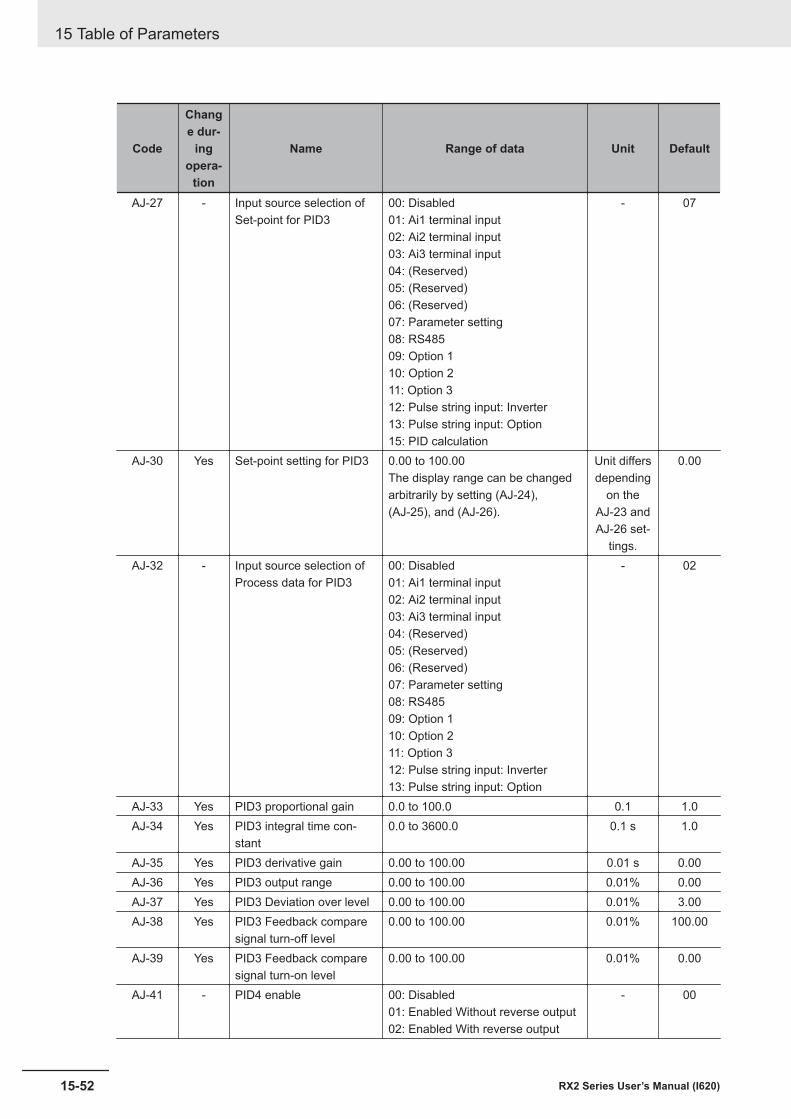
Code
Change dur-
ingopera-
tion
Name Range of data Unit Default
AJ-27 - Input source selection ofSet-point for PID3
00: Disabled01: Ai1 terminal input02: Ai2 terminal input03: Ai3 terminal input04: (Reserved)05: (Reserved)06: (Reserved)07: Parameter setting08: RS48509: Option 110: Option 211: Option 312: Pulse string input: Inverter13: Pulse string input: Option15: PID calculation
- 07
AJ-30 Yes Set-point setting for PID3 0.00 to 100.00The display range can be changedarbitrarily by setting (AJ-24),(AJ-25), and (AJ-26).
Unit differsdepending
on theAJ-23 andAJ-26 set-
tings.
0.00
AJ-32 - Input source selection ofProcess data for PID3
00: Disabled01: Ai1 terminal input02: Ai2 terminal input03: Ai3 terminal input04: (Reserved)05: (Reserved)06: (Reserved)07: Parameter setting08: RS48509: Option 110: Option 211: Option 312: Pulse string input: Inverter13: Pulse string input: Option
- 02
AJ-33 Yes PID3 proportional gain 0.0 to 100.0 0.1 1.0AJ-34 Yes PID3 integral time con-
stant0.0 to 3600.0 0.1 s 1.0
AJ-35 Yes PID3 derivative gain 0.00 to 100.00 0.01 s 0.00AJ-36 Yes PID3 output range 0.00 to 100.00 0.01% 0.00AJ-37 Yes PID3 Deviation over level 0.00 to 100.00 0.01% 3.00AJ-38 Yes PID3 Feedback compare
signal turn-off level0.00 to 100.00 0.01% 100.00
AJ-39 Yes PID3 Feedback comparesignal turn-on level
0.00 to 100.00 0.01% 0.00
AJ-41 - PID4 enable 00: Disabled01: Enabled Without reverse output02: Enabled With reverse output
- 00
15 Table of Parameters
15-52 RX2 Series User’s Manual (I620)
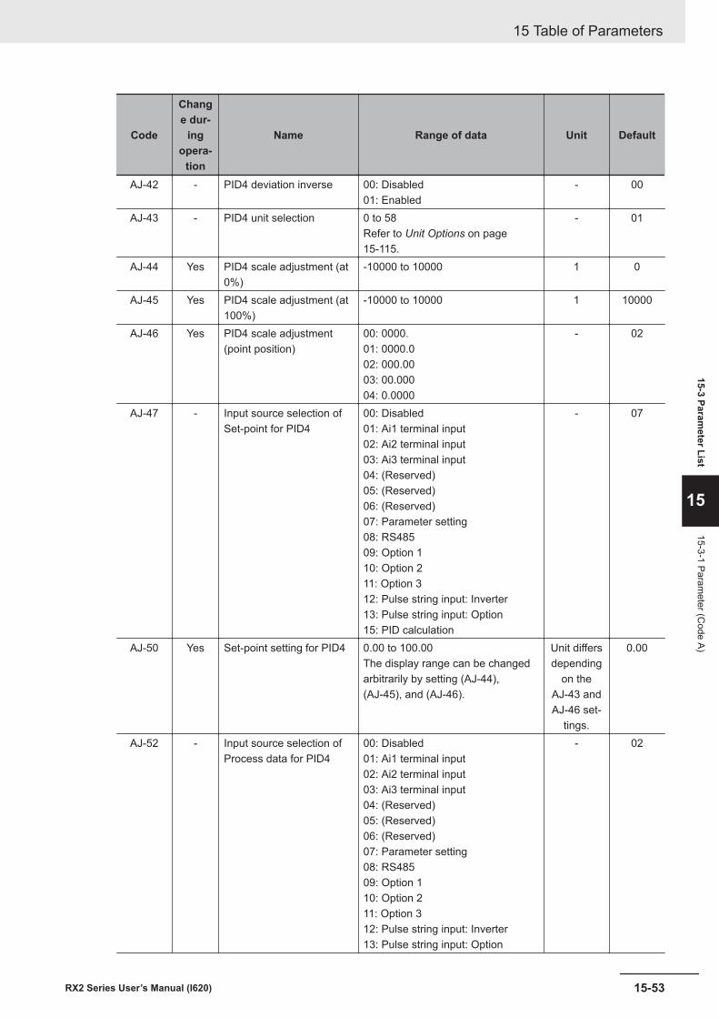
Code
Change dur-
ingopera-
tion
Name Range of data Unit Default
AJ-42 - PID4 deviation inverse 00: Disabled01: Enabled
- 00
AJ-43 - PID4 unit selection 0 to 58Refer to Unit Options on page15-115.
- 01
AJ-44 Yes PID4 scale adjustment (at0%)
-10000 to 10000 1 0
AJ-45 Yes PID4 scale adjustment (at100%)
-10000 to 10000 1 10000
AJ-46 Yes PID4 scale adjustment(point position)
00: 0000.01: 0000.002: 000.0003: 00.00004: 0.0000
- 02
AJ-47 - Input source selection ofSet-point for PID4
00: Disabled01: Ai1 terminal input02: Ai2 terminal input03: Ai3 terminal input04: (Reserved)05: (Reserved)06: (Reserved)07: Parameter setting08: RS48509: Option 110: Option 211: Option 312: Pulse string input: Inverter13: Pulse string input: Option15: PID calculation
- 07
AJ-50 Yes Set-point setting for PID4 0.00 to 100.00The display range can be changedarbitrarily by setting (AJ-44),(AJ-45), and (AJ-46).
Unit differsdepending
on theAJ-43 andAJ-46 set-
tings.
0.00
AJ-52 - Input source selection ofProcess data for PID4
00: Disabled01: Ai1 terminal input02: Ai2 terminal input03: Ai3 terminal input04: (Reserved)05: (Reserved)06: (Reserved)07: Parameter setting08: RS48509: Option 110: Option 211: Option 312: Pulse string input: Inverter13: Pulse string input: Option
- 02
15 Table of Parameters
15-53RX2 Series User’s Manual (I620)
15-3 Parameter List
15
15-3-1 Parameter (C
ode A)
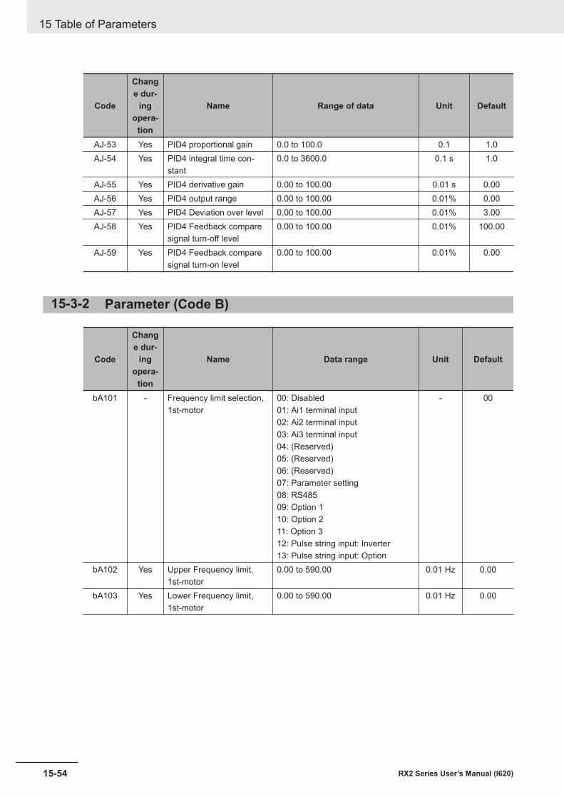
Code
Change dur-
ingopera-
tion
Name Range of data Unit Default
AJ-53 Yes PID4 proportional gain 0.0 to 100.0 0.1 1.0AJ-54 Yes PID4 integral time con-
stant0.0 to 3600.0 0.1 s 1.0
AJ-55 Yes PID4 derivative gain 0.00 to 100.00 0.01 s 0.00AJ-56 Yes PID4 output range 0.00 to 100.00 0.01% 0.00AJ-57 Yes PID4 Deviation over level 0.00 to 100.00 0.01% 3.00AJ-58 Yes PID4 Feedback compare
signal turn-off level0.00 to 100.00 0.01% 100.00
AJ-59 Yes PID4 Feedback comparesignal turn-on level
0.00 to 100.00 0.01% 0.00
15-3-2 Parameter (Code B)
Code
Change dur-
ingopera-
tion
Name Data range Unit Default
bA101 - Frequency limit selection,1st-motor
00: Disabled01: Ai1 terminal input02: Ai2 terminal input03: Ai3 terminal input04: (Reserved)05: (Reserved)06: (Reserved)07: Parameter setting08: RS48509: Option 110: Option 211: Option 312: Pulse string input: Inverter13: Pulse string input: Option
- 00
bA102 Yes Upper Frequency limit,1st-motor
0.00 to 590.00 0.01 Hz 0.00
bA103 Yes Lower Frequency limit,1st-motor
0.00 to 590.00 0.01 Hz 0.00
15 Table of Parameters
15-54 RX2 Series User’s Manual (I620)
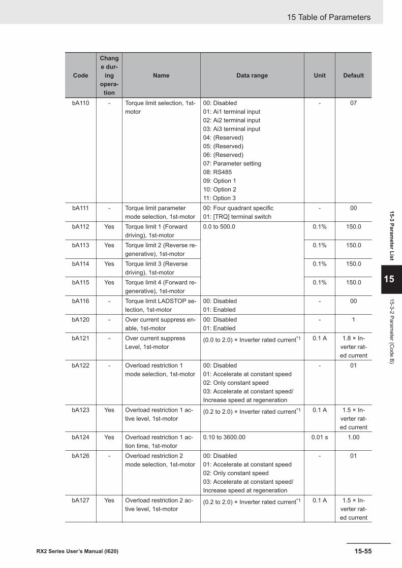
Code
Change dur-
ingopera-
tion
Name Data range Unit Default
bA110 - Torque limit selection, 1st-motor
00: Disabled01: Ai1 terminal input02: Ai2 terminal input03: Ai3 terminal input04: (Reserved)05: (Reserved)06: (Reserved)07: Parameter setting08: RS48509: Option 110: Option 211: Option 3
- 07
bA111 - Torque limit parametermode selection, 1st-motor
00: Four quadrant specific01: [TRQ] terminal switch
- 00
bA112 Yes Torque limit 1 (Forwarddriving), 1st-motor
0.0 to 500.0 0.1% 150.0
bA113 Yes Torque limit 2 (Reverse re-generative), 1st-motor
0.1% 150.0
bA114 Yes Torque limit 3 (Reversedriving), 1st-motor
0.1% 150.0
bA115 Yes Torque limit 4 (Forward re-generative), 1st-motor
0.1% 150.0
bA116 - Torque limit LADSTOP se-lection, 1st-motor
00: Disabled01: Enabled
- 00
bA120 - Over current suppress en-able, 1st-motor
00: Disabled01: Enabled
- 1
bA121 - Over current suppressLevel, 1st-motor
(0.0 to 2.0) × Inverter rated current*1 0.1 A 1.8 × In-verter rat-ed current
bA122 - Overload restriction 1mode selection, 1st-motor
00: Disabled01: Accelerate at constant speed02: Only constant speed03: Accelerate at constant speed/Increase speed at regeneration
- 01
bA123 Yes Overload restriction 1 ac-tive level, 1st-motor
(0.2 to 2.0) × Inverter rated current*1 0.1 A 1.5 × In-verter rat-ed current
bA124 Yes Overload restriction 1 ac-tion time, 1st-motor
0.10 to 3600.00 0.01 s 1.00
bA126 - Overload restriction 2mode selection, 1st-motor
00: Disabled01: Accelerate at constant speed02: Only constant speed03: Accelerate at constant speed/Increase speed at regeneration
- 01
bA127 Yes Overload restriction 2 ac-tive level, 1st-motor
(0.2 to 2.0) × Inverter rated current*1 0.1 A 1.5 × In-verter rat-ed current
15 Table of Parameters
15-55RX2 Series User’s Manual (I620)
15-3 Parameter List
15
15-3-2 Parameter (C
ode B)
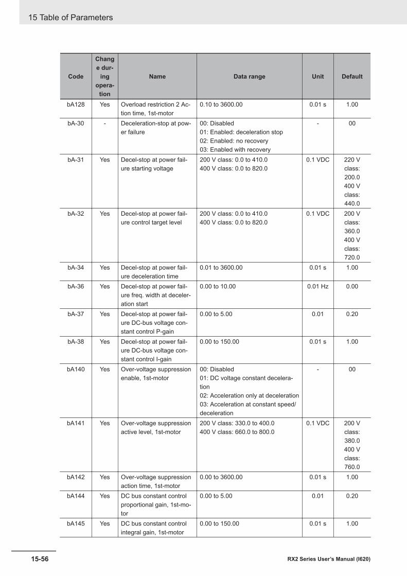
Code
Change dur-
ingopera-
tion
Name Data range Unit Default
bA128 Yes Overload restriction 2 Ac-tion time, 1st-motor
0.10 to 3600.00 0.01 s 1.00
bA-30 - Deceleration-stop at pow-er failure
00: Disabled01: Enabled: deceleration stop02: Enabled: no recovery03: Enabled with recovery
- 00
bA-31 Yes Decel-stop at power fail-ure starting voltage
200 V class: 0.0 to 410.0400 V class: 0.0 to 820.0
0.1 VDC 220 Vclass:200.0400 Vclass:440.0
bA-32 Yes Decel-stop at power fail-ure control target level
200 V class: 0.0 to 410.0400 V class: 0.0 to 820.0
0.1 VDC 200 Vclass:360.0400 Vclass:720.0
bA-34 Yes Decel-stop at power fail-ure deceleration time
0.01 to 3600.00 0.01 s 1.00
bA-36 Yes Decel-stop at power fail-ure freq. width at deceler-ation start
0.00 to 10.00 0.01 Hz 0.00
bA-37 Yes Decel-stop at power fail-ure DC-bus voltage con-stant control P-gain
0.00 to 5.00 0.01 0.20
bA-38 Yes Decel-stop at power fail-ure DC-bus voltage con-stant control I-gain
0.00 to 150.00 0.01 s 1.00
bA140 Yes Over-voltage suppressionenable, 1st-motor
00: Disabled01: DC voltage constant decelera-tion02: Acceleration only at deceleration03: Acceleration at constant speed/deceleration
- 00
bA141 Yes Over-voltage suppressionactive level, 1st-motor
200 V class: 330.0 to 400.0400 V class: 660.0 to 800.0
0.1 VDC 200 Vclass:380.0400 Vclass:760.0
bA142 Yes Over-voltage suppressionaction time, 1st-motor
0.00 to 3600.00 0.01 s 1.00
bA144 Yes DC bus constant controlproportional gain, 1st-mo-tor
0.00 to 5.00 0.01 0.20
bA145 Yes DC bus constant controlintegral gain, 1st-motor
0.00 to 150.00 0.01 s 1.00
15 Table of Parameters
15-56 RX2 Series User’s Manual (I620)
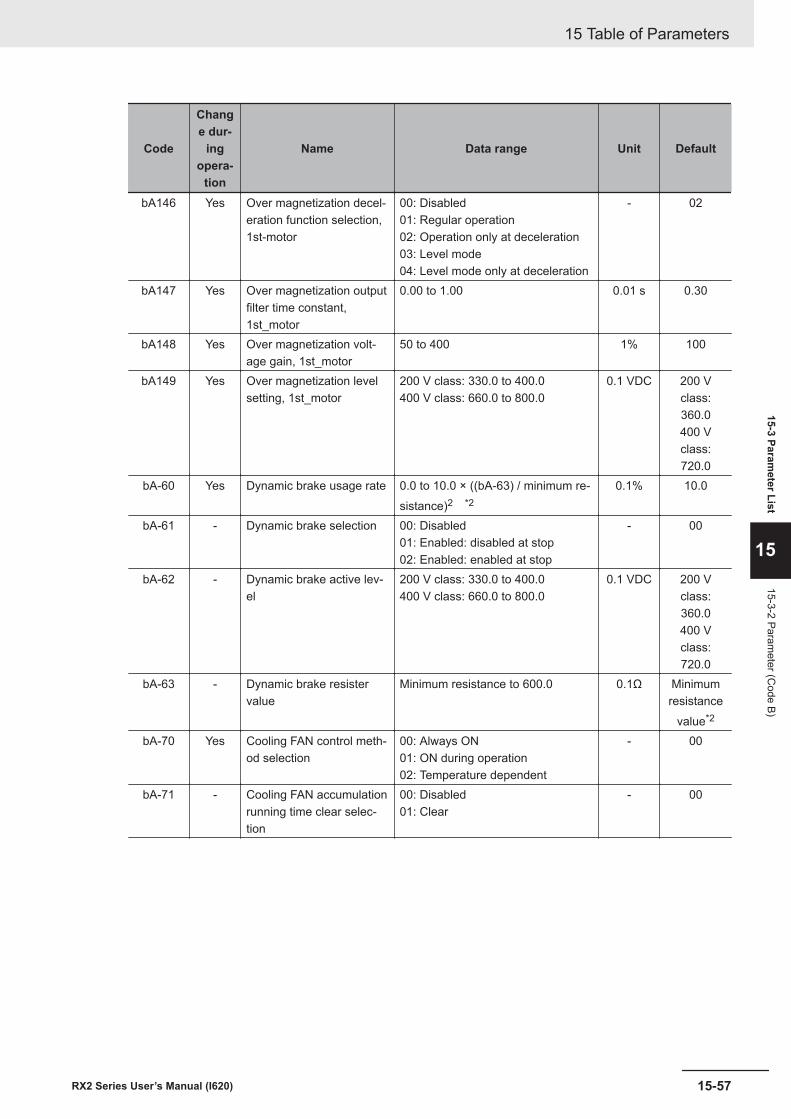
Code
Change dur-
ingopera-
tion
Name Data range Unit Default
bA146 Yes Over magnetization decel-eration function selection,1st-motor
00: Disabled01: Regular operation02: Operation only at deceleration03: Level mode04: Level mode only at deceleration
- 02
bA147 Yes Over magnetization outputfilter time constant,1st_motor
0.00 to 1.00 0.01 s 0.30
bA148 Yes Over magnetization volt-age gain, 1st_motor
50 to 400 1% 100
bA149 Yes Over magnetization levelsetting, 1st_motor
200 V class: 330.0 to 400.0400 V class: 660.0 to 800.0
0.1 VDC 200 Vclass:360.0400 Vclass:720.0
bA-60 Yes Dynamic brake usage rate 0.0 to 10.0 × ((bA-63) / minimum re-sistance)2 *2
0.1% 10.0
bA-61 - Dynamic brake selection 00: Disabled01: Enabled: disabled at stop02: Enabled: enabled at stop
- 00
bA-62 - Dynamic brake active lev-el
200 V class: 330.0 to 400.0400 V class: 660.0 to 800.0
0.1 VDC 200 Vclass:360.0400 Vclass:720.0
bA-63 - Dynamic brake resistervalue
Minimum resistance to 600.0 0.1Ω Minimumresistance
value*2
bA-70 Yes Cooling FAN control meth-od selection
00: Always ON01: ON during operation02: Temperature dependent
- 00
bA-71 - Cooling FAN accumulationrunning time clear selec-tion
00: Disabled01: Clear
- 00
15 Table of Parameters
15-57RX2 Series User’s Manual (I620)
15-3 Parameter List
15
15-3-2 Parameter (C
ode B)
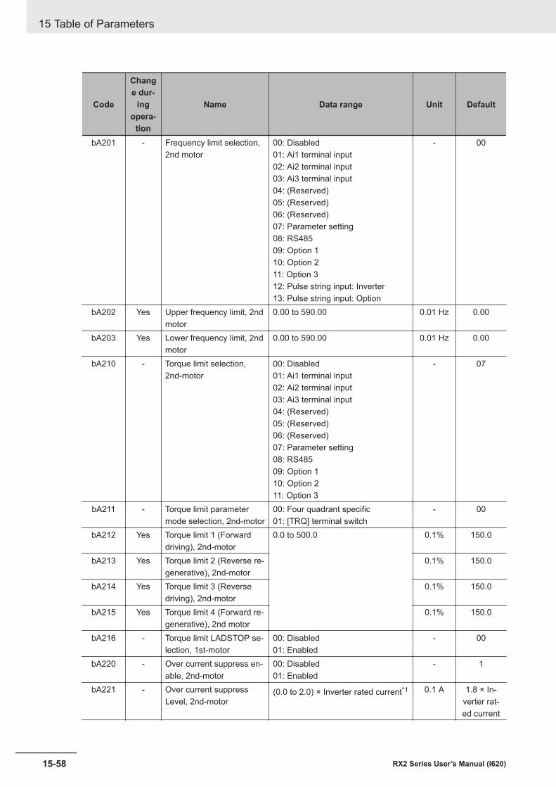
Code
Change dur-
ingopera-
tion
Name Data range Unit Default
bA201 - Frequency limit selection,2nd motor
00: Disabled01: Ai1 terminal input02: Ai2 terminal input03: Ai3 terminal input04: (Reserved)05: (Reserved)06: (Reserved)07: Parameter setting08: RS48509: Option 110: Option 211: Option 312: Pulse string input: Inverter13: Pulse string input: Option
- 00
bA202 Yes Upper frequency limit, 2ndmotor
0.00 to 590.00 0.01 Hz 0.00
bA203 Yes Lower frequency limit, 2ndmotor
0.00 to 590.00 0.01 Hz 0.00
bA210 - Torque limit selection,2nd-motor
00: Disabled01: Ai1 terminal input02: Ai2 terminal input03: Ai3 terminal input04: (Reserved)05: (Reserved)06: (Reserved)07: Parameter setting08: RS48509: Option 110: Option 211: Option 3
- 07
bA211 - Torque limit parametermode selection, 2nd-motor
00: Four quadrant specific01: [TRQ] terminal switch
- 00
bA212 Yes Torque limit 1 (Forwarddriving), 2nd-motor
0.0 to 500.0 0.1% 150.0
bA213 Yes Torque limit 2 (Reverse re-generative), 2nd-motor
0.1% 150.0
bA214 Yes Torque limit 3 (Reversedriving), 2nd-motor
0.1% 150.0
bA215 Yes Torque limit 4 (Forward re-generative), 2nd motor
0.1% 150.0
bA216 - Torque limit LADSTOP se-lection, 1st-motor
00: Disabled01: Enabled
- 00
bA220 - Over current suppress en-able, 2nd-motor
00: Disabled01: Enabled
- 1
bA221 - Over current suppressLevel, 2nd-motor
(0.0 to 2.0) × Inverter rated current*1 0.1 A 1.8 × In-verter rat-ed current
15 Table of Parameters
15-58 RX2 Series User’s Manual (I620)
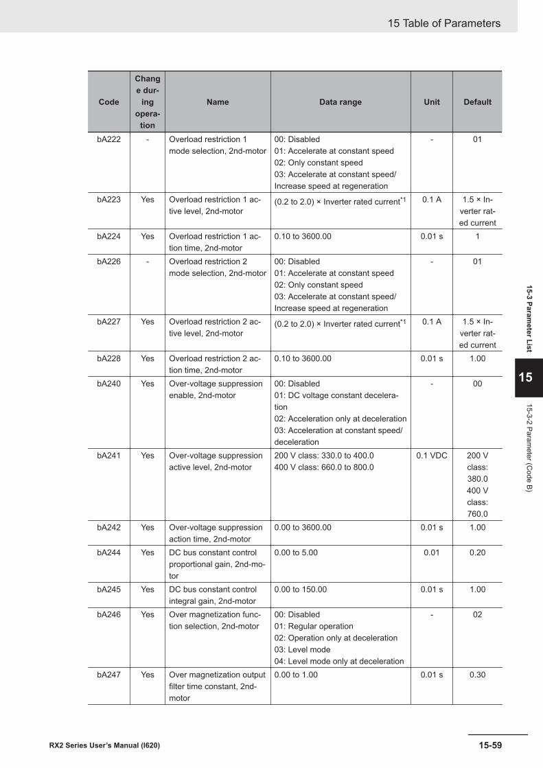
Code
Change dur-
ingopera-
tion
Name Data range Unit Default
bA222 - Overload restriction 1mode selection, 2nd-motor
00: Disabled01: Accelerate at constant speed02: Only constant speed03: Accelerate at constant speed/Increase speed at regeneration
- 01
bA223 Yes Overload restriction 1 ac-tive level, 2nd-motor
(0.2 to 2.0) × Inverter rated current*1 0.1 A 1.5 × In-verter rat-ed current
bA224 Yes Overload restriction 1 ac-tion time, 2nd-motor
0.10 to 3600.00 0.01 s 1
bA226 - Overload restriction 2mode selection, 2nd-motor
00: Disabled01: Accelerate at constant speed02: Only constant speed03: Accelerate at constant speed/Increase speed at regeneration
- 01
bA227 Yes Overload restriction 2 ac-tive level, 2nd-motor
(0.2 to 2.0) × Inverter rated current*1 0.1 A 1.5 × In-verter rat-ed current
bA228 Yes Overload restriction 2 ac-tion time, 2nd-motor
0.10 to 3600.00 0.01 s 1.00
bA240 Yes Over-voltage suppressionenable, 2nd-motor
00: Disabled01: DC voltage constant decelera-tion02: Acceleration only at deceleration03: Acceleration at constant speed/deceleration
- 00
bA241 Yes Over-voltage suppressionactive level, 2nd-motor
200 V class: 330.0 to 400.0400 V class: 660.0 to 800.0
0.1 VDC 200 Vclass:380.0400 Vclass:760.0
bA242 Yes Over-voltage suppressionaction time, 2nd-motor
0.00 to 3600.00 0.01 s 1.00
bA244 Yes DC bus constant controlproportional gain, 2nd-mo-tor
0.00 to 5.00 0.01 0.20
bA245 Yes DC bus constant controlintegral gain, 2nd-motor
0.00 to 150.00 0.01 s 1.00
bA246 Yes Over magnetization func-tion selection, 2nd-motor
00: Disabled01: Regular operation02: Operation only at deceleration03: Level mode04: Level mode only at deceleration
- 02
bA247 Yes Over magnetization outputfilter time constant, 2nd-motor
0.00 to 1.00 0.01 s 0.30
15 Table of Parameters
15-59RX2 Series User’s Manual (I620)
15-3 Parameter List
15
15-3-2 Parameter (C
ode B)
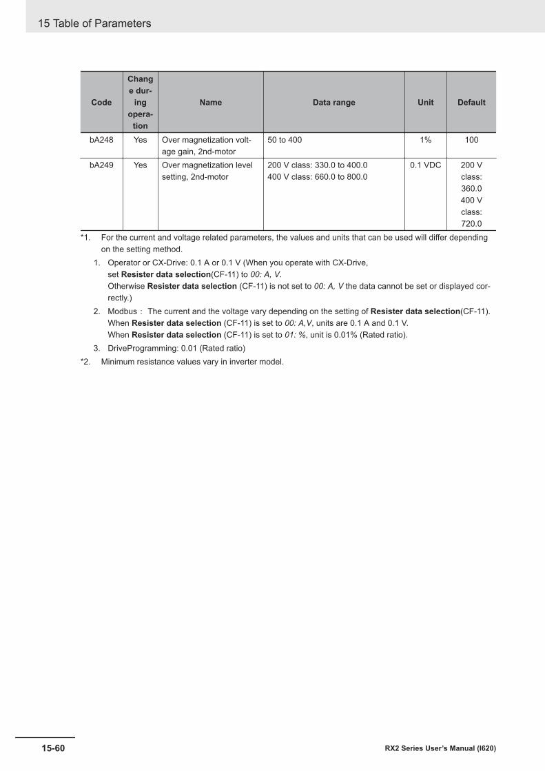
Code
Change dur-
ingopera-
tion
Name Data range Unit Default
bA248 Yes Over magnetization volt-age gain, 2nd-motor
50 to 400 1% 100
bA249 Yes Over magnetization levelsetting, 2nd-motor
200 V class: 330.0 to 400.0400 V class: 660.0 to 800.0
0.1 VDC 200 Vclass:360.0400 Vclass:720.0
*1. For the current and voltage related parameters, the values and units that can be used will differ dependingon the setting method.
1. Operator or CX-Drive: 0.1 A or 0.1 V (When you operate with CX-Drive,set Resister data selection(CF-11) to 00: A, V.Otherwise Resister data selection (CF-11) is not set to 00: A, V the data cannot be set or displayed cor-rectly.)
2. Modbus: The current and the voltage vary depending on the setting of Resister data selection(CF-11).When Resister data selection (CF-11) is set to 00: A,V, units are 0.1 A and 0.1 V.When Resister data selection (CF-11) is set to 01: %, unit is 0.01% (Rated ratio).
3. DriveProgramming: 0.01 (Rated ratio)*2. Minimum resistance values vary in inverter model.
15 Table of Parameters
15-60 RX2 Series User’s Manual (I620)
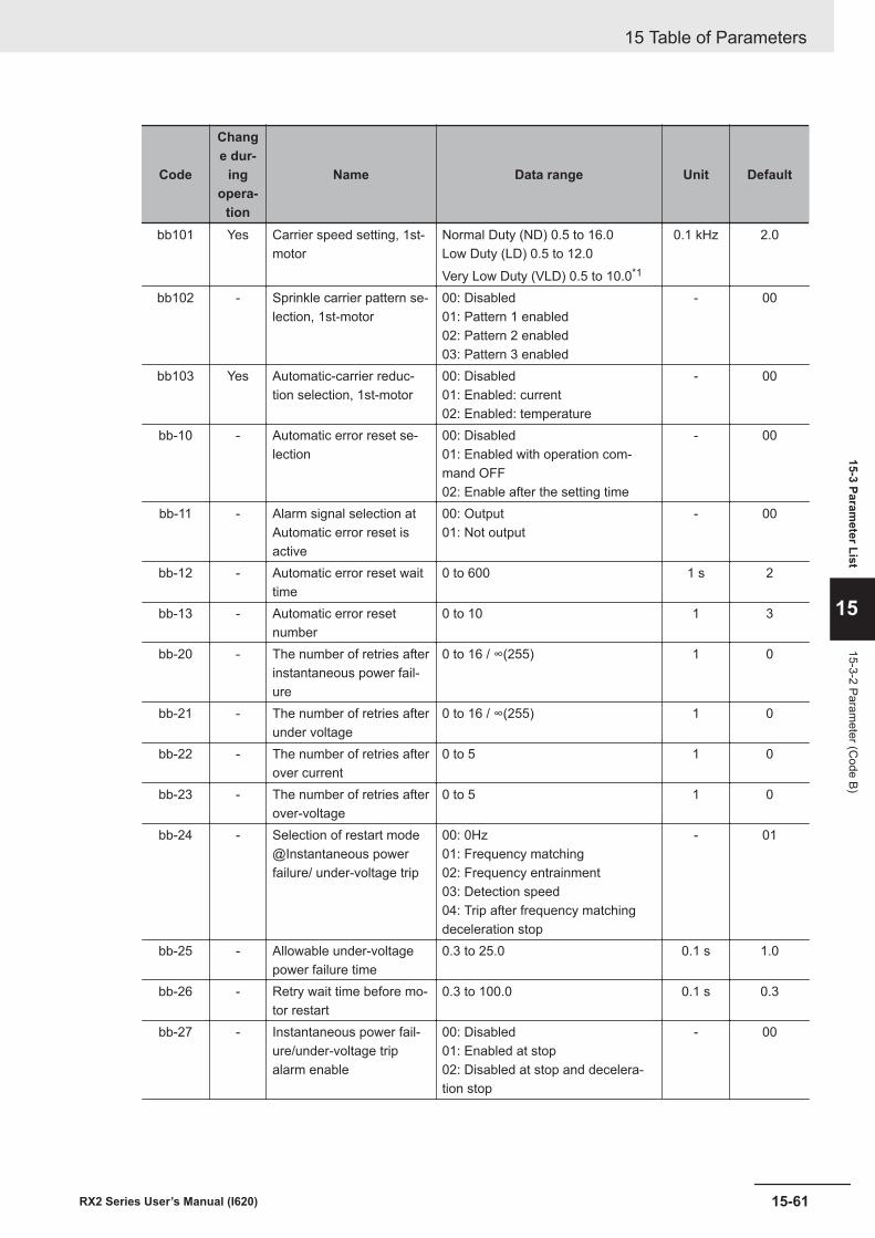
Code
Change dur-
ingopera-
tion
Name Data range Unit Default
bb101 Yes Carrier speed setting, 1st-motor
Normal Duty (ND) 0.5 to 16.0Low Duty (LD) 0.5 to 12.0Very Low Duty (VLD) 0.5 to 10.0*1
0.1 kHz 2.0
bb102 - Sprinkle carrier pattern se-lection, 1st-motor
00: Disabled01: Pattern 1 enabled02: Pattern 2 enabled03: Pattern 3 enabled
- 00
bb103 Yes Automatic-carrier reduc-tion selection, 1st-motor
00: Disabled01: Enabled: current02: Enabled: temperature
- 00
bb-10 - Automatic error reset se-lection
00: Disabled01: Enabled with operation com-mand OFF02: Enable after the setting time
- 00
bb-11 - Alarm signal selection atAutomatic error reset isactive
00: Output01: Not output
- 00
bb-12 - Automatic error reset waittime
0 to 600 1 s 2
bb-13 - Automatic error resetnumber
0 to 10 1 3
bb-20 - The number of retries afterinstantaneous power fail-ure
0 to 16 / ∞(255) 1 0
bb-21 - The number of retries afterunder voltage
0 to 16 / ∞(255) 1 0
bb-22 - The number of retries afterover current
0 to 5 1 0
bb-23 - The number of retries afterover-voltage
0 to 5 1 0
bb-24 - Selection of restart mode@Instantaneous powerfailure/ under-voltage trip
00: 0Hz01: Frequency matching02: Frequency entrainment03: Detection speed04: Trip after frequency matchingdeceleration stop
- 01
bb-25 - Allowable under-voltagepower failure time
0.3 to 25.0 0.1 s 1.0
bb-26 - Retry wait time before mo-tor restart
0.3 to 100.0 0.1 s 0.3
bb-27 - Instantaneous power fail-ure/under-voltage tripalarm enable
00: Disabled01: Enabled at stop02: Disabled at stop and decelera-tion stop
- 00
15 Table of Parameters
15-61RX2 Series User’s Manual (I620)
15-3 Parameter List
15
15-3-2 Parameter (C
ode B)
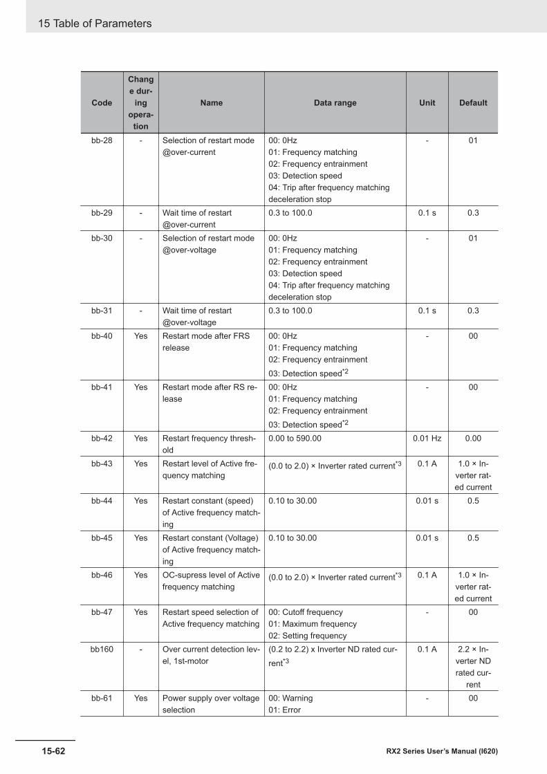
Code
Change dur-
ingopera-
tion
Name Data range Unit Default
bb-28 - Selection of restart mode@over-current
00: 0Hz01: Frequency matching02: Frequency entrainment03: Detection speed04: Trip after frequency matchingdeceleration stop
- 01
bb-29 - Wait time of restart@over-current
0.3 to 100.0 0.1 s 0.3
bb-30 - Selection of restart mode@over-voltage
00: 0Hz01: Frequency matching02: Frequency entrainment03: Detection speed04: Trip after frequency matchingdeceleration stop
- 01
bb-31 - Wait time of restart@over-voltage
0.3 to 100.0 0.1 s 0.3
bb-40 Yes Restart mode after FRSrelease
00: 0Hz01: Frequency matching02: Frequency entrainment03: Detection speed*2
- 00
bb-41 Yes Restart mode after RS re-lease
00: 0Hz01: Frequency matching02: Frequency entrainment03: Detection speed*2
- 00
bb-42 Yes Restart frequency thresh-old
0.00 to 590.00 0.01 Hz 0.00
bb-43 Yes Restart level of Active fre-quency matching
(0.0 to 2.0) × Inverter rated current*3 0.1 A 1.0 × In-verter rat-ed current
bb-44 Yes Restart constant (speed)of Active frequency match-ing
0.10 to 30.00 0.01 s 0.5
bb-45 Yes Restart constant (Voltage)of Active frequency match-ing
0.10 to 30.00 0.01 s 0.5
bb-46 Yes OC-supress level of Activefrequency matching
(0.0 to 2.0) × Inverter rated current*3 0.1 A 1.0 × In-verter rat-ed current
bb-47 Yes Restart speed selection ofActive frequency matching
00: Cutoff frequency01: Maximum frequency02: Setting frequency
- 00
bb160 - Over current detection lev-el, 1st-motor
(0.2 to 2.2) x Inverter ND rated cur-rent*3
0.1 A 2.2 × In-verter NDrated cur-
rentbb-61 Yes Power supply over voltage
selection00: Warning01: Error
- 00
15 Table of Parameters
15-62 RX2 Series User’s Manual (I620)
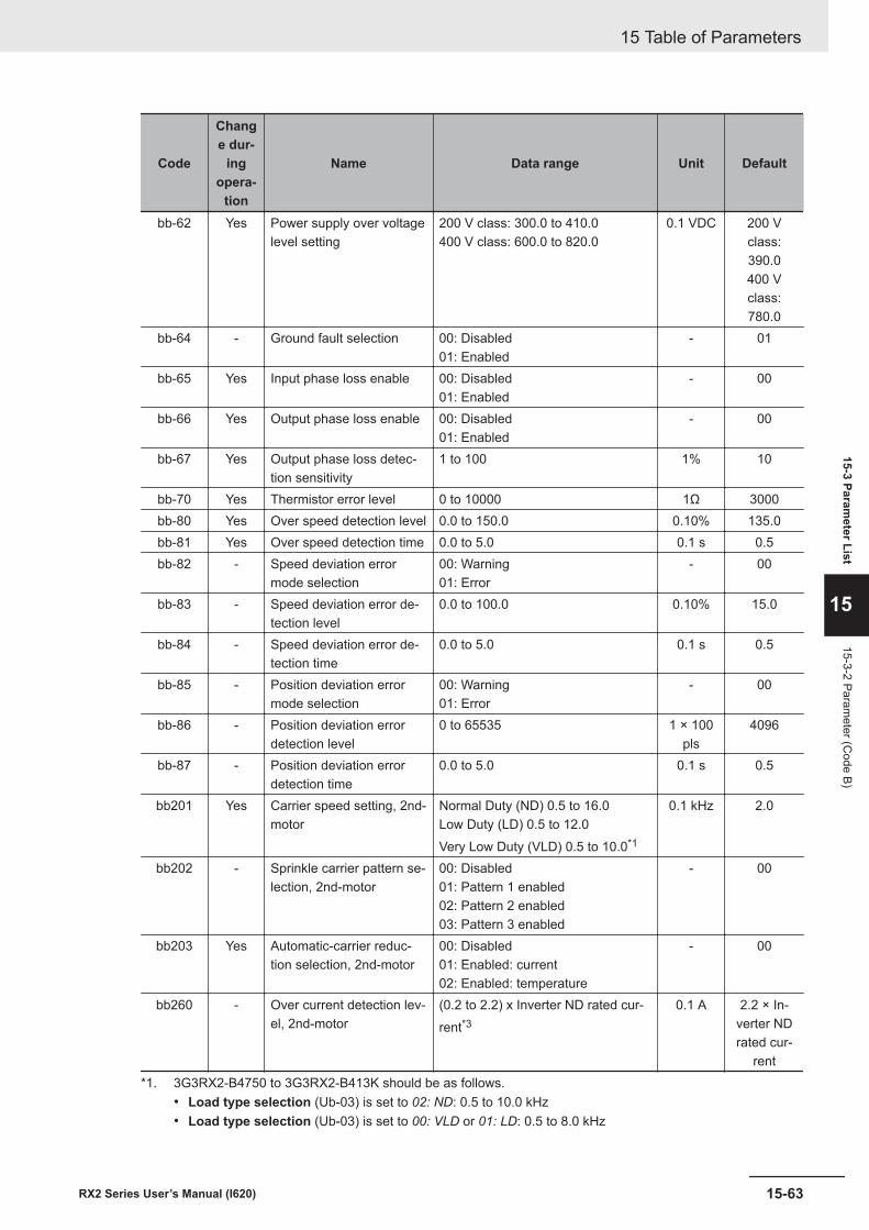
Code
Change dur-
ingopera-
tion
Name Data range Unit Default
bb-62 Yes Power supply over voltagelevel setting
200 V class: 300.0 to 410.0400 V class: 600.0 to 820.0
0.1 VDC 200 Vclass:390.0400 Vclass:780.0
bb-64 - Ground fault selection 00: Disabled01: Enabled
- 01
bb-65 Yes Input phase loss enable 00: Disabled01: Enabled
- 00
bb-66 Yes Output phase loss enable 00: Disabled01: Enabled
- 00
bb-67 Yes Output phase loss detec-tion sensitivity
1 to 100 1% 10
bb-70 Yes Thermistor error level 0 to 10000 1Ω 3000bb-80 Yes Over speed detection level 0.0 to 150.0 0.10% 135.0bb-81 Yes Over speed detection time 0.0 to 5.0 0.1 s 0.5bb-82 - Speed deviation error
mode selection00: Warning01: Error
- 00
bb-83 - Speed deviation error de-tection level
0.0 to 100.0 0.10% 15.0
bb-84 - Speed deviation error de-tection time
0.0 to 5.0 0.1 s 0.5
bb-85 - Position deviation errormode selection
00: Warning01: Error
- 00
bb-86 - Position deviation errordetection level
0 to 65535 1 × 100pls
4096
bb-87 - Position deviation errordetection time
0.0 to 5.0 0.1 s 0.5
bb201 Yes Carrier speed setting, 2nd-motor
Normal Duty (ND) 0.5 to 16.0Low Duty (LD) 0.5 to 12.0Very Low Duty (VLD) 0.5 to 10.0*1
0.1 kHz 2.0
bb202 - Sprinkle carrier pattern se-lection, 2nd-motor
00: Disabled01: Pattern 1 enabled02: Pattern 2 enabled03: Pattern 3 enabled
- 00
bb203 Yes Automatic-carrier reduc-tion selection, 2nd-motor
00: Disabled01: Enabled: current02: Enabled: temperature
- 00
bb260 - Over current detection lev-el, 2nd-motor
(0.2 to 2.2) x Inverter ND rated cur-rent*3
0.1 A 2.2 × In-verter NDrated cur-
rent*1. 3G3RX2-B4750 to 3G3RX2-B413K should be as follows.
• Load type selection (Ub-03) is set to 02: ND: 0.5 to 10.0 kHz• Load type selection (Ub-03) is set to 00: VLD or 01: LD: 0.5 to 8.0 kHz
15 Table of Parameters
15-63RX2 Series User’s Manual (I620)
15-3 Parameter List
15
15-3-2 Parameter (C
ode B)
*2. The feedback input to input terminals A and B and the feedback input to option cassette RX2-PG are neces-sary.
*3. For the current and voltage related parameters, the values and units that can be used will differ dependingon the setting method.
1. Operator or CX-Drive: 0.1 A or 0.1 VWhen you operate with CX-Drive, set Resister data selection (CF-11) to 00: A,V, units are 0.1Aand 0.1V.When Resister data selection (CF-11) is not set to 00: A,V, the data cannot be set or displayedcorrectly.
2. Modbus: The current and the voltage vary depending on the setting of Resister dataselection(CF-11).When Resister data selection (CF-11) is set to 00: A, V, units are 0.1A and 0.1V.When Resister data selection (CF-11) is set to 01: %, unit is 0.01%.
3. DriveProgramming: 0.01 (Rated ratio)
15 Table of Parameters
15-64 RX2 Series User’s Manual (I620)
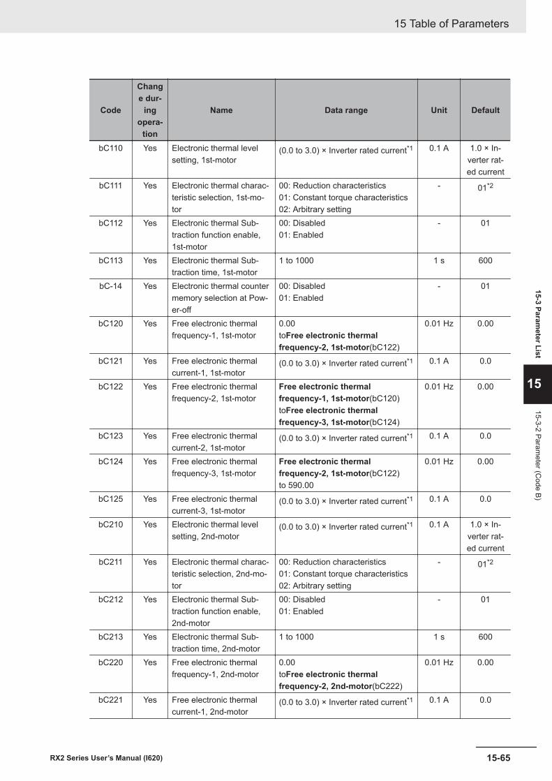
Code
Change dur-
ingopera-
tion
Name Data range Unit Default
bC110 Yes Electronic thermal levelsetting, 1st-motor
(0.0 to 3.0) × Inverter rated current*1 0.1 A 1.0 × In-verter rat-ed current
bC111 Yes Electronic thermal charac-teristic selection, 1st-mo-tor
00: Reduction characteristics01: Constant torque characteristics02: Arbitrary setting
- 01*2
bC112 Yes Electronic thermal Sub-traction function enable,1st-motor
00: Disabled01: Enabled
- 01
bC113 Yes Electronic thermal Sub-traction time, 1st-motor
1 to 1000 1 s 600
bC-14 Yes Electronic thermal countermemory selection at Pow-er-off
00: Disabled01: Enabled
- 01
bC120 Yes Free electronic thermalfrequency-1, 1st-motor
0.00toFree electronic thermalfrequency-2, 1st-motor(bC122)
0.01 Hz 0.00
bC121 Yes Free electronic thermalcurrent-1, 1st-motor
(0.0 to 3.0) × Inverter rated current*1 0.1 A 0.0
bC122 Yes Free electronic thermalfrequency-2, 1st-motor
Free electronic thermalfrequency-1, 1st-motor(bC120)toFree electronic thermalfrequency-3, 1st-motor(bC124)
0.01 Hz 0.00
bC123 Yes Free electronic thermalcurrent-2, 1st-motor
(0.0 to 3.0) × Inverter rated current*1 0.1 A 0.0
bC124 Yes Free electronic thermalfrequency-3, 1st-motor
Free electronic thermalfrequency-2, 1st-motor(bC122)to 590.00
0.01 Hz 0.00
bC125 Yes Free electronic thermalcurrent-3, 1st-motor
(0.0 to 3.0) × Inverter rated current*1 0.1 A 0.0
bC210 Yes Electronic thermal levelsetting, 2nd-motor
(0.0 to 3.0) × Inverter rated current*1 0.1 A 1.0 × In-verter rat-ed current
bC211 Yes Electronic thermal charac-teristic selection, 2nd-mo-tor
00: Reduction characteristics01: Constant torque characteristics02: Arbitrary setting
- 01*2
bC212 Yes Electronic thermal Sub-traction function enable,2nd-motor
00: Disabled01: Enabled
- 01
bC213 Yes Electronic thermal Sub-traction time, 2nd-motor
1 to 1000 1 s 600
bC220 Yes Free electronic thermalfrequency-1, 2nd-motor
0.00toFree electronic thermalfrequency-2, 2nd-motor(bC222)
0.01 Hz 0.00
bC221 Yes Free electronic thermalcurrent-1, 2nd-motor
(0.0 to 3.0) × Inverter rated current*1 0.1 A 0.0
15 Table of Parameters
15-65RX2 Series User’s Manual (I620)
15-3 Parameter List
15
15-3-2 Parameter (C
ode B)
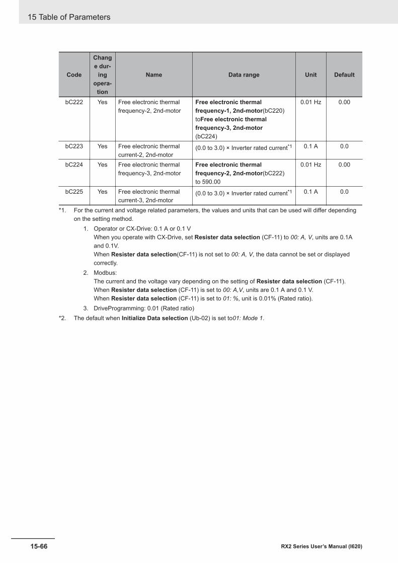
Code
Change dur-
ingopera-
tion
Name Data range Unit Default
bC222 Yes Free electronic thermalfrequency-2, 2nd-motor
Free electronic thermalfrequency-1, 2nd-motor(bC220)toFree electronic thermalfrequency-3, 2nd-motor(bC224)
0.01 Hz 0.00
bC223 Yes Free electronic thermalcurrent-2, 2nd-motor
(0.0 to 3.0) × Inverter rated current*1 0.1 A 0.0
bC224 Yes Free electronic thermalfrequency-3, 2nd-motor
Free electronic thermalfrequency-2, 2nd-motor(bC222)to 590.00
0.01 Hz 0.00
bC225 Yes Free electronic thermalcurrent-3, 2nd-motor
(0.0 to 3.0) × Inverter rated current*1 0.1 A 0.0
*1. For the current and voltage related parameters, the values and units that can be used will differ dependingon the setting method.
1. Operator or CX-Drive: 0.1 A or 0.1 VWhen you operate with CX-Drive, set Resister data selection (CF-11) to 00: A, V, units are 0.1Aand 0.1V.When Resister data selection(CF-11) is not set to 00: A, V, the data cannot be set or displayedcorrectly.
2. Modbus:The current and the voltage vary depending on the setting of Resister data selection (CF-11).When Resister data selection (CF-11) is set to 00: A,V, units are 0.1 A and 0.1 V.When Resister data selection (CF-11) is set to 01: %, unit is 0.01% (Rated ratio).
3. DriveProgramming: 0.01 (Rated ratio)*2. The default when Initialize Data selection (Ub-02) is set to01: Mode 1.
15 Table of Parameters
15-66 RX2 Series User’s Manual (I620)
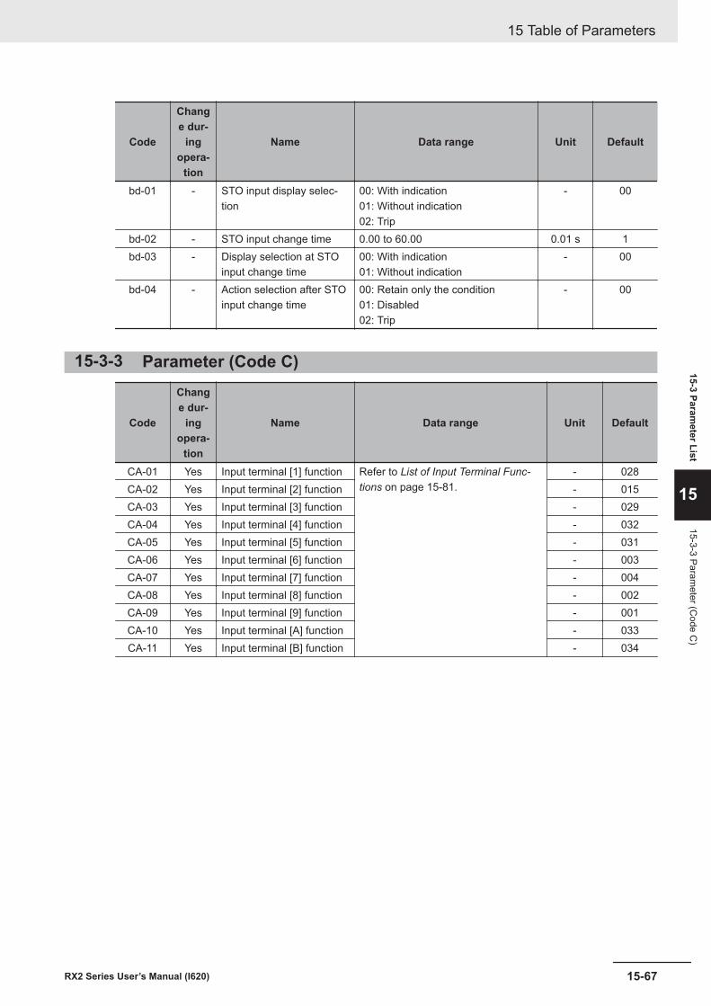
Code
Change dur-
ingopera-
tion
Name Data range Unit Default
bd-01 - STO input display selec-tion
00: With indication01: Without indication02: Trip
- 00
bd-02 - STO input change time 0.00 to 60.00 0.01 s 1bd-03 - Display selection at STO
input change time00: With indication01: Without indication
- 00
bd-04 - Action selection after STOinput change time
00: Retain only the condition01: Disabled02: Trip
- 00
15-3-3 Parameter (Code C)
Code
Change dur-
ingopera-
tion
Name Data range Unit Default
CA-01 Yes Input terminal [1] function Refer to List of Input Terminal Func-tions on page 15-81.
- 028CA-02 Yes Input terminal [2] function - 015CA-03 Yes Input terminal [3] function - 029CA-04 Yes Input terminal [4] function - 032CA-05 Yes Input terminal [5] function - 031CA-06 Yes Input terminal [6] function - 003CA-07 Yes Input terminal [7] function - 004CA-08 Yes Input terminal [8] function - 002CA-09 Yes Input terminal [9] function - 001CA-10 Yes Input terminal [A] function - 033CA-11 Yes Input terminal [B] function - 034
15 Table of Parameters
15-67RX2 Series User’s Manual (I620)
15-3 Parameter List
15
15-3-3 Parameter (C
ode C)
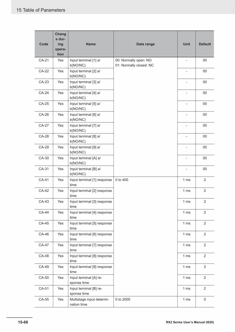
Code
Change dur-
ingopera-
tion
Name Data range Unit Default
CA-21 Yes Input terminal [1] a/b(NO/NC)
00: Normally open: NO01: Normally closed: NC
- 00
CA-22 Yes Input terminal [2] a/b(NO/NC)
- 00
CA-23 Yes Input terminal [3] a/b(NO/NC)
- 00
CA-24 Yes Input terminal [4] a/b(NO/NC)
- 00
CA-25 Yes Input terminal [5] a/b(NO/NC)
- 00
CA-26 Yes Input terminal [6] a/b(NO/NC)
- 00
CA-27 Yes Input terminal [7] a/b(NO/NC)
- 00
CA-28 Yes Input terminal [8] a/b(NO/NC)
- 00
CA-29 Yes Input terminal [9] a/b(NO/NC)
- 00
CA-30 Yes Input terminal [A] a/b(NO/NC)
- 00
CA-31 Yes Input terminal [B] a/b(NO/NC)
- 00
CA-41 Yes Input terminal [1] responsetime
0 to 400 1 ms 2
CA-42 Yes Input terminal [2] responsetime
1 ms 2
CA-43 Yes Input terminal [3] responsetime
1 ms 2
CA-44 Yes Input terminal [4] responsetime
1 ms 2
CA-45 Yes Input terminal [5] responsetime
1 ms 2
CA-46 Yes Input terminal [6] responsetime
1 ms 2
CA-47 Yes Input terminal [7] responsetime
1 ms 2
CA-48 Yes Input terminal [8] responsetime
1 ms 2
CA-49 Yes Input terminal [9] responsetime
1 ms 2
CA-50 Yes Input terminal [A] re-sponse time
1 ms 2
CA-51 Yes Input terminal [B] re-sponse time
1 ms 2
CA-55 Yes Multistage input determi-nation time
0 to 2000 1 ms 0
15 Table of Parameters
15-68 RX2 Series User’s Manual (I620)
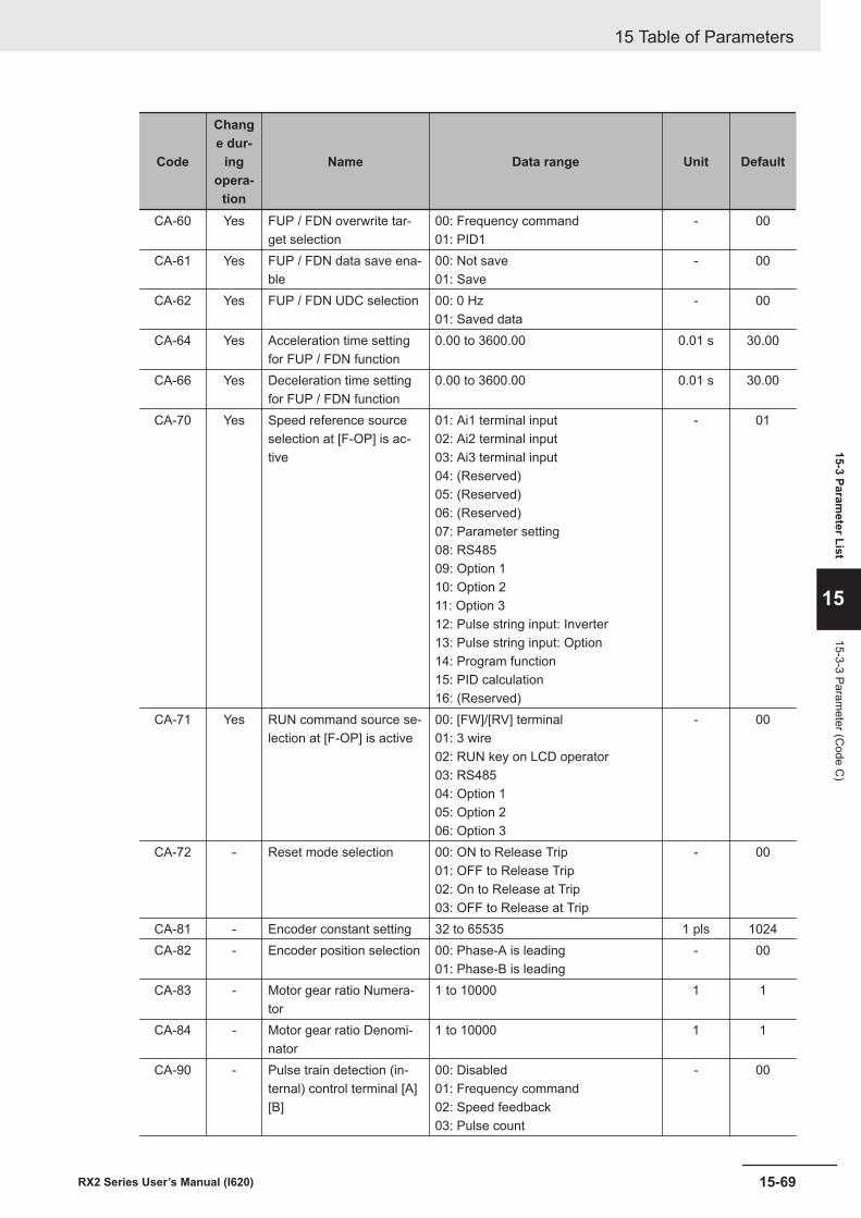
Code
Change dur-
ingopera-
tion
Name Data range Unit Default
CA-60 Yes FUP / FDN overwrite tar-get selection
00: Frequency command01: PID1
- 00
CA-61 Yes FUP / FDN data save ena-ble
00: Not save01: Save
- 00
CA-62 Yes FUP / FDN UDC selection 00: 0 Hz01: Saved data
- 00
CA-64 Yes Acceleration time settingfor FUP / FDN function
0.00 to 3600.00 0.01 s 30.00
CA-66 Yes Deceleration time settingfor FUP / FDN function
0.00 to 3600.00 0.01 s 30.00
CA-70 Yes Speed reference sourceselection at [F-OP] is ac-tive
01: Ai1 terminal input02: Ai2 terminal input03: Ai3 terminal input04: (Reserved)05: (Reserved)06: (Reserved)07: Parameter setting08: RS48509: Option 110: Option 211: Option 312: Pulse string input: Inverter13: Pulse string input: Option14: Program function15: PID calculation16: (Reserved)
- 01
CA-71 Yes RUN command source se-lection at [F-OP] is active
00: [FW]/[RV] terminal01: 3 wire02: RUN key on LCD operator03: RS48504: Option 105: Option 206: Option 3
- 00
CA-72 - Reset mode selection 00: ON to Release Trip01: OFF to Release Trip02: On to Release at Trip03: OFF to Release at Trip
- 00
CA-81 - Encoder constant setting 32 to 65535 1 pls 1024CA-82 - Encoder position selection 00: Phase-A is leading
01: Phase-B is leading- 00
CA-83 - Motor gear ratio Numera-tor
1 to 10000 1 1
CA-84 - Motor gear ratio Denomi-nator
1 to 10000 1 1
CA-90 - Pulse train detection (in-ternal) control terminal [A][B]
00: Disabled01: Frequency command02: Speed feedback03: Pulse count
- 00
15 Table of Parameters
15-69RX2 Series User’s Manual (I620)
15-3 Parameter List
15
15-3-3 Parameter (C
ode C)
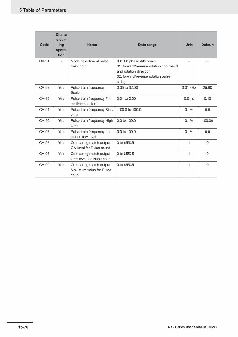
Code
Change dur-
ingopera-
tion
Name Data range Unit Default
CA-91 - Mode selection of pulsetrain input
00: 90° phase difference01: forward/reverse rotation commandand rotation direction02: forward/reverse rotation pulsestring
- 00
CA-92 Yes Pulse train frequencyScale
0.05 to 32.00 0.01 kHz 25.00
CA-93 Yes Pulse train frequency Fil-ter time constant
0.01 to 2.00 0.01 s 0.10
CA-94 Yes Pulse train frequency Biasvalue
-100.0 to 100.0 0.1% 0.0
CA-95 Yes Pulse train frequency HighLimit
0.0 to 100.0 0.1% 100.00
CA-96 Yes Pulse train frequency de-tection low level
0.0 to 100.0 0.1% 0.0
CA-97 Yes Comparing match outputON-level for Pulse count
0 to 65535 1 0
CA-98 Yes Comparing match outputOFF-level for Pulse count
0 to 65535 1 0
CA-99 Yes Comparing match outputMaximum value for Pulsecount
0 to 65535 1 0
15 Table of Parameters
15-70 RX2 Series User’s Manual (I620)
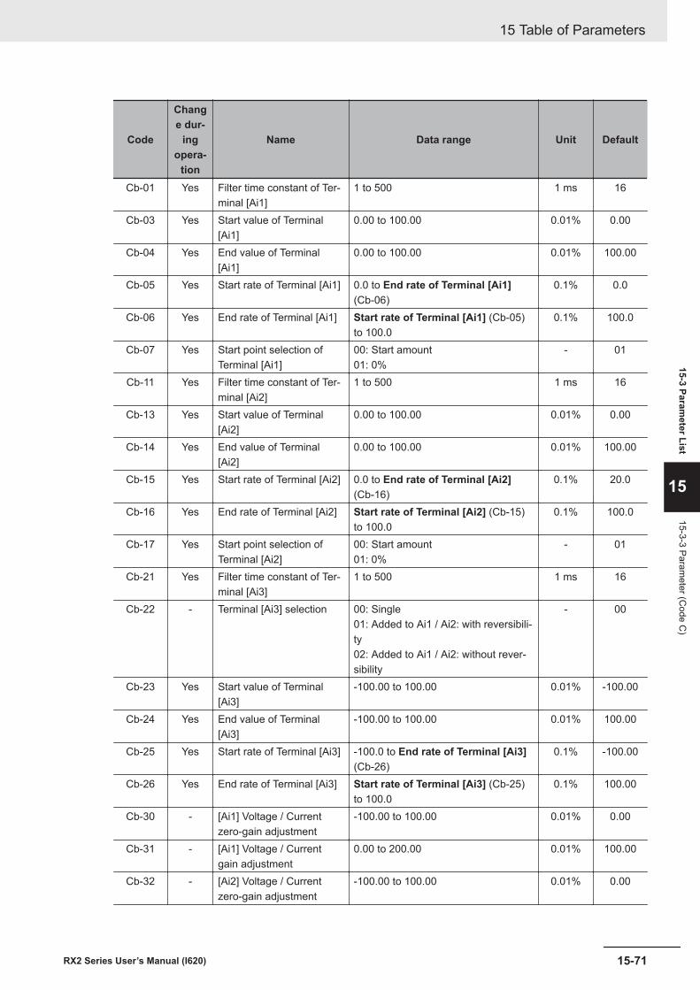
Code
Change dur-
ingopera-
tion
Name Data range Unit Default
Cb-01 Yes Filter time constant of Ter-minal [Ai1]
1 to 500 1 ms 16
Cb-03 Yes Start value of Terminal[Ai1]
0.00 to 100.00 0.01% 0.00
Cb-04 Yes End value of Terminal[Ai1]
0.00 to 100.00 0.01% 100.00
Cb-05 Yes Start rate of Terminal [Ai1] 0.0 to End rate of Terminal [Ai1](Cb-06)
0.1% 0.0
Cb-06 Yes End rate of Terminal [Ai1] Start rate of Terminal [Ai1] (Cb-05)to 100.0
0.1% 100.0
Cb-07 Yes Start point selection ofTerminal [Ai1]
00: Start amount01: 0%
- 01
Cb-11 Yes Filter time constant of Ter-minal [Ai2]
1 to 500 1 ms 16
Cb-13 Yes Start value of Terminal[Ai2]
0.00 to 100.00 0.01% 0.00
Cb-14 Yes End value of Terminal[Ai2]
0.00 to 100.00 0.01% 100.00
Cb-15 Yes Start rate of Terminal [Ai2] 0.0 to End rate of Terminal [Ai2](Cb-16)
0.1% 20.0
Cb-16 Yes End rate of Terminal [Ai2] Start rate of Terminal [Ai2] (Cb-15)to 100.0
0.1% 100.0
Cb-17 Yes Start point selection ofTerminal [Ai2]
00: Start amount01: 0%
- 01
Cb-21 Yes Filter time constant of Ter-minal [Ai3]
1 to 500 1 ms 16
Cb-22 - Terminal [Ai3] selection 00: Single01: Added to Ai1 / Ai2: with reversibili-ty02: Added to Ai1 / Ai2: without rever-sibility
- 00
Cb-23 Yes Start value of Terminal[Ai3]
-100.00 to 100.00 0.01% -100.00
Cb-24 Yes End value of Terminal[Ai3]
-100.00 to 100.00 0.01% 100.00
Cb-25 Yes Start rate of Terminal [Ai3] -100.0 to End rate of Terminal [Ai3](Cb-26)
0.1% -100.00
Cb-26 Yes End rate of Terminal [Ai3] Start rate of Terminal [Ai3] (Cb-25)to 100.0
0.1% 100.00
Cb-30 - [Ai1] Voltage / Currentzero-gain adjustment
-100.00 to 100.00 0.01% 0.00
Cb-31 - [Ai1] Voltage / Currentgain adjustment
0.00 to 200.00 0.01% 100.00
Cb-32 - [Ai2] Voltage / Currentzero-gain adjustment
-100.00 to 100.00 0.01% 0.00
15 Table of Parameters
15-71RX2 Series User’s Manual (I620)
15-3 Parameter List
15
15-3-3 Parameter (C
ode C)
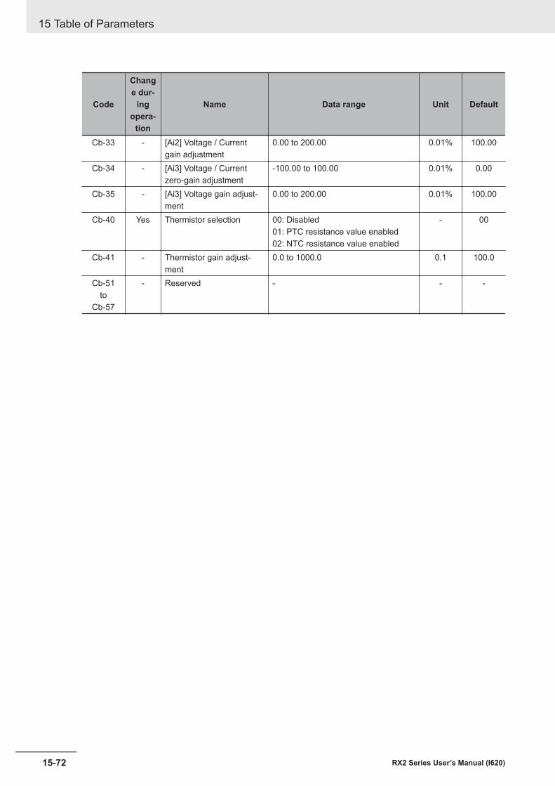
Code
Change dur-
ingopera-
tion
Name Data range Unit Default
Cb-33 - [Ai2] Voltage / Currentgain adjustment
0.00 to 200.00 0.01% 100.00
Cb-34 - [Ai3] Voltage / Currentzero-gain adjustment
-100.00 to 100.00 0.01% 0.00
Cb-35 - [Ai3] Voltage gain adjust-ment
0.00 to 200.00 0.01% 100.00
Cb-40 Yes Thermistor selection 00: Disabled01: PTC resistance value enabled02: NTC resistance value enabled
- 00
Cb-41 - Thermistor gain adjust-ment
0.0 to 1000.0 0.1 100.0
Cb-51to
Cb-57
- Reserved - - -
15 Table of Parameters
15-72 RX2 Series User’s Manual (I620)
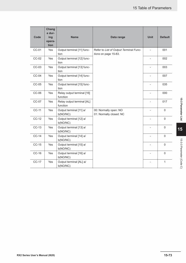
Code
Change dur-
ingopera-
tion
Name Data range Unit Default
CC-01 Yes Output terminal [11] func-tion
Refer to List of Output Terminal Func-tions on page 15-83.
- 001
CC-02 Yes Output terminal [12] func-tion
- 002
CC-03 Yes Output terminal [13] func-tion
- 003
CC-04 Yes Output terminal [14] func-tion
- 007
CC-05 Yes Output terminal [15] func-tion
- 035
CC-06 Yes Relay output terminal [16]function
- 000
CC-07 Yes Relay output terminal [AL]function
- 017
CC-11 Yes Output terminal [11] a/b(NO/NC)
00: Normally open: NO01: Normally closed: NC
- 0
CC-12 Yes Output terminal [12] a/b(NO/NC)
- 0
CC-13 Yes Output terminal [13] a/b(NO/NC)
- 0
CC-14 Yes Output terminal [14] a/b(NO/NC)
- 0
CC-15 Yes Output terminal [15] a/b(NO/NC)
- 0
CC-16 Yes Output terminal [16] a/b(NO/NC)
- 0
CC-17 Yes Output terminal [AL] a/b(NO/NC)
- 1
15 Table of Parameters
15-73RX2 Series User’s Manual (I620)
15-3 Parameter List
15
15-3-3 Parameter (C
ode C)
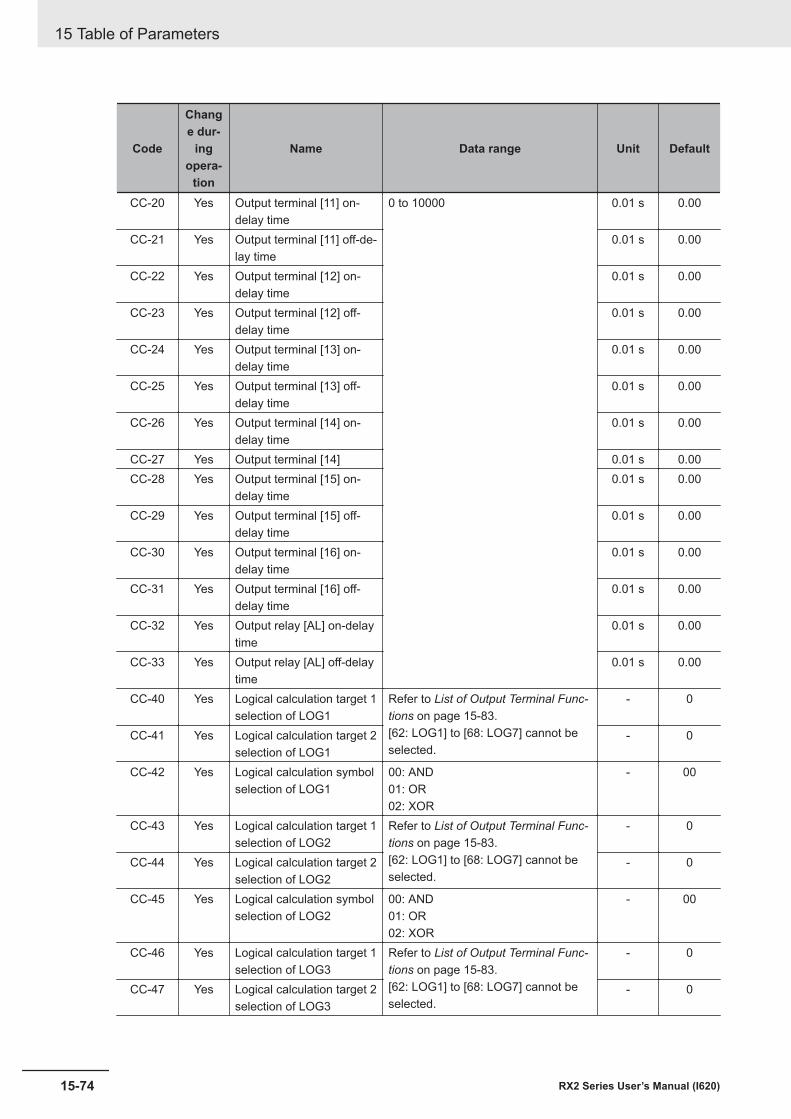
Code
Change dur-
ingopera-
tion
Name Data range Unit Default
CC-20 Yes Output terminal [11] on-delay time
0 to 10000 0.01 s 0.00
CC-21 Yes Output terminal [11] off-de-lay time
0.01 s 0.00
CC-22 Yes Output terminal [12] on-delay time
0.01 s 0.00
CC-23 Yes Output terminal [12] off-delay time
0.01 s 0.00
CC-24 Yes Output terminal [13] on-delay time
0.01 s 0.00
CC-25 Yes Output terminal [13] off-delay time
0.01 s 0.00
CC-26 Yes Output terminal [14] on-delay time
0.01 s 0.00
CC-27 Yes Output terminal [14] 0.01 s 0.00CC-28 Yes Output terminal [15] on-
delay time0.01 s 0.00
CC-29 Yes Output terminal [15] off-delay time
0.01 s 0.00
CC-30 Yes Output terminal [16] on-delay time
0.01 s 0.00
CC-31 Yes Output terminal [16] off-delay time
0.01 s 0.00
CC-32 Yes Output relay [AL] on-delaytime
0.01 s 0.00
CC-33 Yes Output relay [AL] off-delaytime
0.01 s 0.00
CC-40 Yes Logical calculation target 1selection of LOG1
Refer to List of Output Terminal Func-tions on page 15-83.[62: LOG1] to [68: LOG7] cannot beselected.
- 0
CC-41 Yes Logical calculation target 2selection of LOG1
- 0
CC-42 Yes Logical calculation symbolselection of LOG1
00: AND01: OR02: XOR
- 00
CC-43 Yes Logical calculation target 1selection of LOG2
Refer to List of Output Terminal Func-tions on page 15-83.[62: LOG1] to [68: LOG7] cannot beselected.
- 0
CC-44 Yes Logical calculation target 2selection of LOG2
- 0
CC-45 Yes Logical calculation symbolselection of LOG2
00: AND01: OR02: XOR
- 00
CC-46 Yes Logical calculation target 1selection of LOG3
Refer to List of Output Terminal Func-tions on page 15-83.[62: LOG1] to [68: LOG7] cannot beselected.
- 0
CC-47 Yes Logical calculation target 2selection of LOG3
- 0
15 Table of Parameters
15-74 RX2 Series User’s Manual (I620)
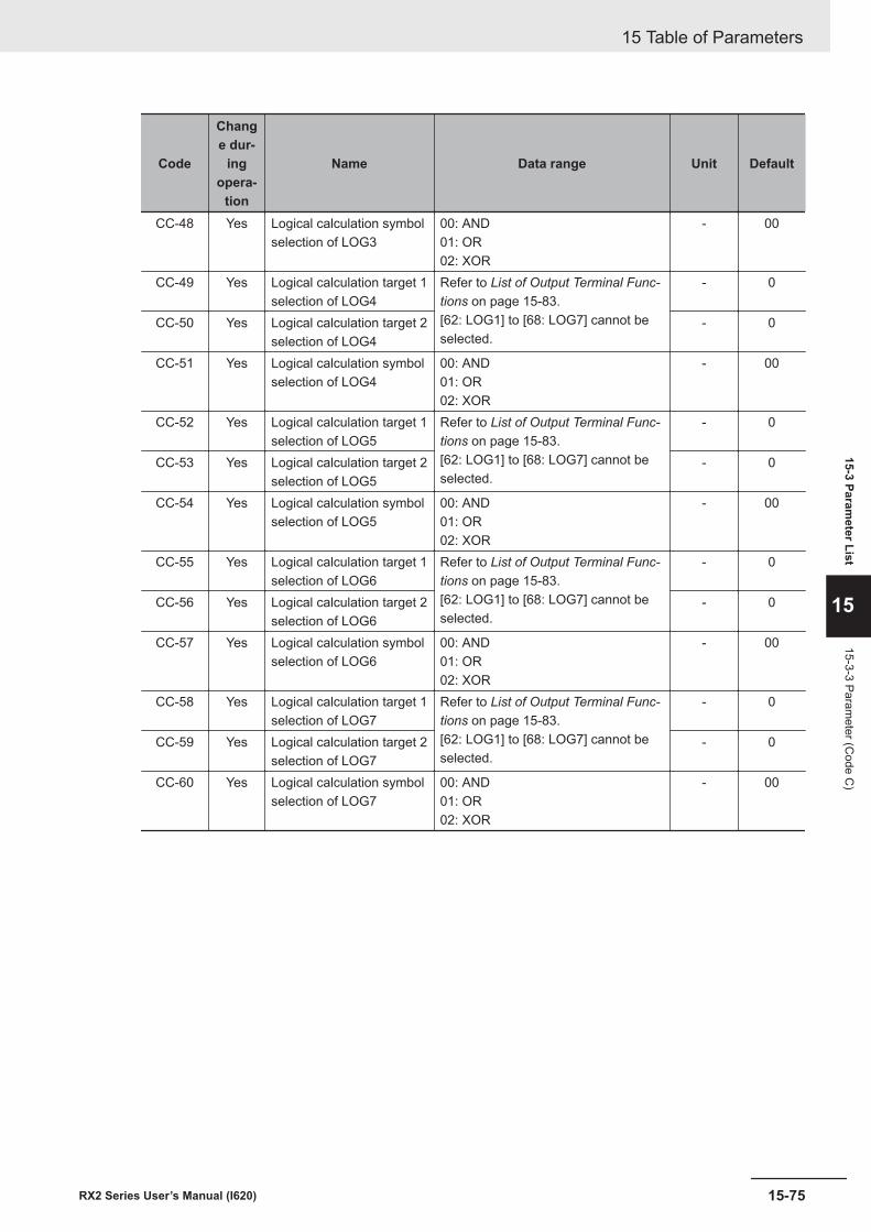
Code
Change dur-
ingopera-
tion
Name Data range Unit Default
CC-48 Yes Logical calculation symbolselection of LOG3
00: AND01: OR02: XOR
- 00
CC-49 Yes Logical calculation target 1selection of LOG4
Refer to List of Output Terminal Func-tions on page 15-83.[62: LOG1] to [68: LOG7] cannot beselected.
- 0
CC-50 Yes Logical calculation target 2selection of LOG4
- 0
CC-51 Yes Logical calculation symbolselection of LOG4
00: AND01: OR02: XOR
- 00
CC-52 Yes Logical calculation target 1selection of LOG5
Refer to List of Output Terminal Func-tions on page 15-83.[62: LOG1] to [68: LOG7] cannot beselected.
- 0
CC-53 Yes Logical calculation target 2selection of LOG5
- 0
CC-54 Yes Logical calculation symbolselection of LOG5
00: AND01: OR02: XOR
- 00
CC-55 Yes Logical calculation target 1selection of LOG6
Refer to List of Output Terminal Func-tions on page 15-83.[62: LOG1] to [68: LOG7] cannot beselected.
- 0
CC-56 Yes Logical calculation target 2selection of LOG6
- 0
CC-57 Yes Logical calculation symbolselection of LOG6
00: AND01: OR02: XOR
- 00
CC-58 Yes Logical calculation target 1selection of LOG7
Refer to List of Output Terminal Func-tions on page 15-83.[62: LOG1] to [68: LOG7] cannot beselected.
- 0
CC-59 Yes Logical calculation target 2selection of LOG7
- 0
CC-60 Yes Logical calculation symbolselection of LOG7
00: AND01: OR02: XOR
- 00
15 Table of Parameters
15-75RX2 Series User’s Manual (I620)
15-3 Parameter List
15
15-3-3 Parameter (C
ode C)
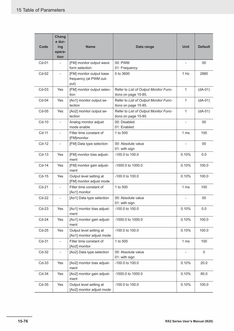
Code
Change dur-
ingopera-
tion
Name Data range Unit Default
Cd-01 - [FM] monitor output waveform selection
00: PWM01: Frequency
- 00
Cd-02 - [FM] monitor output basefrequency (at PWM out-put)
0 to 3600 1 Hz 2880
Cd-03 Yes [FM] monitor output selec-tion
Refer to List of Output Monitor Func-tions on page 15-85.
1 (dA-01)
Cd-04 Yes [Ao1] monitor output se-lection
Refer to List of Output Monitor Func-tions on page 15-85.
1 (dA-01)
Cd-05 Yes [Ao2] monitor output se-lection
Refer to List of Output Monitor Func-tions on page 15-85.
1 (dA-01)
Cd-10 - Analog monitor adjustmode enable
00: Disabled01: Enabled
- 00
Cd-11 - Filter time constant of[FM]monitor
1 to 500 1 ms 100
Cd-12 - [FM] Data type selection 00: Absolute value01: with sign
- 00
Cd-13 Yes [FM] monitor bias adjust-ment
-100.0 to 100.0 0.10% 0.0
Cd-14 Yes [FM] monitor gain adjust-ment
-1000.0 to 1000.0 0.10% 100.0
Cd-15 Yes Output level setting at[FM] monitor adjust mode
-100.0 to 100.0 0.10% 100.0
Cd-21 - Filter time constant of[Ao1] monitor
1 to 500 1 ms 100
Cd-22 - [Ao1] Data type selection 00: Absolute value01: with sign
- 00
Cd-23 Yes [Ao1] monitor bias adjust-ment
-100.0 to 100.0 0.10% 0.0
Cd-24 Yes [Ao1] monitor gain adjust-ment
-1000.0 to 1000.0 0.10% 100.0
Cd-25 Yes Output level setting at[Ao1] monitor adjust mode
-100.0 to 100.0 0.10% 100.0
Cd-31 - Filter time constant of[Ao2] monitor
1 to 500 1 ms 100
Cd-32 - [Ao2] Data type selection 00: Absolute value01: with sign
- 0
Cd-33 Yes [Ao2] monitor bias adjust-ment
-100.0 to 100.0 0.10% 20.0
Cd-34 Yes [Ao2] monitor gain adjust-ment
-1000.0 to 1000.0 0.10% 80.0
Cd-35 Yes Output level setting at[Ao2] monitor adjust mode
-100.0 to 100.0 0.10% 100.0
15 Table of Parameters
15-76 RX2 Series User’s Manual (I620)
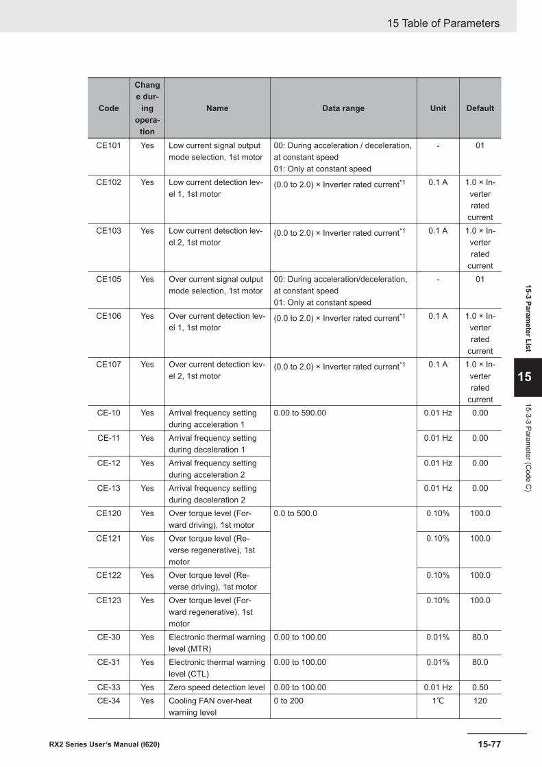
Code
Change dur-
ingopera-
tion
Name Data range Unit Default
CE101 Yes Low current signal outputmode selection, 1st motor
00: During acceleration / deceleration,at constant speed01: Only at constant speed
- 01
CE102 Yes Low current detection lev-el 1, 1st motor
(0.0 to 2.0) × Inverter rated current*1 0.1 A 1.0 × In-verterrated
currentCE103 Yes Low current detection lev-
el 2, 1st motor(0.0 to 2.0) × Inverter rated current*1 0.1 A 1.0 × In-
verterrated
currentCE105 Yes Over current signal output
mode selection, 1st motor00: During acceleration/deceleration,at constant speed01: Only at constant speed
- 01
CE106 Yes Over current detection lev-el 1, 1st motor
(0.0 to 2.0) × Inverter rated current*1 0.1 A 1.0 × In-verterrated
currentCE107 Yes Over current detection lev-
el 2, 1st motor(0.0 to 2.0) × Inverter rated current*1 0.1 A 1.0 × In-
verterrated
currentCE-10 Yes Arrival frequency setting
during acceleration 10.00 to 590.00 0.01 Hz 0.00
CE-11 Yes Arrival frequency settingduring deceleration 1
0.01 Hz 0.00
CE-12 Yes Arrival frequency settingduring acceleration 2
0.01 Hz 0.00
CE-13 Yes Arrival frequency settingduring deceleration 2
0.01 Hz 0.00
CE120 Yes Over torque level (For-ward driving), 1st motor
0.0 to 500.0 0.10% 100.0
CE121 Yes Over torque level (Re-verse regenerative), 1stmotor
0.10% 100.0
CE122 Yes Over torque level (Re-verse driving), 1st motor
0.10% 100.0
CE123 Yes Over torque level (For-ward regenerative), 1stmotor
0.10% 100.0
CE-30 Yes Electronic thermal warninglevel (MTR)
0.00 to 100.00 0.01% 80.0
CE-31 Yes Electronic thermal warninglevel (CTL)
0.00 to 100.00 0.01% 80.0
CE-33 Yes Zero speed detection level 0.00 to 100.00 0.01 Hz 0.50CE-34 Yes Cooling FAN over-heat
warning level0 to 200 1℃ 120
15 Table of Parameters
15-77RX2 Series User’s Manual (I620)
15-3 Parameter List
15
15-3-3 Parameter (C
ode C)
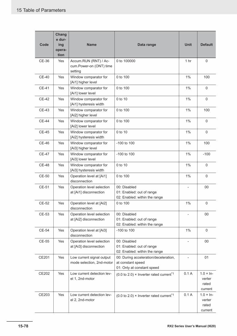
Code
Change dur-
ingopera-
tion
Name Data range Unit Default
CE-36 Yes Accum.RUN (RNT) / Ac-cum.Power-on (ONT) timesetting
0 to 100000 1 hr 0
CE-40 Yes Window comparator for[Ai1] higher level
0 to 100 1% 100
CE-41 Yes Window comparator for[Ai1] lower level
0 to 100 1% 0
CE-42 Yes Window comparator for[Ai1] hysteresis width
0 to 10 1% 0
CE-43 Yes Window comparator for[Ai2] higher level
0 to 100 1% 100
CE-44 Yes Window comparator for[Ai2] lower level
0 to 100 1% 0
CE-45 Yes Window comparator for[Ai2] hysteresis width
0 to 10 1% 0
CE-46 Yes Window comparator for[Ai3] higher level
-100 to 100 1% 100
CE-47 Yes Window comparator for[Ai3] lower level
-100 to 100 1% -100
CE-48 Yes Window comparator for[Ai3] hysteresis width
0 to 10 1% 0
CE-50 Yes Operation level at [Ai1]disconnection
0 to 100 1% 0
CE-51 Yes Operation level selectionat [Ai1] disconnection
00: Disabled01: Enabled: out of range02: Enabled: within the range
- 00
CE-52 Yes Operation level at [Ai2]disconnection
0 to 100 1% 0
CE-53 Yes Operation level selectionat [Ai2] disconnection
00: Disabled01: Enabled: out of range02: Enabled: within the range
- 00
CE-54 Yes Operation level at [Ai3]disconnection
-100 to 100 1% 0
CE-55 Yes Operation level selectionat [Ai3] disconnection
00: Disabled01: Enabled: out of range02: Enabled: within the range
- 00
CE201 Yes Low current signal outputmode selection, 2nd-motor
00: During acceleration/deceleration,at constant speed01: Only at constant speed
- 01
CE202 Yes Low current detection lev-el 1, 2nd-motor
(0.0 to 2.0) × Inverter rated current*1 0.1 A 1.0 × In-verterrated
currentCE203 Yes Low current detection lev-
el 2, 2nd-motor(0.0 to 2.0) × Inverter rated current*1 0.1 A 1.0 × In-
verterrated
current
15 Table of Parameters
15-78 RX2 Series User’s Manual (I620)
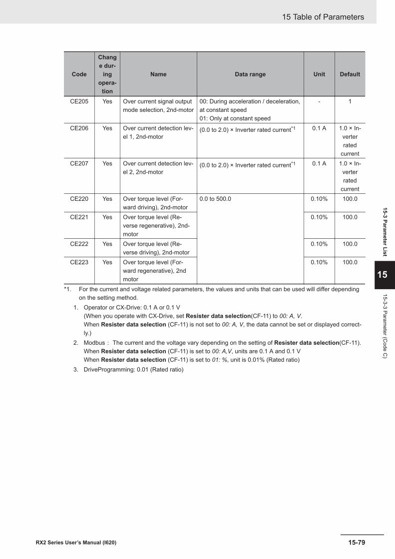
Code
Change dur-
ingopera-
tion
Name Data range Unit Default
CE205 Yes Over current signal outputmode selection, 2nd-motor
00: During acceleration / deceleration,at constant speed01: Only at constant speed
- 1
CE206 Yes Over current detection lev-el 1, 2nd-motor
(0.0 to 2.0) × Inverter rated current*1 0.1 A 1.0 × In-verterrated
currentCE207 Yes Over current detection lev-
el 2, 2nd-motor(0.0 to 2.0) × Inverter rated current*1 0.1 A 1.0 × In-
verterrated
currentCE220 Yes Over torque level (For-
ward driving), 2nd-motor0.0 to 500.0 0.10% 100.0
CE221 Yes Over torque level (Re-verse regenerative), 2nd-motor
0.10% 100.0
CE222 Yes Over torque level (Re-verse driving), 2nd-motor
0.10% 100.0
CE223 Yes Over torque level (For-ward regenerative), 2ndmotor
0.10% 100.0
*1. For the current and voltage related parameters, the values and units that can be used will differ dependingon the setting method.
1. Operator or CX-Drive: 0.1 A or 0.1 V(When you operate with CX-Drive, set Resister data selection(CF-11) to 00: A, V.When Resister data selection (CF-11) is not set to 00: A, V, the data cannot be set or displayed correct-ly.)
2. Modbus: The current and the voltage vary depending on the setting of Resister data selection(CF-11).When Resister data selection (CF-11) is set to 00: A,V, units are 0.1 A and 0.1 VWhen Resister data selection (CF-11) is set to 01: %, unit is 0.01% (Rated ratio)
3. DriveProgramming: 0.01 (Rated ratio)
15 Table of Parameters
15-79RX2 Series User’s Manual (I620)
15-3 Parameter List
15
15-3-3 Parameter (C
ode C)
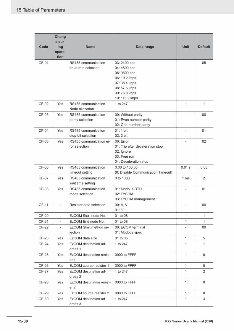
Code
Change dur-
ingopera-
tion
Name Data range Unit Default
CF-01 - RS485 communicationbaud rate selection
03: 2400 bps04: 4800 bps05: 9600 bps06: 19.2 kbps07: 38.4 kbps08: 57.6 kbps09: 76.8 kbps10: 115.2 kbps
- 05
CF-02 Yes RS485 communicationNode allocation
1 to 247 1 1
CF-03 Yes RS485 communicationparity selection
00: Without parity01: Even number parity02: Odd number parity
- 00
CF-04 Yes RS485 communicationstop-bit selection
01: 1 bit02: 2 bit
- 01
CF-05 Yes RS485 communication er-ror selection
00: Error01: Trip after deceleration stop02: Ignore03: Free run04: Deceleration stop
- 02
CF-06 Yes RS485 communicationtimeout setting
0.00 to 100.00(0: Disable Communication Timeout)
0.01 s 0.00
CF-07 Yes RS485 communicationwait time setting
0 to 1000 1 ms 2
CF-08 Yes RS485 communicationmode selection
01: Modbus-RTU02: EzCOM03: EzCOM management
- 01
CF-11 - Resister data selection 00: A, V01: %
- 00
CF-20 - EzCOM Start node No. 01 to 08 1 1CF-21 - EzCOM End node No. 01 to 08 1 1CF-22 - EzCOM Start method se-
lection00: ECOM terminal01: Modbus spec
- 00
CF-23 Yes EzCOM data size 01 to 05 1 5CF-24 Yes EzCOM destination ad-
dress 11 to 247 1 1
CF-25 Yes EzCOM destination resist-er 1
0000 to FFFF 1 0
CF-26 Yes EzCOM source resister 1 0000 to FFFF 1 0CF-27 Yes EzCOM destination ad-
dress 21 to 247 1 2
CF-28 Yes EzCOM destination resist-er 2
0000 to FFFF 1 0
CF-29 Yes EzCOM source resister 2 0000 to FFFF 1 0CF-30 Yes EzCOM destination ad-
dress 31 to 247 1 3
15 Table of Parameters
15-80 RX2 Series User’s Manual (I620)
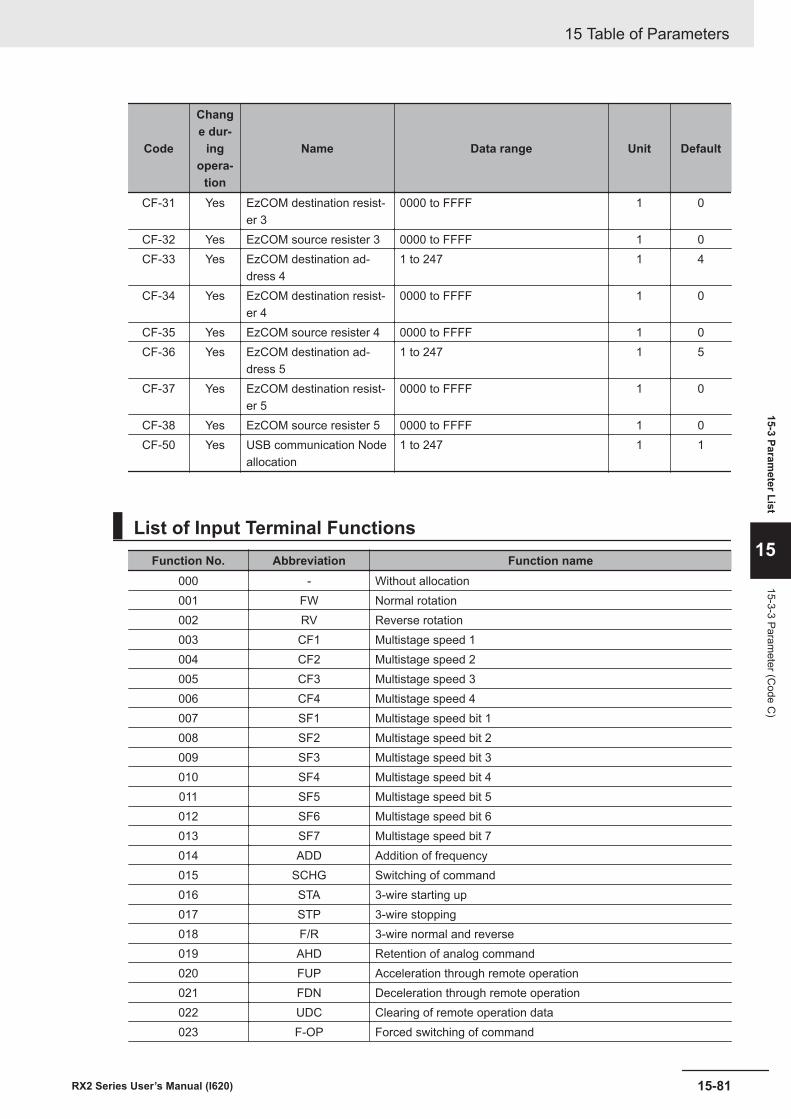
Code
Change dur-
ingopera-
tion
Name Data range Unit Default
CF-31 Yes EzCOM destination resist-er 3
0000 to FFFF 1 0
CF-32 Yes EzCOM source resister 3 0000 to FFFF 1 0CF-33 Yes EzCOM destination ad-
dress 41 to 247 1 4
CF-34 Yes EzCOM destination resist-er 4
0000 to FFFF 1 0
CF-35 Yes EzCOM source resister 4 0000 to FFFF 1 0CF-36 Yes EzCOM destination ad-
dress 51 to 247 1 5
CF-37 Yes EzCOM destination resist-er 5
0000 to FFFF 1 0
CF-38 Yes EzCOM source resister 5 0000 to FFFF 1 0CF-50 Yes USB communication Node
allocation1 to 247 1 1
List of Input Terminal FunctionsFunction No. Abbreviation Function name
000 - Without allocation001 FW Normal rotation002 RV Reverse rotation003 CF1 Multistage speed 1004 CF2 Multistage speed 2005 CF3 Multistage speed 3006 CF4 Multistage speed 4007 SF1 Multistage speed bit 1008 SF2 Multistage speed bit 2009 SF3 Multistage speed bit 3010 SF4 Multistage speed bit 4011 SF5 Multistage speed bit 5012 SF6 Multistage speed bit 6013 SF7 Multistage speed bit 7014 ADD Addition of frequency015 SCHG Switching of command016 STA 3-wire starting up017 STP 3-wire stopping018 F/R 3-wire normal and reverse019 AHD Retention of analog command020 FUP Acceleration through remote operation021 FDN Deceleration through remote operation022 UDC Clearing of remote operation data023 F-OP Forced switching of command
15 Table of Parameters
15-81RX2 Series User’s Manual (I620)
15-3 Parameter List
15
15-3-3 Parameter (C
ode C)
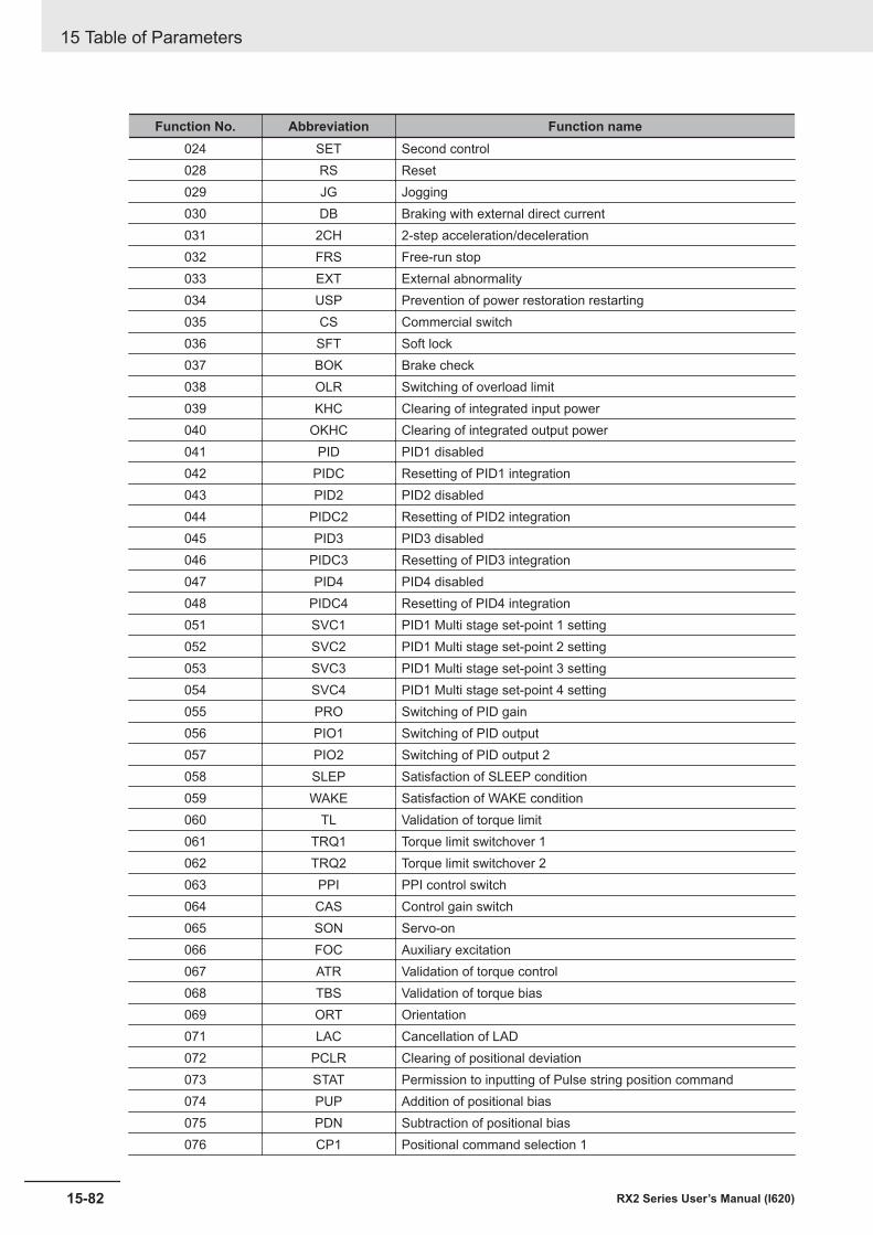
Function No. Abbreviation Function name024 SET Second control028 RS Reset029 JG Jogging030 DB Braking with external direct current031 2CH 2-step acceleration/deceleration032 FRS Free-run stop033 EXT External abnormality034 USP Prevention of power restoration restarting035 CS Commercial switch036 SFT Soft lock037 BOK Brake check038 OLR Switching of overload limit039 KHC Clearing of integrated input power040 OKHC Clearing of integrated output power041 PID PID1 disabled042 PIDC Resetting of PID1 integration043 PID2 PID2 disabled044 PIDC2 Resetting of PID2 integration045 PID3 PID3 disabled046 PIDC3 Resetting of PID3 integration047 PID4 PID4 disabled048 PIDC4 Resetting of PID4 integration051 SVC1 PID1 Multi stage set-point 1 setting052 SVC2 PID1 Multi stage set-point 2 setting053 SVC3 PID1 Multi stage set-point 3 setting054 SVC4 PID1 Multi stage set-point 4 setting055 PRO Switching of PID gain056 PIO1 Switching of PID output057 PIO2 Switching of PID output 2058 SLEP Satisfaction of SLEEP condition059 WAKE Satisfaction of WAKE condition060 TL Validation of torque limit061 TRQ1 Torque limit switchover 1062 TRQ2 Torque limit switchover 2063 PPI PPI control switch064 CAS Control gain switch065 SON Servo-on066 FOC Auxiliary excitation067 ATR Validation of torque control068 TBS Validation of torque bias069 ORT Orientation071 LAC Cancellation of LAD072 PCLR Clearing of positional deviation073 STAT Permission to inputting of Pulse string position command074 PUP Addition of positional bias075 PDN Subtraction of positional bias076 CP1 Positional command selection 1
15 Table of Parameters
15-82 RX2 Series User’s Manual (I620)
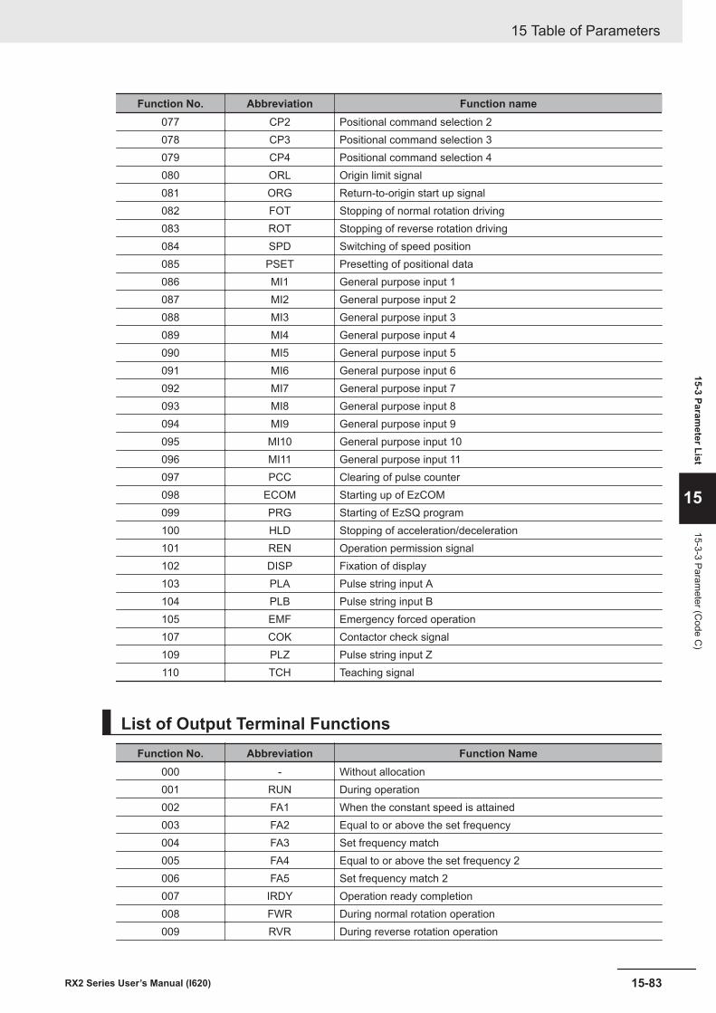
Function No. Abbreviation Function name077 CP2 Positional command selection 2078 CP3 Positional command selection 3079 CP4 Positional command selection 4080 ORL Origin limit signal081 ORG Return-to-origin start up signal082 FOT Stopping of normal rotation driving083 ROT Stopping of reverse rotation driving084 SPD Switching of speed position085 PSET Presetting of positional data086 MI1 General purpose input 1087 MI2 General purpose input 2088 MI3 General purpose input 3089 MI4 General purpose input 4090 MI5 General purpose input 5091 MI6 General purpose input 6092 MI7 General purpose input 7093 MI8 General purpose input 8094 MI9 General purpose input 9095 MI10 General purpose input 10096 MI11 General purpose input 11097 PCC Clearing of pulse counter098 ECOM Starting up of EzCOM099 PRG Starting of EzSQ program100 HLD Stopping of acceleration/deceleration101 REN Operation permission signal102 DISP Fixation of display103 PLA Pulse string input A104 PLB Pulse string input B105 EMF Emergency forced operation107 COK Contactor check signal109 PLZ Pulse string input Z110 TCH Teaching signal
List of Output Terminal FunctionsFunction No. Abbreviation Function Name
000 - Without allocation001 RUN During operation002 FA1 When the constant speed is attained003 FA2 Equal to or above the set frequency004 FA3 Set frequency match005 FA4 Equal to or above the set frequency 2006 FA5 Set frequency match 2007 IRDY Operation ready completion008 FWR During normal rotation operation009 RVR During reverse rotation operation
15 Table of Parameters
15-83RX2 Series User’s Manual (I620)
15-3 Parameter List
15
15-3-3 Parameter (C
ode C)
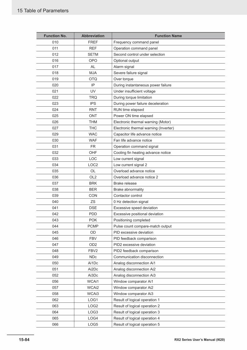
Function No. Abbreviation Function Name010 FREF Frequency command panel011 REF Operation command panel012 SETM Second control under selection016 OPO Optional output017 AL Alarm signal018 MJA Severe failure signal019 OTQ Over torque020 IP During instantaneous power failure021 UV Under insufficient voltage022 TRQ During torque limitation023 IPS During power failure deceleration024 RNT RUN time elapsed025 ONT Power ON time elapsed026 THM Electronic thermal warning (Motor)027 THC Electronic thermal warning (Inverter)029 WAC Capacitor life advance notice030 WAF Fan life advance notice031 FR Operation command signal032 OHF Cooling fin heating advance notice033 LOC Low current signal034 LOC2 Low current signal 2035 OL Overload advance notice036 OL2 Overload advance notice 2037 BRK Brake release038 BER Brake abnormality039 CON Contactor control040 ZS 0 Hz detection signal041 DSE Excessive speed deviation042 PDD Excessive positional deviation043 POK Positioning completed044 PCMP Pulse count compare-match output045 OD PID excessive deviation046 FBV PID feedback comparison047 OD2 PID2 excessive deviation048 FBV2 PID2 feedback comparison049 NDc Communication disconnection050 Ai1Dc Analog disconnection Ai1051 Ai2Dc Analog disconnection Ai2052 Ai3Dc Analog disconnection Ai3056 WCAi1 Window comparator Ai1057 WCAi2 Window comparator Ai2058 WCAi3 Window comparator Ai3062 LOG1 Result of logical operation 1063 LOG2 Result of logical operation 2064 LOG3 Result of logical operation 3065 LOG4 Result of logical operation 4066 LOG5 Result of logical operation 5
15 Table of Parameters
15-84 RX2 Series User’s Manual (I620)
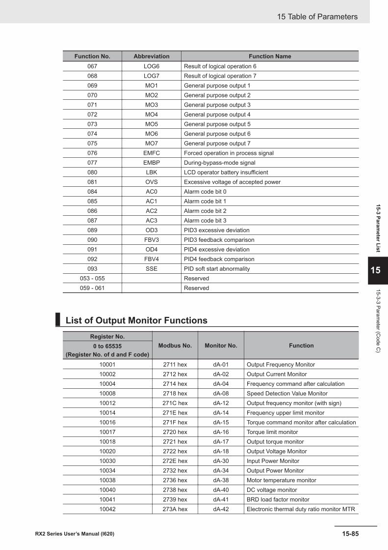
Function No. Abbreviation Function Name067 LOG6 Result of logical operation 6068 LOG7 Result of logical operation 7069 MO1 General purpose output 1070 MO2 General purpose output 2071 MO3 General purpose output 3072 MO4 General purpose output 4073 MO5 General purpose output 5074 MO6 General purpose output 6075 MO7 General purpose output 7076 EMFC Forced operation in process signal077 EMBP During-bypass-mode signal080 LBK LCD operator battery insufficient081 OVS Excessive voltage of accepted power084 AC0 Alarm code bit 0085 AC1 Alarm code bit 1086 AC2 Alarm code bit 2087 AC3 Alarm code bit 3089 OD3 PID3 excessive deviation090 FBV3 PID3 feedback comparison091 OD4 PID4 excessive deviation092 FBV4 PID4 feedback comparison093 SSE PID soft start abnormality
053 - 055 Reserved059 - 061 Reserved
List of Output Monitor FunctionsRegister No.
Modbus No. Monitor No. Function0 to 65535(Register No. of d and F code)
10001 2711 hex dA-01 Output Frequency Monitor10002 2712 hex dA-02 Output Current Monitor10004 2714 hex dA-04 Frequency command after calculation10008 2718 hex dA-08 Speed Detection Value Monitor10012 271C hex dA-12 Output frequency monitor (with sign)10014 271E hex dA-14 Frequency upper limit monitor10016 271F hex dA-15 Torque command monitor after calculation10017 2720 hex dA-16 Torque limit monitor10018 2721 hex dA-17 Output torque monitor10020 2722 hex dA-18 Output Voltage Monitor10030 272E hex dA-30 Input Power Monitor10034 2732 hex dA-34 Output Power Monitor10038 2736 hex dA-38 Motor temperature monitor10040 2738 hex dA-40 DC voltage monitor10041 2739 hex dA-41 BRD load factor monitor10042 273A hex dA-42 Electronic thermal duty ratio monitor MTR
15 Table of Parameters
15-85RX2 Series User’s Manual (I620)
15-3 Parameter List
15
15-3-3 Parameter (C
ode C)
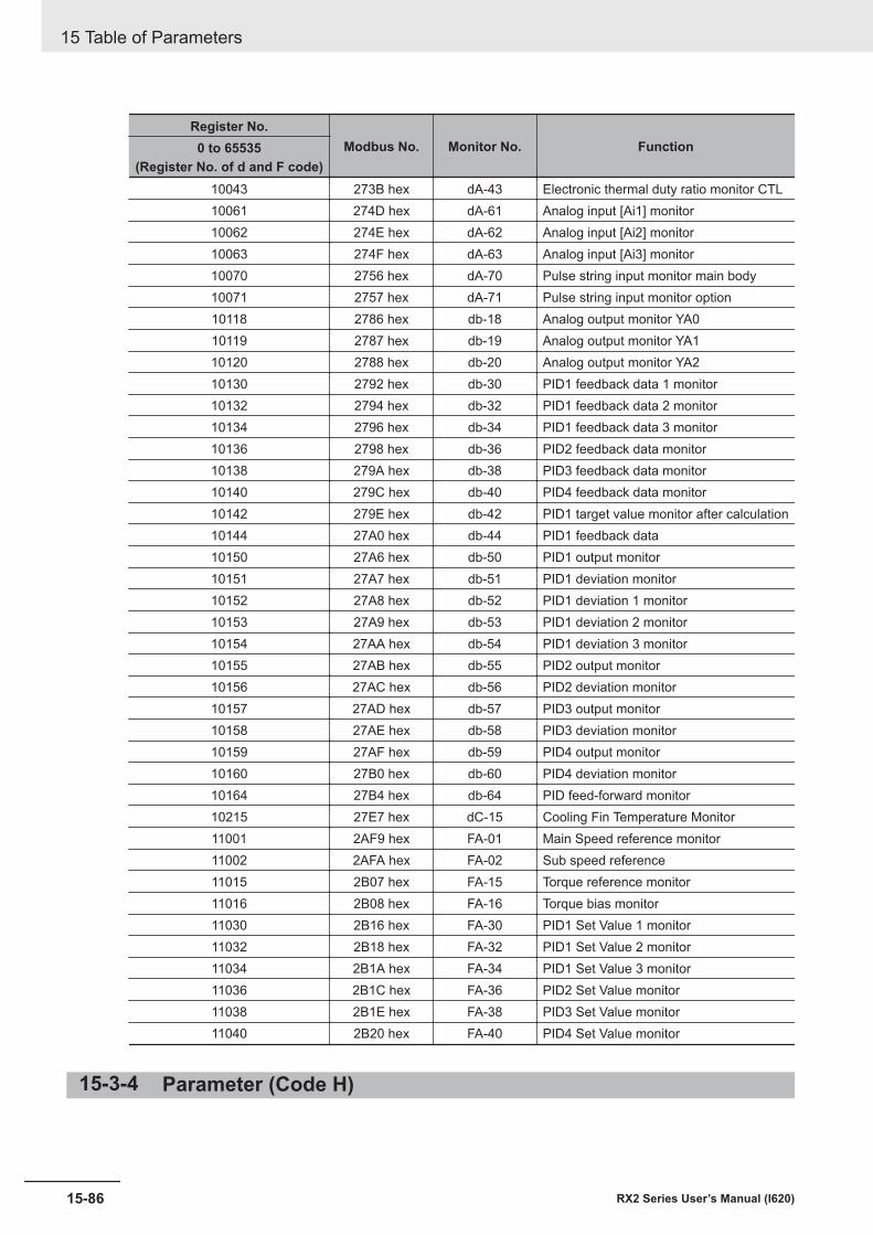
Register No.Modbus No. Monitor No. Function0 to 65535
(Register No. of d and F code)10043 273B hex dA-43 Electronic thermal duty ratio monitor CTL10061 274D hex dA-61 Analog input [Ai1] monitor10062 274E hex dA-62 Analog input [Ai2] monitor10063 274F hex dA-63 Analog input [Ai3] monitor10070 2756 hex dA-70 Pulse string input monitor main body10071 2757 hex dA-71 Pulse string input monitor option10118 2786 hex db-18 Analog output monitor YA010119 2787 hex db-19 Analog output monitor YA110120 2788 hex db-20 Analog output monitor YA210130 2792 hex db-30 PID1 feedback data 1 monitor10132 2794 hex db-32 PID1 feedback data 2 monitor10134 2796 hex db-34 PID1 feedback data 3 monitor10136 2798 hex db-36 PID2 feedback data monitor10138 279A hex db-38 PID3 feedback data monitor10140 279C hex db-40 PID4 feedback data monitor10142 279E hex db-42 PID1 target value monitor after calculation10144 27A0 hex db-44 PID1 feedback data10150 27A6 hex db-50 PID1 output monitor10151 27A7 hex db-51 PID1 deviation monitor10152 27A8 hex db-52 PID1 deviation 1 monitor10153 27A9 hex db-53 PID1 deviation 2 monitor10154 27AA hex db-54 PID1 deviation 3 monitor10155 27AB hex db-55 PID2 output monitor10156 27AC hex db-56 PID2 deviation monitor10157 27AD hex db-57 PID3 output monitor10158 27AE hex db-58 PID3 deviation monitor10159 27AF hex db-59 PID4 output monitor10160 27B0 hex db-60 PID4 deviation monitor10164 27B4 hex db-64 PID feed-forward monitor10215 27E7 hex dC-15 Cooling Fin Temperature Monitor11001 2AF9 hex FA-01 Main Speed reference monitor11002 2AFA hex FA-02 Sub speed reference11015 2B07 hex FA-15 Torque reference monitor11016 2B08 hex FA-16 Torque bias monitor11030 2B16 hex FA-30 PID1 Set Value 1 monitor11032 2B18 hex FA-32 PID1 Set Value 2 monitor11034 2B1A hex FA-34 PID1 Set Value 3 monitor11036 2B1C hex FA-36 PID2 Set Value monitor11038 2B1E hex FA-38 PID3 Set Value monitor11040 2B20 hex FA-40 PID4 Set Value monitor
15-3-4 Parameter (Code H)
15 Table of Parameters
15-86 RX2 Series User’s Manual (I620)
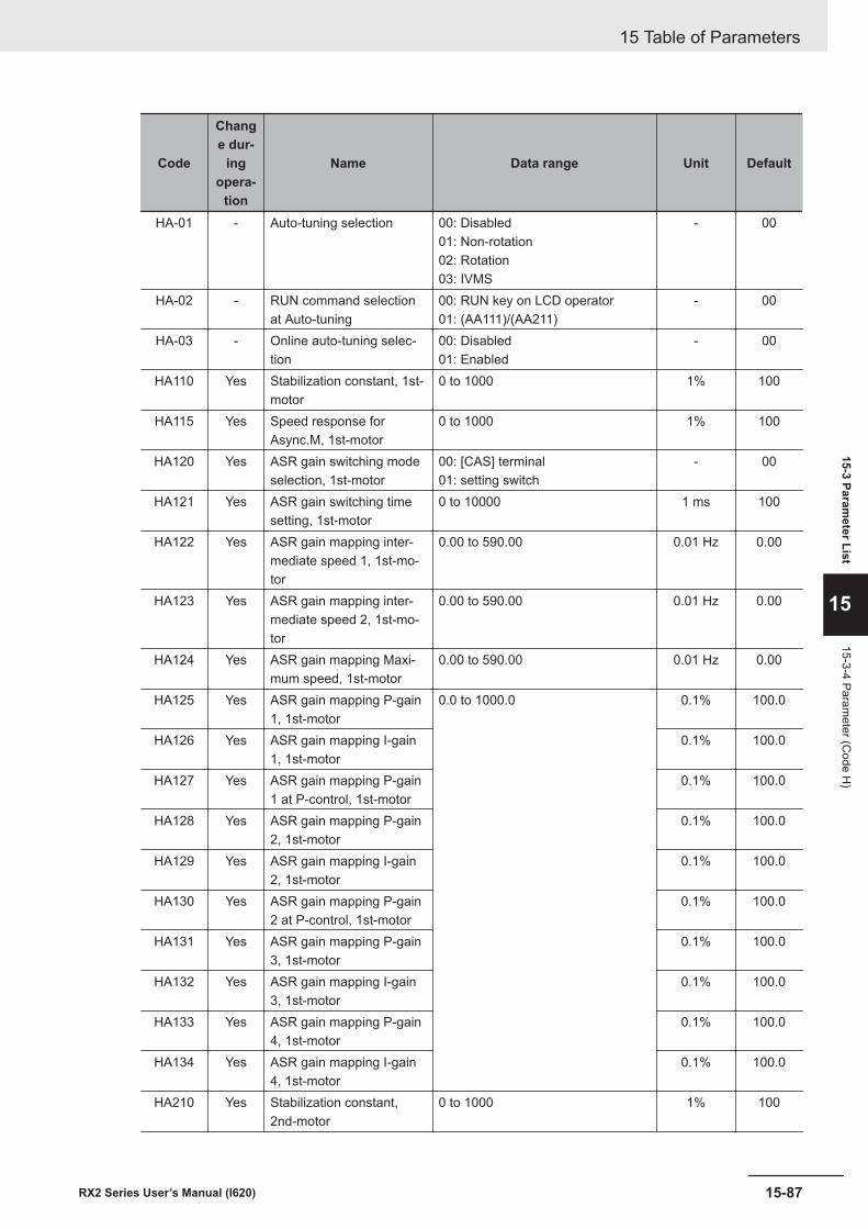
Code
Change dur-
ingopera-
tion
Name Data range Unit Default
HA-01 - Auto-tuning selection 00: Disabled01: Non-rotation02: Rotation03: IVMS
- 00
HA-02 - RUN command selectionat Auto-tuning
00: RUN key on LCD operator01: (AA111)/(AA211)
- 00
HA-03 - Online auto-tuning selec-tion
00: Disabled01: Enabled
- 00
HA110 Yes Stabilization constant, 1st-motor
0 to 1000 1% 100
HA115 Yes Speed response forAsync.M, 1st-motor
0 to 1000 1% 100
HA120 Yes ASR gain switching modeselection, 1st-motor
00: [CAS] terminal01: setting switch
- 00
HA121 Yes ASR gain switching timesetting, 1st-motor
0 to 10000 1 ms 100
HA122 Yes ASR gain mapping inter-mediate speed 1, 1st-mo-tor
0.00 to 590.00 0.01 Hz 0.00
HA123 Yes ASR gain mapping inter-mediate speed 2, 1st-mo-tor
0.00 to 590.00 0.01 Hz 0.00
HA124 Yes ASR gain mapping Maxi-mum speed, 1st-motor
0.00 to 590.00 0.01 Hz 0.00
HA125 Yes ASR gain mapping P-gain1, 1st-motor
0.0 to 1000.0 0.1% 100.0
HA126 Yes ASR gain mapping I-gain1, 1st-motor
0.1% 100.0
HA127 Yes ASR gain mapping P-gain1 at P-control, 1st-motor
0.1% 100.0
HA128 Yes ASR gain mapping P-gain2, 1st-motor
0.1% 100.0
HA129 Yes ASR gain mapping I-gain2, 1st-motor
0.1% 100.0
HA130 Yes ASR gain mapping P-gain2 at P-control, 1st-motor
0.1% 100.0
HA131 Yes ASR gain mapping P-gain3, 1st-motor
0.1% 100.0
HA132 Yes ASR gain mapping I-gain3, 1st-motor
0.1% 100.0
HA133 Yes ASR gain mapping P-gain4, 1st-motor
0.1% 100.0
HA134 Yes ASR gain mapping I-gain4, 1st-motor
0.1% 100.0
HA210 Yes Stabilization constant,2nd-motor
0 to 1000 1% 100
15 Table of Parameters
15-87RX2 Series User’s Manual (I620)
15-3 Parameter List
15
15-3-4 Parameter (C
ode H)
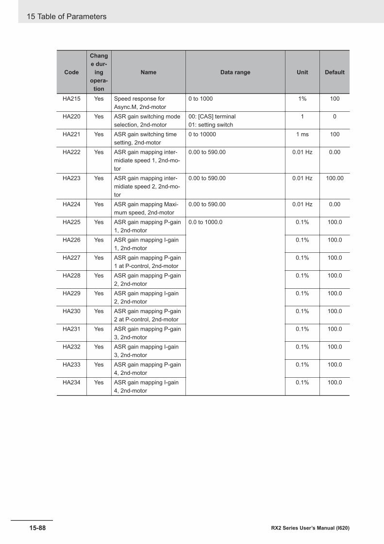
Code
Change dur-
ingopera-
tion
Name Data range Unit Default
HA215 Yes Speed response forAsync.M, 2nd-motor
0 to 1000 1% 100
HA220 Yes ASR gain switching modeselection, 2nd-motor
00: [CAS] terminal01: setting switch
1 0
HA221 Yes ASR gain switching timesetting, 2nd-motor
0 to 10000 1 ms 100
HA222 Yes ASR gain mapping inter-midiate speed 1, 2nd-mo-tor
0.00 to 590.00 0.01 Hz 0.00
HA223 Yes ASR gain mapping inter-midiate speed 2, 2nd-mo-tor
0.00 to 590.00 0.01 Hz 100.00
HA224 Yes ASR gain mapping Maxi-mum speed, 2nd-motor
0.00 to 590.00 0.01 Hz 0.00
HA225 Yes ASR gain mapping P-gain1, 2nd-motor
0.0 to 1000.0 0.1% 100.0
HA226 Yes ASR gain mapping I-gain1, 2nd-motor
0.1% 100.0
HA227 Yes ASR gain mapping P-gain1 at P-control, 2nd-motor
0.1% 100.0
HA228 Yes ASR gain mapping P-gain2, 2nd-motor
0.1% 100.0
HA229 Yes ASR gain mapping I-gain2, 2nd-motor
0.1% 100.0
HA230 Yes ASR gain mapping P-gain2 at P-control, 2nd-motor
0.1% 100.0
HA231 Yes ASR gain mapping P-gain3, 2nd-motor
0.1% 100.0
HA232 Yes ASR gain mapping I-gain3, 2nd-motor
0.1% 100.0
HA233 Yes ASR gain mapping P-gain4, 2nd-motor
0.1% 100.0
HA234 Yes ASR gain mapping I-gain4, 2nd-motor
0.1% 100.0
15 Table of Parameters
15-88 RX2 Series User’s Manual (I620)
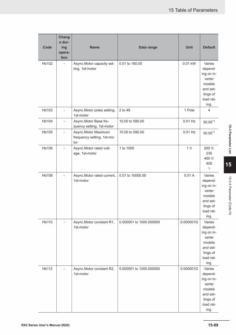
Code
Change dur-
ingopera-
tion
Name Data range Unit Default
Hb102 - Async.Motor capacity set-ting, 1st-motor
0.01 to 160.00 0.01 kW Variesdepend-ing on in-
vertermodelsand set-tings ofload rat-
ing.Hb103 - Async.Motor poles setting,
1st-motor2 to 48 1 Pole 4
Hb104 - Async.Motor Base fre-quency setting, 1st-motor
10.00 to 590.00 0.01 Hz 50.00*1
Hb105 - Async.Motor Maximumfrequency setting, 1st-mo-tor
10.00 to 590.00 0.01 Hz 50.00*1
Hb106 - Async.Motor rated volt-age, 1st-motor
1 to 1000 1 V 200 V:230
400 V:400
*1
Hb108 - Async.Motor rated current,1st-motor
0.01 to 10000.00 0.01 A Variesdepend-ing on in-
vertermodelsand set-tings ofload rat-
ing.Hb110 - Async.Motor constant R1,
1st-motor0.000001 to 1000.000000 0.000001Ω Varies
depend-ing on in-
vertermodelsand set-tings ofload rat-
ing.Hb112 - Async.Motor constant R2,
1st-motor0.000001 to 1000.000000 0.000001Ω Varies
depend-ing on in-
vertermodelsand set-tings ofload rat-
ing.
15 Table of Parameters
15-89RX2 Series User’s Manual (I620)
15-3 Parameter List
15
15-3-4 Parameter (C
ode H)
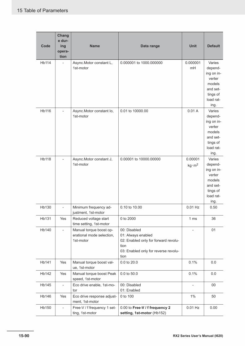
Code
Change dur-
ingopera-
tion
Name Data range Unit Default
Hb114 - Async.Motor constant L,1st-motor
0.000001 to 1000.000000 0.000001mH
Variesdepend-ing on in-
vertermodelsand set-tings ofload rat-
ing.Hb116 - Async.Motor constant Io,
1st-motor0.01 to 10000.00 0.01 A Varies
depend-ing on in-
vertermodelsand set-tings ofload rat-
ing.Hb118 - Async.Motor constant J,
1st-motor0.00001 to 10000.00000 0.00001
kg・m2Varies
depend-ing on in-
vertermodelsand set-tings ofload rat-
ing.Hb130 - Minimum frequency ad-
justment, 1st-motor0.10 to 10.00 0.01 Hz 0.50
Hb131 Yes Reduced voltage starttime setting, 1st-motor
0 to 2000 1 ms 36
Hb140 - Manual torque boost op-erational mode selection,1st-motor
00: Disabled01: Always enabled02: Enabled only for forward revolu-tion03: Enabled only for reverse revolu-tion
- 01
Hb141 Yes Manual torque boost val-ue, 1st-motor
0.0 to 20.0 0.1% 0.0
Hb142 Yes Manual torque boost Peakspeed, 1st-motor
0.0 to 50.0 0.1% 0.0
Hb145 - Eco drive enable, 1st-mo-tor
00: Disabled01: Enabled
- 00
Hb146 Yes Eco drive response adjust-ment, 1st-motor
0 to 100 1% 50
Hb150 - Free-V / f frequency 1 set-ting, 1st-motor
0.00 to Free-V / f frequency 2setting, 1st-motor (Hb152)
0.01 Hz 0.00
15 Table of Parameters
15-90 RX2 Series User’s Manual (I620)
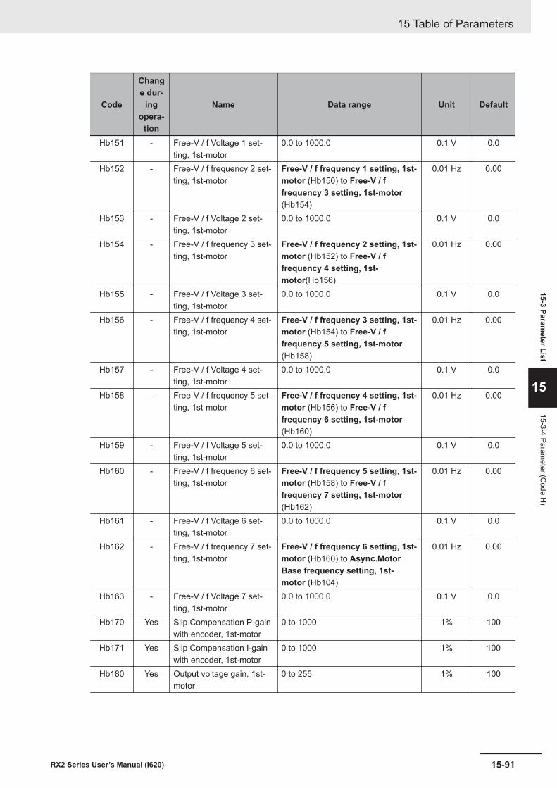
Code
Change dur-
ingopera-
tion
Name Data range Unit Default
Hb151 - Free-V / f Voltage 1 set-ting, 1st-motor
0.0 to 1000.0 0.1 V 0.0
Hb152 - Free-V / f frequency 2 set-ting, 1st-motor
Free-V / f frequency 1 setting, 1st-motor (Hb150) to Free-V / ffrequency 3 setting, 1st-motor(Hb154)
0.01 Hz 0.00
Hb153 - Free-V / f Voltage 2 set-ting, 1st-motor
0.0 to 1000.0 0.1 V 0.0
Hb154 - Free-V / f frequency 3 set-ting, 1st-motor
Free-V / f frequency 2 setting, 1st-motor (Hb152) to Free-V / ffrequency 4 setting, 1st-motor(Hb156)
0.01 Hz 0.00
Hb155 - Free-V / f Voltage 3 set-ting, 1st-motor
0.0 to 1000.0 0.1 V 0.0
Hb156 - Free-V / f frequency 4 set-ting, 1st-motor
Free-V / f frequency 3 setting, 1st-motor (Hb154) to Free-V / ffrequency 5 setting, 1st-motor(Hb158)
0.01 Hz 0.00
Hb157 - Free-V / f Voltage 4 set-ting, 1st-motor
0.0 to 1000.0 0.1 V 0.0
Hb158 - Free-V / f frequency 5 set-ting, 1st-motor
Free-V / f frequency 4 setting, 1st-motor (Hb156) to Free-V / ffrequency 6 setting, 1st-motor(Hb160)
0.01 Hz 0.00
Hb159 - Free-V / f Voltage 5 set-ting, 1st-motor
0.0 to 1000.0 0.1 V 0.0
Hb160 - Free-V / f frequency 6 set-ting, 1st-motor
Free-V / f frequency 5 setting, 1st-motor (Hb158) to Free-V / ffrequency 7 setting, 1st-motor(Hb162)
0.01 Hz 0.00
Hb161 - Free-V / f Voltage 6 set-ting, 1st-motor
0.0 to 1000.0 0.1 V 0.0
Hb162 - Free-V / f frequency 7 set-ting, 1st-motor
Free-V / f frequency 6 setting, 1st-motor (Hb160) to Async.MotorBase frequency setting, 1st-motor (Hb104)
0.01 Hz 0.00
Hb163 - Free-V / f Voltage 7 set-ting, 1st-motor
0.0 to 1000.0 0.1 V 0.0
Hb170 Yes Slip Compensation P-gainwith encoder, 1st-motor
0 to 1000 1% 100
Hb171 Yes Slip Compensation I-gainwith encoder, 1st-motor
0 to 1000 1% 100
Hb180 Yes Output voltage gain, 1st-motor
0 to 255 1% 100
15 Table of Parameters
15-91RX2 Series User’s Manual (I620)
15-3 Parameter List
15
15-3-4 Parameter (C
ode H)
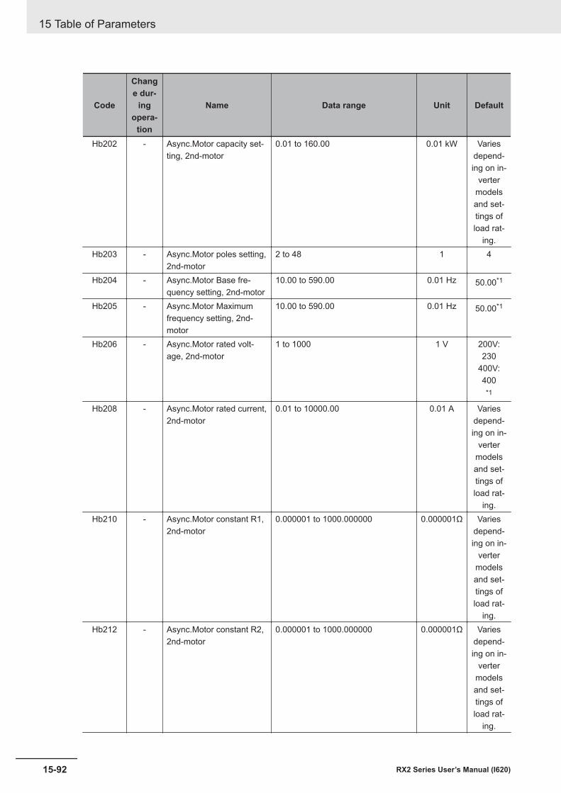
Code
Change dur-
ingopera-
tion
Name Data range Unit Default
Hb202 - Async.Motor capacity set-ting, 2nd-motor
0.01 to 160.00 0.01 kW Variesdepend-ing on in-
vertermodelsand set-tings ofload rat-
ing.Hb203 - Async.Motor poles setting,
2nd-motor2 to 48 1 4
Hb204 - Async.Motor Base fre-quency setting, 2nd-motor
10.00 to 590.00 0.01 Hz 50.00*1
Hb205 - Async.Motor Maximumfrequency setting, 2nd-motor
10.00 to 590.00 0.01 Hz 50.00*1
Hb206 - Async.Motor rated volt-age, 2nd-motor
1 to 1000 1 V 200V:230
400V:400
*1
Hb208 - Async.Motor rated current,2nd-motor
0.01 to 10000.00 0.01 A Variesdepend-ing on in-
vertermodelsand set-tings ofload rat-
ing.Hb210 - Async.Motor constant R1,
2nd-motor0.000001 to 1000.000000 0.000001Ω Varies
depend-ing on in-
vertermodelsand set-tings ofload rat-
ing.Hb212 - Async.Motor constant R2,
2nd-motor0.000001 to 1000.000000 0.000001Ω Varies
depend-ing on in-
vertermodelsand set-tings ofload rat-
ing.
15 Table of Parameters
15-92 RX2 Series User’s Manual (I620)
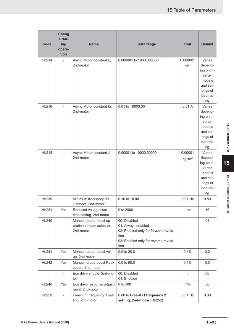
Code
Change dur-
ingopera-
tion
Name Data range Unit Default
Hb214 - Async.Motor constant L,2nd-motor
0.000001 to 1000.000000 0.000001mH
Variesdepend-ing on in-
vertermodelsand set-tings ofload rat-
ing.Hb216 - Async.Motor constant Io,
2nd-motor0.01 to 10000.00 0.01 A Varies
depend-ing on in-
vertermodelsand set-tings ofload rat-
ing.Hb218 - Async.Motor constant J,
2nd-motor0.00001 to 10000.00000 0.00001
kg・m2Varies
depend-ing on in-
vertermodelsand set-tings ofload rat-
ing.Hb230 - Minimum frequency ad-
justment, 2nd-motor0.10 to 10.00 0.01 Hz 0.50
Hb231 Yes Reduced voltage starttime setting, 2nd-motor
0 to 2000 1 ms 36
Hb240 - Manual torque boost op-erational mode selection,2nd-motor
00: Disabled01: Always enabled02: Enabled only for forward revolu-tion03: Enabled only for reverse revolu-tion
- 01
Hb241 Yes Manual torque boost val-ue, 2nd-motor
0.0 to 20.0 0.1% 0.0
Hb242 Yes Manual torque boost Peakspeed, 2nd-motor
0.0 to 50.0 0.1% 0.0
- Eco drive enable, 2nd-mo-tor
00: Disabled01: Enabled
- 00
Hb246 Yes Eco drive response adjust-ment, 2nd-motor
0 to 100 1% 50
Hb250 - Free-V / f frequency 1 set-ting, 2nd-motor
0.00 to Free-V / f frequency 2setting, 2nd-motor (Hb252)
0.01 Hz 0.00
15 Table of Parameters
15-93RX2 Series User’s Manual (I620)
15-3 Parameter List
15
15-3-4 Parameter (C
ode H)
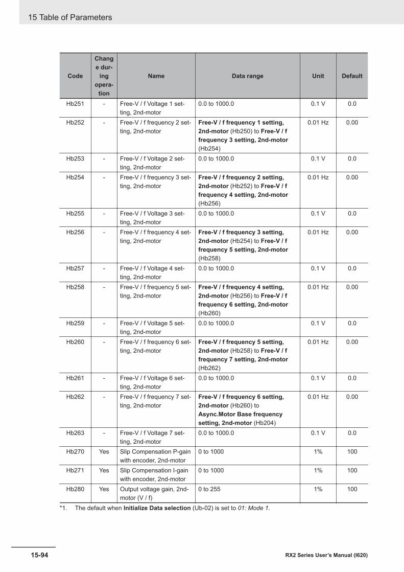
Code
Change dur-
ingopera-
tion
Name Data range Unit Default
Hb251 - Free-V / f Voltage 1 set-ting, 2nd-motor
0.0 to 1000.0 0.1 V 0.0
Hb252 - Free-V / f frequency 2 set-ting, 2nd-motor
Free-V / f frequency 1 setting,2nd-motor (Hb250) to Free-V / ffrequency 3 setting, 2nd-motor(Hb254)
0.01 Hz 0.00
Hb253 - Free-V / f Voltage 2 set-ting, 2nd-motor
0.0 to 1000.0 0.1 V 0.0
Hb254 - Free-V / f frequency 3 set-ting, 2nd-motor
Free-V / f frequency 2 setting,2nd-motor (Hb252) to Free-V / ffrequency 4 setting, 2nd-motor(Hb256)
0.01 Hz 0.00
Hb255 - Free-V / f Voltage 3 set-ting, 2nd-motor
0.0 to 1000.0 0.1 V 0.0
Hb256 - Free-V / f frequency 4 set-ting, 2nd-motor
Free-V / f frequency 3 setting,2nd-motor (Hb254) to Free-V / ffrequency 5 setting, 2nd-motor(Hb258)
0.01 Hz 0.00
Hb257 - Free-V / f Voltage 4 set-ting, 2nd-motor
0.0 to 1000.0 0.1 V 0.0
Hb258 - Free-V / f frequency 5 set-ting, 2nd-motor
Free-V / f frequency 4 setting,2nd-motor (Hb256) to Free-V / ffrequency 6 setting, 2nd-motor(Hb260)
0.01 Hz 0.00
Hb259 - Free-V / f Voltage 5 set-ting, 2nd-motor
0.0 to 1000.0 0.1 V 0.0
Hb260 - Free-V / f frequency 6 set-ting, 2nd-motor
Free-V / f frequency 5 setting,2nd-motor (Hb258) to Free-V / ffrequency 7 setting, 2nd-motor(Hb262)
0.01 Hz 0.00
Hb261 - Free-V / f Voltage 6 set-ting, 2nd-motor
0.0 to 1000.0 0.1 V 0.0
Hb262 - Free-V / f frequency 7 set-ting, 2nd-motor
Free-V / f frequency 6 setting,2nd-motor (Hb260) toAsync.Motor Base frequencysetting, 2nd-motor (Hb204)
0.01 Hz 0.00
Hb263 - Free-V / f Voltage 7 set-ting, 2nd-motor
0.0 to 1000.0 0.1 V 0.0
Hb270 Yes Slip Compensation P-gainwith encoder, 2nd-motor
0 to 1000 1% 100
Hb271 Yes Slip Compensation I-gainwith encoder, 2nd-motor
0 to 1000 1% 100
Hb280 Yes Output voltage gain, 2nd-motor (V / f)
0 to 255 1% 100
*1. The default when Initialize Data selection (Ub-02) is set to 01: Mode 1.
15 Table of Parameters
15-94 RX2 Series User’s Manual (I620)
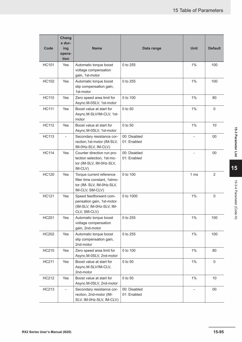
Code
Change dur-
ingopera-
tion
Name Data range Unit Default
HC101 Yes Automatic torque boostvoltage compensationgain, 1st-motor
0 to 255 1% 100
HC102 Yes Automatic torque boostslip compensation gain,1st-motor
0 to 255 1% 100
HC110 Yes Zero speed area limit forAsync.M-0SLV, 1st-motor
0 to 100 1% 80
HC111 Yes Boost value at start forAsync.M-SLV/IM-CLV, 1st-motor
0 to 50 1% 0
HC112 Yes Boost value at start forAsync.M-0SLV, 1st-motor
0 to 50 1% 10
HC113 - Secondary resistance cor-rection,1st-motor (IM-SLV,IM-0Hz-SLV, IM-CLV)
00: Disabled01: Enabled
- 00
HC114 Yes Counter direction run pro-tection selection, 1st-mo-tor (IM-SLV, IM-0Hz-SLV,IM-CLV)
00: Disabled01: Enabled
- 00
HC120 Yes Torque current referencefilter time constant, 1stmo-tor (IM- SLV, IM-0Hz-SLV,IM-CLV, SM-CLV)
0 to 100 1 ms 2
HC121 Yes Speed feedforward com-pensation gain, 1st-motor(IM-SLV, IM-0Hz-SLV, IM-CLV, SM-CLV)
0 to 1000 1% 0
HC201 Yes Automatic torque boostvoltage compensationgain, 2nd-motor
0 to 255 1% 100
HC202 Yes Automatic torque boostslip compensation gain,2nd-motor
0 to 255 1% 100
HC210 Yes Zero speed area limit forAsync.M-0SLV, 2nd-motor
0 to 100 1% 80
HC211 Yes Boost value at start forAsync.M-SLV/IM-CLV,2nd-motor
0 to 50 1% 0
HC212 Yes Boost value at start forAsync.M-0SLV, 2nd-motor
0 to 50 1% 10
HC213 - Secondary resistance cor-rection, 2nd-motor (IM-SLV, IM-0Hz-SLV, IM-CLV)
00: Disabled01: Enabled
- 00
15 Table of Parameters
15-95RX2 Series User’s Manual (I620)
15-3 Parameter List
15
15-3-4 Parameter (C
ode H)
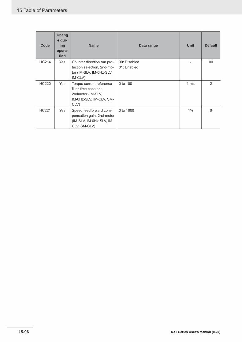
Code
Change dur-
ingopera-
tion
Name Data range Unit Default
HC214 Yes Counter direction run pro-tection selection, 2nd-mo-tor (IM-SLV, IM-0Hz-SLV,IM-CLV)
00: Disabled01: Enabled
- 00
HC220 Yes Torque current referencefilter time constant,2ndmotor (IM-SLV,IM-0Hz-SLV, IM-CLV, SM-CLV)
0 to 100 1 ms 2
HC221 Yes Speed feedforward com-pensation gain, 2nd-motor(IM-SLV, IM-0Hz-SLV, IM-CLV, SM-CLV)
0 to 1000 1% 0
15 Table of Parameters
15-96 RX2 Series User’s Manual (I620)
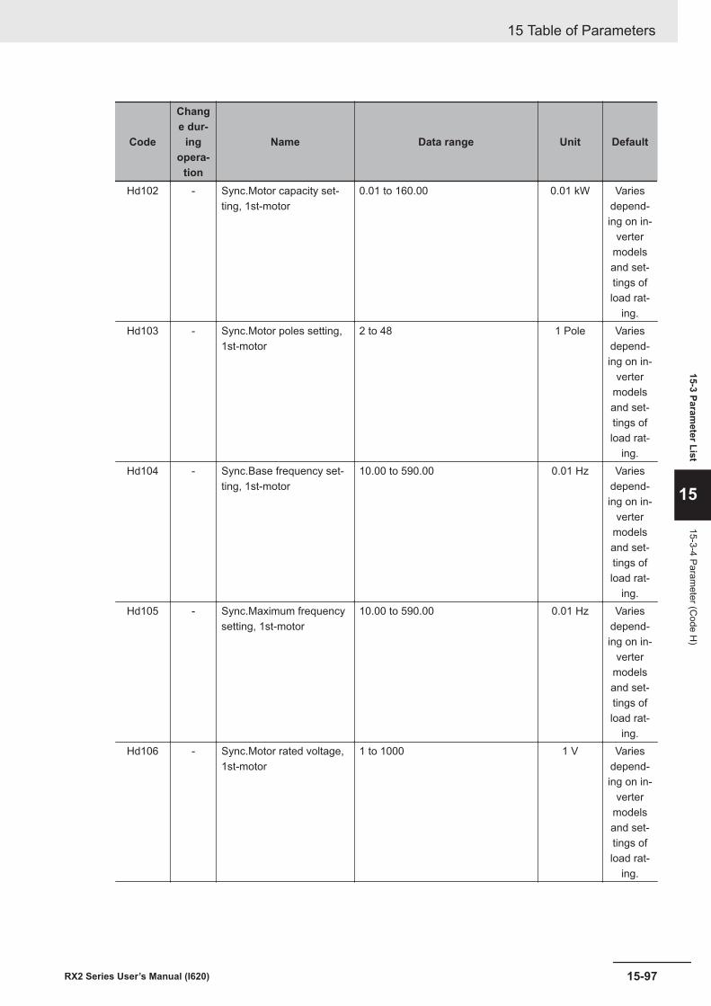
Code
Change dur-
ingopera-
tion
Name Data range Unit Default
Hd102 - Sync.Motor capacity set-ting, 1st-motor
0.01 to 160.00 0.01 kW Variesdepend-ing on in-
vertermodelsand set-tings ofload rat-
ing.Hd103 - Sync.Motor poles setting,
1st-motor2 to 48 1 Pole Varies
depend-ing on in-
vertermodelsand set-tings ofload rat-
ing.Hd104 - Sync.Base frequency set-
ting, 1st-motor10.00 to 590.00 0.01 Hz Varies
depend-ing on in-
vertermodelsand set-tings ofload rat-
ing.Hd105 - Sync.Maximum frequency
setting, 1st-motor10.00 to 590.00 0.01 Hz Varies
depend-ing on in-
vertermodelsand set-tings ofload rat-
ing.Hd106 - Sync.Motor rated voltage,
1st-motor1 to 1000 1 V Varies
depend-ing on in-
vertermodelsand set-tings ofload rat-
ing.
15 Table of Parameters
15-97RX2 Series User’s Manual (I620)
15-3 Parameter List
15
15-3-4 Parameter (C
ode H)
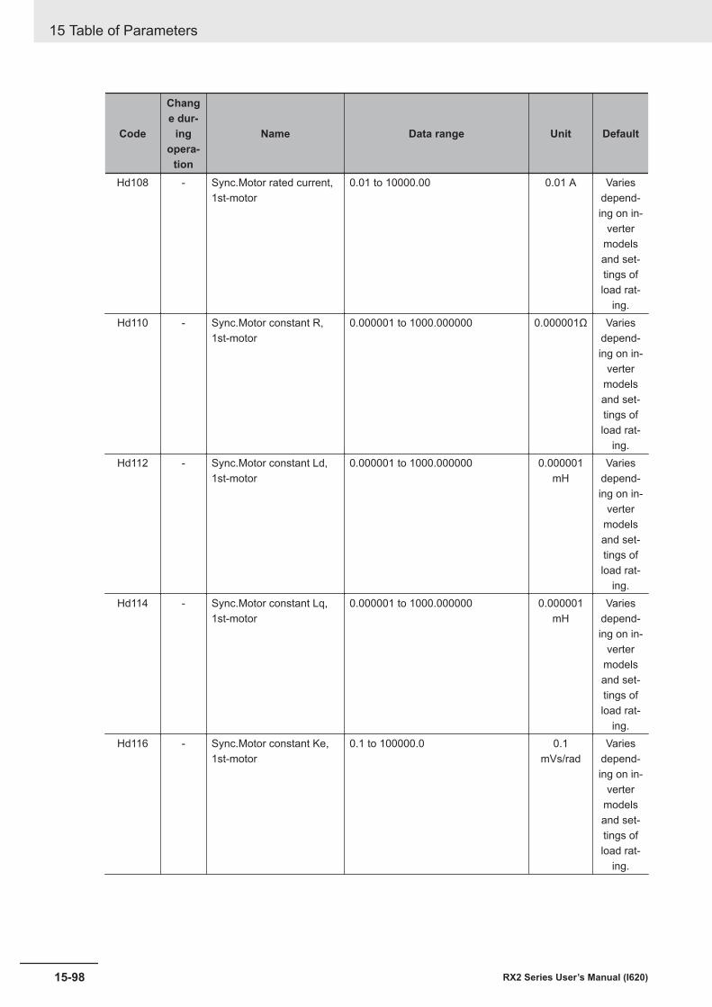
Code
Change dur-
ingopera-
tion
Name Data range Unit Default
Hd108 - Sync.Motor rated current,1st-motor
0.01 to 10000.00 0.01 A Variesdepend-ing on in-
vertermodelsand set-tings ofload rat-
ing.Hd110 - Sync.Motor constant R,
1st-motor0.000001 to 1000.000000 0.000001Ω Varies
depend-ing on in-
vertermodelsand set-tings ofload rat-
ing.Hd112 - Sync.Motor constant Ld,
1st-motor0.000001 to 1000.000000 0.000001
mHVaries
depend-ing on in-
vertermodelsand set-tings ofload rat-
ing.Hd114 - Sync.Motor constant Lq,
1st-motor0.000001 to 1000.000000 0.000001
mHVaries
depend-ing on in-
vertermodelsand set-tings ofload rat-
ing.Hd116 - Sync.Motor constant Ke,
1st-motor0.1 to 100000.0 0.1
mVs/radVaries
depend-ing on in-
vertermodelsand set-tings ofload rat-
ing.
15 Table of Parameters
15-98 RX2 Series User’s Manual (I620)
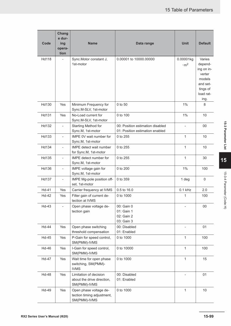
Code
Change dur-
ingopera-
tion
Name Data range Unit Default
Hd118 - Sync.Motor constant J,1st-motor
0.00001 to 10000.00000 0.00001kg・m2
Variesdepend-ing on in-
vertermodelsand set-tings ofload rat-
ing.Hd130 Yes Minimum Frequency for
Sync.M-SLV, 1st-motor0 to 50 1% 8
Hd131 Yes No-Load current forSync.M-SLV, 1st-motor
0 to 100 1% 10
Hd132 - Starting Method forSync.M, 1st-motor
00: Position estimation disabled01: Position estimation enabled
- 00
Hd133 - IMPE 0V wait number forSync.M, 1st-motor
0 to 255 1 10
Hd134 - IMPE detect wait numberfor Sync.M, 1st-motor
0 to 255 1 10
Hd135 - IMPE detect number forSync.M, 1st-motor
0 to 255 1 30
Hd136 - IMPE voltage gain forSync.M, 1st-motor
0 to 200 1% 100
Hd137 - IMPE Mg-pole position off-set, 1st-motor
0 to 359 1 deg 0
Hd-41 Yes Carrier frequency at IVMS 0.5 to 16.0 0.1 kHz 2.0Hd-42 Yes Filter gain of current de-
tection at IVMS0 to 1000 1 100
Hd-43 - Open phase voltage de-tection gain
00: Gain 001: Gain 102: Gain 203: Gain 3
- 00
Hd-44 Yes Open phase switchingthreshold compensation
00: Disabled01: Enabled
- 01
Hd-45 Yes P-Gain for speed control,SM(PMM)-IVMS
0 to 1000 1 100
Hd-46 Yes I-Gain for speed control,SM(PMM)-IVMS
0 to 10000 1 100
Hd-47 Yes Wait time for open phaseswitching, SM(PMM)-IVMS
0 to 1000 1 15
Hd-48 Yes Limitation of decisionabout the drive direction,SM(PMM)-IVMS
00: Disabled01: Enabled
- 01
Hd-49 Yes Open phase voltage de-tection timing adjustment,SM(PMM)-IVMS
0 to 1000 1 10
15 Table of Parameters
15-99RX2 Series User’s Manual (I620)
15-3 Parameter List
15
15-3-4 Parameter (C
ode H)
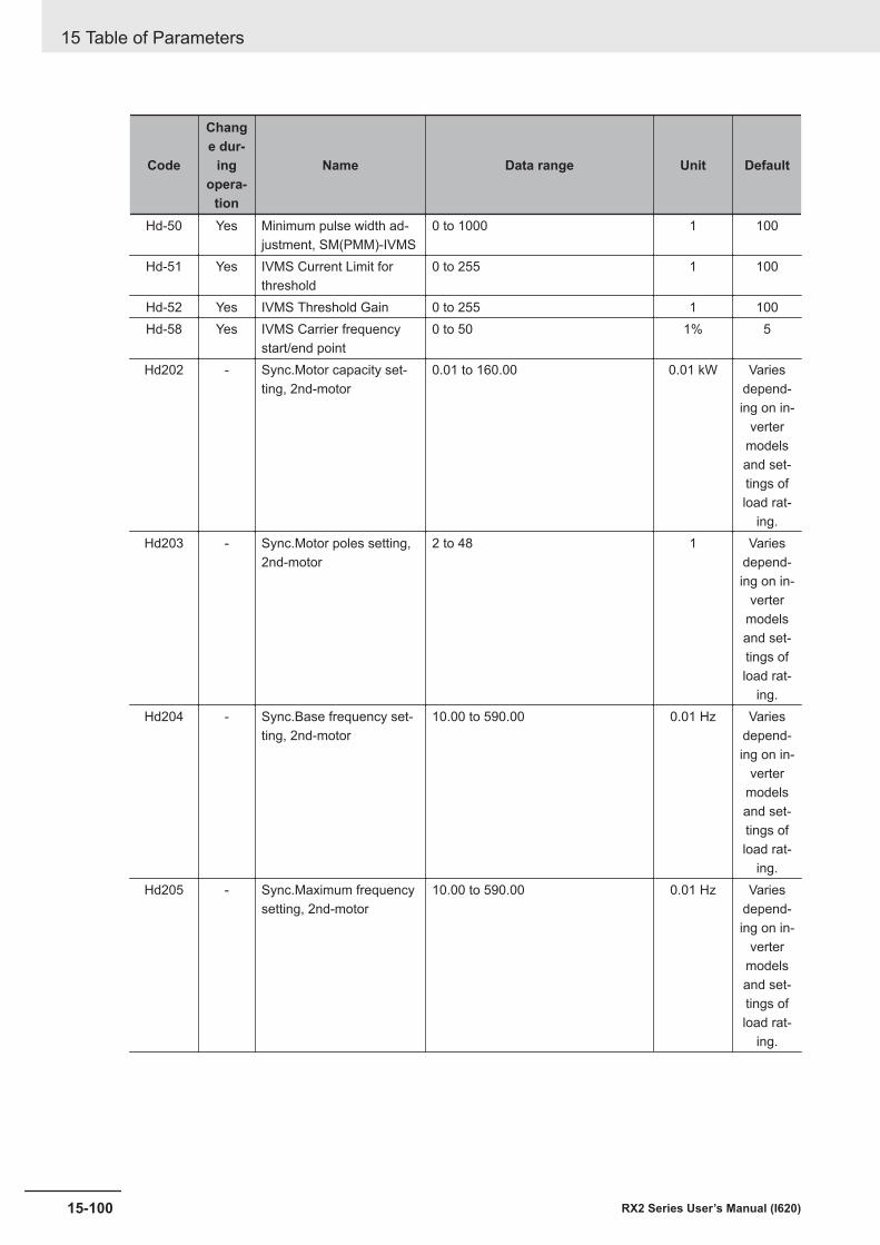
Code
Change dur-
ingopera-
tion
Name Data range Unit Default
Hd-50 Yes Minimum pulse width ad-justment, SM(PMM)-IVMS
0 to 1000 1 100
Hd-51 Yes IVMS Current Limit forthreshold
0 to 255 1 100
Hd-52 Yes IVMS Threshold Gain 0 to 255 1 100Hd-58 Yes IVMS Carrier frequency
start/end point0 to 50 1% 5
Hd202 - Sync.Motor capacity set-ting, 2nd-motor
0.01 to 160.00 0.01 kW Variesdepend-ing on in-
vertermodelsand set-tings ofload rat-
ing.Hd203 - Sync.Motor poles setting,
2nd-motor2 to 48 1 Varies
depend-ing on in-
vertermodelsand set-tings ofload rat-
ing.Hd204 - Sync.Base frequency set-
ting, 2nd-motor10.00 to 590.00 0.01 Hz Varies
depend-ing on in-
vertermodelsand set-tings ofload rat-
ing.Hd205 - Sync.Maximum frequency
setting, 2nd-motor10.00 to 590.00 0.01 Hz Varies
depend-ing on in-
vertermodelsand set-tings ofload rat-
ing.
15 Table of Parameters
15-100 RX2 Series User’s Manual (I620)
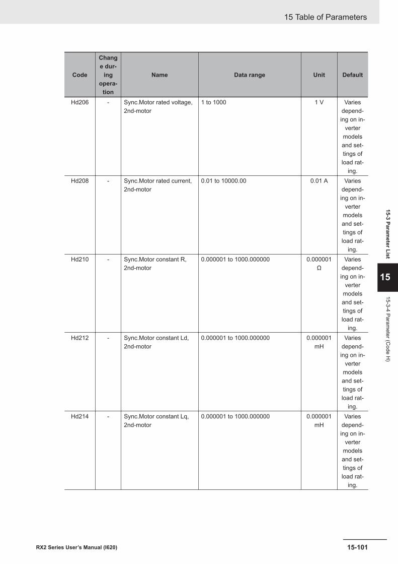
Code
Change dur-
ingopera-
tion
Name Data range Unit Default
Hd206 - Sync.Motor rated voltage,2nd-motor
1 to 1000 1 V Variesdepend-ing on in-
vertermodelsand set-tings ofload rat-
ing.Hd208 - Sync.Motor rated current,
2nd-motor0.01 to 10000.00 0.01 A Varies
depend-ing on in-
vertermodelsand set-tings ofload rat-
ing.Hd210 - Sync.Motor constant R,
2nd-motor0.000001 to 1000.000000 0.000001
ΩVaries
depend-ing on in-
vertermodelsand set-tings ofload rat-
ing.Hd212 - Sync.Motor constant Ld,
2nd-motor0.000001 to 1000.000000 0.000001
mHVaries
depend-ing on in-
vertermodelsand set-tings ofload rat-
ing.Hd214 - Sync.Motor constant Lq,
2nd-motor0.000001 to 1000.000000 0.000001
mHVaries
depend-ing on in-
vertermodelsand set-tings ofload rat-
ing.
15 Table of Parameters
15-101RX2 Series User’s Manual (I620)
15-3 Parameter List
15
15-3-4 Parameter (C
ode H)
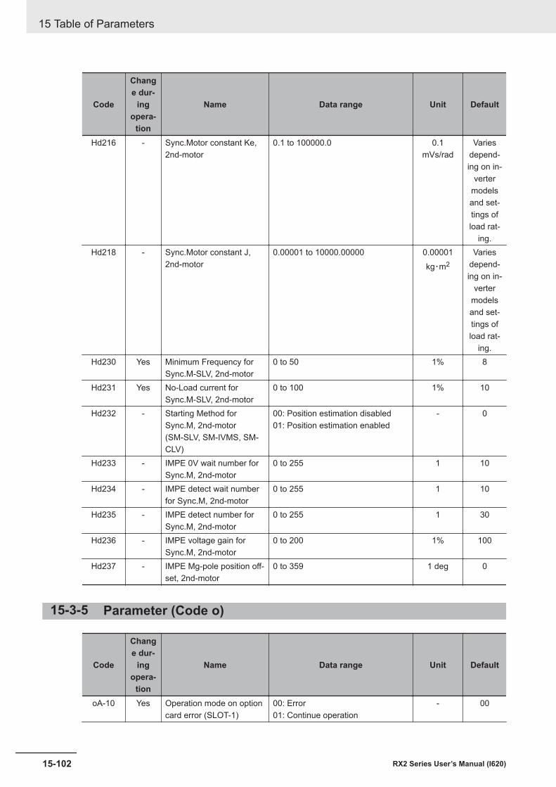
Code
Change dur-
ingopera-
tion
Name Data range Unit Default
Hd216 - Sync.Motor constant Ke,2nd-motor
0.1 to 100000.0 0.1mVs/rad
Variesdepend-ing on in-
vertermodelsand set-tings ofload rat-
ing.Hd218 - Sync.Motor constant J,
2nd-motor0.00001 to 10000.00000 0.00001
kg・m2Varies
depend-ing on in-
vertermodelsand set-tings ofload rat-
ing.Hd230 Yes Minimum Frequency for
Sync.M-SLV, 2nd-motor0 to 50 1% 8
Hd231 Yes No-Load current forSync.M-SLV, 2nd-motor
0 to 100 1% 10
Hd232 - Starting Method forSync.M, 2nd-motor(SM-SLV, SM-IVMS, SM-CLV)
00: Position estimation disabled01: Position estimation enabled
- 0
Hd233 - IMPE 0V wait number forSync.M, 2nd-motor
0 to 255 1 10
Hd234 - IMPE detect wait numberfor Sync.M, 2nd-motor
0 to 255 1 10
Hd235 - IMPE detect number forSync.M, 2nd-motor
0 to 255 1 30
Hd236 - IMPE voltage gain forSync.M, 2nd-motor
0 to 200 1% 100
Hd237 - IMPE Mg-pole position off-set, 2nd-motor
0 to 359 1 deg 0
15-3-5 Parameter (Code o)
Code
Change dur-
ingopera-
tion
Name Data range Unit Default
oA-10 Yes Operation mode on optioncard error (SLOT-1)
00: Error01: Continue operation
- 00
15 Table of Parameters
15-102 RX2 Series User’s Manual (I620)
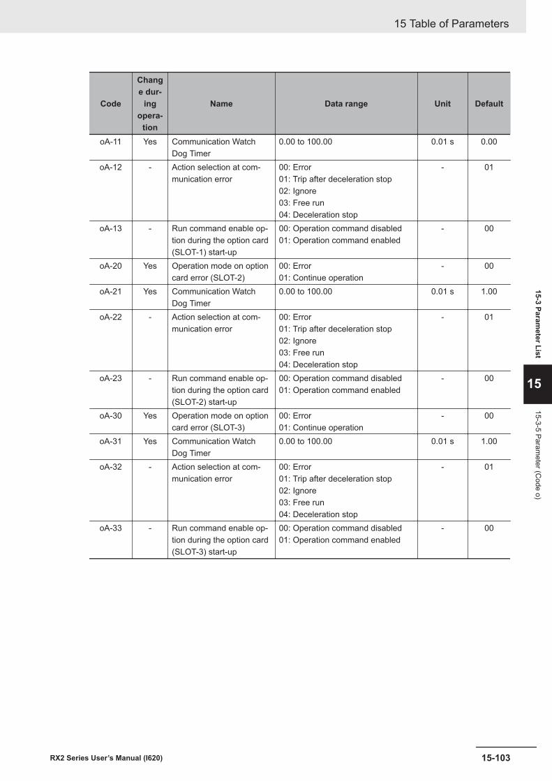
Code
Change dur-
ingopera-
tion
Name Data range Unit Default
oA-11 Yes Communication WatchDog Timer
0.00 to 100.00 0.01 s 0.00
oA-12 - Action selection at com-munication error
00: Error01: Trip after deceleration stop02: Ignore03: Free run04: Deceleration stop
- 01
oA-13 - Run command enable op-tion during the option card(SLOT-1) start-up
00: Operation command disabled01: Operation command enabled
- 00
oA-20 Yes Operation mode on optioncard error (SLOT-2)
00: Error01: Continue operation
- 00
oA-21 Yes Communication WatchDog Timer
0.00 to 100.00 0.01 s 1.00
oA-22 - Action selection at com-munication error
00: Error01: Trip after deceleration stop02: Ignore03: Free run04: Deceleration stop
- 01
oA-23 - Run command enable op-tion during the option card(SLOT-2) start-up
00: Operation command disabled01: Operation command enabled
- 00
oA-30 Yes Operation mode on optioncard error (SLOT-3)
00: Error01: Continue operation
- 00
oA-31 Yes Communication WatchDog Timer
0.00 to 100.00 0.01 s 1.00
oA-32 - Action selection at com-munication error
00: Error01: Trip after deceleration stop02: Ignore03: Free run04: Deceleration stop
- 01
oA-33 - Run command enable op-tion during the option card(SLOT-3) start-up
00: Operation command disabled01: Operation command enabled
- 00
15 Table of Parameters
15-103RX2 Series User’s Manual (I620)
15-3 Parameter List
15
15-3-5 Parameter (C
ode o)
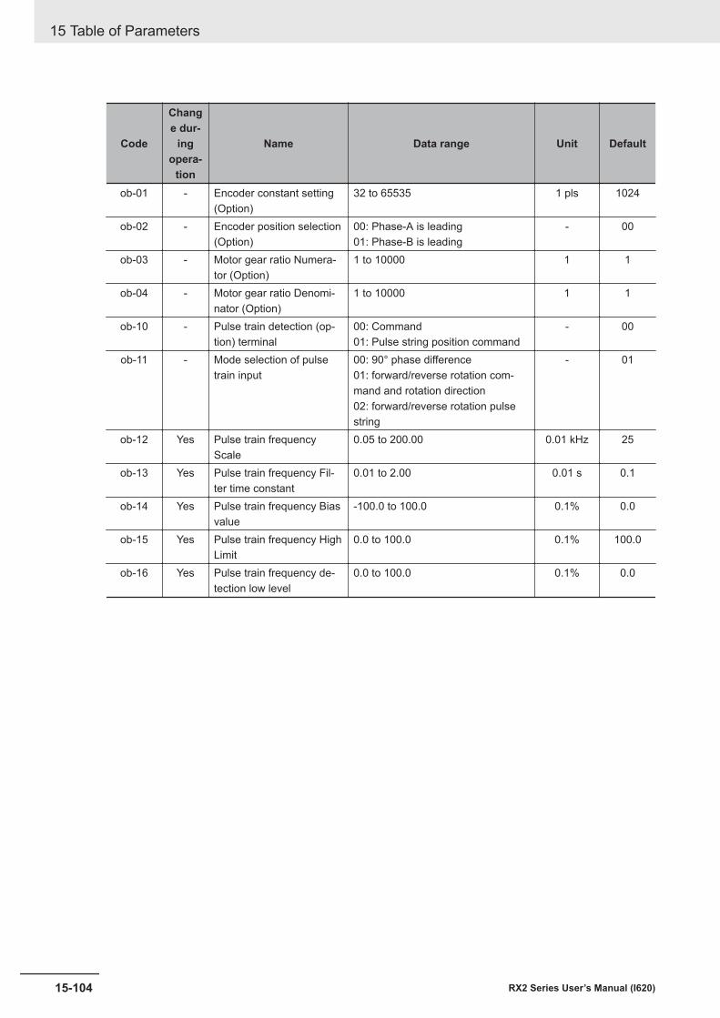
Code
Change dur-
ingopera-
tion
Name Data range Unit Default
ob-01 - Encoder constant setting(Option)
32 to 65535 1 pls 1024
ob-02 - Encoder position selection(Option)
00: Phase-A is leading01: Phase-B is leading
- 00
ob-03 - Motor gear ratio Numera-tor (Option)
1 to 10000 1 1
ob-04 - Motor gear ratio Denomi-nator (Option)
1 to 10000 1 1
ob-10 - Pulse train detection (op-tion) terminal
00: Command01: Pulse string position command
- 00
ob-11 - Mode selection of pulsetrain input
00: 90° phase difference01: forward/reverse rotation com-mand and rotation direction02: forward/reverse rotation pulsestring
- 01
ob-12 Yes Pulse train frequencyScale
0.05 to 200.00 0.01 kHz 25
ob-13 Yes Pulse train frequency Fil-ter time constant
0.01 to 2.00 0.01 s 0.1
ob-14 Yes Pulse train frequency Biasvalue
-100.0 to 100.0 0.1% 0.0
ob-15 Yes Pulse train frequency HighLimit
0.0 to 100.0 0.1% 100.0
ob-16 Yes Pulse train frequency de-tection low level
0.0 to 100.0 0.1% 0.0
15 Table of Parameters
15-104 RX2 Series User’s Manual (I620)
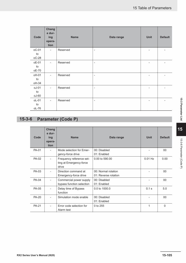
Code
Change dur-
ingopera-
tion
Name Data range Unit Default
oC-01to
oC-28
- Reserved - - -
oE-01to
oE-70
- Reserved - - -
oH-01to
oH-34
- Reserved - - -
oJ-01to
oJ-60
- Reserved - - -
oL-01to
oL-76
- Reserved - - -
15-3-6 Parameter (Code P)
Code
Change dur-
ingopera-
tion
Name Data range Unit Default
PA-01 - Mode selection for Emer-gency-force drive
00: Disabled01: Enabled
- 00
PA-02 - Frequency reference set-ting at Emergency-forcedrive
0.00 to 590.00 0.01 Hz 0.00
PA-03 - Direction command atEmergency-force drive
00: Normal rotation01: Reverse rotation
- 00
PA-04 - Commercial power supplybypass function selection
00: Disabled01: Enabled
- 00
PA-05 - Delay time of Bypassfunction
0.0 to 1000.0 0.1 s 5.0
PA-20 - Simulation mode enable 00: Disabled01: Enabled
- 00
PA-21 - Error code selection forAlarm test
0 to 255 1 0
15 Table of Parameters
15-105RX2 Series User’s Manual (I620)
15-3 Parameter List
15
15-3-6 Parameter (C
ode P)
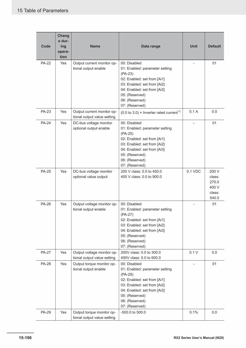
Code
Change dur-
ingopera-
tion
Name Data range Unit Default
PA-22 Yes Output current monitor op-tional output enable
00: Disabled01: Enabled: parameter setting(PA-23)02: Enabled: set from [Ai1]03: Enabled: set from [Ai2]04: Enabled: set from [Ai3]05: (Reserved)06: (Reserved)07: (Reserved)
- 01
PA-23 Yes Output current monitor op-tional output value setting
(0.0 to 3.0) × Inverter rated current*1 0.1 A 0.0
PA-24 Yes DC-bus voltage monitoroptional output enable
00: Disabled01: Enabled: parameter setting(PA-25)02: Enabled: set from [Ai1]03: Enabled: set from [Ai2]04: Enabled: set from [Ai3]05: (Reserved)06: (Reserved)07: (Reserved)
- 01
PA-25 Yes DC-bus voltage monitoroptional value output
200 V class: 0.0 to 450.0400 V class: 0.0 to 900.0
0.1 VDC 200 Vclass:270.0400 Vclass:540.0
PA-26 Yes Output voltage monitor op-tional output enable
00: Disabled01: Enabled: parameter setting(PA-27)02: Enabled: set from [Ai1]03: Enabled: set from [Ai2]04: Enabled: set from [Ai3]05: (Reserved)06: (Reserved)07: (Reserved)
- 01
PA-27 Yes Output voltage monitor op-tional output value setting
200V class: 0.0 to 300.0400V class: 0.0 to 600.0
0.1 V 0.0
PA-28 Yes Output torque monitor op-tional output enable
00: Disabled01: Enabled: parameter setting(PA-29)02: Enabled: set from [Ai1]03: Enabled: set from [Ai2]04: Enabled: set from [Ai3]05: (Reserved)06: (Reserved)07: (Reserved)
- 01
PA-29 Yes Output torque monitor op-tional output value setting
-500.0 to 500.0 0.1% 0.0
15 Table of Parameters
15-106 RX2 Series User’s Manual (I620)
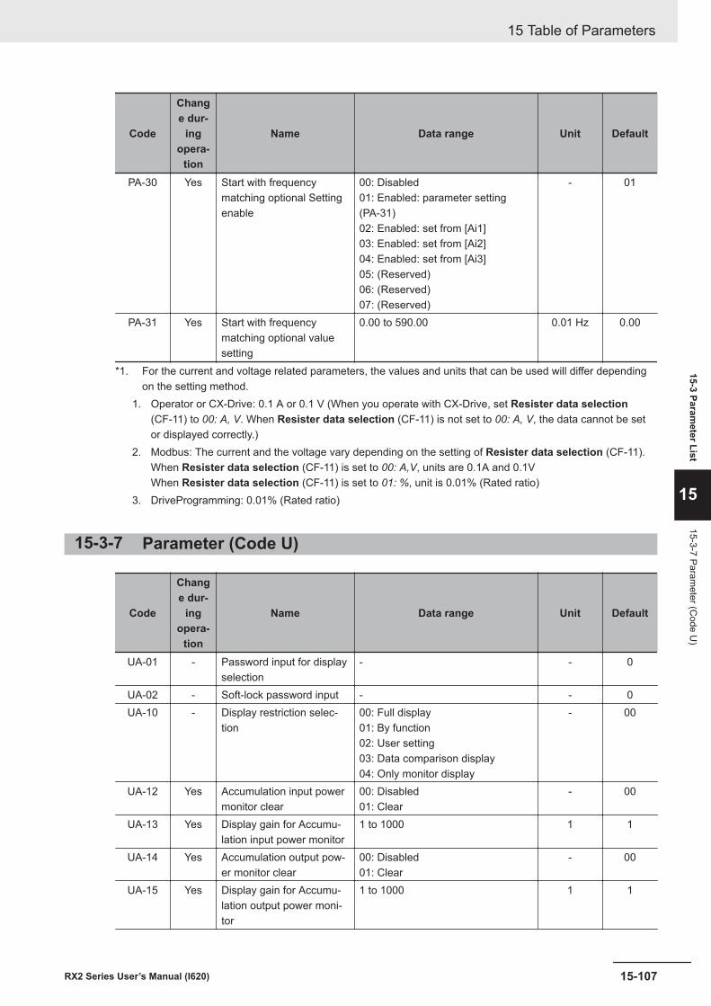
Code
Change dur-
ingopera-
tion
Name Data range Unit Default
PA-30 Yes Start with frequencymatching optional Settingenable
00: Disabled01: Enabled: parameter setting(PA-31)02: Enabled: set from [Ai1]03: Enabled: set from [Ai2]04: Enabled: set from [Ai3]05: (Reserved)06: (Reserved)07: (Reserved)
- 01
PA-31 Yes Start with frequencymatching optional valuesetting
0.00 to 590.00 0.01 Hz 0.00
*1. For the current and voltage related parameters, the values and units that can be used will differ dependingon the setting method.
1. Operator or CX-Drive: 0.1 A or 0.1 V (When you operate with CX-Drive, set Resister data selection(CF-11) to 00: A, V. When Resister data selection (CF-11) is not set to 00: A, V, the data cannot be setor displayed correctly.)
2. Modbus: The current and the voltage vary depending on the setting of Resister data selection (CF-11).When Resister data selection (CF-11) is set to 00: A,V, units are 0.1A and 0.1VWhen Resister data selection (CF-11) is set to 01: %, unit is 0.01% (Rated ratio)
3. DriveProgramming: 0.01% (Rated ratio)
15-3-7 Parameter (Code U)
Code
Change dur-
ingopera-
tion
Name Data range Unit Default
UA-01 - Password input for displayselection
- - 0
UA-02 - Soft-lock password input - - 0UA-10 - Display restriction selec-
tion00: Full display01: By function02: User setting03: Data comparison display04: Only monitor display
- 00
UA-12 Yes Accumulation input powermonitor clear
00: Disabled01: Clear
- 00
UA-13 Yes Display gain for Accumu-lation input power monitor
1 to 1000 1 1
UA-14 Yes Accumulation output pow-er monitor clear
00: Disabled01: Clear
- 00
UA-15 Yes Display gain for Accumu-lation output power moni-tor
1 to 1000 1 1
15 Table of Parameters
15-107RX2 Series User’s Manual (I620)
15-3 Parameter List
15
15-3-7 Parameter (C
ode U)
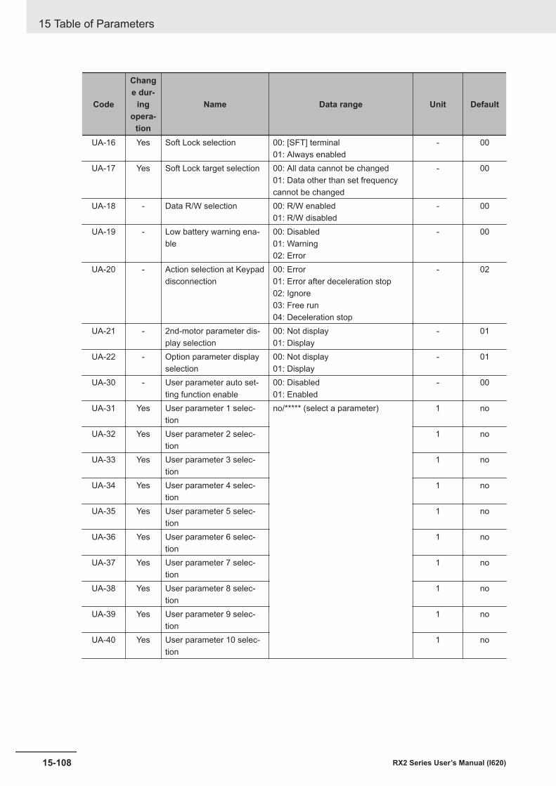
Code
Change dur-
ingopera-
tion
Name Data range Unit Default
UA-16 Yes Soft Lock selection 00: [SFT] terminal01: Always enabled
- 00
UA-17 Yes Soft Lock target selection 00: All data cannot be changed01: Data other than set frequencycannot be changed
- 00
UA-18 - Data R/W selection 00: R/W enabled01: R/W disabled
- 00
UA-19 - Low battery warning ena-ble
00: Disabled01: Warning02: Error
- 00
UA-20 - Action selection at Keypaddisconnection
00: Error01: Error after deceleration stop02: Ignore03: Free run04: Deceleration stop
- 02
UA-21 - 2nd-motor parameter dis-play selection
00: Not display01: Display
- 01
UA-22 - Option parameter displayselection
00: Not display01: Display
- 01
UA-30 - User parameter auto set-ting function enable
00: Disabled01: Enabled
- 00
UA-31 Yes User parameter 1 selec-tion
no/***** (select a parameter) 1 no
UA-32 Yes User parameter 2 selec-tion
1 no
UA-33 Yes User parameter 3 selec-tion
1 no
UA-34 Yes User parameter 4 selec-tion
1 no
UA-35 Yes User parameter 5 selec-tion
1 no
UA-36 Yes User parameter 6 selec-tion
1 no
UA-37 Yes User parameter 7 selec-tion
1 no
UA-38 Yes User parameter 8 selec-tion
1 no
UA-39 Yes User parameter 9 selec-tion
1 no
UA-40 Yes User parameter 10 selec-tion
1 no
15 Table of Parameters
15-108 RX2 Series User’s Manual (I620)
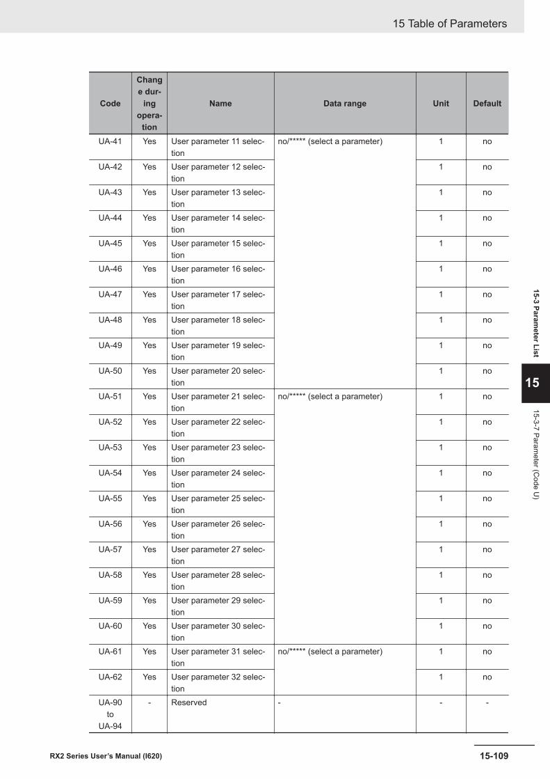
Code
Change dur-
ingopera-
tion
Name Data range Unit Default
UA-41 Yes User parameter 11 selec-tion
no/***** (select a parameter) 1 no
UA-42 Yes User parameter 12 selec-tion
1 no
UA-43 Yes User parameter 13 selec-tion
1 no
UA-44 Yes User parameter 14 selec-tion
1 no
UA-45 Yes User parameter 15 selec-tion
1 no
UA-46 Yes User parameter 16 selec-tion
1 no
UA-47 Yes User parameter 17 selec-tion
1 no
UA-48 Yes User parameter 18 selec-tion
1 no
UA-49 Yes User parameter 19 selec-tion
1 no
UA-50 Yes User parameter 20 selec-tion
1 no
UA-51 Yes User parameter 21 selec-tion
no/***** (select a parameter) 1 no
UA-52 Yes User parameter 22 selec-tion
1 no
UA-53 Yes User parameter 23 selec-tion
1 no
UA-54 Yes User parameter 24 selec-tion
1 no
UA-55 Yes User parameter 25 selec-tion
1 no
UA-56 Yes User parameter 26 selec-tion
1 no
UA-57 Yes User parameter 27 selec-tion
1 no
UA-58 Yes User parameter 28 selec-tion
1 no
UA-59 Yes User parameter 29 selec-tion
1 no
UA-60 Yes User parameter 30 selec-tion
1 no
UA-61 Yes User parameter 31 selec-tion
no/***** (select a parameter) 1 no
UA-62 Yes User parameter 32 selec-tion
1 no
UA-90to
UA-94
- Reserved - - -
15 Table of Parameters
15-109RX2 Series User’s Manual (I620)
15-3 Parameter List
15
15-3-7 Parameter (C
ode U)
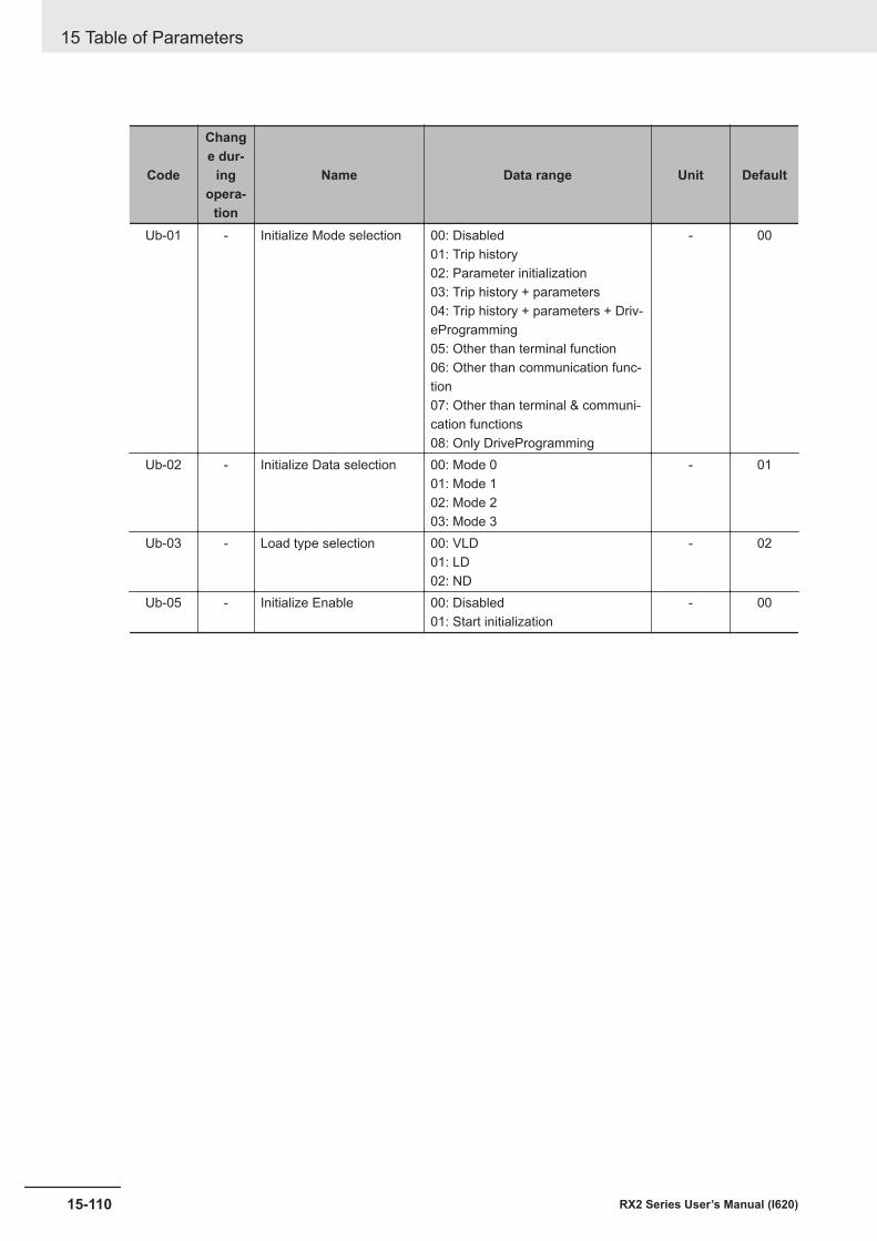
Code
Change dur-
ingopera-
tion
Name Data range Unit Default
Ub-01 - Initialize Mode selection 00: Disabled01: Trip history02: Parameter initialization03: Trip history + parameters04: Trip history + parameters + Driv-eProgramming05: Other than terminal function06: Other than communication func-tion07: Other than terminal & communi-cation functions08: Only DriveProgramming
- 00
Ub-02 - Initialize Data selection 00: Mode 001: Mode 102: Mode 203: Mode 3
- 01
Ub-03 - Load type selection 00: VLD01: LD02: ND
- 02
Ub-05 - Initialize Enable 00: Disabled01: Start initialization
- 00
15 Table of Parameters
15-110 RX2 Series User’s Manual (I620)

Code
Change dur-
ingopera-
tion
Name Data range Unit Default
UC-01 Yes Debug mode enable (do not change) 1 0
15 Table of Parameters
15-111RX2 Series User’s Manual (I620)
15-3 Parameter List
15
15-3-7 Parameter (C
ode U)

Code
Change dur-
ingopera-
tion
Name Data range Unit Default
Ud-01to
Ud-60
- Reserved - - -
15 Table of Parameters
15-112 RX2 Series User’s Manual (I620)
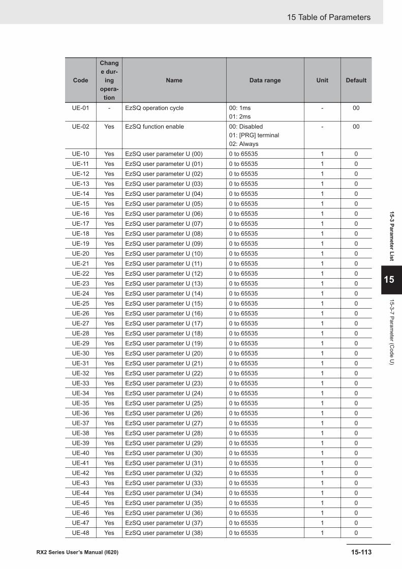
Code
Change dur-
ingopera-
tion
Name Data range Unit Default
UE-01 - EzSQ operation cycle 00: 1ms01: 2ms
- 00
UE-02 Yes EzSQ function enable 00: Disabled01: [PRG] terminal02: Always
- 00
UE-10 Yes EzSQ user parameter U (00) 0 to 65535 1 0UE-11 Yes EzSQ user parameter U (01) 0 to 65535 1 0UE-12 Yes EzSQ user parameter U (02) 0 to 65535 1 0UE-13 Yes EzSQ user parameter U (03) 0 to 65535 1 0UE-14 Yes EzSQ user parameter U (04) 0 to 65535 1 0UE-15 Yes EzSQ user parameter U (05) 0 to 65535 1 0UE-16 Yes EzSQ user parameter U (06) 0 to 65535 1 0UE-17 Yes EzSQ user parameter U (07) 0 to 65535 1 0UE-18 Yes EzSQ user parameter U (08) 0 to 65535 1 0UE-19 Yes EzSQ user parameter U (09) 0 to 65535 1 0UE-20 Yes EzSQ user parameter U (10) 0 to 65535 1 0UE-21 Yes EzSQ user parameter U (11) 0 to 65535 1 0UE-22 Yes EzSQ user parameter U (12) 0 to 65535 1 0UE-23 Yes EzSQ user parameter U (13) 0 to 65535 1 0UE-24 Yes EzSQ user parameter U (14) 0 to 65535 1 0UE-25 Yes EzSQ user parameter U (15) 0 to 65535 1 0UE-26 Yes EzSQ user parameter U (16) 0 to 65535 1 0UE-27 Yes EzSQ user parameter U (17) 0 to 65535 1 0UE-28 Yes EzSQ user parameter U (18) 0 to 65535 1 0UE-29 Yes EzSQ user parameter U (19) 0 to 65535 1 0UE-30 Yes EzSQ user parameter U (20) 0 to 65535 1 0UE-31 Yes EzSQ user parameter U (21) 0 to 65535 1 0UE-32 Yes EzSQ user parameter U (22) 0 to 65535 1 0UE-33 Yes EzSQ user parameter U (23) 0 to 65535 1 0UE-34 Yes EzSQ user parameter U (24) 0 to 65535 1 0UE-35 Yes EzSQ user parameter U (25) 0 to 65535 1 0UE-36 Yes EzSQ user parameter U (26) 0 to 65535 1 0UE-37 Yes EzSQ user parameter U (27) 0 to 65535 1 0UE-38 Yes EzSQ user parameter U (28) 0 to 65535 1 0UE-39 Yes EzSQ user parameter U (29) 0 to 65535 1 0UE-40 Yes EzSQ user parameter U (30) 0 to 65535 1 0UE-41 Yes EzSQ user parameter U (31) 0 to 65535 1 0UE-42 Yes EzSQ user parameter U (32) 0 to 65535 1 0UE-43 Yes EzSQ user parameter U (33) 0 to 65535 1 0UE-44 Yes EzSQ user parameter U (34) 0 to 65535 1 0UE-45 Yes EzSQ user parameter U (35) 0 to 65535 1 0UE-46 Yes EzSQ user parameter U (36) 0 to 65535 1 0UE-47 Yes EzSQ user parameter U (37) 0 to 65535 1 0UE-48 Yes EzSQ user parameter U (38) 0 to 65535 1 0
15 Table of Parameters
15-113RX2 Series User’s Manual (I620)
15-3 Parameter List
15
15-3-7 Parameter (C
ode U)
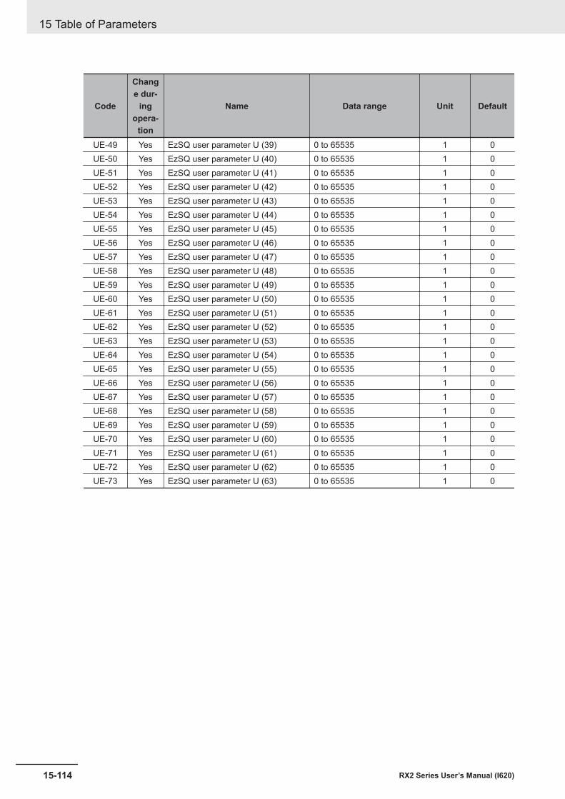
Code
Change dur-
ingopera-
tion
Name Data range Unit Default
UE-49 Yes EzSQ user parameter U (39) 0 to 65535 1 0UE-50 Yes EzSQ user parameter U (40) 0 to 65535 1 0UE-51 Yes EzSQ user parameter U (41) 0 to 65535 1 0UE-52 Yes EzSQ user parameter U (42) 0 to 65535 1 0UE-53 Yes EzSQ user parameter U (43) 0 to 65535 1 0UE-54 Yes EzSQ user parameter U (44) 0 to 65535 1 0UE-55 Yes EzSQ user parameter U (45) 0 to 65535 1 0UE-56 Yes EzSQ user parameter U (46) 0 to 65535 1 0UE-57 Yes EzSQ user parameter U (47) 0 to 65535 1 0UE-58 Yes EzSQ user parameter U (48) 0 to 65535 1 0UE-59 Yes EzSQ user parameter U (49) 0 to 65535 1 0UE-60 Yes EzSQ user parameter U (50) 0 to 65535 1 0UE-61 Yes EzSQ user parameter U (51) 0 to 65535 1 0UE-62 Yes EzSQ user parameter U (52) 0 to 65535 1 0UE-63 Yes EzSQ user parameter U (53) 0 to 65535 1 0UE-64 Yes EzSQ user parameter U (54) 0 to 65535 1 0UE-65 Yes EzSQ user parameter U (55) 0 to 65535 1 0UE-66 Yes EzSQ user parameter U (56) 0 to 65535 1 0UE-67 Yes EzSQ user parameter U (57) 0 to 65535 1 0UE-68 Yes EzSQ user parameter U (58) 0 to 65535 1 0UE-69 Yes EzSQ user parameter U (59) 0 to 65535 1 0UE-70 Yes EzSQ user parameter U (60) 0 to 65535 1 0UE-71 Yes EzSQ user parameter U (61) 0 to 65535 1 0UE-72 Yes EzSQ user parameter U (62) 0 to 65535 1 0UE-73 Yes EzSQ user parameter U (63) 0 to 65535 1 0
15 Table of Parameters
15-114 RX2 Series User’s Manual (I620)
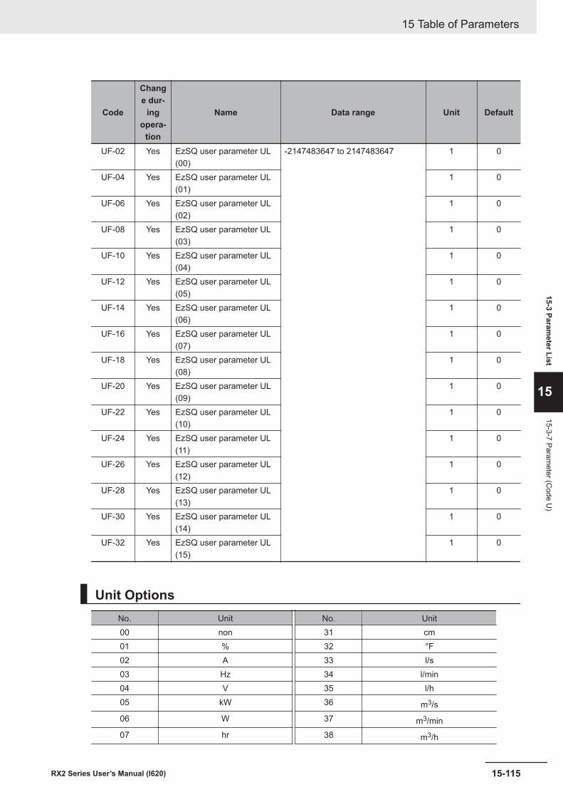
Code
Change dur-
ingopera-
tion
Name Data range Unit Default
UF-02 Yes EzSQ user parameter UL(00)
-2147483647 to 2147483647 1 0
UF-04 Yes EzSQ user parameter UL(01)
1 0
UF-06 Yes EzSQ user parameter UL(02)
1 0
UF-08 Yes EzSQ user parameter UL(03)
1 0
UF-10 Yes EzSQ user parameter UL(04)
1 0
UF-12 Yes EzSQ user parameter UL(05)
1 0
UF-14 Yes EzSQ user parameter UL(06)
1 0
UF-16 Yes EzSQ user parameter UL(07)
1 0
UF-18 Yes EzSQ user parameter UL(08)
1 0
UF-20 Yes EzSQ user parameter UL(09)
1 0
UF-22 Yes EzSQ user parameter UL(10)
1 0
UF-24 Yes EzSQ user parameter UL(11)
1 0
UF-26 Yes EzSQ user parameter UL(12)
1 0
UF-28 Yes EzSQ user parameter UL(13)
1 0
UF-30 Yes EzSQ user parameter UL(14)
1 0
UF-32 Yes EzSQ user parameter UL(15)
1 0
Unit OptionsNo. Unit No. Unit00 non 31 cm01 % 32 °F02 A 33 l/s03 Hz 34 l/min04 V 35 l/h05 kW 36 m3/s06 W 37 m3/min07 hr 38 m3/h
15 Table of Parameters
15-115RX2 Series User’s Manual (I620)
15-3 Parameter List
15
15-3-7 Parameter (C
ode U)
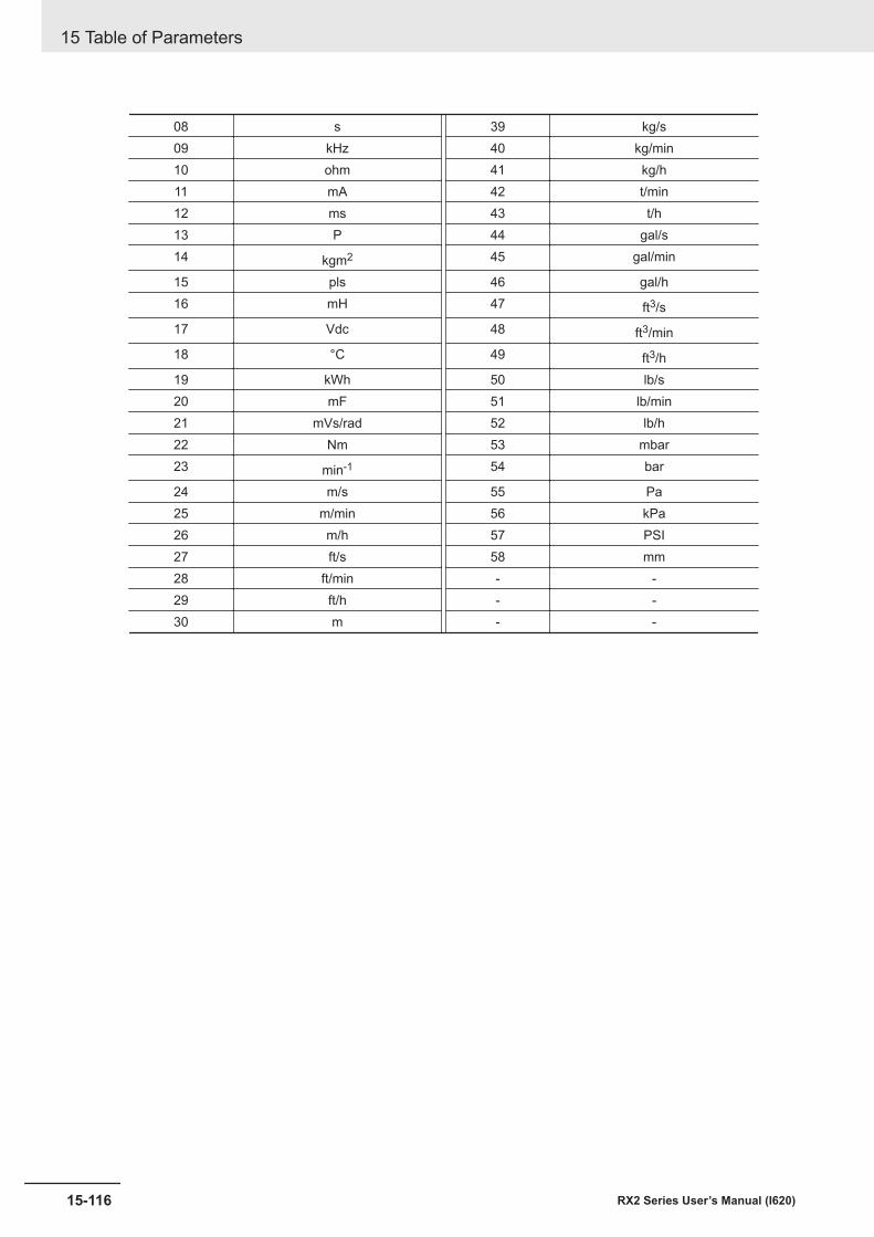
08 s 39 kg/s09 kHz 40 kg/min10 ohm 41 kg/h11 mA 42 t/min12 ms 43 t/h13 P 44 gal/s14 kgm2 45 gal/min
15 pls 46 gal/h16 mH 47 ft3/s17 Vdc 48 ft3/min18 °C 49 ft3/h19 kWh 50 lb/s20 mF 51 lb/min21 mVs/rad 52 lb/h22 Nm 53 mbar23 min-1 54 bar
24 m/s 55 Pa25 m/min 56 kPa26 m/h 57 PSI27 ft/s 58 mm28 ft/min - -29 ft/h - -30 m - -
15 Table of Parameters
15-116 RX2 Series User’s Manual (I620)
AAppendix
A-1 Overview of Inverter Selection..................................................................... A-2A-1-1 Motor Capacity Selection ................................................................................A-2A-1-2 Inverter Capacity Selection .............................................................................A-6A-1-3 Overview of Braking Resistor Selection ..........................................................A-6
A-1RX2 Series User’s Manual (I620)
A
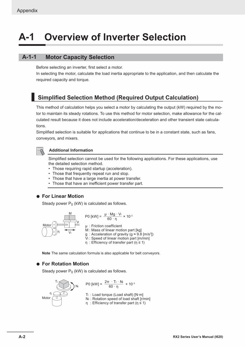
A-1 Overview of Inverter Selection
A-1-1 Motor Capacity SelectionBefore selecting an inverter, first select a motor.In selecting the motor, calculate the load inertia appropriate to the application, and then calculate therequired capacity and torque.
Simplified Selection Method (Required Output Calculation)This method of calculation helps you select a motor by calculating the output (kW) required by the mo-tor to maintain its steady rotations. To use this method for motor selection, make allowance for the cal-culated result because it does not include acceleration/deceleration and other transient state calcula-tions.Simplified selection is suitable for applications that continue to be in a constant state, such as fans,conveyors, and mixers.
Additional Information
Simplified selection cannot be used for the following applications. For these applications, usethe detailed selection method.• Those requiring rapid startup (acceleration).• Those that frequently repeat run and stop.• Those that have a large inertia at power transfer.• Those that have an inefficient power transfer part.
l For Linear MotionSteady power P0 (kW) is calculated as follows.
Motor
η Vl
MP0 [kW] =
μ : Friction coefficientM : Mass of linear motion part [kg]g : Acceleration of gravity (g ≈ 9.8 [m/s2]) Vl : Speed of linear motion part [m/min]η : Efficiency of transfer part (η ≤ 1)
× 10-3
μ
μ · Mg · Vl
60 · η
Note The same calculation formula is also applicable for belt conveyors.
l For Rotation MotionSteady power P0 (kW) is calculated as follows.
60 · η
2π · Tl · Nl× 10-3
Tl : Load torque (Load shaft) [N·m]Nl : Rotation speed of load shaft [r/min]η : Efficiency of transfer part (η ≤ 1)
P0 [kW] =
Motor
η
Tl
Nl
Appendix
A-2 RX2 Series User’s Manual (I620)
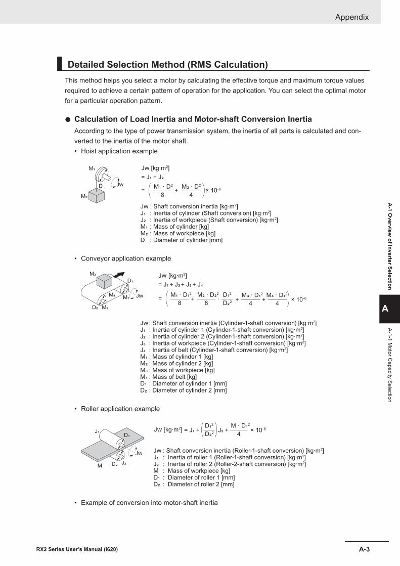
Detailed Selection Method (RMS Calculation)This method helps you select a motor by calculating the effective torque and maximum torque valuesrequired to achieve a certain pattern of operation for the application. You can select the optimal motorfor a particular operation pattern.
l Calculation of Load Inertia and Motor-shaft Conversion InertiaAccording to the type of power transmission system, the inertia of all parts is calculated and con-verted to the inertia of the motor shaft.• Hoist application example
× 10-6
4
M� · D2
+8
M! · D2
=
= J! + J�
J" [kg·m2]
J" : Shaft conversion inertia [kg·m2] J! : Inertia of cylinder (Shaft conversion) [kg·m2]J� : Inertia of workpiece (Shaft conversion) [kg·m2] M! : Mass of cylinder [kg]M� : Mass of workpiece [kg]D : Diameter of cylinder [mm]
J"
M!
M�
D
• Conveyor application example
J : Shaft conversion inertia (Cylinder-1-shaft conversion) [kg·m2]
J" : Inertia of cylinder 1 (Cylinder-1-shaft conversion) [kg·m2] J# : Inertia of cylinder 2 (Cylinder-1-shaft conversion) [kg·m2]J$ : Inertia of workpiece (Cylinder-1-shaft conversion) [kg·m2]J% : Inertia of belt (Cylinder-1-shaft conversion) [kg·m2]M" : Mass of cylinder 1 [kg]M#
: Mass of cylinder 2 [kg]
M$ : Mass of workpiece [kg]M% : Mass of belt [kg]D" : Diameter of cylinder 1 [mm] D# : Diameter of cylinder 2 [mm]
4
M% · D"2
+4
M$ · D"2
+D#2
D"2
· × 10-6
8
M# · D#2
+8
M" · D"2
=
= J" + J#
+ J$
+ J%
J [kg·m2]
J
D"
M"
M$
M%
M#D#
• Roller application example
J : Shaft conversion inertia (Roller-1-shaft conversion) [kg·m2] J" : Inertia of roller 1 (Roller-1-shaft conversion) [kg·m2] J# : Inertia of roller 2 (Roller-2-shaft conversion) [kg·m2] M : Mass of workpiece [kg]D" : Diameter of roller 1 [mm]D# : Diameter of roller 2 [mm]
× 10-6
4
M · D"2
J# + D#2
D"2
= J" + J [kg·m2]
J
D"J"
MJ#D#
• Example of conversion into motor-shaft inertia
Appendix
A-3RX2 Series User’s Manual (I620)
A-1 O
verview of Inverter Selection
A
A-1-1 Motor C
apacity Selection
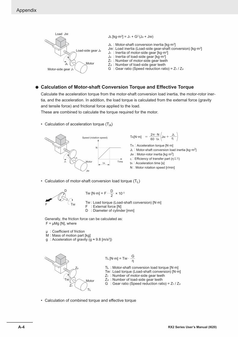
J� [kg·m2] = J� + G2 (J� + J�)
J� : Motor-shaft conversion inertia [kg·m2]
J� : Load inertia (Load-side gear-shaft conversion) [kg·m2]
J�
: Inertia of motor-side gear [kg·m2] J�
: Inertia of load-side gear [kg·m2]
Z� : Number of motor-side gear teeth
Z� : Number of load-side gear teeth
G : Gear ratio (Speed reduction ratio) = Z� / Z�
Load-side gear J�
Motor-side gear J�
J�
Load J�
Motor
l Calculation of Motor-shaft Conversion Torque and Effective TorqueCalculate the acceleration torque from the motor-shaft conversion load inertia, the motor-rotor iner-tia, and the acceleration. In addition, the load torque is calculated from the external force (gravityand tensile force) and frictional force applied to the load.These are combined to calculate the torque required for the motor.
• Calculation of acceleration torque (TA)
JL
JM
η
N
tA
TA:Acceleration torque [N·m]
JL:Motor-shaft conversion load inertia [kg·m2]
JM:Motor-rotor inertia [kg·m2]
η:Efficiency of transfer part (η≦1)
tA:Acceleration time [s]
N:Motor rotation speed [r/min]
Motor
Speed (rotation speed)
Time
+JM60・tA2π・N
η JL
= TA[N·m]
• Calculation of motor-shaft conversion load torque (TL)
2
D T! [N·m] = F ·
F = μMg [N], where
μ : Coefficient of friction M : Mass of motion part [kg] g : Acceleration of gravity (g ≈ 9.8 [m/s2])
Generally, the friction force can be calculated as:
T!
D
FT!
: Load torque (Load-shaft conversion) [N·m]
F : External force [N] D : Diameter of cylinder [mm]
× 10-3
T� : Motor-shaft conversion load torque [N·m]
T� : Load torque (Load-shaft conversion) [N·m]
Z�
: Number of motor-side gear teeth Z�
: Number of load-side gear teeth
G : Gear ratio (Speed reduction ratio) = Z� / Z�
G
ηT�
[N·m] = T�
·
Z�
T�
Z�
Motor
T�
• Calculation of combined torque and effective torque
Appendix
A-4 RX2 Series User’s Manual (I620)
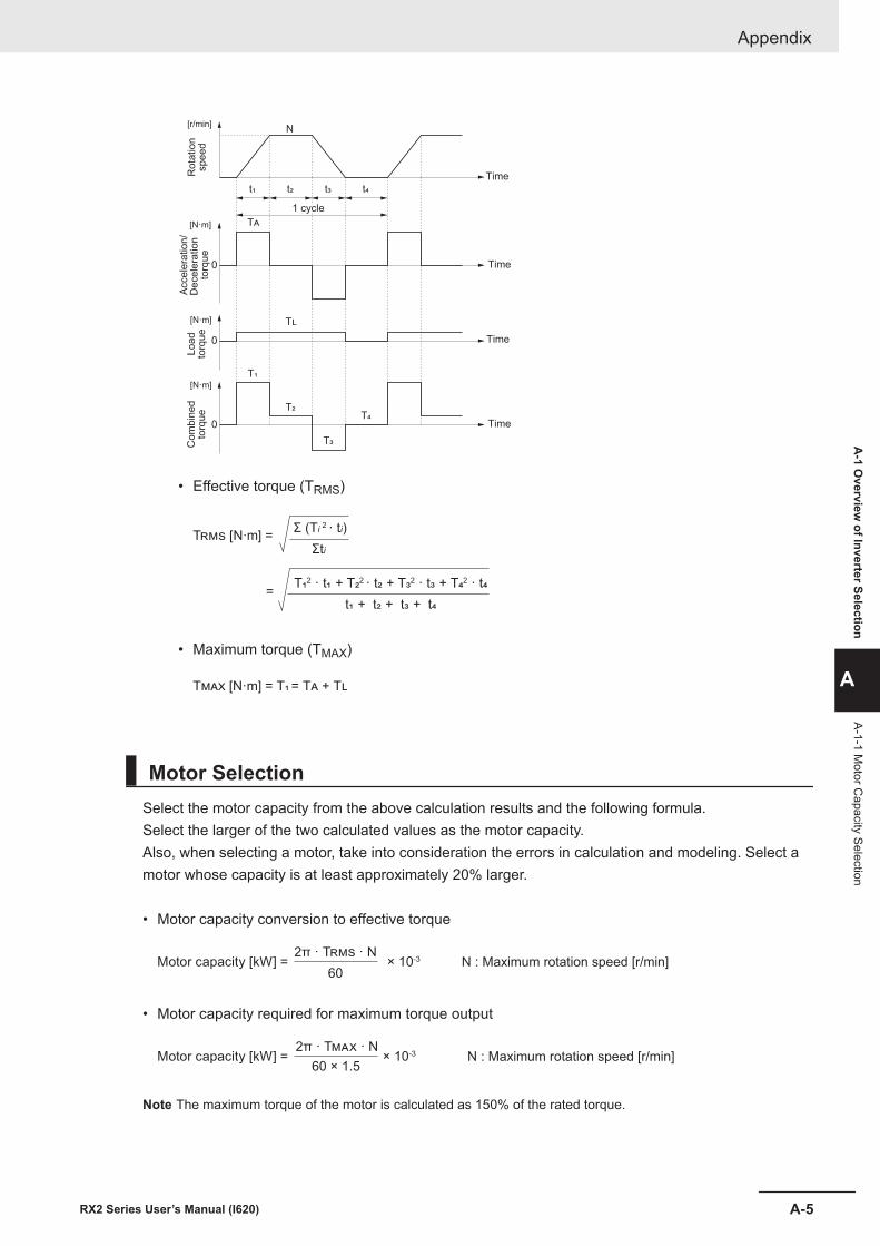
1サイクル
Time
1 cycle
Time
Time
Time
t!t" t#t$
T%
T&
N
T$
T!
T"T#
0
0
0
[r/min]
Ro
tatio
nsp
ee
d
[N·m]
Acce
lera
tio
n/
De
ce
lera
tio
n
torq
ue
Lo
ad
torq
ue
Co
mb
ine
dto
rqu
e
[N·m]
[N·m]
• Effective torque (TRMS)
T !" [N·m] =Σ (Ti
2 · ti)
Σti
= T%2 · t%
+ T&2 · t&
+ T'2 · t'
+ T*2 · t*
t% + t&
+ t'
+ t*
• Maximum torque (TMAX)
T��� [N·m] = T� = T� + T�
Motor SelectionSelect the motor capacity from the above calculation results and the following formula.Select the larger of the two calculated values as the motor capacity.Also, when selecting a motor, take into consideration the errors in calculation and modeling. Select amotor whose capacity is at least approximately 20% larger.
• Motor capacity conversion to effective torque
Motor capacity [kW] = × 10-3
60
2π · T"#$ · NN : Maximum rotation speed [r/min]
• Motor capacity required for maximum torque output
Motor capacity [kW] = × 10-3
60 × 1.5
2π · T"#$ · NN : Maximum rotation speed [r/min]
Note The maximum torque of the motor is calculated as 150% of the rated torque.
Appendix
A-5RX2 Series User’s Manual (I620)
A-1 O
verview of Inverter Selection
A
A-1-1 Motor C
apacity Selection
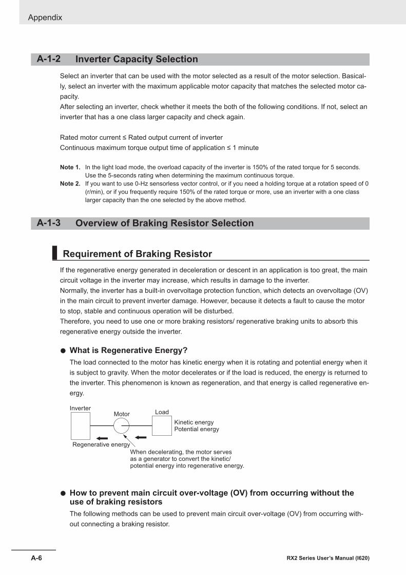
A-1-2 Inverter Capacity SelectionSelect an inverter that can be used with the motor selected as a result of the motor selection. Basical-ly, select an inverter with the maximum applicable motor capacity that matches the selected motor ca-pacity.After selecting an inverter, check whether it meets the both of the following conditions. If not, select aninverter that has a one class larger capacity and check again.
Rated motor current ≤ Rated output current of inverterContinuous maximum torque output time of application ≤ 1 minute
Note 1. In the light load mode, the overload capacity of the inverter is 150% of the rated torque for 5 seconds. Use the 5-seconds rating when determining the maximum continuous torque.
Note 2. If you want to use 0-Hz sensorless vector control, or if you need a holding torque at a rotation speed of 0(r/min), or if you frequently require 150% of the rated torque or more, use an inverter with a one classlarger capacity than the one selected by the above method.
A-1-3 Overview of Braking Resistor Selection
Requirement of Braking ResistorIf the regenerative energy generated in deceleration or descent in an application is too great, the maincircuit voltage in the inverter may increase, which results in damage to the inverter.Normally, the inverter has a built-in overvoltage protection function, which detects an overvoltage (OV)in the main circuit to prevent inverter damage. However, because it detects a fault to cause the motorto stop, stable and continuous operation will be disturbed.Therefore, you need to use one or more braking resistors/ regenerative braking units to absorb thisregenerative energy outside the inverter.
l What is Regenerative Energy?The load connected to the motor has kinetic energy when it is rotating and potential energy when itis subject to gravity. When the motor decelerates or if the load is reduced, the energy is returned tothe inverter. This phenomenon is known as regeneration, and that energy is called regenerative en-ergy.
When decelerating, the motor servesas a generator to convert the kinetic/potential energy into regenerative energy.
Kinetic energyPotential energy
Load Motor
Regenerative energy
Inverter
l How to prevent main circuit over-voltage (OV) from occurring without theuse of braking resistorsThe following methods can be used to prevent main circuit over-voltage (OV) from occurring with-out connecting a braking resistor.
Appendix
A-6 RX2 Series User’s Manual (I620)
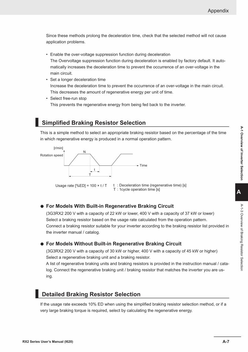
Since these methods prolong the deceleration time, check that the selected method will not causeapplication problems.
• Enable the over-voltage suppression function during decelerationThe Overvoltage suppression function during deceleration is enabled by factory default. It auto-matically increases the deceleration time to prevent the occurrence of an over-voltage in themain circuit.
• Set a longer deceleration timeIncrease the deceleration time to prevent the occurrence of an over-voltage in the main circuit.This decreases the amount of regenerative energy per unit of time.
• Select free-run stopThis prevents the regenerative energy from being fed back to the inverter.
Simplified Braking Resistor SelectionThis is a simple method to select an appropriate braking resistor based on the percentage of the timein which regenerative energy is produced in a normal operation pattern.
Time
Rotation speed
[r/min]
t
N
T
Usage rate [%ED] = 100 × t / T t : Deceleration time (regenerative time) [s]T : 1cycle operation time [s]
l For Models With Built-in Regenerative Braking Circuit(3G3RX2 200 V with a capacity of 22 kW or lower, 400 V with a capacity of 37 kW or lower)Select a braking resistor based on the usage rate calculated from the operation pattern.Connect a braking resistor suitable for your inverter according to the braking resistor list provided inthe inverter manual / catalog.
l For Models Without Built-in Regenerative Braking Circuit(3G3RX2 200 V with a capacity of 30 kW or higher, 400 V with a capacity of 45 kW or higher)Select a regenerative braking unit and a braking resistor.A list of regenerative braking units and braking resistors is provided in the instruction manual / cata-log. Connect the regenerative braking unit / braking resistor that matches the inverter you are us-ing.
Detailed Braking Resistor SelectionIf the usage rate exceeds 10% ED when using the simplified braking resistor selection method, or if avery large braking torque is required, select by calculating the regenerative energy.
Appendix
A-7RX2 Series User’s Manual (I620)
A-1 O
verview of Inverter Selection
A
A-1-3 Overview
of Braking Resistor Selection
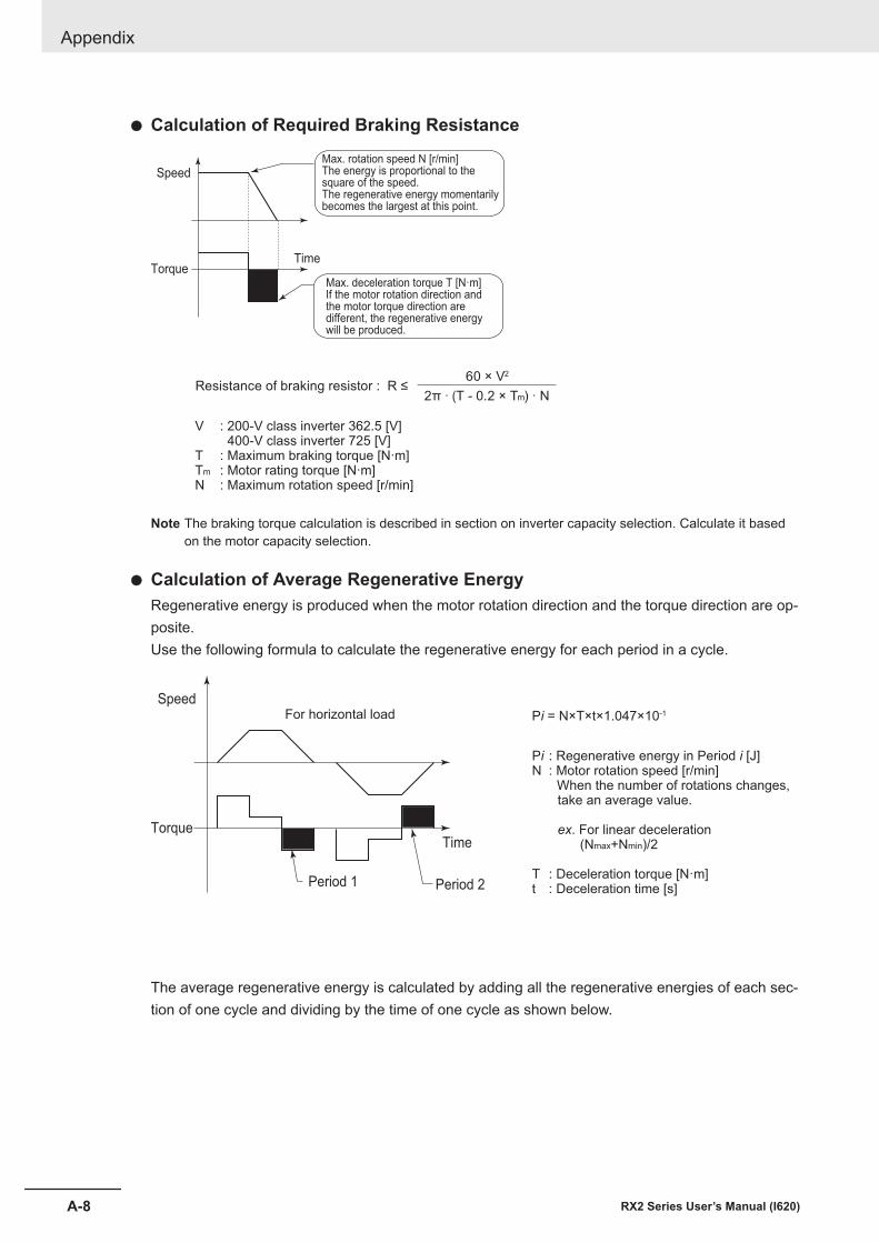
l Calculation of Required Braking Resistance
Max. deceleration torque T [N·m]If the motor rotation direction and the motor torque direction are different, the regenerative energy will be produced.
Max. rotation speed N [r/min]The energy is proportional to the square of the speed. The regenerative energy momentarilybecomes the largest at this point.
Speed
Time Torque
Resistance of braking resistor : R ≤60 × V2
2π · (T - 0.2 × Tm) · N
V : 200-V class inverter 362.5 [V] 400-V class inverter 725 [V]T : Maximum braking torque [N·m]Tm : Motor rating torque [N·m]N : Maximum rotation speed [r/min]
Note The braking torque calculation is described in section on inverter capacity selection. Calculate it basedon the motor capacity selection.
l Calculation of Average Regenerative EnergyRegenerative energy is produced when the motor rotation direction and the torque direction are op-posite.Use the following formula to calculate the regenerative energy for each period in a cycle.
Pi = N×T×t×1.047×10⁻¹
Pi : Regenerative energy in Period i [J]
N : Motor rotation speed [r/min] When the number of rotations changes, take an average value.
ex. For linear deceleration (Nmax+Nmin)/2
T : Deceleration torque [N·m]t : Deceleration time [s]
Time
Period 2Period 1
Torque
SpeedFor horizontal load
The average regenerative energy is calculated by adding all the regenerative energies of each sec-tion of one cycle and dividing by the time of one cycle as shown below.
Appendix
A-8 RX2 Series User’s Manual (I620)
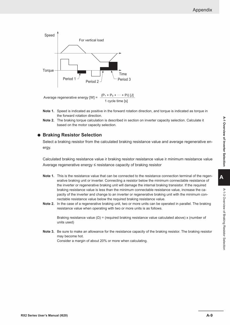
Average regenerative energy [W] =(P! + P" + ··· + Pi) [J]
1 cycle time [s]
For vertical load
Speed
Torque
Period 1Period 2
Period 3
Time
Note 1. Speed is indicated as positive in the forward rotation direction, and torque is indicated as torque inthe forward rotation direction.
Note 2. The braking torque calculation is described in section on inverter capacity selection. Calculate itbased on the motor capacity selection.
l Braking Resistor SelectionSelect a braking resistor from the calculated braking resistance value and average regenerative en-ergy.
Calculated braking resistance value ≥ braking resistor resistance value ≥ minimum resistance valueAverage regenerative energy ≤ resistance capacity of braking resistor
Note 1. This is the resistance value that can be connected to the resistance connection terminal of the regen-erative braking unit or inverter. Connecting a resistor below the minimum connectable resistance ofthe inverter or regenerative braking unit will damage the internal braking transistor. If the requiredbraking resistance value is less than the minimum connectable resistance value, increase the ca-pacity of the inverter and change to an inverter or regenerative braking unit with the minimum con-nectable resistance value below the required braking resistance value.
Note 2. In the case of a regenerative braking unit, two or more units can be operated in parallel. The brakingresistance value when operating with two or more units is as follows.
Braking resistance value (Ω) = (required braking resistance value calculated above) x (number ofunits used)
Note 3. Be sure to make an allowance for the resistance capacity of the braking resistor. The braking resistormay become hot.Consider a margin of about 20% or more when calculating.
Appendix
A-9RX2 Series User’s Manual (I620)
A-1 O
verview of Inverter Selection
A
A-1-3 Overview
of Braking Resistor Selection

Appendix
A-10 RX2 Series User’s Manual (I620)

IIndex
I-1RX2 Series User’s Manual (I620)
I
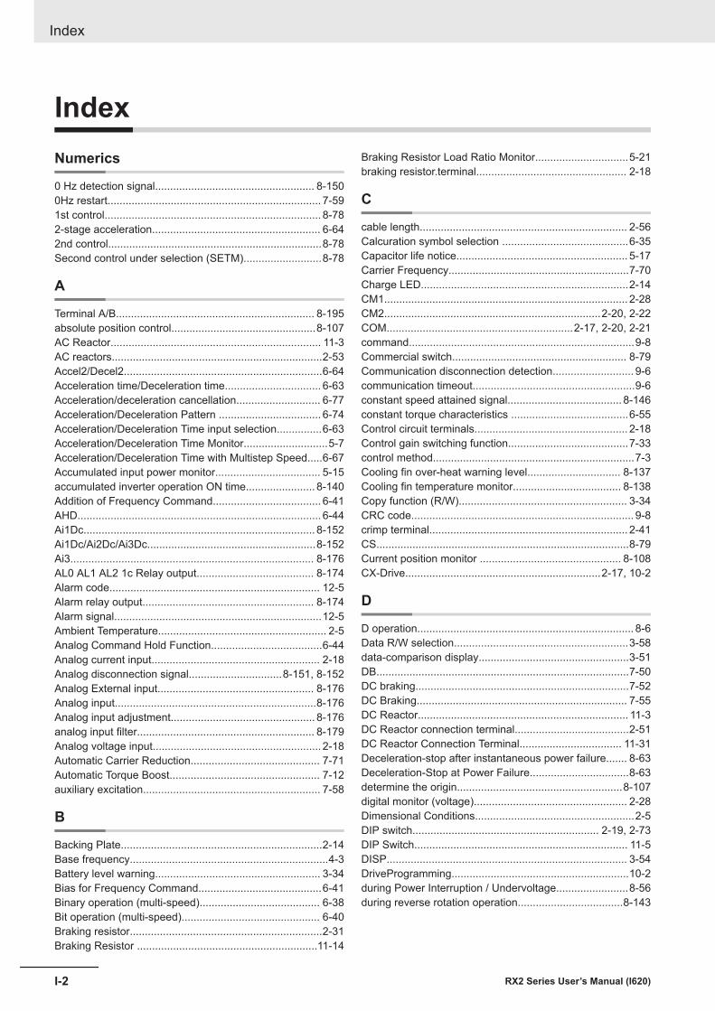
IndexNumerics
0 Hz detection signal..................................................... 8-1500Hz restart....................................................................... 7-591st control........................................................................ 8-782-stage acceleration........................................................ 6-642nd control.......................................................................8-78Second control under selection (SETM)..........................8-78
A
Terminal A/B.................................................................. 8-195absolute position control................................................8-107AC Reactor...................................................................... 11-3AC reactors......................................................................2-53Accel2/Decel2..................................................................6-64Acceleration time/Deceleration time................................ 6-63Acceleration/deceleration cancellation............................ 6-77Acceleration/Deceleration Pattern .................................. 6-74Acceleration/Deceleration Time input selection...............6-63Acceleration/Deceleration Time Monitor............................5-7Acceleration/Deceleration Time with Multistep Speed.....6-67Accumulated input power monitor................................... 5-15accumulated inverter operation ON time....................... 8-140Addition of Frequency Command.................................... 6-41AHD................................................................................. 6-44Ai1Dc............................................................................. 8-152Ai1Dc/Ai2Dc/Ai3Dc........................................................8-152Ai3................................................................................. 8-176AL0 AL1 AL2 1c Relay output....................................... 8-174Alarm code...................................................................... 12-5Alarm relay output......................................................... 8-174Alarm signal.....................................................................12-5Ambient Temperature........................................................ 2-5Analog Command Hold Function.....................................6-44Analog current input........................................................ 2-18Analog disconnection signal...............................8-151, 8-152Analog External input.................................................... 8-176Analog input...................................................................8-176Analog input adjustment................................................ 8-176analog input filter........................................................... 8-179Analog voltage input........................................................ 2-18Automatic Carrier Reduction........................................... 7-71Automatic Torque Boost.................................................. 7-12auxiliary excitation........................................................... 7-58
B
Backing Plate...................................................................2-14Base frequency..................................................................4-3Battery level warning....................................................... 3-34Bias for Frequency Command.........................................6-41Binary operation (multi-speed)........................................ 6-38Bit operation (multi-speed).............................................. 6-40Braking resistor................................................................2-31Braking Resistor ............................................................11-14
Braking Resistor Load Ratio Monitor...............................5-21braking resistor.terminal.................................................. 2-18
C
cable length..................................................................... 2-56Calcuration symbol selection ..........................................6-35Capacitor life notice......................................................... 5-17Carrier Frequency............................................................7-70Charge LED.....................................................................2-14CM1................................................................................. 2-28CM2........................................................................2-20, 2-22COM..............................................................2-17, 2-20, 2-21command...........................................................................9-8Commercial switch.......................................................... 8-79Communication disconnection detection........................... 9-6communication timeout......................................................9-6constant speed attained signal...................................... 8-146constant torque characteristics .......................................6-55Control circuit terminals................................................... 2-18Control gain switching function........................................7-33control method...................................................................7-3Cooling fin over-heat warning level............................... 8-137Cooling fin temperature monitor.................................... 8-138Copy function (R/W)........................................................ 3-34CRC code.......................................................................... 9-8crimp terminal.................................................................. 2-41CS....................................................................................8-79Current position monitor ............................................... 8-108CX-Drive.................................................................2-17, 10-2
D
D operation........................................................................ 8-6Data R/W selection..........................................................3-58data-comparison display..................................................3-51DB....................................................................................7-50DC braking.......................................................................7-52DC Braking...................................................................... 7-55DC Reactor...................................................................... 11-3DC Reactor connection terminal......................................2-51DC Reactor Connection Terminal.................................. 11-31Deceleration-stop after instantaneous power failure....... 8-63Deceleration-Stop at Power Failure.................................8-63determine the origin.......................................................8-107digital monitor (voltage)................................................... 2-28Dimensional Conditions.....................................................2-5DIP switch.............................................................. 2-19, 2-73DIP Switch....................................................................... 11-5DISP................................................................................ 3-54DriveProgramming...........................................................10-2during Power Interruption / Undervoltage........................8-56during reverse rotation operation...................................8-143
Index
I-2 RX2 Series User’s Manual (I620)
E
earth leakage breaker......................................................2-45Edge mode............................................................. 7-53, 7-54EDM 端子........................................................................ 2-86EEPROM memory........................................................... 9-21EL-S curve ratio...............................................................6-75electronic thermal characteristic........................................ 4-3Electronic thermal characteristics....................................6-53Electronic thermal duty ratio monitor............................... 6-59Electronic thermal level setting........................................6-52electronic thermal warning (inverter)............................... 6-61Electronic thermal warning (inverter).............................8-136electronic thermal warning (motor).................................. 6-61Electronic thermal warning level (Motor)....................... 8-135EMC filter.........................................................................2-48Encoder gear ratio........................................................... 7-78End rate......................................................................... 8-180End value.......................................................................8-180Energy-saving Operation Function.................................. 7-76Enter Instruction.............................................................. 9-21ENTER key........................................................................3-4error monitor.................................................................... 3-28EXT..................................................................................8-71external braking resistor connection terminal.................. 2-57External DC Braking........................................................ 7-51external trip function........................................................ 8-71
F
F-OP................................................................................ 6-45FA1 - FA5.......................................................................8-146fan life advance notice signal........................................ 8-139Feedback Comparison Signal......................................... 8-39Feedback Data Selection ............................................... 8-18fixation of display............................................................. 3-54FM................................................................................... 2-28FM Gain setting............................................................. 8-201FM Selection..................................................................8-201Forced Operator Function............................................... 6-45Forward/Reverse operation............................................. 6-18FR..................................................................................8-144Free Setting thermal characteristics................................ 6-55Free V/f Characteristics..................................................... 7-9FREF............................................................................... 6-26frequency attained signals.............................................8-146Frequency calcuration..................................................... 6-35frequency command........................................................ 6-25Frequency command from LCD operator........................ 6-27Frequency Conversion...................................................... 5-4frequency jump function.................................................. 8-74Frequency Matching Start............................................... 7-59Frequency pull-in start..................................................... 7-60Frequency reference......................................................... 5-5FRS................................................................................. 7-69Function Code................................................................. 9-12FW................................................................................... 2-20
G
gain switching (CAS)....................................................... 7-35ground cable....................................................................2-51ground terminal................................................................2-51
H
H...................................................................................... 2-25harmonic current..............................................................2-51heat generation..................................................................2-6Holding Register.............................................................. 9-23Home screen................................................................... 3-34
I
I operation..........................................................................8-6inductive noise.................................................................2-55initial home screen...........................................................3-34initialize operation............................................................3-59initialize the error monitor................................................ 3-59Input Noise Filter..............................................................11-3Input power monitor.........................................................5-15Input terminal function................................................... 15-81Input-side radio noise filter.............................................. 2-31inrush current...................................................................2-47Internal DC braking..........................................................7-52Inverter Load Rating.......................................................... 6-3
J
Jogging frequency........................................................... 8-81Jogging input................................................................... 8-81
K
KHC................................................................................. 5-15
L
LCD Operator.................................................................... 3-3leakage current................................................................2-45Level mode...................................................................... 7-50Life Alarm Detection...................................................... 13-15life diagnostic.....................................................................3-6limit acceleration/deceleration function (LAD)................. 7-40Load rating.........................................................................6-3LOC............................................................................... 8-131LOG1 - LOG3 ............................................................... 8-156Loop-back Test................................................................ 9-16Low current detection.................................................... 8-131Low Duty (LD)....................................................................6-3Lower frequency limit.......................................................6-47
M
magnetic contactor.......................................................... 2-46main circuit terminals.......................................................2-33main power supply input terminals.................................. 2-44Main Speed reference monitor (FA-01)............................. 5-3Manual Torque Boost.......................................................7-74Maximum Frequency......................................................... 6-8
Index
I-3RX2 Series User’s Manual (I620)
I
MJA............................................................................... 8-128Modbus..............................................................................9-7Molded Case Circuit Breaker...........................................2-45Motor control parameters................................................ 6-10Motor Hunting.........................................................7-70, 7-83motor output terminals.....................................................2-31motor stopping...................................................................3-4Motor Thermal Warning Signal...................................... 8-135mounting direction............................................................. 2-2Multi-speed command..................................................... 6-37Multi-step speed bit operation......................................... 6-69Multistage Position Switching.........................................8-111
N
NDc....................................................................................9-6no load operation...............................................................4-2No Response...................................................................9-10no-fuse breaker............................................................... 2-47Noise Filter...................................................................... 2-48Noise reduction................................................................7-43Normal Duty (ND).............................................................. 6-3
O
OD................................................................................... 8-38Offline Auto-tuning...........................................................6-15OHF............................................................................... 8-137OL..................................................................................8-130OL2................................................................................8-130OLR................................................................................. 8-45on-delay/off-delay, hold..................................................8-175Online Auto-tuning...........................................................6-17ONT............................................................................... 8-140Operating environment conditions.....................................2-4operation command.......................................................8-144Operation Command....................................................... 6-18Operation command with LCD operator enabled............ 6-19operation direction monitor................................................ 5-8Option Unit............................................................. 2-13, 2-69Output Current Monitor....................................................5-10Output frequency monitor after conversion....................... 5-4Output Noise Filter................................................11-3, 11-47Output Phase Loss detection.......................................... 8-70Output Power Monitor......................................................5-15Output Terminal Functions.............................................15-83Output torque monitor......................................................7-48Output Voltage Gain........................................................ 7-83Output Voltage Monitor....................................................5-10Output-side noise filter.....................................................2-31Over torque......................................................................7-41Over-Current Restart....................................................... 8-60Over-Voltage Error Trip....................................................12-9Over-Voltage Restart ...................................................... 8-62Overcurrent Suppression Function..................................8-47Overload Limit................................................................. 8-45Overload Warning .........................................................8-130Overvoltage error trip.......................................................8-48
P
P control.......................................................................... 7-36P operation........................................................................ 8-6P-N Voltage Monitor.........................................................5-11P24.................................................................................. 2-29parameter initialization.....................................................3-59Password function........................................................... 3-52PG option unit..................................................................2-68phase loss....................................................................... 2-47Phase Loss......................................................................8-70PI control......................................................................... 7-36PID control ........................................................................8-4PID excessive deviation signal........................................ 8-38PID Feed-forward Value Selection...................................8-20PID feedback value........................................................... 8-7PID Gain............................................................................ 8-4PID Gain switch................................................................. 8-7PID integral reset.............................................................8-21PID negative deviation enable.........................................8-19PID reverse output...........................................................8-37PID1 Feedback Monitor...................................................8-12PIDC................................................................................ 8-21Position command monitor ........................................... 8-108position control................................................................ 7-19Position control range....................................................8-109Power interruption allowable time....................................8-58power LED.........................................................................3-3Power ON Time Elapsed Signal.................................... 8-140Power Recovery Restart Prevention Function.................8-72power supply................................................................... 2-47power supply for control signal........................................ 2-29Pressure Test.................................................................13-10Proportional control......................................................... 7-36Proportional Integral control............................................ 7-36Pulse count monitor.......................................................8-199pulse train input Frequency............................................. 6-28
Q
Query Frame..................................................................... 9-8
R
Radio noise filter..............................................................2-31Radio Noise Filter............................................................ 11-3Rated Current Monitor..................................................... 5-20reactor............................................................................. 2-31Reactor............................................................................ 11-3Read Coil Status..............................................................9-12Read from Holding Register............................................ 9-13reduced torque characteristics............................... 6-53, 6-54Reduced Torque Characteristics(VP)................................ 7-8Reduced Voltage Start.....................................................7-57REF................................................................................. 6-19Regenerative braking unit................................................2-31Regenerative Braking Unit....................................2-100, 11-5regenerative braking unit connection terminal.................2-57Remote Operation........................................................... 6-44Response Frame ............................................................ 9-10
Index
I-4 RX2 Series User’s Manual (I620)
restarting method.............................................................7-59Result of logical operation............................................... 15-6reverse rotation prevention..............................................6-49RNT............................................................................... 8-139RS485 Communication Terminal....................................... 9-2RUN....................................................................8-142, 15-83RUN direction.................................................................. 6-26run key...............................................................................3-3run LED............................................................................. 3-3RUN Time Elapsed........................................................8-139Run-command................................................................. 6-18RUN-direction restriction ................................................ 6-48
S
safety function................................................................. 2-81Secondary resistance correction...................7-15, 7-17, 7-19Sensorless vector control................................................ 7-15Servo-ON function......................................................... 8-121SET..................................................................................8-78SETM...............................................................................8-78Severe failure signal...................................................... 8-128SFT..................................................................................3-37Silent interval..................................................................... 9-7sink logic..........................................................................2-19slave address.................................................................... 9-2Smoothing Capacitor Life Curve....................................13-14soft lock function .............................................................3-37Source logik.....................................................................2-19Speed / Position switching.............................................8-113speed control................................................................... 7-15Speed gain...................................................................... 7-33speed response......................................................7-17, 7-26Speed response.............................................................. 7-15Speed Response....................................................7-19, 7-23Stabilization Constant......................................................7-83Start Frequency............................................................... 7-57Start point selection....................................................... 8-180Start rate........................................................................8-180Start value..................................................................... 8-180STOP/RESET key.................................................... 3-4, 3-55STP Terminal................................................................... 6-20Sub Speed reference monitor............................................5-3Surge absorber................................................................2-48switching terminating resistor.......................................... 2-72
T
Teaching Function..........................................................8-114terminal block cover...........................................................1-7terminating resistor.......................................................... 2-76Terminating resistor switch.............................................. 2-72TH....................................................................................6-61TH+/TH- terminal (R/W)...................................................2-27Thermistor....................................................................... 2-27Thermistor trip function....................................................6-61Torque Bias Command Value Monitor............................. 7-45torque control...................................................................7-46torque limit function......................................................... 7-38Torque reference monitor................................................ 7-48
Total RUN Time Monitor.................................................. 5-12Trip...................................................................................12-4Trip count monitor..........................................................15-10TRQ................................................................................. 7-40
U
UDC.................................................................................6-42under torque.................................................................... 7-38up/down FUP FDN) ......................................................6-42Upper frequency limit.......................................................6-47Upper Limit...................................................................... 5-22user defined parameter-set............................................. 3-38user parameter auto setting function............................... 3-51User parameter selection ............................................... 3-51user selectable monitor................................................... 3-51USP................................................................................. 8-72UV..................................................................................8-134
V
Vector control with sensor............................................... 7-19Very Low Duty (VLD)......................................................... 6-3
W
WAC.............................................................................. 8-138WAF...............................................................................8-139Warning......................................................................... 12-29warning monitor................................................................. 3-6WCAi1/WCAi2/WCAi3................................................... 8-152window comparator....................................................... 8-151wire size...........................................................................2-41Write to Coil..................................................................... 9-14Write to Holding Register ................................................9-15Write to Multiple Coils......................................................9-17Write to Multiple Holding Registers..................................9-18
Z
Zero-Hz range sensorless vector control.........................7-17
Index
I-5RX2 Series User’s Manual (I620)
I

Index
I-6 RX2 Series User’s Manual (I620)


Authorized Distributor:
In the interest of product improvement, specifications are subject to change without notice.
Cat. No. I620-E1-02 1121
© OMRON Corporation 2019-2021 All Rights Reserved.
OMRON Corporation Industrial Automation Company
OMRON ELECTRONICS LLC2895 Greenspoint Parkway, Suite 200 Hoffman Estates, IL 60169 U.S.A.Tel: (1) 847-843-7900/Fax: (1) 847-843-7787
Regional HeadquartersOMRON EUROPE B.V.Wegalaan 67-69, 2132 JD HoofddorpThe NetherlandsTel: (31)2356-81-300/Fax: (31)2356-81-388
Contact: www.ia.omron.comKyoto, JAPAN
OMRON ASIA PACIFIC PTE. LTD.No. 438A Alexandra Road # 05-05/08 (Lobby 2), Alexandra Technopark, Singapore 119967Tel: (65) 6835-3011/Fax: (65) 6835-2711
OMRON (CHINA) CO., LTD.Room 2211, Bank of China Tower, 200 Yin Cheng Zhong Road, PuDong New Area, Shanghai, 200120, ChinaTel: (86) 21-5037-2222/Fax: (86) 21-5037-2200


