Embed Size (px)
Citation preview
IEEE TRANSACTIONS ON POWER ELECTRONICS, VOL. 22, NO. 6, NOVEMBER 2007 2527
High-Power Machine Drive, Using Nonredundant27-Level Inverters and Active Front End Rectifiers
Juan Dixon, Senior Member, IEEE, Alberto A. Bretón, Felipe E. Ríos, José Rodríguez, Senior Member, IEEE,Jorge Pontt, Senior Member, IEEE, and Marcelo A. Pérez, Member, IEEE
Abstract—A nonredundant 27-level inverter using “H” con-verters is being analyzed for high power machine drive applica-tions. The main advantage of this kind of converter is the minimumharmonic distortion obtained at the machine side. The drawbacksare the large number of isolated dc power supplies required foreach one of the three stages of the multistage converter. In thispaper this problem has been overcome in two ways: 1) by usingindependent windings for each phase of the motor and 2) byusing independent input transformers. Special configurations andcombinations of diode rectifiers and active front end rectifiersfor one of the stages of the drive are used to eliminate input har-monics. The topology can also keep high power factor at the inputterminals. Simulation results are shown and some experimentswith small three-stage prototype are displayed. The control of thismulticonverter is being implemented using DSP controllers, whichgive flexibility to the system.
Index Terms—High-power applications, multilevel inverters,power drives.
I. INTRODUCTION
POWER electronic devices contribute with important partof harmonics in all kinds of applications, such as power
rectifiers, thyristor converters, and static var compensators(SVC). On the other hand, the pulsewidth modulation (PWM)techniques used today to control modern static converters suchas high power machine drives, strongly depend on the switchingfrequency of the power semiconductors. Normally, voltage (orcurrent in dual devices) moves to discrete values, forcing thedesign of machines with good isolation, and sometimes loadswith inductances higher than the required design value. Inother words, neither voltage nor current are as expected. Thisalso means harmonic contamination, additional power losses,pulsating torques, and high frequency noise that can affect thecontrollers. All these reasons have generated intensive researchworks on the topic of PWM modulation [1]–[4]. More recently,multilevel converters [5]–[8] have permitted having manylevels or voltage steps to reduce the THD levels. Multilevelconverters offer new solutions for high-power applications,
Manuscript received December 13, 2006; revised March 16, 2007. This workwas supported by CONICYT under Projects Fondecyt 1050683 and Fondecyt1070751, and MIDEPLAN, Chile, under Project Millennium Nucleus IndustrialElectronics and Mechatronics. Recommended for publication by Associate Ed-itor B. Wu.
J. Dixon, A. A. Bretón, and F. E. Ríos are with the Department of ElectricalEngineering, Pontificia Universidad Católica de Chile, Santiago, Chile (e-mail:[email protected]; [email protected]; [email protected]).
J. Rodríguez, J. Pontt, and M. A. Pérez are with the Department of Elec-tronics, Universidad Técnica Federico Santa María, Valparaíso, Chile (e-mail:[email protected]).
Digital Object Identifier 10.1109/TPEL.2007.909276
Fig. 1. Three-level module for building multistage converters.
where reliability and performance are very important, enablingreduced harmonic interaction at the network and at the loadside. In addition multilevel converter produce lower voltagestress at the power semiconductor switches [8].
A three-stage converter using “H” power modules, whichgives 27 different levels of voltage amplitude is studied [9],[10]. This kind of converters work more like amplitude mod-ulation rather than pulse modulation [11], [12], and hence theconverter output is very much cleaner. This way of operationallows having almost perfect currents, and very good voltagewaveforms, eliminating most of the undesirable harmonics atthe machine side. The output bridges of each converter workat a very low switching frequency, which gives the possibilityof working with low speed semiconductors and low switchinglosses. However, the drawback of this topology is that thecomplete drive requires nine isolated dc power supplies, wheresix of them have to be with power reversal capability. Thispaper shows that these nine dc power supplies can be reducedto only one high power dc source (which manages 80% of thetotal power), three bi-directional, medium power dc supplies,and three very small unidirectional power supplies. The currentand voltage waveforms for a standard 4 kV, 2 MW inductionmachine are simulated. There are also some experiments witha small laboratory prototype, using a three-stage three-phaseconverter.
II. BASICS OF MULTISTAGE CONVERTERS
A. Basic Principle
The circuit of Fig. 1 shows the basic topology of one converterused for the implementation of multistage converters. It is basedon the simple, four switches converter, used for single phaseinverters or for dual converters. These converters are able toproduce three levels of voltage in the load: , , andZero.
Fig. 2 displays the main components of a three-stage con-verter which is being analyzed in this work. The figure only
0885-8993/$25.00 © 2007 IEEE
2528 IEEE TRANSACTIONS ON POWER ELECTRONICS, VOL. 22, NO. 6, NOVEMBER 2007
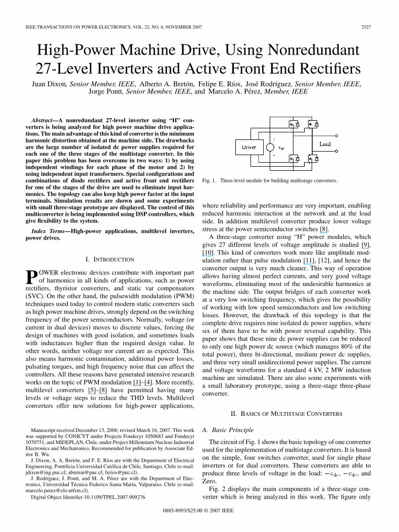
Fig. 2. Main components of the three-stage converter.
shows one of the three phases of the complete system. As can beseen, the dc power supplies of the three converters are isolated,and the dc supplies are scaled with levels of voltage in powerof three. The scaling of voltages to the power of three, allowshaving, with only three converters, 27 different levels ofvoltage: 13 levels of positive values, 13 levels of negative values,and zero. The converter located at the top of the figure has thebiggest voltage, and will be called Main Converter. The othertwo modules will be the Auxiliary Converters. The main worksat a lower switching frequency and carries more than 80% of thetotal power, which is an additional advantage of this topologyfor high-power machine drives applications.
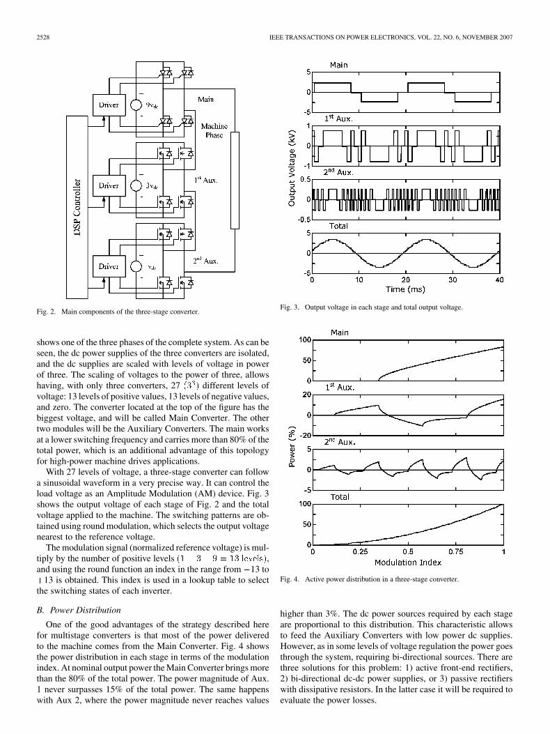
With 27 levels of voltage, a three-stage converter can followa sinusoidal waveform in a very precise way. It can control theload voltage as an Amplitude Modulation (AM) device. Fig. 3shows the output voltage of each stage of Fig. 2 and the totalvoltage applied to the machine. The switching patterns are ob-tained using round modulation, which selects the output voltagenearest to the reference voltage.
The modulation signal (normalized reference voltage) is mul-tiply by the number of positive levels ,and using the round function an index in the range from 13 to
13 is obtained. This index is used in a lookup table to selectthe switching states of each inverter.
B. Power Distribution
One of the good advantages of the strategy described herefor multistage converters is that most of the power deliveredto the machine comes from the Main Converter. Fig. 4 showsthe power distribution in each stage in terms of the modulationindex. At nominal output power the Main Converter brings morethan the 80% of the total power. The power magnitude of Aux.1 never surpasses 15% of the total power. The same happenswith Aux 2, where the power magnitude never reaches values
Fig. 3. Output voltage in each stage and total output voltage.
Fig. 4. Active power distribution in a three-stage converter.
higher than 3%. The dc power sources required by each stageare proportional to this distribution. This characteristic allowsto feed the Auxiliary Converters with low power dc supplies.However, as in some levels of voltage regulation the power goesthrough the system, requiring bi-directional sources. There arethree solutions for this problem: 1) active front-end rectifiers,2) bi-directional dc-dc power supplies, or 3) passive rectifierswith dissipative resistors. In the latter case it will be required toevaluate the power losses.
DIXON et al.: HIGH-POWER MACHINE DRIVE, USING NONREDUNDANT 27-LEVEL INVERTERS 2529
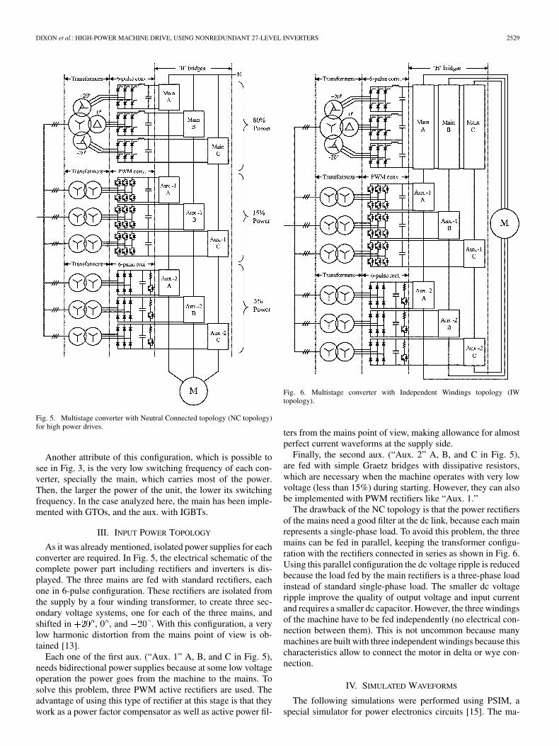
Fig. 5. Multistage converter with Neutral Connected topology (NC topology)for high power drives.
Another attribute of this configuration, which is possible tosee in Fig. 3, is the very low switching frequency of each con-verter, specially the main, which carries most of the power.Then, the larger the power of the unit, the lower its switchingfrequency. In the case analyzed here, the main has been imple-mented with GTOs, and the aux. with IGBTs.
III. INPUT POWER TOPOLOGY
As it was already mentioned, isolated power supplies for eachconverter are required. In Fig. 5, the electrical schematic of thecomplete power part including rectifiers and inverters is dis-played. The three mains are fed with standard rectifiers, eachone in 6-pulse configuration. These rectifiers are isolated fromthe supply by a four winding transformer, to create three sec-ondary voltage systems, one for each of the three mains, andshifted in , 0 , and . With this configuration, a verylow harmonic distortion from the mains point of view is ob-tained [13].
Each one of the first aux. (“Aux. 1” A, B, and C in Fig. 5),needs bidirectional power supplies because at some low voltageoperation the power goes from the machine to the mains. Tosolve this problem, three PWM active rectifiers are used. Theadvantage of using this type of rectifier at this stage is that theywork as a power factor compensator as well as active power fil-
Fig. 6. Multistage converter with Independent Windings topology (IWtopology).
ters from the mains point of view, making allowance for almostperfect current waveforms at the supply side.
Finally, the second aux. (“Aux. 2” A, B, and C in Fig. 5),are fed with simple Graetz bridges with dissipative resistors,which are necessary when the machine operates with very lowvoltage (less than 15%) during starting. However, they can alsobe implemented with PWM rectifiers like “Aux. 1.”
The drawback of the NC topology is that the power rectifiersof the mains need a good filter at the dc link, because each mainrepresents a single-phase load. To avoid this problem, the threemains can be fed in parallel, keeping the transformer configu-ration with the rectifiers connected in series as shown in Fig. 6.Using this parallel configuration the dc voltage ripple is reducedbecause the load fed by the main rectifiers is a three-phase loadinstead of standard single-phase load. The smaller dc voltageripple improve the quality of output voltage and input currentand requires a smaller dc capacitor. However, the three windingsof the machine have to be fed independently (no electrical con-nection between them). This is not uncommon because manymachines are built with three independent windings because thischaracteristics allow to connect the motor in delta or wye con-nection.
IV. SIMULATED WAVEFORMS
The following simulations were performed using PSIM, aspecial simulator for power electronics circuits [15]. The ma-
2530 IEEE TRANSACTIONS ON POWER ELECTRONICS, VOL. 22, NO. 6, NOVEMBER 2007
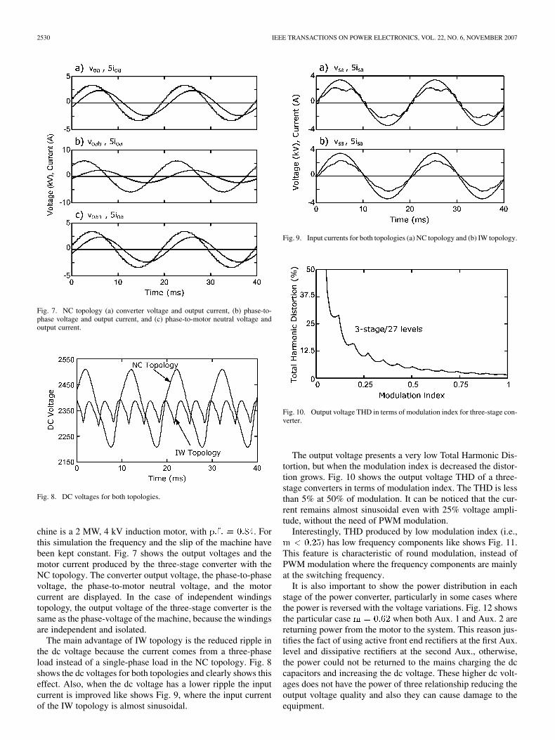
Fig. 7. NC topology (a) converter voltage and output current, (b) phase-to-phase voltage and output current, and (c) phase-to-motor neutral voltage andoutput current.
Fig. 8. DC voltages for both topologies.
chine is a 2 MW, 4 kV induction motor, with . Forthis simulation the frequency and the slip of the machine havebeen kept constant. Fig. 7 shows the output voltages and themotor current produced by the three-stage converter with theNC topology. The converter output voltage, the phase-to-phasevoltage, the phase-to-motor neutral voltage, and the motorcurrent are displayed. In the case of independent windingstopology, the output voltage of the three-stage converter is thesame as the phase-voltage of the machine, because the windingsare independent and isolated.
The main advantage of IW topology is the reduced ripple inthe dc voltage because the current comes from a three-phaseload instead of a single-phase load in the NC topology. Fig. 8shows the dc voltages for both topologies and clearly shows thiseffect. Also, when the dc voltage has a lower ripple the inputcurrent is improved like shows Fig. 9, where the input currentof the IW topology is almost sinusoidal.
Fig. 9. Input currents for both topologies (a) NC topology and (b) IW topology.
Fig. 10. Output voltage THD in terms of modulation index for three-stage con-verter.
The output voltage presents a very low Total Harmonic Dis-tortion, but when the modulation index is decreased the distor-tion grows. Fig. 10 shows the output voltage THD of a three-stage converters in terms of modulation index. The THD is lessthan 5% at 50% of modulation. It can be noticed that the cur-rent remains almost sinusoidal even with 25% voltage ampli-tude, without the need of PWM modulation.
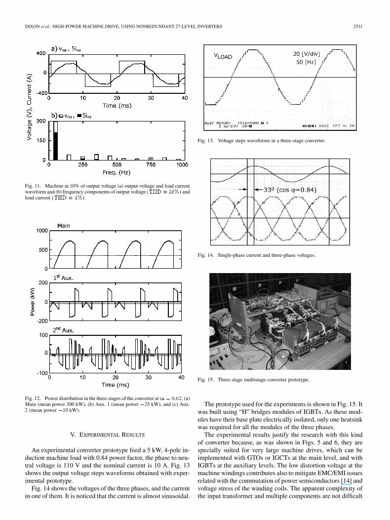
Interestingly, THD produced by low modulation index (i.e.,) has low frequency components like shows Fig. 11.
This feature is characteristic of round modulation, instead ofPWM modulation where the frequency components are mainlyat the switching frequency.
It is also important to show the power distribution in eachstage of the power converter, particularly in some cases wherethe power is reversed with the voltage variations. Fig. 12 showsthe particular case when both Aux. 1 and Aux. 2 arereturning power from the motor to the system. This reason jus-tifies the fact of using active front end rectifiers at the first Aux.level and dissipative rectifiers at the second Aux., otherwise,the power could not be returned to the mains charging the dccapacitors and increasing the dc voltage. These higher dc volt-ages does not have the power of three relationship reducing theoutput voltage quality and also they can cause damage to theequipment.
DIXON et al.: HIGH-POWER MACHINE DRIVE, USING NONREDUNDANT 27-LEVEL INVERTERS 2531
Fig. 11. Machine at 10% of output voltage (a) output voltage and load currentwaveform and (b) frequency components of output voltage (THD = 28%) andload current (THD = 5%).
Fig. 12. Power distribution in the three stages of the converter atm = 0:62. (a)Main (mean power 300 kW), (b) Aux. 1 (mean power �25 kW), and (c) Aux.2 (mean power �10 kW).
V. EXPERIMENTAL RESULTS
An experimental converter prototype feed a 5 kW, 4-pole in-duction machine load with 0.84 power factor, the phase to neu-tral voltage is 110 V and the nominal current is 10 A. Fig. 13shows the output voltage steps waveforms obtained with exper-imental prototype.
Fig. 14 shows the voltages of the three phases, and the currentin one of them. It is noticed that the current is almost sinusoidal.
Fig. 13. Voltage steps waveforms in a three-stage converter.
Fig. 14. Single-phase current and three-phase voltages.
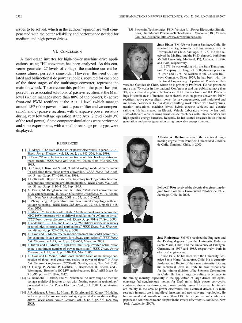
Fig. 15. Three-stage multistage converter prototype.
The prototype used for the experiments is shown in Fig. 15. Itwas built using “H” bridges modules of IGBTs. As these mod-ules have their base plate electrically isolated, only one heatsinkwas required for all the modules of the three phases.
The experimental results justify the research with this kindof converter because, as was shown in Figs. 5 and 6, they arespecially suited for very large machine drives, which can beimplemented with GTOs or IGCTs at the main level, and withIGBTs at the auxiliary levels. The low distortion voltage at themachine windings contributes also to mitigate EMC/EMI issuesrelated with the commutation of power semiconductors [14] andvoltage stress of the winding coils. The apparent complexity ofthe input transformer and multiple components are not difficult
2532 IEEE TRANSACTIONS ON POWER ELECTRONICS, VOL. 22, NO. 6, NOVEMBER 2007
issues to be solved, which in the authors’ opinion are well com-pensated with the better reliability and performance needed formedium and high-power drives.
VI. CONCLUSION
A three-stage inverter for high-power machine drive appli-cations, using “H” converters has been analyzed. As this con-verter generates 27 levels of voltage, the machine current be-comes almost perfectly sinusoidal. However, the need of iso-lated and bidirectional dc power supplies, required for each oneof the three stages of the multistage converter, represent themain drawback. To overcome this problem, the paper has pro-posed three associated solutions: a) passive rectifiers at the Mainlevel (which manages more than 80% of the power), b) activefront-end PWM rectifiers at the Aux. 1 level (which managearound 15% of the power and act as power filter and var compen-sator), and c) passive rectifiers with dissipative power resistorsduring very low voltage operation at the Aux. 2 level (only 3%of the total power). Some computer simulations were performedand some experiments, with a small three-stage prototype, weredisplayed.
REFERENCES
[1] H. Akagi, “The state-of-the-art of power electronics in japan,” IEEETrans. Power Electron., vol. 13, no. 2, pp. 345–356, Mar. 1998.
[2] B. Bose, “Power electronics and motion control-technology status andrecent trends,” IEEE Trans. Ind. Appl., vol. 29, no. 5, pp. 902–909, Sep.1993.
[3] D. Chung, J. Kim, and S. Sul, “Unified voltage modulation techniquefor real-time three-phase power conversion,” IEEE Trans. Ind. Appl.,vol. 34, no. 2, pp. 374–380, Mar. 1998.
[4] J. Holtz and B. Beyer, “Fast current trajectory tracking control based onsynchronous optimal pulsewidth modulation,” IEEE Trans. Ind. Appl.,vol. 31, no. 5, pp. 1110–1120, Sep. 1995.
[5] A. Draou, M. Benghanen, and A. Tahri, “Multilevel converters andVAR compensation,” in Power Electronics Handbook, M. H. Rashid,Ed. New York: Academic, 2001, ch. 25, pp. 615–622.
[6] F. Zheng Peng, “A generalized multilevel inverter topology with selfvoltage balancing,” IEEE Trans. Ind. Appl., vol. 37, no. 2, pp. 611–618,Mar. 2001.
[7] K. Matsui, Y. Kawata, and F. Ueda, “Application of parallel connectedNPC-PWM inverters with multilevel modulation for AC motor drive,”IEEE Trans. Power Electron., vol. 15, no. 5, pp. 901–907, Sep. 2000.
[8] J. Rodríguez, J.-S. Lai, and F.-Z. Peng, “Multilevel inverters: A surveyof topologies, controls, and applications,” IEEE Trans. Ind. Electron.,vol. 49, no. 4, pp. 724–738, Aug. 2002.
[9] J. Dixon and L. Morán, “A clean four-quadrant sinusoidal power recti-fier using multistage converters for subway applications,” IEEE Trans.Ind. Electron., vol. 25, no. 5, pp. 653–661, May–Jun. 2005.
[10] J. Dixon and L. Morán, “High-level multistep inverter optimizationusing a minimum number of power transistors,” IEEE Trans. PowerElectron., vol. 21, no. 2, pp. 330–337, Mar. 2006.
[11] J. Dixon and L. Morán, “Multilevel inverter, based on multistage con-nection of three-level converters, scaled in power of three,” in Proc.Ind. Electron. Conference, IECON-02, Sevilla, Spain, Nov. 5–8, 2002.
[12] O. Gaupp, P. Zanini, P. Daehler, E. Baerlocher, R. Boeck, and J.Werninger, “Bremen’s 100 MW static frequency link,” ABB Issue No.9 10/96, pp. 4–17, 1996, M420.
[13] G. Beinhold, R. Jakob, and M. Nahrstaed, “A new range of mediumvoltage multilevel inverter drives with floating capacitor technology,”presented at the Eur. Power Electron. Conf., EPE 2001, Graz, Austria,2001.
[14] J. Rodriguez, J. Pontt, L. Moran, R. Osorio, and S. Kouro, “Modelingand analysis of common mode voltages generated in medium voltagedrives,” IEEE Trans. Power Electron., vol. 18, no. 3, pp. 873–879, May2003.
[15] Powersim Technologies, PSIM Version 4.1, Power Electronics Simula-tions, User Manual Powersim Technologies. Vancouver, BC, Canada[Online]. Available: http://www.powersimtech.com
Juan Dixon (SM’95) was born in Santiago, Chile. Hereceived the Degree in electrical engineering from theUniversidad de Chile, Santiago, in 1977. He also re-ceived the Ms.Eng. and the Ph.D. degreed, both fromMcGill University, Montreal, PQ, Canada, in 1986,and 1988, respectively.
In 1976, he was working with the State Transporta-tion Company in charge of trolleybuses operation.In 1977 and 1978, he worked at the Chilean Rail-ways Company. Since 1979, he has been with theElectrical Engineering Department, Pontificia Uni-
versidad Catolica de Chile, where he is presently Professor. He has presentedmore than 70 works in International Conferences and has published more than30 papers related to power electronics in IEEE Transactions and IEE Proceed-ings. His main areas of interests are in electric traction, power converters, PWMrectifiers, active power filters, power factor compensators, and multilevel andmultistage converters. He has done consulting work related with trolleybuses,traction substations, machine drives, hybrid electric vehicles, and electricrailways. He has created an Electric Vehicle Laboratory where he has builtstate-of-the-art vehicles using brushless-dc machines with ultracapacitors andhigh specific energy batteries. Recently, he has started research in distributedgeneration and power generation using renewable energy sources.
Alberto A. Bretón received the electrical engi-neering degree from Pontificia Universidad Católicade Chile, Santiago, Chile, in 2003.
Felipe E. Ríos received the electrical engineering de-gree from Pontificia Universidad Católica de Chile,Santiago, Chile, in 2003.
José Rodríguez (SM’95) received the Engineer andthe Dr.-Ing degrees from the University FedericoSanta Maria, Chile, and the University of Erlangen,Germany, in 1977 and 1985, respectively, both inelectrical engineering.
Since 1977, he has been with the University Fed-erico Santa María, Valparaíso, Chile. He is currentlyProfessor and Rector of the same university. Duringhis sabbatical leave in 1996, he was responsiblefor the mining division ofthe Siemens Corporationin Chile. He has a large consulting experience in
the mining industry, especially in the application of large drives like cyclo-converter-fed synchronous motors for SAG mills, high power conveyors,controlled drives for shovels, and power quality issues. His research interestsare mainly in the area of power electronics and electrical drives. His mainresearch interests are in multilevel inverters and new converter topologies. Hehas authored and co-authored more than 130 refereed journal and conferencepapers and contributed to one chapter in the Power Electronics Handbook (NewYork: Academic, 2007).
DIXON et al.: HIGH-POWER MACHINE DRIVE, USING NONREDUNDANT 27-LEVEL INVERTERS 2533
Jorge Pontt (M’00–SM’04) received the Engineerand M.S. degrees in electrical engineering fromthe Universidad Técnica Federico Santa María(UTFSM), Valparaíso, Chile, in 1977.
Since 1977, he has been Professor with UTFSMwhere he works with the Power Electronics Group inthe Electronics Engineering Department, with R&D,and the Graduate Program. He is Director of the Lab-oratory for Reliability and Power Quality (LACSE).He is coauthor of the software Harmonix used in har-monic studies in electrical systems. He is coauthor of
patent applications concerning innovative instrumentation systems employed inhigh-power converters and large grinding mill drives. He has authored more than90 international refereed journal and conference papers. He is a Consultant to themining industry, in particular, the design and application of power electronics,drives, instrumentation systems, and power quality issues, with management ofmore than 80 consulting and R&D projects. He has had scientific stays at theTechnische Hochschule Darmstadt (1979–1980), the University of Wuppertal(1990), and the University of Karlsruhe (2000–2001), all in Germany. He is cur-rently the Director of the Nucleus for Industrial Electronics and Mechatronics,UTFSM. He has contributed to the foundation of two spin-off knowledge-basedcompanies. His research interests are high-power converter and drives, powerquality, and safety and productivity in mineral processing.
Marcelo A. Pérez (M’07) was born in Concepción,Chile, in 1976. He received the Engineer degree inelectronic engineering, the M.Sc. degree in electricalengineering, and the D.Sc. degree in electrical engi-neering from the University of Concepción in 2000,2003, and 2006, respectively.
Currently he holds a postdoctoral position atthe Universidad Técnica Federico Santa María,researching in the area of power converters.