Embed Size (px)
Citation preview
IEEE TRANSACTIONS ON INDUSTRIAL ELECTRONICS, VOL. 57, NO. 7, JULY 2010 2197
A Survey on Cascaded Multilevel InvertersMariusz Malinowski, Senior Member, IEEE, K. Gopakumar, Senior Member, IEEE,
Jose Rodriguez, Senior Member, IEEE, and Marcelo A. Pérez, Member, IEEE
Abstract—Cascaded multilevel inverters synthesize a medium-voltage output based on a series connection of power cells whichuse standard low-voltage component configurations. This char-acteristic allows one to achieve high-quality output voltages andinput currents and also outstanding availability due to their in-trinsic component redundancy. Due to these features, the cascadedmultilevel inverter has been recognized as an important alternativein the medium-voltage inverter market. This paper presents asurvey of different topologies, control strategies and modulationtechniques used by these inverters. Regenerative and advancedtopologies are also discussed. Applications where the mentionedfeatures play a key role are shown. Finally, future developmentsare addressed.
Index Terms—Cascaded inverters, modulation and control,multilevel converters.
I. INTRODUCTION
MULTILEVEL voltage-source inverters provide a cost-effective solution in the medium-voltage energy man-
agement market [1]. These converters have been widely appliedto chemical, oil, and liquefied natural gas (LNG) plants, waterplants, marine propulsion, power generation, energy transmis-sion, and power-quality devices [2].
Nowadays, there exist three commercial topologies of multi-level voltage-source inverters: neutral point clamped (NPC) [3],cascaded H-bridge (CHB) [4], and flying capacitors (FCs) [5].Among these inverter topologies, cascaded multilevel inverterreaches the higher output voltage and power levels (13.8 kV,30 MVA) and the higher reliability due to its modular topology.
Cascaded multilevel inverters are based on a series connec-tion of several single-phase inverters. This structure is capableof reaching medium output voltage levels using only standardlow-voltage mature technology components. Typically, it isnecessary to connect three to ten inverters in series to reach therequired output voltage.
These converters also feature a high modularity degree be-cause each inverter can be seen as a module with similar circuittopology, control structure, and modulation [6]. Therefore, in
Manuscript received March 17, 2009; revised June 11, 2009; acceptedJuly 23, 2009. Date of publication August 28, 2009; date of current versionJune 11, 2010. This work was supported in part by the Chilean Governmentunder the Science and Technology Bicentenario Project PSD-30 and in part bythe Universidad Técnica Federico Santa María.
M. Malinowski is with the Institute of Control and Industrial Electronics,Warsaw University of Technology, 00-662 Warsaw, Poland (e-mail: [email protected]).
K. Gopakumar is with the Centre for Electronics Design and Tech-nology, Indian Institute of Science, Bangalore 560 012, India (e-mail:[email protected]).
J. Rodriguez and M. A. Pérez are with the Department of ElectronicsEngineering, Universidad Técnica Federico Santa María, Valparaíso 110-V,Chile (e-mail: [email protected]; [email protected]).
Digital Object Identifier 10.1109/TIE.2009.2030767
the case of a fault in one of these modules, it is possible toreplace it quickly and easily. Moreover, with an appropriatedcontrol strategy, it is possible to bypass the faulty module with-out stopping the load, bringing an almost continuous overallavailability [7].
This paper presents a bibliographical review of cascadedmulticell inverters, its working principle, circuit topologies,control techniques, and industrial applications. This paper is or-ganized as follows. Section II shows the working principle andbasic and advanced topologies. Regenerative topologies andits control are addressed in Section III. In Section IV, severalnewly introduced topologies for cascaded inverters are shown.A complete review of control and modulation used in theseinverters is presented in Section V. A group of applications isreviewed in Section VI. Finally, future trends and conclusionsare presented in Sections VII and VIII, respectively.
II. POWER CIRCUIT TOPOLOGIES
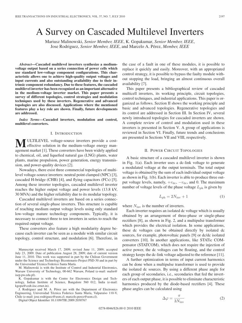
A basic structure of a cascaded multilevel inverter is shownin Fig. 1(a). Each inverter uses a dc-link voltage to generatea modulated voltage at the output terminals. The total outputvoltage is obtained by the sum of each individual output voltageas shown in Fig. 1(b). Each inverter is able to produce three out-put voltage levels, namely, +vdc, −vdc, and 0. The maximumnumber of voltage levels of the phase voltage Lph is given by
Lph = 2Ninv + 1 (1)
where Ninv is the number of inverters.Each inverter requires an isolated dc voltage which is usually
obtained by an arrangement of three-phase or single-phaserectifiers [8], as shown in Fig. 2, and a multipulse transformerwhich provides the electrical isolation. In some applications,these dc voltages can be obtained directly by isolated dcsources, for example, photovoltaic panels [9] or dc/dc isolatedconverters [10]. In another applications, like STATic COM-pensator (STATCOM), which does not require the injection ofactive power, the dc voltages can be floating, and the controlstrategy keeps the dc-link voltage adjusted to the reference [11].
A further optimization in terms of input current harmonicscan be done when a multipulse transformer is used to providethe isolated dc sources. By using a different phase angle foreach group of secondaries, i.e., secondaries that fed the invert-ers of each output phase, it is possible to eliminate characteristicharmonics produced by the diode-based rectifiers [4]. Thesephase angles can be calculated using
Δϕ =π
3Ninv(2)
0278-0046/$26.00 © 2010 IEEE
2198 IEEE TRANSACTIONS ON INDUSTRIAL ELECTRONICS, VOL. 57, NO. 7, JULY 2010
Fig. 1. Multilevel cascaded inverter. (a) Basic circuit topology. (b) Typicalmultilevel output voltage and load current.
Fig. 2. Diode-based rectifier power cell topologies. (a) Three-phase.(b) Single-phase.
where Δϕ is the relative angle between group of secondaries.When single phase rectifiers are used the secondaries must
be arranged in a more complex structure [8].The use of a cascaded five-level NPC inverter instead
of a three-level inverter has received an increased attention[12]–[15], due to the possibility to increase the total numberof output voltage levels by keeping a fixed number of invert-ers. Moreover, the NPC topology has become an establishedtechnology in power electronics inverters. The total number oflevels using cascaded five-level NPC inverters is given by
LNPCph = 4NNPC + 1 (3)
where NNPC is the number of NPC inverters connected inseries.
By using the same principle, there is a possibility to connectin series two or more FC inverters in order to increase thenumber of output voltage levels. In [16], two FC inverters areconnected in series to obtain a 13-level output voltage.
Usually, cascaded multilevel inverters use the same dc-linkvoltage value for every cell. However, using different dc-linkvoltages, it is possible to increase the maximum numberof output voltage levels. The topologies that have differentdc-link voltages are called in the literature as asymmetriccascaded inverter. The relationship among the dc-link voltagesto provide a regularly stepped output voltage waveform couldbe binary (power of two) or trinary (power of three). Themaximum numbers of output voltage levels are given by
Lbinph = 2(Ninv+1) − 1 Ltri
ph = 3Ninv . (4)
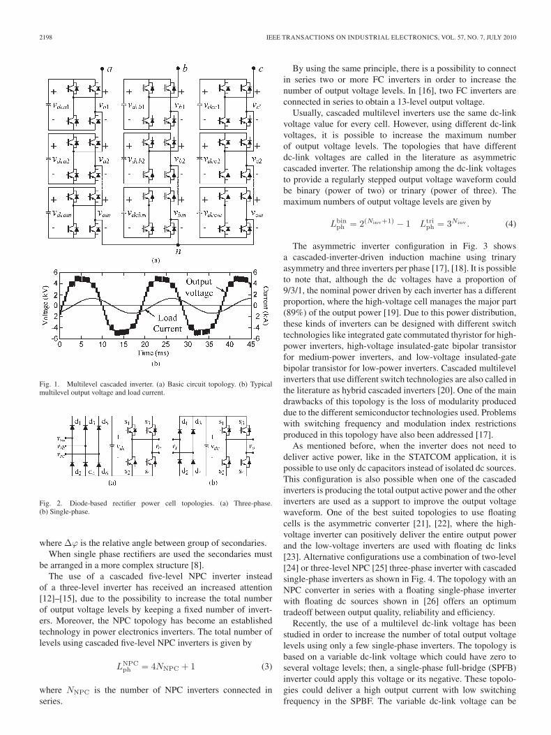
The asymmetric inverter configuration in Fig. 3 showsa cascaded-inverter-driven induction machine using trinaryasymmetry and three inverters per phase [17], [18]. It is possibleto note that, although the dc voltages have a proportion of9/3/1, the nominal power driven by each inverter has a differentproportion, where the high-voltage cell manages the major part(89%) of the output power [19]. Due to this power distribution,these kinds of inverters can be designed with different switchtechnologies like integrated gate commutated thyristor for high-power inverters, high-voltage insulated-gate bipolar transistorfor medium-power inverters, and low-voltage insulated-gatebipolar transistor for low-power inverters. Cascaded multilevelinverters that use different switch technologies are also called inthe literature as hybrid cascaded inverters [20]. One of the maindrawbacks of this topology is the loss of modularity produceddue to the different semiconductor technologies used. Problemswith switching frequency and modulation index restrictionsproduced in this topology have also been addressed [17].
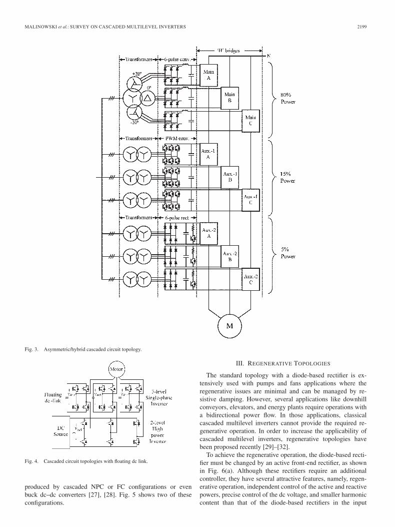
As mentioned before, when the inverter does not need todeliver active power, like in the STATCOM application, it ispossible to use only dc capacitors instead of isolated dc sources.This configuration is also possible when one of the cascadedinverters is producing the total output active power and the otherinverters are used as a support to improve the output voltagewaveform. One of the best suited topologies to use floatingcells is the asymmetric converter [21], [22], where the high-voltage inverter can positively deliver the entire output powerand the low-voltage inverters are used with floating dc links[23]. Alternative configurations use a combination of two-level[24] or three-level NPC [25] three-phase inverter with cascadedsingle-phase inverters as shown in Fig. 4. The topology with anNPC converter in series with a floating single-phase inverterwith floating dc sources shown in [26] offers an optimumtradeoff between output quality, reliability and efficiency.
Recently, the use of a multilevel dc-link voltage has beenstudied in order to increase the number of total output voltagelevels using only a few single-phase inverters. The topology isbased on a variable dc-link voltage which could have zero toseveral voltage levels; then, a single-phase full-bridge (SPFB)inverter could apply this voltage or its negative. These topolo-gies could deliver a high output current with low switchingfrequency in the SPBF. The variable dc-link voltage can be
MALINOWSKI et al.: SURVEY ON CASCADED MULTILEVEL INVERTERS 2199
Fig. 3. Asymmetric/hybrid cascaded circuit topology.
Fig. 4. Cascaded circuit topologies with floating dc link.
produced by cascaded NPC or FC configurations or evenbuck dc–dc converters [27], [28]. Fig. 5 shows two of theseconfigurations.
III. REGENERATIVE TOPOLOGIES
The standard topology with a diode-based rectifier is ex-tensively used with pumps and fans applications where theregenerative issues are minimal and can be managed by re-sistive damping. However, several applications like downhillconveyors, elevators, and energy plants require operations witha bidirectional power flow. In those applications, classicalcascaded multilevel inverters cannot provide the required re-generative operation. In order to increase the applicability ofcascaded multilevel inverters, regenerative topologies havebeen proposed recently [29]–[32].
To achieve the regenerative operation, the diode-based recti-fier must be changed by an active front-end rectifier, as shownin Fig. 6(a). Although these rectifiers require an additionalcontroller, they have several attractive features, namely, regen-erative operation, independent control of the active and reactivepowers, precise control of the dc voltage, and smaller harmoniccontent than that of the diode-based rectifiers in the input
2200 IEEE TRANSACTIONS ON INDUSTRIAL ELECTRONICS, VOL. 57, NO. 7, JULY 2010
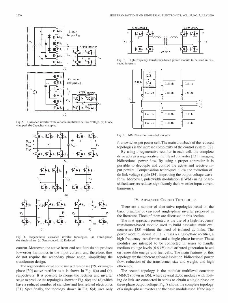
Fig. 5. Cascaded inverter with variable multilevel dc-link voltage. (a) Diodeclamped. (b) Capacitor clampled.
Fig. 6. Regenerative cascaded inverter topologies. (a) Three-phase.(b) Single-phase. (c) Semireduced. (d) Reduced.
current. Moreover, the active front-end rectifiers do not producelow-order harmonics in the input current, and therefore, theydo not require the secondary phase angle, simplifying thetransformer design.
The regenerative drive could use a three-phase [29] or single-phase [30] active rectifier as it is shown in Fig. 6(a) and (b),respectively. It is possible to merge the rectifier and inverterstage to produce the topologies shown in Fig. 6(c) and (d) whichhave a reduced number of switches and less related electronics[31]. Specifically, the topology shown in Fig. 6(d) uses only
Fig. 7. High-frequency transformer-based power module to be used in cas-caded inverters.
Fig. 8. MMC based on cascaded modules.
four switches per power cell. The main drawback of the reducedtopologies is the increase complexity of the control system [32].
By using a regenerative rectifier in each cell, the completedrive acts as a regenerative multilevel converter [33] managingbidirectional power flow. By using a proper controller, it ispossible to decouple and control the active and reactive in-put powers. Compensation techniques allow the reduction ofdc-link voltage ripple [34], improving the output voltage wave-form. Moreover, pulsewidth modulation (PWM) using phase-shifted carriers reduces significantly the low-order input currentharmonics.
IV. ADVANCED CIRCUIT TOPOLOGIES
There are a number of alternative topologies based on thebasic principle of cascaded single-phase inverter proposed inthe literature. Three of them are discussed in this section.
The first approach presented is the use of a high-frequencytransformer-based module used to build cascaded multilevelconverters [35] without the need of isolated dc links. Thepower module, shown in Fig. 7, uses a single-phase rectifier, ahigh-frequency transformer, and a single-phase inverter. Thesemodules are intended to be connected in series to handlemedium voltage levels (6.6 kV) in distributed generation basedon renewable energy and fuel cells. The main features of thistopology are the inherent galvanic isolation, bidirectional powerflow, reduction of the transformer size and weight, and highefficiency.
The second topology is the modular multilevel converter(MMC) shown in [36], where several dc/dc modules with float-ing dc link are connected in series to obtain a single-phase orthree-phase output voltage. Fig. 8 shows the complete topologyof a single-phase inverter and the basic module used. If the input
MALINOWSKI et al.: SURVEY ON CASCADED MULTILEVEL INVERTERS 2201
voltage is directly an ac voltage, then the basic module must bea single-phase inverter. The MMC provides high scalability, ithas low filter requirements and, in addition, it does not requirean input transformer. To control the input/output currents andthe floating dc voltages, a scheme composed by linear PI con-trollers and switching logic has been proposed in [37].
The third circuit topology, recently found in the literature, isthe cascaded multilevel inverter based on single-phase current-source inverters [38]. This topology is the dual of the standardvoltage-source topology but uses an inductive dc link. The in-ductors of each one of the three output phases are magneticallycoupled, minimizing the second-order harmonics that appear onthe dc link. Thus, the ripple in the input currents, as well as thedc inductor footprint, is reduced.
V. MODULATION AND CONTROL
This section presents a review of the most commonly usedmodulation techniques and control strategies in cascaded multi-level inverters.
A. Modulation Techniques
Several modulation techniques have been proposed for cas-caded multilevel inverters. A high number of power electronicdevices and switching redundancies bring a higher level ofcomplexity compared with a two-level inverter counterpart.However, this complexity could be used to add additionalcapabilities to the modulation technique, namely, reducing theswitching frequency, minimizing the common-mode voltage, orbalancing the dc voltages.
Modulation techniques for cascaded multilevel invertersare usually an extension of the two-level modulations [39].According to their switching frequency, they can be classified asfollows [40]: 1) fundamental switching frequency, where eachinverter has only one commutation per cycle, for example, mul-tilevel selective harmonic elimination (SHE), space vector con-trol, and nearest voltage level, and 2) high switching frequency,where each inverter has several commutations per cycle, forexample, multilevel PWM and space vector modulation (SVM).
1) Multilevel SHE: SHE techniques can be applied to cas-caded multilevel inverters using two approaches.
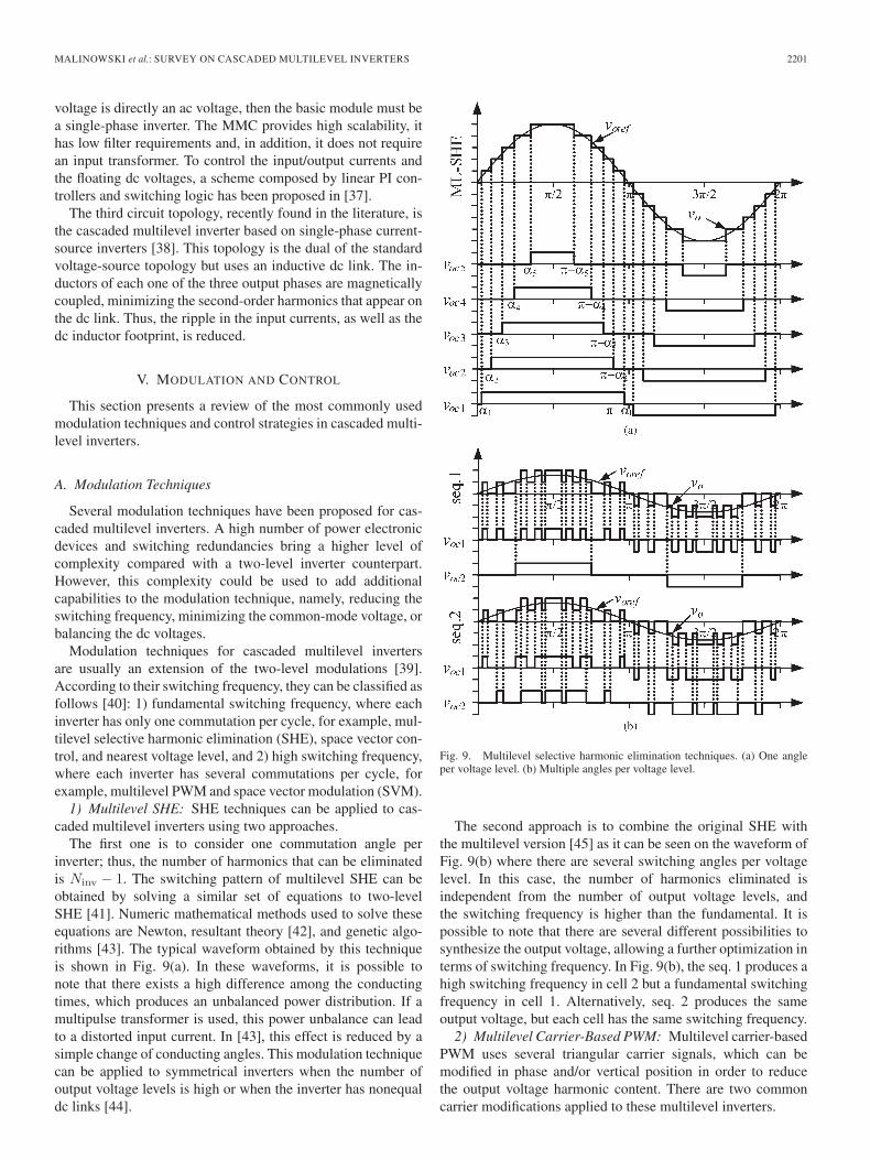
The first one is to consider one commutation angle perinverter; thus, the number of harmonics that can be eliminatedis Ninv − 1. The switching pattern of multilevel SHE can beobtained by solving a similar set of equations to two-levelSHE [41]. Numeric mathematical methods used to solve theseequations are Newton, resultant theory [42], and genetic algo-rithms [43]. The typical waveform obtained by this techniqueis shown in Fig. 9(a). In these waveforms, it is possible tonote that there exists a high difference among the conductingtimes, which produces an unbalanced power distribution. If amultipulse transformer is used, this power unbalance can leadto a distorted input current. In [43], this effect is reduced by asimple change of conducting angles. This modulation techniquecan be applied to symmetrical inverters when the number ofoutput voltage levels is high or when the inverter has nonequaldc links [44].
Fig. 9. Multilevel selective harmonic elimination techniques. (a) One angleper voltage level. (b) Multiple angles per voltage level.
The second approach is to combine the original SHE withthe multilevel version [45] as it can be seen on the waveform ofFig. 9(b) where there are several switching angles per voltagelevel. In this case, the number of harmonics eliminated isindependent from the number of output voltage levels, andthe switching frequency is higher than the fundamental. It ispossible to note that there are several different possibilities tosynthesize the output voltage, allowing a further optimization interms of switching frequency. In Fig. 9(b), the seq. 1 produces ahigh switching frequency in cell 2 but a fundamental switchingfrequency in cell 1. Alternatively, seq. 2 produces the sameoutput voltage, but each cell has the same switching frequency.
2) Multilevel Carrier-Based PWM: Multilevel carrier-basedPWM uses several triangular carrier signals, which can bemodified in phase and/or vertical position in order to reducethe output voltage harmonic content. There are two commoncarrier modifications applied to these multilevel inverters.
2202 IEEE TRANSACTIONS ON INDUSTRIAL ELECTRONICS, VOL. 57, NO. 7, JULY 2010
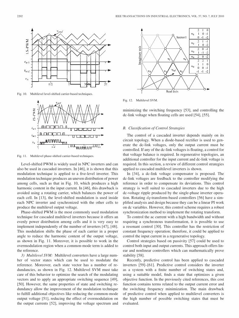
Fig. 10. Multilevel level-shifted carrier-based techniques.
Fig. 11. Multilevel phase-shifted carrier-based techniques.
Level-shifted PWM is widely used in NPC inverters and canalso be used in cascaded inverters. In [46], it is shown that thismodulation technique is applied to a five-level inverter. Thismodulation technique produces an uneven distribution of poweramong cells, such as that in Fig. 10, which produces a highharmonic content in the input current. In [46], this drawback isavoided using a rotating carrier, which balances the power ofeach cell. In [13], the level-shifted modulation is used insideeach NPC inverter and synchronized with the other cells toproduce the multilevel output voltage.
Phase-shifted PWM is the most commonly used modulationtechnique for cascaded multilevel inverters because it offers anevenly power distribution among cells and it is very easy toimplement independently of the number of inverters [47], [48].This modulation shifts the phase of each carrier in a properangle to reduce the harmonic content of the output voltage,as shown in Fig. 11. Moreover, it is possible to work in theovermodulation region when a common-mode term is added tothe reference.
3) Multilevel SVM: Multilevel converters have a large num-ber of vector states which can be used to modulate thereference. Moreover, each state vector has a number of re-dundancies, as shown in Fig. 12. Multilevel SVM must takecare of this behavior to optimize the search of the modulatingvectors and to apply an appropriate switching sequence [49],[50]. However, the same properties of state and switching re-dundancy allow the improvement of the modulation techniqueto fulfill additional objectives like reducing the common-modeoutput voltage [51], reducing the effect of overmodulation onthe output currents [52], improving the voltage spectrum and
Fig. 12. Multilevel SVM.
minimizing the switching frequency [53], and controlling thedc-link voltage when floating cells are used [54], [55].
B. Classification of Control Strategies
The control of a cascaded inverter depends mainly on itscircuit topology. When a diode-based rectifier is used to gen-erate the dc-link voltages, only the output current must becontrolled. If any of the dc-link voltages is floating, a control forthat voltage balance is required. In regenerative topologies, anadditional controller for the input current and dc-link voltage isrequired. In this section, a review of different control strategiesapplied to cascaded multilevel inverters is shown.
In [34], a dc-link voltage compensator is proposed. Thedc-link voltages are feedback to the controller modifying thereference in order to compensate its deviations. This controlstrategy is well suited to cascaded inverters due to the highdc-voltage ripple produced by the single-phase inverter opera-tion. Rotating dq-transform-based controllers [56] have a sim-plified analysis and design because they can be a linear PI workon dc variables. However, this control scheme requires a robustsynchronization method to implement the rotating transform.
To control the ac current with a high bandwidth and withoutrequiring a synchronous transformation, it is possible to usea resonant control [30]. This controller has the restriction ofconstant frequency operation; therefore, it could be applied tocontrol the input current in a regenerative topology.
Control strategies based on passivity [57] could be used tocontrol both input and output currents. This approach offers lin-ear and nonlinear controllers which can mathematically provestability [58].
Recently, predictive control has been applied to cascadedinverters [59]–[61]. Predictive control considers the inverteras a system with a finite number of switching states and,using a suitable model, finds a state that optimizes a givenobjective function. In the previously cited references, this costfunction contains terms related to the output current error andthe switching frequency minimization. The main drawbackof predictive control when applied to multilevel converters isthe high number of possible switching states that must beevaluated.
MALINOWSKI et al.: SURVEY ON CASCADED MULTILEVEL INVERTERS 2203
TABLE ISUPPLIERS OF CHB INVERTERS AVAILABLE IN THE MARKET
Fig. 13. Cascaded multilevel inverter application: Pumps and fans.
VI. APPLICATIONS
In this section, successful applications of CHB invertersare presented. Each one of these applications has particularrequirements where cascaded inverters are well suited.
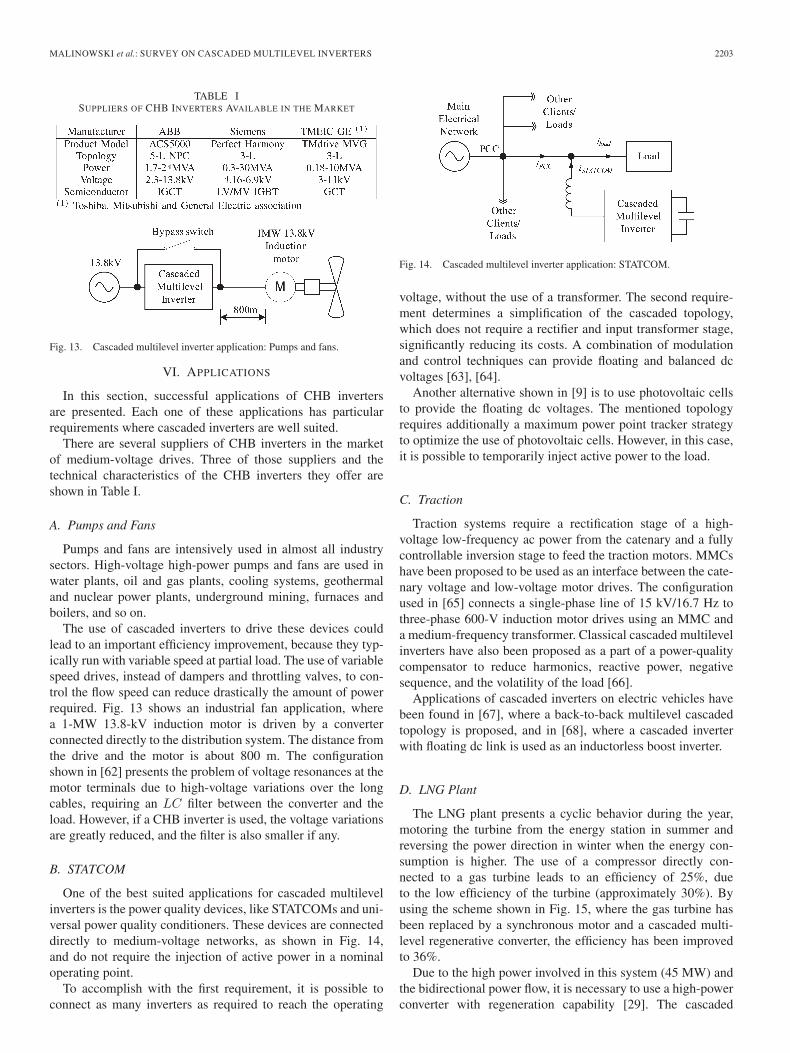
There are several suppliers of CHB inverters in the marketof medium-voltage drives. Three of those suppliers and thetechnical characteristics of the CHB inverters they offer areshown in Table I.
A. Pumps and Fans
Pumps and fans are intensively used in almost all industrysectors. High-voltage high-power pumps and fans are used inwater plants, oil and gas plants, cooling systems, geothermaland nuclear power plants, underground mining, furnaces andboilers, and so on.
The use of cascaded inverters to drive these devices couldlead to an important efficiency improvement, because they typ-ically run with variable speed at partial load. The use of variablespeed drives, instead of dampers and throttling valves, to con-trol the flow speed can reduce drastically the amount of powerrequired. Fig. 13 shows an industrial fan application, wherea 1-MW 13.8-kV induction motor is driven by a converterconnected directly to the distribution system. The distance fromthe drive and the motor is about 800 m. The configurationshown in [62] presents the problem of voltage resonances at themotor terminals due to high-voltage variations over the longcables, requiring an LC filter between the converter and theload. However, if a CHB inverter is used, the voltage variationsare greatly reduced, and the filter is also smaller if any.
B. STATCOM
One of the best suited applications for cascaded multilevelinverters is the power quality devices, like STATCOMs and uni-versal power quality conditioners. These devices are connecteddirectly to medium-voltage networks, as shown in Fig. 14,and do not require the injection of active power in a nominaloperating point.
To accomplish with the first requirement, it is possible toconnect as many inverters as required to reach the operating
Fig. 14. Cascaded multilevel inverter application: STATCOM.
voltage, without the use of a transformer. The second require-ment determines a simplification of the cascaded topology,which does not require a rectifier and input transformer stage,significantly reducing its costs. A combination of modulationand control techniques can provide floating and balanced dcvoltages [63], [64].
Another alternative shown in [9] is to use photovoltaic cellsto provide the floating dc voltages. The mentioned topologyrequires additionally a maximum power point tracker strategyto optimize the use of photovoltaic cells. However, in this case,it is possible to temporarily inject active power to the load.
C. Traction
Traction systems require a rectification stage of a high-voltage low-frequency ac power from the catenary and a fullycontrollable inversion stage to feed the traction motors. MMCshave been proposed to be used as an interface between the cate-nary voltage and low-voltage motor drives. The configurationused in [65] connects a single-phase line of 15 kV/16.7 Hz tothree-phase 600-V induction motor drives using an MMC anda medium-frequency transformer. Classical cascaded multilevelinverters have also been proposed as a part of a power-qualitycompensator to reduce harmonics, reactive power, negativesequence, and the volatility of the load [66].
Applications of cascaded inverters on electric vehicles havebeen found in [67], where a back-to-back multilevel cascadedtopology is proposed, and in [68], where a cascaded inverterwith floating dc link is used as an inductorless boost inverter.
D. LNG Plant
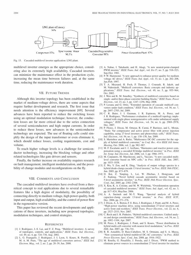
The LNG plant presents a cyclic behavior during the year,motoring the turbine from the energy station in summer andreversing the power direction in winter when the energy con-sumption is higher. The use of a compressor directly con-nected to a gas turbine leads to an efficiency of 25%, dueto the low efficiency of the turbine (approximately 30%). Byusing the scheme shown in Fig. 15, where the gas turbine hasbeen replaced by a synchronous motor and a cascaded multi-level regenerative converter, the efficiency has been improvedto 36%.
Due to the high power involved in this system (45 MW) andthe bidirectional power flow, it is necessary to use a high-powerconverter with regeneration capability [29]. The cascaded
2204 IEEE TRANSACTIONS ON INDUSTRIAL ELECTRONICS, VOL. 57, NO. 7, JULY 2010
Fig. 15. Cascaded multilevel inverter application: LNG plant.
multilevel inverter emerges as the appropriate choice, consid-ering also its extremely high availability. Cascaded inverterscan minimize the maintenance effect in the production cycle,increasing the mean time between failures and, at the sametime, reducing the maintenance work duration.
VII. FUTURE TRENDS
Although this inverter topology has been established in themarket of medium-voltage drives, there are some aspects thatrequire further development and research. The first issue thatneeds attention is the efficiency improvement [69]. Severaladvances have been reported to reduce the switching lossesusing an optimal modulation technique; however, the conduc-tion losses are far more critical due to the series connectionof several semiconductors and high output currents. In orderto reduce these losses, new advances in the semiconductortechnology are expected. The use of floating cells could sim-plify the design of the input transformer or even eliminate it,which should reduce losses, cooling requirements, cost andvolume.
To reach higher voltage levels is a challenge for semicon-ductor technology, increasing the blocking voltage and otherrelated technologies like gate drivers and sensors.
Finally, the further increase on availability requires researchon fault management, intelligent modularization, and the possi-bility of change modules and reconfigurations on the fly.
VIII. COMMENTS AND CONCLUSION
The cascaded multilevel inverters have evolved from a theo-retical concept to real applications due to several remarkablefeatures like a high degree of modularity, the possibility ofconnecting directly to medium voltage, high power quality, bothinput and output, high availability, and the control of power flowin the regenerative version.
This paper has reviewed the recent developments and appli-cations of these inverters, including new proposed topologies,modulation techniques, and control strategies.
REFERENCES
[1] J. Rodriguez, J.-S. Lai, and F. Z. Peng, “Multilevel inverters: A surveyof topologies, controls, and applications,” IEEE Trans. Ind. Electron.,vol. 49, no. 4, pp. 724–738, Aug. 2002.
[2] L. G. Franquelo, J. Rodriguez, J. I. Leon, S. Kouro, R. Portillo, andM. A. M. Prats, “The age of multilevel converters arrives,” IEEE Ind.Electron. Mag., vol. 2, no. 2, pp. 28–39, Jun. 2008.
[3] A. Nabae, I. Takahashi, and H. Akagi, “A new neutral-point-clampedPWM inverter,” IEEE Trans. Ind. Appl., vol. IA-17, no. 5, pp. 518–523,Sep./Oct. 1981.
[4] P. W. Hammond, “A new approach to enhance power quality for mediumvoltage AC drives,” IEEE Trans. Ind. Appl., vol. 33, no. 1, pp. 202–208,Jan./Feb. 1997.
[5] T. A. Meynard, H. Foch, P. Thomas, J. Courault, R. Jakob, andM. Nahrstaedt, “Multicell converters: Basic concepts and industry ap-plications,” IEEE Trans. Ind. Electron., vol. 49, no. 5, pp. 955–964,Oct. 2002.
[6] J. Wen and K. M. Smedley, “Synthesis of multilevel converters based onsingle- and/or three-phase converter building blocks,” IEEE Trans. PowerElectron., vol. 23, no. 3, pp. 1247–1256, May 2008.
[7] P. Lezana and G. Ortiz, “Extended operation of cascade multicell con-verters under fault condition,” IEEE Trans. Ind. Electron., vol. 56, no. 7,pp. 2697–2703, Jul. 2009.
[8] C. R. Baier, J. I. Guzman, J. R. Espinoza, M. A. Perez, andJ. R. Rodriguez, “Performance evaluation of a multicell topology imple-mented with single-phase nonregenerative cells under unbalanced supplyvoltages,” IEEE Trans. Ind. Electron., vol. 54, no. 6, pp. 2969–2978,Dec. 2007.
[9] P. Flores, J. Dixon, M. Ortuzar, R. Carmi, P. Barriuso, and L. Moran,“Static Var compensator and active power filter with power injectioncapability, using 27-level inverters and photovoltaic cells,” IEEE Trans.Ind. Electron., vol. 56, no. 1, pp. 130–138, Jan. 2009.
[10] S. Mariethoz and A. Rufer, “Multisource DC-DC converter for the sup-ply of hybrid multilevel converter,” in Conf. Rec. 41st IEEE IAS Annu.Meeting, Oct. 2006, vol. 2, pp. 982–987.
[11] M. F. Escalante and J. J. Arellano, “Harmonics and reactive power com-pensation using a cascaded H-bridge multilevel inverter,” in Proc. IEEEInt. Symp. Ind. Electron., Jul. 2006, vol. 3, pp. 1966–1971.
[12] M. Carpaneto, M. Marchesoni, and L. Vaccaro, “A new cascaded multi-level converter based on NPC cells,” in Proc. IEEE ISIE, Jun. 2007,pp. 1033–1038.
[13] Z. Wu, Y. Zou, and K. Ding, “Analysis of output voltage spectra in ahybrid diode-clamp cascade 13-level inverter,” in Proc. IEEE 36th PESC,Jun. 2005, pp. 873–879.
[14] D. Kai, Z. Yunping, L. Lei, W. Zhichao, J. Hongyuan, andZ. Xudong, “Novel hybrid cascade asymmetric inverter based on5-level asymmetric inverter,” in Proc. IEEE 36th Power Electron. Spec.Conf., Jun. 2005, pp. 2302–2306.
[15] X. Kou, K. A. Corzine, and M. W. Wielebski, “Overdistention operationof cascaded multilevel inverters,” IEEE Trans. Ind. Appl., vol. 42, no. 3,pp. 817–824, May/Jun. 2006.
[16] A. A. Sneineh and M.-Y. Wang, “Spectral analysis of hybridcapacitor-clamp cascade 13-level inverter,” in Proc. IEEE ICIT ,Dec. 2006, pp. 271–276.
[17] J. Dixon, A. A. Breton, F. E. Rios, J. Rodriguez, J. Pontt, and M. A. Perez,“High-power machine drive, using nonredundant 27-level inverters andactive front end rectifiers,” IEEE Trans. Power Electron., vol. 22, no. 6,pp. 2527–2533, Nov. 2007.
[18] C. Rech and J. R. Pinheiro, “Hybrid multilevel converters: Unified analy-sis and design considerations,” IEEE Trans. Ind. Electron., vol. 54, no. 2,pp. 1092–1104, Apr. 2007.
[19] M. Perez, J. Rodriguez, J. Pontt, and S. Kouro, “Power distribution inhybrid multi-cell converter with nearest level modulation,” in Proc. IEEEISIE, Jun. 2007, pp. 736–741.
[20] R. R. Astudillo, D. Ruiz-Caballero, M. S. Ortmann, and S. A. Mussa,“New symmetrical hybrid multilevel DC-AC converters,” in Proc. IEEEPower Electron. Spec. Conf., Jun. 2008, pp. 1916–1922.
[21] M. Rotella, G. Penailillo, J. Pereda, and J. Dixon, “PWM method toeliminate power sources in a nonredundant 27-level inverter for machine
MALINOWSKI et al.: SURVEY ON CASCADED MULTILEVEL INVERTERS 2205
drive applications,” IEEE Trans. Ind. Electron., vol. 56, no. 1, pp. 194–201, Jan. 2009.
[22] Z. Du, B. Ozpineci, and L. M. Tolbert, “Modulation extension controlof hybrid cascaded H-bridge multilevel converters with 7-level funda-mental frequency switching scheme,” in Proc. IEEE Power Electron.Spec. Conf., Jun. 2007, pp. 2361–2366.
[23] S. Vazquez, J. I. Leon, L. G. Franquelo, J. J. Padilla, and J. M. Carrasco,“DC-voltage-ratio control strategy for multilevel cascaded converters fedwith a single DC source,” IEEE Trans. Ind. Electron., vol. 56, no. 7,pp. 2513–2521, Jul. 2009.
[24] H. Liu, L. M. Tolbert, S. Khomfoi, B. Ozpineci, and Z. Du, “Hybridcascaded multilevel inverter with PWM control method,” in Proc. IEEEPower Electron. Spec. Conf., Jun. 2008, pp. 162–166.
[25] S. Lu and K. A. Corzine, “Advanced control and analysis of cascadedmultilevel converters based on P-Q compensation,” IEEE Trans. PowerElectron., vol. 22, no. 4, pp. 1242–1252, Jul. 2007.
[26] M. Veenstra and A. Rufer, “Control of a hybrid asymmetric multilevelinverter for competitive medium-voltage industrial drives,” IEEE Trans.Ind. Appl., vol. 41, no. 2, pp. 655–664, Mar./Apr. 2005.
[27] G.-J. Su, “Multilevel DC-link inverter,” IEEE Trans. Ind. Appl., vol. 41,no. 3, pp. 848–854, May/Jun. 2005.
[28] P. Lezana and J. Rodriguez, “Mixed multicell cascaded multilevel in-verter,” in Proc. IEEE ISIE, Jun. 2007, pp. 509–514.
[29] J. R. Rodriguez, J. Pontt, M. Perez, P. Lezana, and P. W. Hammond, “Highpower synchronous machine fed by a cascaded regenerative inverter,” inConf. Rec. IEEE IAS Annu. Meeting, Oct. 2008, pp. 1–7.
[30] P. Lezana, C. A. Silva, J. Rodriguez, and M. A. Perez, “Zero-steady-state-error input-current controller for regenerative multilevel converters basedon single-phase cells,” IEEE Trans. Ind. Electron., vol. 54, no. 2, pp. 733–740, Apr. 2007.
[31] P. Lezana, J. Rodriguez, D. Rojas, and J. Pontt, “Novel cell based onreduced single-phase active front end for multicell converters,” in Proc.31st IEEE IECON, Nov. 2005, pp. 733–738.
[32] P. Lezana, J. Rodriguez, and D. A. Oyarzun, “Cascaded multilevel inverterwith regeneration capability and reduced number of switches,” IEEETrans. Ind. Electron., vol. 55, no. 3, pp. 1059–1066, Mar. 2008.
[33] A. J. Watson, P. W. Wheeler, and J. C. Clare, “A complete harmonicelimination approach to DC link voltage balancing for a cascaded multi-level rectifier,” IEEE Trans. Ind. Electron., vol. 54, no. 6, pp. 2946–2953,Dec. 2007.
[34] S. Kouro, P. Lezana, M. Angulo, and J. Rodriguez, “Multicarrier PWMwith DC-link ripple feedforward compensation for multilevel inverters,”IEEE Trans. Power Electron., vol. 23, no. 1, pp. 52–59, Jan. 2008.
[35] S. Inoue and H. Akagi, “A bidirectional isolated DC–DC converter asa core circuit of the next-generation medium-voltage power conversionsystem,” IEEE Trans. Power Electron., vol. 22, no. 2, pp. 535–542,Mar. 2007.
[36] M. Glinka and R. Marquardt, “A new AC/AC multilevel converter family,”IEEE Trans. Ind. Electron., vol. 52, no. 3, pp. 662–669, Jun. 2005.
[37] M. Hagiwara and H. Akagi, “PWM control and experiment of modu-lar multilevel converters,” in Proc. IEEE Power Electron. Spec. Conf.,Jun. 2008, pp. 154–161.
[38] P. E. Melin, J. R. Espinoza, N. R. Zargari, L. A. Moran, and J. I. Guzman,“A novel multi-level converter based on current source power cell,” inProc. IEEE Power Electron. Spec. Conf., Jun. 2008, pp. 2084–2089.
[39] J. I. Leon, S. Vazquez, S. Kouro, L. G. Franquelo, J. M. Carrasco,and J. Rodriguez, “Unidimensional modulation technique for cascadedmultilevel converters,” IEEE Trans. Ind. Electron., vol. 56, no. 8,pp. 2981–2986, Aug. 2009.
[40] J. Rodriguez, S. Kouro, J. Rebolledo, and J. Pontt, “A reduced switchingfrequency modulation algorithm for high power multilevel inverters,” inProc. IEEE 36th Power Electron. Spec. Conf., Jun. 2005, pp. 867–872.
[41] Z. Du, L. M. Tolbert, and J. N. Chiasson, “Active harmonic eliminationfor multilevel converters,” IEEE Trans. Power Electron., vol. 21, no. 2,pp. 459–469, Mar. 2006.
[42] Z. Du, L. M. Tolbert, J. N. Chiasson, and B. Ozpineci, “Reducedswitching-frequency active harmonic elimination for multilevel con-verters,” IEEE Trans. Ind. Electron., vol. 55, no. 4, pp. 1761–1770,Apr. 2008.
[43] M. Perez, S. Kouro, J. Rodriguez, and B. Wu, “Modified staircase modu-lation with low input current distortion for multicell converters,” in Proc.IEEE Power Electron. Spec. Conf., Jun. 2008, pp. 1989–1994.
[44] M. G. Hosseini Aghdam, S. H. Fathi, and G. B. Gharehpetian, “Elimina-tion of harmonics in a multi-level inverter with unequal DC sources usingthe homotopy algorithm,” in Proc. IEEE ISIE, Jun. 2007, pp. 578–583.
[45] V. G. Agelidis, A. I. Balouktsis, and M. S. A. Dahidah, “A five-level sym-metrically defined selective harmonic elimination PWM strategy: Analy-
sis and experimental validation,” IEEE Trans. Power Electron., vol. 23,no. 1, pp. 19–26, Jan. 2008.
[46] M. Angulo, P. Lezana, S. Kouro, J. Rodriguez, and B. Wu, “Level-shiftedPWM for cascaded multilevel inverters with even power distribution,” inProc. IEEE Power Electron. Spec. Conf., Jun. 2007, pp. 2373–2378.
[47] R. Gupta, A. Ghosh, and A. Joshi, “Switching characterization of cas-caded multilevel-inverter-controlled systems,” IEEE Trans. Ind. Electron.,vol. 55, no. 3, pp. 1047–1058, Mar. 2008.
[48] Y.-M. Park, H.-S. Yoo, H.-W. Lee, M.-G. Jung, S.-H. Lee, C.-D. Lee,S.-B. Lee, and J.-Y. Yoo, “A simple and reliable PWM synchronizationand phase-shift method for cascaded H-bridge multilevel inverters basedon a standard serial communication protocol,” in Conf. Rec. 41st IEEEIAS Annu. Meeting, Oct. 2006, vol. 2, pp. 988–994.
[49] O. Lopez, J. Alvarez, J. Doval-Gandoy, and F. D. Freijedo, “Multilevelmultiphase space vector PWM algorithm,” IEEE Trans. Ind. Electron.,vol. 55, no. 5, pp. 1933–1942, May 2008.
[50] A. Das, K. Sivakumar, R. Ramchand, C. Patel, and K. Gopakumar, “Acombination of hexagonal and 12-sided polygonal voltage space vectorPWM control for IM drives using cascaded two-level inverters,” IEEETrans. Ind. Electron., vol. 56, no. 5, pp. 1657–1664, May 2009.
[51] A. K. Gupta and A. M. Khambadkone, “A space vector modulationscheme to reduce common mode voltage for cascaded multilevel in-verters,” IEEE Trans. Power Electron., vol. 22, no. 5, pp. 1672–1681,Sep. 2007.
[52] A. K. Gupta and A. M. Khambadkone, “A general space vector PWMalgorithm for multilevel inverters, including operation in overmodula-tion range,” IEEE Trans. Power Electron., vol. 22, no. 2, pp. 517–526,Mar. 2007.
[53] Z. Cheng and B. Wu, “A novel switching sequence design for five-levelNPC/H-bridge inverters with improved output voltage spectrum and mini-mized device switching frequency,” IEEE Trans. Power Electron., vol. 22,no. 6, pp. 2138–2145, Nov. 2007.
[54] V. Oleschuk, F. Profumo, A. Tenconi, R. Bojoi, and A. M. Stankovic,“Cascaded three-level inverters with synchronized space-vector modula-tion,” in Conf. Rec. 41st IEEE IAS Annu. Meeting, Oct. 2006, vol. 2,pp. 595–602.
[55] J. I. Leon, S. Vazquez, A. J. Watson, L. G. Franquelo, P. W. Wheeler, andJ. M. Carrasco, “Feed-forward space vector modulation for single-phasemultilevel cascaded converters with any DC voltage ratio,” IEEE Trans.Ind. Electron., vol. 56, no. 2, pp. 315–325, Feb. 2009.
[56] S. Alepuz, S. Busquets-Monge, J. Bordonau, J. A. Martinez-Velasco,C. A. Silva, J. Pontt, and J. Rodriguez, “Control strategies based onsymmetrical components for grid-connected converters under voltagedips,” IEEE Trans. Ind. Electron., vol. 56, no. 6, pp. 2162–2173,Jun. 2009.
[57] H. Miranda, V. Cardenas, G. Espinosa-Perez, and D. Noriega-Pineda,“Multilevel cascade inverter with voltage and current output regulatedusing a passivity based controller,” in Conf. Rec. 41st IEEE IAS Annu.Meeting, Oct. 2006, vol. 2, pp. 974–981.
[58] M. Perez, R. Ortega, and J. R. Espinoza, “Passivity-based PI control ofswitched power converters,” IEEE Trans. Control Syst. Technol., vol. 12,no. 6, pp. 881–890, Nov. 2004.
[59] M. A. Perez, P. Cortes, and J. Rodriguez, “Predictive control algorithmtechnique for multilevel asymmetric cascaded H-bridge inverters,” IEEETrans. Ind. Electron., vol. 55, no. 12, pp. 4354–4361, Dec. 2008.
[60] P. Zanchetta, D. B. Gerry, V. G. Monopoli, J. C. Clare, and P. W. Wheeler,“Predictive current control for multilevel active rectifiers with reducedswitching frequency,” IEEE Trans. Ind. Electron., vol. 55, no. 1, pp. 163–172, Jan. 2008.
[61] C.-C. Hua, C.-W. Wu, and C.-W. Chuang, “A digital predictive currentcontrol with improved sampled inductor current for cascaded inverters,”IEEE Trans. Ind. Electron., vol. 56, no. 5, pp. 1718–1726, May 2009.
[62] J. Rodriguez, J. Pontt, C. Silva, R. Musalem, P. Newman, R. Vargas, andS. Fuentes, “Resonances and overvoltages in a medium-voltage fan motordrive with long cables in an underground mine,” IEEE Trans. Ind. Appl.,vol. 42, no. 3, pp. 856–863, May/Jun. 2006.
[63] J. A. Barrena, L. Marroyo, M. A. R. Vidal, and J. R. T. Apraiz, “Indi-vidual voltage balancing strategy for PWM cascaded H-bridge converter-based STATCOM,” IEEE Trans. Ind. Electron., vol. 55, no. 1, pp. 21–29,Jan. 2008.
[64] Y. Liu, A. Q. Huang, W. Song, S. Bhattacharya, and G. Tan, “Small-signal model-based control strategy for balancing individual DC capacitorvoltages in cascade multilevel inverter-based STATCOM,” IEEE Trans.Ind. Electron., vol. 56, no. 6, pp. 2259–2269, Jun. 2009.
[65] M. Glinka, “Prototype of multiphase modular-multilevel-converter with2 MW power rating and 17-level-output-voltage,” in Proc. IEEE 35thPESC, 2004, vol. 4, pp. 2572–2576.
2206 IEEE TRANSACTIONS ON INDUSTRIAL ELECTRONICS, VOL. 57, NO. 7, JULY 2010
[66] L. Zhou, Q. Fu, X. Li, and C. Liu, “A novel multilevel power qual-ity compensator for electrified railway,” in Proc. IEEE 6th IPEMC,May 2009, pp. 1141–1147.
[67] A. Dell’Aquila, M. Liserre, V. G. Monopoli, and C. Cecati, “Designof a back-to-back multilevel induction motor drive for traction systems,”in Proc. IEEE 34th Power Electron. Spec. Conf., Jun. 2003, vol. 4,pp. 1764–1769.
[68] Z. Du, B. Ozpineci, L. M. Tolbert, and J. N. Chiasson, “DC–AC cascadedh-bridge multilevel boost inverter with no inductors for electric/hybridelectric vehicle applications,” IEEE Trans. Ind. Appl., vol. 45, no. 3,pp. 963–970, May 2009.
[69] T. Kinjo, K. Takao, Y. Tanaka, K. Sung, and H. Ohashi, “Quantitativestudy on operation frequency limitation of multi-level high voltage powerconverter equipped with Si-IEGT and SiC-PiN diode,” in Proc. IEEEPower Electron. Spec. Conf., Jun. 2008, pp. 2909–2913.
Mariusz Malinowski (M’99–SM’08) received theM.Sc. and Ph.D. degrees (with honors) in electri-cal engineering from the Institute of Control andIndustrial Electronics, Warsaw University of Tech-nology (WUT), Warsaw, Poland, in 1997 and 2001,respectively.
He was a Visiting Scholar with Aalborg Univer-sity, Aalborg, Denmark, the University of Nevada,Reno, and the Technical University of Berlin, Berlin,Germany. He is currently with the Institute of Con-trol and Industrial Electronics, WUT. He is the author
of 80 technical papers and a coauthor of two book chapters in Control in PowerElectronics (Academic, 2002). He is the holder of two patents. His currentresearch interests include control of pulsewidth-modulated rectifiers and activefilters, modulation techniques, and DSP applications.
Dr. Malinowski is an Associate Editor of the IEEE TRANSACTIONS ON
INDUSTRIAL ELECTRONICS. He is a Scholar of the Foundation for PolishScience. He was the recipient of the Siemens Prize for his Ph.D. dissertation,a WUT President Prize, a Paper Award at IEEE IECON 2000, and a PolishMinister of Education Award.
K. Gopakumar (M’94–SM’96) received the B.E.,M.Sc.(Engg.), and Ph.D. degrees from the IndianInstitute of Science, Bangalore, India, in 1980, 1984,and 1994, respectively.
From 1984 to 1987, he was with the Indian SpaceResearch Organization. He is currently an AssociateProfessor with the Centre for Electronics Designand Technology, Indian Institute of Science. Hisfields of interest are power converters, pulsewidth-modulation techniques, and ac drives.
Dr. Gopakumar is a Fellow of the Institution ofElectrical and Telecommunication Engineers, India, and of the Indian NationalAcademy of Engineers. He is currently an Associate Editor of the IEEETRANSACTIONS ON INDUSTRIAL ELECTRONICS.
Jose Rodriguez (M’81–SM’94) received the Engi-neer degree in electrical engineering from the Uni-versidad Técnica Federico Santa María, Valparaíso,Chile, in 1977 and the Dr.-Ing. degree in electri-cal engineering from the University of Erlangen,Erlangen, Germany, in 1985.
Since 1977, he has been with the Departmentof Electronics Engineering, Universidad TécnicaFederico Santa María, where he is currently a Pro-fessor. From 2001 to 2004, he was the Director ofthe Department of Electronics Engineering of the
same university. From 2004 to 2005, he was the Vice Rector of academicaffairs, and since 2005, he has been the Rector of the same university. Duringhis sabbatical leave in 1996, he was responsible for the Mining Division ofSiemens Corporation, Santiago, Chile. He has extensive consulting experiencein the mining industry, particularly in the application of large drives such ascycloconverter-fed synchronous motors for SAG mills, high-power conveyors,and controlled ac drives for shovels and power-quality issues. He has directedmore than 40 R&D projects in the field of industrial electronics. He hascoauthored more than 250 journals and conference papers and contributed onebook chapter. His research group was recognized as one of the two Centersof Excellence in Engineering in Chile from 2005 to 2008. His main researchinterests include multilevel inverters, new converter topologies, control ofpower converters, and adjustable-speed drives.
Dr. Rodriguez has been an active Associate Editor of the IEEETRANSACTIONS ON POWER ELECTRONICS and the IEEE TRANSACTIONS
ON INDUSTRIAL ELECTRONICS since 2002. He has served as a Guest Ed-itor for the IEEE TRANSACTIONS ON INDUSTRIAL ELECTRONICS in sixinstances [Special Sections on Matrix Converters (2002), Multilevel Invert-ers (2002), Modern Rectifiers (2005), High Power Drives (2007), PredictiveControl of Power Converters and Drives (2008), and Multilevel Inverters(2009)]. He received the Best Paper Award from the IEEE TRANSACTIONS
ON INDUSTRIAL ELECTRONICS in 2007.
Marcelo A. Pérez (M’06) received the Engineerdegree in electronic engineering and the M.Sc. andD.Sc. degrees in electrical engineering from the Uni-versity of Concepción, Concepción, Chile, in 2000,2003, and 2006, respectively.
He is currently a Postdoctoral Researcher in thearea of efficiency improvement in multilevel con-verters with the Department of Electronics Engi-neering, Universidad Técnica Federico Santa María,Valparaíso, Chile.


