Embed Size (px)
Citation preview
High Resolution Tracking of Non-Rigid 3D Motion of Densely Sampled DataUsing Harmonic Maps
Yang Wang1, Mohit Gupta1, Song Zhang2, Sen Wang1, Xianfeng Gu1, Dimitris Samaras1, Peisen Huang2
1 Computer Science Department, Stony Brook University, Stony Brook, NY USA{yangwang,mogupta,swang,gu,samaras}@cs.sunysb.edu
2 Mechanical Engineering Department, Stony Brook University, Stony Brook, NY USA{song.zhang,peisen.huang}@sunysb.edu
Abstract
We present a novel fully automatic method for high res-olution, non-rigid dense 3D point tracking. High qual-ity dense point clouds of non-rigid geometry moving atvideo speeds are acquired using a phase-shifting structuredlight ranging technique. To use such data for the temporalstudy of subtle motions such as those seen in facial expres-sions, an efficient non-rigid 3D motion tracking algorithmis needed to establish inter-frame correspondences. Thenovelty of this paper is the development of an algorithmicframework for 3D tracking that unifies tracking of intensityand geometric features, using harmonic maps with addedfeature correspondence constraints. While the previous usesof harmonic maps provided only global alignment, the pro-posed introduction of interior feature constraints guaranteesthat non-rigid deformations will be accurately tracked aswell. The harmonic map between two topological disksis a diffeomorphism with minimal stretching energy andbounded angle distortion. The map is stable, insensitive toresolution changes and is robust to noise. Due to the strongimplicit and explicit smoothness constraints imposed by thealgorithm and the high-resolution data, the resulting reg-istration/deformation field is smooth, continuous and givesdense one-to-one inter-frame correspondences. Our methodis validated through a series of experiments demonstratingits accuracy and efficiency.
1. Introduction and Previous Work
Automatic tracking of non-rigid 3D motion is essentialin many computer vision and graphics applications, espe-cially dynamic facial expression analysis, such as facial ex-pression recognition, classification, detection of emotionalstates, etc. In the literature, most non-rigid object track-ing and registration algorithms utilize image data from 2Dvideo sequences, e.g. [34, 4, 20, 1, 6, 31, 12, 13, 33, 30, 24].
Previous methods establishing 3D inter-frame correspon-dences for non-rigid motion largely fall into two categories:One depends on markers attached to the object [15, 19, 2]or on feature correspondences manually selected by theusers [21]; the other calculates correspondences based onthe geometry using a 3D deformable/morphable model[23, 29, 13, 36, 7, 5, 35, 9], or other 3D shape registrationalgorithms such as [3, 39]. In general, most of the exist-ing methods rely on templates with relatively few degreesof freedom. While the recovered low dimensional configu-rations can often be used effectively in classification, theyare hardly sufficient in many analysis applications, espe-cially dynamic facial expression analysis, since many dis-tinct characteristics of a person’s expression lie in the subtledetails such as the wrinkles and the furrows that are gener-ated by highly local skin deformations. The major contri-bution of this paper is the use of the elements of conformalgeometry theory for the 3D tracking problem, which to thebest of our knowledge, has not been attempted before. Al-though our method was implemented in the context of fa-cial expression tracking, it is general and could be appliedto other classes of similarly deforming objects.
Recent technological advances in digital imaging, digitalprojection display and personal computers have made realtime 3D shape acquisition increasingly more feasible. Suchranging techniques include structured light [26, 25], andspace-time stereo [38, 8]. These systems can capture dense3D data at a high frame rate. Recently, a high-resolution 3Dexpression data acquisition system was developed in [26]which captures highly accurate geometry at speeds that ex-ceed regular video frame rate. Such high-quality data isvery attractive for the analysis of facial expressions. How-ever, since the dense data samples in these 3D face scans arenot registered in object space, inter-frame correspondencescan not be established, which makes the tracking of facialfeatures, temporal study of facial expression dynamics andother analysis difficult. For this purpose, a number of track-
Proceedings of the Tenth IEEE International Conference on Computer Vision (ICCV’05)
1550-5499/05 $20.00 © 2005 IEEE
(a) (b) (c) (d) (e)
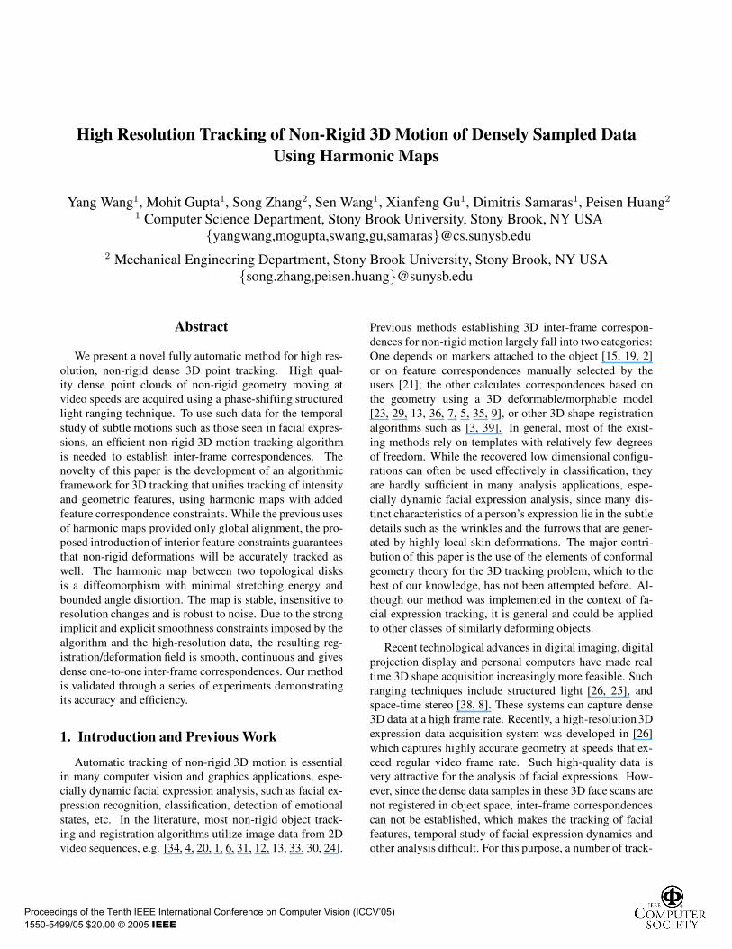
Figure 1. Snapshots from a tracking Sequence: a) Initial data frame b) Initial tracked frame c) Data at the expression peak d)Tracked data at the peak e) Close-up at the peak
ing algorithms have been proposed recently for 3D facialexpression data [38, 32]. Tracking methods based on op-tical flow estimation[38, 13] can be sensitive to noise fortextureless regions. A hierarchical tracking framework forhigh resolution 3D dynamic expression data was presentedin [32], using a deformable generic face model. However, itsuffers from problems like folding and clustering, which areinherent to the methods employing local optimization tech-niques such as FFD. Also, the face model needs to be man-ually divided into several deformable regions, with associ-ated shape and motion control parameters. This initial seg-mentation, along with the associated parameters has to berecovered statistically, requiring many experiments for eachdifferent expression of every subject. Although this mightbe acceptable for certain applications like motion capturefor computer graphics, it requires prohibitive amounts oftime and effort for processing of the large number of data-sets required for data driven applications in facial expres-sion analysis and synthesis[5].
In this paper, we present a novel fully automatic methodfor high resolution, non-rigid dense 3D point tracking. Highquality dense point clouds of facial geometry moving atvideo speeds are acquired using a phase-shifting basedstructured light ranging technique [26]. To use such datafor temporal study of the subtle dynamics in expressions, anefficient non-rigid 3D motion tracking algorithm is neededto establish inter-frame correspondences. In this paper, wepropose such an algorithmic framework that uses a math-ematical tool called harmonic maps [27, 22, 10, 11]. Har-monic maps were used in [37] to do surface matching, al-beit focusing on rigid transformations. Given the sourcemanifold M and the target manifold D, only the bound-ary condition u|∂M : ∂M → ∂D was used to constrainand uniquely determine the harmonic map u : M → D.For applications like high resolution facial tracking though,we need to account for non-rigid deformations, with a highlevel of accuracy. To this end, we introduce additional fea-ture correspondence constraints, in addition to the boundaryconstraint in our implementation of harmonic maps. We se-
lect a set of motion-representative feature corners (for ex-ample, for facial expression tracking, we select corners ofeyes, lips, eye brows etc.) and establish inter-frame corre-spondences using commonly used techniques (for example,hierarchical matching used in [34]). We can then integratethese correspondence constraints with the boundary condi-tion to calculate harmonic maps, which not only account forglobal rigid motion, but also subtle non-rigid deformationsand hence achieve high accuracy registration and tracking.
The theory of harmonic maps is based on conformal ge-ometry theory [14, 28]; the harmonic map between twotopological disks is a diffeomorphism with minimal stretch-ing energy and bounded angle distortion. Harmonic mapsare invariant for the same source surface with differentposes, thus making it possible to account for global rigidmotion. Harmonic maps are highly continuous, stable androbust to noise. They depend on the geometry in a con-tinuous manner. A very important property, which governsour registration and tracking algorithm is that the harmonicmap is one-to-one. To register two frames, we align their re-spective harmonic maps as closely as possible by imposingthe suitable boundary and feature constraints. The motiva-tion to do so is to establish a common parametric domainfor the two surfaces, which, coupled with the above men-tioned property, allows to recover 3D registration betweenthe two frames. In our case, the harmonic maps are dif-feomorphisms, that is one to one and on-to, and hence lendthemselves as a natural choice for surface parameterizationin tracking applications.
As part of our framework, a deforming generic facemodel is employed to track the dense 3D data sequencemoving at video speeds, with the harmonic maps guidingthe deformation field. The harmonic maps are constrained,and hence driven by the feature correspondences estab-lished between adjacent frames using an iterative scheme;the feature correspondences are made on texture and curva-ture images using standard techniques, such as corner de-tection and optical flow. Most surface regions have strongfeatures either in intensity or shape images. Our framework
Proceedings of the Tenth IEEE International Conference on Computer Vision (ICCV’05)
1550-5499/05 $20.00 © 2005 IEEE
uses both simultaneously providing denser feature tracking.Harmonic maps, thus, help us to simplify a 3D surface reg-istration problem to a 2D image matching problem. The re-sulting harmonic map provides dense registration betweenthe face model and the target frame, thereby computing themotion vectors for the vertices of the generic face model.Our system can not only track global facial motion that iscaused by muscle action, but also subtler expression detailsthat are generated by highly local skin deformations. Wehave achieved high accuracy tracking results on facial ex-pression sequences, which are comparable to those reportedin [32, 17], using the same dense 3D data, while minimiz-ing the amount of human labor required for preprocessingand initialization. The above mentioned level of accuracy,coupled with the automatic nature of our method, demon-strates the merits of our framework for the purpose of highresolution tracking of non-rigid 3D motion.
The remainder of the paper is organized as follows: InSection 2, we give an overview of harmonic mapping. Sec-tion 3 explains our tracking method in detail. We first de-scribe the global alignment of 3D scans, followed by a de-scription of the registration algorithm based on harmonicmapping and an iterative refinement scheme using local fea-tures. Experimental results are presented in Section 4, andwe conclude with a discussion and future work in Section 5.
2. Harmonic Mapping
An important contribution of our tracking method is toreduce the non-rigid 3D tracking problem to a 2D imageregistration problem, which has been extensively studied.We are dealing with 3D surfaces, but since they are mani-folds, they have an inherent 2D structure which can be ex-ploited to make the problem more tractable using harmonicmaps.
A harmonic map H : M → D can be viewed as an em-bedding from a manifold M with disk topology to a planargraph D. A harmonic map is a critical point for the har-monic energy functional,
E(H) =∫
M
|dH |2dµM,
and can be calculated by minimizing E(H). The norm ofthe differential |dH | is given by the metric on M and D,and dµM is the measure on M [27, 22, 10, 11]. Since oursource manifold M is in the form of a discrete triangularmesh, we approximate the harmonic energy as [10, 37, 14],
E(H) =∑
[v0,v1]
k[v0,v1]|H(v0) − H(v1)|2, (1)
where [v0, v1] is an edge connecting two neighboring ver-tices v0 and v1, and k[v0,v1] is defined as
12(
(v0 − v2) · (v1 − v2)|(v0 − v2) × (v1 − v2)| +
(v0 − v3) · (v1 − v3)|(v0 − v3) × (v1 − v3)| ),
where {v0, v1, v2} and {v0, v1, v3} are two conjuncted tri-angular faces.
By minimizing the harmonic energy, a harmonic mapcan be computed using the Euler-Lagrange differentialequation for the energy functional, i.e. ∆E = 0, where ∆is the Laplace-Beltrami operator [27, 22, 10, 11]. This willlead to solving a sparse linear least-square system for themapping H of each vertex vi [10, 37, 14]. If the boundarycondition is given,
H |∂M : ∂M → ∂D, (2)
then the solution exists and is unique.For tracking purposes though, we need to align the two
harmonic maps closely together (as explained in Section 1),and hence track interior non-rigid deformations as well. Forthis purpose, we also incorporate additional hard constraintsto establish interior feature correspondences and to han-dle non-disk topologies (e.g., a 3D face scan with an openmouth). Suppose we have a point on an inner-boundary oran interior feature point vi on the 3D mesh M , which shouldbe mapped to a corresponding point wi on the target 2Dplane D. We can add it as a hard constraint H(vi) = wi
to the system from Equation 1 and 2. However, the result-ing harmonic energy is expected to increase due to the addi-tional hard constraints introduced. In order to reduce the en-ergy to achieve a smoother mapping, we use the Neumannboundary condition, a soft constraint. This condition justconstrains the boundary points of M to lie on the boundaryof the 2D disk D, the exact positions being governed bythe minimization of harmonic energy criteria. It is differentfrom the fixed boundary condition used for surface match-ing [37], in which each boundary point on the 3D mesh Mis mapped to a fixed point on the 2D disk, making it a hardconstraint. In our method, all the interior feature correspon-dences on the face scans which can be reliably establishedare given the maximum weight, and hence are chosen ashard constraints. In the absence of any strong features onthe boundary, the boundary condition is given a relativelylower weight, and hence the soft boundary constraint is em-ployed to minimize the harmonic energy.
Intuitively, consider the manifold M to be made of asheet of rubber [10]. The harmonic map with just theboundary constraint can be thought of as stretching theboundary of M over the boundary of the target 2D diskD. In this case, each point on the boundary of M is as-signed a fixed location on the boundary of D, where it willbe nailed down. The interior of the sheet then rearrangesto minimize the stretching(or folding), thus minimizing theenergy. Now, adding extra feature constraints is analogousto clamping down the rubber sheet at certain interior points.The harmonic map with added feature constraints acts likea clamped rubber sheet, rearranging around the nailed downinterior points to achieve the most stable configuration. The
Proceedings of the Tenth IEEE International Conference on Computer Vision (ICCV’05)
1550-5499/05 $20.00 © 2005 IEEE
points on the boundary of the rubber sheet M still remainon the boundary of D, though they are free to slide alongit (Neumann boundary condition, a soft constraint) to helpachieve the most stable configuration.
In our work, we compute harmonic maps between a sur-face undergoing non-rigid deformations (e.g. a human face)and a canonical unit disk on the plane. Harmonic maps havemany merits which are valuable for tracking purposes:
• First, the harmonic map is computed through global opti-mization, and takes into account the overall surface topology.Thus it does not suffer from local minima, folding, cluster-ing, which are common problems due to local optimization.
• Second, the harmonic map is not sensitive to the resolutionof the face surface, and to the noise on the surface. Evenif the data for the input surface is noisy, the result won’t beaffected significantly.
• Third, the harmonic map doesn’t require the surface to besmooth. It can be accurately computed even when the surfaceincludes sharp features.
• Forth, in our case, since the range of the map is a unit diskwhich is convex, the harmonic map exists, and is a diffeo-morphism, namely, the map is one to one and on-to. So itcan allow us to establish correspondences on 2D and recover3D registration from the same.
• Fifth, the harmonic map is determined by the metric, not theembedding. This implies that the harmonic map is invariantfor the same face surface with different poses. Furthermore,if there is not too much stretching between two faces with dif-ferent expressions, they will induce similar harmonic maps.Because our dynamic range sequences are acquired at a highframe rate (40 Hz), we can assume that the local deformationbetween two adjacent frames is small.
Furthermore, harmonic maps are easy to compute androbust to numerical errors. By using a traditional finite ele-ment method [18], they are easy to implement.
3. The Non-Rigid Tracking Algorithm
In this section, we present our novel fully automaticmethod for high resolution, non-rigid dense 3D point track-ing using harmonic maps. We first describe the global align-ment of 3D scans, followed by a description of the registra-tion algorithm based on harmonic mapping and an iterativerefinement scheme using local features.
3.1. Data Preparation and Initialization
The dynamic range sequences used in this paper arecollected by a phase-shifting based structured light rang-ing system [26]. When scanning faces, the real-time 3Dshape acquisition system returns high quality dense pointclouds of facial geometry with an average of 75 thousand
3D measurements per frame, at a 40Hz frame rate. TheRMS (Root-Means-Squared) error of the 3D range data isabout 0.05mm. Small holes around brows, eyes, nose, etc.are filled by a simple interpolation technique.
However, since the dense data samples in these 3D facescans are not registered in object space, inter-frame corre-spondences can not be established. Furthermore, the densepoint clouds differ across the scans both in terms of thenumber of data samples as well as the relative positionsof the samples on the surfaces. To solve these problems,a generic face model (a coarser face mesh) is fitted to thefirst 3D scan frame in the initialization step, by a variationalFree-Form Deformation (FFD) shape registration method[32, 16]. The FFD technique is employed only for fittingof the first frame, and not for subsequent tracking.
3.2. Global Alignment and Boundary Identification
In the captured sequences, in addition to the non-rigidfacial expression motion, there is also a certain amount ofrigid head motion involved. To account for the latter, wealign the 3D face scans globally. To start with, we manuallymark and identify the boundary of the first frame. We canthen apply the Iterative Closest Point(ICP) algorithm: foreach sample on the identified boundary of the first frame,we find the closest sample on subsequent frames and applya rigid body transformation that minimizes the distance be-tween corresponding points [3]. Once we have the bound-ary of the initial frame and the rigid transformation, we canalign the face scans globally and identify the boundaries ofthe subsequent frames.
3.3. Initial Coarse Registration
Once we have the global alignment, we want to capturethe non-rigid deformation between two adjacent frames Mi
and Mi+1. This inter-frame registration problem, resultingin a dense map R : Mi → Mi+1, is solved by finding acoarse set of interior feature correspondences.
The relative ease of finding feature correspondences on2D images as compared to 3D scans is the motivation forthe next step of mapping Mi and Mi+1, to 2D disks Di
and Di+1 respectively, using the boundary constraint asdescribed in Section 2. According to [37], the harmonicmapping is robust to boundary variation and occlusion.We define these mappings as Hi: Mi → Di and Hi+1:Mi+1 → Di+1. Following the disk mapping, we selecta sparse set of easily detectable motion representative fea-ture corners on the disks (for example, for facial expressiontracking, we select corners of eyes, corners of lips, tip ofthe nose etc.) using texture and shape information. For thelatter, we also adopted the idea of harmonic shape imagesas in [37], associating the curvature information of verticesin Mi to the corresponding ones in Di. In practice, these
Proceedings of the Tenth IEEE International Conference on Computer Vision (ICCV’05)
1550-5499/05 $20.00 © 2005 IEEE
(a) (b) (c)
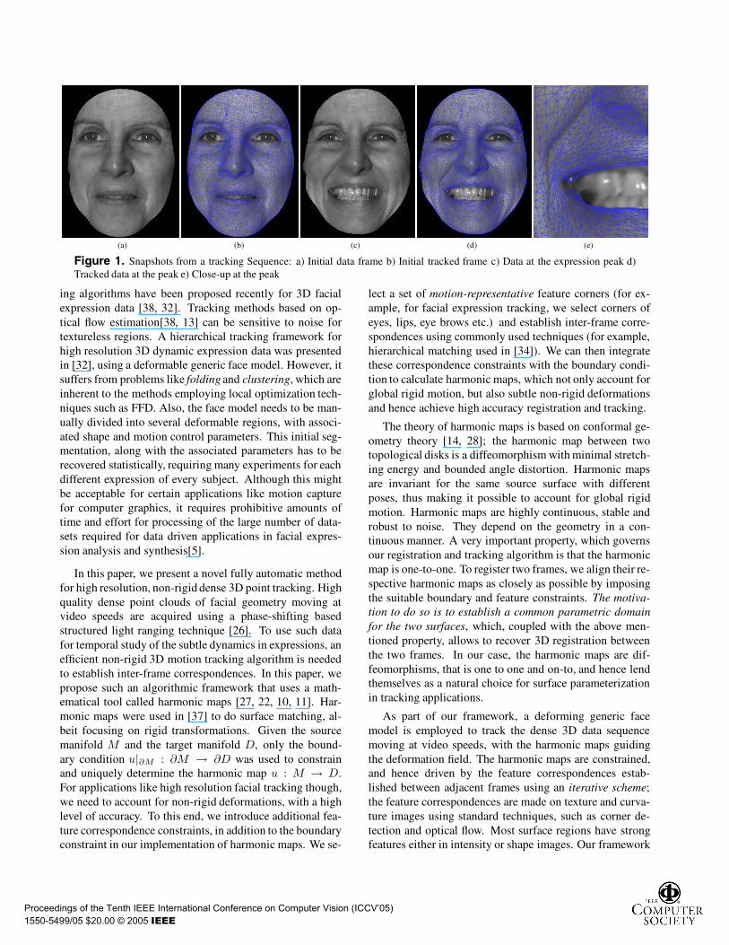
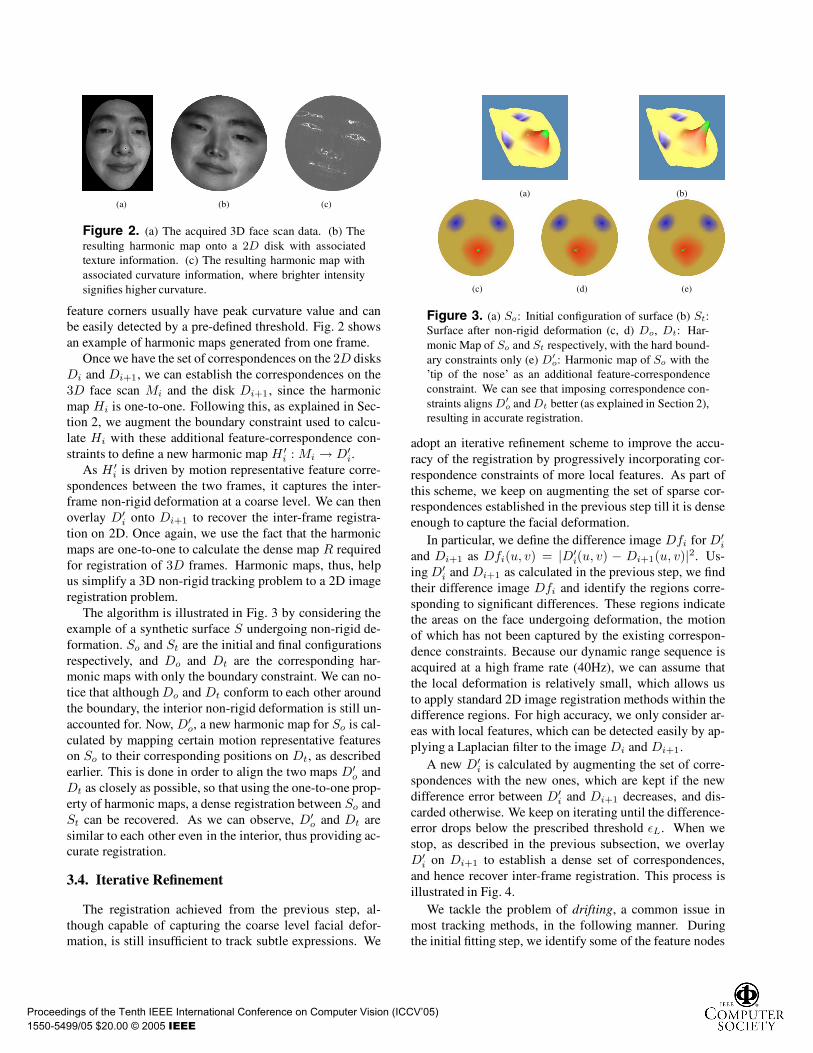
Figure 2. (a) The acquired 3D face scan data. (b) Theresulting harmonic map onto a 2D disk with associatedtexture information. (c) The resulting harmonic map withassociated curvature information, where brighter intensitysignifies higher curvature.
feature corners usually have peak curvature value and canbe easily detected by a pre-defined threshold. Fig. 2 showsan example of harmonic maps generated from one frame.
Once we have the set of correspondences on the 2D disksDi and Di+1, we can establish the correspondences on the3D face scan Mi and the disk Di+1 , since the harmonicmap Hi is one-to-one. Following this, as explained in Sec-tion 2, we augment the boundary constraint used to calcu-late Hi with these additional feature-correspondence con-straints to define a new harmonic map H ′
i : Mi → D′i.
As H ′i is driven by motion representative feature corre-
spondences between the two frames, it captures the inter-frame non-rigid deformation at a coarse level. We can thenoverlay D′
i onto Di+1 to recover the inter-frame registra-tion on 2D. Once again, we use the fact that the harmonicmaps are one-to-one to calculate the dense map R requiredfor registration of 3D frames. Harmonic maps, thus, helpus simplify a 3D non-rigid tracking problem to a 2D imageregistration problem.
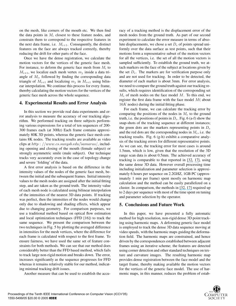
The algorithm is illustrated in Fig. 3 by considering theexample of a synthetic surface S undergoing non-rigid de-formation. So and St are the initial and final configurationsrespectively, and Do and Dt are the corresponding har-monic maps with only the boundary constraint. We can no-tice that although Do and Dt conform to each other aroundthe boundary, the interior non-rigid deformation is still un-accounted for. Now, D′
o, a new harmonic map for So is cal-culated by mapping certain motion representative featureson So to their corresponding positions on Dt, as describedearlier. This is done in order to align the two maps D′
o andDt as closely as possible, so that using the one-to-one prop-erty of harmonic maps, a dense registration between So andSt can be recovered. As we can observe, D′
o and Dt aresimilar to each other even in the interior, thus providing ac-curate registration.
3.4. Iterative Refinement
The registration achieved from the previous step, al-though capable of capturing the coarse level facial defor-mation, is still insufficient to track subtle expressions. We
(a) (b)
(c) (d) (e)
Figure 3. (a) So: Initial configuration of surface (b) St:Surface after non-rigid deformation (c, d) Do, Dt: Har-monic Map of So and St respectively, with the hard bound-ary constraints only (e) D′
o: Harmonic map of So with the’tip of the nose’ as an additional feature-correspondenceconstraint. We can see that imposing correspondence con-straints aligns D′
o and Dt better (as explained in Section 2),resulting in accurate registration.
adopt an iterative refinement scheme to improve the accu-racy of the registration by progressively incorporating cor-respondence constraints of more local features. As part ofthis scheme, we keep on augmenting the set of sparse cor-respondences established in the previous step till it is denseenough to capture the facial deformation.
In particular, we define the difference image Dfi for D′i
and Di+1 as Dfi(u, v) = |D′i(u, v) − Di+1(u, v)|2. Us-
ing D′i and Di+1 as calculated in the previous step, we find
their difference image Dfi and identify the regions corre-sponding to significant differences. These regions indicatethe areas on the face undergoing deformation, the motionof which has not been captured by the existing correspon-dence constraints. Because our dynamic range sequence isacquired at a high frame rate (40Hz), we can assume thatthe local deformation is relatively small, which allows usto apply standard 2D image registration methods within thedifference regions. For high accuracy, we only consider ar-eas with local features, which can be detected easily by ap-plying a Laplacian filter to the image Di and Di+1.
A new D′i is calculated by augmenting the set of corre-
spondences with the new ones, which are kept if the newdifference error between D′
i and Di+1 decreases, and dis-carded otherwise. We keep on iterating until the difference-error drops below the prescribed threshold εL. When westop, as described in the previous subsection, we overlayD′
i on Di+1 to establish a dense set of correspondences,and hence recover inter-frame registration. This process isillustrated in Fig. 4.
We tackle the problem of drifting, a common issue inmost tracking methods, in the following manner. Duringthe initial fitting step, we identify some of the feature nodes
Proceedings of the Tenth IEEE International Conference on Computer Vision (ICCV’05)
1550-5499/05 $20.00 © 2005 IEEE
on the mesh, like corners of the mouth etc. We then findthe data points in Mi closest to these feature nodes, andconstrain them to correspond to the respective features inthe next data frame, i.e. Mi+1. Consequently, the distinctfeatures on the face are always tracked correctly, therebyreducing the drift for other parts of the face.
Once we have the dense registration, we calculate themotion vectors for the vertices of the generic face mesh.For instance, to deform the generic face mesh from Mi toMi+1, we localize each mesh vertex mj inside a data tri-angle of Mi, followed by finding the corresponding datatriangle of Mi+1 and localizing mj in Mi+1 using bilin-ear interpolation. We continue this process for every frame,thereby calculating the motion vectors for the vertices of thegeneric face mesh across the whole sequence.
4. Experimental Results and Error Analysis
In this section we provide real data experiments and er-ror analysis to measure the accuracy of our tracking algo-rithm. We performed tracking on three subjects perform-ing various expressions for a total of ten sequences of 200-300 frames each (at 30Hz) Each frame contains approxi-mately 80K 3D points, whereas the generic face mesh con-tains 8K nodes. The tracking results are available as videoclips at http : //www.cs.sunysb.edu/samaras/, includ-ing opening and closing of the mouth (female subject) orstrongly asymmetric smile (male subject). Our techniquetracks very accurately even in the case of topology changeand severe ’folding’ of the data.
A first error analysis is based on the difference in theintensity values of the nodes of the generic face mesh, be-tween the initial and the subsequent frames. Initial intensityvalues to the mesh nodes are assigned after the initial fittingstep, and are taken as the ground truth. The intensity valueof each mesh node is calculated using bilinear interpolationof the intensities of the nearest 3D data points. If trackingwas perfect, then the intensities of the nodes would changeonly due to shadowing and shading effects, which appeardue to changing geometry. For comparison purposes, weuse a traditional method based on optical flow estimationand local optimization techniques (FFD [16]) to track thesame sequence. We present the comparison between thetwo techniques in Fig. 5 by plotting the averaged differencein intensities for the mesh vertices, where the difference foreach frame is calculated with respect to the first frame. Toensure fairness, we have used the same set of feature con-straints for both methods. We can see that our method doesconsiderably better than the FFD based method, which failsto track large non-rigid motion and breaks down. The error,increases significantly as the sequence progresses for FFDwhereas it remains relatively stable for our method, indicat-ing minimal tracking drift issues.
Another measure that can be used to establish the accu-
racy of a tracking method is the displacement error of themesh nodes from the ground truth. As part of our secondexperiment to calculate the error measure in terms of abso-lute displacements, we chose a set De of points spread uni-formly over the data surface as test points, such that theirmotions form a representative subset of the motion vectorsfor all the vertices, i.e. the set of all the motion vectors issampled sufficiently. To establish the ground truth, we at-tach markers on the face of the subject at locations given bythe set De. The markers are for verification purpose onlyand are not used for tracking. In order to be detected, thediameter of each marker is about 3mm. For error analysis,we need to compare the ground truth against our tracking re-sults, which requires identification of the corresponding setMe of mesh nodes on the face model M . To this end, weregister the first data frame with the face model M ( about16K nodes) during the initial fitting phase.
For each frame, we can calculate the tracking error bycomparing the positions of the nodes in Me to the groundtruth, i.e. the positions of points in De. Fig. 6 (a-f) show thesnap-shots of the tracking sequence at different instances;the green dots are the markers representing points in De
and the red dots are the corresponding nodes in Me , i.e. thetracking results. Fig. 6 (g-h) exhibit a comparative analy-sis of the tracking errors for different representative points.As we can see, the tracking error for most cases is around1.5mm, which is low, given that the resolution of the 3Drange scan data is about 0.5mm. The achieved accuracy oftracking is comparable to that reported in [32, 17], usingthe same dense 3D data. However overall processing timeincluding initialization and parameter selection is approxi-mately 6 hours per sequence on 2.2GHZ, 1GB PC (approx-imately 1 min per frame) spent mostly on harmonic mapcalculation and the method can be easily parallelized on acluster. In comparison, the methods in [32, 17] required upto 2 days per sequence with most of the time spent on tuningand parameter selection by the operator.
5. Conclusions and Future Work
In this paper, we have presented a fully automaticmethod for high resolution, non-rigid dense 3D point track-ing using harmonic maps. A deforming generic face modelis employed to track the dense 3D data sequence moving atvideo speeds, with the harmonic maps guiding the deforma-tion field. The harmonic maps are constrained, and hencedriven by the correspondences established between adjacentframes using an iterative scheme; the features are detectedusing corner detection and other standard techniques on tex-ture and curvature images. The resulting harmonic mapprovides dense registration between the face model and thetarget frame, thereby making available the motion vectorsfor the vertices of the generic face model. The use of har-monic maps, in this manner, reduces the problem of estab-
Proceedings of the Tenth IEEE International Conference on Computer Vision (ICCV’05)
1550-5499/05 $20.00 © 2005 IEEE
lishing correspondences in 3D, to that of 2D image registra-tion, which is more tractable. We have achieved high accu-racy tracking results on facial expression sequences, with-out manual intervention, demonstrating the merits of ouralgorithm for the purpose. In future work, we will exploitthe knowledge of underlying facial muscle structure to im-pose more constraints on the tracking process, in order tofurther increase accuracy. We also plan to use the proposedframework for more applications like face recognition anddynamic expression recognition for dense 3D data.
6. Acknowledgements
We are grateful to Deborah Mayo for the help with thework presented in this paper. This work was partially sup-ported by grants: NSF ACI-0313184, NSF CMS-9900337,NSF CAREER Award CCF-0448339, NIH RR13995, andDOJ 2004-DD-BX-1224.
References
[1] Y. Akgul and C. Kambhamettu. Recovery and tracking ofcontinuous 3d surfaces from stereo data using a deformabledual-mesh. In ICCV99, pages 765–772, 1999.
[2] B. Allen, B. Curless, and Z. Popovic. The space of humanbody shapes: Reconstruction and parameterization fromrange scans. ACM Trans. Graph., 22(3):587–594, 2003.
[3] P. Besl and N. McKay. A method for registration of 3-dshapes. PAMI, 14(2), 1992.
[4] M. Black and Y. Yacoob. Tracking and recognizing rigidand non-rigid facial motions using local parametric modelsof image motion. In ICCV95, pages 374–381, 1995.
[5] V. Blanz and T. Vetter. Face recognition based on fitting a3d morphable model. PAMI, 25(9):1063–1074, 2003.
[6] M. Brand and R. Bhotika. Flexible flow for 3d nonrigidtracking and shape recovery. In CVPR01, pages I:315–322.
[7] J. Chai, J. Xiao, and J. Hodgins. Vision-based control of 3dfacial animation. In ACM SIGGRAPH/Eurographics Sym-posium on Computer Animation, pages 193–206, 2003.
[8] J. Davis, R. Ramamoorthi, and S. Rusinkiewicz. Spacetimestereo: A unifying framework for depth from triangulation.In CVPR’03, pages 359–366, 2003.
[9] M. Dimitrijevic, S. Ilic, and P. Fua. Accurate face modelsfrom uncalibrated and ill-lit video sequences. In CVPR04,pages II: 1034–1041, 2004.
[10] M. Eck, T. DeRose, T. Duchamp, H. Hoppe, M. Louns-bery, and W. Stuetzle. Multiresolution analysis of arbitrarymeshes. In SIGGRAPH’95, pages 173–182, 1995.
[11] J. Eells and J. H. Sampson. Harmonic mappings of rieman-nian manifolds. Amer. J. Math., 86(109-160), 1964.
[12] S. Gokturk, J. Bouguet, and R. Grzeszczuk. A data-drivenmodel for monocular face tracking. In ICCV01, 2001.
[13] S. K. Goldenstein, C. Vogler, and D. Metaxas. Statisticalcue integration in dag deformable models. PAMI, 25(7).
[14] X. Gu and S. Yau. Surface classification using conformalstructures. In ICCV’03, pages 701–708, 2003.
[15] B. Guenter, C. Grimm, D. Wood, H. Malvar, and F. Pighin.Making faces. In SIGGRAPH’98, pages 55–66, 1998.
[16] X. Huang, N. Paragios, and D. Metaxas. Establishinglocal correspondences towards compact representations ofanatomical structures. In MICCAI’03, pages 926–934, 2003.
[17] X. Huang, S. Zhang, Y. Wang, D. Metaxas, and D. Samaras.A hierarchical framework for high resolution facial expres-sion tracking. In IEEE Workshop on Articulated and Non-rigid Motion, 2004.
[18] T. Hughes. The Finite Element Method. Prentice-Hall, 1987.[19] G. A. Kalberer and L. V. Gool. Face animation based on
observed 3d speech dynamics. In IEEE Conf. on ComputerAnimation.
[20] J. Lien, T. Kanade, A. Zlochower, J. Cohn, and C. Li. Subtlydifferent facial expression recognition and expression inten-sity estimation. In CVPR’98, pages 853–859.
[21] J.-Y. Noh and U. Neumann. Expression cloning. In SIG-GRAPH’01, pages 277–288, 2001.
[22] B. O’Neill. Elementary Differential Geometry. 1997.[23] F. Pighin, R. Szeliski, and D. Salesin. Resynthesizing facial
animation through 3d model-based tracking. In ICCV99,pages 143–150, 1999.
[24] D. Ramanan and D. Forsyth. Finding and tracking peoplefrom the bottom up. In CVPR03, pages II: 467–474, 2003.
[25] S. Rusinkiewicz, O. Hall-Holt, and L. Marc. Real-time 3dmodel acquisition. In SIGGRAPH’02, pages 438–446.
[26] P. H. S. Zhang. High resolution, real time 3-d shape acquisi-tion. In IEEE Workshop on Real-time 3D Sensors and TheirUse (joint with CVPR’04), 2004.
[27] R. Schoen and S. T. Yau. Lectures on Harmonic Maps. Inter-national Press, Harvard University, Cambridge MA, 1997.
[28] E. Sharon and D. Mumford. 2d-shape analysis using confor-mal mapping. In CVPR04, pages II: 350–357.
[29] H. Tao and T. Huang. Explanation-based facial mo-tion tracking using a piecewise bezier volume deformationmodel. In CVPR99, pages I: 611–617, 1999.
[30] C. Tomasi, S. Petrov, and A. Sastry. 3d tracking = classifi-cation + interpolation. In ICCV03, pages 1441–1448, 2003.
[31] L. Torresani, D. Yang, E. Alexander, and C. Bregler. Track-ing and modeling non-rigid objects with rank constraints. InCVPR01, pages I:493–500, 2001.
[32] Y. Wang, X. Huang, C.-S. Lee, S. Zhang, Z. Li, D. Samaras,D. Metaxas, A. Elgammal, and P. Huang. High resolutionacquisition, learning and transfer of dynamic 3-d facial ex-pressions. Computer Graphics Forum, 23(3):677–686.
[33] Z. Wen and T. Huang. Capturing subtle facial motions in 3dface tracking. In ICCV03, pages 1343–1350, 2003.
[34] A. Witkin, D. Terzopoulos, and M. Kass. Signal matchingthrough scale space. IJCV, 1(2):133–144, 1987.
[35] J. Xiao, S. Baker, I. Matthews, and T. Kanade. Real-timecombined 2d+3d active appearance models. In CVPR04,pages II: 535–542, 2004.
[36] A. Yezzi and S. Soatto. Deformotion: Deforming motion,shape average and the joint registration and approximationof structures in images. IJCV, 53(2):153–167, 2003.
[37] D. Zhang and M. Hebert. Harmonic maps and their applica-tions in surface matching. In CVPR99, pages II: 524–530.
[38] L. Zhang, N. Snavely, B. Curless, and S. M. Seitz. Space-time faces: high resolution capture for modeling and anima-tion. ACM Trans. Graph., 23(3):548–558, 2004.
[39] Z. Zhang. Iterative point matching for registration of free-form curves and surfaces. IJCV, 13(2):119–152, 1994.
Proceedings of the Tenth IEEE International Conference on Computer Vision (ICCV’05)
1550-5499/05 $20.00 © 2005 IEEE
(a) (c) (e)
(b) (d) (f)
0 2 4 6 8 10 121
1.02
1.04
1.06
1.08
1.1
1.12
1.14
1.16
1.18
Ave
rage
Inte
nsity
Err
or (
0−25
5)
Feature Number
Iterative Tracking Refinement
(g)
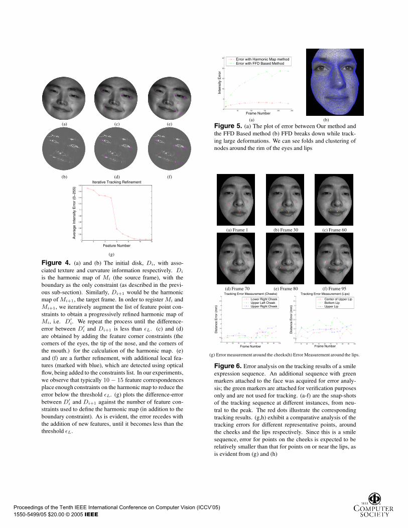
Figure 4. (a) and (b) The initial disk, Di, with asso-ciated texture and curvature information respectively. Di
is the harmonic map of Mi (the source frame), with theboundary as the only constraint (as described in the previ-ous sub-section). Similarly, Di+1 would be the harmonicmap of Mi+1, the target frame. In order to register Mi andMi+1, we iteratively augment the list of feature point con-straints to obtain a progressively refined harmonic map ofMi, i.e. D′
i. We repeat the process until the difference-error between D′
i and Di+1 is less than εL. (c) and (d)are obtained by adding the feature corner constraints (thecorners of the eyes, the tip of the nose, and the corners ofthe mouth.) for the calculation of the harmonic map. (e)and (f) are a further refinement, with additional local fea-tures (marked with blue), which are detected using opticalflow, being added to the constraints list. In our experiments,we observe that typically 10 − 15 feature correspondencesplace enough constraints on the harmonic map to reduce theerror below the threshold εL. (g) plots the difference-errorbetween D′
i and Di+1 against the number of feature con-straints used to define the harmonic map (in addition to theboundary constraint). As is evident, the error recedes withthe addition of new features, until it becomes less than thethreshold εL.
50 100 150 200 2500
5
10
15
20
25
Inte
nsity
Err
or
Frame Number
Error with Harmonic Map methodError with FFD Based Method
(a) (b)
Figure 5. (a) The plot of error between Our method andthe FFD Based method (b) FFD breaks down while track-ing large deformations. We can see folds and clustering ofnodes around the rim of the eyes and lips
(a) Frame 1 (b) Frame 30 (c) Frame 60
(d) Frame 70 (e) Frame 80 (f) Frame 95
10 20 30 40 50 60 70 80 90 1000
0.5
1
1.5
2
2.5
3
3.5
4
4.5
5
Dis
tanc
e E
rror
(m
m)
Frame Number
Tracking Error Measurement (Cheeks)
Lower Right CheekUpper Left CheekUpper Right Cheek
10 20 30 40 50 60 70 80 90 1000
0.5
1
1.5
2
2.5
3
3.5
4
4.5
5
Dis
tanc
e E
rror
(m
m)
Frame Number
Tracking Error Measurement (Lips)
Center of Upper LipBottom LipUpper Lip
(g) Error measurement around the cheeks.(h) Error Measurement around the lips.
Figure 6. Error analysis on the tracking results of a smileexpression sequence. An additional sequence with greenmarkers attached to the face was acquired for error analy-sis; the green markers are attached for verification purposesonly and are not used for tracking. (a-f) are the snap-shotsof the tracking sequence at different instances, from neu-tral to the peak. The red dots illustrate the correspondingtracking results. (g,h) exhibit a comparative analysis of thetracking errors for different representative points, aroundthe cheeks and the lips respectively. Since this is a smilesequence, error for points on the cheeks is expected to berelatively smaller than that for points on or near the lips, asis evident from (g) and (h)
Proceedings of the Tenth IEEE International Conference on Computer Vision (ICCV’05)
1550-5499/05 $20.00 © 2005 IEEE


