Embed Size (px)
Citation preview
Highly birefringent microstructured fibers with enhanced sensitivity to hydrostatic pressure
Tadeusz Martynkien1,*
, Gabriela Statkiewicz-Barabach1, Jacek Olszewski
1,
Jan Wojcik2,Paweł Mergo
2, Thomas Geernaert
3, Camille Sonnenfeld
3,
Alicja Anuszkiewicz1, Marcin K. Szczurowski
1, Karol Tarnowski
1, Mariusz Makara
2,
Krzysztof Skorupski 2
, Jacek Klimek2, Krzysztof Poturaj
2,Waclaw Urbanczyk
1,
Tomasz Nasilowski3, Francis Berghmans
3 and Hugo Thienpont
3
1 Institute of Physics, Wroclaw University of Technology, Wybrzeze Wyspianskiego 27, 50-370 Wroclaw, Poland 2 Department of Optical Fiber Technology, Marie Curie-Skłodowska University, Pl. M. Curie-Sklodowskiej 3,
20- 031 Lublin, Poland 3 Brussels Photonics Team: B-PHOT, Vrije Universiteit Brussel, Pleinlaan 2, 1050 Brussels, Belgium
Abstract: We designed, manufactured and characterized two birefringent microstructured fibers that feature a 5-fold increase in polarimetric sensitivity to hydrostatic pressure compared to the earlier reported values for microstructured fibers. We demonstrate a good agreement between the finite element simulations and the experimental values for the polarimetric sensitivity to pressure and to temperature. The sensitivity to hydrostatic
pressure has a negative sign and exceeds −43 rad/MPa × m at 1.55 µm for both fibers. In combination with the very low sensitivity to temperature, this makes our fibers the candidates of choice for the development of microstructured fiber based hydrostatic pressure measurement systems.
©2010 Optical Society of America
OCIS codes: (060.5295) Photonic crystal fibers; (060.4005) Microstructured fibers; (060.2420) Fibers, polarization-maintaining; (060.2270) Fiber characterization; (060.2370) Fiber optics sensors.
References and Links
1. C. Kerbage, and B. Eggleton, “Numerical analysis and experimental design of tunable birefringence in microstructured optical fiber,” Opt. Express 10(5), 246–255 (2002), http://www.opticsinfobase.org/oe/abstract.cfm?URI=oe-10-5-246.
2. T. M. Monro, D. J. Richardson, and P. J. Bennett, “Developing holey fibers for evanescent field devices,” Electron. Lett. 35(14), 1188–1189 (1999).
3. J. M. Fini, “Microstructured fibers for sensing in gases and liquids,” Meas. Sci. Technol. 15(6), 1120–1128 (2004).
4. J. B. Jensen, L. H. Pedersen, P. E. Hoiby, L. B. Nielsen, T. P. Hansen, J. R. Folkenberg, J. Riishede, D. Noordegraaf, K. Nielsen, A. Carlsen, and A. Bjarklev, “Photonic crystal fiber based evanescent-wave sensor for detection of biomolecules in aqueous solutions,” Opt. Lett. 29(17), 1974–1976 (2004).
5. B. J. Eggleton, P. S. Westbrook, R. S. Windeler, S. Spälter, and T. A. Strasser, “Grating resonances in air-silica microstructured optical fibers,” Opt. Lett. 24(21), 1460–1462 (1999).
6. S. J. Mihailov, D. Grobnic, H. Ding, C. W. Smelser, and J. Broeng, “Femtosecond IR laser fabrication of Bragg gratings in photonic crystal fibers and tapers,” IEEE Photon. Technol. Lett. 18(17), 1837–1839 (2006).
7. O. Frazão, J. P. Carvalho, L. A. Ferreira, F. M. Araújo, and J. L. Santos, “Discrimination of strain and temperature using Bragg gratings in microstructured and standard optical fibres,” Meas. Sci. Technol. 16(10), 2109–2113 (2005).
8. J. Canning, N. Groothoff, K. Cook, C. Martelli, A. Pohl, J. Holdsworth, S. Bandyopadhyay, and M. Stevenson, “Gratings in structured optical fibres,” Laser Chem. 2008, 1–20 (2008).
9. A. Cusano, D. Paladino, and A. Iadicicco, “Microstructured Fiber Bragg Gratings,” J. Lightwave Technol. 27(11), 1663–1697 (2009).
10. T. Geernaert, T. Nasilowski, K. Chah, M. Szpulak, J. Olszewski, G. Statkiewicz, J. Wojcik, K. Poturaj, W. Urbanczyk, M. Becker, M. Rothhardt, H. Bartelt, F. Berghmans, and H. Thienpont, “Fiber Bragg gratings in germanium-doped highly birefringent microstructured optical fibers,” IEEE Photon. Technol. Lett. 20(8), 554–556 (2008).
11. A. Ortigosa-Blanch, J. C. Knight, W. J. Wadsworth, J. Arriaga, B. J. Mangan, T. A. Birks, and P. St. J. Russell, “Highly birefringent photonic crystal fibers,” Opt. Lett. 25(18), 1325–1327 (2000).
#126727 - $15.00 USD Received 9 Apr 2010; revised 8 Jun 2010; accepted 10 Jun 2010; published 30 Jun 2010(C) 2010 OSA 5 July 2010 / Vol. 18, No. 14 / OPTICS EXPRESS 15113
12. K. Suzuki, H. Kubota, S. Kawanishi, M. Tanaka, and M. Fujita, “Optical properties of a low-loss polarization-maintaining photonic crystal fiber,” Opt. Express 9(13), 676–680 (2001), http://www.opticsinfobase.org/oe/abstract.cfm?URI=oe-9-13-676.
13. T. P. Hansen, J. Broeng, S. E. B. Libori, E. Knudsen, A. Bjarklev, J. R. Jensen, and H. Simonsen, “Highly birefringent index guiding photonic crystal fibers,” IEEE Photon. Technol. Lett. 13(6), 588–590 (2001).
14. M. J. Steel, and R. M. Osgood, Jr., “Polarization and dispersive properties of elliptical-hole photonic crystal fibers,” J. Lightwave Technol. 19(4), 495–503 (2001).
15. M. Szpulak, G. Statkiewicz, J. Olszewski, T. Martynkien, W. Urbańczyk, J. Wójcik, M. Makara, J. Klimek, T. Nasilowski, F. Berghmans, and H. Thienpont, “Experimental and theoretical investigations of birefringent holey fibers with a triple defect,” Appl. Opt. 44(13), 2652–2658 (2005).
16. J. R. Folkenberg, M. D. Nielsen, N. A. Mortensen, C. Jakobsen, and H. R. Simonsen, “Polarization maintaining large mode area photonic crystal fiber,” Opt. Express 12(5), 956–960 (2004), http://www.opticsinfobase.org/oe/abstract.cfm?URI=oe-12-5-956.
17. W. J. Bock, and W. Urbanczyk, “Measurements of sensitivity of birefringent holey fiber to temperature, elongation, and hydrostatic pressure,” Proc. of the 21st IEEE-Instrumentation and Measurement Technology Conference (Como, Italy 18–20 MAY 2004) vol. 2, pp. 1228–1232.
18. D. H. Kim, and J. U. Kang, “Sagnac loop interferometer based on polarization maintaining photonic crystal fiber with reduced temperature sensitivity,” Opt. Express 12(19), 4490–4495 (2004), http://www.opticsinfobase.org/abstract.cfm?URI=oe-12-19-4490.
19. C. H. L. Zhao, X. Yang, Ch. Lu, W. Jin, and M. S. Demokan, “Temperature-insensitive interferometer using a highly birefringent photonic crystal fiber loop mirror,” IEEE Photon. Technol. Lett. 16(11), 2535–2537 (2004).
20. G. Statkiewicz, T. Martynkien, and W. Urbanczyk, “Measurements of modal birefringence and polarymetic sensitivity of the birefringent holey fiber to hydrostatic pressure and strain,” Opt. Commun. 241(4-6), 339–348 (2004).
21. W. J. Bock, J. Chen, T. Eftimov, and W. Urbanczyk, “A photonic crystal fiber sensor for pressure measurements,” IEEE Trans. Instrum. Meas. 55(4), 1119–1123 (2006).
22. H. Y. Fu, H. Y. Tam, L. Y. Shao, X. Dong, P. K. Wai, C. Lu, and S. K. Khijwania, “Pressure sensor realized with polarization-maintaining photonic crystal fiber-based Sagnac interferometer,” Appl. Opt. 47(15), 2835–2839 (2008).
23. Y. S. Shinde, and H. K. Gahir, “Dynamic pressure sensing study using photonic crystal fiber: Application to tsunami sensing,” IEEE Photon. Technol. Lett. 20(4), 279–281 (2008).
24. O. Frazão, J. M. Baptista, J. L. Santos, and Ph. Roy, “Curvature sensor using a highly birefringent photonic crystal fiber with two asymmetric hole regions in a Sagnac interferometer,” Appl. Opt. 47(13), 2520–2523 (2008).
25. Ch. Jewart, K. P. Chen, B. McMillen, M. M. Bails, S. P. Levitan, J. Canning, and I. V. Avdeev, “Sensitivity enhancement of fiber Bragg gratings to transverse stress by using microstructural fibers,” Opt. Lett. 31(15), 2260–2262 (2006).
26. T. Martynkien, M. Szpulak, and W. Urbanczyk, “Modeling and measurement of temperature sensitivity in birefringent photonic crystal holey fibers,” Appl. Opt. 44(36), 7780–7788 (2005).
27. T. Martynkien, G. Statkiewicz, M. Szpulak, J. Olszewski, G. Gołojuch, W. Urbanczyk, J. Wojcik, P. Mergo, M. Makara, T. Nasilowski, F. Berghmans, and H. Thienpont, “Measurements of polarimetric sensitivity to temperature in birefringent holey fibers,” Meas. Sci. Technol. 18(10), 3055–3060 (2007).
28. M. Szpulak, T. Martynkien, and W. Urbanczyk, “Effects of hydrostatic pressure on phase and group modal birefringence in microstructured holey fibers,” Appl. Opt. 43(24), 4739–4744 (2004).
29. W. Urbanczyk, T. Martynkien, and W. J. Bock, “Dispersion effects in elliptical-core highly birefringent fibers,” Appl. Opt. 40(12), 1911–1920 (2001).
30. R. B. Dyott, Elliptical Fiber Waveguides, Artech House, Boston, Mass., 1995. 31. T. Geernaert, M. Becker, T. Nasilowski, J. Wojcik, W. Urbanczyk, M. Rothhardt, Ch. Chojetzki, H. Bartelt, H.
Terryn, F. Berghmans, and H. Thienpont, “Bragg Grating Inscription in GeO2-doped Microstructured Optical Fibers,” J. Lightwave Technol. 28(10), 1459–1467 (2010).
32. N. Imoto, N. Yoshizawa, J. Sakai, and H. Tsuchiya, “Birefringence in single-mode optical fiber due to elliptical core deformation and stress anisotropy,” IEEE J. Quantum Electron. 18, 53–58 (1982).
33. K. Takada, J. Noda, and R. Ulrich, “Precision measurement of modal birefringence of highly birefringent fibers by periodic lateral force,” Appl. Opt. 24(24), 4387–4391 (1985).
34. P. Hlubina, and D. Ciprian, “Spectral-domain measurement of phase modal birefringence in polarization-maintaining fiber,” Opt. Express 15(25), 17019–17024 (2007), http://www.opticsinfobase.org/abstract.cfm?URI=oe-15-25-17019.
35. K. Bohnert, A. Frank, E. Rochat, K. Haroud, and H. Brändle, “Polarimetric fiber laser sensor for hydrostatic pressure,” Appl. Opt. 43(1), 41–48 (2004).
36. H. M. Xie, Ph. Dabkiewicz, R. Ulrich, and K. Okamoto, “Side-hole fiber for fiber-optic pressure sensing,” Opt. Lett. 11(5), 333–335 (1986).
37. J. R. Clowes, S. Syngellakis, and M. N. Zervas, “Pressure sensitivity of side-hole optical fiber sensors,” IEEE Photon. Technol. Lett. 10(6), 857–859 (1998).
38. W. Urbanczyk, M. S. Nawrocka, and W. J. Bock, “Digital demodulation system for low-coherence interferometric sensors based on highly birefringent fibers,” Appl. Opt. 40(36), 6618–6625 (2001).
39. J. A. Croucher, L. Gomez-Rojas, S. Kanellopoulos, and V. A. Handerek, “Approach to highly sensitive pressure measurements using side-hole fibre,” Electron. Lett. 34(2), 208–209 (1998).
#126727 - $15.00 USD Received 9 Apr 2010; revised 8 Jun 2010; accepted 10 Jun 2010; published 30 Jun 2010(C) 2010 OSA 5 July 2010 / Vol. 18, No. 14 / OPTICS EXPRESS 15114
40. S. Kreger, S. Calvert, and E. Udd, “High pressure sensing using fiber Bragg grating written in birefringent side hole fiber,” in Proceedings of IEEE Conference on Optical Fiber Sensors, (Portland, 2002), pp. 355–358.
41. E. Chmielewska, W. Urbańczyk, and W. J. Bock, “Measurement of pressure and temperature sensitivities of a Bragg grating imprinted in a highly birefringent side-hole fiber,” Appl. Opt. 42(31), 6284–6291 (2003).
42. C. M. Jewart, Q. Wang, J. Canning, D. Grobnic, S. J. Mihailov, and K. P. Chen, “Ultrafast femtosecond-laser-induced fiber Bragg gratings in air-hole microstructured fibers for high-temperature pressure sensing,” Opt. Lett. 35(9), 1443–1445 (2010).
43. D. S. Moon, B. H. Kim, A. Lin, G. Sun, Y.-G. Han, W.-T. Han, and Y. Chung, “The temperature sensitivity of Sagnac loop interferometer based on polarization maintaining side-hole fiber,” Opt. Express 15(13), 7962–7967 (2007), http://www.opticsinfobase.org/abstract.cfm?URI=oe-15-13-7962.
1. Introduction
Microstructured fibers (MSFs) receive an increasing interest for their potential in sensing applications. Various types of MSF sensors have already been proposed, including interferometric and polarimetric sensors of different physical parameters [1], evanescent field sensors for monitoring specific chemical compounds in gases [2, 3] and liquids [3, 4]. Moreover the first demonstration of Bragg grating inscription in MSFs [5] opened the way for applications of such elements for sensing purposes [6–10]. Highly birefringent (HB) MSFs reported for the first time in [11] revealed that the modal birefringence in HB MSFs can be one order of magnitude larger than in conventional HB fibers. The birefringence in MSFs is introduced either by breaking the hexagonal symmetry of the fiber structure [11–15] or by internal stress inducing an anisotropy of the refractive index in the core region [16]. The first
approach leads to strong form birefringence typically exceeding 10−3
at 1.55 µm. Meanwhile numerous publications reported on possible applications of birefringent MSFs in measurements of hydrostatic pressure, strain, bending and lateral force [17–25].
A crucial factor governing the potential of a particular optical fiber to carry out a specific sensing task remains its cross-sensitivity to temperature. Birefringent MSFs are most often made of glass with a uniform composition in the entire cross-section. Therefore, and in contrast to what occurs in standard fibers, there is no thermal stress induced by the difference in thermal expansion coefficients between the doped core region and the cladding in a MSF. The experimental results published so far indicate that the polarimetric sensitivity to temperature KT in HB MSFs strongly depends on the fiber geometry and can be up to 3 orders of magnitudes lower than in standard elliptical core fibers [17–19, 26, 27].
Hydrostatic pressure sensing is a promising application area for birefringent MSFs, especially when combined with very low temperature cross-sensitivity. The effect of hydrostatic pressure on the phase modal birefringence was first analyzed for commercially available birefringent MSF with two large holes adjacent to the core [28]. This work has shown that the polarimetric sensitivity to hydrostatic pressure KP is mostly related to pressure-induced stress birefringence in the core region. The sensitivity to pressure is therefore directly linked to the mechanical asymmetry of the microstructured region, which generates a large difference in the normal stress components in the fiber core. In commercially available HB MSF featuring two large holes adjacent to the core region, the pressure sensitivity is relatively
high and equals KP = −7.5 rad/MPa × m at λ = 1.55 µm [20]. For comparison, the polarimetric sensitivity to pressure is KP = +0.5 rad/MPa×m in a conventional HB elliptical core fiber and KP = +8 rad/MPa×m in bow-tie fibers at λ = 0.85 µm [29].
In this work, we present two novel designs for HB MSFs with a polarimetric sensitivity to hydrostatic pressure that exceeds previously reported values for microstructured fibers with a factor of 5 [20–23]. Whilst our fibers include a germanium doped inclusion in the core to allow inscribing Bragg gratings, the ratio KP/KT, which is an important figure of merit for such fibers, reaches record values of 980 K/MPa and 540 K/MPa. Our MSFs are therefore excellent candidates for hydrostatic pressure measurement systems without need for temperature compensation.
Our paper is further structured as follows. Section 2 deals with the actual design targets and strategy. In section 3 we detail the experimental results and we compare the measured values for polarimetric pressure and temperature sensitivities to those obtained with finite
#126727 - $15.00 USD Received 9 Apr 2010; revised 8 Jun 2010; accepted 10 Jun 2010; published 30 Jun 2010(C) 2010 OSA 5 July 2010 / Vol. 18, No. 14 / OPTICS EXPRESS 15115
element simulations carried out on the actual microstructure of the fabricated fibers. Section 4 closes our paper with the general conclusions.
2. Microstructured fiber designs
Enlarging the diameter of selected holes can optimize the required mechanical asymmetry in the microstructured cladding. This prevents applied external stress from being transferred into the core region along one of the fiber symmetry axes and enhances the polarimetric sensitivity to pressure. Using this reasoning and by applying the numerical approach shortly outlined in the following paragraphs, we have analyzed several fiber structures. We aimed at obtaining designs that fulfilled the following requirements:
(i) a significantly increased polarimetric sensitivity to hydrostatic pressure relying on relatively simple cross-section features to allow effective and repeatable manufacturing of the fiber;
(ii) a germanium doped core that allows inscribing Bragg gratings with conventional ultraviolet inscription techniques so that the fiber cannot only be used as an active element in interferometric or polarimetric sensors but also as a host for Bragg grating sensors;
(iii) a phase modal birefringence larger than 10−3
at 1.55 µm to minimize coupling between the polarization modes that can possibly be induced by external perturbations, for example by mounting the fiber in the sensing head. Moreover
birefringence greater than 10−3
assures sufficient (at least x
Bλ - y
Bλ = 1.5 nm)
separation of the Bragg peaks (each corresponding to one of the orthogonally polarized modes) thus allowing for a differential interrogation without using any polarizing elements in the detection system. It is worth to mention that direct measurements of that Bragg peak wavelength separation provides a very convenient way for monitoring birefringence changes;
(iv) a low polarimetric sensitivity to temperature KT to allow for hydrostatic pressure measurements with no need for temperature compensation.
In the modeling process, we first calculated the spectral dependence of the phase modal birefringence taking into account both the geometry of the microstructured cladding and the effect of the thermal stress induced by the germanium doped inclusion. To do so we determined the distribution of the normal σxx, σyy, σzz and shear σxy components of the thermal stress using a plane strain model. In a next step, the stress induced corrections to the refractive indices ∆nxx, ∆nyy, ∆nzz and ∆nxy were arranged into symmetric tensors and used to model the fiber birefringence with a fully vectorial finite element model (FEM). The calculations of the birefringence and of the sensitivities KP and KT also accounted for the spectral dependence of the refractive indices of pure and GeO2 doped glass as described by Sellmeier equations [30]. Moreover in the calculations of the stress components and of the corrections to the refractive index tensor, we used the material constants for pure and doped silica glass given in Table 1. To evaluate the material constants for germanium-doped glass, we used the estimated dependence of E, ν, α and Tg on the dopant concentration following the expressions in [29].
In the simulations, we considered a relatively small concentration of GeO2 in the doped inclusions, with a maximum of 3 mol%. Such GeO2 concentrations are sufficient to inscribe Bragg gratings for sensing applications in the MSFs [31], while maintaining the increase of the polarimetric sensitivity to temperature within very acceptable limits.
The thermal response of germanium doped MSFs is known to stem from [26, 32]:
(i) a temperature induced variation of the refractive index (thermooptic effect) in the glass and in the air filling the holes characterized by the respective thermooptic coefficients dn/dT and dnair/dT;
#126727 - $15.00 USD Received 9 Apr 2010; revised 8 Jun 2010; accepted 10 Jun 2010; published 30 Jun 2010(C) 2010 OSA 5 July 2010 / Vol. 18, No. 14 / OPTICS EXPRESS 15116
(ii) an expansion of the fibre in the radial and longitudinal directions described by the thermal expansion coefficient α;
(iii) the variation of the stress distribution throughout the MSF cross-section related to the different thermal expansion coefficients of pure silica and the doped region.
The first two factors have a purely geometrical nature and contribute to the temperature
sensitivity of pure silica MSFs [26] while the third factor is typical for doped fibers [32]. To
account simultaneously for these three effects, we determined the sensitivity of the phase modal birefringence B using the following relation:
o oT 300 C T=20 C ,
B BdB
dT T
=−
=∆
(1)
where BT = 300°C and BT = 20°C are the phase modal birefringence at 300 °C and at room temperature, respectively. Finally, the polarimetric sensitivity to temperature was calculated from the following relation:
T
2,
dBK B
dT
πα
λ = +
(2)
where the second term represents a contribution to KT resulting from temperature-induced fiber elongation.
To model the pressure sensitivity our approach followed that of the calculation of the phase modal birefringence and sensitivity to temperature [28]. First, we calculated the distribution of the normal σxx, σyy, and shear σxy stress components and structure deformation using a plane stress model for an applied hydrostatic pressure of p = 20 MPa. In the second step, the stress-induced corrections to the refractive indices ∆nxx, ∆nyy, ∆nzz and ∆nxy were determined. Finally, the structure deformation and the variations of the refractive index were imported in the software used for the electromagnetic FEM simulations. This allowed determining the phase modal birefringence under increased hydrostatic pressure and finally the MSF polarimetric pressure sensitivity:
p=20MPa p=0MPa
P
2.
B BK
p
πλ
− =
(3)
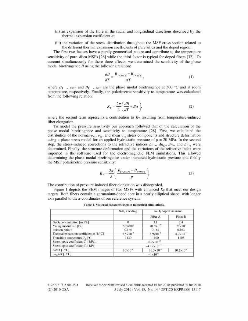
The contribution of pressure-induced fiber elongation was disregarded. Figure 1 depicts the SEM images of two MSFs with enhanced KP that meet our design
targets. Both fibers contain a germanium-doped core in a nearly elliptical shape, with longer axis parallel to the x-coordinates of our reference system.
Table 1. Material constants used in numerical simulations.
SiO2 cladding GeO2 doped inclusion
Fiber A Fiber B
GeO2 concentration [mol%] 0 3.1 2.4
Young modulus E [Pa] 72.5×10⁹ 70.6×10⁹ 71×109
Poisson ratio ν 0.165 0.162 0.163
Thermal expansion coefficient α [1/°C] 5.5×10⁻⁷ 8.9×10⁻⁷ 8.2×10⁻⁷
Transition temperature Tg [°C] 1130 1100 1105
Stress-optic coefficient C1 [1/Pa], −6.9×10⁻¹³
Stress-optic coefficient C2 [1/Pa] −41.9×10⁻¹³
dn/dT [1/°C] 10×10−6 10.3×10⁻⁶ 10.2×10⁻⁶
dnair/dT [1/°C] −1×10⁻⁶
#126727 - $15.00 USD Received 9 Apr 2010; revised 8 Jun 2010; accepted 10 Jun 2010; published 30 Jun 2010(C) 2010 OSA 5 July 2010 / Vol. 18, No. 14 / OPTICS EXPRESS 15117
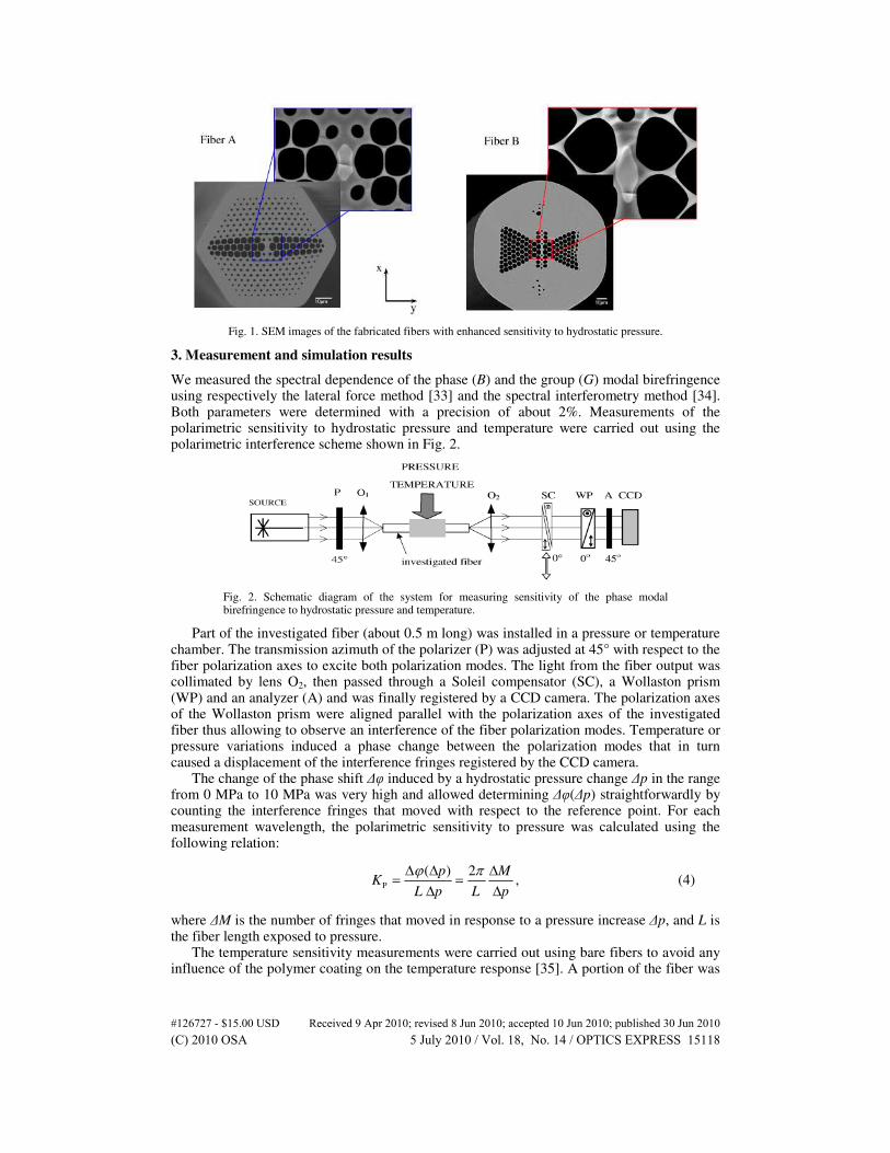
Fig. 1. SEM images of the fabricated fibers with enhanced sensitivity to hydrostatic pressure.
3. Measurement and simulation results
We measured the spectral dependence of the phase (B) and the group (G) modal birefringence using respectively the lateral force method [33] and the spectral interferometry method [34]. Both parameters were determined with a precision of about 2%. Measurements of the polarimetric sensitivity to hydrostatic pressure and temperature were carried out using the polarimetric interference scheme shown in Fig. 2.
Fig. 2. Schematic diagram of the system for measuring sensitivity of the phase modal birefringence to hydrostatic pressure and temperature.
Part of the investigated fiber (about 0.5 m long) was installed in a pressure or temperature chamber. The transmission azimuth of the polarizer (P) was adjusted at 45° with respect to the fiber polarization axes to excite both polarization modes. The light from the fiber output was collimated by lens O2, then passed through a Soleil compensator (SC), a Wollaston prism (WP) and an analyzer (A) and was finally registered by a CCD camera. The polarization axes of the Wollaston prism were aligned parallel with the polarization axes of the investigated fiber thus allowing to observe an interference of the fiber polarization modes. Temperature or pressure variations induced a phase change between the polarization modes that in turn caused a displacement of the interference fringes registered by the CCD camera.
The change of the phase shift ∆φ induced by a hydrostatic pressure change ∆p in the range from 0 MPa to 10 MPa was very high and allowed determining ∆φ(∆p) straightforwardly by counting the interference fringes that moved with respect to the reference point. For each measurement wavelength, the polarimetric sensitivity to pressure was calculated using the following relation:
P
( ) 2,
p MK
L p L p
ϕ π∆ ∆ ∆= =
∆ ∆ (4)
where ∆M is the number of fringes that moved in response to a pressure increase ∆p, and L is the fiber length exposed to pressure.
The temperature sensitivity measurements were carried out using bare fibers to avoid any influence of the polymer coating on the temperature response [35]. A portion of the fiber was
#126727 - $15.00 USD Received 9 Apr 2010; revised 8 Jun 2010; accepted 10 Jun 2010; published 30 Jun 2010(C) 2010 OSA 5 July 2010 / Vol. 18, No. 14 / OPTICS EXPRESS 15118
exposed to temperature changes in the range from 20°C to 250°C. The temperature induced phase shift was typically lower than a fraction of the interference fringe. We therefore used a Soleil compensator to increase the measurement resolution. KT was determined using Eq. (4), where in this case ∆M stands for the fraction of the interference fringe measured using the Soleil compensator. We observed a linear response to hydrostatic pressure and temperature changes with no sign of hysteresis in both MSFs. The measurements were repeated six times for sake of statistical relevance. The estimated measurement uncertainty is about 10% for KT and about 3% for KP.
Finally we determined the sign of the phase change induced by temperature or pressure by observing the direction of the fringe displacement, while slowly tuning the wavelength of the laser diode. Because of the strong chromatic dispersion of the phase modal birefringence the phase difference between polarization modes increases with wavelength in HB MSFs. This effect was used to identify the sign of the temperature and pressure induced phase shifts: KT and KP were found to be negative in both fibers.
To verify our numerical approach the results of the measurements carried out in a wide spectral range were compared with the results of simulations obtained for the actual MSF geometry. The edges of the holes in the cladding and the doped inclusion were automatically detected by image processing of the SEM micrographs. We obtained a binary image of the fiber cross-sections that was used as a mask to generate the mesh for the FEM, which reflected the real shape and location of each hole and the doped inclusion with a precision of about 20 nm. To assure high numerical accuracy of our results, we applied a mesh composed of about 500 000 elements.
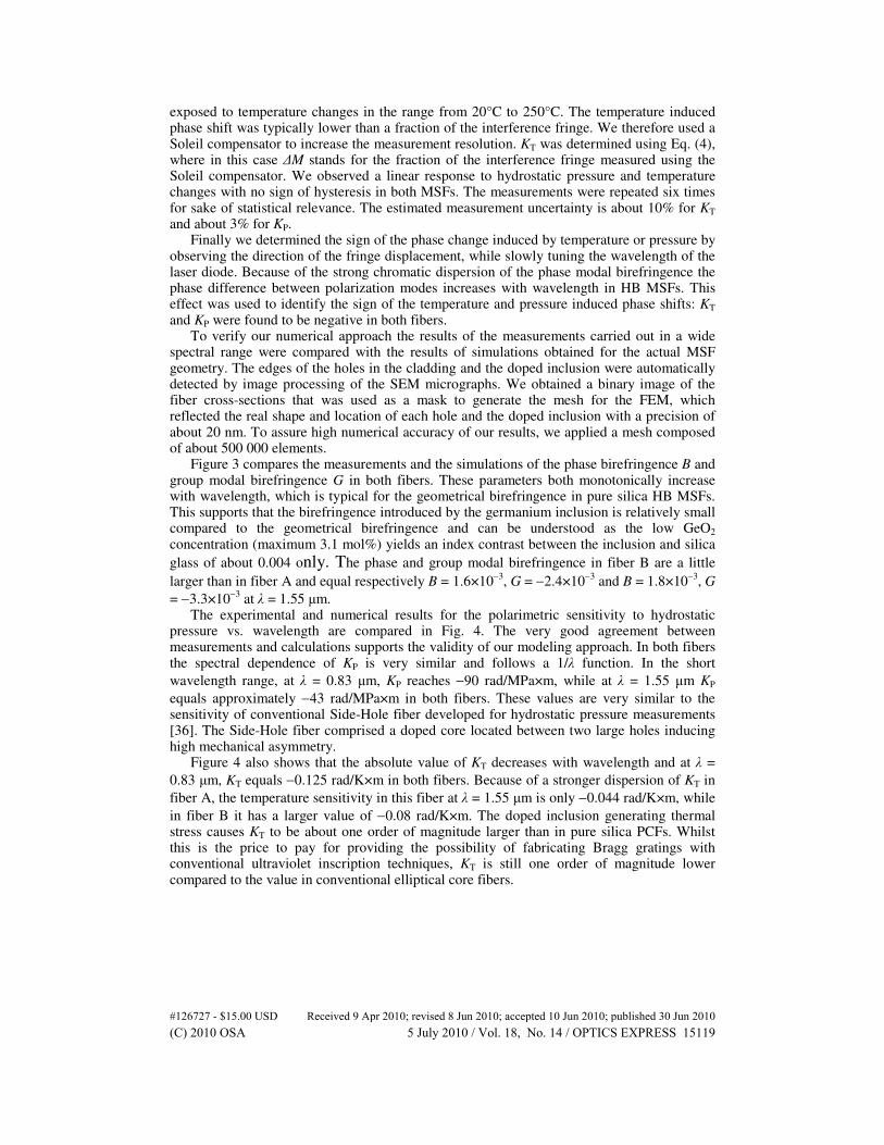
Figure 3 compares the measurements and the simulations of the phase birefringence B and group modal birefringence G in both fibers. These parameters both monotonically increase with wavelength, which is typical for the geometrical birefringence in pure silica HB MSFs. This supports that the birefringence introduced by the germanium inclusion is relatively small compared to the geometrical birefringence and can be understood as the low GeO2 concentration (maximum 3.1 mol%) yields an index contrast between the inclusion and silica
glass of about 0.004 only. The phase and group modal birefringence in fiber B are a little
larger than in fiber A and equal respectively B = 1.6×10⁻³
, G = −2.4×10⁻³
and B = 1.8×10⁻³
, G
= −3.3×10⁻³
at λ = 1.55 µm. The experimental and numerical results for the polarimetric sensitivity to hydrostatic
pressure vs. wavelength are compared in Fig. 4. The very good agreement between measurements and calculations supports the validity of our modeling approach. In both fibers the spectral dependence of KP is very similar and follows a 1/λ function. In the short
wavelength range, at λ = 0.83 µm, KP reaches −90 rad/MPa×m, while at λ = 1.55 µm KP
equals approximately −43 rad/MPa×m in both fibers. These values are very similar to the sensitivity of conventional Side-Hole fiber developed for hydrostatic pressure measurements [36]. The Side-Hole fiber comprised a doped core located between two large holes inducing high mechanical asymmetry.
Figure 4 also shows that the absolute value of KT decreases with wavelength and at λ =
0.83 µm, KT equals −0.125 rad/K×m in both fibers. Because of a stronger dispersion of KT in
fiber A, the temperature sensitivity in this fiber at λ = 1.55 µm is only −0.044 rad/K×m, while
in fiber B it has a larger value of −0.08 rad/K×m. The doped inclusion generating thermal stress causes KT to be about one order of magnitude larger than in pure silica PCFs. Whilst this is the price to pay for providing the possibility of fabricating Bragg gratings with conventional ultraviolet inscription techniques, KT is still one order of magnitude lower compared to the value in conventional elliptical core fibers.
#126727 - $15.00 USD Received 9 Apr 2010; revised 8 Jun 2010; accepted 10 Jun 2010; published 30 Jun 2010(C) 2010 OSA 5 July 2010 / Vol. 18, No. 14 / OPTICS EXPRESS 15119
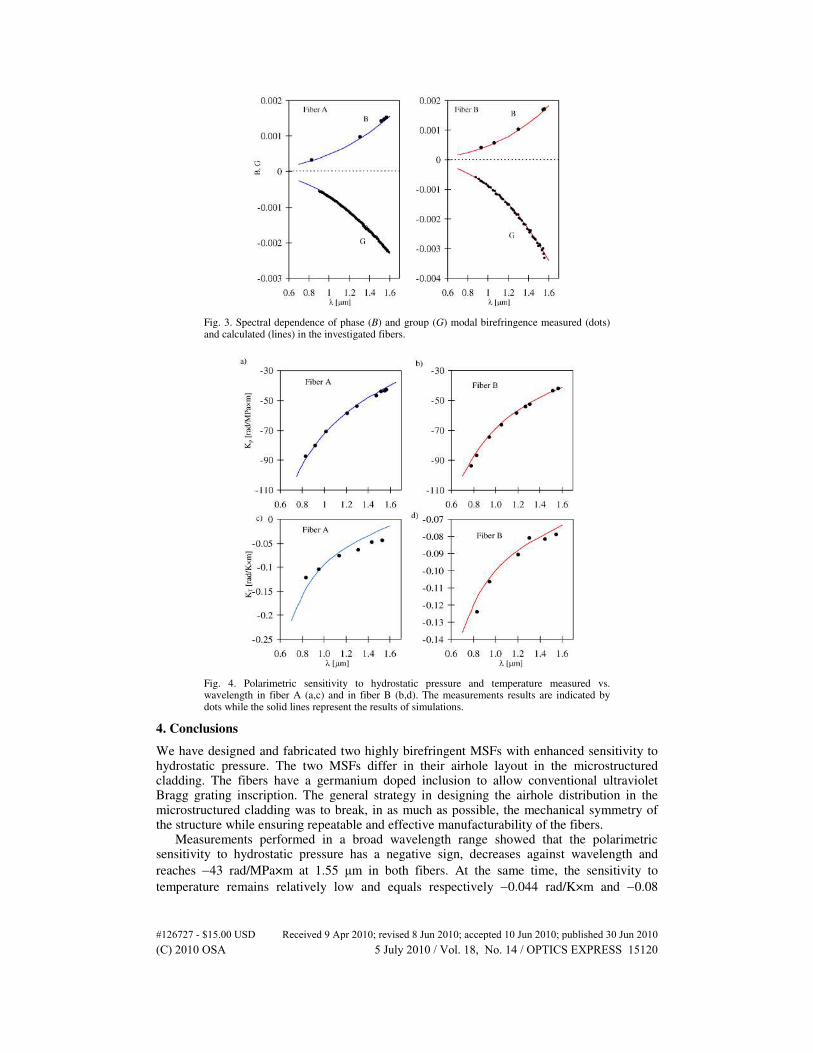
Fig. 3. Spectral dependence of phase (B) and group (G) modal birefringence measured (dots) and calculated (lines) in the investigated fibers.
Fig. 4. Polarimetric sensitivity to hydrostatic pressure and temperature measured vs. wavelength in fiber A (a,c) and in fiber B (b,d). The measurements results are indicated by dots while the solid lines represent the results of simulations.
4. Conclusions
We have designed and fabricated two highly birefringent MSFs with enhanced sensitivity to hydrostatic pressure. The two MSFs differ in their airhole layout in the microstructured cladding. The fibers have a germanium doped inclusion to allow conventional ultraviolet Bragg grating inscription. The general strategy in designing the airhole distribution in the microstructured cladding was to break, in as much as possible, the mechanical symmetry of the structure while ensuring repeatable and effective manufacturability of the fibers.
Measurements performed in a broad wavelength range showed that the polarimetric sensitivity to hydrostatic pressure has a negative sign, decreases against wavelength and
reaches −43 rad/MPa×m at 1.55 µm in both fibers. At the same time, the sensitivity to
temperature remains relatively low and equals respectively −0.044 rad/K×m and −0.08
#126727 - $15.00 USD Received 9 Apr 2010; revised 8 Jun 2010; accepted 10 Jun 2010; published 30 Jun 2010(C) 2010 OSA 5 July 2010 / Vol. 18, No. 14 / OPTICS EXPRESS 15120
rad/K×m at 1.55 µm, respectively in the fiber A and fiber B. This results in a record figure of merit KP/KT at 1.55 µm, which equals 980 K/MPa in fiber A and 540 K/MPa in fiber B.
The polarimetric sensitivity to hydrostatic pressure in the fibers reported in this work is similar to sensitivity of the Side-Hole fibers first proposed in [36] and later tested for hydrostatic pressure measurements using polarimetric or interferometric sensors [36–38], rocking filters [39] and Bragg gratings based sensors [40–42]. While the polarimetric sensitivity to pressure in the Side-Hole fibers reaches the value of 30-60 rad/MPa×m at λ = 1.55 µm depending on the holes size and location, the polarimetric sensitivity to temperature is inherently related to fiber birefringence. As it was shown in [43], in the elliptical core Side-
Hole fiber with B = 1.7×10⁻⁴
(refractive index contrast ∆n = 0.02) KT reach the value of −1.06
rad/MPa×m, while in the Side-Hole fiber with circular core B = 1.6x10⁻⁵
(∆n = 0.0046) KT =
−0.023rad/MPa×m at 1.55µm. An advantage of the proposed fibers over the Side-Hole fibers in pressure sensing based
on Bragg gratings lays in unique combination of three features:
(i) high polarimetric sensitivity to pressure resulting in high differential sensitivity of the grating inscribed in such fiber;
(ii) high birefringence resulting in very good separation of Bragg peaks corresponding to different polarization modes thus allowing for interrogation without polarization discrimination;
(iii) low concentration of GeO2, which on one hand allows for fast and repeatable fabrication of Bragg gratings, while on the other hand does not increase significantly KT.
One should note, that although the Side-Hole fibers and the proposed fibers show similar sensitivity to pressure, it is not possible to achieve in the class of Side-Hole fibers high birefringence without significantly increasing KT. This is because in the Side-Hole fibers the birefringence is directly related to the concentration of GeO2 in the core, while in our fibers high birefringence is induced mostly by microstructured cladding. The dopant concentration in our fibers is low because it is only necessary for convenient fabrication of Bragg gratings. Therefore, KT in our fibers is much lower compared to that in the Side-Hole fiber with a similar phase modal birefringence.
Acknowledgement
The work described in this paper was carried out with the support of the PHOSFOS-project (“Photonic Skins for Optical Sensing”), funded by the European Commission through the 7th ICT-Framework Programme. W. Urbanczyk acknowledges the Statutory Grant at Wroclaw University of Technology. J. Olszewski and G. Statkiewicz-Barabach acknowledge the Foundation for Polish Science FNP Program “START” and the fellowship co-financed by EU within European Social Funds. G. Statkiewicz-Barabach, J. Olszewski, A. Anuszkiewicz, K. Tarnowski, M. K. Szczurowski, acknowledge support of the FNP Program “MISTRZ”. T. Geernaert was funded by the Institute for the Promotion of Innovation through Science and Technology in Flanders (IWT-Vlaanderen). This work was also supported in part by the COST 299 action “FIDES” and the IWT SBO project “FAOS”. The Methusalem and Hercules Foundation, the Network of Excellence on Micro-Optics “NEMO”, the Research Foundation - Flanders (FWO-Vlaanderen), IAP and GOA are acknowledged as well. The SEM images were made by the Department SURF of the Vrije Universiteit Brussel.
#126727 - $15.00 USD Received 9 Apr 2010; revised 8 Jun 2010; accepted 10 Jun 2010; published 30 Jun 2010(C) 2010 OSA 5 July 2010 / Vol. 18, No. 14 / OPTICS EXPRESS 15121


