Embed Size (px)
Citation preview
Measurements of birefringent media properties usingoptical vortex birefringence compensator
Monika Borwinska,* Agnieszka Popiołek–Masajada, and Piotr KurzynowskiInstitute of Physics, Wrocław University of Technology, Wrocław, Poland
*Corresponding author: [email protected]
Received 13 February 2007; accepted 4 May 2007;posted 28 June 2007 (Doc. ID 80051); published 30 August 2007
We present some applications of the optical vortex birefringence compensator, based on the C polarizationtype singularities generated using two Wollaston compensators. The theory and experimental results ofbirefringent media properties measurements are presented. The possibility of the simultaneous measure-ment of both the azimuth angle and the phase retardance has been analyzed and experimentallyverified. © 2007 Optical Society of America
OCIS codes: 120.3180, 120.4640, 120.5410, 260.1560, 260.6042.
1. Introduction
Wave fields containing phase singularities, called op-tical vortices [1,2], have been recently used in inter-ferometry [3]. The stable and regular optical vortexlattices enable measurement of the influence of opti-cal media on some geometrical wave properties, forexample, high sensitive measurement of wave tilt,simultaneously reconstruction of the angle and direc-tion of the wave tilt caused by wedged objects [4,5],and displacement measurements [6]. The appliedvortex lattices had been generated by three planewave interference or using holographic methods. Op-tical singularities of another kind, C polarization typesingularities [7], enable extending the application ofsingular optics to the light polarization state mea-surements, including the birefringent media proper-ties measurements [8] and generation of opticalvortices using birefringent elements [9]. Birefringentmedia can be examined using several methods, forexample the polarizer-sample-analyzer method [10],two-wave-plate compensator method [11], a high ac-curacy universal polarimeter (HAUP) [12,13], animaging�Fourier polarimeter [14–16], a heterodyneinterferometer [17], or an imaging [18] interferome-ter. In our previous paper [19], we presented a po-lariscopic setup with two Wollaston compensators
generating in observation plane C polarization typesingularities, and it was suggested that using thissetup as an optical vortices generator there is thepossibility to measure linear birefringent mediumproperties. In this paper we consider in more detailthe influence of the birefringent medium parameterson the optical vortex lattice movement: Both the the-ory and experimental results of measurements arepresented here with the procedures used to deter-mine the medium parameters.
2. OVBC Setup
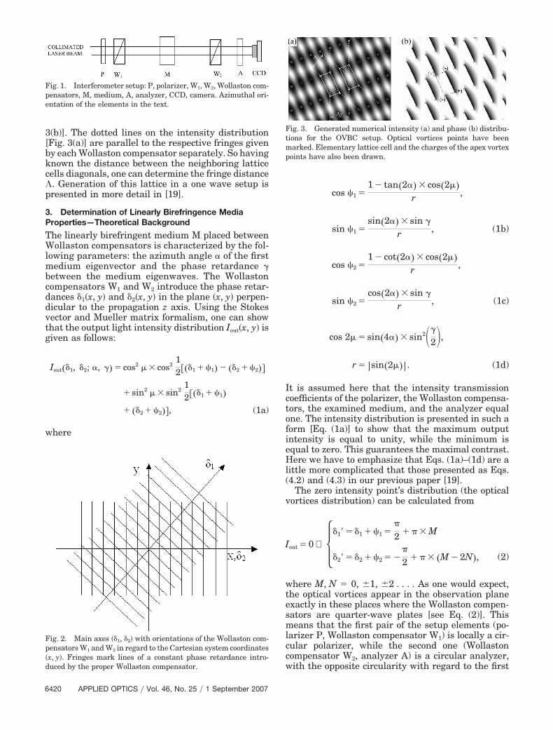
The main part of the optical vortex birefringence com-pensator (OVBC) setup consists of the following ele-ments (Fig. 1): the polarizer P with the azimuth angle�P � 0°, the first Wollaston compensator W1 with theazimuth angle �W1
� 45°, the second Wollaston com-pensator W2 with the azimuth angle �W2
� 0°, and theanalyzer A with the azimuth angle �A � 45°. Thebirefringent medium M of the plane-parallel plateform is placed between the Wollaston compensators.Visually speaking, the Wollaston compensators gen-erate fringes inclined with each other with the angle45° (Fig. 2), and after the analyzer the interferencepattern with the regular vortex lattice structure ap-pears. The exemplary intensity and phase distribu-tions of the wave after the analyzer are presented inFig. 3. The elementary lattice cell is of the tetragonalshape. The vortices of the same topological charge[20] lie on the respective diagonals of the cell [Fig.
0003-6935/07/256419-08$15.00/0© 2007 Optical Society of America
1 September 2007 � Vol. 46, No. 25 � APPLIED OPTICS 6419
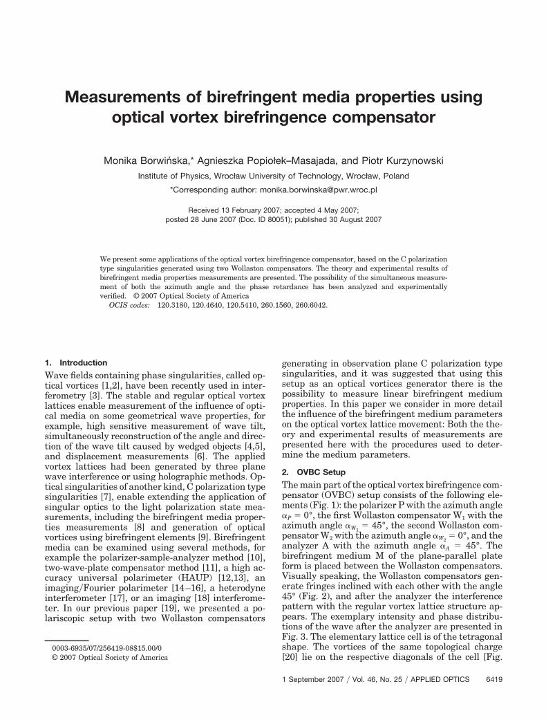
3(b)]. The dotted lines on the intensity distribution[Fig. 3(a)] are parallel to the respective fringes givenby each Wollaston compensator separately. So havingknown the distance between the neighboring latticecells diagonals, one can determine the fringe distance�. Generation of this lattice in a one wave setup ispresented in more detail in [19].
3. Determination of Linearly Birefringence MediaProperties—Theoretical Background
The linearly birefringent medium M placed betweenWollaston compensators is characterized by the fol-lowing parameters: the azimuth angle � of the firstmedium eigenvector and the phase retardance �between the medium eigenwaves. The Wollastoncompensators W1 and W2 introduce the phase retar-dances �1�x, y� and �2�x, y� in the plane �x, y� perpen-dicular to the propagation z axis. Using the Stokesvector and Mueller matrix formalism, one can showthat the output light intensity distribution Iout�x, y� isgiven as follows:
Iout��1, �2; �, �� � cos2 � � cos212���1 � �1� ��2 � �2��
� sin2 � � sin212���1 � �1�
� ��2 � �2��, (1a)
where
cos �1 �1 tan�2�� � cos�2��
r ,
sin �1 �sin�2�� � sin �
r , (1b)
cos �2 �1 cot�2�� � cos�2��
r ,
sin �2 �cos�2�� � sin �
r , (1c)
cos 2� � sin�4�� � sin2��
2�,r � sin�2��. (1d)
It is assumed here that the intensity transmissioncoefficients of the polarizer, the Wollaston compensa-tors, the examined medium, and the analyzer equalone. The intensity distribution is presented in such aform [Eq. (1a)] to show that the maximum outputintensity is equal to unity, while the minimum isequal to zero. This guarantees the maximal contrast.Here we have to emphasize that Eqs. (1a)–(1d) are alittle more complicated that those presented as Eqs.(4.2) and (4.3) in our previous paper [19].
The zero intensity point’s distribution (the opticalvortices distribution) can be calculated from
Iout � 0 ⇔ ��1� � �1 � �1 ��
2 � � � M
�2� � �2 � �2 � �
2 � � � �M 2N�, (2)
where M, N � 0, �1, �2 . . . . As one would expect,the optical vortices appear in the observation planeexactly in these places where the Wollaston compen-sators are quarter-wave plates [see Eq. (2)]. Thismeans that the first pair of the setup elements (po-larizer P, Wollaston compensator W1) is locally a cir-cular polarizer, while the second one (Wollastoncompensator W2, analyzer A) is a circular analyzer,with the opposite circularity with regard to the first
Fig. 3. Generated numerical intensity (a) and phase (b) distribu-tions for the OVBC setup. Optical vortices points have beenmarked. Elementary lattice cell and the charges of the apex vortexpoints have also been drawn.
Fig. 1. Interferometer setup: P, polarizer, W1, W2, Wollaston com-pensators, M, medium, A, analyzer, CCD, camera. Azimuthal ori-entation of the elements in the text.
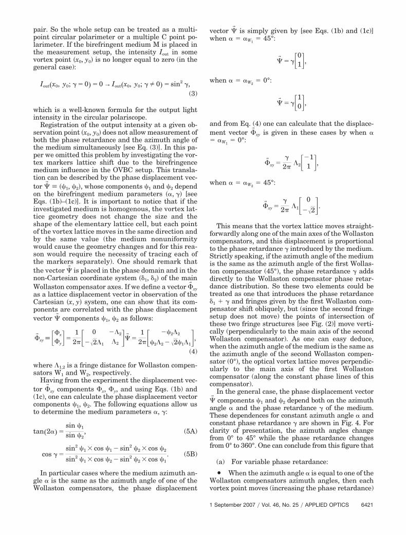
Fig. 2. Main axes ��1, �2� with orientations of the Wollaston com-pensators W1 and W2 in regard to the Cartesian system coordinates�x, y�. Fringes mark lines of a constant phase retardance intro-duced by the proper Wollaston compensator.
6420 APPLIED OPTICS � Vol. 46, No. 25 � 1 September 2007
pair. So the whole setup can be treated as a multi-point circular polarimeter or a multiple C point po-larimeter. If the birefringent medium M is placed inthe measurement setup, the intensity Iout in somevortex point �x0, y0� is no longer equal to zero (in thegeneral case):
Iout�x0, y0; � � 0� � 0 → Iout�x0, y0; � 0� � sin2 �,(3)
which is a well-known formula for the output lightintensity in the circular polariscope.
Registration of the output intensity at a given ob-servation point �x0, y0� does not allow measurement ofboth the phase retardance and the azimuth angle ofthe medium simultaneously [see Eq. (3)]. In this pa-per we omitted this problem by investigating the vor-tex markers lattice shift due to the birefringencemedium influence in the OVBC setup. This transla-tion can be described by the phase displacement vec-tor �� ��1, �2�, whose components �1 and �2 dependon the birefringent medium parameters ��, �� [seeEqs. (1b)–(1c)]. It is important to notice that if theinvestigated medium is homogenous, the vortex lat-tice geometry does not change the size and theshape of the elementary lattice cell, but each pointof the vortex lattice moves in the same direction andby the same value (the medium nonuniformitywould cause the geometry changes and for this rea-son would require the necessity of tracing each ofthe markers separately). One should remark thatthe vector �� is placed in the phase domain and in thenon-Cartesian coordinate system ��1, �2� of the mainWollaston compensator axes. If we define a vector �� xy
as a lattice displacement vector in observation of theCartesian �x, y� system, one can show that its com-ponents are correlated with the phase displacementvector �� components �1, �2 as follows:
�� xy �x
�y��
12� 0 �2
�2�1 �2��� �
12� �2�2
�2�2 �2�1�1�,
(4)
where �1,2 is a fringe distance for Wollaston compen-sators W1 and W2, respectively.
Having from the experiment the displacement vec-tor �� xy components �x, �y, and using Eqs. (1b) and(1c), one can calculate the phase displacement vectorcomponents �1, �2. The following equations allow usto determine the medium parameters �, �:
tan�2�� �sin �1
sin �2, (5A)
cos � �sin2 �1 � cos �1 sin2 �2 � cos �2
sin2 �1 � cos �2 sin2 �2 � cos �1. (5B)
In particular cases where the medium azimuth an-gle � is the same as the azimuth angle of one of theWollaston compensators, the phase displacement
vector �� is simply given by [see Eqs. (1b) and (1c)]when � � �W1
� 45°:
�� � �01�,when � � �W2
� 0°:
�� � �10�,and from Eq. (4) one can calculate that the displace-ment vector �� xy is given in these cases by when �� �W1
� 0°:
�� xy ��
2��21
1 �,when � � �W2
� 45°:
�� xy ��
2��1 0
�2�.
This means that the vortex lattice moves straight-forwardly along one of the main axes of the Wollastoncompensators, and this displacement is proportionalto the phase retardance � introduced by the medium.Strictly speaking, if the azimuth angle of the mediumis the same as the azimuth angle of the first Wollas-ton compensator (45°), the phase retardance � addsdirectly to the Wollaston compensator phase retar-dance distribution. So these two elements could betreated as one that introduces the phase retardance�1 � � and fringes given by the first Wollaston com-pensator shift obliquely, but (since the second fringesetup does not move) the points of intersection ofthese two fringe structures [see Fig. (2)] move verti-cally (perpendicularly to the main axis of the secondWollaston compensator). As one can easy deduce,when the azimuth angle of the medium is the same asthe azimuth angle of the second Wollaston compen-sator (0°), the optical vortex lattice moves perpendic-ularly to the main axis of the first Wollastoncompensator (along the constant phase lines of thiscompensator).
In the general case, the phase displacement vector�� components �1 and �2 depend both on the azimuthangle � and the phase retardance � of the medium.These dependences for constant azimuth angle � andconstant phase retardance � are shown in Fig. 4. Forclarity of presentation, the azimuth angles changefrom 0° to 45° while the phase retardance changesfrom 0° to 360°. One can conclude from this figure that
(a) For variable phase retardance:
Y When the azimuth angle � is equal to one of theWollaston compensators azimuth angles, then eachvortex point moves (increasing the phase retardance)
1 September 2007 � Vol. 46, No. 25 � APPLIED OPTICS 6421
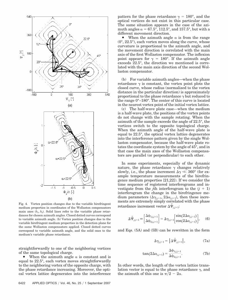
straightforwardly to one of the neighboring vorticesof the same topological charge.
Y When the azimuth angle � is constant and isequal to 22.5°, each vortex moves straightforwardlyto the neighboring vortex of the opposite charge, withthe phase retardance increasing. Moreover, the opti-cal vortex lattice degenerates into the interference
pattern for the phase retardance � � 180°, and theoptical vortices do not exist in this particular case.The same situation appears in the case of the azi-muth angles � � 67.5°, 112.5°, and 157.5°, but with adifferent movement direction.
Y When the azimuth angle � is from the range(0°, 22.5°), each vortex moves along the curve, whosecurvature is proportional to the azimuth angle, andthe movement direction is correlated with the mainaxis of the first Wollaston compensator. The inflexionpoint appears for � � 180°. If the azimuth angleexceeds 22.5°, the direction we mentioned is corre-lated with the main axis direction of the second Wol-laston compensator.
(b) For variable azimuth angles—when the phaseretardance � is constant, the vortex point plots theclosed curve, whose radius (normalized to the vortexdistance in the particular direction) is approximatelyproportional to the phase retardance � but reduced tothe range 0°–180°. The center of this curve is locatedin the nearest vortex point of the initial vortex lattice.
(c) The half-wave plate case—when the mediumis a half-wave plate, the positions of the vortex pointsdo not change with the sample rotating. When theazimuth of the sample exceeds the angle of 22.5°, thevortices switch to the opposite topological charge.When the azimuth angle of the half-wave plate isequal to 22.5°, the optical vortex lattice degeneratesinto the interference pattern given by the single Wol-laston compensator, because the half-wave plate ro-tates the coordinate system by the angle of 45°, and inthat case the main axes of the Wollaston compensa-tors are parallel (or perpendicular) to each other.
In some experiments, especially of the dynamicnature, the phase retardance � changes relativelyslowly, i.e., the phase increment �� �� 360° (for ex-ample temperature measurements of the birefrin-gence medium properties [21,22]). If we consider thetime sequence of registered interferograms and in-vestigate from the jth interferogram to the �j � 1�interferogram the change in the birefringence me-dium parameters ���j,j�1, 2��j,j�1�, then these incre-ments are extremely simply correlated with the phaseretardance increment vector ��� j,j�1:
��� j,j�1 ��1;j,j�1
��2;j,j�1�� ��j,j�1sin�2��j,j�1�
cos�2��j,j�1��, (6)
and Eqs. (5A) and (5B) can be rewritten in the form
��j,j�1 ���� j,j�1, (7a)
tan�2��j,j�1� ���1;j,j�1
��2;j,j�1. (7b)
In other words, the length of the vortex lattice trans-lation vector is equal to the phase retardance �, andthe azimuth of this one is ��2 2�.
Fig. 4. Vortex position changes due to the variable birefringentmedium properties in coordinates of the Wollaston compensatorsmain axes ��1, �2�. Solid lines refer to the variable phase retar-dances for chosen azimuth angles. Closed dotted curves correspondto variable azimuth angle. (b) Vortex position changes due to thevariable birefringent medium properties in the detection plane forthe same Wollaston compensators applied. Closed dotted curvescorrespond to variable azimuth angle, and the solid ones to themedium’s variable phase retardance.
6422 APPLIED OPTICS � Vol. 46, No. 25 � 1 September 2007
4. Experimental Results
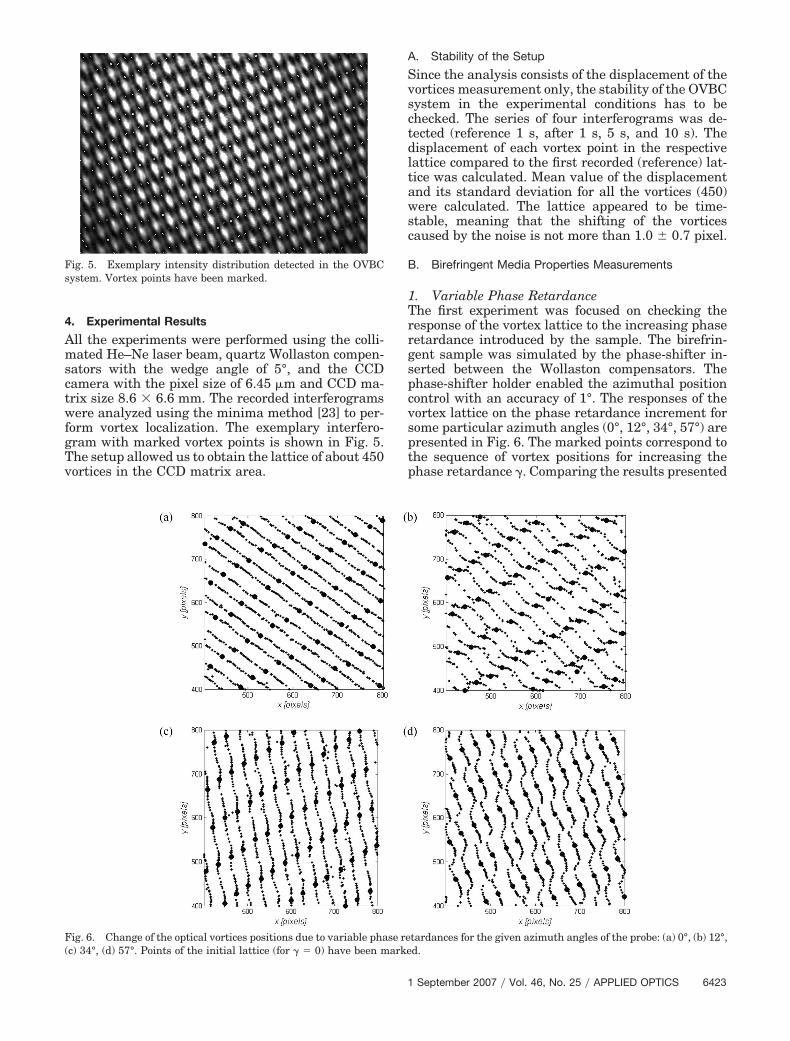
All the experiments were performed using the colli-mated He–Ne laser beam, quartz Wollaston compen-sators with the wedge angle of 5°, and the CCDcamera with the pixel size of 6.45 �m and CCD ma-trix size 8.6 � 6.6 mm. The recorded interferogramswere analyzed using the minima method [23] to per-form vortex localization. The exemplary interfero-gram with marked vortex points is shown in Fig. 5.The setup allowed us to obtain the lattice of about 450vortices in the CCD matrix area.
A. Stability of the Setup
Since the analysis consists of the displacement of thevortices measurement only, the stability of the OVBCsystem in the experimental conditions has to bechecked. The series of four interferograms was de-tected (reference 1 s, after 1 s, 5 s, and 10 s). Thedisplacement of each vortex point in the respectivelattice compared to the first recorded (reference) lat-tice was calculated. Mean value of the displacementand its standard deviation for all the vortices (450)were calculated. The lattice appeared to be time-stable, meaning that the shifting of the vorticescaused by the noise is not more than 1.0 � 0.7 pixel.
B. Birefringent Media Properties Measurements
1. Variable Phase RetardanceThe first experiment was focused on checking theresponse of the vortex lattice to the increasing phaseretardance introduced by the sample. The birefrin-gent sample was simulated by the phase-shifter in-serted between the Wollaston compensators. Thephase-shifter holder enabled the azimuthal positioncontrol with an accuracy of 1°. The responses of thevortex lattice on the phase retardance increment forsome particular azimuth angles (0°, 12°, 34°, 57°) arepresented in Fig. 6. The marked points correspond tothe sequence of vortex positions for increasing thephase retardance �. Comparing the results presented
Fig. 5. Exemplary intensity distribution detected in the OVBCsystem. Vortex points have been marked.
Fig. 6. Change of the optical vortices positions due to variable phase retardances for the given azimuth angles of the probe: (a) 0°, (b) 12°,(c) 34°, (d) 57°. Points of the initial lattice (for � � 0) have been marked.
1 September 2007 � Vol. 46, No. 25 � APPLIED OPTICS 6423
in Fig. 6 to the simulation results [Fig. (4)], one canconclude that the vortex lattice reaction observed inthe experiments confirms the theoretical predictionswith good accuracy.
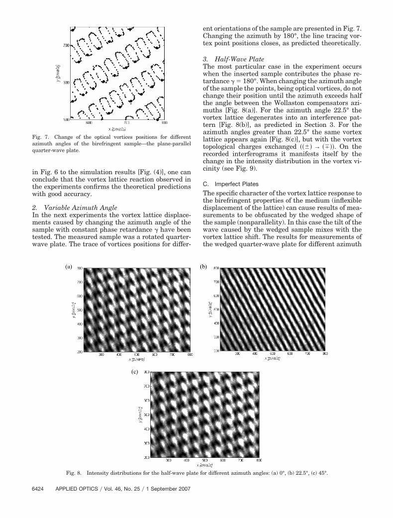
2. Variable Azimuth AngleIn the next experiments the vortex lattice displace-ments caused by changing the azimuth angle of thesample with constant phase retardance � have beentested. The measured sample was a rotated quarter-wave plate. The trace of vortices positions for differ-
ent orientations of the sample are presented in Fig. 7.Changing the azimuth by 180°, the line tracing vor-tex point positions closes, as predicted theoretically.
3. Half-Wave PlateThe most particular case in the experiment occurswhen the inserted sample contributes the phase re-tardance � � 180°. When changing the azimuth angleof the sample the points, being optical vortices, do notchange their position until the azimuth exceeds halfthe angle between the Wollaston compensators azi-muths [Fig. 8(a)]. For the azimuth angle 22.5° thevortex lattice degenerates into an interference pat-tern [Fig. 8(b)], as predicted in Section 3. For theazimuth angles greater than 22.5° the same vortexlattice appears again [Fig. 8(c)], but with the vortextopological charges exchanged ���� → ����. On therecorded interferograms it manifests itself by thechange in the intensity distribution in the vortex vi-cinity (see Fig. 9).
C. Imperfect Plates
The specific character of the vortex lattice response tothe birefringent properties of the medium (inflexibledisplacement of the lattice) can cause results of mea-surements to be obfuscated by the wedged shape ofthe sample (nonparallelity). In this case the tilt of thewave caused by the wedged sample mixes with thevortex lattice shift. The results for measurements ofthe wedged quarter-wave plate for different azimuth
Fig. 7. Change of the optical vortices positions for differentazimuth angles of the birefringent sample—the plane-parallelquarter-wave plate.
Fig. 8. Intensity distributions for the half-wave plate for different azimuth angles: (a) 0°, (b) 22.5°, (c) 45°.
6424 APPLIED OPTICS � Vol. 46, No. 25 � 1 September 2007
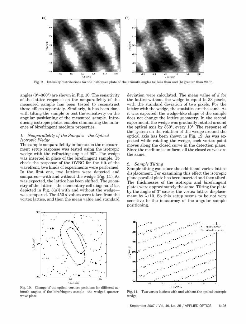
angles (0°–360°) are shown in Fig. 10. The sensitivityof the lattice response on the nonparallelity of themeasured sample has been tested to reconstructthese effects separately. Similarly, it has been donewith tilting the sample to test the sensitivity on theangular positioning of the measured sample. Intro-ducing isotropic plates enables eliminating the influ-ence of birefringent medium properties.
1. Nonparallelity of the Samples—the OpticalIsotropic WedgeThe sample nonparallellity influence on the measure-ment setup response was tested using the isotropicwedge with the refracting angle of 90°. The wedgewas inserted in place of the birefringent sample. Tocheck the response of the OVBC for the tilt of thewavefront, two kinds of experiments were performed.In the first one, two lattices were detected andcompared—with and without the wedge (Fig. 11). Aswas expected, the lattice has been shifted. The geom-etry of the lattice—the elementary cell diagonal d [asdepicted in Fig. 3(a)] with and without the wedge—was compared. The 450 d values were taken from thevortex lattice, and then the mean value and standard
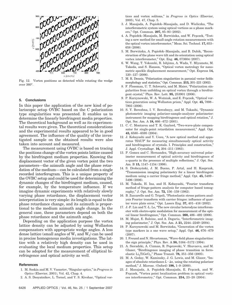
deviation were calculated. The mean value of d forthe lattice without the wedge is equal to 33 pixels,with the standard deviation of two pixels. For thelattice with the wedge, the statistics are the same. Asit was expected, the wedge-like shape of the sampledoes not change the lattice geometry. In the secondexperiment, the wedge was gradually rotated aroundthe optical axis by 360°, every 10°. The response ofthe system on the rotation of the wedge around theoptical axis has been shown in Fig. 12. As was ex-pected while rotating the wedge, each vortex pointmoves along the closed curve in the detection plane.Since the medium is uniform, all the closed curves arethe same.
2. Sample TiltingSample tilting can cause the additional vortex latticedisplacement. For examining this effect the isotropicplane parallel plate has been inserted and then tilted.The thicknesses of the isotropic and birefringentplates were approximately the same. Tilting the plateby the angle of 3° causes the vortex lattice displace-ment by ��10. So this setup seems to be not verysensitive to the inaccuracy of the angular samplepositioning.
Fig. 9. Intensity distributions for the half-wave plate of the azimuth angles (a) less than and (b) greater than 22.5°.
Fig. 10. Change of the optical vortices positions for different az-imuth angles of the birefringent sample—the wedged quarter-wave plate.
Fig. 11. Two vortex lattices with and without the optical isotropicwedge.
1 September 2007 � Vol. 46, No. 25 � APPLIED OPTICS 6425
5. Conclusions
In this paper the application of the new kind of po-lariscopic setup OVBC based on the C polarizationtype singularities was presented. It enables us todetermine the linearly birefringent media properties.The theoretical background as well as its experimen-tal results were given. The theoretical considerationsand the experimental results appeared to be in goodagreement. The influence of the quality of the inves-tigated sample on the obtained results were alsotaken into account and measured.
The measurement using OVBC is based on tracingthe positions change of the vortex points lattice causedby the birefringent medium properties. Knowing thedisplacement vector of the given vortex point the twoparameters—the azimuth angle and the phase retar-dation of the medium—can be calculated from a singlerecorded interferogram. This is a unique property ofthe OVBC setup and could be used for determining thedynamic changes of the birefringent medium, caused,for example, by the temperature influence. If weimagine dynamic experiments with relatively slowlyvarying phase retardance, the displacement vectorinterpretation is very simple: its length is equal to thephase retardance change, and its azimuth is propor-tional to the medium azimuth angle change. In thegeneral case, these parameters depend on both thephase retardance and the azimuth angle.
Depending on the application purpose the vortexlattice density can be adjusted by using Wollastoncompensators with appropriate wedge angles. A lessdense lattice (small angles of W1 and W2) can be usedin precise homogenous media investigations. The lat-tice with a relatively high density can be used inevaluating the local medium properties. This setupcan be adopted for the measurement of elliptical bi-refringence and optical activity as well.
References1. M. Soskin and M. V. Vasnetov, “Singular optics,” in Progress in
Optics (Elsevier, 2001), Vol. 42, Chap. 4.2. A. S. Desyatnikov, L. Tornel, and Y. S. Kivshar, “Optical vor-
tices and vortex solitons,” in Progress in Optics (Elsevier,2005), Vol. 47, Chap. 5.
3. J. Masajada, A. Popiołek–Masajada, and D. Wieliczka, “Theinterferometric system using optical vortices as a phase mark-ers,” Opt. Commun. 207, 85–93 (2002).
4. A. Popiołek–Masajada, M. Borwinska, and W. Fraczek, “Test-ing a new method for small-angle rotation measurements withthe optical vortex interferometer,” Meas. Sci. Technol. 17, 653–658 (2006).
5. M. Borwinska, A. Popiołek–Masajada, and B. Dubik, “Recon-struction of the plane wave tilt and its orientation using opticalvortex interferometer,” Opt. Eng. 46, 073604 (2007).
6. W. Wang, T. Yokozeki, R. Ishjima, A. Wada, Y. Miyamoto, M.Takeda, and S. Hanson, “Optical vortex metrology for nano-metric speckle displacement measurement,” Opt. Express 14,120–127 (2006).
7. M. R. Dennis, “Polarization singularities in paraxial vector fields:morphology and statistics,” Opt. Commun. 213, 201–221 (2002).
8. F. Flossman, U. T. Schwartz, and M. Maier, “Polarization sin-gularities from unfolding an optical vortex through a birefrin-gent crystal,” Phys. Rev. Lett. 95, 253901 (2006).
9. P. Kurzynowski, W. A. Wozniak, and E. Fraczek, “Optical vor-tices generation using Wollaston prism,” Appl. Opt. 45, 7898–7903 (2006).
10. S. Y. Berezhna, I. V. Berezhnyy, and M. Takashi, “Dynamicphotometric imaging polarizer-sample-analyzer polarimeter:instrument for mapping birefringence and optical rotation,” J.Opt. Soc. Am. A 18, 666–672 (2001).
11. C. C. Montarou and T. K. Gaylord, “Two-wave-plate compen-sator for single-point retardation measurement,” Appl. Opt.43, 6580–6595 (2004).
12. J. Kobayashi and Y. Uesu, “A new optical method and appa-ratus ‘HAUP’ for measuring simultaneously optical activityand birefringence of crystals. I. Principles and construction,”J. Appl. Crystallogr. 16, 204–211 (1983).
13. P. Gomez and C. Hernandez, “High-accuracy universal polar-imeter measurement of optical activity and birefringence of�-quartz in the presence of multiple reflections,” J. Opt. Soc.Am. B 15, 1147–1154 (1998).
14. S. Drobczynski, J. M. Bueno, P. Artal, and H. Kasprzak,“Transmission imaging polarimetry for a linear birefringentmedium using a carrier fringe method,” Appl. Opt. 45, 5489–5496 (2006).
15. M. Takeda, H. Ina, and H. Kobayashi, “Fourier transformmethod of fringe-pattern analysis for computer based tomog-raphy,” J. Opt. Soc. Am. 72, 156–159 (1982).
16. B. Zuccarello and G. Tripoli, “Photoelastic stress pattern anal-ysis Fourier transform with carrier fringes: influence of quar-ter wave plate error,” Opt. Lasers Eng. 37, 401–416 (2002).
17. J.-F. Lin and Y.-L. Lo, “The new circular heterodyne interferom-eter with electro-optic modulation for measurement of the opti-cal linear birefringence,” Opt. Commun. 260, 486–492 (2006).
18. M. Mujat, E. Baleine, and A. Dogariu, “Interferometric imag-ing polarimeter,” J. Opt. Soc. Am. A 21, 2244–2249 (2004).
19. P. Kurzynowski and M. Borwinska, “Generation of the vortextype markers in a one wave setup,” Appl. Opt. 46, 676–679(2007).
20. I. Freund and N. Shvartsman, “Wave-field phase singularities:the sign principle,” Phys. Rev. A 50, 5164–5172 (1994).
21. A. Sieradzki, A. Cizman, R. Poprawski, V. Shuvaeva, and M.Glazer, “Birefringence imaging of phase transition in ferro-elastic Li2TiGeO5,” Phase Transit. 78, 351–356 (2005).
22. M. A. Geday, W. Kaminsky, J. G. Lewis, and M. Glazer, “Im-ages of absolute retardance L � �n, using the rotating polarizermethod,” J. Microsc. (Oxford) 198, 1–9 (2000).
23. J. Masajada, A. Popiołek–Masajada, E. Fraczek, and W.Fraczek, “Vortex point localization problem in optical vorti-ces interferometry,” Opt. Commun. 234, 23–28 (2004).
Fig. 12. Vortex positions as detected while rotating the wedgeover 360°.
6426 APPLIED OPTICS � Vol. 46, No. 25 � 1 September 2007