Embed Size (px)
Citation preview
1000 Clark Avenue Saint Louis Missouri 63102 T 314-645-6232 www.mcclureeng.com
McClure Engineering
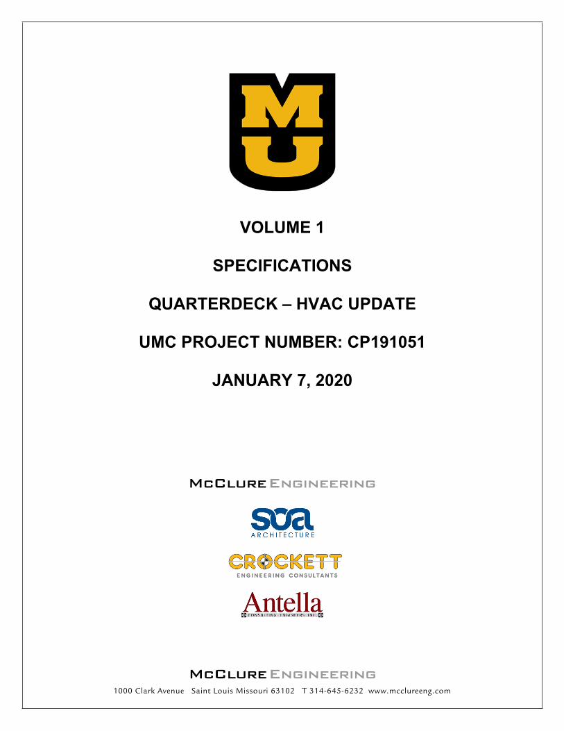
VOLUME 1
SPECIFICATIONS
QUARTERDECK – HVAC UPDATE
UMC PROJECT NUMBER: CP191051
JANUARY 7, 2020
McClure Engineering
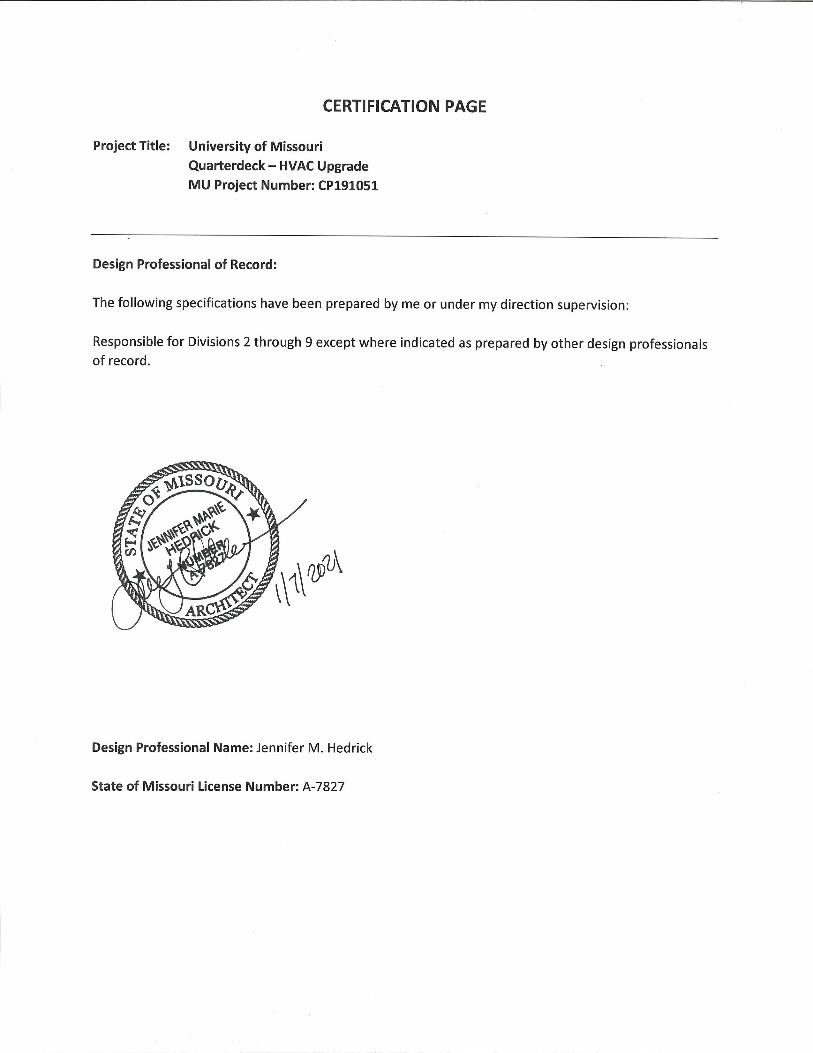
CERTIFICATION PAGE
Project Title: University of Missouri
Quarterdeck – HVAC Upgrade
MU Project Number: CP191051
Design Professional of Record:
The following specifications have been prepared by me or under my direction supervision:
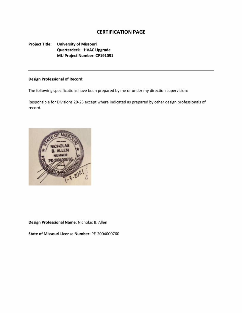
Responsible for Divisions 20-25 except where indicated as prepared by other design professionals of
record.
Design Professional Name: Nicholas B. Allen
State of Missouri License Number: PE-2004000760
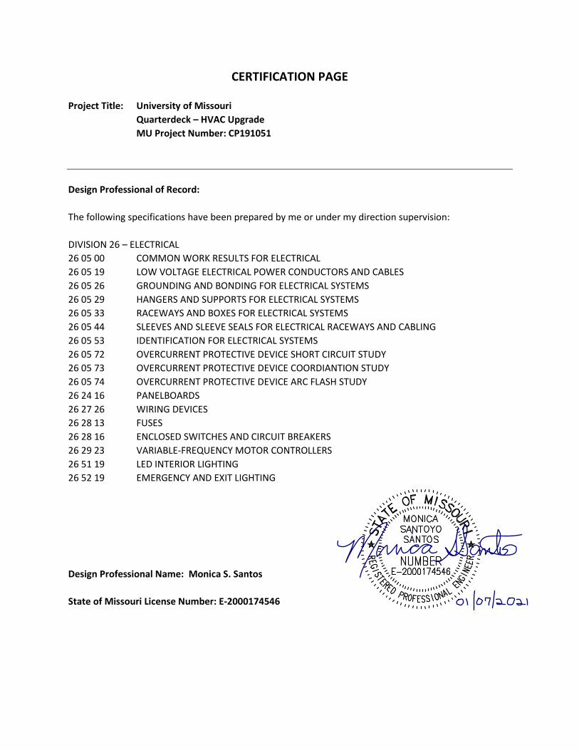
CERTIFICATION PAGE
Project Title: University of Missouri
Quarterdeck – HVAC Upgrade
MU Project Number: CP191051
Design Professional of Record:
The following specifications have been prepared by me or under my direction supervision:
DIVISION 26 – ELECTRICAL
26 05 00 COMMON WORK RESULTS FOR ELECTRICAL
26 05 19 LOW VOLTAGE ELECTRICAL POWER CONDUCTORS AND CABLES
26 05 26 GROUNDING AND BONDING FOR ELECTRICAL SYSTEMS
26 05 29 HANGERS AND SUPPORTS FOR ELECTRICAL SYSTEMS
26 05 33 RACEWAYS AND BOXES FOR ELECTRICAL SYSTEMS
26 05 44 SLEEVES AND SLEEVE SEALS FOR ELECTRICAL RACEWAYS AND CABLING
26 05 53 IDENTIFICATION FOR ELECTRICAL SYSTEMS
26 05 72 OVERCURRENT PROTECTIVE DEVICE SHORT CIRCUIT STUDY
26 05 73 OVERCURRENT PROTECTIVE DEVICE COORDIANTION STUDY
26 05 74 OVERCURRENT PROTECTIVE DEVICE ARC FLASH STUDY
26 24 16 PANELBOARDS
26 27 26 WIRING DEVICES
26 28 13 FUSES
26 28 16 ENCLOSED SWITCHES AND CIRCUIT BREAKERS
26 29 23 VARIABLE-FREQUENCY MOTOR CONTROLLERS
26 51 19 LED INTERIOR LIGHTING
26 52 19 EMERGENCY AND EXIT LIGHTING
Design Professional Name: Monica S. Santos
State of Missouri License Number: E-2000174546
PROJECT MANUAL FOR: QUARTERDECK – HVAC UPGRADE PROJECT NUMBER: CP191051
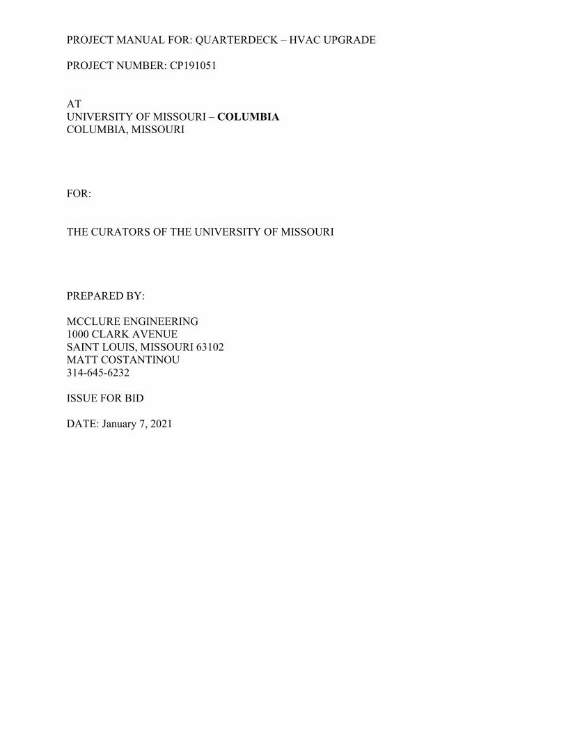
AT UNIVERSITY OF MISSOURI – COLUMBIA COLUMBIA, MISSOURI FOR: THE CURATORS OF THE UNIVERSITY OF MISSOURI PREPARED BY: MCCLURE ENGINEERING 1000 CLARK AVENUE SAINT LOUIS, MISSOURI 63102 MATT COSTANTINOU 314-645-6232 ISSUE FOR BID DATE: January 7, 2021
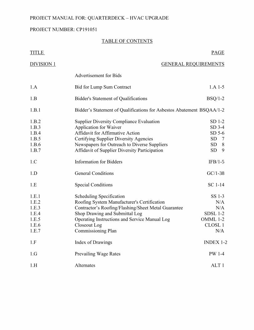
PROJECT MANUAL FOR: QUARTERDECK – HVAC UPGRADE PROJECT NUMBER: CP191051
TABLE OF CONTENTS TITLE PAGE DIVISION 1 GENERAL REQUIREMENTS Advertisement for Bids 1.A Bid for Lump Sum Contract 1.A 1-5 1.B Bidder's Statement of Qualifications BSQ/1-2 1.B.1 Bidder’s Statement of Qualifications for Asbestos Abatement BSQAA/1-2 1.B.2 Supplier Diversity Compliance Evaluation SD 1-2 1.B.3 Application for Waiver SD 3-4 1.B.4 Affidavit for Affirmative Action SD 5-6 1.B.5 Certifying Supplier Diversity Agencies SD 7 1.B.6 Newspapers for Outreach to Diverse Suppliers SD 8 1.B.7 Affidavit of Supplier Diversity Participation SD 9
1.C Information for Bidders IFB/1-5 1.D General Conditions GC/1-38 1.E Special Conditions SC 1-14 1.E.1 Scheduling Specification SS 1-3 1.E.2 Roofing System Manufacturer's Certification N/A
1.E.3 Contractor’s Roofing/Flashing/Sheet Metal Guarantee N/A 1.E.4 Shop Drawing and Submittal Log SDSL 1-2 1.E.5 Operating Instructions and Service Manual Log OMML 1-2 1.E.6 Closeout Log CLOSL 1 1.E.7 Commissioning Plan N/A 1.F Index of Drawings INDEX 1-2 1.G Prevailing Wage Rates PW 1-4 1.H Alternates ALT 1
PROJECT MANUAL FOR: QUARTERDECK – HVAC UPGRADE PROJECT NUMBER: CP191051
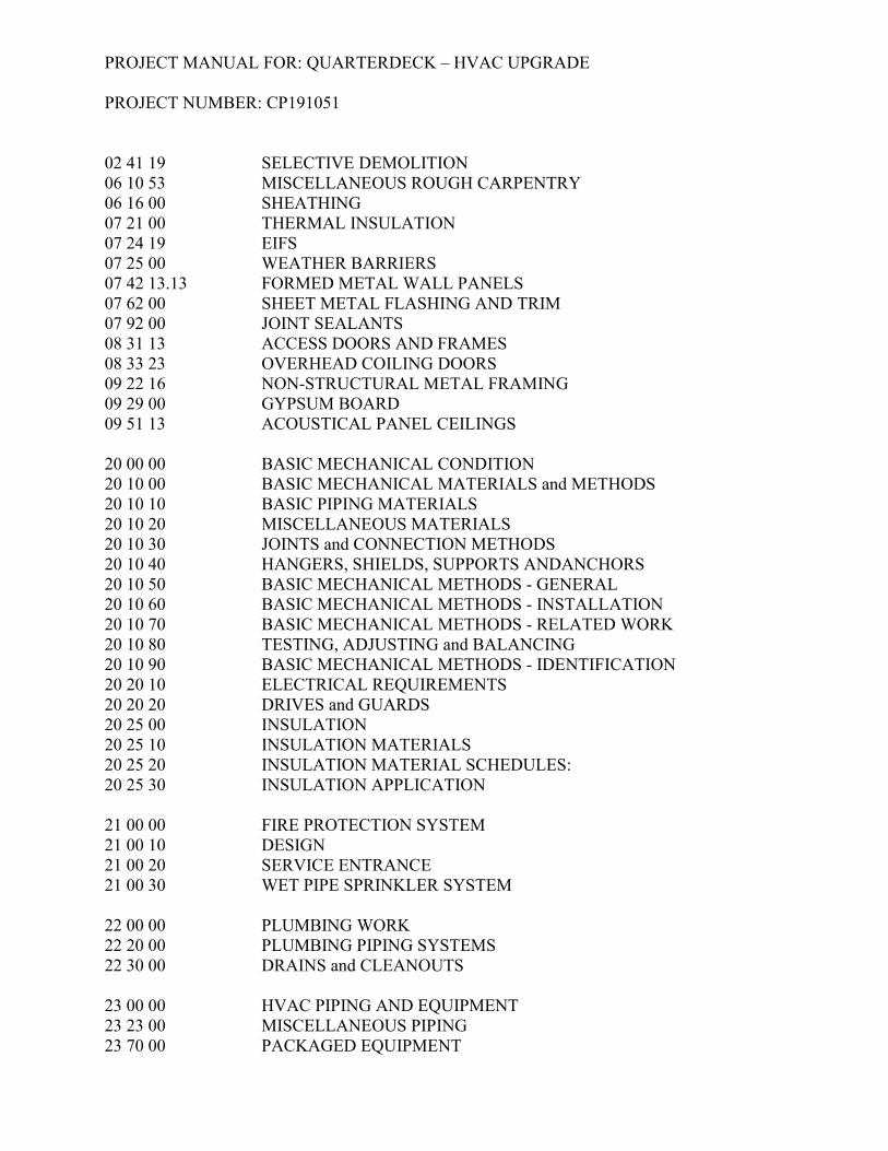
02 41 19 SELECTIVE DEMOLITION 06 10 53 MISCELLANEOUS ROUGH CARPENTRY 06 16 00 SHEATHING 07 21 00 THERMAL INSULATION 07 24 19 EIFS 07 25 00 WEATHER BARRIERS 07 42 13.13 FORMED METAL WALL PANELS 07 62 00 SHEET METAL FLASHING AND TRIM 07 92 00 JOINT SEALANTS 08 31 13 ACCESS DOORS AND FRAMES 08 33 23 OVERHEAD COILING DOORS 09 22 16 NON-STRUCTURAL METAL FRAMING 09 29 00 GYPSUM BOARD 09 51 13 ACOUSTICAL PANEL CEILINGS
20 00 00 BASIC MECHANICAL CONDITION 20 10 00 BASIC MECHANICAL MATERIALS and METHODS 20 10 10 BASIC PIPING MATERIALS 20 10 20 MISCELLANEOUS MATERIALS 20 10 30 JOINTS and CONNECTION METHODS 20 10 40 HANGERS, SHIELDS, SUPPORTS ANDANCHORS 20 10 50 BASIC MECHANICAL METHODS - GENERAL 20 10 60 BASIC MECHANICAL METHODS - INSTALLATION 20 10 70 BASIC MECHANICAL METHODS - RELATED WORK 20 10 80 TESTING, ADJUSTING and BALANCING 20 10 90 BASIC MECHANICAL METHODS - IDENTIFICATION 20 20 10 ELECTRICAL REQUIREMENTS 20 20 20 DRIVES and GUARDS 20 25 00 INSULATION 20 25 10 INSULATION MATERIALS 20 25 20 INSULATION MATERIAL SCHEDULES: 20 25 30 INSULATION APPLICATION 21 00 00 FIRE PROTECTION SYSTEM 21 00 10 DESIGN 21 00 20 SERVICE ENTRANCE 21 00 30 WET PIPE SPRINKLER SYSTEM 22 00 00 PLUMBING WORK 22 20 00 PLUMBING PIPING SYSTEMS 22 30 00 DRAINS and CLEANOUTS 23 00 00 HVAC PIPING AND EQUIPMENT 23 23 00 MISCELLANEOUS PIPING 23 70 00 PACKAGED EQUIPMENT
PROJECT MANUAL FOR: QUARTERDECK – HVAC UPGRADE PROJECT NUMBER: CP191051
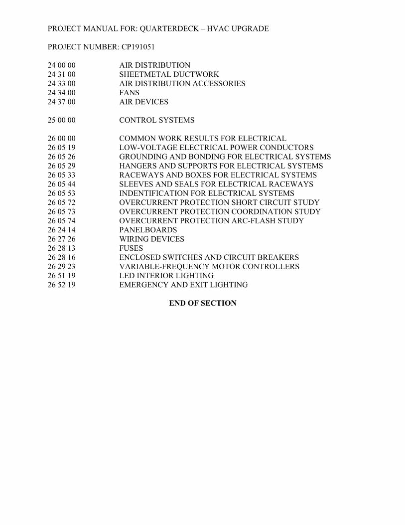
24 00 00 AIR DISTRIBUTION 24 31 00 SHEETMETAL DUCTWORK 24 33 00 AIR DISTRIBUTION ACCESSORIES 24 34 00 FANS 24 37 00 AIR DEVICES 25 00 00 CONTROL SYSTEMS
26 00 00 COMMON WORK RESULTS FOR ELECTRICAL 26 05 19 LOW-VOLTAGE ELECTRICAL POWER CONDUCTORS 26 05 26 GROUNDING AND BONDING FOR ELECTRICAL SYSTEMS 26 05 29 HANGERS AND SUPPORTS FOR ELECTRICAL SYSTEMS 26 05 33 RACEWAYS AND BOXES FOR ELECTRICAL SYSTEMS 26 05 44 SLEEVES AND SEALS FOR ELECTRICAL RACEWAYS 26 05 53 INDENTIFICATION FOR ELECTRICAL SYSTEMS 26 05 72 OVERCURRENT PROTECTION SHORT CIRCUIT STUDY 26 05 73 OVERCURRENT PROTECTION COORDINATION STUDY 26 05 74 OVERCURRENT PROTECTION ARC-FLASH STUDY 26 24 14 PANELBOARDS 26 27 26 WIRING DEVICES 26 28 13 FUSES 26 28 16 ENCLOSED SWITCHES AND CIRCUIT BREAKERS 26 29 23 VARIABLE-FREQUENCY MOTOR CONTROLLERS 26 51 19 LED INTERIOR LIGHTING 26 52 19 EMERGENCY AND EXIT LIGHTING
END OF SECTION
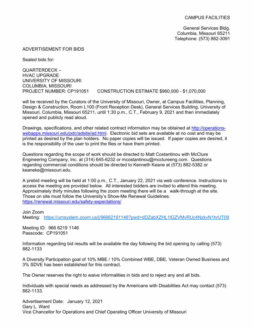
CAMPUS FACILITIES
General Services Bldg. Columbia, Missouri 65211
Telephone: (573) 882-3091
ADVERTISEMENT FOR BIDS
Sealed bids for:
QUARTERDECK – HVAC UPGRADE UNIVERSITY OF MISSOURI COLUMBIA, MISSOURI PROJECT NUMBER: CP191051 CONSTRUCTION ESTIMATE $960,000 - $1,070,000
will be received by the Curators of the University of Missouri, Owner, at Campus Facilities, Planning, Design & Construction, Room L100 (Front Reception Desk), General Services Building, University of Missouri, Columbia, Missouri 65211, until 1:30 p.m., C.T., February 9, 2021 and then immediately opened and publicly read aloud.
Drawings, specifications, and other related contract information may be obtained at http://operations-webapps.missouri.edu/pdc/adsite/ad.html. Electronic bid sets are available at no cost and may be printed as desired by the plan holders. No paper copies will be issued. If paper copies are desired, it is the responsibility of the user to print the files or have them printed.
Questions regarding the scope of work should be directed to Matt Costantinou with McClure Engineering Company, Inc. at (314) 645-6232 or [email protected]. Questions regarding commercial conditions should be directed to Kenneth Keane at (573) 882-5382 or [email protected].
A prebid meeting will be held at 1:00 p.m., C.T., January 22, 2021 via web conference. Instructions to access the meeting are provided below. All interested bidders are invited to attend this meeting. Approximately thirty minutes following the zoom meeting there will be a walk-through at the site. Those on site must follow the University’s Show-Me Renewal Guidelines. https://renewal.missouri.edu/safety-expectations/
Join Zoom Meeting: https://umsystem.zoom.us/j/96662191146?pwd=dDZabXZHL1lGZVMvRUc4NzkvN1hrUT09
Meeting ID: 966 6219 1146 Passcode: CP191051
Information regarding bid results will be available the day following the bid opening by calling (573) 882-1133
A Diversity Participation goal of 10% MBE / 10% Combined WBE, DBE, Veteran Owned Business and 3% SDVE has been established for this contract.
The Owner reserves the right to waive informalities in bids and to reject any and all bids.
Individuals with special needs as addressed by the Americans with Disabilities Act may contact (573) 882-1133.
Advertisement Date: January 12, 2021 Gary L. Ward Vice Chancellor for Operations and Chief Operating Officer University of Missouri
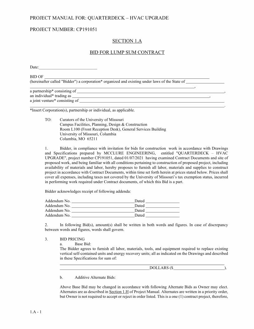
PROJECT MANUAL FOR: QUARTERDECK – HVAC UPGRADE PROJECT NUMBER: CP191051
1.A - 1
SECTION 1.A BID FOR LUMP SUM CONTRACT Date:____________________________ BID OF (hereinafter called "Bidder") a corporation* organized and existing under laws of the State of , a partnership* consisting of , an individual* trading as , a joint venture* consisting of . *Insert Corporation(s), partnership or individual, as applicable.
TO: Curators of the University of Missouri Campus Facilities, Planning, Design & Construction
Room L100 (Front Reception Desk), General Services Building University of Missouri, Columbia Columbia, MO 65211
1. Bidder, in compliance with invitation for bids for construction work in accordance with Drawings and Specifications prepared by MCCLURE ENGINEERING, entitled "QUARTERDECK – HVAC UPGRADE", project number CP191051, dated 01/07/2021 having examined Contract Documents and site of proposed work, and being familiar with all conditions pertaining to construction of proposed project, including availability of materials and labor, hereby proposes to furnish all labor, materials and supplies to construct project in accordance with Contract Documents, within time set forth herein at prices stated below. Prices shall cover all expenses, including taxes not covered by the University of Missouri’s tax exemption status, incurred in performing work required under Contract documents, of which this Bid is a part.
Bidder acknowledges receipt of following addenda:
Addendum No. Dated Addendum No. Dated Addendum No. Dated Addendum No. Dated 2. In following Bid(s), amount(s) shall be written in both words and figures. In case of discrepancy between words and figures, words shall govern.
3. BID PRICING
a. Base Bid: The Bidder agrees to furnish all labor, materials, tools, and equipment required to replace existing vertical self-contained units and energy recovery units; all as indicated on the Drawings and described in these Specifications for sum of:
DOLLARS ($ ).
b. Additive Alternate Bids:
Above Base Bid may be changed in accordance with following Alternate Bids as Owner may elect. Alternates are as described in Section 1.H of Project Manual. Alternates are written in a priority order, but Owner is not required to accept or reject in order listed. This is a one (1) contract project, therefore,
PROJECT MANUAL FOR: QUARTERDECK – HVAC UPGRADE PROJECT NUMBER: CP191051
1.A - 2
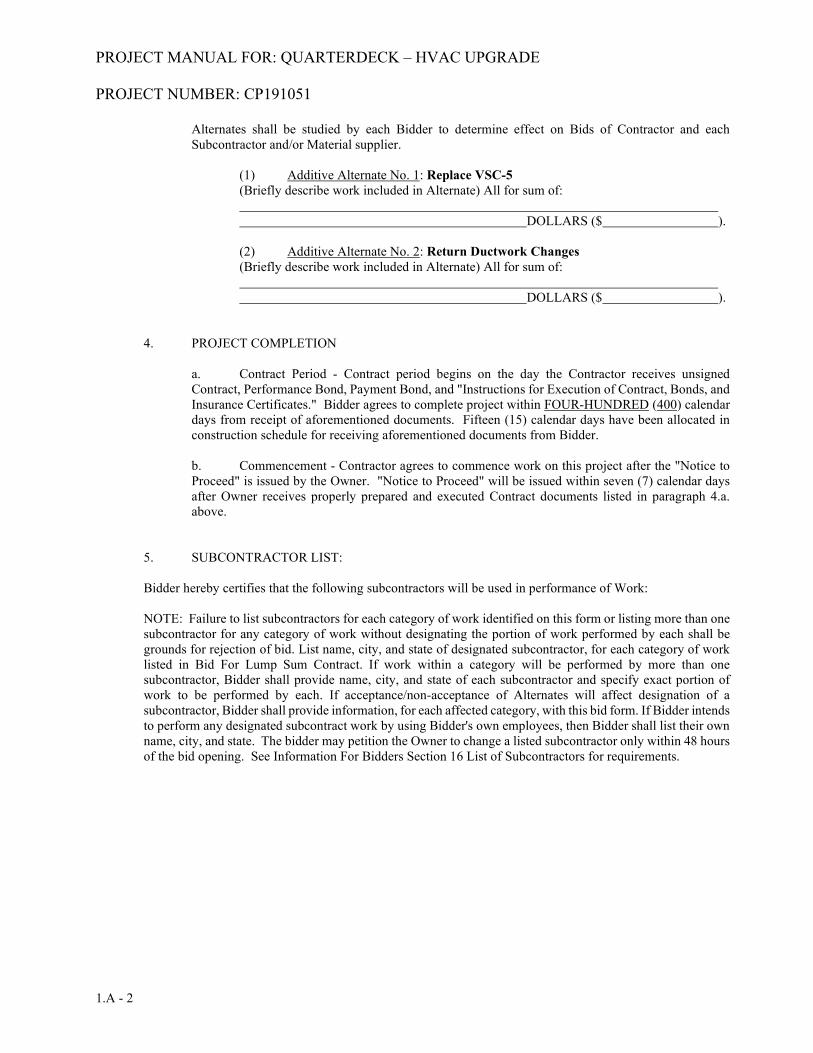
Alternates shall be studied by each Bidder to determine effect on Bids of Contractor and each Subcontractor and/or Material supplier.
(1) Additive Alternate No. 1: Replace VSC-5 (Briefly describe work included in Alternate) All for sum of:
DOLLARS ($ ).
(2) Additive Alternate No. 2: Return Ductwork Changes (Briefly describe work included in Alternate) All for sum of:
DOLLARS ($ ).
4. PROJECT COMPLETION
a. Contract Period - Contract period begins on the day the Contractor receives unsigned Contract, Performance Bond, Payment Bond, and "Instructions for Execution of Contract, Bonds, and Insurance Certificates." Bidder agrees to complete project within FOUR-HUNDRED (400) calendar days from receipt of aforementioned documents. Fifteen (15) calendar days have been allocated in construction schedule for receiving aforementioned documents from Bidder.
b. Commencement - Contractor agrees to commence work on this project after the "Notice to Proceed" is issued by the Owner. "Notice to Proceed" will be issued within seven (7) calendar days after Owner receives properly prepared and executed Contract documents listed in paragraph 4.a. above.
5. SUBCONTRACTOR LIST:
Bidder hereby certifies that the following subcontractors will be used in performance of Work:
NOTE: Failure to list subcontractors for each category of work identified on this form or listing more than one subcontractor for any category of work without designating the portion of work performed by each shall be grounds for rejection of bid. List name, city, and state of designated subcontractor, for each category of work listed in Bid For Lump Sum Contract. If work within a category will be performed by more than one subcontractor, Bidder shall provide name, city, and state of each subcontractor and specify exact portion of work to be performed by each. If acceptance/non-acceptance of Alternates will affect designation of a subcontractor, Bidder shall provide information, for each affected category, with this bid form. If Bidder intends to perform any designated subcontract work by using Bidder's own employees, then Bidder shall list their own name, city, and state. The bidder may petition the Owner to change a listed subcontractor only within 48 hours of the bid opening. See Information For Bidders Section 16 List of Subcontractors for requirements.
PROJECT MANUAL FOR: QUARTERDECK – HVAC UPGRADE PROJECT NUMBER: CP191051
1.A - 3
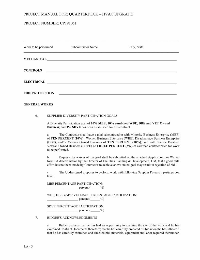
_______________________________________________________________________________________________ Work to be performed Subcontractor Name, City, State _______________________________________________________________________________________________
MECHANICAL
CONTROLS
ELECTRICAL FIRE PROTECTION GENERAL WORKS
6. SUPPLIER DIVERSITY PARTICIPATION GOALS
A Diversity Participation goal of 10% MBE; 10% combined WBE, DBE and VET Owned
Business; and 3% SDVE has been established for this contract
a. The Contractor shall have a goal subcontracting with Minority Business Enterprise (MBE) of TEN PERCENT (10%); Women Business Enterprise (WBE), Disadvantage Business Enterprise (DBE), and/or Veteran Owned Business of TEN PERCENT (10%); and with Service Disabled Veteran Owned Business (SDVE) of THREE PERCENT (3%) of awarded contract price for work to be performed.
b. Requests for waiver of this goal shall be submitted on the attached Application For Waiver form. A determination by the Director of Facilities Planning & Development, UM, that a good faith effort has not been made by Contractor to achieve above stated goal may result in rejection of bid.
c. The Undersigned proposes to perform work with following Supplier Diversity participation level:
MBE PERCENTAGE PARTICIPATION: ___________________ percent ( %)
WBE, DBE, and/or VETERAN PERCENTAGE PARTICIPATION: ___________________ percent ( %)
SDVE PERCENTAGE PARTICIPATION: ___________________ percent ( %)
7. BIDDER'S ACKNOWLEDGMENTS
a. Bidder declares that he has had an opportunity to examine the site of the work and he has examined Contract Documents therefore; that he has carefully prepared his bid upon the basis thereof; that he has carefully examined and checked bid, materials, equipment and labor required thereunder,
PROJECT MANUAL FOR: QUARTERDECK – HVAC UPGRADE PROJECT NUMBER: CP191051
1.A - 4
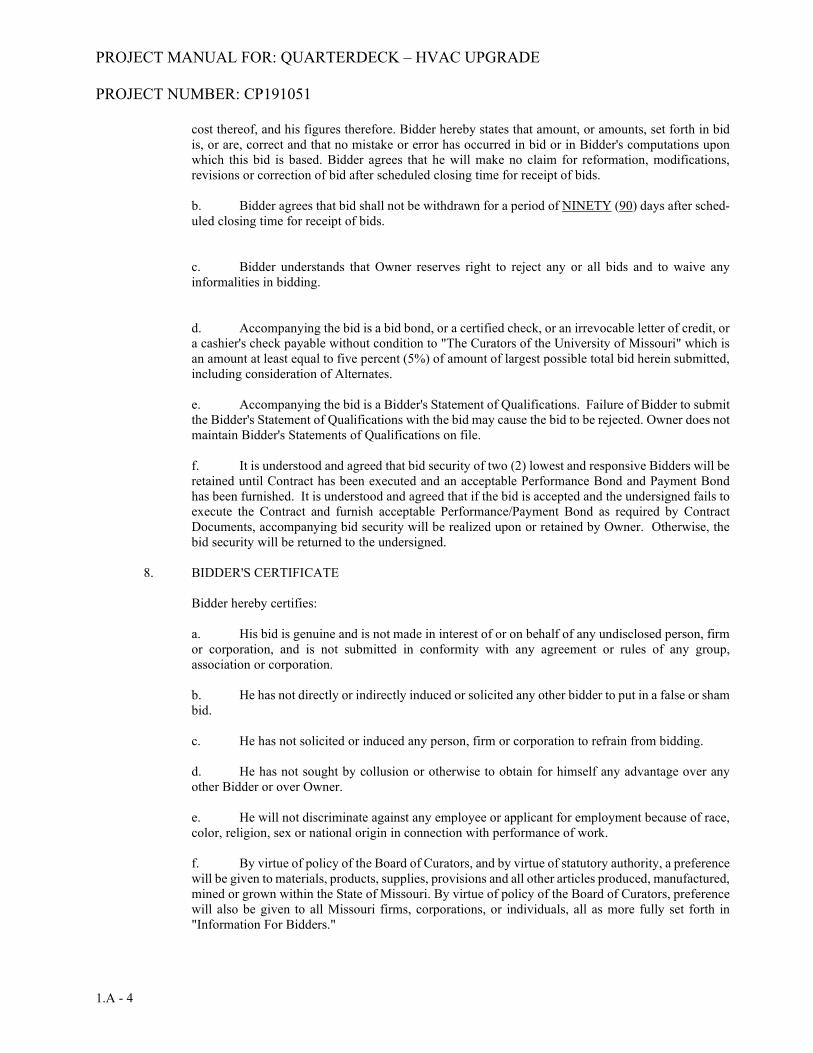
cost thereof, and his figures therefore. Bidder hereby states that amount, or amounts, set forth in bid is, or are, correct and that no mistake or error has occurred in bid or in Bidder's computations upon which this bid is based. Bidder agrees that he will make no claim for reformation, modifications, revisions or correction of bid after scheduled closing time for receipt of bids.
b. Bidder agrees that bid shall not be withdrawn for a period of NINETY (90) days after sched-uled closing time for receipt of bids.
c. Bidder understands that Owner reserves right to reject any or all bids and to waive any informalities in bidding.
d. Accompanying the bid is a bid bond, or a certified check, or an irrevocable letter of credit, or a cashier's check payable without condition to "The Curators of the University of Missouri" which is an amount at least equal to five percent (5%) of amount of largest possible total bid herein submitted, including consideration of Alternates.
e. Accompanying the bid is a Bidder's Statement of Qualifications. Failure of Bidder to submit the Bidder's Statement of Qualifications with the bid may cause the bid to be rejected. Owner does not maintain Bidder's Statements of Qualifications on file.
f. It is understood and agreed that bid security of two (2) lowest and responsive Bidders will be retained until Contract has been executed and an acceptable Performance Bond and Payment Bond has been furnished. It is understood and agreed that if the bid is accepted and the undersigned fails to execute the Contract and furnish acceptable Performance/Payment Bond as required by Contract Documents, accompanying bid security will be realized upon or retained by Owner. Otherwise, the bid security will be returned to the undersigned.
8. BIDDER'S CERTIFICATE
Bidder hereby certifies:
a. His bid is genuine and is not made in interest of or on behalf of any undisclosed person, firm or corporation, and is not submitted in conformity with any agreement or rules of any group, association or corporation.
b. He has not directly or indirectly induced or solicited any other bidder to put in a false or sham bid.
c. He has not solicited or induced any person, firm or corporation to refrain from bidding.
d. He has not sought by collusion or otherwise to obtain for himself any advantage over any other Bidder or over Owner.
e. He will not discriminate against any employee or applicant for employment because of race, color, religion, sex or national origin in connection with performance of work.
f. By virtue of policy of the Board of Curators, and by virtue of statutory authority, a preference will be given to materials, products, supplies, provisions and all other articles produced, manufactured, mined or grown within the State of Missouri. By virtue of policy of the Board of Curators, preference will also be given to all Missouri firms, corporations, or individuals, all as more fully set forth in "Information For Bidders."
PROJECT MANUAL FOR: QUARTERDECK – HVAC UPGRADE PROJECT NUMBER: CP191051
1.A - 5
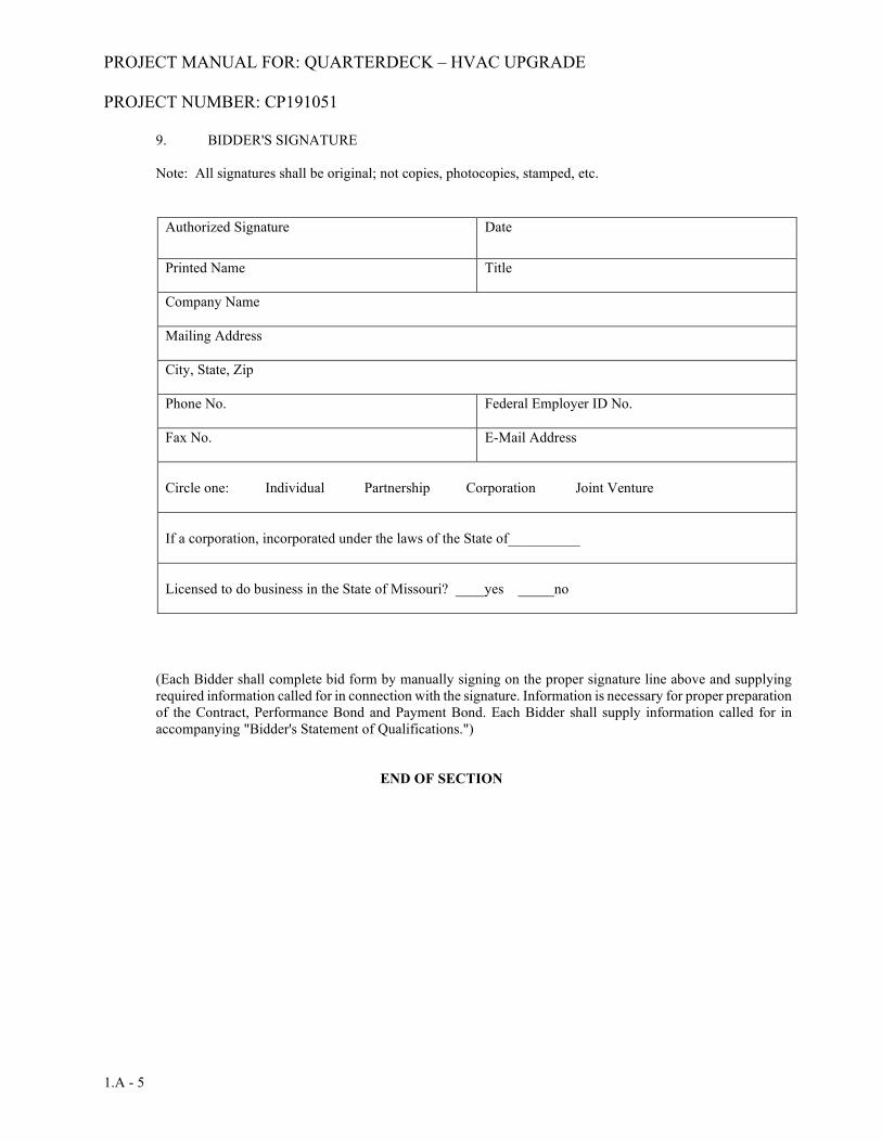
9. BIDDER'S SIGNATURE
Note: All signatures shall be original; not copies, photocopies, stamped, etc.
Authorized Signature Date
Printed Name Title
Company Name
Mailing Address
City, State, Zip
Phone No. Federal Employer ID No.
Fax No. E-Mail Address
Circle one: Individual Partnership Corporation Joint Venture
If a corporation, incorporated under the laws of the State of__________
Licensed to do business in the State of Missouri? ____yes _____no
(Each Bidder shall complete bid form by manually signing on the proper signature line above and supplying required information called for in connection with the signature. Information is necessary for proper preparation of the Contract, Performance Bond and Payment Bond. Each Bidder shall supply information called for in accompanying "Bidder's Statement of Qualifications.")
END OF SECTION

BSQ/1 9/2016 Revision
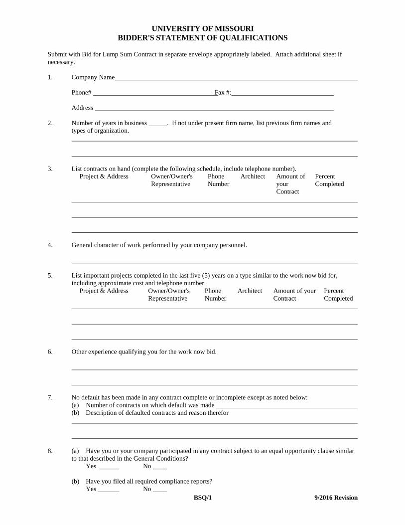
UNIVERSITY OF MISSOURI BIDDER'S STATEMENT OF QUALIFICATIONS Submit with Bid for Lump Sum Contract in separate envelope appropriately labeled. Attach additional sheet if necessary. 1. Company Name Phone# Fax #: Address 2. Number of years in business . If not under present firm name, list previous firm names and types of organization. 3. List contracts on hand (complete the following schedule, include telephone number).
Project & Address Owner/Owner's Representative
Phone Number
Architect Amount of your Contract
Percent Completed
4. General character of work performed by your company personnel. 5. List important projects completed in the last five (5) years on a type similar to the work now bid for,
including approximate cost and telephone number. Project & Address Owner/Owner's
Representative Phone Number
Architect Amount of your Contract
Percent Completed
6. Other experience qualifying you for the work now bid. 7. No default has been made in any contract complete or incomplete except as noted below: (a) Number of contracts on which default was made (b) Description of defaulted contracts and reason therefor 8. (a) Have you or your company participated in any contract subject to an equal opportunity clause similar
to that described in the General Conditions? Yes No (b) Have you filed all required compliance reports? Yes No
BSQ/2 9/2016 Revision
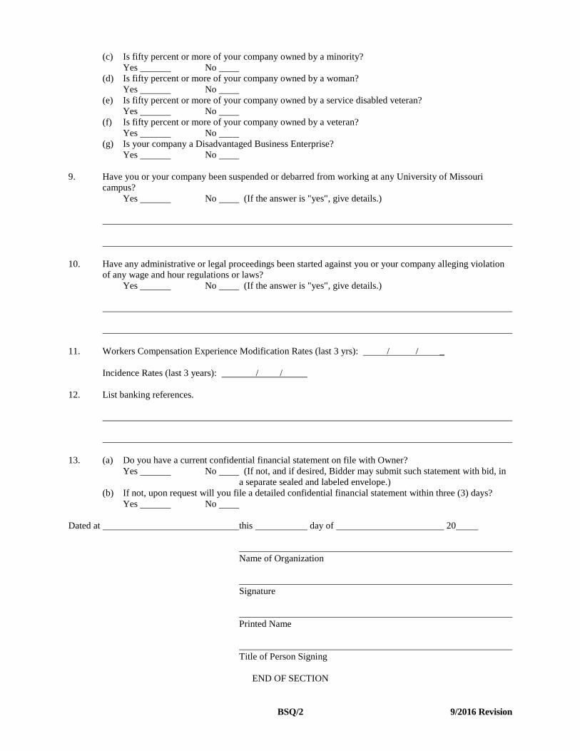
(c) Is fifty percent or more of your company owned by a minority? Yes No (d) Is fifty percent or more of your company owned by a woman? Yes No (e) Is fifty percent or more of your company owned by a service disabled veteran? Yes No (f) Is fifty percent or more of your company owned by a veteran? Yes No (g) Is your company a Disadvantaged Business Enterprise? Yes No 9. Have you or your company been suspended or debarred from working at any University of Missouri
campus? Yes No (If the answer is "yes", give details.) 10. Have any administrative or legal proceedings been started against you or your company alleging violation
of any wage and hour regulations or laws? Yes No (If the answer is "yes", give details.) 11. Workers Compensation Experience Modification Rates (last 3 yrs): / / _ Incidence Rates (last 3 years): / / 12. List banking references. 13. (a) Do you have a current confidential financial statement on file with Owner? Yes No (If not, and if desired, Bidder may submit such statement with bid, in
a separate sealed and labeled envelope.) (b) If not, upon request will you file a detailed confidential financial statement within three (3) days? Yes No Dated at this day of 20 Name of Organization Signature Printed Name Title of Person Signing END OF SECTION

BSQ/1 9/2016 Revision
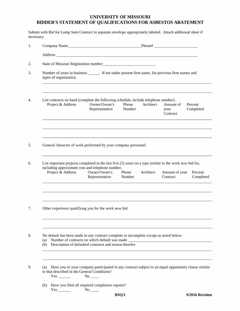
UNIVERSITY OF MISSOURI BIDDER'S STATEMENT OF QUALIFICATIONS FOR ASBESTOS ABATEMENT Submit with Bid for Lump Sum Contract in separate envelope appropriately labeled. Attach additional sheet if necessary. 1. Company Name Phone# Address 2. State of Missouri Registration number 3. Number of years in business . If not under present firm name, list previous firm names and types of organization. 4. List contracts on hand (complete the following schedule, include telephone number).
Project & Address Owner/Owner's Representative
Phone Number
Architect Amount of your Contract
Percent Completed
5. General character of work performed by your company personnel. 6. List important projects completed in the last five (5) years on a type similar to the work now bid for,
including approximate cost and telephone number. Project & Address Owner/Owner's
Representative Phone Number
Architect Amount of your Contract
Percent Completed
7. Other experience qualifying you for the work now bid. 8. No default has been made in any contract complete or incomplete except as noted below: (a) Number of contracts on which default was made (b) Description of defaulted contracts and reason therefor 9. (a) Have you or your company participated in any contract subject to an equal opportunity clause similar
to that described in the General Conditions? Yes No (b) Have you filed all required compliance reports? Yes No
BSQ/2 9/2016 Revision
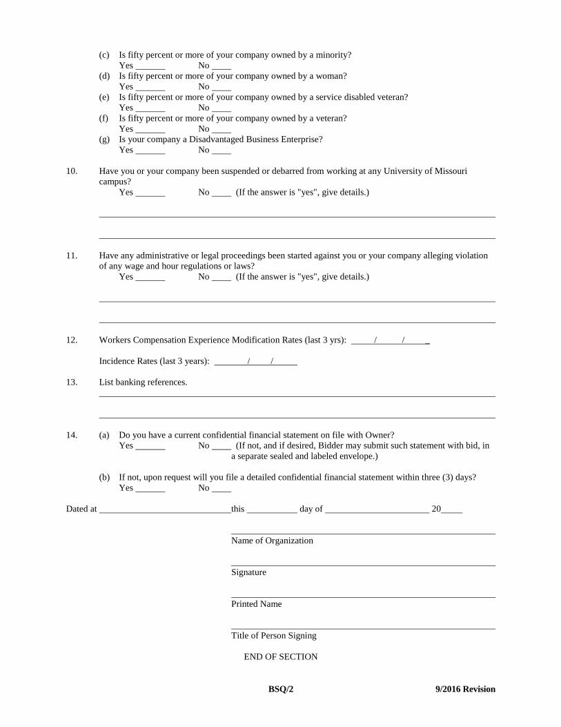
(c) Is fifty percent or more of your company owned by a minority? Yes No (d) Is fifty percent or more of your company owned by a woman? Yes No (e) Is fifty percent or more of your company owned by a service disabled veteran? Yes No (f) Is fifty percent or more of your company owned by a veteran? Yes No (g) Is your company a Disadvantaged Business Enterprise? Yes No 10. Have you or your company been suspended or debarred from working at any University of Missouri
campus? Yes No (If the answer is "yes", give details.)
11. Have any administrative or legal proceedings been started against you or your company alleging violation
of any wage and hour regulations or laws? Yes No (If the answer is "yes", give details.) 12. Workers Compensation Experience Modification Rates (last 3 yrs): / / _ Incidence Rates (last 3 years): / / 13. List banking references. 14. (a) Do you have a current confidential financial statement on file with Owner? Yes No (If not, and if desired, Bidder may submit such statement with bid, in
a separate sealed and labeled envelope.) (b) If not, upon request will you file a detailed confidential financial statement within three (3) days? Yes No Dated at this day of 20 Name of Organization Signature Printed Name Title of Person Signing END OF SECTION

SD/1
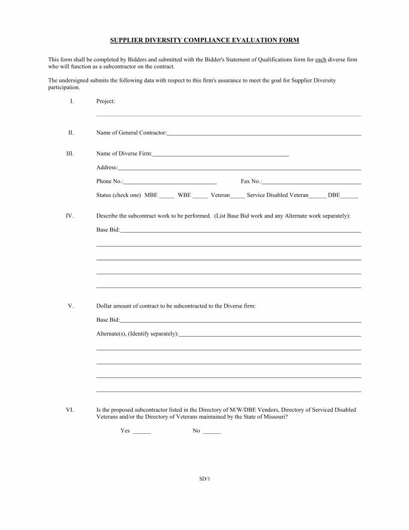
SUPPLIER DIVERSITY COMPLIANCE EVALUATION FORM This form shall be completed by Bidders and submitted with the Bidder's Statement of Qualifications form for each diverse firm who will function as a subcontractor on the contract. The undersigned submits the following data with respect to this firm's assurance to meet the goal for Supplier Diversity participation. I. Project:
II. Name of General Contractor: III. Name of Diverse Firm:
Address:
Phone No.: Fax No.:
Status (check one) MBE _____ WBE _____ Veteran_____ Service Disabled Veteran______ DBE______ IV. Describe the subcontract work to be performed. (List Base Bid work and any Alternate work separately):
Base Bid:
V. Dollar amount of contract to be subcontracted to the Diverse firm:
Base Bid:
Alternate(s), (Identify separately):
VI. Is the proposed subcontractor listed in the Directory of M/W/DBE Vendors, Directory of Serviced Disabled
Veterans and/or the Directory of Veterans maintained by the State of Missouri?
Yes ______ No ______
SD/2
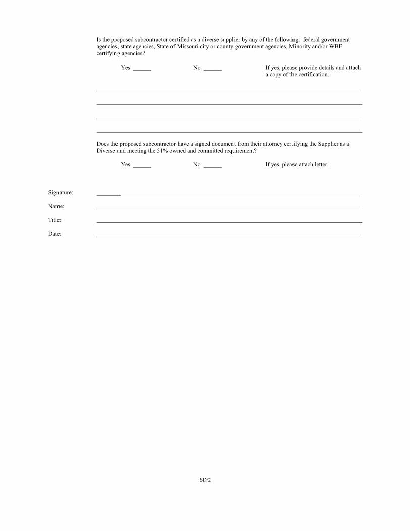
Is the proposed subcontractor certified as a diverse supplier by any of the following: federal government agencies, state agencies, State of Missouri city or county government agencies, Minority and/or WBE certifying agencies?
Yes ______ No ______ If yes, please provide details and attach
a copy of the certification.
Does the proposed subcontractor have a signed document from their attorney certifying the Supplier as a Diverse and meeting the 51% owned and committed requirement?
Yes ______ No ______ If yes, please attach letter.
Signature: ________ Name: Title: Date:
SD/3
APPLICATION FOR WAIVER This form shall be completed and submitted with the Bidder's Statement of Qualifications. Firms wishing to be considered for award are required to demonstrate that a good faith effort has been made to include diverse suppliers. This form will be used to evaluate the extent to which a good faith effort has been made. The undersigned submits the following data with respect to the firm's efforts to meet the goal for Supplier Diversity Participation. 1. List pre-bid conferences your firm attended where Supplier Diversity requirements were discussed.
2. Identify advertising efforts undertaken by your firm which were intended to recruit potential diverse subcontractors for
various aspects of this project. Provide names of newspapers, dates of advertisements and copies of ads that were run.
3. Note specific efforts to contact in writing those diverse suppliers capable of and likely to participate as subcontractors
for this project.
4. Describe steps taken by your firm to divide work into areas in which diverse suppliers/contractors would be capable of
performing.
5. What efforts were taken to negotiate with prospective diverse suppliers/contractors for specific sub-bids? Include the
names, addresses, and telephone numbers of diverse suppliers/contractors contacted, a description of the information given to diverse suppliers/contractors regarding plans and specifications for the assigned work, and a statement as to why additional agreements were not made with diverse suppliers/contractors.
6. List reasons for rejecting a diverse supplier/contractor which has been contacted.
SD/4
8. Describe the follow-up contacts with diverse suppliers/contractors made by your firm after the initial solicitation.
9. Describe the efforts made by your firm to provide interested diverse suppliers/contractors with sufficiently detailed information about the plans, specifications and requirements of the contract.
10. Describe your firm's efforts to locate diverse suppliers/contractors.
Based on the above stated good faith efforts made to include supplier diversity, the bidder hereby requests that the original supplier diversity percentage goal be waived and that the percentage goal for this project be set at ________ percent.
The undersigned hereby certifies, having read the answers contained in the foregoing Application for Waiver, that they are true and correct to the best of his/her knowledge, information and belief.
Signature
Name
Title
Company
Date
SD/5
AFFIDAVIT
"The undersigned swears that the foregoing statements are true and correct and include all material information necessary to identify and explain the operation of ____________________________ ____________________(name of firm) as well as the ownership thereof. Further, the undersigned agrees to provide through the prime contractor or directly to the Contracting Officer current, complete and accurate information regarding actual work performed on the project, the payment therefore and any proposed changes, if any, of the project, the foregoing arrangements and to permit the audit and examination of books, records and files of the named firm. Any material misrepresentation will be grounds for terminating any contract which may be awarded and for initiating action under federal or state laws concerning false statements."
Note - If, after filing this information and before the work of this firm is completed on the contract covered by this regulation, there is any significant change in the information submitted, you must inform the Director of Facilities Planning and Development of the change either through the prime contractor or directly. Signature Name Title Date Corporate Seal (where appropriate) Date State of County of On this _______________________________________ day of _________________________________________, 19 ,
before me appeared (name) __________________________________________________ to me personally known, who, being
duly sworn, did execute the foregoing affidavit, and did state that he or she was properly authorized by (name of firm)
to execute the affidavit and did so as his or her own free act and deed. (Seal) Notary Public Commission expires

THIS PAGE LEFT BLANK INTENTIONALLY
SD/6
AFFIDAVIT FOR AFFIRMATIVE ACTION
State of Missouri )
) ss. County of ) _______________________________________________________________________ first being duly sworn on his/her oath states: that he/she is the (sole proprietor, partner, or officer) of __________________________________________________ _______________________ a (sole proprietorship, partnership, corporation), and as such (sole proprietor, partner, or officer) is duly authorized to make this affidavit on behalf of said (sole proprietorship, partnership, corporation); that under the contract known as "___________________________________________________________________________________________" Project No. ________________ less than 50 persons in the aggregate will be employed and therefore, the applicable Affirmative Action requirements as set forth in the "Nondiscrimination in Employment Equal Opportunity," Supplemental Special Conditions, and Article 13 in the General Conditions do not apply.
Subscribed and sworn before me this _______________ day of ___________________________, 19________. My commission expires ___________________________________________________________, 19________.

THIS PAGE LEFT BLANK INTENTIONALLY
SD/7
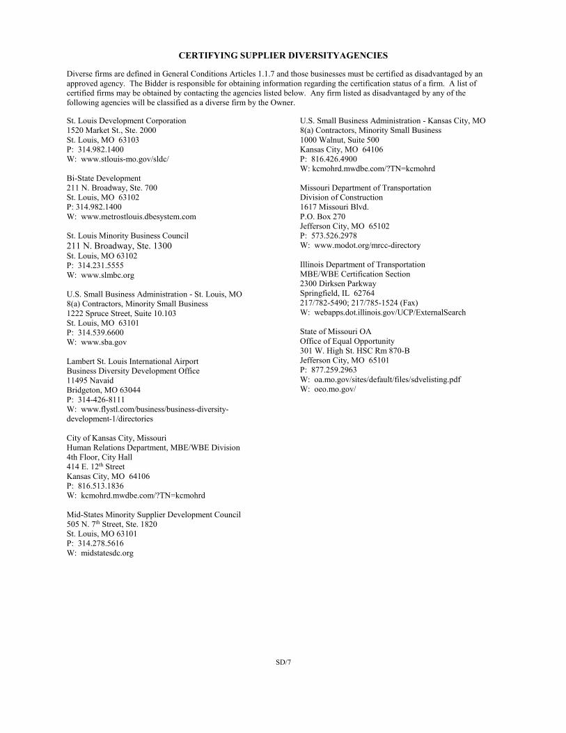
CERTIFYING SUPPLIER DIVERSITYAGENCIES Diverse firms are defined in General Conditions Articles 1.1.7 and those businesses must be certified as disadvantaged by an approved agency. The Bidder is responsible for obtaining information regarding the certification status of a firm. A list of certified firms may be obtained by contacting the agencies listed below. Any firm listed as disadvantaged by any of the following agencies will be classified as a diverse firm by the Owner. St. Louis Development Corporation 1520 Market St., Ste. 2000 St. Louis, MO 63103 P: 314.982.1400 W: www.stlouis-mo.gov/sldc/ Bi-State Development 211 N. Broadway, Ste. 700 St. Louis, MO 63102 P: 314.982.1400 W: www.metrostlouis.dbesystem.com St. Louis Minority Business Council 211 N. Broadway, Ste. 1300 St. Louis, MO 63102 P: 314.231.5555 W: www.slmbc.org U.S. Small Business Administration - St. Louis, MO 8(a) Contractors, Minority Small Business 1222 Spruce Street, Suite 10.103 St. Louis, MO 63101 P: 314.539.6600 W: www.sba.gov Lambert St. Louis International Airport Business Diversity Development Office 11495 Navaid Bridgeton, MO 63044 P: 314-426-8111 W: www.flystl.com/business/business-diversity-development-1/directories City of Kansas City, Missouri Human Relations Department, MBE/WBE Division 4th Floor, City Hall 414 E. 12th Street Kansas City, MO 64106 P: 816.513.1836 W: kcmohrd.mwdbe.com/?TN=kcmohrd Mid-States Minority Supplier Development Council 505 N. 7th Street, Ste. 1820 St. Louis, MO 63101 P: 314.278.5616 W: midstatesdc.org
U.S. Small Business Administration - Kansas City, MO 8(a) Contractors, Minority Small Business 1000 Walnut, Suite 500 Kansas City, MO 64106 P: 816.426.4900 W: kcmohrd.mwdbe.com/?TN=kcmohrd Missouri Department of Transportation Division of Construction 1617 Missouri Blvd. P.O. Box 270 Jefferson City, MO 65102 P: 573.526.2978 W: www.modot.org/mrcc-directory Illinois Department of Transportation MBE/WBE Certification Section 2300 Dirksen Parkway Springfield, IL 62764 217/782-5490; 217/785-1524 (Fax) W: webapps.dot.illinois.gov/UCP/ExternalSearch State of Missouri OA Office of Equal Opportunity 301 W. High St. HSC Rm 870-B Jefferson City, MO 65101 P: 877.259.2963 W: oa.mo.gov/sites/default/files/sdvelisting.pdf W: oeo.mo.gov/
SD/8
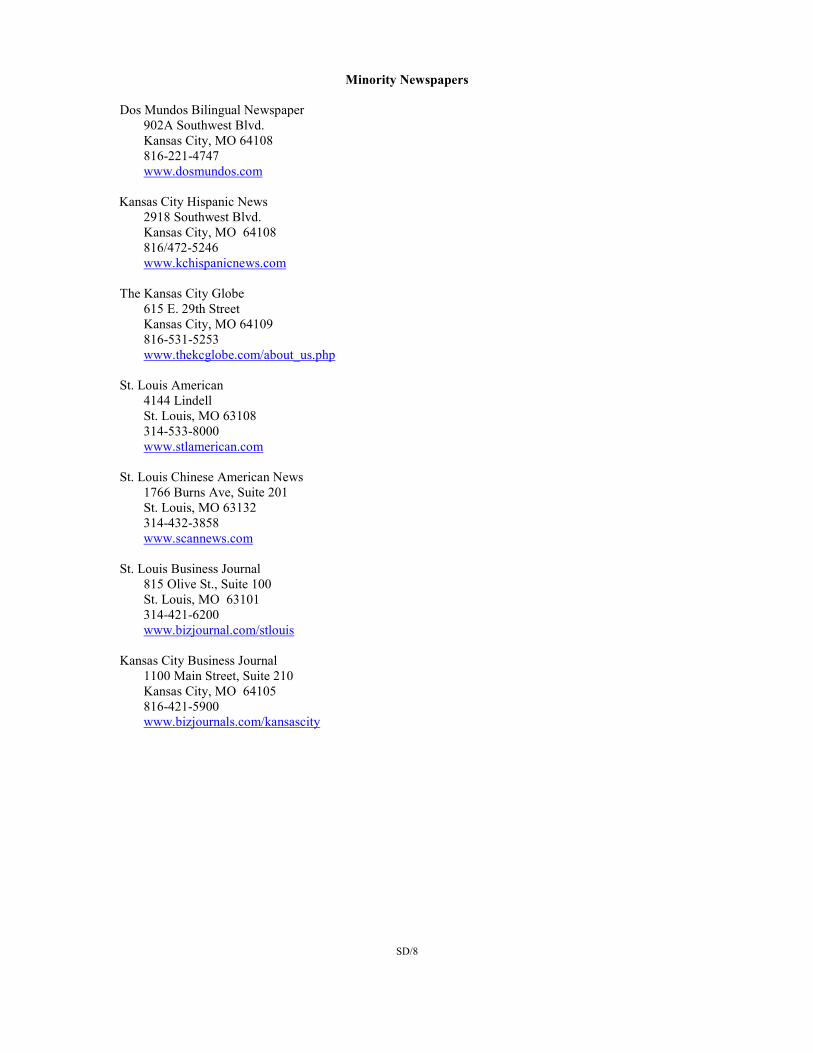
Minority Newspapers Dos Mundos Bilingual Newspaper
902A Southwest Blvd. Kansas City, MO 64108 816-221-4747 www.dosmundos.com
Kansas City Hispanic News 2918 Southwest Blvd. Kansas City, MO 64108 816/472-5246 www.kchispanicnews.com The Kansas City Globe
615 E. 29th Street Kansas City, MO 64109 816-531-5253 www.thekcglobe.com/about_us.php
St. Louis American
4144 Lindell St. Louis, MO 63108 314-533-8000 www.stlamerican.com
St. Louis Chinese American News
1766 Burns Ave, Suite 201 St. Louis, MO 63132 314-432-3858 www.scannews.com
St. Louis Business Journal 815 Olive St., Suite 100 St. Louis, MO 63101 314-421-6200 www.bizjournal.com/stlouis Kansas City Business Journal 1100 Main Street, Suite 210 Kansas City, MO 64105 816-421-5900 www.bizjournals.com/kansascity
SD/9
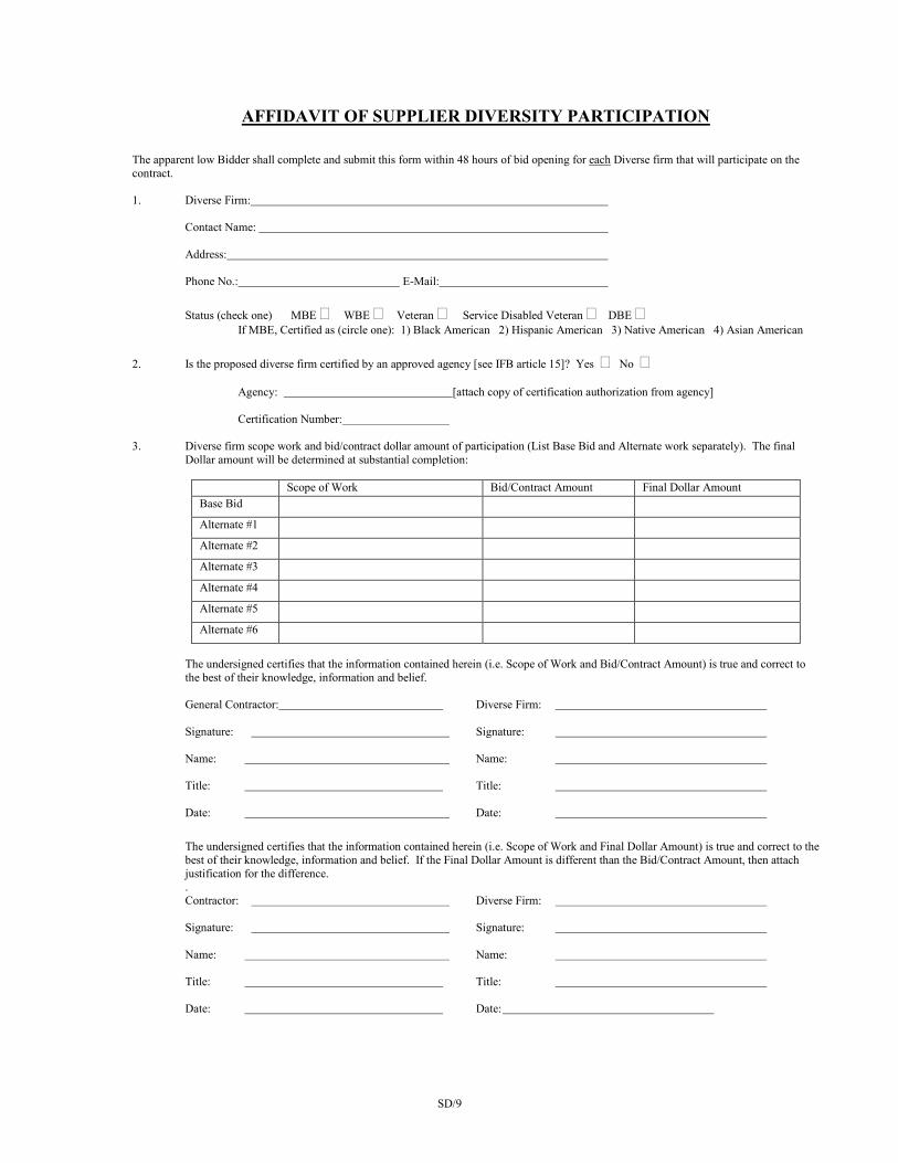
AFFIDAVIT OF SUPPLIER DIVERSITY PARTICIPATION The apparent low Bidder shall complete and submit this form within 48 hours of bid opening for each Diverse firm that will participate on the contract. 1. Diverse Firm:
Contact Name:
Address: Phone No.: E-Mail:
Status (check one) MBE � WBE � Veteran � Service Disabled Veteran � DBE � If MBE, Certified as (circle one): 1) Black American 2) Hispanic American 3) Native American 4) Asian American
2. Is the proposed diverse firm certified by an approved agency [see IFB article 15]? Yes � No �
Agency: [attach copy of certification authorization from agency]
Certification Number: 3. Diverse firm scope work and bid/contract dollar amount of participation (List Base Bid and Alternate work separately). The final
Dollar amount will be determined at substantial completion:
Scope of Work Bid/Contract Amount Final Dollar Amount Base Bid
Alternate #1
Alternate #2
Alternate #3
Alternate #4
Alternate #5
Alternate #6
The undersigned certifies that the information contained herein (i.e. Scope of Work and Bid/Contract Amount) is true and correct to the best of their knowledge, information and belief. General Contractor: Diverse Firm: Signature: Signature: Name: Name: Title: Title: Date: Date: The undersigned certifies that the information contained herein (i.e. Scope of Work and Final Dollar Amount) is true and correct to the best of their knowledge, information and belief. If the Final Dollar Amount is different than the Bid/Contract Amount, then attach justification for the difference. . Contractor: Diverse Firm: Signature: Signature: Name: Name: Title: Title: Date: Date:

THIS PAGE LEFT BLANK INTENTIONALLY
IFB/1
7/2020
University of Missouri
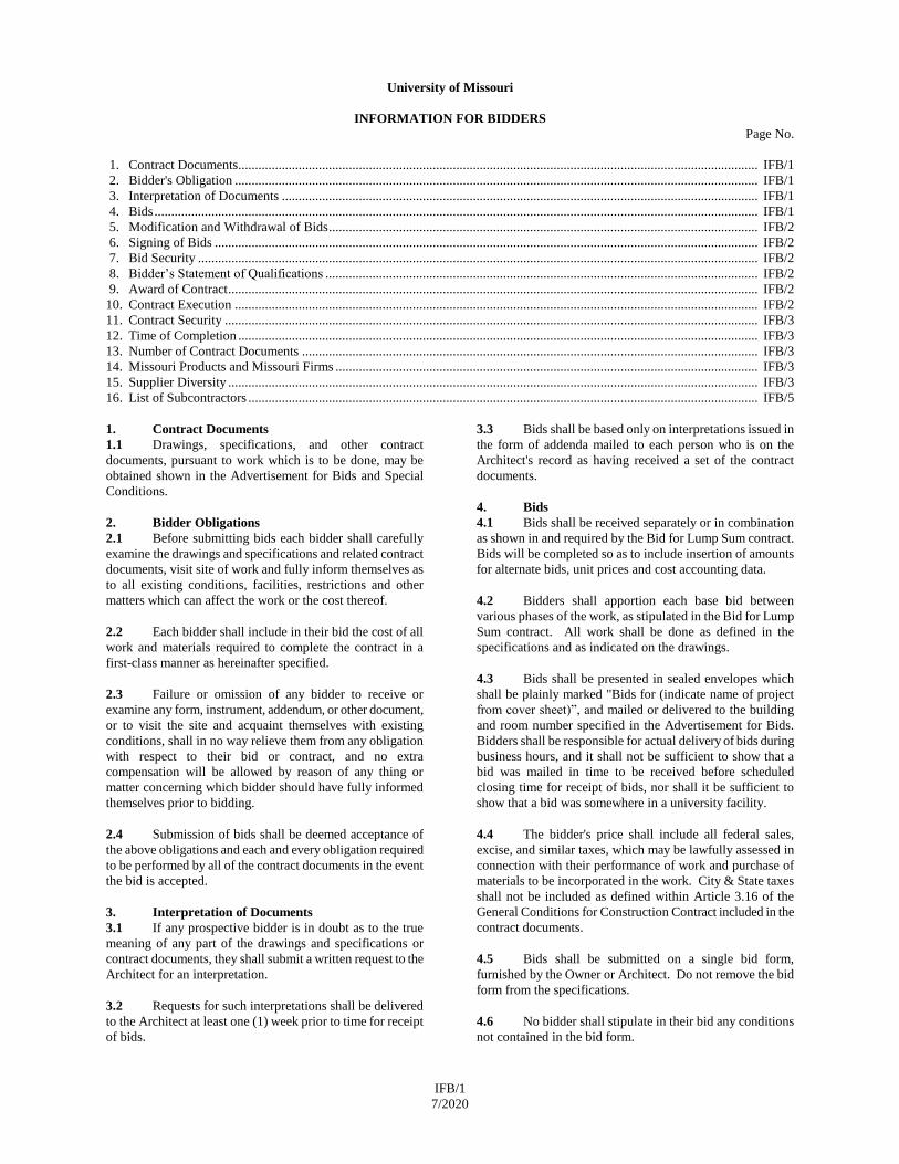
INFORMATION FOR BIDDERS
Page No.
1. Contract Documents ........................................................................................................................................................... IFB/1
2. Bidder's Obligation ............................................................................................................................................................ IFB/1
3. Interpretation of Documents .............................................................................................................................................. IFB/1
4. Bids .................................................................................................................................................................................... IFB/1
5. Modification and Withdrawal of Bids ................................................................................................................................ IFB/2
6. Signing of Bids .................................................................................................................................................................. IFB/2
7. Bid Security ....................................................................................................................................................................... IFB/2
8. Bidder’s Statement of Qualifications ................................................................................................................................. IFB/2
9. Award of Contract .............................................................................................................................................................. IFB/2
10. Contract Execution ............................................................................................................................................................ IFB/2
11. Contract Security ............................................................................................................................................................... IFB/3
12. Time of Completion ........................................................................................................................................................... IFB/3
13. Number of Contract Documents ........................................................................................................................................ IFB/3
14. Missouri Products and Missouri Firms .............................................................................................................................. IFB/3
15. Supplier Diversity .............................................................................................................................................................. IFB/3
16. List of Subcontractors ........................................................................................................................................................ IFB/5
1. Contract Documents
1.1 Drawings, specifications, and other contract
documents, pursuant to work which is to be done, may be
obtained shown in the Advertisement for Bids and Special
Conditions.
2. Bidder Obligations
2.1 Before submitting bids each bidder shall carefully
examine the drawings and specifications and related contract
documents, visit site of work and fully inform themselves as
to all existing conditions, facilities, restrictions and other
matters which can affect the work or the cost thereof.
2.2 Each bidder shall include in their bid the cost of all
work and materials required to complete the contract in a
first-class manner as hereinafter specified.
2.3 Failure or omission of any bidder to receive or
examine any form, instrument, addendum, or other document,
or to visit the site and acquaint themselves with existing
conditions, shall in no way relieve them from any obligation
with respect to their bid or contract, and no extra
compensation will be allowed by reason of any thing or
matter concerning which bidder should have fully informed
themselves prior to bidding.
2.4 Submission of bids shall be deemed acceptance of
the above obligations and each and every obligation required
to be performed by all of the contract documents in the event
the bid is accepted.
3. Interpretation of Documents
3.1 If any prospective bidder is in doubt as to the true
meaning of any part of the drawings and specifications or
contract documents, they shall submit a written request to the
Architect for an interpretation.
3.2 Requests for such interpretations shall be delivered
to the Architect at least one (1) week prior to time for receipt
of bids.
3.3 Bids shall be based only on interpretations issued in
the form of addenda mailed to each person who is on the
Architect's record as having received a set of the contract
documents.
4. Bids
4.1 Bids shall be received separately or in combination
as shown in and required by the Bid for Lump Sum contract.
Bids will be completed so as to include insertion of amounts
for alternate bids, unit prices and cost accounting data.
4.2 Bidders shall apportion each base bid between
various phases of the work, as stipulated in the Bid for Lump
Sum contract. All work shall be done as defined in the
specifications and as indicated on the drawings.
4.3 Bids shall be presented in sealed envelopes which
shall be plainly marked "Bids for (indicate name of project
from cover sheet)”, and mailed or delivered to the building
and room number specified in the Advertisement for Bids.
Bidders shall be responsible for actual delivery of bids during
business hours, and it shall not be sufficient to show that a
bid was mailed in time to be received before scheduled
closing time for receipt of bids, nor shall it be sufficient to
show that a bid was somewhere in a university facility.
4.4 The bidder's price shall include all federal sales,
excise, and similar taxes, which may be lawfully assessed in
connection with their performance of work and purchase of
materials to be incorporated in the work. City & State taxes
shall not be included as defined within Article 3.16 of the
General Conditions for Construction Contract included in the
contract documents.
4.5 Bids shall be submitted on a single bid form,
furnished by the Owner or Architect. Do not remove the bid
form from the specifications.
4.6 No bidder shall stipulate in their bid any conditions
not contained in the bid form.
IFB/2
7/2020
4.7 The Owner reserves the right to waive informalities
in bids and to reject any or all bids.
5. Modification and Withdrawal of Bids
5.1 The bidder may withdraw their bid at any time
before the scheduled closing time for receipt of bids, but no
bidder may withdraw their bid after the scheduled closing
time for receipt of bids.
5.2 Only telegrams, letters and other written requests for
modifications or correction of previously submitted bids,
contained in a sealed envelope which is plainly marked
"Modification of Bid on (name of project on cover sheet),”
which are addressed in the same manner as bids, and are
received by Owner before the scheduled closing time for
receipt of bids will be accepted and bids corrected in
accordance with such written requests.
6. Signing of Bids
6.1 Bids which are signed for a partnership shall be
manually signed in the firm name by at least one partner, or
in the firm name by Attorney-in-Fact. If signed by Attorney-
in-Fact there should be attached to the bid, a Power of
Attorney evidencing authority to sign the bid dated the same
date as the bid and executed by all partners of the firm.
6.2 Bids that are signed for a corporation shall have the
correct corporate name thereon and the signature of an
authorized officer of the corporation manually written below
corporate name. Title of office held by the person signing for
the corporation shall appear below the signature of the
officer.
6.3 Bids that are signed by an individual doing business
under a firm name, shall be manually signed in the name of
the individual doing business under the proper firm name and
style.
6.4 Bids that are signed under joint venture shall be
manually signed by officers of the firms having authority to
sign for their firm.
7. Bid Security
7.1 Each bid shall be accompanied by a bid bond,
certified check, or cashier's check, acceptable to and payable
without condition to The Curators of the University of
Missouri, in an amount at least equal to five percent (5%) of
bidder's bid including additive alternates.
7.2 Bid security is required as a guarantee that bidder
will enter into a written contract and furnish a performance
bond within the time and in form as specified in these
specifications; and if successful bidder fails to do so, the bid
security will be realized upon or retained by the Owner. The
apparent low bidder shall notify the Owner in writing within
48 hours (2 work days) of the bid opening of any
circumstance that may affect the bid security including, but
not limited to, a bidding error. This notification will not
guarantee release of the bidder’s security and/or the bidder
from the Bidder’s Obligations.
7.3 If a bid bond is given as a bid security, the amount of
the bond may be stated as an amount equal to at least five
percent (5%) of the bid, including additive alternates,
described in the bid. The bid bond shall be executed by the
bidder and a responsible surety licensed in the State of
Missouri with a Best’s rating of no less than A-/XI.
7.4 It is specifically understood that the bid security is a
guarantee and shall not be considered as liquidated damages
for failure of bidder to execute and deliver their contract and
performance bond, nor limit or fix bidder's liability to Owner
for any damages sustained because of failure to execute and
deliver the required contract and performance bond.
7.5 Bid security of the two (2) lowest and responsive
Bidders will be retained by the Owner until a contract has
been executed and an acceptable bond has been furnished, as
required hereby, when such bid security will be returned.
Surety bid bonds of all other bidders will be destroyed and all
other alternative forms of bid bonds will be returned to them
within ten (10) days after Owner has determined the two (2)
lowest and responsive bids.
8. Bidder's Statement of Qualifications
8.1 Each bidder submitting a bid shall present evidence
of their experience, qualifications, financial responsibility and
ability to carry out the terms of the contract by completing
and submitting with their bid the schedule of information set
forth in the form furnished in the bid form.
8.2 Such information, a single copy required in a
separate sealed envelope, will be treated as confidential
information by the Owner, within the meaning of Missouri
Statue 610.010.
8.3 Bids not accompanied with current Bidder's
Statement of Qualifications may be rejected.
9. Award of Contract
9.1 The Owner reserves the right to let other contracts in
connection with the work, including, but not by way of
limitation, contracts for furnishing and installation of
furniture, equipment, machines, appliances, and other
apparatus.
9.2 In awarding the contract, the Owner may take into
consideration the bidder's, and their subcontractor’s, ability to
handle promptly the additional work, skill, facilities, capacity,
experience, ability, responsibility, previous work, financial
standing of bidder, and the bidder’s ability to provide the
required bonds and insurance; quality, efficiency and
construction of equipment proposed to be furnished; period
of time within which equipment is proposed to be furnished
and delivered; success in achieving the specified Supplier
Diversity goal, or demonstrating a good faith effort as
described in Article 15; necessity of prompt and efficient
completion of work herein described, and the bidder’s status
as suspended or debarred. Inability of any bidder to meet the
requirements mentioned above may be cause for rejection of
their bid.
10. Contract Execution
10.1 The Contractor shall submit within fifteen (15) days
from receipt of notice, the documents required in Article 9 of
the General Conditions for Construction Contract included in
the contract documents.
IFB/3
7/2020
10.2 No bids will be considered binding upon the Owner
until the documents listed above have been furnished. Failure
of Contractor to execute and submit these documents within
the time period specified will be treated, at the option of the
Owner, as a breach of the bidder's bid security under Article 7
and the Owner shall be under no further obligation to Bidder.
11. Contract Security
11.1 When the Contract sum exceeds $50,000, the
Contractor shall procure and furnish a Performance bond and
a Payment bond in the form prepared by Owner. Each bond
shall be in the amount equal to one hundred percent (100%)
of the contract sum, as well as adjustments to the Contract
Sum. The Performance Bond shall secure and guarantee
Contractor’s faithful performance of this Contract, including
but not limited to Contractor’s obligation to correct defects
after final payment has been made as required by the Contract
Documents. The Payment Bond shall secure and guarantee
payment of all persons performing labor on the Project under
this Contract and furnishing materials in connection with this
Contract. These Bonds shall be in effect through the duration
of the Contract plus the Guaranty Period as required by the
Contract Documents.
11.2 The bonds required hereunder shall be meet all
requirements of Article 11 of the General Conditions for
Construction Contract included in the contract documents.
11.3 If the surety of any bond furnished by Contractor is
declared bankrupt or becomes insolvent or its right to conduct
business in the State of Missouri is terminated, or it ceases to
meet the requirements of this Article 11, Contractor shall
within ten (10) days substitute another bond and surety, both
of which must be acceptable to Owner. If Contractor fails to
make such substitution, Owner may procure such required
bonds on behalf of Contractor at Contractor’s expense.
12. Time of Completion
12.1 Contractors shall agree to commence work within
five (5) days of the date "Notice to Proceed" is received from
the Owner, and the entire work shall be completed by the
completion date specified or within the number of
consecutive calendar days stated in the Special Conditions.
The duration of the construction period, when specified in
consecutive calendar days, shall begin when the contractor
receives notice requesting the documents required in Article 9
of the General Conditions for Construction Contract included
in the contract documents.
13. Number of Contract Documents
13.1 The Owner will furnish the Contractor a copy of the
executed contract and performance bond.
13.2 The Owner will furnish the Contractor the number of
copies of complete sets of drawings and specifications for the
work, as well as, clarification and change order drawings
pertaining to change orders required during construction as
set forth in the Special Conditions.
14. Missouri Products and Missouri Firms
14.1 The Curators of the University of Missouri have
adopted a policy which is binding upon all employees and
departments of the University of Missouri, and which by
contract, shall be binding upon independent contractors and
subcontractors with the University of Missouri whereby all
other things being equal, and when the same can be secured
without additional cost over foreign products, or products of
other states, a preference shall be granted in all construction,
repair and purchase contracts, to all products, commodities,
materials, supplies and articles mined, grown, produced and
manufactured in marketable quantity and quality in the State
of Missouri, and to all firms, corporations or individuals
doing business as Missouri firms, corporations or individuals.
Each bidder submitting a bid agrees to comply with, and be
bound by the foregoing policy.
15. SUPPLIER DIVERSITY
15.1 Award of Contract
The Supplier Diversity participation goal for this project is
stated on the Bid for Lump Sum Contract Form, and the
Owner will take into consideration the bidder's success in
achieving the Supplier Diversity participation goal in
awarding the contract. Inability of any bidder to meet this
requirement may be cause for rejection of their bid.
The University will grant a three (3) point bonus preference
to a Missouri based, certified Service Disabled Veteran
Enterprise (SDVE) bidder as defined in Article 1 – (Supplier
Diversity Definitions) of the General Conditions of the
Contract for Construction included in the contract documents.
The three percent (3%) goal can be met, and the bonus points
obtained, by a qualified SDVE vendor and/or through the use
of qualified subcontractors or suppliers that provide at least
three percent (3%) of the total contract value.
15.2 List of Supplier Diversity Firms
15.2.1 The bidder shall submit as part of their bid a list of
diverse firms performing as contractor, subcontractors, and/or
suppliers. The list shall specify the single designated diverse
firm name and address. If acceptance or non-acceptance of
alternates will affect the designation of a subcontractor,
provide information for each affected category.
15.2.2 Failure to include a complete list of diverse firms
may be grounds for rejection of the bid.
15.2.3 The list of diverse firms shall be submitted in
addition to any other listing of subcontractors required in the
Bid for Lump Sum Contract Form.
15.3 Supplier Diversity Percentage Goal
The bidder shall have a minimum goal of subcontracting with
diverse contractors, subcontractors, and suppliers, the percent
of contract price stated in the Supplier Diversity goal
paragraph of the Bid for Lump Sum Contract Form.
.
15.4 Supplier Diversity Percent Goal Computation
15.4.1 The total dollar value of the work granted to the
diverse firms by the successful bidder is counted towards the
applicable goal of the entire contract, unless otherwise noted
below.
15.4.2 The bidder may count toward the Supplier Diversity
goal only expenditures to diverse firms that perform a
commercially useful function in the work of a contract. A
diverse firm is considered to perform a commercially useful
function when it is responsible for executing a distinct
element of the work and carrying out its responsibilities by
IFB/4
7/2020
actually performing, managing and supervising the work
involved. A bidder that is a certified diverse firm may count
as 100% of the contract towards the Supplier Diversity goal.
For projects with separate MBE, SDVE, and WBE/Veteran
/DBE goals, a MBE firm bidding as the prime bidder is
expected to obtain the required SDVE, and WBE/Veteran/
DBE participation; a WBE or Veteran or DBE firm bidding
as the prime bidder is expected to obtain the required MBE
and SDVE participation and a SDVE firm bidding as the
prime bidder is expected to obtain the required MBE, and
WBE/Veteran/ DBE participation.
15.4.3 When a MBE, WBE, Veteran Business Enterprise,
DBE, or SDVE performs work as a participant in a joint
venture, only the portion of the total dollar value of the
contract equal to the distinct, clearly defined portion of the
work of the contract that the MBE, WBE, Veteran Business
Enterprise, DBE, or SDVE performs with its own forces shall
count toward the MBE, WBE, Veteran Business Enterprise,
DBE, or SDVE individual contract percentages.
15.4.4 The bidder may count toward its Supplier Diversity
goal expenditures for materials and supplies obtained from
diverse suppliers and manufacturers, provided the diverse
firm assumes the actual and contractual responsibility for the
provision of the materials and supplies.
15.4.4.1 The bidder may count its entire expenditure to a
diverse manufacturer. A manufacturer shall be defined as an
individual or firm that produces goods from raw materials or
substantially alters them before resale.
15.4.4.2 The bidder may count its entire expenditure to
diverse suppliers that are not manufacturers provided the
diverse supplier performs a commercially useful function as
defined above in the supply process.
15.4.4.3 The bidder may count 25% of its entire expenditures
to diverse firms that do not meet the definition of a
subcontractor, a manufacturer, nor a supplier. Such diverse
firms may arrange for, expedite, or procure portions of the
work but are not actively engaged in the business of
performing, manufacturing, or supplying that work.
15.4.5 The bidder may count toward the Supplier Diversity
goal that portion of the total dollar value of the work awarded
to a certified joint venture equal to the percentage of the
ownership and control of the diverse partner in the joint
venture.
15.5 Certification by Bidder of Diverse Firms
15.5.1 The bidder shall submit with its bid the information
requested in the "Supplier Diversity Compliance Evaluation
Form" for every diverse firm the bidder intends to award
work to on the contract.
15.5.2 Diverse firms are defined in Article 1 – (Supplier
Diversity Definitions) of the General Conditions of the
Contract for Construction included in the contract documents,
and as those businesses certified as disadvantaged by an
approved agency. The bidder is responsible for obtaining
information regarding the certification status of a firm. A list
of certified firms may be obtained by contacting the agencies
listed in the proposal form document “Supplier Diversity
Certifying Agencies”. Any firm listed as disadvantaged by
any of the identified agencies will be classified as a diverse
firm by the Owner.
15.5.3 Bidders are urged to encourage their prospective
diverse contractors, subcontractors, joint venture participants,
team partners, and suppliers who are not currently certified to
obtain certification from one of the approved agencies.
15.6 Supplier Diversity Participation Waiver
15.6.1 The bidder is required to make a good faith effort to
locate and contract with diverse firms. If a bidder has made a
good faith effort to secure the required diverse firms and has
failed, the bidder shall submit with the bid, the information
requested in "Application for Supplier Diversity Participation
Waiver." The Contracting Officer will review the bidder's
actions as set forth in the bidder's "Application for Waiver"
and any other factors deemed relevant by the Contracting
Officer to determine if a good faith effort has been made to
meet the applicable percentage goal. If the bidder is judged
not to have made a good faith effort, the bid may be rejected.
Bidder's who demonstrate that they have made a good faith
effort to include Supplier Diversity participation may be
awarded the contract regardless of the percent of Supplier
Diversity participation, provided the bid is otherwise
acceptable and is determined to be the best bid.
15.6.2 To determine good faith effort of the bidder, the
Contracting Officer may evaluate factors including, but not
limited to, the following:
15.6.2.1 The bidder’s attendance at pre-proposal
meetings scheduled to inform bidders and diverse firms of
contracting and subcontracting opportunities and
responsibilities associated with Supplier Diversity
participation.
15.6.2.2 The bidder’s advertisements in general
circulation trade association, and diverse (minority) focused
media concerning subcontracting opportunities.
15.6.2.3 The bidder’s written notice to specific diverse
firms that their services were being solicited in sufficient time
to allow for their effective participation.
15.6.2.4 The bidder’s follow-up attempts to the initial
solicitation(s) to determine with certainty whether diverse
firms were interested.
15.6.2.5 The bidder’s efforts to divide the work into
packages suitable for subcontracting to diverse firms.
15.6.2.6 The bidder’s efforts to provide interested diverse
firms with sufficiently detailed information about the
drawings, specific actions and requirements of the contract,
and clear scopes of work for the firms to bid on.
15.6.2.7 The bidder’s efforts to solicit for specific sub-
bids from diverse firms in good faith. Documentation should
include names, addresses, and telephone numbers of firms
contacted a description of all information provided the
diverse firms, and an explanation as to why agreements were
not reached.
IFB/5
7/2020
15.6.2.8 The bidder's efforts to locate diverse firms not
on the directory list and assist diverse firms in becoming
certified as such.
15.6.2.9 The bidder's initiatives to encourage and
develop participation by diverse firms.
15.6.2.10 The bidder’s efforts to help diverse firms
overcome legal or other barriers impeding the participation of
diverse firms in the construction contract.
15.6.2.11 The availability of diverse firms and the
adequacy of the bidder's efforts to increase the participation
of such business provided by the persons and organizations
consulted by the bidder.
15.7 Submittal of Forms
15.7.1 The bidder will include the Supplier Diversity
Compliance Evaluation Form(s), or the Application for
Waiver and other form(s) as required above in the envelope
containing the "Bidder's Statement of Qualifications", see
Article 8.
15.8 Additional Bid/Proposer Information
15.8.1 The Contracting Officer reserves the right to request
additional information regarding Supplier Diversity
participation and supporting documentation from the apparent
low bidder. The bidder shall respond in writing to the
Contracting Officer within 24 hours (1 work day) of a
request.
15.8.2 The Contracting Officer reserves the right to request
additional information after the bidder has responded to prior
24 hour requests. This information may include follow up
and/or clarification of the information previously submitted.
15.8.3 The Owner reserves the right to consider additional
diverse subcontractor and supplier participation submitted by
the bidder after bids are opened under the provisions within
these contract documents that describe the Owner’s right to
accept or reject subcontractors including, but not limited to,
Article 16 below. The Owner may elect to waive the good
faith effort requirement if such additional participation
achieves the Supplier Diversity goal.
15.8.4 The Bidder shall provide the Owner information
related to the Supplier Diversity participation included in the
bidder’s proposal, including, but is not limited to, the
complete Application for Waiver, evidence of diverse
certification of participating firms, dollar amount of
participation of diverse firms, information supporting a good
faith effort as described in Article 15.6 above, and a list of all
diverse firms that submitted bids to the Bidder with the
diverse firm’s price and the name and the price of the firm
awarded the scope of work bid by the diverse firm.
16. List of Subcontractors
16.1 If a list of subcontractors is required on the Bid for
Lump Sum Contract Form, the bidders shall list the name,
city and state of the firm(s) which will accomplish that
portion of the contract requested in the space provided. This
list is separate from both the list of diverse firms required in
Article 15.2, and the complete list of subcontractors required
in Article 10.1 of this document. Should the bidder choose to
perform any of the listed portions of the work with its own
forces, the bidder shall enter its own name, city and state in
the space provided. If acceptance or non-acceptance of
alternates will affect the designation of a subcontractor, the
bidder shall provide that information on the bid form.
16.2 Failure of the bidder to supply the list of
subcontractors required or the listing of more than one
subcontractor for any category without designating the
portion of the work to be performed by each, shall be grounds
for the rejection of the bid. The bidder can petition the
Owner to change a listed subcontractor within 48 hours of the
bid opening. The Owner reserves the right to make the final
determination on a petition to change a subcontractor. The
Owner will consider factors such as clerical and mathematical
bidding errors, listed subcontractor’s inability to perform the
work for the bid used, etc. Any request to change a listed
subcontractor shall include at a minimum, contractor’s bid
sheet showing tabulation of the bid; all subcontractor bids
with documentation of the time they were received by the
contractor; and a letter from the listed subcontractor on their
letterhead stating why they cannot perform the work if
applicable. The Owner reserves the right to ask for additional
information.
16.3 Upon award of the contract, the requirements of
Article 10 of this document and Article 5 of the General
Conditions of the Contract for Construction included in the
contract documents will apply.

University of Missouri
General Conditions
of the
Contract
for
Construction
August 2020 Edition
THIS PAGE INTENTIONALLY LEFT BLANK
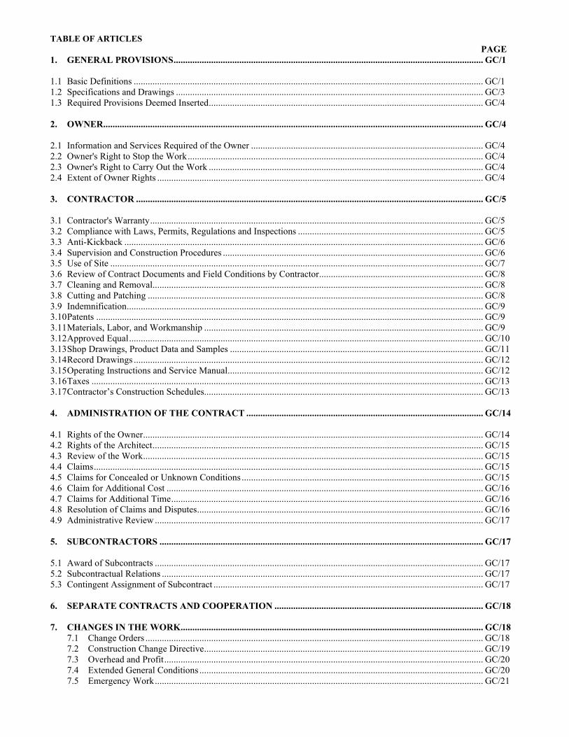
TABLE OF ARTICLES PAGE
1. GENERAL PROVISIONS .................................................................................................................................... GC/1 1.1 Basic Definitions ..................................................................................................................................................... GC/1 1.2 Specifications and Drawings ................................................................................................................................... GC/3 1.3 Required Provisions Deemed Inserted ..................................................................................................................... GC/4 2. OWNER.................................................................................................................................................................. GC/4 2.1 Information and Services Required of the Owner ................................................................................................... GC/4 2.2 Owner's Right to Stop the Work .............................................................................................................................. GC/4 2.3 Owner's Right to Carry Out the Work ..................................................................................................................... GC/4 2.4 Extent of Owner Rights ........................................................................................................................................... GC/4 3. CONTRACTOR .................................................................................................................................................... GC/5 3.1 Contractor's Warranty .............................................................................................................................................. GC/5 3.2 Compliance with Laws, Permits, Regulations and Inspections ............................................................................... GC/5 3.3 Anti-Kickback ......................................................................................................................................................... GC/6 3.4 Supervision and Construction Procedures ............................................................................................................... GC/6 3.5 Use of Site ............................................................................................................................................................... GC/7 3.6 Review of Contract Documents and Field Conditions by Contractor ...................................................................... GC/8 3.7 Cleaning and Removal ............................................................................................................................................. GC/8 3.8 Cutting and Patching ............................................................................................................................................... GC/8 3.9 Indemnification ........................................................................................................................................................ GC/9 3.10 Patents ..................................................................................................................................................................... GC/9 3.11 Materials, Labor, and Workmanship ....................................................................................................................... GC/9 3.12 Approved Equal ....................................................................................................................................................... GC/10 3.13 Shop Drawings, Product Data and Samples ............................................................................................................ GC/11 3.14 Record Drawings ..................................................................................................................................................... GC/12 3.15 Operating Instructions and Service Manual ............................................................................................................. GC/12 3.16 Taxes ....................................................................................................................................................................... GC/13 3.17 Contractor’s Construction Schedules....................................................................................................................... GC/13 4. ADMINISTRATION OF THE CONTRACT ..................................................................................................... GC/14 4.1 Rights of the Owner ................................................................................................................................................. GC/144.2 Rights of the Architect ............................................................................................................................................. GC/15 4.3 Review of the Work ................................................................................................................................................. GC/15 4.4 Claims ...................................................................................................................................................................... GC/15 4.5 Claims for Concealed or Unknown Conditions ....................................................................................................... GC/15 4.6 Claim for Additional Cost ....................................................................................................................................... GC/16 4.7 Claims for Additional Time ..................................................................................................................................... GC/16 4.8 Resolution of Claims and Disputes .......................................................................................................................... GC/16 4.9 Administrative Review ............................................................................................................................................ GC/17 5. SUBCONTRACTORS .......................................................................................................................................... GC/17 5.1 Award of Subcontracts ............................................................................................................................................ GC/17 5.2 Subcontractual Relations ......................................................................................................................................... GC/17 5.3 Contingent Assignment of Subcontract ................................................................................................................... GC/17 6. SEPARATE CONTRACTS AND COOPERATION ......................................................................................... GC/18 7. CHANGES IN THE WORK ................................................................................................................................. GC/18
7.1 Change Orders ................................................................................................................................................ GC/18 7.2 Construction Change Directive ....................................................................................................................... GC/19 7.3 Overhead and Profit ........................................................................................................................................ GC/20 7.4 Extended General Conditions ......................................................................................................................... GC/20 7.5 Emergency Work ............................................................................................................................................ GC/21
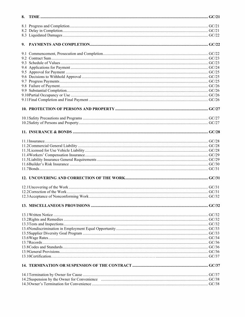
8. TIME ...................................................................................................................................................................... GC/21 8.1 Progress and Completion ......................................................................................................................................... GC/21 8.2 Delay in Completion ................................................................................................................................................ GC/21 8.3 Liquidated Damages ................................................................................................................................................ GC/22 9. PAYMENTS AND COMPLETION..................................................................................................................... GC/22 9.1 Commencement, Prosecution and Completion ........................................................................................................ GC/22 9.2 Contract Sum ........................................................................................................................................................... GC/23 9.3 Schedule of Values .................................................................................................................................................. GC/23 9.4 Applications for Payment ........................................................................................................................................ GC/24 9.5 Approval for Payment ............................................................................................................................................. GC/25 9.6 Decisions to Withhold Approval ............................................................................................................................. GC/25 9.7 Progress Payments ................................................................................................................................................... GC/25 9.8 Failure of Payment................................................................................................................................................... GC/26 9.9 Substantial Completion ............................................................................................................................................ GC/26 9.10 Partial Occupancy or Use ........................................................................................................................................ GC/26 9.11 Final Completion and Final Payment ...................................................................................................................... GC/26 10. PROTECTION OF PERSONS AND PROPERTY ............................................................................................ GC/27 10.1 Safety Precautions and Programs ............................................................................................................................ GC/27 10.2 Safety of Persons and Property ................................................................................................................................ GC/27 11. INSURANCE & BONDS ...................................................................................................................................... GC/28 11.1 Insurance.................................................................................................................................................................. GC/28 11.2 Commercial General Liability ................................................................................................................................. GC/28 11.3 Licensed for Use Vehicle Liability .......................................................................................................................... GC/28 11.4 Workers’ Compensation Insurance .......................................................................................................................... GC/29 11.5 Liability Insurance General Requirements .............................................................................................................. GC/29 11.6 Builder’s Risk Insurance ......................................................................................................................................... GC/30 11.7 Bonds ....................................................................................................................................................................... GC/31 12. UNCOVERING AND CORRECTION OF THE WORK .................................................................................. GC/31 12.1 Uncovering of the Work .......................................................................................................................................... GC/31 12.2 Correction of the Work ............................................................................................................................................ GC/31 12.3 Acceptance of Nonconforming Work ...................................................................................................................... GC/32 13. MISCELLANEOUS PROVISIONS .................................................................................................................... GC/32 13.1 Written Notice ......................................................................................................................................................... GC/32 13.2 Rights and Remedies ............................................................................................................................................... GC/32 13.3 Tests and Inspections ............................................................................................................................................... GC/32 13.4 Nondiscrimination in Employment Equal Opportunity ........................................................................................... GC/33 13.5 Supplier Diversity Goal Program ............................................................................................................................ GC/33 13.6 Wage Rates .............................................................................................................................................................. GC/34 13.7 Records .................................................................................................................................................................... GC/36 13.8 Codes and Standards ................................................................................................................................................ GC/36 13.9 General Provisions ................................................................................................................................................... GC/36 13.10Certification…………………………………………………………………… .................................................... GC/37 14. TERMINATION OR SUSPENSION OF THE CONTRACT ........................................................................... GC/37 14.1 Termination by Owner for Cause ............................................................................................................................ GC/37 14.2 Suspension by the Owner for Convenience .......................................................................................................... GC/38 14.3 Owner’s Termination for Convenience ................................................................................................................... GC/38
GC/1 08/18
ARTICLE 1
GENERAL PROVISIONS 1.1 Basic Definitions As used in the Contract Documents, the following terms shall have the meanings and refer to the parties designated in these definitions. 1.1.1 Owner The Curators of the University of Missouri. The Owner may act through its Board of Curators or any duly authorized committee or representative thereof. 1.1.2 Contracting Officer The Contracting Officer is the duly authorized representative of the Owner with the authority to execute contracts. Communications to the Contracting Officer shall be forwarded via the Owner's Representative. 1.1.3 Owner's Representative The Owner’s Representative is authorized by the Owner as the administrator of the Contract and will represent the Owner during the progress of the Work. Communications from the Architect to the Contractor and from the Contractor to the Architect shall be through the Owner's Representative, unless otherwise indicated in the Contract Documents. 1.1.4 Architect When the term "Architect" is used herein, it shall refer to the Architect or the Engineer specified and defined in the Contract for Construction or its duly authorized representative. Communications to the Architect shall be forwarded to the address shown in the Contract for Construction. 1.1.5 Contractor The Contractor is the person or entity with whom the Owner has entered into the Contract for Construction. The term “Contractor” means the Contractor or the Contractor’s authorized representative. 1.1.6 Subcontractor and Lower-tier Subcontractor A Subcontractor is a person or organization who has a contract with the Contractor to perform any of the Work. The term "Subcontractor" is referred to throughout the Contract Documents as if singular in number and means a Subcontractor or its authorized representative. The term "Subcontractor" also is applicable to those furnishing materials to be incorporated in the Work whether work performed is at the Owner’s site or off site, or both. A lower-tier Subcontractor is a person or organization who has a contract with a Subcontractor or another lower-tier Subcontractor to perform any of the Work at the site. Nothing contained in the Contract Documents shall create contractual relationships between the Owner or the Architect and any Subcontractor or lower-tier Subcontractor of any tier.
1.1.7 Supplier Diversity Definitions Businesses that fall into the Supplier Diversity classification shall mean an approved certified business concern which is at least fifty-one percent (51%) owned and controlled by one (1) or more diverse suppliers as described below. .1 Minority Business Enterprises (MBE) Minority Business Enterprise [MBE] shall mean an approved certified business concern which is at least fifty-one percent (51%) owned and controlled by one (1) or more minorities as defined below or, in the case of any publicly-owned business, in which at least fifty-one percent (51%) of the stock of which is owned by one (1) or more minorities as defined below, and whose management and daily business operations are controlled by one (1) or more minorities as defined herein.
.1.1 "African Americans", which includes persons having origins in any of the black racial groups of Africa.
.1.2 "Hispanic Americans", which includes persons of Mexican, Puerto Rican, Cuban, Central or South American, or other Spanish culture or origin, regardless of race.
.1.3 "Native Americans", which includes persons of American Indian, Eskimo, Aleut, or Native Hawaiian origin.
.1.4 "Asian-Pacific Americans", which includes persons whose origins are from Japan, China, Taiwan, Korea, Vietnam, Laos, Cambodia, the Philippines, Samoa, Guam, the U.S. Trust Territories of the Pacific, or the Northern Marinas.
.1.5 "Asian-Indian Americans", which includes persons whose origins are from India, Pakistan, or Bangladesh.
.2 Women Business Enterprise (WBE) Women Business Enterprise [WBE] shall mean an approved certified business concern which is at least fifty-one percent (51%) owned and controlled by one (1) or more women or, in the case of any publicly-owned business, in which at least fifty-one percent (51%) of the stock of which is owned by one (1) or more women, and whose management and daily business operations are controlled by one (1) or more women. .3 Veteran Owned Business Veteran Owned Business shall mean an approved certified business concern which is at least fifty-one percent (51%) owned and controlled by one (1) or more Veterans or, in the case of any publicly-owned business, in which at least fifty-one percent (51%) of the stock of which is owned by one (1) or more Veterans, and whose management and daily business operations are controlled by one (1) or more Veterans. Veterans must be certified by the appropriate federal agency responsible for veterans’ affairs. .4 Service Disabled Veteran Enterprise (SDVE) Service Disabled Veteran Enterprise (SDVE) shall mean a business certified by the State of Missouri Office of Administration as a Service Disabled Veteran Enterprise, which is at least fifty-one percent (51%) owned and controlled by one (1) or more Serviced Disabled Veterans or, in the case of any publicly-owned business, in which at least
GC/2 08/2020
fifty-one percent (51%) of the stock of which is owned by one (1) or more Service Disabled Veterans, and whose management and daily business operations are controlled by one (1) or more Serviced Disabled Veterans. .5 Disadvantaged Business Enterprise (DBE) A Disadvantaged Business Enterprise (DBE) is a for-profit small business concern where a socially and economically disadvantaged individual owns at least 51% interest and also controls management and daily business operations. These firms can and also be referred to as Small Disadvantaged Businesses (SDB). Eligibility requirements for certification are stated in 49 CFR (Code of Federal Regulations), part 26, Subpart D. U.S. citizens that are African-Americans, Hispanics, Native Americans, Asian-Pacific and Subcontinent Asian Americans, and women are presumed to be socially and economically disadvantaged. Also recognized as DBE’s are Historically Black Colleges and Universities (HBCU) and small businesses located in Federal HUB Zones. To be regarded as economically disadvantaged, an individual must have a personal net worth that does not exceed $1.32 million. To be seen as a small business, a firm must meet Small Business Administration (SBA) size criteria (500 employees or less) and have average annual gross receipts not to exceed $22.41 million. To be considered a DBE/SDB, a small business owned and controlled by socially and/or economically disadvantaged individuals must receive DBE certification from one of the recognized Missouri state agencies to be recognized in this classification. 1.1.9 Work Work shall mean supervision, labor, equipment, tools, material, supplies, incidentals operations and activities required by the Contract Documents or reasonably inferable by Contractor therefrom as necessary to produce the results intended by the Contract Documents in a safe, expeditious, orderly, and workmanlike manner, and in the best manner known to each respective trade. 1.1.10 Approved The terms "approved", "equal to", "directed", "required", "ordered", "designated", "acceptable", "satisfactory", and similar words or phrases will be understood to have reference to action on the part of the Architect and/or the Owner's Representative. 1.1.11 Contract Documents The Contract Documents consist of (1) the executed Contract for Construction, (2) these General Conditions of the Contract for Construction, (3) any Supplemental Conditions or Special Conditions identified in the Contract for Construction, (4) the Specifications identified in the Contract for Construction, (5) the Drawings identified in the Contract for Construction, (6) Addenda issued prior to the receipt of bids, (7) Contractor’s bid addressed to Owner, including Contractor’s completed Qualification Statement, (8)
Contractor’s Performance Bond and Contractor’s Payment Bond, (9) Notice to Proceed, (10) and any other exhibits and/or post bid adjustments identified in the Contract for Construction, (11) Advertisement for Bid, (12) Information for Bidders, and (13) Change Orders issued after execution of the Contract. All other documents and technical reports and information are not Contract Documents, including without limitation, Shop Drawings, and Submittals. 1.1.12 Contract The Contract Documents form the Contract and are the exclusive statement of agreement between the parties. The Contract represents the entire and integrated agreement between the parties hereto and supersedes prior representations or agreements, either written or oral. The Contract Documents shall not be construed to create a contractual relationship of any kind between the Owner and a Subcontractor or any lower-tier Subcontractor. 1.1.13 Change Order The Contract may be amended or modified without invalidating the Contract, only by a Change Order, subject to the limitations in Article 7 and elsewhere in the Contract Documents. A Change Order is a written instrument signed by the Owner and the Contractor stating their agreement to a change in the Work, the amount of the adjustment to the Contract Sum, if any, and the extent of the adjustment to the Contract Time, if any. Agreement to any Change Order shall constitute a final settlement of all matters relating to the change in the work which is the subject of the Change Order, including, but not limited to, all direct and indirect costs associated with such change and any and all adjustments of the Contract sum, time and schedule. 1.1.14 Substantial Completion The terms “Substantial Completion” or "substantially complete" as used herein shall be construed to mean the completion of the entire Work, including all submittals required under the Contract Documents, except minor items which in the opinion of the Architect, and/or the Owner's Representative will not interfere with the complete and satisfactory use of the facilities for the purposes intended. 1.1.15 Final Completion The date when all punch list items are completed, including all closeout submittals and approval by the Architect is given to the Owner in writing. 1.1.16 Supplemental and Special Conditions The terms “Supplemental Conditions” or “Special Conditions” shall mean the part of the Contract Documents which amend, supplement, delete from, or add to these General Conditions. 1.1.17 Day The term "day" as used in the Contract Documents shall mean calendar day unless otherwise specifically defined. 1.1.18 Knowledge.
GC/3 08/2020
The terms “knowledge,” “recognize” and “discover,“ their respective derivatives and similar terms in the Contract Documents, as used in reference to the Contractor, shall be interpreted to mean that which the Contractor knows or should know, recognizes or should recognize and discovers or should discover in exercising the care, skill, and diligence of a diligent and prudent contractor familiar with the work. Analogously, the expression “reasonably inferable” and similar terms in the Contract Documents shall be interpreted to mean reasonably inferable by a diligent and prudent contractor familiar with the work. 1.1.19 Punch List “Punch List” means the list of items, prepared in connection with the inspection of the Project by the Owner’s Representative or Architect in connection with Substantial Completion of the Work or a portion of the Work, which the Owner’s Representative or Architect has designated as remaining to be performed, completed or corrected before the Work will be accepted by the Owner. 1.1.20 Public Works Contracting Minimum Wage The public works contracting minimum wage shall be equal to one hundred twenty percent of the average hourly wage in a particular locality, as determined by the Missouri economic research and information center within the department of economic development, or any successor agency. 1.1.21 Force Majeure An event or circumstance that could not have been reasonably anticipated and is out of the control of both the Owner and the Contractor. 1.2 Specifications and Drawings 1.2.1 The Specifications are that portion of the Contract Documents consisting of the written requirements for materials, equipment, construction system, standards and workmanship and performance of related services for the Work identified in the Contract for Construction. Specifications are separated into titled divisions for convenience of reference only. Organization of the Specifications into divisions, sections and articles, and arrangement of Drawings shall not control the Contractor in dividing the Work among Subcontractors or in establishing the extent of Work to be performed by any trade. Such separation will not operate to make the Owner or the Architect an arbiter of labor disputes or work agreements. 1.2.2 The drawings herein referred to, consist of drawings prepared by the Architect and are enumerated in the Contract Documents. 1.2.3 Drawings are intended to show general arrangements, design, and dimensions of work and are partly diagrammatic. Dimensions shall not be determined by scale or rule. If figured dimensions are lacking, they
shall be supplied by the Architect on the Contractor's written request to the Owner's Representative. 1.2.4 The intent of the Contract Documents is to include all items necessary for the proper execution and completion of the Work by the Contractor. The Contract Documents are complimentary, and what is required by one shall be as binding as if required by all; performance by the Contractor shall by required only to the extent consistent with the Contract Documents and reasonably inferable from them as being necessary to produce the intended results. 1.2.5 In the event of inconsistencies within or between parts of the Contract Documents, or between the Contract Documents and applicable standards, codes and ordinances, the Contractor shall (1) provide the better quality or greater quantity of Work or (2) comply with the more stringent requirement; either or both in accordance with the Owner’s Representative’s interpretation. On the Drawings, given dimensions shall take precedence over scaled measurements and large scale drawings over small scale drawings. Before ordering any materials or doing any Work, the Contractor and each Subcontractor shall verify measurements at the Work site and shall be responsible for the correctness of such measurements. Any difference which may be found shall be submitted to the Owner’s Representative and Architect for resolution before proceeding with the Work. If a minor change in the Work is found necessary due to actual field conditions, the Contractor shall submit detailed drawings of such departure for the approval by the Owner’s Representative and Architect before making the change. 1.2.6 Data in the Contract Documents concerning lot size, ground elevations, present obstructions on or near the site, locations and depths of sewers, conduits, pipes, wires, etc., position of sidewalks, curbs, pavements, etc., and nature of ground and subsurface conditions have been obtained from sources the Architect believes reliable, but the Architect and Owner do not represent or warrant that this information is accurate or complete. The Contractor shall verify such data to the extent possible through normal construction procedures, including but not limited to contacting utility owners and by prospecting. 1.2.7 Only work included in the Contract Documents is authorized, and the Contractor shall do no work other than that described therein. 1.2.8 Execution of the Contract by the Contractor is a representation that the Contractor has visited the site, become familiar with local conditions under which the Work is to be performed and correlated personal observations with requirements of the Contract Documents. Contractor represents that it has performed its own investigation and examination of the Work site and its surroundings and satisfied itself before entering into this Contract as to: .1 conditions bearing upon transportation, disposal,
handling, and storage of materials;
GC/4 08/2020
.2 the availability of labor, materials, equipment, water, electrical power, utilities and roads;
.3 uncertainties of weather, river stages, flooding and similar characteristics of the site;
.4 conditions bearing upon security and protection of material, equipment, and Work in progress;
.5 the form and nature of the Work site, including the surface and sub-surface conditions;
.6 the extent and nature of Work and materials necessary for the execution of the Work and the remedying of any defects therein; and
.7 the means of access to the site and the accommodations it may require and, in general, shall be deemed to have obtained all information as to risks, contingencies and other circumstances.
.8 the ability to complete work without disruption to normal campus activities, except as specifically allowed in the contract documents.
The Owner assumes no responsibility or liability for the physical condition or safety of the Work site or any improvements located on the Work site. The Contractor shall be solely responsible for providing a safe place for the performance of the Work. The Owner shall not be required to make any adjustment in either the Contract Sum or Contract Time concerning any failure by the Contractor or any Subcontractor to comply with the requirements of this Paragraph. 1.2.9 Drawings, specifications, and copies thereof furnished by the Owner are and shall remain the Owner’s property. They are not to be used on another project and, with the exception of one contract set for each party to the Contract, shall be returned to the Owner's Representative on request, at the completion of the Work. 1.3 Required Provisions Deemed Inserted Each and every provision of law and clause required by law to be inserted in this Contract shall be deemed to be inserted herein, and the Contract shall be read and enforced as though it were included herein; and if through mistake or otherwise any such provision is not inserted, or is not correctly inserted, then upon the written application of either party the Contract shall forthwith be physically amended to make such insertion or correction.
ARTICLE 2 OWNER
2.1 Information and Services Required of the
Owner 2.1.1 Permits and fees are the responsibility of the Contractor under the Contract Documents, unless specifically stated in the contract documents that the Owner will secure and pay for specific necessary approvals, easements, assessments, and charges required for construction, use or occupancy of permanent
structures, or for permanent changes in existing facilities. 2.1.2 When requested in writing by the Contractor, information or services under the Owner's control, which are reasonably necessary to perform the Work, will be furnished by the Owner with reasonable promptness to avoid delay in the orderly progress of the Work. 2.2 Owner's Right to Stop the Work 2.2.1 If the Contractor fails to correct Work which is not in strict accordance with the requirements of the Contract Documents or fails to carry out Work in strict accordance with the Contract Documents, the Owner's Representative may order the Contractor to stop the Work, or any portion thereof, until the cause for such order has been eliminated; however, the right of the Owner to stop the Work will not give rise to a duty on the part of the Owner to exercise this right for the benefit of the Contractor or any other person or entity. Owner’s lifting of Stop Work Order shall not prejudice Owner’s right to enforce any provision of this Contract. 2.3 Owner's Right to Carry Out the Work 2.3.1 If the Contractor defaults or neglects to carry out the Work in accordance with the Contract Documents, and fails within a seven (7) day period after receipt of a written notice from the Owner to correct such default or neglect, the Owner may, without prejudice to other remedies the Owner may have, correct such default or neglect. In such case, an appropriate Change Order shall be issued deducting from payments then or thereafter due the Contractor the cost of correcting such deficiencies, including compensation for the Architect’s additional services and expenses made necessary by such default or neglect. If payments then or thereafter due the Contractor are not sufficient to cover such amounts, the Contractor shall pay the difference to Owner. However, such notice shall be waived in the event of an emergency with the potential for property damage or the endangerment of students, faculty, staff, the public or construction personnel, at the sole discretion of the Owner. 2.3.2 In the event the Contractor has not satisfactorily completed all items on the Punch List within thirty (30) days of its receipt, the Owner reserves the right to complete the Punch List without further notice to the Contractor or its surety. In such case, Owner shall be entitled to deduct from payments then or thereafter due the Contractor the cost of completing the Punch List items, including compensation for the Architect’s additional services. If payments then or thereafter due Contractor are not sufficient to cover such amounts, the Contractor shall pay the difference to Owner. 2.4 Extent of Owner Rights 2.4.1 The rights stated in this Article 2 and elsewhere in the Contract Documents are cumulative and not in limitation of any rights of the Owner (1) granted in the Contract Documents, (2) at law or (3) in equity.
GC/5 08/2020
2.4.2 In no event shall the Owner have control over, charge of, or any responsibility for construction means, methods, techniques, sequences or procedures or for safety precautions and programs in connection with the Work, notwithstanding any of the rights and authority granted the Owner in the Contract Documents.
ARTICLE 3 CONTRACTOR
3.1 Contractor's Warranty 3.1.1 The Contractor warrants all equipment and materials furnished, and work performed, under this Contract, against defective materials and workmanship for a period of twelve months after acceptance as provided in this Contract, unless a longer period is specified, regardless of whether the same were furnished or performed by the Contractor or any Subcontractors of any tier. Upon written notice from the Owner of any breech of warranty during the applicable warranty period due to defective material or workmanship, the affected part or parts thereof shall be repaired or replaced by the Contractor at no cost to the Owner. Should the Contractor fail or refuse to make the necessary repairs, replacements, and tests when requested by the Owner, the Owner may perform, or cause the necessary work and tests to be performed, at the Contractor's expense, or exercise the Owner's rights under Article 14. 3.1.2 Should one or more defects mentioned above appear within the specified period, the Owner shall have the right to continue to use or operate the defective part or apparatus until the Contractor makes repairs or replacements or until such time as it can be taken out of service without loss or inconvenience to the Owner. 3.1.3 The above warranties are not intended as a limitation, but are in addition to all other express warranties set forth in this Contract and such other warranties as are implied by law, custom, and usage of trade. The Contractor, and its surety or sureties, if any, shall be liable for the satisfaction and full performance of the warranties set forth herein. 3.1.4 Neither the final payment nor any provision in the Contract Documents nor partial or entire occupancy of the premises by the Owner, nor expiration of warranty stated herein, will constitute an acceptance of Work not done in accordance with the Contract Documents or relieve the Contractor of liability in respect to any responsibility for non-conforming work. The Contractor shall immediately remedy any defects in the Work and pay for any damage to other Work resulting therefrom upon written notice from the Owner. Should the Contractor fail or refuse to remedy the non-conforming work, the Owner may perform, or cause to be performed the work necessary to bring the work into conformance with the Contract Documents at the Contractor's expense.
3.1.5 The Contractor agrees to defend, indemnify, and save harmless The Curators of the University of Missouri, their Officers, Agents, Employees and Volunteers, from and against all loss or expense from any injury or damages to property of others suffered or incurred on account of any breech of the aforesaid obligations and covenants. The Contractor agrees to investigate, handle, respond to and provide defense for and defend against any such liability, claims, and demands at the sole expense of the Contractor, or at the option of the University, agrees to pay to or reimburse the University for the defense costs incurred by the University in connection with any such liability claims, or demands. The parties hereto understand and agree that the University is relying on, and does not waive or intend to waive by any provision of this Contract, any monetary limitations or any other rights, immunities, and protections provided by the State of Missouri, as from time to time amended, or otherwise available to the University, or its officers, employees, agents or volunteers. 3.2 Compliance with Laws, Permits, Regulations and
Inspections 3.2.1 The Contractor shall, without additional expense to the Owner, comply with all applicable laws, ordinances, rules, statutes, and regulations (collectively referred to as “Laws”). 3.2.2 Since the Owner is an instrumentality of the State of Missouri, municipal, or political subdivision, ordinances, zoning ordinances, and other like ordinances are not applicable to construction on the Owner's property, and the Contractor will not be required to submit plans and specifications to any municipal or political subdivision authority to obtain construction permits or any other licenses or permits from or submit to, inspection by any municipality or political subdivision relating to the construction on the Owner's property, unless required by the Owner in these Contract Documents or otherwise in writing. 3.2.3 All fees, permits, inspections, or licenses required by municipality or political subdivision for operation on property not belonging to the Owner, shall be obtained by and paid for by the Contractor. The Contractor, of its own expense, is responsible to ensure that all inspections required by said permits or licenses on property, easements, or utilities not belonging to the Owner are conducted as required therein. All connection charges, assessments or transportation fees as may be imposed by any utility company or others are included in the Contract Sum and shall be the Contractor’s responsibility, as stated in 2.1.1 above. 3.2.4 If the Contractor has knowledge that any Contract Documents are at variance with any Laws, including Americans with Disabilities Act – Standards for Accessible Design, ordinances, rules, regulations or codes applying to the Work, Contractor shall promptly notify the Architect and the Owner’s Representative, in writing, and any necessary changes will be adjusted as provided in Contract Documents.
GC/6 08/2020
However, it is not the Contractor’s primary responsibility to ascertain that the Contract Documents are in accordance with applicable Laws, unless such Laws bear upon performance of the Work. 3.3 Anti-Kickback 3.3.1 No member or delegate to Congress, or resident commissioner, shall be admitted to any share or part of this Contract or to any benefit that may arise therefrom, but this provision shall not be construed to extend to this Contract if made with a corporation for its general benefit. 3.3.2 No official of the Owner who is authorized in such capacity and on behalf of the Owner to negotiate, make, accept or approve, or to take part in negotiating, making, accepting, or approving any architectural, engineering, inspection, construction, or material supply contract or any Subcontract of any tier in connection with the construction of the Work shall have a financial interest in this Contract or in any part thereof, any material supply contract, Subcontract of any tier, insurance contract, or any other contract pertaining to the Work. 3.4 Supervision and Construction Procedures 3.4.1 The Contractor shall supervise and direct the Work, using the Contractor’s best skill and attention. The Contractor shall be solely responsible for and have control over construction means, methods, techniques, sequences, and procedures and for coordinating all portions of the Work under the Contract. The Contractor shall supply sufficient and competent supervision and personnel, and sufficient material, plant, and equipment to prosecute the Work with diligence to ensure completion thereof within the time specified in the Contract Documents, and shall pay when due any laborer, Subcontractor of any tier, or supplier. 3.4.2 The Contractor, if an individual, shall give the Work an adequate amount of personal supervision, and if a partnership or corporation or joint venture the Work shall be given an adequate amount of personal supervision by a partner or executive officer, as determined by the Owner's Representative. 3.4.3 The Contractor and each of its Subcontractors of any tier shall submit to the Owner such schedules of quantities and costs, progress schedules in accordance with 3.17.2 of this document, payrolls, reports, estimates, records, and other data as the Owner may request concerning Work performed or to be performed under the Contract. 3.4.4 The Contractor shall be represented at the site by a competent superintendent from the beginning of the Work until its final acceptance, whenever contract work is being performed, unless otherwise permitted in writing by the Owner's Representative. The superintendent for the Contractor shall exercise general supervision over the
Work and such superintendent shall have decision making authority of the Contractor. Communications given to the superintendent shall be binding as if given to the Contractor. The superintendent shall not be changed by the contractor without approval from the Owner’s Representative. 3.4.5 The Contractor shall establish and maintain a permanent bench mark to which access may be had during progress of the Work, and Contractor shall establish all lines and levels, and shall be responsible for the correctness of such. Contractor shall be fully responsible for all layout work for the proper location of Work in strict accordance with the Contract Documents. 3.4.6 The Contractor shall establish and be responsible for wall and partition locations. If applicable, separate contractors shall be entitled to rely upon these locations and for setting their sleeves, openings, or chases. 3.4.7 The Contractor’s scheduled outage/tie-in plan, time, and date for any utilities is subject to approval by the Owner’s Representative. Communication with the appropriate entity and planning for any scheduled outage/tie-in of utilities shall be the responsibility of the Contractor. Failure of Contractor to comply with the provisions of this Paragraph shall cause Contractor to forfeit any right to an adjustment of the Contract Sum or Contract Time for any postponement, rescheduling or other delays ordered by Owner in connection with such Work. The Contractor shall follow the following procedures for all utility outages/tie-ins or disruption of any building system: .1 All shutting of valves, switches, etc., shall be by the
Owner's personnel. .2 Contractor shall submit its preliminary outage/tie-in
schedule with its baseline schedule. .3 The Contractor shall request an outage/tie-in
meeting at least two weeks before the outage/tie-in is required.
.4 The Owner's Representative will schedule an outage/tie-in meeting at least one week prior to the outage/tie-in.
3.4.8 The Contractor shall coordinate all Work so there shall be no prolonged interruption of existing utilities, systems and equipment of Owner. Any existing plumbing, heating, ventilating, air conditioning, or electrical disconnection necessary, which affect portions of this construction or building or any other building, must be scheduled with the Owner's Representative to avoid any disruption of operation within the building under construction or other buildings or utilities. In no case shall utilities be left disconnected at the end of a work day or over a weekend. Any interruption of utilities, either intentionally or accidentally, shall not relieve the Contractor from repairing and restoring the utility to normal service. Repairs and restoration shall be made before the workers responsible for the repair and restoration leave the job.
GC/7 08/2020
3.4.9 The Contractor shall be responsible for repair of damage to property on or off the project occurring during construction of project, and all such repairs shall be made to meet code requirements or to the satisfaction of the Owner's Representative if code is not applicable. 3.4.10 The Contractor shall be responsible for all shoring required to protect its work or adjacent property and shall pay for any damage caused by failure to shore or by improper shoring or by failure to give proper notice. Shoring shall be removed only after completion of permanent supports. 3.4.11 The Contractor shall maintain at his own cost and expense, adequate, safe and sufficient walkways, platforms, scaffolds, ladders, hoists and all necessary, proper, and adequate equipment, apparatus, and appliances useful in carrying on the Work and which are necessary to make the place of Work safe and free from avoidable danger for students, faculty, staff, the public and construction personnel, and as may be required by safety provisions of applicable laws, ordinances, rules regulations and building and construction codes. 3.4.12 During the performance of the Work, the Contractor shall be responsible for providing and maintaining warning signs, lights, signal devices, barricades, guard rails, fences, and other devices appropriately located on site which shall give proper and understandable warning to all persons of danger of entry onto land, structure, or equipment, within the limits of the Contractor’s work area. 3.4.13 The Contractor shall pump, bail, or otherwise keep any general excavations free of water. The Contractor shall keep all areas free of water before, during and after concrete placement. The Contractor shall be responsible for protection, including weather protection, and proper maintenance of all equipment and materials installed, or to be installed by him. 3.4.14 The Contractor shall be responsible for care of the Work and must protect same from damage of defacement until acceptance by the Owner. All damaged or defaced Work shall be repaired or replaced to the Owner's satisfaction, without cost to the Owner. 3.4.15 When requested by the Owner's Representative, the Contractor, at no extra charge, shall provide scaffolds or ladders in place as may be required by the Architect or the Owner for examination of Work in progress or completed. 3.4.16 The Contractor shall be responsible to the Owner for acts and omissions of the Contractor’s employees, Subcontractors of any tier and their agents and employees, and any entity or other persons performing portions of the Work.
3.4.17 The Contractor shall not be relieved of its obligations to perform the Work in accordance with the Contract Documents either by activities or duties of the Owner’s Representative or Architect in their administration of the Contract, or by tests, inspections or approvals required or performed by persons other than the Contractor. 3.4.18 The Contractor shall be responsible for inspection of portions of the Work already performed under this Contract to determine that such portions are in proper condition to receive subsequent Work. 3.5 Use of Site 3.5.1 The Contractor shall limit operations and storage of material to the area within the Work limit lines shown on Drawings, except as necessary to connect to exiting utilities, shall not encroach on neighboring property, and shall exercise caution to prevent damage to existing structures. 3.5.2 Only materials and equipment, which are to be used directly in the Work, shall be brought to and stored on the Work site by the Contractor. After equipment is no longer required for the Work, it shall be promptly removed from the Work site. Protection of construction materials and equipment stored at the Work site from weather, theft, damage and all other adversity is solely the responsibility of the Contractor. 3.5.3 No project signs shall be erected without the written approval of the Owner's Representative. 3.5.4 The Contractor shall ensure that the Work is at all times performed in a manner that affords reasonable access, both vehicular and pedestrian, to the site of the Work and all adjacent areas. Particular attention shall be paid to access for emergency vehicles, including fire trucks. Wherever there is the possibility of interfering with normal emergency vehicle operations, Contractor shall obtain permission from both campus and municipal emergency response entities prior to limiting any access. The Work shall be performed, to the fullest extent reasonably possible, in such a manner that public areas adjacent to the site of the Work shall be free from all debris, building materials and equipment likely to cause hazardous conditions. Without limitation of any other provision of the Contract Documents, Contractor shall not interfere with the occupancy or beneficial use of (1) any areas and buildings adjacent to the site of the Work or (2) the Work in the event of partial occupancy. Contractor shall assume full responsibility for any damage to the property comprising the Work or to the owner or occupant of any adjacent land or areas resulting from the performance of the Work.
3.5.5 The Contractor shall not permit any workers to use any existing facilities at the Work site, including, without limitation, lavatories, toilets, entrances, and parking areas other than those designated by Owner. The Contractor, Subcontractors of any tier, suppliers and employees shall comply with instructions or regulations of the Owner’s
GC/8 08/2020
Representative governing access to, operation of, and conduct while in or on the premises and shall perform all Work required under the Contract Documents in such a manner as not to unreasonably interrupt or interfere with the conduct of Owner’s operations. Any request for Work, a suspension of Work or any other request or directive received by the Contractor from occupants of existing buildings shall be referred to the Owner’s Representative for determination. 3.5.6 The Contractor and the Subcontractor of any tier shall have its’ name, acceptable abbreviation or recognizable logo and the name of the city and state of the mailing address of the principal office of the company, on each motor vehicle and motorized self-propelled piece of equipment which is used in connection with the project. The signs are required on such vehicles during the time the Contractor is working on the project. 3.6 Review of Contract Documents and Field
Conditions by Contractor 3.6.1 The Contractor shall carefully study and compare the Contract Documents with each other and with information furnished by the Architect and Owner and shall at once report in writing to the Architect and Owner’s Representative any errors, inconsistencies or omissions discovered. If the Contractor performs any construction activity which it knows or should have known involves a recognized error, inconsistency or omission in the Contract Documents without such written notice to the Architect and Owner’s Representative, the Contractor shall assume appropriate responsibility for such performance and shall bear an appropriate amount of the attributable costs for correction. 3.6.2 The Contractor shall take field measurements and verify field conditions and shall carefully compare such field measurements and conditions and other information known to the Contractor with the Contract Documents before commencing activities. Errors, inconsistencies or omissions discovered shall be reported in writing to the Architect and Owner’s Representative within twenty-four (24) hours. During the progress of work, Contractor shall verify all field measurements prior to fabrication of building components or equipment, and proceed with the fabrication to meet field conditions. Contractor shall consult all Contract Documents to determine the exact location of all work and verify spatial relationships of all work. Any question concerning said location or spatial relationships shall be submitted to the Owner's Representative. Specific locations for equipment, pipelines, ductwork and other such items of work, where not dimensioned on plans, shall be determined in consultation with Owner's Representative and Architect. Contractor shall be responsible for the proper fitting of the Work in place. 3.6.3 The Contractor shall provide, at the proper time, such material as required for support of the Work. If
openings or chases are required, whether shown on Drawings or not, the Contractor shall see they are properly constructed. If required openings or chases are omitted, the Contractor shall cut them at the Contractors own expense, but only as directed by the Architect, through the Owner Representative. 3.6.4 Should the Contract Documents fail to particularly describe materials or goods to be used, it shall be the duty of the Contractor to inquire of the Architect and the Owner’s Representative what is to be used and to supply it at the Contractor’s expense, or else thereafter replace it to the Owner’s Representative’s satisfaction. At a minimum, the Contractor shall provide the quality of materials as generally specified throughout the Contract Documents. 3.7 Cleaning and Removal 3.7.1 The Contractor shall keep the Work site and surrounding areas free from accumulation of waste materials, rubbish, debris, and dirt resulting from the Work and shall clean the Work site and surrounding areas as requested by the Architect and the Owner's Representative, including mowing of grass greater than 6 inches high. The Contractor shall be responsible for the cost of clean up and removal of debris from premises. The building and premises shall be kept clean, safe, in a workmanlike manner, and in compliance with OSHA standards at all times. At completion of the Work, the Contractor shall remove from and about the Work site tools, construction equipment, machinery, fencing, and surplus materials. Further, at the completion of the work, all dirt, stains, and smudges shall be removed from every part of the building, all glass in doors and windows shall be washed, and entire Work shall be left broom clean in a finished state ready for occupancy. The Contractor shall advise his Subcontractors of any tier of this provision, and the Contractor shall be fully responsible for leaving the premises in a finished state ready for use to the satisfaction of the Owner's Representative. If the Contractor fails to comply with the provisions of this paragraph, the Owner may do so and the cost thereof shall be charged to the Contractor. 3.8 Cutting and Patching 3.8.1 The Contractor shall be responsible for cutting, fitting, or patching required to complete the Work or to make its parts fit together properly. 3.8.2 The Contractor shall not damage or endanger a portion of the Work or fully or partially completed construction of the Owner or separate contractors by cutting, patching, or otherwise altering such construction, or by excavation. The Contractor shall not cut or otherwise alter such construction by the Owner or a separate contractor except with written consent of the Owner and of such separate contractor; such consent shall not be unreasonably withheld. The Contractor shall not unreasonably withhold from the Owner or a separate contractor the Contractor's consent to cutting or otherwise altering the Work. 3.8.3 If the Work involves renovation and/or alteration of existing improvements, Contractor acknowledges that cutting
GC/9 08/2020
and patching of the Work is essential for the Work to be successfully completed. Contractor shall perform any cutting, altering, patching, and/or fitting of the Work necessary for the Work and the existing improvements to be fully integrated and to present the visual appearance of an entire, completed, and unified project. In performing any Work which requires cutting or patching, Contractor shall use its best efforts to protect and preserve the visual appearance and aesthetics of the Work to the reasonable satisfaction of both the Owner’s Representative and Architect. 3.9 Indemnification 3.9.1 To the fullest extent permitted by law, the Contractor shall defend, indemnify, and hold harmless the Owner, the Architect, Architect’s consultants, and the agents, employees, representatives, insurers and re-insurers of any of the foregoing (hereafter collectively referred to as the “Indemnitees”) from and against claims, damages (including loss of use of the Work itself), punitive damages, penalties and civil fines unless expressly prohibited by law, losses and expenses, including, but not limited to, attorneys’ fees, arising out of or resulting from performance of the Work to the extent caused in whole or in part by negligent acts or omissions or other fault of Contractor, a Subcontractor of any tier, or anyone directly or indirectly employed by them or anyone for whose acts they may be liable, regardless of whether or not such claim, damage, loss, or expense is caused in part by the negligent acts or omissions or other fault of a party indemnified hereunder. The Contractor’s obligations hereunder are in addition to and shall not be construed to negate, abridge, or reduce other rights or obligations of indemnity that the Owner may possess. If one or more of the Indemnitees demand performance by the Contractor of obligations under this paragraph or other provisions of the Contract Documents and if Contractor refuses to assume or perform, or delays in assuming or performing Contractor’s obligations, Contractor shall pay each Indemnitee who has made such demand its respective attorneys’ fees, costs, and other expenses incurred in enforcing this provision. The defense and indemnity required herein shall be a binding obligation upon Contractor whether or not an Indemnitee has made such demand. Even if a defense is successful to a claim or demand for which Contractor is obligated to indemnify the Indemnitees from under this Paragraph, Contractor shall remain liable for all costs of defense. 3.9.2 The indemnity obligations of Contractor under this Section 3.9 shall survive termination of this Contract or final payment thereunder. In the event of any claim or demand made against any party which is entitled to be indemnified hereunder, the Owner may in its sole discretion reserve, return or apply any monies due or to become due the Contractor under the Contract for the purpose of resolving such claims; provided, however, that the Owner may release such funds if the Contractor provides the Owner with reasonable assurance of
protection of the Owner’s interests. The Owner shall in its sole discretion determine if such assurances are reasonable. Owner reserves the right to control the defense and settlement of any claim, action or proceeding which Contractor has an obligation to indemnify the Indemnitees against under Paragraph 3.9.1. 3.9.3 In claims against any person or entity indemnified under this Section 3.9 by an employee of the Contractor, a Subcontractor of any tier, anyone directly or indirectly employed by them or anyone for whose acts they may be liable, the indemnification obligation under this Section 3.9 shall not be limited by a limitation on amount or type of damages, compensation or benefits payable by or for the Contractor or a Subcontractor of any tier under workers’ or workmen’s compensation acts, disability benefit acts or other employee benefit acts. 3.9.4 The obligations of the Contractor under Paragraph 3.9.1 shall not extend to the liability of the Architect, his agents or employees, arising out of the preparation and approval of maps, drawings, opinions, reports, surveys, Change Orders, designs, or Specifications. 3.10 Patents 3.10.1 The Contractor shall hold and save harmless the Owner and its officers, agents, servants, and employees from liability of any nature or kind, including cost and expense, for, or on account of, any patented or otherwise protected invention, process, article, or appliance manufactured or used in the performance of the Contract, including its use by the Owner, unless otherwise specifically stipulated in the Contract Documents. 3.10.2 If the Contractor uses any design, device, or material covered by letters patent or copyright, he shall provide for such use by suitable agreement with the Owner of such patented or copyrighted design, device, or material. It is mutually agreed and understood, without exception, that the Contract Sum includes and the Contractor shall pay all royalties, license fees or costs arising from the use of such design, device, or material in any way involved in the Work. The Contractor and/or sureties shall indemnify and save harmless the Owner from any and all claims for infringement by reason of the use of such patented or copyrighted design, device, or material or any trademark or copyright in connection with Work agreed to be performed under this Contract and shall indemnify the Owner for any cost, expense, or damage it may be obligated to pay by reason of such infringement at any time during the prosecution of the Work or after completion of the Work. 3.11 Materials, Labor, and Workmanship 3.11.1 Materials and equipment incorporated into the Work shall strictly conform to the Contract Documents and representations and approved Samples provided by Contractor and shall be of the most suitable grade of their respective kinds for their respective uses, and shall be fit and sufficient for the purpose intended, merchantable, of good
GC/10 08/2020
new material and workmanship, and free from defect. Workmanship shall be in accordance with the highest standard in the industry and free from defect in strict accordance with the Contract Documents. 3.11.2 Materials and fixtures shall be new and of latest design unless otherwise specified, and shall provide the most efficient operating and maintenance costs to the Owner. All Work shall be performed by competent workers and shall be of best quality. 3.11.3 The Contractor shall carefully examine the Contract Documents and shall be responsible for the proper fitting of his material, equipment, and apparatus into the building. 3.11.4 The Contractor shall base his bid only on the Contract Documents. 3.11.5 Materials and workmanship shall be subject to inspection, examination, and test by the Architect and the Owner's Representative at any and all times during manufacture, installation, and construction of any of them, at places where such manufacture, installation, or construction is performed. 3.11.6 The Contractor shall enforce strict discipline and good order among the Contractor’s employees and other persons carrying out the Contract. The Contractor shall not permit employment of unfit persons or persons not skilled in tasks assigned to them. 3.11.7 Unless otherwise specifically noted, the Contractor shall provide and pay for supervision, labor, materials, equipment, tools, construction equipment and machinery, water, heat, utilities, transportation, and other facilities and services necessary for the proper execution and completion of the Work. 3.11.8 Substitutions 3.11.8.1 A substitution is a Contractor proposal of an alternate product or method in lieu of has been specified or shown in the Contract Documents, which is not an “or equal” as set forth in Section 3.12.1. 3.11.8.2 Contractor may make a proposal to the Architect and the Owner’s Representative to use substitute products or methods as set forth herein, but the Architect's and the Owner’s Representative’s decision concerning acceptance of a substitute shall be final. The Contractor must do so in writing and setting forth the following: .1 Full explanation of the proposed substitution and
submittal of all supporting data including technical information, catalog cuts, warranties, test results, installation instructions, operating procedures, and other like information necessary for a complete evaluation of the substitution.
.2 Reasons the substitution is advantageous and necessary, including the benefits to the Owner
and the Work in the event the substitution is acceptable.
.3 The adjustment, if any, in the Contract Sum, in the event the substitution is acceptable.
.4 The adjustment, if any, in the time of completion of the Contract and the construction schedule in the event the substitution is acceptable.
.5 An affidavit stating that (a) the proposed substitution conforms to and meets all of the Contract Documents, except as specifically disclosed and set forth in the affidavit and (b) the Contractor accepts the warranty and correction obligations in connection with the proposed substitution as if originally specified by the Architect. Proposals for substitutions shall be submitted to the Architect and Owner’s Representative in sufficient time to allow the Architect and Owner’s Representative no less than ten (10) working days for review. No substitution will be considered or allowed without the Contractor's submittal of complete substantiating data and information as stated herein.
3.11.8.3 Substitutions may be rejected without explanation in Owner’s sole discretion and will be considered only under one or more of the following conditions: .1 Required for compliance with interpretation of code
requirements or insurance regulations then existing; .2 Unavailability of specified products, through no
fault of the Contractor; .3 Material delivered fails to comply with the Contract
Documents; .4 Subsequent information discloses inability of
specified products to perform properly or to fit in designated space;
.5 Manufacturer/fabricator refuses to certify or guarantee performance of specified product as required; or
.6 When in the judgment of the Owner or the Architect, a substitution would be substantially to the Owner's best interests, in terms of cost, time, or other considerations.
3.11.8.4 Whether or not any proposed substitution is accepted by the Owner or the Architect, the Contractor shall reimburse the Owner for any fees charged by the Architect or other consultants for evaluating each proposed substitute. 3.12 Approved Equal 3.12.1 Whenever in the Contract Documents any article, appliance, device, or material is designated by the name of a manufacturer, vendor, or by any proprietary or trade name, the words "or approved equal," shall automatically follow and shall be implied unless specifically indicated otherwise. The standard products of manufacturers other than those specified will be accepted when, prior to the ordering or use thereof, it is proven to the satisfaction of the Owner’s Representative and the Architect they are equal in design, appearance, spare parts availability, strength, durability,
GC/11 08/2020
usefulness, serviceability, operation cost, maintenance cost, and convenience for the purpose intended. Any general listings of approved manufacturers in any Contract Document shall be for informational purposes only and it shall be the Contractor’s sole responsibility to ensure that any proposed “or equal” complies with the requirements of the Contract Documents. 3.12.2 The Contractor shall submit to Architect and Owner’s Representative a written and full description of the proposed “or equal” including all supporting data, including technical information, catalog cuts, warranties, test results, installation instructions, operating procedures, and similar information demonstrating that the proposed “or equal” strictly complies with the Contract Documents. The Architect or Owner’s Representative shall take appropriate action with respect to the submission of a proposed “or equal” item. If Contractor fails to submit proposed “or equals” as set forth herein, it shall waive any right to supply such items. The Contract Sum and Contract Time shall not be adjusted as a result of any failure by Contractor to submit proposed “or equals” as provided for herein. All documents submitted in connection with preparing an “or equal” shall be clearly and obviously marked as a proposed “or equal” submission. 3.12.3 No approvals or action taken by the Architect or Owner’s Representative shall relieve Contractor from its obligation to ensure that an “or equal” article, appliance, devise or material strictly complies with the requirements of the Contract Documents. Contractor shall not propose “or equal” items in connection with Shop Drawings or other Submittals, and Contractor acknowledges and agrees that no approvals or action taken by the Architect or Owner’s Representative with respect to Shop Drawings or other Submittals shall constitute approval of any “or equal” item or relieve Contractor from its sole and exclusive responsibility. Any changes required in the details and dimensions indicated in the Contract Documents for the incorporation or installation of any “or equal” item supplied by the Contractor shall be properly made and approved by the Architect at the expense of the Contractor. No ‘or equal’ items will be permitted for components of or extensions to existing systems when, in the opinion of the Architect, the named manufacturer must be provided in order to ensure compatibility with the existing systems, including, but not limited to, mechanical systems, electrical systems, fire alarms, smoke detectors, etc. No action will be taken by the Architect with respect to proposed “or equal” items prior to receipt of bids, unless otherwise noted in the Special Conditions. 3.13 Shop Drawings, Product Data, Samples, and
Coordination Drawings/BIM Models 3.13.1 Shop Drawings are drawings, diagrams, schedules and other data specifically prepared for the Work by the Contractor or a Subcontractor, sub-subcontractor,
manufacturer, supplier or distributor to illustrate some portion of the Work. 3.13.2 Product Data are illustrations, standard schedules, performance charts, instructions, brochures, diagrams and other information furnished by the Contractor to illustrate materials or equipment for some portion of the Work. 3.13.3 Samples are physical samples which illustrate materials, equipment or workmanship and establish standards by which the Work will be judged. 3.13.4 Coordination Drawings are drawings for the integration of the Work, including work first shown in detail on shop drawings or product data. Coordination drawings show sequencing and relationship of separate units of work which must interface in a restricted manner to fit in the space provided, or function as indicated. Coordination Drawings are the responsibility of the contractor and are submitted for informational purposes. The Special Conditions will state whether coordination drawings are required. BIM models may be used for coordination in lieu of coordination drawings at the contractor’s discretion, unless required in the Special Conditions. The final coordination drawings/BIM Model will not change the contract documents, unless approved by a fully executed change order describing the specific modifications that are being made to the contract documents. 3.13.5 Shop Drawings, Coordination Drawings/BIM Models, Product Data, Samples and similar submittals (collectively referred to as “Submittals”) are not Contract Documents. The purpose of their submittal is to demonstrate for those portions of the Work for which submittals are required the way the Contractor proposes to conform to the information given and the design concept expressed in the Contract Documents. 3.13.6 The Contractor shall schedule submittal of Shop Drawings and Product Data to the Architect so that no delays will result in delivery of materials and equipment, advising the Architect of priority for checking of Shop Drawings and Product Data, but a minimum of two weeks shall be provided for this purpose. Because time is of the essence in this contract, unless noted otherwise in the Special Conditions or Technical Specifications, all submittals, shop drawings and samples must be submitted as required to maintain the contractor’s plan for proceeding, but must be submitted within 90 days of the Notice To Proceed. If Contractor believes that this milestone is unreasonable for any submittal, Contractor shall request an extension of this milestone, within 60 days of Notice To Proceed, for each submittal that cannot meet the milestone. The request shall contain a reasonable explanation as to why the 90 day milestone is unrealistic, and shall specify a date on which the submittal will be transmitted, for approval by the Owner’s Representative. Failure of the Contractor to comply with this section may result in delays in the submittal approval process and/or charges for expediting approval, both of which will be the responsibility of the Contractor.
GC/12 08/2020
3.13.7 The Contractor, at its own expense, shall submit Samples required by the Contract Documents with reasonable promptness as to cause no delay in the Work or the activities of separate contractors and no later than twenty (20) days before materials are required to be ordered for scheduled delivery to the Work site. Samples shall be labeled to designate material or products represented, grade, place of origin, name of producer, name of Contractor and the name and number of the Owner’s project. Quantities of Samples shall be twice the number required for testing so that Architect can return one set of the Samples. Materials delivered before receipt of Architect’s approval may be rejected by Architect and in such event, Contractor shall immediately remove all such materials from the Work site. When requested by Architect or Owner’s Representative, samples of finished masonry and field applied paints and finishes shall be located as directed and shall include sample panels built at the site of approximately twenty (20) square feet each. 3.13.8 The Contractor shall perform no portion of the Work requiring submittal and review of Shop Drawings, Product Data, Samples or similar submittals until the respective submittal has been approved by the Architect. Such Work shall be in accordance with approved submittals. 3.13.9 By approving and submitting Shop Drawings, Product Data, Samples and similar submittals, the Contractor represents such Submittals strictly comply with the requirements of the Contract Documents and that the Contractor has determined and verified field measurements and field construction criteria related thereto, that materials are fit for their intended use and that the fabrication, shipping, handling, storage, assembly and installation of all materials, systems and equipment are in accordance with best practices in the industry and are in strict compliance with any applicable requirements of the Contract Documents. Contractor shall also coordinate each Submittal with other Submittals. 3.13.10 Contractor shall be responsible for the correctness and accuracy of the dimensions, measurements and other information contained in the Submittals. 3.13.11 Each Submittal will bear a stamp or specific indication that the Submittal complies with the Contract Documents and Contractor has satisfied its obligations under the Contract Documents with respect to Contractor’s review and approval of that Submittal. Each Submittal shall bear the signature of the representative of Contractor who approved the Submittal, together with the Contractor’s name, Owner’s name, number of the Project, and the item name and specification section number. 3.13.12 The Contractor shall not be relieved of responsibility for deviations from requirements of the Contract Documents by the Architect's approval of Shop Drawings, Product Data, Samples or similar submittals.
The Contractor shall not be relieved of responsibility for errors or omissions in Shop Drawings, Product Data, Samples or similar submittals by the Architect's approval thereof. Specifically, but not by way of limitation, Contractor acknowledges that Architect’s approval of Shop Drawings shall not relieve Contractor for responsibility for errors and omissions in the Shop Drawings since Contractor is responsible for the correctness of dimensions, details and the design of adequate connections and details contained in the Shop Drawings. 3.13.13 The Contractor shall direct specific attention, in writing or on resubmitted Shop Drawings, Product Data, Samples or similar submittals, to revisions other than those requested by the Architect on previous Submittals. 3.13.14 The Contractor represents and warrants that all Shop Drawings shall be prepared by persons and entities possessing expertise and experience in the trade for which the Shop Drawing is prepared and, if required by the Architect or applicable Laws, by a licensed engineer or other design professional. 3.14 Record Drawings 3.14.1 The Contractor shall maintain a set of Record Drawings on site in good condition and shall use colored pencils to mark up said set with "record information" in a legible manner to show: (1) bidding addendums, (2) executed change orders, (3)deviations from the Drawings made during construction; (4) details in the Work not previously shown; (5) changes to existing conditions or existing conditions found to differ from those shown on any existing drawings; (6) the actual installed position of equipment, piping, conduits, light switches, electric fixtures, circuiting, ducts, dampers, access panels, control valves, drains, openings, and stub-outs; and (7) such other information as either Owner or Architect may reasonably request. The prints for Record Drawing use will be a set of “blue line” prints provided by Architect to Contractor at the start of construction. Upon Substantial Completion of the Work, Contractor shall deliver all Record Drawings to Owner and Architect for approval. If not approved, Contractor shall make the revisions requested by Architect or Owner’s Representative. Final payment and any retainage shall not be due and owing to Contractor until the final Record Drawings marked by Contractor as required above are delivered to Owner. 3.15 Operating Instructions and Service Manuals 3.15.1 The Contractor shall submit four (4) volumes of operating instructions and service manuals to the Architect before completing 50% of the adjusted contract amount. Payments beyond 50% of the adjusted contract amount may be withheld until all operating instructions and service manuals are received. The operating instructions and service manuals shall contain: .1 Start-up and Shutdown Procedures: Provide a
step-by-step write up of all major equipment. When manufacturer's printed start-up, trouble shooting and shut-down procedures are available, they may be
GC/13 08/2020
incorporated into the operating manual for reference.
.2 Operating Instructions: Written operating instructions shall be included for the efficient and safe operation of all equipment.
.3 Equipment List: List of all major equipment as installed shall include model number, capacities, flow rate, and name-plate data.
.4 Service Instructions: The Contractor shall be required to provide the following information for all pieces of equipment. (a) Recommended spare parts including catalog
number and name of local suppliers or factory representative.
(b) Belt sizes, types, and lengths. (c) Wiring diagrams.
.5 Manufacturer's Certificate of Warranty: Manufacturer's certificates of warranty shall be obtained for all major equipment. Warranty shall be obtained for at least one year from the date of Substantial Completion. Where longer period is required by the Contract Documents, the longer period shall govern.
.6 Parts catalogs: For each piece of equipment furnished, a parts catalog or similar document shall be provided which identifies the components by number for replacement ordering.
3.15.2 Submission .1 Manuals shall be bound into volumes of standard
8 1/2" x 11" hard binders. Large drawings too bulky to be folded into 8 1/2" x 11" shall be separately bound or folded and in brown envelopes, cross-referenced and indexed with the manuals.
.2 The manuals shall identify the Owner’s project name, project number, and include the name and address of the Contractor and major Subcontractors of any tier who were involved with the activity described in that particular manual.
3.16 Taxes 3.16.1 The Contractor shall pay all applicable sales, consumer, use, and similar taxes for the Work which are legally enacted when the bids are received, whether or not yet effective or scheduled to go into effect. However, certain purchases by the Contractor of materials incorporated in or consumed in the Work are exempt from certain sales tax pursuant to RSMo § 144.062. The Contractor shall be issued a Project Tax Exemption Certificate for this Work to obtain the benefits of RSMo § 144.062. 3.16.2 The Contractor shall furnish this certificate to all subcontractors, and any person or entity purchasing materials for the Work shall present such certificate to all material suppliers as authorization to purchase, on behalf
of the Owner, all tangible personal property and materials to be incorporated into or consumed in the Work and no other on a tax-exempt basis. Such suppliers shall provide to the purchasing party invoices bearing the name of the exempt entity and the project identification number. Nothing in this section shall be deemed to exempt from any sales or similar tax the purchase of any construction machinery, equipment or tools used in construction, repairing or remodeling facilities for the Owner. All invoices for all personal property and materials purchased under a Project Tax Exemption Certificate shall be retained by the Contractor for a period of five years and shall be subject to audit by the Director of Revenue. 3.16.3 Any excess resalable tangible personal property or materials which were purchased for the project under this Project Tax Exemption Certificate but which were not incorporated into or consumed in the Work shall either be returned to the supplier for credit or the appropriate sales or use tax on such excess property or materials shall be reported on a return and paid by such purchasing party not later than the due date of the purchasing party’s Missouri sales or use tax return following the month in which it was determined that the materials were not used in the Work. 3.16.4 If it is determined that sales tax is owed by the Contractor on property and materials due to the failure of the Owner to revise the certificate expiration date to cover the applicable date of purchase, Owner shall be liable for the tax owed. 3.16.5 The Owner shall not be responsible for any tax liability due to Contractor’s neglect to make timely orders, payments, etc. or Contractor’s misuse of the Project Tax Exemption Certificate. Contractor represents that the Project Tax Exemption Certificate shall be used in accordance with RSMo § 144.062 and the terms of the Project Tax Exemption Certificate. Contractor shall indemnify the Owner for any loss or expense, including but not limited to, reasonable attorneys’ fees, arising out of Contractor’s use of the Project Tax Exemption Certificate. 3.17 Contractor’s Construction Schedules 3.17.1 The Contractor, within fifteen (15) days after the issuance of the Notice to Proceed, shall prepare and submit for the Owner's and Architect's information Contractor's construction schedule for the Work and shall set forth interim dates for completion of various components of the Work and Work Milestone Dates as defined herein. The schedule shall not exceed time limits current under the Contract Documents, shall be revised on a monthly basis or as requested by the Owner’s Representative as required by the conditions of the Work, and shall provide for expeditious and practicable execution of the Work. The Contractor shall conform to the most recent schedule. 3.17.2 The construction schedule shall be in a detailed format satisfactory to the Owner’s Representative and the Architect and in accordance with the detailed schedule
GC/14 08/2020
requirements set forth in this document and the Special Conditions. If the Owner’s Representative or Architect has a reasonable objection to the schedule submitted by Contractor, the construction schedule shall be promptly revised by the Contractor. The Contractor shall monitor the progress of the Work for conformance with the requirements of the construction schedule and shall promptly advise the Owner of any delays or potential delays. 3.17.3 As time is of the essence to this contract, the University expects that the Contractor will take all necessary steps to insure that the project construction schedule shall be prepared in accordance with the specific requirements of the Special Conditions to this contract. At a minimum, contractor shall comply with the following: .1 The schedule shall be prepared using Primavera
P3, Oracle P6, Microsoft Project or other software acceptable to the Owner’s Representative.
.2 The schedule shall be prepared and maintained in CPM format, in accordance with Construction CPM Scheduling, published by the Associated General Contractors of American (AGC).
.3 Prior to submittal to the Owner’s Representative for review, Contractor shall obtain full buy-in to the schedule from all major subcontractors, in writing if so requested by Owner’s Representative.
.4 Schedule shall be updated, in accordance with Construction CPM Scheduling, published by the AGC, on a monthly basis at minimum, prior to, and submitted with, the monthly pay application or as requested by the Owner’s Representative.
.5 Along with the update the Contractor shall submit a narrative report addressing all changes, delays and impacts, including weather to the schedule during the last month, and explain how the end date has been impacted by same.
.6 The submission of the updated certifies that all delays and impacts that have occurred on or to the project during the previous month have been factored into the update and are fully integrated into the schedule and the projected completion date.
Failure to comply with any of these requirements will be considered a material breach of this contract. See Special Conditions for detailed scheduling requirements. 3.17. 4 In the event the Owner’s Representative or Architect determines that the performance of the Work, as of a Milestone Date, has not progressed or reached the level of completion required by the Contract Documents, the Owner shall have the right to order the Contractor to take corrective measures necessary to expedite the progress of construction, including, without limitation, (1) working additional shifts or overtime, (2) supplying additional manpower, equipment, facilities, (3) expediting delivery of
materials, and (4) other similar measures (hereinafter referred to collectively as Extraordinary Measures). Such Extraordinary Measures shall continue until the progress of the Work complies with the stage of completion required by the Contract Documents. The Owner's right to require Extraordinary Measures is solely for the purpose of ensuring the Contractor's compliance with the construction schedule. The Contractor shall not be entitled to an adjustment in the Contract Sum concerning Extraordinary Measures required by the Owner under or pursuant to this Paragraph 3.17.3. The Owner may exercise the rights furnished the Owner under or pursuant to this Paragraph 3.17.3 as frequently as the Owner deems necessary to ensure that the Contractor's performance of the Work will comply with any Milestone Date or completion date set forth in the Contract Documents.
ARTICLE 4 ADMINISTRATION OF THE CONTRACT
4.1 Rights of the Owner 4.1.1 The Owner's Representative will administer the Construction Contract. The Architect will assist the Owner's Representative with the administration of the Contract as indicated in these Contract Documents. 4.1.2 If, in the judgment of the Owner's Representative, it becomes necessary to accelerate the work, the Contractor, when directed by the Owner's Representative in writing, shall cease work at any point and transfer its workers to such point or points and execute such portions of the work as may be required to enable others to hasten and properly engage and carry out the work, all as directed by the Owner's Representative. The additional cost of accelerating the work, if any, will be borne by the Owner, unless the Contractor's work progress is behind schedule as shown on the most recent progress schedule. 4.1.3 If the Contractor refuses, for any reason, to proceed with what the Owner believes to be contract work, the Owner may issue a Construction Directive, directing the Contractor to proceed. Contractor shall be obligated to promptly proceed with this work. If Contractor feels that it is entitled to additional compensation for this work, it may file a claim for additional compensation and/or time, in accordance with 4.4 of this document. 4.1.4 The Owner's Representative, may, by written notice, require a Contractor to remove from involvement with the Work, any of Contractor’s personnel or the personnel of its Subcontractors of any tier whom the Owner's Representative may deem abusive, incompetent, careless, or a hindrance to proper and timely execution of the Work. The Contractor shall comply with such notice promptly, but without detriment to the Work or its progress. 4.1.5 The Owner's Representative will schedule Work status meetings that shall be attended by representatives of the Contractor and appropriate Subcontractors of any tier.
GC/15 08/2020
Material suppliers shall attend status meetings if required by the Owner's Representative. These meetings shall include preconstruction meetings. 4.1.6 The Owner does not allow smoking on University property. 4.2 Rights of the Architect 4.2.1 The Architect will interpret requirements of the Contract Documents with respect to the quality, quantity and other technical requirements of the Work itself within a reasonable time after written request of the Contractor. Contractor shall provide Owner’s Representative a copy of such written request. 4.3 Review of the Work 4.3.1 The Architect and the Owner's Representative shall, at all times, have access to the Work; and the Contractor shall provide proper and safe facilities for such access. 4.3.2 The Owner’s Representative shall have authority to reject Work that does not strictly comply with the requirements of the Contract Documents. Whenever the Owner’s Representative considers it necessary or advisable for implementation of the intent of the Contract Documents, Owner’s Representative shall have the authority to require additional inspection or testing of the Work, whether or not such Work is fabricated, installed or completed. 4.3.3 The fact that the Architect or the Owner's Representative observed, or failed to observe, faulty Work, or Work done which is not in accordance with the Contract Documents, regardless of whether or not the Owner has released final payment, shall not relieve the Contractor from responsibility for all damages and additional costs of the Owner as a result of defective or faulty Work. 4.4 Claims 4.4.1 A Claim is a demand or assertion by Contractor seeking, as a matter of right, adjustment or interpretation of Contract terms, payment of money, extension of time or any other relief with respect to the terms of the Contract. The term "Claim(s)" also includes demands and assertions of Contractor arising out of or relating to the Contract Documents, including Claims based upon breach of contract, mistake, misrepresentation, or other cause for Contract Modification or recision. Claims must be made by written notice. Contractor shall have the responsibility to substantiate Claims. 4.4.2 Claims by Contractor must be made promptly, and no later than within fourteen (14) days after occurrence of the event giving rise to such Claim. Claims must be made by written notice. Such notice shall include a detailed statement setting forth all reasons for the Claim and the amount of additional money and additional time
claimed by Contractor. The notice of Claims shall also strictly comply with all other provisions of the Contract Documents. Contractor shall not be entitled to rely upon any grounds or basis for additional money on additional time not specifically set forth in the notice of Claim. All Claims not made in the manner provided herein shall be deemed waived and of no effect. Contractor shall furnish the Owner and Architect such timely written notice of any Claim provided for herein, including, without limitation, those in connection with alleged concealed or unknown conditions, and shall cooperate with the Owner and Architect in any effort to mitigate the alleged or potential damages, delay or other adverse consequences arising out of the condition which is the cause of such a Claim. 4.4.3 Pending final resolution of a Claim, the Contractor shall proceed diligently with performance of the Contract and the Owner shall continue to make payments that are not in dispute in accordance with the Contract Documents. 4.5 Claims for Concealed or Unknown Conditions 4.5.1 If conditions are encountered at the site which are (1) subsurface or otherwise concealed physical conditions which differ materially from those indicated in the Contract Documents, or (2) unknown physical conditions of an unusual nature, which differ materially from those ordinarily found to exist and generally recognized as inherent in construction activities of the character provided for in the Contract Documents, then notice by the Contractor shall be given to the Owner's Representative promptly before conditions are disturbed, and in no event later than three (3) days after first observance of the conditions. The Owner's Representative will promptly investigate such conditions. If such conditions differ materially, as provided for above and cause an increase or decrease in the Contractor’s cost, or time, required for performance of the Work, an equitable adjustment in the Contract sum or Contract Time, or both, shall be made, subject to the provisions and restrictions set for herein. If the Owner's Representative determines that the conditions at the site are not materially different from those indicated in the Contract Documents, and that no change in the terms of the Contract is justified, the Owner's Representative will so notify the Contractor in writing. If the Contractor disputes the finding of the Owner’s Representative that no change in the terms of the Contract terms is justified, Contractor shall proceed with the Work, taking whatever steps are necessary to overcome or correct such conditions so that Contractor can proceed in a timely manner. The Contractor may have the right to file a Claim in accordance with the Contract Documents. 4.5.2 It is expressly agreed that no adjustment in the Contract Time or Contract Sum shall be permitted, however, in connection with a concealed or unknown condition which does not differ materially from those conditions disclosed or which reasonably should have been disclosed by the Contractor’s (1) prior inspections, tests, reviews and preconstruction investigations for the Project, or (2) inspections, tests, reviews and preconstruction inspections
GC/16 08/2020
which the Contractor had the opportunity to make or should have performed in connection with the Project. 4.6 Claim for Additional Cost 4.6.1 If the Contractor makes a Claim for an increase in the Contract Sum, written notice as provided herein shall be given before proceeding to execute the Work. In addition to all other requirements for notice of a Claim, said notice shall detail and itemize the amount of all Claims and shall contain sufficient data to permit evaluation of same by Owner. 4.7 Claims for Additional Time 4.7.1 If the Contractor makes a Claim for an increase in the Contract Time, written notice as provided herein shall be given. In addition to other requirements for notice of a Claim, Contractor shall include an estimate of the probable effect of delay upon the progress of the Work, utilizing a CPM Time Impact Schedule Analysis, (TIA) as defined in the AGC Scheduling Manual. In the case of a continuing delay, only one Claim is necessary. .1 Time extensions will be considered for excusable
delays only. That is, delays that are beyond the control and/or contractual responsibility of the contractor.
4.7.2 If weather days are the basis for a Claim for additional time, such Claim shall be documented by the Contractor by data acceptable to the Owner's Representative substantiating that weather conditions for the period of time in question, had an adverse effect on the critical path of the scheduled construction. Weather days shall be defined as days on which critical path work cannot proceed due to weather conditions (including but not limited to rain, snow, etc.), in excess of the number of days shown on the Anticipated Weather Day schedule in the Special Conditions. To be considered a weather day, at least four hours must be lost due to the weather conditions on a critical path scope item for that day.; Weather days and Anticipated weather days listed in the Special Conditions shall only apply to Monday through Friday. A weather day claim cannot be made for Saturdays, Sundays, New Year’s Day, Martin Luther King Day, Memorial Day, Independence Day, Labor Day, Thanksgiving Day, the day after Thanksgiving Day and Christmas Day, unless that specific day was approved in writing for work by the Owner’s Representative. .1 The Contractor must have fulfilled its contract
obligations with respect to temporary facilities and protection of its work; and worker protection for hot and cold weather per OSHA guidelines.
.2 If the contract obligations have been satisfied, the Owner will review requests for non-compensable time extensions for critical path activities as follows: .2.1 If the Contractor cannot work on a
critical path activity due to adverse weather, after implementing all reasonable temporary weather
protection, the Contractor will so notify the Owner’s Representative. Each week, the Contractor will notify the Owner’s Representative of the number of adverse weather days that it believes it has experienced in the previous week. As provided in the contract, until such time as the weather days acknowledged by the Owner’s Representative exceed the number of days of adverse weather contemplated in the Special Conditions, no request for extension of the contract completion time will be considered.
.2.2 If the Contractor has accumulated in excess of the number of adverse weather days contemplated in the Special Conditions due to the stoppage of work on critical path activities due to adverse weather, the Owner will consider a time extension request from the Contractor that is submitted in accordance with the contract requirements. The Owner will provide a change order extending the time for contract completion or direct an acceleration of the work in accordance with the contract terms and conditions to recover the time lost due to adverse weather in excess of the number of adverse weather working days contemplated in the Special Conditions.
4.7.3 A Force Majeure event or circumstance shall not be the basis of a claim by the Contractor seeking an adjustment in the Contract amount for costs or expenses of any type. With the exception of weather delays which are administered under this Article 4, and not withstanding other requirements of the Contract, all Force Majeure events resulting in a delay to the critical path of the project shall be administered as provided in Article 8.
4.7.4 The Owner will consider and evaluate requests for time extensions due to changes or other events beyond the control of the Contractor on a monthly basis only, with the submission of the Contractor’s updated schedule, in conjunction with the monthly application for payment. 4.8 Resolution of Claims and Disputes 4.8.1 The Owner's Representative will review Claims and take one or more of the following preliminary actions within ten days of receipt of a Claim: (1) request additional supporting data from the Contractor, (2) reject the Claim in whole or in part, (3) approve the Claim, or (4) suggest a compromise. 4.8.2 If a Claim has not been resolved, the Contractor shall, within ten days after the Owner's Representative's preliminary response, take one or more of the following actions: (1) submit additional supporting data requested, (2)
GC/17 08/2020
modify the initial Claim, or (3) notify the Owner's Representative that the initial Claim stands. 4.8.3 If a Claim has not been resolved after consideration of the foregoing and of further information presented by the Contractor, the Contractor has the right to seek administrative review as set forth in Section 4.9. However, Owner’s Representative’s decisions on matters relating to aesthetics will be final. 4.9 Administrative Review 4.9.1 Claims not resolved pursuant to the procedures set forth in the Contract Documents except with respect to Owner’s Representative’s decision on matters relating to aesthetic effect, and except for claims which have been waived by the making or acceptance of final payment, or the Contractor's acceptance of payments in full for changes in work may be submitted to administrative review as provided in this section. All requests for administrative review shall be made in writing. 4.9.2 Upon written request from the Contractor, the Owner’s Review Administrator authorized by the Campus Contracting Officer will convene a review meeting between the Contractor and Owner’s Representative’s within fifteen (15) days of receipt of such written request. The Contractor and Owner’s Representative will be allowed to present written documentation with respect to the claim(s) before or during the meeting. The Contractor and Owner’s Representative will be allowed to present the testimony of any knowledgeable person regarding the claim at the review meeting. The Owner’s Review Administrator will issue a written summary of the review meeting and decision to resolve the Claim within fifteen (15) days. If the Contractor is in agreement with the decision the Contractor shall notify the Owner’s Review Administrator in writing within five (5) days, and appropriate documentation will be signed by the parties to resolve the Claim. 4.9.3 If the Contractor is not in agreement with the proposal of the Owner’s Review Administrator as to the resolution of the claim, the Contractor may file a written appeal with the UM System Contracting Officer, [in care of the Director of Facilities Planning and Development, University of Missouri, 109 Old Alumni Centers, University of Missouri, Columbia, Missouri 65211] within fifteen (15) days after receipt of the Owner’s Review Administrator’s proposal. The UM System Contracting Officer will call a meeting of the Contractor, the Owner’s Representative, and the Owner’s Review Administrator by written notice, within thirty (30) days after receipt of the Contractor's written appeal. The Owner’s Review Administrator shall provide the UM System Contracting Officer with a copy of the written decision and summary of the review meeting, the Contractor's corrections or comments regarding the summary of the review meeting, and any written documentation presented by the Contractor and the
Owner’s Representative at the initial review meeting. The parties may present further documentation and/or present the testimony of any knowledgeable person regarding the claim at the meeting called by the UM System Contracting Officer. 4.9.4 The UM System Contracting Officer will issue a written decision to resolve the claim within fifteen (15) days after the meeting. If the Contractor is in agreement with the UM System Contracting Officer's proposal, the Contractor shall notify the UM System Contracting Officer in writing within five (5) days, and the Contractor and the Owner shall sign appropriate documents. The issuance of the UM System Contracting Officer's written proposal shall conclude the administrative review process even if the Contractor is not in agreement. However, proposals and any opinions expressed in such proposals issued under this section will not be binding on the Contractor nor will the decisions or any opinions expressed be admissible in any legal actions arising from the Claim and will not be deemed to remove any right or remedy of the Contractor as may otherwise exist by virtue of Contract Documents or law. Contractor and Owner agree that the Missouri Circuit Court for the County where the Work is located shall have exclusive jurisdiction to determine all issues between them. Contractor agrees not to file any complaint, petition, lawsuit or legal proceeding against Owner except with such Missouri Circuit Court.
ARTICLE 5 SUBCONTRACTORS
5.1 Award of Subcontracts 5.1.1 Pursuant to Article 9, the Contractor shall furnish the Owner and the Architect, in writing, with the name, and trade for each Subcontractor and the names of all persons or entities proposed as manufacturers of products, materials and equipment identified in the Contract Documents and where applicable, the name of the installing contractor. The Owner’s Representative will reply to the Contractor in writing if the Owner has reasonable objection to any such proposed person or entity. The Contractor shall not contract with a proposed person or entity to whom the Owner has made reasonable and timely objection. 5.1.2 The Contractor may request to change a subcontractor. Any such request shall be made in writing to the Owner’s Representative. The Contractor shall not change a Subcontractor, person, or entity previously disclosed if the Owner makes reasonable objection to such change. 5.1.3 The Contractor shall be responsible to the Owner for acts, defaults, and omissions of its Subcontractors of any tier. 5.2 Subcontractual Relations 5.2.1 By appropriate agreement, written where legally required for validity, the Contractor shall require each Subcontractor of any tier, to the extent of the Work to be performed by the Subcontractor of any tier, to be bound to
GC/18 08/2020
the Contractor by terms of the Contract Documents and to assume toward the Contractor all the obligations and responsibilities which the Contractor, by these Documents, assumes toward the Owner and the Architect. Each subcontract agreement of any tier shall preserve and protect the rights of the Owner and the Architect under the Contract Documents with respect to the Work to be performed by the Subcontractor of any tier so that subcontracting thereof will not prejudice such rights and shall allow to the Subcontractor of any tier, unless specifically provided otherwise in the subcontract agreement, the benefit of all rights, remedies, and redress against the Contractor that the Contractor, by the Contract Documents, has against the Owner. Where appropriate, the Contractor shall require each Subcontractor to enter into similar agreements with its sub-subcontractors. The Contractor shall make available to each proposed Subcontractor of any tier, prior to the execution of the subcontract agreement, copies of the Contract Documents to which the Subcontractor of any tier shall be bound Subcontractors of any tier shall similarly make copies of applicable portions of such documents available to their respective proposed Subcontractors of any tier. 5.2.2 All agreements between the Contractor and a Subcontractor or supplier shall contain provisions whereby Subcontractor or supplier waives all rights against the Owner, contractor, Owner’s representative, Architect and all other additional insureds for all losses and damages caused by, arising out of, or resulting from any of the perils covered by property or builders risk insurance coverage required of the Contractor in the Contract Documents. If Contractor fails to include said provisions in all subcontracts, Contractor shall indemnify, defend and hold all the above entities harmless in the event of any legal action by Subcontractor or supplier. If insureds on any such policies require separate waiver forms to be signed by any Subcontractors of any tier or suppliers, Contractor shall obtain the same. 5.3 Contingent Assignment of Subcontract 5.3.1 No assignment by the Contractor of any amount or any part of the Contract or of the funds to be received thereunder will be recognized unless such assignment has had the written approval of the Owner, and the surety has been given due notice of such assignment and has furnished written consent hereto. In addition to the usual recitals in assignment Contracts, the following language must be set forth: "it is agreed that the funds to be paid to the assignee under this assignment are subject to performance by the Contractor of the contract and to claims and to liens for services rendered or materials supplied for the performance of the Work called for in said contract in favor of all persons, firms or corporations rendering such services or supplying such materials.
ARTICLE 6 SEPARATE CONTRACTS AND COOPERATION
6.1 The Owner reserves the right to let other contracts in connection with the Work. 6.2 It shall be the duty of each Contractor to whom Work may be awarded, as well as all Subcontractors of any tier employed by them, to communicate immediately with each other in order to schedule Work, locate storage facilities, etc., in a manner that will permit all Contractors to work in harmony in order that Work may be completed in the manner and within the time specified in the Contract Documents. 6.3 No Contractor shall delay another Contractor by neglecting to perform his work at the proper time. Each Contractor shall be required to coordinate his work with other Contractors to afford others reasonable opportunity for execution of their work. Any costs caused by defective or ill- timed work, including actual damages and liquidated damages for delay, if applicable, shall be borne by the Contractor responsible therefor. 6.4 Each Contractor shall be responsible for damage to Owner's or other Contractor's property done by him or persons in his employ, through his or their fault or negligence. If any Contractor shall cause damage to any other Contractor, the Contractor causing such damage shall upon notice of any claim, settle with such Contractor. 6.5 The Contractor shall not claim from the Owner money damages or extra compensation under this Contract when delayed in initiating or completing his performance hereunder, when the delay is caused by labor disputes, acts of God, or the failure of any other Contractor to complete his performance under any Contract with the Owner, where any such cause is beyond the Owner's reasonable control. 6.6 Progress schedule of the Contractor for the Work shall be submitted to other Contractors as necessary to permit coordinating their progress schedules. 6.7 If Contractors or Subcontractors of any tier refuse to cooperate with the instructions and reasonable requests of other contractors performing work for the Owner under separate contract, in the overall coordinating of the Work, the Owner's Representative may take such appropriate action and issue such instructions as in his judgement may be required to avoid unnecessary and unwarranted delay.
ARTICLE 7 CHANGES IN THE WORK
7.1 CHANGE ORDERS 7.1.1 A change order is a written instrument prepared by the Owner and signed by the Owner and Contractor formalizing their agreement on the following: .1 a change in the Work .2 the amount of an adjustment, if any, in the Contract
amount
GC/19 08/2020
.3 an adjustment, if any, in the Contract time 7.1.2 The Owner may at any time, order additions, deletions, or revisions in the Work by a Change Order or a Construction Change Directive. Such Change Order or Construction Change Directive shall not invalidate the Contract and requires no notice to the surety. Upon receipt of any such document, or written authorization from the Owner’s Representative directing the Contractor to proceed pending receipt of the document, Contractor shall promptly proceed with the Work involved in accordance with the terms set forth therein. 7.1.3 Until such time as the change order is formalized and signed by both the Owner and the Contractor it shall be considered a Change Order Request. 7.1.4 The amount of adjustment in the contract price for authorized Change Orders will be agreed upon before such Change Orders becomes effective and will be determined as follows: .1 By a lump sum proposal from the Contractor
and the Subcontractors of any tier, including overhead and profit.
.2 By a time and material basis with or without a specified maximum. The Contractor shall submit to the Owner’s Representative itemized time and material sheets depicting labor, materials, equipment utilized in completing the Work on a daily basis for the Owner's Representative approval. If this pricing option is utilized, the Contractor may be required to submit weekly reports summarizing costs to date on time and material change orders not yet finalized.
.3 By unit prices contained in the Contractor's original bid and incorporated in the Construction Contract or subsequently agreed upon. Such unit prices contained in the Contractor's original proposal are understood to include the Contractor's overhead and profit. If unit prices are stated in the Contract Documents or subsequently agreed upon, and if quantities originally contemplated are so changed in a proposed Change Order that application of such unit prices to quantities of the Work proposed will cause substantial inequity to the Owner or to the Contractor, the applicable unit prices shall be equitably adjusted.
7.1.5 The Contractor shall submit all fully documented change order requests with corresponding back-up documentation within the time requested by the Owner but no later than fourteen (14) working days following 1.) the Owner’s request for change order pricing in the case of a lump sum; or 2.) the completion of unit price or time and material work.
7.1.6 The Contractor shall submit change order requests in sufficient detail to allow evaluation by the Owner. Such requests shall be fully itemized by units of labor, material and equipment and overhead and profit. Such breakdowns shall be itemized as follows: .1 Labor: The Contractor’s proposal shall include
breakdowns by labor, by trade, indicating number of hours and cost per hour for each Subcontractor as applicable. Such breakdowns shall only include employees in the direct employ of Contractor or Subcontractors in the performance of the Work. Such employees shall only include laborers at the site, mechanics, craftsmen and foremen. Payroll cost shall include base rate salaries and wages plus the cost of fringe benefits required by agreement or custom and social security contributions, unemployment, payroll taxes and workers' or workmen's compensation insurance and other customary and legally required taxes paid by the Contractor or Subcontractors. Any item or expense outside of these categories is not allowed. The expense of performing Work after regular working hours, on Saturdays, Sundays or legal holidays shall not be included in the above, unless approved in writing and in advance by Owner.
.2 Material, supplies, consumables and equipment to be incorporated into the Work at actual invoice cost to the Contractor or Subcontractors; breakdowns showing all material, installed equipment and consumables fully itemized with number of units installed and cost per unit extended. Any singular item or items in aggregate greater than one thousand dollars ($1,000) in cost shall be supported with supplier invoices at the request of the Owner’s Representative. Normal hand tools are not compensable.
.3 Equipment: Breakdown for required equipment shall itemize (at a minimum) delivery / pick-up charge, hourly rate and hours used. Operator hours and rate shall not be included in the equipment breakdown. Contractor must use the most cost effective equipment available in the area and should not exceed the rates listed in the Rental Rate Blue Book for Construction Equipment (Blue Book). Contractor shall submit documentation for the Blue Book to support the rate being requested.
7.2 Construction Change Directive 7.2.1 A construction change directive is a written order prepared and signed by the Owner, issued with supporting documents prepared by the Architect (if applicable), directing a change in the Work prior to agreement on adjustment of the Contract amount or Contract time, or both. A Construction Change Directive shall be used in the absence of complete agreement between the Owner and Contractor on the terms of a change order. If the Construction Change Directive allows an adjustment of the contract amount or time, such adjustment amount shall be based on one of the following methods: .1 A lump sum agreement, properly itemized and supported
by substantiating documents of sufficient detail to allow evaluation.
GC/20 08/2020
.2 By unit prices contained in the Contractor's original proposal and incorporated in the Construction Contract or subsequently agreed upon.
.3 A method agreed to by both the Owner and the contractor with a mutually agreeable fee for overhead and profit.
.4 In the absence of an agreement between the Owner and the Contractor on the method of establishing an adjustment of the contract amount, the Owner, with the assistance of the architect, shall determine the adjustment amount on the basis of expenditures by the Contractor for labor, materials, equipment and other costs consistent with other provisions of the Contract. The contractor shall keep and submit to the Owner an itemized accounting of all cost components, either expended or saved, while performing the Work covered under the Construction Change Directive.
7.2.2 Upon receipt of a Construction Change Directive, Contractor shall promptly proceed with the change in the Work involved and advise Owner of Contractor’s agreement or disagreement with the method, if any, provided in the Construction Change Directive for determining the proposed adjustment in the Contract Sum, Contract Time or both.
7.2.3 A Construction Change Directive signed by Contractor indicates the agreement of the Contractor therewith, including adjustment in Contract Sum and Contract Time or the method for determining them. Such agreement shall be effective immediately and shall be recorded as a Change Order.
7.3 Overhead and Profit 7.3.1 Overhead and Profit on Change Orders shall be applied as follows: .1 The overhead and profit charged by the
Contractor and Subcontractors shall be considered to include, but not limited to, job site office and clerical expense, normal hand tools, incidental job supervision, field supervision, payroll costs and other compensation for project manager, officers, executives, principals, general managers, estimators, attorneys, auditors, accountants, purchasing and contracting agents, expediters, time-keepers, and other personnel employed whether at the site or in principal or a branch office for general superintendent and administration of the Work.
.2 The percentages for overhead and profit charged on Change Orders shall be negotiated and may vary according to the nature, extent, and complexity of the Work involved but in no case shall exceed the following:
15% To the Contractor or the Subcontractor of any tier for Work performed with their respective forces or materials purchased
5% To the Contractor on Work performed by other than his forces
5% To first tier Subcontractor on Work performed by his Subcontractor
.3 The Contractor will be allowed to add 2% for the cost of bonding and insurance to their cost of work. This 2% shall be allowed on the total cost of the added work, including overhead and profit.
.4 Not more than three mark-ups, not to exceed individual maximums shown above, shall be allowed regardless of the number of tier subcontractors. Overhead and profit shall be shown separately for each subcontractor of any tier and the Contractor.
.5 On proposals covering both increases and decreases in the amount of the Contract, the application of overhead and profit shall be on the net change in direct cost for the Contractor or Subcontractor of any tier performing the Work.
.6 The percentages for overhead and profit credit to the Owner on Change Orders that are strictly decreases in the quantity of work or materials shall be negotiated and may vary according to the nature, extent, and complexity of the Work involved, but shall not be less than the following: Overhead and Profit 7.5% Credit to the Owner from the Contractor or
Subcontractor of any tier for Work performed with their respective forces or materials purchased
2.5% Credit to the Owner from the Contractor on Work performed by other than his forces
2.5% Credit to the Owner from the first tier Subcontractor on Work performed by his Subcontractor of any tier
7.4 Extended General Conditions 7.4.1 The Contractor acknowledges that the percentage mark-up allowed on change orders for overhead and profit cover the Contractor’s cost of administering and executing the Work, inclusive of change orders that increase the contract time. Contractor further acknowledges that no compensation beyond the specified mark-up percentages for extended overhead shall be due or payable as a result of an increase in the Contract Time. 7.4.2 The Owner may reimburse the Contractor for extended overhead if an extension of the Contract Time is granted by the Owner, in accordance with Article 4.7.1 and the Owner determines that the extension of the Contract Time creates an inequitable condition for the Contractor. If these conditions are determined by the Owner to exist the Contractor may be reimbursed by unit prices contained in the Contractor's original bid and incorporated in the Construction Contract or by unit prices subsequently agreed upon.
GC/21 08/2020
7.4.3 If unit prices are subsequently agreed upon, the Contractor’s compensation shall be limited as follows: .1 For the portion of the direct payroll cost of the
Contractor’s project manager expended in completing the Work and the direct payroll cost of other onsite administrative staff not included in Article 7.3.1. Direct payroll cost shall include base rate salaries and wages plus the cost of fringe benefits required by agreement or custom and social security contributions, unemployment, payroll taxes and workers' or workmen's compensation insurance and other customary and legally required taxes paid by the Contractor;
.2 Cost of Contractor’s temporary office, including temporary office utilities expense;
.3 Cost of temporary utilities required in the performance of the work;
.4 Profit not to exceed 5% of the total extended overhead direct costs;
7.4.4 All costs not falling into one of these categories and costs of the Contractors staff not employed onsite are not allowed. 7.5 Emergency Work 7.5.1 If, during the course of the Work, the Owner has need to engage the Contractor in emergency work, whether related to the Work or not, the Contractor shall immediately proceed with the emergency work as directed by the Owner under the applicable provisions of the contract. In so doing, Contractor agrees that all provisions of the contract remain in full force and effect and the schedule for the Work is not impacted in any way unless explicitly agreed to in writing by the Owner.
ARTICLE 8 TIME
8.1 Progress and Completion 8.1.1 Contractor acknowledges and agrees that time is of the essence of this Contract 8.1.2 Contract Time is the period of time set forth in the Contract for Construction required for Substantial Completion and Final Completion of the entire Work or portions of the Work as defined in the Contract Documents. Time limits stated in the Contract Documents are of the essence of the Contract. The Contract Time may only be changed by a Change Order. By executing the Contract, the Contractor confirms that the Contract Time is a sufficient period for performing the Work in its entirety. 8.1.3 The Contractor shall not knowingly, except by agreement or instruction of the Owner in writing, prematurely commence operations on the site or elsewhere prior to the effective date of insurance and
bonds required by Article 11 to be furnished by the Contractor. 8.1.4 The Contractor shall proceed expeditiously and diligently with adequate forces and shall achieve Substantial Completion and Final Completion within the time specified in the Contract Documents. 8.2 Delay in Completion 8.2.1 The Contractor shall be liable for all of the Owner’s damages for delay in achieving Substantial Completion and/or Final Completion of the entire Work or portions of Work as set forth in the Contract Documents within the Contract Time unless liquidated damages are specifically provided for in the Contract Documents. If liquidated damages are specifically provided for in the Contract for Construction, Contractor shall be liable for such liquidated damages as set forth in Paragraph 8.3 8.2.2 All time limits stated in the Contract are of the essence of the Contract. However, if the Contractor is delayed at any time in the progress of the Work by any act or neglect of the Owner or by the Owner's Representative, by changes ordered in the Work, Force Majeure including but not limited to war, armed conflict, riot, civil commotion or disorder, act of terrorism or sabotage; epidemic, pandemic, outbreaks of infectious disease or any other public health crisis, including quarantine or other employee restrictions, compliance with any law or governmental order, rule, regulation or direction, curfew restriction, act of God or natural disaster such as earthquake, volcanic activity, landslide, tidal wave, tsunami, flood, damage or destruction by lightning, drought; explosion, fire, destruction of machines, equipment, prolonged break-down of transport, telecommunication or electric current; general labor disturbance such as but not limited to boycott, strike and lock-out, occupation of factories and premises, or any other causes beyond the Contractor's reasonable control which the Owner’s Representative determines may justify delay then, upon submission of the Time Impact Schedule Analysis (TIA) justifying the delay called out in Section 4.7 of these General Conditions, the Contract Time may be extended for a reasonable time to the extent such delay will prevent Contractor from achieving Substantial Completion and/or Final Completion within the Contract Time and if performance of the Work is not, was not or would not have been delayed by any other cause for which the Contractor is not entitled to an extension of the Contract Time under the Contract Documents. It shall be a condition precedent to any adjustment of the Contract Time that Contractor provide the Owner’s Representative with written notice of the cause of delay within seven (7) days from the occurrence of the event or condition which caused the claimed delay. If a Force Majeure is approved by the Owner as the basis for a delay claim, an adjustment in the contract time to the extent the Force Majeure impacts the schedule is the only remedy. No increase in the contract sum for any reason shall be allowed due to a Force Majeure.
GC/22 08/2020
8.2.3 The Contractor further acknowledges and agrees that adjustments in the Contract Time will be permitted for a delay only to the extent such delay (1) is not caused, or could not have been anticipated, by the Contractor, (2) could not be limited or avoided by the Contractor's timely notice to the Owner of the delay, (3) prevents Contractor from completing its Work by the Contract Time, and (4) is of a duration not less than one (1) day. Delays attributable to and within the control of a Subcontractor or supplier shall not justify an extension of the Contract Time. 8.2.4 Notwithstanding anything to the contrary in the Contract Documents, except as otherwise noted in these General Conditions, an extension in the Contract Time, to the extent permitted under this Article, shall be the sole remedy of the Contractor for any (1) delay in the commencement, prosecution or completion of the Work, (2) hindrance or obstruction in the performance of the Work, (3) loss of productivity, or (4) other claims due to or caused by any events beyond the control of both the Owner and Contractor defined herein as Force Majeure. In no event shall the Contractor be entitled to any compensation or recovery of any damages or any portion of damages resulting from delays caused by or within the control of Contractor or by acts or omissions of Contractor or its Subcontractors of any tier or delays beyond the control of both Owner and Contractor. If the Contractor contends that delay, hindrance, obstruction or other adverse condition results from acts or omissions of the Owner, the Owner’s Representative or the Architect, Contractor shall provide written notice to the Owner within seven (7) calendar days of the event giving rise to such claim. Contractor shall only be entitled to an adjustment in the Contract Sum to the extent that such acts or omissions continue after the Contractor's written notice to the Owner of such acts or omissions, but in no case shall Force Majeure be the basis of an increase in the Contract sum. The Owner's exercise of any of its rights or remedies under the Contract Documents (including, without limitation, ordering changes in the Work, or directing suspension, rescheduling or correction of the Work) regardless of the extent or frequency of the Owner's exercise of such rights or remedies, shall not be the basis of any Claim for an increase in the Contract Sum or Contract Time. In the event Contractor is entitled to an adjustment in the Contract Sum for any delay, hindrance, obstruction or other adverse condition caused by the acts or omissions of the Owner, the Owner’s Representative or the Architect, Contractor shall only be entitled to its actual direct costs caused thereby and Contractor shall not be entitled to and waives any right to special, indirect, or consequential damages including loss of profits, loss of savings or revenues, loss of anticipated profits, labor inefficiencies, idle equipment, home office overhead, and similar type of damages. 8.2.5 If the Contractor submits a progress report or any construction schedule indicating, or otherwise expressing an intention to achieve completion of the Work prior to any completion date required by the Contract Documents or
expiration of the Contract Time, no liability of the Owner to the Contractor for any failure of the Contractor to so complete the Work shall be created or implied. Further, the Contractor acknowledges and agrees that even if Contractor intends or is able to complete the Work prior to the Contract Time, it shall assert no Claim and the Owner shall not be liable to Contractor for any failure of the Contractor, regardless of the cause of the failure, to complete the Work prior to the Contract Time. 8.3 Liquidated Damages 8.3.1 If Liquidated Damages are prescribed on the Bid Form and Special Conditions in the Contract Documents, the Owner may deduct from the Contract Sum and retain as Liquidated Damages, and not as penalty or forfeiture, the sum stipulated in the Contract Documents for each calendar day after the date specified for completion of the Work that the entire Work is not substantially complete and/or finally complete. 8.3.2 The Owner’s Representative shall establish the date of Substantial completion and the date of Final Completion of the Work which shall be conclusive and binding on the Owner and Contractor for the purpose of determining whether or not Liquidated Damages shall be assessed under terms hereof and the sum total amount due. 8.3.3 Liquidated Damages or any matter related thereto shall not relieve the Contractor or his surety of any responsibility or obligation under this Contract.
ARTICLE 9 PAYMENTS AND COMPLETION
9.1 Commencement, Prosecution, and Completion 9.1.1 The Contractor shall commence Work within five (5) days upon the date of a “Notice to Proceed” from the Owner or the date fixed in the Notice to Proceed. Contractor shall prosecute the Work with faithfulness and diligence, and the Contractor shall complete the Work within the Contract Time set forth in the Contract Documents. 9.1.2 The Owner will prepare and forward three (3) copies of the Contract and Performance Bond to the bidder to whom the contract for the Work is awarded and such bidder shall return two (2) properly executed prescribed copies of the Contract and Bond to the Owner. 9.1.3 The construction period, when specified in consecutive calendar days, shall begin when the Contractor receives notice requesting the instruments listed in below. Before the Owner will issue Notice to Proceed to permit the Contractor to begin Work, the Owner shall have received the following instruments, properly executed as described in the Contract Documents. The documents below shall have been received by the Owner within fifteen (15) days after receipt of request for documents: .1 Contract .2 Bond (See Article 11)
GC/23 08/2020
.3 Insurance (See Article 11)
.4 List of Subcontractors of any tier
.5 Affirmative Action Plan (see Article 13.4) 9.1.4 In the event Contractor fails to provide Owner such documents, Contractor may not enter upon the site of the Work until such documents are provided. The date the Contractor is required to commence and complete the Work shall not be affected by the Owner denying Contractor access to the site as a result of Contractor’s failure to provide such documents and Contractor shall not be entitled to an adjustment of the Contract Time or Contract sum as a result of its failure to comply with the provisions of this Paragraph 9.1.5 Contracts executed by partnerships shall be signed by all general partners of the partnership. Contracts signed by corporations shall be signed by the President or Vice President and the Secretary or Assistant Secretary. In case the Assistant Secretary or Vice President signs, it shall be so indicated by writing the word "Asst." or "Vice" in front of the words "Secretary" and "President". The corporate seal of the corporation shall be affixed. For all other types of entities, the Contractor and the person signing the Contract on behalf of Contractor represent and warrant that the person signing the Contract has the legal authority to bind Contractor to the Contract. 9.1.6 Any successful bidder which is a corporation organized in a state other than Missouri or any bidder doing business in the State of Missouri under a fictitious name shall furnish, at no cost to the Owner, no later than the time at which the executed Contract for Construction, the Payment Bond, and the Performance Bond are returned, a properly certified copy of its current Certificate of Authority and License to do business in the State of Missouri. No contract will be executed by the Owner until such certificate is furnished by the bidder, unless there already is on file with the Owner a current certificate, in which event, no additional certificate will be required during the period of time for which such current certificate remains in effect. 9.1.7 Within fifteen (15) calendar days of the issuance of a Notice to Proceed, the Contractor shall submit one (1) signed copy of the following instruments. No payment will be processed until all of these instruments are received and approved by the Owner's Representative. .1 Reproducible progress and payment schedule .2 Contractor's Schedule of Values .3 List of material suppliers .4 Itemized breakdown of all labor rates for each
classification. Overhead and profit shall not be included. Payroll cost shall include base rate salaries and wages plus the cost of fringe benefits required by agreement or custom and social security contributions, unemployment, payroll taxes and workers' or workmen's compensation
insurance and other customary and legally required taxes paid by the Contractor or Subcontractors. Any item or expense outside of these categories is not allowed. The expense of performing Work after regular working hours, on Saturdays, Sundays or legal holidays shall not be included in the above, unless approved in writing and in advance by Owner.
.5 Itemized breakdown of anticipated equipment rates (breakout operator rate). Overhead and profit shall not be included. Breakdown for required equipment shall itemize (at a minimum) delivery/ pick-up charge, hourly rate and hours used. Operator hours and rate shall not be included in the equipment breakdown. Contractor must use the most cost effective equipment available in the area and should not exceed the rates listed in the Rental Rate Blue Book for Construction Equipment (Blue Book). Contractor shall submit documentation for the Blue Book to support the rate being requested.
9.1.8 The Contractor shall be paid electronically using the Owner’s web-based payment program with a direct electronic transfer from the Owner’s account into the Contractor’s account. The Contractor must submit the following information to the Owner’s Representative: .1 Bank Transit Number for the Contractor’s bank into
which the electronic deposit will be made. .2 Bank Account Number for the Contractor’s account
into which the electronic deposit will be made. .3 Contractor’s E-Mail address so that formal
notification of the deposit by the Owner can be provided.
9.2 Contract Sum 9.2.1 The Owner shall compensate Contractor for all Work described herein and in the Contract Documents the Contract Sum set forth in the Contract for Construction, subject to additions and deletions as provided hereunder. 9.3 Schedule of Values 9.3.1 Within fifteen (15) days after receipt of the Notice to Proceed, the Contractor shall submit to the Owner’s Representative a schedule of values allocated to various portions of the Work, prepared in such form and supported by such data to substantiate its accuracy as the Owner’s Representative may require. This schedule, unless objected to by the Owner’s Representative, shall be used as a basis for reviewing the Contractor's Applications for Payment. The values set forth in such schedule may, at the Owner’s option be used in any manner as fixing a basis for additions to or deletions from the Contract Sum. 9.3.2 The progress and payment schedule of values shall show the following: .1 Enough detail as necessary to adequately evaluate
the actual percent complete of any line item on a
GC/24 08/2020
monthly basis, as determined by the Owner’s Representative.
.2 Line items, when being performed by a subcontractor or material supplier, shall correlate directly back to the subcontract or purchase order amount if requested by the Owner’s Representative.
9.4 Applications for Payment 9.4.1 The Contractor shall submit monthly to the Owner’s Representative and the Architect an itemized Application for Payment for operations completed in accordance with the Schedule of Values. Such application shall be supported by such data substantiating the Contractor's right to payment as the Owner’s Representative or Architect may require, such as copies of requisitions from Subcontractors and material suppliers, and reflecting retainage as provided for herein. 9.4.2 Such applications shall not include requests for payment of amounts the Contractor does not intend to pay to a Subcontractor or material supplier 9.4.3 Progress payments shall be made on account of materials and equipment delivered to the site and incorporated in the Work. No payments will be made for materials and equipment stored at the Project site but not yet incorporated into the Work except as provided in Paragraph 9.4.4. 9.4.4 If approved in writing and in advance by Owner, progress payments may be made on account of materials and equipment delivered and suitably stored at the site for subsequent incorporation in the Work. Owner may in its sole discretion refuse to grant approval for payments for materials and equipment stored at the Project site but not yet incorporated in the Work. Any approval by Owner for payment for materials and equipment delivered and suitably stored at the site, or stored offsite as noted below, for subsequent incorporation in the Work shall be conditioned upon Contractor’s demonstrating that such materials and equipment are adequately protected from weather, damage, vandalism and theft and that such materials and equipment have been inventoried and stored in accordance with procedures established by or approved by the Owner. Nothing in this clause shall imply or create any liability on the part of the Owner for the Contractor’s inventory and storage procedures or for any loss or damage to material, equipment or supplies stored on the site, whether incorporated into the work or not. In the event any such loss or damage occurs, the Contractor remains solely responsible for all costs associated with replacement of the affected materials, supplies and equipment including labor and incidental costs, and shall have no claim against the Owner for such loss. No allowance shall be made in the project pay requests for materials not delivered to the site of the work and incorporated into the work, except as noted below. For
the purposes of this Article, Offsite is defined as any location not owned or leased by the Owner. Contractor shall submit a list of materials that they are requesting payment for offsite storage within 60 days of Notice Proceed. .1 Items considered to be major items of considerable
magnitude, if suitably stored, may be allowed in project pay requests on the basis of ninety percent (90%) of invoices
.2 Determination of acceptable “major items of considerable magnitude” and “suitably stored” shall be made by the Owner’s Representative.
.3 Aggregate quantities of materials not considered unique to this project will not be considered for offsite storage payment.
.4 Contractor shall submit to the Owner’s Representative a list of the material for which application for payment for offsite storage is anticipated no less than forty-five days prior to the submission of the applicable pay request. The list shall include a material description, applicable division, quantity and discounts offered to the Owner for early payment. Contractor shall also submit the location the material will be stored and the method of protection
.5 The storage facility shall be subject to approval by the Owner’s representative, shall be located within an acceptable distance of the project sites as established by the Owner’s Representative and all materials for the Owner’s project must be stored separately from all other items within the storage facility and shall be labeled and stored in the name of the Curators of the University of Missouri.
.6 The Owner’s representative shall be provided a minimum of two weeks tice to visit the storage facility and inspect the stored material prior to submission of the pay request.
.7 Upon favorable inspection by the Owner’s Representative, the Contractor shall, at the Owner’s option, submit the appropriate UCC filing, transferring title of the material or equipment to The Curators of the University of Missouri.
.8 An invoice provided by the supplier shall be included with the applicable pay request.
.9 The contractor shall remain fully responsible for all items, until acceptance of the project by the Owner.
10. The contractor shall reimburse all costs incurred by the Owner in inspecting and verifying all material stored offsite, including mileage, airfare, meals, lodging and time, charged at a reasonable hourly rate.
9.4.5 The Application for Payment shall constitute a representation by the Contractor to the Owner that the Work has progressed to the point indicated; the quality of the Work covered by the Application for Payment is in accordance with the Contract Documents; and the Contractor is entitled to payment in the amount requested. 9.4.6 The Contractor will be reimbursed for ninety-five
percent (95%) of the value of all labor furnished and
GC/25 08/2020
material installed and computed in the same manner, less all previous payments made. On projects where a bond is not required, the contractor will be reimbursed for ninety percent (90%) of the value of all labor furnished and material installed and computed in the same manner, less all previous payments made
9.5 Approval for Payment 9.5.1 The Owner’s Representative will, within fifteen (15) days after receipt of the Contractor's Application for Payment, either approve Contractor’s Application for Payment for such amount as the Owner’s Representative determines is properly due, or notify the Contractor of the Owner’s Representative's reasons for withholding certification in whole or in part as provided in Section 9.6. 9.6 Decisions to Withhold Approval 9.6.1 The Owner’s Representative may decide not to certify payment and may withhold approval in whole or in part, to the extent reasonably necessary to protect the Owner. If the Owner’s Representative is unable to approve payment in the amount of the Application, the Owner’s Representative will notify the Contractor as provided in Paragraph 9.5.1. If the Contractor and Owner’s Representative cannot agree on a revised amount, the Owner’s Representative will promptly issue approval for payment for the amount for which the Owner’s Representative is able to determine is due Contractor. The Owner’s Representative may also decide not to approve payment or, because of subsequently discovered evidence or subsequent observations, may nullify the whole or a part of approval for payment previously issued, to such extent as may be necessary in the Owner’s Representative opinion to protect the Owner from loss because of: .1 defective Work not remedied or damage to
completed Work; .2 failure to supply sufficient skilled workers or
suitable materials; .3 third party claims filed or reasonable evidence
indicating probable filing of such claims; .4 failure of the Contractor to make payments
properly to Subcontractors or for labor, materials or equipment, Owner may, at its sole option issue joint checks to subcontractors who have presented evidence that it has not been paid in accordance with the Contract;
.5 reasonable evidence that the Work cannot be completed for the unpaid balance of the Contract Sum;
.6 damage to the Owner or another contractor;
.7 reasonable evidence that the Work will not be completed within the Contract Time or an unsatisfactory rate of progress made by Contractor;
.8 Contractor's failure to comply with applicable Laws;
.9 Contractor’s or Subcontractor’s failure to comply with contract Prevailing Wage requirements; or
.10 Contractor’s failure to carry out the Work in strict accordance with the Contract Documents.
9.6.2 When the above reasons for withholding approval are removed, approval will be made for amounts previously withheld. 9.7 Progress Payments 9.7.1 Based upon Applications for Payment submitted to the Owner by the Contractor and approvals issued by the Owner’s Representative, the Owner shall make progress payments on account of the Contract Sum to the Contractor as provided below and elsewhere in the Contract Documents. 9.7.2 The period covered by each Application for Payment shall be one (1) calendar month. 9.7.3 The Owner shall make payment to Contractor for amounts due and approved by Owner’s Representative not later than thirty (30) days after the Owner approves a properly detailed Application for Payment which is in compliance with the Contract Documents. The Owner shall not have the obligation to process or pay such Application for Payment until it receives an Application for Payment satisfying such requirements. 9.7.4 Based on the Schedule of Values submitted by Contractor, Applications for Payment submitted by Contractor shall indicate the actual percentage of completion of each portion of Contractor's Work as of the end of the period covered by the Application for Payment. 9.7.5 The Contractor shall promptly pay each Subcontractor and Supplier, upon receipt of payment from the Owner, out of the amount paid to the Contractor on account of such Subcontractor's or supplier's portion of the Work, the amount to which said Subcontractor or supplier is entitled, reflecting percentages actually retained from payments to the Contractor on account of each Subcontractor's or supplier's portion of the Work, in full compliance with state statute. The Contractor shall, by appropriate agreement with each Subcontractor or supplier, require each Subcontractor or supplier to make payments to Sub-subcontractors in similar manner. 9.7.6 Neither the Owner nor Architect shall have an obligation to pay or to see to the payment of money to a Subcontractor of any tier nor a laborer or employee of Contractor except to the extent required by law. Retainage provided for by the Contract Documents are to be retained and held for the sole protection of Owner, and no other person, firm or corporation shall have any claim or right whatsoever thereto. 9.7.7 An approval for payment by Owner’s Representative, a progress payment, or partial or entire use or occupancy of the Project by the Owner shall not constitute acceptance of Work not in accordance with the Contract Documents.
GC/26 08/2020
9.8 Failure of Payment 9.8.1 If the Owner is entitled to reimbursement or payment from the Contractor under or pursuant to the Contract Documents, such payment by Contractor shall be made promptly upon demand by the Owner. Notwithstanding anything contained in the Contract Documents to the contrary, if the Contractor fails to promptly make any payment due the Owner, or the Owner incurs any costs and expenses to cure any default of the Contractor or to correct defective Work, the Owner shall have an absolute right to offset such amount against the Contract Sum and may, in the Owner's sole discretion, elect either to: (1) deduct an amount equal to that to which the Owner is entitled from any payment then or thereafter due the Contractor from the Owner, or (2) issue a written notice to the Contractor reducing the Contract Sum by an amount equal to that to which the Owner is entitled. 9.9 Substantial Completion 9.9.1 Substantial Completion is the stage in the progress of the Work as defined in Paragraph 1.1.9 as certified by the Owner. 9.9.2 When the Contractor considers the Work, or a portion thereof which the Owner agrees to accept separately, is substantially complete, the Contractor shall notify the Owner and the Architect. The Owner’s Representative will make an inspection to determine whether the Work or designated portion thereof is substantially complete. If the Owner’s Representative's inspection discloses any item which is not in accordance with the requirements of the Contract Documents, the Contractor shall complete or correct such item upon notification by the Owner’s Representative. The Contractor shall then submit a request for another inspection by the Owner’s Representative to determine Substantial Completion. When the Work or designated portion thereof is substantially complete, the Owner will issue a Certificate of Substantial Completion. Substantial Completion shall transfer from the Contractor to the Owner responsibilities for security, maintenance, heat, utilities, damage to the Work and insurance. In no event shall Contractor have more than thirty (30) days to complete all items on the Punch List and achieve Final Completion. Warranties required by the Contract Documents shall commence on the date of Substantial Completion or as agreed otherwise. 9.9.3 At the date of Substantial Completion, the Contractor may apply for, and if approved by Owner’s Representative, the Owner, subject to the provisions herein, shall increase total payments to one hundred percent (100%) of the Contract Sum less one hundred fifty percent (150%) of the value of any incomplete Work and unsettled claims, as determined by the Owner’s Representative. 9.10 Partial Occupancy or Use 9.10.1 The Owner may occupy or use any completed or partially completed portion of the Work at any stage when
such portion is designated by separate agreement with the Contractor. Such partial occupancy or use may commence whether or not the portion is substantially complete, provided the Owner and Contractor have accepted in writing the responsibilities assigned to each of them for payments, retainage, security, maintenance, heat, utilities, damage to the Work and insurance. Consent of the Contractor to partial occupancy or use shall not be unreasonably withheld. The stage of the progress of the Work shall be determined by the Owner’s Representative. 9.10.2 Immediately before such partial occupancy or use, the Owner, and Contractor shall jointly inspect the area to be occupied or portion of the Work to be used in order to determine and record the condition of the Work. Unless otherwise agreed upon, partial occupancy or use of a portion or portions of the Work shall not constitute acceptance of Work not complying with the requirements of the Contract Documents. 9.11 Final Completion and Final Payment 9.11.1 Upon receipt of written notice that the Work is ready for final inspection and acceptance and upon receipt of a final Application for Payment, the Owner’s Representative and the Architect will promptly make such inspection and, when the Owner’s Representative and Architect find the Work acceptable under the Contract Documents and the Contract fully performed, the Owner’s Representative will promptly issue a final approval for payment; otherwise, Owner’s Representative will return Contractor's Final Application for Payment to Contractor, indicating in writing the reasons for refusing to recommend final payment, in which case Contractor shall make the necessary corrections and resubmit the Application. Submission of a Final Application for Payment shall constitute a further representation that conditions listed in Paragraph 9.11.2 as precedent to the Contractor's being entitled to final payment have been fulfilled. All warranties and guarantees required under or pursuant to the Contract Documents shall be assembled and delivered by the Contractor to the Owner’s Representative as part of the final Application for Payment. The final approval for payment will not be issued by the Owner’s Representative until all warranties and guarantees have been received and accepted by the Owner. 9.11.2 The Owner will request the Contractor to submit the application for final payment along with a manually signed notarized letter on the Contractor's letterhead certifying that: .1 Labor costs, prevailing wage rates, fringe benefits
and material costs have been paid. .2 Subcontractors of any tier and manufacturers
furnishing materials and labor for the project have fully completed their Work and have been paid in full.
.3 The project has been fully completed in accordance with the Contract Documents as modified by Change Orders.
.4 The acceptance by Contractor of its Final Payment, by check or electronic transfer, shall be and operate
GC/27 08/2020
as a release of all claims of Contractor against Owner for all things done or furnished or relating to the Work and for every act or alleged neglect of Owner arising out of the Work.
9.11.3 Final Payment constituting the entire unpaid balance due shall be paid by the Owner to the Contractor within thirty (30) days after Owner's receipt of Contractor's Final Application for Payment which satisfies all the requirements of the Contract Documents and Owner’s receipt of all information and documents set forth in Section 9.11. 9.11.4 No payment under this Contract, including but not limited to final payment, shall constitute acceptance by Owner of any Work or act not in accordance with the requirements of the Contract Documents. 9.11.5 No recourse shall be had against any member of the Board of Curators, or officer thereof, for any payment under the Contract or any claim based thereon.
ARTICLE 10 PROTECTION OF PERSONS AND PROPERTY
10.1 Safety Precautions and Programs 10.1.1 The Contractor shall at all times conduct operations under this Contract in a manner to avoid the risk of bodily harm to persons or risk of damage to any property. The Contractor shall promptly take precautions which are necessary and adequate against conditions created during the progress of the Contractor's activities hereunder which involve a risk of bodily harm to persons or a risk of damage to property. The Contractor shall continuously inspect Work, materials, and equipment to discover and determine any such conditions and shall be solely responsible for discovery, determination, and correction of any such conditions. The Contractor shall comply with applicable safety laws, standards, codes, and regulations in the jurisdiction where the Work is being performed, specifically, but without limiting the generality of the foregoing, with rules regulations, and standards adopted pursuant to the Williams-Steiger Occupational Safety and Health Act of 1970 and applicable amendments. 10.1.2 All contractors, subcontractors and workers on this project are subject to the Construction Safety Training provisions 292.675 RSMo. 10.1.3 In the event the Contractor encounters on the site, material reasonably believed to be asbestos, polychlorinated biphenyl (PCB), lead, mercury, or other material known to be hazardous, which has not been rendered harmless, the Contractor shall immediately stop Work in the area affected and report the condition to the Owner's Representative and the Architect in writing. The Work in the affected area shall not thereafter be resumed
except by written agreement of the Owner's Representative and Contractor if in fact the material is asbestos or polychlorinated biphenyl (PCB) and has not been rendered harmless. The Work in the affected area shall be resumed in the absence of asbestos or polychlorinated biphenyl (PCB), or when it has been rendered harmless by written agreement of the Owner's Representative and the Contractor. “Rendered Harmless” shall mean that levels of such materials are less than any applicable exposure standards, including but limited to OSHA regulations. 10.2 Safety Of Persons And Property 10.2.1 The Contractor shall take reasonable precautions for safety of, and shall provide protection to prevent damage, injury, or loss to: .1 students, faculty, staff, the public, construction
personnel, and other persons who may be affected thereby;
.2 the Work and materials and equipment to be incorporated therein, whether in storage on or off the site, under care, custody, or control of the Contractor or the Contractor's Subcontractors of any tier; and
.3 other property at the site or adjacent thereto, such as trees, shrubs, lawns, walks, pavements, roadways, structures, and utilities not designated for removal, relocation, or replacement in the course of construction.
10.2.2 The Contractor shall give notices and comply with applicable laws, ordinances, rules, regulations, and lawful orders of public authorities bearing on safety of persons or property or their protection from damage, injury, or loss. 10.2.3 The Contractor shall erect and maintain, as required by existing conditions and performance of the Contract, safeguards for safety and protection, including, but not limited to, posting danger signs and other warnings against hazards, promulgating safety regulations, and notifying owners and users of adjacent sites and utilities. 10.2.4 When use or storage of explosives or other hazardous materials or equipment or unusual methods are necessary for execution of the Work, the Contractor shall exercise the highest degree of care and carry on such activities under supervision of properly qualified personnel. 10.2.5 The Contractor shall promptly remedy damage and loss (other than damage or loss insured under property insurance required by the Contract Documents) to property referred to in Article 10 caused in whole or in part by the Contractor, a Subcontractor of any tier, or anyone directly or indirectly employed by any of them, or by anyone for whose acts they may be liable, and for which the Contractor is responsible under Article 10, except damage or loss attributable solely to acts or omissions of Owner or the Architect or anyone directly or indirectly employed by either of them, or by anyone for whose acts either of them may be liable, and not attributable to the fault or negligence of the Contractor. The foregoing obligations of the Contractor are
GC/28 08/2020
in addition to the Contractor's other obligations stated elsewhere in the Contract. 10.2.6 The Contractor shall designate a responsible member of the Contractor's organization at the site whose duty shall be the prevention of accidents, and the maintaining, enforcing and supervising of safety precautions and programs. This person shall be the Contractor's superintendent unless otherwise designated by the Contractor in writing to the Owner's Representative and Architect. The Contractor shall hold regularly scheduled safety meetings to instruct Contractor personnel on safety practices, accident avoidance and prevention, and the Project Safety Program. The Contractor shall furnish safety equipment, and enforce the use of such equipment by it's employees and it’s subcontractors of any tier. 10.2.7 The Contractor shall not load or permit any part of the construction or site to be loaded so as to endanger its safety. 10.2.8 The Contractor shall promptly report in writing to the Owner all accidents arising out of or in connection with the Work which cause death, lost time injury, personal injury, or property damage, giving full details and statements of any witnesses. In addition, if death, serious personal injuries, or serious property damages are caused, the accident shall be reported immediately by telephone or messenger to the Owner 10.2.9 The Contractor shall promptly notify in writing to the Owner of any claims for injury or damage to personal property related to the work, either by or against the Contractor.
ARTICLE 11 INSURANCE & BONDS
11.1 Insurance 11.1.1 Contractor shall secure from the date of the Contract for Construction and maintain for such periods of time as set forth below, insurance of such types and in such amounts specified below, to protect Contractor, Owner and others against all hazards or risks of loss described below. The form of such insurance together with carriers thereof, in each case, shall be approved by Owner, but, regardless of such approval, it shall be the responsibility of Contractor to maintain the insurance coverages set forth herein. 11.1.2 The contractor shall not be allowed on the Owners property without proof of the insurance coverages set forth herein 11.2 Commercial General Liability 11.2.1 Contractor shall secure and maintain from the date of the Contract and for a period of at least five (5)
years from the date of Final Completion of the entire Work Commercial General Liability insurance (“CGL”) with a combined single limit of not less than $2,000,000 per occurrence, $5,000,000 general aggregate, $5,000,000 products and completed operations aggregate and $1,000,000 personal injury and advertising injury. General Aggregate should apply per project. An umbrella policy may be used to satisfy these limits. If the General Aggregate is not on a per project basis, the contractor shall provide an additional $2,000,000 general aggregate. 11.2.2 CGL insurance shall be written on a comprehensive form and shall cover claims and liability in connection with or resulting from the Contractor’s operations and activities under the Contract, for personal injuries, occupational sickness, disease, death or damage to property of others, including loss of use resulting therefrom, arising out of any operations or activities of the Contractor, its agents, or any Subcontractors of any tier or by anyone directly or indirectly employed by either of them. 11.2.3 CGL insurance shall include premises, operations, independent contractors, products-completed operations, personal injury and advertising injury and liability assumed under an insured contract (including the tort liability of another assumed in a business contract) coverages. In particular, and not by way of any limitation, the CGL insurance shall cover the Contractor’s indemnity obligations contained in the Contract Documents. 11.2.4 There shall be no endorsement or modification of the CGL policy limiting the scope of coverage for liability arising from blasting, explosion, collapse, or underground property damage. 11.2.5 “The Curators of the University of Missouri” shall be endorsed as an “additional insured” under the CGL policy. The additional insured status must be conveyed by using the ISO CG 2 10 (2004) edition or equivalent and the ISO CG 20 37 (2004) edition. The policy shall be endorsed to be primary coverage and any other insurance carried by the Owner shall be excess only and will not contribute with Contractors’ insurance. To confirm, the Endorsement should accompany the insurance certificate. 11.2.6 Contractor waives all rights against Owner and its agents, officers, representatives and employees for recovery of damages to the extent those damages are covered by the CGL policy required hereunder. 11.3 Licensed for Use Vehicle Liability 11.3.1 Contractor shall secure and maintain from the date of the Contract for Construction until the date of Final Completion of the entire Work, insurance, to be on comprehensive form, which shall protect Contractor against any and all claims for all injuries and all damage to property arising from the use of automobiles, trucks and motorized vehicles, in connection with the performance of Work under this Contract, and shall cover the operation on or off the site of
GC/29 08/2020
the Work of all motor vehicles licensed for highway use whether they are owned, non-owned or hired. Such insurance shall include contractual liability coverage and shall provide coverage on the basis of the date of any accident. The liability limits under such policy shall not be less than $2,000,000 combined single limit for bodily injury and property damage per accident. 11.3.2 Contractor waives all rights against Owner and its agents, officers, directors and employees for recovery of damages to the extent such damages are covered by the automobile liability insurance required hereunder. 11.4 Workers’ Compensation Insurance 11.4.1 Contractor shall purchase and maintain workers’ compensation insurance and employers’ liability insurance which shall protect Contractor from claims for injury, sickness, disease or death of Contractor’s employees or statutory employees. The insurance policies required hereunder shall include an “all states” or “other states” endorsement. In case any Work is sublet, Contractor shall require any Subcontractor of any tier to provide the insurance coverages required under this Section 11.4. 11.4.2 Contractor’s workers’ compensation insurance coverage shall be in compliance with all applicable Laws, including the statutes of the State of Missouri. Contractor’s employers’ liability coverage limits shall not be less than $1,000,000 each accident for bodily injury by accident or $1,000,000 each employee for bodily injury by disease. 11.5 Liability Insurance General Requirements 11.5.1 All insurance coverages procured by Contractor shall be provided by agencies and insurance companies acceptable to and approved by Owner. Any insurance coverage shall be provided by insurance companies that are duly licensed to conduct business in the State of Missouri as an admitted carrier. The form and content of all insurance coverage provided by Contractor are subject to the approval of Owner. All required insurance coverages shall be obtained and paid for by Contractor. Any approval of the form, content or insurance company by Owner shall not relieve the Contractor from the obligation to provide the coverages required herein. 11.5.2 All insurance coverage procured by the Contractor shall be provided by insurance companies having policyholder ratings no lower than "A-" and financial ratings not lower than "XI" in the Best's Insurance Guide, latest edition in effect as of the date of the Contract, and subsequently in effect at the time of renewal of any policies required by the Contract Documents. Insurance coverages required hereunder shall not be subject to a deductible amount on a per-claim basis of more than $10,000.00 and shall not be subject to a per-occurrence deductible of more than $25,000.00. Insurance procured by Contractor covering the additional insureds shall be primary insurance
and any insurance maintained by Owner shall be excess insurance. 11.5.3 All insurance required hereunder shall provide that the insurer’s cost of providing the insureds a defense and appeal, including attorneys’ fees, shall be supplementary and shall not be included as part of the policy limits but shall remain the insurer’s separate responsibility. Contractor shall cause its insurance carriers to waive all rights of subrogation, except for Workers’ Compensation, against the Owner and its officers, employees and agents. 11.5.4 The Contractor shall furnish the Owner with certificates, Additional Insured endorsements, policies, or binders which indicate the Contractor and/or the Owner and other Contractors (where required) are covered by the required insurance showing type, amount, class of operations covered, effective dates and dates of expiration of policies prior to commencement of the work. Contractor is required to maintain coverages as stated and required to notify the University of a Carrier Change or cancellation within 2 business days. The University reserves the right to request a copy of the policy. Contractor fails to provide, procure and deliver acceptable policies of insurance or satisfactory certificates or other evidence thereof, the Owner may obtain such insurance at the cost and expense of the Contractor without notice to the Contractor. 11.5.5 With respect to all insurance coverages required to remain in force and affect after final payment, Contractor shall provide Owner additional certificates, policies and binders evidencing continuation of such insurance coverages along with Contractor’s application for final payment and shall provide certificates, policies and binders thereafter as requested by Owner. 11.5.6 The maintenance in full current force and effect of such forms and amounts of insurance and bonds required by the Contract Documents shall be a condition precedent to Contractor’s exercise or enforcement of any rights under the Contract Documents. 11.5.7 Failure of Owner to demand certificates, policies and binders evidencing insurance coverages required by the Contract Documents, approval by Owner of such certificates, policies and binders or failure of Owner to identify a deficiency from evidence that is provided by Contractor shall not be construed as a waiver of Contractor’s obligations to maintain the insurance required by the Contract Documents. 11.5.8 The Owner shall have the right to terminate the Contract if Contractor fails to maintain the insurance required by the Contract Documents. 11.5.9 If Contractor fails to maintain the insurance required by the Contract Document, Owner shall have the right, but not the obligation, to purchase said insurance at Contractor’s expense. If Owner is damaged by Contractor’s failure to maintain the insurance required by the Contract Documents,
GC/30 08/2020
Contractor shall bear all reasonable costs properly attributable to such failure. 11.5.10 By requiring the insurance set forth herein and in the Contract Documents, Owner does not represent or warrant that coverage and limits will necessarily be adequate to protect Contractor, and such coverages and limits shall not be deemed as a limitation on Contractor’s liability under the indemnities granted to Owner in the Contract Documents. 11.5.11 If Contractor’s liability policies do not contain a standard separation of insureds provision, such policies shall be endorsed to provide cross-liability coverage. 11.5.12 If a part of the Work hereunder is to be subcontracted, the Contractor shall: (1) cover any and all Subcontractors in its insurance policies; (2) require each Subcontractor to secure insurance which will protect said Subcontractor and supplier against all applicable hazards or risks of loss designated in accordance with Article 11 hereunder; and (3) require each Subcontractor or supplier to assist in every manner possible in the reporting and investigation of any accident, and upon request, to cooperate with any insurance carrier in the handling of any claim by securing and giving evidence and obtaining the attendance of witnesses as required by any claim or suit. 11.5.13 It is understood and agreed that the insurance coverages required by the provisions of this Article 11 are required in the public interest and that the Owner does not assume any liability for acts of Contractor or Subcontractors of any tier or their employees in the performance of the Contract or Work. 11.6 Builder’s Risk Insurance 11.6.1 The Contractor shall purchase and maintain, in a company or companies lawfully authorized to do business in the State of Missouri, as an admitted carrier, builder’s risk insurance on the entire Work. Such insurance shall be written on a completed value form for the entire Work. The insurance shall apply on a replacement cost basis. 11.6.2 The insurance as required herein shall name as insureds the Owner, Contractor and all Subcontractors of any tier. The insurance policy shall contain a provision that the insurance will not be canceled, allowed to expire or materially changed until at least thirty (30) days prior written notice has been given to Owner. 11.6.3 The insurance as required herein shall cover the entire Work, including reasonable compensation for Architect’s services and expenses made necessary by an insured loss. Insured property shall include portions of the Work located away from the site (including all offsite stored materials) but intended for use at the site, and shall also cover portions of the Work in transit, including ocean transit. The policy shall include as insured property scaffolding, falsework, and temporary buildings located at
the site. The policy shall cover the cost of removing debris, including demolition as may be made legally necessary by the operation of any law, ordinance or regulation. 11.6.4 The insurance required herein shall be on an all risk form and shall be written to cover all risks of physical loss or damage to the insured party and shall insure at least against the perils of fire and extended coverage, theft, vandalism, malicious mischief, collapse, lightening, earthquake, flood, frost, water damage, windstorm and freezing. 11.6.5 If there are any deductibles applicable to the insurance required herein, Contractor shall pay any part of any loss not covered because of the operation of such deductibles. 11.6.6 The insurance as required herein shall be maintained in effect until the earliest of the following dates: .1 the date which all persons and organization who are
insureds under the policy agree in writing that it shall be terminated;
.2 the date on which final payment of this Contract has been made by Owner to Contractor; or
.3 the date on which the insurable interests in the property of all insureds other than the Owner have ceased.
11.6.7 The Owner and Contractor waive all rights against (1) each other and any of their subcontractors of any tier, suppliers, agents and employees, each of the other, (2) the Architect and Architect's consultants, and (3) separate contractors described in Article 6, if any, and any of their subcontractors of any tier, suppliers, agents and employees, for damages caused by fire or other perils to the extent covered by property insurance obtained pursuant to this Section 11.7 or other insurance applicable to the Work, except such rights as they have to proceeds of such insurance. The Owner or Contractor, as appropriate, shall require of the Architect, Architect's consultants, separate contractors described in Article 6, if any, and the subcontractors of any tier, suppliers, agents and employees of any of them, by appropriate agreements, written where legally required for validity, similar waivers each in favor of other parties enumerated herein. The policies shall provide such waivers of subrogation by endorsement or otherwise. A waiver of subrogation shall be effective as to a person or entity even though that person or entity would otherwise have a duty of indemnification, contractual or otherwise, did not pay the insurance premium directly or indirectly, was at fault or was negligent in causing the loss and whether or not the person or entity had an interest in the property damaged. 11.6.8 A loss insured under Contractor's property insurance shall be adjusted by the Owner in good faith and made payable to the Owner for the insureds, subject to requirements of the Contract Documents. The Contractor shall pay Subcontractors of any tier their just shares of insurance proceeds received by the Contractor, and by appropriate agreements, written where legally required for validity, shall require Subcontractors of
GC/31 08/2020
any tier to make payments to their Sub-subcontractors in similar manner. 11.7 Bonds 11.7.1 When the Contract sum exceeds Fifty Thousand Dollars ($50,000), the Contractor shall procure and furnish a Performance Bond and a Payment Bond in the form prepared by the Owner, each in an amount equal to one hundred percent (100%) of the Contract Sum, as well as adjustments to the Contract Sum. The Performance Bond shall secure and guarantee Contractor’s faithful performance of this Contract, including but not limited to Contractor’s obligation to correct defects after final payment has been made as required by the Contract Documents. The Payment Bond shall secure and guarantee payment of all persons performing labor on the Project under this Contract and furnishing materials in connection with this Contract. These Bonds shall be in effect through the duration of the Contract plus the Guaranty Period as required by the Contract Documents. 11.7.2 The bonds required hereunder shall be executed by a responsible surety licensed in the State of Missouri, with a Best’s rating of no less than A-/XI. The Contractor shall require the attorney in fact who executes the required bonds on behalf of the surety to affix thereto a certified and current copy of this power of attorney indicating the monetary limit of such power. 11.7.3 If the surety of any bond furnished by Contractor is declared bankrupt or becomes insolvent or its right to conduct business in the State of Missouri is terminated, or it ceases to meet the requirements of this paragraph, Contractor shall within ten (10) days substitute another bond and surety, both of which must be acceptable to Owner. If Contractor fails to make such substitution, Owner may procure such required bonds on behalf of Contractor at Contractor’s expense. 11.7.4 Upon the request of any person or entity appearing to be a potential beneficiary of bonds covering payment of obligations arising under the Contract, the Contractor shall promptly furnish a copy of the bonds to such person or entity. 11.7.5 The Contractor shall keep the surety informed of the progress of the Work, and, where necessary, obtain the surety's consent to or waiver of: (1) notice of changes in the Work; (2) request for reduction or release of retention; (3) request for final payment; and (4) any other material required by the surety. The Owner shall be notified by the Contractor, in writing, of all communications with the surety, as it relates to items one through four. The Owner may, in the Owner's sole discretion, inform surety of the progress of the Work, any defects in the Work, or any defaults of Contractor under the Contract Documents and obtain consents as necessary to protect the Owner's rights, interest, privileges and benefits under and pursuant to any bond issued in connection with the Work.
11.7.6 Contractor shall indemnify and hold harmless the Owner and any agents, employees, representative or member of the Board of Curators from and against any claims, expenses, losses, costs, including reasonable attorneys’ fees, as a result of any failure of Contractor to procure the bonds required herein.
ARTICLE 12 UNCOVERING AND CORRECTION OF THE WORK
12.1 Uncovering of the Work 12.1.1 If a portion of the Work is covered contrary to the Architect's request or to requirements specifically expressed in the Contract Documents, it shall, if required in writing by the Architect or the Owner's Representative, be uncovered for the Architect's observation and be replaced at the Contractor's expense without change in the Contract Time. 12.1.2 If a portion of the Work has been covered which the Architect or the Owner's Representative has not specifically requested to observe, prior to its being covered, the Architect or the Owner's Representative may request to see such Work, and it shall be uncovered by the Contractor. If such Work is in accordance with the Contract Documents, costs of uncovering and replacement shall, by appropriate Change Order, be charged to the Owner. If such Work is not in accordance with the Contract Documents, the Contractor shall pay such costs unless the condition was caused by the Owner or a separate contractor in which event the Owner will be responsible for payment of such costs. 12.2 Correction of the Work 12.2.1 The Architect or Owner’s Representative shall have the right to reject Work not in strict compliance with the requirements of the Contract Documents. The Contractor shall promptly correct Work rejected by the Architect or the Owner's Representative for failing to conform to the requirements of the Contract Documents, whether observed before or after final completion and whether or not fabricated, installed, or completed. If Work has been rejected by Architect or Owner’s Representative, the Architect or Owner’s Representative shall have the right to require the Contractor to remove it from the Project site and replace it with Work that strictly conforms to the requirements of the Contract Documents regardless if such removal and replacement results in “economic waste.” Contractor shall pay all claims, costs, losses and damages caused by or resulting from the correction, removal or replacement of defective Work, including but not limited to, all costs of repair or replacement of Work of others. The Contractor shall bear costs of correcting, removing and replacing such rejected Work, including additional testing and inspections and compensation for the Architect's services and expenses made necessary thereby. If prior to the date of final payment, the Contractor, a Subcontractor or anyone for whom either is responsible uses or damages any portion of the Work, including, without limitation, mechanical, electrical,
GC/32 08/2020
plumbing and other building systems, machinery, equipment or other mechanical device, the Contractor shall cause such item to be restored to “like new” condition at no expense to the Owner. 12.2.2 If, within twelve (12) months after the date of Final Completion of the Work or designated portion thereof, or after the date for commencement of warranties, or by terms of an applicable special warranty required by the Contract Documents, any of the Work is found not to be in strict accordance with the requirements of the Contract Documents, the Contractor shall correct or remove and replace such defective Work, at the Owner’s discretion. Such twelve (12) month period is referred to as the “Guarantee Period.” The obligations under this Paragraph 12.2.2 shall cover any repairs, removal and replacement to any part of the Work or other property caused by the defective Work. 12.2.3 The Contractor shall remove from the site portions of the Work which are not in accordance with the requirements of the Contract Documents and are neither corrected by the Contractor nor accepted by the Owner. 12.2.4 If the Contractor fails to correct nonconforming Work within a reasonable time, the Owner may correct or remove it and replace such nonconforming Work. If the Contractor does not proceed with correction of such nonconforming Work within a reasonable time fixed by written notice from the Owner, the Owner may take action to correct or remove the nonconforming work at the contractor’s expense. 12.2.5 The Contractor shall bear the cost of correcting destroyed or damaged Work or property, whether completed or partially completed, of the Owner or of others caused by the Contractor's correction or removal of Work which is not in accordance with the requirements of the Contract Documents. 12.2.6 Nothing contained in Article 12 shall be construed to establish a period of limitation with respect to other obligations that the Contractor might have under the Contract Documents. Establishment of the twelve (12) month Guarantee Period as described in Article 12 relates only to the specific obligation of the Contractor to correct, remove or replace the Work, and has no relationship to the time within which the obligation to comply with the Contract Documents may be sought to be enforced, nor to the time within which proceedings may be commenced to establish the Contractor's liability with respect to the Contractor's obligations under the Contract Documents. The requirements of Article 12 are in addition to and not in limitation of any of the other requirements of the Contract for warranties or conformance of the Work to the requirements of the Contract Documents. 12.3 Acceptance of Nonconforming Work
12.3.1 The Owner may accept Work which is not in accordance with the Contract Documents, instead of requiring its removal and correction, in its sole discretion. In Such case the Contract Sum will be adjusted as appropriate and equitable. Such adjustment shall be made whether or not final payment has been made. Nothing contained herein shall impose any obligation upon the Owner to accept nonconforming or defective Work.
ARTICLE 13 MISCELLANEOUS PROVISIONS
13.1 Written Notice 13.1.1 All notices required to be given by the contractor under the terms of this Contract shall be made in writing. Written notice when served by the Owner will be deemed to have been duly served if delivered in person to the individual or a member of the firm or entity or to an office of the corporation for which it was intended, or if delivered at or sent to the last business address known to the party giving notice. 13.2 Rights and Remedies 13.2.1 Duties and obligations imposed by the Contract Documents, and rights and remedies available thereunder shall be in addition to and not a limitation of duties, obligations, rights, and remedies otherwise imposed or available by law. 13.2.2 No action or failure to act by the Owner, the Architect, or the Owner’s Representative will constitute a waiver of a right or duty afforded to the Owner under the Contract Documents, nor will such action or failure to act constitute approval of or acquiescence in a breach thereunder, except as may be specifically agreed in writing. 13.2.3 The terms of this Contract and all representations, indemnifications, warranties and guarantees made in, required by or given in accordance with the Contract Documents, as well as all continuing obligations indicated in the Contract Documents, will survive final payment, completion and acceptance of the Work and termination or completion of the Work and shall remain in effect so long as the Owner is entitled to protection of its rights under applicable law. 13.2.4 Contractor shall carry out the Work and adhere to the current construction schedule during all disputes or disagreements with the Owner. No Work shall be delayed or postponed pending resolution of any disputes or disagreements except as the Owner and Contractor may otherwise agree to in writing. 13.3 Tests and Inspections 13.3.1 Tests, inspections, and approvals of portions of the Work required by the Contract Documents or by laws, ordinances, rules or regulations shall be made at an appropriate time. Unless otherwise provided, the Contractor shall make arrangements for such tests, inspections and
GC/33 08/2020
approvals with an independent testing laboratory or entity acceptable to the Owner, and shall bear related costs of tests, inspections, and approvals. The Contractor shall give the Architect and the Owner's Representative timely notice of when and where tests and inspections are to be made so the Architect and/or the Owner's Representative may observe procedures. 13.3.2 If the Architect or the Owner's Representative determine that portions of the Work require additional testing, inspection or approval not included in the Contract Documents, or required by law, the Architect, or the Owner's Representative will instruct the Contractor to make arrangements for such additional testing, inspection, or approval by an entity acceptable to the Owner's Representative and the Contractor shall give timely notice to the Architect, and the Owner's Representative, of when and where tests and inspections are to be made so the Architect and/or the Owner's Representative may observe such procedures. The Owner will bear such costs except as provided elsewhere in Article 13. 13.3.3 If such procedures for testing, inspection, or approval under Article 13 reveal failure of the portions of the Work to comply with requirements established by the Contract Documents, the Contractor shall bear all costs made necessary by such failure including those of repeated procedures and compensation for the Architect's services and expenses. 13.3.4 Required certificates of testing, inspection, or approval shall, unless otherwise required by the Contract Documents, be secured by the Contractor and promptly delivered to the Owner’s Representative and Architect. 13.3.5 Contractor shall take all necessary actions to ensure that all tests or inspections conducted pursuant to the Contract Documents shall be made promptly to avoid unreasonable delay in the Work. 13.3.6 Contractor shall arrange for and pay for all costs of all testing required by the Contract Documents or any applicable Laws for materials to be tested or certified at or on the place or premises of the source of the material to be supplied. The Owner shall have the right to require testing of all materials at the place of the source of the material to be supplied if not required by the Contract Documents or any applicable Laws. The Owner shall bear the costs of such tests and inspections not required by the Contract Documents or by applicable Laws unless prior defective Work provides Architect or Owner with a reasonable belief that additional defective Work may be found, in which case Contractor shall be responsible for all costs of tests and inspections ordered by the Owner or Architect, whether or not such tests or inspection reveals that Work is in compliance with the Contract Documents. 13.4 Nondiscrimination in Employment Equal
Opportunity
13.4.1 The University serves from time to time as a contractor for the United States government. Accordingly, the provider of goods and/or services shall comply with federal laws, rules and regulations applicable to subcontractors of government contracts including those relating to equal employment opportunity and affirmative action in the employment of minorities (Executive Order 11246), women (Executive Order 11375), persons with disabilities (29 USC 706) and Executive Order 11758, and certain veterans (38 USC 4212 formerly [2012]) contracting with business concerns with small disadvantaged business concerns (Publication L. 95-507). Contract clauses required by the Government in such circumstances are incorporated herein by reference. 13.5 Supplier Diversity Goal Program 13.5.1 The Contractor shall subcontract with diverse firms no less than the amount pledged in the Contractor’s Bid and/or the amount accepted by the Owner. 13.5.2 If the Contractor must remove any diverse subcontractor of any tier, the Contractor shall replace the diverse subcontractor of any tier with another diverse subcontractor(s) of equal dollar value to the diverse supplier removed. The Contractor shall immediately notify the Owner’s Representative in writing of the Contractor’s intent to remove any, and the Contractor’s plan to maintain subcontracts with diverse firms of no less than amount pledged in the Contractor’s Bid and/or the amount accepted by the Owner. All changes of diverse subcontractor of any tier shall be approved by the Director of Facilities Planning & Development. 13.5.3 If the Contractor fails to meet or maintain the contractor’s Supplier Diversity subcontracting pledge, the Contractor shall immediately notify in writing the Owner’s Representative, and the Director of Facilities Planning & Development. Such notice shall include a description of the Contractor’s good faith effort to comply with their Supplier Diversity subcontracting pledge. 13.5.4 If the Director of Facilities Planning & Development finds the Contractor has failed to comply in good faith with the Owner’s Supplier Diversity goal program, the Director may take appropriate action, including but not limited to, declaring the Contractor ineligible to participate in any contracts with the Owner for a period not to exceed six (6) months, and/or directing that the Contractor's actions be declared a material breach of the Contract and that the Contract be terminated. 13.5.5 The Contractor and his subcontractors shall develop, implement, maintain, and submit in writing to the Director of Facilities Planning & Development, an affirmative action program if at least fifty (50) persons in the aggregate are employed under this contract. If less than fifty (50) persons in the aggregate are to be employed under this contract, the Contractor shall submit, in lieu of the written affirmative action program, a properly executed "Affidavit for
GC/34 08/2020
Affirmative Action" in the form as included in the Contract Documents. For the purpose of this section, an "Affirmative Action Program" means positive actions to influence all employment practices (including, but not limited to, recruiting, hiring, promoting, and training) in providing equal employment opportunity regardless of race, color, sex, national origin, religion, age (where the person affected is between 40 and 70), disabled and Vietnam-era veteran status, and handicapped otherwise qualified status. Such affirmative action program shall include: .1 A written policy statement committing the total
organization to affirmative action and assigning management responsibilities and procedures for evaluation and dissemination.
.2 The identification of a person designated to handle affirmative action.
.3 The establishment of non-discriminatory selection standards, objective measures to analyze recruitment, an upward mobility system, a wage and salary structure, and standards applicable to lay-off, recall, discharge, demotion, and discipline.
.4 The exclusion of discrimination from collective bargaining agreements.
.5 Performance of an internal audit of the reporting system to monitor execution and to provide for future planning.
13.5.6 In the enforcement of this non-discrimination requirement, the Owner may use any reasonable procedures available, including but not limited to: requests, reports, site visits, and inspection of relevant documents of Contractors and Subcontractors of any tier. The contractor shall submit a final Affidavit of Supplier Diversity Participation for each diverse firm at the end of the project stating the actual amount paid to the diverse firm. 13.6 Wage Rates (If the contract amount is less than $75,000, the requirements of this section will not apply. Any contract adjustments that increase the contract above $75,000 will be subject to this section.) 13.6.1 The Contractor shall pay workers employed in the execution of this contract in full each week and not less than the predetermined wage rates and overtime for work of a similar character that have been made a part of this Contract. These rates are determined by the University of Missouri Director of Facilities Planning and Development. The rates are based on wage rates published in the Annual Wage Orders of the Missouri Department of Labor and Industrial Relations (MDLIR). The Contractor is to use MDLIR 8 CSR 30-3.020; .030; .040, .060 in determining the appropriate occupational titles and rates for workers used in the execution of this contract. All determinations and/or interpretations regarding wage rates and classification of workers will be made by the office of the University of Missouri Director
of Facilities Planning and Development. The Contractor is responsible for the payment of the aggregate of the Basic Hourly Rate and the Total Fringe Benefits to the workers on the project. Fringe benefit payments may be made to the worker in cash, or irrevocably made by a Contractor or Subcontractor to a trustee or to a third person pursuant to a fund, plan or program, or pursuant to an enforceable commitment, or any combination thereof, to carry out a financially responsible plan or program which was communicated in writing to the workmen affected, for medical or hospital care, pensions on retirement or death, compensation for injuries or illness resulting from occupational activity, or insurance to provide any of the foregoing, for unemployment benefits, life insurance, disability and sickness insurance, accident insurance, for vacation and holiday pay, for defraying costs of apprenticeship or other similar programs, or for other bona fide fringe benefits, but only where the Contractor or Subcontractor is not required by other federal or state law to provide any of the benefits as referenced in §290.210(5) RSMo 1994. Pay for travel, mileage, meals, bonuses, or other expenses are not fringe benefits and cannot be considered part of the workers wage rate. The Contractor shall not make any deductions for food, sleeping accommodations, transportation, use of small tools, uniforms, or anything of any kind or description, unless the Contractor and employee enter into an agreement in writing at the beginning of the worker’s term of employment, and such agreement is approved by the Owner. In the event the contract contains more than one wage determination the Contractor shall comply with both. 13.6.2 The Contractor shall submit to the Owner with the Contractor’s periodic pay request, certified payroll records for labor performed by the Contractor and Subcontractors of any tier. The Contractor shall submit all required certified payroll information records electronically in pdf format using the Owner’s web-based payment program. The certified payroll forms shall contain the name, address, personal identification number, and occupational title of the workers as well as the hours they work each day. The Owner’s acceptance of certified payroll records does not in any way relieve the Contractor of any responsibility for the payment of prevailing wages to workers on the project. The Contractor shall also maintain copies of the certified payroll records. The Owner may, at any time, request copies of, and/or inspect all of the Contractor's payroll records for the Work to verify compliance. The Contractor shall furnish the Owner copies of payroll records within 10 days of the Owner’s written request. The Contractor shall provide copies of workers I-9 forms within 24 hours of written notice. (If applicable, and required by Owner, the Contractor will demonstrate that the Contractor is enrolled and participating in a federal work authorization program with respect to the employees working in connection with this project.) Such payroll records shall be maintained in accordance with Article 13.7.1 and shall be available for inspection for two (2) years after final completion of the Work. The contractor further agrees, in the event the records are not presented as
GC/35 08/2020
requested, he will abide by any decision made by the Owner regarding underpayment of wages to workers and amounts owed them as well as liquidated damages for underpayment of wages. Falsification of the certified payroll records may result in the debarment of the contractor or subcontractor from future work with the University. 13.6.3 The acquisition of products or services is subject to the supplier's conformance to the rules and regulations of the President's Committee on Equal Employment Opportunity (41 CFR, Ch. 60). 13.6.4 The Contractor shall comply with the Copeland Regulations of the Secretary of Labor (29 CFR, Part 3), which are incorporated herein by reference. In addition, the Weekly Statement of Compliance required by these Regulations shall also contain a statement that the applicable fringe benefits paid are equal to or greater than those set forth in the minimum wage decision. 13.6.5 Contractor acknowledges that violation of the requirements of Article 13.6 result in additional costs to Owner, including, but not limited to, cost of construction delays, of additional work for Owner’s staff and legal expense. The cost of Contractor’s violation of the provisions of Article 13.6 would be and is difficult to determine and establish. In the event that Contractor fails to comply with the provisions of this Article 13.6, Owner shall be entitled to retain or recover from the Contractor, as liquidated damages and not as a penalty, the sum of Fifty Dollars ($50.00) per day per individual who is paid less than the applicable prevailing wage, to approximate the investigative cost resulting to the Owner for such violations. To approximate the delay costs, Owner shall be entitled to retain or recover from the Contractor, as liquidated damages and not as a penalty, the sum of One Hundred Dollars ($100.00) per day for each day the Contract cannot be closed out and final payment made because of Contractor’s failure to comply with the provisions of this Article 13.6. Such liquidated damages shall be collected regardless of whether the Work has been completed. The liquidated damages and other amounts set forth in this Article 13.6 shall be in addition to all other liquidated damages the Owner may be entitled as set forth in the Contract Documents. 13.6.6 The Owner may deduct liquidated damages described Article 13 and the amounts set forth in Article 13 from any unpaid amounts then or thereafter due the Contractor under the Contract. Any liquidated damages not so deducted from any unpaid amounts due the Contractor shall be payable to the Owner at the demand of the Owner. 13.6.7 The Contractor shall specifically incorporate the obligations of Article 13 into the subcontracts, supply agreements and purchase orders for the Work and require the same of any Subcontractors of any tier.
13.6.8 Contractor acknowledges and recognizes that a material factor in its selection by the Owner is the Contractor’s willingness to undertake and comply with the requirements of this Article 13.6. If Contractor fails to comply with the provisions of this Article 13.6, Owner may, in its sole discretion, immediately terminate the Contract upon written notice. The rights and remedies of Owner provided herein shall not be exclusive and are in addition to other rights and remedies provided by law or under this Contract. 13.6.9 Only such workers who are individually registered in a bona fide apprenticeship program approved by the U.S. Department of Labor, Office of Apprenticeship can be paid less than the journeyperson rate of pay. “Entry Level Workers; must be registered apprentices. The apprenticeship ratio will be one to one with a journeyperson of the same classification. Any worker not registered as an apprentice per this section will be paid as a journeyperson. 13.6.10 The Contractor shall post the wage rates for the contract in a conspicuous place at the field office on the project. On projects where there is no field office the Contractor may post the wage rates at their local office, as long as they provide a copy of the wage rates to a worker upon request. The wage rates shall be kept in a clearly legible condition for the duration of the project. 13.6.11 Neither the Contractor, nor any Subcontractor of any tier, nor any person hired by them or acting on their behalf, shall request or demand that workers pay back, return, donate, contribute or give any part, or all, of said workers wages, salary, or any thing of value, upon the statement, representation or understanding that failure to comply with such request or demand will prevent such worker from procuring or retaining employment. The exception being to an agent or representative of a duly constituted labor organization acting in the collection of dues or assessments of such organization.
13.6.12 No contractor or subcontractor may directly or indirectly receive a wage subsidy, bid supplement, or rebate for employment on this project if such wage subsidy, bid supplement, or rebate has the effect of reducing the wage rate paid by the employer on a given occupational title below the prevailing wage rate as provided in contract. In the event a wage subsidy, bid supplement, or rebate is provided or received, the entity receiving such subsidy, supplement, or rebate shall report the date and amount of such subsidy, supplement, or rebate to the University within thirty days of receipt of payment. This disclosure report shall be a matter of public record. Any employer not in compliance with this Article shall owe to the University double the dollar amount per hour that the wage subsidy, bid supplement, or rebate has reduced the wage rate paid by the employer below the prevailing wage rate for each hour that work was performed.
GC/36 08/2020
13.6.13 Time and one half overtime will be paid on all hours over 10 hours per day or 40 hours per week. The wage rate is the total of the “Basic Hourly Rate” plus “Total Fringe Benefits” or the “public works contracting minimum wage”. For all work performed on a Sunday or Holiday, not less than twice the prevailing hourly rate of pay or public works contracting minimum wage will apply. Holidays are as follows: January first, the last Monday in May, July fourth, the first Monday in September, November 11, the fourth Thursday in November, December twenty-fifth. If any holiday falls on a Sunday, the following Monday shall be considered a holiday. 13.7 Records 13.7.1 The Owner, or any parties it deems necessary, shall have access to and the right to examine any accounting or other records of the Contractor involving transactions and Work related to this Contract for five (5) years after final payment or five (5) years after the final resolution of any on going disputes at the time of final payment. All records shall be maintained in accordance with generally accepted accounting procedures, consistently applied. Subcontractors of any tier shall be required by Contractor to maintain records and to permit audits as required of Contractor herein. 13.8 Codes and Standards 13.8.1 The Work shall be performed to comply with the International Code Council (ICC) Codes, and the codes and standards noted below. The latest editions and supplements of these Codes and Standards in effect on the date of the execution of the Contract for Construction shall be applicable unless otherwise designated in the Contract Documents. Codes and standards required by accreditation agencies will also be used unless the ICC requirements are more stringent. In the event that special design features and/or construction systems are not covered in the ICC codes, the applicable edition of the National Fire Protection Association (NFPA) family of standards and/or the NFPA 101 Life Safety Code shall be used. .1 ICC International Building Code and reference
standards .2 ICC International Plumbing Code .3 ICC International Mechanical Code .4 NFPA 70 National Electric Code (NEC) .5 Americans with Disabilities Act – Standards for
Accessible Design. .6 American National Standard Safety Code for
Elevators, Dumbwaiters, Escalators, and Moving Walks as published by the American Society of Mechanical Engineers (ASME), American National Standards Institute (ANSI) A17.1
.7 NFPA 101 Life Safety Code (as noted above)
.8 American Concrete Institute (ACI)
.9 American National Standards Institute (ANSI)
.10 American Society of Heating, Refrigeration and Air Conditioning Engineers (ASHRAE)
.11 American Refrigeration Institute (ARI)
.12 American Society for Testing and Materials (ASTM)
.13 Missouri Standard Specification for Highway Construction, Missouri State Highway Commission
.14 National Electrical Manufacturers Association (NEMA)
.15 Underwriter's Laboratories, Inc. (UL), Federal Specifications
.16 Williams Steiger Occupational Safety and Health Act of 1970 (OSHA)
13.9 General Provisions 13.9.1 Any specific requirement in this Contract that the responsibilities or obligations of the Contractor also apply to a Subcontractor is added for emphasis and are also hereby deemed to include a Subcontractor of any tier. The omission of a reference to a Subcontractor in connection with any of the Contractor's responsibilities or obligations shall not be construed to diminish, abrogate or limit any responsibilities or obligations of a Subcontractor of any tier under the Contract Documents or the applicable subcontract. 13.9.2 This Contract shall be interpreted, construed, enforced and regulated under and by the laws of the State of Missouri. Whenever possible, each provision of this Contract shall be interpreted in a manner as to be effective and valid under applicable law. If, however, any provision of this Contract, or a portion thereof, is prohibited by law or found invalid under any law, only such provision or portion thereof shall be ineffective, without invalidating or affecting the remaining provisions of this Contract or valid portions of such provision, which are hereby deemed severable. Contractor and Owner further agree that in the event any provision of this Contract, or a portion thereof, is prohibited by law or found invalid under any law, this Contract shall be reformed to replace such prohibited or invalid provision or portion thereof with a valid and enforceable provision which comes as close as possible to expressing the intention of the prohibited or invalid provision. 13.9.3 Contractor and Owner each agree that the State of Missouri Circuit Court for the County where the Project is located shall have exclusive jurisdiction to resolve all Claims and any issue and disputes between Contractor and Owner. Contractor agrees that it shall not file any petition, complaint, lawsuit or legal proceeding against Owner in any other court other than the State of Missouri Circuit Court for the County where the Project is located. 13.9.4 Owner’s total liability to Contractor and anyone claiming by, through, or under Contractor for any Claim, cost, loss, expense or damage caused in part by the fault of Owner and in part by the fault of Contractor or any other entity or individual shall not exceed the percentage share that Owner’s fault bears to the total fault of Owner, Contractor and all other entities and individuals as determined on the basis of comparative fault principles.
GC/37 08/2020
13.9.5 Contractor agrees that Owner shall not be liable to Contractor for any special, indirect, incidental, or consequential damage whatsoever, whether caused by Owner’s negligence, fault, errors or omissions, strict liability, breach of contract, breach of warranty or other cause or causes whatsoever. Such special, indirect, incidental or consequential damages include, but are not limited to loss of profits, loss of savings or revenue, loss of anticipated profits, labor inefficiencies, idle equipment, home office overhead, and similar types of damages. 13.9.6 Nothing contained in this Contract or the Contract Documents shall create any contractual relationship with or cause of action in favor of a third party against the Owner. 13.9.7 No member or officer of the Board of Curators of the University incurs or assumes any individual or personal liability under the Contract or by reason of the default of the Owner in the performance of any terms thereof. Contractor releases and discharges all members or officers of the Board of Curators of the University from any liability as a condition of and as consideration for the award of the Contract to Contractor. 13.9.8 The Contractor hereby binds itself, its partners, successors, assigns and legal representatives to the Owner in respect to covenants, agreements and obligations contained in the Contract Documents. Contractor shall not assign the Contract or proceeds hereof without written consent of the Owner. If Contractor attempts to make such an assignment without such consent, it shall be void and confer no rights on third parties, and Contractor shall nevertheless remain legally responsible for all obligations under the Contract. The Owner’s consent to any assignment is conditioned upon Contractor entering into a written assignment which contains the following language: “it is agreed that the funds to be paid to the assignee under this assignment are subject to performance by the Contractor and to claims and to liens for services rendered or materials supplied for the performance of the Work required in said Contract in favor of all persons, firms, corporations rendering such services or supplying such materials.”
13.10 Certification 13.10.1 The contractor certifies to the best of its knowledge and belief that it and its principals are not presently debarred, suspended, proposed for debarment, declared ineligible, or voluntarily excluded from covered transactions by any Federal department or agency in accordance with Executive Order 12549 (2/18/86). 13.10.2 If this contract is for $100,000 or more, and if the Contractor is a company with ten (10) or more employees, then Contractor certifies that it, and any company affiliated with it, does not boycott Israel and will not boycott Israel during the term of this Contract. In this paragraph, the terms
“company” and “boycott Israel” shall have the meanings described in Section 34.600 of the Missouri Revised Statutes.
ARTICLE 14 TERMINATION OR SUSPENSION OF THE
CONTRACT 14.1 Termination by Owner for Cause 14.1.1 In addition to other rights and remedies granted to Owner under the Contract Documents and by law, the Owner may terminate the Contract if the Contractor: .1 refuses or fails to supply enough properly skilled
workers, superintendents, foremen, or managers; .2 refuses or fails to supply sufficient or proper
materials; .3 fails to make payment to Subcontractors for materials
or labor in accordance with the respective agreements between the Contractor and the Subcontractors;
.4 disregards laws, ordinances, rules, or regulations or orders of a public authority having jurisdiction;
.5 disregards the authority of the Owner’s Representative or Architect;
.6 breaches any warranty or representations made by the Contractor under or pursuant to the Contract Documents;
.7 fails to furnish the Owner with assurances satisfactory to the Owner evidencing the Contractor's ability to complete the Work in compliance with all the requirements of the Contract Documents;
.8 fails after commencement of the Work to proceed continuously with the construction and completion of the Work for more than ten (10) days, except as permitted under the Contract Documents;
.9 fails to maintain a satisfactory rate of progress with the Work or fails to comply with approved progress schedules; or
.10 violates in any substantial way any provisions of the Contract Documents.
14.1.2 When any of the above reasons exist, the Owner may, without prejudice to any other rights or remedies of the Owner, terminate this Contract by delivering a written notice of termination to Contractor and Contractor’s surety, and may: .1 take possession of the site and of all materials,
equipment, tools, and construction equipment and machinery thereon owned by the Contractor;
.2 accept assignment of subcontracts pursuant to Paragraph 5.3; and
.3 finish the Work by whatever reasonable method the Owner may deem expedient, including turning the Work over to the surety.
14.1.3 The Contractor, in the event of a termination under Section 14.1, shall not be entitled to receive any further payments under the Contract until the Work is completed in its entirety. Then, if the unpaid balance under the Contract shall exceed all expenses of the Owner in finishing the Work,
GC/38 08/2020
including additional compensation for the Architects services and expenses made necessary thereby, such excess will be paid to the Contractor; but, if such expenses of Owner to finish the Work shall exceed the unpaid balance, the Contractor and its surety shall be liable for, and shall pay the difference and any damages to the Owner. The obligation of the Contractor and its surety for payment of said amounts shall survive termination of the Contract. 14.1.4 In exercising the Owner's right to secure completion of the Work under any of the provisions hereof, the Owner shall have the right to exercise the Owner's sole discretion as to the manner, methods, and reasonableness of costs of completing the Work. 14.1.5 The rights of the Owner to terminate pursuant to Article 14.1 will be cumulative and not exclusive and shall be in addition to any other remedy provided by law or the Contract Documents. 14.1.6 Should the Contractor fail to achieve Final Completion of the Work within thirty (30) calendar days following the date of Substantial Completion, the Owner may exercise its rights under Article 14.1. 14.2 Suspension by the Owner for Convenience 14.2.1 The Owner may, without cause, order the Contractor in writing to suspend, delay, or interrupt the Work in whole or in part for such period of time as the Owner may determine. 14.2.2 An adjustment will be made to the Contract Sum for increases in the cost of performance of the Contract caused by suspension, delay or interruption. However, in the event of a suspension under this Article 14.2, Contractor hereby waives and forfeits any claims for payment of any special, indirect, incidental or consequential damages such as lost profits, loss of savings or revenue, loss of anticipated profits, idle labor or equipment, home office overhead, and similar type damages. No adjustment will be made to the extent: .1 that performance is, was, or would have been so
suspended, delayed or interrupted by another cause for which the Contractor in whole or in part is responsible, or
.2 that an equitable adjustment is made or denied under another provision of this Contract.
14.3 Owner’s Termination for Convenience 14.3.1 The Owner may, at any time, terminate the Contract in whole or in part for the Owner's convenience and without cause. Termination by the Owner under this Paragraph shall be by a notice of termination delivered to the Contractor specifying the extent of termination and the effective date. 14.3.2 Upon receipt of a notice of termination for convenience, the Contractor shall immediately, in
accordance with instructions from the Owner, proceed with performance of the following duties regardless of delay in determining or adjusting amounts due under this Paragraph: .1 cease operation as specified in the notice; .2 place no further orders and enter into no further
subcontracts for materials, labor, services or facilities except as necessary to complete Work not terminated;
.3 terminate all subcontracts and orders to the extent they relate to the Work terminated;
.4 proceed to complete the performance of Work not terminated; and
.5 take actions that may be necessary, or that the Owner may direct, for the protection and preservation of the terminated Work.
14.3.3 Upon such termination, the Contractor shall recover as its sole remedy payment for Work properly performed in connection with the terminated portion of the Work prior to the effective date of termination and for items properly and timely fabricated off the Project site, delivered and stored in accordance with the Owner's instructions and for all Owner approved claims, costs, losses and damages incurred in settlement of terminated contracts with Subcontractors and suppliers. The Contractor hereby waives and forfeits all other claims for payment and damages, including, without limitation, anticipated profits, consequential damages and other economic losses. 14.3.4 The Owner shall be credited for (1) payments previously made to the Contractor for the terminated portion of the Work, (2) claims which the Owner has against the Contractor under the Contract and (3) the value of the materials, supplies, equipment or other items that are to be disposed of by the Contractor that are part of the Contract Sum. 14.3.5 Upon determination by a court that termination of Contractor or its successor in interest pursuant to Paragraph 14.1 was wrongful, such termination will be deemed converted to a termination for convenience pursuant to Paragraph 14.3, and Contractor's sole and exclusive remedy for wrongful termination is limited to recovery of the payments permitted for termination for convenience as set forth in Paragraph 14.3.
SC - 1
SECTION 1.E SPECIAL CONDITIONS
1. DEFINITIONS
a. "Drawings"
Drawings referred to in and accompanying Project Manual consist of Drawings prepared by and bearing name of below defined Architect, bearing Quarterdeck –
HVAC Upgrade.
b. Architect SOA, Inc. 2801 Woodard Drive, Suite 103 Columbia, MO 65202 Brad Stegemann
c. Mechanical Engineer
McClure Engineering 1000 Clark Avenue St. Louis, MO 63102 Matt Costantinou
d. Structural Engineer
Crockett Engineering 1000 W. Nifong Blvd., Building 1 Columbia, MO 65203 Greg Linneman
e. Electrical Engineer
Antella Consulting Engineers 1600 Genessee Street, Suite 260 Kansas City, MO 64102 Monica Santos
f. Other Definitions: See Article 1., General Conditions.
2. SPECIAL SCHEDULING REQUIREMENTS
a. Special scheduling requirements supplemental to the bid form Contractor may not begin work on the project until 05/01/2021.
The building will be occupied during regular business hours and the Logistics Center, located on the upper level, shall be occupied 24 hours a day, 7 days a week.
3. SCOPE OF WORK
SC - 2
a. The Contractor shall furnish all labor, materials, tools, equipment necessary for, and incidental to, construction of this project as indicated on Drawings and specified herein.
b. Work shall include everything requisite and necessary to finish work properly,
notwithstanding that every item of labor or materials or accessories required to make project complete may not be specifically mentioned.
c. General Description of Work:
(1) Project consists of replacing existing HVAC equipment. (2) Demolition shall consist of removal of existing HVAC units and limited
exterior wall section to accommodate installation of louvres. (3) Architectural work shall consist of limited work to support installation of
louvres. (4) Structural work shall consist of very limited work to support new ERV
units. (5) Mechanical work shall consist of installing new VSC and ERV units and
ductwork. (6) Electrical work shall consist of limited work to reconnect new VSC units
and limited upgrades to accommodate larger ERV units. 4. LOCATION
Work shall be performed under this Contract on campus of the University of Missouri - Columbia, at the Quarterdeck Building.
5. NUMBER OF CONSTRUCTION DOCUMENTS
a. The Owner's Representative will furnish the Contractor a copy of executed Contract and electronic PDF sets of Drawings and Specifications.
b. Additional sets may be obtained from the architect at cost of reproduction.
c. The Owner will furnish electronic PDF sets of explanatory and changed Drawings at no cost to Contractor as issued during project.
d. The Owner will provide electronic data files to the Contractor for their convenience and
use in progressing the Work and the preparation of shop drawings or other submittal requirements required for construction of the referenced project. The electronic data files shall reflect Construction Documents and Bid Addenda only. These files will be transmitted subject to the following terms and conditions: (1) The Owner makes no representation as to the compatibility of these files with the
Contractor’s hardware or software.
SC - 3
(2) Data contained on these electronic files shall not be used by the Contractor or anyone else for any purpose other than as a convenience in progressing the Work or in the preparation of shop drawings or other required submittals for the referenced project. Any other use or reuse by the Contractor or by others will be at their own sole risk and without liability or legal exposure to Owner. The Contractor agrees to make no claim and hereby waive, to the fullest extent permitted by law, any claim or cause of action of any nature against the Owner and its consultants, contractors, agents, employees, and representatives that may arise out of or in connection with the use of the electronic files transmitted.
(3) Furthermore, the Contractor shall, to the fullest extent permitted by law, indemnify and hold harmless the Owner and its consultants, contractors, agents, employees, and representatives, against all damages, liabilities or costs, including reasonable attorney’s fees and defense costs, arising out of or resulting from the use of these electronic files.
(4) These electronic files are not contract documents. Differences may exist between these electronic files and corresponding hard-copy construction documents. The Owner makes no representation regarding the accuracy or completeness of the electronic files you receive. In the event that a conflict arises between the signed or sealed hard-copy construction documents prepared by the Consultant and the electronic files, the signed and sealed hard-copy construction documents shall govern. The Contractor is responsible for determining if any conflict exists. By use of these electronic files, the Contractor is not relieved of their duty to fully comply with the contract documents.
(5) Because information presented on the electronic files can be modified, unintentionally or otherwise, the Owner reserves the right to remove all indications of ownership and/or involvement from each electronic display.
(6) Under no circumstances shall delivery of the electronic files be deemed a sale by the Owner and no warranties are made, either expressed or implied, of merchantability and fitness for any particular purpose. In no event shall the Owner be liable for any loss of profit, or any consequential damages as a result of use or reuse of these electronic files.
6. SUBMITTALS
a. The Contractor shall submit for approval to the Architect, equipment lists and Shop Drawings, as expediently as possible. Failure of the Contractor to submit Shop Drawings in a timely manner will result in the Owner holding back Contractor payments. (See General Conditions)
b. The material and equipment lists shall be submitted and approved before any material or equipment is purchased and shall be corrected to as-built conditions before the completion of the project.
c. The Contractor shall submit electronic versions of all required Shop Drawings, material and equipment lists. The Contractor shall upload all Shop Drawings to a secure information sharing website determined by the Owner notifying the Owner and Consultant that these shop drawings are available for review. Each submittal shall have the General Contractors digital stamp affixed to the first page signifying their review and acceptance. Review comments, approvals, and rejections will be posted on this same site with notification to the contractor. Submittals requiring a professional seal shall be submitted hard copy with a manual seal affixed.
SC - 4
(1) The Contractor shall identify each submittal item with the following: (a) Project Title and Location (b) Project Number (c) Supplier’s Name (d) Manufacturer’s Name (e) Contract Specification Section and Article Number (f) Contract Drawing Number (g) Acrobat file name: Spec Section_Times Submitted-Spec Title:
033000 _01-Cast In Place Concrete.pdf
(2) Reference the accompanying Shop Drawing and Submittal Log at the end of this section (1.E.3) for required submittal information.
d. The Contractor shall submit to the Owner one (1) bound copies and one electronic bound copy of all required Operating Instructions and Service Manuals for the Architect’s and the Owner’s sole use prior to completing 50% of the adjusted contract. Payments beyond 50% of the contract amount may be withheld until all Operating Instructions and Service Manuals are received as referenced in the accompanying Operating Instructions and Service Manual Log at the end of this section (1.E.4).
e. The Contractor shall submit to the Owner’s Representative all items referenced in
the accompanying Closeout Log (1.E.5) within 30 days following substantial completion of the work. The Owner’s Representative will maintain the closeout log and include as an agenda item at all coordination meetings.
7. NOTIFICATION
Before beginning Demolition Work or service outages, the Contractor shall provide, at minimum, seventy-two (72) hours advance notice to Owner’s Representative for purpose of verifying utility locations including, but not limited to, gas, telecommunications, electric, water, steam, sewer, and nitrogen. Contractor shall minimize the number of outages, minimize the length of outages and related work shall be continuous until the utility is restored.
8. USE OF PREMISES
a. Access: Access to construction site shall be as indicated on Drawings and as directed by the Owner's Representative.
b. Parking:
(1) Parking or driving on sidewalks, landscaped areas, within fire and service
lanes or generally in areas not designated for vehicular traffic is prohibited except as allowed in the contract documents. Violation of this requirement may result in ticketing and/or towing at the vehicle owner’s expense and suspension of progress payments.
SC - 5
c. Storage of materials: The Contractor shall store all materials within project limits.
The Contractor shall confine apparatus, materials, and operation of workers to location established by the Owner's Representative. The Contractor shall not unreasonably encumber premises with materials. Storage trailer locations shall be subject to approval by the Owner's Representative and are available to the Contractor without cost.
d. Utilities: Drinking water, water required to carry on work, and 120 volt electrical power required for small tool operation may be obtained without cost to the Contractor from existing utilities at locations designated by the Owner's Representative. Provisions for obtaining power, including temporary extensions, shall be furnished and maintained by the Contractor. Upon completion of work such extensions shall be removed and any damage caused by use of such extensions shall be repaired to satisfaction of the Owner's Representative, at no cost to the Owner.
e. Restroom: Existing toilet facilities within Project Limits or Restrooms designated
by the Owner's Representative for use by the Contractor will be available. Failure of the Contractor to maintain restrooms in a clean condition will be cause for the Contractor's discontinued use of the restroom.
f. Smoking is prohibited at the University of Missouri and all properties owned,
operated, leased or controlled by the University of Missouri. Violation of the policy is defined as smoking any tobacco products, including e-cigarettes.
g. Landfill: The Contractor shall not use the Owner’s landfill. Dumping or disposal
of excavated or demolition materials on Owner’s property shall not be permitted. The Contractor shall remove and legally dispose of excavated or demolished materials off the Owner’s property.
h. Care of Project Work Site: The contractor shall be responsible for maintaining the
construction site in a reasonably neat and orderly condition by regular cleaning and mowing of the premises as determined by the Owner’s Representative.
i. Discharge to Sewer Request: The University of Missouri’s MS4 permit and NPDES Storm Water Discharge Permits along with the City of Columbia’s POTW Operating Permit as well as local ordinances, and state and federal environmental regulations prohibit hazardous materials from being disposed into either the storm water or sanitary sewer systems. Unless specifically approved, all chemical products such as paints, dyes, lawn care products, maintenance products, and oil is are prohibited from drain disposal. Any product, including contaminated water, being discarded into the storm water or sanitary sewer systems requires written approval from the Owner through a formal “Discharge to Sewer Request” form obtained at Discharge to Sewer Request Form. The contractor should submit the form to the Owner’s Representative, not to the Department of Environmental Health and Safety as the form indicates.
SC - 6
j. All concrete waste material including washout water shall be totally contained and removed from the Owner’s property.
k. Artifacts Found During Construction: Contractor shall immediately notify the
Owner’s Representative when artifacts are uncovered or found during the demolition or construction process. Artifacts include, but are not limited to, tools, drawings (construction or other), photographs, books and other objects/devices which may hold historical importance/significance. Do not remove or disturb the object(s) in question. Artifacts are not considered part of demolished materials and shall remain the property of the University of Missouri.
l. “Permit Required Confined Space” Entry Communication and Coordination
(See OSHA 1926 subpart aa – Construction Confined Space for the definition of “permit required confined spaces” - Note: OSHA does not apply to the University. However, the University will provide a list of all known “permit required confined spaces”)
There are no known “permit required confined spaces” within the project limits. Each contractor shall conduct a survey to confirm whether or not any confined spaces exist within the project limits. It is incumbent upon each contractor to list all “permit required spaces”. The Contractor shall notify the Owner’s Representative if 1) conditions change resulting in a non-permit required confined space being reclassified to a “permit required confined space” after evaluation of the space by a competent person; 2) a space previously thought to be non-permit required space is classified as a “permit required confined space”; or 3) during the course of construction a “permit required confined space” is created after evaluation by a competent person.
The Contractor shall submit to the Owner’s Representative a copy of the cancelled confined space entry permit and a written report summarizing the permit space program followed and all hazards confronted or created during entry operations. This information shall be submitted within one week of cancelling the permit.
9. PROTECTION OF OWNER'S PROPERTY
a. The Contractor shall be responsible for repair of damage to building exterior and interior, drives, curbs, streets, walks, grass, shrubbery and trees, which was caused by workmen or equipment employed during progress of work. All such repairs shall be made to satisfaction of the Owner's Representative, at no cost to the Owner, or reimburse the Owner if the Owner elects to make repairs. For landscape damage, the Owner shall make such repairs. Compensation for these repairs shall be determined by the Owner's Representative using the "Valuation of Landscape Trees, Shrubs, and other Plants" as published by the International Society of Arboriculture, as last revised.
b. Construction Project Fencing:
(1) Fencing requirements, as indicated on Drawings, shall be constructed of 9
SC - 7
or 11-gauge chain link not less than six (6) feet in height and not more than 2-inch mesh with posts spaced not more than ten (10) feet apart and all corner and gate posts imbedded in concrete. All other posts shall be sufficiently secured in ground to maintain proper and adequate support of fence. Fenced in area shall have at least two (2) access gates and all gates shall be lockable.
(2) Using existing landmarks, lamp posts, trees or other Owner property for support of fencing is strictly prohibited unless a written waiver is obtained from Owner's Representative.
(3) Use of ribbon, snow fence, chicken wire, rope, and wooden barricades as
fencing is prohibited.
(4) Fencing shall be maintained in an "as-installed" condition throughout the life of the project.
(5) The Contractor may use used fencing provided it is in good condition and
is satisfactory to the Owner's Representative.
c. Preserving and Protecting Existing Vegetation:
(1) Protection and compensation for damages:
(a) Trees and shrubs within work area designated to remain shall be protected from damage during construction by fixed chain link fencing or armoring as indicated on Drawings or specified herein. Plant protection devices shall be installed before work has begun and shall be maintained for duration of work unless otherwise directed by Owner's Representative.
(b) In the event that damage(s) to the Owner's trees, shrubs or vegetation occurs as a result of the Contractor's unauthorized operations, the Contractor shall pay or allow to the Owner compensation for said damage(s). Compensation shall be determined by the Owner's Representative using the "Valuation of Landscape Trees, Shrubs, and other Plants" as published by the International Society of Arboriculture, as last revised.
(2) Plants within work area designated for removal shall be removed by
Contractor. (3) To prevent compaction of soil over tree roots, vehicles or equipment shall
not at any time park or travel over, nor shall any materials be stored within drip line of trees designated to remain.
(4) Area within drip line of trees and shrubs shall be protected from work area
by use of a standard 60" high woven plastic or woven wire fence mounted on standard steel posts set not more than 10‘ apart. Tree protection shall be
SC - 8
removed during work in area of protection only when necessary to perform grading and other work required by Drawings and only as authorized by Owner's Representative.
(5) Only minimal grading or disturbance will be allowed to area within and
adjacent to drip line of trees or shrubs designated to remain. Contractor shall obtain approval from Owner's Representative prior to starting any grading work in these areas. Unnecessary cutting of plant roots shall not be permitted. The Contractor shall stop work immediately and shall notify Owner’s Representative immediately if root system is exposed or if any roots over 1 ½” in diameter are encountered. Roots exposed and/or damaged during construction shall be immediately cut off cleanly behind exposed or damaged area, and cut surface treated in accordance with established horticultural standards and covered with top soil.
(6) Owner's Representative will stop work immediately when proper measures
are not being employed to protect trees and shrubs. Contractor will be notified to resume work after required protection measures are implemented.
(7) Pruning of limbs necessary to repair damage or provide clearance for work
shall be done by MU Landscape Services Department, trained tree maintenance personnel at the direction of the Owner’s Representative. Limbs shall be cut off cleanly and cut surfaces treated according to established horticultural standards.
(8) Contractor shall repair tire ruts and other damages to existing lawn areas.
Repairs shall match surrounding area. 10. SUBSTITUTIONS and EQUALS
a. Substitutions are defined in General Conditions article 3.11.8 for and Equals are
defined General Conditions Article 3.12 .
b. Use of materials, products or equipment other than those named and described in the Contract Documents are substitutions and/or equal. Substitutions and/or equals of any item described in the Contract Documents will be allowed only prior to the receipt of bids provided that a request for approval has been received by both the Architect and the Owner at least ten calendar days prior to the date for receipt of Bids. To be considered, bidder’s proposal shall include a complete description of the proposed substitution and/or equal and a comparison of significant qualities of the proposed substitution and/or equal with those specified including drawings, performance and test data, and other information necessary for an evaluation. The Architect's decision on the approval or disapproval of a proposed substitution and/or equal shall be final.
c. No substitutions and/or equal will be allowed for the following items:
SC - 9
Item Specification Section Lock Cylinders [Best] 08710 Fire Alarm System Building Automation System
11. CODES AND STANDARDS
The Contractor shall comply with applicable codes and standards as listed in General Conditions. The following codes and standards shall also apply:
a. City of Columbia - Sewer Line Installation Standards - Department of Public Works
“All sanitary sewer construction shall be in accordance with the City of Columbia Specifications and Standards and in conformance with the rules and regulations of the Missouri Clean Water Commission.”
12. PERMITS
a. The University has contracted with George Butler Associates (GBA) to act as the permit authority for this project. It is the responsibility of the contractor to coordinate with GBA to obtain the proper permits, coordinate the required inspections, and take action as needed to ensure the permitting process is complete.
Before commencement of Boilers, Water Heaters or Pressure Vessels the Contractor must obtain an installation permit from the State of Missouri, Division of Fire Safety, Boiler and Pressure Unit as required by 11 CSR 40-2.010 through 11 CSR 40-2.065. The permit applications are available at http://www.dfs.dps.mo.gov/programs/bpv/ . .
13. SPECIALTIES NOT USED 14. PRE-BID INSPECTION
All pre-bid inspections of work areas shall be scheduled with pre-bid inspection guide, telephone: 573-882-2228
15. ROOF WARRANTY REQUIREMENT
NOT USED 16. MODIFICATIONS TO INFORMATION TO BIDDERS
a. Information to Bidders:
(1) Referenced Information to Bidders, Page IFB/6. Add new Article 15.9.2 as follows:
SC - 10
15.9.2.1 Within 48 hours of the receipt of bids, the apparent low bidder shall submit to the Director of Facilities Planning and Development an “Affidavit of Supplier Diversity Participation” for every diverse subcontractor or supplier the bidder intends to award work to on the contract. The affidavit will be signed by both the bidder and the diverse firm.
17. MODIFICATION TO INFORMATION FOR BIDDERS: BIDDERS STATEMENT OF
QUALIFICATIONS NOT USED
18. MODIFICATIONS TO GENERAL CONDITIONS
a. General Conditions:
(1) Reference: General Conditions Article 11.2.1 Commercial General Liability.
19. PROJECT SCHEDULING
The project scheduling specification for the project are included immediately after the Special Conditions. For this project the Contractor shall meet the following scheduling requirements. Option 3: Contractor Schedule – Contractor is responsible for the schedule and he may provide with in-house personnel or hire a third party scheduling consultant. See Contractor Schedule Specification included in these documents.
20. PROJECT COORDINATION
a. Coordinate construction operations included in various Sections of these Specifications to assure efficient and orderly installation of each part of the Work. Coordinate construction operations included under different Sections that depend on each other for proper installation, connection, and operation.
(1) Schedule construction operations in the sequence required to obtain the best
results where installation of one part of the Work depends on installation of other components, before or after its own installation.
(2) Coordinate installation of different components to assure maximum
accessibility for required maintenance, service, and repair. (3) Make provisions to accommodate items scheduled for later installation.
21. PROJECT PARTNERING NOT USED
SC - 11
22. VALUE ENGINEERING NOT USED 23. BUILDING SYSTEM COMMISSIONING
a. Contractor shall provide all personnel and equipment required to complete the commissioning activities referenced in the Commissioning Plan. The requirements of the commissioning plan shall be completed in their entirety before substantial completion and submitted as referenced in the Closeout Log.
b. The contractor shall designate a competent person, separate from the
superintendent or Project Manager, to act as the contractor’s commissioning coordinator. The commissioning coordinator is responsible for planning, scheduling, coordinating, conducting and verifying all commissioning activities required by the commissioning plan and ensuring all building systems are complete, operable and ready for use by the Owner. At a minimum, building ventilation systems, chilled/hot water generation systems, hydronic distribution systems, power distributions systems and fire detection and alarm systems, as applicable.
24. MECHANICAL, ELECTRICAL, PLUMBING (MEP) PRE-INSTALLATION
MEETING(S)
a. Before the start of MEP installation, the Owner’s Representative will convene an MEP pre-installation meeting. Meeting participants to include contractor (including MEP subcontractors), Owner’s Representative and additional contractor and University operational staff invited by the Owner’s Representative. Topics will include underground rough-ins, steam piping, chilled water piping, sprinkler piping, hot water piping, electrical system, duct, telephone/data wiring, control wiring. Additional meetings will be conducted as required for the review of coordination drawings and scope specific installations. Cross section drawings of corridor ceilings and other congested areas will be of highest priority and will be reviewed prior to the start of installations in the affected areas. Meeting minutes and sign-up sheet will be transcribed by contractor and distributed to attendees.
25. COST BREAKOUT FOR OWNER’S ACCOUNTING PURPOSES NOT USED 26. PROJECT MANAGEMENT/COMMUNICATION REQUIREMENTS
a. The Contractor shall be represented at the site by a full-time, competent superintendent with no other assigned duties or responsibilities from the beginning of the work until its final acceptance, unless otherwise permitted by the Owner’s Representative. The superintendent for the Contractor for the general building work shall exercise general supervision over all subcontractors of any tier engaged on the work with decision-making authority of the Contractor.
SC - 12
b. The Contractor shall use a current industry standard (Primavera, Microsoft Project, etc.) project scheduling software which provides as a minimum: Critical paths, milestones, estimated and actual start and completion dates, scheduled vs. actual progress, and detailed task and subtask breakdown. The following schedules shall be provided as a minimum and kept current: Overall project schedule, four- (4-) week look-ahead, and two- (2-) week look-ahead.
27. SAFETY PRECAUTIONS AND PROGRAMS
a. The Bidder’s Statement of Qualifications includes a requirement that the Bidder provide its Worker’s Compensation Experience Modification Rates (EMR) and Incidence Rates for the three recent years. The Bidder shall also include the EMR and Incidence Rates of listed major subcontractors on the Bid for Lump Sum Contract. If the EMR exceeds 1 or the Incidence Rate exceeds 13, the Contractor or major subcontractor shall take additional safety measures including, but not limited to, developing a site specific safety plan and assigning a Safety Manager to the Project to perform inspections on a schedule as determined acceptable by the Owner with written reports to be submitted to the Owner. The Owner reserves the right to reject a Bidder or major subcontractor whose rates exceed these stated rates.
b. The contractor shall provide Emergency Contact Information for the Contractor’s on-site staff and home office management as well as contact information for all major subcontractor personnel. This information shall contain business and personal phone numbers for each individual for contact during or after hours in case of an emergency. This information shall be submitted within 15 days of the Notice to Proceed.
28. HOT WORK PERMITTING AND GENERAL REQUIREMENTS
Hot work Requirements: The contractor shall comply with the following hot work requirements and the requirements of the International Fire Code and 2014 NFPA 51B.
a. Hot work shall be defined as any work involving burning, welding, grinding,
cutting, or similar operations that are capable of initiating fires or explosions. a. The Contractor shall utilize the hot work permit decision tree and permit provided
in the 2014 NFPA 51B for all Hot Work operations.
b. A hot work permit shall be used on all hot work performed outside a designated hot work area. The hot work permit shall be posted and clearly visible within proximity of the hot work area. The hot work permit authorizing individual (PAI) shall be as designated by the Contractor.
c. Notify the Owner’s Representative 24 hours prior to starting hot work in buildings with operational fire alarm or fire suppression systems. The Owner’s Representative will coordinate the appropriate system outage with Campus Maintenance personnel.
SC - 13
d. Unless otherwise instructed by the Owner’s Representative, the Contractor shall post a copy of each completed hot work permit to the Owner’s project management file system the following business day.
29. GENERAL REQUIREMENTS FOR CRANE AND HOISTING OPERATIONS
All crane and hoisting operations shall be performed in compliance with OSHA 29 CFR 1926. All Operators, riggers, and signal persons must have the proper qualifications and training necessary to perform the intended hoisting activities for this project.
a. Only fully certified and evaluated Operators shall perform equipment operations.
Operators in an “Operator in Training” status shall not be used.
b. Submittal requirements:
1. Submit copies of Operator certifications, licenses, and evaluations to the Owners Representative.
2. Submit Rigger and Signal Person qualifications to the Owners Representative.
3. Unless otherwise directed by the Owners Representative, submit a lift plan and conduct
a lift coordination meeting for hoisting or crane operations for any lift greater than 2,000 pounds, or for any multi pick lift. Include protective measures for existing underground utilities, occupied buildings, pedestrian and vehicle pathways, adjacent buildings and overhead power lines. If the lift is to occur over an occupied building, provide a registered structural engineer’s review and verification that the building can resist the impact of a dropped load for the intended lift. If evacuation of an occupied building is necessary to conduct the lift, the decision for building evacuation or scheduling the lift for off-hours will be determined by the Owner.
30. CONSTRUCTION WASTE MANAGEMENT (for projects without a Division 02
specification)
The goal of Construction Waste Management is to divert waste from the sanitary landfill. This shall be accomplished through reuse, recycling and/or salvage of non-hazardous construction and demolition debris to the greatest extent practical. Track and report all efforts related to reuse, recycling and/or salvage materials from the project (including clean fill material). Report all material types and weights, where material was diverted, type of diversion, documentation of diversion (eg: waste or recycling tickets), and applicable dates. In order to calculate the diversion percentage, total weights of all non-hazardous landfill material must be reported. This information shall be updated monthly utilizing the Construction Waste Management Worksheet provided here: [for MU] http://www.cf.missouri.edu/cf/pdc/contractor_information. Copies of all applicable receipts, tickets and tracking logs shall be uploaded to the Owner’s information sharing website or reported as required by the Construction Project Manager.
(A summary worksheet is required prior to substantial completion).
SC - 14
31. WARRANTY WALKTHROUGH Contractor shall attend a walk-thru with the Owner at 11 months after acceptance to
review and document any warranty items to be addressed as part of the 12 month warranty stated in article 3.1 of the General Conditions.
END OF SECTION
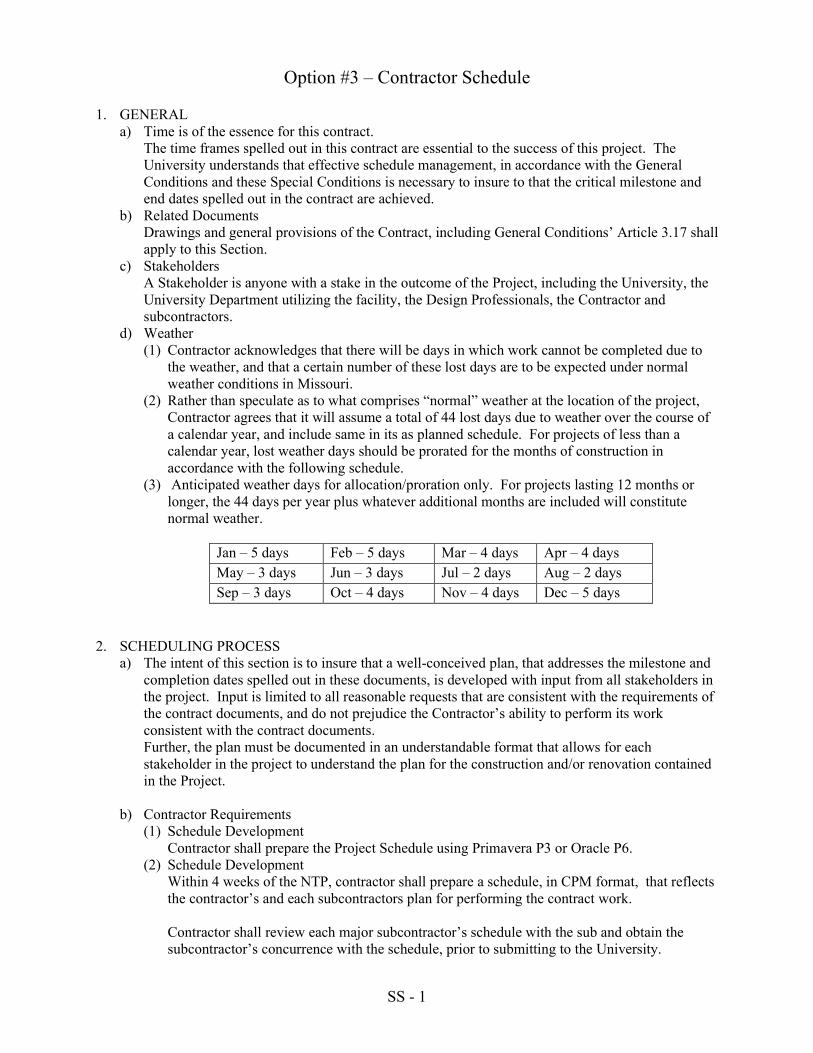
SS - 1
Option #3 – Contractor Schedule
1. GENERAL a) Time is of the essence for this contract.
The time frames spelled out in this contract are essential to the success of this project. The University understands that effective schedule management, in accordance with the General Conditions and these Special Conditions is necessary to insure to that the critical milestone and end dates spelled out in the contract are achieved.
b) Related Documents Drawings and general provisions of the Contract, including General Conditions’ Article 3.17 shall apply to this Section.
c) Stakeholders A Stakeholder is anyone with a stake in the outcome of the Project, including the University, the University Department utilizing the facility, the Design Professionals, the Contractor and subcontractors.
d) Weather (1) Contractor acknowledges that there will be days in which work cannot be completed due to
the weather, and that a certain number of these lost days are to be expected under normal weather conditions in Missouri.
(2) Rather than speculate as to what comprises “normal” weather at the location of the project, Contractor agrees that it will assume a total of 44 lost days due to weather over the course of a calendar year, and include same in its as planned schedule. For projects of less than a calendar year, lost weather days should be prorated for the months of construction in accordance with the following schedule.
(3) Anticipated weather days for allocation/proration only. For projects lasting 12 months or longer, the 44 days per year plus whatever additional months are included will constitute normal weather.
Jan – 5 days Feb – 5 days Mar – 4 days Apr – 4 days
May – 3 days Jun – 3 days Jul – 2 days Aug – 2 days
Sep – 3 days Oct – 4 days Nov – 4 days Dec – 5 days
2. SCHEDULING PROCESS a) The intent of this section is to insure that a well-conceived plan, that addresses the milestone and
completion dates spelled out in these documents, is developed with input from all stakeholders in the project. Input is limited to all reasonable requests that are consistent with the requirements of the contract documents, and do not prejudice the Contractor’s ability to perform its work consistent with the contract documents. Further, the plan must be documented in an understandable format that allows for each stakeholder in the project to understand the plan for the construction and/or renovation contained in the Project.
b) Contractor Requirements (1) Schedule Development
Contractor shall prepare the Project Schedule using Primavera P3 or Oracle P6. (2) Schedule Development
Within 4 weeks of the NTP, contractor shall prepare a schedule, in CPM format, that reflects the contractor’s and each subcontractors plan for performing the contract work. Contractor shall review each major subcontractor’s schedule with the sub and obtain the subcontractor’s concurrence with the schedule, prior to submitting to the University.
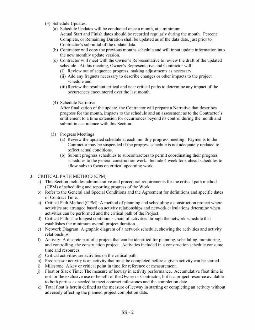
SS - 2
(3) Schedule Updates. (a) Schedule Updates will be conducted once a month, at a minimum.
Actual Start and Finish dates should be recorded regularly during the month. Percent Complete, or Remaining Duration shall be updated as of the data date, just prior to Contractor’s submittal of the update data.
(b) Contractor will copy the previous months schedule and will input update information into the new monthly update version.
(c) Contractor will meet with the Owner’s Representative to review the draft of the updated schedule. At this meeting, Owner’s Representative and Contractor will: (i) Review out of sequence progress, making adjustments as necessary, (ii) Add any fragnets necessary to describe changes or other impacts to the project
schedule and (iii) Review the resultant critical and near critical paths to determine any impact of the
occurrences encountered over the last month.
(4) Schedule Narrative After finalization of the update, the Contractor will prepare a Narrative that describes progress for the month, impacts to the schedule and an assessment as to the Contractor’s entitlement to a time extension for occurrences beyond its control during the month and submit in accordance with this Section.
(5) Progress Meetings (a) Review the updated schedule at each monthly progress meeting. Payments to the
Contractor may be suspended if the progress schedule is not adequately updated to reflect actual conditions.
(b) Submit progress schedules to subcontractors to permit coordinating their progress schedules to the general construction work. Include 4 week look ahead schedules to allow subs to focus on critical upcoming work.
3. CRITICAL PATH METHOD (CPM) a) This Section includes administrative and procedural requirements for the critical path method
(CPM) of scheduling and reporting progress of the Work. b) Refer to the General and Special Conditions and the Agreement for definitions and specific dates
of Contract Time. c) Critical Path Method (CPM): A method of planning and scheduling a construction project where
activities are arranged based on activity relationships and network calculations determine when activities can be performed and the critical path of the Project.
d) Critical Path: The longest continuous chain of activities through the network schedule that establishes the minimum overall project duration.
e) Network Diagram: A graphic diagram of a network schedule, showing the activities and activity relationships.
f) Activity: A discrete part of a project that can be identified for planning, scheduling, monitoring, and controlling, the construction project. Activities included in a construction schedule consume time and resources.
g) Critical activities are activities on the critical path. h) Predecessor activity is an activity that must be completed before a given activity can be started. i) Milestone: A key or critical point in time for reference or measurement. j) Float or Slack Time: The measure of leeway in activity performance. Accumulative float time is
not for the exclusive use or benefit of the Owner or Contractor, but is a project resource available to both parties as needed to meet contract milestones and the completion date.
k) Total float is herein defined as the measure of leeway in starting or completing an activity without adversely affecting the planned project completion date.
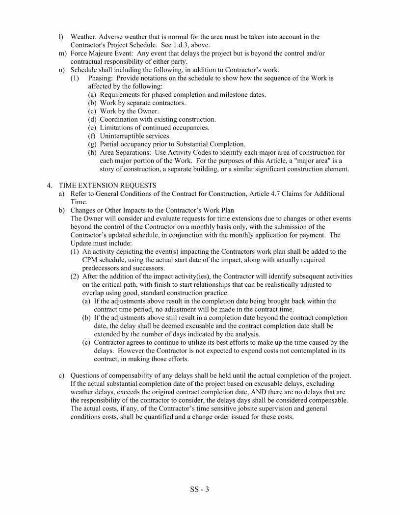
SS - 3
l) Weather: Adverse weather that is normal for the area must be taken into account in the Contractor's Project Schedule. See 1.d.3, above.
m) Force Majeure Event: Any event that delays the project but is beyond the control and/or contractual responsibility of either party.
n) Schedule shall including the following, in addition to Contractor’s work. (1) Phasing: Provide notations on the schedule to show how the sequence of the Work is
affected by the following: (a) Requirements for phased completion and milestone dates. (b) Work by separate contractors. (c) Work by the Owner. (d) Coordination with existing construction. (e) Limitations of continued occupancies. (f) Uninterruptible services. (g) Partial occupancy prior to Substantial Completion. (h) Area Separations: Use Activity Codes to identify each major area of construction for
each major portion of the Work. For the purposes of this Article, a "major area" is a story of construction, a separate building, or a similar significant construction element.
4. TIME EXTENSION REQUESTS a) Refer to General Conditions of the Contract for Construction, Article 4.7 Claims for Additional
Time. b) Changes or Other Impacts to the Contractor’s Work Plan
The Owner will consider and evaluate requests for time extensions due to changes or other events beyond the control of the Contractor on a monthly basis only, with the submission of the Contractor’s updated schedule, in conjunction with the monthly application for payment. The Update must include: (1) An activity depicting the event(s) impacting the Contractors work plan shall be added to the
CPM schedule, using the actual start date of the impact, along with actually required predecessors and successors.
(2) After the addition of the impact activity(ies), the Contractor will identify subsequent activities on the critical path, with finish to start relationships that can be realistically adjusted to overlap using good, standard construction practice. (a) If the adjustments above result in the completion date being brought back within the
contract time period, no adjustment will be made in the contract time. (b) If the adjustments above still result in a completion date beyond the contract completion
date, the delay shall be deemed excusable and the contract completion date shall be extended by the number of days indicated by the analysis.
(c) Contractor agrees to continue to utilize its best efforts to make up the time caused by the delays. However the Contractor is not expected to expend costs not contemplated in its contract, in making those efforts.
c) Questions of compensability of any delays shall be held until the actual completion of the project.
If the actual substantial completion date of the project based on excusable delays, excluding weather delays, exceeds the original contract completion date, AND there are no delays that are the responsibility of the contractor to consider, the delays days shall be considered compensable. The actual costs, if any, of the Contractor’s time sensitive jobsite supervision and general conditions costs, shall be quantified and a change order issued for these costs.
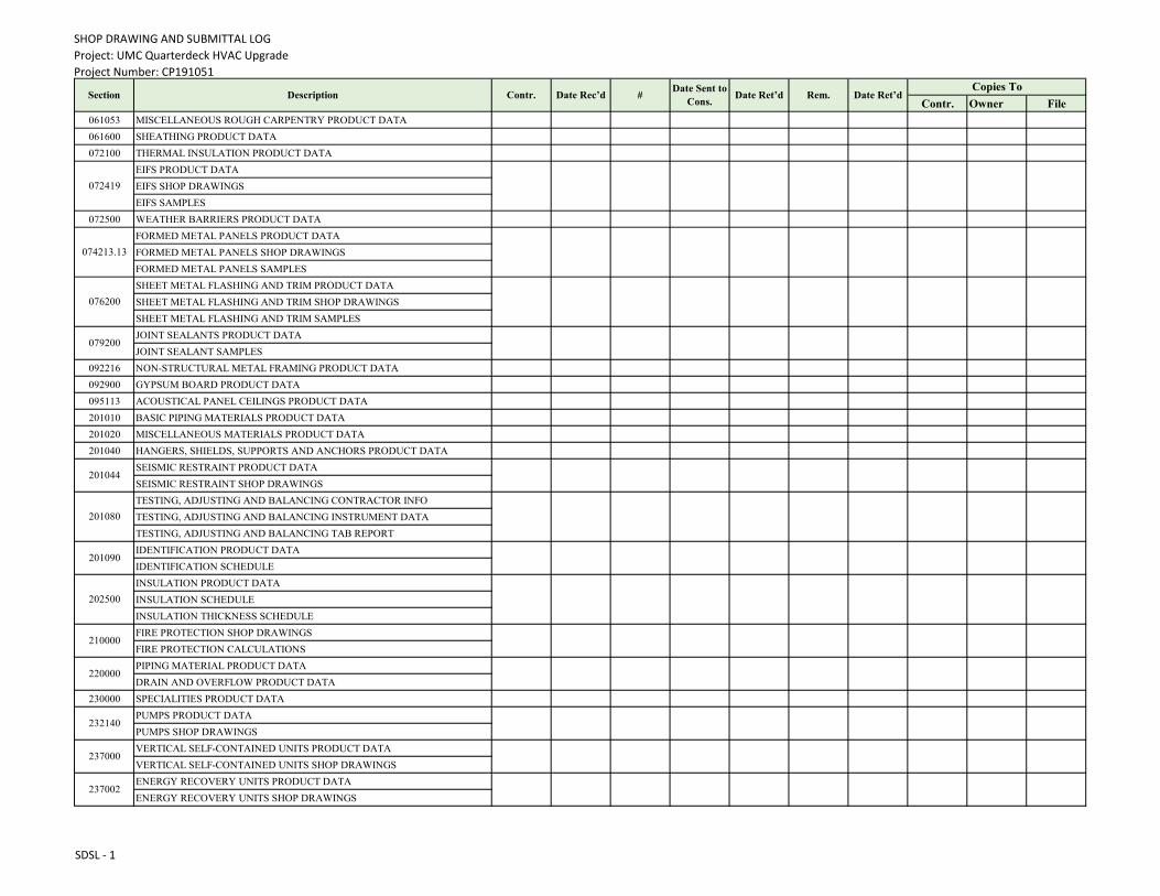
SHOP DRAWING AND SUBMITTAL LOG
Project: UMC Quarterdeck HVAC Upgrade
Project Number: CP191051
Contractor:
Contr. Owner File
061053 MISCELLANEOUS ROUGH CARPENTRY PRODUCT DATA
061600 SHEATHING PRODUCT DATA
072100 THERMAL INSULATION PRODUCT DATA
EIFS PRODUCT DATA
EIFS SHOP DRAWINGS
EIFS SAMPLES
072500 WEATHER BARRIERS PRODUCT DATA
FORMED METAL PANELS PRODUCT DATA
FORMED METAL PANELS SHOP DRAWINGS
FORMED METAL PANELS SAMPLES
SHEET METAL FLASHING AND TRIM PRODUCT DATA
SHEET METAL FLASHING AND TRIM SHOP DRAWINGS
SHEET METAL FLASHING AND TRIM SAMPLES
JOINT SEALANTS PRODUCT DATA
JOINT SEALANT SAMPLES
092216 NON-STRUCTURAL METAL FRAMING PRODUCT DATA
092900 GYPSUM BOARD PRODUCT DATA
095113 ACOUSTICAL PANEL CEILINGS PRODUCT DATA
201010 BASIC PIPING MATERIALS PRODUCT DATA
201020 MISCELLANEOUS MATERIALS PRODUCT DATA
201040 HANGERS, SHIELDS, SUPPORTS AND ANCHORS PRODUCT DATA
SEISMIC RESTRAINT PRODUCT DATA
SEISMIC RESTRAINT SHOP DRAWINGS
TESTING, ADJUSTING AND BALANCING CONTRACTOR INFO
TESTING, ADJUSTING AND BALANCING INSTRUMENT DATA
TESTING, ADJUSTING AND BALANCING TAB REPORT
IDENTIFICATION PRODUCT DATA
IDENTIFICATION SCHEDULE
INSULATION PRODUCT DATA
INSULATION SCHEDULE
INSULATION THICKNESS SCHEDULE
FIRE PROTECTION SHOP DRAWINGS
FIRE PROTECTION CALCULATIONS
PIPING MATERIAL PRODUCT DATA
DRAIN AND OVERFLOW PRODUCT DATA
230000 SPECIALITIES PRODUCT DATA
PUMPS PRODUCT DATA
PUMPS SHOP DRAWINGS
VERTICAL SELF-CONTAINED UNITS PRODUCT DATA
VERTICAL SELF-CONTAINED UNITS SHOP DRAWINGS
ENERGY RECOVERY UNITS PRODUCT DATA
ENERGY RECOVERY UNITS SHOP DRAWINGS
074213.13
Date Ret’d Rem. Date Ret’dCopies To
072419
Section Description Contr. Date Rec’d #Date Sent to
Cons.
079200
076200
201044
201090
201080
210000
202500
232140
220000
237002
237000
SDSL - 1
SHOP DRAWING AND SUBMITTAL LOG
Project: UMC Quarterdeck HVAC Upgrade
Project Number: CP191051
Contractor:
Contr. Owner FileDate Ret’d Rem. Date Ret’d
Copies ToSection Description Contr. Date Rec’d #
Date Sent to
Cons.
SHEET METAL DUCTWORK PRODUCT DATA
SHEET METAL DUCTWORK SHOP DRAWINGS
243300 AIR DISTRIBUTION ACCESSORIES PRODUCT DATA
FANS PRODUCT DATA
FANS SHOP DRAWINGS
243700 AIR DEVICE PRODUCT DATA
CONTROL SYSTEMS PRODUCT DATA
CONTROL SYSTEMS SHOP DRAWINGS
CONTROL SYSTEMS WIRING DIAGRAMS
260519 LOW-VOLTAGE CONDUCTORS AND CABLES PRODUCT DATA
260526 GROUNDING AND BONDING PRODUCT DATA
HANGERS AND SUPPORTS PRODUCT DATA
HANGERS AND SUPPORTS SHOP DRAWINGS
RACEWAYS AND BOXES PRODUCT DATA
RACEWAYS AND BOXES SHOP DRAWINGS
260544 SLEEVE AND SEALS PRODUCT DATA
IDENTIFICATION PRODUCT DATA
IDENTIFICATION SCHEDULE
SHORT CIRCUIT STUDY PRELIMINARY REPORT
SHORT CIRCUIT STUDY FINAL REPORT
COORDINATION STUDY PRELIMINARY REPORT
COORDINATION STUDY FINAL REPORT
ARC FLASH STUDY PRELIMINARY REPORT
ARC FLASH STUDY FINAL REPORT
PANELBOARDS PRODUCT DATA
PANELBOARDS SHOP DRAWINGS
262726 WIRING DEVICES PRODUCT DATA
262813 FUSES PRODUCT DATA
ENCLOSED SWITCHES AND CIRCUIT BREAKERS PRODUCT DATA
ENCLOSED SWITCHES AND CIRCUIT BREAKERS SHOP DRAWINGS
ENCLOSED CONTROLLERS PRODUCT DATA
ENCLOSED CONTROLLERS SHOP DRAWINGS
VFD PRODUCT DATA
VFD SHOP DRAWINGS
LED LIGHTING PRODUCT DATA
LED LIGHTING SHOP DRAWINGS
EMERGENCY AND EXIT LIGHTING PRODUCT DATA
EMERGENCY AND EXIT LIGHTING SHOP DRAWINGS
243400
243101
260529
250000
260553
260533
260573
260572
262416
260574
262913
262816
265119
262923
265219
SDSL - 2
OPERATING INSTRUCTIONS AND SERVICE MANUAL LOG
Project: UMC Quarterdeck HVAC Upgrade
Project Number: CP191051
Contractor:
Section DescriptionCatalog
Data
Wiring
Diagrams
Installation
Instructions
Service &
Maintenance
Instructions
Parts List &
Availability
Performance
Curves
Startup &
Operating
Instructions
061053 MISCELLANEOUS ROUGH CARPENTRY
061600 SHEATHING X
072100 THERMAL INSULATION X
072419 EIFS X X
072500 WEATHER BARRIERS X
074213.13 FORMED METAL PANELS X X
076200 SHEET METAL FLASHING AND TRIM X
079200 JOINT SEALANTS X
092216 NON-STRUCTURAL METAL FRAMING X
092900 GYPSUM BOARD X
095113 ACOUSTICAL PANEL CEILINGS X X
201010 BASIC PIPING MATERIALS X
201020 MISCELLANEOUS MATERIALS X
201040 HANGERS, SHIELDS, SUPPORTS AND ANCHORS X
201044 SEISMIC RESTRAINT X
201080 TESTING, ADJUSTING AND BALANCING X
201090 IDENTIFICATION X
202500 INSULATION X
210000 FIRE PROTECTION X X X X
220000 PIPING MATERIAL X
230000 SPECIALITIES X
232140 PUMPS X X X X X X X
237000 VERTICAL SELF-CONTAINED UNITS X X X X X X X
237002 ENERGY RECOVERY UNITS X X X X X X X
243101 SHEET METAL DUCTWORK X
243300 AIR DISTRIBUTION ACCESSORIES X X
243400 FANS X X X X X X X
243700 AIR DEVICE X
250000 CONTROL SYSTEMS X
260519 LOW-VOLTAGE CONDUCTORS AND CABLES X
260526 GROUNDING AND BONDING X
260529 HANGERS AND SUPPORTS X
260533 RACEWAYS AND BOXES X
260544 SLEEVE AND SEALS X
260553 IDENTIFICATION X
OMML - 1
OPERATING INSTRUCTIONS AND SERVICE MANUAL LOG
Project: UMC Quarterdeck HVAC Upgrade
Project Number: CP191051
Contractor:
Section DescriptionCatalog
Data
Wiring
Diagrams
Installation
Instructions
Service &
Maintenance
Instructions
Parts List &
Availability
Performance
Curves
Startup &
Operating
Instructions
260572 SHORT CIRCUIT STUDY X
260573 COORDINATION STUDY X
260574 ARC FLASH STUDY X
262416 PANELBOARDS X X X X
262726 WIRING DEVICES X
262813 FUSES X
262816 ENCLOSED SWITCHES AND CIRCUIT BREAKERS X X
262913 ENCLOSED CONTROLLERS X X
262923 VFD X X X X X
265119 LED LIGHTING X X X X
265219 EMERGENCY AND EXIT LIGHTING X X X X
OMML - 2
CLOSEOUT LOG
Project: UMC Quarterdeck HVAC Upgrade
Project Number: CP191051
Contractor:Section Description
Contractor
SubcontractorDate Rec'd # of Copies
CPM
InitialsRemarks
GC /3.11 As-built drawings
GC /13.5.6 Final Affidavit of Supplier Diversity Participation for each Diverse firm
061053 MISCELLANEOUS ROUGH CARPENTRY
061600 SHEATHING WARRANTY
072100 THERMAL INSULATION WARRANTY
072419 EIFS WARRANTY
072500 WEATHER BARRIERS WARRANTY
FORMED METAL PANELS WARRANTY
FORMED METAL PANELS EXTRA MATERIALS
079200 JOINT SEALANTS WARRANTY
201080 TESTING, ADJUSTING AND BALANCING FINAL REPORT
210000 FIRE PROTECTION EXTRA MATERIALS FOR HEADS
232140 PUMPS WARRANTY
237000 VERTICAL SELF-CONTAINED UNITS WARRANTY
237002 ENERGY RECOVERY UNITS WARRANTY
243400 FANS WARRANTY
250000 CONTROL SYSTEMS WARRANTY
260572 SHORT CIRCUIT STUDY FINAL REPORT
260573 COORDINATION STUDY FINAL REPORT
260574 ARC FLASH STUDY FINAL REPORT
262416 PANELBOARDS KEYS
262923 VFD WARRANTY
265119 LED LIGHTING WARRANTY
265219 EMERGENCY AND EXIT LIGHTING WARRANTY
074213.13
CLOSEOUT - 1
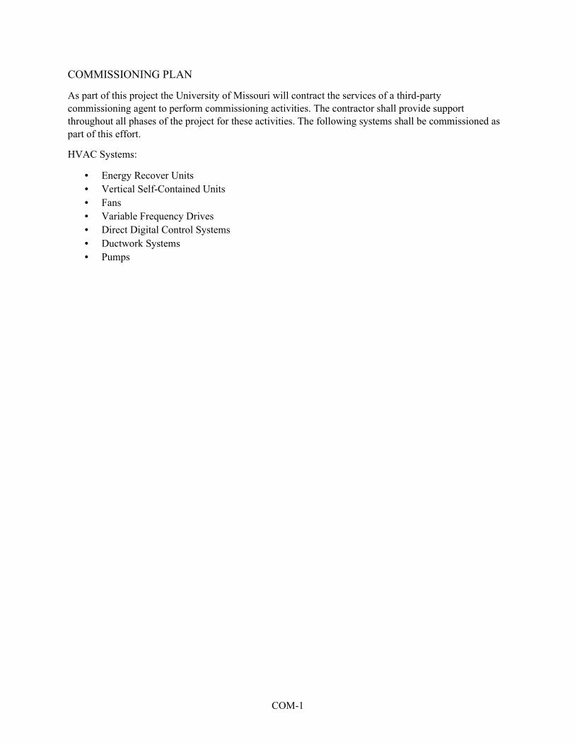
COM-1
COMMISSIONING PLAN
As part of this project the University of Missouri will contract the services of a third-party
commissioning agent to perform commissioning activities. The contractor shall provide support
throughout all phases of the project for these activities. The following systems shall be commissioned as
part of this effort.
HVAC Systems:
• Energy Recover Units
• Vertical Self-Contained Units
• Fans
• Variable Frequency Drives
• Direct Digital Control Systems
• Ductwork Systems
• Pumps
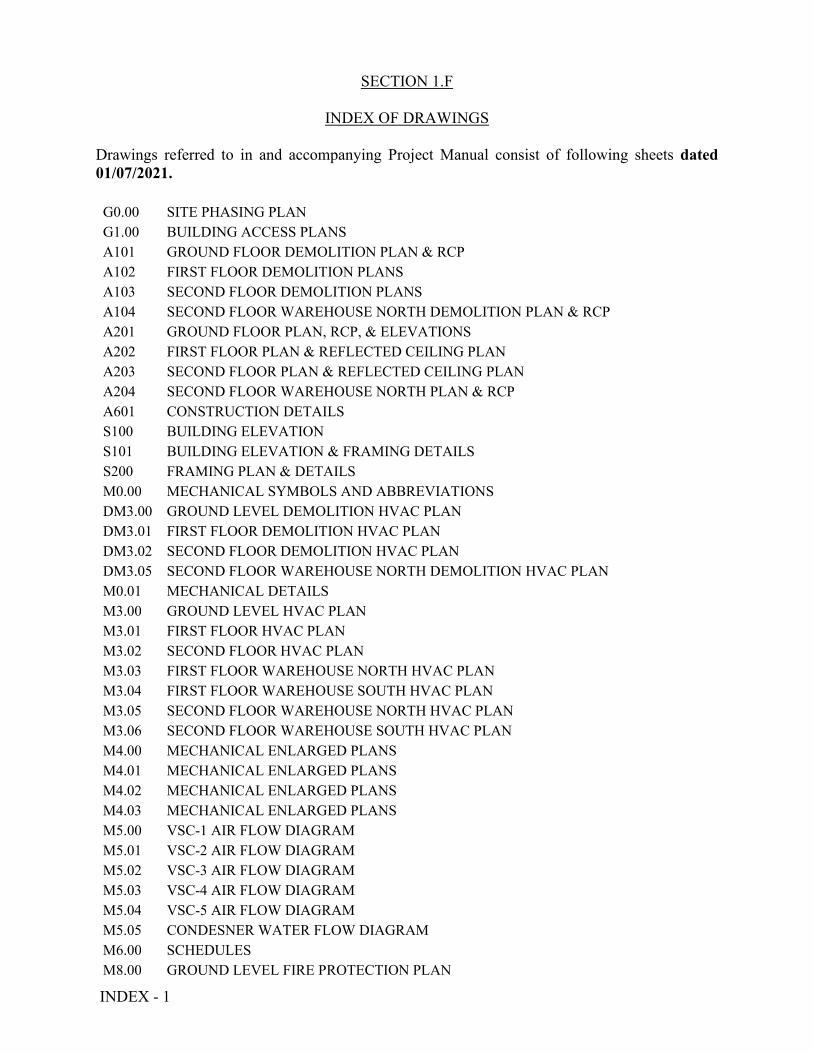
INDEX - 1
SECTION 1.F
INDEX OF DRAWINGS Drawings referred to in and accompanying Project Manual consist of following sheets dated
01/07/2021.
G0.00 SITE PHASING PLAN
G1.00 BUILDING ACCESS PLANS
A101 GROUND FLOOR DEMOLITION PLAN & RCP
A102 FIRST FLOOR DEMOLITION PLANS
A103 SECOND FLOOR DEMOLITION PLANS
A104 SECOND FLOOR WAREHOUSE NORTH DEMOLITION PLAN & RCP
A201 GROUND FLOOR PLAN, RCP, & ELEVATIONS
A202 FIRST FLOOR PLAN & REFLECTED CEILING PLAN
A203 SECOND FLOOR PLAN & REFLECTED CEILING PLAN
A204 SECOND FLOOR WAREHOUSE NORTH PLAN & RCP
A601 CONSTRUCTION DETAILS
S100 BUILDING ELEVATION
S101 BUILDING ELEVATION & FRAMING DETAILS
S200 FRAMING PLAN & DETAILS
M0.00 MECHANICAL SYMBOLS AND ABBREVIATIONS
DM3.00 GROUND LEVEL DEMOLITION HVAC PLAN
DM3.01 FIRST FLOOR DEMOLITION HVAC PLAN
DM3.02 SECOND FLOOR DEMOLITION HVAC PLAN
DM3.05 SECOND FLOOR WAREHOUSE NORTH DEMOLITION HVAC PLAN
M0.01 MECHANICAL DETAILS
M3.00 GROUND LEVEL HVAC PLAN
M3.01 FIRST FLOOR HVAC PLAN
M3.02 SECOND FLOOR HVAC PLAN
M3.03 FIRST FLOOR WAREHOUSE NORTH HVAC PLAN
M3.04 FIRST FLOOR WAREHOUSE SOUTH HVAC PLAN
M3.05 SECOND FLOOR WAREHOUSE NORTH HVAC PLAN
M3.06 SECOND FLOOR WAREHOUSE SOUTH HVAC PLAN
M4.00 MECHANICAL ENLARGED PLANS
M4.01 MECHANICAL ENLARGED PLANS
M4.02 MECHANICAL ENLARGED PLANS
M4.03 MECHANICAL ENLARGED PLANS
M5.00 VSC-1 AIR FLOW DIAGRAM
M5.01 VSC-2 AIR FLOW DIAGRAM
M5.02 VSC-3 AIR FLOW DIAGRAM
M5.03 VSC-4 AIR FLOW DIAGRAM
M5.04 VSC-5 AIR FLOW DIAGRAM
M5.05 CONDESNER WATER FLOW DIAGRAM
M6.00 SCHEDULES
M8.00 GROUND LEVEL FIRE PROTECTION PLAN
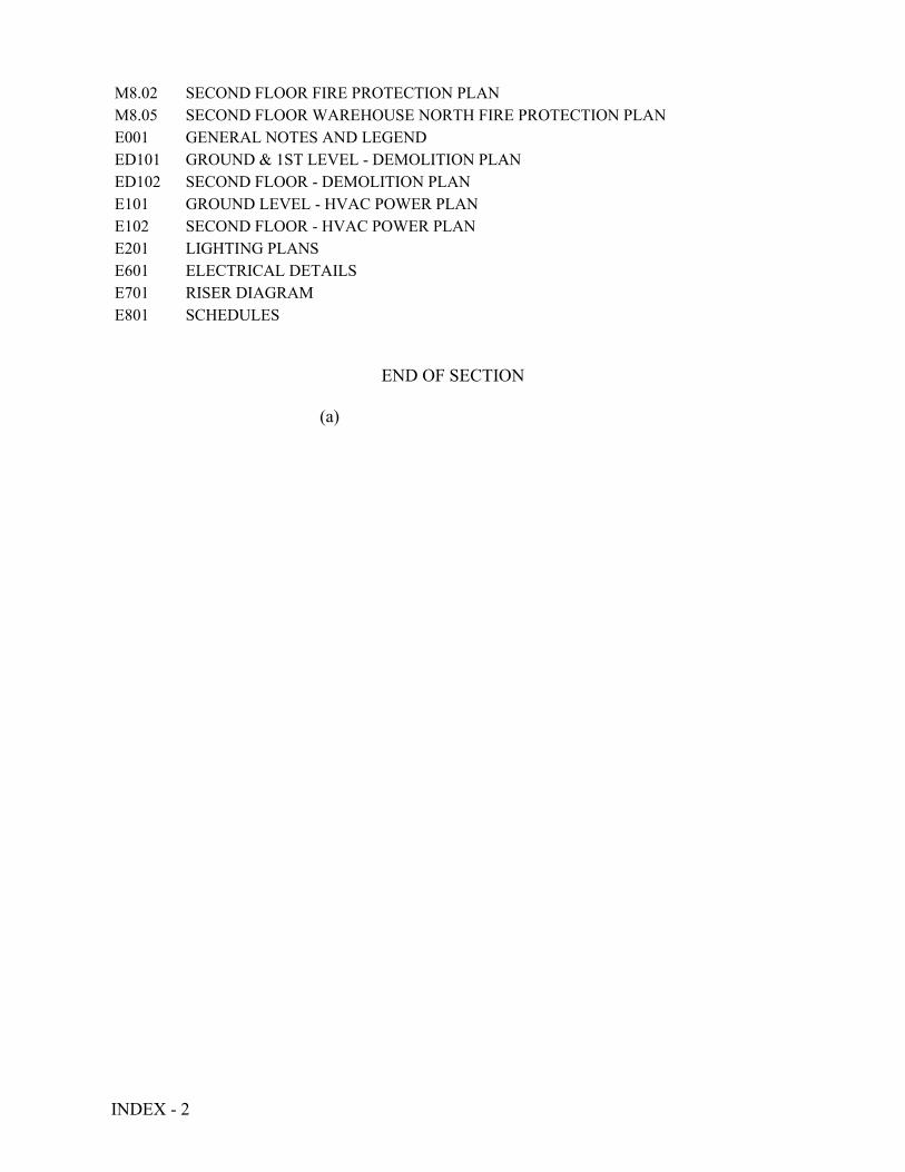
INDEX - 2
M8.02 SECOND FLOOR FIRE PROTECTION PLAN
M8.05 SECOND FLOOR WAREHOUSE NORTH FIRE PROTECTION PLAN
E001 GENERAL NOTES AND LEGEND
ED101 GROUND & 1ST LEVEL - DEMOLITION PLAN
ED102 SECOND FLOOR - DEMOLITION PLAN
E101 GROUND LEVEL - HVAC POWER PLAN
E102 SECOND FLOOR - HVAC POWER PLAN
E201 LIGHTING PLANS
E601 ELECTRICAL DETAILS
E701 RISER DIAGRAM
E801 SCHEDULES
END OF SECTION (a)

PW - 1
SECTION 1.G
PREVAILING WAGE RATES
END OF SECTION (b)

Division of Labor Standards WAGE AND HOUR SECTION
MICHAEL L. PARSON, Governor
Annual Wage Order No. 27 Section 010
BOONE COUNTY
In accordance with Section 290.262 RSMo 2000, within thirty (30) days after a certified copy of this Annual Wage Order has been filed with the Secretary of State as indicated below, any person who may be affected by this Annual Wage Order may object by filing an objection in triplicate with the Labor and Industrial Relations Commission, P.O. Box 599, Jefferson City, MO 65102-0599. Such objections must set forth in writing the specific grounds of objection. Each objection shall certify that a copy has been furnished to the Division of Labor Standards, P.O. Box 449, Jefferson City, MO 65102-0449 pursuant to 8 CSR 20-5.010(1). A certified copy of the Annual Wage Order has been filed with the Secretary of State of Missouri.
Original Signed by Taylor Burks, Director Division of Labor Standards
Filed With Secretary of State: March 10, 2020 Last Date Objections May Be Filed: April 9, 2020
Prepared by Missouri Department of Labor and Industrial Relations
Missouri
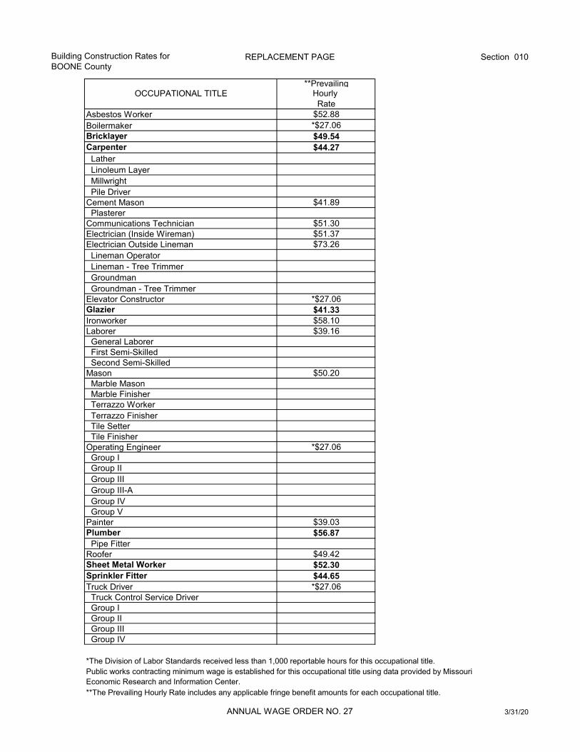
Building Construction Rates forBOONE County
REPLACEMENT PAGE Section 010
ANNUAL WAGE ORDER NO. 27 3/31/20
**PrevailingOCCUPATIONAL TITLE Hourly
RateAsbestos Worker $52.88Boilermaker *$27.06Bricklayer $49.54Carpenter $44.27 Lather Linoleum Layer Millwright Pile DriverCement Mason $41.89 PlastererCommunications Technician $51.30Electrician (Inside Wireman) $51.37Electrician Outside Lineman $73.26 Lineman Operator Lineman - Tree Trimmer Groundman Groundman - Tree TrimmerElevator Constructor *$27.06Glazier $41.33Ironworker $58.10Laborer $39.16 General Laborer First Semi-Skilled Second Semi-SkilledMason $50.20 Marble Mason Marble Finisher Terrazzo Worker Terrazzo Finisher Tile Setter Tile FinisherOperating Engineer *$27.06 Group I Group II Group III Group III-A Group IV Group VPainter $39.03Plumber $56.87 Pipe FitterRoofer $49.42Sheet Metal Worker $52.30Sprinkler Fitter $44.65Truck Driver *$27.06 Truck Control Service Driver Group I Group II Group III Group IV
*The Division of Labor Standards received less than 1,000 reportable hours for this occupational title. Public works contracting minimum wage is established for this occupational title using data provided by Missouri Economic Research and Information Center.**The Prevailing Hourly Rate includes any applicable fringe benefit amounts for each occupational title.
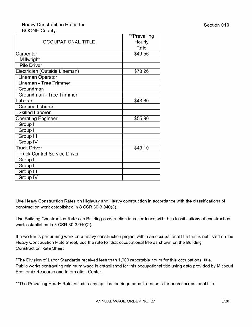
Heavy Construction Rates forBOONE County
Section 010
ANNUAL WAGE ORDER NO. 27 3/20
**PrevailingOCCUPATIONAL TITLE Hourly
RateCarpenter $49.56 Millwright Pile DriverElectrician (Outside Lineman) $73.26 Lineman Operator Lineman - Tree Trimmer Groundman Groundman - Tree TrimmerLaborer $43.60 General Laborer Skilled LaborerOperating Engineer $55.90 Group I Group II Group III Group IVTruck Driver $43.10 Truck Control Service Driver Group I Group II Group III Group IV
Use Heavy Construction Rates on Highway and Heavy construction in accordance with the classifications of construction work established in 8 CSR 30-3.040(3).
Use Building Construction Rates on Building construction in accordance with the classifications of constructionwork established in 8 CSR 30-3.040(2).
If a worker is performing work on a heavy construction project within an occupational title that is not listed on the Heavy Construction Rate Sheet, use the rate for that occupational title as shown on the Building Construction Rate Sheet.
*The Division of Labor Standards received less than 1,000 reportable hours for this occupational title. Public works contracting minimum wage is established for this occupational title using data provided by Missouri Economic Research and Information Center.
**The Prevailing Hourly Rate includes any applicable fringe benefit amounts for each occupational title.

OVERTIME and
HOLIDAYS
ANNUAL WAGE ORDER NO. 27 3/20
OVERTIME
For all work performed on a Sunday or a holiday, not less than twice (2x) the prevailing hourly rate of wages for work of a similar character in the locality in which the work is performed or the public works contracting minimum wage, whichever is applicable, shall be paid to all workers employed by or on behalf of any public body engaged in the construction of public works, exclusive of maintenance work.
For all overtime work performed, not less than one and one-half (1½) the prevailing hourly rate of wages for work of a similar character in the locality in which the work is performed or the public works contracting minimum wage, whichever is applicable, shall be paid to all workers employed by or on behalf of any public body engaged in the construction of public works, exclusive of maintenance work or contractual obligation. For purposes of this subdivision, "overtime work" shall include work that exceeds ten hours in one day and work in excess of forty hours in one calendar week; and
A thirty-minute lunch period on each calendar day shall be allowed for each worker on a public works project, provided that such time shall not be considered as time worked.
HOLIDAYSJanuary First; The last Monday in May; July Fourth; The first Monday in September; November Eleventh; The fourth Thursday in November; and December Twenty-Fifth;
If any holiday falls on a Sunday, the following Monday shall be considered a holiday.
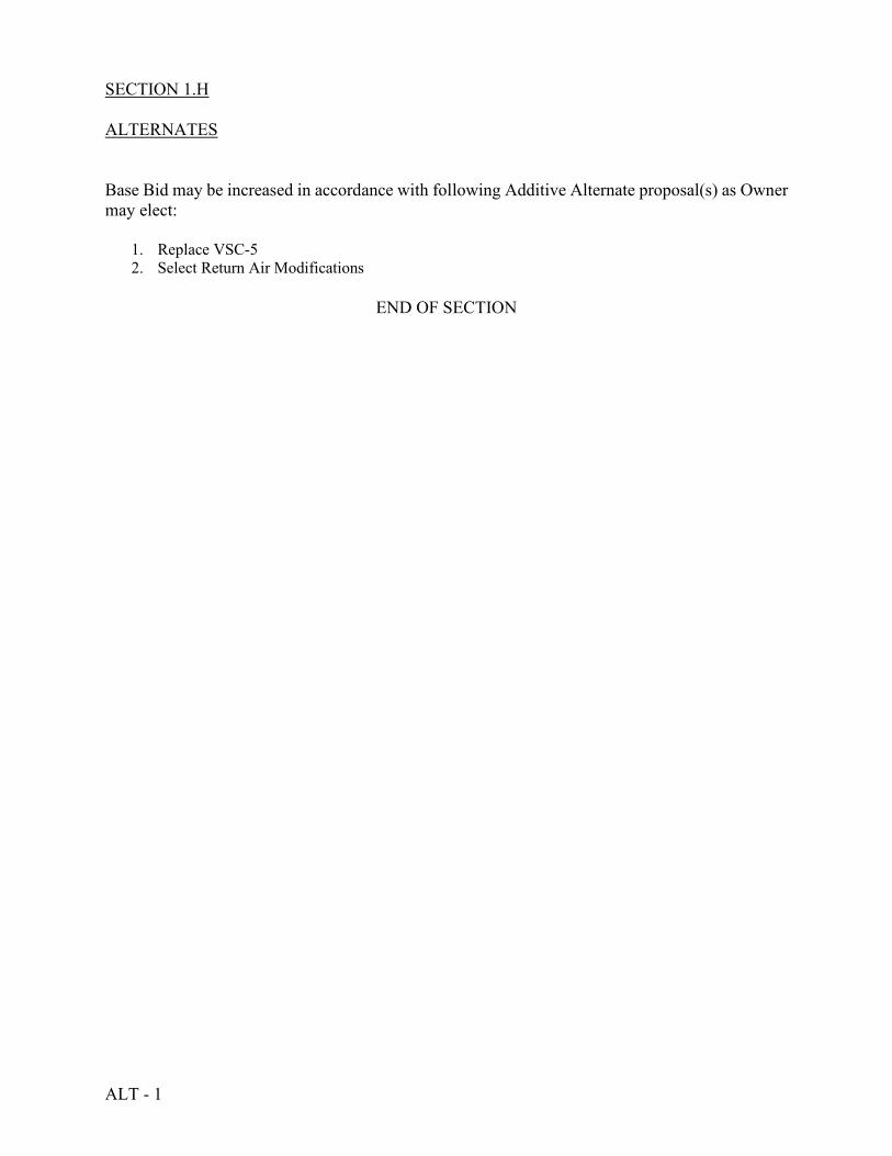
ALT - 1
SECTION 1.H ALTERNATES Base Bid may be increased in accordance with following Additive Alternate proposal(s) as Owner may elect:
1. Replace VSC-5 2. Select Return Air Modifications
END OF SECTION
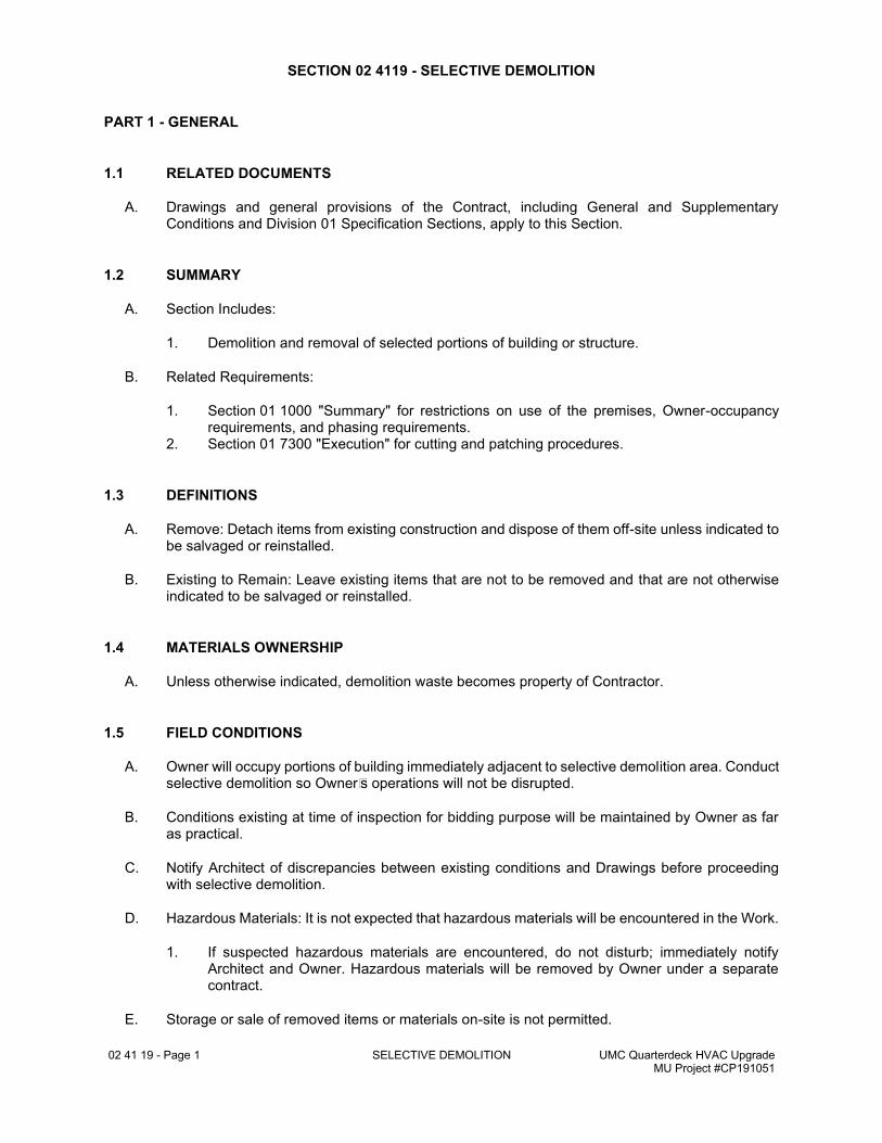
02 41 19 - Page 1 SELECTIVE DEMOLITION UMC Quarterdeck HVAC Upgrade MU Project #CP191051
SECTION 02 4119 - SELECTIVE DEMOLITION
PART 1 - GENERAL
1.1 RELATED DOCUMENTS
A. Drawings and general provisions of the Contract, including General and Supplementary Conditions and Division 01 Specification Sections, apply to this Section.
1.2 SUMMARY
A. Section Includes:
1. Demolition and removal of selected portions of building or structure.
B. Related Requirements:
1. Section 01 1000 "Summary" for restrictions on use of the premises, Owner-occupancy requirements, and phasing requirements.
2. Section 01 7300 "Execution" for cutting and patching procedures.
1.3 DEFINITIONS
A. Remove: Detach items from existing construction and dispose of them off-site unless indicated to be salvaged or reinstalled.
B. Existing to Remain: Leave existing items that are not to be removed and that are not otherwise indicated to be salvaged or reinstalled.
1.4 MATERIALS OWNERSHIP
A. Unless otherwise indicated, demolition waste becomes property of Contractor.
1.5 FIELD CONDITIONS
A. Owner will occupy portions of building immediately adjacent to selective demolition area. Conduct selective demolition so Owner's operations will not be disrupted.
B. Conditions existing at time of inspection for bidding purpose will be maintained by Owner as far as practical.
C. Notify Architect of discrepancies between existing conditions and Drawings before proceeding with selective demolition.
D. Hazardous Materials: It is not expected that hazardous materials will be encountered in the Work.
1. If suspected hazardous materials are encountered, do not disturb; immediately notify Architect and Owner. Hazardous materials will be removed by Owner under a separate contract.
E. Storage or sale of removed items or materials on-site is not permitted.
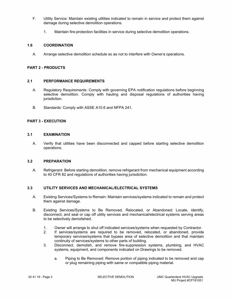
02 41 19 - Page 2 SELECTIVE DEMOLITION UMC Quarterdeck HVAC Upgrade MU Project #CP191051
F. Utility Service: Maintain existing utilities indicated to remain in service and protect them against damage during selective demolition operations.
1. Maintain fire-protection facilities in service during selective demolition operations.
1.6 COORDINATION
A. Arrange selective demolition schedule so as not to interfere with Owner's operations.
PART 2 - PRODUCTS
2.1 PERFORMANCE REQUIREMENTS
A. Regulatory Requirements: Comply with governing EPA notification regulations before beginning selective demolition. Comply with hauling and disposal regulations of authorities having jurisdiction.
B. Standards: Comply with ASSE A10.6 and NFPA 241.
PART 3 - EXECUTION
3.1 EXAMINATION
A. Verify that utilities have been disconnected and capped before starting selective demolition operations.
3.2 PREPARATION
A. Refrigerant: Before starting demolition, remove refrigerant from mechanical equipment according to 40 CFR 82 and regulations of authorities having jurisdiction.
3.3 UTILITY SERVICES AND MECHANICAL/ELECTRICAL SYSTEMS
A. Existing Services/Systems to Remain: Maintain services/systems indicated to remain and protect them against damage.
B. Existing Services/Systems to Be Removed, Relocated, or Abandoned: Locate, identify, disconnect, and seal or cap off utility services and mechanical/electrical systems serving areas to be selectively demolished.
1. Owner will arrange to shut off indicated services/systems when requested by Contractor. 2. If services/systems are required to be removed, relocated, or abandoned, provide
temporary services/systems that bypass area of selective demolition and that maintain continuity of services/systems to other parts of building.
3. Disconnect, demolish, and remove fire-suppression systems, plumbing, and HVAC systems, equipment, and components indicated on Drawings to be removed.
a. Piping to Be Removed: Remove portion of piping indicated to be removed and cap or plug remaining piping with same or compatible piping material.
02 41 19 - Page 3 SELECTIVE DEMOLITION UMC Quarterdeck HVAC Upgrade MU Project #CP191051
b. Piping to Be Abandoned in Place: Drain piping and cap or plug piping with same or compatible piping material and leave in place.
c. Equipment to Be Removed: Disconnect and cap services and remove equipment. d. Ducts to Be Removed: Remove portion of ducts indicated to be removed and plug
remaining ducts with same or compatible ductwork material. e. Ducts to Be Abandoned in Place: Cap or plug ducts with same or compatible
ductwork material and leave in place.
3.4 PROTECTION
A. Temporary Protection: Provide temporary barricades and other protection required to prevent injury to people and damage to adjacent buildings and facilities to remain.
1. Provide protection to ensure safe passage of people around selective demolition area and to and from occupied portions of building.
2. Provide temporary weather protection, during interval between selective demolition of existing construction on exterior surfaces and new construction, to prevent water leakage and damage to structure and interior areas.
3. Protect walls, ceilings, floors, and other existing finish work that are to remain or that are exposed during selective demolition operations.
4. Cover and protect furniture, furnishings, and equipment that have not been removed. 5. Comply with requirements for temporary enclosures, dust control, heating, and cooling
specified in Section 01 5000 "Temporary Facilities and Controls."
B. Temporary Shoring: Design, provide, and maintain shoring, bracing, and structural supports as required to preserve stability and prevent movement, settlement, or collapse of construction and finishes to remain, and to prevent unexpected or uncontrolled movement or collapse of construction being demolished.
1. Strengthen or add new supports when required during progress of selective demolition.
C. Remove temporary barricades and protections where hazards no longer exist.
3.5 SELECTIVE DEMOLITION, GENERAL
A. General: Demolish and remove existing construction only to the extent required by new construction and as indicated. Use methods required to complete the Work within limitations of governing regulations and as follows:
1. Proceed with selective demolition systematically, from higher to lower level. Complete selective demolition operations above each floor or tier before disturbing supporting members on the next lower level.
2. Neatly cut openings and holes plumb, square, and true to dimensions required. Use cutting methods least likely to damage construction to remain or adjoining construction. Use hand tools or small power tools designed for sawing or grinding, not hammering and chopping. Temporarily cover openings to remain.
3. Cut or drill from the exposed or finished side into concealed surfaces to avoid marring existing finished surfaces.
4. Do not use cutting torches until work area is cleared of flammable materials. At concealed spaces, such as duct and pipe interiors, verify condition and contents of hidden space before starting flame-cutting operations. Maintain portable fire-suppression devices during flame-cutting operations.
5. Maintain fire watch during and for at least two hours after flame-cutting operations. 6. Maintain adequate ventilation when using cutting torches. 7. Remove decayed, vermin-infested, or otherwise dangerous or unsuitable materials and
promptly dispose of off-site.
02 41 19 - Page 4 SELECTIVE DEMOLITION UMC Quarterdeck HVAC Upgrade MU Project #CP191051
8. Remove structural framing members and lower to ground by method suitable to avoid free fall and to prevent ground impact or dust generation.
9. Locate selective demolition equipment and remove debris and materials so as not to impose excessive loads on supporting walls, floors, or framing.
10. Dispose of demolished items and materials promptly.
B. Site Access and Temporary Controls: Conduct selective demolition and debris-removal operations to ensure minimum interference with roads, streets, walks, walkways, and other adjacent occupied and used facilities.
C. Removed and Salvaged Items:
1. Transport items to Owner's storage area designated by Owner.
3.6 SELECTIVE DEMOLITION PROCEDURES FOR SPECIFIC MATERIALS
A. Concrete: Demolish in sections. Cut concrete full depth at junctures with construction to remain and at regular intervals using power-driven saw, and then remove concrete between saw cuts.
B. Concrete Slabs-on-Grade: Saw-cut perimeter of area to be demolished, and then break up and remove.
C. Resilient Floor Coverings: Remove floor coverings and adhesive according to recommendations in RFCI's "Recommended Work Practices for the Removal of Resilient Floor Coverings." Do not use methods requiring solvent-based adhesive strippers.
3.7 DISPOSAL OF DEMOLISHED MATERIALS
A. Remove demolition waste materials from Project site and dispose of them in an EPA-approved construction and demolition waste landfill acceptable to authorities having jurisdiction.
1. Do not allow demolished materials to accumulate on-site. 2. Remove and transport debris in a manner that will prevent spillage on adjacent surfaces
and areas. 3. Remove debris from elevated portions of building by chute, hoist, or other device that will
convey debris to grade level in a controlled descent. 4. Comply with requirements specified in Section 01 7419 "Construction Waste Management
and Disposal."
B. Burning: Do not burn demolished materials.
3.8 CLEANING
A. Clean adjacent structures and improvements of dust, dirt, and debris caused by selective demolition operations. Return adjacent areas to condition existing before selective demolition operations began.
END OF SECTION 02 4119
06 10 53 - Page 1 MISCELLANEOUS ROUGH CARPENTRY
UMC Quarterdeck HVAC Upgrade MU Project #CP191051
SECTION 06 1053 - MISCELLANEOUS ROUGH CARPENTRY
PART 1 - GENERAL
1.1 RELATED DOCUMENTS
A. Drawings and general provisions of the Contract, including General and Supplementary Conditions and Division 01 Specification Sections, apply to this Section.
1.2 SUMMARY
A. Section Includes:
1. Wood blocking and nailers. 2. Wood furring.
B. Related Requirements:
1. Section 06 1600 "Sheathing" for sheathing, subflooring, and underlayment.
1.3 DEFINITIONS
A. Boards or Strips: Lumber of less than 2 inches nominal size in least dimension.
B. Dimension Lumber: Lumber of 2 inches nominal or greater size but less than 5 inches nominal size in least dimension.
1.4 ACTION SUBMITTALS
A. Product Data: For each type of process and factory-fabricated product. Indicate component materials and dimensions and include construction and application details.
1. Include data for wood-preservative treatment from chemical treatment manufacturer and certification by treating plant that treated materials comply with requirements. Indicate type of preservative used and net amount of preservative retained.
1.5 DELIVERY, STORAGE, AND HANDLING
A. Stack lumber flat with spacers beneath and between each bundle to provide air circulation. Protect lumber from weather by covering with waterproof sheeting, securely anchored. Provide for air circulation around stacks and under coverings.
PART 2 - PRODUCTS
2.1 WOOD PRODUCTS, GENERAL
A. Lumber: DOC PS 20 and applicable rules of grading agencies indicated. If no grading agency is indicated, provide lumber that complies with the applicable rules of any rules-writing agency
06 10 53 - Page 2 MISCELLANEOUS ROUGH CARPENTRY
UMC Quarterdeck HVAC Upgrade MU Project #CP191051
certified by the ALSC Board of Review. Provide lumber graded by an agency certified by the ALSC Board of Review to inspect and grade lumber under the rules indicated.
1. Factory mark each piece of lumber with grade stamp of grading agency. 2. Dress lumber, S4S, unless otherwise indicated.
2.2 WOOD-PRESERVATIVE-TREATED MATERIALS
A. Preservative Treatment by Pressure Process: AWPA U1; Use Category UC2 for interior construction not in contact with ground, Use Category UC3b for exterior construction not in contact with ground, and Use Category UC4a for items in contact with ground.
1. Preservative Chemicals: Acceptable to authorities having jurisdiction and containing no arsenic or chromium.
2. For exposed items indicated to receive a stained or natural finish, chemical formulations shall not require incising, contain colorants, bleed through, or otherwise adversely affect finishes.
B. Kiln-dry lumber after treatment to a maximum moisture content of 19 percent. Do not use material that is warped or does not comply with requirements for untreated material.
C. Mark lumber with treatment quality mark of an inspection agency approved by the ALSC Board of Review.
D. Application: Treat items indicated on Drawings, and the following:
1. Wood cants, nailers, curbs, equipment support bases, blocking, stripping, and similar members in connection with roofing, flashing, vapor barriers, and waterproofing.
2.3 MISCELLANEOUS LUMBER
A. General: Provide miscellaneous lumber indicated and lumber for support or attachment of other construction, including the following:
1. Blocking.
B. Dimension Lumber Items: Construction or No. 2 grade lumber of any species.
C. For blocking not used for attachment of other construction, Utility, Stud, or No. 3 grade lumber of any species may be used provided that it is cut and selected to eliminate defects that will interfere with its attachment and purpose.
D. For blocking and nailers used for attachment of other construction, select and cut lumber to eliminate knots and other defects that will interfere with attachment of other work.
E. For furring strips for installing plywood or hardboard paneling, select boards with no knots capable of producing bent-over nails and damage to paneling.
2.4 PLYWOOD BACKING PANELS
A. Equipment Backing Panels: Plywood, DOC PS 1, Exterior, A-C, in thickness indicated or, if not indicated, not less than 3/4-inch nominal thickness.
06 10 53 - Page 3 MISCELLANEOUS ROUGH CARPENTRY
UMC Quarterdeck HVAC Upgrade MU Project #CP191051
2.5 FASTENERS
A. General: Provide fasteners of size and type indicated that comply with requirements specified in this article for material and manufacture.
1. Where carpentry is exposed to weather, in ground contact, pressure-preservative treated, or in area of high relative humidity, provide fasteners with hot-dip zinc coating complying with ASTM A153/A153M .
B. Screws for Fastening to Metal Framing: ASTM C954, length as recommended by screw manufacturer for material being fastened.
C. Power-Driven Fasteners: Fastener systems with an evaluation report acceptable to authorities having jurisdiction, based on ICC-ES AC70.
PART 3 - EXECUTION
3.1 INSTALLATION, GENERAL
A. Framing Standard: Comply with AF&PA's WCD 1, "Details for Conventional Wood Frame Construction," unless otherwise indicated.
B. Set carpentry to required levels and lines, with members plumb, true to line, cut, and fitted. Fit carpentry accurately to other construction. Locate nailers, blocking, and similar supports to comply with requirements for attaching other construction.
C. Install plywood backing panels by fastening to studs; coordinate locations with utilities requiring backing panels.
D. Install metal framing anchors to comply with manufacturer's written instructions. Install fasteners through each fastener hole.
E. Do not splice structural members between supports unless otherwise indicated.
F. Provide blocking and framing as indicated and as required to support facing materials, fixtures, specialty items, and trim.
1. Provide metal clips for fastening gypsum board or lath at corners and intersections where framing or blocking does not provide a surface for fastening edges of panels. Space clips not more than 16 inches o.c.
G. Sort and select lumber so that natural characteristics do not interfere with installation or with fastening other materials to lumber. Do not use materials with defects that interfere with function of member or pieces that are too small to use with minimum number of joints or optimum joint arrangement.
H. Comply with AWPA M4 for applying field treatment to cut surfaces of preservative-treated lumber.
1. Use inorganic boron for items that are continuously protected from liquid water. 2. Use copper naphthenate for items not continuously protected from liquid water.
I. Where wood-preservative-treated lumber is installed adjacent to metal decking, install continuous flexible flashing separator between wood and metal decking.
06 10 53 - Page 4 MISCELLANEOUS ROUGH CARPENTRY
UMC Quarterdeck HVAC Upgrade MU Project #CP191051
J. Securely attach carpentry work to substrate by anchoring and fastening as indicated, complying with the following:
1. Table 2304.9.1, "Fastening Schedule," in ICC's International Building Code. 2. ICC-ES evaluation report for fastener.
K. Use steel common nails unless otherwise indicated. Select fasteners of size that will not fully penetrate members where opposite side will be exposed to view or will receive finish materials. Make tight connections between members. Install fasteners without splitting wood. Drive nails snug but do not countersink nail heads unless otherwise indicated.
3.2 INSTALLATION OF WOOD BLOCKING AND NAILER
A. Install where indicated and where required for attaching other work. Form to shapes indicated and cut as required for true line and level of attached work. Coordinate locations with other work involved.
B. Attach items to substrates to support applied loading. Recess bolts and nuts flush with surfaces unless otherwise indicated.
C. Provide permanent grounds of dressed, pressure-preservative-treated, key-beveled lumber not less than 1-1/2 inches wide and of thickness required to bring face of ground to exact thickness of finish material. Remove temporary grounds when no longer required.
3.3 PROTECTION
A. Protect wood that has been treated with inorganic boron (SBX) from weather. If, despite protection, inorganic boron-treated wood becomes wet, apply EPA-registered borate treatment. Apply borate solution by spraying to comply with EPA-registered label.
B. Protect miscellaneous rough carpentry from weather. If, despite protection, miscellaneous rough carpentry becomes wet, apply EPA-registered borate treatment. Apply borate solution by spraying to comply with EPA-registered label.
END OF SECTION 06 1053
06 16 00 - Page 1 SHEATHING UMC Quarterdeck HVAC Upgrade MU Project #CP191051
SECTION 06 1600 - SHEATHING
PART 1 - GENERAL
1.1 RELATED DOCUMENTS
A. Drawings and general provisions of the Contract, including General and Supplementary Conditions and Division 01 Specification Sections, apply to this Section.
1.2 SUMMARY
A. Section Includes:
1. Wall sheathing.
B. Related Requirements:
1. Section 06 1053 "Miscellaneous Rough Carpentry" for plywood backing panels. 2. Section 07 2500 "Weather Barriers" for water-resistive barrier applied over wall sheathing.
1.3 ACTION SUBMITTALS
A. Product Data: For each type of process and factory-fabricated product. Indicate component materials and dimensions and include construction and application details.
1. For air-barrier and water-resistant glass-mat gypsum sheathing, include manufacturer's technical data and tested physical and performance properties of products.
1.4 DELIVERY, STORAGE, AND HANDLING
A. Stack panels flat with spacers beneath and between each bundle to provide air circulation. Protect sheathing from weather by covering with waterproof sheeting, securely anchored. Provide for air circulation around stacks and under coverings.
PART 2 - PRODUCTS
2.1 PERFORMANCE REQUIREMENTS
2.2 WALL SHEATHING
A. Glass-Mat Gypsum Sheathing: ASTM C1177/C1177M.
1. Manufacturers: Subject to compliance with requirements, provide products by one of the following:
a. CertainTeed Corporation. b. Georgia-Pacific Gypsum LLC. c. National Gypsum Company
06 16 00 - Page 2 SHEATHING UMC Quarterdeck HVAC Upgrade MU Project #CP191051
2. Thickness: 5/8 inch thick. 3. Size: 48 by 96 inches, 48 by 108 inches and/or 48 by 120 inches for vertical installation. 4. Edges: Square. 5. Flashing and Transitions Strips: As acceptable to sheathing manufacturer. 6. Air Permeance: Maximum 0.004 cfm/sq. ft. of surface area at 1.57-lbf/sq. ft. pressure
difference when tested according to ASTM E2178. 7. Vapor Permeance: Minimum 20 perms when tested according to ASTM E96/E96M,
Desiccant Method, Procedure A. 8. Sheathing Assembly Air Leakage: Maximum 0.04 cfm/sq. ft. of surface area at 1.57 lbf/sq.
ft. (0.2 L/s x sq. m of surface area at 75 Pa) when tested according to ASTM E2357. 9. Fire Propagation Characteristics: Complies with NFPA 285 testing as part of an approved
assembly. 10. UV Resistance: Can be exposed to sunlight for 90 days according to manufacturer's written
instructions. 11. Provide primers, transition strips, termination strips, joint reinforcing fabric and strips, joint
sealants, counterflashing strips, flashing sheets and metal termination bars, termination mastic, substrate patching materials, adhesives, tapes, foam sealants, lap sealants, and other accessory materials that are recommended in writing by sheathing manufacturer to produce a complete air-barrier assembly and that are compatible with primary air-barrier material and adjacent construction to which they may seal.
2.3 FASTENERS
A. General: Provide fasteners of size and type indicated that comply with requirements specified in this article for material and manufacture.
1. For wall sheathing, provide fasteners.
B. Power-Driven Fasteners: Fastener systems with an evaluation report acceptable to authorities having jurisdiction, based on ICC-ES AC70.
C. Screws for Fastening Gypsum Sheathing to Cold-Formed Metal Framing: Steel drill screws, in length recommended by sheathing manufacturer for thickness of sheathing to be attached.
1. For steel framing from 0.033 to 0.112 inch thick, use screws that comply with ASTM C954.
PART 3 - EXECUTION
3.1 INSTALLATION, GENERAL
A. Do not use materials with defects that impair quality of sheathing or pieces that are too small to use with minimum number of joints or optimum joint arrangement. Arrange joints so that pieces do not span between fewer than three support members.
B. Cut panels at penetrations, edges, and other obstructions of work; fit tightly against abutting construction unless otherwise indicated.
C. Securely attach to substrate by fastening as indicated, complying with the following:
1. Table 2304.9.1, "Fastening Schedule," in the ICC's International Building Code. 2. ICC-ES evaluation report for fastener.
D. Use common wire nails unless otherwise indicated. Select fasteners of size that will not fully penetrate members where opposite side will be exposed to view or will receive finish materials. Make tight connections. Install fasteners without splitting wood.
06 16 00 - Page 3 SHEATHING UMC Quarterdeck HVAC Upgrade MU Project #CP191051
E. Coordinate wall sheathing installation with flashing and joint-sealant installation so these materials are installed in sequence and manner that prevent exterior moisture from passing through completed assembly.
F. Do not bridge building expansion joints; cut and space edges of panels to match spacing of structural support elements.
G. Coordinate sheathing installation with installation of materials installed over sheathing so sheathing is not exposed to precipitation or left exposed at end of the workday when rain is forecast.
3.2 GYPSUM SHEATHING INSTALLATION
A. Comply with GA-253 and with manufacturer's written instructions.
1. Fasten gypsum sheathing to cold-formed metal framing with screws. 2. Install panels with a 3/8-inch gap where non-load-bearing construction abuts structural
elements.
B. Apply fasteners so heads bear tightly against face of sheathing, but do not cut into facing.
C. Vertical Installation: Install vertical edges centered over studs. Abut ends and edges with those of adjacent panels. Attach at perimeter and within field of panel to each stud.
1. Space fasteners approximately 8 inches o.c. and set back a minimum of 3/8 inch from edges and ends of panels.
D. Seal sheathing joints according to sheathing manufacturer's written instructions.
1. Apply elastomeric sealant to joints and fasteners and trowel flat. Apply sufficient amount of sealant to completely cover joints and fasteners after troweling. Seal other penetrations and openings.
2. Apply glass-fiber sheathing tape to glass-mat gypsum sheathing joints and apply and trowel sealant to embed entire face of tape in sealant. Apply sealant to exposed fasteners with a trowel so fasteners are completely covered. Seal other penetrations and openings.
E. Air-Barrier and Water-Resistant Glass-Mat Gypsum Sheathing:
1. Install accessory materials according to sheathing manufacturer's written instructions and details to form a seal with adjacent construction, to seal fasteners, and ensure continuity of air and water barrier.
a. Coordinate the installation of sheathing with installation of roofing membrane and base flashing to ensure continuity of air barrier with roofing membrane.
b. Install transition strip on roofing membrane or base flashing, so that a minimum of 3 inches of coverage is achieved over each substrate.
2. Connect and seal sheathing material continuously to air barriers specified under other Sections as well as to roofing-membrane air barrier, concrete below-grade structures, floor-to-floor construction, exterior glazing and window systems, glazed curtain-wall systems, storefront systems, exterior louvers, exterior door framing, and other construction used in exterior wall openings, using accessory materials.
3. Apply joint sealants forming part of air-barrier assembly within manufacturer's recommended application temperature ranges. Consult manufacturer when sealant cannot be applied within these temperature ranges.
4. Wall Openings: Prime concealed, perimeter frame surfaces of windows, curtain walls, storefronts, and doors. Apply transition strip , so that a minimum of 3 inches of coverage is
06 16 00 - Page 4 SHEATHING UMC Quarterdeck HVAC Upgrade MU Project #CP191051
achieved over each substrate. Maintain 3 inches of full contact over firm bearing to perimeter frames, with not less than 1 inch of full contact.
a. Transition Strip: Roll firmly to enhance adhesion.
5. Fill gaps in perimeter frame surfaces of windows, curtain walls, storefronts, doors, and miscellaneous penetrations of sheathing material with foam sealant.
6. Seal strips and transition strips around masonry reinforcing or ties and penetrations with termination mastic.
7. Seal top of through-wall flashings to sheathing with an additional 6-inch- wide, transition strip.
8. Seal exposed edges of strips at seams, cuts, penetrations, and terminations not concealed by metal counterflashings or ending in reglets with termination mastic.
9. Repair punctures, voids, and deficient lapped seams in strips and transition strips extending 6 inches beyond repaired areas in strip direction.
END OF SECTION 06 1600
07 21 00 - Page 1 THERMAL INSULATION UMC Quarterdeck HVAC Upgrade MU Project #CP191051
SECTION 07 2100 - THERMAL INSULATION
PART 1 - GENERAL
1.1 RELATED DOCUMENTS
A. Drawings and general provisions of the Contract, including General and Supplementary Conditions and Division 01 Specification Sections, apply to this Section.
1.2 SUMMARY
A. Section Includes:
1. Glass-fiber blanket insulation.
B. Related Requirements:
2. Section 09 2900 "Gypsum Board" for sound attenuation blanket used as acoustic insulation.
1.3 ACTION SUBMITTALS
A. Product Data: For the following:
3. Glass-fiber blanket insulation.
1.4 DELIVERY, STORAGE, AND HANDLING
A. Protect insulation materials from physical damage and from deterioration due to moisture, soiling, and other sources. Store inside and in a dry location. Comply with manufacturer's written instructions for handling, storing, and protecting during installation.
PART 2 - PRODUCTS
2.1 GLASS-FIBER BLANKET INSULATION
A. Glass-Fiber Blanket Insulation, Unfaced: ASTM C665, Type I; passing ASTM E136 for combustion characteristics.
4. Manufacturers: Subject to compliance with requirements, provide products by one of the following:
a. CertainTeed Insulation. b. Johns Manville; a Berkshire Hathaway company. c. Knauf Insulation. d. Owens Corning.
5. Flame-Spread Index: Not more than 25 when tested in accordance with ASTM E84. 6. Smoke-Developed Index: Not more than 50 when tested in accordance with ASTM E84.
07 21 00 - Page 2 THERMAL INSULATION UMC Quarterdeck HVAC Upgrade MU Project #CP191051
7. Labeling: Provide identification of mark indicating R-value of each piece of insulation 12 inches and wider in width.
2.2 ACCESSORIES
A. Insulation for Miscellaneous Voids:
8. Glass-Fiber Insulation: ASTM C764, Type II, loose fill; with maximum flame-spread and smoke-developed indexes of 5, per ASTM E84.
PART 3 - EXECUTION
3.1 PREPARATION
A. Clean substrates of substances that are harmful to insulation, including removing projections capable of puncturing insulation or vapor retarders, or that interfere with insulation attachment.
3.2 INSTALLATION, GENERAL
A. Comply with insulation manufacturer's written instructions applicable to products and applications.
B. Install insulation that is undamaged, dry, and unsoiled and that has not been left exposed to ice, rain, or snow at any time.
C. Install insulation with manufacturer's R-value label exposed after insulation is installed.
D. Extend insulation to envelop entire area to be insulated. Fit tightly around obstructions and fill voids with insulation. Remove projections that interfere with placement.
E. Provide sizes to fit applications and selected from manufacturer's standard thicknesses, widths, and lengths. Apply single layer of insulation units unless multiple layers are otherwise shown or required to make up total thickness or to achieve R-value.
3.3 INSTALLATION OF INSULATION IN FRAMED CONSTRUCTION
A. Blanket Insulation: Install in cavities formed by framing members according to the following requirements:
9. Use insulation widths and lengths that fill the cavities formed by framing members. If more than one length is required to fill the cavities, provide lengths that will produce a snug fit between ends.
10. Place insulation in cavities formed by framing members to produce a friction fit between edges of insulation and adjoining framing members.
11. Maintain 3-inch clearance of insulation around recessed lighting fixtures not rated for or protected from contact with insulation.
12. For metal-framed wall cavities where cavity heights exceed 96 inches, support unfaced blankets mechanically and support faced blankets by taping flanges of insulation to flanges of metal studs.
B. Miscellaneous Voids: Install insulation in miscellaneous voids and cavity spaces where required to prevent gaps in insulation using the following materials:
07 21 00 - Page 3 THERMAL INSULATION UMC Quarterdeck HVAC Upgrade MU Project #CP191051
13. Glass-Fiber Insulation: Compact to approximately 40 percent of normal maximum volume equaling a density of approximately 2.5 lb/cu. ft.
14. Spray Polyurethane Insulation: Apply according to manufacturer's written instructions.
3.4 PROTECTION
A. Protect installed insulation from damage due to harmful weather exposures, physical abuse, and other causes.
B. Provide temporary coverings or enclosures where insulation is subject to abuse and cannot be concealed and protected by permanent construction immediately after installation.
END OF SECTION 07 2100
THIS PAGE LEFT BLANK INTENTIONALLY
07 24 19 - Page 1 WATER-DRAINAGE EXTERIOR INSULATION AND FINISH SYSTEM
(EIFS)
UMC Quarterdeck HVAC Upgrade MU Project #CP191051
SECTION 07 2419 - WATER-DRAINAGE EXTERIOR INSULATION AND FINISH SYSTEM (EIFS)
PART 1 - GENERAL
1.1 RELATED DOCUMENTS
A. Drawings and general provisions of the Contract, including General and Supplementary Conditions and Division 01 Specification Sections, apply to this Section.
1.2 SUMMARY
A. Section Includes:
1. EIFS-clad drainage-wall assemblies that are field applied over substrate. 2. Water-resistive barrier coatings.
B. Related Requirements:
1. Section 07 2500 "Weather Barriers" for water-resistant building paper or building wrap and flexible flashings installed over sheathing behind mechanically fastened EIFS.
1.3 DEFINITIONS
A. Definitions in ASTM E 2110 apply to Work of this Section.
B. EIFS: Exterior insulation and finish system(s).
C. IBC: International Building Code.
1.4 ACTION SUBMITTALS
A. Product Data: For each EIFS component, trim, and accessory, including water-resistive barrier coatings.
B. Shop Drawings:
1. Include details for EIFS buildouts. 2. Include details for parapet cap flashing.
C. Samples for Verification: 24-inch- square panels for each type of finish-coat color and texture indicated, prepared using same tools and techniques intended for actual work, including.
1. Include exposed trim and accessory Samples to verify color selected. 2. Include a typical control joint filled with sealant of color selected, as specified in
Section 07 9200 "Joint Sealants."
1.5 DELIVERY, STORAGE, AND HANDLING
A. Deliver materials in original, unopened packages with manufacturers' labels intact and clearly identifying products.
07 24 19 - Page 2 WATER-DRAINAGE EXTERIOR INSULATION AND FINISH SYSTEM
(EIFS)
UMC Quarterdeck HVAC Upgrade MU Project #CP191051
B. Store materials inside and under cover; keep them dry and protected from weather, direct sunlight, surface contamination, aging, corrosion, damaging temperatures, construction traffic, and other causes.
1. Stack insulation board flat and off the ground. 2. Protect plastic insulation against ignition at all times. Do not deliver plastic insulating
materials to Project site before installation time. 3. Complete installation and concealment of plastic materials as rapidly as possible in each
area of construction.
1.6 FIELD CONDITIONS
A. Weather Limitations: Proceed with installation only when existing and forecasted weather conditions and ambient outdoor air, humidity, and substrate temperatures permit EIFS to be applied, dried, and cured according to manufacturers' written instructions and warranty requirements.
1. Proceed with installation of adhesives or coatings only when ambient temperatures have remained, or are forecast to remain, above 40 deg F (4.4 deg C) for a minimum of 24 hours before, during, and after application. Do not apply EIFS adhesives or coatings during rainfall.
PART 2 - PRODUCTS
2.1 MANUFACTURERS
A. Basis-of-Design Product: Subject to compliance with requirements, provide Dryvit Systems, Inc.; Outsulation;Plus MD or comparable product by one of the following:
1. BASF Corporation. 2. Sto Corp. 3. Stuc-O-Flex International, Inc. 4. Total Wall, Inc.
B. Source Limitations: Obtain EIFS from single source from single EIFS manufacturer and from sources approved by EIFS manufacturer as compatible with EIFS components.
2.2 PERFORMANCE REQUIREMENTS
A. EIFS Performance: Comply with ASTM E 2568 and with the following:
1. Weathertightness: Resistant to uncontrolled water penetration from exterior, with a means to drain water entering EIFS to the exterior.
2. Drainage Efficiency: 90 percent average minimum when tested according to ASTM E 2273.
2.3 EIFS MATERIALS
A. Water-Resistive Barrier Coating: EIFS manufacturer's standard formulation and accessories for use as water-resistive barrier coating; compatible with substrate.
07 24 19 - Page 3 WATER-DRAINAGE EXTERIOR INSULATION AND FINISH SYSTEM
(EIFS)
UMC Quarterdeck HVAC Upgrade MU Project #CP191051
1. Water-Resistance: Comply with physical and performance criteria of ASTM E 2570/E 2570M.
B. Flexible-Membrane Flashing: Cold-applied, self-adhering, self-healing, rubberized-asphalt, and polyethylene-film composite sheet or tape and primer; EIFS manufacturer's standard or product recommended in writing by EIFS manufacturer.
C. Insulation Adhesive: EIFS manufacturer's standard formulation designed for indicated use; specifically formulated to be applied to back side of insulation in a manner that creates open vertical channels designed to serve as an integral part of the water-drainage system of the EIFS-clad drainage-wall assembly; compatible with substrate; and complying with one of the following:
1. Factory-mixed noncementitious formulation designed for adhesive attachment of insulation to substrates of type indicated, as recommended by EIFS manufacturer.
D. Drainage Mat: Woven or fused, self-furring, PVC mesh lath mat designed to drain incidental moisture by gravity; EIFS manufacturer's standard or product recommended in writing by EIFS manufacturer, with manufacturer's standard corrosion-resistant mechanical fasteners suitable for intended substrate.
E. Molded, (Expanded) Rigid Cellular Polystyrene Board Insulation: Comply with ASTM E 2430/E 2430M, unless otherwise noted, and the following:
1. Flame-Spread and Smoke-Developed Indexes: 25 and 450 or less, respectively, according to ASTM E 84.
2. Dimensions: Provide insulation boards of not more than 24 by 48 inches, with thickness indicated on Drawings.
F. Reinforcing Mesh: Balanced, alkali-resistant, open-weave, glass-fiber mesh treated for compatibility with other EIFS materials, made from continuous multiend strands with retained mesh tensile strength of not less than 120 lbf/in. according to ASTM E 2098/E 2098M and the following:
1. Reinforcing Mesh for EIFS, General: Not less than weight required to comply with impact-performance level specified in "Performance Requirements" Article.
2. Strip-Reinforcing Mesh: Not less than As recommended by EIFS manufacturer. 3. Detail-Reinforcing Mesh: Not less than As recommended by EIFS manufacturer. 4. Corner-Reinforcing Mesh: Not less than As recommended by EIFS manufacturer.
G. Base Coat: EIFS manufacturer's standard mixture complying with the following:
1. Factory-mixed noncementitious formulation of polymer-emulsion adhesive and inert fillers that is ready to use without adding other materials.
H. Mechanical Fasteners: EIFS manufacturer's standard corrosion-resistant fasteners, consisting of thermal cap, standard washer and shaft attachments, and fastener indicated below; designed to resist Project's design loads; capable of pulling fastener head below surface of insulation board; and complying with the following:
1. For attachment to masonry and concrete substrates, provide sheathing dowel in form of a plastic wing-tipped fastener with thermal cap, sized to fit insulation thickness indicated and to penetrate substrate to depth required to secure anchorage.
2. For attachment to Gypsheathing and cold formed metal studs, provide manufacturer's standard fasteners suitable for substrate.
I. Finish Coat: EIFS manufacturer's standard acrylic-based coating standard acrylic-based coating with enhanced mildew resistance complying with the following:
07 24 19 - Page 4 WATER-DRAINAGE EXTERIOR INSULATION AND FINISH SYSTEM
(EIFS)
UMC Quarterdeck HVAC Upgrade MU Project #CP191051
1. Factory-mixed formulation of polymer-emulsion binder, colorfast mineral pigments, and fillers used with stone particles for embedding in finish coat to produce an applied-aggregate finish.
2. Colors: Match Architect's sample. 3. Textures: Match Architect's sample.
J. Water: Potable.
2.4 MIXING
A. Comply with EIFS manufacturer's requirements for combining and mixing materials. Do not introduce admixtures, water, or other materials, except as recommended by EIFS manufacturer. Mix materials in clean containers. Use materials within time period specified by EIFS manufacturer or discard.
PART 3 - EXECUTION
3.1 EXAMINATION
A. Examine substrates, areas, and conditions, with Installer present, for compliance with requirements for installation tolerances and other conditions affecting performance of the Work.
B. Examine roof edges, wall framing, flashings, openings, substrates, and junctures at other construction for suitable conditions where EIFS will be installed.
C. Proceed with installation only after unsatisfactory conditions have been corrected.
1. Begin coating application only after surfaces are dry. 2. Application of coating indicates acceptance of surfaces and conditions.
3.2 PREPARATION
A. Protect contiguous work from moisture deterioration and soiling caused by application of EIFS. Provide temporary covering and other protection needed to prevent spattering of exterior finish coats on other work.
B. Protect EIFS, substrates, and wall construction behind them from inclement weather during installation. Prevent penetration of moisture behind drainage plane of EIFS and deterioration of substrates.
C. Prepare and clean substrates to comply with EIFS manufacturer's written instructions to obtain optimum bond between substrate and adhesive for insulation.
3.3 EIFS INSTALLATION, GENERAL
A. Comply with ASTM C 1397, ASTM E 2511, and EIFS manufacturer's written instructions for installation of EIFS as applicable to each type of substrate indicated.
3.4 SUBSTRATE PROTECTION APPLICATION
A. Water-Resistive Barrier Coating: Apply over sheathing to provide a water-resistive barrier.
07 24 19 - Page 5 WATER-DRAINAGE EXTERIOR INSULATION AND FINISH SYSTEM
(EIFS)
UMC Quarterdeck HVAC Upgrade MU Project #CP191051
1. Tape and seal joints, exposed edges, terminations, and inside and outside corners of sheathing unless otherwise indicated by EIFS manufacturer's written instructions.
B. Flexible-Membrane Flashing: Install over water-resistive barrier coating, applied and lapped to shed water; seal at openings, penetrations, and terminations. Prime substrates with flashing primer if required and install flashing.
3.5 DRAINAGE MAT INSTALLATION
A. Drainage Mat: Apply wrinkle free, continuously, with edges butted and mechanically secured with fasteners over water-resistive barrier coating.
3.6 INSULATION INSTALLATION
A. Board Insulation: Adhesively and mechanically attach insulation to substrate in compliance with ASTM C 1397 and the following:
1. Apply adhesive to insulation by notched-trowel method in a manner that results in coating the entire surface of drainage mat with adhesive once insulation is adhered to drainage mat.
2. Press and slide insulation into place. Apply pressure over entire surface of insulation to accomplish uniform contact, high initial grab, and overall level surface.
3. Allow adhered insulation to remain undisturbed for not less than 24 hours, before beginning rasping and sanding insulation or applying base coat and reinforcing mesh.
4. Mechanically attach insulation to substrate. Install top surface of fastener heads flush with plane of insulation. Install fasteners into or through substrates with the following minimum penetration:
a. Concrete and Masonry: 1 inch.
5. Apply insulation over substrates in courses with long edges of boards oriented horizontally. 6. Begin first course of insulation from a level base line and work upward. 7. Begin first course of insulation from screed/track and work upward. Work from perimeter
casing beads toward interior of panels if possible. 8. Stagger vertical joints of insulation boards in successive courses to produce running bond
pattern. Locate joints, so no piece of insulation is less than 12 inches wide or 6 inches high. Offset joints not less than 6 inches from corners of window and door openings and not less than 4 inches from aesthetic reveals.
a. Adhesive Attachment: Offset joints of insulation not less than 6 inches from horizontal and 4 inches from vertical joints in sheathing.
b. Mechanical Attachment: Offset joints of insulation from horizontal joints in sheathing.
9. Apply channeled insulation, with drainage channels aligned vertically. 10. Interlock ends at internal and external corners. 11. Abut insulation tightly at joints within and between each course to produce flush,
continuously even surfaces without gaps or raised edges between boards. If gaps greater than 1/16 inch occur, fill with insulation cut to fit gaps exactly; insert insulation without using adhesive or other material.
12. Cut insulation to fit openings, corners, and projections precisely and to produce edges and shapes complying with details indicated.
13. Rasp or sand flush entire surface of insulation to remove irregularities projecting more than 1/32 inch from surface of insulation and to remove yellowed areas due to sun exposure; do not create depressions deeper than 1/16 inch. Prevent airborne dispersal and immediately collect insulation raspings or sandings.
07 24 19 - Page 6 WATER-DRAINAGE EXTERIOR INSULATION AND FINISH SYSTEM
(EIFS)
UMC Quarterdeck HVAC Upgrade MU Project #CP191051
14. Cut aesthetic reveals in outside face of insulation with high-speed router and bit configured to produce grooves, rabbets, and other features that comply with profiles and locations indicated. Do not reduce insulation thickness at aesthetic reveals to less than 3/4 inch.
15. Interrupt insulation for expansion joints where indicated. 16. Form joints for sealant application by leaving gaps between adjoining insulation edges and
between insulation edges and dissimilar adjoining surfaces. Make gaps wide enough to produce joint widths indicated after encapsulating joint substrates with base coat and reinforcing mesh.
17. Form joints for sealant application with back-to-back casing beads for joints within EIFS and with perimeter casing beads at dissimilar adjoining surfaces. Make gaps between casing beads and between perimeter casing beads and adjoining surfaces of width indicated.
18. Before installing insulation and before applying field-applied reinforcing mesh, fully wrap board edges. Cover edges of board and extend encapsulating mesh not less than 2-1/2 inches over front and back face unless otherwise indicated on Drawings.
19. Treat exposed edges of insulation as follows:
a. Except for edges forming substrates of sealant joints, encapsulate with base coat, reinforcing mesh, and finish coat.
b. Encapsulate edges forming substrates of sealant joints within EIFS or between EIFS and other work with base coat and reinforcing mesh.
c. At edges trimmed by accessories, extend base coat, reinforcing mesh, and finish coat over face leg of accessories.
20. Coordinate installation of flashing and insulation to produce wall assembly that does not allow water to penetrate behind flashing and water-resistive barrier coating.
B. Expansion Joints: Install at locations indicated, where required by EIFS manufacturer, and as follows:
1. At expansion joints in substrates behind EIFS. 2. Where EIFS adjoin dissimilar substrates, materials, and construction, including other EIFS. 3. Where wall height or building shape changes. 4. Where EIFS manufacturer requires joints in long continuous elevations.
3.7 BASE-COAT APPLICATION
A. Base Coat: Apply full coverage to exposed insulation with not less than 1/16-inch dry-coat thickness.
B. Reinforcing Mesh: Embed reinforcing mesh in wet base coat to produce wrinkle-free installation with mesh continuous at corners, overlapped not less than 2-1/2 inches or otherwise treated at joints to comply with ASTM C 1397. Do not lap reinforcing mesh within 8 inches of corners. Completely embed mesh, applying additional base-coat material if necessary, so reinforcing-mesh color and pattern are invisible.
3.8 FINISH-COAT APPLICATION
A. Finish Coat: Apply full-thickness coverage over dry primed base coat, maintaining a wet edge at all times for uniform appearance, to produce a uniform finish of color and texture matching approved sample and free of cold joints, shadow lines, and texture variations.
07 24 19 - Page 7 WATER-DRAINAGE EXTERIOR INSULATION AND FINISH SYSTEM
(EIFS)
UMC Quarterdeck HVAC Upgrade MU Project #CP191051
3.9 FIELD QUALITY CONTROL
A. Special Inspections: Owner will engage a qualified special inspector to perform the following special inspections:
1. Water-resistive barrier coatings applied over sheathing.
B. Prepare test and inspection reports.
3.10 CLEANING AND PROTECTION
A. Remove temporary covering and protection of other work. Promptly remove coating materials from window and door frames and other surfaces outside areas indicated to receive EIFS coatings.
END OF SECTION 07 2419

THIS PAGE LEFT BLANK INTENTIONALLY
07 25 00 - Page 1 WEATHER BARRIERS UMC Quarterdeck HVAC Upgrade MU Project #CP191051
SECTION 07 2500 - WEATHER BARRIERS
PART 1 - GENERAL
1.1 RELATED DOCUMENTS
A. Drawings and general provisions of the Contract, including General and Supplementary Conditions and Division 01 Specification Sections, apply to this Section.
1.2 SUMMARY
A. Section Includes:
1. Building wrap.
1.3 ACTION SUBMITTALS
A. Product Data: For each type of product.
1. For building wrap, include data on air and water-vapor permeance based on testing according to referenced standards.
B. Shop Drawings: Show details of building wrap at terminations, openings, and penetrations. Show details of flexible flashing applications.
PART 2 - PRODUCTS
2.1 WATER-RESISTIVE BARRIER
A. Building Wrap: ASTM E 1677, Type I air barrier; with flame-spread and smoke-developed indexes of less than 25 and 450, respectively, when tested according to ASTM E 84; UV stabilized; and acceptable to authorities having jurisdiction.
1. Basis-of-Design Product: Subject to compliance with requirements, provide DuPont Safety and Construction Tyvek CommercialWrap or comparable product by one of the following:
a. Kingspan Insulation Limited. b. Raven Industries, Inc. c. TYPAR.
2. Water-Vapor Permeance: Not less than 20 perms per ASTM E 96/E 96M, Desiccant Method (Procedure A).
3. Air Permeance: Not more than 0.004 cfm/sq. ft. at 0.3-inch wg when tested according to ASTM E 2178.
4. Allowable UV Exposure Time: Not less than three months.
B. Building-Wrap Tape: Pressure-sensitive plastic tape recommended by building-wrap manufacturer for sealing joints and penetrations in building wrap.
07 25 00 - Page 2 WEATHER BARRIERS UMC Quarterdeck HVAC Upgrade MU Project #CP191051
1. Manufacturers: Subject to compliance with requirements, provide products by one of the following:
a. DuPont Safety and Construction. b. GCP Applied Technologies Inc. c. Protecto Wrap Company. d. Raven Industries, Inc. e. TYPAR. f. Carlisle Coatings & Waterproofing Inc. g. MFM Building Products Corp. h. Wire-Bond.
2.2 DRAINAGE MATERIAL
A. Drainage Material: Product shall maintain a continuous open space between water-resistive barrier and exterior cladding to create a drainage plane and shall be used under siding. Product manufacturer shall be compatible with Building-Wrap Tape and Building-Wrap.
PART 3 - EXECUTION
3.1 WATER-RESISTIVE BARRIER INSTALLATION
A. Cover exposed exterior surface of sheathing with water-resistive barrier securely fastened to framing immediately after sheathing is installed.
B. Cover sheathing with water-resistive barrier as follows:
1. Cut back barrier 1/2 inch on each side of the break in supporting members at expansion- or control-joint locations.
2. Apply barrier to cover vertical flashing with a minimum 4-inch overlap unless otherwise indicated.
C. Building Wrap: Comply with manufacturer's written instructions and warranty requirements.
1. Seal seams, edges, fasteners, and penetrations with tape. 2. Extend into jambs of openings and seal corners with tape.
END OF SECTION 07 2500
07 42 13.13 - Page 1 FORMED METAL WALL PANELS UMC Quarterdeck HVAC Upgrade MU Project #CP191051
SECTION 07 4213.13 - FORMED METAL WALL PANELS
PART 1 - GENERAL
1.1 RELATED DOCUMENTS
A. Drawings and general provisions of the Contract, including General and Supplementary Conditions and Division 01 Specification Sections, apply to this Section.
1.2 SUMMARY
A. Section Includes:
1. Exposed-fastener, lap-seam metal wall panels.
1.3 ACTION SUBMITTALS
A. Product Data: For each type of product.
1. Include construction details, material descriptions, dimensions of individual components and profiles, and finishes for each type of panel and accessory.
B. Shop Drawings:
1. Include fabrication and installation layouts of metal panels; details of edge conditions, joints, panel profiles, corners, anchorages, attachment system, trim, flashings, closures, and accessories; and special details.
2. Accessories: Include details of the flashing, trim, and anchorage systems, at a scale of not less than 1-1/2 inches per 12 inches.
C. Samples for Verification: For each type of exposed finish, prepared on Samples of size indicated below:
1. Metal Panels: 12 inches long by actual panel width. Include fasteners, closures, and other metal panel accessories.
D. Sample Warranties: For special warranties.
1.4 DELIVERY, STORAGE, AND HANDLING
A. Deliver components, metal panels, and other manufactured items so as not to be damaged or deformed. Package metal panels for protection during transportation and handling.
B. Unload, store, and erect metal panels in a manner to prevent bending, warping, twisting, and surface damage.
C. Stack metal panels horizontally on platforms or pallets, covered with suitable weathertight and ventilated covering. Store metal panels to ensure dryness, with positive slope for drainage of water. Do not store metal panels in contact with other materials that might cause staining, denting, or other surface damage.
07 42 13.13 - Page 2 FORMED METAL WALL PANELS UMC Quarterdeck HVAC Upgrade MU Project #CP191051
D. Retain strippable protective covering on metal panels during installation.
E. Copper Panels: Wear gloves when handling to prevent fingerprints and soiling of surface.
1.5 FIELD CONDITIONS
A. Weather Limitations: Proceed with installation only when existing and forecasted weather conditions permit assembly of metal panels to be performed according to manufacturers' written instructions and warranty requirements.
1.6 COORDINATION
A. Coordinate metal panel installation with rain drainage work, flashing, trim, construction of soffits, and other adjoining work to provide a leakproof, secure, and noncorrosive installation.
PART 2 - PRODUCTS
2.1 Manufacturers and products listed in SpecAgent and MasterWorks Paragraph Builder are neither recommended nor endorsed by the AIA or Avitru. Before inserting names, verify that manufacturers and products listed there comply with requirements retained or revised in descriptions and are both available and suitable for the intended applications. For definitions of terms and requirements for Contractor's product selection, see Section 01 6000 "Product Requirements."
2.2 PERFORMANCE REQUIREMENTS
A. Air Infiltration: Air leakage of not more than 0.06 cfm/sq. ft. when tested according to ASTM E283 at the following test-pressure difference:
1. Test-Pressure Difference: 1.57 lbf/sq. ft.
B. Water Penetration under Static Pressure: No water penetration when tested according to ASTM E331 at the following test-pressure difference:
1. Test-Pressure Difference: 2.86 lbf/sq. ft.
C. Thermal Movements: Allow for thermal movements from ambient and surface temperature changes by preventing buckling, opening of joints, overstressing of components, failure of joint sealants, failure of connections, and other detrimental effects. Base calculations on surface temperatures of materials due to both solar heat gain and nighttime-sky heat loss.
1. Temperature Change (Range): 120 deg F, ambient; 180 deg F, material surfaces.
2.3 EXPOSED-FASTENER, LAP-SEAM METAL WALL PANELS
A. Provide factory-formed metal panels designed to be field assembled by lapping side edges of adjacent panels and mechanically attaching panels to supports using exposed fasteners in side laps. Include accessories required for weathertight installation.
07 42 13.13 - Page 3 FORMED METAL WALL PANELS UMC Quarterdeck HVAC Upgrade MU Project #CP191051
B. Reverse-Rib-Profile, Exposed-Fastener Metal Wall Panels MWP: Formed with recessed, trapezoidal major valleys and intermediate stiffening valleys symmetrically spaced a flat pan between major valleys.
1. Basis-of-Design Product: Subject to compliance with requirements, provide American Buildings a Nucor company; Architectural III Panel or comparable product by one of the following:
a. Architectural Metal Systems. b. Flexospan Steel Buildings, Inc. c. Union Corrugating Company. d. United Steel Deck, Inc.
2. Metallic-Coated Steel Sheet: Zinc-coated (galvanized) steel sheet complying with ASTM A653/A653M, G90 coating designation, or aluminum-zinc alloy-coated steel sheet complying with ASTM A792/A792M, Class AZ50 coating designation; structural quality. Prepainted by the coil-coating process to comply with ASTM A755/A755M.
a. Nominal Thickness: 0.028 inch. b. Exterior Finish: Two-coat fluoropolymer [Siliconized polyester]. c. Color: Match existing.
3. Major-Rib Spacing: 12 inches o.c. 4. Panel Coverage: 36 inches. 5. Panel Height: 1.25 inches.
2.4 MISCELLANEOUS MATERIALS
A. Miscellaneous Metal Subframing and Furring: ASTM C645, cold-formed, metallic-coated steel sheet, ASTM A653/A653M, G90 coating designation or ASTM A792/A792M, Class AZ50 aluminum-zinc-alloy coating designation unless otherwise indicated. Provide manufacturer's standard sections as required for support and alignment of metal panel system.
B. Panel Accessories: Provide components required for a complete, weathertight panel system including trim, copings, fasciae, mullions, sills, corner units, clips, flashings, sealants, gaskets, fillers, closure strips, and similar items. Match material and finish of metal panels unless otherwise indicated.
1. Closures: Provide closures at eaves and rakes, fabricated of same metal as metal panels. 2. Closure Strips: Closed-cell, expanded, cellular, rubber or crosslinked, polyolefin-foam or
closed-cell laminated polyethylene; minimum 1-inch- thick, flexible closure strips; cut or premolded to match metal panel profile. Provide closure strips where indicated or necessary to ensure weathertight construction.
C. Flashing and Trim: Provide flashing and trim formed from same material as metal panels as required to seal against weather and to provide finished appearance. Locations include, but are not limited to, bases, drips, sills, jambs, corners, endwalls, framed openings, rakes, fasciae, parapet caps, soffits, reveals, and fillers. Finish flashing and trim with same finish system as adjacent metal panels.
D. Panel Fasteners: Self-tapping screws designed to withstand design loads. Provide exposed fasteners with heads matching color of metal panels by means of plastic caps or factory-applied coating. Provide EPDM or PVC sealing washers for exposed fasteners.
E. Panel Sealants: Provide sealant type recommended by manufacturer that are compatible with panel materials, are nonstaining, and do not damage panel finish.
07 42 13.13 - Page 4 FORMED METAL WALL PANELS UMC Quarterdeck HVAC Upgrade MU Project #CP191051
1. Sealant Tape: Pressure-sensitive, 100 percent solids, gray polyisobutylene compound sealant tape with release-paper backing. Provide permanently elastic, nonsag, nontoxic, nonstaining tape 1/2 inch wide and 1/8 inch thick.
2. Joint Sealant: ASTM C920; elastomeric polyurethane or silicone sealant; of type, grade, class, and use classifications required to seal joints in metal panels and remain weathertight; and as recommended in writing by metal panel manufacturer.
3. Butyl-Rubber-Based, Solvent-Release Sealant: ASTM C1311.
2.5 FABRICATION
A. Fabricate and finish metal panels and accessories at the factory, by manufacturer's standard procedures and processes, as necessary to fulfill indicated performance requirements demonstrated by laboratory testing. Comply with indicated profiles and with dimensional and structural requirements.
B. Provide panel profile, including major ribs and intermediate stiffening ribs, if any, for full length of panel.
C. Fabricate metal panel joints with factory-installed captive gaskets or separator strips that provide a weathertight seal and prevent metal-to-metal contact, and that minimize noise from movements.
D. Sheet Metal Flashing and Trim: Fabricate flashing and trim to comply with manufacturer's recommendations and recommendations in SMACNA's "Architectural Sheet Metal Manual" that apply to design, dimensions, metal, and other characteristics of item indicated.
1. Form exposed sheet metal accessories that are without excessive oil canning, buckling, and tool marks and that are true to line and levels indicated, with exposed edges folded back to form hems.
2. Seams for Aluminum: Fabricate nonmoving seams with flat-lock seams. Form seams and seal with epoxy seam sealer. Rivet joints for additional strength.
3. Seams for Other Than Aluminum: Fabricate nonmoving seams in accessories with flat-lock seams. Tin edges to be seamed, form seams, and solder.
4. Sealed Joints: Form nonexpansion, but movable, joints in metal to accommodate sealant and to comply with SMACNA standards.
5. Conceal fasteners and expansion provisions where possible. Exposed fasteners are not allowed on faces of accessories exposed to view.
6. Fabricate cleats and attachment devices from same material as accessory being anchored or from compatible, noncorrosive metal recommended in writing by metal panel manufacturer.
a. Size: As recommended by SMACNA's "Architectural Sheet Metal Manual" or metal wall panel manufacturer for application but not less than thickness of metal being secured.
2.6 FINISHES
A. Protect mechanical and painted finishes on exposed surfaces from damage by applying a strippable, temporary protective covering before shipping.
B. Appearance of Finished Work: Variations in appearance of abutting or adjacent pieces are acceptable if they are within one-half of the range of approved Samples. Noticeable variations in same piece are not acceptable. Variations in appearance of other components are acceptable if they are within the range of approved Samples and are assembled or installed to minimize contrast.
C. Steel Panels and Accessories:
07 42 13.13 - Page 5 FORMED METAL WALL PANELS UMC Quarterdeck HVAC Upgrade MU Project #CP191051
1. Two-Coat Fluoropolymer: AAMA 621. Fluoropolymer finish containing not less than 70 percent polyvinylidene fluoride (PVDF) resin by weight in color coat. Prepare, pretreat, and apply coating to exposed metal surfaces to comply with coating and resin manufacturers' written instructions.
2. Concealed Finish: Apply pretreatment and manufacturer's standard white or light-colored acrylic or polyester backer finish consisting of prime coat and wash coat with a minimum total dry film thickness of 0.5 mil.
PART 3 - EXECUTION
3.1 EXAMINATION
A. Examine substrates, areas, and conditions, with Installer present, for compliance with requirements for installation tolerances, metal panel supports, and other conditions affecting performance of the Work.
1. Examine wall framing to verify that girts, angles, channels, studs, and other structural panel support members and anchorage have been installed within alignment tolerances required by metal wall panel manufacturer.
2. Examine wall sheathing to verify that sheathing joints are supported by framing or blocking and that installation is within flatness tolerances required by metal wall panel manufacturer.
a. Verify that air- or water-resistive barriers have been installed over sheathing or backing substrate to prevent air infiltration or water penetration.
B. Examine roughing-in for components and systems penetrating metal panels to verify actual locations of penetrations relative to seam locations of metal panels before installation.
C. Proceed with installation only after unsatisfactory conditions have been corrected.
3.2 PREPARATION
A. Miscellaneous Supports: Install subframing, furring, and other miscellaneous panel support members and anchorages according to ASTM C754 and metal panel manufacturer's written recommendations.
3.3 INSTALLATION
A. Install metal panels according to manufacturer's written instructions in orientation, sizes, and locations indicated. Install panels perpendicular to supports unless otherwise indicated. Anchor metal panels and other components of the Work securely in place, with provisions for thermal and structural movement.
1. Shim or otherwise plumb substrates receiving metal panels. 2. Flash and seal metal panels at perimeter of all openings. Fasten with self-tapping screws.
Do not begin installation until air- or water-resistive barriers and flashings that will be concealed by metal panels are installed.
3. Install screw fasteners in predrilled holes. 4. Locate and space fastenings in uniform vertical and horizontal alignment. 5. Install flashing and trim as metal panel work proceeds. 6. Locate panel splices over, but not attached to, structural supports. Stagger panel splices
and end laps to avoid a four-panel lap splice condition. 7. Align bottoms of metal panels and fasten with blind rivets, bolts, or self-tapping screws.
Fasten flashings and trim around openings and similar elements with self-tapping screws.
07 42 13.13 - Page 6 FORMED METAL WALL PANELS UMC Quarterdeck HVAC Upgrade MU Project #CP191051
8. Provide weathertight escutcheons for pipe- and conduit-penetrating panels.
B. Fasteners:
1. Steel Panels: Use stainless steel fasteners for surfaces exposed to the exterior; use galvanized-steel fasteners for surfaces exposed to the interior.
C. Metal Protection: Where dissimilar metals contact each other or corrosive substrates, protect against galvanic action as recommended in writing by metal panel manufacturer.
D. Lap-Seam Metal Panels: Fasten metal panels to supports with fasteners at each lapped joint at location and spacing recommended by manufacturer.
1. Lap ribbed or fluted sheets one full rib. Apply panels and associated items true to line for neat and weathertight enclosure.
2. Provide metal-backed washers under heads of exposed fasteners bearing on weather side of metal panels.
3. Locate and space exposed fasteners in uniform vertical and horizontal alignment. Use proper tools to obtain controlled uniform compression for positive seal without rupture of washer.
4. Install screw fasteners with power tools having controlled torque adjusted to compress washer tightly without damage to washer, screw threads, or panels. Install screws in predrilled holes.
5. Flash and seal panels with weather closures at perimeter of all openings.
E. Watertight Installation:
1. Apply a continuous ribbon of sealant or tape to seal lapped joints of metal panels, using sealant or tape as recommend by manufacturer on side laps of nesting-type panels; and elsewhere as needed to make panels watertight.
2. Provide sealant or tape between panels and protruding equipment, vents, and accessories. 3. At panel splices, nest panels with minimum 6-inch end lap, sealed with sealant and
fastened together by interlocking clamping plates.
F. Accessory Installation: Install accessories with positive anchorage to building and weathertight mounting, and provide for thermal expansion. Coordinate installation with flashings and other components.
1. Install components required for a complete metal panel system including trim, copings, corners, seam covers, flashings, sealants, gaskets, fillers, closure strips, and similar items. Provide types indicated by metal wall panel manufacturer; or, if not indicated, provide types recommended by metal panel manufacturer.
G. Flashing and Trim: Comply with performance requirements, manufacturer's written installation instructions, and SMACNA's "Architectural Sheet Metal Manual." Provide concealed fasteners where possible, and set units true to line and level as indicated. Install work with laps, joints, and seams that are permanently watertight.
1. Install exposed flashing and trim that is without buckling and tool marks, and that is true to line and levels indicated, with exposed edges folded back to form hems. Install sheet metal flashing and trim to fit substrates and achieve waterproof performance.
2. Expansion Provisions: Provide for thermal expansion of exposed flashing and trim. Space movement joints at a maximum of 10 feet with no joints allowed within 24 inches of corner or intersection. Where lapped expansion provisions cannot be used or would not be sufficiently waterproof, form expansion joints of intermeshing hooked flanges, not less than 1 inch deep, filled with mastic sealant (concealed within joints).
07 42 13.13 - Page 7 FORMED METAL WALL PANELS UMC Quarterdeck HVAC Upgrade MU Project #CP191051
3.4 FIELD QUALITY CONTROL
A. Manufacturer's Field Service: Engage a factory-authorized service representative to test and inspect completed metal wall panel installation, including accessories.
B. Remove and replace metal wall panels where tests and inspections indicate that they do not comply with specified requirements.
C. Additional tests and inspections, at Contractor's expense, are performed to determine compliance of replaced or additional work with specified requirements.
D. Prepare test and inspection reports.
3.5 CLEANING AND PROTECTION
A. Remove temporary protective coverings and strippable films, if any, as metal panels are installed, unless otherwise indicated in manufacturer's written installation instructions. On completion of metal panel installation, clean finished surfaces as recommended by metal panel manufacturer. Maintain in a clean condition during construction.
B. After metal panel installation, clear weep holes and drainage channels of obstructions, dirt, and sealant.
C. Replace metal panels that have been damaged or have deteriorated beyond successful repair by finish touchup or similar minor repair procedures.
END OF SECTION 07 4213.13

THIS PAGE LEFT BLANK INTENTIONALLY
07 62 00 - Page 1 SHEET METAL FLASHING AND TRIM UMC Quarterdeck HVAC Upgrade MU Project #CP191051
SECTION 07 6200 - SHEET METAL FLASHING AND TRIM
PART 1 - GENERAL
1.1 RELATED DOCUMENTS
A. Drawings and general provisions of the Contract, including General and Supplementary Conditions and Division 01 Specification Sections, apply to this Section.
1.2 SUMMARY
A. Section Includes:
1. Formed low-slope roof sheet metal fabrications. 2. Formed wall sheet metal fabrications.
B. Related Requirements:
1. Section 06 1053 "Miscellaneous Rough Carpentry" for wood nailers, curbs, and blocking.
1.3 COORDINATION
A. Coordinate sheet metal flashing and trim layout and seams with sizes and locations of penetrations to be flashed, and joints and seams in adjacent materials.
B. Coordinate sheet metal flashing and trim installation with adjoining roofing and wall materials, joints, and seams to provide leakproof, secure, and noncorrosive installation.
1.4 ACTION SUBMITTALS
A. Product Data: For each of the following
1. Underlayment materials. 2. Elastomeric sealant. 3. Butyl sealant.
B. Shop Drawings: For sheet metal flashing and trim.
1. Include plans, elevations, sections, and attachment details. 2. Detail fabrication and installation layouts, expansion-joint locations, and keyed details.
Distinguish between shop- and field-assembled Work. 3. Include identification of material, thickness, weight, and finish for each item and location in
Project. 4. Include details for forming, including profiles, shapes, seams, and dimensions. 5. Include details for joining, supporting, and securing, including layout and spacing of
fasteners, cleats, clips, and other attachments. Include pattern of seams. 6. Include details of termination points and assemblies. 7. Include details of expansion joints and expansion-joint covers, including showing direction
of expansion and contraction from fixed points. 8. Include details of roof-penetration flashing.
07 62 00 - Page 2 SHEET METAL FLASHING AND TRIM UMC Quarterdeck HVAC Upgrade MU Project #CP191051
9. Include details of edge conditions, including eaves, ridges, valleys, rakes, crickets, flashings, and counterflashings.
10. Include details of special conditions. 11. Include details of connections to adjoining work.
C. Samples for Verification: For each type of exposed finish.
1. Sheet Metal Flashing: 12 inches long by actual width of unit, including finished seam and in required profile. Include fasteners, cleats, clips, closures, and other attachments.
2. Trim, Metal Closures, Expansion Joints, Joint Intersections, and Miscellaneous Fabrications: 12 inches long and in required profile. Include fasteners and other exposed accessories.
3. Unit-Type Accessories and Miscellaneous Materials: Full-size Sample.
1.5 INFORMATIONAL SUBMITTALS
1.6 DELIVERY, STORAGE, AND HANDLING
A. Do not store sheet metal flashing and trim materials in contact with other materials that might cause staining, denting, or other surface damage.
1. Store sheet metal flashing and trim materials away from uncured concrete and masonry. 2. Protect stored sheet metal flashing and trim from contact with water.
B. Protect strippable protective covering on sheet metal flashing and trim from exposure to sunlight and high humidity, except to extent necessary for period of sheet metal flashing and trim installation.
PART 2 - PRODUCTS
2.1 PERFORMANCE REQUIREMENTS
A. Sheet metal flashing and trim assemblies, including cleats, anchors, and fasteners, shall withstand wind loads, structural movement, thermally induced movement, and exposure to weather without failure due to defective manufacture, fabrication, installation, or other defects in construction. Completed sheet metal flashing and trim shall not rattle, leak, or loosen, and shall remain watertight.
B. Sheet Metal Standard for Flashing and Trim: Comply with SMACNA's "Architectural Sheet Metal Manual" requirements for dimensions and profiles shown unless more stringent requirements are indicated.
2.2 SHEET METALS
A. Protect mechanical and other finishes on exposed surfaces from damage by applying strippable, temporary protective film before shipping.
B. Stainless Steel Sheet: ASTM A240/A240M, Type 304, dead soft, fully annealed; with smooth, flat surface.
1. Finish: ASTM A480/A480M, No. 2D (dull, cold rolled).
07 62 00 - Page 3 SHEET METAL FLASHING AND TRIM UMC Quarterdeck HVAC Upgrade MU Project #CP191051
a. Surface Preparation: Remove tool and die marks and stretch lines, or blend into finish.
b. Polished Finishes: Grind and polish surfaces to produce uniform finish, free of cross scratches.
1) Run grain of directional finishes with long dimension of each piece. 2) When polishing is completed, passivate and rinse surfaces. Remove
embedded foreign matter and leave surfaces chemically clean.
C. Metallic-Coated Steel Sheet: Provide zinc-coated (galvanized) steel sheet in accordance with ASTM A653/A653M, G90 coating designation or aluminum-zinc alloy-coated steel sheet in accordance with ASTM A792/A792M, Class AZ50 coating designation, Grade 40 ; prepainted by coil-coating process to comply with ASTM A755/A755M.
1. Surface: Smooth, flat. 2. Exposed Coil-Coated Finish:
a. Two-Coat Fluoropolymer: AAMA 621. Fluoropolymer finish containing not less than 70 percent polyvinylidene fluoride (PVDF) resin by weight in color coat. Prepare, pretreat, and apply coating to exposed metal surfaces to comply with coating and resin manufacturers' written instructions.
3. Color: Match existing. 4. Concealed Finish: Pretreat with manufacturer's standard white or light-colored acrylic or
polyester backer finish, consisting of prime coat and wash coat with minimum total dry film thickness of 0.5 mil.
2.3 UNDERLAYMENT MATERIALS
A. Synthetic Underlayment: Laminated or reinforced, woven polyethylene or polypropylene, synthetic roofing underlayment; bitumen free; slip resistant; suitable for high temperatures over 220 deg F; and complying with physical requirements of ASTM D226/D226M for Type I and Type II felts.
1. Source Limitations: Obtain underlayment from single source from single manufacturer.
B. Self-Adhering, High-Temperature Sheet Underlayment: Minimum 30 mils thick, consisting of a slip-resistant polyethylene- or polypropylene-film top surface laminated to a layer of butyl- or SBS-modified asphalt adhesive, with release-paper backing; specifically designed to withstand high metal temperatures beneath metal roofing. Provide primer in accordance with underlayment manufacturer's written instructions.
1. Source Limitations: Obtain underlayment from single source from single manufacturer. 2. Low-Temperature Flexibility: ASTM D1970/D1970M; passes after testing at minus 20
deg F or lower.
C. Slip Sheet: Rosin-sized building paper, 3 lb/100 sq. ft. minimum.
2.4 MISCELLANEOUS MATERIALS
A. Provide materials and types of fasteners, solder, protective coatings, sealants, and other miscellaneous items as required for complete sheet metal flashing and trim installation and as recommended by manufacturer of primary sheet metal or manufactured item unless otherwise indicated.
07 62 00 - Page 4 SHEET METAL FLASHING AND TRIM UMC Quarterdeck HVAC Upgrade MU Project #CP191051
B. Fasteners: Wood screws, annular threaded nails, self-tapping screws, self-locking rivets and bolts, and other suitable fasteners designed to withstand design loads and recommended by manufacturer of primary sheet metal or manufactured item.
1. General: Blind fasteners or self-drilling screws, gasketed, with hex-washer head.
a. Exposed Fasteners: Heads matching color of sheet metal using plastic caps or factory-applied coating. Provide metal-backed EPDM or PVC sealing washers under heads of exposed fasteners bearing on weather side of metal.
b. Blind Fasteners: High-strength aluminum or stainless-steel rivets suitable for metal being fastened.
2. Fasteners for Sheet: Copper, hardware bronze or passivated Series 300 stainless steel. 3. Fasteners for Stainless Steel Sheet: Series 300 stainless steel. 4. Fasteners for Zinc-Coated (Galvanized) Steel Sheet: Series 300 stainless steel or hot-dip
galvanized steel in accordance with ASTM A153/A153M or ASTM F2329.
C. Solder:
1. For Stainless Steel: ASTM B32, Grade Sn60, with acid flux of type recommended by stainless steel sheet manufacturer.
D. Butyl Sealant: ASTM C1311, single-component, solvent-release butyl rubber sealant; polyisobutylene plasticized; heavy bodied for hooked-type expansion joints with limited movement.
2.5 FABRICATION, GENERAL
A. Custom fabricate sheet metal flashing and trim to comply with details indicated and recommendations in cited sheet metal standard that apply to design, dimensions, geometry, metal thickness, and other characteristics of item required.
1. Fabricate sheet metal flashing and trim in shop to greatest extent possible. 2. Fabricate sheet metal flashing and trim in thickness or weight needed to comply with
performance requirements, but not less than that specified for each application and metal. 3. Verify shapes and dimensions of surfaces to be covered and obtain field measurements
for accurate fit before shop fabrication. 4. Form sheet metal flashing and trim to fit substrates without excessive oil-canning, buckling,
and tool marks; true to line, levels, and slopes; and with exposed edges folded back to form hems.
5. Conceal fasteners and expansion provisions where possible. Do not use exposed fasteners on faces exposed to view.
B. Fabrication Tolerances:
1. Fabricate sheet metal flashing and trim that is capable of installation to a tolerance of 1/4 inch in 20 feet on slope and location lines indicated on Drawings and within 1/8-inch offset of adjoining faces and of alignment of matching profiles.
2. Fabricate sheet metal flashing and trim that is capable of installation to tolerances specified.
C. Expansion Provisions: Form metal for thermal expansion of exposed flashing and trim.
1. Form expansion joints of intermeshing hooked flanges, not less than 1 inch deep, filled with butyl sealant concealed within joints.
2. Use lapped expansion joints only where indicated on Drawings.
07 62 00 - Page 5 SHEET METAL FLASHING AND TRIM UMC Quarterdeck HVAC Upgrade MU Project #CP191051
D. Sealant Joints: Where movable, nonexpansion-type joints are required, form metal in accordance with cited sheet metal standard to provide for proper installation of elastomeric sealant.
E. Fabricate cleats and attachment devices from same material as accessory being anchored or from compatible, noncorrosive metal.
F. Seams:
1. Fabricate nonmoving seams with flat-lock seams. Tin edges to be seamed, form seams, and solder.
G. Do not use graphite pencils to mark metal surfaces.
2.6 LOW-SLOPE ROOF SHEET METAL FABRICATIONS
A. Roof-Penetration Flashing: Fabricate from the following materials:
1. Galvanized Steel: 0.028 inch thick.
2.7 WALL SHEET METAL FABRICATIONS
A. Through-Wall Flashing: Fabricate continuous flashings in minimum 96-inch- long, but not exceeding 12-foot- long, sections, under copings, and at shelf angles. Fabricate discontinuous lintel, sill, and similar flashings to extend 6 inches beyond each side of wall openings; and form with 2-inch- high, end dams. Fabricate from the following materials:
1. Stainless Steel: 0.0156 inch thick.
B. Opening Flashings in Frame Construction: Fabricate head, sill, jamb, and similar flashings to extend 4 inches beyond wall openings. Form head and sill flashing with 2-inch- high, end dams. Fabricate from the following materials:
1. Galvanized Steel: 0.022 inch thick.
PART 3 - EXECUTION
3.1 EXAMINATION
A. Examine substrates, areas, and conditions, with installer present, for compliance with requirements for installation tolerances, substrate, and other conditions affecting performance of the Work.
1. Verify compliance with requirements for installation tolerances of substrates. 2. Verify that substrate is sound, dry, smooth, clean, sloped for drainage, and securely
anchored. 3. Verify that air- or water-resistant barriers have been installed over sheathing or backing
substrate to prevent air infiltration or water penetration.
B. Proceed with installation only after unsatisfactory conditions have been corrected.
07 62 00 - Page 6 SHEET METAL FLASHING AND TRIM UMC Quarterdeck HVAC Upgrade MU Project #CP191051
3.2 INSTALLATION, GENERAL
A. Install sheet metal flashing and trim to comply with details indicated and recommendations of cited sheet metal standard that apply to installation characteristics required unless otherwise indicated on Drawings.
1. Install fasteners, solder, protective coatings, separators, sealants, and other miscellaneous items as required to complete sheet metal flashing and trim system.
2. Install sheet metal flashing and trim true to line, levels, and slopes. Provide uniform, neat seams with minimum exposure of solder sealant.
3. Anchor sheet metal flashing and trim and other components of the Work securely in place, with provisions for thermal and structural movement.
4. Install sheet metal flashing and trim to fit substrates and to result in watertight performance. 5. Install continuous cleats with fasteners spaced not more than 12 inches o.c. 6. Space individual cleats not more than 12 inches apart. Attach each cleat with at least two
fasteners. Bend tabs over fasteners. 7. Install exposed sheet metal flashing and trim with limited oil-canning, and free of buckling
and tool marks. 8. Do not field cut sheet metal flashing and trim by torch. 9. Do not use graphite pencils to mark metal surfaces.
B. Metal Protection: Where dissimilar metals contact each other, or where metal contacts pressure-treated wood or other corrosive substrates, protect against galvanic action or corrosion by painting contact surfaces with bituminous coating or by other permanent separation as recommended by sheet metal manufacturer or cited sheet metal standard.
1. Coat concealed side of stainless steel sheet metal flashing and trim with bituminous coating where flashing and trim contact wood, ferrous metal, or cementitious construction.
2. Underlayment: Where installing sheet metal flashing and trim directly on cementitious or wood substrates, install underlayment and cover with slip sheet.
C. Expansion Provisions: Provide for thermal expansion of exposed flashing and trim.
1. Space movement joints at maximum of 10 feet with no joints within 24 inches of corner or intersection.
2. Form expansion joints of intermeshing hooked flanges, not less than 1 inch deep, filled with sealant concealed within joints.
3. Use lapped expansion joints only where indicated on Drawings.
D. Fasteners: Use fastener sizes that penetrate substrate not less than recommended by fastener manufacturer to achieve maximum pull-out resistance .
E. Conceal fasteners and expansion provisions where possible in exposed work and locate to minimize possibility of leakage. Cover and seal fasteners and anchors as required for a tight installation.
F. Seal joints as required for watertight construction.
1. Use sealant-filled joints unless otherwise indicated.
a. Embed hooked flanges of joint members not less than 1 inch into sealant. b. Form joints to completely conceal sealant. c. When ambient temperature at time of installation is between 40 and 70 deg F, set
joint members for 50 percent movement each way. d. Adjust setting proportionately for installation at higher ambient temperatures.
1) Do not install sealant-type joints at temperatures below 40 deg F.
07 62 00 - Page 7 SHEET METAL FLASHING AND TRIM UMC Quarterdeck HVAC Upgrade MU Project #CP191051
2. Prepare joints and apply sealants to comply with requirements in Section 07 9200 "Joint Sealants."
G. Soldered Joints: Clean surfaces to be soldered, removing oils and foreign matter.
1. Pretin edges of sheets with solder to width of 1-1/2 inches; however, reduce pretinning where pretinned surface would show in completed Work.
2. Do not solder metallic-coated steel and aluminum sheet. 3. Do not pretin zinc-tin alloy-coated copper. 4. Do not use torches for soldering. 5. Heat surfaces to receive solder, and flow solder into joint.
a. Fill joint completely. b. Completely remove flux and spatter from exposed surfaces.
6. Stainless Steel Soldering:
a. Tin edges of uncoated sheets, using solder for stainless steel and acid flux. b. Promptly remove acid-flux residue from metal after tinning and soldering. c. Comply with solder manufacturer's recommended methods for cleaning and
neutralization.
3.3 INSTALLATION OF ROOF FLASHINGS
A. Install sheet metal flashing and trim to comply with performance requirements, sheet metal manufacturer's written installation instructions, and cited sheet metal standard.
1. Provide concealed fasteners where possible, and set units true to line, levels, and slopes. 2. Install work with laps, joints, and seams that are permanently watertight and weather
resistant.
B. Roof-Penetration Flashing: Coordinate installation of roof-penetration flashing with installation of roofing and other items penetrating roof. Seal with butyl sealant and clamp flashing to pipes that penetrate roof.
3.4 INSTALLATION OF WALL FLASHINGS
A. Install sheet metal wall flashing to intercept and exclude penetrating moisture in accordance with cited sheet metal standard unless otherwise indicated. Coordinate installation of wall flashing with installation of wall-opening components such as windows, doors, and louvers.
B. Opening Flashings in Frame Construction: Install continuous head, sill, jamb, and similar flashings to extend 4 inches beyond wall openings.
3.5 INSTALLATION OF MISCELLANEOUS FLASHING
A. Equipment Support Flashing:
1. Coordinate installation of equipment support flashing with installation of roofing and equipment.
2. Weld or seal flashing with elastomeric sealant to equipment support member.
B. Overhead-Piping Safety Pans:
07 62 00 - Page 8 SHEET METAL FLASHING AND TRIM UMC Quarterdeck HVAC Upgrade MU Project #CP191051
3. Suspend pans from structure above, independent of other overhead items such as equipment, piping, and conduit, unless otherwise indicated on Drawings.
4. Pipe and install drain line to plumbing waste or drainage system.
3.6 INSTALLATION TOLERANCES
A. Installation Tolerances: Shim and align sheet metal flashing and trim within installed tolerance of 1/4 inch in 20 feet on slope and location lines indicated on Drawings and within 1/8-inch offset of adjoining faces and of alignment of matching profiles.
3.7 CLEANING
A. Clean exposed metal surfaces of substances that interfere with uniform oxidation and weathering.
B. Clean and neutralize flux materials. Clean off excess solder.
C. Clean off excess sealants.
3.8 PROTECTION
A. Remove temporary protective coverings and strippable films as sheet metal flashing and trim are installed unless otherwise indicated in manufacturer's written installation instructions.
B. On completion of sheet metal flashing and trim installation, remove unused materials and clean finished surfaces as recommended in writing by sheet metal flashing and trim manufacturer.
C. Maintain sheet metal flashing and trim in clean condition during construction.
D. Replace sheet metal flashing and trim that have been damaged or that have deteriorated beyond successful repair by finish touchup or similar minor repair procedures, as determined by Architect.
END OF SECTION 07 6200
07 92 00 - Page 1 JOINT SEALANTS UMC Quarterdeck HVAC Upgrade MU Project #CP191051
SECTION 07 9200 - JOINT SEALANTS
PART 1 - GENERAL
1.1 RELATED DOCUMENTS
A. Drawings and general provisions of the Contract, including General and Supplementary Conditions and Division 01 Specification Sections, apply to this Section.
1.2 SUMMARY
A. Section Includes:
1. Nonstaining silicone joint sealants. 2. Latex joint sealants.
B. Related Requirements:
1.3 ACTION SUBMITTALS
A. Product Data: For each joint-sealant product.
B. Samples for Initial Selection: Manufacturer's color charts consisting of strips of cured sealants showing the full range of colors available for each product exposed to view.
C. Samples for Verification: For each kind and color of joint sealant required, provide Samples with joint sealants in 1/2-inch- wide joints formed between two 6-inch- long strips of material matching the appearance of exposed surfaces adjacent to joint sealants.
1.4 FIELD CONDITIONS
A. Do not proceed with installation of joint sealants under the following conditions:
1. When ambient and substrate temperature conditions are outside limits permitted by joint-sealant manufacturer or are below 40 deg F .
2. When joint substrates are wet. 3. Where joint widths are less than those allowed by joint-sealant manufacturer for
applications indicated. 4. Where contaminants capable of interfering with adhesion have not yet been removed from
joint substrates.
1.5 WARRANTY
A. Special Installer's Warranty: Installer agrees to repair or replace joint sealants that do not comply with performance and other requirements specified in this Section within specified warranty period.
1. Warranty Period: Two years from date of Substantial Completion.
07 92 00 - Page 2 JOINT SEALANTS UMC Quarterdeck HVAC Upgrade MU Project #CP191051
B. Special Manufacturer's Warranty: Manufacturer agrees to furnish joint sealants to repair or replace those joint sealants that do not comply with performance and other requirements specified in this Section within specified warranty period.
1. Warranty Period: Five years from date of Substantial Completion.
C. Special warranties specified in this article exclude deterioration or failure of joint sealants from the following:
1. Movement of the structure caused by stresses on the sealant exceeding sealant manufacturer's written specifications for sealant elongation and compression.
2. Disintegration of joint substrates from causes exceeding design specifications. 3. Mechanical damage caused by individuals, tools, or other outside agents. 4. Changes in sealant appearance caused by accumulation of dirt or other atmospheric
contaminants.
PART 2 - PRODUCTS
2.1 JOINT SEALANTS, GENERAL
A. Compatibility: Provide joint sealants, backings, and other related materials that are compatible with one another and with joint substrates under conditions of service and application, as demonstrated by joint-sealant manufacturer, based on testing and field experience.
B. Colors of Exposed Joint Sealants: As selected by Architect from manufacturer’s full range.
2.2 NONSTAINING SILICONE JOINT SEALANTS
A. Nonstaining Joint Sealants: No staining of substrates when tested according to ASTM C 1248.
B. Silicone, Nonstaining, S, NS, 50, NT: Nonstaining, single-component, nonsag, plus 50 percent and minus 50 percent movement capability, nontraffic-use, neutral-curing silicone joint sealant; ASTM C 920, Type S, Grade NS, Class 50, Use NT.
1. Manufacturers: Subject to compliance with requirements, provide products by one of the following:
a. GE Construction Sealants; Momentive Performance Materials Inc. b. May National Associates, Inc.; a subsidiary of Sika Corporation. c. Pecora Corporation. d. Sika Corporation; Joint Sealants. e. The Dow Chemical Company. f. Tremco Incorporated.
2.3 LATEX JOINT SEALANTS
A. Acrylic Latex: Acrylic latex or siliconized acrylic latex, ASTM C 834, Type OP, Grade NF.
07 92 00 - Page 3 JOINT SEALANTS UMC Quarterdeck HVAC Upgrade MU Project #CP191051
2.4 JOINT-SEALANT BACKING
A. Sealant Backing Material, General: Nonstaining; compatible with joint substrates, sealants, primers, and other joint fillers; and approved for applications indicated by sealant manufacturer based on field experience and laboratory testing.
B. Cylindrical Sealant Backings: ASTM C 1330, Type C (closed-cell material with a surface skin) Type O (open-cell material) Type B (bicellular material with a surface skin) or any of the preceding types, as approved in writing by joint-sealant manufacturer for joint application indicated, and of size and density to control sealant depth and otherwise contribute to producing optimum sealant performance.
PART 3 - EXECUTION
3.1 EXAMINATION
A. Examine joints indicated to receive joint sealants, with Installer present, for compliance with requirements for joint configuration, installation tolerances, and other conditions affecting performance of the Work.
B. Proceed with installation only after unsatisfactory conditions have been corrected.
3.2 PREPARATION
A. Surface Cleaning of Joints: Clean out joints immediately before installing joint sealants to comply with joint-sealant manufacturer's written instructions and the following requirements:
1. Remove all foreign material from joint substrates that could interfere with adhesion of joint sealant, including dust, paints (except for permanent, protective coatings tested and approved for sealant adhesion and compatibility by sealant manufacturer), old joint sealants, oil, grease, waterproofing, water repellents, water, surface dirt, and frost.
2. Clean porous joint substrate surfaces by brushing, grinding, mechanical abrading, or a combination of these methods to produce a clean, sound substrate capable of developing optimum bond with joint sealants. Remove loose particles remaining after cleaning operations above by vacuuming or blowing out joints with oil-free compressed air. Porous joint substrates include the following:
a. Exterior insulation and finish systems.
3. Remove laitance and form-release agents from concrete. 4. Clean nonporous joint substrate surfaces with chemical cleaners or other means that do
not stain, harm substrates, or leave residues capable of interfering with adhesion of joint sealants. Nonporous joint substrates include the following:
a. Metal. b. Glass.
B. Joint Priming: Prime joint substrates where recommended by joint-sealant manufacturer or as indicated by preconstruction joint-sealant-substrate tests or prior experience. Apply primer to comply with joint-sealant manufacturer's written instructions. Confine primers to areas of joint-sealant bond; do not allow spillage or migration onto adjoining surfaces.
C. Masking Tape: Use masking tape where required to prevent contact of sealant or primer with adjoining surfaces that otherwise would be permanently stained or damaged by such contact or
07 92 00 - Page 4 JOINT SEALANTS UMC Quarterdeck HVAC Upgrade MU Project #CP191051
by cleaning methods required to remove sealant smears. Remove tape immediately after tooling without disturbing joint seal.
3.3 INSTALLATION OF JOINT SEALANTS
A. General: Comply with joint-sealant manufacturer's written installation instructions for products and applications indicated, unless more stringent requirements apply.
B. Sealant Installation Standard: Comply with recommendations in ASTM C 1193 for use of joint sealants as applicable to materials, applications, and conditions indicated.
C. Install sealant backings of kind indicated to support sealants during application and at position required to produce cross-sectional shapes and depths of installed sealants relative to joint widths that allow optimum sealant movement capability.
1. Do not leave gaps between ends of sealant backings. 2. Do not stretch, twist, puncture, or tear sealant backings. 3. Remove absorbent sealant backings that have become wet before sealant application, and
replace them with dry materials.
D. Install sealants using proven techniques that comply with the following and at the same time backings are installed:
1. Place sealants so they directly contact and fully wet joint substrates. 2. Completely fill recesses in each joint configuration. 3. Produce uniform, cross-sectional shapes and depths relative to joint widths that allow
optimum sealant movement capability.
E. Tooling of Nonsag Sealants: Immediately after sealant application and before skinning or curing begins, tool sealants according to requirements specified in subparagraphs below to form smooth, uniform beads of configuration indicated; to eliminate air pockets; and to ensure contact and adhesion of sealant with sides of joint.
1. Remove excess sealant from surfaces adjacent to joints. 2. Use tooling agents that are approved in writing by sealant manufacturer and that do not
discolor sealants or adjacent surfaces. 3. Provide concave joint profile per Figure 8A in ASTM C 1193 unless otherwise indicated.
3.4 CLEANING
A. Clean off excess sealant or sealant smears adjacent to joints as the Work progresses by methods and with cleaning materials approved in writing by manufacturers of joint sealants and of products in which joints occur.
3.5 PROTECTION
A. Protect joint sealants during and after curing period from contact with contaminating substances and from damage resulting from construction operations or other causes so sealants are without deterioration or damage at time of Substantial Completion. If, despite such protection, damage or deterioration occurs, cut out, remove, and repair damaged or deteriorated joint sealants immediately so installations with repaired areas are indistinguishable from original work.
07 92 00 - Page 5 JOINT SEALANTS UMC Quarterdeck HVAC Upgrade MU Project #CP191051
3.6 JOINT-SEALANT SCHEDULE
A. Joint-Sealant Application: Exterior joints in vertical surfaces and horizontal nontraffic surfaces.
1. Joint Locations:
a. Joints in exterior insulation and finish systems. b. Joints between metal panels. c. Joints between different materials listed above. d. Perimeter joints between materials listed above and frames of doors windows and
louvers. e. .
2. Joint Sealant: Silicone, nonstaining, S, NS, 50, NT. 3. Joint-Sealant Color: As selected by Architect from manufacturer's full range of colors.
B. Joint-Sealant Application: Interior joints in vertical surfaces and horizontal nontraffic surfaces not subject to significant movement.
1. Joint Locations:
a. Perimeter joints between interior wall surfaces and frames of interior doors windows. b. . c. Other joints as indicated on Drawings.
2. Joint Sealant: Acrylic latex. 3. Joint-Sealant Color: As selected by Architect from manufacturer's full range of colors.
END OF SECTION 07 9200

THIS PAGE LEFT BLANK INTENTIONALLY
08 31 13 - Page 1 ACCESS DOORS AND FRAMES UMC Quarterdeck HVAC Upgrade MU Project #CP191051
SECTION 08 3113 - ACCESS DOORS AND FRAMES
PART 1 - GENERAL
1.1 RELATED DOCUMENTS
A. Drawings and general provisions of the Contract, including General and Supplementary Conditions and Division 01 Specification Sections, apply to this Section.
1.2 SUMMARY
A. Section includes access doors and frames for walls and ceilings.
B. Related Requirements:
1.3 ACTION SUBMITTALS
A. Product Data: For each type of product.
PART 2 - PRODUCTS
2.1 ACCESS DOORS AND FRAMES
A. Flush Access Doors with Concealed Flanges:
1. Manufacturers: Subject to compliance with requirements, provide products by one of the following:
a. Babcock-Davis. b. JL Industries, Inc.; a division of the Activar Construction Products Group. c. Larsens Manufacturing Company. d. MIFAB, Inc. e. Milcor; Commercial Products Group of Hart & Cooley, Inc. f. Nystrom.
2. Description: Face of door flush with frame; with concealed flange for gypsum board installation and concealed hinge.
3. Locations: Wall and ceiling. 4. Door Size: 24 x 24 inches. 5. Metallic-Coated Steel Sheet for Door: Nominal 0.064-inch, 16 gage factory primed. 6. Frame Material: Same material and thickness as door. 7. Latch and Lock: Cam latch, pinned-hex-head wrench operated.
2.2 MATERIALS
A. Steel Plates, Shapes, and Bars: ASTM A36/A36M.
B. Steel Sheet: Uncoated or electrolytic zinc coated, ASTM A879/A879M, with cold-rolled steel sheet substrate complying with ASTM A1008/A1008M, Commercial Steel (CS), exposed.
08 31 13 - Page 2 ACCESS DOORS AND FRAMES UMC Quarterdeck HVAC Upgrade MU Project #CP191051
C. Metallic-Coated Steel Sheet: ASTM A653/A653M, Commercial Steel (CS), Type B; with minimum G60 or A60 metallic coating.
D. Frame Anchors: Same material as door face.
2.3 FABRICATION
A. General: Provide access door and frame assemblies manufactured as integral units ready for installation.
B. Metal Surfaces: For metal surfaces exposed to view in the completed Work, provide materials with smooth, flat surfaces without blemishes. Do not use materials with exposed pitting, seam marks, roller marks, rolled trade names, or roughness.
C. Doors and Frames: Grind exposed welds smooth and flush with adjacent surfaces. Furnish mounting holes, attachment devices and fasteners of type required to secure access doors to types of supports indicated.
D. Latch and Lock Hardware:
1. Quantity: Furnish number of latches and locks required to hold doors tightly closed.
2.4 FINISHES
A. Comply with NAAMM's "Metal Finishes Manual for Architectural and Metal Products" for recommendations for applying and designating finishes.
B. Protect mechanical finishes on exposed surfaces from damage by applying a strippable, temporary protective covering before shipping.
PART 3 - EXECUTION
3.1 EXAMINATION
A. Examine substrates for compliance with requirements for installation tolerances and other conditions affecting performance of the Work.
B. Proceed with installation only after unsatisfactory conditions have been corrected.
3.2 INSTALLATION
A. Comply with manufacturer's written instructions for installing access doors and frames.
3.3 ADJUSTING
A. Adjust doors and hardware, after installation, for proper operation.
END OF SECTION 08 3113
08 33 23 - Page 1 OVERHEAD COILING DOORS UMC Quarterdeck HVAC Upgrade MU Project #CP191051
SECTION 08 3323 - OVERHEAD COILING DOORS
PART 1 - GENERAL
1.1 SUMMARY
A. Section Includes:
1. Service doors.
1.2 ACTION SUBMITTALS
A. Product Data: For each type and size of overhead coiling door and accessory.
1. Include construction details, material descriptions, dimensions of individual components, profiles for slats, and finishes.
2. Include rated capacities, operating characteristics, electrical characteristics, and furnished accessories.
B. Shop Drawings: For each installation and for special components not dimensioned or detailed in manufacturer's product data.
1. Include plans, elevations, sections, and mounting details. 2. Include details of equipment assemblies, and indicate dimensions, required clearances,
method of field assembly, components, and location and size of each field connection. 3. Include points of attachment and their corresponding static and dynamic loads imposed on
structure. 4. For exterior components, include details of provisions for assembly expansion and
contraction and for excluding and draining moisture to the exterior. 5. Show locations of controls, locking devices, and other accessories. 6. Include diagrams for power, signal, and control wiring.
C. Samples for Initial Selection: Manufacturer's finish charts showing full range of colors and textures available for units with factory-applied finishes.
1. Include similar Samples of accessories involving color selection.
D. Samples for Verification: For each type of exposed finish on the following components, in manufacturer's standard sizes:
1. Curtain slats. 2. Bottom bar with sensor edge. 3. Guides. 4. Brackets. 5. Hood. 6. Locking device(s). 7. Include similar Samples of accessories involving color selection.
1.3 INFORMATIONAL SUBMITTALS
A. Sample Warranty: For special warranty.
08 33 23 - Page 2 OVERHEAD COILING DOORS UMC Quarterdeck HVAC Upgrade MU Project #CP191051
1.4 WARRANTY
A. Special Warranty: Manufacturer agrees to repair or replace components of doors that fail in materials or workmanship within specified warranty period.
1. Warranty Period: Two years from date of Substantial Completion.
PART 2 - PRODUCTS
2.1 MANUFACTURERS
A. Source Limitations: Obtain overhead coiling doors from single source from single manufacturer.
1. Obtain operators and controls from overhead coiling-door manufacturer.
2.2 DOOR ASSEMBLY
A. Service Door: Overhead coiling door formed with curtain of interlocking metal slats.
1. Manufacturers: Subject to compliance with requirements, provide products by one of the following:
a. Cookson Company. b. Cornell. c. Overhead Door Corporation. d. Raynor. e. Wayne-Dalton Corp.
B. Operation Cycles: Door components and operators capable of operating for not less than 20,000. One operation cycle is complete when a door is opened from the closed position to the fully open position and returned to the closed position.
1. Include tamperproof cycle counter.
C. Air Infiltration: Maximum rate of 0.4 cfm/sq. ft. at 15 and 25 mph when tested according to ASTM E283 or DASMA 105.
D. Door Curtain Material: Galvanized steel.
E. Door Curtain Slats: Flat profile slats of 2-5/8-inch center-to-center height.
1. Insulated-Slat Interior Facing: Metal. 2. Gasket Seal. Manufacturer's standard continuous gaskets between slats.
F. Bottom Bar: Two angles, each not less than 1-1/2 by 1-1/2 by 1/8 inch thick; fabricated from hot-dip galvanized steel or aluminum extrusions and finished to match door .
G. Curtain Jamb Guides: Galvanized steel with exposed finish matching curtain slats.
H. Hood: Match curtain material and finish.
1. Shape: Square. 2. Mounting: Face of wall.
08 33 23 - Page 3 OVERHEAD COILING DOORS UMC Quarterdeck HVAC Upgrade MU Project #CP191051
I. Locking Devices: Equip door with locking device assembly.
1. Locking Device Assembly: Single-jamb side locking bars, operable from inside and outside with cylinders .
J. Electric Door Operator:
1. Usage Classification: Standard duty, up to 25 cycles per hour and up to 90 cycles per day. 2. Operator Location: Top of hood. 3. Safety: Listed according to UL 325 by a qualified testing agency for commercial or industrial
use; moving parts of operator enclosed or guarded if exposed and mounted at 8 feet or lower.
4. Motor Exposure: Interior. 5. Motor Electrical Characteristics:
a. Horsepower: 1 hp. b. Voltage: 115-V ac, single phase, 60 Hz.
6. Emergency Manual Operation: Chain type. 7. Obstruction-Detection Device: Automatic photoelectric sensor electric sensor edge on
bottom bar.
a. Sensor Edge Bulb Color: As selected by Architect from manufacturer's full range.
8. Control Station(s): Interior mounted. 9. Other Equipment:
K. Curtain Accessories: Equip door with weatherseals.
L. Door Finish:
1. Baked-Enamel or Powder-Coated Finish: Color as selected by Architect from manufacturer's full range (not just standard finishes).
2. Interior Curtain-Slat Facing:
2.3 MATERIALS, GENERAL
A. Electrical Components, Devices, and Accessories: Listed and labeled as defined in NFPA 70, by a qualified testing agency, and marked for intended location and application.
2.4 DOOR CURTAIN MATERIALS AND CONSTRUCTION
A. Door Curtains: Fabricate overhead coiling-door curtain of interlocking metal slats, designed to withstand wind loading indicated, in a continuous length for width of door without splices. Unless otherwise indicated, provide slats of thickness and mechanical properties recommended by door manufacturer for performance, size, and type of door indicated, and as follows:
1. Steel Door Curtain Slats: Zinc-coated (galvanized), cold-rolled structural-steel sheet; complying with ASTM A653/A653M, with G90 zinc coating; nominal sheet thickness (coated) of 0.028 inch; and as required.
2. Insulation: Fill slats for insulated doors with manufacturer's standard thermal insulation complying with maximum flame-spread and smoke-developed indexes of 75 and 450, respectively, according to ASTM E84 or UL 723. Enclose insulation completely within slat faces.
3. Metal Interior Curtain-Slat Facing: Match metal of exterior curtain-slat face, with minimum steel thickness of 0.010 inch.
08 33 23 - Page 4 OVERHEAD COILING DOORS UMC Quarterdeck HVAC Upgrade MU Project #CP191051
B. Curtain Jamb Guides: Manufacturer's standard angles or channels and angles of same material and finish as curtain slats unless otherwise indicated, with sufficient depth and strength to retain curtain, to allow curtain to operate smoothly, and to withstand loading. Slot bolt holes for guide adjustment. Provide removable stops on guides to prevent overtravel of curtain, and a continuous bar for holding windlocks.
2.5 HOODS
A. General: Form sheet metal hood to entirely enclose coiled curtain and operating mechanism at opening head. Contour to fit end brackets to which hood is attached. Roll and reinforce top and bottom edges for stiffness. Form closed ends for surface-mounted hoods and fascia for any portion of between-jamb mounting that projects beyond wall face. Equip hood with intermediate support brackets as required to prevent sagging.
1. Galvanized Steel: Nominal 0.028-inch- thick, hot-dip galvanized-steel sheet with G90 zinc coating, complying with ASTM A653/A653M.
2.6 LOCKING DEVICES
A. Locking Device Assembly: Fabricate with cylinder lock, spring-loaded dead bolt, operating handle, cam plate, and adjustable locking bars to engage through slots in tracks.
1. Lock Cylinders: As specified in Section 08 7100 "Door Hardware" and keyed to building keying system.
B. Safety Interlock Switch: Equip power-operated doors with safety interlock switch to disengage power supply when door is locked.
2.7 CURTAIN ACCESSORIES
A. Weatherseals for Exterior Doors: Equip each exterior door with weather-stripping gaskets fitted to entire exterior perimeter of door for a weather-resistant installation unless otherwise indicated.
1. At door head, use 1/8-inch- thick, replaceable, continuous-sheet baffle secured to inside of hood or field-installed on the header.
2. At door jambs, use replaceable, adjustable, continuous, flexible, 1/8-inch- thick seals of flexible vinyl, rubber, or neoprene.
2.8 COUNTERBALANCE MECHANISM
A. General: Counterbalance doors by means of manufacturer's standard mechanism with an adjustable-tension, steel helical torsion spring mounted around a steel shaft and contained in a spring barrel connected to top of curtain with barrel rings. Use grease-sealed bearings or self-lubricating graphite bearings for rotating members.
B. Counterbalance Barrel: Fabricate spring barrel of manufacturer's standard hot-formed, structural-quality, seamless carbon-steel pipe, of sufficient diameter and wall thickness to support rolled-up curtain without distortion of slats and to limit barrel deflection to not more than 0.03 in./ft. of span under full load.
C. Counterbalance Spring: One or more oil-tempered, heat-treated steel helical torsion springs. Size springs to counterbalance weight of curtain, with uniform adjustment accessible from outside barrel. Secure ends of springs to barrel and shaft with cast-steel barrel plugs.
08 33 23 - Page 5 OVERHEAD COILING DOORS UMC Quarterdeck HVAC Upgrade MU Project #CP191051
1. Fire-Rated Doors: Equip with auxiliary counterbalance spring and prevent tension release from main counterbalance spring when automatic-closing device operates.
D. Torsion Rod for Counterbalance Shaft: Fabricate of manufacturer's standard cold-rolled steel, sized to hold fixed spring ends and carry torsional load.
E. Brackets: Manufacturer's standard mounting brackets of either cast iron or cold-rolled steel plate.
2.9 MANUAL DOOR OPERATORS
A. General: Equip door with manual door operator by door manufacturer.
B. Chain-Hoist Operator: Consisting of endless steel hand chain, chain-pocket wheel and guard, and gear-reduction unit with a maximum 25-lbf force for door operation. Provide alloy-steel hand chain with chain holder secured to operator guide.
2.10 ELECTRIC DOOR OPERATORS
A. General: Electric door operator assembly of size and capacity recommended and provided by door manufacturer for door and operation-cycles requirement specified, with electric motor and factory-prewired motor controls, starter, gear-reduction unit, solenoid-operated brake, clutch, control stations, control devices, integral gearing for locking door, and accessories required for proper operation.
1. Comply with NFPA 70. 2. Control equipment complying with NEMA ICS 1, NEMA ICS 2, and NEMA ICS 6, with
NFPA 70 Class 2 control circuit, maximum 24-V ac or dc.
B. Usage Classification: Electric operator and components capable of operating for not less than number of cycles per hour indicated for each door.
C. Door Operator Location(s): Operator location indicated for each door.
1. Wall Mounted: Operator is mounted to the inside front wall on the left or right side of door and connected to door drive shaft with drive chain and sprockets. Side room is required for this type of mounting. Wall-mounted operator can also be mounted above or below shaft; if above shaft, headroom is required.
D. Motors: Reversible-type motor with controller (disconnect switch) for motor exposure indicated for each door assembly.
1. Electrical Characteristics: Minimum as indicated for each door assembly. If not indicated, large enough to start, accelerate, and operate door in either direction from any position, at a speed not less than 8 in./sec. and not more than 12 in./sec., without exceeding nameplate ratings or service factor.
2. Operating Controls, Controllers, Disconnect Switches, Wiring Devices, and Wiring: Manufacturer's standard unless otherwise indicated.
3. Coordinate wiring requirements and electrical characteristics of motors and other electrical devices with building electrical system and each location where installed.
E. Limit Switches: Equip each motorized door with adjustable switches interlocked with motor controls and set to automatically stop door at fully opened and fully closed positions.
F. Obstruction-Detection Devices: External entrapment protection consisting of indicated automatic safety sensor capable of protecting full width of door opening.
08 33 23 - Page 6 OVERHEAD COILING DOORS UMC Quarterdeck HVAC Upgrade MU Project #CP191051
1. Photoelectric Sensor: Manufacturer's standard system designed to detect an obstruction in door opening without contact between door and obstruction.
a. Self-Monitoring Type: Designed to interface with door operator control circuit to detect damage to or disconnection of sensing device. When self-monitoring feature is activated, door closes only with sustained or constant pressure on close button.
2. Electric Sensor Edge: Automatic safety sensor edge, located within astragal or weather stripping mounted to bottom bar. Contact with sensor activates device. Connect to control circuit using manufacturer's standard take-up reel or self-coiling cable.
a. Self-Monitoring Type: Four-wire-configured device designed to interface with door operator control circuit to detect damage to or disconnection of sensor edge.
G. Control Station: Three-button control station in fixed location with momentary-contact push-button controls labeled "Open" and "Stop" and sustained- or constant-pressure push-button control labeled "Close."
1. Interior-Mounted Units: Full-guarded, surface-mounted, heavy-duty type, with general-purpose NEMA ICS 6, Type 1 enclosure.
2. Exterior-Mounted Units: Full-guarded, standard-duty, surface-mounted, weatherproof type, NEMA ICS 6, Type 4 enclosure, key operated.
H. Emergency Manual Operation: Equip each electrically powered door with capability for emergency manual operation. Design manual mechanism so required force for door operation does not exceed 25 lbf.
I. Emergency Operation Disconnect Device: Equip operator with hand-operated disconnect mechanism for automatically engaging manual operator and releasing brake for emergency manual operation while disconnecting motor without affecting timing of limit switch. Mount mechanism so it is accessible from floor level. Include interlock device to automatically prevent motor from operating when emergency operator is engaged.
J. Motor Removal: Design operator so motor may be removed without disturbing limit-switch adjustment and without affecting emergency manual operation.
K. Portable Radio-Control System: Consisting of two of the following per door operator:
1. Three-channel universal coaxial receiver to open, close, and stop door. 2. Remote-antenna mounting kit.
2.11 GENERAL FINISH REQUIREMENTS
A. Comply with NAAMM/NOMMA 500 for recommendations for applying and designating finishes.
B. Appearance of Finished Work: Noticeable variations in same piece are not acceptable. Variations in appearance of adjoining components are acceptable if they are within the range of approved Samples and are assembled or installed to minimize contrast.
2.12 STEEL AND GALVANIZED-STEEL FINISHES
A. Baked-Enamel or Powder-Coat Finish: Manufacturer's standard baked-on finish consisting of prime coat and thermosetting topcoat. Comply with coating manufacturer's written instructions for cleaning, pretreatment, application, and minimum dry film thickness.
08 33 23 - Page 7 OVERHEAD COILING DOORS UMC Quarterdeck HVAC Upgrade MU Project #CP191051
PART 3 - EXECUTION
3.1 EXAMINATION
A. Examine substrates areas and conditions, with Installer present, for compliance with requirements for substrate construction and other conditions affecting performance of the Work.
B. Examine locations of electrical connections.
C. Proceed with installation only after unsatisfactory conditions have been corrected.
3.2 INSTALLATION
A. Install overhead coiling doors and operating equipment complete with necessary hardware, anchors, inserts, hangers, and equipment supports; according to manufacturer's written instructions and as specified.
B. Install overhead coiling doors, hoods, controls, and operators at the mounting locations indicated for each door.
C. Accessibility: Install overhead coiling doors, switches, and controls along accessible routes in compliance with the accessibility standard.
D. Fire-Rated Doors: Install according to NFPA 80.
E. Smoke-Control Doors: Install according to NFPA 80 and NFPA 105.
F. Power-Operated Doors: Install according to UL 325.
3.3 ADJUSTING
A. Adjust hardware and moving parts to function smoothly so that doors operate easily, free of warp, twist, or distortion.
1. Adjust exterior doors and components to be weather resistant.
B. Lubricate bearings and sliding parts as recommended by manufacturer.
C. Adjust seals to provide tight fit around entire perimeter.
END OF SECTION 08 3323

THIS PAGE LEFT BLANK INTENTIONALLY
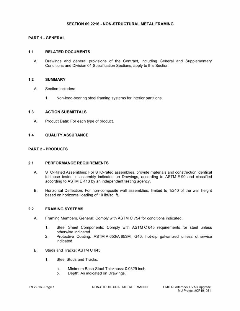
09 22 16 - Page 1 NON-STRUCTURAL METAL FRAMING UMC Quarterdeck HVAC Upgrade MU Project #CP191051
SECTION 09 2216 - NON-STRUCTURAL METAL FRAMING
PART 1 - GENERAL
1.1 RELATED DOCUMENTS
A. Drawings and general provisions of the Contract, including General and Supplementary Conditions and Division 01 Specification Sections, apply to this Section.
1.2 SUMMARY
A. Section Includes:
1. Non-load-bearing steel framing systems for interior partitions.
1.3 ACTION SUBMITTALS
A. Product Data: For each type of product.
1.4 QUALITY ASSURANCE
PART 2 - PRODUCTS
2.1 PERFORMANCE REQUIREMENTS
A. STC-Rated Assemblies: For STC-rated assemblies, provide materials and construction identical to those tested in assembly indicated on Drawings, according to ASTM E 90 and classified according to ASTM E 413 by an independent testing agency.
B. Horizontal Deflection: For non-composite wall assemblies, limited to 1/240 of the wall height based on horizontal loading of 10 lbf/sq. ft.
2.2 FRAMING SYSTEMS
A. Framing Members, General: Comply with ASTM C 754 for conditions indicated.
1. Steel Sheet Components: Comply with ASTM C 645 requirements for steel unless otherwise indicated.
2. Protective Coating: ASTM A 653/A 653M, G40, hot-dip galvanized unless otherwise indicated.
B. Studs and Tracks: ASTM C 645.
1. Steel Studs and Tracks:
a. Minimum Base-Steel Thickness: 0.0329 inch. b. Depth: As indicated on Drawings.
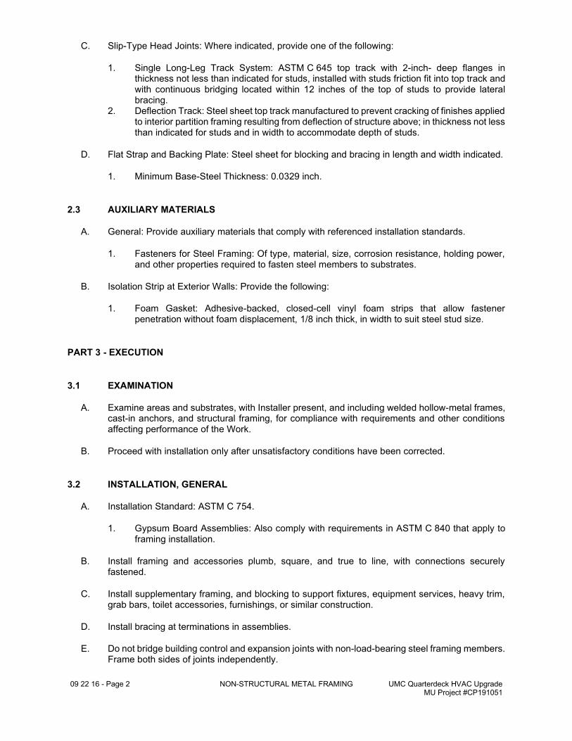
09 22 16 - Page 2 NON-STRUCTURAL METAL FRAMING UMC Quarterdeck HVAC Upgrade MU Project #CP191051
C. Slip-Type Head Joints: Where indicated, provide one of the following:
1. Single Long-Leg Track System: ASTM C 645 top track with 2-inch- deep flanges in thickness not less than indicated for studs, installed with studs friction fit into top track and with continuous bridging located within 12 inches of the top of studs to provide lateral bracing.
2. Deflection Track: Steel sheet top track manufactured to prevent cracking of finishes applied to interior partition framing resulting from deflection of structure above; in thickness not less than indicated for studs and in width to accommodate depth of studs.
D. Flat Strap and Backing Plate: Steel sheet for blocking and bracing in length and width indicated.
1. Minimum Base-Steel Thickness: 0.0329 inch.
2.3 AUXILIARY MATERIALS
A. General: Provide auxiliary materials that comply with referenced installation standards.
1. Fasteners for Steel Framing: Of type, material, size, corrosion resistance, holding power, and other properties required to fasten steel members to substrates.
B. Isolation Strip at Exterior Walls: Provide the following:
1. Foam Gasket: Adhesive-backed, closed-cell vinyl foam strips that allow fastener penetration without foam displacement, 1/8 inch thick, in width to suit steel stud size.
PART 3 - EXECUTION
3.1 EXAMINATION
A. Examine areas and substrates, with Installer present, and including welded hollow-metal frames, cast-in anchors, and structural framing, for compliance with requirements and other conditions affecting performance of the Work.
B. Proceed with installation only after unsatisfactory conditions have been corrected.
3.2 INSTALLATION, GENERAL
A. Installation Standard: ASTM C 754.
1. Gypsum Board Assemblies: Also comply with requirements in ASTM C 840 that apply to framing installation.
B. Install framing and accessories plumb, square, and true to line, with connections securely fastened.
C. Install supplementary framing, and blocking to support fixtures, equipment services, heavy trim, grab bars, toilet accessories, furnishings, or similar construction.
D. Install bracing at terminations in assemblies.
E. Do not bridge building control and expansion joints with non-load-bearing steel framing members. Frame both sides of joints independently.
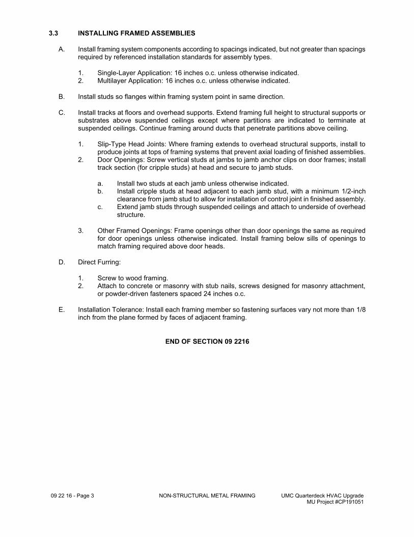
09 22 16 - Page 3 NON-STRUCTURAL METAL FRAMING UMC Quarterdeck HVAC Upgrade MU Project #CP191051
3.3 INSTALLING FRAMED ASSEMBLIES
A. Install framing system components according to spacings indicated, but not greater than spacings required by referenced installation standards for assembly types.
1. Single-Layer Application: 16 inches o.c. unless otherwise indicated. 2. Multilayer Application: 16 inches o.c. unless otherwise indicated.
B. Install studs so flanges within framing system point in same direction.
C. Install tracks at floors and overhead supports. Extend framing full height to structural supports or substrates above suspended ceilings except where partitions are indicated to terminate at suspended ceilings. Continue framing around ducts that penetrate partitions above ceiling.
1. Slip-Type Head Joints: Where framing extends to overhead structural supports, install to produce joints at tops of framing systems that prevent axial loading of finished assemblies.
2. Door Openings: Screw vertical studs at jambs to jamb anchor clips on door frames; install track section (for cripple studs) at head and secure to jamb studs.
a. Install two studs at each jamb unless otherwise indicated. b. Install cripple studs at head adjacent to each jamb stud, with a minimum 1/2-inch
clearance from jamb stud to allow for installation of control joint in finished assembly. c. Extend jamb studs through suspended ceilings and attach to underside of overhead
structure.
3. Other Framed Openings: Frame openings other than door openings the same as required for door openings unless otherwise indicated. Install framing below sills of openings to match framing required above door heads.
D. Direct Furring:
1. Screw to wood framing. 2. Attach to concrete or masonry with stub nails, screws designed for masonry attachment,
or powder-driven fasteners spaced 24 inches o.c.
E. Installation Tolerance: Install each framing member so fastening surfaces vary not more than 1/8 inch from the plane formed by faces of adjacent framing.
END OF SECTION 09 2216

THIS PAGE LEFT BLANK INTENTIONALLY
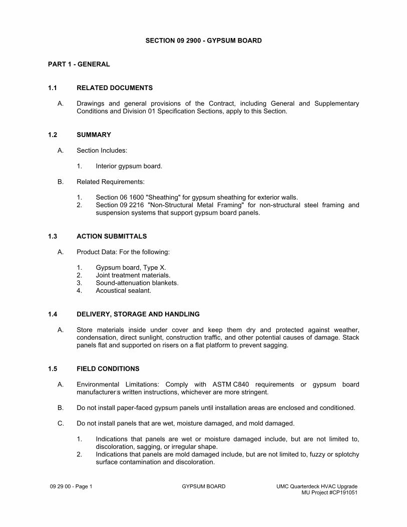
09 29 00 - Page 1 GYPSUM BOARD UMC Quarterdeck HVAC Upgrade MU Project #CP191051
SECTION 09 2900 - GYPSUM BOARD
PART 1 - GENERAL
1.1 RELATED DOCUMENTS
A. Drawings and general provisions of the Contract, including General and Supplementary Conditions and Division 01 Specification Sections, apply to this Section.
1.2 SUMMARY
A. Section Includes:
1. Interior gypsum board.
B. Related Requirements:
1. Section 06 1600 "Sheathing" for gypsum sheathing for exterior walls. 2. Section 09 2216 "Non-Structural Metal Framing" for non-structural steel framing and
suspension systems that support gypsum board panels.
1.3 ACTION SUBMITTALS
A. Product Data: For the following:
1. Gypsum board, Type X. 2. Joint treatment materials. 3. Sound-attenuation blankets. 4. Acoustical sealant.
1.4 DELIVERY, STORAGE AND HANDLING
A. Store materials inside under cover and keep them dry and protected against weather, condensation, direct sunlight, construction traffic, and other potential causes of damage. Stack panels flat and supported on risers on a flat platform to prevent sagging.
1.5 FIELD CONDITIONS
A. Environmental Limitations: Comply with ASTM C840 requirements or gypsum board manufacturer's written instructions, whichever are more stringent.
B. Do not install paper-faced gypsum panels until installation areas are enclosed and conditioned.
C. Do not install panels that are wet, moisture damaged, and mold damaged.
1. Indications that panels are wet or moisture damaged include, but are not limited to, discoloration, sagging, or irregular shape.
2. Indications that panels are mold damaged include, but are not limited to, fuzzy or splotchy surface contamination and discoloration.
09 29 00 - Page 2 GYPSUM BOARD UMC Quarterdeck HVAC Upgrade MU Project #CP191051
PART 2 - PRODUCTS
2.1 GYPSUM BOARD, GENERAL
A. Size: Provide maximum lengths and widths available that will minimize joints in each area and that correspond with support system indicated.
2.2 INTERIOR GYPSUM BOARD
A. Gypsum Board, Type X: ASTM C1396/C1396M.
1. Thickness: 5/8 inch. 2. Long Edges: Tapered and featured (rounded or beveled) for prefilling.
2.3 JOINT TREATMENT MATERIALS
A. General: Comply with ASTM C475/C475M.
B. Joint Tape:
1. Interior Gypsum Board: Paper.
C. Joint Compound for Interior Gypsum Board: For each coat, use formulation that is compatible with other compounds applied on previous or for successive coats.
1. Prefilling: At open joints, rounded or beveled panel edges, and damaged surface areas, use setting-type taping compound.
2. Embedding and First Coat: For embedding tape and first coat on joints, fasteners, and trim flanges, use drying-type, all-purpose compound.
a. Use setting-type compound for installing paper-faced metal trim accessories.
3. Fill Coat: For second coat, use drying-type, all-purpose compound. 4. Finish Coat: For third coat, use setting-type, sandable topping compound.
2.4 AUXILIARY MATERIALS
A. Provide auxiliary materials that comply with referenced installation standards and manufacturer's written instructions.
B. Steel Drill Screws: ASTM C1002 unless otherwise indicated.
1. Use screws complying with ASTM C954 for fastening panels to steel members from 0.033 to 0.112 inch thick.
2. For fastening cementitious backer units, use screws of type and size recommended by panel manufacturer.
C. Sound-Attenuation Blankets: ASTM C665, Type I (blankets without membrane facing) produced by combining thermosetting resins with mineral fibers manufactured from glass, slag wool, or rock wool.
1. Fire-Resistance-Rated Assemblies: Comply with mineral-fiber requirements of assembly.
09 29 00 - Page 3 GYPSUM BOARD UMC Quarterdeck HVAC Upgrade MU Project #CP191051
D. Acoustical Sealant: As specified in Section 07 9219 "Acoustical Joint Sealants."
PART 3 - EXECUTION
3.1 EXAMINATION
A. Examine areas and substrates including welded hollow-metal frames and support framing, with Installer present, for compliance with requirements and other conditions affecting performance of the Work.
B. Examine panels before installation. Reject panels that are wet, moisture damaged, and mold damaged.
C. Proceed with installation only after unsatisfactory conditions have been corrected.
3.2 INSTALLATION AND FINISHING OF PANELS, GENERAL
A. Comply with ASTM C840.
B. Install ceiling panels across framing to minimize the number of abutting end joints and to avoid abutting end joints in central area of each ceiling. Stagger abutting end joints of adjacent panels not less than one framing member.
C. Install panels with face side out. Butt panels together for a light contact at edges and ends with not more than 1/16 inch of open space between panels. Do not force into place.
D. Locate edge and end joints over supports, except in ceiling applications where intermediate supports or gypsum board back-blocking is provided behind end joints. Do not place tapered edges against cut edges or ends. Stagger vertical joints on opposite sides of partitions. Do not make joints other than control joints at corners of framed openings.
E. Form control and expansion joints with space between edges of adjoining gypsum panels.
F. Cover both faces of support framing with gypsum panels in concealed spaces (above ceilings, etc.), except in chases braced internally.
1. Unless concealed application is indicated or required for sound, fire, air, or smoke ratings, coverage may be accomplished with scraps of not less than 8 sq. ft. in area.
2. Fit gypsum panels around ducts, pipes, and conduits. 3. Where partitions intersect structural members projecting below underside of floor/roof
slabs and decks, cut gypsum panels to fit profile formed by structural members; allow 1/4- to 3/8-inch- wide joints to install sealant.
G. Isolate perimeter of gypsum board applied to non-load-bearing partitions at structural abutments. Provide 1/4- to 1/2-inch- wide spaces at these locations and trim edges with edge trim where edges of panels are exposed. Seal joints between edges and abutting structural surfaces with acoustical sealant.
H. Attachment to Steel Framing: Attach panels so leading edge or end of each panel is attached to open (unsupported) edges of stud flanges first.
I. STC-Rated Assemblies: Seal construction at perimeters, behind control joints, and at openings and penetrations with a continuous bead of acoustical sealant. Install acoustical sealant at both faces of partitions at perimeters and through penetrations. Comply with ASTM C919 and with
09 29 00 - Page 4 GYPSUM BOARD UMC Quarterdeck HVAC Upgrade MU Project #CP191051
manufacturer's written instructions for locating edge trim and closing off sound-flanking paths around or through assemblies, including sealing partitions above acoustical ceilings.
J. Install sound attenuation blankets before installing gypsum panels unless blankets are readily installed after panels have been installed on one side.
3.3 INSTALLATION OF INTERIOR GYPSUM BOARD
A. Install interior gypsum board in the following locations:
1. Type X: Vertical surfaces unless otherwise indicated .
B. Single-Layer Application:
1. On partitions/walls, apply gypsum panels vertically (parallel to framing)or horizontally (perpendicular to framing) unless otherwise indicated or required by fire-resistance-rated assembly, and minimize end joints.
a. Stagger abutting end joints not less than one framing member in alternate courses of panels.
2. Fastening Methods: Apply gypsum panels to supports with steel drill screws.
C. Multilayer Application:
1. On partitions/walls, apply gypsum board indicated for base layers and face layers vertically (parallel to framing) with joints of base layers located over stud or furring member and face-layer joints offset at least one stud or furring member with base-layer joints unless otherwise indicated or required by fire-resistance-rated assembly. Stagger joints on opposite sides of partitions.
2. Fastening Methods: Fasten base layers with screws; fasten face layers with adhesive and supplementary fasteners.
3.4 INSTALLATION OF TILE BACKING PANELS
A. Where tile backing panels abut other types of panels in same plane, shim surfaces to produce a uniform plane across panel surfaces.
3.5 FINISHING GYPSUM BOARD
A. General: Treat gypsum board joints, interior angles, edge trim, control joints, penetrations, fastener heads, surface defects, and elsewhere as required to prepare gypsum board surfaces for decoration. Promptly remove residual joint compound from adjacent surfaces.
B. Prefill open joints, rounded or beveled edges, and damaged surface areas.
C. Apply joint tape over gypsum board joints, except for trim products specifically indicated as not intended to receive tape.
D. Gypsum Board Finish Levels: Finish panels to levels indicated below and according to ASTM C840:
1. Level 1: Ceiling plenum areas, concealed areas, and where indicated. 2. Level 4: At panel surfaces that will be exposed to view unless otherwise indicated.
09 29 00 - Page 5 GYPSUM BOARD UMC Quarterdeck HVAC Upgrade MU Project #CP191051
a. Primer and its application to surfaces are specified in Section 09 9123 "Interior Painting."
3.6 PROTECTION
A. Protect adjacent surfaces from drywall compound and promptly remove from floors and other non-drywall surfaces. Repair surfaces stained, marred, or otherwise damaged during drywall application.
B. Protect installed products from damage from weather, condensation, direct sunlight, construction, and other causes during remainder of the construction period.
C. Remove and replace panels that are wet, moisture damaged, and mold damaged.
1. Indications that panels are wet or moisture damaged include, but are not limited to, discoloration, sagging, or irregular shape.
2. Indications that panels are mold damaged include, but are not limited to, fuzzy or splotchy surface contamination and discoloration.
END OF SECTION 09 2900

THIS PAGE LEFT BLANK INTENTIONALLY
09 51 13 - Page 1 ACOUSTICAL PANEL CEILINGS UMC Quarterdeck HVAC Upgrade MU Project #CP191051
SECTION 09 5113 - ACOUSTICAL PANEL CEILINGS
PART 1 - GENERAL
1.1 RELATED DOCUMENTS
A. Drawings and general provisions of the Contract, including General and Supplementary Conditions and Division 01 Specification Sections, apply to this Section.
1.2 SUMMARY
A. Section includes acoustical panels and exposed suspension systems for interior ceilings.
B. Products furnished, but not installed under this Section, include anchors, clips, and other ceiling attachment devices to be cast in concrete.
1.3 ACTION SUBMITTALS
A. Product Data: For each type of product.
1.4 MAINTENANCE MATERIAL SUBMITTALS
A. Furnish extra materials, from the same product run, that match products installed and that are packaged with protective covering for storage and identified with labels describing contents.
1. Acoustical Ceiling Units: Full-size panels equal to 2 percent of quantity installed. 2. Suspension-System Components: Quantity of each exposed component equal to 2 percent
of quantity installed.
1.5 DELIVERY, STORAGE, AND HANDLING
A. Deliver acoustical panels, suspension-system components, and accessories to Project site and store them in a fully enclosed, conditioned space where they will be protected against damage from moisture, humidity, temperature extremes, direct sunlight, surface contamination, and other causes.
B. Before installing acoustical panels, permit them to reach room temperature and a stabilized moisture content.
1.6 FIELD CONDITIONS
A. Environmental Limitations: Do not install acoustical panel ceilings until spaces are enclosed and weathertight, wet-work in spaces is complete and dry, work above ceilings is complete, and ambient temperature and humidity conditions are maintained at the levels indicated for Project when occupied for its intended use.
09 51 13 - Page 2 ACOUSTICAL PANEL CEILINGS UMC Quarterdeck HVAC Upgrade MU Project #CP191051
PART 2 - PRODUCTS
2.1 MANUFACTURERS
A. Source Limitations: Obtain each type of acoustical ceiling panel and its supporting suspension system from single source from single manufacturer.
2.2 ACOUSTICAL PANELS AC-1
A. Manufacturers: Subject to compliance with requirements, provide products by the following:
1. Refer to Appendix A "Interior Finish Key" for manufacturer, color and style.
B. Acoustical Panel Standard: Provide manufacturer's standard panels according to ASTM E 1264 and designated by type, form, pattern, acoustical rating, and light reflectance unless otherwise indicated.
C. Classification: Provide panels as follows:
1. Type and Form: Type III, mineral base with painted finish; Form 1, nodular. 2. Pattern: CE (perforated, small holes and lightly textured) [and] Refer to Appendix.
D. Color: Refer to Appendix A.
E. Antimicrobial Treatment: Manufacturer's standard broad spectrum, antimicrobial formulation that inhibits fungus, mold, mildew, and gram-positive and gram-negative bacteria and showing no mold, mildew, or bacterial growth when tested according to ASTM D 3273, ASTM D 3274, or ASTM G 21 and evaluated according to ASTM D 3274 or ASTM G 21.
2.3 METAL SUSPENSION SYSTEM
A. Metal Suspension-System Standard: Provide manufacturer's standard, direct-hung, metal suspension system and accessories according to ASTM C 635/C 635M and designated by type, structural classification, and finish indicated.
1. High-Humidity Finish: Where indicated, provide coating tested and classified for "severe environment performance" according to ASTM C 635/C 635M.
B. Wide-Face, Capped, Double-Web, Steel Suspension System: Main and cross runners roll formed from cold-rolled steel sheet; prepainted, electrolytically zinc coated, or hot-dip galvanized, G30 coating designation; with prefinished 15/16-inch- wide metal caps on flanges.
1. Structural Classification: Intermediate -duty system. 2. End Condition of Cross Runners: Override (stepped) or butt-edge type. 3. Face Design: Flat, flush. 4. Cap Material: Cold-rolled steel. 5. Cap Finish: Painted in color as selected from manufacturer's full range.
2.4 ACCESSORIES
A. Attachment Devices: Size for five times the design load indicated in ASTM C 635/C 635M, Table 1, "Direct Hung," unless otherwise indicated. Comply with seismic design requirements.
09 51 13 - Page 3 ACOUSTICAL PANEL CEILINGS UMC Quarterdeck HVAC Upgrade MU Project #CP191051
B. Wire Hangers, Braces, and Ties: Provide wires as follows:
1. Zinc-Coated, Carbon-Steel Wire: ASTM A 641/A 641M, Class 1 zinc coating, soft temper. 2. Size: Wire diameter sufficient for its stress at three times hanger design load (ASTM C
635/C 635M, Table 1, "Direct Hung") will be less than yield stress of wire, but not less than 0.135-inch- diameter wire.
C. Hanger Rods: Mild steel, zinc coated or protected with rust-inhibitive paint.
D. Angle Hangers: Angles with legs not less than 7/8 inch wide; formed with 0.04-inch- thick, galvanized-steel sheet complying with ASTM A 653/A 653M, G90 coating designation; with bolted connections and 5/16-inch- diameter bolts.
2.5 METAL EDGE MOLDINGS AND TRIM
A. Roll-Formed, Sheet-Metal Edge Moldings and Trim: Type and profile indicated or, if not indicated, manufacturer's standard moldings for edges and penetrations that comply with seismic design requirements; formed from sheet metal of same material, finish, and color as that used for exposed flanges of suspension-system runners.
1. Edge moldings shall fit acoustical panel edge details and suspension systems indicated and match width and configuration of exposed runners unless otherwise indicated.
2. For circular penetrations of ceiling, provide edge moldings fabricated to diameter required to fit penetration exactly.
PART 3 - EXECUTION
3.1 EXAMINATION
A. Examine substrates, areas, and conditions, including structural framing to which acoustical panel ceilings attach or abut, with Installer present, for compliance with requirements specified in this and other Sections that affect ceiling installation and anchorage and with requirements for installation tolerances and other conditions affecting performance of acoustical panel ceilings.
B. Examine acoustical panels before installation. Reject acoustical panels that are wet, moisture damaged, or mold damaged.
C. Proceed with installation only after unsatisfactory conditions have been corrected.
3.2 PREPARATION
A. Measure each ceiling area and establish layout of acoustical panels to balance border widths at opposite edges of each ceiling. Avoid using less-than-half-width panels at borders unless otherwise indicated and comply with layout shown on reflected ceiling plans.
B. Layout openings for penetrations centered on the penetrating items.
3.3 INSTALLATION
A. Install acoustical panel ceilings according to ASTM C 636/C 636M and manufacturer's written instructions.
09 51 13 - Page 4 ACOUSTICAL PANEL CEILINGS UMC Quarterdeck HVAC Upgrade MU Project #CP191051
1. Fire-Rated Assembly: Install fire-rated ceiling systems according to tested fire-rated design.
B. Suspend ceiling hangers from building's structural members and as follows:
1. Install hangers plumb and free from contact with insulation or other objects within ceiling plenum that are not part of supporting structure or of ceiling suspension system.
2. Splay hangers only where required to miss obstructions; offset resulting horizontal forces by bracing, countersplaying, or other equally effective means.
3. Where width of ducts and other construction within ceiling plenum produces hanger spacings that interfere with location of hangers at spacings required to support standard suspension-system members, install supplemental suspension members and hangers in form of trapezes or equivalent devices.
4. Secure wire hangers to ceiling-suspension members and to supports above with a minimum of three tight turns. Connect hangers directly to structure or to inserts, eye screws, or other devices that are secure and appropriate for substrate and that will not deteriorate or otherwise fail due to age, corrosion, or elevated temperatures.
5. Secure flat, angle, channel, and rod hangers to structure, including intermediate framing members, by attaching to inserts, eye screws, or other devices that are secure and appropriate for both the structure to which hangers are attached and the type of hanger involved. Install hangers in a manner that will not cause them to deteriorate or fail due to age, corrosion, or elevated temperatures.
6. Do not support ceilings directly from permanent metal forms or floor deck. Fasten hangers to cast-in-place hanger inserts, postinstalled mechanical or adhesive anchors, or power-actuated fasteners that extend through forms into concrete.
7. When steel framing does not permit installation of hanger wires at spacing required, install carrying channels or other supplemental support for attachment of hanger wires.
8. Do not attach hangers to steel deck tabs. 9. Do not attach hangers to steel roof deck. Attach hangers to structural members. 10. Space hangers not more than 48 inches o.c. along each member supported directly from
hangers unless otherwise indicated; provide hangers not more than 8 inches from ends of each member.
11. Size supplemental suspension members and hangers to support ceiling loads within performance limits established by referenced standards.
C. Secure bracing wires to ceiling suspension members and to supports with a minimum of four tight turns. Suspend bracing from building's structural members as required for hangers, without attaching to permanent metal forms, steel deck, or steel deck tabs. Fasten bracing wires into concrete with cast-in-place or postinstalled anchors.
D. Install edge moldings and trim of type indicated at perimeter of acoustical ceiling area and where necessary to conceal edges of acoustical panels.
1. Apply acoustical sealant in a continuous ribbon concealed on back of vertical legs of moldings before they are installed.
2. Screw attach moldings to substrate at intervals not more than 16 inches o.c. and not more than 3 inches from ends. Miter corners accurately and connect securely.
3. Do not use exposed fasteners, including pop rivets, on moldings and trim.
E. Install suspension-system runners so they are square and securely interlocked with one another. Remove and replace dented, bent, or kinked members.
F. Install acoustical panels with undamaged edges and fit accurately into suspension-system runners and edge moldings. Scribe and cut panels at borders and penetrations to provide precise fit.
1. Arrange directionally patterned acoustical panels as follows:
09 51 13 - Page 5 ACOUSTICAL PANEL CEILINGS UMC Quarterdeck HVAC Upgrade MU Project #CP191051
a. As indicated on reflected ceiling plans.
2. For square-edged panels, install panels with edges fully hidden from view by flanges of suspension-system runners and moldings.
3. For reveal-edged panels on suspension-system runners, install panels with bottom of reveal in firm contact with top surface of runner flanges.
4. Paint cut edges of panel remaining exposed after installation; match color of exposed panel surfaces using coating recommended in writing for this purpose by acoustical panel manufacturer.
3.4 ERECTION TOLERANCES
A. Suspended Ceilings: Install main and cross runners level to a tolerance of 1/8 inch in 12 feet, non-cumulative.
B. Moldings and Trim: Install moldings and trim to substrate and level with ceiling suspension system to a tolerance of 1/8 inch in 12 feet, non-cumulative.
3.5 CLEANING
A. Clean exposed surfaces of acoustical panel ceilings, including trim, edge moldings, and suspension-system members. Comply with manufacturer's written instructions for cleaning and touchup of minor finish damage.
B. Remove and replace ceiling components that cannot be successfully cleaned and repaired to permanently eliminate evidence of damage.
END OF SECTION 09 5113

THIS PAGE LEFT BLANK INTENTIONALLY
20 00 00 - Page 1 BASIC MECHANICAL CONDITIONS
UMC Quarterdeck HVAC UpgradeMU Project #CP191051
TABLE OF CONTENTS
DIVISION 20 – BASIC MECHANICAL CONDITIONS
20 00 00 BASIC MECHANICAL CONDITIONS...........................................................................................420 00 01 GENERAL................................................................................................................................420 00 02 SCOPE of WORK ....................................................................................................................420 00 03 REFERENCES.....................................................................................................................420 00 04 REFERENCES, REGULATORY REQUIREMENTS................................................................420 00 05 DEFINITIONS ..........................................................................................................................520 00 06 CODES, STANDARDS, etc. ....................................................................................................6
20 10 00 BASIC MECHANICAL MATERIALS and METHODS ..................................................................120 10 01 GENERAL................................................................................................................................120 10 02 REGULATORY REQUIREMENTS ..........................................................................................120 10 03 RELATED SECTIONS of the SPECIFICATIONS....................................................................120 10 04 WORK INCLUDED ..................................................................................................................120 10 05 WORK not INCLUDED ............................................................................................................220 10 06 SUBMITTALS ..........................................................................................................................220 10 07 SPECIAL REQUIREMENTS....................................................................................................2
20 10 10 BASIC PIPING MATERIALS .....................................................................................................120 10 11 PIPE and TUBE .......................................................................................................................120 10 12 FITTINGS.................................................................................................................................220 10 13 VALVES ...................................................................................................................................320 10 14 STRAINERS ............................................................................................................................6
20 10 20 MISCELLANEOUS MATERIALS..................................................................................................620 10 21 SLEEVES (non-water proof, non-fire rated).............................................................................620 10 22 WATER SEALS .......................................................................................................................620 10 23 FIRESTOPS and SMOKESTOPS, fire rated/smoke partitions................................................720 10 24 SEALS, non-fire rated ..............................................................................................................720 10 25 ESCUTCHEONS .....................................................................................................................720 10 28 ACCESS DOORS ....................................................................................................................720 10 29 RESTRICTIONS, general for all piping systems......................................................................8
20 10 30 JOINTS and CONNECTION METHODS......................................................................................120 10 31 THREADED .............................................................................................................................120 10 32 WELDED..................................................................................................................................120 10 33 GROOVED...............................................................................................................................120 10 34 SOLDERED and BRAZED.......................................................................................................220 10 35 FLANGED ................................................................................................................................220 10 36 CAST IRON PIPE and FITTINGS............................................................................................2
20 10 40 HANGERS, SHIELDS, SUPPORTS AND ANCHORS..................................................................320 10 41 HANGERS ...............................................................................................................................320 10 42 HANGER RODS and HANGER SPACING..............................................................................420 10 43 ANCHORING ...........................................................................................................................520 10 44 SEISMIC RESTRAINT.............................................................................................................5
20 10 50 BASIC MECHANICAL METHODS - GENERAL...........................................................................620 10 51 INTENT of PROJECT DOCUMENTS......................................................................................620 10 52 ARRANGEMENT of WORK.....................................................................................................620 10 53 COORDINATION.....................................................................................................................720 10 54 DELIVERY, STORAGE and HANDLING .................................................................................720 10 55 GENERAL CLEANING ............................................................................................................820 10 56 CLEANING of PIPING SYSTEMS ...........................................................................................820 10 57 PRESSURE TESTING.............................................................................................................920 10 58 LEAK TESTING of REFRIGERANT PIPING ...........................................................................920 10 59 CHARGING REFRIGERATION SYSTEMS.............................................................................9
20 00 00 - Page 2 BASIC MECHANICAL CONDITIONS
UMC Quarterdeck HVAC UpgradeMU Project #CP191051
20 10 60 BASIC MECHANICAL METHODS - INSTALLATION..................................................................120 10 61 GENERAL................................................................................................................................120 10 62 PIPING.....................................................................................................................................120 10 63 VALVES ...................................................................................................................................220 10 64 EQUIPMENT............................................................................................................................320 10 65 MISCELLANEOUS...................................................................................................................4
20 10 70 BASIC MECHANICAL METHODS - RELATED WORK...............................................................120 10 71 DEMOLITION...........................................................................................................................120 10 72 CUTTING and PATCHING ......................................................................................................120 10 74 CONCRETE WORK (cast-in-place) ........................................................................................220 10 75 PAINTING ................................................................................................................................320 10 76 LUBRICATION.........................................................................................................................520 10 77 DRAINING, FILLING and VENTING SYSTEMS......................................................................6
20 10 80 TESTING, ADJUSTING and BALANCING ..................................................................................120 10 81 GENERAL................................................................................................................................120 10 82 REFERENCES.........................................................................................................................120 10 83 WORK INCLUDED ..................................................................................................................120 10 84 SUBMITTALS ..........................................................................................................................220 10 85 RESPONSIBILITIES and COORDINATION............................................................................220 10 86 REPORTS................................................................................................................................320 10 87 PROCEDURES........................................................................................................................6
20 10 90 BASIC MECHANICAL METHODS - IDENTIFICATION ...............................................................120 10 91 GENERAL................................................................................................................................120 10 92 REFERENCES.........................................................................................................................120 10 93 WORK INCLUDED ..................................................................................................................120 10 94 SUBMITTALS ..........................................................................................................................120 10 95 GENERAL METHODS for IDENTIFICATION..........................................................................120 10 96 PIPING IDENTIFICATION .......................................................................................................220 10 97 VALVE IDENTIFICATION ....................................................................................................320 10 98 EQUIPMENT IDENTIFICATION..............................................................................................320 10 99 DUCTWORK IDENTIFICATION..............................................................................................420 10 100 CONTROL DEVICES IDENTIFICATION .............................................................................4
20 20 10 ELECTRICAL REQUIREMENTS..................................................................................................120 20 11 GENERAL................................................................................................................................120 20 12 REFERENCES.........................................................................................................................120 20 13 MOTORS .................................................................................................................................120 20 14 MOTOR CONTROLS ..............................................................................................................320 20 15 DISCONNECT SWITCHES.....................................................................................................320 20 16 MULTI-SPEED MOTORS and CONTROLS............................................................................320 20 17 VARIABLE SPEED DRIVES....................................................................................................320 20 18 CONTROL PANEL...................................................................................................................3
20 20 20 DRIVES and GUARDS...................................................................................................................120 20 21 GENERAL................................................................................................................................120 20 22 V-BELT DRIVES ......................................................................................................................120 20 23 DIRECT DRIVES .....................................................................................................................120 20 24 GUARDS..................................................................................................................................120 20 25 INSTALLATION and OPERATION ..........................................................................................1
20 25 00 INSULATION..................................................................................................................................120 25 01 GENERAL................................................................................................................................120 25 02 REFERENCES, REGULATORY REQUIREMENTS................................................................120 25 03 RELATED SECTIONS of the SPECIFICATIONS....................................................................120 25 04 DEFINITIONS ..........................................................................................................................120 25 05 WORK INCLUDED ..................................................................................................................220 25 06 SUBMITTALS ..........................................................................................................................2
20 00 00 - Page 3 BASIC MECHANICAL CONDITIONS
UMC Quarterdeck HVAC UpgradeMU Project #CP191051
20 25 07 SPECIAL REQUIREMENTS....................................................................................................3
20 25 10 INSULATION MATERIALS...........................................................................................................120 25 11 GENERAL................................................................................................................................120 25 12 FIRE SAFETY STANDARDS...................................................................................................120 25 13 TYPES of INSULATION MATERIALS .....................................................................................120 25 14 TYPES of PIPING JACKET MATERIALS...............................................................................220 25 15 DELIVERY and STORAGE of MATERIALS ............................................................................220 25 16 ACCEPTABLE MANUFACTURERS........................................................................................3
20 25 20 INSULATION MATERIAL SCHEDULES: .....................................................................................120 25 21 INSULATION MATERIAL SCHEDULE I-1..............................................................................120 25 24 INSULATION MATERIAL SCHEDULE I-4..............................................................................3
20 25 30 INSULATION APPLICATION........................................................................................................320 25 31 INSULATION APPLICATION - GENERAL ..............................................................................320 25 32 INSULATION APPLICATION - PIPING ...................................................................................420 25 33 INSULATION APPLICATION - EQUIPMENT..........................................................................420 25 34 INSULATION APPLICATION - DUCTWORK..........................................................................5
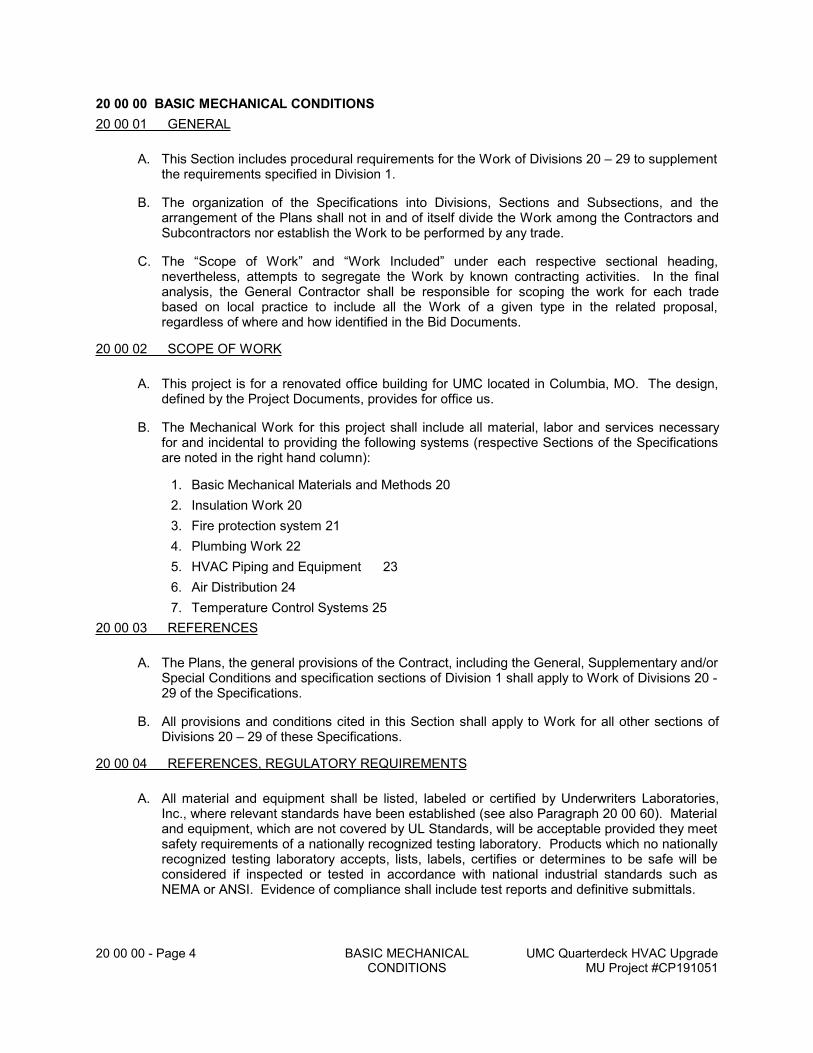
20 00 00 - Page 4 BASIC MECHANICAL CONDITIONS
UMC Quarterdeck HVAC UpgradeMU Project #CP191051
20 00 00 BASIC MECHANICAL CONDITIONS
20 00 01 GENERAL
A. This Section includes procedural requirements for the Work of Divisions 20 – 29 to supplement the requirements specified in Division 1.
B. The organization of the Specifications into Divisions, Sections and Subsections, and the arrangement of the Plans shall not in and of itself divide the Work among the Contractors and Subcontractors nor establish the Work to be performed by any trade.
C. The “Scope of Work” and “Work Included” under each respective sectional heading, nevertheless, attempts to segregate the Work by known contracting activities. In the final analysis, the General Contractor shall be responsible for scoping the work for each trade based on local practice to include all the Work of a given type in the related proposal, regardless of where and how identified in the Bid Documents.
20 00 02 SCOPE OF WORK
A. This project is for a renovated office building for UMC located in Columbia, MO. The design, defined by the Project Documents, provides for office us.
B. The Mechanical Work for this project shall include all material, labor and services necessary for and incidental to providing the following systems (respective Sections of the Specifications are noted in the right hand column):
1. Basic Mechanical Materials and Methods 20
2. Insulation Work 20
3. Fire protection system 21
4. Plumbing Work 22
5. HVAC Piping and Equipment 23
6. Air Distribution 24
7. Temperature Control Systems 25
20 00 03 REFERENCES
A. The Plans, the general provisions of the Contract, including the General, Supplementary and/or Special Conditions and specification sections of Division 1 shall apply to Work of Divisions 20 - 29 of the Specifications.
B. All provisions and conditions cited in this Section shall apply to Work for all other sections of Divisions 20 – 29 of these Specifications.
20 00 04 REFERENCES, REGULATORY REQUIREMENTS
A. All material and equipment shall be listed, labeled or certified by Underwriters Laboratories, Inc., where relevant standards have been established (see also Paragraph 20 00 60). Material and equipment, which are not covered by UL Standards, will be acceptable provided they meet safety requirements of a nationally recognized testing laboratory. Products which no nationally recognized testing laboratory accepts, lists, labels, certifies or determines to be safe will be considered if inspected or tested in accordance with national industrial standards such as NEMA or ANSI. Evidence of compliance shall include test reports and definitive submittals.
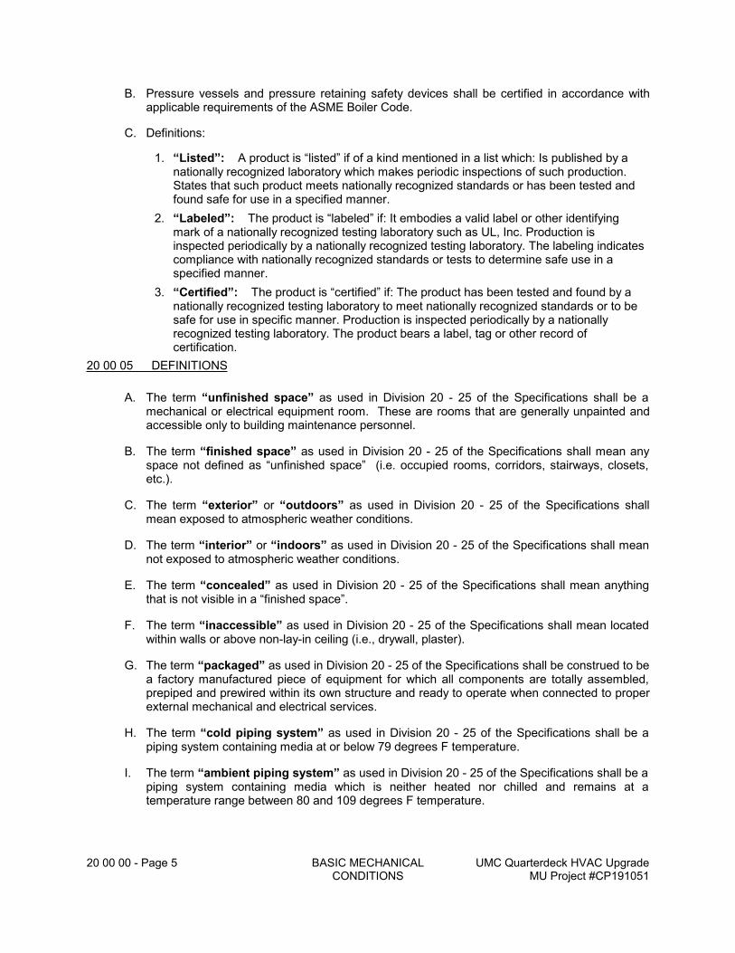
20 00 00 - Page 5 BASIC MECHANICAL CONDITIONS
UMC Quarterdeck HVAC UpgradeMU Project #CP191051
B. Pressure vessels and pressure retaining safety devices shall be certified in accordance with applicable requirements of the ASME Boiler Code.
C. Definitions:
1. “Listed”: A product is “listed” if of a kind mentioned in a list which: Is published by a nationally recognized laboratory which makes periodic inspections of such production. States that such product meets nationally recognized standards or has been tested and found safe for use in a specified manner.
2. “Labeled”: The product is “labeled” if: It embodies a valid label or other identifying mark of a nationally recognized testing laboratory such as UL, Inc. Production is inspected periodically by a nationally recognized testing laboratory. The labeling indicates compliance with nationally recognized standards or tests to determine safe use in a specified manner.
3. “Certified”: The product is “certified” if: The product has been tested and found by a nationally recognized testing laboratory to meet nationally recognized standards or to be safe for use in specific manner. Production is inspected periodically by a nationally recognized testing laboratory. The product bears a label, tag or other record of certification.
20 00 05 DEFINITIONS
A. The term “unfinished space” as used in Division 20 - 25 of the Specifications shall be a mechanical or electrical equipment room. These are rooms that are generally unpainted and accessible only to building maintenance personnel.
B. The term “finished space” as used in Division 20 - 25 of the Specifications shall mean any space not defined as “unfinished space” (i.e. occupied rooms, corridors, stairways, closets, etc.).
C. The term “exterior” or “outdoors” as used in Division 20 - 25 of the Specifications shall mean exposed to atmospheric weather conditions.
D. The term “interior” or “indoors” as used in Division 20 - 25 of the Specifications shall mean not exposed to atmospheric weather conditions.
E. The term “concealed” as used in Division 20 - 25 of the Specifications shall mean anything that is not visible in a “finished space”.
F. The term “inaccessible” as used in Division 20 - 25 of the Specifications shall mean located within walls or above non-lay-in ceiling (i.e., drywall, plaster).
G. The term “packaged” as used in Division 20 - 25 of the Specifications shall be construed to be a factory manufactured piece of equipment for which all components are totally assembled, prepiped and prewired within its own structure and ready to operate when connected to proper external mechanical and electrical services.
H. The term “cold piping system” as used in Division 20 - 25 of the Specifications shall be a piping system containing media at or below 79 degrees F temperature.
I. The term “ambient piping system” as used in Division 20 - 25 of the Specifications shall be a piping system containing media which is neither heated nor chilled and remains at a temperature range between 80 and 109 degrees F temperature.
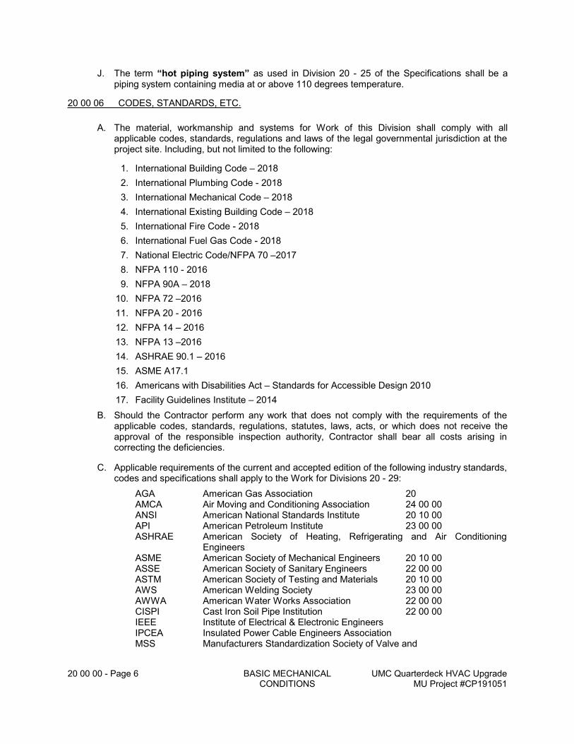
20 00 00 - Page 6 BASIC MECHANICAL CONDITIONS
UMC Quarterdeck HVAC UpgradeMU Project #CP191051
J. The term “hot piping system” as used in Division 20 - 25 of the Specifications shall be a piping system containing media at or above 110 degrees temperature.
20 00 06 CODES, STANDARDS, ETC.
A. The material, workmanship and systems for Work of this Division shall comply with all applicable codes, standards, regulations and laws of the legal governmental jurisdiction at the project site. Including, but not limited to the following:
1. International Building Code – 2018
2. International Plumbing Code - 2018
3. International Mechanical Code – 2018
4. International Existing Building Code – 2018
5. International Fire Code - 2018
6. International Fuel Gas Code - 2018
7. National Electric Code/NFPA 70 –2017
8. NFPA 110 - 2016
9. NFPA 90A – 2018
10. NFPA 72 –2016
11. NFPA 20 - 2016
12. NFPA 14 – 2016
13. NFPA 13 –2016
14. ASHRAE 90.1 – 2016
15. ASME A17.1
16. Americans with Disabilities Act – Standards for Accessible Design 2010
17. Facility Guidelines Institute – 2014
B. Should the Contractor perform any work that does not comply with the requirements of the applicable codes, standards, regulations, statutes, laws, acts, or which does not receive the approval of the responsible inspection authority, Contractor shall bear all costs arising in correcting the deficiencies.
C. Applicable requirements of the current and accepted edition of the following industry standards, codes and specifications shall apply to the Work for Divisions 20 - 29:
AGA American Gas Association 20AMCA Air Moving and Conditioning Association 24 00 00ANSI American National Standards Institute 20 10 00API American Petroleum Institute 23 00 00ASHRAE American Society of Heating, Refrigerating and Air Conditioning
EngineersASME American Society of Mechanical Engineers 20 10 00ASSE American Society of Sanitary Engineers 22 00 00ASTM American Society of Testing and Materials 20 10 00AWS American Welding Society 23 00 00AWWA American Water Works Association 22 00 00CISPI Cast Iron Soil Pipe Institution 22 00 00IEEE Institute of Electrical & Electronic EngineersIPCEA Insulated Power Cable Engineers AssociationMSS Manufacturers Standardization Society of Valve and
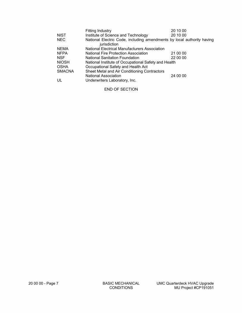
20 00 00 - Page 7 BASIC MECHANICAL CONDITIONS
UMC Quarterdeck HVAC UpgradeMU Project #CP191051
Fitting Industry 20 10 00NIST Institute of Science and Technology 20 10 00NEC National Electric Code, including amendments by local authority having
jurisdictionNEMA National Electrical Manufacturers AssociationNFPA National Fire Protection Association 21 00 00NSF National Sanitation Foundation 22 00 00NIOSH National Institute of Occupational Safety and HealthOSHA Occupational Safety and Health ActSMACNA Sheet Metal and Air Conditioning Contractors
National Association 24 00 00UL Underwriters Laboratory, Inc.
END OF SECTION
20 10 00 - Page 1 BASIC MECHANICAL MATERIALS AND METHODS
UMC Quarterdeck HVAC UpgradeMU Project #CP191051
20 10 00 BASIC MECHANICAL MATERIALS and METHODS
20 10 01 GENERAL
A. This Section describes and specifies basic mechanical materials and methods to be utilized in the Work included in other sections of Divisions 20 - 25.
B. The Plans, the general provisions of the Contract including the General, Supplementary and/or Special Conditions and specification sections of Division 1 shall apply to Work of Divisions 20 - 25 of the Specifications.
C. Provisions and conditions cited in this Section shall apply, where and when relevant, to Work of other sections of Divisions 20 - 25 of these Specifications.
20 10 02 REGULATORY REQUIREMENTS
A. Work for this section of the Specifications shall be performed in accordance with the Codes, Standards, etc. as identified in Division 20.
20 10 03 RELATED SECTIONS of the SPECIFICATIONS
A. Requirements of the following Section(s) of the Specifications apply to Work of this Section:
B. Division 20 - Basic Mechanical Conditions
C. Requirements of this Section of the Specifications shall apply to Work of the following sections of Divisions 20 - 29:
1. Division 20 - Insulation Work
2. Division 21 - Fire Protection System
3. Division 22 - Plumbing Work
4. Division 23 - HVAC Piping and Equipment
5. Division 24 - Air Distribution System
6. Division 25 - Temperature Control System
20 10 04 WORK INCLUDED
A. Furnish material, labor and services necessary for and incidental to the installation of the following work where shown on the Plans and as hereinafter specified. Include all necessary work in related sections of the Specifications (sub-section 20 10 03) to perform the Work completely.
B. Identification of piping and equipment for the work of Divisions 20 - 25.
C. Testing, adjusting and balancing of systems for the work of Divisions 20 - 25.
D. Cleaning of piping and equipment for the work of Divisions 20 - 25.
E. Excavation, trenching and backfilling for the work of Divisions 20 - 25.
F. Painting of piping and equipment for the work of Divisions 20 - 25.
G. Demolition for the work of Divisions 20 - 25.
H. Concrete for the work of Divisions 20 - 25.
20 10 00 - Page 2 BASIC MECHANICAL MATERIALS AND METHODS
UMC Quarterdeck HVAC UpgradeMU Project #CP191051
20 10 05 WORK NOT INCLUDED
A. Materials and methods are specified in this section for the work of Divisions 20 - 25. The Work, itself, is specified in the respective sections of Divisions 20 - 25 of the Specifications.
20 10 06 SUBMITTALS
A. The Contractor shall submit materials for the Work of Divisions 20 - 25 for approval in accordance with Section 20 00 43. The requirements are enumerated in the respective sections of Divisions 20 - 25 of the Specifications.
B. Single and multiple manufacturers are cited in this Sub-section as acceptable sources of piping material. While “or equivalent” is not included, the intent of this Section is to permit substitution as defined in Sub-section 20 00 51, EQUIPMENT MANUFACTURERS, unless “no substitution allowed “ is noted.
C. The following shall be submitted under this section of the specification:
1. Firestop schedule and product data, see Section 20 10 20 for specific requirements.
2. Coordination drawings, see Section 20 10 53 for specific requirements.
3. Testing and Balancing, see Section 20 10 80 for specific requirements.
4. Identification, see Section 20 10 90 for specific requirements.
5. Commissioning, see Section 152300 for specific requirements.
20 10 07 SPECIAL REQUIREMENTS
A. Special requirements for work shall be specified in the respective sections of Divisions 20 - 25 of the Specifications.
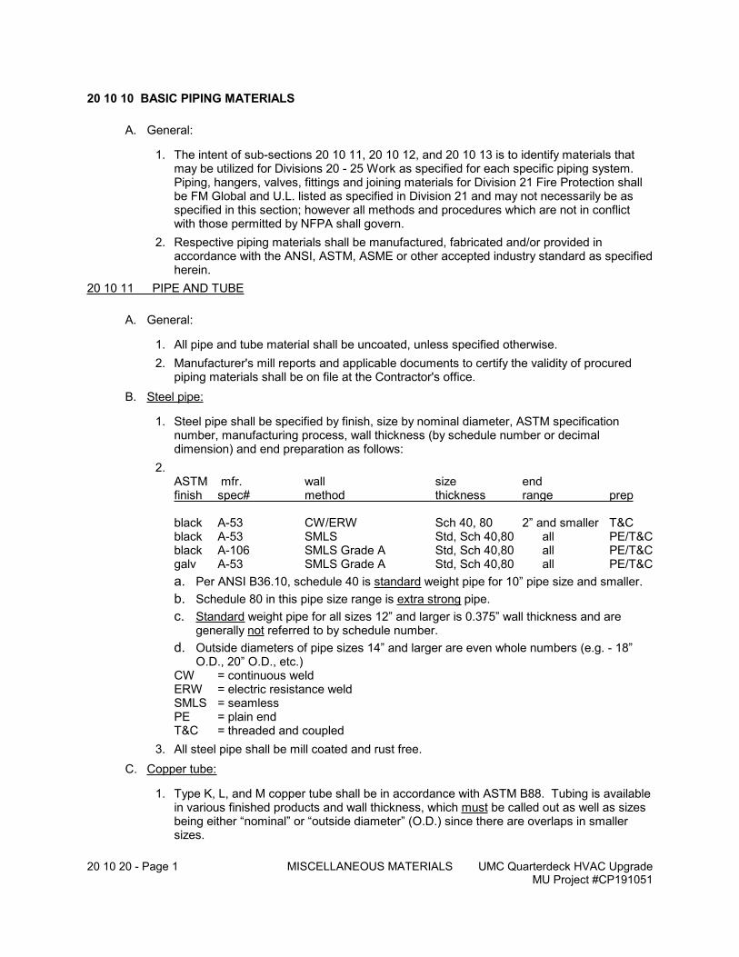
20 10 20 - Page 1 MISCELLANEOUS MATERIALS UMC Quarterdeck HVAC UpgradeMU Project #CP191051
20 10 10 BASIC PIPING MATERIALS
A. General:
1. The intent of sub-sections 20 10 11, 20 10 12, and 20 10 13 is to identify materials that may be utilized for Divisions 20 - 25 Work as specified for each specific piping system. Piping, hangers, valves, fittings and joining materials for Division 21 Fire Protection shall be FM Global and U.L. listed as specified in Division 21 and may not necessarily be as specified in this section; however all methods and procedures which are not in conflict with those permitted by NFPA shall govern.
2. Respective piping materials shall be manufactured, fabricated and/or provided in accordance with the ANSI, ASTM, ASME or other accepted industry standard as specified herein.
20 10 11 PIPE AND TUBE
A. General:
1. All pipe and tube material shall be uncoated, unless specified otherwise.
2. Manufacturer's mill reports and applicable documents to certify the validity of procured piping materials shall be on file at the Contractor's office.
B. Steel pipe:
1. Steel pipe shall be specified by finish, size by nominal diameter, ASTM specification number, manufacturing process, wall thickness (by schedule number or decimal dimension) and end preparation as follows:
2.ASTM mfr. wall size endfinish spec# method thickness range prep
black A-53 CW/ERW Sch 40, 80 2” and smaller T&Cblack A-53 SMLS Std, Sch 40,80 all PE/T&Cblack A-106 SMLS Grade A Std, Sch 40,80 all PE/T&Cgalv A-53 SMLS Grade A Std, Sch 40,80 all PE/T&C
a. Per ANSI B36.10, schedule 40 is standard weight pipe for 10” pipe size and smaller.
b. Schedule 80 in this pipe size range is extra strong pipe.
c. Standard weight pipe for all sizes 12” and larger is 0.375” wall thickness and are generally not referred to by schedule number.
d. Outside diameters of pipe sizes 14” and larger are even whole numbers (e.g. - 18” O.D., 20” O.D., etc.)
CW = continuous weldERW = electric resistance weldSMLS = seamless PE = plain endT&C = threaded and coupled
3. All steel pipe shall be mill coated and rust free.
C. Copper tube:
1. Type K, L, and M copper tube shall be in accordance with ASTM B88. Tubing is available in various finished products and wall thickness, which must be called out as well as sizes being either “nominal” or “outside diameter” (O.D.) since there are overlaps in smaller sizes.
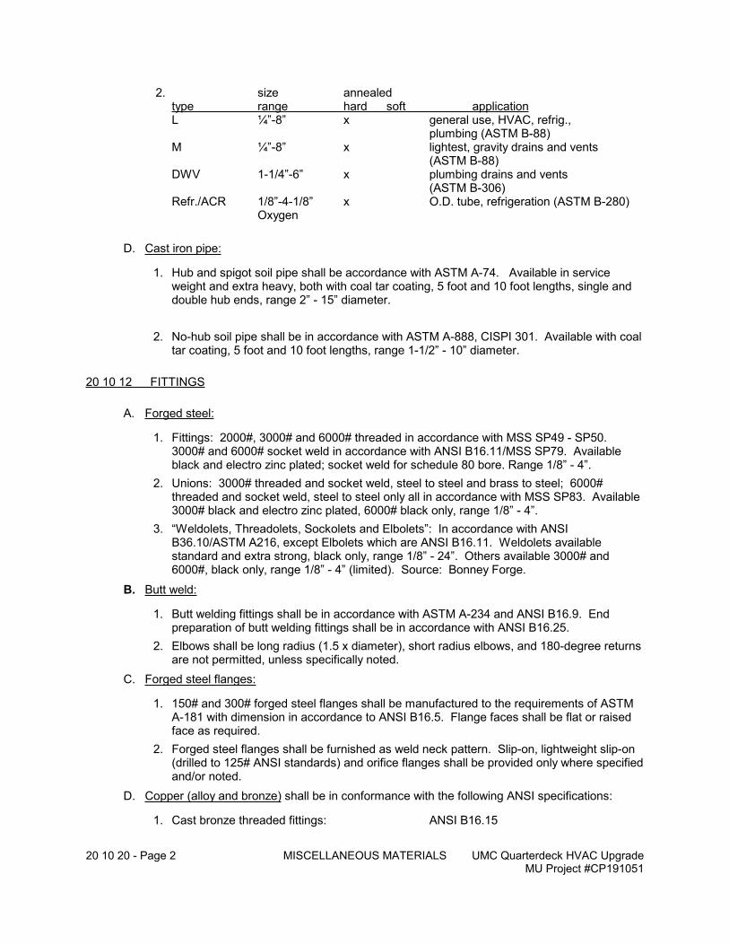
20 10 20 - Page 2 MISCELLANEOUS MATERIALS UMC Quarterdeck HVAC UpgradeMU Project #CP191051
2. size annealedtype range hard soft applicationL ¼”-8” x general use, HVAC, refrig.,
plumbing (ASTM B-88)M ¼”-8” x lightest, gravity drains and vents
(ASTM B-88)DWV 1-1/4”-6” x plumbing drains and vents
(ASTM B-306)Refr./ACR 1/8”-4-1/8” x O.D. tube, refrigeration (ASTM B-280)
Oxygen
D. Cast iron pipe:
1. Hub and spigot soil pipe shall be accordance with ASTM A-74. Available in service weight and extra heavy, both with coal tar coating, 5 foot and 10 foot lengths, single and double hub ends, range 2” - 15” diameter.
2. No-hub soil pipe shall be in accordance with ASTM A-888, CISPI 301. Available with coal tar coating, 5 foot and 10 foot lengths, range 1-1/2” - 10” diameter.
20 10 12 FITTINGS
A. Forged steel:
1. Fittings: 2000#, 3000# and 6000# threaded in accordance with MSS SP49 - SP50. 3000# and 6000# socket weld in accordance with ANSI B16.11/MSS SP79. Available black and electro zinc plated; socket weld for schedule 80 bore. Range 1/8” - 4”.
2. Unions: 3000# threaded and socket weld, steel to steel and brass to steel; 6000# threaded and socket weld, steel to steel only all in accordance with MSS SP83. Available 3000# black and electro zinc plated, 6000# black only, range 1/8” - 4”.
3. “Weldolets, Threadolets, Sockolets and Elbolets”: In accordance with ANSI B36.10/ASTM A216, except Elbolets which are ANSI B16.11. Weldolets available standard and extra strong, black only, range 1/8” - 24”. Others available 3000# and 6000#, black only, range 1/8” - 4” (limited). Source: Bonney Forge.
B. Butt weld:
1. Butt welding fittings shall be in accordance with ASTM A-234 and ANSI B16.9. End preparation of butt welding fittings shall be in accordance with ANSI B16.25.
2. Elbows shall be long radius (1.5 x diameter), short radius elbows, and 180-degree returns are not permitted, unless specifically noted.
C. Forged steel flanges:
1. 150# and 300# forged steel flanges shall be manufactured to the requirements of ASTM A-181 with dimension in accordance to ANSI B16.5. Flange faces shall be flat or raised face as required.
2. Forged steel flanges shall be furnished as weld neck pattern. Slip-on, lightweight slip-on (drilled to 125# ANSI standards) and orifice flanges shall be provided only where specified and/or noted.
D. Copper (alloy and bronze) shall be in conformance with the following ANSI specifications:
1. Cast bronze threaded fittings: ANSI B16.15
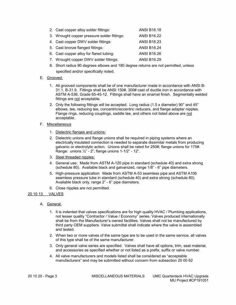
20 10 20 - Page 3 MISCELLANEOUS MATERIALS UMC Quarterdeck HVAC UpgradeMU Project #CP191051
2. Cast copper alloy solder fittings: ANSI B16.18
3. Wrought copper pressure solder fittings: ANSI B16.22
4. Cast copper DWV solder fittings: ANSI B16.23
5. Cast bronze flanged fittings: ANSI B16.24
6. Cast copper alloy for flared tubing: ANSI B16.26
7. Wrought copper DWV solder fittings: ANSI B16.29
8. Short radius 90 degrees elbows and 180 degree returns are not permitted, unless
specified and/or specifically noted.
E. Grooved:
1. All grooved components shall be of one manufacturer made in accordance with ANSI B-31.1, B-31.9. Fittings shall be ANSI 150#, 300# cast of ductile iron in accordance with ASTM A-536, Grade 65-45-12. Fittings shall have an enamel finish. Segmentally welded fittings are not acceptable.
2. Only the following fittings will be accepted: Long radius (1.5 x diameter) 90° and 45° elbows, tee, reducing tee, concentric/eccentric reducers, and flange adapter nipples. Flange rings, reducing couplings, saddle tee, and others not listed above are not acceptable.
F. Miscellaneous
1. Dielectric flanges and unions:
2. Dielectric unions and flange unions shall be required in piping systems where an electrically insulated connection is needed to separate dissimilar metals from producing galvanic or electrolytic action. Unions shall be rated for 250#; flange unions for 175#. Range: unions ½” - 2”; flange unions 1-1/2” - 12”.
3. Steel threaded nipples:
4. General use: Made from ASTM A-120 pipe in standard (schedule 40) and extra strong (schedule 80). Available black and galvanized, range 1/8” - 6” pipe diameters.
5. High-pressure application: Made from ASTM A-53 seamless pipe and ASTM A106 seamless pressure tube in standard (schedule 40) and extra strong (schedule 80). Available black only, range 2” - 6” pipe diameters.
6. Close nipples are not permitted.
20 10 13 VALVES
A. General:
1. It is indented that valves specifications are for high quality HVAC / Plumbing applications, not lesser quality “Contractor / Value / Economy” series. Valves produced internationally shall be from the Manufacturer’s owned facilities. Valves shall not be manufactured by third party OEM suppliers. Valve submittal shall indicate where the valve is assembled and tested.
2. When two or more valves of the same type are to be used in the same service, all valves of this type shall be of the same manufacturer.
3. Only general valve series are specified. Valves shall have all options, trim, seat material, and accessories as specified whether or not listed as a prefix, suffix or valve number.
4. All valve manufacturers and models listed shall be considered as “acceptable manufacturers” and may be submitted without concern from subsection 20 00 62
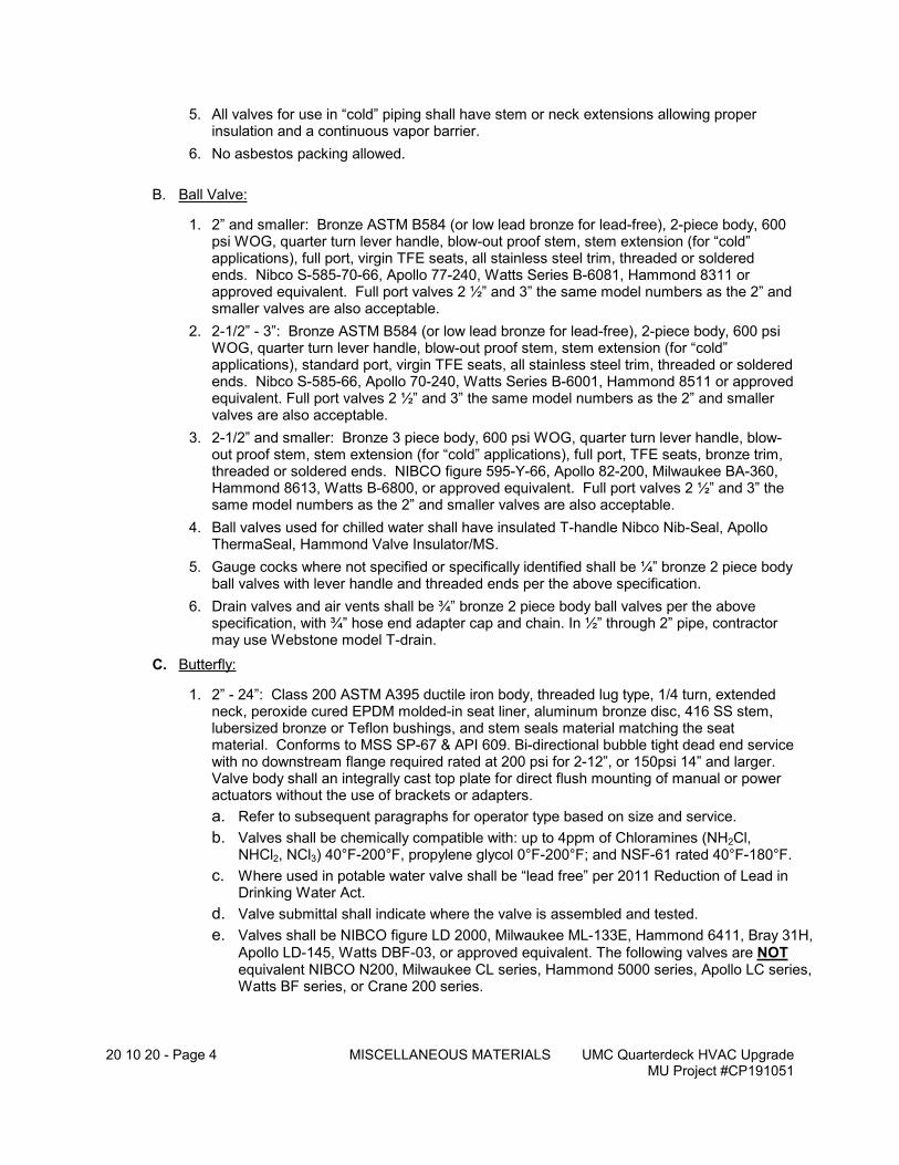
20 10 20 - Page 4 MISCELLANEOUS MATERIALS UMC Quarterdeck HVAC UpgradeMU Project #CP191051
5. All valves for use in “cold” piping shall have stem or neck extensions allowing proper insulation and a continuous vapor barrier.
6. No asbestos packing allowed.
B. Ball Valve:
1. 2” and smaller: Bronze ASTM B584 (or low lead bronze for lead-free), 2-piece body, 600 psi WOG, quarter turn lever handle, blow-out proof stem, stem extension (for “cold” applications), full port, virgin TFE seats, all stainless steel trim, threaded or soldered ends. Nibco S-585-70-66, Apollo 77-240, Watts Series B-6081, Hammond 8311 or approved equivalent. Full port valves 2 ½” and 3” the same model numbers as the 2” and smaller valves are also acceptable.
2. 2-1/2” - 3”: Bronze ASTM B584 (or low lead bronze for lead-free), 2-piece body, 600 psi WOG, quarter turn lever handle, blow-out proof stem, stem extension (for “cold” applications), standard port, virgin TFE seats, all stainless steel trim, threaded or soldered ends. Nibco S-585-66, Apollo 70-240, Watts Series B-6001, Hammond 8511 or approved equivalent. Full port valves 2 ½” and 3” the same model numbers as the 2” and smaller valves are also acceptable.
3. 2-1/2” and smaller: Bronze 3 piece body, 600 psi WOG, quarter turn lever handle, blow-out proof stem, stem extension (for “cold” applications), full port, TFE seats, bronze trim, threaded or soldered ends. NIBCO figure 595-Y-66, Apollo 82-200, Milwaukee BA-360, Hammond 8613, Watts B-6800, or approved equivalent. Full port valves 2 ½” and 3” the same model numbers as the 2” and smaller valves are also acceptable.
4. Ball valves used for chilled water shall have insulated T-handle Nibco Nib-Seal, Apollo ThermaSeal, Hammond Valve Insulator/MS.
5. Gauge cocks where not specified or specifically identified shall be ¼” bronze 2 piece body ball valves with lever handle and threaded ends per the above specification.
6. Drain valves and air vents shall be ¾” bronze 2 piece body ball valves per the above specification, with ¾” hose end adapter cap and chain. In ½” through 2” pipe, contractor may use Webstone model T-drain.
C. Butterfly:
1. 2” - 24”: Class 200 ASTM A395 ductile iron body, threaded lug type, 1/4 turn, extended neck, peroxide cured EPDM molded-in seat liner, aluminum bronze disc, 416 SS stem, lubersized bronze or Teflon bushings, and stem seals material matching the seat material. Conforms to MSS SP-67 & API 609. Bi-directional bubble tight dead end service with no downstream flange required rated at 200 psi for 2-12”, or 150psi 14” and larger. Valve body shall an integrally cast top plate for direct flush mounting of manual or power actuators without the use of brackets or adapters.
a. Refer to subsequent paragraphs for operator type based on size and service.
b. Valves shall be chemically compatible with: up to 4ppm of Chloramines (NH2Cl, NHCl2, NCl3) 40°F-200°F, propylene glycol 0°F-200°F; and NSF-61 rated 40°F-180°F.
c. Where used in potable water valve shall be “lead free” per 2011 Reduction of Lead in Drinking Water Act.
d. Valve submittal shall indicate where the valve is assembled and tested.
e. Valves shall be NIBCO figure LD 2000, Milwaukee ML-133E, Hammond 6411, Bray 31H,
Apollo LD-145, Watts DBF-03, or approved equivalent. The following valves are NOT equivalent NIBCO N200, Milwaukee CL series, Hammond 5000 series, Apollo LC series, Watts BF series, or Crane 200 series.
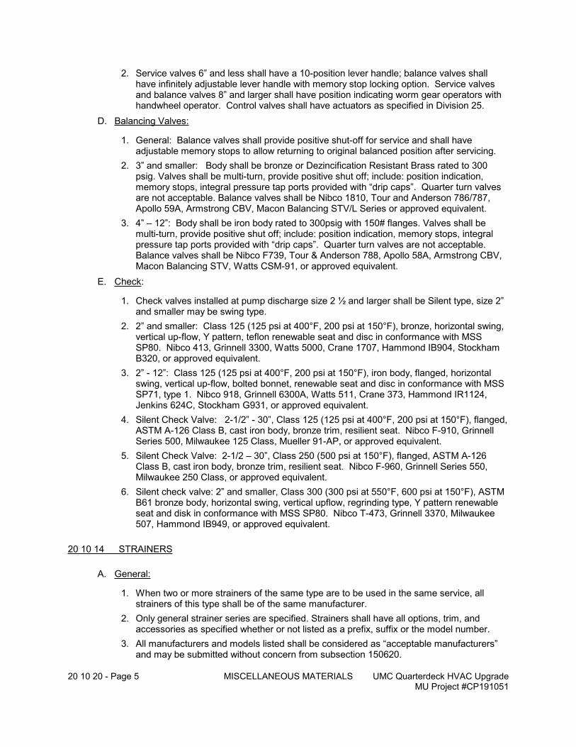
20 10 20 - Page 5 MISCELLANEOUS MATERIALS UMC Quarterdeck HVAC UpgradeMU Project #CP191051
2. Service valves 6” and less shall have a 10-position lever handle; balance valves shall have infinitely adjustable lever handle with memory stop locking option. Service valves and balance valves 8” and larger shall have position indicating worm gear operators with handwheel operator. Control valves shall have actuators as specified in Division 25.
D. Balancing Valves:
1. General: Balance valves shall provide positive shut-off for service and shall have adjustable memory stops to allow returning to original balanced position after servicing.
2. 3” and smaller: Body shall be bronze or Dezincification Resistant Brass rated to 300 psig. Valves shall be multi-turn, provide positive shut off; include: position indication, memory stops, integral pressure tap ports provided with “drip caps”. Quarter turn valves are not acceptable. Balance valves shall be Nibco 1810, Tour and Anderson 786/787, Apollo 59A, Armstrong CBV, Macon Balancing STV/L Series or approved equivalent.
3. 4” – 12”: Body shall be iron body rated to 300psig with 150# flanges. Valves shall be multi-turn, provide positive shut off; include: position indication, memory stops, integral pressure tap ports provided with “drip caps”. Quarter turn valves are not acceptable. Balance valves shall be Nibco F739, Tour & Anderson 788, Apollo 58A, Armstrong CBV, Macon Balancing STV, Watts CSM-91, or approved equivalent.
E. Check:
1. Check valves installed at pump discharge size 2 ½ and larger shall be Silent type, size 2” and smaller may be swing type.
2. 2” and smaller: Class 125 (125 psi at 400°F, 200 psi at 150°F), bronze, horizontal swing, vertical up-flow, Y pattern, teflon renewable seat and disc in conformance with MSS SP80. Nibco 413, Grinnell 3300, Watts 5000, Crane 1707, Hammond IB904, Stockham B320, or approved equivalent.
3. 2” - 12”: Class 125 (125 psi at 400°F, 200 psi at 150°F), iron body, flanged, horizontal swing, vertical up-flow, bolted bonnet, renewable seat and disc in conformance with MSS SP71, type 1. Nibco 918, Grinnell 6300A, Watts 511, Crane 373, Hammond IR1124, Jenkins 624C, Stockham G931, or approved equivalent.
4. Silent Check Valve: 2-1/2” - 30”, Class 125 (125 psi at 400°F, 200 psi at 150°F), flanged, ASTM A-126 Class B, cast iron body, bronze trim, resilient seat. Nibco F-910, Grinnell Series 500, Milwaukee 125 Class, Mueller 91-AP, or approved equivalent.
5. Silent Check Valve: 2-1/2 – 30”, Class 250 (500 psi at 150°F), flanged, ASTM A-126 Class B, cast iron body, bronze trim, resilient seat. Nibco F-960, Grinnell Series 550, Milwaukee 250 Class, or approved equivalent.
6. Silent check valve: 2” and smaller, Class 300 (300 psi at 550°F, 600 psi at 150°F), ASTM B61 bronze body, horizontal swing, vertical upflow, regrinding type, Y pattern renewable seat and disk in conformance with MSS SP80. Nibco T-473, Grinnell 3370, Milwaukee 507, Hammond IB949, or approved equivalent.
20 10 14 STRAINERS
A. General:
1. When two or more strainers of the same type are to be used in the same service, all strainers of this type shall be of the same manufacturer.
2. Only general strainer series are specified. Strainers shall have all options, trim, and accessories as specified whether or not listed as a prefix, suffix or the model number.
3. All manufacturers and models listed shall be considered as “acceptable manufacturers” and may be submitted without concern from subsection 150620.
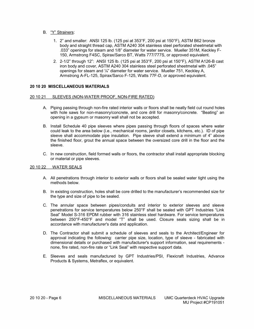
20 10 20 - Page 6 MISCELLANEOUS MATERIALS UMC Quarterdeck HVAC UpgradeMU Project #CP191051
B. “Y” Strainers:
1. 2” and smaller: ANSI 125 lb. (125 psi at 353°F, 200 psi at 150°F), ASTM B62 bronze body and straight thread cap, ASTM A240 304 stainless steel perforated sheetmetal with .033” openings for steam and 1/8” diameter for water service. Mueller 351M, Keckley F-150, Armstrong F4SC, Spirax/Sarco BT, Watts 777/777S, or approved equivalent.
2. 2-1/2” through 12”: ANSI 125 lb. (125 psi at 353°F, 200 psi at 150°F), ASTM A126-B cast iron body and cover, ASTM A240 304 stainless steel perforated sheetmetal with .045” openings for steam and ¼” diameter for water service. Mueller 751, Keckley A, Armstrong A-FL-125, Spirax/Sarco F-125, Watts 77F-D, or approved equivalent.
20 10 20 MISCELLANEOUS MATERIALS
20 10 21 SLEEVES (NON-WATER PROOF, NON-FIRE RATED)
A. Piping passing through non-fire rated interior walls or floors shall be neatly field cut round holes with hole saws for non-masonry/concrete, and core drill for masonry/concrete. “Beating” an opening in a gypsum or masonry wall shall not be accepted.
B. Install Schedule 40 pipe sleeves where pipes passing through floors of spaces where water could leak to the area below (i.e., mechanical rooms, janitor closets, kitchens, etc.). ID of pipe sleeve shall accommodate pipe insulation. Pipe sleeve shall extend a minimum of 4” above the finished floor, grout the annual space between the oversized core drill in the floor and the sleeve.
C. In new construction, field formed walls or floors, the contractor shall install appropriate blocking or material or pipe sleeves.
20 10 22 WATER SEALS
A. All penetrations through interior to exterior walls or floors shall be sealed water tight using the methods below.
B. In existing construction, holes shall be core drilled to the manufacturer’s recommended size for the type and size of pipe to be sealed.
C. The annular space between pipes/conduits and interior to exterior sleeves and sleeve penetrations for service temperatures below 250°F shall be sealed with GPT Industries “Link Seal” Model S-316 EPDM rubber with 316 stainless steel hardware. For service temperatures between 250°F-450°F and model “T” shall be used. Closure seals sizing shall be in accordance with manufacturer's data and application.
D. The Contractor shall submit a schedule of sleeves and seals to the Architect/Engineer for approval indicating the following: carrier pipe size, location, type of sleeve - fabricated with dimensional details or purchased with manufacturer's support information, seal requirements - none, fire rated, non-fire rate or “Link Seal” with respective support data.
E. Sleeves and seals manufactured by GPT Industries/PSI, Flexicraft Industries, Advance Products & Systems, Metraflex, or equivalent.
20 10 20 - Page 7 MISCELLANEOUS MATERIALS UMC Quarterdeck HVAC UpgradeMU Project #CP191051
20 10 23 FIRESTOPS AND SMOKESTOPS, FIRE RATED/SMOKE PARTITIONS.
A. All penetrations through rated assemblies, walls, shafts, floors, roofs, etc., shall be firestopped in accordance with Local Building Codes, NFPA, U.L. Fire Resistant Directory, and manufacturer’s instructions.
B. Provide a FIRESTOP PRODUCT SCHEDULE consisting of the following minimum information:
1. Type – indicate the type of materials, or system.
2. Manufacturer – manufacturer’s name, product name and product number.
3. Mechanical System – indicate which Divisions 20 - 25 items the product is utilized for.
4. Rating – indicate the fire rating and UL detail numbers.
C. Submit the following with the above FIRESTOP PRODUCT SCHEDULE:
1. Manufacturer’s specifications and technical data including installation instructions.
2. Details of each proposed assembly.
3. Manufacturer’s representative who shall provide qualified engineering judgments and drawings for non-standard applications.
4. Contractor’s qualifications and related experience.
D. Materials shall be stored per the manufacturer’s recommendations and as specified for General Project storage in Division 20.
20 10 24 SEALS, NON-FIRE RATED
A. All penetrations through non-rated walls, floors, etc., shall be sealed for draft stopping with caulk, putty, etc., designed for this use.
20 10 25 ESCUTCHEONS
A. Wall, floor, and ceiling plates shall be spun brass, plain pattern, chrome plated, spring type or setscrew fastening. Provide escutcheons for all exposed piping in finished spaces.
20 10 28 ACCESS DOORS
A. Access to mechanical equipment and ductwork of Divisions 20 - 29 required for testing, adjusting, inspection, maintenance or servicing shall be the responsibility of the Contractor. Doors for manufactured equipment shall be an integral feature included with the respective equipment. Access openings in ductwork shall be included with the fabrication in accordance with SMACNA practices.
B. Openings in building components for access to concealed mechanical work shall be furnished by the Contractor and installed with the building construction work. Access doors shall be located as indicated on the Plans or as strategically required for inspection, maintenance, and service. The model and style shall fit the building construction, fire rating requirements and provide adequate size and function.
C. Access doors shall be sized as shown on the drawings or shall be a minimum size of 18” x 18” and otherwise shall be large enough for purpose intended and shall be fabricated of heavy gauge steel frames and door panels with double action concealed spring hinges, 1/4 turn flush
20 10 20 - Page 8 MISCELLANEOUS MATERIALS UMC Quarterdeck HVAC UpgradeMU Project #CP191051
screwdriver operated cam locks and prime coat paint finish. Access doors for various applications shall be as follows:
building construction: Milcor access door:flush door in dry wall construction (walls and ceilings) style DWflush door in masonry or tile walls with exposed frame style M (steel), Style MS flange (stainless)flush door in plaster construction (walls and ceilings) style Krecessed door in acoustical plaster ceiling style APrecessed door in suspended drywall ceiling style CT (aluminum - wet
locations)flush door in suspended drywall ceiling style CF (aluminum - wet
locations)door in suspended drywall ceiling style ATR (fire resistive door)fire rated separation (walls and ceilings) - fire rated door
D. Access doors are not required for Work above lay-in panel ceilings.
E. Submittals shall indicate schedule of locations, sizes, types, adjacent building construction, finish, fire rating including thickness and type of insulation, conformance to UL requirements and associated labeling, metal and gauge of fabrication. Access door shall be as manufactured by Karp Associates, Milcor, or Higgins MfCO.
20 10 29 RESTRICTIONS, GENERAL FOR ALL PIPING SYSTEMS
A. Do not use gaskets or packing containing asbestos.
B. Selections of material and equipment and options for substitution shall conform to the requirements of Sub-section 20 00 60, MATERIAL and EQUIPMENT.
C. “Bull head” tee connections are not permitted, unless approved by the Engineer.
D. Close nipples and bushing reducers are not permitted.
E. Mitered elbows are not permitted in welded pipe construction.
F. Solder for use in joints of copper piping for domestic (sanitary) cold water, hot water, hot water recirculating and softened water shall not contain lead.
G. Black and galvanized pipe, fittings, nipples and specialties are not permitted in water piping systems where copper and/or brass are the basic materials.
H. Short radius 90-degree elbows and 180-degree returns are not permitted, unless specified and/or specifically noted.
I. The use of pipe hooks, chain and perforated band iron are not permitted for hanging or supporting piping.
J. Power driven inserts and attachments are not permitted unless approved by the Archi-tect/Engineer on express request by the Contractor.
K. Welded attachments to the structural steel of the building are not permitted unless otherwise noted or approved by the Architect/Engineer on specific request of the Contractor.
20 10 50 - Page 1 BASIC MECHANICAL METHODS - GENERAL
UMC Quarterdeck HVAC UpgradeMU Project #CP191051
20 10 30 JOINTS AND CONNECTION METHODS
20 10 31 THREADED
A. Threads for all screwed pipe systems shall be American National Standard taper threads in accordance with ANSI B-1.201.
B. Threads shall be full, sharp, clean and free of fins and burrs. Pipe ends shall be reamed to remove internal burrs.
C. Threaded connections shall be joined using teflon sealing tape applied to the male threads only.
D. D. This sub-section does not apply to threads for compression, flare and sanitary drainage slip type drainage fittings.
20 10 32 WELDED
A. Welded joints shall be “V” type butt welds in accordance with ANSI B31.1.
B. The Contractor shall only use welders regularly engaged in the piping trades and certified by the National Certified Welding Bureau, using procedures set forth in ASME Boiler Construction Code, Section IX, “Welding Qualifications”.
C. Contractor shall keep a copy of welder's certification on file at Contractor's office. Upon request the Architect/Engineer may request Contractor to produce certifications. Any pipe installed by a non-certified welder shall be removed if requested by Architect/Engineer.
D. All steel piping shall be cleaned of mill scale and rust before assembly. Welds shall be chipped and hammered after each pass and joints shall be built up to at least the same thickness as that of the pipe wall. All welding shall be done in accordance with the welding procedures of the National Certified Pipe Welding Bureau conforming to the requirements of the ASA Code for Pressure Piping.
E. Architect/Engineer shall have the authority to accept or reject the welds and require random samples of installed welds to be removed, tested and inspected.
20 10 33 GROOVED
A. Grooved joints for grooved couplings and fittings shall be in accordance with accepted manufacturer's specifications and practices.
B. Grooves may be cut or rolled in accordance with manufacturer's recommendations for type of pipe, sizes and thicknesses specified for respective systems.
C. Gaskets shall be suitable for the temperature, pressure and compatibility with the fluid contained therein. Unless specifically specified otherwise or incompatibility with the system, gaskets shall be EPDM grade E.
D. Grooved couplings shall be ASTM-A47 grooved malleable iron clamp type couplings as manufactured by Victaulic or equivalent.
20 10 50 - Page 2 BASIC MECHANICAL METHODS - GENERAL
UMC Quarterdeck HVAC UpgradeMU Project #CP191051
E. Grooved couplings for vibration isolation or as unions at equipment connections shall be similar to Victaulic Style 77; all others shall be similar to Victaulic Style 07.
20 10 34 SOLDERED AND BRAZED
A. Soldered and brazed connections shall be made in accordance with recommendations of the current edition of the Copper Tube Handbook of the Copper Development Association or as hereinafter specified.
B. General criteria for soldered and brazed joints shall be as follows:
1. Copper tubing shall be square-end cut by varied methods at the Contractor's option. The ends of the tubing shall be reamed to remove both internal and external burrs.
2. Joints for copper piping for hydronic systems, domestic water, temperature controls, DWV systems and other applications of fluids below 250 degrees F. shall be soldered with 95-5 Tin Antimony. 50-50 Tin Lead solder shall not be used.
3. Joints in copper piping for refrigerant lines and other applications operating above 250 degrees F., or where otherwise specified shall be brazed with Copper Phosphorus (BCuP Series), Silver solder (BAg Series), or other approved high temperature brazing alloy.
4. Cleaning of tubing and fittings, application of flux and heat, purging and cooling shall be in accordance with recommendations of solder and brazing alloy manufacturers for the joint type and material specified in the respective “PIPING MATERIAL SCHEDULE” in Section 155000.
20 10 35 FLANGED
A. Flanges shall be flat faced or raised faced as required for mating flanges of valves, specialties, equipment connections, etc.
B. Carbon steel hex head machine bolts, ASTM A307, grade 2, with heavy hex nuts shall be used for joining 125 and 150# flanged joints, unless otherwise specified.
C. Alloy steel machine bolts, studs and heavy hex nuts shall be used for joining of 250 and 300# flanged joints, unless otherwise specified.
D. Lubricate the threads of bolts and studs with an acceptable commercial product. Include data with submittal for approval for piping material.
E. Gaskets shall be 1/16” thick non-metallic type conforming to ANSI B16.21 and shall be suitable for the pressure and temperature of the fluid contained therein, shall be provided at all flange joints. Full-faced gaskets shall be used for flat face flanges; ring gaskets shall be used for raised face flanges.
20 10 36 CAST IRON PIPE AND FITTINGS
F. Joints for hub and spigot and no-hub cast iron soil pipe and fittings shall be installed in accordance with recommendations of the CISPI, unless noted otherwise.
G. Do not use joint material which has deteriorated or which does not spread easily or smoothly.
H. No-hub couplings shall be NSF Listed and conform to the requirements of CISPI 310, ASTM C1277, FM1680, IAPMO 35-89 and gaskets shall comply with ASTM C564.
1. Band, screw housing, screw, and shield shall all be stainless steel.
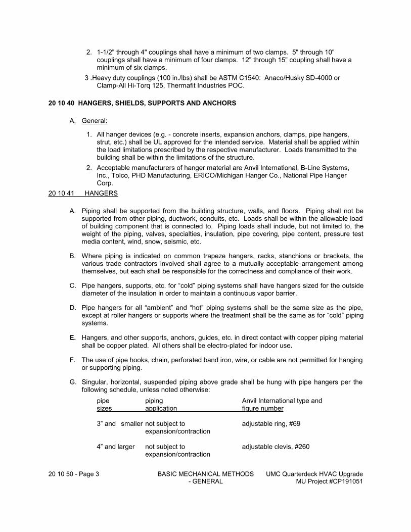
20 10 50 - Page 3 BASIC MECHANICAL METHODS - GENERAL
UMC Quarterdeck HVAC UpgradeMU Project #CP191051
2. 1-1/2" through 4" couplings shall have a minimum of two clamps. 5" through 10" couplings shall have a minimum of four clamps. 12" through 15" coupling shall have a minimum of six clamps.
3 .Heavy duty couplings (100 in./lbs) shall be ASTM C1540: Anaco/Husky SD-4000 or Clamp-All Hi-Torq 125, Thermafit Industries POC.
20 10 40 HANGERS, SHIELDS, SUPPORTS AND ANCHORS
A. General:
1. All hanger devices (e.g. - concrete inserts, expansion anchors, clamps, pipe hangers, strut, etc.) shall be UL approved for the intended service. Material shall be applied within the load limitations prescribed by the respective manufacturer. Loads transmitted to the building shall be within the limitations of the structure.
2. Acceptable manufacturers of hanger material are Anvil International, B-Line Systems, Inc., Tolco, PHD Manufacturing, ERICO/Michigan Hanger Co., National Pipe Hanger Corp.
20 10 41 HANGERS
A. Piping shall be supported from the building structure, walls, and floors. Piping shall not be supported from other piping, ductwork, conduits, etc. Loads shall be within the allowable load of building component that is connected to. Piping loads shall include, but not limited to, the weight of the piping, valves, specialties, insulation, pipe covering, pipe content, pressure test media content, wind, snow, seismic, etc.
B. Where piping is indicated on common trapeze hangers, racks, stanchions or brackets, the various trade contractors involved shall agree to a mutually acceptable arrangement among themselves, but each shall be responsible for the correctness and compliance of their work.
C. Pipe hangers, supports, etc. for “cold” piping systems shall have hangers sized for the outside diameter of the insulation in order to maintain a continuous vapor barrier.
D. Pipe hangers for all “ambient” and “hot” piping systems shall be the same size as the pipe, except at roller hangers or supports where the treatment shall be the same as for “cold” piping systems.
E. Hangers, and other supports, anchors, guides, etc. in direct contact with copper piping material
shall be copper plated. All others shall be electro-plated for indoor use.
F. The use of pipe hooks, chain, perforated band iron, wire, or cable are not permitted for hanging or supporting piping.
G. Singular, horizontal, suspended piping above grade shall be hung with pipe hangers per the following schedule, unless noted otherwise:
pipe piping Anvil International type andsizes application figure number
3” and smaller not subject to adjustable ring, #69expansion/contraction
4” and larger not subject to adjustable clevis, #260expansion/contraction
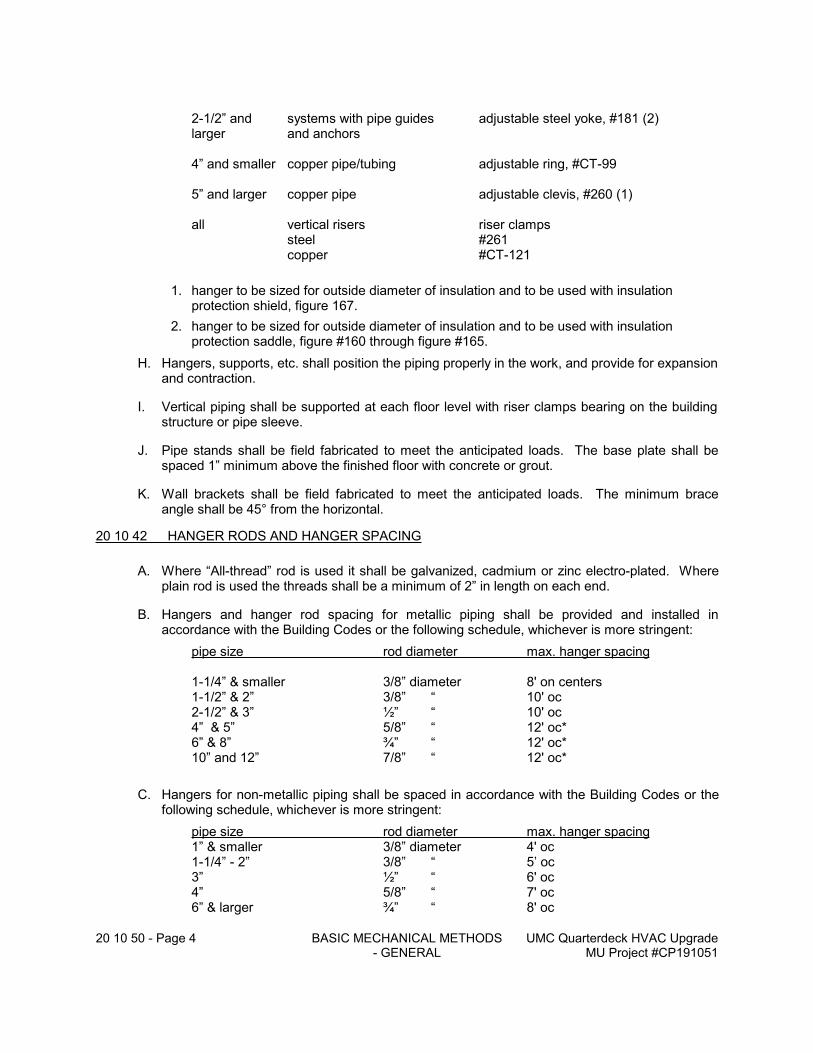
20 10 50 - Page 4 BASIC MECHANICAL METHODS - GENERAL
UMC Quarterdeck HVAC UpgradeMU Project #CP191051
2-1/2” and systems with pipe guides adjustable steel yoke, #181 (2)larger and anchors
4” and smaller copper pipe/tubing adjustable ring, #CT-99
5” and larger copper pipe adjustable clevis, #260 (1)
all vertical risers riser clampssteel #261copper #CT-121
1. hanger to be sized for outside diameter of insulation and to be used with insulation protection shield, figure 167.
2. hanger to be sized for outside diameter of insulation and to be used with insulation protection saddle, figure #160 through figure #165.
H. Hangers, supports, etc. shall position the piping properly in the work, and provide for expansion and contraction.
I. Vertical piping shall be supported at each floor level with riser clamps bearing on the building structure or pipe sleeve.
J. Pipe stands shall be field fabricated to meet the anticipated loads. The base plate shall be spaced 1” minimum above the finished floor with concrete or grout.
K. Wall brackets shall be field fabricated to meet the anticipated loads. The minimum brace angle shall be 45° from the horizontal.
20 10 42 HANGER RODS AND HANGER SPACING
A. Where “All-thread” rod is used it shall be galvanized, cadmium or zinc electro-plated. Where plain rod is used the threads shall be a minimum of 2” in length on each end.
B. Hangers and hanger rod spacing for metallic piping shall be provided and installed in accordance with the Building Codes or the following schedule, whichever is more stringent:
pipe size rod diameter max. hanger spacing
1-1/4” & smaller 3/8” diameter 8' on centers1-1/2” & 2” 3/8” “ 10' oc2-1/2” & 3” ½” “ 10' oc4” & 5” 5/8” “ 12' oc*6” & 8” ¾” “ 12' oc*10” and 12” 7/8” “ 12' oc*
C. Hangers for non-metallic piping shall be spaced in accordance with the Building Codes or the following schedule, whichever is more stringent:
pipe size rod diameter max. hanger spacing1” & smaller 3/8” diameter 4' oc1-1/4” - 2” 3/8” “ 5’ oc3” ½” “ 6' oc4” 5/8” “ 7' oc6” & larger ¾” “ 8' oc
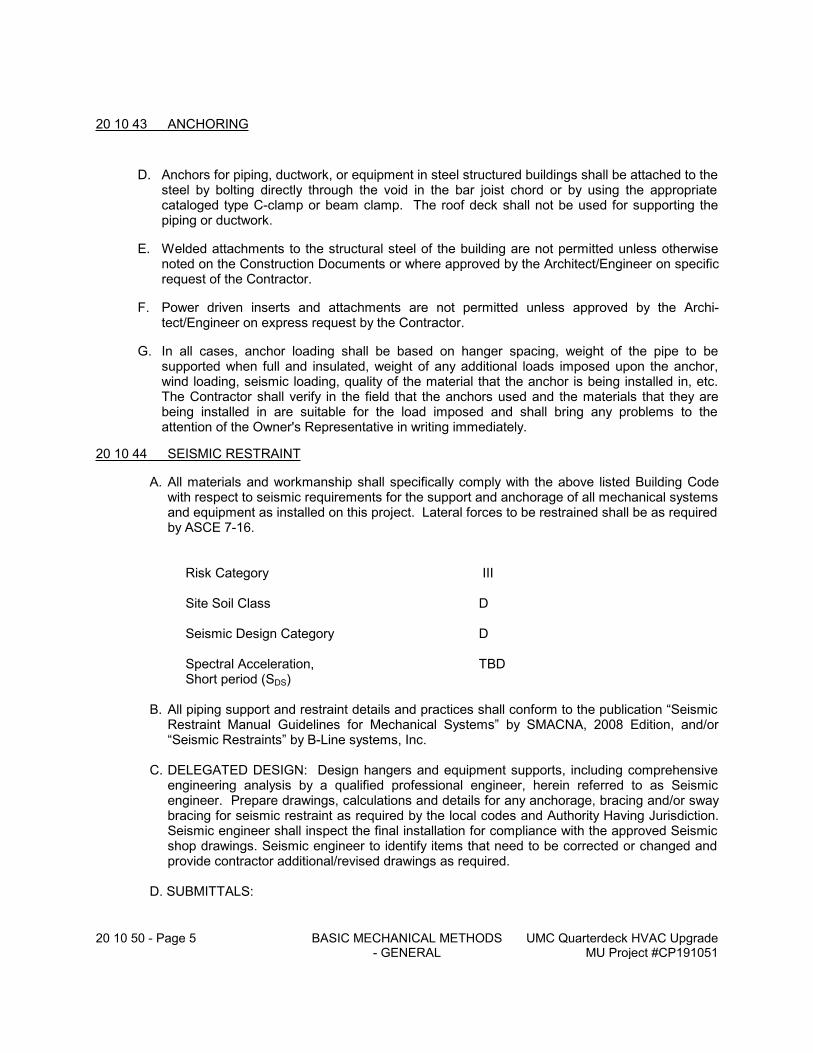
20 10 50 - Page 5 BASIC MECHANICAL METHODS - GENERAL
UMC Quarterdeck HVAC UpgradeMU Project #CP191051
20 10 43 ANCHORING
D. Anchors for piping, ductwork, or equipment in steel structured buildings shall be attached to the steel by bolting directly through the void in the bar joist chord or by using the appropriate cataloged type C-clamp or beam clamp. The roof deck shall not be used for supporting the piping or ductwork.
E. Welded attachments to the structural steel of the building are not permitted unless otherwise noted on the Construction Documents or where approved by the Architect/Engineer on specific request of the Contractor.
F. Power driven inserts and attachments are not permitted unless approved by the Archi-tect/Engineer on express request by the Contractor.
G. In all cases, anchor loading shall be based on hanger spacing, weight of the pipe to be supported when full and insulated, weight of any additional loads imposed upon the anchor, wind loading, seismic loading, quality of the material that the anchor is being installed in, etc. The Contractor shall verify in the field that the anchors used and the materials that they are being installed in are suitable for the load imposed and shall bring any problems to the attention of the Owner's Representative in writing immediately.
20 10 44 SEISMIC RESTRAINT
A. All materials and workmanship shall specifically comply with the above listed Building Code with respect to seismic requirements for the support and anchorage of all mechanical systems and equipment as installed on this project. Lateral forces to be restrained shall be as required by ASCE 7-16.
Risk Category III
Site Soil Class D
Seismic Design Category D
Spectral Acceleration, TBDShort period (SDS)
B. All piping support and restraint details and practices shall conform to the publication “Seismic Restraint Manual Guidelines for Mechanical Systems” by SMACNA, 2008 Edition, and/or “Seismic Restraints” by B-Line systems, Inc.
C. DELEGATED DESIGN: Design hangers and equipment supports, including comprehensive engineering analysis by a qualified professional engineer, herein referred to as Seismic engineer. Prepare drawings, calculations and details for any anchorage, bracing and/or sway bracing for seismic restraint as required by the local codes and Authority Having Jurisdiction. Seismic engineer shall inspect the final installation for compliance with the approved Seismic shop drawings. Seismic engineer to identify items that need to be corrected or changed and provide contractor additional/revised drawings as required.
D. SUBMITTALS:
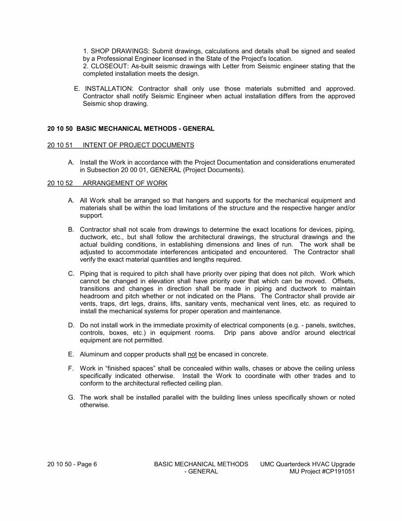
20 10 50 - Page 6 BASIC MECHANICAL METHODS - GENERAL
UMC Quarterdeck HVAC UpgradeMU Project #CP191051
1. SHOP DRAWINGS: Submit drawings, calculations and details shall be signed and sealed by a Professional Engineer licensed in the State of the Project's location.
2. CLOSEOUT: As-built seismic drawings with Letter from Seismic engineer stating that the completed installation meets the design.
E. INSTALLATION: Contractor shall only use those materials submitted and approved. Contractor shall notify Seismic Engineer when actual installation differs from the approved Seismic shop drawing.
20 10 50 BASIC MECHANICAL METHODS - GENERAL
20 10 51 INTENT OF PROJECT DOCUMENTS
A. Install the Work in accordance with the Project Documentation and considerations enumerated in Subsection 20 00 01, GENERAL (Project Documents).
20 10 52 ARRANGEMENT OF WORK
A. All Work shall be arranged so that hangers and supports for the mechanical equipment and materials shall be within the load limitations of the structure and the respective hanger and/or support.
B. Contractor shall not scale from drawings to determine the exact locations for devices, piping, ductwork, etc., but shall follow the architectural drawings, the structural drawings and the actual building conditions, in establishing dimensions and lines of run. The work shall be adjusted to accommodate interferences anticipated and encountered. The Contractor shall verify the exact material quantities and lengths required.
C. Piping that is required to pitch shall have priority over piping that does not pitch. Work which cannot be changed in elevation shall have priority over that which can be moved. Offsets, transitions and changes in direction shall be made in piping and ductwork to maintain headroom and pitch whether or not indicated on the Plans. The Contractor shall provide air vents, traps, dirt legs, drains, lifts, sanitary vents, mechanical vent lines, etc. as required to install the mechanical systems for proper operation and maintenance.
D. Do not install work in the immediate proximity of electrical components (e.g. - panels, switches, controls, boxes, etc.) in equipment rooms. Drip pans above and/or around electrical equipment are not permitted.
E. Aluminum and copper products shall not be encased in concrete.
F. Work in “finished spaces” shall be concealed within walls, chases or above the ceiling unless specifically indicated otherwise. Install the Work to coordinate with other trades and to conform to the architectural reflected ceiling plan.
G. The work shall be installed parallel with the building lines unless specifically shown or noted otherwise.
20 10 50 - Page 7 BASIC MECHANICAL METHODS - GENERAL
UMC Quarterdeck HVAC UpgradeMU Project #CP191051
20 10 53 COORDINATION
A. Each Contractor shall prepare and submit coordination drawings (at a scale equal to or larger than the project documents) to the Architect/Engineer for review prior to any fabrication or installation.
B. It shall be the Contractor's responsibility to coordinate their work with the work of other trades, and with the architectural and structural drawings. Where physical interferences cannot be resolved between the trades, or when encountered in the field, the Contractor shall prepare composite drawings at a scale of not less than 3/8” = 1'-0” clearly showing the Work of Divisions 20 - 29 in relation to the Work of others to identify the conflict. Submit a proposed resolution to the Architect/Engineer for approval in accordance with Sub-sections 20 00 01, GENERAL (Project Documents) and 20 10 06, SUBMITTALS.
1. Do not proceed with Work in question until the matter is mutually resolved among the involved parties, and adequate information has been submitted to the Architect/Engineer for review. No additional compensation shall be granted for modifications and execution of the resolution(s). Modifications are to be incorporated in the “as-built” drawings.
C. Contractor shall review the Project Documents, site conditions, and the requirements of other disciplines, and shall report any discrepancies between them to the Architect/Engineer and obtain from him written permission for changes necessary in the Mechanical Work. Subsequent clarification(s) by the Architect/Engineer will not be a change in scope of the Work. The Contractor at no addition in the contract price shall perform any such modifications required.
D. Contractor shall verify tie-in locations to verify sizes, direction of flow (via pressure or physical tracing, not labels), materials, elevations, etc. prior to commencing new work. Contractor shall notify Architect/Engineer upon discovery of discrepancy. Work performed prior to verification will be corrected at no cost to Owner.
E. The drawings shall not be scaled; obtain detailed information, shop drawings, installation and maintenance bulletins, etc. to determine exact requirements and to satisfactorily achieve the intent of the Project Documents.
F. The Contractor shall furnish and properly install all sleeves, slots, chases, openings, recesses, supports, anchors and anchor bolts required for his Work in coordination with the other trades as the building is erected.
G. The expenses for changes required by neglect in executing, coordinating or scheduling the Work properly or avoiding conflicts shall be borne by the Contractor precipitating the issue requiring the changes.
20 10 54 DELIVERY, STORAGE AND HANDLING
A. Delivery, storage and handling of equipment and material are the Contractor's responsibilities. The Contractor shall perform the Work in accordance with the following criteria:
1. Delivery shall be arranged by the Contractor (including Owner furnished items) for the expeditious and economical pursuit of the Work and to meet the scheduling requirements of the Contract.
2. The Contractor will be assigned a “lay-down” area at the job site and shall confine temporary storage to this area.
20 10 50 - Page 8 BASIC MECHANICAL METHODS - GENERAL
UMC Quarterdeck HVAC UpgradeMU Project #CP191051
3. The Contractor may take delivery of equipment and material at his “shop” or an off-site location as suits the performance and schedule of the Work.
4. Regardless of where and how equipment and material are temporarily stored prior to installation, or if installed at the job site prior to acceptance, the Contractor is responsible for the following:
a. All equipment and material shall be accessible to the Architect/Engineer for inspection.
b. All equipment and material shall be protected adequately and properly from the weather, dirt and water, chemical, mechanical or comprehensive damages.
c. The Contractor shall be liable for the repair and/or replacement (including labor) of any equipment and material lost, damaged or defective prior to acceptance.
5. The Contractor shall arrange all labor, tools, services and scheduling to perform the handling of equipment and material for his Work.
20 10 55 GENERAL CLEANING
A. Each Contractor and Subcontractor shall be responsible for progress and final clean-up of his respective Work in accordance with the Contract Documents, requisite ordinances and regulations. Clean-up and legal disposal of debris from the Work, excess refuse and presence at the job site shall be performed in a timely and satisfactory manner. If not, the Contractor shall be notified of the unsatisfactory condition. If the matter persists, the Contractor will be back charged for the clean-up performed by others.
B. Clean exposed exteriors and limited access interior surfaces of all equipment, piping and ductwork of foreign matter to provide an “as new” condition.
20 10 56 CLEANING OF PIPING SYSTEMS
A. The Contractor shall clean the respective piping system(s) that are included in his scope of work. All systems shall be flushed with water or air (depending on ultimate use) to relieve any congestion and internally cleanse the respective piping system. The Contractor shall provide all flushing media in sufficient quantity, inlet connections, discharge or drainage outlets and any temporary provisions to protect components, or remove it, to facilitate the flushing. Clean and replace all strainer screens and filters. Flush clean and drain all low points in the piping.
B. Owner’s representative shall be present for flushing, cleaning, and rinsing. Water treatment representative must check water after rinsing to insure all chemical cleaner has been removed and the Alkalinity of the rinse water is equal to that of the make-up water.
C. All pipe systems for hydronic applications shall be flushed continuously with 100% city water make-up until the water runs clean from all drain locations. Each piping system shall be subsequently cleaned with recommended dosage of an approved pre-cleaning chemical designed to remove deposition such as pipe dope, oils, loose rust, mill scale and other extraneous materials for a minimum period of twenty-four (24) hours then drained, refilled, and rinsed clean. Flushing before and rinsing after cleaning shall be supplying constant make-up water while draining at all system low points and drains.
D. Condenser/tower water piping shall be flushed continuously with a surfactant cleaning chemical designed to remove deposition such as pipe dope and oils. This chemical shall not be alkaline or aggressive to the system metallurgy. Recommended dosages of a surfactant chemical product shall be added and circulated throughout the water system for a minimum period of twenty-four (24) hours then drained, refilled and rinsed clean.
20 10 50 - Page 9 BASIC MECHANICAL METHODS - GENERAL
UMC Quarterdeck HVAC UpgradeMU Project #CP191051
20 10 57 PRESSURE TESTING
A. The Contractor shall submit a schedule at the beginning of the Work of the piping systems that are to be pressure tested, and indicate whether tests will be for an entire or partial system. Entire piping systems shall be pressure tested at one time unless it is not possible or practical.
B. All piping to be insulated or concealed shall be pressure tested prior to the application of the insulation or concealment.
C. A representative of the Architect/Engineer shall witness all pressure testing. The Contractor shall notify the Architect/Engineer at least three (3) days prior to the test date.
D. Each piping system shall be tested per the method, test pressure, and test duration as specified in the Piping Material Schedules.
E. The Contractor shall provide all test media, measuring devices, inlet connections, test measurement connections, and disposal of test media. The Contractor shall protect, isolate and/or remove piping system components that can not be subjected to test pressures.
F. Hammer each joint in welded or soldered piping while under test. Leaks shall be repaired and the test(s) repeated until the respective piping system is tight.
20 10 58 LEAK TESTING OF REFRIGERANT PIPING
A. After the refrigerant piping connections have all been made, the entire refrigerant system shall be put under pressure and tested for leaks using dry nitrogen to develop the test pressure and the refrigerant charge as the tracer gas for leak testing.
B. A pressure regulator and a relief valve set at the test pressure (see Pipe Material Schedules) shall be used in the nitrogen test hookup.
C. The nitrogen shall be admitted to the system through the gage port on one of the refrigerant valves. All valves in the system shall be back seated so that holding charge refrigerant gas and nitrogen can diffuse throughout the piping.
D. If any leaks are discovered, the joint shall be broken and re-soldered. If possible, the section of piping containing the leaking joint should be isolated from the rest of the system. Dry nitrogen shall be passed through the joint being remade to prevent the formation of copper oxide.
1. Occasionally, a joint may be suspected of leaking, but the leak is so small that it is difficult to get a positive indication with the halide detector. When this happens, completely enclose the joint with a small plastic bag. Tape the open ends of the bag securely to the piping to insure a gas tight seal. Leave the bag in place for several hours.
2. To test a leak, make a small hole in the bag at the lowest point and insert the exploring tube of your halide detector. Make another hole at the top of the bag to admit air. If the joint does have a slow leak, enough refrigerant gas will collect in the bag to give a positive indication.
20 10 59 CHARGING REFRIGERATION SYSTEMS
A. Evacuation and Dehydration. The Contractor shall evacuate and dehydrate the refrigerant system to remove any air and moisture from the system. The manufacturer's literature shall be referred to for the evacuation procedure for each system installed.
20 10 50 - Page 10 BASIC MECHANICAL METHODS - GENERAL
UMC Quarterdeck HVAC UpgradeMU Project #CP191051
1. A vacuum pump capable of producing a vacuum of 1-mm Hg absolute is necessary for field evacuating. A single-stage pump having a free air displacement of 100 liters, or about 3 cubic feet/minute, is suitable. An accurate manometer type high vacuum gage, such as a Stokes or a Zimmerli gage, is also necessary.
2. The vacuum pump shall be connected to the gage port of the suction line shutoff valve, so that moisture in the new refrigerant lines will not be drawn through the compressor when the system is evacuated. The vacuum gage shall be connected to the gage port of the liquid line shutoff valve. The pump shall be operated until the gage indicated a vacuum of 2.5 mm Hg or less.
3. When the vacuum is sufficient, the refrigerant valves shall be back seated while the vacuum pump is running. The pump is then stopped. The system shall be allowed to stand under vacuum for at least 12 hours to allow all moisture to vaporize and to see if there is any in-leakage of air.
4. After 12 hours, the Contractor shall break the vacuum with oil-pumped dry nitrogen or gaseous refrigerant and re-evacuate the system to 2.5 mm HG to further reduce the residual air and moisture to prevent compressor damage.
5. The system can now be charged if the pressure has not risen noticeably.
B. Charging. The Contractor shall determine the weight of a full charge of refrigerant and oil for the equipment plus refrigerant charge based on the length of refrigerant piping and in accordance with the unit manufacturer's literature.
The following charging procedure shall be used:
1. The Contractor shall follow the manufacturer’s installation instructions and/or industry standards in charging and start-up of equipment.
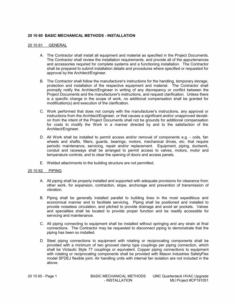
20 10 60 - Page 1 BASIC MECHANICAL METHODS - INSTALLATION
UMC Quarterdeck HVAC UpgradeMU Project #CP191051
20 10 60 BASIC MECHANICAL METHODS - INSTALLATION
20 10 61 GENERAL
A. The Contractor shall install all equipment and material as specified in the Project Documents. The Contractor shall review the installation requirements, and provide all of the appurtenances and accessories required for complete systems and a functioning installation. The Contractor shall be prepared to submit installation details and procedures where specified or requested for approval by the Architect/Engineer.
B. The Contractor shall follow the manufacturer's instructions for the handling, temporary storage, protection and installation of the respective equipment and material. The Contractor shall promptly notify the Architect/Engineer in writing of any discrepancy or conflict between the Project Documents and the manufacturer's instructions, and request clarification. Unless there is a specific change in the scope of work, no additional compensation shall be granted for modification(s) and execution of the clarification.
C. Work performed that does not comply with the manufacturer's instructions, any approval or instructions from the Architect/Engineer, or that causes a significant and/or unapproved deviati-on from the intent of the Project Documents shall not be grounds for additional compensation for costs to modify the Work in a manner directed by and to the satisfaction of the Architect/Engineer.
D. All Work shall be installed to permit access and/or removal of components e.g. - coils, fan wheels and shafts, filters, guards, bearings, motors, mechanical drives, etc. that require periodic maintenance, servicing, repair and/or replacement. Equipment, piping, ductwork, conduit and raceways shall be arranged to permit access to valves, motors, motor and temperature controls, and to clear the opening of doors and access panels.
E. Welded attachments to the building structure are not permitted.
20 10 62 PIPING
A. All piping shall be properly installed and supported with adequate provisions for clearance from other work, for expansion, contraction, slope, anchorage and prevention of transmission of vibration.
B. Piping shall be generally installed parallel to building lines in the most expeditious and economical manner and to facilitate servicing. Piping shall be positioned and installed to provide noiseless circulation, and pitched to provide drainage and avoid air pockets. Valves and specialties shall be located to provide proper function and be readily accessible for servicing and maintenance.
C. All piping connecting to equipment shall be installed without springing and any strain at final connections. The Contractor may be requested to disconnect piping to demonstrate that the piping has been so installed.
D. Steel piping connections to equipment with rotating or reciprocating components shall be provided with a minimum of two grooved clamp type couplings per piping connection, which shall be Victaulic Style 77 couplings or equivalent. Copper piping connections to equipment with rotating or reciprocating components shall be provided with Mason Industries SafetyFlex model SFDEJ flexible joint. Air handling units with internal fan isolation are not included in the above.
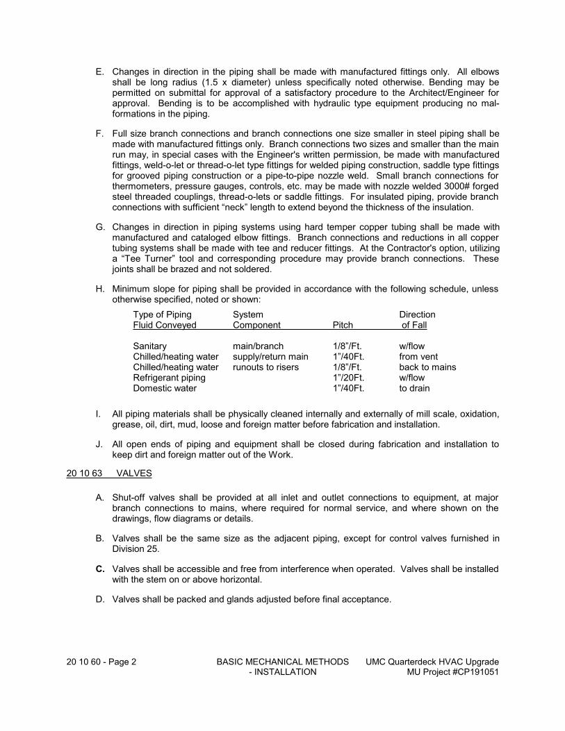
20 10 60 - Page 2 BASIC MECHANICAL METHODS - INSTALLATION
UMC Quarterdeck HVAC UpgradeMU Project #CP191051
E. Changes in direction in the piping shall be made with manufactured fittings only. All elbows shall be long radius (1.5 x diameter) unless specifically noted otherwise. Bending may be permitted on submittal for approval of a satisfactory procedure to the Architect/Engineer for approval. Bending is to be accomplished with hydraulic type equipment producing no mal-formations in the piping.
F. Full size branch connections and branch connections one size smaller in steel piping shall be made with manufactured fittings only. Branch connections two sizes and smaller than the main run may, in special cases with the Engineer's written permission, be made with manufactured fittings, weld-o-let or thread-o-let type fittings for welded piping construction, saddle type fittings for grooved piping construction or a pipe-to-pipe nozzle weld. Small branch connections for thermometers, pressure gauges, controls, etc. may be made with nozzle welded 3000# forged steel threaded couplings, thread-o-lets or saddle fittings. For insulated piping, provide branch connections with sufficient “neck” length to extend beyond the thickness of the insulation.
G. Changes in direction in piping systems using hard temper copper tubing shall be made with manufactured and cataloged elbow fittings. Branch connections and reductions in all copper tubing systems shall be made with tee and reducer fittings. At the Contractor's option, utilizing a “Tee Turner” tool and corresponding procedure may provide branch connections. These joints shall be brazed and not soldered.
H. Minimum slope for piping shall be provided in accordance with the following schedule, unless otherwise specified, noted or shown:
Type of Piping System DirectionFluid Conveyed Component Pitch of Fall
Sanitary main/branch 1/8”/Ft. w/flowChilled/heating water supply/return main 1”/40Ft. from ventChilled/heating water runouts to risers 1/8”/Ft. back to mainsRefrigerant piping 1”/20Ft. w/flowDomestic water 1”/40Ft. to drain
I. All piping materials shall be physically cleaned internally and externally of mill scale, oxidation, grease, oil, dirt, mud, loose and foreign matter before fabrication and installation.
J. All open ends of piping and equipment shall be closed during fabrication and installation to keep dirt and foreign matter out of the Work.
20 10 63 VALVES
A. Shut-off valves shall be provided at all inlet and outlet connections to equipment, at major branch connections to mains, where required for normal service, and where shown on the drawings, flow diagrams or details.
B. Valves shall be the same size as the adjacent piping, except for control valves furnished in Division 25.
C. Valves shall be accessible and free from interference when operated. Valves shall be installed with the stem on or above horizontal.
D. Valves shall be packed and glands adjusted before final acceptance.
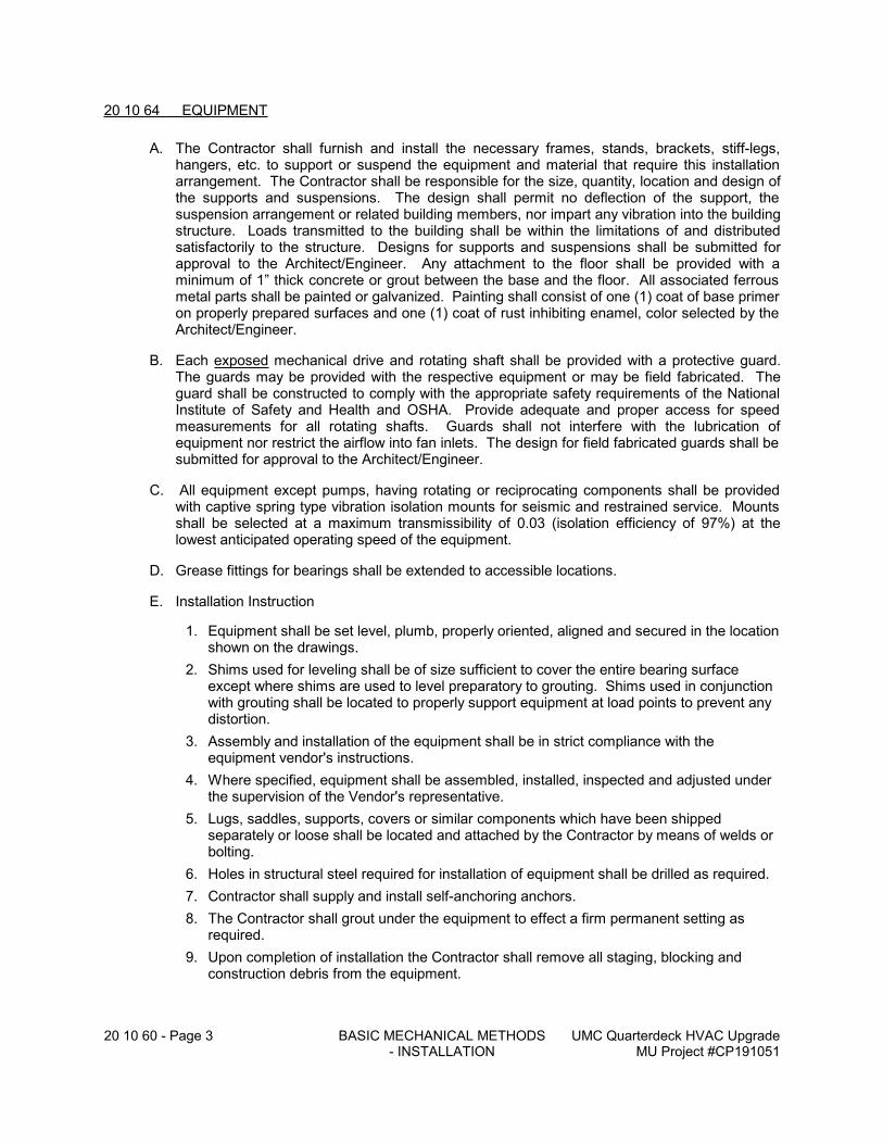
20 10 60 - Page 3 BASIC MECHANICAL METHODS - INSTALLATION
UMC Quarterdeck HVAC UpgradeMU Project #CP191051
20 10 64 EQUIPMENT
A. The Contractor shall furnish and install the necessary frames, stands, brackets, stiff-legs, hangers, etc. to support or suspend the equipment and material that require this installation arrangement. The Contractor shall be responsible for the size, quantity, location and design of the supports and suspensions. The design shall permit no deflection of the support, the suspension arrangement or related building members, nor impart any vibration into the building structure. Loads transmitted to the building shall be within the limitations of and distributed satisfactorily to the structure. Designs for supports and suspensions shall be submitted for approval to the Architect/Engineer. Any attachment to the floor shall be provided with a minimum of 1” thick concrete or grout between the base and the floor. All associated ferrous metal parts shall be painted or galvanized. Painting shall consist of one (1) coat of base primer on properly prepared surfaces and one (1) coat of rust inhibiting enamel, color selected by the Architect/Engineer.
B. Each exposed mechanical drive and rotating shaft shall be provided with a protective guard. The guards may be provided with the respective equipment or may be field fabricated. The guard shall be constructed to comply with the appropriate safety requirements of the National Institute of Safety and Health and OSHA. Provide adequate and proper access for speed measurements for all rotating shafts. Guards shall not interfere with the lubrication of equipment nor restrict the airflow into fan inlets. The design for field fabricated guards shall be submitted for approval to the Architect/Engineer.
C. All equipment except pumps, having rotating or reciprocating components shall be provided with captive spring type vibration isolation mounts for seismic and restrained service. Mounts shall be selected at a maximum transmissibility of 0.03 (isolation efficiency of 97%) at the lowest anticipated operating speed of the equipment.
D. Grease fittings for bearings shall be extended to accessible locations.
E. Installation Instruction
1. Equipment shall be set level, plumb, properly oriented, aligned and secured in the location shown on the drawings.
2. Shims used for leveling shall be of size sufficient to cover the entire bearing surface except where shims are used to level preparatory to grouting. Shims used in conjunction with grouting shall be located to properly support equipment at load points to prevent any distortion.
3. Assembly and installation of the equipment shall be in strict compliance with the equipment vendor's instructions.
4. Where specified, equipment shall be assembled, installed, inspected and adjusted under the supervision of the Vendor's representative.
5. Lugs, saddles, supports, covers or similar components which have been shipped separately or loose shall be located and attached by the Contractor by means of welds or bolting.
6. Holes in structural steel required for installation of equipment shall be drilled as required.
7. Contractor shall supply and install self-anchoring anchors.
8. The Contractor shall grout under the equipment to effect a firm permanent setting as required.
9. Upon completion of installation the Contractor shall remove all staging, blocking and construction debris from the equipment.
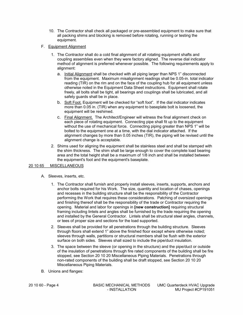
20 10 60 - Page 4 BASIC MECHANICAL METHODS - INSTALLATION
UMC Quarterdeck HVAC UpgradeMU Project #CP191051
10. The Contractor shall check all packaged or pre-assembled equipment to make sure that all packing shims and blocking is removed before rotating, running or testing the equipment.
F. Equipment Alignment
1. The Contractor shall do a cold final alignment of all rotating equipment shafts and coupling assemblies even when they were factory aligned. The reverse dial indicator method of alignment is preferred whenever possible. The following requirements apply to alignment:
a. Initial Alignment shall be checked with all piping larger than NPS 1” disconnected from the equipment. Maximum misalignment readings shall be 0.05-in. total indicator reading (TIR) on the rim and on the face of the coupling hub for all equipment unless otherwise noted in the Equipment Data Sheet instructions. Equipment shall rotate freely, all bolts shall be tight, all bearings and couplings shall be lubricated, and all safety guards shall be in place.
b. Soft Foot. Equipment will be checked for “soft foot”. If the dial indicator indicates more than 0.05 in. (TIR) when any equipment to baseplate bolt is loosened, the equipment will be reshimed.
c. Final Alignment. The Architect/Engineer will witness the final alignment check on each piece of rotating equipment. Connecting pipe shall fit up to the equipment without the use of mechanical force. Connecting piping greater than NPS 1” will be bolted to the equipment one at a time, with the dial indicator attached. If the alignment changes by more than 0.05 inches (TIR), the piping will be revised until the alignment change is acceptable.
2. Shims used for aligning the equipment shall be stainless steel and shall be stamped with the shim thickness. The shim shall be large enough to cover the complete load bearing area and the total height shall be a maximum of 1/8 inch and shall be installed between the equipment's foot and the equipment's baseplate.
20 10 65 MISCELLANEOUS
A. Sleeves, inserts, etc.
1. The Contractor shall furnish and properly install sleeves, inserts, supports, anchors and anchor bolts required for his Work. The size, quantity and location of chases, openings and recesses in the building structure shall be the responsibility of the Contractor performing the Work that requires these considerations. Patching of oversized openings and finishing thereof shall be the responsibility of the trade or Contractor requiring the
opening. Material and labor for openings in [new construction] requiring structural framing including lintels and angles shall be furnished by the trade requiring the opening and installed by the General Contractor. Lintels shall be structural steel angles, channels, or tees of proper size and sections for the load supported.
2. Sleeves shall be provided for all penetrations through the building structure. Sleeves through floors shall extend 1” above the finished floor except where otherwise noted; sleeves through walls, partitions or structural members shall be flush with the exterior surface on both sides. Sleeves shall sized to include the pipe/duct insulation.
3. The space between the sleeve (or opening in the structure) and the pipe/duct or outside of the insulation of penetrations through fire rated components of the building shall be fire stopped, see Section 20 10 20 Miscellaneous Piping Materials. Penetrations through non-rated components of the building shall be draft stopped, see Section 20 10 20 Miscellaneous Piping Materials.
B. Unions and flanges:
20 10 60 - Page 5 BASIC MECHANICAL METHODS - INSTALLATION
UMC Quarterdeck HVAC UpgradeMU Project #CP191051
1. A ground joint type union shall be provided in threaded and sweat joint piping, 2” and smaller pipe or tube size, down-stream of each branch shut-off valve, control valve and specialty item, the inlet and outlet connections of each piece of equipment, and where shown on the drawings.
2. Flanged connections shall be provided in piping 2-1/2” and larger at each manual valve, control valve, specialty item and the inlet and outlet of each piece of equipment.
C. Interconnections between dissimilar piping material systems shall be made with fittings manufactured for the specific application.
20 10 70 - Page 1 BASIC MECHANICAL METHODS – RELATED WORK
UMC Quarterdeck HVAC UpgradeMU Project #CP191051
20 10 70 BASIC MECHANICAL METHODS - RELATED WORK
20 10 71 DEMOLITION
A. Work Included:
1. The Owner shall keep possession of the designated equipment, apparatus and/or piping as shown on the Plans, or as indicated during construction, or as hereinafter specified. The Contractor shall deliver, off-load and store this property as directed by the Owner.
2. The Contractor shall legally dispose of the non-designated equipment, apparatus and/or piping. Any cost of removal or salvage value shall be credited to the Contractor's account and shall be considered accordingly in the Contractor's bid.
a. Recovery and reclaim of refrigerant shall be performed by the Contractor in accordance with EPA regulations. The Contractor shall submit to the Owner a certificate stating the names and license numbers of the personnel performing the removal of the refrigerant, the machine and serial number of the reclaim equipment used, type and quantity of reclaimed refrigerant, and all other required data.
b. The Contractor shall return to the Owner for his use the reclaimed refrigerant in cylinders.
3. Remove all of the externally applied insulation and dispose of it, not including asbestos-based material.
B. Work Not Included:
1. The removal and disposal of asbestos based insulation or other hazardous materials applied to, or contained in, the mechanical equipment, material and piping designated to be demolished shall not be included in the scope of the work regardless if known ahead of time or discovered in the course of performing the Work. In the latter case, the Contractor shall notify the Architect/Engineer and shall not pursue that portion of the Work until others have removed the asbestos-based material. The removal and disposal of asbestos-based material shall be arranged by and to the account of the Owner, and conducted separately from the demolition work.
C. Miscellaneous:
1. Loose ends of mechanical systems shall be capped and/or sealed in a safe and secure manner approved by the Architect/Engineer.
2. Dead legs of branch piping are not permitted unless a cap is specifically shown on the drawings. Where a cap is not shown and the drawings indicate to cap piping, the Contractor shall remove branch piping back to the main and cap at that point.
20 10 72 CUTTING AND PATCHING
A. The basic premise of this Sub-section is that the cutting and patching (where required) are performed in existing building components. In “new” construction, the premise is that the building component is already in place.
B. The Contractor requiring the penetration of or the access way in the building structure to fulfill the intent of the Project Documents for his Work shall be responsible for the cutting and the subsequent patching in accordance with the following criteria:
1. .No structural component of the building shall be cut or violated without express approval of the Architect/Engineer.
20 10 70 - Page 2 BASIC MECHANICAL METHODS – RELATED WORK
UMC Quarterdeck HVAC UpgradeMU Project #CP191051
2. The Contractor shall verify the presence of any concealed utility or service within the structure (walls, roof, floor, etc.) in question, and shall be responsible for maintaining continuity and/or replacing it.
C. Cutting of work-in-place in “new” construction because of error, neglect or damage inflicted shall be the responsibility of the Contractor precipitating the issue.
D. “Patching” shall be construed as the repairing or replacing of the building structure to return it to an original or new condition, in the opinion of the Owner and/or Architect/Engineer, as existed prior to the cutting.
E. Patching and finishing work shall be the responsibility of the Contractor requiring the cutting. The patching shall match all the substantive and visual aspects of the structure and adjacent surfaces. Restoration and finishes shall be as specified and executed in the respective sections, schedules and/or details of the Project Documents for the general construction work. Completed work and any special requirements shall be subject to approval by and satisfaction of the Architect/Engineer.
20 10 74 CONCRETE WORK (CAST-IN-PLACE)
A. General:
1. This sub-section shall supplement Section 03300 – Concrete Work for the concrete work required to install the work of Divisions 20 - 25.
2. In the event of a conflict between this sub-section and Section 03300, the more stringent shall apply.
B. The Contractor shall include the following Work:
1. Provide concrete foundations, bases and/or housekeeping pads for mechanical equipment furnished in his respective scope of work where such are not indicated on the architectural or structural drawings. Concrete work shall include requisite excavation, formwork, reinforcing and contained hardware.
2. Submit for approval to the Architect/Engineer detailed and dimensioned drawings of size, location, reinforcing and hardware contained therein of concrete work to be provided.
C. Housekeeping Pads:
1. All equipment setting on concrete or other type of pave flooring shall be set upon a raised “housekeeping” pad, unless noted otherwise.
2. The Contractor shall be responsible for this size, location, and any required anchor bolts. In general, housekeeping pads shall be a minimum of 3 ½” high, a ¾” chamfer on exposed corners and edges, and a minimum of 3” beyond the equipment on all sides or as required for anchor bolt edge distance.
3. Housekeeping pads shall be 3000 psi 28-day compressive strength concrete. Pads shall be reinforced and doweled to the floor slab. Refer to ASHRAE-A Practical Guide to Seismic Restraint 1999, Chapter 6 – Housekeeping Pads for size and spacing of reinforcing and dowels.
4. Specifically designed vibration isolation/inertia concrete bases for equipment will be specified and shown separately.
D. Thrust Blocks:
1. Thrust blocks shall be installed at all changes in direction and end points in unrestrained underground piping systems.
2. Thrust blocks shall only contact the backside of the fittings and shall not cover any joints. All thrust blocks will be inspected by the Owner’s Representative prior to backfilling, provide a minimum of 3 days notice.
20 10 70 - Page 3 BASIC MECHANICAL METHODS – RELATED WORK
UMC Quarterdeck HVAC UpgradeMU Project #CP191051
20 10 75 PAINTING
A. General:
1. This sub-section shall supplement Section 09900 – Painting for the painting work required for the work installed by Divisions 20 - 25.
2. In the event of a conflict between this sub-section and Section 09900, the more stringent shall apply.
B. Painting of the following shall be included in the scope of work of this sub-section:
1. All mechanical equipment including housings, fans, etc., not factory painted shall have prime coat and finish painting.
2. All plain steel hanger rods, plain steel pipe hangers, field fabricated or prefabricated steel supports and braces, and other ferrous metal. Prime coat only for all interior work, both exposed and concealed. Prime coat and finish painting of all exterior work.
3. Touch-up, as required, of factory finished equipment to original condition.
4. Interior surface of air ducts, cabinets, enclosures, covers and air dampers where visible from a finished space through grilles and louvers with one coat of flat black paint.
5. All above grade exterior uninsulated piping systems shall have a prime coat and finish painting.
6. All piping systems exposed in mechanical rooms, both insulated and uninsulated, shall have a color coded finish painting. Uninsulated piping shall receive a prime coat.
C. Painting of the following shall not be included in the scope of work of this Sub-section, unless noted otherwise:
1. Surfaces to receive special finishes specified elsewhere.
2. Building construction surfaces - floors, ceilings, interior and exterior walls, exposed concrete work, special finishes, etc.
3. All stainless steel, brass, copper, aluminum, plastic, electro-plated and galvanized surfaces.
4. Caulking, sealers, fire stops, etc.
5. Valves, controls, specialties.
6. Nameplates of equipment. Replace nameplate if painted.
7. Light fixtures.
8. Equipment (mechanical and electrical) which has been finished in a factory.
9. Black steel surfaces over 250 degrees F. (e.g. - breechings, kitchen hood exhaust ducts, etc.).
D. General Requirements:
1. The Contractor shall provide all labor, coating materials, accessory materials (e.g.- turpentine, painting thinners, etc.), tools and services necessary and reasonably incidental to the scope of work of Sub-section 20 10 75.
2. Coatings shall be factory prepared and mixed; ready for application upon delivery; have good flow and brushing properties and be capable of drying and curing free of streaks or sags.
3. Materials for each application shall be compatible with one another and with other specified materials with which contact may be made.
4. Products shall meet the following UL fire hazard classifications when tested in accordance with ASTM E84: Flame spread, 0; Fuel contributed, 5; Smoke developed, 15.
20 10 70 - Page 4 BASIC MECHANICAL METHODS – RELATED WORK
UMC Quarterdeck HVAC UpgradeMU Project #CP191051
5. Coatings shall be applied in accordance with the paint manufacturer's recommendations with the surfaces well illuminated. In general, coatings shall not be applied when the relative humidity is above 60% nor the ambient temperature below 45 degrees F.
6. The Architect/Engineer shall make color selections, when required.
E. Acceptable Manufacturers
1. Benjamin Moore & Co.
2. Porter International
3. Pratt & Lambert, Inc.
4. Sherwin Williams Co.
5. Glidden
6. Pittsburgh
F. The Contractor shall submit the following to the Architect/Engineer for review and approval:
1. Statement of qualification that the company specializes in commercial painting and finishing with a minimum of five (5) years experience.
2. Product data describing the following:
a. Instructions for substrate preparation including priming.
b. Instructions for product preparation, application procedures, clean-up and maintenance.
c. .Recommended ambient temperature and relative humidity range, substrate temperature, moisture content and alkalinity at the time of application.
d. Manufacturer's list of trademarked products for each coat of each system. For each product, state vehicle type, percent solids by volume, method of application, drying time, recommended rate of coverage and dry film thickness for each coat. Coordinate with the Schedule in Sub-section in 20 10 75.84.
e. Advise any recommendations which differ from the specified or scheduled requirements.
3. Material Safety Data Sheet (MSDS) for each coating and painting product, and maintain a file of it at the job site for reference and emergency use.
4. Certificates and/or test reports demonstrating that the painting products specified meet regulatory requirements.
5. Color charts and available sheens of finish, when required, for selection by the Archi-tect/Engineer.
6. Samples of painting products when requested for inspection by the Architect/Engineer.
G. Painting:
1. The Contractor shall be responsible for delivery, handling and storage of all coating and painting materials for the pursuit of his work.
a. All painting products shall be delivered in sealed containers.
b. All painting product containers shall be labeled to show the manufacturer's name, type of coating, brand name, coverage, surface preparation, drying time, clean-up, color designation and instructions for mixing and reducing.
c. All painting products shall be handled and stored in accordance with the respective manufacturer's recommendations. In the absence of specific instructions, products shall stored in well-ventilated areas at a minimum ambient temperature of 45 degrees F. and a maximum temperature of 90 degrees F.
20 10 70 - Page 5 BASIC MECHANICAL METHODS – RELATED WORK
UMC Quarterdeck HVAC UpgradeMU Project #CP191051
d. Precautions shall be exercised to prevent fire hazards and spontaneous combustion. Provide adequate type and quantity of fire extinguisher at the job site.
2. The Contractor shall perform the following in preparation of the painting application:
a. Verify that surfaces and substrate conditions are ready to receive the application of coatings as specified or in accordance with manufacturer's recommendations. Commencement of application is acceptance of existing conditions.
b. Provide drop clothes and other protective measures to prevent coatings on other work not included in the scope of work of this sub-section.
c. Where required by Architect/Engineer, post “WET PAINT” signs.
d. Solvent or power tool clean surfaces, as required or as deemed appropriate, to remove grease, scale, dirt, rust, mill scale, weld splatter and burrs. Apply primer immediately after cleaning.
3. Application:
a. Coating products shall be prepared and applied in accordance with the respective manufacturer's instructions and reviewed submittals. Dry mil thickness of each coat shall be as scheduled or as recommended by the manufacturer. Finish coat shall not be less than 5.0 mils in thickness, and sufficient to cover completely substrates and undercoats.
b. Where shop prime coat finishes are specified elsewhere, primer may be omitted, except as otherwise scheduled, specified or recommended by the coating manufacturer. Damaged shop prime coats shall be touched-up, using a primer compatible with or same as original primer.
c. Each coat shall be applied to provide a uniform finish, without sags, laps, brush marks or other defects. Allow applied coat to dry before next coat is applied.
4. Schedule - Latex, General Painting Materials:
a. Steel - unprimed, located indoors or outdoors:One (1) coat lead and chromate free alkyd primer. Two (2) coats latex, semi-gloss.
b. Steel - shop primed, located indoors or outdoors:Touch-up with lead and chromate free alkyd primer.Two (2) coats latex, semi-gloss.
c. Insulation on mechanical equipment, located indoors:One (l) coat latex primer sealer.Two (2) coats latex, flat.
d. Schedule - Epoxy, General Painting Materials:
20 10 76 LUBRICATION
A. Provide all oil and grease for the operation of all equipment until acceptance. The Mechanical Contractor and Subcontractors shall be held responsible for all damage to bearing while the equipment is being operated by them up to the date of acceptance of the equipment. Protect all bearings during installation and thoroughly grease steel shafts and other unpainted steel surfaces to prevent corrosion. All motors and other equipment shall be provided with covers as required for proper protection during construction. For equipment that is received void (dry) of lubrication the Contractor shall lubricate the equipment before storing to prevent internal damage to the equipment.
20 10 77 DRAINING, FILLING AND VENTING SYSTEMS
A. The Contractor shall provide all required labor for draining, filling and venting of new or modified systems as many times as required during construction and for all phasing activities.
20 10 70 - Page 6 BASIC MECHANICAL METHODS – RELATED WORK
UMC Quarterdeck HVAC UpgradeMU Project #CP191051
B. Where draining and filling systems affects other systems or the Owner’s normal operations, then they shall be scheduled at least 24 hours in advance with the Owner and shall be carried out to minimize such disruptions.
20 10 80 - Page 1 TESTING, ADJUSTING AND BALANCING
UMC Quarterdeck HVAC UpgradeMU Project #CP191051
20 10 80 TESTING, ADJUSTING AND BALANCING
20 10 81 GENERAL
A. At the completion of the installation work, the Contractor shall execute tests and make adjustments to qualify and quantify that all mechanical systems and subsystems installed or modified under this project function to their respective specified performance and the intent of the Project Documents. All systems shall be operated and tested systematically for capacity, calibration, pressure balances between spaces, balancing and sequence as close to design conditions as possible with maximum attainable internal load. Adjustment to system components shall be made including replacing motor drives, if necessary, to achieve specified performance.
B. Work shall be conducted under the supervision of an individual certified by NEBB or AABC and trained technicians. All test results shall be documented per the previously approved procedure and transmitted to the Architect/Engineer for review as a requisite for final acceptance and payment. Final inspection shall follow completion and acceptance of the test results.
C. The balancing contractor shall review plans and specifications for balancing dampers, balancing valves, gauge connections, airflow/pitot sections. The Contractor shall notify the Engineer if the Contractor cannot perform the Work because of inadequate provisions so that the inadequacy can be corrected by change order during project construction without any cost over and above the device itself. No excuses during the testing and balancing procedure will be accepted for Contractor's lack of performance, and the Contractor shall be responsible for the additional cost of adding the required device(s) into the completed systems.
D. Employment of a Balancing Subcontractor by the Contractor shall not relieve him of obligations to perform Work in accordance with the Project Documents.
20 10 82 REFERENCES
A. National Standards for Total System Balance, by the Associated Air Balance Council (AABC), latest edition.
B. Procedural Standards for Testing, Balancing and Adjusting of Environmental Systems, by the National Environmental Balancing Bureau (NEBB), latest edition.
C. 1999 Application Handbook, Chapter 36, Testing, Adjusting and Balancing by the American Society of Heating, Refrigeration and Air Conditioning Engineers (ASHRAE).
20 10 83 WORK INCLUDED
A. Testing and adjusting each air handling unit, energy recover ventilator, and return/relief fans to achieve the design airflow rates as scheduled.
B. Testing and adjusting each pump to achieve design water flow rate as scheduled.
C. Testing and adjusting each fan to achieve design airflow rate as scheduled.
D. Testing and adjusting each air device to achieve design airflow rate as indicated on the plans.
E. Furnishing and/or installing fixed sheaves for all fans.
F. Provide sufficient labor and resources required to assist in the commissioning process, refer to Section 152300.
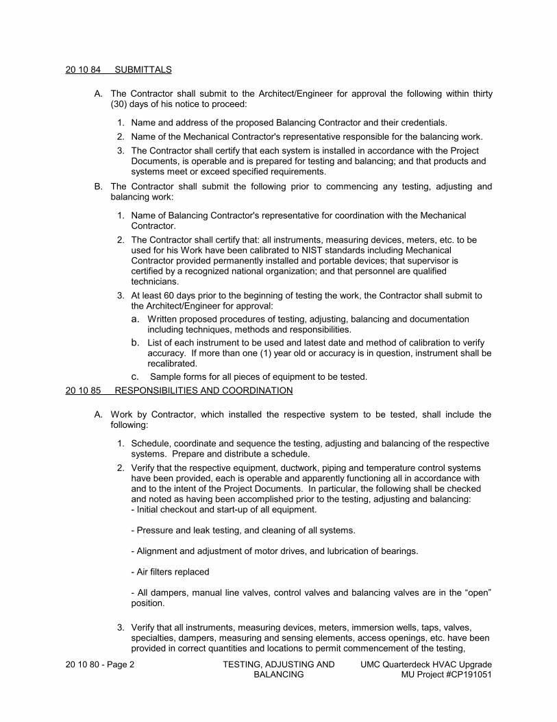
20 10 80 - Page 2 TESTING, ADJUSTING AND BALANCING
UMC Quarterdeck HVAC UpgradeMU Project #CP191051
20 10 84 SUBMITTALS
A. The Contractor shall submit to the Architect/Engineer for approval the following within thirty (30) days of his notice to proceed:
1. Name and address of the proposed Balancing Contractor and their credentials.
2. Name of the Mechanical Contractor's representative responsible for the balancing work.
3. The Contractor shall certify that each system is installed in accordance with the Project Documents, is operable and is prepared for testing and balancing; and that products and systems meet or exceed specified requirements.
B. The Contractor shall submit the following prior to commencing any testing, adjusting and balancing work:
1. Name of Balancing Contractor's representative for coordination with the Mechanical Contractor.
2. The Contractor shall certify that: all instruments, measuring devices, meters, etc. to be used for his Work have been calibrated to NIST standards including Mechanical Contractor provided permanently installed and portable devices; that supervisor is certified by a recognized national organization; and that personnel are qualified technicians.
3. At least 60 days prior to the beginning of testing the work, the Contractor shall submit to the Architect/Engineer for approval:
a. Written proposed procedures of testing, adjusting, balancing and documentation including techniques, methods and responsibilities.
b. List of each instrument to be used and latest date and method of calibration to verify accuracy. If more than one (1) year old or accuracy is in question, instrument shall be recalibrated.
c. Sample forms for all pieces of equipment to be tested.
20 10 85 RESPONSIBILITIES AND COORDINATION
A. Work by Contractor, which installed the respective system to be tested, shall include the following:
1. Schedule, coordinate and sequence the testing, adjusting and balancing of the respective systems. Prepare and distribute a schedule.
2. Verify that the respective equipment, ductwork, piping and temperature control systems have been provided, each is operable and apparently functioning all in accordance with and to the intent of the Project Documents. In particular, the following shall be checked and noted as having been accomplished prior to the testing, adjusting and balancing:- Initial checkout and start-up of all equipment.
- Pressure and leak testing, and cleaning of all systems.
- Alignment and adjustment of motor drives, and lubrication of bearings.
- Air filters replaced
- All dampers, manual line valves, control valves and balancing valves are in the “open” position.
3. Verify that all instruments, measuring devices, meters, immersion wells, taps, valves, specialties, dampers, measuring and sensing elements, access openings, etc. have been provided in correct quantities and locations to permit commencement of the testing,
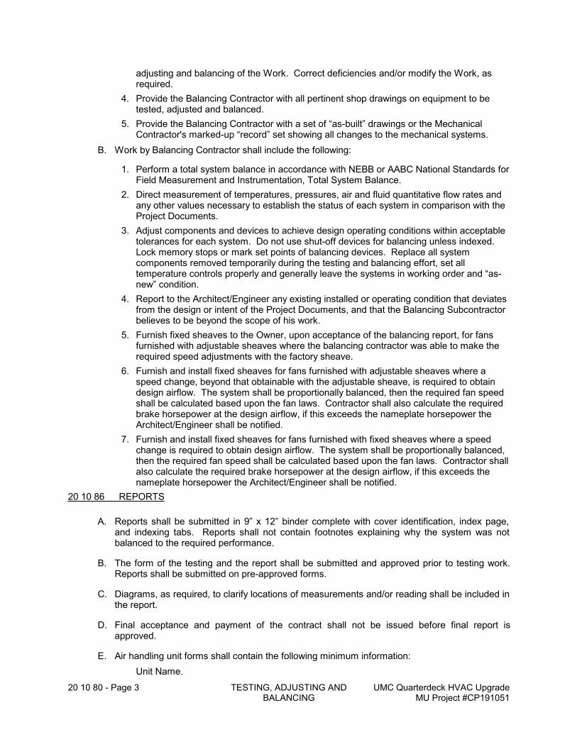
20 10 80 - Page 3 TESTING, ADJUSTING AND BALANCING
UMC Quarterdeck HVAC UpgradeMU Project #CP191051
adjusting and balancing of the Work. Correct deficiencies and/or modify the Work, as required.
4. Provide the Balancing Contractor with all pertinent shop drawings on equipment to be tested, adjusted and balanced.
5. Provide the Balancing Contractor with a set of “as-built” drawings or the Mechanical Contractor's marked-up “record” set showing all changes to the mechanical systems.
B. Work by Balancing Contractor shall include the following:
1. Perform a total system balance in accordance with NEBB or AABC National Standards for Field Measurement and Instrumentation, Total System Balance.
2. Direct measurement of temperatures, pressures, air and fluid quantitative flow rates and any other values necessary to establish the status of each system in comparison with the Project Documents.
3. Adjust components and devices to achieve design operating conditions within acceptable tolerances for each system. Do not use shut-off devices for balancing unless indexed. Lock memory stops or mark set points of balancing devices. Replace all system components removed temporarily during the testing and balancing effort, set all temperature controls properly and generally leave the systems in working order and “as-new” condition.
4. Report to the Architect/Engineer any existing installed or operating condition that deviates from the design or intent of the Project Documents, and that the Balancing Subcontractor believes to be beyond the scope of his work.
5. Furnish fixed sheaves to the Owner, upon acceptance of the balancing report, for fans furnished with adjustable sheaves where the balancing contractor was able to make the required speed adjustments with the factory sheave.
6. Furnish and install fixed sheaves for fans furnished with adjustable sheaves where a speed change, beyond that obtainable with the adjustable sheave, is required to obtain design airflow. The system shall be proportionally balanced, then the required fan speed shall be calculated based upon the fan laws. Contractor shall also calculate the required brake horsepower at the design airflow, if this exceeds the nameplate horsepower the Architect/Engineer shall be notified.
7. Furnish and install fixed sheaves for fans furnished with fixed sheaves where a speed change is required to obtain design airflow. The system shall be proportionally balanced, then the required fan speed shall be calculated based upon the fan laws. Contractor shall also calculate the required brake horsepower at the design airflow, if this exceeds the nameplate horsepower the Architect/Engineer shall be notified.
20 10 86 REPORTS
A. Reports shall be submitted in 9” x 12” binder complete with cover identification, index page, and indexing tabs. Reports shall not contain footnotes explaining why the system was not balanced to the required performance.
B. The form of the testing and the report shall be submitted and approved prior to testing work. Reports shall be submitted on pre-approved forms.
C. Diagrams, as required, to clarify locations of measurements and/or reading shall be included in the report.
D. Final acceptance and payment of the contract shall not be issued before final report is approved.
E. Air handling unit forms shall contain the following minimum information:
Unit Name.
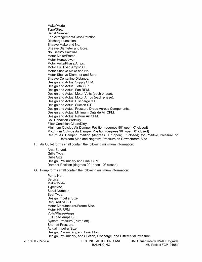
20 10 80 - Page 4 TESTING, ADJUSTING AND BALANCING
UMC Quarterdeck HVAC UpgradeMU Project #CP191051
Make/Model.Type/Size.Serial Number.Fan Arrangement/Class/RotationDischarge Location.Sheave Make and No.Sheave Diameter and Bore.No. Belts/Make/Size.Motor Make/Frame.Motor Horsepower.Motor Volts/Phase/Amps.Motor Full Load Amps/S.F.Motor Sheave Make and No.Motor Sheave Diameter and Bore.Sheave Centerline Distance.Design and Actual Supply CFM.Design and Actual Total S.P.Design and Actual Fan RPM.Design and Actual Motor Volts (each phase).Design and Actual Motor Amps (each phase).Design and Actual Discharge S.P.Design and Actual Suction S.P.Design and Actual Pressure Drops Across Components.Design and Actual Minimum Outside Air CFM.Design and Actual Return Air CFM.Coil Condition Wet/Dry.Filter Condition Clean/Dirty.Minimum Outside Air Damper Position (degrees 90° open; 0° closed)Maximum Outside Air Damper Position (degrees 90° open; 0° closed)Return Air Damper Position (degrees 90° open; 0° closed) for Positive Pressure on
Upstream Side and Negative Pressure on Downstream Side
F. Air Outlet forms shall contain the following minimum information:
Area Served.Grille Type.Grille Size.Design, Preliminary and Final CFM.Damper Position (degrees 90° open - 0° closed).
G. Pump forms shall contain the following minimum information:
Pump No.Service.Make/Model.Type/Size.Serial Number.Seal Type.Design Impeller Size.Required NPSH.Motor Manufacturer/Frame Size.Motor HP/RPM.Volts/Phase/Amps.Full Load Amps.S.F.System Pressure (Pump off).Shut-off Pressure.Actual Impeller Size.Design, Preliminary, and Final Flow.Design, Preliminary, and Suction, Discharge, and Differential Pressure.
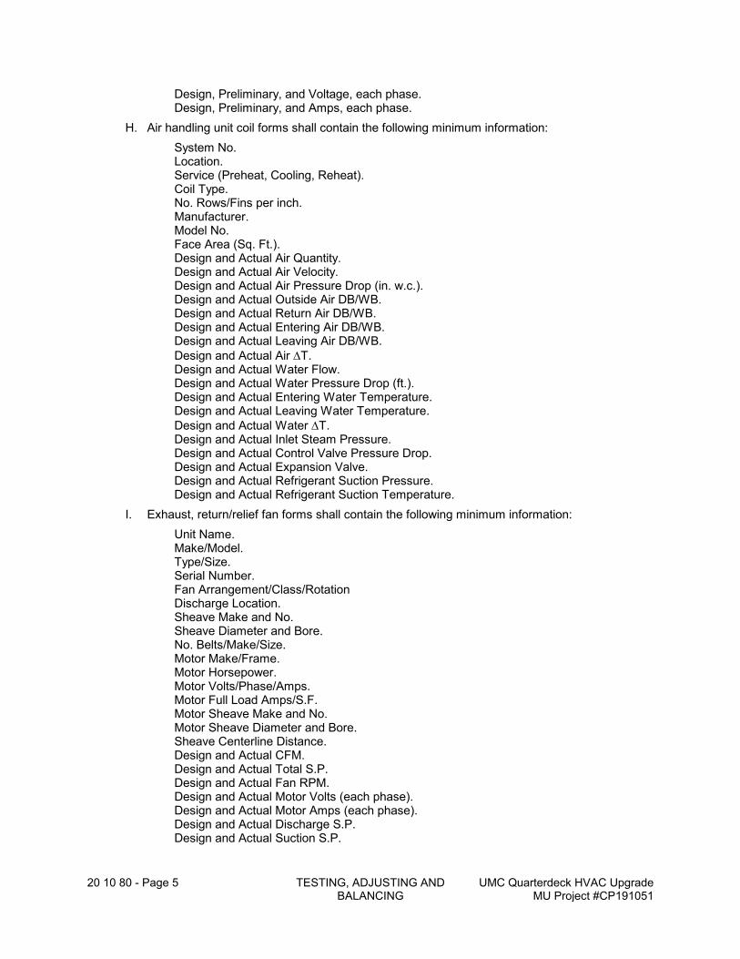
20 10 80 - Page 5 TESTING, ADJUSTING AND BALANCING
UMC Quarterdeck HVAC UpgradeMU Project #CP191051
Design, Preliminary, and Voltage, each phase.Design, Preliminary, and Amps, each phase.
H. Air handling unit coil forms shall contain the following minimum information:
System No.Location.Service (Preheat, Cooling, Reheat).Coil Type.No. Rows/Fins per inch.Manufacturer.Model No.Face Area (Sq. Ft.).Design and Actual Air Quantity.Design and Actual Air Velocity.Design and Actual Air Pressure Drop (in. w.c.).Design and Actual Outside Air DB/WB.Design and Actual Return Air DB/WB.Design and Actual Entering Air DB/WB.Design and Actual Leaving Air DB/WB.
Design and Actual Air T.Design and Actual Water Flow.Design and Actual Water Pressure Drop (ft.).Design and Actual Entering Water Temperature.Design and Actual Leaving Water Temperature.
Design and Actual Water T.Design and Actual Inlet Steam Pressure.Design and Actual Control Valve Pressure Drop.Design and Actual Expansion Valve.Design and Actual Refrigerant Suction Pressure.Design and Actual Refrigerant Suction Temperature.
I. Exhaust, return/relief fan forms shall contain the following minimum information:
Unit Name.Make/Model.Type/Size.Serial Number.Fan Arrangement/Class/RotationDischarge Location.Sheave Make and No.Sheave Diameter and Bore.No. Belts/Make/Size.Motor Make/Frame.Motor Horsepower.Motor Volts/Phase/Amps.Motor Full Load Amps/S.F.Motor Sheave Make and No.Motor Sheave Diameter and Bore.Sheave Centerline Distance.Design and Actual CFM.Design and Actual Total S.P.Design and Actual Fan RPM.Design and Actual Motor Volts (each phase).Design and Actual Motor Amps (each phase).Design and Actual Discharge S.P.Design and Actual Suction S.P.
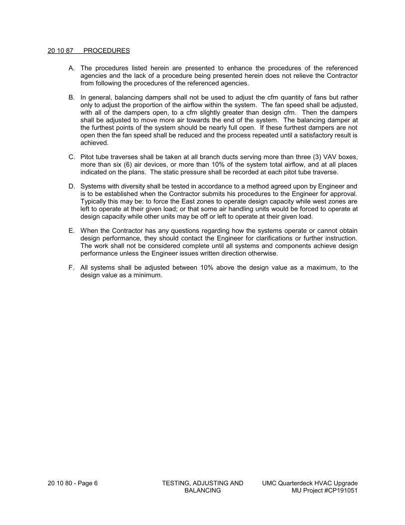
20 10 80 - Page 6 TESTING, ADJUSTING AND BALANCING
UMC Quarterdeck HVAC UpgradeMU Project #CP191051
20 10 87 PROCEDURES
A. The procedures listed herein are presented to enhance the procedures of the referenced agencies and the lack of a procedure being presented herein does not relieve the Contractor from following the procedures of the referenced agencies.
B. In general, balancing dampers shall not be used to adjust the cfm quantity of fans but rather only to adjust the proportion of the airflow within the system. The fan speed shall be adjusted, with all of the dampers open, to a cfm slightly greater than design cfm. Then the dampers shall be adjusted to move more air towards the end of the system. The balancing damper at the furthest points of the system should be nearly full open. If these furthest dampers are not open then the fan speed shall be reduced and the process repeated until a satisfactory result is achieved.
C. Pitot tube traverses shall be taken at all branch ducts serving more than three (3) VAV boxes, more than six (6) air devices, or more than 10% of the system total airflow, and at all places indicated on the plans. The static pressure shall be recorded at each pitot tube traverse.
D. Systems with diversity shall be tested in accordance to a method agreed upon by Engineer and is to be established when the Contractor submits his procedures to the Engineer for approval. Typically this may be: to force the East zones to operate design capacity while west zones are left to operate at their given load; or that some air handling units would be forced to operate at design capacity while other units may be off or left to operate at their given load.
E. When the Contractor has any questions regarding how the systems operate or cannot obtain design performance, they should contact the Engineer for clarifications or further instruction. The work shall not be considered complete until all systems and components achieve design performance unless the Engineer issues written direction otherwise.
F. All systems shall be adjusted between 10% above the design value as a maximum, to the design value as a minimum.
20 10 90 - Page 1 BASIC MECHANICAL METHODS - IDENTIFICATION
UMC Quarterdeck HVAC UpgradeMU Project #CP191051
20 10 90 BASIC MECHANICAL METHODS - IDENTIFICATION
20 10 91 GENERAL
A. This Sub-section specifies basic materials and methods for identification that shall apply to systems specified in other sections of Divisions 20 - 29 of the Specifications.
B. The Contractor shall submit schedules and listings of Work to be identified indicating color code, material, name plate information and method of application for approval prior to performing the Work.
20 10 92 REFERENCES
A. All provisions and conditions cited in this Sub-section shall apply to Work of all other sections of Divisions 20 - 29 of these Specifications, where and when relevant.
B. Applicable requirements of the current and accepted edition of the following codes and standards shall apply to the Work of this Sub-section:
1. ANSI/ASME A 13.1 - “Scheme for the Identification of Piping Systems”.
20 10 93 WORK INCLUDED
A. Each respective Contractor and Subcontractor shall identify the applicable components of his Work in accordance with specifications hereinafter enumerated or where required by other sections of Divisions 20 - 29 of the Specifications.
1. All equipment items (i.e. air handling units, fans, pumps, etc.).
2. All condenser water and fire protection valves both new and existing.
3. All piping systems identifying the system type and direction of flow.
4. All control devices and panels.
20 10 94 SUBMITTALS
A. Contractor shall submit shop drawings for approval in accordance with Section 20 00 43 submittals.
B. Provide an Identification Product Schedule consisting of the following minimum information:
- Material - type of identification product.- System - indicate which system or equipment materials will be used for.- Manufacturer - Manufacturer's name, product name and model numbers.- Accessories - Miscellaneous materials used in affixing identification.
C. Provide manufacturer's technical product sheet and recommended installation instructions.
D. Provide color list/schedule and lettering sizes for pipe markers, valve tags, and equipment nameplates.
E. Provide a valve tag list for approval prior to ordering or making valve tags.
20 10 95 GENERAL METHODS FOR IDENTIFICATION
A. All surfaces to receive identification nameplates or markers shall be clean, degreased, dry, free of oxidation and prepared per manufacturer's recommendations.
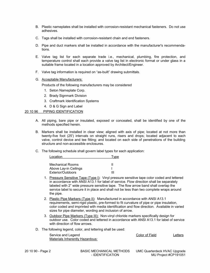
20 10 90 - Page 2 BASIC MECHANICAL METHODS - IDENTIFICATION
UMC Quarterdeck HVAC UpgradeMU Project #CP191051
B. Plastic nameplates shall be installed with corrosion-resistant mechanical fasteners. Do not use adhesives.
C. Tags shall be installed with corrosion-resistant chain and end fasteners.
D. Pipe and duct markers shall be installed in accordance with the manufacturer's recommenda-tions.
E. Valve tag list for each separate trade i.e., mechanical, plumbing, fire protection, and temperature control shall each provide a valve tag list in electronic format or under glass in a suitable frame located in a location approved by Architect/Engineer.
F. Valve tag information is required on “as-built” drawing submittals.
G. Acceptable Manufacturers:
Products of the following manufacturers may be considered
1. Seton Nameplate Corp.
2. Brady Signmark Division
3. Craftmark Identification Systems
4. D & G Sign and Label
20 10 96 PIPING IDENTIFICATION
A. All piping, bare pipe or insulated, exposed or concealed, shall be identified by one of the methods specified herein.
B. Markers shall be installed in clear view; aligned with axis of pipe; located at not more than twenty-five foot (25') intervals on straight runs, risers and drops; located adjacent to each valve, control device and tee fitting; and located on each side of penetrations of the building structure and non-accessible enclosures.
C. The following schedule shall govern label types for each application:
Location Type
Mechanical Rooms IIAbove Lay-in Ceilings IExterior/Outdoors III
1. Pressure Sensitive Tape (Type I): Vinyl pressure sensitive tape color coded and lettered in accordance with ANSI A13.1 for label of service. Flow direction shall be separately labeled with 2” wide pressure sensitive tape. The flow arrow band shall overlap the service label to secure it in place and shall not be less than two complete wraps around the pipe.
2. Plastic Pipe Markers (Type II): Manufactured in accordance with ANSI A13.1 requirements, semi-rigid plastic, pre-formed to fit curvature of pipe or pipe insulation, color coded and imprinted with media identification and flow direction. Available in varied sizes for pipe diameter, wording and inclusion of arrow.
3. Outdoor Pipe Markers (Type III): Non-vinyl chloride markers specifically design for outdoor use. Color coded and lettered in accordance with ANSI A13.1 for label of service with direction of flow arrows.
D. The following legend, color, and lettering shall be used:
Service and Legend Color of Field LettersMaterials Inherently Hazardous:
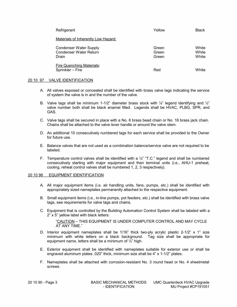
20 10 90 - Page 3 BASIC MECHANICAL METHODS - IDENTIFICATION
UMC Quarterdeck HVAC UpgradeMU Project #CP191051
Refrigerant Yellow Black
Materials of Inherently Low Hazard:
Condenser Water Supply Green WhiteCondenser Water Return Green WhiteDrain Green White
Fire Quenching Materials:Sprinkler – Fire Red White
20 10 97 VALVE IDENTIFICATION
A. All valves exposed or concealed shall be identified with brass valve tags indicating the service of system the valve is in and the number of the valve.
B. Valve tags shall be minimum 1-1/2” diameter brass stock with ¼” legend identifying and ½” valve number both shall be black enamel filled. Legends shall be HVAC, PLBG, SPR, and GAS.
C. Valve tags shall be secured in place with a No. 6 brass bead chain or No. 16 brass jack chain. Chains shall be attached to the valve lever handle or around the valve stem.
D. An additional 10 consecutively numbered tags for each service shall be provided to the Owner for future use.
E. Balance valves that are not used as a combination balance/service valve are not required to be labeled.
F. Temperature control valves shall be identified with a ¼” “T.C.” legend and shall be numbered consecutively starting with major equipment and then terminal units (i.e., AHU-1 preheat, cooling, reheat control valves shall be numbered 1, 2, 3 respectively).
20 10 98 EQUIPMENT IDENTIFICATION
A. All major equipment items (i.e. air handling units, fans, pumps, etc.) shall be identified with appropriately sized nameplates permanently attached to the respective equipment.
B. Small equipment items (i.e., in-line pumps, pot feeders, etc.) shall be identified with brass valve tags, see requirements for valve tags and chains.
C. Equipment that is controlled by the Building Automation Control System shall be labeled with a 2” x 5” yellow label with black letters:
“CAUTION – THIS EQUIPMENT IS UNDER COMPUTER CONTROL AND MAY CYCLE AT ANY TIME.”
D. Interior equipment nameplates shall be 1/16” thick two-ply acrylic plastic 2-1/2” x 1” size minimum with white letters on a black background. Tag size shall be appropriate for equipment name, letters shall be a minimum of ½” high.
E. Exterior equipment shall be identified with nameplates suitable for exterior use or shall be engraved aluminum plates .020” thick, minimum size shall be 4” x 1-1/2” plates.
F. Nameplates shall be attached with corrosion-resistant No. 3 round head or No. 4 sheetmetal screws.
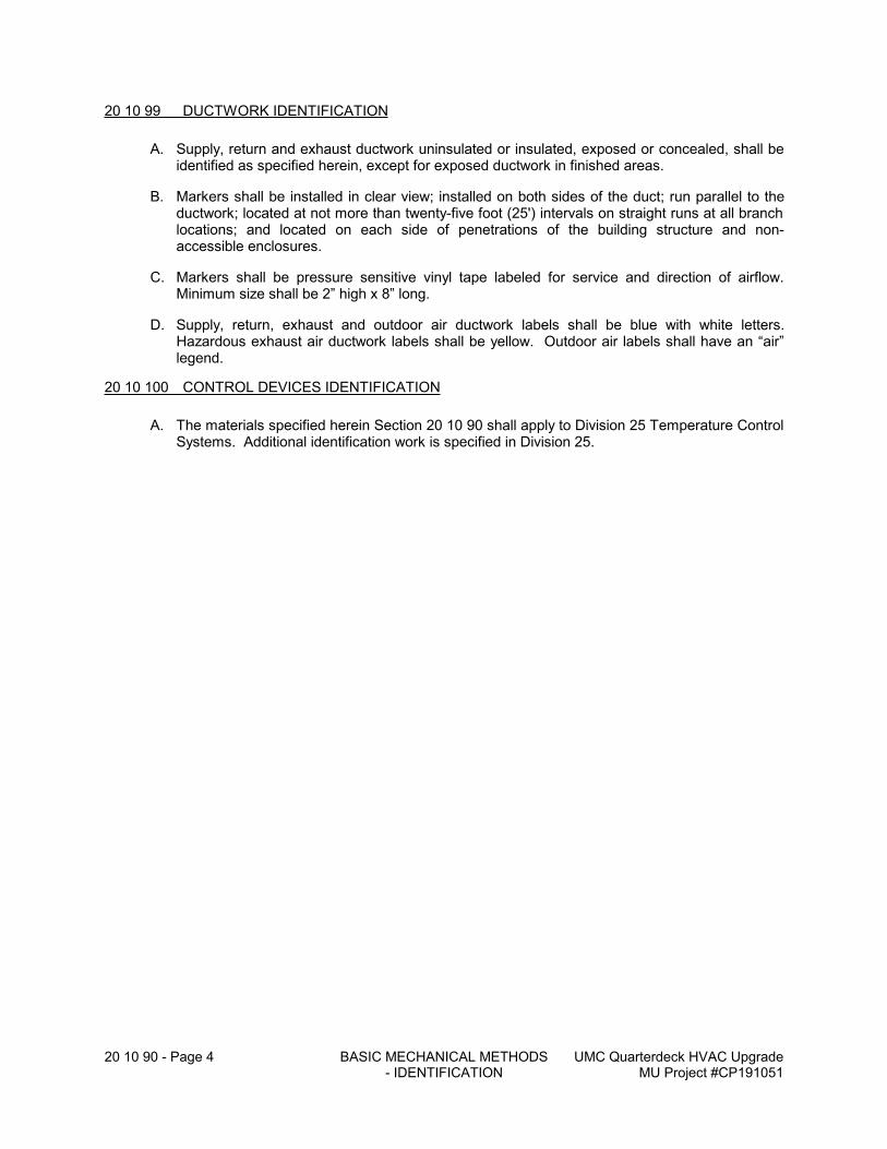
20 10 90 - Page 4 BASIC MECHANICAL METHODS - IDENTIFICATION
UMC Quarterdeck HVAC UpgradeMU Project #CP191051
20 10 99 DUCTWORK IDENTIFICATION
A. Supply, return and exhaust ductwork uninsulated or insulated, exposed or concealed, shall be identified as specified herein, except for exposed ductwork in finished areas.
B. Markers shall be installed in clear view; installed on both sides of the duct; run parallel to the ductwork; located at not more than twenty-five foot (25') intervals on straight runs at all branch locations; and located on each side of penetrations of the building structure and non-accessible enclosures.
C. Markers shall be pressure sensitive vinyl tape labeled for service and direction of airflow. Minimum size shall be 2” high x 8” long.
D. Supply, return, exhaust and outdoor air ductwork labels shall be blue with white letters. Hazardous exhaust air ductwork labels shall be yellow. Outdoor air labels shall have an “air” legend.
20 10 100 CONTROL DEVICES IDENTIFICATION
A. The materials specified herein Section 20 10 90 shall apply to Division 25 Temperature Control Systems. Additional identification work is specified in Division 25.
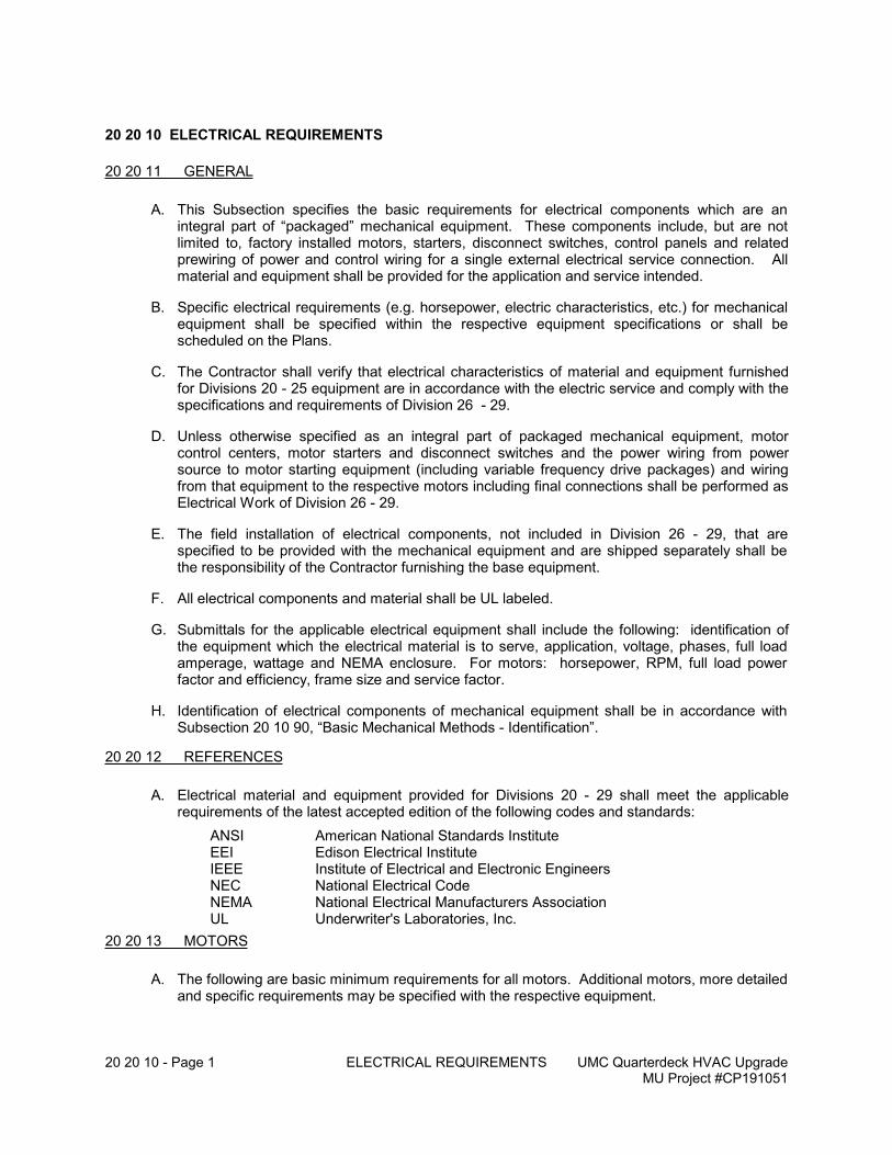
20 20 10 - Page 1 ELECTRICAL REQUIREMENTS UMC Quarterdeck HVAC UpgradeMU Project #CP191051
20 20 10 ELECTRICAL REQUIREMENTS
20 20 11 GENERAL
A. This Subsection specifies the basic requirements for electrical components which are an integral part of “packaged” mechanical equipment. These components include, but are not limited to, factory installed motors, starters, disconnect switches, control panels and related prewiring of power and control wiring for a single external electrical service connection. All material and equipment shall be provided for the application and service intended.
B. Specific electrical requirements (e.g. horsepower, electric characteristics, etc.) for mechanical equipment shall be specified within the respective equipment specifications or shall be scheduled on the Plans.
C. The Contractor shall verify that electrical characteristics of material and equipment furnished for Divisions 20 - 25 equipment are in accordance with the electric service and comply with the specifications and requirements of Division 26 - 29.
D. Unless otherwise specified as an integral part of packaged mechanical equipment, motor control centers, motor starters and disconnect switches and the power wiring from power source to motor starting equipment (including variable frequency drive packages) and wiring from that equipment to the respective motors including final connections shall be performed as Electrical Work of Division 26 - 29.
E. The field installation of electrical components, not included in Division 26 - 29, that are specified to be provided with the mechanical equipment and are shipped separately shall be the responsibility of the Contractor furnishing the base equipment.
F. All electrical components and material shall be UL labeled.
G. Submittals for the applicable electrical equipment shall include the following: identification of the equipment which the electrical material is to serve, application, voltage, phases, full load amperage, wattage and NEMA enclosure. For motors: horsepower, RPM, full load power factor and efficiency, frame size and service factor.
H. Identification of electrical components of mechanical equipment shall be in accordance with Subsection 20 10 90, “Basic Mechanical Methods - Identification”.
20 20 12 REFERENCES
A. Electrical material and equipment provided for Divisions 20 - 29 shall meet the applicable requirements of the latest accepted edition of the following codes and standards:
ANSI American National Standards InstituteEEI Edison Electrical InstituteIEEE Institute of Electrical and Electronic EngineersNEC National Electrical CodeNEMA National Electrical Manufacturers AssociationUL Underwriter's Laboratories, Inc.
20 20 13 MOTORS
A. The following are basic minimum requirements for all motors. Additional motors, more detailed and specific requirements may be specified with the respective equipment.
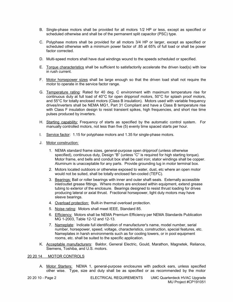
20 20 10 - Page 2 ELECTRICAL REQUIREMENTS UMC Quarterdeck HVAC UpgradeMU Project #CP191051
B. Single-phase motors shall be provided for all motors 1/2 HP or less, except as specified or scheduled otherwise and shall be of the permanent split capacitor (PSC) type.
C. Polyphase motors shall be provided for all motors 3/4 HP or larger, except as specified or scheduled otherwise with a minimum power factor of .85 at 65% of full load or shall be power factor corrected.
D. Multi-speed motors shall have dual windings wound to the speeds scheduled or specified.
E. Torque characteristics shall be sufficient to satisfactorily accelerate the driven load(s) with low in rush current.
F. Motor horsepower sizes shall be large enough so that the driven load shall not require the motor to operate in the service factor range.
G. Temperature rating: Rated for 40 deg. C environment with maximum temperature rise for continuous duty at full load of 40°C for open dripproof motors, 50°C for splash proof motors, and 55°C for totally enclosed motors (Class B insulation). Motors used with variable frequency drives/inverters shall be NEMA MG1, Part 31 Compliant and have a Class B temperature rise with Class F insulation design to resist transient spikes, high frequencies, and short rise time pulses produced by inverters.
H. Starting capability: Frequency of starts as specified by the automatic control system. For manually controlled motors, not less than five (5) evenly time spaced starts per hour.
I. Service factor: 1.15 for polyphase motors and 1.35 for single-phase motors.
J. Motor construction:
1. NEMA standard frame sizes, general-purpose open dripproof (unless otherwise specified), continuous duty, Design “B” (unless “C” is required for high starting torque). Motor frame, end bells and conduit box shall be cast iron; stator windings shall be copper. Aluminum is unacceptable for any parts. Provide grounding lug in motor terminal box.
2. Motors located outdoors or otherwise exposed to water, dust, etc where an open motor would not be suited, shall be totally enclosed fan-cooled (TEFC).
3. Bearings: Ball or roller bearings with inner and outer shaft seals. Externally accessible inlet/outlet grease fittings. Where motors are enclosed within equipment, extend grease tubing to exterior of the enclosure. Bearings designed to resist thrust loading for drives producing lateral or axial thrust. Fractional horsepower, light duty motors may have sleeve bearings.
4. Overload protection: Built-in thermal overload protection.
5. Noise rating: Motors shall meet IEEE, Standard 85.
6. Efficiency: Motors shall be NEMA Premium Efficiency per NEMA Standards Publication MG 1-2003, Table 12-12 and 12-13.
7. Nameplate: Indicate full identification of manufacturer's name, model number, serial number, horsepower, speed, voltage, characteristics, construction, special features, etc. Nameplates in harsh environments such as for cooling towers, or in pool equipment rooms, etc. shall be suited to the specific application.
K. Acceptable manufacturers: Baldor, General Electric, Gould, Marathon, Magnetek, Reliance, Siemens, Toshiba, and U.S. motors.
20 20 14 MOTOR CONTROLS
A. Motor Starters: NEMA 1, general-purpose enclosures with padlock ears, unless specified other wise. Type, size and duty shall be as specified or as recommended by the motor
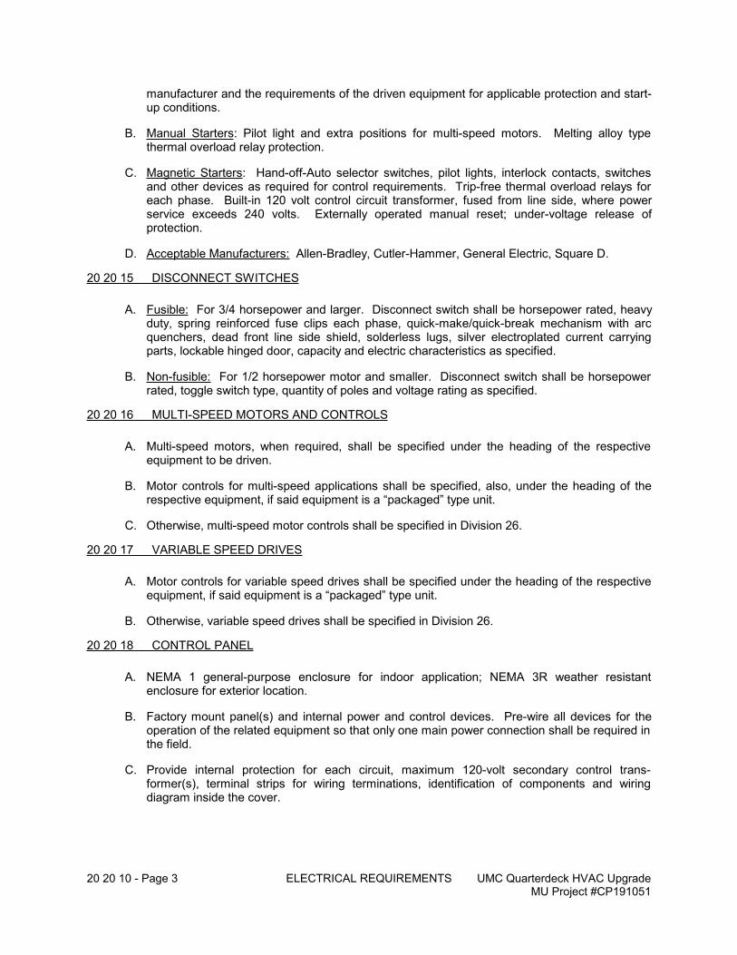
20 20 10 - Page 3 ELECTRICAL REQUIREMENTS UMC Quarterdeck HVAC UpgradeMU Project #CP191051
manufacturer and the requirements of the driven equipment for applicable protection and start-up conditions.
B. Manual Starters: Pilot light and extra positions for multi-speed motors. Melting alloy type thermal overload relay protection.
C. Magnetic Starters: Hand-off-Auto selector switches, pilot lights, interlock contacts, switches and other devices as required for control requirements. Trip-free thermal overload relays for each phase. Built-in 120 volt control circuit transformer, fused from line side, where power service exceeds 240 volts. Externally operated manual reset; under-voltage release of protection.
D. Acceptable Manufacturers: Allen-Bradley, Cutler-Hammer, General Electric, Square D.
20 20 15 DISCONNECT SWITCHES
A. Fusible: For 3/4 horsepower and larger. Disconnect switch shall be horsepower rated, heavy duty, spring reinforced fuse clips each phase, quick-make/quick-break mechanism with arc quenchers, dead front line side shield, solderless lugs, silver electroplated current carrying parts, lockable hinged door, capacity and electric characteristics as specified.
B. Non-fusible: For 1/2 horsepower motor and smaller. Disconnect switch shall be horsepower rated, toggle switch type, quantity of poles and voltage rating as specified.
20 20 16 MULTI-SPEED MOTORS AND CONTROLS
A. Multi-speed motors, when required, shall be specified under the heading of the respective equipment to be driven.
B. Motor controls for multi-speed applications shall be specified, also, under the heading of the respective equipment, if said equipment is a “packaged” type unit.
C. Otherwise, multi-speed motor controls shall be specified in Division 26.
20 20 17 VARIABLE SPEED DRIVES
A. Motor controls for variable speed drives shall be specified under the heading of the respective equipment, if said equipment is a “packaged” type unit.
B. Otherwise, variable speed drives shall be specified in Division 26.
20 20 18 CONTROL PANEL
A. NEMA 1 general-purpose enclosure for indoor application; NEMA 3R weather resistant enclosure for exterior location.
B. Factory mount panel(s) and internal power and control devices. Pre-wire all devices for the operation of the related equipment so that only one main power connection shall be required in the field.
C. Provide internal protection for each circuit, maximum 120-volt secondary control trans-former(s), terminal strips for wiring terminations, identification of components and wiring diagram inside the cover.
20 20 20 - Page 1 DRIVES AND GUARDS UMC Quarterdeck HVAC UpgradeMU Project #CP191051
20 20 20 DRIVES AND GUARDS
20 20 21 GENERAL
A. This Subsection covers V-belt, sprocket-chain, gear and direct coupled drives.
B. All drives shall be selected for 150% of specified motor nameplate horsepower.
C. All drives shall be installed, balanced and aligned in accordance with the respective manufacturer's instructions and recommendations.
20 20 22 V-BELT DRIVES
A. All motors shall be provided with variable pitch pulleys with design RPM at mid-range of adjustment.
B. V-belts shall be premium quality, endless cord impregnated rubber with trapezoidal cross section, type A, B, C or D, matched set (if more than one), 95% minimum drive efficiency.
C. The driving motor shall be installed on an adjustable bolt device to provide for belt tension adjustment.
D. Acceptable manufacturers:
1. V-belt drives: Browning, Eaton, Gates
20 20 23 DIRECT DRIVES
A. Wherever available, motors and related direct driven equipment shall be mounted on a common base.
20 20 24 GUARDS
A. All belts, chains, pulleys, shafts, sheaves, sprockets, gears, couplings, projecting setscrews, keys and any other rotating parts shall be provided with guards by the Contractor furnishing the base equipment.
B. Guards shall be designed and arranged in accordance with OSHA requirements.
C. Guards shall completely enclose the drive, shall be secured to the respective equipment and shall be removable for servicing. Wherever available from the manufacturer, guards shall be provided with the equipment. If not, these shall be field fabricated.
D. Provide reinforced openings with removable coverplates for access to motor and driven shafts for speed measurement.
E. Extend tubing for grease fittings inside the guard to accessible locations outside the guard.
20 20 25 INSTALLATION AND OPERATION
A. Install, balance and align all drives in accordance with the respective manufacturer's instructions and recommendations.
B. The balancing and alignment of drives including pinning, doweling and grouting shall be the responsibility of the Contractor furnishing the equipment. Any adversities arising from executing the Work shall be resolved/remedied by the Contractor.
20 20 20 - Page 2 DRIVES AND GUARDS UMC Quarterdeck HVAC UpgradeMU Project #CP191051
C. Verify all electrical characteristics prior to running electric motor driven equipment. Check motor amperage draw and rotation for proper operation.
20 25 00 - Page 1 INSULATION UMC Quarterdeck HVAC UpgradeMU Project #CP191051
20 25 00 INSULATION
20 25 01 GENERAL
A. This Section specifies mechanical insulation of piping, equipment and ductwork.
B. The Plans, the general provisions of the Contract including the General, Supplementary and/or Special Conditions and specification sections of Division 1 shall apply to Work of Divisions 20 - 29 of the Specifications.
C. Provisions and conditions cited in this Section shall apply to Work for other sections of Divisions 20 - 29 of these Specifications.
20 25 02 REFERENCES, REGULATORY REQUIREMENTS
A. Work for this Section of the Specifications shall be performed in accordance with the Codes, Standards, etc. as identified in Division 20 in addition to the following:
1. State and local Air Pollution Codes and Regulations.
2. NFPA 255/UL 723/ASTM E-84 Surface Burning Characteristics of Building Materials.
3. UL 1479/ASTM E-814 Fire Test of Through-Penetration Firestops.
20 25 03 RELATED SECTIONS OF THE SPECIFICATIONS
A. Requirements of the following Sections of the Specifications apply to Work for this Section:.1 Division 20 - Basic Mechanical Conditions.2 Division 20 - Basic Mechanical Materials and Methods.3 Division 22 - Plumbing Work.4 Division 23 - HVAC Piping and Equipment.5 Division 24 - Air Distribution
20 25 04 DEFINITIONS
A. The term “fitting” where used in this Section of the Specifications shall be construed as an elbow, tee or reducer. Unions, flanges and valves shall not be considered as fittings.
B. The term “cold” shall be defined as the temperature of a surface that may result in the formation of condensation.
C. The term “accessory” shall include staples, bands, wire, mesh, clips, pins, studs, tape, anchors, corner angles, cements, adhesives, coatings, sealers, mastics, finishes, etc.
D. The term “ASJ” where used in this Section of the Specifications shall mean a reinforced vapor retarding All Service Jacket.
E. The term “SSL” where used in this Section of the Specifications shall mean Self-sealing Lap Joint closure system for longitudinal jacket joints.
F. The term “supply air” where used in this Section of the Specifications shall mean downstream of a coil.
G. The term “outdoor air” where used in this Section of the Specifications shall mean ambient air that has not been conditioned.
H. The term “return air” where used in this Section of the Specifications shall mean conditioned air that is returned from the space.
20 25 00 - Page 2 INSULATION UMC Quarterdeck HVAC UpgradeMU Project #CP191051
I. The term “mixed air” where used in this Section of the Specifications shall mean air streams that are a mixture of “outdoor air” and “return air”.
J. The term “relief air” where used in this Section of the Specifications shall mean excess return air that is relieved from the building.
K. The term “exhaust air” where used in this Section of the Specifications shall mean air that is removed due to contaminates, odors, or heat.
20 25 05 WORK INCLUDED
A. Furnish material, labor and services necessary for and incidental to the insulation of the following systems where shown on the Plans and as hereinafter specified. Include all necessary considerations in the related sections of the Specifications (Subsection 20 25 03) to perform the Work completely.
1. Refrigerant piping suction, hot gas/discharge
2. Condensate drain piping.
3. Ductwork/sheetmetal systems.
B. Providing appropriate size calcium silicate/cellular glass/pipe shield manufactured inserts to the trade contractor for installation between the pipes and oversized hangers as specified in this section.
C. Fire wrapping piping system located in occupied spaces or plenum spaces that do not meet flame spread 25 and smoke development 50.
20 25 06 SUBMITTALS
A. The Contractor shall submit shop drawings for approval in accordance with Subsection 20 00 43, Duties of Contractor - Submittals.
B. Provide an INSULATION PRODUCT SCHEDULE consisting of the following minimum information:
Material - type of insulation material, jackets, or covers.Manufacturer - manufacturers name, product name, and K-value where applicable.Accessories - tapes, staples, coatings, adhesives including manufacturer's name andproduct name.Systems - indicate systems where product is used.
C. Provide an INSULATION THICKNESS SCHEDULE consisting of the following minimum information:
System - indicate which system insulation is installed.Location - inside, outside, concealed, exposed, etc.Size - indicate size range of pipe, insulation type used.Thickness - indicate insulation thickness in inches.
D. Provide manufacturer's technical product data of each material and accessory item with engineering support information and recommended installation procedure. Indicate product number, “K” value, thickness and required accessories for each application.
E. At the completion of the project, submit a letter stating all materials are asbestos free, and meet the specified ASTM E-84 flame/smoke rating of 25/50, and that all piping and duct penetrations are smoke or fire stopped as required by the Code.
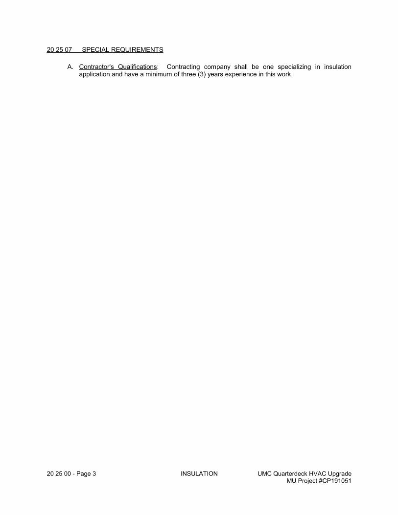
20 25 00 - Page 3 INSULATION UMC Quarterdeck HVAC UpgradeMU Project #CP191051
20 25 07 SPECIAL REQUIREMENTS
A. Contractor's Qualifications: Contracting company shall be one specializing in insulation application and have a minimum of three (3) years experience in this work.
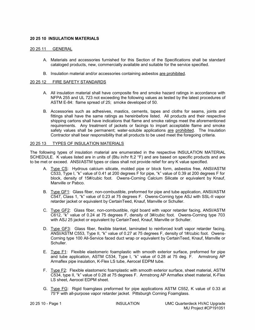
20 25 10 - Page 1 INSULATION UMC Quarterdeck HVAC UpgradeMU Project #CP191051
20 25 10 INSULATION MATERIALS
20 25 11 GENERAL
A. Materials and accessories furnished for this Section of the Specifications shall be standard cataloged products, new, commercially available and suitable for the service specified.
B. Insulation material and/or accessories containing asbestos are prohibited.
20 25 12 FIRE SAFETY STANDARDS
A. All insulation material shall have composite fire and smoke hazard ratings in accordance with NFPA 255 and UL 723 not exceeding the following values as tested by the latest procedures of ASTM E-84: flame spread of 25; smoke developed of 50.
B. Accessories such as adhesives, mastics, cements, tapes and cloths for seams, joints and fittings shall have the same ratings as hereinbefore listed. All products and their respective shipping cartons shall have indications that flame and smoke ratings meet the aforementioned requirements. Any treatment of jackets or facings to impart acceptable flame and smoke safety values shall be permanent; water-soluble applications are prohibited. The Insulation Contractor shall bear responsibility that all products to be used meet the foregoing criteria.
20 25 13 TYPES OF INSULATION MATERIALS
The following types of insulation material are enumerated in the respective INSULATION MATERIAL SCHEDULE. K values listed are in units of (Btu in/hr ft.2 °F) and are based on specific products and are to be met or exceed. ANSI/ASTM types or class shall not provide relief for any K value specified.
A. Type CS: Hydrous calcium silicate, molded pipe or block form, asbestos free, ANSI/ASTM C533, Type I, “k” value of 0.41 at 200 degrees F for pipe, “k” value of 0.39 at 200 degrees F for block, density of 15#/cubic foot. Owens-Corning Calcium Silicate or equivalent by Knauf, Manville or Pabco.
B. Type GF1: Glass fiber, non-combustible, preformed for pipe and tube application, ANSI/ASTM C547, Class 1, “k” value of 0.23 at 75 degrees F. Owens-Corning type ASJ with SSL-II vapor retarder jacket or equivalent by CertainTeed, Knauf, Manville or Schuller.
C. Type GF2: Glass fiber, non-combustible, rigid board with vapor retarder facing, ANSI/ASTM C612, “k” value of 0.24 at 75 degrees F, density of 3#/cubic foot. Owens-Corning type 703 with ASJ 25 jacket or equivalent by CertainTeed, Knauf, Manville or Schuller.
D. Type GF3: Glass fiber, flexible blanket, laminated to reinforced kraft vapor retarder facing, ANSI/ASTM C553, Type II, “k” value of 0.27 at 75 degrees F, density of 1#/cubic foot. Owens-Corning type 100 All-Service faced duct wrap or equivalent by CertainTeed, Knauf, Manville or Schuller.
E. Type F1: Flexible elastomeric foamplastic with smooth exterior surface, preformed for pipe and tube application, ASTM C534, Type I, “k” value of 0.28 at 75 deg. F. Armstrong AP Armaflex pipe insulation, K-Flex LS tube, Aerocel EDPM tube.
F. Type F2: Flexible elastomeric foamplastic with smooth exterior surface, sheet material, ASTM C534, type II, “k” value of 0.28 at 75 degrees F. Armstrong AP Armaflex sheet material, K-Flex LS sheet, Aerocel EDPM sheet.
G. Type FG: Rigid foamglass preformed for pipe applications ASTM C552, K value of 0.33 at 75°F with all-purpose vapor retarder jacket. Pittsburgh Corning Foamglass.
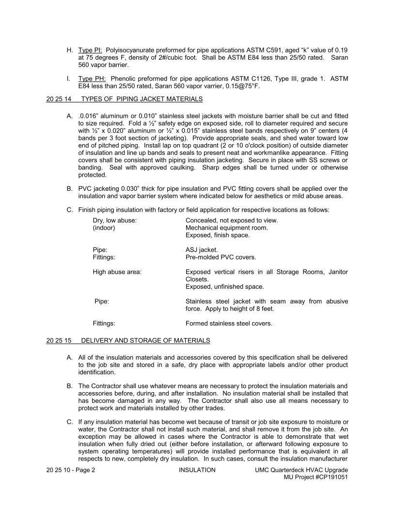
20 25 10 - Page 2 INSULATION UMC Quarterdeck HVAC UpgradeMU Project #CP191051
H. Type PI: Polyisocyanurate preformed for pipe applications ASTM C591, aged “k” value of 0.19 at 75 degrees F, density of 2#/cubic foot. Shall be ASTM E84 less than 25/50 rated. Saran 560 vapor barrier.
I. Type PH: Phenolic preformed for pipe applications ASTM C1126, Type III, grade 1. ASTM E84 less than 25/50 rated, Saran 560 vapor varrier, 0.15@75°F.
20 25 14 TYPES OF PIPING JACKET MATERIALS
A. .0.016” aluminum or 0.010” stainless steel jackets with moisture barrier shall be cut and fitted to size required. Fold a ½” safety edge on exposed side, roll to diameter required and secure with ½” x 0.020” aluminum or ½” x 0.015” stainless steel bands respectively on 9” centers (4 bands per 3 foot section of jacketing). Provide appropriate seals, and shed water toward low end of pitched piping. Install lap on top quadrant (2 or 10 o'clock position) of outside diameter of insulation and line up bands and seals to present neat and workmanlike appearance. Fitting covers shall be consistent with piping insulation jacketing. Secure in place with SS screws or banding. Seal with approved caulking. Sharp edges shall be turned under or otherwise protected.
B. PVC jacketing 0.030” thick for pipe insulation and PVC fitting covers shall be applied over the insulation and vapor barrier system where indicated below for aesthetics or mild abuse areas.
C. Finish piping insulation with factory or field application for respective locations as follows:
Dry, low abuse: Concealed, not exposed to view.(indoor) Mechanical equipment room.
Exposed, finish space.
Pipe: ASJ jacket. Fittings: Pre-molded PVC covers.
High abuse area: Exposed vertical risers in all Storage Rooms, Janitor Closets.Exposed, unfinished space.
Pipe: Stainless steel jacket with seam away from abusive
force. Apply to height of 8 feet.
Fittings: Formed stainless steel covers.
20 25 15 DELIVERY AND STORAGE OF MATERIALS
A. All of the insulation materials and accessories covered by this specification shall be delivered to the job site and stored in a safe, dry place with appropriate labels and/or other product identification.
B. The Contractor shall use whatever means are necessary to protect the insulation materials and accessories before, during, and after installation. No insulation material shall be installed that has become damaged in any way. The Contractor shall also use all means necessary to protect work and materials installed by other trades.
C. If any insulation material has become wet because of transit or job site exposure to moisture or water, the Contractor shall not install such material, and shall remove it from the job site. An exception may be allowed in cases where the Contractor is able to demonstrate that wet insulation when fully dried out (either before installation, or afterward following exposure to system operating temperatures) will provide installed performance that is equivalent in all respects to new, completely dry insulation. In such cases, consult the insulation manufacturer
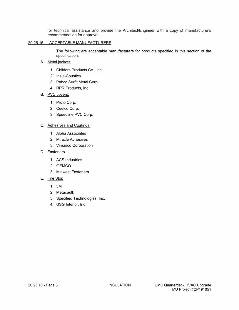
20 25 10 - Page 3 INSULATION UMC Quarterdeck HVAC UpgradeMU Project #CP191051
for technical assistance and provide the Architect/Engineer with a copy of manufacturer's recommendation for approval.
20 25 16 ACCEPTABLE MANUFACTURERS
The following are acceptable manufacturers for products specified in this section of the specification.
A. Metal jackets:
1. Childers Products Co., Inc.
2. Insul-Coustics
3. Pabco Surfit Metal Corp.
4. RPR Products, Inc.
B. PVC covers:
1. Proto Corp.
2. Ceelco Corp.
3. Speedline PVC Corp.
C. Adhesives and Coatings:
1. Alpha Associates
2. Miracle Adhesives
3. Vimasco Corporation
D. Fasteners
1. ACS Industries
2. GEMCO
3. Midwest Fasteners
E. Fire Stop
1. 3M
2. Metacaulk
3. Specified Technologies, Inc.
4. USG Interior, Inc.
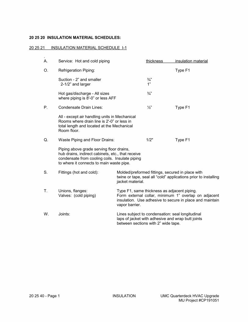
20 25 40 - Page 1 INSULATION UMC Quarterdeck HVAC UpgradeMU Project #CP191051
20 25 20 INSULATION MATERIAL SCHEDULES:
20 25 21 INSULATION MATERIAL SCHEDULE I-1
.A. Service: Hot and cold piping thickness insulation material
O. Refrigeration Piping: Type F1
Suction - 2” and smaller ¾” 2-1/2” and larger 1”
Hot gas/discharge - All sizes ¾”where piping is 8'-0” or less AFF
P. Condensate Drain Lines: ½” Type F1
All - except air handling units in MechanicalRooms where drain line is 2'-0” or less in total length and located at the MechanicalRoom floor.
Q. Waste Piping and Floor Drains: 1/2" Type F1
Piping above grade serving floor drains,hub drains, indirect cabinets, etc., that receivecondensate from cooling coils. Insulate pipingto where it connects to main waste pipe.
S. Fittings (hot and cold): Molded/preformed fittings, secured in place with twine or tape, seal all “cold” applications prior to installing jacket material.
T. Unions, flanges: Type F1, same thickness as adjacent piping.Valves: (cold piping) Form external collar, minimum 1” overlap on adjacent
insulation. Use adhesive to secure in place and maintain vapor barrier.
W. Joints: Lines subject to condensation: seal longitudinal laps of jacket with adhesive and wrap butt joints
between sections with 2” wide tape.
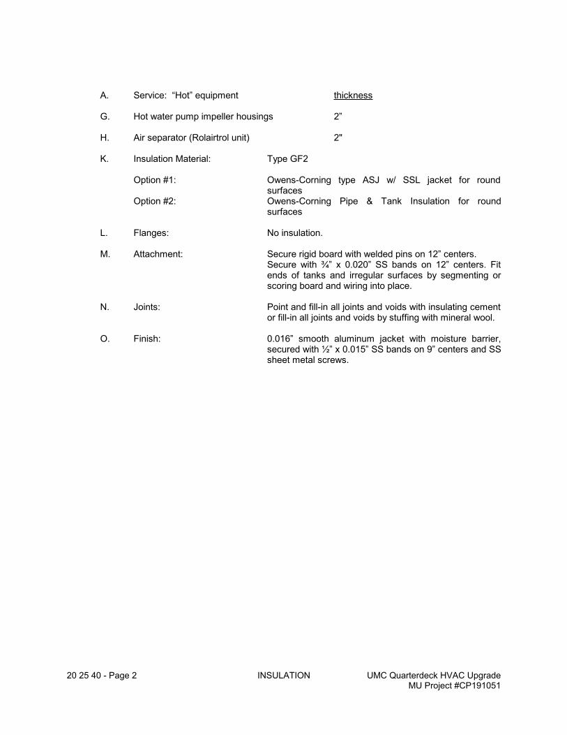
20 25 40 - Page 2 INSULATION UMC Quarterdeck HVAC UpgradeMU Project #CP191051
A. Service: “Hot” equipment thickness
G. Hot water pump impeller housings 2”
H. Air separator (Rolairtrol unit) 2"
K. Insulation Material: Type GF2
Option #1: Owens-Corning type ASJ w/ SSL jacket for round surfaces
Option #2: Owens-Corning Pipe & Tank Insulation for round surfaces
L. Flanges: No insulation.
M. Attachment: Secure rigid board with welded pins on 12” centers. Secure with ¾” x 0.020” SS bands on 12” centers. Fit ends of tanks and irregular surfaces by segmenting or scoring board and wiring into place.
N. Joints: Point and fill-in all joints and voids with insulating cement or fill-in all joints and voids by stuffing with mineral wool.
O. Finish: 0.016” smooth aluminum jacket with moisture barrier, secured with ½” x 0.015” SS bands on 9” centers and SS sheet metal screws.
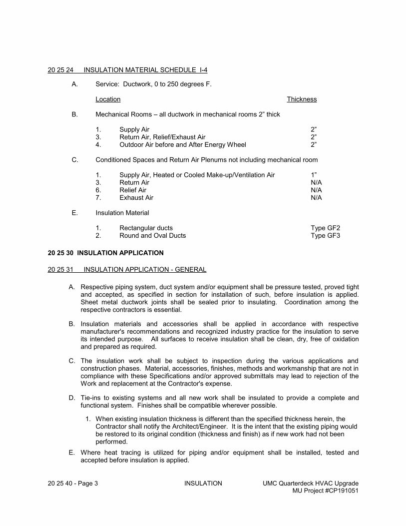
20 25 40 - Page 3 INSULATION UMC Quarterdeck HVAC UpgradeMU Project #CP191051
20 25 24 INSULATION MATERIAL SCHEDULE I-4
A. Service: Ductwork, 0 to 250 degrees F.
Location Thickness
B. Mechanical Rooms – all ductwork in mechanical rooms 2” thick
1. Supply Air 2”3. Return Air, Relief/Exhaust Air 2”4. Outdoor Air before and After Energy Wheel 2”
C. Conditioned Spaces and Return Air Plenums not including mechanical room
1. Supply Air, Heated or Cooled Make-up/Ventilation Air 1”3. Return Air N/A6. Relief Air N/A7. Exhaust Air N/A
E. Insulation Material
1. Rectangular ducts Type GF22. Round and Oval Ducts Type GF3
20 25 30 INSULATION APPLICATION
20 25 31 INSULATION APPLICATION - GENERAL
A. Respective piping system, duct system and/or equipment shall be pressure tested, proved tight and accepted, as specified in section for installation of such, before insulation is applied. Sheet metal ductwork joints shall be sealed prior to insulating. Coordination among the respective contractors is essential.
B. Insulation materials and accessories shall be applied in accordance with respective manufacturer's recommendations and recognized industry practice for the insulation to serve its intended purpose. All surfaces to receive insulation shall be clean, dry, free of oxidation and prepared as required.
C. The insulation work shall be subject to inspection during the various applications and construction phases. Material, accessories, finishes, methods and workmanship that are not in compliance with these Specifications and/or approved submittals may lead to rejection of the Work and replacement at the Contractor's expense.
D. Tie-ins to existing systems and all new work shall be insulated to provide a complete and functional system. Finishes shall be compatible wherever possible.
1. When existing insulation thickness is different than the specified thickness herein, the Contractor shall notify the Architect/Engineer. It is the intent that the existing piping would be restored to its original condition (thickness and finish) as if new work had not been performed.
E. Where heat tracing is utilized for piping and/or equipment shall be installed, tested and accepted before insulation is applied.
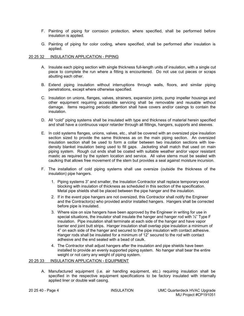
20 25 40 - Page 4 INSULATION UMC Quarterdeck HVAC UpgradeMU Project #CP191051
F. Painting of piping for corrosion protection, where specified, shall be performed before insulation is applied.
G. Painting of piping for color coding, where specified, shall be performed after insulation is applied.
20 25 32 INSULATION APPLICATION - PIPING
A. Insulate each piping section with single thickness full-length units of insulation, with a single cut piece to complete the run where a fitting is encountered. Do not use cut pieces or scraps abutting each other.
B. Extend piping insulation without interruptions through walls, floors, and similar piping penetrations, except where otherwise specified.
C. Insulation on unions, flanges, valves, strainers, expansion joints, pump impeller housings and other equipment requiring accessible servicing shall be removable and reusable without damage. Items requiring periodic attention shall have covers and/or casings to contain the insulation.
D. All “cold” piping systems shall be insulated with type and thickness of material herein specified and shall have a continuous vapor retarder through all fittings, hangers, supports and sleeves.
E. In cold systems flanges, unions, valves, etc., shall be covered with an oversized pipe insulation section sized to provide the same thickness as on the main piping section. An oversized insulation section shall be used to form a collar between two insulation sections with low-density blanket insulation being used to fill gaps. Jacketing shall match that used on main piping system. Rough cut ends shall be coated with suitable weather and/or vapor resistant mastic as required by the system location and service. All valve stems must be sealed with caulking that allows free movement of the stem but provides a seal against moisture incursion.
F. The installation of cold piping systems shall use oversize (outside the thickness of the insulation) pipe hangers.
1. Piping systems 3” and smaller, the Insulation Contractor shall replace temporary wood blocking with insulation of thickness as scheduled in this section of the specification. Metal pipe shields shall be placed between the pipe hanger and the insulation.
2. If in the event pipe hangers are not oversized, this Contractor shall notify the Engineer and the Contractor(s) who provided and/or installed hangers. Hangers shall be corrected before pipe is insulated.
3. Where size on size hangers have been approved by the Engineer in writing for use in special situations, the insulator shall insulate the hanger and hanger rod with ½” Type F insulation. Pipe insulation shall terminate at each side of the hanger and have vapor barrier end joint butt strips. Hanger insulation shall overlap pipe insulation a minimum of 4” on each side of the hanger and secured to the pipe insulation with contact adhesive. Hanger rods shall be insulated for a minimum of 12” secured to the rod with contact adhesive and the end sealed with a bead of caulk.
4. The Contractor shall adjust hangers after the insulation and pipe shields have been installed to provide an evenly supported piping system. No hanger shall bear the entire weight or not carry any weight of piping system.
20 25 33 INSULATION APPLICATION - EQUIPMENT
A. Manufactured equipment (i.e. air handling equipment, etc.) requiring insulation shall be specified in the respective equipment specifications to be factory insulated with internally applied liner or double wall casing.
20 25 40 - Page 5 INSULATION UMC Quarterdeck HVAC UpgradeMU Project #CP191051
20 25 34 INSULATION APPLICATION - DUCTWORK
A. Ductwork systems shall be insulated in accordance with the insulation schedules. Insulate each duct section with single thickness full length pieces. Do not use scraps abutting each other.
B. Extend insulation without interruptions through walls, floors, and similar penetration, except where otherwise specified.
C. “Cold” duct systems shall have insulation with a continuous vapor retarder through all fittings, hangers, supports, air devices, fire dampers, duct mounted coils, dampers, and other devices in the ductwork system, etc.
D. In “cold” duct systems, using rigid board or sheet elastomeric foam insulation, support angles, stiffener angles, ductmate flanges, etc. they shall be covered with an oversized insulation strip sized to provide the same insulation thickness as on the duct. Provide a minimum of 2” of overlap on each side of the obstruction.
E. Board insulation shall be properly cut and dry fitted to the surface to be insulated. Edges shall be neat and clean cut. No intermediate cut pieces shall be allowed on the bottom and sides of the ductwork. Insulation board shall be secured in place using mechanical fasteners such as welded pins or speed clips. Locate not less than 3” from each edge or corner and approximately 12” on centers on all sides. There shall be a minimum of two (2) rows of pins on the bottom of the duct and one (1) on the sides. Additional pins may be needed on the bottom to prevent sagging. All seams, joints, penetrations and breaks in the vapor retarder jacket shall be sealed with pressure sensitive tape matching insulation facing. Edges shall be provided with 28 ga. 1” x 1” aluminum corner beading properly secured and shall have the same facing material as the insulation board.
F. Flexible duct wrap insulation shall be cut properly and fitted to “stretchout” dimensions and a 2” piece of insulation removed from the facing at the end of the piece to form an overlapping staple and tape flap. Insulation shall be installed with facing outside so tape flap overlaps facing at the other end. Insulation shall be butted tightly. Seams shall be stapled on 6” centers with outward clinching staples. Adjacent sections of duct wrap insulation shall be butted tightly with the 2” tape flap overlapping and stapled. For horizontal oval ducts over 30” wide, duct wrap insulation shall be secured additionally to the bottom of the duct with mechanical fasteners such as pins and speed clip washers spaced on 18” centers to prevent sagging. All seams, joints, tears, punctures and other penetrations in the vapor retarder jacket shall be sealed with FRK backing pressure sensitive tape.
G. Stop and point insulation around access doors and damper operators to allow operation without disturbing insulation.
H. Where a duct run changes from interior lining to exterior application (or vice versa), there shall be a 6” overlap of insulation.
I. In "cold" duct system with internal duct insulation, with 1 1/2 " thickness flexible duct wrap, insulate air devices, fire dampers, duct mounted coils, dampers, and other devices in the ductwork system that are not internally insulated.
END OF SECTION
21 00 00 – TOC FIRE PROTECTION SYSTEM UMC Quarterdeck HVAC UpgradeMU Project #CP191051
TABLE OF CONTENTS
DIVISION 21 – FIRE PROTECTION SYSTEM
21 00 00 FIRE PROTECTION SYSTEM......................................................................................................121 00 01 GENERAL................................................................................................................................121 00 02 REFERENCES, REGULATORY REQUIREMENTS................................................................121 00 03 REFERENCES, RELATED SECTIONS of the SPECIFICATIONS .........................................121 00 04 DEFINITIONS ..........................................................................................................................121 00 05 WORK INCLUDED ..................................................................................................................221 00 06 SUBMITTALS ..........................................................................................................................221 00 07 SPECIAL REQUIREMENTS....................................................................................................221 00 08 CLOSE-OUT REQUIREMENTS..............................................................................................2
21 00 10 DESIGN .........................................................................................................................................321 00 11 WATER SUPPLY.....................................................................................................................321 00 12 LAYOUT - GENERAL to all SPRINKLER SYSTEMS ..............................................................321 00 13 APPROVALS ...........................................................................................................................321 00 14 TESTING .................................................................................................................................421 00 15 ACCEPTANCE ........................................................................................................................421 00 16 SPACE CLASSIFICATION ......................................................................................................5
21 00 20 SERVICE ENTRANCE ...................................................................................................................521 00 28 PIPING MATERIAL and FITTING SCHEDULE .......................................................................5
21 00 30 WET PIPE SPRINKLER SYSTEM.................................................................................................621 00 31 SPRINKLER HEADS ...............................................................................................................6
21 00 00 - Page 1 FIRE PROTECTION SYSTEM UMC Quarterdeck HVAC UpgradeMU Project #CP191051
21 00 00 FIRE PROTECTION SYSTEM
21 00 01 GENERAL
A. This section specifies a hydraulically calculated fire protection system designed and installed by the Contractor as described on the drawings and hereinafter.
B. It is the intent that the drawings and specifications shall describe and provide for a working installation complete in every detail and all items necessary for such complete installation shall be furnished whether specifically mentioned or not.
C. The Plans, the general provisions of the Contract including the General, Supplementary and/or Special Conditions and specification sections of Division 1 shall apply to Work of Divisions 20 - 29 of the Specifications.
D. Provisions and conditions cited in this Section shall apply to Work for other sections of Divisions 20 - 29 of these Specifications.
21 00 02 REFERENCES, REGULATORY REQUIREMENTS
A. Work for this Section of the Specifications shall be performed in accordance with the Codes, Standards, etc. as identified in Division 20 in addition to the following:
1. National Fire Protection Association (NFPA) 13, 2016.
2. National Fire Protection Association (NFPA) 14, 2016.
3. The Local Authority having jurisdiction.
4. Owner’s Insurance carrier – FM Global
21 00 03 REFERENCES, RELATED SECTIONS OF THE SPECIFICATIONS
Requirements of the following Sections of the Specifications apply to Work for this Section:
A. Division 20 - Basic Mechanical Conditions.
B. Division 20 - Basic Mechanical Materials and Methods
21 00 04 DEFINITIONS
A. The term “layout” where used in this Section of the Specifications shall mean drawings prepared by the Contractor showing where all piping and heads are located. These drawings should include pipe elevations, need not include pipe sizes and should not include hydraulic calculations.
B. The term “Authority Having Jurisdiction” or “AHJ” where used in this Section of the Specification shall mean the organization, office, or individual responsible for approving equipment, an installation, or a procedure.
C. The term “rhythm” where used in this Section of the Specifications shall mean spaced in a manner which would place the heads at the same location with respect to lights or diffusers (i.e., for a row of lights spaced at 12' centers heads shall also be on 12' centers so that the heads will remain the same number of ceiling tiles or distance away from the lights; where there is an odd number of tiles between lights or diffusers, it is also preferable to have heads located at the tile centered between them).
21 00 00 - Page 2 FIRE PROTECTION SYSTEM UMC Quarterdeck HVAC UpgradeMU Project #CP191051
D. The term “working drawings” where used in this Section of the Specifications shall mean drawing of the quality and containing all information as which would be required for approval by local official and for field construction.
21 00 05 WORK INCLUDED
A. Furnish material, labor and services necessary for and incidental to the installation of the following systems where shown on the Plans and as hereinafter specified. Include all necessary work in the related sections of the Specifications (Subsection 21 00 03 to perform the Work completely.
B. Furnish and install a complete hydraulically engineered fire protection system for a fully sprinklered building, including but not limited to:
1. Wet pipe systems for areas not subject to freezing.
2. Hydraulic calculations shall include the domestic water demand in all common piping back to the point of the flow test.
C. Verify actual water supply with a test, preferably witnessed or performed by the local fire official.
D. Contractor shall coordinate his work with the work of other trades, and with the architectural and structural drawings.
21 00 06 SUBMITTALS
A. The Contractor shall prepare submittals for approval in accordance with Subsection 20 00 43, Duties of Contractor - Submittals.
B. Submit “Layout drawings” and equipment cut sheets with 30 days from the General Contractor’s contract date.
C. Contractor shall submit “Working drawings” coordinated with the other trades for review prior to any fabrication or installation and prior to the General Contractor’s fourth partial pay request.
21 00 07 SPECIAL REQUIREMENTS
A. The Contractor preparing the drawings and calculations shall be NICET Level 3 certified or a Professional Engineer licensed in the State of MIssouri, whichever is required by the Authority Having Jurisdiction.
B. All equipment shall be U.L. Listed or F.M. approved for use in fire protection systems.
C. Where Pipe and accessories installed under this section of the specification tie-in to existing systems, Contractor shall verify existing lines for: sizes, direction of flow (via pressure or physical tracing of piping, not labels), materials, and elevations before installing new work. Contractor shall notify Architect/Engineer upon discovery of discrepancy. Work performed prior to verification will be corrected at no cost to Owner.
21 00 08 CLOSE-OUT REQUIREMENTS
A. Reference Section 20 00 48.
B. Where NFPA maintenance information is utilized, it shall be edited to contain only information that is relevant to this project.
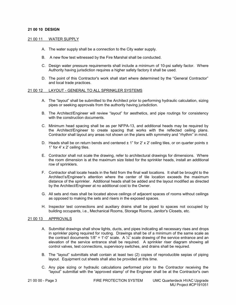
21 00 00 - Page 3 FIRE PROTECTION SYSTEM UMC Quarterdeck HVAC UpgradeMU Project #CP191051
21 00 10 DESIGN
21 00 11 WATER SUPPLY
A. The water supply shall be a connection to the City water supply.
B. A new flow test witnessed by the Fire Marshal shall be conducted.
C. Design water pressure requirements shall include a minimum of 10-psi safety factor. Where Authority having jurisdiction requires a higher safety factory it shall be used.
D. The point of this Contractor's work shall start where determined by the “General Contractor” and local trade practices.
21 00 12 LAYOUT - GENERAL TO ALL SPRINKLER SYSTEMS
A. The “layout” shall be submitted to the Architect prior to performing hydraulic calculation, sizing pipes or seeking approvals from the authority having jurisdiction.
B. The Architect/Engineer will review “layout” for aesthetics, and pipe routings for consistency with the construction documents.
C. Minimum head spacing shall be as per NFPA-13, and additional heads may be required by the Architect/Engineer to create spacing that works with the reflected ceiling plans. Contractor shall layout any areas not shown on the plans with symmetry and “rhythm” in mind.
D. Heads shall be on return bends and centered ± 1” for 2' x 2' ceiling tiles, or on quarter points ± 1” for 4' x 2' ceiling tiles.
E. Contractor shall not scale the drawing, refer to architectural drawings for dimensions. Where the room dimension is at the maximum size listed for the sprinkler heads, install an additional row of sprinklers.
F. Contractor shall locate heads in the field from the final wall locations. It shall be brought to the Architect’s/Engineer’s attention where the center of tile location exceeds the maximum distance of the sprinkler. Additional heads shall be added and the layout modified as directed by the Architect/Engineer at no additional cost to the Owner.
G. All sets and rises shall be located above ceilings of adjacent spaces of rooms without ceilings as opposed to making the sets and risers in the exposed spaces.
H. Inspector test connections and auxiliary drains shall be piped to spaces not occupied by building occupants, i.e., Mechanical Rooms, Storage Rooms, Janitor's Closets, etc.
21 00 13 APPROVALS
A. Submittal drawings shall show lights, ducts, and pipes indicating all necessary rises and drops in sprinkler piping required for routing. Drawings shall be of a minimum of the same scale as the contract documents 1/8” = 1'-0” scale. A ¼” scale drawing of the service entrance and an elevation of the service entrance shall be required. A sprinkler riser diagram showing all control valves, test connections, supervisory switches, and drains shall be required.
B. The “layout” submittals shall contain at least two (2) copies of reproducible sepias of piping layout. Equipment cut sheets shall also be provided at this time.
C. Any pipe sizing or hydraulic calculations performed prior to the Contractor receiving the “layout” submittal with the 'approved stamp' of the Engineer shall be at the Contractor's own
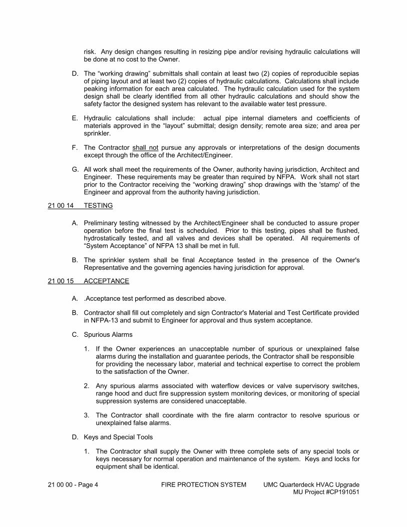
21 00 00 - Page 4 FIRE PROTECTION SYSTEM UMC Quarterdeck HVAC UpgradeMU Project #CP191051
risk. Any design changes resulting in resizing pipe and/or revising hydraulic calculations will be done at no cost to the Owner.
D. The “working drawing” submittals shall contain at least two (2) copies of reproducible sepias of piping layout and at least two (2) copies of hydraulic calculations. Calculations shall include peaking information for each area calculated. The hydraulic calculation used for the system design shall be clearly identified from all other hydraulic calculations and should show the safety factor the designed system has relevant to the available water test pressure.
E. Hydraulic calculations shall include: actual pipe internal diameters and coefficients of materials approved in the “layout” submittal; design density; remote area size; and area per sprinkler.
F. The Contractor shall not pursue any approvals or interpretations of the design documents except through the office of the Architect/Engineer.
G. All work shall meet the requirements of the Owner, authority having jurisdiction, Architect and Engineer. These requirements may be greater than required by NFPA. Work shall not start prior to the Contractor receiving the “working drawing” shop drawings with the 'stamp' of the Engineer and approval from the authority having jurisdiction.
21 00 14 TESTING
A. Preliminary testing witnessed by the Architect/Engineer shall be conducted to assure proper operation before the final test is scheduled. Prior to this testing, pipes shall be flushed, hydrostatically tested, and all valves and devices shall be operated. All requirements of “System Acceptance” of NFPA 13 shall be met in full.
B. The sprinkler system shall be final Acceptance tested in the presence of the Owner's Representative and the governing agencies having jurisdiction for approval.
21 00 15 ACCEPTANCE
A. .Acceptance test performed as described above.
B. Contractor shall fill out completely and sign Contractor's Material and Test Certificate provided in NFPA-13 and submit to Engineer for approval and thus system acceptance.
C. Spurious Alarms
1. If the Owner experiences an unacceptable number of spurious or unexplained false alarms during the installation and guarantee periods, the Contractor shall be responsible for providing the necessary labor, material and technical expertise to correct the problem to the satisfaction of the Owner.
2. Any spurious alarms associated with waterflow devices or valve supervisory switches, range hood and duct fire suppression system monitoring devices, or monitoring of special suppression systems are considered unacceptable.
3. The Contractor shall coordinate with the fire alarm contractor to resolve spurious or unexplained false alarms.
D. Keys and Special Tools
1. The Contractor shall supply the Owner with three complete sets of any special tools or keys necessary for normal operation and maintenance of the system. Keys and locks for equipment shall be identical.
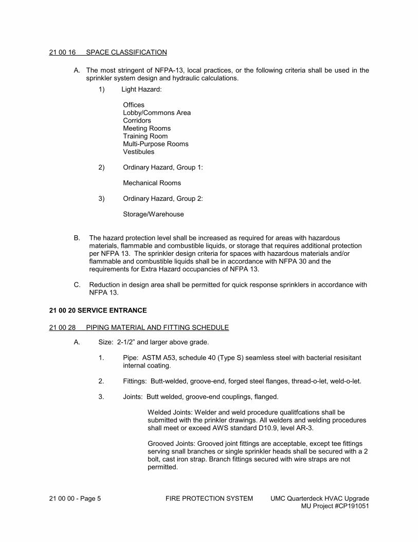
21 00 00 - Page 5 FIRE PROTECTION SYSTEM UMC Quarterdeck HVAC UpgradeMU Project #CP191051
21 00 16 SPACE CLASSIFICATION
A. The most stringent of NFPA-13, local practices, or the following criteria shall be used in the sprinkler system design and hydraulic calculations.
1) Light Hazard:
Offices Lobby/Commons Area Corridors Meeting Rooms Training Room
Multi-Purpose RoomsVestibules
2) Ordinary Hazard, Group 1:
Mechanical Rooms
3) Ordinary Hazard, Group 2:
Storage/Warehouse
B. The hazard protection level shall be increased as required for areas with hazardous materials, flammable and combustible liquids, or storage that requires additional protection per NFPA 13. The sprinkler design criteria for spaces with hazardous materials and/or flammable and combustible liquids shall be in accordance with NFPA 30 and the requirements for Extra Hazard occupancies of NFPA 13.
C. Reduction in design area shall be permitted for quick response sprinklers in accordance with NFPA 13.
21 00 20 SERVICE ENTRANCE
21 00 28 PIPING MATERIAL AND FITTING SCHEDULE
A. Size: 2-1/2” and larger above grade.
1. Pipe: ASTM A53, schedule 40 (Type S) seamless steel with bacterial resisitant internal coating.
2. Fittings: Butt-welded, groove-end, forged steel flanges, thread-o-let, weld-o-let.
3. Joints: Butt welded, groove-end couplings, flanged.
Welded Joints: Welder and weld procedure qualitfcations shall be submitted with the prinkler drawings. All welders and welding procedures shall meet or exceed AWS standard D10.9, level AR-3.
Grooved Joints: Grooved joint fittings are acceptable, except tee fittings serving snall branches or single sprinkler heads shall be secured with a 2 bolt, cast iron strap. Branch fittings secured with wire straps are not permitted.
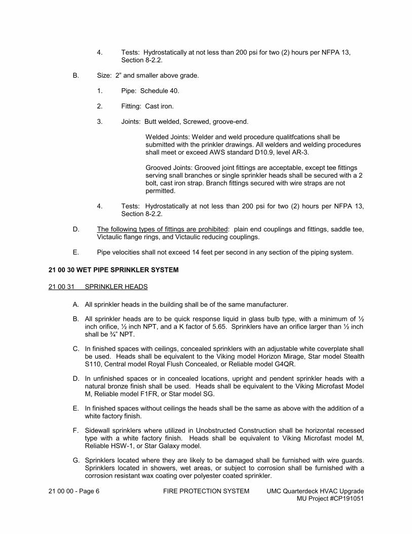
21 00 00 - Page 6 FIRE PROTECTION SYSTEM UMC Quarterdeck HVAC UpgradeMU Project #CP191051
4. Tests: Hydrostatically at not less than 200 psi for two (2) hours per NFPA 13, Section 8-2.2.
B. Size: 2” and smaller above grade.
1. Pipe: Schedule 40.
2. Fitting: Cast iron.
3. Joints: Butt welded, Screwed, groove-end.
Welded Joints: Welder and weld procedure qualitfcations shall be submitted with the prinkler drawings. All welders and welding procedures shall meet or exceed AWS standard D10.9, level AR-3.
Grooved Joints: Grooved joint fittings are acceptable, except tee fittings serving snall branches or single sprinkler heads shall be secured with a 2 bolt, cast iron strap. Branch fittings secured with wire straps are not permitted.
4. Tests: Hydrostatically at not less than 200 psi for two (2) hours per NFPA 13, Section 8-2.2.
D. The following types of fittings are prohibited: plain end couplings and fittings, saddle tee, Victaulic flange rings, and Victaulic reducing couplings.
E. Pipe velocities shall not exceed 14 feet per second in any section of the piping system.
21 00 30 WET PIPE SPRINKLER SYSTEM
21 00 31 SPRINKLER HEADS
A. All sprinkler heads in the building shall be of the same manufacturer.
B. All sprinkler heads are to be quick response liquid in glass bulb type, with a minimum of ½ inch orifice, ½ inch NPT, and a K factor of 5.65. Sprinklers have an orifice larger than ½ inch shall be ¾” NPT.
C. In finished spaces with ceilings, concealed sprinklers with an adjustable white coverplate shall be used. Heads shall be equivalent to the Viking model Horizon Mirage, Star model Stealth S110, Central model Royal Flush Concealed, or Reliable model G4QR.
D. In unfinished spaces or in concealed locations, upright and pendent sprinkler heads with a natural bronze finish shall be used. Heads shall be equivalent to the Viking Microfast Model M, Reliable model F1FR, or Star model SG.
E. In finished spaces without ceilings the heads shall be the same as above with the addition of a white factory finish.
F. Sidewall sprinklers where utilized in Unobstructed Construction shall be horizontal recessed type with a white factory finish. Heads shall be equivalent to Viking Microfast model M, Reliable HSW-1, or Star Galaxy model.
G. Sprinklers located where they are likely to be damaged shall be furnished with wire guards. Sprinklers located in showers, wet areas, or subject to corrosion shall be furnished with a corrosion resistant wax coating over polyester coated sprinkler.
21 00 00 - Page 7 FIRE PROTECTION SYSTEM UMC Quarterdeck HVAC UpgradeMU Project #CP191051
H. Temperature range and response time shall be suitable for the location and the expected heat release. Within a space all sprinklers should be the same Temperature Range and Response Time to avoid “skipping”.
END OF SECTION
22 00 00 - TOC PLUMBING WORK UMC Quarterdeck HVAC UpgradeMU Project #CP191051
TABLE OF CONTENTS
DIVISION 22 – PLUMBING WORK
22 00 00 PLUMBING WORK .......................................................................................................................1
22 00 01 GENERAL................................................................................................................................122 00 02 REFERENCES, REGULATORY REQUIREMENTS................................................................122 00 03 RELATED SECTIONS of the SPECIFICATIONS....................................................................122 00 04 DEFINITIONS ..........................................................................................................................122 00 05 WORK INCLUDED ..................................................................................................................122 00 06 SUBMITTALS (see Subsection 20 00 43) ..............................................................................222 00 07 SPECIAL REQUIREMENTS....................................................................................................2
22 20 00 PLUMBING PIPING SYSTEMS....................................................................................................2
22 20 02 PIPING MATERIAL SCHEDULE P-2......................................................................................3
22 30 00 DRAINS and CLEANOUTS ...........................................................................................................3
22 30 01 FLOOR DRAINS ......................................................................................................................4
22 00 00 - Page 1 PLUMBING WORK UMC Quarterdeck HVAC UpgradeMU Project #CP191051
22 00 00 PLUMBING WORK
22 00 01 GENERAL
A. The Plans, the general provisions of the Contract including the General, Supplementary and/or Special Conditions and specification sections of Division 1 shall apply to Work of Divisions 22 of the Specifications.
B. Provisions and conditions cited in this Section shall apply to Work for other sections of Divisions 22 of these Specifications.
C. Each plumbing fixture, accessory, equipment item and specialty shall be installed in accordance with the respective manufacturer's recommendations.
D. Plumbing fixtures, equipment and specialties shall be protected against damage in the period between installation and acceptance. Any item damaged shall be removed, repaired and/or replaced at no additional compensation.
E. All operable devices and features of plumbing fixtures, accessories, equipment and specialties provided for in the Scope of Work of this Section shall be operated and proved to function satisfactorily for a period of eight (8) hours. Adjust, balance, lubricate as required, and instruct the Owner in the proper operation and maintenance of each device.
F. The plumbing system shall comply with the 2011 Reduction of Lead in Drinking Water Act. Components shall be “lead free” equivalent of model number specified regardless if manufacturer’s prefix and suffix have been included.
22 00 02 REFERENCES, REGULATORY REQUIREMENTS
A. Work for this Section of the Specifications shall be performed in accordance with the Codes, Standards, etc. as identified in Division 20.
22 00 03 RELATED SECTIONS OF THE SPECIFICATIONS
The following sections of the Specifications apply to Work under this Section:
1. Division 20 - Basic Mechanical Conditions and Basic Mechanical Material and Methods
2. Division 25 - Temperature Control (for monitoring domestic water temperature)
22 00 04 DEFINITIONS
(none)
22 00 05 WORK INCLUDED
A. Furnish material, labor and services necessary for and incidental to providing the following Plumbing Work where shown on the Plans and as hereinafter specified. Include all necessary work in the related sections of the Specifications (Subsection 20 00 43) to perform the Work completely.
1. Sanitary waste system, including but not limited to, sanitary piping, vent piping, floor drains, and cleanouts.
2. Contractor shall coordinate his work with the work of other trades, and with the architectural and structural drawings.
3. Smoke stopping of all penetrations of pipes and firestopping of the same through fire rated partitions as shown on the architectural drawings including, but not limited to stairways, shafts, corridors, floors, roofs, and required exits. (Refer to Section 20 10 20).
22 00 00 - Page 2 PLUMBING WORK UMC Quarterdeck HVAC UpgradeMU Project #CP191051
4. Cleaning and pressure testing equipment, piping, and accessories installed under this section of the specification. (Refer to Section 20 10 50).
5. All seismic restraints for the above work. (Refer to Section 20 10 40).
6. Installing accessories specified under other sections of the specification referenced in subsection 20 00 05.
22 00 06 SUBMITTALS (SEE SUBSECTION 20 00 43)
A. The Contractor shall submit the following shop drawings for approval in accordance with Subsection 20 00 43 - Submittals.
1. Piping materials as specified in Piping Material Schedule(s) in subsection 22 20 00.
2. All specified drains and overflows in subsection 22 30 00.
3. All general items specified under Division 20 utilized in the installation of work required by this section of the specification.
B. Provide manufacturer's technical product data of each material and accessory item with engineering support information and recommended installation procedure. Data shall be specific to product specified and clearly identified on all data sheets, which contains multiple models or sizes.
C. At the completion of the project, submit a letter stating all materials are asbestos free, and meet the specified ASTM E-84 flame/smoke rating of 25/50, and that all piping and duct penetrations are smoke or fire stopped as required by the Code.
D. Contractor shall submit coordination drawings to the Engineer for review prior to any fabrication or installation. (Refer to Section 20 10 50).
22 00 07 SPECIAL REQUIREMENTS
A. Where Pipe and accessories installed under this section of the specification tie-in to existing systems, Contractor shall verify existing for: sizes, direction of flow (via pressure or physical tracing of piping, or camera work, not labels), materials, and elevations before installing new work. Contractor shall notify Architect/Engineer upon discovery of discrepancy. Work performed prior to verification will be corrected at no cost to Owner.
B. Where lines installed under this section of the specification tie-in to existing lines Contractor shall verify all existing lines, their elevations and directions of flow before running any new lines.
1. Contractor shall notify Architect/Engineer upon discovery if the new line cannot tie-in to the existing line due to location, elevation, or direction of flow.
22 20 00 PLUMBING PIPING SYSTEMS
A. General
1. Furnish and install the piping systems shown on the Plans and as hereinafter specified in the respective PIPING MATERIAL SCHEDULE. Include all necessary considerations in the related sections of the Specifications (subsection 22 00 05) to provide for complete systems.
B. .All drainage lines shall be flushed clean at the completion of the Work. Rod out any obstructions encountered.
22 00 00 - Page 3 PLUMBING WORK UMC Quarterdeck HVAC UpgradeMU Project #CP191051
C. Pressure test each respective piping system for tightness to the test pressure indicated without loss. Repair any leaks and retest, as required. If test pressure is not indicated, hydrostatically test to 1.5 times the system operating pressure.
D. The Plans indicate the approximate location and arrangement of roughing-in for waste, vent and domestic water piping to serve the respective plumbing fixture, equipment and specialties. Final locations and arrangements shall be determined from approved shop drawings of the respective item.
22 20 02 PIPING MATERIAL SCHEDULE P-2
A. Service: Sanitary waste (SAN) and Vent (V), above grade.Piping within the building perimeter.
B. Design: Pressure: gravity vented.Temperature: 140 degrees F.
C. Pipe: Cast iron soil pipe, no-hub.
D. Fittings: Cast iron, no-hub.
E. Joints: No-hub stainless steel coupling assembly (heavy duty couplings), neoprene rubber gasket per ASTM C564 and ASTM C1540 conforming to CISPI 310.
F. Flashing: Provide 6 #/SF sheet lead flashing consistent with the type of roofconstruction x 12” high for all vents-thru-roof (VTR), except for membrane type roofing only which flashing shall be provided by roofingcontractor. Minimum VTR shall be 3” size (see also 20 10 26).
G. Test: Pressure test at not less than 15 feet static head of water for two (2)hours minimum.
22 30 00 DRAINS AND CLEANOUTS
A. General
1. Furnish and install the following drains and cleanouts where shown on the Plans and as hereinafter specified. Drains and cleanouts shall have all options, body material, top size, top style, top material, and accessories as specified whether or not listed as a prefix, suffix, or catalog number.
B. Drain and cleanout outlets shall be compatible with respective piping material and size. Outlets below grade shall be push type. Outlets above grade may be no-hub or push type at the Contractor’s option. Tops shall be compatible with the flooring system.
C. Provide deep seal P-traps for all floor drains.
D. Provide full size cleanouts up to 4” size above the lowest floor line in all drainage risers, and where total of the fittings exceed 45 degrees within a 40 ft section, and at intervals of not greater than fifty (50) feet in straight piping runs 4” diameter and smaller, and one hundred (100) feet for piping over 4” diameter.
E. Do not install cleanouts in electrical equipment rooms. Extend the cleanout to outside the room limits.
22 00 00 - Page 4 PLUMBING WORK UMC Quarterdeck HVAC UpgradeMU Project #CP191051
F. Submit with products, a room by room schedule indicating floor drains and cleanouts to be used including top size, shape, floor finish material, and setting height with respect to concrete slabs. Any drain body set prior to approval shall be performed with block-outs to allow correct tops and finished heights to be adjusted.
G. Trap Guards where called for on the drawings at existing drains and for new FD-A shall be waterless inline with HDPE housing and EPDM gasketed seal. SureSeal Model SSX009V or approved equivalent.
22 30 01 FLOOR DRAINS
A. Floor Drain: (FD-A)
Cast iron body with flashing flange, integral reversible clamping collar, seepage openings, adjustable nickel bronze, 6” square strainer top with 4” diameter funnel. Wade 1000-STD6-EF4, Zurn ZN-505-T, J.R. Smith 3510, or approved equivalent.
END OF SECTION
23 00 00 - TOC HVAC PIPING AND EQUIPMENT UMC Quarterdeck HVAC UpgradeMU Project #CP191051
TABLE OF CONTENTS
DIVISION 23 – HVAC PIPING AND EQUIPMENT
23 00 00 HVAC PIPING AND EQUIPMENT ................................................................................................1
23 00 01 GENERAL................................................................................................................................123 00 02 REFERENCES, REGULATORY REQUIREMENTS................................................................123 00 03 REFERENCES, RELATED SECTIONS of the SPECIFICATIONS .........................................123 00 04 DEFINITIONS ..........................................................................................................................123 00 05 WORK INCLUDED ..................................................................................................................123 00 06 SUBMITTALS: .........................................................................................................................2
23 10 00 HYDRONIC PIPING ....................................................................................................................2
23 10 01 PIPING MATERIAL SCHEDULE M-1 ......................................................................................323 10 06 PIPING MATERIAL SCHEDULE M-4 ......................................................................................423 10 09 HYDRONIC SPECIALTIES......................................................................................................4
23 23 00 MISCELLANEOUS PIPING ...........................................................................................................6
23 23 02 PIPE MATERIAL SCHEDULE M-6 ..........................................................................................6
23 70 00 PACKAGED EQUIPMENT.............................................................................................................6
23 70 01 VERTICAL SELF-CONTAINED UNITS (VSCs) ......................................................................623 70 02 ENERGY RECOVERY VENTILATORS...................................................................................8
23 00 00 - Page 1 HVAC PIPING AND EQUIPMENT UMC Quarterdeck HVAC UpgradeMU Project #CP191051
23 00 00 HVAC PIPING AND EQUIPMENT
23 00 01 GENERAL
A. The Plans, the general provisions of the Contract including the General, Supplementary and/or Special Conditions and specification sections of Division 1 shall apply to Work of Division 20 of the Specifications.
B. Provisions and conditions cited in this Section shall apply to Work for other sections of Division 20 of these Specifications.
23 00 02 REFERENCES, REGULATORY REQUIREMENTS
A. Work for this Section of the Specifications shall be performed in accordance with the Codes, Standards, etc., as identified in Division 20.
23 00 03 REFERENCES, RELATED SECTIONS OF THE SPECIFICATIONS
Requirements of the following Sections of the Specifications apply to Work for this Section:
1. Division 20 - Basic Mechanical Conditions and Basic Mechanical Materials and Methods
2. Division 24 – Air Distribution
3. Division 25 - Temperature Controls
23 00 04 DEFINITIONS
(none)
23 00 05 WORK INCLUDED
A. Furnish material, labor and services necessary for, and incidental to, installing the following systems where shown on the Plans and as hereinafter specified. Include all necessary work in the related sections of the Specifications (Sub-section 23 00 03 to provide for complete systems.
1. Cooling system including, but not limited to, piping, piping specialties, pumps, and relief valves.
2. Air handling equipment including, but not limited to, modular air handling units, energy recovery ventilators, and return fans.
3. Draining, filling, and venting of all modified systems as required for the above work. This includes scheduling shutdowns with the Owner (Refer to Section 20 10 70).
4. All seismic restraints for the above work (Refer to Section 20 10 40).
5. Smoke stopping of all penetrations of pipes and ductwork, and firestopping of the same through fire rated partitions as shown on the Architectural drawings including, but not limited to stairways, shafts, corridors, floors, roofs, and required exits (Refer to Section 20 10 20).
6. Cleaning and pressure testing equipment, piping, and accessories installed under this section of the specification. (Refer to Section 20 10 50).
7. Leak testing and charging of field piped refrigerant systems (Refer to Section 20 10 50).
8. Provide sufficient labor and resources required for the testing and balancing (Refer to Section 20 10 80) and for the commissioning process (Refer to Section 152300).
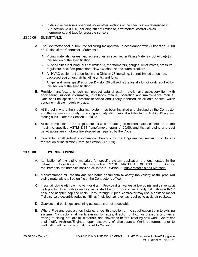
23 00 00 - Page 2 HVAC PIPING AND EQUIPMENT UMC Quarterdeck HVAC UpgradeMU Project #CP191051
9. Installing accessories specified under other sections of the specification referenced in Sub-section 23 00 05, including but not limited to, flow meters, control valves, thermowells, and taps for pressure sensors.
23 00 06 SUBMITTALS:
A. The Contractor shall submit the following for approval in accordance with Subsection 20 00 43, Duties of the Contractor - Submittals.
1. Piping materials, valves, and accessories as specified in Piping Materials Schedule(s) in this section of the specification.
2. All specialties including, but not limited to, thermometers, gauges, relief valves, pressure regulators, backflow preventers, flow switches, and vacuum breakers.
3. All HVAC equipment specified in this Division 23 including, but not limited to, pumps, packaged equipment, air handling units, and fans.
4. All general items specified under Division 20 utilized in the installation of work required by this section of the specification.
B. Provide manufacturer's technical product data of each material and accessory item with engineering support information, installation manual, operation and maintenance manual. Data shall be specific to product specified and clearly identified on all data sheets, which contains multiple models or sizes.
C. At the point where the mechanical system has been installed and checked by the Contractor and the systems are ready for testing and adjusting, submit a letter to the Architect/Engineer stating such. Refer to Section 20 10 85.
D. At the completion of the project, submit a letter stating all materials are asbestos free, and meet the specified ASTM E-84 flame/smoke rating of 25/50, and that all piping and duct penetrations are smoke or fire stopped as required by the Code.
E. Contractor shall submit coordination drawings to the Engineer for review prior to any fabrication or installation (Refer to Section 20 10 50).
23 10 00 HYDRONIC PIPING
A. Itemization of the piping materials for specific system application are enumerated in the following sub-sections for the respective PIPING MATERIAL SCHEDULE. Specific requirements for materials shall be as listed in Division 20 Basic Materials and Methods.
B. Manufacturer's mill reports and applicable documents to certify the validity of the procured piping materials shall be on file at the Contractor's office.
C. Install all piping with pitch to vent or drain. Provide drain valves at low points and air vents at high points. Drain valves and air vents shall be ¾’ bronze 2 piece body ball valves with ¾” hose end adapter, cap and chain. In ½” through 2” pipe, contractor may use Webstone model T-drain. Use eccentric reducing fittings (installed top level) as required to avoid air pockets.
D. Gaskets and packings containing asbestos are not acceptable.
E. Where Pipe and accessories installed under this section of the specification tie-in to existing systems, Contractor shall verify existing for: sizes, direction of flow (via pressure or physical tracing of piping, not labels), materials, and elevations before installing new work. Contractor shall notify Architect/Engineer upon discovery of discrepancy. Work performed prior to verification will be corrected at no cost to Owner.
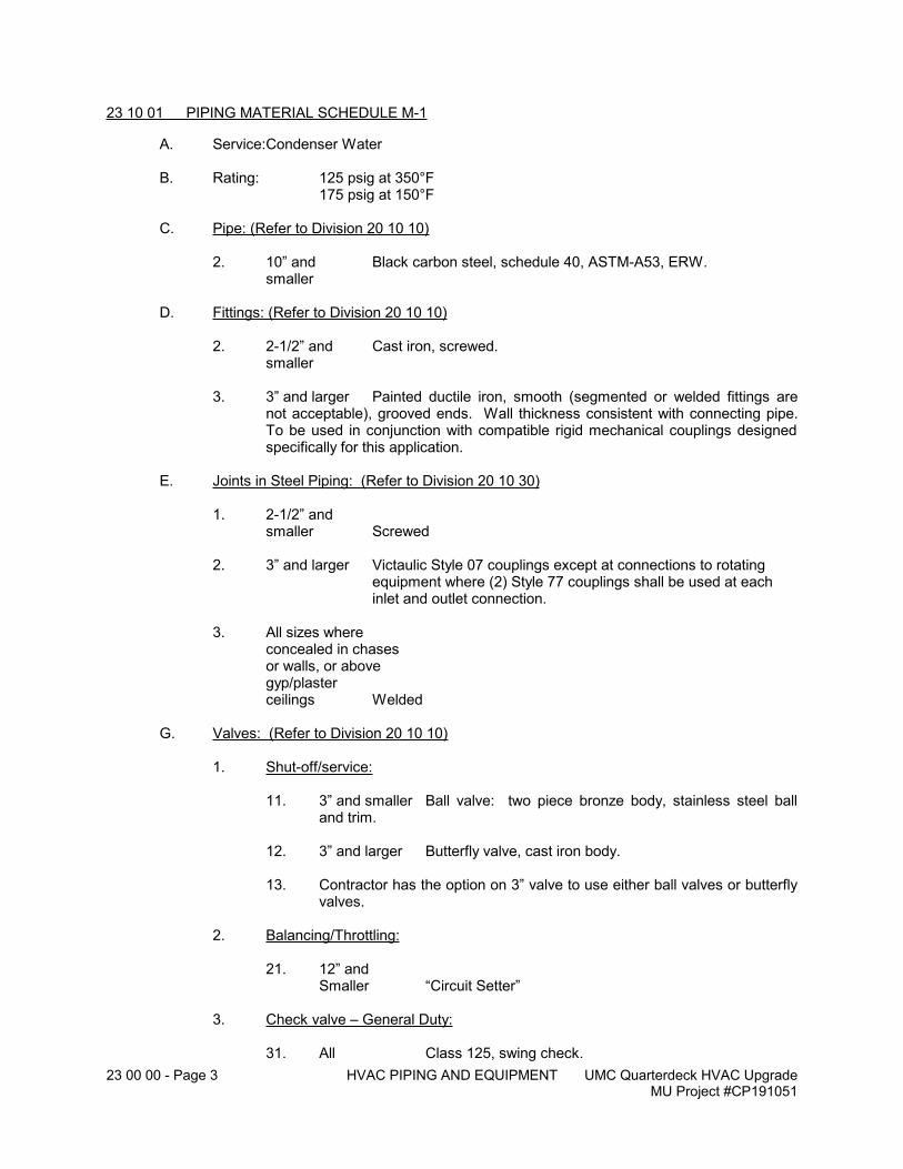
23 00 00 - Page 3 HVAC PIPING AND EQUIPMENT UMC Quarterdeck HVAC UpgradeMU Project #CP191051
23 10 01 PIPING MATERIAL SCHEDULE M-1
A. Service:Condenser Water
B. Rating: 125 psig at 350°F 175 psig at 150°F
C. Pipe: (Refer to Division 20 10 10)
2. 10” and Black carbon steel, schedule 40, ASTM-A53, ERW.smaller
D. Fittings: (Refer to Division 20 10 10)
2. 2-1/2” and Cast iron, screwed.smaller
3. 3” and larger Painted ductile iron, smooth (segmented or welded fittings are not acceptable), grooved ends. Wall thickness consistent with connecting pipe. To be used in conjunction with compatible rigid mechanical couplings designed specifically for this application.
E. Joints in Steel Piping: (Refer to Division 20 10 30)
1. 2-1/2” and smaller Screwed
2. 3” and larger Victaulic Style 07 couplings except at connections to rotating equipment where (2) Style 77 couplings shall be used at eachinlet and outlet connection.
3. All sizes whereconcealed in chasesor walls, or abovegyp/plasterceilings Welded
G. Valves: (Refer to Division 20 10 10)
1. Shut-off/service:
11. 3” and smaller Ball valve: two piece bronze body, stainless steel ball and trim.
12. 3” and larger Butterfly valve, cast iron body.
13. Contractor has the option on 3” valve to use either ball valves or butterfly valves.
2. Balancing/Throttling:
21. 12” and Smaller “Circuit Setter”
3. Check valve – General Duty:
31. All Class 125, swing check.
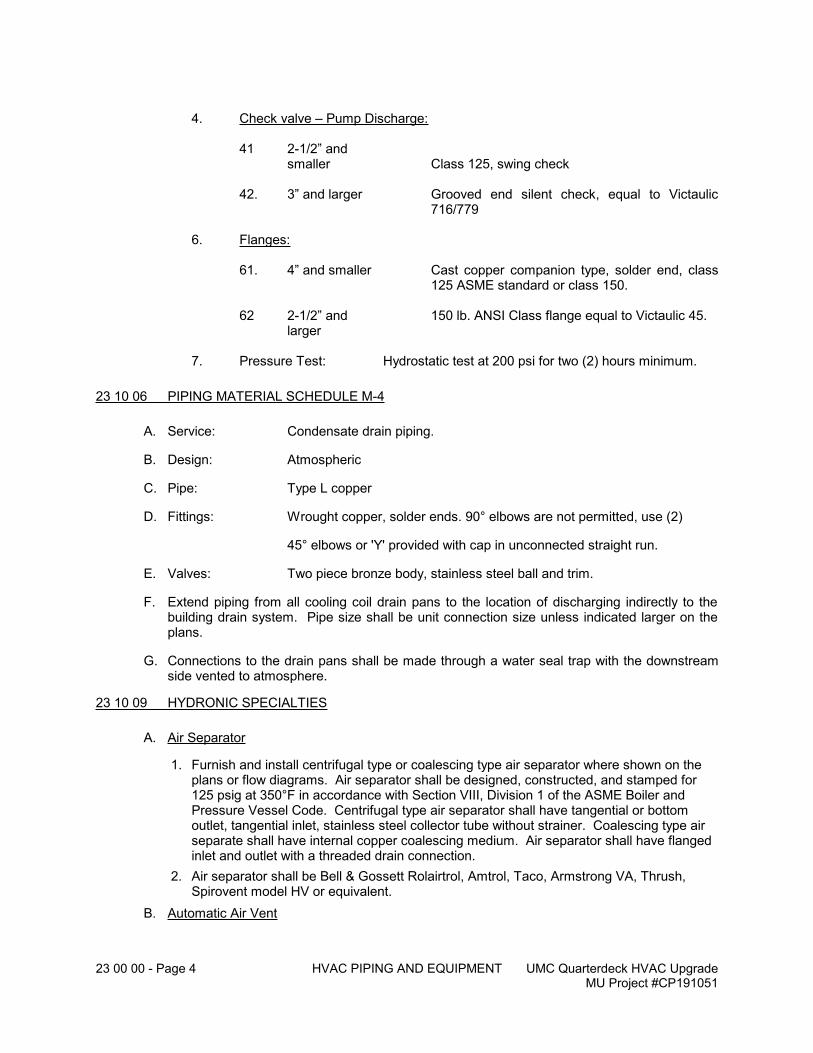
23 00 00 - Page 4 HVAC PIPING AND EQUIPMENT UMC Quarterdeck HVAC UpgradeMU Project #CP191051
4. Check valve – Pump Discharge:
41 2-1/2” and smaller Class 125, swing check
42. 3” and larger Grooved end silent check, equal to Victaulic 716/779
6. Flanges:
61. 4” and smaller Cast copper companion type, solder end, class 125 ASME standard or class 150.
62 2-1/2” and 150 lb. ANSI Class flange equal to Victaulic 45. larger
7. Pressure Test: Hydrostatic test at 200 psi for two (2) hours minimum.
23 10 06 PIPING MATERIAL SCHEDULE M-4
A. Service: Condensate drain piping.
B. Design: Atmospheric
C. Pipe: Type L copper
D. Fittings: Wrought copper, solder ends. 90° elbows are not permitted, use (2)
45° elbows or 'Y' provided with cap in unconnected straight run.
E. Valves: Two piece bronze body, stainless steel ball and trim.
F. Extend piping from all cooling coil drain pans to the location of discharging indirectly to the building drain system. Pipe size shall be unit connection size unless indicated larger on the plans.
G. Connections to the drain pans shall be made through a water seal trap with the downstream side vented to atmosphere.
23 10 09 HYDRONIC SPECIALTIES
A. Air Separator
1. Furnish and install centrifugal type or coalescing type air separator where shown on the plans or flow diagrams. Air separator shall be designed, constructed, and stamped for 125 psig at 350°F in accordance with Section VIII, Division 1 of the ASME Boiler and Pressure Vessel Code. Centrifugal type air separator shall have tangential or bottom outlet, tangential inlet, stainless steel collector tube without strainer. Coalescing type air separate shall have internal copper coalescing medium. Air separator shall have flanged inlet and outlet with a threaded drain connection.
2. Air separator shall be Bell & Gossett Rolairtrol, Amtrol, Taco, Armstrong VA, Thrush, Spirovent model HV or equivalent.
B. Automatic Air Vent
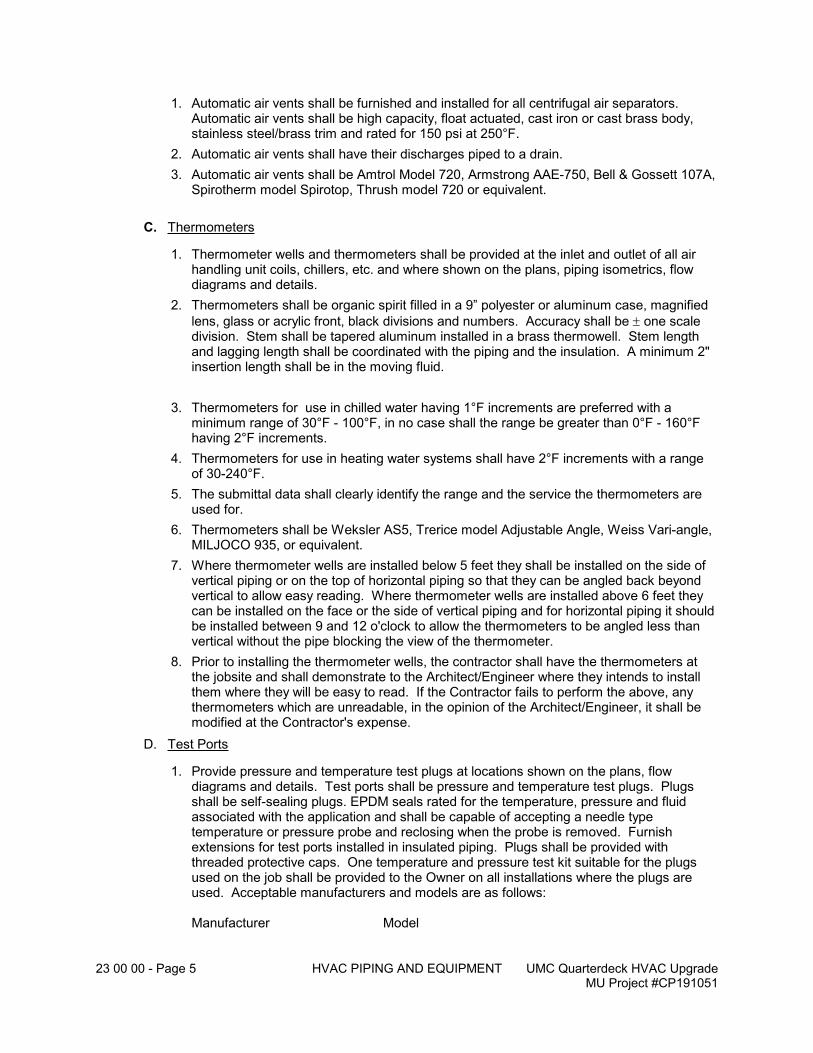
23 00 00 - Page 5 HVAC PIPING AND EQUIPMENT UMC Quarterdeck HVAC UpgradeMU Project #CP191051
1. Automatic air vents shall be furnished and installed for all centrifugal air separators. Automatic air vents shall be high capacity, float actuated, cast iron or cast brass body, stainless steel/brass trim and rated for 150 psi at 250°F.
2. Automatic air vents shall have their discharges piped to a drain.
3. Automatic air vents shall be Amtrol Model 720, Armstrong AAE-750, Bell & Gossett 107A, Spirotherm model Spirotop, Thrush model 720 or equivalent.
C. Thermometers
1. Thermometer wells and thermometers shall be provided at the inlet and outlet of all air handling unit coils, chillers, etc. and where shown on the plans, piping isometrics, flow diagrams and details.
2. Thermometers shall be organic spirit filled in a 9” polyester or aluminum case, magnified
lens, glass or acrylic front, black divisions and numbers. Accuracy shall be one scale division. Stem shall be tapered aluminum installed in a brass thermowell. Stem length and lagging length shall be coordinated with the piping and the insulation. A minimum 2" insertion length shall be in the moving fluid.
3. Thermometers for use in chilled water having 1°F increments are preferred with a minimum range of 30°F - 100°F, in no case shall the range be greater than 0°F - 160°F having 2°F increments.
4. Thermometers for use in heating water systems shall have 2°F increments with a range of 30-240°F.
5. The submittal data shall clearly identify the range and the service the thermometers are used for.
6. Thermometers shall be Weksler AS5, Trerice model Adjustable Angle, Weiss Vari-angle, MILJOCO 935, or equivalent.
7. Where thermometer wells are installed below 5 feet they shall be installed on the side of vertical piping or on the top of horizontal piping so that they can be angled back beyond vertical to allow easy reading. Where thermometer wells are installed above 6 feet they can be installed on the face or the side of vertical piping and for horizontal piping it should be installed between 9 and 12 o'clock to allow the thermometers to be angled less than vertical without the pipe blocking the view of the thermometer.
8. Prior to installing the thermometer wells, the contractor shall have the thermometers at the jobsite and shall demonstrate to the Architect/Engineer where they intends to install them where they will be easy to read. If the Contractor fails to perform the above, any thermometers which are unreadable, in the opinion of the Architect/Engineer, it shall be modified at the Contractor's expense.
D. Test Ports
1. Provide pressure and temperature test plugs at locations shown on the plans, flow diagrams and details. Test ports shall be pressure and temperature test plugs. Plugs shall be self-sealing plugs. EPDM seals rated for the temperature, pressure and fluid associated with the application and shall be capable of accepting a needle type temperature or pressure probe and reclosing when the probe is removed. Furnish extensions for test ports installed in insulated piping. Plugs shall be provided with threaded protective caps. One temperature and pressure test kit suitable for the plugs used on the job shall be provided to the Owner on all installations where the plugs are used. Acceptable manufacturers and models are as follows:
Manufacturer Model
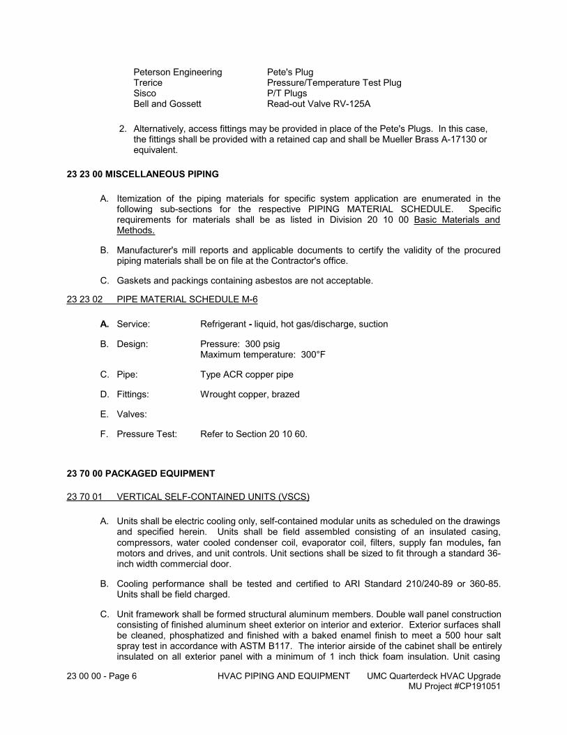
23 00 00 - Page 6 HVAC PIPING AND EQUIPMENT UMC Quarterdeck HVAC UpgradeMU Project #CP191051
Peterson Engineering Pete's PlugTrerice Pressure/Temperature Test PlugSisco P/T PlugsBell and Gossett Read-out Valve RV-125A
2. Alternatively, access fittings may be provided in place of the Pete's Plugs. In this case, the fittings shall be provided with a retained cap and shall be Mueller Brass A-17130 or equivalent.
23 23 00 MISCELLANEOUS PIPING
A. Itemization of the piping materials for specific system application are enumerated in the following sub-sections for the respective PIPING MATERIAL SCHEDULE. Specific requirements for materials shall be as listed in Division 20 10 00 Basic Materials and Methods.
B. Manufacturer's mill reports and applicable documents to certify the validity of the procured piping materials shall be on file at the Contractor's office.
C. Gaskets and packings containing asbestos are not acceptable.
23 23 02 PIPE MATERIAL SCHEDULE M-6
A. Service: Refrigerant - liquid, hot gas/discharge, suction
B. Design: Pressure: 300 psigMaximum temperature: 300°F
C. Pipe: Type ACR copper pipe
D. Fittings: Wrought copper, brazed
E. Valves:
F. Pressure Test: Refer to Section 20 10 60.
23 70 00 PACKAGED EQUIPMENT
23 70 01 VERTICAL SELF-CONTAINED UNITS (VSCS)
A. Units shall be electric cooling only, self-contained modular units as scheduled on the drawings and specified herein. Units shall be field assembled consisting of an insulated casing,
compressors, water cooled condenser coil, evaporator coil, filters, supply fan modules, fan motors and drives, and unit controls. Unit sections shall be sized to fit through a standard 36-inch width commercial door.
B. Cooling performance shall be tested and certified to ARI Standard 210/240-89 or 360-85. Units shall be field charged.
C. Unit framework shall be formed structural aluminum members. Double wall panel construction consisting of finished aluminum sheet exterior on interior and exterior. Exterior surfaces shall be cleaned, phosphatized and finished with a baked enamel finish to meet a 500 hour salt spray test in accordance with ASTM B117. The interior airside of the cabinet shall be entirely insulated on all exterior panel with a minimum of 1 inch thick foam insulation. Unit casing

23 00 00 - Page 7 HVAC PIPING AND EQUIPMENT UMC Quarterdeck HVAC UpgradeMU Project #CP191051
provided with removable panels secured with hinges to act as an access door or be completely removed to service compressors, condensers, fans, coils, and valves. Refrigerant site glass windows accessible while unit is in operation. Condensate drain pans shall be insulated with full thickness, non-compressed, insulation between the drain pan and the unit casing and shall drain both the coil and the fan; units with multiple vertically stacked coils shall have an intermediate drain pan. The pans shall be continuously welded seams, Series 300 stainless steel, ‘V’ shaped and/or sloping to the drain connection, flat pans will not be acceptable. Drain pans shall be located in the coil section.
D. Compressor shall be isolator mounted, high efficient, hermetically sealed, refrigerant cooled, scroll type with high starting torque. Motor shall be capable of operating at plus/minus 10 percent of nameplate voltage. Motor shall have internal temperature and current sensors for motor protection. Each compressor shall have separate refrigeration circuits each with a thermostatic expansion valve. Each compressor shall have an automatic resetting low pressure safety and a manual reset high pressure safety. Refrigeration filter-drier, sight glass, liquid service valve, suction service valve, and gauge ports shall be factory furnished and installed. Compressor quantity shall match what is scheduled. Lead compressor shall be provided with prewired factory VFD.
E. Water-cooling condensers shall be brazed plate, chemically cleanable. One condenser shall be provided for each compressor. A 20 mesh removeable screen shall be provided upstream of all condensers. Condenser working pressure up to 400 psig. Unit shall have single point piping connection to serve all condensers. Each condenser shall be provided with head pressure control valve.
F. Fans shall be provided in the quantities and capacities as indicated on the schedules. Each fan shall be direct drive centrifugual provided in a modular casing. Where Class II construction is required, wheels shall be reinforced with a welded intermediate ring. Fan bearings shall be heavy duty, self-aligning, grease lubricated, antifriction type with double row rollers and labyrinth grease seals. Fans and motors shall be resiliently mounted on a single structural base, internally mounted with resilient mounts on the unit structural frame. Internal resilient mounting shall be spring type with minimum 1-1/2” static deflection and provided with seismic restraints. Fan motors shall be electronically commutated motors.
G. The units shall be provided with coils of the types and capacities scheduled. Cooling coil casing shall be galvanized steel. Coils shall be constructed with no less than 3/8” diameter x .014” wall thickness copper tubes and .0075” aluminum or copper fins spaced not closer than 14 per inch. Tubes are to be mechanically expanded into fins. Frame shall be shall include intermediate tube supports to prevent sagging of the tubes. The coil shall be removable with removing casing panels (i.e., casing shall have its own internal frame and shall not use the coil for support).
1. Refrigerant coils shall be row split or interlaced type with equalizing distributors. Coils shall be tested to 300 psig and shipped with a holding charge of dry nitrogen. Tube diameters, wall thickness, and fins shall be the same as above.
2. Waterside economizer coil shall be provided with unit. Minimum of 4 rows. Tube diameters, wall thickness, and fins shall be the same as above.
H. Air filters shall mount integral within the unit casing accessible through access door in unit casing. The filter frame shall include a positive sealing gasket material to seal the top and bottom of the filter to prevent bypass. Filter bank shall include 2” pre-filters and 4” post-filters.
I. Units shall have a factory furnished and wired non-fused single point power disconnect switch and fused 24 volt control power transformer. The disconnect switch handle shall be accessible without opening any unit access doors. The unit shall be provided with a factory furnished and wired GFI 120V outlet that the transformer (460 models) is powered from the line side of the incoming three phase power, so that the outlet can remain powered when the
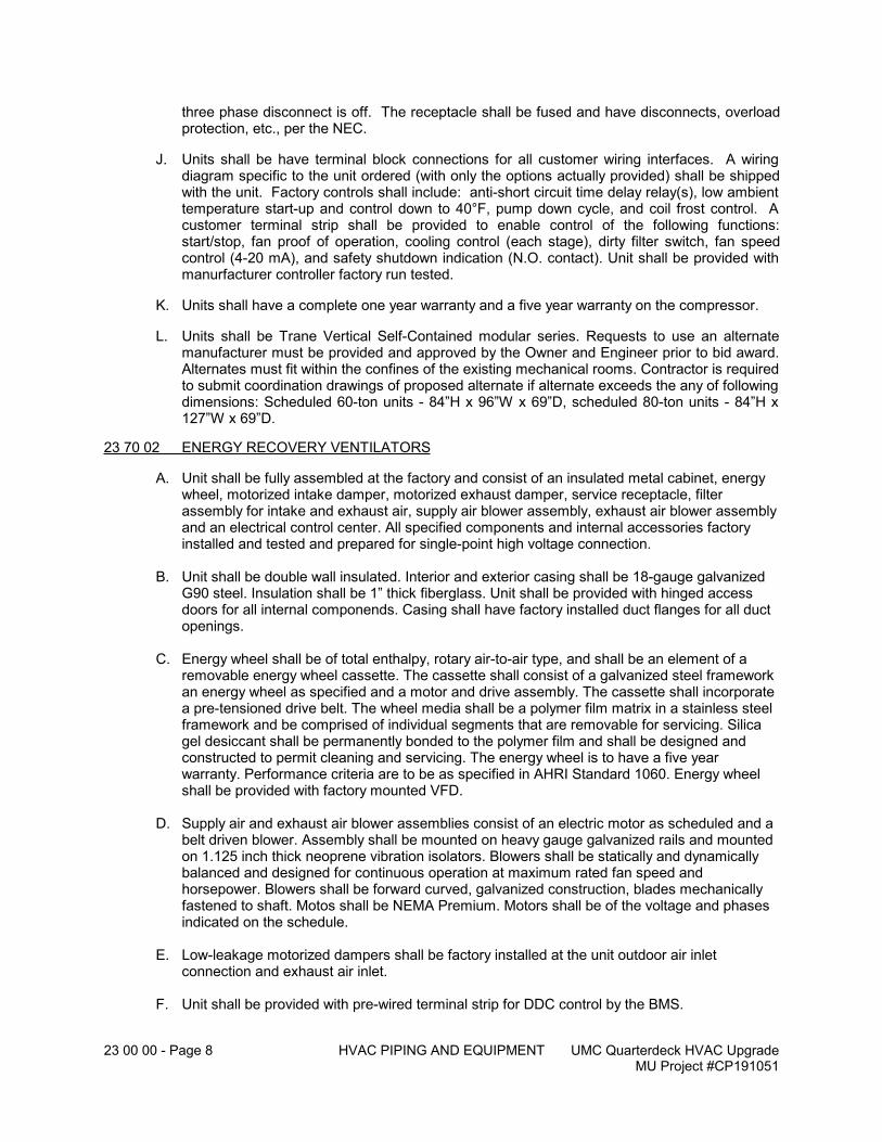
23 00 00 - Page 8 HVAC PIPING AND EQUIPMENT UMC Quarterdeck HVAC UpgradeMU Project #CP191051
three phase disconnect is off. The receptacle shall be fused and have disconnects, overload protection, etc., per the NEC.
J. Units shall be have terminal block connections for all customer wiring interfaces. A wiring diagram specific to the unit ordered (with only the options actually provided) shall be shipped with the unit. Factory controls shall include: anti-short circuit time delay relay(s), low ambient temperature start-up and control down to 40°F, pump down cycle, and coil frost control. A customer terminal strip shall be provided to enable control of the following functions: start/stop, fan proof of operation, cooling control (each stage), dirty filter switch, fan speed control (4-20 mA), and safety shutdown indication (N.O. contact). Unit shall be provided with manurfacturer controller factory run tested.
K. Units shall have a complete one year warranty and a five year warranty on the compressor.
L. Units shall be Trane Vertical Self-Contained modular series. Requests to use an alternate manufacturer must be provided and approved by the Owner and Engineer prior to bid award. Alternates must fit within the confines of the existing mechanical rooms. Contractor is required to submit coordination drawings of proposed alternate if alternate exceeds the any of following dimensions: Scheduled 60-ton units - 84”H x 96”W x 69”D, scheduled 80-ton units - 84”H x 127”W x 69”D.
23 70 02 ENERGY RECOVERY VENTILATORS
A. Unit shall be fully assembled at the factory and consist of an insulated metal cabinet, energy wheel, motorized intake damper, motorized exhaust damper, service receptacle, filter assembly for intake and exhaust air, supply air blower assembly, exhaust air blower assembly and an electrical control center. All specified components and internal accessories factory installed and tested and prepared for single-point high voltage connection.
B. Unit shall be double wall insulated. Interior and exterior casing shall be 18-gauge galvanized G90 steel. Insulation shall be 1” thick fiberglass. Unit shall be provided with hinged access doors for all internal componends. Casing shall have factory installed duct flanges for all duct openings.
C. Energy wheel shall be of total enthalpy, rotary air-to-air type, and shall be an element of a removable energy wheel cassette. The cassette shall consist of a galvanized steel framework an energy wheel as specified and a motor and drive assembly. The cassette shall incorporate a pre-tensioned drive belt. The wheel media shall be a polymer film matrix in a stainless steel framework and be comprised of individual segments that are removable for servicing. Silica gel desiccant shall be permanently bonded to the polymer film and shall be designed and constructed to permit cleaning and servicing. The energy wheel is to have a five year warranty. Performance criteria are to be as specified in AHRI Standard 1060. Energy wheel shall be provided with factory mounted VFD.
D. Supply air and exhaust air blower assemblies consist of an electric motor as scheduled and a belt driven blower. Assembly shall be mounted on heavy gauge galvanized rails and mounted on 1.125 inch thick neoprene vibration isolators. Blowers shall be statically and dynamically balanced and designed for continuous operation at maximum rated fan speed and horsepower. Blowers shall be forward curved, galvanized construction, blades mechanically fastened to shaft. Motos shall be NEMA Premium. Motors shall be of the voltage and phases indicated on the schedule.
E. Low-leakage motorized dampers shall be factory installed at the unit outdoor air inlet connection and exhaust air inlet.
F. Unit shall be provided with pre-wired terminal strip for DDC control by the BMS.
23 00 00 - Page 9 HVAC PIPING AND EQUIPMENT UMC Quarterdeck HVAC UpgradeMU Project #CP191051
G. Unit shall be provided with pleated, 2” MERV 8 filters in both the intake airstream and the exhaust air stream.
END OF SECTION
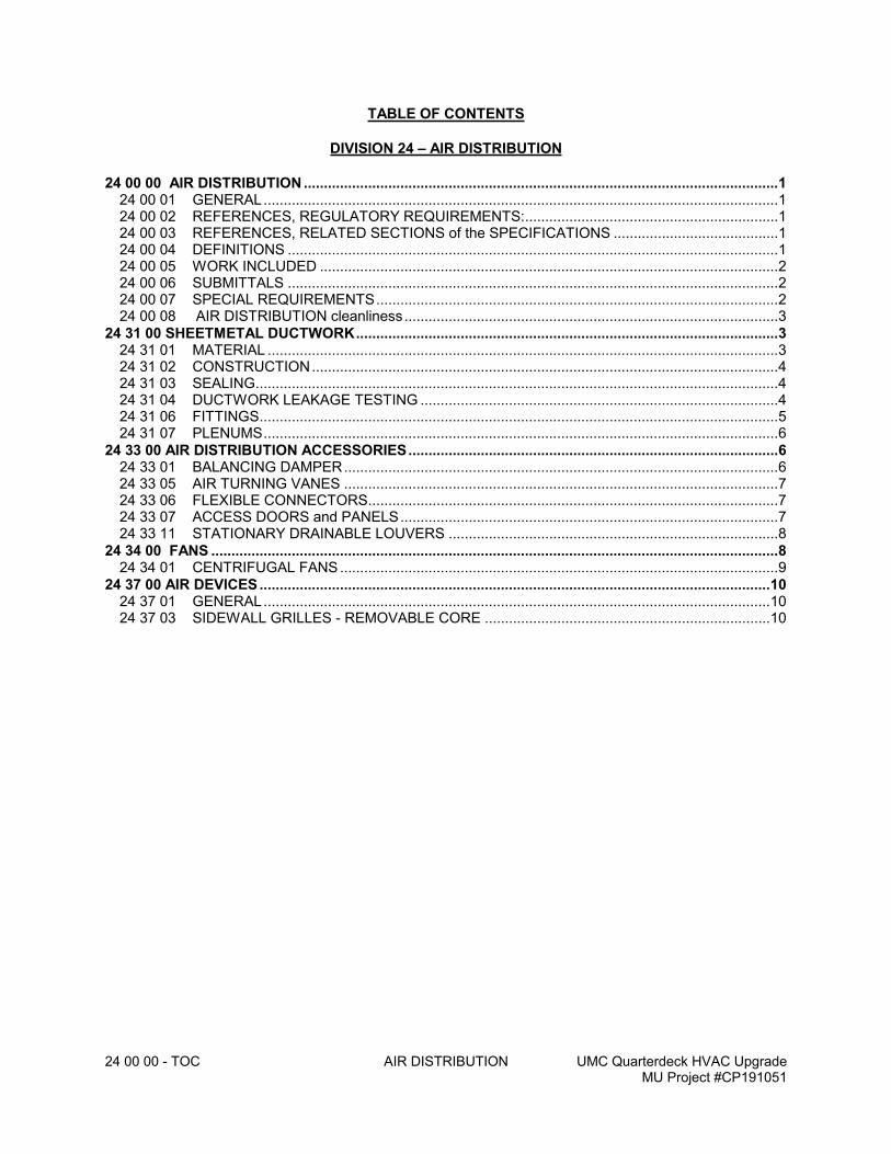
24 00 00 - TOC AIR DISTRIBUTION UMC Quarterdeck HVAC UpgradeMU Project #CP191051
TABLE OF CONTENTS
DIVISION 24 – AIR DISTRIBUTION
24 00 00 AIR DISTRIBUTION ......................................................................................................................124 00 01 GENERAL................................................................................................................................124 00 02 REFERENCES, REGULATORY REQUIREMENTS:...............................................................124 00 03 REFERENCES, RELATED SECTIONS of the SPECIFICATIONS .........................................124 00 04 DEFINITIONS ..........................................................................................................................124 00 05 WORK INCLUDED ..................................................................................................................224 00 06 SUBMITTALS ..........................................................................................................................224 00 07 SPECIAL REQUIREMENTS....................................................................................................224 00 08 AIR DISTRIBUTION cleanliness.............................................................................................3
24 31 00 SHEETMETAL DUCTWORK.........................................................................................................324 31 01 MATERIAL ...............................................................................................................................324 31 02 CONSTRUCTION....................................................................................................................424 31 03 SEALING..................................................................................................................................424 31 04 DUCTWORK LEAKAGE TESTING .........................................................................................424 31 06 FITTINGS.................................................................................................................................524 31 07 PLENUMS................................................................................................................................6
24 33 00 AIR DISTRIBUTION ACCESSORIES............................................................................................624 33 01 BALANCING DAMPER............................................................................................................624 33 05 AIR TURNING VANES ............................................................................................................724 33 06 FLEXIBLE CONNECTORS......................................................................................................724 33 07 ACCESS DOORS and PANELS..............................................................................................724 33 11 STATIONARY DRAINABLE LOUVERS ..................................................................................8
24 34 00 FANS .............................................................................................................................................824 34 01 CENTRIFUGAL FANS.............................................................................................................9
24 37 00 AIR DEVICES...............................................................................................................................1024 37 01 GENERAL..............................................................................................................................1024 37 03 SIDEWALL GRILLES - REMOVABLE CORE .......................................................................10
24 00 00 - Page 1 AIR DISTRIBUTION UMC Quarterdeck HVAC UpgradeMU Project #CP191051
24 00 00 AIR DISTRIBUTION
24 00 01 GENERAL
1. This Section specifies air distribution systems.
2. The Plans, the general provisions of the Contract including the General, Supplementary and/or Special Conditions and specification sections of Division 1 shall apply to Work of Divisions 20 - 29 of the Specifications.
3. Provisions and conditions cited in this Section shall apply to Work for other sections of Divisions 20 - 29 of these Specifications.
24 00 02 REFERENCES, REGULATORY REQUIREMENTS:
A. Work for this section of the specifications shall be performed in accordance with the Codes, Standards, etc. as identified in Division 20 in addition to the following:
1. ASHRAE, “Handbook 1997 Fundamentals”; Chapter 32 - Duct Design.
2. ASHRAE, “Handbook 1996 Equipment”; Chapter 16 - Duct Construction.
3. ASTM A90-81 (1991), “Test Method for Weight of Coating on Zinc-Coated (Galvanized) Iron or Steel Articles”.
4. ASTM A525-91b, “Spec for General Requirements for Steel Sheet, Zinc-Coated (Galvanized) by the Hot-Dip Process”.
5. ASTM A527/A527M-90, “Spec for Steel Sheet, Zinc-Coated (Galvanized) by Hot-Dip Process, Lock Forming Quality”.
6. NFPA 90A, “Installation of Air Conditioning and Ventilating Systems.”
7. SMACNA “HVAC Duct Construction Standard – Metal and Flexible” – Second Edition.
8. UL 33, “Heat Responsive Links for Fire Protection Service.”
9. UL 555, “Fire Dampers and Ceiling Dampers.”
10. UL 181, “Factory Made Air Ducts and Connectors.”
24 00 03 REFERENCES, RELATED SECTIONS OF THE SPECIFICATIONS
Requirements of the following Sections of the Specifications apply to Work for this Section:
A. Division 20 - Basic Mechanical Conditions and Basic Mechanical Materials & Methods
B. Division 23 – HVAC Piping and Equipment
C. Division 25 - Temperature Control
24 00 04 DEFINITIONS
A. The size of the ducts shown on the drawings and in this Section of the Specifications shall be the outside dimension of the ductwork which will take into account any internal acoustical lining thickness specified for duct system or sub-system.
B. The term “supply air” where used in this Section of the Specifications shall mean downstream of a coil.
C. The term “outdoor air” where used in this Section of the Specifications shall mean ambient air that has not been conditioned.
24 00 00 - Page 2 AIR DISTRIBUTION UMC Quarterdeck HVAC UpgradeMU Project #CP191051
D. The term “return air” where used in this Section of the Specifications shall mean conditioned air that is returned from the space.
E. The term “mixed air” where used in this Section of the Specifications shall mean air streams
that are a mixture of “outdoor air” and “return air”.
F. The term “relief air” where used in this Section of the Specifications shall mean excess return air that relieved from the building.
G. The term “exhaust air” where used in this Section of the Specifications shall mean air that is removed due to contaminates, odors, or heat.
24 00 05 WORK INCLUDED
Furnish material, labor and services necessary for and incidental to the installation of the following systems where shown on the Plans and as hereinafter specified. Include all necessary considerations in the related sections of the Specifications (Sub-section 20 30 03) to perform the Work completely.
A. Sheet metal ducts, sheet metal plenums, duct linings, flexible ductwork, dampers and accessories.
B. Air devices including adjusting the pattern controllers.
C. Louvers, louvered penthouses.
D. Installing accessories specified in referenced sections above.
E. Smoke stopping of all penetrations of ductwork, and firestopping of the same through fire rated partitions as shown on the Architectural drawings including, but not limited to stairways, shafts, corridors, floors, roofs, and required exits (Refer to Section 20 10 20).
F. Contractor shall coordinate his work with the work of other trades, and with the architectural and structural drawings.
24 00 06 SUBMITTALS
A. The Contractor shall submit the following for approval in accordance with Subsection 20 00 43, Duties of Contractor - Submittals.
B. Contractor shall submit coordination drawings to the Engineer for review prior to any fabrication or installation (Refer to Section 20 10 50).
C. Submittals shall include drawings showing joining methods, location of duct transverse joints, and duct support locations.
D. Submittals shall be required for all shop fabricated balancing dampers.
E. At the completion of the project, submit a letter stating all materials are asbestos free, and meet the specified ASTM E-84 flame/smoke rating of 25/50, and that all piping and duct penetrations are smoke or fire stopped as required by the Code.
24 00 07 SPECIAL REQUIREMENTS
A. Contractor shall inspect each component of the heating and air conditioning system to eliminate rattles, air whistles, vibration, and mechanical system sound transmission. Rough edges in ducts, insecure dampers, turning vanes, fire dampers, etc., shall be corrected to
24 00 00 - Page 3 AIR DISTRIBUTION UMC Quarterdeck HVAC UpgradeMU Project #CP191051
assure no recurrence of the noise source. Each vibration isolator and flexible connector shall be adjusted to limit transmission of sound to the occupied space.
B. Where Ductwork and accessories installed under this section of the specification tie-in to existing systems, Contractor shall verify existing for: sizes, direction of flow (via pressure or physical tracing of ductwork, not labels), materials, and elevations before installing new work. Contractor shall notify Architect/Engineer upon discovery of discrepancy. Work performed prior to verification will be corrected at no cost to Owner.
24 00 08 AIR DISTRIBUTION CLEANLINESS
A. Contractor shall implement procedures to maintain an “Advanced Level’ of ductwork cleanliness per the latest addition of the SMACNA Duct Cleanliness for New Construction Guidelines.
1. Production and Site Delivery:
a. Self-adhesive labels for part of identification are to be applied to the external surfaces only.
b. During transportation, ductwork and air distribution components shall be sealed either by blanketing or capping the duct ends, bagging small fittings, surface wrapping or shrink wrapping.
2. Site Storage:
a. Temporary storage shall be located away from high dust generating processes such as masonry, tile cutters, saws, drywall sanding, mortar and plaster mixers, roof pitch kettles, portable electric generators, and main walkways that will be constantly broom swept.
b. Temporary storage shall include pallets or blocking to keep ductwork and air distribution components above floor surface to prevent water damage.
c. Coverage should be used to protect stored materials at all times.
d. Duct open ends and air side of air distribution components shall be securely sealed at all times.
e. Seals shall be visually examined and if damaged, resealed with an appropriate material.
3. Installation:
a. Before installation of individual duct sections and air distribution components, they are to be inspected to ensure that they are free from debris and shall be wiped clean if debris exists.
b. The working area shall be clean, dry, and the airside of ductwork and air distribution components protected from dust and moisture.
c. Protective coverings shall only be removed immediately before installation and inspected to determine if additional wipe down is necessary.
d. Open ends on completed ductwork shall be sealed immediately if left for an extended period of time (work breaks, overnight, etc.).
24 31 00 SHEETMETAL DUCTWORK
24 31 01 MATERIAL
A. All ducts unless specified otherwise shall be constructed from sheets or rolls of G-90 or better-galvanized steel, LFQ, Chemtreat. Fiberglass ductboard is prohibited.
24 00 00 - Page 4 AIR DISTRIBUTION UMC Quarterdeck HVAC UpgradeMU Project #CP191051
B. All supply ductwork, unless specified otherwise, shall be constructed of gauges and reinforcement to 4” w.g. static pressure in SMACNA Duct Construction Standard – Latest Edition.
C. All return, exhaust, outdoor air, relief, and supply ductwork downstream of terminal units shall be constructed of gauges and reinforcement to 2” w.g. static pressure in SMACNA Duct Construction Standard – Latest Edition. Panels in all ducts 12” and larger shall be cross-broken or beaded on 12” centers.
D. Where local code requires gauges heavier than required by SMACNA then the local code shall govern.
24 31 02 CONSTRUCTION
A. All ductwork shall be neatly constructed, stiffened, on the outside surfaces where necessary to prevent perceptible vibration or buckling. All ducts, housings, etc., shall be fabricated as detailed on the drawings and in the SMACNA Duct Construction Manual –Latest Edition.
B. All rectangular ducts unless specified otherwise shall be “Pittsburgh Lock” longitudinal joints. Snaplock is not acceptable.
C. All round ducts and flat oval ducts shall have spiral seams or continuously welded longitudinal seams.
D. All transverse joints in rectangular ductwork 24” and larger shall be Ductmate, SMACNA T-25, or approved equivalent. All flanged ductwork, regardless of pressure class, shall use gaskets, corner closures, and be TEK screwed or riveted on 10” centers with a minimum of two (2) per side. Transverse joints in rectangular ductwork smaller than 24” shall be made in accordance with SMACNA suitable with the pressure class.
E. All transverse joints in round and oval ductwork 24” and larger shall be Ductmate, or approved equivalent. Transverse joints in round and overall ductwork smaller than 24” shall be beaded sleeve joints.
F. Ducts shall be securely supported in accordance with SMACNA Duct Construction Manual – Latest Edition and in no case less than double thickness 1” x #24 gauge galvanized metal. Cable hangers are not allowed.
G. Ducts that are to be externally insulated shall not be supported on unistrut channel unless it required based upon loading. Hanger rods for trapeze bars shall be spaced to allow for insulation installation.
24 31 03 SEALING
A. Duct sealant shall be flexible, water-based, adhesive sealant designed for use in 4” static pressure systems. Sealer shall be UL listed and conform to ASTM E84. Sealer shall be equal to Ductmate PROseal, United McGill Uni-Mastic, Duro-Dyne DSW, or equivalent.
B. All supply ductwork unless specified otherwise shall be SMACNA's seal class A.
C. All return, exhaust, outdoor air, relief and supply ductwork downstream of terminal units shall be SMACNA's seal class B.
24 31 04 DUCTWORK LEAKAGE TESTING
A. Installed ductwork on systems greater than 5HP shall be tested prior to installation of access door, take-offs, or other specialties.
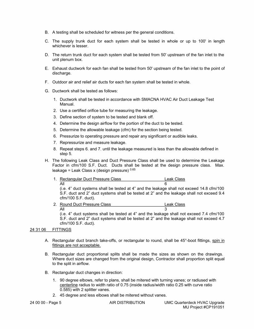
24 00 00 - Page 5 AIR DISTRIBUTION UMC Quarterdeck HVAC UpgradeMU Project #CP191051
B. A testing shall be scheduled for witness per the general conditions.
C. The supply trunk duct for each system shall be tested in whole or up to 100' in length whichever is lesser.
D. The return trunk duct for each system shall be tested from 50' upstream of the fan inlet to the unit plenum box.
E. Exhaust ductwork for each fan shall be tested from 50' upstream of the fan inlet to the point of discharge.
F. Outdoor air and relief air ducts for each fan system shall be tested in whole.
G. Ductwork shall be tested as follows:
1. Ductwork shall be tested in accordance with SMACNA HVAC Air Duct Leakage Test Manual.
2. Use a certified orifice tube for measuring the leakage.
3. Define section of system to be tested and blank off.
4. Determine the design airflow for the portion of the duct to be tested.
5. Determine the allowable leakage (cfm) for the section being tested.
6. Pressurize to operating pressure and repair any significant or audible leaks.
7. Repressurize and measure leakage.
8. Repeat steps 6. and 7. until the leakage measured is less than the allowable defined in step 5.
H. The following Leak Class and Duct Pressure Class shall be used to determine the Leakage Factor in cfm/100 S.F. Duct. Ducts shall be tested at the design pressure class. Max.
leakage = Leak Class x (design pressure) 0.65
1. Rectangular Duct Pressure Class Leak ClassAll 6(i.e. 4” duct systems shall be tested at 4” and the leakage shall not exceed 14.8 cfm/100 S.F. duct and 2” duct systems shall be tested at 2” and the leakage shall not exceed 9.4 cfm/100 S.F. duct).
2. Round Duct Pressure Class Leak ClassAll 3(i.e. 4” duct systems shall be tested at 4” and the leakage shall not exceed 7.4 cfm/100 S.F. duct and 2” duct systems shall be tested at 2” and the leakage shall not exceed 4.7 cfm/100 S.F. duct).
24 31 06 FITTINGS
A. Rectangular duct branch take-offs, or rectangular to round, shall be 45°-boot fittings, spin in fittings are not acceptable.
B. Rectangular duct proportional splits shall be made the sizes as shown on the drawings. Where duct sizes are changed from the original design, Contractor shall proportion split equal to the split in airflow.
B. Rectangular duct changes in direction:
1. 90 degree elbows, refer to plans, shall be mitered with turning vanes; or radiused with centerline radius to width ratio of 0.75 (inside radius/width ratio 0.25 with curve ratio 0.585) with 2 splitter vanes.
2. 45 degree and less elbows shall be mitered without vanes.
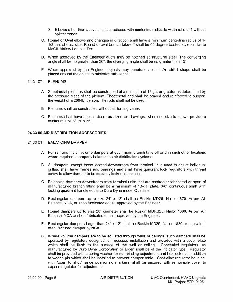
24 00 00 - Page 6 AIR DISTRIBUTION UMC Quarterdeck HVAC UpgradeMU Project #CP191051
3. Elbows other than above shall be radiused with centerline radius to width ratio of 1 without splitter vanes.
C. Round or Oval elbows and changes in direction shall have a minimum centerline radius of 1-1/2 that of duct size. Round or oval branch take-off shall be 45 degree booted style similar to McGill Airflow Lo-Loss Tee.
D. When approved by the Engineer ducts may be notched at structural steel. The converging angle shall be no greater than 30°, the diverging angle shall be no greater than 15°.
E. When approved by the Engineer objects may penetrate a duct. An airfoil shape shall be placed around the object to minimize turbulence.
24 31 07 PLENUMS
A. Sheetmetal plenums shall be constructed of a minimum of 18 ga. or greater as determined by the pressure class of the plenum. Sheetmetal and shall be braced and reinforced to support the weight of a 200-lb. person. Tie rods shall not be used.
B. Plenums shall be constructed without air turning vanes.
C. Plenums shall have access doors as sized on drawings, where no size is shown provide a minimum size of 18” x 36”.
24 33 00 AIR DISTRIBUTION ACCESSORIES
24 33 01 BALANCING DAMPER
A. Furnish and install volume dampers at each main branch take-off and in such other locations where required to properly balance the air distribution systems.
B. All dampers, except those located downstream from terminal units used to adjust individual grilles, shall have frames and bearings and shall have quadrant lock regulators with thread screw to allow damper to be securely locked into place.
C. Balancing dampers downstream from terminal units that are contractor fabricated or apart of manufactured branch fitting shall be a minimum of 18-ga. plate, 3/8” continuous shaft with locking quadrant handle equal to Duro Dyne model Quadline.
D. Rectangular dampers up to size 24” x 12” shall be Ruskin MD25, Nailor 1870, Arrow, Air Balance, NCA, or shop fabricated equal, approved by the Engineer.
E. Round dampers up to size 20” diameter shall be Ruskin MDRS25, Nailor 1890, Arrow, Air Balance, NCA or shop fabricated equal, approved by the Engineer.
F. Rectangular dampers larger than 24” x 12” shall be Ruskin MD35, Nailor 1820 or equivalent manufactured damper by NCA.
G. Where volume dampers are to be adjusted through walls or ceilings, such dampers shall be operated by regulators designed for recessed installation and provided with a cover plate which shall be flush to the surface of the wall or ceiling. Concealed regulators, as manufactured by Duro Dyne Corporation or Elgen shall be of the indicator type. Regulator shall be provided with a spring washer for non-binding adjustment and hex lock nut in addition to wedge pin which shall be installed to prevent damper rattle. Cast alloy regulator housing, with “open to shut” range positioning markers, shall be secured with removable cover to expose regulator for adjustments.
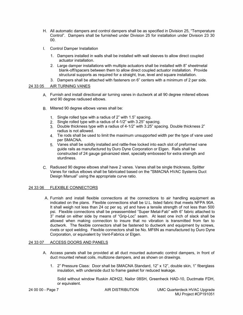
24 00 00 - Page 7 AIR DISTRIBUTION UMC Quarterdeck HVAC UpgradeMU Project #CP191051
H. All automatic dampers and control dampers shall be as specified in Division 25, “Temperature Control”. Dampers shall be furnished under Division 25 for installation under Division 23 30 00.
I. Control Damper Installation
1. Dampers installed in walls shall be installed with wall sleeves to allow direct coupled actuator installation.
2. Large damper installations with multiple actuators shall be installed with 8” sheetmetal blank-off/spacers between them to allow direct coupled actuator installation. Provide structural supports as required for a straight, true, level and square installation.
3. Dampers shall be attached with fasteners on 6” centers with a minimum of 2 per side.
24 33 05 AIR TURNING VANES
A. Furnish and install directional air turning vanes in ductwork at all 90 degree mitered elbows and 90 degree radiused elbows.
B. Mitered 90 degree elbows vanes shall be:
1. Single rolled type with a radius of 2” with 1.5” spacing.
2. Single rolled type with a radius of 4-1/2” with 3.25” spacing.
3. Double thickness type with a radius of 4-1/2” with 3.25” spacing. Double thickness 2” radius is not allowed.
4. Tie rods shall be used to limit the maximum unsupported width per the type of vane used per SMACNA.
5. Vanes shall be solidly installed and rattle-free locked into each slot of preformed vane guide rails as manufactured by Duro Dyne Corporation or Elgen. Rails shall be constructed of 24 gauge galvanized steel, specially embossed for extra strength and sturdiness.
C. Radiused 90 degree elbows shall have 2 vanes. Vanes shall be single thickness, Splitter Vanes for radius elbows shall be fabricated based on the "SMACNA HVAC Systems Duct Design Manual” using the appropriate curve ratio.
24 33 06 FLEXIBLE CONNECTORS
A. Furnish and install flexible connections at the connections to air handling equipment as indicated on the plans. Flexible connections shall be U.L. listed fabric that meets NFPA 90A. It shall weigh not less than 24 oz per sq. yd and have a tensile strength of not less than 500 psi. Flexible connections shall be preassembled “Super Metal-Fab” with 6” fabric attached to 3” metal on either side by means of “Grip-Loc” seam. At least one inch of slack shall be allowed when making connection to insure that no vibration is transmitted from fan to ductwork. The flexible connectors shall be fastened to ductwork and equipment by screws, rivets or spot welding. Flexible connectors shall be No. MF6N as manufactured by Duro Dyne Corporation, or equivalent by Vent-Fabrics or Elgen.
24 33 07 ACCESS DOORS AND PANELS
A. Access panels shall be provided at all duct mounted automatic control dampers, in front of duct mounted reheat coils, multizone dampers, and as shown on drawings.
1. 2” Pressure Class: Door shall be SMACNA Standard, 12” x 12”, double skin, 1” fiberglass insulation, with underside duct to frame gasket for reduced leakage.
Solid without window Ruskin ADH22, Nailor 08SH, Greenheck HAD-10, Ductmate FDH, or equivalent.
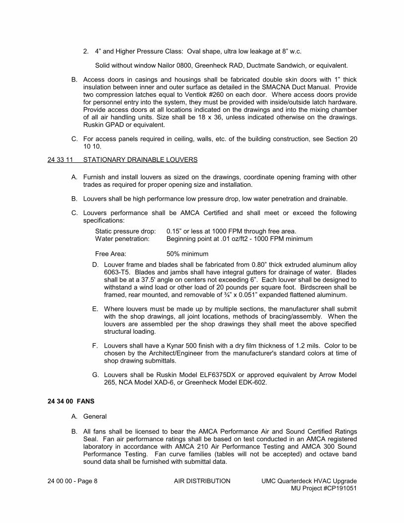
24 00 00 - Page 8 AIR DISTRIBUTION UMC Quarterdeck HVAC UpgradeMU Project #CP191051
2. 4” and Higher Pressure Class: Oval shape, ultra low leakage at 8” w.c.
Solid without window Nailor 0800, Greenheck RAD, Ductmate Sandwich, or equivalent.
B. Access doors in casings and housings shall be fabricated double skin doors with 1” thick insulation between inner and outer surface as detailed in the SMACNA Duct Manual. Provide two compression latches equal to Ventlok #260 on each door. Where access doors provide for personnel entry into the system, they must be provided with inside/outside latch hardware. Provide access doors at all locations indicated on the drawings and into the mixing chamber of all air handling units. Size shall be 18 x 36, unless indicated otherwise on the drawings. Ruskin GPAD or equivalent.
C. For access panels required in ceiling, walls, etc. of the building construction, see Section 20 10 10.
24 33 11 STATIONARY DRAINABLE LOUVERS
A. Furnish and install louvers as sized on the drawings, coordinate opening framing with other trades as required for proper opening size and installation.
B. Louvers shall be high performance low pressure drop, low water penetration and drainable.
C. Louvers performance shall be AMCA Certified and shall meet or exceed the following specifications:
Static pressure drop: 0.15” or less at 1000 FPM through free area.Water penetration: Beginning point at .01 oz/ft2 - 1000 FPM minimum
Free Area: 50% minimum
D. Louver frame and blades shall be fabricated from 0.80” thick extruded aluminum alloy 6063-T5. Blades and jambs shall have integral gutters for drainage of water. Blades shall be at a 37.5' angle on centers not exceeding 6”. Each louver shall be designed to withstand a wind load or other load of 20 pounds per square foot. Birdscreen shall be framed, rear mounted, and removable of ¾” x 0.051” expanded flattened aluminum.
E. Where louvers must be made up by multiple sections, the manufacturer shall submit with the shop drawings, all joint locations, methods of bracing/assembly. When the louvers are assembled per the shop drawings they shall meet the above specified structural loading.
F. Louvers shall have a Kynar 500 finish with a dry film thickness of 1.2 mils. Color to be chosen by the Architect/Engineer from the manufacturer's standard colors at time of shop drawing submittals.
G. Louvers shall be Ruskin Model ELF6375DX or approved equivalent by Arrow Model 265, NCA Model XAD-6, or Greenheck Model EDK-602.
24 34 00 FANS
A. General
B. All fans shall be licensed to bear the AMCA Performance Air and Sound Certified Ratings Seal. Fan air performance ratings shall be based on test conducted in an AMCA registered laboratory in accordance with AMCA 210 Air Performance Testing and AMCA 300 Sound Performance Testing. Fan curve families (tables will not be accepted) and octave band sound data shall be furnished with submittal data.
24 00 00 - Page 9 AIR DISTRIBUTION UMC Quarterdeck HVAC UpgradeMU Project #CP191051
C. All fans shall have premium efficiency open dripproof motor unless indicated otherwise. Fans with variable speed drives shall have inverter duty motors. All fans with V-belt drives shall be equipped with adjustable pitch sheave rated for 1.5 times the motor horsepower, shall have sliderail base, and shall have a belt-guard.
D. All fan shafts shall be designed so that the first critical speed is at least 20% over the maximum operating speed. Bearings shall be self-aligning, grease lubricated, anti-friction, pillow block bearings with a minimum life (L50) of 200,000 hours.
E. Where fans are other than scheduled the following criteria shall apply: Fans shall be picked at the scheduled flow and static pressure, fan efficiency shall not be more than 5% less efficiency than scheduled fan, fan motor shall not be larger than scheduled motor (manufacturer shall notify Contractor of any larger motor sizes, Contractor can pursue equipment substitution as required in subsection 20 00 52), the fan rpm shall not be within 15% of the maximum or minimum allowable rpm, and in general the fan selections shall be based upon maximum energy efficiency but in no case shall the fan wheel be smaller than what is scheduled. Where selection point is within 15% of the maximum allowable rpm of the fan class, provide a higher fan class.
24 34 01 CENTRIFUGAL FANS
A. Centrifugal fans shall be provided where shown and shall have capacities and minimum wheel diameters, wheel type, and class as indicated on the schedule. Each fan shall be of the non-overloading centrifugal type with deep drawn inlet rings, streamlined housing continuously welded and scroll, blades continuously welded to the flange, solid backplate, full curved shroud, and flanged discharge collar. Where Class II construction is required, wheels shall be reinforced with a welded intermediate ring. Fans shall be statically and dynamically balanced. Provide drain openings at the bottom of fan scroll. Fans shall be spark resistance Type C. Fans and motors shall be mounted on structural steel bases of continuously welded sections to form a rigid chassis. The bases shall be supported on isolation mountings equipped with built-in leveling devices and sound attenuating rubber pads. The isolation medium shall be steel springs with 1-1/2” deflection and shall be Korfund Type “L” with seismic restraints or equivalent by Mason Industries, Vibration Eliminator Company, Acme Engineering, or fan manufacturer.
B. Provide low-loss fan inlet box for fan where there is not at least 5 equivalent diameters of straight duct run upstream of the fan inlet.
C. Air Foil fans shall be Cook CA, Greenheck AF Series 41, ACME 8100, or approved equal.
D. Back Incline fans shall be Cook CPS, Greenheck BI Series 41, ACME 3000, or approved equal.
24 37 00 AIR DEVICES
24 37 01 GENERAL
A. Furnish and install diffusers, grilles, and registers as shown on the drawings and specified herein.
B. Air devices shall be installed in the orientation and the pattern controllers adjusted as indicated on the plans, as indicated on the shop drawing, or through supplemental information.
C. Submittal data for all distribution devices shall contain the following information:
24 00 00 - Page 10 AIR DISTRIBUTION UMC Quarterdeck HVAC UpgradeMU Project #CP191051
1) Room Number 2) Model Number3) Flow Rate4) Size: Neck and where applicable5) Throw in feet: Based on 50-fpm velocity 6) Air patterns: Such as one-way, two-way opposite, corner, four-way, etc.7) Pressure drop in inches of water8) Sound rating9) Airflow factor: Such as K factor or as required for airflow rate measurements.10) Accessories: Such as volume dampers, deflectors, etc.11) Three-color charts and balance instructions shall be furnished with submittal data.
D. Devices described below and indicated on the drawings are based on Titus. Similar design characteristics as manufactured by Price, Carnes, Metal Aire, Nailor, or Tuttle & Bailey will also be acceptable. Such substitute equipment shall be sized on the basis of ADPI performance, and shall be selected for a maximum of 0.05 inches w.c. static pressure drop and a maximum noise criterion curve of NC30. Return or exhaust devices shall not be smaller than sizes shown.
E. Ceiling diffusers shall be of the type, service, size, and finish as scheduled on the drawings. Border types shall be coordinated by the Contractor to be suitable for ceiling types.
24 37 03 SIDEWALL GRILLES - REMOVABLE CORE
A. Sidewall supply air grilles (SAG) shall be adjustable double deflection type with removable core with a separate mounting frame with a gasketed one-inch wide flange as scheduled. Sidewall grilles shall be similar to Titus Model 1700 with optional 07 directional blades. Sidewall return or exhaust grilles shall be single deflection to match sidewall supply grilles in appearance. Where registers are required (SAR or RAR), include a key operated opposed blade volume control.
END OF SECTION
25 00 00 - Page 1 CONTROL SYSTEMS UMC Quarterdeck HVAC UpgradeMU Project #CP191051
DIVISION 25 00 00
CONTROL SYSTEMS
PART 1 GENERAL
1.01 SUMMARY
A. University of Missouri Controls Specification.
B. This section contains requirements for pneumatic, electric and digital control systems as indicated on the contract drawings.
C. Contractor is responsible for providing, installing and connecting all sensors, pneumatic actuators, control valves, control dampers, electrical components and all interconnecting pneumatic tubing and electrical wiring between these devices and up to the Direct Digital Controller (DDC).
D. DDC systems consist of Johnson Controls METASYS controllers. Contractor shall provide and install control enclosures. Owner will provide controllers for contractors to install. After all equipment has been installed, wired and piped, Owner will provide controller programming Contractor will be responsible for all termination connections at the DDC controller’s and for checking, testing, and start-up of the control system. Contractor must be on site at start-up to make any necessary hardware adjustments as required.
E. Once each mechanical system is completely operational under the new control system, contractor shall make any final connections and adjustments. For controls renovation jobs, contractor shall remove all unused sensors, operators, panels, wiring, tubing, conduit, etc. Owner shall have the option of retaining any removed pneumatic controls.
1.02 RELATED SECTIONS
A. Drawings and general provisions of Contract, including General and Special Conditions apply to work of this section.
1.03 QUALITY ASSURANCE
A. Contractor's Qualifications:1. Contractor shall be regularly engaged in the installation of digital control systems and
equipment, of types and sizes required. Contractor shall have a minimum of five years’ experience installing digital control systems. Contractor shall supply sufficient and competent supervision and personnel throughout the project in accordance with General Condition’s section 3.4.1 and 3.4.4.
B. Codes and Standards:1. Electrical Standards: Provide electrical components of control systems which have been
UL-listed and labeled, and comply with NEMA standards.2. NEMA Compliance: Comply with NEMA standards pertaining to components and
devices for control systems.3. NFPA Compliance: Comply with NFPA 90A "Standard for the Installation of Air
Conditioning and Ventilating Systems" where applicable to controls and control sequences.
4. NFPA Compliance: Comply with NFPA 70 "National Electric Code."
25 00 00 - Page 2 CONTROL SYSTEMS UMC Quarterdeck HVAC UpgradeMU Project #CP191051
1.04 SUBMITTALS
A. Shop Drawings: Submit shop drawings for each control system, containing the following information:
B. Product data for each damper, valve, and control device.
C. Schematic flow diagrams of system showing fans, pumps, coils, dampers, valves, and control devices.
D. Label each control device with setting or adjustable range of control.
E. Indicate all required electrical wiring. Clearly differentiate between portions of wiring that are factory-installed and portions to be field-installed.
F. Provide details of faces on control panels, including controls, instruments, and labeling.
G. Include written description of sequence of operation.
H. Provide wiring diagrams of contractor provided interface and I/O panels.
I. Provide field routing of proposed network bus diagram listing all devices on bus.
PART 2 PRODUCTS
2.01 MATERIALS AND EQUIPMENT
A. Air Piping:1. Copper Tubing: Seamless copper tubing, Type M or L, ASTM B 88; wrought-copper
solder-joint fittings, ANSI B16.22; except brass compression-type fittings at connections to equipment.
2. Flex Tubing: Virgin Polyethylene non-metallic tubing, ASTM D 2737, with flame-retardant harness for multiple tubing. Use compression or push-on polyethylene fittings. Tubing used above suspended ceilings to be plenum rated per NFPA 90A. See section 3.1.b for locations where flex tubing can be used.
3. Copper to polyethylene connections shall be compression barbed fittings or solder barbed fittings.
B. Conduit and Raceway:1. Electrical Metallic Tubing: EMT and fittings shall conform to ANSI C80.3.2. Surface Metal Raceway and Fittings: Wiremold 500, Ivory, or approved equal. 3. Flexible Metal Conduit: Indoors, per National Electric Code for connection to moving or
vibrating equipment. 4. Liquidtight Flexible Conduit: Outdoors, per National Electric Code for connection to
moving or vibrating equipment.
C. Control Valves: Provide factory fabricated pneumatic or electric control valves of type, body material, and pressure class as indicated on the drawings. Butterfly style control valves are not acceptable except for two position applications. Equip control valves with heavy-duty actuators, with proper shutoff rating for each individual application.1. Steam and Hot Water
a) Manufacturer: Do not allow KMC valves and actuators.b) Water Service Valves: Equal percentage characteristics.c) Steam Service Valves: Equal percentage characteristics.d) Single Seated Valves: Cage type trim, providing seating and guiding surfaces for
plug on "top and bottom" guided plugs.
25 00 00 - Page 3 CONTROL SYSTEMS UMC Quarterdeck HVAC UpgradeMU Project #CP191051
e) Valve Trim and Stems: Polished stainless steel.f) Packing: Spring-loaded Teflon, self-adjusting.g) Control valves should have a minimum 100 psi close-off rating for chilled water
applications.2. Hydronic Chilled Water and Heating Water
a) At minimum, hydronic control valves shall be pressure independent. High performing energy monitoring control valves may be considered depending on the project. The flow through the valve shall not vary more than +/- 5% due to system pressure fluctuations across the valve in the selected operating range. The control valve shall accurately control the flow from 1 to 100% full rated flow.
b) The valve bodies shall be of cast iron, steel or bronze and rated for 150 PSI working pressure. All internal parts shall be stainless steel, steel, Teflon, brass, or bonze.
c) DeltaP Valves manufactured by Flow Control Industries, Belimo, Danfoss Series, or approved equal.
d) The valves shall have pressure taps across the valve for measuring the pressure drop across the valve. The pressure taps shall have ½-inch extensions for accessibility.
e) Control valves shall be installed with unions or flanges as necessary for easy removal and replacement.
f) Valve Tag shall include the model number, AHU being served, design flow, and maximum flow for that valve.
g) The control valves shall be delivered preset to the scheduled design flow and should be capable of reaching 110% of the design flow to allow for field adjustment for capacity changes.
D. Control Dampers: Ruskin CD-50 or approved equal.1. Provide dampers with parallel blades for 2- position control.2. Provide opposed blades for modulating control. 3. Dampers shall be low leakage design with blade and edge seals.4. Provide multiple sections and operators as required by opening size and sequence of
operations, as indicated on the contract drawings.
E. Electric Actuators: Johnson Controls, Bray, Belimo, TAC or approved equal. KMC actuators are not approved. Size electric actuators to operate their appropriate dampers or valves with sufficient reserve power to provide smooth modulating action or 2-position action as specified. If mixed air AHU has return air, exhaust air and outside air dampers that are not mechanically linked then static safety switch must be installed and wired to safety circuit. Spring return actuators should be provided on heat exchanger control valves or dampers or as specified on the drawings. Control signal shall be 0 to 10 VDC unless otherwise specified on drawings. Actuators with integral damper end switch are acceptable. For VAV reheat valves, actuators shall have a manual override capability to aid in system flushing, startup, and balancing.
F. Air and Hot Water Electronic Temperature Sensors:
1. All electronic temperature sensors shall be compatible with Johnson METASYS systems.
2. Sensors shall be 1,000 ohm platinum, resistance temperature detectors (RTDs) with two wire connections. Duct mounted sensors shall be averaging type. Contractor may install probe type when field conditions prohibit averaging type, but must receive permission from Owner's Representative.
3. Coordinate thermowell manufacturer with RTD manufacturer. Thermowells that are installed by the contractor, but are to have the RTD installed by owner, must be Johnson Controls Inc. series WZ-1000.
G. Electronic Temperature Sensors and Transmitters:1. Chilled Water, Tower Water, Heating Hot Water, and Steam Temperature Sensors
25 00 00 - Page 4 CONTROL SYSTEMS UMC Quarterdeck HVAC UpgradeMU Project #CP191051
a) General: The RTD/Temperature Transmitter/Thermowell assembly shall come as a complete assembly from a single manufacturer. The Assembly shall be suitable for use in the accurate measurement of Chilled/Tower/Hot Water and steam temperatures in a mechanical room environment.
b) Calibration: Each RTD must be match calibrated to the Transmitter via NIST traceable calibration standards. Results are to be programmed into the transmitter. Results are to be presented on report as after condition at the specified calibration points. Assembly shall not be approved for installation until Owner has received all factory calibration reports.
c) RTD: (1) RTD type: 2-wire or 3-wire 100 ohm platinum class A(2) Outside Diameter: 0.25 inch(3) Tolerance: +/- 0.06% Type A(4) Stability: +/- 0.1 % over one year.(5) TCR: 0.00385 (ohm/ohm/oC).(6) RTD shall be tip sensitive.(7) Resistance vs. Temperature table for the RTD must be provided to the
Owner.d) Transmitter:
(1) Transmitter shall be match calibrated to the RTD and assembled as a matched pair.
(2) Type: 2 wire (loop powered)(3) Input: 2 or 3 wire 100 ohm platinum class A or class B RTD(4) Output: Output shall be a 4-20 mA signal linear to temperature(5) Calibrated Span:
(a) Chilled Water: 30 oF to 130 oF.(b) Tower Water: 30 oF to 130 oF.(c) Hot Water: 100 oF to 250 oF.(d) Steam: 150 oF to 450 oF
(6) Calibration Accuracy, including total of all errors, of the Transmitter & RTD matched pair over the entire span shall be within +/- 0.2% of the calibrated span or +/- 0.18 oF, whichever is greater.
(7) Supply Voltage: 24 VDC.(8) Ambient Operating Temp.: 32 to 122 oF (9) Epoxy potted for moisture resistance.(10) Mounting: Transmitter shall be mounted in the RTD connection head.
e) Thermowell(1) Thermowell shall be suitable for immersion in chilled/hot water and steam.(2) Thermowell shall be reduced tip.(3) Thermowell shall be one piece stainless steel machined from solid bar stock.(4) Thermowell shall have 1/2” NPT process connection to pipe thred-o-let.(5) Thermowell Insertion depth shall be ½ the inside pipe diameter but not to
exceed 10”.f) Assembly:
(1) Assembly configuration: Spring loaded RTD with thermowell-double ended hex-connection head.
(2) Connection head shall be cast aluminum with chain connecting cap to body, have 1/2” NPT process and 3/4” NPT conduit connections, and a sealing gasket between cap and body.
g) RTD/Temperature Transmitter/Thermowell assembly shall be the following or approved equal:(1) Manufacturer: Pyromation, Inc.(2) Chilled Water: RAF185L-S4C[length code]08-SL-8HN31,TT440-385U-S(30-
130)F with calibration SMC(40,60)F(3) Tower Water: RAF185L-S4C[length code]08-SL-8HN31,TT440-385U-
S(5130)F with calibration SMC(55,85)F
25 00 00 - Page 5 CONTROL SYSTEMS UMC Quarterdeck HVAC UpgradeMU Project #CP191051
(4) Hot Water: RAF185L-S4C[length code]08T2-SL-8HN31,TT440-385U-S(100-250)F with calibration SMC(140,180)F
(5) Steam: RAT185H-S4C[length code]08T2-SL-8HN31,TT440-385U-S(150-450)F with calibration SMC(300,350)F
H. Occupant Override: Provide wall mounted occupant override button in locations shown on drawings.
I. Low Limit Controllers: Provide unit-mounted low limit controllers, of rod-and-tube type, with an adjustable set point and a manual reset. Capillary shall be of adequate length to horizontally traverse face of cooling coil every 12". Multiple low limit controllers may be required for large coils. Controller shall have an extra set of contactors for connection to control panel for alarm status. Locate the thermostat case and bellows where the ambient temperature is always warmer than the set point.1. Freeze Stats: Johnson Controls model A70HA-1 or approved equal.
J. Fan/Pump Status: Status points for fan or pump motors with a VFD must be connected to the terminal strip of the VFD for status indication. Current switches: Current switches are required for fan and pump statuses that are not connected to a VFD. The switches must have an adjustable trip setpoint with LED indication and be capable of detecting broken belts or couplings. Units shall be powered by monitored line, UL listed and CE certified, and have a five year warranty.1. Kele, Hawkeye or approved equal.
K. Relays Used for Fan and Pump Start/Stop: Must have LED indication and be mounted externally of starter enclosure or VFD.1. Kele, RIBU1C or approved equal.
L. Power Supply Used to Provide Power to Contractor-Provided Control Devices: Shall have adjustable DC output, screw terminals, overload protection and 24 VAC and 24 VDC output.1. Kele, DCPA-1.2 or approved equal.
M. Pressure Differential Switch:1. Fans: NECC model DP222 or approved equal.
N. Differential Pressure Transmitter: Provide units with linear analog 4-20mA output proportional to differential pressure, compatible with the Johnson METASYS Systems.1. Water: Units shall be wet/wet differential pressure capable of a bi-directional pressure
range of +/- 50 psid. Accuracy shall be +/- 0.25% full scale with a compensated temperature range of 30 to 150 deg F and a maximum working pressure of 250 psig.
2. Install transmitter in a pre-manufactured assembly with shut off valves, vent valves and a bypass valve.a) Setra model 230 with Kele model 3-VLV, three valve manifold or approved equal.
3. Air: Units shall be capable of measuring a differential pressure of 0 to 5 in. WC. Accuracy shall be +/- 1.0% full scale with a compensated temperature range of 40 to 149 deg F and a maximum working pressure of 250 psig. a) Setra model 267, or approved equal.b) Shall be installed in control panel and piped 2/3 down the duct unless shown
otherwise or approved by owners representative.
O. Building Static Pressure: Transducer shall utilize a ceramic capacitive sensing element to provide a stable linear output over the specified range of building static pressure. Transducer shall be housed in a wall-mounted enclosure with LCD display. Transducer shall have the following capabilities:1. Input Power: 24 VAC2. Output: 0-10 VDC
25 00 00 - Page 6 CONTROL SYSTEMS UMC Quarterdeck HVAC UpgradeMU Project #CP191051
3. Pressure Range: -0.25 to +0.25 inches w.g.4. Display: 3-1/2 digit LCD, displaying pressure in inches w.g.5. Accuracy: +/- 1.0% combined linearity and hysteresis 6. Temperature effect: 0.05% / deg C7. Zero drift (1 year): 2.0% max8. Zero adjust: Push-button auto-zero and digital input 9. Operating Environment: 0 to 140 deg F, 90% RH (non-condensing)10. Fittings: Brass barbs, 1/8” O.D.11. Enclosure: High-impact ABS plastic12. Outside Air Sensor Pickup Port: UV stabilized thermoplastic or aluminum “can”
enclosure to shield outdoor pressure sensing tube from wind effects. BAPI ZPS-ACC10-rooftop mount, wall mount, or equivalent.
13. Transducer shall be Veris Industries Model PXPLX01S, equivalent from Setra, or approved equal.
P. High Static Pressure Limit Switch: Provide pressure high limit switch to open contact in fan circuit to shut down the supply fan when the inlet static pressure rises above the set point. Provide with an adjustable set point, a manual reset button, 2 SPST (normally closed) contacts, and ¼” compression fittings.1. Kele model AFS-460-DDS, or approved equal.
Q. AIRFLOW/TEMPERATURE MEASUREMENT DEVICES1. Provide airflow/temperature measurement devices where indicated on the plans. Fan inlet
measurement devices shall not be substituted for duct or plenum measurement devices indicated on the plans.
2. The measurement device shall consist of one or more sensor probe assemblies and a single, remotely mounted, microprocessor-based transmitter. Each sensor probe assembly shall contain one or more independently wired sensor housings. The airflow and temperature readings calculated for each sensor housing shall be equally weighted and averaged by the transmitter prior to output. Pitot tubes and arrays are not acceptable. Vortex shedding flow meters are not acceptable.
3. All Sensor Probe Assembliesa) Each sensor housing shall be manufactured of a U.L. listed engineered
thermoplastic.b) Each sensor housing shall utilize two hermetically sealed, bead-in-glass thermistor
probes to determine airflow rate and ambient temperature. Devices that use “chip” or diode case type thermistors are unacceptable. Devices that do not have 2 thermistors in each sensor housing are not acceptable.
c) Each sensor housing shall be calibrated at a minimum of 16 airflow rates and have an accuracy of +/-2% of reading over the entire operating airflow range. Each sensor housing shall be calibrated to standards that are traceable to the National Institute of Standards and Technology (NIST).(1) Devices whose accuracy is the combined accuracy of the transmitter and
sensor probes must demonstrate that the total accuracy meets the performance requirements of this specification throughout the measurement range.
d) The operating temperature range for the sensor probe assembly shall be -20° F to 160 F. The operating humidity range for the sensor probe assembly shall be 0-99% RH (non-condensing).
e) Each temperature sensor shall be calibrated at a minimum of 3 temperatures and have an accuracy of +/-0.15° F over the entire operating temperature range. Each temperature sensor shall be calibrated to standards that are traceable to the National Institute of Standards and Technology (NIST).
25 00 00 - Page 7 CONTROL SYSTEMS UMC Quarterdeck HVAC UpgradeMU Project #CP191051
f) Each sensor probe assembly shall have an integral, U.L. listed, plenum rated cable and terminal plug for connection to the remotely mounted transmitter. All terminal plug interconnecting pins shall be gold plated.
g) Each sensor assembly shall not require matching to the transmitter in the field.h) A single manufacturer shall provide both the airflow/temperature measuring
probe(s) and transmitter at a given measurement location.4. Duct and Plenum Sensor Probe Assemblies
a) Sensor housings shall be mounted in an extruded, gold anodized, 6063 aluminum tube probe assembly. Thermistor probes shall be mounted in sensor housings using a waterproof marine grade epoxy resin. All wires within the aluminum tube shall be Kynar coated.
b) The number of sensor housings provided for each location shall be as follows:(1) Area (sq.ft.) Sensors
<2 42 to <4 64 to <8 88 to <16 12>=16 16
c) Probe assembly mounting brackets shall be constructed of 304 stainless steel. Probe assemblies shall be mounted using one of the following options:(1) Insertion mounted through the side or top of the duct.(2) Internally mounted inside the duct or plenum.(3) Standoff mounted inside the plenum.
d) The operating airflow range shall be 0 to 5,000 FPM unless otherwise indicated on the plans.
5. Fan Inlet Sensor Probe Assembliesa) Sensor housings shall be mounted on 304 stainless steel blocks.b) Mounting rods shall be field adjustable to fit the fan inlet and constructed of nickel
plated steel.c) Mounting feet shall be constructed of 304 stainless steel.d) The operating airflow range shall be 0 to 10,000 FPM unless otherwise indicated
on the plans.6. Transmitters
a) The transmitter shall have a 16 character alpha-numeric display capable of displaying airflow, temperature, system status, configuration settings and diagnostics. Configuration settings and diagnostics shall be accessed through a pushbutton interface on the main circuit board. Airflow shall be field configurable to be displayed as a velocity or a volumetric rate.
b) The transmitter shall be capable of independently monitoring and averaging up to 16 individual airflow and temperature readings. The transmitter shall be capable of displaying the airflow and temperature readings of individual sensors on the LCD display.
c) The transmitter shall have a power switch and operate on 24 VAC (isolation not required). The transmitter shall use a switching power supply fused and protected from transients and power surges.
d) All interconnecting pins, headers and connections on the main circuit board, option cards and cable receptacles shall be gold plated.
e) The operating temperature range for the transmitter shall be -20° F to 120° F. The transmitter shall be protected from weather and water.
f) The transmitter shall be capable of communicating with the host controls using one of the following interface options:(1) Linear analog output signal: Field selectable, fuse protected and isolated, 0-
10VDC and 4-20mA (4-wire).(2) RS-485: Field selectable BACnet-MS/TP, ModBus-RTU and Johnson
Controls N2 Bus.(3) 10 Base-T Ethernet: Field selectable BACnet Ethernet, BACnet-IP, ModBus-
25 00 00 - Page 8 CONTROL SYSTEMS UMC Quarterdeck HVAC UpgradeMU Project #CP191051
TCP and TCP/IP.(4) LonWorks Free Topology.
g) The transmitter shall have an infra-red interface capable of downloading individual sensor airflow and temperature data or uploading transmitter configuration data to a handheld PDA (Palm or Microsoft Pocket PC operating systems).
7. The measuring device shall be UL listed as an entire assembly.8. The manufacturer’s authorized representative shall review and approve placement and
operating airflow rates for each measurement location indicated on the plans. A written report shall be submitted to the consulting mechanical engineer if any measurement locations do not meet the manufacturer’s placement requirements.
9. Manufacturera) Primary flow elements, sensors, meters and transducers shall be EBTRON, Inc.
Model GTx116-P and GTx116-F or approved equal.b) The naming of any manufacturer does not automatically constitute acceptance of
this standard product nor waive their responsibility to comply totally with all requirements of the proceeding specification.
R. Electrical Requirements: Provide electric-pneumatic switches, electrical devices, and relays that are UL-listed and of type which meet current and voltage characteristics of the project. All devices shall be of industrial/ commercial grade or better. Residential types will be rejected.1. EP Switches: Landis & Gyr Powers, Inc. Series 265 - Junction Box Type or approved
equal.2. Relays: Relays shall have an LED status indicator, voltage transient suppression,
Closed-Open-Auto switch, plastic enclosure, and color coded wires. Kele model RIBU1C or approved equal.
V. Magnetic Flowmeter for Chilled Water, Tower Water, Make Up Water:1. The Magnetic Flowmeter flow tube and computer/transducer shall come as a complete
system assembled by a single manufacturer. The flowmeter shall be suitable for use in the accurate measurement of Chilled Water flow, Cooling Tower Water flow, or Make Up water flow for process control and/or utility metering, in a mechanical room environment, with a Johnson Controls EMCS system.
2. The flowmeter shall consist of a pulsed DC electromagnetic coil incorporating Faraday’s Law utilizing the flowing Water as the conductor. The flowmeter shall provide proper grounding for use in Schedule 40 steel pipe, Schedule 10S stainless steel pipe, or copper pipe as application requires.
3. The flowmeter element should be sized to maintain maximum accuracy over the flow range of the application while keeping flow tube velocity below 15 fps at max flow. The flowmeter element shall be the flow tube, spool piece type with a non-conductive lining and no intrusions into the flow path. The flowmeter flow tube shall be suitable for direct mounting to standard ANSI flanges.
4. The flowmeter shall have a local LCD display that indicates flow in GPM and/or Total gallons from the totalizer. The flowmeter shall be programmable/configurable via local push buttons. The flowmeter computer/transducer shall be remote mounted. The flow tube shall have a direct mounted junction box for wiring connections.
5. The flowmeter shall have the capability to be calibrated insitu to verify proper operation and accuracies.
6. The flowmeter shall also meet the following specifications:
a) Measures Bi-directional flow.b) Zero-point stability.c) Flow tube can withstand a full vacuum on an intermittent basis.d) Normal obstructions, partially opened valves, 900 or 450 elbows, and pump
discharges shall require no more than 5 pipe diameters upstream and 3 pipe diameters downstream of straight pipe run for specified performance.
e) Auto re-start after electrodes have lost wetness.
25 00 00 - Page 9 CONTROL SYSTEMS UMC Quarterdeck HVAC UpgradeMU Project #CP191051
f) Computer/transducers shall be interchangeable to multiple flow tubes without affecting the published accuracies of the meter.
g) Computer/transducer internal electronic components, including power supply and output boards, shall be field interchangeable/exchangeable.
h) Calibration: NIST Traceable, certificate provided with each meter.
i) Electrode Pressure Rating: Equivalent to flow tube flange ratingj) Minimum Conductivity: 5 mS/cm for fluid to be measuredk) Transmitter Ambient Temp.: 122 0Fl) Flow Tube Process Temp.: 32 0F to 140 0F for Chilled Water applicationsm) Flow Tube Process Temp.: 32 0F to 140 0F for Make Up Water applicationsn) Flow Tube Process Temp.: 32 0F to 311 0F for Hot or Dual Water applicationso) Flow Range: +/- 0 to 30 fpsp) Accuracy (velocity < /= 1.0 fps): +/- 0.5% of reading or +/- 0.005 fpsq) Accuracy (velocity > 1.0 fps): +/- 0.5% of readingr) Analog Output: 4-20 mA, linear to flow in GPMs) Analog Output Accuracy: +/- 0.05% of spant) Repeatability: +/- 0.1%u) Stability: +/- 0.1%v) Ambient Temperature Effect: <1% per 100 0Fw) Vibration Effect: 0.1% (remote mounted transducer)x) Low Flow Cutoff: settable to 0.04 fps or lowery) Low Flow Cutoff Analog Output: Analog output shall be 4.0 mA at flows below the
low cutoff.z) Humidity Limits: 5-90% RHaa) Power Supply: 115 VACbb) Power Consumption: 20 W maximumcc) Enclosures: NEMA 4dd) Flow Tube working pressure: 150 psiee) Flanges: Carbon steel, ANSI Class 150#ff) Electrodes: Corrosion resistant Alloy Cgg) Cable Length: As required per plans, 150 ft minimumhh) Cable shall be capable of empty pipe detection.ii) All cable shall be provided by the meter manufacturer.
7. The flowmeter shall be Foxboro IMT31A with 9500A, 9700A for high temperature, or approved equal.
8. Bids/Submittals: All bids and/or submittals must include published specifications, specific model number configurations, and operation & maintenance manuals.
9. Warranty: All parts and components as needed for the specified operation and performance shall be covered under warranty for a period of not less than two yearsrs.
T. Ultrasonic Level Transmitter for Cooling Tower Basin Water: Furnish and install, where indicated on plans, a device for measuring the tower basin water level. The level transmitter shall meet the following specifications:1. Make: Flowline2. Model: EchoSpan LU83-51-013. Range: 8” to 26.2 feet4. Accuracy: 0.2% of span in air5. Resolution: 0.039”6. Beam width: 3”7. Dead band: 8”8. Display type: 6 digit LCD9. Display units: Inch, cm, %
25 00 00 - Page 10 CONTROL SYSTEMS UMC Quarterdeck HVAC UpgradeMU Project #CP191051
10. Memory: Non-volatile11. Supply voltage: 12-28 VDC12. Loop resistance: 500 Ohms @ 24 VDC13. Signal output: 4-20 mA two-wire14. Signal invert: 4-20 mA or 20-4 mA15. Calibration: Push button16. Fail-safety: Selectable 4 mA, 20 mA, 21 mA, 22 mA, or hold17. Process temperature: -4 oF to 140 oF18. Temp. Comp.: Automatic19. Electronics temp.: -40 oF to 160 oF20. Pressure: 30 psi @ 25 oC, derated @ 1.667 psi/oC above 25 oC21. Enclosure rating: NEMA 4X (IP65)22. Enclosure vent: Water tight membrane23. Enclosure material: PC/ABS FR24. Trans. Material: PVDF25. Process mount: 2” NPT26. Mounting gasket: Viton27. Conduit entrance: Dual, ½” NPT28. Classification: General purpose29. CE compliance: EN 61326 EMC30. Level transmitter shall be Flowline EchoSpan LU83-51-01 or equivalent.
PART 3 EXECUTION
3.01 INSTALLATION OF CONTROL SYSTEMS
A. General: Install systems and materials in accordance with manufacturer’s instructions, roughing-in drawings and details shown on drawings.
B. Control Air Piping:1. All control air piping shall be copper. Exception: Flexible Tubing may be used for a
maximum of two (2) feet at connections to equipment [except for steam control valves] and inside control cabinets.
2. Provide copper tubing with a maximum unsupported length of 3'-0".3. Pressure Test control air piping at 30 psi for 24 hours. Test fails if more than 5 PSI loss
occurs.4. Fasten flexible connections bridging cabinets and doors, neatly along hinge side, and
protect against abrasion. Tie and support tubing neatly.5. Number-code or color-code tubing, except local individual room control tubing, for future
identification and servicing of control system.6. All control tubing at control panel shall be tagged and labeled during installation to assist
owner in making termination connections at control panel.7. Provide pressure gages on each output device.8. Paint all exposed control tubing to match existing.
C. Raceway: Raceway is to be installed in accordance with the National Electric Code. Use of flexible metal conduit or liquidtight flexible conduit is limited to 36" to connect from EMT to devices subject to movement. Flexible raceway is not to be used to compensate for misalignment of raceway during installation.
D. Control Wiring: Install control wiring in raceway, without splices between terminal points, color-coded. Install in a neat workmanlike manner, securely fastened. Install in accordance with National Electrical Code.1. Install circuits over 25-volt with color-coded No. 12 stranded wire.2. Install electronic circuits and circuits under 25-volts with color-coded No. 18 stranded
25 00 00 - Page 11 CONTROL SYSTEMS UMC Quarterdeck HVAC UpgradeMU Project #CP191051
twisted shielded pair type conductor.3. N2 communications bus wire shall be 18 AWG, plenum rated, stranded twisted shielded,
3 conductor, with blue outer casing, descripted as 18-03 OAS STR PLNM NEON BLU JK distributed by Windy City Wire, constructed by Cable-Tek, or approved equivalent.a) Metastat wiring shall be minimum 20 AWG, plenum rated, stranded, 8 conductor
stranded wire.4. FC communications bus wire shall be 22 AWG, plenum rated, stranded twisted shielded,
3 conductor, with blue outer casing, descripted as 22-03 OAS STR PLNM NEON BLU JK distributed by Windy City Wire, constructed by Cable-Tek, or approved equivalent.a) Network sensor wiring (SA Bus) shall be 22 gauge plenum rated stranded twisted
wire, 4 conductor.5. All control wiring at control panel shall be tagged and labeled during installation to assist
owner in making termination connections at control panel. Label all control wires per bid documents.
E. All low voltage electrical wiring shall be run as follows:1. Route electrical wiring in concealed spaces and mechanical rooms whenever possible.2. Provide EMT conduit and fittings in mechanical rooms and where indicated on drawings.3. Low voltage electrical wiring routed above acoustical ceiling is not required to be in
conduit, but wire must be plenum rated and properly supported to building structure.4. Provide surface raceway, fittings and boxes in finished areas where wiring cannot be run
in concealed spaces. Route on ceiling or along walls as close to ceiling as possible. Run raceway parallel to walls. Diagonal runs are not permitted. Paint raceway and fittings to match existing conditions. Patch/repair/paint any exposed wall penetrations to match existing conditions.
F. All devices shall be mounted appropriately for the intended service and location.1. Adjustable thermostats shall be provided with base and covers in occupied areas and
mounted 48" above finished floor to the top of the device. Tubing and/or wiring shall be concealed within the wall up to the ceiling where ever possible. Surface raceway may only be used with approval of Owners Representative. Wall mounted sensors such as CO2, RH, and non-adjustable temperature sensors shall be mounted 54” above finished floor. Duct mounted sensors shall be provided with mounting brackets to accommodate insulation. Mounting clips for capillary tubes for averaging sensors are required.
2. All control devices shall be tagged and labeled for future identification and servicing of control system.
3. Preheat and mixed air discharge sensors must be of adequate length and installed with capillary tube horizontally traversing face of coil, covering entire coil every 24 inches bottom to top.
4. All field devices must be accessible or access panels must be installed.
G. Install magnehelic pressure gage across each air handling unit filter bank. If the air handling unit has a prefilter and a final filter, two magnehelic pressure gages are required.
3.02 ADJUSTING AND START-UP
A. Start-Up: Temporary control of Air Handling Units shall be allowed only if approved by the owner’s representative to protect finishes, etc., AHUs may be run using caution with temporary controls installed by contractor early in the startup process. All safeties including a smoke detector for shut down must be operational. Some means of discharge air control shall be utilized and provided by the contractor such as a temporary temperature sensor and controller located and installed by the Contractor.
B. The start-up, testing, and adjusting of pneumatic and digital control systems will be conducted by owner. Once all items are completed by the Contractor for each system, Contractor shall allow time in the construction schedule for owner to complete commissioning of controls before project substantial completion. This task should be included in the original schedule and updated to include the allotted time necessary to complete it. As a minimum, the following
25 00 00 - Page 12 CONTROL SYSTEMS UMC Quarterdeck HVAC UpgradeMU Project #CP191051
items are required to be completed by the Contractor for Owner to begin controls commissioning.1. Process Control Network
a) The control boards and enclosures need to be installed in the mechanical rooms.b) The fiber optic conduit and box for the process control network needs to be
installed. Once in place, Owner needs to be contacted so the length of the owner provided fiber cable can be determined and ordered, if required. Coordinate with Owner to schedule the pull in and termination of the fiber cable. Power should be in place at that time. (Fiber for the process control network is required to allow metering of utilities prior to turn on.)
2. Heating Systema) Pumps, heat exchangers, steam pressure reducing station, piping, control valves,
steam and/or hot water meter, feeder conduit and wire, VFDs, control panels and control wiring installed in the mechanical room. The house keeping pads must be poured before pump operation. All must be in place in working order (pumps aligned, VFDs set up by vendor, motors checked for rotation, steam regulators set to required pressure, condensate pumps operational, heating system ready to circulate (all piping pressure tested, flushed, and insulated) with differential pressure sensors in place.
3. Cooling Systema) Pumps, heat exchangers, piping, control valves, chilled water meter, feeder
conduit and wire, VFDs, control panels and control wiring installed in the mechanical room. The house keeping pads must be poured before pump operation. All must be in place in working order (pumps aligned, VFDs set up by vendor, motors checked for rotation, cooling system ready to circulate (all piping pressure tested, flushed, and insulated) with differential pressure sensors in place.
4. VAVs-First Passa) Power, (FC or N2 bus), and control wire installed before owner can make first
commissioning pass. First pass includes installation of VAV controller, termination of power, control and network communication wiring.
5. Air Handlersa) Prior to owner commissioning, at a minimum, the following items shall be
complete: Power wiring, motor rotation check, fire/smoke dampers open, control wiring including all safeties, IO cabinet, air handler cleaned, and filters installed as required. To protect the systems from dirt, outside air with no return will be used until the building is clean enough for return air operation.
6. VAVs-Second Passa) After the air handlers are running and under static pressure control and the heating
water system is operating, a second pass can be made on the VAVs to download the control program and commission controllers to verify the VAV dampers, thermostat, and reheat control valves are working properly.
7. Some balance work can be done alongside the control work as long as areas are mostly complete and all diffusers are in place.
3.03 CLOSEOUT PROCEDURES
A. Contractor shall provide complete diagrams of the control system including flow diagrams with each control device labeled, a diagram showing the termination connections, and an explanation of the control sequence. The diagram and sequence shall be framed and protected by glass and mounted next to controller.
B. Contractor shall provide as built diagram of network bus routing listing all devices on bus, once wiring is complete prior to scope completion.
25 00 00 - Page 13 CONTROL SYSTEMS UMC Quarterdeck HVAC UpgradeMU Project #CP191051
PART 4 ATTACHMENTS
ATTACHMENT 1: 25 95 00 INTEGRATED AUTOMATION CONTROL SEQUENCES FOR
HVAC
ATTACHMENT 2: CONTROL POINTS
END OF SECTION
26 05 00 - Page 1 COMMON WORK RESULTS FOR ELECTRICAL
UMC Quarterdeck HVAC Upgrade MU Project #CP191051
SECTION 26 05 00 - COMMON WORK RESULTS FOR ELECTRICAL
PART 1 - GENERAL
1.1 RELATED DOCUMENTS
A. Drawings and general provisions of the Contract, including General and Supplementary Conditions and Division 01 Specification Sections, apply to this Section.
1.2 SUMMARY
A. Section Includes:
1. Electrical equipment coordination and installation.2. Common electrical installation requirements.
1.3 COORDINATION
A. Coordinate arrangement, mounting, and support of electrical equipment:
1. To allow maximum possible headroom unless specific mounting heights that reduce headroom are indicated.
2. To provide for ease of disconnecting the equipment with minimum interference to other installations.
3. To allow right of way for piping and conduit installed at required slope.4. So connecting raceways, cables, wireways, cable trays, and busways will be clear of
obstructions and of the working and access space of other equipment.
B. Coordinate installation of required supporting devices and set sleeves in cast-in-place concrete, masonry walls, and other structural components as they are constructed.
C. Coordinate location of access panels and doors for electrical items that are behind finished surfaces or otherwise concealed. Access doors and panels are specified in Division 08 Section "Access Doors and Frames."
D. Coordinate sleeve selection and application with selection and application of firestopping specified in Division 07 Section "Penetration Firestopping.".
PART 2 - PRODUCTS
PART 3 - EXECUTION
3.1 COMMON REQUIREMENTS FOR ELECTRICAL INSTALLATION
A. Comply with NECA 1.
26 05 00 - Page 2 COMMON WORK RESULTS FOR ELECTRICAL
UMC Quarterdeck HVAC Upgrade MU Project #CP191051
B. Measure indicated mounting heights to bottom of unit for suspended items and to center of unit for wall-mounting items.
C. Headroom Maintenance: If mounting heights or other location criteria are not indicated, arrange and install components and equipment to provide maximum possible headroom consistent with these requirements.
D. Equipment: Install to facilitate service, maintenance, and repair or replacement of components of both electrical equipment and other nearby installations. Connect in such a way as to facilitate future disconnecting with minimum interference with other items in the vicinity.
E. Right of Way: Give to piping systems installed at a required slope.
3.2 SLEEVE INSTALLATION FOR ELECTRICAL PENETRATIONS
A. Install sleeves as specified in Division 26 Section “Sleeves and Sleeve Seals for Electrical Raceways and Cabling.”
3.3 SLEEVE-SEAL INSTALLATION
A. Install sleeves as specified in Division 26 Section “Sleeves and Sleeve Seals for Electrical Raceways and Cabling.”
3.4 FIRESTOPPING
A. Apply firestopping to penetrations of fire-rated floor and wall assemblies for electrical installations to restore original fire-resistance rating of assembly. Firestopping materials and installation requirements are specified in Division 07 Section "Penetration Firestopping."
END OF SECTION 26 05 00
26 05 19 - Page 1 LOW VOLTAGE ELECTRICAL POWER CONDUCTORS AND
CABLES
UMC Quarterdeck HVAC Upgrade MU Project #CP191051
SECTION 26 05 19 - LOW-VOLTAGE ELECTRICAL POWER CONDUCTORS AND CABLES
PART 1 - GENERAL
1.1 RELATED DOCUMENTS
A. Drawings and general provisions of the Contract, including General and Supplementary Conditions and Division 01 Specification Sections, apply to this Section.
1.2 SUMMARY
A. This Section includes the following:
1. Building wires and cables rated 600 V and less.2. Connectors, splices, and terminations rated 600 V and less.
1.3 DEFINITIONS
A. EPDM: Ethylene-propylene-diene terpolymer rubber.
B. NBR: Acrylonitrile-butadiene rubber.
1.4 ACTION SUBMITTALS
A. Product Data: For each type of product indicated.
1.5 INFORMATIONAL SUBMITTALS
A. Qualification Data: For testing agency.
B. Field quality-control test reports.
1.6 QUALITY ASSURANCE
A. Electrical Components, Devices, and Accessories: Listed and labeled as defined in NFPA 70, Article 100, by a testing agency acceptable to authorities having jurisdiction, and marked for intended use.
B. Comply with NFPA 70.
26 05 19 - Page 2 LOW VOLTAGE ELECTRICAL POWER CONDUCTORS AND
CABLES
UMC Quarterdeck HVAC Upgrade MU Project #CP191051
PART 2 - PRODUCTS
2.1 CONDUCTORS AND CABLES
A. Manufacturers: Subject to compliance with requirements, provide products by one of the following:
1. Alcan Products Corporation; Alcan Cable Division.2. American Insulated Wire Corp.; a Leviton Company.3. General Cable Corporation.4. Senator Wire & Cable Company.5. Southwire Company.
B. Copper Conductors: Comply with NEMA WC 70.
C. Conductor Insulation: Comply with NEMA WC 70 for Types THHN-THWN-2 (Minimum insulation rating 90° C).
D. Multiconductor Cable: Comply with NEMA WC 70 for metal-clad cable, Hospital Grade Type MC cable with ground wire. (To be used as dedicated light fixture whips from junction box to fixture with a maximum length of 6 ft.)
2.2 CONNECTORS AND SPLICES
A. Manufacturers: Subject to compliance with requirements, provide products by one of the following:
1. AFC Cable Systems, Inc.2. Hubbell Power Systems, Inc.3. O-Z/Gedney; EGS Electrical Group LLC.4. 3M; Electrical Products Division.5. Tyco Electronics Corp.
B. Description: Factory-fabricated connectors and splices of size, ampacity rating, material, type, and class for application and service indicated.
PART 3 - EXECUTION
3.1 CONDUCTOR MATERIAL APPLICATIONS
A. Feeders: Copper. Solid for No. 10 AWG and smaller; stranded for No. 8 AWG and larger.
B. Branch Circuits: Copper. Solid for No. 10 AWG and smaller; stranded for No. 8 AWG and larger.
3.2 CONDUCTOR INSULATION AND MULTICONDUCTOR CABLE APPLICATIONS AND WIRING METHODS
A. Service Entrance: Type THHN-THWN-2, single conductors in raceway
26 05 19 - Page 3 LOW VOLTAGE ELECTRICAL POWER CONDUCTORS AND
CABLES
UMC Quarterdeck HVAC Upgrade MU Project #CP191051
B. Exposed Feeders: Type THHN-THWN-2, single conductors in raceway.
C. Feeders Concealed in Ceilings, Walls, Partitions, and Crawlspaces: Type THHN-THWN-2, single conductors in raceway.
D. Feeders Concealed in Concrete, below Slabs-on-Grade, and Underground: Type THHN-THWN-2, single conductors in raceway.
E. Exposed Branch Circuits, Including in Crawlspaces: Type THHN-THWN-2, single conductors in raceway.
F. Branch Circuits Concealed in Ceilings, Walls, and Partitions: Type THHN-THWN-2, single conductors in raceway.
G. Branch Circuits Concealed in Concrete, below Slabs-on-Grade, and Underground: Type THHN-THWN-2, single conductors in raceway.
H. Cord Drops and Portable Appliance Connections: Type SO, hard service cord with stainless-steel, wire-mesh, strain relief device at terminations to suit application.
I. Class 1 Control Circuits: Type THHN-THWN, in raceway.
J. Class 2 Control Circuits: Type THHN-THWN-2, in raceway.
3.3 INSTALLATION OF CONDUCTORS AND CABLES
A. Conceal cables in finished walls, ceilings, and floors, unless otherwise indicated.
B. Use manufacturer-approved pulling compound or lubricant where necessary; compound used must not deteriorate conductor or insulation. Do not exceed manufacturer's recommended maximum pulling tensions and sidewall pressure values.
C. Use pulling means, including fish tape, cable, rope, and basket-weave wire/cable grips, that will not damage cables or raceway.
D. Install exposed cables parallel and perpendicular to surfaces of exposed structural members, and follow surface contours where possible.
E. Support cables according to Division 26 Section "Hangers and Supports for Electrical Systems."
F. Identify and color-code conductors and cables according to Division 26 Section "Identification for Electrical Systems."
3.4 CONNECTIONS
A. Tighten electrical connectors and terminals according to manufacturer's published torque-tightening values. If manufacturer's torque values are not indicated, use those specified in UL 486A and UL 486B.
B. Make splices and taps that are compatible with conductor material and that possess equivalent or better mechanical strength and insulation ratings than unspliced conductors.
C. Wiring at Outlets: Install conductor at each outlet, with at least 12 inches of slack.
26 05 19 - Page 4 LOW VOLTAGE ELECTRICAL POWER CONDUCTORS AND
CABLES
UMC Quarterdeck HVAC Upgrade MU Project #CP191051
3.5 SLEEVE AND SLEEVE-SEAL INSTALLATION FOR ELECTRICAL PENETRATIONS
A. Install sleeves and sleeve seals at penetrations of exterior floor and wall assemblies. Comply with requirements in Division 26 Section "Sleeves and Sleeve Seals for Electrical Raceways and Cabling."
3.6 FIRESTOPPING
A. Apply firestopping to electrical penetrations of fire-rated floor and wall assemblies to restore original fire-resistance rating of assembly according to Division 07 Section "Penetration Firestopping."
3.7 FIELD QUALITY CONTROL
A. Perform tests and inspections and prepare test reports.
B. Tests and Inspections:
1. After installing conductors and cables and before electrical circuitry has been energized, test panelboard feeder conductors and branch circuits 100amp and larger for compliance with requirements.
2. Perform each visual and mechanical inspection and electrical test stated in NETA Acceptance Testing Specification. Certify compliance with test parameters.
3. Infrared Scanning: After Substantial Completion, but not more than 60 days after Final Acceptance, perform an infrared scan of each splice in cables and conductors No. 3 AWG and larger. Remove box and equipment covers so splices are accessible to portable scanner.
a. Follow-up Infrared Scanning: Perform an additional follow-up infrared scan of each splice 11 months after date of Substantial Completion.
b. Instrument: Use an infrared scanning device designed to measure temperature or to detect significant deviations from normal values. Provide calibration record for device.
c. Record of Infrared Scanning: Prepare a certified report that identifies splices checked and that describes scanning results. Include notation of deficiencies detected, remedial action taken, and observations after remedial action.
C. Test Reports: Prepare a written report to record the following:
1. Test procedures used.2. Test results that comply with requirements.3. Test results that do not comply with requirements and corrective action taken to achieve
compliance with requirements.
D. Remove and replace malfunctioning units and retest as specified above.
END OF SECTION 26 05 19
26 05 26 - Page 1 GROUNDING AND BOUNDING FOR ELECTRICAL SYSTEMS
UMC Quarterdeck HVAC Upgrade MU Project #CP191051
SECTION 26 05 26 - GROUNDING AND BONDING FOR ELECTRICAL SYSTEMS
PART 1 - GENERAL
1.1 RELATED DOCUMENTS
A. Drawings and general provisions of the Contract, including General and Supplementary Conditions and Division 01 Specification Sections, apply to this Section.
1.2 SUMMARY
A. Section includes grounding and bonding systems and equipment.
1.3 ACTION SUBMITTALS
A. Product Data: For each type of product indicated.
1.4 QUALITY ASSURANCE
A. Testing Agency Qualifications: Certified by NETA.
PART 2 - PRODUCTS
2.1 SYSTEM DESCRIPTION
A. Electrical Components, Devices, and Accessories: Listed and labeled as defined in NFPA 70, by a qualified testing agency, and marked for intended location and application.
B. Comply with UL 467 for grounding and bonding materials and equipment.
2.2 MANUFACTURERS
A. Manufacturers: Subject to compliance with requirements, available manufacturers offering products that may be incorporated into the work include, but are not limited to, the following:1. Allen-Bradley Co2. Alltec Coprporation3. Appleton Electric Co4. Calpipe Industries Incorported5. Eric, Inc.6. Harger Lightning & Grounding.7. Lyncole XIT Grounding8. Mk3 Entgerprises, LLC Electrical Contractor9. Superior Grounding Systems, INC.
26 05 26 - Page 2 GROUNDING AND BOUNDING FOR ELECTRICAL SYSTEMS
UMC Quarterdeck HVAC Upgrade MU Project #CP191051
2.3 CONDUCTORS
A. Insulated Conductors: Copper wire or cable insulated for 600 V unless otherwise required by applicable Code or authorities having jurisdiction.
B. Bare Copper Conductors:
1. Solid Conductors: ASTM B 3.2. Stranded Conductors: ASTM B 8.3. Tinned Conductors: ASTM B 33.4. Bonding Cable: 28 kcmil, 14 strands of No. 17 AWG conductor, 1/4 inch in diameter.5. Bonding Conductor: No. 4 or No. 6 AWG, stranded conductor.6. Bonding Jumper: Copper tape, braided conductors terminated with copper ferrules; 1-5/8
inches wide and 1/16 inch thick.7. Tinned Bonding Jumper: Tinned-copper tape, braided conductors terminated with copper
ferrules; 1-5/8 inches wide and 1/16 inch thick.
2.4 CONNECTORS
A. Listed and labeled by an NRTL acceptable to authorities having jurisdiction for applications in which used and for specific types, sizes, and combinations of conductors and other items connected.
B. Welded Connectors: Exothermic-welding kits of types recommended by kit manufacturer for materials being joined and installation conditions.
C. Bus-Bar Connectors: Mechanical type, cast silicon bronze, solderless compression-type wire terminals, and long-barrel, two-bolt connection to ground bus bar.
D. Beam Clamps: Mechanical type, terminal, ground wire access from four directions, with dual, tin-plated or silicon bronze bolts.
E. Cable-to-Cable Connectors: Compression type, copper or copper alloy.
F. Cable Tray Ground Clamp: Mechanical type, zinc-plated malleable iron.
G. Conduit Hubs: Mechanical type, terminal with threaded hub.
H. Ground Rod Clamps: Mechanical type, copper or copper alloy, terminal with hex head bolt.
I. Lay-in Lug Connector: Mechanical type, copper rated for direct burial terminal with set screw.
J. Service Post Connectors: Mechanical type, bronze alloy terminal, in short- and long-stud lengths, capable of single and double conductor connections.
K. Signal Reference Grid Clamp: Mechanical type, stamped-steel terminal with hex head screw.
L. Straps: Solid copper, copper lugs. Rated for 600 A.
M. Tower Ground Clamps: Mechanical type, copper or copper alloy, terminal two-piece clamp.
N. U-Bolt Clamps: Mechanical type, copper or copper alloy, terminal listed for direct burial.
O. Water Pipe Clamps:
26 05 26 - Page 3 GROUNDING AND BOUNDING FOR ELECTRICAL SYSTEMS
UMC Quarterdeck HVAC Upgrade MU Project #CP191051
1. Mechanical type, two pieces with stainless-steel bolts.
a. Material: Tin-plated aluminum.b. Listed for direct burial.
2. U-bolt type with malleable-iron clamp and copper ground connector rated for direct burial.
2.5 GROUNDING ELECTRODES
A. Ground Rods: Copper-clad steel, sectional type; 3/4 inch by 10 feet.
B. Ground Plates: 1/4 inch (6 mm) thick, hot-dip galvanized.
PART 3 - EXECUTION
3.1 APPLICATIONS
A. Conductors: Install solid conductor for No. 8 AWG and smaller, and stranded conductors for No. 6 AWG and larger unless otherwise indicated.
B. Conductor Terminations and Connections:
1. Pipe and Equipment Grounding Conductor Terminations: Bolted connectors.2. Underground Connections: Welded connectors except at test wells and as otherwise
indicated.3. Connections to Ground Rods at Test Wells: Bolted connectors.4. Connections to Structural Steel: Welded connectors.
3.2 GROUNDING AT THE SERVICE (Existing to Remain)
3.3 EQUIPMENT GROUNDING
A. Install insulated equipment grounding conductors with all feeders and branch circuits.
B. Air-Duct Equipment Circuits: Install insulated equipment grounding conductor to duct-mounted electrical devices operating at 120 V and more, including air cleaners, heaters, dampers, humidifiers, and other duct electrical equipment. Bond conductor to each unit and to air duct and connected metallic piping.
C. Water Heater, Heat-Tracing, and Antifrost Heating Cables: Install a separate insulated equipment grounding conductor to each electric water heater and heat-tracing cable. Bond conductor to heater units, piping, connected equipment, and components.
D. Isolated Equipment Enclosure Circuits: For designated equipment supplied by a branch circuit or feeder, isolate equipment enclosure from supply circuit raceway with a nonmetallic raceway fitting listed for the purpose. Install fitting where raceway enters enclosure, and install a separate insulated equipment grounding conductor. Isolate conductor from raceway and from panelboard grounding terminals. Terminate at equipment grounding conductor terminal of the applicable derived system or service unless otherwise indicated.
26 05 26 - Page 4 GROUNDING AND BOUNDING FOR ELECTRICAL SYSTEMS
UMC Quarterdeck HVAC Upgrade MU Project #CP191051
E. Signal and Communication Equipment: In addition to grounding and bonding required by NFPA 70, provide a separate grounding system complying with requirements in TIA/ATIS J-STD-607-A.1. For telephone, alarm, voice and data, and other communication equipment, provide No. 4
AWG minimum insulated grounding conductor in raceway from grounding electrode system to each service location, terminal cabinet, wiring closet, and central equipment location.
2. Service and Central Equipment Locations and Wiring Closets: Terminate grounding conductor on a 1/4 –by-4-by-12-inch grounding bus.
3. Terminal Cabinets: Terminate grounding conductor on cabinet grounding terminal.
3.4 INSTALLATION
A. Grounding Conductors: Route along shortest and straightest paths possible unless otherwise indicated or required by Code. Avoid obstructing access or placing conductors where they may be subjected to strain, impact, or damage.
B. Bonding Straps and Jumpers: Install in locations accessible for inspection and maintenance except where routed through short lengths of conduit.
1. Bonding to Structure: Bond straps directly to basic structure, taking care not to penetrate any adjacent parts.
2. Bonding to Equipment Mounted on Vibration Isolation Hangers and Supports: Install bonding so vibration is not transmitted to rigidly mounted equipment.
3. Use exothermic-welded connectors for outdoor locations; if a disconnect-type connection is required, use a bolted clamp.
C. Grounding and Bonding for Piping:
1. Metal Water Service Pipe: Install insulated copper grounding conductors, in conduit, from building's main service equipment, or grounding bus, to main metal water service entrances to building. Connect grounding conductors to main metal water service pipes; use a bolted clamp connector or bolt a lug-type connector to a pipe flange by using one of the lug bolts of the flange. Where a dielectric main water fitting is installed, connect grounding conductor on street side of fitting. Bond metal grounding conductor conduit or sleeve to conductor at each end.
2. Water Meter Piping: Use braided-type bonding jumpers to electrically bypass water meters. Connect to pipe with a bolted connector.
3. Bond each aboveground portion of gas piping system downstream from equipment shutoff valve.
D. Bonding Interior Metal Ducts: Bond metal air ducts to equipment grounding conductors of associated fans, blowers, electric heaters, and air cleaners. Install tinned bonding jumper to bond across flexible duct connections to achieve continuity.
3.5 FIELD QUALITY CONTROL
A. Perform tests and inspections.
B. Tests and Inspections:
1. After installing grounding system but before permanent electrical circuits have been energized, test for compliance with requirements.
26 05 26 - Page 5 GROUNDING AND BOUNDING FOR ELECTRICAL SYSTEMS
UMC Quarterdeck HVAC Upgrade MU Project #CP191051
2. Inspect physical and mechanical condition. Verify tightness of accessible, bolted, electrical connections with a calibrated torque wrench according to manufacturer's written instructions.
C. Grounding system will be considered defective if it does not pass tests and inspections.
D. Prepare test and inspection reports.
E. Report measured ground resistances that exceed the following values:
1. Power and Lighting Equipment or System with Capacity of 500 kVA and Less: 10 ohms.2. Power and Lighting Equipment or System with Capacity of 500 to 1000 kVA: 5 ohms.3. Power and Lighting Equipment or System with Capacity More Than 1000 kVA:3 ohms.4. Power Distribution Units or Panelboards Serving Electronic Equipment: 1 ohm(s).
F. Excessive Ground Resistance: If resistance to ground exceeds specified values, notify Architect promptly and include recommendations to reduce ground resistance.
END OF SECTION 26 05 26
26 05 29 - Page 1 HANGERS AND SUPPORTS FOR ELECTRICAL SYSTEMS
UMC Quarterdeck HVAC Upgrade MU Project #CP191051
SECTION 26 05 29 - HANGERS AND SUPPORTS FOR ELECTRICAL SYSTEMS
PART 1 - GENERAL
1.1 RELATED DOCUMENTS
A. Drawings and general provisions of the Contract, including General and Supplementary Conditions and Division 01 Specification Sections, apply to this Section.
1.2 SUMMARY
A. Section Includes:
1. Steel slotted support systems.2. Conduit and cable support devices.3. Support for conductors in vertical conduit.4. Mounting, anchoring, and attachment components, including powder-actuated fasteners,
mechanical expansion anchors, concrete inserts, clamps, through bolts, toggle bolts, and hanger rods.
1.3 ACTION SUBMITTALS
A. Product Data: For each type of product.
1. Include construction details, material descriptions, dimensions of individual components and profiles, and finishes for the following:
a. Slotted support systems, hardware, and accessories.b. Hangers and supports for electrical equipment and systems.
2. Include rated capacities and furnished specialties and accessories.
B. Shop Drawings: For fabrication and installation details for electrical hangers and support systems.
1. Hangers. Include product data for components.2. Slotted support systems.3. Equipment supports.
1.4 INFORMATIONAL SUBMITTALS
A. Welding certificates.
1.5 QUALITY ASSURANCE
A. Welding Qualifications: Qualify procedures and personnel according to AWS D1.1/D1.1M.
26 05 29 - Page 2 HANGERS AND SUPPORTS FOR ELECTRICAL SYSTEMS
UMC Quarterdeck HVAC Upgrade MU Project #CP191051
PART 2 - PRODUCTS
2.1 SUPPORT, ANCHORAGE, AND ATTACHMENT COMPONENTS
A. Steel Slotted Support Systems: Preformed steel channels and angles with minimum 13/32-inch- diameter holes at a maximum of 8 inches o.c. in at least one surface.1. Manufacturers: Subject to compliance with requirements, provide products by one of the
following:a. Allied Tube and Conduitb. Cooper B-Line, Inc.; a division of Cooper Industries.c. Erico International Corporation.d. GS Metals Corp.e. Thomas & Betts Corporation.f. Unistrut; Tyco International, Ltd.g. Wesanco, Inc.
2. Standard: Comply with MFMA-4 factory-fabricated components for field assembly.3. Material for Channel, Fittings, and Accessories: Galvanized steel.4. Channel Width: Selected for applicable load criteria.5. Metallic Coatings: Hot-dip galvanized after fabrication and applied according to MFMA-4.6. Protect finishes on exposed surfaces from damage by applying a strippable, temporary
protective covering before shipping.
B. Conduit and Cable Support Devices: Steel hangers, clamps, and associated fittings, designed for types and sizes of raceway or cable to be supported.
C. Support for Conductors in Vertical Conduit: Factory-fabricated assembly consisting of threaded body and insulating wedging plug or plugs for nonarmored electrical conductors or cables in riser conduits. Plugs shall have number, size, and shape of conductor gripping pieces as required to suit individual conductors or cables supported. Body shall be made of malleable iron.
D. Structural Steel for Fabricated Supports and Restraints: ASTM A 36/A 36M steel plates, shapes, and bars; black and galvanized.
E. Mounting, Anchoring, and Attachment Components: Items for fastening electrical items or their supports to building surfaces include the following:
1. Mechanical-Expansion Anchors: Insert-wedge-type, zinc-coated stainless steel, for use in hardened portland cement concrete, with tension, shear, and pullout capacities appropriate for supported loads and building materials where used.a. Manufacturers: Subject to compliance with requirements, provide products by one
of the following:
1) Cooper B-Line, Inc.; a division of Cooper Industries.2) Empire Tool and Manufacturing Co., Inc.3) Hilti Inc.4) ITW Ramset/Red Head; a division of Illinois Tool Works, Inc.5) MKT Fastening, LLC.
2. Concrete Inserts: Steel or malleable-iron, slotted support system units are similar to MSS Type 18 units and comply with MFMA-4 or MSS SP-58.
3. Clamps for Attachment to Steel Structural Elements: MSS SP-58 units are suitable for attached structural element.
4. Through Bolts: Structural type, hex head, and high strength. Comply with ASTM A 325.
26 05 29 - Page 3 HANGERS AND SUPPORTS FOR ELECTRICAL SYSTEMS
UMC Quarterdeck HVAC Upgrade MU Project #CP191051
5. Toggle Bolts: All-steel springhead type.6. Hanger Rods: Threaded steel.
PART 3 - EXECUTION
3.1 APPLICATION
A. Comply with the following standards for application and installation requirements of hangers and supports, except where requirements on Drawings or in this Section are stricter:
1. NECA 1.2. NECA 1013. NECA 105.
B. Comply with requirements in Section 078413 "Penetration Firestopping" for firestopping materials and installation for penetrations through fire-rated walls, ceilings, and assemblies.
C. Comply with requirements for raceways and boxes specified in Section 260533 "Raceways and Boxes for Electrical Systems."
D. Maximum Support Spacing and Minimum Hanger Rod Size for Raceways: Space supports for EMT, IMC, and RMC as required by NFPA 70. Minimum rod size shall be 1/4 inch in diameter.
E. Multiple Raceways or Cables: Install trapeze-type supports fabricated with steel slotted support system, sized so capacity can be increased by at least 25 percent in future without exceeding specified design load limits.
1. Secure raceways and cables to these supports with two-bolt conduit clamps.
3.2 SUPPORT INSTALLATION
A. Comply with NECA 1 and NECA 101 for installation requirements except as specified in this article.
B. Strength of Support Assemblies: Where not indicated, select sizes of components so strength will be adequate to carry present and future static loads within specified loading limits. Minimum static design load used for strength determination shall be weight of supported components plus 200 lb.
C. Mounting and Anchorage of Surface-Mounted Equipment and Components: Anchor and fasten electrical items and their supports to building structural elements by the following methods unless otherwise indicated by code:
1. To Wood: Fasten with lag screws or through bolts.2. To New Concrete: Bolt to concrete inserts.3. To Masonry: Approved toggle-type bolts on hollow masonry units and expansion anchor
fasteners on solid masonry units.4. To Existing Concrete: Expansion anchor fasteners.5. To Steel: Beam clamps (MSS SP-58, Type 19, 21, 23, 25, or 27), complying with
MSS SP-69.6. To Light Steel: Sheet metal screws.
26 05 29 - Page 4 HANGERS AND SUPPORTS FOR ELECTRICAL SYSTEMS
UMC Quarterdeck HVAC Upgrade MU Project #CP191051
7. Items Mounted on Hollow Walls and Nonstructural Building Surfaces: Mount cabinets, panelboards, disconnect switches, control enclosures, pull and junction boxes, transformers, and other devices on slotted-channel racks attached to substrate by means that comply with seismic-restraint strength and anchorage requirements.
D. Drill holes for expansion anchors in concrete at locations and to depths that avoid the need for reinforcing bars.
3.3 PAINTING
A. Touchup: Clean field welds and abraded areas of shop paint. Paint exposed areas immediately after erecting hangers and supports. Use same materials as used for shop painting. Comply with SSPC-PA 1 requirements for touching up field-painted surfaces.
1. Apply paint by brush or spray to provide minimum dry film thickness of 2.0 mils.
B. Touchup: Comply with requirements in Division 09 painting Sections. for cleaning and touchup painting of field welds, bolted connections, and abraded areas of shop paint on miscellaneous metal.
C. Galvanized Surfaces: Clean welds, bolted connections, and abraded areas and apply galvanizing-repair paint to comply with ASTM A 780.
END OF SECTION 26 05 29
26 05 33 - Page 1 RACEWAYS AND BOXES FOR ELECTRICAL SYSTEMS
UMC Quarterdeck HVAC Upgrade MU Project #CP191051
SECTION 26 05 33 - RACEWAYS AND BOXES FOR ELECTRICAL SYSTEMS
PART 1 - GENERAL
1.1 RELATED DOCUMENTS
A. Drawings and general provisions of the Contract, including General and Supplementary Conditions and Division 01 Specification Sections, apply to this Section.
1.2 SUMMARY
A. Section Includes:
1. Metal conduits, tubing, and fittings.2. Nonmetal conduits, tubing, and fittings.3. Metal wireways and auxiliary gutters.4. Boxes, enclosures, and cabinets.
1.3 DEFINITIONS
A. GRC: Galvanized rigid steel conduit.
B. IMC: Intermediate metal conduit.
1.4 ACTION SUBMITTALS
A. Product Data: For surface raceways, wireways and fittings, floor boxes, hinged-cover enclosures, and cabinets.
B. Shop Drawings: For custom enclosures and cabinets. Include plans, elevations, sections, and attachment details.
PART 2 - PRODUCTS
2.1 METAL CONDUITS, TUBING, AND FITTINGS
A. Manufacturers: Subject to compliance with requirements, provide products by one of the following:
1. AFC Cable Systems, Inc.2. Alflex Inc.3. Allied Tube & Conduit; a Tyco International Ltd. Co.4. Anamet Electrical, Inc.; Anaconda Metal Hose.5. Electri-Flex Co.6. Manhattan/CDT/Cole-Flex.7. Maverick Tube Corporation.8. O-Z Gedney; a unit of General Signal.
26 05 33 - Page 2 RACEWAYS AND BOXES FOR ELECTRICAL SYSTEMS
UMC Quarterdeck HVAC Upgrade MU Project #CP191051
9. Wheatland Tube Company.
B. Listing and Labeling: Metal conduits, tubing, and fittings shall be listed and labeled as defined in NFPA 70, by a qualified testing agency, and marked for intended location and application.
C. GRC: Comply with ANSI C80.1 and UL 6.
D. IMC: Comply with ANSI C80.6 and UL 1242.
E. PVC-Coated Steel Conduit: PVC-coated rigid steel conduit.
1. Comply with NEMA RN 1.2. Coating Thickness: 0.040 inch, minimum.
F. EMT: Comply with ANSI C80.3 and UL 797.
G. FMC: Comply with UL 1; zinc-coated steel.
H. LFMC: Flexible steel conduit with PVC jacket and complying with UL 360.
I. Fittings for Metal Conduit: Comply with NEMA FB 1 and UL 514B.
1. Conduit Fittings for Hazardous (Classified) Locations: Comply with UL 1203 and NFPA 70.
2. Fittings for EMT:
a. Material: Steel.b. Type: compression.
3. Expansion Fittings: PVC or steel to match conduit type, complying with UL 651, rated for environmental conditions where installed, and including flexible external bonding jumper.
4. Coating for Fittings for PVC-Coated Conduit: Minimum thickness of 0.040 inch (1 mm), with overlapping sleeves protecting threaded joints.
J. Joint Compound for IMC, or GRC: Approved, as defined in NFPA 70, by authorities having jurisdiction for use in conduit assemblies, and compounded for use to lubricate and protect threaded conduit joints from corrosion and to enhance their conductivity.
K. Color coding for conduit to be as follows:1. Red conduit with Red Junction boxes = Fire Alarm
2.2 NONMETALLIC CONDUITS AND FITTINGS
A. Manufacturers: Subject to compliance with requirements, provide products by one of the following:
1. AFC Cable Systems, Inc.2. Anamet Electrical, Inc.; Anaconda Metal Hose.3. Arnco Corporation.4. CANTEX Inc.5. CertainTeed Corp.; Pipe & Plastics Group.6. Condux International, Inc.7. ElecSYS, Inc.8. Electri-Flex Co.
26 05 33 - Page 3 RACEWAYS AND BOXES FOR ELECTRICAL SYSTEMS
UMC Quarterdeck HVAC Upgrade MU Project #CP191051
9. Lamson & Sessions; Carlon Electrical Products.10. Manhattan/CDT/Cole-Flex.11. RACO; a Hubbell Company.12. Thomas & Betts Corporation.
B. Listing and Labeling: Nonmetallic conduits, tubing, and fittings shall be listed and labeled as defined in NFPA 70, by a qualified testing agency, and marked for intended location and application.
C. ENT: Comply with NEMA TC 13 and UL 1653.
D. RNC: Type EPC-40-PVC, complying with NEMA TC 2 and UL 651 unless otherwise indicated.
E. LFNC: Comply with UL 1660.
F. Fittings for ENT and RNC: Comply with NEMA TC 3; match to conduit or tubing type and material.
G. Fittings for LFNC: Comply with UL 514B.
H. Solvents and Adhesives: As recommended by conduit manufacturer.
1. Solvent cements and adhesive primers shall have a VOC content of 510 and 550g/L or less, respectively, when calculated according to 40 CFR 59, Subpart D (EPA Method 24).
2.3 METAL WIREWAYS AND AUXILIARY GUTTERS
A. Manufacturers: Subject to compliance with requirements, provide products by one of the following:
1. Cooper B-Line, Inc.2. Hoffman.3. Square D; Schneider Electric.
B. Description: Sheet metal, complying with UL 870 and NEMA 250, Type 1 unless otherwise indicated, and sized according to NFPA 70.
1. Metal wireways installed outdoors shall be listed and labeled as defined in NFPA 70, by a qualified testing agency, and marked for intended location and application.
C. Fittings and Accessories: Include covers, couplings, offsets, elbows, expansion joints, adapters, hold-down straps, end caps, and other fittings to match and mate with wireways as required for complete system.
D. Wireway Covers: Screw-cover type unless otherwise indicated.
E. Finish: Manufacturer's standard enamel finish.
2.4 SURFACE RACEWAYS
A. Listing and Labeling: Surface raceways shall be listed and labeled as defined in NFPA 70, by a qualified testing agency, and marked for intended location and application.
26 05 33 - Page 4 RACEWAYS AND BOXES FOR ELECTRICAL SYSTEMS
UMC Quarterdeck HVAC Upgrade MU Project #CP191051
B. Surface Metal Raceways: Galvanized steel with snap-on covers complying with UL 5. Manufacturer's standard enamel finish in color selected by Architect. Surface metal raceway shall only be permitted where specifically indicated on the plans1. Manufacturers: Subject to compliance with requirements, provide products by one of the
following:
a. Thomas & Betts Corporation.b. Walker Systems, Inc.; Wiremold Company (The).c. Wiremold Company (The); Electrical Sales Division.
2. Surface metal raceway is not to be used unless there is specific owner approval for each instance. Contractor shall provide routing for approval prior to rough-in.
2.5 BOXES, ENCLOSURES, AND CABINETS
A. Manufacturers: Subject to compliance with requirements, provide products by one of the following:
1. Cooper Crouse-Hinds; Div. of Cooper Industries, Inc.2. EGS/Appleton Electric.3. Erickson Electrical Equipment Company.4. Hoffman.5. Hubbell Incorporated; Killark Electric Manufacturing Co. Division.6. O-Z/Gedney; a unit of General Signal.7. RACO; a Hubbell Company.8. Robroy Industries, Inc.; Enclosure Division.9. Scott Fetzer Co.; Adalet Division.10. Spring City Electrical Manufacturing Company.11. Thomas & Betts Corporation.12. Walker Systems, Inc.; Wiremold Company (The).13. Woodhead, Daniel Company; Woodhead Industries, Inc. Subsidiary.
B. General Requirements for Boxes, Enclosures, and Cabinets: Boxes, enclosures, and cabinets installed in wet locations shall be listed for use in wet locations.
C. Sheet Metal Outlet and Device Boxes: Comply with NEMA OS 1 and UL 514A.
D. Cast-Metal Outlet and Device Boxes: Comply with NEMA FB 1, aluminum, Type FD, with gasketed cover.
E. Luminaire Outlet Boxes: Nonadjustable, designed for attachment of luminaire weighing 50 lb. Outlet boxes designed for attachment of luminaires weighing more than 50 lb shall be listed and marked for the maximum allowable weight.
F. Small Sheet Metal Pull and Junction Boxes: NEMA OS 1.
G. Cast-Metal Access, Pull, and Junction Boxes: Comply with NEMA FB 1 and UL 1773, cast aluminum with gasketed cover.
H. Box extensions used to accommodate new building finishes shall be of same material as recessed box.
I. Device Box Dimensions: 4 inches square by 2-1/8 inches deep or 4 inches by 2-1/8 inches by 2-1/8 inches deep depending on device configuration or as noted on drawings.
26 05 33 - Page 5 RACEWAYS AND BOXES FOR ELECTRICAL SYSTEMS
UMC Quarterdeck HVAC Upgrade MU Project #CP191051
J. Gangable boxes are allowed.
K. Hinged-Cover Enclosures: Comply with UL 50 and NEMA 250, Type 1 with continuous-hinge cover with flush latch unless otherwise indicated.
1. Metal Enclosures: Steel, finished inside and out with manufacturer's standard enamel.
L. Cabinets:
1. NEMA 250, Type 1 galvanized-steel box with removable interior panel and removable front, finished inside and out with manufacturer's standard enamel.
2. Hinged door in front cover with flush latch and concealed hinge.3. Key latch to match panelboards.4. Metal barriers to separate wiring of different systems and voltage.5. Accessory feet where required for freestanding equipment.
PART 3 - EXECUTION
3.1 RACEWAY APPLICATION
A. Outdoors: Apply raceway products as specified below unless otherwise indicated:
1. Exposed Conduit: GRC.2. Concealed Conduit, Aboveground: GRC.3. Underground Conduit: RNC, Type EPC-40-PVC, direct buried or concrete encased as
noted on drawings.4. Connection to Vibrating Equipment (Including Transformers and Hydraulic, Pneumatic,
Electric Solenoid, or Motor-Driven Equipment): LFMC.5. Boxes and Enclosures, Aboveground: NEMA 250, Type 3R.
B. Indoors: Apply raceway products as specified below unless otherwise indicated:
1. Exposed, Not Subject to Physical Damage: EMT.2. Exposed, Not Subject to Severe Physical Damage: EMT.3. Exposed and Subject to Severe Physical Damage: GRC. Raceway locations include the
following:a. Warehouse and Mechanical rooms on walls below 8’ AFF.
4. Concealed in Ceilings and Interior Walls and Partitions: EMT.5. Connection to Vibrating Equipment (Including Transformers and Hydraulic, Pneumatic,
Electric Solenoid, or Motor-Driven Equipment): FMC, except use LFMC in damp or wet locations.
6. Damp or Wet Locations: GRC.7. Boxes and Enclosures: NEMA 250, Type 1, except use NEMA 250, Type 4 stainless
steel in institutional and commercial kitchens and damp or wet locations.
C. Minimum Raceway Size: 3/4-inch trade size.
D. Raceway Fittings: Compatible with raceways and suitable for use and location.
1. Rigid and Intermediate Steel Conduit: Use threaded rigid steel conduit fittings unless otherwise indicated. Comply with NEMA FB 2.10.
26 05 33 - Page 6 RACEWAYS AND BOXES FOR ELECTRICAL SYSTEMS
UMC Quarterdeck HVAC Upgrade MU Project #CP191051
2. PVC Externally Coated, Rigid Steel Conduits: Use only fittings listed for use with this type of conduit. Patch and seal all joints, nicks, and scrapes in PVC coating after installing conduits and fittings. Use sealant recommended by fitting manufacturer and apply in thickness and number of coats recommended by manufacturer.
3. EMT: Use compression, steel fittings. Comply with NEMA FB 2.10.4. Flexible Conduit: Use only fittings listed for use with flexible conduit. Comply with
NEMA FB 2.20.
E. Do not install aluminum conduits, boxes, or fittings in contact with concrete or earth.
F. Install surface raceways only where indicated on Drawings.
G. Do not install nonmetallic conduit where ambient temperature exceeds 120 deg F.
3.2 INSTALLATION
A. Comply with NECA 1 and NECA 101 for installation requirements except where requirements on Drawings or in this article are stricter. Comply with NECA 102 for aluminum conduits. Comply with NFPA 70 limitations for types of raceways allowed in specific occupancies and number of floors.
B. Keep raceways at least 6 inches away from parallel runs of flues and steam or hot-water pipes. Install horizontal raceway runs above water and steam piping.
C. Complete raceway installation before starting conductor installation.
D. Comply with requirements in Section 260529 "Hangers and Supports for Electrical Systems" for hangers and supports.
E. Arrange stub-ups so curved portions of bends are not visible above finished slab.
F. Install no more than the equivalent of three 90-degree bends in any conduit run except for control wiring conduits, for which fewer bends are allowed. Support within 12 inches of changes in direction.
G. Conceal conduit and EMT within finished walls and ceilings unless otherwise indicated. Install conduits parallel or perpendicular to building lines.
H. Support conduit within 12 inches of enclosures to which attached.
I. Raceways Embedded in Slabs:
1. Only Feeders to be installed under slabs (12” below) Branch circuits are not to be run in slabs.
2. Run conduit larger than 1-inch trade size, parallel or at right angles to main reinforcement. Where at right angles to reinforcement, place conduit close to slab support. Secure raceways to reinforcement at maximum 10-foot intervals.
3. Arrange raceways to cross building expansion joints at right angles with expansion fittings.
4. Arrange raceways to keep a minimum of 1 inch of concrete cover in all directions.5. Do not embed threadless fittings in concrete unless specifically approved by Architect for
each specific location.6. Change from ENT to GRC or IMC before rising above floor.
26 05 33 - Page 7 RACEWAYS AND BOXES FOR ELECTRICAL SYSTEMS
UMC Quarterdeck HVAC Upgrade MU Project #CP191051
J. Stub-ups to Above Recessed Ceilings:
1. Use EMT, IMC, or RMC for raceways.2. Use a conduit bushing or insulated fitting to terminate stub-ups not terminated in hubs or
in an enclosure.
K. Threaded Conduit Joints, Exposed to Wet, Damp, Corrosive, or Outdoor Conditions: Apply listed compound to threads of raceway and fittings before making up joints. Follow compound manufacturer's written instructions.
L. Coat field-cut threads on PVC-coated raceway with a corrosion-preventing conductive compound prior to assembly.
M. Raceway Terminations at Locations Subject to Moisture or Vibration: Use insulating bushings to protect conductors including conductors smaller than No. 4 AWG.
N. Install raceways square to the enclosure and terminate at enclosures with locknuts. Install locknuts hand tight plus 1/4 turn more.
O. Do not rely on locknuts to penetrate nonconductive coatings on enclosures. Remove coatings in the locknut area prior to assembling conduit to enclosure to assure a continuous ground path.
P. Cut conduit perpendicular to the length. For conduits 2-inch trade size and larger, use roll cutter or a guide to make cut straight and perpendicular to the length.
Q. Install pull wires in empty raceways. Use polypropylene or monofilament plastic line with not less than 200-lb tensile strength. Leave at least 12 inches of slack at each end of pull wire. Cap underground raceways designated as spare above grade alongside raceways in use.
R. Surface Raceways:
1. Install surface raceway with a minimum 2-inch radius control at bend points.2. Secure surface raceway with screws or other anchor-type devices at intervals not
exceeding 48 inches and with no less than two supports per straight raceway section. Support surface raceway according to manufacturer's written instructions. Tape and glue are not acceptable support methods.
S. Install raceway sealing fittings at accessible locations according to NFPA 70 and fill them with listed sealing compound. For concealed raceways, install each fitting in a flush steel box with a blank cover plate having a finish similar to that of adjacent plates or surfaces. Install raceway sealing fittings according to NFPA 70.
T. Install devices to seal raceway interiors at accessible locations. Locate seals so no fittings or boxes are between the seal and the following changes of environments. Seal the interior of all raceways at the following points:
1. Where conduits pass from warm to cold locations, such as boundaries of refrigerated spaces.
2. Where an underground service raceway enters a building or structure.3. Where otherwise required by NFPA 70.
U. Comply with manufacturer's written instructions for solvent welding RNC and fittings.
V. Expansion-Joint Fittings:
26 05 33 - Page 8 RACEWAYS AND BOXES FOR ELECTRICAL SYSTEMS
UMC Quarterdeck HVAC Upgrade MU Project #CP191051
1. Install in each run of aboveground RNC that is located where environmental temperature change may exceed 30 deg F and that has straight-run length that exceeds 25 feet Install in each run of aboveground RMC and EMT conduit that is located where environmental temperature change may exceed 100 deg F and that has straight-run length that exceeds 100 feet.
2. Install type and quantity of fittings that accommodate temperature change listed for each of the following locations:
a. Outdoor Locations Not Exposed to Direct Sunlight: 125 deg F temperature change.
b. Outdoor Locations Exposed to Direct Sunlight: 155 deg F temperature change.c. Indoor Spaces Connected with Outdoors without Physical Separation: 125 deg F
temperature change.
3. Install fitting(s) that provide expansion and contraction for at least 0.00041 inch per foot of length of straight run per deg F of temperature change for PVC conduits. Install fitting(s) that provide expansion and contraction for at least 0.000078 inch per foot of length of straight run per deg F of temperature change for metal conduits.
4. Install expansion fittings at all locations where conduits cross building or structure expansion joints.
5. Install each expansion-joint fitting with position, mounting, and piston setting selected according to manufacturer's written instructions for conditions at specific location at time of installation. Install conduit supports to allow for expansion movement.
W. Flexible Conduit Connections: Comply with NEMA RV 3. Use a maximum of 72 inches of flexible conduit for recessed and semirecessed luminaires, equipment subject to vibration, noise transmission, or movement; and for transformers and motors.
1. Use LFMC in damp or wet locations subject to severe physical damage.2. Use LFMC or LFNC in damp or wet locations not subject to severe physical damage.
X. Mount boxes at heights indicated on Drawings. If mounting heights of boxes are not individually indicated, give priority to ADA requirements. Install boxes with height measured to center of box unless otherwise indicated.
Y. Recessed Boxes in Masonry Walls: Saw-cut opening for box in center of cell of masonry block, and install box flush with surface of wall. Prepare block surfaces to provide a flat surface for a raintight connection between box and cover plate or supported equipment and box.
Z. Horizontally separate boxes mounted on opposite sides of walls so they are not in the same vertical channel.
AA. Locate boxes so that cover or plate will not span different building finishes.
BB. Support boxes of three gangs or more from more than one side by spanning two framing members or mounting on brackets specifically designed for the purpose.
CC. Fasten junction and pull boxes to or support from building structure. Do not support boxes by conduits.
DD. Set metal floor boxes level and flush with finished floor surface.
26 05 33 - Page 9 RACEWAYS AND BOXES FOR ELECTRICAL SYSTEMS
UMC Quarterdeck HVAC Upgrade MU Project #CP191051
3.3 SLEEVE AND SLEEVE-SEAL INSTALLATION FOR ELECTRICAL PENETRATIONS
A. Install sleeves and sleeve seals at penetrations of exterior floor and wall assemblies. Comply with requirements in Section 260544 "Sleeves and Sleeve Seals for Electrical Raceways and Cabling."
3.4 FIRESTOPPING
A. Install firestopping at penetrations of fire-rated floor and wall assemblies. Comply with requirements in Section 078413 "Penetration Firestopping."
3.5 PROTECTION
A. Protect coatings, finishes, and cabinets from damage and deterioration.
1. Repair damage to galvanized finishes with zinc-rich paint recommended by manufacturer.
2. Repair damage to PVC coatings or paint finishes with matching touchup coating recommended by manufacturer.
END OF SECTION 26 05 33
26 05 44 - Page 1 SLEEVES AND SLEEVE SEALS FOR ELECTRICAL RACEWAYS AND
CABLING
UMC Quarterdeck HVAC Upgrade MU Project #CP191051
SECTION 26 05 44 - SLEEVES AND SLEEVE SEALS FOR ELECTRICAL RACEWAYS AND CABLING
PART 1 - GENERAL
1.1 RELATED DOCUMENTS
A. Drawings and general provisions of the Contract, including General and Supplementary Conditions and Division 01 Specification Sections, apply to this Section.
1.2 SUMMARY
A. Section Includes:
1. Sleeves for raceway and cable penetration of non-fire-rated construction walls and floors.2. Sleeve-seal systems.3. Sleeve-seal fittings.4. Grout.
B. Related Requirements:
1. Section 078413 "Penetration Firestopping" for penetration firestopping installed in fire-resistance-rated walls, horizontal assemblies, and smoke barriers, with and without penetrating items.
1.3 ACTION SUBMITTALS
A. Product Data: For each type of product.
B. LEED Submittals:
1. Product Data for Credit EQ 4.1: For sealants, documentation including printed statement of VOC content.
2. Laboratory Test Reports for Credit EQ 4: For sealants, documentation indicating that products comply with the testing and product requirements of the California Department of Health Services' "Standard Practice for the Testing of Volatile Organic Emissions from Various Sources Using Small-Scale Environmental Chambers."
PART 2 - PRODUCTS
2.1 SLEEVES
A. Wall Sleeves:
1. Steel Pipe Sleeves: ASTM A 53/A 53M, Type E, Grade B, Schedule 40, zinc coated, plain ends.
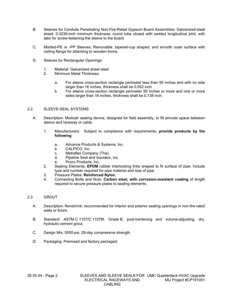
26 05 44 - Page 2 SLEEVES AND SLEEVE SEALS FOR ELECTRICAL RACEWAYS AND
CABLING
UMC Quarterdeck HVAC Upgrade MU Project #CP191051
B. Sleeves for Conduits Penetrating Non-Fire-Rated Gypsum Board Assemblies: Galvanized-steel sheet; 0.0239-inch minimum thickness; round tube closed with welded longitudinal joint, with tabs for screw-fastening the sleeve to the board.
C. Molded-PE or -PP Sleeves: Removable, tapered-cup shaped, and smooth outer surface with nailing flange for attaching to wooden forms.
D. Sleeves for Rectangular Openings:
1. Material: Galvanized sheet steel.2. Minimum Metal Thickness:
a. For sleeve cross-section rectangle perimeter less than 50 inches and with no side larger than 16 inches, thickness shall be 0.052 inch.
b. For sleeve cross-section rectangle perimeter 50 inches or more and one or more sides larger than 16 inches, thickness shall be 0.138 inch.
2.2 SLEEVE-SEAL SYSTEMS
A. Description: Modular sealing device, designed for field assembly, to fill annular space between sleeve and raceway or cable.
1. Manufacturers: Subject to compliance with requirements, provide products by the following:
a. Advance Products & Systems, Inc.b. CALPICO, Inc.c. Metraflex Company (The).d. Pipeline Seal and Insulator, Inc.e. Proco Products, Inc.
2. Sealing Elements: EPDM rubber interlocking links shaped to fit surface of pipe. Include type and number required for pipe material and size of pipe.
3. Pressure Plates: Reinforced Nylon.4. Connecting Bolts and Nuts: Carbon steel, with corrosion-resistant coating of length
required to secure pressure plates to sealing elements.
2.3 GROUT
A. Description: Nonshrink; recommended for interior and exterior sealing openings in non-fire-rated walls or floors.
B. Standard: ASTM C 1107/C 1107M, Grade B, post-hardening and volume-adjusting, dry, hydraulic-cement grout.
C. Design Mix: 5000-psi, 28-day compressive strength.
D. Packaging: Premixed and factory packaged.
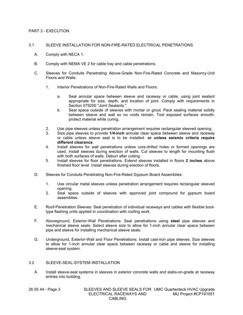
26 05 44 - Page 3 SLEEVES AND SLEEVE SEALS FOR ELECTRICAL RACEWAYS AND
CABLING
UMC Quarterdeck HVAC Upgrade MU Project #CP191051
PART 3 - EXECUTION
3.1 SLEEVE INSTALLATION FOR NON-FIRE-RATED ELECTRICAL PENETRATIONS
A. Comply with NECA 1.
B. Comply with NEMA VE 2 for cable tray and cable penetrations.
C. Sleeves for Conduits Penetrating Above-Grade Non-Fire-Rated Concrete and Masonry-Unit Floors and Walls:
1. Interior Penetrations of Non-Fire-Rated Walls and Floors:
a. Seal annular space between sleeve and raceway or cable, using joint sealant appropriate for size, depth, and location of joint. Comply with requirements in Section 079200 "Joint Sealants."
b. Seal space outside of sleeves with mortar or grout. Pack sealing material solidly between sleeve and wall so no voids remain. Tool exposed surfaces smooth; protect material while curing.
2. Use pipe sleeves unless penetration arrangement requires rectangular sleeved opening.3. Size pipe sleeves to provide 1/4-inch annular clear space between sleeve and raceway
or cable unless sleeve seal is to be installed or unless seismic criteria require different clearance.
4. Install sleeves for wall penetrations unless core-drilled holes or formed openings are used. Install sleeves during erection of walls. Cut sleeves to length for mounting flush with both surfaces of walls. Deburr after cutting.
5. Install sleeves for floor penetrations. Extend sleeves installed in floors 2 inches above finished floor level. Install sleeves during erection of floors.
D. Sleeves for Conduits Penetrating Non-Fire-Rated Gypsum Board Assemblies:
1. Use circular metal sleeves unless penetration arrangement requires rectangular sleeved opening.
2. Seal space outside of sleeves with approved joint compound for gypsum board assemblies.
E. Roof-Penetration Sleeves: Seal penetration of individual raceways and cables with flexible boot-type flashing units applied in coordination with roofing work.
F. Aboveground, Exterior-Wall Penetrations: Seal penetrations using steel pipe sleeves and mechanical sleeve seals. Select sleeve size to allow for 1-inch annular clear space between pipe and sleeve for installing mechanical sleeve seals.
G. Underground, Exterior-Wall and Floor Penetrations: Install cast-iron pipe sleeves. Size sleeves to allow for 1-inch annular clear space between raceway or cable and sleeve for installing sleeve-seal system.
3.2 SLEEVE-SEAL-SYSTEM INSTALLATION
A. Install sleeve-seal systems in sleeves in exterior concrete walls and slabs-on-grade at raceway entries into building.
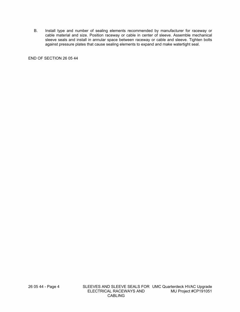
26 05 44 - Page 4 SLEEVES AND SLEEVE SEALS FOR ELECTRICAL RACEWAYS AND
CABLING
UMC Quarterdeck HVAC Upgrade MU Project #CP191051
B. Install type and number of sealing elements recommended by manufacturer for raceway or cable material and size. Position raceway or cable in center of sleeve. Assemble mechanical sleeve seals and install in annular space between raceway or cable and sleeve. Tighten bolts against pressure plates that cause sealing elements to expand and make watertight seal.
END OF SECTION 26 05 44
26 05 53 - Page 1 IDENTIFICATION FOR ELECTRICAL SYSTEMS
UMC Quarterdeck HVAC Upgrade MU Project #CP191051
SECTION 26 05 53 - IDENTIFICATION FOR ELECTRICAL SYSTEMS
PART 1 - GENERAL
1.1 RELATED DOCUMENTS
A. Drawings and general provisions of the Contract, including General and Supplementary Conditions and Division 01 Specification Sections, apply to this Section.
1.2 SUMMARY
A. Section Includes:
1. Color and legend requirements for raceways, conductors, and warning labels and signs.2. Labels.3. Bands and tubes.4. Tapes and stencils.5. Tags.6. Signs.7. Cable ties.8. Paint for identification.9. Fasteners for labels and signs.
1.3 ACTION SUBMITTALS
A. Product Data: For each type of product.
1. Include construction details, material descriptions, dimensions of individual components and profiles, and finishes for electrical identification products.
B. Identification Schedule: For each piece of electrical equipment and electrical system components to be an index of nomenclature for electrical equipment and system components used in identification signs and labels. Use same designations indicated on Drawings.
C. Delegated-Design Submittal: For arc-flash hazard study.
PART 2 - PRODUCTS
2.1 PERFORMANCE REQUIREMENTS
A. Comply with ASME A13.1.
B. Comply with NFPA 70.
C. Comply with 29 CFR 1910.144 and 29 CFR 1910.145.
D. Comply with ANSI Z535.4 for safety signs and labels.
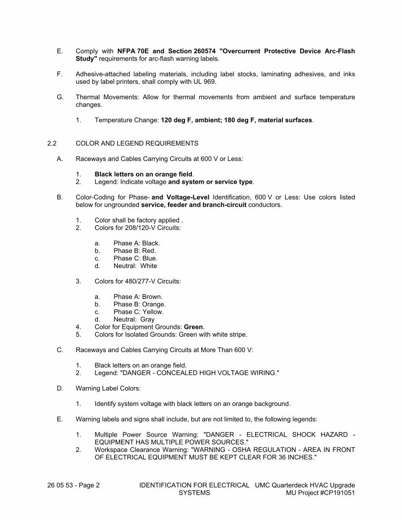
26 05 53 - Page 2 IDENTIFICATION FOR ELECTRICAL SYSTEMS
UMC Quarterdeck HVAC Upgrade MU Project #CP191051
E. Comply with NFPA 70E and Section 260574 "Overcurrent Protective Device Arc-Flash Study" requirements for arc-flash warning labels.
F. Adhesive-attached labeling materials, including label stocks, laminating adhesives, and inks used by label printers, shall comply with UL 969.
G. Thermal Movements: Allow for thermal movements from ambient and surface temperature changes.
1. Temperature Change: 120 deg F, ambient; 180 deg F, material surfaces.
2.2 COLOR AND LEGEND REQUIREMENTS
A. Raceways and Cables Carrying Circuits at 600 V or Less:
1. Black letters on an orange field.2. Legend: Indicate voltage and system or service type.
B. Color-Coding for Phase- and Voltage-Level Identification, 600 V or Less: Use colors listed below for ungrounded service, feeder and branch-circuit conductors.
1. Color shall be factory applied .2. Colors for 208/120-V Circuits:
a. Phase A: Black.b. Phase B: Red.c. Phase C: Blue.d. Neutral: White
3. Colors for 480/277-V Circuits:
a. Phase A: Brown.b. Phase B: Orange.c. Phase C: Yellow.d. Neutral: Gray
4. Color for Equipment Grounds: Green.5. Colors for Isolated Grounds: Green with white stripe.
C. Raceways and Cables Carrying Circuits at More Than 600 V:
1. Black letters on an orange field.2. Legend: "DANGER - CONCEALED HIGH VOLTAGE WIRING."
D. Warning Label Colors:
1. Identify system voltage with black letters on an orange background.
E. Warning labels and signs shall include, but are not limited to, the following legends:
1. Multiple Power Source Warning: "DANGER - ELECTRICAL SHOCK HAZARD - EQUIPMENT HAS MULTIPLE POWER SOURCES."
2. Workspace Clearance Warning: "WARNING - OSHA REGULATION - AREA IN FRONT OF ELECTRICAL EQUIPMENT MUST BE KEPT CLEAR FOR 36 INCHES."
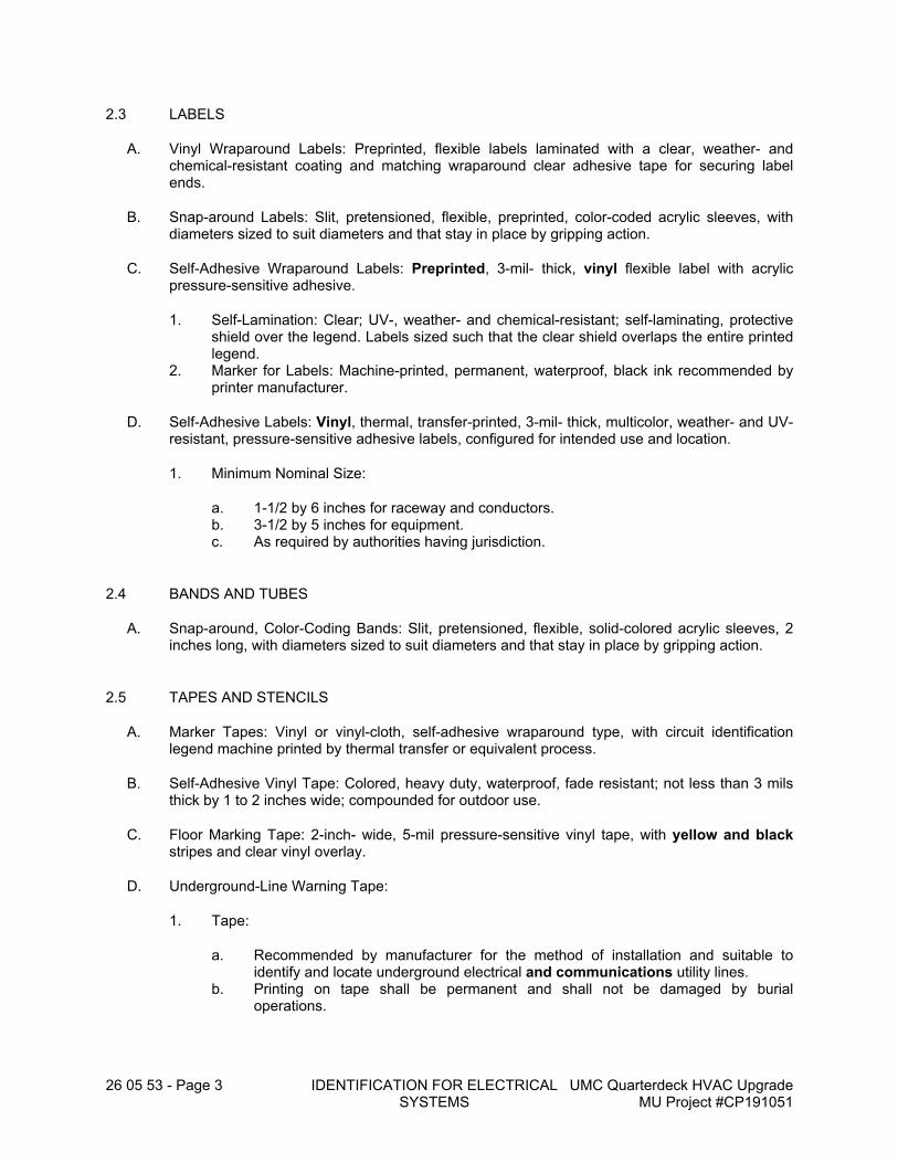
26 05 53 - Page 3 IDENTIFICATION FOR ELECTRICAL SYSTEMS
UMC Quarterdeck HVAC Upgrade MU Project #CP191051
2.3 LABELS
A. Vinyl Wraparound Labels: Preprinted, flexible labels laminated with a clear, weather- and chemical-resistant coating and matching wraparound clear adhesive tape for securing label ends.
B. Snap-around Labels: Slit, pretensioned, flexible, preprinted, color-coded acrylic sleeves, with diameters sized to suit diameters and that stay in place by gripping action.
C. Self-Adhesive Wraparound Labels: Preprinted, 3-mil- thick, vinyl flexible label with acrylic pressure-sensitive adhesive.
1. Self-Lamination: Clear; UV-, weather- and chemical-resistant; self-laminating, protective shield over the legend. Labels sized such that the clear shield overlaps the entire printed legend.
2. Marker for Labels: Machine-printed, permanent, waterproof, black ink recommended by printer manufacturer.
D. Self-Adhesive Labels: Vinyl, thermal, transfer-printed, 3-mil- thick, multicolor, weather- and UV-resistant, pressure-sensitive adhesive labels, configured for intended use and location.
1. Minimum Nominal Size:
a. 1-1/2 by 6 inches for raceway and conductors.b. 3-1/2 by 5 inches for equipment.c. As required by authorities having jurisdiction.
2.4 BANDS AND TUBES
A. Snap-around, Color-Coding Bands: Slit, pretensioned, flexible, solid-colored acrylic sleeves, 2 inches long, with diameters sized to suit diameters and that stay in place by gripping action.
2.5 TAPES AND STENCILS
A. Marker Tapes: Vinyl or vinyl-cloth, self-adhesive wraparound type, with circuit identification legend machine printed by thermal transfer or equivalent process.
B. Self-Adhesive Vinyl Tape: Colored, heavy duty, waterproof, fade resistant; not less than 3 mils thick by 1 to 2 inches wide; compounded for outdoor use.
C. Floor Marking Tape: 2-inch- wide, 5-mil pressure-sensitive vinyl tape, with yellow and black stripes and clear vinyl overlay.
D. Underground-Line Warning Tape:
1. Tape:
a. Recommended by manufacturer for the method of installation and suitable to identify and locate underground electrical and communications utility lines.
b. Printing on tape shall be permanent and shall not be damaged by burial operations.
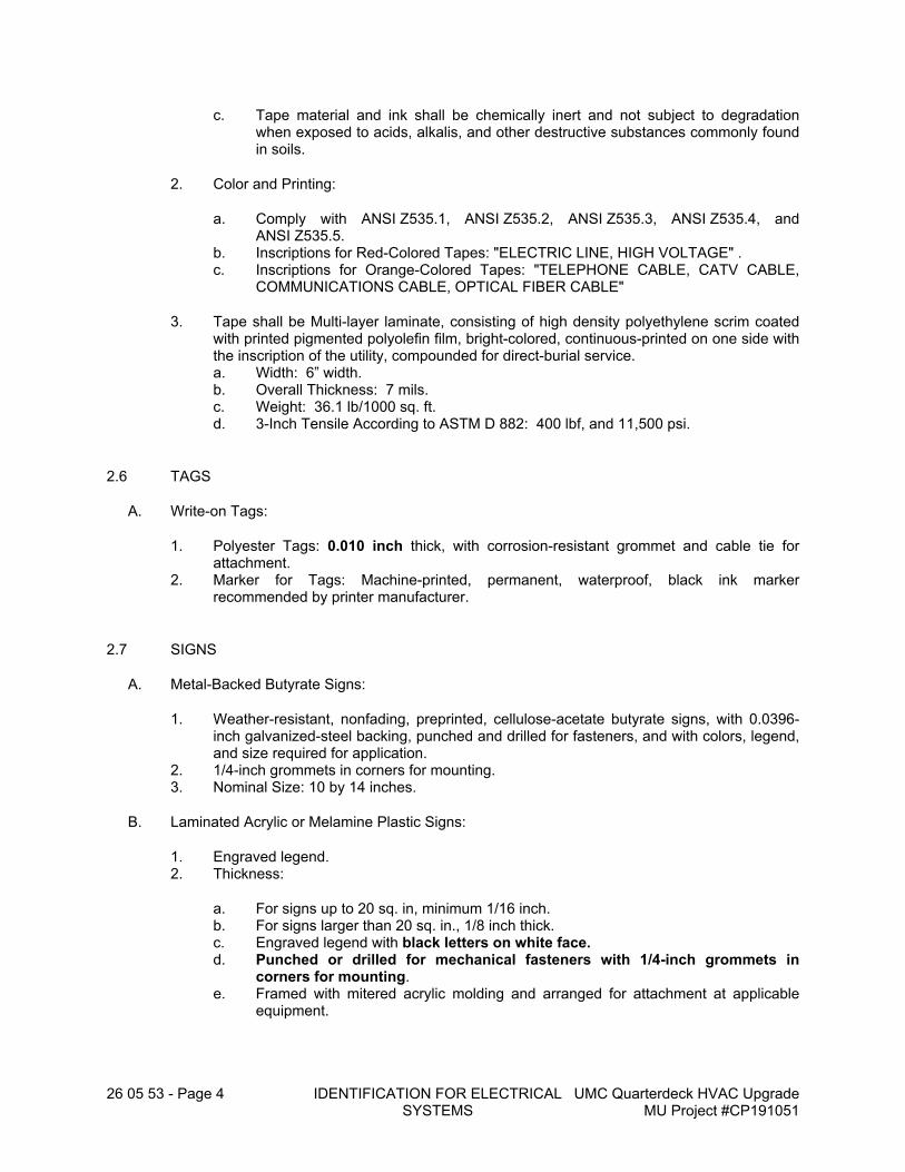
26 05 53 - Page 4 IDENTIFICATION FOR ELECTRICAL SYSTEMS
UMC Quarterdeck HVAC Upgrade MU Project #CP191051
c. Tape material and ink shall be chemically inert and not subject to degradation when exposed to acids, alkalis, and other destructive substances commonly found in soils.
2. Color and Printing:
a. Comply with ANSI Z535.1, ANSI Z535.2, ANSI Z535.3, ANSI Z535.4, and ANSI Z535.5.
b. Inscriptions for Red-Colored Tapes: "ELECTRIC LINE, HIGH VOLTAGE" .c. Inscriptions for Orange-Colored Tapes: "TELEPHONE CABLE, CATV CABLE,
COMMUNICATIONS CABLE, OPTICAL FIBER CABLE"
3. Tape shall be Multi-layer laminate, consisting of high density polyethylene scrim coated with printed pigmented polyolefin film, bright-colored, continuous-printed on one side with the inscription of the utility, compounded for direct-burial service.a. Width: 6” width.b. Overall Thickness: 7 mils.c. Weight: 36.1 lb/1000 sq. ft.d. 3-Inch Tensile According to ASTM D 882: 400 lbf, and 11,500 psi.
2.6 TAGS
A. Write-on Tags:
1. Polyester Tags: 0.010 inch thick, with corrosion-resistant grommet and cable tie for attachment.
2. Marker for Tags: Machine-printed, permanent, waterproof, black ink marker recommended by printer manufacturer.
2.7 SIGNS
A. Metal-Backed Butyrate Signs:
1. Weather-resistant, nonfading, preprinted, cellulose-acetate butyrate signs, with 0.0396-inch galvanized-steel backing, punched and drilled for fasteners, and with colors, legend, and size required for application.
2. 1/4-inch grommets in corners for mounting.3. Nominal Size: 10 by 14 inches.
B. Laminated Acrylic or Melamine Plastic Signs:
1. Engraved legend.2. Thickness:
a. For signs up to 20 sq. in, minimum 1/16 inch.b. For signs larger than 20 sq. in., 1/8 inch thick.c. Engraved legend with black letters on white face.d. Punched or drilled for mechanical fasteners with 1/4-inch grommets in
corners for mounting.e. Framed with mitered acrylic molding and arranged for attachment at applicable
equipment.
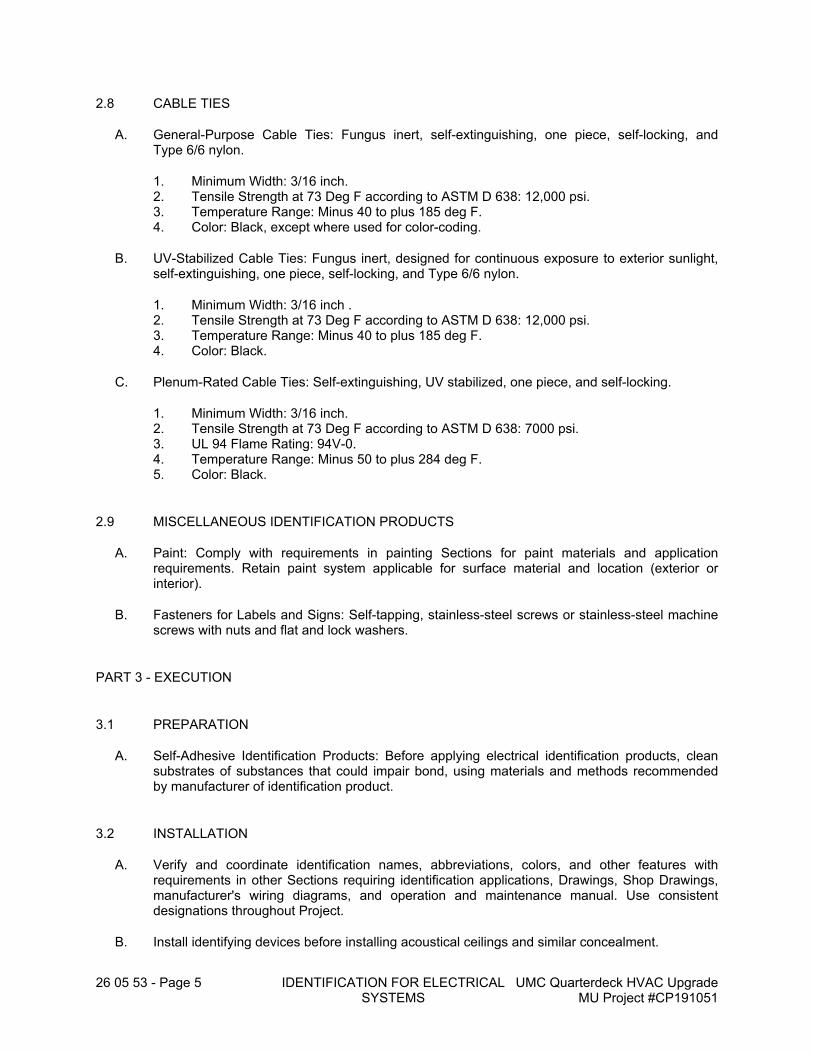
26 05 53 - Page 5 IDENTIFICATION FOR ELECTRICAL SYSTEMS
UMC Quarterdeck HVAC Upgrade MU Project #CP191051
2.8 CABLE TIES
A. General-Purpose Cable Ties: Fungus inert, self-extinguishing, one piece, self-locking, and Type 6/6 nylon.
1. Minimum Width: 3/16 inch.2. Tensile Strength at 73 Deg F according to ASTM D 638: 12,000 psi.3. Temperature Range: Minus 40 to plus 185 deg F.4. Color: Black, except where used for color-coding.
B. UV-Stabilized Cable Ties: Fungus inert, designed for continuous exposure to exterior sunlight, self-extinguishing, one piece, self-locking, and Type 6/6 nylon.
1. Minimum Width: 3/16 inch .2. Tensile Strength at 73 Deg F according to ASTM D 638: 12,000 psi.3. Temperature Range: Minus 40 to plus 185 deg F.4. Color: Black.
C. Plenum-Rated Cable Ties: Self-extinguishing, UV stabilized, one piece, and self-locking.
1. Minimum Width: 3/16 inch.2. Tensile Strength at 73 Deg F according to ASTM D 638: 7000 psi.3. UL 94 Flame Rating: 94V-0.4. Temperature Range: Minus 50 to plus 284 deg F.5. Color: Black.
2.9 MISCELLANEOUS IDENTIFICATION PRODUCTS
A. Paint: Comply with requirements in painting Sections for paint materials and application requirements. Retain paint system applicable for surface material and location (exterior or interior).
B. Fasteners for Labels and Signs: Self-tapping, stainless-steel screws or stainless-steel machine screws with nuts and flat and lock washers.
PART 3 - EXECUTION
3.1 PREPARATION
A. Self-Adhesive Identification Products: Before applying electrical identification products, clean substrates of substances that could impair bond, using materials and methods recommended by manufacturer of identification product.
3.2 INSTALLATION
A. Verify and coordinate identification names, abbreviations, colors, and other features with requirements in other Sections requiring identification applications, Drawings, Shop Drawings, manufacturer's wiring diagrams, and operation and maintenance manual. Use consistent designations throughout Project.
B. Install identifying devices before installing acoustical ceilings and similar concealment.
26 05 53 - Page 6 IDENTIFICATION FOR ELECTRICAL SYSTEMS
UMC Quarterdeck HVAC Upgrade MU Project #CP191051
C. Verify identity of each item before installing identification products.
D. Coordinate identification with Project Drawings, manufacturer's wiring diagrams, and operation and maintenance manual.
E. Apply identification devices to surfaces that require finish after completing finish work.
F. Install signs with approved legend to facilitate proper identification, operation, and maintenance of electrical systems and connected items.
G. System Identification for Raceways and Cables under 600 V: Identification shall completely encircle cable or conduit. Place identification of two-color markings in contact, side by side.
1. Secure tight to surface of conductor, cable, or raceway.
H. System Identification for Raceways and Cables over 600 V: Identification shall completely encircle cable or conduit. Place adjacent identification of two-color markings in contact, side by side.
1. Secure tight to surface of conductor, cable, or raceway.
I. Auxiliary Electrical Systems Conductor Identification: Identify field-installed alarm, control, and signal connections.
J. Emergency Operating Instruction Signs: Install instruction signs with white legend on a red background with minimum 3/8-inch- high letters for emergency instructions at equipment used for power transfer.
K. Elevated Components: Increase sizes of labels, signs, and letters to those appropriate for viewing from the floor.
L. Accessible Fittings for Raceways: Identify the covers of each junction and pull box of the following systems with the wiring system legend and system voltage. System legends shall be as follows:
1. "POWER/VOLTAGE."2. "EMERGENCY POWER."3. "FIRE ALARM SYSTEM POWER."
M. Vinyl Wraparound Labels:
1. Secure tight to surface of raceway or cable at a location with high visibility and accessibility.
2. Attach labels that are not self-adhesive type with clear vinyl tape, with adhesive appropriate to the location and substrate.
N. Snap-around Labels: Secure tight to surface at a location with high visibility and accessibility.
O. Self-Adhesive Wraparound Labels: Secure tight to surface at a location with high visibility and accessibility.
P. Self-Adhesive Labels:
1. On each item, install unique designation label that is consistent with wiring diagrams, schedules, and operation and maintenance manual.
26 05 53 - Page 7 IDENTIFICATION FOR ELECTRICAL SYSTEMS
UMC Quarterdeck HVAC Upgrade MU Project #CP191051
2. Unless otherwise indicated, provide a single line of text with 1/2-inch- high letters on 1-1/2-inch- high label; where two lines of text are required, use labels 2 inches high.
Q. Snap-around Color-Coding Bands: Secure tight to surface at a location with high visibility and accessibility.
R. Marker Tapes: Secure tight to surface at a location with high visibility and accessibility.
S. Self-Adhesive Vinyl Tape: Secure tight to surface at a location with high visibility and accessibility.
T. Floor Marking Tape: Apply stripes to finished surfaces following manufacturer's written instructions.
U. Underground Line Warning Tape:
1. During backfilling of trenches, install continuous underground-line warning tape directly above cable or raceway at 6 to 8 inches below finished grade. Use multiple tapes where width of multiple lines installed in a common trench or concrete envelope exceeds 16 inches overall.
2. Install underground-line warning tape for direct-buried cables and cables in ductbanks.
V. Write-on Tags:
1. Place in a location with high visibility and accessibility.2. Secure using cable ties appropriate for location.
W. Metal-Backed Butyrate Signs:
1. Attach signs that are not self-adhesive type with mechanical fasteners appropriate to the location and substrate.
2. Unless otherwise indicated, provide a single line of text with 1/2-inch- high letters on 1-1/2-inch- high sign; where two lines of text are required, use labels 2 inches high.
X. Laminated Acrylic or Melamine Plastic Signs:
1. Attach signs that are not self-adhesive type with mechanical fasteners appropriate to the location and substrate.
2. Unless otherwise indicated, provide a single line of text with 1/2-inch- high letters on 1-1/2-inch- high sign; where two lines of text are required, use labels 2 inches high.
Y. Cable Ties: General purpose, for attaching tags, except as listed below:
1. Outdoors: UV-stabilized nylon.2. In Spaces Handling Environmental Air: Plenum rated.
3.3 IDENTIFICATION SCHEDULE
A. Install identification materials and devices at locations for most convenient viewing without interference with operation and maintenance of equipment. Install access doors or panels to provide view of identifying devices.
B. Identify conductors, cables, and terminals in enclosures and at junctions, terminals, pull points, and locations of high visibility. Identify by system and circuit designation.
26 05 53 - Page 8 IDENTIFICATION FOR ELECTRICAL SYSTEMS
UMC Quarterdeck HVAC Upgrade MU Project #CP191051
C. Accessible Raceways and Metal-Clad Cables, 600 V or Less, for Service, Feeder, and Branch Circuits, More Than 30 A and 120V to Ground: Identify with self-adhesive vinyl tape applied in bands.
1. Locate identification at changes in direction, at penetrations of walls and floors, at 50-foot maximum intervals in straight runs, and at 25-foot maximum intervals in congested areas.
D. Accessible Fittings for Raceways and Cables within Buildings: Identify the covers of each junction and pull box of the following systems with self-adhesive labels containing the wiring system legend and system voltage. System legends shall be as follows:
1. "EMERGENCY POWER."2. "POWER"3. "FIRE ALARM SYSTEM”
E. Power-Circuit Conductor Identification, 600 V or Less: For conductors in vaults, pull and junction boxes, manholes, and handholes, use self-adhesive wraparound labels to identify the phase.
1. Locate identification at changes in direction, at penetrations of walls and floors, at 50-foot maximum intervals in straight runs, and at 25-foot maximum intervals in congested areas.
F. Power-Circuit Conductor Identification, More Than 600 V: For conductors in vaults, pull and junction boxes, manholes, and handholes, use nonmetallic preprinted tags colored and marked to indicate phase, and a separate tag with the circuit designation.
G. Control-Circuit Conductor Identification: For conductors and cables in pull and junction boxes, manholes, and handholes, use self-adhesive labels with the conductor or cable designation, origin, and destination.
H. Control-Circuit Conductor Termination Identification: For identification at terminations, provide self-adhesive labels with the conductor designation.
I. Conductors to Be Extended in the Future: Attach marker tape to conductors and list source.
J. Auxiliary Electrical Systems Conductor Identification: Marker tape that is uniform and consistent with system used by manufacturer for factory-installed connections.
1. Identify conductors, cables, and terminals in enclosures and at junctions, terminals, and pull points. Identify by system and circuit designation.
K. Locations of Underground Lines: Underground-line warning tape for power, lighting, communication, and control wiring and optical-fiber cable.
L. Workspace Indication: Apply floor marking tape to finished surfaces. Show working clearances in the direction of access to live parts. Workspace shall comply with NFPA 70 and 29 CFR 1926.403 unless otherwise indicated. Do not install at flush-mounted panelboards and similar equipment in finished spaces.
M. Instructional Signs: Self-adhesive labels, including the color code for grounded and ungrounded conductors.
N. Warning Labels for Indoor Cabinets, Boxes, and Enclosures for Power and Lighting: Metal-backed, butyrate warning signs.
1. Apply to exterior of door, cover, or other access.
26 05 53 - Page 9 IDENTIFICATION FOR ELECTRICAL SYSTEMS
UMC Quarterdeck HVAC Upgrade MU Project #CP191051
2. For equipment with multiple power or control sources, apply to door or cover of equipment, including, but not limited to, the following:
a. Power-transfer switches.b. Controls with external control power connections.
O. Arc Flash Warning Labeling: Self-adhesive labels.
P. Operating Instruction Signs: Laminated acrylic or melamine plastic signs.
Q. Emergency Operating Instruction Signs: Laminated acrylic or melamine plastic signs with white legend on a red background with minimum 3/8-inch- high letters for emergency instructions at equipment used for power transfer.
R. Equipment Identification Labels:
1. Indoor Equipment: Laminated acrylic or melamine plastic sign.2. Outdoor Equipment: Laminated acrylic or melamine sign.3. Equipment to Be Labeled:
a. Panelboards: Typewritten directory of circuits in the location provided by panelboard manufacturer. Panelboard identification shall be in the form of an engraved, laminated acrylic or melamine label.
b. Enclosures and electrical cabinets.c. Access doors and panels for concealed electrical items.d. Switchgear.e. Switchboards.f. Transformers: Label that includes tag designation indicated on Drawings for the
transformer, feeder, and panelboards or equipment supplied by the secondary.g. Emergency system boxes and enclosures.h. Enclosed switches.i. Enclosed circuit breakers.j. Enclosed controllers.k. Variable-speed controllers.l. Push-button stations.m. Power-transfer equipment.n. Contactors.o. Remote-controlled switches, dimmer modules, and control devices.p. Battery-inverter units.q. Battery racks.r. Power-generating units.s. Monitoring and control equipment.
END OF SECTION 26 05 53
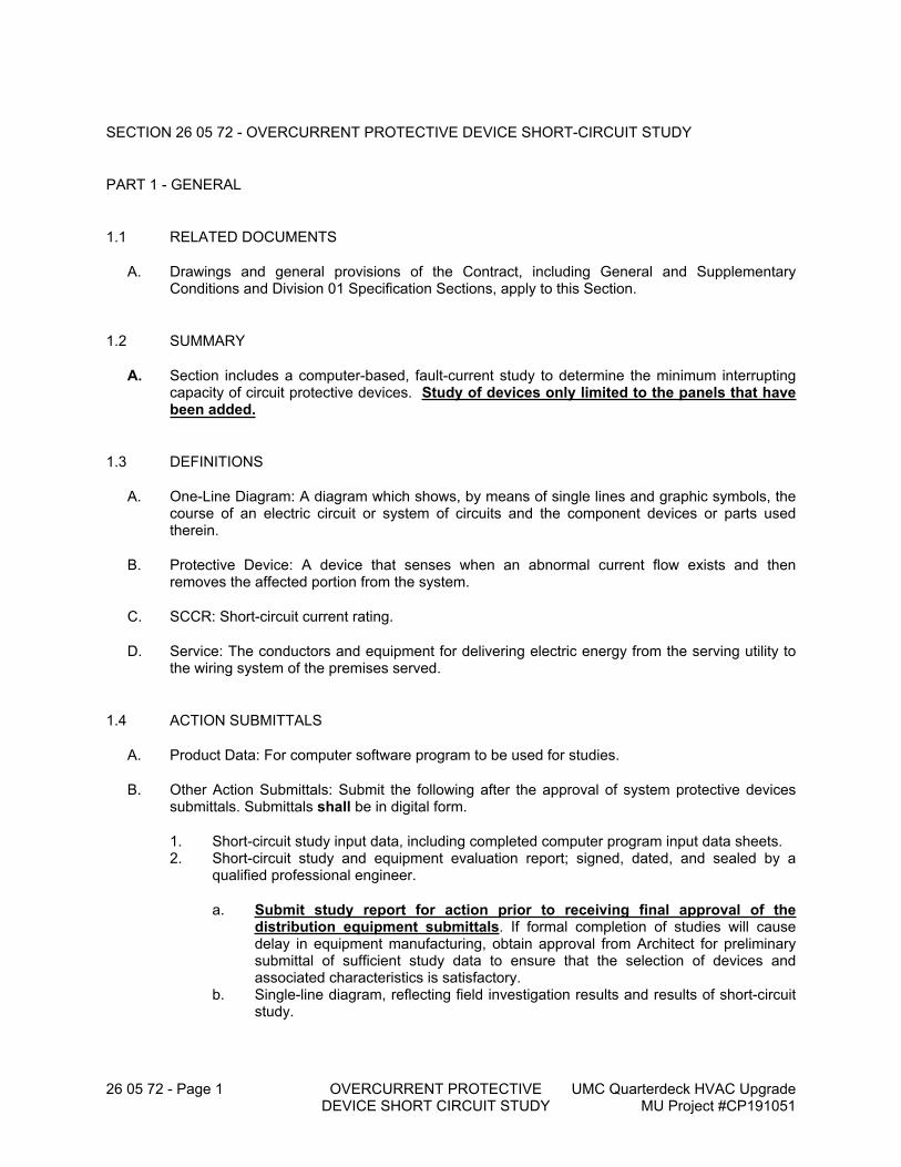
26 05 72 - Page 1 OVERCURRENT PROTECTIVE DEVICE SHORT CIRCUIT STUDY
UMC Quarterdeck HVAC Upgrade MU Project #CP191051
SECTION 26 05 72 - OVERCURRENT PROTECTIVE DEVICE SHORT-CIRCUIT STUDY
PART 1 - GENERAL
1.1 RELATED DOCUMENTS
A. Drawings and general provisions of the Contract, including General and Supplementary Conditions and Division 01 Specification Sections, apply to this Section.
1.2 SUMMARY
A. Section includes a computer-based, fault-current study to determine the minimum interrupting capacity of circuit protective devices. Study of devices only limited to the panels that have been added.
1.3 DEFINITIONS
A. One-Line Diagram: A diagram which shows, by means of single lines and graphic symbols, the course of an electric circuit or system of circuits and the component devices or parts used therein.
B. Protective Device: A device that senses when an abnormal current flow exists and then removes the affected portion from the system.
C. SCCR: Short-circuit current rating.
D. Service: The conductors and equipment for delivering electric energy from the serving utility to the wiring system of the premises served.
1.4 ACTION SUBMITTALS
A. Product Data: For computer software program to be used for studies.
B. Other Action Submittals: Submit the following after the approval of system protective devices submittals. Submittals shall be in digital form.
1. Short-circuit study input data, including completed computer program input data sheets.2. Short-circuit study and equipment evaluation report; signed, dated, and sealed by a
qualified professional engineer.
a. Submit study report for action prior to receiving final approval of the distribution equipment submittals. If formal completion of studies will cause delay in equipment manufacturing, obtain approval from Architect for preliminary submittal of sufficient study data to ensure that the selection of devices and associated characteristics is satisfactory.
b. Single-line diagram, reflecting field investigation results and results of short-circuit study.
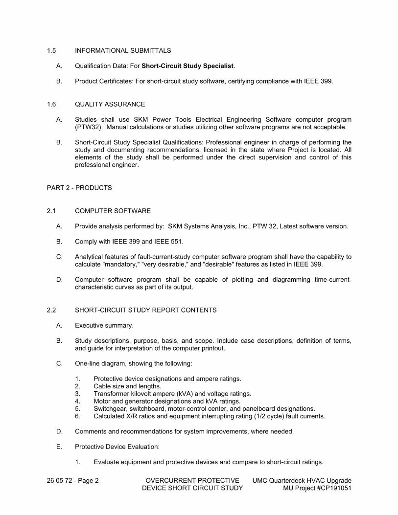
26 05 72 - Page 2 OVERCURRENT PROTECTIVE DEVICE SHORT CIRCUIT STUDY
UMC Quarterdeck HVAC Upgrade MU Project #CP191051
1.5 INFORMATIONAL SUBMITTALS
A. Qualification Data: For Short-Circuit Study Specialist.
B. Product Certificates: For short-circuit study software, certifying compliance with IEEE 399.
1.6 QUALITY ASSURANCE
A. Studies shall use SKM Power Tools Electrical Engineering Software computer program (PTW32). Manual calculations or studies utilizing other software programs are not acceptable.
B. Short-Circuit Study Specialist Qualifications: Professional engineer in charge of performing the study and documenting recommendations, licensed in the state where Project is located. All elements of the study shall be performed under the direct supervision and control of this professional engineer.
PART 2 - PRODUCTS
2.1 COMPUTER SOFTWARE
A. Provide analysis performed by: SKM Systems Analysis, Inc., PTW 32, Latest software version.
B. Comply with IEEE 399 and IEEE 551.
C. Analytical features of fault-current-study computer software program shall have the capability to calculate "mandatory," "very desirable," and "desirable" features as listed in IEEE 399.
D. Computer software program shall be capable of plotting and diagramming time-current-characteristic curves as part of its output.
2.2 SHORT-CIRCUIT STUDY REPORT CONTENTS
A. Executive summary.
B. Study descriptions, purpose, basis, and scope. Include case descriptions, definition of terms, and guide for interpretation of the computer printout.
C. One-line diagram, showing the following:
1. Protective device designations and ampere ratings.2. Cable size and lengths.3. Transformer kilovolt ampere (kVA) and voltage ratings.4. Motor and generator designations and kVA ratings.5. Switchgear, switchboard, motor-control center, and panelboard designations.6. Calculated X/R ratios and equipment interrupting rating (1/2 cycle) fault currents.
D. Comments and recommendations for system improvements, where needed.
E. Protective Device Evaluation:
1. Evaluate equipment and protective devices and compare to short-circuit ratings.
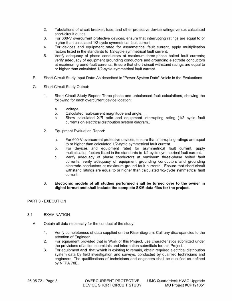
26 05 72 - Page 3 OVERCURRENT PROTECTIVE DEVICE SHORT CIRCUIT STUDY
UMC Quarterdeck HVAC Upgrade MU Project #CP191051
2. Tabulations of circuit breaker, fuse, and other protective device ratings versus calculated short-circuit duties.
3. For 600-V overcurrent protective devices, ensure that interrupting ratings are equal to or higher than calculated 1/2-cycle symmetrical fault current.
4. For devices and equipment rated for asymmetrical fault current, apply multiplication factors listed in the standards to 1/2-cycle symmetrical fault current.
5. Verify adequacy of phase conductors at maximum three-phase bolted fault currents; verify adequacy of equipment grounding conductors and grounding electrode conductors at maximum ground-fault currents. Ensure that short-circuit withstand ratings are equal to or higher than calculated 1/2-cycle symmetrical fault current.
F. Short-Circuit Study Input Data: As described in "Power System Data" Article in the Evaluations.
G. Short-Circuit Study Output:
1. Short Circuit Study Report: Three-phase and unbalanced fault calculations, showing the following for each overcurrent device location:
a. Voltage.b. Calculated fault-current magnitude and angle.c. Show calculated X/R ratio and equipment interrupting rating (1/2 cycle fault
currents on electrical distribution system diagram..
2. Equipment Evaluation Report:
a. For 600-V overcurrent protective devices, ensure that interrupting ratings are equal to or higher than calculated 1/2-cycle symmetrical fault current.
b. For devices and equipment rated for asymmetrical fault current, apply multiplication factors listed in the standards to 1/2-cycle symmetrical fault current.
c. Verify adequacy of phase conductors at maximum three-phase bolted fault currents; verify adequacy of equipment grounding conductors and grounding electrode conductors at maximum ground-fault currents. Ensure that short-circuit withstand ratings are equal to or higher than calculated 1/2-cycle symmetrical fault current.
3. Electronic models of all studies performed shall be turned over to the owner in digital format and shall include the complete SKM data files for the project.
PART 3 - EXECUTION
3.1 EXAMINATION
A. Obtain all data necessary for the conduct of the study.
1. Verify completeness of data supplied on the Riser diagram. Call any discrepancies to the attention of Engineer.
2. For equipment provided that is Work of this Project, use characteristics submitted under the provisions of action submittals and information submittals for this Project.
3. For equipment and that which is existing to remain, obtain required electrical distribution system data by field investigation and surveys, conducted by qualified technicians and engineers. The qualifications of technicians and engineers shall be qualified as defined by NFPA 70E.
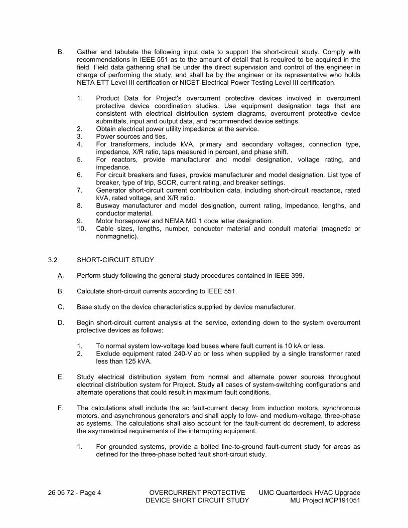
26 05 72 - Page 4 OVERCURRENT PROTECTIVE DEVICE SHORT CIRCUIT STUDY
UMC Quarterdeck HVAC Upgrade MU Project #CP191051
B. Gather and tabulate the following input data to support the short-circuit study. Comply with recommendations in IEEE 551 as to the amount of detail that is required to be acquired in the field. Field data gathering shall be under the direct supervision and control of the engineer in charge of performing the study, and shall be by the engineer or its representative who holds NETA ETT Level III certification or NICET Electrical Power Testing Level III certification.
1. Product Data for Project's overcurrent protective devices involved in overcurrent protective device coordination studies. Use equipment designation tags that are consistent with electrical distribution system diagrams, overcurrent protective device submittals, input and output data, and recommended device settings.
2. Obtain electrical power utility impedance at the service.3. Power sources and ties.4. For transformers, include kVA, primary and secondary voltages, connection type,
impedance, X/R ratio, taps measured in percent, and phase shift.5. For reactors, provide manufacturer and model designation, voltage rating, and
impedance.6. For circuit breakers and fuses, provide manufacturer and model designation. List type of
breaker, type of trip, SCCR, current rating, and breaker settings.7. Generator short-circuit current contribution data, including short-circuit reactance, rated
kVA, rated voltage, and X/R ratio.8. Busway manufacturer and model designation, current rating, impedance, lengths, and
conductor material.9. Motor horsepower and NEMA MG 1 code letter designation.10. Cable sizes, lengths, number, conductor material and conduit material (magnetic or
nonmagnetic).
3.2 SHORT-CIRCUIT STUDY
A. Perform study following the general study procedures contained in IEEE 399.
B. Calculate short-circuit currents according to IEEE 551.
C. Base study on the device characteristics supplied by device manufacturer.
D. Begin short-circuit current analysis at the service, extending down to the system overcurrent protective devices as follows:
1. To normal system low-voltage load buses where fault current is 10 kA or less.2. Exclude equipment rated 240-V ac or less when supplied by a single transformer rated
less than 125 kVA.
E. Study electrical distribution system from normal and alternate power sources throughout electrical distribution system for Project. Study all cases of system-switching configurations and alternate operations that could result in maximum fault conditions.
F. The calculations shall include the ac fault-current decay from induction motors, synchronous motors, and asynchronous generators and shall apply to low- and medium-voltage, three-phase ac systems. The calculations shall also account for the fault-current dc decrement, to address the asymmetrical requirements of the interrupting equipment.
1. For grounded systems, provide a bolted line-to-ground fault-current study for areas as defined for the three-phase bolted fault short-circuit study.
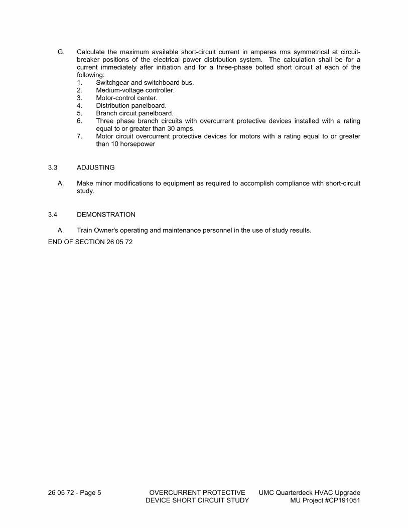
26 05 72 - Page 5 OVERCURRENT PROTECTIVE DEVICE SHORT CIRCUIT STUDY
UMC Quarterdeck HVAC Upgrade MU Project #CP191051
G. Calculate the maximum available short-circuit current in amperes rms symmetrical at circuit-breaker positions of the electrical power distribution system. The calculation shall be for a current immediately after initiation and for a three-phase bolted short circuit at each of the following:1. Switchgear and switchboard bus.2. Medium-voltage controller.3. Motor-control center.4. Distribution panelboard.5. Branch circuit panelboard.6. Three phase branch circuits with overcurrent protective devices installed with a rating
equal to or greater than 30 amps.7. Motor circuit overcurrent protective devices for motors with a rating equal to or greater
than 10 horsepower
3.3 ADJUSTING
A. Make minor modifications to equipment as required to accomplish compliance with short-circuit study.
3.4 DEMONSTRATION
A. Train Owner's operating and maintenance personnel in the use of study results.
END OF SECTION 26 05 72
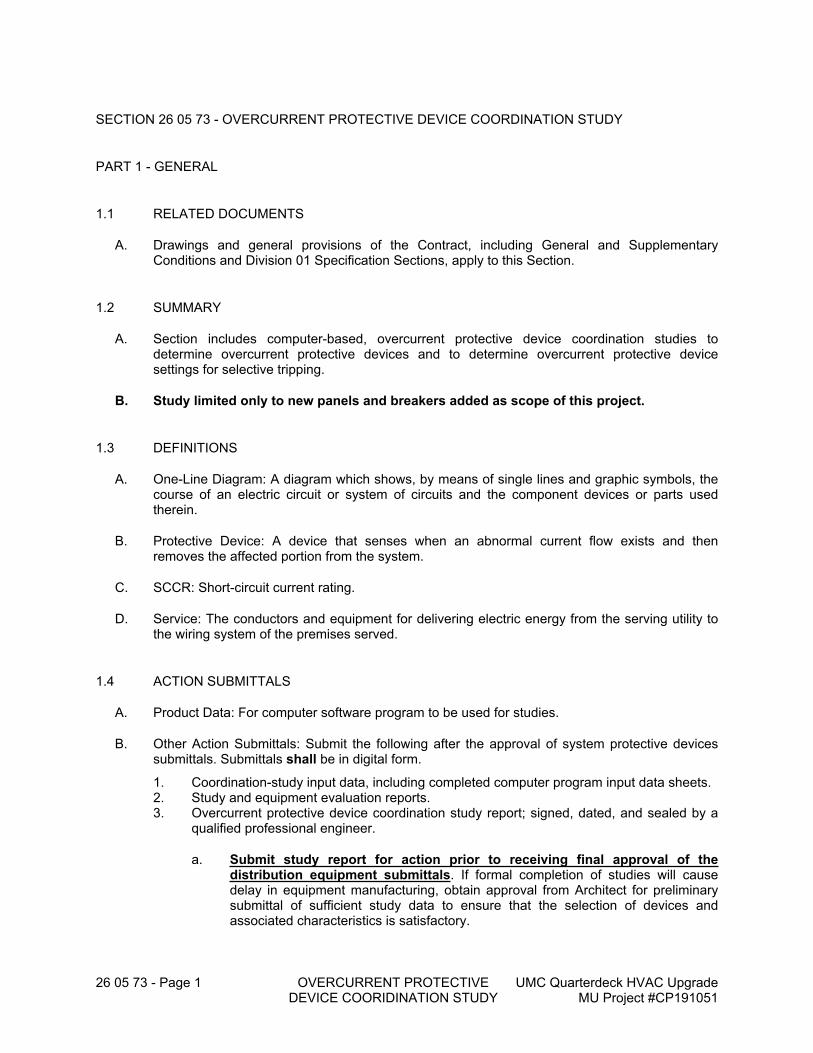
26 05 73 - Page 1 OVERCURRENT PROTECTIVE DEVICE COORIDINATION STUDY
UMC Quarterdeck HVAC Upgrade MU Project #CP191051
SECTION 26 05 73 - OVERCURRENT PROTECTIVE DEVICE COORDINATION STUDY
PART 1 - GENERAL
1.1 RELATED DOCUMENTS
A. Drawings and general provisions of the Contract, including General and Supplementary Conditions and Division 01 Specification Sections, apply to this Section.
1.2 SUMMARY
A. Section includes computer-based, overcurrent protective device coordination studies to determine overcurrent protective devices and to determine overcurrent protective device settings for selective tripping.
B. Study limited only to new panels and breakers added as scope of this project.
1.3 DEFINITIONS
A. One-Line Diagram: A diagram which shows, by means of single lines and graphic symbols, the course of an electric circuit or system of circuits and the component devices or parts used therein.
B. Protective Device: A device that senses when an abnormal current flow exists and then removes the affected portion from the system.
C. SCCR: Short-circuit current rating.
D. Service: The conductors and equipment for delivering electric energy from the serving utility to the wiring system of the premises served.
1.4 ACTION SUBMITTALS
A. Product Data: For computer software program to be used for studies.
B. Other Action Submittals: Submit the following after the approval of system protective devices submittals. Submittals shall be in digital form.
1. Coordination-study input data, including completed computer program input data sheets.2. Study and equipment evaluation reports.3. Overcurrent protective device coordination study report; signed, dated, and sealed by a
qualified professional engineer.
a. Submit study report for action prior to receiving final approval of the distribution equipment submittals. If formal completion of studies will cause delay in equipment manufacturing, obtain approval from Architect for preliminary submittal of sufficient study data to ensure that the selection of devices and associated characteristics is satisfactory.
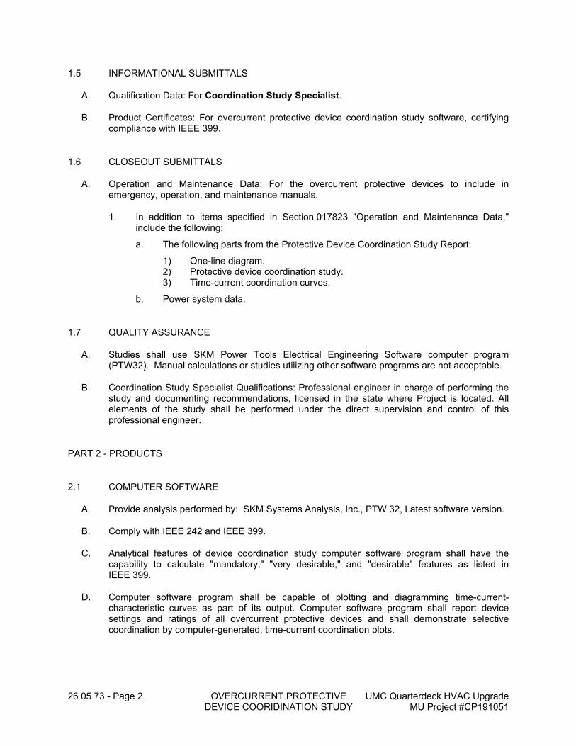
26 05 73 - Page 2 OVERCURRENT PROTECTIVE DEVICE COORIDINATION STUDY
UMC Quarterdeck HVAC Upgrade MU Project #CP191051
1.5 INFORMATIONAL SUBMITTALS
A. Qualification Data: For Coordination Study Specialist.
B. Product Certificates: For overcurrent protective device coordination study software, certifying compliance with IEEE 399.
1.6 CLOSEOUT SUBMITTALS
A. Operation and Maintenance Data: For the overcurrent protective devices to include in emergency, operation, and maintenance manuals.
1. In addition to items specified in Section 017823 "Operation and Maintenance Data," include the following:
a. The following parts from the Protective Device Coordination Study Report:
1) One-line diagram.2) Protective device coordination study.3) Time-current coordination curves.
b. Power system data.
1.7 QUALITY ASSURANCE
A. Studies shall use SKM Power Tools Electrical Engineering Software computer program (PTW32). Manual calculations or studies utilizing other software programs are not acceptable.
B. Coordination Study Specialist Qualifications: Professional engineer in charge of performing the study and documenting recommendations, licensed in the state where Project is located. All elements of the study shall be performed under the direct supervision and control of this professional engineer.
PART 2 - PRODUCTS
2.1 COMPUTER SOFTWARE
A. Provide analysis performed by: SKM Systems Analysis, Inc., PTW 32, Latest software version.
B. Comply with IEEE 242 and IEEE 399.
C. Analytical features of device coordination study computer software program shall have the capability to calculate "mandatory," "very desirable," and "desirable" features as listed in IEEE 399.
D. Computer software program shall be capable of plotting and diagramming time-current-characteristic curves as part of its output. Computer software program shall report device settings and ratings of all overcurrent protective devices and shall demonstrate selective coordination by computer-generated, time-current coordination plots.
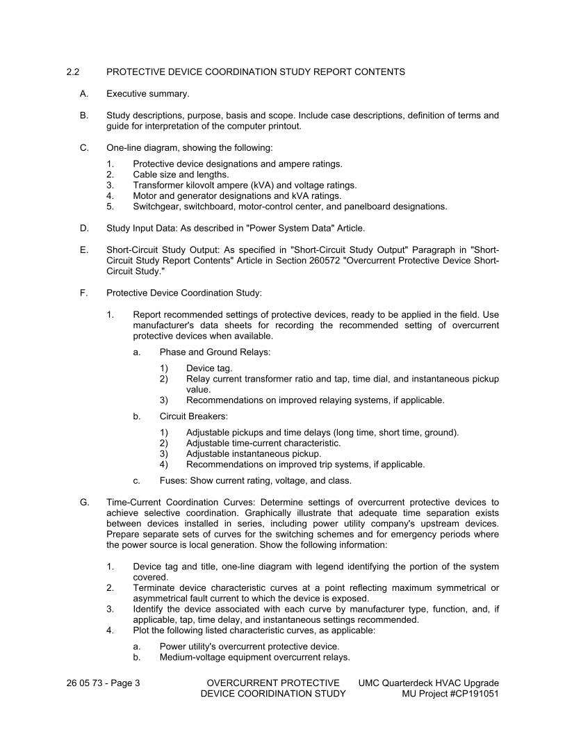
26 05 73 - Page 3 OVERCURRENT PROTECTIVE DEVICE COORIDINATION STUDY
UMC Quarterdeck HVAC Upgrade MU Project #CP191051
2.2 PROTECTIVE DEVICE COORDINATION STUDY REPORT CONTENTS
A. Executive summary.
B. Study descriptions, purpose, basis and scope. Include case descriptions, definition of terms and guide for interpretation of the computer printout.
C. One-line diagram, showing the following:
1. Protective device designations and ampere ratings.2. Cable size and lengths.3. Transformer kilovolt ampere (kVA) and voltage ratings.4. Motor and generator designations and kVA ratings.5. Switchgear, switchboard, motor-control center, and panelboard designations.
D. Study Input Data: As described in "Power System Data" Article.
E. Short-Circuit Study Output: As specified in "Short-Circuit Study Output" Paragraph in "Short-Circuit Study Report Contents" Article in Section 260572 "Overcurrent Protective Device Short-Circuit Study."
F. Protective Device Coordination Study:
1. Report recommended settings of protective devices, ready to be applied in the field. Use manufacturer's data sheets for recording the recommended setting of overcurrent protective devices when available.
a. Phase and Ground Relays:
1) Device tag.2) Relay current transformer ratio and tap, time dial, and instantaneous pickup
value.3) Recommendations on improved relaying systems, if applicable.
b. Circuit Breakers:
1) Adjustable pickups and time delays (long time, short time, ground).2) Adjustable time-current characteristic.3) Adjustable instantaneous pickup.4) Recommendations on improved trip systems, if applicable.
c. Fuses: Show current rating, voltage, and class.
G. Time-Current Coordination Curves: Determine settings of overcurrent protective devices to achieve selective coordination. Graphically illustrate that adequate time separation exists between devices installed in series, including power utility company's upstream devices. Prepare separate sets of curves for the switching schemes and for emergency periods where the power source is local generation. Show the following information:
1. Device tag and title, one-line diagram with legend identifying the portion of the system covered.
2. Terminate device characteristic curves at a point reflecting maximum symmetrical or asymmetrical fault current to which the device is exposed.
3. Identify the device associated with each curve by manufacturer type, function, and, if applicable, tap, time delay, and instantaneous settings recommended.
4. Plot the following listed characteristic curves, as applicable:
a. Power utility's overcurrent protective device.b. Medium-voltage equipment overcurrent relays.
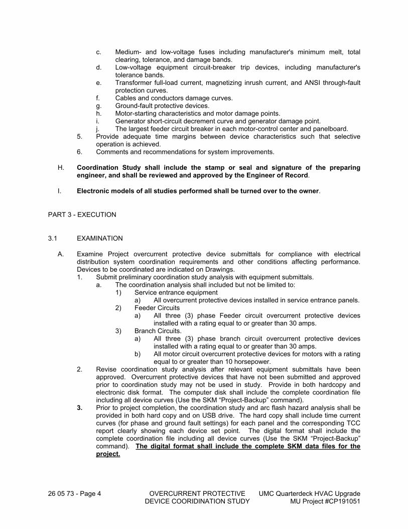
26 05 73 - Page 4 OVERCURRENT PROTECTIVE DEVICE COORIDINATION STUDY
UMC Quarterdeck HVAC Upgrade MU Project #CP191051
c. Medium- and low-voltage fuses including manufacturer's minimum melt, total clearing, tolerance, and damage bands.
d. Low-voltage equipment circuit-breaker trip devices, including manufacturer's tolerance bands.
e. Transformer full-load current, magnetizing inrush current, and ANSI through-fault protection curves.
f. Cables and conductors damage curves.g. Ground-fault protective devices.h. Motor-starting characteristics and motor damage points.i. Generator short-circuit decrement curve and generator damage point.j. The largest feeder circuit breaker in each motor-control center and panelboard.
5. Provide adequate time margins between device characteristics such that selective operation is achieved.
6. Comments and recommendations for system improvements.
H. Coordination Study shall include the stamp or seal and signature of the preparing engineer, and shall be reviewed and approved by the Engineer of Record.
I. Electronic models of all studies performed shall be turned over to the owner.
PART 3 - EXECUTION
3.1 EXAMINATION
A. Examine Project overcurrent protective device submittals for compliance with electrical distribution system coordination requirements and other conditions affecting performance. Devices to be coordinated are indicated on Drawings.1. Submit preliminary coordination study analysis with equipment submittals.
a. The coordination analysis shall included but not be limited to:1) Service entrance equipment
a) All overcurrent protective devices installed in service entrance panels.2) Feeder Circuits
a) All three (3) phase Feeder circuit overcurrent protective devices installed with a rating equal to or greater than 30 amps.
3) Branch Circuits.a) All three (3) phase branch circuit overcurrent protective devices
installed with a rating equal to or greater than 30 amps.b) All motor circuit overcurrent protective devices for motors with a rating
equal to or greater than 10 horsepower.2. Revise coordination study analysis after relevant equipment submittals have been
approved. Overcurrent protective devices that have not been submitted and approved prior to coordination study may not be used in study. Provide in both hardcopy and electronic disk format. The computer disk shall include the complete coordination file including all device curves (Use the SKM “Project-Backup” command).
3. Prior to project completion, the coordination study and arc flash hazard analysis shall be provided in both hard copy and on USB drive. The hard copy shall include time current curves (for phase and ground fault settings) for each panel and the corresponding TCC report clearly showing each device set point. The digital format shall include the complete coordination file including all device curves (Use the SKM “Project-Backup” command). The digital format shall include the complete SKM data files for the project.
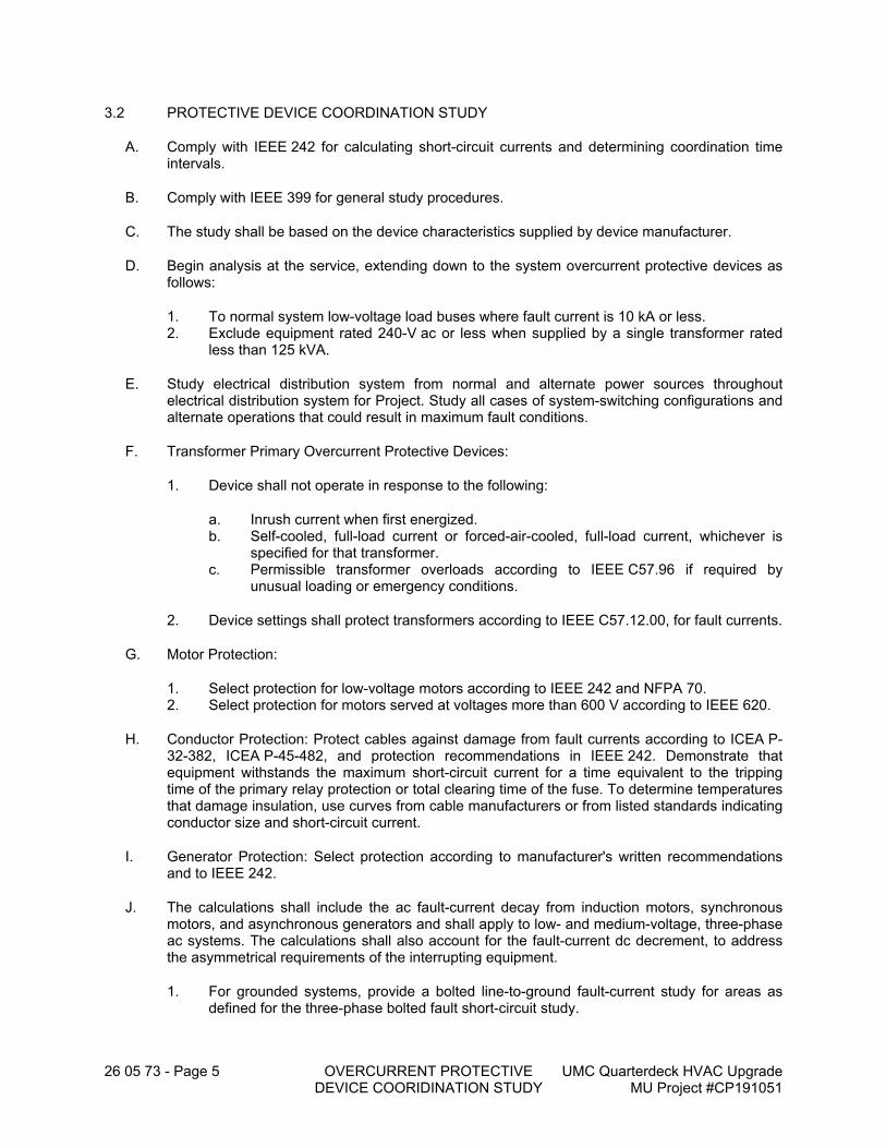
26 05 73 - Page 5 OVERCURRENT PROTECTIVE DEVICE COORIDINATION STUDY
UMC Quarterdeck HVAC Upgrade MU Project #CP191051
3.2 PROTECTIVE DEVICE COORDINATION STUDY
A. Comply with IEEE 242 for calculating short-circuit currents and determining coordination time intervals.
B. Comply with IEEE 399 for general study procedures.
C. The study shall be based on the device characteristics supplied by device manufacturer.
D. Begin analysis at the service, extending down to the system overcurrent protective devices as follows:
1. To normal system low-voltage load buses where fault current is 10 kA or less.2. Exclude equipment rated 240-V ac or less when supplied by a single transformer rated
less than 125 kVA.
E. Study electrical distribution system from normal and alternate power sources throughout electrical distribution system for Project. Study all cases of system-switching configurations and alternate operations that could result in maximum fault conditions.
F. Transformer Primary Overcurrent Protective Devices:
1. Device shall not operate in response to the following:
a. Inrush current when first energized.b. Self-cooled, full-load current or forced-air-cooled, full-load current, whichever is
specified for that transformer.c. Permissible transformer overloads according to IEEE C57.96 if required by
unusual loading or emergency conditions.
2. Device settings shall protect transformers according to IEEE C57.12.00, for fault currents.
G. Motor Protection:
1. Select protection for low-voltage motors according to IEEE 242 and NFPA 70.2. Select protection for motors served at voltages more than 600 V according to IEEE 620.
H. Conductor Protection: Protect cables against damage from fault currents according to ICEA P-32-382, ICEA P-45-482, and protection recommendations in IEEE 242. Demonstrate that equipment withstands the maximum short-circuit current for a time equivalent to the tripping time of the primary relay protection or total clearing time of the fuse. To determine temperatures that damage insulation, use curves from cable manufacturers or from listed standards indicating conductor size and short-circuit current.
I. Generator Protection: Select protection according to manufacturer's written recommendations and to IEEE 242.
J. The calculations shall include the ac fault-current decay from induction motors, synchronous motors, and asynchronous generators and shall apply to low- and medium-voltage, three-phase ac systems. The calculations shall also account for the fault-current dc decrement, to address the asymmetrical requirements of the interrupting equipment.
1. For grounded systems, provide a bolted line-to-ground fault-current study for areas as defined for the three-phase bolted fault short-circuit study.
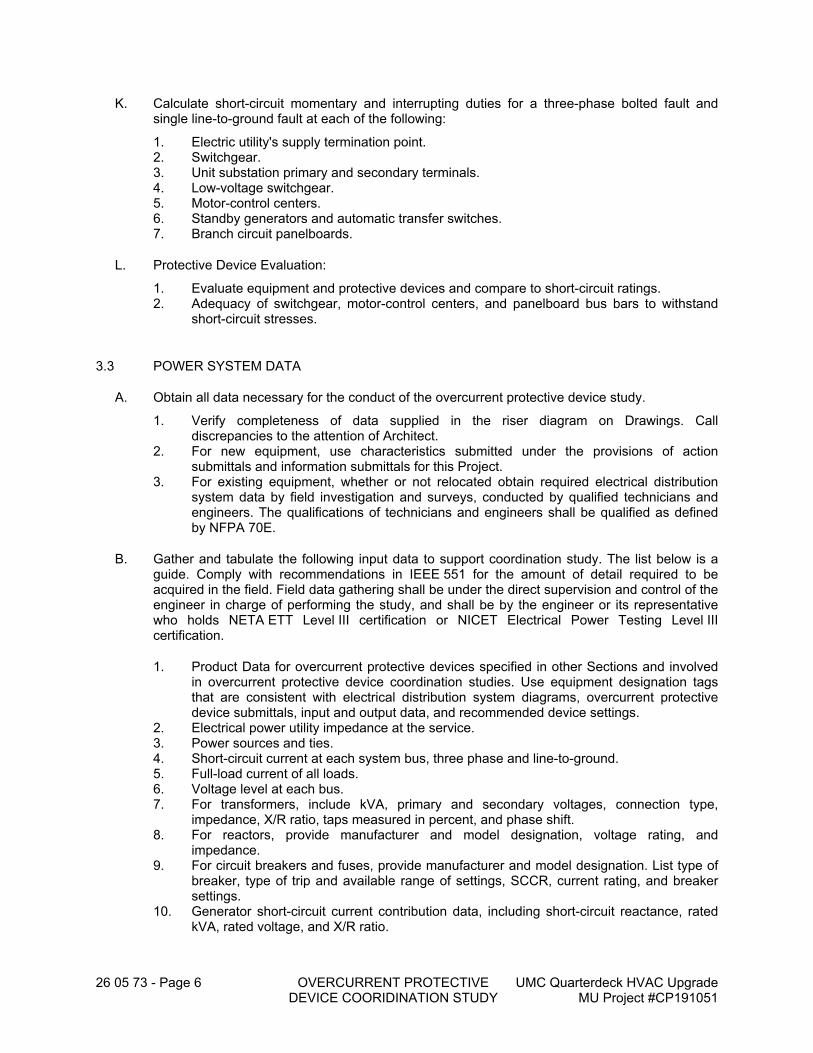
26 05 73 - Page 6 OVERCURRENT PROTECTIVE DEVICE COORIDINATION STUDY
UMC Quarterdeck HVAC Upgrade MU Project #CP191051
K. Calculate short-circuit momentary and interrupting duties for a three-phase bolted fault and single line-to-ground fault at each of the following:
1. Electric utility's supply termination point.2. Switchgear.3. Unit substation primary and secondary terminals.4. Low-voltage switchgear.5. Motor-control centers.6. Standby generators and automatic transfer switches.7. Branch circuit panelboards.
L. Protective Device Evaluation:
1. Evaluate equipment and protective devices and compare to short-circuit ratings.2. Adequacy of switchgear, motor-control centers, and panelboard bus bars to withstand
short-circuit stresses.
3.3 POWER SYSTEM DATA
A. Obtain all data necessary for the conduct of the overcurrent protective device study.
1. Verify completeness of data supplied in the riser diagram on Drawings. Call discrepancies to the attention of Architect.
2. For new equipment, use characteristics submitted under the provisions of action submittals and information submittals for this Project.
3. For existing equipment, whether or not relocated obtain required electrical distribution system data by field investigation and surveys, conducted by qualified technicians and engineers. The qualifications of technicians and engineers shall be qualified as defined by NFPA 70E.
B. Gather and tabulate the following input data to support coordination study. The list below is a guide. Comply with recommendations in IEEE 551 for the amount of detail required to be acquired in the field. Field data gathering shall be under the direct supervision and control of the engineer in charge of performing the study, and shall be by the engineer or its representative who holds NETA ETT Level III certification or NICET Electrical Power Testing Level III certification.
1. Product Data for overcurrent protective devices specified in other Sections and involved in overcurrent protective device coordination studies. Use equipment designation tags that are consistent with electrical distribution system diagrams, overcurrent protective device submittals, input and output data, and recommended device settings.
2. Electrical power utility impedance at the service.3. Power sources and ties.4. Short-circuit current at each system bus, three phase and line-to-ground.5. Full-load current of all loads.6. Voltage level at each bus.7. For transformers, include kVA, primary and secondary voltages, connection type,
impedance, X/R ratio, taps measured in percent, and phase shift.8. For reactors, provide manufacturer and model designation, voltage rating, and
impedance.9. For circuit breakers and fuses, provide manufacturer and model designation. List type of
breaker, type of trip and available range of settings, SCCR, current rating, and breaker settings.
10. Generator short-circuit current contribution data, including short-circuit reactance, rated kVA, rated voltage, and X/R ratio.
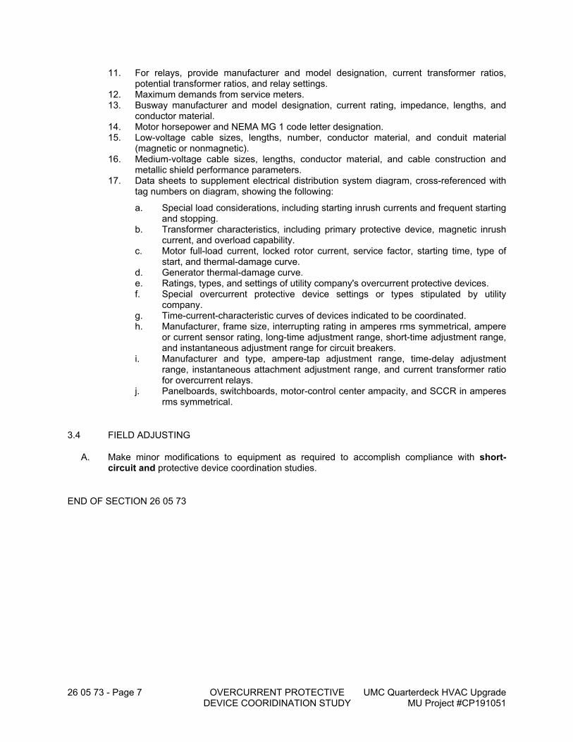
26 05 73 - Page 7 OVERCURRENT PROTECTIVE DEVICE COORIDINATION STUDY
UMC Quarterdeck HVAC Upgrade MU Project #CP191051
11. For relays, provide manufacturer and model designation, current transformer ratios, potential transformer ratios, and relay settings.
12. Maximum demands from service meters.13. Busway manufacturer and model designation, current rating, impedance, lengths, and
conductor material.14. Motor horsepower and NEMA MG 1 code letter designation.15. Low-voltage cable sizes, lengths, number, conductor material, and conduit material
(magnetic or nonmagnetic).16. Medium-voltage cable sizes, lengths, conductor material, and cable construction and
metallic shield performance parameters.17. Data sheets to supplement electrical distribution system diagram, cross-referenced with
tag numbers on diagram, showing the following:
a. Special load considerations, including starting inrush currents and frequent starting and stopping.
b. Transformer characteristics, including primary protective device, magnetic inrush current, and overload capability.
c. Motor full-load current, locked rotor current, service factor, starting time, type of start, and thermal-damage curve.
d. Generator thermal-damage curve.e. Ratings, types, and settings of utility company's overcurrent protective devices.f. Special overcurrent protective device settings or types stipulated by utility
company.g. Time-current-characteristic curves of devices indicated to be coordinated.h. Manufacturer, frame size, interrupting rating in amperes rms symmetrical, ampere
or current sensor rating, long-time adjustment range, short-time adjustment range, and instantaneous adjustment range for circuit breakers.
i. Manufacturer and type, ampere-tap adjustment range, time-delay adjustment range, instantaneous attachment adjustment range, and current transformer ratio for overcurrent relays.
j. Panelboards, switchboards, motor-control center ampacity, and SCCR in amperes rms symmetrical.
3.4 FIELD ADJUSTING
A. Make minor modifications to equipment as required to accomplish compliance with short-circuit and protective device coordination studies.
END OF SECTION 26 05 73
26 05 74 - Page 1 OVERCURRENT PROTECTIVE DEVICE ARC-FLASH STUDY
UMC Quarterdeck HVAC Upgrade MU Project #CP191051
SECTION 26 05 74 - OVERCURRENT PROTECTIVE DEVICE ARC-FLASH STUDY
PART 1 - GENERAL
1.1 RELATED DOCUMENTS
A. Drawings and general provisions of the Contract, including General and Supplementary Conditions and Division 01 Specification Sections, apply to this Section.
1.2 SUMMARY
A. Section includes a computer-based, arc-flash study to determine the arc-flash hazard distance and the incident energy to which personnel could be exposed during work on or near electrical equipment.
B. Study limited only to new panels that have been added and existing panels that have breakers added and/or modified.
1.3 DEFINITIONS
A. One-Line Diagram: A diagram which shows, by means of single lines and graphic symbols, the course of an electric circuit or system of circuits and the component devices or parts used therein.
B. Protective Device: A device that senses when an abnormal current flow exists and then removes the affected portion from the system.
C. SCCR: Short-circuit current rating.
D. Service: The conductors and equipment for delivering electric energy from the serving utility to the wiring system of the premises served.
1.4 ACTION SUBMITTALS
A. Product Data: For computer software program to be used for studies.
B. Study Submittals: Submit the following submittals after the approval of system protective devices submittals. Submittals shall be in digital form.
1. Arc-flash study input data, including completed computer program input data sheets.2. Arc-flash study report; signed, dated, and sealed by a qualified professional engineer.
a. Submit initial study report for action prior to receiving final approval of the distribution equipment submittals. If formal completion of studies will cause delay in equipment manufacturing, obtain approval from Architect for preliminary submittal of sufficient study data to ensure that the selection of devices and associated characteristics is satisfactory.
26 05 74 - Page 2 OVERCURRENT PROTECTIVE DEVICE ARC-FLASH STUDY
UMC Quarterdeck HVAC Upgrade MU Project #CP191051
1.5 INFORMATIONAL SUBMITTALS
A. Qualification Data: For Arc-Flash Study Specialist.
B. Product Certificates: For arc-flash hazard analysis software, certifying compliance with IEEE 1584 and NFPA 70E.
1.6 CLOSEOUT SUBMITTALS
A. Operation and Maintenance Data:
1. Maintenance procedures according to requirements in NFPA 70E shall be provided in the equipment manuals.
2. Operation and Maintenance Procedures: In addition to items specified in Section 017823 "Operation and Maintenance Data," provide maintenance procedures for use by Owner's personnel that comply with requirements in NFPA 70E.
1.7 QUALITY ASSURANCE
A. Studies shall use SKM Power Tools Electrical Engineering Software computer program (PTW 32). Manual calculations or studies utilizing other software programs are not acceptable.
B. Arc-Flash Study Specialist Qualifications: Professional engineer in charge of performing the study, analyzing the arc flash, and documenting recommendations, licensed in the state where Project is located. All elements of the study shall be performed under the direct supervision and control of this professional engineer.
PART 2 - PRODUCTS
2.1 COMPUTER SOFTWARE
A. Provide analysis performed by: SKM Systems Analysis, Inc., PTW 32, Latest software version.1. Do not use the “Use Equipment Specific Arc Flash Equation in Protective Device Library”
method for arc flash calculations in the SKM software.
B. Comply with IEEE 1584 and NFPA 70E.
C. Analytical features of device coordination study computer software program shall have the capability to calculate "mandatory," "very desirable," and "desirable" features as listed in IEEE 399.
2.2 ARC-FLASH STUDY REPORT CONTENT
A. Executive summary.
B. Study descriptions, purpose, basis and scope.
C. One-line diagram, showing the following:
1. Protective device designations and ampere ratings.
26 05 74 - Page 3 OVERCURRENT PROTECTIVE DEVICE ARC-FLASH STUDY
UMC Quarterdeck HVAC Upgrade MU Project #CP191051
2. Cable size and lengths.3. Transformer kilovolt ampere (kVA) and voltage ratings.4. Motor and generator designations and kVA ratings.5. Switchgear, switchboard, motor-control center and panelboard designations.
D. Study Input Data: As described in "Power System Data" Article.
E. Short-Circuit Study Output: As specified in "Short Circuit Study Output" Paragraph in "Short-Circuit Study Report Contents" Article in Section 260572 "Overcurrent Protective Device Short-Circuit Study."
F. Protective Device Coordination Study Report Contents: As specified in "Protective Device Coordination Study Report Contents" Article in Section 260573 "Overcurrent Protective Device Coordination Study."
G. Arc-Flash Study Output:
1. Interrupting Duty Report: Three-phase and unbalanced fault calculations, showing the following for each overcurrent device location:
a. Voltage.b. Calculated symmetrical fault-current magnitude and angle.c. Fault-point X/R ratio.d. No AC Decrement (NACD) ratio.e. Equivalent impedance.f. Multiplying factors for 2-, 3-, 5-, and 8-cycle circuit breakers rated on a symmetrical
basis.g. Multiplying factors for 2-, 3-, 5-, and 8-cycle circuit breakers rated on a total basis.
H. Incident Energy and Flash Protection Boundary Calculations:
1. Arcing fault magnitude.2. Protective device clearing time.3. Duration of arc.4. Arc-flash boundary.5. Working distance.6. Incident energy.7. Hazard risk category.8. Recommendations for arc-flash energy reduction.
I. Fault study input data, case descriptions, and fault-current calculations including a definition of terms and guide for interpretation of the computer printout.
2.3 ARC-FLASH WARNING LABELS
A. Comply with requirements in Section 260553 "Identification for Electrical Systems" for self-adhesive equipment labels. Produce a waterproof, 3.5-by-5-inch self-adhesive, machine printed, equipment label for each work location included in the analysis.
B. The label shall have an orange header with the wording, "WARNING, ARC-FLASH HAZARD," and shall include the following information taken directly from the arc-flash hazard analysis:
1. Location designation.2. Indication on where Fed From.3. Nominal voltage.4. Flash protection boundary.
26 05 74 - Page 4 OVERCURRENT PROTECTIVE DEVICE ARC-FLASH STUDY
UMC Quarterdeck HVAC Upgrade MU Project #CP191051
5. Hazard risk category.6. Incident energy.7. Working distance.8. Proper level of PPE (Personal Protective Equipment)9. Engineering report number, revision number, and issue date.
C. Labels shall be machine printed, with no field-applied markings. Submit sample of label for Owner Approval prior to installation.
PART 3 - EXECUTION
3.1 EXAMINATION
A. Examine Project overcurrent protective device submittals for compliance with electrical distribution system coordination requirements and other conditions affecting performance. 1. Submit preliminary arc flash hazard analysis with equipment submittals.
a. The coordination and arc flash hazard analysis shall included but not be limited to:1) Service entrance equipment
a) All overcurrent protective devices installed in service entrance panels.2) Feeder Circuits
a) All three (3) phase Feeder circuit overcurrent protective devices installed with a rating equal to or greater than 30 amps.
3) Branch Circuits.a) All three (3) phase branch circuit overcurrent protective devices
installed with a rating equal to or greater than 30 amps.b) All motor circuit overcurrent protective devices for motors with a rating
equal to or greater than 10 horsepower.2. Revise arc flash hazard analysis after relevant equipment submittals have been
approved and as installed feeder lengths verified. Overcurrent protective devices that have not been submitted and approved prior to study may not be used in study. Provide in both hardcopy and electronic disk format. The computer disk shall include the complete coordination file including all device curves (Use the SKM “Project-Backup” command).
3. Prior to project completion, the coordination study and arc flash hazard analysis shall be provided in both hard copy and on USB drive. The hard copy shall include time current curves (for phase and ground fault settings) for each panel and the corresponding TCC report clearly showing each device set point. The digital format shall include the complete coordination file including all device curves (Use the SKM “Project-Backup” command). The digital format shall include the complete SKM data files for the project.
3.2 ARC-FLASH HAZARD ANALYSIS
A. Comply with NFPA 70E and its Annex D for hazard analysis study.
B. Preparatory Studies:
1. Short-Circuit Study Output: As specified in Section 260572 "Overcurrent Protective Device Short-Circuit Study."
2. Protective Device Coordination Study Report Contents: As specified in Section 260573 "Overcurrent Protective Device Coordination Study."
C. Calculate maximum and minimum contributions of fault-current size.
26 05 74 - Page 5 OVERCURRENT PROTECTIVE DEVICE ARC-FLASH STUDY
UMC Quarterdeck HVAC Upgrade MU Project #CP191051
1. The minimum calculation shall assume that the utility contribution is at a minimum and shall assume no motor load.
2. The maximum calculation shall assume a maximum contribution from the utility and shall assume motors to be operating under full-load conditions.
D. Calculate the arc-flash protection boundary and incident energy at locations in the electrical distribution system where personnel could perform work on energized parts.1. Identify any location other than the Service Entrance Main with a HCR>2 and
provide recommendations for improvement.
E. Include medium- and low-voltage equipment locations, except equipment rated 240-V ac or less fed from transformers less than 125 kVA.1. Switchgear and switchboard bus.
a. All overcurrent protective devices installed in service entrance panels.2. Motor-control center.
a. All motor circuit overcurrent protective devices for motors with a rating equal to or greater than 10 horsepower.
3. Distribution panelboard.4. Branch circuit panelboard.5. Three phase branch circuits with overcurrent protective devices installed with a rating
equal to or greater than 30 amps.6. Motor circuit overcurrent protective devices for motors with a rating equal to or greater
than 10 horsepower
F. Safe working distances shall be specified for calculated fault locations based on the calculated arc-flash boundary, considering incident energy of 1.2 cal/sq.cm.
G. Incident energy calculations shall consider the accumulation of energy over time when performing arc-flash calculations on buses with multiple sources. Iterative calculations shall take into account the changing current contributions, as the sources are interrupted or decremented with time. Fault contribution from motors and generators shall be decremented as follows:
1. Fault contribution from induction motors should not be considered beyond three to five cycles.
2. Fault contribution from synchronous motors and generators should be decayed to match the actual decrement of each as closely as possible (e.g., contributions from permanent magnet generators will typically decay from 10 per unit to three per unit after 10 cycles).
H. Arc-flash computation shall include both line and load side of a circuit breaker as follows:
1. When the circuit breaker is in a separate enclosure.2. When the line terminals of the circuit breaker are separate from the work location.
I. Base arc-flash calculations on actual overcurrent protective device clearing time. Cap maximum clearing time at two seconds based on IEEE 1584, Section B.1.2.
J. Arc flash hazard analysis shall include the stamp or seal and signature of the preparing engineer, and shall be reviewed and approved by the Engineer of Record.
K. Electronic models of all studies performed shall be turned over to the owner.
3.3 POWER SYSTEM DATA
A. Obtain all data necessary for the conduct of the arc-flash hazard analysis.
26 05 74 - Page 6 OVERCURRENT PROTECTIVE DEVICE ARC-FLASH STUDY
UMC Quarterdeck HVAC Upgrade MU Project #CP191051
1. Verify completeness of data supplied on the riser diagram on Drawings. Call discrepancies to the attention of Architect.
2. For new equipment, use characteristics submitted under the provisions of action submittals and information submittals for this Project.
3. For existing equipment, whether or not relocated, obtain required electrical distribution system data by field investigation and surveys, conducted by qualified technicians and engineers.
B. Electrical Survey Data: Gather and tabulate the following input data to support study. Comply with recommendations in IEEE 1584 and NFPA 70E as to the amount of detail that is required to be acquired in the field. Field data gathering shall be under the direct supervision and control of the engineer in charge of performing the study, and shall be by the engineer or its representative who holds NETA ETT Level III certification or NICET Electrical Power Testing Level III certification.
1. Product Data for overcurrent protective devices specified in other Sections and involved in overcurrent protective device coordination studies. Use equipment designation tags that are consistent with electrical distribution system diagrams, overcurrent protective device submittals, input and output data, and recommended device settings.
2. Obtain electrical power utility impedance at the service.3. Power sources and ties.4. Short-circuit current at each system bus, three phase and line-to-ground.5. Full-load current of all loads.6. Voltage level at each bus.7. For transformers, include kVA, primary and secondary voltages, connection type,
impedance, X/R ratio, taps measured in per cent, and phase shift.8. For reactors, provide manufacturer and model designation, voltage rating and
impedance.9. For circuit breakers and fuses, provide manufacturer and model designation. List type of
breaker, type of trip and available range of settings, SCCR, current rating, and breaker settings.
10. Generator short-circuit current contribution data, including short-circuit reactance, rated kVA, rated voltage, and X/R ratio.
11. For relays, provide manufacturer and model designation, current transformer ratios, potential transformer ratios, and relay settings.
12. Busway manufacturer and model designation, current rating, impedance, lengths, and conductor material.
13. Motor horsepower and NEMA MG 1 code letter designation.14. Low-voltage cable sizes, lengths, number, conductor material and conduit material
(magnetic or nonmagnetic).15. Medium-voltage cable sizes, lengths, conductor material, and cable construction and
metallic shield performance parameters.
3.4 LABELING
A. Apply one owner approved arc-flash label for 600-V ac, 480-V ac, and applicable 208-V ac panelboards, disconnects and transformers.
END OF SECTION 26 05 74
26 24 16 - Page 1 PANELBOARDS UMC Quarterdeck HVAC Upgrade MU Project #CP191051
SECTION 26 24 16 - PANELBOARDS
PART 1 - GENERAL
1.1 RELATED DOCUMENTS
A. Drawings and general provisions of the Contract, including General and Supplementary Conditions and Division 01 Specification Sections, apply to this Section.
1.2 SUMMARY
A. Section Includes:
1. Distribution panelboards.2. Lighting and appliance branch-circuit panelboards.
1.3 DEFINITIONS
A. ATS: Acceptance testing specification.
B. GFCI: Ground-fault circuit interrupter.
C. GFEP: Ground-fault equipment protection.
D. MCCB: Molded-case circuit breaker.
E. SPD: Surge protective device.
F. VPR: Voltage protection rating.
1.4 ACTION SUBMITTALS
A. Product Data: For each type of panelboard.
1. Include materials, switching and overcurrent protective devices, SPDs, accessories, and components indicated.
2. Include dimensions and manufacturers' technical data on features, performance, electrical characteristics, ratings, and finishes.
B. Shop Drawings: For each panelboard and related equipment.
1. Include dimensioned plans, elevations, sections, and details.2. Show tabulations of installed devices with nameplates, conductor termination sizes,
equipment features, and ratings.3. Detail enclosure types including mounting and anchorage, environmental protection,
knockouts, corner treatments, covers and doors, gaskets, hinges, and locks.4. Detail bus configuration, current, and voltage ratings.5. Short-circuit current rating of panelboards and overcurrent protective devices.6. Include evidence of NRTL listing for SPD as installed in panelboard.
26 24 16 - Page 2 PANELBOARDS UMC Quarterdeck HVAC Upgrade MU Project #CP191051
7. Detail features, characteristics, ratings, and factory settings of individual overcurrent protective devices and auxiliary components.
8. Include wiring diagrams for power, signal, and control wiring.9. Include time-current coordination curves for each type and rating of overcurrent
protective device included in panelboards. Submit on translucent log-log graft paper; include selectable ranges for each type of overcurrent protective device. Include an Internet link for electronic access to downloadable PDF of the coordination curves.
1.5 INFORMATIONAL SUBMITTALS
A. Qualification Data: For testing agency.
B. Panelboard Schedules: For installation in panelboards. Submit final versions after load balancing.
1.6 CLOSEOUT SUBMITTALS
A. Operation and Maintenance Data: For panelboards and components to include in emergency, operation, and maintenance manuals. In addition to items specified in Section 017823 "Operation and Maintenance Data," include the following:
1. Manufacturer's written instructions for testing and adjusting overcurrent protective devices.
2. Time-current curves, including selectable ranges for each type of overcurrent protective device that allows adjustments.
1.7 MAINTENANCE MATERIAL SUBMITTALS
A. Furnish extra materials that match products installed and that are packaged with protective covering for storage and identified with labels describing contents.
1. Keys: Two spares for each type of panelboard cabinet lock.
1.8 QUALITY ASSURANCE
A. Manufacturer Qualifications: ISO 9001 or 9002 certified.
1.9 DELIVERY, STORAGE, AND HANDLING
A. Remove loose packing and flammable materials from inside panelboards; install temporary electric heating (250 W per panelboard) to prevent condensation.
B. Handle and prepare panelboards for installation according to NECA 407.
1.10 FIELD CONDITIONS
A. Environmental Limitations:
26 24 16 - Page 3 PANELBOARDS UMC Quarterdeck HVAC Upgrade MU Project #CP191051
1. Do not deliver or install panelboards until spaces are enclosed and weathertight, wet work in spaces is complete and dry, work above panelboards is complete, and temporary HVAC system is operating and maintaining ambient temperature and humidity conditions at occupancy levels during the remainder of the construction period.
2. Rate equipment for continuous operation under the following conditions unless otherwise indicated:
a. Ambient Temperature: Not exceeding minus 22 deg F to plus 104 deg F.b. Altitude: Not exceeding 6600 feet.
B. Service Conditions: NEMA PB 1, usual service conditions, as follows:1. Ambient temperatures within limits specified.2. Altitude not exceeding 6600 feet.
C. Interruption of Existing Electric Service: Do not interrupt electric service to facilities occupied by Owner or others unless permitted under the following conditions and then only after arranging to provide temporary electric service according to requirements indicated:
1. Notify Owner no fewer than two days in advance of proposed interruption of electric service.
2. Do not proceed with interruption of electric service without Owner's written permission.3. Comply with NFPA 70E.
1.11 WARRANTY
A. Manufacturer's Warranty: Manufacturer agrees to repair or replace panelboards that fail in materials or workmanship within specified warranty period.
1. Panelboard Warranty Period: 24 months from date of Substantial Completion.
PART 2 - PRODUCTS
2.1 PANELBOARDS COMMON REQUIREMENTS
A. Fabricate and test panelboards according to IEEE 344 to withstand seismic forces defined in Section 260548.16 "Seismic Controls for Electrical Systems."
B. Product Selection for Restricted Space: Drawings indicate maximum dimensions for panelboards including clearances between panelboards and adjacent surfaces and other items. Comply with indicated maximum dimensions.
C. Electrical Components, Devices, and Accessories: Listed and labeled as defined in NFPA 70, by a qualified testing agency, and marked for intended location and application.
D. Comply with NEMA PB 1.
E. Comply with NFPA 70.
F. Enclosures: Surface-mounted, dead-front cabinets.
1. Rated for environmental conditions at installed location.
26 24 16 - Page 4 PANELBOARDS UMC Quarterdeck HVAC Upgrade MU Project #CP191051
a. Indoor Dry and Clean Locations: NEMA 250, Type 1.b. Outdoor Locations: NEMA 250, Type 3R.c. Other Wet or Damp Indoor Locations: NEMA 250, Type 4, Stainless Steel.d. Indoor Locations Subject to Dust, Falling Dirt, and Dripping Noncorrosive Liquids:
NEMA 250, Type 12.
2. Height: 84 inches maximum.3. Front: Secured to box with concealed trim clamps. For surface-mounted fronts, match
box dimensions; for flush-mounted fronts, overlap box. Trims shall cover all live parts and shall have no exposed hardware.
4. Hinged Front Cover: Entire front trim hinged to box and with standard door within hinged trim cover. Trims shall cover all live parts and shall have no exposed hardware.
5. Finishes:
a. Panels and Trim: Steel and galvanized steel, factory finished immediately after cleaning and pretreating with manufacturer's standard two-coat, baked-on finish consisting of prime coat and thermosetting topcoat.
b. Back Boxes: Galvanized steel.6. Directory Card: Inside panelboard door, mounted in transparent card holder.
G. Incoming Mains:
1. Location: Convertible between top and bottom.2. Main Breaker: Main lug interiors up to 400 amperes shall be field convertible to main
breaker.
H. Phase, Neutral, and Ground Buses:
1. Material: Hard-drawn copper, 98 percent conductivity.
a. Plating shall run entire length of bus.b. Bus shall be fully rated the entire length.
2. Interiors shall be factory assembled into a unit. Replacing switching and protective devices shall not disturb adjacent units or require removing the main bus connectors.
3. Equipment Ground Bus: Adequate for feeder and branch-circuit equipment grounding conductors; bonded to box.
4. Isolated Ground Bus: Adequate for branch-circuit isolated ground conductors; insulated from box.
5. Full-Sized Neutral: Equipped with full-capacity bonding strap for service entrance applications. Mount electrically isolated from enclosure. Do not mount neutral bus in gutter.
6. Extra-Capacity Neutral Bus: Neutral bus rated 200 percent of phase bus and listed and labeled by an NRTL acceptable to authority having jurisdiction, as suitable for nonlinear loads in electronic-grade panelboards and others designated on Drawings. Connectors shall be sized for double-sized or parallel conductors as indicated on Drawings. Do not mount neutral bus in gutter.
I. Conductor Connectors: Suitable for use with conductor material and sizes.
1. Material: Hard-drawn copper, 98 percent conductivity.2. Terminations shall allow use of 75 deg C rated conductors without derating.3. Size: Lugs suitable for indicated conductor sizes, with additional gutter space, if required,
for larger conductors.
26 24 16 - Page 5 PANELBOARDS UMC Quarterdeck HVAC Upgrade MU Project #CP191051
4. Main and Neutral Lugs: Compression type, with a lug on the neutral bar for each pole in the panelboard.
5. Ground Lugs and Bus-Configured Terminators: Two bolt Compression type, with a lug on the bar for each pole in the panelboard.
6. Feed-Through Lugs: Compression type, suitable for use with conductor material. Locate at opposite end of bus from incoming lugs or main device.
7. Subfeed (Double) Lugs: Compression type suitable for use with conductor material. Locate at same end of bus as incoming lugs or main device.
8. Extra-Capacity Neutral Lugs: Rated 200 percent of phase lugs mounted on extra-capacity neutral bus.
J. NRTL Label: Panelboards or load centers shall be labeled by an NRTL acceptable to authority having jurisdiction for use as service equipment with one or more main service disconnecting and overcurrent protective devices. Panelboards or load centers shall have meter enclosures, wiring, connections, and other provisions for utility metering. Coordinate with utility company for exact requirements.
K. Future Devices: Panelboards or load centers shall have mounting brackets, bus connections, filler plates, and necessary appurtenances required for future installation of devices.
L. Panelboard Short-Circuit Current Rating: Fully rated to interrupt symmetrical short-circuit current available at terminals. Assembly listed by an NRTL for 100 percent interrupting capacity.
1. Panelboards and overcurrent protective devices rated 240 V or less shall have short-circuit ratings as shown on Drawings, but not less than 10,000 A rms symmetrical.
2. Panelboards and overcurrent protective devices rated above 240 V and less than 600 V shall have short-circuit ratings as shown on Drawings, but not less than 14,000 A rms symmetrical.
2.2 POWER PANELBOARDS
A. Manufacturers: Subject to compliance with requirements, provide products by one of the following:1. Eaton Electrical Inc.; Cutler-Hammer Business Unit.2. General Electric Company; GE Consumer & Industrial - Electrical Distribution.3. Square D; a brand of Schneider Electric.
B. Panelboards: NEMA PB 1, distribution type.
C. Doors: Secured with vault-type latch with tumbler lock; keyed alike.
1. For doors more than 36 inches high, provide two latches, keyed alike.
D. Mains: Circuit breaker or Lugs only as indicated on drawings.
E. Branch Overcurrent Protective Devices for Circuit-Breaker Frame Sizes 125 A and Smaller: Bolt-on circuit breakers.
F. Branch Overcurrent Protective Devices for Circuit-Breaker Frame Sizes Larger Than 125 A: Bolt-on circuit breakers.
G. Branch Overcurrent Protective Devices (MCCB) frame sizes 100A and larger shall be electronic trip and shall have adjustable trip settings as indicated in Section 2.6 below to allow for coordination and limiting arch flash hazard.
26 24 16 - Page 6 PANELBOARDS UMC Quarterdeck HVAC Upgrade MU Project #CP191051
2.3 LIGHTING AND APPLIANCE BRANCH-CIRCUIT PANELBOARDS
A. Manufacturers: Subject to compliance with requirements, provide products by one of the following:1. Eaton Electrical Inc.; Cutler-Hammer Business Unit.2. General Electric Company; GE Consumer & Industrial - Electrical Distribution.3. Square D; a brand of Schneider Electric.
B. Panelboards: NEMA PB 1, lighting and appliance branch-circuit type.
C. Mains: Circuit breaker or lugs only as indicated in panelboard schedules.
D. Branch Overcurrent Protective Devices: Bolt-on circuit breakers, replaceable without disturbing adjacent units.
E. Doors: Concealed hinges; secured with flush latch with tumbler lock; keyed alike.
F. Doors: Door-in-door construction with concealed hinges; secured with multipoint latch with tumbler lock; keyed alike. Outer door shall permit full access to the panel interior. Inner door shall permit access to breaker operating handles and labeling, but current carrying terminals and bus shall remain concealed.
2.4 DISCONNECTING AND OVERCURRENT PROTECTIVE DEVICES
A. Manufacturers: Subject to compliance with requirements, provide products by one of the following1. Eaton Electrical Inc.; Cutler-Hammer Business Unit.2. General Electric Company; GE Consumer & Industrial - Electrical Distribution.3. Square D; a brand of Schneider Electric.
B. Molded-Case Circuit Breaker (MCCB): Comply with UL 489, with interrupting capacity to meet available fault currents.1. Adjustable trip setting for circuit-breaker frame sizes 200 A and larger.
a. Electronic trip circuit breakers with rms sensing; field-replaceable rating plug or field-replicable electronic trip; and the following field-adjustable settings:1) Instantaneous trip.2) Long- and short-time pickup levels.3) Long- and short-time time adjustments.4) Ground-fault pickup level, time delay, and I2t response.
2. Current-Limiting Circuit Breakers: Frame sizes 400 A and smaller; let-through ratings less than NEMA FU 1, RK-5.
3. GFCI Circuit Breakers: Single- and two-pole configurations with Class A ground-fault protection (6-mA trip).
4. Ground-Fault Equipment Protection (GFEP) Circuit Breakers: Class B ground-fault protection (30-mA trip).
5. Molded-Case Circuit-Breaker (MCCB) Features and Accessories:a. Standard frame sizes, trip ratings, and number of poles.b. Lugs: Mechanical style, suitable for number, size, trip ratings, and conductor
materials.c. Application Listing: Appropriate for application; Type SWD for switching
fluorescent lighting loads; Type HID for feeding fluorescent and high-intensity discharge (HID) lighting circuits.
d. Ground-Fault Protection: Integrally mounted relay and trip unit with adjustable pickup and time-delay settings, push-to-test feature, and ground-fault indicator.
26 24 16 - Page 7 PANELBOARDS UMC Quarterdeck HVAC Upgrade MU Project #CP191051
e. Shunt Trip: 120-V trip coil energized from separate circuit, set to trip at 55 percent of rated voltage.
f. Undervoltage Trip: Set to operate at 35 to 75 percent of rated voltage without intentional time delay.
g. Multipole units enclosed in a single housing or factory assembled to operate as a single unit.
h. Handle Padlocking Device: Fixed attachment, for locking circuit-breaker handle in on or off position.
i. Handle Clamp: Loose attachment, for holding circuit-breaker handle in on position.j. Any device that can trip the breakers shall have a visible indication on the front of
the panel.
2.5 IDENTIFICATION
A. Panelboard Label: Manufacturer's name and trademark, voltage, amperage, number of phases, and number of poles shall be located on the interior of the panelboard door.
B. Breaker Labels: Faceplate shall list current rating, UL and IEC certification standards, and AIC rating.
C. Circuit Directory: Computer-generated circuit directory mounted inside panelboard door with transparent plastic protective cover.
1. Circuit directory shall identify specific purpose with detail sufficient to distinguish it from all other circuits.
2.6 ACCESSORY COMPONENTS AND FEATURES
A. Accessory Set: Include tools and miscellaneous items required for overcurrent protective device test, inspection, maintenance, and operation.
B. Portable Test Set: For testing functions of solid-state trip devices without removing from panelboard. Include relay and meter test plugs suitable for testing panelboard meters and switchboard class relays.
PART 3 - EXECUTION
3.1 EXAMINATION
A. Verify actual conditions with field measurements prior to ordering panelboards to verify that equipment fits in allocated space in, and comply with, minimum required clearances specified in NFPA 70.
B. Receive, inspect, handle, and store panelboards according to NECA 407.
C. Examine panelboards before installation. Reject panelboards that are damaged, rusted, or have been subjected to water saturation.
D. Examine elements and surfaces to receive panelboards for compliance with installation tolerances and other conditions affecting performance of the Work.
26 24 16 - Page 8 PANELBOARDS UMC Quarterdeck HVAC Upgrade MU Project #CP191051
E. Proceed with installation only after unsatisfactory conditions have been corrected.
3.2 INSTALLATION
A. Coordinate layout and installation of panelboards and components with other construction that penetrates walls or is supported by them, including electrical and other types of equipment, raceways, piping, encumbrances to workspace clearance requirements, and adjacent surfaces. Maintain required workspace clearances and required clearances for equipment access doors and panels.
B. Comply with NECA 1.
C. Install panelboards and accessories according to NECA 407.
D. Equipment Mounting:1. Attach panelboard to the vertical finished or structural surface behind the panelboard.
E. Temporary Lifting Provisions: Remove temporary lifting eyes, channels, and brackets and temporary blocking of moving parts from panelboards.
F. Comply with mounting and anchoring requirements specified in Section 260548.16 "Seismic Controls for Electrical Systems."
G. Mount top of trim 90 inches above finished floor unless otherwise indicated.
H. Mount panelboard cabinet plumb and rigid without distortion of box.
I. Mount recessed panelboards with fronts uniformly flush with wall finish and mating with back box.
J. Mount surface-mounted panelboards to steel slotted supports 5/8 inch in depth. Orient steel slotted supports vertically.
K. Install overcurrent protective devices and controllers not already factory installed.
1. Set field-adjustable, circuit-breaker trip ranges.2. Tighten bolted connections and circuit breaker connections using calibrated torque
wrench or torque screwdriver per manufacturer's written instructions.
L. Make grounding connections and bond neutral for services and separately derived systems to ground. Make connections to grounding electrodes, separate grounds for isolated ground bars, and connections to separate ground bars.
M. Install filler plates in unused spaces.
N. Stub four 1-inch empty conduits from panelboard into accessible ceiling space or space designated to be ceiling space in the future. Stub four 1-inch empty conduits into raised floor space or below slab not on grade.
O. Arrange conductors in gutters into groups and bundle and wrap with wire ties after completing load balancing.
26 24 16 - Page 9 PANELBOARDS UMC Quarterdeck HVAC Upgrade MU Project #CP191051
3.3 IDENTIFICATION
A. Identify field-installed conductors, interconnecting wiring, and components; install warning signs complying with requirements in Section 260553 "Identification for Electrical Systems."
B. Create a directory to indicate installed circuit loads after balancing panelboard loads; incorporate Owner's final room designations. Obtain approval before installing. Handwritten directories are not acceptable. Install directory inside panelboard door.
C. Panelboard Nameplates: Label each panelboard with a nameplate complying with requirements for identification specified in Section 260553 "Identification for Electrical Systems."
D. Device Nameplates: Label each branch circuit device in power panelboards with a nameplate complying with requirements for identification specified in Section 260553 "Identification for Electrical Systems."
E. Install warning signs complying with requirements in Section 260553 "Identification for Electrical Systems" identifying source of remote circuit.
3.4 FIELD QUALITY CONTROL
A. Perform tests and inspections.
1. Manufacturer's Field Service: Engage a factory-authorized service representative to inspect components, assemblies, and equipment installations, including connections, and to assist in testing.
B. Acceptance Testing Preparation:
1. Test insulation resistance for each panelboard bus, component, connecting supply, feeder, and control circuit.
2. Test continuity of each circuit.
C. Tests and Inspections:
1. Perform each visual and mechanical inspection and electrical test for low-voltage air circuit breakers stated in NETA ATS, Paragraph 7.6 Circuit Breakers. Do not perform optional tests. Certify compliance with test parameters.
2. Correct malfunctioning units on-site, where possible, and retest to demonstrate compliance; otherwise, replace with new units and retest.
3. Perform the following infrared scan tests and inspections and prepare reports:
a. Initial Infrared Scanning: After Substantial Completion, but not more than 60 days after Final Acceptance, perform an infrared scan of each panelboard. Remove front panels so joints and connections are accessible to portable scanner.
b. Follow-up Infrared Scanning: Perform an additional follow-up infrared scan of each panelboard 11 months after date of Substantial Completion.
c. Instruments and Equipment:
1) Use an infrared scanning device designed to measure temperature or to detect significant deviations from normal values. Provide calibration record for device.
D. Panelboards will be considered defective if they do not pass tests and inspections.
26 24 16 - Page 10 PANELBOARDS UMC Quarterdeck HVAC Upgrade MU Project #CP191051
E. Prepare test and inspection reports, including a certified report that identifies panelboards included and that describes scanning results, with comparisons of the two scans. Include notation of deficiencies detected, remedial action taken, and observations after remedial action.
3.5 ADJUSTING
A. Adjust moving parts and operable components to function smoothly, and lubricate as recommended by manufacturer.
B. Set field-adjustable circuit-breaker trip ranges as specified in Section 260573 "Overcurrent Protective Device Coordination Study."
C. Load Balancing: After Substantial Completion, but not more than 60 days after Final Acceptance, measure load balancing and make circuit changes. Prior to making circuit changes to achieve load balancing, inform Architect of effect on phase color coding.
1. Measure loads during period of normal facility operations.2. Perform circuit changes to achieve load balancing outside normal facility operation
schedule or at times directed by the Architect. Avoid disrupting services such as fax machines and on-line data processing, computing, transmitting, and receiving equipment.
3. After changing circuits to achieve load balancing, recheck loads during normal facility operations. Record load readings before and after changing circuits to achieve load balancing.
4. Tolerance: Maximum difference between phase loads, within a panelboard, shall not exceed 20 percent.
3.6 PROTECTION
A. Temporary Heating: Prior to energizing panelboards, apply temporary heat to maintain temperature according to manufacturer's written instructions.
END OF SECTION 26 24 16
26 27 26 - Page 1 WIRING DEVICES UMC Quarterdeck HVAC Upgrade MU Project #CP191051
SECTION 26 27 26 - WIRING DEVICES
PART 1 - GENERAL
1.1 RELATED DOCUMENTS
A. Drawings and general provisions of the Contract, including General and Supplementary Conditions and Division 01 Specification Sections, apply to this Section.
1.2 SUMMARY
A. Section Includes:
1. Straight-blade convenience and isolated-ground receptacles.2. GFCI receptacles.3. Cord and plug sets.4. Toggle switches.5. Wall plates.
1.3 DEFINITIONS
A. Abbreviations of Manufacturers' Names:
1. Cooper: Cooper Wiring Devices; Division of Cooper Industries, Inc.2. Hubbell: Hubbell Incorporated: Wiring Devices-Kellems.3. Leviton: Leviton Mfg. Company, Inc.4. Pass & Seymour: Pass& Seymour/Legrand.
B. GFCI: Ground-fault circuit interrupter.
C. Pigtail: Short lead used to connect a device to a branch-circuit conductor.
1.4 ACTION SUBMITTALS
A. Product Data: For each type of product.
B. Shop Drawings: List of legends and description of materials and process used for premarking wall plates.
1.5 INFORMATIONAL SUBMITTALS
A. Field quality-control reports.
1.6 CLOSEOUT SUBMITTALS
A. Operation and Maintenance Data: For wiring devices to include in all manufacturers' packing-label warnings and instruction manuals that include labeling conditions.
26 27 26 - Page 2 WIRING DEVICES UMC Quarterdeck HVAC Upgrade MU Project #CP191051
PART 2 - PRODUCTS
2.1 GENERAL WIRING-DEVICE REQUIREMENTS
A. Wiring Devices, Components, and Accessories: Listed and labeled as defined in NFPA 70, by a qualified testing agency, and marked for intended location and application.
B. Comply with NFPA 70.
C. Devices that are manufactured for use with modular plug-in connectors are to be used:
1. Connectors shall comply with UL 2459 and shall be made with stranding building wire.2. Devices shall comply with the requirements in this Section.3. Connector shall be at right angle. Twist type shall not be permitted.
D. Devices for Owner-Furnished Equipment:
1. Receptacles: Match plug configurations.2. Cord and Plug Sets: Match equipment requirements.
E. Source Limitations: Obtain each type of wiring device and associated wall plate from single source from single manufacturer.
2.2 STRAIGHT-BLADE RECEPTACLES
A. Convenience Receptacles, 125 V, 20 A: Comply with NEMA WD 1, NEMA WD 6 configuration 5-20R, and UL 498.
1. All convenience receptacles to be of the quick connect type to have a right angle connector feature with pre-stripped leads. Connector contacts are to be crimped and welded.
2. Products: Basis of design: Pass & Seymour, PT5362 (duplex)a. Subject to compliance with requirements, provide one of the following:
1) Cooper. (Arrowlink Series)2) Hubbell. (Snapconnect Series)
2.3 GFCI RECEPTACLES
A. General Description:
1. 125 V, 20 A, straight blade, non-feed-through type.2. Comply with NEMA WD 1, NEMA WD 6 Configuration 5-20R, UL 498, UL 943 Class A,
and FS W-C-596.3. Include indicator light that shows when the GFCI has malfunctioned and no longer
provides proper GFCI protection.4. When ground fault protection is lost, power to the receptacle is disconnected.
B. Duplex GFCI Convenience Receptacles, 125 V, 20 A:1. All convenience receptacles to be of the quick connect type to have a right angle
connector feature with pre-stripped leads. Connector contacts are to be crimped and welded.
2. Products: Basis of design: Pass & Seymour, PT2095LA (duplex)
26 27 26 - Page 3 WIRING DEVICES UMC Quarterdeck HVAC Upgrade MU Project #CP191051
a. Subject to compliance with requirements, provide one of the following:1) Cooper. (Arrowlink Series)2) Hubbell. (Snapconnect Series)
2.4 PENDANT CORD-CONNECTOR DEVICES
A. Description:
1. Matching, locking-type plug and receptacle body connector.2. NEMA WD 6 Configurations L5-20P and L5-20R, heavy-duty grade, and FS W-C-596.3. Body: Nylon, with screw-open, cable-gripping jaws and provision for attaching external
cable grip.
2.5 CORD AND PLUG SETS
A. Description:
1. Match voltage and current ratings and number of conductors to requirements of equipment being connected.
2. Cord: Rubber-insulated, stranded-copper conductors, with Type SOW-A jacket; with green-insulated grounding conductor and ampacity of at least 130 percent of the equipment rating.
3. Plug: Nylon body and integral cable-clamping jaws. Match cord and receptacle type for connection.
2.6 TOGGLE SWITCHES
A. Comply with NEMA WD 1, UL 20, and FS W-S-896.
1. All Snap switches to be of the quick connect type to have a right angle connector feature with pre-stripped leads. Connector contacts are to be crimped and welded.
B. Switches, 120/277 V, 20 A:1. Products: Basis of design: Pass & Seymour, PT20AC1 (single pole), PT20AC2 (two
pole), PT20AC3 (three way), PT20AC4 (four way).a. Subject to compliance with requirements, provide one of the following:
1) Cooper. (Arrowlink Series)2) Hubbell. (Snapconnect Series)
C. Pilot Light Switches, 20 A:1. Products: Basis of design: Pass & Seymour, PT20AC1-SL (single pole), PT20AC3-SL
(three way), PT20AC4 (four way).a. Subject to compliance with requirements, provide one of the following:
1) Cooper.2) Hubbell.3) Leviton.
2. Description: Single pole, with neon-lighted handle, illuminated when switch is "ON."
26 27 26 - Page 4 WIRING DEVICES UMC Quarterdeck HVAC Upgrade MU Project #CP191051
2.7 WALL PLATES
A. Single and combination types shall match corresponding wiring devices.
1. Plate-Securing Screws: Metal with head color to match plate finish.2. Material for Finished Spaces: Where white devices are installed, use Smooth, high-
impact thermoplastic faceplates. Material for Unfinished Spaces: Galvanized steel.3. Material for Damp Locations: Thermoplastic with spring-loaded lift cover, and listed and
labeled for use in wet and damp locations.
B. Wet-Location, Weatherproof Cover Plates: NEMA 250, complying with Type 3R, weather-resistant, die-cast aluminum with lockable cover.
2.8 FINISHES
A. Device Color:
1. Wiring Devices Connected to Normal Power System: Gray in mechanical rooms or as noted by Architect unless otherwise indicated or required by NFPA 70 or device listing.
B. Wall Plate Color: For plastic covers, match device color.
PART 3 - EXECUTION
3.1 INSTALLATION
A. Comply with NECA 1, including mounting heights listed in that standard, unless otherwise indicated.
B. Coordination with Other Trades:
1. Protect installed devices and their boxes. Do not place wall finish materials over device boxes and do not cut holes for boxes with routers that are guided by riding against outside of boxes.
2. Keep outlet boxes free of plaster, drywall joint compound, mortar, cement, concrete, dust, paint, and other material that may contaminate the raceway system, conductors, and cables.
3. Install device boxes in brick or block walls so that the cover plate does not cross a joint unless the joint is troweled flush with the face of the wall.
4. Install wiring devices after all wall preparation, including painting, is complete.
C. Conductors:
1. Do not strip insulation from conductors until right before they are spliced or terminated on devices.
2. Strip insulation evenly around the conductor using tools designed for the purpose. Avoid scoring or nicking of solid wire or cutting strands from stranded wire.
3. The length of free conductors at outlets for devices shall meet provisions of NFPA 70, Article 300, without pigtails.
D. Device Installation:
26 27 26 - Page 5 WIRING DEVICES UMC Quarterdeck HVAC Upgrade MU Project #CP191051
1. Replace devices that have been in temporary use during construction and that were installed before building finishing operations were complete.
2. Keep each wiring device in its package or otherwise protected until it is time to connect conductors.
3. Do not remove surface protection, such as plastic film and smudge covers, until the last possible moment.
4. Connect devices to branch circuits using pigtails that are not less than 6 inches in length.5. When there is a choice, use side wiring with binding-head screw terminals. Wrap solid
conductor tightly clockwise, two-thirds to three-fourths of the way around terminal screw.6. Use a torque screwdriver when a torque is recommended or required by manufacturer.7. When conductors larger than No. 12 AWG are installed on 20-A circuits, splice
No. 12 AWG pigtails for device connections.8. Tighten unused terminal screws on the device.9. When mounting into metal boxes, remove the fiber or plastic washers used to hold
device-mounting screws in yokes, allowing metal-to-metal contact.
E. Receptacle Orientation:
1. Install ground pin of vertically mounted receptacles up, and on horizontally mounted receptacles to the right.
F. Device Plates: Do not use oversized or extra-deep plates. Repair wall finishes and remount outlet boxes when standard device plates do not fit flush or do not cover rough wall opening.
G. Dimmers:
1. Install dimmers within terms of their listing.2. Verify that dimmers used for fan-speed control are listed for that application.3. Install unshared neutral conductors on line and load side of dimmers according to
manufacturers' device listing conditions in the written instructions.
H. Arrangement of Devices: Unless otherwise indicated, mount flush, with long dimension vertical and with grounding terminal of receptacles on top. Group adjacent switches under single, multigang wall plates.
I. Adjust locations of floor service outlets and service poles to suit arrangement of partitions and furnishings.
3.2 GFCI RECEPTACLES
A. Install non-feed-through-type GFCI receptacles where protection of downstream receptacles is not required.
3.3 IDENTIFICATION
A. Comply with Section 260553 "Identification for Electrical Systems."
B. Identify each receptacle with panelboard identification and circuit number. Use hot, stamped, or engraved machine printing with black-filled lettering on face of plate, and durable wire markers or tags inside outlet boxes.
26 27 26 - Page 6 WIRING DEVICES UMC Quarterdeck HVAC Upgrade MU Project #CP191051
3.4 FIELD QUALITY CONTROL
A. Test Instruments: Use instruments that comply with UL 1436.
B. Test Instrument for Convenience Receptacles: Digital wiring analyzer with digital readout or illuminated digital-display indicators of measurement.
C. Perform the following tests:1. Test Instruments: Use instruments that comply with UL 1436.2. Test Instrument for Convenience Receptacles: Digital wiring analyzer with digital readout
or illuminated digital-display indicators of measurement.
D. Tests for Convenience Receptacles:
1. Line Voltage: Acceptable range is 105 to 132 V.2. Percent Voltage Drop under 15-A Load: A value of 6 percent or higher is unacceptable.3. Ground Impedance: Values of up to 2 ohms are acceptable.4. GFCI Trip: Test for tripping values specified in UL 1436 and UL 943.5. Using the test plug, verify that the device and its outlet box are securely mounted.6. Tests shall be diagnostic, indicating damaged conductors, high resistance at the circuit
breaker, poor connections, inadequate fault current path, defective devices, or similar problems. Correct circuit conditions, remove malfunctioning units and replace with new ones, and retest as specified above.
E. Test straight-blade for the retention force of the grounding blade according to NFPA 99. Retention force shall be not less than 4 oz.
F. Wiring device will be considered defective if it does not pass tests and inspections.
G. Prepare test and inspection reports.
END OF SECTION 26 27 26
26 28 13 - Page 1 FUSES UMC Quarterdeck HVAC Upgrade MU Project #CP191051
SECTION 26 28 13 - FUSES
PART 1 - GENERAL
1.1 RELATED DOCUMENTS
A. Drawings and general provisions of the Contract, including General and Supplementary Conditions and Division 01 Specification Sections, apply to this Section.
1.2 SUMMARY
A. Section Includes:
1. Cartridge fuses rated 600 V ac and less for use in enclosed switches.
1.3 ACTION SUBMITTALS
A. Product Data: For each type of product. Include construction details, material descriptions, dimensions of individual components and profiles, and finishes for spare-fuse cabinets. Include the following for each fuse type indicated:
1. Ambient Temperature Adjustment Information: If ratings of fuses have been adjusted to accommodate ambient temperatures, provide list of fuses with adjusted ratings.
a. For each fuse having adjusted ratings, include location of fuse, original fuse rating, local ambient temperature, and adjusted fuse rating.
b. Provide manufacturer's technical data on which ambient temperature adjustment calculations are based.
2. Dimensions and manufacturer's technical data on features, performance, electrical characteristics, and ratings.
3. Current-limitation curves for fuses with current-limiting characteristics.4. Time-current coordination curves (average melt) and current-limitation curves
(instantaneous peak let-through current) for each type and rating of fuse. Submit in electronic format suitable for use in SKM coordination software.
5. Coordination charts and tables and related data.6. Fuse sizes for elevator feeders and elevator disconnect switches.
1.4 CLOSEOUT SUBMITTALS
A. Operation and Maintenance Data: For fuses to include in emergency, operation, and maintenance manuals. In addition to items specified in Section 017823 "Operation and Maintenance Data," include the following:
1. Ambient temperature adjustment information.2. Current-limitation curves for fuses with current-limiting characteristics.3. Time-current coordination curves (average melt) and current-limitation curves
(instantaneous peak let-through current) for each type and rating of fuse used on the Project. Submit in electronic format suitable for use in SKM coordination software.
26 28 13 - Page 2 FUSES UMC Quarterdeck HVAC Upgrade MU Project #CP191051
4. Coordination charts and tables and related data.
1.5 MAINTENANCE MATERIAL SUBMITTALS
A. Furnish extra materials that match products installed and that are packaged with protective covering for storage and identified with labels describing contents.
1. Fuses: Equal to 10 percent of quantity installed for each size and type, but no fewer than three of each size and type.
1.6 FIELD CONDITIONS
A. Where ambient temperature to which fuses are directly exposed is less than 40 deg F or more than 100 deg F, apply manufacturer's ambient temperature adjustment factors to fuse ratings.
PART 2 - PRODUCTS
2.1 MANUFACTURERS
A. Manufacturers: Subject to compliance with requirements, provide products by one of the following:1. Cooper Bussman, Inc.2. Edison Fuse, Inc.3. Ferraz Shawmut, Inc.4. Littelfuse, Inc.
B. Source Limitations: Obtain fuses, for use within a specific product or circuit, from single source from single manufacturer.
2.2 CARTRIDGE FUSES
A. Characteristics: NEMA FU 1, current-limiting, nonrenewable cartridge fuses with voltage ratings consistent with circuit voltages.
1. Type RK-1 600-V, zero- to 600-A rating, 200 kAIC, time delay.2. Type CC: 600-V, zero- to 30-A rating, 200 kAIC, fast acting.3. Type J: 600-V, zero- to 600-A rating, 200 kAIC, time delay.4. Type L: 600-V, 601- to 6000-A rating, 200 kAIC, time delay.
B. Electrical Components, Devices, and Accessories: Listed and labeled as defined in NFPA 70, by a qualified testing agency, and marked for intended location and application.
C. Comply with NEMA FU 1 for cartridge fuses.
D. Comply with NFPA 70.
E. Coordinate fuse ratings with utilization equipment nameplate limitations of maximum fuse size and with system short-circuit current levels.
26 28 13 - Page 3 FUSES UMC Quarterdeck HVAC Upgrade MU Project #CP191051
PART 3 - EXECUTION
3.1 EXAMINATION
A. Examine fuses before installation. Reject fuses that are moisture damaged or physically damaged.
B. Examine holders to receive fuses for compliance with installation tolerances and other conditions affecting performance, such as rejection features.
C. Examine utilization equipment nameplates and installation instructions. Install fuses of sizes and with characteristics appropriate for each piece of equipment.
D. Evaluate ambient temperatures to determine if fuse rating adjustment factors must be applied to fuse ratings.
E. Proceed with installation only after unsatisfactory conditions have been corrected.
3.2 FUSE APPLICATIONS
A. Cartridge Fuses:
1. Service Entrance: Class RK1, time delay.2. Feeders: Class RK1, time delay.3. Motor Branch Circuits: Class RK1, time delay.4. Large Motor Branch (601-4000 A): Class L, time delay.5. Power Electronics Circuits: Class J, high speed.6. Other Branch Circuits: Class RK1, time delay.7. Control Transformer Circuits: Class CC, time delay, control transformer duty.8. Provide open-fuse indicator fuses or fuse covers with open fuse indication.
3.3 INSTALLATION
A. Install fuses in fusible devices. Arrange fuses so rating information is readable without removing fuse.
B. Install spare-fuse cabinet(s) in location shown on the Drawings or as indicated in the field by Owner.
3.4 IDENTIFICATION
A. Install labels complying with requirements for identification specified in Section 260553 "Identification for Electrical Systems" and indicating fuse replacement information inside of door of each fused switch and adjacent to each fuse block, socket, and holder.
END OF SECTION 26 28 13
26 28 16 - Page 1 ENCLOSED SWITCHES AND CIRCUIT BREAKERS
UMC Quarterdeck HVAC Upgrade MU Project #CP191051
SECTION 26 28 16 - ENCLOSED SWITCHES AND CIRCUIT BREAKERS
PART 1 -
PART 2 - GENERAL
2.1 RELATED DOCUMENTS
A. Drawings and general provisions of the Contract, including General and Supplementary Conditions and other Division 01 Specification Sections, apply to this Section.
2.2 SUMMARY
A. Section Includes:
1. Fusible switches.2. Nonfusible switches.3. Enclosures.
2.3 DEFINITIONS
A. NC: Normally closed.
B. NO: Normally open.
C. SPDT: Single pole, double throw.
2.4 ACTION SUBMITTALS
A. Product Data: For each type of enclosed switch, circuit breaker, accessory, and component indicated. Include nameplate ratings, dimensioned elevations, sections, weights, and manufacturers' technical data on features, performance, electrical characteristics, ratings, accessories, and finishes.
1. Enclosure types and details for types other than NEMA 250, Type 1.2. Current and voltage ratings.3. Short-circuit current ratings (interrupting and withstand, as appropriate).4. Detail features, characteristics, ratings, and factory settings of individual overcurrent
protective devices, accessories, and auxiliary components.5. Include time-current coordination curves (average melt) for each type and rating of
overcurrent protective device; include selectable ranges for each type of overcurrent protective device. Provide in electronic format compatible with SKM Software.
B. Shop Drawings: For enclosed switches and circuit breakers.
1. Include plans, elevations, sections, details, and attachments to other work.2. Include wiring diagrams for power, signal, and control wiring.
26 28 16 - Page 2 ENCLOSED SWITCHES AND CIRCUIT BREAKERS
UMC Quarterdeck HVAC Upgrade MU Project #CP191051
2.5 CLOSEOUT SUBMITTALS
A. Operation and Maintenance Data: For enclosed switches and circuit breakers to include in emergency, operation, and maintenance manuals.
1. In addition to items specified in Section 017823 "Operation and Maintenance Data," include the following:
a. Manufacturer's written instructions for testing and adjusting enclosed switches and circuit breakers.
b. Time-current coordination curves (average melt) for each type and rating of overcurrent protective device; include selectable ranges for each type of overcurrent protective device. Provide in PDF and electronic format compatible with SKM Software.
2.6 MAINTENANCE MATERIAL SUBMITTALS
A. Furnish extra materials that match products installed and that are packaged with protective covering for storage and identified with labels describing contents.
1. Fuses: Equal to 10 percent of quantity installed for each size and type, but no fewer than three of each size and type.
2.7 QUALITY ASSURANCE
A. Testing Agency Qualifications: Accredited by NETA.
1. Testing Agency's Field Supervisor: Currently certified by NETA to supervise on-site testing.
2.8 FIELD CONDITIONS
A. Environmental Limitations: Rate equipment for continuous operation under the following conditions unless otherwise indicated:
1. Ambient Temperature: Not less than minus 22 deg F and not exceeding 104 deg F.2. Altitude: Not exceeding 6600 feet.
2.9 WARRANTY
A. Manufacturer's Warranty: Manufacturer and Installer agree to repair or replace components that fail in materials or workmanship within specified warranty period.
1. Warranty Period: One year(s) from date of Substantial Completion.
26 28 16 - Page 3 ENCLOSED SWITCHES AND CIRCUIT BREAKERS
UMC Quarterdeck HVAC Upgrade MU Project #CP191051
PART 3 - PRODUCTS
3.1 GENERAL REQUIREMENTS
A. Source Limitations: Obtain enclosed switches and circuit breakers, overcurrent protective devices, components, and accessories, within same product category, from single manufacturer.
B. Product Selection for Restricted Space: Drawings indicate maximum dimensions for enclosed switches and circuit breakers, including clearances between enclosures, and adjacent surfaces and other items. Comply with indicated maximum dimensions.
C. Electrical Components, Devices, and Accessories: Listed and labeled as defined in NFPA 70, by an NRTL, and marked for intended location and application.
D. Comply with NFPA 70.
3.2 FUSIBLE SWITCHES
A. Manufacturers: Subject to compliance with requirements, provide products by one of the following:
1. Eaton Electrical Inc.; Cutler-Hammer Business Unit.2. General Electric Company; GE Consumer & Industrial - Electrical Distribution.3. Square D; a brand of Schneider Electric.
B. Type HD, Heavy Duty:
1. Single throw, Three pole, 600-V ac, 1200 A and smaller.2. UL 98 and NEMA KS 1, horsepower rated, with clips or bolt pads to accommodate
specified fuses.3. Lockable handle with capability to accept three padlocks, and interlocked with cover in
closed position.
C. Accessories:
1. Equipment Ground Kit: Internally mounted and labeled for copper and aluminum ground conductors.
2. Neutral Kit: Internally mounted; insulated, capable of being grounded and bonded; labeled for copper and aluminum neutral conductors.
3. Isolated Ground Kit: Internally mounted; insulated, labeled for copper and aluminum neutral conductors.
4. Class R Fuse Kit: Provides rejection of other fuse types when Class R fuses are specified.
5. Auxiliary Contact Kit: Two NO/NC (Form "C") auxiliary contact(s), arranged to activate before switch blades open. Contact rating - 120-V ac.
6. Hookstick Handle: Allows use of a hookstick to operate the handle.7. Lugs: Compression type, suitable for number, size, and conductor material.8. Service-Rated Switches: Labeled for use as service equipment.
26 28 16 - Page 4 ENCLOSED SWITCHES AND CIRCUIT BREAKERS
UMC Quarterdeck HVAC Upgrade MU Project #CP191051
3.3 NONFUSIBLE SWITCHES
A. Manufacturers: Subject to compliance with requirements, provide products by one of the following:
1. Eaton Electrical Inc.; Cutler-Hammer Business Unit.2. General Electric Company; GE Consumer & Industrial - Electrical Distribution.3. Square D; a brand of Schneider Electric.
B. Type HD, Heavy Duty, Three Pole, Single Throw, 600-V ac, 1200 A and Smaller: UL 98 and NEMA KS 1, horsepower rated, lockable handle with capability to accept three padlocks, and interlocked with cover in closed position.
C. Accessories:
1. Equipment Ground Kit: Internally mounted and labeled for copper and aluminum ground conductors.
2. Neutral Kit: Internally mounted; insulated, capable of being grounded and bonded; labeled for copper and aluminum neutral conductors.
3. Isolated Ground Kit: Internally mounted; insulated, labeled for copper and aluminum neutral conductors.
4. Class R Fuse Kit: Provides rejection of other fuse types when Class R fuses are specified.
1. Auxiliary Contact Kit: Two NO/NC (Form "C") auxiliary contact(s), arranged to activate before switch blades open. Contact rating - 120-V ac.
2. Hookstick Handle: Allows use of a hookstick to operate the handle.3. Lugs: Compression type, suitable for number, size, and conductor material.4. Service-Rated Switches: Labeled for use as service equipment.
3.4 ENCLOSURES
A. Enclosed Switches and Circuit Breakers: UL 489, NEMA KS 1, NEMA 250, and UL 50, to comply with environmental conditions at installed location.
B. Enclosure Finish: The enclosure shall be finished with gray baked enamel paint, electrodeposited on cleaned, phosphatized steel (NEMA 250 Type 1).
C. Conduit Entry: NEMA 250 Types 4, 4X, and 12 enclosures shall contain no knockouts. NEMA 250 Types 7 and 9 enclosures shall be provided with threaded conduit openings in both endwalls.
D. Operating Mechanism: The circuit-breaker operating handle shall be externally operable with the operating mechanism being an integral part of the box, not the cover. The cover interlock mechanism shall have an externally operated override. The override shall not permanently disable the interlock mechanism, which shall return to the locked position once the override is released. The tool used to override the cover interlock mechanism shall not be required to enter the enclosure in order to override the interlock.
E. Enclosures designated as NEMA 250 Type 4, 4X stainless steel, 12, or 12K shall have a dual cover interlock mechanism to prevent unintentional opening of the enclosure cover when the circuit breaker is ON and to prevent turning the circuit breaker ON when the enclosure cover is open.
26 28 16 - Page 5 ENCLOSED SWITCHES AND CIRCUIT BREAKERS
UMC Quarterdeck HVAC Upgrade MU Project #CP191051
F. NEMA 250 Type 7/9 enclosures shall be furnished with a breather and drain kit to allow their use in outdoor and wet location applications.
PART 4 - EXECUTION
4.1 EXAMINATION
A. Examine elements and surfaces to receive enclosed switches and circuit breakers for compliance with installation tolerances and other conditions affecting performance of the Work.
B. Proceed with installation only after unsatisfactory conditions have been corrected.
1. Commencement of work shall indicate Installer's acceptance of the areas and conditions as satisfactory.
4.2 PREPARATION
A. Interruption of Existing Electric Service: Do not interrupt electric service to facilities occupied by Owner or others unless permitted under the following conditions and then only after arranging to provide temporary electric service according to requirements indicated:
1. Notify Owner no fewer than seven days in advance of proposed interruption of electric service.
2. Indicate method of providing temporary electric service.3. Do not proceed with interruption of electric service without Owner's written permission.4. Comply with NFPA 70E.
4.3 ENCLOSURE ENVIRONMENTAL RATING APPLICATIONS
A. Enclosed Switches and Circuit Breakers: Provide enclosures at installed locations with the following environmental ratings.
1. Indoor, Dry and Clean Locations: NEMA 250, Type 1.2. Outdoor Locations: NEMA 250, Type 3R.3. Wash-Down Areas: NEMA 250, Type 4X, stainless steel.4. Other Wet or Damp, Indoor Locations: NEMA 250, Type 4.5. Indoor Locations Subject to Dust, Falling Dirt, and Dripping Noncorrosive Liquids:
NEMA 250, Type 12.
4.4 INSTALLATION
A. Coordinate layout and installation of switches, circuit breakers, and components with equipment served and adjacent surfaces. Maintain required workspace clearances and required clearances for equipment access doors and panels.
B. Install individual wall-mounted switches and circuit breakers with tops at uniform height unless otherwise indicated.
C. Comply with mounting and anchoring requirements specified in Section 260548.16 "Seismic Controls for Electrical Systems."
26 28 16 - Page 6 ENCLOSED SWITCHES AND CIRCUIT BREAKERS
UMC Quarterdeck HVAC Upgrade MU Project #CP191051
D. Temporary Lifting Provisions: Remove temporary lifting of eyes, channels, and brackets and temporary blocking of moving parts from enclosures and components.
E. Install fuses in fusible devices.
F. Comply with NFPA 70 and NECA 1.
4.5 IDENTIFICATION
A. Comply with requirements in Section 260553 "Identification for Electrical Systems."
1. Identify field-installed conductors, interconnecting wiring, and components; provide warning signs.
2. Label each enclosure with engraved metal or laminated-plastic nameplate.
4.6 FIELD QUALITY CONTROL
A. Perform tests and inspections.
B. Tests and Inspections for Switches:
1. Visual and Mechanical Inspection:
a. Inspect physical and mechanical condition.b. Inspect anchorage, alignment, grounding, and clearances.c. Verify that the unit is clean.d. Verify blade alignment, blade penetration, travel stops, and mechanical operation.e. Verify that fuse sizes and types match the Specifications and Drawings.f. Verify that each fuse has adequate mechanical support and contact integrity.g. Inspect bolted electrical connections for high resistance using one of the two
following methods:
1) Use a low-resistance ohmmeter.
a) Compare bolted connection resistance values to values of similar connections. Investigate values that deviate from those of similar bolted connections by more than 50 percent of the lowest value.
2) Verify tightness of accessible bolted electrical connections by calibrated torque-wrench method in accordance with manufacturer's published data or NETA ATS Table 100.12.
a) Bolt-torque levels shall be in accordance with manufacturer's published data. In the absence of manufacturer's published data, use NETA ATS Table 100.12.
h. Verify that operation and sequencing of interlocking systems is as described in the Specifications and shown on the Drawings.
i. Verify correct phase barrier installation.j. Verify lubrication of moving current-carrying parts and moving and sliding surfaces.
2. Electrical Tests:
a. Perform resistance measurements through bolted connections with a low-resistance ohmmeter. Compare bolted connection resistance values to values of
26 28 16 - Page 7 ENCLOSED SWITCHES AND CIRCUIT BREAKERS
UMC Quarterdeck HVAC Upgrade MU Project #CP191051
similar connections. Investigate values that deviate from adjacent poles or similar switches by more than 50 percent of the lowest value.
b. Measure contact resistance across each switchblade fuseholder. Drop values shall not exceed the high level of the manufacturer's published data. If manufacturer's published data are not available, investigate values that deviate from adjacent poles or similar switches by more than 50 percent of the lowest value.
c. Perform insulation-resistance tests for one minute on each pole, phase-to-phase and phase-to-ground with switch closed, and across each open pole. Apply voltage in accordance with manufacturer's published data. In the absence of manufacturer's published data, use Table 100.1 from the NETA ATS. Investigate values of insulation resistance less than those published in Table 100.1 or as recommended in manufacturer's published data.
d. Measure fuse resistance. Investigate fuse-resistance values that deviate from each other by more than 15 percent.
e. Perform ground fault test according to NETA ATS 7.14 "Ground Fault Protection Systems, Low-Voltage."
3. Electrical Tests:
a. Perform resistance measurements through bolted connections with a low-resistance ohmmeter. Compare bolted connection resistance values to values of similar connections. Investigate values that deviate from adjacent poles or similar switches by more than 50 percent of the lowest value.
b. Perform insulation-resistance tests for one minute on each pole, phase-to-phase and phase-to-ground with circuit breaker closed, and across each open pole. Apply voltage in accordance with manufacturer's published data. In the absence of manufacturer's published data, use Table 100.1 from the NETA ATS. Investigate values of insulation resistance less than those published in Table 100.1 or as recommended in manufacturer's published data.
c. Perform a contact/pole resistance test. Drop values shall not exceed the high level of the manufacturer's published data. If manufacturer's published data are not available, investigate values that deviate from adjacent poles or similar switches by more than 50 percent of the lowest value.
d. Perform insulation resistance tests on all control wiring with respect to ground. Applied potential shall be 500-V dc for 300-V rated cable and 1000-V dc for 600-V rated cable. Test duration shall be one minute. For units with solid state components, follow manufacturer's recommendation. Insulation resistance values shall be no less than two megohms.
e. Determine the following by primary current injection:
1) Long-time pickup and delay. Pickup values shall be as specified. Trip characteristics shall not exceed manufacturer's published time-current characteristic tolerance band, including adjustment factors.
2) Short-time pickup and delay. Short-time pickup values shall be as specified. Trip characteristics shall not exceed manufacturer's published time-current characteristic tolerance band, including adjustment factors.
3) Ground-fault pickup and time delay. Ground-fault pickup values shall be as specified. Trip characteristics shall not exceed manufacturer's published time-current characteristic tolerance band, including adjustment factors.
4) Instantaneous pickup. Instantaneous pickup values shall be as specified and within manufacturer's published tolerances.
f. Perform minimum pickup voltage tests on shunt trip and close coils in accordance with manufacturer's published data. Minimum pickup voltage of the shunt trip and close coils shall be as indicated by manufacturer.
g. Verify correct operation of auxiliary features such as trip and pickup indicators; zone interlocking; electrical close and trip operation; trip-free, anti-pump function;
26 28 16 - Page 8 ENCLOSED SWITCHES AND CIRCUIT BREAKERS
UMC Quarterdeck HVAC Upgrade MU Project #CP191051
and trip unit battery condition. Reset all trip logs and indicators. Investigate units that do not function as designed.
h. Verify operation of charging mechanism. Investigate units that do not function as designed.
4. Correct malfunctioning units on-site, where possible, and retest to demonstrate compliance; otherwise, replace with new units and retest.
5. Perform the following infrared scan tests and inspections and prepare reports:
a. Initial Infrared Scanning: After Substantial Completion, but not more than 60 days after Final Acceptance, perform an infrared scan of each enclosed switch and circuit breaker. Remove front panels so joints and connections are accessible to portable scanner.
b. Follow-up Infrared Scanning: Perform an additional follow-up infrared scan of each enclosed switch and circuit breaker 11 months after date of Substantial Completion.
c. Instruments and Equipment: Use an infrared scanning device designed to measure temperature or to detect significant deviations from normal values. Provide calibration record for device.
6. Test and adjust controls, remote monitoring, and safeties. Replace damaged and malfunctioning controls and equipment.
C. Enclosed switches and circuit breakers will be considered defective if they do not pass tests and inspections.
D. Prepare test and inspection reports.
1. Test procedures used.2. Include identification of each enclosed switch and circuit breaker tested and describe test
results.3. List deficiencies detected, remedial action taken, and observations after remedial action.
4.7 ADJUSTING
A. Adjust moving parts and operable components to function smoothly, and lubricate as recommended by manufacturer.
B. Set field-adjustable circuit-breaker trip ranges as specified in Section 260573 "Overcurrent Protective Device Coordination Study
END OF SECTION 26 28 16
26 29 23 - Page 1 VARIABLE FREQUENCY MOTOR CONTROLLERS
UMC Quarterdeck HVAC Upgrade MU Project #CP191051
SECTION 26 29 23 - VARIABLE-FREQUENCY MOTOR CONTROLLERS
PART 1 - GENERAL
1.1 RELATED DOCUMENTS
A. Drawings and general provisions of the Contract, including General and Supplementary Conditions and Division 01 Specification Sections, apply to this Section.
1.2 SUMMARY
A. This Section includes AC motor Variable Frequency Drives rated 600 V and below.
1.3 PERFORMANCE REQUIREMENTS
A. Seismic Performance: VFDs shall withstand the effects of earthquake motions determined according to ASCE/SEI 7.1. The term "withstand" means "the unit will remain in place without separation of any parts
from the device when subjected to the seismic forces specified."
1.4 REFERENCE STANDARDS
A. NEMA ICS 7.1 – Safety Standards for Construction and Guide for Selection, Installation, and Operation of Adjustable Speed Drive Systems; National Electrical Manufacturers Association.
B. NEMA ICS 7 – Industrial Control and Systems: Adjustable –Speed Drives; National Electrical Manufacturers Association.
C. NEMA 250 – Enclosures for Electrical Equipment (1000 Volts Maximum); National Electrical Manufacturers Association.
D. NFPA 70 – National Electrical Code; National Fire Protection Association.
1.5 SUBMITTALS
A. See Section 01 3000– Administrative Requirements for submittal procedures.
B. Product Data: Provide catalog sheets showing voltage, controller size, ratings and size of switching and overcurrent protective devices, short circuit ratings, dimensions, and enclosure details.
C. Shop Drawings: Indicate front and side views of enclosures with overall dimensions and weights shown; conduit entrance locations and requirements; and nameplate legends. Test Reports: Indicate field test and inspection procedures and test results.
26 29 23 - Page 2 VARIABLE FREQUENCY MOTOR CONTROLLERS
UMC Quarterdeck HVAC Upgrade MU Project #CP191051
D. Manufacturer’s Instructions: Indicate application conditions and limitations of use stipulated by testing agency. Include instructions for storage, handling, protection, examination, preparation, and installation of product.
E. Manufacturer’s Field Reports: Indicate startup inspection findings.
F. Operation Data: NEMA ICS 7.1. Include instructions for starting and operating controllers, and describe operating limits that may result in hazardous or unsafe conditions.
G. Maintenance Data: NEMA ICS 7.1. Include routine preventative maintenance schedule.
H. Seismic Qualification Certificates: For VFDs, accessories, and components, from manufacturer.1. Basis for Certification: Indicate whether withstand certification is based on actual test of
assembled components or on calculation.2. Dimensioned Outline Drawings of Equipment Unit: Identify center of gravity and locate
and describe mounting and anchorage provisions.3. Detailed description of equipment anchorage devices on which the certification is based,
and their installation requirements.
I. Product Certificates: For each VFD, from manufacturer.
1.6 QUALITY ASSURANCE
A. Conform to requirements of NFPA 70.
B. Manufacturer Qualifications: Company specializing in manufacturing the products specified in this section with minimum five years documented experience and with service facilities within 200 miles of Project.
C. Products: Listed and classified by Underwriters Laboratories Inc. as suitable for the purpose specified and indicated.
1.7 DELIVERY, STORAGE, AND HANDLING
A. Store in a clean, dry space. Maintain factory wrapping or provide an additional heavy canvas or heavy plastic cover to protect units from dirt, water, construction debris, and traffic.
B. Handle in accordance with manufacturer’s written instructions. Lift only with lugs provided for the purpose. Handle carefully to avoid damage to components, enclosure, and finish.
1.8 PROJECT CONDITIONS
A. Environmental Limitations: Rate equipment for continuous operation, capable of driving full load without derating, under the following conditions unless otherwise indicated:1. Ambient Temperature: Not less than 14 deg F (minus 10 deg C) and not exceeding 104
deg F (40 deg C).2. Ambient Storage Temperature: Not less than minus 4 deg F (minus 20 deg C) and not
exceeding 140 deg F (60 deg C)3. Humidity: Less than 95 percent (noncondensing).4. Altitude: Not exceeding 3300 feet (1005 m).
26 29 23 - Page 3 VARIABLE FREQUENCY MOTOR CONTROLLERS
UMC Quarterdeck HVAC Upgrade MU Project #CP191051
B. Interruption of Existing Electrical Systems: Do not interrupt electrical systems in facilities occupied by Owner or others unless permitted under the following conditions and then only after arranging to provide temporary electrical service according to requirements indicated:1. Notify Owner per requirements in the front end documents.2. Do not proceed with interruption of electrical systems without Owner's written
permission.3. Comply with NFPA 70E.
C. Product Selection for Restricted Space: Drawings indicate maximum dimensions for VFDs, including clearances between VFDs, and adjacent surfaces and other items.
1.9 COORDINATION
A. Coordinate features of motors, load characteristics, installed units, and accessory devices to be compatible with the following:1. Torque, speed, and horsepower requirements of the load.2. Ratings and characteristics of supply circuit and required control sequence.3. Ambient and environmental conditions of installation location.
PART 2 - PRODUCTS
2.1 MANUFACTURED UNITS
A. Manufacturers: Subject to compliance with requirements, provide products by one of the following:1. Toshiba; Model Q9 or Model AS3: www.toshiba.com2. ABB; Model ACH550: www.abb.com3. Yaskawa; Model Z1000 www.yaskawa.com
B. Manufacturers other than the above are not allowed
2.2 DESCRIPTION
A. Variable Frequency Controllers: Enclosed controllers suitable for operating the indicated loads, in conformance with requirements of NEMA ICS 7. Select unspecified features and options in accordance with NEMA ICS 3.1.1. Employ microprocessor-based inverter logic isolated from power circuits.2. Employ pulse-width-modulated inverter system.3. Include a DC link reactor for reduction of harmonic distortion.4. The controller, and all associated components, shall be supplied by a single vendor.5. The controller will be operating a variable volume fan motor, or water pump motor for
HVAC application.6. System voltage shall be indicated on front of ASD, using minimum of 1-inch high letters.
B. Enclosures: NEMA 250, Type 1, suitable for equipment application in places regularly open to the public. No disconnects in VFD cabinet. Disconnect must be in separate enclosure.
26 29 23 - Page 4 VARIABLE FREQUENCY MOTOR CONTROLLERS
UMC Quarterdeck HVAC Upgrade MU Project #CP191051
2.3 OPERATING REQUIREMENTS
A. Rated Input Voltage for motors rated below 40 HP: 200 volts, three phase, 60 Hertz, with a voltage tolerance of +/- 10% and a frequency tolerance of +/- 2 Hz.
B. Rated Output: Output frequency shall vary between 0.1 Hz and 400 Hz. Frequency resolution shall be 0.01 Hz digital and 0.03 Hz analog with an accuracy of +/-0.2% of maximum frequency at 25 degrees Celsius. Maximum voltage frequency shall be adjustable from 25 Hz to 400 Hz. Voltage boost shall be adjustable from 0% to 30% with starting frequency adjustable from 0 Hz to 10 Hz. The output current shall be 100% continuous and 110% for 60 seconds, based on NEC table 430-250 (Full-Load Current, Three-Phase Alternating Current Motors) for 200 volts or 460 volts.
C. The controller shall contain three critical frequency jump points with individual bandwidth. Upper and lower frequency limits shall be capable of being varied.
D. The PWM carrier frequency shall be adjustable from 5000 Hz to 15000 Hz.
E. The drive shall contain two separate acceleration/deceleration times (0.1 to 6000 seconds) with a choice of linear, S, or C curves. The drive shall have a standard dynamic electric braking for motors rated 30 HP or below. The drive shall restart into a rotating motor by sensing the coasting motor speed and matching that frequency. The drive shall have adjustable soft stall (10%-150%) and adjustable electronic overload protection (10%-100%).
F. The drive shall have external fault input, be capable of re-setting faults remotely and locally.
G. Input Signal:1. 0 to 10 v DC2. 0 to 5 v DC3. 4 to 20 mA DC
H. Manual bypass is not required on VFD unless indicated on bid documents.
2.4 COMPONENTS
A. Display: Provide integral digital display to indicate output voltage, output frequency, and output current, output power (kw), and motor RPM.
2.5 ENCLOSURES
A. VFD Enclosures: NEMA 250, to comply with environmental conditions at installed location.1. Dry and Clean Indoor Locations: Type 1.2. Outdoor Locations: Type 3R.3. Other Wet or Damp Indoor Locations: Type 4.4. Indoor Locations Subject to Dust, Falling Dirt, and Dripping Noncorrosive Liquids: Type
12.
B. Disconnects associated with VFD’s shall be in separate enclosure from VFD. Disconnect to be installed on the line side of the VFD.
26 29 23 - Page 5 VARIABLE FREQUENCY MOTOR CONTROLLERS
UMC Quarterdeck HVAC Upgrade MU Project #CP191051
PART 3 - EXECUTION
3.1 EXAMINATION
A. Examine areas, surfaces, and substrates to receive VFDs, with Installer present, for compliance with requirements for installation tolerances, and other conditions affecting performance.
B. Examine VFD before installation. Reject VFDs that are wet, moisture damaged, or mold damaged.
C. Examine roughing-in for conduit systems to verify actual locations of conduit connections before VFD installation.
D. Proceed with installation only after unsatisfactory conditions have been corrected.
3.2 INSTALLATION
A. Install in accordance with NEMA ICS 7.1, manufacturer's instructions, and per drawings.1. Coordinate layout and installation of VFDs with other construction including conduit,
piping, equipment, and adjacent surfaces. Maintain required workspace clearances and required clearances for equipment access doors and panels.
B. Wall-Mounting Controllers: Install VFDs on walls with tops at uniform height and with disconnect operating handles not higher than 79 inches (2000 mm) above finished floor unless otherwise indicated, and by bolting units to wall or mounting on lightweight structural-steel channels bolted to wall. For controllers not on walls, provide freestanding racks complying with Division 26 Section "Hangers and Supports for Electrical Systems."
C. Seismic Bracing: Comply with requirements specified in Division 26 Section "Vibration and Seismic Controls for Electrical Systems."
D. Tighten accessible connections and mechanical fasteners after placing controller.
E. The service disconnect switch must be installed on the line side of the VFD. The disconnect must be in a separate enclosure from the VFD. If conditions do not allow this disconnect to be located near the motor within NEC requirements, then a second remote disconnect may be required at the motor. Consult the project manager or University Engineer if this condition arises. All remote disconnects must be provided with auxiliary contacts hardwired to VFD safety circuit to shut down VFD when disconnect is opened. This may affect warranty on the drive so every attempt should be taken to install it per these design guidelines.
F. If a single VFD is controlling multiple fans in an air handling unit then overload protection on each fan must be provided. No more than 4 fans shall be connected to a single VFD.
G. The ground wire should be of the same size as the power conductors from the motor to the VFD and from the VFD to the source.
H. Do not install VFD’s on AHU’s. Refer to mounting detail on drawings.
I. For motors larger than 60hp, the installation shall comply with IEEE 519 with the point of common coupling being the VFD feeder supply terminals of the installation. If a harmonic filter is needed for compliance then it shall be installed.
26 29 23 - Page 6 VARIABLE FREQUENCY MOTOR CONTROLLERS
UMC Quarterdeck HVAC Upgrade MU Project #CP191051
3.3 IDENTIFICATION
A. Identify VFDs, components, and control wiring. Comply with requirements for identification specified in Division 26 Section "Identification for Electrical Systems."
1. Identify field-installed conductors, interconnecting wiring, and components; provide warning signs.
2. Label each VFD with engraved plastic nameplate.3. Label each enclosure-mounted control and pilot device.4. System voltage to be indicated on front of VFD, using minimum 1” high letters.5. Neatly type label inside each motor controller door identifying motor served, nameplate
horsepower, full load amperes, code letter, service factor, and voltage/phase rating. Place in clear plastic holder.
B. Operating Instructions: Frame printed operating instructions for VFDs, including control sequences and emergency procedures. Fabricate frame of finished metal, and cover instructions with clear acrylic plastic. Mount on front of VFD units.
3.4 CONTROL WIRING INSTALLATION
A. Install wiring between VFDs and remote device. Comply with requirements in Division 26 Section "Low-Voltage Electrical Power Conductors and Cables."
B. Bundle, train, and support wiring in enclosures.
3.5 CONNECTIONS
A. Tighten connectors, terminals, bus joints, and mountings. Tighten field connected connectors and terminals, including screws and bolts, in accordance with equipment manufacturer's published torque tightening values. Where manufacturer's torquing requirements are not indicated, comply with tightening torques specified in UL 486A.
3.6 CLEANING
A. Remove paint splatters and other spots, dirt, and debris. Touch up scratches and mars of finish to match original finish. Clean devices internally using methods and materials as recommended by manufacturer.
3.7 FIELD QUALITY CONTROL
A. Prior to initial energizing, provide the service of the manufacturer's field representative to prepare and start controllers.
B. Perform tests and inspections. Owner shall be provided the opportunity to witness all testing.1. Manufacturer's Field Service: Engage a factory-authorized service representative to
inspect components, assemblies, and equipment installations, including connections, and to assist in testing.
C. Acceptance Testing Preparation:1. Pre-testing: On completing installation of the system, perform the following preparations
for tests, under the supervision of the factory authorized service representative.a. Clean devices using manufacturer's approved methods and materials.
26 29 23 - Page 7 VARIABLE FREQUENCY MOTOR CONTROLLERS
UMC Quarterdeck HVAC Upgrade MU Project #CP191051
b. Inspect for defects and physical damage, and nameplate compliance with current project drawings.
c. Check tightness of electrical connections of devices with calibrated torque wrench. Use manufacturer's recommended torque values.
d. Verify proper fuse types and ratings in fusible devices.e. Make insulation resistance tests of conducting parts of motor control components;
and of connecting supply, feeder, and control circuits. For devices containing solid-state components, use test equipment and methods recommended by the manufacturer.
f. Make continuity tests of circuits.g. Exercise and perform operational tests of mechanical components and other
operable devices in accordance with manufacturer's instructions.1) Visual and mechanical inspection: Include the following inspections and
related work.h. Motor-Control Device Ratings and Settings: Verify that ratings and settings as
installed are appropriate for final loads and final system arrangement and parameters as recommended by Division 15. Recommend final protective-device ratings and settings where differences are found. Use accepted revised ratings or settings to make the final system adjustments. Prepare and submit the load current and overload relay heater list.
D. Electrical Tests: Perform the following in accordance with manufacturer's instructions:1. Insulation resistance test of motor control devices conducting parts to the extent
permitted by the manufacturer's instructions. Insulation resistance less than recommended by the manufacturer are unacceptable.a. Make adjustments for final settings of adjustable-trip devices.b. Test auxiliary protective features such as loss of phase, lockout, phase unbalance
and undervoltage to verify operation.c. Check for improper voltages at terminals in Drives that have external control wiring
when controller disconnect is opened. Any voltage over 30 V is unacceptable.
E. Correct deficiencies and retest motor control devices. Verify by the system tests that specified requirements are met.
F. Labeling: On satisfactory completion of tests and related effort, apply a label to tested components indicating test results, date, and responsible organization and person.
3.8 MAINTENANCE
A. Furnish two extra of each air filter.
B. Provide service and maintenance of controllers for one year from date of Substantial Completion.
C. General Requirements: Provide, at no additional cost to the Owner, all services, materials and equipment necessary for the successful operation of the entire system for a period of one year from Date of Substantial completion. Provide necessary material required for the work. Minimize impacts on facility operations when performing scheduled adjustments and non-scheduled work.
D. Description of Work: The adjustment and repair of the system includes all computer equipment, software updates, electronic and electrical components, equipment and all sensors and control devices. Provide the manufacturer's required adjustments and all other work necessary.
26 29 23 - Page 8 VARIABLE FREQUENCY MOTOR CONTROLLERS
UMC Quarterdeck HVAC Upgrade MU Project #CP191051
E. Personnel: Provide qualified personnel to accomplish all work promptly and satisfactorily. Owner shall be advised in writing of the name of the designated service representative, and of any changes in personnel.
F. Emergency Service: Owner will initiate service calls when a Variable Frequency Drive is not functioning properly. Qualified personnel shall be available to provide service of the complete system, including external controls. Furnish owner with a telephone number where service representative can be reached at all times. Service personnel shall be at the site within 24 hours after receiving a request for service. Restore the Variable Frequency Drive system to proper operating condition within 3 days.
G. Operating: Performance of scheduled adjustments and repair shall verify operation of the system as demonstrated by the initial performance test.
H. Systems Modifications: Provide all recommendations for system modification in writing to Owner. Do not make any system modifications, including operating parameters and control settings, without prior approval of Owner. All modifications made to the system shall be incorporated into the operations and maintenance manuals, and other documentation affected.
3.9 DEMONSTRATION
A. Train Owner's maintenance personnel to adjust, operate, reprogram, and maintain VFDs.
END OF SECTION 26 29 23
26 51 19 - Page 1 LED INTERIOR LIGHTING UMC Quarterdeck HVAC Upgrade MU Project #CP191051
SECTION 26 51 19 - LED INTERIOR LIGHTING
PART 1 - PART 1 - GENERAL
1.1 RELATED DOCUMENTS
A. Drawings and general provisions of the Contract, including General and Supplementary Conditions and Division 01 Specification Sections, apply to this Section.
1.2 SUMMARY
A. Section includes LED luminaires:
1.3 DEFINITIONS
A. CCT: Correlated color temperature.
B. CRI: Color Rendering Index.
C. Fixture: See "Luminaire."
D. IP: International Protection or Ingress Protection Rating.
E. LED: Light-emitting diode.
F. Lumen: Measured output of lamp and luminaire, or both.
G. Luminaire: Complete lighting unit, including lamp, reflector, and housing.
1.4 ACTION SUBMITTALS
A. Product Data: For each type of product.
1. Arrange in order of luminaire designation.2. Include data on features, accessories, and finishes.3. Include physical description and dimensions of luminaires.4. Include emergency lighting units, including batteries and chargers.5. Include life, output (lumens, CCT, and CRI), and energy efficiency data.6. Photometric data and adjustment factors based on laboratory tests, complying with IES
Lighting Measurements Testing and Calculation Guides, of each luminaire type. The adjustment factors shall be for lamps and accessories identical to those indicated for the luminaire as applied in this Project. IES LM-79 and IES LM-80.
a. Manufacturers' Certified Data: Photometric data certified by manufacturer's laboratory with a current accreditation under the National Voluntary Laboratory Accreditation Program for Energy Efficient Lighting Products.
B. Shop Drawings: For nonstandard or custom luminaires.
26 51 19 - Page 2 LED INTERIOR LIGHTING UMC Quarterdeck HVAC Upgrade MU Project #CP191051
1. Include plans, elevations, sections, and mounting and attachment details.2. Include details of luminaire assemblies. Indicate dimensions, weights, loads,required
clearances, method of field assembly, components, and location and size of each field connection.
3. Include diagrams for power, signal, and control wiring.
C. Product Schedule: For luminaires and lamps. Use same designations indicated on Drawings.
1.5 INFORMATIONAL SUBMITTALS
A. Qualification Data: For testing laboratory providing photometric data for luminaires.
B. Detailed description of equipment anchorage devices on which the certification is based and their installation requirements.
C. Product Certificates: For each type of luminaire.
D. Product Test Reports: For each luminaire, for tests performed by manufacturer and witnessed by a qualified testing agency.
E. Sample warranty.
1.6 CLOSEOUT SUBMITTALS
A. Operation and Maintenance Data: For luminaires and lighting systems to include in operation and maintenance manuals.
1. Provide a list of all lamp types used on Project; use ANSI and manufacturers' codes.
1.7 MAINTENANCE MATERIAL SUBMITTALS
A. Furnish extra materials that match products installed and that are packaged with protective covering for storage and identified with labels describing contents.1. Diffusers and Lenses: One for every 100 of each type and rating installed. Furnish at
least one of each type.2. Globes and Guards: One for every 20 of each type and rating installed. Furnish at least
one of each type.
1.8 QUALITY ASSURANCE
A. Luminaire Photometric Data Testing Laboratory Qualifications: Luminaire manufacturer's laboratory that is accredited under the NVLAP for Energy Efficient Lighting Products.
B. Provide luminaires from a single manufacturer for each luminaire type.
C. Each luminaire type shall be binned within a three-step MacAdam Ellipse to ensure color consistency among luminaires.
26 51 19 - Page 3 LED INTERIOR LIGHTING UMC Quarterdeck HVAC Upgrade MU Project #CP191051
1.9 DELIVERY, STORAGE, AND HANDLING
A. Protect finishes of exposed surfaces by applying a strippable, temporary protective covering before shipping.
1.10 WARRANTY
A. Warranty: Manufacturer and Installer agree to repair or replace components of luminaires that fail in materials or workmanship within specified warranty period.
B. Warranty Period: Five year(s) from date of Substantial Completion.
PART 2 - PRODUCTS
2.1 PERFORMANCE REQUIREMENTS
A. Seismic Performance: Luminaires shall withstand the effects of earthquake motions determined according to ASCE 7.
B. Seismic Performance: Luminaires and lamps shall be labeled vibration and shock resistant.
1. The term "withstand" means "the luminaire will remain in place without separation of any parts when subjected to the seismic forces specified."
2.2 LUMINAIRE REQUIREMENTS
A. Electrical Components, Devices, and Accessories: Listed and labeled as defined in NFPA 70, by a qualified testing agency, and marked for intended location and application.
B. Standards:1. UL Listing: Listed for damp location.2. Recessed luminaires shall comply with NEMA LE 4.3. User Replaceable Lamps:
a. Bulb shape complying with ANSI C78.79.b. Lamp base complying with ANSI C81.61 or IEC 60061-1].
C. CRI of minimum 80. CCT of 3500 K.
D. Rated lamp life of 50,000 hours to L70.
E. Lamps dimmable from 100 percent to 0 percent of maximum light output.
F. Internal driver.1. Provide remote driver for fixtures in Large RR, Traditional Performance Space, Isolation
Rooms and Live Room/Jazz Combo Rehearsal as noted on the drawings.
G. Nominal Operating Voltage: 277 V ac or as noted on the drawings.
1. Lens Thickness: At least 0.125 inch minimum unless otherwise indicated.
26 51 19 - Page 4 LED INTERIOR LIGHTING UMC Quarterdeck HVAC Upgrade MU Project #CP191051
H. Housings:
1. Extruded-aluminum housing and heat sink.2. powder-coat painted finish or as noted in Luminaire Schedule.
2.3 LUMINAIRE TYPES
A. Refer to Luminaire Schedule on the Drawings for each Luminaire Type.1. Contractor may submit substitution request for equal products to those listed in
the Luminaire schedule prior to bid for evaluation. If approved, formal approval will be issued. No substitutions will be entertained and/or permitted after bid date.
2.4 MATERIALS
A. Metal Parts:
1. Free of burrs and sharp corners and edges.2. Sheet metal components shall be steel unless otherwise indicated.3. Form and support to prevent warping and sagging.
B. Doors, Frames, and Other Internal Access: Smooth operating, free of light leakage under operating conditions, and designed to permit relamping without use of tools. Designed to prevent doors, frames, lenses, diffusers, and other components from falling accidentally during relamping and when secured in operating position.
C. Diffusers and Globes:
1. prismatic acrylic2. Acrylic Diffusers: One hundred percent virgin acrylic plastic, with high resistance to
yellowing and other changes due to aging, exposure to heat, and UV radiation.3. Lens Thickness: At least 0.125 inch minimum unless otherwise indicated.
D. Factory-Applied Labels: Comply with UL 1598. Include recommended lamps. Locate labels where they will be readily visible to service personnel, but not seen from normal viewing angles when lamps are in place.
1. Label shall include the following lamp characteristics:
a. "USE ONLY" and include specific lamp type.b. Lamp diameter, shape, size, wattage, and coating.c. CCT and CRI for all luminaires.
2.5 METAL FINISHES
A. Variations in finishes are unacceptable in the same piece. Variations in finishes of adjoining components are acceptable if they are within the range of approved Samples and if they can be and are assembled or installed to minimize contrast.
26 51 19 - Page 5 LED INTERIOR LIGHTING UMC Quarterdeck HVAC Upgrade MU Project #CP191051
2.6 LUMINAIRE SUPPORT
A. Comply with requirements in Section 260529 "Hangers and Supports for Electrical Systems" for channel and angle iron supports and nonmetallic channel and angle supports.
B. Single-Stem Hangers: 1/2-inch steel tubing with swivel ball fittings and ceiling canopy. Finish same as luminaire.
C. Wires: ASTM A 641/A 641 M, Class 3, soft temper, zinc-coated steel, 12 gage.
D. Rod Hangers: 3/16-inch minimum diameter, cadmium-plated, threaded steel rod.
E. Hook Hangers: Integrated assembly matched to luminaire, line voltage, and equipment with threaded attachment, cord, and locking-type plug.
PART 3 - EXECUTION
3.1 EXAMINATION
A. Examine substrates, areas, and conditions, with Installer present, for compliance with requirements for installation tolerances and other conditions affecting performance of the Work.
B. Examine roughing-in for luminaire to verify actual locations of luminaire and electrical connections before luminaire installation. Proceed with installation only after unsatisfactory conditions have been corrected.
3.2 INSTALLATION
A. Comply with NECA 1.
B. Install luminaires level, plumb, and square with ceilings and walls unless otherwise indicated.
C. Install lamps in each luminaire.
D. Supports:
1. Sized and rated for luminaire weight.2. Able to maintain luminaire position after cleaning and relamping.3. Provide support for luminaire without causing deflection of ceiling or wall.4. Luminaire mounting devices shall be capable of supporting a horizontal force of 100
percent of luminaire weight and vertical force of 400 percent of luminaire weight.
E. Flush-Mounted Luminaire Support:
1. Secured to outlet box.2. Attached to ceiling structural members at four points equally spaced around
circumference of luminaire.3. Trim ring flush with finished surface.
F. Wall-Mounted Luminaire Support:
26 51 19 - Page 6 LED INTERIOR LIGHTING UMC Quarterdeck HVAC Upgrade MU Project #CP191051
1. Attached to a minimum 20 gauge backing plate attached to wall structural members.
2. Do not attach luminaires directly to gypsum board.
G. Ceiling-Mounted Luminaire Support:
1. Ceiling mount with two 5/32-inch- diameter aircraft cable supports adjustable to 120 inches in length.
H. Suspended Luminaire Support:
1. Pendants and Rods: Where longer than 48 inches, brace to limit swinging.2. Stem-Mounted, Single-Unit Luminaires: Suspend with twin-stem hangers. Support with
approved outlet box and accessories that hold stem and provide damping of luminaire oscillations. Support outlet box vertically to building structure using approved devices.
3. Continuous Rows of Luminaires: Use tubing or stem for wiring at one point and wire support for suspension for each unit length of luminaire chassis, including one at each end.
4. Do not use ceiling grid as support for pendant luminaires. Connect support wires or rods to building structure.
I. Ceiling-Grid-Mounted Luminaires:
1. Secure to any required outlet box.2. Secure luminaire to the luminaire opening using approved fasteners in a minimum of four
locations, spaced near corners of luminaire.3. Use approved devices and support components to connect luminaire to ceiling grid and
building structure in a minimum of four locations, spaced near corners of luminaire.
J. Comply with requirements in Section 260519 "Low-Voltage Electrical Power Conductors and Cables" for wiring connections.
3.3 IDENTIFICATION
A. Identify system components, wiring, cabling, and terminals. Comply with requirements for identification specified in Section 260553 "Identification for Electrical Systems."
3.4 FIELD QUALITY CONTROL
A. Perform the following tests and inspections:
1. Operational Test: After installing luminaires, switches, and accessories, and after electrical circuitry has been energized, test units to confirm proper operation.
2. Test for Emergency Lighting: Interrupt power supply to demonstrate proper operation. Verify transfer from normal power to battery power and retransfer to normal.
B. Luminaire will be considered defective if it does not pass operation tests and inspections.
C. Prepare test and inspection reports.
26 51 19 - Page 7 LED INTERIOR LIGHTING UMC Quarterdeck HVAC Upgrade MU Project #CP191051
3.5 ADJUSTING
A. Occupancy Adjustments: When requested within 12 months of date of Substantial Completion, provide on-site assistance in adjusting the direction of aim of luminaires to suit occupied conditions. Make up to two visits to Project during other-than-normal hours for this purpose. Some of this work may be required during hours of darkness.
1. During adjustment visits, inspect all luminaires. Replace lamps or luminaires that are defective.
2. Parts and supplies shall be manufacturer's authorized replacement parts and supplies.3. Adjust the aim of luminaires in the presence of the Architect.
END OF SECTION 26 51 19
26 52 19 - Page 1 EMERGENCY AND EXIT LIGHTING UMC Quarterdeck HVAC Upgrade MU Project #CP191051
SECTION 26 52 19 - EMERGENCY AND EXIT LIGHTING
PART 1 - GENERAL
1.1 RELATED DOCUMENTS
A. Drawings and general provisions of the Contract, including General and Supplementary Conditions and Division 01 Specification Sections, apply to this Section.
1.2 SUMMARY
A. Section Includes:
1. Emergency lighting units.2. Exit signs.3. Luminaire supports.
1.3 DEFINITIONS
A. CCT: Correlated color temperature.
B. CRI: Color Rendering Index.
C. Emergency Lighting Unit: A lighting unit with internal or external emergency battery powered supply and the means for controlling and charging the battery and unit operation.
D. Fixture: See "Luminaire" Paragraph.
E. Lumen: Measured output of lamp and luminaire, or both.
F. Luminaire: Complete lighting unit, including lamp, reflector, and housing.
1.4 ACTION SUBMITTALS
A. Product Data: For each type of emergency lighting unit, exit sign, and emergency lighting support.
1. Include data on features, accessories, and finishes.2. Include physical description of the unit and dimensions.3. Battery and charger for light units.4. Include life, output of luminaire (lumens, CCT, and CRI), and energy-efficiency data.5. Include photometric data and adjustment factors based on laboratory tests, complying
with IES LM-45, for each luminaire type.a. Manufacturers' Certified Data: Photometric data certified by manufacturer's
laboratory with a current accreditation under the National Voluntary Laboratory Accreditation Program for Energy Efficient Lighting Products.
B. Shop Drawings: For nonstandard or custom luminaires.
26 52 19 - Page 2 EMERGENCY AND EXIT LIGHTING UMC Quarterdeck HVAC Upgrade MU Project #CP191051
1. Include plans, elevations, sections, and mounting and attachment details.2. Include details of equipment assemblies. Indicate dimensions, weights, loads, required
clearances, method of field assembly, components, and location and size of each field connection.
3. Include diagrams for power, signal, and control wiring.
C. Product Schedule:
1. For emergency lighting units. Use same designations indicated on Drawings.2. For exit signs. Use same designations indicated on Drawings.
1.5 INFORMATIONAL SUBMITTALS
A. Qualification Data: For testing laboratory providing photometric data for luminaires.
B. Product Certificates: For each type of luminaire.
C. Seismic Qualification Data: For luminaires, accessories, and components, from manufacturer.
1. Basis for Certification: Indicate whether withstand certification is based on actual test of assembled components or on calculation.
2. Dimensioned Outline Drawings of Equipment Unit: Identify center of gravity and locate and describe mounting and anchorage provisions.
3. Detailed description of equipment anchorage devices on which the certification is based and their installation requirements.
4. Provide seismic qualification certificate for each piece of equipment.
D. Product Test Reports: For each luminaire for tests performed by manufacturer and witnessed by a qualified testing agency.
E. Sample Warranty: For manufacturer's special warranty.
1.6 CLOSEOUT SUBMITTALS
A. Operation and Maintenance Data: For luminaires and lighting systems to include in emergency, operation, and maintenance manuals.
1. Provide a list of all lamp types used on Project; use ANSI and manufacturers' codes.
1.7 QUALITY ASSURANCE
A. Luminaire Photometric Data Testing Laboratory Qualifications: Luminaire manufacturer's laboratory that is accredited under the National Volunteer Laboratory Accreditation Program for Energy Efficient Lighting Products.
1.8 DELIVERY, STORAGE, AND HANDLING
A. Protect finishes of exposed surfaces by applying a strippable, temporary protective covering before shipping.
26 52 19 - Page 3 EMERGENCY AND EXIT LIGHTING UMC Quarterdeck HVAC Upgrade MU Project #CP191051
1.9 WARRANTY
A. Warranty: Manufacturer and Installer agree to repair or replace components of luminaires that fail in materials or workmanship within specified warranty period.
1. Warranty Period: Five year(s) from date of Substantial Completion.
B. Special Warranty for Emergency Lighting Batteries: Manufacturer's standard form in which manufacturer of battery-powered emergency lighting unit agrees to repair or replace components of rechargeable batteries that fail in materials or workmanship within specified warranty period.
1. Warranty Period for Emergency Power Unit Batteries: Five years from date of Substantial Completion. Full warranty shall apply for first year and prorated warranty for the remaining four years.
2. Warranty Period for Self-Powered Exit Sign Batteries: Five years from date of Substantial Completion. Full warranty shall apply for the entire warranty period.
PART 2 - PRODUCTS
2.1 PERFORMANCE REQUIREMENTS
A. Seismic Performance: Luminaires shall withstand the effects of earthquake motions determined according to ASCE/SEI 7 Luminaires and lamps shall be labeled vibration and shock resistant.
1. The term "withstand" means "the luminaire will remain in place without separation of any parts when subjected to the seismic forces specified."
2.2 GENERAL REQUIREMENTS FOR EMERGENCY LIGHTING
A. Electrical Components, Devices, and Accessories: Listed and labeled as defined in NFPA 70, by a qualified testing agency, and marked for intended location and application.
B. NRTL Compliance: Fabricate and label emergency lighting units, exit signs, and batteries to comply with UL 924.
C. Comply with NFPA 70 and NFPA 101.
D. Comply with NEMA LE 4 for recessed luminaires.
E. Comply with UL 1598 for fluorescent luminaires.
F. Lamp Base: Comply with ANSI C81.61 or IEC 60061-1.
G. Bulb Shape: Complying with ANSI C79.1.
2.3 EMERGENCY LIGHTING
A. Refer to Luminaire Schedule on the Drawings for each Luminaire Type.
26 52 19 - Page 4 EMERGENCY AND EXIT LIGHTING UMC Quarterdeck HVAC Upgrade MU Project #CP191051
1. Contractor may submit substitution request for equal products to those listed in the Luminaire schedule prior to bid for evaluation. If approved, formal approval will be issued. No substitutions will be entertained and/or permitted after bid date.
B. General Requirements for Emergency Lighting Units: Self-contained units.
C. Emergency Lighting Unit:1. Wall with universal junction box adaptor.2. UV stable thermoplastic housing, rated for damp locations.3. Two LED lamp heads.4. Internal emergency power unit.5. Self-Diagnostics
D. Remote Emergency Lighting Units:1. Wall with universal junction box adaptor.2. UV stable thermoplastic housing, rated for damp locations.3. Two LED lamp heads.4. External emergency power unit.
2.4 EXIT SIGNS
A. Refer to Luminaire Schedule on the Drawings for each Luminaire Type.1. Contractor may submit substitution request for equal products to those listed in
the Luminaire schedule prior to bid for evaluation. If approved, formal approval will be issued. No substitutions will be entertained and/or permitted after bid date.
B. General Requirements for Exit Signs: Comply with UL 924; for sign colors, visibility, luminance, and lettering size, comply with authorities having jurisdiction.1. Lamps for AC Operation: LEDs; 50,000 hours minimum rated lamp life.2. Self-Powered Exit Signs (Battery Type): Internal emergency power unit.3. Master/Remote Sign Configurations:
a. Master Unit: Comply with requirements above for self-powered exit signs, and provide additional capacity in LED power supply battery for power connection to remote unit.
b. Remote Unit: Comply with requirements above for self-powered exit signs, except omit power supply, battery, and test features. Arrange to receive full power requirements from master unit. Connect for testing concurrently with master unit as a unified system.
4. Self-Diagnostics.
2.5 MATERIALS
A. Metal Parts:
1. Free of burrs and sharp corners and edges.2. Sheet metal components shall be steel unless otherwise indicated.3. Form and support to prevent warping and sagging.
B. Doors, Frames, and Other Internal Access:
1. Smooth operating, free of light leakage under operating conditions.2. Designed to permit relamping without use of tools.
26 52 19 - Page 5 EMERGENCY AND EXIT LIGHTING UMC Quarterdeck HVAC Upgrade MU Project #CP191051
3. Designed to prevent doors, frames, lenses, diffusers, and other components from falling accidentally during relamping and when secured in operating position.
C. Diffusers and Globes:
1. Clear, UV-stabilized acrylic.2. Acrylic: 100 percent virgin acrylic plastic, with high resistance to yellowing and other
changes due to aging, exposure to heat, and UV radiation.3. Lens Thickness: At least 0.125 inch minimum unless otherwise indicated.
D. Conduit: Electrical metallic tubing, minimum 3/4 inch in diameter.
2.6 METAL FINISHES
A. Appearance of Finished Work: Noticeable variations in same piece are not acceptable. Variations in appearance of adjoining components are acceptable if they are within the range of approved Samples and are assembled or installed to minimize contrast.
2.7 LUMINAIRE SUPPORT COMPONENTS
A. Comply with requirements in Section 260529 "Hangers and Supports for Electrical Systems" for channel and angle iron supports and nonmetallic channel and angle supports.
B. Support Wires: ASTM A 641/A 641M, Class 3, soft temper, zinc-coated steel, 12 gage.
PART 3 - EXECUTION
3.1 EXAMINATION
A. Examine substrates, areas, and conditions, with Installer present, for compliance with requirements for conditions affecting performance of luminaires.
B. Examine roughing-in for luminaire to verify actual locations of luminaire and electrical connections before luminaire installation.
C. Examine walls, floors, roofs, and ceilings for suitable conditions where emergency lighting luminaires will be installed.
D. Proceed with installation only after unsatisfactory conditions have been corrected.
3.2 INSTALLATION
A. Comply with NECA 1.
B. Install luminaires level, plumb, and square with ceilings and walls unless otherwise indicated.
C. Install lamps in each luminaire.
D. Supports:
26 52 19 - Page 6 EMERGENCY AND EXIT LIGHTING UMC Quarterdeck HVAC Upgrade MU Project #CP191051
1. Sized and rated for luminaire and emergency power unit weight.2. Able to maintain luminaire position when testing emergency power unit.3. Provide support for luminaire and emergency power unit without causing deflection of
ceiling or wall.4. Luminaire-mounting devices shall be capable of supporting a horizontal force of 100
percent of luminaire and emergency power unit weight and vertical force of 400 percent of luminaire weight.
E. Wall-Mounted Luminaire Support:
1. Attached to a minimum 20-gage backing plate attached to wall structural members.2. Do not attach luminaires directly to gypsum board.
F. Suspended Luminaire Support:
1. Pendants and Rods: Where longer than 48 inches, brace to limit swinging.2. Stem-Mounted, Single-Unit Luminaires: Suspend with twin-stem hangers. Support with
approved outlet box and accessories that hold stem and provide damping of luminaire oscillations. Support outlet box vertically to building structure using approved devices.
3. Continuous Rows of Luminaires: Use tubing or stem for wiring at one point and wire support for suspension for each unit length of luminaire chassis, including one at each end.
4. Do not use ceiling grid as support for pendant luminaires. Connect support wires or rods to building structure.
G. Ceiling Grid Mounted Luminaires:
1. Secure to any required outlet box.2. Secure emergency power unit using approved fasteners in a minimum of four locations,
spaced near corners of emergency power unit.3. Use approved devices and support components to connect luminaire to ceiling grid and
building structure in a minimum of four locations, spaced near corners of luminaire.
3.3 IDENTIFICATION
A. Identify system components, wiring, cabling, and terminals. Comply with requirements for identification specified in Section 260553 "Identification for Electrical Systems."
3.4 FIELD QUALITY CONTROL
A. Perform the following tests and inspections:
1. Test for Emergency Lighting: Interrupt power supply to demonstrate proper operation. Verify transfer from normal power to battery power and retransfer to normal.
B. Luminaire will be considered defective if it does not pass operation tests and inspections.
C. Prepare test and inspection reports.
3.5 STARTUP SERVICE
A. Perform startup service:
26 52 19 - Page 7 EMERGENCY AND EXIT LIGHTING UMC Quarterdeck HVAC Upgrade MU Project #CP191051
1. Charge emergency power units and batteries minimum of 24 hours and conduct one-hour discharge test.
3.6 ADJUSTING
A. Adjustments: Within 12 months of date of Substantial Completion, provide on-site visit to do the following:
1. Inspect all luminaires. Replace lamps, emergency power units, batteries, signs, or luminaires that are defective.
a. Parts and supplies shall be manufacturer's authorized replacement parts and supplies.
2. Conduct short-duration tests on all emergency lighting.
END OF SECTION 26 52 19


