Embed Size (px)
Citation preview
Hydro-UnitUser and operating instructions
Series: Break-Unit DPVCI ECO-Control
2
Table of Contents
1 Introduction1.1 Preface................................................................................................................................................... 41.2 Icons and symbols ................................................................................................................................. 4
2 Identification, service and technical support2.1 Identification, service and technical support .......................................................................................... 52.2 Supplementary documentation .............................................................................................................. 5
3 Guarantee3.1 Terms of warranty .................................................................................................................................. 6
4 Safety and environment4.1 General .................................................................................................................................................. 74.2 Users...................................................................................................................................................... 74.3 Safety provisions.................................................................................................................................... 74.4 Safety precautions ................................................................................................................................. 74.5 Environmental aspects........................................................................................................................... 8
5 Introduction5.1 General .................................................................................................................................................. 95.2 Working range........................................................................................................................................ 95.3 Operation HUV1 DPVCI AB ECO-Control ........................................................................................... 10
6 Transport6.1 Transport.............................................................................................................................................. 126.2 Storage................................................................................................................................................. 12
7 Installation7.1 Mechanical installation......................................................................................................................... 137.2 Set up the system ................................................................................................................................ 137.3 Connect the leakage water collector (option)....................................................................................... 137.4 Wall-mounting ...................................................................................................................................... 147.5 Electrical installation ............................................................................................................................ 147.6 Commissioning .................................................................................................................................... 14
8 Operation8.1 General ................................................................................................................................................ 168.2 Indication / fault.................................................................................................................................... 168.3 Operation ............................................................................................................................................. 17
9 Parameter settings9.1 Parameter list....................................................................................................................................... 18
10 Alarm code table10.1 Alarm code at pressure control ............................................................................................................ 20
11 Maintenance11.1 Introduction .......................................................................................................................................... 2111.2 Cleaning instructions............................................................................................................................ 21
3
12 Annexes12.1 Fault table ............................................................................................................................................ 2212.2 Dimensions of the installation HUV1 DPVCI 40 L HDPE AB............................................................... 2312.3 P&ID..................................................................................................................................................... 2412.4 Control unit ECO-Control ..................................................................................................................... 2412.5 Electrical connections .......................................................................................................................... 2512.6 EC declaration of conformity................................................................................................................ 26
4
1 Introduction
1.1 Preface
This manual contains important information for reliable, proper and efficient operation. Compliance with the operating instructions is of vital importance to ensure reliability and a long service life of the product and to avoid any risks.The first chapters contain information about this manual and safety in general. The following chapters provide information about normal use, installation, maintenance and repairs of the product. The annex contains the declaration(s) of conformity.
• Make yourself familiar with the content.• Accurately follow the directions and instructions.• Never change the sequence of the operations to
be carried out.• Keep this manual or a copy of it together with the
logbook in a fixed place near the product which can be accessed by all personnel.
1.2 Icons and symbols
In this manual and in all accompanying documentation the following icons and symbols are used.
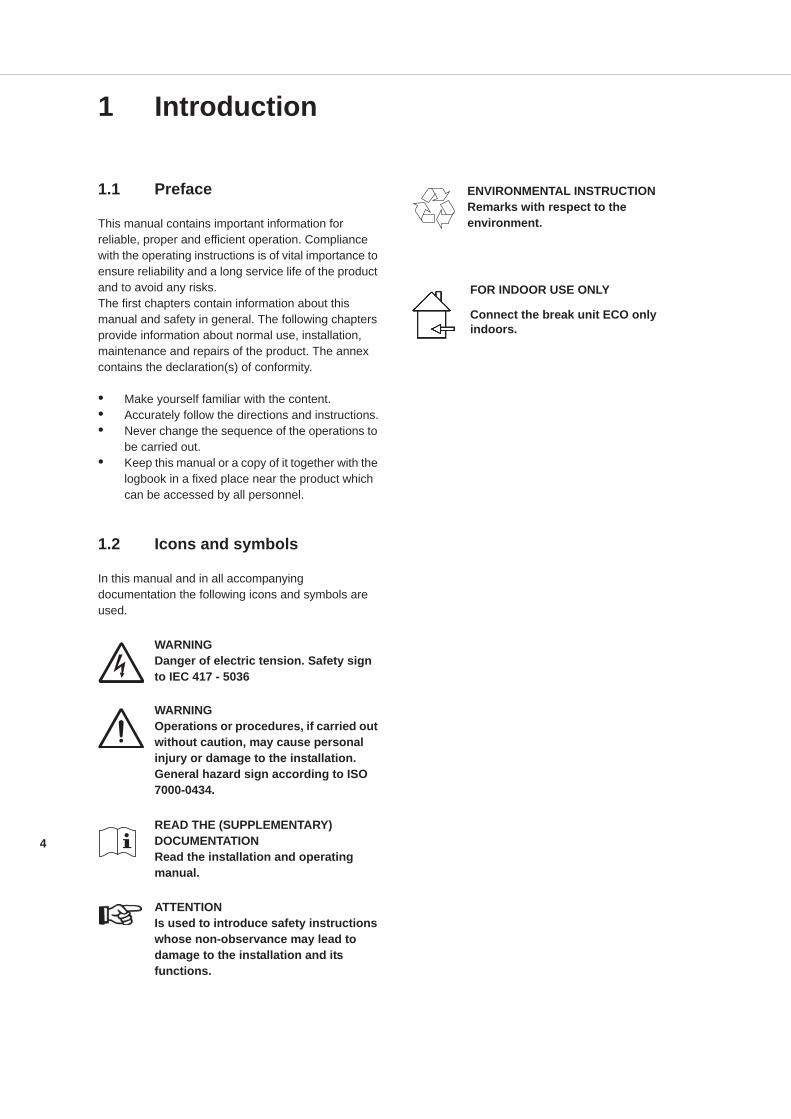
WARNINGDanger of electric tension. Safety sign to IEC 417 - 5036
WARNINGOperations or procedures, if carried out without caution, may cause personal injury or damage to the installation. General hazard sign according to ISO 7000-0434.
READ THE (SUPPLEMENTARY) DOCUMENTATIONRead the installation and operating manual.
ATTENTIONIs used to introduce safety instructions whose non-observance may lead to damage to the installation and its functions.
ENVIRONMENTAL INSTRUCTIONRemarks with respect to the environment.
FOR INDOOR USE ONLY
Connect the break unit ECO only indoors.
5
2 Identification, service and technical support
2.1 Identification, service and technical support
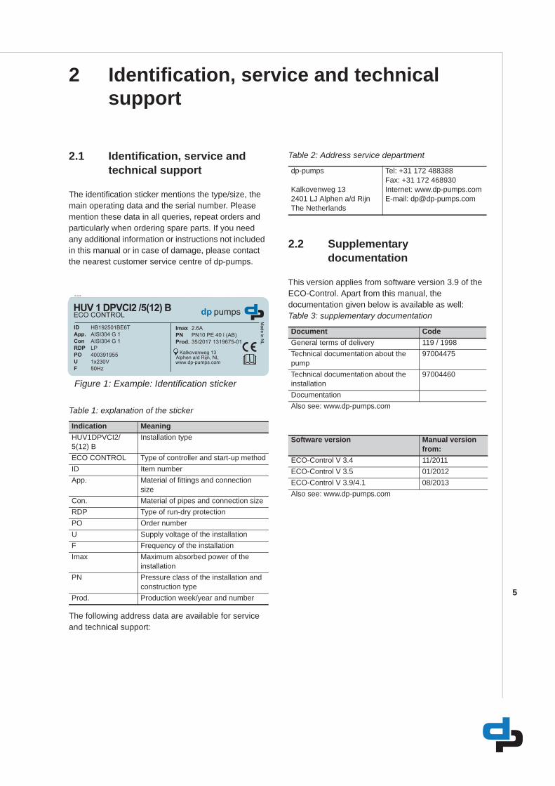
The identification sticker mentions the type/size, the main operating data and the serial number. Please mention these data in all queries, repeat orders and particularly when ordering spare parts. If you need any additional information or instructions not included in this manual or in case of damage, please contact the nearest customer service centre of dp-pumps.
Table 1: explanation of the sticker
The following address data are available for service and technical support:
Table 2: Address service department
2.2 Supplementary documentation
This version applies from software version 3.9 of the ECO-Control. Apart from this manual, the documentation given below is available as well:Table 3: supplementary documentation
ID 4178
Figure 1: Example: Identification sticker
Indication MeaningHUV1DPVCI2/5(12) B
Installation type
ECO CONTROL Type of controller and start-up methodID Item numberApp. Material of fittings and connection
sizeCon. Material of pipes and connection sizeRDP Type of run-dry protectionPO Order numberU Supply voltage of the installationF Frequency of the installationImax Maximum absorbed power of the
installationPN Pressure class of the installation and
construction typeProd. Production week/year and number
dp-pumps
Kalkovenweg 132401 LJ Alphen a/d RijnThe Netherlands
Tel: +31 172 488388Fax: +31 172 468930Internet: www.dp-pumps.comE-mail: [email protected]
Document CodeGeneral terms of delivery 119 / 1998Technical documentation about the pump
97004475
Technical documentation about the installation
97004460
DocumentationAlso see: www.dp-pumps.com
Software version Manual version from:
ECO-Control V 3.4 11/2011ECO-Control V 3.5 01/2012ECO-Control V 3.9/4.1 08/2013Also see: www.dp-pumps.com
6
3 Guarantee
3.1 Terms of warranty
The warranty period is settled by the terms of your contract or at least by the general terms and conditions of sales.
ATTENTIONModifications or alterations of the product supplied are only permitted after consultation with the manufacturer. Original spare parts and accessories authorized by the manufacturer ensure safety. The use of other parts can invalidate any liability of the manufacturer for consequential damage.
ATTENTIONThe warranty relating to the operating reliability and safety of the product supplied is only valid if the product is used in accordance with its designated use as described in the following sections of this manual. The limits stated in the data sheet must not be exceeded under any circumstances.
The warranty becomes invalid if one or more of the points below occur.• The buyer makes modifications himself.• The buyer carries out repairs himself or has
these carried out by a third party.• The product has been handled or maintained
improperly.• The product has non original dp-pumps spare
parts fitted.
dp-pumps repairs defects under warranty when:
• They are caused by flaws in the design, the material or the production.
• They are reported within the warranty period.Other terms of warranty have been included in the general terms of delivery, which are available upon request.
7
4 Safety and environment
4.1 General
This dp-pumps product has been developed using state-of-the-art technology; it is manufactured with utmost care and subject to continuous quality control.dp-pumps does not accept any liability for damage and injury caused by not observing the directions and instructions in this manual, or in cases of carelessness during the installation procedure, use and maintenance of the product.Non-compliance with safety instructions can jeopardize the safety of personnel, the environment and the product itself. Non-compliance with these safety instructions will also lead to forfeiture of any and all rights to claims for damages. For example, in particular non-compliance can result in:
• failure of important pump/system functions,• failure of prescribed maintenance and servicing
practices,• injury to persons by electrical, mechanical and
chemical effects,• hazard of the environment due to leakage of
hazardous substances,• explosions.
Depending on specific activities, extra safety measures may be required. Contact dp-pumps if a potential danger arises during use.
ATTENTIONThe owner of the product is responsible for compliance with the local safety regulations and internal company guidelines.
ATTENTIONNot only must the general safety instructions laid down in this chapter on "Safety" be complied with, but also the safety instructions outlined under specific headings.
4.2 Users
All personnel involved in the operation, maintenance, inspection and installation of the product must be fully qualified to carry out the work involved and be aware
of all applicable responsibilities, authorisations and super visions. If the personnel in question is not already in possession of the required know-how, appropriate training and instruction must be provided. If required, the operator may commission the manufacturer / supplier to take care of such training. In addition, the operator is responsible for ensuring that the contents of the operating instructions are fully understood by the responsible personnel.
4.3 Safety provisions
The product has been designed with the greatest possible care. Original parts and accessories meet the safety regulations. Modifications in the construction or the use of non-original parts may lead to a safety risk.
ATTENTIONMake sure that the product operates within its working range. Only then the product performance is guaranteed.
4.3.1 Labels on the productThe icons, warnings and instructions applied to the product are part of the safety provisions. The labels may not be removed or covered. Labels must remain legible during the entire life of the product. Replace damaged labels immediately.
4.4 Safety precautions
4.4.1 During normal use• Contact the local electricity company for
questions about the power supply.• Shield parts that can become hot such, that
direct contact is impossible.• Always place not deformed coupling protection
plates to protect the coupling before putting the pump into use. Make sure that the coupling protection plates never make contact with the running coupling.
8
4.4.2 During installation, maintenance and repair
Only authorised personnel may install, maintain and inspect the product and repair electrical components. Observe the local safety regulations.
WARNINGAlways first disconnect the energy supply to the product before performing any installation, maintenance and repair activities. Secure this disconnection.
WARNINGAfter continuous operation, the surfaces of a pump can be hot.
WARNINGMake sure that no one can be near rotating components when starting the pump.
WARNINGHandle a pump with dangerous liquids with the utmost care. Avoid danger to persons or the environment when repairing leakages, draining liquids and venting. It is recommended to put a drip tray below the pump.
WARNINGRe-install and/or re-activate all safety and protective devices immediately after completion of the activities.
WARNINGPlease observe all instructions set out in the chapter on 'Commissioning/Start-up' before putting the product into operation again.
4.5 Environmental aspects
4.5.1 GeneralThis product of dp-pumps is designed to function in an environmentally friendly way during their entire life.
ENVIRONMENTAL INSTRUCTIONAlways act according to the laws, by-laws regulations and instructions with respect to health, safety and the environment.
4.5.2 DismantlingDismantle the product and dispose of it in an environmentally friendly way. The owner is responsible for this.
ENVIRONMENTAL INSTRUCTIONAsk at the local government about the re-use or the environmentally friendly processing of discarded materials.
ENVIRONMENTAL INSTRUCTIONAll components of the ECO-Controlare manufactured in accordance with RoHS directive 2002/95/EC.
9
5 Introduction
5.1 General
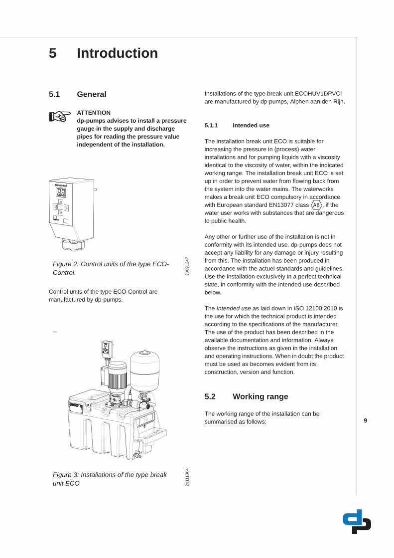
ATTENTIONdp-pumps advises to install a pressure gauge in the supply and discharge pipes for reading the pressure value independent of the installation.
Control units of the type ECO-Control are manufactured by dp-pumps.
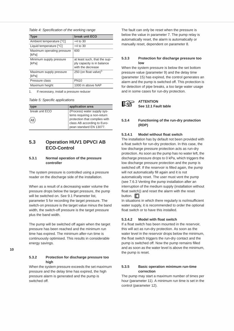
Installations of the type break unit ECOHUV1DPVCI are manufactured by dp-pumps, Alphen aan den Rijn.
5.1.1 Intended use
The installation break unit ECO is suitable for increasing the pressure in (process) water installations and for pumping liquids with a viscosity identical to the viscosity of water, within the indicated working range. The installation break unit ECO is set up in order to prevent water from flowing back from the system into the water mains. The waterworks makes a break unit ECO compulsory in accordance with European standard EN13077 class , if the water user works with substances that are dangerous to public health.
Any other or further use of the installation is not in conformity with its intended use. dp-pumps does not accept any liability for any damage or injury resulting from this. The installation has been produced in accordance with the actuel standards and guidelines. Use the installation exclusively in a perfect technical state, in conformity with the intended use described below.
The Intended use as laid down in ISO 12100:2010 is the use for which the technical product is intended according to the specifications of the manufacturer. The use of the product has been described in the available documentation and information. Always observe the instructions as given in the installation and operating instructions. When in doubt the product must be used as becomes evident from its construction, version and function.
5.2 Working range
The working range of the installation can be summarised as follows:
Figure 2: Control units of the type ECO-Control. 20
0912
47
ID4001
Figure 3: Installations of the type break unit ECO 20
1110
04
AB
10
Table 4: Specification of the working range
Table 5: Specific applications
5.3 Operation HUV1 DPVCI AB ECO-Control
5.3.1 Normal operation of the pressure controller
The system pressure is controlled using a pressure reader on the discharge side of the installation.
When as a result of a decreasing water volume the pressure drops below the target pressure, the pump will be switched on. See 9.1 Parameter list, parameter 5 for recording the target pressure. The switch-on pressure is the target value minus the band width, the switch-off pressure is the target pressure plus the band width.
The pump will be switched off again when the target pressure has been reached and the minimum run time has expired. The minimum after-run time is continuously optimised. This results in considerable energy savings.
5.3.2 Protection for discharge pressure too high
When the system pressure exceeds the set maximum pressure and the delay time has expired, the high pressure alarm is generated and the pump is switched off.
The fault can only be reset when the pressure is below the value in parameter 7. The pump relay is automatically reset, the alarm is automatically or manually reset, dependent on parameter 8.
5.3.3 Protection for discharge pressure too low
When the system pressure is below the set bottom pressure value (parameter 9) and the delay time (parameter 15) has expired, the control generates an alarm and the pump is switched off. This protection is for detection of pipe breaks, a too large water usage and in some cases for run-dry protection.
ATTENTIONSee 12.1 Fault table
5.3.4 Functioning of the run-dry protection (RDP)
5.3.4.1 Model without float switchThe installation has by default not been provided with a float switch for run-dry protection. In this case, the low discharge pressure protection acts as run-dry protection. As soon as the pump has no water left, the discharge pressure drops to 0 kPa, which triggers the low discharge pressure protection and the pump is switched off. If the reservoir is filled again, the pump will not automatically fill again and it is not automatically reset. The user must vent the pump (see 7.6.3 Venting the pump installation after an interruption of the medium supply (installation without float switch)) and reset the alarm with the reset button. In situations in which there regularly is no/insufficient water supply, it is recommended to order the optional float switch or to have this installed.
5.3.4.2 Model with float switchIf a float switch has been mounted in the reservoir, this will act as run-dry protection. As soon as the water level in the reservoir drops below the minimum, the float switch triggers the run-dry contact and the pump is switched off. Now the pump remains filled and as soon as the water level is above the minimum, the pump is reset.
5.3.5 Basic operation minimum run-time correction
The pump may start a maximum number of times per hour (parameter 11). A minimum run time is set in the control (parameter 12).
Type break unit ECOAmbient temperature [°C] +4 to 30Liquid temperature [°C] +4 to 30Maximum operating pressure [kPa]
600
Minimum supply pressure [kPa]
at least such, that the sup-ply capacity is in balance with the decrease
Maximum supply pressure [kPa]
250 (on float valve)1
1. If necessary, install a pressure reducer
Pressure class PN10Maximum height 1000 m above NAP
type application areabreak unit ECO (Process) water supply sys-
tems requiring a non-return protection that complies with class AB according to Euro-pean standard EN 13077.
AB

11
When the pump makes more switches per hour than the number set for Max starts, the minimum run time will be extended by a correction factor (parameter 13) after one hour. If after an hour the number of starts has remained below the max. number of starts per hour, the minimum run time will automatically be decreased.
12
6 Transport
6.1 Transport
WARNINGLift the installation using a hoisting device.
WARNINGHoist the installation according to the applicable hoisting guidelines. Only qualified personnel is allowed to hoist the installation.
1. Place the control unit in the position as indicated on the pallet or packaging.
2. Check if the control unit is stable.3. Observe the instructions on the packaging (if
present).
6.2 Storage
1. Transport the installation in the position indicated on the pallet or packaging.
2. Check if the installation is stable.3. Observe the instructions on the packaging (if
present).
6.2.1 Preparation of storage1. Protect the installation against freezing.2. Store the installation in a frost-free area.3. Place the installation in the position mentioned
on the packaging.
ATTENTIONStore the unit in a dry and dust-free area.
13
7 Installation
7.1 Mechanical installation
ATTENTIONIf parts are missing or damaged, please contact the supplier.
ATTENTIONProvide sufficient support for the ECO-Control, for example by making use of a double wall socket, which will also support the bottom side.
ATTENTIONRemove all packing materials. Check also the inside of the reservoir.
7.2 Set up the system
Preferably set up the system in an area with at least the following properties:
Table 6: Requirements for the installation area
Follow the instruction below for correct connection of the installation:
• Place the unit on a clean, flat surface (or mount it unto the wall using the optional wall-mounting set).
• Connect the supply pipe stress-free, preferably by means of a pipe compensator (available as an option).
• On beforehand check the pipe pressure in the supply and install a pressure reducer if this is above 250 kPa (available a an option).
• Connect the discharge pipe stress-free, preferably by means of a three-piece coupling and a pipe compensator (available as an optional connection set).
• Make sure that any leakage water can be discharged without causing any inconvenience. If necessary, connect the optionally available leakage water collector (see 7.3 Connect the leakage water collector (option)).
Proceed as follows to minimise the noise level:
• Fix the supply and discharge pipes correctly using a bracket.
• Mount a pipe compensator in the supply and discharge pipes (option).
• In case of contamination, insert a filter in the supply pipe.
• Pipes must be connected stress-free.• The diameter of the supply pipes must be large
enough.
7.3 Connect the leakage water collector (option)
If the installation has been provided with the optional leakage water collector, this must be connected to a discharge pipe that can drain sufficient water. A 50 mm knee piece with bush is delivered with the connector for connecting a 50 mm PVC pipe.If the leakage water collector set is ordered at a later stage, the mounting instructions for the leakage water collector will be included.
Item RequirementsArea • Clean, dry, dust-free, frost-free and well
lit.• The surface must be large enough for
easy access to the installation.• The height of the installation area must
meet the minimum requirements.• The layout must be such, that any
released water can be discharged with-out causing inconvenience.
• The system must be free from the walls.• The area must be suitable for installing
technical equipment• The area must be closed for unauthor-
ised people.
14
WARNINGLeakage water collection is meant for draining any leakage water, not for discharging the maximum overflow capacity with a completely opened float valve.
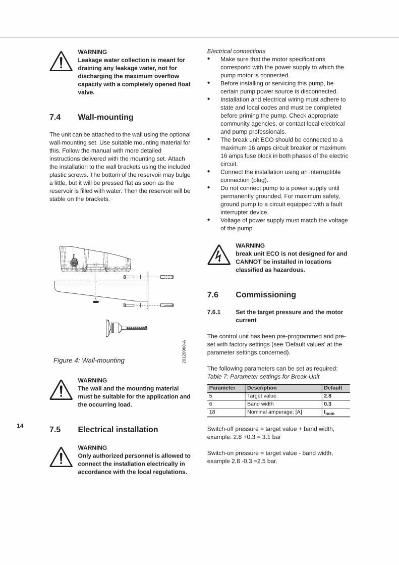
7.4 Wall-mounting
The unit can be attached to the wall using the optional wall-mounting set. Use suitable mounting material for this. Follow the manual with more detailed instructions delivered with the mounting set. Attach the installation to the wall brackets using the included plastic screws. The bottom of the reservoir may bulge a little, but it will be pressed flat as soon as the reservoir is filled with water. Then the reservoir will be stable on the brackets.
WARNINGThe wall and the mounting material must be suitable for the application and the occurring load.
7.5 Electrical installation
WARNINGOnly authorized personnel is allowed to connect the installation electrically in accordance with the local regulations.
Electrical connections• Make sure that the motor specifications
correspond with the power supply to which the pump motor is connected.
• Before installing or servicing this pump, be certain pump power source is disconnected.
• Installation and electrical wiring must adhere to state and local codes and must be completed before priming the pump. Check appropriate community agencies, or contact local electrical and pump professionals.
• The break unit ECO should be connected to a maximum 16 amps circuit breaker or maximum 16 amps fuse block in both phases of the electric circuit.
• Connect the installation using an interruptible connection (plug).
• Do not connect pump to a power supply until permanently grounded. For maximum safety, ground pump to a circuit equipped with a fault interrupter device.
• Voltage of power supply must match the voltage of the pump.
WARNINGbreak unit ECO is not designed for and CANNOT be installed in locations classified as hazardous.
7.6 Commissioning
7.6.1 Set the target pressure and the motor current
The control unit has been pre-programmed and pre-set with factory settings (see 'Default values' at the parameter settings concerned).
The following parameters can be set as required:Table 7: Parameter settings for Break-Unit
Switch-off pressure = target value + band width, example: 2.8 +0.3 = 3.1 bar
Switch-on pressure = target value - band width, example 2.8 -0.3 =2.5 bar.
Figure 4: Wall-mounting 2012
0960
-A
Parameter Description Default5 Target value 2.86 Band width 0.318 Nominal amperage: [A] Inom
15
7.6.2 Venting the pump at initial start-up
WARNINGInstallation must be disconnected from the main supply.
WARNINGSupply valve must be closed. Discharge valve must be closed.
Remove one of the vent plugs, which are located on either side of the discharge connection of the pump. Carefully open the supply valve and fill the tank. Wait 10 seconds after filling and then tighten the vent plug back into the pump. Open the discharge valve a little bit (so that the air in the pump can be drained as soon as the pump is started). Connect the ECO-Control to a suitable wall outlet (230V max 16A). The pump will pump some of the air out. Now close the discharge valve, the pump will build up the maximum pressure. By opening and closing the discharge valve several times the pump will be vented further. Finally, carefully open the discharge valve to pressurize the system. Make sure that the pressure doesn't fall below 1.0 bar low pressure security by pressurizing/filling the system.
ATTENTIONIf the pump does not reach more than 1.0 bar within the specified time, the low pressure warning will switch off the pump (alarm 18).
1 By pressing and holding the right arrow button, the pump can be started manually to get the pressure above the low pressure setting. Keep the discharge valve slightly open.
WARNINGDo not press and hold this button longer then 10 seconds, this may damage the pump.
If the pressure is not above 1.0 bar in 10 seconds, shut the discharge valve. Remove the ECO-Control from the wall outlet. Vent the pump 10 seconds, refit the vent plug and repeat the procedure from step 1.When after repeating these steps the pump is still not building up pressure with a slightly opened discharge valve, do as follows. Remove one of the vent plugs and place a bucket or tank at an angle under the vent opening. Start the pump by pressing and holding the right arrow, so a jet of water and air will come out of the vent opening. Release the button when the jet gets more powerful or the bucket is almost full. Replace the vent plug and continue from step 1.
7.6.3 Venting the pump installation after an interruption of the medium supply (installation without float switch)
If the reservoir is empty and the medium supply is not recovered, follow the instructions described in 7.6.2 Venting the pump at initial start-up
If the reservoir is refilled, but the ECO-Control shows the 18/20 alarm. Probably the pump has to be vented. Proceed as follows: Remove the ECO-Control from the AC outlet; Close the discharge valve; Check the level in the reservoir; Remove one of the vent plugs from the pump. Wait 10 seconds to increase the water level in the pump. Refit the vent plug. Open the discharge valve a little bit (so that the air in the pump can be drained as soon as the pump is started). Connect the ECO-Control to a suitable wall outlet (230V max 16A). The pump will start up and build up pressure. If the pressure is not above the low pressure setting within a few seconds, the pump stops and the alarm 18/20 appears again. Now follow the instructions in paragraph 7.6.2 to vent the pump from step 1. to further vent the pump.
16
8 Operation
8.1 General
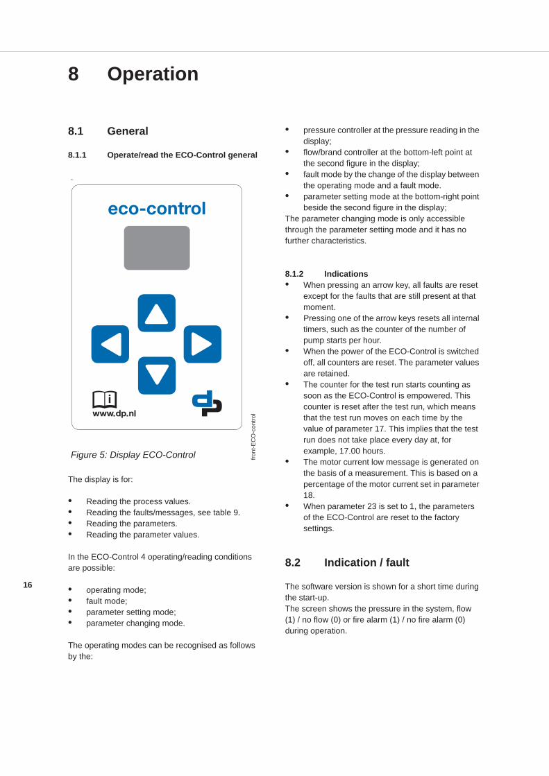
8.1.1 Operate/read the ECO-Control general
The display is for:
• Reading the process values.• Reading the faults/messages, see table 9.• Reading the parameters.• Reading the parameter values.
In the ECO-Control 4 operating/reading conditions are possible:
• operating mode;• fault mode;• parameter setting mode;• parameter changing mode.
The operating modes can be recognised as follows by the:
• pressure controller at the pressure reading in the display;
• flow/brand controller at the bottom-left point at the second figure in the display;
• fault mode by the change of the display between the operating mode and a fault mode.
• parameter setting mode at the bottom-right point beside the second figure in the display;
The parameter changing mode is only accessible through the parameter setting mode and it has no further characteristics.
8.1.2 Indications• When pressing an arrow key, all faults are reset
except for the faults that are still present at that moment.
• Pressing one of the arrow keys resets all internal timers, such as the counter of the number of pump starts per hour.
• When the power of the ECO-Control is switched off, all counters are reset. The parameter values are retained.
• The counter for the test run starts counting as soon as the ECO-Control is empowered. This counter is reset after the test run, which means that the test run moves on each time by the value of parameter 17. This implies that the test run does not take place every day at, for example, 17.00 hours.
• The motor current low message is generated on the basis of a measurement. This is based on a percentage of the motor current set in parameter 18.
• When parameter 23 is set to 1, the parameters of the ECO-Control are reset to the factory settings.
8.2 Indication / fault
The software version is shown for a short time during the start-up.The screen shows the pressure in the system, flow (1) / no flow (0) or fire alarm (1) / no fire alarm (0) during operation.
ID....
Figure 5: Display ECO-Control front
-EC
O-c
ontro
l
17
8.3 Operation
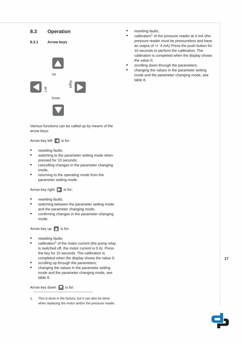
8.3.1 Arrow keys
Various functions can be called up by means of the arrow keys:
Arrow key left is for:
• resetting faults;• switching to the parameter setting mode when
pressed for 10 seconds;• cancelling changes in the parameter changing
mode;• returning to the operating mode from the
parameter setting mode.
Arrow key right is for:
• resetting faults;• switching between the parameter setting mode
and the parameter changing mode;• confirming changes in the parameter changing
mode.
Arrow key up is for:
• resetting faults;• calibration1 of the motor current (the pump relay
is switched off, the motor current is 0 A). Press the key for 10 seconds. The calibration is completed when the display shows the value 0;
• scrolling up through the parameters;• changing the values in the parameter setting
mode and the parameter changing mode, see table 8.
Arrow key down is for:
• resetting faults;• calibration1 of the pressure reader at 4 mA (the
pressure reader must be pressureless and have an output of +/- 4 mA) Press the push button for 10 seconds to perform the calibration. The calibration is completed when the display shows the value 0;
• scrolling down through the parameters;• changing the values in the parameter setting
mode and the parameter changing mode, see table 8.
Up
Left
Right
Down
1. This is done in the factory, but it can also be done when replacing the motor and/or the pressure reader.
18
9 Parameter settings
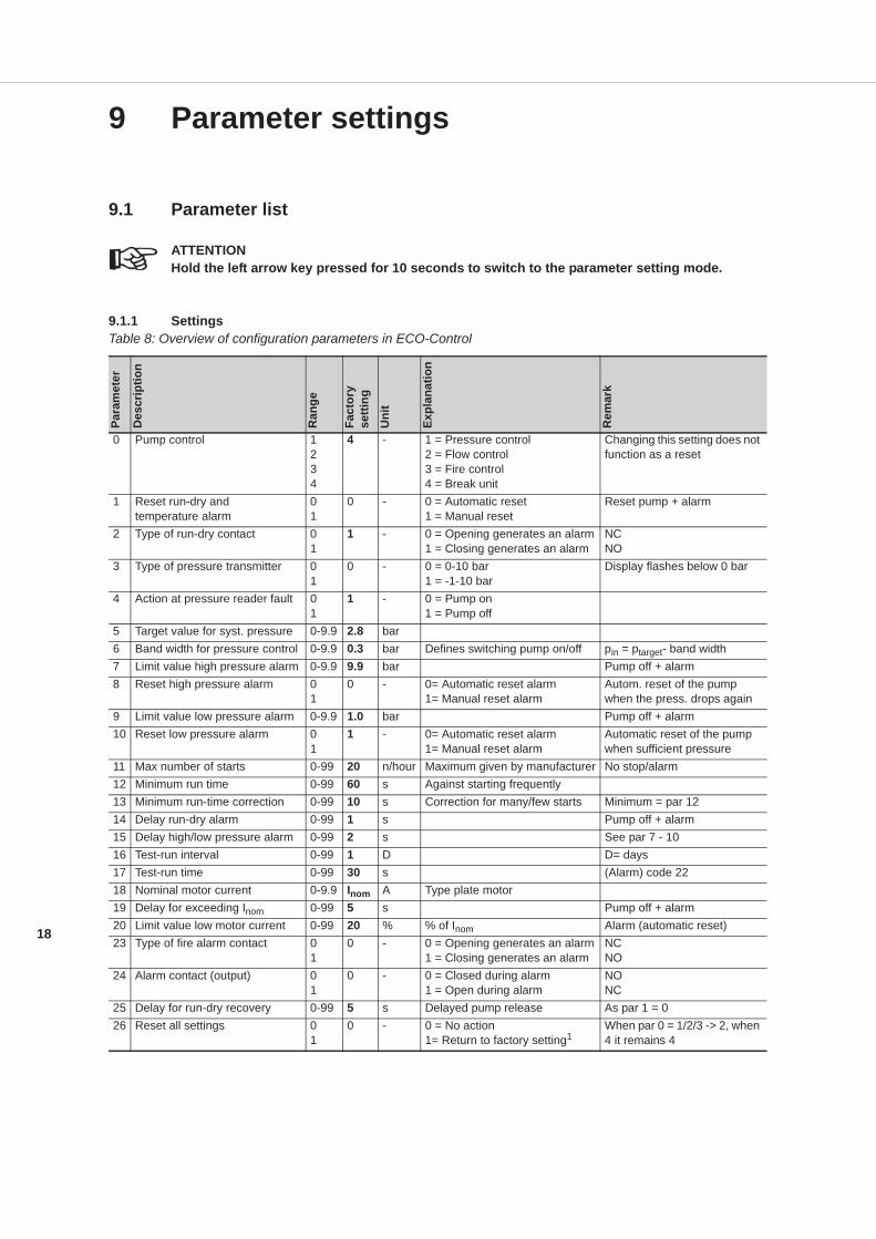
9.1 Parameter list
ATTENTIONHold the left arrow key pressed for 10 seconds to switch to the parameter setting mode.
9.1.1 SettingsTable 8: Overview of configuration parameters in ECO-Control
Para
met
er
Des
crip
tion
Ran
ge
Fact
ory
setti
ng
Uni
t
Expl
anat
ion
Rem
ark
0 Pump control 1234
4 - 1 = Pressure control2 = Flow control3 = Fire control4 = Break unit
Changing this setting does not function as a reset
1 Reset run-dry and temperature alarm
01
0 - 0 = Automatic reset1 = Manual reset
Reset pump + alarm
2 Type of run-dry contact 01
1 - 0 = Opening generates an alarm1 = Closing generates an alarm
NCNO
3 Type of pressure transmitter 01
0 - 0 = 0-10 bar1 = -1-10 bar
Display flashes below 0 bar
4 Action at pressure reader fault 01
1 - 0 = Pump on1 = Pump off
5 Target value for syst. pressure 0-9.9 2.8 bar6 Band width for pressure control 0-9.9 0.3 bar Defines switching pump on/off pin = ptarget- band width7 Limit value high pressure alarm 0-9.9 9.9 bar Pump off + alarm8 Reset high pressure alarm 0
10 - 0= Automatic reset alarm
1= Manual reset alarmAutom. reset of the pump when the press. drops again
9 Limit value low pressure alarm 0-9.9 1.0 bar Pump off + alarm10 Reset low pressure alarm 0
11 - 0= Automatic reset alarm
1= Manual reset alarmAutomatic reset of the pump when sufficient pressure
11 Max number of starts 0-99 20 n/hour Maximum given by manufacturer No stop/alarm12 Minimum run time 0-99 60 s Against starting frequently13 Minimum run-time correction 0-99 10 s Correction for many/few starts Minimum = par 1214 Delay run-dry alarm 0-99 1 s Pump off + alarm15 Delay high/low pressure alarm 0-99 2 s See par 7 - 1016 Test-run interval 0-99 1 D D= days17 Test-run time 0-99 30 s (Alarm) code 2218 Nominal motor current 0-9.9 Inom A Type plate motor19 Delay for exceeding Inom 0-99 5 s Pump off + alarm20 Limit value low motor current 0-99 20 % % of Inom Alarm (automatic reset)23 Type of fire alarm contact 0
10 - 0 = Opening generates an alarm
1 = Closing generates an alarmNCNO
24 Alarm contact (output) 01
0 - 0 = Closed during alarm1 = Open during alarm
NONC
25 Delay for run-dry recovery 0-99 5 s Delayed pump release As par 1 = 026 Reset all settings 0
10 - 0 = No action
1= Return to factory setting1When par 0 = 1/2/3 -> 2, when 4 it remains 4
19
1. Attention: in case of a reset all settings return to the factory settings as shown in the parameter list. After a reset, set thecorrect target value (par 5) and the nominal motor current (par 18). Incorrect settings may result in improper or no func-tioning of the installation
20
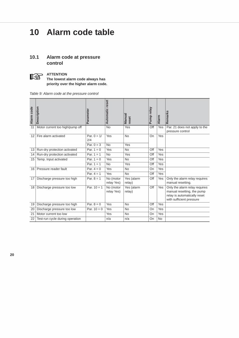
10 Alarm code table
10.1 Alarm code at pressure control
ATTENTIONThe lowest alarm code always has priority over the higher alarm code.
Table 9: Alarm code at the pressure control
Ala
rm c
ode
Des
crip
tion
Para
met
er
Aut
omat
ic re
set
Man
ual
rese
t
Pum
p re
lay
Ala
rm
Rem
arks
11 Motor current too high/pump off No Yes Off Yes Par. 21 does not apply to the pressure control
12 Fire alarm activated Par. 0 = 1/2/4
Yes No On Yes
Par. 0 = 3 No Yes13 Run-dry protection activated Par. 1 = 0 Yes No Off Yes14 Run-dry protection activated Par. 1 = 1 No Yes Off Yes15 Temp. Input activated Par. 1 = 0 Yes No Off Yes
Par. 1 = 1 No Yes Off Yes16 Pressure reader fault Par. 4 = 0 Yes No On Yes
Par. 4 = 1 Yes No Off Yes17 Discharge pressure too high Par. 8 = 1 No (motor
relay Yes)Yes (alarmrelay)
Off Yes Only the alarm relay requires manual resetting.
18 Discharge pressure too low Par. 10 = 1 No (motorrelay Yes)
Yes (alarm relay)
Off Yes Only the alarm relay requires manual resetting, the pump relay is automatically reset with sufficient pressure
19 Discharge pressure too high Par. 8 = 0 Yes No Off Yes20 Discharge pressure too low Par. 10 = 0 Yes No On Yes21 Motor current too low Yes No On Yes22 Test-run cycle during operation n/a n/a On No
21
11 Maintenance
11.1 Introduction
WARNINGObserve the general safety precautions for installation, maintenance and repair.
11.2 Cleaning instructions
WARNINGMake sure the installation has been switched off.
WARNINGThe pump may be hot.
The break unit ECO and the ECO-Control can be cleaned using a dry or slightly moist cloth.
22
12 Annexes
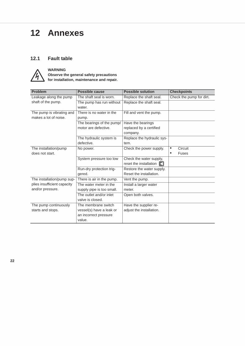
12.1 Fault table
WARNINGObserve the general safety precautions for installation, maintenance and repair.
Problem Possible cause Possible solution CheckpointsLeakage along the pumpshaft of the pump.
The shaft seal is worn. Replace the shaft seal. Check the pump for dirt.The pump has run without water.
Replace the shaft seal.
The pump is vibrating and makes a lot of noise.
There is no water in the pump.
Fill and vent the pump.
The bearings of the pump/motor are defective.
Have the bearings replaced by a certified company.
The hydraulic system is defective.
Replace the hydraulic sys-tem.
The installation/pump does not start.
No power. Check the power supply. • Circuit• Fuses
System pressure too low Check the water supply, reset the installation
Run-dry protection trig-gered.
Restore the water supply. Reset the installation.
The installation/pump sup-plies insufficient capacity and/or pressure.
There is air in the pump. Vent the pump.The water meter in the supply pipe is too small.
Install a larger water meter.
The outlet and/or inlet valve is closed.
Open both valves.
The pump continuously starts and stops.
The membrane switch vessel(s) have a leak or an incorrect pressure value.
Have the supplier re-adjust the installation.
23
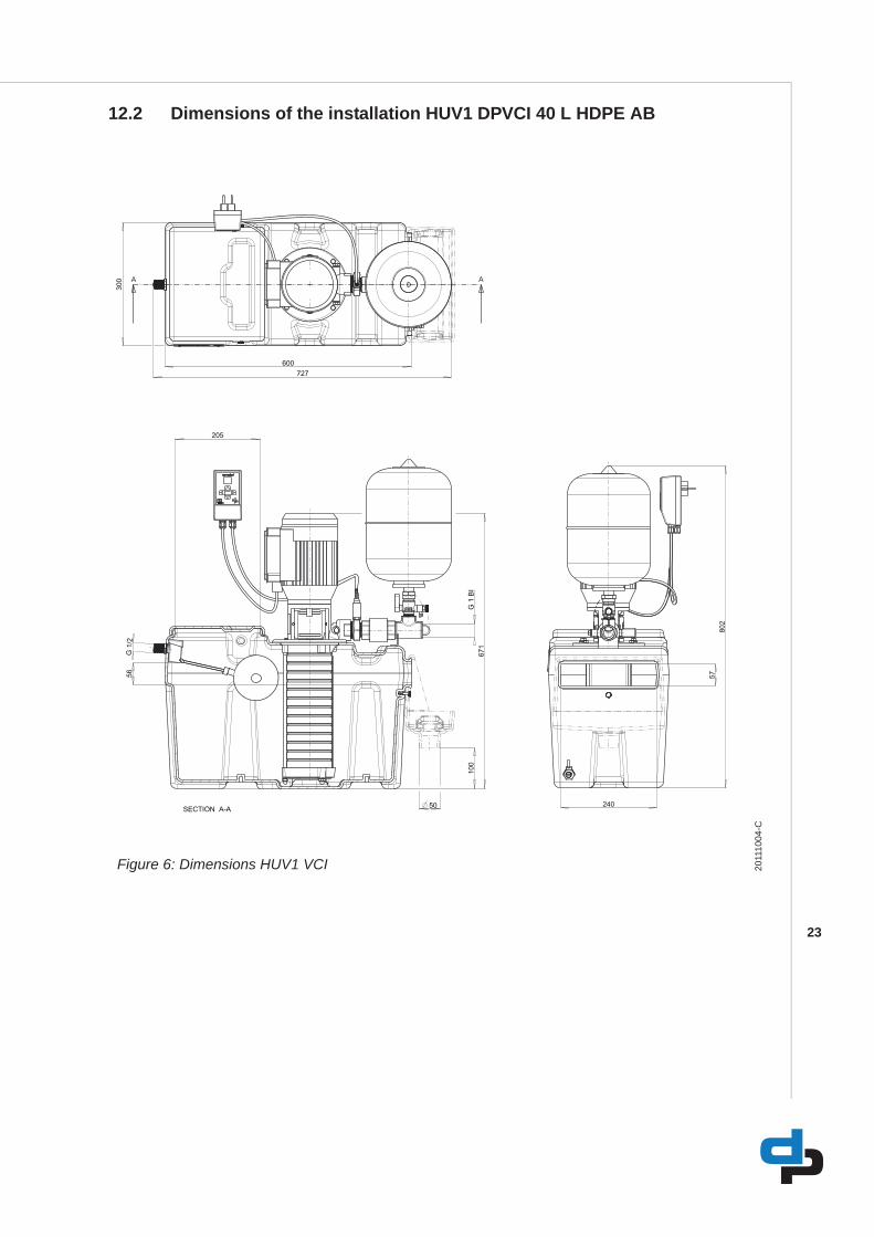
12.2 Dimensions of the installation HUV1 DPVCI 40 L HDPE AB
Figure 6: Dimensions HUV1 VCI 2011
1004
-C
A A
671
50
56
205
G 1
BI
G 1
/2
600
300
727
100
SECTION A-A240
802
57
24
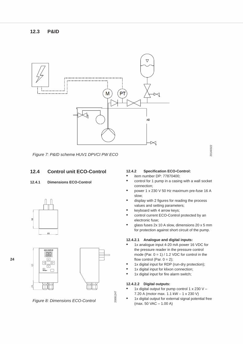
12.3 P&ID
12.4 Control unit ECO-Control
12.4.1 Dimensions ECO-Control
12.4.2 Specification ECO-Control:• item number DP: 77870400;• control for 1 pump in a casing with a wall socket
connection;• power 1 x 230 V 50 Hz maximum pre-fuse 16 A
slow;• display with 2 figures for reading the process
values and setting parameters;• keyboard with 4 arrow keys;• control current ECO-Control protected by an
electronic fuse;• glass fuses 2x 10 A slow, dimensions 20 x 5 mm
for protection against short circuit of the pump.
12.4.2.1 Analogue and digital inputs:• 1x analogue input 4-20 mA power 16 VDC for
the pressure reader in the pressure control mode (Par. 0 = 1) / 1.2 VDC for control in the flow control (Par. 0 = 2);
• 1x digital input for RDP (run-dry protection);• 1x digital input for klixon connection;• 1x digital input for fire alarm switch;
12.4.2.2 Digital outputs:• 1x digital output for pump control 1 x 230 V –
7.20 A (motor max. 1.1 kW – 1 x 230 V)• 1x digital output for external signal potential free
(max. 50 VAC – 1.00 A)
Figure 7: P&ID schem HUV1 DPVCI PW ECO 2014
0322
Figure 8: Dimensions ECO-Control 2009
1247
25
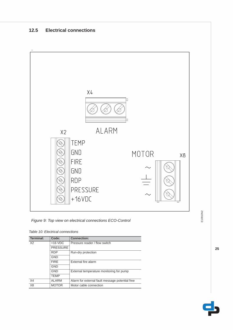
12.5 Electrical connections
Table 10: Electrical connections
4046
Figure 9: Top view on electrical connections ECO-Control E10
910N
2
Terminal: Code: Connection:X2 +16 VDC Pressure reader / flow switch
PRESSURERDP Run-dry protectionGNDFIRE External fire alarmGNDGND External temperature monitoring for pumpTEMP
X4 ALARM Alarm for external fault message potential freeX8 MOTOR Motor cable connection
26
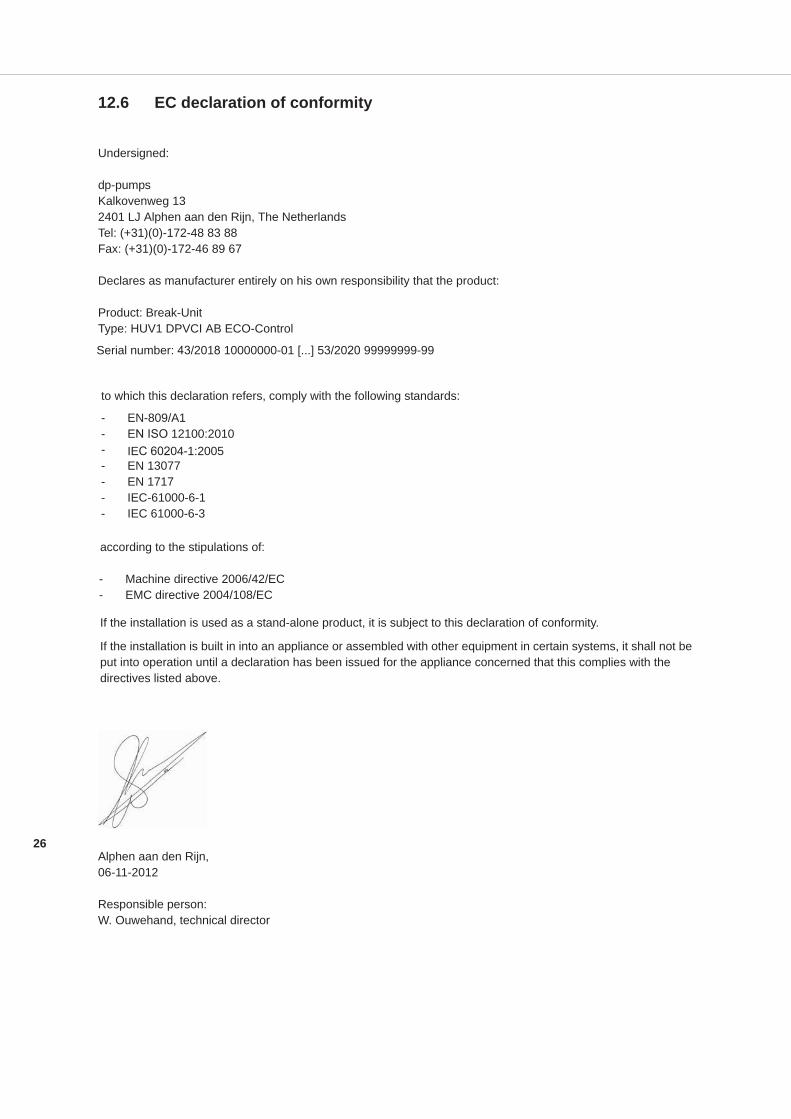
12.6 EC declaration of conformity
Undersigned:
dp-pumpsKalkovenweg 132401 LJ Alphen aan den Rijn, The NetherlandsTel: (+31)(0)-172-48 83 88Fax: (+31)(0)-172-46 89 67
Declares as manufacturer entirely on his own responsibility that the product:
Product: Break-UnitType: HUV1 DPVCI AB ECO-Control
to which this declaration refers, comply with the following standards:
- EN-809/A1- EN ISO 12100:2010- IEC 60204-1:2005- EN 13077- EN 1717- IEC-61000-6-1- IEC 61000-6-3
according to the stipulations of:
- Machine directive 2006/42/EC- EMC directive 2004/108/EC
If the installation is used as a stand-alone product, it is subject to this declaration of conformity.
If the installation is built in into an appliance or assembled with other equipment in certain systems, it shall not be put into operation until a declaration has been issued for the appliance concerned that this complies with the directives listed above.
Alphen aan den Rijn,06-11-2012
Responsible person:W. Ouwehand, technical director
Serial number: 43/2018 10000000-01 [...] 53/2020 99999999-99

27
dp pumps
dp pumpsP.O. Box 282400 AA Alphen aan den Rijn (NL)
t (+31-172) 48 83 88f (+31-172) 46 89 30
10/2018
BE00000534-D / EN
Original instructions
Can be changed without prior notice


