Embed Size (px)
Citation preview

Ocean Engineering 30 (2003) 1997–2017www.elsevier.com/locate/oceaneng
Hydroelasticity of a floating plate inmultidirectional waves1
X.J. Chena,∗, J. Juncher Jensenb, W.C. Cuia, S.X. Fua
a School of Naval Architecture and Ocean Engineering, Shanghai Jiao Tong University,Shanghai 200030, China
b Department of Mechanical Engineering, Technical University of Denmark, DK-2800 Kgs. Lyngby,Denmark
Received 4 February 2002; received in revised form 14 June 2002; accepted 4 July 2002
Abstract
The membrane forces are included in the hydroelastic analysis of a floating plate undergoinglarge vertical deflections in regular monochromatic multidirectional waves. The first-order ver-tical displacements induced by the linear wave exciting forces are calculated by the modeexpansion method in the frequency domain. The second-order vertical displacements inducedby the membrane forces are calculated by the von Karman plate theory. The results show thatthe membrane contribution both in terms of the axial stresses and the effect on the bendingstresses can be important. 2003 Published by Elsevier Science Ltd.
Keywords: VLFS; Hydroelasticity; Large deflection
1. Introduction
The importance of hydroelasticity of ocean structures has come into focus in recentyears. The procedures applied range from two-dimensional linear theory (Bishop andPrice, 1979), three-dimensional linear theory (Wu, 1984; Price and Wu, 1985), two-
∗ Corresponding author. Tel.:+86-21-62932056; fax:+86-21-62933160.E-mail address: [email protected] (X. Chen).
1 The project was jointly supported by the National Natural Science Foundation of China (Grant No.50039010), the Science and Technology Development Foundation of Shanghai Municipal Government(Grant No. 00XD14015), China Postdoctoral Science Foundation and the EUREKA project MONITUSE!2097.
0029-8018/03/$ - see front matter 2003 Published by Elsevier Science Ltd.doi:10.1016/S0029-8018(03)00020-9

1998 X.J. Chen et al. / Ocean Engineering 30 (2003) 1997–2017
Nomenclature
[A] generalised added hydrodynamic coefficients matrixAi wave amplitude of the ith incident waveB width of the plated draught of the plateD11, D12, D22 orthotropic plate stiffness[E] generalised wave exciting forces vectorE, Ex, Ey Young’s modulus of the materialF(t) Airy stress function for the membrane stresses in the plate{F} complex amplitude of {F(t)}Gxy shear modulus of the materialh thickness of the plateh∗ equivalent plate thickness{h(t)}mx1 generalised nonlinear force vector induced by the nonlinear
characteristics of the von Karman plate{h}mx1 complex amplitude of {h(t)}mx1
{H(t)}Nxl nonlinear force vector induced by the nonlinear characteristics ofthe von Karman plate
{H}Nx1 : complex amplitude of {H(t)}Nx1
Jx, Jxy, Jy flexural flexibilities of the orthotropic platek wave number[K] generalised stiffness matrixKii diagonal element of the generalised stiffness matrix [K]lx, ly half of the length and the width of the plateL length of the platem mode number of the plate[M] generalised mass matrixMii diagonal element of the generalised mass matrix [M]Mx, My, Mxy bending moments of the plateN node number of the plateNx, Ny membrane forcesNw total number of incident waves{p}mxl generalised principal coordinate vector{p(t)}E generalised principal coordinate vector induced by the fluid forces{p(t)}h generalised principal coordinate vector induced by the membrane
forcesQx, Qy shear forces in the plate[S] generalised restoring matrixTxy membrane forcest time variablenx, ny Poisson ratio coefficients of the materialVx, Vy effective shear forces in the plate

1999X.J. Chen et al. / Ocean Engineering 30 (2003) 1997–2017
{V(t)} right-hand side of Eq. (19){V} complex amplitude of {V(t)}w(x,y,x) vertical displacement of the platewi, wj, wr vertical displacement modes of the plate{w(t)}E vertical displacement vector induced by the fluid forces[W]Nxm mode matrix of the platebi wave angle of the ith incident wavew incident wave circular frequencywi natural frequency of the ith mode of the elastic responsel wave lengthr volume mass density of the fluidr̄ area mass density of the platef total wave potential of the fluid fieldfD diffraction wave potentialfw incident wave potentialfj radiation potential due to the jth mode of the elastic responsef scattering potential (summation of fD and fw
ei phase angel of the ith incident wave
dimensional nonlinear theory (Xia et al., 1998) to three-dimensional nonlinear theory(Chen et al., 2003) as well as different hybrid hydroelastic analysis methods (Takuji,1998; Hideyuki and Mayumi, 1998; Kashiwagi, 1998; Hamamoto et al., 1997; Herm-ans, 1998). They have been applied to design and research works, also to analysisof very large floating structures (VLFS) (e.g. Ertekin and Riggs, 1991, 1999; Watan-abe, 1996; Kashiwagi et al., 1998).
A pontoon type VLFS is often simplified as a thin plate (Ohkusu and Namba,1996, 1998; Ertekin and Kim, 1999). Usually, the incident waves are taken to beunidirectional, and often the published results show maximum vertical displacementslarger than 1 metre. These deflections are of the same order of magnitude as theplate thickness and if the incident waves come from different directions, the wave-lengths are so small that the membrane forces in the plate should be considered.
In this paper, a numerical method for analysing the hydroelastic characteristics ofa VLFS in multidirectional monochromatic incident waves taking into account theeffect of the membrane forces is developed. The mode expansion method in thefrequency domain is used and the membrane forces are obtained by use of a vonKarman plate theory (see e.g. Brush and Almroth, 1975).
2. Mathematical expressions
A floating plate subjected to monochromatic linear wave forces and undergoingsmall deflections can be modelled by the following hydroelastic equation (Seto andOchi, 1998):

2000 X.J. Chen et al. / Ocean Engineering 30 (2003) 1997–2017
[�w2([M] � [A]) � ([K] � [S])]m×m{p}m×1·eiwt � {E}m×1·eiwt , (1)
where w is the incident wave circular frequency, m is the mode number of the plate.The unknown is the generalised principal coordinate vector {p}mxl. Furthermore,[M], [A], [S] and [E] are the generalised mass matrix, the generalised added hydro-dynamic coefficient matrix, the generalised restoring matrix and the generalised waveexciting force vector. Their elements can be expressed as
Mij � �ly
�ly
�lx
�lx
r̄wiwjdxdy , (2)
Sij � rg�ly
�ly
�lx
�lx
wiwjdxdy , (3)
Aij � r�ly
�ly
�lx
�lx
wi[fj]z=�ddxdy , (4)
Ei � �iwr�ly
�ly
�lx
�lx
wi[f�]z=�ddxdy (5)
respectively. Here, r̄ and r correspond to the area mass density of the plate and thevolume mass density of the fluid, respectively. The half of the length and the widthof the plate is lx = L /2 and ly = B /2 and the vertical modes of the plate are denotedwi = wi(x,y). If the structural finite element or finite difference model of the VLFShas N degrees of freedom, the dry normal mode matrix can be expressed as
[W]N×m � �w1,1 w1,2 % w1,m
w2,1 w2,2 % w2,m
� � � �
wN,1 wN,2 % wN,m
�N×m
, (6)
This normal mode matrix can be calculated by any linear structural analysis codeor, in case of a uniform plate, by analytical use of the orthotropic plate stiffnessesD11, D12 and D22. The diagonal elements of the generalised stiffness matrix [K] canbe expressed as
Kii � w2i Mii , (7)
where wi is the natural frequency of the ith mode of the elastic response. In Eq. (4),fj is the radiation potential due to the jth mode of the elastic response wj and evalu-ated at the draught z = �d of the plate. The scattering potential in Eq. (5) can beexpressed as
f� � fD � fw, (8)
where fD is the diffraction potential for the restrained body caused by the incident

2001X.J. Chen et al. / Ocean Engineering 30 (2003) 1997–2017
wave fw. As regular wave components with the same frequency w are assumed, thetotal flow field potential can be written as
f(x,y,z)eiwt � [�mj � 1
pjfj(x,y,z) � fD(x,y,z) � fw(x,y,z)]eiwt , (9)
where f must satisfy the linear equations
�2f � 0, in the fluid domain �, (10)
� ∂∂z
�w2
g �f � 0, on the free surface SF(z � 0), (11)
∂∂nf � 0, on the seabed SB, (12)
∂∂nf �
∂w∂n
, on the VLFS SH. (13)
Here w(x,y,z) is the vertical displacement of the plate, which can be expressed as
w(x,y,z)eiwt � �mr � 1
prwr(x,y,z)eiwt , (14)
where wr(x,y,z) is the rth vertical displacement mode.Finally, the velocity potential (f�fw)eiwt must satisfy the so-called radiation con-
dition, which allows only outgoing waves at infinity, i.e.
� ∂∂R
�1
2R� ik0�(f�fw) � 0, R � (x2 � y2)1/2→� . (15)
By the field Eq. (10) and the boundary conditions (11–13) and (15), the wave poten-tial components fj and fD can be calculated using the Green function method(Newman, 1986).
According to the von Karman plate equations (see e.g. Brush and Almroth, 1975)and Eq. (1), the hydroelastic equations for a floating plate with large deflections canbe written
[([M] � [A])]m×m{p̈(t)}m×1 � [([K] � [S])]{p(t)}m×1 � {E}m×1eiwt (16)
� {h(t)}m×1 ,
where {h(t)}mx1 is the generalised nonlinear force vector induced by the nonlinearcharacteristics of the large deflections of the plate. This term can be expressed as
{h(t)}m×1 � [W]Tm×N{H(t)}N×1 . (17)
Here, {H(t)}Nx1 is the nonlinear force vector induced by the nonlinear characteristicsof the large deflections and the membrane forces:
{H(t)}N×1 � �∂2F(t)∂y2
∂2w(t)∂x2 �
∂2F(t)∂x2
∂2w(t)∂y2 �2
∂2F(t)∂x∂y
∂2w(t)∂x∂y N×1
, (18)

2002 X.J. Chen et al. / Ocean Engineering 30 (2003) 1997–2017
where F(t) is the Airy stress function for the membrane stresses in the plate,satisfying the compatibility equation
Jx
∂4F(t)∂x4 � 2Jxy
∂4F(t)∂x2∂y2 � Jy
∂4F(t)∂y4 � �∂2w(t)
∂x∂y �2
�∂2w(t)
∂x2
∂2w(t)∂y2 , (19)
with the boundary conditions
∂2F(t)∂x∂y
� 0,∂2F(t)∂y2 � 0, at x � �
L2
, (20)
∂2F(t)∂x∂y
� 0,∂2F(t)∂x2 � 0, at y � �
B2
.
The constants Jx, Jxy and Jy in Eq. (19) are the membrane flexibilities of the ortho-tropic plate. They are given as follows:
Jx �1
Eyh∗, Jy �1
Exh∗, 2Jxy �1
Gxyh∗�nxJy�nyJx. (21)
Here, h ∗ is the equivalent plate thickness, Ex and Ey are equivalent Young’s modulesof the material, Gxy is the equivalent shear modulus, and nx, ny are Poisson ratio coef-ficients.
3. The numerical approach
The incident wave system have the same wave frequency w. Hence, provided thecontribution from the membrane forces is small compare to that of the wave excitingforces, we can approximate the solution of Eq. (16) as
{p(t)}m×1 � {p(t)}E � {p(t)}h , (22)
where {p(t)}E is the linear solution obtained from Eq. (1). The first-order verticaldisplacement induced by the fluid forces becomes
{w(t)}E � [W]{p(t)}E � [W]{p}Eeiwt � {w}Eeiwt . (23)
Substitution of Eq. (23) into the right-hand side of Eq. (19) yields
{V(t)} � ��∂2w(t)∂x∂y �2
�∂2w(t)
∂x2
∂2w(t)∂y2
N×1
� {V}ei(2wt) , (24)
where
{V} � �� ∂2w∂x∂y�2
�∂2w∂x2
∂2w∂y2
N×1
. (25)

2003X.J. Chen et al. / Ocean Engineering 30 (2003) 1997–2017
The solution of Eq. (19) subjected to the boundary conditions (20) can beexpressed as
{F(t)} � {F}ei(2wt) , (26)
where {F} satisfies
Jx
∂4F∂x4 � 2Jxy
∂4F∂x2∂y2 � Jy
∂4F∂y4 � V , (27)
with the homogeneous boundary conditions derived from Eq. (20).From the Airy stress function {F}, we can calculate the first-order membrane
forces
Nx �∂2F∂y2, Ny �
∂2F∂x2, Txy � �
∂2F∂x∂y
. (28)
Substitution of Eqs. (23) and (26) into (18) yields
{H(t)} � {H}ei(3wt) (29)
where
{H}N×1 � �∂2F∂y2
∂2w∂x2 �
∂2F∂x2
∂2w∂y2 �2
∂2F∂x∂y
∂2w∂x∂yN×1
(30)
and hence Eq. (17) can be written
{h(t)}m×1 � [W]Tm×N{H(t)}N×1 � [W]T
m×N{H}N×1ei(3wt) � {h}m×1ei(3wt) . (31)
With this expression of {h(t)}, the equation for the second-order term of Eq. (22)becomes
[�(3w)2([M] � [A(3w)]) � ([K] � [S])]{p(1)}h·ei(3wt) � {h}ei(3wt) (32)
where [A(3w)] is the added hydrodynamic coefficients at the frequency 3w.Hence, the total principal coordinates (only considering the leading order of the
membrane forces) can be expressed as
{p(t)} � {p}Eeiwt � {p(1)}hei(3wt) . (33)
From Eq. (33) it is seen that terms of frequency 2w do not appear, because second-order wave forces are not included.
From the total displacement of the plate
{w(t)} � [W]{p(t)} , (34)
all other parameters for the fluid and the structure can be calculated. For example,the bending moments Mx, My, Mxy, the shear forces Qx, Qy and the effective shearforces Vx, Vy in the plate become
Mx � �D11�∂2w∂x2 � ny
∂2w∂y2�,

2004 X.J. Chen et al. / Ocean Engineering 30 (2003) 1997–2017
My � �D22�∂2w∂y2 � nx
∂2w∂x2�, (35)
Mxy � �2D12� ∂2w∂x∂y�,
Qx � �∂∂x�D11
∂2w∂x2 � D12
∂2w∂y2�,
Qy � �∂∂y�D22
∂2w∂y2 � D12
∂2w∂x2�, (36)
Vx � Qx �∂Mxy
∂y, Vy � Qy �
∂Mxy
∂x.
4. Numerical solution
The incident wave field acting on a VLFS would not in general be a uniformwave. Here, the waves acting on the VLFS will be assumed to consist of a fewmonochromatic regular deep water waves coming from different directions. The inci-dent wave potential in Eq. (9) is hence written as
fw(t) � �Nw
i � 1
gAi
wekzsin[k(xcosbi � ysinbi)�wt � ei] , (37)
where Ai, w, k = w 2 /g, bi and ei are the wave amplitude, the wave circular frequency,the wave number, the heading angle and the phase angle of the ith incident wave.Two different cases are considered: w = 0.64 rad/s (l = L / 2) and w = 1.11 rad/s(l = L / 6). Nw = 8 is the total number of the incident waves in both cases, and theused parameters are given in Table 1. Deep water wave theory is assumed in Eq.(37) although the modification for finite water depth is straightforward, see e.g. Ham-amoto et al. (1997).
The particulars of the VLFS mentioned by Sim and Choi (1998) is chosen as theexample. The data are shown in Table 2. The VLFS is a scaled model of the Mega-Float constructed and developed in Yokosuka (Yago and Endo, 1996) and to be usedclose to land in sheltered waters. In Sim and Choi (1998) the bending rigidity is
Table 1Components of the multidirectional incident waves
i 1 2 3 4 5 6 7 8Ai(m) 0.5 0.5 0.5 0.5 0.5 0.5 0.5 0.5bi(°) 45 –45 0 30 –60 90 75.0 –120.0ei(rad) 0 p/4 p/2 3p/4 p 5p/4 3p/2 7p/4

2005X.J. Chen et al. / Ocean Engineering 30 (2003) 1997–2017
Table 2Particulars of the plate
Length L 300.0 mWidth B 60.0 mDepth h 2.0 mEquivalent plate thickness h∗ 0.766 mDraught d 0.5 mYoung’s modulus E 1.19 × 10¹⁰ N/m2
Poisson’s ratio n 0.13Mass density rb 256.25 kg/m3
given to be EI = 4.77 1011 Nm2. If an isotropic plate of the thickness h = 2.0m is assumed, this bending rigidity corresponds to an equivalent Young’s modulusE = 1.19 x 10¹⁰ N/m2. As no information of the structural layout of this VLFS isgiven in the open literature, the structure is assumed to be made of steel and com-posed of a set of crossing webs spaced both longitudinally and transversely by 3 m.The equivalent thickness of the webs is taken to be 12.9 mm whereas the equivalentthickness of the bottom and top plates is taken as 17.5 mm. The mass of localstiffening and non-structural items is accounted for by increasing the mass of thesteel structure by 25% and hence the draught of the VLFS becomes 0.5 m. Theresulting membrane stiffness Eh ∗ corresponds to an equivalent plate thickness ofapproximately 0.766 m. It should be stressed that shear deformations are neglectedeven if they might be just as important as the membrane effects for the presentstructure. A total number m = 22 (three rigid modes and 19 elastic modes) of modesis chosen. Some of the mode shapes and the corresponding natural frequencies aregiven in Appendix A.
Figure 1 shows the multidirectional incident wave elevation at time t = 2 s for
Fig. 1. Incident wave elevation z [m] (t = 2 s).
2006 X.J. Chen et al. / Ocean Engineering 30 (2003) 1997–2017
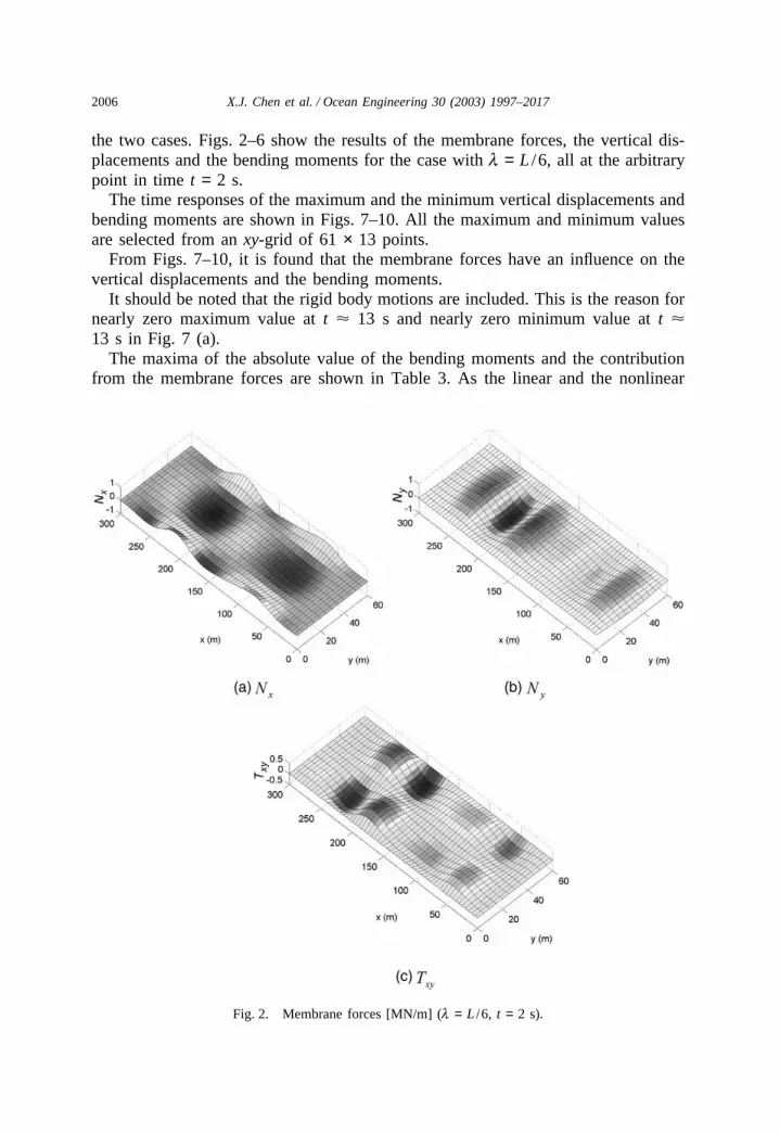
the two cases. Figs. 2–6 show the results of the membrane forces, the vertical dis-placements and the bending moments for the case with l = L /6, all at the arbitrarypoint in time t = 2 s.
The time responses of the maximum and the minimum vertical displacements andbending moments are shown in Figs. 7–10. All the maximum and minimum valuesare selected from an xy-grid of 61 × 13 points.
From Figs. 7–10, it is found that the membrane forces have an influence on thevertical displacements and the bending moments.
It should be noted that the rigid body motions are included. This is the reason fornearly zero maximum value at t 13 s and nearly zero minimum value at t 13 s in Fig. 7 (a).
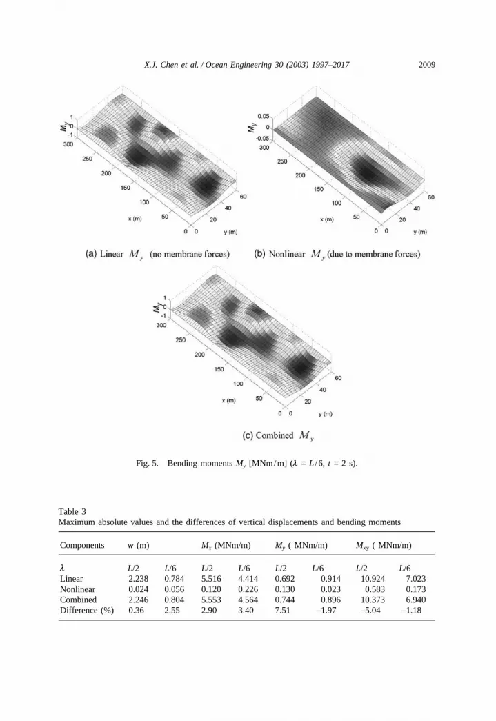
The maxima of the absolute value of the bending moments and the contributionfrom the membrane forces are shown in Table 3. As the linear and the nonlinear
Fig. 2. Membrane forces [MN/m] (l = L /6, t = 2 s).

2007X.J. Chen et al. / Ocean Engineering 30 (2003) 1997–2017
Fig. 3. Vertical displacements w [m] (l = L /6, t = 2 s).
terms do not occur in the same position and at the same time step, the combinedvalue is lower than the algebraic sum of the two.
From the maximum of the bending moments and the membrane forces, themaximum stresses can be determined using the assumed structural layout. For theshort wave length l = L /6, the maximum stresses induced by the maximum linearbending moment Mx = 4.414 MNm/m and the maximum nonlinear bending momentMx = 0.226 MNm/m are 117 MN/m2 and 6 MN/m2, respectively, and the maximumstress induced by the maximum membrane force Nx =1.313 MN/m along the x-axisdirection is 30 MN/m2. The main effect of the membrane forces is thereby throughthe axial force as it accounts for about 80% of the non-linear (membrane) effects.On the other hand the magnitude of the membrane induced stresses are about 30%of the linear bending stresses and therefore important to include in the design process.

2008 X.J. Chen et al. / Ocean Engineering 30 (2003) 1997–2017
Fig. 4. Bending moments Mx [MNm/m] (l = L /6, t = 2 s).
5. Conclusion
An analysis procedure for a VLFS subjected to monochromatic wave loads hasbeen presented. The procedure accounts for the membrane effect in the calculationof the vertical displacements and bending moments. It is shown for a realistic casethat the membrane forces can increase the longitudinal stresses by 30% and henceshould be considered in a design procedure.
The wave loads are treated by a linear procedure and further studies should beperformed to assess the importance of nonlinear wave load components. Also sheardeformations ought to be considered in future work.
2009X.J. Chen et al. / Ocean Engineering 30 (2003) 1997–2017
Fig. 5. Bending moments My [MNm/m] (l = L /6, t = 2 s).
Table 3Maximum absolute values and the differences of vertical displacements and bending moments
Components w (m) Mx (MNm/m) My ( MNm/m) Mxy ( MNm/m)
l L/2 L/6 L/2 L/6 L/2 L/6 L/2 L/6Linear 2.238 0.784 5.516 4.414 0.692 0.914 10.924 7.023Nonlinear 0.024 0.056 0.120 0.226 0.130 0.023 0.583 0.173Combined 2.246 0.804 5.553 4.564 0.744 0.896 10.373 6.940Difference (%) 0.36 2.55 2.90 3.40 7.51 –1.97 –5.04 –1.18

2010 X.J. Chen et al. / Ocean Engineering 30 (2003) 1997–2017
Fig. 6. Bending moments Mxy [MNm/m] (l = L /6, t = 2 s).

2011X.J. Chen et al. / Ocean Engineering 30 (2003) 1997–2017
Fig. 7. Time responses of the maximum and the minimum of the vertical displacements.

2012 X.J. Chen et al. / Ocean Engineering 30 (2003) 1997–2017
Fig. 8. Time responses of the maximum and the minimum of the bending moments Mx.

2013X.J. Chen et al. / Ocean Engineering 30 (2003) 1997–2017
Fig. 9. Time responses of the maximum and the minimum of the bending moments My.

2014 X.J. Chen et al. / Ocean Engineering 30 (2003) 1997–2017
Fig. 10. Time responses of the maximum and the minimum of the bending moments Mxy.
Acknowledgements
The authors would like to express their sincere gratitude to Professor P.T. Pedersenfor his valuable discussions and contributions.
Appendix A
For an isotropic plate with elastic constructs as shown in Table 2, the first eightdry elastic mode shapes and the natural frequencies are illustrated in the followingFigs. A1–8.

2015X.J. Chen et al. / Ocean Engineering 30 (2003) 1997–2017
Fig. A1 The first-order elastic mode shape (natural frequency w1=0.156 Hz).
Fig. A2 The second-order elastic mode shape (natural frequency w2=0.430 Hz).
Fig. A3 The third-order elastic mode shape (natural frequency w3=0.507 Hz).
Fig. A4 The fourth-order elastic mode shape (natural frequency w4=0. 845 Hz).
Fig. A5 The fifth-order elastic mode shape (natural frequency w5=1.036 Hz).

2016 X.J. Chen et al. / Ocean Engineering 30 (2003) 1997–2017
Fig. A6 The sixth-order elastic mode shape (natural frequency w6=1.398 Hz).
Fig. A7 The seventh-order elastic mode shape (natural frequency w7=1.604 Hz).
Fig. A8 The eighth-order elastic mode shape (natural frequency w8=2.090 Hz).
References
Bishop, R.E.D., Price, W.G., 1979. Hydroelasticity of Ships. Cambridge University Press, UK.Brush, D.O., Almroth, B.O., 1975. Buckling of Bars. Plates and Shells, Kingsport Press, USA.Chen, X.J., Wu, Y.S., Cui, W.C., Tang, X.F., 2003. Nonlinear hydroelastic analysis of a moored floating
body. Ocean Engineering 30 (8), 965–1003.Ertekin, R.C., Kim, J.W., 1999. Hydroelastic response of floating mat-type structure in oblique, shallow-
water waves. J. of Ship Research 43 (4), 241–254.Ertekin, R.C., Riggs, H.R., 1991. Proceedings of the First International Workshop on Very Large Floating
Structures-VLFS’91, April 24–26, Honolulu, HI.Ertekin, R.C., Riggs, H.R., 1999. Proceedings of the Third International Workshop on Very Large Floating
Structures-VLFS’99, Honolulu, HI.Hermans, A.J., 1998. A boundary element method to describe the excitation of waves in a very large
floating flexible platform. Hydroelasticity in Marine Technology, 69–76.Hamamoto, T., Suzuki, A., Fujita, K., 1997. Hybrid dynamic analysis of large tension leg floating struc-
tures using plate elements, 7th ISOPE, Vol.1, pp. 285–292.Kashiwagi, M., 1998. A B-Spline Galerkin scheme for calculating the hydroelastic response of a very
large floating structure in waves. Journal of Marine Science and Technology R (1), 37–49.Kashiwagi, M., Koterayama, W., Ohkusu, M., 1998. Hydroelasticity in Marine Technology (Proceedings

2017X.J. Chen et al. / Ocean Engineering 30 (2003) 1997–2017
of the Second International Conference on Hydroelasticity in Marine Technology, Fukuoka, Japan),Yomei Printing Cooperative Society, Fukuoka, Japan.
Newman, J.N., 1986. Marine Hydrodynamics. MIT(Massachusetts Institute of Technology) Press.Ohkusu, M., Namba,Y., 1996. Analysis of hydroelastic behaviour of a large floating platform of thin
plate configuration in waves. VLFS’96, pp. 143–148.Ohkusu, M., Namba, Y., 1998. Hydroelastic behavior of floating artificial islands, JSNA, Vol.183.Price, W.G., Wu, Y.S., 1985. Structural responses of a SWATH of multi-hulled vessel travelling in waves,
Int. Conf. on SWATH Ships and Advanced Multi-hulled Vessels, RINA, London.Seto, H., Ochi, M., 1998. A hybrid element approach to hydroelastic behavior of a very large floating
structure in regular wave, Hydroelasticity in Marine Technology (Proceedings of the Second Inter-national Conference on Hydroelasticity in Marine Technology, Fukuoka, Japan), pp. 185–193.
Sim, I.H., Choi, H.S., 1998. An analysis of the hydroelastic behavior of large floating structures in obliquewaves. Hydroelasticity in Marine Technology (Proceedings of the Second International Conferenceon Hydroelasticity in Marine Technology, Fukuoka, Japan), pp. 195–199.
Takuji H., 1998, 3D hydroelastic analysis of module linked large floating structures using quadratic BE-FE hybrid model, Hydroelasticity in Marine Technology (Proceedings of the Second InternationalConference on Hydroelasticity in Marine Technology, Fukuoka, Japan), pp. 37–36.
Watanabe, Y., 1996. Proceedings of the Second International Workshop on Very Large Floating Struc-tures-VLFS’96, November 25–28, 1996, Hayama, Japan.
Wu, Y.S., 1984. Hydroelasticity of floating bodies, Ph.D. thesis, Brunel University, UK.Xia, J.Z., Wang, Z.H., Jensen, J.J., 1998. Non-linear wave loads and ship responses by a time-domain
strip theory. Marine Structure 11 (3), 101–123.Yago, K., Endo, H., 1996. Model experiment and numerical calculation of the hydroelastic behavior of
matlike VLFS, Proceedings of the International Workshop on Very Large Floating Structures, Japan.


