Embed Size (px)
Citation preview
I Hk..zf‘ZJ”K------.-.---:--.-e
.
NATIONAL
.
f. Jt
——.
#..
TECHNICAL NQ’1’ES
ADVISORY CQ@TTEE FOR
NO. 264
:.’
AERONAUT ~CLS
TESTS OF THE N.P.L. AIRSHIP MODELS IN
THE VARIABLE DXNSITY WIND TUNNEL
By George J. HigginsLangley Memorial Aeronautical
WashingtonSeptember, 1927
.
Laboratory
‘“’.-
https://ntrs.nasa.gov/search.jsp?R=19930087637 2020-06-17T09:19:12+00:00Z

it“
NATIONAL ADVISORY COMMITI’EE FOR AERONAUTICS.
TECHNICAL NOTE NO. 264.
TESTS Ol?THE N.P.L. AIRSHIP MODELS IN
THE VARIABLE DENSITY WIND TUNNEL.
By George J. Higgins. .
‘Summary
Tests have been conducted in the variable density wind tun-i
nel of the National Advisory Committee for Aeronautics, on two
airship models, known as the lil?.P.L.Standardization Models,
t Long and Short.f’ The resistance or shape coefficients were de-
termined for each model through a range of Re~lolds Numbers from*
110,000 to 5,0.00,000. Comparison is made with previous tests
on these models and other airshipmodels.
Introduction
During the years of 1922 and 1923, comparative tests l.vere
made on two NoPoL. airship models in-six American atmospheric
wind tuxmels to determine their resistance with particular ref-
erence to scale effect. These tests were made for the purpose*
of determining some idea of the “standardization of wind tunnels.”
The models used were developed and furnished by the British Aero-● ..
nautical Research Committee.

( N.A. C.A. Technical Note No. 264 2
a It WaS
and, as the
made at the
desired that further tests on these models be made
models had been returned to England, replicas were
}Yashington Navy. Yard by the wind tunnel division of
the Bureau of Construction and Repair. It was of particular im-
portance that a greater “scale” or Reynolds Number be reached;
simplicity in the method of suppo_rtfor the models was also rec-
ommended for the further tests.
The Navy replicas of the N.P.L. airship models were there- .
fore forwarded to the Langley Memorial Aeronautical Laboratory
for testing in the variable density wind tunnel where a Reynolds
Num”oer fifteen times that of the original tests could be obtained...
{ The actual tests in the variable density tunnel were not per-
formed. until June, 1927.8
These consisted of determining the resistance at the angle
of zero pitch for both models through a range of Reynolds Numbers
from 110,000 to 5,000,000.
Apparatus and Method of Test
The airship models used in these tests were cast of alumi-
num and turned in a lathe to specified ordinates measured on
the original N.P.L. models. The model, designated as IIlong,l!is
a 1/225 size r~lica of the IIH.M,A.-R 33.11 The second model,
designated as ‘!short,“ is similar to the first in the shape of●
●
the nose and tail, but’1.5 diameters or 6.3 inches shorter in
● the cylindrical mid-portion. The actual dimensions of the two

N.A. C.A. Techical Note No. 264F
models are qiven in Table I. Here, also, isu
determined by Simpsonts m~e and used in the.
tographs,of the models are Given in Figure 1.
3
given the volume as
computations. Pho-
The models were mounted in the test section of the variable
density wind tunnel (Reference 1) in the manner shown in Fig-
ure 2. The mspension consisted of streamlined wires .025 inch
by.094 inch in cross section. Two wires were screwed into the
model 4 inches aft of the nose 90° apart and making 45° to the
vertical. The outer ends of these wires were attached through
small knife edges to the tunnel walls. Streamlined fairings
covered the outer 16.inches and protected that portion of the
suspension from the air stream. A single wire at the tail fas--4-
tened by a pivot to a short 2-inch sting supported the rear of1
the models in a similar manner as the nose. A round wire, 0.043
inch in diameter, attached to a plug scyewed ig at the nose,
transmitted the drag forces through a bell crank to the auxili-
ary drag balance (for use where resistance only is to be meas-
ured (Figure 3)). A similar round wire attached to the tail
sting”led through a bell crank to a counterweight. This served
the purpose of keeping the systm taut and maintaining a slight
initial load on the balance. The lengths of these horizontal
wires were adjusted by small turnbuckles at the ends away from
the model 80 the model might assume its own position,, thus elim-
. inating any error due to a component of its weight exerting a
force on the balance.●

N.A.COAC Technical Note No. 264 4
Each model was teBted at a velocity of about 50 miles an
hour and at densitie~ ranging from that equivalent to 1/2 atmos–
phere to 20 atmospheres pressure, absolute. Using the (volume)l’=
as a characteristic length, the range in Reynolds Number cov-
ered was from 110,000 to 5,000,000. Readings of the resistance
were obtained at six densities.
Results and Discussion
The results of the tests on these two airship models are
given in Table II, and are plotted in Figures 4 and 5. Resist-
ance or
against.,,
.a
shape coefficients have been computed and plotted
Reynolds Number, where.—1~,
D c~ q (vol.)2’3,
= ,-..
& (VO1.)1’3R.N. =
D = drag
q = dynamic pressure, ~ P V2
R.N. = Reynolds Nimber
vol. = volume of airship model
P = density of air
v= velocity of air
v = viscosity of air
Figure 4 shows the values of Cs for the two models with
reference to the change in R.N. In each case, the curve of..
% >is regular, decreasing in value as the “scale’! is increased
% and apparently approaching a minimum at the upper limit of the

N.A.C.A. Technical Note No. 264 5
k’range tested. The 20-atmosphere run on the long model was irreg-
,ular and the value of the Cs is too high. This is due to in-
sufficient counterweight on the suspension system, which allowed
the model to become ’unsteady and
Re’ynoldsNumber of the IIH.M.A.-R
hour is 60,500,000. Even though
to oscillate. The value of the
33” cruising at 50 miles an
the scale reached is 1/10 that
of full scale, these curves indicate that extrapolation to deter-
mine a full-scale value of ccJ is perhaps unreliable.
In this same chart there are shown the Gs curves obtained
for the N.P.L. originals of these same models in tests made at
six American atmospheric wind tunnels. The range of R.N. cov-
ered by these tests is only about 1/15 that of the variable den-,$ sity tunnel. The curves are very widely scattered, particularly
1 at the lower R.N. There is a decided tendency to converge as
the scale is increased, approaching values of the same magnitude
as obtained in the variable density tunnel.
The results from the Washington Navy Yard agree the best.
with those from the present tests; both are high compared to
the average and it is possible that this is due to the relative
lY hi~h degree of turbulence present in both wind tunnels.
The method Of support used in the present tests was such
that the tare drag amounted to about 45 per cent of the net drag
and that interference to the model was small (see Fig. 2).
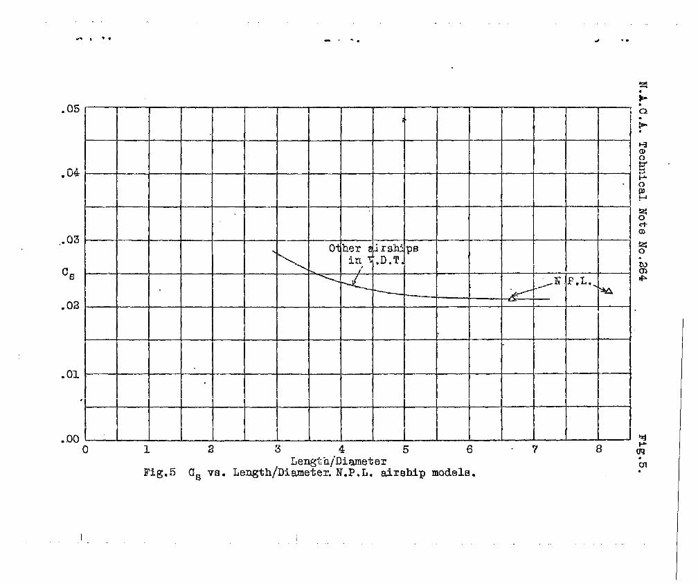
In Fi=~re 5 there is shown a chart of CS versus * “-

..
N.A.C.A. Technical Note No. 264 6
rat io, where a curve has been plotted representing the results of
tests on other airships in the variable density tunnel at a Rey-
nolds Number corresponding to 20 atnodpheres. The values of Cs
for the N.P.L. models are shown as points. The agreement is very ~
good .
Conclusion
The shape or resistance coefficient of the N.P.L. airship
models, as tested in the variable density wind tunnel, decreases
in value as the scale or Reynolds Number is increased, tending to
approach a minimum as the upper.limit of the test range }s reached.
* The results of these tests in comparison with tests at low scale L
in other wind tunnels show that further work is necessary in the3
standardization of wind tunnels. The values of resistance for
these models are in accordance with other airship models tested
in this wind tunnel.
Reference
1. Munk, Max M. The Variable Density Wind Tunnel of theand ● National Advisory Committee for Aeronautics.
Miller, E. W. “ N.A.C.A. Tec’mical Report No. 227. (1926)
1

vTABLE 1.
Dimensions of NtP.Lc Airship Modelsin Inches.
Long Mod-el
Sta.
0.05.,.
100
::;2.53.0
::;4.5
:::.. 7.0
a“;o9.010.011.012.013.014.0
_!.
.0001.3201.8662.2662.5772.8463.0743.2233.4383.5+363.7143.93.94.0664.1494.1884.2004.2004.20054.20054.201
Sta.
15.016.017,018.019.020:021~o22*O23.024.025.026.027,028.029.030.03s.032.033.034.034.28C
Diam.
4.2004.1994.1984.1944.1734.1284.0473.9313.7773.6023.3963.1692.9272.E672.3632.0131.6381.222.752.217.000
Short Model.
O*O
1::1.52*O2.53.0
:::4.55*o6.07.08.09.010.011.0I-2*O
Diam.
.0001.2941.8492.2662.5802.847300733.2683,4393.5853.7113.9164.0594.1504*1884.1964.1954.184
Sta. 1 Dism.
13.014.015.016.017*O18.019.020.021*O22.023.024.025.026.027.027.953
4.1.584.1014.0103.8893.7243.5323.3263.0982.8452.5542.2361.8831.5021,068.592● 000
Total length = 34.280 in. Total length = 27.953 in.
vol. = .00535 m3
(vol.)’” = .0360 m2
(vol.)’/’ = .1748 m
vol. = .00391 m3
(VO1.)2’3 = .02485 m2
(vol.)“3 = .1577 m
..
“.
.

*N.A.C.A. Technical Note No. 264
iTABLE II.
Resistance or Shape Coefficients.
9
,Long
R.N.
,.
;
% =*.
118;000
118;000
254jCC0
254,000
254,000
254,000
610,000
610,000
1,285,000
1,285,000
2,570,000
2,570,000
5,050,000
5,050,000
Modelc~
.0372
.0368
.0346
.0348
.0350
● 0349
.0294
.0294
.0260
.0261
.0233
.0233
.0236
.0238
Short Model
R.N. c~
108,500
108,500
228,000
228,000
545,000
545,000
1,175,000
1,175,000
2,320,000
2,320,000
4,550,000
4,550,000
4,550,000
● 0341
.0341
.0327
.0328
.0290
.0292
.0257
.0257
.0231-
.0230
.0209
.0213
.0213
●
..

..-. . . . . . . .
1.
k.
Fig,l N.P. L. Standard airship models, U.S. N. replicas3
ba)*
W/RE TOrUO/ZL.
COUNTER —DRIVE MOTOR
.- . ..__ ., .._, _..—.— -- —.- ..—- ——— — *
CONTACT
tW/NTS
KNIFE EDGE— COUNTER WE/GkiT
%1
AU2#7L/ARY DRAG BALANCE(K
~5TAB/L/TY WE16HT m
>u
Fig.3*
Auxillaxy c&ag balanoe. Variable demdty tunnel. tJa

----. .
4.......................
-I
<
n L“
Plan 1
Counter weightd
Side elevation
Fig.z.
\
4
. . .
011 crank
ux~Iiaryw balance
i-.Q
?
!#
CtCD
Front view of testsectton.
.

“.. .
.04
!0+
II
Om
● 01.04
II
am
.01
/2
D-
. “—-
\-d
Q---.-—o-
k. -
+.—
\\ \
1
-.——
-$+-
>— -.
t- &-+ -+
/ +-+”
456 7’89
1,00
Reynolds Numb&r ,
.
l==--5
ra Variab
aOli-i5iO:lkea.
d, II
=i“
OH
+ !.
lG Atm()s.
nat
_-Aid
II
NI -. ml
— —.–~
i+
~ .
k. – 9- --- —. --- .-
——
.
Tig.4 CB Vs R.N .N.P. L , air ship mot.el3. ;
-A
1.5 2“ 3 (. 5“000 p ~ 4,000,000
1.N. .T(vol. )~/3
.-, *. . ..-.
.05
,134
,.03
CG
.02
.01
2,
-.(yher $“rsh: PB
in ,D.T.\ ,
\——
DJm*
%1
0 1 2 3 4 5 6“7 8 hLength/Diameter
.
Fig.5 (1~ vs. Length/Diameter. N.P. L, airBbip models.ol.
I

12 NACA‘TNNo. 1642
where x end y are the absoiseaa and ordinates of the airfoiland p Is the central angle of the unit Mrcle. The functionsAx(q) and Ay(@ are related either by the oonJugate Fourier series,direotly derivable from equation (A2) upon substitution of p = ei~,or by the Integral relations:
(A6)
J2X
AY(@ = & Ax(W’) oot ~@’ (A7)
o
Given the airfoil coordinates x and y, equations (A4) (AS),and (A6) oan be solved for the mappingfunotlon Ax(q)+ i@(V\ bythe followlngmethodof euocessiveapproximation:The upper surfaoeof the airfoil is drawn with its leading- and trailing-edge ohordwiseextremitlea at the olnts
/’(JO, O), (-tic,O), respectively, where a
is the solidity o h. This form of the airfoil ie refened to asthe nomual fem. For a conveniently chosen set of values of thevariable cp from 0° to 180° the airfoil ordinates Ay(@ aremeasured at the ohordwise stations x (equatimn (JL4))corresp~~to some appropriate initial abscissa function Ax(v), such as thatof the previous approximation, or Ax(cp)= 0, if there is no previousapproximation.The function Ax(q) is computedfrom this Ay(cp)bY ~~ti~ (A6). (See appendix C.) The oo.nstants K and T areneti determined from the Ax(q) function by means of the equations
1sinh K = P (A8)
T=..
The constants K and Tspending DU3pp@ funotknmntour by equations (A4)andnot
[ 1+ Ax(0) +Ax(fi) (A9)
so detemnined, together with the corre-Ax(q3)+ iAy(cp),yield a derived airfoil
and (AS), which Is In the normal formoan be compared with the given airfoil. If the agreement issufficiently olose, the foregoing procedure is repeated.
.
.

NACA TN NO. 1642
After the mapping functionhas been found, the velocity infrom the general equation
13
relating the cirole and airfoil planesthe airfoil plmes oanbe determined
IIdVc=vdz (A1O)
The resulting formula for the velocity distribution on the airfoilitself’is
Vc 2 coshK Sin—=
j-
(All)v
(sin2g + sinh2 K)
where
[1d~ = 2 coshK SiIl~
~(A12)
sin2cp+ sinh2 K
The details of the calculation of the conjugate derivatives dAx/dq3
and dAy/dq from the Inmwn functions Ax(Q) -d AY(d are gfmnin appendix C.
For the limithg ease of the isolated airfoil, three of theSiX calculating equations (A4), (A5), (A6), (A8), (A9),and (All)must be changed,namely,(A4),(A8),and (All). The correspondingequations are, respectively,
x=
r=
vi—=v
T+r coeq+ Ax(cp)
~ + Ax(x) - &(O)2
+ ()@rdcp
(A4‘)
(A8’)
(All‘)
The quantity r is the diameter of the circle to which the isolatedairfoil is conformably related.
The calculations by the method of finite chord were for themost part based on the set of 12 evenly spaced cp values, 0°,15°, . . ., 180°. The leading edge of the airfoil corresponded to

14
Cp. ooand itsand its
. NACA TN No. 1842
and the traillng edge to 180°. The symmetryof the airfoilposition has a oorrespmdl.ng s~etry in the mappm funotlonderivatives; namely,
h(q) -
Ay(q$
dAx/dV
dAy/dq
r.
even
.t
oddIs m
;d
even.
functionwlth respeotthe station q = X.
to
.
‘g
.
.

I?ACATI?NO. 1842 15
APPENDIX B
CONFCXMAL MAPPING: MEFIOD OF SEMI-_INITE
b this method the flow through the unstaggered
mom
oaaade ofairfoils is determined by the confomal transformation relatingthe oasoade of shapes consisting of the airfoils and their zerostreamline prolon@bn in one direction, z-plane, the oasoade ofsemi-infinite straight chord lines, ~-plane} and the unit cirole~p-plane.
The essential difference between this method and the methodof finite chord lies in the relation between the ~- and p-planes.In thts ease the relatim is
(Bl)
This function transforms the unit oircle in the p-plane Into anunstaggered oasoade of semi-infinite straight lines of which theabscissas rmge fran -1 to -. The temn (p+l)/(p-1) transformsthe unit cirole into an infinite straight line; squarhg the termyields a semi-infinite straight line; and the lo@rithm transfozwthe straight line into a oasoade of Straight lines. The VeZ%i081distance between two consecutive lines is h. On the unit circle
‘2 loglsin ~1 -1 + Ax(q) - Ax(180°)x=—fiu
y = Ay(q)
(B2)
(B3)
where all len@hs are expressed as fkotlons of airfotl chord c,whloh was taken as c = 2, and the term Ax(180°) has been Insertedin order to 100ate the airfotls of the suooessive approximationswith one extremityat the point (-1, O).
The velocity distribution on the airfoil givenby equation (A1O)now beccmes
(B4)

16 NACA TN No. 1642
No Intermediate adjustment suoh as is represented by equation (A8)is required; hence the solution by successive approximation out-lined in appendix A is reduced to little more than the oaloulationof conjugates.
The chordwise stations for an evenly spaced set of cp-pointstend to cluster around x = -1 with the transformation (B2). Con-sequently, in order to obtain a sufficiently even distribution ofpoints over the airfoil, two devices were resorted to. The firstwas to perform the oaloul”atlontwice for each ease. The airfoilwas first considered with the leading edge at x = -1 and thetrailing edge at x = 1 and a solution obtained for the mappingfunction. The airfoil was then considered as reversed with respectto the y-axis and 8 solution obtained for another mapping function.The set of q-points was the same in both solutions. I%e seconddevice, whioh is applicable more generally in conformal-mappingprobkns, consisted in using a standard set of f3-pointsin ap’-Pl~e re~ted to the p-plane by the bilinear tremsformation
The transformation
P= ei~ goes Into
n-1 -p’+=
P=nlfip’+1
(B5)
(B5) Is so chosen that (a) the unit clrole
the unit oircle pt = eie with the points p = Mcorresponding to pf =*1 and the outside spaces corresponding, and
()(b) the derivative ~
dp P=l=n. By condition (a), the conjugate
relaticm (A6) is valid in the p’-plane. Condition (b) oauees asmall range E (c=q-e) of q near q = 0, whioh corresponds tox =CV} to correspond, for n>l, to a larger -e nc of 6 neare o.= Hence, for n>l , an evenly spaced set of 6-points yieldsa more evenly distributed set of chordwise stations x than thesame spacing of ‘~-pointe. The valuesof qI corresponding to theassumed e-points are obtained from equation (B5) with p = ei~,
P’ = eie}
The conJugateby
2n sin e(B6)
* q = (n2-1) + (n2+l) 00S 6
derivatives in the velocity formula (B4) were obtained
jllk= dAx d9——dq de dq.)
dA+
dAy ~d de dq }
(B7)
.
.

I?ACATN NO. 1842
with
de (n2-1) 00s e + (n2+la= 2n
(B8)
The derivatives dAx/dEl and dAy/de, in the caee8 treated by themethod of semt-infinite ohonl (6= 1.0, 1.5, 2.0), were measuredgraphically by drawing tangents to the oaloulated ourves m(e) d.Ay(e). This procedure was found to be more acourate at high solidi-fies than that of oaloulating the derivatives by the formulas givenin appendix C.
A typioal result obtained by the rnethcdof semi-infinite chordis illustrated h figure 8. The quantity n was so ohosen that thepoints obtained for the front halt of the airfoil overlapped thepoints obtained for the rear half of the airfoil. The reeult~values of n ranged from 2 to 30 and =e given for eaoh ease intables II and 111. The oaloulations were based in the ease o = 1on the use of 12 evenly spaoed values of 0 = 0°,
g ~s~~ “7”56s ~“and for the higher solidifies m the 24 values., 180°.
>“) >.0
It may be noted that the effeot of boundary-layer develo~entalong and downstream of the airfoil oan be taken into aocount quitesimply in this method by oonslder~ as boundary omtour the 100usof the outer edge of the displacement bound=y layer along and down-strem of the a~oil.
The ei?feotof boundary-layer development cm the tunnel wallsoan be treated by so altering the mapping problem that the ohannelbetween the zero streamline of the airfoil and one tunnel wall isto be mapped into a uniform ohannel. The mapping methcds for thisprobku are similar to those already deeoribed.

NACA TN No. 1642
AFTEr&xcNUMERICAL EVAIUATIOXVOF COWWATE FUNCTIONS
AND THEIR DERIVATIVES
The determination of the conjugate funotion Ax(q) and ofthe mnJugate derivatives dAx/dV, d&/W frcm a known functionAy(~) was based In this paper on numerical Integratic.mof equa-tion (A6) and, for solidifies of O md 0.5, lntegratlcm of therespective derivatives of equations(A6)and (A7). After severaltrials with other methods of evaluation, Including Fourier expan-sion, graphloal methods, and various kinds of numerbal integration,the following procedures were adopted as a canprcunisebetweenaoouraoy and expenditure of effort.
In order to oaloulate Ax(Q), the range of integration in equa-tion (A6) was divided into an even number of equal intervals. Thefunction Ay(V) was considered to be known numerically at thevalues of CP separating these intervals. In the region outsidethe intervals on either side of the singular point q =cpt, theIntegral was evaluated by Slmpscm’s rule. The contribution to theintegral of the two Intervals separated by the singular point q’was obtained by representing Ay(~) in this range by the fonu
kv(@=Acosq+Bstiq+c (cl)
The oonst=ts A, B, and C were so determined that equation (Cl) wassatisfied at the three ~polnts bounding the two intervals. Thefinal result for Ax(@ is a-expression of the form
2n-1
Ax(q) =Y
ak Ay(q+k6] (C2)
where 8and 2n8in table
The
*
is the Interval between two consecutive values of q= 2X. The 24 Coefficients ak for n = 12 are listedVII.
aonJugate derivatives dAx/dp and dAy/d~ ‘were obtainedin an analo@us mmner frm the rel~ttons
Jw=+ 2“AY(Q’)-AY(Q)dv sin2 ~
o

19
d~’ (C4)
These relaticms can be derived by differentiating equations (A6)and (A7) under the integral sign after subtracting Ay(q$ andAx(q) from the respective integrands to make this operation per-missible. They can also be obtained by a limiting prooess in thecomplex plme similar to that of reference 1, appendix C. Thenumerical integration of equations (C3) and (C4) by Siiupson’sruleand a sinusoidal approximation over the singularity result as beforein expressions of the form
2n-1
dAxq=- 7
~ Ay(q + k6] (C5)
*
-1=(l&= 7 bk Ax(9 + k8) (C6)
me bk Fcoefficients are isted in table VII for. n = 12. The ak
and bk coefficients were also calculated for 48 ~-points, and
are li~tedin tableVIII.
-licit expressionssoheme are (2n 0 = 2?C)
a. =
al =
a2n-1 =
ak .
ak =
for the coefficients for a 2n-point
o
8 $+sin~-&cot~-
2% Sin?l
I (C7)

20 NACA TN No. 16429
b. =
%=
The auouraoythe funotion sin
bzn-] =0
la Ed }6
+ 211‘(l- 00s 87
(k even)
(k odd)
1(c%)
of the 24- and 48-point sohemes was oheoked on29. The 24-point scheme gave results for the
con@gate aoourate to 0.8 peroent and for the derivatives aoourateto 0.2 peroent. The 48-point soheme resulted In 0.2-percentaoouraoy for the oonJugate and 0.05-peroent aoouraoy for the deriva-tives. These values for aoouraoy are given only as a reference withwhioh to compare other methods. They do not give any direot indi-oatica of the acouracy of evaluation of the om~ugate funotions andderivatives of this paper.
!5

NACA TN NO. 1642 21
.
.
.
.
.
APPENDIX D
FIX&l%ORDER IMW3 ~Y
IiIthis method of obtaining the ccastriction oorrectla, the_ aitiofls (fig. 1) are replaced by equivalent doublets. Thedisturbance velocity produoed in the region of the physical airfoilby these doublets is u and the resultant veloolty is thereforeV + u. The tunnel velooity distribute= of the aitioil Vc Isassumed to be given by its nondimensional isolated-aitioil velooitydistribution vi/V multiplied by the velocity V+ u; that is,
(Dl)
so that the constriction correction is
According to Glauert (referenoevelocity u iS @ven by
‘1 u‘Y?
(D2)
3, p. 53), the disturbance
()X-zh;z%-m (D3)
where the factor L is giVen by
(D&)
(reference 3, p. 55; Glauert does not exyllottly indicate the chord aand his q is here V. in aocordauoe with his [email protected] of theevaluation of ~). The integral in equation (M) is taken with respectto surfaoe distance s almg the upper surfaoe of the airfoil franleading to tratling edge. Its fozm lndioates that h is approximatelyinversely proportional to t/o (see also reference 3 equation (17.10)),and thus u/V is proportional to the parameter to/hA. The values ofA oaloulated fran equation (M) for the various oases are given intable X.
The constriotim oorreotion givem by eguaticm (IE) represents urefinement of the usually given first-order constriction correoticnUjv, which is a mnstant alcmg the ohord. lMis procedure is used Inorder to be mnsistent with the omstrioticm correction derived fraaGoldstein’s theory as discussed tn appendix E.

22
Itthat isbe useddoubletfoil h
NACA TN NO. 1642.
.
may be noted that in calculating the strength d a doubletto replaoe an isolated airfoil, vi rather than Vc shouldin equatim (D4). However, inasmuch as the strength of themust be inoreased when it is used to replace the same air-a casoade, the use of VC, which is greater than vi, will
ohange the value of k in the ?&ht direotion. For the low valuesof the solidity for which the doublet correction is used, however,there is no appreciable dlfferenoe in the correction.
.
.
.

NACA Tl?No. 1642 23
.
MPENDIX E
SECOND-ORDER IMAGE -RY
Goldstein (reference 4) first replaces the image airfoils(fig. 1) by the doublet and higher-order singularities given bythe potential ~ction of the airfoil in a uniform free stream.The nonuniform disturbance velocity produced by these singularitiesin the physloal region, in particular at the looation of the physi-oal airfoil,is calculated.This first-approximationnonuntfomndisturbancevelocity(a)changesthe velocitydistributionof theairfoilfrom its isolatedfree-streamvalueand (p) danges thevaluesof the singularitiesthat ~e to be imaged. Change (b) isevaluatedand a second-approximationncaunifom disturbancevelocityis calculated,etc.,to higherapproximations.Lastly,the velocitydistributim of the airfoilh the finalnonuniformstreamis cal-culated.
W principle,Goldstein’smethod is oapableof yieldingto anydegreeof accuracythe effectof a tunnelon the two-dtiensionalvelocitydistributionof an arbitraryairfoil,arbitrarilysituated.The successiveapproximations,however,become lmreasingly laborious.Goldsteingivesthe formulasto the secondapproximation;that is, to
the.order tc3/h4, t2c2/h4, t3c/h4. Theseformulasare quotedhereas used in, and in the notationof, this paper.
The fundamentalfommla for the symmetricalconstrictioncor-rection is obtained as the ratio of tunnel to free-stream velooitydistribution:
where
so that
P(e) =%’ (R sin
(El)
(E2)
(E3)
(E4)
.

24 NACA TN No. 1642
(35)
(E6)
(E7)
1 (E8)
(E9)
A
where y($) is the airfoil ordinate corresponding to the abscissaand 6’= O corresponds to the leading edge of the airfoil.
x=scosg2“
(E1O)

NACA TN NO ● 1642
Equaticm (El) correspondsreference 4. The factor
25
to Goldstein’s equation (97) (p. 48) ofU/V has been inserted to reduce the
isolated-airfoil velocity, &ldatein’s ql, fi’om U to T as thefree-stream velocity. Equations (E3) to (E6) correspond respectivelyto Goldstein’s equations (40) (P. 37), (99) (Po 48)} (21) (Po 34)sand (100) (p. 48). Equaticms (E7) to (E1O) correspond to those ofappendix 5 (p. 21).
The basic ccmstants ~ calculated in this paper are given In
table X on the basis that the airfoil chord be 2.
The velocity distribution by ccmformal mapping was used forvi/V in equations (E2) and (D2) because it had already been calcu-lated. It would have been somewhat more consistent to use thevelocity distributions derived by thin-airfoil theory inasmuoh asthe constants ~ (equation (E9)) were so derived. The differencesbetween the two distributions, being of the orders (t/c)2,(t/C)3j . ● .j do not affect the main contribution to the seccmdorder of Galdstein’s results, namely, the mntribution of the ordertc3/h%
It is noted that in applying equation (E3) to thh aitioils,Goldstein in his %uation (75) (PO 45) ne@ects the ten d12. This
term was not found to be negligible in the calculatims of thispaper and was retained.

26 NACA ~ NO ● 1642
The Irrotationalocunpletelydetermine&
JUPENDIX F
STREAM—FIMMEIW mRY
motion of an ideal incompressible fluid isby the equatlcae of irrotaticmalityand—
continuity of mass and by the boundary conditions. Consider theequation of irrotationality in the form (referenoe 6, equation (41))
(n)
where
n distanoe alcmg potential line at point of flow field
R radius of ourvature of streamline at same point of flow field;positive if streamline is oonvex in positive n direotion.
btroduce the approximations (a) that the potential lines arestraight lines perpendicular to the x-axis, or
n=y (m)
and (b) that the wrvature of the streamlines at any chordwiseIooathn varies linearly &cm Its knuwn value at the airfoil tothe known value, O, at We wall, or
where
c Ourvature
Ca curvature
J@’Rl/R=c=c
of streamlineat chordwise
of airfoil surfaae at ohordwise station X
Y ordinate of airfoil at ohordfise station X
The boundary oondition that the boundaries be streamlines is satis-fied by equation (F3). Substitution of equations (F2) and (F3) into(Fl) and inte~tion yields
v = F(x)e W/W
NACA TN Iio ●
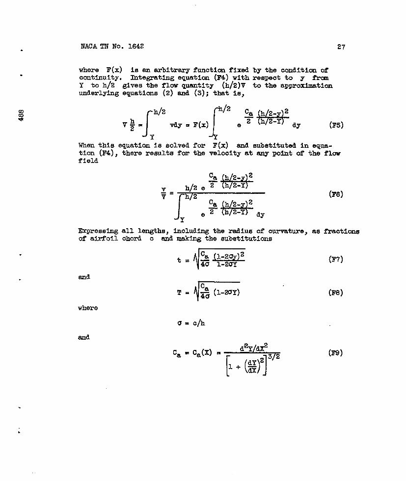
where F(x)continuity●
1642 27
is am arbitrary functim fixed by the conditim ofbtegrating equation (F4) with respect to y fra
Y to h/2Underlylag
gives the flow quantity (h/2)V to the approximaticaequations (2) and (3); that-is,
V$=~’2tiT=F(.][’2e%Wd= (F5]
When this equation is solved for F(x) and substituted in equa-tion (F4), there results for the velooity at any point of the flowfield
-2
h 2-Y
‘=p;z
-2
h 2-Y dy
(F6)
l&pressing all lengths, including the radius of curvature, as fhactionsof airfoil chord c and mak~ the substitutions
‘=@= (F?)
and
‘=-(F8)
where
‘a “ CJX)=*[()]?iz
(F9)

28
equation (F’6)becomes
!r”-+=
JT
(1-2Y) et2dt
0At the airfoil, equaticm (F1O) gives finally
IfCa=fileuuent
()~~T2?8=
(1 -2UY) r dt2dt
I?ACATlfNo. 1642.
5!(F1O)
(Fll)
Jo0, equation (F6) reduces to the simplest fom of stream-theory, nsmely
+--
h2+=h 2-y (F12)
EQu8tims (F8), (F9), and (Fll) were used for the oaloulation of thevelooity distributions of the alrfoll in the tunnel by the stream-filament theory. The integral In equation (Fll) is tabulated inreference 7 (p. 32).
This method may be useful In determining the influence of axu-pressibllity. For an ideal compressible fluid, the only changerequired in equation (F1O) or (Fll) is the Insertion of the factorP/PO under the Integral si~, where P is the density of the fluidand P. is the ultinate upstream density.
.
.
.

NACA TN I?o ● 1642 29.
1.
2.
3.
4.
5.
6.
7.
REFERENCES
Mutterperl, William: The Conformal Transformation of an Airfoilinto a Straight Line and Its Application to the Inverse Problemof Airfoil Theory. NACA ARR No. IAK22a, 1944.
Mutterperl, William: A Solution of the Direct and XhversePotential Problems for Arbitrary Cascades of Airfoils. XACAARR ~Oo UK22b, 1944.
Glauert, H.: Wind Tunnel fiterfereme on Wings, Bodies, andAirscrews. R. & M. ~Oc 1566, A.R.C., 1933.
Goldstein, S.: Steady Two-Dimensional Flow past a Solid Cylinderin a Non-Unifonu Stream and Two-Dimensional Wind-Tunnel Inter-ference. R. & M. No. 1902, M.A.P., 1942.
Kaplan, Carl: The Flow of a Compressible Fluid Past a CurvsdSurface. NACA ARR No. 3K02, 1943.
von K6%6, Th.: Cc$npressibilityAero. Sci., vol. 8, no. 9, July
Jahnke, Eugene, and Fhde, ~itz:and Curves. Dover Publications
Effects In Aerodsos. Jour.1941, pp. 337-356.
Tables of Functions with Foznuzlae(lJewYork), 1943.
.
+
.
.

30
StatIon(peroenchord
nose) “
o1.252.551015202530354045
TABLE I. - ORDINATES OF AIRFOTLS
NACA TN No. 1642.
Ordinateof 12-peroent-thlokairfoil
l~~t
Of 24-percentthickairfoil1
Station(peroentahordfrannose)
Ordinate OrMnateof 12- Of 24-peroent- per@nt-thlck thiokairfoil airfoil
01.4251.9002.5853.5404.2504.8205.2955.6555 ● 9006.0006.010
02.2503.2854.6206.4557.8909.05010.07010.88511.49511.855
11.980
5055606570758085909597.5100
5 ● 8805.5405.0254.4153 ● 7503.0602.3501.6851.060.510,260
0
11.81011.38010.6659,7358.5757.2505.8254.3652.9251.605.950
0
=5=’

NACA TN NO. 1642 31
.
.
TABLE II. - VEWCITY DISTRIBUTION ~ CAI?2E31ANMMPING
MJNCTION8 l!UR12-PEROENT-THICK AIRFOIL
(a) o/h, O; method of finite ohord; r, 1.0896; T, 0.0243
0X151234s678910n12
Peroentchord
o1.6256.48C14.2424.2435.7047.8060.0672.1183.1592.0897 ● 94100.00
vi
II
x AyT
o1.04361.08341.11361.13031.15741.16901.11911.0422.9821.9400
0
1.0000 0.9675 .0312.8704 .0578.7151 .0837● 5151 .1045.2861 ● 1186.0441 .n95
-.2012 ● 1008-.ti22 .0693-.6630 .0389-.8416 .0168-.9588 .0042-1.0000 0
Ax
‘0.1139-.1093-.0976-.0797-.0540-.0202.1098.0565.0783.0832.0777.0694
dAx $~
o 0.1200.0363 .1121.0521 ● 1005● 0845 .0908● 1117 .0695.1436 ● 0305.1582 -.0347.1183 -.0999.0465 -.1233
-.0072 -.1032-.0309 -.0660-.0301 -.03000 -.0127
(b) c/h, 0.5; method of fInite dmrd; oosh k, 1.43094; T, 0.04158
Oxls123456789101112
?eroent~hord
o2.5159.19C18.2028.0237.9647.8257.7668.0878.7488.9496.90100.00
v=
T
o1.07921.10871.12841.15431.17141.18431.14851.07891.0150.9614.9207
0
1.0000 0.9497 .0381.8162 ● 0682.6360 .0925.4396 .1103.2409 .1195.0436 .1195
-.1552 .1059-.3616 ● 0805-.5747 ● 0507-.7789 .0236-.9379 .0062-1.0000 0
-0.2008-.1897-.1623-.1256-.0806-.0290.0269.0805,1200.1387.1376● 1250.1177
0 0.2331.0850 .2081.1218 .1644.1558 .1269.1872 .0830.2046 .0291.2182 -.0411.1865 -.1205.1123 -,1713● 0314 -.1762
-.0362 -.1360-.0541 -.06750 -.0311
.
●
NACA TN No. 1642.
.
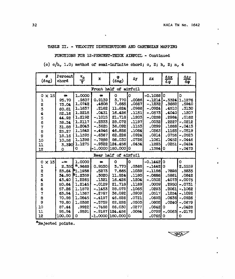
TABLE II. - VEIDCITYDISCRIBUT IONS AND CARTESIAN MAPPING
FUNCTIONS IUR 12-PERC13W-TKCCKAIRFOIL - Continued
(o) o/h, 1.0; method of semi-infinite ohord; o, 2; h, 2; n, 4
Peroent V.(d~g) chord y x
dhx(d~g) ‘y h ~
~
0X15123456789101112
0X151
2
:5678910n12
Oa
95.7073.0460.8152.1644.9238.3431.8825.2718.1610.563.3$00
-m
2.35(23.64S.9043.4050.6457.2663.9470.9878.8087.4495.94100.00
Front half of airfoil
1 ● 0000.9607
1.07421.16371.22151.21921.21171.20431,18421.15951.13981.12750
1.0000a.9668h. 1938h. 23591.22651.21451.18721.13671.08451.0382.9922.9591
0
0 ● 9;39.4608.2162.0431
-.1015-.2333-.3625-.4946-.6367-.7888-.9322
U?s!E
o3 ● 7707.66511.82416.42621.71828.07236.09246.82662.22686.030L24.456L80.000
0.0086.0667.0988.1151.1203● 1197.1153.1064.0924.0726.0434
0
Re= half of airfoil
o ● 9:30.5273.3020.1321
-.0129-.1453-.2787-.4197-*5759-.7488-.9187.1.0000
03.7707.66511.82416.42621.71828.07236.09246.82662.22686.030.24.456.80.000
r.0368.1039.1180● 1204.1169.1065.0909.0721● 0503,0277.0084)
-0● 1088-.1214-.1232-.0924-.0573-.0258.0032.0299.0563.0814.1061.1283.1384
1 0-.3324 1.1276.3682 .5940.4510 .3130● 4040 .1207.2984 .0162.2227 -.0212● 1668 -.0413.1165 -.0519.0756 -.0523.0452 -.0446.0251 -.04241 - ● 0473
-0.1442 0 0-.1442 0 2.5559- ● 1186 .7898 ● 3635-.0686 ● 5881 .0842-.0302 .4073 -.0075.0009 .2950 - ●0731.0293 .2061 -.1062.0517 .1254 -.1092.0692 .0636 -.0926.0802 .0240 -.0679.0842 0 -.0428.0799 -.0063 “.0175.0765 0 0
?Re~ected points.

NACA TN No. 1642 33
TABLE 1. - VELOCITY DISTRIBUTIONS AND CARTESIAN MAPPING
FUNCTIONS FOR 12-PERCmT-THICK AIRFOIL - Continued
(d) o/h, 1.5; method Of semi-f.nflnite chord; c, 2; h, 4/3; n, 8
Pe ‘cent( d:g ) chord ? x (d:g) ‘y ‘x
@
Front half of airfoil
(3X7; m 1.0000 - 0 0 -0.1819 0 0
1 04.68 % .0101 0.6936 .939 .03402
-.1785 .4875 3.418270.72 al.1157 .4145 1.886 .0732 -.1623 1.4512 1.6175
3 63.24 % .1943 .2647 2.849 .0229 -.1363 1.4400 .85474 58.08 1.2407 .1618 3.837 .1048 -.1130 1.25615
.523154.10 1.2699 .0620 4.8!59 .1123
6- ● 0828 1.0758
50.82.3162
1.2851 .0163 5.928 .1169 -.0744 .9134 .16437 47.93 1.2842 -.0414 7.055 .11918
-.0580 .7629 .076945.34 1.2747 -.0231 8.256 .1201 -.0432 .6339 .033242.93 1.2707 -.1414 9.549 .1203 -.0300 .5413 .0067
1: 40.64 1.2717 -.1872 10.95811
.1202 -.0175 .4726 -.007838.43 1.2731 -.2314 12.512 .1198 -.0055 .4155 -.0270
12 36.28 1.2736 -.2745 14.25013
.1189 .0064 .3652 -.036034.12 1.2694 -.3175 16.224
14.1175 .0181 .3169 -. CW37
31.94 1.2640 -.3612 18.50515
.11522Q.68
.0298 .2733 -.05021.2556 -.4064 21.192 .1129 .0415 .2326
16-.0549
27.31 1.2443 -.4538 24.433 .1096 .0537 .1945 -.057317 24.75 1.2339 -.5050 28.447 .1053 .0660 .1611 -.057118 21.98 1.2245 -.5605 33.585 .1006 .0791 .131719 18.87
-.05661.2119 -.6226 40.431 .0939 .0930
20.1038 -.0536
15.32 1.1960 -.6935 50.019 .085421
.107711.25
.0776 -.04811.1792 -.7750 64.292 .0748 .1238 .0544 -.0420
22 6.655 1.1658 -.8669 87.030 .058823
.1414 .0355 -.03762.175 1.1432 -.9565 124.660 .0359 .1586 .0202 -.0344
24 0 0 -1.0000 180.000 0 .1666 0 -.0404Rear ha lf of airfoil
0X7$ -- 1.0000 - 0 0 -0.2335 0 01 12.90 al. 1409 o; ~92=o .959 .0793 -.2066 3.3265 2.39632 25.22 al.2399 1.886 .1064 -.1571 2.5341 .89913 32.14 al. 2787 .3571 2.849 .11564
-.1204 1.8673 .305137.14 1.2787 .2573 3.837 .1192 -.0238 1.3824 .1196
5 41.07 1.2631 .1786 4.859 .1203 -.0723 1.04206 44.38
.03591.2774 .1124 5.928 .1204 -.0543 .8901 -.0246
7 47.25 1.2879 .0550 7.055 .11988
-.0379 .7706 -.071649.84 1 *2868 .0033 8.266 .1179 -.0229 .6580 -.109252.24 1.2776 -.0447 9.549 .1150
J-.0093
54.53 1.26CM.5564 -.1320
-.0206 10.958 .111511
.003056.76 1.2421
.4629 -.1433-.1352 12.512 .1075
58.97.0146 .3844 -.1482
1.2257 -.1794 14.250 .1029 .02s3;:
.3205 -.148761.20 1.2078 -.2241 16.224 .097663.51
.0353 .2647 -.14511.1891 -.2702 18.505 .0920 .0446 .2158 -.1373
;: 65.90 1.1682 -.3181 21.192 .0861 .0537 .1717 -.127816 68.46 1.1466 -.3691 24.433 .0790 .0623 .133117 71.22 1.1247
-.1152-.4245 28.447 .0715 .0703 .0298 -.1016
18 74.28 1.1028 -.4856 33.585 .0532 .0780 .0716 -.067677.72 1.0816 -.5545 40.431 .0534
:: 81.72.0850 . M85 -.0731
1.0504 -.6343 50 ● 01921
.0425 .0908 .0257 -.057986.40 1.0153 -.7279 64.292
22.0300 .0948 .0076 -.0412
91.83 .9822 -.8366 87.030 .017023
.095697.31 .9659
-.0026 -.0256-.9462 124.660 .0055
24.0928
100.00 0-.0046 -.0114
-1.0000 180.000 0 .0905 0 0
‘Rejectedpoints.

34 NACA TN No. 1642
TABLE II. - VELOCITY DISTRIBUTIONS AND CART=IAN MAPPING
FUNCTIONS FOR 12-PERcENT-THICK AIRFOIL - Concluded
(e) c/h, 2.0; method of semi-infinite chord; c, 2; h, 1; n, 15
Percent( d:g ) chord + I
x 16AXI*1‘y ‘x T
Front half of alrfoll
0X7$ - 1.0000 - 0 0 -0.2458 0 0
1 66.28 al.1998 0.3255 .501 .0849 -.2152 6.4838 5.02002 57.80 al .3457 .1560 1.006 .1055 -.1626 4.7171 1.26073 52.94 al.3765 .0588 1.520 .1140 -.1285 3.30774
.659549.44 1.3710 -.0112 2.047 .1181 -.1037 2.4177 .298246.71 1.3692 -.0658 2.593 .1200 -.0s30 1.8974 .0902
: 44.39 1.3742 -.1122 3.164 .1203 -.0662 1.5696 .03087 42.35 1.3647 -.1530 3.766 .1204 -.0515 1.2936 -.00368 40.50 1.3537 -.1901 4.40s .1202 -.0385 1.0805 -.0315
38.78 1.3443 -.2244 5.101 .1199 -.0263 .9154 - .W261: 37.16 1.3501 -.2568 5.857 .1193 -.0148 .807411
-.052135.60 1.3446 -.2880 6.692 .1185 -.0036 .6985 -.0579
12 34.06 1.3404 -.3188 7.628 .1174 .0072 .6185 -.076813 32.52 1.3525 -.3496 8.694 .116014
.0180 .5477 -.081330.94 1.3439 -.3811 9.931 .1143 .0287
1s.4710 -.0773
29.31 1.3340 - .4L38 11.396. .1123 .039716
.4017 -.073927.58 1.3216 -.4485 13.174 .1100 .0510 .3386 -.0813
17 25.70 1.3118 -.4860 15.398 .1070 .062918 23.62
.2s30 -.07501.2931 -.5275 18.286 .1036 .0757 .2272 -.0676
19 21.26 1.2871 -.574Q 22.222 .0890 .0898 .1838 -.062020 18.46 1.2642 -.6309 27.943 .0939 .1055 .1368 -.056021 15.00 1.2476 -.7001 37.058 , .0849 .1237 .0874 -.048522 10.52 1.2381 -.7896 53.714 .0722 .1462 .0636 -.039923 4.645 1.1758 -.9071 90.974 .0500 .1740 .0271 -.031424 0 0 -1.0000 180.000 0 .1887 0 -.0344
Rear half of airfoil
ox7~ - 1.0000 - 0 0 -0.2660 0 01 29.,0 al .3950 0.4061 .501 .1127 -.2194 1o.3834 1.91692 37.16 al .3927 .2567 1.006 .1192 -.1468 5.1175 .33313 41.90 ~1.3449 .1621 1.520 .1204 -.1100 3.0781 .03064 45.42 1.3684 .0916 2.047 .1201 -.0857 2.3995 -.0863
48.14 1.3756 .0372 2.593 .1192 -.0649 1.9233 - ● 1708: 50.47 1.3689 -.0084 3.164 .1171 -.0481 1.5591 -.22457 52.50 1.3469 -.0499 3.766 .1147 -.0332 1.2544 -.23478 64.36 1.3365 -.0872 4.408 .1119 -.0204 1.0506 -.2437
56.08 1.3193 -.1218 5.101 .1089 -.0085 .8769 -.25801: 57.76 1.3013 -.1551 5.857 .105411 59.38
.0021 .7338 -.25311.2876 -.1875 6.692 .1020
12 61.00.0121 .6218 -.2409
1.2764 -.2199 7.628 .0881 .0213 .5303 -.223713 62.63 1.2499 -.2526 8.694 .0942 .0302L4 64.32
.4312 -.20481.2362 -.2863 9.931 .0900 .0387 .3618 -.1864
15 66.06 1.2182 -.3215 11.396 . 0s54 .047216 67.96
.2965 -.16771.2010 -.3592 13.174 . 080s .0555 .2415 -.1569
17 70.01 1.1830 -.4002 15.398 .0748 .0639 .1919 -.138818 72.32 1.1624 -.4464 18.286 .0684 .0720 .1459 -.114819 74.96 1.1336 -.4902 22.222 .0613 .080620
.1024 -.098878.13 1.1045 - .56Z6 27.943 .0523 .0890 .0662 -.0813
21 82.10 1.0737 -.6420 37.058 .0413 .0871 .0364 -.057822 87.38 1 ● 0321 -.7476 53.714 .0278 .1034 .0120 -.035723 94.57 .9826 -.8914 90.974 .0111 .104924 100.00 0
-.0018 -.0173-1.0000 180.000 0 .1039 0 0
ReJeoted points.

NACA TN No. 1642
.
.
TABIm III. - V131.OCITYDISCRDUT IONS.MtD OARTESIANMKEPRVG
3UNCTIONS FOR 24-PEROENT-THICKAIRFOIL
(a) c/h, O; method of finite chord; r, 1.1855; ?, 0.0317
(d:g)
OX15123456789101112
o 01.720 .92336.735 1.101314.64 1.163424.64 1.229735.84 1.296247.42 1.336159.10 1.268270.60 1.159481.49 1.017890.92 .901997.54 .8217100.00 0 I
1.0000.9656.8653.7071.5071.2832.0517
-● 1820-.4119-.6298-.8184-.9508.1.0000
Ay
2.0542.1067.1564.2002.2314.2388.2164.1683.1078.0536.0188)
.0.2172-.22.12-.1931-.1629-.1173-.0553.0200.0931,1491.1768.1766.1626.1538
0.0460.0922.1412.2055.2654.2986.2531.1682.0477
-.0406-.05460
0.2103.2059● 1977.1825.1509● 0818
-.0267- ● 1400-.2174-.2308- ● 1756-.0939-.0569
(b) c/h, 0.5; methmlof finitechord;ooshk, 1.34708; T, 0.05243
0X15123456789101112
o 0 1.00002.855 1.0375 .942910.14 1.1600 .797219.42 1.2225 .611529.04 1.2954 .419338.38 1.3442 .232547.50 1.3602 .050056.68 1.2302 - ● 133566.24 1.2304 -.324876.46 1.1082 -.529187.08 .9768 - ● 741596.20 .8790 -.9240100.00 0 -1● 0000
0.0705.1302.1787.2151.2353.2386.2232.1888,1370● 0757.0262
0
-0.3930-.3744-.3263-.2581-.1733-.0763.0261.1270.2169.2826.3090.2992.2882
c).1396.2248.2918.3530.3837.3938.3713.3085.1893.0157-.08073
0.4310.3961.3276.2566.1721.0719
-.0362-.1506-.2645-.3504-.3411-.2236-.1468
35

NACA TN No. 1642
.TABLE~ - VELOCITY DISTRIBUTIONS AND CARTESIAN MAPPING
FUNCTIONS FOR 24-PERcENT-THICK AIRFOIL - Continued
(c) c/h,l.O;method of semi-fnflnlte chord; c, 2; h, 2; n, 6
Percent(djj) chord ? x 1$%1%?
Front half of airfoil
ox7~
1
:45
;8
1;11121314151617181920
::2324
OX7;
123456789
10
ii131415161718192021222324
ReJeotec
OQ
.15.692.2479.2871.7066.0761.4457.5454.0950.9447.9845.1442.3739.6036.8033.9130.8727.6224.1020.2015.8511.09
6.13C1.83:0
-00
17.435.740
16.7123.5629.0433.4837.3240.7243.8646.8149.6552.4455.2258.0661.0164.1367.5071.2175.3880.1885.7291.8897.54,00.00
1 ● 0000
a.9661a.8895
‘1. 1239‘1 .26561.32311.36621.41461.44691.46521.47331.47691.4’7451.46741.45541.43461.40591.37301.34681.31521.28321.24821.17171.03330
1.0000a.9558a.9243‘1. 3396‘1.3535‘1.3767.1.4015,1,4374‘1.45701.46621.46341.46861.45961.44391.42021.38141.34301.30701.25581.19331.11611.0334
.9668●8979
o
-
1.3125.8449.5856.4340.3214.2289.1509.0818.0188
-.0405-.0971-.1526-.2079-.2640-.3218-.3826-.4475-.5180-.5961-.6830-.7782-.8774-.96331.0000
!ear ha:
Oa
1.3486.8852.6658.5287.4193.3303.2537.1856.1227.0638.0070
-.0487- .1M5-.1612-.2202-.2826-.3501-.4242-.5076-.6036- ●7145- ●8377- .95W1.0000
0
1.2522.5143.7985.1146.4767.8989.397
10.99312.70914.57616.63110.92521.52124.50928.01232.20437.34743.83752.30163.’76479.919,03.388,37.064.80.000
“ of ai:
o1.2522.5143.7985.1146.4767.8989.397
10.99312.70914.57616.63118.92S21.52124.50928.01232.20437.34743.83752.30163.76479.919.03.38@.37.064.80.000
I
1
.0471
.1221
.1640
.1899
.2081
.2208
.2297
.2350
.2383
.2386
.2389
.2368
.2330
.2276
.2201
.2104
.1980
.1819
.1621
.1365
.1018
.0561)
’011
)).1001.1677.1959.2144.2264.2338.2378.2395.2391.2368.2328.2!272.2197.2100.1982.1833.1656.1429.1153.0832.0480.0189
)
0.2370
-.2574-.2811-.2778-.2400-.2025-.1687-.1363-.1059-.0768-.0493-.0224
.0037
.0294
.0549
.08C6
.1066
.1332
.1603
.1880
.2163
.2456
.2739
.2966
.3056
0.2733-.3040-.3234-.2803-.2281-.1872-.1500-.1162-.0848-.0556-.0276-.0010
.0249
.0501
.0751
.0896.1239.1478.1714.1937.2130.2265.2302.2266.2230
0
1.02311.02001.40571.66631.47361.28731.16101.0337
.9129
.8010
.7C32-
.6148
.5351
.4620
.3921
.3258
.2651
.2142
.1669
.1246
.0879
.0526
.03060
01.346502.60101.94761.58931.34191.18471.0391
.9090
.7888
.6973
.6066
.5230
.4447
.3679
.2984
.2398
.1817
.1250
.W715
.02570-.00920
0
04.98862.41011.3743
.9146
.5854
.3766
.2339
.1458
.0684
.0104-.0277-.C608-.0827-.0984-.1078-.1121-.1102-.1060-.0958-.0858-.0806-.0758-.0738
335.99091.5367
.9475
.6356
.3701
.1831
.0856
.0225-.0403-.0843-.1162-.1371-.1512-.1690-.1653-.1626-.1594-.1462-.1282-.0285“ 0675-.03710
●
✎
.
potnts.

-..
3
NACA TN No.
(d]
642
TABLE = - VELOCITY DISTRIBUTIONS AND CARTESIAN NAPPING
FUNCTIONS FOR 24-PERCENT-THICK AIRFOIL - Continued
c/h, 1.5; method of sed-hfhlte chord; c, 2; h, 4/3; n, 8
Percent(d~g) chord ? x ( d~~ ) ‘y ‘x 1%1%$
Front half of airfoil
13x7: ~ 1.0000 - 0 0 -0.4634 0 01 74.50 al. 2438 0.4900 .626 .1477 -.4140 8.7854 8.4772
63.82 al.5358 .2784 1.257 .1997; 58.32
-.3236 7.0656 2.8107al. 5987 .1664 1.899 .2189 -.2589 4.8956 1.2701
4 54.29 al. 6524 .0858 2.558 .2292 -.2C$36 3.7931 .68555 51.17 al.6718 .0234 3.241 .2348 -.1686 3.02866
.355448.56 al.6763 -. 028!3 3.954 .2379 -.1348 2.4837 .1598
7 46.29 1.6684 -.0742 4.705 .2393 -. 1C46 2.0691 .05108 44.23 1.6617 -.1154 5.509 .2395 -.0776 1.7564 -.0144
42.34 1.6654 -.1533 6.374 .23891: 40.52
-.0525 1.5237 -.06731.6613 -.1896 7.318 .2375
11-.0290 1.3234 - ● 0886
38.7,6 1.6633 -.2247 8.360 .235612
-.0065 1.1618 -.115937.04 1.6600 -.2593 9.527 .2334
13.0154 1.0180 -.1299
35.30 1.6441 -.2939 10.85614
.2303 ● 0371 .8818 -.136933.53 1.6197 -.3294 12.396
15.2267 .0589 .7562 -.1436
31.68 1.6023 -.3864 14.218 .2221 .0810 .6494 -.144116 29.71 1.5813 - .~058 16.426 .216817
.1038 .5515 -.142627.57 1.5582 -.4486 19.183 .2102 .1276 .4619 -.1388
18 25.20 1.5281 -.4960 22.750 .2022 .1532 .3769 -.130419 22.48 1.4856 -.5505 27.586 .1916 .1809 .2953 -.120820 19.24 1.4333 -.6151 34.552 .1777 .2114 .2182 -.105821 15.27 1.3815 -.6946 45.462 .1590 .2459 .151322
-.090710.26 1.3382 -.7949 64.666 .1309 .2864 .0962 -.0750
23 4.130 1.2114 -.9174 103.629 .084024
.3306 .0444 -.06310 0 -1.0000 180.000 0 .3524 0 -.0664
Rear half of airf.oll
0X7: ,- 1.0000 00 0 0 -005031 0 0
21.64 al.4721 0.5672 .626 .1879 -.4314 13.2430 6.3899: 30.83 al. 7148 .3834 1.257 .22003
-.3132 8.1650 1.517136,.26 al. 6763 .2749 1.899 .2320 -.2431 5.1959 . 6S39
4 40.26 al.6823 .1948 2.558 .2372 -.1942 3.864643.32
.3391al. 6921 .1335 3.241 .2394 -.1530 300691 .0825
; 45.94 1.6674 ● 0812 3*954 .2394 -.1122 2.4612 -.054948.19 1.6621 .0362 4.706 .2382 -. 0S89 2.0595 -.1218
: 50.26 1.6608 -.0053 5.509 .2361 -.0622 1.7591 -.147852.18 1.6477 -.0435 6.374 .2333 -.0373 1.5062 -.1939
1: 54.02 1.6361 -.0803 7.318 .2300 -.0143 1.3015 -.212311 55.78 1.6222 -.1156 8.360 .2261 . 00s0 1.1275 -.2216
57.54 1.6049 -.1507 9.527 .2213 .0293 .975!3 -.2254:: 59.30 1.5798 -.1861 10.856 .2160 .0503 .8382 -.228514 61.14 1.5539 -.2228 12.396 .2097 .0709 .7170 -.226315 63.05 1.5252 -.2610 14.218 .2027 .0918 .6086 -.223816 65.10 1.486!3 -.3021 16.426 .1943 .1129 .5055 -.217417 67.34 1.4427 -.3468 19.183 .1843 .1347 .4105 - .2W7618 69.87 1.3967 -.3974 22.750 .1723 .1572 .3239 -.1900
72.78 1.3566 -.4557 27.586 .1572 .1811 .25W7 -.1714:; 76.32 1.2716 -.5265 34.552 .1376 .2054 .1662 -.1468
80.80 1.1723 -.6160 45.462 .1117 .2299 .0816 -.1205:: S6.82 1.W63 -.7366 64.666 .0770 .2502 .0360 -.086323 94.77 .9593 -.8954 103.629 .0333 .2580 0 -.049124 100.00 0 -1.0000 180 ● 000 0 .2577 0 0
.‘ReJected polnt8.
37

38 NACA TN No. 1642
TABLE ~. - VELOCITY DISTRIBUTIONS AND CARTESIAN MAPPING
FUNCTIONS FOR 24-PERCENT-THICK AIRFOIL - Concluded
(e) c/’h, 2.0; method of semi-lnflnjte chord; c, 2; h, 1; n, 30
Percent(d~g) chord ? 1
x (d:g) ~Y ~~ 1$%1%
Front half of airfoil
ox7~ 00 1.0000 - 0 0 -0.S528 o 0
1 54.02 a2 .9318 O:gg .250 .2298 -.4566 48.0667 1.911850.26 %2.4921 .503
:.2361 -.3098 21.7485 1.0144
47.18 2.0095 -.0564 .760 .2389 -.2401 12.0661 .44444 44.’74 2.0103 -.10525
1.024 .2396 -.1941 8.9548 .016842.93 2.0025 -.1414 1.297 .2391 -.1550 ?.0434 -.167141.30 1.9859 -.1739 1.582
;.2381 -.1242 5.7267 -.2203
39.94 1.9569 -.2012 1.8848
.2370 -.0360 4.7407 -.251038.65 “’ 1.9564 -.2270 2.205 .2355
9-.0716 4.0615 -.2701
37.48 1.9472 -.2503 2.552 .234010 36.35
-.0485 3.4861 -.27471,9430 -.2730 2.930 .2322 -.0272 3.0307 -.2645
35.27 1.9505 -.2946;;
3.349 .2303 - ● 0063 2.6647 -.254634.18 1.9379 -.3165 3.818 .2280
13 33.09.0136 2.3231 -.2463
1.9070 -.3382 4.354 .225814
.0336 2.0049 -.242931.97 1.8601 -.3606 4.975 .2230
15.0536 1.7098 -.2479
30.80 1.8257 -.384016
5.712 .220029.55
.0742 1.4593 -.23951.8080 -.4090 6.609 .2166
17 28.19.0956 1.2492 -.2288
1.7828 -.4362 7.734 .212318 26.66
.1184 1.0517 -.21641.7531 -.4667 9.202
19.2074 .1431 .866’? -.1959
24.88 1.7156 -.5023 11.217 .2010 .1704 .6916 -.170922.76 1.6762 -.5448 14.182 .1928
%.2022 .5312 -.1510
19.97 1.6100 -.6006 19.02622
.1810 .2393 .3754 -.134716.14 1.5680 -.6771 28.416
23.1632 .2887 .2396 -.0971
10.28 1.4955 - .?944 53.91324
.13090
.3667 .1118 -.05760 -1.0000 180.000 0 .4129 0 -.1019
Rear half of airfoil
0%7$ -00 1.0000 - 0 0 -0.5504 0 01 40.56 a6.4445” o.~887 .250 .2377 -.4492 61.6136 1.33652 44.00 a2.4479 .1199 .503 .23963
-.2960 21.4505 047.02 2.0071 .0597 .760 .2389
4- .!2249 12.0523 -.4346
49.48 1.9861 .0105 1.024 .2368 -.1793 8.8597 -.475951030 1.9730 -.0260 1.297 .2345 -.1405 6.9538 -.5004
: 52.95 1.9658 -.0590 1.582 .2318 -.1102 5.6857 -.51227 54.34 1.9234 -.0869 1.884 .22908
-.0825 4.6756 -.521455.66 1.8777 -.1132
92.205 .2262
56.86-.0588 3.8962 -.5177
1.8665 -.1372 2.552 .2229 -.0362 3.3512 -.508458.04 1.8667 -.16W 2.930 .2197 -.0158 2.9249
;!-.4875
59.16 1.8613 -.183312
3.349 .2162 .0042 2.5560 -.461660.31 1.8437 -.2062 3.818 .2126 .0230 2.2Z25 -
13 61.44.4400
1.8085 -.2889 4.354 .2086 .0421 1.9108 -.415362.64 1.7660 -.2528 4.975 .2041 .0606 1.6263 -.3910
:: 63.88 1.7268 -.2776 5.712 .199416
.0798 1.3804 -.371365.21 1.6881 - .3CM2
176.609 .1940 .0995 1.1604 -.3446
66.67 1.651S -.3334 7.73418
. 18?3 .12CS .9645 -.316668.34 1.6074 -.3667
199.202 .1797 .1422 .7627 -.2932
70.27 1.5614 -.4054 11 .2L7go
.1701 .1664 .6165 - .262972.65 1.6014 -.4530 14.182 .lmo ● 1931
21 75.74.4565 -.2214
1.4235 -.5147 19.02622
.141080.21
.22431.2813
.3065 -.1772-.6042 28.416 .1150
23 88.20.2607 .1560
1.0860-.1318
-.7639 53.913 .0690 .296324 100.00 0
.0362 -.CW3-1.0000 180.000 0 .3120 0 0
m-s----s --,-A-
.
.
8
.
●

●
. .
TABIa Iv. - IocAL Om’m!RIomm oonEm!Iom AY/v m IZ+EROEHT-TEICKA.IEWOIL
eroent
herd
o
5.010.0Moo20.025.0
30.035.040.0
45.0
50.0
55.060.0
65.070.0
75.080.0
65.060.0
95.0
Wmftmal-mmq I Flint-order image n
E1
.020●01.2
.009
.010
.014
.o13
.010
.008
.O1.1
.016
.016
.014
.014
.014
.014
.Olz
.010
.005
.006
1.0 1.5
0
.056 .065
.040 .075
.038 .080’
.043 .0911
.050 .103
.055 .112
.053 .116
.047 .102
.048 .104
.055 .121
.054 .113
.047 .099
.043 .088
.040” .0s0
.038 .073
.033 .082
.027 . M’9
.030 .042
.041 .045
2.0 0.5
I o
.118 .0124
.137 .0126
.133 .0129
.151 .01.30
.173 .0131
.193 .01,33
●M4 ,0134
.182 ,0135
.199 .0136
.204 .OI.35
. le3 .01.33
.160 .0130
.145 .OI.26
.128 . o12!2
.112 .OI.1,9
.093 .0116
.075 .OIJ.3
●061 .oua.059 .0107
0
1.0
0.0516
.0529
.0536● 0540
,0544.0550
.0556
.0582
.0563
,0560
.0552
.0539
.0523
.0507
.0492
.0460
.0469
.0457
.0443
) o 0.1193 .2183 .7595.1224 .2240 3.016
. *4I .2270
.I-250
.ll%o .2
.1272
.1287 .2
.I.mo
.I.303 ●
.1277 .2
,1247 .2
● Izlo .22
. 1~74 .21
.11.39 .20
. lU.O .20
.1085 .19 -------
.1057 .19 -------
.1025 .187 -------
ET)
.0094
.0096
.0103
.0108
.0111
.0115● one
.OI.22
.OI.21
.0Ki6
.0109
.0101
.0089
.0064
.C080------.-----
.-----
T)
.0249
.0277
.0316
.0362
.0409
.0451
.0488
.051.3
.0510
.0478
.0422
.0302
,0247
.0198
.01.59
.-----
.-----
.“----
&Ed0 0
.0029 -.1475
.0140 -.1141
.0315 -.0584
.0534 .01.30
.0764 .0899
.0978 .1611
.1152 .2180
.1259 .2514
d1250 ● 2493
.1120 .2099
.0896 ,1419
.0634 ● 0601
.0363 -.0270
.0103 -.Kl17
-. OI.24 -. I.852
-.0297 -.2405------ . . . . . .------ ---.--
------ -.... -

Peraf!ultChcml
o
5.010.0
15.o20.025.030.0
35.040.0
45.050.055.060.0
65.0
70.075.0
80.085.0
90.095.0
. .
mBIE v.- ILWL COIWIWIOTIOIV 00BEECITOIiS Av/V KIR 24-PEROlOT-TfUCK AJRWIIS
Cmfonaal-llappillgOorreotion
)
.030
.029
.027
.028
.033
.038
.036
.032
.024
.029
.034
.032
.027
.020
.020
.023
.030
.031
.037
c/h
irriTD o
.067 .175
.108 .206
.113 .214
.115 .245
. ).22 .289
.136 .323
. HO .348
.151 .547
.140 .330
● 144 .334.146 .331.138 .311
.I.22 .275
.105 .230
.091 .184
1.082 .163
.077 .X57
.072 .116
.074 .103
z)
-----
.363
.386
.430
.488
.558
.650
.645
.675
.656
.596
.590
.480
.404
.335
.265
.194
.I.35
-----
I 10 10
.0291 .1251 .3057
.0306 .I.314 .3211
.0316 .1.356 .3313
.0325 .I.397 .3413
.0334 .1434 .3504
.0342 .1469 .3589
.0350 .1503 .3672
.0357 .I.534 3748
.0362 .3.555 .3800*0359 .I.!M3 .3771.0352 .1512 .3694.0341 .1467 .3583
.0329 .1414 .3455
.0316 .I.356 ●3313
.0299 .3.286 .3143
.0281 .1208 .2952
.0263 . lM1 .2764
.0247 .1062 .2564
.0231 .0982 .2423
D no
.5859
.6153 3“E
.6349 6:698
.6540 11* 70
.6714 17.86
.6878 25.00
.7036 32.90
.7183 41.32
.7281 50.00
.7227 58.68
.7080 67.10
.6867 75.00
.6622 82.14
.6349 88.30
.6022 93.30
.5657 96.98
.5297 -------
.4970 -------
.4643 -------
Second-cm3er imagecorrection
oh
O*5 I 1.0 I 1.5 I 2.0
I
.0136
.0190
.0211
.0225
.0241
.0257
.0272
.0286
.0287
.0273
.0252
.0227
.0201
.018C
.016:
.O1.fx
o.0303
.0467
.0593
.0724
.0871
.1020
.1153
.1254
.1268
.lJ.79
.1034
.0858
.0673
.0516
, 039C
.029s
o
-.ti29
-.0293
.0170
.0784
.1501
.2212
.2831
.3268●3344.3002.2398
. 1.65C
.0887
.0218
-.0322
-.0709
0-.4470-.5020-.3633
-.1458. 10I.2.3482
.56).2
.7067
.7341
.6282
.4322
.1877-.0602
-.2804
-.4591-.3858
,

NACA TN No. 1642 41
TABLE VI. - AVERAGE CONST!RIC!TIOl!lCORRECTIONS
12-peroent- 24-percent- 10-percentMethod c/h thiok air- thiok 8il?- Kaplan
foil foil section
cauformal- 0.5 0.0123 0.0294 0.0085Mapping 1.0 .0444 .1199 ● 0305aorreotton 1.5 .0907 .2642 ----------
2.0 .1511 .4731 .1033
First-order 0.5 0.0131 0.0324 ----------hage cor- 1.0 ● 0534 .1397 ----------rection 1.5 .1226 .3406 --------.-
2.0 .2250 .6538 --.-------
Seoond-order 0.5 0.0110 0.0252 ----------image cor- 1.0 .0426 .0994 ----------rection 1.5 .0877 .2186 ----------
2.0 .1330 .3555 ----------
TABLE VII. - COEJUGATZlAND DERIX?ATIV200EFFICENTS FOR 24-l?OINTSCHEME
Conjugate Derivative Conjugate Derivativek coefficiente ooeffioients k coefficients coefficients
ak bk ak bk
o 0 -4.95445 12 0 0.027781 -.42564 1.63040 13 .00366 .014132 -.20734 .41467 14 .01489 .029773 -.06706 .09484 15 .01151 .016274 -.09623 ● 11111 16 .03208 .037045 -.03620 .03748 17 .02131 .022076 -.05556 .05556 18 .05556 .055567 -.02131 .02207 19 .03620 .037488 -.03208 .03704 20 .09623 ● 111119 -.01151 .01627 21 .06706 .0948410 -.01489 .02977 22 .20734 .4146711 -.00366 .01413 23 .42564 1.63040
——

42 NACA TN No. 1642
—
k
712345678910111213141516171819202122~
TABLE VIII. - CONJUGATE AND DERIVATIVE COl!WB’ICIXWl!S
FOR 48-POINTSCBRdE
:On$lga-te)oeffioienta
ak “o-.42470-.21099-.06982-.10367-.04092-.06706-.02816-.04811-.02079-.03620-.01584-.02778-.01218-.02132-.00928-.01604-.00685-.01151-.00472-.00744-.00276-.00366-.00091
DerivativeZoefficientI
bk
-9.908913.24694.81517● 18246.20733.06721.09484● 03550.05556.02250.03748.01597.02778.01229.02207.01004.01852.00863.01627.00774● 01489.00722.01413.00697
k
z25262728293031323334353637383940414243444546~
)onjugate
:oeff~cieuteak
o.00091.00366.00276.00744.00472.01151.00685.01604.00928.02132.01218.02778.01584.03620.02079.04811.02816.06706.04092.10367.06982.21099.42470
——Derivative
coefficientsbk
0.0L389.00697.01413.00722.01489.00774.01627.(X)863.01852.01004.02207.01229.02778.01597● 03748.02250.05556.03550.09484.06721.20733.18246.81517
3.24694
TABLE IX. - CRITIW MAC-ENUMBEROF ISOIATEO AIRmrLEBy equation (65), fig. 13, reference 7]
I I
I
Method
I
*/h
,First-order 10.06
Iimagecor- .12rection .18
II.Crltioal Mach number
~ 12-percmnt- 24-permnt -c/h h2 thiok air- thick air-
● ✎
foil foil0.5 0.03 0.74 0.63
II1.0 .12 .75 I .631.5 .27 .76 .65 I2.01 .481 .78 I .650.510.061 0.74 0.62 I
=,, ,Confomual-mapping oorreo-+4m -------------------- 0.74 0.62

NACA TN No. 1642
*
.
43
.
TABLEx. - 00N~ USED IN FIRSl% AND SECOND-ORDER
Ma CORRECTIONS
(a) Constants ~ used in the first-order corrections
ACjh H-peroent - I24-peroent-
Ithick airfoillthiok airfoiln
o 3.89 2.24.5 3.93 2.29
1.0 4.06 ~ 2.451.5 4.18 2.672.0 4.30 2.88
(b)constm*s ~ used in seocd-order mrreotion, c = 2
q 0.08722
clI .05534
c~ -.02401
C31 ● 00455
C4
24-peroent-bhickaiZ’fOil
0.17157
.07177
-.06306
.00158
-.00224

44 NACA TN No. 1642
.
.
alrf 011
-i
Tunnel wall—. —. —— .—. —.— .—
Physical airfoil4*
AEF
D
v Chord lineextendedg-plane
L t-—————’~.— .— -— -— -— .Tunnel wall .
Image airfoil
?
—
Figure lo- Representation of symmetrical airfoil intwo-dimensional tunnel as unstaggered cascade ofairfoils; only three airfoils of’oaseade shown.

NACA TN No. 1642 45.
.
.
.
1(
c
-1(
1(
c
-1(
1(
(
-1(
Kaplan section
12-percent-thick airfoil
24-percent-thick airfoilk
& I i I I I 1 I I I I 1 10 20 40 60 80 100
Percent chord
Figure 2.- Airfoil sections for which calculations were made.

46 NACA TN NO. 1642
10
10
●
0.24 2.0 0.48
4
2 Lt
c/h\
0 ,—Confomnal mapping
o Stream filament 2.0
n Stream filament 1.5A Stream filament 1.0
6 ‘
4 ,
2-,-.—-u‘-,*S ~
10 20 40 60 80 100
Percent ohord
(a) 12-percent-thick airfoil.
Figure 3. - Velocity distributions on airfoils by mapping andstream-filament theory. c, chord of airfoil; h, height oftunnel; t, maximum thickness of airfoil,
.
.

NACA TN No. 1642 47\
r
4 Conformal mappingc“~
o Stream filament 2.0
❑ Stream filament 1.5A Stream filament l.O
20 40 60
3t/h c/h tc/h2
— (3.482.0 0.96.36 1.5 .54●24 1.0 .24.12 .5 .06
—s’0 ao ao
aIsolated vi/V
\
I=Fq2=
20 MOPercent chord
(b) 24-percent-thick airfoil.
Figure 3. - Concluded. Velocity distributions on airfoils by
. .
mapping and stream-filamenttheory. c, chord of airfoil;”h, height of tunnel; t, maximum thicknessof airfoil.

48
●
o
.
NACA TN No. 1642
04
s=— .
40 20 40 60 80 100
Percent ohord
(a) Ratio of chord of airfoil to height of tunnel c/h, 0.5.
o
— Conformal mapping
‘--— First-order imaget J —-— Second-order image
.08 .
.04
to 20 40 60 80 100
Peruent chord
(b) Ratio. of chordof airfoilto heightof tunnel c/h,1.0.
Figure 4. - Local constriction corrections for 12-percent-thickairfoil.
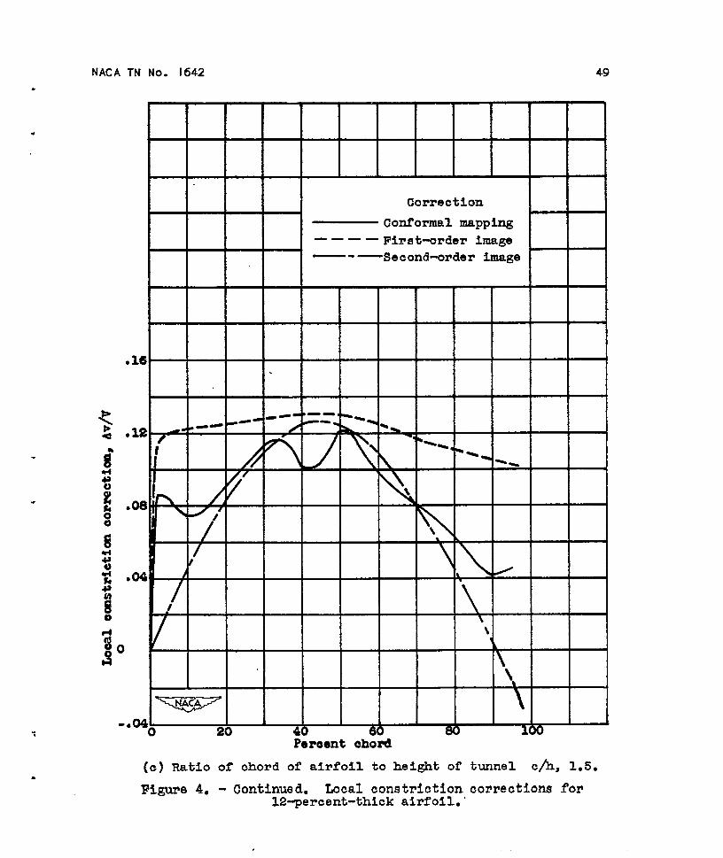
NACA TN No. 1642 49
Correction
— Nonformal mapping
‘— ——First_order image—.— Second-order image
.
*-4.3.2y- “
-- 0 -.
f
.08
/I
.04
/
~.040
20 40 60 60 100Pereent ehmd
(c) Ratio of chord of airfoil to height of tunnel c/h, 1.5.
Figure 4. - Continued, Local constrictioncorrectionsfor12-percent-thick airfoil.’

50 NACA TN No. 1642
● m
.24
.20
● le
● 12
. oe
.04
0
-.04
Correction
Conformal mapping
— — — — First~rder Image
— - — Second-order image
Pereent chord
(d) Ratio of chord of airfoil to height of tunnel c/h, 2.0. ‘
Figure 4. - Concluded. Local constriction corrections for12-percent-thick airfoil.
.
.
.
.
.
.

NACA TN.
No. 1642 51
.
Pereent ohord
(a)Ratioof’chordof airfoilto heightof tunnel cA, 0.5.
+H-H+---F~=:O:mI—Conformal mapping
—---Second-order image
Peroent chofi
(b) Ratio of chord of airfoil to height of tunnel c\h, 1.0.
Figure 5. - Local constriction.corrections for 24-percent-thickairfoil=
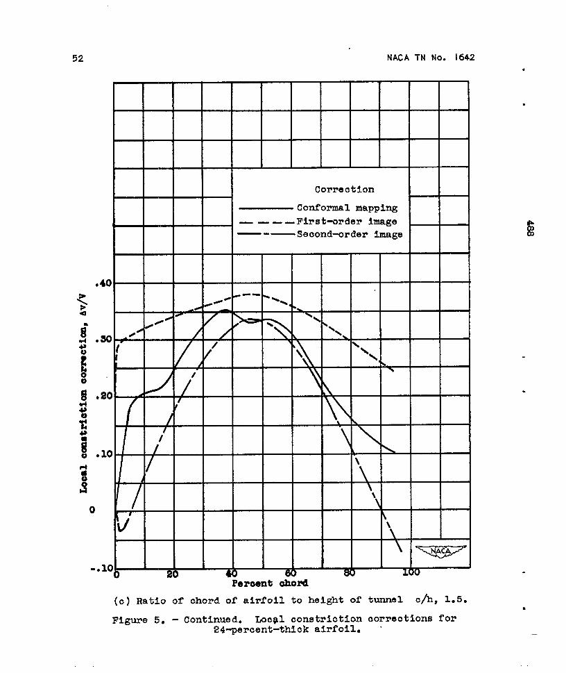
52 NACA TN No. 1642+
●
●
●
●
0
A
Correction
Conformal mapping
— ———First-order image—-—Second-order image
,/~/
30 ..4’/
/
10 ~
1
b
J\
Percent chord
●
.
.
(c) Ratio of chord of airfoil to height of
Figure 5. - Continued. Loc?l constriction24-percent-thick airfoil.
tunnel c/h, 1.5.
corrections for
—

.
.
●
.
NACA TN No. 1642 53
Correction
— Conrormal mapping ,
--- ‘Flrst_order image/ —.— Second-order image
f\\ i
\.60 I
IJ
w .\
4 \9
i I \\
.s0\
i \\I
/
9
● 40 #
\\
I
.30 /
/.\
/
\
k
\.20. 1
AI \ !
● 10II \
1
/o I
~
1
\v
-.10020 40 60 80 100
Pe#eent chord
(d) Ratio of chord of airfoil to height of tunnel c/h, 2,00
Figure 5. - Concluded. Local constrictioncorrectionsfor24-percent-thickairfoil.

54 NACA TN No* 1642
.s6 . /I
!
An/
t/
v
.4a/
#
/
/
.44 , /
I /~.40
//A / ‘*
.ae. // /
A‘
●
/
/~.aa. . . — . — — . .
,//t
/ / ‘.a4 , / /
//\
? /
.ao. / 0
/
● 16
/
,// y/, /.
.18 , / @
comeot.lonConrormd mpplmg
. ———— Flrat-order imnse—- —SeOond-a~der image
o0 .
tolh~
m
.
.
.
i“
Flguro 6.- Oompcri80mof ●vorcgs owmtrlotiom oormetlons by dlfforont nsthodm. o, ohordof ●lrroll; h, height of tuonel; t, maxlmmnthiokaass of ●irfoil.

NACA TN No. 1642 55.
.
.
“
.
.
EJ*oEElo0
.48
.44
.40
.88
.32
2a
,24
.10
.16
..12
.08
.04
00 J .2 A .4 A -6 J a d u
tc/h2
(a) As a function of tc/h2.
F@uxe 7. - Conetrictlon oorreoticm 3y mapping averaged along ohord for airfoils of12-peroent and 24-peroent thlakness and a Ikplan eectlon of 10-~roent thiokwms.c, ohordof airfoil;h, heightof tunnel;b, muimum thloknessof airfoil.

56 NACA TN No. 1642.
-—.
$E‘%
● M
.82
.28
.24
●2O
.16
.12
.06
. Oq
610
.
.
c/h
(b) As a funotion of c/h.. ,
Hgure i’. - Continued. Constrlotion oorreotion by mpping averaged along ohord for air-foils of 12-peroent and 24-~roent thiolrness mda Khplan seotion of 10-percent thiok-nesO . c., ohord of airfoil; h, height of tunnel; t, maximum thiclmess of airfoil. ●_

NACA TN No. 1642 57
t/h
(o) Asafunotionof t/h.
Figure 7. - Concluded. Constriction correction by mpping averaged along chord for air-foils of E-percent and24-wroent thidmess and a Bliplan section of 10-percemt thiek-nem. c, chord of airfoil; h, height of tunnel; t, maximumthidmess of airfoil.

.
8
1.3
1.1
.9 .Method
O FWte chord; 24-point
0 Sconi-tntlntta ohord, f’rent Wr or al.rfoil; 4B~oint
A Semi-inftite ohord, rear half or airfoil; 48-pointTailed symbols Indiaate ra jacted pointo.
.8
z%
.7 v 210 20 30 4 0 60 70
Pad: chord80 90 100 z
o
F~ISUW 8. - Comparison of velocit dletrlbut.lona by the two confomml-mapp~ ESthOdO. 12~rcant-Wck airfoil; ~u = 1.5; vo, Vel.city . . ~rroll In tunnel O, equivalent eascadea; V, undl.tur,ed .traem velcmlty.
+N
, . 88?., %
52 BEPOET ITATIOI?AII ADVT-SOItYCOMWICTEE FOR AERONAUTICS
order to determine the starting cbasactwistics of a weight loss of both metals to practically zero even af~er
commercial 220-pound-thrust rocket engine using crude 26 days of exposure to the acidat170°F. Additiondmonoethylani.lineandotherfuelswithmixedacid. informationconcerningthedIectoffluoridesoncorro-Thefreezingpointsandlow-temperaturefuel-ignitingsionwasobtainedby mm-wring the electrode potentials
propertie9offnmiignitricacidsareofcurrentintere9tofthemetalsagainstaplatinumreferencedectrocle.becauseofademandtoextendtheuseoftheseoxidmtstorocketsoperatingatlowtemperature.The inter-RocketCombustionrelatedeffectsofwater,fromOto10percentbyweight, Ignitiondelaydeterminationsofsevmdfuelswithandnitrogentetroxide,fromOto25percentbyweight,nitric-acidoxidantsweremade atsimulatedaltitudeinfumingniticacidwerestudiedwithrespecttothefreezingpointsoftheacidandth~ignitionde~ayswith
conditionsfrom sea level to 100,000 feet utilizing asmall-scale rocket engine of approximately 60 pounds
several fuels. Several potible chemi~ ~~m @ the ~8t. ~c]uded in the fuels ~we n.nfie, hydmzineopposing effects of WLtsr ~d fitrogen tetromde ‘n hY~te, furf~l alcohol, furfuryl mcrcaptan, turpm-ignition have been proposed. tine, and mistures of triothyhunine with mixed xylidines
lWition delays of severaJ prope~~t combinations and dia~Y]-e Red-fuming, white-fuming, ml
obtained with SLmodified open-cup apparatus and a anhydrous nitric acids were used with and withoutsmall-scale rocket engine of approximately 50 pounds ~ddi~vwthrust were compared to study any correlations that The rocket phenomenon known as scremning oftmmight exist between the two methods of ignition-delay causes chamber, injector, or nozzle burnout fdures rmcldetermination. The results were wed ~ deter~~g ha been obse~ed to inwwe the specitic impulse.the relative utility of each apparatus.
The literature pertaining to the preparation, physicalRocket-engine screaming is a type of combustion-driven
properties, corrosiveness, thermaI stability, constitu-oscillation, with frequenciw from 1,000 to 10,000 cyclw
tion, and analysis of various nitric acids has been re-per second, and i? characterized by an audible wnilingeshaust sound, by a bluish ahnostAnvisible eslmust jet
viewed primarily with respect to their use as rocketConflicting data are evaluated and recom-
in which the shock positions oscillate (making tho shockoxidants. . . pattern appear fuzzy to the eye) and by increased hmtmendations fOr WkhtlOn~ qe~ent~ work we tramf ~ to the charnb~ s~aces. The high- froquenoyindicated. oscillations have been attributed to a combustion-rein-
Numerous studies have been made of the vaPor forced pr~ure wave passing through the chamber andpressure of essentially pure nitric acid and of the binary reflecting from the chamber surfaces to trigger thesystem, nitric acid-water. Data for the ternary system, succeeding combustion surge. The frequency wouldnitric acid-water-nitrogen dio~de, me for the most therefore be governed by the velocity of wave propnga-part lacking. Work was therefore undertaken to pro- tion and the geometg of the chamber. A simplifiedtide more complete vapor-pressure data for the ternary analysis, based on the concept of acoustical resonance,system at physicaI equilibrium. ~e9 conta~g h~ be~ developedto correlate scream frequencies with
?1 to 97 weight-percent nitric acid, O to 20 percent chamber geometzy in terms of experimentally mensur-nitrogen dioxide, and O to 15 percent watar were used.N able quantitbs. The derived parameter is substwn-
Because the storage of fig fitric acids Pr~en~ a ti~Y k&pen&nt of propellant combination or opor-serious operating problem, means for improving the atig con~tions
storage properties of this acid were sought. The storage The application of radiation-measurement techniquesproperties of fuming titric acids, ~th ~d ~tho~lt to the det(tiation of gas temperatures in the flame
additives, were studied at a temperature of 170° F in resulting from liquid propellant reactions has recentlyclowd conts,iners of approximately 100-milliliter capnc- been ~vwtigated Such techniques are clesirnblo inity; the containers had aluminum bodies and stairdw- rocket combustion and injector design studies becausosteel caps.
Among the storage properties of fuming nitric acid,they permit the study of conditions in a flame zone
corrosion and decomposition are of foremost concern.without disturbing the flow and without the necessity
Additional information concmning the effectivene.w ofof maintaining a probe in the chamber. Radiation-
fluorides as corrosion inhibitors in fuming nitric acid wastemperature measurements were made throughout tlm
therefore obtained. It was found that for acids con- flame developed within an open-tube combustor using
taining no fluorides, the weight loss of aluminum was liquid oxygen and a heptane-turpentine mixture M the
approximately one-fifth that of stainless steeI. Addi- rmctants.fi The temperature measurement utilizes
tion of l-percent fluoride ion to the acid reduced the carbon radiation from the flame.
:1&E~B by MoKemn andBeW IIstedon p. 73. S SW PM by AubleandHekhnannW onm70.

REPORT NATIONAL ADVISORY COMMITTEE FOR AERONAUTICS 53
AIRCRAFT CONSTRUCTION
Problems associated with the structural integgity ofaircraft in the subsonic and lower supersonic range aremany and complex. Aerodynamic heating resultingfrom greater speeds continues to add a host of newproblems and to complicate those of a long standingnature further. The need for increased research in thefield of aircraft construction is evident.
The NACA, during the past year, has continued itsefforts on the important problems associated withstructural strength, efficiency, loading, flutter, fatigue,and materials under normal temperatures. It has alsodeveloped research tools and techniques for investi-gating aircraft under the elevated-temperature condi-tions encountered in high-speed flight. Further, it haasucceeded in defining and exposing new- thermal prob-lems which future high-speed aircraft will encounterand has found solutions to certain of these problems.
Most of this research has been performed at theNACA laboratories with additional assistance providedby educational and other nonprofit institutions undercontract to the NAC?A. A description of the Chnrnit-tee’s recent unclasstied research in the field of aircraftconstruction is given in the following pages and isdivided into four sections: (1) Aircraft Structures;(2) Aircraft Loads; (3) Vibration and Flutter; and (4)Aircraft Structural Materials.
AIRCRAFT STRUCTURES
Static Properties
The use of integrally stiffened skins on aircraft isincreasing because of the possibilities of saving weightand eliminating rivets and bolts. Compared withriveted-on stiffeners, integral stiffeners participate morefully with the skin in resisting external loads but,because of this action, may lead to an undesirablecoupling of plate distortions for certain proportions andloading conditions. The nature of this problem isdiscussed in Technical Note 3646 where the modifica-tions to the equations for stress distribution anddeflection are made to account for the effects of coup-ling. Conditions under which the effects of couplingare significant are given in this paper.
Because engineering beam theory fails for deflectionanalysis of thin low-aspeckratio wings, the developmentof efficient methods of analysis has become a problem.A matrk method based on energy principles for obtain-ing influence coefficients is presented in Technical Note3640. The required matrices may be set directly hornthe data of the wing design. The necessary calcula-tions have been arranged to take full advantage ofautomatic computing machines.
The thick-skin multiweb box beam is representativeof wings of high-speedrmd strength analysis of
aircraft. Experimental datathis component are presented
inTechnical Note 3633. The combinationsofdesiOqparameterswhichleadtominimum structuralweightforvariousvaluesofa loadingindexaregiven.Theresultsarepresentedinsuchamannerthatthelightestweightstructurewhichsatisfieswing-stiflnessrequire-mentscanbefound.Classicaltheoriesof the structuralstrengthand
stabilityofplatesasslme thattheplatedeflectionsexperienwdaresmailin comparisonwith theplatethiclmess.In orderto evaluatethe inaccuraciesresultingwhen thisassumptionisnotfulfilled,Colum-biaUniversityhasdevelopeda nonlinearplatetheoryofmotionandsolvedtheequationsforcertaindynamiccases.Underlyingassumptionsofvariousplateequa-tionshavealsobeenstudied.The resultsofthisstudyarepresentedinTechnicalNote3578.Comparisonsbetweentheresultsof u theoryfor
calculatingstressesaroundcutoutsinstiffenedcylindersand theresultsofexperimentarepresentedinTech-nical Note 3544. The data and the theory were pre-viously published and coefficients for use with thetheory have been calculated and published in Tech-nical Note 3460. The theory takes into account thebending flexibility of the ring stitleners. The com-parisons show that good agreement is obtained if thisfactor is correctly accounted for.
New York University has conducted, under NACAsponsorship, a critical review of the literature pub-lished since 1940 on buckling and failure of plate ele-ments. The results of this review, including a com-pilation of existing theories and experimental data, arepresented in Technical Note 3781. A similar reviewhas also been made at NTew York University of theexisting literature on buckling of composite elements.The results of this review are presented in TechnicalNote 3782. During these reviews, general equationsfor the plastic buckling of cylinders were derived.These equations were then used to obtain solutions forthe compressive and torsional buckling of long cylindersin the plastic region. These results, as well as com-parisons between computed and test dat%, are premntedin Technical Note 3726.
An analysis of the stresses in the plastic range arounda circular hole in a plate was made both to exploremeans for solving stress problems in the plastic rangeand to obtain the solution of this basic problem. Theresults are presented in Technical Note 3542. Calcula-tions were made for four diflerent materials and theresulting stress-concentration factors are comparedwith those derived from a previously developed approxi-mate formula.
Dynamic Properties
The major role that flutter plays in the d=ign ofhigh-performance aircraft requires that methods for
/

54 REPORT NATIONAL ADVISORY COMMITTEE FOR AERONAUTICS
computing accurate vibration modes and frequenciesbe obtained. In Technical Note 3636, the investiga-tion of the usefulness of the substitu-tringer methodfor including the effects of shear lag in the calculationof the transveme modw and frequenciw of box beamsis continued. Box beams, the covers of which consistof normrd%ress-carrying stringers OD sheets carryingnot only shear but also normal stres, are analyzedexactly. Frequencies of beams with various numbersof stringerq obtained by means of this exact analysis,serve to d&ermine the possible accuracy of the fre-quencies obtained by the substitute-stringer approach.A combined experimental and theoretical investigationof the modes and frequencies of a large-scale built-upbox beam is reported in Technical Note 3618. Forbending vibrations, frequencies obtained from an
analysis of a substitute-stringer structure which in-cludes the influence .of transverse shear deformationand shear lag were found to agree very well with thoseobtained experiment$ly. In the case of torsional
vibrations, the frequencies obtained horn either anelementary or a four-flange beam analysis whichincludes the effects of restraint of warping were foundto be in satisfactory agreement with the ~xperimentalfrequencies.
The vibration characteristics of hollow thin-walledrectangular beams have been investigated to obtaininsight into the factors affecting the modes and fre-quencies of wings. The experimental results from thisstudy are presented S Technical Note 3463 and indicatethat the effect of shear deformation of the cross sectionon the torsional frequencies can be large. Furtherevaluation of this effect has been made and is prwentedin Technical Note 3464.
Thermal Properties
Rapid changes in temperature of the surface of anaircraft can induce thermal loads in the primary struc-ture which may havq serious aerodynamic and struc-tural consequences. The nature of this problem wasinvestigated by subjecting box beams which simulatehigh-speed-wing structure to a high-intensity heatsource. These tests are reported in Technical Note3474. It was found that the internal structure of thebeams provided enough restraint against expansion ofthe heated skin surfaces to cause severe buckling of theskin. Buckling of the shear webs occurred during thecooling phase of the test when the temperature of theinternal structure exceeded that of the skin. Measuredstrains were used to determine distortions and strwseswhich were found ta agree with a thermal stress analysisof the test conditions.
One of the most important structural problemsresulting &m aerodynamic heating is the deteriorationof material properties at elevated temperatures. Thisdeterioration of m+erial properties produces loss ofstremzth and creeD of structures and can lead to weight
increases that advermly ailect the performance ofhigh-speed aircraft. A study has been made of thestrength and creep behavior of aircraft structuralelements at elevated temperatures to obtain methodsfor predicting structural behavior from materialcharacteristics. One of thwe studies, reported inTechnical Note 3552,wasconcernedwiththeelevnted-temperaturecompressivestrengthandcreeplifetimeofsimplysupportedplatea.A similarstudyon thecom-pressivestrengthand creep lifetime of skin-stringerpanels is reported in Technical Note 3647. Bothstudi-indicatethatelevated-temperaturestrengthofstructuralelementscan be predictedfrom methodsavailablefordeterminingg room-temperatimestrengthprovidedfihattheappropriatestress-straiucurveforelevated-temperaturemater@l is used. Previouslyreported studies of the elevated-temperature bucklingstrength of structural. components have indicatedsimilar results. The present studies also show thatcreep lifetime of structural elbents maybe determinedfrom methods used to determine str~ctural strength ifthe compressive creep properties of the mnterial aresubstituted for the material stress-strain curve, Theresults make it possible to estimate the effect of creepon the weight of structures that are designed to operateat elevated temperatures.
The transient thermal s@esses produced by aero-dynamic heating of supersonic aircraft depend uponthe temperature distribution within the structure,which, in turn, can be markedly influenced by the ther-mal conductivity of any joints present. In order toinvestigate the effects of joint conductivity on thethermal stresses in aerodynamically heated skin-stifFenercombinations under various aerodynamic conditions,a theoretical study was made. In this study an rtero-dynamic heat-transfer parameter (called the Biotnumber), a joint-conductivity parameter, and geo-metrical proportions were varied. The results, pre-sented in Technical Note 3699, indhte that increasingthe joint conductivity beyond a certain value resultsin almost no change in the maximum skin or stiffenerstiess.ee; but, as the joint conductivity approaches zero,the maximum ah% and stiffener stresses increaseappreciably. Increasing the Biot number, an index ofthe rate of transfer of external heat to internal heat,can also cause a considerable increase in the maximumskin and stiilener stresses. However,when theBiotnumber islarge(highrateofexternnlheating),thevalueof the jointconductivityisrelativelyunim-portantsincethestructureisheatedsofastthatthereisno timeforheattobeconductedintotheinteriorofthestructure;thejointconductivitythusaffectsthethermalstressesmost significantlywhen theexternalheatingrateislow. Changingthegeometriccharncter-istimproducesresultswhicharementiallyindependentofthejointconductivityandtheBiotnumber.In thedesiznofaircraftstructnrea.wherenerodv-1., .,

REPORT NATIONAL ADVISORY COIKMITTEE FOR AERONAUTICS 55
namic heating is encountered, knowledge of the tem-perature distribution within ‘the structure is of consid-erable importance. Because interior elements of thestructure me heated by conduction through joints, theinfluen~ of various joint properties on thermal con-ductance has been invcatigated previously and reportedby Syracuse Univemi@. Before extending this inve.sti-gntion, Syracuse University explored the influence ofjoint conductance on the transient temperature distri-bution in composite aircraft joints. Fabricahd speci-mens representative of typical skin-stringer cross sec-tions, as well as geometrically similar specimens withoutjoints, were tested under aerodynamic heating condi-tions and the resuh% from the two sets of joints werecompared. The results, which are presented in Tech-nical Note 3824, indicate that, in the practical case,joint conductance must be taken into account if tem-perature distributions throughout composite structuresme to be predicted accurately.
Aircraft structures for high-speed flight must be de-signed so that excessive creep deformation and creeprupture does not occur during the design lifetime of thestructure. An understanding of the creep behavior ofstructures is therefore neceswuy in order to eliminatesuch failures. A previously reported investigation bythe National Bureau of Standards indicated that creepdeformations within joints may be responsible for a con-siderable portion of the overall deformation of struc-tures. However,no correlationwas obtainedbehveenthecreepofa rivetedjointandthecreepofitscompo-nentmaterials.Thisstudyhasnow beenextendedandcreep-testresultsofa numberofadditionaljointsarereportedinTechnicalNote 3842. Methodsarepre-sentedby whichthetimetorupture,themode ofrup-ture,and thedeformationof structural joints in creepmay be predicted. These methods are based upon thecreep properties of the materials of the joint in tension,shear and beming.
Aircraft structural elements subjected to long periodsof henting nnd compressive loadings can buckle eventhough the applied load is less than the critical load ofthe element at the elevated temperature. This phe-nomenon is called creep buckling. Research equipmentand techniques have been developed at the PolytechnicInstitute of Brooklyn and are presented in TechnicalNote 3493. Additional creep-buckling tests of 2024T4aluminum alloy columns besides those published in thisreport have been conducted and the results correlatedwith theory.
The aircraft designer at the present time must dealwith a multiplicity of materials and material propertieswhich vary with temperature. It is essential, therefore,that speedy and accurate methods for predicting theinfluence of changea in materkd properties on structuralstrength be available. Such methods are given in Tech-nical Note 3553 and Technical Note 3600 for varioustypes of structural components which fail by compres-
43087-74
sive crippling. The methods utilize the concept ofcrippling-strength moduli which are readily calculatedfrom the compressive properties of the material in thestructure. Accuracy of the methods is illustrated withexperimental data obtained in various materials andunder ditlerent temperature conditions.
The transient temperature distributions produced byaerodynamic heating of thin solid wings induce thermalstresses that may effectively reduce the stifness of thewing. This is a new problem that can be a significantfactor in the aero-elastic behavior of aircraft structures.Such reductions in stiffness have been investigated ex-perimentally by rapidly heating the edges of a cantileverplate. The midplane thermal stresses imposed by thenonuniform temperature distribution caused the plateto buckle torsionally, increased the deformations of theplate under a constant applied torque, and reduced thefrequency of the first two natural modes of vibration.Small-deflection plate theory, employing energy meth-ods, predicted the general effects of the thermal stressesbut became inadequate when plate deflections werelarge. Additional studies have been initiated to investi-gate these effects.
AIRCRAFT LOADS
Basic Load Distribution
Extensive &ht investigations have been made withthe X–5 variable-wing-sweep resemch airplane atMach numbers up to 1.0 to determine the effects onthe wing and horizontal tail loads of varying the angleof wing sweep without modifying the other character-istics of the airplane. Up to a Mach number of 0.85,the balancing horizontal-tail loads measured in flightshow a consistent variation as the wing sweep angle isincreased from 20° to 59° with the greatest down tailload occurring at aweep angles of about 36°. The wingloads were found to have a nonlinear variation withairplane angle of attack and to reflect the changes thatoccurred in the wing characteristics. In another flightinvestigation, pressure measurement over the midspanstation of the 8-percent-thick wing on the X-1 airplanein the tmnsonic speed range showed a rmard move-ment of the chordwise load center with increasingMach number with a particularly rapid and largemovement in the Mach number range of 0.82 to 0.88.In th,e Mach number range 0.95 to 1.25 at high normalforce coeilicients, upper surface pressure distributionsapproached a rectangukw slope.
In Technical Note 3476, spanwise lift distributionshave been calculated for 61 swept wings with variousaspect and taper ratios and a variety of angle+f-attackdistributions including flap and aileron deflections.The information presented can be used both in theanalysis of untwisted wings or wings with known twistdistributions and in aeroekstic calculations involving

56 REPORT NATIONAL ADVISORY COMMI’FI’EE FOR AERONAUTICS
initially unknown “twist distributions. The informationpresented in Technical Note 3476 supplements similarinformation previously given in Technical Note .3o14for unswept vvings so that the two papers cover allpractical plan forms.
A method for computing the span loads and theresulting rolling moments for sideslipping wings ofarbitmuy plan form in incompressible flow is presentedin Technical Note 3605. The basic method requiresmechanical differentiation and integration to obtainthe rolling moment for a wing of arbitrary plan form insideslip when the span load at zero sideslip is bow-nThe mechanical ditlerentiation and integration canbe avoided, however, by use of a step-load methodwhich is also derived. A comparison of the calculatedspan loads and rolling-moment parameters with avail-able experimental data shows good agreement.
The development of new--type control devices requiresthat structural design data be provided. The effects,therefore, on the chordtie pressures and section forcmand moment codicient.s near midspan of deflectingvarious plain spoilers and a flap-type control with andwithout an attached tab on a swept wing have beeninvestigated at Mach numbers horn 0.60 to 0.93.
In order to design aircraft one must have a lmowledgeof body eilects on the wing spanwise load distributionat all speeds. Although methods exist for predictingsuch body effects on sweptback wings at low speeds,practically no direct experimental verifications havebeen available. In a recent investigation, detailedwing pressure-distribution data that permit the desiredcomparison were obtained. The data, reported inTechnical Note 3730, indicated that, although previousmethods did not satisfactorily predict body effects onthe unflapped uncambered wing, a swept-wing methodemplo~g 19 spanwise Iifting elements and controlpoints gave good agreement except when the wing haddeflected trailing-edge flaps or was cambered andtwisted.
Normal-force and normal-pressure distributions foran ogive-cylinder body of revolution of fineness ratio 10are reported in Technical LTote 3716 for a free-streamMach number of 1.98 and an angle-of-attack rangefrom 0° to 20°. Comparisons of experimental andtheoretical normal-force and normal-pressure distri-butions indicate that available theoretical methodscan be used to predict experimental results with goodaccuracy for angles of attack to about only 5°. Atgreater angles of attack, the normal-force distributionsdHer signiiknntly from those calculated in accordancewith theories which include methods of estimating theeffects of viscosity on the fore= and moments forinclined bodies. Analysis of the data shows that thesediilereuces are, in general, attributable to inadequateestimates of the magnitude and distribution of thecrms forces resulting from flow separation. A correla-tion curve for the longitudinal distribution of the
cross-flow drag coefficient for laminar boundary-layerflow- has been developed and is based upon the aswnnp-tion that the distribution dependa primarily upon thebody shape. It is believed that use of this curve forthe viscous cross-force contribution in conjunctionwith first-order linear theory for the potential crossforce provides a satisfactory method for estimatingnormal-force and pitching-moment characteristic forsimilarly shaped bodies with laminar-boundary-layerflow.
In Technical Note 3479, horizontal-tail lords meas-ured in gradual and abrupt longitudinal maneuvers ontwo configurations of a four-engine jet bomber arcpresented. The leasksquares procedures were used todetermine aerodynamic loads from strain-gage measure-ments of structural loads. The results are anolyzed todetermine the flight values of the aerodynamic coeffi-cients which are important in calculations of horizontnl-tail loads for comparison with wind-tunnel results.The effects of fuselage flexibility on the loads are de-termined and some calculations of critical horizontal-hil loads beyond the range of the tests are comparedwith the design loads.
Some indication of the importance of the directional-stability characteristics of present-day high-speed air-planes with increasing angle of attack and Mach num-ber has become apparent from recent wind-tunnel tests.An analysis of wind-tunnel data has shown that thevorticity shed from the nose of the fusel~~e and directedby the wing to strategic locations in the vicinity of thevertical tail markedly affects the load on the ver~icaltail in siddip at high angles of attack and supemonicMach numbers. For such conditions, the directionalstability of the airplane may become negative.
Gust Loads
The collection of data with NACA VG and VGHrecorderstodeterminethemagnitudeandfrequencyofoccurrenceofthegustsandgustloadsandtheoperatingairspeedsand altitudesofcommercialtransportair-planeshasbeencontinued.The VGH datacoveringabout3,OOOhoursofoperationfromtwotypesoffour-enginetransportairplane9currentlyinuseon trms-continentaland easternUnitedStatesroutesarepre-sentedinTechnicalNotes3475and3483. The rumlyskofthesedataindicatesthatthemoreseveregustloadsoccurredforoperationsovertheeasternportionoftheUnitedStates,aresultattributabletothehigheroperat-ingspeedsinroughairfortheseoperations.A relatedstudyofapproximately70,000hoursofVG datafromsixdii7erentoperation9of twin-enginetransportair-planesoverthepasteightornineyeara,presentedinTechnicalNote3621,indicatesthattheloadsandgustswere comparablewiththoseexperiencedinpreviousoperationsofthesametypeofairplane.The informationavailableonthespectrumofatmos-
phericturbulenceisbrieflyreviewedinTechnicalNote

REPORT NATIONAL ADVISORY COMllIT’T EE FOR AERONAUTICS 57
3640 and n method is presented for converting availablegust stru5stic9 normally given in terms of counts ofgust peaks into a form appropriate for use in spectralcalculations. The fundamental quantity for this pur-pose appears to be the probability distribution of theroot-mean-square gust velocity. Estimates of the vari-ation of this distribution with altitude and weathercondition are also derived horn available gust statistics.A critical problem in connectiontith the design and oper-ation of missiles and airplanes capable of high-speed ver-tical flight arises horn the loads and motions experiencedwhen intense layers of wind shear are encountered.As a consequence, data on the magnitude and frequencyof occurrence of the shear layers at diflerent altitudesand sensons were determined from U. S. Weather Bureaurawinsonde data and are reported in Technical Note3732. These data indicate that maximum shear inten-sities of about 120 feet pcr second per 1,000 feet occi.uat altitudes of about 50,000 feet during the spring andwinter seasons but occur in relatively thin layers havingthicknesses not greater than about 3,000 feet.
A method for obtaining a power spectrum of verticalgust velocity over a wide range of wave length has beendevised and test resuIta are published in TechnicalNote 3702. A spcctrnm of vertical gust velocity wasmeasured at low altitude in clear-air turbtience havinga root-mean-square intensity of 5 feet per second forwave lengths from 10 feet to 60,000 feet. At the higherfrequencies (short wave lengths), the power spectraldensity varied at n rate which was approximately pre-dicted by theory. The spectrum which was obtainedtended to flatten out for the longest test wave lengths.The break frequency which provides an indication ofthe scale of the turbulence occurred at a wave lengthof approximately 6,000 feet.
Calculated unsteady-lift functions and spanwise liftdistributions for delta, rectangular, and elliptical wingsundergoing a sudden change in sinking speed axe pre-sented in Technical Note 3639. These data indicatethat the normalized unsteady-lift. functions are substan-tially independent of the plan form for elliptical, rec-tangular, or moderately tapered wings, but for deltawings the increase of lift toward the steady-state valueis much more rapid. The results in this report corrobo-rate the results of other investigations which show thatthe rate of growth of lift tends to increase with a de-crease in aspect ratio and that spamvise distributionsof the indicial lift seem to be independent of time forrectrmgukm and elliptical wings. In Technical Note3748, reciprocal relations for unsteady flow are used tocalctdate total-Lift responses of wings to sinusoidal gustsand to sinusoidal vertical oscillations. A variety ofplan forms are considered for incompressible, subsoniccompressible, sonic, and supersonic flow. A theory ispremnted in Technical Note 3805 for calculating thevariation with frequency of the lateral-force and ymv-ing-moment coefficients due to sinusoidal side gusts
p&g over the profile of a simple fuselage combinedwith a vertical fin. Since slender-body theory is used,the results are applicable to both subsonic and super-sonic airspeeds, provided the locrd flow anglea betweenthe profile and the airstream are small.
An investigation to determine the gust-alleviationcapabilitiw of iixed spoilem and deflectors on a trans-port-airphme model incorporating a straight wing isreported in Techaical Note 3705. The results indicateabout equal effectiveness (from 20 to 40 percent) ofspoilers or deflectors in reducing normal accelerationsin rough air through reductions in lift-curve slope.Both devices were also equally effective in decreasingthe air-speed through increased drag. In TechnicalNote 3746, the wing and horizontal-tad loads and sparstrains measured on a twin-engine light transport air-plane, modiiled by a gustdeviating device for passen-ger comfort, were presented. The results presented arew initial analysis of samples of measurements obtainedin clear-air turbulence with the alleviation system bothoff and on. Although the alleviation system was notoptimum, the root-merm+quare normal acceleration atthe airplane center of gravity was reduced by 43 per-cent and the wing bending strains were reduced, butwing-shear strains and horizontal-tail shear and bendingstrains wwe increased.
Landing Loads
b Technical Note 3541, a method is presented forstatistically deriving contact vertical velocities of air-plane9 from measmremerts of maximum incrementalcenter+f-gravity acceleration at contact. Probabilitycurves of derived velocities for a test airplane whencompared with curves of measured velocities show wdiilarence. of 1sss than 0.2 foot per second throughoutthe velocity range covered in the investigation. A sta-tistical comparison of the landing-impact velocities ofthe fit and second wheel to touch ground from about35o transport landings is reported in ,Technical NTote3610. The comparison indicates that the mean verti-cal velocity at the instant of contact was about thesame for either wheeI but that the probabili~ of ahigh value of verticid velocity was somewhat greaterfor the second wheel to touch than for the tit. Theeffect of the rolling velocity of the airplanes at theinstant of initial contact was to increase the vertiwdvelocity of impact of the wheel toward which the fiir-plane was rolling regardless of whether it was the firstor second wheel to touch. There appmred to be nodefiaite inibnce of the ratio of landing-gear head toradius of gyration of the airplanes on the relative ver-tical velocities of the first and second wheels to touch,as would be expected from theoretical considerations.
Technical Note 3604 reports results of tests made todetermine the lateral or cornering force, drag force,torsional moment or self-alining torque, pneumatic cas-ter, vertical tire deflection, lateral tire deflection, wheel

58 REPORT NATIONAL ADVLSO13Y COMM31FTEE FOR AEEONAUIYCS
torsion or yaw angle, rolling radius, relaxation length,tire footprint area, and variation of unloaded tireradius with inflation pressure for two 26- by 6.6-inch,type VII, 12-ply-rating tires. Data were recorded forconditions of rectilinear-yawed rolling over a range ofinflation pressures and yaw- angles at the rated verticalload and at twice the rated vertical load. Vibrationtests were made to determine the dynamic lateralelastic characteristic= of the tires. During rectilinear-yawed rolling, the normal force generally increasedwith increasing yaw angle within the test range, thevariation of normal force with yaw angle differed forthe two vertical loads tested, the pneumatic caster wasa maximum at small yaw anglea and tended to decreasewith increasing yaw angle, and the sliding drag coef6-cient of tiction tended to decrease with increasingbearing pressure.
A comprehensive correlation, evaluation, and ex-tension of linearized theories for tire motion and wheelshimmy has been made and is reported in TechnicalNote 3632. It is demonstrated that most of the pre-viously published theories represent varying degreesof approximation to a summary theory developedtherein which is a minor modification of the basictheory of Von Schlippe and Dietrich. In most caseswhere strong di.tlerences exist betmeen the previouslypublished theories and the summary theory, the pre-viously published theories are shown to possess certaindeficiencies. Compmison of the existing experimentaldata with the predictions of the summary theory pro-vides a fair substantiation. Some discrepancies existhowever, which may be due to tire hyster~ effects orother unknown influences
Theory indicates a sharp increase in the hydro-dynamic load as the dead-rise angle approaches zero.There have been, however, few experimental dataavailable for verifying the loads predicted by theory forangles of dead rise below 20°. Results of a brief inves-tigation of the loads in smooth water for 10° angle ofdead rise are reported in Technical Note 3608 and arecompared with theory for immemed hydrod~amicimpact of nonchine bodies. The trend of the experi-mental variation of load-factor coefficient, draft co-e%icient, time coefficient and velocity ratio is in goodagreement with the theoretical variation.
Technical Note 3619 presents data showing theeffect of horizontal restraint of carriage mass in experi-mental testing facilities upon the general theoreticalequations of motion for the prismatic body during ahydrodynamic impact. The data indicate that thecarriage mass has little effect for the lo-iv trims, sinceat this condition the resisting water force has only asmall component in the horizontal direction, but forthe higher trims the tiect is appreciable. For themore usual seaplanedesign conditions, that is, approachparameter larger than 1.0 and trims up to 15°, the
maximum correction for any of the coefficients is 10percent or less.
Research Techniques
It is frequently desirable to predict the loads thatwould be experienced with more hazardous controlmotions or flight conditions thtm those for which testdata exist. Accordingly, considerable effort has beenexpended in developing and comparing various methodsby which such predictions can be made. Fourier andLaplace transforms and %he type of analyses used instudies of servomechanisms have been used extensivelyin this development. It appears from the work nc-compli.shed that the concept and use of a unit impulseas a research technique has considerable merit. Simpleand rapid methods for determiningg the time response toa unit impulse from frequency-response data and forevaluating the Fourier transform as a function of timehave been derived and are presented in TechnicalNote 3598. These methods are applicable to linearfunctions for which Fourier transforms exist, which isusually the case in the treatment of airplane maneuvers.In Technical Note 3701, the method developed inTechnical Note 3598 is compared with several othermethods of obtaining the time response of linear sys-tems to either a unit impulse or to an arbitrary inputfrom frequency-response data, The comparisons in-dicate that most methods gave good accuracy whenapplied to a second-order system; the main differenceis in the computing time. In general, the method ofTechnical Nob 3598 was advantageous in all respects,since it was more accurate and required less time.
VIBRATION AND FLUTI’ERFlutter ‘
The sonic and supersonic speeds of modern aircmftplus their use of relatively flexible thin wings andstabilize have caused flutter to assume a more im-portant role in aircraft design. In addition to reeemchon the flutter characteristics of typical aircraft con-@mations, research is also being carried out to under-stand better the aerod~amic, structural, and inertialconsiderations inherent in flutter.
On the basis of an analysis of a large quantity offlutter data taken from subsonic, transonic, cmd super-sonic wind tunnels and from rocket- and bombdroptests for a wide variety of wing plan forms, a criterionwas derived which permits a rapid estimate of theprobability of flutter for lifting surfaces. This criteriongroups the significant parametem into simple geometricdimensions and structural properties. Another simplocriterion was developed for stall flutter.
A number of swept wings having systematic variwtions in plan form and structural chamcteristica havebeen flutter tested in transonic and supersonic windtunnels to establish the effect of various parameters

REPORT NATIONAL ADVISORY COMMTTT ED FOR AERONAUTICS 59
on flutter and to serve as a basis for evaluating ana-lytical procedures. Beoause of the large number ofparametem involved, this is a large test program andis stilI underway.
An alternative to the testing of a systematic series ofwind-tunnel models in order to establish the influenceon flutter of elastic and inertial structural characteristicsis to employ an analog computer whose electricalelements and behavior approximate the elements anddynamic behavior of the structure. Such an analogstudy has been carried out at the California Instituteof Technology and is discussed in Technical Note 3780.Four wings representative of those of current aircraftwere considered and the effects of changes in bendingand torsional stifhwsses, mass distribution and angle ofsweep on the flutter characteristics were determined.A sufficient number of cases were treated to establishthe trend over a sizeable range for with parameter.
As reported in the I?orty-1’imt Annual Report, 1955,a theoretical study of the flutter of two-dimensionalpanels was reported in Technieal Note 3465. Morerecently, flutter of panels mounted on the wdl of asupemonic wind tunnel was obtained at a Mach num-ber of 1.3. It was found that, at the flow conditions ofthese tests, increasing the tensile forces in the panelwas effective in eliminating flutter, as was shorteningthe panels or increasing their bending stiffness. Noapparent systematic trends in the flutter modes orfrequencies could be observed, and it is significant thatthe panel flutter sometimw involved bigher modes andfrequencies. ‘ The presence of a pressure differentialbetween the two surfaces of a panel was observed tohavo a stabilizing effect. Initially buckled panels weremore susceptible to flutter than panels without buckling.Buckled panels with all four edges clamped were lessliable to flutter than buckled panels clamped only onthe front and rear edges.
In Technical Note 3638, a preliminary theoreticalinvestigation of the panel flutter and divergence ofinfinitely long, unstiifened and ring-stiflened, thin-vmlled, circular cylinders is described. Linearizedunsteady potential-flow theory was utilized in con-junction with Donnell’s cylinder theory to obtainequilibrium equations for panel flutter. Where neees-sary, a simplified version of l?liigge’s cylinder theorywas used to obtain greater acmracy. By applyingNyquist diagram techniques, analytical criteria for thelocation of stability boundaries were derived. Thisreport also includes a limited number of computedresults.
One of the most troublesome types of flutter is thatinvolving oscillations of a control surface at transonicspeeds, commonly referred to as buzz. In TechnicalNote 3687, results of wind-tunnel teats of three wingmodels are presented and it is shown that a large rangeof change in density of the test medium had little eilecton the initial magnitude and initial Mach number of
.
buzz. The buzz frequency decreased somewhat withdecrease in density. The Mach number correspondingto the onset of buzz decreased as the wing angle ofnttwk was increased. Mass balance and changea inspring stiilness changed only the oscillation frequency.The test results indicated that placing the aileron atthe wing tip delayed the onset of buzz to higher Machnumbem. A comparison of the experimental resultswith two published empirical analyses showed onlyqualitative agreement.
Desiggers of thin aircraft wings must consider thepossibility of wing torsion flutter at high angles ofattack, which is referred to as stall flutter. The resultsof an exploratory, analytical, and experimental studyof some of the factcm which might be of importance inthe stall-flutter characteristics of thin wings are pre-presented in Technical Note 3622. The factors con-sidered were Mach number, Reynolds number, density,aspect ratio, mveepbaok, structural damping, locationof the torsion node Line, and presence of concentratedtip weighti. The importance of aerodynamic tomionaldamping on the stall flutter of thin wings was demon-strated by comparison of the regions of negativetorsional damping measured on a spring-mounted modelwith the regions of flutter. The results of a serkx ofexperiments on a thin wing tested at various spansindicated that compressibility alters the stall-fluttercharaoteristies and that these effects depend uponaspect ratio. A brief study of the inertia effects of con-centrated weights at the tip indicated that such effectscam be important. An approximate analysis is pre-sented for such configurations.
Aerodynamicsof Flutter
It has been demonstrated that generalized forces for aharmonically oscillating wing in pure supersonic flowmay be expressed in terms of certain integrals commonlyreferred to as fx functions. These functions have beentabulated on a large eomputar for a wide range of param-eters important to flutter and the tabulated results arepresented in Technical Note 3606.A fundamental study of the aerodynamic forces on an
oscillating wing is presented in Technical Note 3643.This report presents the magnitude and phase angle ofthe components of normal force and pitching momentacting on an airfoil oscillating in pitoh about the mid-ohord at both high and low mean angles of attack andfor Mach numbers of 0.35 and 0.70. The magnitudesof normal-force and pitohing-moment coefficients weremuch higher at high mean angles of attack than at lowangles of attaok for some ecmditions. Large regions ofangle of attack and reduced frequency were foundwherein one-degree-of-freedom tomion fluttar is possible.It was shown that the effect of inoreaaing the Maohnumber from 0.36 to 0.70 was to deorease the initialangle of attack at which unstable damping occurred.h addition, the aerodynamic damping in essentially the

60 REPORT NATIONAL ADVISORY CO=’ITEE FOR AERONAUTICS
fit bending mode was measured for two fhite-span,3- and 10-percent-thick wings for a range of meanangles of attack and reduced frequencies. NTOregionsof negative damping were found for this motion, and itwas found that the damping measured at high angles ofattack was generally larger than that at low anglesof attack.
An experimental study of the lift and moment aboutthe quarter chord of an oscillating wing at high subsonicMach numbers is presented in Technical Note 3686.A comparison of the experimental magnitude of the liftvector with the theory as given by Dietze showed goodagreement. Comparisons with theory of the momentsand the ouhof-phww component of lift indicated thatsome refinements in the testing technique are necwsmyfor the experimental determination of these quantitiesin the transonic speed range.
An experimental wind-tunnel investigation was car-ried out of the forces, moments, and phase angles on atwo-dimensional wing equipped with an oscillatingcircular-arc spoiler. Schlieren photographs were ob-tained which showed the flow over and behind thespoiler while it was oscillating. The forces and mo-ments on the wing were obtained from instantaneouspressure-distribution measurements. The results indi-cated that the effects of Reynolds number on the nor-mal-force and moment coefficients and their phaseangles were very small and somewhat erratic. Anincrease in Mach number increased the normal-forcecoefficient and had no consistent effect on the momentcoefficient, while the phase lag of both the normal forceand moment decreased. There was little effect of re-duced frequency on the normal-force coeilicient; how-ever, increasing the reduced frequency produced anessentially linear increase in the phase lag of the normalforce.
Btieting
Several studies have been made of the availabletransonic Mach number data on wing dropping, low-lift buileting, buffet boundaries, and changes in theangle of zero lift for symmetrical airfoils and variousairplane configurations. These phenomena are indi-cated to be allied and are probably the result of shock-induced separated flow. It was found that unsweptwings which have airfoil sections 9 percent thick orthicker are susceptible to wing dropping at transonicspeeda. Wing dropping may occur even for thin wings,however, if the airfoil contour is not fair. %veepbackonly partially relieves the wing dropping and bdetingproblem for thick wings. The studiw have also indi-cated that there are combinations of airfoil-thicknessratio, aspect ratio, and sweep angle which may allowflight through the transonic speed range without eitherwing dropping or buffeting at low lift. DemeaseS inaspect ratio and thiclmess ratio and increases in sweep-back all tend to alletiati high-speed btieting. Low-
lift buileting, however, may be induced by the inter-ference effects of thin intersecting surfacea such as atail arrangement in which the horizontal tail is mountedabove the fuselage on the vertical tail. Such a tailarrangement may also be partially responsible for largetransonic trim changes and may exhibit an increase indrag over that for a comparable tail arrangement wherethe horizontal tail is mounted on the fuselage.
An analysis of some statistical properties of the buffet‘loads measured on the unswept wing and tail of a fighterairplane has indicated that bufleting can be consideredas a random process. Buffet loads measured on thewing and tail in both the stall and shock regimes indi-cated that the wing loads in buffeting can be treatedas the response of a simple ekwtic system to a randominput. The wing buffet loads were normally distributedand the probability that a peak load would exceed ogiven level wm in agreement with theoretical results.There was evidence that the tail buffet loads were notnormally distributed as the wing loads but appearedto represent a more complicated process The spectrumof the wing-root shear indicated that the buffet loadswere primarily associated with response in tit sym-metrical bending. The spectmun for the tail-root shearindicated that the tail buffet loads were associated withthe fnselage-tomion or tail-rocking mode. This studywas reported in Technicnl Note 3733.
AIRCRAFT STRUCTURAL MNI’ERIALS
Structural Materials at High Tempedures
Aerodynamic heating continues to be the source ofthe most perplexing and urgent problems in the fieldof aircraft structural materials. This is true in ccxtremecas~ such = long-range ballistic missiles whwo thesevetity of the requirements will clearly necessitate thedevelopment of new kinds of structural materials andnew kinds of test facilitiw. In addition, it is true forless severe applications such a-smanned airplanes, wheretbe effects of high temperatures on the common engi-neering properties of existing materials am so inaclo-quately know-n that the designer lacks the handbookdata he needs to arrive at an ef+icient, yet safe, design.In effect, heat has introduced n new dimension in allmat erial problems; strain-rate effects, changes in mod-ulus, creep, stress rupture, thermal stress, thermalconductivity, and many other temperature-linked chm-acteristica, which heretofore could be ignored, will havoto be taken into consideration in the future. Some ofthese problems are under attack on several fronts.
The tensile properties of a number of structural ma-terials under rapid-heating conditions w-ore determinedby means of a new type of test (a so-called rapid-heatingtest) in which the material is fit loaded and thenheated at various heating rates until yield and failureoccur. Sheet materials used in this investigation in-cluded 7076-T6 and 2024-T3 aluminum alloys (Tech-

REPORT NATIONAL ADVISORY COMMMXE E FOR AERONAUTICS 61
nical Note 34621reported in the Forty- fimt, 1955, An-nual Report), Inconel and RS-120 titanium alloy (Tech-nicrd Note 3731) ,HK31XA-H24magn~nm alloy (Tech-nical Note 3742), and AZ31A-O magnesium alloy (Tech-nical Note 3752). In these tests, heating ratea havebeen varied from 0.2° to 100”F per second. At thehigher herding ratea, the materials were found to bestronger, in general, th~ ~der mns~t-t~peratmeconditions when loaded at a strain rate of 0.002 perminute, In most cases, yield stress, rupture stress, andtemperature have been found to be correlated by meansof rL temperature-rate parameter. Some of the ma-terials, such as the new high-temperature magnesiumalloy HK31XA-H24, exhibited a marked increase instrength at high heating rates in the high-temperatureregion. Other materials, such as 2024-T3 aluminumalloy and Ri+120 titanium alloy, behaved in a verycomplicated manner under rapid heating.
In an investigation, conducted at the University ofAlabama under NACAsponsorship, the fatigue strengthsat 10 million cycles of two of the more promising tita-nium alloys, 3Mn Complex and 3A1–5Cr, were deter-mined at 200°, 400°, 600°, 800°, and l, OOO°F. Data ofthis sort are needed for the evaluation of these newalloys of titanium before the role they can play in thesolution of some phases of the high-temperature prob-lem can be predicted.
The use of thermal insulation on the surface of struc-tural materials is one of several possible methods ofdefeating the adverse effects of aerodynamically gener-ated heat. Howevar, there are many fundamental andtechnological d.ifliculties, such as the realization of ade-quate strength of the coating-to-metal bond, whichstand in the way of achieving practicable coatings.Results of an investigation conducted at the NationalBureau of Standards and reported in Technical hTote3679 show that copper ions in the coating have theeffect of producing a significant increase in the adhesionbetween the coating and the surface of stainless steel.
Laminates of nonmetallic materials possess charac-teristics which uniquely suit them for use in certaincomponents of aircraft. The rate of deterioration of
their mechrmical properties with temperature, however,is a detcrren t to their use in very fast aircraft. Futureprogress demands that improved materials be developedand further test data be obtained to enable the designerto gage the range of applicability of existing laminates.In an investigation conducted at the Univemi@ ofIllinois and reported in Technical Note 3414 the static-tension, static-compression, tension-creep, ~d time-to-fracture characteristics of melamine-resin glass-fabricinminntea and silicone-resin glass-fabric laminates attemperatures up to 600”F were determined. In theanalysis of the creep data an equation based on theactivation-energy theory, which describ~ the effects ofstress, time, and temperature is reported.
Fatigue
Failure by fatigue has always been and still is apotential hazard in aircraft structures and is therefore animportant subject for research. Although steady andsignificant progress has been made in understanding thephenomena of fatigue and in designing structures thatwill incorporate characteristic that both lessen thelikelihood of fatigue cracks and preserve the integgri~ ofthe structure when a crack does develop, there are stillmany aspects of the fatigue problem that require solu-tion. kong these is the stress-concentration eilect ofgeometrical discontinuities on fatigue properties of air-craft structural materials. Technical Note 3631 pre-sents the results of axial-load fatigue tests on 2024–T3and 7076–T6 aluminum-alloy sheet specimens withcentral holes. Specimens with various combinations ofhole diameters and widths were tested to provide datasuitable for study of the geometrical size eilect.
In Technical Note 3293, which reports an investiga-tion conducted at the National Bureau of Standards,the results of cumulative-damage tests of 7075S-T6 and2024S-T3 ahuni.num-dloy sheets under various loadingconditions are given. The cumulative damage ratio,which should be unity if the theory were absolutelycorrect, was found to vary from 0.568 to 1.440; however,40 percent of the cumulative damag6 ratios were within10 percent of unity.
At the Univemity of California, a study (TechnicnlNote 3495) was made of fatigue under combined re-peated stresses with superimposed static stress. Acomprehensive critical review of the literature wheresuch teds were reported was made. b addition, testswere perfomned to determine the effects of static com-
pression on alternating torsion, which was the onlycombination that had received no previous attention.The results were compared with the predictions oftheory. It was shown that the Orowrm theory of the
effects of combined stress and cyclic stress on fati=wecan be modified to predict the observed test results.
In an investigation conducted at the Battelle hle-
morial Institute, tiects of notch severity on the initiationand prop~oation of fatigue cracks in ji- and 2-inch-diameter notched bars were determined in rotatingbending fatigue tests. These bars consisted of 2024S-
T4 aluminum alloy with stress concentration factors of5.2 and 13.9. The results reported in Technical Note3685 indicate that cracks initiate in severely notchedbars earlier than in unnotched or mildly notchedbars. Discernible cracks occurred at 1,000 cycles atstrees levels that would result in failure at 200,000 to1,700,000 cycles. Differences in results of the tests ofthe K- and 2-inch-diametar b- ~dica~d a she @ect,which was attributed to residual stresses in the largerbars.
Fatigue stressing and the accumulation of damagehave effects on the internal fiction of metals and alloys.

62 REPORT NATIONAL ADVISORY COMMTITE E FOR AERONAUTICS
Internal friction measurements are therefore useful inthe study of the fundamentals of fatigue. In an inves-tigation conducted at the California Institute of Tech-nology and reported in Technical ~ote 3755, a corre-lation of internal friction and torsiomd fatigue wasmade at various tempwatures. The results indicatedthe existence of a critical temperature at which fatiguelife reached a minimum, and the effect of this tempera-ture on internal fiction was found to be substantial.In addition, the recovery of internal friction duringperiods of rest after fatigue stressing was observed.This recovery was found ta be dependent on bothstress level and temperature. Attempts were made torationalize the relationship between the changes in thecharactwistics of internal fiction and the inadequatelyunderstood phenomena of damage, recovery, and COaX-ing in fatigue.
Plastic Behavior of Metals
An understanding of the plasticity of metals is essen-tial to the understanding of strength, ductility, re&t-ance to brittle fracture, workability, and other proper-ties of metals which accouqt for their usefulness asaircraft structural materials. The NACA is conductingresearch in various areas of this field.
Technical Note 3681 reports results of an investiga-tion conducted at the Battelle Memorial Institute on theplastic behavior of binary aluminum alloys by internal-friction methods. Effects of strain rate, amount ofstrain, heat treatment, temperature, and cyclic fre-quency on internal fiction were determined, and theresults were analyzed and rationalized in the frameworkof the dislocation theory of plasticity.
During plastic deformation of materials, distortionsoccur which are not predictable by the usual assumptionof isotropy. Errors in strain of 50 percent and moreresulting horn anisotropy in the plastic r~ange would
not be uncommon for some of the materials used inaircraft construction. A series of tests, described inTechnical Note 3736, are utilized to establish somi-empirical relationships between Poisson’s ratio andthe properties of the materials as shown by their stnms-strain curves. The teats also show that there is nopermanent change in volume of the metals tested afterstressing into the plastic range.
In an investigation conducted at Battelle MemorialInstitute and reported in Technical Note 3728, thestructure of slip lines developed in single crystals ofaluminum at various stages during tensile deformationwere examined in an electron microscope. On thebasis of experimental results from this work and othersfrom the literature, a mechanism for slip-band forma-tion based on dislocation theory tvas formulated. Thopossible effects of short-range ordering on deformationmodes are discussed.
Non-Metallic Materials
Cotton fabric-phenolic laminates are useful struc-tural materials for aircraft, but the knowledge of theeffects of processing and manufacturing variables ontheir properties is inadequate. In an investigationconducted at the National Bureau of Standards andreported in Technical Note 2825, tests were conductedto determine strength properties of (1) several untreatedcommercial cotton fabric-phenolic sheet laminates, (2)
the same matm”als after exposure to typical postform-ing heating cycles, (3) industrially postformed shapesmade from one of these materials, (4) industrially-madeand laboratory-molded shapes, and (5) flat pads post-formed from the laboratory-molded shapes. It wasshown that molding of phenolic laminates may or maynot affect the strength, depending on the fabricationtechniques used.
OPERATING PROBLEMS
Duringtiepast year, the NACA has continued toconduct research on various problems that are associ-ated with the operation of today’s modern high-speedaircraft. It is recognized that as me performance ofthe nation’s aircraft is increased new problems areencountered and some old problems become more imp-ortant in the day-tuday operation of these aircraft.Some of the most important current problems includethe effect of aircraft noise on aircraft and people;atmospheric tiects such as icing, turbulence, lightning,temperature, and density; and flight safety, which in-cludes crash fire, survival, aircraft brbg, Visibib,engine reliability,foreignabjectdamage,and otherproblems.Working with the NACA CommitteeonOperatingProblemsaretheSubcommitteeon Air@aftNoise,theSubcommitteeon MeteorologyProblems,theSubcommitteeonIcingProblems,andtheSubcom-mitteeonFlightSafety.
The effects of tho intense noise from modern aircraftand missiies present one of the most serious problemswhich faces the civil and military aircraft operatorstoday. This problem offers a great challenge to ourtechnical ability to find a satisfactory solution. TheNACA withtheadviceandactive help of the Subcom-mittee on Aircraft Noise has expanded its remarch onnoise with particular emphasis on undemtnnding thomechanisms of noise production and noise suppression.The scope of the last several meetings of this Sub-committee has been expanded to be, in effect, limitedconferences on aircraft noise and have had internationalparticipation. These meetings were arranged to pro-vide a free and comprehensive discussion of the noiseproblems and research efforts of various groups activein this field. The resnha of such meetings have beenprofitable: A cooperative effort to utilize the intellectualresources and research facilities of all concerned with

REPORT NATIONAL ADVISORY COMMI!M’EE FOR AERONAUTICS 63
aircraft noise is essential to the solution of the noimproblem.
As part of the constant NACA effort to summarize,discuss, and present recent NACA research results sothat industry can best use these results for practicalaircraft applications, technical conferences are heldwhen appropriate for representatives of pertinent seg-ments of the aircraft industry. On April 17, 1956, theNACA Conference on Airplane Craah-Impact Loads,Crash Injuries, and Principles of Seat Design for CrashWorthiness was held at the Lewis Flight PropuMonLaboraimry, The NACA summarized the results ofseveral years’ work in the field of crash survival andproposed design criteria which, if applied, could im-prove aircraft seat desigd for crash survival. Civil andMilitary aircraft operators, manufacturers, and seatmanufacturers now have the material presented at thisconference as a guide for seat design. This materialfor the @t time includes experimental data from actualdynamic-crash-load studies utilizing actual full-scalecargo, transport, and fighter-type aircraft.
A Summary of results of most of the recent unclti-fied investigations on operating problems is presentedin the following paragraphs.
AIRCR4FI’ NOISE
The noises produced by current aircraft and missilepower plants have increased to such intense levels thatthey affect the integrity of aircraft and missile struc-tures, equipment, and control systems as well as pre-sent serious bioacoustic, eiliciency, and annoyance prob-lems for persons exposed to the noises. The effect ofnoises and related vibrations must now be considered asone of the principal elements of aircraft or missiiedesign, and a speciiic NACA research program isdirected toward obtaining full understanding and con-trol of the production and effects of high-intensitynoise9.
While the noises produced by jet exhausts remain ofprimary concern to the NACA, research is also beingconducted on boundary-layer and propeller noise, onthe effects of noise on structures, and on propagation ofnoise through the atmosphere.
Jet Noise
NACA research haa established that jet noise isproduced by the turbulent mixing of the jet exhaustwith the surrounding air; consequently, detailed in-vestigations of the mixing phenomena are under way.One phaae of this study consisted of measuring theturbulence in a subsonic jet by use of a hot=wi.re ane-mometer. The red+ are described in TechnicalNote 3561.
The studies begun last year of devices for altering thejet exhaust flow and thereby reducing jet noise are con-tinuing. Tests on toothed and ejector nozzles are
43G87ci-57-f3
described in Technical Notes 3516 and 3573. Tests ofthe use of square, rectangular, and elliptical nozzles forsubsonic jets, as reported in Technicrd Note 3590, showedthat simple changes in jet-nozzle shape had very littleeffect on noise genmation. It ia shown in that report,however, that if the exiting flow is supersonic, a con-vergent-divergent nozzle operating near its design pointwill produce less noise than an ordinary convergentnozzle.
With the data preaenbd in Technical Note 3591 foran investigation of the scaling ppmuneters betweenvarious jet engines and model jets, it is possible toestimate the far noise field of a jet engine from its flowcharacteristics. Detailed data are also presented inthat report for the noise field around a modem jetengine operating under static conditions with and with-out afterburner.
A method for limiting the noise received on theground during takeoff of a jet aircraft is to control theoperational techniques. A study of the effects of vax-ious climbing procedures, reported in Technical Note3582, showed that lowest effective noise levels over thelargest ground area will be obtained when the aircraft isclimbing on the steepest flight path consistent withminimum safe airspeed.
Boundary Layer Noise
In addition to the noise problems caused by a jetexhaust, serious problems result from the noise producedby the boundary layer flow over the surface of the fuse-lage and wings. Preliminary flight twts have beenmade to detefie the surface pressure fluctuationscaused by a turbukmt boundary layer. The relation ofboundary-layer noise to Reynolds number, velocity,and altitude has been studied and further work is beingdone on flight at high subsonic velocities.
A study by the California Institute of Technology ofsubsonic and supersonic flow of air past rectangularcavities cut into a flat surface indicated that thecavities would emit a strong acoustic radiation. Fromthat work as reported in Technical Note 3487 and theabove NACA flight tests it appears that noise consider-ations may be a primary factor in establishing thelimits for such items as surface iinish and size and shapeof surface cutouts or protuberances for high-speedaircraft.
As a part of its work on aerod~amic noises underNACA sponsorship, the California Institute of Tech-nology developed an instrument of fairly simple designfor measuring time correlation functions of two sta-tionary random-input signals. The device and its usein determining auto-correlation functions are discussedin Technical Note 3682.
Propeller Noise
Instrumentation suitable for making flight mewue-menk of the free-space sound pressures in the immedi-

64 REPORT NATIONAL ADVISORY COMMITT’EE FOE AERONAUTICS
de vicinity of a propeller in forward flight has beendeveloped and successfully used on a fighter airplane upto a Mach number of 0.72. The smsing element is acapacity microphone housed in a streamlined probe andused in conjunction with an oscillator to convert thepressure pulses into a frequency-modulated signal -whichis telemetered to the ground. At the ground receivingstation, the telemetered signal is detected and recordedon magnetic tape. Subsequtmtly, the recorded signalis converted to a varying voltage which is fed into aheterodyne frequency analyzer. This instrumentationis reported in Technical IVote 3534.
13iTects of Noise on Structures
lV~CA research is continuing on the problems ofdesigning and constructing structures that will besuit able for use in the intense-noise-pressure fields nearpropellers and jets. The response of various structuralsystems to acoustic inputs, the stresses encounteredin the systems, the fatigue characteristics of the systems,nnd the effects of insulation and damping on the struc-ture am all under study. Stress data has been obtainedfor panels exposed to discrete and random noise levelsof over 160 decibels. The fatigue life of panels wasnoted to decrease markedly for further nominal in-creases in the noise intensity level.2e 27
Attenuation of Noise
The NACA has continued its sponsorship of researchat the Massachusetts Institute of Technology to deter-mine the effects of terrain and atmospheric conditionson the attenuation of noise. A theoretical andexpm.rnental investigation of the sound field about apoint source over a plane boundary in the presence of avertical temperature gradient is reported in TechnicalNote 3494. Methods are presented for analyzing thetiects of temperature gradients on the attenuation ofsound in the shadow zone of a sound field. A furtherstudy has produced a semiempirical method for thecalculation of a sound field about a source over ground.This study considered the effects of vertical temperatureas well as wind gradients and the scattering of sound byturbulence inta the shadow zone (Technical Note 3779).
A theoretical study of the sound field from a randomnoise source above ground as measured by a receiverwith finite band width is presented in Technical Note3557. It is shown that the far sound field still containstwo major regions so far as attenuation over ground isconcerned. In the first region, the sound pressure leveldecreases approximately 6 decibeIs per doubling ofdistance. In the second region, how-ever, beyond acertain distance from the sourca, the level decreasesmonotonically 12 decibele per doubling of distance.
FLIGHT SAFETY
During this second year ofitsexistencetheNACASubcommitteeonFlightSafetyhasnotonlymonitoredresearchintoproblemsdirectlyrelatedtosafety,suchas fire,ditching,enginereliability,crashloads,andcra-shsurvival,butalsostudiedresultsofresearchinother specialized fields so that they could be channeleddirectly to aircraft designers and operators throughtheir safety organizations for immediate consiclaration.The following information shows the remdts of variedresearch projects that are signiticrmt for partic.uhwphases of aircraft operation which are considered tobe most important from a safety standpoint.
Landing Problems
Operating statistics indicate that the kmding phaseof flight is most important from the standpoint ofsafety. There is much to be learned about the mnnyfacets of the landing problem. The NACA is activelystudying many parts of the problem and has during thep=t year reported the results obtied with respectto landing loads, landing statistics, runway roughnessand aircraft braking. In addition, the NACA hasgiven wide distribution to the reanlts obtained by othororga.zations investigating speciiic phases of the prob-lem, namely nose-wheel shimmy (Technical Memo-randum 1391) and friction of aircraft tires (TechnicNNote 3294). In the iirst of these two reports, generalconcepts regarding the effects of the condition of thetire, the type of roIIing motion, and the loading arediscussed. In Technical Note 3294, the results ofa systematic study to determine the effects of tempera-ture and normal pressure on frictional resistance be-tween tire-tread material and concrete are given.Although these data are only a small part of the overallproblem, they do offer some insight into the problomof tire-to-runway friction coefficient problem which isbeing attacked through both experimental flight andlaboratory studies at the NACA Langley Laboratory.
In recent years, propeller reversing has been em-ployed very eflectivaly to assist in braking the aircr~ftduring the landing roil on modern propeller-drivenaircraft. A similar reverse-thrust device for the mod-ern jet aircraft would be equally useful and can beaccomplished by the reversing of the direction of thepropulsive jet during landing. The NACA has com-pleted an experimental investigation in which threetypes of thrust reversers were studied. Modo]s of atarget type, a tailpipe cascade type, and n ring cascadotype were tested and the effects of design variables onperformance and revereed-flow boundaries were de-termined. This work was reported in Technical Note3664 and the results indicate that reveme-thrustratios of from 40 to 80 percent could be obtained and

REPORT NATIONAL ADVISORY COMMJTTEE FOR AERONAUTIC% 65
that all three types had satisfactory thruskmodulationchmactmistics. Performance and operational studiesof a full-scale jet engine thrust reverser (TechnicaINote 3666) of the target type utilized on a turbojetengine were aIso conducted. This device was pylonmounted under the wing of a cargo airplane to simulatea jet transport. The thrust reverser was operated forboth stationmy and taxi conditions, but the airplanewas not flown. In addition to obtaining the perform-ance of the thrust revemer, heat-rise patterne andrates resulting from impingement of the reversed hotgases on n simuIated lower wing were also measuredduring periods of thrust reversal. Reingestion of thereversed hot gasea into the engine inlet constituted anadditional operating problem in that the temperaturelevels were raised throughout the engine and the re-versed-thrust ratio was reduced. Taxi tests indicatedthat at ground speeds of 62 knots, the free-streamvelocity was sufficient to prevent the reversed gasflow from entering the engine inlet.
Fire
The NACA has continued its research with turbojetand turboprop types of engines into the problems ofcrash-fire inerting and, in addition, has been studyingthe problems of flight fires in jet aircraft. Effective&e-fighting methods are still an important aspectof the problem. At the heart of the problem is theneed for potent iire-extinguishing agents which haveproperties that make them suitable for use on aircraft.In Technical Note 3565, the results of a study whichexplains the quenching action of halogenated agents inthe fire-extinguishing process are given. It is con-cluded that the presence of halogen in an agent neednot reduce its iire-fighting ability provided that thereis enough halogen to make the agent noninflammable.Tho assumption that hrilogenated agents act merelyby chain-breaking reactions with active particles isconsistent with the experimental facts available andwill help guide the selection of other halogenatedagents for further tests of their fire-fighting properties.
Technical Note 3660 presents the results of aninvestigation conducted at the University of Cincin-nati under the sponsomhip of the NACA on the spon-taneous ignition of lubricants of reduced inflammability.In the initial phase of the investigation, the spon-trmeous-ignition characteristics of approximately 50organic compounds were investigated and observa-tions were made on the efTects of structure on ignition.In studying compounds of interest m lubricants, itwas found that hydrogenated polyisobutylene showedremarkable resistrmce to spontaneous ignition. Re-sults indicate that those esters po=essing high auto-ignition temperatures have low molecular -weights,while those having low molecular weights in the lubri-cant range show poor resistance to spontaneous ignition.
Gust Alleviation
Whenever rough air is encountered in flight, therecommended practice is to reduce the speed of theairplane to the design speed for mtium gust inten-sity. When encountering rough air, the pilot does notalways have time or advanced warning so that he canreduce the airspeed to the design speed. In thesecwws, the distance and maneuvering required to reducespeed may have an important bearing on the loadsimposed on the airframe. Technical Note 3613 pre-sents the results of an investigation of the probhnof reducing the speed of a jet transport in flight. Itma found that the required distance was much greaterfor a jet txansport than for a typical piston-enetietransport at the same altitude. The distance was alsofound to increase with altitude up to the altitude formaximum true airspeed. The increased distance forthe jet transport was primarily the result of increasedkinetic energy and to a lesser extent that of lower~~ co~cients. These results are believed to bequalitatively correct for high-speed transport air-craft. The use of aerodynamic brakes, thrust re-versal, or a climbing maneuver has been shown to beeffective in reducing the distance required to reachthe rough-air speed.
The ability of the human pilot to fly a precisioncourse in rough air has been questioned and comparedwith the ability of an airplane autopilot combinationh do the same task Although the NACA has notstudied this question directly, it has conducted theo-retical studies involving various type9 of autopilotsin an attempt to learn the characteristics of airplaneresponse to gusts. The results of two such investiga-tions have been published in Technical Notes 3635and 3603. The results given in the former reportindicate that the response to side gusts can be notice-ably reduced. In the latter report, when the air-plane was flow-n by various autopilots, the increasedyaw damping greatly reduced the resonance associatedwith Dutch-roll of the airplane. The addition of anautopilot supplied directional stability and roll stabilityand greatly reduced the yaw and roll responses togusts. Autopilots that held side forces to low valuesand provided good course response to commandsignals allowed large roll response to side gusts.
The NACA has been studying various means ofincreasing the smoothness of flight through rough air,both theoretically and experimentally. One of themost promising methods utilizes an autocontrol systemin which the flaps and elevatora are operated in accord-ance with indications of changw in angle of attackto maintain constant lift and zero pitching momentof the airplane. A detailed analysis of this systemand its various refinements is presented in TechnicalNote 3597, including a study of the transient responseof the airplane for both gust disturbances and longi-
66 REPORT NATIONAL ADVISORY COMMtTT ED FOR AERONAUTIC
tudinal control inputs. The aerodynamic charactaris-tiw necessary for optimum gust alleviation are derivedand the response of this system is compared with thatof the basic airplane. In order to study these analyti-cal results in flight, an experimental investigation wasconducted with a light transport airplane whose con-trols were modified to the intent necessary to providegust alleviation. The results indicate that the gustalleviation system is at least capable of alleviatingthe normal acceleration due to gusts by 50 percentat a frequency of 0.6 cycle per second, the naturalfrequency of the airplane, and by 40 percent at afrequency of 2 cycl@ per second. The airplane canbe controlled adequately when this gust alleviationsystem is operating.
Other devices that have been proposed for reducingthe acceleration effects of rough air are spoilers, deflec-tors, and spoiler-deflector combinations. These devicahave been investigated for both swept- and Unswepbwing modek. The results have been reported inTechnical Note 3705 and it would appear horn gust-tunnel and wind-tunnel tests that a forward-locatedtied deflector would be a practical and effectivealleviator of gust loads on an airplane having unsweptwings. Preliminary results on a model having a 35°-.wvept-bwk wing have indicated that deflectcm, in orderto have the same effectiveness as reported for theunswept wing model, would have to be located moreto the rearwar d on the swept wing and would possiblyrequire larger projections if they are to have the sameeffactiveness they had on the unswept-wing airplane.
Optimum Flight Paths
The cIirnb of turbojet aircraft, and the eflects oftangential accelerations, have been analytically deter-mined for minimum time of climb, climb with mini-mum fueJ consumption, and steepest climb. For eachflight condition, the optimum Mach number was ob-tained from the solution of a sixth+mder equation whosecoefhcients are functions of two fundamental param-etem: the ratio of minimum drag in level flightto the thrust and the Mach number which representsthe flight at constant altitude and maximum lift-dragratio. Diagrams have been prepared for the quickcalculation of the optimum Mach numbers and theeffect of acceleration on the rate of climb in troposphericand stratospheric flight.
Airspeed Me.ammin g Systems
Accurate determination of Mach number is funda-mental to any detailed il.ight research and is of particularimportance in the transonic speed range where manyof the aerodynamic parametem vary markedly withMach number. In order to conduct extensive researchin this speed range, it was necessary that a suitableairspeed system be devised. Accordingly, calibrationsof four airspeed systems installed in a turbojet fighter
were determined in flight at Mach numbers up to 1.04by the NACA radar-phototheodolite method (TechnicalNote 3526). The results indicate that, of tho systemsinvestigated (a nose boom, two different wing-tipbooms, and a fuselage-mounted service system), thenose-boom installation is the most suitable for researchuse at transonic and low supersonic speeds. Thestatic-pressure error of the nose-boom system is smalland constant above a Mach number of 1.03 after pas-sage of the fuselage bow shock wave over the airspeedhead.
The need for design information to provide rigidtubes to measure totalhead prewures correctly athigh angles of attack and at high speeds has arisenbecause of the development of airplanea having goodmaneuverability at supemonic speeds. Conventionaltubes, both rigid and swiveling, are unsatisfactoryunder these conditions. In Technical Note 3641,the results of wind-tunnel tests of 54 total-pressuretubes have been summarized and data are presentedon the effects of inclination of the aimtream on meas-ured pressures at subsonic, transonic, and supersonicspeeds. These data are in a form which permits amore detailed comparison of the effects of pertinentdesign values.
Spin Hazards and Recovery
The pilot’s loss of orientation during spins, especiallyduring unintentional spins, is a rising problem and haaapparently led to a number of recent accid6nts andnear-accidents with both trainer and fighter aircraftduring acrobatic maneuvers and after recovery fromerect spins. In Technical Note 3531, the nature ofinverted spins, the optimum control technique forrecovery, and some of the apparent reasons for a pilot’sloss of orientation are discussed. It is pointed out thata pilot in an inverted spin should attempt to orienthimself with respect to direction of turn by refemingto the airplane rate-of-turn indicator in order to de-tarmine properly the direction of the yawing componentof the tot.fd spin rotation. Optimum recovery fromthe inverted spin should then be obtainable by rapidlyreversing the rudder from full with this yawing rotationto full against it while the control stick is held fullforward and laterally neutral and, shortly thereafter,the stick should be moved from full forward to fullback while it is maintained laterally neutral.
The general policy for recovery from either intentionalor accidental spins has been to cut off power as soon aspossible after the spin is initiated, because of possibleadverse effects. In some instancea however, pilotshave flown out of an otherwise uncontrollable spin byapplication of full power in a propeller-driven airplane.Such results from power+m spins may have been due toincreased effectiveness of the controls in the slipstream.For a jet engine, however, the situation is di.fTerent, andunpublished data indicate that thrust alone might be

REPORT NATIONAL ADVISORY COMMT.TTEE FOR AERONAUTICS 67
oflittle assistance. For both propeller-driven and jet-propelled airplanes, spin and spin-recovery character-istic may differ for power+m and powerdf conditions,aa well as for power+n spins to the right and to theleft. These diflerencea may at times have causedserious difficulty in recovering from spins in one direc-tion, whereas recoveries from spins in the other direc-tion could be readily achieved. The differences inspins and recoveries may have been due, in part, to thegyroscopic moments produced by rotating propellem orrotating parts of jet engines. For a jet-propelled air-plane, the rotating parts of the engine may continue torotat o at nearly full speed for a long time after power iscut off. A preliminary investigation has been madeand reported in Technical Note 3480 to determine thegyroscopic effects of jet-engine rotating parts on theerect spin and recovery characteristic of a model of amilitary attack airplane. Results indicate that rotat+ing parts affected the spin characteristics differentlydepending on the type of mass load distribution andthe direction of spin.
Control Devicefor Personal-Owner-Type Airplanes
Although most present-day pemonalavner-type air-planes possess a slight degree of inherent spiral stabilityin cruising flight, they show unstable spiral tendenciesunder operational conditions. The main reasons forthis apparent spiral instability are a lack of means fortrimming the airplane laterally and directionally. Avariation of lateral and directional trim with airspeedand control-system friction prevents the control snr-frwes from returning to trim position after control de-flection. The specific problems facing the pilot of apersonal+vner-type airplane are that of maintainingthe airplane in wings-level position during times whenthere is no natural horizon reference and that of keeping,the airplane from diverging spirally while he may bepreoccupied with navigational problems. It has beendemonstrated that the pilot’s sense of orientation isunreliable in the absence of a visual referencq as maybe the case when inadvertently or unavoidably en-countering instrument weather. Technical Note 3637describes the results of a ilight investigation to deter-rnim the effectiveness of an automatic aileron trimcontrol device installed in n persona-l-owner-type air-pkum. The results indicate that the device is capableof maintaining the airplane in equilibrium over itsoperational speed range under directional out-of-trimconditions that would cause rapid divergence of thebasic airplane. The device also prevents excessiveherding wander and airplane gyration in turbulent airwithout pilot control. A means is provided for holdingthe airplane in a stabilized turn to facilitate mildmaneuvering through the use of the automatic contiol.
Precision of Instrument Flight in Helicopters
Early studies of helicopter instrument flight indicated
the need for improved handling qualities, particularlyfor low-speed flight and for precision maneuvers such asinstrument approaches, sonar dipping, or hoist opera-tions. Although a number of stability parametersaffect the handling characteristics., damping about theprincipal axes appeared to be a worthwhile subject forinitial study. Technical Note 3537 presents the resultsof a study of the eflects of increased damping in roll,pitch, and yaw on the instrunmnt flight-hsdling quaJi-ties of a single-rotor helicopter. Electronic componentswere used to vary the damping of the helicopter, andthese variations were evaluated by performing precisionmaneuvers while flying on instruments. The studiesindicated that, for a representative singlerotor heli-copter, increased damping can improve the accuracy ofthe maneuvers and reduce the effort required of thepilot, particularly at low forward speeds. For thespeed range considered (25 to 65 knots), increaseddamping in roll was found to be particularly effective,much more effective than corresponding changes inyaw and pitch.
AERONAUTICAL METEOROLOGY
Atmospheric Turbulence
Previously evaluated effective gust velocities, U,,from the data available for both convective and frontaltypes of thunderstorms have been converted to therecently defined derived gust velocitiwj ua~, whichtake into account the variations with altitude of theairplane response to gusts. The results, given inTechnical Note 3538, indicate that the intensities ofthe derived gust velociti- are essentially constant foraltitudea up to approximately 20,000 feet in thunder-storms and that an approximate 10-percent reductionin the intensity occurs as altitude is increased to 30,000feet.
The NACA provided the Cambridge Research Centerof the Air Force with a VGH recorder for measuringturbulence in a flight investigation of the jet streamand the Sierra Mountain Wave. Evaluation of thedata showed that the turbulence encountered duringthe flights was generally light.
A review was made of available information concern-ing continuous opcrration of airplanes through rough airat low altitudes and high speeds. From the stand-points of crew efficiency and flight preciiion, it appearsthat reductions in the loads and motions due to turbu-lent air to about one-third of those for present opera-tional airplanes may be required for low-altitude flight.A study of design features indicated that the majorfactors that effect such reductions are increased wingloadings and reduced lift-curve slopes. Reductions inlift-curve slopes accompany low-aspect-ratio, swepbback, and flexible wings. Changes in stability for air-planes with satisfactory stability characteristic ~erenot signikmt when the loads were changed in rough

68 REPORT NATIONAL ADVISORY
air. For configurations with low damping, which causesamplification of the loads in continuous turbulence, theuse of augmented damping can result in significantreductions in loads.
Characteristics of Icing Cloud
A statistical survey and a preliminary analysis weremade of icing data collected from scheduled flights overthe United St&M and Canada from November 1951 toJune 1952 by airline aircraft equipped with NACApressure-type icing-rate meters. Over 600 icing en-counters were logged by three airlines operating in theUnited States, one operatii in Canada, and one oper-ating up the Pacific Coast to Alaska. The data providerelative frequencies of icing cloud variables such ashorizontal extent of icing, vertical thickness of icingclouds, air temperature, icing rate, liquid-water content,and total ice accumulation.
Liquid-water contents were higher than those fromearlier research flights in layer-type clouds but slightlylower than previous ones horn cumulus clouds. Broken-cloud conditions, indicated by intermittent icing, ac-counted for nearly one-half of all the icing encounters.About 90 percent of the encounters did not exceed adistance of 120 miles, and continuous icing did notexceed 50 miles for 90 percent of the unbroken cxmdi-tions. Icing-cloud thiclmesses measured during climbsand desmnts were less than 4,5oo feet for 90 percent ofthe vertical cloud traverses.
ICING PROBLEMS
Droplet Tmpingment
E~erimental studies have been made in the NACAicing tunnel to determine the eflect of a flapped trun-cated airfoil on surface velocity distribution and droplet-impingement rata and limits. A 6-foo~hord NACA66,-212 airfoil was cut successively at the 50- and 30-percent+hord stations to produce the truncated airfoilsections, which were equipped with trailing-edge flapsto alter the flow field. The results indicated that thecorrect use of such airfoils may permit impingement andicing studies to be conducted with fulkcrde leading-edgesections in existing small icing tunnels.
The paths of icing cloud droplets into two engineinlets have been calculated (Technical Note 3593) for0° angle of attack and for a wide range of meteorologicaland flight conditions. In both types of inlets, the inletair velocity of one being 0.7 that of the other, a prolateellipsoid of revolution (10 percent thick) representseithw part or all of the forebody at the center of anannular inlet to an engine. The configurations can alsorepresent the fuselage of an airplane with side ram-scoop inlets. Results indicated that the amount ofwater ingested is not sensitive to small chang= in shapeof the outer wall, that impingement on the cowl (i. e.,
CO~E FOR AERONAUTICS
amount and distribution) is quite sensitive to tbephysical shape and surface condition of the wall, andthat the use of scr,,ena and boundmy-hzyer-removalscoops at the entrance requires careful design because ofthe shadow zone (zero water concentration) and regionsof high concentration. In addition, a general conceptshowed that lowering the inlet velocity ratio lowers theingestion efficiency.
The impingement characteristics of several otherbodies have been obtained from droplet-trajectory cal-culations. For an NACA 65AO04 airfoil at 0° cmgle ofattack, the amount of water in droplet from impingingon the airfoil, the area of droplet impingement, and therate of droplet impingement per unit area of the airfoilsurface were calculated as given in Technical Note 3586.The reanlts were compared with those previously re-ported for the same airfoil at angles of attack of 4° and8°.
For a sphere in an ideal fluid flow, droplet impinge-ment data and equations for determining the collectionefficiency, the area, and the distribution of impingementhave been presented in terms of dimensionless pnra-metera (Technical Note 3587). The range of flight andatmospheric conditions covered in the calculations wasextended considerably beyond the range covered bypreviously reported calculations for a sphere.
A study has also been made of water-droplet imping+ment on a rectanguk half body in a two-dimensionalincompressible flow field (Technical Note 3658). Dataon collection efficiency and distribution of water-dropletimpingement were obtained by means of a mechanicaldiilerential analyzer.
king Protection
A better understanding of the performance and penal-tiea of pneumatic deicers can aid in selecting ice-protec-tion systems for aircraft. Accordingly, an evaluation inicing conditions was made of two types of pneumaticd~icera, one having spanwise inflatable tubes and theother having chordwise inflatable tubes (TechnicalNote 3564). Meaauraments were made to dekrrninelift, drag, and pitching-moment changea mused byirdiation of the de-icer boots and by ice formations onthe boots. In order to help determine the aerodpmmiceffects of aim and location of ridge-type ice formationson an airfoil, spanwise spoilers mounted on the airfoilat various chordwise locations were also studied.
A preliminary experimental study was conducted todetermine the feasibility of preventing rain fromimpinging on aircraft windshields by use of a high-velocity jebair blast. By this means, raindrops arebroken up into a multitude of small droplets by the jet-air blast and deflected aiound the windshield. Thedeflection appeara feasible for flight speeds up to 160miles per hour for low-angle (36° or less) windshields.However, visibility through the mist generated byraindrop breakup is a problem requiring solution.

RESEARCH PUBLICATIONS
REPORTS
1210. Analysis of Turbulent Heat Tranefer, Mass Tranafer, andFriction in Smooth Tubes at High Prandtl and SohmidtNumbers. By Robert Q. Deiasler.
1211. Experimental Investigation of Free-Convection HeatTransfer in Vertioal Tube at Large Gwhof Numbem.By E. R. G. Eokert and A. J. Diagufla.
1212. Analog Study of Interacting and Nonfnteracting Multiple-Loop Control Systems for Turbojet Engines. ByGeorge J. Paok and W. E. Phillips, Jr.
1213. Minimum-Drag Duoted and Pointed Bodies of RevolutionBased on Linearized Supersonic Theory. By HerrnonM. Parker.
1214. Statiatfeal Measurements of Contaot Condition of 478TranaporhAfrplane Landings During Routiie DaytimeOperations. By Norman S. Silaby.
1215. Impin~ement of Cloud Droplets on a Cylinder andProcedure for Measuring Liquid-Water Content andDroplet Sfzea in Supercooled Clouds by RotatingMultioylinder Method. By R. J. BruD, W. Leti, P.J. Perkins, and J. S. Seratini.
1216. Charta for Estimating Tail-Rotor Contribution to Heli-copter Directional Stability and Control in Law-speedFlfght. By Kenneth B. Amer and Alfred Gemow.
1217. Theoretical Prediction of Preesure Diatributione on Non-lifting Airfoilc at High Subconio Speeds. By John R.Spreiter and Alberta Alkane.
1218. Effeot of Ground Interference on the Aerodynamic andFlow Characteristics of a 42° Sweptbaok Wing atReynokie Numbem up to 6.8X l@. By G. ChesterFurlong and Thomas V. Bolleoh.
1219. Mwsurement and Analysic of Wing and Tail BuffetingImade on a Fighter Airplane. By Wilber B. Huatonand T. H. Skopineki.
1220. Calculations of Lamfnar Heat Tranafer Around Cylindemof Arbitrary Cross Section and Transpiration-CooledWalls With Application to Turbine Blade Cooling.By E. R. G, Eokert and J. N. B. Livingood.
1221. Theoretical Study of the Tuunel-Boundary Ltit Inter-ference Due to Slotted Wane in the Presence of theTraiLing-Vortex Systam of a Liftfng Model. ByClarence W. Matthewe.
1222. A Free-Flight Wind Tunnel for Aerodynamic Teting atHypemonfo Speeds. BY Alvin Seitl
1223. Theoretical and Experimental Investigation of HeatTranafer by Laminar Natural Convection BetweenParallel Pfates. By A. F. Lletzke.
1224. Effeota of Wing Position and Fuselage Size on the Lmv-Speed Statio and Rolling Stability Charaoterktfc-s of aDelta-JWng Model. By Alex Goodman and David F.Thomaa, Jr.
1225. Determination of Lateral-Stability Derfvativea andTransfer-Funotion Coefficients from Frequenoy-ReEPoruw Data for Lateral Motione. By Jam= J.Donega~ Samuel W. Robmn, Jr., and Ordway B.Gat~ Jr.
1226. A Method for the Design of Sweptback ‘Wnga Warped hProduca Speoilied Flight Charackrieticc at SuperaonfoSpeeds. By Warren A. Tucker.
1227. An Investigation of the Maximum Lift of Wingc atSuperaordo Speeds. By Jam- J. Gallagher and Jam=N. Mueller.
122+3.Calculated Spanwim Ltit Dietriiutions, Influence Func-tio~ and Intluence Coeffioienta for Unswept JVinga inSubsonio Flow. By Franklin W. Diederioh andMartin Zlotnick.
1229. Exact Solutions of Laminar-Boundary-Layer Equationawith Conetant Property Values for Porous WaU withVariable Temperatum. By Patrick L. Donoughe andJohn N. B. Livingood.
1230. Generalized Indioial Foroea on Deforming RectangularWings in Supemmio Flight. By Harvard Lomas,Franklyn B. Fuller, and Lana Sluder.
1231. NACA Tranaonio ‘iVind-Tunnel Teat seCtiOUZ. By R8yH. Wright and Vernon G. Ward.
1232. A Tlieoretical and Experimental Invwt&tion of theLift and Drag Charaokktica of Hydrofoffs at Sub-critical and Supercritieal Speedc. By Kenneth L.Wadliq Charlea L. Shufor& Jr., and John R. McGehee.
1233. Shook-Turbulenea Interaction and the Generation ofNoise. By H. S. Riiner.
1234. On the Kernel Funotion of the Integral Equation Relatingthe Lift and Downwach Distributions of OscillatingFinite ‘iVinga in Subsonic Flow. BY Charles E.Watk@ Harry L. Runyau and Donald S. Woolaton.
1235. Standard Atrnosphere-Tablea and Data for Altitudmto 66,800 feet. By International Civil Aviation Organ-ization and Langley Aeronautical Laboratory.
1236. Arrangement of Fusiform Bodies to Reduce the WaveDrag at Superconio Speeds. By Morris D. Friedmanand Doris Cohen.
1237. A Flight Evaluation of the Longitudinal Stabtity Char-aoterietics Amociated with the Pit oh-Up of a Swep&Wing Airplane in Maneuvering Ffight at TransonfoSpeede. By Seth B. Anderson and Riohard S. Bray.
1238. Investigation at Supersonic Speeds of 22 TriangularWings Representing Two Airfoil Sectione for Eaoh of11 Apex Angles. By Eugene S. Love.
1239. Error in Airspeed Meaaurement Due to the Static-PrEsure Field Ahead of an Airplane at TransonioSpeeds. By Thomw C. O’Bryan, Edward C. B.Danfort@ and J. Ford Johnston.
1240. An Investigation of the Effects of Heat Tranafer onBoundary-Layer Transition on a Parabolio Body ofRevolution (NACA RM–10) at a Maoh N’umber of1.61. By K. R. Czarneoki and Archibald R. Sinolafr.
1241. Theoretical and Analog Studies of the Effeota of Non-linear Stabtity Derivatives on the LongitudinalMotions of an Aircraft in Response to Stap ControlDefleotione and to the Influence of Proportional Auto-matio Control. By Howard J. Curfman, Jr.
1242. Transordo Flow Past Cone Cylindem By George E.Solomon.
1243. High-tiolution Autoradiography. By George C. Towe,Henry J. Gomberg, and J. W. Freeman.
1244. Free-Stream Boundaries of Turbulent Flows. By StanleyCorrein and Alan L. lIktler.
1245. Analysis and Calculation by Integral Methcxis of LaruinarCompressible Boundary Layer With Heat Transfer and
69

70 REPOET NATIONAL ADVISORY COMMTITE D FOR AERONAUTICS
With and Without Pressure Gradient. By Morrish~orduchow.
1246. The Hydrodynamic Characteristics of hhdified Rectangu-lar Flat Plates Having Aspect Ratios of 1.00, 0.25, and0.125 and Operating Near a Free ‘iVater Surface. ByKenneth L. ‘iVadlinj John A. Rnrnsen, and Victor L.Vaughan, Jr.
1247. Characteristics of Turbulence in a Boundary Layer WithZero Pressure Gradient. By P. S. Klebanoff.
1248. An Experimental Study of Appfied Ground Loads inLanding. By Benjamin Mihvitzky, Dean C. Lindquist,and Dexter hf. Potter.
1249. A L?rdiiedTw-o-Dimensional Appronch to the Calculationof Three-Dimemional Hypamonic Flows, With Appli-cation to Bodies of Revolution. By A. J. Eggem, Jr.,and Raymond C. Satin.
1250. The Dynamic-Response Characteristics of a 35° Swept-Whg Airplane as Determined From Flight Measure-ments. By Wifliam C. Triplett, Stuart C. Brown, andG. Allen Smith.
1261. Strew Analysis of Circular Sernimonocoque Cylinders WithCutouts. By Harvey G. McComb, Jr.
1262. Quasi-Cyfindricul Theory of Wing-Body Interference atSupersonic Speeds and timpmison With Espenment.By Jack N. A’ielsen.
1~. A ~~ation by M-S of Tra~onic Sin-hmity RUlEISofExperimentally Determined Characteristics of a Seriesof Symmetrical and Cambered Wings of RectangularPlan Form. By John B. McDevitt.
TECHNICAL NOTES 1
3218. Flight Determination of the Drag and Presure Recoveryof an NACA 1-40-250 Nose Inlet at Maoh NumbemFrom 0.9 to 1.8. By IL I. Sears and C. F. Merlet.
3271. Thermodynamic Properti= of Gaseous Nitrogen. ByHarold W. Woolley.
3272. Generalized Tables of Corrections to ThermodynarnioProperties for Nonpolar G-. By Harold W. Woolleyand Widfiam S. Benedict.
3274 Some Linear DynarrdeEof Two-spool Turbo Jet Engines.By David Novik.
3275. Investigation of the Effect of Irnpaot Damage on FatigueStrength of Jet-Engine Compressor Rotor Blades ByAlbert Kaufman and Andr6 J. Meyer, Jr.
3277. Space Heating Raw for Some Premixed Turbulent Pro-pane-h Flames. By Burton D. Fine and Paul Wagner.
3293. Cumulative Fatigue Damage of &ally Laded Alclad75S-T6 and Alclad 24S-T3 Alumfnum-Alloy Sheet.By Ira Smith, Darnley M. Howard, and Frank C.Smith.
3294. Friction Study of Airoraft Tire Material on Conorete. ByW. G. Hample.
3298. A Low-Density Wind-Tunnel Study of Shock-WaveStructure and Relaxation Phenomena in Gases. ByF. S. Sherman.
33S4. Effect of Hydrocarbon Struotnre on Reaction ProcessaJLeading to Spontanmus Ignition. By Donald E.SWsrts and Charlea E. Frank.
3413. Investigation of the Use of a Rubber Analog in the Studyof Stress Distribution in Riveted and Cemented Joints.By Louis lL Denmrkk.
3414. Influence of Temperate on Creep, Stress-Rupture, andStatic Properties of Melamine-Resin and Sicone-I&inCYasc-Fabric Larninatea By Wiiliam N. Findley,Harlan W. Peithman, and Wii J. Worley.
IThemkslngnmnlxrsfn the- of TechnkalNotesmm relm.%eclbefore or
afwrtbe-c overwlbgthhrsmt.
3415. A Universaf Column Formula for Load at Whfch YleldhrgStarts. By L. H. Donnell and V. C. Tsien.
3419. NACA Model Inv=tigations of Seaplnneain WrLves. ByJohn B. Parkinson.
3421. Aerodynamics of a Rectangular ~ing of Infhrito AspectRatio at High Angles of Attack and SupersonicSpeedsBy John C. hlartfn and Frank S. Malveatuto,Jr.
3422. Noise Survey of a 10-Foot Four-Blade Turbin&IlrfvenPropeller Under Statio Conditions. By Max C, Kurb-jun.
3455. Recovery and Time-Response Chamcterietics of SixThermocouple Probes in Subsonfo and Supersonic Flow.By Truman M. Stickney.
3456. Propagation of a Free Flame in a Turbulent ChIsStrenm.By William R. hfiokeleen and Normnn E. Ernetein.
3458. Unstable Convection in Vertical Channels With HeatingFrom Below, Including Effects of Heat Sources nndFrictional Henting. By Simon Ostrach.
3460. Tablea of Coefficients for the Analysfs of Stresses AboutCutQuts in Circular Sernimonocoque Cylinders WithFlexible Rings. By Harvey G. McComb, Jr., nnd Em-met F. Low, Jr.
3462. Tensile Properties of 7075-T6 and 2024-T3 Aluminum-Alloy Sheet Heated at Uniform Temperature RatesUnder Constant Load. By George J. Heimorl nndJohn E. Inge.
3463. Investigation of the Vibrations of a HOUOWThhr-WnllcdRectangular Beam. By Ekfon E. Kordea and EdwinT. Kruszewski.
346A Influence of Shear Deformation of the Orose Seotion onTorsionaf Frequencies of Box Beams. By Edwin T.Krnezewski and William W. Davenport.
3465. Theoretical Investigation of Flutter of Two-DimensionalFlat Panels With One Surface Exposed to SuperaonioPotential Flow. By Herbert C. Nelson and HerbertJ. Cunningham.
3466. An Investigation of the Dieoharge and Drag Charnoter-iatics of Auxiliary-Air Outlets Discharging Into nTransonio Stream. By Paul E. Dewey and AUen R.Tlok.
3467. EEect of Interaction on Landing-Gear Behavior and Dy-namio Lends in a Flexible Airpkmo Struoture. ByFrancis E. Cook and Benjamin Mihvitzky.
3468. EfTecta of Sweep on the Mw”mum-Lift Charncterfstica ofFour Aspect-Ratio-4 Wings at Tranaonio Spcede. ByThomas R. Turner.
3469. Summary of Remits Obtained by Tmnaonic-BumpMethod on Effects of Plan Form and ThiokneM on Liftand Drag Characteristic of Wings at Transonio Speeds.By Edward C. Polhamus.
3470. Gus&Tunnelinvestigation of the Effeot of a Sharp-EdgeGust on the Flapwise Blade Bending Momenta of aModel Helicopter Rotor. By Domenio J. Maglierf amlThomas D. Rewx-t.
3471. Theoretical Analysa to Deterrnlne Unbalanced Trniling-Edge Controls Having hfinimum Hinge Moments Ilueto Deflection at Supersonic Speeds. By Kennith L.Goin.
3472. F1OWStudies on Fiat-Plate Delta Wlnge at SuperaordoSpeed. By William H. Michael, Jr.
3473. Effects of SWeopand Angle of Attnok on Boundary-Ln~erTransitionon Tings at Mach Number 4.04. By RobertW. Dunning and Edward F. Uimann.
3474. Rapid Radiant-Heating Tests of Multiweb Beams. ByJoseph N. Kotanchik, Aldie E. Johnson, Jr., andRobert D. Rosa.
3475. An Analysis of Acceleration, Afmpeed, and Gust-VelooityData From One Type of Four-Engtne Transport Ak.

REPORT NATIONAL ADVISORY COMMITTEE FOR AERONAUTICS 71
plane Operated Over TWO Domestic Routes. BYMartin R. Copp and Thomas L. Coleman.
3476. CnIoulated Spanwhw Lift Distributions and AerodynamicInfluence Coefficient for Swept Wings in SubsonicFlow. By Franklin W. Diederfch and Martin ZIotnick.
3477. Hydrodynamic Pressure Distributions Obtained During aPlaning Investigation of Five Related Prismatic Sur-fncm. By ‘iVrdterJ. Kapryan and George M. Boyd, Jr.
3478. On Boattail Bodies of Revolution Having Minimum WaveDrag. By Keith C. Harder and Conrad Rennemann,Jr.
3479. Analysis of the Horizontal-Tail Loads Meaeured in Flighton a Multiengfne Jet Bomber. By William S. Aiken,Jr. and Bernard Wiener.
3480. Free-Spinning-Tunnel Inv=tigation of Gyroscopic Effeatsof Jet-Engine Rotating Parts (Or of Rotating Propellem)on Spin and Spin Reeovery. By James S. Bowman, Jr.
3481. TWnd-Tunnel Inve4gatfon at Low Speed of Effect of Sizermd Position of Closed Air Ducts on Static Longi-tudinal and Static Lateral Stabifity Charactmietim ofUnmvephMfdm.ng Models Having Wings of AapeetRatio 2, 4, and 6. By Byron M. Jaquet and James L.Willinrns.
3482. Supplementary Charts for Estimating Performance ofHigh-Performance Hekoptire. By Robert J. Tap-scott and Alfred Gessow.
3483. An Analvsie of Acceleration, Airweed, and Gust-Velocity
3484.
3485.
3486.
3487.
3488.
3489.
3490.
3491.
3492.
3493.
3494.
3495.
Data “From a Four-En~ne ‘Trar&port Airplane inOperations on an Eastern United States Route. ByThomas L. Coleman and Mary W. Fetner.
On Speotral Analysis of Runway Roughness and LoadaDeveloped During Ta.ximg. By John C. Houbol&James H. ‘iVafls and Robert F. Srniley.
An Approximate Solution for Axially Symrnetrio l?lowOver a Cone With an Attaohed Shock Wave. ByRialmrd A. Herd.
Measurements of Turbulent Skin Friction on a FlatPlate at Transonic Speeds. By Raimo Jaakko Hak-kinen.
Acoustio Radiation From Twm-Dimeneionrd RectangularCutouta in Aerodynamic Surfaces. By K. Krish-namurty.
Some Measurements of Flow in a Rectangular Cutout.By Anatol Roshko.
Contributions on the Meohanics of Boundary-LayerTransition. By G. B. Schubauer and P. S. KIebanoff.
Experimental and Calculated Temperature and MassHistories of Vaporizing Fuel Drops. By M. M. ElWakil, R. J. Priem, H. J. Brikowaki, P. S. Myera, andO. A. Uyehara
Experimental Investigation of Eeeentricity Ratio, Fric-tion, and Oil Flow of Long and Short Journal BearingsWith Load-Number Charts. By George B. DuBois,Fred W. Ocvirk, and R. L. Wehe.
Determination of Inflow Distributions From ExperimentalAerodynamic Loading and Blade-Motion Data on aModel Helicopter Rotor in Hovering and ForwardFfight. By Gaetano Falabe~ Jr., and John R. Meyer,Jr.
Development of Equipment and of Experimental Tech-niques for CMumn Creep T*. By Sfmrad A. Patel,Martin Bloom, Burton Erickson, Alexander Chwiok,and Nioholas John Hoff.
f?aund Propagation Inta the Shadow Zone in a Tem-pemture-stratified Atmosphere Above a Plane Bound-ary. By David C: Pridmore-Brovm and Uno Ingard.
Failure of Materials Under Combined Repeated Str&iseslllth Supenmpoe@d Static Stresw. By George Sines.
3497. Summary of Reaulta of a ‘iVind-Tunnel Inv@igation ofIfine Related Horizontal Tails. By Jules B. Doda, Jr.and Bruce E. Tiuling.
3500. Correction of Additional Span Loadings Computed bythe Weisinger Seven-Point Method for ModeratelyTapered Wings of High Aspect Ratio. By JohnDeYoung and Walter H. Barling, Jr.
3503. F@duction of Profile Drag at Supersonic Velocities by theUse of Airfoil Seotions Having a Blunt Trailing Edge.By Dean R. Ohapman.
3505. An Experimental Investigation of Regions of SeparatedLaminar Ffow. By Donald E. Gault.
3506. Criterions for Prediction and Control of Ram-Jet FfowPufsatione. By ‘iVilliam H. Sterbentz and John C.Eward.
3507. Practical Considerations in Specific Appfioations of Gaa-FIOW Interferometry. By Wrdton L. Howes andDonrdd R. Buchele.
3508. Laminar Free Convection on a Vertieal Plate WithPrewibed INonuniform Wall Heat Flux or PreaoribedNonuniform Wall Temperature. By E. M. SparroW.
3509. A Study of Boundary-Layer Transition and SurfaoeTemperature Distributiona at Mach 3.12. By PaufF. Brinich.
3510. An Automatio Vfacometer for hTon-ATewtonianMaterials.By Ruth N. Weltmann and Perry W. l@lms.
3511. Extra~olation Techniauee ADdied to Matrk Methods inNe&ron DitTusionP~oble&~ By Robert FLMccready.
3512. Effect of Some Selected Heat Treatments on the OperatingLtie of Cast HS-21 Turbine Blades By Franois J.Clauss, Floyd B. Garrett and John W. Weeton.
3513. Heat Transfer at the Forward Stagnation Point of BluntBodies. By Eli Reahotko and Clarence B. Cohen.
3514. Response of Homogeneous and Two-Material LaminatedCyfindera to Sinusoidal Environmental TemperatumChange, With Application to Hot-Wii Anemometryand Thermocouple Pyrometry. By Herman H. Lowelland Norman A. Patton.
2515. Analysis of Two-Dimensional @mpreesible-Flow LamCharacteristics Downstream of Turbomrmhine BladeRows in Terms of Baeio Boundary-Layer Characteris-tic By WarnerL.Stewart.
3516.SummaryEvaluationofToothed-NozzleAtiahmentsasaJet-Noise-Suppmi&onDevioe.BylvarrenJ.North.
3517.ApproximateMethodforDeterrniningEquilibriumOpera-tionofCompressorComponentofTurbojetEngine.By MerleC.Huppert.
3618.Rotating-stallCharacteriaticaofa RotorWithHighHub-TipRadiusRatio.By EleanorL.CostiioWandMerleC.Huppert.
3519.ViauallzationStudyofSecondaryFlominTurbineRotorTlpRegions.By HubertW. AllenandMiltinG.Kofskey.
3520.FlamePropagationLimitsofPropaneand~-PentaneinOsidesofNitrogen.By RileyO.Miller.
8521.A ComparisonoftheMeasuredandPredictedLatemlOscillatoryCharacteristicofa35°Swept-WingFighterAirplane.ByWalterE.MONeillandGeorgeE.Cooper.
3522.MeasurempntioftheEffectsofFiniteSpanonthePree-sureDistributionOverDouble-wedgeWingEatMachNumbem NearShockAttaohrnent.By WalterG.Vfncenti.
3523.ThelMectivenemofWiigVoti GeneratorsinImprovingtheManeuveringCharaOtiristiuofa Swept-WingAirplaneat!l?mnsonioSpeeds.By NorrnamM. Mo-Fadden,GeorgeA.Rathert,Jr.,andRiohardS.Bray.

.— .—. . ——— ——L ____
72 REPORT NATIONAL ADVISORY COMMITTEE FOR AERONAUTICS
3524. The Effeot of Reynolds Number on the Stalling Char-acteristics and Premure Distributions of Four Mod-erately Thin Airfoil Sections. By George B. -Mc-Cullough.
3525. Vortex Interference on Slender AfrplruIee. By Alvin H.sacks.
3526. Flight Calibration of Four Airspeed Systems on a Smept-Wing Airplane at Mach Numbers up to 1.04 by theNACA Radar-Phototheodo fite Method. By JiiRogers Thompson, Riohard S. Bray, and George E.cooper.
3527. A Second-Ofier Shook-Expansion Method Applicable toBodieE of Revolution Near Zero Lift. By Olarence A.Syverkwn and David H. Dennis.
3528. A Theoretical Study of the Aerodynamic of SlenderCruoiform-Wing Arrangements and Their Wakes. ByJohn R. Spreiter and Alvin H. Saoka.
3529. The Transmdo Oharaoteristies of 36 Symmetrical Wiige ofVarying Taper, Aspect Ratio, and Thiclmem as De-torrnined by the Tranaoni*Bump Technique. BYWarren H. -Nelson, Edwin C. Allen, and Walter J.Krumm.
3530. Minimum Wave Drag for Arbitrary Arrangements ofWiigs and Bodk. By Robert T. Jones.
3531. Pilot’s Loss of Orientation in Inverted Spins. By StanleyH. sober. .
3532. Low-Speed Statio Lateral and Rolling Stabfli@ Clwaoter-iatics of a Series of Ccm@wations C%mposed of Inter-secting Triangular Plan-Form Surfacm. BY David F.Thomas, Jr.
3533. The Proper Combination of Lfft Loading for Least Dragon a Supersonic Wing. By Frederiok C. Grant.
3634. Instrumentation for M eaanrement of Free-Spaoe SoundPreE3ure in the Immediate Vicirdty of a Propeller inFlight. By Wiim D. Mace, Francis J. Haney, andEdmund A. Brummer.
3635. Flight Investigation of the Surface—presaumDistributionand the Flow Field Around a conical and Two SphericalNonrotatiig Fufl-%rde Propeller Spinnem. By JeromeB. Hamrnaok, Milton L. Wiidler, and Ehvood F.Scheithauer.
3536. A Limited Flight Investigation of the EEfeat of ThreeVorkm-Generator Con@uratione on the EiTeotivenem ofa Plain Flap on an Unswept Wing. By Garland J.Morri8 and Lindsay John Lii.
3537. Helicopter Instrument Flight and Precision Maneuvem asAffeoted by Changea in Dampfng in Itoll, Pi@ andYaw. By James B. Whitten. John P. Reeder and AlmerD. Crim.
3538. Summary of Derived Gust Velocities Obtafned FromMeasmements Within Thunderstorms. By HaroldB. Tolefson.
3539. Some Effects of System Nonlinearitiex in the Problem ofAircraft Flutter. By Donald S. Wooleton, Harry L.Runyan, and Thomas A. Byrdsong.
3540. A Reevaluation of Gust-had Statisti~ for Applicationsin Speohl Caloulatfons. By Harry Press and May T.Meadows.
3541. A hfethod for Obtaining Stdistfcal Data on AirplaneVertical Velocity at Ground Contaot From Measure—ments of Center-of-Gmvity Acceleration. By RobertC. Dreher.
3542. Analysis of Stresses in the Plastio Range Around aOircular Hole in a Plate Subjected to Uniaxial Tension.By Bernard Budiansky and Robert J. Videnmk.
3543. Some Effects of Fuselage Flexibility on LongitudinalStabflity and Ckmtrol. By Bernard B. IIlawans andHarold I. Johnson.
3644. Comparison Between Theoretical and ExperimentalStreesea in Cirmdar Sernimonocoque cylinders WithReehmgular Cutouts. By Harvey G. MoComb, Jr.,and Emmet F. LOW,Jr.
3545. Investigation of the Effeot of Short Ffxed Diffusers onStarting Blowdown Jets in the Maoh Number RangeFrom 2.7 to 4.5. By John A. Moore.
3546. Explomtory Investigation of Boundary-Layer Transitionon a Hoflow Cylinder at a Maoh Number of 6.9. ByMitchel H. Bertram.
3647. Aerodynamic Charaoteristica of a Small-Scale ShroudedPropeller at- Angles of Attaok From O“ to 90°. ByLysle P. Parlett.
3548. Flight Investigation at Maoh Numbers From 0.6 ta 1,7to Determine Drag and Base Pressures on IL Blunt-Traifing-Edge Airfoil and Drag of Diamond and Cir-oular-Aro Airfoils at Zero Lift. By John D. Morrowand Eflis Katfi.
3549. Flight Investigation at Mach Numbers From 0.8 to 1.5to Detmroine the Effects of Nose Bluntnees on theTotal Drag of Two Fin-Stabillr-ed Bodies of Revolution.By Roger G. Hart.
3550. Measuramente of the Effeot of Trailfng-Edge Thioknemon the Zero-Lift Drag of Thin Low-Aspect-Ratio Wings.By John D. Morrow.
3651. Experimental Investigation at LOW Speed of Effeots ofFuselage CroW Seotion on Statio Longitudinal andLateral Stability Characteristics of Models Havfng 0°and 46° Sweptbaok Surfaces. By William Letko andJames L. W]lliarm.
3552. Investigation of the C%mpremive Strength and CreepLifetime of 2024T8 Aluminum-Alloy Platis at ElevatedTemperature. By Eldon E. Mathauser and WilliomD. Deveikis.
3553. Compremive Crippling of Structuml %otions. By hlelvlnS. Anderson.
3564. A Preliminary Investigation of the Effeota of I’roquonoyand Amplitude on the Rolling Derivatives of nnUnmvep%Wing Model Osoiflating in Roll. By LadsR. Fisher, Jaoob H. Lichttmet.sin, and Katherine D.Williams.
3555. A Method for Calculating the Contour of Bodies ofRevolution With a Prescribed Pressure Gradient atSupersonic Speed With Experimental Verification.By Paige B. Burbank.
3566. Grain-Boundary Behavior in Geep of Aluminum Bi-arystale. By F. N. Rhines, W. E. Bond, and M. A.His9el.
3557. A Theoretical Analysis of the Field of a Random NoiseSource Above an Idinite Plane. By Peter A. Frankcm.
3SS8. Heat Capaci@ Lag of Gaseous Mistures. By Thomas D.Rossing, Robert C. Amme, and Sam Legvold.
3559. Laminar Separation Over a Transpiration-Cooled Surfnoein Compreaaible Flow. By Morris Morduohow.
3660. Spontaneous Igrdtion Studies Relatiig to Lubricants ofReduced Ffammabflity. By Kenneth T. Meoklenborg.
3561. Intensity, Scale, and Spectra of Turbulence in MixLogRegion of Free Subsonio Jet. By James C. Laurence.
3562. Variation of Boundary-Layer Transition With HeatTransfer on Two Bodfee of Revolution at a MaohNumber of 3.12. By John R. Jaok and N. S. Diaconis.
3563. Heat Las From Yawed Hot Wires at Subsonio MaahNumbers. By Virgfl A. Sandborn and James C.Laurence.
3564. Effeot of Pneumatio Da-Icers and Ice Formations onAerodynamic Charaoteristim of an Airfoil. By DeanT. Bmvden.

REPORT ‘NATIONAL ADVISORY COMMJZFl?EE FOR AERONAUTICS 73
3566.
3566.
3567.
3568.
3669.
3670.
3571.
3672.
3673.
3674.3676.
3677.
3678.
3679.
3680.
3681.
3682.
3683.
3684.
3686.
3587,
Chemical Aotion of Halogenated Agents in Fire Extin-guishing. By Frank E. Belles.
A Polar-Coordinate Survey Method for DeterminingJet-Engine Combustion-Chamber Performance. ByRobert Friedman and Edward R. Carlson.
Study of Screeching Combustion in a 6-Inch SimufatedAfterburner. By Perry L. Blackahear, Warren D.Rayle, and Leonard K. Tower.
Averaging of Perfodio Presmme Pulsations by a Total-Pressure Probe. By R. C. Johnson. “
Compremfble Larninar Boundary Layer and Heat Transferfor Unsteady Motions of a Flat Plata. By SimonOstxach.
An Experimental Comparison of the Lagrangian andEulerian Correlation Coefficients in HomogeneousIsotropio Turbulence. By William R. Miokelsen.
Lfft Hyetereafsat Stall aa an Unsteady Boundary-LayerPhenomenon. By FranklfnK. Moore.
Amplitude of SupemordoDitRwer Flow Pulsations. ByWWam H. Sterbentz and Joseph Davicls.
Effeot of Exhaust-Nozzle Ejeotcm on Turbojet NoiseGenemtion. By WarrenJ. North and Willard D. Colea.
Acoustio Analysis of Ram-Jet Bum. By Harold Mirefs.BurningVelocitiesof VariousPremisedTurbulent Propane
Ffames on Open Burners. By Paul Wagner.The Niokel Dip: A Radioisotope Study of Metallio
Deposits fn Pormlain Enameling. By Jomph C.Rfchmond, Harry B. Kirkpatrick, and WilliamN.Harrison.
I~uenceofLargeAmplitudesonFlesuralMotionsofElaatioPlates.By GeorgeHerrmann.
Vapor-Pk OxfdationandSpontaneousIgnition-Corre-lationandEffectofVariables.By DonaldE.S-ivatiandMiltonOrohin.
StallPropagationin&ial-FlowCompmors. By AlanH. Stemdng,AnthonyR. Kriebel,andStephenILMontgomery.
E~erimentalInvestigationofBladeFlu&rinanAnnufarCasoade.ByJ.R.RoweandA.Mendeleon.
EffectofClimbTechnfqueonJet-TransportNofae.ByWarrenJ.North.
Char&ofBoundary-LayerMassF1OWandMomentumforblet Performance Analysis Maoh Number Range, 0..2to 6.0. By Paul C. Simon and Kenneth L. Kowalekl.
Free-Convection Effeoti on Heat Transfer for TurbulentFfow Through a Vertical Tube. By E. R. G. Eckert,Anthony J. Dfaguila, and John N. B. Livingood.
Impingement of Water Droplets on NACA 66AO04 Airfoilat 0° Angle of Attaok. By Rinaldo J. Brun andDorothea E. Vogt.
Impingement of Water Droplets on a S~here. BY RobertG. Dorsoh, Paul G. Sape~, and Charies F. Kadow.
3688. Summary of Laminar-Boundary-Layer Solutions forWedge-Type F1OWOver Convection- and Tranapiration-Cooled Surfacea. By John N. B. Livingood and PatriokL. Donoughe.
3689. Design Criteria for Axiaymmetric and Two-DimensionalSupersonic Inlets and Exits. By James F. Connors andRudolph C. Meyer.
3690. Investigation of Far Noise Field of Jets. I—Effect ofNozzle Shape. By Edmund E. Callaghan and WilfardD. Colea.
3691, Investigation of Far Nob Field of Jeta. II-Comparisonof Air Jets and Jet Engines. By Willard D. Coles andEdmund E. Callaghan.
3692. An Oil-Stream Photondcrographio Aeroscope for ObtainingCloud Liquid-Water Content and DropJet Size Distribu-tions in Flfght. By Paul T. Haoker.
3693.
3694.
3696.
3696.
3697.
3598.
3699.
3600.
3601.
3602.
3603.
3604.
3606.
3606.
3607.
3608.
3609.
3610.
Cloud-Droplet Ingestion in Engine Inlets With InletVelod~ ~ti08 of 1.0 and 0.7. By Rinaldo J. Brun.
Effeot of Tranavere Body Foroe on Channel Flow WithSmall Heat Addition. By Simon Ostraoh and FranklinK. Moore.
WearofTypioalCarbon-BaseSlfdingSealMaterialsatTemperatunxto700°F. ByRobertL.Johnson,M=A.Stikert,andJohnM.Bailey.
OnthePermeabilityofPorousMaterials.By E.CarsonYati,Jr.
Analysisofa Vane-ControlledGust-AlleviationSystem.By RobertW. BoucherandChristopherC.Kraft,Jr.
MethodandTablesforDeterrrdningtheTimeResponsetoaUnitImpulseFromFrequenoy-ResponseDataandforDeterminingtheFourierTransformofa FunotionofTime.By CarlR.HussandJamesJ.Donegan.
TurbulentHeat-TransferMeasurementsataMachNum-berof0.87.By MaurioeJ.BrevoortandBernardIL%dis.
CorrelationofCripplingStrengthofPlateStruoturwWithMatiialProperties.ByRogerA.AndersonandMelvinS.Anderson.
PressureRisoAmooiatidWithShook-InducedBoundary-LayerSepmation.By EugeneS.Love.
LaboratoryInvestigationofan AutopilotUtil~zingaMeohanioalLinkageWitha DeadSpottoObtainanEffeotiveRatiSignal.By ErnestC.Seaberg.
TheorotioalStudyoftheLateralFmquenoyResponseb Gustsofa FighterAhplanqBothWithcontrolsFked and WithSeveralTypesofAutQpilota.ByJamw J.AdamsandCharlesW. Mathews.
Low-SpeedYamd-RollingCharacteristicsand OtherElastioPropertiesofa Pairof26-Inoh-Diameter,12-Ply-Rating,TypeVIIAircraftTires.By WalterB.Horn%RobertF.Smiley,andBertrandH.Stephenson.TheoreticalSpanbad DistributionsandRollfngMo-mentaforSidedippingWingsofArbitraryPlanForminIncompressibleFIow.By M. J.Queijo.
Tabulationoftheh FunotionsWhichOcourintheAero-dynamicTheoryofOscillatingWingafnSuperaonioF1ow.By VeraHuokel.
EffeotofThiokn~Camber,andTbiokneseDistributiononAirfoilCharaotitiksatMaohNumbemupto1.0.By BernardN.DaleyandRiohardS.Dick.
HydrodynamicImpaotLoadsinSmoothWaterforaPrismaticFloatHavinganAngleofDeadRiseof10°.ByPhflfpM.Edge,Jr.
LinearizedLiftiig-SurfacaandLiftiig-LineEvaluationsofSidewashBehindRollingTnan@arlVingEatSuper-sonhSpeeds.ByPeroyJ.Bobbitt.
ComparisonofLandh~-hnDaotVelooMeaofFirstandS&ond Wheel to Co~tac~ From Statiitioal Measure-ment of Transport Airplane Landinga. By EziaglavN. Harrin.
3611. Analysis of a Spin and Recovery From Time Histories ofAttitudes and Velooitiea as Determined for a DynamioModel of a Contemporary Fighter Airplane in the Free-Spinning Tunnel. By Stanley H. Sober.
3612. Initiil Remdta of a Flight Investigation of a Gust-Alle-viation System. By Christopher C. Kr@ Jr.
3613. The Problem of Reduoing the Speed of a Jet Transportin Flight. By Don. D. Dav@ Jr.
8614. Flow Studies on Drooped-brding-Edge Delta Wings atSupersonlo Speed. By Wiiam H. Miohae~ Jr.
3616. An Experimental Investigation of the Scale Relations forthe Impinging Water Spray Generated by a PlaningSurfaca. By Ellis E. MoBride.

74 REPORT NATIONAL ADVISORY COMMIT”J?EE FOR AERONA~CS
3616. Charta for Estiitiig Rotor-Blade Flapping Motion ofHigh-Performance Helicopter. By Robert J. Tapscottand Alfred Gesmv.
3617. Theoretical Analysis of Lded Leading-Edge and Trailing-Edge Flap-Type Controls at Supersonic Speeds. BYE. Camon Ya~ Jr.
3618. Experimental Investigation of the Vibrations of a Built-Up Itaotangnlar Box BeaIu. By Eldon E. Kordea andEdwin T. Kruazewski.
3619. Effeot of Carriage hks Upon the Loads and hIotions of aPrismatio Body During Hydrodynamic Impaot. ByMelvin F. hhrfiey.
3620. The Design of a Miniature Solid-Propellant Rooket. ByRobert H. Heitkotter.
3621. Gust-Load and Aimpeed Data From One Type of Two-Engine Airplane on SLYCivil Airline Routes From 1947to 1955. By Walter G. Walker.
3622. Prelimimuy Study of Some Faotm Which AiTect theStall-Flutter Characteristics of Thin Wings. -By A.Gerald Rainey.
3623. Correlation of Supersonic Convective Heat-Transfer Co-eilicients From Measurements of the Skin Temperatumof a Parabolio Body of Revolution (NACA RM-10).By Leo T. Chauvin and Carlos A. deMoraes.
3624. Invmtigation of the Use of the Thermal Decomp&itionof Nitrous Oside to Produce Hypersonic Flow of a GasClosely Resembling Air. By Alexander P. Sabol andJohn S. Evans.
3626. Investigation of the Propulsive Characteristics of a Heli-copter-Type Pulse-Jet Engine Over a Range of MaohNumbem and Angle of Yaw. By Paul J. Carpenter,Jamea P. Shivew and Edwin E. @ Jr.
‘3626. Experimental Investigation of the Flovr Around LtitingSymmetrical Double-Wedge Airfoils at Maoh h’nmbersof 1.30 and 1.41. By Paul B. Goodernm and GeorgeP. wood.
3627. Boundary-Layer Growth and Shock Attenuation in aShock Tube With Ftoughnesa- By Paul W. Huber andDonald R. MoFarlancL
3628. An Analysis of Estimated and Experimental TransonioDowmvssh Characteristics as Affeoted by Plan Forroand ‘l%icknem for Wiig and Wing-Fuselage Con!igu-ratilons. By Joseph We~ George S. Campbell andMargaret S. Diederich.
3629. Inv@igation of the Effects of Ground Proshnity andPropeller Position on the Effectiveness of a Wing WithLarge-Chord Slotted Flaps in Redirecting PropellerSlipstreams Downward for Vertical Take-Off. ByElchard E. IKuhn.
3630. Hovering-Flight Tests of a hiodel of a Transport Vertkal-Take-off Airplane With Tdtiig Wing and Propellers.By Powell M. Lovell, Jr., and Lyale P. Parlett.
3631. Results of Axial-had Fatigue Tests on Eleotrio-Polished2024-T3 and 7076-T6 Ahuninum-Alloy-Sheet Speci-mens With Central Holes. By Chnrlea B. Landers andHerbert F. Hardrath.
3632. Correlation, Evaluation, and Extension of LinearizedTheories for Tire Motion and 11’heel Shimmy. ByRobert F. $m-ley.
8633. Analysia of the Ultimata Strength and Optiium Propor-tions of hh.dthveb Wing Stmmtnres. By B. WalterRosen.
3634. Calonlations of the Rata of Thermal Dticiation of AirBehind Normal Shook Wavea at Maoh Numbers of 10,12, and 14. BY George P. Wood.
3636. Analytical Study of Moditloations ta the Autopilot of aFighter Airplane in Order to Reduce the Responm to
Side Guste. By Charles W. Mathews and James J,Adams.
3636. The Accuracy of the Substitute-Stringer Approaoh forDetern@ng the Bending Frequencies of MultistringerBox Beams. By William W. Davenport.
3637. Flight Inve&igation of the Effeotivenew of an AutomrdioAileron Trfm Control Device for Personal Afrplnnes.By William H. Phfllfps, Helmut A. Kuehnel and JamesB. Whitten.
363S. On Panel Flutter and Divergence of Infinitely Long Un-stfffened and Ring-Stiffened Thin-Walled Circular Cyl-inders. By Robert W. Leonard and John M. Hedge-peth.
3639. Approximate Indioiaf Lift Functions for Several Wingsof Finite Span io Incompressible Flow as Obtained FromOsc]~atory Lift Coe50ients. By Joseph A. Drisohler.
3640. A Method for Deflection Analysfs of Thin Lav-Aspeot-Ratio Wings. By Manuel Stein and J. Lyell Sanders, Jr.
3641. Wind-Tunnel Investigation of a Number of Totnl-PressureTuba at High Angles of Attack. Subsonio, Transonio,and Supersonic Speeds. By ‘iVilliam Qracey.
3642. Effect of Shallow Water on the Hydrodynamlo Character-istics of a Flat-Bottom Planing Surface. By KennethW. Christopher.
3643. hfeasurernent of Aerod.ynamio Forces fcr Various MeanAngles of Attack on an Airfoil Osoiflating in Pitoh andon Two Finit*Span Wings Oscillating in Bending WithEmphtis on Damping in the Wall. By A. GeraldRainey.
3646. Wind-Tunnel Inve&igation of Effects of Fuselage Cross-Seetionaf Shape, Fuselage Bend, and Vertford-Tail Sizeon Direotionaf CbaracteristicP of Nonoverlap-Type Heli-copter Fuselage Modefs Without Rota-s. By James L.Williams.
3646. A Theory for the Elastio Deflections of Plates IntegrallyStiffened on One Side. By Robert F. Crawford.
3647. Investigation of the Compressive Strength and Creep Life-time of 2024-T Alurninurn-Afloy Skin-Strfnger Panelsat Efevated Temperatures. By Eldon E. Mathauserand William D. Deveikis.
364S. Invmtigation of Boundary-Layer Transition on 10° Conein Langley 4- by 4-Foot Supersonic Pressure Tunnel atMach Numbem of 1.41, 1.61, and 2.01. By ArohibaldFL Siiolair and K. R. Czarneaki.
3649. Static Longitudinal and Lateraf Stability Characteristicsat Lmv Speed of UmnveptiMidting Modela HavingWiigs With an Aspeot Ratio of 2, ~ or 6. By WalterD. Wolhart and David F: Thomas, Jr.
3650. Redts of a Flight Investigation to Determine the Zero-Lift Drag Characteristics of a 60° Delta Wing WithNACA 66-006 Airfoil Seotion and Various Double-Wedge Seotiona at Mach Numbers From 0.7 ta 1.0. ByCfement J. Wefsh.
3651. Cros Flows in Laminar Inoompreesible Boundary Layers,By Arthur G. Hansen and Howard Z. Herzig.
3652. Experimental Investigation of Air-Flow Uniformity andPresure Level on Wire Cloth for Transpiration-CoolingApplications. By Patrick L. Donoughe and Roy A.McKinnon.
3653. Some Effects of Bluntn- on Boundary-T~yer Transitionand Heat Transfer at Supersonic Speeds. By W. E,Moeckel.
3654. Performance Analysis of Fixed- and Free-Turbine Heli-copter Engines. By Riohard P. Krebs and William S.MiUer, Jr.
3655. Method of CaIoulating Core Dimensions of Cromflow HeatExohanger With Prescribed Gas Flows and Inlet and

REPORT NATIONAL ADVISORY COMMTTTEE FOR AERONAIJTK% 75
Exit States. By E. R. G. Eokert apd Anthony J.Diaguila.
3667. Friotion Studfes of Graphite and Mt.-urea of GraphiteWith Several Metallh Oxides and Salts at Tempera-tures to 1000° F. By Marahall B. Peterson and RobertL. Johnson.
3658. Impingement of Water Droplets on a Rectangular HalfBody in a Two-Dimensional Incompr=ble l?low Field.By William Lewis and Rinaldo J. Brun.
3659. Effeot of Leading-Edge Geometry on Boundary-LayerTransition at Maoh 3.1. By Paul F. Brinioh.
3660. Investigation of the NfiAl Phase of Niakel-AlumhmmAlloys. By Edward M. Grala.
3661. Self Shielding in Rectangular and Cylindrical Geometries.By Harold Schneider, Paul G. Sapor, and Charlea F.Kadow.
3662. Theoretical Low Relations for Lav-Speed Two-Dimen-sionrd-Caecade I?Iow. By Seymour Lieblein and WilliamH. R.oudebush.
3663. Disoharge Caefficiente for Combustor-Liner Air-EntryHoles I—Ciroular Holes With Parallel Flow. ByRalph T. Dittrioh and Charles C. Graves
3664, Summary of Scale-Model Thrust-Rev=r Investigation.By John H. Povohy, Fred W. Steffen, and Jack G.MoArdle.
3666. Performance and Operational Studies of a Full-Soale Jet-Engine Thrust Revemer. By Robert C. Kohl.
3666. Bodies of Revolution Having Minimum Drag at HighSupersonic Aimpeeds. By A. J. Eggem, Jr., Meyer M.Resnikoff, and David H. Dennis.
3667. Wing-Body Combfnatione With Certaii Geornetrk Re-straint Having Low Zero-Lift Wave Drag at Low Super-sonic Maoh Numbem. By Harvard Lomex.
366S, Preliminary Investigation of a Family of Diffusem De-signed for Near Sonio Inlet Velocities. By RichardSoherrer and Warren E. Andemon.
3669. Perforated Sheets as a Porous Material for DistributedSuction and Injeotion. By Robert E. Dannenberg,Bruno J. Garobuoci, and Jam& A. Weiberg.
3670. Determfnationof Vortex Paths by SeriesEspansion Teoh-nique With Application to Crnoiform ‘iVinge. By Al-berta Y. Alkane.
3671. Wind-Tunnel Investigation of the lMect of Clipping theTips of Triangular Wings of Dfierent Thiokn~ Cam-ber, and Aspeot Ratio-Traneonio Bump Method. ByHorace F. Emerson.
3672. Investigation at High Subsonio Speeds of a Body-Con-touring Method for Alleviating the.Adveree Interferenceat the Root of a Sweptbaok Wing. By John B. MoDevittand William M. Haire.
3673. On the Range of Applicability of the Transordo Area Rule.By John R. Spreibm.
3674. ‘l%eoretioal Prwmre Distributions for Some Slender Wing-Body Combinations at Zero Lift. By Paul F. Byrd.
3676. Investigation of Lateraf Control Near the Stall. FlightTests With High-Wing and Low-Wing Monoplane ofVarious Configurations. By Fred E. Weiok and H.Norman Abramson.
3677. Investigation of Lateral Control Near the Stall. Analysisfor Required Longitudinal Trim Characterieti~ andDisouedon of Design Variables. By Fred E. Weiok andH. Norman Abraroeon.
3678. Influence of Alfoying Upon Grain-Boundary Creep. ByF. N. Rhinee, W. E. Bond, and M. A -1.
3679. Influence of Copper Ions on Adherence of Viteroue Coat-ings to Stainless Wed. By D. G. Moore and A. G.Eubanks.
36S1. Investigation of Plaatio Behavior of Binary AluminumAfloys by Internal-Friotion Metho& By R. E. Mar-inger, L. L. Marsh, and G. K. Manning.
3682. Time Cwralator for Problems in Aerodynamic= ByGeorge Tohnie Skinner.
3685. Fatigue Craok Propagation in S%vemly Notohed Barn.By W. S. Hyler, E. D. Abrahaq and H. J. Grover.
3686. Experimental Measurements of Forces and Momenta on aTwo-Dimensional oscillating Wing at Subsonio Speeds.By Sherman A. Clevenson and Edward Widmayer, Jr.
3687. Some Wind-Tunnel Experiments on Singl+De_f-Fredom Flutter of ~lcrons in the High Subsonic SpeedRange. By Shermrm A. Clevenson.
3689. Invedigation by the Tranaonio-Bump Method of a 35°%veptback Semispan Model Equipped With a FlapOperated by a i%ries of Semvovanee Located Ahead ofand Geared to the Flap. By Wilfiam H. Phillips andRobert F. Thompson.
3690. Normal Component of Induced Velooity in the Vioinity ofa Lifting Rotor With a Nonuniform Dlak Loading. ByHarry H. Heyson and S. ICatzoff.
3691. Analyaia and Compm-son With Theory of Flow-FieldMeasnrements Near a Lifting Rotor in the LangleyFuWScale TunneL By Harry H. Heyson.
3692. Investigation at Zero Forward Speed of a Leading-EdgeSlat as a Longitudinal Control Device for VertiordlyRising Airplanes that Utilize the Redirected-SffpstreamPrfnoiple. By Riohard E. IIuhn.
3693. Preliminary Investigation of the Effectiveness of a SfidingFlap in Deflecting a Propeller Slipstream Downwardfor Vertical Take-Off. By Riohard E. Kuhn and lKen-neth P. Spreemann.
3606. A Study of the High-SpeedPerformance Charaoterietfcaof90° Bends in circular Duets. By James T. H@@-..botham, Charles C. Wood, and E. Floyd Valentine.
3697. Flfght Tests at Supemoniospeeds to Determinethe EHectof Taper on the Zero-Lift Drag of Sweptback I.ow-Aepecti=tio Wfnge. By Murray Pittel.
3698. Preliminary Investigation of SeK-Excited Vibrations ofSingle Planing Surfaces. By Elmo J. Mottard.
3699. Some Effects of Joint Conductive@ on the Temperaturesand Thermal Stressesin Aerodynamically Heated SHn-StiHener Combmationa. By George E. Griffith and@rgene H. Miltonberger.
3702. Measmements of Atmospheric Turbulence Over a WideRange of Wavelengthfor One Meteorological conditionBy Harold L. Crane and Robert G. Chilton.
3703. The Flow Past and Unswepfi and a SwepGWing-BodyCombination and Their Equivalent Bodies of Revolu-tion at Maoh Numbers Near 1.0. By Walter F. Lindsay.
3705. An Investigation of Forward-Lmcated Fised Spoilem andDeflectors as Gust AIIeviatora on an UneweptiWmgModeL By Delw”n R. Crooq C. C. Shufflebarger, andJarrett K. Huffman.
3708. Investigation at Supereordo Speeds of the Variation WithReynolds Number and Mach Number of the Total, Base,and Skfn-Friotion Drag of &ven Boattail Bodies ofRevolution Dee@ed for Minimum Wave Drag. ByAugust F. Bromm, Jr., and Julia M. Goodwin.
3711. Some Effects of Guide-Vane Turning and Stators on theRotating Stafl Cbaracterfstics of a High Hub-Tip RatfoSingl~tage Compmssnr. By Eleanor L. CostiloW andMerle C. Huppert.
3712. Boundary Layer Behind Shock or TM Espansfon WaveMoving Into Stationary Fluid. By Harold Mirels.
3713. t%leotion of Optimum Configurations for Heat ExohangerWith One Dominating Film Resistance. By E. R. G.Eckert and T. F. Irvine, Jr.

76 REPORT NATIONAL ADVISORY COMMITT EE FOR AERONAUIWS
3714. A Sonic-Flow 0ri6ce Probe for the Inflight Measurementof Temperature Profiles of a Jet Engine Exhaust WithAfterburning. By C. Dewey Havill and L StewartRolls.
3715. Compariem of tbe Esperfmentd and l%eoretioal Distri-butions of Lift on a Slender Inclined Body of Revolutionat hf= 2. By Edward TV. Perkins and Donald M.Kuehn.
3716. comparison of Experimental md Theoretical ~ormal-Force Distributions (Including l?.eynolds Number Ef-fects) on an Ogive-cylinder Body at Mach Number1.98. BY EdwardW. Perkinsand lleland H. Jorgemen.
371S. Theoretical Wave Dmg of Shrouded Airfoils and Bodies.Bv Paul F. Bvrd.
3720. Co~p*n Bef%en EmerimentaI and predicted Dowm-vrash at a hfach Number of 0.25 Behind a ‘iWng-BoiiyCombination Having a Triangular ‘iVing of Aspect Ratfo2.0. By h’ornum E. Sorensen and Edward J. Hopkins.
TECEUWCAL MEMORANDUMS]
1330. Theory of Dynamiu Creep. By A. A. Predvoditelev andB. A. ihirnov. From VeMnik Moskovskogo Univ..Phye., vol. 8, no. 8, 1953.
1369. Flat Plate CascadeE at Supersonic Speed. By Rashad M.El Badrmvy. From Mitteflungen aus dem Institut ftirAerodynamic an dqr E. T. H., no. 19, 1952.
1377. The Theories of Turbulence. By L. Agostini and J. Bass.From Publications Scientiiquee et Techniques duhfiniatfxe de L’Air, No. 237, 1950.
1384. hIetaUography of Aluminum and Its Alloys Use ofEleotrolytia Polishing. By P. A. Jacquet. From OfficeNationaf d’Etudee et de Reaherchee A6ronautiques,Publication No. 51, 1952.
1385. On the Gas Dynamics of a Rotatiig Impeller. ByA. Bmxmann. From zeitschrift f Orangewandte htath~matik und Mecbanik, vol. 18, issue 1, Feb. 1938.
13S6. Remark on the Theory of Ltig Surfaces. By AldoMuggfa. From Atti dells Accademia delle Scienze diTorino, vol. 87, 1952-1953.
138S. General Solutions of optimum Problems in NonstationaryFlight. By Angelo Miele. From L’Aerotecnica, n. 3,vol.~, 1952.
13S9. Optimum Flight Patba of Turbojet Aircraft. By AngeloMiele. From L’Aerotemica, n. 4, VOLX#CfI, 1952.
1390. On the Meahanisrn of Budding of a Ciroular CylindricalShell Under Axial Compredon. By Y. Yoshimura.
1391. Reduotion of the Shhnmy Tendency of Tail and Nose-Wheel Landing Gears by Installation of SpeciallyDe@gned Tires. By H. Sobrode. From Bericht derDeutsohen Veraucbsanstalt filr Luftfahrt E. V., Berlin-Adlerahof. Technische Berichte, Bd. 10, 1943.
1392. On the Buckling of Bnra and Plat.a in the Plastic Range.Part. II. By J. P. Benthem. From NatiormalLuchtvaartiaboratorium, Amsterdam, Rapport S. 423,Jan. 1954.
1393. Flow of Gas Through Turbine Lattices. By M. E. Deich.From (Tekhniakeakaia gazodinamika) ch. 7,1953.
1394. A Flat Wing With Sharp Edges in a Supersonic Stream.By A. E. Donov. From IzvestiL+Akademia, NAUK,USSR, 1939.
1396. From Linear hfeohanics to Nonlinear Mechanics. ‘ByJulien Laeb. From Annales des T61&oommunicationa,vol. 5, no. 2, Feb. 1950.
IThe * nranbm in the zerh of Tecbnld Memorandums were rokasedb?for80r8ftertbe_cewred bythisre~
1397. Interim Report on Fatigue Charaoterfstics of a TypicalMetal Wing. By J. L. Kepert and A. O. Payne. FromAeronautical Research Laboratories Melbourne, Aue-tralia.
1398. Formation of a Vortex at. the Edge of a Plata. By LeoAnton. From G6ttinger Dissertation, Ingenieur-Arohiv,vol. x, 1939. .
1399. Acoustics of a Nonhomogeneous Moving Medium. ByD. I. B10khint6ev. From Ogiz, GosudamtvennoeIzdatel’etvo, Tekhnik@Teoretichcskoi Litmatury,Moskva, 1946, Leningrad.
1400. Boundary Layer. By L. G. Loitsianskfi. From Moohaniosin the U.S.S.R. over Thirty Yeara, 1917-1947.
1401. Directional Stability of Towed Airplanes. By W. SOhne.From Deutschea Ingenieur-Arcbiv, vol. 21, no. 4, 1963.
1403. On the Instability of Methods for the Integration ofOrdinary Differential Equations. By Heinz Rutie-hauser. From ZAMP, Kurze Mittei]ungen, vol. 111,1962.
1415. Laminar Flow About a Rotating Body of Obvolution inan Axial Aimtream. By H. Sohlichtiig. From Ingeniour-Archiv, vol. XXI, no. 4, 1953.
OTHER TECHNICAL PAPERS BYSTAFF MEMkERS
Allen, GabrieL Webeler, Rayjor W., and Barilo, Sam: Mult iplcScattering of Low-Energy Alpha Partioles in Gas. Phys.Rev., vol. 99, no. 2, July 15, 1966, pp. 65+668.
Aflen, H. Julian: Development of Two Hypemonio Test Facili-ties at the National Advise@ Ccmunittee for AeronauticsAmes Aeronautical Laboratory. Presented at the SixthMeeting of the Wind Tunnel and Model Testing Parml (Paris,Nov. 2-6, 1954), Advisory Group for Aeronautical Researchand Development AG 17/7, pp. 333-372.
Allen, H. Julian: Transonio Wind Tumel Development at theNational Advisory Cmunittee for Aeronautics. Presented
‘ at the Sixth hleeting of the Wind Tunnel and Model TestingPanel (Paris, Nov. 2-6, 1964), Adviaory Group for AeronauticalResearch and Development AG 17/7, pp. 103-217.
ARahuIler, Aubrey P.: Lattice Energies and Related Thermo-dynam”o Properties of the Alkali Metal Borohydrides and ofthe Borohydride Ion. Jour. Am. Chem. Soo., vol. 77, no. 21,NOV. 5, 1956, pp. 6455-5467.
An&rson, Roger A.: Weight Efficiency Analysie of Thin WingConstruction. Paper 66-AV-13, A. S. M. E., 1966.
Aron, Jack, and Groetzinger, Gerhart: Longitucilnal Photu-magnetoeleotric Effeot in Germanium. Phys. Rev., vol. 100,no. 4, NOV- 15, 1955, pp. 1126-1129.
Auble, Carmen M., and Heidrnann, Mamus F.: Tim Applicationof Radiation Measurement Techniques to the Determinationof Gas Temperatures in Liquid Propellant Flama. JetPropulsion, vol. 26, no. 9, pt. 1, Sept. 1966, pp. 440-463, 467.
Benser, ‘iWlliam A., and Finger, Harold B.: Compressor-StallProblems in Gas-Turbine Type Airoraft Engines. Preprint761, SAE, 1956.
Berlad, Abraham L., and Potter, Andrew E.: Prediction of theQuenobfng Effect of Various Surface Geometries. Fifth Sym-posium (International) on Combustion (Combustion in Enginesand Combustion Kinetics), University of Pittsburgh, Aug. 30-Sept. 3, 1964. Reinhold Pub. Corp., N. Y., 1956, pp. 72S-736.
Brokmv, Richard S.: Estimating Thermal Conduotivitios forNonpolar Gas Mixturm Ind. and Eng. Chem., vol. 47,no. 11, NOV. 1965, pp. 2396-2400.
Broirmv, Richard S.: Thermal Ignition, With Particular Refer-ence to High Temperatmw. Selected Combustion Problems11-Combustion Colloquium, Advisory Group for Aero-nautical Research and Development (Liege, Belgium, Dee.

REPORT NATIONAL ADVISORY
6-9, 1955), Butterwortbs Sci. Pubs. (London), 1956, pp.llE-138.
Brooks, George W.: Analytical Determination of the NaturalCouple Frequenciw of Tandem Helicopters. Preprint 620,Inst. Aero. Sci., 1956.
Buokner, Howard A., Jr., and Rehske, John J., Jr.: Applica-tion of High-Speed Strain-Gage Torquemeter to Turbo-maohine~ Researuh. Trans. A. S. M. E., vol. 77, no. 5,July 1955, pp. 597-603.
Budfansky, Bernard, and Mayers, Jeau: Influence of Aero-dynmnfo Heating on the Effeotive Torsional Stiilbm of ThinWings Preprint 579, Inst. Aero. %i., 1956.
Bueemann, Adolf: The Relation Between Minimizing Drag andNoiea at Supersonic Speede. Proceedings of the Conferenceon High-Speed Aeronautics (Brooklyn, Jan. 20-22, 1955),Polytmtmb Inst. of Brooklyn, 1955, pp. 133-144.
Caoper, H., Sohwed, Philip, and Webeler, Rayjor W.: Thermo-eleotrio Power of AUCU in Nonequilibnum States. Jour.Appl. Phys., vol. 27, no. 5, May 1956, pp. 516-518.
Ccrtrfght, Edgar M., Jr.: Some Aerodynamic Coneiderationa ofNozzle-Afterbody combinations. Preprint 614, Inst. Aero.SCL, 1956.
Crocco, Luigf, and Cohen, Clarence B.: Compressible LaminarBoundary Layer With Heat Transfer and Pressura Gradient.50 Jrhre Grenzschichtforaohung, Eme Featachrift in Original-beitmgen, EL G5rt1er and W. Tollmien, eds., Friedr. Vlemeg& Sohn (Braunachwejg, Germany), 1955, pp. 280-293.
Dekslcr, Rotmt G., and Lcdller, Albert L, Jr.: TurbulentF1OWand Hent Transfer on a Flat Pfate at High Mach Num-ber With Variable Fluid Properties. Paper 55-A-133,A. S. M. E., 1955.
Deissler, Robert G.: Turbulent Heat Transfer and Friction intho Entrance Regions of Smooth Passages. Trans.A. S. M. E., vol. 77, no. 8, Nov. 1955, pp. 1221–1233.
Dimeff, John, Carson, Jamea A., and Charters, Alex C., Jr.:Piston-Type Strain Gauge for Measuring Pressurea in InteriorBallistics Itawarch. Rev. Sci. Instr., vol. 26, no. 9, Sept.1955, pp. 879-883.
Dryden, Hugh L., rmd Duberg, John E.: Aeroel&ic EHeots ofAerodynamic Heatfng. Presented at the Fifth General As-sembly (Ottawa, June 10-17, 1955), Advisory Group forAermmutfcal Resoaroh and Development AG20/PIO, pp.102-107.
Dryden, Hugh L.: Ballistics Rs-earuh-The Scientific Bases ofAirplane, Projcotilo, and Missile Development. Ordnance,vol. 40, no. 215, Mar./Apr. 1956, pp. 893-897.
Dryden, Hugh L.: The International Ckophysical Year. Nat.Gcogrnphiu, VOL109, no. 2, Feb. 1956, pp. 285-298.
Dryden, Hugh L.: Problems in Ultra-High-Speed FIight. Inst.Radio Engrs.-Trans. on Telemetry and Remote Control,vol. TRU-1, no. 3, Aug. 1955, pp. 2-4.
Dryden, Hugh L.: Itment Investigations on the Problem ofTransition. Zeit. ftlr Flugwiae.enschaften, vol. 4, no. 314,Mm./Apr. 1956, pp. 89-95.
Dryden, Hugh L.: Transition From Laminar to Turbulent Flowat Subsonia and Supersonic Speeds. Proceedings of the Con-ference on High-Speed Aeronautics (Brooklyn, Jan. 20-22,1955), Polytechnic Inst. of Brooklyn, 1955, pp. 41–74.
Duberg, John E.: High Temperature Structural Researoh at theNatfonnl Advisory Committee for Aeronautics. Proceedingsof the Conference on High-Speed Aeronautics (Brooklyn, Jan.20-22, 1955), po~yt%ohnichat. OfBrooklyn, 1955, pp. 213-232.
Duberg, John E.: i%me NACA Reseamh on the Effect of Tran-sient Heating on Aimraft Structures. Paper 66-AV-16,A. S. M. E., 1956.
J?ryburg, George C.: The Conduotometrio Method Appfied tothe High Temperature Oxidation of Iron. Corrosion, vol.12, no. 2, Feb. 1956, pp. 40-42.
COMMITTEE FOR AERONAUTICS 77
Fryburg, George C.: Enhanced Oxidation of Platinum in Aoti-vated Oxygen. Jour. Chem Phys., vol. 24, no. 2, Feb. 1956,pp. 176-180.
Geratein, Melvin, and CM3in, Kenneth P.: Combustion of SolidFuels. High Speed Aerodynamic and Jet Propulsion, Vol.11-Cembutilon Procese+ Princeton University press(Princeton), 1956, pp. 444-469.
Gezwmv,Alfred: The Future Role of the Helicopter (Editorial).Jour. Am. Helicopter Sot., vol. 1, no. 2, April 1956, pp. 1–2.
Godfrey, Douglas: A Study of Fretting Wear in Mineral Oil.Lubrication Eng., vol. 12, no. 1, Jan./Feb. 1956, pp.37-42.
Golosman, Bernard S.: Analysis of a Regenerative AmplifierWith Distributed Amplification (Extract From a Thesis Sub-mitted for M. S. Degree at Cal. U.). Proo. Inst. RadioEngineeW vol. 44, no. 4, April 1956, pp. 533-534.
Gustafson, Frederio B.: A History of ATACA Research on Ro-tatiig-Wing Aircraft. Jour. Am. Helicopter Sot., VOL1, no-1, Jan. 1956, pp. 16-26.
Hamrhk, Joseph T.: Some Aerodynarnb ‘Investigations inCentrifugal Impeflera Trans. -4. S. hI. E., vol. 78, no. 3,Apr. 1956, pp. 591-602.
Heaslet, Mamvefl A.: Reduoing Supersonic Wave Drag. Avia-tion Age, vol. 25, no. 6, June 1956, pp. A: 6-A: 9.
Heldcnfels, Richard IL: Some Elevated Temperatum StructuralProblems of High-Speed Airoraft. Preprint 599, SAE, 1956.
Herzig, Howard Z., and Hanaen, Arthur G.: Experimental andAnalytieaf Investigation of i%condary Flows in Duota PIV-print 593, Inst. Aero. Sci., 1956.
Hibbar~ Robert R., and Barnett, Henry C.: Fuels for TurbojetPowered Aimraft. Seleuted Combustion Problems II-Com-bustion Colloquium, Advisory Group for Aeronautkal Re-search and Development (Liege, Belgium, Des. 5-9, 1955),Butterworths Sci. Pubs. (Imndon), 1956, pp. 30-53.
Huntsberger, Ralph F., and ParMns, John P.: The Design ofLarge High-Speed Wind Tunnels. Presented at the FifthMeeting of the ‘i’tind Tunnel and Model Testing Panel (TheHague, Netherlands, May 3-7, 1954). Advisory Group forAeronautical Resmrch and Development AG15/P6, pp.127-152.
Jon% Melvin H., and Brown, JWIliam F., Jr.: An Axial I.aadingCreep Machine. A. S. T. M. Bull. no. 211, Jan. 1956, pp.53-60.
Jones, Melvin H., Brown, William F., Jr., and Newman, DavidP.: Creep Damage in a Cr-Mo-V Steel as Measured by Re-tained Strem Rupture Properties. Paper 65-A-175,A. S. M. E., 1966.
Jones, Robert T.: Possibilities of I?fEcient High-Speed Trans-port Airplanes. Proceedings of the Conference on High-SpeedAeronautic (Brooklyn, Jan. 20-22, 1955), Polytechnic Inst.of Brooklyn, 1955, pp. 145-156.
Kauffman, Wfiam M.: Flight Application of Tmget-SimulatorPrinciDlea. Preprint 649, Inst. Aero. Sci., 1956.
Kauffman, William M., and Drinkwater, Fred J., III: Variable-Stabifity Airplanes in Lateral-Stability Research. Aero. Eng-Rev., VOL14, no. 8, Aug. 1955, pp. 29-35.
Kuhn, Paul: Effect of Geometrio Size on Notch Fatigue. Inter-national Union of Theoretical and Applied Meohardca(IUTAM) Cofloqnium on Fatigue (Stockholq Sweden, May2$+27, 1965), Proc., Springer (Berlin-GWtingen-Heidelberg,Germany), 1956, pp. 131-140.
Kuhn, Pauk StresaeE in Aircraft Structures. MoGraw-HillPublications in Aeronautical Science, hloGraw-HiU BookCo., hO., (N. Y.), 1956.
Lad, Robert A., and Metz, Florence I.: An ExperimentalInvestigation of the Effeot of Vacancy and F-Centre Concen-trations on the Transient Creep of Sodium Chloride Singlecrystals. Jour. Mech. of Phys. of Solids, vol. ~ no. 1, 00L1956, pp. 28-37.

78 REPORT NATIONAL ADVISORY COMMTITEE FOR AERONAUTICS
Ladanyi, Dezso J., and Miller, Riley O.: TWO Methods forMeasuring Ignition Delays of Self-Igniting Rocket PropellantCombmationa. Jet Propulsion, VOL 26, no. 3, Mar. 1956,pp. 157–163.
Wter, L4ie W., H-, Robert W., and Hubbard, Harvey H:An Espenmenttd Study of the ReEPonse of Siiple Panda toIntense Acouatio Loading. Preprint 632, Inst. Aem. Sei., 1956.
Leider, R. Herman: Effect of X-Irradiation on Surface SfmM-ture of Sodium Chloride CrystaIa. Phys. Rev., VOL 101,no. 1, Jan. 1, 1956, pp. 56-58.
Lanax, Harva@ and Heaalet, Max A: Reoent Developmentsin the Theory of Wiig-Body Wave Drag. Preprint 617,Inst. Aero. Sci., 1956.
MoKeown, Anderson B., and Bell% Frank E.: Nitriu Acid-Nitrogen Dioside-Water System. Vapor P~es andRelated Propertik In& and Eng. Chem., VOL 47, no. 12,Dee. 1955, pp. 2540-2543.
MoKinney, -on O., Kuhn, Richard E., and HammaoIqJerome B.: Problems in the De@n of Propeller-DrivenVertioal Take-Off Transport AirPlanea Aero. Eng. R8V.,VOL15, no. ~ Apr. 1956, pp. 68-75, 84.
MoLeUan, Charlea H.: An Invdiigation of the Melting ofBodies Due to Aerodynamic Heatiig. Trans. A. S. M. E.,VOL77, no. 5, July 1955, pp. 727–733.
MoNuRy, Jamea F.: Thrust Loading on PileE. b Soo.Civil Engineers Proo., VOL 82 (SM 2, no. 940), Apr. 1956,pp. 1-26.
Manaon, Samuel S., and Smith, Robert W.: QuantitativeEvaluation of Thermal-Shook Reaistm CO. Trans. A. S. M. E.,VOL78, no. 3, Apr. 1956, pp. 533-544.
Martin, Frank E., and Raring, Richard H.: High Speed Quench-bg Dilatmneter. Jour. hfetah VOL 8, no. 2, See. 2, Feb.1956, pp. 191–195.
hfaden, Stephen H., and Moore, Fmnldin K: On StrongTranaveme ‘iVavea Without Shocks in a Circular Cylinder.Jour. Aero. Sci., vol. 23, no. 6, June 1956, pp. 683-593.
Mendekon, Alexander, and Manson, SamueI S.: ApproximateSolution to Thermal-Shock Problems in Pla~ Hollow Sphe~and Gylindem With Heat Transfer at Two Surfacea. Trans.A. S. hf. E., VOL78, no. 3, Apr. 1956, pp. 545-553.
Metz, Florence L, and Lad, Robert A.: The Effect of Substrateon the Crystallization of MetaUio Films. Jour. Phya. Chen,vol. 60, no. 3, hfar. 1956, pp. 277–280.
hfiller, William S., Jr., Krebsj Richard P., and Blascbke, T. C.:Shaft Gaa Turbines for Helicopters. Preprint 515, SAE, 1955.
Moo% Ranklin K.: Three-Dimensional Boundary LayerTheory. Advances in Applied Mechani@, VOL IV, EL L.Dryden and Th. von IIarman, eds., AcacL Press, Inc., (N. Y.),1955, pp. 160-228.
hfosh~ George J.: Analog Intarpolatmr for Autornatio Control.Jour. koc. Computing Machinery, vol. 2, no. 2, Apr. 1956,pp. 83-91.
Murray, Sylv%er F., Johnson, Robert L., and %-ike~ MaxL: Difluorodiohloromethane aa Boundary Lubricant for Steel
and Other Metala. Mech Eng., VOL 78, no. 3, Mar. 1956,pp. 233-236.
Neiho~ Anahal L: Ddgn and Operating Techniques ofVertical Spin Tunnels. Presented at the Sixth Meetiig of theWfnd Tunnel and Model Testing Panel (l%@ Nov. 2-6,1954), Advisory Group for Aeronautical I@earoh and De-velopment AG 17/7, pp. 399-42o.
Nemeth, Zolton N., and Anderson, William J.: Effect of Airand Nitrogen Atmospheres on the Temperature Limitationsof Liquid and Solid Lubricant in Ball Bearings. LubricationEng., VOL11, no. ~ July/Aug. 1955, pp. 267–273.
Nemeth, Zolton N., and Anderson, ‘William J.: Effeot of At-mospheric Moisture and Oxygen Content on High-Tempera-ture Lubrication of Ball Bearings With Graphite. Lubrica-tion Eng., VOL 12, no. 3, May/June 1956, p. 169.
Nemeth, Zolton N., and Anderson, William J.: Effeot of OxygenConcentration in Atmosphere on Oil Lubrication of High-Temperature Ball Bearings. Paper 55-Lub-8, A. S. M. E.,1955.
Nemeth, Zolton N., and Anderson, William J.: TemperatureLimitation of Petroleum, Synthetio, and Other Lubrioantein Rolling-Contaot Bearings. Trans. SAE, vol. 63, 1066, pp.566-566.
Olson, Walter T., Cbil@ J. Howard, and Jonash, Edmund R.:The Combustion-Effieienoy Problem of the Turbojet at HjghAltitude. Trana. A. S. M. E., VOL77, no. 5, July 1065, pp.606-615.
Ostraoh, Simon: Convection Phenomena in Fluids HeatedFrom Below. Paper 55-A-88, A. S. M. E., 1955.
Ostrach, Siiom On the Flow, Heat Transfer, and Stabilityof Viscous Fluids Subject to Body Forces and Heated FromBelow in Vertical Channels. 60 Jahre Grenzsobiohtforsohung,Eine Festsohrift in 0riginallx4tragen, H. G8rtler and W.Tollmien, eda., Friedr. Vieweg & Sohn (Braunschwejg, Ger-many), 1955, pp. 226-235.
O’Sullivan, William J., Jr.: Some Thermal and MeohankmlProperties of Inconel at High Temperatures for Use in Aero-dynamic Heating Reeearoh. Proo. A. S. T. M., vol. 55, 1965,pp. 767–764.
Peters, Roger W.: The NACA Combined Load Testing Ma-ohine. Proo. Soo. Exp. Stress Analysis, vol. 13, no. 1, 1965,
. pp. 181-198.Peterson, Marshall B., and Johneon, Robert L.: Faotors In-
fluencing Friction and Wear With Solid Lubricants. Lubrloa-tion Eng., VOL 11, no. 6, 8ept./Oot., 1955, pp. 326-331.
Peterson, Marshall B., and Johnson, Robert L.: Solid Lubri-cnnta for Titanium. Lubrication Eng., vol. 11, no. 5, Sept./oct., 1955, pp. 297, 299.
Pinkel, I. Irvin& Crash-Fire Reaearoh With Jet Airoraft.Aero. Eng. Rev., vol. 15, no. 1, Jan. 1956, pp. 53-67.
Potter, Andrew E., and Berlad, Abraham L.: The Quenohingof Flamea of Propan~Oxygen-Argon and Propane-Oxygen-Helium Mistures. Jour. Phys. Chem., vol. 60, no. 1, Jan.1956, pp. 97-101.
Povolny, John H., and MoArdl~ Jack G.: NACA Investigationof Thrust Reverwd Techniques. Preprint 591, SAE, 1066.
press, Harry: Time Series Problems in Aeronautics. Jour. Am.Statistical Amoc., vol. 60, no. 272, Dee. 1956, pp. 1022-1039.
Regier, Arthur A.: Noise, Vibration, and Airoraft Struoturce.Preprint 631, Inst. Aero. Sci., 1966.
Regier, Arthur A.: Why Do Airplanea Make Noise? Trans.SAE, VOL 63, 1955, pp. 276-283.
Iteshotko, Eli: Heat Tranafer to a Yawed Infirdte CyIfnder inCompressible FIOTV. 1956 Heat Tranafer and Fhdd Me-ohanics Wltute (Stanford Univ., June 21-23, 1056), Stan-ford Univ. Prem (Stanford, CaL), 1966, pp. 275-220.
Rcmnblum, Lads: The Thermal Decomposition of Tri-n-Butylborane. Jour. Am. Chem. Soo., VOL 77, no. 19, Oot.5, 1955, pp. 5016-5017.
Sandera, Newell D., and Laurence, Jamea C.: Fundamental In-vtilgation of Noise Generation by Turbulent Jets. Preprint744 SAE, 1966.
Schmidt, W. C., and Anderson, William J.: Deteotfng BearingFailurea by Meaauring Temperature Acceleration. Lubrkm-tion Eng., VOL11, no. ~ July/Aug. 1966, pp. 274-276.
Sharp, Elmer M.: Experienoea With Automatio Digital DataProcessing. Am. Documentation, vol. 7, no. 1, Jan. 1966,pp. 22-28.

REPORT NATIONAL ADVISORY COMMJ!TTEE FOR AERONAUTICS 79
Shortal, Joeeph A.: Techniques of Model Teeting in Free Flight.Presented at Fifth Meeting of the Wmd Tunnel and ModelTesting Panel (The Hague, Netherlanc@ May 3-7, 1954),Advisory Group for Aeronautical lleaearuh and DevelopmentAG15/-P6, pp. 56-68.
Silvemtein, Abe: Concepts on Turbojet Engin@ for TransportApplication. Preprint 721, SAE, 1956.
Silvemtein, Abe: The Future in Ramjets. Aviation Age, VOL25, no. 6, June 1956, pp. B:6-B:9.
Simon, Dorothy M., and Wagner, Paul: Charaderization ofTurbulent Combustion by Flame Space and Space HeatingRr&eE. Propane-Oxygen-Nitrogen Flamea. Ind. and Eng.Chem., vol. 48, no. 1, Jan. 1956, pp. 129-133.
Sommer, Simon C., and Short, Barbara J.: Free-Flight Measure-ments of Skin Friction of Turbulent Boundary Layers WithHigh Rates of Heat Transfer at High Supersonic Speeds.Jour. Aero. Soi., vol. 23, no. 6, June 1956, pp. 636-542.
SpnrroW, EpMam M., and Gregg, John L.: Laminar Free Con-vection From a Vertical Plate With Uniform Surface HeatFlux. Trans. A. S. M. E., VOL78, no. 2, Feb. 1956, pp. 435-440.
Tnpscott, Robert J., and Gustafson, Frederic B.: HelicopterBlade Flapping. Aero. Eng. Rev., vol. l% no. 9, Sept. 1955,pp. 46-51.
Van Dyke, Milton D.: The Slender Elliptio Cone as a Modelfor Non-Linear Supersonic Flow Theory. Jour. Fluid Ms-chanics, vol. 1, no. 1, May 1956, pp. 1–15.
Warshmvsky, Ieidore: Multiple-Bridge Circuits for Measure-ment of Small Changes in Resistance. ROV. Soi. Instr., vol.26, no. 7, July 1955, pp. 711–715.
Weltmann, Ruth N.: Friution Factors for FIOW of Non-New-tonian Materials in Pipelines Ind. and Eng. Chem., VOL48,no. 3, pt. 1, Mar. 1956, pp. 386-387.
wbitcomb, Rfohard T.: NACA Details Area Rule Break-through. Aviation Week, VOL 63, no. 12, Sept. 19, 1955,pp. 28-31, 33, 35-36, 38, 41-42, 44, 4647.
Whitcomb, Richard T.: Zero-Lif&Drag Characteristics of Wing-Body Combinations at Transonic Speeds. Aero. Eng. Rav.,VOL15, no. 6, June 1956, pp. 42-45.
Wiener, Bernard, Groetzinger, Gerhart, and McCollum, Rathuel:Speciiicatiori of Thermally and Mechanically Induced Non-equilibrium Statea in AUCU by Resiativity and Magnetoresia-tivity. Jour. AppL Phya., VOL 26, no. 7, July 1955, pp.857-862.
Williams, Walter C.: Flight Research at High Altitudes andHigh Speeds With Rooket-Propelled Research AirplanesPreprint 601, SAE, 1955.
Woolston, Donald S., Runyan, Harry L., “and Andrewq RobertE.: An Investigation of Effeota of Certain Typea of StructuralNonlinearities on Wing and Control Surface Flutter. Pre-print 633, Inst. Aero. SoL, 1956.
Yeat+ John E., Jr.: A Disc@on of Helicopter VibrationStudies Including Flight Test and Analysis Methods Used toDetermine the Coupled Response of a Tandem Type. Pre-print 626, Inst. Aero. SOL,1956.
Zimmerman, Charlea H.: Some General Considerationa Concern-ing VTOL Airoraft. Preprint 737, SAE, 1956.
Zimmerman, Charlea H.: Some Stability Problems of VerticallyRising Airoraft. Prou of Second Annual Weatem Forum ofAmerican Helicopter Sooiety (Los Angeles, Sept. 21–22, 195S),Am. Helicopter Boo., Ino. (N. Y.), 1955, pp. 6-32.

Part LLCOMMITTEE ORGANIZATION AND MEMBERSHIP
The National Advisory Committee for Aeronauticwas established by Act of Congress approved March 3,1915 (U. S. Code, title 50, sec. 151). The Committeeconsists of seventeen membem appointed by the Presi-dent, and includes two representatives each of theDepartment of the Air Force, the Department of theNavy, and the Civil Aeronautic Authority; one repre-sentative each of the Smithsonian Institution, theUnited States Weather Bureau, and the NationalBureau of Standards; and “one Department of Defenserepresentative who is acquainted with the needs ofaeronautical research and development.” In additionseven membem are appointed for five-yem terms iiompersons ‘Acquainted with the needs of aeronauticalscience, either civil or military, or skilled in aeronauticalengineaing or its allied sciences.” The representativesof the Government organizations serve for indefiniteperiods, and all membem serve as such without com-pensation.
The following changes in membemhip have takenplace during the past year:
The Committee lost a valuable member by the deathon Jrmuary 4, 1956, of Mr. Ralph S. Damon, Prmidentof Trans World Air Lines, Inc., who had been servingas Chairman of the important NACA Committee onOperating Problems. In its tribute to Mr. Damon’smemory, the NACA at its meeting on January 19, 1956,said: “His intelligence, enthusiasm, sound judgment,and high qualities of integrity and sincerity, togetherwith his wealth of experience, enablecI him to supportmost effectively the responsibilities of the Committeeand to provide highly competent leadership.”
To succeed Mr. Darnon, President Eisenhower onApril 14, 1956, appointed the well-lmown World War Iace and aviation executive, Cap tain Edward V. Ricken-backer, Chairman of the Board of Eastern Air Lines,Inc., to membership on the NACA.
On January 6, 1956, the President appointed Hon.Clifford C. Furnas, Assistant Secretary of Defense(Research and Development), a member of NACA.Dr. l?urnas succeeded Hon. Donald A. Quarles, Secre-tary of the Air Force, who had previously served inDr. Ihrnas’ present post in the Department of Defense.
Vice Admiral William V. Davis, USN, Deputy Chiefof Naval Operations (Air), was appointed a member ofthe NACA on August 2, 1956, succeeding Vice AdmiralThomas S. Combs, who had just been detached from thesame hTavy post and assigned to other duty.
In accordance with the regulations of the Committeeas @pproved by the President, the chairman and vice
so
chairman and the chairman and vice chairman of theExecutive committee are elected annually.
Prior to the annual meeting of the NACA on October17, 1956, Dr. Jerome C. Hunsaker, who had been chair-man since August 1941, indicated his desire to retirefrom the chairmanship of the NACA and of the Execu-tive Committee. At the meeting the NACA electedDr. James H. Doolittle chairman of the NACA and ofthe Executive Committee. Dr. Leonard Carmichaelwas re-elected vice chairman of the NACA and Dr.Detlev W. Bronk vice chairman of the ExecutiveCommittee.
The Committee membership is as follows:
James H. Doolittle, SO.D., Shell Oil Company, Chairman.Leonard Carmichael,Ph. D., Secretary,Smitbsonfaninstitution,
vice chairman.Joseph P. Adama, LL. B., Vice Chairman, Civil Aoronautice
Board.Allen V. Aatin,Ph D., Direotor, National Bureau of Wmcfards.PrestonR. Bassett, M. A., llce President,SperryRand Corpora-
tion.Detlev W. Bronk, Ph. D., President, Rockefeller Institute for
Medioal Research.Frederick C. Crawford, SO.D., Chairmanof the Boarcl,Thomp-
son Products, Inc.William V. Davis, Jr., Vice Admiral, United Statea ~nvy,
Deputy Chief of Naval Operations(Air).Clifford C. Furnaa, Ph. D., Assistant %omtary of Defense
(Research and Development).Jerome C. Hunaaker, Sa. D., Mrwsachusette Institute of Tech-
nology.Carl J. P@@ag, Rear Admiral, United Statea Navy, Assistant
Chief for ~leld Activities, Bureau of Aeronautics.Donald L. Putt, Lieutenant General, United Stntea Air Force,
Deputy Chief of Staff, Development.Arthur E. Raymond, Sc. D., Vice President—Engineering,
Douglae Aircraft Company, Inc.Francie W. Reichelderfer, Sc. D., Chief, United Stntee Weather
Bureau.Edward V. Rickenbacker, So. D., Chairman of the 130ard,lhstern
Air Linee, Inc.Louis S. Rothschild, Under Searetary of Commerce for Trans-
portation.Nathan F. Twining General, United States Air Force, Chief of
SW.
Assistingthe Committee in its coordination of noro-nautical research and the formulation of its rescarcl~programs are four main technical committees: Aerody-namics, Power Plants for Aircraft, Aircraft Construc-tion, and Operating Problems. Each of these commit-tees is assisted by four or more subcommittees. Effec-tive Jnnuary 1, 1956, two new subcommittees woreestablished under the Committee on Aerodynamics inplace of the Subcommittee on Stability and Control,

REPORT NATIONAL ADVISORY COMMJTTE)E FOR AERONAUTICS 81
namely: Aerodynamic Stability and Control, and Auto-matic Stabilization and Control. This action was takenbecause of the increase in the importance of the prob-lems of automatic stabilization and control in connec-tion with both piloted aircraft and missiles.
Tho Committee is advised on matters of policyaffecting the aircraft industry by an Industry Consult-ing Committee.
The membemhip of the committees and their sub-committees is as follows:
COMMITTEE ON AERODYNAMICS
hfr. Preston R. Bassett, Vioe President The Sperry md ~rp.,Chairman.
Dr. Theodore P. Wright, Vice Pmident for Itemamh, CornellUniversity, Vice Chairman.
Cd. Drmiel D. MoKe~ USAF, Wrfght Air Development Center.Rear Adm. W. A. %hoeo~ USN, Assistant Chief of the Bureau of
Aeronautics for Researoh and Development, Department ofthe Navy.
Mr. l?. A. Loudon, Bureau of Aeronautics, Department of theNavy.
Dr. H. H. IIurmveg, Aasooiate Technical Director for Aero-bnlLiatioRcsearoh, Naval Ordnance Laboratory.
hfaj. Gen August Schomburg, USA, Am&ant Chief of Ordnancefor Research and Development Department of the Army.
hlr. D. M. Thompson, Office of the Chief of Transportation,Department of the Army.
hlr. Harold D. Hoeks~ Civif Aeronautic Administm tion.Dr. Hugh L. Dryden (ex offioio).Mr. Floyd L. Thompson, NACA Langley Aeronautical Labora-
tory,hfr. Ruesell G. Robinson, NACA Ames Aeronautical Laboratory.Capt. IV. S. Diehl, USN @et.).Mr. L. L. Douglas, Vice Presidcn%En@wtig, VERTOL
Aircraft Corp.Rear Adm. R. S. Hat.oher, USN (Ret.), Profescor and ~airMEu%
Department of Aeronautical Engineering, New York Univer-sity.
Mr. Clnrence L. Johnson, Chief Engineer, Lookhced AircraftCorp. .
Dr. A. l@tveli, Vice P&dent-Engineering, Republio AviationCorp.
Mr. Sohuyler IKleinhans, Asdatant Chief Engineer, SarItihlonioa Division, Douglas Airoraft Co.
Dr. Albert E. Lombard, Jr., Director of Researoh, MoDonnellAiroraft Corp.
Dr. Clark B. Millika~ Director, Daniel Guggenheim Aero-nnuticaf Laboratory, Cafifomia Institute of Technology.
Dr. William J. O’Donnell, Assistant Chief Engineer-Develop-ment and Esperirnental, Republio Aviation Corp.
Mr. Kendall Perkins, Vice President-Enginwring, McDonnellAiroraft Corp.
hir. H. A. Storms, Jr., Chief, Teohnioal Engineering, NorthAmerioan Aviation, Inc.
Mr. Charles Tilgner, Jr., Chief Aeronautical Engineer (Staff),Grumman Aircraft Enginewing Corp.
Mr. George S. Trfmbl~ Jr., vice Prddent-Chief Engineer,The Martiu Co.
Mr. Robert J. Woods, Chief Design Engineer, Bell Airoraft Corp.
Mr. Mflton B. Ames, Jr., Seoretary
SAco-tteo on Fluid Mechanics
Dr. William R. Sea% tirnell University, Chairman.Maj. Eugene W. Geniess~ USAF, Air Researoh and Develop
ment Command.Mr. E. Haynes, Air Itesearohand Development Omunand.Mr. Phiflip Eicenberg, Offioeof Navaf Research, Department of
the Navy.Mr. John D. Nicolaides, Bureau of Ordnancq Department of
the Navy.Dr. Joceph Steinberg, Balliatio Ik+earoh Laboratories, Aberdeen
Proving Ground.Dr. G. B. Sohubauer, Chief, Fluid Meohanics f$mtion, National
Bureau of Standards.Dr. Adolf Bucemann, NACA Langley Aeronautical Laboratory.Mr. John Stack, NACA Langley Aeronautioaf Laboratory.Dr.. D. R. Chapman, NACA Amec Aeronautical Laboratory.Mr. Robert T. Jon% NACA Am= Aeronautical Laboratory.Dr. John C. Evvard, NACA Lmvia Ffight Propulsion Laboratory.Prof. Wafker Bleakney, Princeton University.Dr. J. V. Charyk, Aeronutroniea Systems, Ino.Dr. Francia H. Cfauaer, The Johns Hopkine Univemity.Dr. Wallaoe D. Hay% Princeton University.Dr. Hana IV. Llepmmm, California Itiltute of Technology.Prof. C. C. Lin, hfmchusetts Institute of Technology.Prof. JVilbur C. Nefaon, Chairma~ Aeronautical Engineering
Department, University of Michigan.Prof. E. L. Reeler, Jr., Cornell Univemity.
Mr. Ernest O. Peamon, Jr., Secretary.
sllbconlmitteo on High-Speed Aorodynarniea
Dr. Clark B. Millikan, Director, Daniel Guggenheim Aeronau-tical Laboratory, Galifomia Institute of Technology, Chair-man.
Maj. Eugene W. Geniam, Jr., USAF, Air Research and Develop-ment Command.
Mr. Joseph Flatt, Wright Air Development Center.Mr. Oscar Seidman, Bureau of Aeronautic, Department of the
Navy.Dr. H. H. lKurmveg, Amooiate Technioaf Direotor for Aero-
ballistic ~arob, Naval Ordnance Laboratory.Mr. C. L. Poor, 3d, Chief, Exterior Ballistics Laboratory,
Baflistic Researoh Laboratories, Aberdeen Proving Ground.Mr. John Beebe, Offioe of the Chief of Transportation, Depart-
ment of the Army.Mr. John Staok, NACA Langley Aeronautical Laboratory.Mr. H. Julian Allen, NACA Ames Aeronautical Laboratory.Mr. Abe Siivemtein, NACA Lewis Flight Propulsion Laboratory.Mr. Walter C. ‘iVilliams, NACA High-Speed Flight Station.Mr. John R. Clark, Asaiiant Chief Engineer, Chance Vought
Airoraft, ho.Mr. Philip A. Colman, Chief Preliminary De&n Engineer,
Lookheed Aircmft Corp.Mr. Alexander H. F@ Vice President-Technical Operations,
Cornell Aeronautical Laboratory, Ino.Mr. L. P. Greene, Chief Aerodynamioist, North American
Aviation, Ino.Mr. Robert L. Gtifcon, Chief of Aerodynamk, Grumman
Aircraft Engineering Corp.Mr. C. J. Koch, The Martin Co.Mr. John G. Lee, Director of Recearoh, United Aircraft Corp.Mr. David S. Lewfa, Jr., McDonnell Airoraft Corp.Mr. Harlowe J. Lcmgfelder, Chief—Preliminary Design, Seattle
Division, Boeing Airpfane Co.

82 REPORT NATIONAL ADVISORY COMMCTTEE FOR AERONAUTICS
Prof. John IL Markham, Professor of Aeronautical Engineering,hksrmhueetts InsWute of Technology.
. Mr. IL E. Van Every, Chief, Aerodynarnka Section, El SegundoDivision, Dougfae Aimreft Co., Inc.
Mr. Albert J. Evans, SeOretary
%beommittee on Aerodynamic StaMlity and Ckmtrol
Capt. W. S. DieM, USN (Ret.), Chairman.hIr. hfelvin Shorr, Wright Air Development Center.hfr. Jerome Teplitz, Bureau of Aeronautics, Department of the
Navy.Mr. L. L. Liooini, Bureau of Ordnanu, Department of the Navy.hlaj. ViWiam H. Brabmn, Jr., US.\, Office of the Chief of Re-
eearob and Development, Department of the Army.Mr. John A. Carmn, Civil Aeronautics Administmtion.Mr. Thomas L Harria, NACA Langley Aeronautical Laboratory.Dr. J. N. Nklsen, NACA Amee Aeronautical Laboratory.Mr. Hubert hf. Drake, NACA High-Speed Flight Station.Mr. hf. J. Abzug, Douglaa Airoraft Co., Inc.Prof. Joseph Bicknell, hksaohuaette Institute of Technology.Mr. E. A. Bonney, Applied Physics Laboratory, The Johns
Hopkins University.hfr. J. E. Goode, Jr., Convair, Division of Geneml Dynamics
Corp.hIr. George S. Graff, Chief of Aerodynamic, hlcDonnell Airomft
Corp.Afr. William T. Hamilton, Chief Aerodynamic Engineer, Boeing
Ah-plane Co.hIr. hfamvell W. Hunter, Adatant Chief Projeet Enginee~
Mi@ea, Douglas Aircraft Co., Inc.hlr. IL B. Katkov, Northrop Airoraft, Ino.hir. Conrad A. Lau, Chanea Vought Aim-aft, Inc.hfr. W. F. Milliken, Jr., hkmger, Ftight Research, Cornell
Aeronautical Laboratory, Ino.Mr. Frank J. hlulholland, Amiatant Chief Development Engineer,
Republio Aviation .$kn-p.
hlr. Jack D. Brewer, Secretary
Subcommittee on Automatic Stabiition and Control
Mr. Warren E. %caneon, North American Avi@tion, Inc. Chair-man.
hlr. George L. Yiigling, Wright Air Development Center.hfr. Wiiarn Koven, Bureau of Aeronautioa,Department of the
Navy.Mr. Marvin Sohuldenfr+4,Bureau of Aeronautics, Department
of the Navy.Mr. J. hf. Lee, Bureau of Ordnance, Department of the Navy.hfr. Paul FL hfilee, Signal C!orpa Engineering Labomtones.hfr. Charlee W. Mathewa, NACA Langiey Aeronautical Labo-
ratory.Ml. Harry J. Goett, NACA Amec Aeronautical Laboratory.hfr. hl. J. Abzug, Douglas Aircraft Co., Inc.hfr. Frank A. Gaynor, General Eleetric Co.Dr. William J. Jacobi, The Ramo-Wooldridge Corp.Mr. W. F. Millike~ Jr., Manager, Flight Researeh, Cornell
Aeronautkal Laboratory, fia.Mr. Louis A. Payne Convair, Divieion of General Dynamics
Corp.Mr. Thomaa L. Phillips, Raytheon Manufacturing Co.Mr. Donald J. Povejsii, Westinghouse Eleotrio Corp.Dr. Allen E. Puokett, Head, Miasiie Aerodynamic Department,
Hughes Aircraft Co.Mr. O. H. Sohuok, Minneapolis-Honeywell Regulator Co.Dr. Robert C. Seamana, Jr., RCA Aviation Syateme Laboratory.
Mr. Bernard Mng@n, Secretary
Subcommittee on InternaI Fbv
Dr. William J. O’Donnell, Aadstant Chief Enginee~Develop-ment and Experimentalj Rapublio Aviation Corp., Chairman,
Mr. Frederiok T. Rrdl, Jr., Wright Air Development Center.Mr. Robert E. Roy, Wright Air Development Center.Mr. R. T. Miller, Bureau of Aeronautic, Department of the
Navy.Dr. Thomaa W. Williams, Ofllce of Navaf Researoh, Department
of the Navy.Mr. V. S. Kupelian, U. S. Naval Ordnanoe Experimental Unit
at National Bureau of Standards.Mr. John V. Becker, NACA Langley Aeronautical Laboratory.Mr. Wallace F. DaVie, NACA Ames Aeronautkal Labomtory.Mr. DeMarquis D. Wyatt, NACA Lawis Flight Propulsion
Laboratory.Mr. J. S. Mfor@ General Eleotrio Co.Mr. Bernard F. Beokelman, Boeing Airplane Co.Mr. William J. Blatz, McDonnell Airoraft Corp.Mr. John A. Dmke, Direotor of Long-Range Planning and
Reseamh Prograrnc, Marquardt Airoraft Co.Mr. Harry Drell, Group Engine-Power Plant Analysis, Look-
heed Aircraft Corp.Dr. Antonio Ferri, Polytechnic Institute of Brooklyn.Mr. Donald J. Jordan, Pratt & Whitney Airoraft, United Air.
craft CapMr. M. A. SulkIn, Chief Thermodynamioiet, North Amerfoan
Aviation, Inc.Mr. William M. Zarkowaky, Chief of PropuMon, Grumman
Aircraft Engineering Corp.
Mr- Albert J. Evans, Seoretary
Subcommittee on PropeUere for Aircraft
Mr. D. H. Jacobson, Aeroproduets Operations, Allison Divieion,General Motors Corp., Ohairman.
Capt. William G. Alexander, USAF, Air Reeearoh and Develop-ment Command.
Mr. Daniel A. Dickey, Wright Air Development Center.Lt. Commander Hugh L. H. Collins, USN, Bureau of Aero-
nauti~ Department of the Navy.Mr. John Bee% Office of the Chief of Traneportation, Depart-
ment of the Army.Mr. John C. Moraq Civil Aeronautic-s Administration.Mr. Eugene C. Draley, NACA Langley Aeronautiord Laboratory.Mr. Donald H. Wood, NACA Ames Aeronautical Laboratory.Mr. George W. Brady, Direotor of Engineering, Propeller Divi-
sion, Curtks-Wright Corp.Mr. Frank W. Caldwelf.Mr. R. Richard Hepp~ Department Head, Aemdynamim, Look-
heed Aircraft Corp.Mr. R S. Kelso, Cornell Aeronautical Laboratory, Ino.Mr. Frank W. Kolk, American Airlines, Ino.Mr. Thomae B. Rbinea, Am&ant Chief Engineer, Hamilton
Standard Di~lon, United Airoraft Corp.Mr. Kenneth E. Ward, Convair, Division of Generrd Dynmnica
Corp.Mr. Ralph W. May, Secretary
SUheommittee on seaplanee
Rear Adm. R. S. Hatcher, USN (Ret.), Profemor and Chairman,Department of Aeronautical Engineering, New York Uni-vereity, Chairman.
Mr. Robert F. Robun, Air Reeearch and Development Com-mand.
Mr. Eugene H. Handler, Bureau of Aeronautics, Department ofthe Navy.

EEPOET NATIONAL ADVISORY CoMMITTEE FOE AERONAUTICS 83
hfr. F. W. S. Looke, Jr., Bureau of Aeronautic, Deprmtmont ofthe Navy.
Mr. Mnmball P. Tulin, 05ee of Naval Researoh, Department ofthe Navy.
Mr. M. St. Denia, David W. Taylor Model Baein.Comdr. H. C. Weart, USN, Naval Air Test Center, Patient.Mr. Joseph Matulaitie, 05ee of the Chief of Tnmaportation,
Department of the Army.Cnpt. Reinhold R. Johnson, USCG, Coast Guard Station,
Brooklyn.Mr. Robert Roeanbaum, Civil Aeronautics Administration.Mr. John B. Parkinson, NACA Langley Aeronautical Laboratory.Mr. H. E. Brooke, Chief of Hydrodynamics, Convair, Division
of General Dynrunim Corp.Mr. Robert B. Cotton, Vioe Pr@”dent, All Amerioan Engineer-
ing Co.Mr. C. L. Fenn, Chief Engineer, Edo Corp.Mr. Wilfred C. Hugli, Jr., Stevene Institute of Technolo~.Mr. Grover Laening.Mr. J. D, Piereon, The Martin Co.
Mr. Ralph W. May, Secretary
SUbcomrnitteo on Helicopters
Mr. L. L. Doug@ Vice Preeident-Engineering, VERTOLAircraft Corp., Chairman.
Mr. Bernard Lmdenbaum, Wright Air Development Center.Mr. Paul A. Simmo~ Jr., Wright Air Development Center.Capt. James W. Klopp, USN, Bureau of Aeronautic, Depart-
ment of the Navy.Mr. T. L. Wikcm, Office of Naval Researclq Department of
the Navy.Lt. Col. M. J. Strok, US% Office of the Chief of Researoh and
Development, Department of the Army.Mr. J. Wallace MoDonal~ Office of the Chief of Tranaportation,
Department of the ArmY.Comdr. Jamee W. Wflliaw USCG, Headquarter, U. S. Coaat
Guard.Mr. Herbert H. Slaughtir, Jr., Civil Aeronautfm Adrninietration.Honorable Joseph P. Adama (CX offioio), Vice Chairman, Civil
Aeronautic Board.hfr. Riohard C. Dfngelde@ NACA Langley Aeronautical
Laboratory.Mr. F. B. Gust.abn, NACA Langley Aeronautical Laboratory.Mr. Charla W. Harper, NACA Ames Aeronautical Laboratory.Mr. Frfedrioh L. V. Doblhoff, Chief Engfneer, Helicopter
Engineering Divbion, MoDonnell Airoraft Corp.Mr. Jaok E. Gallagher, Chief Engineer and Operation Manager,
New York Airways, Ino.Mr. Bartram Kelley, Chief Helicopter Engineer, Bell Airmaft
Corp.Mr. Ralph B. Lightfoot, Sikorsky Aircraft, United Aircraft Corp.Prof. R. H. Mfller, Ae-sooiah Professor of Aeronautical Engineer-
ing, Maasachusetta Inatftuta of Technology.Mr. Charlee M. Seibe~ Chief Engineer, Helicopter Division,
Ceaena Afroraft Co.Mr. N. M. Stefano, Chief-Rotmy Wing, Fairohild Airoraft
Divfalon, Fairahild Engine and Airplane Corp.Mr. Robert Wagner, Chief Engfneer, Hiller Helieoptem
Mr. P. M. Lov~ Jr., Seoretmg
COiWMPITEE ON POWER PLANTS FOR AIRCRAFP
Dr. Fredenok C. Crawfor~ Chairman of the Board, ThompsonProduots, Ino., Chafrman.
Dean C. R. Soderburg, Dean of Engbmerfng, Mas+.achu.wttsInstitute of Technology, Vice Chaiian.
Col. Donald Heaton, USN’, DireotQrate of Researoh andDevelopment.
CoL John J. B. Calderbank, USAF, Wright Air DevelopmentCenter.
Capt. Thomaa B. Haley, USN, Bureau of Aeronauti@ Depart-ment of the Navy.
Col. C. L. Regieter, USA, Bfdliatio Remaroh Laboratori~Aberdeen Proving Ground.
Lt. COL Miohael J. Strolq USA Office of Chfef of Researuh andDevelopment, Department of the Army.
Mr. Stephen H. Rol.le, Chief, Power Plant Brano@ AircraftEngineering Division, Civil Aeronautic Administration.
Dr. Hugh L. Dryden (ex officio).Mr. Abe Silverstein, NACA Lewis Flight Propnleion Laboratory.Mr. John G. Borger, Pan American Airways System.Mr. Allan Chilto~ Chief Engineer, Airoraft Gaa Turbine
Division, WeatiighouaeElectricCorp.Mr.D. Cochran, General Manager, AGT Development Depart-
ment, General Electria Co.Mr. J. T. Cooley, Vioe Pr&den~ California Researoh Corp.Mr. Dirnitrius Gerdaq Direotor of Engfn*g, Allison Division,
General Motore Corp.Mr. JVilton G. Lundqufst, Vkm President, Curtks-Wright
Corp.Mr. Thomae E. Myers, North American Aviation, Ino.Mr. Wright A. Parkine, General Manager, Pratt & Whitney
Aircraft, United Aim-aft Corp.Mr. Ivar L. Shogra~ Douglas Airoraft Co., Ino.Mr. Rudolf H. Thielemann, Senior Metallurgist, Stanford
Reaemch Institute.
Mr. William H. Woodwar~ Semetary
Subcommittee on Aircraft FueIa
Mr. J. L. Cooley, Vice Presiden~ California Reaearoh Corp.,Chairman.
Maj. Eugene Finke, USAF, Dirmtorata of R~ch and Develop-ment, U. S. Air Foroe.
Mr. Maro P. Dunnaw Wright M Development Center.Comdr. B. L. Towle, USN, Bureau of Aeronauti~ Department
of the Navy.Mr. Donald D. Weidhuner, OffiW of Chief of Transportation,
Department of the Army.Mr. N. L. Klein, Office of the Chief of Ordnance, Department
of the Army.Mr. Ralph S. Whim Civil Aeronautics Administration.Mr. Henry C. Barnett, NACA Lmvia Flight Propulsion Lab-
oratory.Dr. D. P. Barnard, Standard Oil Co. of Indiana.Mr. A. J. Blaokwoo~ I&so Researoh and Engineering Co.Mr. C. S. Brandt, Convair, DivMon of General Dynamics Corp.Mr. F. G. Dougherty, Allison Division, General Motors Corp.Mr. E. A. Droegemueller, Pratt & Whitney Ainm@ United
Airoraft Corp.Mr. D. N. Ham@ Shell Oil Co.Dr. J. Bennett ~ Dimutor, R.eswiroh and Development
Department, Sun Oil Co.Mr. W. M. Holaday, Deputy Amistant Seoretary of Defense
-ch and Development).Mr. J. N. Krebe, General Eleotrio Co.Prof. Carl C. Monrad, Head, Department of Chemical Engi-
neering, Carnegie Inetitute of Technology.Mr. Jamea S. Reid, Phillips Petroleum Co.
Mr. Harold F Efipeher, Seoretary
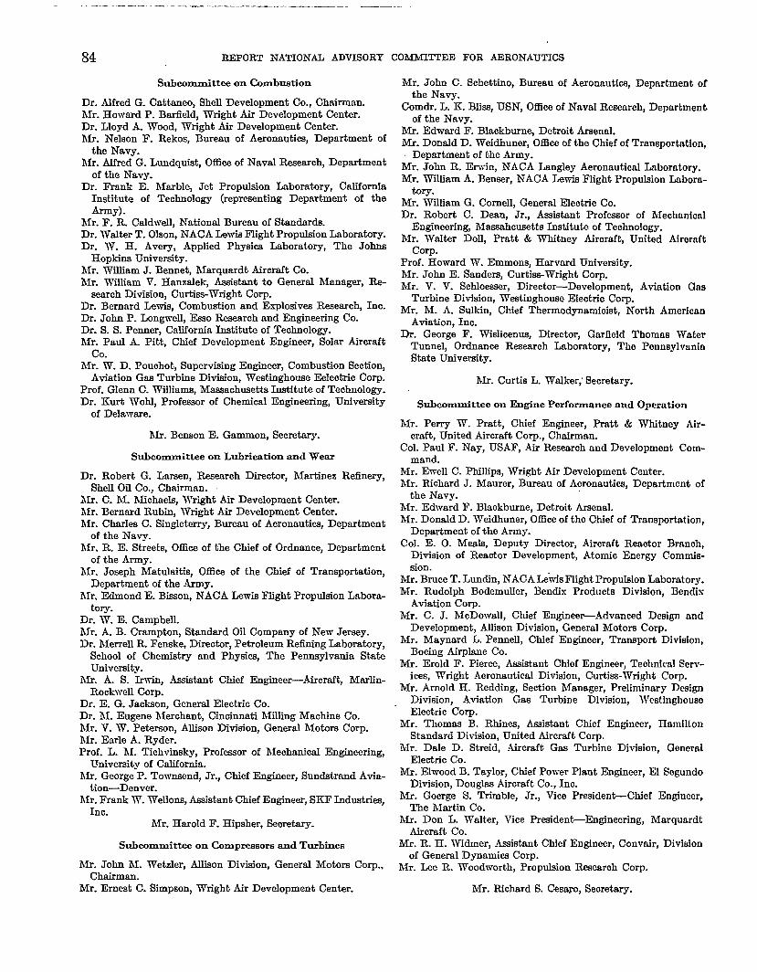
— —---
84 REPORT NATIONAL ADVISORY COMMITTEE FOR AERONAUTICS
%bcmnmittec on Combustion Mr. John C. Schettino, Bureau of
Dr. Alfred G. Cattaneo, Shell Development Co., Chairman.Mr. Howard P. Barfield, Wright Air Development Center.Dr. Lloyd A. Wood, Wright Air Development Center.Mr. Nelson F. Rekos, Bureau of Aeronauti~ Department of
the Navy.Mr. Alfred G. Lundquiat, Office of Naval Research, Department
of the Navy.Dr. Frank E. Marbl~ Jet Propulsion Laboratory, California
Institute of Technolo~ (representing Department of theArmy) .
Mr. F. R. Caldvmll, National Bureau of Standards.Dr. Walter T. Olson, NACA Lmvia Ffight Propulsion Laboratory.Dr. W. H. Avery, Applied Physics Laboratory, The Johns
Hopkins Univemity.hfi. William J. Benne\ Marquardt Aircraft Co.Mr. William V. Hanzrdek, Assistant to General hlanager, Re-
search Division, Curtiss-W%ight Corp.Dr. Bernard Lewfs, combustion and Explodves lleaearc~ Ino.Dr. John P. Imngwell, Esco Research and Engineering Co.Dr. S. S. Penner, Crdifornia Institute of Technology.hfr. Paul A. Pith Chief Development Enginee, Solar Airaraft
co.hfr. W. D. Pouohot, Supervising Engineer, Combustion Sectio~
Aviation Gsa Turbine Division, Westinghouse Eeleotric Corp.Prof. Glenn C. Williams, Macsachuaetta Instftute of Technology.Dr. Kurt Wohl, Professor of Chemical Engineering, Urdversfty
of Delaware.
hfr. Benson E. Gammon, Secretary.
SU.bcommittcc on Lubrication and Wear
Dr. Robert G. Larsen, R.esearoh Director, Martinez Refinery,Shell Oil Co., Chairman.
hIr. C. hf. hfichaels, Wright Air Development Center.hlr. Bernard Rubm, ‘iVnght Air Development Center.hfr. Charles C. Singleterry, Bureau of Aeronautics, Department
of the Navy.hfr. R. E. Streetk Office of the Chief of Ordnrmo~ Department
of the Army.hlr. Joseph Matukdt@ Offlee of the Chief of Transportation,
Department of the Army.hIr. Edmond E. Birmo~ NACA Lewis Flight Propulsion Labora-
tory.Dr. TV. E. Campbell.hlr. A. B. Cramptin, Standard Oil Company of New Jersey.Dr. hlerrell IL Fensk~ Director, Petroleum Refining Laboratory,
School of Chemistry and Physi~ The Pennsylvania StateUniversity.
hfr. A. S. h-in, Assistant Chief Engineer-Aircraft, hfarlin-Rockvrell Corp.
Dr. E. G. Jackson, Generrd Electric Co.Dr. hl. Eugene hkrohan~ Cincinnati Milling Maohfne Co.hfr. V. W. Peterson, Allison Division, General hfotors Corp.hfr. Earle A. Ryder.Prof. L. hI. TichvinaLy, Prof-or of hfeohanical Engineering,
Univemity of California.hfr. George P. Townsend, Jr., Chief Engineer, Sundstrand Avia-
tion-Denver.hfr. Frank IV. Wello@ Assistant Chief Engineer, SKI? Industries,
Inc.hlr. Harold F. Hipsher, Seoretary.
SUbcornmittec on Compressors and Turbines
hfr. John hi. Wetzler, Allison Division, General Motors Corp.,chairman.
Mr. Emeat C. Shnpson, Wright Air Development Center.
Aeronautics, Department ofthe Navy.
Comdr. L. K. Bliss, USN, Office of Naval Research, Departmentof the Navy.
Mr. Edward F. Blackburn~ Detroit Arsenal.Mr. Donald D. Weidhuner, Office of the Chief of Transportation,
Department of the Army.Mr. John R. Erwin, NACA Langley Aeronautical Laboratory.Mr. William A. Benser, NACA Lewfa Flight Propulsion Labom-
tory.Mr. William G. Cornell, General Eleotnc Co.Dr. Robert C. Dean, Jr., Assistant Professor of Mechanioal
Engineering, Mamahma-etts Institute of Technology.Mr. Walter Doll, Pratt & Whitney Airoraft, United Airoraft
Corp.Prof. Howard W. Emmons, Harvard University.Mr. John E. Sandera, Curtim-lVright Corp.Mr. V. V. Schloeeser, Director-Development, Aviation Gas
Turbine Divfsion, ‘iVestiighouee Eieotrfo Corp.Mr. M. A. Sulkin, Chief Thermodynarnfoiat, North American
Aviation, Inc.Dr. George F. Wislicenue, Director, GarEeld Thomas Water
Tunnel, Ordnance Research Laboratory, The PennsylvaniaState Univemfty.
Mr. Curtis L. Walker; Secretary.
subcomrnittee on Engine Performance nnd Opomtion
Mr. Perry TV. Pratt, Chief Engineer, Pratt & Whitney Air-maft, United Aircraft Corp., Cbafrrnan.
Col. Paul F. Nay, USAF, Air Researoh and Development Com-mand.
Mr. Ewefl C. Phiflips, Wright Air Development Center.Mr. Riohard J. Maurer, Bureau of Aeronautic, Department of
the Navy.Mr. Edward F. Blaakburne, Detroit Arsenal.Mr. Donald D. Weidhuner, Office of the Chief of Tmnsportat ion,
Department of the Army.Col. E. O. Meals, Deputy Direotor, Aircraft Reaotor Branoh,
Division of Reaetor Development, Atomio Energy Commis-sion.
Mr. Bruce T. Lundin, NACA h“tisFlight Propulsion Labomt ory.Mr. Rudolph BodemuWr, Bendis Products Division, Bendix
Aviation Corp.Mr. C. J. McDowaU, Chief EngineefiAdvanced Design and
Development, Alfison Division, General Motors Corp.Mr. Maynard L. Pemell, Chief Engineer, Transpcrt Division,
Boeing Airpfane Co.Mr. Erold F. Pierce, Assistant Chfef Engineer, Tedmicrd &wv-
iees, Wright Aeronautical Division, Curtia+Wright Corp.Mr. Arnold H. Redding, Section Manager, Preliminary Design
Division, Aviation Gas Turbine Division, WeetinghousoElectric Corp.
Mr. Thomas B. Rhines, Assistant Chief Engineer, HamiltonStandard Division, United Aircraft Corp.
Mr. Dale D. Streid, Aircraft Gas Turbine Division, GeneralElectrio Co.
Mr. Ehvood B. Taylor, Chief Power Plant Engineer, El SegundoDivision, Douglaa Aircraft Co., Ins.
Mr. Goerge S. Trimble, Jr., Vice Presfden*Chief Engineer,The Martii Co.
Mr. Don L. Walter, Vice PresidenAEngineering, MarquardtAirmaft Co.
Mr. IL H. Widmer, Assistant Chfef Engher, Convair, Divisionof General Dynamics Corp.
Mr. Lee R. Woodworth, Propulsion Rwearoh Corp.
Mr. Riohard S. CesaFO,Seoretary.
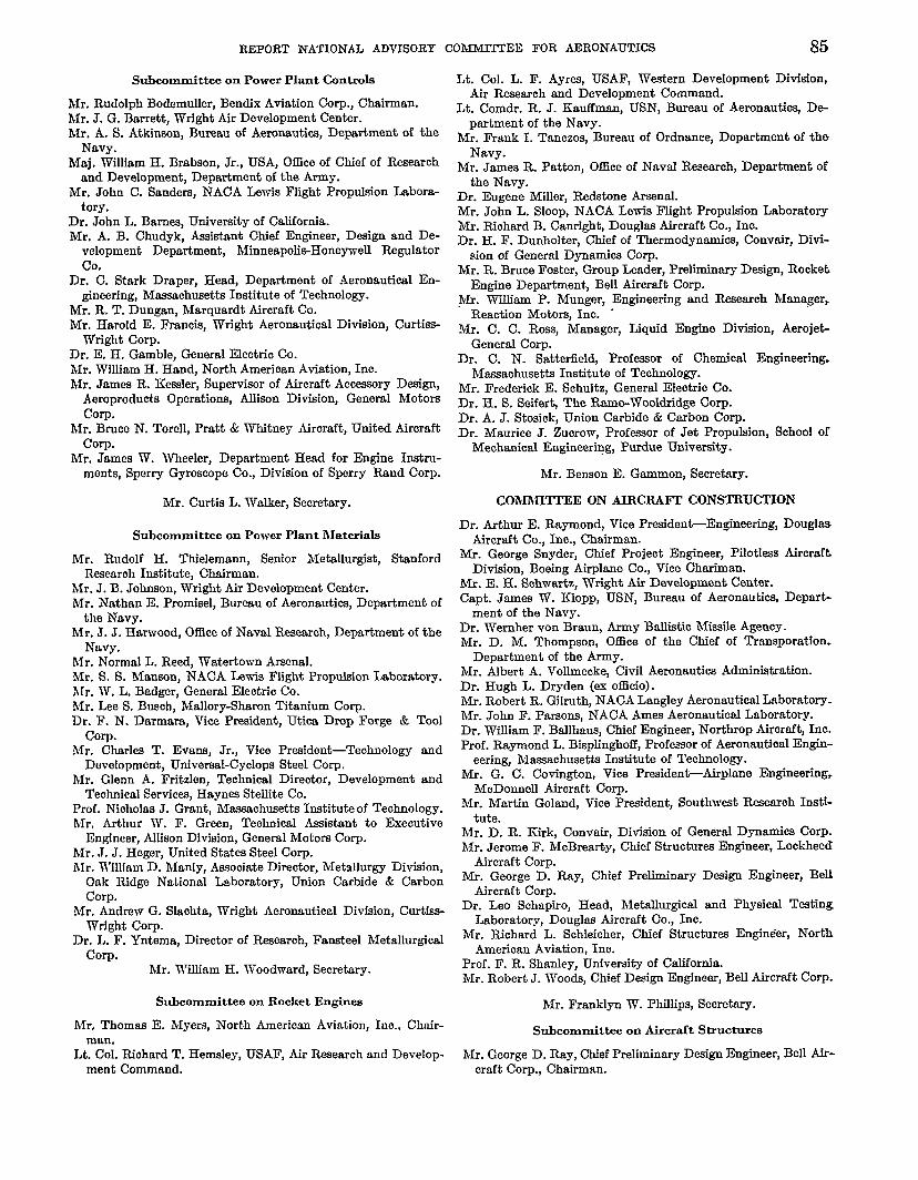
REPORT NATIONAL ADVLSORY COMMMTEE FOR AERONAIJ’ITC9 85
SUb4xlmmittea on Power Plant COnmols
Mr. Rudolph Bodemuller, Bendix Aviation Corp., Chairman.Mr. J. G. Barrett, Wright Air Development Center.Mr. A. S. Atkinson, Bureau of Aeronautics, Department of the
Navy.Maj, Wilfiam H. Brabson, Jr., USA, Office of Chief of Research
and Development, Department of the Army.Mr. John C. Sandem, NACA Lewis Flight Propulsion Labora-
tory.Dr. John L. Barnes, Univemity of California.Mr. A. B. Chudyk, Assiint Chief Engineer, Design and De-
velopment Department, Minneapol&Honeywell Regulatorco.
Dr. C. Stark Draper, Head, Department of Aeronautical En-gineering, Massachusetts Institute of Technology.
Mr. R. T. Dungan, Marquardt Aircraft Co.Mr. Harold E. Francis, Wright Aeronautical Division, Curtiss-
Wright Corp.Dr. E. H. Gamble, General Eleotno Co.Mr. William H. Hand, North Amerioan Aviation, Ino.Mr. James R. Kessler, Supervisor of Airoraft Acceswry Design,
Aeroproducts Operations, Allison Divisfon, General MotorsCorp.
Mr. Bruce N. Torell, Pratt & Whitney Airoraft, United AiroraftCorp.
Mr. James W. Wheeler, Department Head for Engine Instru-ments, Sperry Gyroscope Co., Division of Sperry Rand Corp.
Mr. Curtis L. Walker, Seoretary.
Subcommittee on Power Plant Materiala
Mr. Rudolf H. Thielemann, Senior hletallurgist, StanfordReaearoh Institute, Chairman.
hfr. J. B. Johnson, Wright Air Development Center.Mr. Nathan E. Promisel, Bureau of Aeronautics, Department of
the Navy.Mr. J. J. Harivood, OftIce of Naval Remaroh, Department of the
Navy.Mr. Normal L. Reed, Watertown Arsenal.Mr. S. S. Manson, NACA Lewis Flight Propulsion Laboratory.Mr. W. L. Badger, General Eleotrio CO.Mr. Lee S. Busoh, Maflory-Sharon Titanium Corp.Dr. F. N. Darmara, Vice President, Utica Drop Forge & Tool
Corp.Mr. Charles T. Evans, Jr., Vice President-Technology and
Development, Universal-Cyolops Steel Corp.Mr. Glenn A. Fritzlen, Technical Direotor, Development and
Teohnical Services, Haynes Stellite Co.Prof. Nioholas J. Gmnt, hfwsachusetts Institute of Technology.Mr. Arthur TV. F. Green, Teohnical Assistant to Exeoutive
Engineer, Alfison DivMon, General Motors Corp.Mr. J. J. Heger, United States Steel Corp.hfr. ‘iVSlliamD. Manly, Aasooiate Director, Metallurgy Divicfon,
Oak Ridge National Laboratory, Union Carbide & CarbonCorp.
hfr. Andrew G. Slaohta, Wright Aeronautical Divfsion, Curtfss-Wright Corp.
Dr. L. F. Yntema, Direotor of Reaearoh, Fancteel MetallurgicalCorp.
Mr. William H. Woodward, Secretary.
Subcommittee on Rocket Engines
Mr. Thomaa E. Myers, North Ameriom Aviation, Ino., Chair-man.
Lt. Col. Riohard T. Hemcley, USAF, Air Research and Develop-ment Command.
Lt. Cal. L. F. Ayr~ USAF, Western Development Division,Air Research and Development Command.
Lt. Comdr. R. J. Kauffman, USN, Bureau of Aeronauti~ De-partment of the Navy.
Mr. Frank I. Tanczo~ Bureau of Ordnance, Department of theNavy.
Mr. James IL Patton, Office of NrLvaJResearch, Department ofthe Navy.
Dr. Eugene Miller, Redstone ArsenaLMr. John L. Sloop, NACA Lewis Flfght Propulsion LaboratoryMr. Riohard B. Canright, Douglas Aircraft Co., Ino.Dr. H. F. Dunholter, Chief of Thermodynamics, Convak, Divi-
sion of Generaf Dynamics Corp.Mr. R. Bruce Foster, Group Leader, Preliminary Design, Rooket
Engine Department, Bell Airmaft Corp.~lr. Wdliam P. Munger, Engineering and Reaearoh Manager,
Reaction Motore, Inc. “Mr. C. C. Rosa, Manager, Liquid Engine Division, Aeroje&
General Corp.Dr. C. N. Sattertield, Professor of Chemical Engineering.
M~aohusetts Institute of Technology.Mr. Frederiok E. Schultz, Generaf Eleotrio Co.Dr. H. S. Seifer$ The Ramo-Wooldridge Corp.Dr. A. J. Stosiok, Union Carbide & Carbon Corp.Dr. Maurioe J. Zuorow, Profewm of Jet PropuMlon, School of
Mechanical Engineering, Purdue Univemity.
Mr. Benson E. Gammon, Secretary.
COMMITTEE ON AIRCRAFT CONSTRUCTION
Dr. Arthur E. Raymond, Vice President-En@neering, DouglasAircraft Co., Ino., Chairman.
Mr. George Snyder, Chief Projeot Engineer, Pilotless AircraftDivision, Boeing Airplane Co., Vice Chariman.
Mr. E. H. %hwartz, Wright Air Development Center.Capt. James W. Klopp, USN, Bureau of Aeronautical Depart-
ment of the Navy.Dr. Wernher von Braun, Army Balliitic Missile Agenoy.Mr. D. M. Thompson, Office of the Chief of Transpiration.
Department of the Army.Mr. Albert A. Vollmeckc+ Civil Aeronautiea Administration.Dr. Hugh L. Dryden (ex otlioio).Mr. Robert R. Gilruth, NACA Langley Aeronautical Laboratory.Mr. John F. Parsons, NACA Ames Aeronautioaf Laboratory.Dr. William F. Ballhaus, Chief Engineer, Northrop Airoraf~ Ino.Prof. Raymond L. Bisplinghoff, Professor of Aeronautical Engin-
eering, Macsaohusetts Institute of Technology.Mr. G. C. Covington, Vice Prwident-Airplnne Engineering,
MoDomelf Airoraft Corp.hlr. Martin Gohmd, Vice Prwident, Southwest %searoh Insti-
tute.Mr. D. R. Kirk, Convafr, Division of General Dynamic-s Corp.Mr. Jerome F. MoBrearty, Chief Struoturea Engineer, Lookheed
Aircraft Corp.Mr. George D. Ray, Chief Preliminary Design Engineer, Bell
Aircraft Corp.Dr. Leo Sohapiro, Head, Metallurgical and Physical Testing
Laboratory, Douglas Airoraft Co., Ino.Mr. Riohard L. Sohleicher, Chief Structure Engim$er, North
Amerioan Aviation, Ino.Prof. F. R. Shanley, University of CaliforniahIr. Robert J. IVoo@ Chief Design Engfneer, Bell Aircraft Corp-
Mr. Franklyn W. Phillips, Seoretary.
%beommittee on Aircraft Structures
Mr. George D. Ray, Chief Preliminary Design Engineer, Bell Mr-craft Corp., Chairman.

86 REPORT NATIONAL ADVISORY COMMJTI!EE FOR AERONAWITCS
Capt. ~. T. MuGirmess, USAF, Air Researoh and DevelopmentCommand.
Mr. ‘Wiliam B. Miller, Wright Air Development Center.Mr. Ralph L. Creel, Bureau of Aeronauti~ Department of the
Navy.Mr. Emil A. H. Heliebrand, Army Ballistic Missile Agency.Capt. Earl P. Ford, USA, Office of the Chief of Transportation,
Department of the Army.Mr. hfiiton Jakoaky, Civil Aeronautira Administration.Mr. Riohard R. Heldenfe~ NACA Langley Aeronautical Labo-
ratory.Mr. O. W. Boden, Chief of Mkile Design Seation, North
American Aviation, Ino.Mr. L. M. Hitchooo~ Chief-Teohnieal Staff, Seattle Division
Boeing Airplane Co.Dr,- Nichoiaa J. Hoff, Head, Deparhnent of Aeronautiord” En-
gineering and Applied Mechani~ Polyteohnio Institute ofBrooklyn.
Mr. AntQnio L. LcJ?reati, North American Aviation, Inc.Mr. George N. Mangurian, Chief Analytic-al Engineer, Northrop
Aircraft Ins.Mr. ‘iViiliarnR. Mioka, The RAND Corp.Mr. Herman Pusin, Chief Engineer, Engineering Division, The
Marin m.Prof. Paul E. SandorE, Massachusetts Institute of Tedmology.Prof. E. E. Sechler, Professor of Aeronautics, California Insti-
tute of Technology.Mr. E. H. Spaukiing, Division Engineer, Structural Engineering,
Lockheed AirOMft tirp. -Mr. C. H. Stevenson, Douglas Aimraft Co., Irm.
Mr. Melvin G. Rosohq Secretary.
Subwmmittee on Aircraft Loads
hfr. Jerome F. MoBrear@, Chief %-natures Engineer, LookheedAircraft Corp., chairman.
Lt. Cal. L. S. Jableeki, USAF, Air Researah and Developmentcommand.
hfi. Joseph H. Barrington, Wright Air Development Center.hfr. Clinton T. Newby, Bureau of Aeronautira, Department of
the Navy.Mr. John Carlson, Office of the Chief of Trzmaport.ation, Depart-
ment of the Army.hfr. Burden L. Springer, Civil Aeronautics Administration.hfr. Philip Donely, NACA Langley Aeronautical Laboratory.hfr. hiardey J. Hood, NACA Ames Aeronautical Laboratory.hfr. D. E. Beeler, NACA High-SWed Flight Station.hlr. Ralph B. Davidson, Direotor of Engineering h-vices,
Radioplane Ce.Mr. J. A. Dilhvorth, III, Structural Requirements DivMon
Engineer, Georgia DivMon, Lookheed Aircraft Corp.hfr. E. Z. Gray, Ihx4ng Airplane b.hfr. H. J. Hoge, North Ameriean Aviation, Inr.hfr. H. W. Huntley, North American Aviation, Inc.hfr. WNiam W. Jenney, Douglas Aim-aft Co., Inc.hfr. J. A. Johnson, Lookheed Aircraft Carp.hfr. Aifred I. Sibila, Chief of Engineering Rersonnel and Plan-
ning, Chance Yought Aircraft, Ino.hfr. Harry Tobey, Chief of Structures, Vertol Airoraft Corp.
Mr. Douglas Miohel, Bureau of Aeronautics, Deportment of theNaw.
Mr. Philipp W. Zettler-Seidel, Army Ballistic. Missile Agenoy.Mr. J. Wallace McDonald, Office of the Chief of Transportation,
Department of the krny.Mr. Robert Rosenbaum, Civil Aeronautira Administmtion.Mr. I. E. Garnck, NACA hqdey Aeronautical Laboratory.Mr. Albert Erickson, NACA Ames Aeronautical Laboratory.Mr. Andr6 J. Meyer, Jr., NACA Lewis Fiight Propuhion Labo-
ratory.Prof. Lee Arnold, Columbia University.Prof. Holt Ashley, Mas+saohusettsInstitute of Technology.Mr. Eugene F. Baird, Chief Flutter and Vibration Engineer,
Grumman Aircraft Engineering Corp.Mr. Douglas G. Dili, Douglaa Aircraft Co., Ino.Mr. Michael Dublin, Chief of Dynamics, Convair, Division of
General Dynarrdca Corp.hlr. H. Clay Johnson, Jr., Supervisor, Struotuml Dyrmmiea,
Tbe Martin Co.Mr. Wiiliam R Laidfaw, North American Aviation, Ino.Mr. E. L. Lepp+mt, Jr., Researoh Specialist, Flutter rmd Vibra-
tion, Lockheed Airoraft Corp.Mr. M. J. Turner, Unit Chief-Struotural Dynamics, Seattle
Division, Boeing Airplane Co.
Mr. Harvey H. Brown, Secretary.
Subcommittee on Aircraft Structural Materials
Dr. Leo Sohapim, Head, Metallurgleal and Phyeioal TestingLaboratory, Douglw Airomft Co., Ino., Chairman.
Mr. J. B. Johnson, Wright Air Development Center.Mr. Nathan E. Promise], Bureau of Aeronautics, Department
of the Navy.Dr. W. H. Steurer, Redstone Amend.Mr. L. J. Borges, Office of the Chief of Transportation, Depart-
ment of the Army.Dr. Gordon M. Kline, Chief, Organio and Fibrous Materials
Division, National Bureau of StandardsMr. James E. Dougherty, Jr., Chief, Materials and Procesms
Seotion, Civil Aerorrautica AdrniniatmMon.Mr. Paul Kuhn, NACA Langley Aeronautical Laboratory.Mr. G. Mervin Ault, NACA Lewis Flight Propulsion LaboratoryMr. Robert S. Ames, Goodyear Aimraft Corp.Mr. Hamy A. Campbeli, Bell Aimraft Corp.Mr. Edgar H. Dix, Jr., Assistant Director of Ressaroh, Alumi-
num Company of Amerioa.Prof. Pol Dmvez, California Institute of Technology.Dr. Walter L. Fhday, Vice President and Manager of Researoh,
Rem-Cm Titanium, Ins.Mr. L. R. Jaakaon, Aasiatant Direotor, Battelle Memorial Insti-
tute.Dr. J. C. McDonald, Assistant Technical Direotor, MagneBium
Department, The Dow Chemioal Co.Mr. Peter Payson, Assistant Direotor of Reaearoh, Crucible Steel
CamWny of America.Dr. Dana W. Smith, Amociate Direotor, Division of Metallurgi-
rd I&earoh, Kaiser Aluminum and Chernioal Corp.Dr. George V. Smith Profemor of Metallurgical Engineering,
Cornell University.
hfr. R. Fabian Goranson, Saoretary. Mr. R. H. Raring, Seoretary.
Subcommittee on Vibration and Fiutter COMMITTEE ON “OPERATING PROBLEMS
hfr. hiartin Goland, Vice president, Southw@ R-rob InstL Capt. Edward V. Riokenbaaker, Chairm,m of the Board, Easterntuti, chairman. AirLin~ Irm., Chairman.
hlr. Fred L. Daum, Wright Air Development Center. Mr. Wliliam Littlewood, Vice Preaident-Equipment Reeaaroh,hfr. W. J. hlykytmv, Wright Air Development Center. American Airlin~ Inu., Vice Chairman.

REPORT NATIONAL ADVISORY COM3UJIM’EEFOR AERONAT)TWS w
Col. Joseph Dnvi~Jr., USAF, ‘iVright Air Development Center.Brig. Gen. Albert T. Wfson,Jr.,USAF,De putyChftiof Staff,
Operations, MilitaryAirTransportS ervice.Cnpt. S.R. Oura,USN, Bureau of Aeronautics, Department of
the Navy.Lt. Col. John L. Rowan, US& 05ce of the Deputy Chief of
Staff for Military Operatio~ Department of the Army.Col. George P. Scneff, Jr., USA, Offioeof the Chief of Researoh
and Development, Department of the Army.Mr. Wjlliam B. Davl~ Dhwotor, Officeof Aviation Safety, Civil
AeronauticsAdministration.Mr. Donafd M. Stuart, Direotor, Teohnical Development and
Evaluation Center, Civil AeronauticsAdministration.Dr. ~. W. Relchelderfer(ex officio), Chief, U.S. Weather Bureau.Dr. Hugh L. Dryden (OXofficio).Mr. Melvin N. Gough, NACA Langley AeronauticalLaboratory.Mr. Lawrence A. Clouajng, NACA Am= Aeronautical Labora-
tory.hfr. Eugene J. Manganiello, NACA Lewis Flight Propulsion
Laboratory.hlr. M. G. Beard, Asdatant Vice Prtident-Equipment Re-
swroh, American Airlin~ Ino.hlr. John G. Borger, Pan American World hap Systim.Mr. Warren T. Diokfneon, kdetant to Chief Engineer, Douglm
Aircraft Co., Ino.hfr. CharlW Froeaoh, Vice President-Engineering, Eastern
Airlines, Ino.Mr. Raymond D. Kelly, Superintendent of Teohnical Develop-
ment, United Air Lin~ Ino.Mr. Jerome Ledemr, Direotor, Flight Safety Foundation.Mr. W. C. Mentzer, General Manager-Engfneerhg, United
Air Lines, Ino.Mr. Robert W. Rummel, Vioe Presiden+Engineering, Tram
World Airlines, Ino.hfr. Clarence N. Sayen, president Air Line Piloti Association.hfr. Arthur E. Smith, Engineering Mmmger, Pratt & Whitney
Aircraf& United Aircraft COrp.Mr. R. L. Thoren, Chief Flight Test Engineer, Lookhwd Air-
craft Corp.hfr. H. W. ‘??ithington, Staff Engfneer-Systems, Boeing
Airplane Co.Dr. T. L. K. Smull, Score@.
.%&committee on Meteorological Problems
Dr. F. W. Reiohelderfer, Chief, U.S. Weather Bureau, Chrdrman.Brig. Gen. ThonuM S. Moorman, Jr., USAF, Commander, Air
Wenther service.hlr. C. N. Touar\ Chief, Atmosphena Analysis Laboratory,
Qeophysios Research Directira@ Air Force CambridgeResenmh Center.
Capt. Paul IL Drouilhe& USN, Head, Naval Aerology Branol+Officeof Chief of Naval Operations.
hfre. I?ranoea L. Whedon, 05ce of the Chief Signal Officer,Department of the Army.
Dr. Roes Gunn, Director, Physical Fteaearch Division, U. S.Weather Bureau.
Dr. Harry Wexler, Chfef, Soientith Servioes Division, U. S.Weather Burenu.
hfr. Robert W. Craig, Civil Aeronautioa Administration.hfr. George M. lbmch, Civil Aeronautics Board.Mr. Harry Press, NACA Langley Aeronautical Laboratory.Mr. William Lmvk, NACA Lewfa Flight PropuMlon Laboratory.Mr. Robert N. Buck, Trans World tirlines, Inc.Dr. Horace R. Bye% Prof~or of Meteorology, The Urdvemity
of Chicago.Mr. hfartin B. Cahill, Engineering Pilot Northwest Airlines,
Ino.Mr. Joseph J. George, Eastern Air Lin~ Ino.
43587-7—7
Mr. Henry T. Harrfson, Jr., Pireotor-hfeteorology, United AirLfnes, Ino.
Prof. H. G. Houghton, Mqhusetts Institute of Technology.Mr. H. J. Reid, Manager, Tight Operatio~ Capital Airlines,
Ino.Dean Athefatan F. Spilhaus, University of hfinrmota.Dr. George F. Taylor, Chief, Upper Atmosphere Department
Missile Systems Division, ~ookheed Aircraft Corp.Mr. Frank C. White, Air Transport Association of America.
Mr. Mason ~. Charak, Seoretary.
%beommittee on Icing Probkma
Mr. W. W. Reaser, Douglas Afrcraft Co., Ino., Chairman.Lt. Cd. George B. Eldridge, USAF, Air Reeaaroh and Develop-
ment Command.Mr. Carl L Oakes, Jr., Wright Air Development Center.Dr. Robeti M. Cunningham Air Force Cambridge Researoh
Center.Mr. R. T. Miller, Bureau ~f Aeronautic% Department of the
Navy.Mr. Harcourt C. Sontag, Bupmu of Aeronauti~ Department of
the Navy.Dr. Henri Bader, Chfef Scien~t, Snow, Ice, Permafrost Researoh
Kstabfishment,Maj. John W. Elfiott;USA, Qfflce of the Chief of Transportation,
Department of the Army.Mr. Dwight B. Kline, U. S. Weather Bureau.Mr. Robert J. Auburn, Civil Aeronautics Adminktration.Mr. Ihve H. von Glahn, NA~A hvia Ffight Propulsion Labora-
tory.Mr. J. S. Alfor~ Aircraft ~aa Turbine Department, General
Electric Co.Mr. Vidor Hudson, Senfor Thermodynamic Engineer, Convair,
Division of Generaf Dynamica Corp.Mr. G. Donald Linklater, Senior Meteorologist, Northwest
Airlines, Ino.Mr. Bernard L. M_ger, Department Manager, Thermo-
dynamics, Lockheed Airo t Cap.
IMr. Robort A. Paselk, Nort American Aviatfo% Ino.Mr. Duane M. Patterson, rmtor, Aeronautical Icing Research
Imboratorie% Smith, Hinc~man & Grylla, Ino.Mr. D. A. Richardson, Aqistant to Chief De@n Engfneer,
Vertol Aircraft Corp. ,
Mr. Mason T. Charak, Secretary.
Subcommittee on Flight Safety
Mr. Charles Froesch, Vice Preaiden+Enginearing, Eastern AirLines, Ino., Chairman.
Dr. Albert A. Hetherhugton, Jr., Air Remarch and DevelopmentCommand.
Lt. Col. Johu P. Stapp, USAF, Chief, Aeromedical Field Labora-tory, Holloman Air Development Center.
Mr. Sydney D. Berman, Office of the Inspector Gene@ U. S.Air Force.
Comdr. Forrester C. Au~, USN, Offlze of Deputy Chief ofNaval Operations (Air).
Col. James F. Wells, USA, Office of the Deputy Chief of Stafffor Military Operations, Department of the Army.
Mr. L. J. Borges, Office of tfp Chief of Transportation, Depart-ment of the Army.
W. W. A. Kfikoff, Deputy ~hief, Aircraft Engineering Division,Chd Aeronautics Adminis@tion.
Mr. John M. Chamberlain, Director, Bureau of Safety Regula-tion, Civil Aeronautics Board.
Honorable Joseph P. Adama (es officio), Vice Chairman, CivilAeronautics Board.

88 REPORT .NA’l!ION@. @VISORY_ QOl@UTTEE FOR AERONAUTICS
Mr. Melvin N. Gough, NACA LanrdeYAeronautical Laboratory. Dr. Riohard H. Bolt, Massaohusetta Institute of Technolouv.Mr. I. Irving Pinke~ NACA L.emus‘mght Propulsion Laborati~. “Mr. Carl M. Christenson, United Air Lines, Ino.Mr. Allen ‘W. Dallas, Dmctmr, Engineering Division, Air
Transport Association of Ameri~Dr. Paul M. Fit@ Jr., Ohio State Univemity.Mr. Scott Flower, Pan American World Airways, IDO.Mr. A. Howard IIasbroo& Director, Avfation Crash Inju~”
Resedroh of Comefl University.Mr. Otto E. Kirohner, Sr., Senior Group Engfneer, Preliminary
Des@ Unit,. Boeing Afrpklne Co.. .Mr. Jerome Lederer, Director, Flight Safe~ Foundation.Dr. Rom A. I@d%rland, Harvard Sohool of public Health.Mr. WiJliam I.. Stic+litz, Desi@ Safety En@near, Republio
Adtion Corp:Mr. H. H. Young, Flight S~e~ Eng%mer, D6uglas Aircraft Cc.,
Inc.-,, Mr. Boyd C. My+ 11; EkCIt?tSry.
Mr. Allen W. DalhM, Director, Engineering Division, Air Trans-port Association of America.
‘Dr. Robert O. Fehr, Manager, Mechanical Engineering Labom.tory, General Electrio Co.
Dr. Stacy R. Guild, Jolma Hopkfns Hospital.Dr. Cyril M. Harris, Direotor, Acoustics Labomtory, Columbia
University.Dr. Hans W. Lieproann, California Institute of Technology.Mr. Karl Martinez, Boefng Airplane Co.Mr. M. M. Miller, Chief, Acoustics Seotlon, Douglas Airomft
CO., Ino.Dr. Cha@es T. Molloy, Lookhmd Airoraft Corp.Mr. John M. Tyler, Pmtt &,Whitney Alroraft, Unftecl Airoraft
Corp.Dr. P. J. Westervelt, Assistant fiofesor, Department of Physics,. Brown Urnversity. ,.,Mr. John M. Whitmore, Allhmn Division, Geneml Motors Corp.
%lmmnmittes on Aircraft Noiso:,
Mr. ‘iVillfam Littlewood, Vme ~ldemt-Equipment R~ch,AmeK-ican Airlines, Ino., Chairman. .
Dr. H. O. Parrack, Wright Air Development Center.Capt. R. L. Christy, (MG) USN, Bureau of Aeronautics,.De-
partmentof the Navy.
Capt. C. P. Phoebus, (MC) USN, Office. of Nav&l Research,Department of the Navy.
Mr. Joseph MatuMtia, 05c0 of the Chief of Tmnsportation,Department of the Army. . .
Mr.’ Stephen H. Rolle, Chief, PoIvei Plant Bmnoh, Civil Aero-nautics Administmtion.
Dr. Riobard K. Cook; Chief, %nd” Section; National Buresu ofStandards.
Mr. Maeon C. Eflis, Jr., NACA Langley Aeronautical bbora-tory. .’,’
Mr. Arthur A. Regier, NACA Langley Aeronautical Labomtory~hfr. Newell D. Sandexa, NACA Lewis Flight Propulsion Labora-- tory. .: .,. .
:,” ,,.
.- ..’
Mr. George P. Batea, Jr., Seoretary
INDUSTRY CONSULTING COMMI’M’EE
Mr, WMiam littlewood, Vice Presiden+Equipment Reaemoh,Amerioan Airlima, Ino., Chairman.
Mr. L.ILG rurnman, Chairman of the Board, Grumman Ah’omftEngineering Corp., Vim Chairman.
Mr. J. L. Atwood, President, North American Aviation, Ino.MT. J. H. Carmichael, President, CApital Airlinm, Ino.Dr. M. P. Ferguson, President, Bendix Avfation Corp.Mr. Harvey Gaylord, Vioe President-Helieoptem, Bell Airomft
Corp. -“Mr. L. S. Hobbs, VIM Chairman, United Aircraft Corp.Mr. C. W. LaPieme, Exeoutive Vice President, General Eleotrlo
co.Mr. 3itmdy I. Peale, President, Repub!ic Aviation Corp.Mr. Dwane L. Wallace, President and Geneml Manager, Ceemm
Airfraft co.. ... . Dr. T. L. K. Smull. Secretmy
. .
. . .
. ..+ ’.; -
. r.
. .
.4

Part IIZ-FINANCIAL REPORTFunds appropriated for the Committee for the iiscal years 1956 and 1957 and obligations against the fiscal year 1956
appropriations are as follows:
Ftsdyearlwa
Allotments
SALAIUEllANDEXPENSES APPROPRIATION
NAOA Headquarters. ---------------------------------------------- $1,557,745Lrmgle Aeronautical hboratiW -------------------------------------
I22,141,400
Ames eronautical LabomtiW --------------------------------------- 10,929,250Lewis Flight Propulsion hbomto~---------------------------------- 20,237,805High-Speed Flight Stition ------------------------------------------- 1,929,695Pflotl@ fiomft Stition --------------------------------------------Western Coordination Office-----------------------------------------
928,50023,935
Wright-Patbwson Ltitin Office-------------------------------------- 15, 604Researohoontraots with educational tititutiom ------------------------ ;;$ .33;Researoh contracts with Government ~enoi=--------------------------
Savings reserved for mppropfition -------------------------------Unobligatedbalance-
1,422;766----------------------------------- ~------- - ---------------
Totil ------------------------------------------------------- 160,13s,000
00NSTEW~ON ANDBQIJIP~NT APPllOPllrATION
Lrmgle Aeronautic hbomtoW -------------------------------------I
L
3,325,000Amos eronautid Labomti~--------------------------------------- 1,055,000LewisF htProptiion LabomtiW ----------------------------------
%Pilotlem8,395,000
ctit Stition -------------------------------------------- 90,000Reaerve transferred from ptiorym ------------------------------Unobligated balance ---
–300,000----------------------------------------- ----------------
Toti ------------------------------------------------------- 112,565,000
Obli@ons
$1,541,237;~ 06$ :g
20:200:0661, ;;? ;g
19:97915,439
750,291194000
1,500,000186, 185
60,135,000
31,741418,898
1,796,3491,695
–32, 013S1O,348,43O
12,565,000
Ed year1057
Anotnlenb
6% 050778,100978,600591,244090, 95ct095,33532.10516; llf3
770,000200,000
.-------------------------------
‘tk&176,600
7,826,000906,000
5,712,000----------------
–444, 000.---------------
314,000,0001
lAppm rinted In the Independent Olllcea Approprktlen A% 19Mj approvedJune S0, 1&
Jnno%’,l%WandtheFlmtSnppIemonMA roprWienAxlg57,appmveiJ@yq’.ymp&~s;w&ma=&y:g~&ham lw.5funds
2AppmprletcdIn tbe Inde@ent 013ic?s AppmprietionA* 1967, approved
89

— —. — ————.——
v