Embed Size (px)
Citation preview
Industrial Weight SensorSpecification Book
(Includes Weigh Bars®, Load Cells, Quartzells®
and Assemblies )

2 Industrial Weight Sensor Specification Book
3Industrial Weight Sensor Specification Book
Table of Contents
Table of Contents .................................................................................................................................... 3QuartzellTM Transducer ........................................................................................................................... 5
Theory of Operation ......................................................................................................................... 5The Weigh Bar® ...................................................................................................................................... 5
Electrical Test ................................................................................................................................... 5Testing the Weigh Bar ...................................................................................................................... 7
Repair Procedure for Splicing Weigh Bar Cables .................................................................................. 8Preparing Wires ............................................................................................................................... 8Splicing the Wires ............................................................................................................................ 8Finishing the Repair ......................................................................................................................... 9
Junction Boxes ..................................................................................................................................... 10Signal Trim Junction Boxes ............................................................................................................ 10
System Troubleshooting Sequence ...................................................................................................... 12Cable ................................................................................................................................................. 14Quartzell ............................................................................................................................................... 15
Counting Scale/Bench Scale ......................................................................................................... 15Weigh Bar and Load Cell Lists ............................................................................................................. 17
Diamond Series Bench Scales ...................................................................................................... 17Bench Scales ................................................................................................................................. 18Checkweigher & Stand Alone Torsion Bases ................................................................................. 19Conveyor Scale Weigh Bar 1.0mV/V (Non-certified) ..................................................................... 20Lift Truck Scale Weigh Bar ............................................................................................................. 21Resistance Test of QTLTSC Weigh Bars ....................................................................................... 22Beam Scale .................................................................................................................................... 23Pallet Truck Scale .......................................................................................................................... 23Monorail ......................................................................................................................................... 2470" Weighline Rails ........................................................................................................................ 24Truck Scale .................................................................................................................................... 25Floor Scales ................................................................................................................................... 27Batching Weigh Bars & Assemblies ............................................................................................... 32Hopper Suspension Weigh Bar (HSWB) ....................................................................................... 35Stainless Steel BWPS .................................................................................................................... 37Single-ended Batching Weigh Bars (BWPS Stainless Steel) ......................................................... 38Low Profile Batching Weigh Bars (LPBWB) .................................................................................. 40Double-ended Batching Weigh Bar (DEBWB) ............................................................................... 42SBS (Shear Beam-Stainless steel) ................................................................................................ 47Model 220 Tank Mount ................................................................................................................... 49
Earlier Versions .................................................................................................................................... 50

4 Industrial Weight Sensor Specification Book
5Industrial Weight Sensor Specification Book
The patented QuartzellTM transducer from Weigh-Tronix is the key to a newdimension in weighing. It opens the door to new opportunities in the sameway the introduction of electronic scales did in the 70s.
It uses a new weighing system we call Quartz Digital Technology, whichwe refer to as QDT. Yet it is only a new application of a very commonprinciple. QDT is based on the use of quartz crystals similar to those usedin your wristwatch.
Weigh-TronixCategory Strain Gauge QuartzellTM SensorOIML accuracy 6,000d 10,000dInternal resolution (ppm) 5 <1Readable resolution 200 20Response time (sec) 1 1Repeatability (ppm) 100 10Operating Temperature (C°) -10 to 40 -10 to 40Capacity (LB) 50 55Overload capacity (%) 150 150
QuartzellTM technology has no analog component to slow down, corrupt orinterfere with the sensing of weight. It is digital from the very beginning.
It brings the right blend of accuracy, resolution and cost which positionsQuartzellTM technology out in front of other weighing technologies.
QuartzellTM Transducer
Theory of Operation
The Weigh Bar®
Electrical Test
These tests will also work formost of today's loadcells.
The Weigh Bar® is designed to overcome the shortcomings of the load celland to provide the user with a rugged, highly reliable, and linear loadsensing device at reasonable cost. Nearly thirty years of extensive use inindustrial, farm and transportation applications has demonstrated that theWeigh Bar has met these requirements. The unique patented principle ofthe Weigh Bar is the primary reason for this success. The costly problemsof temperature compensation and sensitivity to extraneous loads associ-ated with the load cell have been eliminated. Also the unreliable so-calledhermetic seal in the load cell has been virtually eliminated in the WeighBar. The fully potted Weigh-Tronix Weigh Bar has Factory Mutual ap-proval for installation in hazardous environments.
You can test a Weigh Bar for proper operation by measuring the outputvoltage. To accomplish this, you need to know the rated Mv/v output of theWeigh Bar (1.0 Mv/v or 2.0 Mv/v) and the excitation voltage supplied by theindicator. The excitation voltage most often used is 10.0 VDC. This shouldbe verified by measuring it at the Weigh Bar between the green wire (+)and the black wire (-). Find the Weigh Bar Mv/v rating in this manual andthe Weigh Bar capacity is easily determined. Simply measure the lengthand the diameter of the Weigh Bar. Locate it in the proper Weigh Barcategory
6 Industrial Weight Sensor Specification Book
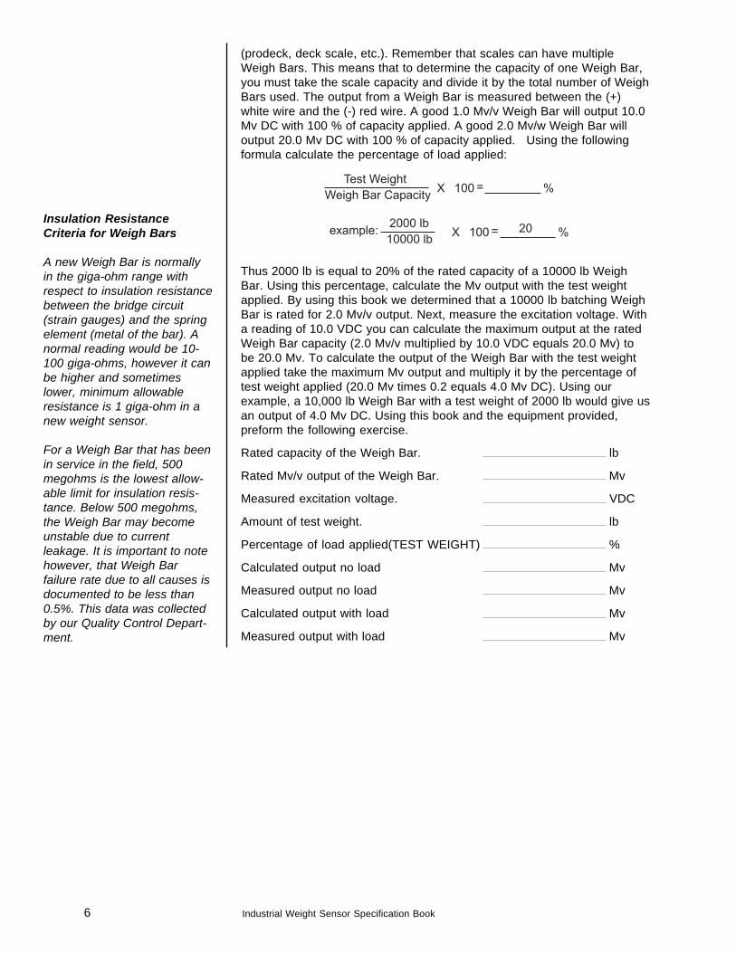
(prodeck, deck scale, etc.). Remember that scales can have multipleWeigh Bars. This means that to determine the capacity of one Weigh Bar,you must take the scale capacity and divide it by the total number of WeighBars used. The output from a Weigh Bar is measured between the (+)white wire and the (-) red wire. A good 1.0 Mv/v Weigh Bar will output 10.0Mv DC with 100 % of capacity applied. A good 2.0 Mv/w Weigh Bar willoutput 20.0 Mv DC with 100 % of capacity applied. Using the followingformula calculate the percentage of load applied:
Thus 2000 lb is equal to 20% of the rated capacity of a 10000 lb WeighBar. Using this percentage, calculate the Mv output with the test weightapplied. By using this book we determined that a 10000 lb batching WeighBar is rated for 2.0 Mv/v output. Next, measure the excitation voltage. Witha reading of 10.0 VDC you can calculate the maximum output at the ratedWeigh Bar capacity (2.0 Mv/v multiplied by 10.0 VDC equals 20.0 Mv) tobe 20.0 Mv. To calculate the output of the Weigh Bar with the test weightapplied take the maximum Mv output and multiply it by the percentage oftest weight applied (20.0 Mv times 0.2 equals 4.0 Mv DC). Using ourexample, a 10,000 lb Weigh Bar with a test weight of 2000 lb would give usan output of 4.0 Mv DC. Using this book and the equipment provided,preform the following exercise.
Rated capacity of the Weigh Bar. lb
Rated Mv/v output of the Weigh Bar. Mv
Measured excitation voltage. VDC
Amount of test weight. lb
Percentage of load applied(TEST WEIGHT) %
Calculated output no load Mv
Measured output no load Mv
Calculated output with load Mv
Measured output with load Mv
Insulation ResistanceCriteria for Weigh Bars
A new Weigh Bar is normallyin the giga-ohm range withrespect to insulation resistancebetween the bridge circuit(strain gauges) and the springelement (metal of the bar). Anormal reading would be 10-100 giga-ohms, however it canbe higher and sometimeslower, minimum allowableresistance is 1 giga-ohm in anew weight sensor.
For a Weigh Bar that has beenin service in the field, 500megohms is the lowest allow-able limit for insulation resis-tance. Below 500 megohms,the Weigh Bar may becomeunstable due to currentleakage. It is important to notehowever, that Weigh Barfailure rate due to all causes isdocumented to be less than0.5%. This data was collectedby our Quality Control Depart-ment.
7Industrial Weight Sensor Specification Book
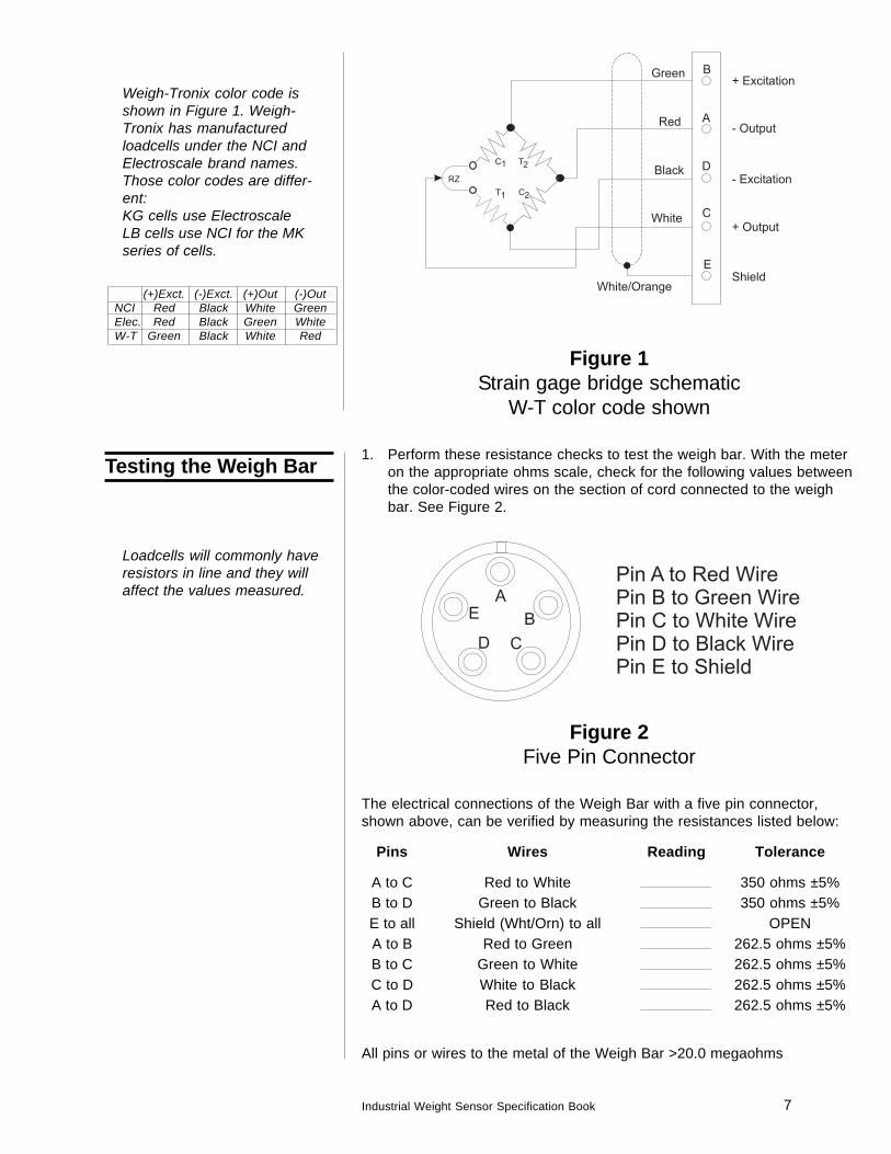
Figure 1Strain gage bridge schematic
W-T color code shown
1. Perform these resistance checks to test the weigh bar. With the meteron the appropriate ohms scale, check for the following values betweenthe color-coded wires on the section of cord connected to the weighbar. See Figure 2.
Figure 2Five Pin Connector
The electrical connections of the Weigh Bar with a five pin connector,shown above, can be verified by measuring the resistances listed below:
Pins Wires Reading Tolerance
A to C Red to White 350 ohms ±5%B to D Green to Black 350 ohms ±5%E to all Shield (Wht/Orn) to all OPENA to B Red to Green 262.5 ohms ±5%B to C Green to White 262.5 ohms ±5%C to D White to Black 262.5 ohms ±5%A to D Red to Black 262.5 ohms ±5%
All pins or wires to the metal of the Weigh Bar >20.0 megaohms
Weigh-Tronix color code isshown in Figure 1. Weigh-Tronix has manufacturedloadcells under the NCI andElectroscale brand names.Those color codes are differ-ent:KG cells use ElectroscaleLB cells use NCI for the MKseries of cells.
(+)Exct. (-)Exct. (+)Out (-)OutNCI Red Black White GreenElec. Red Black Green WhiteW-T Green Black White Red
Loadcells will commonly haveresistors in line and they willaffect the values measured.
Testing the Weigh Bar
8 Industrial Weight Sensor Specification Book
1. Cut away damaged section of weigh bar cord to leave cut ends clean.
2. Strip away approximately 3" of rubber jacket from one cable end and1½" from the other to expose the braided wire shield.
3. Cut away shield to leave 1" exposed beyond rubber jacket.
4. Using a scribe or pick, unbraid the exposed wire shield and twist ittogether to form a wire on each cable.
5. Strip away approximately 5/8" of insulation from the ends of the 3 wireson each cable.
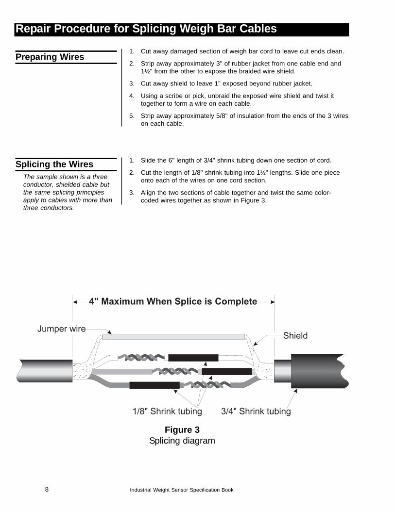
1. Slide the 6" length of 3/4" shrink tubing down one section of cord.
2. Cut the length of 1/8" shrink tubing into 1½" lengths. Slide one pieceonto each of the wires on one cord section.
3. Align the two sections of cable together and twist the same color-coded wires together as shown in Figure 3.
Preparing Wires
Splicing the WiresThe sample shown is a threeconductor, shielded cable butthe same splicing principlesapply to cables with more thanthree conductors.
Figure 3Splicing diagram
Repair Procedure for Splicing Weigh Bar Cables
9Industrial Weight Sensor Specification Book
4. Solder each coupling using the solder supplied. Be sure junctions aresmooth with no bumps or sharp edges. A good solder junction willlook shiny and not have a dull or cracked surface.
5. After the junctions are soldered and cooled, slide the pieces of 1/8"shrink tubing over each junction. Be sure that only the wire insulation isvisible out of each end of the tubing. Use an electric hair dryer to applyheat to the tubing and seal it over the wire junctions.
6. Couple the wire shields together using the length of copper wireprovided. This is necessary so both sections of cable will be guardedagainst radio frequency interference which can affect weigh baroperation.
1. Slide the piece of 3/4" shrink tubing across the junction and be surethat only the rubber cord jacket is visible at both ends of the shrinktubing.
2. Use a torch or heat gun to shrink the 3/4" tubing so it forms a waterresistant seal across the repaired area. The 3/4" tubing is very thick soheat must be applied long enough to ensure adequate shrinkage.Apply the heat evenly to avoid scorching or burning the tubing.
PARTS LIST
Part No. Part Name Required
19741-0012 Cord Repair Kit (includes:)14486-0046 1/8" shrink tubing 6"17764-0117 6" piece of 3/4" shrink tubing 6"16171-0033 Solder 12"15299-0016 24 ga. wire 6"16776-0016 Instructions 1
Do not apply too much heat orthe heat shrink tubing willscorch or burn.
Finishing the Repair
Insulation ResistanceCriteria for Weigh Bars
A new Weigh Bar is normallyin the giga-ohm range withrespect to insulation resistancebetween the bridge circuit(strain gauges) and the springelement (metal of the bar). Anormal reading would be 10-100 giga-ohms, however it canbe higher and sometimeslower, minimum allowableresistance is 1 giga-ohm in anew weight sensor.
For a Weigh Bar that has beenin service in the field, 500megohms is the lowest allow-able limit for insulation resis-tance. Below 500 megohms,the Weigh Bar may becomeunstable due to currentleakage. It is important to notehowever, that Weigh Barfailure rate due to all causes isdocumented to be less than0.5%. This data was collectedby our Quality Control Depart-ment.
10 Industrial Weight Sensor Specification Book
Signal TrimJunction Box
Zero Pot
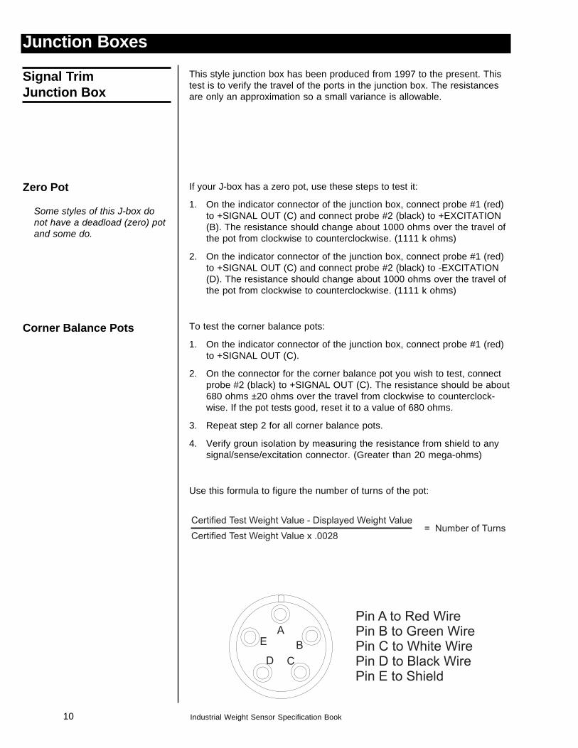
This style junction box has been produced from 1997 to the present. Thistest is to verify the travel of the ports in the junction box. The resistancesare only an approximation so a small variance is allowable.
If your J-box has a zero pot, use these steps to test it:
1. On the indicator connector of the junction box, connect probe #1 (red)to +SIGNAL OUT (C) and connect probe #2 (black) to +EXCITATION(B). The resistance should change about 1000 ohms over the travel ofthe pot from clockwise to counterclockwise. (1111 k ohms)
2. On the indicator connector of the junction box, connect probe #1 (red)to +SIGNAL OUT (C) and connect probe #2 (black) to -EXCITATION(D). The resistance should change about 1000 ohms over the travel ofthe pot from clockwise to counterclockwise. (1111 k ohms)
To test the corner balance pots:
1. On the indicator connector of the junction box, connect probe #1 (red)to +SIGNAL OUT (C).
2. On the connector for the corner balance pot you wish to test, connectprobe #2 (black) to +SIGNAL OUT (C). The resistance should be about680 ohms ±20 ohms over the travel from clockwise to counterclock-wise. If the pot tests good, reset it to a value of 680 ohms.
3. Repeat step 2 for all corner balance pots.
4. Verify groun isolation by measuring the resistance from shield to anysignal/sense/excitation connector. (Greater than 20 mega-ohms)
Use this formula to figure the number of turns of the pot:
Corner Balance Pots
Some styles of this J-box donot have a deadload (zero) potand some do.
Junction Boxes
11Industrial Weight Sensor Specification Book
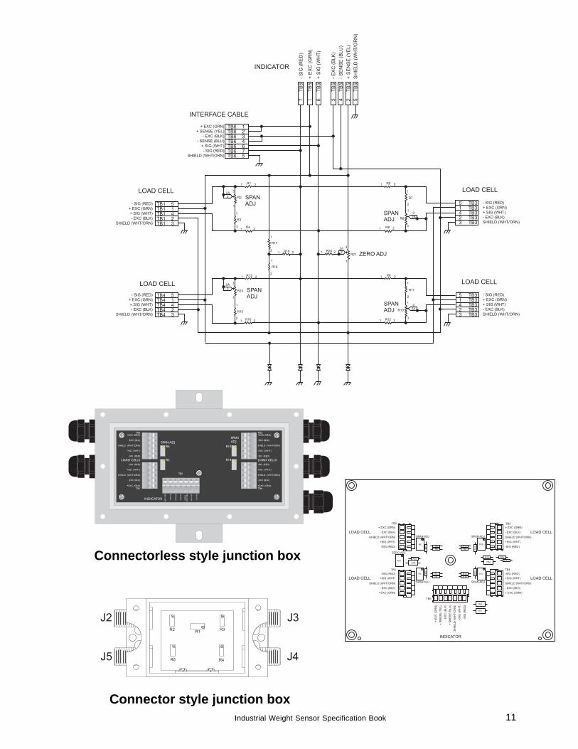
Connectorless style junction box
Connector style junction box
12 Industrial Weight Sensor Specification Book
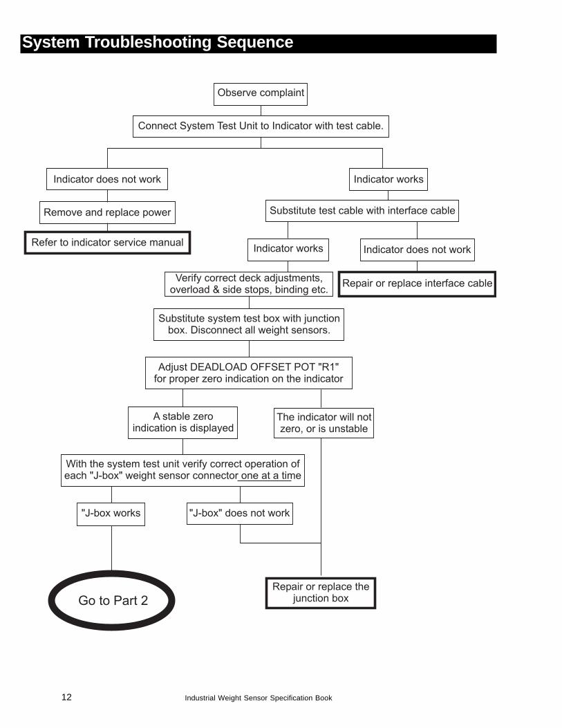
System Troubleshooting Sequence
13Industrial Weight Sensor Specification Book
14 Industrial Weight Sensor Specification Book
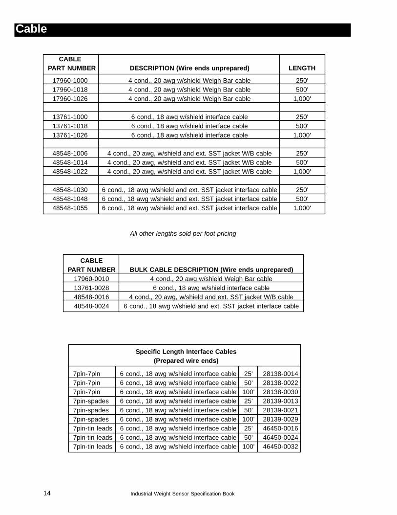
Cable
CABLEPART NUMBER DESCRIPTION (Wire ends unprepared) LENGTH
17960-1000 4 cond., 20 awg w/shield Weigh Bar cable 250'17960-1018 4 cond., 20 awg w/shield Weigh Bar cable 500'17960-1026 4 cond., 20 awg w/shield Weigh Bar cable 1,000'
13761-1000 6 cond., 18 awg w/shield interface cable 250'13761-1018 6 cond., 18 awg w/shield interface cable 500'13761-1026 6 cond., 18 awg w/shield interface cable 1,000'
48548-1006 4 cond., 20 awg, w/shield and ext. SST jacket W/B cable 250'48548-1014 4 cond., 20 awg, w/shield and ext. SST jacket W/B cable 500'48548-1022 4 cond., 20 awg, w/shield and ext. SST jacket W/B cable 1,000'
48548-1030 6 cond., 18 awg w/shield and ext. SST jacket interface cable 250'48548-1048 6 cond., 18 awg w/shield and ext. SST jacket interface cable 500'48548-1055 6 cond., 18 awg w/shield and ext. SST jacket interface cable 1,000'
Specific Length Interface Cables(Prepared wire ends)
7pin-7pin 6 cond., 18 awg w/shield interface cable 25' 28138-00147pin-7pin 6 cond., 18 awg w/shield interface cable 50' 28138-00227pin-7pin 6 cond., 18 awg w/shield interface cable 100' 28138-00307pin-spades 6 cond., 18 awg w/shield interface cable 25' 28139-00137pin-spades 6 cond., 18 awg w/shield interface cable 50' 28139-00217pin-spades 6 cond., 18 awg w/shield interface cable 100' 28139-00297pin-tin leads 6 cond., 18 awg w/shield interface cable 25' 46450-00167pin-tin leads 6 cond., 18 awg w/shield interface cable 50' 46450-00247pin-tin leads 6 cond., 18 awg w/shield interface cable 100' 46450-0032
CABLEPART NUMBER BULK CABLE DESCRIPTION (Wire ends unprepared)
17960-0010 4 cond., 20 awg w/shield Weigh Bar cable13761-0028 6 cond., 18 awg w/shield interface cable48548-0016 4 cond., 20 awg, w/shield and ext. SST jacket W/B cable48548-0024 6 cond., 18 awg w/shield and ext. SST jacket interface cable
All other lengths sold per foot pricing
15Industrial Weight Sensor Specification Book
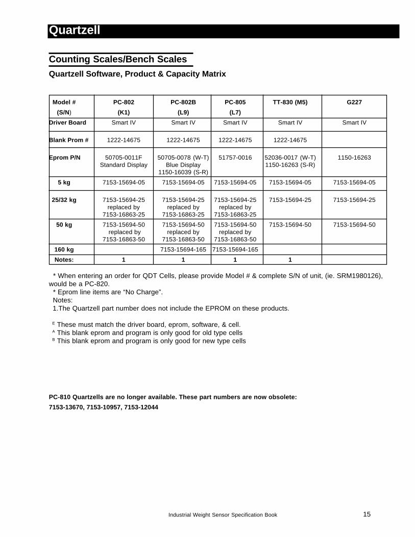
Counting Scales/Bench ScalesQuartzell Software, Product & Capacity Matrix
Model # PC-802 PC-802B PC-805 TT-830 (M5) G227(S/N) (K1) (L9) (L7)
Driver Board Smart IV Smart IV Smart IV Smart IV Smart IV
Blank Prom # 1222-14675 1222-14675 1222-14675 1222-14675
Eprom P/N 50705-0011F 50705-0078 (W-T) 51757-0016 52036-0017 (W-T) 1150-16263Standard Display Blue Display 1150-16263 (S-R)
1150-16039 (S-R)
5 kg 7153-15694-05 7153-15694-05 7153-15694-05 7153-15694-05 7153-15694-05
25/32 kg 7153-15694-25 7153-15694-25 7153-15694-25 7153-15694-25 7153-15694-25replaced by replaced by replaced by
7153-16863-25 7153-16863-25 7153-16863-25
50 kg 7153-15694-50 7153-15694-50 7153-15694-50 7153-15694-50 7153-15694-50 replaced by replaced by replaced by
7153-16863-50 7153-16863-50 7153-16863-50
160 kg 7153-15694-165 7153-15694-165
Notes: 1 1 1 1
* When entering an order for QDT Cells, please provide Model # & complete S/N of unit, (ie. SRM1980126),would be a PC-820. * Eprom line items are “No Charge”. Notes: 1.The Quartzell part number does not include the EPROM on these products.
E These must match the driver board, eprom, software, & cell. A This blank eprom and program is only good for old type cells B This blank eprom and program is only good for new type cells
Quartzell
PC-810 Quartzells are no longer available. These part numbers are now obsolete:7153-13670, 7153-10957, 7153-12044
16 Industrial Weight Sensor Specification Book
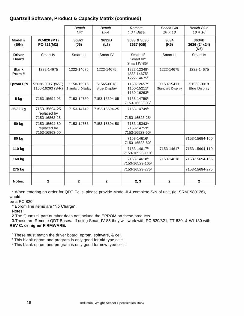
Quartzell Software, Product & Capacity Matrix (continued)
Bench Bench Remote Bench Old Bench BlueOld Blue QDT Base 18 X 18 18 X 18
Model # PC-820 (M1) 3632T 3632B 3633 & 3635 3634 3634B(S/N) PC-821(M2) (J6) (L8) 3637 (G5) (K5) 3636 (24x24)
(K5)Driver Smart IV Smart III Smart IV Smart IIA Smart III Smart IVBoard Smart IIIB
Smart IV-85E
Blank 1222-14675 1222-14675 1222-14675 1222-12348A 1222-14675 1222-14675Prom # 1222-14675B
1222-14675E
Eprom P/N 52036-0017 (W-T) 1150-15516 51565-0018 1150-12657A 1150-15411 51565-00181150-16263 (S-R) Standard Display Blue Display 1150-15211B Standard Display Blue Display
1150-16263E
5 kg 7153-15694-05 7153-14750 7153-15694-05 7153-14750B
7153-16523-05E
25/32 kg 7153-15694-25 7153-14749 7153-15694-25 7153-14749B
replaced by7153-16863-25 7153-16523-25E
50 kg 7153-15694-50 7153-14753 7153-15694-50 7153-15343A
replaced by 7153-14753B
7153-16863-50 7153-16523-50E
80 kg 7153-14616B 7153-15694-1007153-16523-80E
110 kg 7153-14617B 7153-14617 7153-15694-1107153-16523-110E
160 kg 7153-14618B 7153-14618 7153-15694-1657153-16523-165E
275 kg 7153-16523-275E 7153-15694-275
Notes: 2 2 2 2, 3 2 2
* When entering an order for QDT Cells, please provide Model # & complete S/N of unit, (ie. SRM1980126),wouldbe a PC-820. * Eprom line items are “No Charge”. Notes: 2.The Quartzell part number does not include the EPROM on these products. 3.These are Remote QDT Bases. If using Smart IV-85 they will work with PC-820/821, TT-830, & WI-130 withREV C. or higher FIRMWARE.
E These must match the driver board, eprom, software, & cell. A This blank eprom and program is only good for old type cells B This blank eprom and program is only good for new type cells
17Industrial Weight Sensor Specification Book
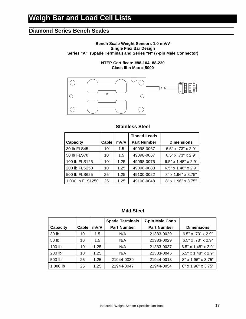
Tinned LeadsCapacity Cable mV/V Part Number Dimensions30 lb FLS45 10' 1.5 49098-0067 6.5" x .73" x 2.9"50 lb FLS70 10' 1.5 49098-0067 6.5" x .73" x 2.9"100 lb FLS125 10' 1.25 49098-0075 6.5" x 1.48" x 2.9"200 lb FLS250 10' 1.25 49098-0083 6.5" x 1.48" x 2.9"500 lb FLS625 25' 1.25 49100-0022 8" x 1.96" x 3.75"1,000 lb FLS1250 25' 1.25 49100-0048 8" x 1.96" x 3.75"
Weigh Bar and Load Cell ListsDiamond Series Bench Scales
Bench Scale Weight Sensors 1.0 mV/VSingle Flex Bar Design
Series "A" (Spade Terminal) and Series "N" (7-pin Male Connector)
NTEP Certificate #88-104, 88-230Class III n Max = 5000
Stainless Steel
Spade Terminals 7-pin Male Conn.Capacity Cable mV/V Part Number Part Number Dimensions30 lb 10' 1.5 N/A 21383-0029 6.5" x .73" x 2.9"50 lb 10' 1.5 N/A 21383-0029 6.5" x .73" x 2.9"100 lb 10' 1.25 N/A 21383-0037 6.5" x 1.48" x 2.9"200 lb 10' 1.25 N/A 21383-0045 6.5" x 1.48" x 2.9"500 lb 25' 1.25 21944-0039 21944-0013 8" x 1.96" x 3.75"1,000 lb 25' 1.25 21944-0047 21944-0054 8" x 1.96" x 3.75"
Mild Steel
18 Industrial Weight Sensor Specification Book
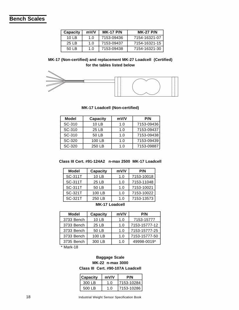
Model Capacity mV/V P/NSC-311T 10 LB 1.0 7153-10018SC-311T 25 LB 1.0 7153-11048SC-311T 50 LB 1.0 7153-10021SC-321T 100 LB 1.0 7153-10022SC-321T 250 LB 1.0 7153-13573
Model Capacity mV/V P/NSC-310 10 LB 1.0 7153-09436SC-310 25 LB 1.0 7153-09437SC-310 50 LB 1.0 7153-09438SC-320 100 LB 1.0 7153-09439SC-320 250 LB 1.0 7153-09887
Capacity mV/V MK-17 P/N MK-27 P/N10 LB 1.0 7153-09436 7154-16321-0725 LB 1.0 7153-09437 7154-16321-1550 LB 1.0 7153-09438 7154-16321-30
MK-17 (Non-certified) and replacement MK-27 Loadcell (Certified)for the tables listed below
Baggage ScaleMK-22 n-max 3000
Class III Cert. #90-107A Loadcell
Capacity mV/V P/N300 LB 1.0 7153-10284500 LB 1.0 7153-10286
MK-17 Loadcell (Non-certified)
Class III Cert. #91-124A2 n-max 2500 MK-17 Loadcell
Model Capacity mV/V P/N3733 Bench 10 LB 1.0 7153-157773733 Bench 25 LB 1.0 7153-15777-123733 Bench 50 LB 1.0 7153-15777-253733 Bench 100 LB 1.0 7153-15777-503735 Bench 300 LB 1.0 49998-0019*
* Mark-18
MK-17 Loadcell
Bench Scales
19Industrial Weight Sensor Specification Book
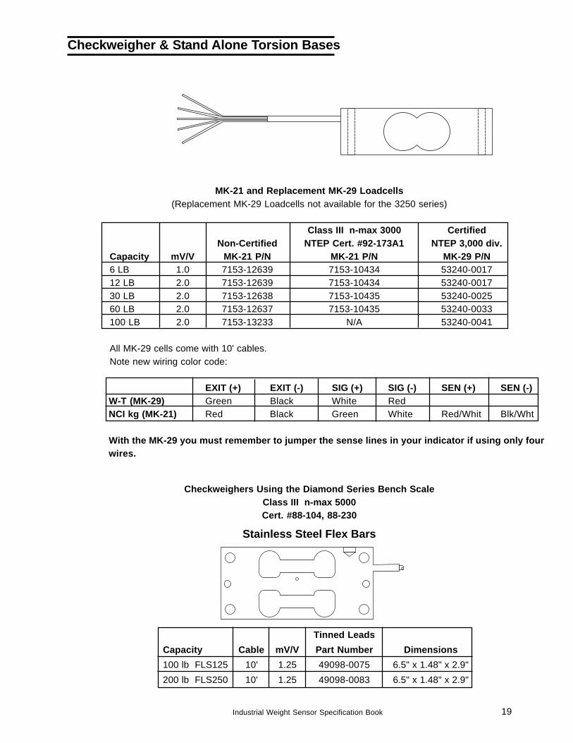
MK-21 and Replacement MK-29 Loadcells(Replacement MK-29 Loadcells not available for the 3250 series)
Class III n-max 3000 CertifiedNon-Certified NTEP Cert. #92-173A1 NTEP 3,000 div.
Capacity mV/V MK-21 P/N MK-21 P/N MK-29 P/N6 LB 1.0 7153-12639 7153-10434 53240-001712 LB 2.0 7153-12639 7153-10434 53240-001730 LB 2.0 7153-12638 7153-10435 53240-002560 LB 2.0 7153-12637 7153-10435 53240-0033100 LB 2.0 7153-13233 N/A 53240-0041
All MK-29 cells come with 10' cables.Note new wiring color code:
EXIT (+) EXIT (-) SIG (+) SIG (-) SEN (+) SEN (-)W-T (MK-29) Green Black White RedNCI kg (MK-21) Red Black Green White Red/Whit Blk/Wht
With the MK-29 you must remember to jumper the sense lines in your indicator if using only fourwires.
Tinned LeadsCapacity Cable mV/V Part Number Dimensions100 lb FLS125 10' 1.25 49098-0075 6.5" x 1.48" x 2.9"200 lb FLS250 10' 1.25 49098-0083 6.5" x 1.48" x 2.9"
Stainless Steel Flex Bars
Checkweigher & Stand Alone Torsion Bases
Checkweighers Using the Diamond Series Bench ScaleClass III n-max 5000Cert. #88-104, 88-230
20 Industrial Weight Sensor Specification Book
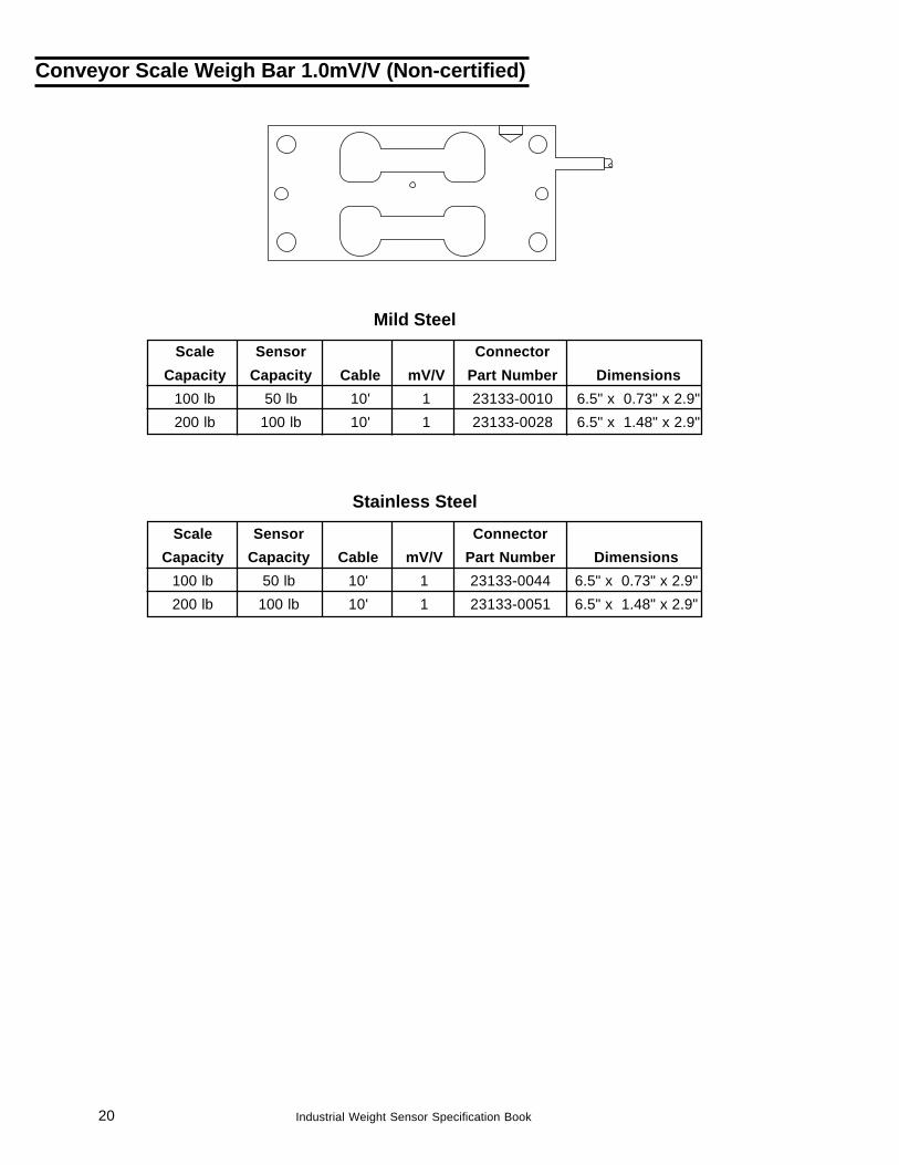
Conveyor Scale Weigh Bar 1.0mV/V (Non-certified)
Scale Sensor ConnectorCapacity Capacity Cable mV/V Part Number Dimensions
100 lb 50 lb 10' 1 23133-0010 6.5" x 0.73" x 2.9"200 lb 100 lb 10' 1 23133-0028 6.5" x 1.48" x 2.9"
Mild Steel
Scale Sensor ConnectorCapacity Capacity Cable mV/V Part Number Dimensions
100 lb 50 lb 10' 1 23133-0044 6.5" x 0.73" x 2.9"200 lb 100 lb 10' 1 23133-0051 6.5" x 1.48" x 2.9"
Stainless Steel
21Industrial Weight Sensor Specification Book
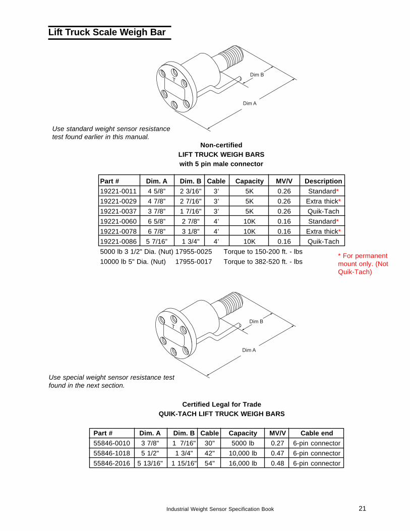
Non-certifiedLIFT TRUCK WEIGH BARSwith 5 pin male connector
Certified Legal for TradeQUIK-TACH LIFT TRUCK WEIGH BARS
Lift Truck Scale Weigh Bar
Part # Dim. A Dim. B Cable Capacity MV/V Description19221-0011 4 5/8” 2 3/16" 3’ 5K 0.26 Standard*19221-0029 4 7/8” 2 7/16" 3’ 5K 0.26 Extra thick*19221-0037 3 7/8” 1 7/16" 3’ 5K 0.26 Quik-Tach19221-0060 6 5/8” 2 7/8" 4’ 10K 0.16 Standard*19221-0078 6 7/8” 3 1/8" 4’ 10K 0.16 Extra thick*19221-0086 5 7/16” 1 3/4" 4’ 10K 0.16 Quik-Tach5000 lb 3 1/2" Dia. (Nut) 17955-0025 Torque to 150-200 ft. - lbs10000 lb 5" Dia. (Nut) 17955-0017 Torque to 382-520 ft. - lbs
Part # Dim. A Dim. B Cable Capacity MV/V Cable end55846-0010 3 7/8" 1 7/16" 30" 5000 lb 0.27 6-pin connector55846-1018 5 1/2" 1 3/4" 42" 10,000 lb 0.47 6-pin connector55846-2016 5 13/16" 1 15/16" 54" 16,000 lb 0.48 6-pin connector
Use standard weight sensor resistancetest found earlier in this manual.
Use special weight sensor resistance testfound in the next section.
* For permanentmount only. (NotQuik-Tach)
22 Industrial Weight Sensor Specification Book
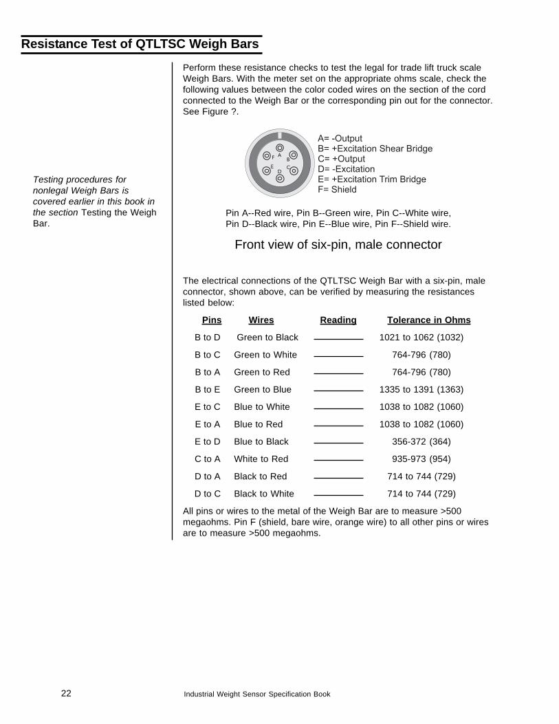
Perform these resistance checks to test the legal for trade lift truck scaleWeigh Bars. With the meter set on the appropriate ohms scale, check thefollowing values between the color coded wires on the section of the cordconnected to the Weigh Bar or the corresponding pin out for the connector.See Figure ?.
Pin A--Red wire, Pin B--Green wire, Pin C--White wire,Pin D--Black wire, Pin E--Blue wire, Pin F--Shield wire.
Front view of six-pin, male connector
The electrical connections of the QTLTSC Weigh Bar with a six-pin, maleconnector, shown above, can be verified by measuring the resistanceslisted below:
Pins Wires Reading Tolerance in Ohms
B to D Green to Black 1021 to 1062 (1032)
B to C Green to White 764-796 (780)
B to A Green to Red 764-796 (780)
B to E Green to Blue 1335 to 1391 (1363)
E to C Blue to White 1038 to 1082 (1060)
E to A Blue to Red 1038 to 1082 (1060)
E to D Blue to Black 356-372 (364)
C to A White to Red 935-973 (954)
D to A Black to Red 714 to 744 (729)
D to C Black to White 714 to 744 (729)
All pins or wires to the metal of the Weigh Bar are to measure >500megaohms. Pin F (shield, bare wire, orange wire) to all other pins or wiresare to measure >500 megaohms.
Resistance Test of QTLTSC Weigh Bars
Testing procedures fornonlegal Weigh Bars iscovered earlier in this book inthe section Testing the WeighBar.
23Industrial Weight Sensor Specification Book
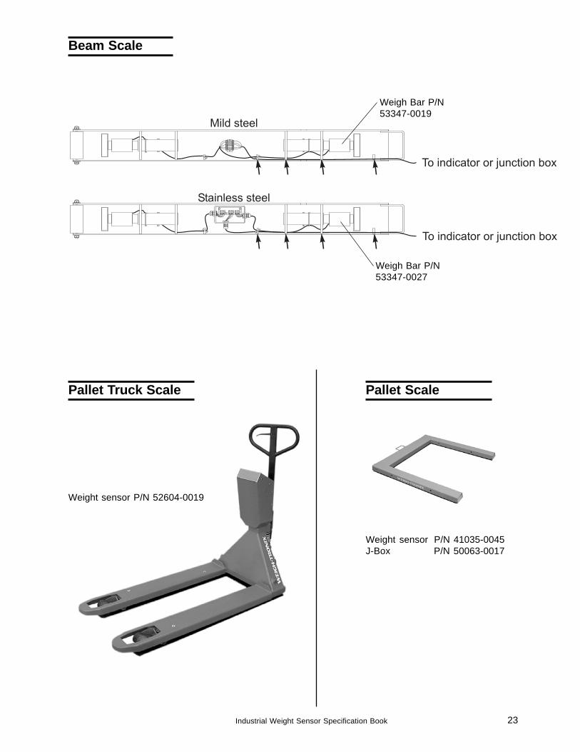
Beam Scale
Weigh Bar P/N53347-0019
Weigh Bar P/N53347-0027
Weight sensor P/N 52604-0019
Pallet Truck Scale
Weight sensor P/N 41035-0045J-Box P/N 50063-0017
Pallet Scale
24 Industrial Weight Sensor Specification Book
WBR MONORAIL WEIGH BARS 2.0m V/VCLASS III n MAX 5000
NTEP Certificate #87-090
WEIGH BARCAPACITY PART NUMBER LENGTH x DIAMETER
1000 lb. 17142-0011 9 1/2" x 1 1/8"2000 lb. 17142-0029 10 9/32" x 1 1/2"
Note: 17142 is stepped to pass through rail.
Style Part Number Output Input115# 47008-0011 700 ohms 800 ohms132# 48265-0017 700 ohms 800 ohms136# 50466-0010 700 ohms 800 ohms4 WB J-Box Assy. 13949-0122J-Box board only 21253-0059
70" Weighline Rails (left and right are interchangeable)
Monorail
25Industrial Weight Sensor Specification Book
Truck Scale
Excitation Resistance Changes:
Old: New:
352-372 ohms Green to Black 383-403 ohms
350 ohms White to Red 350 ohms
262-382 ohms Blk-Red, Blk-Wht, 278.5-298.5 ohmsGrn-Red, Grn-Wht.
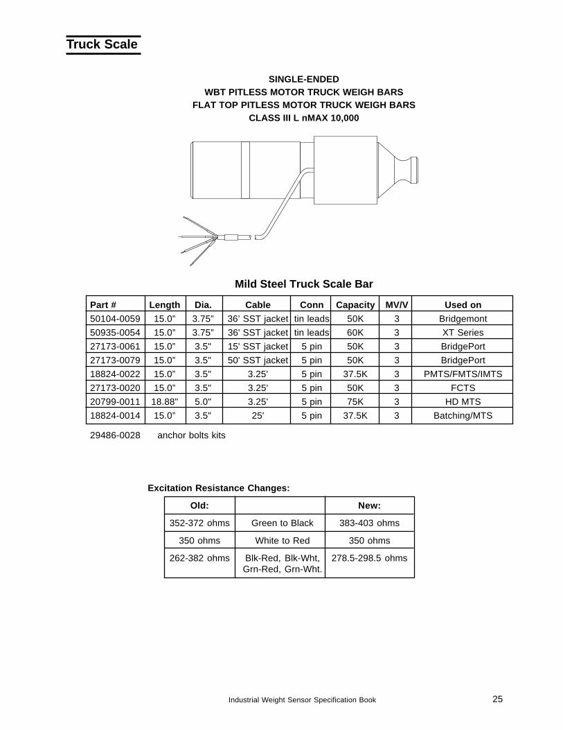
Part # Length Dia. Cable Conn Capacity MV/V Used on50104-0059 15.0” 3.75” 36’ SST jacket tin leads 50K 3 Bridgemont50935-0054 15.0” 3.75” 36' SST jacket tin leads 60K 3 XT Series27173-0061 15.0” 3.5" 15' SST jacket 5 pin 50K 3 BridgePort27173-0079 15.0” 3.5" 50' SST jacket 5 pin 50K 3 BridgePort18824-0022 15.0” 3.5" 3.25' 5 pin 37.5K 3 PMTS/FMTS/IMTS27173-0020 15.0” 3.5" 3.25' 5 pin 50K 3 FCTS20799-0011 18.88" 5.0" 3.25' 5 pin 75K 3 HD MTS18824-0014 15.0” 3.5" 25' 5 pin 37.5K 3 Batching/MTS
29486-0028 anchor bolts kits
Mild Steel Truck Scale Bar
SINGLE-ENDEDWBT PITLESS MOTOR TRUCK WEIGH BARS
FLAT TOP PITLESS MOTOR TRUCK WEIGH BARSCLASS III L nMAX 10,000
26 Industrial Weight Sensor Specification Book
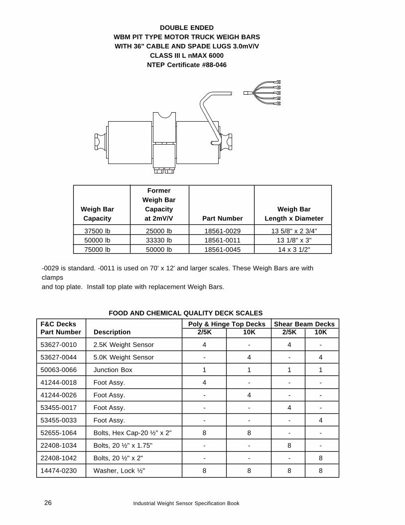
FormerWeigh Bar
Weigh Bar Capacity Weigh BarCapacity at 2mV/V Part Number Length x Diameter
37500 lb 25000 lb 18561-0029 13 5/8" x 2 3/4"50000 lb 33330 lb 18561-0011 13 1/8" x 3"75000 lb 50000 lb 18561-0045 14 x 3 1/2"
-0029 is standard. -0011 is used on 70' x 12' and larger scales. These Weigh Bars are withclampsand top plate. Install top plate with replacement Weigh Bars.
DOUBLE ENDEDWBM PIT TYPE MOTOR TRUCK WEIGH BARSWITH 36" CABLE AND SPADE LUGS 3.0mV/V
CLASS III L nMAX 6000NTEP Certificate #88-046
FOOD AND CHEMICAL QUALITY DECK SCALESF&C Decks Poly & Hinge Top Decks Shear Beam DecksPart Number Description 2/5K 10K 2/5K 10K
53627-0010 2.5K Weight Sensor 4 - 4 -
53627-0044 5.0K Weight Sensor - 4 - 4
50063-0066 Junction Box 1 1 1 1
41244-0018 Foot Assy. 4 - - -
41244-0026 Foot Assy. - 4 - -
53455-0017 Foot Assy. - - 4 -
53455-0033 Foot Assy. - - - 4
52655-1064 Bolts, Hex Cap-20 ½" x 2" 8 8 - -
22408-1034 Bolts, 20 ½" x 1.75" - - 8 -
22408-1042 Bolts, 20 ½" x 2" - - - 8
14474-0230 Washer, Lock ½" 8 8 8 8
27Industrial Weight Sensor Specification Book
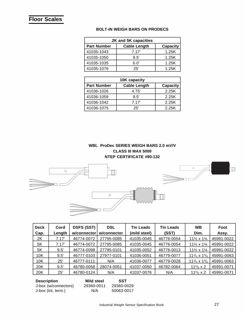
Floor ScalesBOLT-IN WEIGH BARS ON PRODECS
2K and 5K capacitiesPart Number Cable Length Capacity41035-1043 7.17' 1.25K41035-1050 9.5' 1.25K41035-1035 6.0' 1.25K41035-1076 25' 1.25K
10K capacityPart Number Cable Length Capacity41036-1026 4.75' 2.25K41036-1059 9.5' 2.25K41036-1042 7.17' 2.25K41036-1075 25' 2.25K
Description Mild steel SSTJ-box (w/connectors) 29360-0011 29360-0029J-box (int. term.) N/A 50063-0017
Deck Cord DSFS (SST) DSL Tin Leads Tin Leads WB FootCap. Length w/connector w/connector (mild steel) (SST) Dim. Assy.2K 7.17' 46774-0072 27795-0085 41035-0045 46776-0054 11½ x 1¼ 45991-00225K 7.17' 46774-0072 27795-0085 41035-0045 46776-0054 11½ x 1¼ 45991-00225K 9.5' 46774-0098 27795-0101 41035-0052 46776-0013 11½ x 1¼ 45991-002210K 9.5' 46777-0103 27977-0101 41036-0051 46779-0077 113/4 x 15/8 45991-006310K 25' 46777-0111 N/A 41036-0077 46779-0028 113/4 x 15/8 45991-006320K 9.5' 46780-0058 28074-0051 41037-0050 46782-0064 115/8 x 2 45991-007120K 25' 46780-0124 N/A 41037-0076 N/A 115/8 x 2 45991-0071
WBL ProDec SERIES WEIGH BARS 2.0 mV/VCLASS III MAX 5000
NTEP CERTIFICATE #90-132
28 Industrial Weight Sensor Specification Book
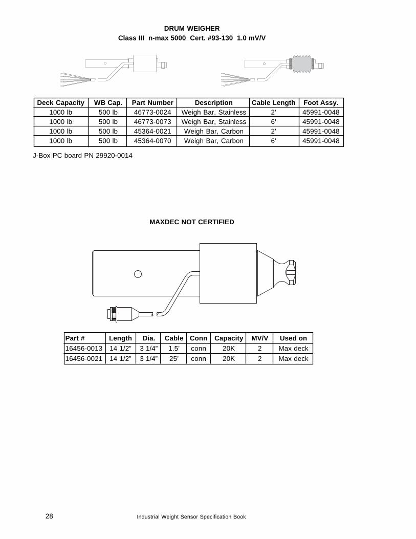
Part # Length Dia. Cable Conn Capacity MV/V Used on16456-0013 14 1/2” 3 1/4” 1.5’ conn 20K 2 Max deck16456-0021 14 1/2” 3 1/4” 25’ conn 20K 2 Max deck
MAXDEC NOT CERTIFIED
Deck Capacity WB Cap. Part Number Description Cable Length Foot Assy.1000 lb 500 lb 46773-0024 Weigh Bar, Stainless 2' 45991-00481000 lb 500 lb 46773-0073 Weigh Bar, Stainless 6' 45991-00481000 lb 500 lb 45364-0021 Weigh Bar, Carbon 2' 45991-00481000 lb 500 lb 45364-0070 Weigh Bar, Carbon 6' 45991-0048
DRUM WEIGHERClass III n-max 5000 Cert. #93-130 1.0 mV/V
J-Box PC board PN 29920-0014
29Industrial Weight Sensor Specification Book
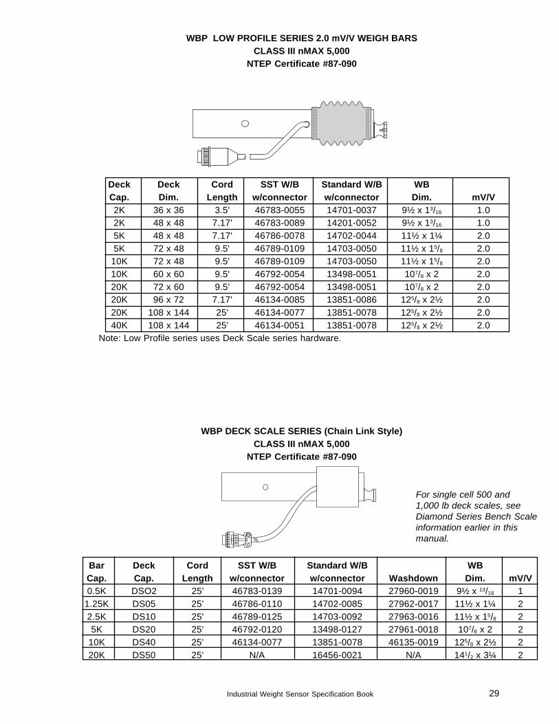
WBP LOW PROFILE SERIES 2.0 mV/V WEIGH BARSCLASS III nMAX 5,000
NTEP Certificate #87-090
Deck Deck Cord SST W/B Standard W/B WBCap. Dim. Length w/connector w/connector Dim. mV/V2K 36 x 36 3.5' 46783-0055 14701-0037 9½ x 13/16 1.02K 48 x 48 7.17' 46783-0089 14201-0052 9½ x 13/16 1.05K 48 x 48 7.17' 46786-0078 14702-0044 11½ x 1¼ 2.05K 72 x 48 9.5' 46789-0109 14703-0050 11½ x 15/8 2.0
10K 72 x 48 9.5' 46789-0109 14703-0050 11½ x 15/8 2.010K 60 x 60 9.5' 46792-0054 13498-0051 107/8 x 2 2.020K 72 x 60 9.5' 46792-0054 13498-0051 107/8 x 2 2.020K 96 x 72 7.17' 46134-0085 13851-0086 125/8 x 2½ 2.020K 108 x 144 25' 46134-0077 13851-0078 125/8 x 2½ 2.040K 108 x 144 25' 46134-0051 13851-0078 125/8 x 2½ 2.0
Note: Low Profile series uses Deck Scale series hardware.
WBP DECK SCALE SERIES (Chain Link Style)CLASS III nMAX 5,000
NTEP Certificate #87-090
Bar Deck Cord SST W/B Standard W/B WBCap. Cap. Length w/connector w/connector Washdown Dim. mV/V0.5K DSO2 25' 46783-0139 14701-0094 27960-0019 9½ x 13/16 1
1.25K DS05 25' 46786-0110 14702-0085 27962-0017 11½ x 1¼ 22.5K DS10 25' 46789-0125 14703-0092 27963-0016 11½ x 15/8 25K DS20 25' 46792-0120 13498-0127 27961-0018 107/8 x 2 2
10K DS40 25' 46134-0077 13851-0078 46135-0019 125/8 x 2½ 220K DS50 25' N/A 16456-0021 N/A 141/2 x 3¼ 2
For single cell 500 and1,000 lb deck scales, seeDiamond Series Bench Scaleinformation earlier in thismanual.
30 Industrial Weight Sensor Specification Book
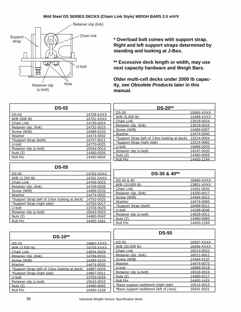
Mild Steel DS SERIES DECKS (Chain Link Style) WEIGH BARS 2.0 mV/V
DS-02DS-02 14729-XXXXW/B (500 lb) 14701-XXXXChain Link 14730-0024Retainer clip, (link) 14731-0015Screw (W/B) 14489-0233Washer 14474-0032*Support Strap (both) 14727-0011U-bolt 14770-0025Retainer clip (u-bolt) 15044-0014Nuts (2) 14480-0026Roll Pin 14450-0634
DS-05DS-05 14763-XXXXW/B (1,250 lb) 14702-XXXXChain Link 14764-0023Retainer clip, (link) 14769-0028Screw (W/B) 14489-0233Washer 14474-0032*Support Strap (left of J-box looking at deck) 14762-0025*Support Strap (right side) 14762-0017U-bolt 13703-0029Retainer clip (u-bolt) 15043-0023Nuts (2) 14480-0042Roll Pin 14450-1061
DS-10**DS-10 14862-XXXXW/B (2,500 lb) 14703-XXXXChain Link 14834-0029Retainer clip, (link) 14769-0010Screw (W/B) 14489-0233Washer 14474-0032*Support Strap (left of J-box looking at deck) 14867-0029*Support Strap (right side) 14867-0011U-bolt 13703-0029Retainer clip (u-bolt) 15043-0015Nuts (2) 14480-0042Roll Pin 14450-1228
DS-20**DS-20 15065-XXXXW/B (5,000 lb) 13498-XXXXChain Link 13518-0024Retainer clip, (link) 13519-0015Screw (W/B) 14489-0357Washer 14474-0040*Support Strap (left of J-box looking at deck) 13214-0054*Support Strap (right side) 13214-0062U-bolt 15066-0025Retainer clip (u-bolt) 14247-0020Nuts (2) 14480-0059Roll Pin 14450-1244
DS-30 & 40**DS-30 & 40 18490-XXXXW/B (10,000 lb) 13851-XXXXChain Link 14201-0032Retainer clip, (link) 14200-0017Screw (W/B) 14494-0012Washer 14474-0065*Support Strap (both) 18488-0011U-bolt 14199-0036Retainer clip (u-bolt) 14828-0011Nuts (2) 14480-0083Roll Pin 14450-1269
DS-50
DS-50 16557-XXXXW/B (20,000 lb) 16456-XXXXChain Link 16513-0022Retainer clip, (link) 16511-0011Screw (W/B) 14494-0137Washer 14474-0073U-bolt 18689-0018Retainer clip (u-bolt) 16518-0019Nuts (2) 14480-0117Roll Pin 14450-1426*Base support weldment (right side) 16514-0013*Base support weldment (left of j-box) 16541-0021
* Overload bolt comes with support strap.Right and left support straps determined bystanding and looking at J-Box.
** Excessive deck length or width, may usenext capacity hardware and Weigh Bars.
Older multi-cell decks under 2000 lb capac-ity, see Obsolete Products later in thismanual.
31Industrial Weight Sensor Specification Book
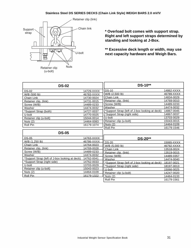
Stainless Steel DS SERIES DECKS (Chain Link Style) WEIGH BARS 2.0 mV/V
DS-02DS-02 14729-XXXXW/B (500 lb) 46783-XXXXChain Link 14730-0024Retainer clip, (link) 14731-0015Screw (W/B) 14489-0233Washer 14474-0032*Support Strap (both) 14727-0037U-bolt 14770-0025Retainer clip (u-bolt) 15044-0014Nuts (2) 14464-0083Roll Pin 16179-1074
DS-05DS-05 14763-XXXXW/B (1,250 lb) 46786-XXXXChain Link 14764-0023Retainer clip, (link) 14769-0028Screw (W/B) 14489-0233Washer 14474-0032*Support Strap (left of J-box looking at deck) 14762-0041*Support Strap (right side) 14762-0033U-bolt 13703-0029Retainer clip (u-bolt) 15043-0023Nuts (2) 14464-0109Roll Pin 16179-1322
DS-10**DS-10 14862-XXXXW/B (2,500 lb) 46789-XXXXChain Link 14834-0029Retainer clip, (link) 14769-0010Screw (W/B) 14489-0233Washer 14474-0032*Support Strap (left of J-box looking at deck) 14867-0045*Support Strap (right side) 14867-0037U-bolt 13703-0029Retainer clip (u-bolt) 15043-0015Nuts (2) 14464-0109Roll Pin 16179-1546
DS-20**DS-20 15065-XXXXW/B (5,000 lb) 46792-XXXXChain Link 13518-0024Retainer clip, (link) 13519-0015Screw (W/B) 14489-0357Washer 14474-0040*Support Strap (left of J-box looking at deck) 18197-0021*Support Strap (right side) 18197-0013U-bolt 15066-0025Retainer clip (u-bolt) 14247-0020Nuts (2) 14464-0133Roll Pin 16179-1561
* Overload bolt comes with support strap.Right and left support straps determined bystanding and looking at J-Box.
** Excessive deck length or width, may usenext capacity hardware and Weigh Bars.
32 Industrial Weight Sensor Specification Book
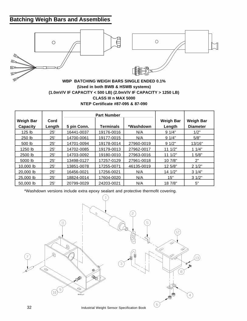
WBP BATCHING WEIGH BARS SINGLE ENDED 0.1%(Used in both BWB & HSWB systems)
(1.0mV/V IF CAPACITY < 500 LB) (2.0mV/V IF CAPACITY > 1250 LB)CLASS III n MAX 5000
NTEP Certificate #87-095 & 87-090
Part NumberWeigh Bar Cord Weigh Bar Weigh BarCapacity Length 5 pin Conn. Terminals *Washdown Length Diameter
125 lb 25' 16441-0037 19176-0016 N/A 9 1/4" 1/2"250 lb 25' 14700-0061 19177-0015 N/A 9 1/4" 5/8"500 lb 25' 14701-0094 19178-0014 27960-0019 9 1/2" 13/16"
1250 lb 25' 14702-0085 19179-0013 27962-0017 11 1/2" 1 1/4"2500 lb 25' 14703-0092 19180-0010 27963-0016 11 1/2" 1 5/8"5000 lb 25' 13498-0127 17257-0129 27961-0018 10 7/8" 2"
10,000 lb 25' 13851-0078 17255-0071 46135-0019 12 5/8" 2 1/2"20,000 lb 25' 16456-0021 17256-0021 N/A 14 1/2" 3 1/4"25,000 lb 25' 18824-0014 17604-0020 N/A 15" 3 1/2"50,000 lb 25' 20799-0029 24203-0021 N/A 18 7/8" 5"
Batching Weigh Bars and Assemblies
*Washdown versions include extra epoxy sealant and protective thermofit covering.
33Industrial Weight Sensor Specification Book
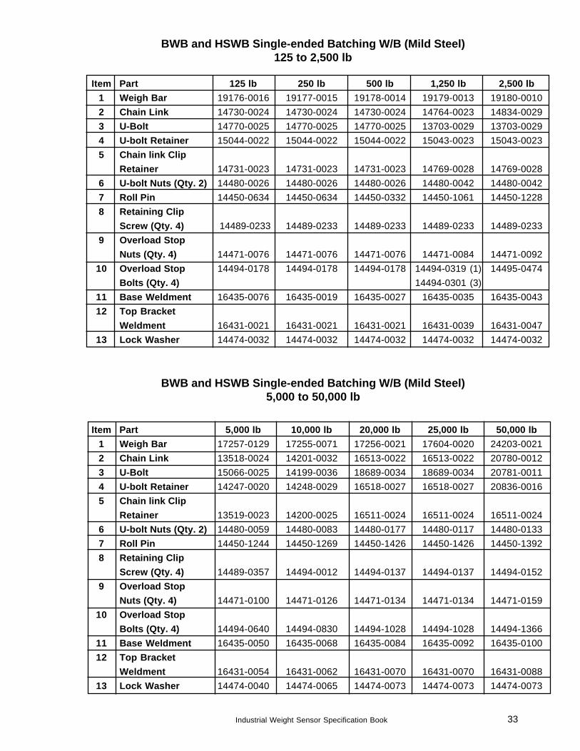
BWB and HSWB Single-ended Batching W/B (Mild Steel)5,000 to 50,000 lb
Item Part 5,000 lb 10,000 lb 20,000 lb 25,000 lb 50,000 lb1 Weigh Bar 17257-0129 17255-0071 17256-0021 17604-0020 24203-00212 Chain Link 13518-0024 14201-0032 16513-0022 16513-0022 20780-00123 U-Bolt 15066-0025 14199-0036 18689-0034 18689-0034 20781-00114 U-bolt Retainer 14247-0020 14248-0029 16518-0027 16518-0027 20836-00165 Chain link Clip
Retainer 13519-0023 14200-0025 16511-0024 16511-0024 16511-00246 U-bolt Nuts (Qty. 2) 14480-0059 14480-0083 14480-0177 14480-0117 14480-01337 Roll Pin 14450-1244 14450-1269 14450-1426 14450-1426 14450-13928 Retaining Clip
Screw (Qty. 4) 14489-0357 14494-0012 14494-0137 14494-0137 14494-01529 Overload Stop
Nuts (Qty. 4) 14471-0100 14471-0126 14471-0134 14471-0134 14471-015910 Overload Stop
Bolts (Qty. 4) 14494-0640 14494-0830 14494-1028 14494-1028 14494-136611 Base Weldment 16435-0050 16435-0068 16435-0084 16435-0092 16435-010012 Top Bracket
Weldment 16431-0054 16431-0062 16431-0070 16431-0070 16431-008813 Lock Washer 14474-0040 14474-0065 14474-0073 14474-0073 14474-0073
BWB and HSWB Single-ended Batching W/B (Mild Steel)125 to 2,500 lb
Item Part 125 lb 250 lb 500 lb 1,250 lb 2,500 lb1 Weigh Bar 19176-0016 19177-0015 19178-0014 19179-0013 19180-00102 Chain Link 14730-0024 14730-0024 14730-0024 14764-0023 14834-00293 U-Bolt 14770-0025 14770-0025 14770-0025 13703-0029 13703-00294 U-bolt Retainer 15044-0022 15044-0022 15044-0022 15043-0023 15043-00235 Chain link Clip
Retainer 14731-0023 14731-0023 14731-0023 14769-0028 14769-00286 U-bolt Nuts (Qty. 2) 14480-0026 14480-0026 14480-0026 14480-0042 14480-00427 Roll Pin 14450-0634 14450-0634 14450-0332 14450-1061 14450-12288 Retaining Clip
Screw (Qty. 4) 14489-0233 14489-0233 14489-0233 14489-0233 14489-02339 Overload Stop
Nuts (Qty. 4) 14471-0076 14471-0076 14471-0076 14471-0084 14471-009210 Overload Stop 14494-0178 14494-0178 14494-0178 14494-0319 (1) 14495-0474
Bolts (Qty. 4) 14494-0301 (3)11 Base Weldment 16435-0076 16435-0019 16435-0027 16435-0035 16435-004312 Top Bracket
Weldment 16431-0021 16431-0021 16431-0021 16431-0039 16431-004713 Lock Washer 14474-0032 14474-0032 14474-0032 14474-0032 14474-0032
34 Industrial Weight Sensor Specification Book
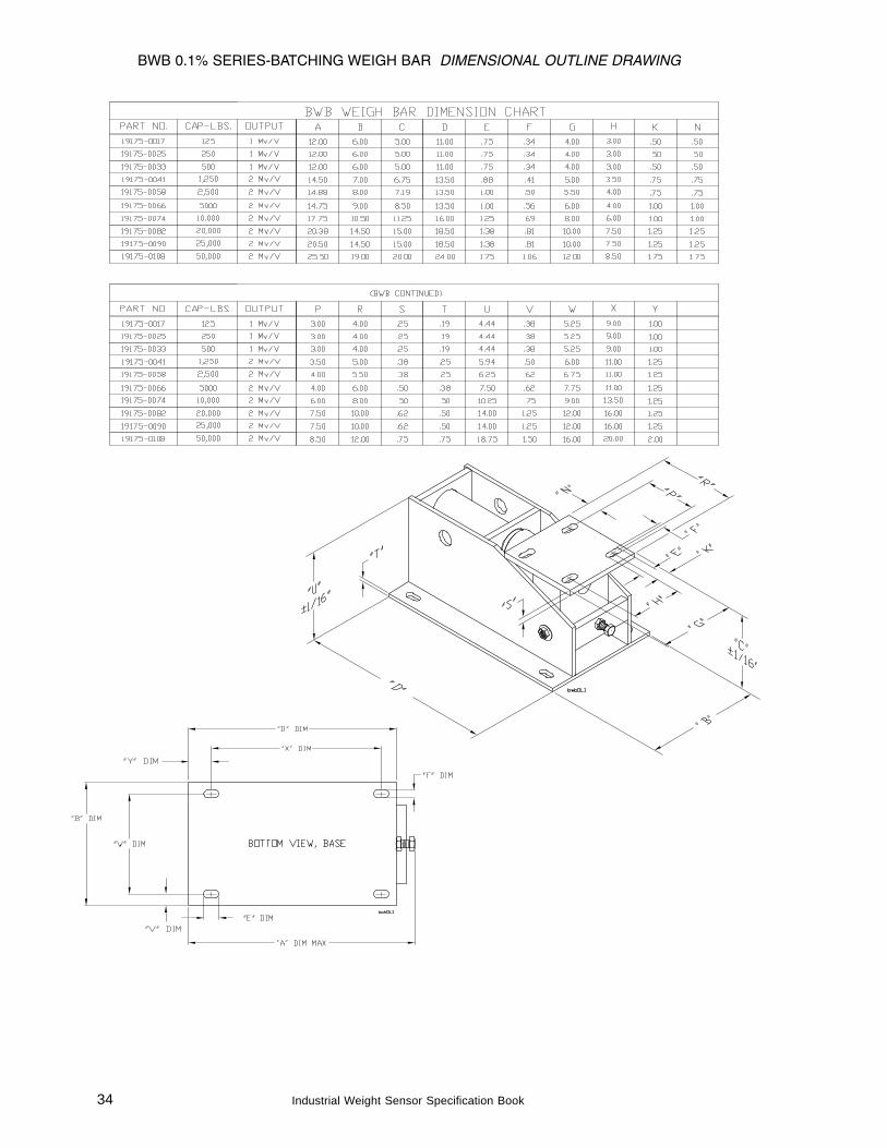
BWB 0.1% SERIES-BATCHING WEIGH BAR DIMENSIONAL OUTLINE DRAWING
35Industrial Weight Sensor Specification Book
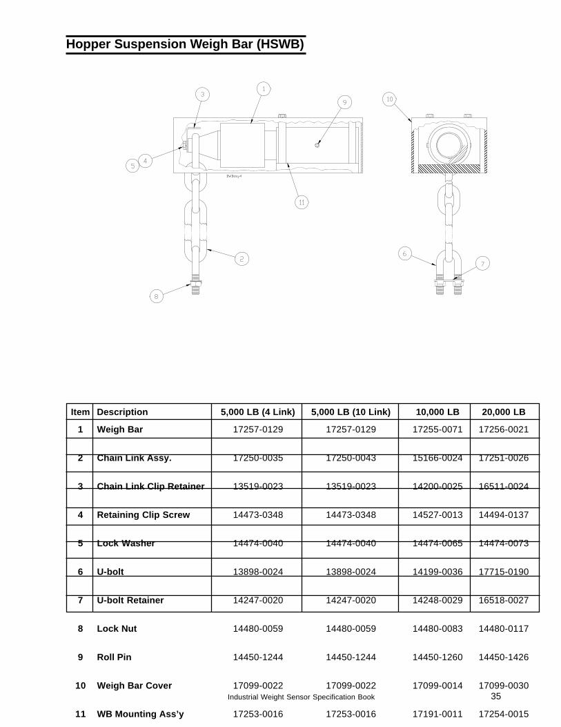
Item Description 5,000 LB (4 Link) 5,000 LB (10 Link) 10,000 LB 20,000 LB
1 Weigh Bar 17257-0129 17257-0129 17255-0071 17256-0021
2 Chain Link Assy. 17250-0035 17250-0043 15166-0024 17251-0026
3 Chain Link Clip Retainer 13519-0023 13519-0023 14200-0025 16511-0024
4 Retaining Clip Screw 14473-0348 14473-0348 14527-0013 14494-0137
5 Lock Washer 14474-0040 14474-0040 14474-0065 14474-0073
6 U-bolt 13898-0024 13898-0024 14199-0036 17715-0190
7 U-bolt Retainer 14247-0020 14247-0020 14248-0029 16518-0027
8 Lock Nut 14480-0059 14480-0059 14480-0083 14480-0117
9 Roll Pin 14450-1244 14450-1244 14450-1260 14450-1426
10 Weigh Bar Cover 17099-0022 17099-0022 17099-0014 17099-0030
11 WB Mounting Ass’y 17253-0016 17253-0016 17191-0011 17254-0015
Hopper Suspension Weigh Bar (HSWB)
36 Industrial Weight Sensor Specification Book
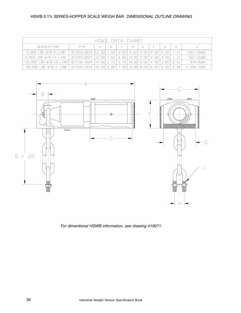
HSWB 0.1% SERIES-HOPPER SCALE WEIGH BAR DIMENSIONAL OUTLINE DRAWING
For dimentional HSWB information, see drawing #19071.
37Industrial Weight Sensor Specification Book
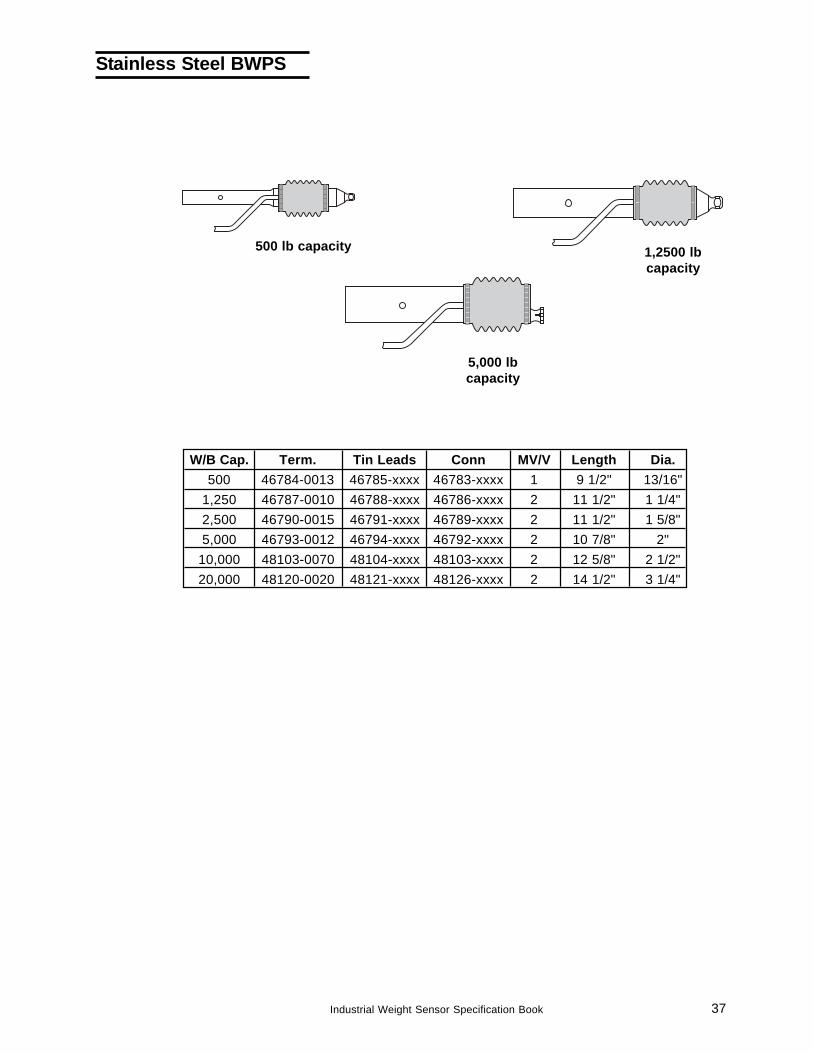
W/B Cap. Term. Tin Leads Conn MV/V Length Dia.500 46784-0013 46785-xxxx 46783-xxxx 1 9 1/2" 13/16"
1,250 46787-0010 46788-xxxx 46786-xxxx 2 11 1/2" 1 1/4"2,500 46790-0015 46791-xxxx 46789-xxxx 2 11 1/2" 1 5/8"5,000 46793-0012 46794-xxxx 46792-xxxx 2 10 7/8" 2"
10,000 48103-0070 48104-xxxx 48103-xxxx 2 12 5/8" 2 1/2"20,000 48120-0020 48121-xxxx 48126-xxxx 2 14 1/2" 3 1/4"
500 lb capacity 1,2500 lbcapacity
5,000 lbcapacity
Stainless Steel BWPS
38 Industrial Weight Sensor Specification Book
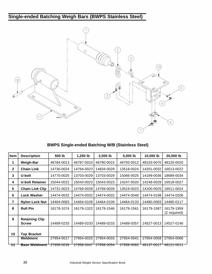
BWPS Single-ended Batching W/B (Stainless Steel)
Item Description 500 lb 1,250 lb 2,500 lb 5,000 lb 10,000 lb 20,000 lb
1 Weigh-Bar 46784-0013 46787-0010 46790-0015 46793-0012 48103-0070 48120-0020
2 Chain Link 14730-0024 14764-0023 14834-0029 13518-0024 14201-0032 16513-0022
3 U-bolt 14770-0025 13703-0029 13703-0029 15066-0025 14199-0036 18689-0034
4 U-bolt Retainer 15044-0022 15043-0023 15043-0023 14247-0020 14248-0029 16518-0027
5 Chain Link Clip 14731-0023 14769-0028 14769-0028 13519-0023 14200-0025 16511-0024
6 Lock Washer 14474-0032 14474-0032 14474-0032 14474-0040 14474-0198 14474-0206
7 Nylon Lock Nut 14464-0083 14464-0109 14464-0109 14464-0133 14480-0083 14480-0117
8 Roll Pin 16179-1074 16179-1322 16179-1546 16179-1561 16179-1587 16179-1959(2 required)
9 Retaining ClipScrew 14489-0233 14489-0233 14489-0233 14489-0357 14527-0013 14527-0146
10 Top BracketWeldment 27954-0017 27954-0025 27954-0033 27954-0041 27954-0058 27954-0066
11 Base Weldment 27958-0039 27958-0047 27958-0054 27958-0062 46137-0017 48121-0011
Single-ended Batching Weigh Bars (BWPS Stainless Steel)
39Industrial Weight Sensor Specification Book
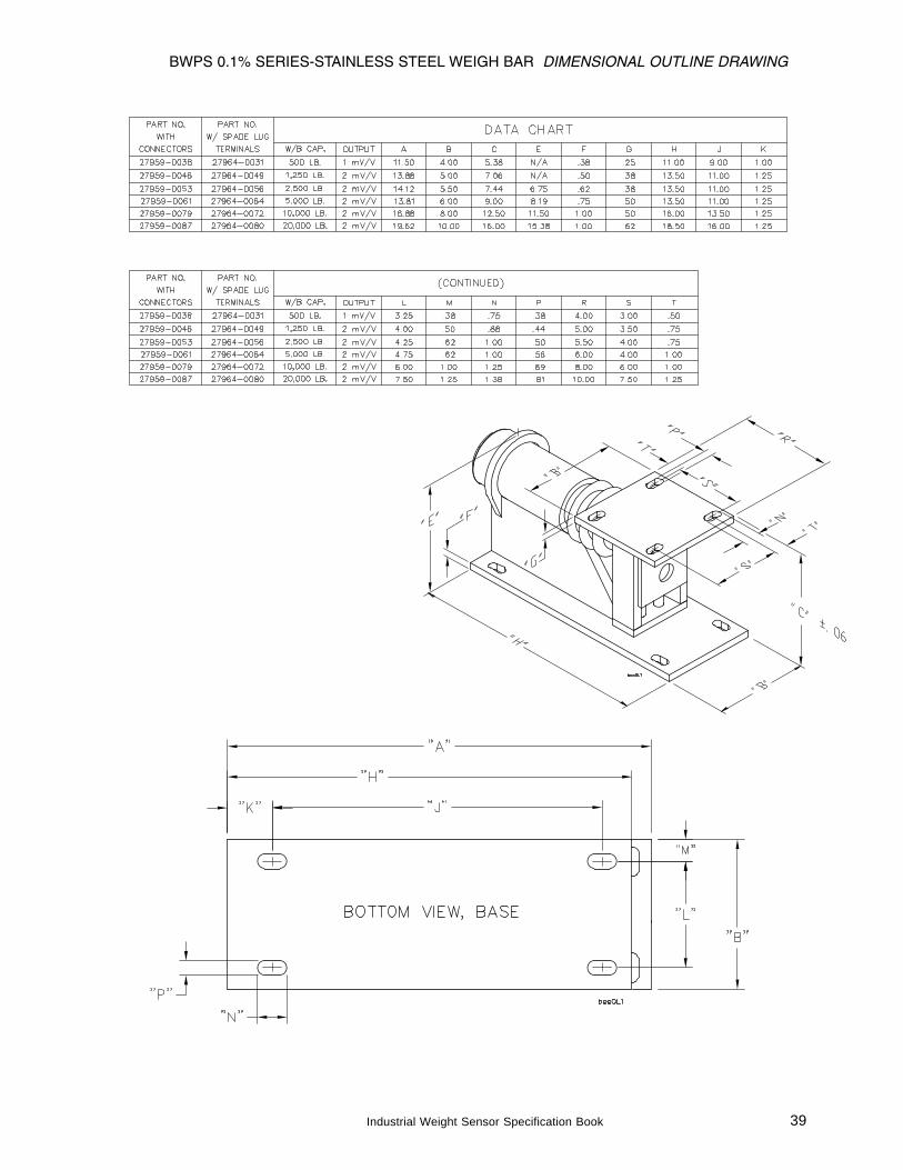
BWPS 0.1% SERIES-STAINLESS STEEL WEIGH BAR DIMENSIONAL OUTLINE DRAWING
40 Industrial Weight Sensor Specification Book
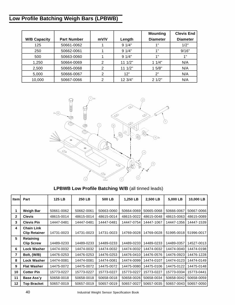
Low Profile Batching Weigh Bars (LPBWB)
LPBWB Low Profile Batching W/B (all tinned leads)
Item Part 125 LB 250 LB 500 LB 1,250 LB 2,500 LB 5,000 LB 10,000 LB
1 Weigh Bar 50661-0062 50662-0061 50663-0060 50664-0069 50665-0068 50666-0067 50667-0066
2 Clevis 48615-0014 48615-0014 48615-0014 48615-0022 48615-0048 48615-0063 48615-0089
3 Clevis Pin 14447-0481 14447-0481 14447-0481 14447-0754 14447-1067 14447-1356 14447-1539
4 Chain LinkClip Retainer 14731-0023 14731-0023 14731-0023 14769-0028 14769-0028 51995-0018 51996-0017
5 RetainingClip Screw 14489-0233 14489-0233 14489-0233 14489-0233 14489-0233 14489-0357 14527-0013
6 Lock Washer 14474-0032 14474-0032 14474-0032 14474-0032 14474-0032 14474-0040 14474-0198
7 Bolt, (W/B) 14476-0253 14476-0253 14476-0253 14476-0410 14476-0576 14476-0923 14476-1228
8 Lock Washer 14474-0081 14474-0081 14474-0081 14474-0099 14474-0107 14474-0123 14474-0149
9 Flat Washer 14475-0072 14475-0072 14475-0072 14475-0080 14475-0106 14475-0122 14475-0148
10 Cotter Pin 15773-0227 15773-0227 15773-0227 15773-0227 15773-0227 15773-0334 15773-0441
11 Base Ass’y 50658-0018 50658-0018 50658-0018 50658-0026 50658-0034 50658-0042 50658-0059
12 Top Bracket 50657-0019 50657-0019 50657-0019 50657-0027 50657-0035 50657-0043 50657-0050
Mounting Clevis EndW/B Capacity Part Number mV/V Length Diameter Diameter
125 50661-0062 1 9 1/4" 1" 1/2"250 50662-0061 1 9 1/4" 1" 9/16"500 50663-0060 1 9 1/4" 1" 1"
1,250 50664-0069 2 11 1/2" 1 1/4" N/A2,500 50665-0068 2 11 1/2" 1 5/8" N/A5,000 50666-0067 2 12" 2" N/A
10,000 50667-0066 2 12 3/4" 2 1/2" N/A
41Industrial Weight Sensor Specification Book
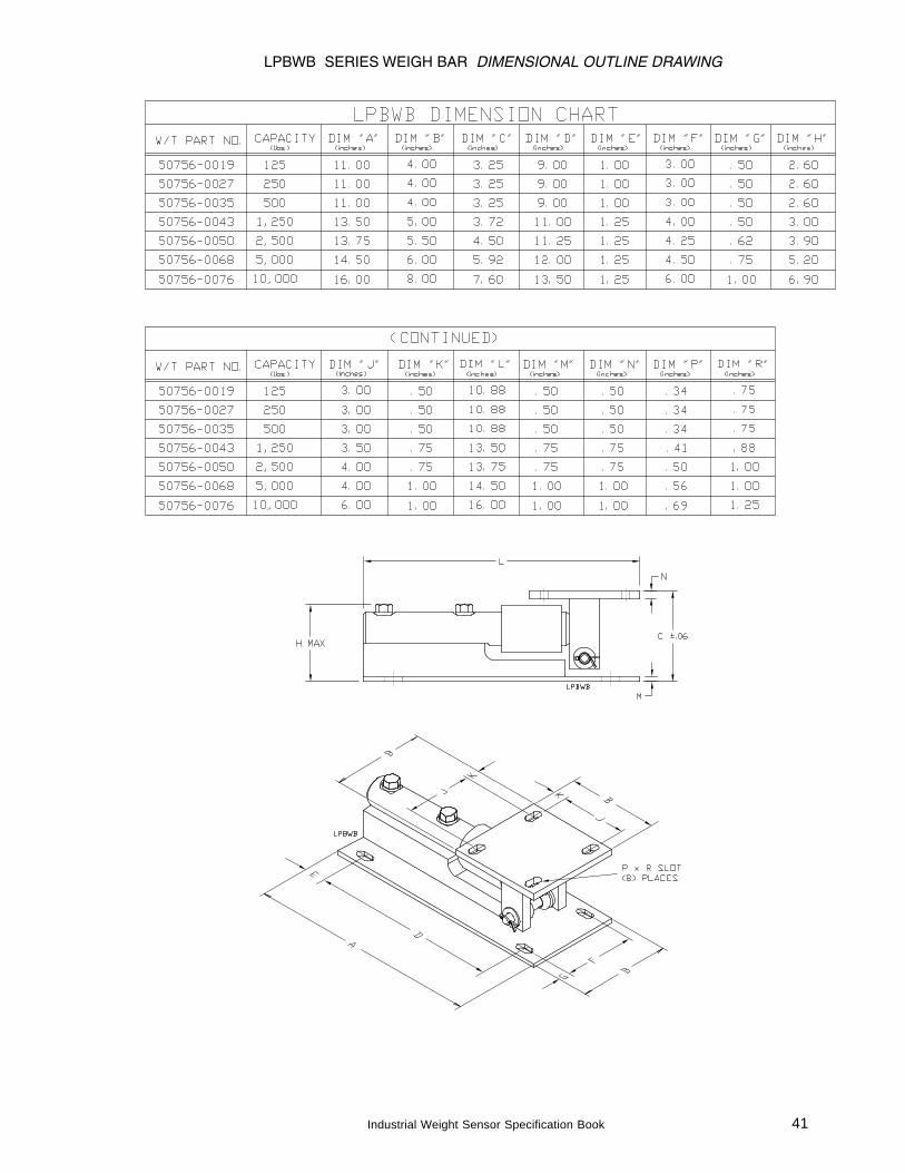
LPBWB SERIES WEIGH BAR DIMENSIONAL OUTLINE DRAWING
42 Industrial Weight Sensor Specification Book
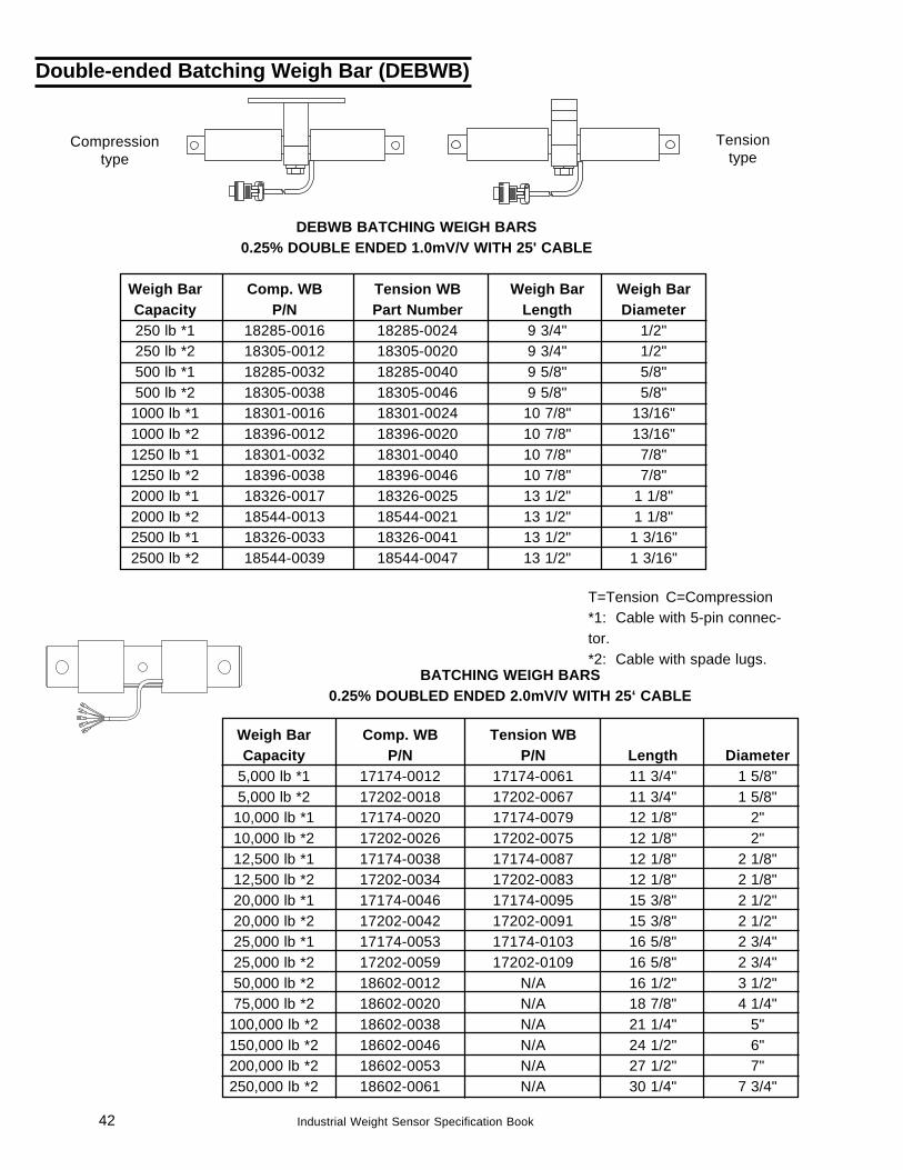
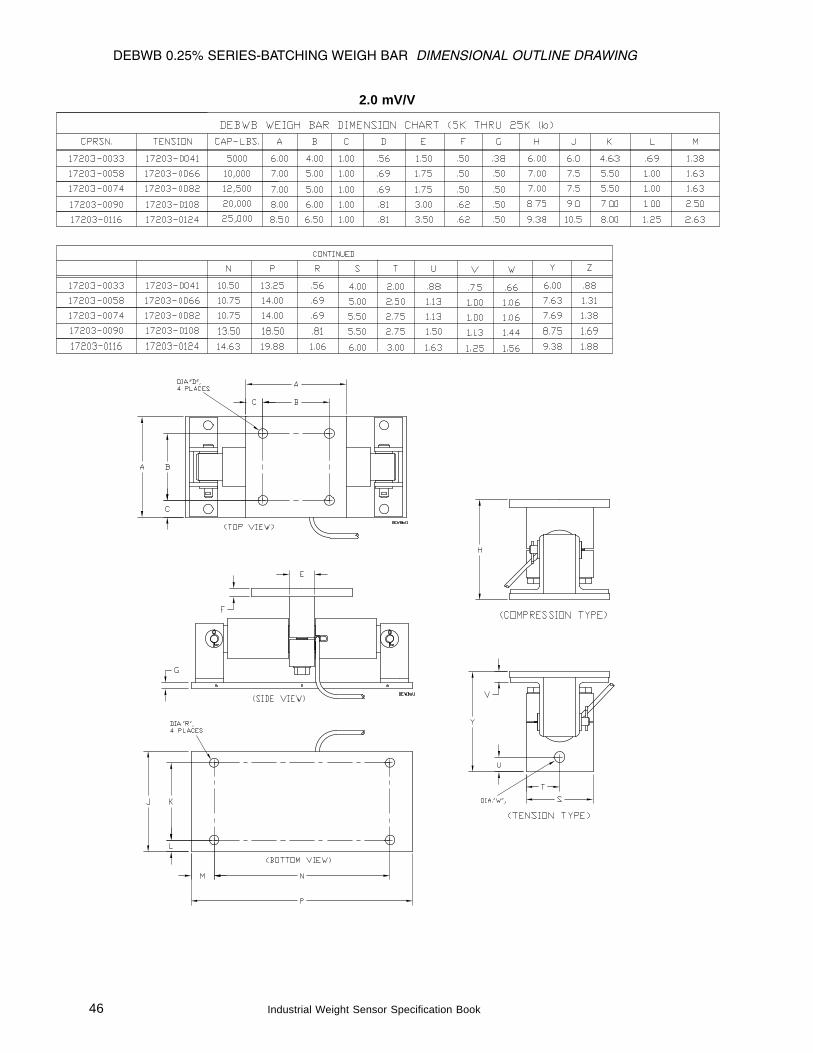
Weigh Bar Comp. WB Tension WBCapacity P/N P/N Length Diameter
5,000 lb *1 17174-0012 17174-0061 11 3/4" 1 5/8"5,000 lb *2 17202-0018 17202-0067 11 3/4" 1 5/8"
10,000 lb *1 17174-0020 17174-0079 12 1/8" 2"10,000 lb *2 17202-0026 17202-0075 12 1/8" 2"12,500 lb *1 17174-0038 17174-0087 12 1/8" 2 1/8"12,500 lb *2 17202-0034 17202-0083 12 1/8" 2 1/8"20,000 lb *1 17174-0046 17174-0095 15 3/8" 2 1/2"20,000 lb *2 17202-0042 17202-0091 15 3/8" 2 1/2"25,000 lb *1 17174-0053 17174-0103 16 5/8" 2 3/4"25,000 lb *2 17202-0059 17202-0109 16 5/8" 2 3/4"50,000 lb *2 18602-0012 N/A 16 1/2" 3 1/2"75,000 lb *2 18602-0020 N/A 18 7/8" 4 1/4"
100,000 lb *2 18602-0038 N/A 21 1/4" 5"150,000 lb *2 18602-0046 N/A 24 1/2" 6"200,000 lb *2 18602-0053 N/A 27 1/2" 7"250,000 lb *2 18602-0061 N/A 30 1/4" 7 3/4"
DEBWB BATCHING WEIGH BARS0.25% DOUBLE ENDED 1.0mV/V WITH 25' CABLE
Weigh Bar Comp. WB Tension WB Weigh Bar Weigh BarCapacity P/N Part Number Length Diameter250 lb *1 18285-0016 18285-0024 9 3/4" 1/2"250 lb *2 18305-0012 18305-0020 9 3/4" 1/2"500 lb *1 18285-0032 18285-0040 9 5/8" 5/8"500 lb *2 18305-0038 18305-0046 9 5/8" 5/8"
1000 lb *1 18301-0016 18301-0024 10 7/8" 13/16"1000 lb *2 18396-0012 18396-0020 10 7/8" 13/16"1250 lb *1 18301-0032 18301-0040 10 7/8" 7/8"1250 lb *2 18396-0038 18396-0046 10 7/8" 7/8"2000 lb *1 18326-0017 18326-0025 13 1/2" 1 1/8"2000 lb *2 18544-0013 18544-0021 13 1/2" 1 1/8"2500 lb *1 18326-0033 18326-0041 13 1/2" 1 3/16"2500 lb *2 18544-0039 18544-0047 13 1/2" 1 3/16"
Compressiontype
Tensiontype
Double-ended Batching Weigh Bar (DEBWB)
T=Tension C=Compression*1: Cable with 5-pin connec-tor.*2: Cable with spade lugs.
BATCHING WEIGH BARS0.25% DOUBLED ENDED 2.0mV/V WITH 25‘ CABLE
43Industrial Weight Sensor Specification Book
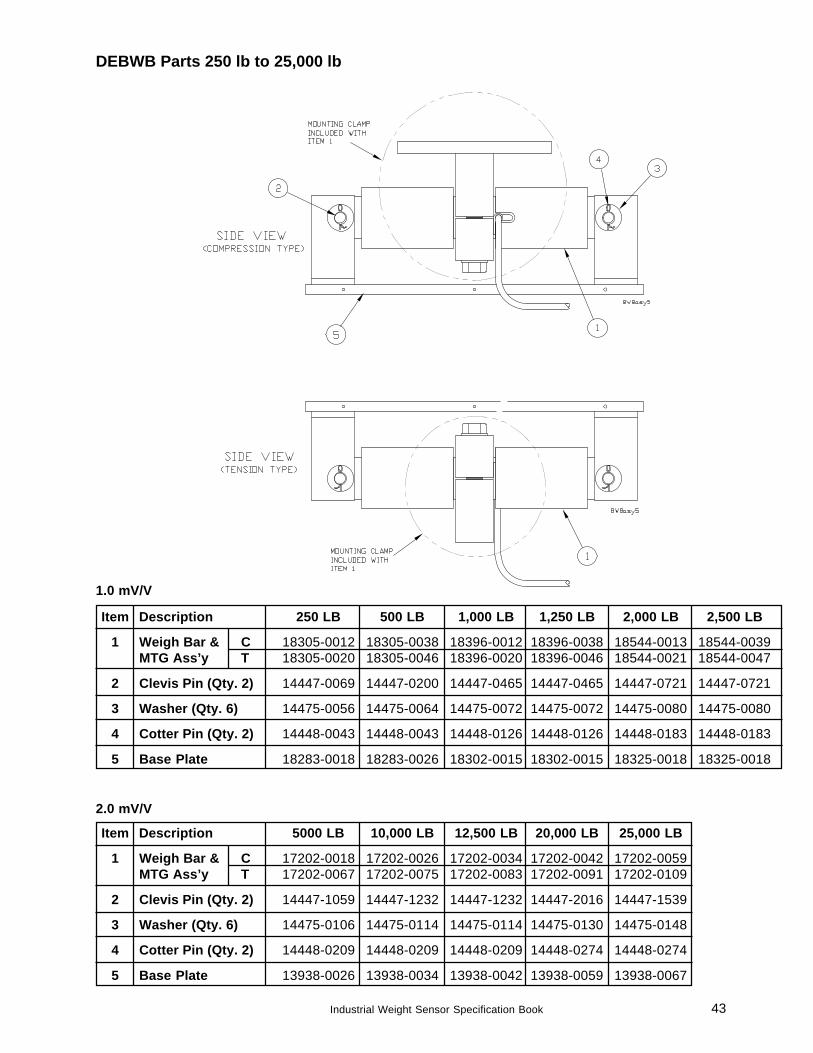
Item Description 250 LB 500 LB 1,000 LB 1,250 LB 2,000 LB 2,500 LB
1 Weigh Bar & C 18305-0012 18305-0038 18396-0012 18396-0038 18544-0013 18544-0039MTG Ass’y T 18305-0020 18305-0046 18396-0020 18396-0046 18544-0021 18544-0047
2 Clevis Pin (Qty. 2) 14447-0069 14447-0200 14447-0465 14447-0465 14447-0721 14447-0721
3 Washer (Qty. 6) 14475-0056 14475-0064 14475-0072 14475-0072 14475-0080 14475-0080
4 Cotter Pin (Qty. 2) 14448-0043 14448-0043 14448-0126 14448-0126 14448-0183 14448-0183
5 Base Plate 18283-0018 18283-0026 18302-0015 18302-0015 18325-0018 18325-0018
Item Description 5000 LB 10,000 LB 12,500 LB 20,000 LB 25,000 LB
1 Weigh Bar & C 17202-0018 17202-0026 17202-0034 17202-0042 17202-0059MTG Ass’y T 17202-0067 17202-0075 17202-0083 17202-0091 17202-0109
2 Clevis Pin (Qty. 2) 14447-1059 14447-1232 14447-1232 14447-2016 14447-1539
3 Washer (Qty. 6) 14475-0106 14475-0114 14475-0114 14475-0130 14475-0148
4 Cotter Pin (Qty. 2) 14448-0209 14448-0209 14448-0209 14448-0274 14448-0274
5 Base Plate 13938-0026 13938-0034 13938-0042 13938-0059 13938-0067
DEBWB Parts 250 lb to 25,000 lb
1.0 mV/V
2.0 mV/V
44 Industrial Weight Sensor Specification Book
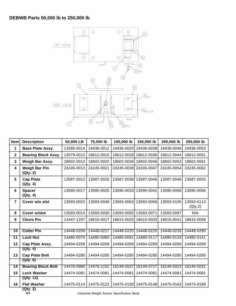
Item Description 50,000 LB 75,000 lb 100,000 lb 150,000 lb 200,000 lb 250,000 lb1 Base Plate Assy. 13585-0014 19436-0012 19436-0020 19436-0038 19436-0046 19436-0053
2 Bearing Block Assy. 13579-0012 18612-0010 18612-0028 18612-0036 18612-0044 18612-0051
3 Weigh Bar Assy. 18602-0012 18602-0020 18602-0038 18602-0046 18602-0053 18602-0061
4 Weigh Bar Pin 24245-0013 24245-0021 24245-0039 24245-0047 24245-0054 24245-0062(Qty. 2)
5 Cap Plate 13587-0012 13587-0020 13587-0038 13587-0046 13587-0046 13587-0053(Qty. 4)
6 Spacer 13590-0017 13590-0025 13590-0033 13590-0041 13590-0058 13590-0066(Qty. 4)
7 Cover w/o slot 13593-0022 13593-0048 13593-0063 13593-0069 13593-0105 13593-0113(Qty.2)
8 Cover w/slot 13593-0014 13593-0030 13593-0055 13593-0071 13593-0097 N/A
9 Clevis Pin 14447-1257 18615-0017 18615-0025 18615-0033 18615-0041 18615-0058
10 Cotter Pin 14448-0209 14448-0217 14448-0225 14448-0225 14448-0233 14448-0290
11 Lock Nut 14480-0075 14480-0083 14480-0091 14480-0117 14480-0133 14480-0141
12 Cap Plate Assy. 14494-0269 14494-0269 14494-0269 14494-0269 14494-0269 14494-0269(Qty. 4)
13 Cap Plate Bolt 14494-0285 14494-0285 14494-0285 14494-0285 14494-0285 14494-0285(Qty. 8)
14 Bearing Block Bolt 14476-0980 14476-1152 16149-0537 16149-0727 16149-5023 16149-5031
15 Lock Washer 14474-0081 14474-0081 14474-0081 14474-0081 14474-0081 14474-0081(Qty. 12)
16 Flat Washer 14475-0114 14475-0122 14475-0130 14475-0148 14475-0163 14475-0189(Qty. 2)
DEBWB Parts 50,000 lb to 250,000 lb
45Industrial Weight Sensor Specification Book
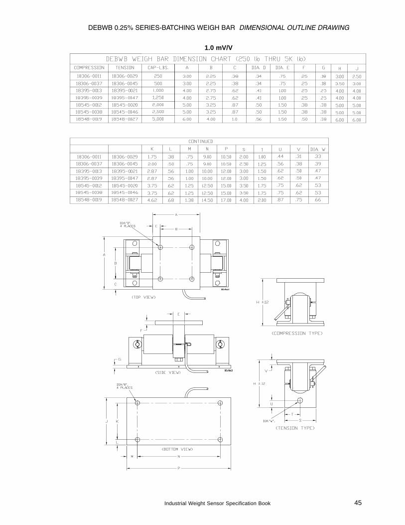
DEBWB 0.25% SERIES-BATCHING WEIGH BAR DIMENSIONAL OUTLINE DRAWING
1.0 mV/V
46 Industrial Weight Sensor Specification Book
DEBWB 0.25% SERIES-BATCHING WEIGH BAR DIMENSIONAL OUTLINE DRAWING
2.0 mV/V
47Industrial Weight Sensor Specification Book
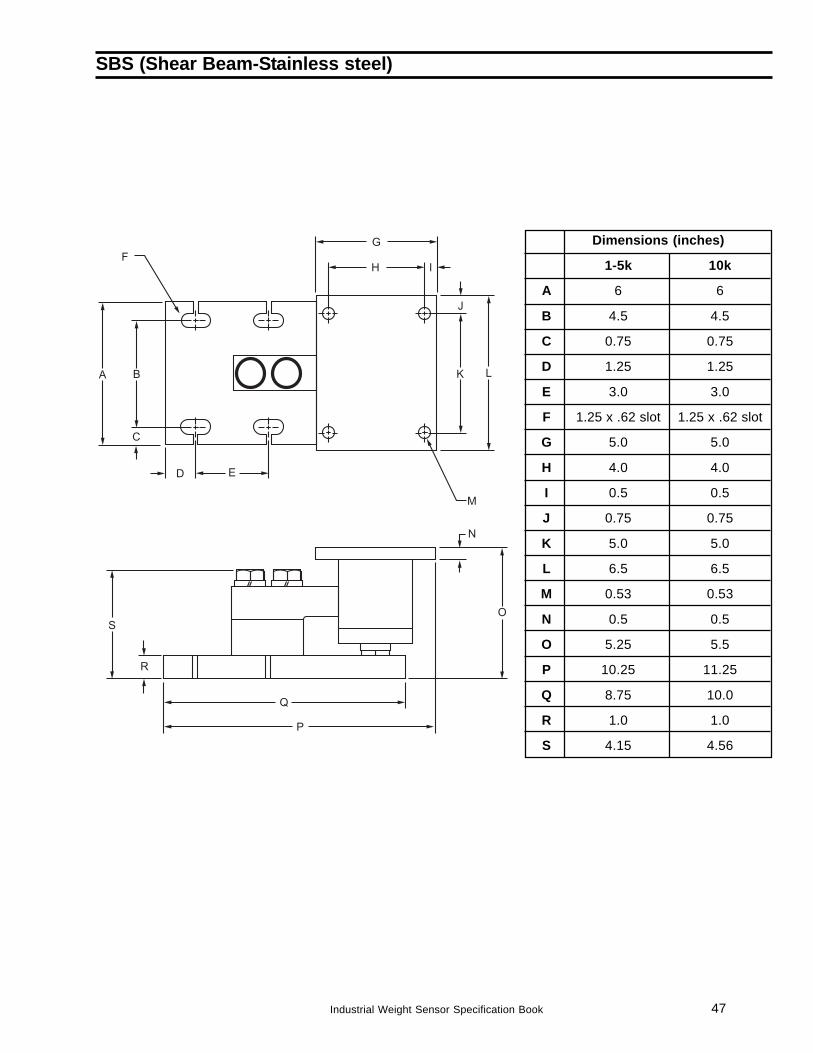
SBS (Shear Beam-Stainless steel)
Dimensions (inches)
1-5k 10k
A 6 6
B 4.5 4.5
C 0.75 0.75
D 1.25 1.25
E 3.0 3.0
F 1.25 x .62 slot 1.25 x .62 slot
G 5.0 5.0
H 4.0 4.0
I 0.5 0.5
J 0.75 0.75
K 5.0 5.0
L 6.5 6.5
M 0.53 0.53
N 0.5 0.5
O 5.25 5.5
P 10.25 11.25
Q 8.75 10.0
R 1.0 1.0
S 4.15 4.56
48 Industrial Weight Sensor Specification Book
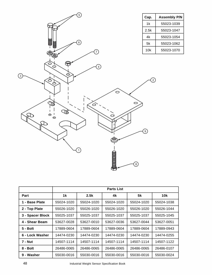
Cap. Assembly P/N
1k 55023-1039
2.5k 55023-1047
4k 55023-1054
5k 55023-1062
10k 55023-1070
Parts List
Part 1k 2.5k 4k 5k 10k
1 - Base Plate 55024-1020 55024-1020 55024-1020 55024-1020 55024-1038
2 - Top Plate 55026-1020 55026-1020 55026-1020 55026-1020 55026-1044
3 - Spacer Block 55025-1037 55025-1037 55025-1037 55025-1037 55025-1045
4 - Shear Beam 53627-0028 53627-0010 53627-0036 53627-0044 53627-0051
5 - Bolt 17889-0604 17889-0604 17889-0604 17889-0604 17889-0943
6 - Lock Washer 14474-0230 14474-0230 14474-0230 14474-0230 14474-0255
7 - Nut 14507-1114 14507-1114 14507-1114 14507-1114 14507-1122
8 - Bolt 26486-0065 26486-0065 26486-0065 26486-0065 26486-0107
9 - Washer 55030-0016 55030-0016 55030-0016 55030-0016 55030-0024
49Industrial Weight Sensor Specification Book
Cap. Loadcell P/N Ass'y minus CompleteLoadcell Assembly
5 ton 53625-0012 53626-0011 55521-0012
10 ton 53625-0020 53626-0029 55521-0020
20 ton 53625-0038 53626-0037 55521-0038
30 ton 53625-0046 53626-0045 55521-0046
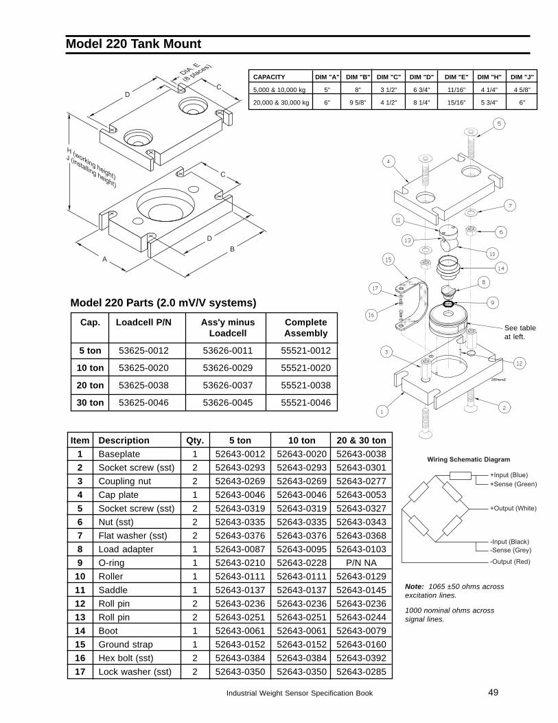
Model 220 Tank Mount
CAPACITY DIM "A" DIM "B" DIM "C" DIM "D" DIM "E" DIM "H" DIM "J"
5,000 & 10,000 kg 5" 8" 3 1/2" 6 3/4" 11/16" 4 1/4" 4 5/8"
20,000 & 30,000 kg 6" 9 5/8" 4 1/2" 8 1/4" 15/16" 5 3/4" 6"
Model 220 Parts (2.0 mV/V systems)
Item Description Qty. 5 ton 10 ton 20 & 30 ton1 Baseplate 1 52643-0012 52643-0020 52643-00382 Socket screw (sst) 2 52643-0293 52643-0293 52643-03013 Coupling nut 2 52643-0269 52643-0269 52643-02774 Cap plate 1 52643-0046 52643-0046 52643-00535 Socket screw (sst) 2 52643-0319 52643-0319 52643-03276 Nut (sst) 2 52643-0335 52643-0335 52643-03437 Flat washer (sst) 2 52643-0376 52643-0376 52643-03688 Load adapter 1 52643-0087 52643-0095 52643-01039 O-ring 1 52643-0210 52643-0228 P/N NA10 Roller 1 52643-0111 52643-0111 52643-012911 Saddle 1 52643-0137 52643-0137 52643-014512 Roll pin 2 52643-0236 52643-0236 52643-023613 Roll pin 2 52643-0251 52643-0251 52643-024414 Boot 1 52643-0061 52643-0061 52643-007915 Ground strap 1 52643-0152 52643-0152 52643-016016 Hex bolt (sst) 2 52643-0384 52643-0384 52643-039217 Lock washer (sst) 2 52643-0350 52643-0350 52643-0285
See tableat left.
Note: 1065 ±50 ohms acrossexcitation lines.
1000 nominal ohms acrosssignal lines.
50 Industrial Weight Sensor Specification Book
Earlier Versions
Excitation Trim Junction Boxes ............................................................................................................ 49Standard Style Junction Box Single (20 Ohm POT) ....................................................................... 49Standard Style Junction Box (10 Ohm POT) .................................................................................. 51Batching Style Junction Box Dual (10 Ohm POT) .......................................................................... 53Batching Style Junction Box Single (20 Ohm POT) ....................................................................... 55
Counting Scales ................................................................................................................................... 57Four Bar Hanging Bench Scale ............................................................................................................ 58WBP Deck Scale (early versions under 2,000 lb capacity) .................................................................. 58TufDec ................................................................................................................................................. 59Weigh Bars with Swaged Cable Assemblies ........................................................................................ 60
51Industrial Weight Sensor Specification Book
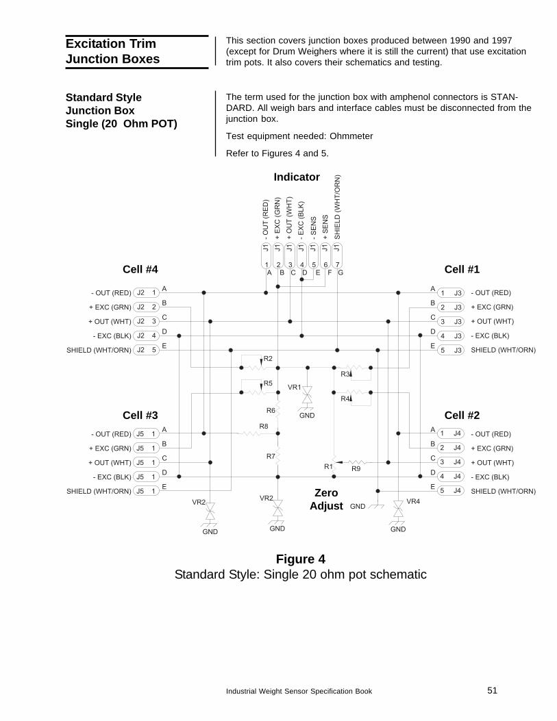
Standard StyleJunction BoxSingle (20 Ohm POT)
Figure 4Standard Style: Single 20 ohm pot schematic
This section covers junction boxes produced between 1990 and 1997(except for Drum Weighers where it is still the current) that use excitationtrim pots. It also covers their schematics and testing.
The term used for the junction box with amphenol connectors is STAN-DARD. All weigh bars and interface cables must be disconnected from thejunction box.
Test equipment needed: Ohmmeter
Refer to Figures 4 and 5.
Cell #4 Cell #1
Cell #3 Cell #2
ZeroAdjust
Excitation TrimJunction Boxes
Indicator
52 Industrial Weight Sensor Specification Book
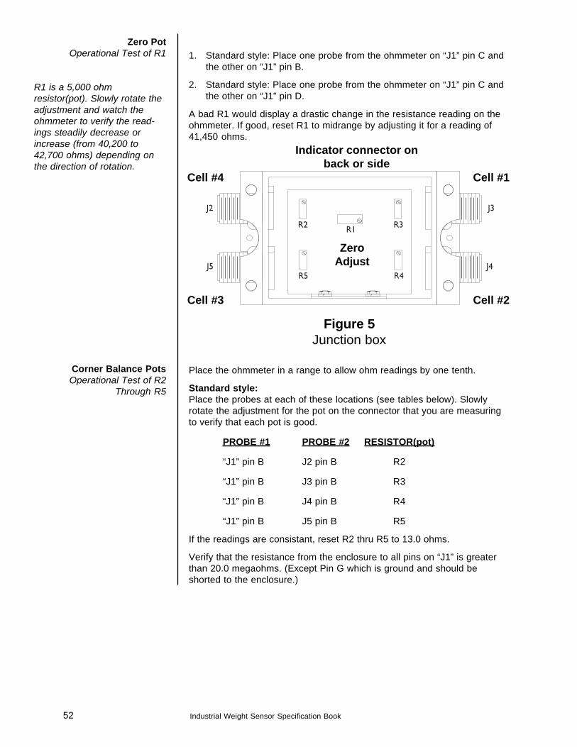
Zero PotOperational Test of R1
R1 is a 5,000 ohmresistor(pot). Slowly rotate theadjustment and watch theohmmeter to verify the read-ings steadily decrease orincrease (from 40,200 to42,700 ohms) depending onthe direction of rotation.
1. Standard style: Place one probe from the ohmmeter on “J1” pin C andthe other on “J1” pin B.
2. Standard style: Place one probe from the ohmmeter on “J1” pin C andthe other on “J1” pin D.
A bad R1 would display a drastic change in the resistance reading on theohmmeter. If good, reset R1 to midrange by adjusting it for a reading of41,450 ohms.
Figure 5Junction box
Place the ohmmeter in a range to allow ohm readings by one tenth.
Standard style:Place the probes at each of these locations (see tables below). Slowlyrotate the adjustment for the pot on the connector that you are measuringto verify that each pot is good.
PROBE #1 PROBE #2 RESISTOR(pot)
“J1” pin B J2 pin B R2
“J1” pin B J3 pin B R3
“J1” pin B J4 pin B R4
“J1” pin B J5 pin B R5
If the readings are consistant, reset R2 thru R5 to 13.0 ohms.
Verify that the resistance from the enclosure to all pins on “J1” is greaterthan 20.0 megaohms. (Except Pin G which is ground and should beshorted to the enclosure.)
Corner Balance PotsOperational Test of R2
Through R5
Cell #4 Cell #1
Cell #3 Cell #2
ZeroAdjust
Indicator connector onback or side
53Industrial Weight Sensor Specification Book
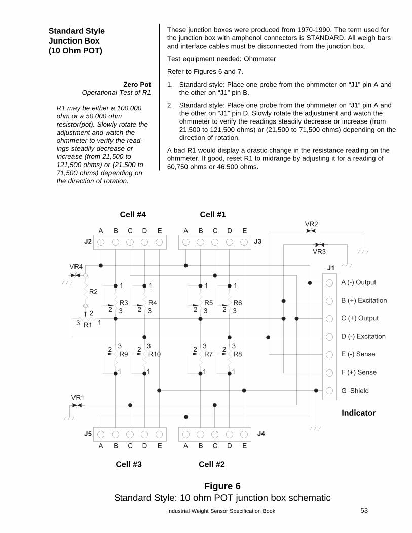
Standard StyleJunction Box(10 Ohm POT)
Zero PotOperational Test of R1
R1 may be either a 100,000ohm or a 50,000 ohmresistor(pot). Slowly rotate theadjustment and watch theohmmeter to verify the read-ings steadily decrease orincrease (from 21,500 to121,500 ohms) or (21,500 to71,500 ohms) depending onthe direction of rotation.
Figure 6Standard Style: 10 ohm POT junction box schematic
These junction boxes were produced from 1970-1990. The term used forthe junction box with amphenol connectors is STANDARD. All weigh barsand interface cables must be disconnected from the junction box.
Test equipment needed: Ohmmeter
Refer to Figures 6 and 7.
1. Standard style: Place one probe from the ohmmeter on “J1” pin A andthe other on “J1” pin B.
2. Standard style: Place one probe from the ohmmeter on “J1” pin A andthe other on “J1” pin D. Slowly rotate the adjustment and watch theohmmeter to verify the readings steadily decrease or increase (from21,500 to 121,500 ohms) or (21,500 to 71,500 ohms) depending on thedirection of rotation.
A bad R1 would display a drastic change in the resistance reading on theohmmeter. If good, reset R1 to midrange by adjusting it for a reading of60,750 ohms or 46,500 ohms.
Cell #4 Cell #1
Cell #3 Cell #2
Indicator
54 Industrial Weight Sensor Specification Book
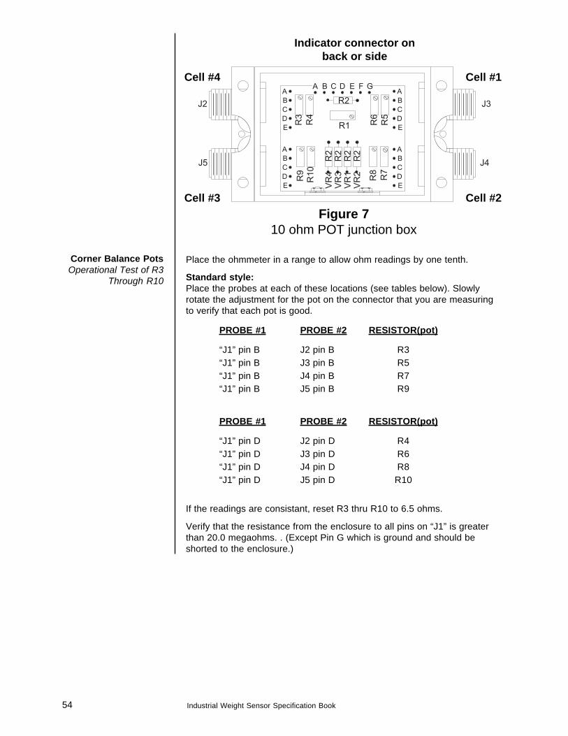
Figure 710 ohm POT junction box
Place the ohmmeter in a range to allow ohm readings by one tenth.
Standard style:Place the probes at each of these locations (see tables below). Slowlyrotate the adjustment for the pot on the connector that you are measuringto verify that each pot is good.
PROBE #1 PROBE #2 RESISTOR(pot)
“J1” pin B J2 pin B R3“J1” pin B J3 pin B R5“J1” pin B J4 pin B R7“J1” pin B J5 pin B R9
PROBE #1 PROBE #2 RESISTOR(pot)
“J1” pin D J2 pin D R4“J1” pin D J3 pin D R6“J1” pin D J4 pin D R8“J1” pin D J5 pin D R10
If the readings are consistant, reset R3 thru R10 to 6.5 ohms.
Verify that the resistance from the enclosure to all pins on “J1” is greaterthan 20.0 megaohms. . (Except Pin G which is ground and should beshorted to the enclosure.)
Corner Balance PotsOperational Test of R3
Through R10
Cell #4 Cell #1
Cell #3 Cell #2
Indicator connector onback or side
55Industrial Weight Sensor Specification Book
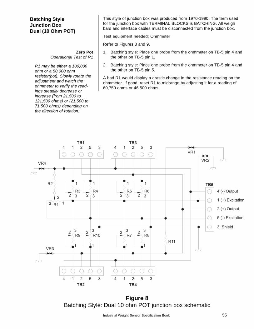
Figure 8Batching Style: Dual 10 ohm POT junction box schematic
Batching StyleJunction BoxDual (10 Ohm POT)
Zero PotOperational Test of R1
R1 may be either a 100,000ohm or a 50,000 ohmresistor(pot). Slowly rotate theadjustment and watch theohmmeter to verify the read-ings steadily decrease orincrease (from 21,500 to121,500 ohms) or (21,500 to71,500 ohms) depending onthe direction of rotation.
This style of junction box was produced from 1970-1990. The term usedfor the junction box with TERMINAL BLOCKS is BATCHING. All weighbars and interface cables must be disconnected from the junction box.
Test equipment needed: Ohmmeter
Refer to Figures 8 and 9.
1. Batching style: Place one probe from the ohmmeter on TB-5 pin 4 andthe other on TB-5 pin 1.
2. Batching style: Place one probe from the ohmmeter on TB-5 pin 4 andthe other on TB-5 pin 5.
A bad R1 would display a drastic change in the resistance reading on theohmmeter. If good, reset R1 to midrange by adjusting it for a reading of60,750 ohms or 46,500 ohms.
56 Industrial Weight Sensor Specification Book
Corner Balance PotsOperational Test of R3
Through R10
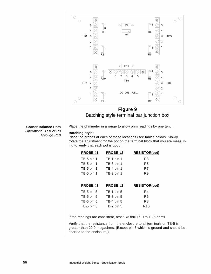
Figure 9Batching style terminal bar junction box
Place the ohmmeter in a range to allow ohm readings by one tenth.
Batching style:Place the probes at each of these locations (see tables below). Slowlyrotate the adjustment for the pot on the terminal block that you are measur-ing to verify that each pot is good.
PROBE #1 PROBE #2 RESISTOR(pot)
TB-5 pin 1 TB-1 pin 1 R3TB-5 pin 1 TB-3 pin 1 R5TB-5 pin 1 TB-4 pin 1 R7TB-5 pin 1 TB-2 pin 1 R9
PROBE #1 PROBE #2 RESISTOR(pot)
TB-5 pin 5 TB-1 pin 5 R4TB-5 pin 5 TB-3 pin 5 R6TB-5 pin 5 TB-4 pin 5 R8TB-5 pin 5 TB-2 pin 5 R10
If the readings are consistent, reset R3 thru R10 to 13.5 ohms.
Verify that the resistance from the enclosure to all terminals on TB-5 isgreater than 20.0 megaohms. (Except pin 3 which is ground and should beshorted to the enclosure.)
57Industrial Weight Sensor Specification Book
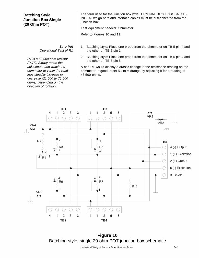
Figure 10Batching style: single 20 ohm POT junction box schematic
Batching StyleJunction Box Single(20 Ohm POT)
The term used for the junction box with TERMINAL BLOCKS is BATCH-ING. All weigh bars and interface cables must be disconnected from thejunction box.
Test equipment needed: Ohmmeter
Refer to Figures 10 and 11.
1. Batching style: Place one probe from the ohmmeter on TB-5 pin 4 andthe other on TB-5 pin 1.
2. Batching style: Place one probe from the ohmmeter on TB-5 pin 4 andthe other on TB-5 pin 5.
A bad R1 would display a drastic change in the resistance reading on theohmmeter. If good, reset R1 to midrange by adjusting it for a reading of46,500 ohms.
R1 is a 50,000 ohm resistor(POT). Slowly rotate theadjustment and watch theohmmeter to verify the read-ings steadily increase ordecrease (21,500 to 71,500ohms) depending on thedirection of rotation.
Zero PotOperational Test of R1
58 Industrial Weight Sensor Specification Book
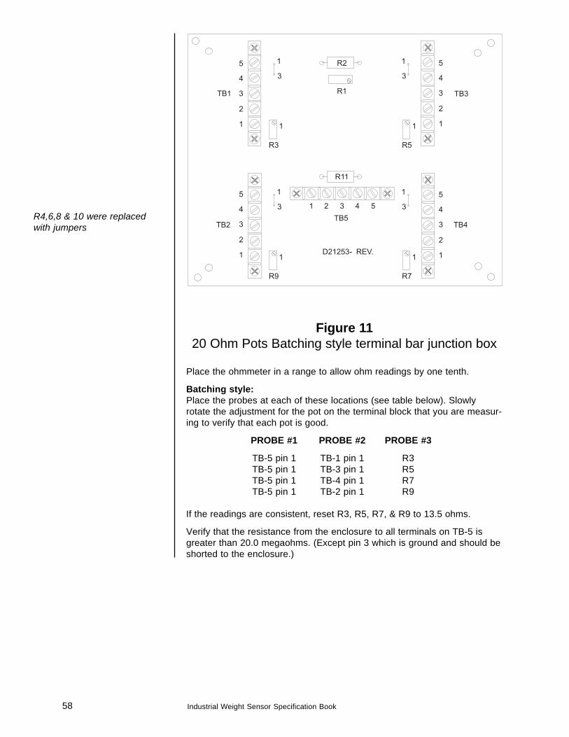
R4,6,8 & 10 were replacedwith jumpers
Figure 1120 Ohm Pots Batching style terminal bar junction box
Place the ohmmeter in a range to allow ohm readings by one tenth.
Batching style:Place the probes at each of these locations (see table below). Slowlyrotate the adjustment for the pot on the terminal block that you are measur-ing to verify that each pot is good.
PROBE #1 PROBE #2 PROBE #3
TB-5 pin 1 TB-1 pin 1 R3TB-5 pin 1 TB-3 pin 1 R5TB-5 pin 1 TB-4 pin 1 R7TB-5 pin 1 TB-2 pin 1 R9
If the readings are consistent, reset R3, R5, R7, & R9 to 13.5 ohms.
Verify that the resistance from the enclosure to all terminals on TB-5 isgreater than 20.0 megaohms. (Except pin 3 which is ground and should beshorted to the enclosure.)
59Industrial Weight Sensor Specification Book
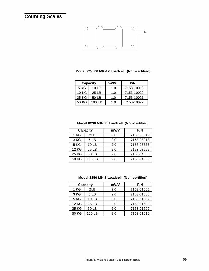
Model 8250 MK-3 Loadcell (Non-certified)
Capacity mV/V P/N1 KG 2LB 2.0 7153-016053 KG 5 LB 2.0 7153-016065 KG 10 LB 2.0 7153-01607
12 KG 25 LB 2.0 7153-0160825 KG 50 LB 2.0 7153-0160950 KG 100 LB 2.0 7153-01610
Model PC-800 MK-17 Loadcell (Non-certified)
Capacity mV/V P/N5 KG 10 LB 1.0 7153-10018
10 KG 25 LB 1.0 7153-1002025 KG 50 LB 1.0 7153-1002150 KG 100 LB 1.0 7153-10022
Model 8230 MK-3E Loadcell (Non-certified)
Capacity mV/V P/N1 KG 2LB 2.0 7153-082123 KG 5 LB 2.0 7153-082135 KG 10 LB 2.0 7153-08663
12 KG 25 LB 2.0 7153-0866525 KG 50 LB 2.0 7153-0483350 KG 100 LB 2.0 7153-04952
Counting Scales
60 Industrial Weight Sensor Specification Book
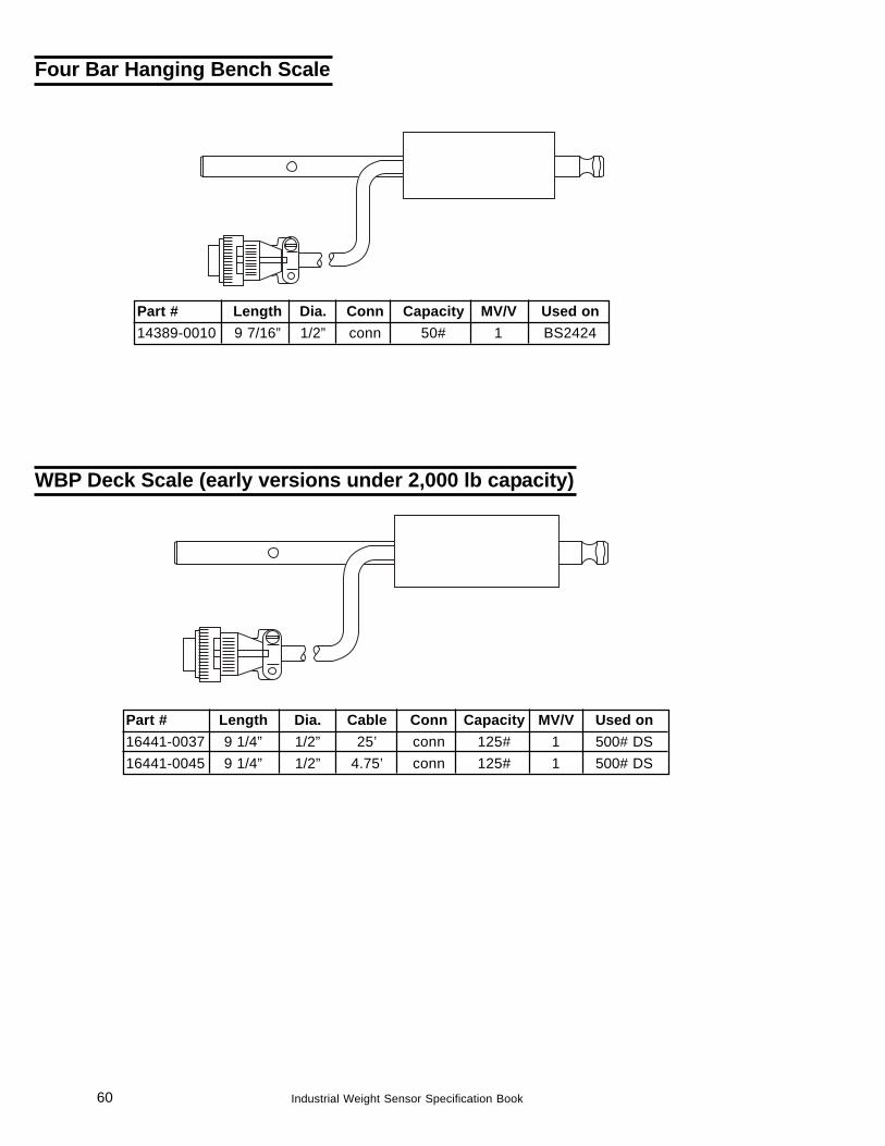
WBP Deck Scale (early versions under 2,000 lb capacity)
Part # Length Dia. Cable Conn Capacity MV/V Used on16441-0037 9 1/4” 1/2” 25’ conn 125# 1 500# DS16441-0045 9 1/4” 1/2” 4.75’ conn 125# 1 500# DS
Part # Length Dia. Conn Capacity MV/V Used on14389-0010 9 7/16” 1/2” conn 50# 1 BS2424
Four Bar Hanging Bench Scale
61Industrial Weight Sensor Specification Book
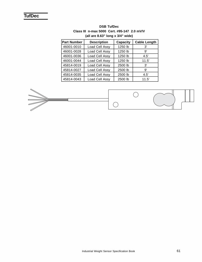
DSB TufDecClass III n-max 5000 Cert. #95-147 2.0 mV/V
(all are 8.63" long x 3/4" wide)
Part Number Description Capacity Cable Length46001-0010 Load Cell Assy 1250 lb 3'46001-0028 Load Cell Assy 1250 lb 9'46001-0036 Load Cell Assy 1250 lb 4.5'46001-0044 Load Cell Assy 1250 lb 11.5'45814-0019 Load Cell Assy 2500 lb 3'45814-0027 Load Cell Assy 2500 lb 9'45814-0035 Load Cell Assy 2500 lb 4.5'45814-0043 Load Cell Assy 2500 lb 11.5'
TufDec
62 Industrial Weight Sensor Specification Book
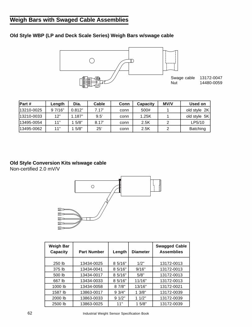
Part # Length Dia. Cable Conn Capacity MV/V Used on13210-0025 9 7/16” 0.812” 7.17’ conn 500# 1 old style 2K13210-0033 12” 1.187” 9.5’ conn 1.25K 1 old style 5K13495-0054 11” 1 5/8” 8.17’ conn 2.5K 2 LP5/1013495-0062 11” 1 5/8” 25’ conn 2.5K 2 Batching
Swage cable 13172-0047Nut 14480-0059
Old Style WBP (LP and Deck Scale Series) Weigh Bars w/swage cable
Weigh Bars with Swaged Cable Assemblies
Old Style Conversion Kits w/swage cableNon-certified 2.0 mV/V
Weigh Bar Swagged CableCapacity Part Number Length Diameter Assemblies
250 lb 13434-0025 8 5/16" 1/2" 13172-0013375 lb 13434-0041 8 5/16" 9/16" 13172-0013500 lb 13434-0017 8 5/16" 5/8" 13172-0013667 lb 13434-0033 8 5/16" 11/16" 13172-0013
1000 lb 13434-0058 8 7/8" 13/16" 13172-00211587 lb 13863-0017 9 3/4" 1 3/8" 13172-00392000 lb 13863-0033 9 1/2" 1 1/2" 13172-00392500 lb 13863-0025 11" 1 5/8" 13172-0039
63Industrial Weight Sensor Specification Book
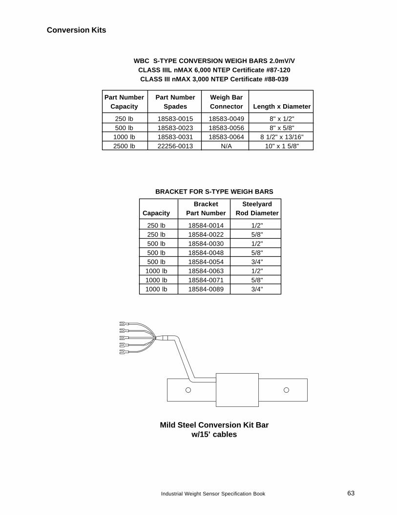
WBC S-TYPE CONVERSION WEIGH BARS 2.0mV/VCLASS IIIL nMAX 6,000 NTEP Certificate #87-120CLASS III nMAX 3,000 NTEP Certificate #88-039
Part Number Part Number Weigh BarCapacity Spades Connector Length x Diameter
250 lb 18583-0015 18583-0049 8" x 1/2"500 lb 18583-0023 18583-0056 8" x 5/8"1000 lb 18583-0031 18583-0064 8 1/2" x 13/16"2500 lb 22256-0013 N/A 10" x 1 5/8"
BRACKET FOR S-TYPE WEIGH BARS
Bracket SteelyardCapacity Part Number Rod Diameter
250 lb 18584-0014 1/2"250 lb 18584-0022 5/8"500 lb 18584-0030 1/2"500 lb 18584-0048 5/8"500 lb 18584-0054 3/4"
1000 lb 18584-0063 1/2"1000 lb 18584-0071 5/8"1000 lb 18584-0089 3/4"
Conversion Kits
Mild Steel Conversion Kit Barw/15' cables

64 Industrial Weight Sensor Specification Book

65Industrial Weight Sensor Specification Book
Weigh Bar® is a registered trademark of Weigh-Tronix Inc.
December 2010 wb_spec_en_16806_0010.P65 PN 16806-0010 Issue AJ
Avery Weigh-Tronix USA1000 Armstrong Dr.Fairmont, MN 56031 USATelephone: 507-238-4461Facsimile: 507-238-4195e-mail: [email protected]
Avery Weigh-Tronix UKFoundry LaneSmethwick, West MidlandsEngland B66 2LPTel: +44 870 90 34343Fax: +44 121 224 8183Email: [email protected] site:www.averyweigh-tronix.com
Avery Weigh-Tronix Canada, ULC217 Brunswick BoulevardPointe Claire, QC H9R 4R7 CanadaTelephone: 514-695-0380Toll free: 800-561-9461Facsimile: 514-695-6820www.weigh-tronix.ca