Embed Size (px)
Citation preview
This article appeared in a journal published by Elsevier. The attachedcopy is furnished to the author for internal non-commercial researchand education use, including for instruction at the authors institution
and sharing with colleagues.
Other uses, including reproduction and distribution, or selling orlicensing copies, or posting to personal, institutional or third party
websites are prohibited.
In most cases authors are permitted to post their version of thearticle (e.g. in Word or Tex form) to their personal website orinstitutional repository. Authors requiring further information
regarding Elsevier’s archiving and manuscript policies areencouraged to visit:
http://www.elsevier.com/copyright
Author's personal copy
Influence of slag chemistry on the hydration of alkali-activated blast-furnaceslag — Part II: Effect of Al2O3
M. Ben Haha, B. Lothenbach ⁎, G. Le Saout, F. WinnefeldEmpa, Swiss Federal Laboratories for Materials Science and Technology, Laboratory for Concrete and Construction Chemistry, Ueberlandstrasse 129, 8600 Dübendorf, Switzerland
a b s t r a c ta r t i c l e i n f o
Article history:Received 8 April 2011Accepted 16 August 2011
Keywords:Alkali activated slags (D)Al2O3 content (D)Hydration (A)Microstructure (B)Hydrotalcite (D)
The hydration and microstructural evolution of three alkali activated slags (AAS) with Al2O3 contents be-tween 7 and 17%wt.% have been investigated. The slags were hydrated in the presence of two different alka-line activators, NaOH and Na2SiO3·5H2O. The formation of C(\A)–S–H and hydrotalcite was observed in allsamples by X-ray diffraction, thermal analysis and scanning electron microscopy. Higher Al2O3 content of theslag decreased the Mg/Al ratio of hydrotalcite, increased the Al incorporation in the C(\A)-S-H and led to theformation of strätlingite. Increasing Al2O3 content of the slag slowed down the early hydration and a lowercompressive strength during the first days was observed. At 28 days and longer, no significant effects ofslag Al2O3 content on the degree of hydration, the volume of the hydrates, the coarse porosity or on the com-pressive strengths were observed.
© 2011 Elsevier Ltd. All rights reserved.
1. Introduction
Alkali-activated binders based on ground granulated blast-furnaceslag represent a viable and sustainable alternative to Portland cementsince they use by-products of other industrial manufacturing process-es. They often exhibit a rapid setting, fast strength development andhigh resistance to chemical attack [1–3]. Alkalis are used to stimulatethe dissolution of the slag and thus the formation of hydration prod-ucts, mainly calcium silicate hydrates incorporating significantamounts of aluminium, C(\A)-S-H, a hydrotalcite-like phase andsträtlingite [4–9]. The reactivity of the slag depends mainly on themineralogical composition, the fineness of the slag and on the typeand concentration of the alkaline activator used.
A fundamental understanding of physical and chemical effects of thechemical compositions of the slags and of the effect of different activatorson the hydrationmechanisms can give a deeper insight into the relation-ship between composition and mechanical properties. A better under-standing of the slag chemistry may lead to the development of moredurable concretes and could indicate ways to use less reactive slagsefficiently.
In a previous study it has been found that increasingMgO contentsin alkali activated blast furnace slag slow down the early hydrationbut lead in the long-term to higher compressive strengths [10] asthe formation of additional hydrotalcite leads to an increased volume
of the solid and thus to a lower coarse porosity. The present studyaims to investigate the effect of different Al2O3 contents in the slagon the kinetics of slag reaction and on compressive strength.
Experimental studies on the effect of Al2O3 on alkali activated slags arerare. Sakulich et al. [11] reported a delay of the hydration reaction inNaOH/waterglass activated slags which were mixed with high quantitiesof separately added Al2O3. They observed that the addition of a lowamount of Al2O3 (2 wt.%) increased the 7 and 28 days compressivestrength, whilst the addition of 15 wt.% or more did not further improvethe mechanical properties.
A recent study on supersulphated slags activated by 15 wt.% CaSO4
and 0.5 wt.%KOH showed that the slags containingmoreAl2O3 exhibiteda higher reactivity during the first week and a corresponding higherstrength [2]. After longer reaction times, the degree of hydration wasfound to be similar, but for the high Al2O3 slag a higher compressivestrength was observed. Gruskovnjak ea. [2] related the higher compres-sive strength of the Al2O3 rich slag to the higher amount of voluminousettringite formed and thus to a higher degree of space filling.
The present study aims to investigate the effect of Al2O3 in the slag onthe hydration properties of alkali activated slag over 1 year, using threeslagswith different Al2O3 contentswhilst the contents of the other oxidesare nearly the same. The slags were activated by sodium metasilicatepentahydrate (waterglass: WG) and sodium hydroxide. The effect ofthe Al2O3 on strength, rate of hydration, and the nature of the differenthydrates are investigated using calorimetry, thermogravimetry, X-raydiffraction, scanning electron microscopy and thermodynamicmodelling.
Cement and Concrete Research 42 (2012) 74–83
⁎ Corresponding author. Tel.: +41 58 765 47 88; fax: +41 58 765 823 40 35.E-mail address: [email protected] (B. Lothenbach).
0008-8846/$ – see front matter © 2011 Elsevier Ltd. All rights reserved.doi:10.1016/j.cemconres.2011.08.005
Contents lists available at SciVerse ScienceDirect
Cement and Concrete Research
j ourna l homepage: ht tp : / /ees .e lsev ie r .com/CEMCON/defau l t .asp

Author's personal copy
2. Materials and methods
2.1. Slags
The three granulated blastfurnace slags were ground in a laboratoryball mill to a specific surface of 5000+/−100 cm2/g (Table 1).
2.2. Binder and paste formulation
Two alkaline activators, NaOH (3.77 g/100 g slag) and sodiumwaterglass Na2SiO3·5H2O (WG) (10.0 g/100 g slag) were used, resulting inthe sameNa2O content in both cases and in thepresence of an additional2.8 SiO2/100 g slag in the WG-activated systems. The alkaline activatorswere dissolved in thewater prior themixing. Thewater was added tak-ing into account the crystal water ofWG to insure awater to binder ratioof 0.40.
2.3. Methods
2.3.1. Anhydrous slagsThe chemical composition of the anhydrous slags was analysed by
XRF using a Philips PW 2400 instrument (Table 1). Their particle sizedistributionwas determinedwith a laser granulometerMalvernMaster-sizer X.
X-ray powder diffraction XRDwas carried out with an incident beammonochromator and CuKα radiation (λ=1.54 Å) on a PANalyticalX'Pert Pro MPD diffractometer in θ–2θ configuration with an angularscan 5–65° 2θ and an X'Celerator detector. An internal standard (CaF2)was added to the anhydrous slag in order to deduce the amount ofamorphous [12].
The 29Si ΜΑS NMR spectra were recorded on a Bruker Avance 400NMR spectrometer (field strength of 9.4 T) at 79.49 MHz applying4.5 kHz spinning rates on a 7 mm CP MAS probe using ZrO2 rotors.Single-pulse experiments were carried out by applying 90° pulses of8.8 μs with 1H decoupling of 31.3 kHz (TPPM15) and recycle delays of4 s in order to respect the relaxation time T1 of the species present inthe samples (a T1 of less than 1 swas determined for the slag by a T1 sat-uration recovery experiment). The 29Si chemical shift was referencedexternally relative to tetramethylsilane at 0.0 ppm. The observed 29Siresonances were analysed using the Qn(mAl) classification, where a Sitetrahedron is connected to n Si tetrahedra with n varying from 0 to 4;m is the number of neighbouring AlO4 tetrahedra.
The 27Al MAS NMR spectra were obtained at 104.26 MHz on a2.5 mm CP MAS probe using the above mentioned NMR system. Singlepulse experiments were carried out at 20 kHz spinning rates by
applying single pulse (π/12) excitation pulses of 0.5 μs and 0.5 s relaxa-tion delays. The 27Al chemical shifts were referenced relative to a 1.0 MAlCl3·6H2O solution at 0.0 ppm.
2.3.2. Hydrated samplesAbout 5 gof paste (water/binder=0.40)weremixed externally,filled
in a glass vial and loaded in a TAM Air isothermal calorimeter in order todetermine the rate of heat liberation during the first week of hydration at20 °C. The heat flow was measured on duplicate samples, the differencebetween the two measurements was negligible. Prior to mixing, theunhydrated slag, the water and the activator were equilibrated to themeasurement temperature for at least 16 h. In a separate experiment,about 2.5 g of paste were mixed internally using the admix ampoule inorder to follow the early hydration of the slags.
All paste samples were cured in sealed plastic container at 20 °C.The compressive strengths were determined on duplicate pastessamples using two cubes 25×25×25 mm per testing age. The pasteswere demolded and cut into cubes prior to testing.
For XRD and TGAmeasurements, the hydration of the paste sampleswas stopped by solvent exchangewith isopropanol. Before analyses, thesamples were grinded by hand below 63 μm. TGA was performed be-tween 30 and 980 °C at a heat rate of 20 K/min in a Mettler ToledoTGA/SDTA851. The amount of bound water was determined from theweight loss between 30 and 650 °C. Triplicate measurements of severalsamples indicated that the measurement inaccuracy for total boundwater was ±0.2 g/100 g. XRD was performed as described above, butwithout CaF2 standard, on one sample for each measurement time.
Slices of hydrated samples were cut, immediately immersed in iso-propanol and subsequently dried at 40 °C for 24 h for the microscopicalinvestigations. Theywere then impregnated using a low viscosity epoxyresin and polished down to ¼ μm. The samples were further coatedwith carbon and examined using a Philips ESEM FEG XL 30 scanningelectron microscope (SEM). Backscattered electron images (BSE) wereanalysed quantitatively to determine the coarse porosity and the degreeof reaction at different hydration times using image analysis (IA) [13–15]. The volume of coarser pores as determined by SEM-IA includes,depending on the magnification (2500×) used, pore sizes in the rangeof 0.05 to 5 μm and is referred to as “coarse porosity” in this paper. Tobe statistically representative, over 80 imageswere taken for each stud-ied sample at amagnification of 2500. Energy dispersive X-ray spectros-copy (EDX) was applied to determine the elemental compositions ofthe hydrate assemblage and the different element ratio of the differenthydrates. The analyses were carried out using an accelerating voltage of15 kV to ensure a good compromise between spatial resolution and ad-equate excitation of the FeKα peak.
2.3.3. Thermodynamic modellingThermodynamic calculations using the geochemical modelling code
GEMS [16] were carried out using a consistent set of cement specificthermodynamic data, cemdata2007 [17,18], which had been originallycompiled and verified for Portland cement systems. The cemdata2007dataset includes thermodynamic data of common cement mineralssuch as C–S–H, different AFt and AFm phases, hydrotalcite and hydro-garnets [18]. No restrictions on the kind of hydrates calculatedwere im-posed, with the exception of siliceous hydrogarnet (C3AS0.8H4.4), whoseformation was suppressed as its formation seems to be kinetically hin-dered at ambient temperatures [18]. The uptake of alkalis by C–S–Hwasapproached by using an ideal solid solution model between jennite,tobermorite, [(KOH)2.5·SiO2·H2O]0.2 and [(NaOH)2.5·SiO2·H2O]0.2 asproposed by Kulik et al. [19]. The aluminium uptake in the C(\A)–S–H was taken into account based on the EDX measurements. It was as-sumed that the incorporation of aluminium, which occurs mainly atbridging sites [20,21], does not influence the molar volume of the C–S–H, as the incorporation of Al seems to stabilise the 14-Å tobermorite[22]. The kind and volume of solids precipitated were calculated usingthe density of the phases present in the sample. The initial composition
Table 1Chemical composition (g/100g) and granular properties of the slags used in the study.
A7 A14 A17
SiO2 41.6 38.2 37.2Al2O3 7.0 14.1 16.7Fe2O3
a 1.3 1.4 1.4CaO 39.1 36.0 35.0MgO 7.2 6.6 6.4SO3 1.3 1.2 1.0K2O 0.6 0.6 0.5Na2O 0.5 0.5 0.5TiO2 0.3 0.3 0.2Mn2O3 1.1 1.0 1.0Molar Ca/Si 1.01 1.01 1.01Molar Mg/Al 1.29 0.60 0.49Density (g/cm3) 2.90 2.88 2.87Blaine (cm2/g) 5021 4963 4985% R63 μm 0.2 0.4 0.1% R18 μm 21.6 22.4 22.4% R3 μm 74.9 76.5 75.6
a Including iron form the laboratory milling.
75M. Ben Haha et al. / Cement and Concrete Research 42 (2012) 74–83

Author's personal copy
based on the XRF data (cf. Table 1) and the composition of the activatorwere used as input.
3. Analysis of the unhydrated slags
Varying Al2O3 contents may cause differences in the chemical andphysical characteristics of the slags. Thus a detailed analysis of thethree anhydrous slags is performed.
3.1. Chemical composition
The chemical compositions determined by X-ray fluorescence(XRF) and the granular properties of the three slags are given inTable 1. The Al2O3 contents of the slags are 7.0 wt.% (slag A7),14.1 wt.% (slag A14) and 16.7 wt.-% (slag A17). The contents of theother oxides are comparable amongst the slags.
3.2. XRD
Rietveld analysis of the X-ray patterns of the slags shows only aminor contents of crystalline phases (Table 2). Akermanite occurs inthe A7 slag and traces of anhydrite in all slags. The elemental ironhas been introduced by the iron ball mill used in the grinding process.
Although the disorder of the amorphous phase in the differentslags is certainly different, we observe a similar diffuse X-ray scatter-ing present as a hump located around 0.3 nm (2θ=30°) for all slags(Fig. 1).
3.3. 29Si and 27Al NMR
29Si and 27Al NMR have been performed to observe the effect ofhigher Al2O3 content on the structure of the glasses (Fig. 2). The 29SiNMR spectra reveal a broad signal centred around −74 ppm with a fullwidth at halfmaximumof approximately 19 ppm. Similar chemical shiftsare observed for akermanite and gehlenite (−73.7 and −72.5 ppm re-spectively [23]) which are the main constituents of crystalline phasesthat occur when the amorphous slag liquid is slowly quenched [24] orduring devitrification [25]. By comparison with the crystalline phases,Shimoda et al. [24] conclude that the polymerisation structure aroundSi in the slag is on average close to chain-like linkage fashion, Q2(1Al)and Q2(2Al). The linewidth indicates the coexistence of Q0 to Q3 specieswith varying numbers of neighbouring AlO4 tetrahedra. The 27Al NMRspectra confirm that the aluminium is in fourfold coordination in slag aspreviously observed for blast furnace slags [24,25]. We observe little orno influence on the NMR spectra when the weight fraction of Al2O3 in-creases from 7 to 17 wt.% showing that the incorporation of Al3+ doesnot influence the distribution of Qn species in the slag. However, as sug-gested by Shimoda et al. [26], it may influence the coordination numberof Mg and Ca.
4. Results and discussion
4.1. Compressive strength
Activating the slags using NaOH results in relatively high earlystrength, whilst only a modest increase in compressive strength is ob-served for hydration times longer than 28 days. For a given age, no
significant difference in the compressive strength of the NaOH activatedslag pastes containing different amounts of Al2O3 is observed (Table 3).The observation that the strength of NaOH activated pastes is not signif-icantly affected by the chemical composition of the slag agrees with aprevious study investigating the influence of MgO content [10].
Using the WG as activator, the hydration proceeds much slowerthan if NaOH is used but the compressive strengths of the paste samplescontinue to increase beyond 7 days; the samples gain 25 to 40% in com-pressive strength between 7 and 180 days. Increasing the Al2O3 contentof the slags results in a slightly slower strength development at earlyages, but similar compressive strengths are reached at late (28 daysand longer) hydration times. The Al2O3 content of the slag is found tohave no significant impact on the late compressive strength of the WGactivated slags, in contrast to the MgO content which increased thecompressive strength as reported previously [10].
The lower compressive strength after 7 days and longer of the NaOHactivated systems compared to theWG activated slags agrees well with
Table 2Phase composition of the slags by XRD (Rietveld analysis) in g/100 g.
A7 A14 A17
Akermanite 3.1 0.0 0.0Anhydrite 0.3 0.4 0.3Amorphous 96.0 99.0 99.0Iron 0.6 0.6 0.6
10 20 30 40 50
WG-180d
anhydrous slag
A7
A17
A7
A17
A14
*
*
*
*
NaOH-180d
A7
A17
A14
c
c
ccc c c
akermanite (PDF 01-079-2424)
C-S-H (I) (PDF 00-034-0002)*
hydrotalcite (PDF 01-089-0460)
C-S-H (PDF 00-033-0306)
vaterite (PDF 00-024-0030)
*
(a) 28 30 32
(b)
A17
A7
NaOH-180d
WG-180d
A17
A7
anhydrous slag A7
c calcite
strätlingite (PDF 00-029-0285)
Fig. 1. XRD patterns of A7 and A17 slags anhydrous slags and comparison of the XRDpatterns of the different WG and NaOH activated slags at 180 days.
(ppm)-90-80-70-60-50-40
29Si NMR9.4Tv=4.5kHz
(ppm)04080120
27Al NMR9.4Tv=25kHz
A7
A17
(a) (b)
Fig. 2. (a) 29Si and (b) 27Al NMR spectra of the A7 and A17 slags.
76 M. Ben Haha et al. / Cement and Concrete Research 42 (2012) 74–83
Author's personal copy
findings reported in other studies [8,10,27–32]. TheWG activated slagscontain slightly more solids (2.8 g SiO2/100 g slag) than the NaOH acti-vated systems. This corresponds to 10 wt.% of the amount of slagreacted after 7 days and to 7 wt.% after 1 year (Table 4) and is thusexpected to have a minor influence on the compressive strengths.
4.2. Hydration kinetics
4.2.1. Heat of hydrationThe heat of hydration of alkali activated slags as a function of time is
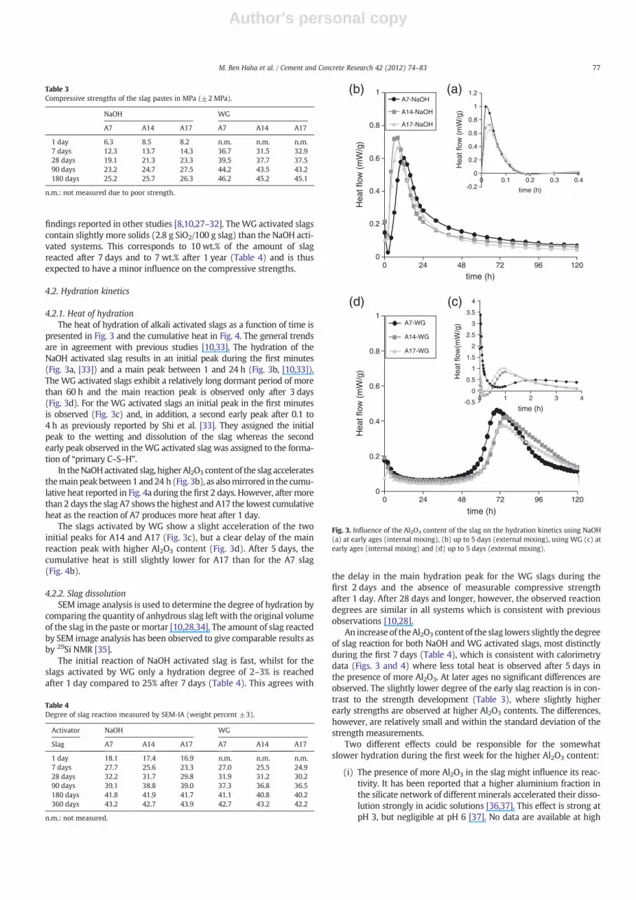
presented in Fig. 3 and the cumulative heat in Fig. 4. The general trendsare in agreement with previous studies [10,33]. The hydration of theNaOH activated slag results in an initial peak during the first minutes(Fig. 3a, [33]) and a main peak between 1 and 24 h (Fig. 3b, [10,33]).The WG activated slags exhibit a relatively long dormant period of morethan 60 h and the main reaction peak is observed only after 3 days(Fig. 3d). For the WG activated slags an initial peak in the first minutesis observed (Fig. 3c) and, in addition, a second early peak after 0.1 to4 h as previously reported by Shi et al. [33]. They assigned the initialpeak to the wetting and dissolution of the slag whereas the secondearly peak observed in theWG activated slag was assigned to the forma-tion of “primary C–S–H”.
In theNaOHactivated slag, higher Al2O3 content of the slag acceleratesthemain peakbetween1 and24 h (Fig. 3b), as alsomirrored in the cumu-lative heat reported in Fig. 4a during the first 2 days. However, aftermorethan 2 days the slag A7 shows the highest and A17 the lowest cumulativeheat as the reaction of A7 produces more heat after 1 day.
The slags activated by WG show a slight acceleration of the twoinitial peaks for A14 and A17 (Fig. 3c), but a clear delay of the mainreaction peak with higher Al2O3 content (Fig. 3d). After 5 days, thecumulative heat is still slightly lower for A17 than for the A7 slag(Fig. 4b).
4.2.2. Slag dissolutionSEM image analysis is used to determine the degree of hydration by
comparing the quantity of anhydrous slag left with the original volumeof the slag in the paste or mortar [10,28,34]. The amount of slag reactedby SEM image analysis has been observed to give comparable results asby 29Si NMR [35].
The initial reaction of NaOH activated slag is fast, whilst for theslags activated by WG only a hydration degree of 2–3% is reachedafter 1 day compared to 25% after 7 days (Table 4). This agrees with
the delay in the main hydration peak for the WG slags during thefirst 2 days and the absence of measurable compressive strengthafter 1 day. After 28 days and longer, however, the observed reactiondegrees are similar in all systems which is consistent with previousobservations [10,28].
An increase of theAl2O3 content of the slag lowers slightly thedegreeof slag reaction for both NaOH and WG activated slags, most distinctlyduring the first 7 days (Table 4), which is consistent with calorimetrydata (Figs. 3 and 4) where less total heat is observed after 5 days inthe presence of more Al2O3. At later ages no significant differences areobserved. The slightly lower degree of the early slag reaction is in con-trast to the strength development (Table 3), where slightly higherearly strengths are observed at higher Al2O3 contents. The differences,however, are relatively small and within the standard deviation of thestrength measurements.
Two different effects could be responsible for the somewhatslower hydration during the first week for the higher Al2O3 content:
(i) The presence of more Al2O3 in the slag might influence its reac-tivity. It has been reported that a higher aluminium fraction inthe silicate network of different minerals accelerated their disso-lution strongly in acidic solutions [36,37]. This effect is strong atpH 3, but negligible at pH 6 [37]. No data are available at high
Table 3Compressive strengths of the slag pastes in MPa (±2 MPa).
NaOH WG
A7 A14 A17 A7 A14 A17
1 day 6.3 8.5 8.2 n.m. n.m. n.m.7 days 12.3 13.7 14.3 36.7 31.5 32.928 days 19.1 21.3 23.3 39.5 37.7 37.590 days 23.2 24.7 27.5 44.2 43.5 43.2180 days 25.2 25.7 26.3 46.2 45.2 45.1
n.m.: not measured due to poor strength.
Table 4Degree of slag reaction measured by SEM-IA (weight percent ±3).
Activator NaOH WG
Slag A7 A14 A17 A7 A14 A17
1 day 18.1 17.4 16.9 n.m. n.m. n.m.7 days 27.7 25.6 23.3 27.0 25.5 24.928 days 32.2 31.7 29.8 31.9 31.2 30.290 days 39.1 38.8 39.0 37.3 36.8 36.5180 days 41.8 41.9 41.7 41.1 40.8 40.2360 days 43.2 42.7 43.9 42.7 43.2 42.2
n.m.: not measured.
0
0.2
0.4
0.6
0.8
1
0 24 48 72 96 120
time (h)
Hea
t flo
w (
mW
/g)
A7-WG
A14-WG
A17-WG
(d) (c)
-0.5
0
0.5
1
1.5
2
2.5
3
3.5
4
0 1 2 3 4
time (h)
Hea
t flo
w(m
W/g
)
0
0.2
0.4
0.6
0.8
1
0 24 48 72 96 120
time (h)
Hea
t flo
w (
mW
/g)
A7-NaOH
A14-NaOH
A17-NaOH
-0.2
0
0.2
0.4
0.6
0.8
1
1.2
0 0.1 0.2 0.3 0.4
time (h)
Hea
t flo
w (
mW
/g)
(b) (a)
Fig. 3. Influence of the Al2O3 content of the slag on the hydration kinetics using NaOH(a) at early ages (internal mixing), (b) up to 5 days (external mixing), using WG (c) atearly ages (internal mixing) and (d) up to 5 days (external mixing).
77M. Ben Haha et al. / Cement and Concrete Research 42 (2012) 74–83

Author's personal copy
pH values whichwould be relevant for alkali activated slags, thusit is unclear whether the aluminium fraction in the solid has anyinfluence on the reaction rate at high pH values. In addition, theNMR results in Fig. 2 show that the polymerisation of the silicatesin the glass is not significantly influenced by the amount of Al2O3.
(ii) Also the dissolved aluminium concentrations could play an im-portant role. It has been reported that the presence of dissolvedaluminium (in millimolar concentrations) decreased drasticallythe dissolution rate of amorphous silica [38], basaltic glass[36,39] and quartz [40]. In the SiO2 rich slags similar effectsmight be expected. The presence of more aluminium in the slagleads to more dissolved aluminium in the pore solution [41] asalso mirrored in the higher aluminium content of the C–S–H(see Section 4.3.1 Hydrates below ). Thus the observed delay ofthe hydration in alkali activated slags where Al2O3 has beenadded externally [11] and in the present study where the addi-tional Al2O3 constitutes a part of the slag could be related to in-creased aluminium concentrations.
4.2.3. Bound water contentThe bound water content as derived from the TGA analyses has been
used as ameasure of the hydration degree of a slag [30,34]. It has been ob-served, however, that the hydration products formeduponWGactivation
incorporate much more water than the NaOH activated slags [10,28,30],which makes the comparison between the two activators difficult.
The weight loss measurements in Table 5 show that the WG acti-vates the slag more slowly than NaOH in agreement with calorimetricand image analysis results. For both activators, little additional wateris bound in the hydrates after 28 days even though the slags continueto react slowly as observed by image analysis (Table 4) and as mirroredin the increase in compressive strength (Table 3). After 90 days and lon-ger, the WG activated slags containing less Al2O3 show more boundwater than A14 and A17. The difference is smaller for the NaOH activat-ed slags. As at longer hydration times the same degree of slag dissolu-tion is observed by image analysis (Table 4), this indicates thepresence of hydrates which contain more water in the A7 than in theslags with higher Al2O3 content.
4.3. Hydrates
4.3.1. Solid phasesXRD shows the presence of C–S–H and a hydrotalcite like phase as
already observed in other studies on hydrated alkali activated slags[3,4,6,9,10,17,28]. XRD analyses indicate also the presence of strätlingitefor the A17 NaOH activated slag (Fig. 1). The hydration pattern is morecomplex for the NaOH than for the WG activated pastes. In addition tohydrotalcite and C–S–H, peaks corresponding to a second type of C–S–H, C–S–H (I), are detected (Fig. 1) as reported previously [10,28]. Wecan notice that the reflections of C–S–H (I) and hydrotalcite becomebroaderwithmoreAl2O3. The basal reflection of C–S–H (I) at 7° 2θ shiftstoward a higher d spacing and is strongly broadened as the amount ofaluminium increases from 7 wt.% to 14 wt.%. As proposed by Renaudinet al. [42], this may be explained by the insertion of aluminium in theC–S–H structure that leads to a decrease in the coherent domain.
The presence of C–S–H (main weight loss 50–200 °C) and of ahydrotalcite-like phase (weight loss at around 200 °C and 400 °C)[43,44] are confirmed by the TGA data (see Fig. 5). The weight lossesindicate that much less hydrotalcite is formed than C–S–H.
EDX measurements indicate the presence of C–S–H containing alu-minium and hydrotalcite. The Si, Mg, and Al contents were used toplot the Mg/Si vs. Al/Si ratios (Figs. 7 and 8) as described by Taylor etal. [3]. The good correlation of Mg/Si with Al/Si indicates the presenceof a hydrotalcite-like phase, whilst the presence of a positive x-axis in-tercept reveals the level of Al incorporation in the C–S–H. Only a fewpoints at 7 days indicate towards the possible presence of strätlingitein the A17 slag. The formation of AFm-type phases such as strätlingitehas been reported in other studies [6,45].
Less C–S–H (or C–S–H with less water) is formed in the slags withhigh Al2O3 content as indicated by the derivative TGA data in Fig. 5 be-tween 30 and 180 °C. It is not possible to quantify the amount of C–S–Has the weight loss of C–S–H, strätlingite and hydrotalcite overlap in thistemperature range (Fig. 6, [34]). The average Ca/Si ratio of the C–S–Hdetermined by SEM-EDX is approx. 0.8 in the case of WG activatorand 0.9 for NaOH (Table 7). The slightly lower Ca/Si ratio in theWG ac-tivated slag is due to the presence of additional SiO2 (2.8 g SiO2/100 gslag) from the WG activator (Na2SiO3·5H2O). The Ca/Si ratios are
0
20
40
60
80
100
0 24 48 72 96 120
time (h)
Cum
ulat
ive
heat
(J/
g)
A7
A14
A17
(a)
0
20
40
60
80
100
0 24 48 72 96 120
time (h)
Cum
ulat
ive
heat
(J/
g)
A7
A14
A17
(b)
Fig. 4. Influence of the Al2O3 content of the slag on the cumulative heat of (a) NaOHand (b) WG activated slags during hydration (external mixing).
Table 5Weight loss (±1 wt.%) between 30 °C and 650 °C determined by TGA of the hydratedsamples (weight percent relative to the hydrated slag).
Activator NaOH WG
Slag A7 A14 A17 A7 A14 A17
1 day 7.9 9.2 9.6 7.3 7.0 6.27 days 11.2 10.3 9.6 11.7 13.1 12.228 days 10.5 11.0 11.0 14.1 13.4 12.590 days 11.2 11.0 10.8 14.5 13.3 12.5180 days 11.9 11.0 10.8 14.9 13.4 12.4360 days 12.2 11.5 11.1 15.2 13.2 12.4
78 M. Ben Haha et al. / Cement and Concrete Research 42 (2012) 74–83

Author's personal copy
influenced neither by the hydration time nor by the Al2O3 content of theslag (Table 7), as also reported in previous studies [10,28].
The C–S–H formed from slag hydration is generally richer in alumin-ium [46,47] than that formed in OPC or blended OPC systems. HigherAl2O3 contents in the slag increase the Al incorporation in the C–S–H(Table 7), as also visible in the increase of the abscissa on the Al/Si axisin Fig. 7 from 0.11 for A7 to 0.27 for A17. The highest observed value isnear to the theoretically the maximum Al incorporation in the C–S–Hof 0.33 [48], if all the bridging position of the dreierkette structure ofthe C–S–H are occupied by aluminium. However, possibly some Al canbe also be inserted in the interlayer part of the C–S–H, resulting ineven higher maximum Al incorporation as suggested by Renaudinet al. [42].
Also the composition of the hydrotalcite-like phase is affected by thedifferent Al2O3 contents of the slag. The hydrotalcite-like phases formedduring the first days have a Mg/Al ratio of approximately 2, whichstrongly decreases with time to a value as low as 1.3 for the slags A14and A17 as shown in Figs. 7 and 8. A Mg/Al ratio of approximately 2 inthe hydrotalcite-like phase is consistent with previous investigations[6,10,28,49] in alkali activated systems, where slags with Mg/Al from0.8 to 1.5 in the unhydrated slag had been used. The lower Mg/Al ratioin the hydrotalcite observed for A14 and A17 (Table 7, Fig. 7) seems tobe related to the very low Mg/Al ratio in the unhydrated slags (0.6 and0.5, respectively, see Table 1). Synthetic hydrotalcite with Mg/Al ratiosdown to 0.5 have been reported [50]. For the higher Al2O3 contentslags, a less well defined XRD peak (Fig. 1) but a similar “shoulder” of
hydrotalcite in the TGA diagrams (Fig. 5) is observed at longer hydrationtimes. This could be related to the formation of a hydrotalcite poorer inMgO at higher Al2O3 content, to a hydrotalcite-like solid with a poorercrystallinity or just to the slightly less MgO present in A14 and A17(Table 1) resulting in the formation of less hydrotalcite.
Thus, the increase of Al2O3 content in slag results in an increased Aluptake in C–S–H, in the long-term in the formation of an Al-richerhydrotalcite-like phase and also in the presence of strätlingite.
4.3.2. MicrostructureDuring the first day of hydration the formation of hydrates around
unhydrated slag particles is observed for the NaOH activated slags(Fig. 9). In contrast, no or little precipitation of hydrates is observedfor the WG activated samples at that time. In the NaOH activatedsamples the formation of hydrotalcite platelets can be observed atearly ages directly in the pore space (Fig. 9).
The samples activated by NaOH form rather narrow and dense hy-dration rims at the place of the reacted slag grains (Fig. 10). The densehydrates,whichdevelop very early in theNaOHactivated slags, probablyhave a lower water content than the hydrates of WG-activated slag (seebound water contents in Table 5) as reported also previously [10,28].These narrow hydration rims result in a coarse microstructure and rela-tively high coarse porosity as reported in Table 8. In the case of the WG
80
85
90
95
100
0 200 400 600 800 1000
Temperature (°C)
Wei
ght l
oss
(%)
-0.08
-0.06
-0.04
-0.02
0
DT
G (
%/K
)
A7
A14
A17
(a)
C-S-H
hydrotalcite
80
85
90
95
100
0 200 400 600 800 1000
Temperature (°C)
Wei
ght l
oss
(%)
-0.08
-0.06
-0.04
-0.02
0
DT
G (
%/K
)
A7
A14
A17
(b)
C-S-H
hydrotalcite
Fig. 5. Influence of the Al2O3 content of the slag on TGA and differential TGA (DTG)curves of the slags with (a) NaOH and (b) WG activation after a hydration time of90 days.
-0.3
-0.25
-0.2
-0.15
-0.1
-0.05
00 200 400 600 800 1000
Temperature (°C)
DT
G (
%/K
)
C-S-H Ca/Si = 1SträtlingiteMg4Al2O7
.10H2O
Fig. 6. Differential thermogravimetry (DTG) data of synthesised C–S–H, strätlingite andhydrotalcite; the main phases present in hydrated slag pastes.
0
0.1
0.2
0.3
0.4
0.5
0.6
0.7
0 0.1 0.2 0.3 0.4 0.5 0.6
Al/Si
Mg/
Si
A7
A14
A17 Mg/Al= 1.38
Mg/Al =1.24
A7 A14 A17
Al in C-S-H
Mg/Al= 2.02
Fig. 7. Atomic Mg/Si versus Al/Si ratios of the WG activated slags after a hydration timeof 180 days. The slope of the linear lines confirms the presence of a hydrotalcite-likephase with a Mg/Al of 1.2, 1.4 and 2.0. The intercept at 0.27, 0.21 and 0.11 in the Al/Si axis indicate that the C–S–H phases contain significant proportions of aluminium.The empty symbols indicate the molar ratios in the unhydrated slags.
79M. Ben Haha et al. / Cement and Concrete Research 42 (2012) 74–83

Author's personal copy
activated slags, the space is well filled by hydrates and almost no coarsepores are observed at longer hydration times (Fig. 10). A thin rim isfound at the original boundary of the unhydrated slag grain.
No influence of the Al2O3 content on the microstructure is visible. Allslags show comparable porosity and a comparable amount of anhydrousslag particles left up to 360 days (Table 4).
4.4. Thermodynamic modelling
The thermodynamic calculations predict the presence of C–S–H (Ca/Si ~1), hydrotalcite and ~1 wt.% of FeS. At higher Al2O3 contents also theformation of strätlingite (2CaO·Al2O3·SiO2·8H2O) is predicted as shownin Fig. 11 (the compositions of the main hydrates and their density arecomplied in Table 6). The thermodynamic calculations indicate thatmore than 90% of the alkalis present are taken up by the C–S–H phase.The calculated pH value of 13.6 agrees well with reported pH values inthe range of 13.4 to 13.7 for comparable alkali activated slag systems[4,51,52]. The calculations indicate that approx. 30 g H2O/100 g slagwould be consumed for the complete reaction of slag with a small in-crease of bound water (±2 H2O/100 g slag) with increasing Al2O3 con-tent, whilst the TGA measurements indicated a slight decrease of theamount of bound water with higher Al2O3 content (Table 5). The calcu-lation of bound water in these systems is associated with a considerable
error as no quantitative information is available on the influence of alka-lis and aluminiumon thewater content of C–S–H. However, the calculat-ed water uptake of 30 g H2O/100 g slag in the NaOH activated slag iscompatible with the measured water loss of about 12 g/100 g at a reac-tion degree of the slag of 43% after 1 year (Table 5).
With increasing Al2O3 content in the slag, the total amount of C–S–H and hydrotalcite decreases, as the presence of more Al2O3 lowersthe concentrations of CaO, SiO2, MgO and other oxides present in theslag. The Al uptake by C–S–H and the Mg/Al ratio of the hydrotalcitehave been considered based on the EDX measurements given inTable 7 and are indicated by the dotted lines in Fig. 11. The predictedphase assemblage is in good agreement with the experimental resultswhere C–S–H, hydrotalcite-like phases as well as strätlingite for highAl2O3 content slags have been observed.
For both activators the same hydrate assemblage is calculated,with the only difference that a slightly lower Ca/Si ratio (Ca/Si=0.9) in the C–S–H and 5% more C–S–H is calculated in the pres-ence of WG compared to NaOH activated systems (Ca/Si=1.0). Thisagrees well with the EDX measurements which indicate a lower Ca/Si ratio in the WG-activated slags. The calculations confirm the obser-vation that the alkaline activator type has a minor influence on thecomposition of the hydrate assemblage.
At high Al2O3 content, the formation of strätlingite is predicted,which has been observed experimentally only for the A17 NaOH acti-vated slags. The strätlingite is difficult to detect due to its poor crystal-linity. At higher Al2O3 contents (N9%), where the formation ofsträtlingite is calculated, less C–S–H is calculated to be present, which
0
0.1
0.2
0.3
0.4
0.5
0.6
0.7
0 0.1 0.2 0.3 0.4 0.5 0.6 0.7
Al/Si
Mg/
Si
A17-7dA17-90dA17-180d
Mg/Al=1.24
Mg/Al=1.54
Mg/Al = 1.80Al in C-S-H
A17
Fig. 8. Atomic Mg/Si versus Al/Si ratios of the WG activated A17 after different hydra-tion times. The decrease in the slope from 1.8 to 1.2 indicates a decrease in the Mg/Alratio of the hydrotalcite-like phase with time. The intercept of approx. 0.34, 0.29 and0.27 in the Al/Si axis indicate that the C–S–H phases contain significant proportionsof aluminium. The empty circle indicates the molar ratio in the unhydrated slag.
A17-NaOH-1d10 µm
unreacted
slag
hydrotalcite
Fig. 9. SEM micrograph of NaOH activated A17 slag after 1 day showing the rim of hy-drates around the slag particles and the presence of hydrotalcite platelets.
10 µm
10 µm A7A7-NaOH-180d
slag
porosity
hydrate rimsfibrous C-S-H
A7-WG-180dA7A7-WG-180d
slag
fullyhydratedslag
hydrates
Fig. 10. SEM-micrographs of NaOH and WG activated A7 slag after 180 days. The brighthydrate rims observed in the NaOH activated samples indicate a relative higherdensity.
80 M. Ben Haha et al. / Cement and Concrete Research 42 (2012) 74–83

Author's personal copy
is consistent with the TGA data in Fig. 5. No relevant effect of the Al2O3
on the volume of the hydrates is predicted (Fig. 11) and thus no signif-icant changes in the coarse porosity at the same degree of hydration areexpected. The strätlingite (density 1.94 g/cm3 [3,53]) formed at highAl2O3 content replaces partially hydrotalcite (2.03 g/cm3 [54]), whichresults in little volume changes, and partially the denser tobermoritelike C–S–H (2.23 g/cm3 [55]), which should increase the total volume.However, at high Al2O3 content also more Al is incorporated in thebridging tetrahedra of the C–S–H, leading to less strätlingite and thusless volume. The effects compensate each other so that no significantvolume changes are predicted. Whilst the amount of Al2O3 seems tohave no significant influence on the volume of the hydrated alkali acti-vated slags, the presence of additionalMgOhas been calculated to resultin a clear increase of the volume of the hydrates and accordingly also ina higher compressive strength [10]. The presence of additional MgO ledto less Al incorporation in C–S–H and to the formation of more volumi-nous hydrotalcite and thus to an increase in the degree of space filling.
5. Conclusions
The activation of slags using NaOH leads to a faster initial reactionand higher early compressive strength than observed for the waterglass activated slags as reported also previously [10,28,32,56]. The fastreaction rate in the presence of NaOH leads to the formation of densehydrate rims at the early stages of hydration, to a larger coarse porosityand thus a lower compressive strength at later ages compared withWGactivated samples although comparable degrees of slag reaction are
observed (Fig. 12a) at later ages as already discussed in detail previously[10,28].
The present paper focuses on the influence of the Al2O3 content onalkali activated blast furnace slags:
i) Higher Al2O3 content slows down slightly the rate of hydrationduring the first days for both NaOH and WG activated slags asindicated by the lower measured cumulative heat and thelower degree of slag reaction after 7 days. After 28 days andlonger, a similar degree of reaction for both activators and allthree slags was observed.
ii) The coarse porosity of the WG activated slags at 28 days andlonger is very small and independent of the amount of Al2O3
present in the slag. In the slags activated by NaOH a muchhigher porosity at the same degree of reaction is observed inall slags, again independent of the amount of Al2O3.
iii) In the hydrated slags the presence of C–S–H (Ca/Si 0.8–0.9)and hydrotalcite is observed experimentally and also predictedby thermodynamic modelling. At high Al2O3 contents also theformation of strätlingite is observed.
iv) Higher Al2O3 content in the slag increases the Al incorporationin C–S–H in the hydrated pastes. Measured Al/Si ratios rangefrom 0.11 (7% Al2O3) to 0.3 in the case of the slag with 17%Al2O3 content. A higher Al2O3 content in the slag increasesalso the quantity of Al2O3 in the hydrotalcite resulting inlower Mg/Al ratios of the hydrotalcite. Initially a hydrotalcite-like solid with Mg/Al of ~2 is formed, whilst at later ageslower Mg/Al ratios (1.3 for the 17% Al2O3 slag after 1 year)are observed indicating recrystallisation.
v) Thermodynamic calculations indicate that the Al2O3 content of theslag is not expected to have a significant influence on the volumeof the hydrated samples, as the formation of strätlingite at highAl2O3 is compensated by the decrease of hydrotalcite, C–S–H andthe increased Al-uptake in C–S–H (Fig. 11). The constant volumepredicted by thermodynamic calculations agrees with the experi-mental observation that at longer hydration times the coarse po-rosity and the compressive strength of the paste samples areindependent of the Al2O3 content (Table 3, Table 8, and Fig. 12).
In the present paper, the Al2O3 content of the alkali activated slagshas found to change the composition of the hydrate assemblage but tonot significantly influence the hydrate volume and the compressivestrength. The presence of additional MgO, however, has been reportedto decrease the porosity and to increase the compressive strength [10]as the presence of additional MgO leads to the formation of more hydro-talcitewhich has a lower density and thus a higher degree of space fillingthan C–S–H.
It should be noted that the effect of different Al2O3 orMgO content candepend strongly on the cementitious system studied. In supersulfated
0 3 6 9 12 15 180
10
20
30
40
50
60
70
Mg/Al
Ato
mic
rat
io
Pha
se c
onte
nt (
cm3 /1
00g)
Al2O3 Content
Hydrotalcite Strätlingite
C-A-S-H
BruciteΔV=0.7%
Al/SiA 7 A 14 A 17
0
1
2
3
4
Fig. 11. Influence of Al2O3 content on the calculated volume of the hydrates present inNaOH activated slag. The dotted lines indicate the molar Al/Si in the C–S–H and Mg/Alratio in hydrotalcite varied based on the EDX data. The difference in volume betweenhydrated slag A7 and A17 is indicated (ΔVol=0.7%).
Table 6Theoretical and measured water content of C–S–H, strätlingite and hydrotalcite.
Phase Formula Theoreticalwater content(wt.%)
Measured weightloss (wt.%)(30–650 °C)
Density(g/cm3)
Jennite likeC–S–H,Ca/Si=1.67
Ca1.67SiO3.67
2.1H2O19.8 – 2.44
[58]
Tobermorite-likeC–S–H, Ca/Si=0.83
Ca0.83SiO2.83
1.3H2O18.4 19.8±1 2.23
[55]
Strätlingite Ca2Al2SiO7
8H2O34.4 33.0±1 1.94
[3,53]Hydrotalcite Mg4Al2
(OH)143H2O
40.6 44.1±1 2.03[54]
Table 7Atomic ratios in the hydrate phases obtained by EDX analyses (±0.05).
Activator NaOH WG
Slag Age (days) Ca/Si Al/Si Mg/Al Ca/Si Al/Si Mg/Al
A7 7 0.89 0.11 2.06 0.74 0.10 1.9790 0.87 0.12 2.04 0.79 0.10 1.94180 0.88 0.12 2.02 0.79 0.11 2.02360 0.87 0.11 2.05 0.82 0.12 2.05
A14 7 0.91 0.23 2.02 0.82 0.22 1.9290 0.88 0.23 1.87 0.83 0.22 1.62180 0.89 0.24 1.58 0.77 0.21 1.38360 0.91 0.22 1.52 0.81 0.22 1.42
A17 7 0.91 0.33 1.76 0.78 0.34 1.8090 0.88 0.32 1.34 0.81 0.29 1.54180 0.89 0.30 1.27 0.80 0.27 1.24360 0.89 0.33 1.28 0.79 0.29 1.29
81M. Ben Haha et al. / Cement and Concrete Research 42 (2012) 74–83

Author's personal copy
slags [2] or Portland cement — slag blends [57], other hydrates areformed, and the presence of additional Al2O3 is observed to increase com-pressive strength [2,57], probably due to the formation ofmore ettringite.
Acknowledgements
The authors would like to thank D. Rentsch (Empa, Laboratory forFunctional Polymers) for his support during the NMR experimentsand B. Ingold for the preparation of the polished samples for theSEM studies.
References
[1] S. Caijun, L. Yinyu, Investigation on some factors affecting the characteristics ofalkali-phosphorus slag cement, Cem. Concr. Res. 19 (4) (1989) 527–533.
[2] A. Gruskovnjak, B. Lothenbach, F. Winnefeld, R. Figi, S.C. Ko, M. Adler, U. Mäder,Hydration mechanisms of super sulphated slag cement, Cem. Concr. Res. 38 (7)(2008) 983–992.
[3] H.F.W. Taylor, Cement Chemistry, Thomas Telford Publishing, London, 1997.[4] A. Gruskovnjak, B. Lothenbach, L. Holzer, R. Figi, F. Winnefeld, Hydration of alkali-
activated slag: comparison with ordinary Portland cement, Adv. Cem. Res. 18 (3)(2006) 119–128.
[5] I.G. Richardson, The calcium silicate hydrates, Cem. Concr. Res. 38 (2) (2008)137–158.
[6] S.-D. Wang, K.L. Scrivener, Hydration products of alkali activated slag cement,Cem. Concr. Res. 25 (3) (1995) 561–571.
[7] C.K. Yip, G.C. Lukey, J.S.J. van Deventer, The coexistence of geopolymeric gel andcalcium silicate hydrate at the early stage of alkaline activation, Cem. Concr.Res. 35 (9) (2005) 1688–1697.
[8] D.M. Roy, Alkali-activated cements opportunities and challenges, Cem. Concr. Res.29 (2) (1999) 249–254.
[9] F. Puertas, A. Fernández-Jiménez, Mineralogical and microstructural characterisa-tion of alkali-activated fly ash/slag pastes, Cem. Concr. Compos. 25 (3) (2003)287–292.
[10] M. Ben Haha, B. Lothenbach, G. Le Saout, F. Winnefeld, Influence of slag chemistryon the hydration of alkali-activated blast-furnace slag — part I: effect of MgO,Cem. Concr. Res. 41 (9) (2011) 955–963.
[11] A. Sakulich, E. Anderson, C. Schauer, M. Barsoum, Influence of Si:Al ratio on themicrostructural and mechanical properties of a fine-limestone aggregate alkali-activated slag concrete, Mater. Struct. 43 (7) (2010) 1025–1035.
[12] R.L. Snyder, D.L. Bish, Quantitative Analysis, in: D.L. Bish, J.E. Post (Eds.), Modernpowder diffraction, Mineralogical Society of America, 1989, pp. 101–144.
[13] M. Ben Haha, K. De Weerdt, B. Lothenbach, Quantification of the degree of reac-tion of fly ash, Cem. Concr. Res. 40 (11) (2010) 1620–1629.
[14] K.L. Scrivener, Backscattered electron imaging of cementitious microstructures:understanding and quantification, Cem. Concr. Compos. 26 (8) (2004) 935–945.
[15] K.L. Scrivener, H.H. Patel, P.L. Pratt, L.J. Parrott, Analysis of phases in cement pasteusing backscattered electron images, methanol adsorption and thermogravi-metric analysis, Proceeding Material Research Society Symposium, Microstruc-tural Development During the Hydration of Cement, 1986, pp. 67–76.
[16] D. Kulik, U. Berner, E. Curti, Modelling Geochemcial Equilibrium Partitioning withthe GEMS-PSI Code, , 2004.
[17] B. Lothenbach, A. Gruskovnjak, Hydration of alkali-activated slag: thermodynamicmodelling, Adv. Cem. Res. 19 (2) (2007) 81–92.
[18] B. Lothenbach, T. Matschei, G. Möschner, F.P. Glasser, Thermodynamic modellingof the effect of temperature on the hydration and porosity of Portland cement,Cem. Concr. Res. 38 (1) (2008) 1–18.
[19] D. Kulik, J. Tits, E. Wieland, Aqueous–solid solution model of strontium uptake inC–S–H phases, Geochim. Cosmochim. Acta 71 (12, Supplement 1) (2007) A530.
[20] P. Yu, R.J. Kirkpatrick, B. Poe, P.F. McMillan, X. Cong, Structure of calcium silicatehydrate (C–S–H): near-, mid-, and far-infrared spectroscopy, J. Am. Ceram. Soc.82 (3) (1999) 742–748.
[21] I.G. Richardson, G.W. Groves, The incorporation of minor and trace elements intocalcium silicate hydrates (C–S–H) gel in hardened cement pastes, Cem. Concr.Res. 23 (1993) 131–138.
[22] G. Renaudin, J. Russias, F. Leroux, F. Frizon, C. Cau-dit-Coumes, Structural charac-terization of C–S–H and C–A–S–H samples— part I: long-range order investigatedby Rietveld analyses, J. Solid State Chem. 182 (2009) 3312–3319.
[23] N. Janes, E. Oldfield, Prediction of silicon-29 nuclear magnetic resonance chemicalshifts using a group electronegativity approach: applications to silicate and alu-minosilicate structures, J. Am. Chem. Soc. 107 (24) (1985) 6769–6775.
[24] K. Shimoda, Y. Tobu, K. Kanehashi, T. Nemoto, K. Saito, Total understanding of thelocal structures of an amorphous slag: Perspective from multi-nuclear (29Si, 27Al,17O, 25Mg, and 43Ca) solid-state NMR, J. Non-Cryst. Solids 354 (10–11) (2008)1036–1043.
[25] Li Chao, Sun Heng Hu, L.T. Li, Glass phase structure of blast furnace slag, Adv.Mater. Res. 168–170 (2011) 3–7.
[26] Keiji Shimoda, Koji Saito, Detailed structure elucidation of the blast furnace slagby molecular dynamics simulation, Iron Steel Inst. Jpn. Int. 47 (9) (2007)1275–1279.
[27] F. Puertas, M. Palacios, H. Manzano, J.S. Dolado, A. Rico, J. Rodriguez, A model forC–A–S–H gel formed in alkali-activated slag cements, J. Eur. Ceram. Soc. 31 (12)(2011) 2043–2056.
[28] M. Ben Haha, G. Le Saout, B. Lothenbach, F. Winnefeld, Influence of activator typeon hydration kinetics, hydrate assemblage and microstructural development ofalkali activated blast-furnace slags, Cem. Concr. Res. 41 (3) (2011) 301–310.
[29] A.R. Brough, A. Atkinson, Sodium silicate-based, alkali-activated slag mortars:part I. Strength, hydration and microstructure, Cem. Concr. Res. 32 (6) (2002)865–879.
[30] J.I. Escalante-Garcia, A.F. Fuentes, A. Gorokhovsky, P.E. Fraire-Luna, G. Mendoza-Suarez,Hydration products and reactivity of blast-furnace slag activated by various alkalis,J. Am. Ceram. Soc. 86 (12) (2003) 2148–2153.
[31] A. Fernández-Jiménez, J.G. Palomo, F. Puertas, Alkali-activated slag mortars: me-chanical strength behaviour, Cem. Concr. Res. 29 (8) (1999) 1313–1321.
[32] A. Fernandez-Jimenez, F. Puertas, Effect of activator mix on the hydration andstrength behaviour of alkali-activated slag cements, Adv. Cem. Res. 15 (3)(2003) 129–136.
0
10
20
30
40
50
0 10 20 30 40 50
degree of hydration (%)
Com
pres
sive
str
engt
h (M
Pa)
A7-WG
A14-WG
A17-WG
A7-NaOH
A14-NaOH
A17-NaOH
0
10
20
30
40
50
0 5 10 15 20 25 30
Coarse porosity (%)
Com
pres
sive
str
engt
h (M
Pa)
A7-WG
A14-WG
A17-WG
A7-NaOH
A14-NaOH
A17-NaOH
(a)
(b)
NaOH
WG
Fig. 12. Compressive strength vs. (a) degree of hydration and (b) coarse porosity of thedifferent slags.
Table 8Coarse porosity (0.05–5 μm) measured by SEM-IA (volume percent ±1%).
Activator NaOH WG
Slag A7 A14 A17 A7 A14 A17
1 day 22.2 22.4 23.2 n.m. n.m. n.m.7 days 17.7 18.2 17.8 12.0 12.5 13.928 days 16.5 17.2 15.1 7.9 6.2 6.190 days 16.2 15.2 16.4 5.4 5.1 5.5180 days 15.8 15.1 15.4 3.7 3.5 4.1360 days 15.5 15.3 15.2 3.4 3.6 3.9
n.m.: not measured due to low degree of hydration.
82 M. Ben Haha et al. / Cement and Concrete Research 42 (2012) 74–83

Author's personal copy
[33] C. Shi, R.L. Day, A calorimetric study of early hydration of alkali-slag cements,Cem. Concr. Res. 25 (6) (1995) 1333–1346.
[34] A. Gruskovnjak, B. Lothenbach, F. Winnefeld, B. Münch, R. Figi, S. Ko, M. Adler, U.Mäder, Quantification of hydration phases in supersulphated cements: reviewand new approaches, Adv. Cem. Res. (in press), doi:10.1680/adcr.2011.23.1.1.
[35] G. Le Saout, M. Ben Haha, F. Winnefeld, B. Lothenbach, Hydration degree of alkaliactivated slags: a 29Si NMR study, J. Am. Ceram. Soc. (in press), doi:10.1111/j.1551-2916.2011.04828.x.
[36] E.H. Oelkers, General kinetic description of multioxide silicate mineral and glassdissolution, Geochim. Cosmochim. Acta 65 (21) (2001) 3703–3719.
[37] S.A. Welch, W.J. Ullman, Feldspar dissolution in acidic and organic solutions:compositional and pH dependence of dissolution rate, Geochim. Cosmochim.Acta 60 (16) (1996) 2939–2948.
[38] R.K. Iler, Effect of adsorbed alumina on the solubility of amorphous silica in water,J. Colloid Interface Sci. 43 (2) (1973) 399–408.
[39] E.H. Oelkers, S.R. Gislason, The mechanism, rates and consequences of basalticglass dissolution: I. An experimental study of the dissolution rates of basalticglass as a function of aqueous Al, Si and oxalic acid concentration at 25 °C andpH=3 and 11, Geochim. Cosmochim. Acta 65 (21) (2001) 3671–3681.
[40] B.R. Bickmore, K.L. Nagy, A.K. Gray, A.R. Brinkerhoff, The effect of Al(OH)4− on thedissolution rate of quartz, Geochim. Cosmochim. Acta 70 (2) (2006) 290–305.
[41] M. Ben Haha, G. Le Saout, B. Lothenbach, F. Winnefeld, Study on the effect of Al2O3 onthe hydration of slag systems using different alkaline activators, Empa Dübendorf,Switzerland, 2010.
[42] G. Renaudin, J. Russias, F. Leroux, F. Frizon, C. Cau-dit-Coumes, Structural charac-terization of C–S–H and C–A–S–H samples—part I: long-range order investigatedby Rietveld analyses, J. Solid State Chem. 182 (12) (2009) 3312–3319.
[43] E. Kanezaki, Thermal behavior of the hydrotalcite-like layered structure of Mgand Al-layered double hydroxides with interlayer carbonate by means of in situpowder HTXRD and DTA/TG, Solid State Ionics 106 (3–4) (1998) 279–284.
[44] K. Rozov, U. Berner, C. Taviot-Gueho, F. Leroux, G. Renaudin, D. Kulik, L.W. Dia-mond, Synthesis and characterization of the LDH hydrotalcite–pyroaurite solid-solution series, Cem. Concr. Res. 40 (8) (2010) 1248–1254.
[45] S.-D. Wang, K.L. Scrivener, 29Si and 27Al NMR study of alkali-activated slag, Cem.Concr. Res. 33 (5) (2003) 769–774.
[46] D.S. Klimesch, A.S. Ray, Effect of quartz content on the nature of Al-substituted11 Å tobermorite in hydrothermally treated CaO–Al2O3–SiO2–H2O systems, Adv.Cem. Res. 11 (1999) 179–187.
[47] J. Schneider, M.A. Cincotto, H. Panepucci, 29Si and 27Al high-resolution NMRcharacterization of calcium silicate hydrate phases in activated blast-furnaceslag pastes, Cem. Concr. Res. 31 (7) (2001) 993–1001.
[48] I.G. Richardson, A.R. Brough, R. Brydson, G.W. Groves, C.M. Dobson, Location ofaluminum in substituted calcium silicate hydrate (C–S–H) gels as determinedby 29Si and 27Al NMR and EELS, J. Am. Ceram. Soc. 76 (9) (1993) 2285–2288.
[49] S.D. Wang, Alkali-activated slag: hydration process and development of micro-structure, Adv. Cem. Res. 12 (4) (2000) 163–172.
[50] D. Wan, H. Liu, X. Zhao, J. Qu, S. Xiao, Y. Hou, Role of the Mg/Al atomic ratio inhydrotalcite-supported Pd/Sn catalysts for nitrate adsorption and hydrogenationreduction, J. Colloid Interface Sci. 332 (1) (2009) 151–157.
[51] F. Puertas, A. Fernández-Jiménez, M.T. Blanco-Varela, Pore solution in alkali-activated slag cement pastes. Relation to the composition and structure of calci-um silicate hydrate, Cem. Concr. Res. 34 (1) (2004) 139–148.
[52] S.J. Song, H.M. Jennings, Pore solution chemistry of alkali-activated ground gran-ulated blast-furnace slag, Cem. Concr. Res. 29 (2) (1999) 159–170.
[53] R. Rinaldi, M. Sacerdoti, E. Passaglia, Strätlingite: crystal structure, chemistry, anda reexamination of its polytype vertumnite, Eur. J. Mineral. 2 (1990) 841–849.
[54] G. Mascolo, O. Marino, A new synthesis and characterization of magnesium-aluminium hydroxides, Mineral. Mag. 43 (1980) 619–621.
[55] E. Bonaccorsi, S. Merlino, A.R. Kampf, The crystal structure of tobermorite 14 A(Plombierite), a C–S–H phase, J. Am. Ceram. Soc. 88 (3) (2005) 505–512.
[56] A. Fernández-Jiménez, F. Puertas, Setting of alkali-activated slag cement: influ-ence of activator nature, Adv. Cem. Res. 13 (2001) 115–121.
[57] W. Wassing, Relationship between the chemical reactivity of granulated blastfurnaceslags and the mortar standard compressive strength of the blastfurnace cements pro-duced from them, Cem. Int. 1 (5) (2003) 95–109.
[58] H.M. Jennings, A model for the microstructure of calcium silicate hydrate in ce-ment paste, Cem. Concr. Res. 30 (2000) 101–116.
83M. Ben Haha et al. / Cement and Concrete Research 42 (2012) 74–83


![Impact analysis of Mg slag[1]](https://img.pdfslide.net/doc/110x75/631df2590ff042c6110c1bf6/impact-analysis-of-mg-slag1.jpg)


