Embed Size (px)
Citation preview

1
Influence of Strand Design, Boron Type, and Carbon Doping Method on the Transport
Properties of Powder-in-Tube MgB2-XCX Strands
Y. Yang1, M. Susner
1, M. D. Sumption
1, M. Rindfleisch
2, M. Tomsic
2, E. W. Collings
1
1Center for Superconducting and Magnetic Materials, Department of Materials Science and
Engineering, The Ohio State University, Columbus, OH, USA
2Hypertech Research, Columbus OH, USA
Abstract
The transport properties of a number of MgB2 strands have been investigated in terms of
their response to strand design, starting B powder choice, and the approach to C doping used.
The strands had various designs, specifically; (i) several chemical barriers were introduced, viz:
Fe and Nb, (ii) the strands were encased in various outer-sheath materials, viz.: monel,
Cu+monel, monel+glidcop, Nb+monel, (iii) the filament counts were varied (1, 18, and 36), and
(iv) the final strand diameter was varied. In addition, for a subset of the strand designs several B
powder and C-dopant types were investigated. Specifically, two types of amorphous B powder
were used: (i) Moissan based “Tangshan boron” from the Tangshan Weihao Magnesium Powder
Co. Ltd, China, (ii) “SMI-boron” from Specialty Metals Inc, USA, which is produced in a
plasma torch by the reduction-by-hydrogen of BCl3. Two approaches to C doping were taken: (i)
“malic-acid treatment” in which C is introduced into the B powder precursor by the moderate
temperature drying out a slurry of B mixed in with a malic-acid-toluene solution (during which
the malic acid decomposes leaving C as the only solid residue) before the Mg powder is mixed
in; (ii) direct C doping of the SMI-produced B by introducing a known percentage of CH4 into

2
the plasma flame. Critical current densities, Jc, were measured on 1.5 m long samples at 4.2 K in
fields of up to 14 T; of all the strands measured, that doped with SMI-C at a nominal 4 mol% C
(in relation B) yielded the highest Jc values e.g 1.1x10⁵ A/cm
2 at 7 T, 4.5x10
4 at 10 T, and
2.2x10⁴ A/cm
2 at 12 T. The n-values are given for all strands at 5 and 10 T, and for a certain set
of strands the magnetic field dependencies of the n-values and the influence of C-doping is
presented. Finally we demonstrate that, over a wide range of B, log(Jc) decreases linearly with B
with a slope –α such that the Jc(B) of any strand can be parameterized in terms of α and its zero-
field intercept Jc(B=0).
Keywords: MgB2, critical current density, n-value, transport properties
PACS: 74.70.Ad; 74.25.Sv; 74.62.Dh

3
1. Introduction
MgB2 superconducting materials and strands are relatively simple to make, are available
at a reasonable cost, and have performance specifications that make them of interest for a
number of applications. Notable among these is MRI, although other devices are also of interest
including fault current limiters, motors, generators, and various special applications. There are
three well known approaches to the fabrication of MgB2 strand: (i) ex-situ, a powder-in-tube
(PIT) process in which the tube, or sheath, is loaded with pre-reacted MgB2 powder [1]; (ii) the
“internal Mg diffusion” (IMD) process, an in-situ one in which the contents of the sheath
consists of B powder surrounding a solid axial rod of Mg [2,3]; and (iii) the standard in-situ PIT
process in which a chemically inert tube (barrier) filled with mixed B and Mg powders, is
encased in an outer sheath, drawn to wire, and reacted for short times at moderate temperatures
[4-6]. Numerous efforts at MgB2 wire development have been undertaken [1-11], with good
result.
In previous reports we have focused on the in-situ approach to MgB2 strand fabrication,
reporting on monofilamentary and multifilamentary strands, both in terms of their properties as
materials [12], and as “conductors” [13,14]. We have reported on the development of in-situ
multifilamentary strands with up to 54 filaments whose basic design embodies Nb barriered
filaments in a Cu matrix, all encased in an outer Monel or Cu-Ni sheath. In the present paper we
describe their transport properties (Jc and n-value) in response to variation of strand design
details and starting powder optimization. Specifically investigated are; (i) the outer-sheath
material, (ii) the interfilamentary matrix material (iii) the strand final diameter, (iv) the number
of filaments, (v) the starting B powder, and (vi) the choice of C-bearing dopant.

4
We have reported previously on property differences stemming from the choice of B
[15], as have other groups [16, 17]. In general, for in-situ conductors, the smaller the B particle
size, the better the transport Jc. In this work we investigate two of the higher performing B types,
one Moissan based, the other made via a plasma spray technique. It is also known that C and C-
bearing dopants (including SiC) are some of the best dopants for enhancing the lower
temperature performance of MgB2. Various methods have been used to introduce C, including
SiC [18,19], direct C additions [20], various hydrocarbons [21,22], and numerous organic
compounds [23,24]. They all have similar effects although small differences in efficiency can be
found, generally small scale and very uniform additions are most effective. The “limit” to the C-
doping process is the addition of C to the starting B powder as in the SMI process described
below. This leads to very high properties in the final strand as described in [25]. Strands formed
from powder similar to that of [25] have been fabricated in longer lengths; their properties are
described in further detail in this work in terms of Jc and n-value.
Below we first describe the strands under investigation. After that we characterize their
transport properties at 4.2 K over a range of applied fields. The results in terms of transport Jc
and n-value are then discussed with reference to strand design, B-power type, and C-doping
method.
2. Experimental
2.1. Strand Fabrication
A series of 30 monofilamentary and multifilamentary strands (the latter with 18 and 36
filaments) were fabricated by HyperTech Research, Inc (HTR) using the by-now well known
CTFF process (a variant of the Powder in Tube process [5]). Most of the strands were 0.83 mm
5
in diameter; they included a thick chemical barrier (typically of Nb but in some cases Fe), and
outer sheaths which were either Monel 400® (henceforth “monel”, a nickel-copper alloy) or
monel associated with Cu, GlidCop® (henceforth “glidcop”, an oxide-dispersion-strengthened
Cu), or Nb. Their specifications, structures, and heat treatments are listed in Table 1. The basic
powder ingredients were commercial Mg powders (99%, 20-25 µm particle size) and B
powder from one of two sources: (i) “Tangshan boron” from the Tangshan Weihao Magnesium
Powder Co. Ltd, China, produced using the Moissan process (ii) “SMI-boron” from Specialty
Metals Inc, USA, produced in a plasma torch by the reduction-by-hydrogen of BCl3. Also
included from time to time in the starting B powders were small percentages of the dopant C,
introduced: (i) by the moderate temperature drying out of a slurry of B mixed in with a malic-
acid-toluene solution, during which the malic acid decomposes leaving C as the only solid
residue [23,26], and (ii) direct C doping of the SMI-produced B by including a known
percentage of CH4 into the plasma flame [27]. After being drawn to size the strands were heat
treated at temperatures of 675oC to 750
oC for times of 20 to 120 min as seen in Table 1.
2.2. Strand Design
Niobium was used as the “chemical barrier” material for most of the wires described here
since it has minimal reaction with the Mg and B powders during the reaction heat treatment. Iron
was used as a chemical barrier (as a replacement for Nb) for a few strand types, but required
some intermediate annealing during wire drawing. Monel was the outer sheath for most strands
because of its high flow strength in combination with its ductility, although it was in a few cases
laminated with glidcop or pure Cu in the interests of electrical stability. Microstructure images
were obtained for several samples using a Sirion field emission SEM in backscatter mode. Figure

6
1 (a) shows strand Type A, a simple monofilament with Nb barriers and an outer monel sheath.
Figures 1 (b)-(g) show the various multifilamentary strand geometries, which are described in
Table 1. Strand Types B and C (Table 1, Figure 1) are 18 and 36 filament variants of Nb-
chemical barrier strands with the Nb-clad filaments packed together inside a monel sheath. In
this case no Cu matrix separates the Nb filaments as in previous strand designs [13,28]. Instead
a central Cu filament (Nb for design style B*) was placed in the center of the multifilamentary
arrangement, for both mechanical and electrical reasons -- (i) to minimize centerburst (an
instability related to flow stress gradients through the strand diameter during wiredrawing), and
(ii) to aid strand stability. Strand Type D consisted of 36 filaments in a double wall sheath of Cu
and monel (and a central Cu filament), while strand Type E, with 18 superconducting filaments
plus a central Cu filament, used a monel/glidcop double wall sheath. Strand Type F which
consisted of 18 filaments protected by Fe chemical barriers, had no Cu matrix, and used a monel
outer sheath. Strand Type G had a Nb wrap around the Fe-clad filaments but otherwise was
similar to strand Type F.
2.3. Measurements
Transport Jc measurements were performed on all samples at 4.2 K in pool boiling liquid
helium in transverse magnetic fields ranging from 0 T to 15 T. Measurements were made not on
“short-samples”, but rather on 1.5 m long samples helically wound on modified “ITER barrel”
holders (i.e. 32 mm diameter Ti-Al-V formers [29]). The gauge length was 500 mm, and the
electric field criterion for transport Jc was 1 µV/cm.

7
3. Results for Critical Current Density
The results of Jc measurements on MgB2 strands of various designs and powder
compositions are given in three sections. Section 3.1 is primarily a B-source comparison. It
compares the Jcs of strands produced from SMI-boron with and without directly doped 1%C
(and also an additional 2% malic acid) with those from Tangshan-boron treated with 5% malic
acid. Section 3.2 deals with the effect on Jc of changes in strand architecture (barrier and
sheath compositions, filament number, strand diameter) and reaction heat treatment of strands all
based on SMI-boron that had been directly doped with a nominal 2%C -- i.e. “SMI-C2%”. In
Section 3.3, which also deals with strands based on SMI-C-doped boron we report on the
variation of Jc with change of C content in the starting B. Tables are included that compare the
“low-field” (i.e. 5 T) and “high-field” (i.e. 10 T) 4.2-K Jcs of all the strands.
3.1. Malic-Acid-Doped Strands based on two Types of B Powder
The two B-powder types used in the fabrication of malic-acid-doped strands were
Tangshan B (TsB) and plasma spray powders (SMI). Two plasma spray powders were used, one
with no C added during the plasma spray process (A-SMI-Malic2%)-1F), and one with 1% C
added during plasma spray (B*-SMI-C1%-Malic2%). In both cases 2% malic acid was added,
see Table 1. Here the 2%malic refers to a nominal mol% of malic in the final MgB2 compound,
and the C1% related to the SMI powder strands refers to a nominal molar addition of C to the B
in the gas stream. However, the actual molar % of C relative to the final MgB2 compound is
listed for all strands in column 3 of Table 1. Carbon levels for all distinct mixtures of SMI C-
doped powder and malic acid doped powder have been confirmed experimentally with a C-
analysis performed by LECO. We note that this C analysis only measures the total amount of C

8
present in the sample, and does not assess the level to which the C has entered the B sublattice.
The two SMI strands had in the finish 0.8mol%C (A-SMI-Malic2%-1F), and 1.7mol% (B*-SMI-
C1%-Malic2%). Also included in this comparison were two strands with 4.77 mol% malic acid
doped TsB boron (leading to a final C content of 1.6 mol% in the MgB2), an 18 stack Type B
with Nb barriers and an 18 stack Type G with Fe barriers. The Jc versus B curves for these
samples are shown in Figure 2, and Table 2 lists the strands of Figure 2 in descending order of 5
T (left three columns) and 10 T (right three columns) 4.2 K Jc. The SMI B samples with 2%
malic doping in addition to 1% C pre-doping (B*-SMI-C1%-Malic2%) have greater high field Jc
values than does the sample with malic acid doping and non-pre-doped SMI B (A-SMI-
malic2%-1F), due to greater C doping level (2x). At lower fields the C-doping is less important,
although the sample with the higher temperature HT performs better. Specifically, at 4.2K the Jc
of B*SMI-C1%-Malic-750/30 is about 105A/cm
2 at 5 T and more than 10
4A/cm
2 at 10 T. This
may suggest that malic acid doped SMI samples prefer higher heat treatment temperatures. The
Tanshan B-based samples, although they have a similar level of C to the B*-SMI-C1%-malic2%
samples, perform similarly to the lower C doped sample A-SMI-malic 2%-1F. This might be
either because of smaller grain sizes which are known to be present for the SMI powders, or
because of a difference in the amount of C uptake into the lattice [25]. For the TsB-based
samples, the best transport Jc was again obtained for the higher reaction temperature. Heat
treated for 30min/700oC the TsB-malic strand attained a Jc of 5x10
4A/cm
2 at 5 T and more than
104A/cm
2 at 8T. We also note that the Fe barrier sample showed lower Jc value especially at high
fields. We note that in this set of six samples there is no obvious relationship between Jc and n.
Finally, to a first approximation, critical current density has an exponential field dependence and
hence can be expressed in the form

9
)/exp(. 00 BBJJ cc (1)
In which Jc0 is the zero-field Jc and B0 is a fitting parameter (not directly related to the upper
critical field). It follows that
BLnJLnJ cc 0 (2)
in which α = 1/B0. In this model LnJc decreases linearly with B with slope -α; hence the Jc field
dependence of a class of superconductors can be characterized in terms of a single parameter, α.
If, as is typical, Jc was plotted on a based 10 log vs linear plot, the slope = 0.434 = 0.434/B0.
The B0 and Jc0 values extracted for the first set of data are shown in Table 3. This fit works well
below a field B*, also listed in Table 3.
3.2. Strand Design
Figure 3 (a) shows transport Jc field dependence at 4.2 K in response to variation of
strand design, viz: various chemical barrier and sheath materials, filament numbers, and strand
diameters. In order to emphasize “design”, all strands used the same powder mixture, specifically
SMI B with a nominal 2% C addition (see Table 1 and Ref [25]) and the same Mg-B ratio of 1:2
(with the exception of strand Type F which is B-rich, see Table 1). On the other hand, a range of
HTs is included. Figure 3 (b) is an expanded region of Figure 3 (a), and Table 4 lists the 5 T and
10 T Jcs and n-values in order of decreasing Jc. First, it can be noted that most of the strands have
5 T Jcs greater than 105 A/cm
2, the highest Jc in the set being 1.78 x 10
5 A/cm
2. The
monofilament, Type A, had a lower performance than most of the multifilament strands, with the
exception of the Fe-barrier multifilament strand. This Fe-barrier strand, Type F, which had a B-
rich powder composition, had the lowest 5 T Jc, 6.6 x 10⁴ A/cm
2. Type B strands are represented
throughout Table 4. On the other hand Type C strands are clustered near the top of the table

10
(higher Jc performance), while Types E and D are near the middle (with A and F closer to the
bottom, as noted above). Type B (18 filaments) and C (36 filament) strands are both monel
sheathed with Nb barriers. Strand Types D and E have composite sheaths: that of Type D being
Cu-monel, and Type E being monel-glidcop. It may be that the extra strength of the pure monel
sheath as compared to the composite sheaths allows for better pre-compression during cooldown
(from the reaction temperature), as was seen to be important for Bi-based superconducting
strands previously [30]. The fact the that monofilamentary Type A underperforms all of the
multifilamentary types, suggests that the additional core-compaction associated with
multifilamentary re-stacking is important, and/or that the larger metal-to-powder ratio of
multifilamentary strands, leading to greater compression during cool–down[30] is also important.
On this subject we also note that reducing the diameter of B*-SMI-C2%-700/120 from 0.984
mm to 0.834 mm increased 10T Jc from 1.61 up to 2.08 (x 104 A/cm
2), and that reducing the
diameter of E-SMI-C2%-MG from 1.008 mm to 0.834 mm increased 10T Jc from 1.4 to 1.6 (x
104 A/cm
2).
Strand Type B experienced the four HTs 675°C/20 minutes, 675°C/60 minutes, 700°C/60
minutes, and 700°C for 120 minutes, Table 4. No discernable relationship between HT and either
the 5 T or 10 T Jcs can be seen. In fact, recent studies completed in this laboratory have shown
the optimum HT temperatures to be about 675°C-700°C (high enough to insure complete
reaction, low enough to minimize grain growth and unwanted reactions). The properties are
relatively insensitive to HT duration once the full reaction is reached (about 20 minutes at these
temperatures). After removing the variables of strand design, barrier type, powder type, filament
count, and strand diameter, Type B appears to have a Jc variation of about 30% (defined as

11
[Jc,min-Jc,ave]/Jc,ave). Strand Type C is represented by only one HT in Table 4, namely 700°C/60
minutes. If we do a similar estimation of its variation, we obtain 12.5%.
Returning to Figures 3 (a) and (b) we note that the Jc(B) slopes are similar, not
unexpected since the powder mixtures and Mg/B ratios are the same (except for Strand F). If we
assume a Jc field dependence of the form J = Jc0exp(-B/B0), B0 ranges from 4.5 to 6.0 T. Finally,
in Table 4 we find no particular relationship between Jc and n-value; to be expected for a group
of variously designed strands.
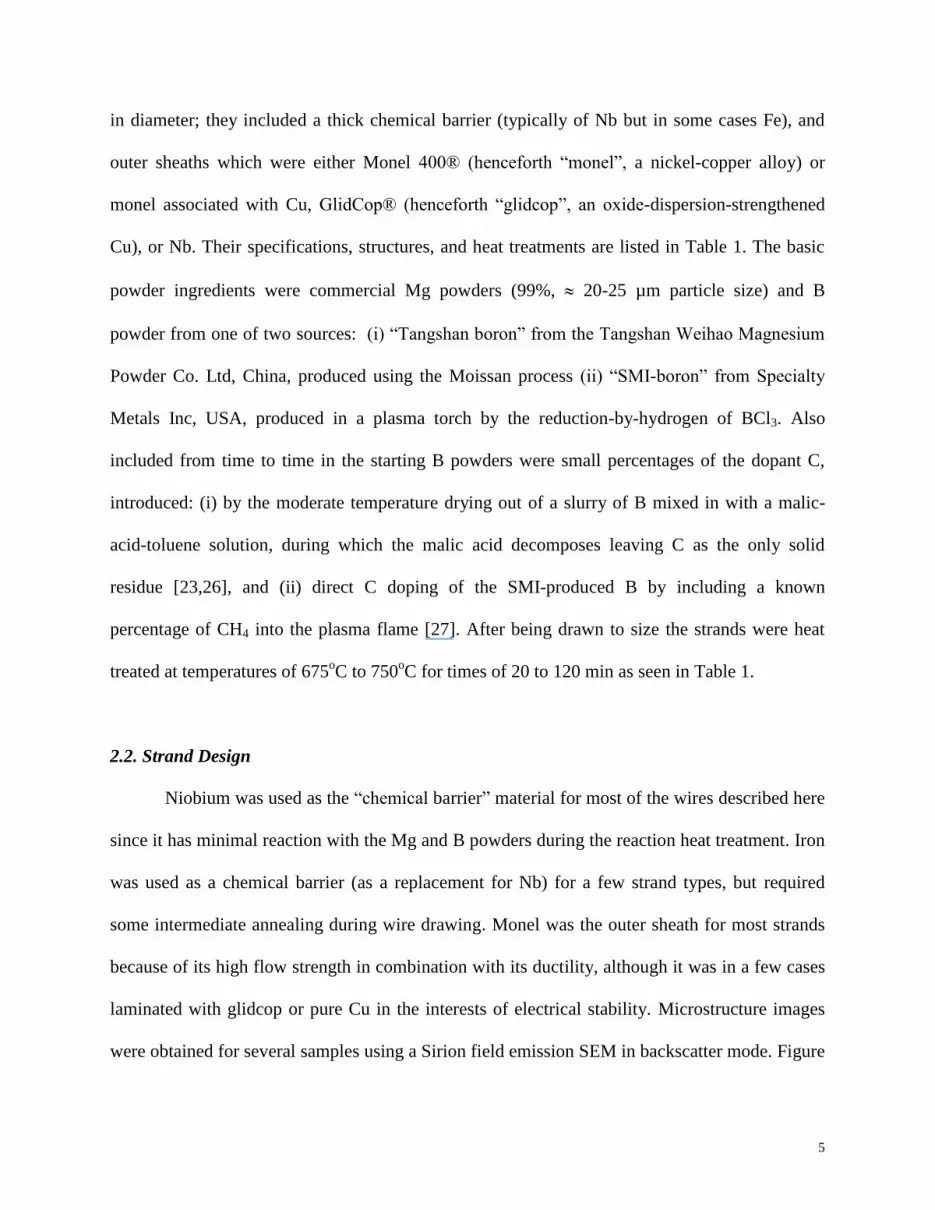
3.3. Critical Current Density of C-Doped Plasma Spray-Boron in Response to Variation of
Carbon Content
The Jcs of strands fabricated from SMI-boron doped with three different levels of carbon
are depicted in Figure 4 and presented in order of decreasing 5 T and 10 T Jc in Table 5. As
reported in [25] (for short 3 cm samples) the strands designated SMI-C1%, SMI-C2%, and SMI-
C4% had measured C levels of 1.29 mol%, 2.10 mol%, and 4.0 mol%, respectively. These
strands were monofilamentary, 0.83 mm OD, with a Nb chemical barrier and an outer monel
sheath (further strand details are available in ref [25]). Figure 4 shows Jc increases rapidly with
increasing levels of C doping. The two SMI-C4%-based strands have Jcs of more than 104A/cm
2
at 13 T – higher than that of HTR’s best SiC-doped strands. Irreversibility field measurements on
these strands [25] indicate that SMI-C4% has about the optimal level of C doping. The Jc(B)
results depicted in Figure 4 clearly indicate their division into three groups depending on carbon
content. At 10 T the Jc of the SMI-C4% pair, at 4x10⁴ A/cm
2, is an order of magnitude higher
than that of the SMI-C1% pair and that of SMI-C2% has an intermediate value. An increase of
the HT temperature from 675°C to 700°C (both for 60 min) uniformly raises the Jc of SMI-C1%

12
but produces no changes in the Jcs of the SMI-C2% and SMI-C4% strands. The B0, Jc0 , and B*
values extracted for this set of data are shown in Table 6, where a clear increase in B0 is seen
with C-additions.
4. n-values of MgB2 Strands`
While many studies of critical current density for MgB2 have been performed, the n-value
(or index number) is less frequently reported. Nevertheless the results of some studies with n-
value as a central focus have been reported. Measuring in-situ HTR-fabricated strands Flukiger
et al [31] found n-values of about 5 at 8 T, 4.2 K, rising to 20-30 at 4 T, 4.2 K. They noted an
unspecified but non-linear variation of n with B, and that densification of the strands
substantially improved the n-values. Goldacker et al [32], measuring both in-situ and ex-situ
wires, saw an exponential field dependence, with n-values of 10-20 at 8 T, 4.2 K, and 20-40 at
4T, 4.2 K. Kitaguchi et al [33], measuring in-situ processed strands, obtained n-values of 17 at
10 T, 4.2 K, values which increased to 27 with SiC doping additions. Suo [34] et al, achieved n-
values of 15-30 at 8 T, 4.2K, and above 60 at 4T, 4.2 K. Martinez [35] using magnetization
measurements to extract n-values, found apparently empirical correlations of n-value to Jc.
Similar correlation of n-value and Jc were seen in the work of Kim et al [36], among samples
where values of about 30 were seen at 8T, 4.2K. It should be noted that all of these studies were
performed on short samples, and for that reason we might expect that they would be less
susceptible to extrinsic limitations of n value. As a limit, the intrinsic n-value is determined by
the pinning potential [37-39]. In any case, shorter samples should be less susceptible to the
extrinsic n-variations brought on by Ic variations of larger wavelength (large compared to the
sample size).

13
As stated above the present transport Jc measurements were performed on 1.5 m long
samples helically wound on modified “ITER barrels”; n-values were obtained from the
accompanying voltage-current data within the electric field range of 0.4 V/cm to 4 V/cm. The
5 T and 10 T results for all the strands are presented in Tables 2, 4, and 5. The Jc results for the
strands with various SMI-C doped starting powders shown in Figure 4 are complemented by the
n-values shown in Figure 5. Here we note several different behaviors for n as a function of field.
For some samples the n vs B curve is relatively flat, while for others n increases with field. It
seems that samples with higher C content may have a better n-value, although the trend is not
uniform. It appears that some mixture of intrinsic and extrinsic contribution to n-values may be
present.
In order to make more general use of this data, it is helpful useful to remember that the
basic index number relationship is
n
c
cJ
JEE
(3)
This allows the curvature of the I-V curve to be described, where Ec is a given electric field
criterion, Jc is the J for that criterion, and E and J are the electric field and current density. If we
chose to use a different criterion, say
n
c
cJ
JEE
'' (4)
Then
n
c
c
c
c
E
E
J
J/1
''
(5)

14
Using this expression we predict the Jc value associated with a new electric field criterion given
a Jc at one criterion and the associated index number.
Consider now two strands with different n-values but which are otherwise identical. Let
one of the strands have an infinite n-value. This strand will transition to the normal state with
infinite sharpness, at a current density we can define as J. If we let the second strand have some
finite n-value, then the Jc of this strand using the same electric field criterion, Ec, will be lower
than the first. Let us consider the condition of this strand at J = J. Here the electric field will be
that of the wire at the transition to the normal state, which we can take to be Em. Eq (1) then
becomes
n
cc
m
J
J
E
E
(6)
which can be re-written
n
c
m
c
E
EJJ
/1
1
(7)
or alternatively
c
mc
E
ELn
nLnJLnJ
1 (8)
i.e
Dn
ALnJc
1 (9)

15
Where A and D are constants. These last two equations express the fact that for a given strand,
given all other factors (specifically including the intrinsic Jc, J) being equal, as n decreases so
does Jc.
5. Discussion and Conclusions
The transport properties of a number of MgB2 strands have been investigated in terms of
their response to strand design, starting B powder choice, and the approach to C doping used. In
general, it was seen that multifilamentary strands, and strands with stronger outer sheaths had a
higher Jc performance. This may be due to the tendency of the outer sheath to apply a pre-stress
during cool-down after HT thereby densifying the superconducting core of the strand and
improving connectivity. Wires with smaller diameters tended to perform better, at least within a
limited range of diameters. The improvement with strand diameter reduction may again be the
result of core densification. Little variation with HT was seen, in the small window defined by
675-700oC and 20-120 minutes, a temperature-time range already seen to be optimum for
previously measured strands of similar design.
In addition, B powder and C-dopant types were investigated, namely a fine Moisson type
B (Tangshan boron) and a plasma spray based B (SMI-B). Generally plasma spray B performed
better than even small powder type Moisson B. C doping was added both directly to the B (in the
Plasma Spray process) or after the fact using malic acid additions. Both powder types responded
well to malic acid treatment. However, the best C doping performance was seen after direct C
doping (i.e., C doped into the starting SMI-process B), and the optimum amount for 4 K
operation is presently set at 4 mol%.

16
Critical current densities, Jc, were measured on 1.5 m long samples at 4.2 K in fields of
up to 14 T; of all the strands measured, that doped with SMI-C at a nominal 4 mol% C yielded
the highest Jc values e.g 1.1x10⁵ A/cm
2 at 7 T, 4.5x10
4 at 10 T, and 2.2x10
4 A/cm
2 at 12 T. The
n-values were given for various strands and reached 20 at 4 T. In addition, we parameterized the
strands in terms of slopes α and zero-field intercept Jc(B=0) values.
References
[1] Grasso G, Malagoli A, Modica M, Tumino A, Ferdeghini C, Siri AS, Vignola C, Martini L,
Previtali V and Volpini G, 2003, “Fabrication and Properties of Monofilamentary MgB2
Superconducting Tapes”, Supercond. Sci. Technol. 16 271–275.
[2] Giunchi G, Ripamonti G, Perini E, Cavallin T and Bassani E, 2007, “Advancements in the
Reactive Liquid Mg Infiltration Technique to Produce Long Superconducting MgB2 Tubular
Wires, IEEE Trans. Appl. Supercond. 17 2761-2765.
[3] Hur JM, Togano K, Matsumoto A, Kumakura H, Wada H and Kimura K, 2008, Fabrication
of High-performance MgB2 Wires by an Internal Mg Diffusion Process, Supercond. Sci. Technol.
21 032001.
[4] Sumption MD, Peng X, Lee E, Tomsic M, Collings EW, 2001, “Transport Current in MgB2
based Superconducting Strand at 4.2 K and Self-Field”, cond-mat/0102441.
[5] Collings EW, Lee E, Sumption MD, Tomsic M, Wang XL, Soltanian S, and Dou SX, 2003,
“Continuous-and Batch-Processed MgB2/Fe Strands––Transport and Magnetic Properties”,
Physica C 386 555–559.
[6] Collings EW, Sumption MD, Bhatia M, Susner MA and Bohnenstiehl SD, 2008, “Prospects
for Improving the Intrinsic and Extrinsic Properties of Magnesium Diboride Superconducting
Strands”, Supercond. Sci. Technol.. 21 103001.

17
[7] Kumakura H, Matsumoto A, Fujii H, Kitaguchi H, Ooi S, Togano K, Hatakeyama H, 2003,
“Fabrication and Properties of Powder-in-Tube Processed MgB2 Tapes and Wires”, Journal of
Low Temperature Physics 131 1085-1093.
[8] Goldacker W, Schlachter SI, Obst B, Eisterer M, 2004, “In-situ MgB2 Round Wires with
Improved Properties”, Supercond. Sci. Technol. 17 S490-S495.
[9] Flukiger R, Suo HL, Musolino N, Beneduce C, Toulemonde P, Lezza P, 2003,
“Superconducting Properties of MgB2 Tapes and Wires”, Physica C, 385 286-305.
[10] Glowacki BA, Majoros M, Vickers M, Evetts JE, Shi Y, McDougall I, 2001,
“Superconductivity of Powder-in-Tube MgB2 Wires”, Supercond. Sci. Technol. 14 193-199.
[11] Soltanian S, Wang XL, Kusevic I, Babic E, Li AH, Qin MJ, Horvat J, Liu HK, Collings
EW, Lee E, Sumption MD, Dou SX, 2001, “High-Transport Critical Current Density above 30 K
in Pure Fe-clad MgB2 Tape, Physica C 361 84-90.
[12] Susner MA, Sumption MD, Bhatia M, Peng X, Tomsic MJ, Rindfleisch MA, Collings EW,
2007, “Influence of Mg/B Ratio and SiC Doping on Microstructure and High Field Transport Jc
in MgB2 Strands”, Physica C 456 180–187.
[13] Sumption MD, Bhatia M, Wu X, Rindfleisch M, Tomsic M and Collings EW, 2005,
Multifilamentary, in situ route, Cu-stabilized MgB2 Strands,” Supercond. Sci. Technol. 18 730–
734.
[14] Sumption MD, Bhatia M, Rindfleisch M, Tomsic M, and Collings EW, 2006, “Transport
Properties of Multifilamentary, in-situ Route, Cu-Stabilized MgB2 Strands: One Metre Segments
and the Jc(B, T) Dependence of Short Samples”, Supercond. Sci. Technol. 19 155–160.

18
[15] Mahmud MAA, Susner MA, Sumption MD, Rindfleisch MA, Tomsic MJ, Yue J, and
Collings EW, 2009, “Comparison of Critical Current Density in MgB2 with Different Boron
Sources and Nano-Particle Dopant Additions”, IEEE Trans. Appl. Supercond. 19 2756-2759.
[16] Chen SK, Yates KA, Blamire MG, and MacManus-Driscoll JL, “Strong Influence of Boron
Precursor Powder on the Critical Current Density of MgB2, 2005,” Supercond. Sci. and Tech. 18
1473–1477.
[17] Xu X, Qin MJ, Konstantinov K, dos Santos DI, Yeoh WK, Kim JH, and Dou SX, 2006,
“Effect of Boron Powder Purity on Superconducting Properties of MgB2”, Supercond. Sci. and
Technol. 19 466–469.
[18] Dou SX, Shcherbakova O, Yeoh WK, Kim JH, Soltanian S, Wang XL, Senatore C, Flukiger
R, Dhalle M, Husnjak O, Babic E., 2007, “Mechanism of Enhancement in Electromagnetic
Properties of MgB2 by Nano SiC Doping”, Phys Rev Lett. 98 097002 (2007).
[19] Sumption MD, Bhatia M, Dou SX, Rindfliesch M, Tomsic M, Arda L, Ozdemir M,
Hascicek Y, and Collings EW, 2004, “Irreversibility Field and Flux Pinning in MgB2 With and
Without SiC Additions” Supercond. Sci. Technol. 17 1180–1184.
[20] Kim JH, Yeoh WK, Qin MJ, Xu X, Dou SX, 2006, “The Doping Effect of Multiwall
Carbon Nanotube on MgB2/Fe Superconductor Wire”, Journal of Applied Physics 100 013908-
013908-6.
[21] Yamada H, Hirakawa M, Kumakura H, Kitaguchi H, 2006, “Effect of Aromatic
Hydrocarbon Addition on in-situ Powder-in-Tube Processed MgB2 Tapes”, Supercond. Sci.
Technol. 19 175-177.

19
[22] Kim JH, Xu X, Hossain MS, Shi DQ, Zhao Y, Wang XL, Dou SX, Choi S, et. al., 2008,
”Influence of Disorder on the in-field Jc of MgB2 Wires using Highly Active Pyrene”, Appl.
Phys. Lett. 92 042506-042506-3.
[23] Kim JH, Zhou S, Hossain MSA, Pan AV and Dou SX, 2006, “Carbohydrate Doping to
Enhance Electromagnetic Properties of MgB2 Superconductors”, Appl. Phys. Lett. 89 142505.
[24] Hossain MSA, Senatore C, Flükiger R, Rindfleisch MA, Tomsic MJ, Kim JH, Dou SX,
2009, Supercond. Sci. Technol. 22 095004.
[25] Susner MA, Yang Y, Sumption MD, Rindfleisch MA, Tomsic MJ, Marzik JV and Collings
EW, 2011, “Enhanced Superconducting Properties of pre-doped B Powder Type MgB2 Strands”,
Supercond. Sci. Technol. 24 012001.
[26] Bohnenstiehl SD, Susner MA, Yang Y, Collings EW, Sumption MD, Rindfleisch MA,
Boone R, 2011, “Carbon Doping of MgB2 by Toluene and Malic-Acid-in-Toluene”, Physica C
471 108–111.
[27] Marzik JV, Lewis RC, Nickles MR, Finnemore DK, Yue J, Tomsic MJ, Rindfleisch M, and
Sumption M, 2010, “Plasma Synthesized Boron Nano-Sized Powder for MgB2 Wires” Adv Cryo
Eng 56 295-301
[28] Tomsic M, Rindfleisch MA, Yue J, McFadden K, Doll D, Phillips J, Sumption MD, Bhatia
M, Bohnenstiehl SD, Collings EW, 2007, “Development of magnesium diboride (MgB2) wires
and magnets using in situ strand fabrication method”, Physica C 456 203–208.
[29] Nijhuis A, Wessel WAJ, Knoopers HG, Ilyin Y, della Corte A and ten Kate HHJ, 2005,
“Compressive Pre-strain in Nb3Sn Strand by Steel Tube and Effect on the Critical Current
Measured on Standard ITER Barrel, IEEE Trans. Appl. Supercond. 15 3466-3469.

20
[30] Tenbrink J, Wilhelm M, Heine K, and Krauth H, 1993, “Development of Technical High-Tc
Superconductor Wires and Tapes”, IEEE Trans Appl. Supercond. 3 1123-1126.
[31] Flükiger R, Shahriar MD, Hossain A, Senatore C, Buta F, and Rindfleisch M, 2011, “A
New Generation of In-Situ MgB2 Wires With Improved Jc and Birr Values Obtained by Cold
Densification (CHPD)”, IEEE Trans Supercond. 21: 2649 – 2654.
[32] Goldacker W, Schlachter SI, Liu B, Obst B, Klimenko E, 2004, “Considerations on Critical
Currents and Stability of MgB2 Wires Made by Different Preparation Routes”, Physica C 401
80–86.
[33] Kitaguchi H, Matsumoto A, Hatakeyama H, Kumakura H, 2004, “V–I Characteristics of
MgB2 PIT Composite tapes: n-values under strain, in High Fields, or at High Temperatures”,
Physica C 401 (2004) 246–250.
[34] Suo HL, Lezza P, Uglietti D, Beneduce C, Abächerli V, and Flükiger R, 2003, “Transport
Critical Current Densities and n Factors in Mono- and Multifilamentary MgB2/Fe Tapes and
Wires Using Fine Powders”, IEEE Trans. Appl. Supercond. 13 3265-3268.
[35] Martínez E, Martínez-López M, Millán A, Mikheenko P, Bevan A, and Abell JS, 2007,
“Temperature and Magnetic Field Dependence of the n-Values of MgB2 Superconductors”, IEEE
Trans. Appl. Supercond. 17 2738-2741.
[36] Kim JH, Dou SX, Matsumoto A, Choi S, Kiyoshi T, Kumakura H, 2010, Correlation
between Critical Current Density and n-Value in MgB2/Nb/Monel Superconductor Wires”,
Physica C 470 1207–1210.
[37] Nilsson-MeUbin, M, Parikh A, Salama K, 1994, “I-V Characteristics of Melt-Textured
YBa2Cu307-x Superconductors Containing Grain Boundaries”, Physica C 223 19-29.

21
[38] Zeldov E, Amer NM, Koren G, Gupta A, McElfresh MW, and Gambino RJ, 1990, “Flux
Creep Characteristics in High-Temperature Superconductors”, Appl. Phys Let 56 680-682.
[39] K. Berger, J. Lévêque, D. Netter, B. Douine, and A. Rezzoug, 2007, “Influence of
Temperature and/or Field Dependences of the E–J Power Law on Trapped
Magnetic Field in Bulk YBaCuO”, IEEE Trans. Appl. Supercond. 17 3028-3031.

22
Tables
Table 1. Strand Specifications.
Table 2. 4.2 K transport Jc values of SMI-boron strands doped with a nominal 2% malic
acid and Tangshan-boron strands doped with a nominal 5% malic acid at 5T and
10T, respectively.
Table 3. B0, B*, and Jc0 values of SMI-boron strands doped with a nominal 2% malic
acid and Tangshan-boron strands doped with a nominal 5% malic acid.
Table 4. 4.2 K transport Jc values of SMI-boron strands directly doped with a nominal 2% C with
various strand designs and heat treatments at at 5T and 10T, respectively.
Table 5. 4.2 K transport Jc values of SMI-boron strands directly doped with nominal levels of
1%C, 2%C, and 4%C at 5T and 10T, respectively.
Table 6. B0, B*, and Jc0 values of SMI-boron strands directly doped with nominal levels
of 1%C, 2%C, and 4%C.

23
Table 1
Name HTR
Tracer No Actual C (mol %)c
Chemical Barrier Sheath Fil.Count HT(Co/min) %SC
OD (mm)
SMI Boron Samples
A-SMI-C2%-1F-675/20 2035 2.3% Nb M 1 675/20 15.8 0.834
A-SMI-Malic2%-1F-700/20a 1980 0.8% Nb M 1 700/20 16 0.834
B*-SMI-C1%-Malic2%-675/30a 2061 1.7% Nb M 18 675/30 21.3 0.834
B*-SMI-C1%-Malic2%-750/30a 2061 1.7% Nb M 18 750/30 21.3 0.834
B*-SMI-C2%-675/20 2066 2.3% Nb M 18 675/20 17.4 0.834
B*-SMI-C2%-700/120-a 2066 2.3% Nb M 18 700/120 17.4 0.834
B*-SMI-C2%-700/120-b 2066 2.3% Nb M 18 700/120 19 0.984
B*-SMI-C2%-700/120-c 2097 2.3% Nb M 18 700/120 17.4 0.834
B-SMI-C1%-675/20 2110 1.4% Nb M 18 675/20 23.6 0.834
B-SMI-C1%-700/20 2110 1.4% Nb M 18 700/20 23.6 0.834
B-SMI-C2%-675/60-a 2115 2.3% Nb M 18 675/60 22.7 0.834
B-SMI-C2%-675/60-b 2163 2.3% Nb M 18 675/60 25.8 0.834
B-SMI-C2%-700/120 2115 2.3% Nb M 18 700/120 20.1 0.984
B-SMI-C2%-700/60 2163 2.3% Nb M 18 700/60 25.8 0.834
B-SMI-C2%-T-675/60 2115T 2.3% Nb M 18 675/60 22.7 0.83
B-SMI-C2%-T-700/60 2115TA 2.3% Nb M 18 700/60 22.7 0.83
B-SMI-C4%-675/60 2158 4.8% Nb M 18 675/60 15.4 0.834
B-SMI-C4%-700/60 2158 4.8% Nb M 18 700/60 15.4 0.834
C-SMI-C2%-36F-700/60-a 2154R 2.3% Nb M 36 700/60 15.5 0.83
C-SMI-C2%-36F-700/60-b 2148 2.3% Nb M 36 700/60 17.3 0.83
C-SMI-C2%-36F-700/60-c 2148P1 2.3% Nb M 36 700/60 17.8 0.94
C-SMI-C2%-36F-700/60-d 2148P2 2.3% Nb M 36 700/60 16.7 0.93
D-SMI-C2%-CuM-36F-675/60 2189 2.3% Nb Cu/M 36 675/60 16.1 0.934
D-SMI-C2%-CuM-36F-700/60 2189 2.3% Nb Cu/M 36 700/60 16.1 0.934
E-SMI-C2%-MG-700/60-a 2170B 2.3% Nb M/G 18 700/60 11.4 0.834
E-SMI-C2%-MG-700/60-b 2170D 2.3% Nb M/G 18 700/60 10.2 1.008
F-SMI-C2%-Fe-Brich-675/20 2020 2.3% Fe M 18 675/20 15.4 0.83
Tangshan Boron (TsB)+Malic-Acid-Treated Samples
B-TsB-Malic5%-675/60b 2056 1.6% Nb M 18 675/60 14.3 0.83
B-TsB-Malic5%-700/30b 2056 1.6% Nb M 18 700/30 14.3 0.83
G-TsB-Malic5%-Fe-NbM-675/60b 2017 1.6% Fe Nb/M 18 675/60 13.2 1.008
Explanation of the Sample Name:
(1) The prefixes “A, B*, B, C – G” refer to the various strand architectures depicted in Figure 1
(2) The letters “a”, “b”, “c” and “d” attached to otherwise “similar” samples designate variations in %SC and strand OD as listed. The letter ‘T” indicates twisted.
(3) A Nb chemical barrier is understood, otherwise an iron barrier is indicated by “Fe”.
(4) A monel sheath is understood, otherwise monel+glidcop, copper+monel. niobium+monel are indicated by M/G, Cu/M and Nb/M, respectively.
(5) A filament count of 18 is understood, otherwise counts of 1 and 36 are indicated by 1F and 36F, respectively. (6) “Brich” indicates extra boron hence MgB2.5.
a Here malic2% refers to mol% in the final MgB2 compound, but does not presuppose complete substitution of the C into the B sublattice.
b Here malic5% refers to mol% in the final MgB2 compound, but does not presuppose complete substitution of the C into the B sublattice.
c Here mol % is relative to the final MgB2 compound, but does not presuppose complete substitution of the C into the B sublattice.

24
Table 2.
Jc at 5T(104
A/cm2) n-value Name Jc at 10T(104 A/cm2) n-value Name
9.6 6.7 B*-SMI-Malic2%-750/30 1.6 10.9 B*-SMI-Malic2%-750/30
6 5.9 A-SMI-Malic2%-1F-700/20 1 12.9 B*-SMI-Malic2%-675/30
5.5 20.5 B*-SMI-Malic2%-675 /30 0.61 3.5 B-TsB-Malic5%-700/30
5 8.1 B-TsB-Malic5%-700/30 0.53 2.4 B-TsB-Malic5%-675/60
4.3 11.2 G-TsB-Malic5%-Fe-NbM-675/60 0.5 1.9 A-SMI-Malic2%-1F-700/20
4.2 5.1 B-TsB-Malic5%-675/60 0.23 6.5 G-TsB-Malic5%-Fe-NbM-675/60

25
Table 3.
Name B0(T) Jc0(106A/cm
2) B*(T)
A-SMI-Malic2%-1F-700/20 1.9 1.1 6
B*-SMI-Malic2%-675/30 2.1 1.2 8
B*-SMI-Malic2%-750/30 2.0 2.4 8
B-TsB-Malic5%-675/60 2.3 0.4 5
B-TsB-Malic5%-700/30 1.6 1.1 3
G-TsB-Malic5%-Fe-NbM-675/60 1.6 1.1 5

26
Table 4.
Jc at 5T(104 A/cm2) n-value Name
Jc at 10T(104
A/cm2) n-value Name
17.8 12.0 B*-SMI-C2%-700/120-a 2.08 14.8 B*-SMI-C2%-700/120-a
17.5 6.5 B*-SMI-C2%-675/20 2.06 10.2 C-SMI-C2%-36F-700/60-b
17.4 7.6 C-SMI-C2%-36F-700/60-c 2.04 8.9 B-SMI-C2%-675/60-b
16.8 14.5 B-SMI-C2%-675/60-b 1.99 9.1 C -SMI-C2%-36F-700/60-c
16.5† -- B-SMI-C2%-700/60 1.98 9.1 C-SMI-C2%-36F-700/60-d
16.3 8.6 C-SMI -C2%-36F-700/60-a 1.97 10.6 B*-SMI-C2%-675/20
16 6.2 C-SMI-C2%-36F-700/60-d 1.87 7.9 C-SMI-C2%-36F-700/60-a
15.3 8.3 C-SMI-C2%-36F-700/60-b 1.84 8.4 B-SMI-C2%-700/60
14.2 9.2 E-SMI-C2%-MG-700/60-a 1.61 3.3 E-SMI-C2%-MG-700/60-a
13.3 9.6 E-SMI-C2%-MG-700/60-b 1.6 5.1 A-SMI-C2%-1F-675/20
12.5 12.2 D-SMI-C2%-CuM-36F-675/60 1.47 7.3 D-SMI-C2%-CuM-36F-675/60
12 11.2 B-SMI-C2%-T-675/60 1.43 4.9 B*-SMI-C2%-700/120-c
11.1 14.7 B-SMI-C2%-700/120 1.42 12.7 B-SMI-C2%-T-675/60
10.2 10.5 D-SMI-C2%-CuM-36F-700/60 1.4 4.6 E-SMI-C2%-MG-700/60-b
9.8 14.9 B-SMI-C2%-675/60-a 1.27 7.6 B-SMI-C2%-700/120
9.5 12.9 A-SMI-C2%-1F-675/20 1.27 6.3 B*-SMI-C2%-700/120-b
9.4 6.9 B*-SMI-C2%-700/120-c 1.26 3.9 B-SMI-C2%-T-700/60
9.2 7.4 B-SMI-C2%-T-700/60 1.2 6.5 D-SMI-C2%-CuM-36F-700/60
8.2 3.4 B*-SMI-C2%-700/120-b 1.04 5.8 B-SMI-C2%-675/60-a
6.6 8.7 F-SMI-C2%-Fe-Brich-675/20
Note:" †" indicates data is extrapolated from fitting curve of the other data , not measured data.

27
Table 5.
Jc at 5T(104 A/cm
2) n-value Name Jc at 10T(10
4 A/cm
2) n-value Name
20.0† -- B-SMI-C4%-700/60 4.6 10.7 B-SMI-C4%-700/60
19.9 21.2 B-SMI-C4%-675/60 4.1 14.5 B-SMI-C4%-675/60
17.1
14.5 B-SMI-C2%-675/60-
b 2.1 8.9 B-SMI-C2%-675/60-b
16.0† -- B-SMI-C2%-700/60 1.9 8.4 B-SMI-C2%-700/60
6.4 4.3 B-SMI-C1%-700/20 0.7 5.7 B-SMI-C1%-700/20
4.6 9.5 B-SMI-C1%-675/20 0.4 6.9 B-SMI-C1%-675/20
Note:" †" indicates data is extrapolated from fitting curve of the other data , not measured data.

28
Table 6.
Name B0(T) Jc0(106A/cm
2) B*(T)
B-SMI-C1%-675/20 1.6 1.6 7
B-SMI-C1%-700/20 1.7 2.0 8
B-SMI-C2%-675/60-b 1.8 5.0 8
B-SMI-C2%-700/60 1.8 4.7 8
B-SMI-C4%-675/60 2.8 1.5 8
B-SMI-C4%-700/60 2.7 1.8 9

29
Figure Captions
Figure 1. SEM-backscatter images of a set of representative strands. (a) Strand Type A: Single
Nb filament (monocore) in a Nb barrier sheathed in monel; (b) Strand Type B: 18 Nb-clad
(barrier) filaments (leading to 18 MgB2 filaments imbedded in Nb), plus a central solid-Cu
filament, all enclosed in a monel outer sheath -- the strands prefixed B* in Table 1 have a
central solid-Nb filament instead, see (b*); (c) Strand Type C: 36 Nb-clad filaments (leading
to 36 MgB2 filaments imbedded in Nb), plus a central Cu filament, all enclosed in a monel
outer sheath; (d) Strand Type D: 36 Nb-clad filaments, plus a central Cu filament, all
enclosed in a Cu-inner/monel-outer double-wall sheath designated Cu/M in Table 1; (e)
Strand Type E: 18 Nb-clad filaments, plus a central Cu filament, all enclosed in a monel-
inner/glidcop-outer double-wall sheath designated M/G in Table 1; (f) Strand Type F: 18 Fe-
clad filaments (leading to 18 MgB2 filaments imbedded in Fe), plus a central “CTFF-formed”
Fe filament, enclosed in a monel outer sheath; (g) Strand Type G: 18 Fe-clad filaments
(leading to 18 MgB2 filaments imbedded in Fe), plus a central “CTFF-formed” Fe filament,
enclosed in a Nb-inner/monel-outer double-wall sheath designated Nb/M in Table 1.
Figure 2. 4.2 K transport JC versus B for SMI-boron strands doped with a nominal 2%
malic acid and Tangshan-boron strands doped with a nominal 5% malic acid.
Figure 3. (a) 4.2 K transport Jc versus B for SMI-boron strands directly doped with a nominal
2% C with various strand designs and heat treatments; (b) Detail for the field range 5-10 T.
Figure 4. 4.2 K transport Jc versus B for SMI-boron strands directly doped with nominal levels
of 1%C, 2%C, and 4%C.
Figure 5. n-value versus B for SMI-boron strands directly doped with nominal levels of 1%C,
2%C, and 4%C.

30
Figure 1
a b
b* c
d e
f g

31
Magnetic Field, B, T
0 2 4 6 8 10 12 14
Cri
tica
l C
urr
ent
Den
sity
, J c
, A
/cm
2
103
104
105
106
A-SMI-Malic2%-1F-700/20
B*-SMI-C1%-Malic2%-675/30
B*-SMI-C1%-Malic2%-750/30
B-TsB-Malic5%-675/60
B-TsB-Malic5%-700/30
G-TsB-Malic5%-Fe-NbM-675/60
Figure 2

32
Magnetic Field, B, T
0 2 4 6 8 10 12 14 16
Cri
tica
l C
urr
ent
Den
sity
, J c
, A
/cm
2
103
104
105
106
A-SMI-C2%-1F-675/20
B*-SMI-C2%-675/20
B*-SMI-C2%-700/120-a
B*-SMI-C2%-700/120-b
B*-SMI-C2%-700/120-c
B-SMI-C2%-675/60-a
B-SMI-C2%-675/60-b
B-SMI-C2%-700/120
B-SMI-C2%-700/60
B-SMI-C2%-T-675/60
B-SMI-C2%-T-700/60
C-SMI-C2%-36F-700/60-a
C-SMI-C2%-36F-700/60-b
C-SMI-C2%-36F-700/60-c
C-SMI-C2%-36F-700/60-d
D-SMI-C2%-CuM-36F-675/60
D-SMI-C2%-CuM-36F-700/60
E-SMI-C2%-MG-700/60-a
E-SMI-C2%-MG-700/60-b
F-SMI-C2%-Fe-Brich-675/20
Figure 3(a)

33
Magnetic Field, B, T
5 6 7 8 9 10
Cri
tica
l C
urr
ent
Den
sity
, J c
, A
/cm
2
104
105
A-SMI-C2%-1F-675/20
B*-SMI-C2%-675/20
B*-SMI-C2%-700/120-a
B*-SMI-C2%-700/120-b
B*-SMI-C2%-700/120-c
B-SMI-C2%-675/60-a
B-SMI-C2%-675/60-b
B-SMI-C2%-700/120
B-SMI-C2%-700/60
B-SMI-C2%-T-675/60
B-SMI-C2%-T-700/60
C-SMI-C2%-36F-700/60-a
C-SMI-C2%-36F-700/60-b
C-SMI-C2%-36F-700/60-c
C-SMI-C2%-36F-700/60-d
D-SMI-C2%-CuM-36F-675/60
D-SMI-C2%-CuM-36F-700/60
E-SMI-C2%-MG-700/60-a
E-SMI-C2%-MG-700/60-b
F-SMI-C2%-Fe-Brich-675/20
Figure 3(b)
34
Magnetic Field, B, T
2 4 6 8 10 12 14
Cri
tica
l C
urr
ent
Den
sity
, J c,
A/c
m2
103
104
105
106
B-SMI-C1%-675/20
B-SMI-C1%-700/20
B-SMI-C2%-675/60-b
B-SMI-C2%-700/60
B-SMI-C4%-675/60
B-SMI-C4%-700/60
Figure 4

35
Magnetic Field, B, T
2 4 6 8 10 12 14
n-v
alu
e
0
5
10
15
20
25B-SMI-C1%-675/20
B-SMI-C1%-700/20
B-SMI-C2%-675/60-b
B-SMI-C2%-700/60
B-SMI-C4%-675/60
B-SMI-C4%-700/60
Figure 5


