Embed Size (px)
Citation preview
Influence of tooth preparation design on the stressdistribution in maxillary central incisors restoredby means of alumina porcelain veneers: A 3D-finiteelement analysis
Fernando Zaronea, Davide Apicellab, Roberto Sorrentinoa, Valeria Ferrob,Raffaella Aversab, Antonio Apicellab,*
aDipartimento di Scienze Odontostomatologiche e Maxillo-Facciali, Universita degli Studi di Napoli‘Federico II’, Naples, ItalybCRIB, Second University of Naples, Naples, Italy
Received 26 October 2004; accepted 8 February 2005
01do
76
KEYWORDSPorcelain veneers;3D-finite elementanalysis;Preparation design;Window technique;Chamfer with palataloverlap preparation;Biomimetic
09-5641/$ - see front matter Q 2005i:10.1016/j.dental.2005.02.014
* Corresponding author. Tel.: C39 082 9103.E-mail address: [email protected] (
Summary Aim. The present study aimed at providing 3D-FEA engineering tools forthe understanding of the influence of tooth preparation design on the stressdistribution and localization of critical sites in maxillary central incisors restored bymeans of alumina porcelain veneers under functional loading.Methods. A 3D-FEM model of a maxillary central incisor is presented. An arbitrarychewing static force of 10 N was applied with an angulation of 60 and 1258 to thetooth longitudinal axis at the palatal surface of the crown. The model was consideredto be restored by means of alumina porcelain veneers with different toothpreparation designs. The differences in occlusal load transfer ability of the tworestorative systems are discussed.Results. The maximum Von Mises equivalent stress values were observed in thewindow restorative system for both 125 and 608 load angulations. When the chamferwith palatal overlap preparation was simulated, the stress distributed uniformly inthe cement layer, whereas in the window preparation the stress mainly occurred inthe incisal area of the cement layer.Significance. When restoring a tooth by means of porcelain veneers, the chamferwith palatal overlap preparation better restores the natural stress distribution underload than the window technique.Q 2005 Academy of Dental Materials. Published by Elsevier Ltd. All rights reserved.
Academy of Dental Materials
1 762 9102; fax: C39 081
A. Apicella).
Introduction
According to the principles of so-called ‘minimalintervention dentistry’ and due to the growing
Dental Materials (2005) 21, 1178–1188
www.intl.elsevierhealth.com/journals/dema
. Published by Elsevier Ltd. All rights reserved.
Influence of tooth preparation design on the stress distribution in maxillary central incisors 1179
demand of patients for dental esthetics, during thelast 20 years, the use of ceramic veneers hasbecome a widespread, reliable and successfultechnique for restoring discolored, worn, mal-formed or crown-fractured teeth. Thanks to recenttechnical and experimental acquisitions, the rangeof clinical indications for such restorations iscontinuously increasing [1]. The introduction ofnew ceramic materials, as well as the reliability ofthe adhesive cementation technique resulted inminimal tooth preparation, preserving a consider-able amount of sound dental structure [2]. In fact,the residual dentin thickness after preparation mayinfluence the life expectancy of a restoration [3];on the other hand, endodontic treatment is lessfrequent after veneer preparations than after full-crown restorations [4]. Bonded ceramic laminatesprovide biocompatibility with minimal risk ofgingival irritation [5].
The clinical survival rate of porcelain veneers hasnowadays become predictable [6] and severalobservational studies with a follow-up periodranging from 18 months up to 15 years are reportedin scientific literature [6–8]. In this study, thereported success rates vary between 75 and 100%[8,9]; in particular, a cumulative success rate of98.4% was noticed at a 5-year recall [10] and asuccess rate of about 93% was recorded after 15years of clinical performance [6]. Several studiesexhaustively described laboratory and technicalprocedures to build-up porcelain veneers [11–13].
Various factors can affect the long-termsuccess of porcelain veneers, such as toothsurface, porcelain thickness, type of compositecement and adhesive system, marginal adap-tation, periodontal response, tooth morphology,geometry of preparation, functional and paraf-unctional activities [14]. Poor oral hygiene, toothfluoridation and severe dentinal demineralizationare considered contraindicating factors for therealization of porcelain veneers [15]. Bondedceramic laminates have also been reported tobe contraindicated in clinical situations develop-ing excessive stress during function, just likecross bite and edge-to-edge occlusal relationships[16]. Some authors affirmed that such restor-ations should theoretically be subjected tominimal occlusal loads [17]. According to thisstatement, Toh et al. [18] suggested the use ofporcelain veneers to restore only esthetics andnot function. On the contrary, Friedman [19]noticed that this restorative technique offersboth suitable esthetics and reliable functionalstrength. Moreover, bonded ceramic laminateswith appropriate incisal length can be used toprovide valid anterior guidance [19].
The most frequent failure factors associatedwith porcelain veneers are fracture, microleakageand debonding [6]. Fractures represented 67% oftotal failures after an observational period of 15years of clinical performance of such restorations[6]. The magnitude and the angle of incisal loadgreatly influenced the long-term success of ceramicveneers [20,21].
Preparation design is one of the possiblevariables affecting the final success of porcelainveneers [22]. In order to achieve the bestadhesion, it is strongly desirable to have atleast 50–70% of the enamel surface available forthe etching procedure [23]. Some studies foundthat 52% of the preparations for porcelainveneers were realized exposing the dentin atthe level of the gingival margin [24] and thisobservation can be due to a thin enamelthickness available at the apical third of thebuccal surface of anterior teeth [25]. Never-theless, although being affected by oral humidity[20], a predictable adhesion to the dentin is anachievable goal [26]. Theoretically, the cohesivestrength of the dentin is the limiting factoraffecting the loadability of a restoration [25].To-date, porcelain appears to be the weakest linkin the veneer/cement/tooth adhesive complex[14]. According to Hui et al. [15], the moreconservative the preparation geometry, thehigher the load tolerance of the restored tooth.The geometry of the preparation itself is still oneof the most controversial topics concerning thefracture strength of porcelain veneers [15,27,28].Different tooth preparation geometries for cer-amic veneers were described in the literature.Although a chamfer or a rounded shoulder havebeen shown to be the best marginal designs inorder to get both a clearly detectable finish lineand an acceptable structural resistance, to-datethere is still no agreement about the possiblelingual extension of the veneer preparation. Inparticular, four typologies of incisal design havebeen proposed: the so-called ‘window’ prep-aration (limited to the buccal tooth surface),the overlapped incisal edge preparation (in whicha palatal extension is performed with a so-calledmarginal ‘mini-chamfer’), the feathered incisaledge preparation (extended up to the incisalmargin but without a definite finish-line) and theincisal bevel preparation (realized by creatinga 0.5–1 mm bevel at the level of the buccalsurface and incisal edge) [29,30].
Clinical observations on the use of ceramicveneers reported that cohesive fracture of porce-lain mainly concerned the incisal edge of therestoration, because of a greater stress
F. Zarone et al.1180
concentration in this area during function [19]. To-date, several studies have been performed in orderto evaluate the clinical reliability of the variouspreparation designs [15,27,28].
Highton et al. [27] published a study pointing outthat the stress concentration at the level ofporcelain veneer can be reduced by extending thetooth preparation to the incisal margin, so dis-tributing the occlusal loads on a wider surface thanwith a window preparation. Friedman [19] noticedthat the overlapped incisal edge preparationincreases adhesion and the retention surface ofthe restoration, whereas Clyde and Gilmour [29]pointed out that the window preparation limited tothe enamel tissue, is particularly resistant to axialstresses. In the chamfer with a palatal overlappreparation, low tensile stresses or even compres-sive stresses were detected at the level of themargins, while a deep chamfer on the palatalsurface determines unfavorable stress levels[31–33]. Seymour et al. [34] reported that theincisal overlap preparation better tolerates occlu-sal loading, since they noticed a small amount ofcompressive stress when using this preparationgeometry. In a 2D-Finite Element Analysis study,Troedson and Derand [20] also suggested the use ofthe chamfer with palatal overlap preparation, whenfull bonding between the tooth and the veneer isachievable, but reported that the margin prep-aration is of less importance than masticatoryloading conditions. Moreover, other authorsaffirmed that a tooth preparation design with anincisal overlap provides adequate porcelain thick-ness [16], improves the translucency of therestoration [35] and makes the seating of theveneer easier during cementation [36].
On the contrary, other studies showed thatwindow preparation allows for the achievement ofa restorative strength that is comparable to that ofunprepared teeth [37] and a structural resistance tofracture similar to that of unrestored teeth [22].The window preparation is suggested when strengthis the main goal: this kind of marginal design ischaracterized by high values of elasticity, so that itcan better sustain high dynamic stresses [15].Castelnuovo et al. [22] noticed that a palatalchamfer did not provide increased strength forceramic veneers; at the same time, however, theystated that the poor performance of this geometrypreparation in their experimental study did notimply that such design does not meet the standardsfor clinical longevity and predictability. Conver-sely, Magne et al. [33] reported that it is advisableto prefer a butt-joint incisal design to a palatalchamfer, in order to increase the ratio betweenceramic and luting composite thickness and to
prevent ceramic cracks after thermal cyclicloading.
Ultimately, the influence of different toothpreparation geometries on the fracture strengthof porcelain veneers still remains controversial,since almost all the data about the clinical behaviorof such restorations was based on anecdotal reports[22]. Anyway, considering the low biting forcesreported in the literature at the level of both themaxillary and mandibular central incisors (100–200 N) [38], the clinical use of both chamfer withpalatal overlap and window preparation can bejustified [37]. The incisal-overlapped preparationtechnique may be used to re-establish correctanterior guidance during excursive movements[37].
Proper understanding of the physical factorsaffecting the behavior of a prosthetic system duringfunction is crucial in validating the clinical effec-tiveness and predicting long-term success. Thecombination of different materials and complexgeometries makes the analysis of stress distributionin teeth very difficult [39]. The simultaneousinteraction of the many variables affecting themechanical behavior of a restoration can be studiedby means of simulation in a computerized model:3D-Finite Element Analysis (FEA) might be a power-ful and effective tool to visualize such a situation[39]. The 3D-Finite Element approach consists ofdividing a geometric model into a finite number ofelements in which the variables of interest areapproximated with some mathematical functions[39]. Biomedical applications of this method havealready been used in other fields of medicalsciences [40–43]. To date, however, only 2D-FiniteElement Analysis has been adopted in dentalresearch to study the mechanical behavior of arestorative system including porcelain veneers [20,44]. Using this kind of 2D-analysis, Magne andDouglas [44] affirmed that long chamfers extendinginto the palatal concavity should be avoided in thepreparation of bonded ceramics, since thin exten-sions of porcelain are generated in an area ofmaximum tensile stress.
The present paper is aimed at evaluating veneerrestoration design criteria for the assessment of arestorative material’s performance in a maxillarycentral incisor using three-dimensional FEA. Natu-ral tooth flexibility has been considered.
Materials and methods
For the investigation, a 3D-FEM model of a restoredtooth (root, crown, root canal, veneer and luting
Influence of tooth preparation design on the stress distribution in maxillary central incisors 1181
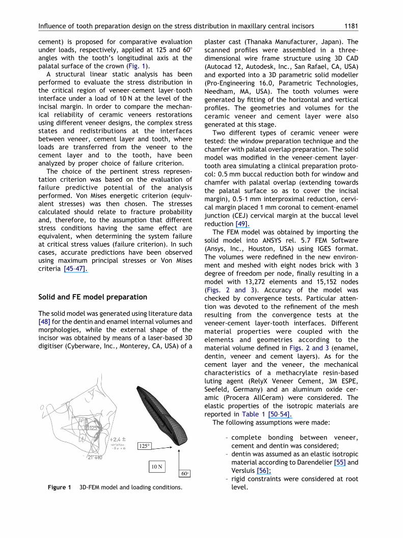
cement) is proposed for comparative evaluationunder loads, respectively, applied at 125 and 608angles with the tooth’s longitudinal axis at thepalatal surface of the crown (Fig. 1).
A structural linear static analysis has beenperformed to evaluate the stress distribution inthe critical region of veneer–cement layer–toothinterface under a load of 10 N at the level of theincisal margin. In order to compare the mechan-ical reliability of ceramic veneers restorationsusing different veneer designs, the complex stressstates and redistributions at the interfacesbetween veneer, cement layer and tooth, whereloads are transferred from the veneer to thecement layer and to the tooth, have beenanalyzed by proper choice of failure criterion.
The choice of the pertinent stress represen-tation criterion was based on the evaluation offailure predictive potential of the analysisperformed. Von Mises energetic criterion (equiv-alent stresses) was then chosen. The stressescalculated should relate to fracture probabilityand, therefore, to the assumption that differentstress conditions having the same effect areequivalent, when determining the system failureat critical stress values (failure criterion). In suchcases, accurate predictions have been observedusing maximum principal stresses or Von Misescriteria [45–47].
Solid and FE model preparation
The solid model was generated using literature data[48] for the dentin and enamel internal volumes andmorphologies, while the external shape of theincisor was obtained by means of a laser-based 3Ddigitiser (Cyberware, Inc., Monterey, CA, USA) of a
Figure 1 3D-FEM model and loading conditions.
plaster cast (Thanaka Manufacturer, Japan). Thescanned profiles were assembled in a three-dimensional wire frame structure using 3D CAD(Autocad 12, Autodesk, Inc., San Rafael, CA, USA)and exported into a 3D parametric solid modeller(Pro-Engineering 16.0, Parametric Technologies,Needham, MA, USA). The tooth volumes weregenerated by fitting of the horizontal and verticalprofiles. The geometries and volumes for theceramic veneer and cement layer were alsogenerated at this stage.
Two different types of ceramic veneer weretested: the window preparation technique and thechamfer with palatal overlap preparation. The solidmodel was modified in the veneer–cement layer–tooth area simulating a clinical preparation proto-col: 0.5 mm buccal reduction both for window andchamfer with palatal overlap (extending towardsthe palatal surface so as to cover the incisalmargin), 0.5–1 mm interproximal reduction, cervi-cal margin placed 1 mm coronal to cement–enameljunction (CEJ) cervical margin at the buccal levelreduction [49].
The FEM model was obtained by importing thesolid model into ANSYS rel. 5.7 FEM Software(Ansys, Inc., Houston, USA) using IGES format.The volumes were redefined in the new environ-ment and meshed with eight nodes brick with 3degree of freedom per node, finally resulting in amodel with 13,272 elements and 15,152 nodes(Figs. 2 and 3). Accuracy of the model waschecked by convergence tests. Particular atten-tion was devoted to the refinement of the meshresulting from the convergence tests at theveneer-cement layer-tooth interfaces. Differentmaterial properties were coupled with theelements and geometries according to thematerial volume defined in Figs. 2 and 3 (enamel,dentin, veneer and cement layers). As for thecement layer and the veneer, the mechanicalcharacteristics of a methacrylate resin-basedluting agent (RelyX Veneer Cement, 3M ESPE,Seefeld, Germany) and an aluminum oxide cer-amic (Procera AllCeram) were considered. Theelastic properties of the isotropic materials arereported in Table 1 [50–54].
The following assumptions were made:
– complete bonding between veneer,cement and dentin was considered;
– dentin was assumed as an elastic isotropicmaterial according to Darendelier [55] andVersluis [56];
– rigid constraints were considered at rootlevel.
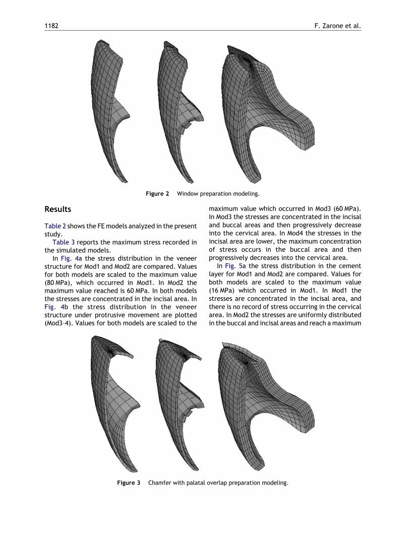
Figure 2 Window preparation modeling.
F. Zarone et al.1182
Results
Table 2 shows the FE models analyzed in the presentstudy.
Table 3 reports the maximum stress recorded inthe simulated models.
In Fig. 4a the stress distribution in the veneerstructure for Mod1 and Mod2 are compared. Valuesfor both models are scaled to the maximum value(80 MPa), which occurred in Mod1. In Mod2 themaximum value reached is 60 MPa. In both modelsthe stresses are concentrated in the incisal area. InFig. 4b the stress distribution in the veneerstructure under protrusive movement are plotted(Mod3–4). Values for both models are scaled to the
Figure 3 Chamfer with palatal o
maximum value which occurred in Mod3 (60 MPa).In Mod3 the stresses are concentrated in the incisaland buccal areas and then progressively decreaseinto the cervical area. In Mod4 the stresses in theincisal area are lower, the maximum concentrationof stress occurs in the buccal area and thenprogressively decreases into the cervical area.
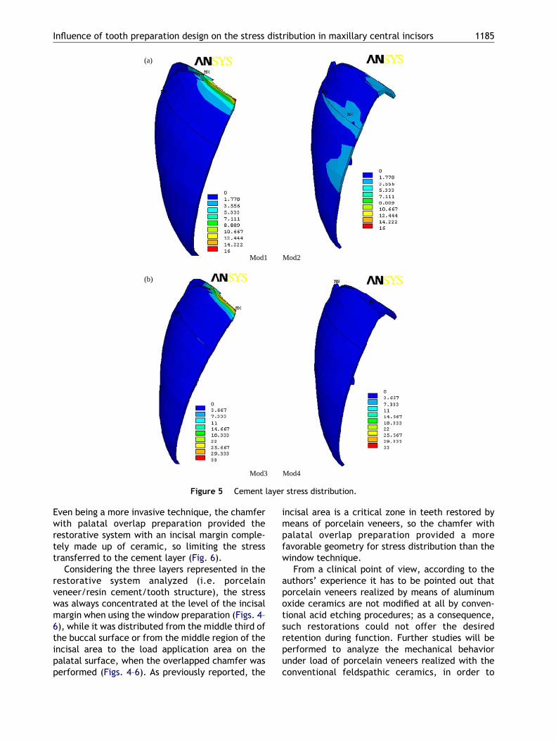
In Fig. 5a the stress distribution in the cementlayer for Mod1 and Mod2 are compared. Values forboth models are scaled to the maximum value(16 MPa) which occurred in Mod1. In Mod1 thestresses are concentrated in the incisal area, andthere is no record of stress occurring in the cervicalarea. In Mod2 the stresses are uniformly distributedin the buccal and incisal areas and reach a maximum
verlap preparation modeling.
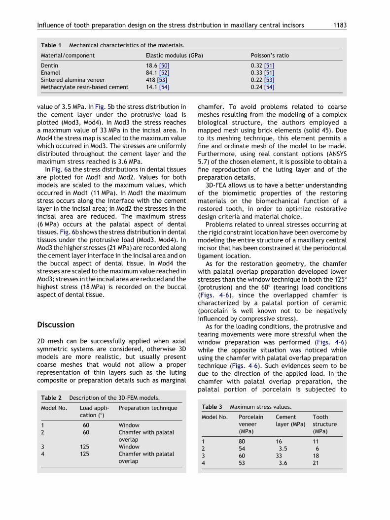
Table 1 Mechanical characteristics of the materials.
Material/component Elastic modulus (GPa) Poisson’s ratio
Dentin 18.6 [50] 0.32 [51]Enamel 84.1 [52] 0.33 [51]Sintered alumina veneer 418 [53] 0.22 [53]Methacrylate resin-based cement 14.1 [54] 0.24 [54]
Influence of tooth preparation design on the stress distribution in maxillary central incisors 1183
value of 3.5 MPa. In Fig. 5b the stress distribution inthe cement layer under the protrusive load isplotted (Mod3, Mod4). In Mod3 the stress reachesa maximum value of 33 MPa in the incisal area. InMod4 the stress map is scaled to the maximum valuewhich occurred in Mod3. The stresses are uniformlydistributed throughout the cement layer and themaximum stress reached is 3.6 MPa.
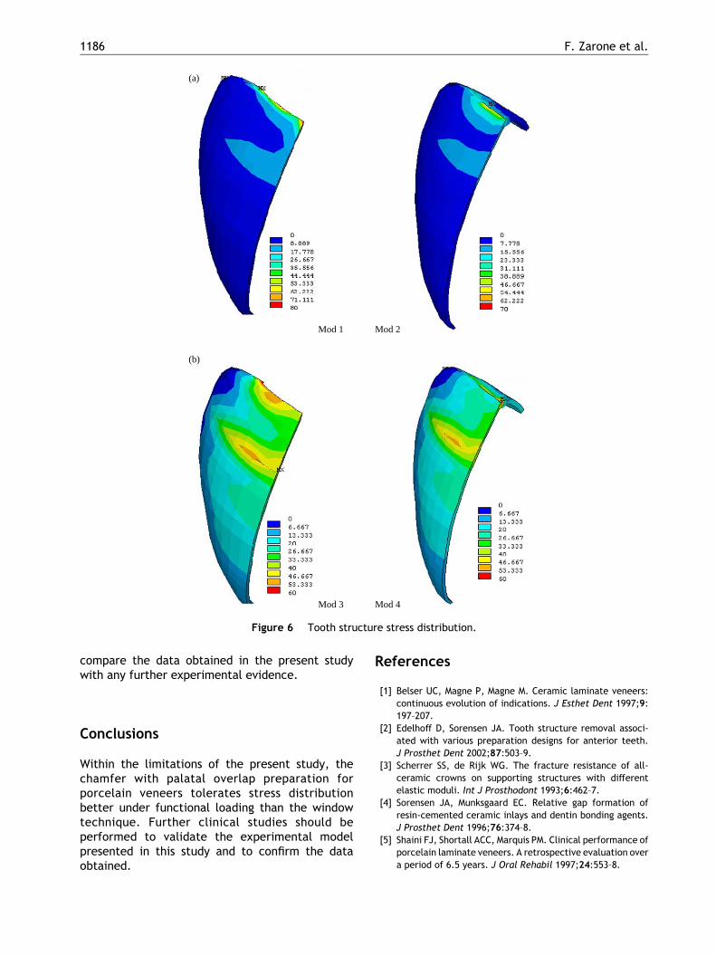
In Fig. 6a the stress distributions in dental tissuesare plotted for Mod1 and Mod2. Values for bothmodels are scaled to the maximum values, whichoccurred in Mod1 (11 MPa). In Mod1 the maximumstress occurs along the interface with the cementlayer in the incisal area; in Mod2 the stresses in theincisal area are reduced. The maximum stress(6 MPa) occurs at the palatal aspect of dentaltissues. Fig. 6b shows the stress distribution in dentaltissues under the protrusive load (Mod3, Mod4). InMod3 the higher stresses (21 MPa) are recorded alongthe cement layer interface in the incisal area and onthe buccal aspect of dental tissue. In Mod4 thestresses are scaled to the maximum value reached inMod3; stresses in the incisal area are reduced and thehighest stress (18 MPa) is recorded on the buccalaspect of dental tissue.
Discussion
2D mesh can be successfully applied when axialsymmetric systems are considered, otherwise 3Dmodels are more realistic, but usually presentcoarse meshes that would not allow a properrepresentation of thin layers such as the lutingcomposite or preparation details such as marginal
Table 2 Description of the 3D-FEM models.
Model No. Load appli-cation (8)
Preparation technique
1 60 Window2 60 Chamfer with palatal
overlap3 125 Window4 125 Chamfer with palatal
overlap
chamfer. To avoid problems related to coarsemeshes resulting from the modeling of a complexbiological structure, the authors employed amapped mesh using brick elements (solid 45). Dueto its meshing technique, this element permits afine and ordinate mesh of the model to be made.Furthermore, using real constant options (ANSYS5.7) of the chosen element, it is possible to obtain afine reproduction of the luting layer and of thepreparation details.
3D-FEA allows us to have a better understandingof the biomimetic properties of the restoringmaterials on the biomechanical function of arestored tooth, in order to optimize restorativedesign criteria and material choice.
Problems related to unreal stresses occurring atthe rigid constraint location have been overcome bymodeling the entire structure of a maxillary centralincisor that has been constrained at the periodontalligament location.
As for the restoration geometry, the chamferwith palatal overlap preparation developed lowerstresses than the window technique in both the 1258(protrusion) and the 608 (tearing) load conditions(Figs. 4–6), since the overlapped chamfer ischaracterized by a palatal portion of ceramic(porcelain is well known not to be negativelyinfluenced by compressive stress).
As for the loading conditions, the protrusive andtearing movements were more stressful when thewindow preparation was performed (Figs. 4–6)while the opposite situation was noticed whileusing the chamfer with palatal overlap preparationtechnique (Figs. 4–6). Such evidences seem to bedue to the direction of the applied load. In thechamfer with palatal overlap preparation, thepalatal portion of porcelain is subjected to
Table 3 Maximum stress values.
Model No. Porcelainveneer(MPa)
Cementlayer (MPa)
Toothstructure(MPa)
1 80 16 112 54 3.5 63 60 33 184 53 3.6 21
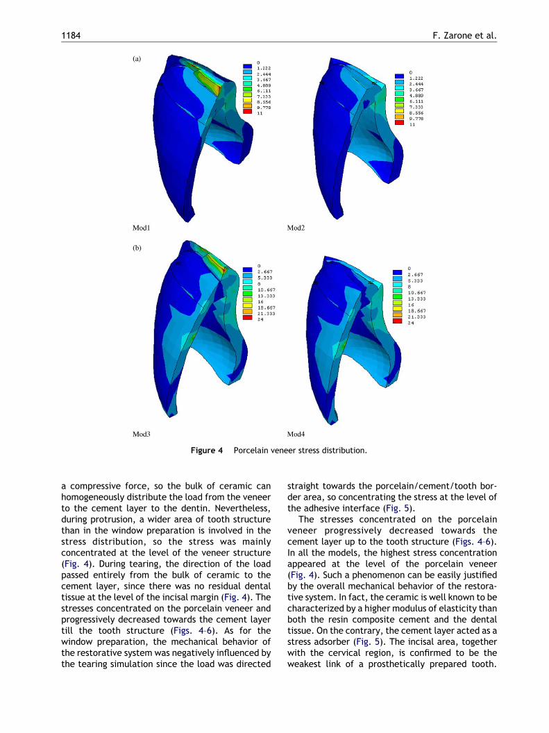
Figure 4 Porcelain veneer stress distribution.
F. Zarone et al.1184
a compressive force, so the bulk of ceramic canhomogeneously distribute the load from the veneerto the cement layer to the dentin. Nevertheless,during protrusion, a wider area of tooth structurethan in the window preparation is involved in thestress distribution, so the stress was mainlyconcentrated at the level of the veneer structure(Fig. 4). During tearing, the direction of the loadpassed entirely from the bulk of ceramic to thecement layer, since there was no residual dentaltissue at the level of the incisal margin (Fig. 4). Thestresses concentrated on the porcelain veneer andprogressively decreased towards the cement layertill the tooth structure (Figs. 4–6). As for thewindow preparation, the mechanical behavior ofthe restorative system was negatively influenced bythe tearing simulation since the load was directed
straight towards the porcelain/cement/tooth bor-der area, so concentrating the stress at the level ofthe adhesive interface (Fig. 5).
The stresses concentrated on the porcelainveneer progressively decreased towards thecement layer up to the tooth structure (Figs. 4–6).In all the models, the highest stress concentrationappeared at the level of the porcelain veneer(Fig. 4). Such a phenomenon can be easily justifiedby the overall mechanical behavior of the restora-tive system. In fact, the ceramic is well known to becharacterized by a higher modulus of elasticity thanboth the resin composite cement and the dentaltissue. On the contrary, the cement layer acted as astress adsorber (Fig. 5). The incisal area, togetherwith the cervical region, is confirmed to be theweakest link of a prosthetically prepared tooth.
Mod1 Mod2
Mod3 Mod4
(a)
(b)
Figure 5 Cement layer stress distribution.
Influence of tooth preparation design on the stress distribution in maxillary central incisors 1185
Even being a more invasive technique, the chamferwith palatal overlap preparation provided therestorative system with an incisal margin comple-tely made up of ceramic, so limiting the stresstransferred to the cement layer (Fig. 6).
Considering the three layers represented in therestorative system analyzed (i.e. porcelainveneer/resin cement/tooth structure), the stresswas always concentrated at the level of the incisalmargin when using the window preparation (Figs. 4–6), while it was distributed from the middle third ofthe buccal surface or from the middle region of theincisal area to the load application area on thepalatal surface, when the overlapped chamfer wasperformed (Figs. 4–6). As previously reported, the
incisal area is a critical zone in teeth restored bymeans of porcelain veneers, so the chamfer withpalatal overlap preparation provided a morefavorable geometry for stress distribution than thewindow technique.
From a clinical point of view, according to theauthors’ experience it has to be pointed out thatporcelain veneers realized by means of aluminumoxide ceramics are not modified at all by conven-tional acid etching procedures; as a consequence,such restorations could not offer the desiredretention during function. Further studies will beperformed to analyze the mechanical behaviorunder load of porcelain veneers realized with theconventional feldspathic ceramics, in order to
Mod 1 Mod 2
Mod 3 Mod 4
(a)
(b)
Figure 6 Tooth structure stress distribution.
F. Zarone et al.1186
compare the data obtained in the present studywith any further experimental evidence.
Conclusions
Within the limitations of the present study, thechamfer with palatal overlap preparation forporcelain veneers tolerates stress distributionbetter under functional loading than the windowtechnique. Further clinical studies should beperformed to validate the experimental modelpresented in this study and to confirm the dataobtained.
References
[1] Belser UC, Magne P, Magne M. Ceramic laminate veneers:continuous evolution of indications. J Esthet Dent 1997;9:197–207.
[2] Edelhoff D, Sorensen JA. Tooth structure removal associ-ated with various preparation designs for anterior teeth.J Prosthet Dent 2002;87:503–9.
[3] Scherrer SS, de Rijk WG. The fracture resistance of all-ceramic crowns on supporting structures with differentelastic moduli. Int J Prosthodont 1993;6:462–7.
[4] Sorensen JA, Munksgaard EC. Relative gap formation ofresin-cemented ceramic inlays and dentin bonding agents.J Prosthet Dent 1996;76:374–8.
[5] Shaini FJ, Shortall ACC, Marquis PM. Clinical performance ofporcelain laminate veneers. A retrospective evaluation overa period of 6.5 years. J Oral Rehabil 1997;24:553–8.
Influence of tooth preparation design on the stress distribution in maxillary central incisors 1187
[6] Friedman MJ. A 15-year review of porcelain veneer failure:a clinician’s observations. Compend Contin Educ Dent 1998;19:625–36.
[7] Strassler HE, Nathanson D. Clinical evaluation of etchedporcelain veneers over a period of 18 to 42 months. J EsthetDent 1989;1:21–8.
[8] Christensen GJ, Christensen RP. Clinical observations ofporcelain veneers: a three-year report. J Esthet Dent 1991;3:174–9.
[9] Dunne SM, Millar BJ. A longitudinal study of the clinicalperformance of porcelain veneers. Br Dent J 1993;175:317–21.
[10] Aristidis GA, Dimitra B. Five-year clinical performance ofporcelain laminate veneers. Quint Int 2002;33:185–9.
[11] Small BW. Porcelain laminate veneers: part I. Gen Dent1998;46:154–7.
[12] Small BW. Porcelain laminate veneers: part II. Gen Dent1998;46:244–9.
[13] Small BW. Porcelain laminate veneers: part III. Gen Dent1998;46:342–7.
[14] Peumans M, Van Meerbeek B, Lambrechts P, Vanherle G.Porcelain veneers: a review of the literature. J Dent 2000;28:163–77.
[15] Hui KK, Williams B, Davis EH, Holt RD. A comparativeassessment on the strengths of porcelain veneers for incisorteeth dependent on their design characteristics. Br Dent J1991;171:51–5.
[16] Sheets CG, Taniguchi T. Advantages and limitations in theuse of porcelain veneer restorations. J Prosthet Dent 1990;64:406–11.
[17] Christensen GJ. Veneering of teeth. State of the art. DentClin North Am 1985;29:373–91.
[18] Toh GC, Setcos JC, Weinstein AR. Indirect dental laminateveneers: an overview. J Dent 1987;15:117–24.
[19] Friedman M. Multiple potential of etched porcelainlaminate veneers. J Am Dent Assoc 1987;115(Spec Iss):83E–87.
[20] Troedson M, Derand T. Effect of margin design, cementpolymerization, and angle of loading on stress in porcelainveneers. J Prosthet Dent 1999;82:518–24.
[21] Wall JG, Reisbick MH, Johnston WM. Incisal-edge strengthof porcelain laminate veneers restoring mandibular inci-sors. Int J Prosthodont 1992;5:441–6.
[22] Castelnuovo J, Tjan AH, Phillips K, Nicholls JI, Kois JC.Fracture load and mode of failure of ceramic veneerswith different preparations. J Prosthet Dent 2000;83:171–80.
[23] Chiche GJ, Pinault A. Esthetics of anterior fixedprosthodontics. Chicago: Quintessence Publishing Co.;1994.
[24] Dumfahrt H, Schaffer H. Porcelain laminate veneers. Aretrospective evaluation after 1 to 10 years of service: partII. Clinical results. Int J Prosthodont 2000;13:9–18.
[25] Ferrari M, Patroni S, Balleri P. Measurement of enamelthickness in relation to reduction for etched laminateveneers. Int J Periodont Restor Dent 1992;12:407–13.
[26] Eick JD, Miller RG, Robinson SJ, Bowles CQ, Gutshall PL,Chappelow CC. Quantitative analysis of the dentin adhesiveinterface by Auger spectroscopy. J Dent Res 1996;75:1027–33.
[27] Highton R, Caputo AA, Matyas J. A photoelastic study ofstresses on porcelain laminate preparations. J ProsthetDent 1987;58:157–61.
[28] Meijering AC, Creugers NHJ, Roeters FJM, Mulder J. Survivalof three types of veneer restorations in a clinical trial: a2.5-year interim evaluation. J Dent 1998;26:563–8.
[29] Clyde JS, Gilmour A. Porcelain veneers: a preliminaryreview. Br Dent J 1988;164:9–14.
[30] Brunton PA, Wilson NHF. Preparations for porcelainlaminate veneers in general dental practice. Br Dent J1998;184:553–6.
[31] Magne P, Kwon KR, Belser UC, Hodges JS, Douglas WH.Crack propensity of porcelain laminate veneers: a simu-lated operatory evaluation. J Prosthet Dent 1999;81:327–34.
[32] Magne P, Versluis A, Douglas WH. Effect of luting compositeshrinkage and thermal loads on the stress distribution inporcelain laminate veneers. J Prosthet Dent 1999;81:335–44.
[33] Magne P, Versluis A, Douglas WH. Rationalization of incisorshape: experimental-numerical analysis. J Prosthet Dent1999;81:345–55.
[34] Seymour KG, Cherukara GP, Samarawickrama DY. Stresseswithin porcelain veneers and the composite lute usingdifferent preparation designs. J Prosthodont 2001;10:16–21.
[35] Weinberg LA. Tooth preparation for porcelain laminates. NYState Dent J 1989;55:25–8.
[36] Calamia JR. The etched porcelain veneer technique. NYState Dent J 1988;54:48–50.
[37] Hahn P, Gustav M, Hellwig E. An in vitro assessment of thestrength of porcelain veneers dependent on tooth prep-aration. J Oral Rehabil 2000;27:1024–9.
[38] Carlsson GE. Bite force and chewing efficiency. Front OralPhysiol 1974;1:265–92.
[39] Ausiello P, Apicella A, Davidson CL, Rengo S. 3D-finiteelement analysis of cusp movements in a human upperpremolar, restored with adhesive resin-based composites.J Biomech 2001;34:1269–77.
[40] Apicella A, Liguori A, Masi E, Nicolais L. Thick laminatecomposite modeling in total hip replacement. In: SheffieldFound MS, editor. Proceedings of the second internationalseminar on experimental techniques and design in compo-site materials.
[41] Dalstra M, Huiskes R, van Erning L. Development andvalidation of a three-dimensional finite element model ofthe pelvic bone. J Biomech Eng 1995;117:272–8.
[42] Apicella A, Masi E, Nicolais L, Zarone F, De Rosa N,Valletta G. A finite element model study of occlusalschemes in full arch implant restoration. J Mater SciMater Med 1998;1:191–6.
[43] Zarone F, Apicella A, Nicolais L, Aversa R, Sorrentino R.Mandibular flexure and stress build-up in mandibular full-arch fixed prostheses supported by osseointegratedimplants. Clin Oral Impl Res 2003;1:319–28.
[44] Magne P, Douglas WH. Design optimization and evolution ofbonded ceramics for the anterior dentition: a finite-element analysis. Quint Int 1999;30:661–72.
[45] Peters MCRB, Poort HW. Biomechanical stress analysis ofthe amalgam-tooth interface. J Dent Res 1982;62:358–62.
[46] Williams KR, Edmundsen JT. A finite element stressanalysis of an endodontically restored tooth. Eng Med13(4):167–73.
[47] Pao YC, Reinhardt KA, Krejci RF. Root stress with tapered-end post design in periodontally compromised teeth.J Prosthet Dent 1987;57:281–6.
[48] Wheeler RH. Dental anatomy, physiology and occlusion. InPhiladelphia, USA: WB Saunders; 1974. p. 151.
[49] Bello A, Jarvis RH. A review of esthetic alternatives for therestoration of anterior teeth. J Prosthet Dent 1997;78:437–40.
F. Zarone et al.1188
[50] Sano H, Ciucchi B, Matthews WG, Pashley DH. Tensileproperties of mineralized and demineralized human andbovine dentin. J Dent Res 1994;73:1205–11.
[51] Farah JW, Craig RG, Meroueh KA. Finite element analysis ofthree and four unit bridges. J Oral Rehabil 1989;16:603–11.
[52] Craig RG, Peyton FA, Johnson DW. Compressive propertiesof enamel, dental cements and gold. J Dent Res 1961;40:936–45.
[53] Jones DW, Jones PA, Wilson HJ. The modulus of elasticity ofdental ceramics. Dent Pract Dent Rec 1972;22:170–3.
[54] Willems G, Lambrechts P, Braem M, Celis JP, Vanherle G. Aclassification of dental composites according to theirmorphological and mechanical characteristics. Dent Mater1992;8:310–9.
[55] Darendeliler SY, Alacam T, Yaman Y. Analysis of stressdistribution in a maxillary central incisor subjected to variouspost and core applications. J Endodont 1998;24:107–11.
[56] Versluis A, Douglas WH, Cross M, Sakaguchi RL. Does anincremental filling technique reduce polymerization shrink-age stresses? J Dent Res 1996;3:871–8.


