Embed Size (px)
Citation preview
INITIAL SUBMITTAL OF THE WALKTHROUGH JPMS
FOR THE PERRY EXAMINATION - JANIFEB 2003
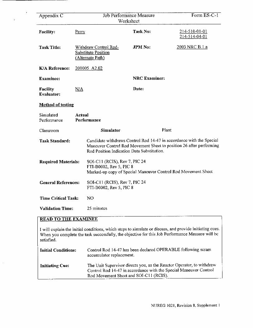
Appendix C Job Performance Measure Form ES-C-I Worksheet
Perry
Withdraw Control RodSubstitute Position (Alternate Path)
Task No:
JPM No:
214-510-01-01 214-514-04-01
2003 NRC B. L a
NRC Examiner:
Date:
Method of testing
Simulated Performance
Classroom
Task Standard:
Required Materials:
General References:
Time Critical Task:
Validation Time:
Actual Performance
Simulator Plant
Candidate withdraws Control Rod 14-47 in accordance with the Special Maneuver Control Rod Movement Sheet to position 26 after performing Rod Position Indication Data Substitution.
SOI-C 11 (RCIS), Rev 7, PIC 24 FTI-B0002, Rev 5, PIC 8 Marked-up copy of Special Maneuver Control Rod Movement Sheet
SOI-C 11 (RCIS), Rev 7, PIC 24 FTI-B0002, Rev 5, PIC 8
NO
25 minutes
READ TO THE EXAMINEE
I will explain the initial conditions, which steps to simulate or discuss, and provide initiating cues.
When you complete the task successfully, the objective for this Job Performance Measure will be satisfied.
Initial Conditions:
Initiating Cue:
Control Rod 14-47 has been declared OPERABLE following scram accumulator replacement.
The Unit Supervisor directs you, as the Reactor Operator, to withdraw Control Rod 14-47 in accordance with the Special Maneuver Control Rod Movement Sheet and SOI-C 11 (RC1S).
NUREG 1021, Revision 8, Supplement 1
Facility:
Task Title:
K/A Reference: 201005 A2.02
Examinee:
Facility Evaluator:
N/A
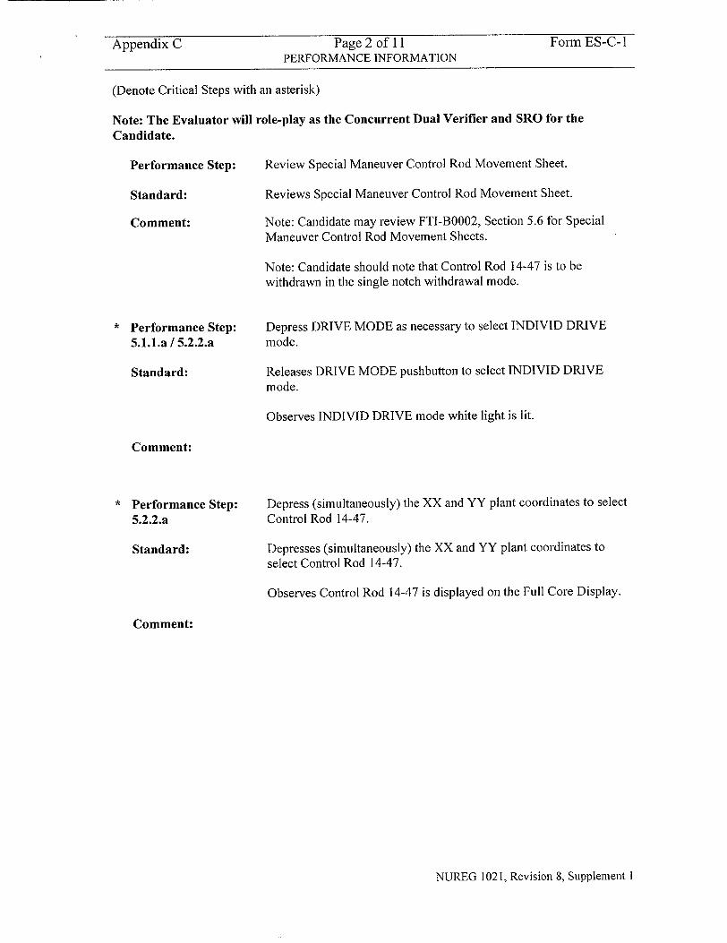
Appendix C Page 2 of 11 Form ES-C-1 PERFORMANCE INFORMATION
(Denote Critical Steps with an asterisk)
Note: The Evaluator will role-play as the Concurrent Dual Verifier and SRO for the
Candidate.
Performance Step: Review Special Maneuver Control Rod Movement Sheet.
Standard: Reviews Special Maneuver Control Rod Movement Sheet.
Comment: Note: Candidate may review FTI-B0002, Section 5.6 for Special
Maneuver Control Rod Movement Sheets.
Note: Candidate should note that Control Rod 14-47 is to be withdrawn in the single notch withdrawal mode.
" Performance Step: Depress DRIVE MODE as necessary to select INDIVID DRIVE
5.1.1.a / 5.2.2.a mode.
Standard: Releases DRIVE MODE pushbutton to select INDIVID DRIVE mode.
Observes INDIVID DRIVE mode white light is lit.
Comment:
" Performance Step: Depress (simultaneously) the XX and YY plant coordinates to select
5.2.2.a Control Rod 14-47.
Standard: Depresses (simultaneously) the XX and YY plant coordinates to
select Control Rod 14-47.
Observes Control Rod 14-47 is displayed on the Full Core Display.
Comment:
NUREG 1021, Revision 8, Supplement I
Appendix C Page 3 of 11I Form ES-C- I PERFORMANCE INFORMATION
Note: The next Step 5.2.2.b will be repeated six times until the Rod Position Indication malfunction occurs at Position 12.
* Performance Step: 5.2.2.b
Standard:
Comment:
Momentarily depress WITHDRAW pushbutton.
Momentarily depresses the WITHDRAW pushbutton.
Observes the following:
1. The IN white light comes on momentarily and then goes off
2. The OUT white light comes on and then goes off after approximately 2 seconds.
3. The SETTLE white light comes on for approximately 6 seconds and then goes off.
4. The Rod Display Module (RDM) indicates the new Control Rod position for Control Rod 14-47.
5. Expected changes occur in the Nuclear Instrumentation.
Note: Alarm Hl13-P680-5 (El0), ROD WITHDRAWAL BLOCK, will occur (expected) due to the 4 notch rod withdrawal limiter.
Note: Candidate will de-select Control Rod 14-47 to clear the rod withdrawal block due to the 4 notch rod withdrawal limiter. He will then re-select Control Rod 14-47 in order to continue Control Rod withdrawal.
Note: Candidate will suspend Control Rod 14-47 rod withdrawal at position 12 due to a Data Fault on RCIS Channel 1.
NUREG 1021, Revision 8, Supplement I
Appendix C Page 4 of 11 Form ES-C-1
PERFORMANCE INFORMATION
Note: The following Step documents the Rod Position Indication malfunction at position 12.
* Performance Step: Recognize and diagnose cause of unexpected Alarm H13-P680-5
5.4.2 (El0), ROD WITHDRAWAL BLOCK
Standard: Observes Alarm H 13-P680-5 (E 10), ROD WITHDRAWAL BLOCK occurs (unexpected).
Observes WITHDRAW BLOCK red status light is blinking on and off.
Observes WITHDRAW INHIBIT red status light is blinking on and off.
Observes CHANNEL DISAGREE amber status light is lit.
Observes DATA FAULT status light is backlit red and blinking on and off.
Comment:
Performance Step:
7.1.1
Standard:
Comment:
1. Depresses DATA FAULT pushbutton.
2. Observes Control Rod 14-47 has a Data Fault ('blank' position indication) on RCIS Channel 1.
3. Releases DATA FAULT pushbutton.
Determines a DATA FAULT exists and enters Rod Position Indication Data Substitution to affected RCIS Channel 1.
Note: The following steps (7.1.1 - 7.1.6) are the Alternate Path for this JPM.
SOI-C11 (RCIS), Section 5.4.2.c directs the Candidate to perform Section 7.1, Rod Position Indication Data Substitution.
Note: Candidate may reference ONI-C I1-1, Inability to Move Control Rods. However, the ONI will not provide any specific direction other than to reference SOI-C I1 (RCIS).
Selects Control Rod 14-47 for which the data substitution is to be made.
Depresses (simultaneously) the XX and YY plant coordinates to
select Control Rod 14-47.
Observes Control Rod 14-47 is displayed on the Full Core Display.
Note: Control Rod 14-47 may already be selected from previous Step 5.2.2.a.
NUREG 1021, Revision 8, Supplement I
Appendix C Page 5 of 11 Form ES-C-i PERFORMANCE INFORMATION
Performance Step: 7.1.2
Standard:
Select the good data channel (RCIS Channel 2).
Releases DATA MODE pushbutton to allow selection of either channel of RACS as a single data input to RIS.
Operates DATA SOURCE pushbutton to select CHAN 2 DATA.
Observes CHAN 2 DATA amber status light is on.
Comment:
Performance Step: 7.1.3
Standard:
Verify RAW DATA is not selected.
Releases RAW DATA pushbutton.
Observes RAW DATA amber status light is off.
Comment:
Performance Step: 7.1.4
Standard:
Comment:
Depress ENT SUBST.
Depresses ENT SUBST pushbutton.
Observes the SUBST POSITION status light is backlit amber.
Observes Alarm H13-P680-5 (E10), ROD WITHDRAWAL BLOCK, clears (expected).
The CHANNEL DISAGREE light will go off if RAW DATA is not selected.
NUREG 1021, Revision 8, Supplement I
Appendix C Page 6 of 11 Form ES-C-I PERFORMANCE INFORMATION
Performance Step: 7.1.5
Standard:
Comment:
Performance Step: 7.1.6
Standard:
Comment:
Select the data channel with bad data.
Operates DATA SOURCE pushbutton to select CHAN I DATA.
Observes CHAN I DATA amber status light is on and CHAN 2 DATA amber status light is off.
Observes the DATA FAULT red status light is on.
Observes the previous position indication of 'FF' is replaced by the correct position indication (12).
Confirms the Process Computer (ICS) indicates the correct Control Rod position has been entered.
Note: If the Candidate depresses the SUBST POSITION pushbutton, then the red status LED for affected Control Rod 14-47 will be lit on the Full Core Display to confirm the substitute position is in effect.
Ensures the following:
a. The position substitution is recorded in the Plant Narrative Log.
b. The position substitution is recorded on the applicable LCO Tracking Sheet record of OAI- 1701.
Records the position substitution for Control Rod 14-47 at position 12 for RCIS Channel I in the Plant Narrative Log.
Informs the SRO that the position substitution is to be recorded on the applicable LCO Tracking Sheet of OAI-1701.
Cue: SRO has completed the LCO Tracking Sheet.
Note: Candidate returns to SOI-C I I (RCIS), Section 5.2 to complete the remainder of the Control Rod insertion.
NUREG 1021, Revision 8, Supplement I
Appendix C Page 7 of 11 Form ES-C-I PERFORMANCE INFORMATION
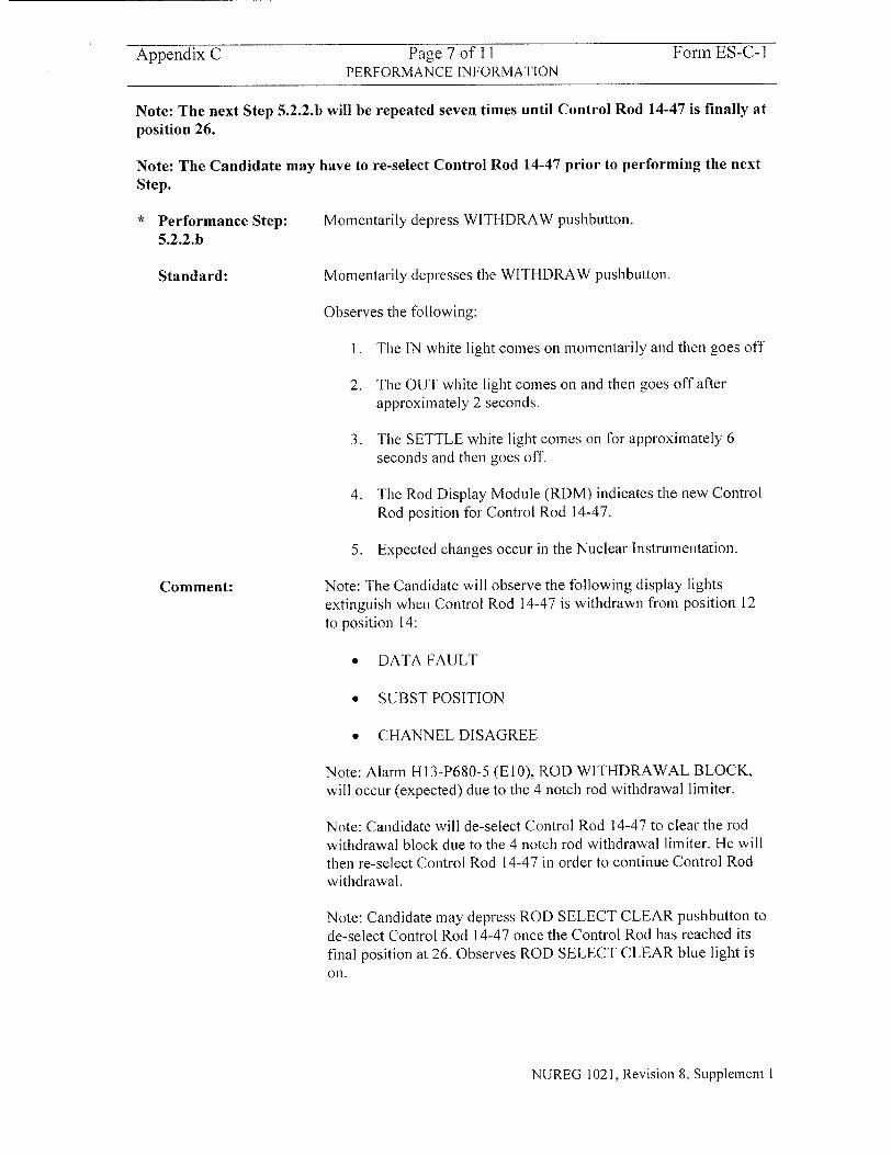
Note: The next Step 5.2.2.b will be repeated seven times until Control Rod 14-47 is finally at position 26.
Note: The Candidate may have to re-select Control Rod 14-47 prior to performing the next Step.
* Performance Step: Momentarily depress WITHDRAW pushbutton.
5.2.2.b
Standard: Momentarily depresses the WITHDRAW pushbutton.
Observes the following:
I. The IN white light comes on momentarily and then goes off
2. The OUT white light comes on and then goes off after approximately 2 seconds.
3. The SETTLE white light comes on for approximately 6 seconds and then goes off.
4. The Rod Display Module (RDM) indicates the new Control Rod position for Control Rod 14-47.
5. Expected changes occur in the Nuclear Instrumentation.
Comment: Note: The Candidate will observe the following display lights extinguish when Control Rod 14-47 is withdrawn from position 12 to position 14:
"* DATA FAULT
"* SUBST POSITION
"* CHANNEL DISAGREE
Note: Alarm HI13-P680-5 (El0), ROD WITHDRAWAL BLOCK, will occur (expected) due to the 4 notch rod withdrawal limiter.
Note: Candidate will de-select Control Rod 14-47 to clear the rod withdrawal block due to the 4 notch rod withdrawal limiter. He will then re-select Control Rod 14-47 in order to continue Control Rod withdrawal.
Note: Candidate may depress ROD SELECT CLEAR pushbutton to de-select Control Rod 14-47 once the Control Rod has reached its final position at 26. Observes ROD SELECT CLEAR blue light is on.
NUREG 1021, Revision 8, Supplement I
Appendix C Page 8 of 11 Form ES-C-I PERFORMANCE INFORMATION
Performance Step: 5.6.4
Standard:
Comment:
Document completion of Special Maneuver Control Rod Movement Sheet.
The 'S.O. INITIAL' block is initialed by the operator when:
a. The Control Rod is correctly placed at the 'TO' position.
b. Expected nuclear instrument response was observed.
The 'I.V. INITIAL' block is initialed by a qualified individual to document independent verification.
Note: Candidate may either give the completed Special Maneuver Control Rod Movement Sheet to the SRO or call Reactor Engineering to come and pick it up.
Terminating Cue:
When Control Rod 14-47 is at position 26, the evaluation for this JPM is complete.
NUREG 1021, Revision 8, Supplement I

Appendix C Page 9 of 11 Form ES-C-I VERIFICATION OF COMPLETION
Job Performance Measure No.
Examinee's Name:
Examiner's Name:
Date Performed:
Facility Evaluator:
Number of Attempts:
Time to complete:
Question Documentation:
Question:
Response:
Result:
2003 NRC B.].a
N/A
SAT OR UNSAT
Examiner's Signature and Date:
NUREG 1021, Revision 8, Supplement I
Appendix C Page 10 of 11 Form ES-C-I JPM CUE SHEET
INITIAL CONDITIONS:
INITIATING CUE:
Control Rod 14-47 has been declared OPERABLE following scram accumulator replacement.
The UniIt Supervisor directs you, as the Reactor Operator, to withdraw Control Rod 14-47 in accordance with the Special Maneuver Control Rod Movement Sheet and SOI-C I I (RCIS).
NUREG 1021, Revision 8, Supplement 1
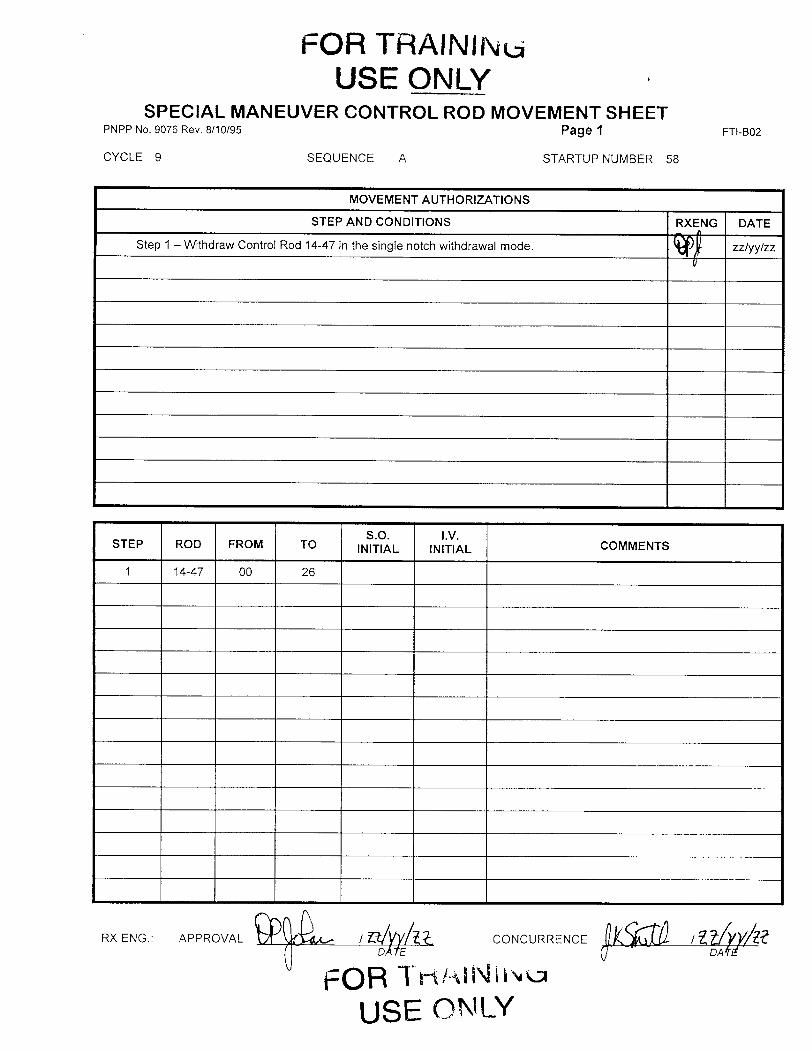
FOR TRAININu USE ONLY
SPECIAL MANEUVER CONTROL ROD MOVEMENT SHEET PNPP No. 9076 Rev. 8/10/95 Page 1
CYCLE 9 SEQUENCE A STARTUP NUMBER 58
I-.'
RX ENG.: APPROVAL L / /vI:
uJ DA OE
USE ON'LY
CONCURRENCE ( 7... . pD A t
FTI-B02
MOVEMENT AUTHORIZATIONS
STEP AND CONDITIONS RXENG DATE
Step I - Withdraw Control Rod 14-47 in the single notch withdrawal mode. zz/yy/zz
I 4-
I -�
I -4-
i 4
I -I-
____ -I-
I I.VI
I -3-
1 -4-
S.O. I.V. C M E T STEP ROD FROM TO INITIAL INITIAL CMET
1 14-47 00 26
FTI-B0002 Page: 14 Rev.: 5 / C-7
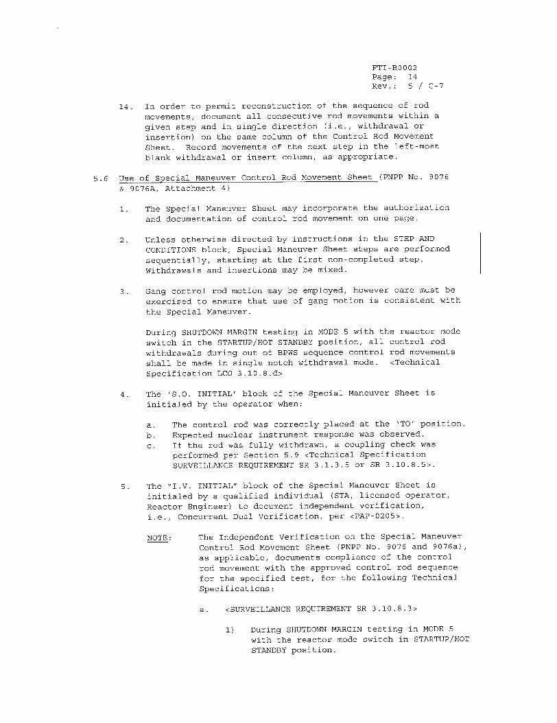
14. In order to permit reconstruction of the sequence of rod
movements, document all consecutive rod movements within a given step and in single direction (i.e., withdrawal or
insertion) on the same column of the Control Rod Movement
Sheet. Record movements of the next step in the left-most
blank withdrawal or insert column, as appropriate.
5.6 Use of Special Maneuver Control Rod Movement Sheet (PNPP No. 9076
& 9076A, Attachment 4)
1. The Special Maneuver Sheet may incorporate the authorization and documentation of control rod movement on one page.
2. Unless otherwise directed by instructions in the STEP AND
CONDITIONS block, Special Maneuver Sheet steps are performed sequentially, starting at the first non-completed step. Withdrawals and insertions may be mixed.
3. Gang control rod motion may be employed, however care must be
exercised to ensure that use of gang motion is consistent with
the Special Maneuver.
During SHUTDOWN MARGIN testing in MODE 5 with the reactor mode
switch in the STARTUP/HOT STANDBY position, all control rod
withdrawals during out of BPWS sequence control rod movements shall be made in single notch withdrawal mode. <Technical
Specification LCO 3.10.8.d>
4. The 'S.O. INITIAL' block of the Special Maneuver Sheet is
initialed by the operator when:
a. The control rod was correctly placed at the 'TO' position.
b. Expected nuclear instrument response was observed. c. If the rod was fully withdrawn, a coupling check was
performed per Section 5.9 <Technical Specification SURVEILLANCE REQUIREMENT SR 3.1.3.5 or SR 3.10.8.5>.
5. The "I.V. INITIAL" block of the Special Maneuver Sheet is initialed by a qualified individual (STA, licensed operator,
Reactor Engineer) to document independent verification,
i.e., Concurrent Dual Verification, per <PAP-0205>.
NOTE: The Independent Verification on the Special Maneuver Control Rod Movement Sheet (PNPP No. 9076 and 9076a), as applicable, documents compliance of the control
rod movement with the approved control rod sequence for the specified test, for the following Technical Specifications:
a. <SURVEILLANCE REQUIREMENT SR 3.10.8.3>
1) During SHUTDOWN MARGIN testing in MODE 5 with the reactor mode switch in STARTUP/HOT STANDBY position.
FTI-B0002 Page: 15 Rev.: 5 / C-5
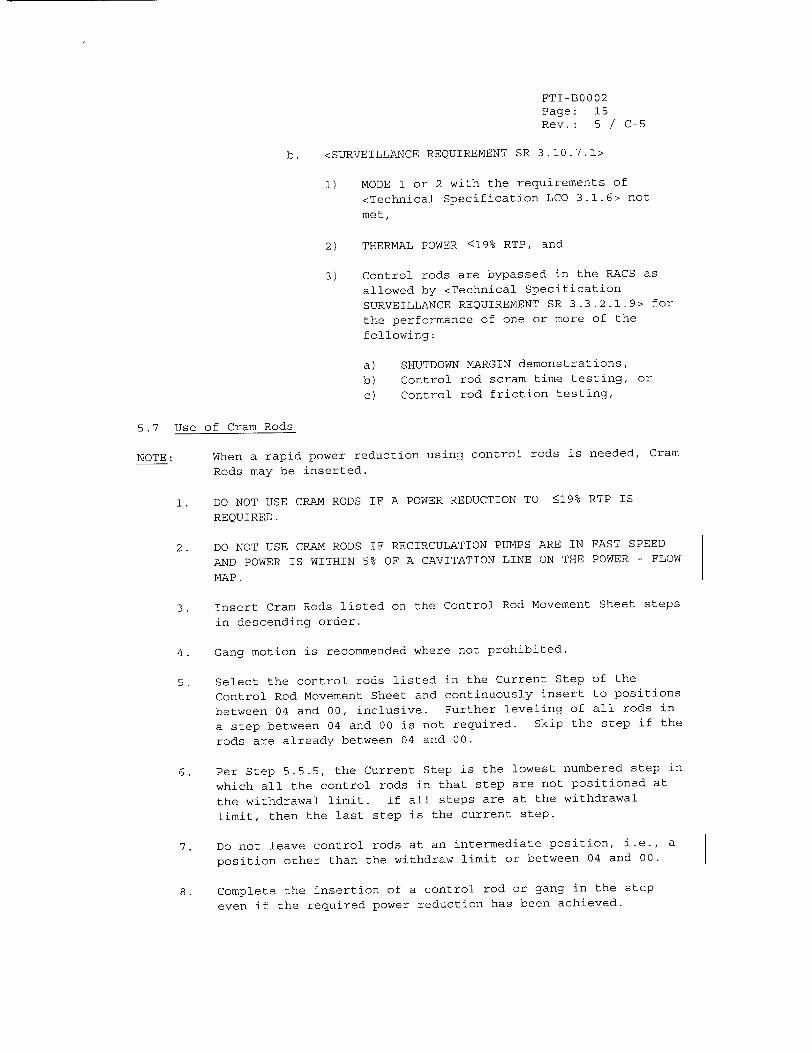
b. <SURVEILLANCE REQUIREMENT SR 3.10.7.1>
1) MODE 1 or 2 with the requirements of
<Technical Specification LCO 3.1.6> not
met,
2) THERMAL POWER <19% RTP, and
3) Control rods are bypassed in the RACS as
allowed by <Technical Specification
SURVEILLANCE REQUIREMENT SR 3.3.2.1.9> for
the performance of one or more of the
following:
a) SHUTDOWN MARGIN demonstrations,
b) Control rod scram time testing, or
c) Control rod friction testing,
5.7 Use of Cram Rods
NOTE: When a rapid power reduction using control rods is needed, Cram
Rods may be inserted.
1. DO NOT USE CRAM RODS IF A POWER REDUCTION TO •19% RTP IS
REQUIRED.
2. DO NOT USE CRAM RODS IF RECIRCULATION PUMPS ARE IN FAST SPEED
AND POWER IS WITHIN 5% OF A CAVITATION LINE ON THE POWER - FLOW
MAP.
3. Insert Cram Rods listed on the Control Rod Movement Sheet steps
in descending order.
4. Gang motion is recommended where not prohibited.
5. Select the control rods listed in the Current Step of the
Control Rod Movement Sheet and continuously insert to positions
between 04 and 00, inclusive. Further leveling of all rods in
a step between 04 and 00 is not required. Skip the step if the
rods are already between 04 and 00.
6. Per Step 5.5.5, the Current Step is the lowest numbered step in
which all the control rods in that step are not positioned at
the withdrawal limit. If all steps are at the withdrawal
limit, then the last step is the current step.
7. Do not leave control rods at an intermediate position, i.e., a
position other than the withdraw limit or between 04 and 00.
8. Complete the insertion of a control rod or gang in the step
even if the required power reduction has been achieved.
SOI-Cll (RCIS) Page: 4 Rev.: 7
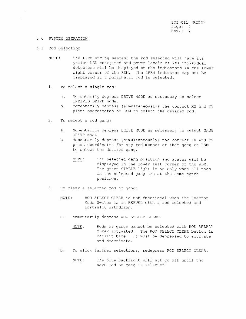
5.0 SYSTEM OPERATION
5.1 Rod Selection
NOTE: The LPRM string nearest the rod selected will have its yellow LED energized and power levels of its individual detectors will be displayed on the indicators in the lower right corner of the RDM. The LPRM indicator may not be displayed if a peripheral rod is selected.
1. To select a single rod:
a. Momentarily depress DRIVE MODE as necessary to select INDIVID DRIVE mode.
b. Momentarily depress (simultaneously) the correct XX and YY plant coordinates on RSM to select the desired rod.
2. To select a rod gang:
a. Momentarily depress DRIVE MODE as necessary to select GANG DRIVE mode.
b. Momentarily depress (simultaneously) the correct XX and YY plant coordinates for any rod member of that gang on RSM to select the desired gang.
NOTE: The selected gang position and status will be displayed in the lower left corner of the RDM. The green STABLE light is on only when all rods in the selected gang are at the same notch position.
3. To clear a selected rod or gang:
NOTE: ROD SELECT CLEAR is not functional when the Reactor Mode Switch is in REFUEL with a rod selected and partially withdrawn.
a. Momentarily depress ROD SELECT CLEAR.
NOTE: Rods or gangs cannot be selected with ROD SELECT CLEAR activated. The ROD SELECT CLEAR button is backlit blue. It must be depressed to activate and deactivate.
b. To allow further selections, redepress ROD SELECT CLEAR.
NOTE: The blue backlight will not go off until the next rod or gang is selected.
SOI-COi (RCIS) Page: 5 Rev.: 7 / C-7
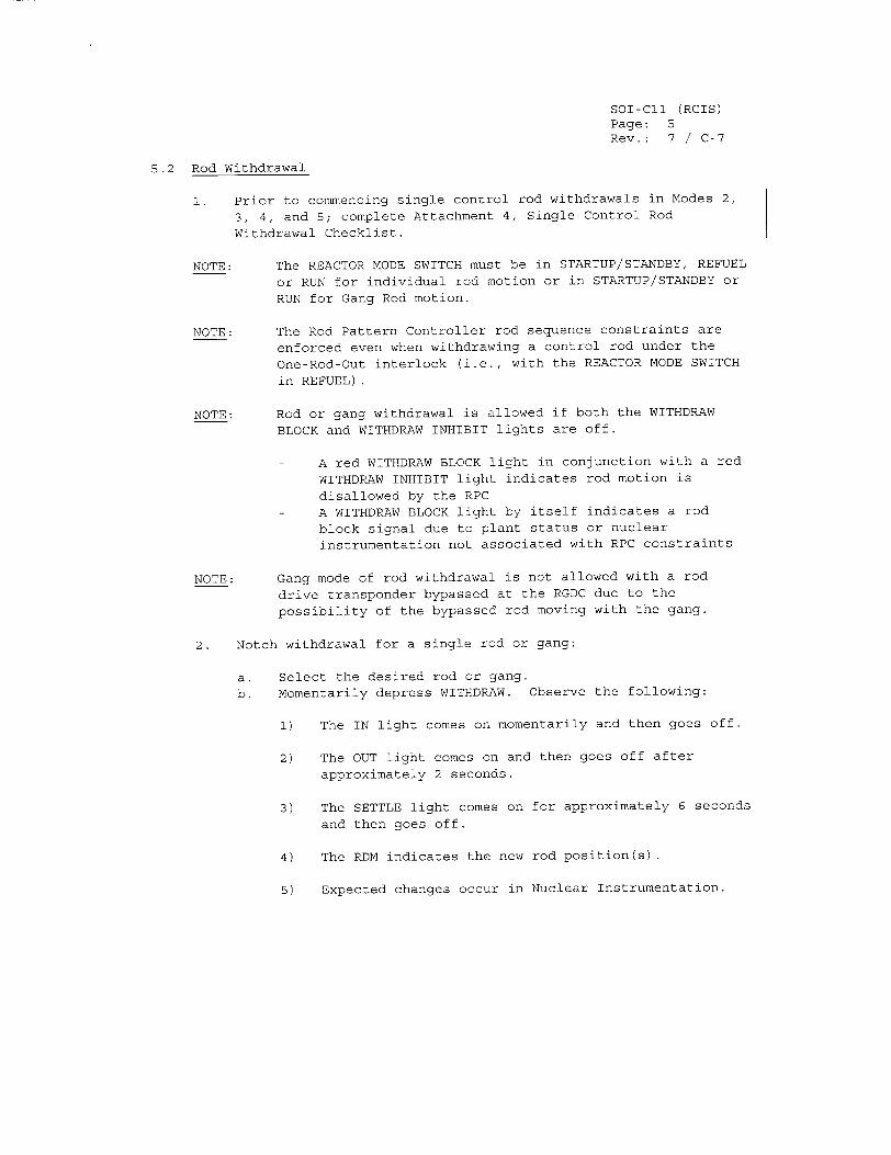
5.2 Rod Withdrawal
1. Prior to commencing single control rod withdrawals in Modes 2,
3, 4, and 5; complete Attachment 4, Single Control Rod
Withdrawal Checklist.
NOTE: The REACTOR MODE SWITCH must be in STARTUP/STANDBY, REFUEL
or RUN for individual rod motion or in STARTUP/STANDBY or
RUN for Gang Rod motion.
NOTE: The Rod Pattern Controller rod sequence constraints are
enforced even when withdrawing a control rod under the
One-Rod-Out interlock (i.e., with the REACTOR MODE SWITCH
in REFUEL).
NOTE: Rod or gang withdrawal is allowed if both the WITHDRAW
BLOCK and WITHDRAW INHIBIT lights are off.
A red WITHDRAW BLOCK light in conjunction with a red
WITHDRAW INHIBIT light indicates rod motion is
disallowed by the RPC
- A WITHDRAW BLOCK light by itself indicates a rod
block signal due to plant status or nuclear
instrumentation not associated with RPC constraints
NOTE: Gang mode of rod withdrawal is not allowed with a rod
drive transponder bypassed at the RGDC due to the
possibility of the bypassed rod moving with the gang.
2. Notch withdrawal for a single rod or gang:
a. Select the desired rod or gang.
b. Momentarily depress WITHDRAW. Observe the following:
1) The IN light comes on momentarily and then goes off.
2) The OUT light comes on and then goes off after
approximately 2 seconds.
3) The SETTLE light comes on for approximately 6 seconds
and then goes off.
4) The RDM indicates the new rod position(s).
5) Expected changes occur in Nuclear Instrumentation.
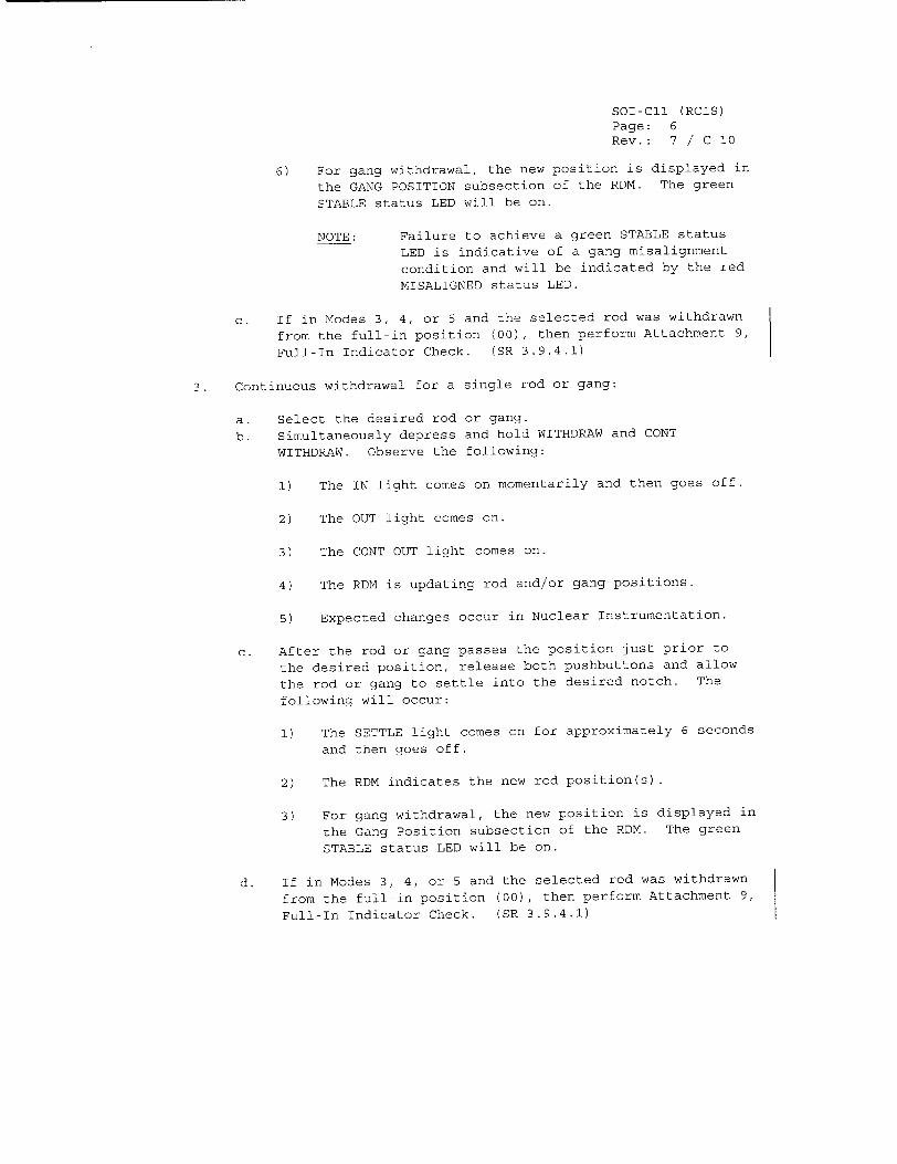
SOI-COI (RCIS) Page: 6 Rev.: 7 / C-10
6) For gang withdrawal, the new position is displayed in
the GANG POSITION subsection of the RDM. The green
STABLE status LED will be on.
NOTE: Failure to achieve a green STABLE status
LED is indicative of a gang misalignment
condition and will be indicated by the red
MISALIGNED status LED.
c. If in Modes 3, 4, or 5 and the selected rod was withdrawn
from the full-in position (00), then perform Attachment 9,
Full-In Indicator Check. (SR 3.9.4.1)
3. Continuous withdrawal for a single rod or gang:
a. Select the desired rod or gang.
b. Simultaneously depress and hold WITHDRAW and CONT
WITHDRAW. Observe the following:
1) The IN light comes on momentarily and then goes off.
2) The OUT light comes on.
3) The CONT OUT light comes on.
4) The RDM is updating rod and/or gang positions.
5) Expected changes occur in Nuclear Instrumentation.
c. After the rod or gang passes the position just prior to
the desired position, release both pushbuttons and allow
the rod or gang to settle into the desired notch. The
following will occur:
1) The SETTLE light comes on for approximately 6 seconds
and then goes off.
2) The RDM indicates the new rod position(s).
3) For gang withdrawal, the new position is displayed in
the Gang Position subsection of the RDM. The green
STABLE status LED will be on.
d. If in Modes 3, 4, or 5 and the selected rod was withdrawn
from the full-in position (00), then perform Attachment 9,
Full-In Indicator Check. (SR 3.9.4.1)
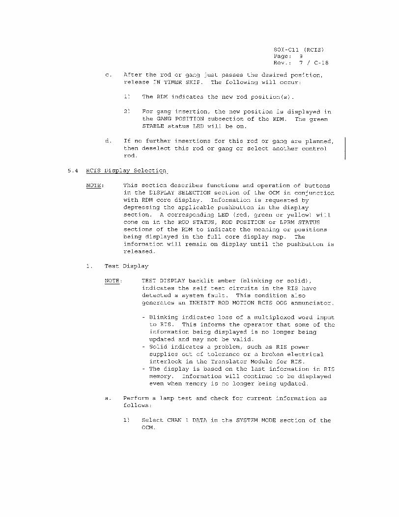
SOI-ClI (RCIS) Page: 9 Rev.: 7 / C-18
c. After the rod or gang just passes the desired position, release IN TIMER SKIP. The following will occur:
1) The RDM indicates the new rod position(s).
2) For gang insertion, the new position is displayed in the GANG POSITION subsection of the RDM. The green STABLE status LED will be on.
d. If no further insertions for this rod or gang are planned, then deselect this rod or gang or select another control rod.
5.4 RCIS Display Selection
NOTE: This section describes functions and operation of buttons in the DISPLAY SELECTION section of the OCM in conjunction with RDM core display. Information is requested by depressing the applicable pushbutton in the display section. A corresponding LED (red, green or yellow) will come on in the ROD STATUS, ROD POSITION or LPRM STATUS sections of the RDM to indicate the meaning or positions being displayed in the full core display map. The information will remain on display until the pushbutton is released.
1. Test Display
NOTE: TEST DISPLAY backlit amber (blinking or solid), indicates the self test circuits in the RIS have detected a system fault. This condition also generates an INHIBIT ROD MOTION RCIS OOS annunciator.
- Blinking indicates loss of a multiplexed word input to RIS. This informs the operator that some of the information being displayed is no longer being updated and may not be valid.
- Solid indicates a problem, such as RIS power supplies out of tolerance or a broken electrical interlock in the Translator Module for RIS.
- The display is based on the last information in RIS memory. Information will continue to be displayed even when memory is no longer being updated.
a. Perform a lamp test and check for current information as follows:
1) Select CHAN 1 DATA in the SYSTEM MODE section of the OCM.
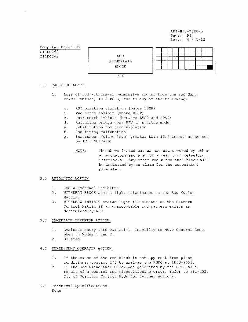
ARI-H13-P680-5 Page: 93 Rev.: 4 / C-13
Computer Point ID C11NC062 C11NC063 ROD
WITHDRAWAL
BLOCK
El0
1.0 CAUSE OF ALARM
1. Loss of rod withdrawal permissive signal from the rod Gang Drive Cabinet, lHI3-P653, due to any of the following:
a. b. c. d. e. f.
g.
RPC position violation (below LPSP) Two notch inhibit (above HPSP) Four notch inhibit (between LPSP and HPSP) Refueling bridge over RPV in startup mode Substitution position violation Rod timing malfunction Instrument Volume level greater than 16.6 inches as sensed by ICIl-N017A(B)
NOTE: The above listed causes are not covered by other annunciators and are not a result of refueling interlocks. Any other rod withdrawal block will be indicated by an alarm for the associated parameter.
2.0 AUTOMATIC ACTION
1. Rod withdrawal inhibited. 2. WITHDRAW BLOCK status light illuminates on the Rod Motion
Matrix. 3. WITHDRAW INHIBIT status light illuminates on the Pattern
Control Matrix if an unacceptable rod pattern exists as determined by RPC.
3.0 IMMEDIATE OPERATOR ACTION
1. Evaluate entry into ONI-CII-1, Inability to Move Control Rods, when in Modes 1 and 2.
2. Deleted
4.0 SUBSEQUENT OPERATOR ACTION
1. If the cause of the rod block is not apparent from plant
conditions, contact I&C to analyze the RGDC at IH13-P653. 2. If the Rod Withdrawal Block was generated by the RPCS as a
result of a control rod mispositioning error, refer to FTI-B02, Out of Position Control Rods for further actions.
4.1 Technical SpecificationsNone
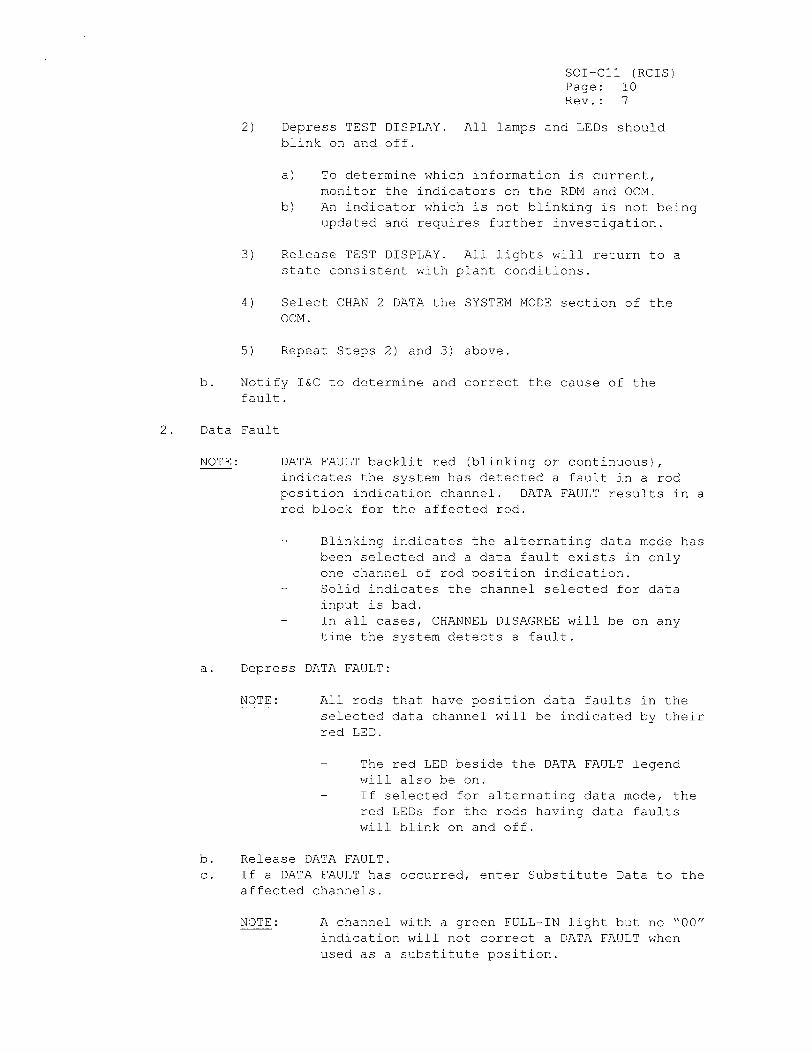
SOl-Cll (RCIS) Page: 10 Rev.: 7
2) Depress TEST DISPLAY. All lamps and LEDs should blink on and off.
a) To determine which information is current, monitor the indicators on the RDM and OCM.
b) An indicator which is not blinking is not being updated and requires further investigation.
3) Release TEST DISPLAY. All lights will return to a state consistent with plant conditions.
4) Select CHAN 2 DATA the SYSTEM MODE section of the 0CM.
5) Repeat Steps 2) and 3) above.
b. Notify I&C to determine and correct the cause of the fault.
2. Data Fault
NOTE: DATA FAULT backlit red (blinking or continuous), indicates the system has detected a fault in a rod position indication channel. DATA FAULT results in a rod block for the affected rod.
- Blinking indicates the alternating data mode has been selected and a data fault exists in only one channel of rod position indication.
- Solid indicates the channel selected for data input is bad.
- In all cases, CHANNEL DISAGREE will be on any time the system detects a fault.
a. Depress DATA FAULT:
NOTE: All rods that have position data faults in the selected data channel will be indicated by their red LED.
The red LED beside the DATA FAULT legend
will also be on. - If selected for alternating data mode, the
red LEDs for the rods having data faults will blink on and off.
b. Release DATA FAULT. c. If a DATA FAULT has occurred, enter Substitute Data to the
affected channels.
NOTE: A channel with a green FULL-IN light but no "00" indication will not correct a DATA FAULT when used as a substitute position.
SOI-CII (RCIS) Page: 16
Rev.: 7
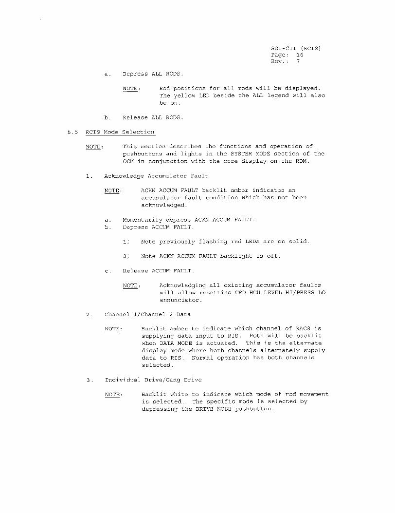
a. Depress ALL RODS.
NOTE: Rod positions for all rods will be displayed.
The yellow LED beside the ALL legend will also
be on.
b. Release ALL RODS.
5.5 RCIS Mode Selection
NOTE: This section describes the functions and operation of
pushbuttons and lights in the SYSTEM MODE section of the
OCM in conjunction with the core display on the RDM.
1. Acknowledge Accumulator Fault
NOTE: ACKN ACCUM FAULT backlit amber indicates an accumulator fault condition which has not been
acknowledged.
a. Momentarily depress ACKN ACCUM FAULT. b. Depress ACCUM FAULT.
1) Note previously flashing red LEDs are on solid.
2) Note ACKN ACCUM FAULT backlight is off.
c. Release ACCUM FAULT.
NOTE: Acknowledging all existing accumulator faults will allow resetting CRD HCU LEVEL HI/PRESS LO
annunciator.
2. Channel 1/Channel 2 Data
NOTE: Backlit amber to indicate which channel of RACS is
supplying data input to RIS. Both will be backlit
when DATA MODE is actuated. This is the alternate
display mode where both channels alternately supply
data to RIS. Normal operation has both channels
selected.
3. Individual Drive/Gang Drive
NOTE: Backlit white to indicate which mode of rod movement
is selected. The specific mode is selected by
depressing the DRIVE MODE pushbutton.
SOI-CIl (RCIS) Page: 17 Rev.: 7 / C-9
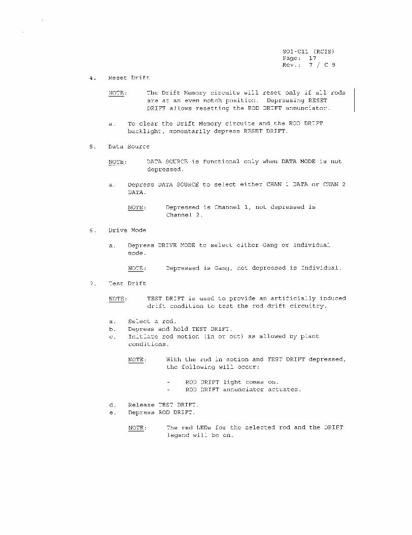
4. Reset Drift
NOTE: The Drift Memory circuits will reset only if all rods
are at an even notch position. Depressing RESET
DRIFT allows resetting the ROD DRIFT annunciator.
a. To clear the Drift Memory circuits and the ROD DRIFT
backlight, momentarily depress RESET DRIFT.
5. Data Source
NOTE: DATA SOURCE is functional only when DATA MODE is not
depressed.
a. Depress DATA SOURCE to select either CHAN 1 DATA or CHAN 2
DATA.
NOTE: Depressed is Channel 1, not depressed is
Channel 2.
6. Drive Mode
a. Depress DRIVE MODE to select either Gang or Individual
mode.
NOTE: Depressed is Gang, not depressed is Individual.
7. Test Drift
NOTE: TEST DRIFT is used to provide an artificially induced
drift condition to test the rod drift circuitry.
a. Select a rod.
b. Depress and hold TEST DRIFT.
c. Initiate rod motion (in or out) as allowed by plant
conditions.
NOTE: With the rod in motion and TEST DRIFT depressed, the following will occur:
ROD DRIFT light comes on. ROD DRIFT annunciator actuates.
d. Release TEST DRIFT.
e. Depress ROD DRIFT.
NOTE: The red LEDs for the selected rod and the DRIFT legend will be on.
SOI-CII (RCIS) Page: 18
Rev.: 7
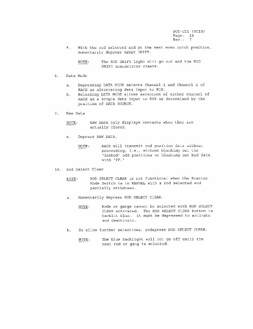
f. With the rod selected and at the next even notch position,
momentarily depress RESET DRIFT.
NOTE: The ROD DRIFT light will go out and the ROD
DRIFT annunciator clears.
8. Data Mode
a. Depressing DATA MODE selects Channel 1 and Channel 2 of
RACS as alternating data input to RIS.
b. Releasing DATA MODE allows selection of either channel of
RACS as a single data input to RIS as determined by the
position of DATA SOURCE.
9. Raw Data
NOTE: RAW DATA only displays contacts when they are
actually closed.
a. Depress RAW DATA.
NOTE: RACS will transmit rod position data without
processing, i.e., without blanking out the
"dashed" odd positions or blanking out bad data with "FF."
10. Rod Select Clear
NOTE: ROD SELECT CLEAR is not functional when the Reactor
Mode Switch is in REFUEL with a rod selected and
partially withdrawn.
a. Momentarily depress ROD SELECT CLEAR.
NOTE: Rods or gangs cannot be selected with ROD SELECT
CLEAR activated. The ROD SELECT CLEAR button is
backlit blue. It must be depressed to activate
and deactivate.
b. To allow further selections, redepress ROD SELECT CLEAR.
NOTE: The blue backlight will not go off until the
next rod or gang is selected.
SOI-ClI (RCIS) Page: 19 Rev.: 7
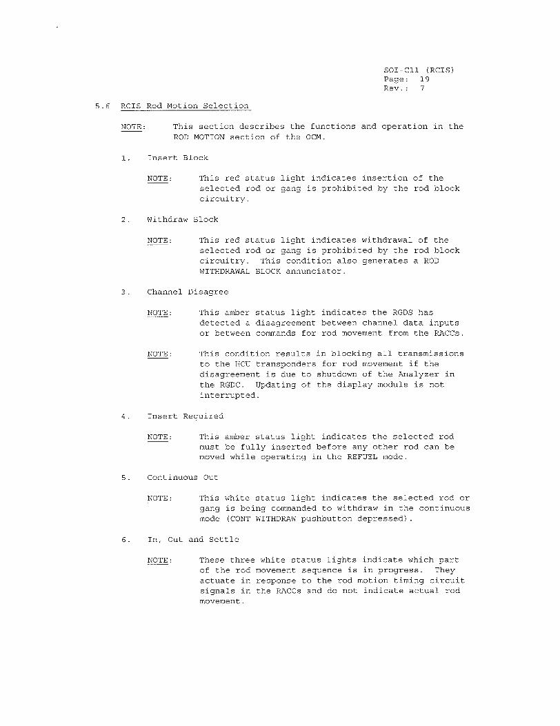
5.6 RCIS Rod Motion Selection
NOTE: This section describes the functions and operation in the ROD MOTION section of the OCM.
1. Insert Block
NOTE: This red status light indicates insertion of the selected rod or gang is prohibited by the rod block circuitry.
2. Withdraw Block
NOTE: This red status light indicates withdrawal of the selected rod or gang is prohibited by the rod block circuitry. This condition also generates a ROD WITHDRAWAL BLOCK annunciator.
3. Channel Disagree
NOTE: This amber status light indicates the RGDS has detected a disagreement between channel data inputs or between commands for rod movement from the RACCs.
NOTE: This condition results in blocking all transmissions to the HCU transponders for rod movement if the disagreement is due to shutdown of the Analyzer in the RGDC. Updating of the display module is not interrupted.
4. Insert Required
NOTE: This amber status light indicates the selected rod must be fully inserted before any other rod can be moved while operating in the REFUEL mode.
5. Continuous Out
NOTE: This white status light indicates the selected rod or gang is being commanded to withdraw in the continuous mode (CONT WITHDRAW pushbutton depressed).
6. In, Out and Settle
NOTE: These three white status lights indicate which part of the rod movement sequence is in progress. They actuate in response to the rod motion timing circuit signals in the RACCs and do not indicate actual rod movement.
SOI-CII (RCIS) Page: 20
Rev.: 7
7. Insert
a. Refer to Rod Insertion.
8. Withdraw
a. Refer to Rod Withdrawal.
9. Continuous Withdrawal
a. Refer to Rod Withdrawal.
10. In Timer Skip
a. Refer to Rod Insertion.
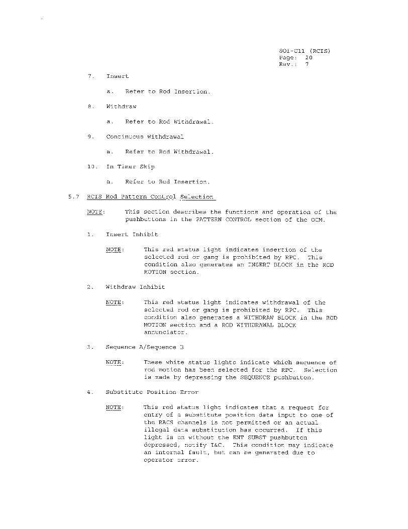
5.7 RCIS Rod Pattern Control Selection
NOTE: This section describes the functions and operation of the pushbuttons in the PATTERN CONTROL section of the OCM.
1. Insert Inhibit
NOTE: This red status light indicates insertion of the selected rod or gang is prohibited by RPC. This condition also generates an INSERT BLOCK in the ROD
MOTION section.
2. Withdraw Inhibit
NOTE: This red status light indicates withdrawal of the
selected rod or gang is prohibited by RPC. This condition also generates a WITHDRAW BLOCK in the ROD MOTION section and a ROD WITHDRAWAL BLOCK annunciator.
3. Sequence A/Sequence B
NOTE: These white status lights indicate which sequence of rod motion has been selected for the RPC. Selection is made by depressing the SEQUENCE pushbutton.
4. Substitute Position Error
NOTE: This red status light indicates that a request for entry of a substitute position data input to one of the RACS channels is not permitted or an actual illegal data substitution has occurred. If this light is on without the ENT SUBST pushbutton
depressed, notify I&C. This condition may indicate an internal fault, but can be generated due to operator error.
SOI-CIl (RCIS) Page: 21 Rev.: 7 / C-21
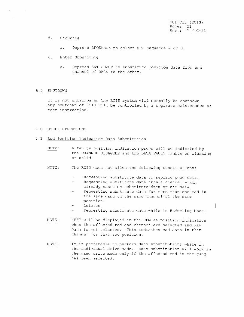
5. Sequence
a. Depress SEQUENCE to select RPC Sequence A or B.
6. Enter Substitute
a. Depress ENT SUBST to substitute position data from one channel of RACS to the other.
6.0 SHUTDOWN
It is not anticipated the RCIS system will normally be shutdown. Any shutdown of RCIS will be controlled by a separate maintenance or test instruction.
7.0 OTHER OPERATIONS
7.1 Rod Position Indication Data Substitution
NOTE: A faulty position indication probe will be indicated by the CHANNEL DISAGREE and the DATA FAULT lights on flashing or solid.
NOTE: The RCIS does not allow the following substitutions:
- Requesting substitute data to replace good data. - Requesting substitute data from a channel which
already contains substitute data or bad data. - Requesting substitute data for more than one rod in
the same gang on the same channel at the same position.
- Deleted - Requesting substitute data while in Refueling Mode.
NOTE: "FF" will be displayed on the RDM as position indication when the affected rod and channel are selected and Raw Data is not selected. This indicates bad data in that channel for that rod position.
NOTE: It is preferable to perform data substitutions while in the individual drive mode. Data substitution will work in the gang drive mode only if the affected rod in the gang has been selected.
SOI-Cll (RCIS) Page: 22 Rev.: 7 / C-20
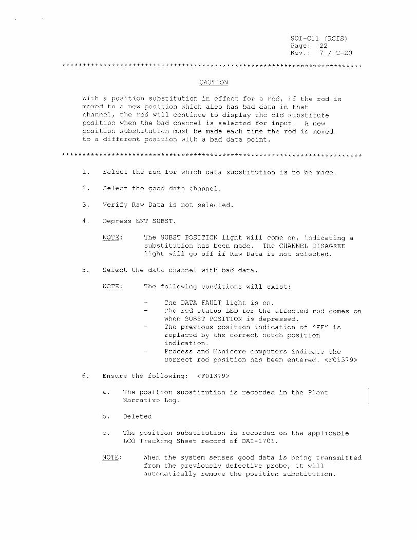
CAUTION
With a position substitution in effect for a rod, if the rod is moved to a new position which also has bad data in that channel, the rod will continue to display the old substitute position when the bad channel is selected for input. A new position substitution must be made each time the rod is moved to a different position with a bad data point.
1. Select the rod for which data substitution is to be made.
2. Select the good data channel.
3. Verify Raw Data is not selected.
4. Depress ENT SUBST.
NOTE: The SUBST POSITION light will come on, indicating a substitution has been made. The CHANNEL DISAGREE light will go off if Raw Data is not selected.
5. Select the data channel with bad data.
NOTE: The following conditions will exist:
- The DATA FAULT light is on. - The red status LED for the affected rod comes on
when SUBST POSITION is depressed. - The previous position indication of "FF" is
replaced by the correct notch position indication.
- Process and Monicore computers indicate the correct rod position has been entered. <F01379>
6. Ensure the following: <F01379>
a. The position substitution is recorded in the Plant Narrative Log.
b. Deleted
c. The position substitution is recorded on the applicable LCO Tracking Sheet record of OAI-1701.
NOTE: When the system senses good data is being transmitted from the previously defective probe, it will automatically remove the position substitution.
SOI-CI1 (RCIS) Page: 11 Rev.: 7 / C-8
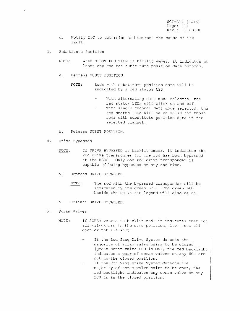
d. Notify I&C to determine and correct the cause of the fault.
3. Substitute Position
NOTE: When SUBST POSITION is backlit amber, it indicates at least one rod has substitute position data entered.
a. Depress SUBST POSITION.
NOTE: Rods with substitute position data will be indicated by a red status LED.
- With alternating data mode selected, the red status LEDs will blink on and off.
- With single channel data mode selected, the red status LEDs will be on solid for those rods with substitute position data in the
selected channel.
b. Release SUBST POSITION.
4. Drive Bypassed
NOTE: If DRIVE BYPASSED is backlit amber, it indicates the rod drive transponder for one rod has been bypassed at the RGDC. Only one rod drive transponder is capable of being bypassed at any one time.
a. Depress DRIVE BYPASSED.
NOTE: The rod with the bypassed transponder will be indicated by its green LED. The green LED beside the DRIVE BYP legend will also be on.
b. Release DRIVE BYPASSED.
5. Scram Valves
NOTE: If SCRAM VALVES is backlit red, it indicates that not all valves are in the same position, i.e., not all open or not all shut.
- If the Rod Gang Drive System detects the majority of scram valve pairs to be closed (green scram valve LED is ON), the red backlight indicates a pair of scram valves on any HCU are not in the closed position.
- If the Rod Gang Drive System detects the majority of scram valve pairs to be open, the red backlight indicates any scram valve on any HCU is in the closed position.
Appendix C Job Performance Measure Form ES-C-I Worksheet
Perry
Manually Initiate SPMU LOCA LogŽic Malfunction (Alternate Path)
Task No:
JPM No:
002-503-05-01
2003 NRC B.l.b
K/A Reference:
Examinee:
Facility Evaluator:
295030 EA1.04
NRC Examiner:
N/A Date:
Method of testing
Simulated Performance
Classroom
Task Standard:
Actual Performance
Simulator Plant
Candidate identifies SPMU logic malfunction, bypasses the SPMU logic malfunction, and then initiates SPMU to open the SPMU Train A valves and dump the Upper Pools.
Required Materials: PEI-SPI 3.2, Rev 0 One PEI-SPI key
General References: PEI-SPI 3.2, Rev 0
Time Critical Task:
Validation Time:
NO
7 minutes
READ TO THE EXAMINEE
I will explain the initial conditions, which steps to simulate or discuss, and provide initiating cues. When you complete the task successfully, the objective for this Job Performance Measure will be satisfied.
Initial Conditions:
Initiating Cue:
An ATWS is in progress. PEI-B13, RPV Control (ATWS) has been entered. PEI-T23, Containment Control, has also been entered on low Suppression Pool level due to a pipe break in the RHR C Pump Room. Suppression Pool level is decreasing. The leak cannot be isolated. SPMU Train B is tagged out of service.
The Unit Supervisor directs you, as the Reactor Operator, to initiate SPMU Train A in accordance with PEI-SPI 3.2.
NUREG 1021, Revision 8, Supplement I
Facility:
Task Title:
Appendix C Page 2 of 8 Form ES-C-1 PERFORMANCE INFORMATION
(Denote Critical Steps with an asterisk)
Note: Since SPMU Train B is tagged out of service, the Candidate is not expected to perform those portions of the PEI-SPI steps associated with SPMU Train B.
Note: The Evaluator will role-play as the SRO for the Candidate.
Performance Step: 1.0
Standard:
Comment:
Verify the following keylock switches are in AUTO:
"* SUPR POOL MAKE-UP A LOGIC G43-S6 "* SUPR POOL MAKE-UP B LOGIC G43-S8
Confirms SUPR POOL MAKE-UP LOGIC G43-S6 keylock switch is in AUTO.
Note: No operator action is required for SUPR POOL MAKEUP B LOGIC G43-S8 keylock switch since SPMU Train B is tagged out of service.
Note: In the next Step, the Candidate will confirm a valid LOCA signal is present but may not be able to ascertain that a LOCA logic malfunction exists which will affect the SPMU System.
NUREG 1021, Revision 8, Supplement I
Appendix C Page 3 of 8 Form ES-C-I PERFORMANCE INFORMATION
Note: In the next Step, the Candidate may recognize that Alarm H13-P601-20 (F2),
SPMU A DUMP SUPR POOL LEVEL A LOW, has occurred. The presence of this
alarm, in conjunction with a valid LOCA signal, should have resulted in the
automatic opening of the SPMU Train A valves.
Based on this diagnosis, the Candidate may reason that a LOCA signal is not
present in the next Step and continue on to Step 3.0 (which is the Alternate Path).
Performance Step: If a LOCA signal is present, then proceed to Step 5.0.
2.0
Standard: Confirms a LOCA signal is present and proceeds to Step 5.0.
Comment: Note: Candidate can confirm a LOCA signal should be present
by observing LOCA-related Alarms H13-P601-21 (A6) and
H13-P601-20 (A3) and the Division 1 LPCS & LPCI A LOCA
initiation signal is sealed-in on H13-P601-21.
Note: This step is not critical because it is faulted. The
Candidate's ability or inability to confirm a LOCA signal is present at this point does not ultimately affect the desired
outcome of the task (i.e., opening the SPMU Train A valves).
NUREG 1021, Revision 8, Supplement I
Appendix C Page 4 of 8 Form ES-C-1 PERFORMANCE INFORMATION
Performance Step: 5.0
Standard:
Comment:
Performance Step: 6.0
Arm and depress the following pushbuttons:
"* SUPR PL MAKE-UP A MANUAL INITIATION G43 -$5
"* SUPR PL MAKE-UP B MANUAL INITIATION G43-$7
Arms and depresses the SUPR PL MAKE-UP A MANUAL INITIATION G43-$5 pushbutton.
Note: No operator action is required for SUPR POOL MAKEUP B MANUAL INITIATION G43-S7 pushbutton since SPMU Train B is tagged out of service.
Note: This step is not critical because the LOCA logic malfunction will prevent the opening of the SPMU Train A valves.
Confirm the following valves are open:
"* SUPR PL MAKE-UP A FIRST SHUTOFF G43-F030A "* SUPR PL MAKE-UP A SECOND SHUTOFF
G43-FO40A
Confirms SUPR PL MAKE-UP A FIRST SHUTOFF G43-F030A and SUPR PL MAKE-UP B SECOND SHUTOFF G43-FO40A did not open.
Observes red light is off and green light is on for each valve.
Note: Alarm H13-P601-20 (H2), SPMU TRAIN A VALVES OPEN, will not occur (unexpected) because the valves did not open.
Note: Candidate must now recognize that the LOCA-portion of the SPMU Train A logic has malfunctioned and go to Step 3.0 to successfully complete the task.
Cue: As the SRO, if asked, inform the Candidate that SPMU Train A initiation is still required.
Note: The following step is the Alternate Path for this JPM.
NUREG 1021, Revision 8, Supplement I
Standard:
Comment:
Appendix C Page 5 of 8 Form ES-C-I PERFORMANCE INFORMATION
Note: In the next Step, when the G43-S13 keylock switch is placed in TEST, then the SPMU Train A valves will automatically open.
Performance Step: 3.0
Standard:
Comment:
Performance Step: 4.0
Standard:
At H13-P869, place SUPR PL MAKEUP A FULL FLW TEST PERM G43-S13 keylock switch in TEST.
Obtains any PEI-SPI key.
Places SUPR PL MAKEUP A FULL FLW TEST PERM G43-S13 keylock switch in TEST.
Note: Panel Hl1I3-P869 is not simulated. The Candidate will proceed to the H-13-PEI Panel where keylock switch G43-S13 is located.
At H13-P868, place SUPR PL MAKEUP B FULL FLW TEST PERM G43-S12 keylock switch in TEST.
No operator action is required since SPMU Train B is tagged out of service.
Comment:
Performance Step: 5.0
Standard:
Comment:
Arm and depress the following pushbuttons:
"* SUPR PL MAKE-UP A MANUAL INITIATION G43 -S5
"* SUPR PL MAKE-UP B MANUAL INITIATION G43 -S7
No operator action is required.
Note: When Step 3.0 (the Alternate Path) was performed, then the SPMU Train A valves automatically opened. Therefore, this step is not critical and does not have to be performed.
Note: It is still acceptable if the Candidate performs the step as written due to procedural compliance concerns.
NUREG 1021, Revision 8, Supplement I
Appendix C Page 6 of 8 Form ES-C-I PERFORMANCE INFORMATION
Performance Step: 6.0
Confirm the following valves are open:
"* SUPR PL MAKE-UP A FIRST SHUTOFF G43-FO30A "* SUPR PL MAKE-UP A SECOND SHUTOFF
G43-FO40A
Standard:
Comment:
Confirms the following valves open:
"* SUPR PL MAKE-UP A FIRST SHUTOFF G43-F030A "* SUPR PL MAKE-UP A SECOND SHUTOFF
G43-F040A
Observes red light is on and green light is off for each valve.
Observes Suppression Pool level is increasing.
Note: Alarm H13-P601-20 (H2), SPMU TRAIN A VALVES OPEN, will occur (expected) because the valves are now open (or in the process of opening).
Terminating Cue:
When PEI-SPI 3.2 Step 6.0 is completed and Suppression Pool level is increasing. the evaluation for this JPM is complete.
NUREG 1021, Revision 8, Supplement I
Appendix C Page 7 of 8 Form ES-C-I VERIFICATION OF COMPLETION
Job Performance Measure No.
Examinee's Name:
Examiner's Name:
Date Performed:
Facility Evaluator:
Number of Attempts:
Time to complete:
Question Documentation:
Question:
Response:
Result:
2003 NRC B.l.b
N/A
SAT OR UNSAT
Examiner's Signature and Date:
NUREG 1021, Revision 8, Supplement I
Appendix C Page 8 of 8 Form ES-C-1 JPM CUE SHEET
INITIAL CONDITIONS:
INITIATING CUE:
An ATWS is in progress. PEI-B 13, RPV Control (ATWS) has been entered. PEI-T23, Containment Control, has also been entered on low Suppression Pool level due to a pipe break in the RHR C Pump Room. Suppression Pool level is decreasing. The leak cannot be isolated. SPMU Train B is tagged out of service.
The Unit Supervisor directs you, as the Reactor Operator, to initiate SPMU Train A in accordance with PEI-SPI 3.2.
NUREG 1021, Revision 8, Supplement I
PEI-SPI 3.2 Page: i Rev.: 0
The Cleveland Electric Illuminating Company
PERRY OPERATIONS MANUAL
Plant Emergency Instruction
TITLE: SPECIAL PLANT INSTRUCTION 3.2
SPMU INITIATION
REVISION: 0
PREPARED: PEI Improvement Team
EFFECTIVE DATE: 8-19-94
7-12-94 / Date
EFFECTIVE PIC's
PIC Type of Effective No. Change Date
PEI-SPI 3.2 Page: 1 of 3 Rev.: 0
PEI-SPI 3.2 SPMU Initiation
ENTRY CONDITIONS
This instruction is entered when water is to be added to the Suppression Pool.
SCOPE
This instruction provides the necessary actions to manually initiate Suppression Pool Make-up, with or without a LOCA signal, to dump the Containment upper pools to the Suppression Pool.
NECESSARY EQUIPMENT
Control Room PEI-SPI File Cabinet: - two PEI-SPI keys
LOCATION OF REQUIRED LOCAL ACTIONS
None
(CONTINUED ON NEXT PAGE)
PEI-SPI 3.2 Page: 2 of 3 Rev.: 0
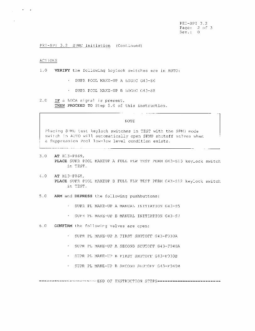
PEI-SPI 3.2 SPMU Initiation (Continued)
ACTIONS
1.0 VERIFY the following keylock switches are in AUTO:
SUPR POOL MAKE-UP A LOGIC G43-$6
SUPR POOL MAKE-UP B LOGIC G43-S8
2.0 IF a LOCA signal is present, THEN PROCEED TO Step 5.0 of this instruction.
3.0 AT H13-P869, PLACE SUPR POOL MAKEUP A FULL FLW TEST PERM G43-S13 keylock switch
in TEST.
4.0 AT H13-P868, PLACE SUPR POOL MAKEUP B FULL FLW TEST PERM G43-S12 keylock switch
in TEST.
5.0 ARM and DEPRESS the following pushbuttons:
SUPR PL MAKE-UP A MANUAL INITIATION G43-S5
SUPR PL MAKE-UP B MANUAL INITIATION G43-87
6.0 CONFIRM the following valves are open:
SUPR PL MAKE-UP A FIRST SHUTOFF G43-F030A
SUPR PL MAKE-UP A SECOND SHUTOFF G43-F040A
SUPR PL MAKE-UP B FIRST SHUTOFF G43-F030B
SUPR PL MAKE-UP B SECOND SHUTOFF G43-F040B
--------=END OF INSTRUCTION STEPS
NOTE
Placing SPMU test keylock switches in TEST with the SPMU mode switch in AUTO will automatically open SPMU shutoff valves when a Suppression Pool low-low level condition exists.
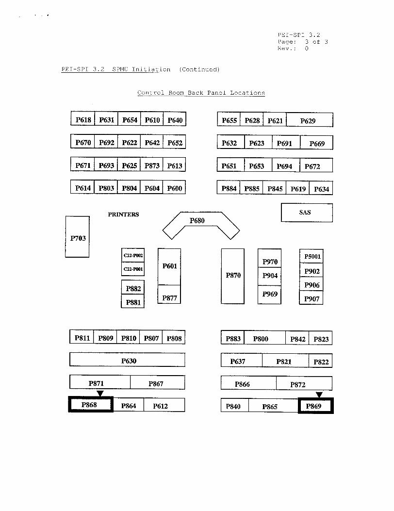
PEI-SPI 3.2 Page: 3 of 3 Rev.: 0
PEI-SPI 3.2 SPMU Initiation (Continued
Control Room Back Par
P618 P631 P654 P610 P640
P670 P692 P622 P642P5
P671 P693 P625 P873 P613
P614 P803 IP804 P604 IP600
iel Locations
,P655 P628 IP621 P629
P632 P623 P691 ]P6769
P651 P653 P694 IP672
P884 P885 IP845 IP619 IP634
PRINTERSP6RO
P601 P870
P877
P811 1P809 I P810 IP807 IP808
P630
P871 P867
P868 P864 P612
P970
P904
P969
1 P5001
P902
P906
P907
P883I P800 P8421 P8231
P637 P821 P822
P866 P872__
P840 P865 I7P869I
P703
i i i i i [
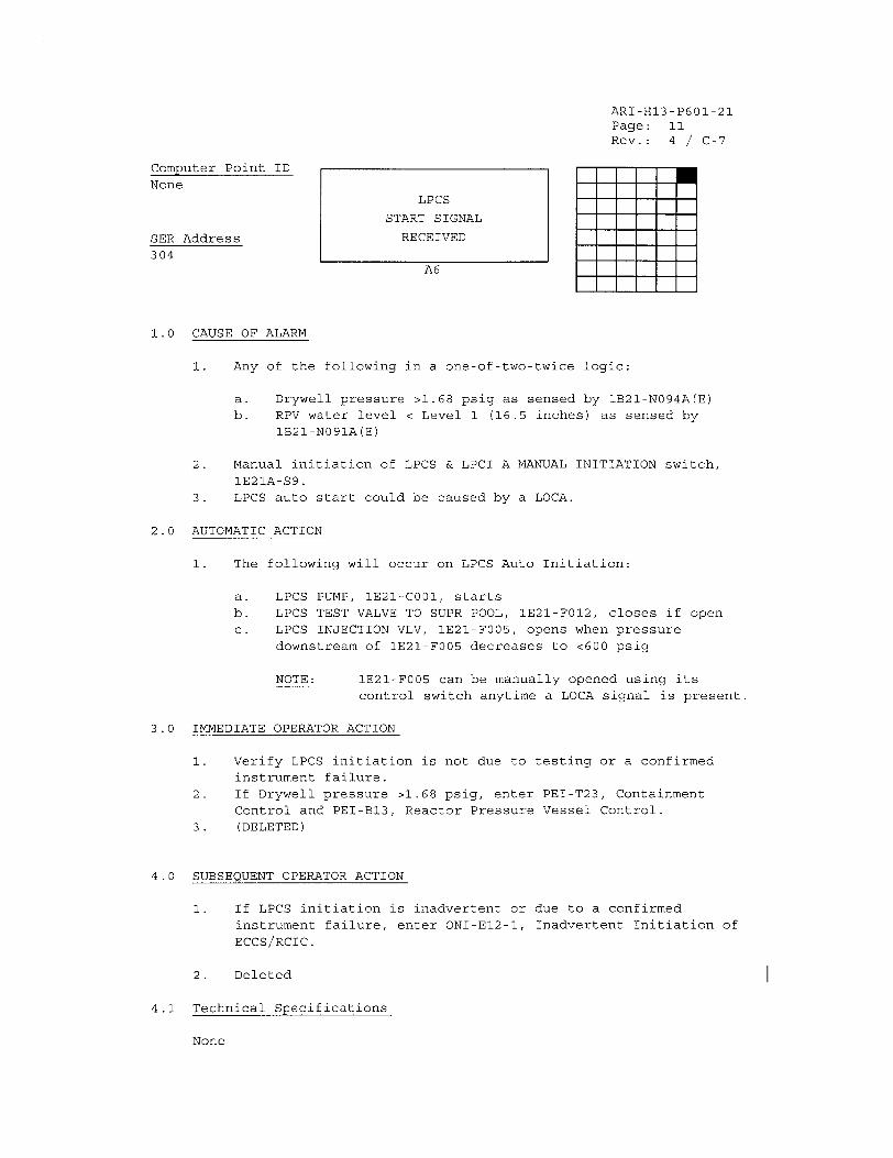
ARI-H13-P601-21 Page: 11 Rev.: 4 / C-7
Computer Point ID
None LPCS
START SIGNAL
SER Address RECEIVED
304 A6
1.0 CAUSE OF ALARM
1. Any of the following in a one-of-two-twice logic:
a. Drywell pressure >1.68 psig as sensed by 1B21-N094A(E) b. RPV water level < Level 1 (16.5 inches) as sensed by
IB21-N091A(E)
2. Manual initiation of LPCS & LPCI A MANUAL INITIATION switch,
lE21A-S9. 3. LPCS auto start could be caused by a LOCA.
2.0 AUTOMATIC ACTION
1. The following will occur on LPCS Auto Initiation:
a. LPCS PUMP, 1E21-C001, starts
b. LPCS TEST VALVE TO SUPR POOL, 1E21-F012, closes if open
c. LPCS INJECTION VLV, 1E21-F005, opens when pressure
downstream of 1E21-F005 decreases to <600 psig
NOTE: 1E21-F005 can be manually opened using its control switch anytime a LOCA signal is present.
3.0 IMMEDIATE OPERATOR ACTION
1. Verify LPCS initiation is not due to testing or a confirmed instrument failure.
2. If Drywell pressure >1.68 psig, enter PEI-T23, Containment
Control and PEI-B13, Reactor Pressure Vessel Control. 3. (DELETED)
4.0 SUBSEQUENT OPERATOR ACTION
1. If LPCS initiation is inadvertent or due to a confirmed
instrument failure, enter ONI-E12-I, Inadvertent Initiation of ECCS/RCIC.
2. Deleted
4.1 Technical Specifications
None
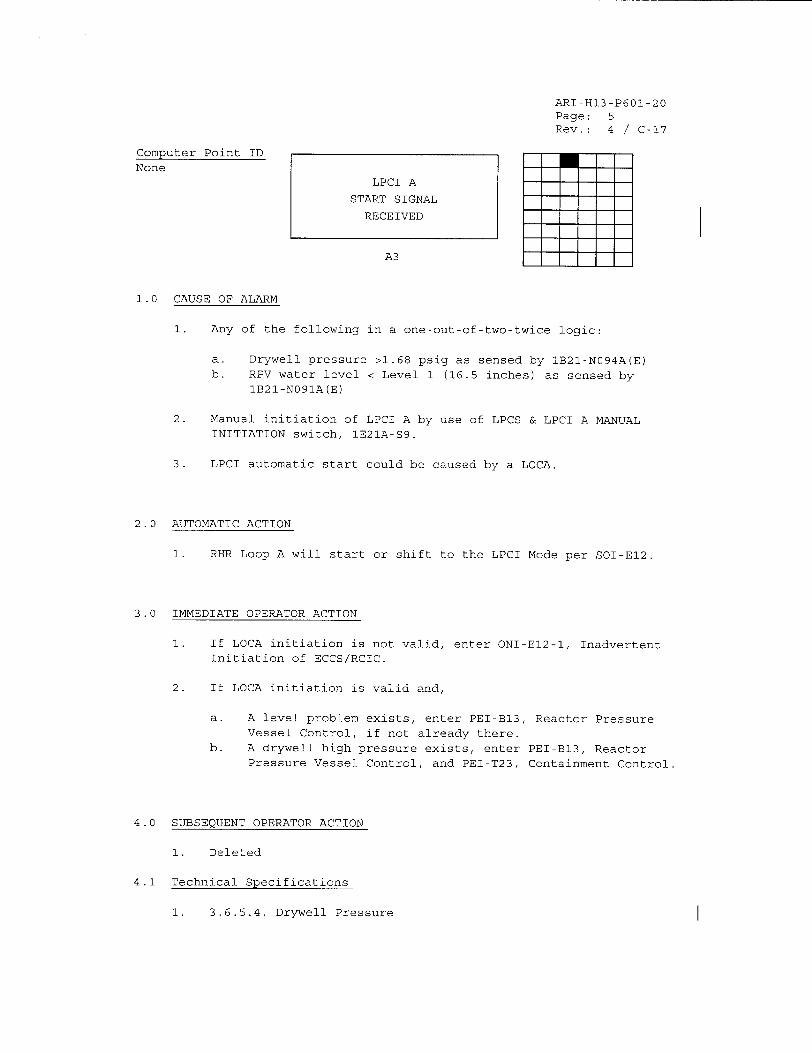
ARI-H13-P601-20 Page: 5 Rev.: 4 / C-17
Computer Point ID None
A3
1.0 CAUSE OF ALARM
1. Any of the following in a one-out-of-two-twice logic:
a. Drywell pressure >1.68 psig as sensed by IB21-N094A(E) b. RPV water level < Level 1 (16.5 inches) as sensed by
1B21-N091A(E)
2. Manual initiation of LPCI A by use of LPCS & LPCI A MANUAL INITIATION switch, lE21A-S9.
3. LPCI automatic start could be caused by a LOCA.
2.0 AUTOMATIC ACTION
1. RHR Loop A will start or shift to the LPCI Mode per SOI-E12.
3.0 IMMEDIATE OPERATOR ACTION
1. If LOCA initiation is not valid, enter ONI-E12-1, Inadvertent Initiation of ECCS/RCIC.
2. If LOCA initiation is valid and,
a. A level problem exists, enter PEI-B13, Reactor Pressure Vessel Control, if not already there.
b. A drywell high pressure exists, enter PEI-B13, Reactor Pressure Vessel Control, and PEI-T23, Containment Control.
4.0 SUBSEQUENT OPERATOR ACTION
1. Deleted
4.1 Technical Specifications
1. 3.6.5.4, Drywell Pressure
LPCI A
START SIGNAL
RECEIVED
I
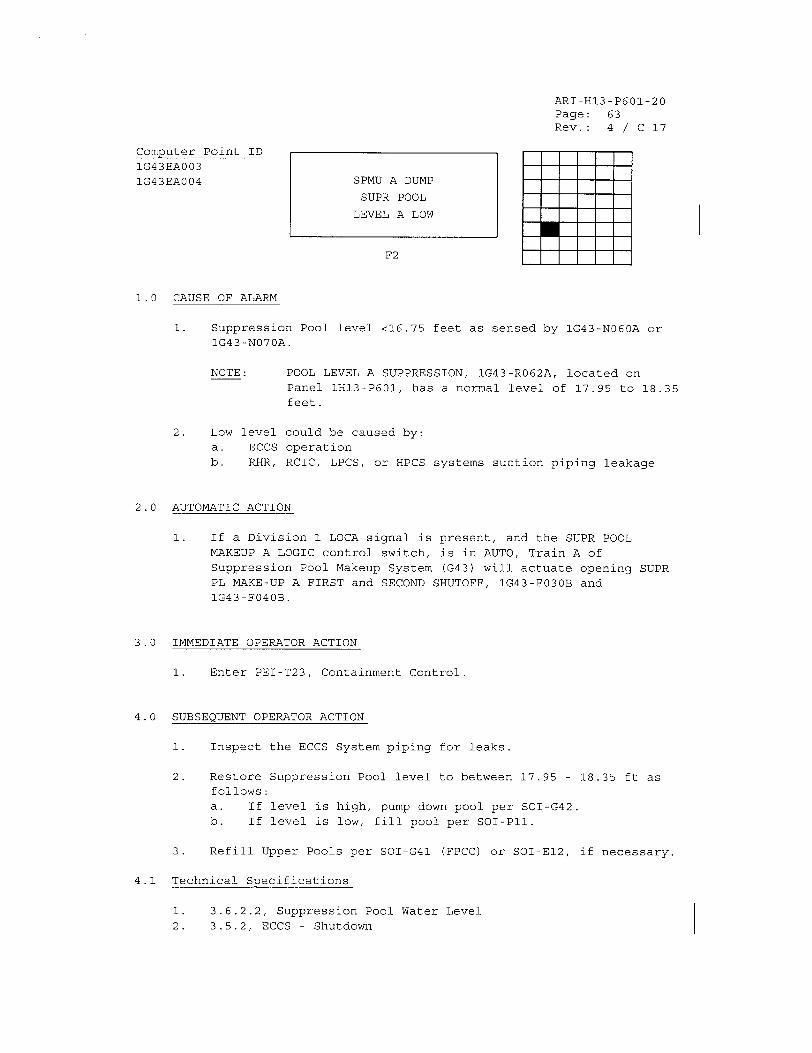
ARI-H13-P601-20 Page: 63 Rev.: 4 / C-17
Computer Point ID
IG43EA003 1G43EA004
F2
1.0 CAUSE OF ALARM
1. Suppression Pool level <16.75 feet as sensed by IG43-N060A or IG43-N070A.
NOTE:
2. Low level
a. ECCS
b. RHR,
POOL LEVEL A SUPPRESSION, 1G43-R062A, located on Panel 1H13-P601, has a normal level of 17.95 to 18.35
feet.
could be caused by:
operation RCIC, LPCS, or HPCS systems suction piping leakage
2.0 AUTOMATIC ACTION
1. If a Division 1 LOCA signal is present, and the SUPR POOL MAKEUP A LOGIC control switch, is in AUTO, Train A of
Suppression Pool Makeup System (G43) will actuate opening SUPR PL MAKE-UP A FIRST and SECOND SHUTOFF, 1G43-F030B and 1G43-F040B.
3.0 IMMEDIATE OPERATOR ACTION
1. Enter PEI-T23, Containment Control.
4.0 SUBSEQUENT OPERATOR ACTION
1. Inspect the ECCS System piping for leaks.
2. Restore Suppression Pool level to between 17.95 - 18.35 ft as follows: a. If level is high, pump down pool per SOI-G42. b. If level is low, fill pool per SOI-Pll.
3. Refill Upper Pools per SOI-G41 (FPCC) or SOI-E12, if necessary.
4.1 Technical Specifications
3.6.2.2, Suppression Pool Water Level
3.5.2, ECCS - Shutdown
SPMU A DUMP
SUPR POOL
LEVEL A LOW
U
1i.
2.
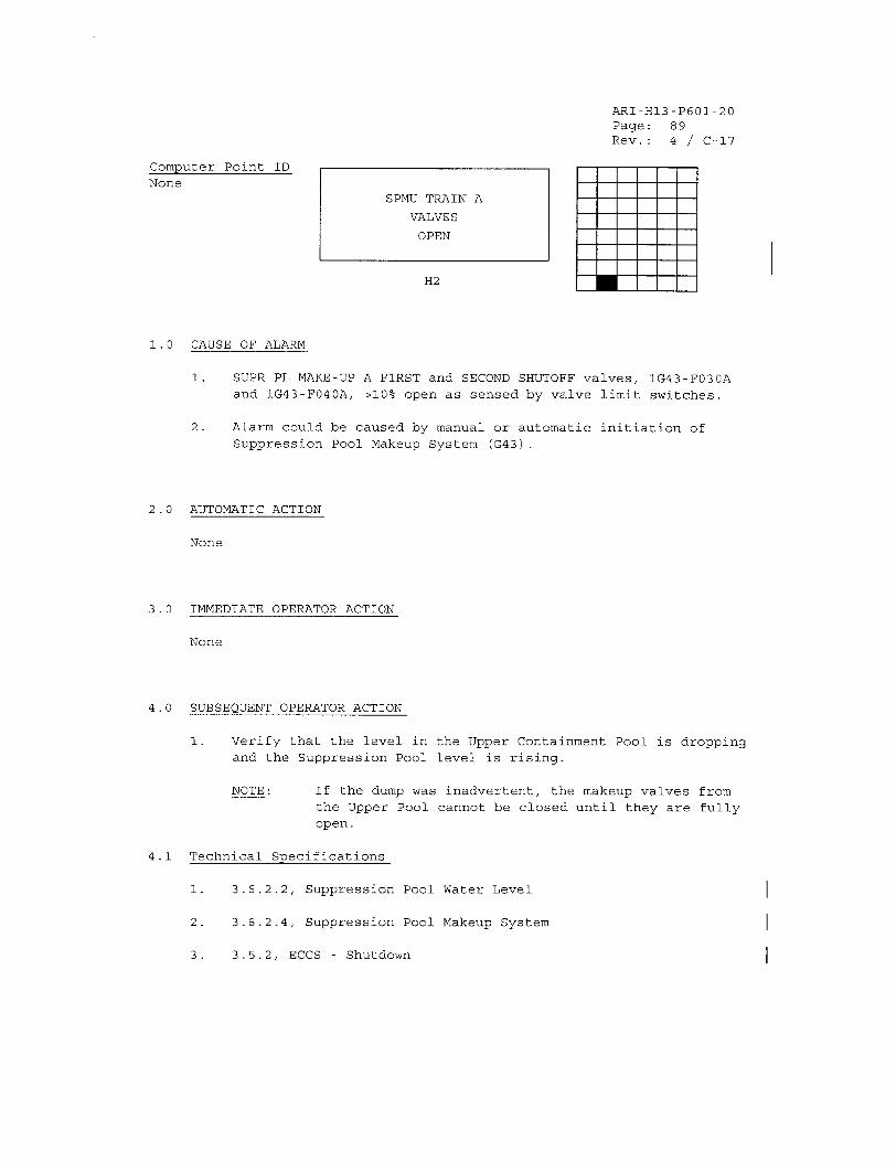
ARI-H13-P601-20 Page: 89 Rev.: 4 / C-17
Computer Point ID None
H2
1.0 CAUSE OF ALARM
1. SUPR PL MAKE-UP A FIRST and SECOND SHUTOFF valves, 1G43-F030A and 1G43-F040A, >10% open as sensed by valve limit switches.
2. Alarm could be caused by manual or automatic initiation of
Suppression Pool Makeup System (G43).
2.0 AUTOMATIC ACTION
None
3.0 IMMEDIATE OPERATOR ACTION
None
4.0 SUBSEQUENT OPERATOR ACTION
1. Verify that the level in the Upper Containment Pool is dropping and the Suppression Pool level is rising.
NOTE: If the dump was inadvertent, the makeup valves from the Upper Pool cannot be closed until they are fully open.
4.1 Technical Specifications
1. 3.6.2.2, Suppression Pool Water Level
2. 3.6.2.4, Suppression Pool Makeup System
3. 3.5.2, ECCS - Shutdown
SPMU TRAIN A
VALVES
OPEN
B
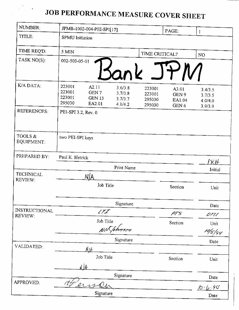
JOB PERFORMANCE MEASURE COVER SHEET
JPMB- 1 002-004-PEI-SPI[ 17]
SPMU Initiation
Paul K. Hetrick
Print NameTECHNICAL REVIEW: Job Title Section
SignatureINSTRUCTIONAL REVIEW: iijrý
Secticn-
A'rs
SignatureVALIDATED:
Job Title
J o T ilIe t o
Section
JPM CUE SHEET
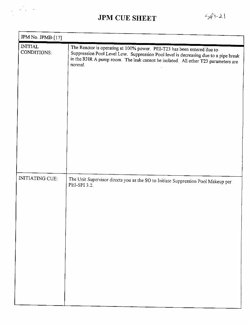
JPM No. JPMB-[17]
INITIAL CONDITIONS:
INITIATING CUE:
mlThe Reactor is operating at 100% power. PEI-T23 has been entered 'due to Suppression Pool Level Low. Suppression Pool level is decreasing due to a pipe break in the RHR A pump room. The leak cannot be isolated. All other T23 parameters are normal.
The Unit Supervisor directs you as the SO to Initiate Suppression Pool Makeup per PEI-SPI 3.2.
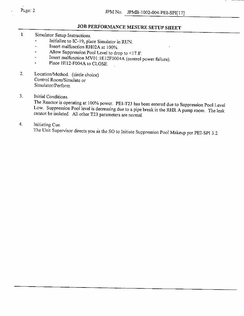
Page: 2 JPMNo. JPMB-1002-004-PEI-SPI[17]
JOB PERFORMANCE MESURE SETUP SHEET 1. Simulator Setup Instructions.
- Initialize to IC-19, place Simulator in RUN. - Insert malfunction RH02A at 100%. - Allow Suppression Pool Level to drop to <17.8'. - Insert malfunction MVO1: 1E I2FOO04A (control power failure). - Place 1E12-F004A to CLOSE.
2. Location/Method. (circle choice) Control Room/Simulate or Simulator/Perform
3. Initial Conditions. The Reactor is operating at 100% power. PEI-T23 has been entered due to Suppression Pool Level Low. Suppression Pool level is decreasing due to a pipe break in the RHR A pump room. The leak cannot be isolated. All other T23 parameters are normal.
4. Initiating Cue. The Unit Supervisor directs you as the SO to Initiate Suppression Pool Makeup per PEI-SPI 3.2.
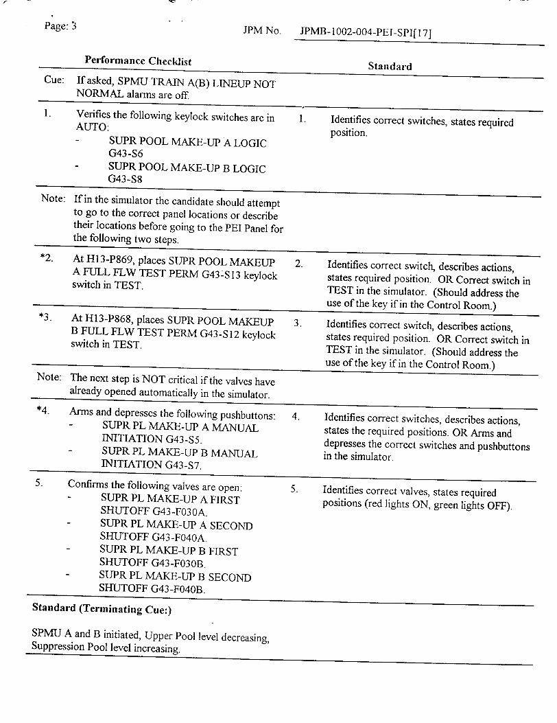
Page: 3 JPM No. JPMB-1002-004-PEI-SPI[l 7]
Performance Checklist Standard
Cue: If asked, SPMU TRAIN A(B) LINEUP NOT NORMAL alarms are off.
1. Verifies the following keylock switches are in 1. Identifies correct switches, states required AUTO:
position. - SUPR POOL MAKE-UP A LOGIC
G43-S6 - SUPR POOL MAKE-UP B LOGIC
G43-S8
Note: If in the simulator the candidate should attempt to go to the correct panel locations or describe their locations before going to the PEI Panel for the following two steps.
*2. At HI 3-P869, places SUPR POOL MAKEUP 2. Identifies correct switch, describes actions, A FULL FLW TEST PERM G43-S 13 keylock states required position. OR Correct switch in switch in TEST. TEST in the simulator. (Should address the
use of the key if in the Control Room.) *3. At H13-P868, places SUPR POOL MAKEUP 3. Identifies correct switch, describes actions, B FULL FLW TEST PERM G43-S 12 keylock states required position. OR Correct switch in switch in TEST. TEST in the simulator. (Should address the
use of the key if in the Control Room.) Note: The next step is NOT critical if the valves have
already opened automatically in the simulator. *4. Arms and depresses the following pushbuttons: 4. Identifies correct switches, describes actions,
- SUPR PL MAKE-UP A MANUAL states the required positions. OR Arms and INITIATION G43-$5. depresses the correct switches and pushbuttons SUPR PL MAKE-UP B MANUAL in the simulator. INITIATION G43-$7.
5. Confirms the following valves are open: 5. Identifies correct valves, states required - SUPR PL MAKE-UP A FIRST positions (red lights ON, green lights OFF).
SHUTOFF G43-F030A. - SUPR PL MAKE-UP A SECOND
SHUTOFF G43-F040A. SUPR PL MAKE-UP B FIRST SHUTOFF G43 -F03 0B.
- SUPR PL MAKE-UP B SECOND SHUTOFF G43-F040B.
Standard (Terminating Cue:)
SPMU A and B initiated, Upper Pool level decreasing, Suppression Pool level increasing.
Appendix C Job Performance Measure Form ES-C-1 Worksheet
Perry
Feedwater Injection Prevention - MFP FCV Malfunction (Alternate Path)
Task No:
JPM No:
259-571-05-01
2003 NRC B.l.c
K/A Reference:
Examinee:
Facility Evaluator:
259001 A4.01
NRC Examiner:
N/A Date:
Method of testing
Simulated Performance
Classroom
Task Standard:
Actual Performance
Simulator Plant
Candidate identifies the preferred method of Feedwater Injection Prevention cannot be completed due a MFP FCV malfunction. Candidate then completes Feedwater Injection prevention using either of the less preferred methods.
Required Materials: PEI-SPI 5.3, Rev 0
General References: PEI-SPI 5.3, Rev 0
Time Critical Task:
Validation Time:
NO
8 minutes
READ TO THE EXAMINEE
I will explain the initial conditions, which steps to simulate or discuss, and provide initiating cues. When you complete the task successfully, the objective for this Job Performance Measure will be satisfied.
Initial Conditions:
Initiating Cue:
An ATWS is in progress. PEI-B13, RPV Control (ATWS) has been entered. Emergency Depressurization is required.
The Unit Supervisor directs you, as the Reactor Operator, to terminate and prevent Feedwater injection into the RPV using the preferred method in accordance with PEI-SPI 5.3 utilizing the procedure.
Cue: If asked, it is not necessary to perform this operation from memory.
NUREG 1021, Revision 8, Supplement I
Facility:
Task Title:
Appendix C Page 2 of 6 Form ES-C-I PERFORMANCE INFORMATION
(Denote Critical Steps with an asterisk)
Note: The Evaluator will role-play as the SRO for the candidate.
Performance Step: Perform Step 2.0 or Step 3.0 or Step 4.0 of this instruction. 1.0
Standard:
Comment:
Note: Step 2.0 (2.1 - 2.4)
Performance Step: 2.1
Standard:
Comment:
Performance Step: 2.2
Standard:
Comment:
None
Note: Candidate was directed to perform Step 2.0 (the preferred method) per the Initiating Cue.
provides the preferred method of feedwater injection prevention.
Terminate and prevent feedwater injection as follows:
Verify the following pumps are tripped:
"* RFPT A "* RFPT B
Depresses RFPT A TRIP, 1N27-S24, pushbutton.
Depresses RFPT B TRIP, IN27-S28, pushbutton.
Note: The following Alarms are expected to occur:
"* HI3-P680-3 (D6), RFPT A TRIP "1 H13-P680-3 (D7), RFPT B TRIP
Note: Candidate may also confirm that RFPT A(B) speed is decreasing on RFPT A(B) RPM, IN27-R41 IA(B).
Verify FDW PUMPS BYPASS VALVE N27-F200 is closed.
Confirms FDW PUMPS BYPASS VALVE N27-F200 is closed.
Observes red light is off, green light is on.
Note: This valve is normally closed.
NUREG 1021, Revision 8, Supplement I
Appendix C Page 3 of 6 Form ES-C-I PERFORMANCE INFORMATION
Performance Step: 2.3
Standard:
Comment:
Performance Step: 2.4
Standard:
Comment:
Place STARTUP RX LEVEL CONTROL C34-R602 in MANUAL and adjust output to minimum.
Depresses STARTUP RX LEVEL CONTROL C34-R602 MANUAL mode pushbutton.
Observes MAN mode amber status light is on and AUTO mode green status light is off.
Adjusts STARTUP RX LEVEL CONTROL C34-R602 horizontal output meter to 0% using the CLOSE pushbutton.
Note: This step is not critical because the expected results in the next step (2.4) will not occur for N27-FO1O/Fl 10.
Verify the following valves are closed:
"* MFP FULL FLOW CONTROL VALVE N27-F010 "* MFP LOW FLOW CONTROL VALVE N27-Fl 10 "• RFP A DISCH VALVE N27-F100A "* RFP B DISCH VALVE N27-FI0OB
Observes MFP FULL FLOW CONTROL VALVE N27-FO 10 and MFP LOW FLOW CONTROL VALVE N27-F 110 are not closed.
Observes red and green lights are on for each valve.
Confirms MFP FULL FLOW CONTROL VALVE N27-F0 10 and MFP LOW FLOW CONTROL VALVE N27-FI 10 cannot be closed.
Determines the preferred method of feedwater injection prevention cannot be properly completed in preparation for Emergency Depressurization.
Confirms RFP A DISCH VALVE N27-FIOOA and RFP B DISCH
VALVE N27-F 1 GOB are closed.
Observes red light is off, green light is on for each valve.
Note: RFP A(B) DISCH VALVE N27-F 1 OOA(B) automatically closed when RFPT A(B) was tripped. The valves have a stroke time of 2 minutes.
Cue: As the SRO, if asked, Feedwater injection prevention is still required.
NUREG 1021, Revision 8, Supplement I
Appendix C Page 4 of 6 Form ES-C-1 PERFORMANCE INFORMATION
Note: The following step (either Step 3.0 or Step 4.0) is the Alternate Path for this JPM.
Note: Candidate can perform either Step 3.0 / 3.1 or Step 4.0 / 4.1 in order to successfully complete Feedwater injection prevention.
* Performance Step: Terminate and prevent feedwater injection as follows: 3.0/3.1
Close the following feedwater shutoff valves:
"* FDW HDR A SHUTOFF B21-F065A "• FDW HDR B SHUTOFF B21-F065B
Standard: Takes valve control switches to the CLOSE position.
Observes red light is off, green light is on for each valve.
Comment:
* Performance Step: Terminate and prevent feedwater injection as follows:
4.0/4.1 Place the following Reactor Feed Booster Pump control switches in OFF:
"* RFBP AN27-COO1A "* RFBP BN27-COOIB "* RFBP C N27-COO 1 C "* RFBP D N27-COO1D
Standard: Places pump control switches in the OFF position.
Observes red light is off, green light is on for each pump.
Comment:
Terminating Cue:
When PEI-SPI 5.3, Step 3.0 or Step 4.0 is completed, the evaluation for this JPM is complete.
NUREG 1021, Revision 8, Supplement 1

Appendix C Page 5 of 6 Form ES-C-I VERIFICATION OF COMPLETION
Job Performance Measure No.
Examinee's Name:
Examiner's Name:
Date Performed:
Facility Evaluator:
Number of Attempts:
Time to complete:
Question Documentation:
Question:
Response:
Result:
2003 NRC B. l.c
N/A
SAT OR UNSAT
Examiner's Signature and Date:
NUREG 1021, Revision 8, Supplement 1
Appendix C Page 6 of 6 Form ES-C-I JPM CUE SHEET
INITIAL CONDITIONS:
INITIATING CUE:
An ATWS is in progress. PEI-B 13, RPV Control (ATWS) has been entered. Emergency Depressurization is required.
The Unit Supervisor directs you, as the Reactor Operator, to terminate and prevent Feedwater injection into the RPV using the preferred method in accordance with PEI-SPI 5.3 utilizing the procedure.
NUREG 1021, Revision 8, Supplement 1
w
PEI-SPI 5.3 Page: i Rev.: 0
The Cleveland Electric Illuminating Company
PERRY OPERATIONS MANUAL
Plant Emergency Instruction
TITLE: SPECIAL PLANT INSTRUCTION 5.3
FEEDWATER INJECTION PREVENTION
0 EFFECTIVE DATE: 8-19-94
PREPARED: PEI Improvement Team 7-12-94/ Date
EFFECTIVE PIC's
I I
REVISION:
PIC Type of Effective
No. Change Date
I I
I I
PEI-SPI 5.3 Page: 1 of 3 Rev.: 0
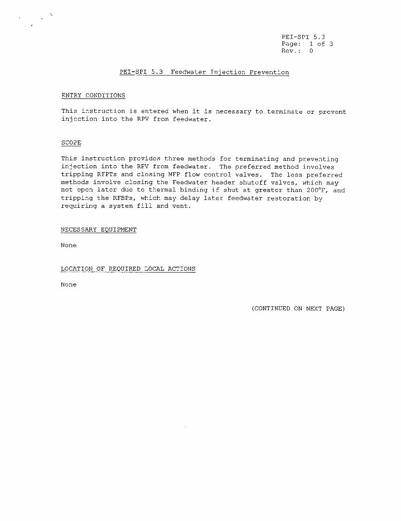
PEI-SPI 5.3 Feedwater Injection Prevention
ENTRY CONDITIONS
This instruction is entered when it is necessary to terminate or prevent injection into the RPV from feedwater.
SCOPE
This instruction provides three methods for terminating and preventing injection into the RPV from feedwater. The preferred method involves tripping RFPTs and closing MFP flow control valves. The less preferred methods involve closing the Feedwater header shutoff valves, which may not open later due to thermal binding if shut at greater than 200'F, and tripping the RFBPs, which may delay later feedwater restoration by requiring a system fill and vent.
NECESSARY EQUIPMENT
None
LOCATION OF REQUIRED LOCAL ACTIONS
None
(CONTINUED ON NEXT PAGE)
PEI-SPI 5.3 Page: 2 of 3 Rev.: 0
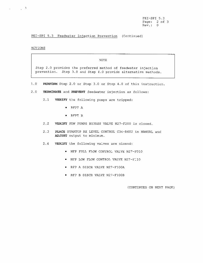
PEI-SPI 5.3 Feedwater Injection Prevention (Continued)
ACTIONS
NOTE
Step 2.0 provides the preferred method of feedwater injection prevention. Step 3.0 and Step 4.0 provide alternative methods.
1.0 PERFORM Step 2.0 or Step 3.0 or Step 4.0 of this instruction.
2.0 TERMINATE and PREVENT feedwater injection as follows:
2.1 VERIFY the following pumps are tripped:
"* RFPT A
"* RFPT B
2.2 VERIFY FDW PUMPS BYPASS VALVE N27-F200 is closed.
2.3 PLACE STARTUP RX LEVEL CONTROL C34-R602 in MANUAL and ADJUST output to minimum.
2.4 VERIFY the following valves are closed:
"* MFP FULL FLOW CONTROL VALVE N27-FO10
"• MFP LOW FLOW CONTROL VALVE N27-FllO
"* RFP A DISCH VALVE N27-FlOOA
"* RFP B DISCH VALVE N27-FI00B
(CONTINUED ON NEXT PAGE)
PEI-SPI 5.3 Page: 3 of 3 Rev.: 0
PEI-SPI 5.3 Feedwater Injection Prevention (Continued)
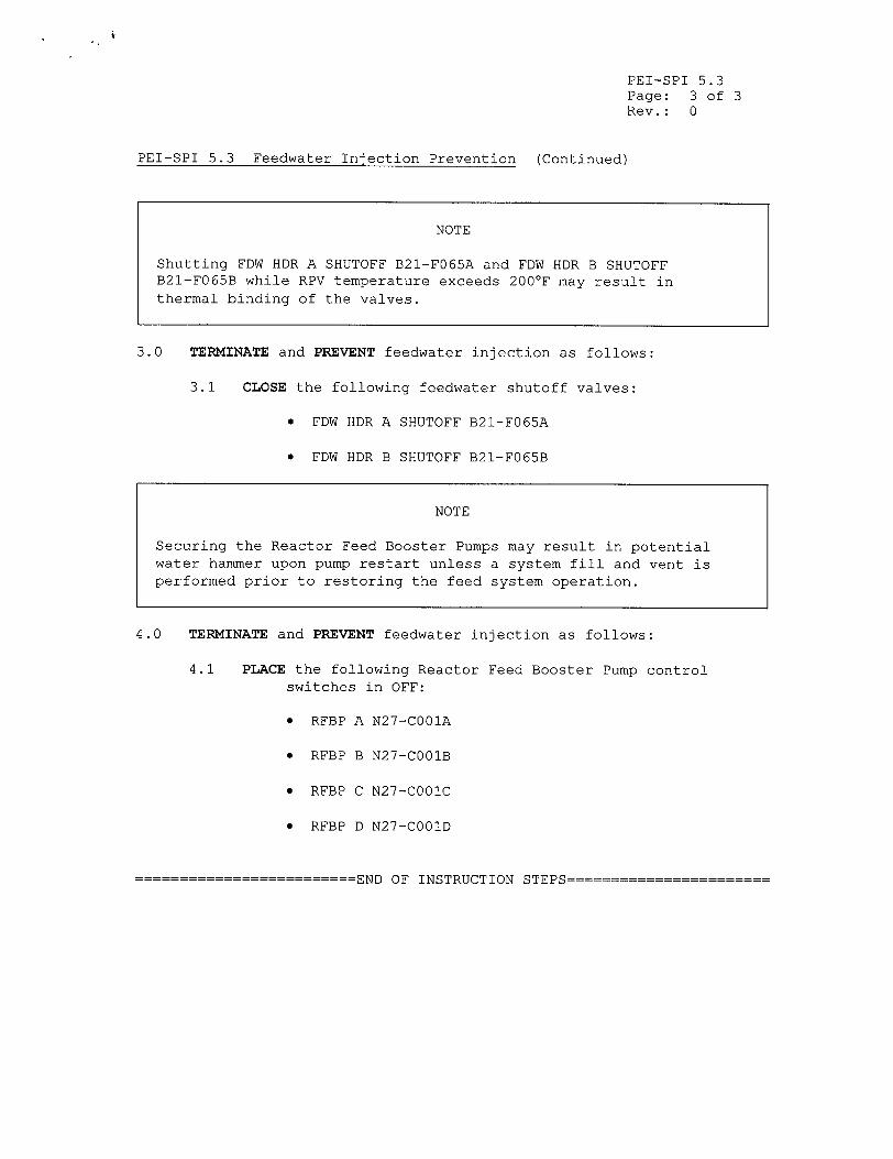
3.0 TERMINATE and PREVENT feedwater injection as follows:
3.1 CLOSE the following feedwater shutoff valves:
"* FDW HDR A SHUTOFF B21-FO65A
"* FDW HDR B SHUTOFF B21-FO65B
4.0 TERMINATE and PREVENT feedwater injection as follows:
4.1 PLACE the following Reactor Feed Booster Pump control switches in OFF:
"* RFBP A N27-CO01A
"* RFBP B N27-CO01B
"* RFBP C N27-CO01C
"* RFBP D N27-COO1D
=========================END OF INSTRUCTION STEPS=======================
NOTE
Shutting FDW HDR A SHUTOFF B21-F065A and FDW HDR B SHUTOFF B21-F065B while RPV temperature exceeds 200'F may result in thermal binding of the valves.
NOTE
Securing the Reactor Feed Booster Pumps may result in potential water hammer upon pump restart unless a system fill and vent is performed prior to restoring the feed system operation.
OM 6: Page: Rev.:
Computer Point ID None
D7
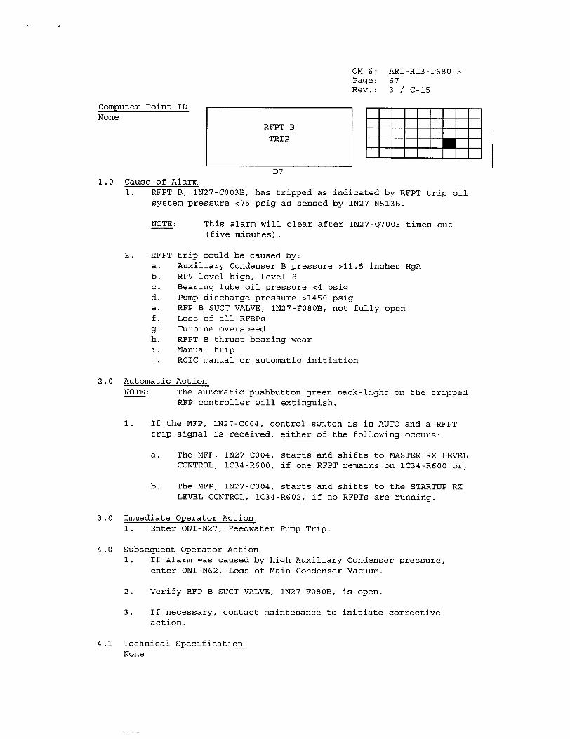
ARI-H13-P680-3 67 3 / C-15
1.0 Cause of Alarm 1. RFPT B, 1N27-C003B, has tripped as indicated by RFPT trip oil
system pressure <75 psig as sensed by 1N27-N513B.
NOTE:
2. RFPT a. b. C. d. e. f. g. h. 1.
This alarm will clear after IN27-Q7003 times out (five minutes).
trip could be caused by: Auxiliary Condenser B pressure >11.5 inches HgA RPV level high, Level 8 Bearing lube oil pressure <4 psig Pump discharge pressure >1450 psig RFP B SUCT VALVE, 1N27-F080B, not fully open Loss of all RFBPs Turbine overspeed RFPT B thrust bearing wear Manual trip RCIC manual or automatic initiation
2.0 Automatic Action NOTE: The automatic pushbutton green back-light on the tripped
RFP controller will extinguish.
1. If the MFP, IN27-C004, control switch is in AUTO and a RFPT trip signal is received, either of the following occurs:
a. The MFP, IN27-C004, starts and shifts to MASTER RX LEVEL CONTROL, IC34-R600, if one RFPT remains on IC34-R600 or,
b. The MFP, 1N27-C004, starts and shifts to the STARTUP RX LEVEL CONTROL, 1C34-R602, if no RFPTs are running.
3.0 Immediate Operator Action 1. Enter ONI-N27, Feedwater Pump Trip.
4.0 Subsequent Operator Action 1. If alarm was caused by high Auxiliary Condenser pressure,
enter ONI-N62, Loss of Main Condenser Vacuum.
2. Verify RFP B SUCT VALVE, lN27-FO80B, is open.
3. If necessary, contact maintenance to initiate corrective action.
4.1 Technical SpecificationNone
RFPT B
TRIP

OM 6: Page: Rev.:
Computer Point ID None
D6
ARI-H13-P680-3 65 3 / C-15
1.0 Cause of Alarm 1. RFPT A, 1N27-C003A, has tripped as indicated by RFPT trip oil
system pressure <75 psig as sensed by IN27-N513A.
NOTE:
2. RFPT a.
b. c. d. e.
f. g. h. 1.
j.
This alarm will clear after IN27-Q7002 times out (five minutes).
trip could be caused by: Auxiliary Condenser A pressure >11.5 inches HgA RPV level high, Level 8 Bearing lube oil pressure <4 psig Pump discharge pressure >1450 psig RFP A SUCT VALVE, 1N27-F080A, not fully open Loss of all RFBPs Turbine overspeed RFPT A thrust bearing wear Manual trip RCIC manual or automatic initiation
2.0 Automatic Action NOTE: The automatic pushbutton green back-light on the tripped
RFP controller will extinguish.
1. If the MFP, 1N27-C004, control switch is in AUTO and a RFPT trip signal is received, either of the following occurs:
a. The MFP, 1N27-C004, starts and shifts to MASTER RX LEVEL CONTROL, 1C34-R600, if one RFPT remains on IC34-R600 or,
b. The MFP, 1N27-C004, starts and shifts to STARTUP RX LEVEL CONTROL, IC34-R602, if no RFPTs are running.
3.0 Immediate Operator Action 1. Enter ONI-N27, Feedwater Pump Trip.
4.0 Subsequent Operator Action 1. If alarm was caused by high Auxiliary Condenser pressure,
enter ONI-N62, Loss of Main Condenser Vacuum.
2. Verify RFP A SUCT VALVE, 1N27-F080A, is open.
3. If necessary, contact maintenance to initiate corrective action.
4.1 Technical SpecificationNone
RFPT A
TRIP
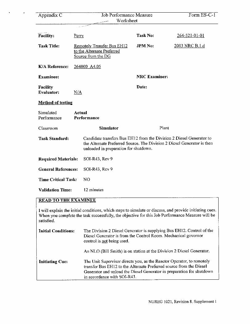
Appendix C Job Performance Measure Form ES-C-1 Worksheet
Perry
Remotely Transfer Bus EH12 to the Alternate Preferred Source from the DG
Task No:
JPM No:
264-521-01-01
2003 NRC B. L.d
K/A Reference:
Examinee:
Facility Evaluator:
264000 A4.05
NRC Examiner:
Date:N/A
Method of testing
Simulated Performance
Classroom
Task Standard:
Actual Performance
Simulator Plant
Candidate transfers Bus EH 12 from the Division 2 Diesel Generator to the Alternate Preferred Source. The Division 2 Diesel Generator is then unloaded in preparation for shutdown.
Required Materials: SOI-R43, Rev 9
General References: SOI-R43, Rev 9
Time Critical Task: NO
Validation Time: 12 minutes
READ TO THE EXAMINEE
I will explain the initial conditions, which steps to simulate or discuss, and provide initiating cues. When you complete the task successfully, the objective for this Job Performance Measure will be satisfied.
Initial Conditions:
Initiating Cue:
The Division 2 Diesel Generator is supplying Bus EHI2. Control of the Diesel Generator is from the Control Room. Mechanical governor control is not being used.
An NLO (Bill Smith) is on station at the Division 2 Diesel Generator.
The Unit Supervisor directs you, as the Reactor Operator, to remotely transfer Bus EH 12 to the Alternate Preferred source from the Diesel Generator and unload the Diesel Generator in preparation for shutdown in accordance with SOI-R43.
NUREG 1021, Revision 8, Supplement 1
Facility:
Task Title:
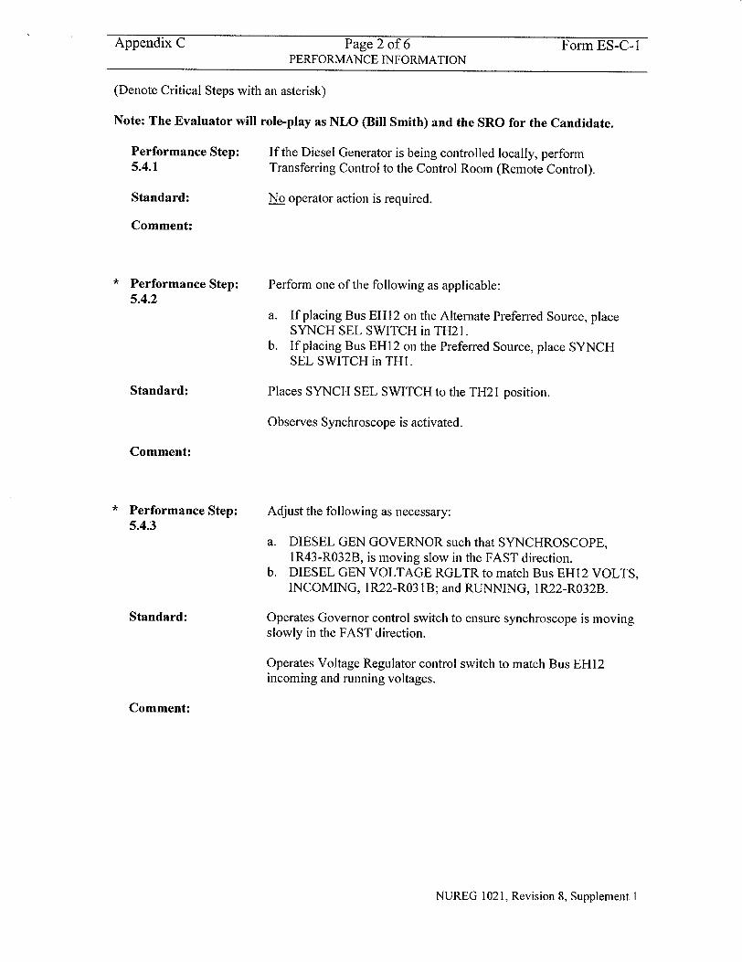
Appendix C Page 2 of 6 Form ES-C-I PERFORMANCE INFORMATION
(Denote Critical Steps with an asterisk)
Note: The Evaluator will role-play as NLO (Bill Smith) and the SRO for the Candidate.
Performance Step: If the Diesel Generator is being controlled locally, perform 5.4.1 Transferring Control to the Control Room (Remote Control).
Standard: No operator action is required.
Comment:
Performance Step:
5.4.2
Standard:
Comment:
Performance Step: 5.4.3
Standard:
Perform one of the following as applicable:
a. If placing Bus EH12 on the Alternate Preferred Source, place SYNCH SEL SWITCH in TH21.
b. If placing Bus EH12 on the Preferred Source, place SYNCH SEL SWITCH in THI.
Places SYNCH SEL SWITCH to the TH21 position.
Observes Synchroscope is activated.
Adjust the following as necessary:
a. DIESEL GEN GOVERNOR such that SYNCHROSCOPE, 1R43-R032B, is moving slow in the FAST direction.
b. DIESEL GEN VOLTAGE RGLTR to match Bus EH12 VOLTS, INCOMING, 1R22-R03 1B; and RUNNING, IR22-R032B.
Operates Governor control switch to ensure synchroscope is moving slowly in the FAST direction.
Operates Voltage Regulator control switch to match Bus EH12 incoming and running voltages.
Comment:
NUREG 1021, Revision 8, Supplement 1
Appendix C Page 3 of 6 Form ES-C-I PERFORMANCE INFORMATION
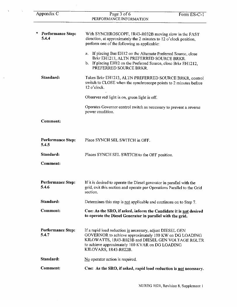
Performance Step: 5.4.4
Standard:
With SYNCHROSCOPE, 1R43-R032B moving slow in the FAST direction, at approximately the 2 minutes to 12 o'clock position, perform one of the following as applicable:
a. If placing Bus EH12 on the Alternate Preferred Source, close Brkr EH1213, ALTN PREFERRED SOURCE BRKR.
b. If placing EH12 on the Preferred Source, close Brkr EH1212, PREFERRED SOURCE BRKR.
Takes Brkr EH1213, ALTN PREFERRED SOURCE BRKR, control switch to CLOSE when the synchroscope points to 2 minutes before 12 o'clock.
Observes red light is on, green light is off.
Operates Governor control switch as necessary to prevent a reverse power condition.
Comment:
Performance Step: 5.4.5
Standard:
Place SYNCH SEL SWITCH in OFF.
Places SYNCH SEL SWITCH to the OFF position.
Comment:
Performance Step: 5.4.6
Standard:
Comment:
Performance Step: 5.4.7
Standard:
Comment:
If it is desired to operate the Diesel generator in parallel with the grid, exit this section and operate per Operations Parallel to the Grid section.
Determines this step is not applicable and continues on to Step 7.
Cue: As the SRO, if asked, inform the Candidate it is not desired to operate the Diesel Generator in parallel with the grid.
If a rapid load reduction is necessary, adjust DIESEL GEN GOVERNOR to achieve approximately 100 KW on DG LOADING KILOWATTS, I R43-R023B and DIESEL GEN VOLTAGE RGLTR to achieve approximately 100 KVAR on DG LOADING KILOVARS, I R43-R022B.
No operator action is required.
Cue: As the SRO, if asked, rapid load reduction is not necessary.
NUREG 1021, Revision 8, Supplement I
Appendix C Page 4 of 6 Form ES-C-I PERFORMANCE INFORMATION
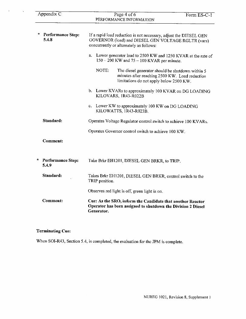
Performance Step: 5.4.8
Standard:
If a rapid load reduction is not necessary, adjust the DIESEL GEN GOVERNOR (load) and DIESEL GEN VOLTAGE RGLTR (vars) concurrently or alternately as follows:
a. Lower generator load to 2500 KW and 1250 KVAR at the rate of 150- 200 KW and 75 - 100 KVAR per minute.
NOTE: The diesel generator should be shutdown within 5 minutes after reaching 2500 KW. Load reduction limitations do not apply below 2500 KW.
b. Lower KVARs to approximately 100 KVAR on DG LOADING KILOVARS, IR43-R022B
c. Lower KW to approximately 100 KW on DG LOADING KILOWATTS, IR43-R023B.
Operates Voltage Regulator control switch to achieve 100 KVARs.
Operates Governor control switch to achieve 100 KW.
Comment:
Performance Step: 5.4.9
Standard:
Comment:
Take Brkr EH1201, DIESEL GEN BRKR, to TRIP.
Takes Brkr EH1201, DIESEL GEN BRKR, control switch to the TRIP position.
Observes red light is off, green light is on.
Cue: As the SRO, inform the Candidate that another Reactor Operator has been assigned to shutdown the Division 2 Diesel Generator.
Terminating Cue:
When SOI-R43, Section 5.4, is completed, the evaluation for the JPM is complete.
NUREG 1021, Revision 8, Supplement 1
Appendix C Page 5 of 6 Form ES-C-1 VERIFICATION OF COMPLETION
Job Performance Measure No. 2003 NRC B. l .d
Examinee's Name:
Examiner's Name:
Date Performed:
Facility Evaluator:
Number of Attempts:
Time to complete:
Question Documentation:
Question:
Response:
Result: SAT OR UNSAT
Examiner's Signature and Date:
NUREG 1021, Revision 8, Supplement I
Appendix C Page 6 of 6 Form ES-C-1 JPM CUE SHEET
INITIAL CONDITIONS:
The Division 2 Diesel Generator is supplying Bus EHI12. Control of the Diesel Generator is from the Control Room. Mechanical governor control is not being used.
An NLO (Bill Smith) is on station at the Division 2 Diesel Generator.
INITIATING CUE: The Unit Supervisor directs you, as the Reactor Operator, to remotely transfer Bus EH12 to the Alternate Preferred source from the Diesel Generator and unload the Diesel Generator in preparation for shutdown in accordance with SOI-R43.
NUREG 1021, Revision 8, Supplement 1
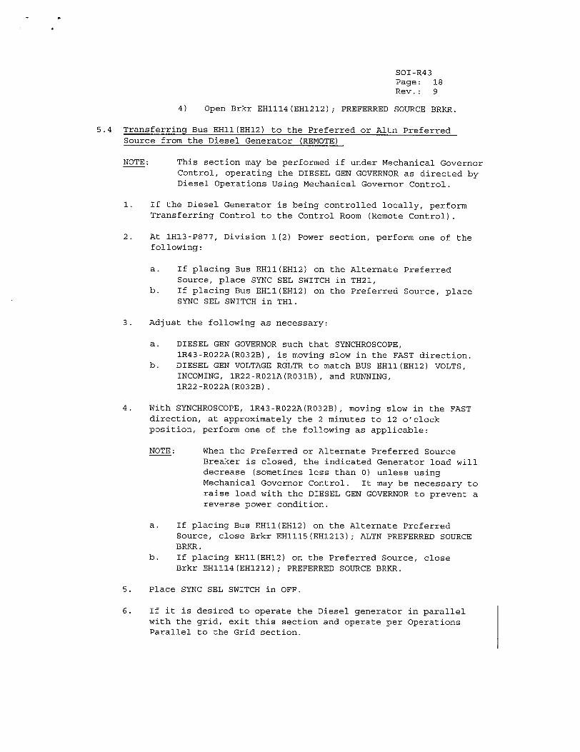
SOI-R43 Page: 18 Rev.: 9
4) Open Brkr EHl1l4(EH1212); PREFERRED SOURCE BRKR.
5.4 Transferring Bus EHIl(EH12) to the Preferred or Altn Preferred Source from the Diesel Generator (REMOTE)
NOTE: This section may be performed if under Mechanical Governor Control, operating the DIESEL GEN GOVERNOR as directed by Diesel Operations Using Mechanical Governor Control.
1. If the Diesel Generator is being controlled locally, perform Transferring Control to the Control Room (Remote Control).
2. At 1H13-P877, Division 1(2) Power section, perform one of the following:
a. If placing Bus EHIl(EH12) on the Alternate Preferred Source, place SYNC SEL SWITCH in TH21,
b. If placing Bus EHI1(EHI2) on the Preferred Source, place SYNC SEL SWITCH in THI.
3. Adjust the following as necessary:
a. DIESEL GEN GOVERNOR such that SYNCHROSCOPE, IR43-R022A(R032B), is moving slow in the FAST direction.
b. DIESEL GEN VOLTAGE RGLTR to match BUS EHll(EHI2) VOLTS, INCOMING, 1R22-RO21A(RO31B), and RUNNING, 1R22-R022A(R032B).
4. With SYNCHROSCOPE, 1R43-R022A(R032B), moving slow in the FAST direction, at approximately the 2 minutes to 12 o'clock position, perform one of the following as applicable:
NOTE: When the Preferred or Alternate Preferred Source Breaker is closed, the indicated Generator load will decrease (sometimes less than 0) unless using Mechanical Governor Control. It may be necessary to raise load with the DIESEL GEN GOVERNOR to prevent a reverse power condition.
a. If placing Bus EH1I(EHI2) on the Alternate Preferred Source, close Brkr EHlll5(EH1213); ALTN PREFERRED SOURCE BRKR.
b. If placing EHll(EHI2) on the Preferred Source, close Brkr EHlll4(EH1212); PREFERRED SOURCE BRKR.
5. Place SYNC SEL SWITCH in OFF.
6. If it is desired to operate the Diesel generator in parallel with the grid, exit this section and operate per Operations Parallel to the Grid section.
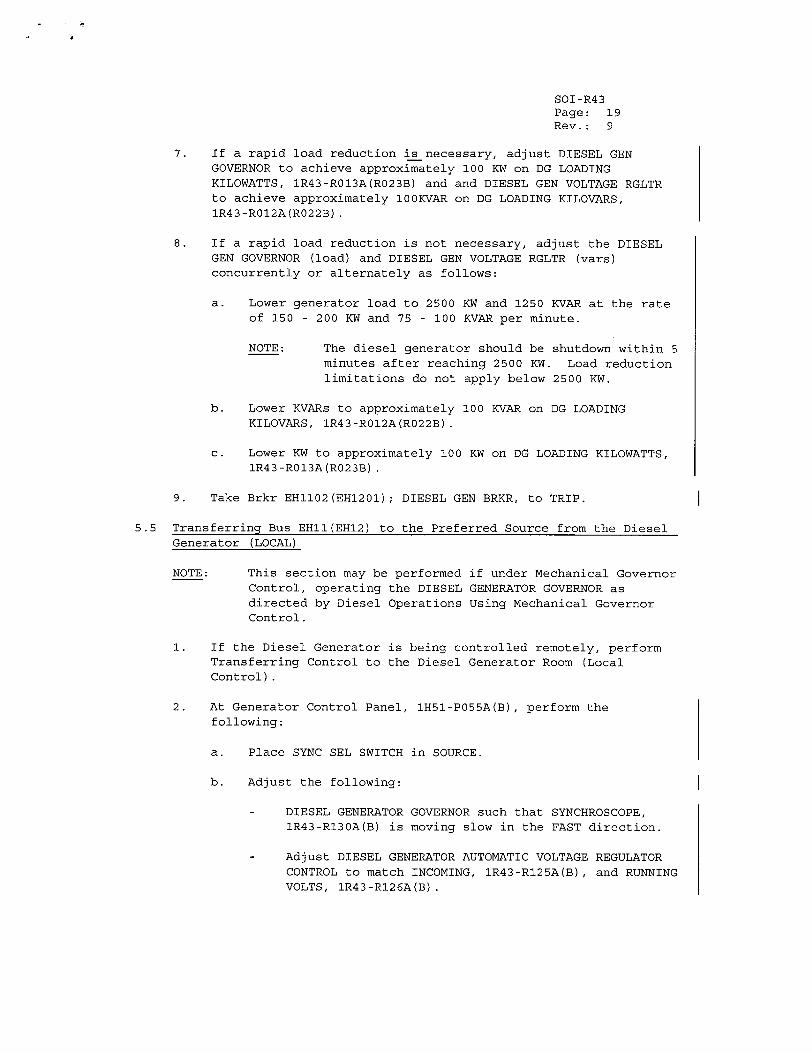
SOI-R43 Page: 19 Rev.: 9
7. If a rapid load reduction is necessary, adjust DIESEL GEN GOVERNOR to achieve approximately 100 KW on DG LOADING KILOWATTS, 1R43-R013A(R023B) and and DIESEL GEN VOLTAGE RGLTR to achieve approximately 100KVAR on DG LOADING KILOVARS, IR43-RO12A(R022B).
8. If a rapid load reduction is not necessary, adjust the DIESEL GEN GOVERNOR (load) and DIESEL GEN VOLTAGE RGLTR (vars) concurrently or alternately as follows:
a. Lower generator load to 2500 KW and 1250 KVAR at the rate of 150 - 200 KW and 75 - 100 KVAR per minute.
NOTE: The diesel generator should be shutdown within 5 minutes after reaching 2500 KW. Load reduction limitations do not apply below 2500 KW.
b. Lower KVARs to approximately 100 KVAR on DG LOADING KILOVARS, IR43-RO12A(R022B).
c. Lower KW to approximately 100 KW on DG LOADING KILOWATTS, 1R43-R013A(R023B).
9. Take Brkr EHII02(EHI201); DIESEL GEN BRKR, to TRIP.
5.5 Transferring Bus EHII(EH12) to the Preferred Source from the Diesel Generator (LOCAL)
NOTE: This section may be performed if under Mechanical Governor Control, operating the DIESEL GENERATOR GOVERNOR as directed by Diesel Operations Using Mechanical Governor Control.
1. If the Diesel Generator is being controlled remotely, perform Transferring Control to the Diesel Generator Room (Local Control).
2. At Generator Control Panel, lH51-PO55A(B), perform the following:
a. Place SYNC SEL SWITCH in SOURCE.
b. Adjust the following:
- DIESEL GENERATOR GOVERNOR such that SYNCHROSCOPE, 1R43-RI30A(B) is moving slow in the FAST direction.
- Adjust DIESEL GENERATOR AUTOMATIC VOLTAGE REGULATOR CONTROL to match INCOMING, 1R43-R125A(B), and RUNNING VOLTS, IR43-RI26A(B).
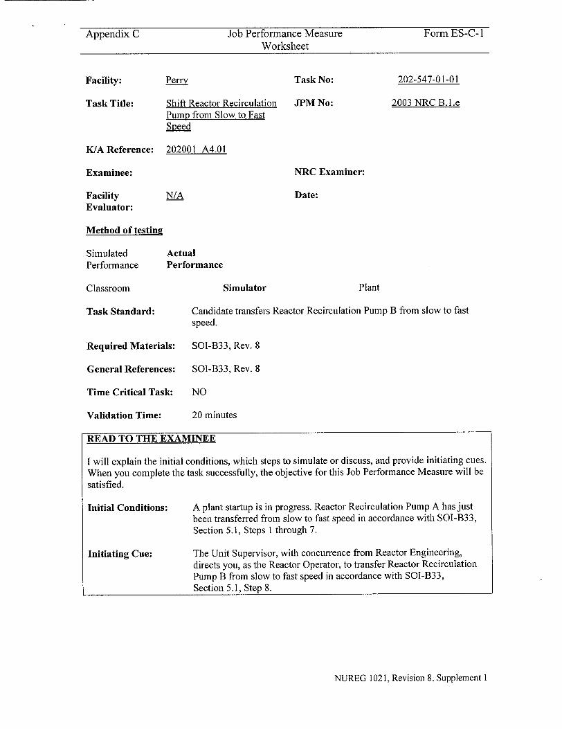
Appendix C Job Performance Measure Form ES-C-1 Worksheet
Perry
Shift Reactor Recirculation Pump from Slow to Fast Speed
Task No:
JPM No:
202-547-01-01
2003 NRC B. 1.e
K/A Reference:
Examinee:
Facility Evaluator:
202001 A4.01
N/A
Method of testing
Simulated Performance
Classroom
Actual Performance
Task Standard: Candidate transfers Reactor Recirculation Pump B from slow to fast speed.
Required Materials: SOI-B33, Rev. 8
General References:
Time Critical Task:
Validation Time:
SOI-B33, Rev. 8
NO
20 minutes
READ TO THE EXAMINEE
I will explain the initial conditions, which steps to simulate or discuss, and provide initiating cues. When you complete the task successfully, the objective for this Job Performance Measure will be satisfied.
Initial Conditions:
Initiating Cue:
A plant startup is in progress. Reactor Recirculation Pump A has just been transferred from slow to fast speed in accordance with SOI-B33, Section 5.1, Steps I through 7.
The Unit Supervisor, with concurrence from Reactor Engineering, directs you, as the Reactor Operator, to transfer Reactor Recirculation Pump B from slow to fast speed in accordance with SOI-B33, Section 5.1, Step 8.
NUREG 1021, Revision 8, Supplement 1
Facility:
Task Title:
NRC Examiner:
Date:
Simulator Plant
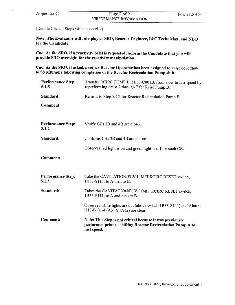
Appendix C Page 2 of 9 Form ES-C-1 PERFORMANCE INFORMATION
(Denote Critical Steps with an asterisk)
Note: The Evaluator will role-play as SRO, Reactor Engineer, I&C Technician, and NLO for the Candidate.
Cue: As the SRO, if a reactivity brief is requested, inform the Candidate that you will provide SRO oversight for the reactivity manipulation.
Cue: As the SRO, if asked, another Reactor Operator has been assigned to raise core flow to 58 Mlbm/hr following completion of the Reactor Recirculation Pump shift.
Performance Step: 5.1.8
Standard:
Transfer RCIRC PUMP B, 1B33-COOIB, from slow to fast speed by reperforming Steps 2 through 7 for Rcirc Pump B.
Returns to Step 5.1.2 for Reactor Recirculation Pump B.
Comment:
Performance Step: 5.1.2
Verify CBs 3B and 4B are closed.
Confirms CBs 3B and 4B are closed.
Observes red light is on and green light is off for each CB.
Performance Step: 5.1.3
Standard:
Comment:
Take the CAVITATION/FCV LIMIT RCIRC RESET switch, I B33-SI 11, to A then to B.
Takes the CAVITATION/FCV LIMIT RCIRC RESET switch, 1 B33-S 11, to A and then to B.
Observes white lights are out (above switch 1B33-S1 11) and Alarms H13-P601-4 (A3) & (A 12) are clear.
Note: This Step is not critical because it was previously performed prior to shifting Reactor Recirculation Pump A to fast speed.
NUREG 1021, Revision 8, Supplement I
Standard:
Comment:
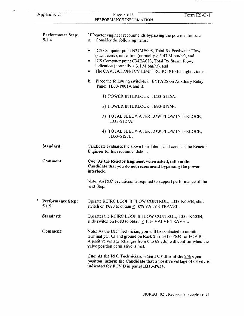
Appendix C Page 3 of 9 Form ES-C-I PERFORMANCE INFORMATION
Performance Step: 5.1.4
Standard:
Comment:
Performance Step: 5.1.5
Standard:
Comment:
If Reactor engineer recommends bypassing the power interlock: a. Consider the following items:
" ICS Computer point N27ME008, Total Rx Feedwater Flow (suct-recirc), indication (normally > 3.43 Mlbm/hr), and
" ICS Computer point C34EAO 13, Total Rx Steam Flow, indication (normally > 3.1 Mlbm/hr), and
"* The CAVITATION/FCV LIMIT RCIRC RESET lights status.
b. Place the following switches in BYPASS on Auxiliary Relay Panel, 1B33-POOIA and B:
1) POWER INTERLOCK, 1B33-S126A.
2) POWER INTERLOCK, 1B33-S 126B.
3) TOTAL FEEDWATER LOW FLOW INTERLOCK, 1B33-S127A.
4) TOTAL FEEDWATER LOW FLOW INTERLOCK, 1B33-S127B.
Candidate evaluates the above listed items and contacts the Reactor Engineer for his recommendation.
Cue: As the Reactor Engineer, when asked, inform the Candidate that you do not recommend bypassing the power interlock.
Note: An I&C Technician is required to support performance of the next Step.
Operate RCIRC LOOP B FLOW CONTROL, 1B33-K603B, slide switch on P680 to obtain < 10% VALVE TRAVEL.
Operates the RCIRC LOOP B FLOW CONTROL, 1 B33-K603B, slide switch on P680 to obtain < 10% VALVE TRAVEL.
Note: As the I&C Technician, you will be contacted to monitor terminal pt. 103 and ground on Rack 2 in IH13-P634 for FCV B. A positive voltage (changes from 0 to 68 vdc) will confirm when the valve position permissive is met.
Cue: As the I&C Technician, when FCV B is at the 9% open position, inform the Candidate that a positive voltage of 68 vdc is indicated for FCV B in panel 1H13-P634.
NUREG 1021, Revision 8, Supplement I
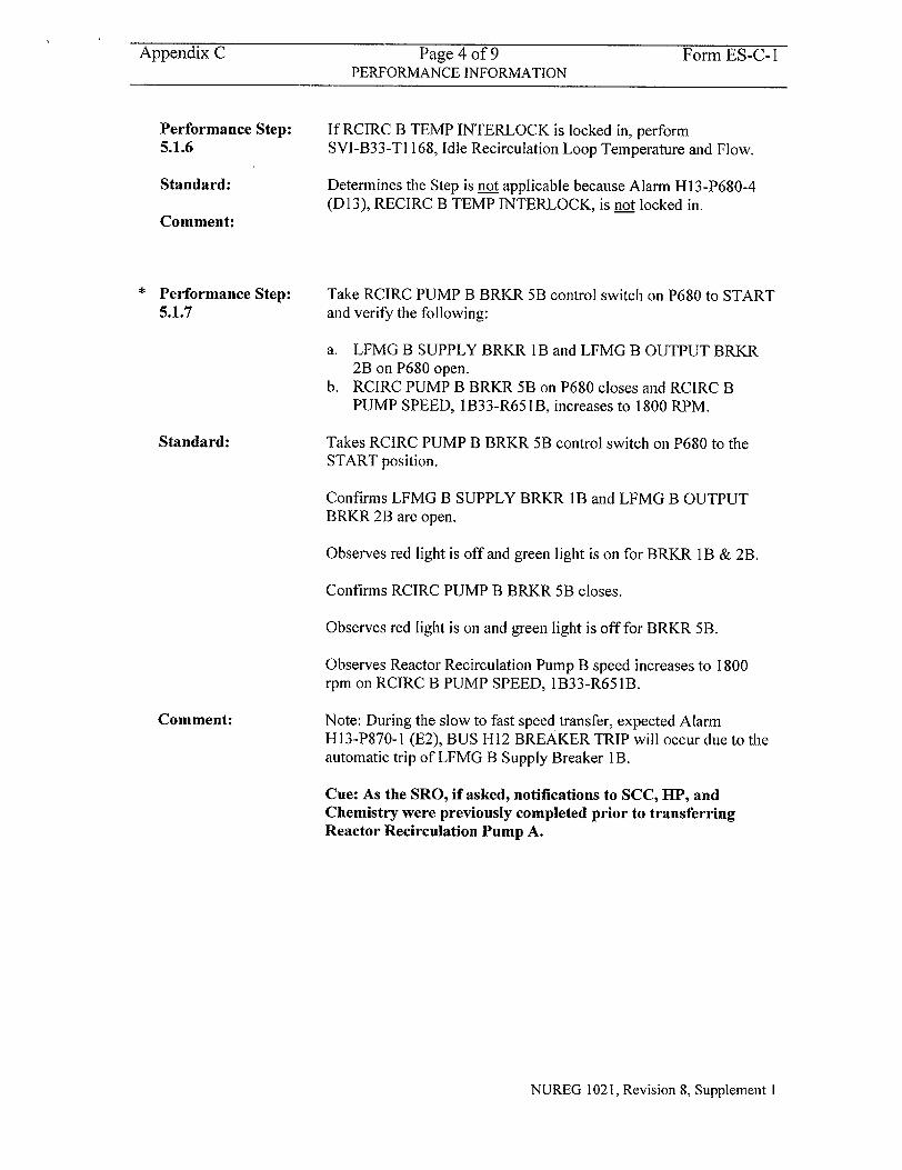
Appendix C Page 4 of 9 Form ES-C-1 PERFORMANCE INFORMATION
Performance Step: 5.1.6
Standard:
Comment:
Performance Step: 5.1.7
Standard:
Comment:
If RCIRC B TEMP INTERLOCK is locked in, perform SVI-B33-TI 168, Idle Recirculation Loop Temperature and Flow.
Determines the Step is not applicable because Alarm H 13-P680-4 (D13), RECIRC B TEMP INTERLOCK, is not locked in.
Take RCIRC PUMP B BRKR 5B control switch on P680 to START and verify the following:
a. LFMG B SUPPLY BRKR lB and LFMG B OUTPUT BRKR 2B on P680 open.
b. RCIRC PUMP B BRKR 5B on P680 closes and RCIRC B PUMP SPEED, 1B33-R651 B, increases to 1800 RPM.
Takes RCIRC PUMP B BRKR 5B control switch on P680 to the START position.
Confirms LFMG B SUPPLY BRKR lB and LFMG B OUTPUT BRKR 2B are open.
Observes red light is off and green light is on for BRKR 1 B & 2B.
Confirms RCIRC PUMP B BRKR 5B closes.
Observes red light is on and green light is off for BRKR 5B.
Observes Reactor Recirculation Pump B speed increases to 1800 rpm on RCIRC B PUMP SPEED, 1B33-R65 lB.
Note: During the slow to fast speed transfer, expected Alarm H13-P870-1 (E2), BUS H12 BREAKER TRIP will occur due to the automatic trip of LFMG B Supply Breaker lB.
Cue: As the SRO, if asked, notifications to SCC, ILP, and Chemistry were previously completed prior to transferring Reactor Recirculation Pump A.
NUREG 1021, Revision 8, Supplement 1
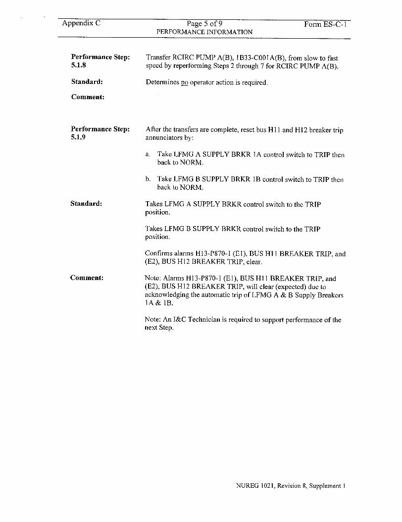
Appendix C Page 5 of 9 Form ES-C-1 PERFORMANCE INFORMATION
Performance Step: 5.1.8
Standard:
Transfer RCIRC PUMP A(B), 1B33-COO1A(B), from slow to fast speed by reperforming Steps 2 through 7 for RCIRC PUMP A(B).
Determines no operator action is required.
Comment:
Performance Step: 5.1.9
Standard:
Comment:
After the transfers are complete, reset bus HI I and H12 breaker trip annunciators by:
a. Take LFMG A SUPPLY BRKR 1A control switch to TRIP then back to NORM.
b. Take LFMG B SUPPLY BRKR 11B control switch to TRIP then back to NORM.
Takes LFMG A SUPPLY BRKR control switch to the TRIP position.
Takes LFMG B SUPPLY BRKR control switch to the TRIP position.
Confirms alarms H13-P870-1 (El), BUS HI 1 BREAKER TRIP, and (E2), BUS H12 BREAKER TRIP, clear.
Note: Alarms H13-P870-1 (El), BUS H 1I BREAKER TRIP, and (E2), BUS H12 BREAKER TRIP, will clear (expected) due to acknowledging the automatic trip of LFMG A & B Supply Breakers ]A& lB.
Note: An I&C Technician is required to support performance of the next Step.
NUREG 1021, Revision 8, Supplement I
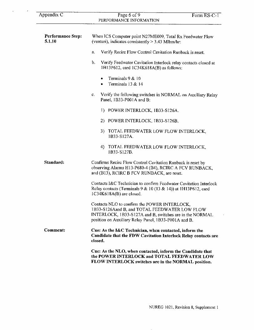
Appendix C Page 6 of 9 Form ES-C-I PERFORMANCE INFORMATION
Performance Step: When ICS Computer point N27ME009, Total Rx Feedwater Flow
5.1.10 (venturi), indicates consistently > 3.43 Mlbm/hr:
a. Verify Recirc Flow Control Cavitation Runback is reset.
b. Verify Feedwater Cavitation Interlock relay contacts closed at 1H13P612, card 1C34K618A(B) as follows:
"* Terminals9& 10 "* Terminals 13 & 14
c. Verify the following switches in NORMAL on Auxiliary Relay Panel, 1B33-POOIA and B:
1) POWER INTERLOCK, 1B33-S126A.
2) POWER INTERLOCK, 1B33-S126B.
3) TOTAL FEEDWATER LOW FLOW INTERLOCK, 1 B33-S 127A.
4) TOTAL FEEDWATER LOW FLOW INTERLOCK, 1B33-S127B.
Standard: Confirms Recirc Flow Control Cavitation Runback is reset by observing Alarms H13-P680-4 (B4), RCIRC A FCV RUNBACK, and (B113), RCIRC B FCV RUNBACK, are reset.
Contacts I&C Technician to confirm Feedwater Cavitation Interlock Relay contacts (Terminals 9 & 10 (13 & 14)) at 1H13P612, card 1 C34K618A(B) are closed.
Contacts NLO to confirm the POWER INTERLOCK, I B33-S I 26Aand B, and TOTAL FEEDWATER LOW FLOW INTERLOCK, I B33-S I 27A and B, switches are in the NORMAL position on Auxiliary Relay Panel, 1B33-POOIA and B.
Comment: Cue: As the I&C Technician, when contacted, inform the Candidate that the FDW Cavitation Interlock Relay contacts are closed.
Cue: As the NLO, when contacted, inform the Candidate that the POWER INTERLOCK and TOTAL FEEDWATER LOW FLOW INTERLOCK switches are in the NORMAL position.
NUREG 1021, Revision 8, Supplement I
Appendix C
Performance Step: 5.1.11
Standard:
Comment:
Page 7 of 9 Form ES-CPage 7 of 9 Form ES-C
PERFORMANCE INFORMATION
Perform independent verification of required components.
Contacts NLO to perform independent verification of required components.
Cue: As the NLO, inform the Candidate that you will perform the independent verification of the required components.
;-1
Terminating Cue:
When SOI-B33, Section 5.1 is completed, the evaluation for this JPM is complete.
NUREG 1021, Revision 8, Supplement I
Appendix C Page 8 of 9 Form ES-C-1 VERIFICATION OF COMPLETION
Job Performance Measure No.
Examinee's Name:
Examiner's Name:
Date Performed:
Facility Evaluator:
Number of Attempts:
Time to complete:
Question Documentation:
Question:
Response:
Result:
2003 NRC B.L.e
N/A
SAT OR UNSAT
Examiner's Signature and Date:
NUREG 1021, Revision 8, Supplement I
Appendix C Page 9 of 9 Form ES-C-I JPM CUE SHEET
INITIAL CONDITIONS:
INITIATING CUE:
A plant startup is in progress. Reactor Recirculation Pump A has just been transferred from slow to fast speed in accordance with SOI-B33, Section 5.1, Steps I through 7.
The Unit Supervisor, with concurrence from Reactor Engineering, directs you, as the Reactor Operator, to transfer Reactor Recirculation Pump B from slow to fast speed in accordance with SOI-B33, Section 5.1, Step 8.
NUREG 1021, Revision 8, Supplement I
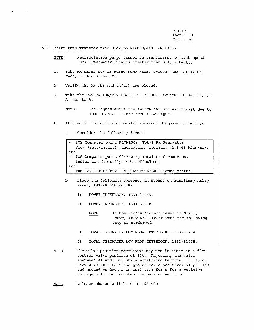
SOI-B33 Page: 11 Rev.: 8
5.1 Rcirc Pump Transfer from Slow to Fast Speed <FO1365>
NOTE: Recirculation pumps cannot be transferred to fast speed until Feedwater Flow is greater than 3.43 Mlbm/hr.
1. Take RX LEVEL LOW L3 RCIRC PUMP RESET switch, 1B33-S113, on P680, to A and then B.
2. Verify CBs 3A(3B) and 4A(4B) are closed.
3. Take the CAVITATION/FCV LIMIT RCIRC RESET switch, IB33-SIII, to A then to B.
NOTE: The lights above the switch may not extinguish due to inaccuracies in the feed flow signal.
4. If Reactor engineer recommends bypassing the power interlock:
a. Consider the following items:
- ICS Computer point N27ME008, Total Rx Feedwater Flow (suct-recirc), indication (normally Ž 3.43 Mlbm/hr),
and - ICS Computer point C34EA013, Total Rx Steam Flow,
indication (normally Ž 3.1 Mlbm/hr), and - The CAVITATION/FCV LIMIT RCIRC RESET lights status.
b. Place the following switches in BYPASS on Auxiliary Relay Panel, 1B33-P001A and B:
1) POWER INTERLOCK, 1B33-S126A.
2) POWER INTERLOCK, 1B33-S126B.
NOTE: If the lights did not reset in Step 3 above, they will reset when the following Step is performed.
3) TOTAL FEEDWATER LOW FLOW INTERLOCK, 1B33-S127A.
4) TOTAL FEEDWATER LOW FLOW INTERLOCK, 1B33-S127B.
NOTE: The valve position permissive may not initiate at a flow control valve position of 10%s. Adjusting the valve (between 8% and 10%) while monitoring terminal pt. 95 on Rack 2 in 1H13-P634 and ground for A and terminal pt. 103 and ground on Rack 2 in 1H13-P634 for B for a positive voltage will confirm when the permissive is met.
Voltage change will be 0 to -68 vdc.NOTE:
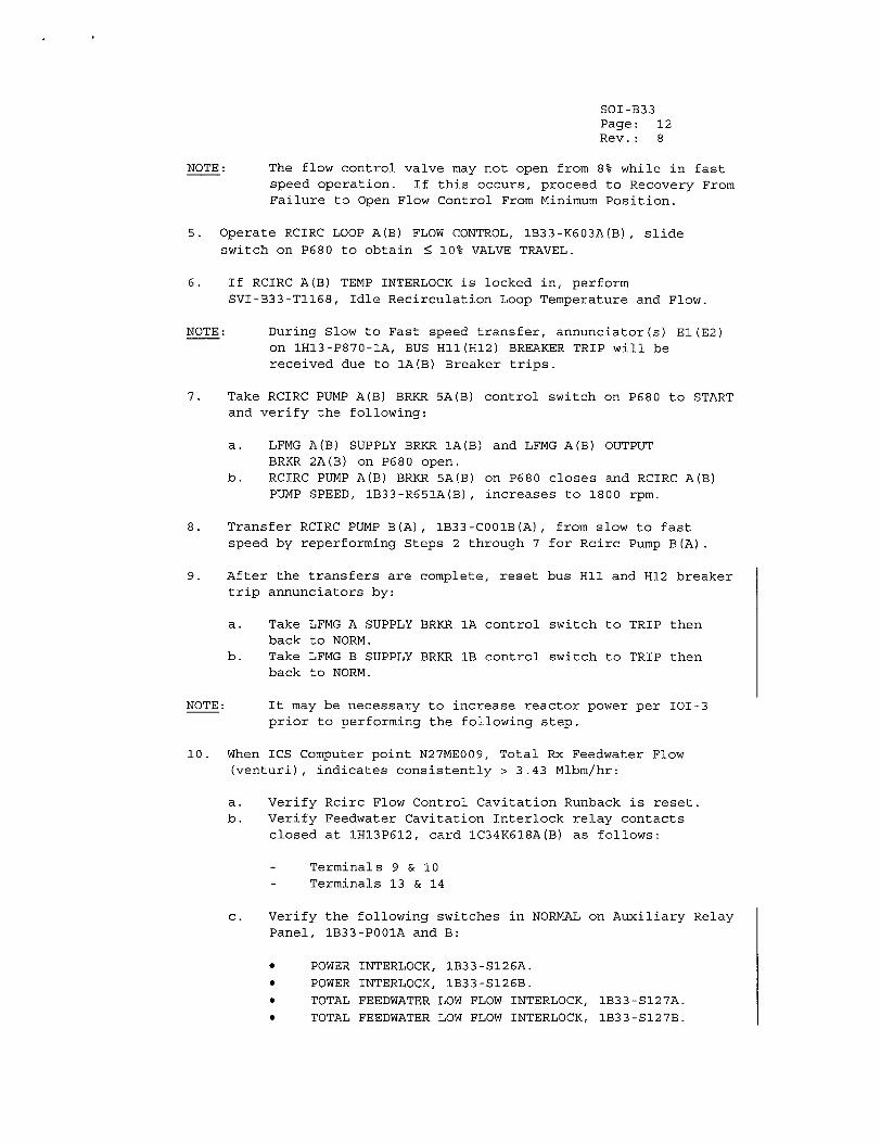
SOI-B33 Page: 12 Rev.: 8
NOTE: The flow control valve may not open from 8% while in fast speed operation. If this occurs, proceed to Recovery From Failure to Open Flow Control From Minimum Position.
5. Operate RCIRC LOOP A(B) FLOW CONTROL, IB33-K603A(B), slide switch on P680 to obtain • 10% VALVE TRAVEL.
6. If RCIRC A(B) TEMP INTERLOCK is locked in, perform SVI-B33-TI168, Idle Recirculation Loop Temperature and Flow.
NOTE: During Slow to Fast speed transfer, annunciator(s) El(E2) on IH13-P870-1A, BUS HII(H12) BREAKER TRIP will be received due to IA(B) Breaker trips.
7. Take RCIRC PUMP A(B) BRKR 5A(B) control switch on P680 to START and verify the following:
a. LFMG A(B) SUPPLY BRKR IA(B) and LFMG A(B) OUTPUT BRKR 2A(B) on P680 open.
b. RCIRC PUMP A(B) BRKR 5A(B) on P680 closes and RCIRC A(B) PUMP SPEED, IB33-R651A(B), increases to 1800 rpm.
8. Transfer RCIRC PUMP B(A), 1B33-C001B(A), from slow to fast speed by reperforming Steps 2 through 7 for Rcirc Pump B(A).
9. After the transfers are complete, reset bus HI1 and H12 breaker trip annunciators by:
a. Take LFMG A SUPPLY BRKR 1A control switch to TRIP then back to NORM.
b. Take LFMG B SUPPLY BRKR lB control switch to TRIP then back to NORM.
NOTE: It may be necessary to increase reactor power per 101-3 prior to performing the following step.
10. When ICS Computer point N27ME009, Total Rx Feedwater Flow (venturi), indicates consistently > 3.43 Mlbm/hr:
a. Verify Rcirc Flow Control Cavitation Runback is reset. b. Verify Feedwater Cavitation Interlock relay contacts
closed at 1H13P612, card IC34K618A(B) as follows:
- Terminals 9 & 10 - Terminals 13 & 14
c. Verify the following switches in NORMAL on Auxiliary Relay Panel, 1B33-P001A and B:
"* POWER INTERLOCK, 1B33-S126A. "* POWER INTERLOCK, 1B33-S126B. "* TOTAL FEEDWATER LOW FLOW INTERLOCK, IB33-S127A. "• TOTAL FEEDWATER LOW FLOW INTERLOCK, 1B33-S127B.
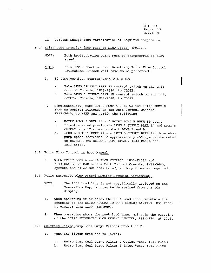
SOI-B33 Page: 13 Rev.: 8
11. Perform independent verification of required components.
5.2 Rcirc Pump Transfer from Fast to Slow Speed <F01365>
NOTE: Both Recirculation Pumps must be transferred to slow speed.
NOTE: If a FCV runback occurs, Resetting Rcirc Flow Control Cavitation Runback will have to be performed.
1. If time permits, startup LFMG A & B by:
a. Take LFMG ASUPPLY BRKR 1A control switch on the Unit Control Console, 1H13-P680, to CLOSE.
b. Take LFMG B SUPPLY BRKR lB control switch on the Unit Control Console, IH13-P680, to CLOSE.
2. Simultaneously, take RCIRC PUMP A BRKR 5A and RCIRC PUMP B BRKR 5B control switches on the Unit Control Console, IH13-P680, to XFER and verify the following:
a. RCIRC PUMP A BRKR SA and RCIRC PUMP B BRKR 5B open. b. If not started previously LFMG A SUPPLY BRKR 1A and LFMG B
SUPPLY BRKR lB close to start LFMG A and B. c. LFMG A OUTPUT BRKR 2A and LFMG B OUTPUT BRKR 2B close when
pump speed decreases to approximately 450 rpm as indicated on RCIRC A and RCIRC B PUMP SPEED, 1B33-R651A and 1B33-R651B.
5.3 Rcirc Flow Control in Loop Manual
1. With RCIRC LOOP A and B FLOW CONTROL, 1B33-K603A and 1B33-K603B, in MAN on the Unit Control Console, IH13-P680, operate the slide switches to adjust loop flows as required.
5.4 Rcirc Automatic Flow Demand Limiter Setpoint Adjustment
NOTE: The 100% load line is not specifically depicted on the Power/Flow Map, but can be determined from the ICS display.
1. When operating at or below the 100% load line, maintain the setpoint of the RCIRC AUTOMATIC FLOW DEMAND LIMITER, B33-K650, at greater than 110% (maximum).
2. When operating above the 100% load line, maintain the setpoint of the RCIRC AUTOMATIC FLOW DEMAND LIMITER, B33-K650, at 104%.
5.5 Shifting Recirc Pump Seal Purge Filters from A to B
1. Vent the filter from the following:
a. Rcirc Pump Seal Purge Filter B Outlet Vent, ICII-F145B b. Rcirc Pump Seal Purge Filter B Inlet Vent, lCII-F149B
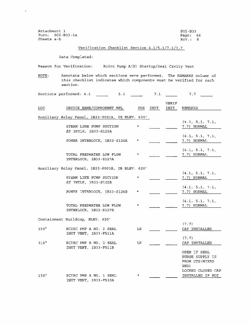
Attachment 1 Form: SOI-B33-1a Sheets a-b
SOI-B33 Page: 66 Rev.: 8
Verification Checklist Section 4.1/5.1/7.1/7.7
Date Completed:
for Verification: Rcirc Pump A(B) Startup/Seal Cavity Vent
Annotate below which sections were performed. The REMARKS column of
this checklist indicates which components must be verified for each section.
Sections performed: 4.1 5.1
LOC DEVICE NAME/COMPONENT MPL POS
Auxiliary Relay Panel, 1B33-P001A, IB ELEV. 620'
STEAM LINE PUMP SUCTION *
AT INTLK, IB33-S125A
POWER INTERLOCK, 1B33-S126A *
TOTAL FEEDWATER LOW FLOW
INTERLOCK, 1B33-S127A
Auxiliary Relay Panel, 1B33-P001B, IB ELEV.
STEAM LINE PUMP SUCTION
AT INTLK, 1B33-S125B
POWER INTERLOCK, 1B33-S126B
Containment
1500
3100
1500
TOTAL FEEDWATER LOW FLOW
INTERLOCK, IB33-SI27B
Building, ELEV. 620'
RCIRC PMP A NO. 2 SEAL INST VENT, 1B33-F511A
RCIRC PMP B NO. 2 SEAL
INST VENT, 1B33-F511B
620'
*
LX
LX
*RCIRC PMP A NO. 1 SEAL
INST VENT, 1B33-F510A
7.1
INIT
VERIF
INIT
7.7
REMARKS
(4.1, 5.1, 7.1,
7.7) NORMAL
(4.1, 5.1, 7.1,
7.7) NORMAL
(4.1, 5.1, 7.1,
7.7) NORMAL
(4.1, 5.1, 7.1,
7.7) NORMAL
(4.1, 5.1, 7.1,
7.7) NORMAL
(4.1, 5.1, 7.1,
7.7) NORMAL
(7.7)
CAP INSTALLED
(7.7)
CAP INSTALLED
OPEN IF SEAL
PURGE SUPPLY IS FROM CTS (MIXED
BED) LOCKED CLOSED CAP
INSTALLED IF NOT
Reason
NOTE:
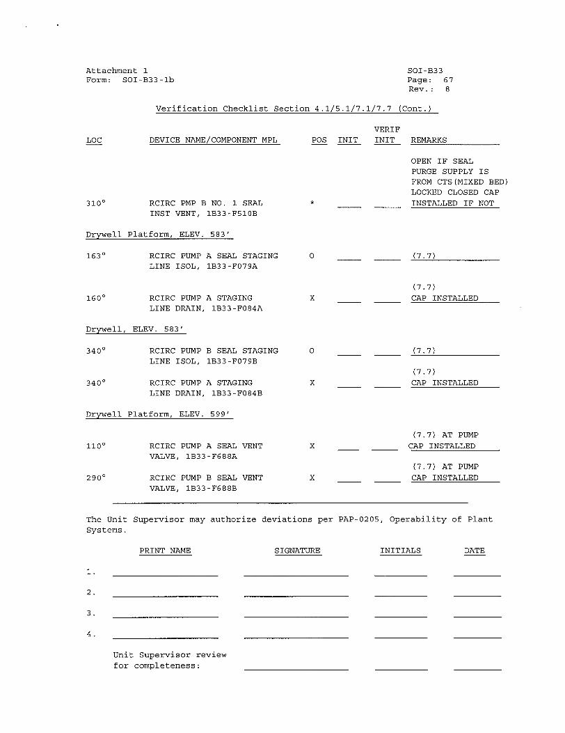
Attachment 1 Form: SOI-B
LOC
SOI-B33 33-lb Page: 67
Rev.: 8
Verification Checklist Section 4.1/5.1/7.1/7.7 (Cont.)
VERIF
DEVICE NAME/COMPONENT MPL POS INIT INIT REMARKS
310 0 RCIRC PMP B NO. 1 SEAL
INST VENT, 1B33-F510B
Drywell Platform, ELEV. 583'
1630 RCIRC PUMP A SEAL STAGING LINE ISOL, 1B33-F079A
1600 RCIRC PUMP A STAGING LINE DRAIN, 1B33-F084A
Drywell, ELEV. 583'
3400 RCIRC PUMP B SEAL STAGING
LINE ISOL, 1B33-F079B
3400 RCIRC PUMP A STAGING LINE DRAIN, 1B33-F084B
Drywell Platform, ELEV. 599'
1100
2900
RCIRC PUMP A SEAL VENT VALVE, 1B33-F688A
RCIRC PUMP B SEAL VENT
VALVE, IB33-F688B
*
0
X
0
x
X
X
OPEN IF SEAL PURGE SUPPLY IS FROM CTS(MIXED BED) LOCKED CLOSED CAP
INSTALLED IF NOT
(7.7)
(7.7)
CAP INSTALLED
(7.7)
(7.7)
CAP INSTALLED
(7.7) AT PUMP
CAP INSTALLED
(7.7) AT PUMP
CAP INSTALLED
The Unit Supervisor may authorize deviations per PAP-0205, Operability of Plant
Systems.
PRINT NAME
Unit Supervisor review
for completeness:
SIGNATURE INITIALS DATE
1.
2.
3.
4.
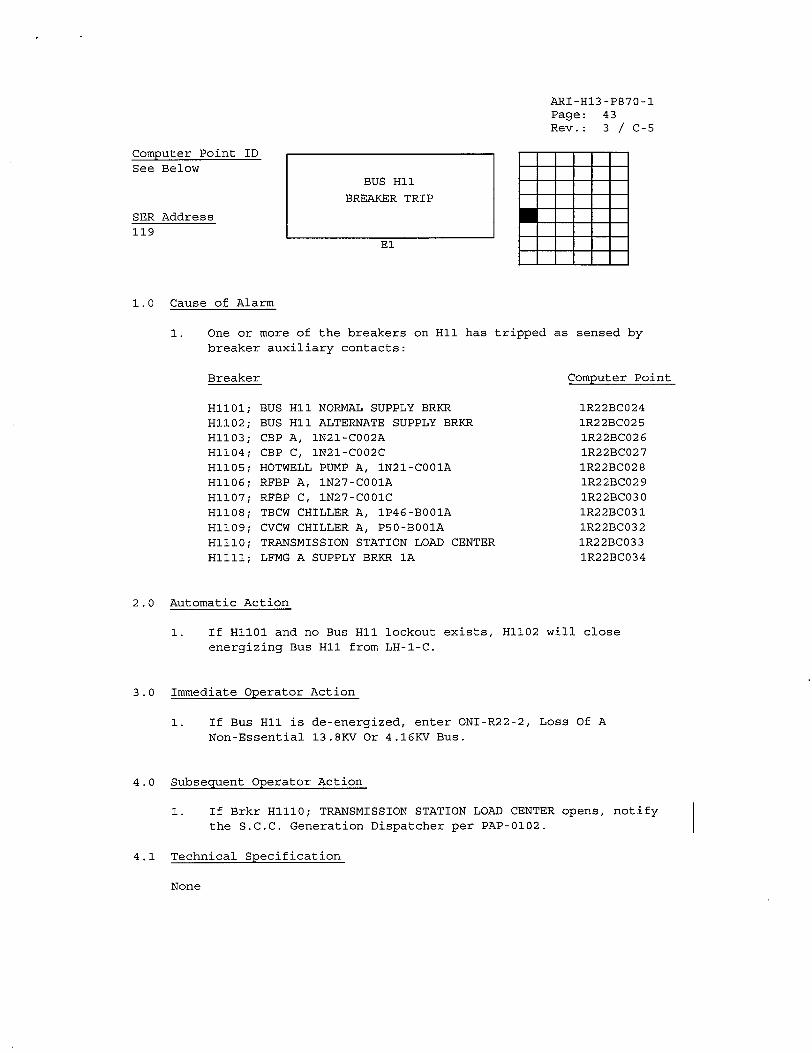
ARI-H13-P870-1 Page: 43 Rev.: 3 / C-5
Computer Point ID
See Below
SER Address 119
1.0 Cause of Alarm
1. One or more of the breakers on HI1 has tripped
breaker auxiliary contacts:
Breaker
H1101;
H1102;
H1103;
H1104;
H1105; H1106;
H1107; H1108;
H1109;
H1ll0;
H1ll1;
BUS H1 NORMAL SUPPLY BRKR
BUS H11 ALTERNATE SUPPLY BRKR
CBP A, IN21-CO02A CBP C, 1N21-C002C HOTWELL PUMP A, IN21-CO01A
RFBP A, 1N27-C001A RFBP C, 1N27-C001C TBCW CHILLER A, 1P46-B001A
CVCW CHILLER A, P50-BOOIA
TRANSMISSION STATION LOAD CENTER
LFMG A SUPPLY BRKR 1A
as sensed by
Computer Point
IR22BC024 1R22BC025
1R22BC026 1R22BC027 IR22BC028
1R22BC029
1R22BC030
1R22BC031
1R22BC032 IR22BC033
IR22BC034
2.0 Automatic Action
1. If H1l01 and no Bus HI1 lockout exists, H1102 will close
energizing Bus H11 from LH-l-C.
3.0 Immediate Operator Action
1. If Bus HI1 is de-energized, enter ONI-R22-2, Loss Of A
Non-Essential 13.8KV Or 4.16KV Bus.
4.0 Subsequent Operator Action
1. If Brkr H1110; TRANSMISSION STATION LOAD CENTER opens, notify the S.C.C. Generation Dispatcher per PAP-0102.
4.1 Technical Specification
None
BUS HI1
BREAKER TRIP
El
U
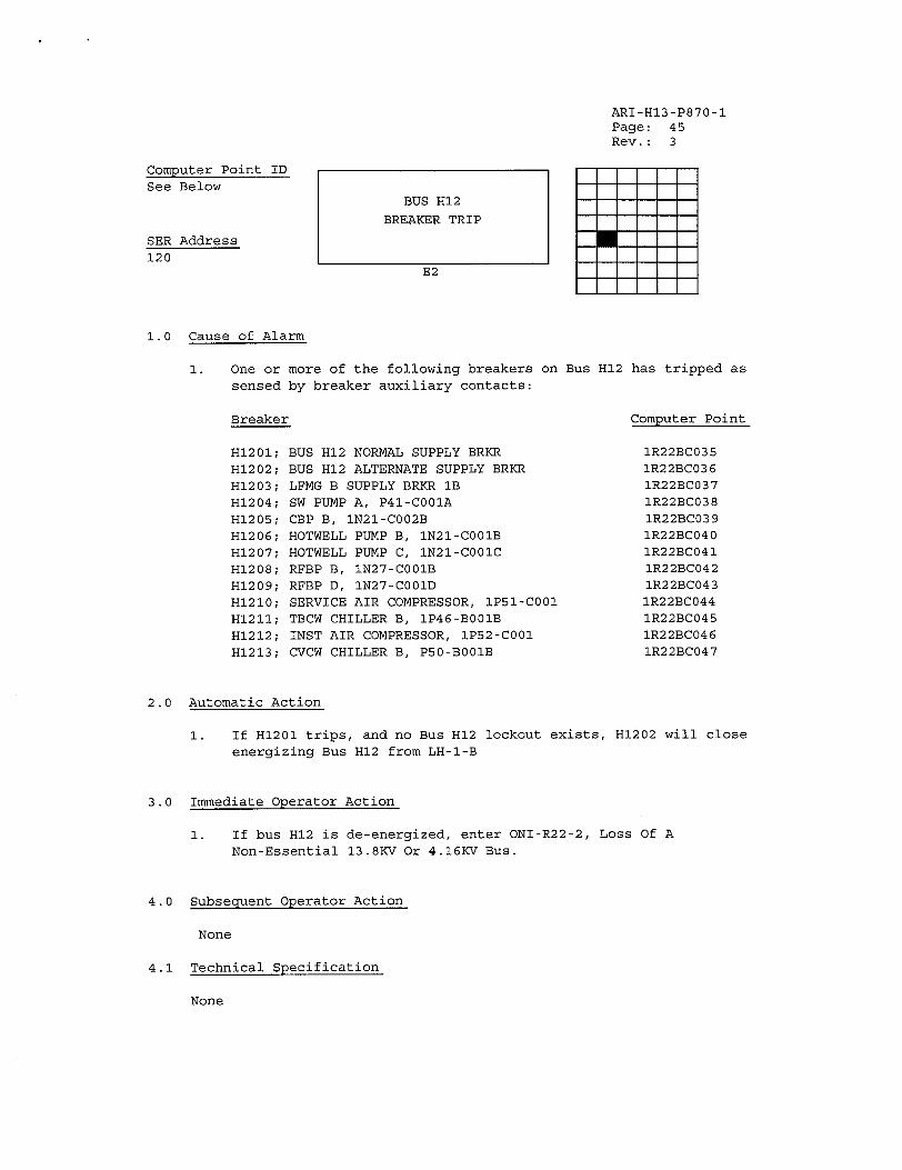
ARI-H13-P870-1 Page: 45 Rev.: 3
Computer Point ID
See Below
SER Address 120
1.0 Cause of Alarm
1. One or more of the following breakers
sensed by breaker auxiliary contacts:
Breaker
H1201;
H1202;
H1203; H1204;
H1205; H1206;
H1207;
H1208; H1209;
H1210; H1211;
H1212;
H1213;
BUS H12 NORMAL SUPPLY BRKR
BUS H12 ALTERNATE SUPPLY BRKR
LFMG B SUPPLY BRKR lB
SW PUMP A, P41-COOIA
CBP B, 1N21-C002B HOTWELL PUMP B, 1N21-C001B
HOTWELL PUMP C, 1N21-C001C RFBP B, 1N27-C001B
RFBP D, IN27-COOlD SERVICE AIR COMPRESSOR, 1P51-C001 TBCW CHILLER B, 1P46-B001B
INST AIR COMPRESSOR, IP52-COOI
CVCW CHILLER B, P50-BO01B
on Bus H12 has tripped as
Computer Point
1R22BC035 IR22BC036 IR22BC037
1R22BC038
1R22BC039 1R22BC040
1R22BC041
1R22BC042 1R22BC043
1R22BC044 1R22BC045 1R22BC046
1R22BC047
2.0 Automatic Action
1. If H1201 trips, and no Bus H12 lockout exists, H1202 will close
energizing Bus H12 from LH-I-B
3.0 Immediate Operator Action
1. If bus H12 is de-energized, enter ONI-R22-2, Loss Of A
Non-Essential 13.8KV Or 4.16KV Bus.
4.0 Subsequent Operator Action
None
4.1 Technical Specification
None
BUS H12
BREAKER TRIP
E2
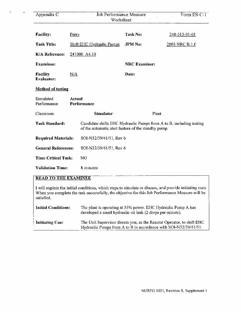
Appendix C Job Performance Measure Form ES-C-I Worksheet
Perry
Shift EHC Hydraulic Pumps
Task No:
JPM No:
248-513-01-01
2003 NRC B.l.f
K/A Reference: 241000 A4.10
Examinee:
Facility Evaluator:
N/A
Method of testing
Simulated Performance
Classroom
Actual Performance
Task Standard: Candidate shifts EHC Hydraulic Pumps from A to B, including testing of the automatic start feature of the standby pump.
Required Materials: SOI-N32/39/41/5 1, Rev 6
General References: SOI-N32/39/41/5 1, Rev 6
Time Critical Task:
Validation Time:
NO
8 minutes
READ TO THE EXAMINEE
I will explain the initial conditions, which steps to simulate or discuss, and provide initiating cues. When you complete the task successfully, the objective for this Job Performance Measure will be satisfied.
Initial Conditions:
Initiating Cue:
The plant is operating at 35% power. EHC Hydraulic Pump A has developed a small hydraulic oil leak (2 drops per minute).
The Unit Supervisor directs you, as the Reactor Operator, to shift EHC Hydraulic Pumps from A to B in accordance with SOI-N32/39/41/5 1.
NUREG 1021, Revision 8, Supplement I
Facility:
Task Title:
NRC Examiner:
Date:
Simulator Plant
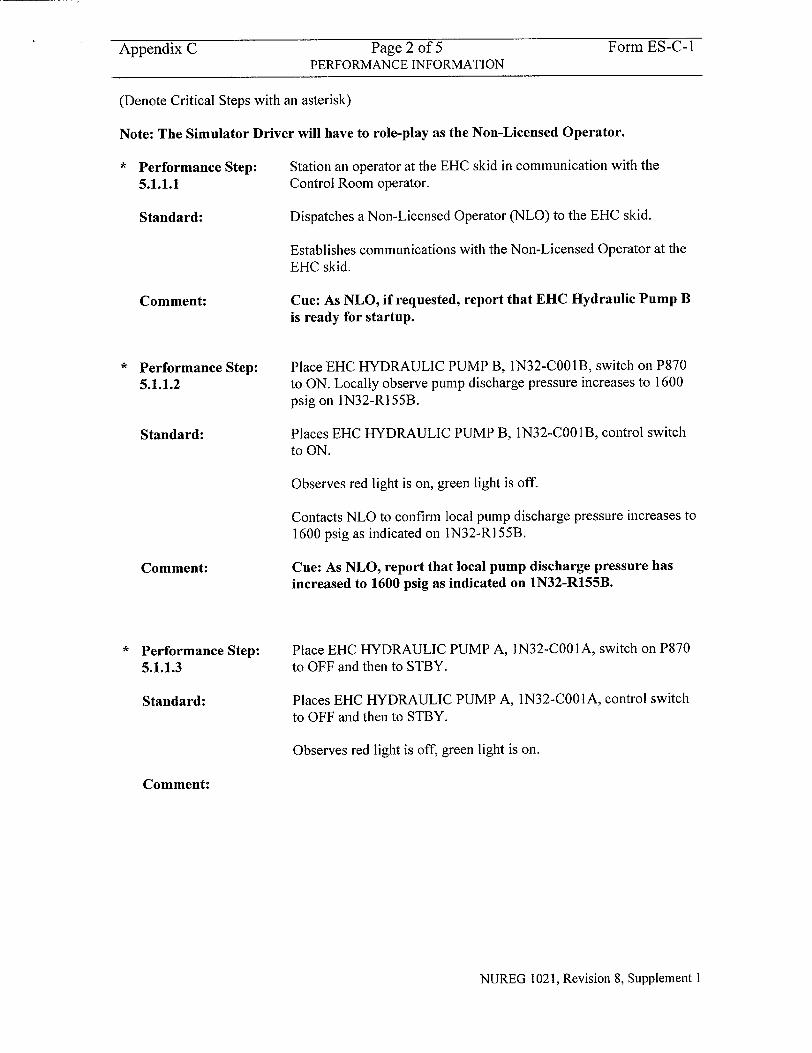
Appendix C Page 2 of 5 Form ES-C-I PERFORMANCE INFORMATION
(Denote Critical Steps with an asterisk)
Note: The Simulator Driver will have to role-play as the Non-Licensed Operator.
* Performance Step: Station an operator at the EHC skid in communication with the
5.1.1.1 Control Room operator.
Standard: Dispatches a Non-Licensed Operator (NLO) to the EHC skid.
Establishes communications with the Non-Licensed Operator at the EHC skid.
Comment: Cue: As NLO, if requested, report that EHC Hydraulic Pump B is ready for startup.
Performance Step: 5.1.1.2
Standard:
Comment:
Performance Step: 5.1.1.3
Standard:
Place EHC HYDRAULIC PUMP B, 1N32-COO1B, switch on P870 to ON. Locally observe pump discharge pressure increases to 1600 psig on 1N32-R155B.
Places EHC HYDRAULIC PUMP B, 1N32-COOI B, control switch
to ON.
Observes red light is on, green light is off.
Contacts NLO to confirm local pump discharge pressure increases to 1600 psig as indicated on 1N32-RI55B.
Cue: As NLO, report that local pump discharge pressure has increased to 1600 psig as indicated on 1N32-R155B.
Place EHC HYDRAULIC PUMP A, 1N32-COO1 A, switch on P870 to OFF and then to STBY.
Places EHC HYDRAULIC PUMP A, 1N32-COO IA, control switch to OFF and then to STBY.
Observes red light is off, green light is on.
Comment:
NUREG 1021, Revision 8, Supplement I
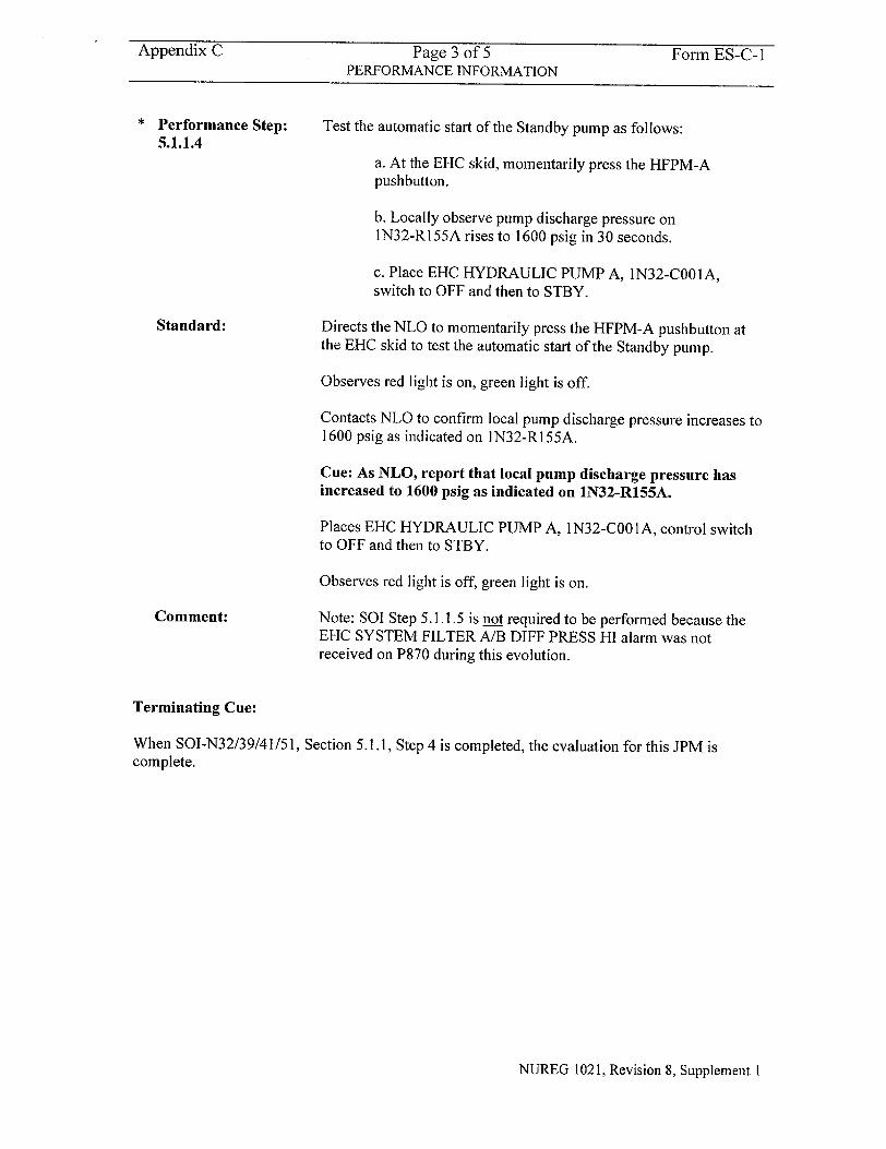
Appendix C Page 3 of 5 Form ES-C-I PERFORMANCE INFORMATION
Performance Step: 5.1.1.4
Standard:
Comment:
Test the automatic start of the Standby pump as follows:
a. At the EHC skid, momentarily press the HFPM-A pushbutton.
b. Locally observe pump discharge pressure on IN32-R155A rises to 1600 psig in 30 seconds.
c. Place EHC HYDRAULIC PUMP A, 1N32-C00 IA, switch to OFF and then to STBY.
Directs the NLO to momentarily press the HFPM-A pushbutton at the EHC skid to test the automatic start of the Standby pump.
Observes red light is on, green light is off.
Contacts NLO to confirm local pump discharge pressure increases to 1600 psig as indicated on IN32-R155A.
Cue: As NLO, report that local pump discharge pressure has increased to 1600 psig as indicated on 1N32-R155A.
Places EHC HYDRAULIC PUMP A, 1N32-C001A, control switch to OFF and then to STBY.
Observes red light is off, green light is on.
Note: SOI Step 5.1.1.5 is not required to be performed because the EHC SYSTEM FILTER A/B DIFF PRESS HI alarm was not received on P870 during this evolution.
Terminating Cue:
When SOI-N32/39/41/51, Section 5.1.1, Step 4 is completed, the evaluation for this JPM is complete.
NUREG 1021, Revision 8, Supplement 1
Appendix C Page 4 of 5 Form ES-C- I VERIFICATION OF COMPLETION
Job Performance Measure No.
Examinee' s Name:
Examiner's Name:
Date Performed:
Facility Evaluator:
Number of Attempts:
Time to complete:
Question Documentation:
Question:
Response:
Result:
2003 NRC B. 1.f
N/A
SAT OR UNSAT
Examiner's Signature and Date:
NUREG 1021, Revision 8, Supplement I
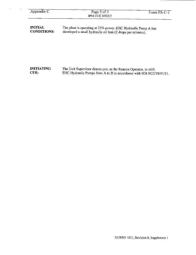
Appendix C Page 5 of 5 Form ES-C-I JPM CUE SHEET
INITIAL CONDITIONS:
INITIATING CUE:
The plant is operating at 35% power. EHC Hydraulic Pump A has developed a small hydraulic oil leak (2 drops per minutes).
The Unit Supervisor directs you, as the Reactor Operator, to shift EHC Hydraulic Pumps from A to B in accordance with SOI-N32/39/41/51.
NUREG 1021, Revision 8, Supplement I
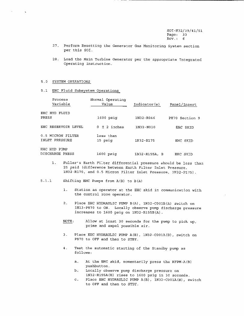
SOI-N32/39/41/51 Page: 33 Rev.: 6
27. Perform Resetting the Generator Gas Monitoring System section per this SOI.
28. Load the Main Turbine Generator per the appropriate Integrated Operating Instruction.
5.0 SYSTEM OPERATIONS
5.1 EHC Fluid Subsystem Operations
Process Normal Operating Variable Value Indicator(s) Panel/Insert
EHC HYD FLUID PRESS 1600 psig 1N32-R046 P870 Section 9
EHC RESERVOIR LEVEL 0 ± 2 inches 1N32-N010 EHC SKID
0.5 MICRON FILTER less than INLET PRESSURE 15 psig 1N32-R175 EHC SKID
EHC HYD PUMP DISCHARGE PRESS 1600 psig 1N32-R155A, B EHC SKID
1. Fuller's Earth Filter differential pressure should be less than 25 psid (difference between Earth Filter Inlet Pressure, 1N32-R170, and 0.5 Micron Filter Inlet Pressure, IN32-PI75).
5.1.1 Shifting EHC Pumps from A(B) to B(A)
1. Station an operator at the EHC skid in communication with the control room operator.
2. Place EHC HYDRAULIC PUMP B(A), 1N32-C001B(A) switch on IH13-P870 to ON. Locally observe pump discharge pressure increases to 1600 psig on IN32-R155B(A).
NOTE: Allow at least 30 seconds for the pump to pick up, prime and expel possible air.
3. Place EHC HYDRAULIC PUMP A(B), IN32-CO01A(B), switch on P870 to OFF and then to STBY.
4. Test the automatic starting of the Standby pump as follows:
a. At the EHC skid, momentarily press the HFPM-A(B) pushbutton.
b. Locally observe pump discharge pressure on 1N32-R155A(B) rises to 1600 psig in 30 seconds.
c. Place EHC HYDRAULIC PUMP A(B), IN32-CO01A(B), switch to OFF and then to STBY.
Appendix C Job Performance Measure Form ES-C-1 Worksheet
Perry
Startup Area Radiation Monitor to Full Operation
Task No:
JPM No:
272-501-01-01
2003 NRC B. 1.
K/A Reference: 272000 Al .01
Method of testing
Simulated Performance
Classroom
NRC Examiner:
N/A Date:
Actual Performance
Simulator Plant
Task Standard: Candidate completes the Control Room startup of TIP Drive Area ARM, 1D21-K062.
Required Materials: SOI-D21, Rev 1, PIC 5
General References: SOI-D21, Rev 1, PIC 5
Time Critical Task:
Validation Time:
NO
8 minutes
READ TO THE EXAMINEE
I will explain the initial conditions, which steps to simulate or discuss, and provide initiating cues. When you complete the task successfully, the objective for this Job Performance Measure will be satisfied.
Initial Conditions:
Initiating Cue:
The plant is operating at 48% power. Reactor Engineering is making preparations to perform TIP operations later in the shift. The TIP Drive Area Radiation Monitor (ARM), 1 D21-K062, is currently shutdown in accordance with SOI-D21. The TIP Drive Area ARM should be in operation before TIP operations commence.
The Unit Supervisor directs you, as the Reactor Operator, to startup the TIP Drive Area ARM, 1D21-K062, in accordance with SOI-D21.
NUREG 1021, Revision 8, Supplement 1
Facility:
Task Title:
Examinee:
Facility Evaluator:
Appendix C Page 2 of 8 Form ES-C- I PERFORMANCE INFORMATION
(Denote Critical Steps with an asterisk)
Note: The Evaluator will role-play as a Health Physics (HP) Supervisor and I&C Supervisor for the Candidate.
Performance Step: Inform Health Physics prior to starting up any portion of the D21 2.0.3 System.
Standard: Informs Health Physics Supervisor that he is going to startup the TIP Drive Area ARM, 1D21-K062, in accordance with SOI-D21.
Comment: Cue: As the Health Physics Supervisor, inform the Candidate that Health Physics is notified.
Note: This step is Precaution & Limitation 2.0.3 in SOI-D21. This is a P&L; therefore, it is not critical if this notification isn't made.
Performance Step: I&C verification that the TIP Drive Area ARM readout module is in 3.0.2 service.
Standard: Confirms with I&C that the TIP Drive Area ARM readout module is in service.
Comment: Cue: As I&C Supervisor, inform the Candidate that the TIP Drive Area ARM readout module is in service.
Note: This step is Prerequisite 3.0.2 in SOI-D21. It is not critical if this verification isn't made since the readout module is already in service.
Performance Step: Verify the function switch is in the OFF position.
4.1.1
Standard: Confirms the function switch is in the OFF position.
Comment:
NUREG 1021, Revision 8, Supplement I
Appendix C Page 3 of 8 Form ES-C-I PERFORMANCE INFORMATION
Performance Step: 4.1.2
Standard:
Turn the function switch to the ALARM position. Check that the needle rests at the lowest graduation.
Turns the function switch to the ALARM position.
Observes that the needle rests at the lowest graduation.
Comment:
* Performance Step: 4.1.3
Standard:
Comment:
* Performance Step:
4.1.4
Standard:
Comment:
Depress the ALERT pushbutton and observe the meter reading increases.
Depresses the ALERT pushbutton.
Observe the meter reading increases.
Note: The meter reading increases to approximately 13 mR/hr.
Depress the HIGH pushbutton and observe the meter reading
increases.
Depresses the HIGH pushbutton.
Observe the meter reading increases.
Note: The meter reading increases to approximately Ixl0 2 mR/hr.
Performance Step: 4.1.5
Standard:
Comment:
Turn the function switch to the OPER. position and verify the FAIL/C.S. light energizes.
Turns the function switch to the OPER. position.
Confirms the FAIL/C.S. white light energizes.
Note: Alarm H13-P680-7 (A9), AREA RAD P803, will clear (expected).
NUREG 1021, Revision 8, Supplement I
Appendix C Page 4 of 8 Form ES-C-I PERFORMANCE INFORMATION
Performance Step: 4.1.6
Standard:
Note the meter reading.
Observes the meter is reading approximately 3 mR/hr.
Comment:
Performance Step: 4.1.7
Standard:
Comment:
Performance Step:
4.1.8
Standard:
Comment:
Depress and hold the ALARM TRIP TEST pushbutton and observe the following:
"* Meter reading goes to full scale "* Yellow ALERT light flashing "* Red HIGH light flashing.
Depresses and holds the ALARM TRIP TEST pushbutton.
Observes the following:
"* Meter reading goes to full scale "* Yellow ALERT light is flashing "* Red HIGH light is flashing.
Note: Alarm H13-P680-7 (A9), AREA RAD P803, will occur (expected).
With the ALARM TRIP TEST pushbutton depressed, depress the ALARM ACK. pushbutton and observe the following:
"* The ALERT alarm light on continuously "• The HIGH alarm light on continuously
With the ALARM TRIP TEST pushbutton still depressed, depresses the ALARM ACK. pushbutton.
Observes the following:
"* The ALERT alarm light is on continuously "* The HIGH alarm light is on continuously
Note: Alarm H 1I3-P680-7 (A9), AREA RAD P803, will clear (expected) due to acknowledging the local ALERT and HIGH alarms on the readout module.
NUREG 1021, Revision 8, Supplement 1
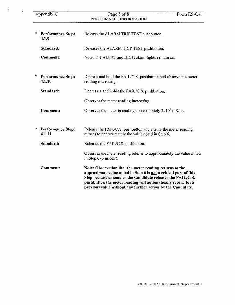
Appendix C Page 5 of 8 Form ES-C- I PERFORMANCE INFORMATION
Performance Step: 4.1.9
Standard:
Comment:
" Performance Step:
4.1.10
Standard:
Comment:
" Performance Step:
4.1.11
Standard:
Comment:
Release the ALARM TRIP TEST pushbutton.
Releases the ALARM TRIP TEST pushbutton.
Note: The ALERT and HIGH alarm lights remain on.
Depress and hold the FAIL/C.S. pushbutton and observe the meter reading increasing.
Depresses and holds the FAIL/C.S. pushbutton.
Observes the meter reading increasing.
Observes the meter is reading approximately 2x1 0 mR/hr.
Release the FAIL/C.S. pushbutton and ensure the meter reading
returns to approximately the value noted in Step 6.
Releases the FAIL/C.S. pushbutton.
Observes the meter reading returns to approximately the value noted in Step 6 (3 mR/hr).
Note: Observation that the meter reading returns to the approximate value noted in Step 6 is not a critical part of this Step because as soon as the Candidate releases the FAIL/C.S. pushbutton the meter reading will automatically return to its previous value without any further action by the Candidate.
NUREG 1021, Revision 8, Supplement 1
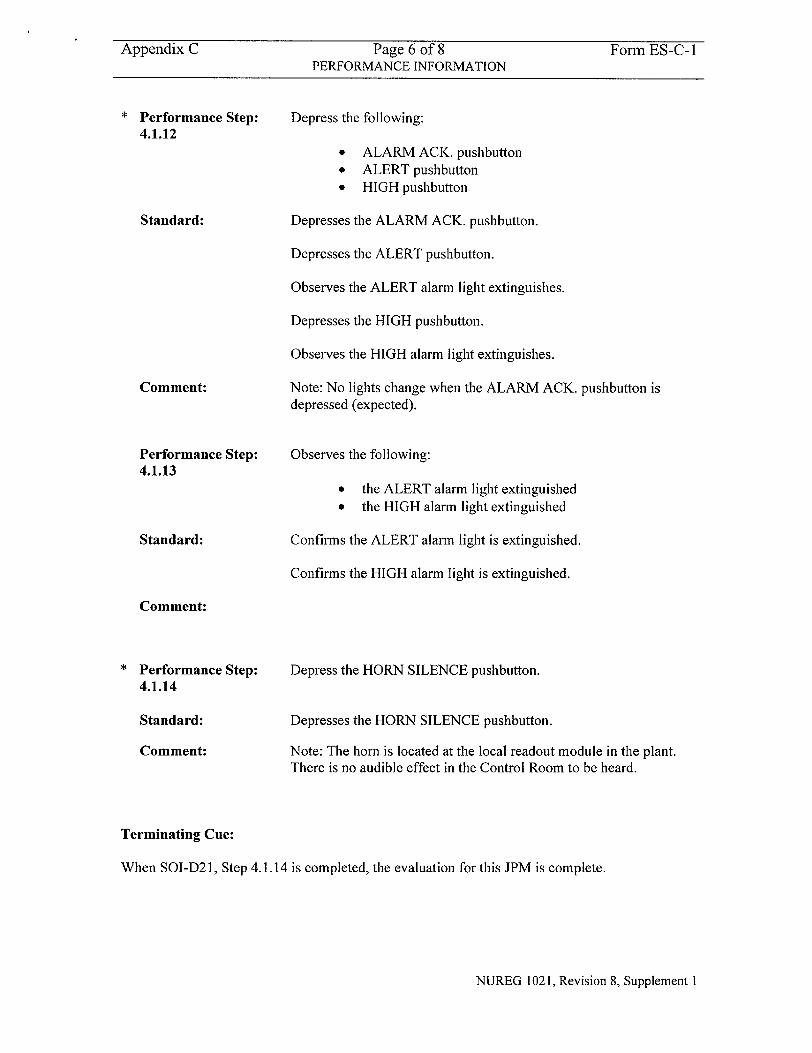
Appendix C Page 6 of 8 Form ES-C-i PERFORMANCE INFORMATION
Performance Step: 4.1.12
Standard:
Comment:
Performance Step: 4.1.13
Standard:
Depress the following:
"* ALARM ACK. pushbutton "• ALERT pushbutton "• HIGH pushbutton
Depresses the ALARM ACK. pushbutton.
Depresses the ALERT pushbutton.
Observes the ALERT alarm light extinguishes.
Depresses the HIGH pushbutton.
Observes the HIGH alarm light extinguishes.
Note: No lights change when the ALARM ACK. pushbutton is depressed (expected).
Observes the following:
* the ALERT alarm light extinguished • the HIGH alarm light extinguished
Confirms the ALERT alarm light is extinguished.
Confirms the HIGH alarm light is extinguished.
Comment:
Performance Step: 4.1.14
Standard:
Comment:
Depress the HORN SILENCE pushbutton.
Depresses the HORN SILENCE pushbutton.
Note: The horn is located at the local readout module in the plant. There is no audible effect in the Control Room to be heard.
Terminating Cue:
When SOI-D21, Step 4.1.14 is completed, the evaluation for this JPM is complete.
NUREG 1021, Revision 8, Supplement I
Appendix C Page 7 of 8 Form ES-C- I VERIFICATION OF COMPLETION
Job Performance Measure No.
Examinee's Name:
Examiner's Name:
Date Performed:
Facility Evaluator:
Number of Attempts:
Time to complete:
Question Documentation:
Question:
Response:
Result:
2003 NRC B.1.•
N/A
SAT OR UNSAT
Examiner's Signature and Date:
NUREG 1021, Revision 8, Supplement 1
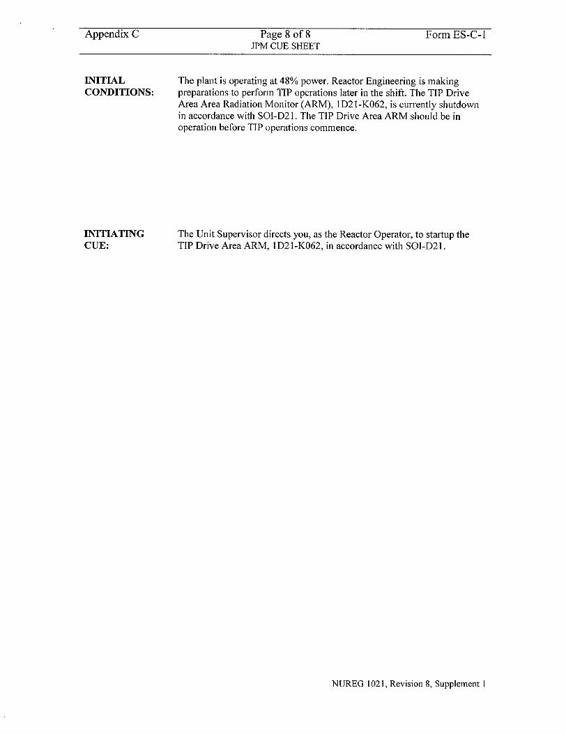
Appendix C Page 8 of 8 Form ES-C-I JPM CUE SHEET
INITIAL CONDITIONS:
INITIATING CUE:
The plant is operating at 48% power. Reactor Engineering is making preparations to perform TIP operations later in the shift. The TIP Drive Area Area Radiation Monitor (ARM), I D2 1 -K062, is currently shutdown in accordance with SOI-D2 1. The TIP Drive Area ARM should be in operation before TIP operations commence.
The Unit Supervisor directs you, as the Reactor Operator, to startup the TIP Drive Area ARM, 1 D2 1 -K062, in accordance with SOI-D2 1.
NUREG 1021, Revision 8, Supplement I
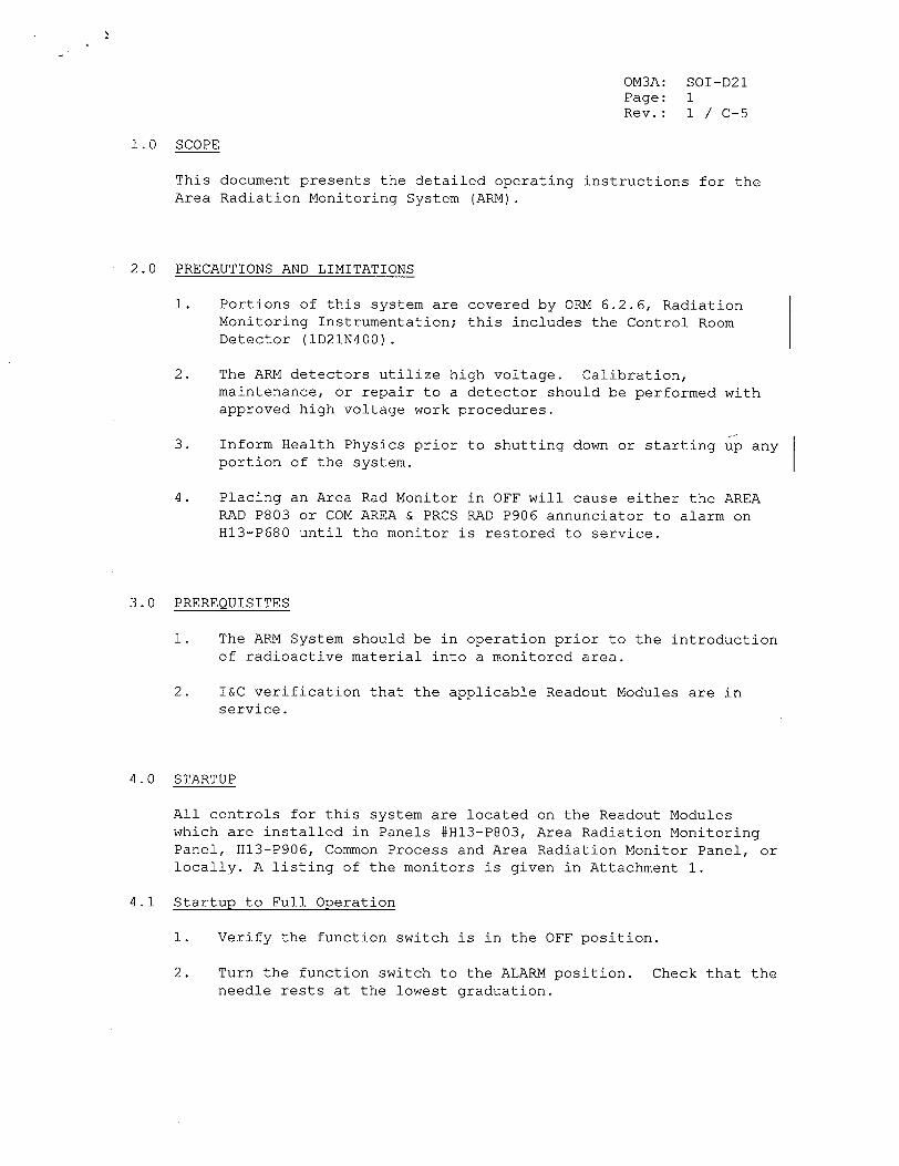
OM3A: SOI-D21 Page: 1 Rev.: 1 / C-5
1.0 SCOPE
This document presents the detailed operating instructions for the Area Radiation Monitoring System (ARM).
2.0 PRECAUTIONS AND LIMITATIONS
1. Portions of this system are covered by ORM 6.2.6, Radiation Monitoring Instrumentation; this includes the Control Room Detector (ID21N400).
2. The ARM detectors utilize high voltage. Calibration, maintenance, or repair to a detector should be performed with approved high voltage work procedures.
3. Inform Health Physics prior to shutting down or starting up any portion of the system.
4. Placing an Area Rad Monitor in OFF will cause either the AREA RAD P803 or COM AREA & PRCS RAD P906 annunciator to alarm on H13-P680 until the monitor is restored to service.
3.0 PREREQUISITES
1. The ARM System should be in operation prior to the introduction of radioactive material into a monitored area.
2. I&C verification that the applicable Readout Modules are in service.
4.0 STARTUP
All controls for this system are located on the Readout Modules which are installed in Panels #H13-P803, Area Radiation Monitoring Panel, H13-P906, Common Process and Area Radiation Monitor Panel, or locally. A listing of the monitors is given in Attachment 1.
4.1 Startup to Full Operation
1. Verify the function switch is in the OFF position.
2. Turn the function switch to the ALARM position. Check that the needle rests at the lowest graduation.
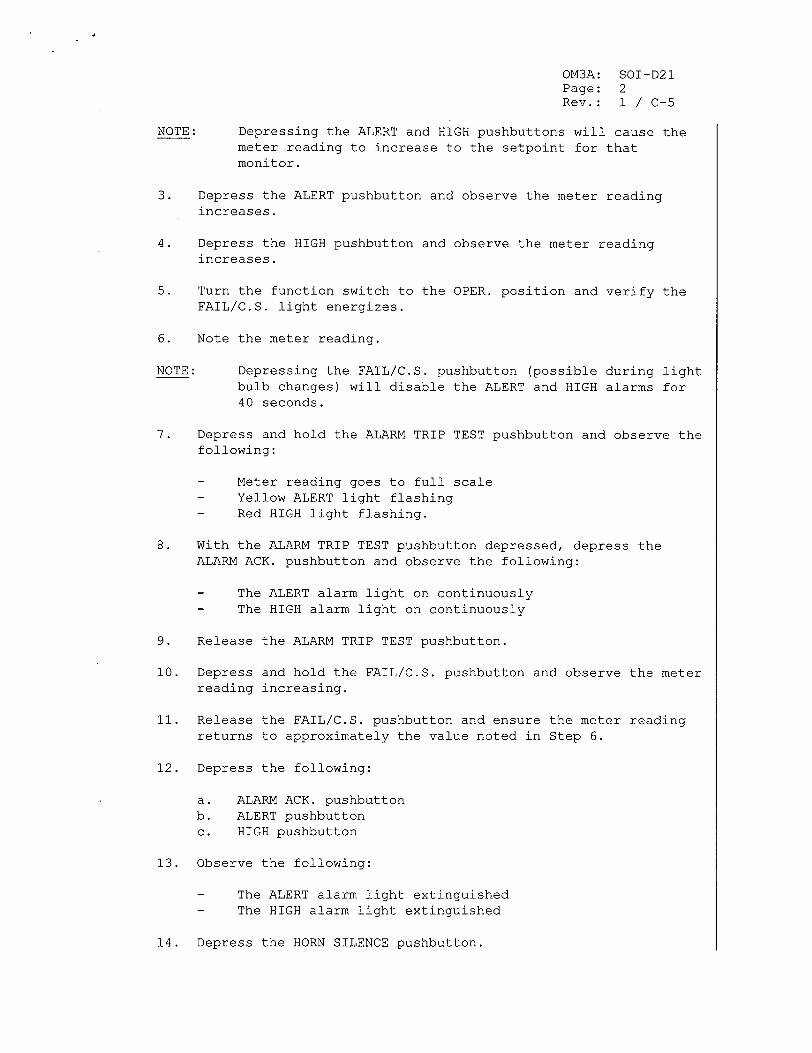
OM3A: SOI-D21 Page: 2 Rev.: 1 / C-5
NOTE: Depressing the ALERT and HIGH pushbuttons will cause the meter reading to increase to the setpoint for that monitor.
3. Depress the ALERT pushbutton and observe the meter reading increases.
4. Depress the HIGH pushbutton and observe the meter reading increases.
5. Turn the function switch to the OPER. position and verify the FAIL/C.S. light energizes.
6. Note the meter reading.
NOTE: Depressing the FAIL/C.S. pushbutton (possible during light bulb changes) will disable the ALERT and HIGH alarms for 40 seconds.
7. Depress and hold the ALARM TRIP TEST pushbutton and observe the following:
- Meter reading goes to full scale - Yellow ALERT light flashing - Red HIGH light flashing.
8. With the ALARM TRIP TEST pushbutton depressed, depress the ALARM ACK. pushbutton and observe the following:
- The ALERT alarm light on continuously - The HIGH alarm light on continuously
9. Release the ALARM TRIP TEST pushbutton.
10. Depress and hold the FAIL/C.S. pushbutton and observe the meter reading increasing.
11. Release the FAIL/C.S. pushbutton and ensure the meter reading returns to approximately the value noted in Step 6.
12. Depress the following:
a. ALARM ACK. pushbutton b. ALERT pushbutton c. HIGH pushbutton
13. Observe the following:
- The ALERT alarm light extinguished - The HIGH alarm light extinguished
14. Depress the HORN SILENCE pushbutton.
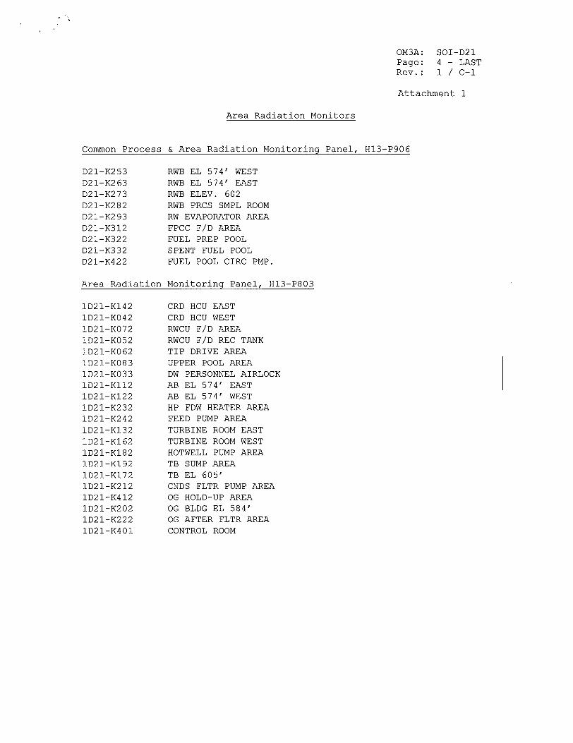
OM3A: Page: Rev.:
SOI-D21 4 - LAST 1 / C-i
Attachment 1
Area Radiation Monitors
Common Process & Area Radiation Monitoring Panel,
RWB EL 574' WEST RWB EL 574' EAST RWB ELEV. 602 RWB PRCS SMPL ROOM RW EVAPORATOR AREA FPCC F/D AREA FUEL PREP POOL SPENT FUEL POOL FUEL POOL CIRC PMP.
Area Radiation Monitoring Panel, HI13-P803
CRD HCU EAST CRD HCU WEST RWCU F/D AREA RWCU F/D REC TANK TIP DRIVE AREA UPPER POOL AREA DW PERSONNEL AIRLOCK AB EL 574' EAST AB EL 574' WEST HP FDW HEATER AREA FEED PUMP AREA TURBINE ROOM EAST TURBINE ROOM WEST HOTWELL PUMP AREA TB SUMP AREA TB EL 605' CNDS FLTR PUMP AREA OG HOLD-UP AREA OG BLDG EL 584' OG AFTER FLTR AREA CONTROL ROOM
D21-K253 D21-K263 D21-K273 D21-K282 D21-K293 D21-K312 D21-K322 D21-K332 D21-K422
H13-P906
1D21-K142 1D21-K042 1D21-K072 1D21-K052 1D21-K062 1D21-K083 1D21-K033 1D21-K112
1D21-K122 1D21-K232 1D21-K242 1D21-K132 1D21-K162 1D21-K182 1D21-K192 1D21-K172 1D21-K212 1D21-K412 1D21-K202 1D21-K222 1D21-K401
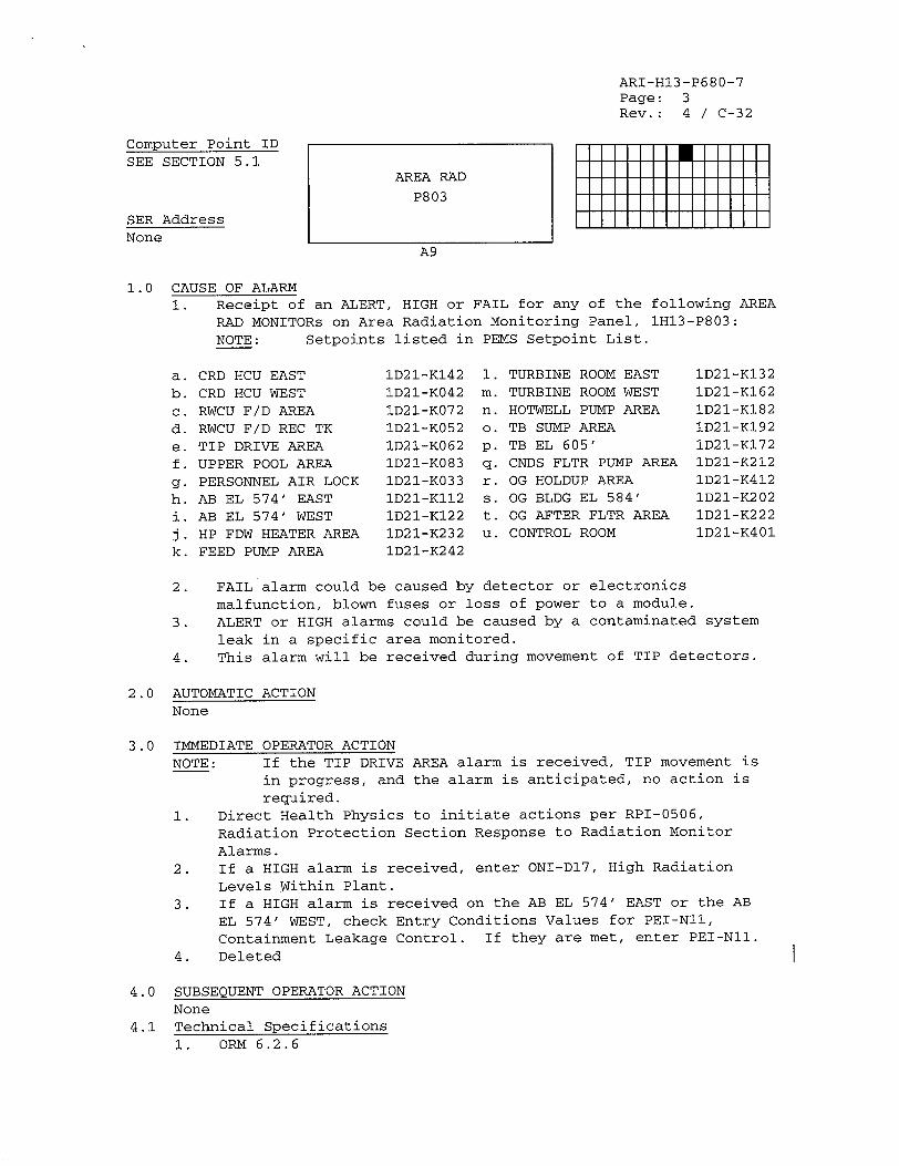
ARI-H13-P680-7 Page: 3 Rev.: 4 / C-32
Computer Point ID SEE SECTION 5.1
SER Address None
A9
1.0 CAUSE OF ALARM 1. Receipt of an ALERT, HIGH or FAIL for any of the following AREA
RAD MONITORs on Area Radiation Monitoring Panel, 1H13-P803:
NOTE: Setpoints listed in PEMS Setpoint List.
CRD HCU EAST CRD HCU WEST RWCU F/D AREA RWCU F/D REC TK TIP DRIVE AREA UPPER POOL AREA PERSONNEL AIR LOCK AB EL 574' EAST AB EL 574' WEST HP FDW HEATER AREA FEED PUMP AREA
1D21-K142 1D21-K042 ID21-K072 ID21-K052 1D21-K062 1D21-K083 1D21-K033 1D21-K112 1D21-K122 1D21-K232 1D21-K242
1. m. n. 0.
p. q. r.
S.
t. U.
TURBINE ROOM EAST TURBINE ROOM WEST HOTWELL PUMP AREA TB SUMP AREA TB EL 605' CNDS FLTR PUMP AREA OG HOLDUP AREA OG BLDG EL 584' OG AFTER FLTR AREA CONTROL ROOM
2. FAIL alarm could be caused by detector or electronics
malfunction, blown fuses or loss of power to a module.
3. ALERT or HIGH alarms could be caused by a contaminated system
leak in a specific area monitored.
4. This alarm will be received during movement of TIP detectors.
2.0 AUTOMATIC ACTION None
3.0 IMMEDIATE OPERATOR ACTION
NOTE: If the TIP DRIVE AREA alarm is received, TIP movement is
in progress, and the alarm is anticipated, no action is required.
1. Direct Health Physics to initiate actions per RPI-0506,
Radiation Protection Section Response to Radiation Monitor
Alarms.
2. If a HIGH alarm is received, enter ONI-D17, High Radiation Levels Within Plant.
3. If a HIGH alarm is received on the AB EL 574' EAST or the AB
EL 574' WEST, check Entry Conditions Values for PEI-Nll,
Containment Leakage Control. If they are met, enter PEI-NII.
4. Deleted
4.0 SUBSEQUENT OPERATOR ACTION None
4.1 Technical Specifications1. ORM 6.2.6
AREA RAD
P803
a. b. c. d. e. f. g.
h.
J k.
1D21-KI32 1D21-K162 1D21-K182 1D21-K192 ID21-K172 1D21-K212 ID21-K412 1D21-K202 1D21-K222 1D21-K401
11111111 0 111111
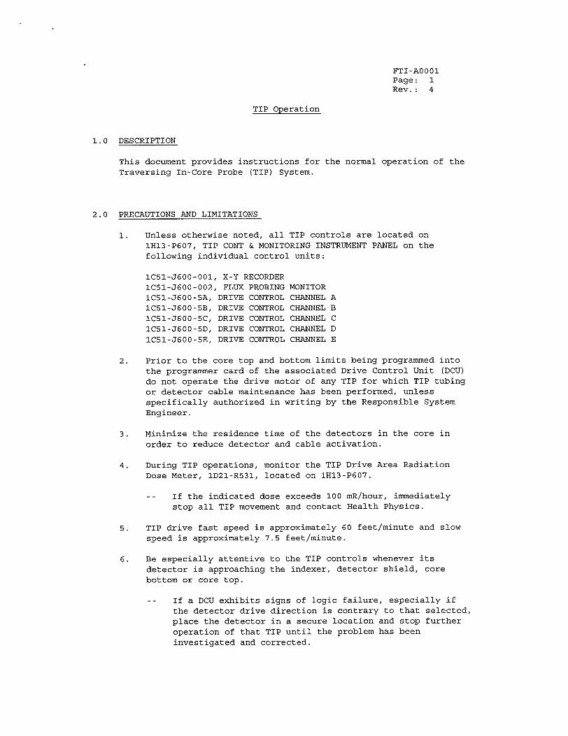
FTI-AO001 Page: 1 Rev.: 4
TIP Operation
1.0 DESCRIPTION
This document provides instructions for the normal operation of the
Traversing In-Core Probe (TIP) System.
2.0 PRECAUTIONS AND LIMITATIONS
1. Unless otherwise noted, all TIP controls are located on
1H13-P607, TIP CONT & MONITORING INSTRUMENT PANEL on the
following individual control units:
lC51-J600-001, X-Y RECORDER
lC51-J600-002, FLUX PROBING MONITOR
lC51-J600-5A, DRIVE CONTROL CHANNEL A
1C51-J600-5B, DRIVE CONTROL CHANNEL B
IC51-J600-5C, DRIVE CONTROL CHANNEL C
1C51-J600-5D, DRIVE CONTROL CHANNEL D
IC51-J600-5E, DRIVE CONTROL CHANNEL E
2. Prior to the core top and bottom limits being programmed into
the programmer card of the associated Drive Control Unit (DCU)
do not operate the drive motor of any TIP for which TIP tubing
or detector cable maintenance has been performed, unless
specifically authorized in writing by the Responsible System
Engineer.
3. Minimize the residence time of the detectors in the core in
order to reduce detector and cable activation.
4. During TIP operations, monitor the TIP Drive Area Radiation
Dose Meter, 1D21-R531, located on IH13-P607.
If the indicated dose exceeds 100 mR/hour, immediately stop all TIP movement and contact Health Physics.
5. TIP drive fast speed is approximately 60 feet/minute and slow speed is approximately 7.5 feet/minute.
6. Be especially attentive to the TIP controls whenever its detector is approaching the indexer, detector shield, core bottom or core top.
If a DCU exhibits signs of logic failure, especially if the detector drive direction is contrary to that selected, place the detector in a secure location and stop further operation of that TIP until the problem has been investigated and corrected.
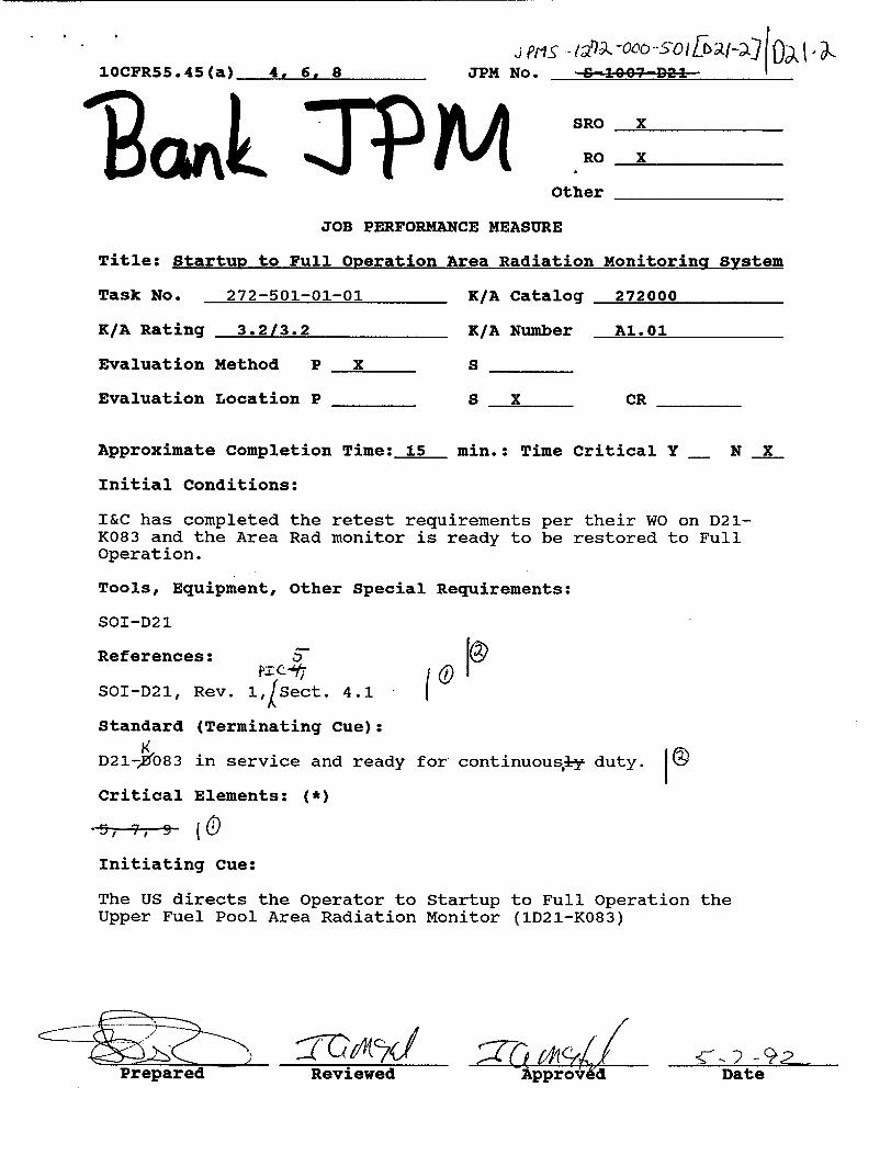
10CFR55.45 (a) 4, 6, 8 JPM
LPMj ors. - -000--2O IEK-)j zo. S 960Q07 D246
SRO X
RO X
Other
JOB PERFORMANCE MEASURE
Title: Startup to Full Operation Area Radiation
Task No. 272-501-01-01 K/A Catalog
K/A Rating 3.2/3.2 K/A Number
Evaluation Method P X S
Evaluation Location P S X
Monitorinq System
272000
AI.01
CR
Approximate Completion Time: 15 min.: Time Critical Y _ N X
Initial Conditions:
I&C has completed the retest requirements per their WO on D21K083 and the Area Rad monitor is ready to be restored to Full Operation.
Tools, Equipment, Other Special Requirements:
SOI-D21
References:
SOI-D21, Rev. 1,?Sect. 4.1
Standard (Terminating Cue):
D21-0083 in service and ready for continuousiy duty.
Critical Elements: (*) 5,--9L,-9 ( (
Initiating Cue:
The US directs the Operator to Startup to Full Operation the Upper Fuel Pool Area Radiation Monitor (1D21-K083)
Reviewed Approved-2 - 92-Date
m
Ale0l
rPage Sptis -I 7ýz -190o - 50 1,• a/2 JPM No. S 1307-D2,
KNOWLEDGE AND ABILITY LISTtING
272000 - K1.13, 2.9/3.0 A3.08, 2.9/2.9 A3.10, 3.3/3.2 A4.02, 3.0/3.0
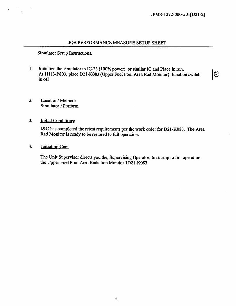
JPMS- 1272-000-501 [D2 1-2]
JOB PERFORMANCE MEASURE SETUP SHEET
Simulator Setup Instructions.
1. Initialize the simulator to IC-23 (100% power) or similar IC and Place in run. At 1H13-P803, place D21-K083 (Upper Fuel Pool Area Rad Monitor) function switch in off
2. Location/ Method: Simulator / Perform
3. Initial Conditions:
I&C has completed the retest requirements per the work order for D21-K083. The Area Rad Monitor is ready to be restored to full operation.
4. Initiating Cue:
The Unit Supervisor directs you the, Supervising Operator, to startup to full operation the Upper Fuel Pool Area Radiation Monitor 1D21-K083.
2
JPMS-1272-000-501[D21-2]
JPM CUE SHEET
INITIAL CONDITIONS:
flTTVflr A rnnyri nr. I
I&C has completed the retest requirements per the work order for D21K083. The Area Rad Monitor is ready to be restored to full operation.
I ________________________________________________________________________________________________
The Unit Supervisor directs you the, Supervising Operator, to startup to full operation the Upper Fuel Pool Area Radiation Monitor 1D21K083.
3
TINI I IAIN Ur•uh:-
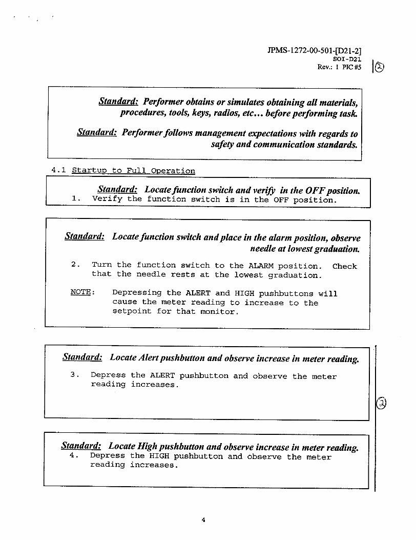
JPMS- 1272-00-501 -[D21-2] SOI-D21
Rev.: I PIC #5
Standard: Performer obtains or simulates obtaining all materials, procedures, tools, keys, radios, etc... before performing task.
Standard: Performer follows management expectations with regards to safety and communication standards.
4.1 Startup to Full Operation
Standard: Locate function switch and verify in the OFF position. 1. Verify the function switch is in the OFF position.
Standard: Locate function switch and place in the alarm position, observe needle at lowest graduation.
2. Turn the function switch to the ALARM position. Check that the needle rests at the lowest graduation.
NOTE: Depressing the ALERT and HIGH pushbuttons will cause the meter reading to increase to the setpoint for that monitor.
4
Standard: Locate Alert pushbutton and observe increase in meter reading.
3. Depress the ALERT pushbutton and observe the meter reading increases.
Standard: Locate High pushbutton and observe increase in meter reading. 4. Depress the HIGH pushbutton and observe the meter
reading increases.
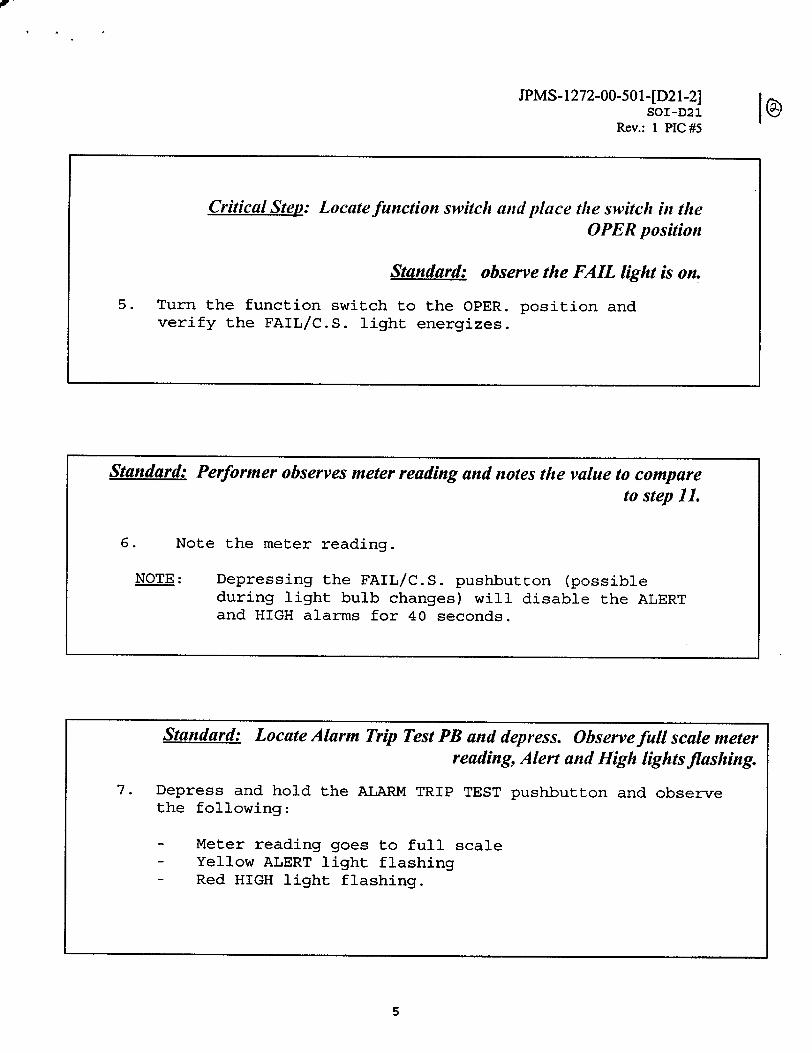
JPMS- 1272-00-501-[D21-2] SOI-D21
Rev.: I PIC #5
5
Critical Step: Locate function switch and place the switch in the OPER position
Standard: observe the FAIL light is on.
5. Turn the function switch to the OPER. position and verify the FAIL/C.S. light energizes.
Standard: Performer observes meter reading and notes the value to compare to step 11.
6. Note the meter reading.
NOTE: Depressing the FAIL/C.S. pushbutton (possible during light bulb changes) will disable the ALERT and HIGH alarms for 40 seconds.
Standard: Locate Alarm Trip Test PB and depress. Observe full scale meter reading, Alert and High lights flashing.
7. Depress and hold the ALARM TRIP TEST pushbutton and observe the following:
- Meter reading goes to full scale - Yellow ALERT light flashing - Red HIGH light flashing.
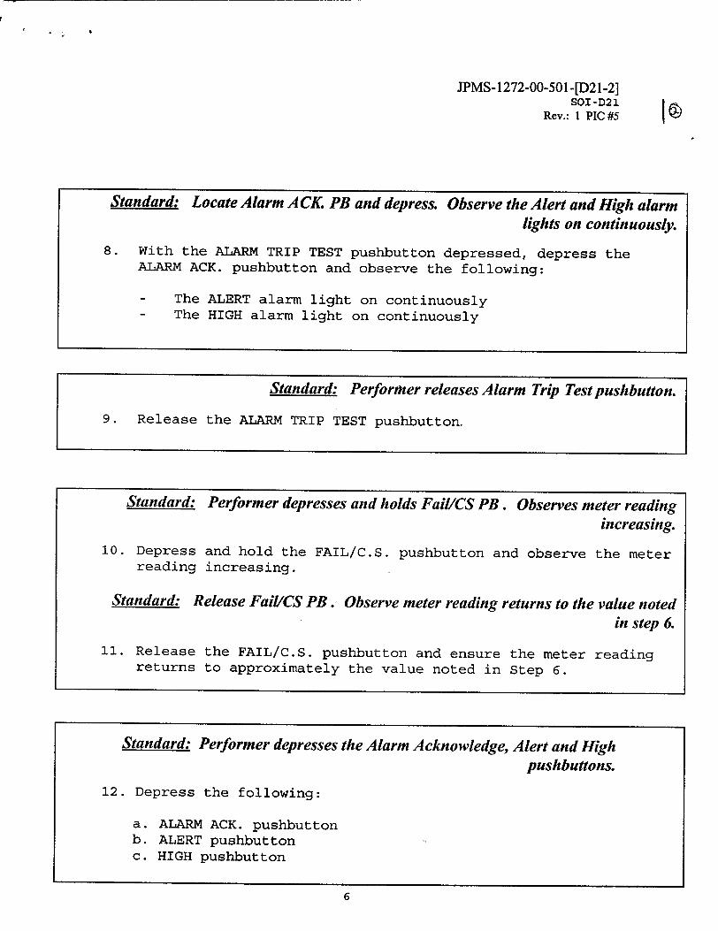
JPMS- 1272-00-501 -[D21-2] SOI -D21
Rev.: 1 PIC #5
Standard: Locate Alarm A CK. PB and depress. Observe the Alert and High alarm lights on continuously.
8. With the ALARM TRIP TEST pushbutton depressed, depress the ALARM ACK. pushbutton and observe the following:
- The ALERT alarm light on continuously - The HIGH alarm light on continuously
Standard: Performer releases Alarm Trip Test pushbutton.
9. Release the ALARM TRIP TEST pushbutton.
Standard: Performer depresses and holds Fail/CS PB. Observes meter reading increasing.
10. Depress and hold the FAIL/C.S. pushbutton and observe the meter reading increasing.
Standard: Release Fail/CS PB. Observe meter reading returns to the value noted in step 6.
11. Release the FAIL/C.S. pushbutton and ensure the meter reading returns to approximately the value noted in Step 6.
Standard: Performer depresses the Alarm Acknowledge, Alert and High pushbuttons.
12. Depress the following:
a. ALARM ACK. pushbutton b. ALERT pushbutton c. HIGH pushbutton
6
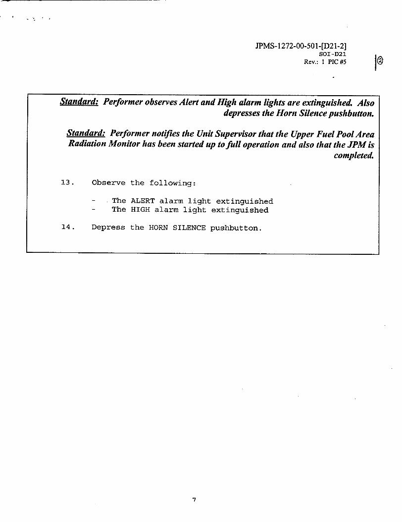
JPMS- 1 272-00-501-[D21-2] SOI-D21
Rev.: 1 PIC #5'1@
7
Standard: Performer observes Alert and High alarm lights are extinguished. Also depresses the Horn Silence pushbutton.
Standard: Performer notifies the Unit Supervisor that the Upper Fuel Pool Area Radiation Monitor has been started up to full operation and also that the JPM is
completed.
13. Observe the following:
- The ALERT alarm light extinguished - The HIGH alarm light extinguished
14. Depress the HORN SILENCE pushbutton.
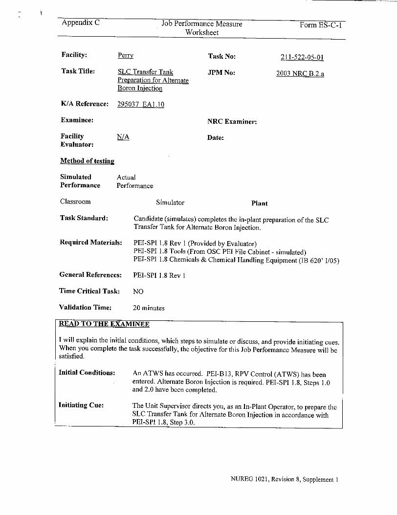
iAppendix C Job Performance Measure Form ES-C-1
Worksheet
Facility: Perry Task No: 211-522-05-01
Task Title: SLC Transfer Tank JPM No: 2003 NRC B.2.a Preparation for Alternate Boron Injection
K/A Reference: 295037 EAI.10
Examinee: NRC Examiner:
Facility N/A Date: Evaluator:
Method of testing
Simulated Actual Performance Performance
Classroom Simulator Plant
Task Standard: Candidate (simulates) completes the in-plant preparation of the SLC Transfer Tank for Alternate Boron Injection.
Required Materials: PEI-SPI 1.8 Rev 1 (Provided by Evaluator) PEI-SPI 1.8 Tools (From OSC PEI File Cabinet - simulated) PEI-SPI 1.8 Chemicals & Chemical Handling Equipment (IB 620' 1/05)
General References: PEI-SPI 1.8 Rev I
Time Critical Task: NO
Validation Time: 20 minutes
READ TO THE EXAMINEE
I will explain the initial conditions, which steps to simulate or discuss, and provide initiating cues. When you complete the task successfully, the objective for this Job Performance Measure will be satisfied.
Initial Conditions:
Initiating Cue:
An ATWS has occurred. PEI-B 13, RPV Control (ATWS) has been entered. Alternate Boron Injection is required. PEI-SPI 1.8, Steps 1.0 and 2.0 have been completed.
The Unit Supervisor directs you, as an In-Plant Operator, to prepare the SLC Transfer Tank for Alternate Boron Injection in accordance with PEI-SPI 1.8, Step 3.0.
NUREG 1021, Revision 8, Supplement I
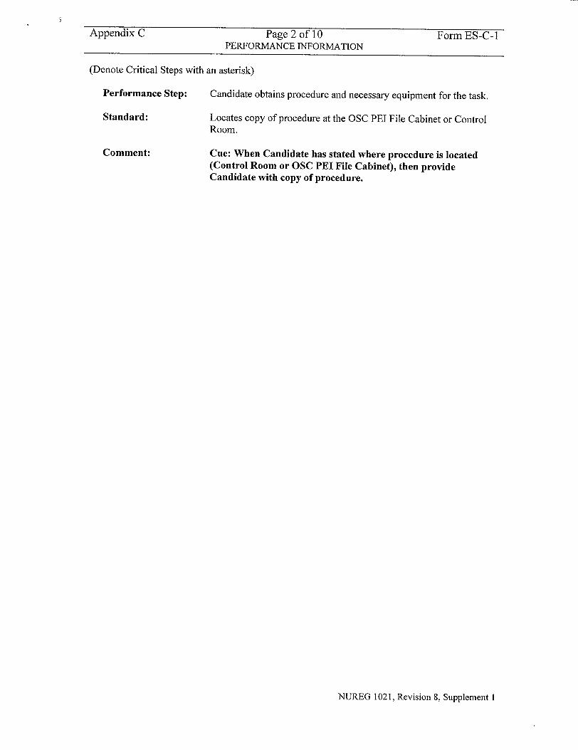
Appendix C Page 2 of 10 Form ES-C-I PERFORMANCE INFORMATION
(Denote Critical Steps with an asterisk)
Performance Step:
Standard:
Comment:
Candidate obtains procedure and necessary equipment for the task.
Locates copy of procedure at the OSC PEI File Cabinet or Control Room.
Cue: When Candidate has stated where procedure is located (Control Room or OSC PEI File Cabinet), then provide Candidate with copy of procedure.
NUREG 1021, Revision 8, Supplement 1
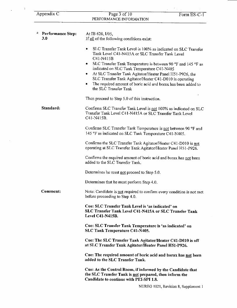
Appendix C Page 3 of 10 Form ES-C-1 PERFORMANCE INFORMATION
Performance Step: At IB 620, 1/05, 3.0 If all of the following conditions exist:
"* SLC Transfer Tank Level is 100% as indicated on SLC Transfer Tank Level C4 I-N415A or SLC Transfer Tank Level C41-N415B
"* SLC Transfer Tank Temperature is between 90 'F and 145 'F as indicated on SLC Tank Temperature C41-N405
"* At SLC Transfer Tank Agitator/Heater Panel H5 1-P926, the SLC Transfer Tank Agitator/Heater C4 1-DO10 is operating
"* The required amount of boric acid and borax has been added to the SLC Transfer Tank
Then proceed to Step 5.0 of this instruction.
Standard: Confirms SLC Transfer Tank Level is not 100% as indicated on SLC Transfer Tank Level C41-N415A or SLC Transfer Tank Level C41-N415B.
Confirms SLC Transfer Tank Temperature is not between 90 'F and 145 'F as indicated on SLC Tank Temperature C41 -N405.
Confirms the SLC Transfer Tank Agitator/Heater C4 1-DO 10 is not operating at SLC Transfer Tank Agitator/Heater Panel H5 1 -P926.
Confirms the required amount of boric acid and borax has not been added to the SLC Transfer Tank.
Determines he must not proceed to Step 5.0.
Determines that he must perform Step 4.0.
Comment: Note: Candidate is not required to confirm every condition is not met before proceeding to Step 4.0.
Cue: SLC Transfer Tank Level is 'as indicated' on SLC Transfer Tank Level C41-N415A or SLC Transfer Tank Level C41-N415B.
Cue: SLC Transfer Tank Temperature is 'as indicated' on SLC Tank Temperature C41-N405.
Cue: The SLC Transfer Tank Agitator/Heater C41-DO10 is off at SLC Transfer Tank Agitator/Heater Panel H51-P926.
Cue: The required amount of boric acid and borax has not been added to the SLC Transfer Tank.
Cue: As the Control Room, if informed by the Candidate that the SLC Transfer Tank is not prepared, then inform the Candidate to continue with PEI-SPI 1.8.
NUREG 1021, Revision 8, Supplement I
Appendix C Page 4 of 10 Form ES-C-1 PERFORMANCE INFORMATION
Note: The following Steps (4.1, 4.2, 4.3, and 4.4) will ultimately prepare the SLC Transfer
Tank for Alternate Boron Injection.
Note: The following Step (4.1) will fill the SLC Transfer Tank.
* Performance Step: 4.1.1
Standard:
Comment:
Performance Step:
4.1.2
Standard:
Comment:
At lB 620', 1/05,
Open Dem Wtr Supply Line Isol Vlv C41-F533.
Opens (simulates) valve by turning handwheel in the counterclockwise direction.
Cue: Valve C41-F533 is open.
Note: Candidate may also explain that he will listen for flow noise when C41-F533 is opened.
Cue: If prompted, flow noise is heard.
At 1B 620', 1/05,
When SLC Transfer Tank level reaches 80% as indicated on SLC Transfer Tank Level C4 1 -N415A or SLC Transfer Tank Level C41-N4151B,
Then close Dem Wtr Supply Line Isol Vlv C41-F533.
Observes SLC Transfer Tank Level increases to 80% as indicated on SLC Transfer Tank Level C4 I-N415A or SLC Transfer Tank Level C4 I-N415B.
Closes (simulates) valve by turning handwheel in the clockwise direction.
Cue: SLC Transfer Tank Level is 80% as indicated on SLC Transfer Tank Level C41-N415A or SLC Transfer Tank Level C41-N415B.
Cue: Valve C41-F533 is closed.
NUREG 1021, Revision 8, Supplement I
Appendix C Page 5 of 10 Form ES-C- I PERFORMANCE INFORMATION
Performance Step: 4.2
Standard:
Comment:
At SLC Transfer Tank Agitator/Heater Panel H5 1 -P926, start SLC Transfer Tank Agitator/Heater C4 1-DO 10.
Places SLC Transfer Tank Agitator/Heater C41-D010 control switch in the ON position.
Observes red light is on and green light is off for the SLC Transfer Tank Agitator.
Observes red light is on and green light is off for the SLC Transfer Tank Heater.
Cue: Red light is on, green light is off. The SLC Transfer Tank Agitator is running.
Cue: Red light is on, green light is off. The SLC Transfer Tank Heater is energized.
Note: The following Step (4.3) will establish the proper amount of chemicals.
* Performance Step: 4.3.1
Standard:
Comment:
When the SLC Transfer Tank is between 90 'F and 145 'F as indicated on SLC Tank Temperature C41-N405,
Then establish the proper amount of chemicals as follows:
Remove the SLC Transfer Tank manway cover.
Observes SLC Transfer Tank temperature increases to between 90 'F and 145 'F as indicated on SLC Tank Temperature C41-N405.
Removes (simulates) the SLC Transfer Tank manway cover.
Note: Candidate may describe use of the crescent wrenches or drive ratchet/socket to remove the manway cover.
Note: Candidate may discuss HP requirements to access the ladder and elevated platform in preparation for removing the manway cover.
Cue: SLC Transfer Tank temperature is 100 'F and slowly
increasing as indicated on SLC Tank Temperature C41-N405.
Cue: The SLC Transfer Tank manway cover is removed.
NUREG 1021, Revision 8, Supplement 1
Appendix C Page 6 of 10 Form ES-C-1 PERFORMANCE INFORMATION
Performance Step: Commence to slowly add a bucket of borax and a bucket of boric 4.3.2 acid alternately until three and one-half barrels of each chemical
have been added
Standard: Locates each type of chemical (borax and boric acid) in its respective barrel.
Removes (simulates) the lid from each required barrel of borax and boric acid.
Slowly adds (simulates) a bucket of borax and a bucket of boric acid alternately until three and one-half barrels of each chemical have been added to the SLC Transfer Tank via the open manway cover.
Comment: Note: The Candidate should describe the use of a face shield or goggles and rubber gloves when handling the boric acid.
Note: The Candidate should describe the use of the two 5 gallon buckets and scoop in order to transfer the borax and boric acid from their respective barrel to the SLC Transfer Tank.
Note: This chemical mix is an endothermic reaction. Adding chemicals too fast will decrease water temperature. The warmer the water, the faster the chemicals will enter solution.
Note: The Candidate may describe monitoring of SLC Transfer Tank temperature because mixing of the chemicals is an endothermic reaction which can cause SLC Transfer Tank temperature to decrease if chemicals are added too fast.
Cue: Three and one-half barrels of each chemical have been added to the SLC Transfer Tank.
NUREG 1021, Revision 8, Supplement 1
Appendix C Page 7 of 10 Form ES-C-I PERFORMANCE INFORMATION
Performance Step: 4.4.1
Standard:
Comment:
Perform the following to fill the SLC Transfer Tank while maintaining SLC Transfer Tank temperature between 60 'F and 145 'F:
Open Dem Wtr Supply Line Isol Vlv C41-F533.
Opens (simulates) valve by turning handwheel in the counterclockwise direction.
Confirms SLC Transfer Tank Temperature is being maintained between 60 'F and 145 'F as indicated on SLC Tank Temperature C41-N405.
Cue: Valve C41-F533 is open.
Note: Candidate may also explain that he will listen for flow noise when C41-F533 is opened.
Cue: If prompted, flow noise is heard.
Cue: SLC Transfer Tank temperature is 120 'F and slowly decreasing as indicated on SLC Tank Temperature C41-N405.
Cue: SLC Transfer Tank Level is 100% as indicated on SLC Transfer Tank Level C41-N415A or SLC Transfer Tank Level C41-N415B.
NUREG 1021, Revision 8, Supplement I
Appendix C Page 8 of 10 Form ES-C-1 PERFORMANCE INFORMATION
Performance Step: 4.4.2
When SLC Transfer Tank level reaches 100% as indicated on SLC Transfer Tank Level C4 l-N415A or SLC Transfer Tank Level C4 I-N415B,
Then close Dem Wtr Supply Line Isol VIv C41-F533.
Standard:
Comment:
Confirms SLC Transfer Tank Temperature is being maintained between 60 'F and 145 'F as indicated on SLC Tank Temperature C41-N405.
Observes SLC Transfer Tank Level increases to 100% as indicated on SLC Transfer Tank Level C4 1 -N415A or SLC Transfer Tank Level C41-N415B.
Closes (simulates) valve by turning handwheel in the clockwise direction.
Cue: SLC Transfer Tank Level is 100% as indicated on SLC Transfer Tank Level C41-N415A or SLC Transfer Tank Level C41-N415B.
Cue: Valve C41-F533 is closed.
Cue: If requested, SLC Transfer Tank temperature is 100 'F and stable as indicated on SLC Tank Temperature C41-N405.
Note: Candidate should inform the Control Room when Step 4.0 is completed.
Cue: As the Control Room, when informed by the Candidate that Step 4.0 is completed, then inform the Candidate that he is to return to the Control Room. Non-Licensed Operators have been assigned to complete the in-plant lineup.
Terminating Cue:
When PEI-SPI 1.8, Step 4.4.2 is completed, the evaluation for this JPM is complete.
NUREG 1021, Revision 8, Supplement I
Appendix C Page 9 of 10 Form ES-C-I VERIFICATION OF COMPLETION
Job Performance Measure No.
Examinee's Name:
Examiner's Name:
Date Performed:
Facility Evaluator:
Number of Attempts:
Time to complete:
Question Documentation:
Question:
Response:
Result:
2003 NRC B.2.a
N/A
SAT OR UNSAT
Examiner's Signature and Date:
NUREG 1021, Revision 8, Supplement 1
Appendix C Page 10 of 10 Form ES-C- I JPM CUE SHEET
INITIAL CONDITIONS:
INITIATING CUE:
An ATWS has occurred. PEI-B 13, RPV Control (ATWS) has been entered. Alternate Boron Injection is required. PEI-SPI 1.8, Steps 1.0 and 2.0 have been completed.
The Unit Supervisor directs you, as an In-Plant Operator, to prepare the SLC Transfer Tank for Alternate Boron Injection in accordance with PEISPI 1.8, Step 3.0.
NUREG 1021, Revision 8, Supplement I
PEI-SPI 1.8 Page: i Rev.: 1
The Cleveland Electric Illuminating Company
PERRY OPERATIONS MANUAL
Plant Emergency Instruction
TITLE: SPECIAL PLANT INSTRUCTION 1.8
ALTERNATE BORON INJECTION
REVISION: EFFECTIVE DATE: 12-2-96
PREPARED: Victor C. Colacicco 8-5-96/ Date
EFFECTIVE PIC's
4 4
PIC Type of Effective No. Change Date
_ .1 __ 1 ___
PEI-SPI 1.8 Page: 1 of 14 Rev.: 1
PEI-SPI 1.8 Alternate Boron Injection
ENTRY CONDITIONS
This instruction is entered during an ATWS when RPS and ARI signals fail to insert control rods and SLC was NOT effective in shutting down the Reactor.
SCOPE
This alignment provides Alternate Boron Injection into the RPV through the HPCS flush connection using the SLC transfer system and the Alternate Boron Injection pump.
NECESSARY EQUIPMENT
Control Room PEI-SPI File Cabinet: - two jumpers
CC 599' D/01, OSC PEI File Cabinet: - one flathead screwdriver - one medium valve hook
- one wirecutter - two 15 inch crescent wrenches - one pipe wrench - two pair goggles - two pair rubber gloves
- one 1/2 inch drive ratchet - one 1 1/8 inch socket
AX 620' D/02, ABI PEI Tool Cabinet: - one High Pressure Hose - two 60 ft Low Pressure Hoses - one ABI Pump Motor Starter Cable - one Storz spanner wrench - one PEI nylon rope
- teflon tape - three 2 inch Parker Connections - one 6 inch strap wrench
(CONTINUED ON NEXT PAGE)
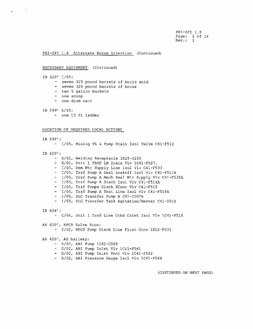
PEI-SPI 1.8 Page: 2 of 14 Rev.: 1
PEI-SPI 1.8 Alternate Boron Injection (Continued)
NECESSARY EQUIPMENT (Continued)
IB 620' 1/05: - seven 325 pound barrels of boric acid - seven 320 pound barrels of borax - two 5 gallon buckets
- one scoop - one drum cart
IB 599' K/05: - one 12 ft ladder
LOCATION OF REQUIRED LOCAL ACTIONS
IB 599': - 1/05, Mixing Tk & Pump Drain Isol Valve C41-F512
IB 620': - D/02, Welding Receptacle IR25-$230 - E/02, Unit 1 TRSF LN Drain Vlv IC41-F527. - 1/05, Dem Wtr Supply Line Isol Vlv C41-F533 - 1/05, Trsf Pump A Seal Leakoff Isol Vlv C41-F511A - 1/05, Trsf Pump A Mech Seal Wtr Supply Vlv C41-F535A - 1/05, Trsf Pump A Disch Isol Vlv C41-F514A - 1/05, Trsf Pumps Disch XConn Vlv C41-F515 - 1/05, Trsf Pump A Test Line Isol Vlv C41-F516A - 1/05, SLC Transfer Pump A C41-CO02A - 1/05, SLC Transfer Tank Agitation/Heater C41-DO10
IB 654': - C/04, Unit 1 Trsf Line Otbd Cntmt Isol Vlv IC41-F518
AX 620', HPCS Valve Room: - D/02, HPCS Pump Disch Line Flush Conn 1E22-F031
AX 620', AX hallway: - D/02, ABI Pump 1C41-C004 - D/02, ABI Pump Inlet Vlv IC41-F561 - D/02, ABI Pump Inlet Vent Vlv IC41-F562 - D/02, ABI Pressure Gauge Isol Vlv IC41-F564
(CONTINUED ON NEXT PAGE)
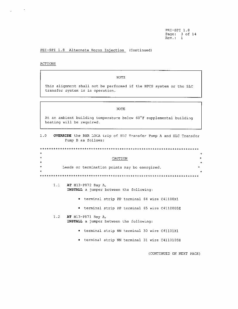
PEI-SPI 1.8 Page: 3 of 14 Rev.: 1
PEI-SPI 1.8 Alternate Boron Injection (Continued)
ACTIONS
NOTE
This alignment shall not be performed if the HPCS system or the SLC transfer system is in operation.
NOTE
At an ambient building temperature below 60'F supplemental building heating will be required.
1.0 OVERRIDE the RHR LOCA trip of SLC Transfer Pump A and SLC Transfer Pump B as follows:
* CAUTION *
* Leads or termination points may be energized. *
WWWWW********* ************** ***** ****** ***** ****** ******************
1.1 AT H13-P872 Bay A, INSTALL a jumper between the following:
"* terminal strip PP terminal 64 wire C4110OXI
"* terminal strip PP terminal 65 wire C4110005E
1.2 AT H13-P871 Bay A, INSTALL a jumper between the following:
"* terminal strip NN terminal 30 wire C4llOlXl
"* terminal strip NN terminal 31 wire C4110105E
(CONTINUED ON NEXT PAGE)
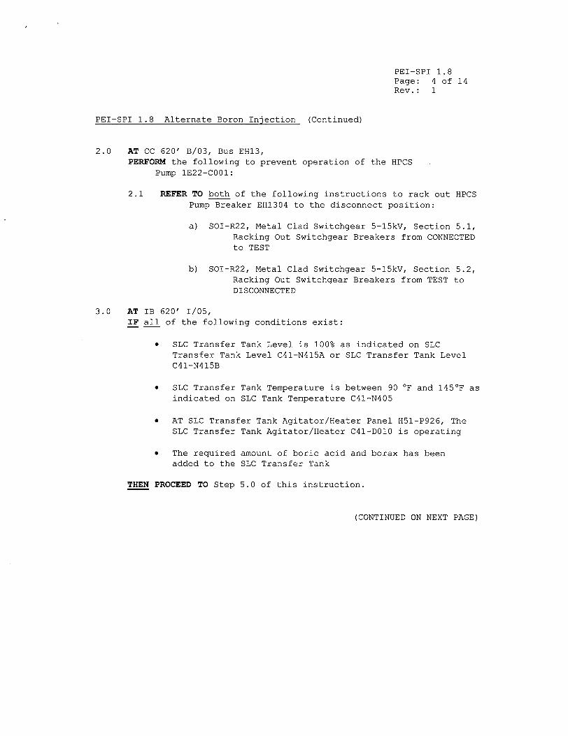
PEI-SPI 1.8 Page: 4 of 14 Rev.: 1
PEI-SPI 1.8 Alternate Boron Injection (Continued)
2.0 AT CC 620' B/03, Bus EHl3, PERFORM the following to prevent operation of the HPCS
Pump 1E22-C001:
2.1 REFER TO both of the following instructions to rack out HPCS Pump Breaker EH1304 to the disconnect position:
a) SOI-R22, Metal Clad Switchgear 5-15kV, Section 5.1, Racking Out Switchgear Breakers from CONNECTED to TEST
b) SOI-R22, Metal Clad Switchgear 5-15kV, Section 5.2, Racking Out Switchgear Breakers from TEST to DISCONNECTED
3.0 AT IB 620' 1/05, IF all of the following conditions exist:
"* SLC Transfer Tank Level is 100% as indicated on SLC Transfer Tank Level C41-N415A or SLC Transfer Tank Level C41-N415B
"* SLC Transfer Tank Temperature is between 90 0F and 145 0 F as indicated on SLC Tank Temperature C41-N405
"* AT SLC Transfer Tank Agitator/Heater Panel H51-P926, The SLC Transfer Tank Agitator/Heater C41-DO10 is operating
"* The required amount of boric acid and borax has been added to the SLC Transfer Tank
THEN PROCEED TO Step 5.0 of this instruction.
(CONTINUED ON NEXT PAGE)
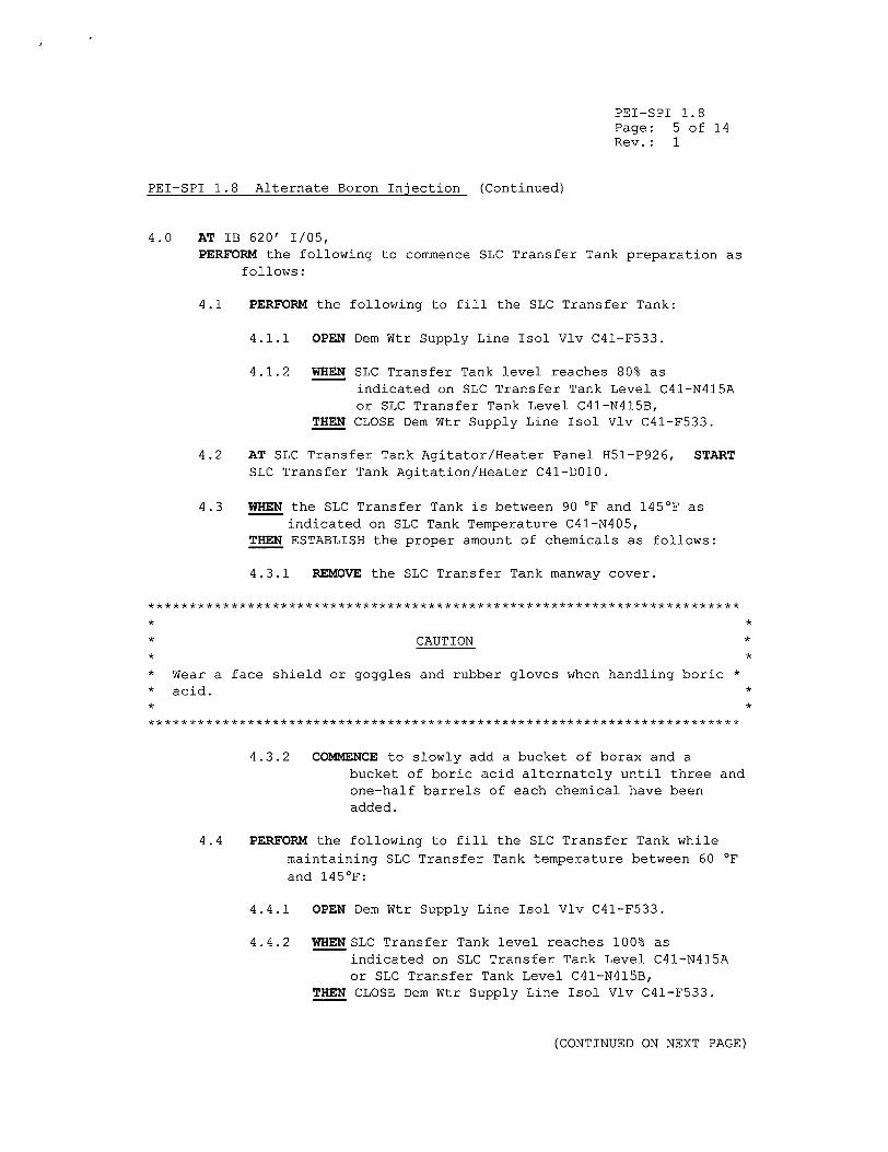
PEI-SPI 1.8 Page: 5 of 14 Rev.: 1
PEI-SPI 1.8 Alternate Boron Injection (Continued)
4.0 AT IB 620' 1/05, PERFORM the following to commence SLC Transfer Tank preparation as
follows:
4.1 PERFORM the following to fill the SLC Transfer Tank:
4.1.1 OPEN Dem Wtr Supply Line Isol Vlv C41-F533.
4.1.2 WHEN SLC Transfer Tank level reaches 80% as indicated on SLC Transfer Tank Level C41-N415A or SLC Transfer Tank Level C41-N415B,
THEN CLOSE Dem Wtr Supply Line Isol Vlv C41-F533.
4.2 AT SLC Transfer Tank Agitator/Heater Panel H51-P926, START SLC Transfer Tank Agitation/Heater C41-DO10.
4.3 WHEN the SLC Transfer Tank is between 90 OF and 145OF as indicated on SLC Tank Temperature C41-N405,
THEN ESTABLISH the proper amount of chemicals as follows:
4.3.1 REMOVE the SLC Transfer Tank manway cover.
************ ******* ***** ***** *********** ***** ********* ********* * *
* CAUTION * * *
"* Wear a face shield or goggles and rubber gloves when handling boric *
"* acid. * * *
4.3.2 COMMENCE to slowly add a bucket of borax and a bucket of boric acid alternately until three and one-half barrels of each chemical have been added.
4.4 PERFORM the following to fill the SLC Transfer Tank while
maintaining SLC Transfer Tank temperature between 60 OF
and 145 0 F:
4.4.1 OPEN Dem Wtr Supply Line Isol Vlv C41-F533.
4.4.2 WHEN SLC Transfer Tank level reaches 100% as indicated on SLC Transfer Tank Level C41-N415A or SLC Transfer Tank Level C41-N415B,
THEN CLOSE Dem Wtr Supply Line Isol Vlv C41-F533.
(CONTINUED ON NEXT PAGE)
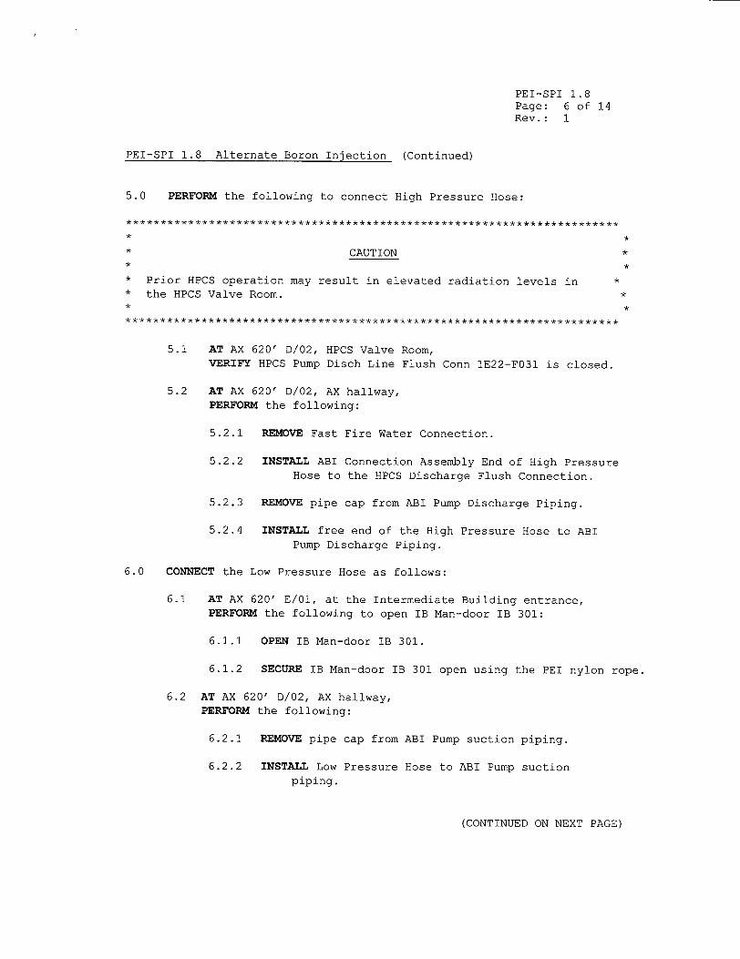
PEI-SPI 1.8 Page: 6 of 14 Rev.: 1
PEI-SPI 1.8 Alternate Boron Injection (Continued)
5.0 PERFORM the following to connect High Pressure Hose:
*********** ** ******* ****** ********** ****** ***** ****** ******** ********** *
* *
* CAUTION *
"* Prior HPCS operation may result in elevated radiation levels in * "* the HPCS Valve Room. *
5.1 AT AX 620' D/02, HPCS Valve Room, VERIFY HPCS Pump Disch Line Flush Conn 1E22-F031 is closed.
5.2 AT AX 620' D/02, AX hallway, PERFORM the following:
5.2.1 REMOVE Fast Fire Water Connection.
5.2.2 INSTALL ABI Connection Assembly End of High Pressure Hose to the HPCS Discharge Flush Connection.
5.2.3 REMOVE pipe cap from ABI Pump Discharge Piping.
5.2.4 INSTALL free end of the High Pressure Hose to ABI Pump Discharge Piping.
6.0 CONNECT the Low Pressure Hose as follows:
6.1 AT AX 620' E/01, at the Intermediate Building entrance, PERFORM the following to open IB Man-door IB 301:
6.1.1 OPEN IB Man-door IB 301.
6.1.2 SECURE IB Man-door IB 301 open using the PEI nylon rope.
6.2 AT AX 620' D/02, AX hallway, PERFORM the following:
6.2.1 REMOVE pipe cap from ABI Pump suction piping.
6.2.2 INSTALL Low Pressure Hose to ABI Pump suction piping.
(CONTINUED ON NEXT PAGE)
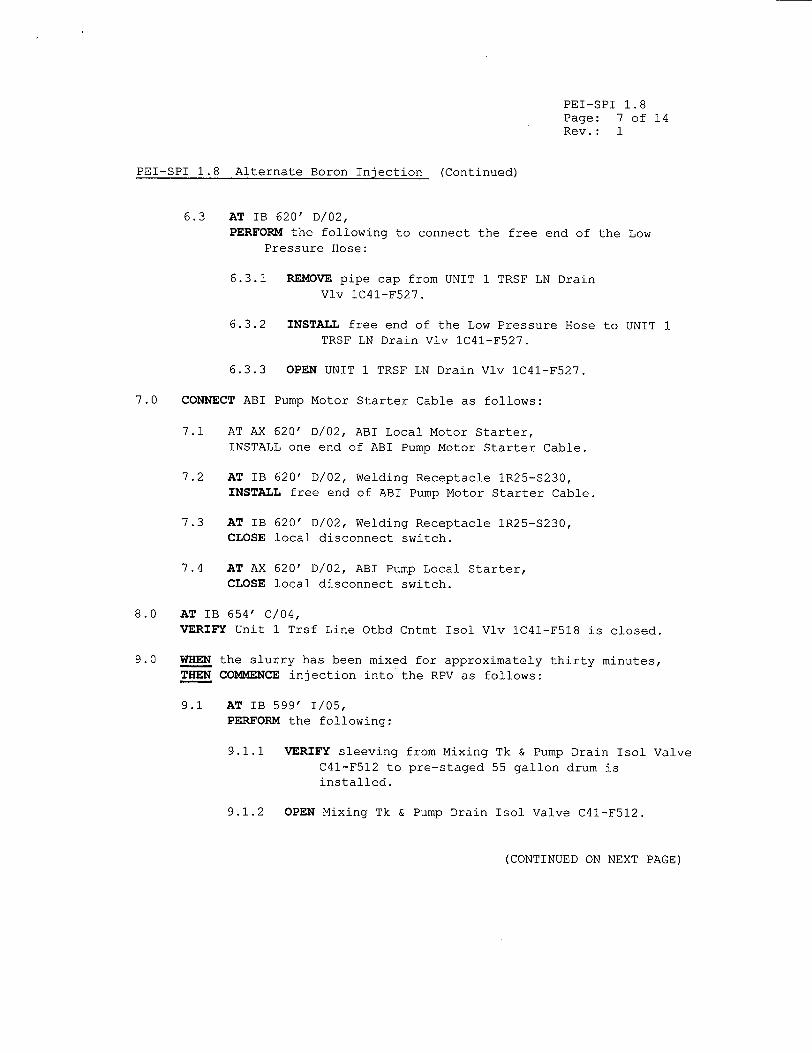
PEI-SPI 1.8 Page: 7 of 14 Rev.: 1
PEI-SPI 1.8 Alternate Boron Injection (Continued)
6.3 AT IB 620' D/02, PERFORM the following to connect the free end of the Low
Pressure Hose:
6.3.1 REMOVE pipe cap from UNIT 1 TRSF LN Drain Vlv IC41-F527.
6.3.2 INSTALL free end of the Low Pressure Hose to UNIT 1 TRSF LN Drain Vlv IC41-F527.
6.3.3 OPEN UNIT 1 TRSF LN Drain Vlv IC41-F527.
7.0 CONNECT ABI Pump Motor Starter Cable as follows:
7.1 AT AX 620' D/02, ABI Local Motor Starter, INSTALL one end of ABI Pump Motor Starter Cable.
7.2 AT IB 620' D/02, Welding Receptacle IR25-S230, INSTALL free end of ABI Pump Motor Starter Cable.
7.3 AT IB 620' D/02, Welding Receptacle IR25-S230, CLOSE local disconnect switch.
7.4 AT AX 620' D/02, ABI Pump Local Starter, CLOSE local disconnect switch.
8.0 AT IB 654' C/04, VERIFY Unit 1 Trsf Line Otbd Cntmt Isol Vlv IC41-F518 is closed.
9.0 WHEN the slurry has been mixed for approximately thirty minutes, THEN COMMENCE injection into the RPV as follows:
9.1 AT IB 599' 1/05, PERFORM the following:
9.1.1 VERIFY sleeving from Mixing Tk & Pump Drain Isol Valve C41-F512 to pre-staged 55 gallon drum is installed.
9.1.2 OPEN Mixing Tk & Pump Drain Isol Valve C41-F512.
(CONTINUED ON NEXT PAGE)
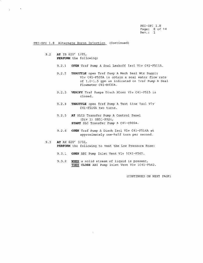
PEI-SPI 1.8 Page: 8 of 14 Rev.: 1
PEI-SPI 1.8 Alternate Boron Injection (Continued)
9.2 AT IB 620' 1/05, PERFORM the following:
9.2.1 OPEN Trsf Pump A Seal Leakoff Isol Vlv C41-F511A.
9.2.2 THROTTLE open Trsf Pump A Mech Seal Wtr Supply Vlv C41-F535A to obtain a seal water flow rate of 1.0-1.5 gpm as indicated on Trsf Pump A Seal Flowmeter C41-R430A.
9.2.3 VERIFY Trsf Pumps Disch XConn Vlv C41-F515 is closed.
9.2.4 THROTTLE open Trsf Pump A Test Line Isol Vlv C41-F516A two turns.
9.2.5 AT SLCS Transfer Pump A Control Panel (Div 1) 0H51-P924,
START SLC Transfer Pump A C41-CO02A.
9.2.6 OPEN Trsf Pump A Disch Isol Vlv C41-F514A at approximately one-half turn per second.
9.3 AT AX 620' D/02, PERFORM the following to vent the Low Pressure Hose:
9.3.1 OPEN ABI Pump Inlet Vent Vlv IC41-F562.
9.3.2 WHEN a solid stream of liquid is present, THEN CLOSE ABI Pump Inlet Vent Vlv IC41-F562.
(CONTINUED ON NEXT PAGE)
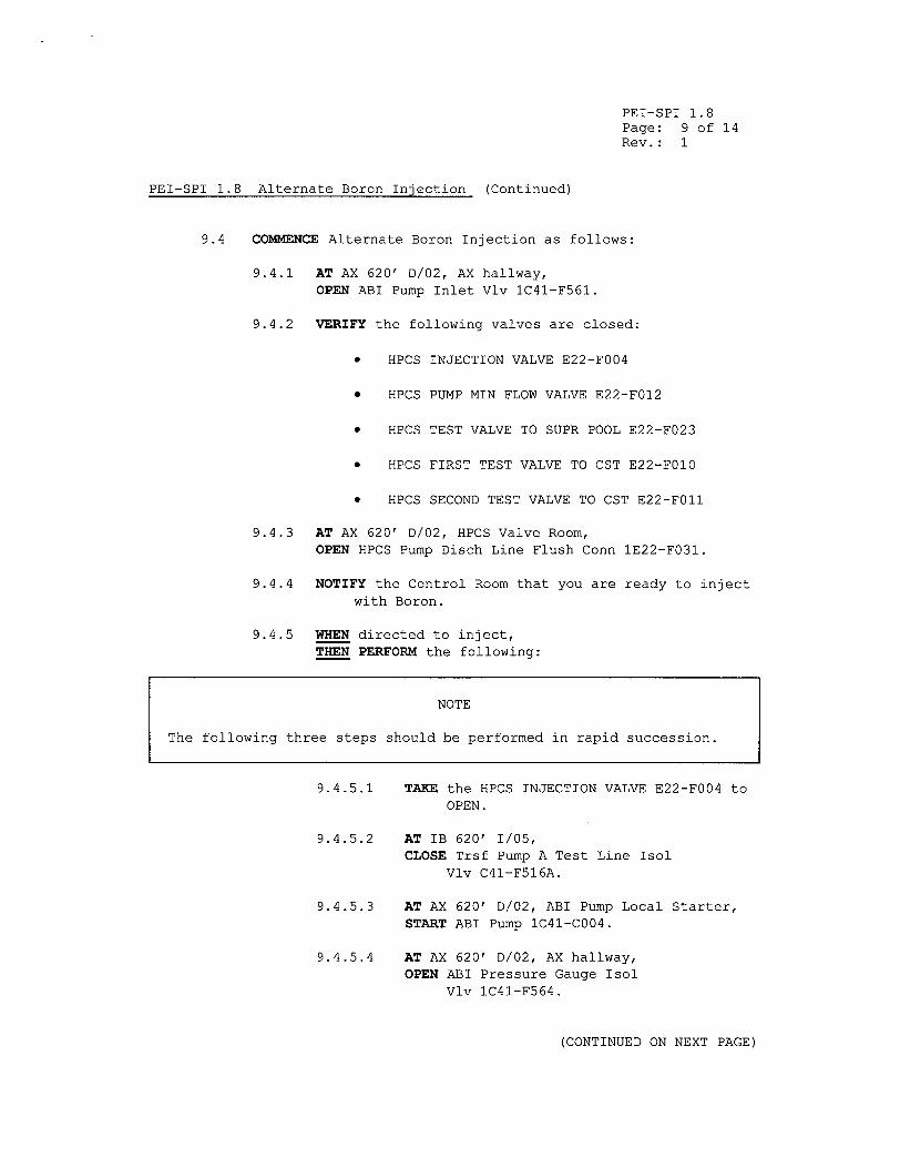
PEI-SPI 1.8 Page: 9 of 14 Rev.: 1
PEI-SPI 1.8 Alternate Boron Injection (Continued)
9.4 COMMENCE Alternate Boron Injection as follows:
9.4.1 AT AX 620' D/02, AX hallway, OPEN ABI Pump Inlet Vlv 1C41-F561.
9.4.2 VERIFY the following valves are closed:
"* HPCS INJECTION VALVE E22-F004
"* HPCS PUMP MIN FLOW VALVE E22-F012
"* HPCS TEST VALVE TO SUPR POOL E22-F023
"* HPCS FIRST TEST VALVE TO CST E22-F010
"* HPCS SECOND TEST VALVE TO CST E22-FOll
9.4.3 AT AX 620' D/02, HPCS Valve Room, OPEN HPCS Pump Disch Line Flush Conn 1E22-F031.
9.4.4 NOTIFY the Control Room that you are ready to inject with Boron.
9.4.5 WHEN directed to inject, THEN PERFORM the following:
9.4.5.1 TAKE the HPCS INJECTION VALVE E22-F004 to OPEN.
9.4.5.2 AT IB 620' 1/05, CLOSE Trsf Pump A Test Line Isol
Vlv C41-F516A.
9.4.5.3 AT AX 620' D/02, ABI Pump Local Starter, START ABI Pump 1C41-C004.
9.4.5.4 AT AX 620' D/02, AX hallway, OPEN ABI Pressure Gauge Isol
Vlv IC41-F564.
(CONTINUED ON NEXT PAGE)
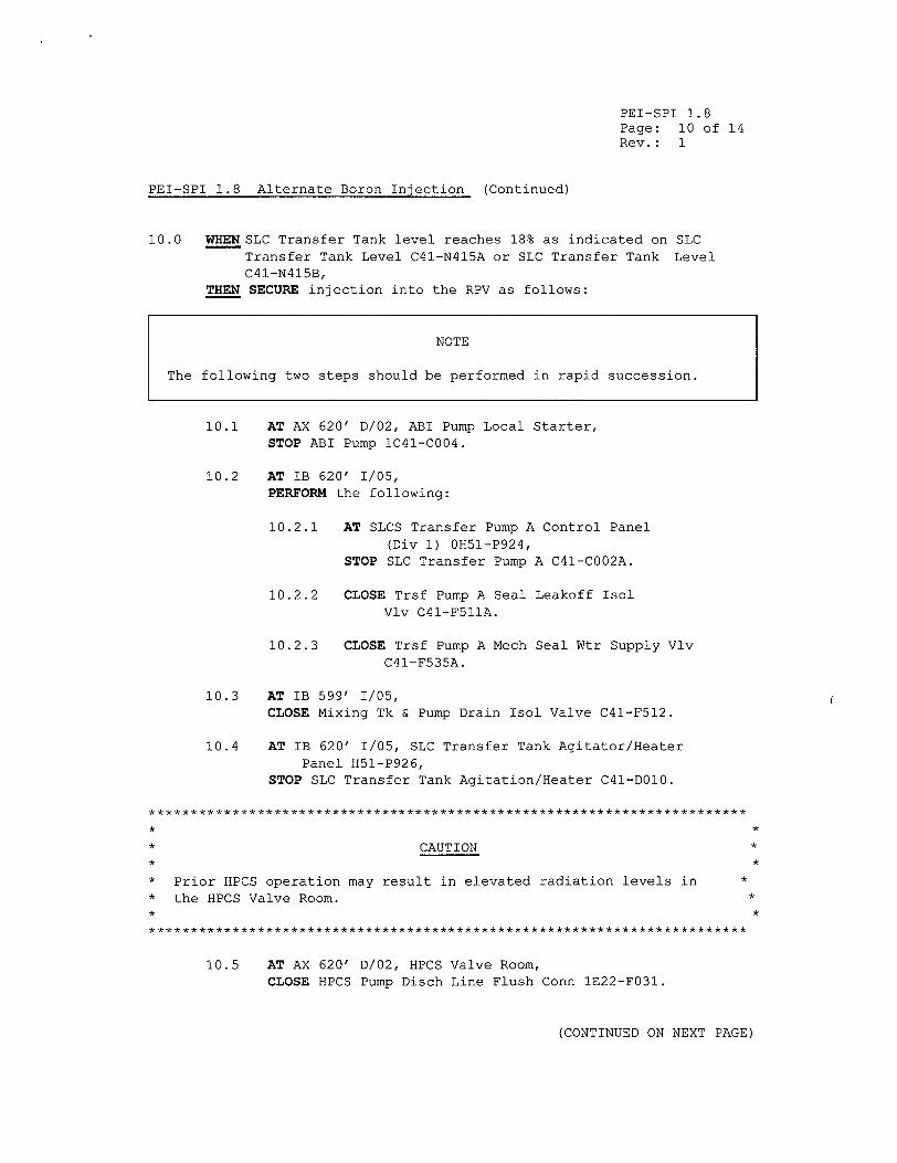
PEI-SPI 1.8 Page: 10 of 14 Rev.: 1
PEI-SPI 1.8 Alternate Boron Injection (Continued)
10.0 WHEN SLC Transfer Tank level reaches 18% as indicated on SLC Transfer Tank Level C41-N415A or SLC Transfer Tank Level C41-N415B,
THEN SECURE injection into the RPV as follows:
NOTE
The following two steps should be performed in rapid succession.
10.1 AT AX 620' D/02, ABI Pump Local Starter, STOP ABI Pump 1C41-C004.
10.2 AT IB 620' 1/05, PERFORM the following:
10.2.1 AT SLCS Transfer Pump A Control Panel (Div 1) 0H51-P924,
STOP SLC Transfer Pump A C41-CO02A.
10.2.2 CLOSE Trsf Pump A Seal Leakoff Isol Vlv C41-F51IA.
10.2.3 CLOSE Trsf Pump A Mech Seal Wtr Supply Vlv C41-F535A.
10.3 AT IB 599' 1/05, CLOSE Mixing Tk & Pump Drain Isol Valve C41-F512.
10.4 AT IB 620' 1/05, SLC Transfer Tank Agitator/Heater Panel H51-P926,
STOP SLC Transfer Tank Agitation/Heater C41-DO10.
* CAUTION *
"* Prior HPCS operation may result in elevated radiation levels in *
"* the HPCS Valve Room. *
10.5 AT AX 620' D/02, HPCS Valve Room, CLOSE HPCS Pump Disch Line Flush Conn 1E22-F031.
(CONTINUED ON NEXT PAGE)
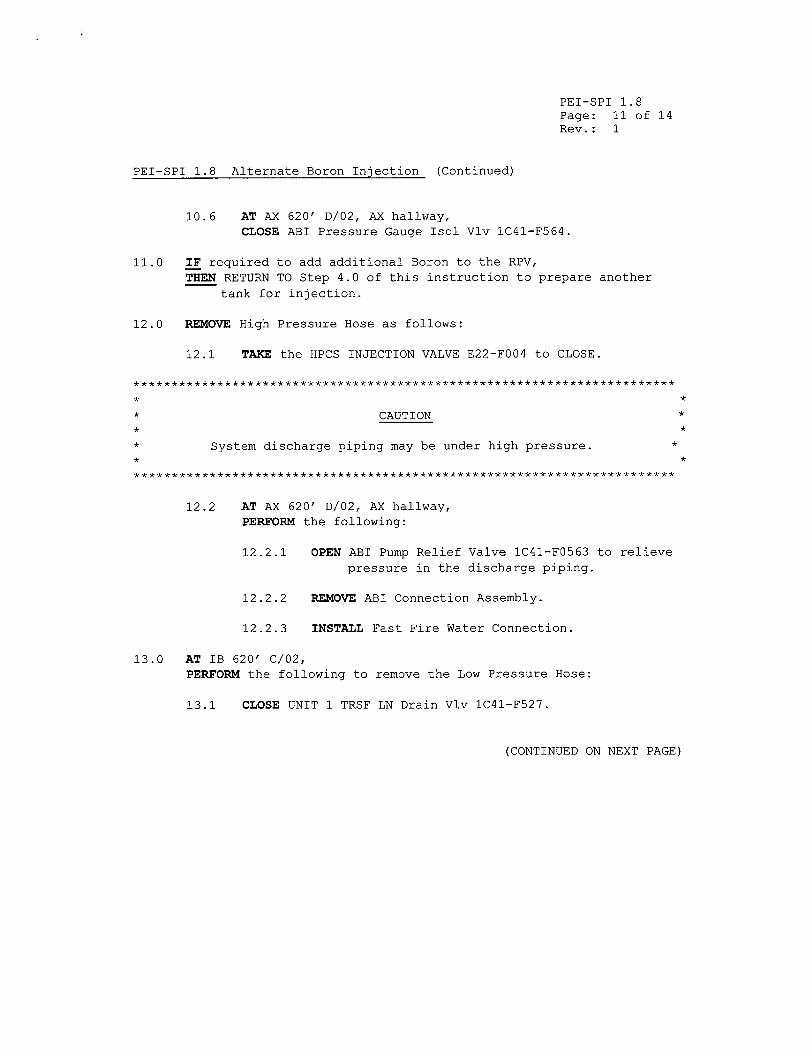
PEI-SPI 1.8 Page: 11 of 14 Rev.: 1
PEI-SPI 1.8 Alternate Boron Injection (Continued)
10.6 AT AX 620' D/02, AX hallway, CLOSE ABI Pressure Gauge Isol Vlv IC41-F564.
11.0 IF required to add additional Boron to the RPV, THEN RETURN TO Step 4.0 of this instruction to prepare another
tank for injection.
12.0 REMOVE High Pressure Hose as follows:
12.1 TAKE the HPCS INJECTION VALVE E22-F004 to CLOSE.
* *
* CAUTION * * *
* System discharge piping may be under high pressure. *
********* ***************** *WWWWW*WWW*WW*WWWWWW***WW**W*** WW ****WWWW**WWW *
12.2 AT AX 620' D/02, AX hallway, PERFORM the following:
12.2.1 OPEN ABI Pump Relief Valve 1C41-F0563 to relieve pressure in the discharge piping.
12.2.2 REMOVE ABI Connection Assembly.
12.2.3 INSTALL Fast Fire Water Connection.
13.0 AT IB 620' C/02, PERFORM the following to remove the Low Pressure Hose:
13.1 CLOSE UNIT 1 TRSF LN Drain Vlv IC41-F527.
(CONTINUED ON NEXT PAGE)
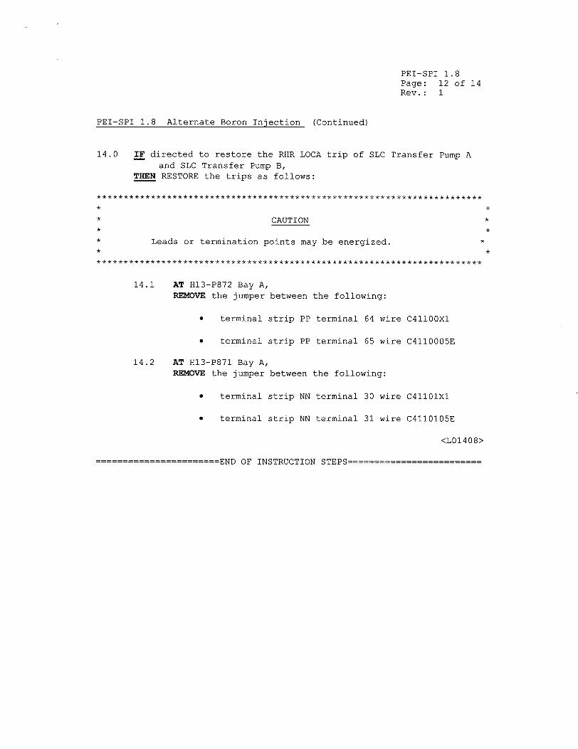
PEI-SPI 1.8 Page: 12 of 14 Rev.: 1
PEI-SPI 1.8 Alternate Boron Injection (Continued)
14.0 IF directed to restore the RHR LOCA trip of SLC Transfer Pump A and SLC Transfer Pump B,
THEN RESTORE the trips as follows:
****************** ***** ***** ****** *********** ******* ************ ***
* CAUTION * * *
* Leads or termination points may be energized. *
14.1 AT H13-P872 Bay A, REMOVE the jumper between the following:
"* terminal strip PP terminal 64 wire C41100X1
"* terminal strip PP terminal 65 wire C4110005E
14.2 AT H13-P871 Bay A, REMOVE the jumper between the following:
"* terminal strip NN terminal 30 wire C41101X1
"* terminal strip NN terminal 31 wire C4110105E
<L01408>
-END OF INSTRUCTION STEPS
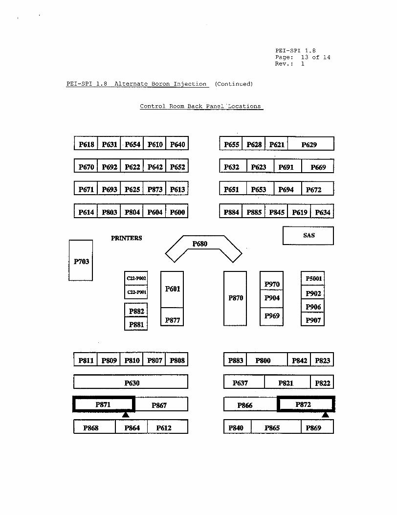
PEI-SPI 1.8 Page: 13 of 14 Rev.: 1
PEI-SPI 1.8 Alternate Boron Injection (Continued)
Control Room Back Panel'Locations
P618i P6311 P654i P6101 P6401
P670 P692 P622 P642 P652
P671 P693 P625 P873 P613
P614 IP803 F1P04 IP604 IP600PRINTERS
SP680
P601
P877
P655 I P623 I P621 I P629
P632 P623 P691 P669
P651 P6S3 P694 P672
I P884 P885 P84I P619 P634
P5001 P970
P870 P904 P902
P906 P969 P907
IP8111 P8091 P8101 P071 P8081
P630
P871 8 P%67
SP86 P864I P612
I831 MOO I P42 IP8231
P637 P821 P822
P866 F P7
P840 P8 P869
JI ....
i I I l l I
P703
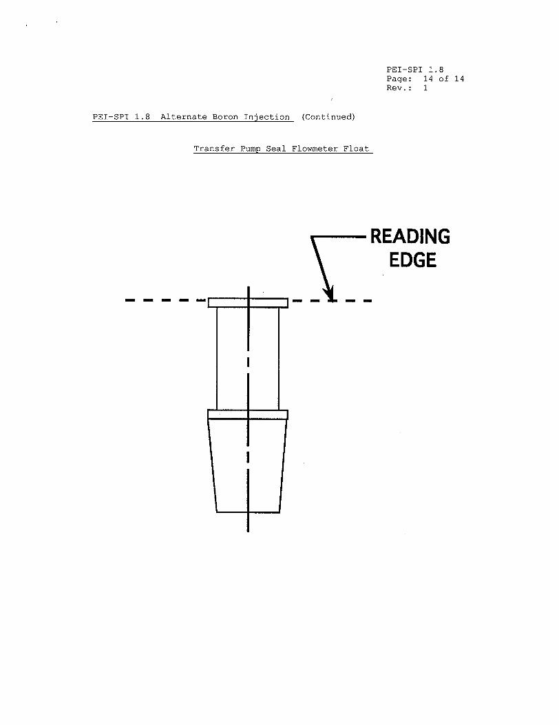
PEI-SPI 1.8 Page: 14 of 14 Rev. : 1
PEI-SPI 1.8 Alternate Boron Injection (Continued)
Transfer Pump Seal Flowmeter Float
READING EDGE
----- - - -
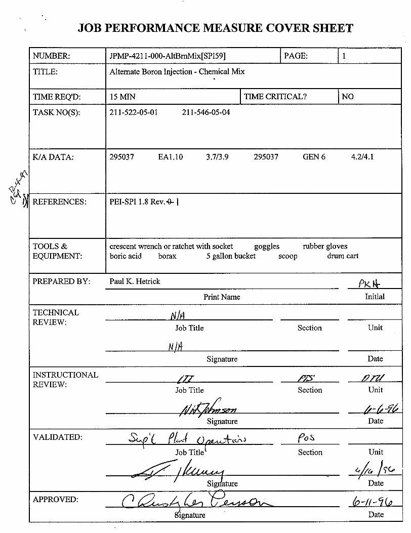
JOB PERFORMANCE MEASURE COVER SHEET
NUMBER: JPMP-421 1-000-AltBmMix[SP159] PAGE: 1
TITLE: Alternate Boron Injection - Chemical Mix
TIME REQ'D: 15 MIN TIME CRITICAL? NO
TASK NO(S): 211-522-05-01 211-546-05-04
K/A DATA: 295037 EAI.10 3.7/3.9 295037 GEN 6 4.2/4.1
REFERENCES: PEI-SPI 1.8 Rev..0- 1
TOOLS & crescent wrench or ratchet with socket goggles rubber gloves EQUIPMENT: boric acid borax 5 gallon bucket scoop drum cart
PREPARED BY: Paul K. Hetrick PK.
Print Name Initial
TECHNICAL I/A REVIEW: Job Title Section Unit
NM1 Signature Date
INSTRUCTIONAL 4a17 /,• , REVIEW: Job Title Section Unit
Signature Date
VALIDATED: too~ eL(oýs~X_ _ _ _
Job Title( Section Unit
/ Date
APPROVED: ignae D
iignature Date
JPM No. JPMP-4211-000-AltBmMix[SPI59]
JOB PERFORMANCE MEASURE SETUP SHEET
1. Simulator Setup Instructions. - N/A
2. Location/Method -Plant/Simulate
3. Initial Conditions. An ATWS has occurred and the Reactor is still at power. Alternate Boron Injection is required. The HPCS Pump Breaker has been racked to the Disconnected position per SOI-R22. You are an in-plant operator.
4. Initiating Cue. (The Unit Supervisor directs the following.) Prepare the Standby Liquid Control Transfer Tank to support boron injection per PEI-SPI 1.8. through step-3-4-, q. Lf
Page: 2
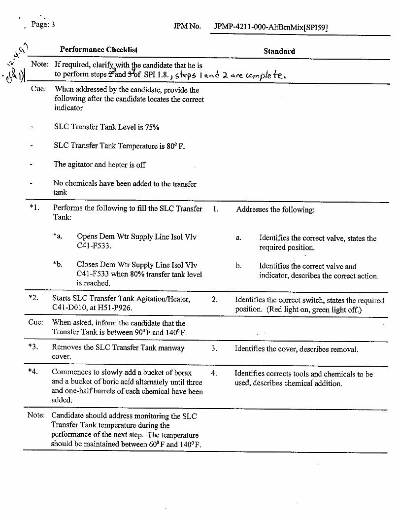
JPM No. JPMP-42 11 -000-AltBmMix[SPI59]
Performance Checklist Standard
Note: If required, clarif with •e candidate that he is to perform steps-29and tiof SPI 1.8. ) eiep:, I x,,,, ar e cci,,ple +e.,
Cue: When addressed by the candidate, provide the following after the candidate locates the correct indicator
- SLC Transfer Tank Level is 75%
- SLC Transfer Tank Temperature is 800 F.
- The agitator and heater is off
- No chemicals have been added to the transfer tank
* 1. Performs the following to fill the SLC Transfer 1. Addresses the following: Tank:
*a. Opens Dem Wtr Supply Line Isol Vlv a. Identifies the correct valve, states the C41-F533. required position.
*b. Closes Dem Wtr Supply Line Isol Vlv b. Identifies the correct valve and C41 -F533 when 80% transfer tank level indicator, describes the correct action. is reached.
*2. Starts SLC Transfer Tank Agitation/Heater, 2. Identifies the correct switch, states the required C41-DO 10, at H51-P926. position. (Red light on, green light off.)
Cue: When asked, inform the candidate that the
Transfer Tank is between 90 0F and 1400F. *3. Removes the SLC Transfer Tank manway 3. Identifies the cover, describes removal.
cover. *4. Commences to slowly add a bucket of borax 4. Identifies corrects tools and chemicals to be
and a bucket of boric acid alternately until three used, describes chemical addition. and one-half barrels of each chemical have been added.
Note: Candidate should address monitoring the SLC Transfer Tank temperature during the performance of the next step. The temperature should be maintained between 601 F and 1400 F.
Page: 3
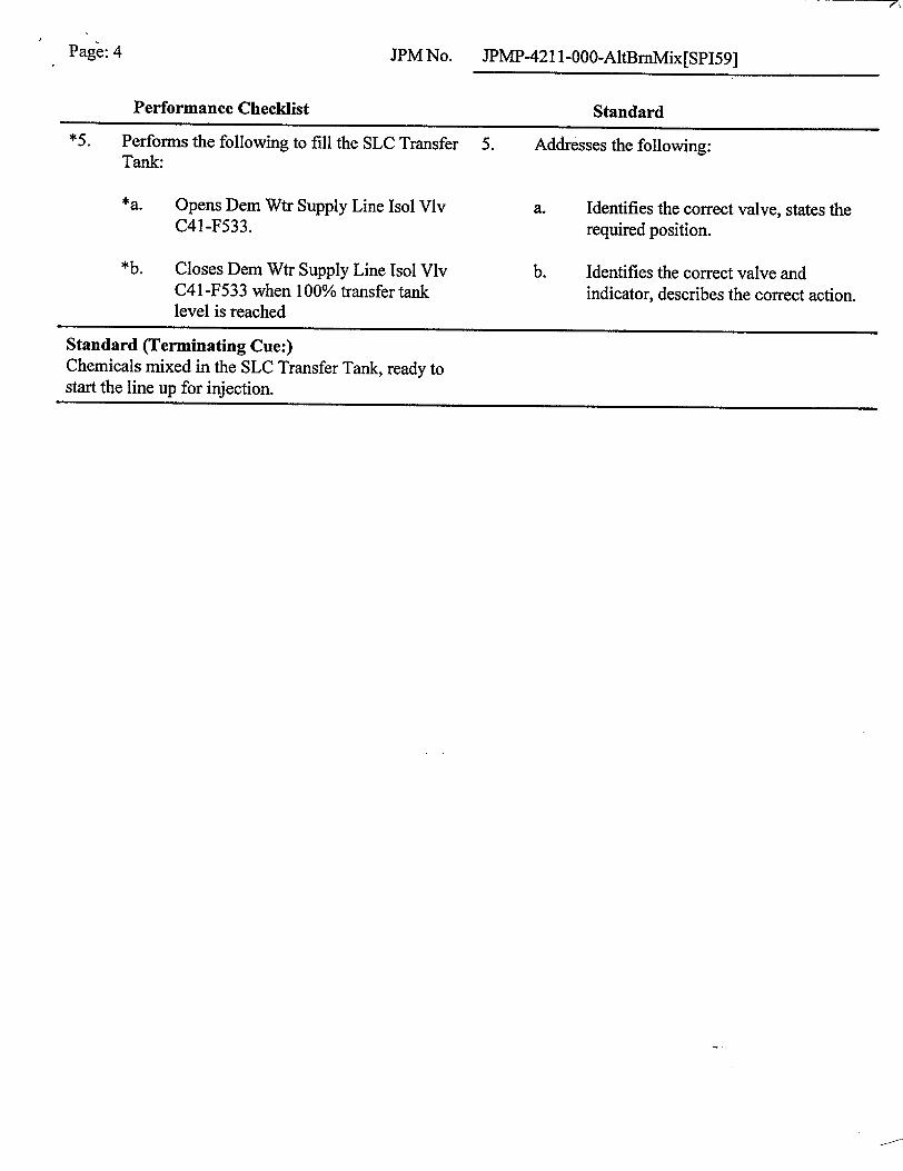
Page: 4 JPM No. JPMP-421 1-000-AltBmMix[SP159]
Performance Checklist Standard*5. Performs the following to fill the SLC Transfer 5. Addresses the following:
Tank:
*a. Opens Dem Wtr Supply Line Isol Vlv a. Identifies the correct valve, states the C41-F533. required position.
*b. Closes Dem Wtr Supply Line Isol Vlv b. Identifies the correct valve and C4 1 -F533 when 100% transfer tank indicator, describes the correct action. level is reached
Standard (Terminating Cue:) Chemicals mixed in the SLC Transfer Tank, ready to start the line up for injection.
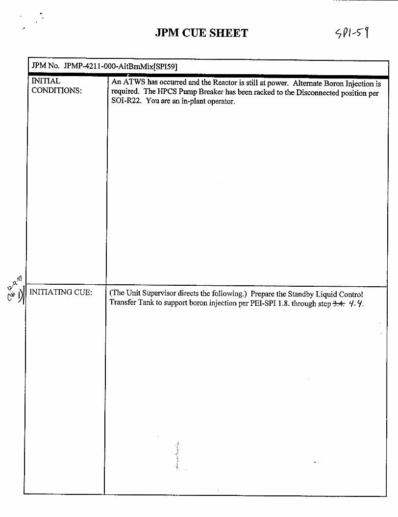
JPM CUE SHEET
JPM No. JPMP-421 1-000-AltBmMix[SP159]
= V~mrIIINI I lAL
CONDITIONS:
INITIATING CUE:f.
An ATWS has occurred and the Reactor is still at power. Alternate Boron Injection is required. The HPCS Pump Breaker has been racked to the Disconnected position per SOI-R22. You are an in-plant operator.
(The Unit Supervisor directs the following.) Prepare the Standby Liquid Control Transfer Tank to support boron injection per PEI-SPI 1.8. through step -3* 9-.
q1,51
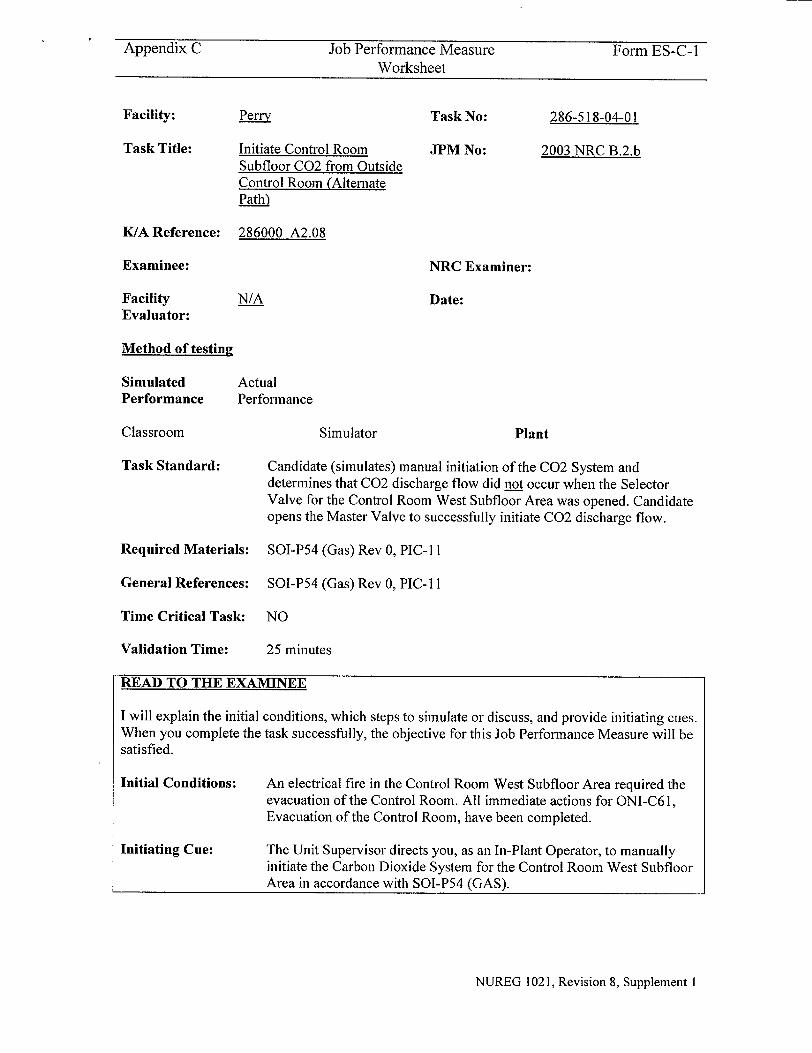
Appendix C Job Performance Measure Form ES-C-I Worksheet
Perry
Initiate Control Room Subfloor C02 from Outside Control Room (Alternate Path)
Task No:
JPM No:
286-518-04-01
2003 NRC B.2.b
K/A Reference:
Examinee:
Facility Evaluator:
286000 A2.08
NRC Examiner:
N/A Date:
Method of testing
Simulated Performance
Classroom
Task Standard:
Actual Performance
Simulator Plant
Candidate (simulates) manual initiation of the C02 System and determines that C02 discharge flow did not occur when the Selector Valve for the Control Room West Subfloor Area was opened. Candidate opens the Master Valve to successfully initiate C02 discharge flow.
Required Materials: SOI-P54 (Gas) Rev 0, PIC-I 1
General References: SOI-P54 (Gas) Rev 0, PIC-11
Time Critical Task: NO
Validation Time: 25 minutes
READ TO THE EXAMINEE
I will explain the initial conditions, which steps to simulate or discuss, and provide initiating cues. When you complete the task successfully, the objective for this Job Performance Measure will be satisfied.
Initial Conditions:
Initiating Cue:
An electrical fire in the Control Room West Subfloor Area required the evacuation of the Control Room. All immediate actions for ONI-C61, Evacuation of the Control Room, have been completed.
The Unit Supervisor directs you, as an In-Plant Operator, to manually initiate the Carbon Dioxide System for the Control Room West Subfloor Area in accordance with SOI-P54 (GAS).
NUREG 1021, Revision 8, Supplement 1
Facility:
Task Title:
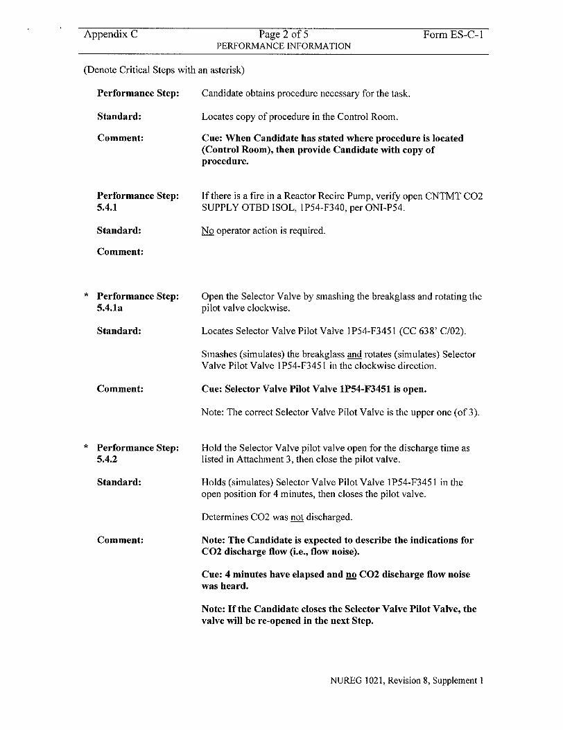
Appendix C Page 2 of 5 Form ES-C-I PERFORMANCE INFORMATION
(Denote Critical Steps with an asterisk)
Performance Step: Candidate obtains procedure necessary for the task.
Standard: Locates copy of procedure in the Control Room.
Comment: Cue: When Candidate has stated where procedure is located (Control Room), then provide Candidate with copy of procedure.
Performance Step: 5.4.1
Standard:
Comment:
" Performance Step:
5.4.1a
Standard:
Comment:
" Performance Step:
5.4.2
Standard:
Comment:
If there is a fire in a Reactor Recirc Pump, verify open CNTMT C02 SUPPLY OTBD ISOL, 1P54-F340, per ONI-P54.
No operator action is required.
Open the Selector Valve by smashing the breakglass and rotating the
pilot valve clockwise.
Locates Selector Valve Pilot Valve 1P54-F3451 (CC 638' C/02).
Smashes (simulates) the breakglass and rotates (simulates) Selector Valve Pilot Valve 1P54-F3451 in the clockwise direction.
Cue: Selector Valve Pilot Valve 1P54-F3451 is open.
Note: The correct Selector Valve Pilot Valve is the upper one (of 3).
Hold the Selector Valve pilot valve open for the discharge time as listed in Attachment 3, then close the pilot valve.
Holds (simulates) Selector Valve Pilot Valve 1P54-F3451 in the
open position for 4 minutes, then closes the pilot valve.
Determines C02 was not discharged.
Note: The Candidate is expected to describe the indications for C02 discharge flow (i.e., flow noise).
Cue: 4 minutes have elapsed and no C02 discharge flow noise was heard.
Note: If the Candidate closes the Selector Valve Pilot Valve, the valve will be re-opened in the next Step.
NUREG 1021, Revision 8, Supplement I
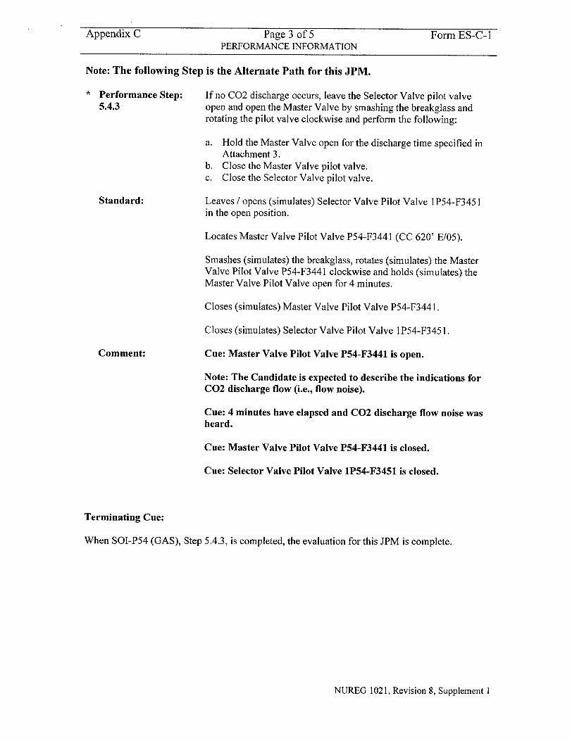
Appendix C Page 3 of 5 Form ES-C-I
PERFORMANCE INFORMATION
Note: The following Step is the Alternate Path for this JPM.
Performance Step: If no C02 discharge occurs, leave the Selector Valve pilot valve 5.4.3 open and open the Master Valve by smashing the breakglass and
rotating the pilot valve clockwise and perform the following:
a. Hold the Master Valve open for the discharge time specified in Attachment 3.
b. Close the Master Valve pilot valve. c. Close the Selector Valve pilot valve.
Standard: Leaves / opens (simulates) Selector Valve Pilot Valve 1 P54-F3451
in the open position.
Locates Master Valve Pilot Valve P54-F3441 (CC 620' E/05).
Smashes (simulates) the breakglass, rotates (simulates) the Master Valve Pilot Valve P54-F3441 clockwise and holds (simulates) the Master Valve Pilot Valve open for 4 minutes.
Closes (simulates) Master Valve Pilot Valve P54-F344 1.
Closes (simulates) Selector Valve Pilot Valve 1P54-F345 1.
Comment: Cue: Master Valve Pilot Valve P54-F3441 is open.
Note: The Candidate is expected to describe the indications for C02 discharge flow (i.e., flow noise).
Cue: 4 minutes have elapsed and C02 discharge flow noise was heard.
Cue: Master Valve Pilot Valve P54-F3441 is closed.
Cue: Selector Valve Pilot Valve 1P54-F3451 is closed.
Terminating Cue:
When SOI-P54 (GAS), Step 5.4.3, is completed, the evaluation for this JPM is complete.
NUREG 1021, Revision 8, Supplement I
Form ES-C-1
Question Documentation:
Question:
Response:
Result: SAT OR UNSAT
Examiner's Signature and Date:
NUREG 1021, Revision 8, Supplement 1
Appendix C Page 4 of 5 VERIFICATION OF COMPLETION
Job Performance Measure No. 2003 NRC B.2.b
Examinee's Name:
Examiner's Name:
Date Performed:
Facility Evaluator: N/A
Number of Attempts:
Time to complete:
Appendix C Page 5 of 5 Form ES-C-I JPM CUE SHEET
INITIAL CONDITIONS:
An electrical fire in the Control Room West Subfloor Area required the evacuation of the Control Room. All immediate actions for ONI-C6 1, Evacuation of the Control Room, have been completed.
INITIATING CUE: The Unit Supervisor directs you, as an In-Plant Operator, to manually initiate the Carbon Dioxide System for the Control Room West Subfloor Area in accordance with SOI-P54 (GAS).
NUREG 1021, Revision 8, Supplement I
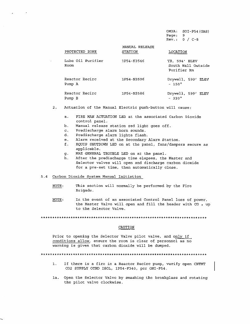
SOI-P54 (GAS) 9 0 / C-8
PROTECTED ZONE
Lube Oil Purifier Room
Reactor Recirc Pump A
Reactor Recirc Pump B
MANUAL RELEASE STATION
1P54-N3546
lP54-N3596
IP54-N3586
LOCATION
TB, 594' ELEV South Wall Outside Purifier Rm
Drywell, 599' ELEV - 1500
Drywell, 599' ELEV - 3200
2. Actuation of the Manual Electric push-button will cause:
a. FIRE MAN ACTUATION LED at the associated Carbon Dioxide control panel.
b. Manual release station red light goes off. c. Predischarge alarm horn sounds. d. Predischarge alarm lights flash. e. Alarm received at the Secondary Alarm Station. f. EQUIP SHUTDOWN LED on at the panel, fans/dampers secure as
applicable. g. HAZ GENERAL TROUBLE LED on at the panel. h. After the predischarge time elapses, the Master and
Selector valves will open and discharge carbon dioxide for a pre-set time, then automatically close.
5.4 Carbon Dioxide System Manual Initiation
NOTE:
NOTE:
This section will normally be performed by the Fire Brigade.
In the event of an associated Control Panel loss of power, the Master Valve will open and fill the header with CO 2 up to the Selector Valve.
W*W************W*W*******************W***WW*WW*W*W********W*W*WW**** ** ***
CAUTION
Prior to opening the Selector Valve pilot valve, and only if conditions allow, ensure the room is clear of personnel as no warning is given that carbon dioxide will be dumped.
*W*W*************W *W*W***********WW**W*W* W*W** ********WWW*W*******WW****
1. If there is a fire in a Reactor Recirc pump, verify open CNTMT C02 SUPPLY OTBD ISOL, IP54-F340, per ONI-P54.
la. Open the Selector Valve by smashing the breakglass and rotating the pilot valve clockwise.
OM3A: Page: Rev.:
I
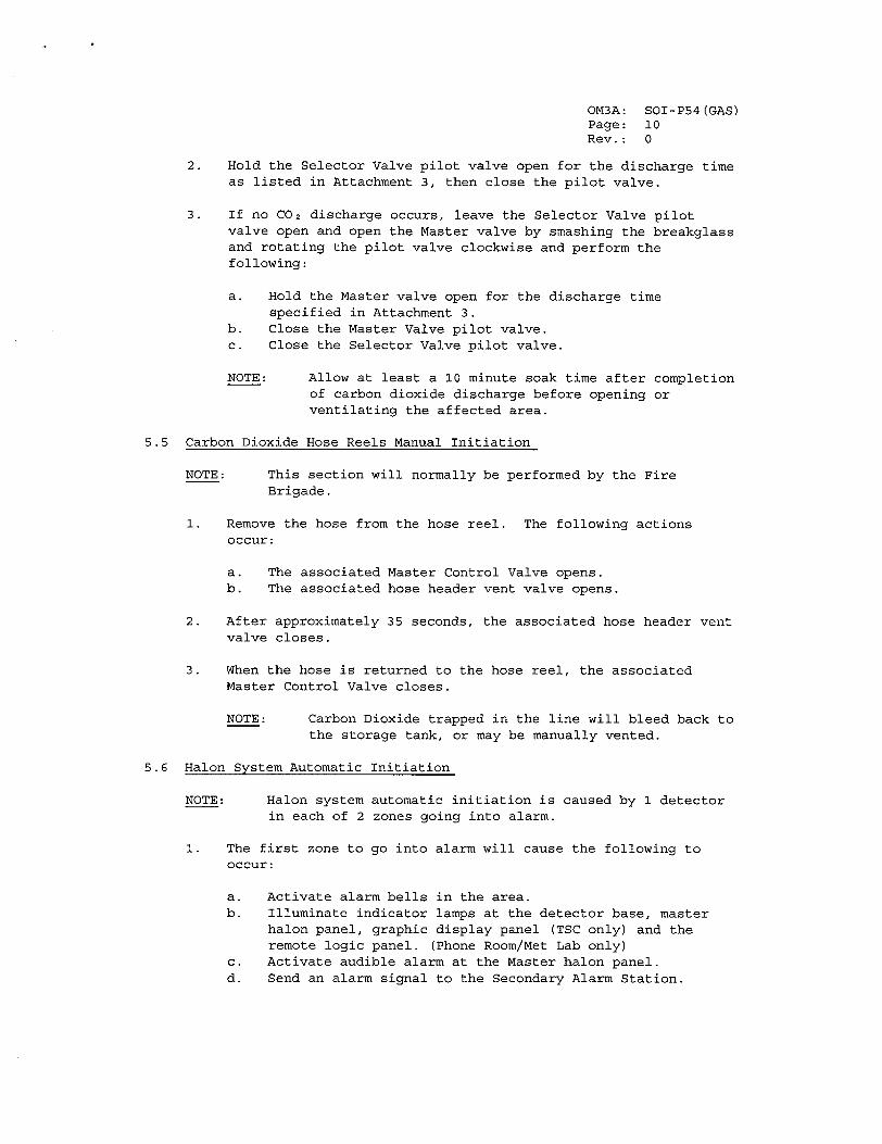
OM3A: SOI-P54(GAS) Page: 10 Rev.: 0
2. Hold the Selector Valve pilot valve open for the discharge time as listed in Attachment 3, then close the pilot valve.
3. If no C0 2 discharge occurs, leave the Selector Valve pilot valve open and open the Master valve by smashing the breakglass and rotating the pilot valve clockwise and perform the following:
a. Hold the Master valve open for the discharge time specified in Attachment 3.
b. Close the Master Valve pilot valve. c. Close the Selector Valve pilot valve.
NOTE: Allow at least a 10 minute soak time after completion of carbon dioxide discharge before opening or ventilating the affected area.
5.5 Carbon Dioxide Hose Reels Manual Initiation
NOTE: This section will normally be performed by the Fire Brigade.
1. Remove the hose from the hose reel. The following actions occur:
a. The associated Master Control Valve opens. b. The associated hose header vent valve opens.
2. After approximately 35 seconds, the associated hose header vent valve closes.
3. When the hose is returned to the hose reel, the associated Master Control Valve closes.
NOTE: Carbon Dioxide trapped in the line will bleed back to the storage tank, or may be manually vented.
5.6 Halon System Automatic Initiation
NOTE: Halon system automatic initiation is caused by 1 detector in each of 2 zones going into alarm.
1. The first zone to go into alarm will cause the following to occur:
a. Activate alarm bells in the area. b. Illuminate indicator lamps at the detector base, master
halon panel, graphic display panel (TSC only) and the remote logic panel. (Phone Room/Met Lab only)
c. Activate audible alarm at the Master halon panel. d. Send an alarm signal to the Secondary Alarm Station.
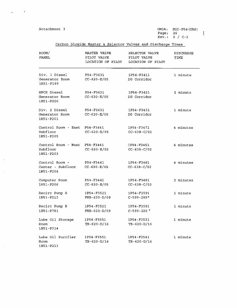
Attachment 3 OM3A: Page: Rev.:
Carbon Dioxide Master & Selector
SOI-P54(GAS) 26 0 / C-3
Valves and Discharqe Times
MASTER VALVE PILOT VALVE LOCATION OF PILOT
SELECTOR VALVE PILOT VALVE LOCATION OF PILOT
Div. 1 Diesel Generator Room 1H51-P199
HPCS Diesel
Generator Room 1H51-P200
Div. 2 Diesel Generator Room IH51-P201
Control Room - East
Subfloor 1H51-P205
Control Room - West Subfloor 1H51-P203
Control Room Center - Subfloor
1H51-P204
Computer Room 1H51-P206
Recirc Pump A IH51-P212
Recirc Pump B 1H51-P781
Lube Oil Storage Room IH51-P214
Lube Oil Purifier Room 1H51-P213
P54-F3631
CC-620-E/05
P54-F3631
CC-620-E/05
P54-F3631
CC-620-E/05
P54-F3441
CC-620-E/05
P54-F3441
CC-620-E/05
P54-F3441
CC-620-E/05
P54-F3441
CC-620-E/05
1P54-F3521
FHB-620-D/09
1P54-F3521
FHB-620-D/09
1P54-F3551
TB-620-D/16
IP54-F3551
TB-620-D/16
1P54-F3411
DG Corridor
1P54-F3421
DG Corridor
1P54-F3431
DG Corridor
IP54-F3471
CC-638-C/02
1P54-F3451
CC-638-C/02
1P54-F3461
CC-638-C/02
1P54-F3481
CC-638-C/03
IP54-F3591 C-599-285 0
IP54-F3581
C-599-320 0
1P54-F3531
TB-620-D/16
IP54-F3541
TB-620-D/16
ROOM/ PANEL
DISCHARGE TIME
1 minute
1 minute
1 minute
4 minutes
4 minutes
4 minutes
2 minutes
1 minute
1 minute
1 minute
1 minute
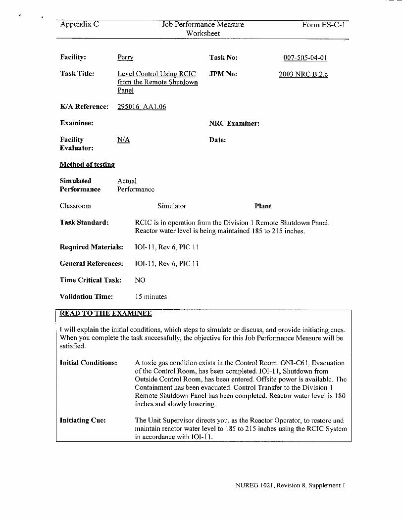
Appendix C Job Performance Measure Form ES-C-I Worksheet
Perry
Level Control Using RCIC from the Remote Shutdown Panel
Task No:
JPM No:
007-505-04-01
2003 NRC B.2.c
K/A Reference:
Examinee:
Facility Evaluator:
295016 AAI.06
NRC Examiner:
N/A Date:
Method of testing
Simulated Performance
Classroom
Task Standard:
Actual Performance
Simulator Plant
RCIC is in operation from the Division 1 Remote Shutdown Panel. Reactor water level is being maintained 185 to 215 inches.
Required Materials: 101-11, Rev 6, PIC 11
General References: 101-I , Rev 6, PIC II
Time Critical Task:
Validation Time:
NO
15 minutes
READ TO THE EXAMINEE
I will explain the initial conditions, which steps to simulate or discuss, and provide initiating cues. When you complete the task successfully, the objective for this Job Performance Measure will be satisfied.
Initial Conditions:
Initiating Cue:
A toxic gas condition exists in the Control Room. ONI-C6 1, Evacuation of the Control Room, has been completed. 101-11, Shutdown from Outside Control Room, has been entered. Offsite power is available. The Containment has been evacuated. Control Transfer to the Division 1 Remote Shutdown Panel has been completed. Reactor water level is 180 inches and slowly lowering.
The Unit Supervisor directs you, as the Reactor Operator, to restore and maintain reactor water level to 185 to 215 inches using the RCIC System in accordance with 101-11.
NUREG 1021, Revision 8, Supplement I
Facility:
Task Title:
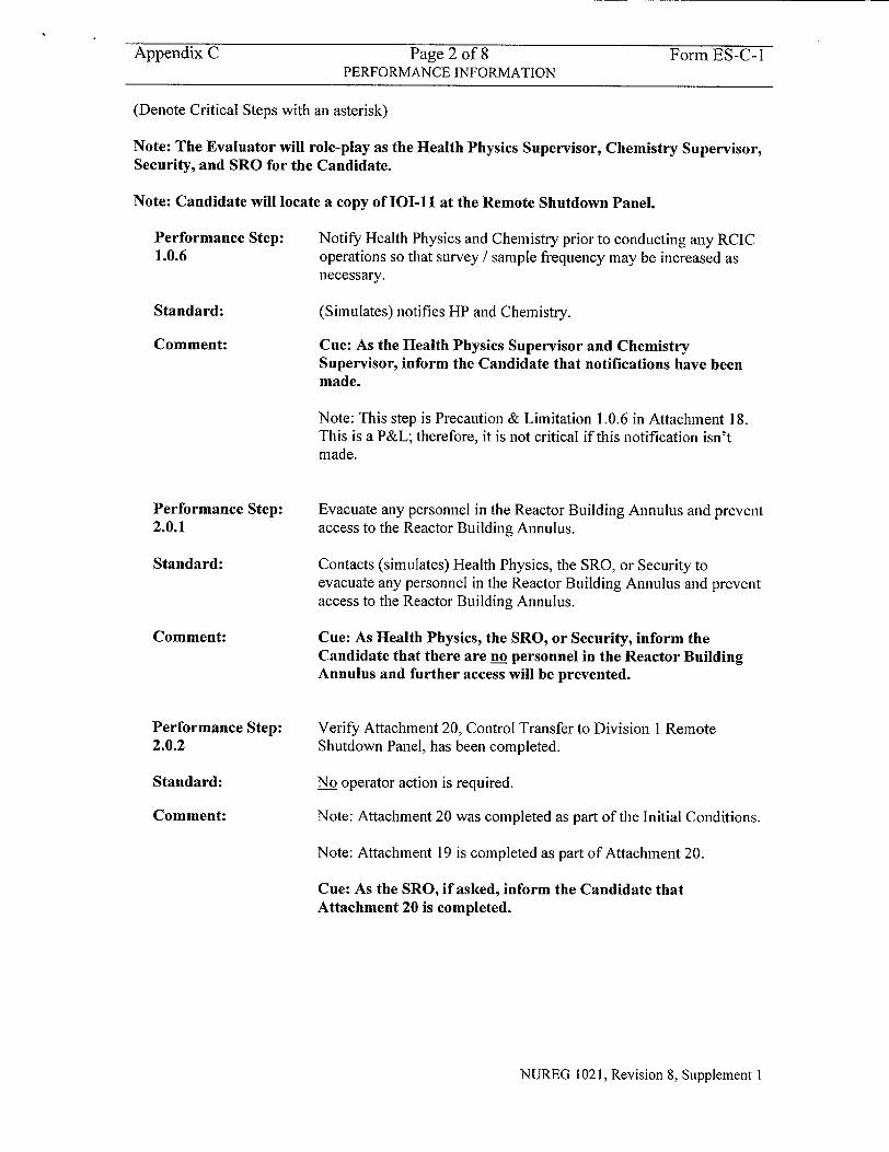
Appendix C Page 2 of 8 Form ES-C-I PERFORMANCE INFORMATION
(Denote Critical Steps with an asterisk)
Note: The Evaluator will role-play as the Health Physics Supervisor, Chemistry Supervisor, Security, and SRO for the Candidate.
Note: Candidate will locate a copy of 101-11 at the Remote Shutdown Panel.
Performance Step: 1.0.6
Standard:
Comment:
Performance Step: 2.0.1
Standard:
Comment:
Performance Step:
2.0.2
Standard:
Comment:
Notify Health Physics and Chemistry prior to conducting any RCIC operations so that survey / sample frequency may be increased as necessary.
(Simulates) notifies HP and Chemistry.
Cue: As the Health Physics Supervisor and Chemistry Supervisor, inform the Candidate that notifications have been made.
Note: This step is Precaution & Limitation 1.0.6 in Attachment 18. This is a P&L; therefore, it is not critical if this notification isn't made.
Evacuate any personnel in the Reactor Building Annulus and prevent access to the Reactor Building Annulus.
Contacts (simulates) Health Physics, the SRO, or Security to evacuate any personnel in the Reactor Building Annulus and prevent access to the Reactor Building Annulus.
Cue: As Health Physics, the SRO, or Security, inform the Candidate that there are no personnel in the Reactor Building Annulus and further access will be prevented.
Verify Attachment 20, Control Transfer to Division I Remote
Shutdown Panel, has been completed.
No operator action is required.
Note: Attachment 20 was completed as part of the Initial Conditions.
Note: Attachment 19 is completed as part of Attachment 20.
Cue: As the SRO, if asked, inform the Candidate that Attachment 20 is completed.
NUREG 1021, Revision 8, Supplement I
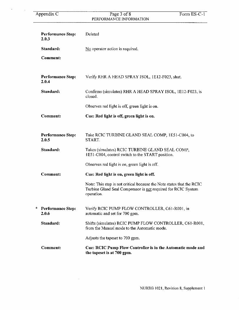
Appendix C Page 3 of 8 Form ES-C-1 PERFORMANCE INFORMATION
Performance Step: 2.0.3
Standard:
Deleted
No operator action is required.
Comment:
Performance Step: 2.0.4
Standard:
Comment:
Performance Step: 2.0.5
Standard:
Comment:
Performance Step: 2.0.6
Standard:
Comment:
Verify RHR A HEAD SPRAY ISOL, 1E12-F023, shut.
Confirms (simulates) RHR A HEAD SPRAY ISOL, 1E12-F023, is closed.
Observes red light is off, green light is on.
Cue: Red light is off, green light is on.
Take RCIC TURBINE GLAND SEAL COMP, 1E51 -C004, to START.
Takes (simulates) RCIC TURBINE GLAND SEAL COMP, I E5 1 -C004, control switch to the START position.
Observes red light is on, green light is off.
Cue: Red light is on, green light is off.
Note: This step is not critical because the Note states that the RCIC Turbine Gland Seal Compressor is not required for RCIC System operation.
Verify RCIC PUMP FLOW CONTROLLER, C6 I -ROO 1, in automatic and set for 700 gpm.
Shifts (simulates) RCIC PUMP FLOW CONTROLLER, C6 l-R001, from the Manual mode to the Automatic mode.
Adjusts the tapeset to 700 gpm.
Cue: RCIC Pump Flow Controller is in the Automatic mode and the tapeset is at 700 gpm.
NUREG 1021, Revision 8, Supplement I
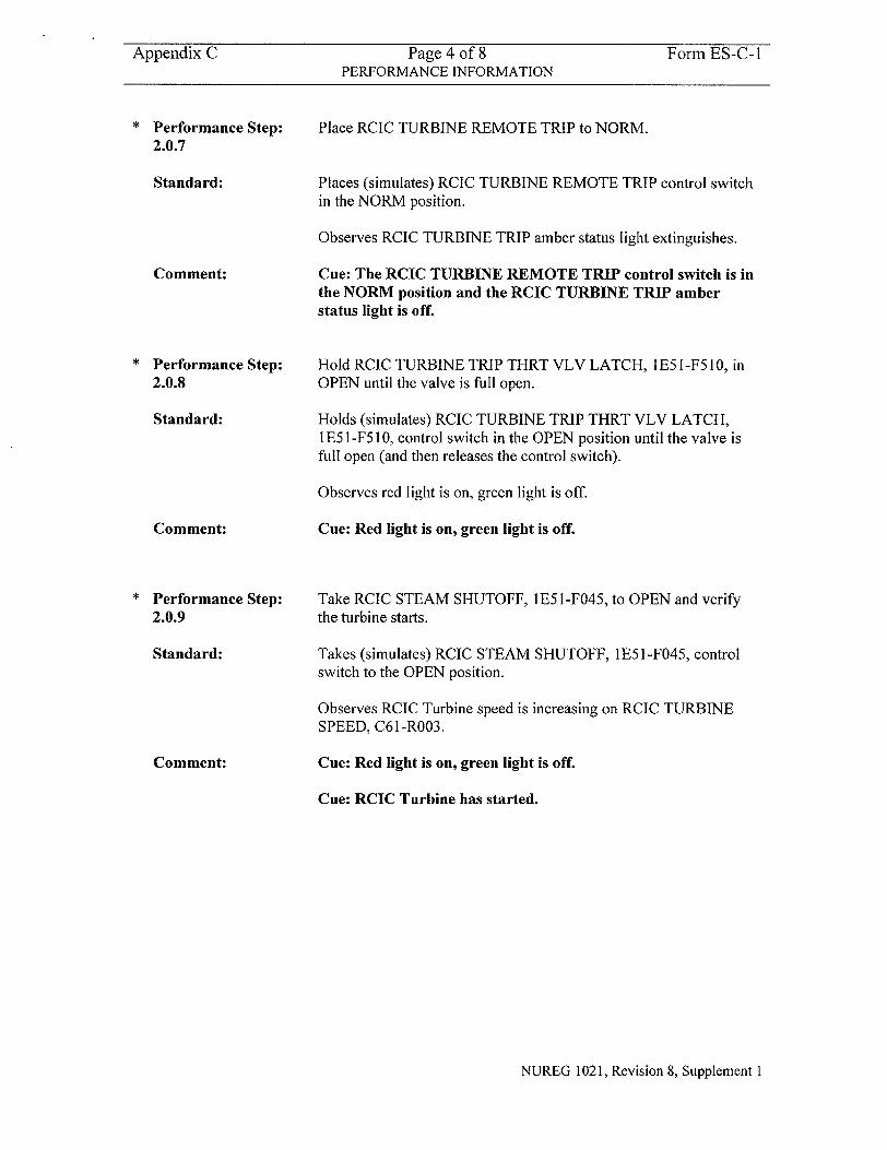
Appendix C Page 4 of 8 Form ES-C- I PERFORMANCE INFORMATION
Performance Step: 2.0.7
Standard:
Comment:
Performance Step:
2.0.8
Standard:
Comment:
Performance Step: 2.0.9
Standard:
Comment:
Place RCIC TURBINE REMOTE TRIP to NORM.
Places (simulates) RCIC TURBINE REMOTE TRIP control switch in the NORM position.
Observes RCIC TURBINE TRIP amber status light extinguishes.
Cue: The RCIC TURBINE REMOTE TRIP control switch is in the NORM position and the RCIC TURBINE TRIP amber status light is off.
Hold RCIC TURBINE TRIP THRT VLV LATCH, I E5 I -F5 10, in OPEN until the valve is full open.
Holds (simulates) RCIC TURBINE TRIP THRT VLV LATCH, I E5 1-F5 10, control switch in the OPEN position until the valve is full open (and then releases the control switch).
Observes red light is on, green light is off.
Cue: Red light is on, green light is off.
Take RCIC STEAM SHUTOFF, I E5 1 -F045, to OPEN and verify the turbine starts.
Takes (simulates) RCIC STEAM SHUTOFF, 1E5 1 -F045, control switch to the OPEN position.
Observes RCIC Turbine speed is increasing on RCIC TURBINE SPEED, C61-R003.
Cue: Red light is on, green light is off.
Cue: RCIC Turbine has started.
NUREG 1021, Revision 8, Supplement 1
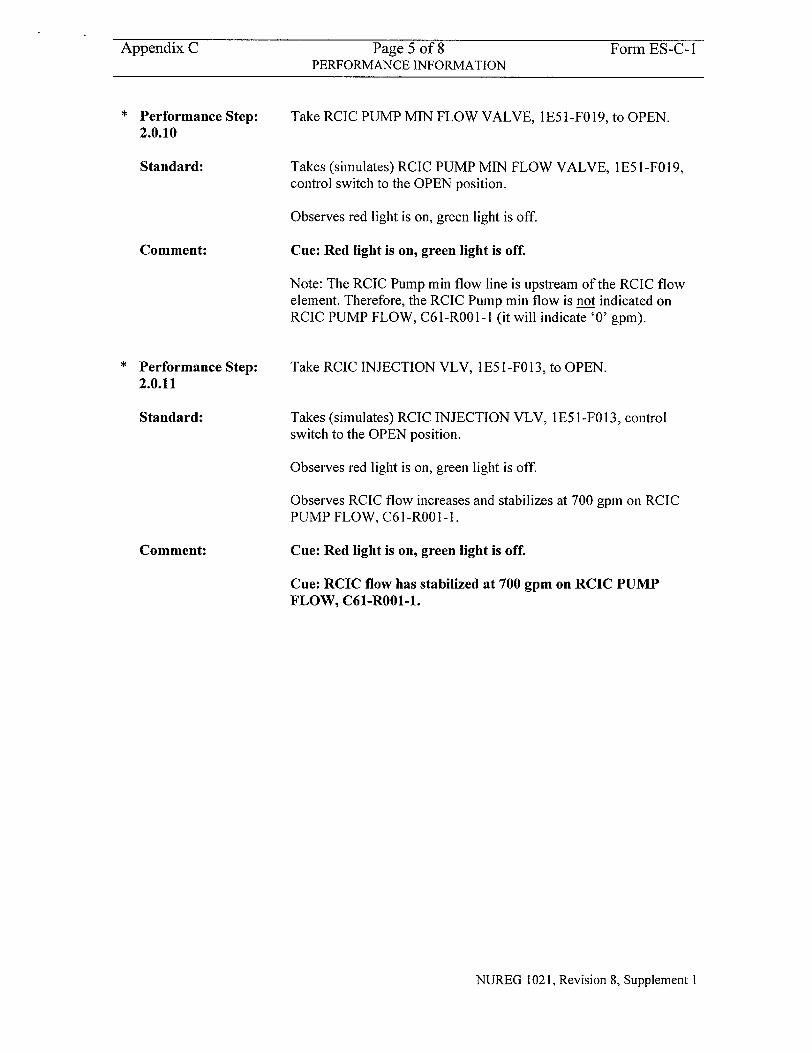
Appendix C Page 5 of 8 Form ES-C-1 PERFORMANCE INFORMATION
Performance Step:
2.0.10
Standard:
Comment:
Performance Step:
2.0.11
Standard:
Comment:
Take RCIC PUMP MIN FLOW VALVE, 1 E5 1 -FO 19, to OPEN.
Takes (simulates) RCIC PUMP MIN FLOW VALVE, I ES l-F019, control switch to the OPEN position.
Observes red light is on, green light is off.
Cue: Red light is on, green light is off.
Note: The RCIC Pump min flow line is upstream of the RCIC flow element. Therefore, the RCIC Pump min flow is not indicated on RCIC PUMP FLOW, C61-ROOl-1 (it will indicate '0' gpm).
Take RCIC INJECTION VLV, 1E51-F013, to OPEN.
Takes (simulates) RCIC INJECTION VLV, 1E51-F013, control switch to the OPEN position.
Observes red light is on, green light is off.
Observes RCIC flow increases and stabilizes at 700 gpm on RCIC PUMP FLOW, C61 -ROOI -1.
Cue: Red light is on, green light is off.
Cue: RCIC flow has stabilized at 700 gpm on RCIC PUMP FLOW, C61-R001-1.
NUREG 1021, Revision 8, Supplement I
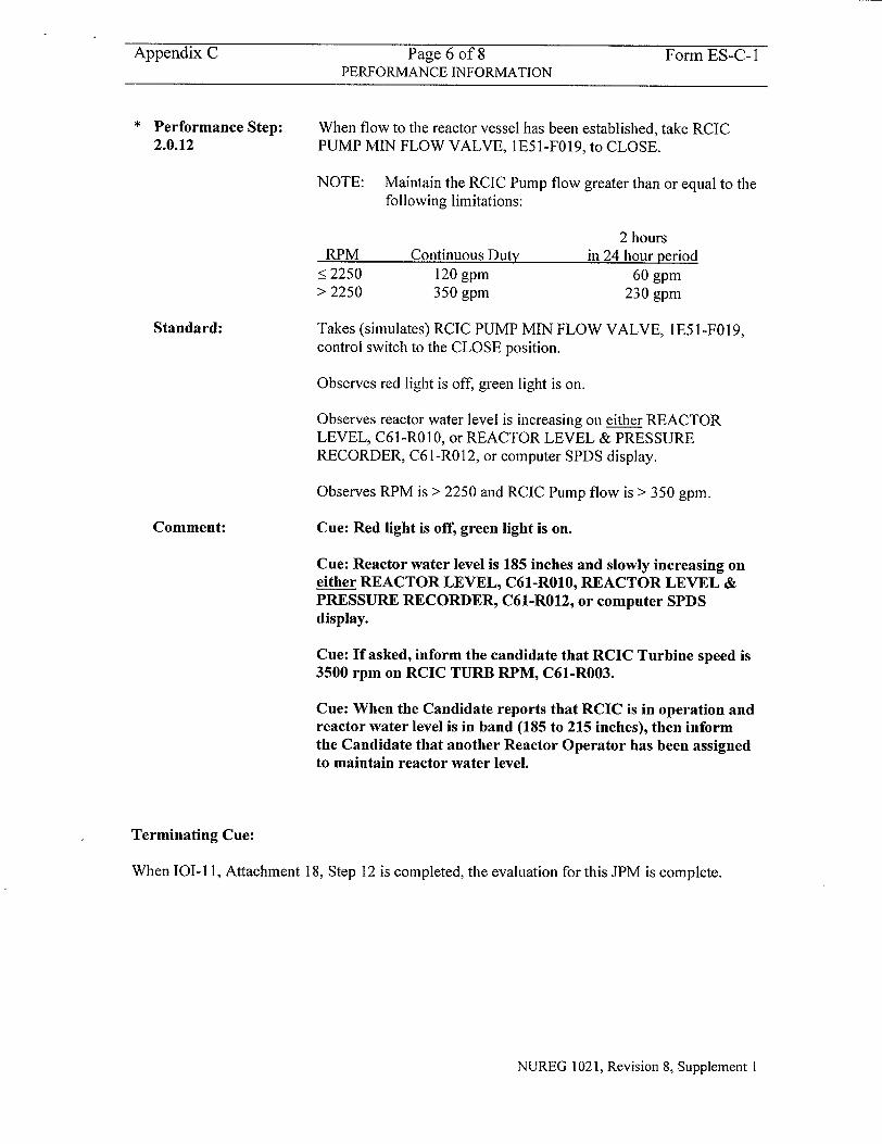
Appendix C Page 6 of 8 Form ES-C-1 PERFORMANCE INFORMATION
Performance Step: 2.0.12
When flow to the reactor vessel has been established, take RCIC PUMP MIN FLOW VALVE, 1E5 I-F019, to CLOSE.
NOTE: Maintain the RCIC Pump flow greater than or equal to the following limitations:
Continuous Duty 120 gpm 350 gpm
2 hours in 24 hour period
60 gpm 230 gpm
Takes (simulates) RCIC PUMP MIN FLOW VALVE, 1E51-F019, control switch to the CLOSE position.
Observes red light is off, green light is on.
Observes reactor water level is increasing on either REACTOR LEVEL, C6 l-RO10, or REACTOR LEVEL & PRESSURE RECORDER, C61-R012, or computer SPDS display.
Observes RPM is > 2250 and RCIC Pump flow is > 350 gpm.
Cue: Red light is off, green light is on.
Cue: Reactor water level is 185 inches and slowly increasing on either REACTOR LEVEL, C61-R010, REACTOR LEVEL & PRESSURE RECORDER, C61-R012, or computer SPDS display.
Cue: If asked, inform the candidate that RCIC Turbine speed is 3500 rpm on RCIC TURB RPM, C61-R003.
Cue: When the Candidate reports that RCIC is in operation and reactor water level is in band (185 to 215 inches), then inform the Candidate that another Reactor Operator has been assigned to maintain reactor water level.
Terminating Cue:
When 101-11, Attachment 18, Step 12 is completed, the evaluation for this JPM is complete.
NUREG 1021, Revision 8, Supplement I
RPM <2250 > 2250
Standard:
Comment:

Appendix C Page 7 of 8 Form ES-C-1 VERIFICATION OF COMPLETION
Job Performance Measure No.
Examinee's Name:
Examiner's Name:
Date Performed:
Facility Evaluator:
Number of Attempts:
Time to complete:
Question Documentation:
Question:
Response:
Result:
2003 NRC B.2.c
N/A
SAT OR UNSAT
Examiner's Signature and Date:
NUREG 1021, Revision 8, Supplement 1
Appendix C Page 8 of 8 Form ES-C-1 JPM CUE SHEET
INITIAL CONDITIONS:
INITIATING CUE:
A toxic gas condition exists in the Control Room. ONI-C61, Evacuation of the Control Room, has been completed. 101-11, Shutdown from Outside Control Room, has been entered. Offsite power is available. The Containment has been evacuated. Control Transfer to the Division 1 Remote Shutdown Panel has been completed. Reactor water level is 180 inches and slowly lowering.
The Unit Supervisor directs you, as the Reactor Operator, to restore and maintain reactor water level to 185 to 215 inches using the RCIC System in accordance with 101-11.
NUREG 1021, Revision 8, Supplement 1
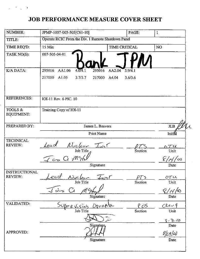
JOB PERFORMANCE MEASURE COVER SHEET
NUMBER: JPMP- 1007-003-505 [C61-10] PAGE:
TITLE: Operate RCIC From the Div. 1 Remote Shutdown Panel
TIME REQ'D: 15 Min TIME CRITICAL NO
TASK NO(S): 007-505-04-01
K/A DATA: 295016 AA1.06 4. 4.1 295016 AA2.04 3.9/4.1
217000 A1.05 3.7/3.7 217000 A4.04 3.6/3.6
REFERENCES: 101-11 Rev. 6 PIC. 10
TOOLS & Training Copy of 101-11 EQUIPMENT:
PREPARED BY: James L. Beavers JLB/ Print Name Initiqrl
TECHNICAL
Job Title Section Unit
Signature Date
INSTRUCTIONAL REVIEW: /cC i2L r
Job Title Section Unit
Signature Date
VALIDATED:
Job Title Section Unit
APPROVED: I. 16date
Signature Date
JPMP- 1007-003-505[C61 -10]
JOB PERFORMANCE MEASURE SETUP SHEET
1. Simulator Setup Instructions. N/A
2. Location! Method Plant / Simulate
3. Initial Conditions.
The evacuation of the Control Room was required due to a fire. The actions of ONI-C61 are complete. The Div. 1 Remote Shutdown Panel and associated systems are operable. Control has been transferred to the Remote Shutdown Panel. Offsite power is available and the divisional buses are energized. Reactor Level is 180" and slowly lowering.
4. Initiating Cue. The Unit Supervisor directs you, as a Supervising Operator, to restore and maintain Reactor Level to 185 - 215" using RCIC, per 101-11, Attachment 18.
-2-
JPM CUE SHEET
INITIAL
CONDITIONS:
INITIATIN(j (UE:
The evacuation of the Control Room was required due to a fire. The actions of ONI-C61 are complete. The Div. 1 Remote Shutdown Panel and associated systems are operable. Control has been transferred to the Remote Shutdown Panel. Offsite power is available and the divisional buses are energized. Reactor Level is 180" and slowly lowering.
4 -
The Unit Supervisor directs you, as a Supervising Operator, to restore and maintain Reactor Level to 185 - 215" using RCIC, per 101-11, Attachment 18.
-3-
i
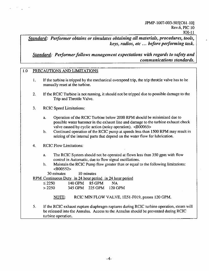
JPMP-1007-003-505[C61-10] Rev.6, PIC 10
101-11
-4-
Standard: Performer obtains or simulates obtaining all materials, procedures, tools, keys, radios, etc ... before performing task.
Standard: Performer follows management expectations with regards to safety and communications standards.
1.0 PRECAUTIONS AND LIMITATIONS
1. If the turbine is tripped by the mechanical overspeed trip, the trip throttle valve has to be manually reset at the turbine.
2. If the RCIC Turbine is not running, it should not be tripped due to possible damage to the Trip and Throttle Valve.
3. RCIC Speed Limitations:
a. Operation of the RCIC Turbine below 2000 RPM should be minimized due to possible water hammer in the exhaust line and damage to the turbine exhaust check valve caused by cyclic action (noisy operation). <B00065>
b. Continued operation of the RCIC pump at speeds less than 1500 RPM may result in seizing of the internal parts that depend on the water flow for lubrication.
4. RCIC Flow Limitations:
a. The RCIC System should not be operated at flows less than 350 gpm with flow control in Automatic, due to flow signal oscillations.
b. Maintain the RCIC Pump flow greater than or equal to the following limitations: <B00552>
30 minutes 10 minutes RPM Continuous Duty in 24 hour period in 24 hour period
< 2250 140 GPM 85 GPM NA > 2250 345 GPM 225 GPM 120 GPM
NOTE: RCIC MIN FLOW VALVE, 1E51-F019, passes 120 GPM.
5. If the RCIC exhaust rupture diaphragm ruptures during RCIC turbine operation, steam will be released into the Annulus. Access to the Annulus should be prevented during RCIC turbine operation.
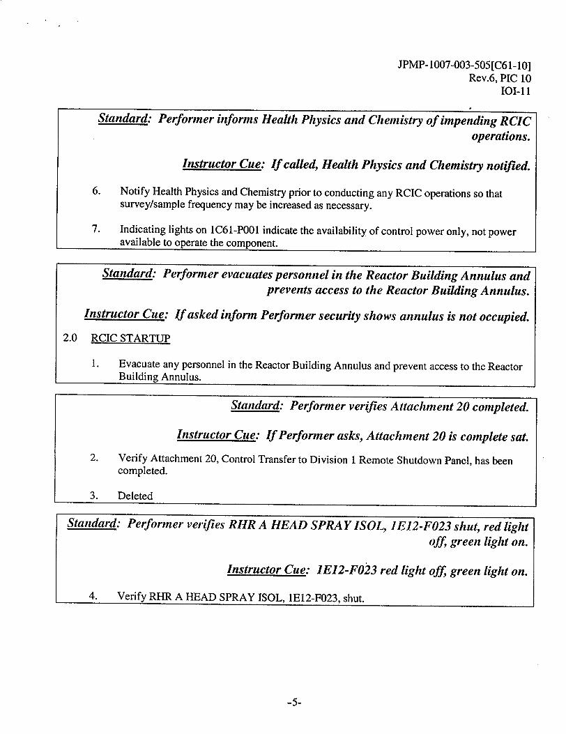
JPMP- 1007-003-505 [C61-10] Rev.6, PIC 10
101-11
Standard: Performer informs Health Physics and Chemistry of impending RCIC
operations.
Instructor Cue: If called, Health Physics and Chemistry notified.
6. Notify Health Physics and Chemistry prior to conducting any RCIC operations so that survey/sample frequency may be increased as necessary.
7. Indicating lights on 1C61-P001 indicate the availability of control power only, not power available to operate the component.
Standard: Performer evacuates personnel in the Reactor Building Annulus and
prevents access to the Reactor Building Annulus.
Instructor Cue: If asked inform Performer security shows annulus is not occupied.
2.0 RCIC STARTUP
1. Evacuate any personnel in the Reactor Building Annulus and prevent access to the Reactor Building Annulus.
Standard: Performer verifies Attachment 20 completed.
Instructor Cue: If Performer asks, Attachment 20 is complete sat.
2. Verify Attachment 20, Control Transfer to Division 1 Remote Shutdown Panel, has been completed.
3. Deleted
Standard: Performer verifies RHR A HEAD SPRA Y ISOL, 1E12-F023 shut, red light off, green light on.
Instructor Cue: 1E12-F023 red light off, green light on.
4. Verify RHR A HEAD SPRAY ISOL, 1E12-F023, shut.
-5-
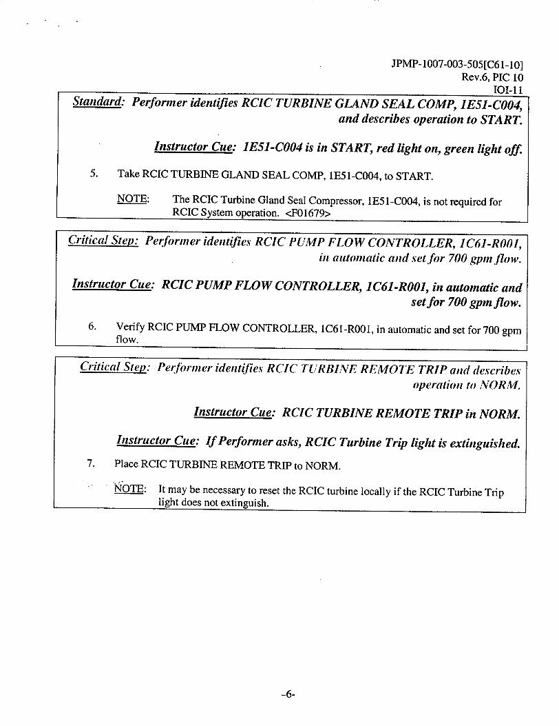
JPMP- 1007-003-505[C61-10] Rev.6, PIC 10
101-11Standard. Performer identifies RCIC TURBINE GLAND SEAL COMP, 1E51-C004,
and describes operation to START.
Instructor Cue: 1E51-C004 is in START, red light on, green light off.
5. Take RCIC TURBINE GLAND SEAL COMP, 1E51-C004, to START.
NOTE: The RCIC Turbine Gland Seal Compressor, IE51-C004, is not required for RCIC System operation. <F01679>
-6-
Critical Step: Performer identifies RCIC PUMP FLOW CONTROLLER, 1C61-RO01, in automatic and set for 700 gpinflow.
Instructor Cue: RCIC PUMP FLOW CONTROLLER, 1C61-R001, in automatic and set for 700 gpm flow.
6. Verify RCIC PUMP FLOW CONTROLLER, 1C61-R001, in automatic and set for 700 gpm flow.
Critical Step: Performer identifies RCIC TURBINE REMOTE TRIP and describes
operation to NORM.
Instructor Cue: RCIC TURBINE REMOTE TRIP in NORM.
Instructor Cue: If Performer asks, RCIC Turbine Trip light is extinguished.
7. Place RCIC TURBINE REMOTE TRIP to NORM.
NOTE: It may be necessary to reset the RCIC turbine locally if the RCIC Turbine Trip light does not extinguish.
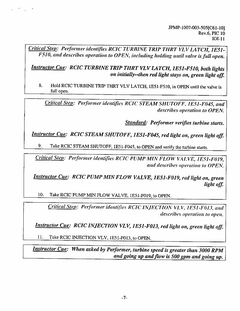
JPMP-1007-003-505[C6 1-101 Rev.6, PIC 10
101-11
Critical Step: Performer identifies RCIC INJECTION VL V/. IE51-FO13, and
describes operation to open.
Instructor Cue: RCIC INJECTION VLV, 1ES1-F013, red light on, green light off
11. Take RCIC INJECTION VLV, 1E51-F013, to OPEN.
-7-
Critical Step: Performner identlfies RCIC TURBINE TRIP THRT VLV LATCH, IE51F510, and describes operation to OPEN, including holding until valve is full open.
Instructor Cue: RCIC TURBINE TRIP THRT VLV LATCH, 1E5-F510, both lights on initially--then red light stays on, green light off
8. Hold RCIC TURBINE TRIP THRT VLV LATCH, IE51-F510, in OPEN until the valve is full open.
Critical Step: Per:firmer identifies RCIC STEAM SHUTOFF, IE51-F045, and describes operation to OPEN.
Standard: Performer verifies turbine starts.
Instructor Cue: RCIC STEAM SHUTOFF, JESI-F045, red light on, green light off
9. Take RCIC STEAM SHUTOFF, 1E5 1-F045, to OPEN and verify the turbine starts.
Critical Step: Performner identifies RCIC PUMP MIN FLOW VALIVE, IESI-FO 19, and describes operation to OPEN.
Instructor Cue: RCIC PUMP MIN FLOW VALVE, 1E51-F019, red light on, green light off
10. Take RCIC PUMP MIN FLOW VALVE. IE51-F019. to OPEN.
Instructor Cue: When asked by Performer, turbine speed is greater than 3000 RPM and going up and flow is 500 gpm and going up.
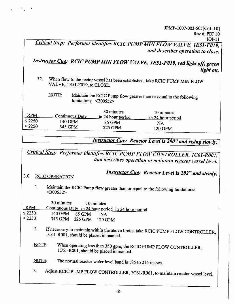
JPMiP-1007-003-505[C61 -10] Rev.6, PIC 10
101-11 Critical Step: Perforner identifies RCIC PUMP MIN FLOW VAL VE, JES1-FO19,
and describes operation to close.
Instructor Cue: RCIC PUMP MIN FLOW VAL VE, JE5J-F0I9, red light off green
light on.
12. When flow to the rector vessel has been established, take RCIC PUMP MIN FLOW VALVE, 1E51-F019, to CLOSE.
NOTE: Maintain the RCIC Pump flow greater than or equal to the following limitations: <B00552>
30 minutes 10 minutes RPM Continuous Duty in 24 hour period in 24 hour period < 2250 140 GPM 85 GPM NA > 2250 345 GPM 225 GPM 120 GPM
Instructor Cue: Reactor Level is 200" and rising slowly.
Critical Step: Peforiner identifies RCIC PUMP FLOW CONTROLLER, 1C61-RO01, and describes operation to mtaintain reactor vessel level.
Instructor Cue: Reactor Level is 202" and steady. 3.0 RCIC OPERATION
1. Maintain the RCIC Pump flow greater than or equal to the following limitations: <B00552>
30 minutes 10 minutes RPM Continuous Duty in 24 hour period in 24 hour period
< 2250 140 GPM 85 GPM NA > 2250 345 GPM 225 GPM 120 GPM
2. If necessary to maintain within the above limits, take RCIC PUMP FLOW CONTROLLER, 1 C6 I-ROO1, should be placed in manual.
NOTE: When operating less than 350 gpm, the RCIC PUMP FLOW CONTROLLER, 1C61-ROO1, should be placed in manual.
NOTE: The normal reactor water level band is 185 to 215 inches.
3. Adjust RCIC PUMP FLOW CONTROLLER, 1C61-ROO1, to maintain reactor vessel level.
-8-
JPMP-1007-003-505[C61-10] Rev.6, PIC 10
IOI-11
Standard: Performer reports maintaining Reactor Level 185 - 215" using RCIC, per 101-11, Attachment 18 to Unit Supervisor and reports JPM is complete.
-9-
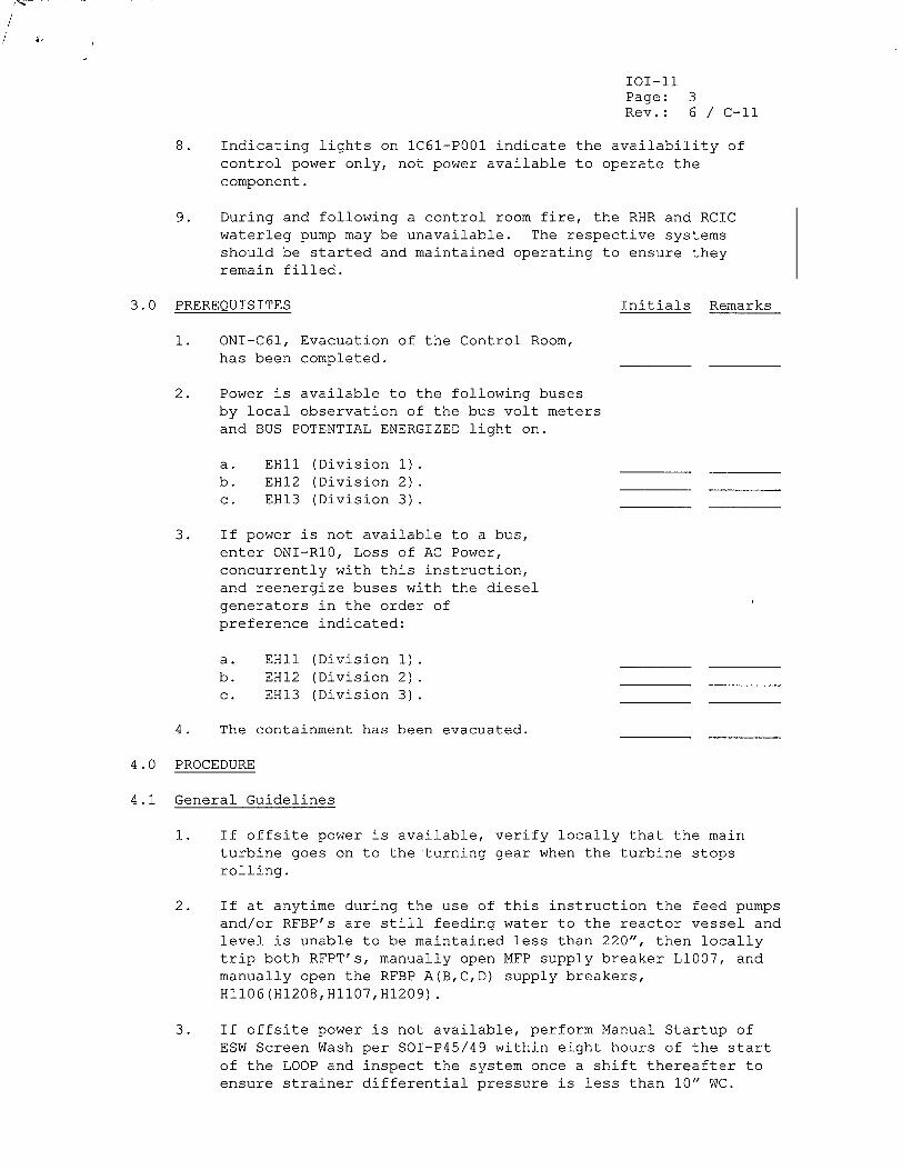
101-11 Page: 3 Rev. : 6 / C-II
8. Indicating lights on lC61-P001 indicate the availability of control power only, not power available to operate the component.
9. During and following a control room fire, the RHR and RCIC waterleg pump may be unavailable. The respective systems should be started and maintained operating to ensure they remain filled.
3.0 PREREQUISITES Initials Remarks
1. ONI-C61, Evacuation of the Control Room, has been completed.
2. Power is available to the following buses by local observation of the bus volt meters and BUS POTENTIAL ENERGIZED light on.
a. EHII (Division 1). b. EH12 (Division 2). c. EH13 (Division 3).
3. If power is not available to a bus, enter ONI-RI0, Loss of AC Power, concurrently with this instruction, and reenergize buses with the diesel generators in the order of preference indicated:
a. EHI1 (Division 1). b. EH12 (Division 2). c. EH13 (Division 3).
4. The containment has been evacuated.
4.0 PROCEDURE
4.1 General Guidelines
1. If offsite power is available, verify locally that the main turbine goes on to the turning gear when the turbine stops rolling.
2. If at anytime during the use of this instruction the feed pumps and/or RFBP's are still feeding water to the reactor vessel and level is unable to be maintained less than 220", then locally trip both RFPT's, manually open MFP supply breaker L1007, and manually open the RFBP A(B,C,D) supply breakers, H1106(H1208,H1107,H1209).
3. If offsite power is not available, perform Manual Startup of ESW Screen Wash per SOI-P45/49 within eight hours of the start of the LOOP and inspect the system once a shift thereafter to ensure strainer differential pressure is less than 10" WC.
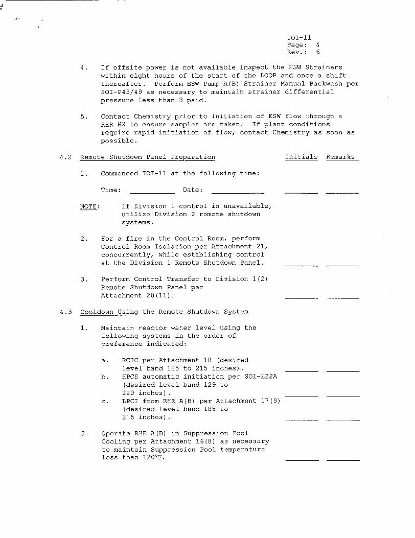
101-ii Page: 4 Rev.: 6
4. If offsite power is not available inspect the ESW Strainers within eight hours of the start of the LOOP and once a shift thereafter. Perform ESW Pump A(B) Strainer Manual Backwash per SOI-P45/49 as necessary to maintain strainer differential pressure less than 3 psid.
5. Contact Chemistry prior to initiation of ESW flow through a RHR HX to ensure samples are taken. If plant conditions require rapid initiation of flow, contact Chemistry as soon as possible.
4.2 Remote Shutdown Panel Preparation Initials Remarks
1. Commenced 10-1l at the following time:
Time: Date:
NOTE: If Division 1 control is unavailable, utilize Division 2 remote shutdown systems.
2. For a fire in the Control Room, perform Control Room Isolation per Attachment 21, concurrently, while establishing control at the Division 1 Remote Shutdown Panel.
3. Perform Control Transfer to Division 1(2) Remote Shutdown Panel per Attachment 20(11).
4.3 Cooldown Using the Remote Shutdown System
1. Maintain reactor water level using the following systems in the order of preference indicated:
a. RCIC per Attachment 18 (desired level band 185 to 215 inches).
b. HPCS automatic initiation per SOI-E22A (desired level band 129 to 220 inches).
c. LPCI from RHR A(B) per Attachment 17(9) (desired level band 185 to 215 inches).
2. Operate RHR A(B) in Suppression Pool Cooling per Attachment 16(8) as necessary to maintain Suppression Pool temperature less than 120'F.
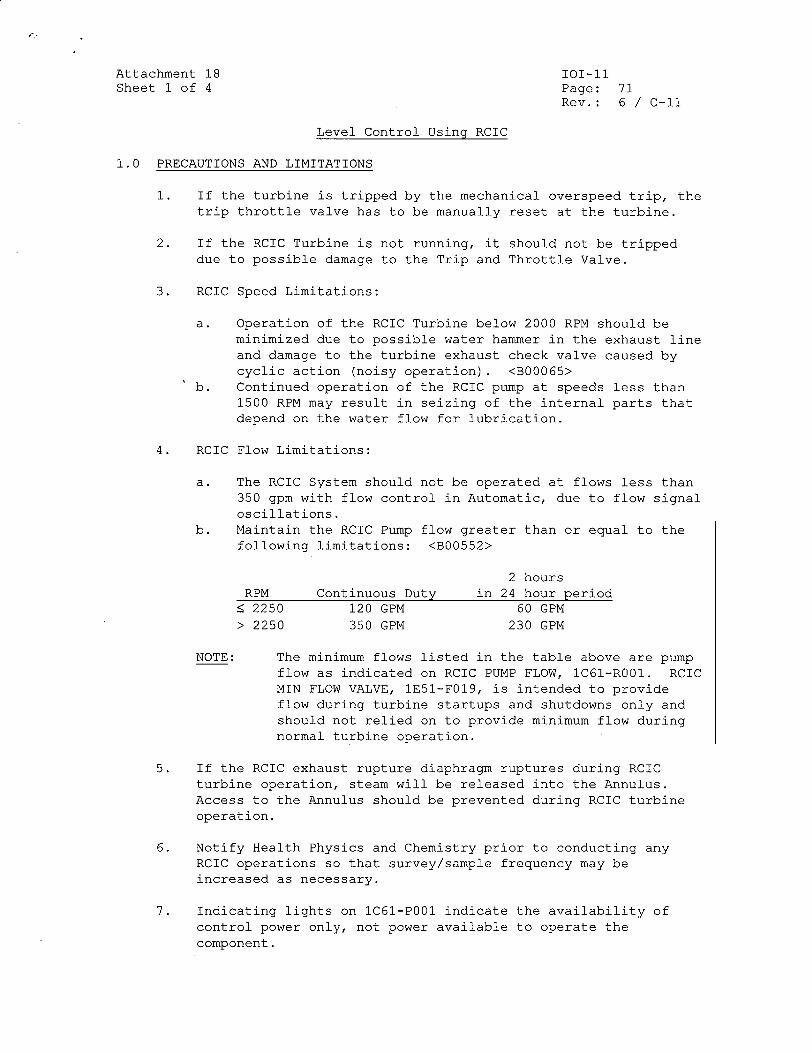
Attachment 18 101-ll Sheet 1 of 4 Page: 71
Rev.: 6 / C-i1
Level Control Using RCIC
1.0 PRECAUTIONS AND LIMITATIONS
1. If the turbine is tripped by the mechanical overspeed trip, the trip throttle valve has to be manually reset at the turbine.
2. If the RCIC Turbine is not running, it should not be tripped due to possible damage to the Trip and Throttle Valve.
3. RCIC Speed Limitations:
a. Operation of the RCIC Turbine below 2000 RPM should be minimized due to possible water hammer in the exhaust line and damage to the turbine exhaust check valve caused by cyclic action (noisy operation). <B00065>
b. Continued operation of the RCIC pump at speeds less than 1500 RPM may result in seizing of the internal parts that depend on the water flow for lubrication.
4. RCIC Flow Limitations:
a. The RCIC System should not be operated at flows less than 350 gpm with flow control in Automatic, due to flow signal oscillations.
b. Maintain the RCIC Pump flow greater than or equal to the following limitations: <B00552>
2 hours RPM Continuous Duty in 24 hour period
< 2250 120 GPM 60 GPM > 2250 350 GPM 230 GPM
NOTE: The minimum flows listed in the table above are pump flow as indicated on RCIC PUMP FLOW, lC61-ROO1. RCIC MIN FLOW VALVE, IE51-F019, is intended to provide flow during turbine startups and shutdowns only and should not relied on to provide minimum flow during normal turbine operation.
5. If the RCIC exhaust rupture diaphragm ruptures during RCIC turbine operation, steam will be released into the Annulus. Access to the Annulus should be prevented during RCIC turbine operation.
6. Notify Health Physics and Chemistry prior to conducting any RCIC operations so that survey/sample frequency may be increased as necessary.
7. Indicating lights on 1C61-P001 indicate the availability of control power only, not power available to operate the component.
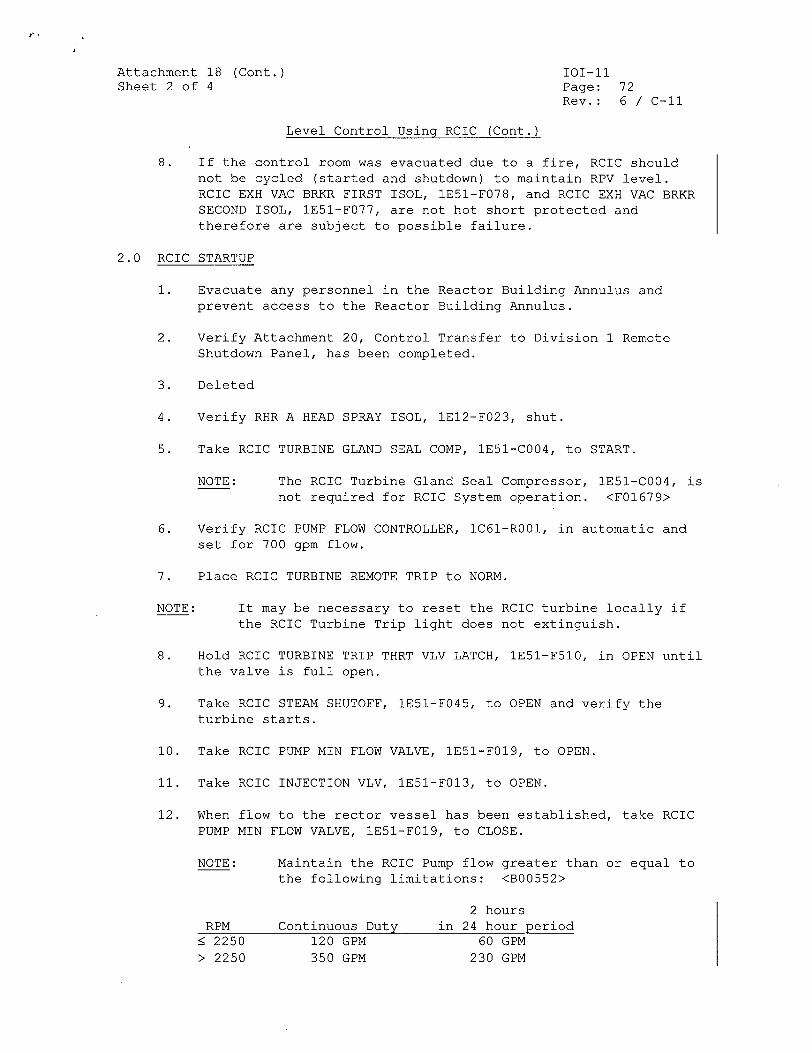
F
Attachment 18 (Cont.) TOT-li Sheet 2 of 4 Page: 72
Rev.: 6 / C-il
Level Control Using RCIC (Cont.)
8. If the control room was evacuated due to a fire, RCIC should not be cycled (started and shutdown) to maintain RPV level. RCIC EXH VAC BRKR FIRST ISOL, lE51-F078, and RCIC EXH VAC BRKR SECOND ISOL, 1E51-F077, are not hot short protected and therefore are subject to possible failure.
2.0 RCIC STARTUP
1. Evacuate any personnel in the Reactor Building Annulus and prevent access to the Reactor Building Annulus.
2. Verify Attachment 20, Control Transfer to Division 1 Remote Shutdown Panel, has been completed.
3. Deleted
4. Verify RHR A HEAD SPRAY ISOL, 1E12-F023, shut.
5. Take RCIC TURBINE GLAND SEAL COMP, 1E51-C004, to START.
NOTE: The RCIC Turbine Gland Seal Compressor, IE51-C004, is not required for RCIC System operation. <F01679>
6. Verify RCIC PUMP FLOW CONTROLLER, 1C61-R001, in automatic and set for 700 gpm flow.
7. Place RCIC TURBINE REMOTE TRIP to NORM.
NOTE: It may be necessary to reset the RCIC turbine locally if the RCIC Turbine Trip light does not extinguish.
8. Hold RCIC TURBINE TRIP THRT VLV LATCH, 1E51-F510, in OPEN until the valve is full open.
9. Take RCIC STEAM SHUTOFF, IE5I-F045, to OPEN and verify the turbine starts.
10. Take RCIC PUMP MIN FLOW VALVE, IE5I-FO19, to OPEN.
1i. Take RCIC INJECTION VLV, IE51-F013, to OPEN.
12. When flow to the rector vessel has been established, take RCIC PUMP MIN FLOW VALVE, 1E51-F019, to CLOSE.
NOTE: Maintain the RCIC Pump flow greater than or equal to the following limitations: <B00552>
2 hours RPM Continuous Duty in 24 hour period
• 2250 120 GPM 60 GPM
> 2250 350 GPM 230 GPM
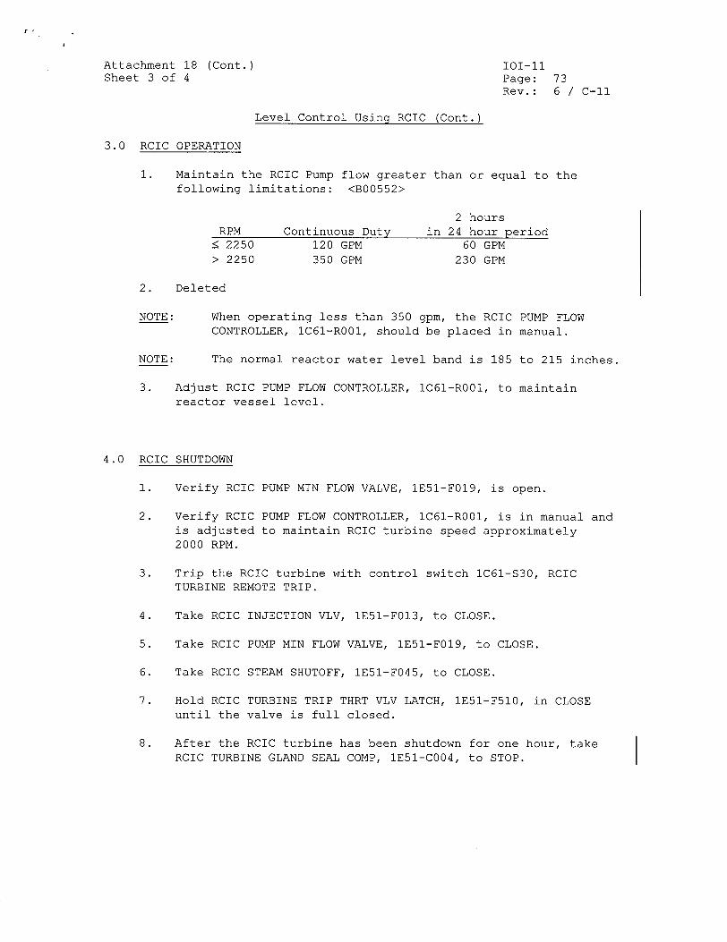
Attachment 18 (Cont.) Sheet 3 of 4
101-11 Page: Rev.:
73 6 / C-il
Level Control Usinq RCIC (Cont.)
3.0 RCIC OPERATION
1. Maintain the RCIC Pump flow greater than or equal to the following limitations: <B00552>
Continuous Duty 120 GPM
350 GPM
2 hours in 24 hour period
60 GPM 230 GPM
2. Deleted
When operating less than 350 gpm, the RCIC PUMP FLOW CONTROLLER, lC61-ROO1, should be placed in manual.
The normal reactor water level band is 185 to 215 inches.
3. Adjust RCIC PUMP FLOW CONTROLLER, IC61-ROO1, to maintain reactor vessel level.
4.0 RCIC SHUTDOWN
1. Verify RCIC PUMP MIN FLOW VALVE, 1E51-F019, is open.
2. Verify RCIC PUMP FLOW CONTROLLER, IC61-ROO1, is in manual and is adjusted to maintain RCIC turbine speed approximately 2000 RPM.
3. Trip the RCIC turbine with control switch lC61-S30, RCIC TURBINE REMOTE TRIP.
4. Take RCIC INJECTION VLV, IE51-F013, to CLOSE.
5. Take RCIC PUMP MIN FLOW VALVE, IE51-F019, to CLOSE.
6. Take RCIC STEAM SHUTOFF, lE51-F045, to CLOSE.
7. Hold RCIC TURBINE TRIP THRT VLV LATCH, 1E51-F510, in CLOSE until the valve is full closed.
8. After the RCIC turbine has been shutdown for one hour, take RCIC TURBINE GLAND SEAL COMP, IE51-C004, to STOP.
RPM < 2250 > 2250
NOTE:
NOTE:
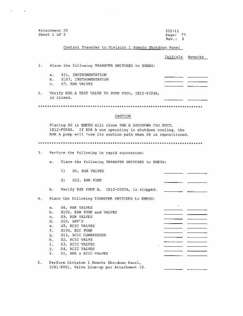
Attachment 20 Sheet 1 of 2
101-11 Page: 77 Rev.: 6
Control Transfer to Division 1 Remote Shutdown Panel
Initials Remarks
1. Place the following TRANSFER SWITCHES to EMERG:
a. b. c.
SIl, INSTRUMENTATION S107, INSTRUMENTATION S7, RHR VALVES
2. Verify RHR A TEST VALVE TO SUPR POOL, 1E12-F024A, is closed.
CAUTION
Placing S6 in EMERG will close RHR A SHUTDOWN CLG SUCT, 1E12-F006A. If RHR A was operating in shutdown cooling, the RHR A pump will lose its suction path when S6 is repositioned.
3. Perform the following in rapid succession:
a. Place the following TRANSFER SWITCHES to EMERG:
1) S6, RHR VALVES
2) S12, RHR PUMP
b. Verify RHR PUMP A, 1E12-C002A, is stopped.
4. Place the following TRANSFER SWITCHES to EMERG:
a. b. c. d. e. f. g. h. k. j. k.
S8, RHR VALVES S102, ESW PUMP and VALVES S9, RHR VALVES SI0, SRV'S S5, RCIC VALVES S100, ECC PUMP S13, RCIC COMPRESSOR S2, RCIC VALVE S3, RCIC VALVES S4, RCIC VALVES S1, RHR & RCIC VALVES
5. Perform Division 1 Remote Shutdown Panel, lC61-P001, Valve Line-up per Attachment 19.
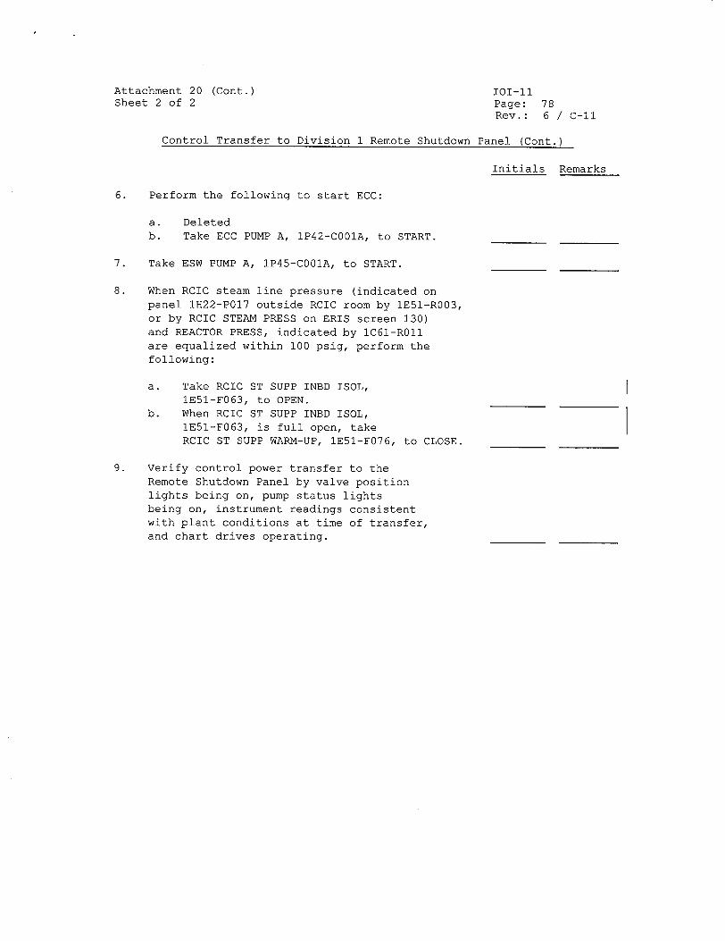
Attachment 20 (Cont.) Sheet 2 of 2
101-11 Page: 78 Rev.: 6 / C-11
Control Transfer to Division 1 Remote Shutdown Panel (Cont.)
Initials Remarks
6. Perform the following to start ECC:
a. Deleted b. Take ECC PUMP A, 1P42-C001A, to START.
7. Take ESW PUMP A, IP45-C001A, to START.
8. When RCIC steam line pressure (indicated on panel 1H22-P017 outside RCIC room by 1E51-R003, or by RCIC STEAM PRESS on ERIS screen 130) and REACTOR PRESS, indicated by 1C61-R011 are equalized within 100 psig, perform the following:
a. Take RCIC ST SUPP INBD ISOL, 1E51-F063, to OPEN.
b. When RCIC ST SUPP INBD ISOL, IE51-F063, is full open, take RCIC ST SUPP WARM-UP, IE51-F076, to CLOSE.
9. Verify control power transfer to the Remote Shutdown Panel by valve position lights being on, pump status lights being on, instrument readings consistent with plant conditions at time of transfer, and chart drives operating.
I
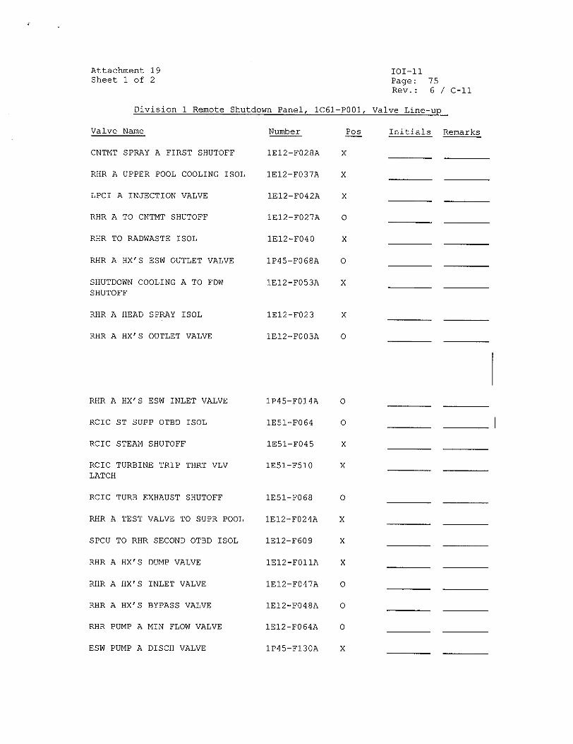
Attachment 19 Sheet 1 of 2
Division 1 Remote Shutdown Panel. 1C61-P001.
I01-11 Page: 75 Rev.: 6 / C-ll
Valve Line-un
Valve Name
CNTMT SPRAY A FIRST SHUTOFF
RHR A UPPER POOL COOLING ISOL
LPCI A INJECTION VALVE
RHR A TO CNTMT SHUTOFF
RHR TO RADWASTE ISOL
RHR A HX'S ESW OUTLET VALVE
SHUTDOWN COOLING A TO FDW
SHUTOFF
RHR A HEAD SPRAY ISOL
RHR A HX'S OUTLET VALVE
RHR A HX'S ESW INLET VALVE
RCIC ST SUPP OTBD ISOL
RCIC STEAM SHUTOFF
RCIC TURBINE TRIP THRT VLV
LATCH
RCIC TURB EXHAUST SHUTOFF
RHR A TEST VALVE TO SUPR POOL
SPCU TO RHR SECOND OTBD ISOL
RHR A HX'S DUMP VALVE
RHR A HX'S INLET VALVE
RHR A HX'S BYPASS VALVE
RHR PUMP A MIN FLOW VALVE
ESW PUMP A DISCH VALVE
Number
1E12-F028A
IE12-F037A
1E12-F042A
1E12-F027A
1E12-F040
1P45-F068A
1E12-F053A
1E12-F023
1E12-F003A
1P45-F014A
lE51-F064
1E51-F045
IE51-F510
lE51-F068
1E12-F024A
1E12-F609
1E12-F011A
1E12-F047A
1E12-F048A
IE12-F064A
1P45-Fl30A
Initials RemarksPos
X
X
X
0
X
0
X
Valve Line-un
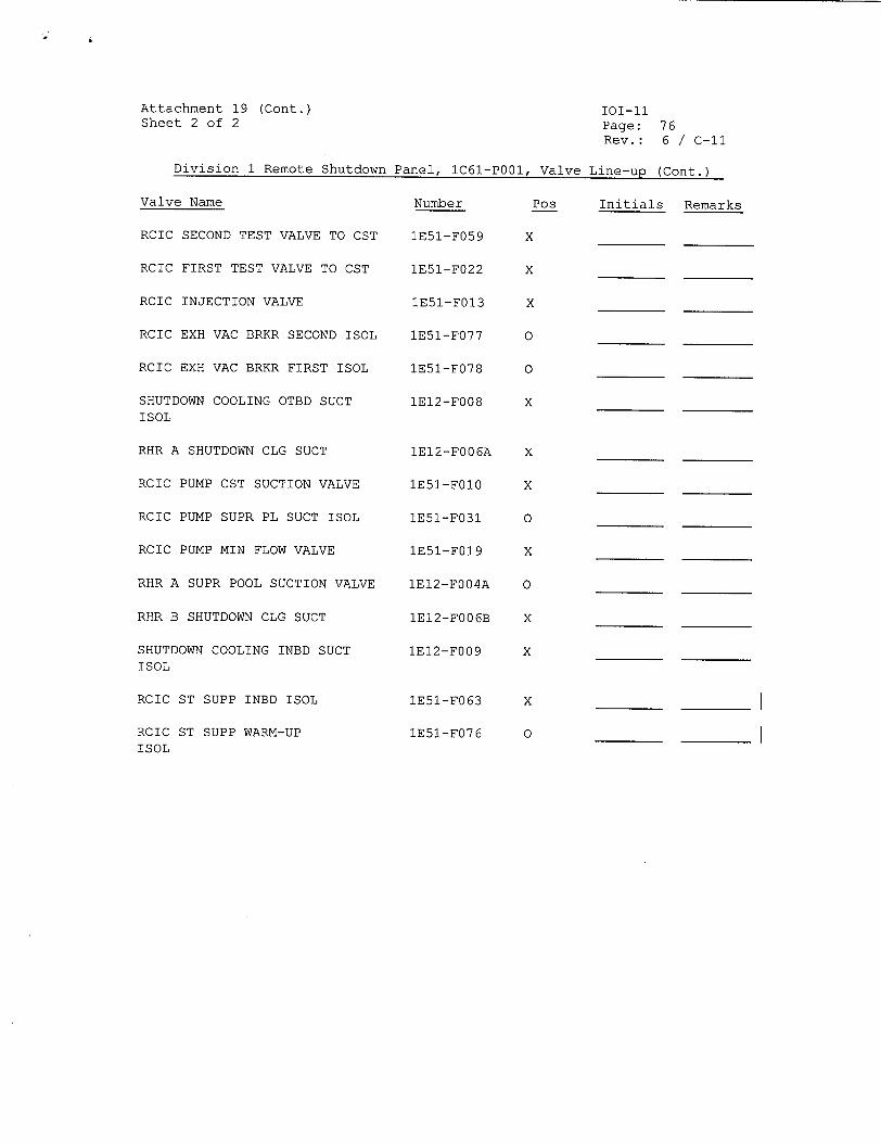
Attachment 19 (Cont.) Sheet 2 of 2
Division 1 Remote Shutdown Panel, lC61-P001, Valve
Valve Name
RCIC SECOND TEST VALVE TO CST
RCIC FIRST TEST VALVE TO CST
RCIC INJECTION VALVE
RCIC EXH VAC BRKR SECOND ISOL
RCIC EXH VAC BRKR FIRST ISOL
SHUTDOWN COOLING OTBD SUCT ISOL
RHR A SHUTDOWN CLG SUCT
RCIC PUMP CST SUCTION VALVE
RCIC PUMP SUPR PL SUCT ISOL
RCIC PUMP MIN FLOW VALVE
RHR A SUPR POOL SUCTION VALVE
RHR B SHUTDOWN CLG SUCT
SHUTDOWN COOLING INBD SUCT ISOL
RCIC ST SUPP INBD ISOL
RCIC ST SUPP WARM-UP ISOL
Number
1E51-F059
1E51-F022
1E51-F013
1E51-F077
1E51-F078
1E12-F008
1E12-F006A
IE51-FO10
1E51-F031
1E51-F019
1E12-F004A
1E12-F006B
1E12-F009
1E51-F063
IE51-F076
Pos
x
x
x
0
0
x
101-11 Page: 76 Rev.: 6 / C-Il
Line-up (Cont.)
Initials Remarks
x
x
0
x
0
x
x
x
0