Embed Size (px)
Citation preview

1/8 EP DESERT BUGGY560016
Instruction & Setup Manual

AA Alkaline or Rechargeable Battery x 4
7.4v RechargeableBattery Pack X 2
Battery Pack charger
Thank you for choosing the Team Magic 4SETH 1/8 EP Desert Buggy. The 4SETH 1/8 EP Desert Buggy is designed for easy to drive and uses top quality parts for performance and durability.
Before you start, we suggest you read though the instruction manual first. We hope you have fun and enjoy our product.
Thank you for purchasing the 4SETH 1/8 EP Desert Buggy . Before start, you will need to check the following procedures.
TM Black HC Nut Driver 5.5mm (for 3mm nut)
#117010
TM Black RC Hex Wrench Metric Size 3.0mm#117057-4
Needlenose Pliers TM Black RC Hex Wrench Metric Size 2.5mm#117057-3
TM Black RC Hex Wrench Metric Size 1.5mm #117057-1
TM Black RC Hex Wrench Metric Size 2.0mm#117057-2
Circlip Plier #117032
General Operation Tips:
■ Read the instruction manual before operate.
■ Clear a work area and try to work on a light color towel to avoid missing dropped parts.
■ When parts doesn't fit, please double check the position or the condition of parts.
A Good Dealer Is Extremely Important!!
17mm Cross Wrench Hobby Knife
Super Sharp Warning!!
Body Scissors #116006For Body Cutting
■ Don't over-tighten fasteners. Many assembly problems are caused by over-tightening screws or nuts. Please driving it slowly and feel the resistance force’s feedback.
■ Check the instructions when there are any problems. If you cannot figure out what's wrong, please contact dealer, distributor or Team Magic. Don't use force beyond what the instructions call for. Using the right tools makes assembly much easier. The instructions below finely indicate you what tools to get to make things easier.
A good hobby dealer can help you with most problems you might encounter. This is the main reason why we suggest you buy the products from a good dealer rather than from the cheapest dealer.Bring your problematic parts to the dealer and, most likely, you'll walk away soon thereafter with the problem solved.If you think that you really don't have the mechanical skills to solve the problem, you may pay your dealer to finish the job for you.
1 Included Tools
3 Helpful Equipments
2 Required Items

FR
RL

3
WP-8BL100-RTR / WP-8BL150-RTR User Manual
Thanks for purchasing our Electronic Speed Controller (ESC). The power system for RC model can be verydangerous, so please read this manual carefully. In that we have no control over the correct use, installation, application, or maintenance of our products, no liability shall be assumed nor accepted for any damages, losses or costs resulting from the use of the product. Any claims arising from the operating, failure of malfunctioning etc. will be denied. We assume no liability for personal injury, consequential damages resulting from our product or our workmanship.
Warnings· Ensure all wires and connections are well insulated before connecting the ESC to related devices. · Ensure all devices are well connected to prevent poor connection that may cause your vehicle out of control or other unpredictable issues. · Read throgh the manuals of all power devices and chassis and ensure the power configuration is rational before using this unit.· Please use a soldering iron with the power of art least 60Wto solder all input/output wires and connectors.· Do not hold the vehicle in the air and rev it up to full throttle, as rubber tires can expanding to extremely size untill explode and cause serious injury.· Stop using the ESC when its casing temperature exceeds 90 0C / 194 0F to avoid the ESC or the motor gets damaged even destroyed. ( We recommend setting the “ ESC Thermal Protection ” to 105 0C/ 221 0F, this refers to the internal temperature of the ESC.)· We recommend removing the cooling fan from ESC before exposing vehicle to liquids, and fully dry it right after use.· Always disconnect batteries after use, as the ESC will continue to consume the current power,even if the ESC is turned off. ( A long-time connecting will cause battires discharge completely and break the ESC .
Features· Completely water-proof and dust-proof. The ESC works properly even under water. (Please remove the cooling fan when running car in water, and after running, please make the ESC clean and then dry it to avoid the oxidation of copper connectors)· External Programming Port (EPP), easy to connect with program card, and also works as power port for cooling fan.· Excellent start-up, acceleration and linearity features, suitable for truggy (especially short course trucks) and buggy.· The built-in switching mode BEC has powerful output to supply all electronic equipments.· There is a mounting stand for installing the ESC on chassis easily and firmly.· Proportional ABS brake function with 5 steps of maximum brake force adjustment, 8 steps of drag-brake force adjustment. Also compatible with the mechanical disc-brake system.· Multiple protection features: Low voltage cut-off protection / Over-heat protection / Throttle signal loss protection / Motor blocked protection· Easily programmed with the SET button of the ESC, and also compatible with pocket-sized Program Card.
Specifications
Connection
Cont. / Peak Current
MODEL WP-8BL100-RTR WP-8BL150-RTR
Motor Supported
Cars Applicable
Motor Limit
Resistance
Battery
BEC Output
Programming Port
Dimension
Weight (with wires)
100A / 650A
1/8 Touring Car , SCT, Buggy , 1/10 Truggy, Buggy
3S LiPo :4068 size motor,KV≤30004S LiPo :4068 size motor,KV≤2400
0.0005 ohm
8-12 Cells NiMH,3-4S LiPo
6V/5A, Switch mode
FAN / PRG Port
59.5(L) × 48(W) × 42(H)
173g
Sensored / Sensorless Brushless Motor (only in sensorless mode)
150A/950A
4S LiPo :4274 size motor,KV≤30006S LiPo :4274 size motor,KV≤2400
0.00035 ohm
8-18 Cells NiMH,3-6S LiPo
178g
NOTE 1 : The cooling fans of ESC is supplied by the built-in BEC, so it is always working under 6V .
NOTE 1
WARNING! For safety, please always keep the wheels away from the track when switching on the ESC.
Connect The ESC, Motor, Receiver, Battery And Servo[ BEGIN TO USE THE NEW ESC ]
The #A, #B, #C wires of the ESC can be connected with the motor wires freely (without any sequence). If the motor runs in the opposite direction, please swap any two wire connections.
Throttle Range Setting (Throttle Range Calibration)
In order to make the ESC match the throttle range, you must calibrate it when you begin to use a new ESC, or a new transmitter, or changethe settings of neutral position of the throttle stick, ATV or EPA parameters, etc.
A Switch off the ESC, turn on the transmitter, set the direction of throttle channel to ”REV”, set the “EPA/ATV” value of throttle channel to “100%”, and disable the ABS function of your transmitter.
B Hold the “SET” key and then switch on the ESC, and
release the “SET” key as soon as possible when the red LED begins to flash. Note 2
Note 2If you don’t release the “SET” key as soon as the red LED begins to flash, the ESC will enter the program mode, in such a case, please switch off the ESC and re-calibrate the throttle range again from step A to step D.
C Set the 3 points according to the steps shown in the pictures on the right side.1. The neutral pointMove the throttle stick at the neutral point, and then click the SET key, the green LED flashes 1 time.2. The end point of forward directionMove the throttle stick at the end point of forward direction, and then click the SET key, the green LED flashes 2 times.3. The end point of backward directionMove the throttle stick at the end point of backward direction, and then click the SET key, the green LED flashes 3 times.
D Throttle range is calibrated; motor can be started after 3 seconds.
Check LED Status In Normal Running
· When the throttle stick is in the neutral range, neither the Red LED nor the Green LED lights up.· When the car moves forward, the Red LED solidly lights; the Green LED also lights up when the throttle stick is at the top position.· When the car brakes, the Red LED solidly lights; the Green LED also lights up when the throttle stick is at the bottom position and themaximum brake force is set to 100%.· When the car reverses, the Red LED solidly lights.

1. Programmable Values1.1. Running Mode: In “Forward with Brake” mode, the car can go forward and brake, but cannot go backward, this mode is suitable for competition; “Forward/Reverse with Brake” mode provides backward function, which is suitable for daily training. Note: “Forward/Reverse with Brake” mode uses “Double-click” method to make the car go backward. When you move the throttle stick from forward zone to backward zone for the first time (The 1st “click”), the ESC begins to brake the motor, the motor speeds down but it is still running, not completely stopped, so the backward action is NOT happened immediately. When the throttle stick is moved to the backward zone again (The 2nd “click”), if the motor speed is slowed down to zero (i.e. stopped), the backward action will happen. The “Double-Click” method can prevent mistakenly reversing action when the brake function is frequently used in steering. By the way, in the process of braking or reversing, if the throttle stick is moved to forward zone, the motor will run forward at once. “Forward/Reverse” mode uses “Single-click” to make the car go backward. When you move the throttle stick from forward zone to backward zone, the car will go backward immediately. This mode is usually used for the Rock Crawler.
1.2. Drag Brake Force: Set the amount of drag brake applied at neutral throttle to simulate the slight braking effect of a neutral brushed motor while coasting. 1.3. Low Voltage Cut-Off: The function prevents the lithium battery pack from over discharging. The ESC detects the battery’s voltage at any time, if the voltage is lower than the threshold for 2 seconds, the output power will be cut off, and the red LED flashes in such a way: “☆-,
☆-, ☆-”.
1.4. Start Mode (Also called “Punch”): Select from “Level1” to “Level9” as you like. Level1 has a very soft start effect, while level9 has a very aggressive start effect. From Level1 to Level9, the start force is increasing. Please note that if you choose “Level7” to “Level9” mode, you must use good quality battery with powerful discharge ability, otherwise these modes cannot get the burst start effect as you want. If themotor cannot run smoothly (that means the motor is trembling), it may caused by the weak discharge ability of the battery, please choose a better one or a softer gear ratio.
1.5. Maximum Brake Force: The ESC provides proportional brake function. The brake force is related to the position of the throttle stick. Maximum brake force refers to the force when the throttle stick is located at the end point of the backward zone. A very large brake force can shorten the brake time, but it may damage the gears. The “Disable” option inhibits the inherent brake function of the speed controller. When this option is selected, the brake function is realized by a traditional mechanical disc-brake system driven by a servo.
2. Reset All Items To Default Values At any time when the throttle is located in neutral zone (except in the throttle calibration or parameters program process), hold the “SET” key for over 3 seconds, the red LED and green LED will flash at the same time , which means each programmable item has be reset to its default value. It needs to be restarted to complete the whole process.
05 TROUBLE SHOOTING
06 Program The ESC 1. Program the ESC with the SET button on the ESC
Note: ► In the program process, the motor will emit “Beep” tone when the LED is flashing. ► We use a long time flash and long “Beep---” tone to represent number “5” for easily identify the items of the big number.
“A long time flash” (Motor sounds “B---”) = the No. 5 item “A long time flash + a short time flash” (Motor sounds “B---B”) = the No. 6 item “A long time flash + 2 short times flash” (Motor sounds “B---BB”) = the No. 7 item “A long time flash + 3 short times flash” (Motor sounds “B---BBB”) = the No. 8 item “A long time flash + 4 short times flash” (Motor sounds “B---BBBB”) = the No. 9 item
2. Program the ESC with the LED program box The Program Card is optional equipment which needs to be purchased separately. It has 3 digital LEDs to display the programmable items’ number and the options’ number. (Please refer to the user manual of the program card for detail info)
The Rx wire of the ESC (for connecting receiver) CANNOT be used to connect with the LED Program Card. Please only use the special port between the terminals ABC to connect with the Program Card.
Trouble Possible Reason Solution After power on, motor doesn’t work, and the cooling fan doesn’t work
The connections between battery pack and ESC are not correct
Check the power connections Replace the connectors
After power on, motor can’t work, but emits “beep-beep-, beep-beep-” alert tone. (Every “beep-beep-” has a time interval of 1 second )
Input voltage is abnormal, too high or too low Check the voltage of the battery pack
After the ESC was powered on and finished LiPo cells detection (the GREEN LED flashed N times), and then the RED LED flashed rapidly.
1. The ESC didn't detect any throttle signal. 2. The neutral throttle value stored on your ESC is different from the value stored on the transmitter.
1. Check if the throttle wire is reversely plugged in or in the wrong channel and if the transmitter is turned on. 2. Re-calibrate the throttle range after you release the throttle trigger to the neutral position.
The motor runs in the opposite direction when it is accelerated
1. The (ESC-to-motor) wiring order was incorrect. 2. Your chassis is different from popular chassis.
Swap any two wire connections between the ESC and the motor.
The motor suddenly stops running while in working state
The throttle signal is lost Check the transmitter and the receiver Check the signal wire from the throttle channel of your receiver
The ESC has entered the Low Voltage Protection Mode or Over-heat Protection Mode
Red LED flashing means Low Voltage. Green LED flashing means Over-heat
The LED program card kept display 3 short lines (- - -) after you connected it to your ESC.
The programming card/box was connected to the ESC via the throttle control cable (Rx cable).
It is wrong to use the Rx cable to connect programming card/box. The programming port of this ESC is also the fan port, so please connect the ESC and programming card/box by plugging the programming cable into the fan port.
The vehicle could run forward (and brake), but could not reverse.
1. The throttle neutral position on your transmitter was actually in the braking zone. 2. Set the “Running Mode” improperly. 3. The ESC was damaged.
1. Re-calibrate the throttle neutral position. No LED on the ESC will come on when the throttle trigger is at the neutral position. 2. Set the “running mode” to “Forward/Reverse with Brake”. 3. Contact the distributor for repair or other customer services.
The car ran forward/backward slowly when the throttle trigger was at the neutral position.
1. The neutral position on the transmitter was not stable, so signals were not stable either. 2. The ESC calibration was not proper.
1. Replace your transmitter 2. Re-calibrate the throttle range or fine tune the neutral position on the transmitter.
�

�
562006
562007 562008
126312
561302
562002
150816BK
561449561303 152005
152005
116201
116201130139
130103
130139
562004
562003
562002
150816BK
126312
562002
150816BK
562005152005
152005
561302
561303 130139
130103130139
562003
116201
562004
562002
150816BK
����������������������� ������
562007-1561202
562007-1
562009
111167562010130138
562011
562007-1
562014
562013
562016
562008-1561202
562008-1
562009
111167
562010
130138
562012
562013
562008-1
562015
562016
562001

�
126505S 562026
562027
562026 116229
130102
150816BK
111147F 562025
150816BK
126410C
561469
111007ST
126410C
561469
123525BU
561321
126316BU
561467 116202
562020
560130
561309
562022
562020
561309 126208BU-6
560117
562024
562024
560244
126404S
150816BK
150816BK
562005
562001
130107 123518
123518
111164
130119 123514
116154BK
562028
126412S
561441
561440
123516BU
123510C
123516BU 126412EN
126306S
561442
561309
123510C
561471
126314
116202
111166
111164 562021
562021 123520BU
126312
562021
126312
123520BU
123520BU
561443 116202
116202
561491 562019 130119
111164
123513BU
561307
123525BU
123525BU
FRONT
130108
126312BU
561476
562030
111007ST
126316BU
115027BK
116135C
115027BK562029
561475
560298
561325
126316BU
561323
561476
561476
130108
562029
560298
561323
562029
111007ST
560511
562030
561325
561476561325
111007ST

�
126416
562072
562071-2G562071-2R
562071G562071R
126310
126310 126310
126308
126308
126416
126412
561406
562037
126314BU
126306C 126312SE560178
191021
562039
562045
191018
562036
126308C 191008
114073
116241
115016BK
126308BU
126308BU
561403
H6818
126306S
561403
126308
126404S
562035562033
126308BU562036
123510C
562036
123510C
K6602-12
562034
561405
561404
126412EN
126412EN
561404
126308562038
562038
FRONT
116249
126310BU
�
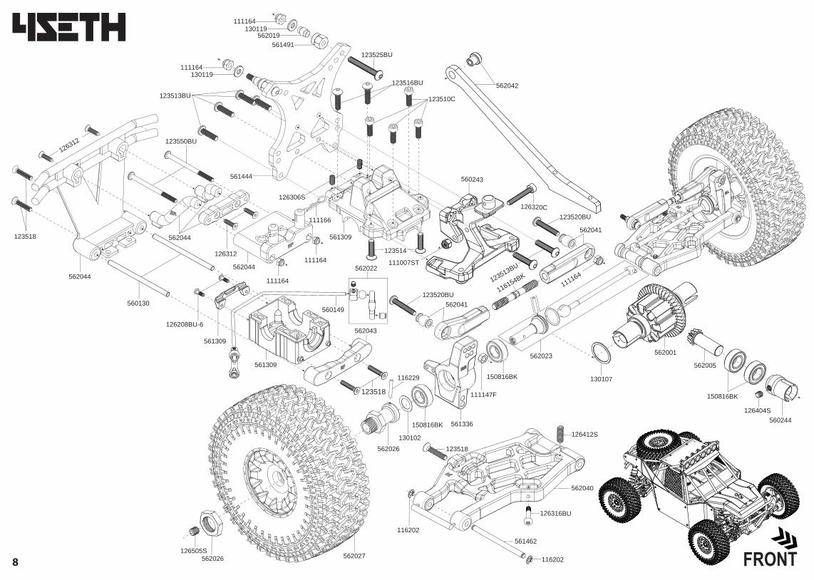
111164
111164
560149
562022111007ST
123514
123518
561309
562043
111166
123550BU
562044 123518
126312
562044
560130
561309
126208BU-6
126312
562044
562001
130107
562005
150816BK
560244126404S
123520BU562041
562041
123520BU
111164
116154BK
126505S562027
562026130102
150816BK
116229
561336
150816BK
562026
111147F
562023
562040
561462
116202
126316BU
123518
116202
126412S
130119
130119562019
561491
561444
126306S
123525BU
111164
111164
560243
126320C
123513BU
123513BU562042123516BU
123510C
561309
FRONT

126416
126505S
130102
130103
130107
130108
130119
130138
130139
150816BK
152005
191008
191018
191021
560117
560130
560149
560178
560243
560244
560298
560511
561202
561302
561303
561307
561309
561321
561323
561325
561336
561403
561404
561405
561406
561440
561441
561442
561443
561444
561449
561462
561467
4x16mm Steel FH Screw (6)
M5x5mm Set Screw(6)
8.1x12x0.2mm Shim (10)
4.2x10x0.2mm Shim (6)
13.2x15.9x0.5mm Shim (6)
6.05x9.5x0.5 mm Shim(10)
3.6x8x1mm Washer (10)
3.5x7x1 Washer (10)
5.2x15x0.5 Washer (10)
8x16x5mm Bearing-Black
O-Ring 4.7X1.4mm(10)
THOR WP-8100 ESC for Brushless Motor (14.8V)(3-4S)
THOR 4068 Brushless Motor 2500KV (14.8V)
S1601 Servo 16KG
Front Anti-Roll Bar 2.4mm
ST Steel 4x68.8mm Hinge Pin (2)
Rear Anti-Roll Bar 2.8mm
Servo Arm (Futaba) (2)
Rear Body Mount
ST Steel Small Bevel Gear Outdrive (2)
Steering Linkage Set
Servo Saver Spring (1.5mm) Blue
M8 Neo-Shock Bladder (4)
Diff Case Set
Diff Case Gasket (4)
Front Shock Tower Stiffener
Front & Rear Diff Gear Box (1 set)
Caster Block (1 pair)
Servo Saver Post (2)
Steering Rod Nylon Ball & Ball End Set
Rear Hub Carrier & Mud Sweeper (1 pair)
Receiver Box
Battery Box
ESC Mount
Side Guard
Triangle Plate (Front)
Front Stiffener
Front Upper Arm Mount
Front Shock Tower
Rear Shock Tower
46T Main Gear
Rear Lower Outer Hinge Pin(2)
Front Lower Outer Hinge Pin(2)
562039
562040
562041
562042
562043
562044
562045
562071G
562071R
562071-2G
562071-2R
562072
H6818
K6310-600
K6310-700
K6330-1000
K6330-10000
K6330-50000
K6602-12
Servo Mount
Rear Lower Arm(2)
Rear Upper Arm Set (2)
Rear Stiffener
Rear Bottom Arm Hinge Pin Mount
Rear Bumper Set
Motor Mount
4SETH Body - Green
4SETH Body - Red
Cabin and Panels - Green
Cabin and Panels - Red
Window Net
HR3GR 3 Channel 2.4G Receiver
K Factory Shock Oil 70ml/2.5oz #600
K Factory Shock Oil 70ml/2.5oz #700
K Factory Diff Oil 40ml #1000
K Factory Diff Oil 40ml #10000
K Factory Diff Oil 40ml #50000
M1.0 Pinion Gear for 5mm Shaft 12T
111007ST
111147F
111164
111166
111167
114073
115016BK
115027BK
116135C
116154BK
116201
116202
116229
116241
116249
123510C
123513BU
123514
123516BU
123518
123520BU
123525BU
123550BU
126208BU-6
126306C
126306S
126308
126308BU
126308C
126310
126310BU
126312
126312BU
126312SE
126314
126314BU
126316BU
126320C
126404S
126410C
126412
126412EN
126412S
3mm Steel Locknut (10)
3.5mm Steel Flat Nut (6)
3.5mm Lock Nut (10)
R8 Angled Body Clip (10)
2.6mm Lock Nut (10)
Singal Extension Cord 12cm (2)
Antenna Rod (2) BLACK
Ball End & 5.8mm Single Flanged Steel Ball (6) Black
3x50mm CR Adjustable Rod (2)
5x40mm Hardened Adjustable Rod -BK (2)
2x10.8mm Pin (10)
E-clip 2.5 (10)
2.5x16.8mm PIN(10)
3M Double Side Tape 4x2.2cm
EVA Tape 4x14cm
3.5x10mm Steel Cap Screw (6)
3.5x13mm Steel Button Head Screw (6)
3.5x14mm Steel FH Screw (6)
3.5x16mm Steel BH Screw (6)
3.5x18mm Steel FH Screw (6)
3.5x20mm Steel BH Screw (6)
3.5x25mm Steel BH Screw (6)
3.5x50mm Steel BH Screw (6)
2.6x8mm Steel Button Head Screw(6)
3x6mm Cap Screw (6)
3x6mm Set Screw (6)
3x8mm Steel F.H. Screw (6)
3x8mm Steel Button Head Screw (6)
3x8mm Steel Cap Screw (6)
3x10mm Steel F.H. Screw (6)
3x10mm Button Head Screw (6)
3x12mm Steel F.H. Screw (6)
3x12mm Button Head Screw (6)
3x12mm Steel Flat Round Servo Mount Screw (6)
3x14mm Steel FH Screw (6)
3x14mm Button Head Screw (6)
M3X16mm BH Screw(10)
3x20mm Cap Screw (6)
4x4mm Set Screw (6)
4x10mm Steel Cap Screw(6)
4x12mm Steel F.H. Screw (6)
4mm Steel Flat Round Engine Mount Screw (6)
4x12mm Set Screw (6)
561469
561471
561475
561476
561491
562001
562002
562003
562004
562005
562006
562007
562007-1
562008
562008-1
562009
562010
562011
562012
562013
562014
562015
562016
562017G
562017R
562018G
562018R
562019
562020
562021
562022
562023
562024
562025
562026
562027
562028
562029
562030
562033
562034
562035
562038
Steering Block Carrier Bushing (4)
Front Upper Inner Hinge Pin(2)
3x7x3mm Steel Bushing(4)
6x10x3mm Steel Bushing(4)
Shock Cap Bushing (4)
Complete Differential Kit (F/R)
F/R Differential Outdrive (2)
Differential Bevel Gear Set (for 1 diff)
Differential Bevel Shaft (2)
Machined Bevel Gear -29T/9T
Center Differential Set
Shock Absorber Set-Front (2)
Shock Body -Front (2)
Shock Absorber Set-Rear (2)
Shock Body -Rear (2)
Shock Spring Holder (2)
Shock Piston (4)
Shock Shaft - Front (2)
Shock Shaft - Rear (2)
Shock O-Ring & Washer (2)
Shock Spring - Front (2)
Shock Spring - Rear (2)
Shock lower Joint (2)
Front Shock Absorber Dust-free Protection
Front Shock Absorber Dust-free Protection
Rear Shock Absorber Dust-free Protection
Shock Absorber Dust-free Protection - Red (2)
Shock Pivot Ball 5.8mm (4)
Front Bottom Arm Hinge Pin Mount
Front Bumper Set
Anti-Roll Bar Linkage Joints (2)
CVA Joints (2)
Front Lower Arm(2)
Steering Block (2)
Wheel Adapter Set (2)
Mounted Tires (2)
Front Upper Arm Set (2)
Servo Saver Nylon Parts
Servo Saver Spring Holder
LED Lights
Center Driveshaft - Front
Center Driveshaft - Rear
Quick Released Battery Fastener (3)
�

61695


