Embed Size (px)
Citation preview

Interaction between spiral and paced waves in cardiac tissue
Konstantin Agladze1, Matthew W. Kay1, Valentin Krinsky2, and Narine Sarvazyan11The George Washington University, Washington DC2Institut Non-Lineaire de Nice, Valbonne, France
AbstractFor prevention of lethal arrhythmias, patients at risk receive implantable cardioverter-defibrillators, which use high-frequency antitachycardia pacing (ATP) to convert tachycardias to anormal rhythm. One of the suggested ATP mechanisms involves paced-induced drift of rotatingwaves followed by their collision with the boundary of excitable tissue. This study provides directexperimental evidence of this mechanism. In monolayers of neonatal rat cardiomyocytes in whichrotating waves of activity were initiated by premature stimuli, we used the Ca2+-sensitiveindicator fluo 4 to observe propagating wave patterns. The interaction of the spiral tip with a pacedwave was then monitored at a high spatial resolution. In the course of the experiments, weobserved spiral wave pinning to local heterogeneities within the myocyte layer. High-frequencypacing led, in a majority of cases, to successful termination of spiral activity. Our data show that1) stable spiral waves in cardiac monolayers tend to be pinned to local heterogeneities or areas ofaltered conduction, 2) overdrive pacing can shift a rotating wave from its original site, and 3) thewave break, formed as a result of interaction between the spiral tip and a paced wave front, movesby a paced-induced drift mechanism to an area where it may become unstable or collide with aboundary. The data were complemented by numerical simulations, which was used to furtheranalyze experimentally observed behavior.
Keywordsantitachycardia pacing; spiral wave drift; neonatal rat cardiomyocytes
Rotating waves of activity have been discovered in many biological, physical, and chemicalsystems (1,3,21,39), yet these studies, in major part, were inspired by the relevance of thistopic to the functioning of the heart (28,31,39). A large body of work during the past fourdecades using experimental and numerical approaches (for review see Refs. 25 and 38)provide a bulk of the information about the dynamics of rotating waves in heart tissue. Thedevelopment of potentiometric and Ca2+-sensitive indicators allowed optical mapping ofexcitation patterns with a high degree of spatial and temporal resolution (for review see Ref.14). Thus it became possible not only to directly visualize spiral waves in the heart but tofollow the details of their behavior.
Another important tool was the development of an in vitro experimental system usingconfluent cardiomyocyte monolayers. This system has reduced structural complexitycompared with the heart per se, which is an advantage when the goal is an understanding ofthe fundamental properties of wave propagation in cardiac tissue. It has provided a basis for
Copyright © 2007 the American Physiological SocietyAddress for reprint requests and other correspondence: K. Agladze or N. Sarvazyan, Pharmacology and Physiology Dept., The GeorgeWashington Univ., 2300 Eye St., Washington, DC 20037 ([email protected])..
NIH Public AccessAuthor ManuscriptAm J Physiol Heart Circ Physiol. Author manuscript; available in PMC 2011 January 11.
Published in final edited form as:Am J Physiol Heart Circ Physiol. 2007 July ; 293(1): H503–H513. doi:10.1152/ajpheart.01060.2006.
NIH
-PA Author Manuscript
NIH
-PA Author Manuscript
NIH
-PA Author Manuscript

many successful studies of wave propagation at the cellular level (19,30,35), generation ofsteadily rotating single and multiple-armed spiral waves (8,15), creation of controlledinhomogeneities and simulated defibrillation shocks (18), and propagation disturbancescaused by local ischemia-reperfusion injury (6,33).
Rotating waves, or reentries, are believed to be responsible for many dangerous cardiactachyarrhythmias. However, despite the wide clinical use of antitachycardia pacing (ATP),the mechanism of its success is not completely understood and remains an area of activeinvestigation (9,12,26,34). There are two main reasons for this. 1) Predicting propagationpatterns in an intact organ is an arduous task, especially when the anatomic and functionalcomplexity of a diseased heart is considered. 2) Technical challenges are involved inrecording propagation patterns in an intact organ at temporal and spatial resolution sufficientto reveal the interactions of rotating waves and paced wave fronts. For these reasons, ourunderstanding of the mechanisms of reentry termination by an external source is derived, inlarge part, from numerical studies or simplified models of cardiac tissue(20,23,28,37,40-42). These works considered the effects of pacing on reentrant activity orprovided insights regarding the motion of a spiral tip, which is relevant to the notion ofpaced-induced spiral drift as a potential mechanism of ATP.
The usefulness of neonatal myocyte cultures for ATP analysis was reinforced by a recentstudy that addressed the relationship between the steepness of the restitution curve and theability of overdrive pacing to convert a single loop of functional reentry to multiple-armspirals (9). This conversion, detrimental in the clinical sense, occurred in <15% of the cases;in the majority (>80%) of cases, functional reentry was successfully terminated by overdrivepacing. Notably, the exact mechanism of such termination remained unclear, mainly becauseof the lack of spatial resolution required to track the motion of a spiral tip.
We met this challenge by real-time observation of excitation waves using confocalmicroscopy. The spatiotemporal resolution of the recordings was sufficient for tracking thetrajectory of a spiral wave tip in an interactive mode. Using this method, we visualized theinteraction of a spiral wave tip with the wave front of paced waves. Our data suggest that 1)stable spiral waves in cardiac monolayers tend to be pinned to local micro-heterogeneities,2) overdrive pacing can shift a rotating wave from its original site, and 3) the wave break,formed as a result of interaction between the spiral tip and the paced wave front, can bemoved by a pace-induced drift mechanism to an area where it becomes unstable or collideswith a boundary.
METHODSCell preparation
Neonatal rat ventricular cardiomyocytes were obtained using a standard trypsin-collagenasedigestion protocol (4). The cells were plated on 25-mm laminin-coated glass coverslips (105
cells/cm2) and kept under standard culture conditions in DMEM supplemented with 5%FBS, 10 U/ml penicillin, 10 μg/ml gentamicin, and 1 μg/ml streptomycin. By the third day,the cells had formed interconnected confluent networks that exhibited rhythmic,spontaneous contractions. The cells were used in experiments during the next 3- 4 days. Tomonitor the monolayer activity, we loaded the cells with the Ca2+-sensitive indicator fluo 4(dissociation constant = 345 nM) and visualized excitation wave propagation by followingCa2+ transients, as described previously (5).
Protocols for pacing and spiral wave generationFunctional reentries (also called spiral waves) were initiated by premature stimulation,whereby two current pulses were sequentially delivered, each to a separate bipolar platinum
Agladze et al. Page 2
Am J Physiol Heart Circ Physiol. Author manuscript; available in PMC 2011 January 11.
NIH
-PA Author Manuscript
NIH
-PA Author Manuscript
NIH
-PA Author Manuscript

electrode placed in close contact with the cell layer using a micromanipulator. The timedelay between the pulses placed the second pulse within the vulnerable window, creating aspiral wave. Overdrive pacing was then applied via either of the two bipolar electrodes.
To slow wave propagation, we lowered the temperature of the bathing medium to 20°C andapplied the gap-junctional uncoupler heptanol (33). The diminished conduction velocity 1)allowed the trajectory of the spiral tip to be resolved at 16 frames/s and 2) increased thespace scale of our monolayers (i.e., reduced the ratio of reentrant path length to the size ofthe media), such that paced waves and fully developed spiral waves could coexist.Specifically, the slow conduction velocity reduced the wavelength to ~4 mm orapproximately one-sixth of the coverslip diameter, allowing observation of interactionsbetween paced waves and fully developed spiral waves within a 25-mm coverslip.
We performed >100 individual experiments in the following order. First, we optimized aprotocol for initiating the spirals. Then we determined how many of these induced spiralsare stable enough for the pacing protocol and evaluated how successfully pacing terminatedthe stable spirals. Only then did we proceed with our efforts to visualize paced-induced drift.This was documented in 10 cases using recordings in which all of the following 4 conditionswere met: 1) the spiral shifted upon pacing; 2) the field of view was constant; i.e., the framewas not moved; 3) the spiral tip's trajectory was within the frame; and 4) the interaction ofpaced fronts with the wave break could be seen.
Imaging techniquesFor close-up measurements, the excitation waves were monitored using a confocal imagingsystem (LSM 510, Zeiss). Images were acquired with a ×4 magnification, 0.16 NA objective(Olympus UPlanApo) at 16 frames/s, 64 × 64 pixels, and 30 μm/pixel spatial resolution.Fluo 4 was excited at 488 nm using a 25-mW argon laser, and emission was acquired from505–530-nm range. The sensitivity of the confocal system allowed us to observe Ca2+
transients in real time, thereby enabling us to acquire the data while moving the field of viewand pacing the layer.
The downside of confocal imaging is its limited field of view, which was circumvented witha charge-coupled device camera imaging system, which we used to image the entirecoverslip. In this system, an Andor iXon DV860DCS-BV camera (100 frames/s, 64 × 64pixels after 2 × 2 binning, and 0.5 mm/pixel spatial resolution) was fitted with a 6 mm/F1.0lens (Cosmicar C40601) and close-up lenses (+17, Kodak). Excitation light was supplied bytwo light-emitting diodes (Luxeon V Star, 470 nm), each of which was coupled to a fiber-optic guide to direct light onto the coverslip.
The tile mode of the confocal imaging system (LSM 510, Zeiss) was employed to create Fig.2. The motorized stage of the confocal imaging system was used to stitch together multipleindividual frames, each at a high spatial resolution.
Numerical simulationsSpiral waves and paced planar waves were simulated using a continuous isotropic sheetmodel with no-flux boundary conditions (27). Transmembrane potential (Vm) was computedat each node in a rectilinear grid as
Agladze et al. Page 3
Am J Physiol Heart Circ Physiol. Author manuscript; available in PMC 2011 January 11.
NIH
-PA Author Manuscript
NIH
-PA Author Manuscript
NIH
-PA Author Manuscript

with a membrane capacitance (Cm) of 1.0 μF/cm2. The membrane current (Iion; μA/cm2)kinetics were computed using the Drouhard-Roberge formulation (13) of the inward Na+
current (INa) and the Beeler-Reuter formulations (7) of the slow inward current (Is), time-independent K+ current (IK1), and time-activated outward current (Ix1). To obtain sustainedspiral waves without breakup, the time constants of Ca2+ current activation and inactivationwere slowed by multiplying by a factor σ, as previously described (11,27).
Model parameters were as follows: the grid size was 2.5 × 2.5 mm, dx = 0.025 mm, dt =0.015 ms, D = 0.6 mm2/s, and σ = 0.50. A spiral was initiated by cross-field stimulation. Inthe absence of a local heterogeneity, the spiral was not stable and drifted into a boundary.Introducing a heterogeneity captured and stabilized the spiral. The process of spiral“capture” is illustrated in Fig. 3 (online Supplement 1). Specifically, the spiral was firstinitiated by cross-field stimulation. After a small delay, a heterogeneity was introduced inthe center of the grid. This was done by assigning a value of 0.3gK1 as the conductance ofthe time-independent outward K+ channel for nodes within a 4-mm-radius circle from thecenter of the grid. Planar waves were then launched from the bottom edge of the grid at afrequency exceeding the spiral rotation rate.
RESULTSTermination of spiral wave activity
Rotating wave initiation and termination were studied in a total of ~100 cell cultures. Anindividual coverslip was used several times; i.e., after termination of the reentry, it wasinduced again and subjected again to high-frequency pacing. The stability of a rotating waveand the success or failure of a pacing protocol were determined from Ca2+ transient signalsobtained from a region of interest within the field of view. After five to eight rotations,~70% of induced reentries (28 of 39 cases) self-terminated (Fig. 1A). If a rotating wavepersisted, the field of view was adjusted for visualization of the spiral tip, and overdrivepacing was applied. Overdrive pacing terminated spiral activity with a 90% success rate (27of 30 cases). The trace in Fig. 1B shows the initiation of a spiral wave followed by a train ofpaced waves that successfully terminated the spiral activity. The trace in Fig. 1C shows arare unsuccessful attempt to terminate spiral activity by overdrive pacing. Examples ofspiral's spontaneous and paced-induced terminations are shown as online Supplements 3 and4, respectively.
Role of heterogeneityThe heart is a highly heterogeneous organ in which rotating waves are likely to be pinned toanatomic or functional obstacles such as coronary vessels, collagen fibers, and ischemic orscar tissue (32). Cardiomyocyte cultures represent a much less heterogeneous substrate.However, the presence of fibroblasts, small differences in cell plating density, clusters ofdamaged or dead myocytes, and even differences in the alignment and number ofintercellular junctions make this simplified model of cardiac tissue intrinsicallyheterogeneous. The heterogeneous nature of a monolayer is illustrated in Fig. 2, whichshows a macroscopically homogeneous coverslip that was imaged with a spatial resolutionsufficient for visualization of microscopic heterogeneities.
Although monolayer heterogeneities have minimal impact on planar wave propagation, theydo affect spiral tip behavior, primarily because of a higher impact of the current sink-sourcerelationship at critical curvatures. Indeed, the majority of spirals that were stable (existed for>1 min) appeared to rotate around areas of microscopic heterogeneities, such as those shownin Fig. 2. A situation of how this might happen is shown in Fig. 3, where a spiral initiated bycross-field stimulation was captured by a nearby heterogeneity (also animated in online
Agladze et al. Page 4
Am J Physiol Heart Circ Physiol. Author manuscript; available in PMC 2011 January 11.
NIH
-PA Author Manuscript
NIH
-PA Author Manuscript
NIH
-PA Author Manuscript

supplement 1). The small area with altered K+ conductance (gk1), seen as a brighter spot atthe center, acts to attract and anchor the tip of the spiral wave (Fig. 3).
Interaction of the paced waves with the spiral tip: formation of a wave breakTo observe the interaction of a spiral wave with paced waves, we initiated a stably rotatingspiral and adjusted the field of view such that its tip was in the center. The tip was monitoredfor ≥1 min to confirm stability. Overdrive pacing was then applied from a distant site.Pacing continued for up to 30 s after paced waves approached the spiral tip and entrained theentire field of view. A typical pattern of the interaction of paced waves with a spiral tip isshown in Figs. 4 and 5. An activation map in Fig. 4A shows one complete rotation of thespiral, and a snapshot of a spiral tip is shown in Fig. 4B. This spiral wave was stable with aperiod of 0.72 s. It persisted for ≥60 s before it was terminated by overdrive pacing (onlinesupplement 2).
A frame-by-frame sequence illustrating the collision of a spiral tip with a paced wave isshown in Fig. 4C. The planar front of the paced wave can be seen as it approaches the spiraltip. The last frame in the top row in Fig. 4C shows that the two waves have collided andcoalesced. Propagation of the coalesced wave continued in the direction of the paced wave,but propagation into an area beyond the collision site was blocked because of refractoriness,resulting in a wave break (Fig. 4C, bottom row). Once the broken wave encountered tissuethat regained excitability, it curled into a new spiral. A movie corresponding to the eventsshown in Fig. 4 can be found online (supplement 4). The numerical illustration of thisprocess presented in Fig. 4D shows how the tip of the spiral, captured by a localheterogeneity in Fig. 3, interacts with the planar wave front of the paced wave.
Paced-induced drift of spiral wavesWhen the frequency of overdrive pacing exceeds the rotational frequency of the spiral,collisions between the wave front of paced waves and the spiral occur closer and closer tothe tip (Fig. 5). In all 10 documented cases, spirals drifted away from the pacing site. Witheach paced wave, the collision site progresses toward the upper right corner until it reachesthe spiral tip (Fig. 5A, top row). As shown in Fig. 5B, the tip location remained unchangedwhen the spiral collided with paced waves 1, 2, and 3, while the respective collision sitesmoved. When paced wave 4 collided with the tip, local refractoriness prevented the spiralfrom curling into the same area, causing an upward displacement of the wave break (arrowin Fig. 5B). Subsequent paced waves 5–8 continued to displace the wave break until itdisappeared from of the field of view (last frame in Fig. 5A and online supplement 4). Anumerical illustration of paced-induced drift is shown in Fig. 6. The plot and correspondingframes (full sequence can be seen in supplement 5) show the upward movement of thecollision site followed by tip displacement away from the pacing electrode. The overallscenario is identical to the experimental case in Fig. 5. Paced-induced drift synchronizes thewave break with the frequency of the pacing wave.
Collision of the wave break with the boundarySpiral waves can anchor to macroscopic obstacles to form anatomic reen-tries. The successof overdrive pacing in terminating anatomic reentries may depend on the size and boundaryconditions of these obstacles (24). This study, however, focuses on functional reentriesunder conditions where endogenous microscopic heterogeneity simply anchors the spiral tip,thereby minimizing its meandering, but the size of the spiral core is negligible (Fig. 4A andonline supplement 2. The complete sequence of events can be seen in online supplement 6).When a train of paced waves shifts a spiral wave from its original location, it is possible that1) the wave break curls into a new spiral wave, which reattaches to heterogeneity orbecomes unstable and self-terminates and 2) the wave break collides with an unexcitable
Agladze et al. Page 5
Am J Physiol Heart Circ Physiol. Author manuscript; available in PMC 2011 January 11.
NIH
-PA Author Manuscript
NIH
-PA Author Manuscript
NIH
-PA Author Manuscript

boundary. To visualize such collisions, we used a CCD camera-based imaging system toexpand our field of view to capture the entire coverslip (Fig. 7). A spiral wave was situated 5mm from the border of the coverslip and pinned to an area of depressed conduction (Fig. 7,A and B). It stably rotated for several minutes before overdrive pacing was applied. Theposition of the pacing electrode is marked by two black dots in Fig. 7A. On collision of thepaced waves with the spiral, the two waves coalesced (Fig. 7, C and D). The wave breakthen curled into a new spiral, which remained pinned to the local heterogeneity (Fig. 7E).With each new paced wave, the collision site and the area where the two waves coalescedmoved toward the coverslip boundary and away from the pacing electrode (Fig. 8).Ultimately, the refractoriness of the collision site prevented curling of the wave breaktoward the area of local heterogeneity in a manner similar to the events shown in Fig. 4. Thisforced the wave break to shift, collide with the boundary (Fig. 7F), and terminate.
DISCUSSIONATP is a procedure that is widely used to restore normal heart rhythm without application ofdamaging defibrillation shocks. Despite significant experimental and theoretical effort toclarify the mechanisms of ATP, it is unclear how a sequence of high-frequency pulsesterminates the rotating waves, which are believed to be a cause of tachycardia (38). Theconventional explanation is that one of the ATP pulses occurs during the so-calledvulnerability window (VW), generating a wave front that rotates in a direction opposite tothe existing rotating wave. This newly formed retrograde wave front then follows the samepath as the existing rotating wave, causing both waves to annihilate on collision. Thealternative explanation involves pacing-induced displacement of rotating waves. Onceshifted from their original locations, functional reentries are likely to self-terminate orcollide with the media boundary. Indeed, studies in isolated swine and sheep ventricularmuscle slices (12,26), as well as in monolayers of neonatal rat cardiomyocytes (9),suggested that such a scenario does occur.
Despite its importance, however, the mechanism of paced-induced spiral displacementremains unclear. This is largely due to the spatiotemporal resolution required to visualize themotion of the spiral tip. Here, using monolayers of rat ventricular myocytes in whichpropagation velocity was significantly reduced to resolve the motion of the spiral tip, weattempted to fill this gap. This measure also allowed us to reduce the wavelength ofpropagating waves to match the dimensions of our experimental preparations (25-mmcoverslip). From experiments in chemical media and numerical analysis, it has been shownthat when the frequency of overdrive pacing exceeds the rotational frequency of the spiral,collisions between the wave front of paced waves and the spiral approach the tip (29). Thisis true even when the size of the media is much larger than the wavelength, such that thespiral tip appears to be shielded from paced waves (20,23). However, wavelength estimatesfor cardiac tissue suggest that heart size and the wavelength are comparable (22). Thus it isunlikely that the in vivo pacing source will be shielded from the spiral core by multiplewraps of the spiral arm. Therefore, one can argue that, even in the case of a limited numberof paced waves (standard ATP protocols of 7–20 pulses), their wave fronts may be able toencroach on the tip of the rotating wave, similar to the sequence shown in Fig. 5. The closerthe pacing electrode is to the core of a spiral, the more likely it is that a fixed number ofpacing stimuli will reach the tip.
When a paced wave encountered the tip of a spiral wave, the spiral wave condensed to asingular wave break (Fig. 4C), similar to the scenario reported earlier for chemicallyexcitable media (29). If pacing was maintained, this wave break cycled through threedistinct steps: 1) it encountered excitable tissue and evolved into a spiral tip, 2) it collidedwith another paced wave, and 3) it propagated with the paced wave without evolving until it
Agladze et al. Page 6
Am J Physiol Heart Circ Physiol. Author manuscript; available in PMC 2011 January 11.
NIH
-PA Author Manuscript
NIH
-PA Author Manuscript
NIH
-PA Author Manuscript

encountered excitable tissue, at which point it again evolved into a spiral tip (step 1). Withinthis cycle, the wave break, which is the seed of the potential spiral, is gradually pushed fromits original site (Fig. 5). Notably, the wave break drifts slowly compared with thepropagation speed (Figs. 5 and 6).
Mechanism-based suggestions to increase ATP success rates are in high demand, since thisimportant task remains largely empirical (36). The two alternative mechanisms of ATP, i.e.,VW-based and paced-induced drift-based, offer opposite recommendations relative topacing frequency. In the VW-based mechanism, a retrograde wave front is generated when astimulus is placed within the partially recovered tail of the rotating wave. In this scenario, anumber of pulses are needed to find a narrow VW. If Ts is the period of spiral wave rotationand Tp is the period of paced waves, then Ts − Tp =ΔT should not exceed the VW. If so,then even with arbitrary placement of the first stimulus, the time of subsequent stimuli willbe systematically shifted with respect to the tail of a rotating wave, such that, with enoughstimuli, one will eventually be placed within the VW. If the condition is not fulfilled, forinstance, if Tp is substantially lower than Ts, then the success of placing a stimulus withinthe VW is probabilistic, and it is possible that the number of stimuli required for successfulATP would increase dramatically. Therefore, pacing frequency should not significantlyexceed the rotational rate of reentry.
On the other hand, the velocity of paced-induced drift could be accelerated by increasingpacing frequency similar to that in the chemical active medium (2) and confirmednumerically (16). So the rotating wave is pushed away faster with increasing Ts − Tp = ΔT(the sole limitation being tissue capture). Therefore, the drift-induced pacing mechanismleads to a recommendation opposite to that derived from the VW concept.
Although the above reasoning is attractive because of the clarity of the underlyingmechanisms, one warns against its simplistic interpretation. The in vivo situation is muchmore complex: waves propagate in three dimensions, their curvature depends on fiberorientation, and tissue properties change as ischemia sets in. In addition, multiple rotatingwaves can occur during one tachycardia episode, and/or paced-induced drift can be followedby VW-based termination (10).
Another factor to consider for the VW-based and paced-induced drift mechanism is thegeometry and size of cardiac tissue. Stimulation into VW will terminate reentry only in aone-dimensional case or in a very confined space. Otherwise, instead of termination, thestimulus could initiate a new pair of rotating waves. Thus, limiting the excitable area is acrucial prerequisite. In the case of the drift-based termination, the border also plays adecisive role. In vivo, many anatomic structures, including large vessels, annuli of cardiacvalves, and atrioventricular septa, which insulate ventricles from the atria, as well as regionsof fibrotic or ischemic tissue, can serve as a boundary. In the case of three-dimensionalrotating waves, or scrolls, the endocardium and epicardium also serve as boundaries of theexcitable media.
Limitations1. Because of the small field of view required to monitor spiral tip movement, it was
not always possible to clearly attribute paced-induced termination of spiral wavesto just the mechanism of paced-induced drift. In a few cases, only one paced-induced shift of a spiral tip resulted in a spiral's disappearance from the field ofview and cessation of its activity. Therefore, the emphasis of this study is to showthat paced-induced drift does occur, not on its relative prevalence. Numericalstudies suggest that many factors, including the distance between the electrode anda spiral tip, propagation velocity, and the ratio of spiral to pacing frequency, may
Agladze et al. Page 7
Am J Physiol Heart Circ Physiol. Author manuscript; available in PMC 2011 January 11.
NIH
-PA Author Manuscript
NIH
-PA Author Manuscript
NIH
-PA Author Manuscript

affect the ability of a limited number of paced waves to reach the spiral tip(17,20,23). Additionally, endogenous monolayer heterogeneities will impact thesuccess of unpinning and how drift would progress after a spiral is unpinned(24,34). We did not report mean values of drift velocity (Vdrift), as this valuedepends on pacing frequency. Our previous studies (29) suggest that Vdrift ~Vplanar wave × (1 − Ts/Tp). Although this relationship is likely to hold for cardiacpreparations, full statistical confirmation awaits future studies.
2. Although it is very likely that stably rotating spirals would be pinned toheterogeneities such as those shown in Fig. 2, further work is required to prove andquantify this effect.
3. The Beeler-Reuter model provides a generic reconstruction of the action potentialfor a mammalian ventricular myocardial cell. It was used in our numericalexperiments to explore the interactions between paced wave fronts and the tips ofspiral waves that were observed in our experiments. We shortened action potentialsin our model by reducing the activation and inactivation time constants of the Ca2+
current. This was done to reduce the time scale of interaction events between pacedwave fronts and spiral tips from ~10–15 s, as observed in experiments, to a littlemore than 1 s for the simulations. This substantially reduced the computationalburden of our simulations. Although the time scale reduction is not expected toalter the model results, it represents one of the limitations of the present study.More detailed numerical models are needed for full exploration of the observedphenomenon.
4. Unanchored spirals in cardiomyocyte cultures can disappear because of theircollision with the boundary. However, they often self-terminate without anyapparent anatomic obstacle in sight. The mechanism of such self-terminationremains to be addressed.
ConclusionsWe have shown that overdrive pacing can terminate rotating waves by a paced-induced driftmechanism in a simple, endogenously heterogeneous model of cardiac tissue. The latteroccurs via cyclical movement of wave break. Continuous high-frequency pacing then shiftsthe wave break to an area where the spiral becomes unstable or collides with the boundaryof the excitable medium.
We also may note that the ability to directly observe paced-induced drift of rotating waves incardiac preparations offers an important methodological tool to further understand thisprocess, e.g., questions regarding the size of heterogeneity that stabilizes the rotating waveand/or its boundary conditions; the role of fiber anisotropy; the effects of the spiral core onthe direction and velocity of paced drift; the efficacy of different pacing strategies; or a newcombination of therapies that combine low-voltage shocks with overdrive pacing. All thesequestions can be addressed with relative ease using the described experimental approach.
Supplementary MaterialRefer to Web version on PubMed Central for supplementary material.
AcknowledgmentsWe thank Dr. Nadezhda Agladze and Luther Swift for assistance with cardiomyocyte culture preparations.
GRANTS: This study was financially supported by National Heart, Lung, and Blood Institute Grant HL-076722and a Biomedical Engineering Research Grant from the Whitaker Foundation.
Agladze et al. Page 8
Am J Physiol Heart Circ Physiol. Author manuscript; available in PMC 2011 January 11.
NIH
-PA Author Manuscript
NIH
-PA Author Manuscript
NIH
-PA Author Manuscript

REFERENCES1. Agladze K, Steinbock O. Waves and vortices of rust on the surface of corroding steel. J Phys Chem
A 2000;104:9816–9819.2. Agladze KI, Krinsky V. Multi-armed vortices in an active chemical medium. Nature 1982;296:424–
426.3. Allessie MA, Bonke FI, Schopman FJ. Circus movement in rabbit atrial muscle as a mechanism of
tachycardia. Circ Res 1973;33:54–62. [PubMed: 4765700]4. Arutunyan A, Webster DR, Swift LM, Sarvazyan N. Localized injury in cardiomyocyte network: a
new experimental model of ischemia-reperfusion arrhythmias. Am J Physiol Heart Circ Physiol2001;280:H1905–H1915. [PubMed: 11247808]
5. Arutunyan A, Swift LM, Sarvazyan N. Initiation and propagation of ectopic waves: insights from anin vitro model of ischemia-reperfusion injury. Am J Physiol Heart Circ Physiol 2002;283:H741–H749. [PubMed: 12124223]
6. Arutunyan A, Pumir A, Krinsky VI, Swift LM, Sarvazyan N. Behavior of ectopic surface: effects ofβ-adrenergic stimulation and uncoupling. Am J Physiol Heart Circ Physiol 2003;285:H2531–H2542. [PubMed: 12893638]
7. Beeler GW, Reuter H. Reconstruction of the action potential of ventricular myocardial fibres. JPhysiol 1977;268:177–210. [PubMed: 874889]
8. Bursac N, Aguel F, Tung L. Multiarm spirals in a two-dimensional cardiac substrate. Proc NatlAcad Sci USA 2004;101:15530–15534. [PubMed: 15492227]
9. Bursac N, Tung L. Acceleration of functional reentry by rapid pacing in anisotropic cardiacmonolayers: formation of multi-wave functional reentries. Cardiovasc Res 2006;69:381–390.[PubMed: 16274682]
10. Byrd IA, Kay MW, Pollard AE. Interactions between paced wavefronts and monomorphicventricular tachycardia: implications for antitachycardia pacing. J Cardiovasc Electrophysiol2006;17:1129–1139. [PubMed: 16989652]
11. Courtemanche M, Winfree AT. Re-entract rotating waves in a Beeler-Reuter-based model of two-dimensional cardiac electrical activity. Int J Bifurcation Chaos 1991;1:431–444.
12. Davidenko JM, Salomonsz R, Pertsov AM, Baxter WT, Jalife J. Effects of pacing on stationaryreentrant activity. Theoretical and experimental study. Circ Res 1995;77:1166–1179. [PubMed:7586230]
13. Drouhard JP, Roberge FA. Revised formulation of the Hodgkin-Huxley representation of thesodium current in cardiac cells. Comput Biomed Res 1987;20:333–350. [PubMed: 3621918]
14. Efimov IR, Nikolski VP, Salama G. Optical imaging of the heart. Circ Res 2004;95:21–33.[PubMed: 15242982]
15. Entcheva E, Lu SN, Troppman RH, Sharma V, Tung L. Contact fluorescence imaging of reentry inmonolayers of cultured neonatal rat ventricular myocytes. J Cardiovasc Electrophysiol2000;11:665–676. [PubMed: 10868740]
16. Ermakova EA, Krinsky VI, Panfilov AV, Pertsov AM. Interaction between spiral and flat periodicautowaves in an active medium. Biofizika 1986;31:318–323. [PubMed: 3697394]
17. Ermakova EA, Pertsov AM. Interaction of rotating spiral waves with a boundary. Biofizika1986;31:855–861.
18. Fast VG, Rohr S, Gillis AM, Kleber AG. Activation of cardiac tissue by extracellular electricalshocks: formation of “secondary sources” at intercellular clefts in monolayers of culturedmyocytes. Circ Res 1998;82:375–385. [PubMed: 9486666]
19. Fast VG, Ideker RE. Simultaneous optical mapping of transmembrane potential and intracellularcalcium in myocyte cultures. J Cardiovasc Electrophysiol 2000;11:547–556. [PubMed: 10826934]
20. Fu YQ, Zhang H, Cao Z, Zheng B, Hu G. Removal of a pinned spiral by generating target waveswith a localized stimulus. Phys Rev E Stat Nonlin Soft Matter Phys 2005;72:046206. [PubMed:16383511]
21. Gerisch G. Cell aggregation and differentiation in Dictyostelium. Curr Top Dev Biol 1968;3:157–197. [PubMed: 5002049]
Agladze et al. Page 9
Am J Physiol Heart Circ Physiol. Author manuscript; available in PMC 2011 January 11.
NIH
-PA Author Manuscript
NIH
-PA Author Manuscript
NIH
-PA Author Manuscript

22. Girouard SD, Rosenbaum DS. Role of wavelength adaptation in the initiation, maintenance, andpharmacologic suppression of reentry. J Cardiovasc Electrophysiol 2001;12:697–707. [PubMed:11405405]
23. Gottwald G, Pumir A, Krinsky V. Spiral wave drift induced by stimulating wave trains. Chaos2001;11:487–494. [PubMed: 12779486]
24. Ikeda T, Yashima M, Uchida T, Hough D, Fishbein MC, Mandel WJ, Chen PS, Karagueuzian HS.Attachment of meandering reentrant wave fronts to anatomic obstacles in the atrium. Role of theobstacle size. Circ Res 1997;81:753–764. [PubMed: 9351449]
25. Jalife J. Ventricular fibrillation: mechanisms of initiation and maintenance. Annu Rev Physiol2000;62:25–50. [PubMed: 10845083]
26. Kamjoo K, Uchida T, Ikeda T, Fishbein MC, Garfinkel A, Weiss JN, Karagueuzian HS, Chen PS.Importance of location and timing of electrical stimuli in terminating sustained functional reentryin isolated swine ventricular tissues: evidence in support of a small reentrant circuit. Circulation1997;96:2048–2060. [PubMed: 9323098]
27. Kay MW, Gray RA. Measuring curvature and velocity vector fields for waves of cardiac excitationin 2-D media. IEEE Trans Biomed Eng 2005;52:50–63. [PubMed: 15651564]
28. Krinsky VI. Spread of excitation in an inhomogeneous medium (state similar to cardiacfibrillation). Biophys J 1966;11:776–784.
29. Krinsky VI, Agladze KI. Interaction of rotating chemical waves. Physica D 1983;8:50–56.30. Kucera JP, Kleber AG, Rohr S. Slow conduction in cardiac tissue: insights from optical mapping at
the cellular level. J Electrocardiol 2001;34:57–64. [PubMed: 11781937]31. Moe GK, Jalife J. Reentry and ectopic mechanisms in the genesis of arrhythmias. Arch Inst Cardiol
Mex 1977;47:206–211. [PubMed: 20066]32. Pertsov AM, Davidenko JM, Salomonsz R, Baxter WT, Jalife J. Spiral waves of excitation underlie
reentrant activity in isolated cardiac muscle. Circ Res 1993;72:631–650. [PubMed: 8431989]33. Pumir A, Arutunyan A, Krinsky V, Sarvazyan N. Genesis of ectopic waves: role of coupling,
automaticity, and heterogeneity. Biophys J 2005;89:2332–2349. [PubMed: 16055545]34. Ripplinger CM, Krinsky VI, Nikolski VP, Efimov IR. Mechanisms of unpinning and termination
of ventricular tachycardia. Am J Physiol Heart Circ Physiol 2006;291:H184–H192. [PubMed:16501014]
35. Rohr S, Scholly DM, Kleber AG. Patterned growth of neonatal rat heart cells in culture.Morphological and electrophysiological characterization. Circ Res 1991;68:114–130. [PubMed:1984856]
36. Sweeney MO. Antitachycardia pacing for ventricular tachycardia using implantable cardioverterdefibrillators. Pacing Clin Electrophysiol 2004;27:1292–1305. [PubMed: 15461721]
37. Vinston M. Interactions of spiral waves in inhomogenous excitable media. Physica D1998;116:313–324.
38. Weiss JN, Chen PS, Wu TJ, Siegerman C, Garfinkel A. Ventricular fibrillation: new insights intomechanisms. Ann NY Acad Sci 2004;1015:122–132. [PubMed: 15201154]
39. Winfree, AT. When Time Breaks Down: The Three-Dimensional Dynamics of Chemical Wavesand Cardiac Arrhythmias. Princeton University Press; Princeton, NJ: 1987.
40. Winfree AT. Alternative stable rotos in an excitable media. Physica D 1991;49:125–140.41. Xie F, Qu Z, Weiss JN, Garfinkel A. Interactions between stable spiral waves with different
frequencies in cardiac tissue. Phys Rev E 1999:59.42. Xie F, Qu Z, Weiss JN, Garfinkel A. Coexistence of multiple spiral waves with independent
frequencies in a heterogeneous excitable medium. Phys Rev E Stat Nonlin Soft Matter Phys2001;63:031905. [PubMed: 11308676]
Agladze et al. Page 10
Am J Physiol Heart Circ Physiol. Author manuscript; available in PMC 2011 January 11.
NIH
-PA Author Manuscript
NIH
-PA Author Manuscript
NIH
-PA Author Manuscript

Fig. 1.Three types of behavior observed for induced reentrant (spiral) activity. Recordings of Ca2+
transients are shown as relative units of fluo 4 fluorescence. Arrows indicate the applicationof premature stimuli, which initiated a reentrant wave. A: self-termination of a reentrantwave. B: reentrant wave termination by overdrive pacing. C: unsuccessful termination ofreentrant wave activation by overdrive pacing.
Agladze et al. Page 11
Am J Physiol Heart Circ Physiol. Author manuscript; available in PMC 2011 January 11.
NIH
-PA Author Manuscript
NIH
-PA Author Manuscript
NIH
-PA Author Manuscript

Fig. 2.Endogenous heterogeneities in macroscopically homogenous coverslips. A: myocyte-freeregions; B: mechanical damage due to forceps during coverslip transfer; C: areas of higherdensity; D: clusters of damaged cells on top of the monolayer (arrows); E: areas of lesser/uneven density.
Agladze et al. Page 12
Am J Physiol Heart Circ Physiol. Author manuscript; available in PMC 2011 January 11.
NIH
-PA Author Manuscript
NIH
-PA Author Manuscript
NIH
-PA Author Manuscript

Fig. 3.Capture of a nearby spiral by a local heterogeneity. A: 12 sequential frames show how asmall area of heterogeneity, seen as a slightly brighter spot at the center, attracts the tip of aspiral wave. B: 4 sequential frames 10 cycles after the capture event shown in A. Theyillustrate that spiral remained stable and pinned to the same spot. Full sequence can be seenin the online supplement 1.
Agladze et al. Page 13
Am J Physiol Heart Circ Physiol. Author manuscript; available in PMC 2011 January 11.
NIH
-PA Author Manuscript
NIH
-PA Author Manuscript
NIH
-PA Author Manuscript

Fig. 4.Reentrant wave terminated by rapid pacing. A: 1 complete rotation of the reentrant wavepresented as an activation map, where color indicates time of activation at each pixel. B:fluorescence snapshot of the wave. Arrow denotes direction of rotation. Normalized fluo 4fluorescence is shown in pseudocolor. Red dot indicates position of the spiral tip. C:sequence of frames illustrating interaction of 1 paced wave front with the tip of the spiralwave before (top row) and after (bottom row) collision. Last 2 frames show formation of awave break. ***, Site of collision. Solid lines, wave fronts; dotted lines, wave backs. Reddot indicates position of the spiral tip. D: numerical illustration of the process described inC. Dotted circle, position of a local heterogeneity [reduced time-independent K+ current(IK1)], around which the spiral rotates.
Agladze et al. Page 14
Am J Physiol Heart Circ Physiol. Author manuscript; available in PMC 2011 January 11.
NIH
-PA Author Manuscript
NIH
-PA Author Manuscript
NIH
-PA Author Manuscript

Fig. 5.Paced-induced drift of spiral waves. A: impeding collisions of the spiral and 4 consecutivepaced waves before they reach the tip (top row) and impeding collisions of the spiral waveand 4 consecutive paced waves during the paced-induced drift (bottom row). Arrows showdirection of paced wave propagation. Right: relative positions of collision site (red lines) andwave break (red circle). Dotted circle indicates location of the initial wave break; arrowshows direction of paced induced drift. At this magnification (~2 × 2 mm area), individualcell heterogeneity is clearly visible. B: graphical illustration of process shown in A. Reddots, position of wave break; black dots, collision site coordinates. Displacement wasmeasured in the direction of drift.
Agladze et al. Page 15
Am J Physiol Heart Circ Physiol. Author manuscript; available in PMC 2011 January 11.
NIH
-PA Author Manuscript
NIH
-PA Author Manuscript
NIH
-PA Author Manuscript

Fig. 6.Paced-induced drift of spiral wave: numerical study. A: impeding collisions between thespiral wave and 4 consecutive paced waves before they reach the tip (top row) and 3impeding collisions of the spiral wave and paced waves during paced-induced drift (bottomrow). Right: relative positions of collision site (white lines) and wave break (solid circle).Dotted circle, area of local heterogeneity similar to that in Fig. 4D. B: graphical illustrationof the process in A. ○, Position of the wave break; ●, collision site coordinates. *, Illustrationthat the wavebreak displacement occurs as a result of the previous collision (paced wave 7),and not due to the collision with what will be the next paced wave (wave 8).
Agladze et al. Page 16
Am J Physiol Heart Circ Physiol. Author manuscript; available in PMC 2011 January 11.
NIH
-PA Author Manuscript
NIH
-PA Author Manuscript
NIH
-PA Author Manuscript

Fig. 7.Paced-induced spiral wave detachment and subsequent termination due to wave breakcollision with a boundary. A: location of pacing electrodes and a local heterogeneity (left)and circular wave fronts of paced waves (note changes in wave curvature near localheterogeneity) and appearance of the cell layer after overdrive pacing was turned off (right).B: 4 sequential frames showing spiral wave pinned to a heterogeneity. C: 5 sequentialframes showing collision of the spiral wave with the paced wave. D: 5 sequential framesshowing the 2 waves coalescing into a single wave front. E: 5 sequential frames showingcurling of the wave break into a new spiral wave. F: 5 sequential frames showing collapse ofthe wave break at the boundary. Time (in seconds) is shown in each frame.
Agladze et al. Page 17
Am J Physiol Heart Circ Physiol. Author manuscript; available in PMC 2011 January 11.
NIH
-PA Author Manuscript
NIH
-PA Author Manuscript
NIH
-PA Author Manuscript
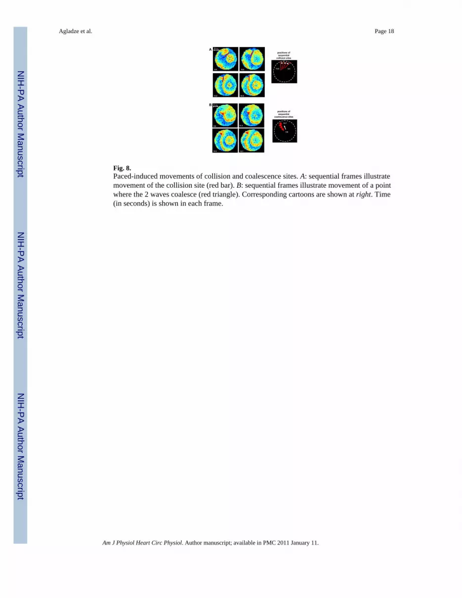
Fig. 8.Paced-induced movements of collision and coalescence sites. A: sequential frames illustratemovement of the collision site (red bar). B: sequential frames illustrate movement of a pointwhere the 2 waves coalesce (red triangle). Corresponding cartoons are shown at right. Time(in seconds) is shown in each frame.
Agladze et al. Page 18
Am J Physiol Heart Circ Physiol. Author manuscript; available in PMC 2011 January 11.
NIH
-PA Author Manuscript
NIH
-PA Author Manuscript
NIH
-PA Author Manuscript


