Embed Size (px)
Citation preview
heavyelementsodels do
nstructionthe path
m and thes, anchorign datants incontrol
Dow
nloa
ded
from
asc
elib
rary
.org
by
Inst
itut T
ekno
logi
Sep
uluh
Nop
embe
r Su
raba
ya o
n 11
/09/
14. C
opyr
ight
ASC
E. F
or p
erso
nal u
se o
nly;
all
righ
ts r
eser
ved.
Spatial Integration in ConstructionLeonhard E. Bernold, M.ASCE1
Abstract: Work in construction always requires moving within, and interacting with, a complex environment while handlingmaterials and building elements to be joined, inserted, or aligned. Modern design software is able to digitally model all of thosein their spatially correct configuration, and without interference. When it comes to the actual construction, however, the spatial mnot find any use. Twenty years after the manufacturing industry began using electronic design data to control their machinery, cois also getting ready to move away from its longstanding tradition of working with paper-based blueprints. The newest steps ontoward the use of three-dimensional digital design data in support of site operation are stimulated by the global positioning systemany uses of lasers. Surveying has always performed critical functions on construction sites, such as marking building layoutbolts, concrete formwork, or bridge bearings. The objective of spatial integration in construction is to digitally merge spatial deswith the digital model of equipment working on implementing the design. This paper will briefly review historical advanceme‘‘perfecting’’ the surveying technology before presenting three examples of a quantum leap in the way we design, plan, andconstruction projects in the future.
DOI: 10.1061/~ASCE!0733-9364~2002!128:5~400!
CE Database keywords: Surveys; Construction; Computer applications; Information; Global positioning.
e-ur
s onenthleerag, inus-w-
d
theiesid-
ents, onrtsp,
al
rktrol
vean-ithsedst,
s fororhastuali-on-tly,uchstepcu-hed
m-n-
e
tor inras-
em
ualed-truc-
tate
musonetor.ibleThis
4/
Introduction and Background
Richard Tucker, recipient of the first Peurifoy Construction Rsearch award in 1986, posed the following question: ‘‘Are osystems truly control systems or merely advanced versiondocumentation?’’~Tucker 1988!. In an attempt to answer his owquestion, he referred to the construction records from a thirtecentury castle project for King Henry III. Through this examphe was able to demonstrate that documentations of 1986 windeed almost identical to those used and perfected 800 yearsThe article also pointed to some remarkable advancementscluding ‘‘radar surveying has done away with the old laboriotransit, rod, and chain’’~Tucker 1988!. Notwithstanding those examples, Tucker maintained that ‘‘the construction industry, hoever, has a need for more dreamers. Construction researchmands more quantum leaps . . . .’’
The successful launch of the global positioning system~GPS!for private use and the advancement of laser technology laidfoundation for rapid advancements in surveying technologafter 1986. By comparing construction magazines from the m1980s with today, one is struck by the amount of advertisemand articles about modern surveying methods. Neverthelesscould compare the efforts of improving surveying with the effoin perfecting the buggy whip. ‘‘Even with the perfect buggy whiman would still prefer to fly,’’ concludes Tucker~1988!. Thispaper builds on this viewpoint by first reviewing the historic
1Associate Professor, Dept. of Civil Engineering, North Carolina SUniv., Raleigh, NC 27695.
Note. Discussion open until March 1, 2003. Separate discussionsbe submitted for individual papers. To extend the closing date bymonth, a written request must be filed with the ASCE Managing EdiThe manuscript for this paper was submitted for review and posspublication on January 24, 2000; approved on November 7, 2001.paper is part of theJournal of Construction Engineering and Manage-ment, Vol. 128, No. 5, October 1, 2002. ©ASCE, ISSN 0733-9362002/5-400–408/$8.001$.50 per page.
400 / JOURNAL OF CONSTRUCTION ENGINEERING AND MANAGEMENT
J. Constr. Eng. Manage.
f
eo.-
e-
e
efforts to ‘‘perfect’’ surveying before presenting research wogeared toward leaping forward in the way we model and conconstruction projects on-site.
The accurate positioning of any civil structure under or aboground is critical to the success of a construction project. Trigulation with angle measuring theodolites, in combination wmeasuring tapes, was, until recently, the most commonly umethod for establishing construction control points. In the pasurveyors and surveying equipment were independent agentlaying out the position of critical building elements, and fchecking as-builts. In the immediate past, laser technologyeliminated the necessity to sequence surveying from the acconstruction by allowing one to do them in parallel. Omndirectional laser reflectors have been attached to climbing ccrete formwork for instantaneous position control. Subsequenthey have been attached directly to construction equipment, sas paving machines and graders. This constitutes a majortoward a spatially fully integrated construction site because acrate positions of key physical items on-site have to be establisin real time.
It seems that spatial positioning using laser technology cobined with electronic communication will change the way costruction is done. Apparent benefits come from several areas—~1!spatial guidance for operators~e.g., equipment and tools arshown relative to desired position!; ~2! diminished amount ofrework due to reduced errors~e.g., elimination of blueprints andstaking!; and ~3! closing down of position checking~e.g., gradesin complex cuts!. First tests with prototype technologies seemindicate that it is not only possible to reduce needed manpowedangerous work zones, but to also allow the operators to be dtically more spatially accurate; most important, it makes thmuch more independent of second-party constraints~e.g., check-ers of grade!.
It is not long ago that spatial interference checking and virtwalkthroughs were exciting features of new computer-aiddesign packages, which result in many cost savings on cons
t
/ SEPTEMBER/OCTOBER 2002
2002.128:400-408.
ra oon
senpesaryast
torr tintoan
ings
thswa
t ththe
plaul-
rdedoffre
ns.and
nlyg iur-roddis
d tno
wer
veytheien-eirtruthe
iserdsenttheereith
ipleese
el-ese
it isrstwasch
of1500ca-d on
washisod-ewsedese
hodsicesbu-
rateday
for
icaltru-
opedThis
e-of-bled aes forble
ichh’’es
a
di-,r-
sing
Dow
nloa
ded
from
asc
elib
rary
.org
by
Inst
itut T
ekno
logi
Sep
uluh
Nop
embe
r Su
raba
ya o
n 11
/09/
14. C
opyr
ight
ASC
E. F
or p
erso
nal u
se o
nly;
all
righ
ts r
eser
ved.
tion sites. The industry seems to have advanced to a new emeasuring and presenting spatial information about objects it cstructs. What are some of the new opportunities that prethemselves? Before introducing several field-tested prototythe paper presents a brief history of surveying as the primmethod for defining spatial positions and relationships in the p
From Plumb Bob to Satellites
The art of measurement possibly began when our ancesstarted to shape the earth to create shelter, to grow food, ohunt large animals. Water had to be led by sloped canalsfields for irrigation. Structures were erected to house the godspeople. One way or the other, it was necessary to put thtogether in such a way that the law of physics~e.g., gravity! couldbe brought to bear. Ensuring that a wall was vertical, the lengof columns were equal, or the slope of a canal was constantas important as good mud and solid rock.
There are several books that have been used to presenhighlights of the past developments of surveying. Some ofauthors include Kavanagh and Bird~1992!, Wilford ~1982!, Rich-eson~1966!, and Peters~1981!. The following section will pro-vide a synopsis of some important steps in its evolution.
Ancient Surveying
The Sumerians and the Egyptians used various techniques toand build their cities, as well as to design and build their agrictural fields. Some of the early Sumerian attempts were recoon clay tablets that still exist today, and stones used to markboundary plots of land have been preserved. The Egyptianscorded their surveys on the tomb walls of prominent EgyptiaThe recorded information gave the dimensions, area, quality,dues required for the given property.
As today, the quality and the accuracy of the survey were oas good as the instrument being used and the person usinTheir techniques and the lack of equipment limited ancient sveyors. In most cases, the ancient surveyor used cords andwith undetermined and nonstandardized lengths to measuretances. Due to this, most distances surveyed were only goothe person who measured them. Surveying techniques hadbeen standardized, had to be learned by trial and error, andpassed down from master to apprentice.
The development of geometry by the Greeks expanded suring techniques. The Greeks were much more advanced inrecord keeping, and gave information regarding detailed dimsions of the land, ownership, and the quality of the land. Threcords also indicate the transfer of Greek methods and insments to the Romans, who used a variety of instruments forconstruction of roads, irrigation systems, canals, and likewTheir line-measuring instruments included wooden rods, coand possibly some form of a taximeter. They used two differforms of levels. The first form depended on the principle thatsurface of a liquid in repose is horizontal. These instruments wknown as chorobates, and consisted of a trough partly filled wa liquid. The second form of instrument depended on the princthat lines perpendicular to a vertical line are horizontal. Thinstruments were usually equipped with a plumb bob.
Surveying from Medieval Times to IndustrialRevolution
One of the major contributions to surveying came with the devopment of the magnetic compass. It is known that the Chin
JOURNAL OF CONSTRUCTION ENG
J. Constr. Eng. Manage.
f-t,
.
so
d
s
e
n
-
t.
s-
ote
-r
-
.,
were using the compass during the eleventh century, butbelieved that they were using it much earlier than this. The fireference to the nautical use of the magnetic needle in Europein 1180 A.D. by Alexander Neckham. However, in 1269, a Frensoldier, Peter Peregrinus, gave the first technical descriptionthe compass. The 32 divisions represented the winds, and bythey were labeled as N, NNE, NE, E, SSE, and so on. Modifitions had to be made before this marine compass could be useland. The next great surveying instrument to be developedcapable of giving the combined altitude and azimuth reading. Tinstrument, known as a Polimetrum, was a prototype of the mern theodolite. Around 1529, Gemma Frisius described a nmethod of land surveying, known as triangulation, and he devia new instrument to perform these surveys. The invention of thinstruments and the development of these new surveying metserved as a major step in surveying. Distance measuring devincluded wheeled instruments known as odometers and peramlators. But surveyors felt that these instruments were not accuenough. In 1620, Edmund Gunter invented what is known toas the Gunter’s chain, which became the instrument of choicedistance measurements.
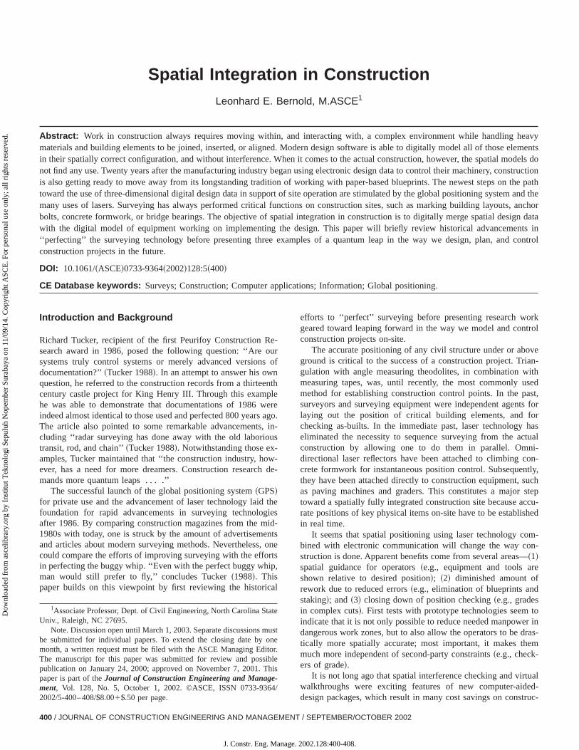
The average land surveyor did not have the mathematbackground to use the methods or the funds to buy the insments. For this reason, the plane table and sight was develand used during the sixteenth and seventeenth centuries.table could be constructed easily and could be used as a rulthumb method of operation. As shown in Fig. 1, the plane taconsisted of a smooth drawing board mounted on a tripod anmetal sight rule~alidade! for accurate aim on the object to bplotted. Telescopic sights, magnetic compasses, and clampholding down the drawing paper were added later. This tacould easily handle the new methods of triangulation.
Leupold ~1727! introduced leveling in his book. ‘‘Leveling isthe science of how to determine, with suitable instruments, whof two points is further removed from the center of the eart~Jensen 1969!. A common instrument used on construction situsing a plumb bob is shown in Fig. 2~a!.
Leupold ~1727! provided the instructions on how to makeworkable spirit level the ‘‘mother’’ of today’s carpenter level. ‘‘Astraight, smooth glass tube is used, with a maximum internalameter of12 inch @~1.27 cm!# and closed at one end. It is filled upexcept for one drop, with a liquid which does not freeze. Afte
Fig. 1. Seventeenth century surveyor assisted by cherubs uGunter’s chain~Leupold 1727!
INEERING AND MANAGEMENT / SEPTEMBER/OCTOBER 2002 / 401
2002.128:400-408.

ori-tly
t aandThed oereun
aden a
rtude
nedeld.
heringer-re-ss,
on-arktheirng:es
ofr of
by
anyewaceetsain
d a
ratesg atdedenr, hes. Itthera 40y on
b-the
is-d a
:
60
Dow
nloa
ded
from
asc
elib
rary
.org
by
Inst
itut T
ekno
logi
Sep
uluh
Nop
embe
r Su
raba
ya o
n 11
/09/
14. C
opyr
ight
ASC
E. F
or p
erso
nal u
se o
nly;
all
righ
ts r
eser
ved.
wards the tube is sealed airtight. If the tube is held exactly hzontal, the bubble rests in the middle, but if one end is slighlifted, the bubble moves immediately to that end’’~Jensen 1969!.
Early American Surveying
The settlement of the British colonies in America brought abounew breed of surveyor. The terrain was much more rugged,instruments, such as the theodolite, were not well suited.early theodolites were heavy and bulky, and were best usecleared lands rather than dense forest. ‘‘Colonial surveyors wgenerally men who possessed a rugged constitution, a basicderstanding of mathematics, and the essential tools of the trusually@a# plane table, chains, and a surveying compass knowa circumferentor’’ ~Wilford 1982!. Initially, the main job ofAmerican surveyors was to establish boundary markers. Unfonately, the accuracy of these early surveyors left a lot to besired, and boundaries were routinely resurveyed.
It is no surprise that Thomas Jefferson, who was a traisurveyor himself, made some important contributions to the fi
Fig. 2. Leveling instruments and methods of seventeenth century~a!leveling techniques for short small areas;~b! large scale leveling forroad or water projects~Leupold 1727!
402 / JOURNAL OF CONSTRUCTION ENGINEERING AND MANAGEMENT
J. Constr. Eng. Manage.
n
-,
s
--
For one, he provided basic training to Lewis Meriwether in tuse of astronomical and surveying instruments, before ensuthat Meriwether received further instruction from Robert Pattson, professor of mathematics, and Major Andrew Ellicott, a pmier surveyor of his time. While Lewis’ surveying capabilitiewere critical in securing for the colony the western territorieincluding the northern part of Louisiana, Jefferson may be csidered the ‘‘father’’ of the tape measure. Since Lewis and Clhad no space to take measuring chains or measuring rods ontrip, Thomas Jefferson suggested to take the following item aloan ‘‘instrument for measuring made of tape with feet & inchmarked on it, confined within a circular lethern@sic# box of suf-ficient thickness to admit the width of the tape which has oneits ends confined to an axis of metal passing through the centethe box, around which and within the box it is readily woundmeans of a small crank on the other side of the box . . . ’’ ~Bedini1990!.
Enabling Grand Projects
The construction of the Suez Canal, 1861–1868, was, in mways, one of the key projects of the nineteenth century. A nlaw implemented in 1863 forced the management to repl20,000 slaves with machines. Thus, it was the first time that fleof large construction equipment replaced human power as a mmeans of construction. As depicted in Fig. 3, surveying playemajor role in the success of the project.
The Suez Canal also serves as a case study that illustproblems the state-of-the-art surveying technology was facinthat time. In 1789, the French engineer Lepere was commanby Napoleon to study the feasibility of building a canal betwethe Red and the Mediterranean Seas. Due to a surveying errocame up with a 9,908 m difference between their surface levelwas not until 1833 that this error was discovered when anosurvey was conducted. Thus, the surveying errors causedyear delay of the project. Other projects that depended heavilthe science of surveying were~1! several long railway tunnels inEurope; ~2! the Eiffel Tower; ~3! the Brooklyn Bridge;~4! theFirth of Forth Bridge;~5! the Crystal Palace Building for theWorld Exhibition in London, 1851; and~6! the Galerie des Ma-chines for the World Exhibition in Paris, 1889. Nothing contriuted as much to the advancement of surveying technology asintroduction of invisible light to measure very accurately the dtance between a transmitter, combined with the theodolite, anreceiver.
Fig. 3. Surveying station during construction of Suez Canal, 18~Peters 1981!
/ SEPTEMBER/OCTOBER 2002
2002.128:400-408.
im-horntansittes
reelec
uren
nfrat thon-I,mu
PSnalanitiet toe inas
pacrcetionosi-d,orldhichnys, abe
itionseals tceivost is
ca-the
ithand
e-
ats
entrad-thella-ets
xedipe.eencon-erlyline
eshethetheori-
Dow
nloa
ded
from
asc
elib
rary
.org
by
Inst
itut T
ekno
logi
Sep
uluh
Nop
embe
r Su
raba
ya o
n 11
/09/
14. C
opyr
ight
ASC
E. F
or p
erso
nal u
se o
nly;
all
righ
ts r
eser
ved.
From Theodolites to Total Stations
The original theodolites had very long telescopes. Over time,provements were made, and the telescope was eventually sened to the point that it could be rotated 360° about its horizoaxis. This act of rotating the telescope became known as traing, and the theodolites were known as transiting theodolieventually shortened to transits~Kavanagh 1989!. Transits use afour-screw leveling base, while today’s theodolites use thscrews. Further improvements to theodolites have led to the etronic distance measurement instruments~EDMIs!, also known asa total station. EDMIs, first introduced in the late 1950s, measthe time it takes for either infrared or microwaves with knowspeeds to cover an unknown distance. Systems employing ired require a transmitter at one end and a reflecting prism aother end of the line being measured. Total stations typically csist of an electronically digitized theodolite, with a built in EDMan onboard microprocessor, a data collector, and a data comnication interface.
Global Positioning System
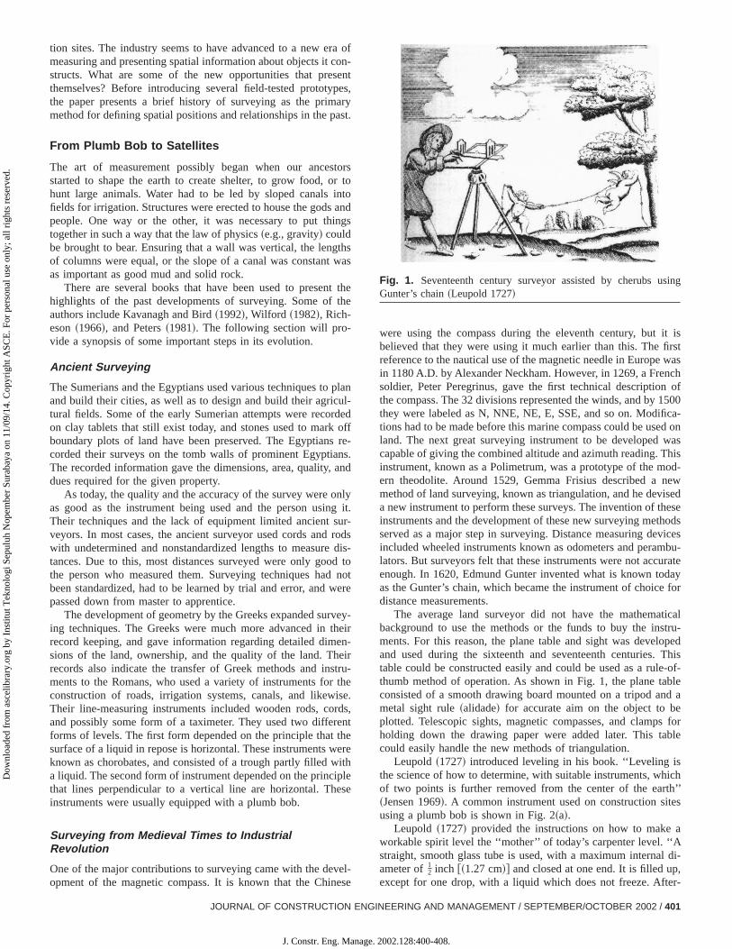
On July 17, 1995 the U.S. Air Force announced that the Gsatellite constellation had met all requirements for full operatiocapability. This declaration signaled the culmination of more th20 years of research, development, and implementation activthat brought the revolutionary navigation system from concepreality. The program was created by the Department of Defens1973. The first GPS satellite, a Block I developmental model, wlaunched in February, 1978. GPS, operated by the 2nd SOperation Squadron of the 50th Space Wing at Falcon Air FoBase, Colo., is a U.S. Department of Defense radio navigasystem. It provides highly accurate, real-time, all-weather ption, velocity, and time information to properly equipped air, lansea, and space-based military and civilian users around the wThere are 27 satellites in the GPS operational constellation, wprovides most users visibility to five to eight satellites from apoint on earth. Fig. 4 presents the positions of the 27 satellitea particular date, together with their orbital paths on Septem29, 1998 at midnight.
Determination of the four dimensions~X, Y, Z, andTime! re-quires at least four satellites. Most receivers convert the possignals into geodetic latitude, longitude, and height abovelevel, but these receivers can often be set to convert the signaother user defined systems. Precise positioning using GPS reers at reference locations provides corrections and relative ptioning data for remote receivers. Another common method thaused to gain higher accuracy is called differential GPS; it ispable of overriding a bias error at an unknown location withmeasured bias error at a known position.
State of Practice in Spatial Positioning
The majority of construction surveying today is performed wlevels, theodolites, many varieties of lasers, total stations,GPS integrated total stations.
Levels
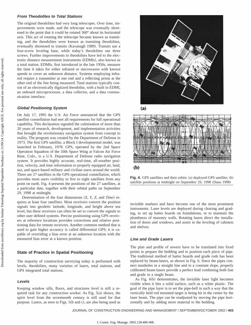
Keeping window sills, floors, and structures level is still a rquired task for any construction worker. As Fig. 5~a! shows, thespirit level from the seventeenth century is still used for thpurpose. Lasers, as seen in Figs. 5~b and c!, are also being used a
JOURNAL OF CONSTRUCTION ENG
J. Constr. Eng. Manage.
t-l-,
-
-e
-
s
e
.
tr
o-
i-
invisible markers and have become one of the most promininstruments. Laser levels are deployed during clearing and ging, to set up batter boards on foundations, or to maintainplumbness of masonry walls. Rotating lasers direct the instation of doors and windows, and assist in the leveling of cabinand shelves.
Line and Grade Lasers
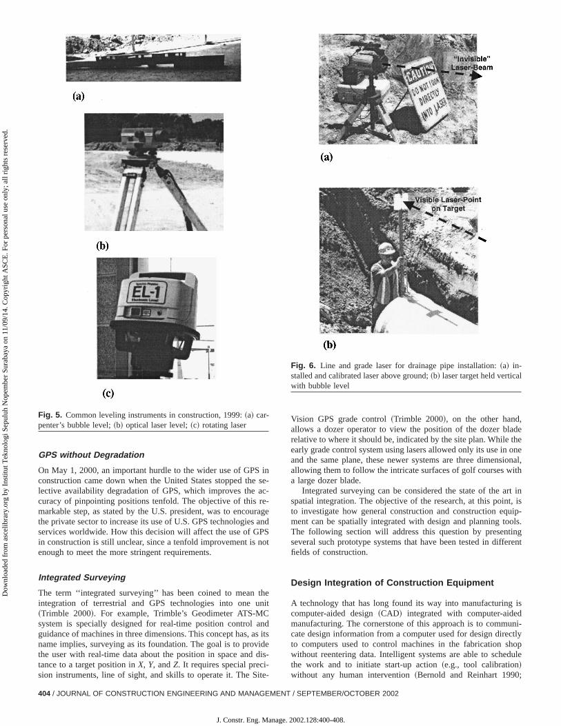
The plan and profile of sewers have to be translated into fipoints to prepare the bedding and to position each piece of pThe traditional method of batter boards and grade rods has breplaced by beam-lasers, as shown in Fig. 6. Since the pipesnect manholes in a straight line and in a constant slope, propcalibrated beam-lasers provide a perfect lead combining bothand grade in a single beam.
As Fig. 6~b! demonstrates, the invisible laser light becomvisible when it hits a solid surface, such as a white plastic. Tgoal of the pipe layer is to set the pipe-bell in such a way thatvertically held rod mounted target is being hit in the center bylaser beam. The pipe can be readjusted by moving the pipe hzontally and by adding more material to the bedding.
Fig. 4. GPS satellites and their orbits:~a! deployed GPS satellite;~b!satellite positions at midnight on September 29, 1998~Dana 1998!
INEERING AND MANAGEMENT / SEPTEMBER/OCTOBER 2002 / 403
2002.128:400-408.
inse
ac-e-ragan
PSnot
thenit
ndas iidedis
-ite-
detheoneional,ith
rt int, isuip-ols.ingrent
is
uni-ctlyhopdule
;
l
Dow
nloa
ded
from
asc
elib
rary
.org
by
Inst
itut T
ekno
logi
Sep
uluh
Nop
embe
r Su
raba
ya o
n 11
/09/
14. C
opyr
ight
ASC
E. F
or p
erso
nal u
se o
nly;
all
righ
ts r
eser
ved.
GPS without Degradation
On May 1, 2000, an important hurdle to the wider use of GPSconstruction came down when the United States stopped thelective availability degradation of GPS, which improves thecuracy of pinpointing positions tenfold. The objective of this rmarkable step, as stated by the U.S. president, was to encouthe private sector to increase its use of U.S. GPS technologiesservices worldwide. How this decision will affect the use of Gin construction is still unclear, since a tenfold improvement isenough to meet the more stringent requirements.
Integrated Surveying
The term ‘‘integrated surveying’’ has been coined to meanintegration of terrestrial and GPS technologies into one u~Trimble 2000!. For example, Trimble’s Geodimeter ATS-MCsystem is specially designed for real-time position control aguidance of machines in three dimensions. This concept has,name implies, surveying as its foundation. The goal is to provthe user with real-time data about the position in space andtance to a target position inX, Y, andZ. It requires special precision instruments, line of sight, and skills to operate it. The S
Fig. 5. Common leveling instruments in construction, 1999:~a! car-penter’s bubble level;~b! optical laser level;~c! rotating laser
404 / JOURNAL OF CONSTRUCTION ENGINEERING AND MANAGEMENT
J. Constr. Eng. Manage.
-
ed
ts
-
Vision GPS grade control~Trimble 2000!, on the other hand,allows a dozer operator to view the position of the dozer blarelative to where it should be, indicated by the site plan. Whileearly grade control system using lasers allowed only its use inand the same plane, these newer systems are three dimensallowing them to follow the intricate surfaces of golf courses wa large dozer blade.
Integrated surveying can be considered the state of the aspatial integration. The objective of the research, at this pointo investigate how general construction and construction eqment can be spatially integrated with design and planning toThe following section will address this question by presentseveral such prototype systems that have been tested in diffefields of construction.
Design Integration of Construction Equipment
A technology that has long found its way into manufacturingcomputer-aided design~CAD! integrated with computer-aidedmanufacturing. The cornerstone of this approach is to commcate design information from a computer used for design direto computers used to control machines in the fabrication swithout reentering data. Intelligent systems are able to schethe work and to initiate start-up action~e.g., tool calibration!without any human intervention~Bernold and Reinhart 1990
Fig. 6. Line and grade laser for drainage pipe installation:~a! in-stalled and calibrated laser above ground;~b! laser target held verticawith bubble level
/ SEPTEMBER/OCTOBER 2002
2002.128:400-408.
eiesatan
rw-abdidre,meuldsived tgfur ints.
onys
t ofsuc, thdanrec
anblehe
thepipele t
yedtachonatheideaseratetem
rasatorkhog aas
h,the
f the b
aoes
tha
rateed
mes
re-
to ate
si-ionrela-
thet ofra-
areentre. Aital
tor.
-
Dow
nloa
ded
from
asc
elib
rary
.org
by
Inst
itut T
ekno
logi
Sep
uluh
Nop
embe
r Su
raba
ya o
n 11
/09/
14. C
opyr
ight
ASC
E. F
or p
erso
nal u
se o
nly;
all
righ
ts r
eser
ved.
Salim and Bernold 1994!. The key problem in achieving the samin construction was the lack of electronic enabling technologthat ~1! allow the construction equipment to receive design delectronically;~2! generate information about their own conditioand performance in real time; and~3! communicate with a highelevel of job planning and control systems. In the meantime, hoever, the emergence of hardened electronic sensors, affordsmall video, the Internet, and wireless data communicationremove key barriers to integration. In a fully integrated structuproject participants, management systems, equipment, equipoperators, support devices, and even the building itself wocommunicate with each other in both an active and a pasmode. It is apparent that not all of the elements mentioned neebe interfaced at one time in order to create new and meaninsolutions. The following discusses three applications that diffethe range in which they apply those new devices and concep
Remote Position Control
To accurately position large objects in construction, such as ccrete pipes, normally requires the presence of a human to phcally maneuver the object into its final place. Because mosthese positioning tasks take place either in confined spaces,as trenches, or in elevated locations, such as steel frameslaborers are exposed to significant dangers. Eliminating suchgerous work situations requires the replacement of the dihuman handling of the object with the precise maneuvering byequipment operator ‘‘far away.’’ Steps that make this possiinclude ~1! providing the operator spatial information about tobject he/she controls; and~2! providing the operator with amechanism that will allow him/her to be as exact in operatingactuator as the task requires. Placing large water and sewerinto the trench at the right line and grade serves as an exampillustrate how remote positioning could be implemented.
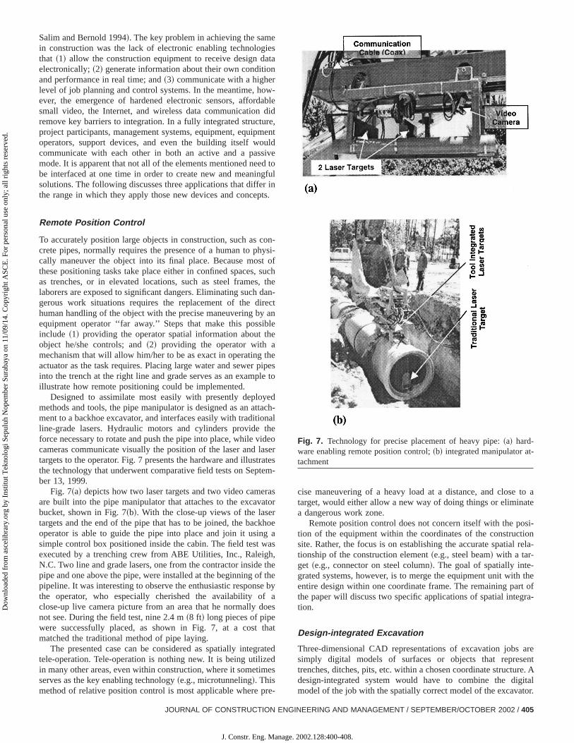
Designed to assimilate most easily with presently deplomethods and tools, the pipe manipulator is designed as an atment to a backhoe excavator, and interfaces easily with traditiline-grade lasers. Hydraulic motors and cylinders provideforce necessary to rotate and push the pipe into place, while vcameras communicate visually the position of the laser and ltargets to the operator. Fig. 7 presents the hardware and illustthe technology that underwent comparative field tests on Sepber 13, 1999.
Fig. 7~a! depicts how two laser targets and two video cameare built into the pipe manipulator that attaches to the excavbucket, shown in Fig. 7~b!. With the close-up views of the lasetargets and the end of the pipe that has to be joined, the bacoperator is able to guide the pipe into place and join it usinsimple control box positioned inside the cabin. The field test wexecuted by a trenching crew from ABE Utilities, Inc., RaleigN.C. Two line and grade lasers, one from the contractor insidepipe and one above the pipe, were installed at the beginning opipeline. It was interesting to observe the enthusiastic responsthe operator, who especially cherished the availability ofclose-up live camera picture from an area that he normally dnot see. During the field test, nine 2.4 m~8 ft! long pieces of pipewere successfully placed, as shown in Fig. 7, at a costmatched the traditional method of pipe laying.
The presented case can be considered as spatially integtele-operation. Tele-operation is nothing new. It is being utilizin many other areas, even within construction, where it sometiserves as the key enabling technology~e.g., microtunneling!. Thismethod of relative position control is most applicable where p
JOURNAL OF CONSTRUCTION ENG
J. Constr. Eng. Manage.
le
nt
ol
-i-
he-t
so
-l
ors-
r
e
ey
t
d
cise maneuvering of a heavy load at a distance, and closetarget, would either allow a new way of doing things or eliminaa dangerous work zone.
Remote position control does not concern itself with the potion of the equipment within the coordinates of the constructsite. Rather, the focus is on establishing the accurate spatialtionship of the construction element~e.g., steel beam! with a tar-get ~e.g., connector on steel column!. The goal of spatially inte-grated systems, however, is to merge the equipment unit withentire design within one coordinate frame. The remaining parthe paper will discuss two specific applications of spatial integtion.
Design-integrated Excavation
Three-dimensional CAD representations of excavation jobssimply digital models of surfaces or objects that represtrenches, ditches, pits, etc. within a chosen coordinate structudesign-integrated system would have to combine the digmodel of the job with the spatially correct model of the excava
Fig. 7. Technology for precise placement of heavy pipe:~a! hard-ware enabling remote position control;~b! integrated manipulator attachment
INEERING AND MANAGEMENT / SEPTEMBER/OCTOBER 2002 / 405
2002.128:400-408.
iledhinas
ig. 8ho.ent
lec-tiontheers
oomn b
siteingcisethethetiml ofofm-
inhatentwstialfivemlcu-en-ctro-w awn
use
canhatracy
tiono be
Dow
nloa
ded
from
asc
elib
rary
.org
by
Inst
itut T
ekno
logi
Sep
uluh
Nop
embe
r Su
raba
ya o
n 11
/09/
14. C
opyr
ight
ASC
E. F
or p
erso
nal u
se o
nly;
all
righ
ts r
eser
ved.
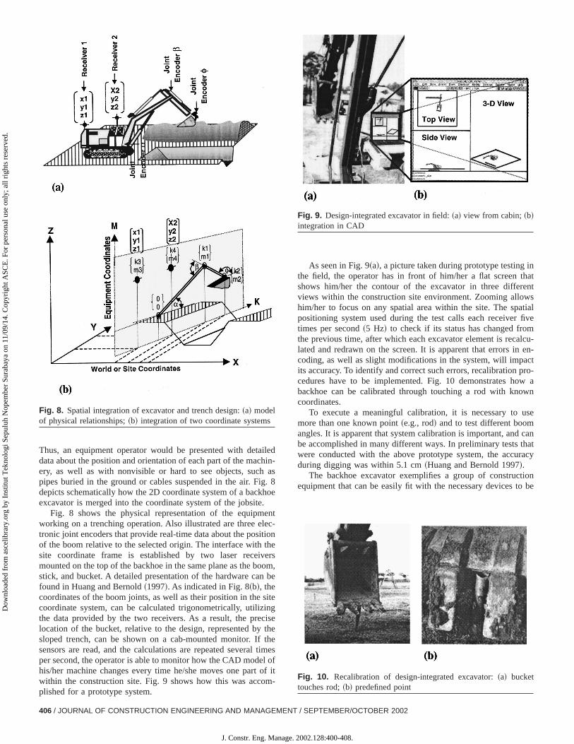
Thus, an equipment operator would be presented with detadata about the position and orientation of each part of the macery, as well as with nonvisible or hard to see objects, suchpipes buried in the ground or cables suspended in the air. Fdepicts schematically how the 2D coordinate system of a backexcavator is merged into the coordinate system of the jobsite
Fig. 8 shows the physical representation of the equipmworking on a trenching operation. Also illustrated are three etronic joint encoders that provide real-time data about the posiof the boom relative to the selected origin. The interface withsite coordinate frame is established by two laser receivmounted on the top of the backhoe in the same plane as the bstick, and bucket. A detailed presentation of the hardware cafound in Huang and Bernold~1997!. As indicated in Fig. 8~b!, thecoordinates of the boom joints, as well as their position in thecoordinate system, can be calculated trigonometrically, utilizthe data provided by the two receivers. As a result, the prelocation of the bucket, relative to the design, represented bysloped trench, can be shown on a cab-mounted monitor. Ifsensors are read, and the calculations are repeated severalper second, the operator is able to monitor how the CAD modehis/her machine changes every time he/she moves one partwithin the construction site. Fig. 9 shows how this was accoplished for a prototype system.
Fig. 8. Spatial integration of excavator and trench design:~a! modelof physical relationships;~b! integration of two coordinate systems
406 / JOURNAL OF CONSTRUCTION ENGINEERING AND MANAGEMENT
J. Constr. Eng. Manage.
-
e
,e
es
it
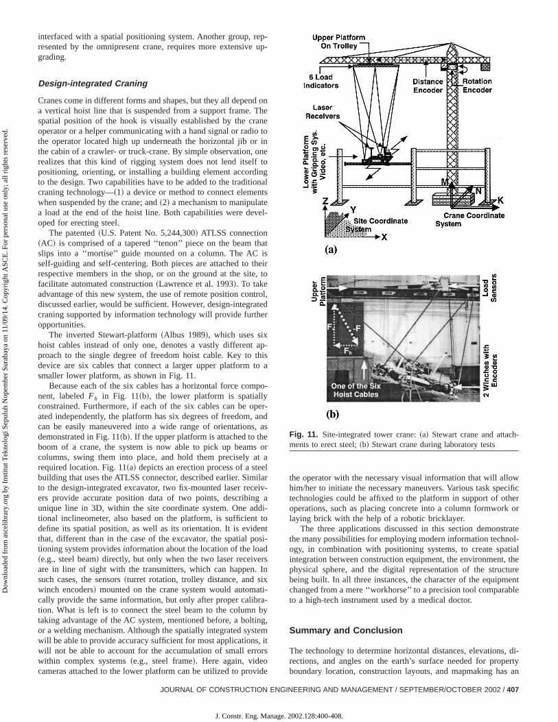
As seen in Fig. 9~a!, a picture taken during prototype testingthe field, the operator has in front of him/her a flat screen tshows him/her the contour of the excavator in three differviews within the construction site environment. Zooming allohim/her to focus on any spatial area within the site. The spapositioning system used during the test calls each receivertimes per second~5 Hz! to check if its status has changed frothe previous time, after which each excavator element is recalated and redrawn on the screen. It is apparent that errors incoding, as well as slight modifications in the system, will impaits accuracy. To identify and correct such errors, recalibration pcedures have to be implemented. Fig. 10 demonstrates hobackhoe can be calibrated through touching a rod with knocoordinates.
To execute a meaningful calibration, it is necessary tomore than one known point~e.g., rod! and to test different boomangles. It is apparent that system calibration is important, andbe accomplished in many different ways. In preliminary tests twere conducted with the above prototype system, the accuduring digging was within 5.1 cm~Huang and Bernold 1997!.
The backhoe excavator exemplifies a group of construcequipment that can be easily fit with the necessary devices t
Fig. 9. Design-integrated excavator in field:~a! view from cabin;~b!integration in CAD
Fig. 10. Recalibration of design-integrated excavator:~a! buckettouches rod;~b! predefined point
/ SEPTEMBER/OCTOBER 2002
2002.128:400-408.
ep-up
d oThene
o tor inoneto
ngnats
evel-
hatisheie, t
troateder
apthisto a
po
peran, aes ot aelilareivg adi-
t toentosiad
rsIn
xti-
ra-byingtem, itrs
ide
wcificeror
trateol-tialthe
tureent
ble
, di-ertyan
-
Dow
nloa
ded
from
asc
elib
rary
.org
by
Inst
itut T
ekno
logi
Sep
uluh
Nop
embe
r Su
raba
ya o
n 11
/09/
14. C
opyr
ight
ASC
E. F
or p
erso
nal u
se o
nly;
all
righ
ts r
eser
ved.
interfaced with a spatial positioning system. Another group, rresented by the omnipresent crane, requires more extensivegrading.
Design-integrated Craning
Cranes come in different forms and shapes, but they all depena vertical hoist line that is suspended from a support frame.spatial position of the hook is visually established by the craoperator or a helper communicating with a hand signal or radithe operator located high up underneath the horizontal jib othe cabin of a crawler- or truck-crane. By simple observation,realizes that this kind of rigging system does not lend itselfpositioning, orienting, or installing a building element accordito the design. Two capabilities have to be added to the traditiocraning technology—~1! a device or method to connect elemenwhen suspended by the crane; and~2! a mechanism to manipulata load at the end of the hoist line. Both capabilities were deoped for erecting steel.
The patented~U.S. Patent No. 5,244,300! ATLSS connection~AC! is comprised of a tapered ‘‘tenon’’ piece on the beam tslips into a ‘‘mortise’’ guide mounted on a column. The ACself-guiding and self-centering. Both pieces are attached to trespective members in the shop, or on the ground at the sitfacilitate automated construction~Lawrence et al. 1993!. To takeadvantage of this new system, the use of remote position condiscussed earlier, would be sufficient. However, design-integrcraning supported by information technology will provide furthopportunities.
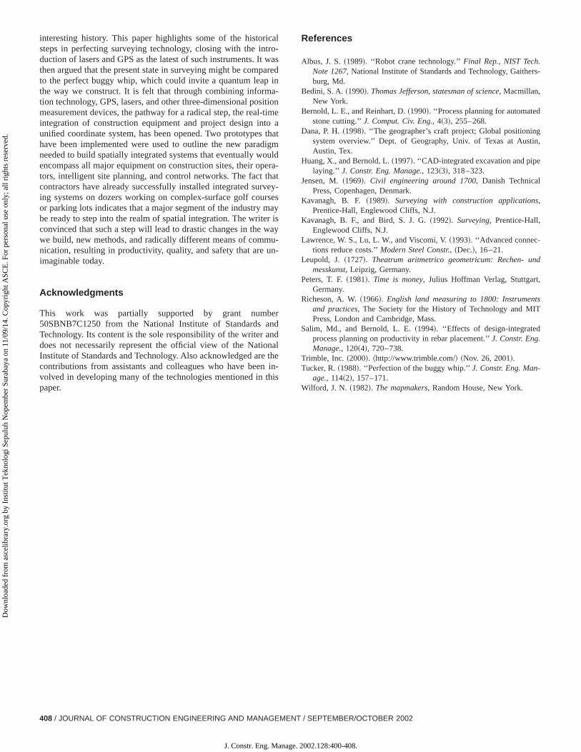
The inverted Stewart-platform~Albus 1989!, which uses sixhoist cables instead of only one, denotes a vastly differentproach to the single degree of freedom hoist cable. Key todevice are six cables that connect a larger upper platformsmaller lower platform, as shown in Fig. 11.
Because each of the six cables has a horizontal force comnent, labeledFh in Fig. 11~b!, the lower platform is spatiallyconstrained. Furthermore, if each of the six cables can be oated independently, the platform has six degrees of freedom,can be easily maneuvered into a wide range of orientationsdemonstrated in Fig. 11~b!. If the upper platform is attached to thboom of a crane, the system is now able to pick up beamcolumns, swing them into place, and hold them precisely arequired location. Fig. 11~a! depicts an erection process of a stebuilding that uses the ATLSS connector, described earlier. Simto the design-integrated excavator, two fix-mounted laser recers provide accurate position data of two points, describinunique line in 3D, within the site coordinate system. One adtional inclineometer, also based on the platform, is sufficiendefine its spatial position, as well as its orientation. It is evidthat, different than in the case of the excavator, the spatial ptioning system provides information about the location of the lo~e.g., steel beam! directly, but only when the two laser receiveare in line of sight with the transmitters, which can happen.such cases, the sensors~turret rotation, trolley distance, and siwinch encoders! mounted on the crane system would automacally provide the same information, but only after proper calibtion. What is left is to connect the steel beam to the columntaking advantage of the AC system, mentioned before, a boltor a welding mechanism. Although the spatially integrated syswill be able to provide accuracy sufficient for most applicationswill not be able to account for the accumulation of small errowithin complex systems~e.g., steel frame!. Here again, videocameras attached to the lower platform can be utilized to prov
JOURNAL OF CONSTRUCTION ENG
J. Constr. Eng. Manage.
-
n
l
ro
l,
-
-
-ds
r
-
-
,
the operator with the necessary visual information that will allohim/her to initiate the necessary maneuvers. Various task spetechnologies could be affixed to the platform in support of othoperations, such as placing concrete into a column formworklaying brick with the help of a robotic bricklayer.
The three applications discussed in this section demonsthe many possibilities for employing modern information technogy, in combination with positioning systems, to create spaintegration between construction equipment, the environment,physical sphere, and the digital representation of the strucbeing built. In all three instances, the character of the equipmchanged from a mere ‘‘workhorse’’ to a precision tool comparato a high-tech instrument used by a medical doctor.
Summary and Conclusion
The technology to determine horizontal distances, elevationsrections, and angles on the earth’s surface needed for propboundary location, construction layouts, and mapmaking has
Fig. 11. Site-integrated tower crane:~a! Stewart crane and attachments to erect steel;~b! Stewart crane during laboratory tests
INEERING AND MANAGEMENT / SEPTEMBER/OCTOBER 2002 / 407
2002.128:400-408.
calro-waarein
a-itio-timo athaigmulderahatveyrses
ayr iswayu-n-
erndndnalthe
n inhis
rs-
gin,
d
,
tsT
Dow
nloa
ded
from
asc
elib
rary
.org
by
Inst
itut T
ekno
logi
Sep
uluh
Nop
embe
r Su
raba
ya o
n 11
/09/
14. C
opyr
ight
ASC
E. F
or p
erso
nal u
se o
nly;
all
righ
ts r
eser
ved.
interesting history. This paper highlights some of the historisteps in perfecting surveying technology, closing with the intduction of lasers and GPS as the latest of such instruments. Itthen argued that the present state in surveying might be compto the perfect buggy whip, which could invite a quantum leapthe way we construct. It is felt that through combining informtion technology, GPS, lasers, and other three-dimensional posmeasurement devices, the pathway for a radical step, the realintegration of construction equipment and project design intunified coordinate system, has been opened. Two prototypeshave been implemented were used to outline the new paradneeded to build spatially integrated systems that eventually woencompass all major equipment on construction sites, their optors, intelligent site planning, and control networks. The fact tcontractors have already successfully installed integrated suring systems on dozers working on complex-surface golf couor parking lots indicates that a major segment of the industry mbe ready to step into the realm of spatial integration. The writeconvinced that such a step will lead to drastic changes in thewe build, new methods, and radically different means of commnication, resulting in productivity, quality, and safety that are uimaginable today.
Acknowledgments
This work was partially supported by grant numb50SBNB7C1250 from the National Institute of Standards aTechnology. Its content is the sole responsibility of the writer adoes not necessarily represent the official view of the NatioInstitute of Standards and Technology. Also acknowledged arecontributions from assistants and colleagues who have beevolved in developing many of the technologies mentioned in tpaper.
408 / JOURNAL OF CONSTRUCTION ENGINEERING AND MANAGEMENT
J. Constr. Eng. Manage.
sd
ne
t
-
-
-
References
Albus, J. S.~1989!. ‘‘Robot crane technology.’’Final Rep., NIST Tech.Note 1267, National Institute of Standards and Technology, Gaitheburg, Md.
Bedini, S. A.~1990!. Thomas Jefferson, statesman of science, Macmillan,New York.
Bernold, L. E., and Reinhart, D.~1990!. ‘‘Process planning for automatedstone cutting.’’J. Comput. Civ. Eng., 4~3!, 255–268.
Dana, P. H.~1998!. ‘‘The geographer’s craft project; Global positioninsystem overview.’’ Dept. of Geography, Univ. of Texas at AustAustin, Tex.
Huang, X., and Bernold, L.~1997!. ‘‘CAD-integrated excavation and pipelaying.’’ J. Constr. Eng. Manage., 123~3!, 318–323.
Jensen, M.~1969!. Civil engineering around 1700, Danish TechnicalPress, Copenhagen, Denmark.
Kavanagh, B. F. ~1989!. Surveying with construction applications,Prentice-Hall, Englewood Cliffs, N.J.
Kavanagh, B. F., and Bird, S. J. G.~1992!. Surveying, Prentice-Hall,Englewood Cliffs, N.J.
Lawrence, W. S., Lu, L. W., and Viscomi, V.~1993!. ‘‘Advanced connec-tions reduce costs.’’Modern Steel Constr., ~Dec.!, 16–21.
Leupold, J. ~1727!. Theatrum aritmetrico geometricum: Rechen- unmesskunst, Leipzig, Germany.
Peters, T. F.~1981!. Time is money, Julius Hoffman Verlag, StuttgartGermany.
Richeson, A. W.~1966!. English land measuring to 1800: Instrumenand practices, The Society for the History of Technology and MIPress, London and Cambridge, Mass.
Salim, Md., and Bernold, L. E.~1994!. ‘‘Effects of design-integratedprocess planning on productivity in rebar placement.’’J. Constr. Eng.Manage., 120~4!, 720–738.
Trimble, Inc. ~2000!. ^http://www.trimble.com/& ~Nov. 26, 2001!.Tucker, R.~1988!. ‘‘Perfection of the buggy whip.’’J. Constr. Eng. Man-
age., 114~2!, 157–171.Wilford, J. N. ~1982!. The mapmakers, Random House, New York.
/ SEPTEMBER/OCTOBER 2002
2002.128:400-408.


