Embed Size (px)
Citation preview
Introduction to
Hans-Petter Halvorsen
An Open-Source Prototyping Platform
2013.08.20
Contents
1. Overview 2. Installation 3. Arduino Starter Kit 4. Arduino TinkerKit 5. Arduino Examples 6. LabVIEW Interface for
Arduino Toolkit
Introduction to Arduino by Hans-Petter Halvorsen 2
http://home.hit.no/~hansha/?equipment=arduino
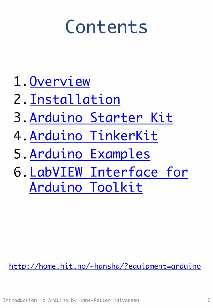
Arduino Overview h"p://arduino.cc
Introduction to Arduino by Hans-Petter Halvorsen 3
Arduino is a single-board microcontroller to make using electronics in multidisciplinary projects more accessible. The hardware consists of a simple open source hardware board designed around an 8-bit Atmel AVR microcontroller, or a 32-bit Atmel ARM. The software consists of a standard programming language compiler and a boot loader that executes on the microcontroller.
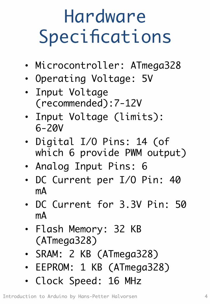
Hardware Specifications
Introduction to Arduino by Hans-Petter Halvorsen 4
• Microcontroller: ATmega328 • Operating Voltage: 5V • Input Voltage (recommended):7-12V
• Input Voltage (limits): 6-20V
• Digital I/O Pins: 14 (of which 6 provide PWM output)
• Analog Input Pins: 6 • DC Current per I/O Pin: 40 mA
• DC Current for 3.3V Pin: 50 mA
• Flash Memory: 32 KB (ATmega328)
• SRAM: 2 KB (ATmega328) • EEPROM: 1 KB (ATmega328) • Clock Speed: 16 MHz
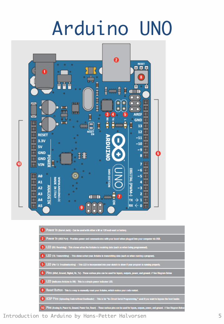
Arduino UNO
5 Introduction to Arduino by Hans-Petter Halvorsen
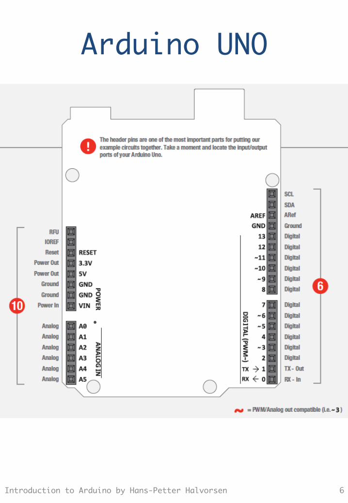
Arduino UNO
6 Introduction to Arduino by Hans-Petter Halvorsen
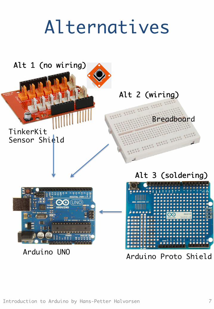
Alternatives
7 Introduction to Arduino by Hans-Petter Halvorsen
Alt 1 (no wiring)
Alt 2 (wiring)
TinkerKit Sensor Shield
Breadboard
Arduino Proto Shield
Alt 3 (soldering)
Arduino UNO
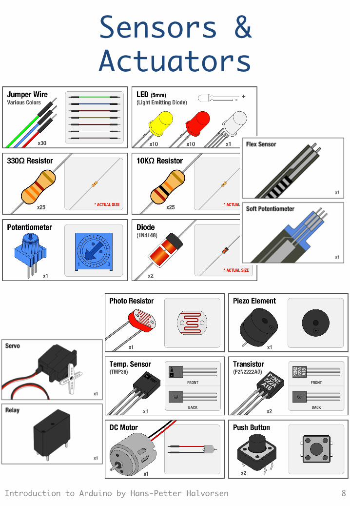
Sensors & Actuators
8 Introduction to Arduino by Hans-Petter Halvorsen
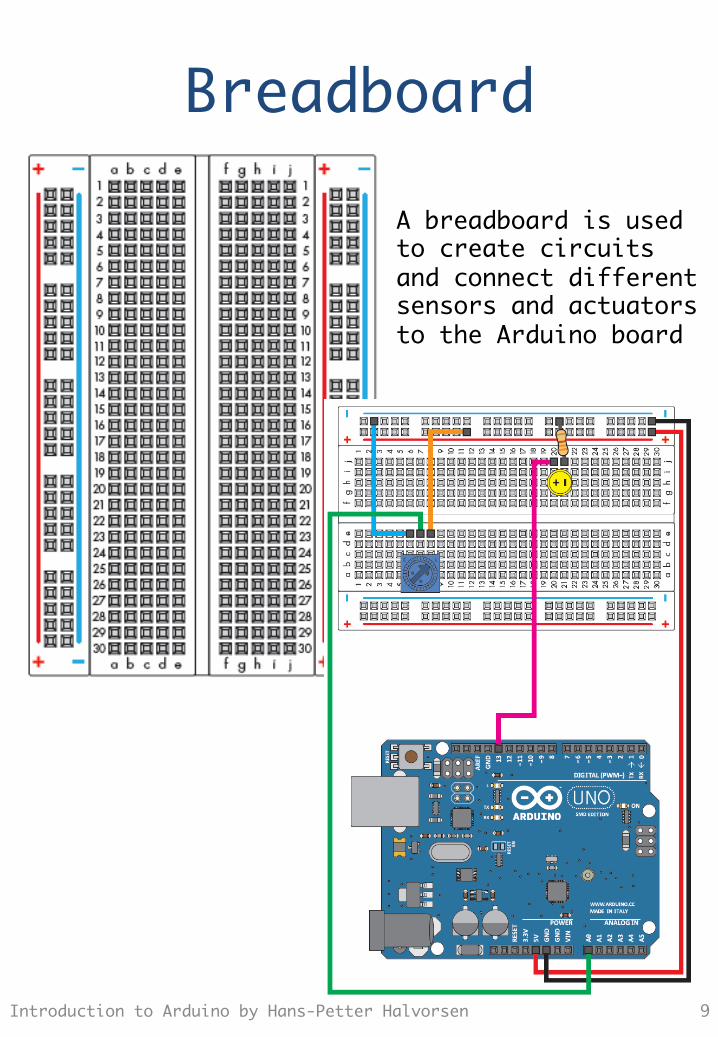
Breadboard
9 Introduction to Arduino by Hans-Petter Halvorsen
A breadboard is used to create circuits and connect different sensors and actuators to the Arduino board
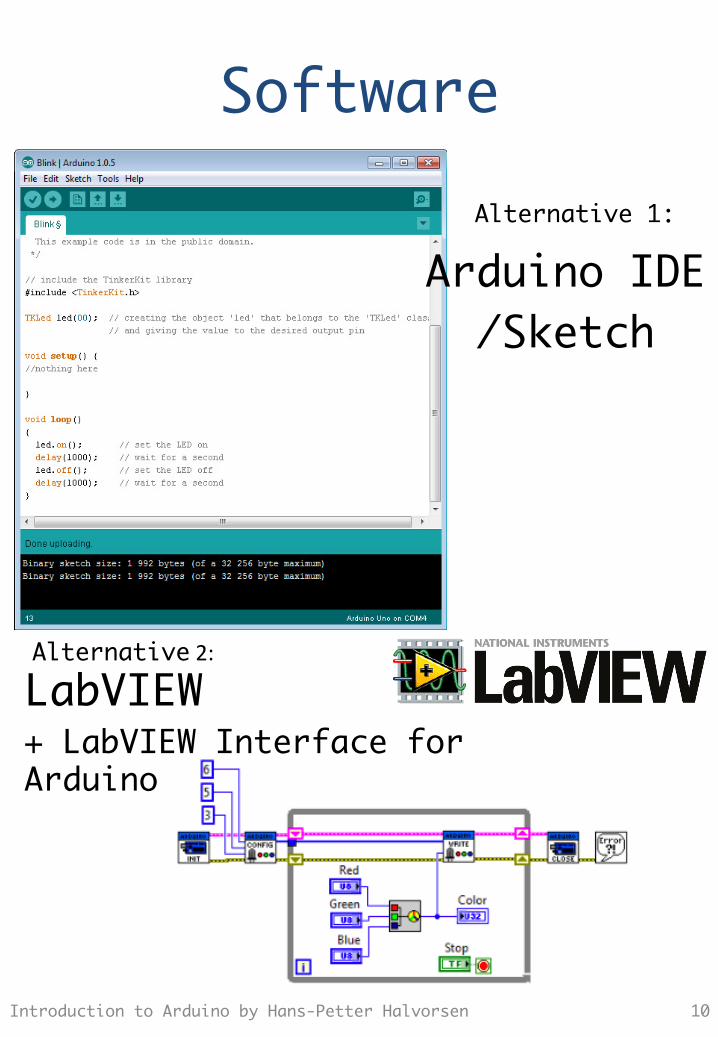
Software
10 Introduction to Arduino by Hans-Petter Halvorsen
Arduino IDE /Sketch
LabVIEW + LabVIEW Interface for Arduino
Alternative 1:
Alternative 2:
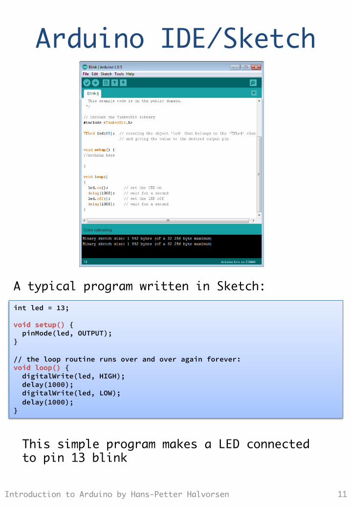
Arduino IDE/Sketch
11 Introduction to Arduino by Hans-Petter Halvorsen
int led = 13; void setup() { pinMode(led, OUTPUT); } // the loop routine runs over and over again forever: void loop() { digitalWrite(led, HIGH); delay(1000); digitalWrite(led, LOW); delay(1000); }
A typical program written in Sketch:
This simple program makes a LED connected to pin 13 blink
Installation
Introduction to Arduino by Hans-Petter Halvorsen 12
http://arduino.cc/en/Main/Software
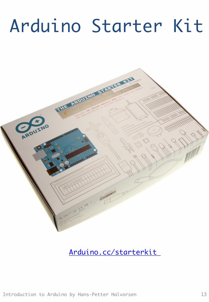
Arduino Starter Kit
Introduction to Arduino by Hans-Petter Halvorsen 13
Arduino.cc/starterkit
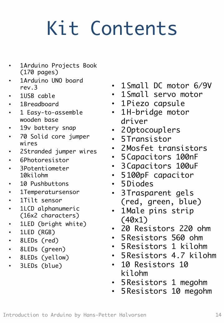
Kit Contents • 1 Arduino Projects Book
(170 pages) • 1 Arduino UNO board
rev.3 • 1 USB cable • 1 Breadboard • 1 Easy-to-assemble
wooden base • 1 9v battery snap • 70 Solid core jumper
wires • 2 Stranded jumper wires • 6 Photoresistor • 3 Potentiometer
10kilohm • 10 Pushbuttons • 1 Temperatursensor • 1 Tilt sensor • 1 LCD alphanumeric
(16x2 characters) • 1 LED (bright white) • 1 LED (RGB) • 8 LEDs (red) • 8 LEDs (green) • 8 LEDs (yellow) • 3 LEDs (blue)
14 Introduction to Arduino by Hans-Petter Halvorsen
• 1 Small DC motor 6/9V • 1 Small servo motor • 1 Piezo capsule • 1 H-bridge motor
driver • 2 Optocouplers • 5 Transistor • 2 Mosfet transistors • 5 Capacitors 100nF • 3 Capacitors 100uF • 5 100pF capacitor • 5 Diodes • 3 Trasparent gels
(red, green, blue) • 1 Male pins strip
(40x1) • 20 Resistors 220 ohm • 5 Resistors 560 ohm • 5 Resistors 1 kilohm • 5 Resistors 4.7 kilohm • 10 Resistors 10
kilohm • 5 Resistors 1 megohm • 5 Resistors 10 megohm
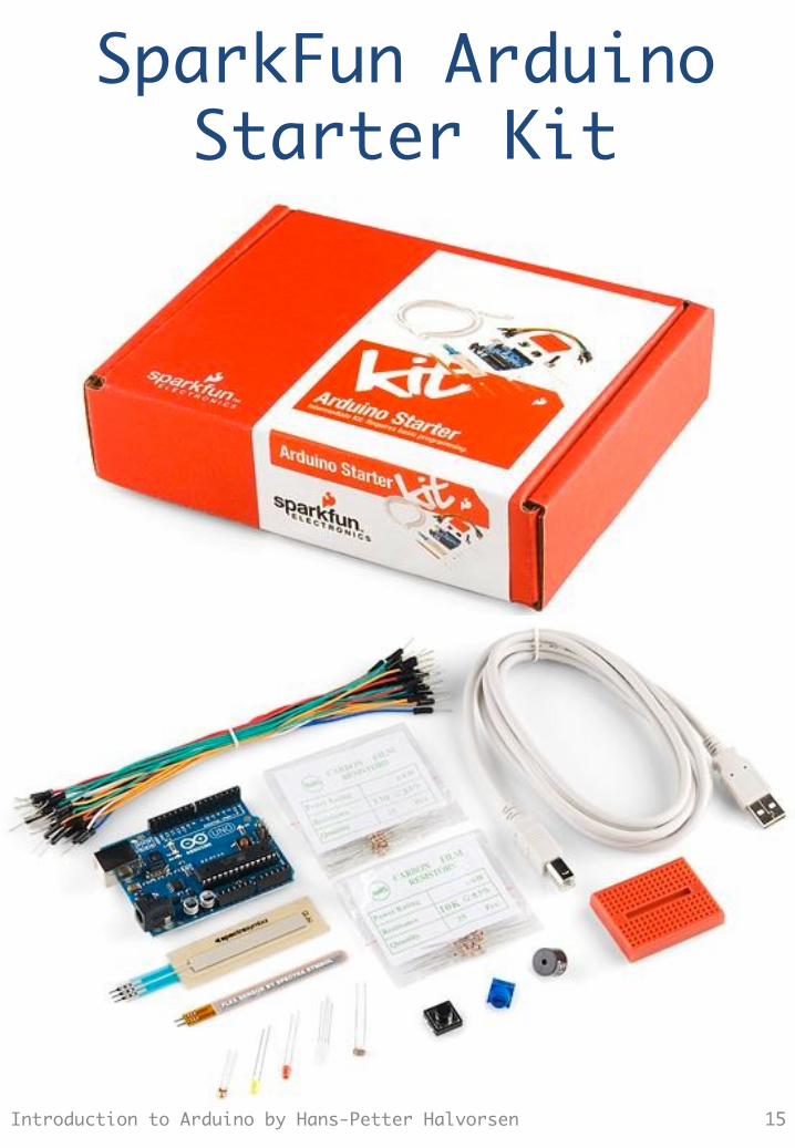
SparkFun Arduino Starter Kit
Introduction to Arduino by Hans-Petter Halvorsen 15
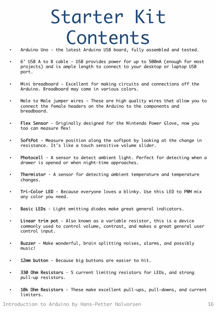
Starter Kit Contents
• Arduino Uno - the latest Arduino USB board, fully assembled and tested.
• 6' USB A to B cable - USB provides power for up to 500mA (enough for most projects) and is ample length to connect to your desktop or laptop USB port.
• Mini breadboard - Excellent for making circuits and connections off the Arduino. Breadboard may come in various colors.
• Male to Male jumper wires - These are high quality wires that allow you to connect the female headers on the Arduino to the components and breadboard.
• Flex Sensor - Originally designed for the Nintendo Power Glove, now you too can measure flex!
• SoftPot - Measure position along the softpot by looking at the change in resistance. It's like a touch sensitive volume slider.
• Photocell - A sensor to detect ambient light. Perfect for detecting when a drawer is opened or when night-time approaches.
• Thermistor - A sensor for detecting ambient temperature and temperature changes.
• Tri-Color LED - Because everyone loves a blinky. Use this LED to PWM mix any color you need.
• Basic LEDs - Light emitting diodes make great general indicators.
• Linear trim pot - Also known as a variable resistor, this is a device commonly used to control volume, contrast, and makes a great general user control input.
• Buzzer - Make wonderful, brain splitting noises, alarms, and possibly music!
• 12mm button - Because big buttons are easier to hit.
• 330 Ohm Resistors - 5 current limiting resistors for LEDs, and strong pull-up resistors.
• 10k Ohm Resistors - These make excellent pull-ups, pull-downs, and current limiters.
16 Introduction to Arduino by Hans-Petter Halvorsen

SparkFun Inventors Kit for Arduino (SIK)
Introduction to Arduino by Hans-Petter Halvorsen 17
sparkfun.com/sikcode
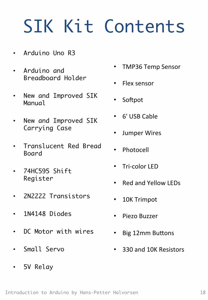
SIK Kit Contents • Arduino Uno R3
• Arduino and Breadboard Holder
• New and Improved SIK Manual
• New and Improved SIK Carrying Case
• Translucent Red Bread Board
• 74HC595 Shift Register
• 2N2222 Transistors
• 1N4148 Diodes
• DC Motor with wires
• Small Servo
• 5V Relay
18 Introduction to Arduino by Hans-Petter Halvorsen
• TMP36 Temp Sensor
• Flex sensor
• So?pot
• 6' USB Cable
• Jumper Wires
• Photocell
• Tri-‐color LED
• Red and Yellow LEDs
• 10K Trimpot
• Piezo Buzzer
• Big 12mm Bu"ons
• 330 and 10K Resistors
Electronics
19 Introduction to Arduino by Hans-Petter Halvorsen
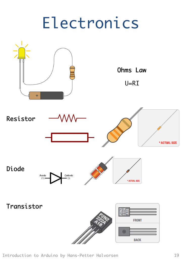
U=RI
Ohms Law
Resistor
Diode
Transistor
Resistors
20 Introduction to Arduino by Hans-Petter Halvorsen
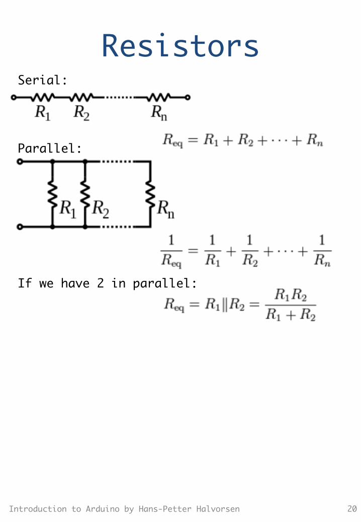
If we have 2 in parallel:
Serial:
Parallel:
Resistors
21 Introduction to Arduino by Hans-Petter Halvorsen
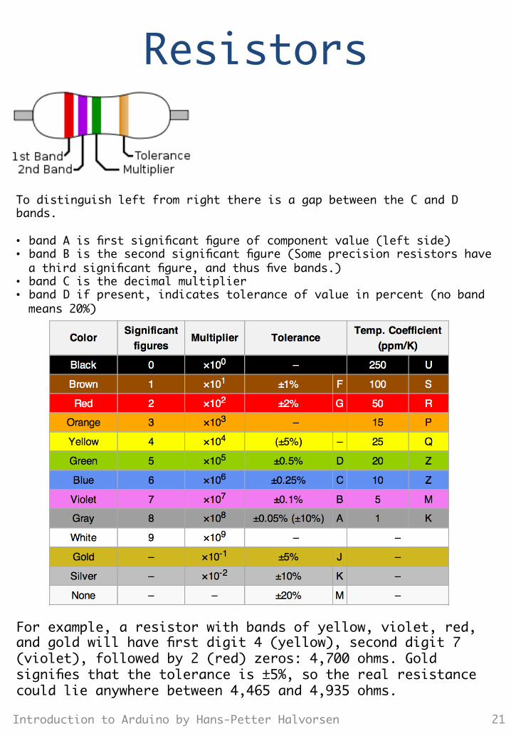
To distinguish left from right there is a gap between the C and D bands. • band A is first significant figure of component value (left side) • band B is the second significant figure (Some precision resistors have a third significant figure, and thus five bands.)
• band C is the decimal multiplier • band D if present, indicates tolerance of value in percent (no band means 20%)
For example, a resistor with bands of yellow, violet, red, and gold will have first digit 4 (yellow), second digit 7 (violet), followed by 2 (red) zeros: 4,700 ohms. Gold signifies that the tolerance is ±5%, so the real resistance could lie anywhere between 4,465 and 4,935 ohms.
Arduino TinkerKit h"p://www.Tnkerkit.com
Introduction to Arduino by Hans-Petter Halvorsen 22
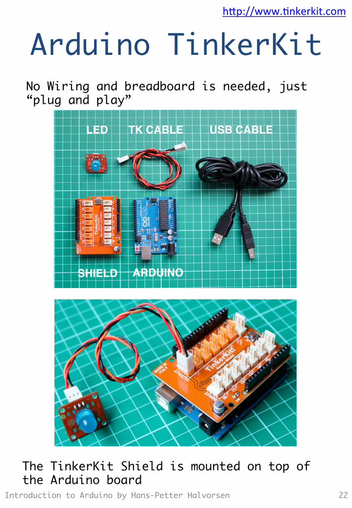
No Wiring and breadboard is needed, just “plug and play”
The TinkerKit Shield is mounted on top of the Arduino board
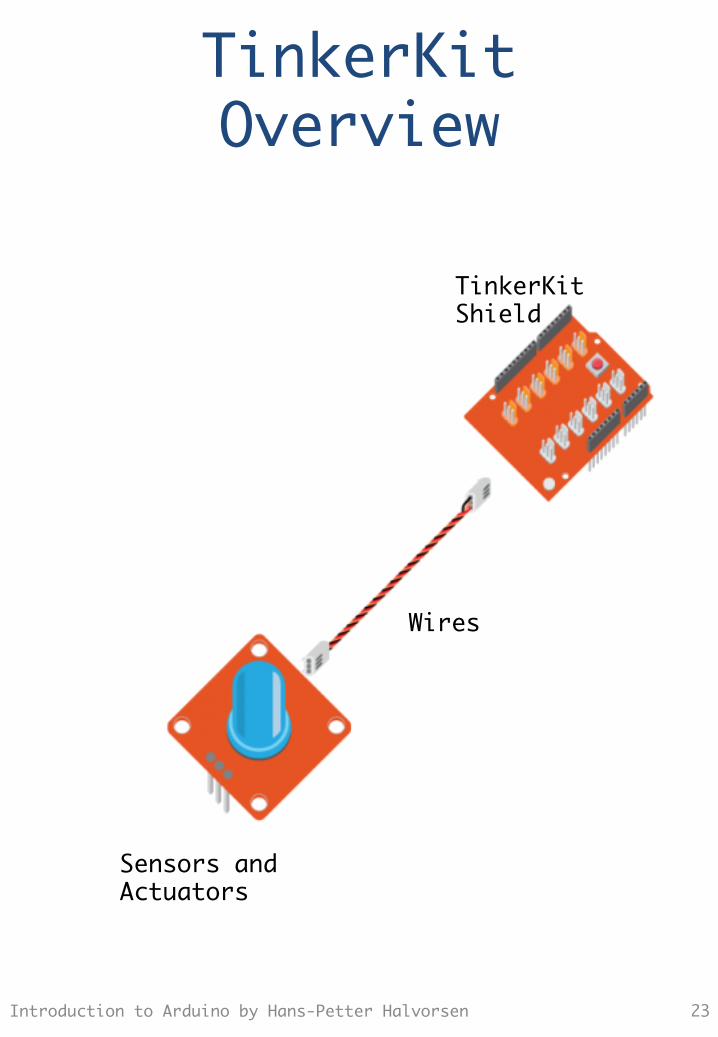
TinkerKit Overview
TinkerKit Shield
Wires
Sensors and Actuators
Introduction to Arduino by Hans-Petter Halvorsen 23
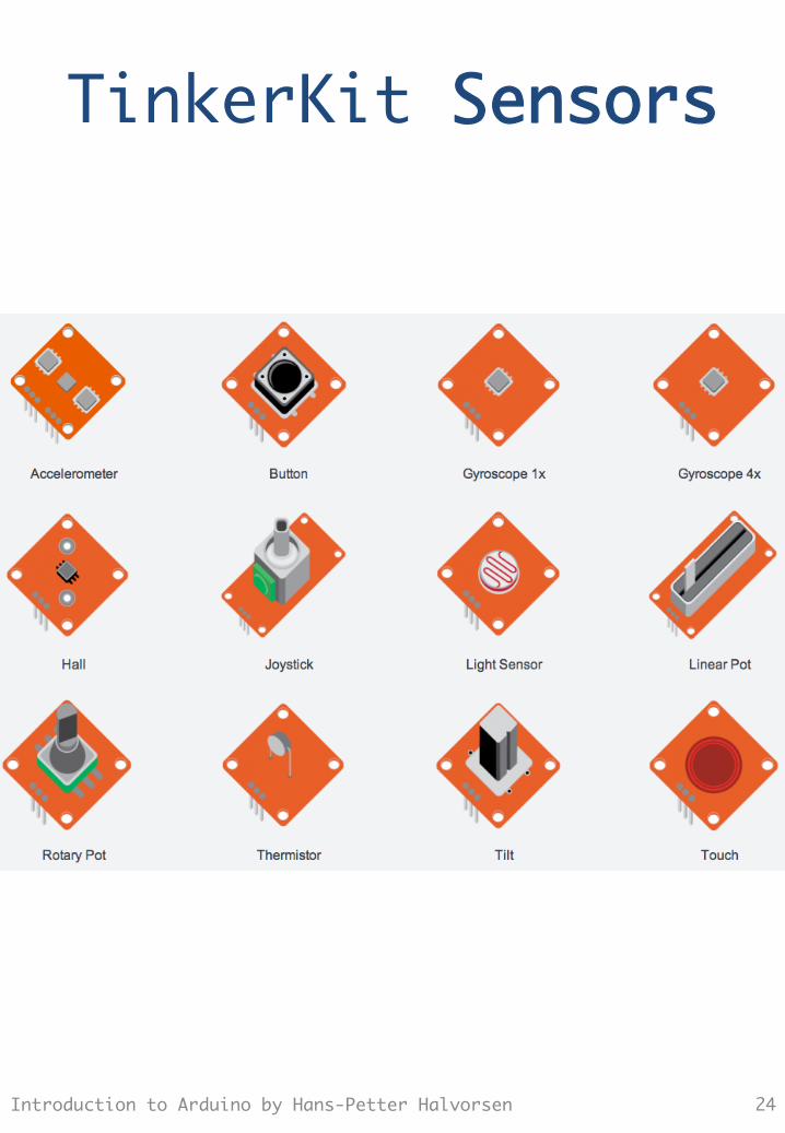
TinkerKit Sensors
Introduction to Arduino by Hans-Petter Halvorsen 24
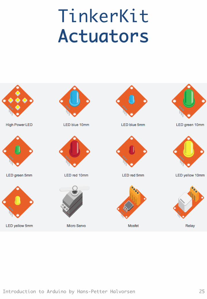
TinkerKit Actuators
Introduction to Arduino by Hans-Petter Halvorsen 25

Installation
Introduction to Arduino by Hans-Petter Halvorsen 26
http://www.tinkerkit.com
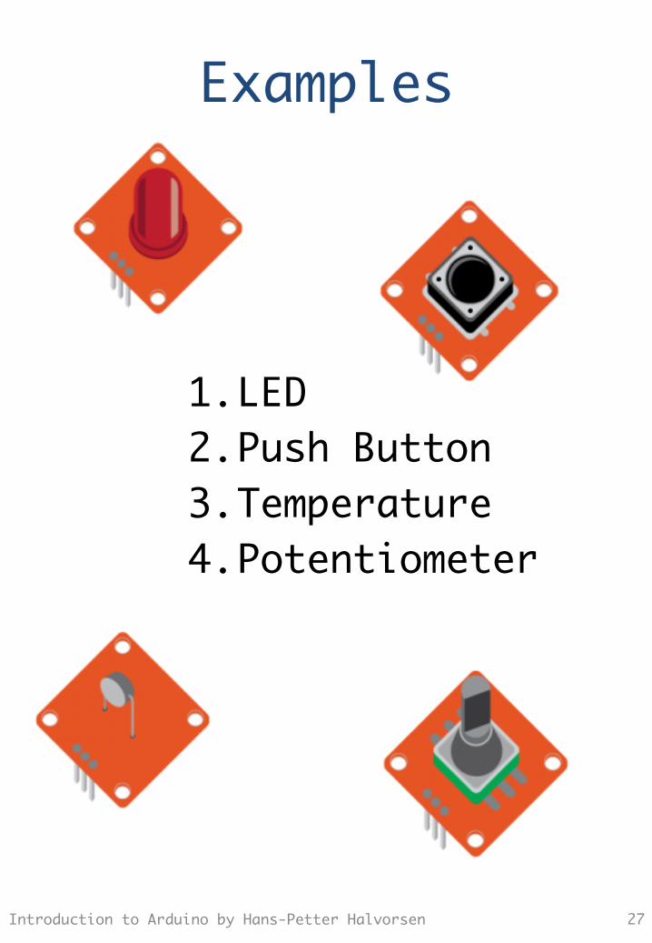
Examples
1. LED 2. Push Button 3. Temperature 4. Potentiometer
Introduction to Arduino by Hans-Petter Halvorsen 27
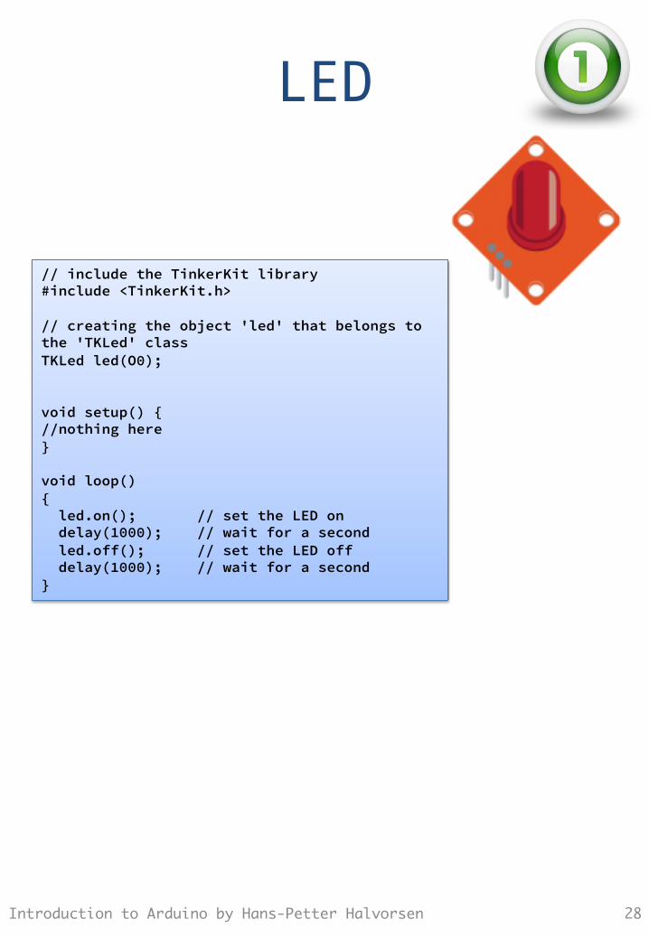
LED
Introduction to Arduino by Hans-Petter Halvorsen 28
// include the TinkerKit library #include <TinkerKit.h> // creating the object 'led' that belongs to the 'TKLed' class TKLed led(O0); void setup() { //nothing here } void loop() { led.on(); // set the LED on delay(1000); // wait for a second led.off(); // set the LED off delay(1000); // wait for a second }
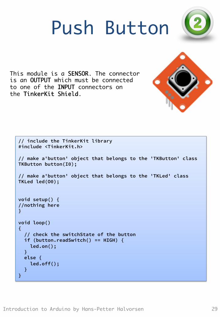
Push Button
Introduction to Arduino by Hans-Petter Halvorsen 29
// include the TinkerKit library #include <TinkerKit.h> // make a'button' object that belongs to the 'TKButton' class TKButton button(I0); // make a'button' object that belongs to the 'TKLed' class TKLed led(O0); void setup() { //nothing here } void loop() { // check the switchState of the button if (button.readSwitch() == HIGH) { led.on(); } else { led.off(); } }
This module is a SENSOR. The connector is an OUTPUT which must be connected to one of the INPUT connectors on the TinkerKit Shield.
Temperature
Introduction to Arduino by Hans-Petter Halvorsen 30
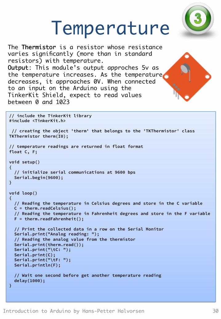
// include the TinkerKit library #include <TinkerKit.h> // creating the object 'therm' that belongs to the 'TKThermistor' class TKThermistor therm(I0); // temperature readings are returned in float format float C, F; void setup() { // initialize serial communications at 9600 bps Serial.begin(9600); } void loop() { // Reading the temperature in Celsius degrees and store in the C variable C = therm.readCelsius(); // Reading the temperature in Fahrenheit degrees and store in the F variable F = therm.readFahrenheit(); // Print the collected data in a row on the Serial Monitor Serial.print("Analog reading: "); // Reading the analog value from the thermistor Serial.print(therm.read()); Serial.print("\tC: "); Serial.print(C); Serial.print("\tF: "); Serial.println(F); // Wait one second before get another temperature reading delay(1000); }
The Thermistor is a resistor whose resistance varies significantly (more than in standard resistors) with temperature. Output: This module’s output approches 5v as the temperature increases. As the temperature decreases, it approaches 0V. When connected to an input on the Arduino using the TinkerKit Shield, expect to read values between 0 and 1023
Potentiometer
Introduction to Arduino by Hans-Petter Halvorsen 31
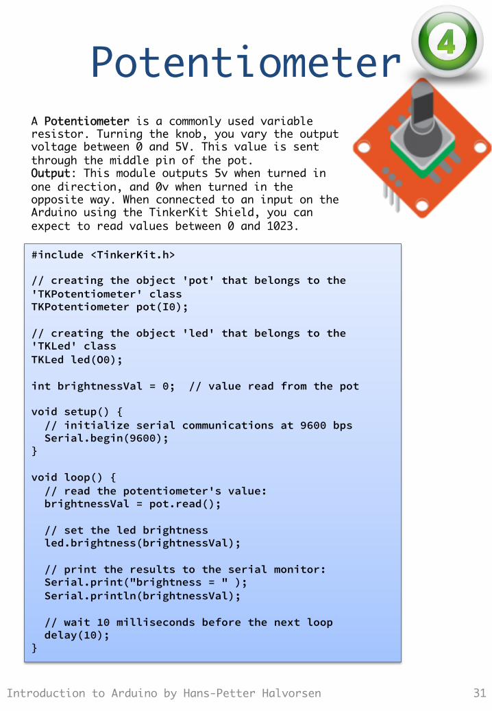
#include <TinkerKit.h> // creating the object 'pot' that belongs to the 'TKPotentiometer' class TKPotentiometer pot(I0); // creating the object 'led' that belongs to the 'TKLed' class TKLed led(O0); int brightnessVal = 0; // value read from the pot void setup() { // initialize serial communications at 9600 bps Serial.begin(9600); } void loop() { // read the potentiometer's value: brightnessVal = pot.read(); // set the led brightness led.brightness(brightnessVal); // print the results to the serial monitor: Serial.print("brightness = " ); Serial.println(brightnessVal); // wait 10 milliseconds before the next loop delay(10); }
A Potentiometer is a commonly used variable resistor. Turning the knob, you vary the output voltage between 0 and 5V. This value is sent through the middle pin of the pot. Output: This module outputs 5v when turned in one direction, and 0v when turned in the opposite way. When connected to an input on the Arduino using the TinkerKit Shield, you can expect to read values between 0 and 1023.
Exercises
1. Thermostat: – Turn a led on when the
temperature is below a value.
– Read the treshold value from a potentiometer
Introduction to Arduino by Hans-Petter Halvorsen 32
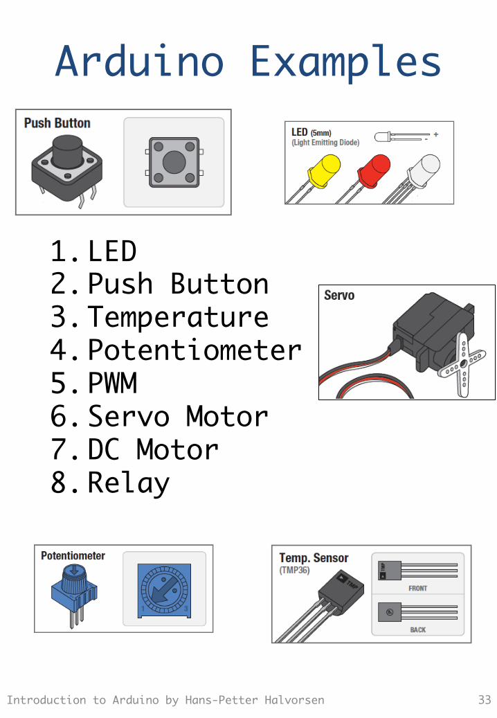
Arduino Examples
1. LED 2. Push Button 3. Temperature 4. Potentiometer 5. PWM 6. Servo Motor 7. DC Motor 8. Relay
Introduction to Arduino by Hans-Petter Halvorsen 33
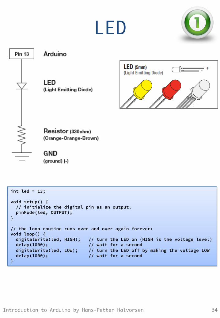
LED
Introduction to Arduino by Hans-Petter Halvorsen 34
int led = 13; void setup() { // initialize the digital pin as an output. pinMode(led, OUTPUT); } // the loop routine runs over and over again forever: void loop() { digitalWrite(led, HIGH); // turn the LED on (HIGH is the voltage level) delay(1000); // wait for a second digitalWrite(led, LOW); // turn the LED off by making the voltage LOW delay(1000); // wait for a second }
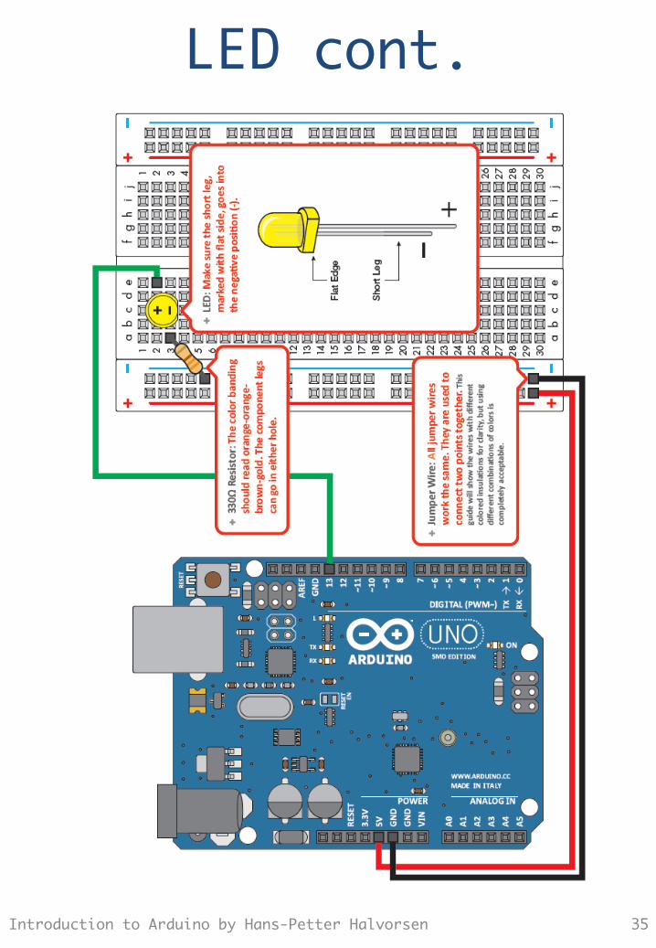
LED cont.
Introduction to Arduino by Hans-Petter Halvorsen 35
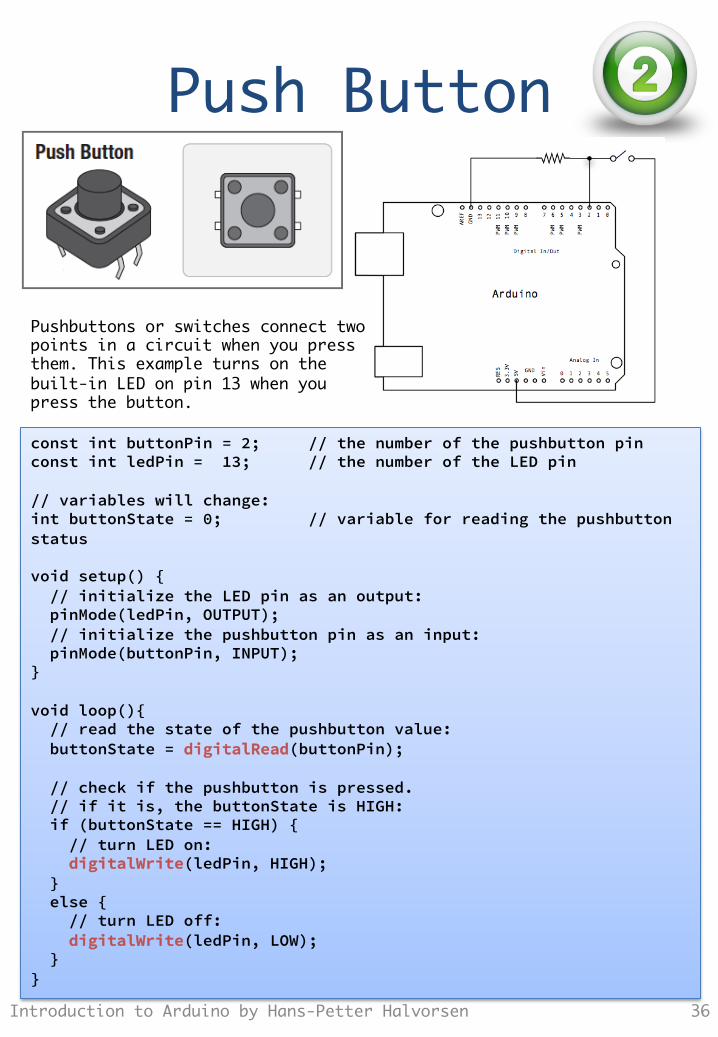
Push Button
Introduction to Arduino by Hans-Petter Halvorsen 36
const int buttonPin = 2; // the number of the pushbutton pin const int ledPin = 13; // the number of the LED pin // variables will change: int buttonState = 0; // variable for reading the pushbutton status void setup() { // initialize the LED pin as an output: pinMode(ledPin, OUTPUT); // initialize the pushbutton pin as an input: pinMode(buttonPin, INPUT); } void loop(){ // read the state of the pushbutton value: buttonState = digitalRead(buttonPin); // check if the pushbutton is pressed. // if it is, the buttonState is HIGH: if (buttonState == HIGH) { // turn LED on: digitalWrite(ledPin, HIGH); } else { // turn LED off: digitalWrite(ledPin, LOW); } }
Pushbuttons or switches connect two points in a circuit when you press them. This example turns on the built-in LED on pin 13 when you press the button.
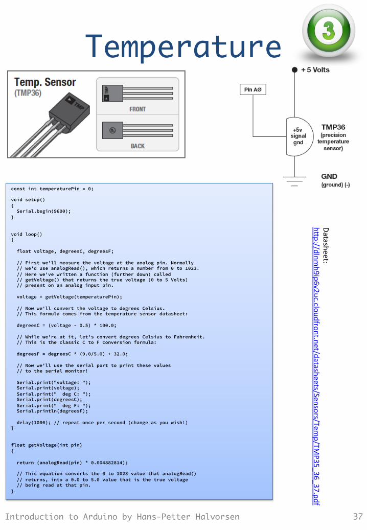
Temperature
Introduction to Arduino by Hans-Petter Halvorsen 37
const int temperaturePin = 0; void setup() { Serial.begin(9600); } void loop() { float voltage, degreesC, degreesF; // First we'll measure the voltage at the analog pin. Normally // we'd use analogRead(), which returns a number from 0 to 1023. // Here we've written a function (further down) called // getVoltage() that returns the true voltage (0 to 5 Volts) // present on an analog input pin. voltage = getVoltage(temperaturePin); // Now we'll convert the voltage to degrees Celsius. // This formula comes from the temperature sensor datasheet: degreesC = (voltage - 0.5) * 100.0; // While we're at it, let's convert degrees Celsius to Fahrenheit. // This is the classic C to F conversion formula: degreesF = degreesC * (9.0/5.0) + 32.0; // Now we'll use the serial port to print these values // to the serial monitor! Serial.print("voltage: "); Serial.print(voltage); Serial.print(" deg C: "); Serial.print(degreesC); Serial.print(" deg F: "); Serial.println(degreesF); delay(1000); // repeat once per second (change as you wish!) } float getVoltage(int pin) { return (analogRead(pin) * 0.004882814); // This equation converts the 0 to 1023 value that analogRead() // returns, into a 0.0 to 5.0 value that is the true voltage // being read at that pin. }
Datasheet: h"
p://dlnmh9ip6v2uc.cloudfront.net/datasheets/Sensors/Tem
p/TMP35_36_37.pdf
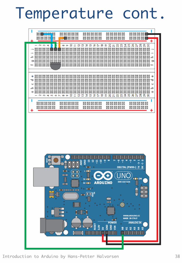
Temperature cont.
Introduction to Arduino by Hans-Petter Halvorsen 38
Potentiometer
Introduction to Arduino by Hans-Petter Halvorsen 39
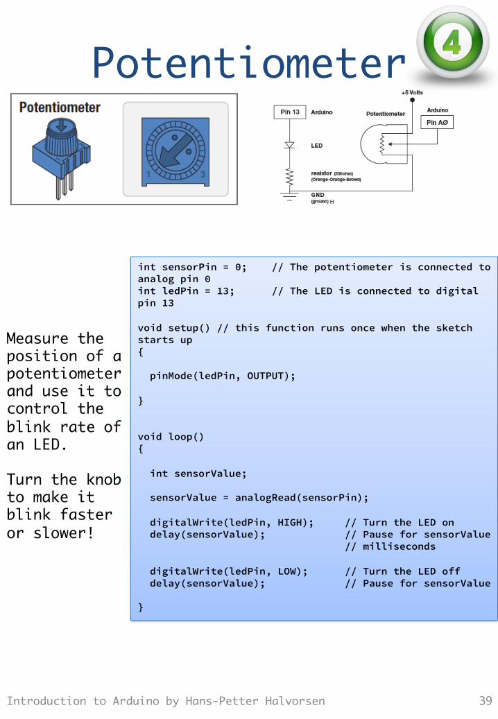
int sensorPin = 0; // The potentiometer is connected to analog pin 0 int ledPin = 13; // The LED is connected to digital pin 13 void setup() // this function runs once when the sketch starts up { pinMode(ledPin, OUTPUT); } void loop() { int sensorValue; sensorValue = analogRead(sensorPin); digitalWrite(ledPin, HIGH); // Turn the LED on delay(sensorValue); // Pause for sensorValue // milliseconds digitalWrite(ledPin, LOW); // Turn the LED off delay(sensorValue); // Pause for sensorValue }
Measure the position of a potentiometer and use it to control the blink rate of an LED. Turn the knob to make it blink faster or slower!
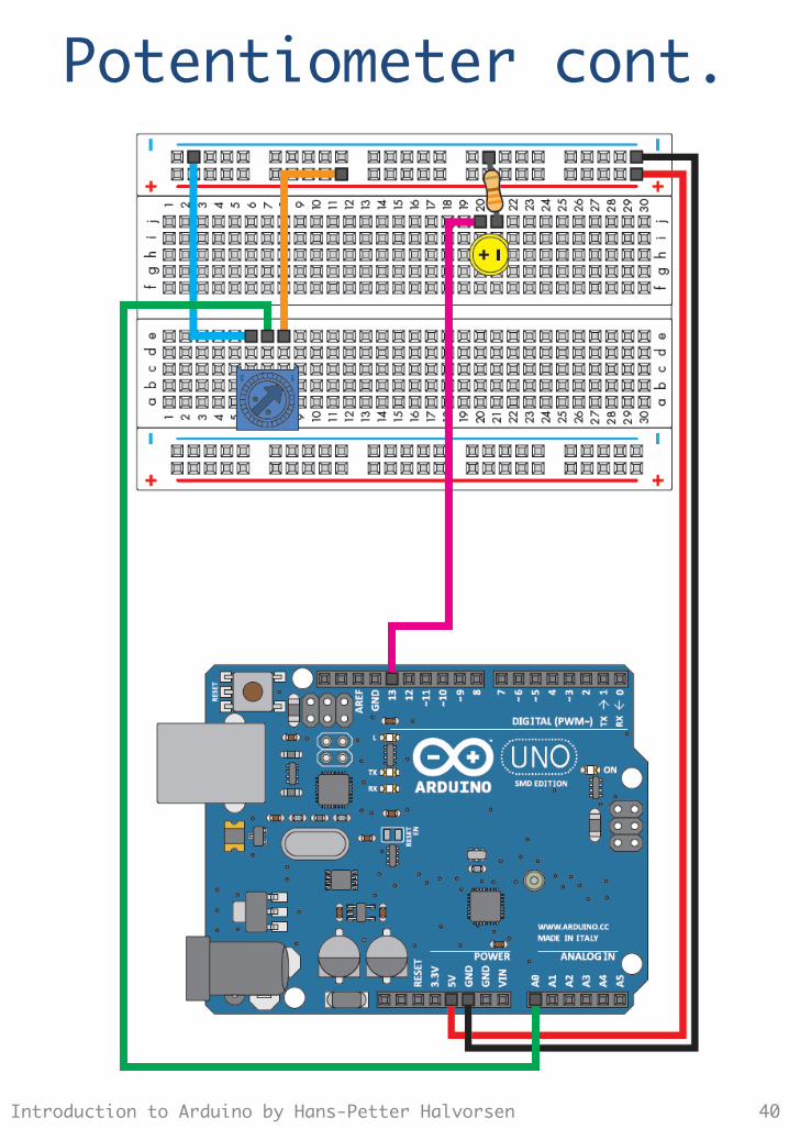
Potentiometer cont.
Introduction to Arduino by Hans-Petter Halvorsen 40
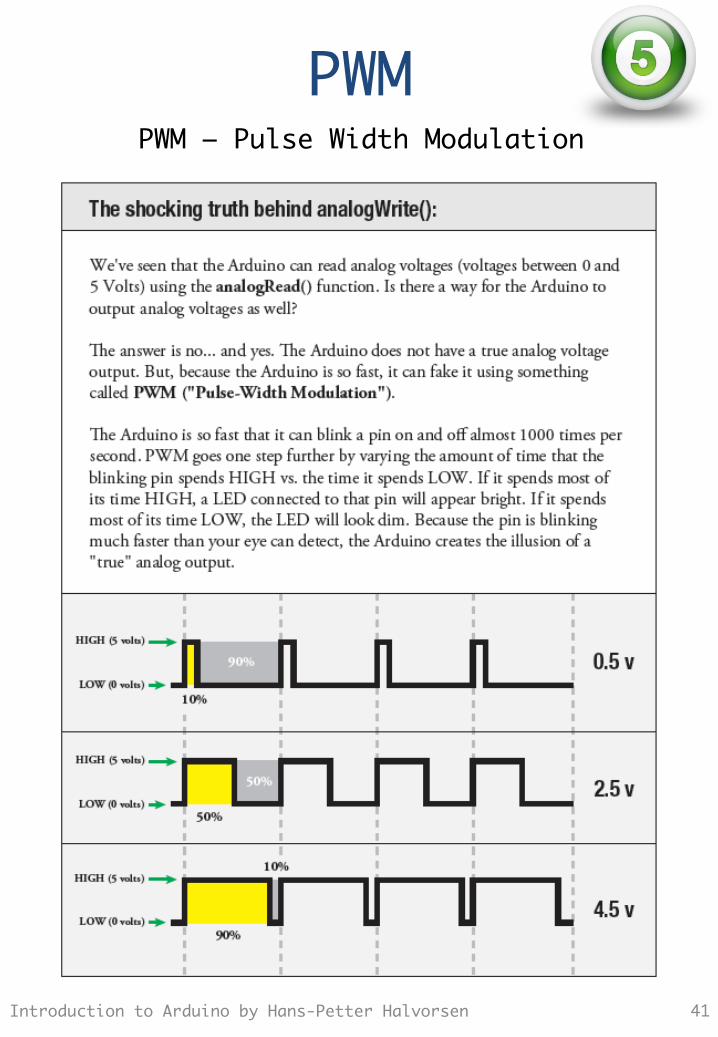
PWM
Introduction to Arduino by Hans-Petter Halvorsen 41
PWM – Pulse Width Modulation
Servo Motor
Introduction to Arduino by Hans-Petter Halvorsen 42
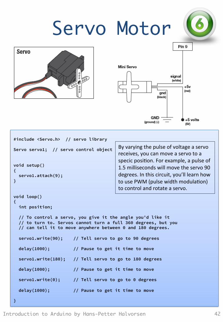
#include <Servo.h> // servo library Servo servo1; // servo control object void setup() { servo1.attach(9); } void loop() { int position; // To control a servo, you give it the angle you'd like it // to turn to. Servos cannot turn a full 360 degrees, but you // can tell it to move anywhere between 0 and 180 degrees. servo1.write(90); // Tell servo to go to 90 degrees delay(1000); // Pause to get it time to move servo1.write(180); // Tell servo to go to 180 degrees delay(1000); // Pause to get it time to move servo1.write(0); // Tell servo to go to 0 degrees delay(1000); // Pause to get it time to move }
By varying the pulse of voltage a servo receives, you can move a servo to a specic posiTon. For example, a pulse of 1.5 milliseconds will move the servo 90 degrees. In this circuit, you’ll learn how to use PWM (pulse width modulaTon) to control and rotate a servo.
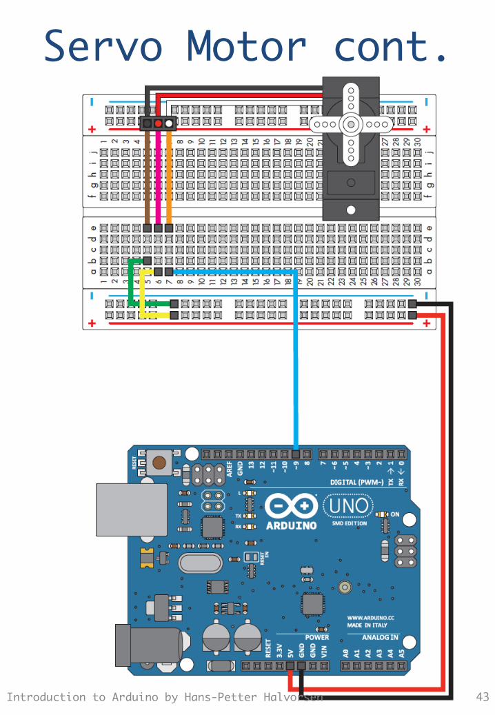
Servo Motor cont.
Introduction to Arduino by Hans-Petter Halvorsen 43
DC Motor
Introduction to Arduino by Hans-Petter Halvorsen 44
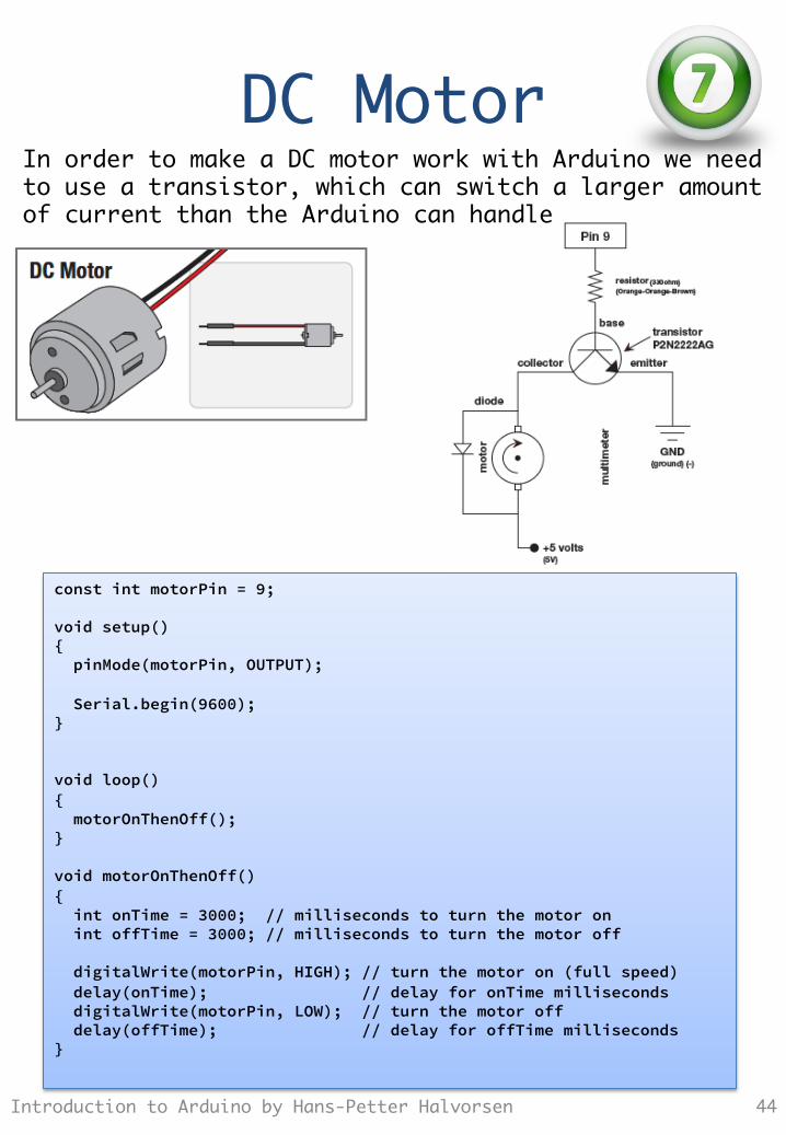
const int motorPin = 9; void setup() { pinMode(motorPin, OUTPUT); Serial.begin(9600); } void loop() { motorOnThenOff(); } void motorOnThenOff() { int onTime = 3000; // milliseconds to turn the motor on int offTime = 3000; // milliseconds to turn the motor off digitalWrite(motorPin, HIGH); // turn the motor on (full speed) delay(onTime); // delay for onTime milliseconds digitalWrite(motorPin, LOW); // turn the motor off delay(offTime); // delay for offTime milliseconds }
In order to make a DC motor work with Arduino we need to use a transistor, which can switch a larger amount of current than the Arduino can handle
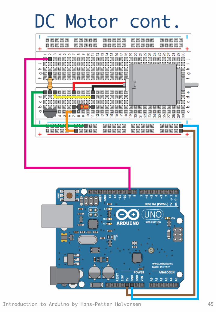
DC Motor cont.
Introduction to Arduino by Hans-Petter Halvorsen 45
DC Motor cont.
Introduction to Arduino by Hans-Petter Halvorsen 46
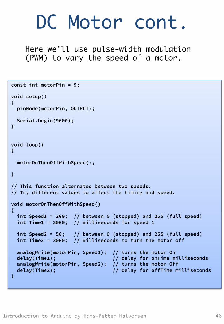
Here we'll use pulse-width modulation (PWM) to vary the speed of a motor.
const int motorPin = 9; void setup() { pinMode(motorPin, OUTPUT); Serial.begin(9600); } void loop() { motorOnThenOffWithSpeed(); } // This function alternates between two speeds. // Try different values to affect the timing and speed. void motorOnThenOffWithSpeed() { int Speed1 = 200; // between 0 (stopped) and 255 (full speed) int Time1 = 3000; // milliseconds for speed 1 int Speed2 = 50; // between 0 (stopped) and 255 (full speed) int Time2 = 3000; // milliseconds to turn the motor off analogWrite(motorPin, Speed1); // turns the motor On delay(Time1); // delay for onTime milliseconds analogWrite(motorPin, Speed2); // turns the motor Off delay(Time2); // delay for offTime milliseconds }
Relay
Introduction to Arduino by Hans-Petter Halvorsen 47
Exercises
1. Thermostat: – Turn a led on when the
temperature is below a value.
– Read the treshold value from a potentiometer
Introduction to Arduino by Hans-Petter Halvorsen 48
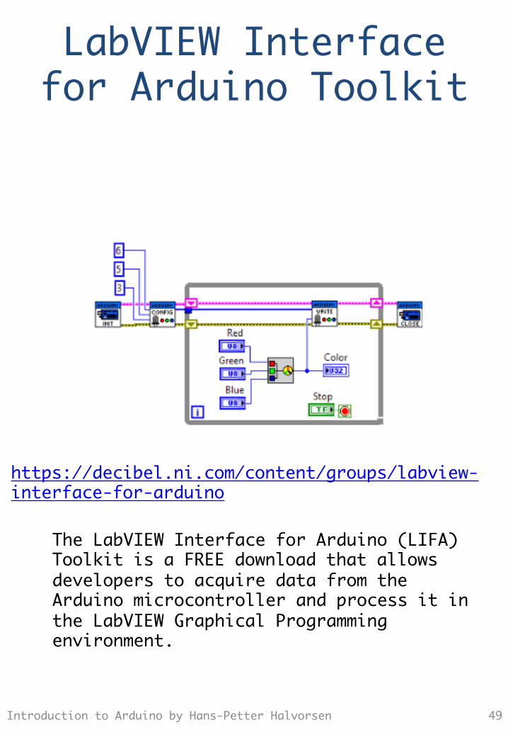
LabVIEW Interface�for Arduino Toolkit
The LabVIEW Interface for Arduino (LIFA) Toolkit is a FREE download that allows developers to acquire data from the Arduino microcontroller and process it in the LabVIEW Graphical Programming environment.
Introduction to Arduino by Hans-Petter Halvorsen 49
https://decibel.ni.com/content/groups/labview-interface-for-arduino
Installation
Introduction to Arduino by Hans-Petter Halvorsen 50
https://decibel.ni.com/content/groups/labview-interface-for-arduino
Examples
1. LED 2. Push Button 3. Temperature 4. Potentiometer
Introduction to Arduino by Hans-Petter Halvorsen 51

Exercises
1. Thermostat: – Turn a led on when the
temperature is below a value.
– Read the treshold value from a potentiometer
Introduction to Arduino by Hans-Petter Halvorsen 52
References
• Arduino Web Site: http://arduino.cc • TinkerKit Web Site:
http://www.tinkerkit.com • LabVIEW Interface for Arduino:
https://decibel.ni.com/content/groups/labview-interface-for-arduino
• Arduino: http://home.hit.no/~hansha/?equipment=arduino
Introduction to Arduino by Hans-Petter Halvorsen 53

Hans-Petter Halvorsen, M.Sc. Telemark University College Faculty of Technology Department of Electrical Engineering, Information Technology and Cybernetics
E-mail: [email protected] Blog: http://home.hit.no/~hansha/
Introduction to