Embed Size (px)
Citation preview
Pergamon 0020-7403 (94) E0009-T Int. J. Mech. $ci. Vol. 36, No. 5, pp. 449-467, 1994 Copyright ~ 1994 Elsevier Scien~ Ltd
Printed in Great Britain. All rights reserved 0020-7403/94 $6.00 + 0.00
LATERAL COLLAPSE OF ORTHOGONAL AND N O N - O R T H O G O N A L CROSS-LAYERED ARRAYS
OF SQUARE AND RECTANGULAR TUBES
N. K. GUPTA and ATUL KHULLAR Applied Mechanics Department, Indian Institute of Technology Delhi, New Delhi-ll0016, India
(Received 5 May 1993; and in revised form 2 November 1993)
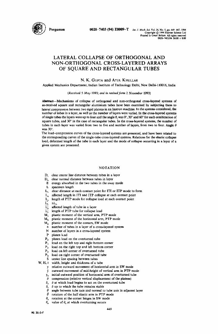
Abstraet--Mechanisms of collapse of orthogonal and non-orthogonal cross-layered systems of as-received square and rectangular aluminium tubes have been examined by subjecting them to lateral compression between two rigid platens in an Instron machine. In the systems considered, the number of tubes in a layer, as well as the number of layers were varied. In the cross-layered systems of single tubes the layers were up to four and the angle 0, was 0 °, 30 ° and 60 ° for each combination of square tubes, and 30 ° in the case of rectangular tubes. In the cross-layered systems, the number of tubes in each layer was varied from two to five and number of layers, from two to four. Angle 0 was 30 ° . The load-compression curves of the cross-layered systems are presented, and have been related to the corresponding curves of the single-tube cross-layered systems. Relations for the elastic collapse load, deformed length of the tube in each layer and the mode of collapse occurring in a layer of a given system are presented.
D c
D. E L
LL
L. L~ L~ L~ L~
M~ Mh Mp
n
N P
Po PI P2 P3 P4
S W, H, t
Y
Yo 6
6o 6, 0 0 0. 0o
N O T A T I O N
clear center line distance between tubes in a layer clear normal distance between tubes in layer energy absorbed in the two tubes in the sway mode specimen length clear distance at each contact point for ITI or ITP mode to form affected length in ITI and ITP collapse at each contact point length of PTP mode for collapse load at each contact point nLL affected length of tube in a layer length of PTP tube for collapse load plastic moment of the vertical arm, PTP mode plastic moment of the horizontal arm, PTP mode plastic moment of the corners, SW mode number of tubes in a layer of a cross-layered system number of layers in a cross-layered system platen lead platen load on the overturned tube load on the left top and right bottom corner load on the right top and left bottom corner load on left corner of overturned tube load on right corner of overturned tube center line spacing between tubes width, height and thickness of a tube relative outward movement of horizontal arm in SW mode outward movement of mid-height of vertical arm in PTP mode initial outward position of horizontal arm of overturned tube compression (relative vertical displacement of the platens) 6 at which load begins to act on the overturned tube 6 up to which the tube remains stable angle between tube axis and normal to tube axis in adjacent layer rotation of the half elastic arm in PTP mode rotation at the corner hinges in SW mode value of 0~ at which overturning occurs
449 H$ 36:5-F
450 N.K. G'UPTA and A, KHULLAR
1. INTRODUCTION
The tubes and their combinations form efficient energy absorbing systems and therefore their large deformation behaviour has been studied quite extensively [l 6] under various loading conditions. The aim is to dissipate kinetic energy of an impact, as in the case of vehicles, in a controlled manner. The deformation behaviour of round or square tubes in axial and lateral compression [2, 3, 5, 6], and their arrays in lateral compression [l, 4] have received much attention in the recent years.
Lateral collapse of cross-layered systems of round tubes has been studied quite extensi- vely in the past [1, 2]. In the case of square tubes the lateral collapse of the orthogonal cross- layered arrangements was considered by Gupta and Sinha and they presented experimental results and the analysis in an earlier paper [4].
In this paper we consider the compression of square and rectangular tubes, in both orthogonal and non-orthogonal cross-layered arrangements, wherein the number of tubes in each layer, n, and the number of layers, N, were both varied. The tubes in the alternate layers were placed vertically in line and parallel to each other, whereas the angle between the tubes in the adjacent layers was varied. Tubes were compressed in an Instron machine at a crosshead speed of 2.5 mm min- 1. The load-compression curve in each case was recorded on the machine chart recorder and the histories of deformation of the tubes were observed by interrupting and terminating the compression at various stages and taking photographs.
It was seen in the experiments that the mode of collapse of the tubes in the individual layers in cross-layered systems, changed with the change in the number of tubes in each layer, as well as the number of layers. These tubes deformed in four different modes. Three of these were similar to those observed in single tubes which are being laterally compressed, respectively, between: (i) two rigid platens; (ii) between two narrow width indenters; and (iii) between a narrow width indenter and a platen.
The fourth mode of deformation was the sway (side shear) mode of collapse; it was observed only during the compression of some cross-layered systems. The analysis of this mode is presented and the results obtained have been compared with the experiments.
The behaviour of the cross-layered combination of tubes has been analyzed by relating their load-compression curves and the histories of their deformation to those of single tubes. Relations for predicting the elastic collapse load, the mode of collapse of tubes in different layers and the length of the tube over which the plastic hinges form are presented.
2. EXPERIMENTAL
Square and rectangular tubes of aluminium were commercially obtained and cut into specimens of length 300 mm each. Cross-layered combinations of these tubes were com- pressed between two parallel rigid platens in an Instron machine of 5 ton capacity at a crosshead speed of 2.5 mm min- 1
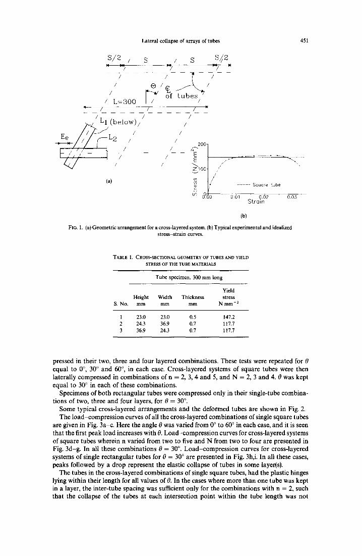
A typical arrangement of the cross-tubes in a test is shown in Fig. la, wherein the various parameters have been defined. S is the distance between the intersections of the center lines of two adjacent tubes with the center line of a tube in an adjacent layer, end overhang is S/2. 0 is the angle between the tube axis in one layer and the normal to the tube axis in the adjacent layer.
The load-compression behaviour of the cross-layered systems was recorded on the machine chart recorder. The histories of deformation of the systems were observed by interrupting or terminating their compression at different stages. Photographs of the deformed tubes were also taken.
The stress-strain curves for the tube materials were obtained from tensile tests on an Instron machine. A typical experimental curve and a corresponding curve idealized as a perfectly plastic curve are shown in Fig. lb.
Three tubes were used in the experiments, one square and two rectangular. The tube dimensions and their yield stress values are given in Table 1. All specimens were 300 mm long.
Firstly, single specimens of the three tubes were individually compressed between two rigid parallel platens. Thereafter, cross-layered systems of single square tubes were com-
Lateral collapse of arrays of tubes 451
s /z /
/ /
/
S / S S/ /2 =/ =/ --:
/ L = 3 0 0 / / /
A L ( b e l o w ) /
Ee / ~ - - S L 2 / /
/ / /
/ /
(a)
2 0 0 .
E E ZlOO.
O3 Q)
/
,!
f,' ¢. • . . . . . . . . . S q u a r e t u b e
o61 0.62 o.03 Strain
(b)
FIG. I. (a) Geometric arrangement for a cross-layered system. (b) Typical experimental and idealized stress-strain curves.
TABLE 1. CROSS-SECTIONAL GEOMETRY OF TUBES AND YIELD
STRESS OF THE TUBE MATERIALS
Tube specimen, 300 mm long
Yield Height Width Thickness stress
S. No. mm mm mm N mm- 2
1 23.0 23.0 0.5 147.2 2 24.3 36.9 0.7 117.7 3 36.9 24.3 0.7 117.7
pressed in their two, three and four layered combinations. These tests were repeated for 0 equal to 0 °, 30 ° and 60 °, in each case. Cross-layered systems of square tubes were then laterally compressed in combinations of n = 2, 3, 4 and 5, and N = 2, 3 and 4. 0 was kept equal to 30 ° in each of these combinations.
Specimens of both rectangular tubes were compressed only in their single-tube combina- tions of two, three and four layers, for 0 = 30 °.
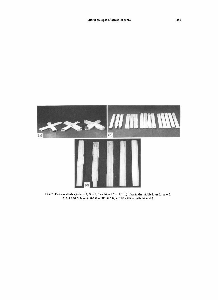
Some typical cross-layered arrangements and the deformed tubes are shown in Fig. 2. The load-compression curves of all the cross-layered combinations of single square tubes
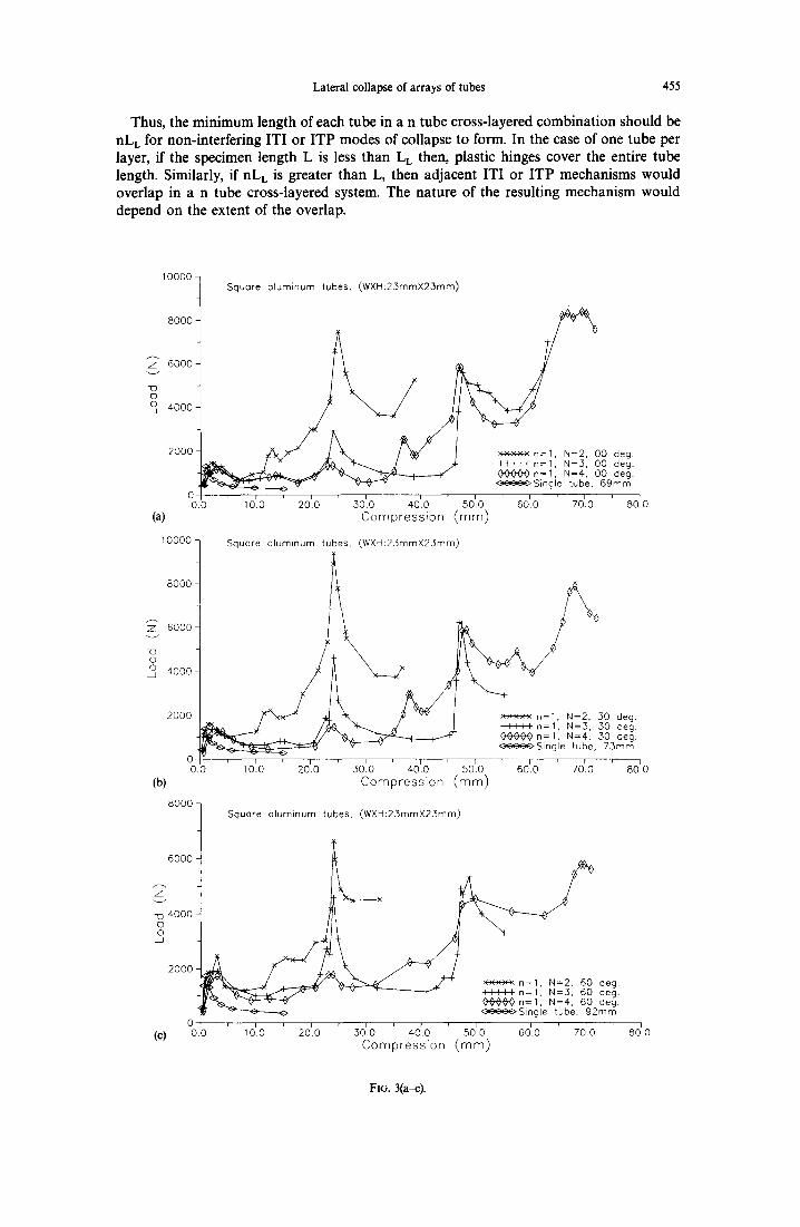
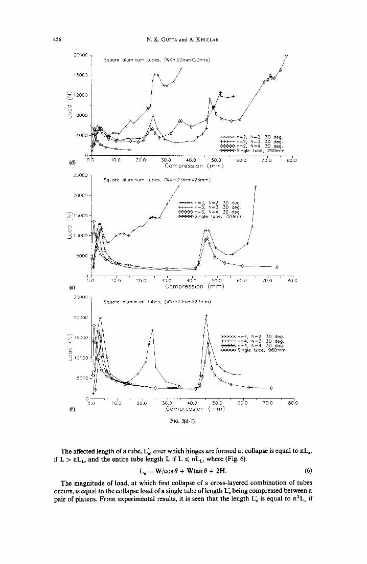
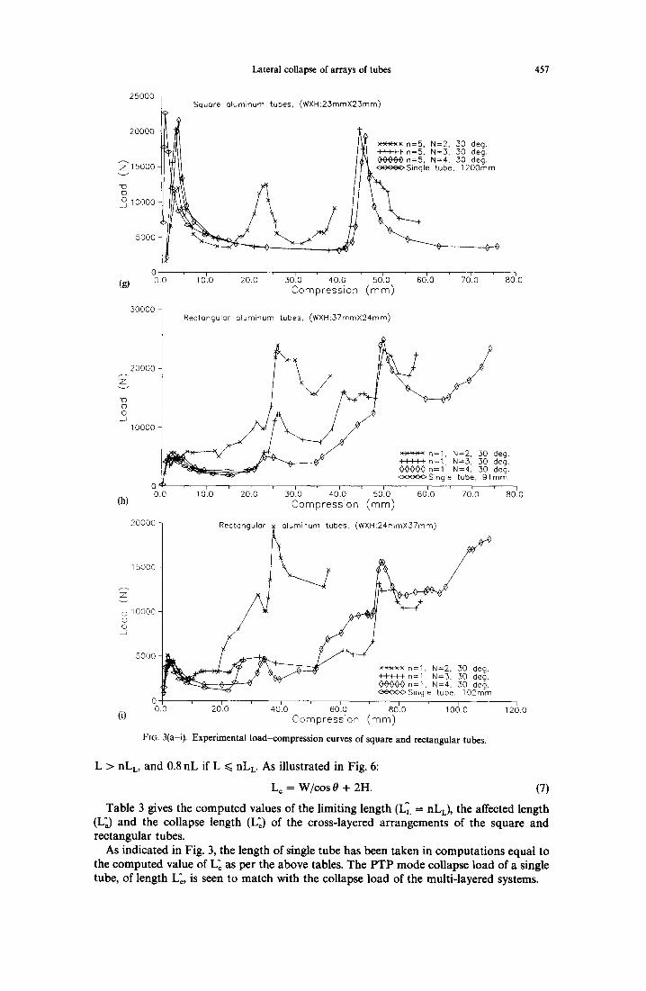
are given in Fig. 3a-c. Here the angle 0 was varied from 0 ° to 60 ° in each case, and it is seen that the first peak load increases with 0. Load-compress ion curves for cross-layered systems of square tubes wherein n varied from two to five and N from two to four are presented in Fig. 3d-g. In all these combinations 0 = 30 °. Load-compress ion curves for cross-layered systems of single rectangular tubes for 0 = 30 ° are presented in Fig. 3h,i. In all these cases, peaks followed by a drop represent the elastic collapse of tubes in some layer(s).
The tubes in the cross-layered combinations of single square tubes, had the plastic hinges lying within their length for all values of 0. In the cases where more than one tube was kept in a layer, the inter-tube spacing was sutticient only for the combinations with n = 2, such that the collapse of the tubes at each intersection point within the tube length was not
452 N.K. GUPTA and A. KHULLAR
influenced by the collapse at adjacent intersection points. In the case of n > 2, the collapse at two adjacent intersections interfered with each other (Fig. 2).
The collapse behaviour of tubes in the individual layers of the cross-layered combinations varied from layer to layer, and system to system. Tubes in a layer deformed in one of the following modes:
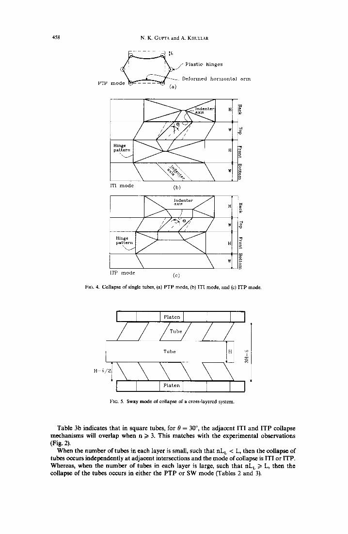
(i) As a single tube being compressed between two parallel rigid platens (henceforth referred to as PTP mode); in this mode, the hinges were formed as shown in Fig. 4a, with the horizontal arms of the tube bending inward into circular arcs.
(ii) As a single tube being compressed symmetrically between two indenters (henceforth referred to as ITI mode); in this mode the vertical sides under the indenter collapsed with the formation of hinges separating two trapezium and two triangular shaped panels on its two vertical sides, as shown in Fig. 4b.
(iii) As a single tube being compressed between an indenter and a platen (henceforth referred to as ITP mode) [Fig. 4c].
(iv) In sway (shear) mode; in this mode, two tubes aligned in the same direction (alternate layers) deform simultaneously (Fig. 5), like frames under lateral horizontal load, acting at their bottom and top faces. This mode of deformation in present ex- periments occurred in two parallel layers, separated by one layer in the middle. In what follows, this mode is referred to as SW mode.
In Table 2 below, the primary modes of collapse of tubes in each layer of various cross- layered combinations tested are presented. The bottom layer is referred to as L1, the second from the bottom as L 2, etc. The sequence in which these layers are mentioned in these tables indicates the order in which they successively deformed.
During the compression process, in the case when ITI and ITP mode of collapse of a layer occurs initially, the undeformed portions of the tube at some stage begin to be crushed in the P TP mode. This occurs not only between platens, but also involves layer(s) of tubes.
It is seen from the experiments that the behaviour of tubes in up to two tubes per layer combinations is similar to that of the single-tube combinations. The behaviour of systems with three, four and five tubes per layer is similar to each other, but it is different from that of systems with only one or two tubes in a layer.
For n = 1, in two layered combinations as the compression is continued, ends of one tube at some stage come in contact with the upper or the lower platen causing the load- compression curve to rise sharply (Fig. 3a-c, h, i). In other combinations of three, four or five layers, this did not happen.
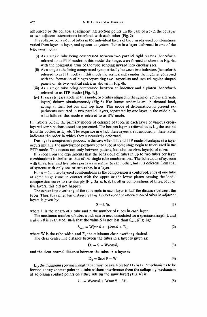
The center line overhang of the tube ends in each layer is half the distance between the tubes. Thus, the center line distance S (Fig. la), between the intersection of tubes in adjacent layers is given by:
S = L/n, (1)
where L is the length of a tube and n the number of tubes in each layer. The maximum number of tubes which can be accommodated for a specimen length L and
a given 0 is evaluated, such that the value S is not less than Smin (Fig. la):
Smin -~- W(sin0 + 1)/cos0 + E,, (2)
where W is the tube width and Ec the minimum clear overhang desired. The clear center line distance between the tubes in a layer is given as:
Dc = S - W/cos 0, (3)
and the clear normal distance between the tubes in a layer is:
Dn = Scos 0 - W. (4)
L L, the minimum specimen length that must be available for ITI or ITP mechanisms to be formed at any contact point in a tube without interference from the collapsing mechanism at adjoining contact points on either side (in the same layer) [Fig. 6] is:
LL = W/cos 0 + Wtan 0 + 3H. (5)
Lateral collapse of arrays of tubes 453
FIG. 2. Deformed tubes, (a) n = 1, N = 2, 3 and 4 and 0 = 30 °, (b) tubes in the middle layer for n = I, 2, 3, 4 and 5, N = 3, and 0 = 30 °, and (c) a tube each of systems in (b).

8000
10000-
A
Z 6000
o 4000.
2000
0
(a)
0 deg. / A . / j~. ~ ] ~- I I I I I n=l, N=3, O0 deg.
~ ~ _ . ~ . . A ~ ~ O 0 0 0 n=l, N=4, O0 deg. caeca Single tube, 69mm
0.0 10'.0 20'.0 30'.0 40'.0 50'.0 60'.0 70'.0 80r0 C o m p r e s s i o n ( m m )
10000 ]
8000 t
6000-
713 D O 4000-
Square aluminum tubes, (WXH:25mmX25rnm)
Thus, the minimum length of each tube in a n tube cross-layered combination should be nL L for non-interfering ITI or ITP modes of collapse to form. In the case of one tube per layer, if the specimen length L is less than L L then, plastic hinges cover the entire tube length. Similarly, if nL L is greater than L, then adjacent ITI or ITP mechanisms would overlap in a n tube cross-layered system. The nature of the resulting mechanism would depend on the extent of the overlap.
2000-
0
(b) 0.0 10'.0 2010 ' .3010 40'.0
Square eluminum tubes, (WXH:23mmX23mm)
Lateral collapse of arrays of tubes 455
x×x×× n=l, N=2, 30 deg. II I I I n=l, N=3, 50 deg.
A A A A vvvvO n=l, N=4, 50 deg. ¢~ooOSingle tube, 73mm
50'.0 ' 60b.0 70r.0 80'0 C o m p r e s s i o n ( r a m )
8000-
6000
4000 0 0
(c)
Square aluminum tubes, (WXH:2.SmrnX23mm)
2000
0 0.0 10'.0 20'.0
<__
deg. deg.
A A A A evvvv n=l , N=4, 60 deg. co~o~Single tube, 92mm
30'.0 40r.O 50'.0 60'.0 70'0 C o m p r e s s i o n ( m m )
80' 0
FIo. 3(a-c).
456 N . K . GuPTA and A. KHULLAR
20000-
16000
~'12000
-o o 0 8000
4000
(d)
25000
20000
~'15000
7:) o °10000
5000
0.0
0 0.0
(e)
25000 -
20000
~15ooo-
OjO 10000-
5000 J
Square a
" ~ ~ ~ I ! I I I n=2, N=3, .30 deg. evA000 n=2, N=4, 30 deg. ~ S i n g l e tube, 290ram
10t.0 20~.0 60~O 70~.0 3o'.o 4oto so'.o C o m p r e s s i o n ( ram)
Squore aluminum tubes, (WXH:25mmX23mm)
x x x x n=3, N=2, 30 deg. l IIII n=3, N=3, 30 deg. OOvA~)n-3, N=4, 30 deg.
I 0'.0 20'.0 3010 40'.0 50'.0 60~.0 Compress i on ( m m )
Square oluminum tubes, (WXH:25mrnX25mm)
70~.0 '
80'.0
80f.O
0 0.0 I 0~.0 20~.0 50~.0 40~.0 50'.0 60~0 70~0 80D.O
(f) C o m p r e s s i o n ( m m )
FIG. 3(d-0.
The affected length of a tube, L~, over which hinges are formed at collapse is equal to nL a, if L > riLL, and the entire tube length L if L ~< nL L, where (Fig. 6):
L a = W/cos 0 + Wtan 0 + 2H. (6)
The magnitude of load, at which first collapse of a cross-layered combination of tubes occurs, is equal to the collapse load of a single tube of length L~ being compressed between a pair of platens. From experimental results, it is seen that the length L~ is equal to n2Lc if
Lateral collapse of arrays of tubes 457
25000
20000
~'15000-
-o o
I0000-
5000
0 (g) 0.0
30000-
20000-
-(3 O O 10000-
(h)
20000
15000
Square aluminum tubes, (WXH:23mmX23mm)
xx×xx n=5, N=2. 30 deg. ~1 11~ I n=5, N=3, 30 deg. ~ ¢0000 n=5, N=4, 30 deg. I ~ ~ tube, 1200mm
I 0'.0 2010 30'.0 40'.0 50'.0 60'.0 70~.0 Compression (mm)
10000 o 0
(i)
5000
Rectangular aluminum tubes. (WXH:37mmX24mm)
0 00 ,0t0 2olo 30tO 4010 501.0 60'.0 7010
Compression (mm)
Rectangular < u b e s , (WXH:24mmX37mm)
[ " ~ l ~ . . . . ~/ ,,Tz v~,#f,/- - - ! ! ~ t l n=l, N=3. 30 deg ~, O0000n=l, N=4. 30 deg.
ooooOSingle tube, 102mm 0 0.0 20~.0 40~.0 60~.0 80~.0 10(3.0
C o m p r e s s i o n (ram) FIG. 3(a-i). Experimental load-compression curves of square and rectangular tubes.
i 80.0
80'.0
i 120.0
L > nLL, and 0.8 nL if L ~< nLL. As illustrated in Fig. 6:
L c = W/cos 0 + 2H. (7)
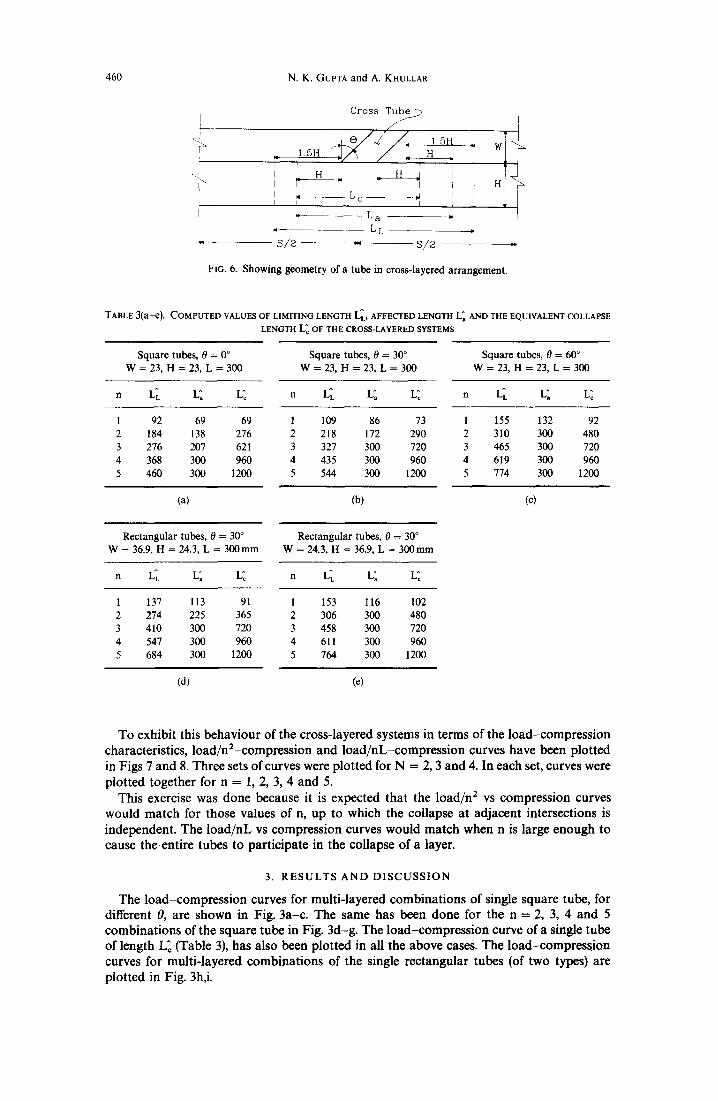
Table 3 gives the computed values of the limiting length (L~ = riLL) , the affected length (L]) and the collapse length (L~) of the cross-layered arrangements of the square and rectangular tubes.
As indicated in Fig. 3, the length of single tube has been taken in computations equal to the computed value of L~ as per the above tables. The PTP mode collapse load of a single tube, of length L~, is seen to match with the collapse load of the multi-layered systems.
458 N.K. GUPTA and A. KHULLAR
| ~ Plastic hinges
Deformed horizontal arm PTP mode (a)
Z t~
Hinge ~ pattern H
ITI mode (b)
Indenter / axis , H ~
Hinge pattern H
W
ITP mode (c)
FIG. 4. Collapse of single tubes, (a) PTP mode, (b) ITI mode, and (c) ITP mode.
H-S
FIG. 5. Sway mode of collapse of a cross-layered system.
Table 3b indicates that in square tubes, for 0 = 30 °, the adjacent ITI and ITP collapse mechanisms will overlap when n/> 3. This matches with the experimental observations (Fig. 2).
When the number of tubes in each layer is small, such that nL L < L, then the collapse of tubes occurs independently at adjacent intersections and the mode of collapse is ITI or ITP. Whereas, when the number of tubes in each layer is large, such that nL L >/L, then the collapse of the tubes occurs in either the PTP or SW mode (Tables 2 and 3).
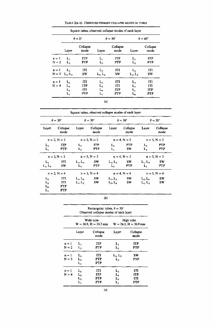
TABLE 2(a--c). OBSERVED PRIMARY COLLAPSE MODES OF TUBES
Square tubes, observed collapse modes of each layer
8 = 0 ° 8 = 3 0 ° 8 = 6 0 °
Collapse Collapse Collapse Layer mode Layer mode Layer mode
n = 1 Lt ITP L1 ITP L t ITP N = 2 L 2 PTP L 2 PTP L 2 PTP
n = 1 L 2 ITI L 2 ITI L 2 ITI N = 3 Lt, L3 SW Lx, L3 SW Ll, L3 SW
n = 1 L 2 ITI L 2 ITI L 2 ITI N = 4 L , ITP L 3 ITI L 3 ITI
L 3 ITI L , ITP Lx ITP Lt PTP L 1 PTP L 4 PTP
(a)
Square tubes, observed collapse modes of each layer
0 = 30 ° 0 = 30 ° 0 = 30 ° 0 = 30 °
Layer Collapse Layer Collapse Layer Collapse Layer Collapse mode mode mode mode
n = 2 , N = 2 n = 3 , N = 2 n = 4 , N = 2 n = 5 , N = 2
L 2 ITP L t ITP L 2 PTP L 2 PTP L 1 PTP L 2 PTP L 1 SW L1 PTP
n = 2 , N - 3 n = 3 , N = 3 n = 4 , N = 3 n = 5 , N = 3
L 2 ITI L 1, L 3 SW LI, L3 SW L1, L3 SW LI, L3 SW L 2 PTP L2 PTP L 2 PTP
n = 2 , N = 4 n = 3 , N = 4 n = 4 , N = 4 n = 5 , N = 4
L a ITI L2, L 4 SW L1, L 3 SW L2, L4 SW L 2 ITI L1, L3 SW L2, L 4 SW L t, L 3 SW L4 PTP
L l PTP
(b)
Rectangular tubes, 0 = 30 ° Observed collapse modes of each layer
Wide tube High tube W = 36.9, H = 24.3 mm W = 24.3, H = 36.9mm
Layer Collapse Layer Collapse mode mode
n = 1 L 1 ITP L l ITP N = 2 L 2 PTP L 2 PTP
n = I L 2 ITI LI, L 3 SW N = 3 L 3 PTP L2 PTP
L t PTP
n = 1 L 2 ITI L 2 ITI N = 4 L , ITP L 4 ITP
L 3 PTP L 3 ITI L: PTP L 1 PTP
(c)
460 N . K . GuPTA a n d A. KHULLAR
J 1 5 H
- I i H
I I I ,
" S / 2
Cross T u b e ~
,, ,, H I I r I I
- - L c - d r I I I I
L a ,.
- - L L
~ S / 2 , ,
FIG. 6. Showing geometry of a tube in cross-layered arrangement.
TABLE 3(a-e). COMPUTED VALUES OF LIMITING LENGTH L~, AFFECTED LENGTH L~ AND THE EQUIVALENT COLLAPSE
LENGTH L~ OF THE CROSS-LAYERED SYSTEMS
Square tubes, 0 = 0 ° Square tubes, 0 = 30 ° Square tubes, 0 = 60 °
W = 23, H = 23, L = 300 W = 23, H = 23, L = 300 W = 23, H = 23, L = 300
n LL L; L~ n LL L; L~ n LL L; L~
1 92 69 69 1 109 86 73 1 155 132 92
2 184 138 276 2 218 172 290 2 310 300 480
3 276 207 621 3 327 300 720 3 465 300 720
4 368 300 960 4 435 300 960 4 619 300 960
5 460 300 1200 5 544 300 1200 5 774 300 1200
(a) (b)
Rectangular tubes , 0 = 30 ° Rectangular tubes, 0 = 30 ° W = 36.9, H = 24.3, L = 3 0 0 m m W = 24.3, H = 36.9, L = 300mm
n LL L~ L~ n L~ L; L~
(c)
1 137 113 91 1 153 116 102 2 274 225 365 2 306 300 480
3 410 300 720 3 458 300 720
4 547 300 960 4 611 300 960
5 684 300 1200 5 764 300 1200
(d) (e)
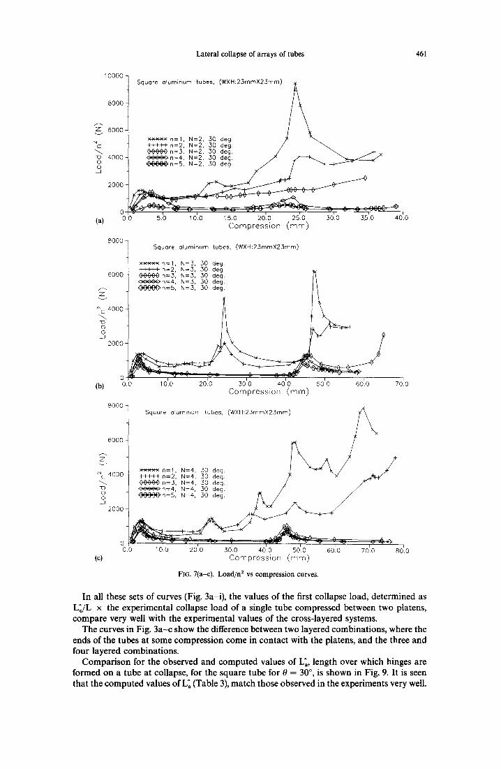
To exhibit this behaviour of the cross-layered systems in terms of the load-compression characteristics, load/n2-compression and load/nL-compression curves have been plotted in Figs 7 and 8. Three sets of curves were plotted for N = 2, 3 and 4. In each set, curves were plotted together for n = 1, 2, 3, 4 and 5.
This exercise was done because it is expected that the load/n 2 vs compression curves would match for those values of n, up to which the collapse at adjacent intersections is independent. The load/nL vs compression curves would match when n is large enough to cause the entire tubes to participate in the collapse of a layer.
3. R E S U L T S A N D D I S C U S S I O N
The load-compression curves for multi-layered combinations of single square tube, for different 0, are shown in Fig. 3a-c. The same has been done for the n = 2, 3, 4 and 5 combinations of the square tube in Fig. 3d-g. The load-compression curve of a single tube of length L~ (Table 3), has also been plotted in all the above cases. The load-compression curves for multi-layered combinations of the single rectangular tubes (of two types) are plotted in Fig. 3h,i.
Lateral collapse of arrays of tubes 461
10000
8000
Z 6OO0
4000
2 0 0 0 -
(a) 0 0.0
Square aquminum tubes, (WXH:23mmX23mm) / ~
/ \ ×××x× n=l , N=2, 30 deg. /~ " ~ IIIII n=2, N=2, 30 deg. / ~. OOAO0 n=3, N=2, 30 deg. / ~. . 4 -
30 /
A~.A ^
5.0 10.0 15.0 20.0 25.0 30.0 35.0 40.0 Compression (ram)
8000 / q Square aluminum tubes, (WXH:25mmX2.3mm)
1 ×xxx× n=l , N=3, .30 deg. I I I I I n=2, N=.3, .30 deg.
6000 - ¢0000 n=3, N=.3, .30 deg. I~ I , c~O~n=4, N=3, 30 deg. I~
1 o 2000
0 i - i (b) 0.0 10.0 20'.0 3010 4010 50'.0 60'.0
Compression (mm) 80007
i 70.0
6000
~ 4000
~D © 0
J 2000-
(c)
o o.o
Square aluminum tubes, (WXH:23mmX23mm) / ~
i 10.0 20.0 30.0 40.0 50.0 600 70.0 80.0
C o m p r e s s i o n ( m m )
FIG. 7(a-c). Load/n 2 vs compression curves.
In all these sets of curves (Fig. 3a-i), the values of the first collapse load, determined as L~/L x the experimental collapse load of a single tube compressed between two platens, compare very well with the experimental values of the cross-layered systems.
The curves in Fig. 3a-c show the difference between two layered combinations, where the ends of the tubes at some compression come in contact with the platens, and the three and four layered combinations.
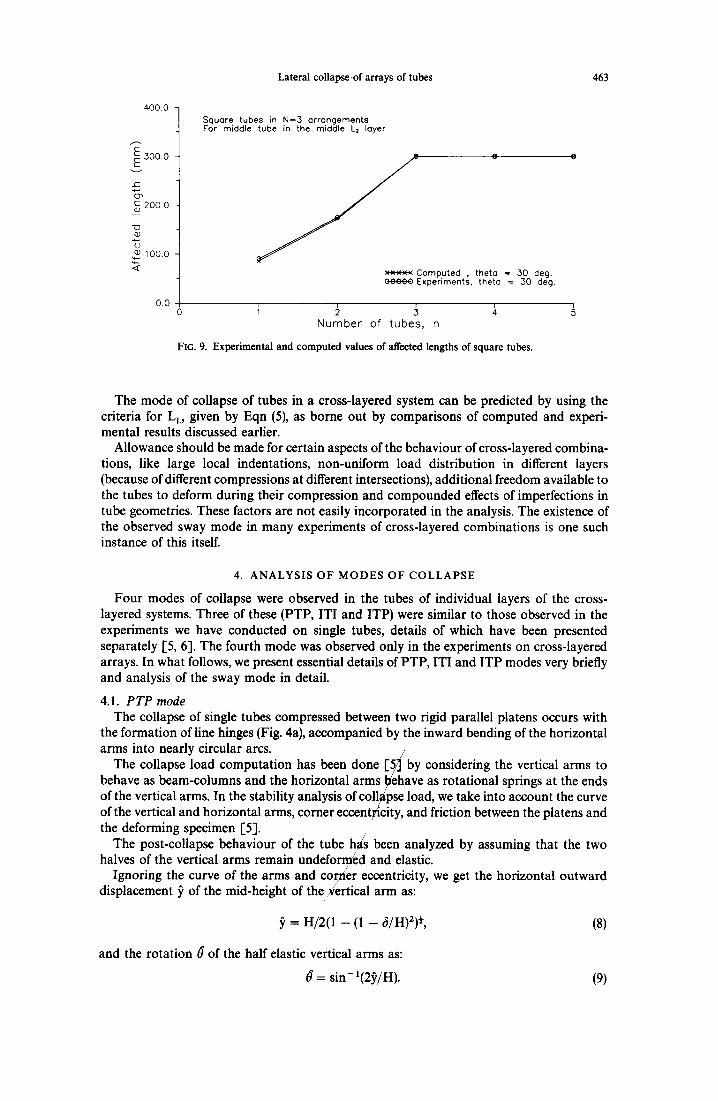
Comparison for the observed and computed values of L~, length over which hinges are formed on a tube at collapse, for the square tube for 0 = 30 °, is shown in Fig. 9. It is seen that the computed values of L~ (Table 3), match those observed in the experiments very well.
462 N.K. GUPTA and A. KHULLAR
40
.._..30 ¸ z
Q- ,~cx20 '
- n l 0 .
0 0 .0
(a)
30-
Z~,20
"o o°10 . __J
0 0.0
(b) 40-
30"
Z
Z" 20-
"(D (3 0 u
10"
(c)
Square aluminum tubes, (WXH:23mmX23mm)
xx×.'<.× n= l , N=2, 30 deg. ] \ t t t l I n = 2 , N = 2 , 3 0 deg. / ~ / 0~)4)"04) n=3 , N=2, 30 deg. [~¢ \ ~ j . . .4 , / /4 ) ~ = = ' n = 4 , N=2, 30 deg. / / \ ~ / ~ n = 5 , N=2, 30 deg.
1010 2010 3010 4010 Compression (ram)
Square aluminum tubes, (WXH:23mmX23mm)
xx×xx n= l , N=3, 30 deg. / +++-I-I-n=2, N=3, 30 deg. / ¢00C0n=3, N=3, 30 deg. ~ ~ , / <3~0~On=4, N=3, 30 deg. ~1 / "~'~'4'''~ /
= , = )
10'.0 20'.0 ' 30~.0 40'.0 50'.0 60~.0 Compression (mm)
70'.0
Square aluminum tubes, (WXH:23mmX23mm)
0 o.o ~o'.o 20'.0
J x x x x x n= l , N=4, 30 deg. / / ' ~ ' \ t1~11 n=2. N=4, .30 deg. ~" x,x ~v~O~O n=3, N=4, 30 deg. ~ . i f ' ~ n = 4 , N=4, 30 deg. 1"~ / /
~ ~ A n I
30).0 ' 40.0 50'.0 60'.0 70.0 80'.0 Compression (mm)
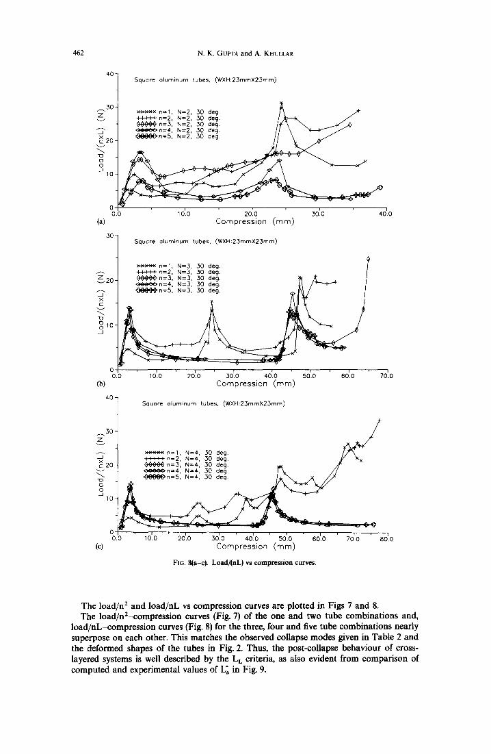
FIG. 8(a-c). Load/(nL) vs compression curves.
The load/n 2 and load/nL vs compression curves are plotted in Figs 7 and 8. The load/n2-compression curves (Fig. 7) of the one and two tube combinations and,
load/nL-compression curves (Fig. 8) for the three, four and five tube combinations nearly superpose on each other. This matches the observed collapse modes given in Table 2 and the deformed shapes of the tubes in Fig. 2. Thus, the post-collapse behaviour of cross- layered systems is well described by the L L criteria, as also evident from comparison of computed and experimental values of L~ in Fig. 9.
Lateral collapse .of arrays of tubes 463
4 0 0 . 0
E 3ooo E
c-
200.0
22 OJ
<~ 100.0 <
0.0
Square tubes in N=3 arrangements For middle tube in the middle L2 layer
::×××× Computed , theto = 30 deg. ¢0~00 Experiments, theto 30 deg.
o ~ ~ ~ ~ N u m b e r o f t u b e s , n
FIG. 9. Experimental and computed values of affected lengths of square tubes.
The mode of collapse of tubes in a cross-layered system can be predicted by using the criteria for L L, given by Eqn (5), as borne out by comparisons of computed and experi- mental results discussed earlier.
Allowance should be made for certain aspects of the behaviour of cross-layered combina- tions, like large local indentations, non-uniform load distribution in different layers (because of different compressions at different intersections), additional freedom available to the tubes to deform during their compression and compounded effects of imperfections in tube geometries. These factors are not easily incorporated in the analysis. The existence of the observed sway mode in many experiments of cross-layered combinations is one such instance of this itself.
4. A N A L Y S I S O F M O D E S O F C O L L A P S E
Four modes of collapse were observed in the tubes of individual layers of the cross- layered systems. Three of these (PTP, ITI and ITP) were similar to those observed in the experiments we have conducted on single tubes, details of which have been presented separately [5, 6]. The fourth mode was observed only in the experiments on cross-layered arrays. In what follows, we present essential details of PTP, ITI and ITP modes very briefly and analysis of the sway mode in detail.
4.1. PTP mode The collapse of single tubes compressed between two rigid parallel platens occurs with
the formation of line hinges (Fig. 4a), accompanied by the inward bending of the horizontal arms into nearly circular arcs. /
The collapse load computation has been done [ ~ b y considering the vertical arms to behave as beam-columns and the horizontal arms ~ehave as rotational springs at the ends of the vertical arms. In the stability analysis of collLapse load, we take into account the curve of the vertical and horizontal arms, corner eccentricity, and friction between the platens and the deforming specimen [5].
The post-collapse behaviour of the tube has been analyzed by assuming that the two halves of the vertical arms remain undeformed and elastic.
Ignoring the curve of the arms and cor/ner eccentricity, we get the horizontal outward displacement S' of the mid-height of the:Vertical arm as:
= H/2(1 - (I - 6/H)2) ½, (8)
and the rotation ~ of the half elastic vertical arms as:
0 = sin- :(2~,/H). (9)
464 N.K. GUPTA and A. KHULLAR
The load at any compression 6 is given by:
P = 2(M v + Mh)/~), (10)
where My is the plastic moment of the vertical arm and M h is the smaller plastic moment of the vertical and horizontal arms.
4.2. ITI mode The tube in this case is being compressed symmetrically between two narrow width
indenters. As the indenter moves down, collapse of the tube occurs with formation of collapsing panels on the four sides of the tube which are enclosed within plastic hinges and separated from undeformed ends of the tube. The hinge pattern formed on the tube in this case was assumed symmetric (Fig. 4b), and therefore the deformed shape at any com- pression remained symmetrical about the horizontal mid-plane.
4.3. l i P mode This mode of deformation occurs when the tube is resting on a platen and is being
compressed by a narrow width flat indenter from the top. The hinge pattern formed locally on the tube sides under the indenter is asymmetric (Fig. 4c). In both ITI and ITP cases the post-collapse analysis, presented separately [6], consisted of first predicting the location of various hinges which enclose the collapsing panels and those formed within them. There- after, we analyzed the different modes in which the tube collapses under the indenter at different compressions; accompanied by the formation of new hinges and rolling of some previously stationary hinges.
The deforming geometry of the tube at any compression was computed by determining the orientation of the various undeformed planes enclosed within plastic hinges. This permitted us to determine the change in angle at all locations of the stationary hinges and the area traversed by rolling hinges, and thus the work done in the stationary and rolling plastic hinges at any compression. The slope of the energy-compression curve gives the load at any compression. The detailed analysis is presented separately in Ref. [6].
4.4. S W mode In sway mode, two tubes aligned in the same direction in alternate layers deformed
simultaneously (Fig. 5) like frames under lateral horizontal load, acting at their bottom and top faces. This occurred in two parallel layers, separated by one layer in the middle. The layer between the two layers, which deformed in the sway mode, could have been deformed previously or still be undeformed, but it did not change its shape during the period the sway occurs. In this mode, the square and rectangular cross-sections deform to become rhomboi- dal and the termination of this mode occurs with the complete flattening of the two tubes. The load-compression curve, for collapse of tubes in this mode, remains fiat during nearly the entire compression involving the two tubes.
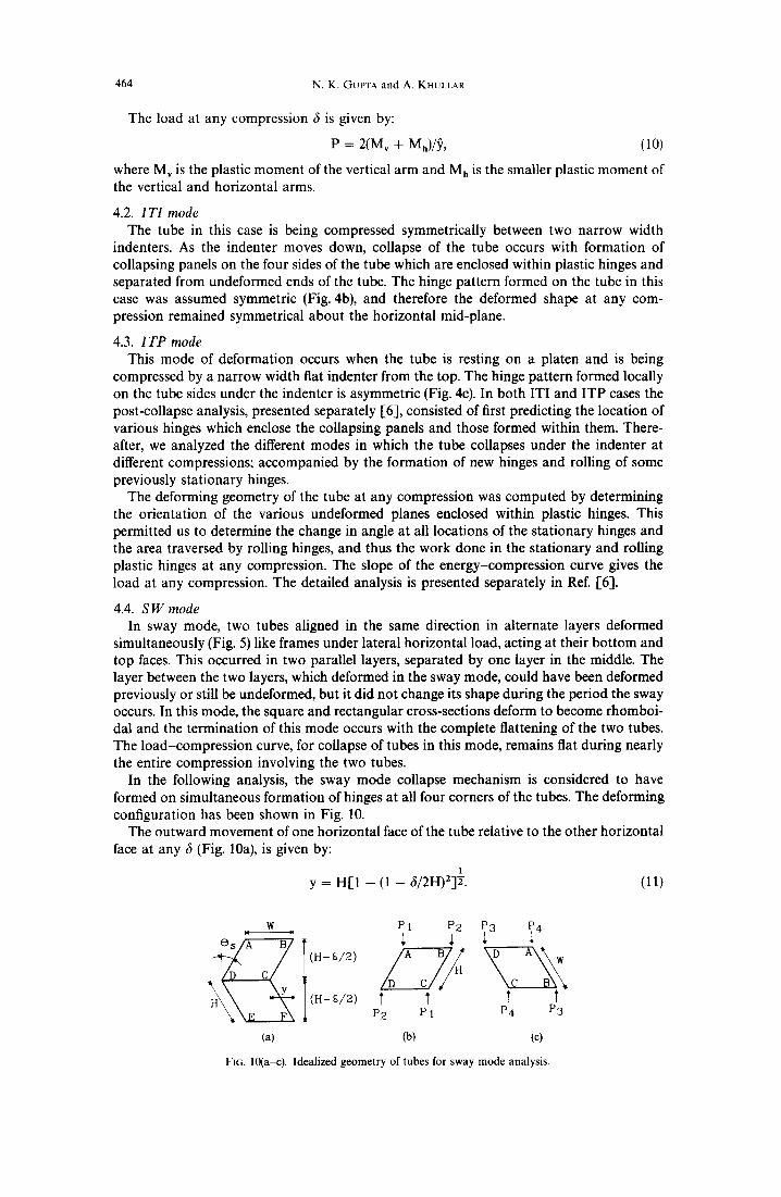
In the following analysis, the sway mode collapse mechanism is considered to have formed on simultaneous formation of hinges at all four corners of the tubes. The deforming configuration has been shown in Fig. 10.
The outward movement of one horizontal face of the tube relative to the other horizontal face at any 6 (Fig. 10a), is given by:
1 y = H[1 - (1 - 5/2H)2ff. (1 l)
W ~- P1 P2
[ (H-$/2) I ~' I I P2 P i P4 P3
(a) (b) (c)
FIG. lO(a-c). Idealized geometry of tubes for sway mode analysis.
Lateral collapse of arrays of tubes 465
The rotation 0 s at the corner hinges (Fig. 10a), is given as:
0 s = cos - t [1 - 6/2H]. (12)
Energy absorbed in the hinges of both tubes (Fig. 10), which are involved in the sway, is given as:
E = 8Mp0,, (13)
Mp is the plastic moment at the corners. Considering that shears are transferred to the vertical arm from the horizontal arms
(beams) and then taking its equilibrium, the loads at the corners (Fig. 10b), are given by:
P1 = 2Mp/y + 2Mp/W, (14)
and:
P2 = 2Mp/y - 2Mp/W. (15)
Similarly, when equilibrium of the other vertical arm is considered separately, the symmetry of the loading on the top and bot tom faces of each tube is established as shown in Fig. 10b:
P = PI + P2 = 4Mp/y. (16)
Considering the overall moment equilibrium of one tube we get:
P2/P1 = (W - y)/(W + y). (17)
Thus, when y just exceeds W, then one corner of the tube will tend to lift up and P2 becomes zero.
Compression 6s up to which the tube remains stable is given by:
6~ = 2H - 2[H 2 - - W 2 ] ½. (18)
The tube remains stable all the time if W > H. For W < H, at some stage, the tube will begin to overturn and on further compression come to rest on the longer side (Fig. 10c). In the overturned stable configuration, the height of the deformed tube now is less than its height at the instant at which the overturning started.
The value of 0s at which overturning occurs is given by:
0o = sin- 1[W/H]. (19)
The compression 6 o at which the load begins to act on the overturned tube is:
60 = 2(H - Wcos 0o). (20)
The corresponding outward slide of the now top face of the tube relative to the bot tom face is:
yo = Wsin 0o. (21)
Hereafter, the analysis proceeds in the same manner as before and so corner loads (Fig. 10c) now for 6 > 60 are:
P3 = 2Mp/y - 2Mp/H, and (22)
P4 = 2Mp/y + 2Mp/H, (23)
where:
y = W[1 -- (1 - 6/2W)23 ½. (24)
The total load on the overturned tube is:
Po = P3 + P4 = 4Mp/y. (25)
For compression between fs and 6o gradual overturning takes place. We assume that the load-compression curve transits from 6s to 6o linearly, while the total energy dissipated remains unchanged.
466 N.K. GuPTA and A. KHULLAR
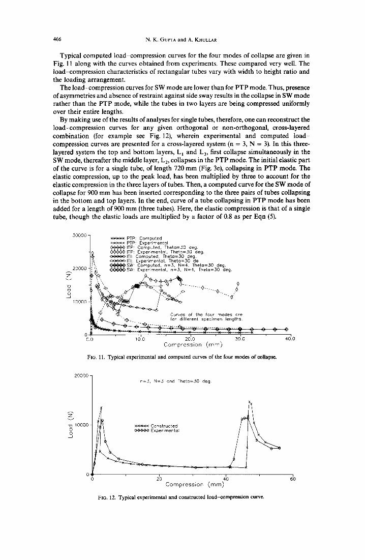
Typical computed load-compression curves for the four modes of collapse are given in Fig. 11 along with the curves obtained from experiments. These compared very well. The load-compression characteristics of rectangular tubes vary with width to height ratio and the loading arrangement.
The load-compression curves for SW mode are lower than for PTP mode. Thus, presence of asymmetries and absence of restraint against side sway results in the collapse in SW mode rather than the PTP mode, while the tubes in two layers are being compressed uniformly over their entire lengths.
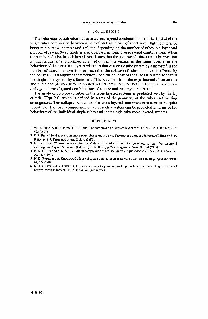
By making use of the results of analyses for single tubes, therefore, one can reconstruct the load-compression curves for any given orthogonal or non-orthogonal, cross-layered combination (for example see Fig. 12), wherein experimental and computed load- compression curves are presented for a cross-layered system (n = 3, N = 3). In this three- layered system the top and bottom layers, L 1 and L3, first collapse simultaneously in the SW mode, thereafter the middle layer, L2, collapses in the PTP mode. The initial elastic part of the curve is for a single tube, of length 720 mm (Fig. 3e), collapsing in PTP mode. The elastic compression, up to the peak load, has been multiplied by three to account for the elastic compression in the three layers of tubes. Then, a computed curve for the SW mode of collapse for 900 mm has been inserted corresponding to the three pairs of tubes collapsing in the bottom and top layers. In the end, curve of a tube collapsing in PTP mode has been added for a length of 900 mm (three tubes). Here, the elastic compression is that of a single tube, though the elastic loads are multiplied by a factor of 0.8 as per Eqn (5).
30000-
20000 Z
~D o 0 J
100oo
0 0.0 10'.0
×xxxx PTP: Computed x-~x-wK PTP: Experimentol ^^A^ vvvvOITP. Computed, Theto=30 deg O~O~OITP: Experimentol, Theto=30 deg. ~ I T I : Computed, Theta=30 deg. ~ I T I : Experimental, Theto=30 de
i~, @ S W : Computed, n=3, N=4, Theta=30 deg. ~,[~,~SW: Experlmentol, n=3, N=4, Theto=30 deg.
, "~ ... . . . . . . ~... ,~
i , 'q'~ "'b'&. for different specimen lengths.
20[0 30'.0 Compression (mm)
FIG. 11. Typical experimental and computed curves of the four modes of collapse.
40~.0
20000
10000 o 0 J
n=3, N=3 ond Theto=30 deg.
×x×x× Constructed / COOOO Experimental
2'o ,~ 6'0 Compression (ram)
FIG. 12. Typical experimental and constructed load-compression curve.
Lateral collapse of arrays of tubes 467
5. C O N C L U S I O N S
The behaviour of individual tubes in a cross-layered combination is similar to that of the single tubes compressed between a pair of platens, a pair of short width flat indenters, or between a narrow indenter and a platen, depending on the number of tubes in a layer and number of layers. Sway mode is also observed in some cross-layered combinations. When the number of tubes in each layer is small, such that the collapse of tubes at each intersection is independent of the collapse at an adjoining intersection in the same layer, then the behaviour of the tubes in a layer is related to that of a single tube system by a factor n 2. If the number of tubes in a layer is large, such that the collapse of tubes in a layer is affected by the collapse at an adjoining intersection, then the collapse of the tubes is related to that of the single-tube system by a factor nL. This is evident from the experimental observations and their comparison with computed results presented for both orthogonal and non- orthogonal cross-layered combinations of square and rectangular tubes.
The mode of collapse of tubes in the cross-layered systems is predicted well by the L L criteria [Eqn (5)], which is defined in terms of the geometry of the tubes and loading arrangement. The collapse behaviour of a cross-layered combination is seen to be quite repeatable. The load-compression curve of such a system can be predicted in terms of the behaviour of the individual single tubes and their single-tube cross-layered systems.
R E F E R E N C E S
1. W. JOHNSON, S. R. REID and T. Y. REDD¥, The compression of crossed layers of thin tubes. Int. J. Mech. Sci. 19, 423 (1977).
2. S. R. REID, Metal tubes as impact energy absorbers, in Metal Forming and Impact Mechanics (Edited by S. R. REID), p. 249. Pergamon Press, Oxford (1985).
3. N. JONES and W. ABRAMOWlCZ, Static and dynamic axial crushing of circular and square tubes, in Metal Forming and Impact Mechanics (Edited by S. R. REID), p. 225. Pergamon Press, Oxford (1985).
4. N. K. GUPTA and S. K. SINHA, Lateral compression of crossed layers of square-section tubes. Int. J. Mech. Sci. 32, 565 (1990).
5. N. K. GUPTA and A. KHULLAR, Collapse of square and rectangular tubes in transverse loading. Ingeneiur-Archiv 63, 479 (1993).
6. N. K. GUPTA and A. KHULLAR, Lateral crushing of square and rectangular tubes by non-orthogonally placed narrow width indenters. Int. J. Mech. Sci. (submitted).
HS 36:5-G