Embed Size (px)
Citation preview
INSTRUCTION MANUAL
LE-110SALE-120SA
DATA LINE MONITOR
《 Ver.5 2020.10 》

-1-
IntroductionThank you for your purchase of LE-series.To use it correctly, you are advised to read and understand this instruction manual thoroughly. Keep this together with the warranty. If you encounter any problems, you will find helpful information in this manual.
NOTICEIt is prohibited to reprint or duplicate any part of this manual without prior permission from LINEEYE. The content of this manual and specification of the product is subject to change without any notice.This instruction manual has been designed and edited with great care to give you all necessary information. If you have any questions, feel free to direct your inquiries to LINEEYE.LINEEYE makes no warranty or guarantee, either expressed or implied with respect to its quality, performance, merchantability, or fitness for a particular purpose. LINEEYE shall not be liable for direct, in-direct, special, incidental, or consequential damages resulting from any defect in the product. The warranty and remedies set forth above are exclusive and in lieu of all others.
USER LIMITATIONThis product has been developed for the purpose of using as an line monitor only.When you use this product with the following devices that are required to function with a high degree of reliability, safety and accuracy, use it under considering the safe design of the system in order to maintain reliability and safety for that system;
*Devices that are directly related to transportation such as airplanes, trains, cars etc.
*Devices for crime prevention and disaster prevention.*Each kind of safety devices and so on.
This product has not been developed for the use that needs exclusive high reliability and safety:aerospace apparatus, trunk communication apparatus, nuclear control apparatus, medical apparatus related with life maintenance etc. Therefore, do no use for those purposes.
= = = Notice = = = When you dispose of it, please follow the regulation of the region
2018 by LINEEYE CO.,LTD All rights reserved
Warning
* Do not disassemble, modify or repair the line monitor.This may result in an injury, electric shock, and ignition.
* Do not put the line monitor in a fire or place near the heater.This may result an injury, ignition and explosion.
* Do not use the line monitor if there is inflammable gas.This may result in ignition and explosion.
* Turn off the power and unplug the line monitor immediately when emanating smoke or odor.Continuous use may result in an electric shock burn and ignition.
-2-
Read this first!!This Safety Information includes the following important information in order to not only have you learn the right way to use the line monitor, but also prevent you from causing damage to people and property. Before using, please read the main contents after you understand the following symbols & marks.
Warning There is a possibility of getting hurt, such as a death or a serious injury.
Caution There is a possibility of getting injured or damaging the product.
Prohibition
necessity
Safety Information
Warning
* Turn off the power and unplug the line monitor immediately when liquid or foreign substance gets into the line monitor.Continuous use may result in ignit ion, elect r ic shock and malfunction.
* Do not touch the line monitor with wet hand.This may result in an electric shock and malfunction.
* Do not give a strong impact on the product, such as dropping and crashing.
* Use the bat ter ies and USB charger which LINEEYE recommends.It may cause the generation of heart, ignition, electric shock and malfunction.
* Do not use the batteries other than Ni-MH batteries or alkaline batteries.This may result generat ion of heat , ignit ion, leaking and malfunction.
* Do not leave the batteries near children. If drinking them, please go to see your doctor.
* Please check +/- of the batteries before inserting them. Do not short the electrode of batteries.It may cause the generation of heat, ignition, explosion, leaking and malfunction.
* Do not charge the Alkali batteries.It may cause leaking, generat ion of hear t , explosion and malfunction.
* Do not touch the liquid of batteries.It may result in serious injury, such as losing your eyesight. If you touch it, wash out the part first and go to see your doctor.
* Do not use the new battery and old battery at the same time. Do not use the batteries which are different manufactures. It may cause the leaking, generation of heat, explosion and malfunction.
* Remove the batteries from the line monitor if you do not use it for a while.It may cause leaking, generation of heat, explosion and malfunction.
-3-
Caution
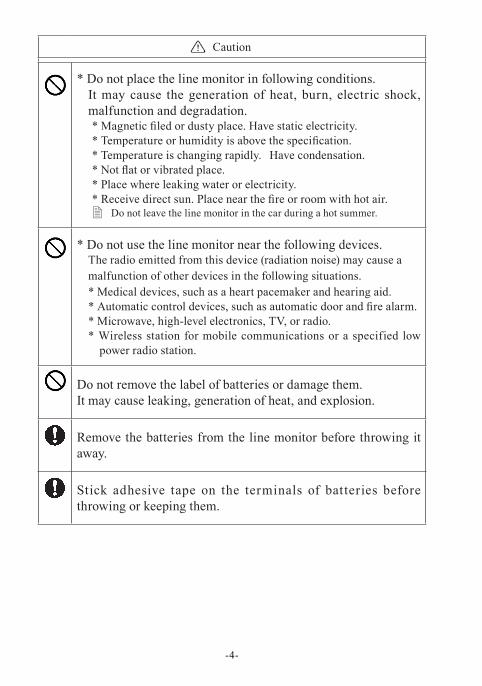
* Do not place the line monitor in following conditions.It may cause the generation of heat, burn, electric shock, malfunction and degradation.* Magnetic filed or dusty place. Have static electricity.* Temperature or humidity is above the specification.* Temperature is changing rapidly. Have condensation.* Not flat or vibrated place.* Place where leaking water or electricity. * Receive direct sun. Place near the fire or room with hot air.
� Do not leave the line monitor in the car during a hot summer.
* Do not use the line monitor near the following devices.The radio emitted from this device (radiation noise) may cause a malfunction of other devices in the following situations.* Medical devices, such as a heart pacemaker and hearing aid.* Automatic control devices, such as automatic door and fire alarm.* Microwave, high-level electronics, TV, or radio.* Wireless station for mobile communications or a specified low
power radio station.
Do not remove the label of batteries or damage them. It may cause leaking, generation of heat, and explosion.
Remove the batteries from the line monitor before throwing it away.
Stick adhesive tape on the terminals of batteries before throwing or keeping them.
-4-
Caution
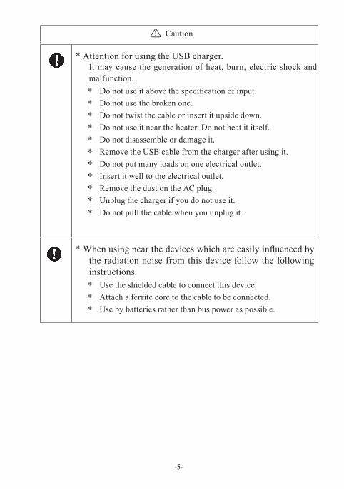
* Attention for using the USB charger.It may cause the generation of heat, burn, electric shock and malfunction.* Do not use it above the specification of input.* Do not use the broken one.* Do not twist the cable or insert it upside down.* Do not use it near the heater. Do not heat it itself.* Do not disassemble or damage it.* Remove the USB cable from the charger after using it.* Do not put many loads on one electrical outlet.* Insert it well to the electrical outlet.* Remove the dust on the AC plug.* Unplug the charger if you do not use it.* Do not pull the cable when you unplug it.
* When using near the devices which are easily influenced by the radiation noise from this device follow the following instructions.* Use the shielded cable to connect this device. * Attach a ferrite core to the cable to be connected.* Use by batteries rather than bus power as possible.
-5-
-6-
CONTENTSIntroduction ........................................................................................1
Safety Information ......................................................................2
Chapter 1 Before Using the Product ...........................................9
1.1 Guide to This Manual ...................................................................91.2 Unpacking ................................................................................... 101.3 Major Functions and Features .................................................... 111.4 Explanation of Each Part ............................................................ 121.5 Power and Battery ...................................................................... 14
Chapter 2 Basic Operation and Set-Up .....................................16
2.1 Power Source ON ....................................................................... 162.2 Operation .................................................................................... 162.3 Data Display window ................................................................. 172.4 Languages (Japanese/English) ................................................... 182.5 Date and Time Setting ................................................................ 182.6 Settings for Charging Batteries .................................................. 192.7 Adjust LCD Back Light ..............................................................202.8 Power saving Mode ....................................................................20
Chapter 3 Basic Settings ...........................................................21
3.1 Setting Menu ............................................................................... 213.2 Measurement Port / Function .....................................................223.3 Communication Speed ...............................................................243.4 Frame End Setting ......................................................................263.5 Capture Memory ........................................................................273.6 Idle Time and Time Stamp .........................................................283.7 Line State .................................................................................... 293.8 Auto Backup ............................................................................... 29
-7-
Chapter 4 Connect to the Target Devices .................................30
4.1 Connect to RS-232C ...................................................................304.2 Connect to RS-422/RS-485(LE-110SA) .................................... 314.3 Connect to TTL interface(LE-120SA) ....................................... 33
Chapter 5 Monitor Function .....................................................34
5.1 Overview .....................................................................................345.2 Start and Stop Monitoring ..........................................................345.3 Scroll and Jump .......................................................................... 365.4 Retrieval Function ...................................................................... 375.5 Line State Display Function ....................................................... 395.6 Display Data Per a Frame ...........................................................405.7 Save a Screen Image ...................................................................405.8 Auto Configuration Function ..................................................... 41
Chapter 6 Simulation Function .................................................42
6.1 Simulation Function ................................................................... 426.2 Registration of Transmission Data ............................................. 426.3 Start/Finish Simulation ..............................................................44
Chapter 7 Trigger Function .......................................................46
7.1 Trigger Function .........................................................................467.2 External Trigger Input/Output ....................................................467.3 Trigger Setting ............................................................................ 477.4 Timer / counter function ............................................................. 51
Chapter 8 Data Save and Read.................................................53
8.1 File Management Function ......................................................... 538.2 Save ............................................................................................. 538.3 Filter Function ............................................................................548.4 Reload (Read) ............................................................................. 558.5 Delete ......................................................................................... 55
-8-
Chapter 9 PC Link Function .....................................................56
9.1 Installation of the USB Driver ....................................................569.2 Installation of PC link software ................................................. 579.3 Remote control ............................................................................ 589.4 Measured data display and text conversion ...............................60
Chapter 10 Documents .............................................................62
10.1 Specifications ............................................................................ 6210.2 Data Code Table ........................................................................6410.3 Option ...................................................................................... 65
Chapter 11 After Support and Maintenance ............................66
11.1 How to make it back to default state .........................................6611.2 How to Update the Firmware....................................................6611.3 Troubleshooting ........................................................................6811.4 Warranty and After service ...................................................... 70
-9-
Chapter 1 Before Using the Product
1.1 Guide to This Manual
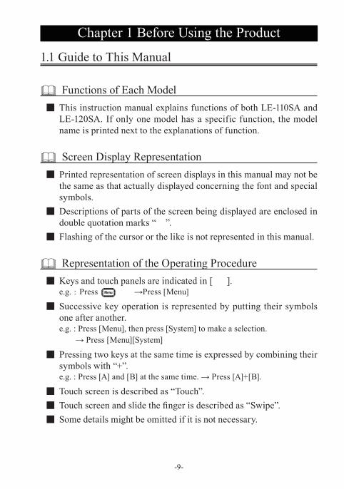
Functions of Each Model ■ This instruction manual explains functions of both LE-110SA and LE-120SA. If only one model has a specific function, the model name is printed next to the explanations of function.
Screen Display Representation ■ Printed representation of screen displays in this manual may not be the same as that actually displayed concerning the font and special symbols.
■ Descriptions of parts of the screen being displayed are enclosed in double quotation marks “ ”.
■ Flashing of the cursor or the like is not represented in this manual.
Representation of the Operating Procedure ■ Keys and touch panels are indicated in [ ].e.g. : Press →Press [Menu]
■ Successive key operation is represented by putting their symbols one after another.e.g. : Press [Menu], then press [System] to make a selection.
→ Press [Menu][System]
■ Pressing two keys at the same time is expressed by combining their symbols with “+”. e.g. : Press [A] and [B] at the same time. → Press [A]+[B].
■ Touch screen is described as “Touch”. ■ Touch screen and slide the finger is described as “Swipe”. ■ Some details might be omitted if it is not necessary.
-10-
1.2 Unpacking
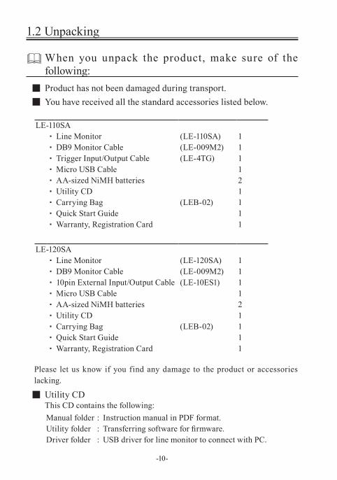
When you unpack the product, make sure of the following:
■ Product has not been damaged during transport. ■ You have received all the standard accessories listed below.
LE-110SA・ Line Monitor (LE-110SA) 1 ・ DB9 Monitor Cable (LE-009M2) 1・ Trigger Input/Output Cable (LE-4TG) 1・ Micro USB Cable 1 ・ AA-sized NiMH batteries 2・ Utility CD 1 ・ Carrying Bag (LEB-02) 1・ Quick Start Guide 1 ・ Warranty, Registration Card 1
LE-120SA・ Line Monitor (LE-120SA) 1 ・ DB9 Monitor Cable (LE-009M2) 1 ・ 10pin External Input/Output Cable (LE-10ES1) 1 ・ Micro USB Cable 1 ・ AA-sized NiMH batteries 2・ Utility CD 1 ・ Carrying Bag (LEB-02) 1 ・ Quick Start Guide 1 ・ Warranty, Registration Card 1
Please let us know if you find any damage to the product or accessories lacking.
■ Utility CDThis CD contains the following:Manual folder : Instruction manual in PDF format.Utility folder : Transferring software for firmware.Driver folder : USB driver for line monitor to connect with PC.
-11-
1.3 Major Functions and Features
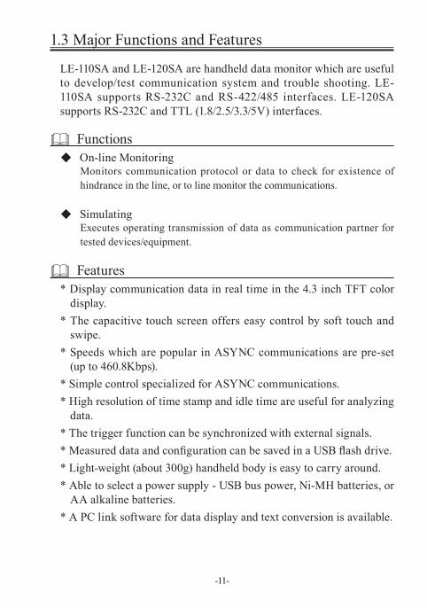
LE-110SA and LE-120SA are handheld data monitor which are useful to develop/test communication system and trouble shooting. LE-110SA supports RS-232C and RS-422/485 interfaces. LE-120SA supports RS-232C and TTL (1.8/2.5/3.3/5V) interfaces.
Functions◆ On-line Monitoring
Monitors communication protocol or data to check for existence of hindrance in the line, or to line monitor the communications.
◆ SimulatingExecutes operating transmission of data as communication partner for tested devices/equipment.
Features* Display communication data in real time in the 4.3 inch TFT color
display.* The capacitive touch screen offers easy control by soft touch and
swipe.* Speeds which are popular in ASYNC communications are pre-set
(up to 460.8Kbps).* Simple control specialized for ASYNC communications.* High resolution of time stamp and idle time are useful for analyzing
data.* The trigger function can be synchronized with external signals.* Measured data and configuration can be saved in a USB flash drive.* Light-weight (about 300g) handheld body is easy to carry around.* Able to select a power supply - USB bus power, Ni-MH batteries, or
AA alkaline batteries.* A PC link software for data display and text conversion is available.
6)
11)
14) 13) 10)12)
4)
7)
5) 3) 2) 1) 8)
9)
-12-
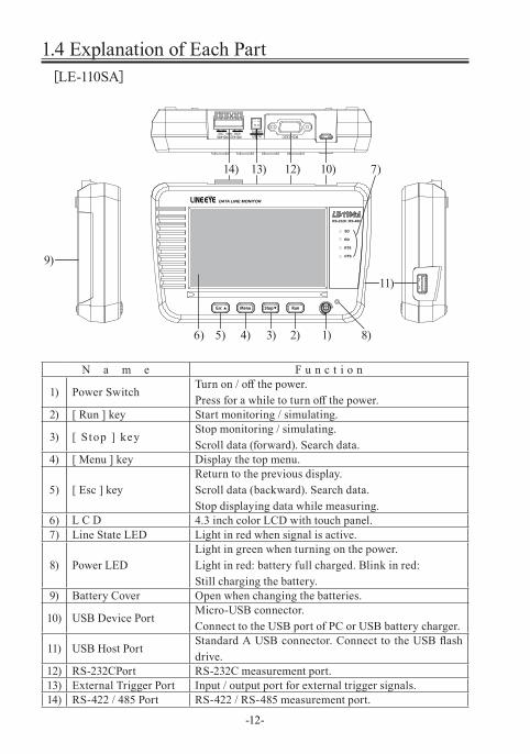
1.4 Explanation of Each Part[LE-110SA]
N a m e F u n c t i o n
1) Power SwitchTurn on / off the power.Press for a while to turn off the power.
2) [ Run ] key Start monitoring / simulating.
3) [ Stop ] keyStop monitoring / simulating.Scroll data (forward). Search data.
4) [ Menu ] key Display the top menu.
5) [ Esc ] keyReturn to the previous display.Scroll data (backward). Search data.Stop displaying data while measuring.
6) 4.3 inch color LCD with touch panel.7) Line State LED Light in red when signal is active.
8) Power LEDLight in green when turning on the power.Light in red: battery full charged. Blink in red: Still charging the battery.
9) Battery Cover Open when changing the batteries.
10) USB Device PortMicro-USB connector.Connect to the USB port of PC or USB battery charger.
11) USB Host PortStandard A USB connector. Connect to the USB flash drive.
12) RS-232CPort RS-232C measurement port.13) External Trigger Port Input / output port for external trigger signals.14) RS-422 / 485 Port RS-422 / RS-485 measurement port.
L C D
6) 1)
13) 10)12)
4)
7)
5) 3) 2)
11)
8)
9)
-13-
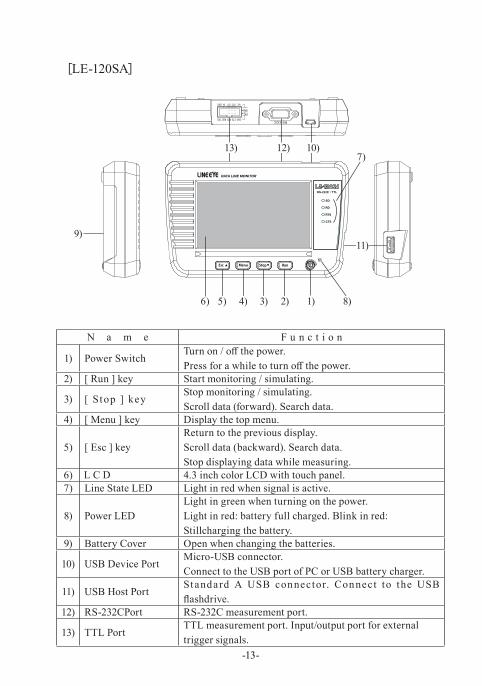
[LE-120SA]
N a m e F u n c t i o n
1) Power SwitchTurn on / off the power.Press for a while to turn off the power.
2) [ Run ] key Start monitoring / simulating.
3) [ Stop ] keyStop monitoring / simulating.Scroll data (forward). Search data.
4) [ Menu ] key Display the top menu.
5) [ Esc ] keyReturn to the previous display.Scroll data (backward). Search data.Stop displaying data while measuring.
6) 4.3 inch color LCD with touch panel.7) Line State LED Light in red when signal is active.
8) Power LEDLight in green when turning on the power.Light in red: battery full charged. Blink in red: Stillcharging the battery.
9) Battery Cover Open when changing the batteries.
10) USB Device PortMicro-USB connector.Connect to the USB port of PC or USB battery charger.
11) USB Host PortStandard A USB connector. Connect to the USB flashdrive.
12) RS-232CPort RS-232C measurement port.
13) TTL PortTTL measurement port. Input/output port for externaltrigger signals.
L C D
-14-
1.5 Power and Battery
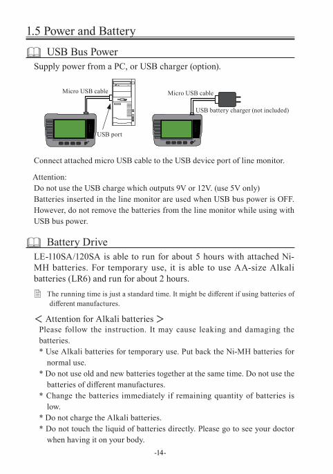
USB Bus PowerSupply power from a PC, or USB charger (option).
Connect attached micro USB cable to the USB device port of line monitor.
Attention:Do not use the USB charge which outputs 9V or 12V. (use 5V only)Batteries inserted in the line monitor are used when USB bus power is OFF. However, do not remove the batteries from the line monitor while using with USB bus power.
Battery DriveLE-110SA/120SA is able to run for about 5 hours with attached Ni-MH batteries. For temporary use, it is able to use AA-size Alkali batteries (LR6) and run for about 2 hours.
� The running time is just a standard time. It might be different if using batteries of different manufactures.
< Attention for Alkali batteries >Please follow the instruction. It may cause leaking and damaging the batteries.* Use Alkali batteries for temporary use. Put back the Ni-MH batteries for
normal use.* Do not use old and new batteries together at the same time. Do not use the
batteries of different manufactures. * Change the batteries immediately if remaining quantity of batteries is
low. * Do not charge the Alkali batteries.* Do not touch the liquid of batteries directly. Please go to see your doctor
when having it on your body.
Micro USB cable
USB port
USB battery charger (not included)
Micro USB cable
-15-
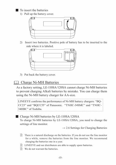
■ To insert the batteries1) Pull up the battery cover.
2) Insert two batteries. Positive pole of battery has to be inserted to the side where it is labeled.
3) Put back the battery cover.
Charge Ni-MH BatteriesAs a factory setting, LE-110SA/120SA cannot charge Ni-MH batteries to prevent charging Alkali batteries by mistake. You can charge them using the Ni-MH battery charger for AA-size.
LINEEYE confirms the performance of Ni-MH battery chargers: “BQ-CC23” and “BQCC55” of Panasonic. “TNHC-34SMC” and “TNHC-34HBC” of Toshiba.
■ Charge Ni-MH batteries by LE-110SA/120SATo charge Ni-MH batteries by LE-110SA/120SA, you need to change the settings of line monitor.
→ 2.6 Settings for Charging Batteries
� There is a natural discharge on the batteries. If you do not use the line monitor for a while, remove the batteries from the line monitor. We recommend charging the batteries one in a year.
� LINEEYE and our distributors are able to supply spare batteries. � We do not warrant the batteries.
+
+
-16-
Chapter 2 Basic Operation and Set-Up
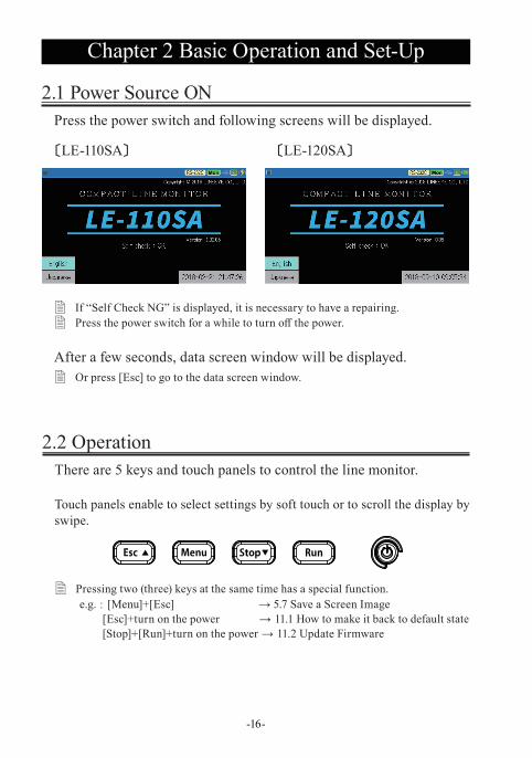
2.1 Power Source ONPress the power switch and following screens will be displayed.
〔LE-110SA〕 〔LE-120SA〕
� If “Self Check NG” is displayed, it is necessary to have a repairing. � Press the power switch for a while to turn off the power.
After a few seconds, data screen window will be displayed. � Or press [Esc] to go to the data screen window.
2.2 OperationThere are 5 keys and touch panels to control the line monitor.
Touch panels enable to select settings by soft touch or to scroll the display by swipe.
� Pressing two (three) keys at the same time has a special function.e.g. : [Menu]+[Esc] → 5.7 Save a Screen Image
[Esc]+turn on the power → 11.1 How to make it back to default state[Stop]+[Run]+turn on the power → 11.2 Update Firmware
-17-
2.3 Data Display window
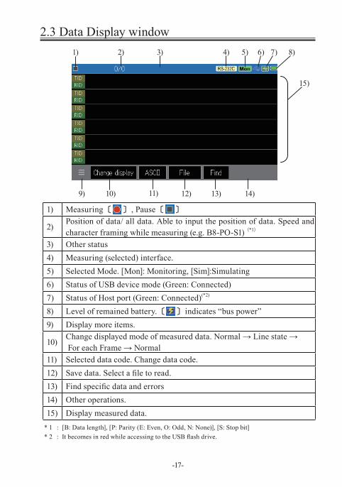
1) Measuring 〔 〕 , Pause 〔 〕
2)Position of data/ all data. Able to input the position of data. Speed and character framing while measuring (e.g. B8-PO-S1) (*1)
3) Other status4) Measuring (selected) interface.5) Selected Mode. [Mon]: Monitoring, [Sim]:Simulating6) Status of USB device mode (Green: Connected)7) Status of Host port (Green: Connected)(*2)
8) Level of remained battery. 〔 〕 indicates “bus power”9) Display more items.
10)Change displayed mode of measured data. Normal → Line state → For each Frame → Normal
11) Selected data code. Change data code.12) Save data. Select a file to read.13) Find specific data and errors14) Other operations.15) Display measured data.
* 1 : [B: Data length], [P: Parity (E: Even, O: Odd, N: None)], [S: Stop bit]* 2 : It becomes in red while accessing to the USB flash drive.
9)
1) 3) 4) 5) 6) 7) 8)
11) 12)10) 14)13)
2)
15)
-18-
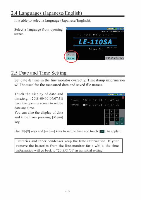
2.5 Date and Time SettingSet date & time in the line monitor correctly. Timestamp information will be used for the measured data and saved file names.
Touch the display of date and time.(e.g. : 2018-09-10 09:07:31) from the opening screen to set the date and time.You can also the display of data and time from pressing [Menu] key.
Use [0]-[9] keys and [→][←] keys to set the time and touch [ ] to apply it.
Batteries and inner condenser keep the time information. If your remove the batteries from the line monitor for a while, the time information will go back to “2018/01/01” as an initial setting.
2.4 Languages (Japanese/English)It is able to select a language (Japanese/English).
Select a language from opening screen.
-19-
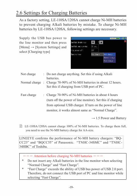
2.6 Settings for Charging BatteriesAs a factory setting, LE-110SA/120SA cannot charge Ni-MH batteries to prevent charging Alkali batteries by mistake. To charge Ni-MH batteries by LE-110SA/120SA, following settings are necessary.
Supply the USB bus power to the line monitor and then press [Menu] → [System Settings] and select [Charging type]
Not charge : Do not charge anything. Set this if using Alkali batteries.
Normal charge : Charge 70-90% of Ni-MH batteries in about 12 hours. Set this if charging from USB port of PC.
Fast charge : Charge 70-90% of Ni-MH batteries in about 4 hours (turn off the power of line monitor). Set this if charging from optional USB charger. If turn on the power of line monitor, it works almost same as “Normal Charge”.
→ 1.5 Power and Battery
� LE-110SA/120SA cannot charge 100% of Ni-MH batteries. To charge them full, you need to use the Ni-MH battery charge for AA-size.
LINEEYE confirms the performance of Ni-MH battery chargers: “BQ-CC23” and “BQCC55” of Panasonic. “TNHC-34SMC” and “TNHC-34HBC” of Toshiba.
--- Attention before charging Ni-MH batteries ---
* Do not insert any Alkali batteries in the line monitor when selecting “Normal Charge” and “Fast Charge”.
* “Fast Charge” exceeds the ability of USB bus power of USB 2.0 port. Therefore, do not connect the USB port of PC and line monitor while selecting “Fast Charge”.
-20-
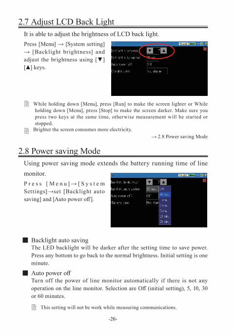
2.7 Adjust LCD Back LightIt is able to adjust the brightness of LCD back light.Press [Menu] → [System setting] → [Backlight brightness] and adjust the brightness using [▼][▲] keys.
� While holding down [Menu], press [Run] to make the screen lighter or While holding down [Menu], press [Stop] to make the screen darker. Make sure you press two keys at the same time, otherwise measurement will be started or stopped.
� Brighter the screen consumes more electricity. → 2.8 Power saving Mode
2.8 Power saving ModeUsing power saving mode extends the battery running time of line monitor. P r e s s [ M e n u ] → [ S y s t e m Settings]→set [Backlight auto saving] and [Auto power off].
■ Backlight auto savingThe LED backlight will be darker after the setting time to save power. Press any bottom to go back to the normal brightness. Initial setting is one minute.
■ Auto power offTurn off the power of line monitor automatically if there is not any operation on the line monitor. Selection are Off (initial setting), 5, 10, 30 or 60 minutes.
� This setting will not be work while measuring communications.
-21-
Chapter 3 Basic Settings
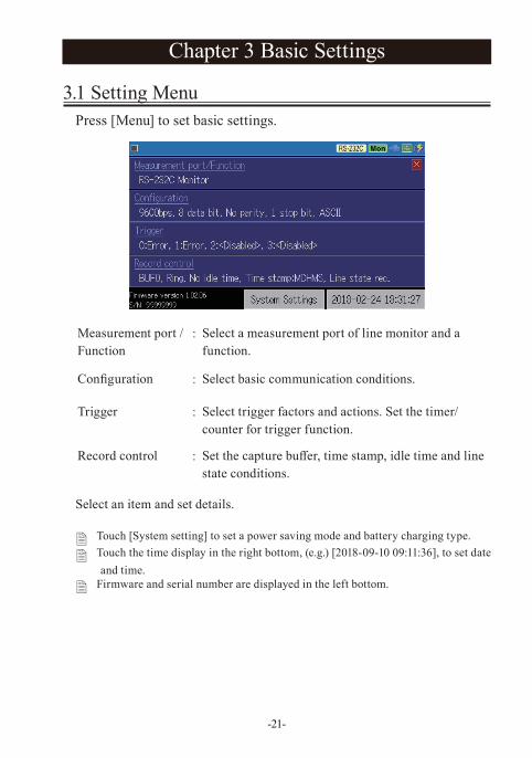
3.1 Setting MenuPress [Menu] to set basic settings.
Measurement port /Function
: Select a measurement port of line monitor and a function.
Configuration : Select basic communication conditions.
Trigger : Select trigger factors and actions. Set the timer/counter for trigger function.
Record control : Set the capture buffer, time stamp, idle time and line state conditions.
Select an item and set details.
� Touch [System setting] to set a power saving mode and battery charging type.
� Touch the time display in the right bottom, (e.g.) [2018-09-10 09:11:36], to set date and time.
� Firmware and serial number are displayed in the left bottom.
-22-
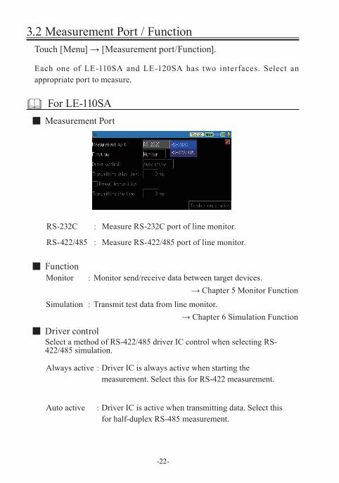
3.2 Measurement Port / FunctionTouch [Menu] → [Measurement port/Function].
Each one of LE-110SA and LE-120SA has two interfaces. Select an appropriate port to measure.
For LE-110SA ■ Measurement Port
RS-232C : Measure RS-232C port of line monitor.
RS-422/485 : Measure RS-422/485 port of line monitor.
■ FunctionMonitor : Monitor send/receive data between target devices.
→ Chapter 5 Monitor FunctionSimulation : Transmit test data from line monitor.
→ Chapter 6 Simulation Function
■ Driver controlSelect a method of RS-422/485 driver IC control when selecting RS-422/485 simulation.
Always active : Driver IC is always active when starting the measurement. Select this for RS-422 measurement.
Auto active : Driver IC is active when transmitting data. Select this for half-duplex RS-485 measurement.
-23-
■ Transmitting delay timeSelect an interval (1-99999ms) of one data when transmitting test data.
■ Repeat transmittionMark on this to send data repeatedly.
■ Transmitting idle timeSelect an interval (1-99999ms) of sending data repeatedly.
� For low speed data below 300bps, delay time and idle time settings might not be reflected correctly.
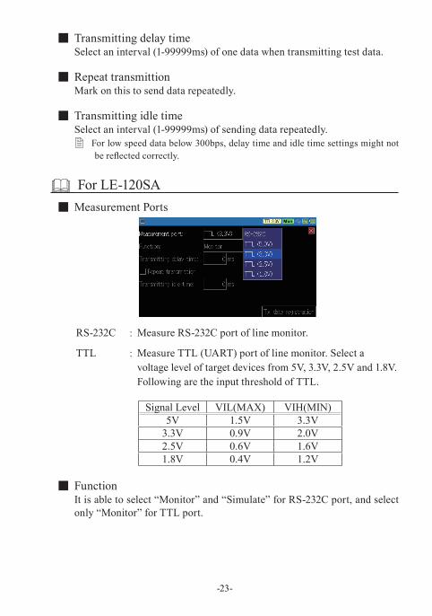
For LE-120SA ■ Measurement Ports
RS-232C : Measure RS-232C port of line monitor.
TTL : Measure TTL (UART) port of line monitor. Select a voltage level of target devices from 5V, 3.3V, 2.5V and 1.8V. Following are the input threshold of TTL.
Signal Level VIL(MAX) VIH(MIN)5V 1.5V 3.3V
3.3V 0.9V 2.0V2.5V 0.6V 1.6V1.8V 0.4V 1.2V
■ FunctionIt is able to select “Monitor” and “Simulate” for RS-232C port, and select only “Monitor” for TTL port.
-24-
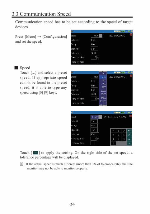
3.3 Communication SpeedCommunication speed has to be set according to the speed of target devices.
Press [Menu] → [Configuration] and set the speed.
■ SpeedTouch […] and select a preset speed. If appropriate speed cannot be found in the preset speed, it is able to type any speed using [0]-[9] keys.
Touch [ ] to apply the setting. On the right side of the set speed, a tolerance percentage will be displayed.
� If the actual speed is much different (more than 3% of tolerance rate), the line monitor may not be able to monitor properly.
-25-
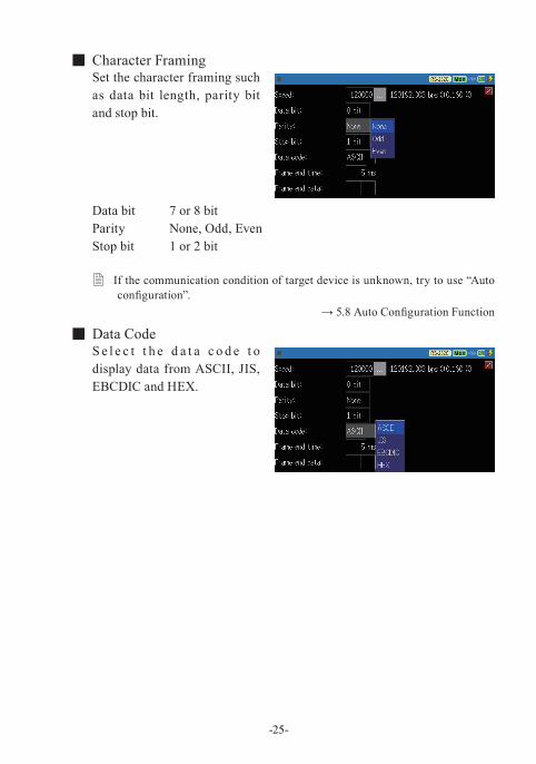
■ Character FramingSet the character framing such as data bit length, parity bit and stop bit.
Data bit 7 or 8 bitParity None, Odd, EvenStop bit 1 or 2 bit
� If the communication condition of target device is unknown, try to use “Auto configuration”.
→ 5.8 Auto Configuration Function
■ Data CodeS e l e c t t h e d a t a c o d e t o display data from ASCII, JIS, EBCDIC and HEX.
-26-
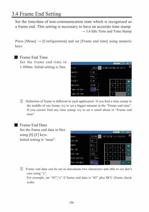
3.4 Frame End SettingSet the time/data of non-communication state which is recognized as a frame end. This setting is necessary to have an accurate time stamp
→ 3.6 Idle Time and Time Stamp
Press [Menu] → [Configuration] and set [Frame end time] using numeric keys.
■ Frame End TimeSet the f rame end t ime in 1-100ms. Initial setting is 5ms.
� Definition of frame is different in each application. If you find a time stamp in the middle of one frame, try to set a bigger amount in the “Frame end time”. If you cannot find any time stamp, try to set a small about in “Frame end time”
■ Frame End DataSet the frame end data in Hex using [0]-[F] keys.Initial setting is “none”.
� Frame end data can be set in maximum two characters and able to set don’t care using “x”. For example, set “03”,“x” if frame end data is “03” plus BCC (frame check code).
-27-
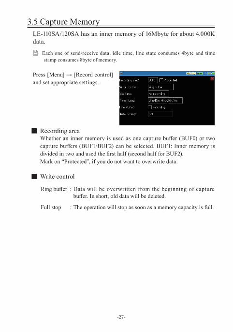
3.5 Capture MemoryLE-110SA/120SA has an inner memory of 16Mbyte for about 4.000K data.
� Each one of send/receive data, idle time, line state consumes 4byte and time stamp consumes 8byte of memory.
Press [Menu] → [Record control] and set appropriate settings.
■ Recording areaWhether an inner memory is used as one capture buffer (BUF0) or two capture buffers (BUF1/BUF2) can be selected. BUF1: Inner memory is divided in two and used the first half (second half for BUF2). Mark on “Protected”, if you do not want to overwrite data.
■ Write control
Ring buffer : Data will be overwritten from the beginning of capture buffer. In short, old data will be deleted.
Full stop : The operation will stop as soon as a memory capacity is full.
-28-
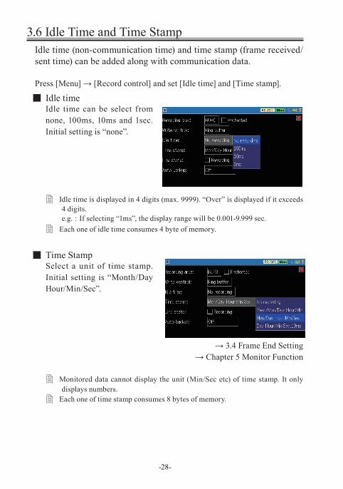
3.6 Idle Time and Time StampIdle time (non-communication time) and time stamp (frame received/sent time) can be added along with communication data.
Press [Menu] → [Record control] and set [Idle time] and [Time stamp].
■ Idle timeIdle time can be select from none, 100ms, 10ms and 1sec. Initial setting is “none”.
� Idle time is displayed in 4 digits (max. 9999). “Over” is displayed if it exceeds 4 digits. e.g. : If selecting “1ms”, the display range will be 0.001-9.999 sec.
� Each one of idle time consumes 4 byte of memory.
■ Time StampSelect a unit of time stamp. Initial setting is “Month/Day Hour/Min/Sec”.
→ 3.4 Frame End Setting→ Chapter 5 Monitor Function
� Monitored data cannot display the unit (Min/Sec etc) of time stamp. It only displays numbers.
� Each one of time stamp consumes 8 bytes of memory.
-29-
3.7 Line StateControl lines of target devices and status of external trigger input can be added along with communication data.
Press [Menu] → [Record Control] and mark on “Line State Recording”.
� External trigger input is displayed in the “TRG” line. � Available control lines are different in each port.
RS-232C RTS/CTS/DCD/DTR/DSR/RI/TRGRS-422/485 TRGTTL RTS/CTS/TRG
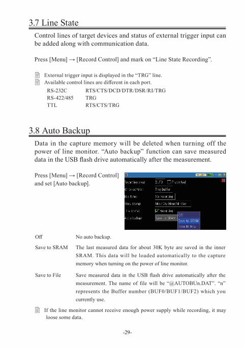
3.8 Auto BackupData in the capture memory will be deleted when turning off the power of line monitor. “Auto backup” function can save measured data in the USB flash drive automatically after the measurement.
Press [Menu] → [Record Control] and set [Auto backup].
Off No auto backup.
Save to SRAM The last measured data for about 30K byte are saved in the inner SRAM. This data will be loaded automatically to the capture memory when turning on the power of line monitor.
Save to File Save measured data in the USB flash drive automatically after the measurement. The name of file will be “@AUTOBUn.DAT”. “n” represents the Buffer number (BUF0/BUF1/BUF2) which you currently use.
� If the line monitor cannot receive enough power supply while recording, it may loose some data.
-30-
Chapter 4 Connect to the Target Devices
4.1 Connect to RS-232CSet “Measurement port: RS-232C” before measuring RS-232C.
→ 3.2 Measurement Port / Function
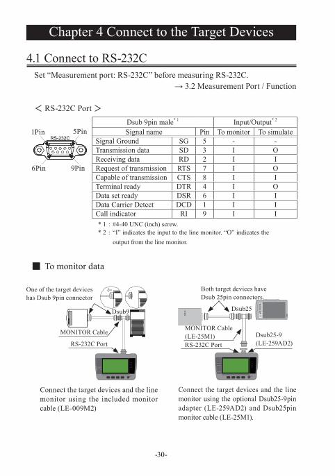
< RS-232C Port >
Dsub 9pin male* 1 Input/Output* 2
Signal name Pin To monitor To simulateSignal Ground SG 5 - -Transmission data SD 3 I OReceiving data RD 2 I IRequest of transmission RTS 7 I OCapable of transmission CTS 8 I ITerminal ready DTR 4 I OData set ready DSR 6 I IData Carrier Detect DCD 1 I ICall indicator RI 9 I I* 1 : #4-40 UNC (inch) screw.* 2 : “I” indicates the input to the line monitor. “O” indicates the
output from the line monitor.
■ To monitor data
Connect the target devices and the line monitor using the included monitor cable (LE-009M2)
Connect the target devices and the line monitor using the optional Dsub25-9pin adapter (LE-259AD2) and Dsub25pin monitor cable (LE-25M1).
1Pin 5Pin
6Pin 9Pin
Dsub9
One of the target deviceshas Dsub 9pin connector
MONITOR Cable
RS-232C PortDsub25-9(LE-259AD2)
Both target devices haveDsub 25pin connectors.
Dsub25
MONITOR Cable(LE-25M1)RS-232C Port
-31-
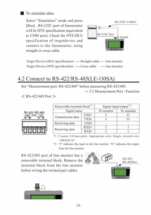
4.2 Connect to RS-422/RS-485(LE-110SA)Set “Measurement port: RS-422/485” before measuring RS-422/485.
→ 3.2 Measurement Port / Function< RS-422/485 Port >
Removable terminal block(*1) Signal input/output(*2)
Signal name To monitor To simulate
Transmission data TXD+ I OTXD- I O
Receiving data GND - -
Receiving data RXD+ I IRXD- I I
*1: 5 poles 3.81mm pitch. Appropriate wire: Single, twisted wire “AWG28-16”.
*2: “I” indicates the input to the line monitor. “O” indicates the output from the line monitor.
RS-422/485 port of line monitor has a removable terminal block. Remove the terminal block from the line monitor before wiring the twisted pair cables.
■ To simulate data
Select “Simulation” mode and press [Run] . RS-232C port of linemonitor will be DTE specification (equivalent to COM port). Check the DTE/DCE specif ication of targetdevice and connect to the linemonitor, using straight or cross cable.
RS-232C CABLE
RS-232C PortDsub9
Target Device (DCE specification) ---- Straight cable ---- line monitorTarget Device (DTE specification) ---- Cross cable ---- line monitor
RS-422/RS-485Port
-32-
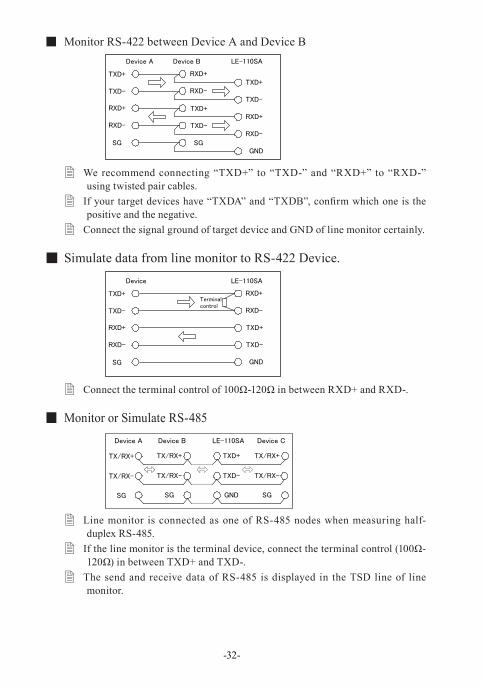
■ Monitor RS-422 between Device A and Device B
� We recommend connecting “TXD+” to “TXD-” and “RXD+” to “RXD-” using twisted pair cables.
� If your target devices have “TXDA” and “TXDB”, confirm which one is the positive and the negative.
� Connect the signal ground of target device and GND of line monitor certainly.
■ Simulate data from line monitor to RS-422 Device.
� Connect the terminal control of 100Ω-120Ω in between RXD+ and RXD-.
■ Monitor or Simulate RS-485
� Line monitor is connected as one of RS-485 nodes when measuring half-duplex RS-485.
� If the line monitor is the terminal device, connect the terminal control (100Ω-120Ω) in between TXD+ and TXD-.
� The send and receive data of RS-485 is displayed in the TSD line of line monitor.
Device A Device B LE-110SA
TXD+
TXD-
TXD+
TXD-
TXD+
TXD-RXD+
RXD-
RXD+
RXD-
RXD+
RXD-SG SG
GND
Device LE-110SA
TXD+
TXD-
TXD+
TXD-
RXD+
RXD-
RXD+
RXD-
SG GND
Terminalcontrol
Device A Device B LE-110SA
TX/RX+
TX/RX-
SG SG SG
Device C
GND
TX/RX+
TX/RX-
TX/RX+
TX/RX-
TXD+
TXD-
-33-
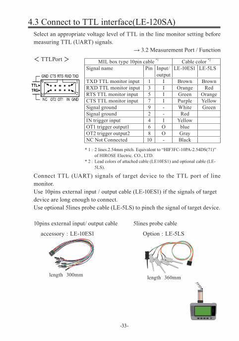
4.3 Connect to TTL interface(LE-120SA)Select an appropriate voltage level of TTL in the line monitor setting before measuring TTL (UART) signals.
→ 3.2 Measurement Port / Function< TTLPort >
* 1: 2 lines.2.54mm pitch. Equivalent to “HIF3FC-10PA-2.54DS(71)”of HIROSE Electric. CO., LTD.
* 2: Lead colors of attached cable (LE10ES1) and optional cable (LE-5LS).
Connect TTL (UART) signals of target device to the TTL port of line monitor.Use 10pins external input / output cable (LE-10ES1) if the signals of target device are long enough to connect.Use optional 5lines probe cable (LE-5LS) to pinch the signal of target device.
10pins external input/ output cable 5lines probe cable
MIL box type 10pin cable *1 Cable color *2
Signal name Pin Input/output
LE-10ES1 LE-5LS
TXD TTL monitor input 1 I Brown BrownRXD TTL monitor input 3 I Orange RedRTS TTL monitor input 5 I Green OrangeCTS TTL monitor input 7 I Purple YellowSignal ground 9 - White GreenSignal ground 2 - RedIN trigger input 4 I YellowOT1 trigger output1 6 O blueOT2 trigger output2 8 O GrayNC Not Connected 10 - Black
1
2
9
10
length 300mm
accessory : LE-10ES1
length 360mm
Option : LE-5LS
5.2 Start and Stop Monitoring
Setting and ConnectionSelect a measurement port, conditions for monitoring and communication conditions.Connect the line monitor and target devices.
→ 3.2 Measurement Port / Function→ 3.3 Communication Speed→ Chapter 4 Connect to the Target Devices
Set “Record control” such as time stamp and control line settings.→ 3.6 Idle Time and Time Stamp→ 3.7 Line State
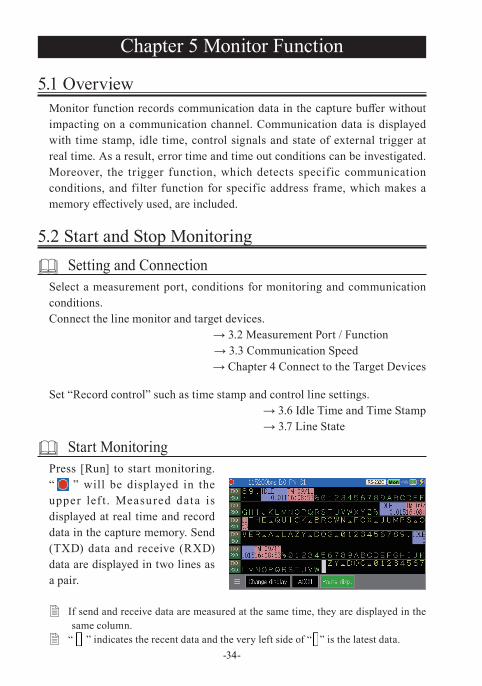
Start Monitoring Press [Run] to start monitoring. “ ” will be displayed in the upper lef t . Measured data is displayed at real time and record data in the capture memory. Send (TXD) data and receive (RXD) data are displayed in two lines as a pair.
� If send and receive data are measured at the same time, they are displayed in the same column.
� “ ” indicates the recent data and the very left side of “ ” is the latest data.-34-
Chapter 5 Monitor Function
5.1 OverviewMonitor function records communication data in the capture buffer without impacting on a communication channel. Communication data is displayed with time stamp, idle time, control signals and state of external trigger at real time. As a result, error time and time out conditions can be investigated. Moreover, the trigger function, which detects specific communication conditions, and filter function for specific address frame, which makes a memory effectively used, are included.
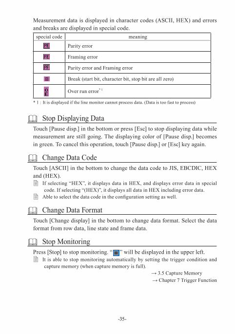
Measurement data is displayed in character codes (ASCII, HEX) and errors and breaks are displayed in special code.
special code meaning
Parity error
Framing error
Parity error and Framing error
Break (start bit, character bit, stop bit are all zero)
Over run error* 1
* 1 : It is displayed if the line monitor cannot process data. (Data is too fast to process)
Stop Displaying DataTouch [Pause disp.] in the bottom or press [Esc] to stop displaying data while measurement are still going. The displaying color of [Pause disp.] becomes in green. To cancel this operation, touch [Pause disp.] or [Esc] key again.
Change Data CodeTouch [ASCII] in the bottom to change the data code to JIS, EBCDIC, HEX and (HEX).
� If selecting “HEX”, it displays data in HEX, and displays error data in special code. If selecting “(HEX)”, it displays all data in HEX including error data.
� Able to select the data code in the configuration setting as well.
Change Data FormatTouch [Change display] in the bottom to change data format. Select the data format from row data, line state and frame data.
Stop MonitoringPress [Stop] to stop monitoring. “ ” will be displayed in the upper left.
� It is able to stop monitoring automatically by setting the trigger condition and capture memory (when capture memory is full).
→ 3.5 Capture Memory→ Chapter 7 Trigger Function
-35-
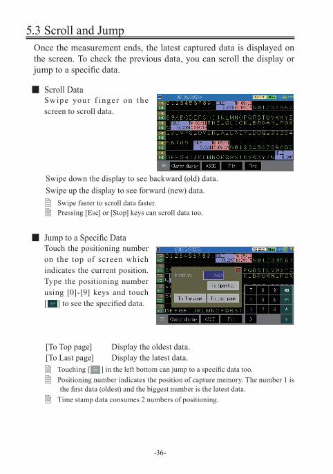
5.3 Scroll and JumpOnce the measurement ends, the latest captured data is displayed on the screen. To check the previous data, you can scroll the display or jump to a specific data.
■ Scroll DataSwipe you r f inger on the screen to scroll data.
Swipe down the display to see backward (old) data.Swipe up the display to see forward (new) data.
� Swipe faster to scroll data faster. � Pressing [Esc] or [Stop] keys can scroll data too.
■ Jump to a Specific DataTouch the positioning number on the top of screen which indicates the current position. Type the positioning number using [0]-[9] keys and touch [ ] to see the specified data.
[To Top page] Display the oldest data. [To Last page] Display the latest data.
� Touching [ ] in the left bottom can jump to a specific data too. � Positioning number indicates the position of capture memory. The number 1 is
the first data (oldest) and the biggest number is the latest data. � Time stamp data consumes 2 numbers of positioning.
-36-
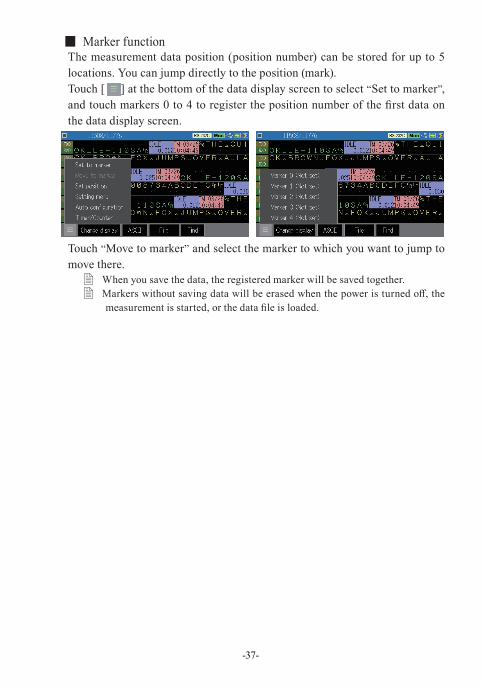
■ Marker functionThe measurement data position (position number) can be stored for up to 5 locations. You can jump directly to the position (mark).Touch [ ] at the bottom of the data display screen to select “Set to marker”, and touch markers 0 to 4 to register the position number of the first data on the data display screen.
Touch “Move to marker” and select the marker to which you want to jump to move there.
� When you save the data, the registered marker will be saved together. � Markers without saving data will be erased when the power is turned off, the
measurement is started, or the data file is loaded.
-37-
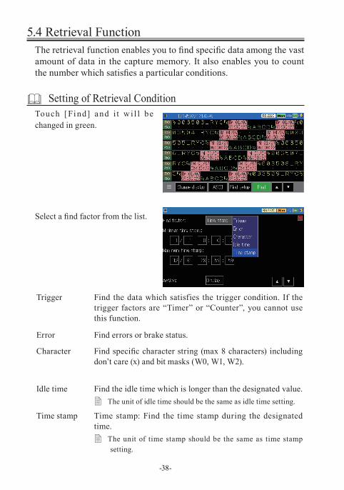
5.4 Retrieval FunctionThe retrieval function enables you to find specific data among the vast amount of data in the capture memory. It also enables you to count the number which satisfies a particular conditions.
Setting of Retrieval ConditionTouch [Fi nd] and i t w i l l be changed in green.
Select a find factor from the list.
Trigger Find the data which satisfies the trigger condition. If the trigger factors are “Timer” or “Counter”, you cannot use this function.
Error Find errors or brake status.
Character Find specific character string (max 8 characters) including don’t care (x) and bit masks (W0, W1, W2).
Idle time Find the idle time which is longer than the designated value. � The unit of idle time should be the same as idle time setting.
Time stamp Time stamp: Find the time stamp during the designated time.
� The unit of time stamp should be the same as time stamp setting.
-38-
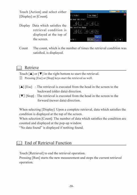
Touch [Action] and select either [Display] or [Count].
Display Data which satisfies the retrieval condition is displayed at the top of the screen.
Count The count, which is the number of times the retrieval condition was satisfied, is displayed.
RetrieveTouch [▲] or [▼] in the right bottom to start the retrieval.
� Pressing [Esc] or [Stop] keys start the retrieval as well.
[▲] [Esc] : The retrieval is executed from the head in the screen to the backward (older data) direction.
[▼] [Stop] : The retrieval is executed from the head in the screen to the forward (newer data) direction.
When selecting [Display]: Upon a complete retrieval, data which satisfies the condition is displayed at the top of the screen.When selection [Count]: The number of data which satisfies the condition are counted and displayed at the pop-up window.“No data found” is displayed if nothing found.
End of Retrieval Function
Touch [Retrieval] to end the retrieval operation.Pressing [Run] starts the new measurement and stops the current retrieval operation.
-39-
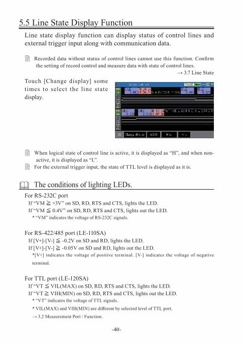
5.5 Line State Display FunctionLine state display function can display status of control lines and external trigger input along with communication data.
� Recorded data without status of control lines cannot use this function. Confirm the setting of record control and measure data with state of control lines.
→ 3.7 Line StateTouch [Change display] some t imes to select the l ine state display.
� When logical state of control line is active, it is displayed as “H”, and when non-active, it is displayed as “L”.
� For the external trigger input, the state of TTL level is displayed as it is.
The conditions of lighting LEDs.For RS-232C port
If “VM ≧ +3V” on SD, RD, RTS and CTS, lights the LED. If “VM ≦ 0.4V” on SD, RD, RTS and CTS, lights out the LED.
* “VM” indicates the voltage of RS-232C signals.
For RS-422/485 port (LE-110SA)If [V+]-[V-] ≦ -0.2V on SD and RD, lights the LED. If [V+]-[V-] ≧ -0.05V on SD and RD, lights out the LED.
*[V+] indicates the voltage of positive terminal. [V-] indicates the voltage of negative
terminal.
For TTL port (LE-120SA)If “VT ≦ VIL(MAX) on SD, RD, RTS and CTS, lights the LED. If “VT ≧ VIH(MIN) on SD, RD, RTS and CTS, lights out the LED.
* “VT” indicates the voltage of TTL signals.
* VIL(MAX) and VIH(MIN) are different by selected level of TTL port.
→ 3.2 Measurement Port / Function.
-40-
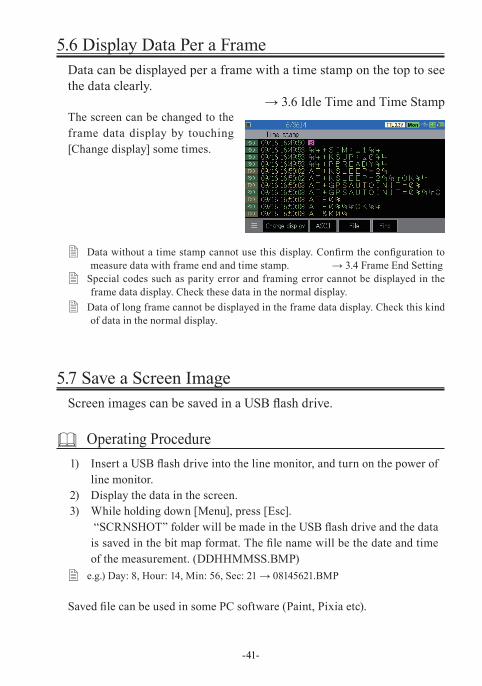
5.6 Display Data Per a FrameData can be displayed per a frame with a time stamp on the top to see the data clearly.
→ 3.6 Idle Time and Time Stamp The screen can be changed to the frame data display by touching [Change display] some times.
� Data without a time stamp cannot use this display. Confirm the configuration to measure data with frame end and time stamp. → 3.4 Frame End Setting
� Special codes such as parity error and framing error cannot be displayed in the frame data display. Check these data in the normal display.
� Data of long frame cannot be displayed in the frame data display. Check this kind of data in the normal display.
5.7 Save a Screen ImageScreen images can be saved in a USB flash drive.
Operating Procedure1) Insert a USB flash drive into the line monitor, and turn on the power of
line monitor.2) Display the data in the screen.3) While holding down [Menu], press [Esc].
“SCRNSHOT” folder will be made in the USB flash drive and the data is saved in the bit map format. The file name will be the date and time of the measurement. (DDHHMMSS.BMP)
� e.g.) Day: 8, Hour: 14, Min: 56, Sec: 21 → 08145621.BMP
Saved file can be used in some PC software (Paint, Pixia etc).
-41-
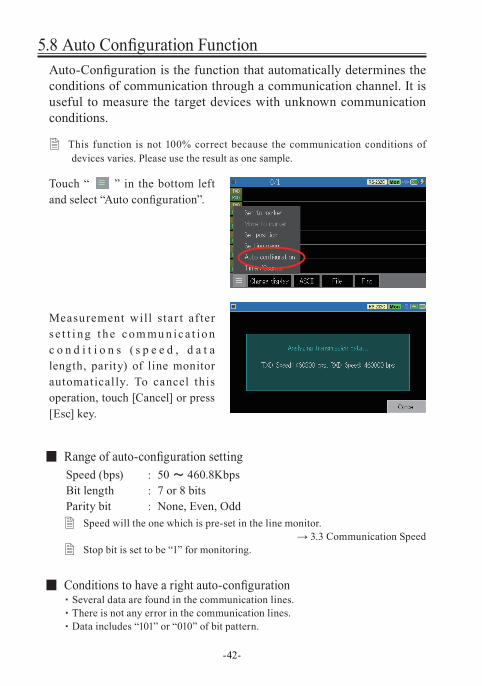
5.8 Auto Configuration FunctionAuto-Configuration is the function that automatically determines the conditions of communication through a communication channel. It is useful to measure the target devices with unknown communication conditions.
� This function is not 100% correct because the communication conditions of devices varies. Please use the result as one sample.
Touch “ ” in the bottom left and select “Auto configuration”.
Measurement will star t af ter s e t t i ng t he c om mu n ic a t ion c o n d i t i o n s ( s p e e d , d a t a length, parity) of line monitor automatically. To cancel this operation, touch [Cancel] or press [Esc] key.
■ Range of auto-configuration settingSpeed (bps) : 50 ~ 460.8KbpsBit length : 7 or 8 bitsParity bit : None, Even, Odd
� Speed will the one which is pre-set in the line monitor.→ 3.3 Communication Speed
� Stop bit is set to be “1” for monitoring.
■ Conditions to have a right auto-configuration・ Several data are found in the communication lines.・ There is not any error in the communication lines.・ Data includes “101” or “010” of bit pattern.
-42-
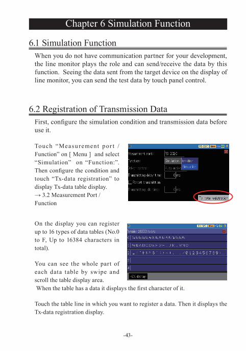
6.2 Registration of Transmission DataFirst, configure the simulation condition and transmission data before use it.
Touch “Measu rement por t / Function” on [ Menu ] and select “Simulation” on “Function:”. Then configure the condition and touch “Tx-data registration” to display Tx-data table display.→ 3.2 Measurement Port / Function
On the display you can register up to 16 types of data tables (No.0 to F, Up to 16384 characters in total).
You can see the whole part of each data table by swipe and scroll the table display area. When the table has a data it displays the first character of it.
Touch the table line in which you want to register a data. Then it displays the Tx-data registration display.
-43-
Chapter 6 Simulation Function
6.1 Simulation FunctionWhen you do not have communication partner for your development, the line monitor plays the role and can send/receive the data by this function. Seeing the data sent from the target device on the display of line monitor, you can send the test data by touch panel control.
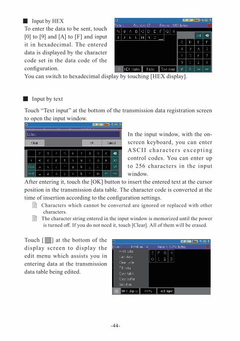
■ Input by HEXTo enter the data to be sent, touch [0] to [9] and [A] to [F] and input it in hexadecimal. The entered data is displayed by the character code set in the data code of the configuration.You can switch to hexadecimal display by touching [HEX display].
■ Input by text
Touch “Text input” at the bottom of the transmission data registration screen to open the input window.
In the input window, with the on-screen keyboard, you can enter ASCI I cha r ac t e r s exce pt i ng control codes. You can enter up to 256 characters in the input window.
After entering it, touch the [OK] button to insert the entered text at the cursor position in the transmission data table. The character code is converted at the time of insertion according to the configuration settings.
� Characters which cannot be converted are ignored or replaced with other characters.
� The character string entered in the input window is memorized until the power is turned off. If you do not need it, touch [Clear]. All of them will be erased.
Touch [ = ] at the bottom of the display screen to display the edit menu which assists you in entering data at the transmission data table being edited.
-44-
Touch “First data” to move the cursor to the first data in the transmission data table. Touch “Last data” to move the cursor to the final data. Touch “Clear table” to delete all the data in the transmission data table being edited.
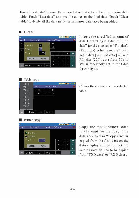
■ Data fillInserts the specified amount of data from “Begin data” to “End data” for the size set at “Fill size”. (Example) When executed with begin data [30], End data [39], and Fill size [256], data from 30h to 39h is repeatedly set in the table for 256 bytes.
■ Table copy
Copies the contents of the selected table.
■ Buffer copy
Copy t he mea su rement d a t a i n t he capt u re memor y. T he data specified in “Copy size” is copied from the first data on the data display screen. Select the communication line to be copied from “TXD data” or “RXD data”.
-45-
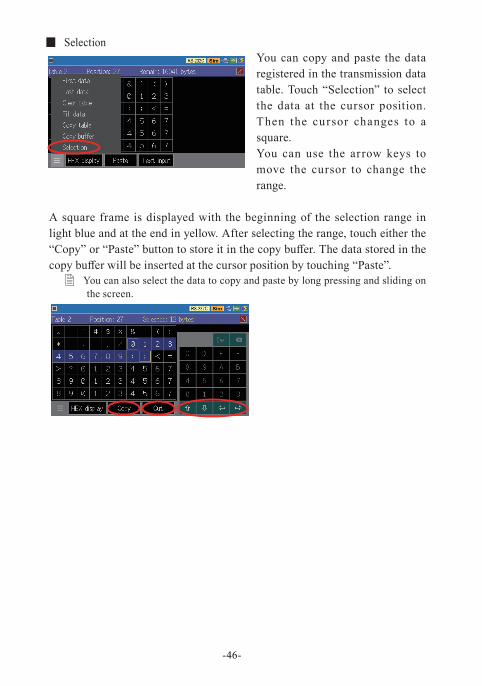
■ SelectionYou can copy and paste the data registered in the transmission data table. Touch “Selection” to select the data at the cursor position. Then the cursor changes to a square.You can use the arrow keys to move the cursor to change the range.
A square frame is displayed with the beginning of the selection range in light blue and at the end in yellow. After selecting the range, touch either the “Copy” or “Paste” button to store it in the copy buffer. The data stored in the copy buffer will be inserted at the cursor position by touching “Paste”.
� You can also select the data to copy and paste by long pressing and sliding on the screen.
-46-
6.3 Start/Finish Simulation
Confirm settings and connectionConfirm the measurement port, Simulation settings, and communication condition.Confirm the connection with the target device.
→ 3.2 Measurement Port / Function→ 3.3 Communication Speed→ Chapter 4 Connect to the Target Devices
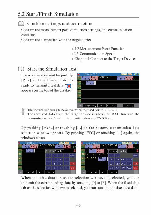
Start the Simulation TestIt starts measurement by pushing [Run] and the line monitor is ready to transmit a test data. “ ” appears on the top of the display.
� The control line turns to be active when the used port is RS-232C. � The received data from the target device is shown on RXD line and the
transmission data from the line monitor shows on TXD line.
By pushing [Menu] or touching […] on the bottom, transmission data selection window appears. By pushing [ESC] or touching […] again, the windows closes.
When the table data tab on the selection windows is selected, you can transmit the corresponding data by touching [0] to [F]. When the fixed data tab on the selection windows is selected, you can transmit the fixed test data.
-47-
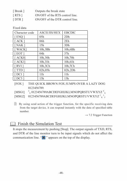
[ Break ] Outputs the break state[ RTS ] ON/OFF of the RTS control line. [ DTR ] ON/OFF of the DTR control line.
Fixed dataCharacter code ASCII/JIS/HEX EBCDIC[ ENQ ] 05h 2Dh[ ACK ] 06h 2Eh[ NAK ] 15h 3Dh[ WACK] 10h,3Bh 10h,6Bh[ EOT ] 04h 37h[ ACK0] 10h,30h 10h,70h[ ACK1] 10h,31h 10h,61h[ RVI ] 10h,3Ch 10h,7Ch[ TTD ] 02h,05h 02h,2Dh[ DC1 ] 11h 11h[ DC3 ] 13h 13h
[FOX ] THE QUICK BROWN FOX JUMPS OVER A LAZY DOG 0123456789.
[MSG1] SX 0123456789ABCDEFGHIJKLMNOPQRSTUVWXYZ E
X
[MSG2] 0123456789ABCDEFGHIJKLMNOPQRSTUVWXYZ CR L
F
� By using send action of the trigger function, for the specific receiving data from the target device, it can respond instantly with the data of specified table number.
→ 7.2 Trigger Function
Finish the Simulation TestIt stops the measurement by pushing [Stop]. The output signals of TXD, RTS, and DTR of the line monitor turn to be input signals which do not affect the communication line. “ ” appears on the top of the display.
-48-
-49-
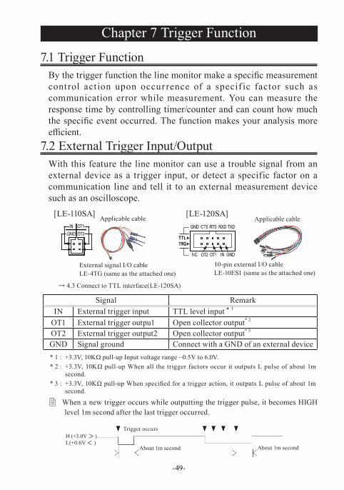
7.2 External Trigger Input/OutputWith this feature the line monitor can use a trouble signal from an external device as a trigger input, or detect a specific factor on a communication line and tell it to an external measurement device such as an oscilloscope.
[LE-110SA] [LE-120SA]
→ 4.3 Connect to TTL interface(LE-120SA)
Signal RemarkIN External trigger input TTL level input* 1
OT1 External trigger outpu1 Open collector output* 2
OT2 External trigger output2 Open collector output* 3
GND Signal ground Connect with a GND of an external device* 1 : +3.3V, 10KΩ pull-up Input voltage range –0.5V to 6.0V.* 2 : +3.3V, 10KΩ pull-up When all the trigger factors occur it outputs L pulse of about 1m
second.* 3 : +3.3V, 10KΩ pull-up When specified for a trigger action, it outputs L pulse of about 1m
second.
� When a new trigger occurs while outputting the trigger pulse, it becomes HIGH level 1m second after the last trigger occurred.
Chapter 7 Trigger Function
7.1 Trigger FunctionBy the trigger function the line monitor make a specific measurement control action upon occurrence of a specif ic factor such as communication error while measurement. You can measure the response time by controlling timer/counter and can count how much the specific event occurred. The function makes your analysis more efficient.
External signal I/O cableLE-4TG (same as the attached one)
10-pin external I/O cableLE-10ES1 (same as the attached one)
Applicable cable Applicable cable
H (+3.0V >)
L (+0.6V <)
Trigger occurs
About 1m second About 1m second
H (+3.0V > )L(+0.6V < )
-50-
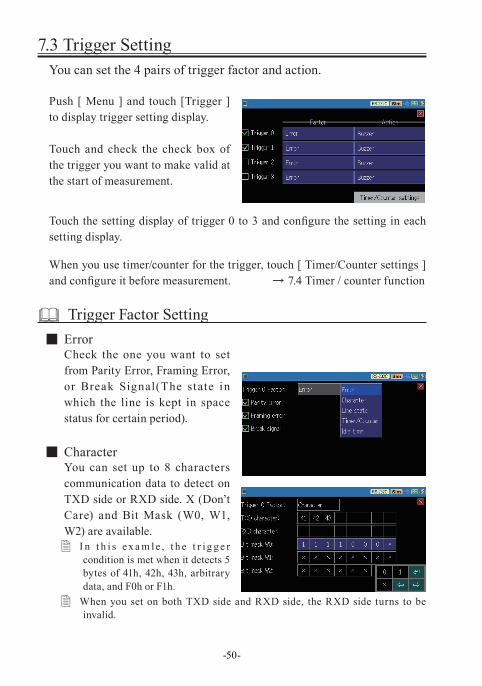
7.3 Trigger SettingYou can set the 4 pairs of trigger factor and action.
Push [ Menu ] and touch [Trigger ] to display trigger setting display.
Touch and check the check box of the trigger you want to make valid at the start of measurement.
Touch the setting display of trigger 0 to 3 and configure the setting in each setting display.
When you use timer/counter for the trigger, touch [ Timer/Counter settings ] and configure it before measurement. → 7.4 Timer / counter function
Trigger Factor Setting ■ ErrorCheck the one you want to set from Parity Error, Framing Error, or Break Signal(The state in which the line is kept in space status for certain period).
■ CharacterYou can set up to 8 characters communication data to detect on TXD side or RXD side. X (Don’t Care) and Bit Mask (W0, W1, W2) are available. � I n t h i s e x a m le , t h e t r ig ge r
condition is met when it detects 5 bytes of 41h, 42h, 43h, arbitrary data, and F0h or F1h.
� When you set on both TXD side and RXD side, the RXD side turns to be invalid.
-51-
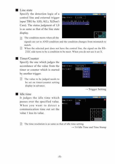
■ Line stateSpecify the detection logic of a control line and external trigger input TRG by 1(H), 0(L), X(Don’t Care). The status judgment of 1,0 is as same as that of the line state display.
� The condition meets when all the signals are set to AND condition and the condition changes from mismatch to match.
� When the selected port does not have the control line, the signal on the RS-232C side turns to be a condition to be meet. When you do not use it set X.
■ Timer/CounterSpecify the one which judges the accordance of the value from the timer or counter which is started by another trigger.
� The value to be judged needs to be set on timer/counter setting display in advance.
→ Trigger Setting
■ Idle timeIt judges the idle t ime which passes over the specified value. W hen you wa nt t o de t ec t a communication time out set the value 1 less its value.
� The time resolution is as same as that of idle time setting.→ 3.6 Idle Time and Time Stamp
-52-
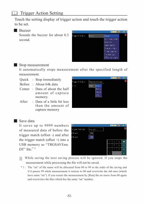
Trigger Action SettingTouch the setting display of trigger action and touch the trigger action to be set.
■ BuzzerSounds the buzzer for about 0.3 second.
■ Stop measurementIt automatically stops measurement after the specif ied length of measurement.Quick : Stop immediatelyBefore : About 64k dataCenter : Data of about the half
a mou nt of cap t u re memory.
After : Data of a little bit less than the amount of capture memory
■ Save dataIt saves up to 9999 numbers of measured data of before the trigger match (offset -) and after the trigger match (offset +) into a USB memory as “TRGSAVEnn.DT” file.(* 1)
� While saving the next saving process will be ignored. If you stops the measurement while processing the file will not be saved.
* 1 : The “nn” of file name will be allocated from 00 to 99 in the order of the saving and if it passes 99 while measurement it returns to 00 and overwrite the old ones (which have same “nn”). If you restart the measurement by [Run] the nn starts from 00 again and overwrites the files which has the same “nn” number.
-53-
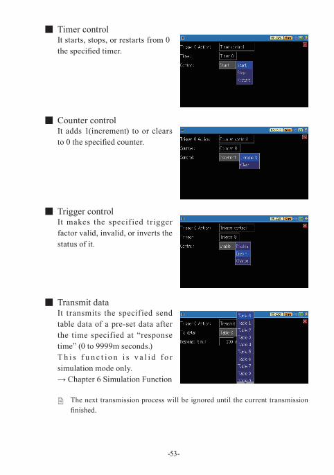
■ Timer controlIt starts, stops, or restarts from 0 the specified timer.
■ Counter controlIt adds 1(increment) to or clears to 0 the specified counter.
■ Trigger controlIt makes the specif ied trigger factor valid, invalid, or inverts the status of it.
■ Transmit dataIt transmits the specified send table data of a pre-set data after the time specified at “response time” (0 to 9999m seconds.)T h i s f u n c t i o n i s v a l i d fo r simulation mode only.→ Chapter 6 Simulation Function
� The next transmission process will be ignored until the current transmission finished.
-54-
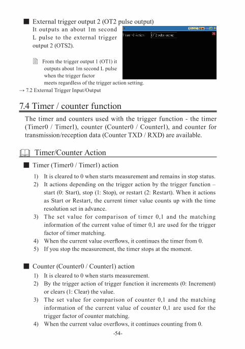
■ External trigger output 2 (OT2 pulse output)It outputs an about 1m second L pulse to the external trigger output 2 (OTS2).
� From the trigger output 1 (OT1) it outputs about 1m second L pulse when the trigger factor meets regardless of the trigger action setting.
→ 7.2 External Trigger Input/Output
7.4 Timer / counter functionThe timer and counters used with the trigger function - the timer (Timer0 / Timer1), counter (Counter0 / Counter1), and counter for transmission/reception data (Counter TXD / RXD) are available.
Timer/Counter Action ■ Timer (Timer0 / Timer1) action
1) It is cleared to 0 when starts measurement and remains in stop status.2) It actions depending on the trigger action by the trigger function –
start (0: Start), stop (1: Stop), or restart (2: Restart). When it actions as Start or Restart, the current timer value counts up with the time resolution set in advance.
3) The set value for comparison of timer 0,1 and the matching information of the current value of timer 0,1 are used for the trigger factor of timer matching.
4) When the current value overflows, it continues the timer from 0.5) If you stop the measurement, the timer stops at the moment.
■ Counter (Counter0 / Counter1) action1) It is cleared to 0 when starts measurement.2) By the trigger action of trigger function it increments (0: Increment)
or clears (1: Clear) the value.3) The set value for comparison of counter 0,1 and the matching
information of the current value of counter 0,1 are used for the trigger factor of counter matching.
4) When the current value overflows, it continues counting from 0.
-55-
■ Transmission/Reception counter (TXD Counter / RXD Cou) action1) It is cleared to 0 when starts measurement.2) It increments the counter when receiving data of transmission side
TXD or reception side RXD. (The max number is 4294967295.)
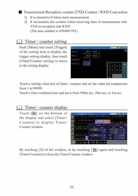
Timer / counter settingPush [Menu] and touch [Trigger] of the setting item to display the trigger setting display, then touch [Timer/Counter setting] to move to the setting display.
Touch a setting value box of timer / counter and set the value for comparison from 1 to 99999.Touch a time resolution box and set it from 100m sec, 10m sec, or 1m sec.
Timer / counter displayTouch [ ] on the bot tom of the display and select [Timer/Cou nt e r] t o d i splay Ti me r /Counter window.
By touching [X] of the window, or by touching [ ] again and touching [Timer/Counter] to close the Timer/Counter window.
-56-
Chapter 8 Data Save and Read
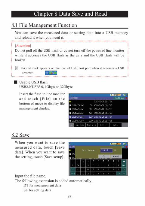
8.1 File Management FunctionYou can save the measured data or setting data into a USB memory and reload it when you need it.
■ Usable USB flashUSB2.0/USB3.0, 1Gbyte to 32Gbyte
Insert the flash to line monitor a n d t o u c h [ F i l e] o n t h e bottom of move to display file management display.
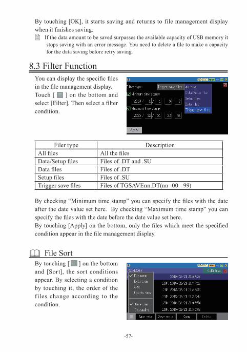
8.2 SaveWhen you want to save the measured data, touch [Save data]. When you want to save the setting, touch [Save setup].
Input the file name.The following extension is added automatically.
.DT for measurement data
.SU for setting data
[Attention]Do not pull off the USB flash or do not turn off the power of line monitor while it accesses the USB flash as the data and the USB flash will be broken.
� UA red mark appears on the icon of USB host port when it accesses a USB memory.
-57-
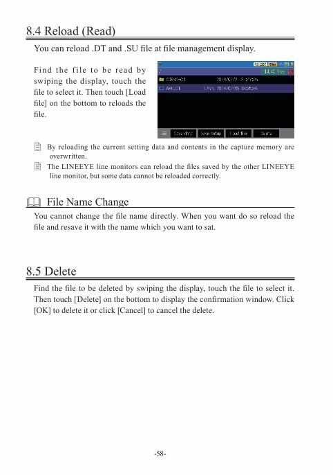
8.3 Filter FunctionYou can display the specific files in the file management display.Touch [ ] on the bottom and select [Filter]. Then select a filter condition.
Filer type DescriptionAll files All the filesData/Setup files Files of .DT and .SUData files Files of .DTSetup files Files of .SUTrigger save files Files of TGSAVEnn.DT(nn=00 - 99)
By checking “Minimum time stamp” you can specify the files with the date after the date value set here. By checking “Maximum time stamp” you can specify the files with the date before the date value set here.By touching [Apply] on the bottom, only the files which meet the specified condition appear in the file management display.
File SortBy touching [ = ] on the bottom and [Sort], the sort conditions appear. By selecting a condition by touching it, the order of the f iles change according to the condition.
By touching [OK], it starts saving and returns to file management display when it finishes saving.
� If the data amount to be saved surpasses the available capacity of USB memory it stops saving with an error message. You need to delete a file to make a capacity for the data saving before retry saving.
-58-
8.5 Delete Find the file to be deleted by swiping the display, touch the file to select it. Then touch [Delete] on the bottom to display the confirmation window. Click [OK] to delete it or click [Cancel] to cancel the delete.
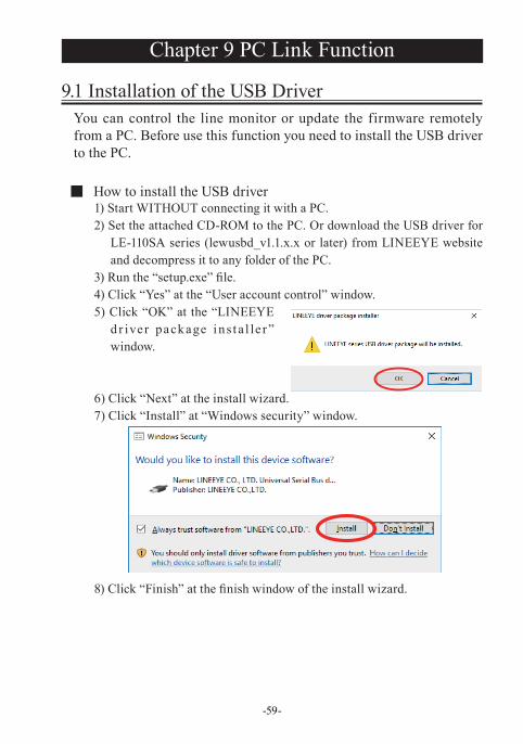
8.4 Reload (Read)You can reload .DT and .SU file at file management display.
Find the f i le to be read by swiping the display, touch the file to select it. Then touch [Load file] on the bottom to reloads the file.
� By reloading the current setting data and contents in the capture memory are overwritten.
� The LINEEYE line monitors can reload the files saved by the other LINEEYE line monitor, but some data cannot be reloaded correctly.
File Name ChangeYou cannot change the file name directly. When you want do so reload the file and resave it with the name which you want to sat.
-59-
Chapter 9 PC Link Function
9.1 Installation of the USB DriverYou can control the line monitor or update the firmware remotely from a PC. Before use this function you need to install the USB driver to the PC.
■ How to install the USB driver1) Start WITHOUT connecting it with a PC.2) Set the attached CD-ROM to the PC. Or download the USB driver for
LE-110SA series (lewusbd_v1.1.x.x or later) from LINEEYE website and decompress it to any folder of the PC.
3) Run the “setup.exe” file.4) Click “Yes” at the “User account control” window.5) Click “OK” at the “LINEEYE
d r iver package i ns t a l le r ” window.
6) Click “Next” at the install wizard.7) Click “Install” at “Windows security” window.
8) Click “Finish” at the finish window of the install wizard.
-60-
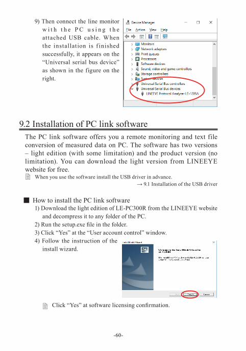
9) Then connect the line monitor w i t h t h e P C u s i n g t h e at tached USB cable. When the installation is f inished successfully, it appears on the “Universal serial bus device” as shown in the figure on the right.
9.2 Installation of PC link softwareThe PC link software offers you a remote monitoring and text file conversion of measured data on PC. The software has two versions – light edition (with some limitation) and the product version (no limitation). You can download the light version from LINEEYE website for free.
� When you use the software install the USB driver in advance.→ 9.1 Installation of the USB driver
■ How to install the PC link software1) Download the light edition of LE-PC300R from the LINEEYE website
and decompress it to any folder of the PC.2) Run the setup.exe file in the folder.3) Click “Yes” at the “User account control” window.4) Follow the instruction of the
install wizard.
� Click “Yes” at software licensing confirmation.
-61-
5) Input the company name and the serial number at the following display.
� Input “LITE” to the serial number box for the light edition. You need to input a serial number when you install the product version.
6) Click “Finish” at the finish window of the install wizard.
■ How to uninstall1) Open “Application and Function” from the control panel.
(The name may differ depending on the PC you use.)2) Select “LE-PC300R” and execute “Uninstall”.
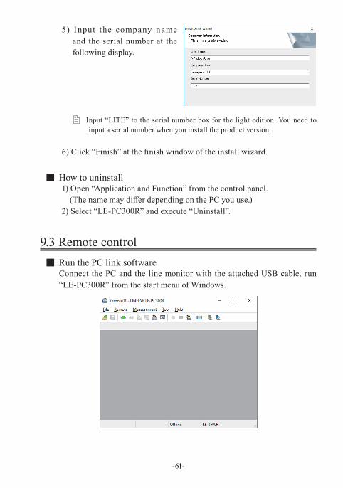
9.3 Remote control ■ Run the PC link softwareConnect the PC and the line monitor with the attached USB cable, run “LE-PC300R” from the start menu of Windows.
-62-
By [ ] (or at Remote – Remote setting – Connection), confirm that the connection method is USB and the serial number is that of the line monitor.
By [ ] (or at Measurement – Analyzer setting), set the monitor condition of the line monitor.
By [ ] (or at Remote – Connection), link the line monitor and the PC.
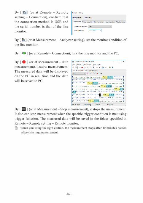
By [ ] (or at Measurement – Run measurement), it starts measurement. The measured data will be displayed on the PC in real time and the data will be saved to PC.
By [ ] (or at Measurement – Stop measurement), it stops the measurement. It also can stop measurement when the specific trigger condition is met using trigger function. The measured data will be saved in the folder specified at Remote – Remote setting – Remote monitor.
� When you using the light edition, the measurement stops after 10 minutes passed aftere starting measurement.
-63-
9.4 Measured data display and text conversion ■ Measured data displayThe saved data in the USB memory captured by line monitor can be displayed on PC.1) Connect the USB flash which has the measured data into the USB port
of PC.2) ) By [ ] (or File – Open data file) specify the data file of the USB port
and then clock Open to read it on PC link software.
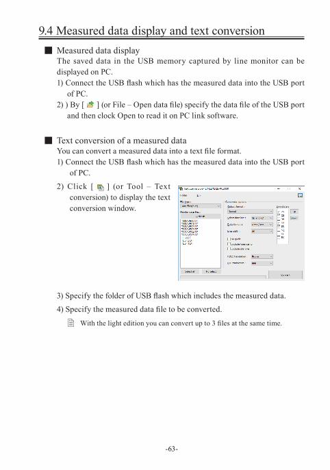
■ Text conversion of a measured dataYou can convert a measured data into a text file format.1) Connect the USB flash which has the measured data into the USB port
of PC.2) Click [ ] (or Tool – Text
conversion) to display the text conversion window.
3) Specify the folder of USB flash which includes the measured data.4) Specify the measured data file to be converted.
� With the light edition you can convert up to 3 files at the same time.
-64-
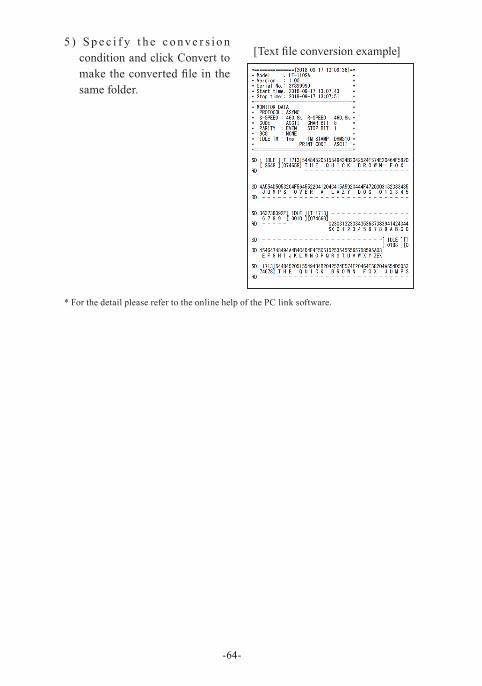
5 ) S p e c i f y t h e c o n ve r s i o n condition and click Convert to make the converted file in the same folder.
* For the detail please refer to the online help of the PC link software.
[Text file conversion example]
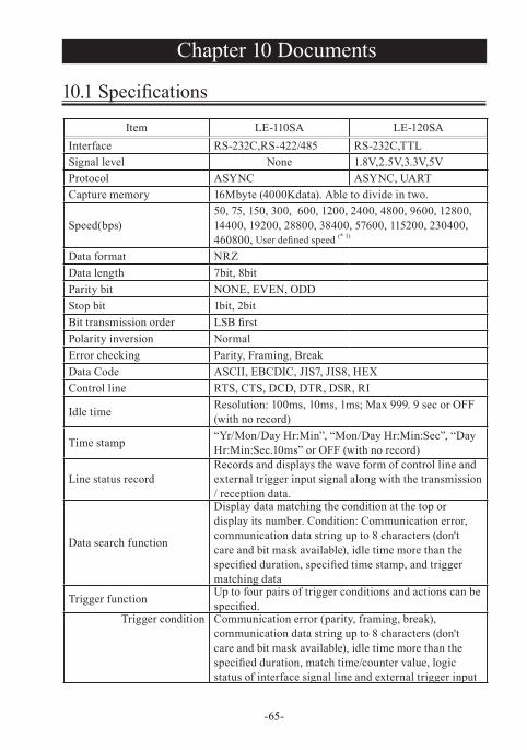
Item LE-110SA LE-120SAInterface RS-232C,RS-422/485 RS-232C,TTLSignal level None 1.8V,2.5V,3.3V,5VProtocol ASYNC ASYNC, UARTCapture memory 16Mbyte (4000Kdata). Able to divide in two.
Speed(bps)50, 75, 150, 300, 600, 1200, 2400, 4800, 9600, 12800, 14400, 19200, 28800, 38400, 57600, 115200, 230400, 460800, User defined speed (* 1)
Data format NRZData length 7bit, 8bitParity bit NONE, EVEN, ODDStop bit 1bit, 2bitBit transmission order LSB firstPolarity inversion NormalError checking Parity, Framing, BreakData Code ASCII, EBCDIC, JIS7, JIS8, HEXControl line RTS, CTS, DCD, DTR, DSR, RI
Idle time Resolution: 100ms, 10ms, 1ms; Max 999. 9 sec or OFF (with no record)
Time stamp “Yr/Mon/Day Hr:Min”, “Mon/Day Hr:Min:Sec”, “Day Hr:Min:Sec.10ms” or OFF (with no record)
Line status recordRecords and displays the wave form of control line and external trigger input signal along with the transmission / reception data.
Data search function
Display data matching the condition at the top or display its number. Condition: Communication error, communication data string up to 8 characters (don't care and bit mask available), idle time more than the specified duration, specified time stamp, and trigger matching data
Trigger function Up to four pairs of trigger conditions and actions can be specified.
Trigger condition Communication error (parity, framing, break), communication data string up to 8 characters (don't care and bit mask available), idle time more than the specified duration, match time/counter value, logic status of interface signal line and external trigger input
-65-
Chapter 10 Documents
10.1 Specifications
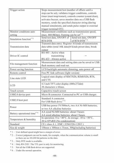
Trigger action Stops measurement/test (number of offsets until a stop can be set), validates trigger conditions, controls timer (start/stop/restart), controls counter (count/clear), activates buzzer, saves monitor data on a USB flash memory, sends the specified character string (during manual simulation), and sends pulse output to external trigger terminal OT2.
Monitor conditions auto setting
Measurement conditions such as transmission speed, (max. 460.8Kbps), framing can be set(* 2)
Simulation function(* 3) Send test data, ON/OFF of RTS/DTR
Send test data, ON/OFFof RTS/DTR(* 4)
Transmission dataTransmit data entry: Register 16 kinds of transmission data tables (total 16K data)14 kinds preset data, break output
Driver IC controlRS-485 : Active when
transmittingRS-422 : Always active
-
File management function Measurement data and setting data can be saved in USB flash memory and read out.
Power saving function LCD backlight automatic dimming, auto power offRemote control Free PC link software (light version)
Line state LED Logical state display of SD(TXD), RD(RXD), RTS,and CTS
LCD 4.3 inch TFT color display (480x272dot)28 characters x 6lines.
Touch screen Capacitive touch screenUSB2.0 device port Micro B connector. Connected to PC or USB charger.
USB2.0 host port Standard A connector. For USB flash drive.(* 5)
Power USB bus power 5V/500mA, two AA Ni-MH batteries,or two AA alkaline batteries
Battery operational time(* 6) AA sized Ni-MH batteries: about 5 hoursAA sized alkaline batteries: about 2 hours
Temperature & humidity In operation: 0 to +40°C, In storage: -10 to +50°C, 20 to 85%RH (No condensation)
Standard CE ( class A ) , EMC ( EN61326-1:2013 )Size & weight 158mm x 100mm x 31mm, 300g(including batteries)
* 1 : User defined speed might have a margin of error.* 2 : Correct judgment can not be made, for example, when the communication volume is small
or there are no 101,010 bit patterns in the data.* 3 : Only DTE mode is available.* 4 : Only RS-232C. The TTL port is only for monitoring.* 5 : Not all the USB flash drives are supported.* 6 : Under the normal operation.
-66-
0 1 2 3 4 5 6 7
0 NU DL △ 0 @ P ` p
1 SH D1 ! 1 A Q a q
2 SX D2 ” 2 B R b r
3 EX D3 # 3 C S c s
4 ET D4 $ 4 D T d t
5 EQ NK % 5 E U e u
6 AK SY & 6 F V f v
7 BL EB ’ 7 G W g w
8 BS CN ( 8 H X h x
9 HT EM ) 9 I Y i y
A LF SB * : J Z j z
B VT EC + ; K [ k {
C FF FS , < L \ l |
D CR GS - = M ] m }
E SO RS . > N ^ n ~
F SI US / ? O _ o DT
-67-
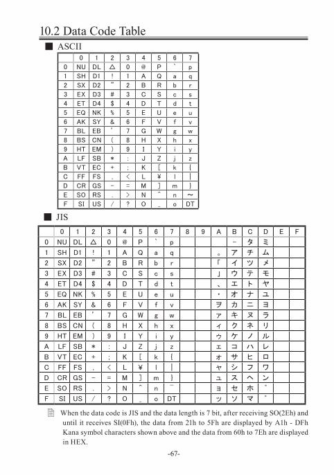
10.2 Data Code Table ■ ASCII
■ JIS0 1 2 3 4 5 6 7 8 9 A B C D E F
0 NU DL △ 0 @ P ` p - タ ミ
1 SH D1 ! 1 A Q a q 。 ア チ ム
2 SX D2 ” 2 B R b r 「 イ ツ メ
3 EX D3 # 3 C S c s 」 ウ テ モ
4 ET D4 $ 4 D T d t 、 エ ト ヤ
5 EQ NK % 5 E U e u ・ オ ナ ユ
6 AK SY & 6 F V f v ヲ カ ニ ヨ
7 BL EB ’ 7 G W g w ァ キ ヌ ラ
8 BS CN ( 8 H X h x ィ ク ネ リ
9 HT EM ) 9 I Y i y ゥ ケ ノ ル
A LF SB * : J Z j z ェ コ ハ レ
B VT EC + ; K [ k { ォ サ ヒ ロ
C FF FS , < L ¥ l | ャ シ フ ワ
D CR GS - = M ] m } ュ ス ヘ ン
E SO RS . > N ^ n ¯ ョ セ ホ ゛
F SI US / ? O _ o DT ッ ソ マ ゜
� When the data code is JIS and the data length is 7 bit, after receiving SO(2Eh) and until it receives SI(0Fh), the data from 21h to 5Fh are displayed by A1h - DFh Kana symbol characters shown above and the data from 60h to 7Eh are displayed in HEX.
0 1 2 3 4 5 6 7 8 9 A B C D E F
0 NU DL DS △ & - { } \ 0
1 SH D1 SS / a j ~ A J 1
2 SX D2 FS SY b k s B K S 2
3 EX D3 WS IR c l t C L T 3
4 PF RE BP PN d m u D M U 4
5 HT NL LF TN e n v E N V 5
6 LC BS EB NS f o w F O W 6
7 DT PC EC ET g p x G P X 7
8 GE CN SA S2 h q y H Q Y 8
9 S1 EM SE IT i r z I R Z 9
A RT US SM RF ¢ ! :
B VT C1 CP C3 . $ , #
C FF IF MA D4 < * % @
D CR IG EQ NK ( ) _ ’
E SO RS AK + ; > =
F SI IB BL SB | ¬ ? ゛
-68-
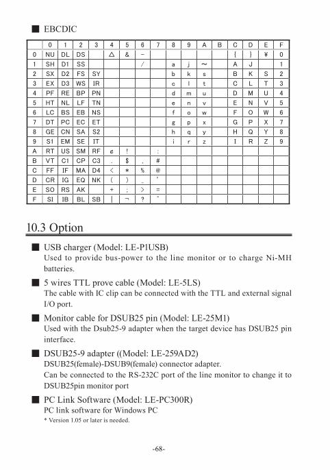
■ EBCDIC
10.3 Option ■ USB charger (Model: LE-P1USB)Used to provide bus-power to the line monitor or to charge Ni-MH batteries.
■ 5 wires TTL prove cable (Model: LE-5LS)The cable with IC clip can be connected with the TTL and external signal I/O port.
■ Monitor cable for DSUB25 pin (Model: LE-25M1)Used with the Dsub25-9 adapter when the target device has DSUB25 pin interface.
■ DSUB25-9 adapter ((Model: LE-259AD2)DSUB25(female)-DSUB9(female) connector adapter.Can be connected to the RS-232C port of the line monitor to change it to DSUB25pin monitor port
■ PC Link Software (Model: LE-PC300R)PC link software for Windows PC* Version 1.05 or later is needed.
-69-
Chapter 11 After Support and Maintenance
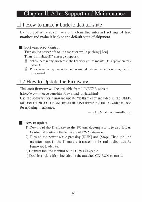
11.1 How to make it back to default stateBy the software reset, you can clear the internal setting of line monitor and make it back to the default state of shipment.
■ Software reset controlTurn on the power of the line monitor while pushing [Esc].Then “Initialized!!” message appears.
� When there is any problem in the behavior of line monitor, this operation may solve it.
� Please note that by this operation measured data in the buffer memory is also all cleaned.
11.2 How to Update the FirmwareThe latest firmware will be available from LINEEYE website.https://www.lineeye.com/html/download_update.htmlUse the software for firmware update “le8firm.exe” included in the Utility folder of attached CD-ROM. Install the USB driver into the PC which is used for updating in advance.
→ 9.1 USB driver installation
■ How to update1) Download the firmware to the PC and decompress it to any folder.
Confirm it contains the firmware of FW2 extension.2) Turn on the power while pressing [RUN] and [Stop]. Then the line
monitor runs in the firmware transfer mode and it displays ## Firmware loader ##.
3) Connect the line monitor with PC by USB cable.4) Double-click le8firm included in the attached CD-ROM to run it.
-70-
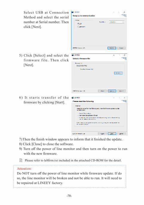
Select USB at Connect ion Method and select the serial number at Serial number. Then click [Next].
5) Click [Select] and select the f i r mware f i le. Then cl ick [Next].
6 ) I t s t a r t s t r a n s fe r of t h e firmware by clicking [Start].
7) Then the finish window appears to inform that it finished the update.8) Click [Close] to close the software.9) Turn off the power of line monitor and then turn on the power to run
with the new firmware.
� Please refer to le8firm.txt included in the attached CD-ROM for the detail.
Attention:Do NOT turn off the power of line monitor while firmware update. If do so, the line monitor will be broken and not be able to run. It will need to be repaired at LINEEY factory.
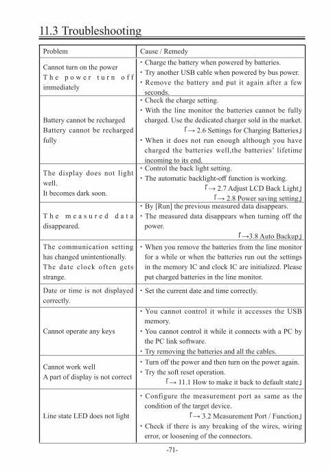
Problem Cause / Remedy
Cannot turn on the powerT h e p o w e r t u r n o f f immediately
・ Charge the battery when powered by batteries.・ Try another USB cable when powered by bus power.・ Remove the battery and put it again after a few
seconds.
Battery cannot be rechargedBattery cannot be recharged fully
・ Check the charge setting.・ With the line monitor the batteries cannot be fully
charged. Use the dedicated charger sold in the market.「→ 2.6 Settings for Charging Batteries」
・ When it does not run enough although you have charged the batteries well,the batteries’ lifetime incoming to its end.
The display does not light well.It becomes dark soon.
・ Control the back light setting.・ The automatic backlight-off function is working.
「→ 2.7 Adjust LCD Back Light」「→ 2.8 Power saving setting」
T h e m e a s u r e d d a t a disappeared.
・ By [Run] the previous measured data disappears.・ The measured data disappears when turning off the
power.「→3.8 Auto Backup」
The communication setting has changed unintentionally.The date clock often gets strange.
・ When you remove the batteries from the line monitor for a while or when the batteries run out the settings in the memory IC and clock IC are initialized. Please put charged batteries in the line monitor.
Date or time is not displayed correctly.
・ Set the current date and time correctly.
Cannot operate any keys
・ You cannot control it while it accesses the USB memory.
・ You cannot control it while it connects with a PC by the PC link software.
・ Try removing the batteries and all the cables.
Cannot work wellA part of display is not correct
・ Turn off the power and then turn on the power again.・ Try the soft reset operation.
「→ 11.1 How to make it back to default state」
Line state LED does not light
・ Configure the measurement port as same as the condition of the target device.
「→ 3.2 Measurement Port / Function」
・ Check if there is any breaking of the wires, wiring error, or loosening of the connectors.
-71-
11.3 Troubleshooting
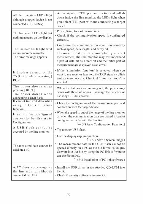
All the line state LEDs light although a target device is not connected. (LE-120SA)
・ As the signals of TTL port are L active and pulled-down inside the line monitor, the LEDs light when you select TTL port without connecting a target device.
The line state LEDs light but nothing appears on the display.
・ Press [ Run ] to start measurement.・ Check if the communication speed is configured
correctly.
The line state LEDs light but it cannot monitor correctly.The error message appears.
・ Configure the communication condition correctly such as speed, data length, and parity bit.
・ I f communicat ion data run when you s tar t measurement, the line monitor may misunderstand a part of data bit as a start bit and the initial part of measurement are displayed as an error.
It displays an error on the TXD side when pressing [ RUN ].
・ If the “simulation function” is selected when you want to use monitor function, the TXD signals collide and an error occurs. Check if “monitor mode” is selected.
T h e p o w e r d o w n s w h e n pressing [ RUN ].T h e p o w e r d o w n s w h e n connecting a USB flash.
・ When the batteries are running out, the power may down with these situations. Exchange the batteries or use it by USB bus power.
It cannot transmit data when u s i n g i n t h e s i m u l a t i o n function.
・ Check the configuration of the measurement port and connection with the target device.
I t c a n n o t b e c o n f i g u r e d c o r r e c t l y b y t h e A u t o Configuration.
・ When the speed is out of the range of the line monitor or when the communication data are biased it cannot configure correctly with the function.
「→ 5.8 Auto Configuration Function」A U S B f l a s h c a n n o t b e accepted by the line monitor. ・ Try another USB flash.
The measured data cannot be used on a PC.
・ Use the display capture function.「→ 5.7 Save a Screen Image」
・ The measurement data in the USB flash cannot be opened directly on a PC as the file format is unique. Convert it to .txt file by using the PC link software to use the file on PC.
「→ 9.2 Installation of PC link software」
A PC does not recognize the line monitor although connected by USB.
・ Install the USB driver in the attached CD-ROM into the PC.
・ Check if security softwares interrupt it.
-72-
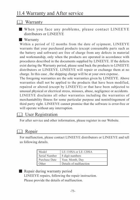
Model LE-110SA or LE-120SASerial Number 8 digit numbersPurchase Date Year, Month, DayOther Details of malfunction
-73-
11.4 Warranty and After service
Warranty ■ When you face any problems, please contact LINEEYE distributors or LINEEYE
■ WarrantyWithin a period of 12 months from the date of syipment, LINEEYE warrants that your purchased products (except consumable parts such as the battery and software) are free of charge from any defects in material and workmanship, only when the products are operated in accordance with procedures described in the documents supplied by LINEEYE. If the defects exist during the Warranty period, please send back the products to LINEEYE distributors or LINEEYE. LINEEYE will repair or exchange them at no charge. In this case , the shipping charge will be at your own expense..The foregoing warranties are the sole warranties given by LINEEYE. Above warranties shall not be applied to the products that have been modified, repaired or altered (except by LINEEYE) or that have been subjected to unusual physical or electrical stress, misuses, abuse, negligence or accidents.LINEEYE disclaims all other warranties including the warranties of merchantability fitness for some particular purpose and noninfringement of third party right. LINEEYE cannot promise that the software is error-free or will operate without any interruption.
User RegistrationFor after service and other information, please register in our Website.
RepairFor malfunction, please contact LINEEYE distributors or LINEEYE and tell us following details.
■ Repair during warranty periodLINEEYE repairs, following the repair instruction.Please provide the details of malfunction.
-74-
■ Repair after warranty periodLINEEYE will repair the products at our own expense.
■ CalibrationEnable to have a hardware calibration test by the line monitor
After SupportRead “FAQ” in our Website or email us.Please refer to “FAQ”. We also have support by email regarding the technical issue. When you use it, please register yourproduct via our website.
Website : https://www.lineeye.com


4F., Marufuku Bldg., 39-1, Karahashi Nishihiragaki-cho, Minami-ku, Kyoto, 601-8468, Japan
Tel : 075(693)0161 Fax : 075(693)0163
URL https://www.lineeye.com Email :[email protected]
Printed in Japan
M-50112SAE/LE
LINEEYE CO., LTD.