Embed Size (px)
Citation preview
P
Tli(cocdte
dB7
Int. J. Radiation Oncology Biol. Phys., Vol. 59, No. 1, pp. 293–299, 2004Copyright © 2004 Elsevier Inc.
Printed in the USA. All rights reserved0360-3016/04/$–see front matter
doi:10.1016/j.ijrobp.2004.01.019
HYSICS CONTRIBUTION
LENS DOSE IN MLC-BASED IMRT TREATMENTS OF THE HEADAND NECK
TODD PAWLICKI , PH.D.,* GARY LUXTON, PH.D.,* QUYNH-THU LE, M.D.,* DAVID FINDLEY, PH.D.,*AND C.-M. MA, PH.D.†
*Department of Radiation Oncology, Stanford University School of Medicine, Stanford, CA;†Department of Radiation Oncology,Fox Chase Cancer Center, Philadelphia, PA
Purpose: The objectives of this work are: (1) to determine typical dose to the lens during step-and-shoot intensitymodulated radiotherapy (IMRT) treatments of the head and neck, and (2) to report on the dose calculationaccuracy of a commercial inverse planning system in predicting lens dose.Methods and Materials: The Corvus inverse treatment planning system (Nomos, Cranberry Township, PA) wasused to plan IMRT treatments for patients with head-and-neck cancers in our clinic. Patients were treated onVarian C-series linacs (Varian, Palo Alto, CA) with 4-MV or 6-MV X-rays. A Rando phantom (AldersonLaboratories, Stamford, CT) was specially modified to accommodate 1 � 1 � 1 mm3 thermoluminescentdosimeters at the position of the lens. The IMRT treatment plans were then delivered to the modified Randophantom. The thermoluminescent dosimeter measurements were converted to dose and taken as an estimate ofthe lens dose. A total of 20 cases were used in this study (15 cases with 4 MV and 5 cases with 6 MV).Results: Expressed as a percentage of the prescription dose, the mean dose to the left and right lens for all 4-MVcases was 9.1% (range, 2.0% to 61.3%). For the 6-MV cases, the mean dose to the left and right lens was 12.8%(range, 3.6% to 41.3%). For both the 4-MV and 6-MV cases, the case of maximum dose occurred when the IMRTtreatment target included volumes superior to the level of the lens. The field size and number of monitor unitsdid not correlate with the measured lens dose. The only factor of significance affecting lens dose was theinferior-to-superior distance of the target to the lens. For target–lens distance >6 mm, the maximum measuredlens doses were 5.9% and 9.0% relative to the prescribed dose for the 4-MV and 6-MV beams, respectively. Thesedata are similar to those observed in conventional head-and-neck treatments. For all cases, the differencebetween the dose measured and that predicted by Corvus was less than 2% and 4% of the dose prescribed to thegross tumor volume for the 4-MV and 6-MV cases, respectively.Conclusion: In IMRT, factors such as leaf leakage and number of monitor units play a secondary role and arenot more significant than what is observed in conventional head-and-neck treatment when the lens is shielded bythe collimator jaws. The target–lens distance is the parameter that affects the lens dose most strongly. For caseswhere the tumor is at or above the level of the lens, the lens dose can amount to an appreciable fraction of theprescription dose. To keep the lens dose to a minimum, noncoplanar beams that enter or exit into the lens shouldnot be used. © 2004 Elsevier Inc.
IMRT, TLD, Lens dose.
turetheby
lenswhilessed
duet theerly
ar ationa treat-m
afterr -j s ofa Gyg ppeara doseo uce
Ra-875
98-u
A enH tom.
004.A
INTRODUCTION
he lens of the eye is a transparent crystalline strucocated just posterior to the iris. The cortex surroundsnnermost part of the lens. The lens is held in placezonular) fibers that attach to the anterior and posteriorapsule. New lens fibers replicate at the lens equatorld fibers, which have lost their nuclei, become compreentrally and form heavier, less elastic lens fibers(1). Ra-iation insult that results in opacification of the lens is
o damage incurred by the proliferating epithelial cells aquator of the lens, which later fail to differentiate prop
Reprint requests to: Todd Pawlicki, Ph.D., Department ofiation Oncology, Stanford Cancer Center, Ground Floor,lake Wilber Drive, Stanford, CA 94305-5487. Tel: (650) 4102; Fax: (650) 498-4015; E-mail: [email protected]
293
s they migrate to the central part of the lens(2). For thiseason, dose to the lens and subsequent cataract formre a concern in most head-and-neck radiotherapyents.The eye is subject to both acute and late effects
adiotherapy. Hempel and Hinkelbein(3) found that conunctivitis leading to conjunctival damage occurs at dosebout 50 Gy. Keratitis develops with doses of 30–50iven over 4–5 weeks. Late effects such as cataracts at an average of 2–3 years postradiotherapy. A singlef 2–10 Gy or fractionated doses of 10–15 Gy will prod
cknowledgment—We would like to acknowledge Fred van daak for creating the TLD holders fitted for the Rando phanReceived May 27, 2003, and in revised form Jan 7, 2
ccepted for publication Jan 12, 2004.
oy3cspta25Gcra
mtuttosbndttw
cmI3dIuemtefifdciiscpttttmstl
rpdsnc
lcpnPbfFCCTi(cw6eMVac
vTcb1uvTptItbdtifin7
pwtlm
294 I. J. Radiation Oncology ● Biology ● Physics Volume 59, Number 1, 2004
pacities. Retinopathy occurs anywhere from 6 months to 3ears after radiotherapy with threshold doses in the range0–35 Gy. Henk et al. investigated dose to the lens andataract formation for orbital tumors (4). In a prospectivetudy of 40 patients treated with radiation therapy via 60Cohotons or 5-MeV electrons, the patients were evaluated forhe appearance of lens opacities and diminution of visualcuity. Treatment doses ranged from 20 to 40 Gy in 1.9–.0-Gy fractions, and the dose to the lens was estimated at–30 Gy, depending on the modality. It was found that 15y to the lens in 1-Gy fractions will produce radiation
hanges from 3 to 8 years after irradiation. All lenses thateceived �16.5 Gy developed opacities that reduced visualcuity.
The lens dose that results from any radiotherapy treat-ent depends on many factors, including distance of the
arget to the lens, number of fields irradiated, and monitornits delivered. The dose to the lens is usually reduced inhree-dimensional conformal radiotherapy (3DCRT); withhis technique, it is ensured that beams do not enter throughr exit into the lens. Foo et al. evaluated radiation dose totructures outside the irradiated volume for head-and-neck,rain, breast, and pelvis treatments (5). For the head-and-eck cases, the lens received 5%–16% of the total midplaneose from opposed lateral fields. For the brain treatment, ahree-field technique was used (opposed laterals and a ver-ex field) to treat 50 Gy to the isocenter, and the lens doseas found to be 0.4–2 Gy.Head-and-neck tumors are now frequently treated with
one beam (multileaf collimator [MLC] based) intensityodulated radiotherapy (IMRT). Bragg et al. investigated
MRT for parotid tumors (6) and found that compared toDCRT, IMRT had little effect on the contralateral lensose but increased the ipsilateral lens dose by up to 3.2 Gy.n MLC-based IMRT treatments, the planner often choosesnconventional beam angles—where beams may enter orxit through the eye and/or lens. Additionally, there is aodulation scale factor (7) associated with dynamic MLC
reatments. This refers to the greater beam “on” time forach IMRT treatment field compared to a 3DCRT treatmenteld and corresponds to an increase in monitor units by aactor of 3 or more. Direct in vivo measurement of the lensose during IMRT treatments is impossible, and dose cal-ulation accuracy using conventional algorithms is limitedn superficial tissues like the lens. Measuring the lens dosen an anthropomorphic phantom would permit a direct mea-urement of the lens dose and also allow one to assess dosealculation accuracy of a treatment planning system inredicting lens dose. The clinically interesting data are forargets that are farther from the lens. This is because whenhe superior border of the target is at the level of, or superioro, the level of the lens and adjacent to the optic apparatus,he physician must seek a balance between aggressive treat-ent and sparing the lens. In these cases, lens dose and
ubsequent cataract formation may be secondary to poten-ial tumor cure. However, when the target is away from theens, then knowing how much confidence to place in the
esult reported by the planning system would be useful toredict lens complications. The objective of this work is toetermine the typical dose to the lens during MLC-basedtep-and-shoot IMRT treatments for cancers of the head andeck. Additionally, we report on the ability of a commer-ially available inverse planning system to predict lens dose.
MATERIALS AND METHODS
The cases used in this study were taken from the popu-ation of patients treated with IMRT for head-and-neckancer in our department. IMRT was used to treat therimary tumor at 2.15–2.20 Gy/fraction and to simulta-eously treat all regional lymph nodes at 1.80 Gy/fraction.atients were immobilized using the S-type carbon fiberoard (Med-Tec, Orange City, IA) and a 3-mm-thick per-orated thermoplastic mask with neck support by the Accu-orm custom-form patient positioning support (Med-Tec).T images were acquired with 3-mm slices on a PQ 5000T scanner (Philips Medical Systems, Cleveland, OH).arget and critical structures were delineated by the attend-
ng physician using the AcQSim VoxelQ segmentation toolsPhilips Medical Systems, Cleveland, OH). A total of 20ases were used in this study. Fifteen cases were treatedith 4-MV photon beams, and 5 cases were treated with-MV photon beams. The 4-MV photon beams were deliv-red by a Varian Clinac 2100C with a 120-leaf MillenniumLC, and the 6-MV photon beams were delivered by aarian Clinac 2300C/D with an 80-leaf MLC (4 cases) andVarian Clinac 21EX with a 120-leaf Millennium MLC (1
ase).The IMRT plans were generated with a commercial in-
erse planning system (Corvus 4.0, Nomos, Cranberryownship, PA). All Corvus IMRT treatment plans werealculated with heterogeneity correction turned on duringoth optimization and dose calculation. For all cases, a0-mm leaf width in the inferior-superior direction wassed. The number of fixed gantry angles used in planningaried from case to case with an average of 6 (range, 5 to 9).he gantry angles were coplanar in the axial plane of theatient for all cases in this study. On Varian accelerators,he maximum treatable field width in 1 beam “on” time forMRT is limited to 14.5 cm. This is because the lengths ofhe Varian MLC leaves in the travel direction are finite andecause the collimator jaws are not permitted to moveuring treatment. The Corvus inverse planning system au-omatically accounts for this limitation by splitting a fieldnto 2 or more fields if the target width exceeds the Varianeld size limit in the beam’s-eye view. As a result, theumber of fixed fields that was actually treated ranged fromto 14 with an average of 10.To investigate the lens dose, an anthropomorphic Rando
hantom (Alderson Research Laboratories, Stamford, CT)as specially modified to accommodate 1 � 1 � 1 mm3
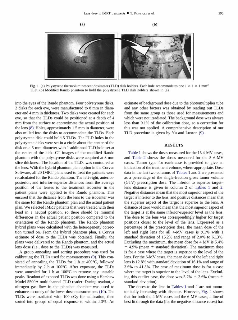
hermoluminescent dosimeters (TLDs) at the position of theens. Figures 1a and 1b show the TLD holders and theodified Rando phantom, respectively. Holes were milled
i2eemtappdtpstSrpppetphdohtepl
csiwpMneTs
eafwltT
acida(lNttdtTpplsE�ill3wis
ttb
295Lens dose in IMRT treatments ● T. PAWLICKI et al.
nto the eyes of the Rando phantom. Four polystyrene disks,disks for each eye, were manufactured to 8 mm in diam-
ter and 4 mm in thickness. Two disks were created for eachye, so that the TLDs could be positioned at a depth of 4m from the surface to approximate the actual position of
he lens (8). Holes, approximately 1.5 mm in diameter, werelso milled into the disks to accommodate the TLDs. Eacholystyrene disk could hold 5 TLDs. The TLD holes in theolystyrene disks were set in a circle about the center of theisk on a 5-mm diameter with 1 additional TLD hole set athe center of the disk. CT images of the modified Randohantom with the polystyrene disks were acquired at 3-mmlice thickness. The location of the TLDs was contoured ashe lens. With the hybrid phantom plan option in the Corvusoftware, all 20 IMRT plans used to treat the patients wereecalculated for the Rando phantom. The left-right, anterior-osterior, and inferior-superior distances from the averageosition of the lenses to the treatment isocenter in theatient plans were applied to the Rando phantom. Thisnsured that the distance from the lens to the isocenter washe same for the Rando phantom plan and the actual patientlan. We selected IMRT patients that were treated with theiread in a neutral position, so there should be minimalifferences in the actual patient position compared to therientation of the Rando phantom. The Rando phantomybrid plans were calculated with the heterogeneity correc-ion turned on. From the hybrid phantom plan, a Corvusstimate of dose to the TLDs was obtained. Finally, thelans were delivered to the Rando phantom, and the actualens dose (i.e., dose to the TLDs) was measured.
A group annealing and sorting procedure was used foralibrating the TLDs used for measurements (9). This con-isted of annealing the TLDs for 1 h at 400°C, followedmmediately by 2 h at 100°C. After exposure, the TLDsere annealed for 1 h at 100°C to remove any unstableeaks. Readout of exposed TLDs was done using a Harshawodel 5500A multichannel TLD reader. During readout, a
itrogen gas flow in the planchet chamber was used tonhance accuracy of the lower dose measurements (10). TheLDs were irradiated with 100 cGy for calibration, thenorted into groups of equal response to within �3%. An
Fig. 1. (a) Polystyrene thermoluminescent dosimeter (TLTLD. (b) Modified Rando phantom to hold the polystyr
stimate of background dose due to the photomultiplier tubend any other factors was obtained by reading out TLDsrom the same group as those used for measurements andhich were not irradiated. The background dose was always
ess than 0.1% of the calibration dose, so a correction forhis was not applied. A comprehensive description of ourLD procedure is given by Yu and Luxton (9).
RESULTS
Table 1 shows the doses measured for the 15 4-MV cases,nd Table 2 shows the doses measured for the 5 6-MVases. Tumor type for each case is provided to give anndication of the treatment volume, where appropriate. Doseata in the last two columns of Tables 1 and 2 are presenteds a percentage of the single-fraction gross tumor volumeGTV) prescription dose. The inferior to superior target–ens distance is given in column 2 of Tables 1 and 2.egative distances mean that the most superior aspect of the
arget is inferior to the lens, and positive distances mean thathe superior aspect of the target is superior to the lens. Aistance of zero would mean that the most superior aspect ofhe target is at the same inferior-superior level as the lens.he dose to the lens was correspondingly higher for targetositions closer to the level of the lens. Expressed as aercentage of the prescription dose, the mean dose of theeft and right lens for all 4-MV cases is 9.1% with 1tandard deviation of 15.2% and range of 2.0% to 61.3%.xcluding the maximum, the mean dose for 4 MV is 5.4%
4.9% (mean � standard deviation). The maximum doses for a case where the target is superior to the level of theens. For the 6-MV cases, the mean dose of the left and rightens is 12.8% with standard deviation of 16.1% and range of.6% to 41.3%. The case of maximum dose is for a casehere the target is superior to the level of the lens. Exclud-
ng this outlier case, the dose was 5.7% � 2.6% (mean �tandard deviation).
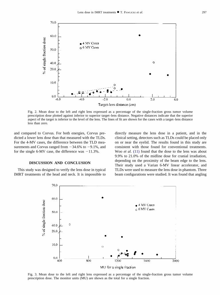
The doses to the lens in Tables 1 and 2 are not mono-onically increasing with distance. However, Fig. 2 showshat for both the 4-MV cases and the 6-MV cases, a line ofest fit through the data (for the negative-distance cases) has
holders. Each hole accommodates one 1 � 1 � 1 mm3
D disk holders shown in (a).
D) diskene TL
atdTdlcp
lptdsdt
b(�oamtt1tt3rl
t
OBBTLPBTATTNLLL
it
TBNUS
iv
296 I. J. Radiation Oncology ● Biology ● Physics Volume 59, Number 1, 2004
positive slope. Figure 3 shows a plot of the mean dose tohe left and right lens (as a percentage of the single-fractionose to the GTV) vs. the monitor units for a single fraction.here is little correspondence between the monitor unitselivered during treatment and an increase in the dose to theens. The most significant factor that correlates with in-reased dose to the lens is the proximity of the open fieldrimary beam to the lens.Table 3 shows the mean lens dose of the left and right
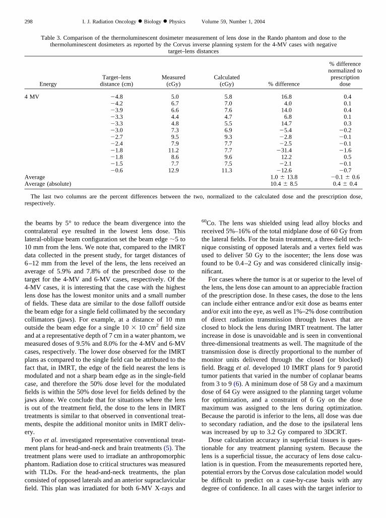
ens with the average lens dose reported by the Corvuslanning system for the 4-MV Rando phantom plans wherehe target is inferior to the level of the lens. The percentifference between the Corvus calculations and the mea-urements is shown in the fifth column, and the percentifference normalized to the prescription dose is shown inhe last column. The magnitude of the percent difference
Table 1. Thermoluminescent dosim
Tumor
Target–lensdistance
(cm)
Numberof beam
directions
ral tongue �4.8 5ase of tongue �4.2 7ase of tongue �3.9 6onsil �3.3 6arynx �3.3 6yriform sinus �3.0 6ase of tongue �2.7 6onsil �2.4 7lveolar ridge �1.8 5onsil �1.8 5onsil �1.5 6asopharynx �0.6 9eft maxillary sinus* 0.9 7eft temporal area† 1.8 5eft maxillary sinus‡ 3.3 7
* Adenoid cystic carcinoma.† High-grade malignant neoplasm.‡ Squamous cell carcinoma.The dose to the left and right lens is given as a percentage of the
s the length in the inferior-superior direction from the superior asparget volume) to the level of the lens. Positive distances indicate
Table 2. Thermoluminescent dosim
Tumor
Target–lensdistance
(cm)
Numberof beam
directions
onsil �4.2 6ase of tongue �3.9 6asopharynx �1.2 6nknown primary* �1.2 7kull base† 2.1 7
* Squamous cell carcinoma.† Meningioma.The dose to the left and right lens is given as a percentage of th
n the inferior-superior direction from the most superior aspect of tolume) to the level of the lens.
etween the TLD measurements and Corvus is 10.4%range, 2.1% to 31.4%). The maximum difference was31.4% for a case where the predicted lens dose was 3.5%
f the prescribed dose. Relative to the prescription dose, theverage difference between calculation and measurement isuch smaller, 0.4% (range, 0.1% to 1.6%). Similarly, for
he 6-MV cases where the target is inferior to the level ofhe lens, the average magnitude of the percent difference is4.1% (range, 0.4% to 37.8%). But, relative to the prescrip-ion dose, the average absolute percent difference betweenhe TLD measurements and Corvus is 1.1% (range, 0% to.4%). As seen in Table 3, the difference in the measuredesults compared to Corvus does not correlate with target–ens distance.
Four cases where the target was superior to the level ofhe lens (1 6-MV case and 3 4-MV cases) were measured
easurements for the 4-MV plans
umberf fieldsradiated
MUsper
fractionLeft lens
(%)Right lens
(%)
9 1338 2.3 � 0.1 2.2 � 0.114 1743 3.1 � 0.1 3.0 � 0.212 1315 3.0 � 0.2 3.0 � 0.1
9 1111 1.9 � 0.1 2.0 � 0.18 1216 2.2 � 0.1 2.2 � 0.1
12 1433 3.1 � 0.1 3.5 � 0.211 1438 4.4 � 0.3 4.2 � 0.211 1540 3.7 � 0.2 3.6 � 0.110 1445 4.8 � 0.5 5.4 � 0.610 1256 3.6 � 0.3 4.4 � 0.411 1339 4.0 � 0.4 3.1 � 0.110 1328 5.6 � 0.4 6.1 � 1.1
7 991 61.9 � 4.1 60.6 � 13.97 1032 8.3 � 0.4 25.9 � 1.4
12 1258 13.6 � 1.1 18.9 � 4.3
-fraction dose to the gross target volume. The target–lens distancethe target (planning target volume, clinical target volume, or grosse lens was inferior to the superior aspect of the target.
easurements for the 6-MV plans
mberfieldsdiated
MUsper
fractionLeft lens
(%)Right lens
(%)
11 1297 3.4 � 0.3 3.9 � 0.212 1240 3.5 � 0.2 3.6 � 0.111 993 8.6 � 0.6 9.3 � 0.814 1210 5.2 � 0.4 7.7 � 0.27 539 70.0 � 13.5 12.5 � 0.9
to the gross target volume. The target–lens distance is the lengthet (planning target volume, clinical target volume, or gross target
eter m
Noir
singleect ofthat th
eter m
Nuofirra
e dosehe targ
adFsf
I
dcocW9dTTb
297Lens dose in IMRT treatments ● T. PAWLICKI et al.
nd compared to Corvus. For both energies, Corvus pre-icted a lower lens dose than that measured with the TLDs.or the 4-MV cases, the difference between the TLD mea-urements and Corvus ranged from �34.6% to �9.1%, andor the single 6-MV case, the difference was �11.3%.
DISCUSSION AND CONCLUSION
This study was designed to verify the lens dose in typicalMRT treatments of the head and neck. It is impossible to
Fig. 2. Mean dose to the left and right lens expressedprescription dose plotted against inferior to superior targaspect of the target is inferior to the level of the lens. Theless than zero.
Fig. 3. Mean dose to the left and right lens expressedprescription dose. The monitor units (MU) are shown a
irectly measure the lens dose in a patient, and in thelinical setting, detectors such as TLDs could be placed onlyn or near the eyelid. The results found in this study areonsistent with those found for conventional treatments.oo et al. (11) found that the dose to the lens was about
.9% to 21.0% of the midline dose for cranial irradiation,epending on the proximity of the beam edge to the lens.heir study used a Varian 6-MV linear accelerator, andLDs were used to measure the lens dose in phantom. Threeeam configurations were studied. It was found that angling
percentage of the single-fraction gross tumor volumes distance. Negative distances indicate that the superiorof fit are shown for the cases with a target–lens distance
percentage of the single-fraction gross tumor volumetal for a single fraction.
as aet–lenlines
as as the to
tcl1d6at4lotcoamcpfmcfijitme
mtpwcfi
6
rtnufn
tocaocittmfitfdfmBtw
tllpbd
4
AA
r
298 I. J. Radiation Oncology ● Biology ● Physics Volume 59, Number 1, 2004
he beams by 5° to reduce the beam divergence into theontralateral eye resulted in the lowest lens dose. Thisateral-oblique beam configuration set the beam edge �5 to0 mm from the lens. We note that, compared to the IMRTata collected in the present study, for target distances of–12 mm from the level of the lens, the lens received anverage of 5.9% and 7.8% of the prescribed dose to thearget for the 4-MV and 6-MV cases, respectively. Of the-MV cases, it is interesting that the case with the highestens dose has the lowest monitor units and a small numberf fields. These data are similar to the dose falloff outsidehe beam edge for a single field collimated by the secondaryollimators (jaws). For example, at a distance of 10 mmutside the beam edge for a single 10 � 10 cm2 field sizend at a representative depth of 7 cm in a water phantom, weeasured doses of 9.5% and 8.0% for the 4-MV and 6-MV
ases, respectively. The lower dose observed for the IMRTlans as compared to the single field can be attributed to theact that, in IMRT, the edge of the field nearest the lens isodulated and not a sharp beam edge as in the single-field
ase, and therefore the 50% dose level for the modulatedelds is within the 50% dose level for fields defined by the
aws alone. We conclude that for situations where the lenss out of the treatment field, the dose to the lens in IMRTreatments is similar to that observed in conventional treat-ents, despite the additional monitor units in IMRT deliv-
ry.Foo et al. investigated representative conventional treat-ent plans for head-and-neck and brain treatments (5). The
reatment plans were used to irradiate an anthropomorphichantom. Radiation dose to critical structures was measuredith TLDs. For the head-and-neck treatments, the plan
onsisted of opposed laterals and an anterior supraclaviculareld. This plan was irradiated for both 6-MV X-rays and
Table 3. Comparison of the thermoluminescent dosimeter mthermoluminescent dosimeters as reported by the Corvu
target–l
EnergyTarget–lens
distance (cm)Measured
(cGy)
MV �4.8 5.0�4.2 6.7�3.9 6.6�3.3 4.4�3.3 4.8�3.0 7.3�2.7 9.5�2.4 7.9�1.8 11.2�1.8 8.6�1.5 7.7�0.6 12.9
verageverage (absolute)
The last two columns are the percent differences between thespectively.
0Co. The lens was shielded using lead alloy blocks andeceived 5%–16% of the total midplane dose of 60 Gy fromhe lateral fields. For the brain treatment, a three-field tech-ique consisting of opposed laterals and a vertex field wassed to deliver 50 Gy to the isocenter; the lens dose wasound to be 0.4–2 Gy and was considered clinically insig-ificant.
For cases where the tumor is at or superior to the level ofhe lens, the lens dose can amount to an appreciable fractionf the prescription dose. In these cases, the dose to the lensan include either entrance and/or exit dose as beams enternd/or exit into the eye, as well as 1%–2% dose contributionf direct radiation transmission through leaves that arelosed to block the lens during IMRT treatment. The latterncrease in dose is unavoidable and is seen in conventionalhree-dimensional treatments as well. The magnitude of theransmission dose is directly proportional to the number ofonitor units delivered through the closed (or blocked)eld. Bragg et al. developed 10 IMRT plans for 9 parotid
umor patients that varied in the number of coplanar beamsrom 3 to 9 (6). A minimum dose of 58 Gy and a maximumose of 64 Gy were assigned to the planning target volumeor optimization, and a constraint of 6 Gy on the doseaximum was assigned to the lens during optimization.ecause the parotid is inferior to the lens, all dose was due
o secondary radiation, and the dose to the ipsilateral lensas increased by up to 3.2 Gy compared to 3DCRT.Dose calculation accuracy in superficial tissues is ques-
ionable for any treatment planning system. Because theens is a superficial tissue, the accuracy of lens dose calcu-ation is in question. From the measurements reported here,otential errors by the Corvus dose calculation model woulde difficult to predict on a case-by-case basis with anyegree of confidence. In all cases with the target inferior to
ement of lens dose in the Rando phantom and dose to therse planning system for the 4-MV cases with negativetances
Calculated(cGy) % difference
% differencenormalized toprescription
dose
5.8 16.8 0.47.0 4.0 0.17.6 14.0 0.44.7 6.8 0.15.5 14.7 0.36.9 �5.4 �0.29.3 �2.8 �0.17.7 �2.5 �0.17.7 �31.4 �1.69.6 12.2 0.57.5 �2.1 �0.1
11.3 �12.6 �0.71.0 � 13.8 �0.1 � 0.610.4 � 8.5 0.4 � 0.4
, normalized to the calculated dose and the prescription dose,
easurs inve
ens dis
e two
tdrtwt
Iptiaoo(tcpmlbl
naasatoltbttfga
aitaty
299Lens dose in IMRT treatments ● T. PAWLICKI et al.
he lens, the differences were less than 2% and 4% of theose prescribed to the GTV for the 4-MV and 6-MV cases,espectively. For the cases where the target was superior tohe lens, relative to the prescription dose, these differencesere �9.2% to �1.5% for the 4-MV cases and �4.7% for
he 6-MV case.Sometimes the benefits of a new treatment technique like
MRT are emphasized, and its attendant risks are down-layed. Radiation-induced cataracts may be an acceptablerade-off for potential tumor cure; however, we have exam-ned the dose to the lens in a number of head-and-neck casesnd found that the dose delivered to the lens depends moren the proximity of the target to the lens than on the numberf beams, monitor units, or individual beam orientationsfor the case of coplanar axial beams). For targets inferior tohe level of the lens, the modulation scale factor and asso-iated leaf transmission/leakage with internal patient scatterlay only a minor role in dose to the lens in IMRT treat-ents. When the lens lies within the treated region, then to
imit the lens dose, one must develop treatment plans witheam directions that do not enter through or exit into theens. This is analogous to three-dimensional planning tech-
1
1
iques. One of the hallmarks of IMRT plans is that tochieve a conformal dose, a low-dose region is spread overlarger area of the patient. To a radiosensitive structure
uch as the lens, however, this low dose can exceed toler-nce. To minimize this dose, one must limit the source ofhe dose to the lens to only scatter and not to direct entrancer exit dose. For cases where the target is at or above theevel of the lens, the lens dose will be higher than if thearget is inferior to the level of the lens. But an analogy cane made to prostate IMRT plans where the rectum is in thereatment region, and a direct posterior beam directly throughhe rectum will sometimes give the best IMRT plan. Similarly,or head-and-neck IMRT, a beam right through the lens mayive the best plan, but if one wants to keep the lens dose to anbsolute minimum, such beams are not permitted.
The results found in this work apply to Varian linearccelerators with the secondary movable collimators (jaws)n the recommended position. However, for cases where thearget is inferior to the lens, it is expected that linearccelerators with the MLC as one of the jaws (i.e., aransmission factor comparable to a Varian jaw) wouldield results and conclusions similar to those reported here.
REFERENCES
1. Newell FW. Ophthalmology principles and concepts. 4th ed.St. Louis, MO: The CV Mosby Company; 1978. p. 37–39.
2. Worgul BV, Merriam GR, Szechter A, et al. Lens epitheliumand radiation cataract. Arch Ophthalmol 1976;94:996–999.
3. Hempel W, Hinkelbein W. Eye sequelae following externalirradiation. Recent Results Cancer Res 1993;130:231–236.
4. Henk JM, Whitelocke RA, Warrington AP, Bessell EM. Ra-diation dose to the lens and cataract formation. Int J RadiatOncol Biol Phys 1993;25:815–820.
5. Foo ML, McCullough EC, Foote RL, Pisansky TM, Shaw EG.Doses to radiation sensitive organs and structures locatedoutside the radiotherapeutic target volume for four treatmentsituations. Int J Radiat Oncol Biol Phys 1993;27:403–417.
6. Bragg CM, Conway J, Robinson MH. The role of intensity-modulated radiotherapy in the treatment of parotid tumors. IntJ Radiat Oncol Biol Phys 2002;52:729–738.
7. Geis P, Boyer AL, Wells NH. Use of a multileaf collimator asa dynamic missing-tissue compensator. Med Phys 1996;23:1199–1205.
8. Charles MW, Brown N. Dimensions of the human eyerelevant to radiation protection. Phys Med Biol 1975;20:202–218.
9. Yu C, Luxton G. TLD dose measurement: A simplified accu-rate technique for the dose range from 0.5 cGy to 1000 cGy.Med Phys 1999;26:1010–1016.
0. Meigooni AS, Mishra V, Panth H, et al. Instrumentationand dosimeter-size artifacts in quantitative thermolumines-cence dosimetry of low-dose fields. Med Phys 1995;22:555–561.
1. Woo SY, Donaldson SS, Heck RJ, et al. Minimizing andmeasuring lens dose when giving cranial irradiation. Ra-diother Oncol 1989;16:183–188.


![[68Ga]-DOTATOC-PET/CT for meningioma IMRT treatment planning](https://img.pdfslide.net/doc/110x75/6347f3c9f4145ce0ba0278fb/68ga-dotatoc-petct-for-meningioma-imrt-treatment-planning.jpg)


