Embed Size (px)
Citation preview

Name : Adil SherazReg No : 8276Subject : Advance Digital CommunicationAssignment # : 01Submitted to : Sir Shah NawazProgram : MS Telecom and Networks
Line Coding:In order to be transmitted over a digital communications system, an information
signal must first be formatted so that it is represented by digital symbols (usually binary digits or bits). Next, these digital or binary representations must be converted into electrical waveforms that are transmitted over the communications channel. In baseband digital transmission, the electrical waveforms used are pulses and this conversion from digital data to digital waveforms is known as line coding.
A signal whose spectrum extends from dc up to some finite frequency (usually a few MHz) is called a baseband signal. Hence line coding is concerned with baseband digital transmission. In many cases it is not possible to directly transmit electrical pulses over the communications channel (e.g. radio channels). In these cases, the digital data must be converted into bandpass signals (i.e. modulated onto a sinusoidal carrier wave to make their spectral characteristics more compatible with the communications channel).
The binary data such as the binary 1’s and 0’s produced by a PCM encoder may be represented in various serial-bit signaling formats known as line codes. There exists many line codes and each has its own particular advantages and disadvantages depending on the particular application. However, there are a number of desirable properties that a line code should exhibit.
Signal Spectrum:Several aspects of the signal spectrum are important: The spectral occupancy (i.e. the bandwidth) should be as small as possible to
ensure good spectral efficiency. There should be no dc component as this permits the use of ac coupling via
transformer. This provides for electrical isolation and helps reduce the effects of interference.
Clock Signal:Synchronization between the transmitter and receiver is of critical importance in
digital communications systems. Ideally, the spectrum of the line code should contain a frequency component at
the clock frequency to permit clock extraction. This avoids having to transmit a separate clock signal between the transmitter
and receiver.Signal Interference and Noise Immunity:
Ideally, the line code should be rugged in terms of exhibiting an immunity to interference and noise. In more technical terms, the line code should have a low probability of error for a
given level of transmitted power. Certain line codes are more rugged than others, e.g. polar codes have a better
error performance compared to unipolar codes.

Error Detection:It is useful to have some error detection capability built into the line code to permit transmission errors to be detected more quickly.
Transparency:The performance of the line code should be independent of the data, i.e. long strings of binary 1’s or 0’s should not affect the performance.
Cost and Complexity:The line coding scheme should not be excessively complex and/or costly.
Line Coding Formats:The various line coding waveforms can be categorized in terms of the following.
The duration of the pulses. The way in which voltage levels are assigned to the pulses.
Pulse Duration:There are two classes used here.
– Non return-to-zero (NRZ) where the pulse or symbol duration Ts = the bit period Tb.– Return-to-zero (RZ) where the pulse or symbol duration Ts < the bit period Tb. Usually Ts = 0.5Tb.
The pulse duration will usually have an effect on the synchronization properties of the line code (i.e. it determines the presence or absence of a frequency component at the clock frequency).
Line Coding Techniques:The below diagram show the division of Line Coding.
1. Unipolar SignallingUnipolar signalling (also called on-off keying, OOK) is the type of line coding in which one binary symbol (representing a 0 for example) is represented by the absence of a pulse (i.e. a SPACE) and the other binary symbol (denoting a 1) is represented by the presence of a pulse (i.e. a MARK).There are two common variations of unipolar signalling: Non-Return to Zero (NRZ) and Return to Zero (RZ).

(i) Unipolar Non-Return to Zero (NRZ):In unipolar NRZ the duration of the MARK pulse (Ƭ ) is equal to the duration (T0) of the symbol slot. As shown in the figure below:
Figure: 1 NRZ Voltage patternAdvantages:
– Simplicity in implementation.– Doesn’t require a lot of bandwidth for transmission.
Disadvantages:– Presence of DC level (indicated by spectral line at 0 Hz).– Contains low frequency components. Causes “Signal Droop” (explained
later).– Does not have any error correction capability.– Does not possess any clocking component for ease of synchronisation.– Is not transparent. Long string of zeros causes loss of synchronisation.
Figure. PSD of Unipolar NRZ
When Unipolar NRZ signals are transmitted over links with either transformer or capacitor coupled (AC) repeaters, the DC level is removed converting them into a polar format.
The continuous part of the PSD is also non-zero at 0 Hz (i.e. contains low frequency components). This means that AC coupling will result in distortion of the transmitted pulse shapes. AC coupled transmission lines typically behave like high-pass RC filters and the distortion takes the form of an exponential decay of the

signal amplitude after each transition. This effect is referred to as “Signal Droop” and is illustrated in figure below.
(ii) Return to Zero (RZ):In unipolar RZ the duration of the MARK pulse (Ƭ ) is less than the duration (To)
of the symbol slot. Typically RZ pulses fill only the first half of the time slot, returning to zero for the second half.
The above figure shows the RZ Voltage Pattern.
Advantages:– Simplicity in implementation.– Presence of a spectral line at symbol rate which can be used as symbol
timing clock signal.Disadvantages:
– Presence of DC level (indicated by spectral line at 0 Hz).– Continuous part is non-zero at 0 Hz. Causes “Signal Droop”.– Does not have any error correction capability.

– Occupies twice as much bandwidth as Unipolar NRZ.– Is not Transparent
In conclusion it can be said that neither variety of unipolar signals is suitable for transmission over AC coupled lines.
2. Polar Signalling:In polar signalling a binary 1 is represented by a pulse g1(t) and a binary 0 by the opposite (or antipodal) pulse g0(t) = -g1(t). Polar signalling also has NRZ and RZ forms.
PSD of Polar Signalling:

Polar NRZ and RZ have almost identical spectra to the Unipolar NRZ and RZ. However, due to the opposite polarity of the 1 and 0 symbols, neither contain any spectral lines.
Advantages:– Simplicity in implementation.– No DC component.
Disadvantages:– Continuous part is non-zero at 0 Hz. Causes “Signal Droop”.– Does not have any error correction capability.– Does not possess any clocking component for ease of synchronisation.– Is not transparent.
Advantages:– Simplicity in implementation.– No DC component.
Disadvantages:– Continuous part is non-zero at 0 Hz. Causes “Signal Droop”.– Does not have any error correction capability.– Does not posses any clocking component for easy synchronisation.
However, clock can be extracted by rectifying the received signal.– Occupies twice as much bandwidth as Polar NRZ.
3 Bipolar / AMI NRZ Signaling:
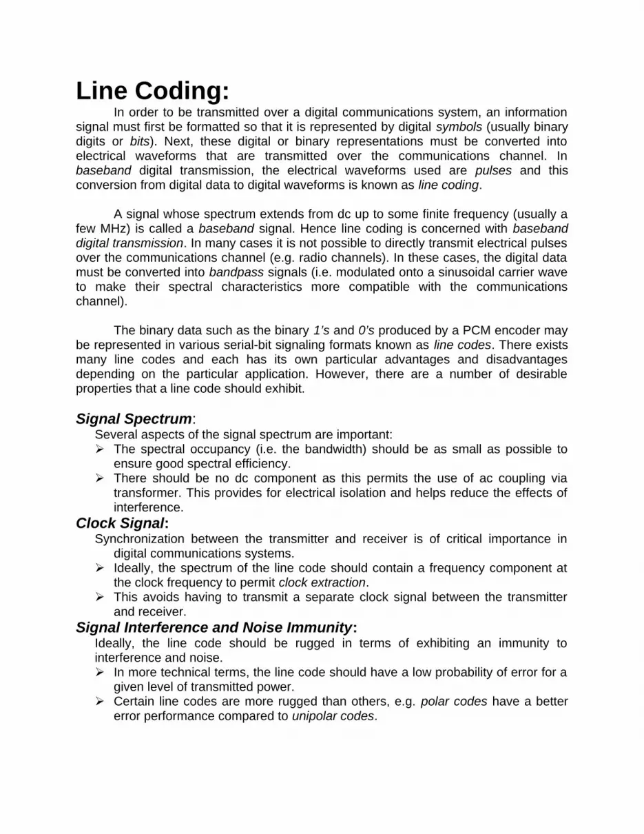
Bipolar Signalling is also called “alternate mark inversion” (AMI) uses three voltage levels (+V, 0, -V) to represent two binary symbols. Zeros, as in unipolar, are represented by the absence of a pulse and ones (or marks) are represented by alternating voltage levels of +V and –V.
Alternating the mark level voltage ensures that the bipolar spectrum has a null at DC. The alternating mark voltage also gives bipolar signalling a single error detection capability. Like the Unipolar and Polar cases, Bipolar also has NRZ and RZ variations.
Bipolar NRZ:
Advantages:– No DC component.– Occupies less bandwidth than unipolar and polar NRZ schemes.– Does not suffer from signal droop (suitable for transmission over AC
coupled lines).– Possesses single error detection capability.
Disadvantages:– Does not posses any clocking component for ease of synchronisation.– Is not transparent.
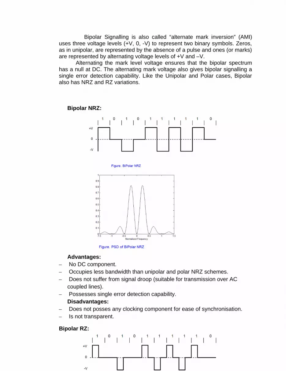
Bipolar RZ:

Advantages:– No DC component.– Occupies less bandwidth than unipolar and polar RZ schemes.– Does not suffer from signal droop (suitable for transmission over AC
coupled lines).– Possesses single error detection capability.– Clock can be extracted by rectifying (a copy of) the received signal.
Disadvantages:– Is not transparent.
High Density Bipolar Substitution (HDBn) Signalling:HDBn is an enhancement of Bipolar Signalling. It overcomes the
transparency problem encountered in Bipolar signalling. In HDBn systems when the number of continuous zeros exceeds n they are replaced by a special code. The code recommended by the ITU-T for European PCM systems is HDB-3 (i.e. n=3).In HDB-3 a string of 4 consecutive zeros are replaced by either 000V or B00V. Where,
‘B’ conforms to the Alternate Mark Inversion Rule.‘V’ is a violation of the Alternate Mark Inversion Rule
The reason for two different substitutions is to make consecutive Violation pulses alternate in polarity to avoid introduction of a DC component. The substitution is chosen according to the following rules:

1. If the number of nonzero pulses after the last substitution is odd, the substitution pattern will be 000V.2. If the number of nonzero pulses after the last substitution is even, the substitution pattern will be B00V.
Advantages:– No DC component.– Occupies less bandwidth than unipolar and polar RZ schemes.– Does not suffer from signal droop (suitable for transmission over AC
coupled lines).– Possesses single error detection capability.– Clock can be extracted by rectifying (a copy of) the received signal.– Is Transparent.These characteristic make this scheme ideal for use in Wide Area Networks
4 Manchester Signalling:In Manchester encoding, the duration of the bit is divided into two halves. The voltage remains at one level during the first half and moves to the other level during the second half.
A ‘One’ is +ve in 1st half and -ve in 2nd half.A ‘Zero’ is -ve in 1st half and +ve in 2nd half.
Note: Some books use different conventions.

The transition at the centre of every bit interval is used for synchronization at the receiver.
Manchester encoding is called self-synchronizing. Synchronization at the receiving end can be achieved by locking on to the the transitions, which indicate the middle of the bits.
It is worth highlighting that the traditional synchronization technique used for unipolar, polar and bipolar schemes, which employs a narrow BPF to extract the clock signal cannot be used for synchronization in Manchester encoding. This is because the PSD of Manchester encoding does not include a spectral line/ impulse at symbol rate (1/To). Even rectification does not help.
Advantages:– No DC component.– Does not suffer from signal droop (suitable for transmission over AC
coupled lines).– Easy to synchronise with.– Is Transparent.
Disadvantages:

– Because of the greater number of transitions it occupies a significantly large bandwidth.
– Does not have error detection capability.
These characteristic make this scheme unsuitable for use in Wide Area Networks. However, it is widely used in Local Area Networks such as Ethernet and Token Ring.
5 Differential Manchester:Differential Manchester, combines the ideas of RZ and NRZ-I. There is
always a transition at the middle of the bit, but the bit values are determined at the beginning of the bit. If the next bit is 0, there is a transition; if the next bit is 1, there is none.
Advantages– There is no baseline wandering.– There is no DC component because each bit has a positive and
negative voltage contribution.Disadvantages
– The signal rate for Manchester and differential Manchester is double that for NRZ. The minimum bandwidth of Manchester and differential Manchester is 2 times that of NRZ.
6 Huffman Coding:Huffman codes can be used to compress information. Like WinZip – although WinZip doesn’t use the Huffman algorithm JPEGs do use Huffman as part of their compression process .The basic idea is that instead of storing each character in a file as an 8-bit ASCII value, we will instead store the more frequently occurring characters using fewer bits and less frequently occurring characters using more bits
On average this should decrease the filesize (usually ½).
As an example, let’s take the string:“duke blue devils”
We first to a frequency count of the characters:e:3, d:2, u:2, l:2, space:2, k:1, b:1, v:1, i:1, s:1
Next we use a Greedy algorithm to build up a Huffman TreeWe start with nodes for each character.

• We then pick the nodes with the smallest frequency and combine them together to form a new node– The selection of these nodes is the Greedy part
• The two selected nodes are removed from the set, but replace by the combined node
• This continues until we have only 1 node left in the setStep 1:
Step 2:
Step 3:
Step 4:

Step 5:
Step 6:
Step 7:

Step 8:
Step 9:
Step 10:

• Now we assign codes to the tree by placing a 0 on every left branch and a 1 on every right branch.
• A traversal of the tree from root to leaf gives the Huffman code for that particular leaf character.
• Note that no code is the prefix of another code
• These codes are then used to encode the string• Thus, “duke blue devils” turns into:
010 011 11 10 001 011 11101000 1100101 0 10001111 1 1100 100 1101
• When grouped into 8-bit bytes:
01001111 10001011 11101000 11001010 10001111 11100100 1101xxxx
• Thus it takes 7 bytes of space compared to 16 characters * 1 byte/char = 16 bytes uncompressed
• Uncompressing works by reading in the file bit by bit• Start at the root of the tree• If a 0 is read, head left• If a 1 is read, head right• When a leaf is reached decode that character and start over again at the
root of the tree• Thus, we need to save Huffman table information as a header in the compressed
file• Doesn’t add a significant amount of size to the file for large files (which are
the ones you want to compress anyway)

• Or we could use a fixed universal set of codes/frequencies.


