Embed Size (px)
Citation preview

Making Graphics Tangible
Carlo H. Sequin
EECS, Computer Science, University of California, Berkeley
Abstract
This is a write-up of material presented at keynote talks at Virtual Reality 2012 and at Shape Modeling International 2012. Produc-ing tangible, physical output becomes a growing role for computer graphics due to the emergence of inexpensive rapid-prototypingmachines and on-line fabrication services. While producing small models with a layered manufacturing process has become veryeasy, creating larger and more durable objects still requires a designer to address an expanded list of issues. In this article someof these issues are discussed based on experiences the author has gained while designing various physical artifacts ranging frommathematical visualization models and geometrical puzzles to large scale sculptures. Tangible artifacts also gain importance at thebeginning of a design process and as input to computer graphics tools. An argument is made and an outline is given for new waysand better user interfaces to enter the geometry of inspirational artifacts into our virtual CAD environments.
Keywords: Procedural modeling, tangible modeling tools, rapid prototyping, durable physical output.
a b
Figure 1: (a) CCD solid state image sensor; (b) Soda hall, U.C. Berkeley.
1. Introduction1
For most of my life geometry and geometrical constructions2
have been my profession as well as my hobby. In some in-3
stances, the realization of a particular design required an army4
of people and a major organization for turning the design into5
a usable physical artifact. My first job after graduation placed6
me in the group at Bell Labs that had just invented Charge-7
Coupled Devices (CCD). Over the next few years I designed8
ever larger solid state image sensors, culminating in 1973 in9
a CCD imaging chip with enough resolution to be compatible10
with the American broadcast TV format (Fig.1a). The produc-11
tion of three good chips to be placed around a color separation12
prism involved the fabrication of tens of silicon wavers, requir-13
ing several dozen individual processing steps in a very sophis-14
ticated fabrication line for integrated circuits. A decade later15
I was spearheading the design effort of Soda Hall, the home16
of Computer Science on the Berkeley campus. There again,17
the realization of that design took several architects, many con-18
tractors and subcontractors, and kept a large number of skilled19
a b
Figure 2: Large and/or complex physical entities that started out as a computergraphics description: (a) Hilbert Cube 512 ; (b) Pillar of Engineering .
workers busy for two years to produce the final building (Fig.1b).20
Fortunately, not all physical artifacts take that long from21
initial concept to a first realization. Because of the emergence22
of rapid-prototyping (RP) machines and services, some smaller23
objects can now be realized in a matter of hours or days. This24
has had a tremendous impact on product design in many areas,25
ranging from car manufacturing to computers and to household26
items such as toasters, or sports articles such as running shoes.27
Most of these products now undergo a design cycle that in-28
volves a few rapid prototyping models. The final product how-29
ever, still requires a much more involved and more expensive30
process, for instance the creation of sophisticated molds for in-31
jection molding.32
In the world of computer graphics, every year hundreds of33
stunning renderings and virtual artifacts with which users can34
interact in video-game settings are being created with interac-35
tive modeling tools. Because of the emergence of affordable RP36
machines, e.g. MakerBots [1] and readily available fabrication37
services such as Shapeways [2] or Ponoko [3], an ever grow-38
Preprint submitted to Computers & Graphics February 16, 2013

a b c d
Figure 3: (a) Collins’ Hyperbolic Hexagon ; (b) Scherk tower; (c) twisted Scherk tower; (d) corresponding Scherk tower loops.
ing fraction of these models may find their way into the world39
of physical reality. People produce small replicas of their fa-40
vorite action figures, models of their designs in Second Life [4],41
custom-made coffee mugs or cookie cutters, or pendants and42
ear rings. But still, to produce an object that serves a functional43
purpose in your car, in some exercise machine, or in a hand tool44
like an electric drill, requires a more substantial effort that takes45
more than a single pass through the rapid-prototyping process.46
In this paper I will describe what it takes to turn an ap-47
pealing virtual design into a physical artifact in the context of48
mathematical visualization models (Fig.2a), geometrical puz-49
zles, and large and durable public sculptures that can be touched50
by spectators and can withstand the abuse by weather (Fig.2b).51
Section 2 gives the background story of how I got started with52
computer-aided modeling of large sculptures. Sections 3 and53
4 describe the realization of two large sculptures implemented54
with different fabrication technologies. Section 5 discusses ad-55
ditional concerns that come into play when one plans to make56
multiple copies of an artistic artifact such as an award trophy57
to be handed to several recipients every year. Section 6 fo-58
cuses on making models on RP machines with the added con-59
straint of models composed of multiple parts that must fit to-60
gether smoothly, such as dissection puzzles; it also addresses61
approaches of reducing the fabrication costs of such models.62
Sections 7 and 8 address design and user-interface issues,63
to the extent that this front-end activity may involve tangible64
physical artifacts. They conclude with a generalization of the65
procedural modeling approach that I have used in most of my66
sculpture designs, called Inverse 3D Modeling. They end up67
with a proposal of how to use tangible pieces of material as68
design building blocks in an immersive virtual work space.69
Rapid prototyping technologies have advanced tremendously70
in the last decade and have now become quite affordable. Sec-71
tion 9 gives a brief preview of the possibilities that lie ahead in72
the near future.73
2. Scherk Collins Sculptures74
My interest in computer-assisted sculpture design started in75
1995. It grew out of the need for a virtual prototyping tool76
that would permit a quick evaluation of a variety of abstract ge-77
ometrical forms to determine which ones of many conceptual78
ideas would have the potential to be turned into a 3-dimensional79
physical sculpture that would look interesting and aesthetically80
pleasing from most directions. This need arose after I had made81
contact with sculptor Brent Collins [5], living in Gower, MO,82
and we started to have weekly phone discussions in which we83
generated more conceptual ideas than could possibly be exam-84
ined and evaluated with physical mock-up models.85
In 1994 I had come across an article by George Francis [6]86
in which he analyzed some of Brent Collins’ wood sculptures87
from a topological and knot-theoretical point of view. One of88
the key elements in Collins’ work is a composition of stacked89
saddles and intertwined tunnels. I was intrigued by the sophis-90
ticated way in which the edges of the various saddles merged91
seamlessly into one another and by the fact that all this com-92
plicated geometry resulted in smooth and balanced surfaces. In93
1995, after I had come across an image of the graceful Hyper-94
bolic Heptagon (Fig.3a), I picked up the phone and contacted95
Brent Collins. Based on the analysis by George Francis, this96
sculpture could be understood as a toroidal deformation of a97
6-story “Scherk tower.” The latter is a finite cylindrical cut-out98
(Fig.3b) from the center of Scherk’s 2nd minimal surface [7].99
Our first phone discussion started from the observation that100
making a good 3D sculpture is not easy, if you want to make101
it look good from all sides. Hyperbolic Hexagon shows some102
weaknesses in this respect, because from some angles it dis-103
plays some strange coincidences. This is because it has too104
much symmetry: All six peripheral holes pass through the dom-105
inant plane at ± 45◦; and thus from certain viewing angles they106
all close up simultaneously or show their full, open, circular107
tunnels.108
2

a b c
Figure 4: Hyperbolic trefoils: (a) Sequin’s Minimal Trefoil ; (b,c) Collins’ Trefoils with different azimuth angles.
We contemplated whether this could be fixed by adding109
some twist into this structure, so that every hole would pass110
through the dominant plane of the toroidal sweep path at a111
somewhat different angle. Clearly such twist would have to112
be inserted in increments of 180◦, so that the chain of saddles113
would still close smoothly onto itself. We also realized that, if114
there are an odd number of stories in this toroidal loop, an odd115
multiple of 90◦ twist is required to close the toroid smoothly;116
but then the surface becomes single-sided, thus forming a non-117
orientable Mobius configuration. Moreover, in the original Hy-118
perbolic Hexagon all four edges form their own separate, closed119
loops. Adding twist to the Scherk tower interlinks the edges of120
this sculpture in interesting ways. For certain amounts of twist,121
these edges will merge into one another after one pass around122
the twisted toroid, and it will then take several laps around the123
toroid to reach the starting point again. Analyzing the multi-124
ple intertwined torus knots that can be formed in such twisted125
structures is rather intriguing.126
These insights were mathematically fascinating, but Collins127
was interested in deriving new ideas for structures that would128
result in aesthetically pleasing physical sculptures. Typically,129
Collins first builds small scale models from PVC piping or em-130
broidery hoops, fleshed out with wire meshing and bees wax,131
before he embarks on carving a large wood sculpture. Mak-132
ing a small scale model takes itself a couple of weeks. Thus133
it quickly became clear that Brent could not possibly keep up134
with making models for all the new concepts we discussed in135
order to judge their visual appeal.136
At this point I decided that a computer-based visualization137
tool was our only hope of keeping up with our stream of ideas.138
The result was Sculpture Generator I [8], a special purpose139
modeling program written in the C language, the geometry ker-140
nel of which comprised only about 3000 lines of code [9]. Within141
a few months I had a first prototype running that allowed me to142
specify the number of stories in the loop, their combined total143
twist, the azimuth orientation of the edges around the smaller144
radius of the torus, as well as the thickness and extension of145
the flanges, and various simulated surface properties (Fig.5).146
Now I could try out many different ideas and parameter com-147
binations in a matter of minutes, and then focus on the most148
promising configurations and optimize them for their aesthetic149
appeal. Or I could investigate such questions as: What is the150
tightest toroid into which a Scherk tower with only three stories151
could be curled up. The latter question led to my version of the152
Minimal Trefoil (Fig.4a). I gave myself the constraint that the153
tunnels would start out with a circular profile, trying to avoid154
any vertical stretching of the 3-story Scherk tower before clos-155
ing it into a loop. I succeeded in doing this for an azimuthal156
orientation of 45◦ of the three saddles in the ring. Collins also157
hand-designed and built two trefoils with different azimuthal158
orientations (0◦ and 45◦), but in both instances he stretched the159
hole-saddle chain substantially, so that he would obtain a cen-160
tral hole that was comparable to the tunnels in the periphery.161
He wanted to keep all of these tunnels large enough so that he162
could easily get one of his hand inside for the final carving and163
polishing (Fig.4b,c).164
One key technical issue I had to address in the development165
of Sculpture Generator I was the question how I should best166
represent the geometry of these shapes to maximize the bene-167
fit of the inherent modularity and symmetry in these toroidal168
structures. Even though these shapes were inspired by the min-169
imal surfaces formed by soap films spanning some boundary170
loop, they are not typically true minimal surfaces. For aesthetic171
reasons, most of the twisting ribbons connecting adjacent sad-172
dles have a much stronger lateral curvature than their longitu-173
dinal curvature. Thus I decided to model one quarter of a stan-174
dard biped saddle with a stack of hyperbolas with ever more175
pointy hyperbolic curves that eventually end up as two straight176
lines crossing at a 90◦ angle at the saddle point (Fig.6a). Ad-177
jacent hyperbolas are connected with triangle strips to form a178
tessellated surface with an adjustable degree of approximation179
(Fig.6b). This small piece of surface can then be deformed as180
needed for a particular sculpture. Properly rotated, mirrored,181
and translated, it will form a complete 1-story saddle. The de-182
sired number of saddles can then be stacked on top of one an-183
other, and the whole assembly can be given a suitable amount184
of twist before it is bent into a loop and closed into the final185
toroid. If saddles of a higher order are desired, e.g., a 3-way186
“monkey saddle,” the 90◦ sector forming the fundamental do-187
main of a basic biped saddle can be compressed into a wedge188
3

Figure 5: Design parameters in one story of the Scherk-Collins toroid.
a b
Figure 6: Internal shape representation: (a) set of stacked, parametrized hyper-bolas, (b) approximated with symmetrical pairs of triangle strips.
with only a 60◦ opening, and this wedge is then instantiated189
six times around the z-axis. Compressing it into 180◦/n and in-190
stantiating it n times in a rotationally symmetrical manner will191
generate an n-th order saddle.192
By the end of 1996, Sculpture Generator I [8] had evolved193
into a fairly robust program with several different output mod-194
ules. Besides interactive virtual renderings on a computer screen,195
the program also could output a boundary mesh of these solid196
shapes in the .STL file format, which is accepted by most lay-197
ered manufacturing machines. I also added a program module198
that could output full-size blue prints of cross sections spaced199
at regular intervals, say 7/8 of an inch apart, corresponding to200
the thickness of the wooden boards from which Brent Collins201
was planning to build such sculptures. Hyperbolic Hexagon202
II was the first large sculpture that Collins built from a set of203
blue prints generated by Sculpture Generator I. He cut the in-204
dividual profiles from 7/8 inch thick walnut boards, assembled205
them with industrial strength glue, then fine-tuned the shape206
with hand tools, and honed the surface to perfection. Figure207
7a shows our first truly collaborative piece. In 2008 this wood208
sculpture was used as the master for making a silicon rubber209
mold, and Reinmuth Bronze Studio [10] produced two bronze210
replicas. The second one was cast just in time for the opening of211
the CITRIS headquarter building on the U.C. Berkeley campus212
(Fig.7b).213
a b
Figure 7: Hyperbolic Hexagon II : (a) 1997 wood master carved by BrentCollins; (b) 2009 bronze sculpture cast by Steve Reinmuth, installed in SutardjaDai Hall at U.C. Berkeley.
a b c
Figure 8: Heptoroid : (a) blueprint of one of its slices, (b) laminated assembly,(c) final sculpture.
Hyperbolic Hexagon II has enough symmetry that Collins214
thinks he might have been able himself to generate the basic ge-215
ometry with ruler and compasses. On the other hand, he admits216
that he could never have conceived and drawn the geometry of217
our second collaborative piece, the Heptoroid (Fig.8). This is a218
7-story structure with 4th-order saddles and a total twist of 135◦219
(3/8 of a full turn). Figure 8a shows one of a dozen actual 3-220
foot wide blue prints, produced in my Sculpture Generator I.221
The five superposed traces show the geometry of this sculpture222
at top and bottom of the board, as well as at intermediate lev-223
els at 1/4, 1/2, and 3/4 of the board thickness. Again, Collins224
used a saber saw to cut these shapes out of 7/8-inch thick wood225
boards and laminated all the 12 profiles together with industrial-226
strength glue. In this way he obtained a first rough shape that227
defines all the right symmetries, but shows strong stair-casing228
on its surface (Fig.8b). He then grinds down the stair-casing229
and creates a smooth, thinned-down surface, with one contin-230
uous rim that travels around the loop eight times before it re-231
turns to the starting point. The glue lines provide good cues for232
the smoothness of the shape – in addition to the haptic feed-233
back gained from running the hand over the surface. This is234
a manual version of “layered manufacturing.” Heptoroid was235
exhibited at Fermi Lab in 1998 (Fig.8c). Many physicists saw236
something that reminded them of their profession: a stellarator237
fusion chamber, or some structure relating to string theory.238
4

a b c
Figure 9: Sweeps along Gabo curves: (a) Collins’ Pax Mundi wood master; (b)Gabo-4 ribbon; (c) Gabo-2 (baseball seam) sweep.
a b c
Figure 10: Viae Globi sculptures: (a) 5-lobe Gabo path; (b) Altamont sculpture;(c) Chinese Button Knot .
3. Pax Mundi and Viae Globi239
The first commission to build a large metal sculpture con-240
cerned a different original model sculpted by Brent Collins.241
He created Pax Mundi completely independently shortly af-242
ter we had started our collaboration (Fig.9a). It comprised a243
highly curved ribbon undulating around the surface of a vir-244
tual sphere. This new sculpture fascinated me as much as Hy-245
perbolic Hexagon, and I immediately set out to also capture it246
in a procedural description. There was no way that Sculpture247
Generator I could emulate this geometry, because this sculp-248
ture was based on quite a different geometrical paradigm. The249
key module needed was some generalized sweep program that250
could extrude an arbitrary cross section along a loopy sweep251
path embedded in the surface of a sphere. The main question252
was what might be the best way to parametrize the geometry253
of this sweep path to be able to quickly generate a multitude254
of different members of this sculpture family. The key associ-255
ation came from some sculptures by Naum Gabo in which he256
had wound up broad-rimmed annuli so that the outer rim would257
roughly fall onto a sphere. So I introduced the concept of a258
“Gabo curve,” which is a path that undulates symmetrically up259
and down around the equator of a globe. The key parameter is260
how many periods it takes to close the loop; in the case of Fig-261
ure 9b this number is 4. Correspondingly, the seam on a base-262
ball or on a tennis ball is then a 2-period Gabo curve (Fig.9c).263
The geometry of the lobes can easily be represented by a B-264
spline with just 3 parameters that define the amplitude, width,265
and shape of each lobe. In this light, I could now describe Pax266
Mundi as an “amplitude-modulated 4-period Gabo curve.”267
Using the SLIDE modeling environment [11], gradually de-268
a b
Figure 11: Segmentation of Pax Mundi : (a) Four replicas of the fundamentaldomain, (b) the domain split into two horseshoes.
Figure 12: Small horseshoe produced on an NC milling machine.
veloped by several of my PhD students, I was now able to con-269
struct a new and much more modular sculpture generator that270
could capture this shape and produce many others like it. There271
are three banks of slider controls. One defines the sweep path272
on the sphere, another one the shape of the cross section of273
the ribbon, and the third one the scaling and rotation of the274
cross section during the sweep. By default the cross section275
is kept in a fixed orientation with respect to the Frenet frame276
of the sweep curve. Alternatively it can be propagated in a277
rotation-minimizing manner along the sweep curve, with ad-278
ditional control through a globally applied azimuthal rotation279
of the cross section and an evenly spread out gradual twist; the280
latter makes it possible to obtain an end-to-end alignment of281
the cross section after a full pass around any arbitrary closed282
3D space curve. Adding optional local twist parameters al-283
lows the programmer to fine-tune the amount of twisting in284
the neighborhood of critical loops or turns. This programming285
environment proved to be particularly fertile and has led to286
dozens of attractive designs (Fig.10a, 11a). Over the subse-287
quent years I gradually broadened the concept of the Viae Globi288
program and enhanced it to take more complicated undulations289
(Fig.10b), to allow over/under crossings of the ribbon sweep-290
ing along the sphere surface, and eventually leading to com-291
pletely free-form space curves that could make intriguing knot-292
ted structures (Fig.10c).293
5

a b
c d
Figure 13: Realization of Pax Mundi in bronze: (a) coated part; (b) wax copy;(c) plaster shell; (d) freed up bronze.
In 2007 Collins obtained the commission to make a large294
metal version of Pax Mundi for the H&R Block headquarters in295
Kansas City. I used my program to generate the scaled-up ge-296
ometry at the desired size (6 foot diameter), properly slimmed297
down to fit within the weight limit (≤ 1500 pounds) and budget298
constraints (≤ $ 50’000) while maximizing its aesthetic appeal.299
Moreover, I had the responsibility to figure out the minimal set300
of master modules that would have to be produced to create the301
necessary molds in which segments of this sculpture could be302
cast. The minimal amount of “master geometry” for this shape303
turned out to be 1/4 of the whole sculpture. I defined this geom-304
etry as a curvy sweep through space (Fig.11a) and also provided305
this segment with alignment tabs, so that the four pieces could306
be joined with perfect alignment. Unfortunately the gantry of307
the NC milling machine available to us had a clearance of only308
14 inches and could not handle my complicated, bulky 3D part.309
So I split the ribbon geometry into two smaller horseshoe pieces310
as shown in Figure 11b, and provided additional alignment tabs.311
Both halves are now relatively flat and fit under the gantry of312
that milling machine.313
However both these horseshoes were still too large to fit314
into the kiln in Steve Reinmuth’s bronze foundry [10]. Thus315
Reinmuth cut the smaller part (Fig.12) in half, and the larger316
one into three parts. Judiciously he made a suitable jig that317
later allowed him to re-align the individually cast parts into the318
required horseshoe shape, since those cut-up segments had no319
alignment tabs. The five different styro-foam master-geometry320
modules were coated with (blue) plastic paint (Fig.13a) to yield321
a smooth surface, suitable for making silicon rubber molds.322
These molds are then used to cast four identical positive copies323
each in (brown) wax, to be used in a classical investment-casting324
process: All wax parts are provided with the (red) sprues and325
runners and funnels into which the molten bronze will be poured326
(Fig.13b). This whole assembly then gets dipped repeatedly327
into plaster slurry to make a ceramic shell (Fig.13c). These328
shells then get fired in a hot kiln. In this process, the wax runs329
out, leaving a cavity of the desired shape for the bronze. After330
a b
c d
Figure 14: Pax Mundi assembly: (a) fitting together two segments, (b) assem-bling one horse shoe, (c) assembly completed, (d) cuts with wedges to elongatesculpture.
the liquid bronze has been cast and has cooled down, the ce-331
ramic shell is smashed and removed (Fig.13d) - freeing up the332
bronze part. On all 20 cast parts, the sprues and runners are333
cut away, and a lot of cleaning and polishing has to be applied334
before the pieces are ready for assembly (Fig.14a). First the335
eight horseshoes are re-assembled (Fig.14b), and then they are336
combined into the complete undulating ribbon (Fig.14c). All337
the welds are ground down to a perfectly smooth surface.338
But at this stage we had a bad surprise: The whole sculp-339
ture sagged under its own weight by about 15% of its over-340
all height – and it was noticeably no longer spherical! Steve341
Reinmuth found a good solution, but it took several working342
days to fix the problem: He hung the sculpture from its highest343
point and let it stretch under its own weight. In addition he cut344
gaps half-way through the ribbon in four of the mostly horizon-345
tal hairpin curves, which enhanced the lengthening even more346
(Fig.14d). In this elongated state, those gaps were then filled347
with bronze welds leading to a vertically stretched ellipsoidal348
overall shape. When the complete sculpture was finally sup-349
ported from its central point at the bottom, it settled back to an350
almost perfectly spherical shape. The main lesson learned for351
future ribbon sculptures of this kind is to do some basic stiffness352
analysis, because physics is important too – not just geometry!353
The assembled and polished shape is then subjected to a se-354
lect set of chemicals applied with a spray flask and the heat from355
a hand-held flame torch (Fig.15a). With the skilled hands of an356
experienced craftsman an even, and possibly smoothly varying357
patina can be applied, which turns this geometrical form into a358
true work of art. The installed sculpture is shown in Figure 15b.359
We think the result is highly successful – and it has indeed led360
to additional commissions.361
Right now a similar bronze ribbon sculpture is in the works362
as a commission for a new science building for Missouri West-363
ern State University. It is based on Brent Collins’ Music of the364
Spheres, another one of his original ribbon sculptures carved365
in wood. The extended version of my Viae Globi program366
6

a b
Figure 15: Pax Mundi installation: (a) applying patina; (b) finished sculpture.
a b d
Figure 16: Music of the Spheres : (a) FDM maquette. Simulation analysis ofgravitational deformation: (b) for Pax Mundi and (c) for Music of the Spheres .
could easily capture this new shape and produce a maquette367
(Fig.16a)). Again, to make this into a 6 foot bronze sculpture,368
the proportions had to be changed. Learning from my negli-369
gence with Pax Mundi, I subjected the computer model to some370
displacement analysis, using the Scan&SolveTM for Rhino sim-371
ulator [12]. The colors in Figures 16b,c indicate how much372
each vertex moves from its design position under the influ-373
ence of gravity. The red areas showing in the simulation of374
Pax Mundi indicate a 15% displacement from the original po-375
sition (Fig.16b). The worst-case cyan color in the Music of376
the Spheres simulation predicts a displacement of only about377
a 3% (Fig.16c). Thanks to a different geometry and a some-378
what thicker ribbon we should be much better off with this new379
sculpture. To be totally on the safe side, Reinmuth cast the up-380
per ribbon segments, which primarily act as pure loads, in the381
form of hollow extrusions of the crescent profile.382
4. Millennium Arch383
Shortly after the large-scale realization of Pax Mundi, Collins384
also obtained a commission for a large Scherk-Collins toroid.385
The design was coming directly out of Sculpture Generator I386
(Fig.17a). It was a 12-story ring with 4th-order saddles and 270◦387
twist. This was the first large sculpture not based on an initial388
model by Collins. This sculpture was destined to be hung in-389
door under an atrium sky light in a community center in the390
City of Overland Park, Kansas. Thus it had to be light-weight391
and somewhat translucent.392
In 2007 David Lynn and Nova Blue Studio Arts, L.L.C.,393
in Seymour, MO, [13] helped us realize this 10-foot-diameter394
a b
Figure 17: Millennium Arch : (a) computer model; (b) final sculpture.
sculpture (Fig.17b). The master geometry module was carved395
out of high-density styro-foam on a large NC milling machine396
(Fig.18a). A mixture of glass-fiber and epoxy was employed to397
form a reusable multi-piece shell around this module (Fig.18b).398
Within that shell (Fig.18c) six copies were cast from a mixture399
of polyester and glass fiber. Two half-circles of three modules400
each were then formed by fusing together some of the cast mod-401
ules. These arches were transported to their destination and as-402
sembled into a closed ring on the atrium floor (Fig.18d). The403
completed ring (Fig.17b) was then hoisted into its final display404
position.405
a b
c d
Figure 18: Realization of Millennium Arch : (a) NC-machined master geometrymodule; (b) fiberglass patches to form the mold; (c) complete mold of mastermodule; (d) assembly of the arch. (Images courtesy of David Lynn, Nova BlueStudio Arts, L.L.C.)
5. Making Multiple Copies406
Creating Pax Mundi and Millennium Arch were both one-407
time, individual, custom realizations. The set of design con-408
cerns expands if one wants to make multiple, perhaps even sev-409
eral dozen copies of a sculpture. And it expands even further if410
a particular shape is supposed to be mass-produced – perhaps411
using production techniques such as injection molding. Here412
7

a b
c d
Figure 19: Eurographics Award : (a) master; (b) parts; (c) wax assemblies; (d)patinaed bronze awards.
I will just offer a few observations based on my experience413
with taking one of the Scherk-Collins motives and turning it414
into an Award Trophy for EuroGraphics. Three or four of these415
awards are being given out every year; thus overall I had to plan416
for something that would be replicated several dozen times. In417
this context, the molds should be relatively simple, robust, and418
able to last for many dozen wax castings. The assembly of the419
bronze sculptures should also involve as few pieces as possible420
and require no tricky alignments.421
The design that the EuroGraphics committee liked best was422
based on Whirled White Web, a twisted monkey-saddle trefoil423
from the family of Scherk-Collins toroids, which was carved424
in snow at the 2003 annual Snowsculpting Championships in425
Breckenridge, CO [14]. Unfortunately this shape is too com-426
plicated to be made with a single mold and cast in one piece.427
It has a depth complexity of 3 or 4 in almost every direction428
and would require a very complicated multi-piece mold. But429
it turns out that the shape can be split in its dominant central430
plane into two identical pieces; and these pieces only have a431
depth complexity of one or two measured perpendicularly to432
this plane (Fig.19a). A four-piece silicon rubber mold was able433
to reproduce such a half-wheel element. Two of those elements434
could then be fused together and jointly be subjected to a stan-435
dard investment casting process (Fig.19c). Thus the complete436
trophy is assembled from only three metal parts: the wheel,437
the base, and the individual engraved plaques (Fig.19b). Dif-438
ferent patinas distinguish the different award categories: The439
greenish-blue patina is for the Distinguished Career Award; the440
reddish-brown patina is for the Technical Achievement Award;441
the pale tan patina is for the Young Researcher Award (Fig.19d).442
Fabrication issues are as important as aesthetic concerns,443
and the former have to be integrated into the design process444
from a very early stage on. In the end, engineering concerns445
often cause many more headaches than the artistic design con-446
sideration.447
6. Dissection Puzzles and Other RP Models448
In the above example the final artifact, its material com-449
position, and the manufacturing process had to be taken care-450
fully into account before the design of the trophy was finalized.451
Another area, where material properties and tolerances play an452
important role is whenever several parts are designed that in453
the end need to fit together snugly - perhaps to make a mov-454
able joint or a snap-together junction between parts, such as455
between a bottom and top half of the casing of a cell phone.456
A prime tutorial example is the construction of 3D dissection457
puzzles, and this task domain was explored in a graduate course458
on “Solid Modeling and Rapid Prototyping” at U.C.Berkeley in459
the fall of 2011. Such puzzles are an excellent educational tool.460
They strongly emphasize 3D spatial thinking, and the fabrica-461
tion gives hands-on feedback about accuracy and tolerances.462
Moreover, the resulting artifacts are fun to play with and to463
show off to friends and relatives!464
One of the assignments given to the students was: “Design a465
2- or 3-piece geometrical puzzle in which a simple shape splits466
into all congruent parts via a helical screw motion.” All student467
teams quickly figured out that the parting surfaces would have468
to be one or more helicoids winding around a common straight469
line, e.g. the z-axis. It was then their choice to select a suitable470
overall shape, positioned symmetrically with respect to the cho-471
sen system of helicoids, so that the resulting dissection (or tri-472
section) pieces turn out to be congruent. Different teams picked473
quite different shapes and different modeling approaches. The474
teams that relied on the Berkeley SLIDE [11] software, which475
offers very general, versatile sweep constructs, typically defined476
a cross section (Fig.20a) and then swept that cross section along477
a helical path (Fig.20b), while applying some uniform scaling478
as a function of the z-value of the sweep path (Fig.20c). When479
a teardrop scaling profile is used (Fig.20d), the puzzle shown in480
Figure 20e results.481
Another team of students, who had access to SolidWorks482
[15], which provides Boolean Constructive Solids Geometry483
(CSG) operations, decided to partition a cube along a space di-484
agonal into three congruent pieces, which by themselves also485
exhibited 2-fold rotational symmetry. To accomplish this, they486
adjusted the pitch of the helicoids so that each cutting surface487
makes a 780◦ turn around the z-axis while sweeping from the488
top to the bottom corner of the cube. Figures 21a,b show two489
different assembly stages of this puzzle. Figure 21c shows what490
the individual parts looked like as they came out of the fused491
deposition modeling (FDM) machine.492
In all these puzzles, issues of geometrical design, numeri-493
cal accuracy, and suitable tolerancing had to be addressed. For494
some designs like the trisected “teardrop” – or “upside-down495
ice-cream cone” (Fig.20e) the geometry was so tight and the496
friction was so high that the three pieces could not be fully497
screwed together until the helicoidal parting surfaces had been498
sanded thoroughly. The designers of the trisected cube (Fig.21)499
struck a good compromise and hollowed-out the central por-500
tion of the cube with a diameter equal to about half the cube501
edge-length. This reduced friction dramatically, and the puzzle502
slipped together after only minimal sanding. The big question503
8

a b c d e
Figure 20: Helicoidal sweeps: (a) cross section; (b) simple sweep; (c) modulated scaling of cross section; (d) a different scale modulating function; (e) the resultingdissection puzzle geometry.
a b c
Figure 21: Helical cube dissection: (a),(b) two different states of assembly; (c) the individual parts coming off the FDM machine.
is: How do you know what the right amount of clearance should504
be? There were some puzzles that did not hold together well505
and fell apart under the influence of gravity alone. My expe-506
rience is that one cannot avoid doing an initial test-run on the507
machine that one plans to use, submitting two or three design508
variations that bracket one’s best estimate of the proper amount509
of clearance.510
In this course we also addressed the question of how to min-511
imize the costs of making parts on such a layered manufacturing512
machine. To first order, the cost of such a part is proportional513
to the material used in making the part. As a dramatic example,514
I showed the class a neat little burr puzzle that I had purchased515
from Shapeways [2] for about $10.- (Fig.22), and then I asked516
the students: “How could I obtain the same puzzle scaled-up by517
a factor of 10 without having to pay $10’000.- ?” Specifically I518
asked them to come up with a design that would minimize the519
material usage on our old FDM machine, a type “1650” from520
Stratasys [16].521
In our discussions we quickly came to the conclusion that522
it would be advantageous to build just the outline of the puz-523
zle pieces, keeping the interior mostly hollow. However, since524
the FDM machine builds some kind of scaffolding underneath525
bridges and overhangs in the part geometry, building a com-526
pletely hollow cube is not possible, and the internal scaffolding527
can still use up a lot of build material. A reasonable approach528
is to decompose each puzzle piece into its constituent cubelets,529
and then realize each such cubelet as a thickened edge-frame530
(Fig.23a) - akin to a style used by Leonardo DaVinci to depict531
some to the regular and semi-regular polyhedra. This approach532
a b
Figure 22: Small burr puzzle: (a) individual parts, (b) assembled puzzle.
a b
Figure 23: Cubelet frame: (a) Leonardo rendering, (b) cross sections throughframe, without and with 45-degree bevel.
9

a b
c d
Figure 24: “Framed” cubic burr puzzle in various stages of assembly.
can save build material as well as support material, if the central533
portions of the cubelets can be kept free of any type of scaffold-534
ing, and if the support material can be restricted to the vertical535
“windows” in the sidewalls of every cubelet (Fig.23b).536
When trying to limit the scaffolding material to the vertical537
walls, we had to contend with some idiosyncrasies of Quick-538
Slice, the software that comes with the Stratasys FDM machine539
1650. It slices the geometrical part into 10mil (0.25mm) thick540
layers and then drives the FDM machine to “paint-in” each541
such layer with a back-and-forth motion (in the x-y-plane) of542
the nozzle that dispenses the hot, semi-liquid ABS plastic. In543
this program, the user has the option to specify what kind of544
supports the machine is supposed to build. First we tell the ma-545
chine to simply build straight, vertical support structures. Since546
we expect all support structures to be small and locally confined547
to the vertical walls of the cubelets, there is no need to use any548
tapered lateral growth for stability. Furthermore we specify that549
overhanging faces of 45◦ or steeper need no support structures,550
but can be built by relying on cantilevering outwards the beads551
in subsequent layers by half their diameter. Moreover, we in-552
ternally bevel the cube frame at a 45◦ angle and thereby limit553
the scaffolding to be constructed to a thin support slab inside554
each vertical window. Figure 23b shows a schematic cross sec-555
tion through one cubelet with and without the 45◦ beveling of556
the frame; the green color represents the outer skin of the front557
face; pink is the inside of the back face; the cross section of558
the frame is shown in gray; and the thin, black, vertical lines559
depict the area of space filled with support material. In this way560
the material costs can be reduced by about a factor 100 over a561
simple, 10-fold scaled-up version of the original solid model.562
Figure 24 shows the complete scaled-up, “framed” burr puzzle563
in various stages of assembly.564
Clearly, in the design of a puzzle viable for mass produc-565
tion, the envisioned manufacturing technique needs to be con-566
sidered right from the beginning. Such puzzles then become567
a good exercise in design for manufacturing (CAM). Professor568
Paul Wright in Mechanical Engineering and I have been run-569
a b
Figure 25: Product prototypes build with layered manufacturing: (a) mainte-nance kit for contact lenses; (b) hand-held video game controller mock-up.
Figure 26: Multi-material prototype: A self-contained sensor node.
ning courses at U.C. Berkeley that also focus on the design for570
manufacturing of more complex products that go beyond pure571
shape design. Figure 25 shows two models that students have572
built in this context: a compact travel kit for the maintenance573
of your contact lenses (Fig.25a) and one of several shapes pro-574
duced in a study to test the tactile quality for hand-held video575
game controllers (Fig.25b).576
New problems that arise when one has to deal with a prod-577
uct design in which several technologies and knowledge do-578
mains need to be brought together and interfaced with one an-579
other. An example is the self-contained “mote” shown in Fig-580
ure 26. The contact pads on the printed circuit board need to be581
brought into alignment with the access holes in the plastic lid582
of this self-contained sensor / transmitter / networking node.583
7. Capturing the Geometry of an Inspirational Model584
Now I want to address the issue of how to get started with585
the design of one of these artifacts discussed above. It turns586
out that in this context tangible objects also can (and should)587
play a more important role. Often a design or re-design task588
starts from some related inspirational artifact. Many of my early589
abstract geometrical sculptures were inspired by an individual590
piece of art work sculpted by Brent Collins (Section 2). With591
Sculpture Generator I [9] I custom-built a program to capture592
the essence of Hyperbolic Hexagon. With the more general,593
modular Viae Globi program in SLIDE [11], I extracted the594
essence of Pax Mundi and of other ribbon sculptures (Section595
3). In 2009 I started an effort with James Andrews to general-596
ize this approach even more [17]. Our prototypical Interactive597
Inverse 3D Modeling system starts from an existing artifact that598
may only exist in some low-level, unstructured representation,599
10
a b
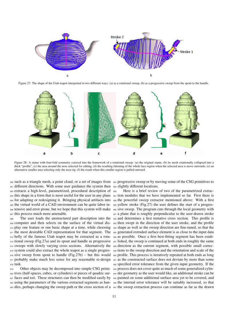
Figure 27: The shape of the Utah teapot interpreted in two different ways: (a) as a rotational sweep, (b) as a progressive sweep from the spout to the handle.
Figure 28: A statue with four-fold symmetry coerced into the framework of a rotational sweep: (a) the original statue, (b) its mesh rotationally collapsed into athick “profile”, (c) the area around the nose selected for editing, (d) the resulting fattening of the whole face region when the selected area is move outwards, (e) analternative smaller area selecting only the nose tip, (f) the result when this smaller region is pulled outward.
such as a triangle mesh, a point cloud, or a set of images from600
different directions. With some user guidance the system then601
extracts a high-level, parametrized, procedural description of602
this shape in a form that is most useful for the user in any plans603
for adapting or redesigning it. Bringing physical artifacts into604
the virtual world of a CAD environment can be quite labor in-605
tensive and error prone, but we hope that this system will make606
this process much more amenable.607
The user loads the unstructured part description into the608
computer and then selects on the surface of the virtual dis-609
play one feature or one basic shape at a time, while choosing610
the most desirable CAD representation for that segment. The611
belly of the famous Utah teapot may be extracted as a rota-612
tional sweep (Fig.27a) and its spout and handle as progressive613
sweeps with slowly varying cross sections. Alternatively the614
system could also extract the whole teapot as a single progres-615
sive sweep from spout to handle (Fig.27b) – but this would616
probably make much less sense for any reasonable re-design617
task.618
Other objects may be decomposed into simple CSG primi-619
tives (half-spaces, cubes, or cylinders) or pieces of quadric sur-620
faces and tori. These structures can then be modified easily by621
using the parameters of the various extracted segments as han-622
dles, perhaps changing the sweep path or the cross section of a623
progressive sweep or by moving some of the CSG primitives to624
slightly different locations.625
Here is a brief review of two of the parametrized extrac-626
tion modules that we have implemented so far. First there is627
the powerful sweep extractor mentioned above: With a first628
yellow stroke (Fig.27) the user defines the start of a progres-629
sive sweep. The program cuts through the local geometry with630
a plane that is roughly perpendicular to the user-drawn stroke631
and determines a first tentative cross section. This profile is632
then swept in the direction of the user stroke, and the profile633
shape as well as the sweep direction are fine-tuned, so that the634
generated extruded surface element is as close to the input data635
as possible. Once a first best-fitting segment has been estab-636
lished, the sweep is continued at both ends in roughly the same637
direction as the current segment, with possible small correc-638
tions to the sweep direction and the orientation and scale of the639
profile. This process is iteratively repeated at both ends as long640
as the constructed surface does not deviate by more than some641
specified error tolerance from the given input geometry. If the642
process does not cover quite as much of some generalized cylin-643
der geometry as the user would like, an additional stroke can be644
painted on some additional surface area yet to be covered, and645
the internal error tolerance will be suitably increased, so that646
the sweep extraction process can continue as far as the drawn647
11

Figure 29: Virtual work space with haptic feedback
stroke indicates (Fig.27b). Conversely, with a different type of648
stroke, the extent of the sweep extraction can be restricted. Dif-649
ferent starting strokes and different error tolerances result in a650
wide variety of possible extracted sweeps. The selected sweep651
paths and profiles can then be edited independently at interac-652
tive speeds.653
A different extraction module tries to fit a generalized ro-654
tational sweep to the surface areas selected by the user. This655
module cannot only match surfaces with strict rotational sym-656
metry but can also extract helical and spiral sweeps [18] [19].657
In all our extraction modules, the reconstructed, parametrized658
surface can either be used directly as the starting point for a659
new design, or the surface details of the input model can be660
preserved and reused. To allow this, the difference between the661
actual input geometry and the extracted surface is stored as a662
displacement map, which can be re-applied to any edited ver-663
sion of the reconstructed surface. This is demonstrated in Fig-664
ure 28 with a roughly cylindrical statue. The whole shape is first665
approximated by a rotational sweep, and all the vertices as well666
as their interconnecting edges are then rotationally collapsed667
into the green profile bundle shown in Figure 28b. Portions668
of this bundle can now be selected and modified interactively669
with respect to their distance from (and position along) the z-670
axis. If we select the whole region around the nose (Fig.28c)671
and move it to the right, all the nose and cheek areas will be672
puffed up (Fig.28d). If, on the other hand, we only select the673
tip of the nose (Fig.28e), only those vertices will change their674
radial component, and we simply obtain four stretched noses675
(Fig.28f). The variety of the extraction modules, and the versa-676
tility with which they can be applied and the extracted geometry677
can be used and transformed, make this a powerful way to get678
a new design started, – if an artifact close enough to the envi-679
sioned design can be found.680
8. Capturing an Initial Inspiration Existing in Your Mind681
But sometimes a model close enough to the intended de-682
sign may not exist, and the design is just a vision in one’s mind.683
How do we get this into the computer? It would be nice if we684
a b
c d
Figure 30: Shape elements to be inserted: (a) physical spline; (b) paper shapes;(c) plastic parts; (d) pipe cleaners.
could wave our hands and describe shapes in this way. Sev-685
eral such sculpting systems have been presented over the last686
two decades, e.g. [20]. A few years ago together with Profes-687
sor Sara McMains in Mechanical Engineering, we built such688
an interactive shape editor in an immersive 3D environment689
[21]. Through a head-tracked pair of shutter glasses, the user690
was seeing a 3D rendering of the design object in front of a691
rear-projected display wall. With a haptic stylus attached to692
a position-sensing articulating arm the user could interact with693
that object. Vertices could be moved around, or the model could694
be annotated or painted (Fig.29). However, the project was not695
a smashing success! The tactile feeling was not solid; it was696
more like drawing on a balloon with a ball point pen. Also, the697
whole set-up was tedious and tiring. I found it impossible to698
create conceptually new sculpture models in this environment.699
Looking back over the last two decades of my own involve-700
ment with sculpting and model making, I find that most novel701
ideas start with something tangible in my hands. The things702
that I am forming and combining are: wire, paper, scotch-tape,703
paper clips, styro foam, clay, etc. Touch and proprioception704
(knowing where your hands are even when blind-folded) play705
an important role. Another important aspect of tangible objects706
is that the materials properties contribute an important part of707
the shape formation process. Bending a plastic strip or a thin708
steel band creates nicely behaved spline curves. A knot made709
from thick plastic tubing can be pulled tight mechanically to710
produce some tightest configuration, – a process that would be711
rather complicated to program in virtual space. Even famous712
architects like Frank Gehry [22] occasionally use heavy cloth713
or velvet to outline the roof of a new concert hall or museum.714
Thus, what I really would like to do is to use whatever ma-715
terial is most appropriate to form components of my design and716
then integrate them with what is already there. One way in717
which this could be accomplished is to work in an immersive718
12

virtual environment (but comfortably sitting down) in which I719
can hold up various elements of the types shown in Figure 30,720
positioning and aligning them visually with the emerging com-721
posite, and then, by tapping my foot (or clicking my tongue)722
send a command to capture this proffered shape and add it into723
the design description. This capture could be accomplished724
with a fast 3D scanner, a structured light system [23], or a future725
version of something like the Kinect [24]. The captured shape726
would be presented to the designer through the Interactive In-727
verse 3D Modeling system described above (Section 7), so that728
it can be represented with the most beneficial parametrization729
for further editing, refinement, and optimization.730
An environment like this could offer the best of both the731
physical world and the virtual domain of computer graphics. It732
should allow us to readily grab a wide variety of tangible things,733
or unstructured geometry descriptions, – whatever serves as a734
possible inspiration or take-off point for our designs. How-735
ever, once such elements have entered the CAD design envi-736
ronment, these pieces of geometry can take on a new identity737
in the form of materials that mimic the best of: clay, wire, pa-738
per, scotch-tape, styro foam, etc, but without the adversity of:739
messy glue, gravity, or strength limitations; and they can repre-740
sent ideal pseudo-physical materials that bend as nicely as steel741
wire, or stretch like a nylon hose, but are as strong as titanium,742
and as transparent as quartz.743
9. Possibilities of Emerging RP Technologies744
Rapid prototyping technologies are currently in a phase of745
fast development. Every year several new models of “Maker-746
Bots” and other layered fabrication machines are introduced747
[25]. Many companies, as well as individuals, are experiment-748
ing with new materials, different binders and support structures,749
and are exploring new application domains for these emerging750
technologies.751
The large annual graphics conferences recently have de-752
voted whole sessions to the topic of rapid prototyping and to753
novel ways of producing physical, tangible output from com-754
puter graphics designs. Some of these applications are quite755
different from the traditional task of producing a physical 3D756
object from a virtual model developed with one of the commer-757
cial graphics or CAD programs. For instance, the development758
of a bas relief of some arbitrary 3D scene [26] requires sophisti-759
cated depth compression schemes, which are similar in their ap-760
proach to techniques used to compress high dynamic range im-761
ages into renderings that can be displayed optimally on standard762
graphics screens with limited dynamic range [27]. Other work763
explores ways to make bas reliefs structured as height fields at764
the pixel level to generate physical panels that will produce one765
or possibly several images when illuminated at oblique angles766
from suitable directions [28] [29]. Such systems typically re-767
quire multi-pass optimization, and the outputs are often plagued768
with low contrast and ghosting or cross talk between the differ-769
ent images.770
Instead of structuring the geometry of the output artifact to771
produce images through shadows, other researchers have used772
optimization algorithms to tailor the shape of a reflector so as773
to create a desired illumination pattern [30]. In yet another ap-774
proach, transparent materials are micro-machined, and refrac-775
tion is used to form the desired image as a superposition of776
properly tailored caustics [31].777
The emergence of multi-material RP machines [32] makes778
it possible to create physical output with novel optical prop-779
erties or varying stress-strain relationships. In the first sector780
researchers have created flat panels or 3D models from materi-781
als with custom-designed subsurface-scattering properties [33]782
[34]. This approach, which is also based on physical simulation783
and multi-pass optimization, makes it possible to emulate the784
look of marble, jade, or even a slice of salmon. By varying the785
deposited materials from layer to layer, as well as adjusting the786
porosity with which these layers are deposited, the strength and787
pliability of the resulting composite also can be controlled and788
finely tuned. Researchers have been able to closely model and789
reproduce the bending and compression behavior of the soles790
of flip-flops or slippers [35].791
An even tougher challenge is to create complex 3D mod-792
els that can change shape. Among the many different possi-793
ble approaches, there are some inspiring trend-setters. Some794
of the rapid prototyping methods allow in-situ construction of795
interlocking assemblies of movable parts. This allows the pro-796
duction of demonstration models of wrenches [36] or of com-797
plete gear boxes [37]. Another approach is to create articu-798
lated figures from snap-together parts, so that phantasy crea-799
tures designed in Spore [38] can be brought to life as toys that800
can assume many different poses [39]. Another highly intrigu-801
ing problem is the design and fabrication of balloon hulls that,802
when inflated to the proper size, will assume a desired shape.803
Since such membranes do not inflate in a linear manner at all,804
the initial limp hulls have to be given some quite different shapes.805
Again, a multi-pass optimization step comprising detailed phys-806
ical simulation can lead to success [40]. There seems to be no807
limit to the modalities by which computer graphics design and808
physical output can be related.809
10. Summary and Conclusion810
Interactive computer graphics has come a long way since811
Ivan Sutherland first demonstrated his Sketchpad [41]. Remark-812
able progress has been made in photo-realistic rendering, simu-813
lation, immersive 3D worlds, and haptic feedback. Further de-814
velopments will couple the virtual domain of computer graphics815
and the 3D world of physical artifacts in ever more diverse and816
intriguing ways. Most of the techniques mentioned in the pre-817
vious section are at a stage of demonstrating feasibility. It will818
take some time before they turn into mainstream output tech-819
nologies that can readily be applied at the push of a button.820
To produce substantial and durable physical artifacts is still821
a venture that takes special attention for most new models. I822
have learned that every time when I work on a new sculpture823
family, or switch materials from bronze to stone, to sintered824
steel, or to translucent polyester resins, a new set of problems825
emerge; those need careful attention and often require some826
preliminary testing of the modeling as well as of the fabrication827
technologies. The 3D Hilbert Cube (Fig.2a), made with the828
13

ExOne metal-sintering process [42], required three attempts,829
comprising an ever-increasing number of internal support rods.830
These auxiliary struts were necessary to hold this shape to-831
gether in its green state as it is inserted into the sintering oven,832
because at this stage the model has the weight of iron, but only833
the strength of the selectively deposited binder that holds the834
stainless steel particles together.835
For many of the techniques mentioned in Section 9, mature836
processes and services will develop over time, and will eventu-837
ally allow a one-click order of the desired physical output. One838
such example is the stone-carving service offered by Dingli in839
China [43]. All I had to do to obtain the four foot tall granite840
sculpture shown in Figure 2b was to send them a six inch tall841
RP model of the top part; they did not even use the CAD files842
for the actual production.843
As discussed in Sections 7 and 8, the coupling between844
computer graphics and the physical world is not a one-way845
street. Pre-existing artifacts, as well as RP models with tailor-846
made deformation properties, could serve as design elements847
for inputting shapes into a CAD environment at the early stages848
of a design process. However, both the input end, as well as the849
output end of a computer-based design effort, require signifi-850
cant advances in tool development and user-interface design to851
make these transition points reliable and easy to use.852
11. Acknowledgements853
This work is supported in part by the National Science Foun-854
dation: NSF award #CMMI-1029662 (EDI).855
References856
[1] MakerBots . Desktop 3d printers. web page:857
– http://www.makerbot.com/; 2013.858
[2] Shapeways . 3d printed products. web page:859
– http://www.shapeways.com/; 2013.860
[3] Ponoko . The world’s easiest making system. web page:861
– http://www.ponoko.com/; 2013.862
[4] SecondLife . A popular virtual space. web page:863
– http://maps.secondlife.com/; 2012.864
[5] Collins B. Brent collins: Photo gallery by philip geller. web page:865
– http://bridgesmathart.org/bcollins/bcollins.html; 2013.866
[6] Francis GK, Collins B. On knot-spanning surfaces: An illustrated essay867
on topological art. Leonardo 1992;25(3,4):313–20.868
[7] Scherk HF. Bemerkungen uber die kleinste flache innerhalb gegebener869
grenzen. J Reine Angew Math (Crelle’s Journal) 1834;13(3,4):185–208.870
[8] Sequin CH. Sculpture Generator I. web page:871
– http://www.cs.berkeley.edu/ sequin/GEN/; 2013.872
[9] Sequin CH. Virtual prototyping of scherk-collins saddle rings. Leonardo873
1997;30(2):89–96.874
[10] Reinmuth S. Reinmuth bronze studio. web page:875
– http://www.reinmuth.com/; 2013.876
[11] Smith J. Slide design environment. web page:877
– http://www.cs.berkeley.edu/ ug/slide/docs/slide/spec/; 2004.878
[12] Scan&Solve . Scan-and-solve for rhino. web page:879
– http://www.scan-and-solve.com; 2013.880
[13] Lynn D. Nova blue studio arts. web page:881
– http://sites.google.com/site/novabluestudioarts/home; 2013.882
[14] Sequin CH. Whirled White Web. web page:883
– http://www.cs.berkeley.edu/ sequin/SCULPTS/SnowSculpt03/; 2013.884
[15] SolidWorks . 3d design simplified. web page:885
– http://www.solidworks.com/; 2013.886
[16] Stratasys . For a 3d world. web page: – http://www.stratasys.com/; 2013.887
[17] Andrews J, Jin H, Sequin CH. Interactive inverse 3d modeling. Computer-888
Aided Design and Applications 2012;9.889
[18] Pottmann H, Randrup T. Generalized, basis-independent kinematic sur-890
face fitting. Computing 1998;60:307–22.891
[19] Andrews J, Sequin CH. Generalized, basis-independent kinematic surface892
fitting. Computer-Aided Design 2013;45(3):615–20.893
[20] Dachille F, Qin H, Kaufman A. A novel haptics-based interface and894
sculpting system for physics-based geometric design. Computer-Aided895
Design 2001;33(5):403–20.896
[21] Shon Y, McMains S. Evaluation of drawing on 3d surfaces with haptics.897
IEEE Computer Graphics and Applications 2004;24(6):40–50.898
[22] Gehry F. The architecture of frank gehry. web page:899
– http://www.gehrytechnologies.com/architecture/recent-work; 2012.900
[23] Zhang L, Curless B, Seitz SM. Rapid shape acquisition using color struc-901
tured light and multi-pass dynamic programming. In: The 1st IEEE In-902
ternational Symposium on 3D Data Processing, Visualization, and Trans-903
mission. 2002, p. 24–36.904
[24] Xbox . Introducing kinect. web page:905
– http://www.xbox.com/en-US/KINECT; 2013.906
[25] MAKEeditors . Ultimate guide to 3d printing. Make 2012;:1–116.907
[26] Weyrich T, Deng J, Barnes C, Rusinkiewicz S, Finkelstein A. Digital908
bas-relief from 3d scenes. ACM Trans Graph 2007;26(3):3201–7.909
[27] DiCarlo J, Wandell B. Rendering high dynamic range images. Proc SPIE910
Electronic Imaging Conf 2000;3965:392–401.911
[28] Alexa M, Matusik W. Images from self-occlusion. Computational Aes-912
thetics in Graphics, Visualization, and Imaging (CAe2011) 2011;:17–24.913
[29] Alexa M, Matusik W. Reliefs as images. ACM Transactions on Graphics914
(SIGGRAPH’10) 2010;29(4):6001–7.915
[30] Patow G, Pueyo X, Vinacua A. User-guided inverse reflector design.916
Computers & Graphics 2007;31:501–15.917
[31] Papas M, Jarosz W, Jakob W, Rusinkiewicz S, Matusik W, Weyrich918
T. Goal-based caustics. Computer Graphics Forum (Eurographics’11)919
2011;30(2):503–11.920
[32] Stratasys . Objetconnex, multi-material 3d printing system. web page:921
– http://objet.com/3d-printers/connex/objet-connex500/; 2013.922
[33] Hasan M, Fuchs M, Matusik W, Pfister H, Rusinkiewicz S. Physical re-923
production of materials with specified subsurface scattering. ACM Trans-924
actions on Graphics (SIGGRAPH’10) 2010;29(4):6101–10.925
[34] Dong Y, Wang J, Pellacini F, Tong X, Guo B. Fabricating spatially-926
varying subsurface scattering. ACM Transactions on Graphics (SIG-927
GRAPH’10) 2010;29(4):6201–10.928
[35] Bickel B, Bacher M, Otaduy M, Lee H, Pfister H, Gross M, et al. Design929
and fabrication of materials with desired deformation behavior. ACM930
Transactions on Graphics (SIGGRAPH’10) 2010;29(3):6301–10.931
[36] Custom3dSolutions . Your source for rapid prototyping and 3d cad ser-932
vices. web page:933
– http://custom3dsolutions.com/; 2013.934
[37] PRGprototyping . Bringing ideas to reality. web page:935
– http://prgprototyping.com/about.htm; 2013.936
[38] Spore . How will you create the universe? web page:937
– http://www.spore.com/; 2013.938
[39] Moritz Bacher M, Bickel B, James D, Pfister H. Fabricating articulated939
characters from skinned meshes. ACM Transactions on Graphics (SIG-940
GRAPH’12) 2012;31(4):4701–9.941
[40] Skouras M, Thomaszewski B, Bickel B, Gross1 M. Computational de-942
sign of rubber balloons. Computer Graphics Forum (Eurographics’12)943
2012;31:835–44.944
[41] Sutherland IE. SketchPad: A man-machine graphical communication sys-945
tem. In: AFIPS Conference Proceedings; vol. 23. 1963, p. 323–8.946
[42] ExOne . Digital part materialization. web page:947
– http://www.exone.com/; 2013.948
[43] Dingli . Fujian dingli stone carving art co., ltd. web page:949
– http://www.dinglistone.com/English/index.asp; 2013.950
14


