Embed Size (px)
Citation preview
Matrix Method of Structural AnalysisProf. Amit Shaw
Department of Civil EngineeringIndian Institute of Technology, Kharagpur
Lecture - 09Review of Structural Analysis - I (Contd.)
Hello everyone; welcome to the 9th lecture of the ongoing course on Matrix Method of
Structural Analysis. This and the next lecture is the, are the conclude concluding lecture
of the of the review of structural analysis 1. What is essentially we are going to do today
and the next lecture is to is to put everything whatever we have reviewed so for put
everything together and in a bag and then prepare our self for the journey for structural
analysis through matrix methods ok.
(Refer Slide Time: 00:52)
Let us try to just recall what we have done so far.
(Refer Slide Time: 00:53)
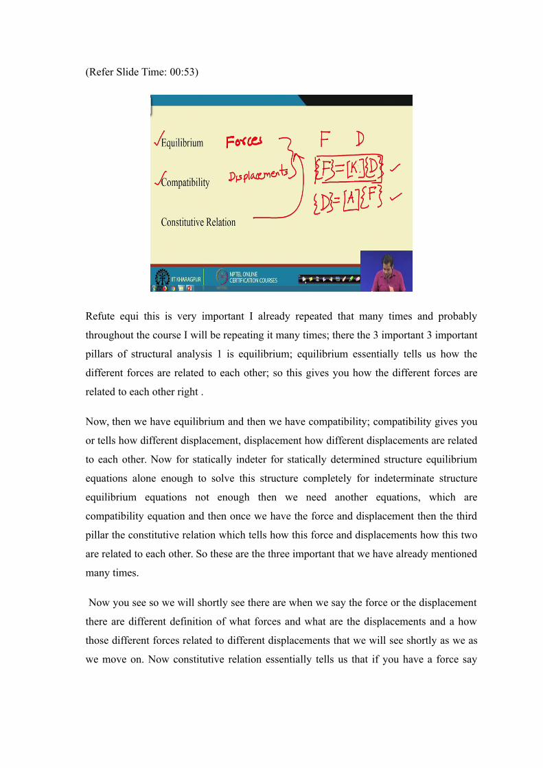
Refute equi this is very important I already repeated that many times and probably
throughout the course I will be repeating it many times; there the 3 important 3 important
pillars of structural analysis 1 is equilibrium; equilibrium essentially tells us how the
different forces are related to each other; so this gives you how the different forces are
related to each other right .
Now, then we have equilibrium and then we have compatibility; compatibility gives you
or tells how different displacement, displacement how different displacements are related
to each other. Now for statically indeter for statically determined structure equilibrium
equations alone enough to solve this structure completely for indeterminate structure
equilibrium equations not enough then we need another equations, which are
compatibility equation and then once we have the force and displacement then the third
pillar the constitutive relation which tells how this force and displacements how this two
are related to each other. So these are the three important that we have already mentioned
many times.
Now you see so we will shortly see there are when we say the force or the displacement
there are different definition of what forces and what are the displacements and a how
those different forces related to different displacements that we will see shortly as we as
we move on. Now constitutive relation essentially tells us that if you have a force say
this is force and then we have a displacement this is displacement then constitutive
relation tells us how this two different forces and displacement are related to each other.
Now, based on how this relation is expressed we have two definition of this relation;
there are two way we can express this relation one is the flexibility definition and another
one is stiffness definition. Flexibility definition is what?
Flexibility definition is if you have a force you have a force then that force is equal to
say some A into D that is and then stiffness definition is D if we have if we the
displacement sorry this is stiffness definition and the flex flexibility definition is this so
we can use K here that is the term that will be using very often. So let is let it is K and
then we have say A which is essentially K inverts which is equal to force right which is
equal to force.
Now, this 2 relation this and this they essentially tells us the similar thing, but in a
different way; different way in the sense whether with the knowledge of force we
determine the displacements or with the knowledge of displacement we determine the
force. So based on which definition we are using whether it is the flexibility definition or
stiffness definition we have two class of method one is force method and one is
displacement method. Force method where the example of the force method is the
method of consistency deformation where we use the flexibility definition and then we
have displacement method for instance it slope displacement method we use stiffness
definition.
Now, the this the displacement method now if further extended in the course will be
extending displacement method to have a more general method. Now we see, but they ca
they premise the concept that constitute the premise of the matrix method of the
structural analysis is the, this equation. This definition, but you know the concept alone
is not sufficient the concept is important, but ah, but how the concept is translated into a
method that is also important because you see whether the force method and the method
of consistency deformation or method of slope deflection method or movement
distribution method they all are based on flexibility or stiffness definition of force and
displacement relation.
So that same concept is you will be using in the for matrix method of structural analysis,
but the way this concept is been translated into met a into a method for instance for
method of consistency deformation slope deflection method they lack the generality, they
lack the they there is a huge the way it is translated that puts a huge restriction on the
applicability of the method for the larger class of problem.
And more importantly that if you recall the many operations that to performed in
structural analysis 1; even with the same concept all the operations you performed
manually we had to do it manually, but then for the larger structure we really cannot do
all these calculations. manual calculations; so we need a method which can be translated
into computer code as well, so that that is the major motivation of moving or looking
beyond structural analysis 1.
(Refer Slide Time: 07:02)
Now, but this the if I have to tell you the concept wise as a different really they are not it
is the similar concept, but the that the different lies in the way the concept is translated
into a method ok. Now so now you see for instance; suppose if you take truss now if you
recall the very first lecture we that introductory lecture I try to give you a general over
view or philosophy of the matrix method of structural analysis and there we discussed
the assent the essence is the you; if you have a structure which may be very complicated,
very large, there are many members in the structure, different joints..
ah But we do not we do not solve this structure, we do not analyze this structure as a
whole; what we do is we break this structure into small pieces and then write equations
for all the pieces and then and then we relate those different pieces we write equations
which gives us how the different pieces are related to each other and that relations gives
a global system of equation which we need to solve for the entire structure.
So, but then now here the 2 important part in this method 1 important part is are other 3
important part; the first important part is break the entire structure into different pieces,
different members is the first thing and the second thing is write equation for each
different parts and then third is you assemble all these pieces to get the global to get the
equation for the entire structure.
Now what we do is the second step we just try to understand the second step in the
context of structural analysis here. Now you see for instance and the and they when we
do that we will realize that the second step the concept is essentially the same that we
have learnt in the structural analysis 1 and also reviewed in the first 8 lectures of this
course ok.
So, consider as truss it could be any complicated struct, determinate, indeterminate
structure; here another important point is though what we learned in structural analysis 1
is this displacement method force method we learned while solving indeterminate
structure, for determinate structure just equilibrium equation was enough ah, but again in
matrix method of structural analysis there is nothing like that it has to be applicable for
only determinate structure or indeterminate structure or for only indeterminate structure
we go for matrix method of structural analysis; it is nothing like that irrespective of the
fact whether struct is determinate or indeterminate we can apply this method ok. Now,
but again the structure has to be stable.
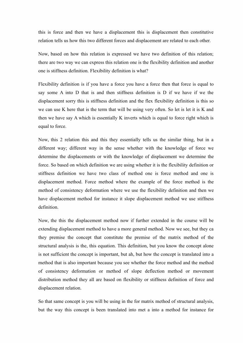
Now, take an example we have we have a truss here; it is determinate truss we can you
can easily see, but again as I said it is the concept is any structure any number of
members and now the take for the first you consider structure itself, remove all the loads;
different loads only the structure.
Now the first step is to remove is to is to is to divide the entire structure into small pieces
and these are the small pieces ok. Now here you have 3 members so it is divided into 3
parts you can have any number of members if it is it is a plane truss; if it space truss then
the members will be oriented in 3-dimensional space it depends on the on the problem
we are considering ok.
So, once we have different parts of the structure, the next step if you recall next step is to
is to write equations for each part; and what is that equation? The equation is the force
displacement equation. So what we do is we write equation for this part this part what we
write equation is here the force is equal to force is equal to stiffness into displacement
right and here also we write the same part that force is equal to is equal to stiffness into
displacement right and for these part also you write the same thing force is equal to
stiffness into displacement right.
We already know how to write force is equal to stiffness into displacement if you recall
the all the method that we now just reviewed they also based on the similar equation;
same equations will be using for this method as well. But now since we have to we have
to disc we have to divide the entire problem into small small pieces so we have to write
these equations for every pieces and once we have written this then will assemble all this
equation; so will get an equation say we get the equation these equation from this
member, we have a set of equation for this member and we have a set of equation for this
member and then we combine this all these set of equations to get the equations for the
entire structure and then we solve it right.
Now, but how to write equations for the; how to; what to form of the equation for truss or
for different other members for different other structure; for instance beam or frame for
any other structural component that will see as we move. Now take an example of
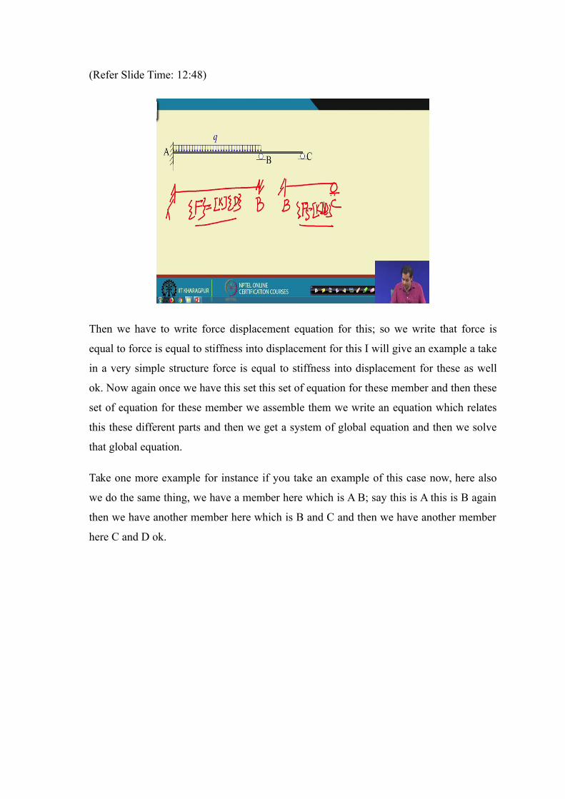
another take example of say beam now we have to divide the entire into 2 small parts; let
take here in this case we divide into 2 part; 1 is part A B 1 is part A B and then another is
part B C. So this is part A B and this is part A B and this is part B C right A B then B C.
(Refer Slide Time: 12:48)
Then we have to write force displacement equation for this; so we write that force is
equal to force is equal to stiffness into displacement for this I will give an example a take
in a very simple structure force is equal to stiffness into displacement for these as well
ok. Now again once we have this set this set of equation for these member and then these
set of equation for these member we assemble them we write an equation which relates
this these different parts and then we get a system of global equation and then we solve
that global equation.
Take one more example for instance if you take an example of this case now, here also
we do the same thing, we have a member here which is A B; say this is A this is B again
then we have another member here which is B and C and then we have another member
here C and D ok.
(Refer Slide Time: 14:10)
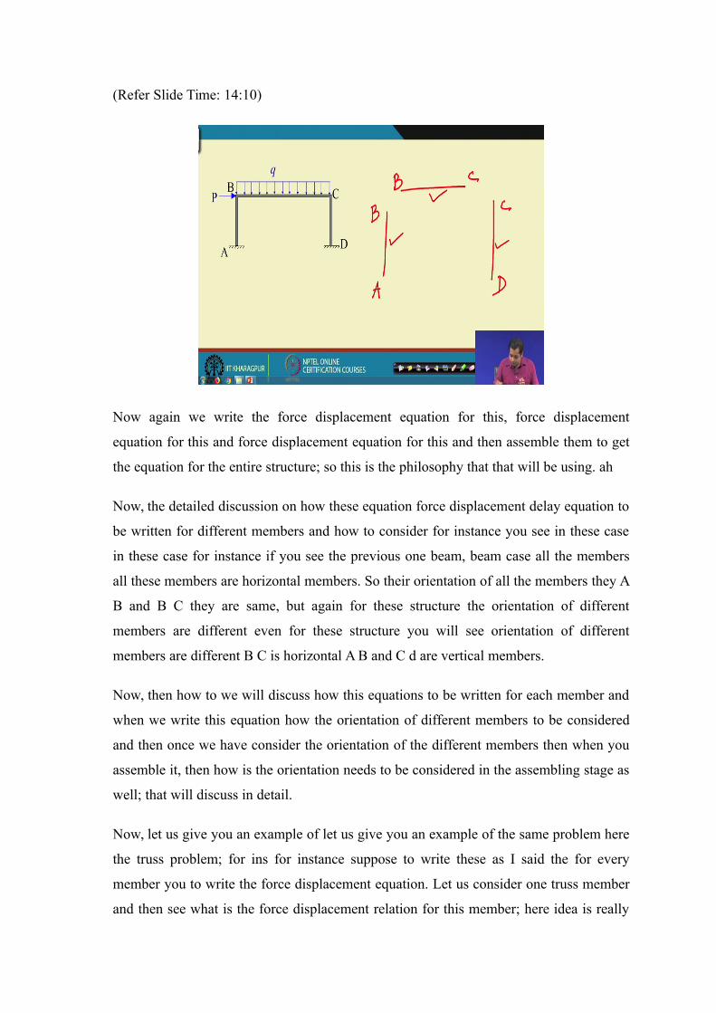
Now again we write the force displacement equation for this, force displacement
equation for this and force displacement equation for this and then assemble them to get
the equation for the entire structure; so this is the philosophy that that will be using. ah
Now, the detailed discussion on how these equation force displacement delay equation to
be written for different members and how to consider for instance you see in these case
in these case for instance if you see the previous one beam, beam case all the members
all these members are horizontal members. So their orientation of all the members they A
B and B C they are same, but again for these structure the orientation of different
members are different even for these structure you will see orientation of different
members are different B C is horizontal A B and C d are vertical members.
Now, then how to we will discuss how this equations to be written for each member and
when we write this equation how the orientation of different members to be considered
and then once we have consider the orientation of the different members then when you
assemble it, then how is the orientation needs to be considered in the assembling stage as
well; that will discuss in detail.
Now, let us give you an example of let us give you an example of the same problem here
the truss problem; for ins for instance suppose to write these as I said the for every
member you to write the force displacement equation. Let us consider one truss member
and then see what is the force displacement relation for this member; here idea is really
not to give a detail derivation of the force displacement relation or this because that will
be doing any way in the subsequent weeks; the idea to make some point which are
important and which we need to keep in mind when we actually do this exercise in detail
ok.
(Refer Slide Time: 16:42)
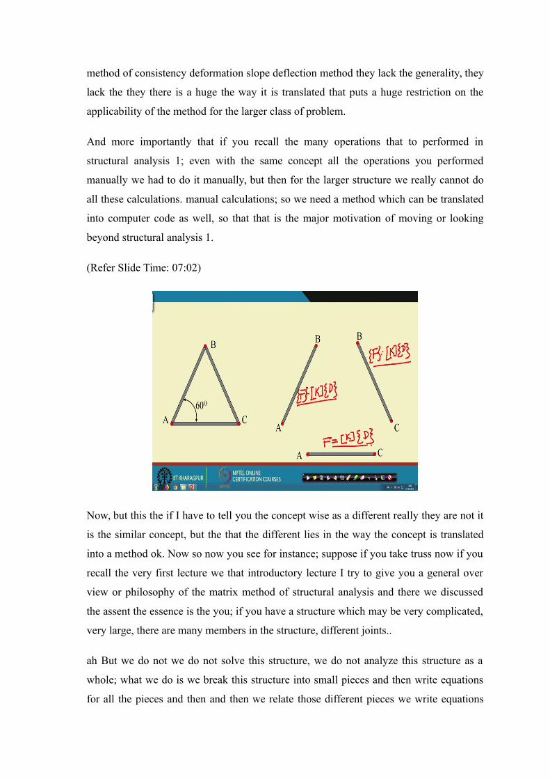
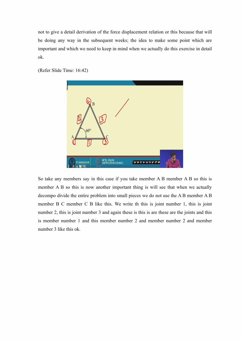
So take any members say in this case if you take member A B member A B so this is
member A B so this is now another important thing is will see that when we actually
decompo divide the entire problem into small pieces we do not use the A B member A B
member B C member C B like this. We write th this is joint number 1, this is joint
number 2, this is joint number 3 and again these is this is are these are the joints and this
is member number 1 and this member number 2 and member number 2 and member
number 3 like this ok.
(Refer Slide Time: 17:18)
So, suppose this is joint number 1 and joint number this is joint number 1 and this is joint
number 2. So take this member this is joint number 1 and this is joint number 2; now you
see the truss member we all we know that truss member are the two force members two
force members means the it has the force along the longitudinal direction of these
member.
The truss member is either subjected to axial compression or axial tension; so if it is the
forces are either the forces are either tension either tension or the forces are either
compression if we take this is 1 and this 2 the forces should be either compression either
forces compression, compression and tension.
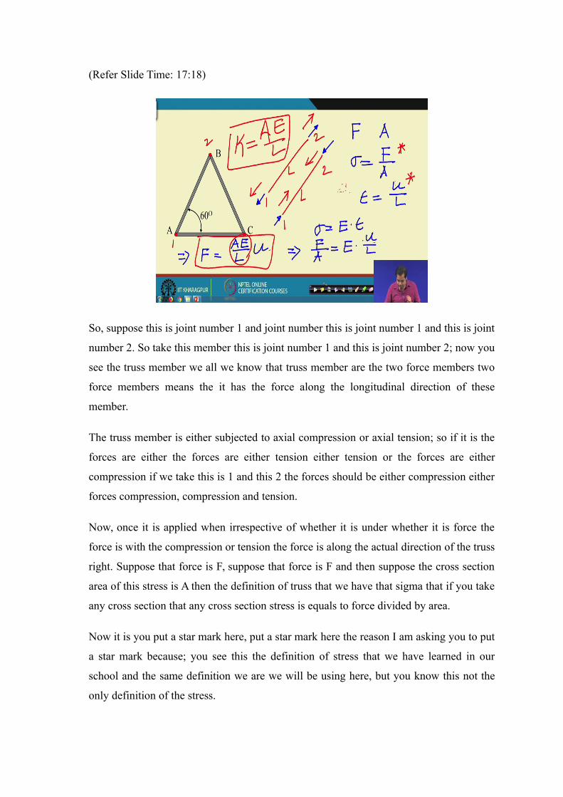
Now, once it is applied when irrespective of whether it is under whether it is force the
force is with the compression or tension the force is along the actual direction of the truss
right. Suppose that force is F, suppose that force is F and then suppose the cross section
area of this stress is A then the definition of truss that we have that sigma that if you take
any cross section that any cross section stress is equals to force divided by area.
Now it is you put a star mark here, put a star mark here the reason I am asking you to put
a star mark because; you see this the definition of stress that we have learned in our
school and the same definition we are we will be using here, but you know this not the
only definition of the stress.
For instance here stress has two important parts two important parts it depends on two
important parts one is the force and another one is the area. Now which force we are
talking about or we are considering or which area we are which area we are taking
depending on the there could be different majors of stresses. So as we see in the other
courses for instance the course on elasticity or then course of non-linear mechanics we
will see that there are different major of the stresses and how these stresses are different
depending on the what force and what area are using for the definition of stress.
Now, then suppose this force is F now under the action of this stress suppose or the
force; suppose this the change in length, suppose original length of the member is L this
is member length L and this is member length L. Suppose change in length it could be
the extension, it should be the it could be the under tension or under compression
suppose the change in length is delta L suppose the change in length is delta L. So if
change in length is delta L then we know the strain is equal to strain, strain is equal to
delta L by L. So if it tension then delta L is positive, if it is compression the shortening
take place then delta is negative automatically strain is compression.
Now again here also you put a star mark here because you will see in the subsequent
courses there are different measure of strains as well so, but the definition of stress and
the definition of strain that we are using here is this ok.
Now, once you know what is stress for this and strain for this; then stress strain relation
is essentially the constitutive relation and the stress and strain is related through Young’s
modulus. So we know that sigma is equal to young’s modulus strain into epsilon right;
strain into epsilon. Now if I substitute the value of substitute the value of sigma and
epsilon here then what we get is this these becomes F by A F by A is equal to E is the
young’s modulus and L is equal to delta L by L. So these gives us a very important
equation that is equal to F is equal to A E by L into delta L ok.
Now, let us let us not use delta L here because the reason is instead of delta L you can
use u here because that is the definition of displace that is the way that is how we will
define displacement in the subsequent lectures. So let us write from the beginning we
stick to the notation; so let us let us this is u is the displacement, this is u, this becomes u
and this becomes u and then this is so u is the displacement and strain is equal to u by L.
So, these is; now look at this what is essential this is essentially here stiffness definition
where the force is equal to something multiplied by displacement and this something
these something K in this case is equal to A E by L this is the stiffness for this member
ok.
Now, but you know this is the stiffness of this member. Let us now t, let us now see in a
more general case more general case in the sense take the same member same member,
but you see you remember this is force is equal to stiffness into displacement. Now then
what is important is; what are the forces you are considering and what are the
displacement components we consider in our in our analysis.
Now, what is u here; u is the change in length right if the original length is L and the u is
the change in length and force is equal to because of this change in length what is the
force or the because of the force there is a change in length, but really suppose consider a
situation where you have, but when we say u is some value we cannot really say then
how much is the movement of; suppose how the change in length can takes place 0.1 in
this case, for in this case 0.1 moves in this direction and 0.2 moves in this direction.
Similarly, in this case 0.1 is moves in this direction and this point moves in this direction.
And what is the net movement between 0.1 and 2 net change ha between 0.1 and 2 is u,
but we say u, u can tell us that what is the movement of 0.1 and what is the movement of
0.2 separately ok. Now let us take the more general case; where we do not we do not
write this equations in terms of net change in length, instead we write this equation in
terms of the movement of points or the displacements of rather the displacement is the
correct word in this case the displacement of 0.1and displacement of 0.2.
The net displacement would be u, but let us write the same equation in terms of not in a
displacement write the equation in terms of net displacement at u at 1 and the net
displacement at 2 right. So if you do that so take once again this suppose in this case you
cons a draw the draw the draw these once again this is A B; now this is point number 1
this is point number 2.
(Refer Slide Time: 25:39)
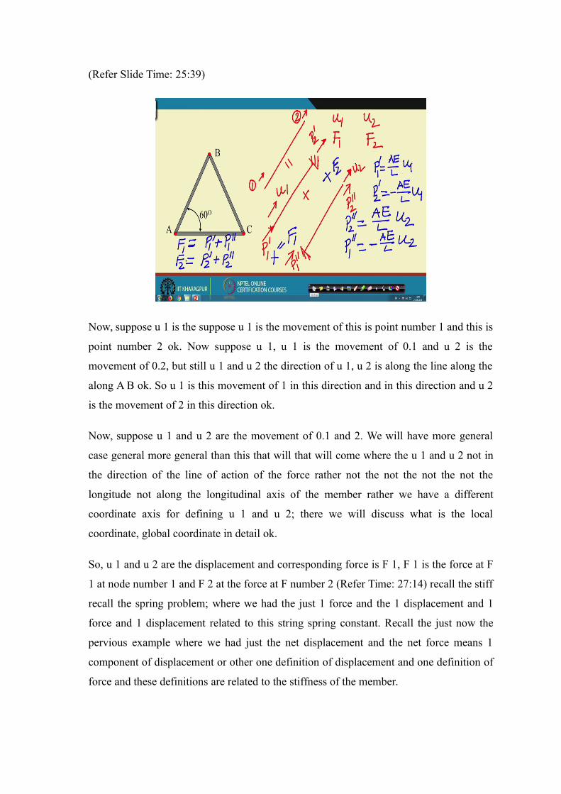
Now, suppose u 1 is the suppose u 1 is the movement of this is point number 1 and this is
point number 2 ok. Now suppose u 1, u 1 is the movement of 0.1 and u 2 is the
movement of 0.2, but still u 1 and u 2 the direction of u 1, u 2 is along the line along the
along A B ok. So u 1 is this movement of 1 in this direction and in this direction and u 2
is the movement of 2 in this direction ok.
Now, suppose u 1 and u 2 are the movement of 0.1 and 2. We will have more general
case general more general than this that will that will come where the u 1 and u 2 not in
the direction of the line of action of the force rather not the not the not the not the
longitude not along the longitudinal axis of the member rather we have a different
coordinate axis for defining u 1 and u 2; there we will discuss what is the local
coordinate, global coordinate in detail ok.
So, u 1 and u 2 are the displacement and corresponding force is F 1, F 1 is the force at F
1 at node number 1 and F 2 at the force at F number 2 (Refer Time: 27:14) recall the stiff
recall the spring problem; where we had the just 1 force and the 1 displacement and 1
force and 1 displacement related to this string spring constant. Recall the just now the
pervious example where we had just the net displacement and the net force means 1
component of displacement or other one definition of displacement and one definition of
force and these definitions are related to the stiffness of the member.
But now here we have 2 displacement, 2 definite 2 displacements and 2 forces then we
have to find out how this 2 displacements are related to 2 forces. Let us do that here; so
we will do that in a separates again applying a linear the principle super position, where
we assume first there is no movement of 0.2 there is no movement of 0.2 the 0.1 moves
and then write the equation and then assume that there is no movement at 0.1 and the 0.2
moves write the equation and then we add the these 2 equations to get the total
movement at 0.1 and 0.2.
Now, so these is now divided into 2 part so these is equal to 1 problem, this problem
where this end is fixed and the 0.1 is allowed to move so these point is these point may
move these point these point may move say this is u 1 these is u 1 and suppose these is
these is and then plus another problem where this point is fixed and then we have we
have this moment of point u 2 ok.
This plus this gives us this right. Now when let us corresponding let us find out what are
the corresponding forces; the corresponding forces are now is corresponding forces are
suppose this is this is let us write this is this is P P 1 dash and this is P 2 dash this is P 2
dash and similarly here it is P P 1 double dash and this is P 2 P 2 double dash.
Now this problem plus this problem gives us this problem ok. Now let us write the
equation for equation for equation for a the this is equation for this and equation for this;
so equation for these will be the first one will be say P 1 if you recall P 1 dash P 1 dash
will be A E by L, A E by L into E 1 and similarly P 2 dash will be P 2 dash will be minus
A E by L into u 1 the minus is because if you apply a force if you apply a force in this
direction the reaction will be in opposite direction, but since we showed the we are
taking a as a per as sign convention if we assume a these force is positive soon as the
opposite will be negative so that is why it is negative.
Now, similarly the P 2 dash will be so if we write P P 2 dash so P 1 dash and P 2 dash so
we have we have P 1 double dash if we write; so P 2 double dash is equal to it will be A
E by L A E by L into u 2 because it is in the direction of u 2 and then P 1 double dash P 1
double dash will be negative minus A E by L into u 2 right.
So, now look at here P 1 and u 2 P 1 so because if we apply P 2 P 2 will cause
displacement in this direction and the result and force will be in the opposite direction,
but we have taken P 1 in this direction that is why it is negative right. Now you see if we
add them then we get this right if we add them then what we get is the total force is equal
to the F 1; F 1 is the force applied at node number 1 and F 2 is the force applied at node
number 2.
So, F 1 will be P 1 this plus this will be F 1 and this plus will be this plus this will be F 2
F 2; so if we if we write F 1 and F 2 then what we if we write F 1 and F 2 then what we
have is if you write here that F 1 is equal to F 1 is equal to we have P 1 dash plus P 1
double dash P 1 dash plus P 1 double dash and similarly F 2 is equal to P 2 dash plus P 2
double dash.
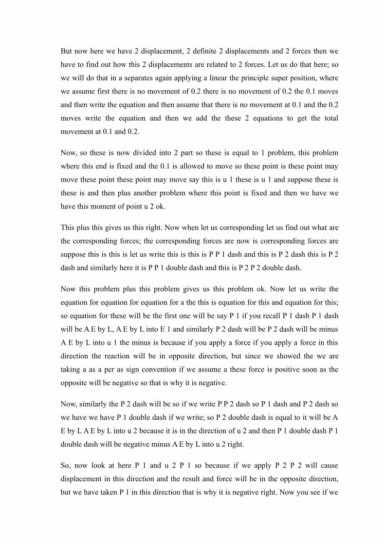
Now, if you substitute P 1 dash here and P 2 dash here and write in a matrix form then
what we get is this. So let us remove erase everything what we get is this we get that F 1
F 1 and then F 2 is equal to or matrix this is u 1 u 2 and this we get E by L minus A E by
L and then this is also minus A E by L and A E by L.
(Refer Slide Time: 33:58)
A E by L or if we take just write the same equation if we write quickly F 1 and F 2 taking
A E by L common or if we can take A E by L common then it will be A E by L A E by L
this is 1 minus 1 minus 1 and 1 and then u 1 u 2 u 1 u 2. Now this is essentially K and
this is essentially F and this is essentially D; so you see the same stiffness definition we
have for 1 member.
Now, similarly similar equation we can have for this member and this member and then
assemble it, but then the process is not that straight forward; so what is what will do now
is the idea has been to that exercise doing the same doing the doing the writing this
equation for all the members and then assembling it solution of this all this members that
will write that will do that will be doing in details in subsequent weeks ok.
But here the objective the idea has been for this lecture has been to tell you see look this
is this is the way we can write the force we can write force displacement relation for a
given member and the similar thing you can do it for beam or frame structural
components as well, but then this is the this equation are the building blocks of matrix
method of structural analysis.
So when we, but again another important thing you look at all this equations are written
in terms of matrixes right stiffness matrixes when we solve this equation essentially we
have to solve we have to do several matrix operations and that is the reason why in next
week we will be having a brief review of matrix algebra ok.
And then on the 4th week when we start solving or formulating the method for truss; will
start with these equation this force displacement relation and then see; just now I said
that what are the definition of the what are the direction of the displacement or the
direction of the forces you are take; you are considering depending on that you have a
stiffness matrix. Because stiffness when you talk about the stiffness it always it let to
force and displacement therefore, therefore, it is important that what forces we are taking
and what displacement we are taking that definition needs to be needs to be needs to be
properly given.
In previous example where we had just the one displacement component and the one
force component it was the net displacement of the, net changing length of the member,
in this case it is the u 1 and u 2 the displacement at node 1 and the displacement at node
2, but they are in the direction in the in the directional longitudinal access of the member
and then again in a more in the more generalize in the more general form we will see that
instead of writing the equation in terms of displacement along the longitudinal axis why
not write the equation in terms of displacement with respect to certain global coordinate.
Means the horizontal displacement and the vertical displacement irrespective of the
configuration of the member; always write the equation in terms of horizontal
displacement, vertical displacement and the horizontal force and the vertical force and
then will see and their we have to bring in we have to incorporate the orientation of the
member now that we will do in the 4th week.
So, I will stop here today in the next class which will be the concluding class for this
review will not do repeat this similar exercise for beams and frames, but we will try to
understand what are the different displacement components we can have for beams and
frames and then a conclude this review see you in the next class.
Thank you.


